ML101380375.pdf - Nuclear Regulatory Commission
113
Enclosure 37 to TN E-29128 Transnuclear Calculation MP197HB-0401, Revision 2 associated with RAI 3-21 (Non-proprietary)
-
Upload
khangminh22 -
Category
Documents
-
view
0 -
download
0
Transcript of ML101380375.pdf - Nuclear Regulatory Commission

Enclosure 37 to TN E-29128
Transnuclear Calculation MP197HB-0401, Revision 2associated with RAI 3-21 (Non-proprietary)

Non-PROPRIETARY Version
A Form 3.2-1 Calculation No.: MP197HB-0401AR EVA Calculation Cover Sheet Revision No.: 2TRANSNUCLEAR INC. TIP 3.2 (Revision 4) Page: 1 of 112
DCR NO (if applicable): NUH09-006, Rev. 0 PROJECT NAME: MP197HB Transport Packaging Design
PROJECT NO: 61003 CLIENT: Transnuclear, Inc.
CALCULATION TITLE:
Thermal Analysis of MP1 97HB Transport Cask for Normal Conditions of Transport
SUMMARY DESCRIPTION:
1) Calculation Summary
This calculation determines the maximum component temperatures of MP197HB transport cask for normalconditions of transport (NCT) for 1000F, -20 0F, and -40°F ambient temperatures. The temperature distributionof the DSC shell is determined to be used for detail analysis of the basket. The maximum accessible surfacetemperature is also evaluated in this calculation.
2) Storage Media Description
Secure network server initially, then redundant tape backup
If original issue, is licensing review per TIP 3.5 required?
Yes El No I] (explain below) Licensing Review No.: N/A
This calculation is performed to support a 10CFR71 transport license application that will be reviewed andapproved by the NRC. Therefore, a 10CFR72.48 licensing review per TIP 3.5 is not applicable.
Software Utilized: Version:
ANSYS 8.1
Calculation is complete:
Originator Name and Signature: Kamran Tavassoli Date: 6')io2/,
Calculation has been checked for consistency, completeness and correctness:
_ / /Checker Name and Signature: Slava Guzeyev / Date:
Calculation is approved for use:
Project Engineer Name and Signature: Steven Streutker Date:

A Calculation No.: MP197HB-0401AREVA Ca UcDat•o Revision No.: 2
TRANSNUCLEAR INC. Page: 2 of 112
REVISION SUMMARY
AFFECTED AFFECTEDREV. DATE DESCRIPTION PAGES Computational
I/O
0 03/27/09T Initial Issue All All
1 04/29/09 Changes due to Internal Review All affected Nonepages are
indicated byrevision bars
2 To address RAI questions a justification of the 1-7, 9-12, One
assumption that the personnel barrier is out of 57, 58, 60- Spreadsheet
out streams from the cask is added in Section 65, and 88 (BL thk.xls) isadded. See
5.6.1. Table 8-4

A Calculation No.: MP197HB-0401AREVA Calculation Revision No.: 2
TRANSNUCLEAR INC. Page: 3 of 112
TABLE OF CONTENTS
Page
1 .0 P u rp o s e ............................................................................................................................. 7
2 .0 R e fe re n ce s ........................................................................................................................ 9
3.0 Assumptions and Conservatism .................................................................................. 12
4 .0 D e s ig n In p u t .................................................................................................................... 164.1 Thermal Properties of Materials ......................................................................... 164.2 Surface Properties of Materials ......................................................................... 234.3 Design Criteria .................................................................................................... 23
5 .0 M e th o d o lo g y .................................................................................................................... 2 55.1 Effective Heat Transfer Coefficient for External Fins ........................................ 405.2 Effective Conductivity for Helium Gap between DSC and TC/Sleeve ................ 455.3 Effective Conductivity for DSC Top and Bottom Cover Plates ........................... 495.4 Effective Conductivity for TC Slide Rails ........................................................... 545.5 Effective Conductivity for Inner Sleeve ............................................................... 55
5.5.1 Axial Effective Conductivity 555.5.2 Radial Effective Conductivity 56
5.6 Maximum Accessible Surface Temperature ...................................................... 575.6.1 Evaluation of Thermal Boundary Layer Thickness on Cask 60
6 .0 R e s u lts ............................................................................................................................ 6 66.1 Maximum Temperatures .................................................................................... 666.2 Maximum Accessible Surface Temperature ...................................................... 766.3 Heat Balance ...................................................................................................... 77
7 .0 C o n c lu s io n ...................................................................................................................... 8 2
8.0 Listing of Computer Files ........................................................................................... 85
APPENDIX A Shapes of External Fins and Inner Sleeve .................................................... 89
APPENDIX B Total Heat Transfer Coefficients ................................................................. 94
APPENDIX C Justification of Gamma Shield / Outer Shell Gap ......................................... 97
APPENDIX D Justification of Cask Shield Shell / Aluminum Finned Shell Gap .................... 100
APPENDIX E Mesh Sensitivity .............................................................................................. 104
APPENDIX F Sensitivity Analysis for Temperatures at Contact Area between Slide Rails andD S C S h e ll ................................. .................................................................................... 10 5
APPENDIX G Thermal Analysis Results for MP197HB loaded with 37PTH DSC and 23.2 kWHeat Load for Structural Analysis Input ......................................................................... 107
APPENDIX H Thermal Analysis Results for MP197HB loaded with 69BTH DSC and 32 kW HeatLoad without External Fins ............................................................................................ 108

A Calculation No.: MP197HB-0401AREVA Calculation Revision No.: 2
TRANSNUCLEAR INC. Page: 4 of 112
LIST OF TABLESPage
Table 1-1 DSC Types and Heat Loads in MP197HB ...................................................... 8Table 3-1 Nominal DSC Dimensions in MP197HB Model .............................................. 15Table 4-1 List of Materials in ANSYS Model ................................................................. 17Table 4-2 Stainless Steel Properties .............................................................................. 18Table 4-3 Low A lloy Steel Properties ............................................................................. 18Table 4-4 Carbon Steel Properties ................................................................................ 19Table 4-5 Alum inum Alloys Properties ........................................................................... 19Table 4-6 Lead Properties ............................................................................................ 19Table 4-7 Non-M etallic Solids Properties ....................................................................... 20Table 4-8 Helium Thermal Conductivity ......................................................................... 20Table 4-9 A ir Therm al Properties .................................................................................. 21Table 4-10 Thermal Conductivity for SS304 and A36 in Various ASME Years ................ 22Table 5-1 Normal Conditions of Transport for MP197HB .............................................. 25Table 5-2 Solar Heat Flux .............................................. 26Table 5-3 D ecay H eat Flux ............................................................................................ 27Table 5-4 Distance between DSC and TC Centerlines .................................................. 28Table 5-5 Effective Heat Transfer Coefficients for External Fins @ 1 00°F Ambient ..... 42Table 5-6 Effective Heat Transfer Coefficients for External Fins @ -20°F Ambient ..... 43Table 5-7 Effective Heat Transfer Coefficients for External Fins @ -40°F Ambient ..... 43Table 5-8 Radial Effective Conductivity for Helium in DSC Shell/TC Inner Shell Gap ....... 47Table 5-9 Radial Effective Conductivity for Helium in DSC ShellI/TC Inner Sleeve
G a p .................................................................................................................... 4 8Table 5-10 Axial Effective Conductivities for Bottom Shield Plug and Top Inner Cover
P la te .................................................................................................................. 5 1Table 5-11 Axial Effective Conductivities for Cover Plates of 24PT4 DSC ...................... 52Table 5-12 Axial Effective Conductivities for Lead Shield Plugs of 24PT4 DSC .............. 53Table 5-13 Effective Conductivities for TC Slide Rail ...................................................... 54Table 5-14 Effective Conductivity of Inner Sleeve .......................................................... 56Table 5-15 Variation of Grashof, Prandtl, and Rayleigh Numbers ................................... 63Table 5-16 Variation of C' and f in Calculation of NUL .................................................... 64Table 5-17 V ariation of N uL/N UD ...................................................................................... 64Table 5-18 Thickness of the Thermal Boundary Layer .................................................... 65Table 6-1 Maximum Temperatures of TC Component / DSC Shell for Hot NCT
(1001F and Insolation) ................................................................................... 66Table 6-2 Average TC Component Temperatures for Hot NCT (100°F and Insolation) ..... 70Table 6-3 Comparison of Maximum DSC Shell Temperatures ..................................... 74Table 6-4 Maximum Component Temperatures for Cold NCT (69BTH, 32 kW, No
Inso la tio n ) ................................................................................................... . . 7 5Table 6-5 Maximum Component Temperatures for Cold NCT (37PTH, 22.0 kW, No
In s o la tio n ) .......................................................................................................... 7 6Table 6-6 Insolance Boundary Conditions for MP197HB .............................................. 78

A Calculation No.: MP197HB-0401
AREVA Calculation Revision No.: 2
TRANSNUCLEAR INC. Page: 5 of 112
Table 6-7Table 7-1Table 7-2Table 8-1Table 8-2Table 8-3Table 8-4
Table C-1Table C-2
Table D-1
Table D-2
Table E-1
Heat Balance for MP197HB ......................................................................... 81Maximum Temperatures of TC Component / DSC Shell for Hot NCT ........... 83Maximum Temperatures of TC Component / DSC Shell for Cold NCT ...... 84List of G eom etry Files .................................................................................... 85Summary of ANSYS Runs ........................................................................... 86Associated Files and Macros ......................................................................... 87List of S preadsheets ...................................................................................... 88
Thermal Expansion Coefficients ................................................................... 97D e nsity of Le ad ............................................................................................. . . 97
Surface Properties for Aluminum and Stainless Steel Plates ........................... 102
Contact Resistances between Shield Shell and Finned Aluminum Shell ......... 102
Maximum Temperatures for Coarse and Fine Model of MP197HB TC ............ 104
Table F-1 Temperatures at Contact between TC Rail and DSC Shell for SensitivityA n a ly s is ........................................................................................................... 1 0 6
Table G-1
Table H-1
Maximum Component Temperatures for MP197HB loaded with 37PTHDSC and 23.2 kW Heat Load ........................................................................... 107
Maximum Component Temperatures of TC and 69BTH DSC with 32 kWHeat Load within MP197HB with No External Fins .......................................... 109

A Calculation No.: MP197HB-0401AREVA Calculation Revision No.: 2
TRANSNUCLEAR INC. Page: 6 of 112
LIST OF FIGURESPage
Figure 5-1Figure 5-2Figure 5-3Figure 5-4Figure 5-5Figure 5-6Figure 5-7Figure 5-8Figure 5-9Figure 5-10Figure 5-11Figure 5-12Figure 5-13Figure 6-1
Figure 6-2
Figure 6-3Figure 6-4
Figure A-1Figure A-2Figure A-3Figure A-4
Figure D-1
Figure H-1
Figure H-2
Transport Configuration for MP197HB Cask .................................................. 30Location of DSC within MP197HB TC ............................ 31Finite Element Model of MP197HB with 69BTH DSC .................................... 32MP197HB Finite Element Model, Components ............................................. 33Gaps in MP197HB Transport Cask Model .................................................... 34MP197HB Finite Element Model, Cross Section .......................................... 35G aps in C ross Section ................................................................................. 36Typical Decay Heat and Insolance Boundary Conditions .............................. 37Typical Convection and Radiation Boundary Conditions ............................... 38Typical Convection and Radiation Boundary Conditions - Details ................ 39Sub-Model of the External Fins for MP197HB TC ........................................ 44Sub-Model for Helium Gap Effective Conductivity Calculation ............ 45Schematic View of Cask and Personnel Barrier .......................................... 59Temperature Profiles for MP197HB Transport Cask NCT, 100°F,Insolation, 69BTH DSC , 32 kW .................................................................... 68Temperature Profiles for MP197HB Transport Cask NCT, 100°F,Insolation, 24PTH DSC , 26 kW .................................................................... 69Comparison of DSC Shell Temperature Profiles for 61 BTH DSC .................. 72Comparison of DSC Shell Temperature Profiles for 24PTH DSC .................. 73
Assumed Geometry of External Fins in Thermal Model ................................. 90Assumed Geometry of Inner Sleeve in Thermal Model ................................ 91Designed Geometry of External Fins ............................................................. 92Designed Geometry of the Inner Sleeve ...................................................... 93
Conform ing Rough Surfaces [15] ..................................................................... 103
Temperature Profiles for MP197HB Transport Cask NCT, 100°F,Insolation, 69BTH DSC, 32 kW, No External Fins ........................................... 110Temperature Profiles for 69BTH DSC Components NCT, 100°F, HLZC #4[25] in T C w /o External Fins ............................................................................. 111

A Calculation No.: MP197HB-0401AREVA Calculation Revision No.: 2
TRANSNUCLEAR INC. Page: 7 of 112
1.0 PURPOSE
The purpose of this calculation is to determine the maximum component temperatures andthe DSC shell temperature distribution for MP197HB transport cask (TC) under normalconditions of transport (NCT) with 1 00°F ambient temperature and insolation. The maximumaccessible surface temperature of the TC under shade is also evaluated in this calculation.
The temperature distributions under cold NCT with -20°F and -40°F ambient temperatures,and no insolance are determined to be used in structural analysis.
MP197HB transport cask includes optional features such as aluminum inner sleeve toaccommodate DSC types with outer diameters smaller than 69.75" and an aluminum shellwith external circular fins to accommodate heat loads over 26 kW. The optional featuresalong with the DSC types and their maximum heat loads considered for transportation inMP197HB are summarized in Table 1-1.
Based on Table 1-1, the maximum decay heat load for transport of DSO types 61 BTHType 1, 61 BT, 32PT, and 24PT4 are considered at their maximum heat load for storageconditions.
The maximum decay heat load for transport of DSO types 32PTH, 32PTH Type 1, 32PTH1Type 1, and 24PTH Type 1 (24PTH-S or 24PTH-L with aluminum inserts) and Type 2(24PTH-S, 24PTH-L, or 24PTH-S-LC without aluminum inserts) are considered equal to26.0 kW which is the maximum heat load for MP197HB without external fins.
The maximum decay heat load for 24PTH-S-LC (without aluminum inserts) is 24 kW [3].Therefore, the analysis of 24PTH DSC Type 2 with 26 kW heat load is bounding for 24PTH-S-LO with 24 kW heat load.
The maximum decay heat load for transport of DSO types 61 BTH Type 2 and 32PTH1 Type 2are considered equal to 24.0 kW in order to maintain the maximum DSC shell temperaturebelow the values reported in [5] for normal transfer conditions. The maximum decay heat loadfor 37PTH DSO is considered equal to 22.0 kW for transport operations.
DSO types 61BTHF and 24PTHF contain failed fuel and have possibly lower heat loads thanDS0 types 61BTH and 24PTH, respectively. Nevertheless, it is considered in this calculationthat the heat loads for DSO types 61 BTHF and 24PTHF are the same as those for DSC types61BTH and 24PTH, respectively.
To address RAI questions, a discussion is added in Section 5.6.1 to justify the assumptionthat the personnel barrier is exposed to hot air stream from the cask.
The shapes of inner sleeve and external fins considered in this calculation are discussed inAPPENDIX A.

A Calculation No.: MP197HB-0401
AREVA Calculation Revision No.: 2
TRANSNUCLEAR INC. Page: 8 of 112
To provide thermal input for structural evaluation, a heat load of 23.2 kW was considered for37PTH DSC. Since the considered heat load of 23.2 kW is higher than the design heat loadof 22.0 kW, this approach is conservative for structural evaluation of 37PTH DSC. Themaximum component temperatures for 37PTH DSC with 23.2 kW are summarized inAPPENDIX G.
Table 1-1 DSC Types and Heat Loads in MP197HB
DSC type DSC OD Sleeve External Fins Max. Heat Load Max. Heat Load(in) for Storage for Transport
(kW) (kW)
1 69BTH 69.75 No No N/A 26.0
2 Yes N/A 29.2
3 Yes N/A 32.0
4 61BTH Type 1(1) 67.25 Yes No 22.0 [5] 22.0
5 61BTH Type 2 (1) 67.25 Yes No 31.2 [5] 24.0
6 61BT 67.25 Yes No 18.3 [3] 18.3
7 37PTH 69.75 No No N/A 22.0
8 32PTH / 32PTH Type 1 69.75 No No 34.8 [6] 26.0
9 32PTH1 Type 1 69.75 No No 40.8 [5] 26.0
10 32PTH1 Type 2 69.75 No No 31.2 [5] 24.0
11 32PT 67.19 Yes No 24.0 [3] 24.0
12 24PTH Type 1 67.19 Yes No 40.8 [3] 26.0(24PTH-S or -L w/ Al inserts)
13 24PTH Type 2 67.19 Yes No 31.2 [3] 26.0(24PTH-S or -L w/o Al inserts)
14 24PTH Type 2 67.19 Yes No 24.0 [3] 24.012)
(24PTH-S-LC)
15 24PT4 67.19 Yes No 24.0 [4] 24.0
Note (1): DSC types 61BTHF and 24PTHF has the same dimensions and use the same MP197HB featuresas DSC types 61 BTH and 24PTH, respectively.
Note (2): The analysis for 24PTH-S-LC DSC is bounded by 24PTH DSC Type 2 with 26 kW heat load.

A Calculation No.: MP197HB-0401AREVA Calculation Revision No.: 2
TRANSNUCLEAR INC. Page: 9 of 112
2.0 REFERENCES
1 U.S. Code of Federal Regulations, Part 71, Title 10, "Packaging and Transportation ofRadioactive Material".
2 Project MP197HB, "Design Criteria Document (DCD) for the NUHOMS® MP197HBTransport Package", Transnuclear, Inc., Document No. MP197HB.0101, Rev. 2.
3 Updated Final Safety Analysis Report for the Standardized NUHOMS® HorizontalModular Storage System for Irradiated Nuclear Fuel, NUH-003, Rev. 11.
4 Updated Final Safety Analysis Report for the Standardized Advanced NUHOMS®Horizontal Modular Storage System for Irradiated Nuclear Fuel, ANUH-01.0150, Rev. 3.
5 Safety Analysis Report for the Standardized NUHOMS® Horizontal Modular StorageSystem for Irradiated Nuclear Fuel, Amendment 10, Rev. 5.
6 Final Safety Analysis Report for NUHOMS® HD Horizontal Modular Storage System forIrradiated Nuclear Fuel, Rev. 1.
7 Rohsenow, Hartnett, Cho, "Handbook of Heat Transfer", 3 rd Edition, 1998.
8 ASME Boiler and Pressure Vessel Code, Section II, Part D, "Material Properties", 2004with 2006 Addenda.
9 Rohsenow, Hartnett, "Handbook of Heat Transfer Fundamentals", 2 nd Edition, 1985.
10 Calculation, "NUHOMS-61 B, Finite Element Model for Thermal Analysis",Transnuclear, Inc., Calculation No. 1093-20, Rev. 0.
11 Siegel, Howell, "Thermal Radiation Heat Transfer", 4th Edition, 2002.
12 Bucholz, J. A., Scoping Design Analysis for Optimized Shipping Casks Containing 1-,2-, 3-, 5-, 7-, or 10-Year old PWR Spent Fuel, Oak Ridge National Laboratory,January, 1983, ORNL/CSD/TM-149.
13 Perry, Chilton, "Chemical Engineers' Handbook", 5 th Edition, 1973.
14 ANSYS computer code and On-Line User's Manuals, Version 8.1.
15 M. M. Yovanovich, J. R. Culham, P. Teertstra, "Calculating Interface Resistance",Electronics Cooling, Vol. 3, No. 2, May 1997.
16 Amiss, J. M., et al., "Machinery's Handbook", 2 4 th Edition, Industrial Press, 1992 - Fig.5, pg 672.

A• Calculation No.: MP197HB-0401AREVA Calculation Revision No.: 2
TRANSNUCLEAR INC. Page: 10of112
17 Aluminum Association, Inc., "Aluminum Standards and Data", 1 0 th Edition, 1990 -
Table 2.1, pg 33.
18 Not Used.
19 Gordon England Company, "Microhardness Test",http://www.qordonengland.co.uklhardness/microhardness.htm
20 U.S. Code of Federal Regulations, Part 72, Title 10, "Licensing Requirements for theIndependent Storage of Spent Nuclear Fuel and High-Level Radioactive Waste".
21 Calculation, "NUHOMS®-61 BTH DSC Thermal Evaluation for Storage and TransferConditions", Transnuclear, Inc., Calculation No. NUH61BTH-0403, Rev. 0.
22 Calculation, "NUHOMS®-24PTH DSC Thermal Evaluation for Storage and TransferConditions", Transnuclear, Inc., Calculation No. NUH24PTH-0403, Rev. 5.
23 ASME Boiler and Pressure Vessel Code, Section II, Part D, "Material Properties", 1998with 2000 addenda.
24 Kumar, Madras, "Thermal Degradation Kinetics of Isotatic and Atactic Polypropylene,"Journal of Applied Polymer Science, Vol. 90, 2206-2213, 2003.
25 Calculation, "Thermal Analysis of Baskets for Normal Conditions of Transport inMP197HB Transport Cask", Transnuclear, Inc., Calculation No. MP197HB-0402, Rev.1.
26 Calculation, "NUHOMS MP197HB Transport Cask Weight Properties Calculation",Transnuclear, Inc., Calculation No. MP197HB-0200, Rev. 0.
27 Safety Analysis Report for NUHOMS®-MP197 Transport Packaging, Rev. 4.
28 Henninger, J. H., "Solar Absorptance and Thermal Emittance of Some CommonSpacecraft Thermal-Control Coatings," NASA Scientific and Technical InformationBranch, NASA Reference Publication 1121, 1984.
29 Eckert, "Introduction to the Transfer of Heat and Mass", 1st Edition, 1950.
30 Eckert and Jackson, "Analysis of Turbulent Free-Convection Boundary Layer on FlatPlate", NASA Technical Reports, Report Number NACA-TN-2207, 1950.
31 Kays, Crawford, and Weigand, "Convective Heat and Mass Transfer", 4 th Edition,2005.
32 Holman, "Heat Transfer", 8 th Edition, 1997.
33 Kreith, "Principles of Heat Transfer", 3 rd Edition, 1973.

A Calculation No.: MP197HB-0401AREVA Calculation Revision No.: 2
TRANSNUCLEAR INC. Page: 11of 112
34 Misumi, Suzuki, and Kitamura, "Fluid Flow and Heat Transfer of Natural Convection aroundLarge Horizontal Cylinders: Experiments with Air", Heat Transfer-Asian Research, 32 (4),2003.

A Calculation No.: MP197HB-0401AREVA Calculation Revision No.: 2
TRANSNUCLEAR INC. Page: 12 of 112
3.0 ASSUMPTIONS AND CONSERVATISM
The following assumptions are considered in the MP197HB model.
DSC types without spacer are centered axially in the transport cask. For DSC types with thespacer, a 0.5" gap is considered between the DSC outer top cover plate and the cask lid.These assumptions reduce the axial heat transfer and maximize the DSC shell temperature,which in turn result in higher fuel cladding temperature.
Heat load is simulated by heat flux distributed uniformly over the basket length on the radialinner surface of the DSC shell.
Since the transfer operation occurs in horizontal position, the lower halves of the caskcylindrical surfaces are not exposed to insolance. No solar heat flux is considered over thesesurfaces. To remove any uncertainty about the solar impact on the vertical surfaces, theentire surface areas of vertical surfaces are considered for application of the solar heat flux.
For the finned cask, insolance is applied only over the radial surfaces of the shield shell andfins. Insolance over the vertical surfaces of the fins is ignored. This approach is justified sincethe shadow of the exposed fins covers most of the other fins and the cask outer surface.
No convection is considered within the cask cavity.
No convection is considered between the cask ends and the thermal shields.
No heat transfer is considered within the bearing block.
No heat transfer is considered through spacers for short DSC types.
Heat dissipations from lateral surfaces of the skid straps, inner radial surface of impact limiterrecess, thermal shield outer rings, and neutron shield end caps are conservatively neglected,see Figure 5-10.
No thermal radiation to ambient is considered for the cask surfaces in contact with thetransport skid saddles. These areas are shown in Figure 5-9 and Figure 5-10.
Radiation heat exchange is considered between the DSC and the cask inner shell / innersleeve by calculating effective conductivities for helium in this region. As discussed in Section4.2, a conservative emissivity of 0.587 is considered for the painted surfaces of the cask innershell for this calculation.
It is assumed that the personnel barrier is out of the hot streams from the cask. This
assumption is justified in Section 5.6.1.
The following gaps are considered in the MP197HB transport cask model:
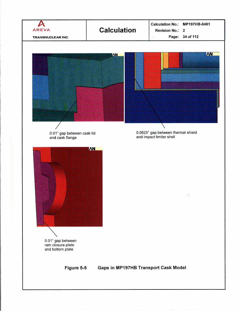
a 0.0625" axial gap between thermal shield and impact limiter shell

A Calculation No.: MP197HB-0401AREVA Calculation Revision No.: 2
TRANSNUCLEAR INC. Page: 13 of 112
* 0.0625" axial gap between the three inches high, thermal shield standoffs and the casktop or bottom end surfaces
* 0.10" diametrical gap between cask lid and cask inner shell
* 0.01" axial gap between cask lid and cask flange
* 0.01" axial gap between ram closure plate and cask bottom plate
a 0.01" radial gaps between neutron shield boxes and surrounding shells
* 0.025" radial gap between gamma shield and cask outer shell
a 0.01" radial gaps between the cask inner shell and aluminum sleeve
* 0.01" radial gap between the finned aluminum shell and the cask shield shell
* 0.0625" axial gaps between the DSC bottom shield plug and bottom cover plates
* 0.0625" axial gaps between the DSC top inner cover and the adjacent top shield plugand top outer cover plate
* 0.025" axial gaps between the lead shield plugs and encapsulating plates for 24PT4DSC
* 0.01" gaps between trunnion replacement plugs and the trunnion attachment blocks.
The 0.0625" gaps between thermal shield, impact limiter shell, and cask top or bottom endsurfaces are based on assumption in MP197 SAR [27] and account for the 0.06" thick weldoverlay conservatively.
The 0.01" gap between cask lid/ cask flange and ram closure plate/cask bottom plate accountfor thermal resistance between bolted components. The 0.01" radial gaps between theneutron shield boxes and the surrounding shells is also based on assumptions in MP197 SAR[27].
The gap of 0.025" assumed between gamma shield and cask outer shell is justified inAPPENDIX C.
The radial gap of 0.01" assumed between the finned aluminum shell and the cask shield shellis justified in APPENDIX D.
The 0.0625" and 0.025" axial gaps between DSC end plates maximize the radial heat transferthrough DSC shell toward the cask to bound the maximum component temperaturesconservatively.
The width of TC slide rail is 3". For conservatism, a gap of 0.01" with a contact width of 0.12"is considered between the TC slide rails and the DSC shell at 1680 and 1920 orientations.The 00 orientation is located at the top of the horizontal TC as shown in [26], Appendix B,Sketch B.5. The sensitivity of the maximum component temperatures to the size of this gap isdiscussed in APPENDIX F.

A Calculation No.: MP197HB-0401AREVA Calculation Revision No.: 2
TRANSNUCLEAR INC. Page: 14 of 112
The finned shell is divided into three axial sections with one inch distance between adjacentsections and no finned shell is considered over the trunnion plugs in the model. Since thefinned shell is designed as a continuous shell which covers the trunnion plugs, the modelwhich has fewer fins is conservative for thermal analysis of transport cask under NCT.
APPENDIX H provides results for the most limiting case of 69BTH payload with 32 kW and noexternal fins on the cask. This appendix demonstrates the conservatism provided by addingthe external fins into the design.
The conservatism involved in the calculation of the maximum accessible surface temperatureis discussed in Section 5.6.
The nominal dimensions considered for DSCs in MP197HB model are listed in Table 3-1. Foreach basket type, the shortest cavity length is considered for the analysis to bound themaximum decay heat flux.
To provide thermal input for structural evaluation, a heat load of 23.2 kW (along with 22.0 kW)is considered for 37PTH DSC. Since the heat load of 23.2 kW is higher than the design heatload of 22.0 kW, this assumption is conservative for structural evaluation of 37PTH DSC.

A Calculation No.: MP197HB-0401AREVA Calculation Revision No.: 2
TRANSNUCLEAR INC. Page: 15 of 112
Table 3-1 Nominal DSC Dimensions in MP197HB Model
61 BT /Parameter (1) 69BTH 611BTH 61 BTH 37PTH 32PTH / 32PT 24PTHType 1 Type 2 (2) 32PTH1 (3) (4) (5) 24PT4
Outer Top Cover 2.00 1.25 1.50 2.00 2.00 1.50 1.50 1.25
Inner Top Cover 2.00 0.75 1.25 2.00 2.00 1.25 1.25 6.75 (6)
Top Shield Plug 5.75 7.00 6.25 5.75 8.00 7.50 6.25
Total Top End 9.75 9.00 9.00 9.75 12.00 10.25 9.00 8.00
Inner Bottom Cover 2.25 (8) 0.75 1.75 .2.25 (8) 2.25 1.75 1.75 2.00.
Bottom Shield Plug 3.00 (8) 5.00 4.00 3.00 (8) 4.50 5.25 4.00
Outer Bottom Cover 2.00 1.75 1.75 2.00 2.00 1.75 1.75
Total Bottom End 7.25 7.50 7.50 7.25 8.75 8.75 7.50 6.75
Cavity Length 178.41 179.50 179.50 164.38 164.38 167.10 169.60 180.20
Canister Length 195.41 196.00 196.00 181.38 185.13 186.10 186.10 194.95(w/o grapple) (7)
Basket height 164 164 164 162 162.00 166.10 168.60 179.13
Note (1): DSC types 61BTHF and 24PTHF has the same dimensions as DSC types 61BTH and 24PTH,respectively.
Note (2): The shortest cavity length for 37PTH baskets belongs to 37PTH-S.Note (3): The shortest cavity length for 32PTH, 32PTH, type 1 and 32PTH1 Type 1 & 2 baskets belongs to
32PTH1-S.Note (4): The shortest cavity length for 32PT baskets belongs to 32PT-S125.
Note (5): The shortest cavity length for 24PTH baskets belongs to 24PTH-S.Note (6): Shield plugs of 24PT4 DSC are lead encapsulated in plates of stainless steel 316, see [4]
Note (7): The canister length in the model is the sum of total top end, total bottom end, and cavity length.Note (8): The thicknesses of inner bottom cover plate and bottom shield plug for 69BTH and 37PTH DSCs are
designed as 1.75" and 3.5", respectively. Since the bottom shield plug (carbon steel) has a higherconductivity than inner bottom cover plate (stainless steel), considering a smaller thickness of 3" forbottom shield plug and higher thickness of 2.25" for inner bottom cover plate is conservative whichincreases the thermal resistance across these two plates.

A Calculation No.: MP197HB-0401
AREVA Calculation Revision No.: 2
TRANSNUCLEAR INC. Page: 16 of 112
4.0 DESIGN INPUT
4.1 Thermal Properties of Materials
Materials used in the transport cask model are listed in Table 4-1.
Thermal conductivity values used in this calculation are listed in Table 4-2 through Table 4-9.
Various ASME code years are called for DSCs in MP197HB in [2], Table 2-1. Except for24PT4, the other DSC types are covered by ASME code from 1998 to 2006.
The shell and cover plates of all DSC types except for 24PT4 consist of stainless steel SA-240, type 304 (SS304). There are no changes in thermal conductivity of SS304 in ASME1998 to 2006 in temperature range from 70 to 7000 F. This range properly covers the DSCshell temperature for all DSC types in this calculation.
The shield plugs of all DSC types except for 24PT4 consist of carbon steel A36. The changesin the A36 conductivity between ASME code years 1998 to 2006 are limited to ±0.9% asshown in Table 4-10. Since relative large gaps of 0.0625" are considered between the DSCshield plugs and the cover plates, this small change has no significant effect on the thermalevaluation.
The conductivity values in various ASME code years for SA-240, type 304 and A36 arecompared in Table 4-10.
The thermal properties for 24PT4 DSC are taken from UFSAR ANUH [4]. These propertiesare based on ASME code 1992 through 1994 addenda and used in this calculation withoutany changes.

A Calculation No.: MP197HB-0401
AREVA Calculation Revision No.: 2
TRANSNUCLEAR INC. Page: 17 of 112
Table 4-1 List of Materials in ANSYS Model
Component Mat # in ANSYS Model MaterialDSC shell 1 SA-240, type 304, SA-240, type 316 for 24PT4
DSC bottom inner cover plate 2 SA-240, type 304SA-240, type 316 for 24PT4 with axial gaps (1)
DSC bottom shield plug 3 A36 with axial gaps (1)
6 Lead for 24PT4 with axial gaps(1)SA-240, type 304 with axial gaps (1)
DSC top inner cover plate 4 SA-240, type 316 for 24PT4DSC top shield plug 5 A36
9 Lead for 24PT4 with axial gaps
DSC outer cover plates 7 SA-240, type 304SA-240, type 316 for 24PT4
67 SA-240, type 316 for 24PT4 (Inner sleeve 8 6061 aluminum with gaps (2)
Cask slide rails 10 Nitronic 60 (3)
Cask inner shell 11 SA-203, Gr. EGamma shield 12 ASTM B-29 (Lead)Cask outer shell 13 SA-203, Gr. ECask bottom plate 14 SA-350-LF3Cask bearing block 15 SA-1 82-F6NMCask lid 16 SA-350-LF3 or SA-203, Gr. ENeutron shield boxes 17 6063 aluminumNeutron shield resin 18 Epoxy resin - VYAL BRam closure plate 19 SA-203, Gr. E (4)
Thermal shield 20 Aluminum (Al 6061 is used for analysis)Impact limiter material 21 WoodTrunnion plug - plates 22 SA-240, type 304Trunnion block 23 SA-350-LF3Impact limiter shell and gussets 24 SA-240, type 304Shield shell 25 SA-516-70External fins and shell 26 6061 aluminumSkid straps 28 SA-240, type 304TC Cavity gas 31 HeliumGamma shield / Outer shell gap 33 AirCask gaps 34 AirDSC shell / TC inner shell gap 37 / 38 Helium with radiation (5)
Trunnion plug - resin 40 Polypropylene
Note (1): Axial air gaps are integrated into the component. The effective conductivity for these components in theaxial direction is calculated in Section 5.3.
Note (2): Effective conductivities are calculated for inner sleeve in Section 5.5.Note (3): A gap of 0.01" is considered between the slide rail and the DSC shell. The effective conductivity of slide
rail is calculated in Section 5.4.Note (4): A stainless steel weld is overlaid on the ram closure surfaces in contact with the cask bottom plate. For
conservatism, ram closure plate is considered as SA-240, type 304 in this analysis.Note (5): Effective conductivities are calculated for this gap in Section 5.2.

A Calculation No.: MP197HB-0401AREVA Calculation Revision No.: 2
TRANSNUCLEAR INC. Page: 18 of 112
Table 4-2 Stainless Steel Properties
Stainless Steel Thermal conductivity Thermal conductivitySA-240, Type 304 / Nitronic 60 SA-240, Type 316 for 24PT4 DSC
ASME, Group J [81, [2] UFSAR ANUH [4], [2]Temperature (OF) (Btu/hr-ft-°F) (Btu/hr-in-°F) (Btu/hr-ft-OF) (Btu/hr-in-OF)
70 8.6 0.717 7.7 0.642100 8.7 0.725 7.9 0.658200 9.3 0.775 8.4 0.700300 9.8 0.817 9.0 0.750400 10.4 0.867 9.5 0.792500 10.9 0.908 10.0 0.833600 11.3 0.942 10.5 0.875700 11.8 0.983 11.0 0.917800 12.3 1.025 11.5 0.958900 12.7 1.0581000 13.1 1.092
Table 4-3 Low Alloy Steel Properties
Low Alloy Steel Thermal conductivitySA-1 82-F6NM
ASME, Group G [8]Temperature (OF) (Btu/hr-ft-°F) (Btu/hr-in-°F)
70 14.2 1.183100 14.2 1.183200 14.3 1.192300 14.4 1.200400 14.5 1.208500 14.5 1.208600 14.6 1.217700 14.6 1.217800 14.7 1.225900 14.7 1.2251000 14.7 1.225

A Calculation No.: MP197HB-0401
AREVA Calculation Revision No.: 2
TRANSNUCLEAR INC. Page: 19 of 112
Table 4-4 Carbon Steel Properties
Carbon Steel Thermal conductivity Thermal conductivitySA-516-70 or A36 SA-203, Gr. E or SA-350-LF3
ASME, Group B [8], [21 ASME, Group C [8], [2]Temperature (OF) (Btu/hr-ft-0F) (Btu/hr-in-°F) (Btu/hr-ft-0 F) (Btu/hr-in-°F)
70 27.3 2.275 23.7 1.975100 27.6 2.300 23.6 1.967200 27.8 2.317 23.5 1.958300 27.3 2.275 23.4 1.950400 26.5 2.208 23.1 1.925500 25.7 2.142 22.7 1.892600 24.9 2.075 22.2 1.850700 24.1 2.008 21.6 1.800800 23.2 1.933 21.0 1.750900 22.3 1.858 20.3 1.692
1000 21.1 1.758 19.7 1.642
Table 4-5 Aluminum Alloys Properties
Aluminum Thermal conductivity Thermal conductivityA1 6061 Al 6063
ASME [8], [2] ASME [8], [2)Temperature (OF) (Btu/hr-ft-OF) (Btu/hr-in-OF) (Btu/hr-ft-°F) (Btu/hr-in-OF)
70 96.1 8.008 120.8 10.067100 96.9 8.075 120.3 10.025150 98.0 8.167 119.7 9.975200 99.0 8.250 119.0 9.917250 99.8 8.317 118.5 9.875300 100.6 8.383 118.1 9.842350 101.3 8.442 118.0 9.833400 101.9 8.492 117.6 9.800
Table 4-6 Lead Properties
LeadTemperature Conductivity [9] Temperature Conductivity
(K) (W/m-K) (OF) (Btu/hr-in-OF)200 36.7 -100 1.767250 36.0 -10 1.733300 35.3 80 1.700400 34.0 260 1.637500 32.8 440 1.579600 31.4 620 1.512

A Calculation No.: MP197HB-0401
AREVA Calculation Revision No.: 2
TRANSNUCLEAR INC. Page: 20 of 112
Table 4-7 Non-Metallic Solids Properties
Neutron Shield Resin (Vyal B) Trunnion Plug Resin (PP) WoodConductivity Conductivity Conductivity(Btu/hr-in-°F) (Btu/hr-in-OF) (Btu/hr-in-°F)
0.039 ") 0.0067 [13], Table 23-10 0.0019 (2)
Note (1): Minimum conductivity of VYAL B is taken from [6], Section 4.2, Item 5.
Note (2): Minimum conductivity of wood is discussed in [10], Appendix B.
Table 4-8 Helium Thermal Conductivity
Temperature Thermal conductivity Temperature Thermal conductivity(K) (W/m-K) (OF) (Btu/hr-in-OF)300 0.1499 80 0.0072.400 0.1795 260 0.0086500 0.2115 440 0.0102600 0.2466 620 0.0119800 0.3073 980 0.01481000 0.3622 1340 0.01741050 0.3757 1430 0.0181
The above data are calculated base on the following polynomial functionfrom [7] or [2]k = j C, T for conductivity in (W/m-K) and T in (K)
For 300 < T < 500 K for 500< T < 1050 KCO -7.761491E-03 CO -9.0656E-02C1 8.66192033E-04 C1 9.37593087E-04C2 -1.5559338E-06 C2 -9.13347535E-07C3 1.40150565E-09 C3 5.55037072E-10C4 0.OE+00 C4 -1.26457196E-13

A Calculation No.: MP197HB-0401
AREVA Calculation Revision No.: 2
TRANSNUCLEAR INC. Page: 21 of 112
Table 4-9 Air Thermal Properties
Temperature Thermal conductivity Temperature Thermal conductivity(K) (W/m-K) (OF) (gtu/hr-in-°F)
200 0.01822 -100 0.0009250 0.02228 -10 0.0011300 0.02607 80 0.0013400 0.03304 260 0.0016500 0.03948 440 0.0019600 0.04557 620 0.0022800 0.05698 980 0.00271000 0.06721 1340 0.0032
The above data are calculated base on the following polynomial function from [7] or [2]
k = C C, T; for conductivity in(W/m-K) and T in (K)
For 250 < T < 1050 KCO -2.2765010E-03C1 1.2598485E-04C2 -1.4815235E-07C3 1.7355064E-10C4 -1.0666570E-13C5 2.4766304E-17
Specific heat, viscosity, density and Prandtl number of air are used to calculate heattransfer coefficients in APPENDIX B based on the following data from [7] or [2].
cP, =IXAi Ti for specific heat in (kJ/kg-K) and T in (K)
________________For 250< T < 1050 K
AO 0.1 03409E+1Al -0.2848870E-3A2 0.781681 8E-6A3 -0.4970786E-9A4 0.1077024E-12
for viscosity (N-/m2)Xl 06 and T in (K)
For 250 < T < 600 KBO -9.8601E-1B1 9.080125E-2B2 -1.17635575E-4B3 1.2349703E-7B4 -5.7971299E-11
For 600 < T < 1050 KBO 4.8856745B1 5.43232E-2B2 -2.4261775E-5B3 7.9306E-9B4 -1.10398E-12
p = PIRT for density (kg/m 3) with P=1 01.3 kPa; R = 0.287040 kJ/kg-K; T = air temp in (K)
Pr = cp/lk Prandtl number

A Calculation No.: MP197HB-0401
AREVA Calculation Revision No.: 2
TRANSNUCLEAR INC. Page: 22 of 112
Table 4-10 Thermal Conductivity for SS304 and A36 in Various ASME Years
SA-240, type 304 (Group J A-36 (Group B)ASME 2004 ASME 1998 Deviation ASME 2004 ASME 1998 Deviation
w/2006 w/ 2000 w/ 2006 w/ 2000Addenda [8], [2] Addenda [23], [2] Addenda [8], [2] Addenda [23], [2]
Temp TC TC TC TC(OF) (Btu/hr-ft-°F) (Btu/hr-ft-OF) (Btu/hr-ft-°F) (Btulhr-ft-°F)70 8.6 8.6 0.0% 27.3 27.5 0.7%100 8.7 8.7 0.0% 27.6 27.6 0.0%200 9.3 9.3 0.0% 27.8 27.6 -0.7%300 9.8 9.8 0.0% 27.3 27.2 -0.4%400 10.4 10.4 0.0% 26.5 26.7 0.8%500 10.9 10.9 0.0% 25.7 25.9 0.8%600 11.3 11.3 0.0% 24.9 25.0 0.4%700 11.8 11.8 0.0% 24.1 24.0 -0.4%800 12.3 12.2 -0.8% 23.2 23.0 -0.9%
max 0.0% max 0.8%min -0.8% min -0.9%

A Calculation No.: MP197HB-0401
AREVA Calculation Revision No.: 2
TRANSNUCLEAR INC. Page: 23 of 112
4.2 Surface Properties of Materials
Reference [11] gives an emissivity between 0.92 to 0.96 and a solar absorptivity between0.09 and 0.23 for white paints. To account for dust and dirt and to bound the problem, thethermal analysis uses a solar absorptivity of 0.3 and an emissivity of 0.9 for white paintedsurfaces of the neutron shield shell.
Emissivity of rolled stainless steel plates is 0.578 as considered in [12]. The emissivity forrolled steel sheets is 0.657 as reported in [13], Table 10-17. The transport cask inner shell ispainted white. For conservatism, the emissivity value of 0.587 is considered for both the DSCshell (stainless steel) and the transport cask inner shell (painted carbon steel) in calculation ofthermal radiation exchange between these shells.
Solar absorptance values of 0.39 and 0.47 are given in [28] for rolled and machined stainlesssteel plates, respectively. For conservatism, it is assumed that the absorptivity and theemissivity of stainless steel are equal in this calculation. Solar absorptivity and emissivity of0.587 are used for the exposed impact limiters and skid strap surfaces.
Emissivity of anodized aluminum is between 0.84 and 0.72 for temperatures between 296Kand 484K (between 730 F and 411°F) and its solar absorptivity is between 0.12 and 0.16 [7,Table A.7.2]. An emissivity of 0.70 and a solar absorptivity of 0.16 are considered for thefinned aluminum shell of MP197HB cask in this analysis.
Although an emissivity of 0.7 can be considered for the anodized surface of the inner sleevefor the purposes of this calculation, the effective conductivity for helium between DSC andinner sleeve is conservatively set equal to the effective conductivity of helium between DSCshell and TC inner shell with surface emissivities of 0.587. The effective conductivity of heliumbetween DSC shell and TC inner shell is calculated in Section 5.2.
For plain aluminum, an absorptivity of 0.1 is reported in [7], Table A.7.2. This value is usedonly for calculation of insolance over thermal shield in Section 6.3 and is not used in the finiteelement model of MP197HB.
4.3 Design Criteria
To establish the heat removal capability, several thermal design criteria are established forthe MP197HB TC. These are:
* Seal temperatures must be maintained within specified limits to satisfy the leak tightfunction of transport cask back filled with helium. A maximum long-term sealtemperature limit of 400°F (2040C) is considered for the Fluorocarbon O-Rings [2].
" To maintain the shielding property of the neutron shield during NCT, a maximumtemperature of 320°F (1600C) is considered for the neutron shield resin [2].

A Calculation No.: MP197HB-0401AREVA Calculation Revision No.: 2
TRANSNUCLEAR INC. Page: 24of112
To prevent melting of the gamma shield (lead) during NCT, an allowable maximumtemperature of 621'F (327.5°C - melting point of lead) is considered for the gammashield [13].
* A temperature limit of 1600C (3200F) is considered for wood to maintain its crushproperties for structural analysis [2].
* The accessible surface temperature of the packaging under normal conditions oftransport shall be limited to 185°F in the shade [2].
" Based on [24], the onset of polypropylene thermal degradation associated with weightloss starts at 230 to 2500C (446 to 4820F). Although the breakdown of the polymerleading to volatile products begins above 3000C (5720 F), no significant weight lossoccurs below 3500C (6620F). A temperature limit of 4451F is consideredconservatively for polypropylene to prevent thermal degradation of resin in trunnionplugs.
All materials of MP197HB can be subjected to a minimum environment temperature of-40°F(-400C) without any adverse effects.

A Calculation No.: MP197HB-0401
AREVA Calculation Revision No.: 2
TRANSNUCLEAR INC. Page: 25 of 112
5.0 METHODOLOGY
A half-symmetric, three-dimensional finite element model of MP197HB transport cask isdeveloped using ANSYS [14]. The model contains the cask shells, cask bottom plate, casklid, impact limiters, DSC shell, and DSC end plates without the basket. The DSC dimensionscorrespond to nominal DSC dimensions listed in Table 3-1 for variations of the MP197HBmodel.
SOLID70 elements are used to model the components including the gaseous gaps. Impactlimiter gussets, cask slide rails, and trunnion plug plates are modeled using SHELL57elements. Surface elements SURF152 are used for applying the insolation boundaryconditions.
Ambient conditions for NCT are taken from 1OCFR71 [1] and applied on the boundaries of thecask model. These conditions are listed in Table 5-1.
Table 5-1 Normal Conditions of Transport for MP197HB
Case # Ambient temperature (OF) Insolance Purpose
1 100 Yes Maximum Component Temperatures
2 -20 No Cold conditions for Structural Analysis
3 -40 No Maximum Thermal Stress
4 100 No Maximum Accessible Surface Temperature
A personnel barrier installed on the transport skid between the two impact limiters limits theaccessible packaging surfaces to the impact limiter and barrier outer surfaces. The personnelbarrier has an open area of at least 80%. Heat transfer between the cask and barrier will beminimal due to the small radiation view factor between the cask and the barrier. Due to largedistance between the barrier and cask outer surface, the free convection heat transferremains undisturbed. The transport configuration is shown in Figure 5-1.
The methodology to calculate the accessible surface temperature is described in Section 5.6.
Insolance is applied as a heat flux over the TC outer surfaces using average insolence valuesfrom 10CFR71 [1]. The insolance values are averaged over 24 hours and multiplied by thesurface absorptivity factor to calculate the solar heat flux. The solar heat flux values used inMP197HB model are summarized in Table 5-2.

A Calculation No.: MP197HB-0401
AREVA Calculation Revision No.: 2
TRANSNUCLEAR INC. Page: 26 of 112
Table 5-2 Solar Heat Flux
Surface Material Shape Insolance Solar Total solar heat fluxover 12 hrs [1] Absorptivity (1) averaged over 24 hrs
(gcal/cm ) (Btu/hr-in 2)
Stainless Steel Curved 400 0.587 (2) 0.2505
Flat vertical 200 0.587 (2) 0.1252
White Paint Curved 400 0.30 0.1280(shield shell)
Anodized Curved 400 0.16 0.0683Aluminum
Plain aluminum Flat vertical 200 0.10 0.0213
Note (1): See Section 4.2 for surface properties.Note (2): Solar absorptivity of stainless steel is taken equal to its emissivity.
The cask external fins are not considered explicitly in the TC model. Instead, an effective heattransfer coefficient is applied over the outer surface of the un-finned aluminum shell tosimulate the heat dissipation from this area. The methodology to calculate the effective heattransfer coefficient for external fins is described in Section 5.1.
A radial gap of 0.01" is considered between the finned aluminum shell and the cask shieldshell to account for the thermal resistance between these two shells. The size of this gap isjustified in APPENDIX D.
Convection and radiation heat transfer from the un-finned cask surfaces are combinedtogether as total heat transfer coefficients. The total heat transfer coefficients are calculatedusing free convection correlations from Rohsenow Handbook [7] and are incorporated in themodel using ANSYS macros. These correlations are described in APPENDIX B. The ANSYSmacros used in this calculation are listed in Section 8.0.
Decay heat load is applied as a uniform heat flux over the inner surface of the DSC shellcovering the basket length.
q QT DQ Lb
q" = decay heat flux (Btu/hr-in 2)Q = decay heat load (Btu/hr) (to convert from kW multiply by 3412.3)Di = DSC inner diameter (in)Lb = Basket length (in)
The applied decay heat values in the model are listed in Table 5-3

A Calculation No.: MP197HB-0401
AREVA Calculation Revision No.: 2
TRANSNUCLEAR INC. Page: 27 of 112
Table 5-3 Decay Heat FluxDSC Type Heat Load Di Lb Decay heat flux
(kVV) (Btu/hr) (in) (in) (Btu/hr-in 2)
69BTH 26.0 88,720 68.75 164 2.505
29.2 99,639 2.813
32.0 109,194 3.083
61BTH Type 1 (1) 22.0 75,071 66.25 164 2.199
61BTH Type 2 (1) 24.0 81,895 66.25 164 2.399
61BT 18.3 62,445 66.25 164 1.829
37PTH 22.0 75,071 68.75 162 2.146
32PTH / 32PTH Type 1 26.0 88,720 68.75 162 2.536
32PTH1 Type 1 26.0 88,720 68.75 162 2.536
32PTH1 Type 2 24.0 81,895 68.75 162 2.341
32PT 24.0 81,895 66.19 166.10 2.371
24PTH Type 1 & 2 26.0 88,720 66.19 168.60 2.531
24PT4 24.0 81,895 66.19 179.13 2.199
Note (1): DSC types 61BTHF and 24PTHF has the same dimensions and heat loads as DSC types61BTH and 24PTH, respectively.
Radiation and conduction between the DSC and the TC inner shell / inner sleeve isconsidered by calculating effective conductivities for helium gaps between the abovecomponents. Calculation of the helium effective conductivities within this gap is described inSection 5.2.
During transportation, the DSC shell rests on four slide rails in the TC. These rails are flatstainless steel plates welded to the inner shell of the TC. The thickness of the slide rail is0.12" when no inner sleeve is used. The slide rail at 1800 orientation is 0.06" thick and doesnot contact the DSC shell. The same configuration is considered for the small diameter DSCand the inner sleeve.
The angle between the lower rail and the vertical plane is 12 degree. Considering thisconfiguration shown in Figure 5-2, the distance between the centerline of DSC and centerlineof the cask are calculated as follows.R2 2 = R 2 + x 2 - 2 R, x Cos(a)
With
R, = Di, TC /2 - trailR2 = Do, DSC / 2
= 120

A Calculation No.: MP197HB-0401
AREVA Calculation Revision No.: 2
TRANSNUCLEAR INC. Page: 28 of 112
x = Distance between the DSC and TC centerlinesDi, TC = Inner diameter of TC or inner sleeveDo, DSC = DSC outer diametertrail = cask slide rail thickness = 0.12"
The calculated values for x are listed in Table 5-4. In the ANSYS model, the DSC is shifteddown by the amount of x in the Cartesian y-direction within the TC cavity.
Table 5-4 Distance between DSC and TC Centerlines
DSC Type Di,TC Do,DSC R1 R2 U x
(in) (in) (in) (in) (degree) (in)
69BTH37PTH37PTH 70.5 69.75 35.130 34.875 12 0.26132PTH32PTH1
61 BT61BTH 68 67.25 33.880 33.625 12 0.26161BTHF
32PT24PTH24PTH 68 67.19 33.880 33.595 12 0.29124PTHF
24PT4
To simplify the model, the lower cask slide rails at 1680 and 1920 orientations are modeledusing shell elements with the conductivity of Nitronic 60 and a helium gap of 0.01". Theeffects of the other cask slide rails are conservatively omitted. The slide rail width is 3". Forconservatism, a contact width of 0.12" is considered between the lower rails and the DSCshell.
The axial gaps considered between DSC cover plates and shield plugs are integrated intobottom shield plug and top inner cover plates. The axial gaps considered for the lead shieldplugs of 24PT4 are also integrated into the shield plug material. The axial effectiveconductivities are calculated for these components in Section 5.3. The conductivity in radialdirection remained unchanged and equal to the conductivity of the corresponding material.
To reduce the complexity of the model, effective conductivities are calculated for the innersleeve in axial and radial directions. The methodology to calculate the effective conductivity ofthe inner sleeve is described in Section 5.5. These effective conductivities are conservativesince the number and the assumed gaps between the inner sleeve pieces are larger thanthose considered for the proposed inner sleeve.
The material properties used in the MP197HB model are listed in Section 4.0.

A Calculation No.: MP197HB-0401
AREVA Calculation Revision No.: 2
TRANSNUCLEAR INC. Page: 29 of 112
The geometry of the TC model and its mesh density are shown in Figure 5-3 through Figure
5-7. Mesh sensitivity of the MP197HB model is discussed in APPENDIX E.
Typical boundary conditions for TC model are shown in Figure 5-8 through Figure 5-10.
The seal o-rings are not explicitly considered in the models. The maximum seal temperaturesare retrieved from the models by selecting the nodes at the locations of the correspondingseal o-rings. The nodal coordinates corresponding to seal locations are defined in the inputfiles for running the MP197HB models listed in Table 8-2.
Except for DSC types 69BTH and 37PTH, all other DSC types listed in Table 1-1 areanalyzed for storage/transfer conditions under 1 OCFR72 [20]. The safety analysis reports(SAR) for these DSC types under storage/transfer conditions are presented in [3], [4], [5], and[6].
The following approach is undertaken to determine the maximum heat load for all DSC typesin MP197HB except for 69BTH and 37PTH DSCs.
a) The MP197HB/DSC shell model is run with either the design basis total heat load foreach particular DSC or the maximum allowable heat load in MP1 97HB without externalfins (26 kW) to get the maximum DSC shell temperature (TDSC shell max).
b) If TDSC shell max is higher than TDSC shell max predicted by corresponding 1 0CFR72 SAR,the total heat load in the MP197HB/DSC model is reduced until TDSC shell max is belowTDSC shell max predicted by corresponding 1 OCFR72 SAR.
c) The DSC shell temperature profile in MP197HB model is compared with thecorresponding profile in 10CFR72 SAR and is verified that the 10CFR72 SARrepresents the bounding profile.
d) Since 10CFR72 SAR represents the bounding case, the DSC component and fuelcladding temperatures for transport in MP1 97HB cask are bounded by thecorresponding values in the 10CFR72 SAR. The thermal analysis results in 10CFR72SAR are applicable for 10CFR, Part 71 conditions and no further DSC thermal analysisis required.
The maximum heat load for 69BTH and 37PTH DSCs are determined based on requirementsdefined under 10CFR71 [1] for MP197HB.
The final heat loads for each DSC type are those listed in Table 1-1.

A Calculation No.: MP197HB-0401
AREVA Calculation Revision No.: 2
TRANSNUCLEAR INC. Page: 30 of 112
Proprietary Information Withheld Pursuant to 10 CFR 2.390

A Calculation No.: MP197HB-0401
AREVA Calculation Revision No.: 2
TRANSNUCLEAR INC. Page: 31 of 112
TCc
R = Di, TC /2 - trail
R2 = D., DSC / 2Angle 120
DSC +L
Slide Rail
Figure 5-2 Location of DSC within MP197HB TC

A Calculation No.: MP197HB-0401
AREVA Calculation Revision No.: 2
TRANSNUCLEAR INC. Page: 32 of 112
MP197HB with 69BTH DSC
ImpactLimiter Shell
/Impact Limiter
Skid Strap
Thermal Shield
Transport Cask DSC
MP197HB with 69BTH
Cask Bottom Plate Bearing Block Cask Lid
Finite Element Model of MP197HB with 69BTH DSCFigure 5-3

MPi97HB-04 0 1Calculation No.:Revision No.:
Page:
233 of M1
Cask outer ShellGamma Shield
N1 Neutron Shield
/Bottom plate
Cask Lid
RamClosureplate
Cask Inner Shell
ANDSC shell
Grapple Ring andDSC Bottom plates
DSC Top plates
zx
AN
inner RingandGussets
Thermal ShieldImpact Limiter
MP197HB finite Element Model, ComponentsFigure 5-4
A Calculation No.: MP197HB-0401
AREVA Calculation Revision No.: 2
TRANSNUCLEAR INC. Page: 34 of 112
0.01" gap between cask lid 0.0625" gap between thermal shieldand cask flange and impact limiter shell
0.01" gap betweenram closure plateand bottom plate
Figure 5-5 Gaps in MP197HB Transport Cask Model

A Calculation No.: MP197HB-0401AREVA Calculation Revision No.: 2
TRANSNUCLEAR INC. Page: 35 of 112
FAN AN
ShieldShell
DSC ShellNot Shown
Cask Inner Shell. l
Gamma Shield --
Outer Shell
DSC Shell Z I
Inner Sleeve
Neutron Shield Box
Neutron ShieldI\
ShieldShell
MP197HB without Inner Sleeve
AN
MP197HB with Inner Sleeve ýc
Figure 5-6 MP197HB Finite Element Model, Cross Section

A Calculation No.: MP197HB-0401
AREVA Calculation Revision No.: 2
TRANSNUCLEAR INC. Page: 36 of 112
' 0.01" gap betweenneutron shield boxes
- and surroundingshells
0.025" gap betweengamma shield and outershell
DSCShell
0.01" gap betweeninner sleeve andinner shell
Figure 5-7 Gaps in Cross Section

A Calculation No.: MP197HB-0401
AREVA Calculation Revision No.: 2
TRANSNUCLEAR INC. Page: 37 of 112
HFLU2. 505
Decay Heat Boundary Conditions for 69BTH DSC, 26 kW
ANSYS 8.1HFLU
.125234- .139149
.1530641 .1669791 .1808941 .194809- .208724
.222639
.2365541 .250469
Iinsolance Boundary Coniditions~
Insolance on Skid Straps
Insolance on Impact Limiter Recess
Typical Decay Heat and Insolance Boundary ConditionsFigure 5-8

Calculation No.: MP197HB-0401FA Calculation Revision No.: 2
IUCLEAR INC. Page: 38 of 112
ANSYS 8.1CONV-HCOE
-112-110.778
.... • 108.333
- -107.111-105.889
E-- -104.667m -103.4441W -102.222
Convection and Radiation Boundary Conditions for MPI97HB w/o External Fins
ANSYS 8.1CONV-HCOE
-112-110.778-109.556-108.333-107.111- 105.889
-104.667M-- -103.444
-102.222-101
lJFinned ShellRegulatory Plate
No Fins- Trunnion Plug
Skid Straps
Convection and Radiation Boundary Conditions for MP197HB with External Fins
Figure 5-9 Typical Convection and Radiation Boundary Conditions

A Calculation No.: MP197HB-0401
AREVA Calculation Revision No.: 2
TRANSNUCLEAR INC. Page: 39 of 112
I,
b
No heat dissipation is considered over markedareas, a, b, and c:
a Lateral surface of skid strapsb Inner radial surface of impact limiter
recessc Thermal shield outer ring and neutron
shield end caps
No thermal radiation exchange is consideredon area d.
d Cask area in contact with transport skidsaddles
ANSYS 8.1CONV- HCOE
-107-106 889
- -106:778-106 667
- 106 556- 106 444
- 106 333-106.222
- -106.111-106
d
Cask area in contactwith skid saddles
Figure 5-10 Typical Convection and Radiation Boundary Conditions - Details

ACalculation No.: MP197HB-0401AREVA Calculation Revision No.: 2
TRANSNUCLEAR INC. Page: 40 of 112
5.1 Effective Heat Transfer Coefficient for External Fins
To reduce the complexity of the TC model, an effective heat transfer coefficient is calculatedfor the external fins based on the geometry shown in Figure A-I. Circular external fins arewelded to an aluminum shell which will be installed over the outer surface of the TC shieldshell to enhance heat dissipation for heat loads over 26 kW. An effective heat transfercoefficient is calculated for the external fins which includes the convection and radiation heattransfer to ambient. The following dimensions are considered for the fins.
* Fin height = 3.0"
* Fin thickness = 0.156"
* Fin pitch = 1.0"
A sub-model of the TC outer surface is developed for this purpose using ANSYS [14].
This sub-model considers a 30 degree segment of the aluminum shell with three circularexternal fins. Figure 5-11 shows the sub-model of the finned shell.
Convection boundary conditions are applied over the outer surfaces of the fins in the modelusing surface load (SF) commands in ANSYS [14]. SHEL157 elements are overlaid on theexternal surfaces of the fins to create radiation super-element. The radiation shell elementsare shown in Figure 5-11. Thermal radiation from the outer surfaces is modeled using /AUX12processor. Ambient temperature of 1000 F, -20 0F, and -40°F are considered for convectionand radiation.
Based on discussions in Section 4.2, an emissivity of 0.70 is considered for the anodizedaluminum for exposed finned surfaces.
Fixed temperature boundary conditions are applied over the inner surface of the aluminumshell. The amount of heat dissipation is retrieved from the model using reaction solutioncommand (PRRSOL) in ANSYS [14]. The effective heat transfer coefficient is calculated asfollows.
heff QreactAeff (Ts - Tamb)
heff = effective heat transfer coefficient over finned surface (Btu/hr-in 2)Qreact = heat input entering the cask shield shell (reaction solution) retrieved from model
(Btu/hr)Ts = shield shell inner surface temperature (fixed temperature boundary conditions) (OF)Tamb = ambient temperature (IF) = 1000F, -20 0F, and -40'FAeff = outer surface area of the un-finned shield shell (in2).
Since the heff will be applied over the un-finned surface of the aluminum shell, Aeff is the areaof the un-finned surface.

A Calculation No.: MP197HB-0401AREVA Calculation Revision No.: 2
TRANSNUCLEAR INC. Page: 41 of 112
Aeff = z Do (3x fin pitch) (30/360) = 7c x 98.25 x 3 x 1.0 x (30/360) = 77.2 in2
Convection heat transfer coefficients are calculated using correlations from RohsenowHandbook [7], page 4.39 and 4.40, equations 4.68 to 4.70b. The correlations used forconvection coefficients are:
Nu h S D, g=(Tw - Tamb )S 3 S v
S 0; Ra - am Pr-k Df va Df a
Do= outer diameter of un-finned surface = 98.25"Df = outer diameter of circular fins = (98.25 + 2x3.0) = 104.25"S = fin pitch = 1.0"g = gravitational constant =9.81 (m/s 2)13 = expansion coefficient = 1/T (1/K)T = absolute temperature (K)v = kinematic viscosity (m2/s)a = thermal diffusivity (m2/s)k = air conductivity (W/m-K)
On fin tips:Nu = c Rab for 2 < Ra < 104 with c and b defined in Table 5-5.
On fin lateral surfaces together with the supporting shell:
Nu = Co RaoP 1-exp [ 2 ]|C1 for 1.0•< Df-< 1.67Rao )D 0
where Co = -0.15 + 0.3 + 0.32 16 C, = -180 + 480ý - 1.4 ý-8
C2 = 0.04 + 0.9 C3 = 1.3 (1 - ý) + 0.0017 ý-12
p = 0.25 + C2 C3 Ra 0 = Ra/ý
Properties are evaluated at wall temperature as required in [7]. Air properties used for thesecorrelations are listed in Table 4-9.
The results for the effective heat transfer coefficient are summarized in Table 5-5, Table 5-6,and Table 5-7 for ambient temperatures of 1 00°F, -20 0 F, and -400 F, respectively.

A Calculation No.: MP197HB-0401AREVA Calculation Revision No.: 2
TRANSNUCLEAR INC. Page: 42 of 112
Table 5-5
fin-h =
finp =
fin t=
fin n=
o=
Df =
Df/Do =
A eff=
Effective Heat Transfer Coefficients for External Fins @ 100°F Ambient
3.0
1.0
0.156
3
98.25
104.25
1.061
77.2
fin height (in)
fin pitch (in)
fin thickness (in)
No. of fins in model
cask diameter (in)
fin diameter (in)
area of un-finned surface (in2)
From Rohsenow Handbook [7]Df/Do c b1.36 0.62 0.29
1.14 0.59 0.27Extrapolated for this calculation based on above data
1.061 [ 0.579 [ 0.263
File name Heff fin 100.outTs Tamb Qreact Aeff heff
(OF) (OF) (Btu/hr) (in 2 (Btu/hr-in2_-OF)
120 100 31.295 77.2 0.0203140 100 71.639 77.2 0.0232160 100 116.59 77.2 0.0252180 100 165.15 77.2 0.0268200 100 216.89 77.2 0.0281220 100 271.55 77.2 0.0293240 100 329.01 77.2 0.0305260 100 388.75 77.2 0.0315280 100 452.15 77.2 0.0326300 100 518.00 77.2 0.0336320 100 586.59 77.2 0.0346340 100 658.05 77.2 0.0355

A Calculation No.: MP197HB-0401
AREVA Calculation Revision No.: 2
TRANSNUCLEAR INC. Page: 43 of 112
Table 5-6 Effective Heat Transfer Coefficients for External Fins @ -20°F AmbientGeometrical data are the same as those in Table 5-5File name Heff Alfin 20.out
Ts Tamb Qreact Aeff heff
(-F) (OF) (Btu/hr) (in2) (Btu/hr-in 2 -OF)0 -20 26.511 77.2 0.0172
20 -20 61.325 77.2 0.019940 -20 99.88 77.2 0.0216
60 -20 141.15 77.2 0.022980 -20 184.56 77.2 0.0239100 -20 229.46 77.2 0.0248120 -20 278.04 77.2 0.0257140 -20 329.65 77.2 0.0267160 -20 382.98 77.2 0.0276180 -20 437.79 77.2 0.0284200 -20 494.84 77.2 0.0291220 -20 553.94 77.2 0.0299
Table 5-7 Effective Heat Transfer Coefficients for External Fins @ -40°F Ambient
Geometrical data are the same as those in Table 5-5File name Heff Alfin 40.out
T, Tamb Qreact Aeff heff
(0F) (0F) (Btu/hr) (in2) (Btu/hr-in2 -OF)-20 -40 26.044 77.2 0.0169
0 -40 60.344 77.2 0.019620 -40 98.33 77.2 0.021240 -40 139.00 77.2 0.0225
60 -40 181.83 77.2 0.023680 -40 226.42 77.2 0.0245100 -40 272.53 77.2 0.0252
120 -40 321.95 77.2 0.0261140 -40 374.39 77.2 0.0270160 -40. 427.93 77.2 0.0277180 -40 483.57 77.2 0.0285200 -40 541.13 77.2 0.0292

A Calculation No.: MP197HB-0401AREVA Calculation Revision No.: 2
TRANSNUCLEAR INC. Page: 44of112
LI AN
Solid Elements
I AN
Shell Elements for Radiation
Sub-Model of the External Fins for MP1 97HB TCFigure 5-11

A Calculation No.: MP197HB-0401AREVA Calculation Revision No.: 2
TRANSNUCLEAR INC. Page: 45 of 112
5.2 Effective Conductivity for Helium Gap between DSC and TC/Sleeve
Effective conductivities are calculated for helium between the DSC and the TC inner shell /inner sleeve to account for conduction and radiation between these components. Anemissivity of 0.587 is considered for rolled steel shells.
The inner surface of the inner sleeve is anodized. Based on discussion in Section 4.2, anemissivity of 0.7 is considered for anodized surface of inner sleeve.
The effective conductivity of helium within the gap between the DSC shell and TC inner shellis calculated based on a detailed sub-model of this region. This sub-model considers a 10"high, 30 degree segment of the shells. Conductivity of helium is considered for the gapbetween the shells. Radiation between surfaces is modeled using /AUX12 processor. Figure5-12 shows the sub-model of the DSC shell and the TC inner shell.
Heat Flux
DSC Shell
\ FixedTemperature
TC Inner Shell
Figure 5-12 Sub-Model for Helium Gap Effective Conductivity Calculation
In the DSC/TC sub-model, a heat flux of 2.813 Btu/hr-in 2 equivalent to 29.2 kW (see Table5-3) is applied on the radial surface of the innermost shell (DSC shell) and fixed temperatureboundary conditions are applied over the radial surface of the outermost shell (TC innershell).
The nodes of the gap between the DSC shell and TC inner shell build up the radiation superelement (MATRIX50). To avoid convergence problems, the heat flux or fixed temperature

A Calculation No.: MP197HB-0401AREVA Calculation Revision No.: 2
TRANSNUCLEAR INC. Page: 46 of 112
boundary conditions are not applied directly on the nodes of the radiation super element.Instead the heat flux is applied on the innermost nodes of the DSC shell and the fixedtemperatures are applied on the outermost nodes of the TC shell.
The effective conductivity is calculated as follows.
(qreact x 360/30) In(D,TC/Do,DSc)keff 2 x 10 x (TDSC - TC)
Where,qreact = reaction solution retrieved from the model (Btu/hr)Di,TC = inner diameter of TC inner shell = 70.5"Do,DSC = outer diameter of DSC for 69BTH, 37PTH, 32PTH, and 32PTH1 = 69.75"TTC = temperature of the TC inner shell innermost nodes (IF)TDSC = average temperature of DSC shell (IF)
The conductivity of SA-240, type 304 is considered for the TC inner shell in this sub-model.Since the TC inner shell material is SA-203, Gr. E and has higher conductivity than SA-240,type 304, this approach is conservative.
Due to high conductivity of the metallic shells, the temperature gradient across the shells isvery small (< 10F). Therefore the actual temperature gradient across the gap is slightly lowerthan the temperature gradient between the shells (TDSC - TTC) considered in the aboveequation. This results in a slightly underestimated effective conductivity across the gap, whichis conservative for the purpose of this calculation.
The average temperature of the DSC shell is retrieved from the model using "ETABLE"commands in ANSYS [14]. The fixed temperature boundary condition applied on theoutermost node of TC shell is considered as TC temperature.
The qreact depends on the applied heat flux. Since the effect of qreact is accounted for in theequation for keff, the calculated keff values can be used for other heat loads considered in thisanalysis.
The effective conductivity values for the helium within the gap between the DSC shell and theTC inner shell are summarized in Table 5-8.

A Calculation No.: MP197HB-0401AREVA Calculation Revision No.: 2
TRANSNUCLEAR INC. Page: 47 of 112
Table 5-8 Radial Effective Conductivity for Helium in DSC SheII/TC Inner Shell Gap
Between DSC Shell and Cask Inner Shell(Mat # 37 in the ANSYS model)Do,DSC= 69.75 DSC OD (in)DTC = 70.50 Cask ID (in)L = 10 Model height (in)
File name Keff gap.outKeffgc.out
TDSC TTC qreact Tava k eff
(OF) (OF) (Btu/hr) (OF) (Btu/hr-in-OF)110 -20 506 45 0.0080153 30 506 92 0.0084195 80 506 138 0.0090237 130 506 183 0.0097279 180 506 230 0.0104296 200 506 248 0.0108339 250 506 294 0.0116382 300 506 341 0.0126426 350 506 388 0.0136470 400 506 435 0.0148515 450 506 482 0.0160560 500 506 530 0.0173606 550 506 578 0.0187652 600 506 626 0.0202698 650 506 674 0.0217745 700 506 722 0.0233791 750 506 771 0.0251
The calculated effective conductivity in Table 5-8 is applied only in radial direction for the gapbetween the DSC shell and the TC inner shell. The conductivity in axial direction is set equalto helium conductivity for conservatism.
As shown in Table 5-4, the gap size between the 61 BTH or 61 BT DSC shell and the innersleeve is equal to the gap size between the large diameter DSC shells (69BTH, 37PTH,32PTH, and 32PTH1) and the TC inner shell. Since the emissivity of stainless steel is lowerthan emissivity of anodized aluminum, the above effective conductivity calculated for the gapbetween the large diameter DSC and TC inner shell can be used conservatively for the gapbetween the DSC and the inner sleeve for DSC types 61 BTH and 61 BT.
For small diameter DSC types, 32PT, 24PTH, and 24PT4, an effective conductivity iscalculated for the gap between the DSC shell and TC inner sleeve using the samemethodology described above with the following data.
Di,sleeve = inner diameter of TC inner sleeve = 68.0"Do,DSC = outer diameter of small diameter DSC types = 67.19"

A Calculation No.: MP197HB-0401
AREVA Calculation Revision No.: 2
TRANSNUCLEAR INC. Page: 48 of 112
EDSC = 0.587 (emissivity of steel or stainless steel, see Section 4.2)Esleeve = 0.7 (emissivity of anodized aluminum, see Section 4.2)
The effective conductivity values for the helium within the gap between the small DSC shelland the TC inner sleeve are listed in Table 5-9.
Table 5-9 Radial Effective Conductivity for Helium in DSC Shell/TC Inner Sleeve Gap
Between DSC Shell and Cask Inner Sleeve(Mat # 38 in the ANSYS model)O,DSC = 67.19 DSC OD (in)
Di,sleeve = 68.00 Cask ID (in)L = 10 Model height (in)
File name Keff sl.out
TDsc Tsleeve qreact Tava k eff k eff in Model (1)
(OF) (OF) (Btu/hr) (OF) (Btu/hr-in-°F) (Btu/hr-in-°F)297 200 487 249 0.0115 0.0102339 250 487 295 0.0125 0.0111382 300 487 341 0.0136 0.0121425 350 487 388 0.0148 0.0132469 400 487 435 0.0161 0.0144514 450 487 482 0.0175 0.0156559 500 487 529 0.0191 0.0170604 550 487 577 0.0207 0.0185650 600 487 625 0.0225 0.0201696 650 487 673 0.0244 0.0217742 700 487 721 0.0263 0.0235789 750 487 770 0.0285 0.0254
Note (1): For conservatism, approximately 90% of the calculated effective conductivity values areconsidered in the model.
This analysis uses the effective conductivity values in Table 5-8 for the gaps between theDSC shell and TC inner sleeve for 32PT, 24PTH, and 24PT4 DSC types only in radialdirection. The conductivity in axial direction is set equal to helium conductivity forconservatism.

ACalculation No.: MP197HB-0401AREVA Calculation Revision No.: 2
TRANSNUCLEAR INC. Page: 49 of 112
5.3 Effective Conductivity for DSC Top and Bottom Cover Plates
Axial air gaps of 0.0625" are considered between the carbon steel/stainless steel shield plugsand cover plates for all DSC types. These gaps account for contact resistance and fabricationimperfections between these components and adjacent plates. In addition, axial gaps of0.025" are considered on both sides of lead shield plugs for 24PT4 DSC.
For simplification of the model, the axial air gaps of 0.0625" are integrated into DSC bottomshield plug and DSC top inner cover plate for all DSC types except for 24PT4.
Single axial air gaps of 0.0625" are integrated into DSC bottom inner cover plate and DSC topouter cover plate for 24PT4 DSC. The axial gaps of 0.025" are also integrated into the leadshield plugs of 24PT4 DSC.
An effective conductivity in the axial direction is calculated for these components. Theconductivities of these components remain unchanged in the radial direction.
The gaps and the plates built up serial thermal resistances in the axial direction. The effectiveconductivity through these serial pieces is:
keff - tplate + nl- tg~ptplate + n tgap
kplate kair
Where,keff = effective conductivity in axial direction (Btu/hr-in-°F)tplate = thickness of targeted plate
(bottom shield plug and top inner cover plate for all DSC types except 24PT4)(bottom inner cover plate, top outer cover plate, and lead shield plugs for 24PT4 DSC)
tgap = 0.0625" between steel shield plugs and stainless steel plates0.025" between lead shield plugs and stainless steel plates
kplate = conductivity of A36 steel for bottom shield plug (all DSC except 24PT4)conductivity of SS304 steel for top cover plate (all DSC except 24PT4)conductivity of SS316 steel for top outer cover and bottom inner cover plates for24PT4conductivity of lead for lead shield plugs of 24PT4 DSC (Btu/hr-in-°F)
kair = conductivity of air (Btu/hr-in-°F)n = number of gaps
= 2 for gaps between shield plugs and cover plates for all DSC types except 24PT4=1 for gap between top shield plug and outer cover plate for 24PT4=1 for gap between bottom shield plug and outer cover plate for 24PT4=2 for gaps between lead shield plugs and encapsulating stainless steel plates for 24PT4
The conductivity values are taken from Section 4.1.

A Calculation No.: MP197HB-0401
AREVA Calculation Revision No.: 2
TRANSNUCLEAR INC. Page: 50 of 112
Based on data in Table 3-1, the smallest thickness of DSC shield plug is 3" and the smallestthickness for DSC top cover plate is 0.75". These values are considered to calculate the axialeffective conductivities conservatively for all DSC types except for 24PT4. The thicknesses ofcover plates for 24PT4 are as follows.
24PT4 DSC top outer cover plate =1.25"24PT4 DSC bottom inner cover plate =2.0"24PT4 DSC top lead shield plug = 3.38"24PT4 DSC bottom lead shield plug = 2.88"
The axial effective conductivities for bottom shield plug and top inner cover plates of all DSCtypes except 24PT4 are listed in Table 5-10.
The axial effective conductivities calculated for top/bottom inner cover plates and lead shieldplugs of 24PT4 DSC are listed in Table 5-11 and Table 5-12, respectively.

A Calculation No.: MP197HB-0401
AREVA Calculation Revision No.: 2
TRANSNUCLEAR INC. Page: 51 of 112
Table 5-10 Axial Effective Conductivities for Bottom Shield Plug and Top Inner CoverPlate
Top inner cover plate for all DSC types except 24PT4Plate thickness = 0.75 inGap thickness = 0.0625 inTwo axial aps
Temp k_SS304 Temp k air[Table 4-2] [Table 4-9] k(air k-eft(OF) (Btu/hr-in-OF) (K) (W/m-K) (Btu/hr-in-°F) (Btu/hr-in-°F)
70 0.717 294.4 0.0257 0.0012 0.0086100 0.725 311.1 0.0269 0.0013 0.0090200 0.775 366.7 0.0308 0.0015 0.0103300 0.817 422.2 0.0345 0.0017 0.0115400 0.867 477.8 0.0381 0.0018 0.0127500 0.908 533.3 0.0415 0.0020 0.0138600 0.942 588.9 0.0449 0.0022 0.0149700 0.983 644.4 0.0482 0.0023 0.0160800 1.025 700.0 0.0514 0.0025 0.0171900 1.058 755.6 0.0545 0.0026 0.0181
1,000 1.092 811.1 0.0576 0.0028 0.0191
Bottom shield plug for all DSC types except 24PT4 (1)Plate thickness = 3 inGap thickness = 0.0625 inTwo axial gaps
Temp kA36 k air kair keffTemp,) [Table 4-4] Temp ,[Table 4-9] ktrin ket(OF) (Btu/hr-in-OF) (K) (W/m-K) (Btu/hr-in-°F) (Btu/hr-in-°F)
70 2.275 294.4 0.0257 0.0012 0.030100 2.300 311.1 0.0269 0.0013 0.032200 2.317 366.7 0.0308 0.0015 0.037300 2.275 422.2 0.0345 0.0017 0.041400 2.208 477.8 0.0381 0.0018 0.045500 2.142 533.3 0.0415 0.0020 0.049600 2.075 588.9 0.0449 0.0022 0.053700 2.008 644.4 0.0482 0.0023 0.056800 1.933 700.0 0.0514 0.0025 0.060900 1.858 755.6 0.0545 0.0026 0.063
1,000 1.758 811.1 0.0576 0.0028 0.067
Note (1): See Note 8 of Table 3-1 regarding 69BTH and 37PTH DSCs.
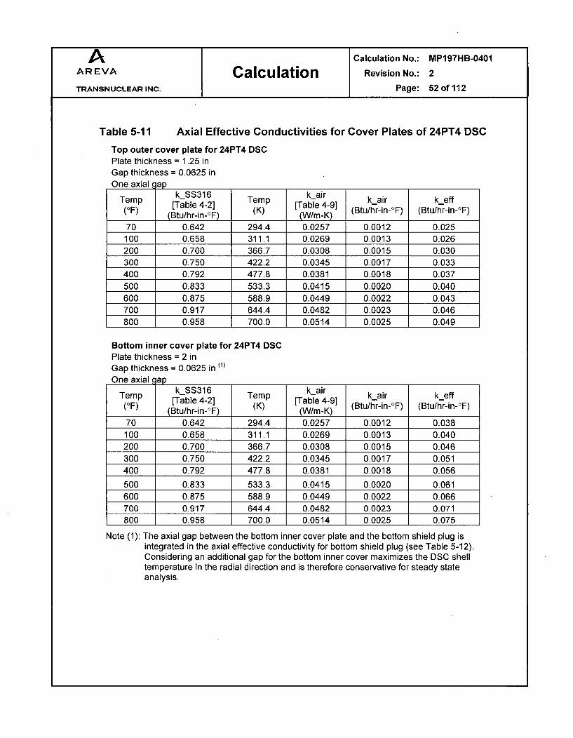
A Calculation No.: MP197HB-0401
AREVA Calculation Revision No.: 2
TRANSNUCLEAR INC. Page: 52 of 112
Table 5-11 Axial Effective Conductivities for Cover Plates of 24PT4 DSC
Top outer cover plate for 24PT4 DSCPlate thickness = 1.25 inGap thickness = 0.0625 inOne axial c ap
Tern k_SS316 Temp k air k-air k-eff(eF) [Table 4-2] [K) [Table 4-9] (Btu/hr-in-rF) (Btu/hr-in-F)
(Btu/hr-in-_F) (K) (W/m-K)70 0.642 294.4 0.0257 0.0012 0.025
100 0.658 311.1 0.0269 0.0013 0.026200 0.700 366.7 0.0308 0.0015 0.030300 0.750 422.2 0.0345 0.0017 0.033400 0.792 477.8 0.0381 0.0018 0.037500 0.833 533.3 0.0415 0.0020 0.040600 0.875 588.9 0.0449 0.0022 0.043700 0.917 644.4 0.0482 0.0023 0.046800 0.958 700.0 0.0514 0.0025 0.049
Bottom inner cover plate for 24PT4 DSCPlate thickness = 2 inGap thickness = 0.0625 in (1)
One axial lap
Tern kSS316 Temp k air k-air k-eff(OF) [Table 4-2] [K) [Table 4-9] (Btu/hr-in-rF) (Btu/hr-in-OF)
(Btu/hr-in-OF) (K) (W/m-K)70 0.642 294.4 0.0257 0.0012 0.038100 0.658 311.1 0.0269 0.0013 0.040200 0.700 366.7 0.0308 0.0015 0.046300 0.750 422.2 0.0345 0.0017 0.051400 0.792 477.8 0.0381 0.0018 0.056
500 0.833 533.3 0.0415 0.0020 0.061600 0.875 588.9 0.0449 0.0022 0.066700 0.917 644.4 0.0482 0.0023 0.071800 0.958 700.0 0.0514 0.0025 0.075
Note (1): The axial gap between the bottom inner cover plate and the bottom shield plug isintegrated in the axial effective conductivity for bottom shield plug (see Table 5-12).Considering an additional gap for the bottom inner cover maximizes the DSC shelltemperature in the radial direction and is therefore conservative for steady stateanalysis.

A Calculation No.: MP197HB-0401AREVA Calculation Revision No.: 2
TRANSNUCLEAR INC. Page: 53 of 112
Table 5-12 Axial Effective Conductivities for Lead Shield Plugs of 24PT4 DSC
Top shield plug for 24PT4 DSCPlate thickness = 3.38 inGap thickness = 0.025 inTwo axial aps
Temp k lead Temp k air k air k effTemL) [Table 4-6] [Table 4-9] ktair ket(OF) (Btu/hr-in-OF) (K) (W/m-K) (Btu/hr-in-°F) (Btu/hr-in-°F)
-100 1.767 200 0.0182 0.0009 0.0582-10 1.733 250 0.0223 0.0011 0.070680 1.700 300 0.0261 0.0013 0.0820
260 1.637 400 0.0330 0.0016 0.1024440 1.579 500 0.0395 0.0019 0.1206620 1.512 600 0.0456 0.0022 0.1371
Bottom shield plug for 24PT4 DSCPlate thickness = 2.88 inGap thickness = 0.025 inTwo axial aps
Temp k lead Temp k air k air k eff(e0F) [Table 4-6] [Table 4-9] ktain ket(OF) (Btu/hr-in-OF) (K) (W/m-K) (Btu/hr-in-°F) (Btu/hr-in-°F)
-100 1.767 200 0.0182 0.0009 0.0500-10 1.733 250 0.0223 0.0011 0.060780 1.700 300 0.0261 0.0013 0.0706
260 1.637 400 0.0330 0.0016 0.0883440 1.579 500 0.0395 0.0019 0.1042620 1.512 600 0.0456 0.0022 0.1187

A Calculation No.: MP197HB-0401
AREVA Calculation Revision No.: 2
TRANSNUCLEAR INC. Page: 54 of 112
5.4 Effective Conductivity for TC Slide Rails
A helium gap of 0.01" is considered between the slide rail and DSC shell to account for thecontact resistance. For simplification of the model, this gap is integrated into slide rail and aneffective conductivity is calculated for this component. The calculated effective conductivityfor slide rail is applied conservatively in all directions.
The gap and the slide rail built up serial thermal resistances along the rail height. Theeffective conductivity through these serial pieces is:
trail + tgapk eff =
trail tgap
krail kHe
Where,keff = effective conductivity (Btu/hr-in-OF)trail = thickness of TC slide rail = 0.12"tgap = thickness of gap = 0.01"kraii = conductivity of TC slide rails (Nitronic 60)kHe = conductivity of helium (Btu/hr-in-°F)
The conductivity values are taken from Section 4.1. The effective conductivities for TC sliderail are listed in Table 5-13.
Table 5-13
Slide rail thickness = 0.12GaD thickness = 0.01 in
Effective Conductivities for TC Slide Rail
in
kSS304 kHeTemnp k S30 Temp k - He kHekeffTemF) [Table 4-2] [Table 4-8] kHe ket(OF) (Btu/hr-in-OF) (K) (W/m-K) (Btu/hr-in'°F) (Btu/hr-in-°F)
70 0.717 294.4 0.1482 0.0071 0.076100 0.725 311.1 0.1533 0.0074 0.079200 0.775 366.7 0.1697 0.0082 0.087300 0.817 422.2 0.1861 0.0090 0.095400 0.867 477.8 0.2038 0.0098 0.104500 0.908 533.3 0.2236 0.0108 0.113600 0.942 588.9 0.2429 0.0117 0.122700 0.983 644.4 0.2610 0.0126 0.131800 1.025 700.0 0.2781 0.0134 0.139900 1.058 755.6 0.2945 0.0142 0.147
1,000 1.092 811.1 0.3104 0.0149 0.154

A Calculation No.: MP197HB-0401
AREVA Calculation Revision No.: 2
TRANSNUCLEAR INC. Page: 55of112
5.5 Effective Conductivity for Inner Sleeve
To reduce the complexity of the TC model, an effective conductivity is calculated for the innersleeve based on the shape shown in Figure A-2. The following dimensions are considered forthe inner sleeve in the thermal model.
Sleeve ID = 68 inSleeve OD = 70.5 inTotal length = 196 inNo. of pieces in axial direction = 4No. of segments in radial direction = 40Axial gap = 0.188 inRadial gap = 0.25 in
Although the above dimensions differ from the designed dimensions, they result in lowereffective conductivities for the aluminum inner sleeve as discussed in APPENDIX A. Theassumed dimensions are therefore conservative.
5.5.1 Axial Effective Conductivity
Along one segment of the sleeve, there are four sections of aluminum pieces with 0.1875"gaps between them in the axial direction (see Figure A-2, at bottom). The thermal resistancethrough these serial pieces is:
R.xIi = 4 RAI + 3 Rgap
Raxii= Lt RAI LAI R g Lgap
keff'A kAI.A kHe.A
Lt = 196"Lgap = 0.1875"
LAI = (196 - 3x0.1875) /4 = 48.86"keff = effective conductivity of one axial segment (Btu/hr-in-°F)kAI = conductivity of aluminum (Btu/hr-in-°F)kHe = conductivity of helium (Btu/hr-in-°F)A = surface area of one segment (in2)
Rearranging the above equations gives:
keff~axl Lt
S4 LAI + 3 Lgap
kA, kHe)

A Calculation No.: MP197HB-0401
AREVA Calculation Revision No.: 2
TRANSNUCLEAR INC. Page: 56 of 112
The axial segments are parallel to each other. Due to low conductivity of helium incomparison to aluminum, helium conductivity can be conservatively ignored. The total axialeffective conductivity is then proportional to the ratio of the surface area for the aluminumsegments in cross section to the total cross-sectional area of the inner sleeve, which isequivalent to the ratio of aluminum segment angle to the nominal angle (see Figure A-2).
keffaxi = keffaxl1 x -A1'0,om
360with 0,om = - 9040
gapped 180x--=8.6°0 AI nom -Dosleeve /2 ;
gaprad = radial gap =0.25"Do,sleeve = 70.5"
5.5.2 Radial Effective Conductivity
Forty aluminum segments in the radial direction build up parallel resistances perpendicular tothe direction of heat flow from center to periphery. Again, the total radial effective conductivitycan be set proportional to the ratio of the angle for one aluminum segment (OAF) to the nominalangle of each segment (Onom).
keff,rad = kAl x 0 A1Onom
The effective conductivity values calculated for sleeve are summarized in Table 5-14.
Table 5-14 Effective Conductivity of Inner Sleeve
Temperature kAl (1) kHe (2) keff,axl,1 keffaxi keffrad
(°F) (Btu/hr-in-OF) (Btu/hr-in-°F) (Btu/hr-in-°F) (Btu/hr-in-°F) (Btu/hr-in-°F)70 8.008 0.0071 1.894 1.808 7.646100 8.075 0.0074 1.947 1.859 7.710150 8.167 0.0077 2.030 1.938 7.798200 8.250 0.0081 2.111 2.016 7.878250 8.317 0.0085 2.190 2.091 7.941
300 8.383 0.0090 2.276 2.173 8.005350 8.442 0.0094 2.362 2.255 8.061400 8.492 0.0098 2.445 2.335 8.109
Note (1): See Table 4-5 for aluminum properties.
Note (2): Interpolated / extrapolated between data in Table 4-8

A Calculation No.: MP197HB-0401AREVA Calculation Revision No.: 2
TRANSNUCLEAR INC. Page: 57of112
5.6 Maximum Accessible Surface Temperature
The cask model is run without insolance to determine the accessible surface temperature ofthe impact limiters in the shade. A heat load of 32 kW and boundary conditions at 1 00°F andno insolance are considered in the cask model to bound the maximum accessible surfacetemperature under shade.
The personnel barrier is exposed to thermal radiation from the cask shield shell / finned shelland dissipates heat via thermal radiation and natural convection to ambient. Since thepersonnel barrier is far apart from the cask shield shell, it is not exposed to the hot airstreams from the cask. This assumption is justified in Section 5.6.1.
The heat balance for the personnel barrier is shown schematically in Figure 5-13. Thefollowing conservative assumptions are considered to simplify the heat balance.
* Convection heat dissipation from the barrier is omitted completely
* Radiation heat dissipation to ambient from barrier surfaces facing the cask areomitted
* The maximum cask shield shell temperature is considered for the entire shield shell /finned shell surface
* An emissivity of 0.9 is considered for the cask outer surface. Based on discussion inSection 4.2, the emissivities for shield shell and finned shell are 0.9 and 0.7,respectively. The emissivity of 0.9 bounds these values.
The simplified heat balance for the personnel barrier is as follows.
qin,ad = qoutrad
q (Tnherad- -- B-qinrad = 1 - 8 shell 1 1 -4 PB
t- + -
she, Ahell FPB-shell APB EPB APB
qoutrad = ql,rad,amb + q2,rad,amb, qlrad,amb = 0 (conservatively, omitted in this analysis)
q2,rad,amb = - 8 PB 1
8PB APB FPB_- APB
= Stefan-Boltzmann constant = 0.1 19E-10 (Btu/hr-in 2 -OR4)Tshell = maximum cask shield shell temperature (OR)TPB = maximum personnel barrier temperature (OR)T~o = ambient temperature = 100 OF = 560 OREshell = emissivity of TC outer surface = 0.9EPB = emissivity of personnel barrier SS304 = 0.587 (see discussion in Section 4.2)FPB-shell = view factor from personnel barrier to cask shield shell

A Calculation No.: MP197HB-0401AREVA Calculation Revision No.: 2
TRANSNUCLEAR INC. Page: 58 of 112
FPB-, = view factor from personnel barrier (not facing cask) to ambient = 1.0ApB = surface area of personnel barrier (in)Ashell = surface area of cask shield shell (in )
The dimensions of the cask shield shell (gshell) and personnel barrier (IPB) are 97.75" and52.38", respectively as shown in Figure 5-1.
Ashell _ 1Dshell /2 _ z×x 97.75/2 = 2.931APB /PB 52.38
The view factor of a long strip element to a parallel cylinder is given in [7], Chapter 7,Appendix B, Page 7.80 as follows. The dimensions are shown schematically in Figure 5-13for reference.
YFd1- 2 - X2 + y2
WithY y/r, X = x/ry = 58" (Figure 5-1)r = 97.75/2 = 48.875" (Figure 5-1)
Integration of the above incremental view factor over the length of the strip barrier gives theview factor of the strip to the cask.
F, = 1 fP' ( Y )dxP2 = - X2+y2d
Considering L=lpB/r and dX=dx/r, gives the view factor of the personnel barrier to the cask.
F1_2 = L X2 Y 2 jdX = 1tan-1' L= r tan-'lp 1 - 0.685
Since the personnel barrier has an open area of 80%, a factor of 0.2 should be considered tocalculate the view factor of the personnel barrier mesh to the cask.
FpB-shell = F1_2 x 0.2 = 0.137
Substitution of the above values in the heat balance of the personnel barrier gives themaximum temperature of the personnel barrier as reported in Section 6.2.

Calculation No.: MP197HB-0401
Revision No.: 2
Page: 59 of 112
ql ,rad,amb(Omitted in this analysis)
qconv(Omitted in this analysis)
q2,rad,amb
dAl
I,I1
Y'I
Figure 5-13 Schematic View of Cask and Personnel Barrier

A Calculation No.: MP197HB-0401
AREVA Calculation Revision No.: 2
TRANSNUCLEAR INC. Page: 60 of 112
5.6.1 Evaluation of Thermal Boundary Layer Thickness on Cask
The assumption that the personnel barrier is not exposed to hot air stream from the caskshield shell can be justified by calculation of the thermal boundary layer thickness around thelower half of the cask. This calculation demonstrates that the thermal boundary layerthickness is smaller than the shortest distance between the personnel barrier and the caskand therefore the personnel barrier remains out of the hot air stream from the cask.
The large diameter of the cask and the relative large temperature difference between thecask outer surface and ambient temperature suggest that the free convection over thecylinder is a turbulent flow.
The theoretical and experimental studies of the free convection and its related thermalboundary layer thickness are widely available and well documented ([29], [31], [32], and [33]).These correlations can be used to determine the free convection thermal boundary layerthickness over the horizontal MP1 97HB cask. These studies show that the thickness of thefree convection thermal boundary layer is inversely proportional to a power of the localNusselt number for laminar or turbulent flows.
6 _ Cf(Pr) (1)x Nuxm
6 = local thermal boundary layer thicknessx = local positionf(Pr) = a function of Prandtl numberNux = local Nusselt numberm and c = constant values
For instance, the theoretical calculation in reference [32] determines the following equation fora free convection laminar flow over flat vertical plates.
6 2x Nux
This equation means that c = 2, f(Pr) =1, and m = 1 in equation (1).
The correlations to determine the free convection thermal boundary layer thickness and localand average Nusselt number over a vertical flat plate in turbulent flow are documented inreferences [30] and [31]. These correlations are shown below.
6x =0.565 Grx-O. 1 Pr_8/ 15 (1+0.494Pr213)o" [30] (2)x
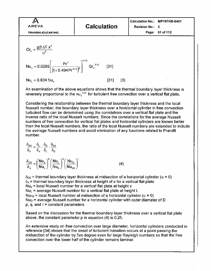
A Calculation No.: MP197HB-0401AREVA Calculation Revision No.: 2
TRANSNUCLEAR INC. Page: 61 of 112
_ g g3 AT x3D2
1/15
Nux 0.0295 Pr)7 1/3 , 25 [31. (1 + 0.494 Pr2/ I
NuL =0.834 Nux [311 (3)
An examination of the above equations shows that the thermal boundary layer thickness isreversely proportional to the NUx° 25 for turbulent free convection over a vertical flat plate.
Considering the relationship between the thermal boundary layer thickness and the localNusselt number, the boundary layer thickness over a horizontal cylinder in free convectionturbulent flow can be determined using the correlations over a vertical flat plate and theinverse ratio of the local Nusselt numbers. Since the correlations for the average Nusseltnumbers of free convection for vertical flat plates and horizontal cylinders are known betterthan the local Nusselt numbers, the ratio of the local Nusselt numbers are extended to includethe average Nusselt numbers and avoid elimination of any functions related to Prandtlnumber.
8DO 8L 5D 5DO
8. (5x 85L 8D
5D60 NUx P(NUL)q(NUD (4)85x L. NUL } NUD .) NUDo (4
5DO = thermal boundary layer thickness at midsection of a horizontal cylinder (( = 0)8x = thermal boundary layer thickness at height of x for a vertical flat plateNux = local Nusselt number for a vertical flat plate at height xNUL = average Nusselt number for a vertical flat plate at height LNUDO = local Nusselt number at midsection of a horizontal cylinder (a = 0)Nug = average Nusselt number for a horizontal cylinder with outer diameter of Dp, q, and r = constant parameters
Based on the discussion for the thermal boundary layer thickness over a vertical flat plateabove, the constant parameter p in equation (4) is 0.25.
An extensive study on free convection over large diameter, horizontal cylinders conducted inreference [34] shows that the onset of turbulent transition occurs at a point passing themidsection of the cylinder by five degree even for large Rayleigh numbers so that the freeconvection over the lower half of the cylinder remains laminar.

A Calculation No.: MP197HB-0401
AREVA Calculation Revision No.: 2
TRANSNUCLEAR INC. Page: 62 of 112
Since the personnel barrier designed for MP197HB cask is extended only to the midsection ofthe cask, the correlations for free convection laminar flow over horizontal cylinders can beused to determine the thermal boundary layer thickness at this location.
The free convection local Nusselt number over a horizontal cylinder in laminar flow in air isgiven in reference [33] as follows.
NuDa = 0.604 GrD1/ 4 N(O) [33]
gp3AT D3
GrD 21.2
a -900 -60o -30o 00 300 600 750 900
Q(ct) 0.76 0.75 0.72 0.66 0.58 0.46 0.36 0
Bottom half Top half
The local Nusselt number at the midsection of the cylinder at a = 0 is:
NuDo = 0.604 GrD1/ 4 x 0.66
Based on the above correlation, the average Nusselt number over the horizontal cylinder is:
90 90
NuD - 1 fNUD0 d( = 0.604 GrD114 x fJ(a)d(x
-90 -90
The integration of 0(a) over the range of -901 to 900 performed using the data in the abovetable gives:
Nu, = 0.604 GrD1/ 4 x 0.6025
Comparison of the correlations for NUDO and NUD gives:
NuD = 0.6025 NuD0 = 0.913 NUD00.66 (5)
Since the equation (5) is based on free convection laminar flow, the constant parameter r inequation (4) is equal to 1.
The ratio of the average Nusselt numbers for vertical flat plate and horizontal cylinder can bedetermined using the corresponding correlations shown in Section APPENDIX B.

A Calculation No.: MP197HB-0401AREVA Calculation Revision No.: 2
TRANSNUCLEAR INC. Page: 63 of 112
The thickness of the boundary layer at the midsection of the cask can be determined bysubstitution of the correlations for the local and average Nusselt numbers into equation (4).The height (L) of the vertical flat plate can be set equal to the outer diameter of the cask (D)for this evaluation. Average of the cask outer surface and ambient temperatures areconsidered in calculation of the Nusselt numbers.
As seen above, the correlations for the local and average Nusselt numbers depend on theGrashof and Prandtl numbers, which in turn depend on the cask outer surface temperature. Asensitivity analysis is performed to cover the effects of a wide range of cask temperaturesfrom 200'F to 500'F on the thickness of free convection thermal boundary layer at themidsection of the cask. This sensitivity analysis starts with variation of Grashof and Prandtlnumbers as summarized in Table 5-15.
Table 5-15 Variation of Grashof, Prandtl, and Rayleigh Numbers
Th =100°F
For L=D
Tcask Tcask Tc Tavg 3 v Gr Pr Ra
(OF) (K) (K) (K) (1/K) (m2/s) (---) (---) (---)
200 367 311 339 2.95E-03 2.235E-05 4.931E+1 0 0.71 3.490E+10
300 422 311 367 2.73E-03 2.849E-05 5.609E+10 0.70 3.948E+10
400 478 311 394 2.54E-03 3.516E-05 5.135E+10 0.70 3.602E+10
500 533 311 422 2.37E-03 4.232E-05 4.415E+10 0.70 3.091E+10
The values in Table 5-15 are calculated based on air properties taken from Table 4-9 at theaverage air temperature. As seen in Table 5-15, the Grashof number varies between 5.6E+1 0and 4.4E+10, the Prandtl number varies between 0.70 and 0.71, and the Rayleigh numbervaries between 3.1E+1 0 and 4.0E+10 for the cask outer surface temperatures between200OF and 5000F. Since the variation of Prandtl is relative small, an average Prandtl numberof 0.70 is considered in the sensitivity analysis to calculate the average Nusselt numbers for avertical flat plate (NUL) and a horizontal cylinder (NUD). To bound the variation of the Rayleighnumber conservatively, the average Nusselt numbers NUL and Nug are evaluated for a widerrange of Rayleigh numbers between 1 E+1 0 and 1 E+1 1.
As shown in APPENDIX B, the correlation for NUL depends on c[ and f factors, which in turndepend on Prandtl number and surface temperature, respectively. Cv' is a weak function ofPrandtl number. The variation of the f factor is determined for a cask outer surfacetemperature from 200OF to 5000F. The variations of these values are summarized in Table5-16.

A Calculation No.: MP197HB-0401
AREVA Calculation Revision No.: 2
TRANSNUCLEAR INC. Page: 64of112
Table 5-16 Variation of C•' and f in Calculation of NUL
Th =100°F
Pr C_ Tcsk f
(_---_ ) (_--- ) (OF) ---)
0.70 0.103 200 1.014
0.71 0.103 300 1.028
Average 0.103 400 1.042500 1.056
Average 1.035
The average values of ct and f from the above table are considered in calculation of NUL.The variation of the average Nusselt numbers NUL and NUD and their ratios summarized inTable 5-17.
Table 5-17 Variation of NUL/NUD
Vertical Flat Plate
Pr = 0.70
T CRa Nu Nu C' f Nut NUL
1.OOE+I0 162.86 163.9 0.103 1.035 208.5 216.0
2.OOE+I0 193.67 194.7 0.103 1.035 275.0 280.5
5.OOE+I0 243.53 244.5 0.103 1.035 384.0 388.1
8.OOE+10 273.89 274.9 0.103 1.035 452.4 456.1
1.OOE+I 1 289.61 290.6 0.103 1.035 488.5 492.0
Horizontal Cylinder
Pr = 0.70
Ra NuT F Nu C Nut NUD NUL/NUD
1.OOE+I0 125.73 0.940 126.7 0.103 221.9 222.0 0.973
2.OOE+10 149.51 0.942 150.5 0.103 279.6 279.6 1.003
5.OOE+10 188.00 0.944 188.9 0.103 379.5 379.5 1.023
8.OOE+10 211.44 0.945 212.4 0.103 443.8 443.8 1.028
1.OOE+I 1 223.58 0.945 224.5 0.103 478.1 478.1 1.029
Average 1.011
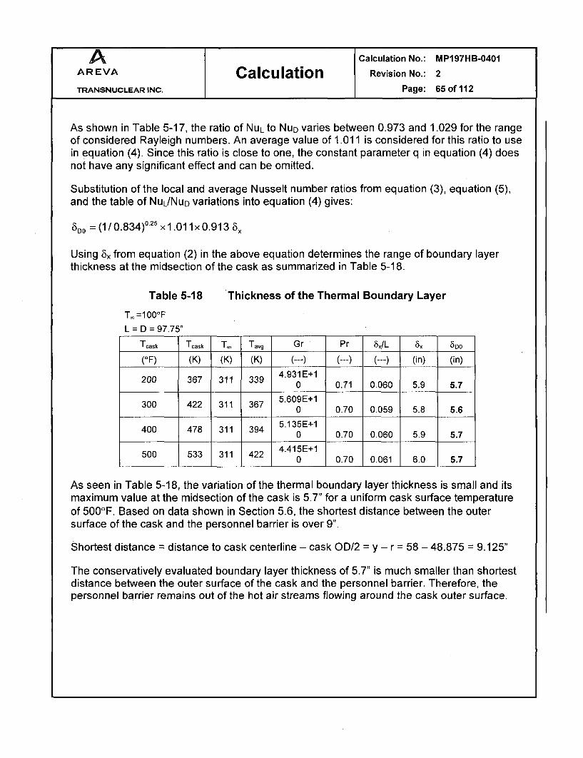
A Calculation No.: MP197HB-0401AREVA Calculation Revision No.: 2
TRANSNUCLEAR INC. Page: 65 of 112
As shown in Table 5-17, the ratio of NUL to NUD varies between 0.973 and 1.029 for the rangeof considered Rayleigh numbers. An average value of 1.011 is considered for this ratio to usein equation (4). Since this ratio is close to one, the constant parameter q in equation (4) doesnot have any significant effect and can be omitted.
Substitution of the local and average Nusselt number ratios from equation (3), equation (5),and the table of NuL/NuD variations into equation (4) gives:
6o = (1 / 0.834)0.25 x 1.01 lx 0.913 6x
Using 8x from equation (2) in the above equation determines the range of boundary layerthickness at the midsection of the cask as summarized in Table 5-18.
Table 5-18 Thickness of the Thermal Boundary Layer
T.o =100°F
L D = 97.75"
Tcask Tcask T. Tavg Gr Pr 5,/L 8x 5DO
(OF) (K) (K) (K) (--- ) ( --- ) ( --- ) (in) (in)
200 367 311 339 4.931E+10 0.71 0.060 5.9 5.7
300 422 311 367 5.609E+10 0.70 0.059 5.8 5.6
400 478 311 394 5.135E+10 0.70 0.060 5.9 5.7
500 533 311 422 4.415E+10 0.70 0.061 6.0 5.7
As seen in Table 5-18, the variation of the thermal boundary layer thickness is small and itsmaximum value at the midsection of the cask is 5.7" for a uniform cask surface temperatureof 5001F. Based on data shown in Section 5.6, the shortest distance between the outersurface of the cask and the personnel barrier is over 9".
Shortest distance = distance to cask centerline - cask OD/2 = y - r = 58 - 48.875 = 9.125"
The conservatively evaluated boundary layer thickness of 5.7" is much smaller than shortestdistance between the outer surface of the cask and the personnel barrier. Therefore, thepersonnel barrier remains out of the hot air streams flowing around the cask outer surface.

A Calculation No.: MP197HB-0401
AREVA Calculation Revision No.: 2
TRANSNUCLEAR INC. Page: 66 of 112
6.0 RESULTS
6.1 Maximum Temperatures
Typical temperature distributions for the MP197HB finite element models are shown in Figure6-1 and Figure 6-2.
The maximum component temperatures for hot NCT for ambient temperature of 1001F withinsolance are listed in Table 6-1.
Table 6-1 Maximum Temperatures of TC Component/ DSC Shellfor Hot NCT (1001F and Insolation)
69BTH 61BTH/ 61BTH/ 61BTDSC type 61BTHF 61BTHF
Type 1 Type 2
Heat Load 32 kW 29.2 kW 26 kW 22 kW 24 kW 18.3 kW
Inner sleeve No No No Yes Yes Yes
External fins Yes Yes No No No No
Component Tmax Tmax Tmax Tmax Tmax Tmax Limit
t(OF) (OF) (OF) (OF) (OF) (OF) (OF)
DSC shell 484 458 451 414 435 372 ---
DSC shell @ mid-length (1) 470 445 440 406 427 365 ---
Inner sleeve N/A N/A N/A 317 333 286 ---
Cask inner shell 367 347 351 315 331 284 ---
Gamma shield 366 345 349 314 330 283 621 [13]
Outer shell 352 332 337 306 321 276 ---
Shield shell 305 289 299 272 285 248 ---
Finned Shell 229 220 N/A N/A N/A N/A ---
Cask lid 267 254 265 248 259 228 ---
Cask bottom plate 353 334 338 307 322 277 ---
Neutron Shield Resin (2) 323 305 314 285 299 259 ---
Trunnion Plug Resin (2) 324 306 315 286 299 259 ---
Cask lid seal 268 256 266 249 260 229 400 [2]
Ram plate seal 352 332 337 306 321 277 400 [2]
Drain port seal @ bottom 351 332 337 306 321 276 400 [2]
Test seal @ bottom 349 330 335 305 320 276 400 [2]
Vent & test seal @ top 267 254 265 248 259 228 400 [2]
Wood in Impact limiter 302 287 291 265 278 242 320 [2]

A Calculation No.: MP197HB-0401AREVA Calculation Revision No.: 2
TRANSNUCLEAR INC. Page: 67 of 112
Table 6-1 Maximum Temperatures of TC Component / DSC Shellfor Hot NCT (1001F and Insolation) - Continued
37PTH 32PTH / 32PTH1 32PT 24PTH / 24PT432PTH Type 2 24PTHF
DSC type Typel / Type 1 & 232PTH1Type 1
Heat Load 22.0 kW 26 kW 24 kW 24 kW 26 kW 24 kW
Inner sleeve No No No Yes Yes Yes
External fins No No No No No No
Component Tmax Tmax Tmax Tmax Tmax Tmax Limit
(OF) (OF) (OF) (0F) (OF) (OF) (OF)
DSC shell 408 444 423 443 464 428 ---
DSC shell @ mid-length (1) 397 436 416 432 449 424
Inner sleeve N/A N/A N/A 329 347 319 ---
Cask inner shell 314 337 322 326 344 317 ---
Gamma shield 313 336 321 325 343 316 621 [13]
Outer shell 301 320 306 316 335 308 ---
Shield shell 271 290 278 281 295 274 ---
Cask lid 301 319 305 318 336 306 ---
Cask bottom plate 246 276 265 268 282 309 ---
Neutron Shield Resin (2) 284 303 290 295 310 287 ---
Trunnion Plug Resin (2) 285 305 292 296 311 287 ---
Cask lid seal 301 319 305 317 336 307 400 [2]
Ram plate seal 244 274 263 267 280 308 400 [2]
Drain port seal @ bottom 245 275 264 267 281 308 400 [2]
Test seal @ bottom 243 272 262 265 279 307 400 [2]
Vent & test seal @ top 300 318 305 317 336 306 400 [21
Wood in Impact limiter 262 278 266 274 289 267 320 [2]
Note (1): This value is the maximum DSC shell temperature in the region where the fuel assemblies have themaximum peaking factor. The values for PWR DSCs are retrieved from the models using the macro"DSCmidPWR.txt" listed in Table 8-3.
Note (2): See Table 6-2 for the highest volumetric average resin temperature and its temperature limit.

A Calculation No.: MP197HB-0401
AREVA Calculation Revision No.: 2
TRANSNUCLEAR INC. Page: 68 of 112
I(- - --- - - I101.73 186.636 271.541 356. 447 441. 352
144.183 229.088 313.994 398.899 483. 805MP197HB with 69BMH DSC - 32 kW, Normal Transport @ 10OF
197.677 235. 367 273 057 310. 747 3481.43 267.2
216.522 25.1 21.902 329.592 67.282 291.34 9339.45' 387.57 '3 35.689' 483.805Cask tenperature profile DSC temperature profile
211.045223.45 235. 854248260. 664 73 285.473297.8NResin tenperatuwe profile
S28 322.688 102.331124.568 8169.042Wood temperature profile
3 35 .754 280 .228213.517 257. 991 302,465
Figure 6-1 Temperature Profiles for MP197HB Transport CaskNCT, 1000F, Insolation, 69BTH DSC, 32 kW

A Calculation No.: MP197HB-0401
AREVA Calculation Revision No.: 2
TRANSNUCLEAR INC. Page: 69 of 112
101. 8352. 17ý82. 3122.55 2.••"79 3"3.2' 423.744142074 222551 303.028 38350 463.983Wf197HB with 24FM1 LSC - 26 kW, NOnnLl ITansport 8 100F
216.088 561 2 73.034 301.50 329.98 299 464 36 024 372. 584 409,144 445.703430.324 25..797 27.27 315.743 344.216 317.744 " 354.304 390.864 427.3 "463.983
Cask tamperature profile DSC temperature profile
227.1 245.507 263.914 282.1236.30 t"254.71 " 273.118p
ResJln teoerature profile729 102.213122.9743.7
309.932 122p974Wood temperature profile
2 226 782 268 305106.02 " 247.543 "289. 06
Figure 6-2 Temperature Profiles for MP197HB Transport CaskNCT, 1000F, Insolation, 24PTH DSC, 26 kW

A Calculation No.: MP197HB-0401AREVA Calculation Revision No.: 2
TRANSNUCLEAR INC. Page: 70of112
The average temperatures of helium within TC cavity, the average temperatures of TC innershell, and the volumetric average temperatures of neutron shield and trunnion plug resins forNCT with 1 00°Fambient temperature and insolance are listed in Table 6-2.
The volumetric average temperatures of resins are calculated for elements at the hottestcross section of the resin with a thickness of one or two element.
Table 6-2 Average TC Component Temperatures(100°F and Insolation)
for Hot NCT
69BTH 61BTH/ 61BTH/ 61BTDSC Type 61BTHF 61BTHF
Type 1 Type 2
Heat load 32 kW 29.2 kW 26 kW 22 kW 24 kW 18.3 kW
Inner sleeve No No No Yes Yes Yes
External fins Yes Yes No Yes No No
mavg Tavg Tavg Tavg mavg TavgComponent (OF) (OF) (OF) (OF) (OF) (OF)
Helium in TC cavity 339 321 328 301 316 273
TC inner shell 321 304 314 287 300 260
Neutron Shield Resin (1) 290 276 288 264 276 241
Trunnion Plug Resin (2) 277 263 272 249 260 229
37PTH 32PTH / 32PTH1 32PT 24PTH/ 24PT4DSC Type 32PTH Typel / Type 2 24PTHF
32PTH1 Type 1 Type 1 & 2
Heat load 22.0 kW 26 kW 24 kW 24 kW 26 kW 24 kW
Inner sleeve No No No Yes Yes Yes
External fins No No No No No No
Component mavg mavg Tavg Tavg Tavg Tavg
(OF) (OF) (OF) (OF) (OF) (OF)
Helium in TC cavity 269 301 288 281 297 313
TC inner shell 285 312 298 299 313 302
Neutron Shield Resin (1) 263 280 268 273 285 265
Trunnion Plug Resin (2) 249 264 254 257 268 250
Note (1): This temperature is the volumetric, average temperature of the elements located at hottestcross section of the neutron shield resin. The temperature limit for neutron shield resin(Vyal B) is 3200F [2].
Note (2): This temperature is the volumetric, average temperature of the elements located at hottestcross section of the trunnion plug resin. Based on discussion in Section 4.3, atemperature limit of 4450F is selected for trunnion plug resin (Polypropylene).

A Calculation No.: MP197HB-0401AREVA Calculation Revision No.: 2
TRANSNUCLEAR INC. Page: 71 of 112
The maximum DSC shell temperature for normal transfer conditions without air circulationoccurs generally in the mid section of the DSC where the fuel assembly has its highestpeaking factor while the maximum DSO shell temperature for NCT occurs toward the ends ofthe DSC shell where it is covered by impact limiters.
To illustrate this fact, the DSC shell temperature profiles for 61 BTH DSC and 24PTH DSCunder normal transfer conditions and NCT at 100°F ambient are compared in Figure 6-3 andFigure 6-4.

A Calculation No.: MP197HB-0401
AREVA Calculation Revision No.: 2
TRANSNUCLEAR INC. Page: 72 of 112
6M071L 22 I94. "I•r P. Tr fr. IOtF. bier. ON Air.
2M111r, A.1MT 5 2005U2:56:1"!Fr14 M1. 34
S79P I
184=222.0351X =4O. 41
S222. 075244 .121266.21w
310.26
354.352398.445420.491
A-• z1 zoo.
-M U-1A
T- I2 0
TE ul W
1i
ARMSS 0.1OCr 12 200507: 01t 41wUAr No. 46•AL W,• ITO
sTMS-44A1E 1
5M -227. 343
I 214. 2092 69-.42321.075344.508
r-- 361,941311 374
S438.24
[28 I1r, Contiq 061281! 41.2 kW-1 Tar 2. Irerter 1IAF. ral-r %~ Air.... 22 W.. 1 " - - ........ r .... F L .. • .. ..
Transfer Conditions61BTH Type 1,22.0 kW, 1000 Ffrom [21], Appendix A, Figure A-26
Transfer Conditions61BTH Type 2, 31.2 kW, 1000Ffrom [21], Appendix A, Figure A-88
•35 l445
,,rn!9,, nsl-jn Tyr.2bt 2492Nt. -da~at~nnV,:e -ad, 44,2,,. Sn'.. 9 922 42 kM. jla...j 9..n.raa 4 non.
a- 0.1
1- , aotzoo
M4 ,49
41114)
I4 52. :0=
In.54 o.fl1
954 .2(0.i0
O19A9I -nt 449r,0 I",1 I -07 22 W*. N444544 - -p-no 0 1041 -7n2n..1~ i4hA , "yn. I - - 410 - ..- Ir-.--t,, 0 Nr
NCT, 61BTH Type 1,22.0 kW, 100 0F NCT, 61BTH Type 2, 24.0 kW, 100°F
Figure 6-3 Comparison of DSC Shell Temperature Profiles for 61BTH DSC

A Calculation No.: MP197HB-0401
AREVA Calculation Revision No.: 2
TRANSNUCLEAR INC. Page: 73 of 112
ANEM 7.0SEP 8 200314:04:06~flT NO. 8
STEP•1SeB -1TinE-ITEMWSbM -240.058S{ -477.264
240.058266. 41422.9771S319 .127
S345 .483- 371.839
398.196424.552I 450.908
477.264
475F
1 AISYS 7.0JUL 15 200320:58:42PLD NO. 8NODAL SC•5TMONSTEPISUB -1TIIE=ITar8SMn =282.038SM =-650.463
282.038311.863- 341. 688- 371.513401.338431.163r--j 460. 988
V-S490.813520.638550. 463
inserts24M.H, 31.2 kW, 0S197 (m air), mo inserts, IBsx Shell 24PTM, 31.2 kW, 100F, 0S197 (no forced air), All Fuel,
Transfer Conditions24PTH Type 2, 31.2 kW, 100°Ffrom [22], Appendix A, Figure A65.2
1'...9 09.100.
0":4:•
401. 44
445 703
4i 3t0.i
Transfer Conditions24PTH Type 1,31.2 kW, 100°Ffrom [22], Appendix A, Figure A62.2
*00 26 '004
03. n-.•
39904
I354.304
30:.744I336..24
4- L44
55107"1 .03.6 M4TN 03C - 26 M,1 MU-6.1 71.0.e0.t 0 10007 -I"-79 idtl 24-.7 -3 - 26 k.. I 49........ 0 190,
NCT, 24PTH Type 1 or Type 2, 26.0 kW, 1 00°F
Figure 6-4 Comparison of DSC Shell Temperature Profiles for 24PTH DSC
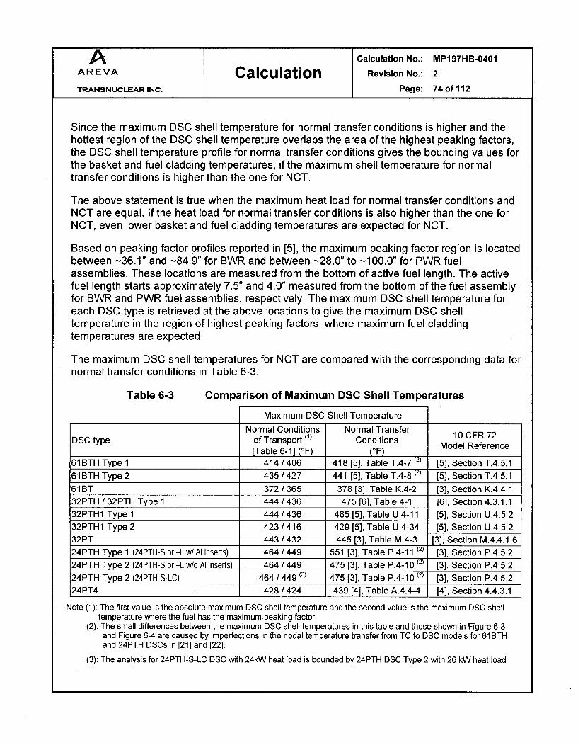
A Calculation No.: MP197HB-0401
AREVA Calculation Revision No.: 2
TRANSNUCLEAR INC. Page: 74of112
Since the maximum DSC shell temperature for normal transfer conditions is higher and thehottest region of the DSC shell temperature overlaps the area of the highest peaking factors,the DSC shell temperature profile for normal transfer conditions gives the bounding values forthe basket and fuel cladding temperatures, if the maximum shell temperature for normaltransfer conditions is higher than the one for NCT.
The above statement is true when the maximum heat load for normal transfer conditions andNCT are equal. If the heat load for normal transfer conditions is also higher than the one forNCT, even lower basket and fuel cladding temperatures are expected for NCT.
Based on peaking factor profiles reported in [5], the maximum peaking factor region is locatedbetween -36.1" and -84.9" for BWR and between -28.0" to -100.0" for PWR fuelassemblies. These locations are measured from the bottom of active fuel length. The activefuel length starts approximately 7.5" and 4.0" measured from the bottom of the fuel assemblyfor BWR and PWR fuel assemblies, respectively. The maximum DSC shell temperature foreach DSC type is retrieved at the above locations to give the maximum DSC shelltemperature in the region of highest peaking factors, where maximum fuel claddingtemperatures are expected.
The maximum DSC shell temperatures for NCT are compared with the corresponding data fornormal transfer conditions in Table 6-3.
Table 6-3 Comparison of Maximum DSC Shell Temperatures
Maximum DSC Shell Temperature
Normal Conditions Normal TransferDSC type of Transport (1) Conditions 10 CFR 72
[Tabl 6- (OF)(OF)Model Reference______________________ [Table 6-1] (°F) (°F)
61BTH Type 1 414 /406 418 [5], Table T.4-7 (2) [5], Section T.4.5.161BTH Type 2 435 /427 441 [5], Table T.4-8 (2) [5], Section T.4.5.161 BT 372/365 378 [3], Table K.4-2 [3], Section K.4.4.132PTH / 32PTH Type 1 444 /436 475 [6], Table 4-1 [6], Section 4.3.1.132PTH1 Type 1 444 /436 485 [5], Table U.4-11 [5], Section U.4.5.232PTH1 Type 2 423 /416 429 [5], Table U.4-34 [5], Section U.4.5.232PT 443/432 445 [3], Table M.4-3 [3], Section M.4.4.1.624PTH Type 1 (24PTH-S or -L w/Al inserts) 464 / 449 551 [3], Table P.4-11 (2) [3], Section P.4.5.224PTH Type 2 (24PTH-S or -L w/o Al inserts) 464 / 449 475 [3], Table P.4-10 (2) [3], Section P.4.5.224PTH Type 2 (24PTH-S-LC) 464 / 449 (3) 475 [3], Table P.4-10 (2) [3], Section P.4.5.224PT4 428 /424 439 [4], Table A.4.4-4 [4], Section 4.4.3.1
Note (1): The first value is the absolute maximum DSC shell temperature and the second value is the maximum DSC shelltemperature where the fuel has the maximum peaking factor.
(2): The small differences between the maximum DSC shell temperatures in this table and those shown in Figure 6-3and Figure 6-4 are caused by imperfections in the nodal temperature transfer from TC to DSC models for 61 BTHand 24PTH DSCs in [21] and [22].
(3): The analysis for 24PTH-S-LC DSC with 24kW heat load is bounded by 24PTH DSC Type 2 with 26 kW heat load.

A Calculation No.: MP197HB-0401
AREVA Calculation Revision No.: 2
TRANSNUCLEAR INC. Page: 75 of 112
As seen in Table 6-3, the maximum DSC shell temperature for NCT at the mid section, wherethe highest peaking factors are located, is 4 to 150F lower than the absolute maximum DSCshell temperature for the NCT and both of these values are lower than the maximum DSCshell temperature for normal transfer conditions. This concludes that the DSC shelltemperature profiles for normal transfer conditions represent the bounding cases for themaximum basket and fuel cladding temperatures.
Table 6-3 shows that the maximum DSC shell temperature for NCT is lower than thecorresponding value for normal transfer conditions for all DSC types. Therefore, the selectedmaximum heat loads listed in Table 1-1 are acceptable and the thermal analysis results forloaded DSCs in 1 0CFR72 SARs ([3], [4], [5], and [6]) are applicable for NCT. Except for69BTH and 37PTH DSCs, no further DSC thermal analyses are required.
Based on Table 6-1, the results for the 69BTH DSC with 32 kW heat load bound themaximum MP197HB cask component and DSC shell temperatures. The maximumtemperature gradients are also expected to be bounded by this case. Therefore, 69BTH DSCwith 32 kW heat load case is selected to determine the maximum temperature gradientsthrough MP197HB cask. The maximum component temperatures for cold NCT at -201F and-40°F ambient temperatures without insolance are listed in Table 6-4.
Table 6-4 Maximum Component Temperatures for Cold NCT(69BTH, 32 kW, No Insolation)
DSC type 69BTH, 32 kW, TC with External Fins and No Inner Sleeve
Ambient Temperature -20°F -40°F
Component Tmax Tmax(OF) (OF)
DSC shell 405 392
Cask inner shell 267 250
Gamma shield 265 248
Outer shell 250 233
Shield shell 202 184
Finned Shell 124 105
Cask lid 162 145
Cask bottom plate 252 235
Neutron Shield Resin (1) 187 169
Trunnion Plug Resin (2) 169 151
Wood in Impact limiter 193 175
Note (1): This temperature is the volumetric, average temperature of the elements located athottest cross section of the neutron shield resin.
Note (2): This temperature is the volumetric, average temperature of the elements located athottest cross section of the trunnion plug resin.

A Calculation No.: MP197HB-0401AREVA Calculation Revision No.: 2
TRANSNUCLEAR INC. Page: 76 of 112
The temperature profiles for 37PTH DSC shell are also determined for cold NCT at -20°F and-40°F ambient temperatures without insolance to be used for basket thermal and structuralevaluations. The maximum component temperatures for 37PTH at -20°F and -40°F ambienttemperatures without insolance are listed in Table 6-5.
Table 6-5 Maximum Component Temperatures for Cold NCT(37PTH, 22.0 kW, No Insolation)
DSC type 37PTH, 22.0 kW, TC without External Fins or Inner Sleeve
Ambient Temperature -20OF -40°F
Component Tmax Tmax(OF) (OF)
DSC shell 328 315
Cask inner shell 219 203
Gamma shield 217 202
Outer shell 204 188
Shield shell 173 157
Cask lid 204 188
Cask bottom plate 146 130
Neutron Shield Resin (1) 164 148
Trunnion Plug Resin (2) 145 128
Wood in Impact limiter 157 140
Note (1): This temperature is the volumetric, average temperature of the elements located athottest cross section of the neutron shield resin.
Note (2): This temperature is the volumetric, average temperature of the elements located athottest cross section of the trunnion plug resin.
The maximum component temperatures for 37PTH DSC with 23.2 kW under NCT are listedin APPENDIX G. The results of the analysis for 37PTH DSC with 23.2 kW are used only forstructural evaluations.
6.2 Maximum Accessible Surface Temperature
With the installation of the personnel barrier, the accessible packaging surfaces are limited to
the impact limiter and the barrier outer surfaces.
Based on requirements in [1] and [2], the maximum accessible surface temperature isdetermined for impact limiters considering the maximum decay heat load of 32 kW, ambienttemperature of 100 0 F, and no insolation. The maximum accessible surface temperature ofimpact limiters under these conditions is 121IF.

A Calculation No.: MP197HB-0401AREVA Calculation Revision No.: 2
TRANSNUCLEAR INC. Page: 77 of 112
The maximum temperature of the cask outer surface is 302°F and belongs to a part of shieldshell uncovered by the external fins. This temperature is retrieved by selecting the outermostelements and nodes (element type # 3) from the cask ANSYS model. The maximumtemperature of the personnel barrier is calculated based on the maximum temperature of thecask outer surface using the methodology described in Section 5.6. The maximumtemperature of the personnel barrier is 152°F.
The maximum accessible surface temperatures are well below the limit of 1851F defined in
Section 4.3.
6.3 Heat Balance
Insolance over various surfaces of MP197HB is calculated using the following equation.
SOIA q" - S F
SOIA = insolance over surface A (Btu/hr)q"sol = solar heat flux from Table 5-2 for surface A (Btu/hr-in 2)SA = surface area of surface Aca = solar absorptivity for surface AF = exposure factor for surface A (1 for vertical surfaces, 0.5 for other surfaces, see Section
3.0 for discussion)
The results are summarized in Table 6-6.
In order to check the proper application of insolance in MP197HB cask model, the insolanceboundary conditions are applied in two separate models. The decay heat loads were ignoredin these models. The model "check Sol U" is used for insolance over un-finned TC and themodel "checkSol_F" is used for insolance over TC equipped with finned aluminum shell.These model runs are listed in Table 8-2. The reaction solutions in "checkSolU" and"checkSol_F" models are retrieved using "PRRSOL" commands in ANSYS [14] to show theamount of applied insolance.
The retrieved values are then compared to the calculated insolance over neutron shield shellor finned shell. This comparison shows the proper application of insolance boundaryconditions as summarized in Table 6-6.
The dissipated heat (convection and radiation) from MP197HB is retrieved from the modelusing "ETABLE" commands [14] to build up the heat balance for TC. The commands arecollected in the input files for each run listed in Table 8-2. The data for TC heat balance arelisted in Table 6-7.
Since the MP197HB model is half-symmetric, the retrieved insolance and heat dissipationsare multiplied by two in Table 6-6 and Table 6-7.

A Calculation No.: MP197HB-0401
AREVA Calculation Revision No.: 2
TRANSNUCLEAR INC. Page: 78of112
Table 6-6 Insolance Boundary Conditions for MP197HB
Calculation of total insolance for un-finned TC based on ANSYS run check Sol U listed in Table 8-2Insolance
Surface # Location Description (Btu/hr-in 2)(MAT # in ANSYS Model) [Table 5-2]41 Impact limiter end surface Vertical SS304 0.125242 Impact limiter radial surface Curved SS304 0.250543 Impact limiter surface facing cask Vertical SS304 0.125244 Exposed area of thermal shield Vertical Al 0.0213 (1)
45 Neutron shield outer surface Curved painted 0.128046 Radial inner surface of impact limiter recess Curved SS304 0.250547 Outer surface of the skid strap Curved SS304 0.250548 Lateral side of the skid strap Vertical SS304 0.125250 Outer surface of the regulatory plate Curved SS304 0.250553 Outer surface of the trunnion plug Curved SS304 0.2505
ID/Surface # OD Height Length Qty Total Area Exposure Factor Insolance Solar Heat Solar Heat
(in) (in) (in) (in 2) (gtu/hr-in 2) (gtu/hr) (kW)
41 126 2 24938 entire 1 0.1252 3123 0.9242 126 58 2 45918 upper half 0.5 0.2505 5750 1.6943 126 98.5 2 9698 entire 1 0.1252 1214 0.3644 98.5 97.75 2 231 entire 1 0.0213 5 0.0045 97.75 154.25 1 40662 upper half 0.5 0.1280 2603 0.7646 125.5 0.25 2 197 entire 1 0.2505 49 0.0147 99.75 6 2 1880 entire 1 0.2505 471 0.1448 99.75 97.75 4 620 entire 1 0.1252 78 0.0250 97.75 10.2 22 2 451 upper half 0.5 0.2505 56 0.0253 97.75 27 29.5 4 2571 upper half 0.5 0.2505 322 0.09
Total 13672 4.01
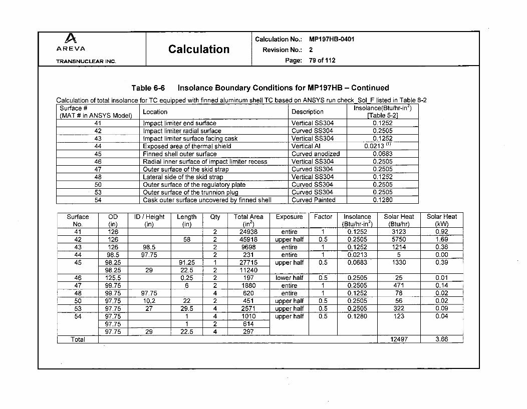
A Calculation No.: MP197HB-0401AREVA Calculation Revision No.: 2
TRANSNUCLEAR INC. Page: 79of112
Table 6-6 Insolance Boundary Conditions for MP197HB - Continued
Calculation of total insolance for TC equipped with finned aluminum shell TC based on ANSYS run check Sol F listed in Table 8-2Surface # Location I nsolance(Btu/hr-in2)(MAT # in ANSYS Model) Description [Table 5-2]
41 Impact limiter end surface Vertical SS304 0.125242 Impact limiter radial surface Curved SS304 0.250543 Impact limiter surface facing cask Vertical SS304 0.125244 Exposed area of thermal shield Vertical Al 0.0213 (1)
45 Finned shell outer surface Curved anodized 0.068346 Radial inner surface of impact limiter recess Vertical SS304 0.250547 Outer surface of the skid strap Curved SS304 0.250548 Lateral side of the skid strap Vertical SS304 0.125250 Outer surface of the regulatory plate Curved SS304 0.250553 Outer surface of the trunnion plug Curved SS304 0.250554 Cask outer surface uncovered by finned shell Curved Painted 0.1280
Surface OD ID / Height Length Qty Total Area Exposure Factor Insolance Solar Heat Solar HeatNo. (in) (in) (in) (in2) (Btu/hr-in 2) (Btu/hr) (kW)41 126 2 24938 entire 1 0.1252 3123 0.9242 126 58 2 45918 upper half 0.5 0.2505 5750 1.6943 126 98.5 2 9698 entire 1 0.1252 1214 0.3644 98.5 97.75 2 231 entire 1 0.0213 5 0.0045 98.25 91.25 1 27715 upper half 0.5 0.0683 1330 0.39
98.25 29 22.5 2 1124046 125.5 0.25 2 197 lower half 0.5 0.2505 25 0.0147 99.75 6 2 1880 entire 1 0.2505 471 0.1448 99.75 97.75 4 620 entire 1 0.1252 78 0.0250 97.75 10.2 22 2 451 upper half 0.5 0.2505 56 0.0253 97.75 27 29.5 4 2571 upper half 0.5 0.2505 322 0.0954 97.75 1 4 1010 upper half 0.5 0.1280 123 0.04
97.75 1 2 61497.75 29 22.5 4 297 1
Total 12497 3.66

A Calculation No.: MP197HB-0401AREVA Calculation Revision No.: 2
TRANSNUCLEAR INC. Page: 80 of 112
Table 6-6 Insolance Boundary Conditions for MP197HB - Concluded
Retrieved data from Model "check Sol U"(Btu/hr) (kW)
Solar heat in half-model 6830 2.00
Total solar heat in ANSYS model 13660 4.00
Calculated total solar 13672 4.01
Deviation from calculated values -0.1% -0.1%
Retrieved data from Model "check Sol F"(Btu/hr) .(kW)
Solar heat in half-model 6255 1.83
Total solar heat in ANSYS model 12510 3.67
Calculated total solar 12497 3.66
Deviation from calculated values 0.1% 0.1%
Note (1): The surface area of exposed thermal shield is very small. Solar heat over this surface is omitted in the model.

A Calculation No.: MP197HB-0401
AREVA Calculation Revision No.: 2
TRANSNUCLEAR INC. Page: 81 of 112
Table 6-7 Heat Balance for MP197HB
Hot Transport Conditions at 1 00°F Ambient with Insolation
Decay Heat Insolance from Total Heat Dissipation Heat Dissipation Heat DissipationDSC type [Table 5-3] ANSYS model Heat from Rear from Neutron from Front
[Table 6-6] Load Impact limiter Shield/Finned Shell Impact limiter(Btu/hr) (Btu/hr) (Btu/hr) (Btu/hr) (Ratio to Total) (Btu/hr) (Ratio to Total) (Btu/hr) (Ratio to Total)
69BTH, 26 kW 88720 13660 102380 7327 7.2% 88445 86.4% 6597 6.4%
69BTH, 29.2 kW 99639 12510 112149 7264 6.5% 98409 87.7% 6480 5.8%
69BTH, 32 kW 109194 12510 121704 7470 6.1% 107614 88.4% 6606 5.4%
61BTH/61BTHF Type 1 75071 13660 88731 6989 7.9% 75333 84.9% 6416 7.2%
61BTH / 61BTHF Type 2 81895 13660 95555 7158 7.5% 81873 85.7% 6531 6.8%
61BT 62445 13660 76105 6675 8.8% 63238 83.1% 6201 8.1%
37PTH 75071 13660 88731 6381 7.2% 75407 85.0% 6950 7.8%
32PTH / 32PTH Type 1 88720 13660 102380 6688 6.5% 88535 86.5% 7146 7.0%
32PTH1 Type 1 88720 13660 102380 6688 6.5% 88535 86.5% 7146 7.0%
32PTH1 Type 2 81895 13660 95555 6579 6.9% 81981 85.8% 7001 7.3%
32PT 81895 13660 95555 6602 6.9% 81842 85.7% 7102 7.4%
24PTH / 24PTHF Type 1 & 2 88720 13660 102380 6749 6.6% 88318 86.3% 7302 7.1%
24PT4 81895 13660 95555 7004 7.3% 81552 85.4% 6989 7.3%
Cold Transport Conditions / Hot Transport under Shade
69BTH, 32kW, -20OF 109194 0 109194 2486 2.3% 105032 96.2% 1664 1.5%
69BTH, 32kW, -40-F 109194 0 109194 2481 2.3% 105034 96.2% 1668 1.5%
69BTH, 32kW, 100 0F, Shade 109194 0 109194 2490 2.3% 105061 96.2% 1630 1.5%
37PTH, 22.0kW, -20°F 75071 0 75071 1497 2.0% 71523 95.3% 2044 2.7%
37PTH, 22.0kW, -40°F 75071 0 75071 1514 2.0% 71492 95.2% 2058 2.7%

A Calculation No.: MP197HB-0401
AREVA Calculation Revision No.: 2
TRANSNUCLEAR INC. Page: 82of112
7.0 CONCLUSION
Heat balance of MP1 97HB for the hot NCT shows that more than 83% of total heat load(decay heat and insolance) is dissipated to environment from the neutron shield shell orfinned shell surface. The heat dissipation from each impact limiter is limited to about 5 to 8%.Heat balance for the cold NCT shows that more than 95% of decay heat load dissipatesthrough the neutron shield or finned shell.
The maximum and average temperatures of major components from Table 6-1 and Table 6-2are summarized in Table 7-1. As seen in Table 7-1, the maximum temperatures of theMP197HB components calculated for NCT are lower than the allowable limits.
The maximum seal temperature is 3520F at ram closure plate for 32 kW heat load in 69BTHDSC. This temperature is well below the long-term limit of 400°F specified for continued sealfunction.
The maximum wood temperature for 32 kW heat load is 302°F which is below the consideredlimit of 320°F for crush structural analysis.
The maximum temperature of gamma shield (lead) is 3660F, which is well below the leadmelting point of 621°F.
The highest volumetric average resin temperature in the neutron shield at the hottest crosssection is 2901F, which occurs for the maximum heat load of 32 kW. The Vyal B resintemperature is below the temperature limit of 320°F and no degradation of the neutron resinis expected.
The highest volumetric average resin temperature in the trunnion plugs at the hottest crosssection is 2770F occurring for the maximum heat load of 32 kW. The polypropylene resintemperature is well below the temperature limit of 4450F and no degradation of the trunnionplug resin is expected.
All materials can be subjected to a minimum environment temperature of -40°F (-400C)without any adverse effects. The maximum component temperatures for cold NCT aresummarized in Table 7-2.
The maximum accessible -surface temperatures of MP197HB cask at 100°F without insolanceare 121IF for impact limiters and 152°F for personnel barrier. These temperatures are wellbelow the limit of 185 0F defined in Section 4.3.
The evaluations of 69BTH and 37PTH DSCs for storage conditions are not available yet. Forall other DSC types in MP197HB, the maximum DSC shell temperatures for transportconditions are bounded by the values reported for normal transfer conditions as shown inTable 6-3. Based on discussion in Section 6.1, the DSC shell temperature profiles for normaltransfer conditions are bounding for NCT. Therefore, the thermal analysis results for DSCs in

A Calculation No.: MP197HB-0401
AREVA Calculation Revision No.: 2
TRANSNUCLEAR INC. Page: 83 of 112
10CFR72 SARs ([3], [4], [5], and [6]) are applicable for NCT and no further DSC thermal
analysis is required except for 69BTH and 37PTH DSCs.
All design criteria are herein satisfied.
Table 7-1 Maximum Temperatures of TC Component/ DSC Shellfor Hot NCT
Conditions 1 F00°F
with Insolation
Heat load 26 < Q! <32 kW Q5 <26 kW
Inner sleeve No No Yes
External fins Yes No No
Component Tmax Tmax Tmax Limit
(OF) (OF) (OF) (OF)
DSC shell 484 451 464 ---
Inner sleeve N/A N/A 347 ---
Cask inner shell 367 351 344 ---
Gamma shield 366 349 343 621 [13]
Outer shell 352 337 335 ---
Shield shell 305 299 295 ---
Finned Shell 229 N/A N/A ---
Cask lid 267 319 (2) 336 (2) ---
Cask bottom plate 353 338 322 ---
Neutron Shield Resin (1) 290 288 285 320 [2]
Trunnion Plug Resin (1) 277 272 268 445 [24]
Seals 352 337 336 400 [2]
Wood in Impact limiter 302 291 289 320 [2]
Notes:
(1) The resin temperature is the volumetric, average temperature at the hottestcross section.
(2) The maximum cask lid temperatures for 26 kW < Q < 32 kW and Q < 26 kWbelong to DSCs loaded with BWR and PWR fuel assemblies, respectively.Since a spacer is used for PWR DSCs, the heat load of the PWR fuelassemblies is closer to the cask lid. Due to this configuration, the maximumcask lid temperature for Q 5 26 kW is higher than for 26 kW < Q 5 32 kW.See Table 6-1 for details.
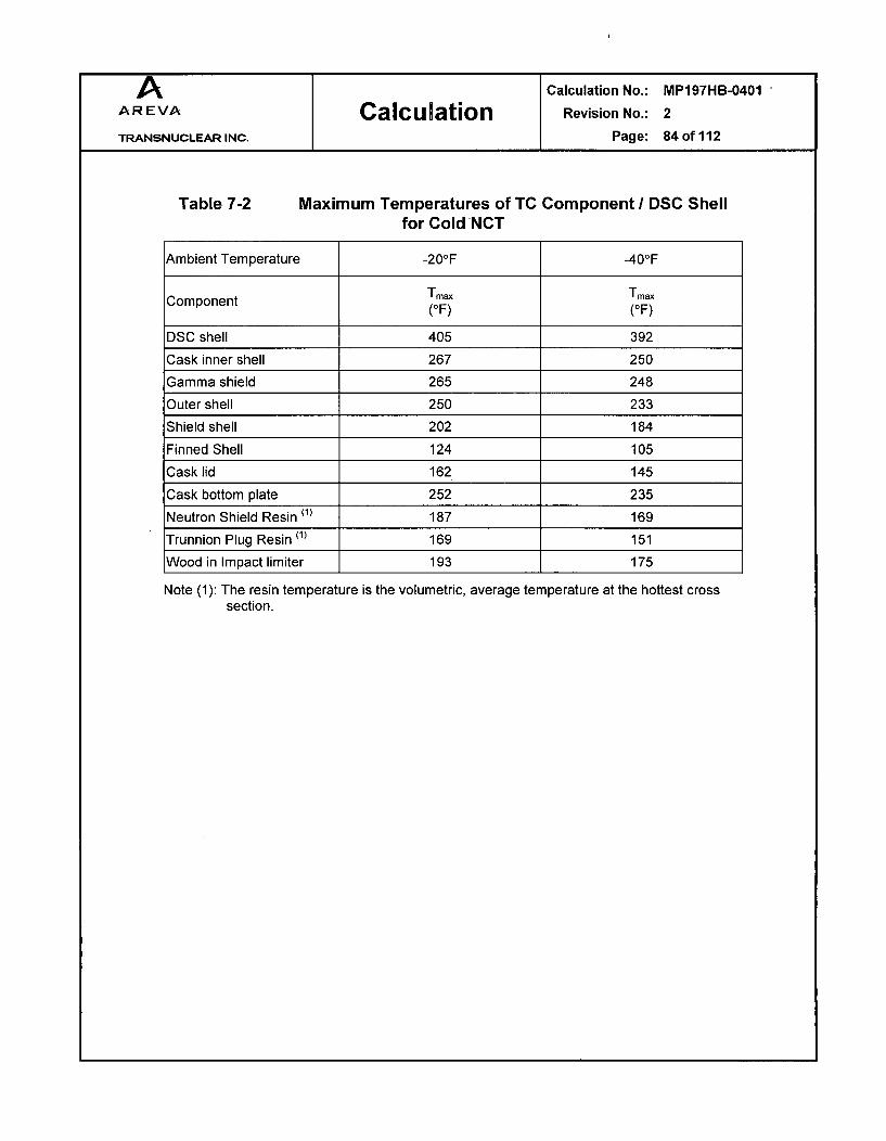
Calculation No.:
Revision No.:
Page:
MP197HB-0401
2
84 of 112
Table 7-2 Maximum Temperatures of TC Component / DSC Shellfor Cold NCT
Ambient Temperature -20°F -40OF
Component Tmax Tmax(OF) (OF)
DSC shell 405 392
Cask inner shell 267 250
Gamma shield 265 248
Outer shell 250 233
Shield shell 202 184
Finned Shell 124 105
Cask lid 162 145
Cask bottom plate 252 235
Neutron Shield Resin (1) 187 169
Trunnion Plug Resin (1) 169 151
Wood in Impact limiter 193 175
Note (1): The resin temperature is the volumetric,section.
average temperature at the hottest cross

A Calculation No.: MP197HB-0401AREVA Calculation Revision No.: 2
TRANSNUCLEAR INC. Page: 85 of 112
8.0 LISTING OF COMPUTER FILES
A list of the files to create geometries of MP197HB models are shown in Table 8-1.
A summary of ANSYS runs is shown in Table 8-2. All the runs are performed using ANSYSversion 8.1 [14] with operating system "Windows XP PRO-SPI", and CPU "Xeon 3.20 GHz".
ANSYS macros, and associated files used in this calculation are shown in Table 8-3.
The spreadsheets for this calculation are listed in Table 8-4.
Table 8-1 List of Geometry Files
File Name Description Date / Time(Input and Output) for Output File
MP197HB+BWRAICS Macro to create geometry of finned 08/25/08 08:10 PMMP97B+W__A____S_ MPI97HB with 69BTH DSC
MP197HB+BWRNICS Macro to create geometry of un-finned 08/25/08 08:15 PMMP1 97HB with 69BTH DSC
MP197HB+BWRSiCS Macro to create geometry of un-finned 08/25/08 08:20 PMMP1 97HB with 61 BT/ 61 BTH Type 1 DSCMP197HB+BWR S2CS Macro to create geometry of un-finned 08/25/08 08:25 PM
MP197HB with 61BTH Type 2 DSCMacro to create geometry of un-finned
MP197HB+PWR_N1CS MP197HB with 32PTH, 32PTH Type 1, 08/25/08 08:30 PM32PTH1 Type 1 and Type 2 DSC
MP197HB+PWRN2CS Macro to create geometry of un-finned 08/25/08 08.34 PMMP197HB with 37PTH DSC 08/25/0808:34_P
MP197HB+PWRS1CS Macro to create geometry of un-finned 08/25/08 08:39 PMMP197HB with 32PT DSC
MP197HB+PWRS2CS Macro to create geometry of un-finned 08/25/08 08:43 PMMP197HB with 24PTH Type 1 and Type 2 DSC
MP197HB+PWRS3CS Macro to create geometry of un-finned 08/25/08 08:48 PM-_ _ MP197HB with 24PT4 DSC

A Calculation No.: MP197HB-0401AREVA Calculation Revision No.: 2
TRANSNUCLEAR INC. Page: 86 of 112
Table 8-2 Summary of ANSYS Runs
Run Name Description. Date / TimeRun NameDescription, for Output File
TC_69BTH_32CS TC finned with 69BTH and 32 kW 08/26/08 12:47 PM
TC 69BTH 29CS TC finned with 69BTH and 29.2 kW 08/26/08 01:35 PMTC_69BTH_26CS TC un-finned with 69BTH and 26 kW 08/26/08 02:24 PM
TCO61BTHT1_22CS TC un-finned with 61BTH Type 1 and 22 kW 08/26/08 03:09 PMTCO61 BTHT2_24CS TC un-finned with 61 BTH Type 2 and 24 kW 08/26/08 03:55 PM
TC 61B 18CS TC un-finned with 61BT and 18.3 kW 08/26/08 04:41 PMTCO37PTH_23CS TC un-finned with 37PTH and 23.2 kW 08/26/08 05:22 PM
TCO37PTH_22CS TC un-finned with 37PTH and 22.0 kW 09/17/08 06:49 PM
TO_32PTHlTl_260S TC un-finned with 32PTH, 32PTH Type 1, 08/26/08 06:07 PMTC __32PTH1T1_26CS and 32PTH1 Type 1 with 26 kW
TCO32PTH1T2 24CS TC un-finned with 61BT and 18.3 kW 08/26/08 06:48 PMTC 32PT 24CS TC un-finned with 32PT and 24 kW 08/26/08 07:35 PM
TCO24PTH_26CS TC un-finned with 24PTH Type 1 & 2 08/26/08 08:25 PM-_ _- _ with 26 kW
TCO24PT4_24CS TC un-finned with 24PT4 and 24 kW 08/26/08 09:16 PM
TC 32kW 20CS TC with 69BTH, 32 kW, -20OF 08/28/08 02:23 PM
TCO32kW_40CS TC with 698TH, 32 kW, -40°F 08/28/08 03:17 PM
TCO32kWShCS TC with 69BTH, 32 kW, 1 00°F, Shade 08/26/08 09:33 AM
TC 23kW 20CS TC with 37PTH, 23.3 kW, -20°F 08/26/08 10:21 AM
TCO23kW_40CS TC with 37PTH, 23.2 kW, -40°F 08/26/08 11:20 AM
TCO22kW_20CS TC with 37PTH, 22.0 kW, -20°F 09/18/08 09:25 PM
TCO22kW_40CS TC with 37PTH, 22.0 kW, -40°F 09/18/08 10:15 PM
check Sol U Checking of solar heat flux boundary conditions 08/25/08 09:18 PMfor un-finned cask
check Sol F Checking of solar heat flux boundary conditions 08/25/08 09:36 PMfor finned cask
HeffAlfin_100 Effective heat transfer coefficient for external 04/15/08 08:46 AMHeft Alfin -20 fis04/15/08 09:03 AM
Heff Alfin 40 04/15/08 09:05 AM
Keff_gap Effective conductivity for gap between 03/06/08 10:55 AMKeffsgc DSC shell and TC inner shell 03/06/08 11:00 PMKeff sl 03/06/08 11:02 PM
MeshCN Mesh sensitivity coarse mesh 08/25/08 08:50 PMMeshFN Mesh sensitivity fine mesh 08/25/08 09:00 PM
TCO69BTH_32CSR Sensitivity analysis for slide rail/DSC contact 09/10/08 08:42 AMTC 69BTH 32U TC un-finned with 69BTH and 32 kW 10/15/08 09:05 PM
69BTH 32CS 4 69BTH basket w/32kW in un-finned TC 10/15/08 11:16 PM

A Calculation No.: MP197HB-0401
AREVA Calculation Revision No.: 2
TRANSNUCLEAR INC. Page: 87 of 112
Table 8-3 Associated Files and Macros
File Name Description Date / Time
MatMP197HBCS.inp Material properties for MP1 97HB cask 08/25/08 07:26 PMmodels
HTOTHCL.mac Total heat transfer coefficients for 04/29/08 09:59 AMhorizontal cylindrical surface
HTOTVPL.mac Total heat transfer coefficients for 11/13/07 12:41 PMvertical flat surface
HTOTHPD.mac Total heat transfer coefficients forhorizontal flat surface facing downwards
MatAlfins.mac Material properties for finned 01/29/08 05:12 PM- __aluminum shell in Heft fin runs
HGFin.mac Convection for external fins used in 09/04/07 08:57 PMHFin___________mac __________Heft fin runs
HCTip.mac Convection for external fin tips used in 05/21/07 04:10 PMHeft fin runs
Fins Gen.inp Macro to create geometry for external 02/07/08 11:31 AMFinsGen___inpfin sub-model
DSCCask.inp Macro to create geometry for 08/27/07 01:00 PMDSC/Cask radiation sub-model
MatDSC_Cask.inp Material properties for DSC/Cask inner 03/06/08 10:59 AMshell radiation sub-model
MatDSC_Sl.inp Material properties for DSC/Sleeve 03/06/08 10:56AMradiation sub-modelDSCmidPWR.txt Retrieve max DSC shell temp at hottest 10/22/08 09:20 AMDSCmid PWR.out fuel region for PWR DSCs 10/22/08 09:28 AMTempMap_32U.inp Transfer temp from TC to DSC/Basket 10/15/08 07:42 PMTempMap 32U.out model for 69BTH, 32.0 kW w/o fins 10/15/08 09:06 PMTavg.inp Retrieve average temperatures for TC 10/20/08 05:07 PMTavg.out model w/o fins, 32 kW 10/20/08 05:09 PM

A Calculation No.: MP197HB-0401
AREVA Calculation Revision No.: 2
TRANSNUCLEAR INC. Page: 88 of 112
Table 8-4 List of Spreadsheets
File Name Description Date / Time
DSCDataNominal.xis Nominal DSC Dimensions 04/16/08 04:51 PM
MatProp.xls Material Properties for MP197HB 07/31/08 12:14 PM
Keffsleeve.xls Effective conductivity for inner sleeve 11/16/07 12:37 PM
Insolance.xls Solar heat flux 08/26/08 03:17 PM
HeatFlux.xls Decay heat flux 09/24/08 02:04 PM
KeffRadiation.xls Effective conductivity for gap between DSC/TC 03/10/08 08:45 AM
HeffAlfin.xls Effective heat transfer for finned aluminum shell 04/16/08 03:10 PMShiftx.xls Calculation of gap sizes between DSC and TC 02/12/08 11:47 AM
HeatBalance~xls Heat balance for MP197HB 09/26/08 10:58 AM
ShellContact.xls Gap between shield shell and finned shell 02/15/08 07:56 PM
GammaGap.xls Gap between gamma shield and outer shell 01/20/09 10:31 AM
NodalTemp.xls Nodal temperatures at the slide rail/DSC contact 09/10/08 09:19 AM
Tmax.xls Maximum Temperatures for Table 7-1 09/24/08 04:13 PM
BL thk.xls Boundary layer thinness around cask 02/08/10 06:06 PM
A Calculation No.: MP197HB-0401
AREVA Calculation Revision No.: 2
TRANSNUCLEAR INC. Page: 89 of 112
APPENDIX A SHAPES OF EXTERNAL FINS AND INNER SLEEVE
The shapes of the optional external fins and the inner sleeve considered in the TC model areshown in Figure A-1 and Figure A-2, respectively.
The designed external finned shell, shown in Figure A-3 is a continuous shell which coversboth of the trunnion plugs up to the skid straps. The considered shape of the external fins inthe TC model has fewer fins than the designed finned shell and is therefore conservative forthermal analysis under NCT.
The designed shape of the inner sleeve is shown in Figure A-4. As seen in Figure A-4, thereis virtually no gap between the segments of the inner sleeve. The considered shape of theinner sleeve in the TC model includes 120 individual aluminum pieces with 39 radial gaps andthree axial gaps. The thicknesses of the radial and axial gaps are respectively 0.25"and0.188" as shown in Figure A-2. In addition, the material properties of the inner shell elementsin contact with the cask slide rails are changed to those of helium to avoid any directconduction between these two components. Since the considered shape of the inner sleevein the TC model includes more gaps, it is conservative to use it for thermal analysis oftransport cask under NCT.

A Calculation No.: MP197HB-0401AREVA Calculation Revision No.: 2
TRANSNUCLEAR INC. Page: 90 of 112
Proprietary Information Withheld Pursuant to 10 CFR 2.3 90

Calculation No.: MP197HB-0401
Revision No.: 2
Page: 91of112
41'r•a
"48-86",. A- ax gapU.--188"total thr:egaps
Figure A-2 Assumed Geometry of Inner Sleeve in Thermal Model

A Calculation No.: MP197HB-0401
AREVA Calculation Revision No.: 2
TRANSNUCLEAR INC. Page: 92 of 112
Proprietary Information Withheld Pursuant to 10 CFR 2.3 90

A Calculation No.: MP197HB-0401
AREVA Calculation Revision No.: 2
TRANSNUCLEAR INC. Page: 93 of 112
Proprietary Information Withheld Pursuant to 10 CFR 2.390

A Calculation No.: MP197HB-0401AREVA Calculation Revision No.: 2
TRANSNUCLEAR INC. Page: 94 of 112
APPENDIX B TOTAL HEAT TRANSFER COEFFICIENTS
Total heat transfer coefficient, ht, is used to combine the convection and radiation heattransfer together.
ht = hr + hc
Where,hr = radiation heat transfer coefficient (Btu/hr-in 2-OF)hc = free convection heat transfer coefficient (Btu/hr-in 2-oF)
The radiation heat transfer coefficient, hr, is given by the equation:
hr=FF (Tw4 -Tamb) 1 Btu/hr-in 2 -OF
wI Tw - Tamb
Where,6 = surface emissivityF12 = view factor from surface 1 to ambient = 1G = 0.1714 x10⁻⁸ Btu/hr-ft2-OR4
Tw = surface temperature (°R)Tamb = ambient temperature (OR)
Surface emissivity values are discussed in Section 4.2.
The following equations from Rohsenow handbook [7] are used to calculate the freeconvection coefficients.
For horizontal cylinders:
Ra =Gr Pr ; Gr = g,8 (Tw 2 T.) D3
Nu - 2fNu, 2f= withln(l+ 2f /Nu T)
NuT =0.772 C, Ra 4 T 0.13 with C, =0.515 for gases [7]f(NuT)O.16,
Nut = Ct Ra1/3
Ct = 0.103 for air with Pr 0.71 [7]
Nu = I(Nu,)' + (Nut)' I /M with m=10 for 10-10 <Ra <10 7

A Calculation No.: MP197HB-0401AREVA Calculation Revision No.: 2
TRANSNUCLEAR INC. Page: 95 of 112
hc =Nuk x 0.1761/144D
withg = gravitational constant =9.81 (m/s 2)13 = expansion coefficient = 1/T (1/K)T = absolute temperature (K)v = kinematic viscosity (m2/s)D = diameter of the horizontal cylinder (in)k = air conductivity (W/m-K)
The above correlations are incorporated in ANSYS model via macro "HTOTHCL.mac" listedin Section 8.0.
For vertical flat surfaces:
Ra =Gr Pr Gr = g,8 (T, 2 T.)
2.0Nu, = ln(I+ 2.0/NuT) with
NuT = C, Ra114 with C, = 0.515 for gases [7]
Nut =Cv f Ra1/3 /(1+1.4x109 Pr/Ra) withCV = 0.13Pr0.22 f = 1.0 + 0.078T-- - 1
(1 +0.61 Pr'-" )0 T2
Nu [(Nu,)m + (Nu,) /M with m=6 for 1<Ra<1012
Nu kL
withg = gravitational constant =9.81 (m/s 2)13 = expansion coefficient = 1/T (1/K)T = absolute temperature (K)v = kinematic viscosity (m 2/s)L = height of the vertical surface (in)k = air conductivity (W/m-K)
The above correlations are incorporated in ANSYS model via macro "HTOTVPL.mac" listedin Section 8.0.

A Calculation No.: MP197HB-0401
AREVA Calculation Revision No.: 2
TRANSNUCLEAR INC. Page: 96 of 112
For horizontal flat surfaces facing downwards:
The following correlations are used only for the outer surface of the bearing block at the lowerhalf of the TC.
Ra = Gr Pr ; Gr= g(TW - Ti)(L*)3
2V
Nu, = 2.5 withln(l+ 2.5/NuT )
NuT = 0.527 Ra115
(1+ (1.9 / pr)9/ly'9
Nu = Nu, for 103 < Ra < 1010
= Nu k
withg = gravitational constant =9.81 m/s 2
13 = expansion coefficient = 1/T (1/K)T = absolute temperature (K)v = kinematic viscosity (m 2/s)
A - heated area =1.2" (shortest surface of bearing block)
p heated perimeter
k = air conductivity (W/m-K)
The above correlations are incorporated in ANSYS model via macro "HTOTHPD.mac" listedin Section 8.0.
Air properties are taken from [7] and listed in Table 4-9.

A Calculation No.: MP197HB-0401AREVA Calculation Revision No.: 2
TRANSNUCLEAR INC. Page: 97 of 112
APPENDIX C JUSTIFICATION OF GAMMA SHIELD / OUTER SHELL GAP
A 0.025" radial air gap is assumed between the gamma shield (lead) and the TC outer shellwithin the finite element model described in Section 4.0. This air gap is due to the differentialthermal expansion of the cask body and the gamma shield during the lead pour.
The following assumptions are made for the verification of the gap:
The cask body has nominal dimension at 701F.
During the lead pour the cask body and lead are at 620'F.
The inner diameter of the gamma shell (lead) is equal to the outer diameter of the inner caskshell at thermal equilibrium.
The average coefficients of thermal expansion for SA-203, Gr. E and lead are listed in TableC-1.
Table C-1 Thermal Expansion Coefficients
Temperature SA203, Gr. E(OF) a
(in/in-OF) [2]70 6.40E-06
200 6.70E-06300 6.90E-06400 7.1OE-06500 7.30E-06600 7.40E-06650 7.60E-06
Temperature Lead(OF) a
(in/in-°F) [2]70 16.07 E-6100 16.21 E-6175 16.58 E-6250 16.95 E-6325 17.54 E-6440 18.50 E-6620 20.39 E-6
The density of lead as a function of temperature is listed in Table C-2.
Table C-2 Density of Lead
Temperature Density [9] Temperature Density(K) (kg/mn) (OF) (Ibm/in50 11,570 -370 0.4180100 11,520 -280 0.4162150 11,470 -190 0.4144200 11,430 -100 0.4129250 11,380 -10 0.4111300 11,330 80 0.4093400 11,230 260 0.4057500 11,130 440 0.4021600 11,010 620 0.3978

A Calculation No.: MP197HB-0401AREVA Calculation Revision No.: 2
TRANSNUCLEAR INC. Page: 98 of 112
The volume within the "lead cavity" is found by determining the cask body dimensions at620'F. As no gaps will be present between the molten lead and the cask body this volume isalso equal to the volume of lead at 6200F. The mass of the lead filled the lead cavity at 6200Fis then determined.
The dimensions of the "lead cavity" are calculated based on cask body temperature. Atemperature of 3601F is considered for the cask body. This temperature is lower than themaximum cask inner shell temperature shown in Table 6-1. Since the gap size increases atlower temperatures, the above chosen value is conservative. From the mass of the lead andits density at 360 0F, the lead volume is determined.
The length of the gamma shield at the cask body temperature is calculated based on thermalexpansion coefficients listed in Table C-1. The lead volume is used to determine themaximum size of the air gap adjacent to the lead.
Determination of Lead Mass
acs = 7.44 x 10. in/in-OF @ 620OF (via linear interpolation, Table C-1)Plead = 0.3978 Ibm/in 3 @ 620OF (Table C-2)
Rin = inner radius of lead cavity @ 70'F= 36.50"Rout = outer radius of lead cavity @ 701F = 39.75"Lcvity = length of lead cavity @ 70OF = 195.75"
ain, 620 = (Rin)(1 +((x cs)(AT)) = (36.50)[1+(7.44E-6)(550)] = 36.6494"
Rout, 620 = (Rout)(1 +((x cs)(AT)) = (39.75)[1+(7.44E-6)(550)] = 39.9127"
Lcavity, 62 0 = (Lcavity)(1 +(a cs)(AT)) = (1 95.75)[1 +(7.44E-6)(550)] = 196.5510"
Vcavity = Vlead = (i)(Rout,620 2 - Rin, 6202)(Lcavity, 620) = 154,274.9 in3
Mlead = (Vlead)(Plead) = (154,274.9 in3)(0.3978 Ibm/in 3) = 61,363.6 Ibm
Determination of Lead Gap
acs = 7.02 x 10⁻⁶ in/in-OF @ 360OF (via linear interpolation, Table C-1)UIead, 620 = 20.39 x 10⁻⁶ in/in-OF @ 620OF (Table C-1)alead, 360 = 17.83 x 10⁻⁶ in/in-OF @ 360°F (via linear interpolation, Table C-1)Plead = 0.4037 Ibm/in 3 at 3600F, via linear interpolation from Table C-2
Rin, cs, 360 = (Rin)(1+(acs)(AT)) = (36.50)[1+(7.02E-6)(290)] = 36.5743"
Rout, cs, 360 = (Rout)(1 +(a cs)(AT)) = (39.75)[1+(7.02E-6)(290)] = 39.8309"
Llead, 360 = (Lcavity, 620)/(1 +(C lead,620)( 6 2 0 - 70))*(1 +((x lead,620)( 3 6 0 - 70)) =
(196.5510) / [1 +(20.39E-6)(550)] * [1 +(1 7.83E-6)(290)] = 195.3764"

A Calculation No.: MP197HB-0401
AREVA Calculation Revision No.: 2
TRANSNUCLEAR INC. Page: 99 of 112
Vlead, 360 - Mlead / Plead = 61,363.6 / 0.4037 = 152,004.6 in3
Since Rin,cs,360 = Rin,lead,360, then :
Vlead,360 = (7r)(Rout, lead,360 - Rin, ss, 360 )(Llead, 360)
It gives:
Rout,lead,360 = 39.8162"
Air gap = aout,cs,360 - Rout, lead,360 = 39.8309 - 39.8162 = 0.0147"
The assumed air gap of 0.025" is larger than the above calculated gap. Therefore, using agap of 0.025" is conservative to maximize the DSC shell temperature.

A Calculation No.: MP197HB-0401AREVA Calculation Revision No.: 2
TRANSNUCLEAR INC. Page: 100 of 112
APPENDIX D JUSTIFICATION OF CASK SHIELD SHELL / ALUMINUM FINNED
SHELL GAP
An air gap of 0.01" is considered in the model between the cask shield shell (SA-516-70) andthe finned aluminum shell (Al 6061) for MP197HB cask with over 26 kW heat load. Thefollowing calculation shows that the modeled gap of 0.01" is adequate to bound the existingcontact resistance between these two shells.
Yovanovich suggests the following approach in [15] to calculate the thermal contactconductance.
hj = h, + hg (D.1)
hj= total thermal contact conductance (m2-K/W)hc= contact conductance (m2-K/W)hg = gap conductance (m2-K/W)
The thermal contact resistance is:
R1 =11hj (D.2)
The contact conductance, h,, is given in [15] by:
hc = 1.25 k., M )0.95 (D.3)
Wherek= 2k 1 k2 (kl + k 2) Harmonic mean thermal conductivity of interface (W/m-K)
m = ým12 + M22 Effective mean absolute asperity slope of interface
a = ýo-,2 + o-22 Effective RMS surface roughness of contacting asperities (m)
P = Contact pressure (MPa)Hc = Microhardness of the softer of the two contacting solids (MPa) = HC,AI in this evaluation
The mean absolute asperity slope for each plate can be approximated by the followingcorrelation from [15]:
mi = 0.125 (o-, x 10-6)Y.4 2 for 0.216/um _< o- < 9.6/.m (D.4)
As seen in equation (D.3), the contact conductance, he, depends heavily on contact pressure,P. Assuming a very small contact pressure of 10-6 psi, gives a negligible contact

A• Calculation No.: MP197HB-0401AREVA Calculation Revision No.: 2
TRANSNUCLEAR INC. Page: 101 of 112
conductance, h, and eliminates this term in calculation of the total thermal contactconductance in equation (D.1).
A contact pressure of 10-6 psi is equivalent to having no friction between the two shells, whichis very conservative.
Due to elimination of h, in equation (D.1), the conductivities of the contacting plates are notrequired for this calculation.
The gap conductance, hg, is given in [15] by:
hg = kg /(Y + M) (D.5)
Wherekg = thermal conductivity of the gap substance (W/m-K)Y = effective gap thickness (m)M = gas parameter (m)
Based on [15], the effective gap thickness, Y, shown in Figure D-1, can be calculated asfollows:
Y = 1.53 o- (P / Hc)-°0 97 for 10-5 < P/HN < 2x1 0-2 (D.6)
The gas parameter M accounts for the rarefaction effects at high temperatures and low gaspressure. This gas-surface parameter depends on the thermal accommodation coefficients,the ratio of specific heats, the Prandtl number, and the molecular mean free-path of the gas.This complex gas-surface parameter depends on gas pressure and temperature according tothe following relationship:
M = Mo T Pg, (0.7)
Where M0 denotes the gas parameter value at the reference values of gas temperature andpressure, To and Pg,o, respectively. T and Pg are temperature and pressure of the contactgas. The gas parameter for air is 0.373x1 0-6 m at 500C and 1 atm, as reported in [15].
An operating temperature of 200OF (378K) is considered for T and kg in equations (D.5) and(D.7). The assumed operating temperature is well below the cask shield shell and the finnedaluminum shell temperatures in Table 6-1 and is therefore conservative.
A pressure of 1 atm is considered for air between the two shells.
Based on Table 4-9, the air conductivity is 0.0015 Btu/hr-in-°F or 0.031 W/m-K at 2000F.
The following data in Table D-1 are considered for roughness and hardness of the shells.

A Calculation No.: MP197HB-0401
AREVA Calculation Revision No.: 2
TRANSNUCLEAR INC. Page: 102 of 112
Table D-1 Surface Properties for Aluminum and Stainless Steel Plates
Material Roughness Hardness Microhardness (1)
(l-tm) (MPa)Aluminum 0.2 to 6.3 [16] Brinell 500kg [1 7] 440 to 1079
SA 203, Gr. E 0.2 to 6.3 [16] (2)
Note (1): For conversion of roughness units see reference [19]
Note (2): Based on [15], the hardness of the softer plate, aluminum here, is taken for evaluation.
Surface roughness is mainly determined by the production method. The roughness values inTable D-1 correspond to average values for cold rolling / drawing process.
The contact resistances are calculated based on the average roughness and hardness fromTable D-1 and listed below.
GAI = 3.25 ýtm, Hc,Ai = 760 MPa
cycs = 3.25 ptm
The calculated contact resistance is listed in Table D-2.
Table D-2 Contact Resistances between Shield Shell and Finned Aluminum Shell
Contact Type AI / SA203
a (•tm) 4.60E-06
P (MPa) 6.891E-09
Hc (MPa) 760
Pg (atm) 1.0
T (K) 378
kg (W/m-K) 0.031
P/Hc 9.073E-12
Y (Pm) 8.283E-05
M (Pm) 4.361E-07
h, (W/m 2-K) 0.00
hg (W/m 2-K) 374
hj (W/m2-K) 374
Rj (m2-K/W) 2.7E-03
The equivalent thermal resistance for the air gaps across the shells considered in theMP197HB is:

A Calculation No.: MP197HB-0401AREVA Calculation Revision No.: 2
TRANSNUCLEAR INC. Page: 103 of 112
R. =• AgapRjmod el k-
kg (D.8)
AXgap = 0.01" = 2.54E-4 m
Rj model -2 .5 4 E - 4
_ 8.2E - 3 m2-K/W0.031
The above thermal resistance considered in the model (Rj,model) is about three times largerthan the calculated contact resistances (Rj,) shown in Table D-2. This indicates that the airgap of 0.01" considered in the model is more than adequate to bound the contact resistancebetween the cask shield shell and the finned aluminum shell.
Ti alm ._'
ýy
L-fo =Vo * o 21 2m=Im ,2+m 2
Figure D-1 Conforming Rough Surfaces [15]

A Calculation No.: MP197HB-0401
AREVA Calculation Revision No.: 2
TRANSNUCLEAR INC. Page: 104 of 112
APPENDIX E MESH SENSITIVITY
A slice of the TC model containing 69BTH DSC shell is recreated for mesh sensitivity analysis(Mesh_CN run listed in Table 8-2). The length of the TC slice model is 24" and includes theDSC shell and cask shells. The mesh density of this model is the same as the mesh densityof the geometry model "MP197HB+PWRN" listed in Table 8-1 from z=30.5" to z=60.34"except that the element size is decreased from 3.73" to 3.0" in the axial direction. The slicemodel contains 26,744 elements and 29,574 nodes. The number of nodes and elements inthe slice model are identical to the model "MP197HB+PWRN" from z=30.5" to z=60.34".
For the purpose of mesh sensitivity analysis, the mesh density of the slice model is increasedto more than five folds of its original value so that the number of elements and nodes areincreased to 147,376 and 154,564, respectively (MeshFN run listed in Table 8-2).
Ambient temperature of 1 00°F with insolation and a decay heat of 26 kW are considered asboundary conditions for both TC slice models with coarse and fine meshes. The boundaryconditions are applied using the same methodology as described in Section 5.0. Themaximum temperatures are retrieved from these models and listed in Table E-1 forcomparison.
As seen in Table E-1, the differences between the maximum temperature for coarse and finemesh models are less than 1OF. It concludes that the TC model described in Section 5.0 ismesh insensitive and the results reported in Sections 6.0 and 7.0 are adequately accurate forevaluation.
Table E-1 Maximum Temperatures for Coarse and Fine Model of MP197HB TC
69BTH, 26 kW, 100 0F, InsolationDSC type TC without External Fins and Inner Sleeve
Mesh Type Coarse Fine
Tmax Tmax DifferenceComponent (TFine - Tcoarse)
(OF) (OF) (OF)
DSC shell 426.5 427.3 0.8
Cask inner shell 307.4 308.3 0.9
Gamma shield 305.9 306.8 0.9
Outer shell 269.1 270.0 0.9
Shield shell 218.8 218.8 0.0
Neutron Shield Resin (1) 239.9 240.4 0.5
Note (1): The resin temperature is the volumetric, average temperature at the hottest crosssection.

A Calculation No.: MP197HB-0401AREVA Calculation Revision No.: 2
TRANSNUCLEAR INC. Page: 105 of 112
APPENDIX F SENSITIVITY ANALYSIS FOR TEMPERATURES
AT CONTACT AREA BETWEEN SLIDE RAILS AND DSC SHELL
As stated in Section 3.0, a 0.01" gap is considered between the TC slide rail and the DSCshell. Although this gap is conservative regarding the maximum DSC temperatures, itdecreases potentially the temperature gradient through the circumference of the DSC shell atthe location of its contact with the TC slide rail. To capture the maximum circumferentialtemperature gradient, it is assumed in this sensitivity analysis that perfect contact existbetween the slide rails and the DSC shell at 1680 and 1920 orientations.
MP197HB TC loaded with 69BTH DSC and 32 kW heat load under hot NCT (100°F ambientand insolation) is selected for sensitivity analysis.
The above assumption is implemented by changing the effective conductivity of the TC sliderails (calculated in Section 5.4) to conductivity of SA-240, type 304 (see Table 4-2 for theproperties). Since the upper nodes of the TC slide rail are connected to the DSC shell, thismodification creates a perfect contact between these two components. The ANSYS run forthe modified model "TCO69BTH_32CSR" is listed in Table 8-2.
The maximum DSC shell temperature for the model with 0.01" gap between the TC slide railand the DSC shell is 483.80 F as shown in Figure 6-1. The maximum temperature of the DSCshell for the modified model is 483.80 F and remains unchanged.
The local temperatures of the contact area between the TC slide rail and the DSC shell arelisted in Table F-1.
As seen in Table F-1, the DSC shell temperature at the contact area decrease at most by12.7 0 F when perfect contact is assumed between the TC slide rail and the DSC shell.
The following commands are used to select the nodes in the contact area between the TCslide rail and the DSC shell:
esel,s,mat,,10nsle,sesel,s,mat,,1nsle,r
The nodal temperatures are listed using the PRNSOL command in ANSYS post processor(/post1).

A Calculation No.: MP197HB-0401AREVA Calculation Revision No.: 2
TRANSNUCLEAR INC. Page: 106 of 112
Table F-1 Temperatures at Contact between TC Rail and DSC Shell for SensitivityAnalysis
With 0.01' gap w/o gap ____With 0.01" gap w/o gap
Run Name TC 69BTH 32CS TC 69BTH 32CS R ____ Run Name TO 69BTH 32CS TO 69BTH 32CS R
Node No. T32CS (IF) T32CSR (IF) AT (IF) Node No. T32CS (IF) T32CSR (IF) AT (IF)
230470 385.3 374.1 11.2 379357 360.3 348.3 12.0233980 1 385.5 374.3 11.2 381138 1 359.6 347,6 12.0234452 385.6 374.4 11.2 382945 357.2 345.1 12.1234924 385.7 374.5 11.2 385911 287.4 284.5 2.9235396 385.8 374.6 11.2 387542 289.5 285.8 3.7235868 385.9 374.8 11.2 389173 309.7 299.9 9.8236340 387.0 376.0 11.0 390804 309.7 300.0 9.8236812 386.8 376.2 10.7 392435 318.6 306.5 12.1237284 1 383.7 374.4 9.4 394066 320.9 308.5 12.4237756 371.5 367.3 4.2 395847 320.9 308.5 12.4238662 366.2 363.6 2.6 397628 326.1 313.4 12.7239351 362.1 360.0 2.1 1399409 329.3 316.7 12.6240040 360.8 359.1 1.7 401190 331.6 319.0 12.6240729 359.9 358.1 1.8 402971 333.2 320.6 12.6293401 285.5 283.1 2.4 404752 333.2 320.6 12.6295752 284.7 282.5 2.1 406533 1 334.4 321.8 12.6296224 283.9 282.0 1.9 408314 334.4 321.8 12.6296696 1 283.7 281.8 1.9 410095 334.6 322.1 12.6297168 283.0 281.3 1.7 411876 334.8 322.3 12.6297640 282.3 280.8 1.5 413507 355.0 342.9 12.1298112 277.0 276.5 0.5 415314 353.0 340.8 12.1298584 273.8 273.6 0.2 417121 351.2 339.0 12.2299056 271.6 271.4 0.1 418928 349.5 337.3 12.2299528 270.1 270.0 0.1 420735 348.0 335.7 12.3300434 268.9 268.7 0.2 422542 346.6 334.3 12.3301123 268.5 268.2 0.3 424349 345.3 333.0 12.3301812 267.9 267.6 0.3 426156 344.0 331.6 12.4302501 267.6 267.3 0.3 427963 342.8 330.4 12.4303190 1 267.3 267.0 0.3 429770 341.7 329.2 12.4355173 385.0 373.8 11.2 431571 340.8 328.3 12.5356804 384.7 373.5 11.3 433336 340.0 327.5 12.5358435 382.4 371.1 11.4 435101 339.5 327.0 12.5360066 382.4 371.0 11.4 1436902 339.2 326.7 12.5361697 380.0 368.6 11.4 1438709 338.9 326.4 12.5363328 378.9 367.5 11.5 1440516 338.6 326.1 12.5365109 378.9 367.4 11.5 442323 338.3 325.8 12.5366890 375.1 363.5 11.6 444130 338.0 325.5 12.5368671 371.3 359.6 11.7 445937 337.6 325.1 12.5370452 367.6 355.8 11.8 447744 337.2 324.6 12.5372233 364.2 352.3 11.9 449551 336.7 324.2 12.5374014 364.1 352.3 11.9 451358 336.2 323.6 12.5375795 361.0 349.1 12.0 1453165 335.6 323.0 12.6
377576 361.0 1 349.0 12.0 AT,,,x 12.70 F
Note (1): AT =(T 3 2 CS- T 3 2 CS R)

A Calculation No.: MP197HB-0401AREVA Calculation Revision No.: 2
TRANSNUCLEAR INC. Page: 107 of 112
APPENDIX G THERMAL ANALYSIS RESULTS FOR MP197HB LOADED WITH 37PTH DSC
AND 23.2 KW HEAT LOAD FOR STRUCTURAL ANALYSIS INPUT
MP197HB loaded with 37PTH DSC and 23.2 kW heat load is analyzed only for the structuralevaluation purposes. The maximum component temperatures for NCT at various ambientconditions are listed in Table G-1.
Table G-1 Maximum Component Temperatures for MP197HB loaded with 37PTH DSCand 23.2 kW Heat Load
DSC type 37PTH, 23.2 kW, TC without External Fins or Inner Sleeve
Ambient Conditions 10OF with Insolation -20 0F, No Insolation -40 0F, No Insolation
Component Tmax Tmax TmaxComponent_(OF) (OF) (OF)
DSC shell 421 342 329
Cask inner shell 324 229 214
Gamma shield 323 228 212
Outer shell 311 215 199
Shield shell 279 182 166
Cask lid 310 214 198
Cask bottom plate 252 154 137
Neutron Shield Resin (1) 270 172 156
Trunnion Plug Resin (2) 255 152 135
Wood in Impact limiter 270 165 148
Note (1): This temperature is the volumetric, average temperature of the elements located athottest cross section of the neutron shield resin.
Note (2): This temperature is the volumetric, average temperature of the elements located athottest cross section of the trunnion plug resin.

A• Calculation No.: MP197HB-0401
AREVA Calculation Revision No.: 2
TRANSNUCLEAR INC. Page: 108 of 112
APPENDIX H THERMAL ANALYSIS RESULTS FOR MP197HB LOADED WITH 69BTH DSC
AND 32 KW HEAT LOAD WITHOUT EXTERNAL FINS
This section provides the thermal analysis for MP197HB loaded with 69BTH DSC and 32 kWheat load when no external fins are used for the cask. The geometry model developed forun-finned cask "MP197HB+BWR_N1CS" listed in Table 8-1 is used for this analysis.
The heat load for this model is set to 32 kW. All other boundary conditions, assumptions,conservatism, and material properties are the same as those used for the un-finned caskmodel "TC_69BTH 26CS" listed in Table 8-2. The boundary conditions for TC model aredescribed in Section 5.0. The finite element model of un-finned cask with 32 kW heat load isdocumented in "TCO69BTH_32U" run listed in Table 8-2.
The DSC shell temperature profile is retrieved from the TC model using the macro"TempMap_32U.inp" listed in Table 8-3. The retrieved DSC shell temperatures are applied asboundary conditions on the DSC/basket model of 69BTH DSC described in [25]. All otherboundary conditions, assumptions, conservatism, and material properties remain the same asthose described in [25] for 69BTH DSC.
The maximum TC and DSC component temperatures are listed in Table H-1 for MP197HBwith no external fins loaded with 69BTH DSC and 32 kW heat load under NCT at 100OFambient.
The temperature profiles for TC and DSC components are shown in Figure H-1 and FigureH-2, respectively.

A Calculation No.: MP197HB-0401
AREVA Calculation Revision No.: 2
TRANSNUCLEAR INC. Page: 109of112
Table H-1 Maximum Component Temperatures of TC and 69BTH DSCwith 32 kW Heat Load within MP197HB with No External Fins
Tmax LimitComponent (OF) (OF)
Fuel Cladding 674 752 [2]Basket (compartment) 638 ---
Al / Poison Plate 622 ---
Basket Rails 534 ---
Top Shield Plug 302 ---
Bottom Shield Plug 470 ---
DSC shell 510 ---
DSC shell @ mid-length (1) 496 ---
Cask inner shell 398 ---
Gamma shield 397 621 [13]
Outer shell 382 ---
Shield shell 335 ---
Cask lid 295 ---
Cask bottom plate 383 ---
Neutron Shield Resin (2) 276 320 [2].Trunnion Plug Resin (3) 303 445 [24]
Cask lid seal 296 400 [2]
Ram plate seal 382 400 [2]
Drain port seal @ bottom 381 400 [2]
Test seal @ bottom 379 400 [2]Vent & test seal @ top 295 400 [2]Wood in Impact limiter (4) 208 320 [2]
Note (1): This value is the maximum DSC shell temperature in the region where the fuelassemblies have the maximum peaking factor.
Note (2): This temperature is the volumetric, average temperature of the elements over theentire length of the neutron shield resin.
Note (3): This temperature is the volumetric, average temperature of the elements located athottest cross section of the trunnion plug resin.
Note (4): This temperature is the volumetric, average temperature of the elements located athottest cross section of the wood.
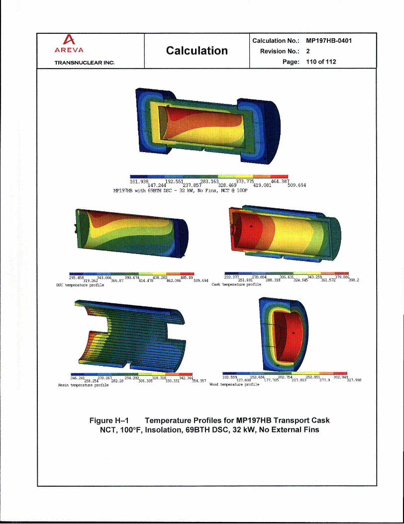
A Calculation No.: MP197HB-0401AREVA Calculation Revision No.: 2
TRANSNUCLEAR INC. Page: 110 of 112
101.938 47.2d192.551231 85283. 163328 469373.77519.08464.387509.694W197HB with 69BMH DC - 32 W, No Fins, HC• 8 10OFl7-1
295. 319.26243,066366.8 7 .414,7 .24 8 62.0868" 509.694 233.351.6912. 04288. 3306.324.9453 361.572171. 86398.2DSC temperature profile Cask temperature profile
I
24.21 27.27 29.22 31.38 34.34102.559 152.65617.2• 02.754 252.851 3094258.25470 267282.28 294.292306.305 318.318330.331?42. 3454.357 127.608'177.70 227.803 "277.9 302.94927.998
Resin tenperature profile Wood temparatbre profile
8
Figure H-1 Temperature Profiles for MP197HB Transport CaskNCT, 100IF, Insolation, 69BTH DSC, 32 kW, No External Fins

A Calculation No.: MP197HB-0401
AREVA Calculation Revision No.: 2
TRANSNUCLEAR INC. Page: 111 of 112
405 4 0534.9764 48994. 8224.454.669. 65914 .516443 674.362Fuel asseably temperature profile
376.193 434 .448 492 .704 550 .96 609 .216405.32 463.576 521.832 580.088 638.344Basket teaperature profile
392.498 424.004 455.509 487.014. 518.5232 408.251 4 439.756 " 471.262 "70l2. 70l-5 2534.272Rail tenperattre profile
Figure H-2 Temperature Profiles for 69BTH DSC ComponentsNCT, 100-F, HLZC #4 [25] in TC wlo External Fins

A Calculation No.: MP197HB-0401
AREVA Calculation RevisionNo.: 2
TRANSNUCLEAR INC. Page: 112 of 112
As seen in Table H-i, the maximum (average when applicable) temperatures of theMP197HB components calculated for NCT are lower than the allowable limits.
The maximum fuel cladding temperature is 6740F and remains well below the allowable fuelcladding temperature limit of 752 0F established in [2].
The maximum seal temperature is 382°F belonging to ram closure plate. This temperature iswell below the long-term limit of 400°F specified for continued seal function.
The maximum wood temperature retrieved from the model (TC_69BTH_32U.out, see FigureH-i) is 3280F. This high temperature is local and spread only in a thin layer of wood asshown in Figure H-1. The average wood temperature at the hottest cross section is 2080F,which is well below the limit of 320°F for crush structural analysis.
The maximum temperature of gamma shield (lead) is 3970F (see Table H-i), which is wellbelow the lead melting point of 621IF.
The highest volumetric average resin temperature in the neutron shield at the hottest crosssection is 322 0 F (TC_69BTH_32U.out), which is slightly over the selected limit of 3200 F. Thehighest average resin temperature is concentrated in a thin segment located at the bottom ofthe neutron shield as shown in Figure H-1. The average resin temperature over the entirelength of the neutron shield resin is 2760F (see Table H-i), which is well below the limit of3200F. It concludes that the overall shielding effect of the resin remains intact.
The highest volumetric average resin temperature in the trunnion plugs at the hottest crosssection is 3550F. The polypropylene resin temperature is well below the temperature limit of4450 F and no degradation of the trunnion plug resin is expected.
All materials can be subjected to a minimum environment temperature of -40°F (-400C)without any adverse effects.
Based on discussions in Section 6.2, the maximum accessible surface temperature belongsto personnel barrier. Table H-1 shows that the maximum temperature of the cask outersurface for TC without external fins under insolation is 3350F. This temperature bounds thecask outer surface temperature without insolation. Using the methodology described inSection 5.6, the maximum temperature of the personnel barrier is calculated based on themaximum cask outer surface temperature of 3350F. The maximum temperature of thepersonnel barrier is 1630 F. This temperature is well below the limit of 1850F defined inSection 4.3.
All design criteria are herein satisfied for MP197HB without external fins loaded with 69BTHDSC with the maximum heat load of 32 kW for NCT.