ML20094Q086.pdf - Nuclear Regulatory Commission
238
, * . 1 I Vilf ulN I A l'I.l;rl tilt' A N il I'O W l: lf CO H 1'A n N I C il %f il N !B , Yllit a l N 1 A U {lU til Apri1 3, 1992 United States Nuclear Regulatory Commission Serial No. 92183 Attention: Document Control Desk NAPS /JHL Washington, D.C. 20555 Docket Nos. 50 338 50 339 License Nos. NPF 4 NPF-7 Gentlemen: VIRGINIA ELECTRIC AND POWER COMPANY NORTH ANNA POWER STATION UNIT NOS.1 AND 2 SUMMARY OF FACILITY CHANGES. TESTS ALID EXPEFilMEtLTS Pursuant to 10 CFR 50.59(b)(2), ericiused is a summary description of facility changes, tests and experiments, including a summary of the safety evaluations, that were conducted at North Anna Power Station during 1991. If you have any questions, please contact us. Very truly yours, W. L. Stewart Senior Vice President - Nuclear Enclosure cc: U.S. Nuclear Regulatory Commission Region || 101 Marietta Street, N.W. Suite 2000 Atlanta, Georgia 30323 Mr. M. S. Lesser NRC Senior Resident inspector North Anna Power Station } |$ft ADojQ gs t 4U R I s 6
-
Upload
khangminh22 -
Category
Documents
-
view
2 -
download
0
Transcript of ML20094Q086.pdf - Nuclear Regulatory Commission
,
* .
1
I
Vilf ulN I A l'I.l;rl tilt' A N il I'O W l: lf CO H 1'A n
N I C il %f il N !B , Yllit a l N 1 A U {lU til
Apri1 3, 1992
United States Nuclear Regulatory Commission Serial No. 92183Attention: Document Control Desk NAPS /JHLWashington, D.C. 20555 Docket Nos. 50 338
50 339License Nos. NPF 4
NPF-7
Gentlemen:
VIRGINIA ELECTRIC AND POWER COMPANYNORTH ANNA POWER STATION UNIT NOS.1 AND 2SUMMARY OF FACILITY CHANGES. TESTS ALID EXPEFilMEtLTS
Pursuant to 10 CFR 50.59(b)(2), ericiused is a summary description of facility changes,tests and experiments, including a summary of the safety evaluations, that wereconducted at North Anna Power Station during 1991.
If you have any questions, please contact us.
Very truly yours,
W. L. StewartSenior Vice President - Nuclear
Enclosure
cc: U.S. Nuclear Regulatory CommissionRegion ||101 Marietta Street, N.W.Suite 2000Atlanta, Georgia 30323
Mr. M. S. LesserNRC Senior Resident inspectorNorth Anna Power Station
}|$ft ADojQ gs t4U
R
I s
6

__ . . ._ . _ . _. - _._ - ._
i. .
.
r , ,
!
.
1991 53.59 S AFETY EVALUATIOt1 REPORTABLE _
TO f4RC~
s
- J C O'S |1
!
i
91.S E.J C O 0 0 t i
002.
003 i.
004- ,
005.
,
!
,
|
<
i
!
,
f
- .
t
a
:- - www_ - __-. . . - - - . . - - ,- -ew,-w.---ww we--- -sr-,vyv r. . ..rwsr .. w pa..w- e -rw -++ -- --w. m e . w-n m-v1aww--*4r.n-. -- r-wweev- v- ev ,--w,-ew-* --tr vw 4'- r w- *
.- .- . . - _ . _ . - _ . _ _ . - . . - - _ _ . . - . . - . - - . . . .
. .
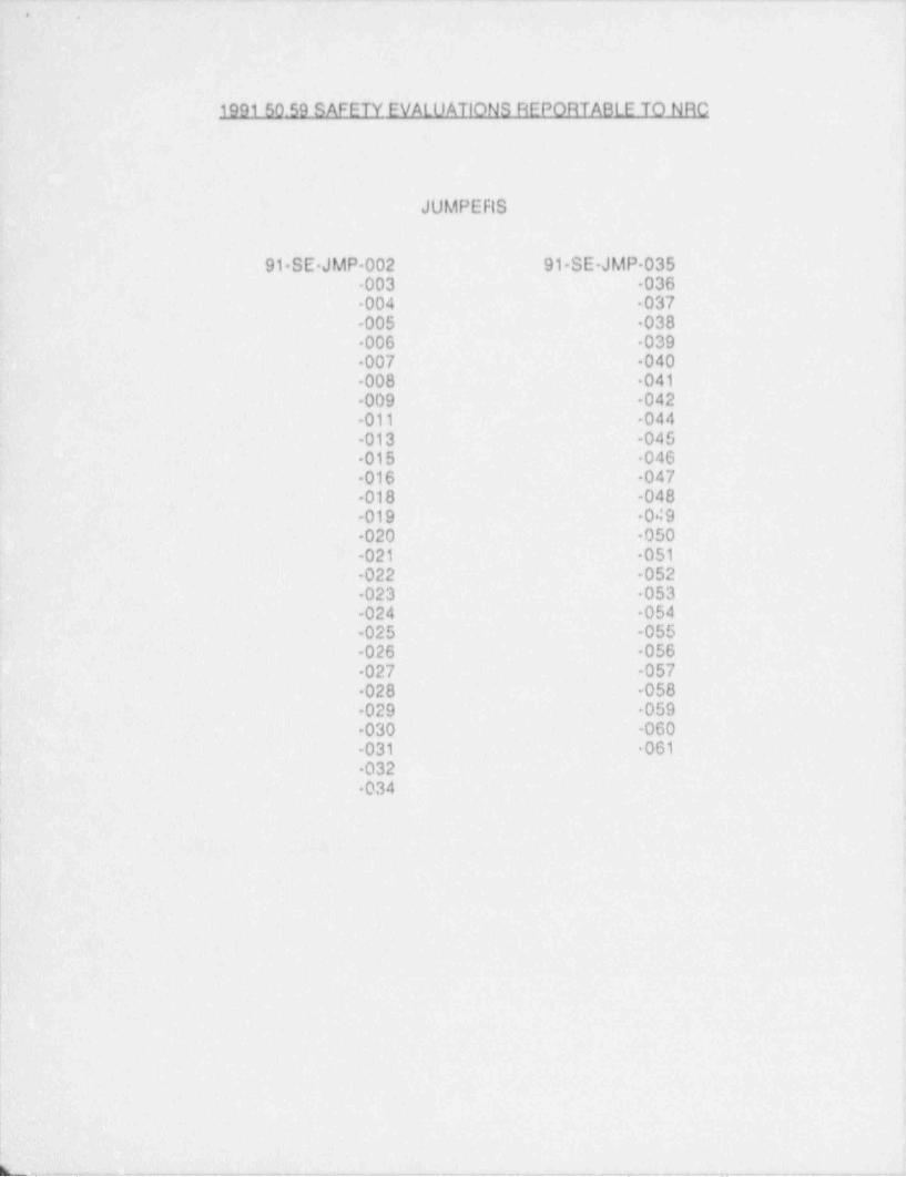
199150.59 SAFETY EVALUATIONS REPORTABLE TO NRC
JUMPEFIS
91 SE JMP 002 91 SE-JMP 035003 036004 037
-005 038006 039007 040008 041009 042011 -044
-013 -045015 046016 047018 -048
-019 049020 -050
-021 051022 052023 053
-024 -054025 -055026 056027 -057028 -058029 059
-030 -060-031 061 -
| 032034
i
{
|'
I*
l
|,
l'
|
-
r
i
C -. - . -- - _ - . _ _ - _ . . _ . . _ .

.
199150.59 SAFETY EVALUATIONS REPORTABLE TO NRC
MODIFICATIONS.
91 SE MOD 001 9t-SE MOD 026 91 SE MOD 050-002 027 -051-003 028 052004 029 053005 -030 054-006 031 055 .-
-007 032 -056008 -033 057
-009 034 -058'
010 035 -059011 036 -060
-012 -037 061-013 038 062-014 039 063-015 040 064-016 041 065017 042 066
'018 043 -067-019 044 068-020 -045 069-021 -046 -070023 -047 071
-024 048 072-025 049 -073
074075076077
-078
N............ ... ,

-
._
i
199150.59 SAFETY EVALUATIONS REPORTABLE TO NRC
OTHERS
91 SE 0T-001- 91-SE OT 025 91-SE-OT-0 40002 027 -049003 028 -050
-004 -029 -051-005 030 -052006 031 -053007 032 054
-010 033 056012 034 -057013 035 -058014 036 0S9 e
-015 037 060-016 038 -062017 040 -063
-018 041 064019 044 066
-020 045 067-021 046 -068022 047 069023 070
-071-072-073 >
-074.
k
. - . - . m. .. . _ . . . . _ _ . _ . .. . , . . , _ _ . , , , , , , . . , _ _ _ . , _ _ . ., . , , , . . , . . , , ,

_ .. _ _ _ _ . - . . _ . . . . . . _ _ . . _ _ _ . _ _ . _ -
, . , .
..l
1991 50.59 SAFETY EVALUATIONS REPORT &D.LETO NRC
PRIOR TO USE (PTU),
91 ' S E. M O D.0 01002 1
'
003004005006 ,
010011012 i
'
013,
b
L
|
|
|
:
:I
I
. - , . ..__.. _ . . ._ . __.-__ - . . _ . _ - - . . _ - _ - - . _ . . . ~ . _ , _ - _ - . . _ . . . _ . - _ _ _ _ . _ , . . . _ _ - . _ . - -
.
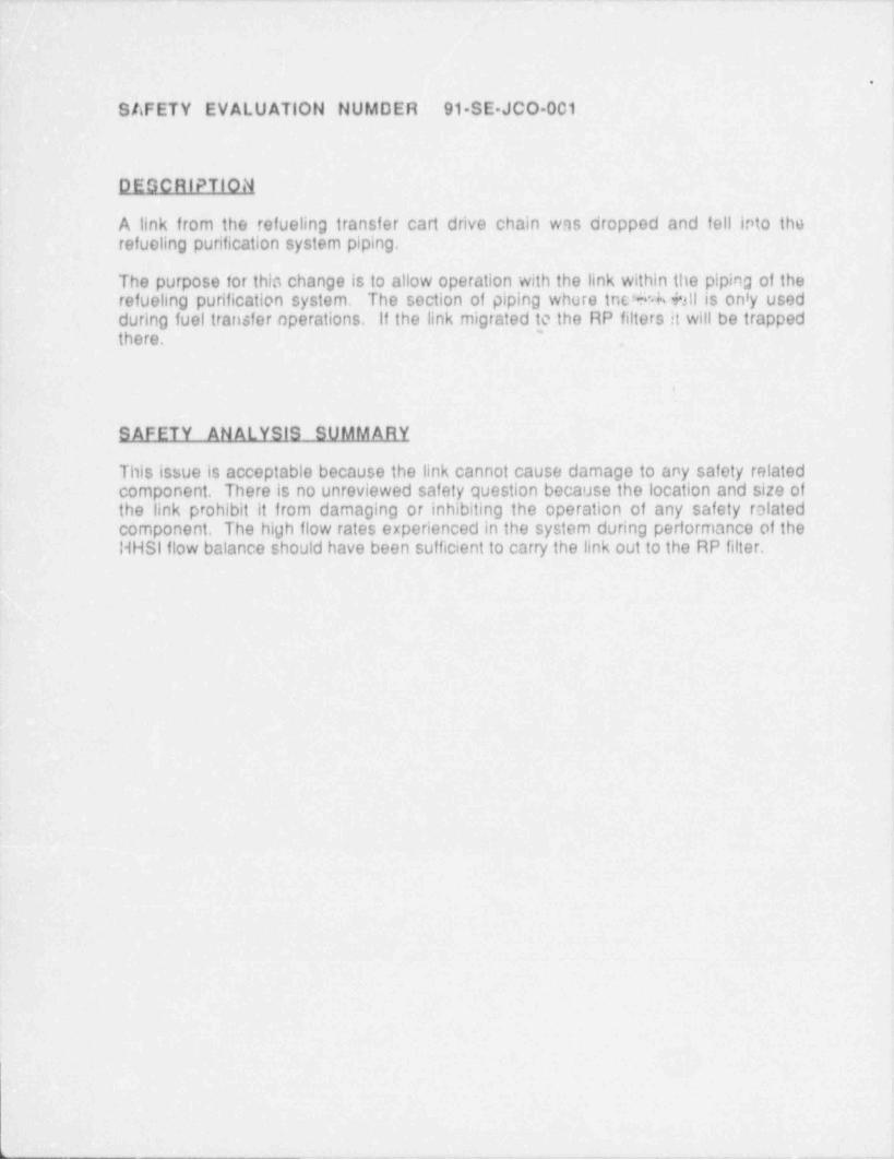
SAFETY EVALUATION NUMDER 91 SE JCO 001
DEGCRIPTION
A link from the refueling transfer cart drive chain was dropped and fell into therefueling purification system piping.
The purpose for this change is to allow operation with the link within the piping of therefueling purification system. The section of piping where inc% Y;ll is only usedduring fuel transfer operations. If the link migrated to the RP filters it will be trapped
'there.
4
SAFETY ANALYSIS SUMMARY
This issue is acceptable because the link cannot cause damage to any safety relatedcomponent. There is no unreviewed safety question because the location and size ofthe link prohibit it from damaging or inhibiting the operation of any safety relatedcomponent. The high flow rates experienced in the system during performance of theHHSI flow balance should have been sufficient to carry the link out to the RP filter,
u- . -

- . -._--_._- -.- - - _ . -_ . - - _ _ - . - .-. . _. .- _ . - _ _ _ .
1
I.
SAFETY EVALUATION NUMBER 91 SE JCO-002
DESCRIPTION'
Several Recirculation Spray Heat Exchanger's isolation MOV's (Units 1 & 2) werefound to have hi0h dynamic torque. JCO 9102 was written tt justify that the valvesoperated during a CDA event.
.
The JCO evaluated the concerns and determined the affected valves can be operatedproperly during a CDA event.
|
SAFETY ANALYSIS _SklMMABX
This safety analysis assumes that during post CDA recovery actions, an operatorrequires isolating or unisolating a Recirculation Spray Heat Exchanger. A guideilne tooperate the Recirculation Spray Heat Exchanger isolation MOV's will be in place.
The Recirculation Spray Heat Exchanger isolation MOV's will operate as raquiredduring the initial phase of a CDA event. The ability to isolate & leaking HeatExchanger or to unisolate a Heat Exchariger which was isolated by mistake still exists.
:
|!
!
I
L!-
.
!
L. - . _ . . . . _ . . ~ .

. . _ - _ _ _. - -. __ -
,
SAFETY EVALUATION NUMBER 91 SE JCO 003
DESCRIPTION
Justification for continued operation 9103 ovaluates the minor leakage of servicewater due to pitting corrosion in the encased in concrete portion of the Service Waterpiping to/from the Unit 2 CR chillers.
The purpose of the JCO ls to specify the required compensatory action for thecontinued operation of Units 1 & 2 with the breach of piping integrity of the encased inconcrete Service Water thss to CR chillers for Unit '. Also, an action plan correctingthe breach of Service Water piping integrity will be established.
SAFETY ANALYSIS SUMMARY
With the leakage described, the service water system components remain capablo ofproviding the required flow to safety related equipment under design basis accidentconditions. The seismic integrity of the piping is preserved. Safoty related structuresin the area have been evaluated under the conditions outlined and are unaffected.
Operability of safety related components (as defined 5y the ability to perform theintended safety function) remains unaffectod. The monitoring of minor SW Icakagedoes not create the possibility for a different type of accident nor is the minor leakageof sufficient magnitude to have any impact on the functional capability of safety relatedcomponents.
The redundancy in the SW system has not been compromised and therefore, theability of either header to perform the required safety function under design basisconditions (assuming complete loss of one header has been maintained). Thecapacity of the ultimate heat sink to maintain a 30 day supply of water following theDBA with no allowance for make up water is preserved. The ability of the control roomcompressed air system to perform its safety function has not been degraded. Theability to monitor radioactive contamination of the SW system is maintained,
- - _- - . - - _ . - _ - . .

_ _ - __ ___ .. ___ - _ . ~ . __ _ . _ .
SAFETY EVALUATIOll NUMBER 91 SE JCO 004
DESCRIPTION
Missing plastic ear protector of a cound powered phone headset and a high rad doorkey was lost in the containment.
The JCO was prepared to justify safe operation of safety related equipment in thecontainment due to debris left in the containment.
,
J
SAFETY ANALYSIS SUMMARY
A plastic ear protector of a sound _ powered phone headset and a high rad door keywas lost in the contr.inment. Should these pieces be washed down to the containment '
sump, they would have no offect on the operability of the safety injection system or therecirculation spray system because of the pump screen design. The screen system, asdetailed on UFSAR Figure 6.2 79, is dos:gned to prevent passage of panicles larger in .
size than the smallest restriction in the Recirculation Spray system (i.e., spiay nozzies).Per UFSAR section 6.2.2.2, particles of this size would have no effect ore Low HeadSafety injection or Recirculation Spray pump operation. The amount of hydrogen thatmay be generated by the decomposition of the ear piece or the key is no'significant.
.
|
-. - - . . ---. - . _ - . . .-

-. . _ _ . . _. __-
.
S AFETY EVALUATION NUMBER 91 SE JCO 005 ,
D.E SC RIPTIO N s
Justification for continued operation 91-03, Rev.1 evaluates the minor leakage due topitting corrosion in the concreto encased 4" and possibly 24" SW and Aux. ServiceWater piping. The minor ieakages observed in Instrument Rack Room Unit 2, ServiceBui! ding, Unit 1 Turbine Building Condensate Pump Pit, and Auxiliary Building Piping -
Tunnel, South of Manways.
The purpose of this JCO is to specify the required compensatory action for the ,
continued operation of Units 1 & 2 with the breach of piping integrity of the concreteoncased 4" SW lines to CR chillers Unit 2 and possibly 24" diameter concreto encased4
portion of SW and Aux. Service Water lines. Also, an action plan correcting the breachof SW piping integrity will be established. .(
SAFETY ANALYSIS SUMMally
With the leekage der.cribed, the service water system components remain capable ofproviding the required flow to safety relatcd equipment under design basis accidentconditions. The seismic integrity of the piping is preserved. Safety related structuresin the area have been evaluated under the conditions outlined and are unaffected.
Operabli;ty of safety related components (as defined by the ability to perform theintended safety function) remains unaffected. The monitoring of minor SW leakagedoes not create the possibility for a different type of accident nor is the minor leakage
-
of sufficient magnitude to have any impact on the functional capability of safety relatedcomponents.
-
The redundancy in the SW system has not been compromised and therefore, theability of either header to perform the required safety function under design basisconditions (assuming-complete loss of one header has been maintained). Thecapacity of the ultimate heat sink to maintain a 30 day supply of water following theDesign Basis Accident with no allowance for make-up water is preserved. The ability
~
of the control room compressed air system to perform its safety function has not beendegraded. The ability to monitor radioactive contamination of the SW system isimaintained.
... .. . _ _ _ _ _ _ - _

SAFETY EVALUATION NUMBER 91-S E-J M P-002
DESCRIPTION,
install temporary Gaitronics in the Auxiliary Building Penetration Area.
To provide communications via Gaitronics to and from the Auxiliary BuildingPenetration Area. This will eliminate the current practice of having to exit a
- contaminated area to use the Gaitronics.
SAFETY ANALYSIS SUMMA 6I|
A temporary Gaitronics will be installed in the auxiliary bui!dinq ?cnetratiori area toprovide communications via Gaitronics to the area. The purpt a ' 'o eliminate the.
: need to exit a contaminated area to use the Gaitronics.!
The temporary Gaitronics will apply a negligible load to tha Vital Bus.
Fuses will prevent fe600ack of an electrical fault into the permanent Gaitronics or the! Vital Bus.
The temporary Gaitronics will be mounted adequately so that it is not a seismicconcern.'
|
l
I
1

- . .. .- -- . . . _ . .
SAFETY EVALUATION NUMBER 91-SE JMP-003
DESCRIPTION
Temporarily install r.t hose from the primary drcin translei pump discharge to a) hotlegs v!a HHSI, b) normal charging, or c) the Reactor Purification System via Cavitysuction.
To conserve reactor coolant system (RCS) inventory by recovering leakage past the1. cop Stop VMves and returning it to the RCS or t: , Refueling Cavity.
S AFETY AN ALYSIS SUMM A._RY
The jumper is adequately rated for service conditions.
Check Valve will prevent backilow into the primary drain transfer tank (PDTT) or theprimary drain system to the Stripper.
The jumper !ocation and arrangement are such that the RHR System and RHR Pumpoperation are not adversely affected.

. . _ _. _ _ _ _ _ - _ . . _ _ _ . . . _ _ . . . _ _ _ . . - - _ _ _ _ _ _
i
!
SAFETY 2 EVALUATION NUMBER. 91 SE JMP-004
DESCRIPTION
Jumper to defeat the unit 2 annunciator because of the bad shed switch being in the i
defeat position -(Annunciator H panel, window E8) i
Annunciator to be cleared in accordance with the '' black board" concept. Redundantindication is already provided by the corresponding annunciator on the un!t 1 panel.
SAFETY ! ANALYSIS SUMM AFlY
t dll only defeat a single input to a single redundant annunciator. The.< uaporath e plant systems and components is otherwise unaffected. Should an>~:16 . - coincident with a loss of offsite power, the ability of the Emergency
. )rs to respond to the event is unaffected. The protection afforded'byd. w ~" .
r scheme is not required while unit'1 is shutdown, but if it were to bes ..ce, even with the jumper in place, the system would function just as- <
c .ne inputs to the annunciator from an actual overload condition on aresmva station service bus are not defeated, and the annunciator will still be capableof alarming should r.uch a condition occur, Since the change involves only aredundant annunciator, there is no potential for causing a different type of accident or '
malfunction, nor is there any increase in the potential of a previously analyzedaccident or malfunction to occur,
!
-|
|
-
I
|
|
1
|
)!
. _ . , _. . . _ . . _ . _ _ _ _. -_i

SAFETY EVALUATION NUMBER 91.SE-JMP 005
DESCRIPTION
Attach a portable generator to provide power to the vacuum primary system levelcontrol val a, 2 LCV VP-201.
Bus 1 A1-3 is the normal power supply fM valve 2-LCV VP 201. However, bus 1 A1-3is temporarily de energized for maintenance.
SAEETY ANALYSIS SUMM ARY
The proposed jumper provides a temporary power source to supply the vacuumprimaiy system level control valve 2 LCV-VP-201. The normal power supply for thisvalve is 1 A1<3, however this bus was removed from service for maintenance. Theproposed jumper is simple and does not affect any other station power supp;ics. Nosafety systems are affected by operation of 2-LCV-VP-201. Therefore, no unreviewedsafety question can exist and the jumper should be allowed.
|
|

SAFETY EVALUATION NUMBER 91 SE JMP-006
DESCRIPTION
Electrical jumper to bypass the bearing oil and bearing lift pressure switches in thestart circuit of the turning gear motor.
The turbine shaft needs to be jogged over one or two revolutions to allow NDEinspections of various components.
SAFETY ANALYSIS SUMMARY
Operation of the turning gear motor to jog over the turbine for inspections has nobearing on the capability of safety systems to respond to any accident. While the unitis shutdown, the turbine cannot contribute to causing such an accident since it has nomechanism for removing energy from the RD. The inspections are necessary toensure that the turbine is structurally sound and that no excessive potential exists forthe generation of turbine missiles.
i:
i-|
I
1-
. ._ . _ _ -
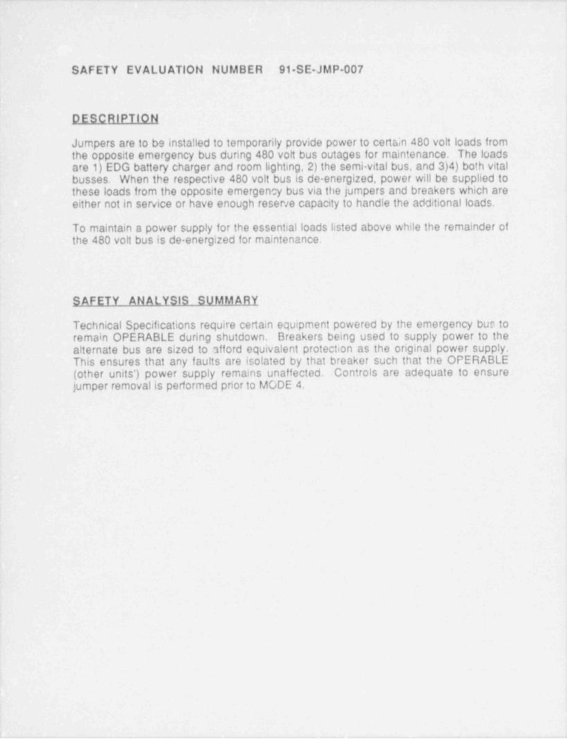
SAFETY EVALUATION NUMBER 91-SE-JMP-007
DESCRIPTION
Jumpers are to be installed to temporarily provide power to certain 480 volt loads fromthe opposite emergency bus during 480 volt bus outages for maintenance. The loadsare 1) EDG battery charger and room lighting,2) the semi-vital bus, and 3)4) both vitalbusses. When the respective 480 volt bus is de energized, power will be supplied tothese loads from the opposite emergency bus via the jumpers and breakers which areeither not in service or have enough reser/e capacity to handle the additional loads.
To maintain a power supply for the essential loads listed above while the remainder ofthe 480 volt bus is de-energized for maintenance.
SAFETY ANALYSIS SUMMARY
Technical Specifications require certain equipment powered by the emergency bus toremain OPERABLE during shutdown. Breakers being used to supply power to thealternate bus are sized to afford equivalent protection as the original power supply.This ensures that any faults are isolated by that breaker such that the OPERABLE(other units') power supply remains unaffected. Controls are adequate to ensurejumper removalis performed prior to MODE 4.

SAFETY EVAll1 ATIC'l NUMBER 91-S E-J M P-008
DESCRIPTION
Installation of temporary (non seismic) pump and associated piping and valves forremoving service water (SW) from a SW header which is out of service.
To facilitate SW header outages.
SAJETY ANALYS:S SUMM ARY,
Use of a temporary pump arrangement with flexible connections to facilitate SWheader outages is acceptable.
The arrangement will be leak-tested after installation to ensure integrity. Flexibleconnections will be used to ensure no adverse effect on the SW system as result of aseismic event. Installation of pipe caps will be verified after removal to ensure SWsystem integrity.
- _ ____ _ _ _ _ _ _ _ _ _ _ . _ _ _ _ _ _ __
i
SAFETY EVALUATION NUMBER 91-SE JMP-009,
DESCRIPTION
Temporarily Install shorting screws in the Ma!n Generator Current transfer blocks.
To prevent protective relay actuation during Main Generator testing.
SAFETY ANALYSIS SUMMARY
The reactor will be shutdown during the Main Generator Testing.
The Main Generator will not be connected to the Grid, nor willit be powered by theMain Turbine during this testing. Without steam flow, there is no reactivity feedback.
High Potontial Testing is performed on the Main Generator to verify the integrity of theinsulation.
Ir.stallation of shorting screws in Main Generator current transformer blocks places thecurrent transformers at the same potential to prevent protective relay actuation duringMain Generator high potential testing.
This action enables the terting to proceed without interuption by the protectivecircuitry.
The bypassing of Main Generator protective circuitry during testing while the reactor is-
shut down and not providing thermal power for steam generation cannot possiblycause, contribute to, or increase the consequences of a Design Basis Accident or anynew accident.
The Main Generator is non-safety related. No other equipment's protective circuitrywill be altered. Technical Specifications do not reference this circuitry, equipment, ortesting.
_ _ _ - - - _ _ _ _ _ _ _ - _ _ _ _ _ _ _ _ - _ - - _ _ _ - - _ _ _ _ _ _ _ _ _ _ _ _ - _ _ _ _ _ _

- . . ..- - . . . - . - - .-.-
-
.
'
SAFETY EVALUATION NUMBER 91 SE-JMP-011
D ESCRIPTION -
Installation of a temporary sump pump in the Unit 1 rack room.,
Normal sump pumps,1 DA P 9A and 9B, are inoperable.
SAFETY ANALYSIS - SUMM ARY
The temporary sump purnp installed in the Unit 1. rack room sump will provide the- same function as the normal sump pumps, The temporary sump will make it easier onoperations by not requiring manual pumping of sumps on a regular basis.
No unreviewed safety question exists because the temporary sump pump does notinterface with any safety systems, high energy systems, or safety electrical systems.
,
*
- _ _ _ . . s , , ., . . - , ,- _ , . _ - . . , . ,, , . . . . . ,-
SAFETY EVALUATIOli NUMBER 91-S E-J M P-013
DESCRIPTION
Mechanically block the containment sump pump discharge line trip valve,1-DA-TV-100B, in the open position.
The inside containment isolation valve for the containment sump pump discharge lineis broken. Parts will not be available for a few days.
S AFETY ANALYSIS SUMM ARY
The jumper is to install a mechanical block to keep 1-DA TV-1008 open while partsare ordered for valve repair. The jumper is routine in nature and provides a criticalfunction for operations during the outage.
No unreviewed safety question exists because containment isolation is not requiredbelow Mode 4. In addition,1-DA-TV-100A will still provide isolation of the penetrationas needed.
-
- - - - - - - - - - - - _ _ _ _ ___ _ __.

., . . . . _ . . . . - - . - - - .-
[
,.
SAFETY EVALUATION NUMBER 91-SE-JMP-015
i
p_ESCRIPTION I
. .
Remove -suction strainer- for lube oil pump,1-LO-P 1, and install jumper toWestinghouse Temporary Lube Oil Conditioning Unit.
To facilitate flushing of Lube Oil System through the Westinghouse Temporary Lube. Oil Conditioning Unit,
SAEETY ANALYSIS SUMMARY
The Main Lube Oil System is non safety related.
This is a simple mechanical jumper to allow flushing and cleaning of the Lube Oil- System with a Westinghouse Temporary Lube Oil Purification Unit.
j
The-jumper is rated for this application and is verified leak-tight before and afterremoval / installation.
;
Oil spill cont!ngencies and precautions will be observed.
pg

SAFETY EVALUATION NUMBER 91-SE-JMP-016
DESCRIPTION
Temporarily jumper around the instrument air solenoid operated valve (SOV) whichmaintains safety injection trip valve,1-SI-TV-100, open. This is to ensure that 1 SI TV-100 stays open at all times to ensure that N2 is supplied to containment.
The SOV on 1-SI-TV-100 has failed.
SAFETY ANALYSIS SUMMARY
The affected penetration will be declared INOPERABLE in accordance with Tech Spec3.6.1.1. If containment integrity is required to ensure that an ACTION STATEMENT iscomp;sted, the jumper will be removed. The jumper will be removed prior to Mode 4.Therefore, there is no unreviewed safety question since containment integrity is notrequired for the period while the jumper is installed. The jumper willincrease theoverall safety of the plant by ensuring that N is available to containment.2
;
1
!.
-. . _ _ _ - _ - _ _ . - _ - - - -

, , . . - . . - . . - - . - - . . . . . . - . . . - - , - . . - _ _ .-.. -
L
-.'} - 4'
SAFETY -EVALUATION NUMBER 91-SE JMP-018
- r-
RESCRIPTION
Temporarily jumper out the pump motor permissives on the high pressure heater drainpumps,1-SD-P-1 A, B, & C,
'
:
Temporarily jumper out the pump motor permissives to run motor uncoupled for postmaintenance testing.
-
SAFETY ANALYSIS SUMMARY
All permissives jumpered out will be returned to operable status prior to returning theequipment to varvice._ Running the motor uncoupled from the pump will not affectsystem performance and will not adversely affect electrical bus parameters Requiredsurveillances will be performed prior to declaring equipment operable.
Because the system (bott; electrical and mechar,ical) will not be adversely affected, no -
_
unreviewed safety question exists.
4
I
f
5
6^
,
J
;. |
!.
|i-
'- --- - . . _ _ _ . _ ____ _ __ _ _ _ ___|
SAFETY EVALUATION NUMBER- 91-S E-J M P-019
DESCRIPTION
Temporarily install 1" OD stainless steel tubing from moisture separator / reheater 1/2"Hydro Vent Valve to the steam dump system vent valve 3/4"-1-SD-827.
To determine whether or not the level column is being adequately vented, thus beingthe cause of the high levelindication alarm.
SAFETY ANALYSIS SUMMARY
The jumper will be installed between the 1/2" Hydro Vent Valve and level column ventvalve 1-SD-827. The purpose is to see if the level column is being adequately vented,which could cause the high level indication / alarm. The jumper will not alter thefunction of the MSR, nor willits failure cause the MSR to malfunction. Should failureoccur, jumper can be isolated with existing valves. Jumper does not require changesto Tech Specs or UFSAR.
.

_ _ _ - _ _ _ - _ _ - _ _ _ _ _ _
V
SAFETY EVALUATION NUMBER 91-S E-J M P-020 |
l-' pESCRIPTION
Jumper Out Pump / Motor Permissives for pump 1-SD-P-28.
The purpose for this change is to run the motor uncoupled for post maintenance;
testing,
,
--
SAFETY AN ALYSIS SUMMARY
Al; permissives jumpered out will be returned to oper N9 status prior to returning theequipment to service. Running the motor uncoupled from the pump will not affectsystem performance and will not adversely affect electrical bus parameters. Requiredsurveillances will be performed prior to declaring equipment operable.
Because the systera (both electrical and mechanica!) will not be adversely affected, noJnreViewed safety question exists.
'I
%
6
r-
_ .

.
SAFETY EVALUATION NUMBER 91-S E-J M P-021
QESCRIPTION
Disabling the low tank level switch for the 1H diesel day tank. The level switch ismalfunctioning and causing a continuous alarm when tank levelis adequate.
The switch is not operating properly. A Work Order has been submitted to correct theswitch problem, but at present, no replacement parts are available. Themalfunctionit'g switch is causing a continuous alarm when the actual tank level isadequate.
SAFETY ANAIJSIS SUMM ARY
The automatic makeup control system to the tank is unaffected.
TS requires monthly surveillance of level, not continuous, operators verify level onceevery 12 hours on logs.
By clearing this annunciator, operators will not be distracted frorn other potentialproblems associated with this EDG. 1
The EDG's ability to perforrn its intended talety function is unaffected..
p

.
SAFETY EVALUATION NUMBER 91 -S E-J M P-022
DESCRIPTION
Installation of a temporary video camera in containment to monitor 'A' RCP lower lubeoil reservoir.
The lower lube oil reservoir for 'A' RCP is low due to a minor oil leak.
SAFETY ANALYSIS SUMM ARY
Use of the camera will not result in any performance characteristics being changed.The camera is small (<5 lbs) and can easily be restrained. In the event of a CDAduring use of this camera, the design of the sump screens is such that LHSI/RSperformance will not be adversely affected. Material consideration have beenadequately evaluated for use of the camera in containment.
.
- - - - - - - - - - - - _ _ _ _ _ _ _ _ _ . _ _ _ _ _________ _ _ _ _ _ ___ __

. , _ __ _ . __ -. _ .. __._. __ . _ _ _ _ . _ _ _,
SAFETY EVALUATION NUMBER 91-SE JMP-023
DESCRIPTION
Defeat alternator circuit on fuel building sump pumps.'
~The purpose for this change is to allow maintenance on pump 1-DA-P-2A whlie pump1-DA P 2B is allowed to function normally in " auto."
SAFETY ANALYSIS SUMMARY
Section 9.3.3.5 of the UFSAR states that the fuel building' sump pumps are full sizedpumps, and therefore, are designed to handle 100% of expected sump inleakage.
The alternator circuit merely provides equal wear on both pumps. - Bypassing the~
- alternator circuit while_ maintenance is being performed on one pump allows the otherpump to perform its design function in " auto",- thereby reducing control room nuisancealarms and eliminating unnecessary operator action to manually operate the pumps.
Chapter 15 accidents or malfunctions are unaffected by bypassing the alternatorcircuit.
:-
<
t
4
-- , , w ,, ,w-.
- . - -. .. -
SAFETY EVALUATION NUMBER 91 SE-JMP 024
DESCRIPTION
Domostic Water will be used as a water source for a temporary shower to be used byasbestos workers. The temporary shower is located in a trailer cutside the Unit 2Turbine Buildilig (west side).
To provide a shower for asbestos workers.
.
SAFETY ANALYSIS SUMMARY
No Unreviewed Safety Question exists since Domestic Water is not Safety Rotated.The Domestic Water jumper runs through a hose to a trailer for the purposes ofproviding a shower for asbestos workers. This is a normalload for the Domestic Watersystem. The shower drain is passed through filters in the trailer specially designed tocapture asbestos wastes. By installing this jumper, the health and safety of theasbestos workers is ensured.
,
a

. _ _ . . _ _ ._. , _ _ .._
,t
._SAFETYj EVALU ATION ENUMBER 91 SE.JMP-0254
4
1
DESCRIPTION
Removal of Alarm Card in "0" Amplifier- for Main Turbine Generator _#J Bearingm
LVibiation Sensor.
I.To defeat the| input from the #8 Bearing to the Main Control Board Annunciator ForMain Turbine vibration. ,
.
SAFETY ANALYSIS SUMMARY
No unreviewed safety question exists since:'
1. The Main Turbine Vibrati_on Monitoring _ System _is not Safety Related.2. The #8 Bearing vibration sensor is one of many in the system. Defeating its input .
will not alter performance characteristics of the turbine generator or any of the otherbearing vibration sensors.
3. The #8 Bearing vibration sensor is not functioning._
.
<-
~4. Main Turbine vibrations are monitored regularly by predictive analysis locally at the= bearings.
~
5. :|| an actualvibration condition arose, other bearing vibration sensors would sensethe common snaft's vibration.
6. Bearing temperature monitoring is functional on the #8 bearing.
_The change should be allowed because:,
-1, Failure to-defeat the #8 Bearing input to the Main-Control Board Annuriciatorassociated with Main Turbine Vibration will only result in sporadic, invalid alarms.
,2. While the Main Turbine Vibration Monitoring System is not safety-related, an. invalid _ alarm is distracting to the operators and should be defeated to allow thevalid sensors to annunciate,
3. The alarm caused by the #8 Bearing prevents other turbine bearings * vibrationsfrom alarming on the main control board.
4. Operator awareness and sensitivity to valid alarms is enhanced by the defeat of the-~
#8 Bearing Vibration input to the Main Control Board Annunciator..
e
W
't
=- Q-, y- e ,, s -,, .- ,.#-l emr- .wmv 'rm - + - w v -ve + +- -- e --v n'e c t- v w re< --

_ _ _ _ _ _ - _ _ _ _ _ . _
|
SAFETY EVALUATION NUMBER 91-SE-JMP 026
DESCRIPTION
Install temporary support to maintain the main turbine turnine gear latched.
The turbine sometimes jumps off of the turning gear due to tolerance problems in thegear teeth. This jumper will allow the turbine to maintain on the gear as required toensure even cooldown and to prevent bowing of the turbine shaft.
SAFETY ANALYSIS SUMMARY
This jumper is a simple mechanical device used to maintain the turbine turning gearlever engaged. Maintaining the turbine on the turning gear while the turbine is warmwill ensure even cooldown and prevent turbine shaft bowing. The turbine is off lineand isolated from the steam supply system whenever the turning gear system wouldbe placed in service. Therefore, the possibility of an accident occurring due to thejumper does not exist. The turning gear is not safety related (although the turning gearoil pump is powered from the 'H' emergency bus) and is not required to function tomitigate the consequences of any accidents or malfunctions of equipment important tosafety. The loading on the emergency bus is not affected by the proposed jumper.
|
_ _ _ _ _ _ . _ _ . _ _ _ _ _ _ _ . _ _ _ _ _ _ _ _ _ _ _ _ _ _ _ _ _ _ _ _ _ _ _.
__ _ _

- - .. - . . . . .- . -_-
)i
SAFETY EVALUATION 1 NUMBER 91-SE-JMP-027-
DESCRIPTION
Remove cover from the stator cooler for_ reactor coolant pump (RCP) 1-RC-P-1B toincrease the RCP stator cooling flow.
To provide adequate air flow through the 1-RC-P-1B stator. Temperatures arecurrently elevated.
SAFETY ANALYSIS SUMMARY -
This jumper increases the stator-cooling flow for 1-RC-P-1B, thus ensuring thecontinued safe operation of the pump. The only safety function that the RCP motor-
. provides is inertia for.RCP coastdown. This jumper does not affect the mass or inertia-of the RCP. The jumper does not alter the component cooling system in any way. T_hejumper will reduce the cooling to the RCP motor cubicle room. However, fan 1-HV-F-928 mixes the air in the cubicle with the air in the containment dome area. Becausethe air la thoroughly' mixed with the containment atmosphere, the weighted averagecontainment temperature will be affected. However, this parameter is closelymonitored by the-Control Room Operator, and actions may be taken to adjust this-
- temperature. Furthermore, the Containment Air Recirculation Fans provide the bulk of.-the cooling to the containment environs, so the actual change to the containmentambient will be small and can be controlled by the Control Room Operator. As suchthis jumper does not constitute an unreviewed cafety question.
,
)
$
--
,
I:
>
i
, - - - w. , , ,w , e- - , ,w - -,r-+

_ .- . ..~ .- __ . . _. _. _ . . _ . . _ . . _ . _ . . . _ _ _ . - _ . . . .
LSAFETY EVALUATION NUMBER- 91-SE-JMP-028
.
D ESCRIPTION - - t
~ Energize control power for instrument air compressor 1 IA C-1 for a technicalrepresentatwe while compressor it; tagged out. See jumper form for details.
Allow for post maintenance testinc/ troubleshooting.
- SAFETY ANALYSIS SUMMARY-
The jumper will only energize the. control circuit for 1-!A-C-1. Power for thecompressor is tagged out and the jumper will verify no voltage present in backfeed tothe compressor.
- _
j
| '
e 4 - , ,n , -,, , , e, ,, a .- ,- -- c--

,, ..-. . . . - _ - . . - . - . . _ . - - - - . . . _ _ - . .
SAFETY EVALUATION F4 UMBER 91-S E-J MP-029
DESCRIPTIONL
Jumper IA to liquid waste 1-LW-PCV-109 and 1-LW-TCV-111 to close valves.
Controllers for valves are not operable and the valves fail open. The valves aredesired to be shut to prevent draining unnecessary amounts of component coolingfrom the system to work on component cooling valve 1-CC-RV-119.
c
SAFETY ANALYSIS SUMMARY
The valves will be the second isolation for the tagout boundary and high flow stopvalves will be installed in the lA line to prevent loss of the lA system if the jumpers fall,
.
These valves provide component cooling flow to 1-L_W E-P, and 3 (waste evaporatoroverhead condensers), which will be tagged out (component cooling side) during this!! _
evolution. Therefore, the valves are not needed to be in service.e
The UFSAR states that the _ waste evaporator is not used.
.
.
1
1
:t
:'
,
E
---
, .,--.,.e.. .,.._..w - ,e

., ~.. ..- .. -. . .. - ... .. --. . . _ - .- . ... .-. -- -- .
!
SAFETY EVALUATION - NUMBER 91-SE-J MP-030 :i
. i
D ESCRIPTION .
- Tie wrap has been utilized on the turning gear for the main turbine to hold the handle-to the engage position.
The turning gear is not staying engaged, and this mechanism is required to ensure.
- that the turbine continues to rollin order t.; r,revent wrapping the rotor.
SAFETY ANALYSIS SUMMARY
Operation of the turbine on the turning gear does not create the potential for anyaccident or major malfunction of any safety related equipment. It is desirable to keep ,
the turbine on the turning gear to ensure that the rotor does not exporience_ bowing.Thir will further ensure that the turbine rolls true when the unit is returned to power,and minimizes the chance of creating a turbine missile. The turning gear is not safetyrelated,-is not a Tech Spec consideration, and is not used to respond to any accidentor malfun_ction of safety reisted equipment. The turning gear motor rotates the turbine
- at such a slow' speed as to be inconsequential. '
1
..
.
J w , .- -.-. -c - ge - r -
.

, . _ . - _ _ _ _ . - _ _ _ _ . _ - _.
.,
. SAFETY EVALUATION NUMBER 91-S E-J M P-031
DESCRIPTION
Use an air jumper to bypass the sol'enoid operated valves (SOVs) that control thesupply dampers for the 288 and 280 turbine building _ supply fans.
The supply dampers for the 28B and 28C turbine building supply fans are full closedand.the controlling SOVs are missing.or inoperable. -Temperatures in the turbineouilding are extremely high .and subsequently, the bearing temperatures of thesecondary pumps and motors are approaching unacceptable levels.
SAFETY- ANALYSIS SUMMARY
The major issue considered _ was the effect of high temperatures on secondary plantequipment.- This jumper should be allowed because it will help alleviate those high
- temperatures by supplying more outside air to the turbine building fcar cooling.
No unreviewed safety question exists because the turbine building supply fans are notsafety related and operability of these fans is not required for any designed accidents.:
The jumper will help ensure that the Feedwater Pump motor and pump bearings arewithin acceptable operating temperatures. This will help reduce the possibility of aloss of normal feedwater accident.
d
3
-y,, , _... y _; , .. -. m - - ..,, - ,

. _ .. _ _ _ _ _ _ _ _ _ _ . _ _ . _ _ _ . _ _ - _ _ _ _ . . _ , _.
I
I
SAFETY EVALUATION NUMBER 91-S E-J M P.-032:
i
l
DESCRIPTION. -l-
. The lifting of two leads at the penetration area to defeat alarm 1 A A3 " CONT RECIRCFAN 1 A, B. C AOD CLOSED"
.
The lifting of the leads will defeat a control room nuisance alarm due to the sw!1ch ]being inaccessible at this time.
'
SAFETY - ANALYSIS- SUMM ARY*
:The major issues considered were whether the defeating of the alarm would cause the''
control room. personnel to lose all indication of the air operated damper (AOD)*
position. -With the indicating lamp on the ventilation panel illuminated,-it can be shownthat the damper is in fact open.-
i The reason that the change sh'ould be allowed is that with the alternate indicationP available it is obvious that the AODs are open and that the fans will not be harmed by
[ the defeating of the alarm..
p An unreviewed safety _ question does not exist because:.
. The containment recirculation fans will not be degraded due to the fact that the| :
- AODs are open and the alarm is the result of a spurious signal from a'
. malfunctioning switch.
The defeating of the alarm from one of the 3 containment recirculation fans will-+
in no way alter the ability of the fan or the AOD to perform its intended function.
i The purpose of the jumper is only to eliminate a nuisance alarm and in no way-
i performs any control function of either the fan or the AOD.
4
.
1
ii
$4
i
i!
L
i-
|
;_ . . __ _ _- . _, - . . _ _ __ _ _ _ . . . _ . _

_
SAFETY EVALUATION NUMBER 91-SE-JMP 034
DESCRIPTION
Jumper out the start permissives for feedwater pump 2-FW-P-1C1 for an uncoupledrun to allow post maintenance testing.
Maintenance has been performed on the C main feed pump and it is necessary to testrun the pump uncoupled.
S AFETY ANALYSIS SUMM ARY
The major issues considered are:
1. Maintenance has been performed on the C main feed pump and it is necessary totest run the pump uncoupled.
2. The jumper involves jumpering two sets of electrical contacts and lifting one lead.
The reasons the change should be allowed are:
1. The pamp motor that is to be run uncoupled is isolated from the remainder of thesystem and the operable equipment is not affected. The autostart of the standbypump will be disabled Cring the period of the run, but this is allowable.
2. The safety related control and protection features of feedwater are unaffected sincethe uncoupled pump is isolated from the system.
3. No system containing radioactive rr- 'ial is involved or affected.jed out) and this test run does not affect the4. The pump is currently unavailable .
emergency plan in any way.5. Any mechanical failure of the mo curing the run would be less severe than a
failure during normal operation since the pump is isolated from the system and themotor is uncoupled from the pump.
6. The jumper does not involve any instrument channels and only applies to a non-safety related power supply.
7. The jumper does not affect any electrical loads.8. L) code requirements are affected.
An unreviewed safety question does not exist because:
The feedwater pump motor is to be test run while the pump is isolated from the-
remainder of the system. The motor is to be tested uncoupled and there will beno unusual loads or conditions on the pump.The reactor protective circuitry is not affected in any way.-
No part of the jumper is related to any safety related system.-
.

_
|
No Tech Spocs are involved since the main foodwater system is the only system.
affected.
F
.
iI
~~~ ---

- .. - _ _ - _ _ _ _ - _ _ _ _ _ - _ _ . _ _ - _ _
SAFETY EVALUATIOt1 IJUMBER 91 SE JMP 035
DESCRIPTION
The jumper will defeat the SB hydro unit hydraulic valve from auto closing in the eventof hydro unit 5A tripping off line with skimmer gate #2 inoperable due to traintenanceTo ensure that minimu:: flow requirements (40 cis) over th? dam to river are met. Aminimum flow will ensure no environmentalimpact to river.
SAFETY ANALYillS SUMM ARY
The jumper will ensure that the minimum reo,uired discharge flow from the main dam ismaintained The seismic integrl;y of the main dam will not be affected. Control of lake!evel will not be affected.
Analysis for all design basis accidents will not be affected.
- _ _ _ _ _ _ _ _ _ - - _ - - _ _ - _ _ _ - _ _ _ _ _ _ _ _ _ _ _ _ _ _ _ _ _ _ - _ _ _ _ _ _ _ - _ _ _ _ __
.. - _. _- - - . _.
SAFETY EVALUATION NUMBER 91 SE-JMP 036
D ESCRIPT1Q11
Open Breaker 8s in the G 12 cabinet to defeat the low cooling flow pump trip circuitry.
i
SAFETY ANALYSIS SUMM AB.y, '
The operation of the G-12 breaker is unchanged. An actual cooling flow problem willstill be annunciated. Only the pump trip circuitry is defeated to prevent spurious lowflow actuations from tripping the running pump. G 12 will still perform its intendedsafety functions,
l
.
!1
i
!
. - . . . - . . . .- - .

,
. - _ _ - _ - _ ._ . . - -. . . - _ _ .
'
|
SAFETY EVALUATION NUMBER 91 SE JMP 037 |l
!
i
DESCRIPTION |!
Jumper contacts were placed in the C loop hot Ir.' isolation valve circuit to allow thehot leg isolation valve to be opened. The C loop hot leg isolation valvo logic is notoperable. This jumper will allow the valve to be opened.
SAFETY ANALYSIS SUMMARY
This jurnpor allows opening the C loop hot leg isolation valve due to malfunction of theinterlock logic. Since the intent of the interiocks will be met, and this is a permissiva toopen rather than an automatic safety function, administrative control is sufficient as asubstitute for the interlock.
,
,w - ,

. - - _ _ - - . .- . . _ _ . . = .. _
SAFETY EVALUATION NUMBER 91 SE.JMP 038
DESCRIPTION
Jumper out the low temperature cutout for the Casing Cooling Tank chillers due to afaulty relay. Faulty relays are not picking up which enable the Casing Cooling Tankchillers to run. The relays, which appear to be inoperable, muct energize to allow thechillers to run. Tne doenergized state of the relay is indicative of a Casing CoolingTank low temperature, in which case the chillers should not run. However, thetemperature circuit was verified to be operable by l&C personnel, and the lowtemperature switch is in the position which should energize tha relays. Power to therelays was also verified.
SAFETY ANALYSIS SUMM&BX
The jumper af,'octs a control circuit only. The Casing Cooling Tank will be periodicallymonitored by the Operations Department to verify that the temperature of the tankcontents remains within the allowable values. The Operations Department has theability to turn on/off the chillers locally to ensure that the temperature requirements aremet. There is no credit taken in any Accident Ant. lysis for auto control uf the CasingCooling Tank Chillers.
_ _ _ _ - _ _ . _ - _ _ - - . . _ - _ _.

- ____-___ _ _ _ - _ _ _ - _ _ _ _ _ _ _ . _ _ _ _
|
SAFETY EVALUATION NUMBER 91 SE JMP 039
DESCRIPTION
Jumper instrument air to trip valves 1 HRS TV-1613 and 2 HRS TV 1612 to maintainvalves open.
Control power for the valves is not operable due to a transformer failure in the HighRange Sample System (HRSS). The valves fait closed to divert water from thecontainment sump pump discharge to the HRSS. The valves need to be jumperedopen to allow the normal periodic pumpdown of the Unit 1 and Unit 2 ReactorContainment Sumps.
SAFETY ANALYSIS SUMMARY
Control power for the valves is not operable due to a transformer failure in the HRSS.The valves fail closed to divert water from the containment sump pump discharge tothe HRSS. The valves need to be jumpered open to allow the normal periodicpumpdown of the Unit 1 and Unit 2 Reactor Containment Sumps. The HRSS is onlyused after a Design Basis Accident. Since it is already out of commission due to theTransformer failure, its operation is unaffected. The containment sump pumpsnormally pump the containment sumps down periodically, this jumper is necessary toallow this to happen Containment Isolation trip valves will still function as designed.A small diameter piece of tubing will be used to bypass the SOV and supply normaloperating pressure air from the valve's own regulator. The containment sumps pumpsare not required to operate in an accident. The HRSS is out of commission due to thetransformer failure and is not prevented from operating due to this SOV bypassjumper, since the SOVs use the same transformer. No environmental impact isexpected. Containment isolation is still functional.
I
l1
. _ - _ . _ _ _ - _ _ _ _ _ _ _ - _ _ _ - _ _ - _ _ _ _ _ _ _ _ ___

. ---- - ._ . .. - - .- .
SAFETY EVALUATIOtJ t1 UMBER 91 GE.JMP 040
DESCRIP1 sot 1
Lift Load # 1FPMN01P00 (Bbck) on termir.at 7 3 in penotration cabinet # RCPC 4B
The purpose is to clear the Radiant Heat Detector Alarm for reactor coolant pump 1RC P 1B caused by a closed circuit on detector in order to support tho *Dlack Board"concept.
SAFETY ANALYSIS SUMMARY
The radiant heat defector for the Unit One *B" Reactor Coolant Pump Ms failed to thealarm condition. Jumporing out its alarm will not alter its notioxis: .apability to-
provido further useful information. The jumpor will be installed outsido reactorcontainment in a penetration cabinet by lifting one load. The reactor coolant systemtemperature, boron concentration, steam domand, or control rnd position cannot beaffected by thic one wire, nor can the levels of radiation or airborno activity. TheUFSAR allows op9 ration for extended periods with the substitution of an RCP bearingor motor temperature for an inoperabla RCP heat detector provided the bearing ormotor temperature is monitored at least once por hour when the RCP is in operation.(UFSAR Section 19.2,* at bottom of page 16.2. 8). By eliminating the locked in troublealarm on the Main Control Board Annunc!ator Panel for the Fire Protection System, theop9fators' monitoring ability Will bo enhanced, according to the " Black Board" concept.Other detectors wil; still provido alarms, and will be annunciated normally.
|!
|
/

._ . -
SAFETY EVALUATION NUMBER 91-SE JMP 041
RESCRIPTION
Jumper N11474 is used to block closed boron recovery system valves 1-BR TCV-111 A and 1 BR-PCV-109A to support tagout N191 CC-0109.
1 BR TOV 111 A and 1 BR PCV-109A fail open and must be closed to support tagoutN191-CC Ot09.
S AFETY AN ALYSIS SUML1 ARY
Yhe boron recovery system temperature valves 1 BR TCV-111 A and 1 BR PCV 109Afail open and must be closed to support tagout N191-CC 0109. This is not anunroviewed Saloty Question since the "A" Evaporator will be tagged out during thisevolution. Blocks to ensure that these valves remain closed are permitted, asspecified in operating procedure OPAP 10.
|
. - - - - - - - - - . - - - - - - - _ _ ___ _ _ _ _ _ __ _ _ ,

,
I
SAFETY EVALUATION NUMBER 91 SE.JMP 042
D ESC RIPTIOR
Jumoer instrument air to bypass solenoid operated valves 1-CC SOV-104A 1 and104A 2 for trip valve 1-CC TV 104A, the component cooling water supply to thereactor coolant pump 1 RC P 1 A.
This change is for the purpose of conducting maintenance on air leaks.
SAFETY ANALYSIS SUMMARY
During the time that the jumper is installed, the valve will be inoperable and TechSpec LCO 3.6.3.1 will be complied with. During that time, a dedicated operator will beavailable to remove the jumper upon receipt of a Phase B signal. It should be possibleto accomplish this action within the 60 second period that is the basis of the TechSpec. Since the maintenance involved is only to repair leaks in the irstrument airpiping, operability of the trip valve after jumper removal should not be affected.
Tech Spec LCO 3.6.3.1 ACTION requires the valve to be fixed within 4 hours or elseisolate the penetration.
L
._. . - - - -
_ _ _ _ _ _ _ _ _ _ _ _ __ _ _ - _ - ._ ._
d
SAFETY EVALUATIOf1 NUMBER 91 SE-JMP 044
DESC RIPTIOff
Two 3 ft. lengths of 1/2" stainless steel tubing with a c.apped stainless steel 'T"between them was installed between the iocal Pressure Indicators downctream of 2-PCV MS 223 and 2 PCV MS 224, the Gland Steam P. essure Regulators for the Unit 2#1 LP Turbine rear gland and #1 LP Turbine front gland.
The strainer upstream of 2 PCV-MS 224 is clogging, restricting steam flow to the #2LP Turbine front gland. The sttainer has been blown down several times to c; ear it, butthe gland pressure and temperature continue to drop. The strainer is unisolable fromthe Gland Steam Header. This jumper is an attempt to provide addi onal steam flowtito the #2 LP Turbine front gland. The "T" fitting will be used for a future jumper (ifnecessary) to provide flow from upstream of the PCV.
SAFETY AN/U,YSIS SUf/dd.ABY
The operators will be able to monitor pressure as before. The control system is beingassisted by providing additional steam flow to makeup for the reduced flow caused bythe clogged strainer. Installation will be in accordance with the Accident PreventionManual policies. Equip ~ ment reliability will be maintained by supplying gland sealingsteam to the #2 LP Turbine front gland, if the gland flow continues to drop, a loss ofvacuum could result. The Gland Steam System is non-safety related. Failure of thejumper to provide additional steam flow will merely result in the degraded flowconditions that already exist. The supplying FCV would open further to supply the #1LP Turbine rear glano in the event of a leak. The activity is designed to preventexposure of the #2 LP Turbine to air inleakage through its forward gland. Noprotective circuitry, redundant instrument trains, or 1E power is involved with thismechanical jumper. The Gland Steam system is non Tech Spec related.
I
l
l
.

._
SAFETY EVALUATION NUMBER 91 SE JMP 045
QfdQJijPTION
'nstallation of a stainless steel tubing jumper between the local Pressure Indicatorsdownstream of 2 PCV MS 223 and ;-ICV MS 224, the Gland Steam PressureRegulators for the Unit #21 LP Turbine rear gland and #2 LP Turbine forward gland,in addition, stainless steel tubing will also be installed from the strainer blowdown lineupstream of 2 PCV MS 224 to a "T''in it'e line between the local Pressure Indicators.
A previously injected pipe flange downstream of 2 PCV MS 224 is apparentlyckegged, restricting steam flow to the #2 LP Turbine forward gland. This jumper is anattempt to provide additional sealing steam flow to the #2 LP Turbine forward gland.
SAFETY AN ALYSIS SUMM ARY
Tne jumper will not hinder eperators ability to monitor or control sealing steam to the#1 LP Turbine rear gland or the #2 LP Turbine forward gland. Operators will be ableto monitor pressure as before. Installation will be in accordance with the AccidentPrevention Manual policies. Equipment reliability will be maintained by supplyinggland sealing steam to the #2 LP Turbine front gland. If the gland flow continues todrop, a loss of main cordenser vacuum could result. The Gland Steam System is non-safety related. Failuro of he jumper to provide additional steam flow wiH merely resultin the degraded flow conditions that already exist. No protective circuitry, redundantins'.rument trains, or 1E power is involved with this mechanicai jumper. The GlandSteam system is non Tech Spec related.
|
l
||
|_ . - .. _-__ _

- - - . - - . - - - - . - . - - . - _ - . . - - ~ . . . . - . . . - - _ - - . . - - -
SAFETY EVALUATION NUMBER 91 SE JMP 046|
DESCRIPTION|'
Jumper relay contacts to simulate a 90% degraded voltage condition on the C phaseof the 2J Emergency Bus.
:
The 27XC 2J1 relay contacts do not operate properly when the relay is de energized,so the channel must be placed in trip in accordance with Tech Spec 3.3.2.1, item 7.b.
!
2
<
SAEETY ANALYSIS SUMMARY
RGy 27XC-2J1 has failed. This relay is normally energized, and doenergizes on a C-phc;o 90% degraded voltage signal. In order to comply with Technical Specification
_
-
3.3.2.1, Item 7.b, the channel must be placed in trip. The jumper accomplishes this byplacing jumpers across relay contacts to simulate a 90% degraded voltage condition.on the C phase of the 2J Emergency Bus. This is conservative since it now will requireonly a degraded voltage.on either A or B phases to actuate the degraded voltagecircuitry. .The 2 out of 3 logic for the 90% degraded voltage condition is still
.
maintained.
t
V
i
1::
|
.
, . . . - , , . - . . . . . . .. - . . - . - . . .. ,- - . - -- .. - ,. .. ..-.- -. . . ...- -.

_. .
SAFETY EVALUATION NUMBER 91-SE JMP-047
DESCRIPTION !
A jumper will be installed on Terminal Board 604 contacts 7 and 8 of 2-El CB-47E to I
provide a simulated Safety injection (SI) signal to Relay 2 RPS RLY 604XA.
Following the Unit 2 trip from full power and subsequent Si on 9/20/91, the othercontacts on TB 604 were verified a; closed; however, those on 2 RPS RLY 604XAwere not verified as having closed. This jumper will be installed to observe one of theautomatic actuations which follow the closure of TB 604 contacts 7 and 8. This is doneto verify proper operation of the Train A H: Analyzer Heat Trace System.
SAFETY ANALYSIS SUMMARY
Following the Unit 2 trip and subsequent Sl on the morning of 9/20/91, the automaticactuations of Terminal Block 604 in 2-El CB-47E were verified with the exception ofthose which should have occurred via 2-RPS RLY 604XA. These latter actuationsmay have occurred; however, whether they did so is unknown.
Four actuations should have occurred. The first two are blocks of any closure signalsto 2-SI-MOV-28658 (the "B" accumulator dircharge valve) and 2 SI MOV 2867A (the"A" BIT inlet valve). The third actuation is the energizing of the hydrogen analyzer heattracing following a five minute delay. The fourth and final actuation is an SI/CDA loadshed.
Tech Spec 3.6.4.1 (hydrogen analyzer operability) cannot be verified unless its heattracing can be shown to energize on the SI/CDA. The jumper will allow thisdemonstration.
Jumper N2-983 will lift lead 2ENSH08P01 on TB 902 contact 4 and short TB 604contacts 7 and 8 in cabinet 2 El CB 47E. The lifted lead will disaole the SI/CDA loadshed on relay 604XA; the landed lead will block closure of the Si valves '.'s notedabove) and energize the hydrogen analyzer heat tracing, the latter after - ninutetime delay.
The consequences of the jumper are acceptable because the affected componentsare moved into a safe condition, with the exception of the SI/CDA load shed disabling;the disabling will be brief and, even in the cause of an Si actuation while the jumper isinstalled, will not result in an unacceptable low voltage profile on the emergencybuses, in conjunction with the limiting conditions of item #7.
, .. -. - . . . _ .
SAFETY EVALUATION NUMBER 91-SE JMP 048
plSCRIPTION'
Defeat speed sensing trip to reactor coolant pumps 2 RC P-1B and 2-RC P-1C duringpump start by removing " connect / disconnect' plug from relay 2583 C2 (2 RC P 18)and relay 25C3 C2 (2 RC P-1C).
Speed sensing relay could actuate prematurely due to setpoint drift and result in anunnecessary tripping of RCP during pump start.
SAFETY ANALYSIS SUMMARY
With speed sensing relay defeated, the RCP will not automatically trip in the event of alocked rotor condition. Operating Procedures OP-5.2 requires the oporator tomanually trip RCP being started if loop flow does not increase or starting current doesnot decay within 30 seconds of closing breaker. This manual action is adequate toprevent RCP motor and/or penetration damage should a locked rotor condition exist.No other protection is being defeated by this jumper. All required RCS and/or RHRloops will be maintained operable. Design RCS flowrates are unaffected.
i
i

_ _
SAFETY EVALUATION NUMDER 91 SE.JMP-049
D ESC RIPTIOli
Jumper N2 986 documents the removal of the driver card for the automatic functions ofthe moisture separator reheater (MSR) reheat system flow control valves (FCVs). :
The driver card to the MSR reheat steam FCVs is providing a signal to partially penthe valves, even when the " reset" pushbutton is depressed. By removing the ..ard,only the manual function and the * reset" functions are available, which is the preferredmode of operation.
SAEETY ANALYSIS SUMMARY
The automatic control portion of the MSR reheat system FCVs is being removed byremoving the driver card for the automatic portion of the control circuit. However, themanual control and the " reset" pushbutton portion of the c;rcuit will remain active. Theautomatic functions are not used (and are specifically not allowed to be used), andsince the only functions that will be available after the jumper is installed are thosefunctions that are used for normal and upset plant conditions.
.._ ._. __ _ _ _ - _ . _ _ _ _ . . . _ _ _ _ _ _ _ . . .

.. - ___. - -
SAFETY EVALUATION NUMBER 91 SE JMP 050
DESCRIPTION |
Tio wrap is to be utilized on the turning gear for the main turbine to hold the handle inthe engaged position.
The turning gear is not staying engaged, and this mechanism is required to ensurethat the turbine continues to rollin order to prevent warping the rotor.
1
SAFETY ANALYSIS SUMMARY |
It is desirable to keep the turbine on the turning gear to ensure that the rotor does notexperience bowing. This will further ensure that the turbine rolls true when the unit isreturned to power, and minimizes the chance of creating a turbine missile. The turninggear is not safety related, is not a Technical Specification consideration, and is notused to respond to any accident or malfunction of safety related equipment. Theturning gear motor rotates the turbine at such slow speed as to be inconsequential.
_ ___ _ _ __

,
SAFETY EVALUATION NUMBER 91 SE-JMP-051i
|l
DESCRIPTION
Defeat the lower lubo oil reservoir, high level alarm for reactor coolant pump 2 RC P..
1 A. ii
The reservoir level is currently at the high level value and will not lock in either thehigh or normal value. A containment entry at power would be required to adjust the :
actual level.
.
' SAFETY AN ALYSIS ' SUMMARY>
lt was determined in Safety Evaluation 89 SE JMP 034 that there was no unreviewedsafety concern if the high and normallevel alarms were reversed. This action was:
taken to " darken" a lit annunciator. In that case, if the level remained high,- the alarm |- would be clear and if and when the level decreased to the normal range, the alarm
.'would be received. This method of * black board" maintained the level of information>
available to the operators, but in a slightly different method. In current plant conditions,the lower reservoir level on the A pump is just at its normal /hlgh setpoint. The constantalarming detracts from the operators awareness of the actual conditions of the pump.Since the annunciator is a common high/ low level alarm, it is necessary to periodicallydetermine if the alarm is a high or a low value. ;
A valid low level alarm in the reservoir is a condition that requires prompt action in- order to protect the pump. It has been determlncd by Westinghouse that a high level-
in the reservoir is acceptable for long term plant operation. Operation with an alarmthat constantly changes state .is_ not acceptable from the standpoint of equipmentsafety. If the lube oil reservoir were to suddenly fall, there would be an increasedlikelihood that the alarm .would be dismissed as unreliable until major damageoccurred to the pump.
,
d
. -...----,-,,a,-1. . ,..-- e,_,-,,M. -- ~ - - . . . - - - . - _ . . - - _ _ , _____,mm_-_ , _ _ _ _._____-_ _ _ _ _____-

_ _ _ _ _ _ _ _ _ _ _ _ _ _ _ _ _ _ _ _ _ _ _ _ _ _ _ _ _ . . _ _ _ _ _ _ _ _ _
SAFETY EVALUATION t4 UMBER 91 SE JMP 052
DESCRIPTION
Jumper out the Hathaway alarm for bearing coolirg fan 1 BC-F 1B ioss of powcr..
1 BC F-1B is tagged out for several weeks to allow mainte;iance. The bearin0 coolingfan loss of power alarm is common to both the A and B fans. Jumpering out the fieldinput from the B fan will not only clear the unnecessary alarm, but it will ensure that ifthe A fan were to loose power, the alarm will be noticed.
jiMJTY ANALYSIS SUMMARY
The alarm for bearing cooling fan loss of power is a common annunciator to both the Aand B fans. The alarm is mentioned in the UFSAR as being available to the operatorsto aid in overall system monitoring. With the field input from the B fan jumpered out,the aiarm will be fully operable for the A fan. This will result in a " black board" and willEnsure that any loss of power on the A fan will be noticed.
The alarm is still valid for the operable fan.
- _ _ _ - _ _ _ _ _ _ _ _ _ _ _ _ _ _ - _ _ _ _ _ _ _ _ _ ___ _--_____ _____ - __--- -

l
SAFETY EVALUATION NUMDER 91-SE JMP-0531
DESCElEllQR
Jumper out the 'B' moisture separator reheater (MSR) HI LEVEL annunciator.
The HI levelis locked in on the 'B' MSR and is no longer an unusual condition. Thisjumper will remove this '' nuisance" annunciatur from displaying.
SAFETY ANALYSIS SUMMARY
lt is desired to jumper out the 'B' MSR Hi Level alarm in order to comply with theblackboard policy. A high level exists !n the 'B' MSR continuously, so the alarm islocked in and no longer indicating an unusual condition. The Hi Level alarm is backedup by a Hi Hi Level alarm. No automatic functions are defeated by the proposedjumper. The consequences of a turbine trip would not be affected by thb jumperbecause additional indication is available to the operator to warn of an impendingturbine water induction event (e.g., MSR HI HI Level alarm, Turbine Vibration alarm).The MSR Hi Level alarm has no protective functions and is backed up by the Hi HiLevel alarm. Operator response to the Hi Hi Level alarm is sufficient to preventequipment damage or other accidents or malfunctions. Operation of the MSR Hi Levelalarm is not addressed in the Toch Specs. No protective or cor, trol functions areprovided by this alarm. The ability of the turbine overspeed protection system is notaffected.
|
|,
|
1
._

_ _ - _ . . _ . _ _ . - - . . _ _ . ._ _ __
l
SAFETY EVALUATION NUMDER 91.SE JMP 054 l
DESCRIPTION |Install jumper between points terminal blocks TD 105 5 and TB105 6 in auxiliary relay 1
cabinet No.1,2 El CB 48A.
To allow opening of level control valve 2 CH LCV 2460A to restore letdown eventhough 2 CH HCV 2200A shows intermediate position.
S AFETY ANALYSIS-_ SUMMAl1Y
Low Pressurizer level letdown isolation is not discussed in the CVCS or Small BreakLOCA discussions in the UFSAR.
:
Operation of the Chemical and Volume Control System will be allowed by this jumper.RCS Chemictry and Baron Concentration can be controlled more readily with lotdownin service.
2-CH LCV 2460A will be verified as being able to open alter installation Doubleverification of jumper removal and verification that 2-CH LCV 2460A remains open isadequate after removal.
Opening 2-CH LCV 2460A will not affect RCS temperature or Doron concantration.The systems will perform as required once the letdown isolation valve is opened.
Personnel injury is not likely because the jumper will t;e installed in the rack on a 2SVDC circuit rather than at the valve. Normal caution will be used during jumperinstallation and removal. Equipment damage is not likely since RCS pressure andtemperature are reduced. The letdown orifice isolation va!ve is a fail closed valve andis most likely in a full closed position whh only limit switches malfunctioning.
CVCS piping will contain the RCS liquid as designed. RCS activity levels will bereduced by allowing letdown purification.
Fuses serve as adequate protection for the 25V DC circuitry. Normal caution will beused during jumper installation and removal
Letdown isolation circuitry has no effect on EDG logics.
No additional surveillance is necessary. Containment isolation is still available via the2 CH-TV 2204 isolation valves.
- - _ - _ , , - _

_ . . _ . _ - _ _ . - _. - . __ _-_ - _ _ _ __ . __- _._
1
.
SAFETY EVALUATION NUMBER 91-SE JMP 0564
i.
DESCRIPTION:
!Installation of pipe plug in the bearing cooling (BC) tower cell "1B" sensing line'
downstream of the isolation valve and pressure switch. This will remove the fire 1-
protection (FP) delugo actuation signal for the *1B" cell only.
To prevent the bearing cooling fans from tripping due to degraded "1B" cell sensingline piping.-
!
i,
SAFETY ANALYSIS SUMMARY
: The Bearing Cooling tower and FP deluge systems are not required by the TechnicalSpecifications nor are they Safety Related. A fire watch will be posted while thisjumper is installed to provide fire detection capability. The fire protection system for
i the remaining BC tower cells are unaffected and will remain in service.>
i
J
5
f

-__
SAFETY EVALUATIOt1 ilUMBER 91-SE JMP 056
DESCRIPTIOt1
Pull relay RSR in Panel 1 EP CB 96B; this action will deactivate the Bearing Coolingtower trouble alarm (fire protection).
Eliminate alarm until fan repairs are completed.
SAFETY At4ALYSifi_ SUMMARY
Fire Protection deluge to the Bearing Cocling tower 1B cell has already beendeactivated for repairs to the 18 fan. Deluge to the other three fans remains active andwill not be affected by the jumper. The jumper will only deactivate the alarm which issint from the 1B cell and is presently locked in. By jumpering out that signal, the alarmmay come in for valid signals originat;r.1 from the other three cells or any other soutco.In general, however, Bearing Cooling and Fire Protection deluge to th BC tower arenot safety related and are not required to mitigate the consequences of a designbases accident. The ability to deluge the BC tower is not affected by the proposedjumper.
This safety evaluation is very similar to a previoust approved SE; see Part A, Box 21/("Other References").
1
- - - - - -_-- __ _ ___ __ _ _ __

. - - . _ . - _ _
SAFETY EVALUATION NUMBER 91-SE-JMP 057
D ESQJ11PTION
|nstall a loop seal off the drain valve located on th9 High Lnvol Liquid Waste Tanks(HLLWTs') vent line to the Process Vent Sjstern.
To remove condensation from HLLWTs' vent line to the Process Vent System andmonitor the rate of condensation accumulation.
SAFETY ANALYSIS SUMM ARY
This safaty evaluation evaluates the temporary installation of a loop seal o!! of a drainvalve in tha vent line from the HLLWTs to the Process Vent System. Due to pipingconfiguration, an inadvertent " loop seal" exists in this vent line which prevents theProcess Vent System from sweeping gases from the HLLWTs as designed. Th!stemporary loop seal off the drain valve will remove condensation from the vent lineand allow the systern to operate as designed,
in the event of a seismic event, the tubing may become disconnected from the drainvalve or the " drain can." In this event, an accumulation of condensation on the AB floorcould occur. However. the Process Vent System operator would not be adverselyaffected by the failure of the tubing.
,
_ ___. ___ _ __ _ __ _ _ _ - _ - _ __ _.
l
SAFETY EVALUATION NUMBER 91 SE JMP 058
D E SC RIPTIO,H I
install a point to point jumper (red rubber hose) from boron evaporator 1 BR 406 toprocess vent line drain 1 DA 59 to allow venting the overhead condenser to theprocess vent equipment line drain.
It is desired to vent the boron evaporm to process vents. However, there is not |enough pressure in the overhead condeneer to lift the spring loaded dischargo check I
valvo. This jumper will bypass the check valve and allow for venting the boronevaporator.
SAFETY ANALYSIS SUMMARY
lt is desired to vent the Boron Evaporator to Process Vents, however, there is notenough pressure in the overhead vent condenser tank to lift the spring loadeddischarge check valve 1 BR 173. This jumper will temporarily install a rubber hosefrom 1-BR 406 to 10A 59 and bypass the check valve. This will allow venting theBoron Evaporator. Operaiion of the Boron Recovery System will otherwise remainunchanged
The Boron Recovery System is nonsafety related and is not required for mitigation ofany design basis accident. Also, operation of the Boron Recovery System is notaddressed in the Technicat Specifications.
_ ._ . . . __

SAFETY EVALUATION NUMDER 91 SE.JMP 059
DESCRIPTION
Install a pressure regulator, rotometer, and tubing on the Boron Evaporator ReboilerVent to supply service air as a regulated, measured pressure source tu purge theBoron Evaporator to process vents. The previous point to point jumper (red rubberhose) from 1 BR 406 to 1 DA 59 to allow venting the overhead condenser to theprocess vent equipment line drain will be left installed, so that lower pressures may beused. (will not have to unseat the spring loaded check valve in the overheadcondMser diccharge).
It is desired to vont the boron evaporator to process vents. However, there is notenough pressure in the overhead condenser to litt the spring loaded discharge checkvalve. This jumper will supply servico air as a regulated, measured pressure source topurge the Baron Evaporator to process vents.
The previous jumper will bypass the check valve and allow for purging the boronevaporator at lower pressures.
SAFETY ANALYSIS SUMPLAllY
The Boron Recovey System is nonsafety related and is not required for mitigation ofany design basis accident. Also, operation of the Baron Recovery System is notaddressed in the Technical Specifications.
&
_ _ ___________________ _

. -
I!
SAFETY EVALUATION NUMBER 91 SE JMP 060
DESCRIPTLQN
Operating procedure 1 OP 5.4 will be modified to allow the Rx Head to be vented I
directly to the gas stripper when at least one pressurizer safety valve has been |tremoved.
This feature will protect against radioactive releases to containment or to theenvironment. The Waste Gas Decay Tank (WGDT) oxygen level must be closelymonitored during the venting and for several days thereafter because additionaloxygen may enter the primary system via the missing cafety valve (s). Further, the rateof venting should not be allowed to exceed the capacity of the gas stripper.
i SAFETY ANALYSJS SUMMARY|
Previously, the RCS head was vented to the pressurizer, which in turn could be vented'
either to the gas stripper or to the process vents. With a pressurizer safety valveremoved, however, the pressurizer is exposed to containment atmosphere and anygases therein will be released to containment. This jumper will send RCS gasesdirectly to the stripper, so that they will not be released to containment nor to theenvironment via the process vents.
This jumper should be installed because it retains any radioactive gases from thevessel head within systems which are designed to handle them, rather than releasethem either to containment atmosphere or to the environment via the process vents.
The RCS head gases will remain confined to systems which are designed to handlethem.
i
|!
|;
1
._.
-

Y \
SAFETY EVALUATION NUMBER 91 SE JMP 061
DESCRIPTION
Inctall hose from primary drains transfer tank (PDTT) pump discharge to normalcharging.
To conserve RCS Inventory by recovering leakage past ths Loop Stop Valves andreturning it to the RCS.
S.AEETY ANALYSIS SUMMARY
The jumper is adequately rated for service conditions. A check valve will preventbackflow into the PDTT or the DG System to the Stripper. The jumper location andarrangement are such that the boration flowpath is not adversely affected.
|||
|
__

, . . _ _ _ _ _ . _ _ _ _ _ _ _ _ _ _ _
SAFETY EVALUATION NUMBER 91 SE MOD 001
DESCRIPTION
This EWR provided instructions for the replacement of cable 1EGPA0C020, removal oftemporary wiring modification and like for like replacement of N and P terminal blocksin panel 1 El CB 202 asso Jaled with the 1H EDG differential re'ay circuit.
SAFETY ANALYSIS SUMMARY
The caole and terminal block replacements are one for one replacements having thesame form, fit and function as tho originally installed cable and terminal b'.ocks. Theoperation and function of the 1H EDG differential relay circuit is not changed andspecial post installation testing will verify component and system operation.
, . , . . _ - . . . . _ _ ._. ._ . _

_ _ _
SAFETY EVALUATION NUMBER 91-SE !JOD 002
DESCRIPTION
Engine 9 ring Work Requost Number 90 290 installed flanges in the 1/2" leakoff line ofthe rellet valves in the Safety injection System. It also provided instructions formounting the 1/2" and 1" lenkoff lines to new supports. coming off the Safeguards j
Building wall. In some instances the 1/2" line requires edcitional support. The existing i
vertical / lateral restraints on the 1/2" and 1" lines wera niodified to vertical restraints.Although the lines are non safety, they require seismic supports to insure the integrity
,
of other safety related equipment in the area. li
installation of the flanges was complet9d in accordance with the Virginia Power |Corporate Weld Manual. No testing was required a!; the lines are 1" or smaller in jdiameter and are not safety-related. <
|
SAFETY ANALYSIS SUMM ARY
The modification did not increase the probability or consequences of an accidentalready evaluated in the UFSAR.
No unrevies.ed safety question was involved with this modification.
The margin of safety as sat up ir the Technicai Specifications was not affected.
,
f - - - . - - - - - - - - - - - - _ _ _ - _ _ _ - -
. . ... . _
SAFETY EVALUATION NUMBER 91-SE MOD-003
CESC111PTION
Flanges were installed on each of the two stuffing box leak off lines on the inain steamtrip valves on Units 1 and 2. This was done to make it easier to take the valves apart.The flanges were installed 6 inches (12 inches) downstream of the trip valve. ThisEWR evaluated the installation of flanges on all valves, but installed the flanges onmain steam trip valve 1 ''9-TV-101 A.
SAFETY At!ALYSIS SUMM ARY
The flanges were in accordance with the r.or. piping Specification NAS 1009(Installation of Piping and MeCmnic ' Equip .n), and do not interfere with thefunction or operation of the leak off mies.
A flange in the leak off line doct, not affect the ability of the main steam trip valves tooperate as designed.
Installation of flanges does not increase the probability or consequences of anaccident. The leak off lines function exactly as originally designed.
_
_ _ _ . _ _ _ _ _ _ _ _ _ _ _ _ _ _ _ _ _ _ _ _ _ _ _ _ _ ___

_ _ _ _ _ _ _ _ _ _ _ _ _ _ .
SAFETY EVALUATION NUMBER 91-SE MOD-004
DESCRIPTION
Replacement of 01-CC-RV 115B&C Farris Type 2740 relief valves with 2740-OL Typerelief valves.
Farris type 2740 relief valves have been discontinued and parts are no longeravailable.
SAFETY AN ALYSIS SUMM ARY
The relief valve replacement does not constitute an unreviewed safety question orrequire a modification to the Technical Specifications.
Modification will not increase the probability, consequence or possibility of anaccident.
Margin of safety as set forth in the Technical Specifications will not be affected.
Accidents of a different type than was previously analyzed wouk' not be possible.
_ _ _ _ _ _ _ _ _ ___ __ __ _- _____ _______ ________-_ _ _ _ _ _ - -_ _ ___

- _.___ _ . . _ _ . . _ _ . _ _ _ _ . _ . _
.w
~
SAFETY. EVALUATION . NUMBER 91-S E-MOD-005
PESCRIPTION *
The alignment lug welds on Charging Pumps 1-CH P 1B and 2-CH P-1C 'and the fin_
block welds (1 CH P-1B only) were determined to be undersized. The welds vrererepaired to provide the required weld size. The associated end plates on the pump >
cradle were modified to provide for welding.,
SAFETY ANALYSIS SUMMARY
The operability of the charging pumps is not adversely affected. The: weld repair-returned the welds to the design standard. The modification to the end plates does notadversely affect the structuralintegrity of the pump cradle.
.
I
y., , ,w - ,- ,- - g,% .--wi , , . - - .y--y .w

._ ._ - _ . . _ . .- _. _ _._. . ___ . . . . , _ _ _ _ _ .._ ._ _ _. _ _ . . . .._
SAFETY - EVALUATION- NUMBER 91-SE-MOD 006
DESCRIPTION
This EWR pnvided a :empereijre permiss!ve for loops TE BR103A and TE BR103B;stripper stea.a heater A & B cutlet temperature 10. annunciator BR-A-G1 alarms when ,
'
steam is not supplied to the stripper. The permissive will resolve nuisance alarming,insupport of blackboard. Modification has been performed in the 7300 process racks, '
cabinei G. No control or indication functions have been altered, only alarm logic.
SAFETY ANALYSIS SUMMARY
A~ safety evaluation was performed. Modification / activity does not impact operation ofgas stripper system. Ability of operator to perform safety functions was not affected.Wiring modification changes logic to annunciator only. Annunciator does not performcontrol functions. Plant S.R. systems and Tech Specs were not impacted by thisactivity.
--
.
7
N
p wr,- v*tv a g - - -<n. -,, , s, . ~.-.,e - -, .,-wm-- --.
_ _ _ _ _ _.
SAFETY EVALUATION NUMBER 91-SE-MOD 007
DESCRIPTION
The manifold associated with 1-CC-FT-128 was replaced due to excessive leakage.The replacement manifold, Whitey model number SS M3NBF86MPLTPW20 3022, ismore reliable. The tube stubs off the manifold have an isolation valve and a capinstalled which allows for the instrument to be calibrated without disassembly.
~
SAFETY AN ALYSIS SUMM A.BX
The Whitey manifold exceeds the design requirements and was pressure tested toensure it's integrity. It was seismically supported using existing supports. This doesnot create or increase the consequences of an accident.
i
/
-
c
f
_ _ _ _ _ _ _ _ - _ _ _ _ _ _ _ _ _ _ _ _ _ _ _ - _ - _ _ _ _ _ _ _
_ __
SAFETY EVALUATION NUMBER 91-S E-M O D-008
p_ ESC RIPTIOll
The gas purge system of the incore Flux Detector System is to be removed.
To reduce radiation exposure associated with replacing the carbon dioxide (CO )2
bottle after depietion.
S.AFETY ANALYSIS SUMMARY
The CO2 gas purge bottle should t removed because the system does notsignificantly reduce corrosion in the thimbles, but does involve periodic maintenance(replacing CO2 bottle) and associated personnel exposure.
Possible corrosion of thimbles was considered as part of an unreviewed safetyquestion determination. Westinghouse and North Anna Power Station Engineeringconcur that this corrosion is not a major concern.
|

- - - _ - _ - _ _ _ _ _ _ _ _ - _ _ _ _ _ _ _ _ _ _ _ _ . _ _ _
_
GSAFETY EVALUATION NUMBER 91 SE-MOD 009 ,
.pESCRIPTION jI
Existing instrument manifolds are to be replaced with a similar Whitey instrumentmanifold.
The Whitey instrument manifolds have been determined to be more reliable than manyexisting manifelde.
{ .
n
_
RAFETY AN/LL,YSIS SUMMARY'
Some existing instrument manifolds are to ba replaced with similar Whitey manifolds.The Whitey manifolds have been determined to be more re!iable than come existingmodels.
The repiscement instrument manifolds exceed design requirements. The manifoldswill be seismically mounted and have been seismically qualified in Virginia PowerCalculation UEO 1655. The function of the new manifolds has not been changed andthe associated instrumentation wi!! not be affected.
Therefore, tlie probability and consequences of any accident er malfunctions has notbeen chang 3d. Adequate post maintenance testing will verify leak tightness and
'
'
ensure the possibility for new accidents or malfunctions does not exist.
I
_ _ _ _ _ . _ _ __ _ _ _ _ _ _ _ ___

. . - . . .. - - .- . - --- . . - . . - - . .
SAFETY EVALUATION NUMBER 91-SE MOD-010
DESCRIPTION '
This EWR replaced two sections of 4" pipe in the-Air Conditioning Condenser Water--System. These piping sections are downstream of strainers 2-HV S 1 A and 2 HV-S-18, and were replaced with class 163 stainless steel piping.
The carbon steel piping was internally corroded, Buildup of corrosion products on theinside of the piping prevents accurate measurement of cooling we.ter flow rate to the-control room chillers. Accurate cooling water flow rates are necessary to verify theheat transfer capability of the chiller condensers as required by NRC Generic Letter
~ 89-13~
_
.
The' stainless steel pipe has the same thickness as the carbon steel and therefore hasidentical flow characteristics, Class 163 piping is Type 316L stainless steel. Thismaterial has been used successfully for replacement of piping in the Service Water-System, The effect of this replacement on the seismic qJalification of this piping hasbeen evaluated,' and the existing seismic pipe supports are adequc.te.
SAFETY A.'ALYSIS - SUMM ARY
This modification is acceptable for the following reasons: The flow characteristics andsystem operation remain unchanged. Class 163 piping materialis compatible with thepumped fluid and the existing piping, The seismic ' evaluation indicates that the
- existing pipe supports are adequate, and installation and inspection requirementsmeet or exceed those of the original piping installation,
,
l
. .. - . - .. - - _ _ - . . . - - .- _
. . - . . .- ..._ - - . _ . .. . . _ . - . . . . .. . . _ ~ - ..
SAFETY EVALUATION NUMBER 91 SE-MOD-011
DEf9CRIPTION
_ Ouench Spray Relie! valve 1-OS RV 'iOOB was defective and required replacement.An exact replacement was not available from the manufacturer in time for the Unit 1Outage so a suitable replacement was found from another manufacturer.
'~
. SAFETY ANALYSIS SUMMARY
The replacement valve, Consolidated Model 2990, was constructed of the_ samematerial and met the design requirements of the onginal valve and provides the samefunction as the original valve.
,
!,
4
-, 4
i -!n
;
!

SAFETY EVALUATION NUMBER 91-S E-MO D-012
DESCRIPTION
Retraction of incore Flux Thimble Guide tubes approximately 2 to 4 inches. Removingfrom service a limited number of guide tubes.
Eddy current testing of the incore flux thimble guide tubes determines that excessivewall thinning has occurred.
SAFETY ANALYSIS SUMMARY
This Safety Evaluation reviewed the safety implications of retracting flux thimble guidetubes and/or removing from service a limited number of guide tubes. The major issueconsidered was the ability of the incore flux monitoring system to perform its job withtubes retracted and/or removed from service.
Retracting tubes does not affect system performance at all and it enhances thestructural integrity of the components by providing a new wear surface for futureoneration. Removing tubes from service can affect the ability of the system to workdepending on how many and which tubes are affected. The Reactor Engineer and theSNSOC will approve all tubes prior to being removed from service. They will ensurethat all Tech Spec requirements are met with regard to maintaining the incore fluxmnnitoring system operable.
No unreviewed safety question exists because the proposed changes will not affectthe ebility of the incore monitoring system to respond to accidents (fuel assemblyloaded in impropor position, dropped rod, etc.). No new accidents are created and the
! potential for a small LOCA is reduced.
||
1

SAFETY ' EVALU ATION. NUMBER 91-SE-MOD 013
Et!.SCRIPTIOff
The Emergency Diesel Generator over/under excitation relay will be replaced toeliminate contact deterioration. The existing D 3 relay wil1 be replaced by two BBCtype 76T solid state relays. The circuit function has been re evaluated and found to be
. .
non-safety related.
The existing Westinghouse D-3 relay'(40/76 has' continuing contact deteriorationproblems, causing numerous station deviations, nuisance alarms and loss ofprotection. The modification is intended to resolve the problem.
SAFETY ANALYSIS JUMMARY
The Emergency Diesel Generabr (EDG) System had been entirely classified asSafety Related. This is a proper classification for many of the system components andsub-components which are required to support the system safety function. In somecases the safety-related classification has existed simply because a component-levelevaluation was never conducted to identify those components which did not perform asafety function,'
it ha's been determined that the EDG under/over excitation relay was, in the past,unnecessarily blanketed by the EDG Safety-Related Classification. A subcomponentclassification evaluation (SCE number EG024) has been performed as part of EWR88-2738. The evaluation determined that the 40/76 relay function was not a Safety-Related application because it is overridden by an emergency start and it has sufficientisolation from Class 1E power supplies. Therefore, the relay has been classified non-
,
safety.
- The function of these relays (40/76) is to alarm an under-excited condition (40 relay) ofthe' emergency diesel. generator (EDG) or shutdown the EDG upon loss-of excitation(76 relay) when in an non-emergency EDG start operating mode. These relays -provide no protection, superWsion, or trip function when the EDG is operating in itssafety related mode. During an emergency EDG start, any re'ay contacts which couldprevent operation of the EDG or shutdown the EDG are isolated from the EDG controlcircuits. Additionally, sufficient isolation has been provided between the relays ~and-their Class 1E power supplies to prevent a malfunction in the relays from being
.
transmitted back to the power supply. Any spurious operation of failure of either or-.
both of the 40/76 relays or their auxiliary relays in the energized or de-energized mode! with their associated contacts closed or cpen, respectively, will not prevent or diminish
the EDG's capability from performing its intended safety function, or compromise anyClass 1E supplies.
,
3
- .

.. - .. - . -. -
-
SAFETY EVALUATION NUMBER 91-SE-MOD 014
DESCRIPTION
This EWR addendum provided justification and direction for the modification of aFeodwater MOV by changing out the motor pinion and worm shaft gears. Tne newgears have sicwed the stroke time down in order to lessen the problems withinertia / momentum. The net result will be easier control of the valve opcrator andgreater reliabil;ty.
SAFETY ANALYSIS SUMMARY
The Safety Evaluation found that there are no unreviewed safety questions becausethe modification would rm violate the bases and LCOs of the Tech Specs. Allpostulated failures were bounded by analyses found in the UFSAR.
!
|

. - . . . - . - - . - - . . . . . _ - . -. - . . - .
.
SAFETY' EVALUATION NUMBER 91 SE-MOD-015 Rev.1
,
DESCRIPTIQR
Guard plates will be installed over the limit switches on the refueling manipulator -crane.
The purpose of this change is to avoid accidentaljarring of the limit switches.. _
:SAFET AN ALYSIS- SUMM AFtY
A guard plate.will be installed over the limit switches on_ the refueling manipulatorcrane to protect the limit switches from jarring. : Installation of the plate will help ensure: proper operation of the crane. The guard plate is small,11 gauge x 6 inches x 1-2inches (maximum) and weighs less than three pounds. The failure of the guard plate-is bounded by the evaluations for failure of the crane.
I
~
.
.
1
).
. . , - . . _ . . - - . . . . _ _ . . . _ .

. _ _ - _ .. _ . _ z._.., . _ _. ~ . . _ . - ___ _ _. __ __._ . _ _ . _
i
|
||
' SAFETY' EVALUATION NUMBER 91 SE MOD 016
DESCRIPTION
The change being made is t'o replace six Indicating lights per diesel and replace themwith indicating lights which are in series with a 2 kilohm resistor.
.To eliminate the. chance of rendering a dieselinoperable in the event that a light bulb" shorts out".
SAFETY AN ALYSIS .SUMMAllY
The major issues considered were whether the repla' cement lights would functionwithin the guidelines of the original design basis.
The reat '(s) the change should be allowed is because the replacement lights havethe samt design requirements as the original and will be mounted in the samelocation. - Additionally, with the resistor in series with the light, it will~ render the affectedcircuit more reliable,
An unreviewed safety question does not exist bec9use:
- the replacement lights will function exactly the same as the existing lights,*
these lights are orily used for Indication and will not function any differently*
than the existing _ lights,
the replacement lights meet or exceed all desion~ requirements, They have-
been evaluated and found to be an acce; able replacement. Thecomponent / system will function as designed.
.. .
3
,. n . -+- - . --- .-- --- - - - -

SAFETY EVALUATION NUMBER 91-S E-MO D-017
D ESCRIPTIO.B
Trap 02-MS-TD 421D has a pinhole leak in its body and had to be replaced. The onlytraps available have 1/2" NPS connections whereas the existing trap had 1" NPSconnections. The two : caps were equivalent in terms of construction, capacity,function, and pressure / temperature ratings, therefore the trap was used with reducers.Also, the drain valve was 10placed with a Conval valve. The Conval valve met orexceeded all requirements of the original valve. Seismic integrity was maintainedsince weight change was less than 10%.
SAFETY ANALYSIS SUMMARY
The replacement valve provides the same function and meets the same designrequirements as the original valve. Since the velve meets the original design criteria,the probability of failure is not increased.

.. . - _ -_ _ _ _ _ _ _ - .
SAFETY EVALUATION NUMBER 91-SE-MO D-018
DESCRIPTION
Flanges are to be installed on the auxiliary feedwater pumps (motor driven) sealcocling water line.
The flanges will allow upper pump casing to be easily removed.
_
- SAFETY ANALYSIS SUMMARY
Flanges are being installed on the seal cooling water line of the auxiliary feedwaterpumps (motor driven)_to facilitate pump maintenance.
The possibility of pump failur6 was considered in this review. The installation offlanges would not affect pump operabi:ity, s0 no increase in possibility of pump failure -exists.
c_
.
}
. _ --
_ - - , - -----.-m-- - - - - - ,--__..-

_ _ _ _ _ _ _ - - _ _ _ _ _ - _ _
.
'
SAFETY EVALUATION NUMBER 91-SE-MOD 019
DESCRIPTION
in order to restore the cold piston setting to the design range of 2 5/8" to 51/8', (2) W4"thick spacer plates were added between the pivot lug and the end plate of snubber 1-CH-HSS 803. This will increase the pin-to-pin length by 1 1/2" and result in a coldpiston setting of about 4 7/8". The plates were cut to fit the contour of the snubber endplate (i.e. 41/4" x 2 t/2") with 7/16" diameter holes to pass the end plate bolts through.The plates were made from ASTM A36, SR material. This is suitable for the '
application since the plates are only loaded in compression and their additionaldeadicad (i.e. 4.52 LBS) will have no impact upon existing analyses, but is hereby s
documented. The existing end plate bolts were replaced with 3/8-16UNC x 3" long, g
carbon steel, ASTM A449, GR 5, SR bolts The bolt material has a yield strength in the !range of 55-95 KSI which is more than adequate for the application and do not 4significantly alter component stiffness. lhe plates were coated in accordance with $$Specification for Inside Containment Protective Coatings NAS-3000. F
0
1SAFETY ANALYSIS SUMMAHY
The modification of the pin-to-pin dimension is a local modification to snubber 1-CH-HSS-803 and does not affect the associated piping or any other component or system.The increased pin-to-pin dimension will permit the snubber to support the pipe at thedesign cold piston setting. The local modification has been evaluated and found to beacceptable, enabling the snubber to perform its intended support function. This is vaccordance with the original design basis. Therefore, the modification Gaes notincreasa the consequences or probability of a previously analyzed accident nor does itcreate an accident not previously considered.
,
.
_ . _ _ _ _ _m. _ _ _ _ _ . _ _ _ _ _

,/
SAFETY EVALUATION NUMBER 91-SE MOD-020
3 p ESC RIP.lLQ.tl
Accumulator test line containment isolation valve,1-SI-TV-1842 is a 3/4" MasoneilanModel 38 20721, Like many others of this type of valve, the stem has a tendency torotats as the valve strokes. This causes problems with the mechanism that actuatesthe valve position indication limit switches.
3 An anti-rotation device was installed on the valve. The device is held in place by thelimit switch mounting screws. it straddles the limit switch actuating arm, thereby
g preventing rotation of the valves' stem.
|
[ S AFETY AN ALYSIS_SJ)_MM ARY
The anti rotation device is a light weight, simple, passive devico. Reliability of theposition indication is improved. Seisn': quabfication of the valve and piping is notaffected. The potential for, or consequences of. a smal: break LOCA are not affected.
-
- . _ _ - - - - - - - - - - _ _ _ _ _ _ - _ _ _ _ _ _ _ _ _ _ _ _ _ _ _ _ _ _ _ _ _ _ _ _ _ _ _ ___ _ __ ____

m
SAFETY! EVALUATION- HUMBER 91-SE-MOD 021
D ESCRIP_TLOti
This EWR replaced the actuator motor on safety injection MOV with one having thesame form, fit and function as the original except for a 5% reduction in motor weight
- and slightly more current consumption (,2 amps).
- SAFETY ANAL'YSIS SUMMARY
The motor replacement has no effect on Nuclear Safety. The motor, with the exceptionof the weight change was essentially a replace in kind activity. The motor replacement- did- not create an unreviewed safety question because it does not increase theprobability or consequences of.an accident nor did it create the potential for a newaccident. The operation of the _ component remains unchanged from the originaldesign basis.
!
,
a
y - - -- e --r ,. -- ,r , _ _ -, --, - - - c--

- _ _ _ _ _ _ _ _ _ _ _ _ _ _ - _ _ _ _ _ _ - _ _ - _ _ _ _ _ - _ _ _ _ _ _ _ _ _ _ _ _ _ _ _ _ _ _ _ _ - - _ _ -
s
SAFETY EVALUATION NUMBER 91 SE-MOD 023
DESCRIPTION
The fluorescent lighting in the Emergency Diesel Generator Rooms was replaced withhigh pressure sodium fixtures and lamp. The reason for this being that the existinglighting was a low ballast cutoff temperature causing lights to turn off at unpredictabletimes. The new HPS lighting has a higher cutoff temperature and has provided betterillumination.
_
SAFETY ANALYSIS SUMMARY
The major issues considered were the effects of a seismic event and loss of off sitepower. In the case of a seismic event, the new lighting has not had any effect on thediesel engine operation in any way. The lighting does not interface with the diesel andhas been seismically evaluated and found to be acceptable. In the case of a powerloss, the emergency lighting will self-activate, just as it would with the existing lighting.Rep'acement of the lights does not pose an unreviewed safety question. Seismic andelectrical considerations have oeen made and the new lighting has been found to beacceptable.
__ _ _ _ _ _ _ _ _ _ _ _ _ _ _ _ _ _ .

-. -- - .. . . _ . - . - . . . . - . - . . , . -- . . - .
h
SAFETY EVALUATION NUMBER 91-SE MOD-0024
- DESCRIPTION
The Engineering Work Request (EWR) places switch covers on the containment- depressurization activation (CDA) switches in order to lessan the chances of mistaking- them for adjacent switches. The switches in question are located on control roombenchboard 1-1 and the adjacent switches are those for Si initiation and Phase /\initiation. Additional labeling will be added if required.
The switch covers will act as mechanical barriers to prevent inadvertent operation ofthe control switches.
;
SAFETY ANALYSIS SUMMARY . ;
The major issues consicie.ed were: the selection of a suitable switch cover to serve as -a mechanical barrier to prevent inadvertent operation of the CDA actuation switch (es).Also considered was- the nee _d for additional labeling to compensate for . legend
-
,
?(escutcheon) plate removal as well as additional labeling because of the switch cover'
profile. The clear plastic of the cover allows visual verification'of switch position.
The reason (s) the change should be allowed: this switch cover should serve as amechanical barrier to prevent operator error in inadvertent operation of the CDAactuation switch (es). This cover addition will not alter the design or circuitryassociated with the CDA system. The cover will not hamper normal or emergencyoperator actions.
, . -
- An unreviewed safety question does'not exist because:e - ,
No change to the CDA circuitry is involved.- The switch cover will selve to*
prevent operator error while additional labeling will compensate -for c::sr_ profils. Operators will still be able to operate the switch / system as designed. 4
The switch cover will serve to prevent inadvertent operation of the switch only.-
The circuitry of the CDA system will not be altered. Use of the control room-bench boards will be as designed.
Equipment'oparability is not modified, implementation will be in modes 5 cr 6<-
only. No charge will result in the component / system design or circuitry. The -
chances for inadvertent operation will be reduced-,
i
t
s,, , , - - ,- - - - , , , , y n , + w. w v

1
|
|)
SAFETY EVALUATION NUMBER 91-S E-MO D-025 |
\;
DESCRIPTION
Extra dowel holes installed in Charging Pump 2-CH-P-1B served no apparentpurpose. They had been used in the past by mistake during seal replacement, notallowing the out board bearing housing to be properly reassembled. This action inturn caused the pump to bind when put into use. Maintenance requested a method bywhich these noles could be plugged to ensure that they are not inadvertently usedagain in the future.
After considering the design temperature of the pumps and material characteristics ofpot.#ible plugs, the easiest solution was to plug the holes with Belzona R metal. Thissolutio was easy to implement and met all material requirements of the pump.
SAFETY ANALYSIS SUMM/@Y
No unreviewed safety question exists. The plugging of the hole does not interfere withthe pumps operation. Tne modification only exists on a external pump surface anddoes not interfere with moving parts of the pump. Also, no adverse affects result fromthe plug coming loose. The plug can in no way hurt the pump.
.

._ -. . -.- - - . - . _ . - . - . - - _ - - . - . - - . , _ _ . - -
!
,
SAFETY EVALUATION NUMBER 91-SE-MOD 026 -
'DESCRIPTION
Thermostat temperature switches 01/02-HV-TS 601 A, B, C/701 A, B, C on Control andRelay Room Chillars 01/02-HV-E-4A, B, and C for both Unit 1 and 2 are currentlycalibra' d at 300 F. The thermostat tempcrature switch is physically mounted remote.
from the actual area to be controlled at 300 F. The thermostat should be set at 239 F+/- 9* F, per East Coast Compressor Corporation.
'
The Chil!er Safety circuit on Unit 2 did not include contacis from the chilled water outletflow switch (02-HV-FS-2213A, B, and C), Without adequate chilled outlet flow theCon:rol and Relay Room Chiller will fail to operate. The current confisuration of thechiller safety circuit wiring had the chilled water flow outlet relay contacts wired to anindicator locally or in the contrcl room. East Coast Compressor Corporation hasrecommended the chilled water outlet flow switch be wired in series with the existing -
safety circuit switches on the chiller. This configuration currently exists on Unit 1 andhas been added to Unit 2 by this EWR. _This switch ensured that there is adequatechilled water flow outlet (50 GPM or greater) and prevent the compressor fromoverheating and automatically shutting off.
I
SAFETY ANALYSIS SUMMARY
The wiring modification and high temperature switch replacemnnt of the Control andRelay Room Chliiers has been performed under approved maintenance proceduresand has not affected-the operation of the chillers. System design' bases for theoperation of the Control and Relay Room Chillers were unchanged. Thus, the safety ofthe Control and Relay Room _ Chillers was unchanged.,
'
,
|n|,
! -._. - . . _ . __ _ ._. .

SAFETY EVALUATION NUMBER 91-S E-MO D-027
DESCRIPTION
As a result of a complete roofing condition and repair analysis conducted in April1990, the following maintenance was performed. The report recommended and thisEWR implemented the complete removal of existing buit;-up roofs (BUR) on U1 & U2Main Steam Valve House, Unit 1 and 2 Rod Drive, Unit 2 Casing Cooling, H2Recombiners and Auxiliary Building Elevator Shaft; the replacement roofing includesnew insulation covered by a single ply EPDM membrane.
i
Additionally, the report and this EWR adoressed U1 and U2 Quench Spray, SecurityBlockhouse, Waste Solids, Oil Storage Pumphouse roofs, calling for them to be retrofit;existing loose gravel ballast was removed, identified wet insulation areas were cut out,removed and replaced; existing BUR remained and was topped with a 1/2" layer of -
insulation before being covered with the single-ply EPDM membrane..
i 3
S AFETY_ _AN ALYSIS SUMM ARY
Reroofing with the single-ply membrane system will not increase the probability ofoccurrence or the consequences of an accident or malfunction of a different typo thanpreviously considered on the original roofing.
Safety analysis required due to the necessity to drill 3/8" diameter holes,1-3/4" deep,spaced 12" o.c. into safety related concrete walls. These holes received the anchoringfasteners used in association with the termination dr all for the roofing membrane to
"
vertical surfacet.
_ _ _ _ _ . _ _ _ _ . _ ____ __ __ _ _________ __-_ _ _ -_
_ _ _ .
|
SAFETY EVALU ATION NUMBER 91-SE-MOD 028
DESCRIPTION
Abandonment-in-place of liquid waste (L.W.) equipment identified in Type 1 study (NP-2154-13) as being suitable for retirement, because it is no longer required for plantoperation.
To abandon in-place several components of the L.W. system so that preventivemaintenance and periodic tests will no longer be required, thereby saving on man-hours and man rem expenditures.
I SAFETY AN ALYSIS SUMM ARY
The major issues considered were the probability of some other accident ormalfunction, resulting from the bandonment of several L.W. components, that was notpreviously considered. This also includes any possible resultant environmentalimpacts.
A Type 1 Study (NP-215413) was done which concluded inet various portions of theL.W. system could be retired in place without affecting the operation of the plant.These components are no longer in use. Only two of the fc.1y components areclassified as Safety Related. Th9 two components act as system pressure boundariesfor the component cooling water which is supplied to them. These two condensers aswell as the other components will be drained and isoiated as appropriate. They will nolenger function as a system pressure boundary.
These components currently exist in the plant. The abandonment-in-place of thesecomponents will not physically alter any equipment except to isolate them from thesystem. They will no longer be part of the system fluid boundary. The integrity of thesystem will be maintained and the L.W. effluent treatment will not be compromised.
I
_ _. ._. - - _ _ - _ - _ - - _ _ -

_ _ - _ _ _ _ _ _ _ _ _ _ _ _ _ _ _ _ . ...
.. .. . ...
.. . ,
; SAFETY- EVALUATION - NUMBER-- 91 -S E-M O D-029 "
p Df,StCRIPTION
A sbrvice water valve (isolating th's pressure indicator off of the line 4"-W 469-151-O3)became plugged. - The existing globe valve design did not allow associated piping to
- be unplugged. Also; tubing was welded to the existing valve requiring the tubing to be-.
.
p cut to clean out the plugged:line. To correct these problems, a gate valve wasP installed to replace the existin valve and the pigig configuration was modified. TheL ' gate design and new configuration allows the line to be easily unplugged.
This type of replacement was found acceptable by EWR 87-162 and has been used in. the SW System when 1" or 3/4" globe valves have become plugged.
|
- SAFETY - AN ALYSIS SUMMARX
No un"; viewed safety question exists. The valve did not alter performance of theService Water System under accident or normal conditions, The new valve serves the
. same function as the old om.
,
e A

_ .. __. ~ . _ . . _ . . _ . _ _ . . _ - - . . _ . - _ . . ._
SAFETY EVALUATION NUMBER 91-S E-MO D-030 -
DESCRIPTION
- The lube oil filter on charging pump 2-CH P 1B was worn and in need of replacement.The vendor no longer made this filter but provided a different filter'as an updatedequivalent. This EWR evaluated the new filter for acceptability and seismicconsiderations. . It also provided~ an installation procedure and information fordocument updates.
SAFETY AN ALYSIS SUMM ARY i
The filters were similar and had the same performance characteristics. The new filterswere the recommended replacement by the vendor and were supplied safety related.
- There will be no change in the probability of malfunction or accident due to thischange.
i
.
f
4
.
<
-n- -, - ma w .s . , ,.- - - -- -

. . _ _ _ _ . _ _ _ _ _ . __
>
SAFETY EVALUATION NUMBER 91 SE MOU 031!!
DESCRIPTION
This rnodification replaces the isolation valves and associated piping to the auxiliaryfoodwater putrp lubrication oil pressure hidicators.
The now piping configuration is such that the overall height of the pressuto indicator isreduced and the number of potential leakage points is reduced to one tubingconr ection.
SAFETY ANALYSIS SUMMARY
This modification replaces the isolation valves to the Turbine Driven Auxilie.ryFeedwater Pump Lube Oil Pressure Indicators. The new valve and pipingconfiguration will decrease the number of potential leakage points to only one tubingconnection.
Tho valves and fittings meet the system design iequirernents of the AuxillaryFeedwater Pump Lube Oil System. The seismic integrity on the Auxiliary FeedwaterPump and the lube oil piping is maintained. System function, operatio'i and j
performance remains unchanged.
i
a .- _ _ - _ _ _ _ _ _ _ . . _ _ _ __ _______ __ _ _ _ _ _ _ _ _ _ _ _ _ _ _ _ _ _ _ _ _ _

- - . - - - - - - - - - - . . - --.-. - - -
SAFETY EVALUATION NUMBER 91 SEWOD 032
DESCRIPTIOtf
This EWR provided instructions for insta!hng a new 25 pair telephone cable and anadditional duplex receptacle for the Alternate OSC Area in the Unit 1 EmergencySwitchgear Hoom. The modification, although impacting a safety related structure, hasbeen classified non safety related. A seismic evaluat! 's provided. Themodification was necessary to support additional communica" aquirements for theAlternate OSC Area.
SAFETY ANALYSIS SUMM ARY
The major issues considered were the seismic impact to the I IV Battery Room in theUnit 1 Emergency Swtichgear Room.
A seismic evaluation we' , c.:i.- ned to ensure that there would be no adverso impactto the existing qualificatic..., ', the Battery Room. The conduit from the existing IDFBox to the Alternate OSC Area contains a 25 pair telephone cord. Existing, qualifiedsuppods have been used to run the conduit. The conduit from the lighting panel 1S12,to the new electrical outlet in the Alternate OSC Area has not been seismically.
mounted, however, based upon the weigiit and length of the conduit to be run, therewould be minimal impa:t to equipment in it e vicinity if the conduit were to fall.
An unrnviewed safety question does not exist because the ac6vity did not increase the,'
probability or consequences of occurrence for an accident previously evaluated in theUFSAR. Additionally, the activity did not increase the probability or consequences ofoccurrence for any malfunction of equipment related to safety and previouslyevaluated in the UFSAR.
1
;

. . - - - . - _ - - - - - _ - _ .
1
SAFETY EVALUATION tlUMBER 91 SE MOD 033
DESCRIPTION
This EWR provided engineering approval for olderii g and installing lock out plates forsafeiy and non safety related 4160V ITE/ABB breakers. The 4160V breakers wereoriginally designed to accommodate these lock out plates. The lock out plates wereordered safety related and a new procedure was created to provide installationinstructions. Installation of the devices was performed during convenient maintenanceintervals.
SAFETY ANALYSIS SUMMARY
The majo issues considered were the seismic impact to the existing breakerconfiguration, personnel safety and inedvertent racking in of the breaker duringmaintenance activitieF.
The reason the modif! cation was ellowed is that the original design of the 4160VITE/ABB breakers provided a mounting bracket for the locking devices. However, thelocking devices were not installed when the breakers were originally purchasei Aseismic analysis has been performed to ensure ti,at the locking devices have notadversely impacted the qualification of the breakers or impacted the breaker during aseismic event. These locking devices have enhanced personnel safety during breakermaintenatice, as well as, ensure that the breaker is not inadvertently racked in.
An unreviewed safety question does not exist because the activity does not increasethe probability or consequences of occurrence for an accident previously evaluated inthe UFSAR. Additior:.ily, the activity does rot increase the probability orconsequences of occurrenco for any malfunction of equipment related to safety andpreviously evaluated in the UFSAR
. - - ._ --. - - . .. - .- . - - . . . . - _ _ -- -

. - . - - .- .-. . . . . - . . - - . - - -. ..
i
SAFETY EVALUATION NUMBER 91 SE-MOD 034
DESCRIPTION
Use of General Electric (G.E.)' Breaker Locking Devices as tagging devices for 120 voltand select 480 volt breakers throughout the station. Duvices will be permanently i
attached to the breakers.
To provide adequate tagging for 120 volt and 480 volt G.E. breakers and to furtherensure that tags are attached to the breakers as per the Virginia Power AccidentPrevention Manual.
SAFETY ANALYSIS _ SUMMARY
The major issues considered and the reason the change should be allowed are asfollows:
In considering whether or not to use breaker locking devices for tagging purposes onG.E.120 volt and 480 volt breakers, engineering reviewed the operational concernswith inadvertently energizing breakers which were taggad out. Dy using thesedevices, both personnel injury and equipment damage will be reduced.
The above referenced device will not adversely impact any Tech Spec requiredequipment. Normal breaker operation is not altered by the addition of a taggingdevice.>
The modification is riot adversely impacting ar.y equipment necessary for accidentmitigation or safe shutdown.
The devices will help to ensure personnel and equipment safety by reducing theprobability of lost or missing tags.
. -- . - - - . . - - - . .- . - - - - .- ..

_ _ _ _ .
SAFETY EVALUATION NUMBER 91 SE MOD 035
DESCRIPTION,
The inspection cover on the Charging Pumps speed increaser gearbox was repitacedwith a similar one from the same vendor. This was done to prevent oil vapors from theincreaser gearbox from being orawn into the motor.
SAFETY ANALYSIS SUMMARY ._
No unreviewed safety questions exists because this modification does not adverselyaffect the operation of the Charging Pumps. The cover has the same fit, form, andfunction as the existing one.
,
1
m
.
_ __ _ _
SAFETY EVALUATION NUMBER 91-SE MOD 036
DESCRIPTION
The original EWR 90-411 provided a temporary service air connection (hose) to themat sump pumps on both units. A more permanent connection was needed and theseaddenda allowed the connection to be hard pipcd with 3/4" copper lines. The pipewas attached to exterior containment walls in accordance with STD CEN 0041(Attachment to the Reactor Containment Exterior Concrete Wall).
SAFETY ANALYSIS SUMMARY
No unreviewed safety question exists. The referenced Civil Engineering standardSTD-CEN 0041 (Attachment to the Reactor Containment Exterior Concrete Wall)provided guidance to ensure that the structuralintegrity of the containment structurewas not affected by attaching pipe supports to containment. Also, because thestructural'ntegrity was not affected, the probabilities or consequences of cny accidentor malfunction was not increased. Finally, no accident or malfunction was createdbecause the modification did not interfere with any safety related system orcomponents.
(
-- ,-_ . - - . - ,. - - - , . . - - . .. -, -_. . _ .

. . .
.- _ _ _ _ _ _ _ _ _ _ _ _ _ _ _ _ _ _ _ _ _ _ _-
|
SAFETY EVALU ATION NUMBER 91 SE fAOD 037
DESCRIPTION
The existing heating and ventilation system for the Control Rod Drive Room is modifiedby the addition of a mechanical refrigeration system consisting of acondenning/ compressor unit, cooling coll, filter and louver, and related componentswhich will be installed on the Rod Drive Room roof at elevation 229'-G".
To lower the summertime ambient temperaturoe in the Rod Drive Room and CableVault areas, thereby extending the operati.ig life and reliability of electricalaquipment/ components located therein.
SAFETY ANALYSIS SUMMARYD
The accidents considered in the Unreviewed Safety Question evaluation are 1)Uncontrolled Rod Cluster Withdrawal and 2) Large Breck LOCA. TM equipr.ient '
malfunctions related to safety that were considered are 1) Failure of Emer0ency Fans1 & 2 HV F 68A and B and 2) Malfunction of Rod Drive Control System.
This Design Change should be allowed to be implemented to Nortn Anna PowerStation, Units 1 and 2 since it improves the ambient temperature environment of theRod Drive Room and Cable Vault and thereby extending the operating life andreliability of all electrical equipment and components located in these areas.
_
!
r
_ - - - - _ _ _ - _ _ - - _ _ . - - - - _ - _ - _ _ - _ - . - . - _ - _ - _ - - - - _ - - - . - - . -

-_ _ _ _ _ - _ - _ _ _ _ _ _ _ _ _ _ _ _ _ _ _ _ _ _ _ _ _ _ _ _ _ _ _ _ _ _ _ _ _ _ _ .____-_ _ -___ _ _ _ _ _ _ _ _ _ _ _ _ _ _ _ _ _ _ _ _ _ _ _ - _ _ _ _
SAFETY EVALUATION NUMBER 91 SE MOD 038B
DESCRIPTION
This EWR provides documentation on the temporary installation of the Calgon ,,
Corrosion Test Station, Chemonitor TL, on the service . vater system. The station is )installed in the area of motor operations for valves 1,2 MOV 123A, D,223A, B in theservice water valve house, evaluation 326' 0". The station takes up to 10 gpm of theservice water upstream of the spray nozzles and returns experimentally treated water !to the service water reservoir. This installation does not affect the service water systemperformance and serves the purpose to investigate adequate service water chemical l
treatment to control the service water system corrosion rate. The test station has now |
been removed. |,
SAFETY ANALYSIS SUMM ARY
The implementation of this EWR does not increase the probability of occunence or theconsequences of an accident or malfunction of equipment important to safety andpreviously ovaluated in Section 9.2.1 of the UFSAR, neither does it create possibilityfor an accident or malfunction of a different type than any evaluated previously in theUFSAR. The test station installation also does not reduce margin of safety as definedin the basis of 3/4.7.4 and 3/4.7.7 of the Technical Specifications. No functionalchanges wers made to any safety related system or component.
__.- . __ - ___ . , . - - . . . - -

_- - ~ . - . - - .. - , -_ - . - - . _ . _ . - ____
l
SAFETY EVALUATION NUMBER 91 SE MOD 039
DESCRIPTION
This Engincering Work Request (FWR) authorizes use of Swagelch compressionfittings in lieu of wolded fittings for replacement ni containment isolation valve 1 SS-TV 102A it also provides instructions for replacement cf the valve.
The valve will be replaced with the containment in a vacuum. Use of compressionfittings will expedite the job.
SAFETY __ ANALYSIS SUMMARY
The compresslor fittings should be as reliable as the welded fittings they replace. Thefittings that will be used were purchased to 02 requirements. Additionalnondestructive examination (NDE) will be performed to upgrade them to 01.
Failure of one of these fit!!ngs wculd result in a hole no larger than 0.245 inches. Onecharging pump is adequate to maintain pressurizer level with a hole this size.
Upon replacement of 1 bS-TV-102A, the ability to isolate penetration 56 will beensured. With the exception of the compression fittings the system will maintain itsoriginal configuration. The systems pressure boundary and scismic qualification willnot be compromised.
.
. - - - re- +-,- - - , , , w v. - - ,-.

_. .- = . . - . - .. _- - .-. .. . .-
SAFETY EVALUATION I4 UMBER 91-SE fAOD 040
1DESCRIPTION l
Replacing the motor for 01 SW-MOV-113A service water system motor operated valvein a neat like for like replacement.
,
The original motor was grounded and could not be repaired.
SAFETY ANALYSIS SUMMARY
The major issues considered were whather the replacement motor would functionwithin the guidelines of the original design basis.
1he reason (s) the change should be allowed is because the replacement motor hasthe same characteristics as the original except for minor differences in horsepowerratings and nominal amperage ratings, which will not affect functionality. Theseexceptions have been evaluated and have been found to be insignificant.
An unreviewed safety question does not exist because:
The motor being Installed will function as designed.*
These motors will be properly tested to ensure operability and will not*
function any differently than the existing motors.
The replacement motor meets or exceeds all design requirements it has*
been evaluated and found to be an acceptable replacemern. Thecomponent / system will function as designed.
|
.. . .. . _ . . . . . - .-

__ - --, . _ . . -- - . - - _ - _ - - - _ . - _-- _.
SAFETY EVALUATION NUMBER 91 SE-MOD 041I
DESCRIPTION
This EWR was written for the purpose of reducing the alarm setpoint on the Heat Traceon the piping sections between the Blender and the VCT (U1 & U2). The controllingsetpoint has not been affected. The modification has reduced / eliminated nuisancealarms on the local annunciator panel. The alarm setpoint has been maintainedabove the temperature required for solubility of the fluid.
SAFETY ANALYSIS SUMMARY
The Safety Analysis for this modification has shown that no unreviewed safetyquestions exists. The margin of safety has not been reduced. The consequences offailure of equipment or components important to safety and described in the UFSARhas not been increased.
i
!
- . ..

SAFETY EVALUAYlON NUMBER 91 SE-MOD 042
DESCRIPTIOE
This Engineering Work Request (EWR) willinstall a 5-valve manifold on existing Unit 1and Unit 2 Reactor Coolant System level transmitters 01/02 RC LT 1000/2000, inaddition, this EWR will remove existing tubing, calibration pot, and sealed reference, ifas low as reasonably achievable (Al. ARA) dose conditions exist. The leveltransmitters provide pressurizer water levelindication on the reactor coolant panelinthe fuel building. This water level indication is utilized during startup, shutdown, andrefueling.
The existing transmitters require a cornplicated valvo line up, root valve manipulation,and filling during calibration. This presents an ALARA concern. Installing 5 valvemanifolds will eliminate the complicated valvo lineup, root valve manipulation, andfilling. In addition, time spent in containment will be less and the dose received will beless.
SAFETY ANALYSIS SUMMARY
The installation of the 5 valve manifold will not alter the operation of level transmittersRC 1000//2000 and will not alter the operation of the RCS.
The 5 valvo manifold installation will not increase the chances of accidentaldepressurization of the RCS as analyzed in section 15.2.12 of the UFSAR. Themanifold will be installed and tested in accordance with approved specifications.
The design basis of the Reactor Coolant System (RCS) are preserved. The 5 valvemanifold installation will not affect the operation of the RCS.
I
The major issue considered was how this modification would affect the pressureboundary of the RCS. The manifold is qualified to be used in the environment that itwill be exposed to. The tubing will be connected to the manifold using approvedfittings and welds. Thus, the RCS pressure boundary will not be affected.
This modification will lessen the time required to calibrate level transmitters 1000 and,
2000, which will reduce dose. In addition, it will alleviate a complex valve line-up l
procedure required prior to calibrating the level transmitters. To reduce the dose rateand simplify the calibration procedure and not affect the operation of level transmitters1000 and 2000 is the reason why this modification shculd be allowed,
i
!
,
I
|-

- . .. .. _ _ _ _
l
SAFETY EVALUATION NUMDER 91 SE MOD 043
DESCRIPTIO1{ .
This Engineering Work Request (EWR) will change the field wiring to the co.' tactoutput board of the inadequate core cooling monitor (ICCM) cabinet trains "A" and "B"irom a normally open set of contacts to a normally closed set of contacts. In addition,the software of the multibus controller will be changed to energize this contact coilupon loss of power (AC or DC) in the ICCM cabinet.
The existlag contact output board energizes a coil and opens a set of dry C contactswhen power (AC or DC) is lost in the ICCM cabinet. The hathaway system is lookingfor an open set of contacts to provide an alctm annunciation in the control room. Thecurrent coafiguration of the power loss contacts will not provide an annunciation in thecontrol room.
SAFETY ANALYSIS StjMM ARY
The wiring modification will not affect the operation of the ICCM cabinet trains "A" and"B". This modification will only affect the annunciation of power loss (AC or DC)in theICCM cabinet. Tnis annunciation WH still alarm when loss of plasma display isdetected, which is shortly after loss o. A or DC power to the ICCM cabinet.
The wiring modification will only affect an annunciation alarm in the control room for asystem that provides monitoring capability only. The annunciation will aid the operatorin evaluating the cord! Son of the reactor core cooling system.
The design basis of the system are preserved. The wiring modification will provideannunciation in the control room when loss of power (AC or DC) occurs in the ICCMcabinet.
The major issue considered was how this modification would affect the monitoringcapability of the ICCM cabinet. Currently, an alarm annunciation does not occur whenloss of power (AC or DC) to the ICCM cabinet is present. This alarm will eventuallyannunciate when loss of power to the plasma display occurs. This wiring modificationwill not affect the monitoring capability of the ICCM.
This modification will alert the operator when there is a problem in the ICCM cabinet.The alarms and indications that the ICCM provide are vital to the stability of the reactor
By alerting the operator of possible problems in the ICCM cabinet and notcore.affecting the operation of the ICCM is the reason why this modification should beallowed.
- - ___ -

-- . . - - - .- - _. . - - . - - - - _ . _ _ - . _ - - _ - -
SAFETY EVALUATION NUMBER 91-S E-MO D-044
RESCRIPTION
Bump bars were installed across the front panel controls of all inverters in theswitchgear (SWGR) rooms. A seismic evolution of the bump bars was performed andthe installation was documented to ensure that no adverse consequences wouldresult.
Existing bump bars on the SWGR room inverters were installed without any quality i
ar:>urance documentation. While the installation does not appear to cause a proble'n, !a seismic evaluation would require that the material and installation be documented, i
Hence, th's Engineering Work Request (EWR) provides a veillcle for suchdocumentLtion.
SAFETY ANALYSIS SUMMARY
'he rnajor issue involved with the addition of bump bato onto the face of inverterpanels is whether or -not the addit;onal mass would alter the original seismicevaluation of the inverters and/or create a new safety significant issue by itself. Takingtne !ssue of mass, first: 'he weight of the bump bars is less than 1% of the inverterweight which was shown to have negligible effect upon frequency, deflection andanchorage reactions. (3ee engineering evaluation in EWR #91-129). The concern forthe bump bar creating its own safety significant issue can be rationalized by theengineering evaluation which demonstrates its ability to withstand the Operating BasisEarthquake (OBE)/ Design Basis Earthquake (DBE) events without failing. Since thismodification is a self contained, structural only change, and does not alter originaloperation or design basis of the inverters an unreviewed safety question does not existfor this modification.
|,
'
|. - ._._ _ _ _ _ _ _ _ _ _ _ _ _ _ __ __ _ _. . _ _ _ . _ __

. _- . . - . . - - - _ _ - - . . . _ - = . _ - _ - . - _ _ - -.
SAFETY EVALUATION NUMBER 91.SE MOD 045
D ESC RIPTIOtl
Teflon sealing materials will be replaced in the air equalizing valves in the personnelair lock and squipment hatch emergency air lock. Also Tefion shaft seals will bereplaced in the personnel air lock escape hatches. ,
;
Teflon has been documented to begin to degrade when exposed to a radiationenvironment in excess of 1.5 x 10⁴ rads. Replacement of Teflon components willmaintain original design factors of safety against containment leakage.
SAFETY ANALYSIS SUMMARY
The air equa!! zing valve seats and stem seals in the Containment Personnel Air Lockand Equipment Hatch Emergency Air Lock shall be rebuilt to replace Teflon sealingcomponents with modified EPT whlch has a radiation resistance of 1 x 10E8 Rads.The teflon shaft seats in the Containment Personnel Air Lock Escape Hatches shall bereplaced with letzel shaft seals which have a radiation resistance of 2 x 10E8 Rads.The radiation resistance for the replacement seal components exceeds me worst caseaccident radiation environment or 6.79 x 10E6 as described for environmental zoneRC 291B (outside crane wall). The replacement seat materials envelope all otherparameters described by envnonmental zone RC 291B.
Operation, function and periodic testing of the containment air locks will not bechanged by replacement of the teflon sealing components in the air equalizing valvesand escape hatch shaft. The potential for the seals to completely fallis unlikely sincethey are confined by metal parts. The potential leakage path provided by a seal failureis very small due to the close clearance design. In addition, the air locks are designedwith a double barrier (interior and exterior) pressure boundary to minimize thepotential of any single leakage path compromising containment integrity.
_Containment air lock leakage will be verified within the acceptance criteria of Tech.Spec. 3.6.1.3. No change to any Tech. Spec. Limiting Condition for Operation,'
Surveillance or Bases is required by this modification.
;-
)
, - - . . . , . _ - - _ - - _ - , , . . .

- __ -__________ _______-
L
SAFETY EVALU ATION NUMBER 91 SE MOD 046
pESCRIPTIONt
This activity replaces the containment t, ump pumps 1-DA P 4A&B, 2-DA P-4A&Bwhich will physically modify the sump pumps as described in UFSAR Table 9.3.3.
The sump pumpe currently instal!ed are failing at a high rate.
SAFETY ANALYSIS SUMMAR1
The pump replacemer,t should be allowed since too replacement pumps meet orexceed the material, performance and design viteria of the currently Installed pumps.This EWR will revise the UFSAR to accurately acscribe the sump pump and accountfor the aluminum addition to the maximum allowable aluminum inventory insidecontainment. Though the currently installed pumps do contain aluminum components,this EWR will ensure that the aluminum mass and surface area are administrativelyaccounted for. The additional aluminum will not increase the aluminum inventory so
.
as to exceed the maxirnum allowable inventory of aluminum inside containment.,
i
- - _ _ - - _ _ _ _ _ _ _ _ _ _ _ . . _ _ _ _ _ _ _ _ _ _ , _ _ _ _ . , . _ _ _ _ _ _ _ _ _ . . _ _ _ _ _ _ _ _ _ _ _ _ _ _ _ _ _ _ _ _ _ _ _ _ _ _ , _ _ _ _ _ _ _ _ _ _ ___

SAFETY EVALUATION NUMBER 91-SE MOD 0471
DESCRIPTION
This modification installed suction pressure gauges for each Boric Acid Transfer Pump(1 CH P 2A, 28, 2C, and 2D). These cauges are required to meet the pump testrequirements of ASME XI. Although the gauges are for ASME XI Testing only, theRoot Valves will be open for ALARA concerns and equipment operability reasons. ThePoot Valves are considered accessible isolation valves and the installation isselsrnically qualified.
SAFETY ANALYSIS SUMM ARY
A Safety Evaluation (ADM 3.9) was completed and revised as part of the EWR series.The modification was intended for pump testing purposes only and will not impactnormal system operation. The installation meets the requirements of ISA StandardANSI /ISA 567.02-1980 entitled " Nuclear Safety Related Instrument Sensing LinePiping and Tubing Standards for use in Nuclear Power plants." This standard isaccepted by the NRC as described in Technical Report No. EE 0012 Rev.1. Thismodification does not involve an unreviewed safety question.
|
|.
,
i
|
|
1.. -

- _ _ _ _ . . . __ . _ ._ _ _ _ . . _ _
SAFETY EVALUATION NUMBER 91 SE MOD 048
DESCRIPTION
The sensing line for the Emergency Diesel Generator low starting air pressureswitches was moved fiom downstream of the header check valve to upstream of thecheck valves. This provided a more accurato indication of the pressure in the airrecolver. This modification was performed for all four of the Emergency DieselGenerators.
SAFETY ANALYSIS SUMMARY
The Air Start System and consequently the Ernergency Diesel Generator were notadversely affected. The Air Start System functions as before, however, by relocatingthe sensing line the pressure switch provides more accurate information. The Air StartSystem has two redu.ndant trains. The EDG function is unchanged by the modificationand the likelihood or consequences of failure are not increased.
,
#
.,....n.. . . . -e, -.,, - ,, . . , - - , - . .,,e.-, - ,- - - ,c-. . . . . , - , , u..-- em - w ~ n

.- _ - - - - .-- - - . - -- - _ - - - - .
SAFETY EVALUATION NUMBER 91 SE MOD 049
DESCRIPTION
This design change will modify the control circuits for the Main Steam Trip Valves 1-MS TV 111 A/B and 2 MS TV 211 A/B such that it will be necessary to provide amanual"Close" command to the valves in order to stop the steam driven AFW Pumps1, 2-FW-P 2.
This change is intended to provide control response for the AFW Pumps 1,2 FW P-2,
that is similar to the motor driven pumps in that a manual command is required to stopthem after an automatic start. This is to provide a more controlled recovery of plantconditions after on event is brought under control.
'
SAFETY ANALYSIS SUMMARY
The major issues considered were: On November 2,1990, while returning to powerfollowing a refueling outage, Unit No. 2 experienced an automatic reactor trip fromabout 13 percent reactor power. This generated RCE 90 0006 which recommended;.
i control circuitry be modified so that operator action is required to secure the TurbineDriven Auxiliary Feedwater Pumps. See DCP Appendix 8.3 for LER 90-10-00 andRoot Cause Evaluation 90 0006. The reason the change should be allowed:Changing the controls for the 1,2 FW-P-2 Pumps to require manual stop commandswill provide greater standardization in that it will make their operation similar to that oftho Motor Driven AFW Pumps. This cimplifies the operators environment during anevent. Also, requiring a manual shut down of the Turbine Driven Pumps allows theoperator more positive control of the systems while recovering from an event. Themodification to the Main Steam Trip Valve control circuits will add an auxiliary relay.The controls will operate as they did before with the exception thc. there will be noautomatic circuit reset after initiation of an automatic start. The operator will have tomake a manual close command. This will enhance the availability of the pumps. TheSystems will perform their Safety Related functions as they did before the modification.During the modification, the affected Main Steam Trip Valve will be unavailable. Only
,
one train per Unit will be affected at a time. The addition of this auxiliary relay will bemade "in kind" with the philosophy used during the original design. This circuit is a" fait safe" circuit that requires components to be available to prevent the operation ofthe steam driven feed pump. The steam turbine will start for the following conditions:loss of 125VDC control power, loss of air to the Main Steem Trip Valves and/or thefailure of a required coll. This will continue to be true after he modification. Shouldthe auxiliary relay coil fall, the steem driven feed pump will start, in the unlikely eventthat the auxiliary relay fails to open its contact, the circuit will operate exactly as it has
,
in the past. The control, function and operating conditiuns of the Auxiliary FeedwaterSystem will not be affected by the addition of this auxiliary relay. The modification in
i no way affects the availability of the system.
. - - - . - . - - . . . - - - - - - - -

__ __. -. -. _ _ . _ - _ - - . . . _ _ ._.
|
,
SAFETY EVALUATION NUMBER 91-SE MOD 05091 SE MOD 066 !
|
D ESC FilPTION
These modifications have installed a Rosemount transmitter, 3 valve manifold, and jassociated tubing for flow transmitter 02 SW FT 205. This flow transmitter is utilized to j
monitor ' low in the auxiliary Servico Water supply piping. This indication is supplied to i
the Connol Room, in addition, those EWRs downgraded the flow transmitter from SR |to NSO.
l.
.
SAFETY ANALYSIS SUMMARY.
The Rosemount transmitter, 3-valve manifold, and associated tubing installation hasnot affected the operation of auxiliary Service Water supply piping or the Service
-Water system. System design bases for the operation of the Gervice Water and flowtransmitter 02 SW FT 205 remain unchanged. Thus the cafety of the Service Watersystem is unchanged.
.
-, , - - - , y

_. _ _ _ _ _ _ _ _ _ _ _ _ __ . _ _ __. _ _ _ m . _ . . _ - . . . _ _ _
:|
|
SAFETY EVALUATION NUMBER 91 SE MOD 051
D ESCRIPTIOtl
Replacement of an older model solenoid operated valve (SOV) which is no longermanufactured, with a new model.
The existing SOV has failed and needs to be replaced.
SAFETY ANALYSIS SUMMARY
The major issues considered were whether the replacement SOV would functionwithin the guidelines of the original design basis.
The reason (s) the change should be allowed is because the replacement SOV has thesame characteristics as the original except for wattage rating which will not affectfunctionality and a lower MOPD which has been found to be acceptable. The lowerMOPD !." acceptable because it still exceeds the system operating pressure. Theseexceptions have been evaluated and have been found insignificant.
An unreviewed safety question does not exist because:
The SOV being installed will perform in the same manner as the existing and-
will perform its intended design function.
The system will not be reconfigured nor willits operation be altered.*
The replacement SOV meets or exceeds all design requirements. it has-
been evaluated and found to be an acceptable replacem, it. Thecomponent / system will function as designed.
:
L,
!__ _ _. _ _ __ _ _.

_
||
i
SAFETY EVALUATION NUMBER 91-SE MOD-052 !
||
QESCRIPTION
Conta:nment isolation check valve 1-FP 272 was replaced with a valve composed of adifferent material. The originai valve was a TRW/ Mission 4 inch Duo Check vaive Fig155EF-X0 carbon steel body and plate. The new valve is a TWR/ Mission 4 inch Duo-check valve Fig KISCMF X20 stainless steel body and plate. Both valves weigh thesame.
1 FP 272 failed Type C leakage test requiring rep |acement.
SAFETY ANALYSIS SUMMARY
Containment isolation check valve 1 FP 272 was replaced during the 1991 Unit 1outage. A non-safety related replacement was procured from Virginia Power stock atanother station and at the time was believed to be an identical replacement. However,it was later discovered that the originnt valve utilized a carbon steel bocy and platewhile the replacement valve was composed of a stainless steel body and plate. Thereplacement should be allowed becauce of the fol!cwing:
1. Both valves are identical except for material composition. Each valve is a 4 inchTRW/ Mission Duo-Check valve.
2. The weight of each valve is 17 pounds. Therefore no new seismic concernshave been introduced by the replacement.
3. The replacement valve is composed of material which meets or exceeds theoriginal design specifications.
The pressure rating on the valve shou:d be lowered to 150 psig design since the valvewas tested to 225 psig and system design piping pressure is rated for 150 psig.
:
|
|
|
,. . , . _ - . . . . ._ , - - . --_ --_

- . . - - . - . - - - - _ - _ . - . . -. - -
SAFETY EVALUATION SUMBER 91-SE-MDD 053
DESCRIPTION
During the Self-Assessment prior to the NRC Electrical D:stribution System FunctionalInspection (EDSFI), Item No.120 was written reponing that the North Anna SetpointDocument (NASD) was not correct with regard to power protective relaying setpoints.These EWRs provide the methodology used to revise the NASD. The power protectiverelay settings are applied to the relays by the System Protection - Control OperatiorisGroup; these settings are taken ftom " White Sheets" initiated by System Protection.These EWRs immediately authorized System Protection " White Sheets" as the onlysourco of power protective relay set points and revised the NASD. The NASD hasbeen revised in two steps. The first step has been Addendum A to review the setpointsin Section G1 with an approved date of November 26,1991 and the second step wasAddendum B for Section G2 with an approved date of February 26,1992.
SAFE 1Y ANALYSIS SUMMARY
Updating the Setpoint Document to reflect the existing settings does not increase theprobability or the consequences of an accident or malfunction of the equipmentimportant to safety, in accordance with STD GN-0030, calculations are required toupdate the Setpoint Document. Since preparing calculations for all setpoints in thesubject sections of the document will require extensive time, the Setpoint Documenthas been updated by this change to correct the errors and the calculations willcontinue to be prepared. The changes have not adversely impact the TechnicalSpecifications required equipment nor caused revision of the UFSAR. No knownproblems exist with the setpoints shown in the UFSAR or Technical Specifications.
Updating the Setpoint Document does not create the probability of an accident ormalfunction of a different type than any evaluated previously in the UFSAR becauseno setpoints are being changed, and therefore, no equipment necessary for accidentmitigation or safe shutdown is l'eing modified.
The updating of the Setpoint Document to reflect existing settings does not reduce themargin of safety as defined in the bases of any Technical Specification,
i
,
-- -- - - -. -. . _ - - - _ _ _ . __ , -

___ . __ _ - . - _ _ . _ . _ _ . . _ _ _ _ _ _ _ _ _ - _ . . . _ - _ __
SAFETY EVALUATIOI: NUMBER 91.SE MOD 054
DESCRIPTION
This Engineering Work Request controls the removal of Conductivity Samplingequipment associated with the Condensate Polishing System. The piping, valves,conductivity cells, etc. will be physically removed. Associated cables, recorders andannunicators will be abandoned in place and labeled as such.
The conductivity sampling equipment is outdated and is no longer being used. Theequipment now used takes a sample at the local condensate polishing sampling sinkand provides more accurate information.
SAFETY ANALYSIS SUMMARY
The Condensate Polishing System and associated conductivity sampling equipmentare non safety related. The removal / abandonment of the conductivity samplingequipment does not alter the function of the Condensate Polishing System.
_- - - _ _ _ _ _ _ _ _ _ _. . , _ _

. . - _- . _. - . _
SAFETY EVALUATIOt1 NUMBER 91 SE MOD 055
DESCRIPTION
Replacement components for Klockner Moeller (K M) motor control centers (MCC's)required a seismic review to ertablish the appropriate guidelines for mounting suchreplacement components onto existing mounting plates of K M MCC's. Technicalguidance was required for this effort since the mounting holes in the replacementcomponents do not line up with |he mounting holes of the obsolete components. Itwas necessary to drill new moue!!ng holes, adjust cornponent location withir thecabinet slightly, install cover plates and cover existing openings in the MCC cabinet asadjustments to the new K M campononts. This EWn was part of a ProcurementTechnical Review which opproved the new K M components as approvedreplacement parts.
l
S AFETY AN ALYSIS S_tlMFI ARY
There were no unreviewed safety questions as a result of this EWR evaluation sinceno modification resulted via this document. The new K M components became one-for one replacement parts, except for the minor mounting adjustments that werementioned above. These minor mounting adjustments have been shown to provide amounting surface equal to or better than the original surface, without affecting thestructural or electrical performance of the K M MCC.
This EWR evaluation is unrelated to the probability of occurrence for any NAPSUFSAR Chapter 15 accident. Failure of the activities, governed by this evaluation,cannot increase the severity of consequences of previously analyzed accidents sincethey are bounded by NAPS UFSAR Chapter 15 accident analyses. The routine natureof the work associated with this evaluation, and fact that the new part is approved as a
: replacement part will ensure that no unreviewed safety questions remain.
.
D
:- , . _ . , . _ , -, . , , . . . , . _ . _ _ __ _ , _ - - . - , ._ - . . _ . . __

_
|
|
SAFETY EVALUATIOtl NUMBER 91-SE MOD 05G
D.LSDB12IIDEl
Ventilation for Domineralizer Alley sumps were provided during the reactor coolant j
and letdown filter changeouts. Vented covers were placed over the sumps with ductrunning to a 1000 cubic feet per minute (CFM) Flanders ventilation unit with profilterand High Efficioney Postulate Absorber (HEPA) filter. The exhaust is then ducted to i
the auxiliary building ventilation system via polyvinye chloride (PVC) itas hung fromconduit / pipe supports.
Without ventilation, the Dem!rorata y sumps contain contaminated particles andgaces that can escape during rouwor coolant and letdown filter changeouts.Personnel are required to visually verify that flow to the sumps has ceased duringthose changeouts. This Engineering Work Request (EWR) reduced the risk of apersonnel contamination event (PCE) during filter changeouts.
SAFE'iY AN ALYSIS SUMM ARY
The major issue involved in this EWR is providing adequate ventilation for the (5)Domineralizer Alley sumps during reactor coolant and letdown filter enangeouts. Theparticular resolution, chosen in this EWR, has minimal impact upon neighboringsystems, structures and components. The plexiglass sump covers are simple, lightweight and positioned such that they don't interfere with any safety related equi.oment.The PVC duct is floxible, light weight and can be tye-wrapped to conduit / pipe supportsalong the route without adding significant deadicad to the pipe, conduit or conduit / pipesupports. The motive force of ventilation is a modified 1000 CFM Flanders ventilationunit. This unit has been used in similar fashion before where its use has been metwith success. The unit has a profilter and HEPA filter which virtually elimincte allcontaminants. The exhaust is still routed through the auxiliary building ventilationsystem charcoal and HEPA f!|ters for added protection. All exhaust is monitored forcontamination according to 10 CFR, Part 100 and Technical Specifications. Since thismodification is self-contained, imparts insignificant loads to safety related equipment,and does not affect the margins of existing safety related systems, structures orcomponents, an unreviewed safety question does not appear to exist for this EWR.
. - _ - . _ _ . - . . . . .- .-. - _ _. . . _ _ _ - - --

- ___ . _ _ _ _ _ _ . _ . _ __ ,
1
|
SAFETY EVALUATIOt1 |JUMBER 91-SE MOD 057
D ESC RIPTIOt1
The settings for the Emergency Bus 72% Undervoltage Timers for both Units 1 & 2 areshown in the Setpoint Document as 2.0 seconds. These settings are also shown as2.0 seconds on Drawing 11715/12050 FE 21T/21U. This did not agree with eitherUnits' Technical Specifications which states that the setting should be 2.2+/ 0.03seconds. These EWRs revised the System Protection * White Sheets", authorized byEWR 91 112, to reflect the Tech. Spec. setpoint. It also rovined the drawings and otherpertinent documents.
SAFETY AtJALYSIS SUMMARY
Revision of the 72% Undervoltage relay time settings from 2.0 to 2.2 seconds providesagreement between the Technical Specifications and the Setpoint Document. Thetotal EDG response time required in Tech Specs (13.3 sec.) was not changed; onlyone time delay was changed which contributes to the total EDG response time.
There are no unreviewed safety questions because:
This setpoint change did not increase the probability of occurrence orconsequences of an accident or malfunction of equipment important to safetysince this setpoint change provides agreement with Tech Specs.
The revision of the setpoint oid not create the possibility for an accident or amalfunction of a different type than any evaluated previously in the UFSAR. Therevised setpoint laaves the relay configured such that single failure criterion stillbounds any postulated malfunctions.
Those EWRs have not reduced the margin of safety as defined in the basis ofthe Tech Specs because the setpoint c,hange provides agreement with the TechSpec settings.
_ _ _ _ - _ _ _ _ _ _ - . - _ _ _ _ _ _ _ _ _ _ _ _ _ _ _ _ - _ _ _ - _ _ _ _ _ _ _ _ -_ _ ,

SAFETY EVALU ATION i4 UMBER 91 SE MOD 058
Q ESCRIPTIOll
Removal of a 120 volt alternating current (VAC) circuit from semi vital bus 1 A; Panel 1-EP-CB 16A, Circuit Breaker #24.
Above circuit is presently feeding an unmarked receptacle in the service buildinghallway, as w' 3 outiot strip in the Chemistly Office area. Receptacle and outlet ctripare not requh.o to be on the semi vital bus.
SAFETY ANALYSIS SUMMARY
The major issues considered were the possibility of adverse impact to the semi vitalbus 1 A, and other breakers located in panel 1 EP-CB 16A.
The reason the modification should be allowed is that there is no exeting equiprnent inthe Chemistry Lab, secondary side sample sink area which requires power trcm anemergency bus. Additionally, the 120 VAC receptacle in the service building hallwayis not identified as being powered from a sem! vital bus. Removal of this circuit iromthe semi vital panel will decrease the potential for any adverse impact to the 1 A semi-vital bus. A now power supply for the Chemistry area will be obtained f:om a lightingpanelin the Chemistry / Health Physics Office area,
i
!
__ _ _ - _ _ _ _ - _ - - _ _ -

_. . . .- . _ - .. . . -,
!
. |
; SAFET1 EVALUATION NUMBER 91 SE MOD 059
D_fSAIPTION
M settings for the Emergency Bus 90% Degraded Vohage Timers,62, were shown inu./ Setpoint Document for Unit 1 as 63 +/ 5% Seconds and were not shown for Unit 2.This did not agree with either Units' Technice' Specifications which state that thesetung should be 60+/-3 Seconds. This EWR revised the G1 and G2 Sections of theA ] int Document to 60+/-1 Seconds in order to insure compliance with the Tech.
~ setpoint. These setting were verified to be in complianc-- with Tec~ . Specs. bynThis timer setting is included in Calculation EE 0036.
' timer for the 90% Degraded Voltage with Safety injection was added to the~ 9. Document. This time is 7.5 Seconds +/-0.75 as stated in Calculation EE-<
L To provide better control of the possible adjustments of the 62S timers, their'
^ification was added to the tests presently included in 1/2-PT-36.11. In this waya.. , "asion of the time setting is directly related to the overall EDG response timeswhics: ce Tech. Spec. requirem6nts.
SAFETY ANALYSLS SUMMARY
Revision of the Setpoint Document to sho 190% Degraded Voltage relay time settings,
i as 60 +/-1 seconds provides agreement with the Technical Specifications. The total|- EDG response *Me reovired did not change.
Thr re are no uirv:ewed safety questhns because this Setpoint Document changee
.
dow not increase the probability of os currence or consequences of an accident orj malfunction of quipment important to safety since this setpoint change provided! agreement with Tech, Specs.!
| The revision of the setpoint does not create the possibility for an accident or amalfunction of a different tyoe than any evaluated previously in the UFSAR. Thereviced saipoint leaves the relay configured such that single failure criterion stillbounds any postulated malfuactions.
! This EWR does not reduce the margin of safety as defined in the basis of the Tech.| Specs, because the setpoint change provided agreement with the Tech. Spec.
settings.
1l

. _
SAFETY EVALUATION NUMBER 91-SE MOD-060
DESCRIPTION
Replacing the air drive system for moving the Fuel Transfer car with a winch and cablesystem to improve the Fuel Transfer System Reliability.
SAFETY ANALYSIS SUMMAHY
This safety evaluation was performed because a UFSAR change is required where itrefers to the means for Fuel Transfer Car movement as being an " air motor". The airmotor is balng replaced with a winch / cable system and new ebove water limit switcheswhich are more sensitive and reliable. These features are improvements in designand therefore do not constitute an unreviewed safety question.
.

- . - - . . - . _ - . - . . - - . -_- . . . ~ . . - . - - - . - - -. ..- ._ .. _
1
u
.
- SAFETY- EVALUATION NUMBER- 91-SE-MOD 061 ,
i
DESCRIPTION
: Main Steam Valve 2 MS 95 will be replaced with a similar valve. _ |, ;
The valve has been repaired numerous times and continues to leak.
||
SAFETY : ANALYSIS SUMMARY>
1
- Valve 2-MS 95 is being replaced with a similar valve due to numerous repairs andleaks with the existing valve, Both the new and existing valves are 600 pound Class 2
-Gate valves made of carbon steel. The only real difference is that the new valve is an
- Anchor / Darling valve and the existing one is a Walworth. The new valve will functionthe same as the existing one. The new valve _has been acceptable from a seismicconcern,
L
_
b
t
I
w
I
k'
i
. -
Y
, -, y - , ,--, -, - , - e-r-- y-.-r r,- ,--g- - , .- y''

SAFETY EVALUATION NUMBER 91-S E-M O D-062 |l
|
DESCRIPTION
Sixteen one foot by three foot lead blankets are to be tye wrapped and stainless steel(S.S.) banded around line 8".51.40.153A.02 in the reactor purification (RP) pumpcubicle of the auxiliary ' uilding at 244 foot level. The lead blankets are to be installedoin 2 layers on the 8 foot run of pipe and fastened together with tye-wraps and securedwith 2 S.S. bands per blanket.
Based on as low as reasonably achievable (ALARA) studies, an overall 35% reductionin radiation levels within the RP pump cubicle can be expected.
SAFETY ANALYSIS SUMMARY
The major issue to be considered here is the impact of attaching (16) 1 foot x 3 footlead blankets to 8 feet of line 8".51.40.153A.02 in the RP pump cubicle of the auxiliarybuilding, elevation 244 feet. The lead blankets will wrap around the pipe and be tye-wrapped together to keep them from shifting. To prevent any long-term degradation,twc S.S. bands shall circumferentially secure the blankets to the pipe. As such, theblankets become rigidly attached to the pipe. Calculation CE 0874 has verified thatline 8".51.40.153A,02 can withstand operating basis earthquake (OBE)/ design basisearthquake (DBE) events, within code st,ess limits, with the shielding in place. Withthe blankets rigidly attached to the pipe, the shielding becomes passive with respect toother equipment, hence there are no other unreviewed safety questions to be created.
1
!
|
0
|
|!
,

..
SAFETY EVALUATION NUMBER 91-SE-MOD 063
DESCRIPTION
Permanent lead blanket shielding weighing 60 pounds per foot is being placedaround line 2"-CH-264-602-02 in the Unit 1 pipe penetration area, auxiliary building,elevation 244 feet 6 inches.
To reduce the general area dose rates for routine jobs in the Unit 1 pipe penetrationarea, auxiliary building, elevation 244 feet 6 inches.
_
^
ELAEETY ANALYSIS SUMMARY.
The lead blanket shielding will be rigidly attached to the pipe creating no additionalharmonic motion. The pipe may remain in service as dead load and seismicconditions were avaluated. General area dose rates will be reduced at no sacrifice tomargin of safety. Also, minor amount of combustibles due to the installation of ,
permanent lead blanket, shielding are added wh'-h do not change the area's (Area11) fire severity classification and no impact to Appendix "R" equipment or programdue to shielding. Changes to Chapter 8, combustile loading analysis initiated inaccordance with STD-GN-0021.
.
- - - - - - - - - - - - - - _ _ _ . _ _ _ _ . _ _ _ _ _ _ _ . _ _ _ _ _ _ _ _ _ _ _ __

__
SAFETY EVALUATION NUMBER 91-SE-MOD-064
pESCRIPTION
A drain line will be added to the existing fume hood located in the Drumming Room.As this drain line enters the 259'-6" floor elevation of the auxiliary building it isseismically supported to prevent seismic interaction with any safety related equipment.
To prevent seismic interaction (two over one seisrnic criteria) with safety relatedequipment within the collapsible envelope of the drain line route @ 259'6" floor slabelevation in the auxiliary building by seismically supporting it.
SAFETY AflALYSIS SUMMARY
The Drain Line Route on the 259'-6" elevation floor of the auxiliary building installedfor the existing fume hood located in the drumming room is non-safety but supportedseismically. The only reason that this drain line is supported seismically at thiselevation is because of its interaction with any safety related component within itscollapse envelope.
,
._ -
_

_ - _ _ _ _ _ _ _ _ _ - _ _
SAFETY EVALU ATION NUMBER 91-S E-MO D-065
.D ESCRIPTIQR
The heating vontilation and air conditioning (HVAC) purge restraints,1-SM 264 265and 2-SM-167 are to be revised to eliminate any linkages that may exist betwer theHod Drive Control rooms, where they are located, and the containment walls. Externalsupport legs are eliminated, member sizes are increased (1-SM-264 & 2-SM-167only) and greater clearance provided.
.
HVAC purge restraints,1-SM-264 & 265 and 2-SM-167 are linking the Rod DriveControl rooms of the Auxiliary Building to the external side of containment walls.These buildings are built on separate foundationc with a 2" rattle space toaccommodate relative building seismic displacement. This design change will releasethe linkage.
SAFETY AN ALYSIS SUMM ARY
The main technical issue to be addressed in this design change is the potential foradverse effects to the Containment Air Supply and Purge system due to the existingHVAC support vrangement. Tne Containments and Rod Drive Control rooms aresupported on separate foundations with a 2 inch rattle space to permit relative buildingdisplacer.1ents during a seismic event. Any linkage between the two buildings must beevaluated to ensure that it does not rigidly link the buildings together, rior create acondition of overstress, W, the linkage, due to postulated r#ative displacementsbetween the two buildingu. It is obvious that the linkage caused by these existingHVAC supports will not rigid;y link the buildings together, however; the linkage doescreate a condition of overstress, within in all three HVAC supports, during relativeseiGmic displacements of the two buildings (reference Calculation Nos. CE-0876, Rev.
~
O and CE-0842, Rev. 0). To eliminate the conditions of overstress, supportmodifications are required.
HVAC support member and steel Juct stresses were analyzed and maintained withinthe AISC, 8th Edition allowable limits. Piping and pipe penetration stresses werelimited to meet the requirements of AISI B31.7-1969 with addenda through 1970. Fordetails of these analyses, see Calculation Mos. CE-0842, Rev. O and CE-0876, Rev. O.
To eliminate the linkage between the Containment wall and the Rod Drive Controlrooms, the short angle lateral brace was removed from supports 1-SH-265 and 2-SH-167. The removal of this lateral brace created higher member loads for these supportsand in the supports directly above them (i.e.1-SH-266 and 2-SH-168, referencedrawings 11715-FB-7G and 12050-FB-7G, respectively). Accordingly, member sizesneed to be increased for supports 1-SH-265 and 2-SH-167 in order to accommodatethe increased loads at the same margin of safety. See sketches N-91125-3-S-001,SH 1 & 2 of 2 for details.
- . _ _ _ _. _ _ _ _ _ _ _ - _ _ _ _ _ _ _ - _ _ - - _ _ - _

.~ - - - - - - _. - . . . , - - . . - . - ._ .- . .- _ . - .
The angle member of 1-SH 264, which is adjacent to the column in the Unit 1 RodDrive Control room, shall be removed to allow the mating bracket to be coped. Theexisting holes in the mating bracket shall be elongated to provide sufficient clearance(i.e. 7/16" minimum) between the angle member and the column. A minimumclearance of 7/16" will prevent the support from hhting the column during a seismicevent. For details of this modification, see sketches N-91125 3 S-002, SH 1-3 of 3.
.-
(
__ _

- .
SAFETY EVALUATION NUMBER 91-SE-MOD 067
DESCRIPTION
This EWR allowed the interchanging of the Diesel Generator (EDG) output voltageadjust switch handle with the EDG voltmeter selector switch handle. Only the switchhandles were involved in this change, the switch mechanism and wiring was notimpacted. The output voltage adjust handle is currently a " pistol grip" and thevoltmeter selector hane's is a knurled knob. This was a human performanceenhancement to the diesel generator control panels in the main control room.
SAFETY ANALYSIS SUMMARY
An unreviewed safety question does not exist because interchanging the EDG outputvoltage adjust and voltmeter salector enitches did not increase the probability ofoccurrnnce or the consequences of an accioent or malfunction of equipment importantto sataty and previously evaluated in the UFSAR. The switches themselves, and anyassociated wiring circuits have not been altered when the hardles were interchanged.The handles did not affect the diesel start circuits or loading sequencing.
The possibliity of an accident or a malfunction of a different type than any evaluatedpreviously it; the UFSAR was not created because only the handles wereinterchanged. No circuitry important to the auto or manual stad capability was altered.The switch function was not changed, and no additional modifications to the handles(to ensure that they will be securely attached to the switch mechanism) werenecessary. Both handle types (pistol grip and knurled knob) are qualified for the SBMtype switch mechanism. All accidents involving use of emergency power supplieswere considered during the engineering evaluation,
i
i
i
I
, . . . _
j
SAFETY EVALUATION NUMBER 91 SE-MOD-068
DESCRIPTION
Welding receptacles will be mounted in the Main Steam Valve houses. This willinvolve seismic conduit run through each of the Rod Drive rooms and in the MainSteam Valve houses (MSVHs).
Extension lords are presantly used every time a welding machine is used in theMSVHs.
'
SAFETY ANALYSIS SUMMARY
The major issues considered are tha following:
1) The ability of the recept. or conduit to harm surrounding equipment in the case of aseismic event, and
2) The breach of a fire barrier.
It was decided that the seismically mounted conduit and receptacles will have nopotential to harm any surroundMg eqe!,9 ment because seismic mounting is designedto withstand a design basis seismic event. In the case of the fire barrier, a fire watch
'
will be posted while the barrier is opened, then it will be resealed. This presents nosafety threat.
In conclusion, this modification does not constitute an unreviewed safety question.The ability of the mounted equipment to withstand a seismic event and the opening
i and resealing of a fire barrier have both been considered.,
!
|-
1
'
|
._ _ _ _ -- .~

SAFETY EVA1.U ATION NUMBER 91-SE MOD-069
DESCRIPTlQH
Replace the existing undersized p issurizer heater cables with larger cables. Replacethe existing 70A fuses and 90A cuicent limiting fuses in the pressurizer heater circuits.
Unit 2 has been experiencing problems with fuses and circu;t breakers failing in thepressurizer heater circuits. Inspections show excessive heat being generated by thecables. The heat is being transferred through the conduits into the tuse cabinets andbreaker panels. The insulation on the cables in some places is stiff and brittle from theheat. Calculatinns show that the cables are undersized.
|
SAFETY AN Al.YSIS SUMM ARY
The major issues and reasons for the change are as follows:
The inadequate cable size should be repaired to provide for a safe reliable andoperable Pressurizer Heater System. After implementation of this change thenuisance trips of the circuit breakers and the failure of the fuses should be eliminated.This will be accomphshed without jeopardizing the safety or reliability of the plantssystems, components or structures.
| The above referenced devices will not adversely impact on the Tech. Spec. requiredequipment nor cause revision to the UFSAR.
I
The modification is not adversely impacting any eouipineni necessary for accidentmitigation or safe shutdown.
I An unreviewed safety question does not exist.
|.
|-i
l
|
I
i

- _ _ _ _ _ _ _ _ _ _ _ _
l
SAFETY EVALUATION NUMBER 91-SE-MOD 070
DESCRIPTION,
A jail bar type cover will be installed in the opening below the platform leading into thespent resin dewatering tank cubicle. A seismic evaluation of tNs change wasperformed.
This change will preclude access to an a'ea which is normally accessed through alocked, high radiation area door above the platform.
EAFETY ANALYSIS SUMMARYbA jail bar type cover will be installed over the opening below the platform to the spent
resin dowatering tank. The cover will consist of two angles bo:ted with Hitti Kwik BoltII's to the concrete walls on either side of the opening. Four bars will be welded
'
between the angles and run horizontally. One bar will be welded in the rniddle ,
connecting all four horizontal bars and run vertically.
A seismic evaluation of the jail bar cover shows that the cover will not be damaged.'
fall, or affect Safety Related systems or components in the event of an Operating BasisEarthquake or Design Basis Earthquake.
r<
':
$
i
|l
_ _ _ _ _ _ _ _
.. ._ _ _ - _ _ _ - _ _ _ - _ _ _ _ _ _ _ _ _
SAFETY EVALUATION NUMBER 91-S E-MO D-071
DESCRIPTION
Installation of new station UHF radio antennas and associated cables in the Turbine,Auxiliary, and Contairment Buildin s. This is non operational system and is supportufor a future DCP that installs a new station UHF transmitting / receiver system to supportan upgraded Station UHF radio system in the future.
~
SfFETY ANALYSIS SUMMARY
This change will provide for the installation of antennas and associated cable tosupport an upgrade to the Station Radio System via a future DCP (91-14-3). Theconcern of attaching the nntennas to safety related walls and the containment craneaccess platform has been addressed in Calculation CE-0866.
An unreviewed safety question does not exist.
.
um
- - - - - - - - - - _ _ - - _ - _ - - - --_ .

- - - . _ . .
SAFETY EVALUATION NUMBER 91-SE MOD-072
DESCRIPTION |
Instrument Air Volume Tanks for Service Water Trip Valves,1-SW-TV-101 A, B and 2-SW-TV 201 A, B will be elim'nated.
The Instrument Air volume tanks for 1,2 SW-TV-101, 201 A & B are not ASME Vllicertified nor are they part of any maintenance or testing program. Due to the reliabilityof the Instrument Air system and that the containment air recirculation system has noESF functions, the tanks are not required.
SAFETY ANALYSIS SUMMARY
The volume tanks associated with the Service Water trip valves 1,2-SW-TV-101,201A&B are not required and should be eliminated because: the Instrument Air system isa highly reliable system (power supply from the H emergency bus) to provide sufficientair for the valves, loss of a coolirig mediure ;o the containment air recirculation coolingcoils would require a simultaneous loss of both the chilled water system (stationblackout) and the Instrumant Air to prevent the trip valves from opening to introduceservice water to the cooling coils, containment air recirculation system is used duringnormal unit operation and after Condition 11 and lll accidents to remove heat from thecontainment structure. Since this system is not used after Condition IV accidents, it isnot considered an Engineered Safety Feature (ESF). Quench Spray and Recire.Spray are the on!y ESF that are used after a LOCA or Main Steamline Break insidecontainment to remove heat from the containment structure, the Instrument Air volumetank's reliability remains uncertain since the tan?s are not included in the stationsmaintenance, test or ISI programs, the highly unlikely event of a total loss of the airrecirculation system will not prevent safe snutdown of the plant, and the containmentisolation return trip valves for the recirculating air cooling coils (1,2-CC-TV-100,200t
A,B,0 and 1,2-CC-TV-105,205 A,B,C) wi'l fail close on a loss of Instrument Air. Thesevalves are not provided with a backup air supply volume tank so that on a loss of
L Instrument Air, the valves will close and prevent flow through the cooling coils. In the| event that the service water trip valves were to remain cpen on a loss of Instrument Airi due to the volame tank backup air supply, flow through the recirc air cooling coils
would r.ot be possible due to the fact that the containment isolation vaivos for thecooling coil return piping would fail close.
:l
|
||

. _ __. - -- - - -
SAFETY EVAL.UATION NUMBER 91 SE MOD-073
DESCRIPTION
Key-lock saitches will be add 6d in series with each of seven turbine trip inputchannels to the Reactor Protection System. Three key-lock switches will be added inseries with the three auto stop oil pressure indication channel, and four will be addedin series with the four stop valve indication chennels.
This change will allow any of the seven channels discussed above to be easily put into'
" trip" condition. This will be do;1e because Technical Specification 3.3.11 requiresthat if these input channels fail or require maintenance, they shall be placed in "tnp"condition. Currently the only way to accomplish this is by jumper.
SAFETY ANALYSIS SURMARY
The major issue considered is that of the turbine being in " trip" condition without thereactor tripping while at 30% power or above.
The installation of key-lock switches cannot cause such an accident to occur. Failureof key lock switch could, at the worst, cause a " trip'' signal to be received from theparticular channel involved. A key-lock failure could not prevent a turbine trip fromregistering a " trip" signal on the corresponding channel.
The system involved consists of low-voltage, isolated circuits that could not causeharm to any of the surrounding systems. An unreviewed safety question does noexist.
|
|
|

- _ _ _ _ _ _ - _ _ _ _ _ _ _ _
SAFETY EVALUATION NUMBER 91 -SE-MO D-074
DESCRIPTION
Changing the Unit 2 4160/480V Load Center Transformer Tap setting from 4160V to4056V to ir. crease cutput voltage to be in accordance with the GDC-17 Analysis andCalculation EE-0008.
Correct field conditions to match the analysis cf GDC-17. Transformer setungdiscrepancies were found during thn NRC EDSFl inspection and noted in DeviationReport N-91-1243. Unit 2's settings were review and found acceptable, but CorporateElectrical Ergineering recommended changing the settings to provide additional __
margin for equipment operation.
SAFETY ANALYSIS SUMMARY
The Emergency Bus Trancformer Tap Setting Changes wi|| provide a 2.5% boost inthe voltage of the 480V busses supplied by the transformers. These tap changes arebeing completed to prov!de transformer tap setting that agree with settings used in thecalculations for the GCC-17 analysis. These transformer tap changes do not createthe possibility of a new or different kind of accident from any acc. dent previouslyevaluated since the tan settings are enveloped by the electrical design analysis.There is no increase in the probability of an accident since transformer tap settings donot impact the probability of accidents evaluated. Consequences of accident arereduced since the transformer tap settings provide additional margin for operation ofthe equipment is provided by the additional voltage. Fault analysis !3 not impacted
-
since the proposed new tap settirigs were are in the existing fault calculations.
_ _ _ _ _ _ _ _ _ _ _ _ _ _ _ _ _ - _ _ . _ _ _ _ __ - . _ _ _ _ _ _ _ _ _ _ _ _ _ _ _ _ - _ _ _ _ _ _ _ _ _ _ _ _ _ _ _ _ _ - _

. . __ _ . ._ _
SAFETY EVALUATION NUMBER ' 91-S E-MOD-075
DESCRIPTIONI
The modification will enhance the reliability and operation of the Service Waterradiation monitor RM-SW-109. Activities will consist of rerouting the detectordischarge piping to the east side of the service water valve house, installation of a i
power supply regulator for the control room ratemeter and permatizing the jumper out ,
of the antijamming device. .he elimination of the antijamming device involves )analysis of the overall Service Water and Radiation Monitor systems design.
The purpcse of the discharge piping reroute is to enable easy verification of flowthrough RM-SW-109. Presently, this flow can only be observed from the Service -
Water Valve House roof or from the other side of the Service Water pond. The formeris impractical and the latter is only possible during daylight and good weather. Thepower supply regulator is installed to make the ratemeter less \ alnerable to Electro-Magnetic interference, lighming and power supely noise. This vuinerability hascontributed to nuisance alarms chronically since its initial installation. Thepermatization of the jumper out of the antijamming circuit will minimize the recoverytime from any nuisance alarms because no fuse will be blown.
SAFETY AN ALYSIS SUMM ARY
The major issues considered were: The modification to enhance the reliability andcperation of the Service Water radiation monitor RM-SW-109. Activities consideredwere: rerouting the detector discharge piping to the east side of the SWVH. This isdone to provide a means for verifying desired flow through RM-SW-109, installation ofa power supply regulator for the control room ratemeter. This is done to eliminatepower supply noise induced false alarms on the ratemeter, permatizing the jumper outof the antijamming device. The elimination of the antijamming device involves
' analysis of the change with respect to the operation of the ratemeter under differentinputs.
The three elements considered will tend to make the RM-SW-109 subsystem more!Mable without compromising any of the necessary design features. The measurestaken to improve reliability and provide flow indication will enhance the existingdesign. RM-SW-109 is not evaluated in the UFSAR. Radiation monitoring of theService Water system is done primarily by other monitors. Design of the flowindication will be ucing sound engineering practices. The power supply regulator is acommon and prudent method for eliminating noise related problems with sensitiveinstrumentation. The elimination of the antijamming feature only removes nuisancealarms on the high end which is redundant to other detectors. These other detectorsare not susceptible to the noise sources with plague RM-SW-109. High activity ratesin the Service Water would not go undetected. In the event that the ratemeter wentoffscale the digital readout would show all "E"s and an LED would be lit to show" Range" (i.e. offscale high). These positive indications to the operators would directthe operators to enter the appropriate response procedures (AP 5.1).
.- ___ ____. ____ __.

.- . . . - .
SAFETY EVALUATION NUMBER 91-SE MOO 076
DESCRIPTION
The design chant e will remote each of three Steam Generator Blowdown handl
control valves' downstream piping and have it discharging to the Steam GeneratorBlowdown tank separately. A new sparger pipe will be provided for each SteamGenerator Blowdown line in the tank. The ourpose of the design change is tominimize the erosive effect of Steam Generator Blowdown flow by shortening the handconttol valve downstream pip',r.g and adding sparger to divert the discharging energyof Steam Generator Blowdown flow.
SAFETY ANALYSIS SUMMARY
The only accident evaluated in the UFSAR, which may relate to the port;on of the SGBlowdown system that is affected by this design change, is the requirement tomanually terminate the steam generator blowdown (Section 15.4.3.1). The designchange will not violate this requirement.
The changes will be consistent with the affected' system's design basis. Themodifications made do not change the operation or ability of equipment important tosafety to perform their safety function.
_
Based on the above, an unreviewed safety question does not exist.
.
.-_
SAFETY EVALUATION NUMBER 91-SE-MOD 077
DESCRIPTION
Replace the existing undersized pressurizer heater cables with larger cables. Replacethe existing 70 ampere fuses and 90 ampere current limiting fuses in the pressurizerheater circuits. Change the existing circuit breakers with temperature compensatingbreakers (All new cable will be routed in tray).
Unit 1 has been experiencing problems with fuses and circuit breakers failing in thepressurizer heater circuits. An inspection showed excessive heat being generated bythe cables. The heat is being transferred through the conduits into the fuse cabinetsand breaker panels. The insulation on the cables was also identified to be stiff andbritiie fium the heat. Oc!cu! tions showed that the cables are undersized.
SAFETY ANALYSIS SUMMA,8X
The major issues and reasons for the change are as follows:
The inadequate cable size should be repaired to provide for a safe, reliable andoperable Prescurizer Heater System. After implementation of this change thenuisance trips of the circuit breakers and the faliure of the fuses should be eliminated.
The replacement of cables with larger cables, use of current limiting fuses andtemperature compensating circuit breakers will not adversely impact the TechnicalSpecification required equipment nor cause revision to the UFSAR and is notadversely impacting any equipment necessary for accident mitigation or safeshutdown.
.-

. _
SAFETY EVALUATION NUMBER 91-SE MOD 078
D ESCRIPTIOE
The in-containraent structural modificat|ons are performed in preparation for the steamgenerator replacement project. The modifications consist of cutting the bioshield wallsaround each steam generator (SG), removal of a portion of the operating floor in frontof the equipment hatch, and enlargement of the opening in the crane wall to provideclearance for the SG lower assemblies. The change also consists of drilling andinstalling anchor bolts on the operating floor. SG level transmitter tubing and tubingsupports will be detached to allow for the blowall cutting and then reattached.
The equipment hatch platform will be permanently !engthened by 6 feet and widenedby 5 feet. A permanent staircase will be erected to replace the existing ladder, and ajib crane will be added. The platform will also be temporarily lengthened toaccommodate the SG lower assemblies. Following the steam generator repair (SGR),the temporary platform will be removed and the tugger cable will be relocated.
The equipment hatet, barrel floor will be removed to provide the clearance needed forthe removal and reinstallation of the SG lower assemblies. A new floor will beinstalled in the equipment hatch barrel to allow the movement of other equipment. Thenew floor will becoma a permanent part of the plant configuration.
An electrica' outlet, conduit 1CK907NN3 and receptacle 124, will be relocatedpermanently from the section of the steam generator A biowall that is being removed tothe wall adjacent to the polar crane wall opening. Conduit 1CK907NN2 and the outlet,receptacle 122 will also be reiocated permanently from the portion of the steamgenerator C blowall that is being removed to the same wall, but closer to thepressurizer. A section of concrete at the top of the polar crane wall openin0 s beingi
removed. A light fixture is located in the area above the polar crane wall opening. Thelight f!xture will be relocated permanently above this opening by shortening theconduit that extends down to the fixture from a tee conduit. Design drawings that showthe affected electrical components are N 9015-1-1FE46A, N 9015-1-1FE46B, and N-9015-1-1 FE67D.
These modifications are performed to provide clearance for passage of the existingSG lower assemblies and for installation of the new lower assemblies during theSGRP outage.
SAFETY ANALYSIS SUMMARY
The major issues considered for the in-containment modifications follow:
Could the cutting and removal of the bioshield wall, crane wall, and operating*
floor significantly affect the design performance of the containment?

. . . -- , -_ ._--
Could the rall replacement affect any of the results of the design basta accident*
analyses as discussed in the UFSAR7
Could the cutting, reinstallation, and drilling of anchor bolts lead to a significantincrease in radiation doses?
Will the auxiliary crane and runway bearn anchor bolts affect the seismic or*
structuralintegrity of the floor slab?
Will the installed instrument tubing function in the same manner as pmviouslyand willit be as reliable?
Upon evaluation of these issues, it was concluded tnat the activities covered by thissafety evaluation can be conducted without undue rick to the health and safety of thepublic and that this design changes does not create an unreviewed safety question asdefined by 10 CFR 50.59. These conclusions rest on the following major points:
( The containment structure is designed to sustam, without loss of required*
integrity, all effects of gross equipment failures up to and including the rupture ofthe largest pipe in the reactor coolant system and any condition resulting from aLOCA. The in-conte.inment structural modifications do not affect theperformance-or integrity of the containment. The as left conditions after theblowall and operating floor cutting will be similar to !ne present conditions, andthere will be no effect on the design performance. The replacement of theoperating floor with a structural steel platform does not affect the seismic loads,An analysis _ as performed which showed the slab as accepting the same loadswas prior to the cutting. The blowall sections will be restrained to ensure that theymeet their structural and biological shielding design as well as all other designcriteria. An analysis was perfurmed showing no effect on seismic and wallloading. The permanent enJargement of the opening in the crane wall, whichcreates a reduction af the wall depth by I foot, is insignificant in terms of the wallstructural capacity. 9ased on the stress distribution through the depth ci the
; wall due to the. loads on top, the bottom few feet of the crane will make nocontribution to the wall's structural capacity. An analysis shows no effect onseismic and crane loading.
The in-containment modifications do nct aifect any results of tile design basisaccident analyses as discussed in the i?SAR. The re,nforced-concrete wallsand slabs are provided for biological shielding. Results of the design basis
,
accident analyses remain valid.!
j. The cutting of the in-containment structures will not lead to a significant increase
Lin radiation doses. The cutting will be accomplished using a diamond wiro saw.
| This cutting technique is faster than conventional methods arid creates nosignificant airborne dust or rubble.
..
-. ..
|
|
|,
The modifications associated with the auxilia y crane and runway anchor boltsdo not involve cutting rebar and, therefore, a seismic analysis was notnecessary.
The level transmitter will have the same configuration and wili not affect theNnction. Reliability will not be affected because the connection process used toreinstall the tubing will be identical to the process previously used. Sometubing supports will be required to be welded to 'he steel plates in lieu of theoriginal bolt-to-concrete configuration. The installation will meet plantspecifications to ensure seismic installation.
The major issues considered for the equipment hatch platform modifications are:
Whether the platform modifications would adversely affect the containmentbuilding, equipment hatch, or any other structures, systems or componentsimportant to safety; and
Will the modified platform be capable of supporting the SG lower assembly*
load.
Upon evaluation of these issues, it was concluded that the activities covered by thissafety evalaution can be conducted without undue risk to the health and safety of thepublic. It was also determined that this activity will not results in an unreviewed safetyquestion as defined in 10 CFR 50.59. Theae conclusions were based on the following:
The platform is not physically connected to the equipment hatch, containmentstructure, or any other structures, systems, or components. The platform doessupport the weight of the equipment hatch missile shields. The platform hasbeen proven to withstand tornado loads up to 360 mph (Calculations 11715-Book BK-5AF and 11715-Book BK-5AH). Seismic design of the platform is notrequired. It is a self-supportive st ucture; thus, it will not adversely affect anystructures, systems, or components. Support of the equipment hatch missileshield will not be altered by the modification.
The jib crane will not have any seismic requirements. An evaluation shows thatthe effects cf the crane as a missile will not result in a condition worae than theutility pole missile postulated in UFSAR Section 3.5.4. Therefore, the crane asa missile will not adversely affect the containment structure or the missile shield.
Calculations C106-01 and C106-02 determined that the modified platformwould be capable of supporting the SG lower assemoly load during the transferprocess. The affect of wind loading on the platform is not significant.
All the modifications in this activity will be conducted outside the containmentbuilding and will not affect any structures, systems, or components important tosafety required to function at the time the platform is in the transfer process.Therefore. accidents and malfunctions analyses in the USFSAR will not beaffected by this activity.

- . _ . - _ _ . - - -. . - . - . - - -
Upon completion of the SGR outage the temporary portion of the platform will bedismantled. The remainder of the platform will be acceptable as determined byCalculation C106 01.
J
The major issues considered for the equipment hatch barrel floor modification werethe followingi
Whether the equipment hatch will be able to perform its intended function afterthe installation of a new floor.
Whether the load-bearing capability of the equipment hatch barrel floor will bereduced.
Whether containment integrity will be affected during the removal andreplacement of the equipment hatch barrel floor.
The movement of heavy loads during the removal ar.d replacement of theequipment hatch barrel floor.
,
Whether the equipment hatch barrel will sustain any damage during themodification process.
Upon evaluation of the_se ;ssues, it was concluded that the activities covered by thissafety evaluation can be conducted without undue risk to the health and safety of thepublic and that this design change does not create an unreviewed safety question asdefined by 10 CFR 50.59. These conclusions are based on the following:
The structuralintegrity of the equipment hatch barrel will be maintained.
The load bearing capability of the equipment hatch barrel floor will not bereduced because the new floor will have the same load-bearing capability asthe original floor.
Work regarding this-design change will be done anytime containment integrityis not required to be maintained or when the LCOs of Tech. Spec. 3/4.9.4 aremet. Therefore, containment integrity will not be affected.
Heavy loads will be handled in accordance with 0-MCM-1303-01, " MovingMiscellaneous Heavy Loads and Qoncrete Floor Plugs in Qontainment duringUnit Outage," to protect structures, systems, or components required to befunctional during the removal and replacement processes.
Detailed work procedures will be developed to ensure that the equipment hatchbarrel is not damaged during removal of the existing floor. The equipmenthatch barrel will be inspected after the work is completed to verify that it has notbeen damaged by the work, or that any incidental damage has been acceptably .
repaired..
The major issues for the electrical modifications are:
. _ . _ _

. - - . . . _ - .- . . .. . . . ...
Will the relocation of the conduits and receptac|es introduce a new failure ,
*
!mode?
- Are the conduits and receptacles required for safe shutdown?
Upon evaluation of these issues,it was concluded that the a &Kies covered by this |safety evaluation can be conducted without undue risk to the health and safety of thepublic and that this design change does not create an unreviewed e,afety question asdefined by 10 CFR 50.59. These conclusions rest on the following major points:
Electrical outlets, Conduits 1CK907NN2 and receptacles 124 and 122, are used bythe reactor vessel stud tensioners. The light fixture is an overhead light that is beingraised since the polar crane wall opening is being made higher. The conduits,receptacles, and light fixture are non seismic, nonsafety-related electrical componentsthat are not relied upon for accident mitigation Pad control, nor are they required forthe safe shutdown of the facility. The relocation will be in accordance withspecification NAS 2016 and NAS-3014. The proposed activity does not involveprecursors to accidents described in the UFSAR. No new failure modes areintroduced by relocating the electrical components. The relocation will use the same. materials and no revision to the system and/or plant design basis documentation isrequired.
,
>__e ___, _ __m __ . , _- -.

_ _. _ _ . ~.. _ _ _ . _ _ . ._
LSAFETY EVALUAT'lON NUMBER 91-S E-0T-001
DESCRIPTION
~ To add requirement for operable power source during movement of fuel when no fuel-
in core-(not in any mode) and separate power supplies into two trains to shutdownoperations.
This ensures available power in the event of a fuel handling accident and preventsconfusion on what needs to be operable when shutdown.
SAFETY ANALYSIS SUMMARY
The' proposed Tech Spec changes clarities the Emergency Power Supplies whichmust be OPERABLE in Modes 5 and 6 and adds to the applicability the case of Mode 6while moving fuel or. heavy loads over fuel. This accommodates a fuel handling= accident.in the fuel building. The proposed Tech Spec ensur.es that equipment is-- available for this accident, and is therefore conservative..
Removal of the action requiring that CONTAINMENT INTEGRITY be established is< acceptable for the following reasons:
1) When the unit is defueled, there is no need for containment integrity.
2) In Modes 5 and 6 there is no potential to pressurize the containment.
3) Action was added to suspend movement of irradiated fuel and movement of ;
lo' ads over irradiated fuel if minimum number of power sources or buses isinoperable. This Action will preclude any accident initiators that may require thecontainment to be sealed from the outside environment.
.
-
,-rw, g, T --%ew . .-w,,-

--
---
(
1[ '*
..;,s, s
/.Os:v 9gr,
'o$9, e% a! #
o // 1 ';f' V ' f fIMAGE EVALUATION , C' %!
4( TEST TARGET (MT-3) / [['/ d{g
b
4- f
4s|
!
l.0 |f: Hi T' u 8 N 2.2 i
*l I TR I
'~ !' * " ||3! 2.0||rr= l
' |,|"
!!Il 1.8 I-
il'l= |,
|| 1.25 1.4 !I =l.6|| _ ll ===
4 - 150mm >
4-- 6" k
sr +;r 8 ,A%q %g y , ,g ,>q.__ - - _
A V4 o%;4.,g,,
4p
. ,. .,
,
| Cw . .

-
A b // 0,.;,v,"s>%"vv e .t<
\g t, 9 4 IMAGE EVALUATION ,*f6,7 ,'E %
~
<\ ,- 'k[' $f9 TEST TARGET (MT-3) ,f',|#f dggf4
,
$'^ ///f' "' '{ kg<
'%V & %94> 4:
L
i
,
1.0 P "" P?d) 1 - s "I m_;y
yA-=20_ um|, 1.1
'
y@| 1.8
:|i ==I5~~
I c
l.25 il I.4 !!!! 1.6__ ma %
!4 150mm - Wf
4-- 6" ' >
3
|
[ % >r A . .;. , ,e*4%
. ,g : p % ,,es- --i, ,; ~
ear ag : ,
'Q * z,D ;\' */. ' < '
0,//,i, (B> p4s e
:
..
4
bz' a .M s m''
. _ _ _ _ _ _ . _ _ . .
- - - - - - - - - -
f.1 :)-
. 4'
%q)8 ? g, tz. ,
R, 9 D IMAGE EVALUATION ,7,, A'A\ #
,'4 %:9' TEST TARGET (MT-3) 'A / [c4;*CS
h'), @gy /)/* (: #Q G'
'
gep
L
1'0 :- J '''"
CP n2g m MD
j' | fl' RI !!J1
'
j l.25 1.4 11.6is , == ; ===
* -- -- 150mm >
4 6" - >
h'
.SV &p. 4% *,,,,@,$4>4$b,jy ,4jr 4
pY X--- - o,_- see c
*~, N
() v($b ~+h? _~
.
<p,e
.___-___________-___Lh_._-_-__------------_-i_-_-_--- -.-

-
|
L
SAFETY EVALUATION NUMBER 91 -S E-0T-002
DESCRIPTION
Emergency use of Lake to Lake operation of the Service Water System toproceduralize requirements for conformence with Serv;ce Water Design Basis(Standing Order #177 " Service Water System Controls").
SAFETY ANALYSIS SUMM ARY
The major issue considered with regards to Lake-to-Lake operation of the GewiceWater system was the effect Lake-to-Lake operation had on meeting the design flow I
requirements durirg a design basis accident. With the Service Water system alignedLake-to Lake, Service Water pumps 1/2-SW P-4 are running wh.ch bcks out ServiceWater pumps 1/2 SW-P-1 A from auto starting, t/2-SW-P-1B will auto start butbecause of the elevation difference between the Service Water reservoir and thedischarge canal, the discharge pressure of service water pump 1/2 SW-P-1B will belower and flow higher than expected. Therefore, when Service Water is !!ned up Lake-to Lake and a Safety injection / Containment Depressurization Accident (CDA) occurs,there is a good chance that the Service Water pumps located at the reservoir will run
Service Water pump 1/2 SW-P-4 will continue to run, however single faliureout.
criteria :equires the assumption that one will fail. In addition, no flow balance testing ofthe Service Water system using 1/2-SW-P-4 in Lake-to-Lake mode has beenperformeo so credit should not be taken for these pumps. Adequate recirculationspray service water flow may not be available to retura containment to subatmospheric
j conditions within one hour of a design basis accidant and therefore Lake-to-Lakeoperation of the Service Water system should not be used for normal operations.
Note that 1-OP-49.1 (Service Water Operation) restricts Lake-to-Lake operation of theService Water system to ernergency situations or when both units are in Mode 5 or 6.During Mode 5 or 6, a Loss of Coolant Accident (LOCA) or Feed / Steam Line breakrequiring CDA are not credible accidents and Lake-to Lake Service Water operationwould therefore not increase the consequences of an accident or ma. function. In anemergency situation (such as loss of all normal service water pumps), both units wouldbe makir g preparatN for shutdown and the time spr it aligneo Lake -to-Lake aboveMode 5 would be s x... The chances that an accide t requiring CDA initiation during
,
this situation is nt;p ole. Therefore, the increase in the consequences of an accidentrequiring CDA or of a malfunction is negligible. In no case would operation of theservice water system in Lake-to-Lake mode increase the probability of an accidentrequiring CDA.
f
i*
- _ - _ _ _ - _ . _ _ _ - _ - - _ _ _ _ . _ _ - _ _ _ _ .

. .._
. . . .,
SAFETY EVALUATION NUMBER 91-SE OT-003
DESCRIPTION
Section 15.2.4.2.3 will be revised to indicate that the reactor coolant system can befilled via the charging system as well as the refueling water storage tank.
Resolution of Deviation Report 901442.
_
SAFETY AN ALYSIS SUMM ARY
Section 15.2.4 of the UFSAR discusses uncontrolled boren dilution accidents. As partof this general section, 15.2.4.2.3 describes how the reactor coolant system is filledprior to startup, and what design parameters of our power plant prevent uncontrolledboron dilution during this evolution.
As currently written, Section 15.2.4.2.3 states that the teactor coolant system is filled t
with borated water from the refueling water storage tank. Deviation Report 90 1442was written because we normally use the charging pumps to fill the reactor coolantsystem with water that has been sorated in the boric acid blender.
Filling the reactor coolant system is controlled by 1/2-OP-5.1. This procedure givesinstructions for filling from the refueling water storage tank or by use of the chargingsystem. When filling via the charging system, this procedure prevents uncontrolledboron dilution by the following requirements:
1. The fill water must have a boron concentration equal to or greate than the~
water in the reactor coolant system.
2. The procedure limits total charging system flow to a maximum of 150 gpm.
Filling the reactor coolant system in accordance with 1/2-OP-5.1 does not violate thelimitations of UFSAR Section 15.2.4.2.3, because the maximum dilution rate is still lessthan 300 gpm. Therefore, there is no increase in the probability of an uncontrolledboron dilution accident. Consequences of an uncontrolled boron dilution accidentwould not be increased by this method of filling, as the dilution could be stopped byincreasing the concentration of boron or stopping the charging pump.
During the filling evolution, the charginC system and the reactor coolant system will beoperated within their design bases. This should prevent the malfunction of any safetyrelated equipment or an accident o' a type not previously evaluated.
I!

__ . _ _ . ___ _ _ _ _ _ _ _ _ . _ _ _ _ _ _ _ _ _ _ _ _ _ _ _ _ _,
_
Section 15,2.4.2.3 of the UFSAR should N revised to indicate that the reactor coolantsystem can be filled via the charging system as well as the refueling water storagetank.
.
mm
,
a
1
--
_ - - _ _ - _ _ _ _ - _ - _ _ _ _ - .

SAFETY EVALUATION NUMBER 91-SE OT 0044
|
DESCRIPTION
The general (High Level) outage plan / schedule for the upcoming Unit 1_ refuelingoutage is being evaluated. This is not a change, test, or experiment, but the outageinvolves numerous tests and abnormal plant configurations, and therefore warrants asafety evaluation.
The purpose of the outage plan / schedule is to provide a guideline for outage activiticein order to ensure that all required testing and maintenance evolutions areaccomplished. The plan must accomplish this while maintaining essentialcomponents, power supplies, and system configurations operable to the extentrequired by Technical Specifications, cther license commitments, and operatinglimitations in general.
SAFETY ANALYSIS SUMM ARY
The outage schedule is only a plan for the various activities which must occur in orderto refuel the reactor, test various components, and to properly maintain the equipmentso that it can perform design functions. These activities are planned with the intent ofeliminating situations that could increase the probability of accidents or equipmentmalfunctions. This is accomplished by arranging the timing of potentially conflicting '
activities so that operability and availability of essential equipment is maintained at alltimes. Maintenance activities are scheduled such that boration flow paths and highvolume make-up are available whenever fuel is in the reactor vessel. Complex, multi-departmental evolutions are routinely preceded by a pre job briefing where all aspectsof expected and potentially unexpected plant responses are discussed by keypersonnel. All equipment required by Technical Specifications while shutdown will bemaintained operable. The shutdown and start-up sequence will be carried out usingapproved procedures and nuclear design parameters will be verified prior to powerascension via performance of start.up physics testing.
i
4
h
|. . .-- . - - .-
. .- .. . .. - . - . . .-
SAFETY EVALUATION NUMBEFi 91-SE-OT 005
Q. ESC RIPTION
Reload of North Anna Unit 1 for Cycle 9 operation.
.
S AFETY ANALYSIS SUMM ARY
Technical Report NE-822 Rev.0 presenis a discuss |on of the analyses and evaluationssupporting the conclusion that the North Anna 1 Cycle 9 reload core can be safelyoperated to its cycle burnup limit and that an unreviewed safety question does notexist.
;
_ -___ _ - ___ _ . . . _ - . .

- . - _ . . - . _ . .. . . ~ . . .- ..
SAFETY EVALUATION NUMBER 91-SE OT 006
DESCRIPTION
To clarify the definitions of a cooling system as described in sec. 9.4.1.1 of the UFSAR."C" chiller is not a " swing" chiller as it can only be powered from the H train. It can bemechanically aligned to the I train air conditioner as described in sec. 9.4.1.1.To clarify the Service Water line up to the air conditioning systems.
The purpose for this change:
Unclear explanation of air conditioning systems.Provide the current equipment configuration of the cooling systems.Clarify the Service Water line ups.Clarify the operating hours of the cooling system equipment.
SAFETY AN ALYSIS SUMMARY
One 100% capacity cooling system which supplies the common control rooms andemergency switchgear rooms in order to meet the single failure criterion is installed foreach reactor unit. The cooling systems cannot be cross connected between the tworeactor units. Each cooling system consists of two independent 100% redundant airconditioning trains, one powered from the H train and the other powered from the J
,
train. An air conditioning train consists of a control room air handling unit (AHU), an!
emergency switchgear room AHU, chilled-water piping and a water chiller. Anadditional water chiller (HV E-4C) for each reactor unit is provided to prevent
,
compressor fai!ure from shutting down the H train air conditioning system for any! appreciable time. This chiller has the capability of being mechanically aligned to| provide chilled water to either air conditioning system of its respective reactor unit.| Because the HV E 4C chiller cannot be powered from two emergency power sources; (H & J), it is not truly a " swing" unit. Each reactor unit has two (HV-E-4A & HV-E-40)j chillers which receive power from the H train and an HV-E-4B chiller which receives
power from the J train. The air conditioning arrangement is such that no action, eitherautomatic or manual, is required during an emergency, as the normal mode willcontinue. However manual action is always required during normal and emergencyplant conditions for the respective reactor unit whenever any operating air conditioningsystem fails. Therefore, it is ,ermissible to mechanically align the HV-E-4C chiller-toprovide chilled water to eithe air conditioning system of its respective reactor unitduring normal and emergency pu conditions: however, if HV-E-4C is aligned to 'J'train AHU's, the 'B' air conditioning i.:.. Mil only be considered operable if HV E-4B isavailable to be placed in service.
,
!
:
* m .,_

_ __. _ . ._. _ _ __ _ . _ .
SAFETY EVALUATION NUMBER 91-SE-OT-007 and91-SE-OT-007 (Revised)
DESCRIPTION
To add requirements to TS 3.7.4.1 to throttle flow to Component Cooling HeatExchangers when less than 4 Service Water Pumps are operable to Action d of 3.7.4.1that the third Service Water pump does not require auto-start capability and change1/2 auxiliary service water pumps to 2/2 and add LCO 3/4.7.4.2 for OPERABILITY ofService Water System in Modes 5 and 6.
This will ensure that greater than or equal to design flows are achieved to therecirculetion spray heat exchangers during a design basis accident and clasily therequirements of the 3rd service water pump and ensure that a complete backupsystem is available in case of a passive failure and that an adequate heat sink ismaintained for the residual heat removal system.
SAFETY ANALYSIS '30MMARY
The Technical Specification change will enhance the availability of the service waterpumps and ensure adequate flow to the recirculation spray heat exchangers.Operation of the service water system is not affected. Throttling service water to the-component cooling heat exchangers has no significant affect on the componentcooling system operation. Clarifying Action d, of TS 3.7.4.1, to not require auto startcapability for the 3rd service water pump, will protect the service water pumps from low
'
flow conditions and still provide a backup in case of an active failure. Requiring 2/2Aux service whter pumps will ensure that a backup system is available in case of apassive failure. New Action e of TS 3.7.4.1 will place the units in a safe condition ifheat sink is not available during Modes 1-4. The new LCO (3/4.7.4.2) ensures that anadequate heat sink will rema:r aeallable when both units are in Modes 5 or 6.
-- Based upon the above statements, the design basis of the system involved will beassured. There is not an unreviewed safety question. ,
,
;
_ . _ _ __

_ _ _ .
|!|
I
SAFETY EVALUATION NUMBER 91-SE-OT 010,
DESCRIPTION
This Special Test was performed to determine the torque required (using MOVATSEquipment) to operate the Recirculation Spray Heat Exchanger (RSHX) inlet andoutlet Motor Operated Valves (MOVs) by simulating design basis conditions. This testwas conducted as part of the GL 8910 actions. This test applied to the followingvalves:
1. 1-SW-MOV-103A, SW Supply to "A" RSHX |s01 Valve.
2. 1-SW-MOV-1038. SW Supply to "B" RSHX isol Vab/e.
3.1-SW MOV-103C, SW Supply to "C" RSHX isol Valve.
4. 1-SW-MOV-103D, SW Supply to "D" RSHX isol Valve.
5. 1-SW-MOV 104A, SW Supply to "A" RSHX isol. Valve.
6.1-SW-MOV-104B,SW Supply to "B" RSHX lsol Valve.
7.1-SW-MOV-104C, So Supply to "C" RSHX isol Valve.
8. 1-SW-MOV-104D, SW Supply to "D" RSHX isol Valve.
SAFETY ANALYSIS SUMMARY
This Special Test measured system performance, but did not change the system inany permanent way. Also, as specified by Safety Evaluation 91-SE-ST-010, the testcould have been performed in Mode 5 or 6 when RSHX operability is not required.Adequate SW flow to opposite Unit during CDA was insured by requiring immediateisolation of Unit 1's RSHXs in the event of a Unit 2 CDA. Follow.ng the test, the LMCswere c osed and capped.
Although performed for only Unit 1 at this time, this safety analysis is applicable to anearly identical Unit 2 procedure.

_ _ _ _ - __
!
SAFETY EVALUATION NUMBER 91 SE 0T-012
DESCRIPTION
Paragraphs in UFSAR Sections 4.2.1.1.2, 4.2.1.2.2, 4.2.1.3.2, 4.2.1.4.2, 4.2,1.4.3,4.2.3.1, 4.2.3.2, 4.2.3.2.1, 4.2.3.3.1. and 4.2.3.4.1 were slightly modified. Paragraphswere deleted from Section 4.2.1.3.1.
These sections were modified or deleted to reflect current Westinghouse design andmanufacturing methods,
SAFETY ANALYSIS SUMMARY
These sections were modified to make them consistent with current assembly designand manufacturing and design methods. These changes involve only formatimprovements and text clarification.
.
The changes to the text do not involve plant changes, tests or experiments. Thereforethe probability of occurrence or the consequences of an accident or malfunction ofequipment important to safety is not increased.
The changes do not involve the identification of technical information other than thatalready considered in the safety analyses. Therefore the possibility for an accident ormalfunction of a different type than any previously evaluated in the FSAR is notcreated.
The changes do nct introduce any information relative to the performance or integrity-of any fission product barrier which was not incorporated in the safety analyses. Theconclusions of the approved safety analyses are unchanged. Therefore the margin of
- safety as defined in the basis for any tech,1ical specitication is not reduced.
l1
_ _ _ _ . _ _ _ . _ . _ . _ _ _ _

. .
'SAFETY EVALUATION NUMBER 91 SE-OT-013
i
D ESCRIPTIOR
Updated Section 2.3 of NAPS UFSAR with more recent information.
More recent information is available.
SAFETY ANALYSIS SUMMARY
New meteorological information has becoma available (updated) incorporating recentyears of climatological data gathering. An unreviewed safety question does not existas no changes to the facility, no changes to the equipment, and no changes to testingresulted from including news meteorological data.

_ . _ _. _ . - _ . . . _ _ _ _ . _ __ __
SAFETY EVALUATION NUMBER 91-S E-OT-014
DESCRIPTION
Correct a typographical error in the UFSAR.
These change (s) were identified by the UFSAR Verification Project in accordance withNDCM-3.18 and E:ectrical Engineering implamenting Procedure EE-021,
SAFETY AN ALYSIS SUMMARY
The following changes were identified by the UFSAR Verification Project inaccordance with NDCM-3.18 of Electrical Engineering Implementation Procedure EE-021. .
North Anna Power Station (NAPS) UFSAR Section 9.2.1 in listing the service watersystem indicators and alarms which are monitored from the control room lists: " Lowflow alarms on the recirculation spray heat exchanger radiation monitoring pumpdischarge, the charging pump, gearbox, and seal water lines, and the discharge to theservice water spray system." Source documents (listed in References) indicate thatthe gearbox and seal water lines of the charging pump are the lines being monitoredfor low-flow. This UFSAR change will correct a typographical error by stating: " Low-flows alarms on the recirculation spray heat exchanger radiation monitoring pumpdischarge, the charging pump (gearbox and seal water lines), and the discharge to theservice water spray system."
This change to the UFSAR is to correct a typographical error, Correcting this error willalso add clarity to the statement. There will be no physical changes to the station.
- -. .- . . . .-- _ - .-
SAFETY EVALUATION NUMBER 91 -S E-OT-015'
DESCRIPTION
Correct the discussion of control room displays in section 5.6.2 of the UFSAR.
These change (s) were identified by the UFSAR Verification Project in accordance withNDCM-3.18 and Electrical Engineering implementing Procedure EE-021.
SAFETY ANALYSIS SUMMABX,
| The following. cnanges were identified by the UFSAR Verification Project inL acccrdance with NDCM 3,18 of Electrical Engineonng implementation Procedure EE-
021,.
North Anna Power Station (NAPS) UFSAR Section 5.6.2, in discussing the ResistanceTemperature Detector Bypass Manifolds states: "The Tavg for each loop is indicatedon the main control board." Sourca documents (listed in References) indicate thatdelta T is also indicated on the main control board. This UFSAR change willindicatethis by stating: "The Tavg and delta T for each loop is indicated on the main controlboard."
|
North Anna Power Station (NAPS) UFSAR Section 5.4.2.3 states: "An additionalsignalis transmitted...in the control room. This separation r,leets 10CFR50 Appendix RSection Ill.G.2.d," Section 5.G.2.4 states: "A signalis also transmitted to the auxiliarymonitoring panel.in the control room. This separation meets 10CFR50 Appendix RSection Ill G.2.d." The attached source dacuments (listed in References) show that!
| separation is actually accomplished by implementing the requirements of 10CFR50' Appendix R Section Ill.G.2.f. - Since any of the means of separation identified in'
10CFR50 Appendix R Section Ill.G.2 are acceptable, this UFSAR change will reviseboth of the impacted sections as follows: "This separation meets 10CFR50 AppendixR Section Ill.G.2."
These editorial changes to the UFSAR-will ,4 ovide consistency between the UFSARand design documents. No physical changes to the station are being reported.
|
L
|
|.
-1

.. . . - -. - . . . - . .-
1
SAFETY EVALUATION NUMBER 91-S E-OT-016
| DESCRIPTION
i This UFSAR Change Request discusses full flow testing of the inside recirculationL spray pumps (IRSPs) which is performed during refueling and " cry bump" testing
which is performed quarterly.
Support / reflect proposed License Amendment (Serial NO. 90-596R2) to deleteLicanse Condition 2.C(15)(c) on Unit 2.
|
|
!
:
SAFETY ANAL fflS SUMMARY
Long term mechanical renability of the Inside Recirculation Spray Pumps (IRSPs) is )
the major issued conaldered, De!eting the requirement (License Condition 2.C(15)(c)) i
to remove and inspect the Unit 2 ISRPs and notifying the NRC of our current practice of |fuil flow testing the Unit 1 and 2. ISRPs on a refueling basis sufficiently providesverification of the ISRPs ability to perform their irtended function. Continued reliabilitytesting of the ISRP sufficiently justifies deleting the license condition.
|
|t .
1
|
|
|
'
|.
||
{
!

_
t
SAFETY EVALUATION NUMBER 91-SE-0T-017
DESCRIPTION
Evaluation of Steam Generator Row 1 Explosive Tube Plugs and Tubes.
Potential for explosive plug failure or Row 1 tube failure.
SAFETY AN ALYSIS_SUMM ARY
During the 1987 refueling outage for North Anna Unit 1, visual inspections of theA few explosivelyprimary side of the steam generator tubesheets were performed. installed Row 1 plugs were identified as potential leakers. Several of these explosiveplugs appeared to be dripping water, several other plugs in each steam generatorappeared to be either damp or wet. All suspected leaking explosive plugs are locatedire the hot leg side of the affected tubes. All row 1 tubes in the North Anna Unit 1 steamgenerators which were plugged using explosive plugs were preventively plugged priorto indication of tube degradation.
A safety evaluation was previously performed for operation for one cycle with anypotentially leaking plugs as found. This evaluation has been written to evaluate theeffect on safety of operation of the steam generators with the previously identified ornewly identified leaking explosive plugs for an indefinite number of fuel cycles. Theevaluation is based on continued periodic observation of the row 1 tubes. Additionallythis evaluation considers the potential for plug top release.
To date, no primary to secondary leakage has been attributed to any potential leakingSince the tubes were plugged after a limited period ofrow 1 explosive plugs.
operation, through wall corrosion of the tubes would not be expected, therefore thefocus of the previous evaluation was consideration of damage that a leaking explosive
The following is a summary of the 1987plug could cause to a plugged tube.evaluation, the 1989 flow slot inspection, and plug top release consideration.
1987 Evaluation Summary
Analysis of the potential for contained waer in a plugged tube indicates that more thanone cycle of pressurization and heatup is necessary to obtain the required not volumeexpansion of the tube until a break occurs. The number of cycles required to open athe initial conditions of thebreak in a tube depends on several factors including:trapped mass, water out-leakage if any during plant heatup, the dissolution of air in thewater, etc. However, the actual number of cycles required is unknown.
Flow slot photographs for all three SG's were examined during the 1987 refueling'
If the hydraulicoutage to determine if any of the tubes exhibited signs of bulging.
- - - - - . - _ - - _ _ _ _ _ ___

- . .. -- - -. . . . . . -
cycling' mechanism described above were occurring, the pictures would be expectedto reveal somo degree of relative bulging. A photographic inspection of the. tubes and
; flow slots during each refueling outage is expected to provide sufficient monitoring ofthe potential for tube bulging The validation that no tubes are bulged at the start of afuel cycle will assure that the potential for a tube rupture has not been increased.
1989 Flow Slot inspection
An evaluation of the flow shot photographs taken during the 1989 refueling outageshowed none of the tubes visible in Row 1 exhibited any indications of volumetric tubeexpansion. The pattern formed by the intersections of the tubes with the tube supportplate is determined to be linear except.for some curvature attributable to lens parallax;the same curvature is discemible along the edges of the flow slots. The visibility oftubes away from the center of the photographs is diminished uniformly with distance
^
(as would be expected). The distance from the flow slots to tubes adjacent to the slotsappears to be. uniform.
.
Plug to Release .
The phenomenon of plug top release has also been considered as a possible failuremechanism. Unlike a mechanical plug configuration, exp!osive plugs have aninstalled configuration which is not expected to temporarily or intermittently coalprimary to secondary leakage from a through wall crack above the primary contactarea between the plug and the tube. The residual stress as a result of the explosiveexpansion process is not conducive to a Lniform through wa!! circumferential orientedPWSCC process. Tube portions containing tubesheet expansion transitions also -formed by an explosive process were removed from North Anna Unit 2 anddestructively examined. Cracking which had occurred in these transitions was non-uniform and through wall. Addltionally, explosive tube pugs removed from anotherunit and eyamined did not show uniform circumferentially oriented cracking. These .
. investigations. support the conclusion that explosive plugs will not degrado in amanner that could result in a rapid plug top release similar to that postulated for - .)mechanical tube plugs. Given the . expected corrosion inechanirm for a leaking
,
explosive plug, any leak as a result of a hypothetical tube rupture in an explosively~
L plugged tube would be less than that of the previously analyzed postulated tuberupture accident.
Conclusion
! Since the secondary side photographic inspection of the visible row 1 tubes in all 3steam generators did not indicate any volumetric tube expansion, the hydraulic cyclingmechanism described above would not be expected to result in tube rupture of a
! previously plugged tube during the current fuel cycle of plant operation based on the! previous safety evaluation. Verification that tube bulging has not occurred using visual| ~ inspection of the row 1 tubes during subsequent refueling outages will-support-
operation of the steam generator during the following fuel cycle.|
. ased on the information outlined above and the previous evaluation, operation of theBNorth Anna Unit 1 steam gonerators with potentially leaking axplosive plugs during a
|
!|
I^, _ - . ,

. - .. .. - .- . . . . _ .. -
fuel cycle following a visual tube inspection with no indication of tube bulging isacceptable. Based on the information evaluated, continued operation the steamgenerator North Anna Unit 1 will not result in an unroviewed safety question as '
defined in ths criteria of 10CFR 50.59 (a) (2).
,
I
d
&
||
|
I
|
|
|
|
.
|- -

- _ -
SAFETY EVALUATION NUMBER 91-S E-0T-018
DESCRIPTION
Action plan for corrective actions taken to mitigate plug top release.
A plug top release problem has been identified with Westinghouse designedmechanical plugs.
SAFETY ANALYSIS SUMMARY
The potential for rapid release of the top of some Westinghouse designed mechanicaltube plugs has been identified. While this is considered a low probability event, undercertain conditions the release of the plug top can occur with sufficient energy topuncture the tube in which it is installed. As one part of the program to address thisphenomenon, an action plan has been developed to minimize the potential for plugtop release from mechanical tube plugs installed in steam generators. The action planis discussed in detail in the safety evaluation. This safety evaluation is written to'
address the program implemented at North Anna Unit 1 to determine the plugs whichmay be returned to service as is or modified by installation of a plug in plug (PIP) andthe plugs to be removed and replaced. Additionally, the integrity of welded plugs isassessed. ,
Operation of the North Anna Unit 1 stearn generators subsequent to the completion ofthe action plan has been evaluated using the criteria of 10 CFR 50.59 for anunreviewed safety question. The action plan included installation of PIPS in orremoval and replacement of mechanical plugs judged to have the potential forcracking during the next fuel cycle. However, for part of the evaluation of the criteria of10 CFR 50.59 for an unreviewed safety question, instantaneous plug top release isarbitrarily assumed, although not expected.
The maximum flow rate through a leaking plug in a tube with a postulated tube ruptureis limited by the expander of the plug and would be less than the leak rate assumed forthe previously completed accident analysis for tube rupture. The possibility of ananalyzed accident, in particular a steam generator tube rupture,-has not beenincreased since the maximum flow rate through the expander of a failed plug is lessthan the RCS maKeuD Capability and does not represent a tiow rate equal to a tuberupture. Thus a plug top release would not represent an accident
Any hypothetical failure of a plug due to PWSCC, including simultaneous plug toprelease in several plugs, would be bounded by the analysis of a single tube ruptureand the possibility of a Gifferent accident has not been created. Based on analysis andtesting, the released tube plug top is not calculated to contain enough energy toperforate the tube walls of both the inactive tube and an adjacent active tube or tubes.
_

.- . . . . . - - - - . . - .. -. . ~ . . . . - - -
The action plan outlined in the evaluation is expected to minimize the potential for a-
plug top release event which could result in a tube perforation for the next fuel cycle.The tube plugs remaining in service either operate at a temperature, are of a materialcondition, or a design configuration not expected to experience cracking in the next "cycle, have had a PIP installed, or are in tubes plugged with a sentinel plug in the coldleg end and therefore expected to be filled with water -
Based on the information outlined in the safety evaluation, operation subsequent tothe implementation of the mechanical plug action plan for North Anna Unit 1 will notresult in an unreviewed safety question as defined in the criteria of 10 CFR 50.59.
.
,
f
.
i -
l
],..

. - . . _ .
SAFETY EVALUATION NUMBER 91-S E-OT-019
DfSCRIPTION
Evaluation of the use of " Plug In Plug" methodology to prevent steam generatormechanical tube plug failure.
Method used to repair steam generator mechanical tube plugs.
SAFETY ANALYSIS SUMMARY
This evaluation is written to address the effect on the safe operation of the plant of theinstallation of plug in plups in selected steam generator mechanical tube plugs atNorth Anna Station Unit 1.
The potential for the rapid release of the top of some Westinghouse designedmechanical tube plugs has been identified. While this is considered a low probabilityevent, under certain conditions the release of the plug top can occur with sufficientenergy to puncture the tube in which it is installed. As one part of the programinstituted to address this phenomenon, a device has been developed to minimize theenergy which can be imparted to the plug top in the event of a sudden plug toprelease. This device restricts the rate at which reactor coolant can enter the interior ofthe tube by plugging the opening to the plug. This device is referred to as the plug inplug (PIP). The PIP is designed to be installed-in plugs as determined by anevaluation of the corrosion propensity of plugs and in lieu of other actions such asremoval and replacement of the plug. It is expected thnt the PIP may remain in placein the plug for the remaining operationallife of the steam generator.
The evaluation of the corrosion propensity of tube plugs is basaa on considerationssuch sc materid conditions and operating temper @ ras. The evaluation of tube plugcorrosion propensity and the determination of which plugs are to have PIP's: installedare addressed elsewhere, separately and are not considered in this safety evaluation.
The PIP has a threaded shaft which is screwed into the internal threads M theexpander of a mechanical plug. The PIP is screwed into the expander until a flangeon the bottom of the PIP contacts the bottom of the tube plug shell and an pre-established torque limit is reached. The PIP does not contact the top of the tube plugand does not engage the threads in the bottom of the plug shell. The PIP is designedto be removable without damage to the pressure boundary integrity of the PlP and thebottom of the tube plug shell.
The function and integrity of the tube plug is not adversely affected by the installationof the PIP. Since the tube p!ug represents the pressure boundary, installation of thePIP will not increase the potential of a tube rupture or tube leak. The PIP is installed in
I.

- _ _ . . _ _ . . . _ . _ . . _. .. . _ _ _ _ . _ _ . . _ _._ _ _ . _ _. . ..
,
a previously plugged tube and wlli not change = the hydraulic or heat transfercharacteristics of the steam generator for design-transients or postulated accidentanalyses, The installation of a PIP will not increase the possibility or consequences of ,
a previously analyzed accident. The effect of any failure as a result of the installation |of a PIP, including hypothetical failure of a tube plug, would be bounded by the '
analysis for a steam generator tube rupture and the possibility of a previouslyunanalyzed accident has not been creatsd. The margin to safety for the primary to -secondary pressure boundary as defined in the basis of the Technical Specification isprovided in part by the-Technical Specification requirements-for tube eddy currentinspection and plugging limit and the provisions of the ASME Code used in the designof the tube plug and the PIP including inherent safety factors. The margin of safety isnot reduced.
Based on the information outlined above, installation of the PIP into selectedmechanical plugs in the steam generator tubes at the North Anna Power Station Unit 1will not result in an unreviewed safety question as defined in the criteria of 10 CFR50.59.
'
>
4 h
I
I
['
l
i s
|
|
t
j
.. _ , __ _ _ . . . _ . . . . _ _ _ -. _ . ~ _ . .- . - _ _. , , , _ . ,, _ . _ , -
. . _ .. _.
SAFETY EVALUATION. NUMBER 91-SE-OT-020
iDESCRIPTION
Operation with Steam Generator Mechanical Tube Plug Remnants remaining in thetubes.
The plug top remnants can not be removed with remote equipment and ALARAconsequences are great.
SAFETY - AN ALYSIS SUMM ARY
This evaluation assesses the potential safety impact of operation with steam generatormechanical plug remnants (i.e., a portion of the top of a tube plug), including in some ,
cases portions of the sealing lands, remaining in steam generator tubes within thetubesheet region of steam generators. This evaluation is valid for any steam generatorin which mechanical tube plugs are used. The evaluation is valid for any number ofplugged tubes with plug remnants.
The subject condition can arise as a result of the removal of mechanical plugs fromsteam generator tubes. A portion of the plug above the expander may not be removedr
by the plug removal process and to be removed must be manualy pulled from the tubefollowing the machining operation. Since removing the plug remnant is typicallydifficult and may account for unnecessary occupational radiation exposure (ORE), theoption is provided to leave tie steam generator tube plug remnant in the tubesheetand reinstall plugs fabricated of Alloy 690 material. Hence, the plug remnants willremain in the tubes within the tubesheet region. The newly installed plug will performthe function of removing the tube from service and acting as the primary to secondarypressure boundary.
This evaluation demonstrates that operation of the steam generators with pluggedtubes containing plug remnants will not have an adverse effect on the pressureboundary integrity of the steam generator and does not represent an unreviewedsafety question per the criteria of 10 CFR 50.59.
The steam generator tube plug remnant is captured in an inactive steam generatortube by the installation of a new plug. The new plug represents the pressure boundarybetween the reactor coolant and the secondary side. There are no forces on the plugremnant as a result of normal operation or postulated accident conditions which wouldtend to move it from within the tubesheet region of the tube where it remains after theplug removal and installation operations. There are no fluid or dynamic structuralforces on a remnant in a tube removed from service which could result in wear of the ,
remnant on the tube or replacement plug. The presence of a plug remnant does not'
impact any structural considerations relative to the integrity of a tube.
!

._ ., - _ . - . _ _ . _ _ . . _ _ ._ ._. _..._._ _.___..._ __ _ _ . _ _._ _.. _._
T
Operation of the steam ganerators with tube plug remnants, is not expected in have anadverse impact on material of the tubes or tube plugs. Ton plug remnant material as-
well as the newiv insta!!ed tube plugs are compatible with Ailoy 600 and Alloy 690steam generator tubing and tube plugs. The presence of a plug remnant in a tuberemoved from service does not provide :a-concentrating mechanism to induce :corrosion of the tube or new plug.
A plug remnant inside the steam generator tubesheet region may have a potentialadverse effect on a postulated tube plug top release. However, the tube plugs to beinstalled in tubes containing plug remnants are of Alloy 690 material. Cracking of the ,
plugs is a necessary precursor to plug top release and cracking ' not expected inthermally treated Alby 690 tube plugs based on extensive corrosion testing.i
.
i
.g9.+ , - - - -m.,-. ,. - , , - -w, , , - -e - -

_ _ _ _ - _ - _ .__
SAFETY EVALUATION NUMBER 91-SE OT-021
.D ESC RIPTIO N
Test data now exists that justifies removal of a majority of sentinel p!ugs installed inUnit 1 Steam Generators during the Fall 1987 Outage. Tubes that pass inspection willbe returned to service. Those that do not pass inspection will be re-plugged.
Tubes recovered as a result of this analysis wi!! offset the tubes required to be pluggedin this Outage. This analysis still addresses requirements of NRC Bulletin 89 01," Failure of Westinghouse SG Tube Mechanical Plugs."
-
SAFETY ANALYSIS SUMMARY
Subsequent to the North Anna Unit 1 tube rupture on July 15,198'7, a tube fatigueanalysis was performed for the North Anna 1 plant, and several modifications wereimplemented. Downcomer flow resistance plates were installed in all steamgenerators, resulting in a nominal reduction of tube stability ratios. Sentinel plugs, )which provide a leak rate less than the Technical Specification limit of 500 gpd andwell below that of a ruptured tube, were installed. The plug locations wern determinedbased upon criteria developed at the time
Testing since this evaluation has determined that single-sided support of the tubes issufficient to limit fluideiastic excitation of the tubes. Non-uniform AVB insertionconfigurations have been tested to define AVB positions which, dependent upon lucalflow conditions, produce excessive tube vibration. The analysis document providesthe justification for the removal of a majority of the sentinel plugs installed in NorthAnna Unit 1 during the July,1987, outage. The justification is developed from adetailed AVB insertion mapping, updated thermal / hydraulic analysis, and vibrationanalysis. The fatigue analysis considered the effects of prior operating history on tubefatigue and of a postulated Thot reduction. The report concludes that a few tubesshould remain sentinelly plugged. The remainder of the sentinel plugs installed inresponse to the tube fatigue issue, with the exception of those " boxing" the pluggedR9C51 tube, may be removed.
. . . . . . . _ - _ - - _ _

. _ - - _ _ _ _ _ _ _ _ _ - _ _ _ _ _ _ _ _ _ _ _ _ _ _ _ - _ _
|
SAFETY EVALUATION NUMBER 91-SE-OT 022
DESCRIPTION
Evaluation of loose objects identified in secondary side of steam generators.
Lcose parts have been identified in the steam generator secondary side.
SAFETY ANALYSIS SUMM ARY _
Dunrig a Foreign Object Search And Retrieval (FOSAR) conducted during the Cycle 8refueling outage, several loose objects were found in he secondary side of the NorthAnna Unit 1 steam generators A and B. This safety evaluation addresses theoperatica of North Anna Unit 1 with the identified loose objects remaining thesecondary side of the steam generators and demonstrates that they will not have anadverse effect on the primary pressure boundary integrity of these steam generatorsand does not represent an unreviewed safety question per the criteria of 10CFR 50.59.
BACKGROUND
The following foreign objects have been identified in the secondary side of the NorthAnna Unit 1 steam generators during a FOSAR conducted during the Cycle 8 refuelingov'ege:
EG Obiect Dimensions
A Cylindrical Metallic Object 0.25"x1 1/2 inches in length
A Flexitallic Gasket Strip 0.15" width x1 1/2 incnes inlength
B Tube Segment (From Tube Pull) 0.125 inch in length
The cylindrical metallic object in Steam Generator A is located on the tubesheet neartube R40 C24 in the nozzle side hot leg of the tube bundle. The object could not beretrieved due to its position relative to the steam generator hand hole. It is not certainwhether the object will remain fixed in p!&ce during subsequent plant operation. Theobject appears to be highly corroded and it appears to have threads The flexitallicgasket strip, also in Steam Generator A, was originally located on the tubesheet neartubes R33-34 C16 in the cold leg of the tube bundle. The object was moved almost tothe hand hole then was " lost". The piece could not be relocated.
During the tube pu efforts in steam generator B, two attempts were made to performu
the cut on the inner diameter of the tube. The drive system for the cutters broke while
s
- _ - _ _ _ - _ _ _ _ _ _ _ _ _ .|
- -__ _ _ -__ -___ _ - __ _ - _ -
making the first cut in tube R11 C14 (hot leg). The second cut in the same locationresulted in a small tube segment as the cutter was not positioned in the exact locationas the first cet. This segment was observed during a Welsh Allyn inspection of the cutarea. The tube segment is currently locatea on the first tube support plate; it isexpected to either remain in place or migrate further into the bundle or potentially tothe tubesheet during subsequent plant operation.
1
This evaluation demonstrates that operation with the identified foreign objectsremaining in the secondary side steam generators A and B will nut have adverse effecton the primary pressure boundary integrity of these steam generators and does notrepresont an unreviewed safety question.
No significant tube wear would be expected at this location as there is virtually no tubevibration at the top of the tubesheet elevation since the tube is expanded into the top y
cf the tubesheet. No eddy current signal was identified in Tube R40 C24 at the top ofthe tubesheet region.
To address the potential for the objects in Steam Generator A and B to migrate duringfuture plant operation, estimated wear calculations were conducted for each of theseobjects assuming that the objects may, in time, remain in contact with a tube in a worstcase orientation and that slidinghmpact wear occurs. The wear calculations performedtake lato account the flow. velocities, fluid densities, and resultant drag torces for the-North Anna Unit 1 Mcdel 51 steam generators. The bounding wear calculationapprox; mates the time expected for the impact sliding wear mechanism to reduce atube form 0% wall loss to the technical specification plugging limit of 40% allowablewall loss. Eddy current inspection showed no evidence of wall thinning in theperipheral tubes in either Steam Generator A or B. The results of this evaluationindicate that tube wear times to allowable wall loss envelop Cycle 9 operation.
INSTRMENTATION AND CONTROL EVALUATION
The foreign parts are on (or near) the top of the tubesheet, therefore, it is highlyunlikely that any of the foreign parts would be lifted by fluid flow from the top of the_ tubesheet. Even if some foreign parts would be lifted from the top of the tube sheet, it ishighly improbable that these foreign parts would flow through the tube bundle, throughthe flow distribution baffle,- through the tube support plates, and through the ant-vibration bars. In addition, the foreign parts would have to be oriented such that it-would flow in the gap between the steam generator tubes and the support plates.Even if these loose parts would flow through the tube bundle, through the flow
_
distribution baffle, through the tube support plates, and through the anti-vibration barsit is highly unlikely that the foreign parts would be lifted up through the primary
-
moisture separators. In the highly unlikely event that the subject foreign parts could(_ migrate upward through the steam generator bundle, through the flow distribution
baffle, through the tube support-plates, through the anti-vibration bars, and thenthrough the primary separators then the loose part could migrate either upward intothe steam region or downward into the downcomer region between the generator shelland wrapper,
,
_ _ _ _ _ _ _ _ _ _

[
If loose parts could flow through the tortuous paths indicated above, then a potentialsafety concern exists concerning loose parts in the steam generator secondary side inthat the loose parts could migrate upward through the steam generator bundle _ andthen either upward into the steam region or downward into the downcomer regionbetween the generator shell and wrapper.
Safety-related instrument sensing lines are located in both of those areas. At NorthAnna Unit 1, there are safety related level and delta P level sensing instrument taps onthe shell of the steam generator. These taps are flush with the inside diameter of thesteam generator shell. The sensing lines associated with levelinstrument taps havean inside diameter (l.D.) of approximately 1/4 inch.
Loose parts flow through the secondary moisture separators and into the steamline is '
not credible because of the additional tortuous path through the chevron type dryervanes. In addition, a loose part would have to be orianted such that it would flowthrougi a perforated plate located upstream of the secondary moisture separator.Therefore, the safety related pressure taps in the steamline will not be impacted byany loose parts.
-The operation at North Anna Unit 1 with the fore!gn objects present in the secondaryside of the Steam Generators A and B has been evaluated using the guidance ofNSAC 125 and does not involve an onreviewed safety question per the criteria of 10CFR 50.59.
,
-
4-
I
. -

_. -_- _ _ _
SAFETY EVALUATION NUMBER 91-SE 0T-023
D_ ESC RIPTION
Demonstrate that the previous Safety Evaluation for cable stabilizers for S/G tubesexhibiting circumferential degradation is applicable to the implementction of the S/Gtube cable stabilization program for the North Anna Unit 1 Feb.1991 outage.
The North Anna Unit 1 cable stabilization program during the Feb.,1991 outage isslightly different than the previous Safety Evaluations. However, the current
methodology is sound and remains bounded by the previous Safety Evaluations, thissafety evaluation documents the slight changes in the program and the overall _
integrity of the S/G identification and tube stabilization program.
SAFETY ANALYSIS SUMMARY
Virginia Power requested Westinghouse to provide an evaluation assessing thepotential safety impact of operating Nonn Anna Unit 1 with thirteen (13) tubes pluggedand stabilized due to eddy current inspection results indicating circumferentiallyoriented cracking near the top of the tubesheet.
In addition, Westinghouse has assessed the potential safety impact of operating theNorth Anna Unit 1 steam generators without stabilizing plugged tubes which hadexhibited indications of circumferential cracking,' ,
The crack indications are located within the tube explosive-expansion transition zone-
in the hot leg tube end at the top of the tubesheet. Typically, these indications are notreadily detectable via the standard bobbin coil probe. The indications reported abovewere detected by an 8 x 1 probe and characterized by a rotating pancake coil (RPC)probe.
Steam generator secondary side loose objects are not judged to be the cause of thetube degradation. Confidence in eddy current signal characteristics and tubelocations (essentially all non-penpheral) support the absence of a loose object at thetubesheet elevation as a localized wear mechanism.
The evaluation, completed in accordance with 10 CFR 50.59 criteria, is written toassess the potential safety impact of operation of North Anna Unit 1 with certainstabilized, plugged, and removed from service. These tubes had exhibitedunacceptable indications of circumferential cracking.
In addition, this evaluation assesses the potential safety impact of operating the NorthAnna Unit 1 steam generators without stabilizing various plugged tubes which alsoh d exhibited indications of circumferential cracking.
I- -_ __ __

. .. __ _ ____
I
Furthermore, structural, i.e., thermal mechanical and flow induced vibrationconsiderations are addressed within this evaluation as is the potential for intoraction ofthe afore referenced tubes with active tubes.
This evaluation also considered continued operation of the North Anna Unit 1 steamgenerators with the twenty nine (29) plugged tubes exhibiting moderate indications ofcircumferential cracking. This assessment addressed corrosion considerations andtube structural considerations, in addition, the potential interaction of inactive tubeswith adjacent active neighboring tubes was evaluated and judged to be acceptable, itis concluded that operation of the North Anna Unit 1 steam generators after stabilizingthe 13 subject degraded, plugged tubes will not result in a previously unanalyzedaccident or increase the probability of an analyzed accident. Concomitantly, it isconcluded that continued operation at the steam generatore without stabilizing the 29tubes is not expected to deleteriously impact the safe operation of the North Anna Unit m
1 steam generators. Additionally, from the perspective of the probability andconsequences of a steam generator tube rupture, the abovo evaluation supports the ,
conclusions that steam generator tube integrity margins cs provided in the TechnicalSpecification bases are not reduced. Therefore, operation of North Anna Unit 1through Cycle 18 with the 13 tubes plugged and stabilized and the 29 tubes plugged '
but not stabilized does not reprecent an unreviewed safety question per 10 CFR 50.59(a) (2) criteria.
,
m
- - - - - . _ _ . _ _ _ _ _ . _ _ _ - - _ - - . - _ . _ - _ - - . _ _ . _ _ _ - _ . _ _ _ - - _ _ _ _ _ _ - _ _ _ _ _ _ _ - _ _ . - _ .

... - _
l
SAFETY EVALUATION NUMBER 91.SE.OT 025
DESCRIPTION
Operation at high power (> 30%) using the bypass feedwater regulating valves. Thismay be accomplished by any combination of manual or auto control of the bypass andwin faed regulating valves.
Occasionally there are " rough" operating positions on the main feed, tog, valves. Byutilizing the bypass feedwater valves, smoother feedwater control is maintained andthus better S/G level controlis attained.
G
SAFETY ANALYSIS SUMMARY
The concern for operating at any power level with any combination of Main Feed ,
Regulation Valva (MFRV) or Bypass Feed Regulation Valve,is an excessive feedwateraddition due to a feedwater control problem. The feedwater control preolem may bedue to equipment failure or operator error.
UFSAR Chapter 15.2.10 evaluates this transient. The UFSAR assumes the following:
1) Initial S/G water level at the low low limit2) All FW injection into the S/G is assumed to be 70*F3) All FW lo injected at 200% of the normal full power food rate4) The FW is terminated when the S/G water level reaches the hign high setpoint5) No credit is taken for the heat capacit) f the S/G metal, er initial S/G water or
steam heat capacities6) Cases for Reactor power at 0% and full y wer are evaluated.
Usin0 these extraordinary assumptions, this accident is still less severe than aexcessive load increase or rod-withdrawal accident, Clearly, overleeding a S/Gbecause either a MFRV, or Bypass valve, is in mamal is much less limiting than theassumptions used in the accident analysis. Furtherr. ore, the most probable cause foran operator error induced accident is due to a valve being placed in manual (such asa FW Bypass valve) and a reactor trip occurring at full power. In this case, the operatorerror (not recognizing the RCS cooldown is being caused by the excessive FW) will be
~s
corrected by Emergency Operating Procedures E 0, ECA-0.0, or ES-0.1. Theseprocedures ensure proper FW and S/G water level control.
The UFSAR accident remains bounding 'cr . excessive FW addition accident.Furthermore, the 'robability ut equipmer: makr ition causing the accident or planttransient is red ; ed, since the activity is . a to stop FW transients / oscillationswhich may poteWly increase the wear on the MFRV's and/or Bypass valves. Thereis no quantitative method for evaluating the frequency of operator errors. However,in
l
1i
- _ _ _ _ - - - - _ _ - _ _

_ . _ _ _ . _ _ . - . _ _ _ _ _ _ _ . _ _ _ _ . . _ _ _ _ . . _ . . _ _ _ _ _ .._ _ _ _ _ _ _ _ _ _
,
i
the event that an oporator errs in FW Control, the error will be revealed and resolvedby the Station Proceduto that is utilized to recover the unit attor a transient. In addition,excessive overfoeding will be terminated @ 75% narrow rango level by a trip of the ,
Main Feodwater pumps. This will stop the flow of FW to the S!G's.
Nuclear Safety Analysis and Mech. Engincoring have reviewed this condition. The,
maximum calculated flow that can be achieved through throo (3) full open main;,
feedwater reg. valvos plus three (3) full open bypass FW 100. valvos is 133% ofnominal full power FW flow. This is bounded by the current FW flow analyzer whichassume a 200% of nominal t W ihw at accident initiation. |
-
j 140TE: The current UFSAR description shows 200% to one generator. The latest ,
Westinghouse analys,s is 200% to all generators. ;i'
r
!
| .
i
!
__
f
1 \
{ !
:,
|
|
L
L i
|
|
1
-
,
i
,
.
. . . _ _ . _ . . . . . _ _ . . _ _ . _ _ _ . _ _ . . - . . . . , . - . _ . , _ _ _ _ _ . _ . ~ , , - - , ~ .. . . . _ . - . . . , . . , . . _.-.. _~_. .. _

_ _ .. . _ _ . - _- ._. _
SAFETY EVALUATION NUMDER 91.SE.OT 027
DESCRIPTION
Evaluate of potential head deficit on the motor-driven auxiliary feedwater pumps 1/2-FW P 3B reduced the design basis AFW flow for the main feedline break event from340 gpm to 300 gpm.
The purpose is to support continued full power operation within current TechnicalSpecifications limitat!ons in conjunction with AFW flow requirements for the main ,
feedline break event and Station Emergency Operating Procedures.
|
SAFETY ANALYSIS SUMMARY
Technical Report NE 827, Rev. O prescnts a discussion of the analysis andevaluations supporting the conclusion that the minimum motor driven AFW pump flowcan be reduced and still meet the most limiting acceptance criterion for the main *
feedline break event. No other UFSAR transients are affected by this change. Theexisting Ncrth Anna setpoints remain valid.
This evaluation does not address any change to the present AFW flow test acceptancecriterion. It is expected that any future change to the flow test acceptance criterion willbe addressed via a separate 50.59 evaluation in conjunction with associatedproceduto changes.
|
- -.- -. . . .

SAFETY EVALUATION NUMBER 91 SEoOT 028 and91 SE 0T 028 Rev.1
DESCRIPTION
The change involves extending biennial procedure reviews to every four years basedon the guidance provided in ANSI N10.7. This change requires a modification to theOA Topical Report.
The purpose of this change is that our current programmatic procedure reviews andactivities are meeting the intent of the Biennial procedure review requirement fromANSI N18.71976 and that given these programmatic reviews and activities should be ,
extended to a 4 year review to allow for more focus to our programmatic reviewactivities, such as the procedure upgrado prontam.
EAFETY At1ALYSIS SUMM ARY
The OA Topical commits us to follow ANSI N18.7. As currently written, the Topicaldoes no' allow us to revise the periodicity of procedure reviews. Therefore, to change
,the frequency of procedure reviews a OA Topical raport change is necessa;y. ANSIN18.7, Section 5.d.15 contains the requirement for biennial procedure reviews.'
However, the ANSI standard is flexible enough to allow the modification or deletion ofthis requirement based on the following:
ANSI N18.7 states that the frequency of reviews may vary depending on the-
type and complexity of the activity involved an may vary with time as a givenplant reaches operational maturity.
ANSI N18.7 also sta'es that to ensure that the procedures in current use+
pr0 vide the best possible instructions for performance of the work involved,systematic review and feedback of information based on use is required.
Therefore, our interpretation of ANSI N18.7 is that it was structured to require newplants to review procedures more frequently than a plant which has reachedoperational maturity. Once a plant has reached operational maturity (as our plantshave), the requirement then focus on mointaining the best possible proceduresthrough systematic feedback. We are exterfjig the current biennial procedure reviewrequirement to a periodic procedure review requirement (the period will be every 4years) based on the guidance provided in BSI N18.7 and overallimproved quality ofthe procedures now being used at the st;ikos. Note that procedures that currentlyrequire an annual review will be unalfer.ted by this change. In addition, to ensurecontinued high quality procedures we will periodically assess a sample of proceduresto verify that more frequent rsviews are not necessary.
;
!

-_. .__ _ .. . _ _ . _ _ _ ._.___._ __ _ _ . . _ _ _ _ _ - - - _ _;
i
SAFETY EVALUATION NUMBER 91 SE 0T 029.
D ESCRIPTIOE
The purpose for this change is to satisfy our requirement to submit an update to the OATopical report annually.
SAFETY ANALYSIS SUMMARY,
The changes to the Operational Quality Assurance Program Topical Report have beenreviewed with respect to the criteria defined in 10CFR50.59. The changes to theTopical Report do not reflect or affect changes in the facility as described in the UFSARor propose the conduct of tests or experiments not described in the UFSAR. Thechanges do reflect changes-in the standards (procedures) and the organizationimplementing these standards which may be referenced in the UFSAR. Thesechanges are deemed not to involve an unreviewed safety question. These changesare editorial and organizational changes and serve only to enhance administrative-controls at the power stations and improve the effectiveness of the quality assuranceprogram.
1
.
|
i
__ . _ - . ~_ _ __. .._ _. . . _ , . - _ . . -

_ _ . _ _ . . ..___. _ _ __. - _ _ _ _ . _ . . _ . . . . . _ - . _ _ _ _ . _ - _ . = _ . _ _ _ _ ._.-
SAFETY C ' ALUATION NUMBER 91-SE.OT 030'
;
'
kfi ?CRIPTION,
i Revision of section 13.1, Organizational Structural, of the UFSAR. This re writereflects the current operating organizational structure of the Station.
,
To reflect the current Station Operating Organization, to remove extraneous material,and to simplify the descriptions used..:
SAFETY ANALYSIS SullMARY
This change provides a re write of the position descriptions and reflects the currentOperating Organization of the North Anna Power Station. Changes to the UFSAR forthe Operating organization and descriptions of this organization do not reflect the
_'
accidents analyzed in other sections of the Safety Analysis Report. Regulatoryrequirements, Station equipment, components, systems, operating procedures, andTechnical Specifications remain unaffected by these internal organization changesTherefore, this change does not constitute an unreviewed safety question.
,
, - - - - - - y ny___,., r...- ._~ , . . - . , . _ - , _ _ . . . . . , - _ _ , . . . _ , . . , , , . _ . - . . _

- . ._. . . - _. . . _ . . . _ - - ._ _ . -
SAFETY EVALUATION NUMBER 91 SE-OT 031
DESCRIPTLQ.8
3/4.7.3.1 is being changed to require 3 operable component cooling subsystems,provide actions for 1 or 2 inoperable subsystems and provide for determiningoperability of the component cooling pumps for as per T.S. 4.0.5 if either unit is Modes1-4. 3/4.7.3.2 is being added. The bases are being changed or added to reflect therevised specifications.
3/4.7.3.1 is being changed to reflect the design basis as descriued in the UFSAR.3/4.7.3.2 is being added to ensure that an adequate complement of componentcooling components is operable if both units are in Modes 5 or 6.
SAFETY ANALYSIS SUMMARY
This is a Technical Specification change and no modifications of hardware or systemsis required. All previously evaluated component malfunctions associated withcomponent cooling are still valid. In addition, no accidents associated with componentcooling are identified in Chapter 15, Accident Analysis, of the UFSAR.
This change will ensure that the design basis as described in the UFSAR is met, inaddition, the margin to safety will be increased by requiring an additional componentcooling subsystem to be operable in Modes 1-4, and 2 component cooling subsystemsto be operable in Modes 5 and 6.
|
|
;
_ . _ __ ._ ,, , , _ _ . . __ __ __ _ __ _

_
SAFETY EVALUATION NUMBER 91 SE 0T 032
DESCRIPTION
Fuel rods will be removed from fuel assembly AM1 and tested for profilometry, lentith,and oxide thickness.
The rods to be tested have advanced cladding material. The tests will provide data onhow the rods performed after two cycles of irradiation
S_AFETY AN ALYSIS SUMM ARY
North Anna fuel assembly AM1 is an advanced materials demonstration assemblywhich recently acquired two full cycles of ope:ation. Westinghouse is prepared, at -their expense, to mobilize their test equipment and perform length, profilometry, andoxide measurement tests on selected fuel rods with advanced cladding materials. TheWestinghouse equipment has been modified and fully tested prior to its arrival at NorthAnna. The Vantage 5 fuel rod handlin0 tool whose rod g ripping device failedresulting in a dropped rod at North Anna in 1990 will not be used during those tests.Instead, the MFRS handling tool which successfully handled over 264 fuel rods duringthe same project when the Vantage-5 tool failed will be used. However, the Vantage-5tool with a redesigned rod gripping mechanism will be brought as a backup to theMFRS handling tool. The tests that Westinghouse will .eriorm are integral to thetdevelopment of high performance advanced cladding materials which North Anna hasa direct benefit in terms of the development of materials which reduce the amount of
_
fuel rod oxidation. Only one fuel assembly or one individual fuel rod is handled at anygiven time. The lids to tho fuel assembly inverting basket are checked to ensure theyare locked any time a fuel assembly is inverted. The collect for the fuel rod handlingtool has been load tested to ensure adequate rod gripping icrce. All fuel will behandled in accordance with axisting approved Station procedures. The fuel assemblyinverting rig will be securely mounted to the fuel pool deck to prevent theequipment / fuel from dropping into the pool. This is the same equi,cment that was usedto reconstitute eight tuel assemblies and recago one assembly at North AnnT in early1990. Upon completion of the tests, fuel assembly AM1 w'll have all removed rodsreplaced in their respective assembly locations. Thus, there will be no chan00 to anysystem or component, nc r will the operation of any system or component be changedas a result of performing the fuel rod examinations.

.._
.-
SAFETY EVALUATION NUMDER 91 SE-0T 033
DESCRIPT1QR
This procedure replaces the existing relay cover of device 94/P4 BU with a modifiedrelay cover. The trip fuses for CB 242 will be remosed during this cover replacementto prevent inadvertent trip of CB 242 and loss of "B" RSS.
The existing relay wiring prevents the relay cover from being installed properly. Thecover is interfering with the relay armature such that the contacts are physically closerto making contact with the coil de energized (non actuating state).
SAFETY AN ALYSIS GUMhiefly.
The relay cover replacement is required in order to prevent inadvertent loss of "B" RSSsupply to the station due to vibration induced actuation of device 94/P4 BU whichcould occur in its existing condition. The trip fuses for CB 242 will be removed in orderto prevent actuation of the relay during the replacement. The time required to replacethis relay cover is relatively short, less than 1 hour. The probability of a fault occurringwithin this brief window is extremelf unlikely. Protection of plant equipment from afault on the primary side of the "B" RSS transformer is still provided by breakers L102and/or 1SE1 and 15E3.
i
~ ~ " " ' ' ' ' - _ _ _ _ _ _ _ _ _ _ , _ _ _ _ _ _ _

,
SAFETY EVALUATION NUMBER 91 SE 0T 034
DESCRIPT!ON
Evaluate use of binder clips (such as 1DL Binder clip No.10020) to attach tags tobreakers which do not have an attaching device.
The purpose is to a!!ow use of binder clips for breaker tagging.
SAFETY AllALYSIS SUMfMBy.
Use of binder clips does not impede breakers operation and, in fact, enhances theequipment and personnel safety aspects of tagging breakers by providing greaterassurance that the tag will remain attached to the breaker. This will decrease thepotential fcr equipment damage and/or personnelinjury from inadvertently operating a" tagged out" breaker.
.
0
+ e

_ _ _ _ _ _ - _ _ _ - _ - _ _ _ _ _ _ _ _ _ _ _ _ __ - _ - _ _ _ .
SAFETY EVALUATION NUMDER 91 SE 0T 035
DESCRIPTION
This TS change will modify tolerance values from the Undervoltage (UV) TripSotpoints and Allowable Values for items 7a and 7b of TS Table 3.3-4 and will changethe values for Trip Setpoints and Allowable Values. This change also will modify thevalues for Trip Getpoints and Allowable Values for item 6e from a percentage of busvoltage to actual voltage values.
Start Setpoints should be presented as fixed numbers rather than percentages of abus voltage. UV setpoint and allowable values are changed to maximize protection toClass 1E components and to allow for future additions to the emergency busses.
SAFETY AN ALY.JIS SU_MM ARY
Technical Specification 3/4.3.2 Table 3.3 4 Item 6.e.The Trip Setpoint is changed from 57.5% of transfer bus voltage to 2392 volts on the
-transfer bus. The Allowable Value is changed from 52.5% of transfer bus voltage to2184 volts on the transfer bus. 2392 and 2184 volts are the actual values representedby 57.5% and 52.5% of 4160 volts (nominal voltage of the transfer busses). Therefore,these changes are of an administrative nature intended to promote clarity and case ofuse of tho specitication.
Technical Specification 3/4.3.2 Table 3.3 4 Items 7.a & 7.b.The tolerance values listed in Table 3.3 4 are modified by this change. The TripSetpoints and Allowable Values represent the minimum values for the actuation of theLoss of Power sensing relays. The appropriate tolerances for the Loss of Powerser sing relays are developed according to the characteristics of the specific relaysused in the application. The tolerances are applied to the specification limits toestablish actualinstrument setpoint for the actuation of the relays. Thus the setpoints<
insure that the operation of equipment remains consistent with the assumptions andlimitations defined in the UFSAR.
e
The assumptions used in the accident analysis require undervoltage protection to beactuated before voltage on the busses drops below a given value. TechnicalSpecification instrument trip setpoints are derived from this value with addedconservatisms. The undervoltage Trip Setpoints and Allowable Values are changedto maximize UV protection for the Class 1E equipment and to provide additionaloperating margins for loads to be added to the emergency busses. The calculations,
supporting this Tech Spec Change uses GDC methodology and calculatlonalmethodologies from GN-0030 for single element setpoints. These setpoints are notconsidered as primary protection setpoints.
The undervoltage and degraded voltage allowabte values are changed to ensure UVprotection for the Class 1E equipment and to provide clarification of the islationshipbetween the Trip Setpoints and the Allowable Values.
' '': _ _ _ _ _ _ _ _ - - _ - - . _ _ - - . _ - _ . . - _ . - _ .

_ _ _ _ _ _ _ _ -
I
SAFETY EVALUATION NUMBER 91-SE 0T 036
DESCRIPTION
This evaluates the contingency acticns which have been taken to ensure positiveisolation of penetration 56C due to 1 SS TV-102A (RCS Cold Leg Sample LineIsolation Valve insido containment) being imperable.
The purpose is to provide a technical justification for obtaining a waiver of complianceregarding Technical Specification 3.6.3.1 so that power escalation and modo changemay occur since the penetration is isolated and there is no leakage potential throughthis penetration to the outside atmosphere.
S AFETY ANALYSIS SUMM ARY
Containment integrity for penetration 56C has already been established withoutrelying on an ESF actuation, and the leakage limits are acceptable for this penetration.However, LCO 3.0.4 applies to LCO 3.6.3.1, so the trip valves must be demonstrated tobe OPERABLE and capable of performing a stroke within the required time for anyincrease in mode. Even though the penetration has been isolated and the trip valvesdeenergized in their safe position, an increase in modes is not allowed unless awaiver of compliance is received from the NRC. The plant is in a safer condition withthese trip valves closed and deenergized, since an ESF actuation is not required toestablish Containment Integrity for penetration 56C, so the waiver of compliance in thiscase is justified.
1
I
|
_ __________.__.--___N

. _ ._ - -- ._ . - - . -
.
SAFETY EVALUATION NUMBER 91 SE OT-037
D ESC RIPTLON
Early draindown of the RCS to mid loop in order to perform maintenance on Loop *B"stop valve disc pressurization line.
The line is leaking and drainage to mid-loop is required to perform repairs.
SAFFJ.LA1]AjsYSIS SUMM ARY
Ocorati.onai ConstralDl3
The analyses above suggest the following operational constraints for midloopoperation in the current situation.
1) At least two steam generators should be avelable. This means:
- SG level > 5% narrow rangeAFW makeup capability t c these generatorsPORV's for those generators blocked open
2) RCS makeup capability on each safeguards bus consisting of at least a HHSIcharging pump or a LHSI pump.
3) Draindown should not proceed before 48 hours. Alternately, draindown canproceed as early as 33 hours if all 3 SG's are available as defined in 1) above.
4) Calibrated instrumentation must be avai|able for monitoring RCS level in thedrained condition.
5) One loop stop valve bypass line should be open to avoid a potential hot sidepressurization and loss of crossover leg fluid out the RCS breach at the loop B coldled stop valve.
!
|We do NOT recommend venting of the RCS to the containment in this situation. Refluxcooling is more eifective if the pressure is ai! owed to rise naturally to a saturationj
temperature that is several degrees above the secondary side. Use of an open loopstop valve bypass line should prevent any ioss of fluid through the RCS breach due tohot side overpressurization.
|
!Based on a review of the currently applicable analyses for loss of RHR events at mid-l
loop, we concludes that early draindown of the RCS (as early as 33 hours) does notinvalidate the generic analysis, does not place the unit in an unalyzed condition, and
| does not pose an unreviewed safety question as defined in 10 CFR 50.59, provided,
| the operational constraints outlined herein are adhered to.
||
. . - ,. , - ,

. .. .- ..
SAFETY EVALUATION NUMBER 91 St 0T 038
|
DESEll.lfT|ON|
The Boron Recovery Heat Exchanger will be cleaned with a Citric Acid solution at 200degrees,150 psig, pumped by a temporarily installed skid with high pressure hosesand fittings.
The purpose is the decontamination of the Heat Exchangers.,
1
|
S AFETY AN Al.YSIS SUMM ARY l
The process involved in this procedure is the chemical cleaning of the stripper feedheat exchangers 1 BR E-6A and 6B with a sequential addition, recirculation, and ionexchange.of several agents. The process will use a skid mounted arrangement of *
pumps, ion exchangers, heaters, lines, and associated equipment. The system design'
and operation is compatible with the boron recovery heat exchanger. The chemicalreagents used will not adversely affect the piping or components of the boron recoverysystem and they will be neutralized and flushed out prior to returning the system to ,
operation.
During the cleaning process, the heat exchanger will remain isolated from theremainder of the boron recovery system. The skid mounted equipment is located in asafe manner with consideration for shielding and leak detection. There is nointeraction with safety related equipment, and the procedure guidance is clear andcomplete. Any chemicals spilled will be contained in the auxiliary building sump andprocessed as a normal liquid effluent. The procedure outlines methods to be used todetermine any system leakage and actions to take in the event of a spill or leak-by intothe boron recovery system.
The cleaning process is design to reduce the radiological source term in an effort todecrease personnel exposure. The boron recovery system is described in the UFSARbut its operation will not be affected in any way.
_ _ . _ . . -_ _ _ . __ _- . - . _ _ . . _ . _ ___ _ _ _ _

_ - - . - . _ , - - .. - -
SAFETY EVALUATION 14 UMBER 91 SE OT-040
DESCRIPTION
Remove reference to daily operation of the flash evaporator.
The flash evaporator is not used.
SAFETY ANALYSIS SUMMABY
The flash evaporator is no longer used in daily plant operation. Makeup water isprovided for the plant by a reverse osmosis unit located near the intake structure. Theflash evaporator served no safety function.
t
,
* * - ,- r - - - , , .

_. _ _ . _ _ _ . - _ _ - . . __ _ _ .
!
|
SAFETY EVALUATION NUMBER 91 SE-0T 041
RESCRIPTIO.tl
This is a UFSAR chance to provide clear descriptions and to correct typographicaland grammatical errors, to correct an incorrect description, and to correct a referenceto a figure and the title on the figure.
Typographical and grammatical errors were found in the review process.UFSAR contains an incorrect description of the purpose of a chiller pressure switch.Several system drawings are referenced in section 9.4.10.2 which in fact only covorone of the systems. ,
The UFSAR does not specify that a manual response is needed for the Control Roomchillers in an emergency if power is interrupted and exceeds the protective circuit timesetting.Descriptions for instrumentation application for air conditioning systems and bottled airsystems were unclear and could be interpreted incorrectly.
SAFETY ANAL.YSIS SUMM ARX
The impact that the chiller pressure switch description change, a descriptionclarification of the operation of the chillers in an emergency, a description clanficationfor tha instrumentation application section, and typographical and grammaticalcorrections have on the Control Room and Relay Room Air Conditioning SafetyRelated System viere the major issues considered in the Unreviewed Safety QuestionDetermination. This UFSAR change is justifiable because it does not physically alterany equipment in the plant it only contains changes which are already existing butneed to be reflected in the UFSAR to avoid confusion. An Unreviewed SafetyQuestion does not exist because the chat'ges do not impact the plant in any way. Thisis so because:
1) Clarifying the description of the operation of the chillers in an ernorgency onlyprovided the leader with clearer information about the system.
2) Correcting the description of the purpose of the chiller pressure switch only helpsthe reader understand the chillers better as well as eliminating incorrect information inthe UFSAR.
3) Clarifying the description of the instrumentation application section only eliminatesthe possibility for human error when interpreting the UFSAR.
4) Typographical and grammatical corrections only aid the reader when reading theUFSAR.

_ _ _ - _ _ _ ___ - - _ __ -
)SAFETY EVALUATION NUMBER 91 SE 0T 044
DESCRIPTION
Manually place 1-SI MOV 1865B, Accumulator Tank B Isolation Valve, on thebackseat and adjust the externallimit switch to allow this.
To place 1 SI-MOV-1865B on Backseat to stop a steady drip packing leak.
SAFETY ANALYSIS SUMMARY
1-SI MOV 18658 is normal locked open during power operation to ensure that the "B"Sefety injection (SI) Accumulator,1 SI TK 1B, passively discharges into the ReactorCoolant System (RCS) in the event of a major primary or secondary loss of coolantaccident. Under certain circumstances during accident recovery actions theaccumulators may be isolated to prevent nitrogen discharge to the coolant system ordischarge of the accumulator water inventory if control of RCS leakage has beenestablished and controlled depressurization is occurring. Discharge of theaccumulators at these particular times would exasperate but not prevent recoveryactions.
1 SI-MOV 18658 currently is experiencing a minor packing leak which will very slowlydegrade the carbon steel studs if allowed to continue. Either the leak must be fixed orperiodic inspection of the valvo established to assure continued integrity of the studs.The most benign fix is to place the valve on its back seat.
'To fix the leakage it will be placed on the back seat and the external snap lock typeposition limit indicator adjusted so the operator in the control room can still remotely
'
verify the valve is still full open on its back seat.
1 SI MOV-1865B has a stellite No. 6 backseat with very limited seating area. Thedesign of the valve is such that very limited wedging action will take place whon thevalve is placed on the backseat. The valve may experience a heatup of approximately200 degrees F during a design basis accident; however, this change is not expected tosignificantly affect seating force.11 placed on the back seat the valve should close withessentially the same reliability as other Sl accumulator valves.
1 SI MOV 1865B has an open ano closed limit torque switch. The cpen torque switchis bypassed for the first 80 to 85% if travelis from the closed seat in the open direction.The closed torque switch is bypassed only at the 100% open or greater position. Theclosed limit bypass will be maintained as the valve is opened past the 100% openposition. This helps assure automatic valve closing.
_ - -_ - _____

lT
1
I
If 1 SI MOV 1865B falls to close in post accident recovery the Emer0ency OperatingProcedures specity a qualified vent path to depressurize the Sl accumulator and
'
prevent Nitrogen injection into the RCS.
No adverse consequences on valve reliability or operation are expected as a result ofthe planned backseating attempt.
i
_ . , . , _ , . ._ _ . . . , . . ,_ , _ . _ , . _ . . . , . . - . . - - . _ - , , - . . _ . _ . _ . . . ~ . _ . . , , _

-. . _ -._ ._ .-_ . - . - - - - - ._ - . . _-.
4
SAFETY EVALUATION NUMBER 91-SE 0T-045
DESCRIPTION
Change required actions for Unit 1 nonfunctional penetration fire protection barriers tomake them consistent with Unit 2. ,
To avoid misinterpretation of required actions between units.
SAFETY ANALYSIS SUMMAIE
This change will alter the Unit 1 requirements for nonfunctional penetration fireprotection barriers in the conservative direction. Protection requirements will in noway be degraded due to the change, but compliance with the requirements will beenhanced due to the simplification associated with commonality between units. Sincethis change to the UFSAR will preclude misinterpretation of the fire protectionrequirements while making the requirements more conservative, this change shouldbe allcwed.
,
1
!
i
Ii
. _ _ _ _. , . _-
_~. -.-.-. -- - . _ _ _ - . _ - - - .. . . - - - - . - _ - _ _ .
I
SAFETY EVALUATION NUMBER 91 SE OT 046|
pfSCB1PEQR
This evalpation is being petformed to assess the 1991 update of the North AnnaPower Station Appendix R R9 port. it incorporates design changes completed in 1990and !hformation concerning Appendix A to APCSB 9.5-1, Fire Area Commitments.
|This change incorporates rnodifications to th9 plant which impact the Appendix Rprogram and updates the program to reflect correct plant configurations,
s AFETY AN ALY. Sis sum.MAlly.
The 1991 update of the North Anna 10 CFR 50 Appendix R Report incorporateschanges and plant modifications made since revision 7. Changes made to the plantby either by Design Change Packages (DCPs) or Engineering Work Requests (EWRs)are controlled by Virginia Power General Engineering Nuclear Standard STD-GN-0021, " Appendix R Design Guidelines, if during a modification the Appendix Rplogram documentation is affected, Attachment 5.3, " Appendix R Report ChangeNotification" form, of the standard is required to be completed. The 1991 update of theAppendix R Report complies and incorporates all submitted " Appendix R ReportChange Notification" forms since revision 7 of the Report was issued. In addition, allDCPs and EWRs completed in this time period were researched to determine if anyadditional modifications may have been performed which could have an impact on the ;
Appendix R Program and which were not identified as such. This additional review didnot identify any generic concerns, and it was concluded that the proceduresaddressing Appendix R Report changes are adequate.
,
m....

. . . _ . - - - . _ . - .-
SAFETY EVALUATION NUMBER 91-SE-OT 047
D ESCalP_ TION
Power operation with low pressure turbine blades removed.
Blade #102 on LP1 governor end has an indication near its key to the turbino rotor.Operation with this indication is not acceptable, so the blade will be removed alongwith blade #11, its 178 degree counterpart (to keep the turbine balanced).
SAFETY ANALYSIS StJMARY
As stated by Westinghouse, the removal of the two blades will not adversely impactturbine operation. Vibration levels may change, but will not exceed normal operatinglimits. Operators will still be required to trip the tutbine if vibrations become excessive.The turbine will also be tripped if condenser backpressure exceeds the limits specifiedin CAL 06 02. The ability of the turbine to trip when required is unaffected. Theprobability and severity of a turbine damage resulting in a reactor trip or turbine missiledamage is not significantly increased.
|||
|
|
|
|
|
.
'
..- -. ,

. _ - . . _ . _ - . _ _ . ._ _ _ - . . _ _ . . . . _ _ _ _ _ .-
1
SAFETY EVALUATION NUMBER 91 SE 0T 048
DESCRIPTION'
Change the text of UFSAR Section 9.5.8.2 to state that the surface of the groundoutside the air intake is paved and that operations personnel take logs periodically,
Plant configuration and station practice (as noted above) do not concur with UFSARdescriptions. To correct these inconsistencies, a change in the text of the UFSAR isnecessary.
_ SAFETY ANALYSIS SUMMARY>
This change simply updates the UFSAR to conform with current practices and physicalplant layout. Having a paved surface outside the Emergency Diesel Generator (EDG)'
intake loovers rather than a crushed stone surfaco further limits dust intake and is animprovement. Reducing log taking frequency in the EDG rooms does not introduce ahigher probability of dirt / dust collection since this is a long term accumulation problem.At least once per 12 hours or twice a day is more than sufficient to detect dirt buildupand have appropriate actions taken before it becomes a significant problem.
,
P
, . , , - . - , --- , , , - - , . , , ,,n.-.- , ,. --

__ _ _ _ - - _ _ _ _ . . _ . _ _ _ _ .
SAFETY EVALUATION NUMDER 91 SE OT-049'
DESCRIPTION
Change the text of UFSAR section 9.5 to state that compressor relief valves are set toopen at 275 psi and that the first (of two) tube oil high temperature switch sounds analarm if lubs oil temperature reaches 225'F.
This change is necessary to correct inaccuracles/ inconsistencies between the UFSARand other station documents observed during the 1991 EDSFA.
SAFETY ANALYSIS SUMMARY
The proposed UFSAR text change does not involve an unreviewed safety question as ,this change is necessary to create concurrence between this document and currentstation practices. Compressor relief valves have previously been set to open at 225psi and the first (of two) lube oil high temperature switch sounds an alarm at a lube oiltemperature of 225*F. Station documents and technical manuals reflect these currentsetpoints. (See Attachments). Since these design bases are in effect, there is noincreased probability of accidents or malfunctions to previously evaluated safetyrelated equipment created by these changes. To rectify inconsistencies betweenUFSAR descriptions and station documents, UFSAR section 9.5 needs to be changed.
||1
- . _ - . . . . . _ . _ , _ . - . . - . . _ . , _ , ___
.>
,
SAFETY EVALUATION NUMBER 91 SE OT-050
t
DESCRIPTION
The postulated primary to secondary leakage in the 'Julted steam generator for a mainsteam line break is assumed to increase the 10 gpm when the steam generatordepressurires. The previous assumed leakage for control room operator dosecalculations was less than 1 gpm.
To support operation of North Anna Unit 1 Cycle 9 to end of cycle prior to performingthe next steam generator inspection.
i
S AFETY ANALY.S[S SUMM ARY
A review of the current steam generator tube integrity status for North Anna Unit 1 hasbeen performed, and an assessment made of the potential primary to secondary leak j
rates under accident conditions at the end of the current operating cycle. A jWestinghouse assessment of the observed tube flaw characteristics led to theconclusion that an upper limit primary to secondary leak rate under accident (main ,
steam line break) conditions is 9.5 gpm to the faulted steam generator. This limit was {developed based on the assumption that the currently established administrative limit -|for leakcge during normal operation of 50 gpd in any steam generator continues to beadhered to.
Based on this result, the existing licensing basis analyses for both control room and i
offsite doses following a steam |ine break were reviewed for the potentialimpact of aL 10 gpm primary-to secondary leak rate.
[ l
For the offsite consequence analysis documented in the UFSAR, the 10 gpm leak rate jis bounded by the analysis assumption. Further, when the analysis is reperformeowith the USNRC Standard Review Plan Methodology currently used in the industryand assuming a 10 gpm leak rate, the doses remain well within the SRP acceptancecriteria. I
For the control room dose analysis, the 10 gpm leakage is higher than the assumptionused in the current licensing basis analysis. However, it has been demonstratedpreviously that the current licensing analysis is based on a physically unrealisticmodel for transport of radiosotopes from the steam release point in the turbine buildingto the control room. When a more realistic (but still conservative) transport modelisused in conjunction with a 10 gpm primary-to secondary leak rate assumption thedoses remain bounded by those reported in the currently docketed analysis.
As a result, it is concluded that operation of North Anna Unit 1's steam generatorsthrough the end of the current refueling cycle will not create the potential for accidentconditions more severe than already assessed in the currently docketed safety
ianalyses.
I
)

_ _ . - _ _ _ _ _ _ -
I1
N I
SAFETY EVALUATION NUMBER 91 SE 0T 051
!
DESCRIPTION
While reviewing the code requirements for procurement of 8 new Recirculation SprayHeat Exchanger Service Water radiation monitoring pumps in Units 1 & 2 OuenchSpray Pump House (OSPH) basements, OA questioned why tho original purchasespecification (NAS 184) did not call out ANSI B31.7 code compliance. This raised anoperability concern for the existing pumps as noted iri deviation report DR# :N 91-1127. The intent of this evaluation is to answer the question of operabilityregarding the existing pumps (1(2)-SW P 5,6,7, and 8).
.
SAFETY ANALYSIS- SUMMARY
The pumps are considered Safety Related class Ill. Since they are not normallyisolated they function as a system pressure boundary. These pumps are purchasedcommercial grade as-allowed under purchase specification NAS 290 for pumpsoperating below 150 psi and 212 F. The pumps have a nomina! flow rate of 6 GPMand a casing design pressure and temperature rating of 175 psig and 212*F. TheService Water system parameters expected during a LOCA would not exceed 150 pslor 212 F. Therefore, these pumps exceed the system design requirements for theirapplication. Additionally, they meet the seismic requirements specified in NAS 184.
The associated radiation monitor are not specifically identified or discussed in thsTech Specs. Section 11.4 of the UFSAR does discuss the monitors and states theyare only required during a LOCA event in order to detect Recirculation Sprcy HeatExchanger tube leaks. The existing pump requirements were determined by Stoneand Webster engineering analysis when designing the original system for expectedconditions. Frorn this data the original purchase specification NAS 184 wasdeveloped.
Performance testing to evaluate the function of the radiation monitors is performed atleast every two years. This involves flowing Service Water through the pumps to themonitor. This testing is further evidence inat.these pumps perform their designfunction and so does not pose an operability concern as implied in the DR.
An extensive evaluation performed by EccTech/ RAM O (Report # 2132) for the Aurorareplacement pump (1-SW P-8) provides documentation of the suitability of the pumpfor the application. As this replacement pump is essentially ideath:al to the originalpumps, the EcoTech Report may be considered as further evidence to the adequacy _ofthe original pump design.
|
|
I|- .. - - -. .- . .- - _ . - . . - .. . . ._ - . . . - . . -- .

._ .. . - _ . . - - - - - .,
|.
SAFETY EVALJATION NUMBER 91 SE 0T 052
DESCNIPTION
1) The section on r4 ssurizer Water Level currently states that no credit is taken forthis trip in the accident analyses. This is not correct. In certain cases, the PressurizerHigh Water Level trip is now assumed to operate. The section on Steam GeneratorWater Level currently states that a Turbine trip will cause a Reactor trip it above the P 7setpoint. This is not correct. A turbine trip willinitiate a Reactor trip if above the P 8setpoint. 2) UFSAR is being changed to reflect that a Turbine Trip Reactor Trip isinterlocked with P-8.
1) In certain cases, which were analyzed for increasing the allowable ModeratorTernperature Coefficient values and how the departure from nucleate boiling ratio(DNBR)is analyzed, the pressurizer filled prior to a High Flux or Overtemperature ATtrip when no credit was taken for the Pressurizer High Water Level trip. Because ofthis, the Pressurizer High Water Level trip is now assumed to operate in these safetyanalyses.1 & 2) DCP 88-03 & 88 04 changed Turbine Trip Reactor trip permissive toP 8.
SAFETY ANALYSJS SUMMARY
No modifications are being made to the plant. This Safety Evaluation is beingperiormed for a change to the Bases of Section 2.0 of the Technical Specifications andto Section 7.2 of the UFSAR.
The Safety Evaluation that was performed for License Amendments 112 and 100 forUnits 1 and 2 respectively took credit for the Pressurizer High Level Trip in the SafetyAnalysis. Based upon this previous Safety Evaiuation and the issuance of the LicenseAmendments, the change to the Bases of Section 2.0, specifically the part concerningthe Pressurizer Water Level trip, does not constitute an Unreviewed Safety Question.
Safety Evaluations were performed for DCP 88 03, DCP 88-04, License Amendments119 and 103 for Unit 1 and 2 respectively, and Revision 14 of the UFSAR (whichpartially incorporated DCPs 88-03 and 88-04 into the UFSAR). Based upon theseSafety Evaluations and the issuance of License Amendments 119 and 103, changingSection 7.2 of the UFSAR to reflect that the Turbine Trip-P3 actor Trip is interlockedwith P 8 and the Bases of Section 2.0 of the Technical Specifications, specifically thepart concerning Steam Generator Water Level, does not constitute an UnreviewedSafety Question.
.
. .- -

- _ - ,
I
}SAFETY EVALUATION NUMBER 91 SE OT-053
DESCRIPTI.Qti
The proposed Technical Specifications change affects Surveillance Requirement4.4.5.4.a.9. The change doietes the schedular requirement which requires thepreservice oddy current examinations of the tubes of the replacement steamgenerators be performed after the field hydrostatic pressure test. The proposedTo::hnical Specifications change provides the benefit and flexibility of performing therequired preservice inspections of the replacement steam generator tubes at thevendor's fabrication facility. This inspection schedule is a suitable alternative toperforming steam generator tubing eddy current examinations in the field afterinstallation.
SAFETY At1ALYSIS SUMM ARY
The purpose of this amendment request is to revise the Technical Specificationacceptance critoria for preservice inspection of steam generator tubes by removing theunnecessary schedular restriction that the preservice inspection be performed after thefield hydrostatic pressure test. North Anna Power Station's inservice inspectionprogram for steam generator tubing conforms to the requirement of ASME Section XI,the North Anna Technical Specifications, and the guidance of NRC Regulatory Guide1.83, Revision 1.
The proposed amendment would aitect only the schedule for performing a preeerviceinspection of tubing in replacement steam generators by removing the rostriction thatthe preservice inspection be performed after the field hydrostatic pressure test. Thisproposed change does not affect or change any limiting conditions for operation (LCO)or any other surveillance requirements in the Technical Specifications for North AnnaUnits 1 and 2. In addition, the proposed change continues to comply with therequiremer.ts of NRC Regulatory Guide 1.03, Revision 1, nnd ASME Section XI.Further, this proposed amendment is identical to the one issued for Surry PcworStation Units 1 and 2.
The proposed amendment continues to ensure that preservice inspection ofreplacement steam generator tubes will be performed to establish the baselinecondition of the tubing. Further, the inspection will continue to be performed prior toresumption of service followmg the replacement. Therefore, the change continues toensure that subsequent inservice inspections will provide evidence of structuraldegradation of the steam generator tubes.
The proposed Technical Specifications change would provide the benefit andflexibility of performing required preservice inspections of the replacement steamgenerator tubes at the vendor's fabrication facility. In accordance with RegulatoryGuide 1.83, ReviMon 1, this inspection schedule is suitable alternative to performingthe tubing examinations in the fie|d after the replacement stearn generators have beeninstallec. The current reactor coolant system reliability and operation are maintainedin accordance with the descriptions found in the UFSAR. Further, the proposedchange does not affect the assumotions, design parameters, or results of any UFSARaccident analysis.
The operability of each steam generator will continue to be verified by the augmentedinservice inspections required by the Technical Specifications. This is not anoperability concern for either the current steam generators or the replacement steamgenerators.
- - - - - _ _ _ _ _ _ _ _ _ _ _ _ _ _ _ _ _ _ _ _ __

- - - _ - . - - - - _ _ . _ _ _ _ - - _ - _ - _ _ _ _ ____
,
i
SAFETY EVALUATION NUMBER 91 SE OT 054
DESCRIPTION
Mechanically block open Containmont isolation Valve 2-CC TV 201 A.
The purpose of manually blocking open 2 CC TV-201 A is to allow replacement of aleaking air line to the pressure regulator for the valve. 2 CC-TV 201 A is the outsidocontainment isolation valve on the comrnon RCP thermal barrier return line, itisdesired to maintain RCP thermal barrier flow during this maintenance evolution.
SMETY ANALYSIS _jiUMMARY
2 CC TV 201 A has an air leak on the instrument air line going to th, .t pressureregulator. This leak is small and does not adversely affect valve performance.However, it is prudent to repair this leak before it becomes a problem 2 CC: TV 201 Ais the outside containment isolation valve for the common RCP therma barrier returnline. As such, it is desired to maintain this valve in the open postlion during themaintenance effort. This can be accomplished by mechanically blocking open thevalvo prior to isolating the air for maintenance.
Blocking open 2-CC-TV-201 A renders this valve inoperable with regard to itscontainment isolation function. This is acceptable as long as the atsociatedcontainment isolation valve (2-CC TV-201B) is operable and the work in completedwithin the Tech Spec LCO allowed 4 hour time period.
'
- _ - _
_ _ _ _ _ _ _ _ _ -
[
SAFETY EVALUATION NUMBER 91-SE OT-056
DESCRIPTION
Operation without componc ,,ooling water flow to the RCP thermal barriers.
Perform maintenance on containment isolation valve 2 CC-TV 201 A with the unit atpower.
SAFETY ANALYSIS SUMMABY~
Loss of thermal barrier flow to en RCP does not affect the ability of the RCP or its sealpackage to perform its design function. The thermal barrier acts only as a back upsource of seat cooling in case sealinjection flow is lost. If seal injection is lost while no7thermal banier flow exists, the RCP(3) and the reactor will be shutdown in accordancewith abnormal procedure 2-AP-33.2, Loss of Seal Cooling. It is unlikely, however, thatsealinjection will be lost due to thc inherent redundancy of the system. Sealinjection,
flow is provided by any one of three chargirig pumps and delivered through either thenormal or alternate charging flow paths. In addition, the seal injection lineup includesonly one air-operated valve (HCV-2186) which fails open on a loss of air. The ,
additional redundancy built in to the seal injection subsystem ensures an extremelyhigh degree of reliability and rninimizes the potential for a loss of sealinjection duringthe period that CC is isolation to the thermal barrier. Due to the high degree ofreliability in the sealinjection system, therefore, it is unlikely that the isolation of CC tothe thermal barrier will have any effect on RCP or plant operation.
Reactor Coolant Pump vibration will be monitored to ensues that pump operability isnot in jeopardy Pump bearing temperature will be monitored using the P-250 p'ocesscomp'.rter points on a five minute trend to ensure that degradation of the RCP radialbearings is not imminent, Any adverse trend in these parameters will lead to pumpand reactor shutdown.
While work is in prog,ess on 2-CC-TV-201 A, 2-CC-TV-201B will be closed anddeenergized in accordance with T.S.3.6.3.1, therefore maintaining acceptablecontainment integrity.
Operation of the RCPs without CC cooling to the thermal barrier does not affect anysystems required to mitigate accidents or maintain safe shutdown, in the unlikelyevent that the RCPs are secured due to a loss of sealinjection, natural circulation canbe used to maintain RCS heat removal. Natural circulation heat removal has beensuccessfully demonstrated on North Anna Unit 2.
c
_ _ _ _ _ _ - - - - - - - _ _ - - - . J

___ ______ _ _ -__ _ .. . . . ..
. .,
i
SAFETY EVALUATION NUMBER 91-SE-0T-057
D ESCRIP.ILQli
Three 6' sections of tygon hose in loop rooms below honeycomb supported withconduit clamps to unistrut members.
These sections of tygon hose could not be removed as they are not easily accessibleand are securely fastened in place with clamps.
.
SAFETY ANALYSIS SUMMARY
The hoses are held securely with clamps. If they should become loose, they are toolarge to pass through the recirc sump screens, yet too small to cause significant flowblockage.
The hose is rated for 240 degrees assuming it is the same type as currentlypurchased. This temperature is below the maximum peak containment temperaturereached durin0 a LOCA or secondary pipe rupture inside containment. The hose istherefore assumed to reach its melting temperature. This melted material woulddisperse and=is expected to harden sufficiently prior to its reaching the RS sumpscreens and therefore will either be trapped by the screens or, if small enough, wouldpass through the RS pumps and spray nozzles without damage due to the size of thefine mesh screens.
1
_ _ _ _ _ _ _ _ _ _ _ . _ . _ _ _ _ _ _

- . ,, .- -- . _- - . . . - . . - . .. . -- - . - - .
$ t
f_I
* - SAFETY EVALUATION - NUMBER- 91-S E-0T-058,
D ESCRIPTION .
1.: Correct the reactor coolant letdown high range rad monitor detector type to a ,
Geiger Mueller tube in Table 11.4-1.-
2, Delete reference to the reactor coolant letdown low range radiation monitor fromTable 11.4 2. f.
The purpose for this change: ,
1. _A Geiger Mueller tube has been in place since at least 1984 in the high range'
system.
2, . The _ low range _ system was permanently disabled by EWR 85 492 but UFSARTable 11.4-2 was not identified during the review process.
.
-
SAFETY AN ALYSIS-- SUMM ARY
In the high range' portion of the letdown radiation monitor system, a Geiger-Muellertube has been installed since at least 1984. - This has been determined _ by_ a review ofthe maintenance work history. _ UFSAR Table 11.41 states that the detector type is-agamma scintillation tube. A scintillation detector is typically'.used in applications
~
. involving particulate er liquid sample streams, but due to-the higher activity levels- involved in _the reactor. coolant letdown, a GM tube was installed. - A GM tube is- appropriate fur this application and provides. all of the' necessary indication'andtrending capability assumed in the UFSAR.
The low range portion' of the letdown radiation monitor system.was disabled by the' ,
Jumper process shortly after unit operation began as: a result of higher- than <
anticipated activity levels. The jumper was changed into a permanent feature by EWR -- 85 492 but UFSAR Table 11.41 was not identified'during the EWR process. L A Safety _Evaluation'was written and approved in accordance with that EWR and no unreviewedsafety concems were found.
'
;--,
.
__ . , . _. _ .- , ,. . . , _ . -

SAFETY EVALUATION NUMBER 91-SE 0T-059
DESCRIPTION
This change will update the Technical Specifications to reflect the installation of fourpiezometers and the deletion of four inoperable piezometers that was done underDCP 90-01-3.
Four of piezometers (P-12, P 13, P-16 and P-1~/) that were used to monitor groundwater levels became Inoperable. DCP 90-01-3, " Service Water Reservoir Addition"installed four additional open tube piezometers at selected locations around theservice water reservoir and deleted the inoperable piezometers. Each newpiezometer is located in a monitored zone of the service water reservoir and does notrepresent a replacement of the failed piezometers. This change will update theTechnical Specifications to reflect this replacement.
SAFETY AN ALYSIS SUMM ARY
This change to the Technical Specification reflects work that was done previouslyunder DCP 90-0103, as such it will not involve an unreviewed safety question.

/
cf&A#.
./ t*
,
\
~*W*g. .
,
>
,
.
'
*
b&
,,
,,,

. _ _ . _ _ _ _ . _. . - . . . . _
SAFETY 1 EVALUATION NUMBER- 91 -S E-0T-060 -.
DESCRIPTION..
Change the range of the Triaxial Response-Spectrum Recorders from 1-30 Hz to 2-,
25.4 Hz to reflect the as built configuration of the plant.s,:
y j
.
SAFETY ANALYSIS SUMMABX
l, This-Safety Evaluation is being done for a Technical Specification and UFSAR- |+ change. No modifications are being made to any plant equipment. The recorders, '
although inoperable pursuant to the current Technical ~ Specification definition, are'.,
;L capable of performing their design functions and comply with Regulatory Guide 1.12,as modified by the exceptions stated in .Section 3A.12 of the.UFSAR. Therefore, thereare no unreviewed safety question.
i
i
4
4
1
i
i
,
*,
J
|
_ _ .._ _ __ __.____ _ _ ___ _ _... _._ _. . . _.
SAFETY EVALUATION NUMBER- 91-S E-OT-062 -
DESCRIPTION
Incorporation ~ of training progra'm accrediation information.In lieu of description ofoperations /STA programs to conform to regulatory guidance which allows deletion of
. training program descriptive material for accredited operator /STA training programs,
T-
SAFETY ANALYSIS SUMMARY
Revision of the Technical Specifications to conform with regulatory guidance foraccredited operator /STA training programs is strictly an administrative change and willnot involve an unreviewed safety question.
Furthermore, NRC guidance in NUREG-1262 concluded that proposed changes to theTechnical Specifications,- consistent _ with NRC guidance on this issue, wereconsidered to be administrative in nature. Because the proposed changes areconsistent with' NRC guidance, we conclude that the changes are administrative, and ,
no unreviewed safety question exists.
:
,
,
I
f.-
. ._, - . _ - . - , ,, , . _ _ _, _ , , , , _ _ , _, ,_ _,-_;

. _ _ - - ________ - -._
|
SAFETY EVALUATION NUMBER 91 SE-OT-063
DESCRIPTION
Hydrogen Peroxide is added to the RCS prior to refueling to help control the release ofradiocobatt. The addition of hydrogen peroxide advances the natural oxygenation ofthe coolant system which would normally occur when the reactor head is removed.Due to the potential for developing an explosive gas mixture of hydrogen and oxygen,the Westinghouse position is to perform the coolant oxygenation with the system watersolid with no bubble in the pressurizer. North Anna would like to continue tooxygenate at reduced RCS inventories.
^
The purpose of North Anna performing oxygenation at reduced RCS inventories is toreduce the impact on outage critical path.
SAFETY ANALYSIS SUMMARY
Oxygenation of the RCS at reduced inventories should be allowed because it reducesthe impact on the refueling outage critical path and its significantly reduces radiationlevels near the vessel during ofueling. The addition of hydrogen peroxide to the RCSat reduced inventories is acceptable as long as RCS samples show that the gas spaceis sufficiently degassed (<4% hydrogen) and the RCS liquid is sufficiently degassed(<5.0ceag). Periodic sampling of the RCS should continue during the oxygenationprccess to ensure that an explosive mixture does not develop. T his RCS sampling willensure that no unreviewed safety question develops.
1
- - _ _ _ _ _ _ _

_ _ _ _ _ _ _ _ _ . _ _ _ - .
L
SAFETY EVALUATION- NUMBER 91-S E-OT-064
D ESCRIPTIOt{
This will reword the description (UFSAR Sect. 9-5, Page 9.5-58) for valve indication for,
Emergency Diosel Generator exhaust bypass values.
This will reflect the actual plant configuration. The discrepancy was identified duringFall 1991 NRC EDSFl.
_
SAFETY ANALYSIS SUMM ARYe
The change is required to reflect the actual plant conf;guration. The method presentlydescribed in UFSAR Section 9.5 and the proposed change accomplish the same task(i.e. provide means to verify valve position). Therefore, the probability of an accidentor equipment failure is not increased. The consequences of an cccident or equipmentfailure are not increased
il
i
1m . _ _ _ _ _ _ _ _ _ _ _ _ _ _ _ _ _ _ _ _ _

- . . . - -- . - . , -. .. . - . . ..-_ - . . - - . . -.- . . . .
__
,
a'-|
SAFETY EVALUATION NUMBER 91 SE-OT-066.
. DESCRIPTION
Operation with the circulating water ' pump /waterbox key switches in DEFEAT.
To prevent unnecessary tripping of the circulating water pumps due to waterbox MOV- drift.
.
:
; - SAFETY ANALYSIS SUMM ARY~
The interlock trips a running pump if its corresponding waterbox inlet or outlet MOV isnot full open. The units are currently run with the interlock in DEFEAT due to theoccasional drifting of _.the waterbox MOVs off their full open seat.- This prevents--unnecessary circulating water pump trips and subsequent unit perturbations. *
There-will always be one more waterbox than number of circulating water pumps- running _with the keyswitches in DEFEAT, therefore there will not be a chance'of intaketunnel overpressurization.
,
A
1-
4
i
, , , = , . - :--- ,,,,q w ya m. , - - , -,-

. _ _ _ _ _ _ _ _ ____ _
' c
SAFETY EVALUATION NUMBER 91-S E-OT-067
DESCRIPTION
The steam dump valves will be manually isolated and the control system will bechecked for proper operation by injection of a simulated test signal.
The purpose is to functionally verify that the steam dump control system will properlyrespond to a plant transient.
_
SAFETY ANALYSIS SUMM ARY
During the performance of this test, the steam dumps will be manually isolated andunavailable in the event of a reactor trip or sudden loss of e|ectrical load. The designbasis of the steam dumps is to provide up to approximately 40 percent of full loadsteam flow as a means of preventing a reactor trip on loss of electrical load. Thiscapability will be lost during the performance of the test. This loss of load feature is notused in any of the accident analyses. It is provided as a way to reduce unnecessaryreactor and turbine trips.
All of the accident analyses assume that the steam dump system is unavailable andthat the excess steam load following unit transient or trip will be relieved by the steamgenerator PORV's (if available) and the main steam safeties. UFSAR Section 15.2.7states that the pressurizer and main steam safeties are sized such that the dumps arenot required. All of the remaining scenarios are bounded by the assumption that thereis a coincident loss of off-site power, in which case the steam dumps will beunavailable. -
No unanalayzed accidents could be introduced by this test since steam linedepressurization and main steam line rupture have ueeri previously considered.Excessive leakaby of the steam dump manualisolations would be less severe thaneither of those accidents.
4
_ _ _ _ _ _ _ _ _ _

. _ _ _ _ _ _
.
SAFETY EVALUATION NUMBER 91-SE-OT 068
DESCRIPTION
Jumper out Cell #19 of EDG 1H Battery
The purpose for this change is to ieniove a deficient cell from the battery.
S AFETY AN ALYSIS SUMM ARY_ _
The batteries are described in the UFSAR as 60 cells. Th:s change is to reduce thenumber of active cells to 59 cells until the battery can be replaced during the next UnitOne refueling outage.
I- The battery's terminal voltage and capacity will be reduced, but will still be adequate toprovide accident loads as analyzed by Engineering,
The 1H EDG will be declared inoperable during this activity and not available forsafety functions. No other systems will be affected since the Battery is a dedicatedpower supply for the 1H EDG.
The 1H EDG Battery is not electrically connected to any control or protectbn circuitry.-The battery charger is supplied from the 1H bus but will be disconnected during theactivity. Following jumper installation, the battery charger will still fonction asdesigned.
The battery will retain its ability to flash the EDG field and provide power to control ?
relays for the EDG. Logics and sequencing remain unchanged.
I1

,
. _
|
SAFETY EVALUATION NUMBER 91-SE-OT 069 Rev.1
DESCRIPTION
Jumper out Cell #t9 and Cell #42 of EDG 1H Battery.
The purpose for this change is to remove two deficient cells from the battery.
SAFETY ANALYSIS SUMMABX
This change is to reduce the number of active cells to 58 cells until the battery can bereplaced during the next Unit One refueling outage or sooner if spare cells areavailable,
The battery's terminal voltage and capacity will be reduced, but will still be adequate toprovide accident loads and will be adequate to meet the Tech Spec terminal voltagerequirement of 129 Volts.i
The 1H EDG will be declared inoperable during this activity and not available forsafety functions. No other systems will be affected since the Battery is a dedicated
- power supply for the 1H EDG.
The 1H EDG Battery is not electrically connected to any process control or protection. circuitry. The battery charger is supplied from the 1H bus but will be disconnectedduring the activity. Following jumper installation, the battery charger will still functionas designed.
The battery will retain its ability to flash the EDG field and provide power to controlrelays for the EDG (see attached analysis). Logics and sequencing remainunchanged.
T
The battery terminal voltage will be maintained between 129 and 130.5 volts as perthe: manufacturer's recommendation. The upper limit prevents accelerated celldegradation due to overcharging.

- . . . __ .
SAFETY EVALUATION NUMBER 91-S E-OT-070
p_Ejl.QEPTION
The Technical Specifications are being changed to reflect updatedpressure / temperature operating limits and low temperature overpressure protectionsystem (LTOPS) setpoints. Revised heatup and cooldown curves, applicable to 12EFPY and 17 EFPY for Units 1 & 2, respectively, have been develooed. ExistingTechnical Specifications pressure / temperature limits expire at 10 EFPY (April,1993 forUnit 1; September,1993 for Unit 2) and must be replaced to permit continuedoperation.
SAEETY ANALYSIS SUMM ARY
The heatup and cooldown curves required by Appendix G of 10 CFR 50 have beenextrapolated to 12 EFPY and 17 EFPY for North Anna Units 1 and 2, respectively, byincluding the effects of the incremental radiation exposure on the reactor vesselbeltline region. The results are referenced to the analyses of the North Anna Units 1and 2 Capsule U results. The revised Appendix G curves were prepared usingstandard B&W and Westinghouse methodologies including Regulatory Guide 1.99Rev. 2. PORV setpoints were developed to provide bounding heatup and cooldowncurve protection for the worst case mass and heat addition low temperatureoverpressure transients. The next Unit 1 reactor vessel surveillance capsule (CapsuleX) is scheduled to be removed after the tenth fuel cycle (10 EFPY) which allowssufficient time for analysis prior to exceeding 12 EFPY. The next Unit 2 reactor vesselsurveillance capsule (Capsule W) is echeduled to be removed after the thirteenth fuelcycle (15 EFPY) which allows sufficient time for analysis prior to exceeding 1'7 EFPY,The heatup and cooldown curves prepared by B&W and Westinghouse weredetermined in a conventional manner according to Section Ill of the ASME code asrequired by 10 CFR 50 Appendix G. Both steady-state and transient thermalconditions were considered in order to bound the possible combinations of pressure(i.e. membrane) and thermal stresses. The new North Anna Unit 1 low temperatureoverpressure protection system PORV lift settings should be less than or equal to 450psig whenever any RCS cold leg temperature is less than or equal to 270 F, and lessthan or equal to 390 psig whenever any RCS cold leg temperature is less than 150 F.The new North Anna Unit 2 low temperature overpressure protection system PORV liftsettings should be less than or equal to 510 psig whenever any RCS cold legtemperature is less than or equal to 321 F, and less than or equal to 360 psigwhenever any RCS cold leg temperature is less than 210 F.
PTS evaluations were made for the limiting beltline locations. It was demonstrated|
that (a) predicted end-of-license fluences do not result in RTPTs values in excess of| the screening criteria when calculated using the methodology uf Regulatory Guide
1.99, Revision 2; (b) there is an excellent comparison between experimentallydetermined and calculated vessel fluences; and (c) the extrapolated fluences at thebumup limit to which the revised heatup and cooldown curves are applicable for eachunit are significantly less than the extrapolated end-of-license fluences (which have!
i been demonstrated to not result in a violation of PTS screening criteria). On this basisit may be concluded that there is neither a significant change in predicted RT TsPvalues; nor is there a PTS concern for either unit up to the burnup limit to which the
; revised heatup and cooldown curves are valid.l
||
. _ _ _ _ _ _ _ . _ _ _ _ _ _ _ _ _ _ _ _

. - - . .
1
!i
i
SAFETY EVALUATION NUMBER 91-S E-OT-071
I
,
DESCRIPTION |
-Remove the resistance temperature detector (RTD) bypass system and installtherniowells that extend into the main reactor coolant system (RCS) piping.
This modification will remove a source of radiation exposure and will reduce thepotential for RCS leaks.
SAFETY ANALYSIS SUMMARY
The probability and consequences of thermowell leakage or missile generation isbounded by the existing analysis for the RTD bypass system. The response time of thetemperature measurement is important for accident analysis. The new system willreduce the response time due to water transport by 1.75 seconds and increase theresponse time due to thermal conductiun by 1.75 seconds for a net change of zero.Because the Technical Specification response times do not include water transport,these figures will have to be increased by 1.75 seconds.
1

e);
SAFETY EVALUATION NUMBER 91-S E-0T-072i
DESCRIPTION
UFSAR Section 11.3. 2 Safety Considerations for the Waste Gas Disposal System,will be revised to reflect a change in Technical Specification (TS) requirements for theWaste Gas Decay Tank (WGDT). The TS change removes hydrogen monitoring fromthe explosive gas monitoring requirements.
To make the UFSAR consistent with current practice.
SAFETY ANALYSIS SUMMARY
The change is a clarification change which will make the UFSAR consistent with theTechnical Specifications. Explosive mixtures in the WGDT are limited by maintainingthe oxygen concentration less than 2%. Controlling oxygen concentration alone issufficient to prevent an explosive oxygen /nydrogen mixture.
,
e

_ _-
SAFETY EVALUATION NUMBER 91-SE OT-073
DESCRIPTION
This is an update of UFSAR Table 6.2-72, Mechanical Penetrations, ContainmentLeak Rate Test Status" to be consistent with Technical Specifications. This changessystem status (valve lineups) for Type A Testmg and application of Type C penalties toType A test results.
Update UFSAR table (revised 6/85) to reflect the current Technical Specifications(Table 3.6.1), Units 1 & 2, which has had several changes since then.
SAFETY ANALYSIS SUMM ARY
The changes to the UFSAR Tabie 6.7-72 (Mechanical Penetrations, Containment LeakRate Test Status) are to update it to be consistent with Table 3.6-1 (ContainmsatIsolation Valves) in the Unit 1 & 2 Tecrinical Specifications.
The piping penetration status (Vented, Flooded, Isolated, etc.) for the Type A test ischanged for some of the penetrations. Also the requirements for adding a psnalty fromthe Type C test results to the Type A test results is changed because of some of thesestatus changes and other Technical Specification changes which have been made.
The appropriate verification of containment integrity is still made directly by exposureto test pressure or indirectly by adding Type C penalties. The change should beallowed to update the UFSAR to the current Technical Specifications.
An unreviewed safety question does not exist because containment irlegrity b stillverified to meet the same requirements and individual penetrations are stilltested / verified as before.
I
e

.- .
,
SAFETY EVALUATION NUMBEll 91-S E-OT-074
DESCRIPTION
This test will d9 energize the process cabinet's main power supply and verify that eachcabinet's backup power supply energizes the cabinet.
The purpuse is to functionally verify that the process cabinet backup power supplieswill pro <ide power in tne event of a failure of the main power supply.
SAFETY AN ALYSIS SUMMARY
These new procedures test the instrument process cabinet power supplies. The test isperformed by de-energizing the primary power supply in each cabinet and verifyingthat the backup supply continues to provide power to the racks. In the event that abackup supply is found not to perform its required function, the instrument technicianperforming the test will resto.e cabinet power by re energizing the primary power
i supply.
I in the unlikely event that a test results in a card failure, a replacement card may berapidly installed to restore instrument / control function.i
|
Test conditions have been specified to ensure that potential automatic actuations,resulting from a loss of instrument / control power, are minimized. Where actuations
| can occur, these have been verified as conservative. When required, alternate| channels will be selected to ensure that there will be no loss of control.
Only one cabinet will be tested at a time.
| Every attempt will be made to perform this test with the unit defueled. In thisL configuration, the potential affects on RHR, NDT Protection, and RCS inventory control
become less of a concern for decay heat removal and RCS integrity. The Safety'
Evaluation, however, was written to evaluate the test's impact during any coldshutdown condition, and therefore is conservative during a defueled condition.
_ _ _ _ _ ___ __ _ _ _ _ - _ _ _ _ _ __ _ _ _ _ _ _ _ - _ - - - -,
I
l
SAFETY EVALUATION NUMBER 91-SE-PTU 001
D E SC RIP _TIO N,
Change to procedure for removing RCS loops from service.
- The procedure change allows for draining the RCS loops using a temporarily installed^
vacuum breaker arrangement vice the VA f.cader.
m
SAFETY ANALYSIS SUMMARY
Draining the RCS loops by use of a vacuum breaker arrangernent versus the VA-header provides for a more efficient method. No unreviewed safety question exists '
because the evolution is allowed by T.S., the evolution is allowed by the UFSAR, andthe PDTT subsystem will be operated within design conditions.
.. ._
1
_ _ _ _ _ _ . _ _ _ _ _ _ _ _ _ _ . _ _ . _ _ ._ ]
r
ea
SAFETY EVALUATION NUMBER 91-S E-PT U-002
DESCRIPTION
Addition of a caution to procedure MOP-49-08 removing need to comply withrequirements to throttle the CC Hxs and to delete those steps from procedure 1-CP-49.1.
The installation of a temporary (non seismic) pump for removing Servico Water fromthe header that is out of service.
The purpose for this chango is to facilitate operation with one Service Water headerout of service.
S AFETY ANALYSIS SUMM ARY
These changes are acceptable because they ensure the ability of the Service Watersystem to respond to a CDA actuation on Unit 2 while one Service Water header is outof service. This capability is ensured even in the event of the additional Milure ofanother Service Water pump or EDO. The probability of these failures is not increasedbecause the end result of operation in this configuration is the same (i.e. all heat loadswill still be serviced). The modified line-up of the system provides sufficientredundancy to protect against pump runout and to supply adequate Service Waterflows to all necessary components in the limiting case of a Unit 2 CDA occurrence.Technical Specifications will be complied with at all times.
:
|
l
|<
]

:
SAFETY EVALUATION NUMBER 91 SE-PTU-003
D ESCRIPTION
To collect the baseline data of the Unit I's Control Room Ch!llers for performanceevaluation.
The purpose for this change is to satisfy Generic Letter 8913, Service Water SystemProb! ems Affecting Safety Related Equipment.
SAFETY ANALYSIS SUMMARY
The Periodic Test is to obtain baseline data of the Unit 1 Control Room Chillers forperformance evaluation. All activities related to the Periodic Test are consideredroutine in nature. Hence, the possibilities for errors or operational problems are small.The chiller being tested will be declared " inoperable." The other chillers will besecured but will remain " operable" as required. The secured chillers will be under thecontrol of an operator during the testing.

,
a
SAFETY EVALUATION NUMBER 91-SE-PTU 004'
D ESC RIPTION -
Change the position of 1-RC-141 and 1-RC-142, Pressurizer Spray Bypass Valves,from "Open" to " Closed" on Operating Procedure 1-OP 5A Valve Checkoff ReactorCoolant. i
The purpose for this change is to enhance pressurizer pressure control with leakby ofspray valves.
S AFETY ANALYSIS SUMM ARY
The Pressurizer Spray Vaive leakby is large enough to provide the same function asmanual bypass vs.lves being open. The pressurizer spray line low temperature alarmprovides sufficient warning of loss of spray flow. Pressurizer volume is smallcompared to total RCS volume, therefore, boron mixing effects are minimal.
\. .-. _.

- -_ .
.
SAFETY EVALUATION NUMBEF; 91-SE-PTU 005
DESCRIPTION
a. Permanently changes acceptance cnteria of the PM concerning Main GeneratorExciter Rectifier fuses from: "No more than three (3) fuses with raised flags per phase(red, white, blue) per polarity. If more, generator must be shutdown and repaired" to"No more than three...lf more, supervision has oeen notified and work order issubmitted."
b. Also permanently changes acceptance criteria of PM from "The core monitor isoperating properly." to "The core monitor is operating properly, or a work order hasbeen submitted."
This permanent change allows supervision to make the decision of whether or not toshut the Main Generator down-as the procedure previously required and as theWestinghouse technical manuals and letter dated 4/29/91 recommend.
SAFETY ANALYSIS SUMM ARY
The limiting condition assumed in this safety analysis is not nuclear safety. Thenuclear steam supply system is designed for a 100% loss of turbine load resulting froma main generator trip.
The Main Generator and Exciter are not in a Radiological Controlled Area.
The operation of the Main Generator is not safety related, nor is it described in theUFSAR.-
:
| The main generator has no direct affect on reactivity during steady state operation. AMain Generator trip would result in a Reactor Trip.
| The main generator has no connection with protective circuitry, emergency buses, or| instrument buses. Reactor Protection, Emergency Diesel Generators Vital| Instrumentation, and Safety-Related loads are not affected.!
The principle concern in this analysis is equipment and personnel safety.;
Li Continuing to operate the Main Generator with 4 fuses blown on the red phase and 3| blown on the white phase limits the ability of the exciter to control main generator! output voltage in a transient. In addition, one fuse is blown on the blue phase. in the
previous 48 hours, another fuse blew on the inboard wheel. Normal operating limitcurves on the main generator have been reduced to reflect the degraded state of theexciter before the last fuse blew. The Voltags Regulator is required to be in Manual
|
_ . .-

_ _ _ - __. - _ - - _ - _ _ _ _ - - _ _ _
h
Base ' Adjust. Instead of Automatic, thus imposing an additional burden on- the_
operators. Main Generator MVARs are now restricted to 0 MVARsi which wouldrequire the operators to manually adjust MVARs during system voltage changes or-. turbine load changes.
Continued operation of the main generator with 4 fuses blown on one phase subjectsthe remaining fuses to higher exciter current.
Thel current that was carried by the 4 blown fuses is now being carried by theremaining 16 fuses, which are not carryin0 approximately 125% of their normalcurrent.-_ As additional fuses are blown, the result may be a cascado effect, with the -
. current load from each additional blown fuse being added to.the remaining fuses. Thisload can result in a destructive failure of the last fus_e which could spread contaminantsthroughout the rectifier wheel, causing arcing and burning which would result-in aforced outage.
The potential also exists for an explosion or fire in the exciter since hydrogen leakageinto the exciter is possible. A recent inspection of the exciter housing air revealed a1% hydrogen concentration, well below the 4% level necessary to sustain a fire. A fire ,
. in the exciter may lead to fire and/or damage to the main generator.
Main Generator Exciter fuses will be monitored every six hours for further degradation.A generator outage to inspect / replace the fuses is scheduled for 5/10/91. This reducesthe time that the unit remains in a degraded condition and therefore reduced thechances of an exciter failure and/or generator trip.
... . .. . _ _ _ _ _ _ .__

,
SAFETY EVALUATION NUMBER 91-S E-PTU-006,
.
DESCRIPTION
The temporay procedure provides guidance for establishing, securing, and adjustingfeedwater flow around the First Poir.t Feedwater Heaters.
The purpose for this change is to provide instructions for directing operation of the FirstPoint Feedwater Heater Bypass Valves to obtain 100 percent reactor power.
SAFETY ANALYSIS SUMMABX
The major issue censidered was the long term affect of operating with feedwaterpartially bypassed around the first point feedwater heaters. Although operation in thisalignment is different than described in the UFSAR, all potential accidents andmalfunctions are bounded by UFSAR accident analysis.
This temcorary procedure should be allowed because it is simple and providesincreased electrical generation without sacrificing significant unit thermal efficiency orcreating a safety concem. This Safety Evaluation is valid until the next refueling cycle.At that time inspection of the piping / tees associated with the first point feeawaterbypass valves will be performed to verify adequacy for continued operation.

,
I
SAFETY EVALUATION NUMBER 91-SE PTU-010
1
DESCRIPTION
Procedure to evaluate the following potential reactor coolant pump 1 RC-P-1C #' sealflow paths to determine the total #1 sealleakoff flow:
a.1-RC-P-1C standpipe flow (#2 seal leak-off) |
b.1 RC-P-1C #1 seal bypass line flow
The purpose for this change is to evaluate the cause of the low #1 seal leak-off flowassociated with 1-RC-P-1C.
SAFETY ANALYSIS SyMMARY|
Performance of this Procedure Action Request (PAR) will not impact pump operation orRCS integrity. RCP sealintegrity will not be adversely affected by this evolution.
The potential exists for personnel injury when opening 1 RC-168 due to reactorcoolant flashing. A caution has been placed in the PAR to warn the operator of thispossibility.
An RWP will be prepared to properly outfit the operator that will be handling reactorcoolant so that his dose will be minimized.
I
1
|.
I
I
1
1

._
SAFETY EVALUATION NUMBER 91-SE-PTU 011
~ DESCRIPTIQH
This Procedure Action Request (PAR) changes the equations used to calculate Lithium+
Concentration Bands. This results in a change in Lithium Concentration Bands fromwhe.t is included in the UFSAR.
Procedure revision to implement new boron-lithium bands for Reactor Coolant Systemchemistry in accordance with memorandum to G. Kane from W. Wigley, dated June 19,1991.
SAFETY ANALYSIS SUMMARY
This change in the operati:.g band for the Lithium-Boron ratio does not constitute anunreviewed safety question. The effects of the change have been evaluated by bothWestinghouse and Virginia Power, and the change does not adversely affect the fuelc! adding, RCS piping, or S/G tubes. Westinghouse has performed extensive researchin the area of fuel performance (specifically cladciing performance) at the proposedLithium concentrations and has found that the cladding integrity is not compromised.Westinghouse has also performed extensive testing and analysis of Primary WaterStress Corrosion Cracking on the S/G tubes and has found that the proposed changecan limit the Primary Water Stress Corrosion Cracking phenomena, and thus extendthe lifetime of the S/G tubes. Finally, the Containment sump pH has been evaluated,and the higher Lithium concentrations were necessitated by the higher baronconcentrations necessary at normal Beginning Of Cycle operation.
. .

_ _ _ _ - - _ _ _ - _ _
SAFETY EVALUATION NUMBER 91-S E-PTU-012
DESCRIPTION
Application of the Westinghouse Owners' Group (WOG) methodology (WCAP-11394-P-A) for performing the dropped rod (s) evaluation and potential removal of theadministrative control rod insertion restrictions for operation in the automatic modeabove 90% power.
The current analysis of record for the dropped rod event was performed byWestinghouse using the methodology of WCAP-10297-P A. Use of the WOG -
methodology will provide consistency between the analysis of record and theverification on a reload basis of meeting 0 NB limits for the dropped rod event as they
_
are both based on the same assumption. bases, and correlations approved by theNRC. Use of this methodology also allow removal of the administrative control rodinsertion restrictions for automatic control operation above 90% power.
SAFETY ANALYSIS SUMM ARY
When operating at power, a dropped (withdrawn) control rod, single or multiple, mayresult in a trans;ent leading to reduced margins to fuel design limits and in particular toDNB limits. This would be a result of increased power distribution peaking factors withthe inserted (dropped) rods and a possible " return to power" transient, produced byfeedback or automatic control, which might, depending on the control system,including a power level exceeding the initiallevel. A dropped rod (s) transient resultingfrom a single failure and exceeding DNB limits is considered unacceptable.
Normally the plant is protected from exceeding DNB limits through a negative flux ratetrip system. The system will sense the initial rapidly decreasing neutron flux (as anegative rate) and trip the scram system thus ending the event for many of the droppedrod occurrences. For some events, however, tne flux decrease rate may be insufficientfor a trip. For these, it was originally thought the peaking factors and transient powerswould not result in exceeding limits as very limited overshoot above the initial powerlevel was assumed to result.
It was subsequently recognized that when operating with the Rod Control System inautomatic, the control system could be reading a lower than average nuclear powerlevel signal. This could cause a larger transient power overshoot than had beenconsidered and result in lower DNB ratios than had been previously reported. Tnelower control signal and transient overshoot occurs if the dropped rod (which lowersthe flux in its vicinity) is near the excore neutron detector used for control.
The problem is most lirniting when the Rod Control System is in automatic and there issufficient control rod bank reactivity worth inserted to allow the Rod Control System towithdraw the bank and raise the power into an overshoot condition. An " interimoperational" solution for the problem was proposed by Westinghouse in 1979 whichrequired either manual control or minimal control rod insertion (D bank control rods
|;;
__ _ _ _ _ _ _ - _ _ __ _ _ _ _ _ _ _ _ _ _ _ ___
above 215 steps) above 90% power. The NRC found this proposal acceptable and inlate 1979 Virginia Power notified the NRC by letter of the administrative imposition of .
these rod insertion restnctions at the North Anna Power Station.
The process used by Virgirija Power to evaluate the dropped rod event now consistedof calculating the cycle specific radial power tilt (to determine the impact on the controlsignal) as well as the radial peaking factors and drcpped rod worths for single andpaired dropped rods for evaluation against a set of analysis limits to ensure thetransient analysis results will remain acceptable. Virginia Power further modified thisevaluation to include all single and paired dropped rods regardless of voorth when itwas questioned whether the negative flux rate trip would be actuated on wortnsgreater than 300 pcm. Virginia Power has continued to employ this evaluationprocedure described in the Virginia Power Nuclear Reload Design MethodologyTopical and administratively apply the too insertion limits for operation above 90%power whlle in automatic roo control mode.
Westinghouse, after the implementation of this interim operational solution, developeda,1alytical methods which allowou removal of these restrictions on control rod insertionfor operation above 90% power in automatic rod control mode. This methodologydescriced in WCAP 10297 P A, " Dropped Rod Methodology for Negative Flux RateTnp Plants", retains the negative flux rate trip protection (fm dropped rod worths ofgreater than 400 pcm for three loop plants) and evaluates the consequences of thetransient for dropped rods which may not cause reactor trip on negative flux rate,
(dropped rod worths less than 400 pcm). Westinghouse suomitted this methodologyi
I for NRC review in 1982. In 1983 the NRC found the methodology acceptable and
|indicated use of this methodology for the dropped rod analysis would allow removal ofthe rod insertion restrictions currently being administratively applied provided anominal satpoint of 5% RTP with a time constant of 2 E9conds was used for thenegative flux rate trip.
In 1986 a core uprate program was implemented for North Anna which requiredrearalyses of most of the UFSAR Chapter 15 accidents. T 1se reanalyses whichwee performed by Westinghouse, included a reanalysis of the (Napod rod eventusing the methodology of WCAP 10297 P-A. Vir0 inia Pows w this time wasperforming the reload safety evaluations in-house for both .nu Nu!!b a nna and Surryunits. Without access to the WCAP 10297-P-A dropped roa methodology. VirginiaPower continued to use the conservative method for reload c. pped rod evaluaWwhich required the restrictions on control rod insertion for operation above 90% powcwhite in auto rod control mode for North Anna.
,
i
WOAP-11394 P A, " Methodology for the Analysis of the Droppoo Rod Event",describes a dropped rod analysis methodology developed by Westinghouse andfurided by the Westinghouse Owners' Group (WOG). This methodology approved bythe NRC in 1989 is an extension of the methodology of WCAP 10297-P A andeliminates the need to take credit for the negative flux rate trip for dropped rod worthsgreater than 400 pcm. The negative flux rate trip then becomes a backup trip andcould be eliminated completely, if desired. via Tech Spec change.
I
i
'_ _ _ - - - _ _ _ _ _ _ . _ _ - _ _ _ - _ - _ _ _ _ - _ _ _ _ - _ _ _ _ _ _ _ _ _ - _ _ _ _ _ - - _ _ _ _ _ _ _ _ _ . .

In 1990 Virginia Power purchased from Westinghouse the transient database andmethodology information necessary to perform the dropped rod analysos of eitherWCAP 10297 or WCAP 11'194 in house. Since the purchaso of this information,Virginia Power has performed ovaluations which show the applicability of themethodology, the correlations, and the transient databaso for analysis of the droppedrod event for North Anna Units I and 2. Having verified the applicability of themethodology, toload calculations woro periormed for North Anna Unit 2 Cycle 8 andNorth Anna Unit 1 Cycle 9 which provido assuranco DNBR limits are mot in the eventof a dropped rod (s) for those cyclos.
The verification of the applicability of this dropped rod ovaluation methodology and itscorrelations and databaso for North Anna, along with the results of the evaluation foithose cycles demonstrate that use of the methodology doos not constituto anunroviewed safety question and the administrativo rod insertion limits for automatic todcontrol operation above 90% power are no lon0er required when this methodology isused.
,
I
|
!
C,-...-___,_..,,_....._.,__. ,._,,.., _ , _ _ _ , _ ._ ._ _ , , , ___

-. -- . - - _ _ . - _ -
SAFETY EVALUATION NUMDER 91 SE.PTU 013
DESCRIPTION
Temporarily remove the upper limit on feedwater pH and cation conductivity, if notadding morpholine, while performing a special corrosion product transport study.
The purpose for this change is to test corrosion product transport rates at a differentpH.
SAFETY ANALYSIS SUMM ARY
The NAPS Nuclear Plant Chemistry Manual limits for foodwater pH under;
! ammonia / boric acid chemistry are 8.8 to 9.2 at 25 degrees C. This limit was original:ydeveloped to address corrosion concerns in copper alloy tubes in the feedwater
,
l heaters with optimum POWDEX system operation. The copper tubin0 in the feedwaterheaters has been replaced and this phase of the corrosion product transport study
l does teot call for POWDEX operation.
The Westinghouse pH limit is 9.3 to 9.6 for ali ferrous feodwater systems. In addition,the EPRI Secondary Water Chemistry Guidelines state that in a boric acid treatedsystem the pH should be maintained above 8.5. Under these guidelines, operation of
l the feedwater system with the pH above 9.2 rnay be permitted for the duration of thetest period.
|
The secondary systems will continue to operate within vendor guidelines asestablished specifically to address the secondary chemistry design criteria.
l
!
:
||t
|
l,
.-. -,