ML18040B044.pdf - Nuclear Regulatory Commission
778
SSES-FSAR TABLE 1 6-1 Repor Number Title APED-4824 A PED-4986 aximum Two-Phase Blovdown from ( ril 1965) Cons uences of Operating Zircaloy- 2 Cla Fuel Rods Above the Critical Heat Fl (October 1965) . REFERENCED REPORTS A. Ge eral Electric Company Reports Referenced in FSAR Section 6.2 4 2 ~ C 0 (0 o v ~ APED-5286 APED-5458 APED-5460 APED-5555 APED-5640 A PED-5652 Design Bas s for Critical Heat Flux Condition i BMRs (September 1966) Effectiveness f Core Standby Cooling Systems or General Electric Boiling Mater Rea tors (March 1968) Design and Performa ce of General Electric BMR Jet Pum (July 1968) Impact Testing on Colle Assembly for Control Rod Drive Me anism 7RDB 144 A (No v em ber 19 67) Xenon Considerations in Desi of Large Boiling Mater Reactors une 1968) Stability and Dynamic Per formance of the General Electric Boiling Mater Reactor 1.5 5.4 3.9 4.6 4. 1 e 4-3 4.1 APED-5706 APED-5736 APED-5750 In-Core Neutron Monitoring System f or General Electric Boiling Water Reactors (November 1968, Revised April 1969) Guidelines for Determining Sa fe Test Intervals and Repair Times for Engineered Safeguards (April 1969) Design and Performance of General Electric Boiling Water Reactor Main Steam Line Isolation Valves (March 1 969) 7.6, 7.7, 6. 2a.5 Appen ix 5.4 Rev. 17, 9/80
-
Upload
khangminh22 -
Category
Documents
-
view
0 -
download
0
Transcript of ML18040B044.pdf - Nuclear Regulatory Commission
SSES-FSAR
TABLE 1 6-1
ReporNumber Title
APED-4824
A PED-4986
aximum Two-Phase Blovdown from( ril 1965)
Cons uences of Operating Zircaloy-2 Cla Fuel Rods Above the CriticalHeat Fl (October 1965) .
REFERENCED REPORTS
A. Ge eral Electric Company Reports
Referenced inFSAR Section
6.2
4 2
~ C
0 (0
o
v ~APED-5286
APED-5458
APED-5460
APED-5555
APED-5640
A PED-5652
Design Bas s for Critical Heat FluxCondition i BMRs (September 1966)
Effectiveness f Core StandbyCooling Systems or General ElectricBoiling Mater Rea tors (March 1968)
Design and Performa ce of GeneralElectric BMR Jet Pum (July 1968)
Impact Testing on Colle Assemblyfor Control Rod Drive Me anism7RDB 144 A (No v em ber 19 67)
Xenon Considerations in Desi ofLarge Boiling Mater Reactors une1968)
Stability and Dynamic Per formanceof the General Electric BoilingMater Reactor
1.5
5.4
3.9
4.6
4. 1 e 4-3
4.1
APED-5706
APED-5736
APED-5750
In-Core Neutron Monitoring Systemfor General Electric Boiling WaterReactors (November 1968, RevisedApril 1969)
Guidelines for Determining Sa feTest Intervals and Repair Timesfor Engineered Safeguards (April1969)
Design and Performance of GeneralElectric Boiling Water Reactor MainSteam Line Isolation Valves (March1 969)
7.6, 7.7,6. 2a.5
Appen ix
5.4
Rev. 17, 9/80
ReportNumber Title
S S ES-PS AR
TABL 1 6-1 CONTINUED
gage
Referenced inFsaa section
APED-5756
GEAP-10546
GEAP-13112
NE DE- 103 13
NEDE-11146
N EDE-20386
NEDE-21156
NEDE-21175-P
N EDE-213 54-P
NEDE-23014
NEDN-10735
NEDO-10173
Analytical Methods for Evaluatingthe Radiological Aspects of theGeneral Electric Boiling MaterReactor (March 1969)
Theory Report for Creep-PlastComputer Program (January 1972)
Thermal Response and CladdingPerformance of an InternallyPressurized,' irca loy-Clad,Simulated BMR Bundle Cooled bySpray Under Loss-of-Coolant Conditions(April 1971)
PDA-Pipe Dynamic Analysis Programfor Pipe Rupture Movement(Proprietary Filing)Design Basis 'for New Gas System(July 1971) {Company Proprietary)
Fuel Channel Deflections
Supplemental Information for PlantModification to Eliminate SignificantIn-Core Vibration (January 1976)
B MR/6 Sue 1 Assem bly E va 1ua t ion ofCombined Safe Shutdown Earthguake(SSE) and Loss-of-Coolant. Accident(LOCA) Loadings (November 1976)
BMR Fuel Channel Nechanical Designand Deflection (September 1976)
HEX Ol User's Manual (July 1976)
Densif ication Considerations in BMR,Fuel Design and Performance (December1972)
Current State of Knowledge, HighPerformance BMB Zircaloy-Clad U02Fuel (Nay 1970)
4 2
3 6
11 3
2
4 4
3 9
3 9
"15 2
2
4 2, 11-1
R EV 1 8/78
SSES- FS AR
TABLE 1. 6-1 COHTINrJED
Page 3
ReportNumber Title
Referenced inFSAR Sect ion
NEDO-10174
NEDO-10299
NEDO-10320
NEDO-10329
NEDO-10349
Consequences oi a Postulated FuelBlockage Incident in a Boiling MaterReactor (Nay 1970)
Core Flow Distribution in a NodernBoiling Mater Reactor as measured inMon ticello (Jan ua.-y 1971)
The General Electric PressureSuppression Contairrment AnalyticalModel (April 1971)Supplement 1 (Yiay 1971)
Loss-of-Coolant Accident andEmergency Core Coo'ling Models forGeneral Electric Boiling MaterReactors (April 1971) Supplement 1(April 1971) Addenda (Nay 1971)
Analysis of Anticipated TransientsMithout Scram (i)arch 1971)
4
4.4
Oo 2
.4 3
15. 8
NEDO-10466 Power Generation Control Complex Design 3.12.3. 4.2. 1 (f)Criteria and Safety Evaluation (February1972)
NEDO-10505
NEDO-10527
NEDO-10585
NEDO-10602
NEDO-10734
Experience with BMH Fuel ThroughSeptember 197l (Nay 1972)
Rod Drop Accident. Analysis forLarge Boiling Mater Reactors (March1972) Supplement 1 (July 1972)Supplement 2 (January 1973)
Behavior of Iodine in Reactor MaterDuring Plant Shutdown and Startup(August 1972)
Testing of Improved Jet Pumps forthe BMR/6 Nuclear System (June 1972)
A General Justification for Classi-fication of Effluent TreatmentSystem Equipment as Group D (February1973)
4.2, 11. 1
43,154
15. 6
3.9
11. 3
REV 4 ]/79


SSES-PSAR Page 4 i
Report~a@beg Title
Referenced inFSAR Section
NEDO-10739
N EDO-10751
NEDO-10801
NEDO-10802
NEDO-10846
NEDO-10899
NEDO-10958
NEDO-10958- A
NEDO-109 59
N EDO-20231
methods for Calculating Safe TestIntervals andnd Allowable RepairTimes for Engineered SafeguardSystems (January 1973)
Experimental and OperationalConfirmation of Offgas System DesignParameters (January 1973) {CompanyProprietary)
Modeling the BMR/6 Ross-of-CoolantAccident: Core Spray and BottomFlooding Heat Transfer Effectiveness(March 1973)
Analytical Methods of PlantTransient Evaluations for GeneralElectric Boiling Water Reactor{February 1973)
BMR Core Spray Distribution (April1973)
Chloride Control in BMR Coolants(June 1973)
General Electric BMR ThermalAnalysis Basis (GETAB): Data,Correlation, and Design Application(Novemb'er 1973)
General Electric BMR ThermalAnalysis Basis -(GETAB): Data,Correlation, and Design Application(January 1977)
General Electric,BMR'ThermalAnalysis Basis .(GETAB): Data,Correlation, and Design Application(November 1973)
Emergency Core Cooling Tests ofan Internally Pressurized, Zircaloy-Clad 8x8 Simulated BMR Fuel Bundle{December. 1973)
r
6.3
11. 3
1.5
4.4, 5.2, 15.1
1.5
5 2
4.3, 4 4, 15 0
1.5, 15 4, 16 1
15 0
1.5
REV 1 8/'78
SSES-FSAR
TABLE 1 6-1 CONTXNUED
Page 5
ReportNumber Title
Referenced inFSAR Section
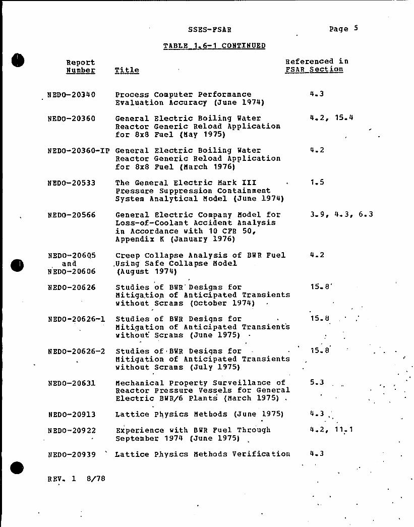
N ED0-2 03 4 0
NEDO-20360
Process Computer PerformanceEvaluation Accuracy (June 1974)
General Electric Boiling MaterReactor Generic Reload Applicationfor 8x8 Fuel (May 1975)
4 3
42,154
NEDO-20360-IP General Electric Boiling MaterReactor Generic Reload Applicationfor 8x8 Fuel (March 1976)
4 2
NEDO-20533
NEDO-20566
NEDO-206Q5and
N EDO-206 06
NEDO-20626
NEDO-20626-1
NEDO-20626-2
NEDO-20631
NEDO-20913
N EDO-209 22
The General Electric Mark XXI *
Pressure Suppression ContainmentSystem Analytical Model (June 1974)
General Electric Company Model forLoss-of-Coolant Accident Analysisin Accordance with 10 CFR 50,Appendix K (January 1976)
Creep Collapse Analysis of BMR Fuel.Using Safe Collapse Model(August 1974)
Studies of BMR'esigns forMitigation of Anticipated Transientswithout Scrams (October 1974) ~
Studies of BMR Designs forMitigation of Anticipated Transientswithout Scrams (June 1975)
Studies of ~ BMR Designs forMitigation of Anticipated Transientswithout Scrams (July 1975)
Mechanical Property Surveillance ofReactor Pressure Vessels for GeneralElectric BMR/6 Plants (March 1975)
Lattice Physics Methods (June 1975)
Experience with BMR Fuel ThroughSeptember 1974 (June 1975)
1 5
3 9, 4 3, 6.3
4 2
15 8"
15 8
15 8
5 3
4.3
4 2, 11.1
NEDO-20939 'attice Physics Methods Verification 4 3
R EV 1 8/78

SSES-PSAR
TABLE 1 6-1 CONTINUED
Page 6
ReportNumber T tie
Referenced inFSAR Section
NEDO-20943
NEDO-20944and
NEDE-20944PNEDO-20946
(August 1975)
Uran ia- G ado linia Nuclear F ue 1Physical and Material Properties(January 1977)
BMR/4 and BMR/5 Fuel Design(October 1976)
BMR Simulator Methods Verification(May, 1976)
4.2
4. 1r
4 3
NEDE-20944-XP BMR/4 and BMR/5 Fuel Design(January 1977)
NEDO-20948-P BMR/6 Fuel Design (June 1976)V
4 2
4 2
NEDO-20953
NEDO-209 64
,.NEDO-.211 42
NEDO-21143
N EDO-21159
N ED 0-211 74
N EDO-21231
N EDO-212 91
Three-Dimensional Boiling MaterReactor Core Core Simulator (May 1976)
Generation of Void and DopplerReactivity Feedback for Applicationto BMR Plant Transient Analysis(August 1.975)
Realistic Accident Analysis forGeneral Electric Boiling WaterReactor — The RELAC .Code and User'sGuide to be issued(December 1977)
Conservative Radiological AccidentEvaluation.— The CpNACOl Code {March1976)
Airborne Release from BMRs forEnvironment Impact Evaluations {March1976)
'MR
Fuel Channel DeflectionsE
Banked Position Withdrawal Sequence(September 1976)
Group Notch Node of the RSCS,for
15,4
4 3
15.4, 15 6, 15 7
15 4, 15 6, 15;7
1'1 1
4.2
4 3
15 4,
R EV 1 8/78

ReportNumber Title
SS ES-FSA R
I~RBL ~16-1 'COHIIHUBD
Page 7
Referenced inFSAR Section
NEDO-26453
Cooper (June 1976)
3D BMR Core'Simulator (May 1976) 4 3
Oyster Creek Station, FSAR Amendment 10 1 5
1tSummary Memorandum on ExcursionAnalysis Uncert'ainties," DresdenNuclear Power Station, Unit 3,. PlantDesign Analysis ReportAmendment 3
Hatch Nuclear Plant, Unit 1, PSARAmendment 10, Appendix L
Millstone Nuclear Power Station, PSARAmendment 14
4.3, 15 .0
15 5
6 3
Pilgrim Nuclear Power Station, PSARAmendment 14
6 3
Quad Cities Station, Units 1 and 2, ...-. 4 3PSAR, Amendment 9
This listing to be updated for each requisition plant.
B. Other Referenced Reports
AE-RTL-788
ANL-5621
A NL-6385
AGN-TM-407
ANL-7460
Void Measurements in the Region ofSubcooled and I,ow Quality Boiling(April 1966)
Boiling. Density in VerticalRectangular Multichannel Sectionswith Natural Circulation (November1956)
Power-to-Void Transfer Functions{July 1961)
AGN-GAM, an IBM 7090 Code toCalculate Spectra and MultigroupConstants (April 1965)
Reactor Development Program ProgressReport, p. 121-122 (June 1968)
4„4
4;4
4 4
4 3
4 3
R EV 1 8/78
SSES-FSAR
TABLE 1 6-1 CONTINUED
Page; 8
Report~usher Title
Referenced inPSAR Section
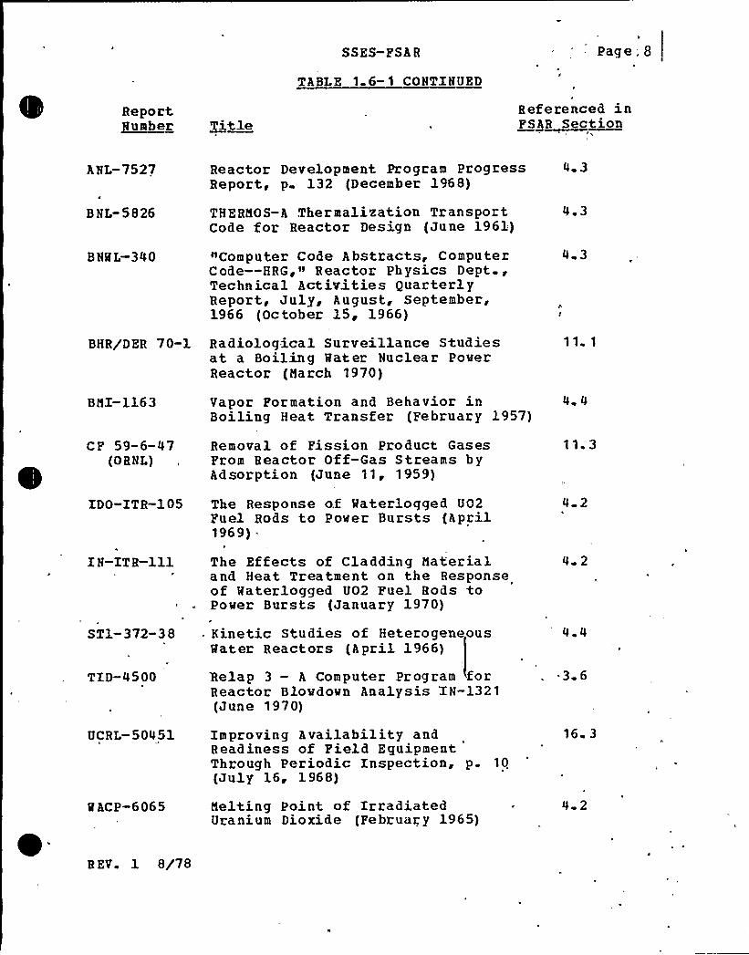
ANL-7527
BNL-5826
B NML-340
BHR/DER 70-1
BMI-1163
CF 59-6-47(OBNL)
IDO-ITR-1 05
IN-ITR-ill
ST1-372-38
TID-4500
UCRL-50451
M ACP-6065
Reactor Development Program ProgressReport, p 132 (December 1968)
THERMOS-A Thermalization TransportCode for Reactor Design (June 1961)
"Computer Code Abstracts, ComputerCode —HRG ~
~~ Reactor Physics Dept.,Technical Activities QuarterlyReport, July, August, September,1966 (October 15, 1966)
Radiological Surveillance Studiesat a Boiling Water Nuclear PowerReactor (March 1970)
Vapor Formation and Behavior inBoiling Heat Transfer (February 1957)
Removal of Fission Product GasesFrom Reactor Off-Gas Streams byAdsorption (June 11 '959)The Response of Materlogged UO2Fuel Rods to Power Bursts {April1969)
The Effects of Cladding Materialand Heat Treatment on the Responseof Waterlogged UO2 Fuel Rods toPower Bursts (January 1970)
Kinetic Studies of HeterogeneousWater Reactors (April 1966)
%clap 3 — A Computer Program forReactor Blowdown Analysis 'IN-1321(June 1970)
Improving Availability andReadiness of Field EguipmentThrough Periodic Inspection, p. 10(July 16, 1968)
Melting Point of IrradiatedUranium Dioxide (February 1965)
4 3
4 ~ 3
4 3
11 1
4 4
11. 3
4 2
4 2
4 4
~ 3 6
16 3
4 2
B EV. 1 8/78
SSES-FSAR
TABLE 'I 6-1 CONTINUED
Page 9
ReportNumber Title
Referenced inFSAR Section
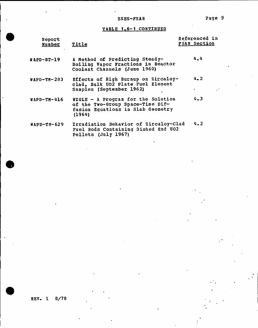
M APD-BT-. 19
MAPD-TM-283
MAPD-TM-416
A Method of Predicting Steady-Boiling Vapor Fractions in ReactorCoolant Channels (June 1960)
Effects of High Burnup on Zircaloy-clad, Bulk U02 Plate Fuel ElementSamples (September 1962)
MXGLE — A Program for the Solutionof the Two-Group Space-Time Dif-fusion Equations in Slab Geometry(1964)
4 4
4 2
4 3
MAPD-TM-629 Irradiation Behavior of Zircaloy-Clad 4. 2Fuel Rods Containing Dished End UO2Pellets (July 1967)
REV 1 8/78

SSZS-FS AR
Design Conformance
The primary containment system, which includes the drywell andsuppression chamber,. is desiqned, fabricated, and erected toaccommodate, without failure, the pressures and temperaturesresultinq from the double-ended rupture or equivalent failure ofany coolant pipe within the primary containment. The reactorbuildinq encompassinq the primary containment provides secondarycontainment. The two containment systems and their associatedsafety systems are desiqned and maintained so that offsite doses,which rould result from postulated design basis accidents, remainbelow the quideline values stated in 10CPH100 when calculated bythe methods of Regulatory Guide 1.3 (Rev. 2, 6/74) . Sections 6.2and 15.1 have detailed information which demonstrates compliancewith Criterion 16.
1.2. 2. 8 Electric Power Systems ]Criterion .17)
r.r i+erion
An onsite electric power system and an offsite electric powersystem shall be provided to permit functioning of structure.,systems, and components important to safety. The safety functionfor each system (assuminq the other system is not functioning)shall be o provide sufficient capacity and capability to assuret ha+ (1) ..pecif ied acceptable fuel design limits and designconditions of the reactor coolant pressure boundary are notexceeded as a result of anticipated operational occurrences and(2) the core is cooled and containment integrity and other vitalfunrtions are maintained in the event of postula+ed accidents.
The onsi te electric power supplies, including the bat teries, andtho onsi+e electric Distribution system shall have sufficientindependence, redundancy, and testability to perform their safetyfunction s, a ssuminq a sinqle failure.Electric power from the +ransmission network to the onsi"eelectric Distribution system shall be supplied by two physicallyindependent circuits (not necessarily on sepa ate rights of way),desiqned and located so as to minimize to the extent practicalthe likelihood of their simultaneous failure undo.r operating andoostul.ated accident and environmental conditions. A switchyardcommon to both circuits is acceptable. Each of these cirruitsshall be Designed to be available in sufficient time followinq aloss of all onsite alternatinq current power supplies and theother of fsite electric power rircuit, to assu're that specifiedacceptable fuel desiqn limit and design conditions of. the reactorcoolant pressure boundary are not exceeded. One of thesecircuits shal1 be desiqned to be available within a few seconds
Rev. 30, 5/82 3% 1 17
SS ES-FS AR
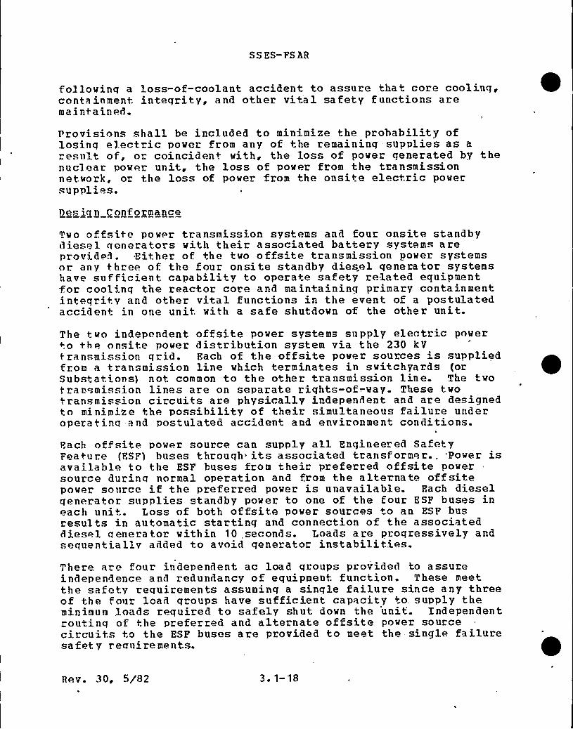
followinq a loss-of-coolant accident to assure that core cooling,containment inteqrity, and other vital safety functions aremai ntained.
Provisions shall be included to minimize the probability oflosinq electric power from any of the remaining supplies as aresult of, or coinciden+ with, the loss of power generated by thenuclear power unit, the loss of power from the transmissionnetwork, or the loss of power from the onsite electric powersupplies.
Des ia n C onf ormance
Two offsite power transmission systems and four onsite standbydiesel qenerators with their associated battery systems areprovided. Either of. the two offsite transmission power systemsor. any three of the four onsite standby diesel generator systemshave sufficient capability to operate safety related equipment+or cool inq the reactor core and maintaining primary containmentinteqrity and other vital functions in the event of a postulatedacciden+ in one unit with a safe shutdown of the other unit.
The two independent offsite power systems supply electric powerto the onsite power distribution system via the 230 kVtransmission qrid. Each of the offsite power sources is suppliedfrom a transmission line which terminates in switchyards (orSubstations) not common to the other transmission line. The twot ransmission lines are on separate rights-of-.way. These twotransmission circuits are physically independent and are designedto minimize the possibility of their simultaneous failure underoperatinq and postulated accident and environment conditions.
Hach offsitp power source can supply all Engineered SafetyFeature {ESP) buses through its associated transformor.. Power isavailable to the ESF buses from their preferred offsite powersource durinq normal operation and from the alternate offsitepower source if the preferred power is unavailable. Hach dieselqenerator supplies standby power to one of the four ESF buses ineach unit. Loss of both offsite power sources +o an ESF busresults in automatic starting and connection of the associateddiesel generator within 10 seconds. Loads are proqressively andsequentiallv added to avoid generator instabilities.There are four independent ac load groups provided to assureindependence and redundancy of equipment function. These meetthe safety requirements assuming a sinqle failure since any threeof the four load groups have sufficient capacity +o. supply theminimum loads required to safely shut down the unit. Independentroutinq of the preferred and alternate offsite power sourcecircuits to the ESF buses are provided to meet the- single failuresa fet y reaui re ments.
Rev. 30, 5/82 3. 1-18
SS ES-PS AR
3~ 4- MATER LEVEL = QPLOOD) DESIGN*
As discussed in Section 2.4 all Seismic Category I structuresare secure against floodinq due to probable maximum flood (PMP}of the Susquehanna River or probable maximum precipitation {PMP)on the area surrounding the plant; Therefore, special floodprotection measures are unnecessary. The Seismic Category Istructures have, however, been designed. for hydrostatic loadsresultinq from groundwater, as discussed in Section 3.8. Thegroundwater table is at elevation 665 MSL in the main plant area.
A postulated break in the coolinq tower basins or of the waterdelivery pipes to the basin could result in a build-up of vateragainst the valls of either or both of the ESSM pumphouse and theturbine building. In the event of such water build-up breachingthe turbine buildinq wall, water that vould not be intercepted bythe floor Brains or qrilles and thus vould flow through theturbine building to the reactor building would be prevented fromendangering eguipment in the latter by means of vatertight doors.Plood water buildinq up against the ESSM pumphouse vould also beprevented from enterinq the building by means of watertightdoors. Impact forces and vater pressure due to flood water villnot endanqer the integrity of the ESSM pumphouse.
All safety-related systems are located in the Reactor Building,Diesel Generator Building, Control Structure and the EngineeredSafeguard Service Water {ESSM} Pumphouse.
Sufficient physical separation betveen these buildings isprovideR to prevent internal spreading of any floods from onebuilding to another..
Redundant Engineered Safety Peatures, pumps and drives, heatexchanqers and associated pipes, valves and instrumentation inthe reactor building subject to potential flooding, are housed inseparate vatertiqht rooms. Seismic "ategory I level detectorstrip alarms in the main control room when the water level in anyroom exceeds the set point. Isolation of the floor drainagelines from these rooms is provided by outside manual valves..
All other rooms in the reactor building and control structurecontaininq safety related equipment vhich are subject topotentia l flooding by process fluid leakage or fire protectionvater are provided with at least one open floor drain.
Floods in excess of the approximately 80 gpm floor drain capacityincrease the vater level in the affected area and are releasedthrough the door-to-floor clearance of these rooms.
Refer to Subsection 9.3.3 for a detailed description of thereactor building and control structure drainage system.
Rev. 29, 3/82 3 '4-1
SS ES-FS AR
The four diesel generator sets are housed in individual watertight compartments within the diesel generator building. Ploordrain line branches from each of these compartments are equippedwith check valves to prevent backflooding from the common sump.
The ESSW pumphouse is divided into two redundan't compartments.Flooding from internal leakage would, therefore, only affect oneof the redundant pump sets. The control and electrical panelsare mounted on minimum 0 inch high concrete pads or structuralsupports. Operating floor openings allow drainage of any leakageto the ESSM pump suction space below or to a reserve sump spacethat could be emptied with a portable pump.
Rev. 29, 3/82 3. 0-2
SSES- PS AR
APPENDIX 3.6A
PIPE BREAK OUTSIDE CONTAINMENTSUMMARY OP ANALYSIS AND RESULTS
PART I — ANALYSIS FOR SPACES OTHER THAN MAIN STEAM TUNNEL
In addition to the analysis provided in Table 3.6-3, compartmentscontaining high energy lines were analyzed to determine the peakpressures that might result'from breaks in these lines. Theanalysis vas done mainly to verify structural integrity.Duration of the blowdovn vas not a factor in th'e analysis sinceadequate vent area vas provided, and pressure peaked guickly thendeclined to a lower steady state value. The'tructures areadequate to withstand the peak pressures indicated by theanaly sis.The valves which would be used to terminate the blowrlown areindicated. In qeneral, hovever, it is unnecessary to qualifyequipment for the pipe break environment because the safeguardssystems are separated into compartments which are vented directlyto the atmosphere and high enerqy breaks affect only a singlespace. The plant can be safely shutrlovn using eguipment notaffected by the hiqh enerqy line break.
The followinq information for each compartment vas utilized withtha analytical techniques described in Appendix 6B of the PSAR todetermine the pressures and temperatures resulting from highenergy line breaks outside containment.
ANALYSIS FOR HPCI PENETRATION ROOM /UNIT 1}
Pipe Break Data
Location: HPCI Penetration RoomLine Identification/Size: DBB-114/10"
Isolation Valve Designation and Location: HV E41-1P003 located inthe HPCI PenetrationRoom
Rev. 31, 7/82 3. 6A-1

SSES-PSAR
Blowdown Data:
t~sec}.
0.00.10.10.20.20. 8820. 882
51. 0
mlXbnZ~«3.
1892189213531353
738738407
0
hgBTU~lbm}
1192 21192.21192. 21192. 21192 21192.21'192. 21192.2
I
Compartment Volume: 87,680 cu ftVent Area: 67.0 sq ftVent Coefficient: .574
L/A 0 0022 Ft- <
Results: Peak Pressure: 2.12 psigPeak Temperature: 288. 4 F
ANALYSIS FOR HQCI PUMP POOQ gU$ IT
Pipe Break Data
Location: HPCI Pump RoomLine Identification/Size: DBB-114/10"
Blovdovn Data:
HV E41-1F003 located inthe HPCI PenetrationRoom
tgsgg}
0.0.088
088. 164~ 164. 218.218
50 0
mdlbmdrecl=
1892189214021402
946'46283
0
J
. 1192.21192 21192. 2
~ 1192.21192 21192 21192.21192.2
Compartment Volume: 27,883 cu ftVent Area: 60 sq ft
Rev. 31, 7/82 3. 6A-2
SS ES-FS AR
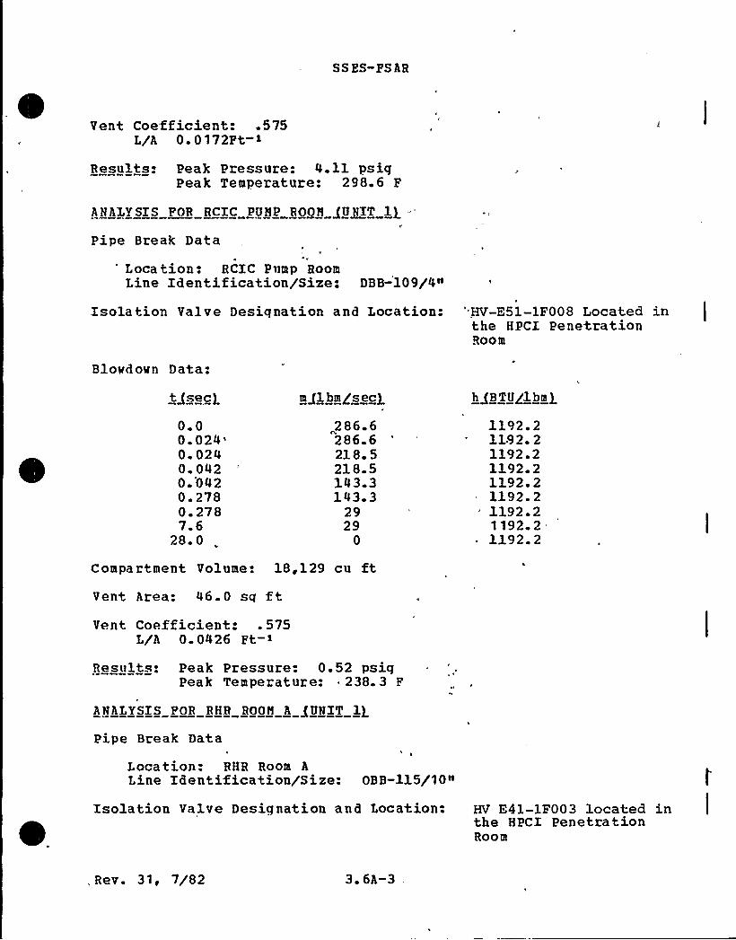
Vent Coefficient: .575L/A 0 0 172Ft
Results. Peak Pressure: 4.11 psigPeak Temperature: 298.6 F
ANALYSIS POR RCIC PUNP ROON /UNIT li -"
I'ipeBreak Data
'ocation: RCIC Pump RoomLine Identification/Size: DBB 109/4n
Isolation Valve Designation and Location: 'V-E51-1F008 Located inthe HPCI PenetrationRoom
Blowdown Data:
tg sec)
0.00.
024'.
0240. 0420. 0420.2780. 2787.6
28. 0
286 6286 6218 5218.5143 3143. 3
2929
0
~hB TUglbn g
1192.21192. 21192 21192. 21192 21192. 2l192. 21192 21192. 2
Compartment Volune: 18,129 cu ftVent Area: 46.0 sq ftVent Coefficient: .575
L/A 0 0426 Ft
Results: Peak Pressure: 0.52 psiqPeak Temperature: ~ 238. 3 F
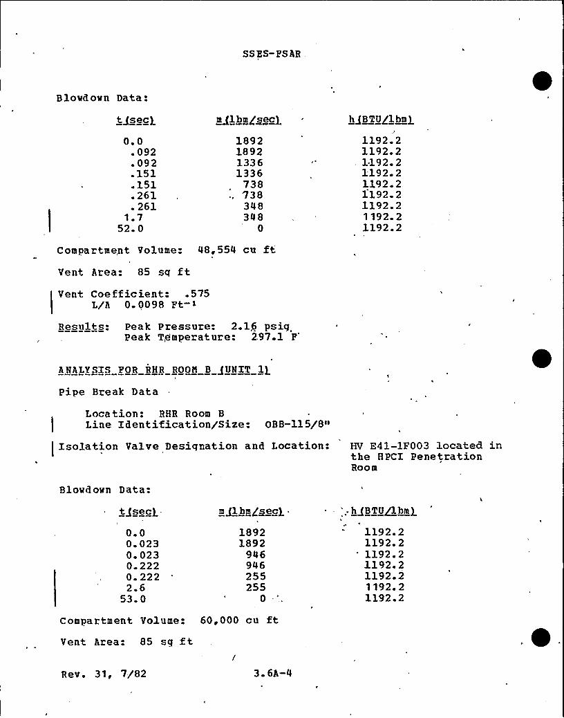
ANALYSIS FOR RHR ROON A /UNIT 1}
Pipe Break Data
Location: RHR Roon ALine Identification/Size: OBB-115/10"
Isolation Valve Designation and Location: HV E41-1F003 located inthe HPCI PenetrationRoon
., Rev. 31, 7/82 3. 6A-3
SS ES- PS AR,
Blowdown Data:
0.0. 092
092.151.151.261. 261
1.752. 0
~ml bmoc sec)
1892189213361336
738738348348
0
1192.21192. 21.192. 21192. 21192. 21192. 21192.21 192. 21192.2
Compartment Volume: 48,554 cu ftVent Area: 85 sq ftVent Coe fficient: .575
L/A 0 0098 Ft
Results: Peak Pressure: 2.1$ psigPeak Temperature: 297.1 F
ANALYSIS FOR RHR ROON B /UNIT liPipe Break Data
Location: RHR Room BLine Identification/Size: OBB-115/8»
!Isolation Valve Desiqnation and Location: HV E41-1F003 located in
the HPCX PenetrationRoom
Blowd own Data:
tgsecg
0.00. 0230. 0230. 2220. 2222.6
53. 0
18921892
946946255255
0
'; ~hBTU~bmg
1192. 21192. 2
'192.21192. 21192.21192. 21192. 2
Compartment Volume: 60,000 cu ftVent Area: 85 sq ftRev. 31, 7/82 3. 6A-4
SS ES-PS AR
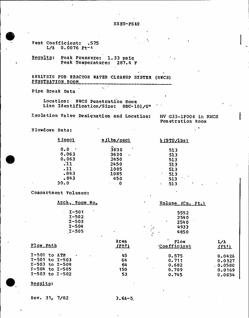
Vent Coefficient: .575L/A 0. 0076 Ft-1
Results: Peak Pressure: l. 33 psigPeak Temperature: 287.4 P
ANALYSIS FOR REACTOR MATER CLEANUP SYSTEN {RMCS)PENETRATION ROON
Pipe Break Data
Location: RMCS Penetration RoomLine Identification/Size. DBC-101/6"
Isolation Valve Designation and Location:
Bio@down Data:
HV G33-1F004 in RWCSPenetration Room
tgsecg
0 00. 0630. 063.'ll
.11
.843
. 84330. 0
Compartment Volumes:
Arch. Room No.
I-501I-502I-503I-504I-505
mal hm /~ed
363036302450245010851085
4500
513513513513513513513
~ 513
Volume ~Cu. Ft~5552254 0254049334850
Flow gathAreaaz> a
Plow'Coe fficient
L/A
I-501 toI-501 toI-503 toI-504 toI-503 to
Results:
ATNI-503I-504I-505I "502
456464
15053
0. 5750. 7110.6820.7090 745
0 04260 03270. 05800 01690. 0854
Rev. 31, 7/82 3.6A-5,
SS ES-FS AR
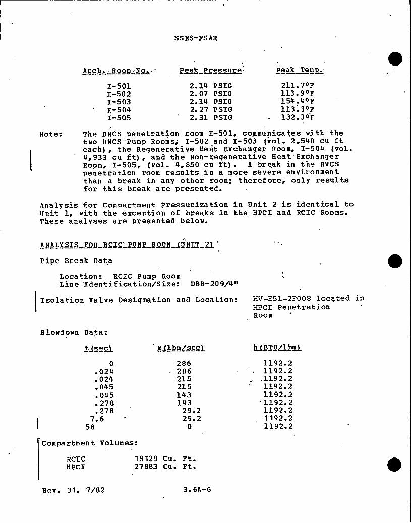
Arch. Boom-No.
I-501I-502I-503I-504I-505
Peak Pressure
2 14 PSIG2 07 PSIG2 14 PSIG2 27 PSIG2. 31 PSIG
Peak Tem n.=
211 7OF113.9OF154.4~F113.3<F132.3OF
Note:I
The RHCS penetration room l-501, communicates vith thetvo RMCS Pump Rooms; I-502 and I-503 (vol. 2,540 cu fteach), the Regenerative Heat Fxchanger Room, I-504 (vol.4,933 cu ft), and the Non-regenerative Heat ExchangerRoom, I-505, (vol. 4, 850 cu ft) . A break in the RMCS
penetration room results in a more severe environmentthan a break in any other zoom; theref ore, only resultsfor this break are presented.
Analysis for Compartment Pressurization in Unit 2 is identical toUnit 1, vith the exception of breaks in the HPCI and RCIC Rooms.These analyses are presented belov.
ANALYSIS FOR RCIC'UMP ROON (UNIT 2)
Pipe Break Data
Location: RCIC Pump BoomLine Identification/Size: DBB-209/4"
Isolation Valve Designation and Location:
Blovdovn Data:
HV-E51-2F008 located inHPCI PenetrationRoom
tQsegj
0.024.024.045.045.278.278
7.658
mg1bgggecg
286286215215143143
29 229. 2
0
hgB Ta/1bmg
1192. 21192. 2
.1192. 21192. 21192 2'192 21192.21192 21192. 2
Compartment Volumes:
RCI CHPCI
18129 Cu. Ft-27883 CQ Ft
Rev. 31, 7/82 3 6A-6

SSZS-FS AR
Tunnel 2650 Cu. Ft.
F1ow Path
RCIC to TunnelTunnel to HPCXTunnel to ATM
Area
257245
FloeCoeff icient
p
0. 6770.7110.679
L/A~Ft >)
0. 3410. 3550. 319
Results:
Boom
RCXCHPCXTunnel
Peak Pressure (PSIG3
0.570.740.74
Peak Te~m. /OFT
238. 5108. 1220. 2
Notes:
A break in the RCXC pump room results in a change in environmentto'the HPCI pump zoom via connection of the tunnel to both rooms.Therefore, peak pressures are shown for all three compartments.
ANALYSIS FOR HPCI PUHP HOON /UNIT 2J
Pipe Break Data
Location: HPCI Pump RoomLine Identification/Size: DBB-214/10"
Isolation Valve Designation and Location: HV-E41-2F003 located inthe HPCX PenetrationRoom
Blovdovn Data:
.0707
.127
.127223
.223500
1892189214121412
946946284
0
1192. 21192. 21192.21192. 21192 21192. 21192.21192 2
Comma rtm en t - Volumes:
HPCIRCICTunnel
27883 CQ F t18129 Cu. Ft.2650 Cu. Ft.
Rev. 31, 7/82 '3.6A-6a
SSES- FS AR
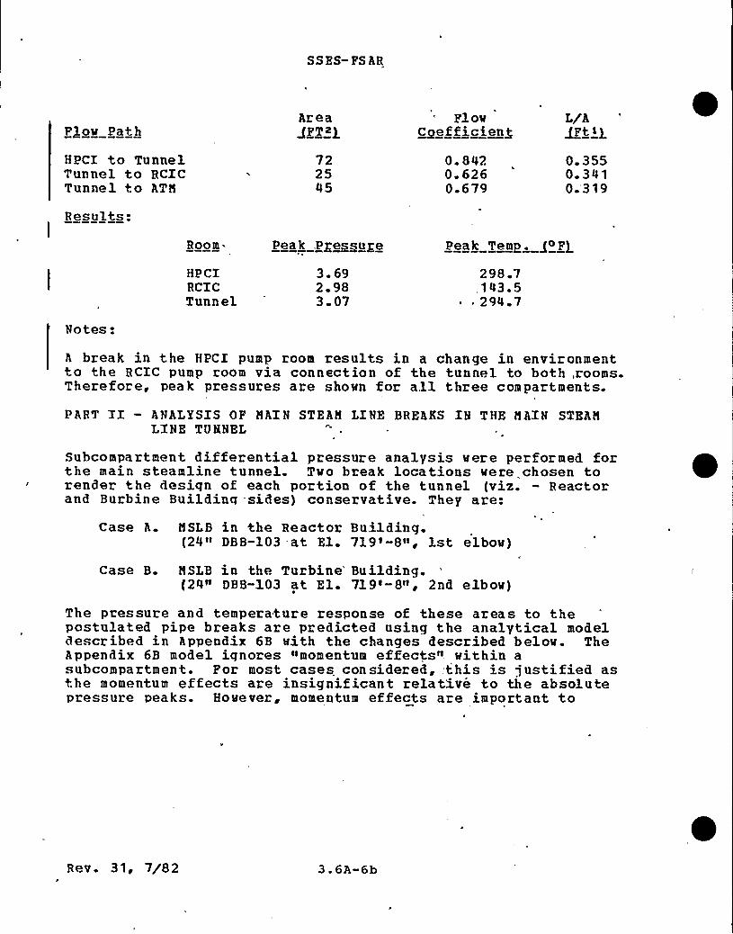
Plow Path
HPCI to TunnelTunnel to RCICTunnel to ATH
Area
722545
FlowC efficien+
0. 8420. 6260.679
L/A~Ft <g
0. 3550. 3410.'31 9
Results:I
Room- Peak, Pressure Peak Temp. g~F}
HPCIRCICTunnel
3.692 983 07
298 7,143.5
~ 294 7
Notes:
A break in the HPCI pump room results in a change in environmentto the RCIC pump room via connection of the tunnel to both, rooms.Therefore, peak pressures are shown for all three compartments.
PART II — ANALYSIS OF HAIN STEAM LINE BREAKS IN THE HAIN STEANLINE TUNNEL
Subcompartment differential pressure analysis were performed forthe main steamline tunnel. Two break locations were chosen torender the design of each portion of the tunnel (viz. — Reactorand Burbine Building -sides) conservative. They are:
Case A. MSLB in the Reactor Building.(24» DBB-103 at El. 719'-8», 1st elbow)
Case B. HSLB in the Turbine'uilding.(24" DBB-103 at El. 719'-8», 2nd elbow)
The pressure and temperature response of these areas to thepostulated pipe breaks are predicted using the analytical modeldescribed in Appendix 6B with the changes described below. TheAppendix 6B model ignores »momentum effects" within asubcompartment. For most cases considered, .this is justified asthe momentum effects are insignificant relative to the absolutepressure peaks. However, momentum effects are important to
Rev. 31, 7/8 2 3.6A-6b
SSES-FSAB
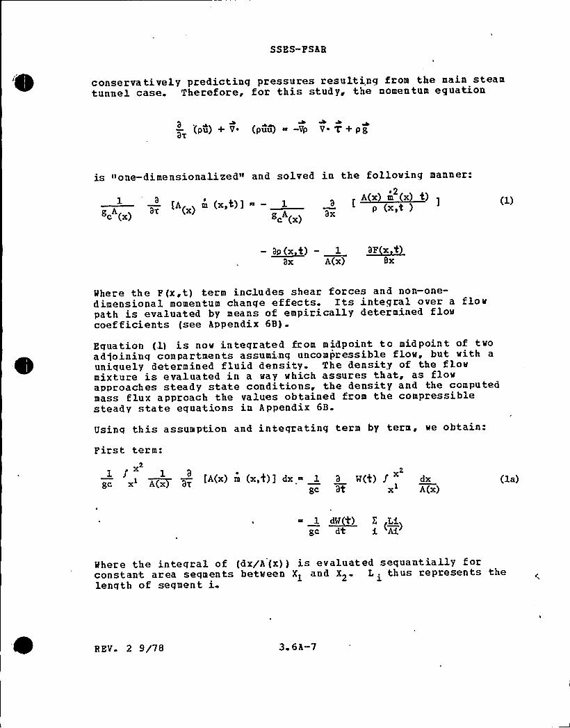
conservatively predicting pressures resulting from the main steamtunnel case. Therefore, for this study, the nomentum equation
a (pu) + V. (puu) -Vp V ~ V+ pgaT
is none-dimensionalized" and solved in the following manner:~ 2
A a. '"(.) " —— p (.,e )gp (x) g,A(„) ax
- ~Bp x t) — 1 ~SP x '0
ax A(x) Bx
Mhere the F(x,t) term includes shear forces and non-one-dimensional momentum change effects. Its integral over a flowpath is evaluated by means of empirically determined flowcoefficients (see Appendix 6B).
Equation (1) is now integrated from midpoint to midpoint of twoadjoining compartments assuming uncompressible flow, but with a
uniquely determined fluid density. The density of the flowmixture is evaluated in a way which assures that, as flowapproaches steady state conditions, the density and the computedmass flux approach the values obtained from the compressiblesteady state equations in Appendix 6B.
tJsinq this assumption and inteqrating term by term, we obtain:
First term:x
1 f 1 8
gu x> A(x aTfA(x) m (x,t)] dx 1 a W(4) f dxx
g('- at x A(x)
1 ~dW d') E EAgc d'C
Mhere the inteqral of (dx/A(x) j is evaluated sequantially forconstant area seqments between X1 and X2. L . thus represents the
l.length of segment i
REV 2 9/78 3 6A-7
SS ES-FS AR
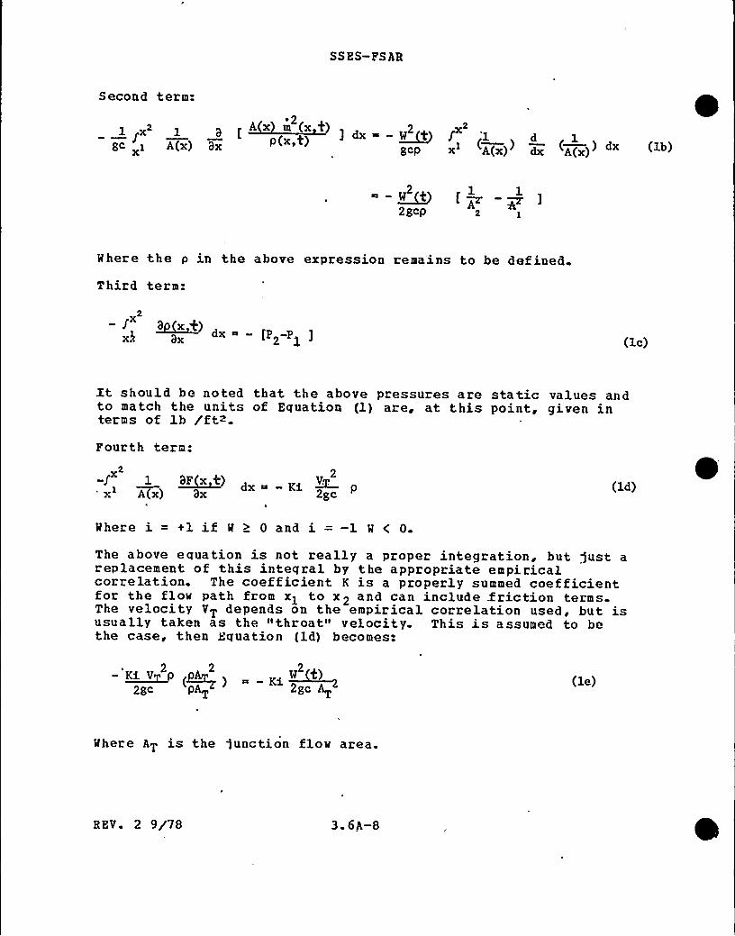
Second term:A2
1~x 1 3 [Ax m(xt)
] dx~-~Wt J '12 2
gc A(x) Bx gcp x A(x) dx A( )) dx (lb)
—~W
2
2 gcp
Mhere the p in the above expression rema'ins to be def ined
Third term:
x
(1c)
Xt should be noted that the above pressures are static values andto match the units of Equation (1) are, at this point, given interms of lb /ft~.
Fourth term:
-)' BP(x 0)A K< ~V..
x 2
x~ A(x) Bx 2gc (ld)
Mhere i=+lifM> Oand i=-1 M(0.The above equation is not really a proper integration, but just areplacement of this inteqral by the appropriate empiricalcorrelation. The coefficient K is a properly summed coefficientfor the floe path from xl to x 2 and can include .friction termsThe velocity VT depends on the empirical correlation used, but isusually taken as the "throat" velocity. This is assumed to bethe case, then Equation (ld) becomes:
2 2 2— ~KA V P PAA ) KA~W'2)
2gc pAT 2gc AT(le)
Mhere AT is the junction flow area.
REV. 2 9/78 3.6A-8

SS ES- FSA R
Before collectinq all the integrated terms, it is preferable toconvert the static pressures of Equation lc into stagnationpressures.
Pstat(i) Pstag(i) — ~ Pstag(i) - ~* v i) * w ~t)2gc 2gcpA.
Summinq the expressions obtained by Equations (lb) to (le) andusinq (lf) ve qet:
21 ~dW t) E (~L) Pl* — PE* K~AW ('t
at i Ai 2gcQAT
(lg)
Mhere the starred pressures imply stagnation values.
Nov the flov rate of the previous time step is used to evaluate afinite-difference approximation of the time derivative:
«(t) ~t)- 1; tlat at
(2)
In a given time interval, R (t-gt) is known, thus Equation (lg) isa quadratic in a (t) . Writing it in the customary quadratric formve have:
W ( t) + ~A'A W(t)Ki 2 (~)
ht gc
( i (+)w (t-Zt) + Pl* - P2* ) - 0gc (3)
and substituting the compressible flo~ equation for 'A Theresultinq ratio is:
I@ 1 P2 1/Ic P2Q
(Z E) ( Z PE 1 ((PE) -(PE) )
Pa
R EV 2 9/78 3 6A-9

SSES-FSAR
In the limit as ( PQP1) ~ 1, Equation 5 approaches a value of one) as required and the PQP1 ratio stays below one for all other
values of p2/p> and for all positive k. p is thus smaller thanthe arithmetic mean of the densities and smaller than thedownstream density itself. This assures a conservativelyminimized flow rate for a given pressure gradient. This alsoholds true when the inertial effects (time dependent momentumequation) are included. Table 3. 6A-l shows representative massflux values calculated bv density p>, and the proper compressibleflow compatible density P is used. As seen for all cases, theuse of. p results in minimum and thus conservative flow rates.The calculational sequence can now be summarized.
(l) After compartment state functions have been obtained, a firstestimate of M(t) is evaluated using the compressible flowequation.
(2) The estimate of M(t) is used in Equation 3b to evaluate thefluid density.
(3) Utilizing the flow rate from the previous time step and thecalculated p , Equation (3) is solved to obtain M(t).
Daring each time step, the junction flow rate is chosen as thesmaller of the flow rate resulting from the one-dimensionalmomentum equation or the flow rate resulting from the selectedsteady state compressible flow correlation. (Appendix 6B).
Schematic drawings showing the nodalization of the steam tunnelfor Case A and Case B are given in Figures 3 6A-1 and 3.6A-5,respectively. Blow out panel locations are shown in Figure 3.6A-2 Volumes, flow areas, flow coefficients, and L/A's for themodels are presented in Tables 3.6A-2 through 3.6A-5. Asindicated in Fiqure 3.6A-l, the main steam tunnel is subdividedinto a total of eiqhteen volumes to model the effect ofobstructions such as pipe restraints and blowout panels. ForCase B, in Figure 3.6A-5, a ten volume model is used since theone-way blowout panels completely block the flow path to reactorbuilding side, leaving it unpressurized. The overall flowdiagrams for both Cases A 8 B are presented in Figures 3.6A-3 and3.6A-6
The blowdown data for the postulated double end guillotinemainsteam line break is shown in Table 3.6A-4. This blowdown isdone in a way similar to ANs 176 standard (draft), as discussedbelow, but system friction is accounted for to reduce thecalculated mass and energy releases to reasonable levels whilemaintaining a degree of conservatism. Other criteria areaddressed as follows:
Rev. 9 5/79 3. 6A-10
SSES-CESAR
1. Pull double-end break area Noody flow for steam blowdownimmediately af ter pipe b rea k.
2. Chokinq Hoody flow occurs first at the break, then moves upto choke at flow restrictors.
3. Prictional loss of valves is not included.
4 Level swell (4% quality blowdown) occurs at 1 sec.
5. Steam isolation valves close in 5 seconds with a 0.6 secondinstrument and signal delay time. A linear ramp in flow areais used to model this closure.
The computational method of this double-end guillotine mainsteamline break is shown in Fiq. 3. 6A-8.
In Piqure 3 6A-8, flow from the RPV to the break location is"forward flow,» while the flow from the turbine to the breaklocation is »reverse flow.»
Let L> = The distance from flow restrictors to break location.L 2
= The distance from reactor pressure vessel nozzle tothe flo w re stric tors.
L3 The distance from flow restrictor to the turbine crosstie.
Lp = The shortest distance from the MSL crosstie back to thebreak location.
(A) Calculation of mass and energy release rates from the forwarddirection.Let Ap = The cross-sectional flow area of the break, ft~.
Av
p 0
The throat area of the flow restrictor, ft~.
No-load system pressure, PSIA.
Steam quality.Enthalpy of fluid, BTU/IBM
Number of lines.
D
Sonic speed for steam.
Prie t iona 1 fac to r.Diameter of the pipe system.
Rev. 9 5/793 6A-11
SS ES-PS AB
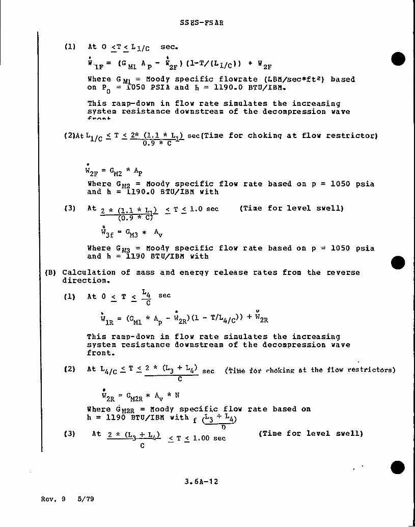
(1) At 0 <T < L1/C sec.
W. = (GM1
A W2F (1 T/(L1/C) ) W2F
Where G M>= Nood y specific flovrate (LBN/sec+f te) based
on P = >050 PSIA and h = 1190.0 BTU/IBN.0
This ramp-dovn in flow rate simulates the increasingsystem resistance downstream of the decompression wave+r nn 4.
(2)At L1/C < T < 2* (1.1 * L1) sec(Time for choking at flow restrictor)0.9*C
W2F GM
Where GM2 = Noody specific flow rate based on p = 1050 psiaand h = l.190.0 BTU/IBN with
(3) At 2 * (1.1 * L ) < T < 1.0 sec~)0
(Time for level swell)
Where GM3 = Noody specific flow rate based on p = 1050 psiaand h = 1190 BTU/IBN vith
(B) Calculation of mass and energy release rates from the reversedirection.
(1) At 0 < T < 4L
C
W1R (GMj* A W2R (1 — T/L4/C) )
This ramp-dovn in flov rate simulates the increasingsystem resistance downstream of the decompression wavefront.
(2) At L4/c < T < 2 (L> + L4 sec (lib((h f6> choking at the fice xestx'icterus)C
(Time for level svell)
W2R=
GM2R* A * N
Where GM2R = Noody specific flow rate based onh = 119p BTU/TBB with ( (LB + Lh)
p( ) 2 * (L~+L ) < T ( L.pp set
C
3 6A-1 2
Rev. 9 5/79
SS ES-PS AR
W3R W3 (A LINE) + W (B LINE) + W ( C LZNF)
= A [G3R (A) +G (B) +G (C)]
Where G MgR (A), GER (B) and GM~ (C} are the Moody
specific klow rates for lines A, 5, C based on Po = 1050PSIA and H = 1190 BTU/IBM with L for each line.
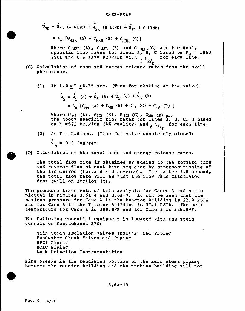
(C) Calculation of mass and energy release rates from the swellphenomenon.
(1) At l. 0 < T <4.35 sec. {Time for choking at the valve)I 0 yl t
W =W (A)+WS )+WS (C)+WSS S
= A [GMA (A) + GMS (B) + GMS (C) + GMS (D) ]
Where Ghg {A) ~ GM2 (B), G Mz (C), GM2 (D) arethe Moody specific flow rates for lines A, B, C, D basedon h =572 BTU/IBM (4'A guality) and L for each line.
2/D(2) At T = 5.6 sec. (Time for valve completely closed)
W = 0.0 LBM/secS
(D) Calculation of the total mass and energy release rates.
The total flov rate is obtained by adding up the forward flovand reverse flow at each time sequence by superpositioning ofthe two curves (forward and reverse). Then after 1.0 second,the total flow rate vill be just the flow rate calculatedfrom svell on section (C).
The pressure transients of this analysis for Cases A and B areplotted in Figures 3.6A-4 and 3.6A-7. It can be seen that themaximum pressure for Case A in the Reactor Building is 22.9 PSIAand for Case B in the Turbine Building is 37.1 PSIA. The peaktemperature for Case A is 300. OeP and for Case B is 325.0oP.
The following essential equipment is located with the steamtunnels on Susquehanna SES:
Main Steam Isolation Valves {MSIV's) and PipingPeedwater Check Valves and PipingHPCI PipingRCIC PipinqLeak Detection Instrumentation
Pipe breaks in the remaining portion of the main steam pipingbetween the reactor building and the turbine building will not
3. 6A-13
Rev. 9 5/79
SS ES-PS AR
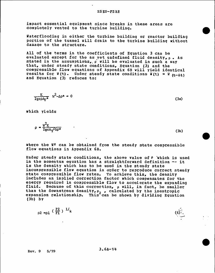
impact essential equipment since breaks in these areas arecompletely vented to the turbine building.Materflooding in either the turbine building or reactor buildingportion of the tunnel will drain to the turbine building withoutdamage to the structure.All of the terms in the coefficients of Equation 3 can beevaluated except for the as yet undefined fluid density, p . Asstated in the assumptions,. p'ill be evaluated in such a vaythat, under steady state conditions, Equation (3) and thecompressible flov equations of Appendix 6B vill yield identicalresults for R(t). Under steady state conditions M(t) = M (t At)and Equation (3) reduces to:
W -Ap* 0K 2
2gcp+ (3a)
vhich yields
W K~ggcAT Ap* (3b)
vhere the W~ can be obtained from the steady state compressibleflow equations in Appendix 6B.
Under steady state conditions, the above value of p 'which is usedin the momentum equation has a straightforward definition —itis the density vhich has to be used in the steady stateincompressible flow equation in order to reproduce correct steadystate compressible flov rates. To achieve this, the densityincludes an implied correction factor which compensates for theenerqy required in compressible flow to accelerate the expandingfluid. Because of this correction, p vill, in fact be smallerthan the downstream density,p2 ~ calculated by the isentropicexpansion relationship. This can be shown by dividing Equation(3b) by
P2 1/p2 pl Pl (4)-,
1' —~ V
Rev. 9 5/79 3 6A-1 0

SSBS-PSAR
GB BWR fuel assembly desiqn bases and analytical methodsincludinq those applicable to the faulted conditions, arecontained in References 3.9-4 and 3.9-5. Reference 3.9-5 isvritten primarily for BWR/6 plants; hovever, the methodology isapplicable to BQR/4 plants.
3.9. 1.4~11 pefueligg Egujpment
1
Refueling and servicing equipment that is important to safety isclassified as essential equipment per the requirements of 10 CPR
50, Appendix A. This equipment and other equipment whose failurewould degrade an essential component is defined in Section 9.1and is classified as Seismic Category X. These components aresubjected to an elastic dynamic finite element analysis togenerate loadinqs. This analysis utilizes appropriate, seismicfloor response spectra and combines loads at frequencies up to 33Hz for seismic and up to 60 .Hz for the hydrodynamic loads inthree directions. Imposed stresses are generated and combinedfor normal, upset, and faulted conditions. Stresses arecompared, depending on the specific safety class of theequipment, to Industrial Codes, ASME, ANSI or Industr ialStandards,'ISC, allovables. The calculated stresses a ndallowable limits for the faulted loads for, the fuel preparationmachine are provided in Table 3.9-2 (s) . The refueling platf ormhas also been examined; it can withstand the faulted loads due toseismic hydrodynamic events.
3.9.1.4. 12 Seismic Cateaory I- Items Other than NSSS
Por statically applied loads, the stress allowables of Appendix P
of the ASNE Code, Section IXI, Winter 1972 were used for codecomponents. Por noncode components, 'allowables vere based ontests or accepted standards consistent .with those in Appendix P
of the code.I
Dynamic loads for components loaded in the elastic range werecalculated using dynamic load factors, time history analysis, orany other method that assumes elastic behavior of the component.
The limits of the elastic range are defined in Paragraph 1323 ofAppendix F for the code components. The local yielding due tostress concentration is assumed not to affect the validity of theassumptions of elastic behavior. The stress allovables ofAppendix P for elastically analyzed components were used for codecomponents. Por noncode components, allowables vere based on
Re v. 31, 7/82 3 9-25
SSES-PSAR
tests or accepted material standards consistent with those inAppendix F for elastically analyzed components.
The methods used in evaluating the pipe break effects arediscussed in Section 3.6.
3 9 2 DYNAHIC TESTING=AND ANALYSIS
3.9.2.1a Preoperational Vibration and Dynamic EffectsTempting on gSSQ pgpggg
The test program is divided into three phases: ~ preoperationalvibration, startup vibration, and operational transients.
3.9.2 1a.1 Preooerational Vibration Testina~ ~ ~ ~ W
The purpose of the preoperational vibration test phase is toverify that operating vibrations in the recirculation piping areacceptable. This phase of the test uses visual observation.
3.9 2.1a 2 Sma'll Attached Pioina
There is no small attached piping in the NSSS scope of supply.
a. === ~ KX 2 RK3 9.2.1a 3 St tu Vib tion
The purpose of this phase of the program is to verify that themain steam and recirculation piping vibration are withinacceptable limits. Because of limited access due to highradiation levels, no visual observation is made during this phaseof the test. Remote measurements shall be made during thefollowing steady state conditions:
(a) Hain steam flow at 25% of rated;
{b) Hain steam flow at 50$ of rated;
(c) Hain steam flow at 75% of rated;
(d) Hain steam flow at 100'%f rated.
Rev. 31, 7/82 3 9-26

SSES-PS AR
3~9 7. QEggRgPCQS
3. 9-1 "Design and Performance of G.E. BMR Jet Pumps,» GeneralElectric Company, Atomic Power Equipment Department,AP ED-5460 i Jul y 1968
3. 9-2
3. 9-3
Moen, H.H., "Testing of Improved Jet Pumps for the BMR/6Nuclear System," General Electric Company, Atomic PowerEquipment Department, NED0-10602, June 1972.
General Electric Company, "Analytical Model for Loss-of-Coolant Analysis in Accordance with 10 CPR 50, AppendixK,» Proprietary Document, General Electric Company,NEDE-20566
3. 9-4
3.9-5
3. 9-6
3 9-7
3 9-8
»BQR Puel Channel Mechanical Design and Deflection,"NEDE-21354-P, September, 1976.
»BHR/6 Puel Assembly Evaluation of Combined SafeShutdown Earthquake (SSE) and Loss-of-Coolant Accident(LOCA) Loadings," NEDE-21175-P, November, 1976.
1
Seismic Analysis o f Pipinq Systems, BP-TOP-1, BechtelPower Corporation, San Francisco, California, Rev. 2,January,'975.
"Assessment of Reactor Internals Vibration in BMR/4 andBMR/5 Plants», NEDE-24057-P (Class III) and NEDO-24057(Class I), Noveiher, 1977.
»Punctional Capability Criteria for Essential Mark IIPiping» ~ NFD0-21985, 78 NED'l74 (Class I), September,1978
Rev 31, 7/82 3 9-97
SS ES- FS AR
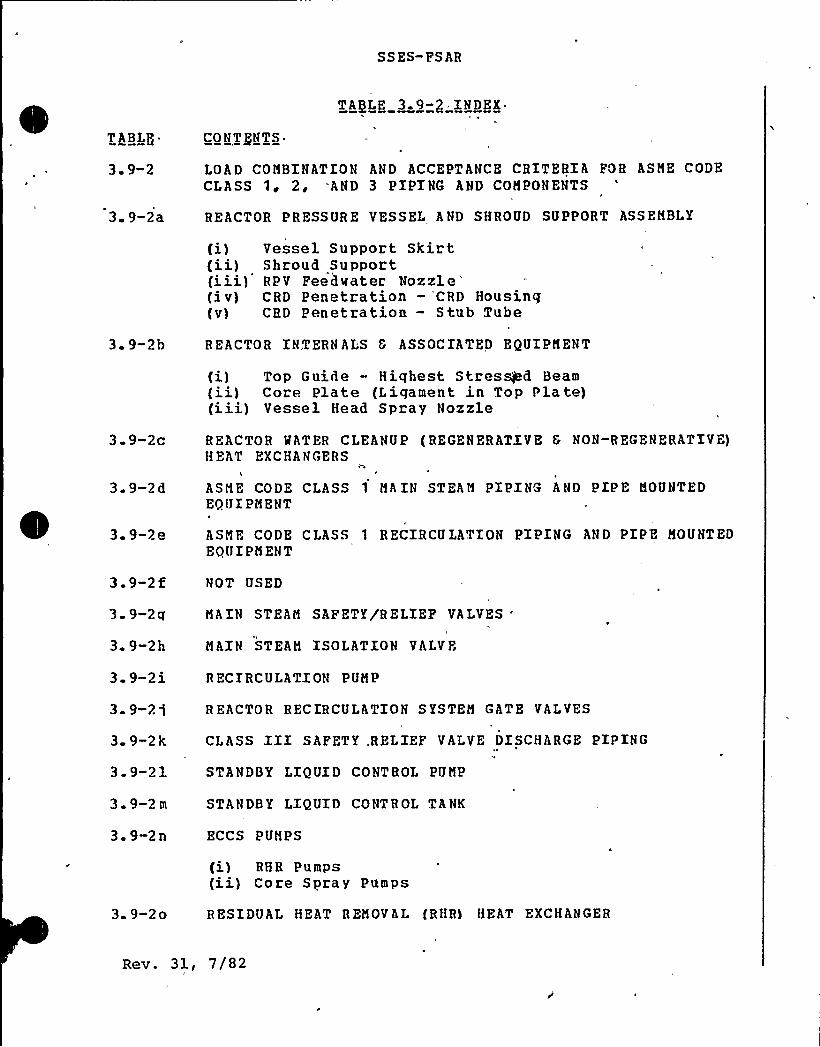
TABLE 3-9-2.INDEX
T ABLP„.
3. 9-2
3 9-2a
CONTENTS.II
LOAD CONBINATION AND ACCEPTANCE CRITERIA FOR ASNE CODECLASS 1i 2, "AND 3 PIPING AND COMPONENTS
REACTOR PRESSURE VESSEL AND SHROUD SUPPORT ASSEMBLY
(i){ii)(iii)(iv)(v)
Vessel Support SkirtShroud SupportRPV Feedwater NozzleCRD Penetration — CRD HousingCRD Penetration — Stub Tube
3 9-2b
3-9-2c
3 9-2d
3. 9-2e
3 9-2t
3 9-2q
3 9-2h
3 9-2i
3. 9-21
3 9-2k
3. 9-21
3. 9-2 m
3. 9-2n
REACTOR INTERN ALS 8 ASSOCIATED EQUIPMENT
(i) Top Guide - Highest Stressed Beam(ii) Core Plate (Ligament in Top Plate)(iii) Vessel Head Spray Nozzle
REACTOR WATER CLEANUP (REGENERATIVE 6 NON-REGENERATIVE)HEAT EXCHANGERS
\
ASME CODE CLASS 1 HAIN STEAN PIPING AND PIPE MOUNTEDEQUIPMENT
ASNE CODE CLASS 1 RECIRCULATION PIPING AND PIPE MOUNTEDEQUIPMENT
NOT USED
MAIN STEAN SAFETY/RELIEF VALVES
'AIN
STEAN ISOLATION VALVE
R ECIRCULATION PUNP
R EACTOR RECIRCULATION S YSTEN GATE VALVES
CLASS III SAFETY .RELIEF VALVE DISCHARGE PIPING
STANDBY LIQUID CONTROL PUMP
STANDBY LIQUID CONTROL TANK
ECCS PUNPS
3 9-2o
{i) RHR Pumps(ii) Core Spray Pumps
RESIDUAL HEAT RENOVAL (RHR) HEAT EXCHANGER
Rev. 31, 7/82
SSES-FSAR
of this portion of the system is specifically exempted from therequirement for volumetric inspection by'paraqraph IRB-1220(a) ofSection XI of the ASME Boiler and Pressure Vessel Code (Summer1975 Addenda) .
Regulatory Guide 1.97 INSTRUMENTATION FOR LIGHT HATERCOOLED NUCLEAR POSER P LA NTS TOASSESS PLANT CONDITIONS DURINGA ND FOLLOW'KNG AN ACCIDENT/Decem her 1975)
The accident monitoring instrumentation was designed prior tothis Regulatory Guide beinq issued. The instrumentation foraccident monitorinq is not specifically identified on the con.rolpanels and has not been evaluated aqainst Regulatory Guide 1.97,Revision l."
Safety related display instrumentation and seismic qualificationwill be addressed followinq issue and project resolution of Beg..Guide 1.97 (Rev. 2) .
Peaulatorv Guide 1.98 ASSUMPTIONS USED F OR EVALUAgXNGT HE POTENTI AL R ADIOLOGICALCONSEQJJENCES OF A RADIOACTIVEOFFG AS SYSTEM PAILUR E IN A
BOILING MATER RFACTOR/March 1976)
Subject to the clarifications or exceptions indicated below, theassumptions of. Regulatory Guide 1.98 are followed in the analysesof the o ffgas system failure in Subsection 15. 7. 1.
(1) Reference: Position C. 4. a. Dose conversion factors aretaken from the most recent data available. The average beta andqamma enerqies used are given in Section 15. 8.
-{2) Reference: Position C.4.a. External whole-body gamma dosesand beta-skin doses are presented separately, inasmuch as thedose from beta radiation to the whole body is negligible. Thet.otal dose to the skin is the sum of. the beta-skin dose andwhole-body dose.
Regulatory Guide 1.99 EFFECTS OF RESIDUAL ELEMENTSON PRF,DICTED RADIATION DAMAGETO REACTOR VESSEL MATERIALS/Revision 1 Ao".il 1977)
GF. is responds.nq to this guide under the Appendix G proqramFracture Toughness Requirements.
Rev. 32, 12/82 3~1337
SS ES-PS AR
Regulatory Guide 1.100 SEISMIC'UALXFICAT.ION OFELECTRIC EQUIPMENT PORNUCLEAR POMER PLANTS/larch 1976}
~I
The implementation paragraph'of this regulatory guide states thatthe requirements of the position statements will 'only he appliedto plants that received construction permits after November 16,1976. The Construction Permit for Susquehanna SES was issued inNovember 1973 and therefore the guidelines of this regulatoryguide have not been utilized in- the design of this nurlear powerstation.Seismic qualification of the safety related electric equipment{non-NSSS scope nf supply) has been conducted in accordance witht.he TFFF. Standard 344-1971. Section 3.10 describes t he completequalifiration methods and procedures that have been utilized.The safety-related electric equipment {NSSS scope of supply)meets IFEE 323-1971 and IEEE 344-1971.
Regulatogv Chide 1. 101 - FNFRGENCY PLANNING FORNUCLEAR PONEB PLANTS
Nithd awn September 24 ~ 1980. ~
Regulatory Guide 1. 102 - PLOOD PROTECTION POR NUCLEARPOMER PLANTS (Revision 1,September 1976}
The present design of the Susquehanna SES complies with theprovisions of this regulatory quide.
/equi.a+or@ Guide 1. 103
Not Applicable.
POSTTE NSIONED PRESTRESSZ NGSYSTENS POR CONCRETE REACTORV ESS ELS A ND CONTAINNENTSggevision l~ October 1976}
Regii1atory ('uide 1.104 — OVERHEAD CRANE HANDLING SYSTEMSPOR NUCLEAR POWER PL ANTSQPehruary 1976}
Subject to the clarifications and exceptions indicated below, thesafety related overhead rrane handling systems of this stationcomply with the provisions of this regulatory guide.
{1) Reference: Position C. 1.b (2). The nil-ductility transitiontemperature for the structural steel associated with the craneswas not determined as suggested by this position. Position
Rev. 32, 12/82 3 13-3 8

SSES-PSAR
5.3.1.4.1.3 Regulatory Guide 1.43, (5/73) Control ofStainless Steel Meld Cladding of Low-AlloySteel ~Com onents
Reactor pressure vessel specifications require that all low alloysteel be produced to fine grain practice. The requirements ofthis regulatory guide are not applicable to BMR vessels.
5.3.1.4.1.4 Regulatory Guide 1.44, (5/73) Controlof the Use of Sensitized Stainless Steel
Controls to avoid severe sensitization are discussed inSubsection 5. 2. 3. 4. l. l.
5.3.1.4.1. 5 Regulatory Guide 1. 50 (5/73), Control of PreheatTe~merature for Meld in@ Low-All~oSteel
preheat controls are discussed in Subsection 5.2.3.3.2.1.
~
~5.3.1 4.1.6 Regulatory Guide 1.71, (12/73) MelderQualification f~oAreas of Limited Accessibility
Qualification for areas of limited accessibility is discussed inSubsection 5. 2. 3. 3. 2. 3.
5-3-1.4.1.7 Regulatory Guide 1.99, (Rev. 1) Effects of ResidualElements on Predicted Radiation Damage toReacto~r ressure Vessel Materials
Predictions for changes in transition temperature and upper shelfenergy were made in accordance with the requirements ofRegulatory Guide l. 99.
Rev. 13, ll/79 5 ~ 3 3
SSES-PSAR
5 3 1 5 Practure Toughness
5 3.1.5 l Compliance with lOCPR50 Appendix G
A major condition necessary for full compliance to Appendix G issatisfaction of the requirements of the Summer 1972 Addenda toSection III. This is not possible with components which werepurchased to earlier Code requirements. Por the extent of thecompliance, see Tables 5. 3-1a and 5.3-2a.
Perritic material complying with 10 CFR 50, Appendix G, must haveboth drop weight tests and Charpy V-notch (CVN) tests with theCVN specimens oriented transverse to the principal materialworking direction to establish the RTNDT The CVN tests must heevaluated against both an absorbed energy and lateral expansioncriteria. The maximum acceptable RT DT must be determined inaccordance with the analytical procedures,of ASNE Code SectionXII, Appendix G. Appendix G of 10 CFR 50 requires a minimum of75 ft-lb upper shelf CVN energy for beltline material. j:t alsorequires at least 45 ft-lb CVN energy and 25 mils lateralexpansion for bolting material at the lower of the preload orlowest service temperature.
By comparison, material, for the Susquehanna SES reactor vesselswas qualified by either drop weight tests or longitudinallyoriented CVN tests (both not required), confirming that thematerial nil-ductility transition temperature (NDTT) is at least60oF below the lowest service temperature. When,the CVN test wasapplied, a 30 ft-lb energy level was used in defining the NDTT.There was no upper shelf CVN energy requirement on the beltlinematerial. The bolting material was qualified to a 30 ft-lbenergy requirement at 60oP below the minimum preload temperature'.
Prom the previous comparison it can be seen that the fracturetoughness testing performed on the SSES reactor vessel materialcannot be shown to comply with 10 CFR 50, Appendix G. However,to determine operating limits in accordance with 10 CPR 50,Appendix G, estimates of the beltline material RTNDT and thehighest RTNnT of all other material were made, as explained inSubsection 5.3. 1.5 1 2 The method for developing theseoperating limits is also described therein.
On the basis of the last paragraph on page 19013 of the July 17,1973, Federal Register, the following is considered anappropriate method of complaince
Rev. 13, ll/79 5.3-4

SSES-FSAR
- 5 3 1.5 1.1 Intent of Proposed A~roach
The intent of the proposed special method of compliance withAppendix G for this vessel is to provide operating limitations onpressure and temperature based on fracture toughness. Theseoperating limits assure that a margin of safety against anonductile failure of this vessel is nearly the same as that fora vessel built to the Summer 1972 Addenda.
The specific temperature limits for operation vhen the core iscritical are based on a proposed modification to 10 CFR 50,Appendix G, Paragraph IV, A.2.C. The proposed modification andthe'ustification for it are given in GE Licensing TopicalRepor t, N EDO-21778- A.
5 3.1.5.1 2 O~eratinq Limits Based on Fracture Toughness
Operating limits which define minimum reactor vessel metaltemperatures vs reactor pressure during normal heatup andcooldown and, during in-service hydrostatic testing, wereestablished using the methods of Appendix G of Section III of theASIDE Boiler and Pressure Vessel Code, 1971 Edition, including thesummer 1972 Addenda. The results- are shown in Figure 5.3-4a forUnit 1 and 5.3-4b for Unit 2.
All the vessel shell and head areas remote .from discontinutiesplus the feedwater nozzles were evaluated, and the operatinglimit curves are based on the limiting location. The boltuplimits for the flange and adjacent shell region are based on aminimum metal temperature of RTNDT + 60O. The maximum through-wall temperature gradient from continuous heating or cooling at100oF per hour vas considered. The safety factors applied wereas specified in ASIDE Code, Appendix G, and GE Licensing TopicalReport, N ED0-21778-A.-
For the purpose of setting these operating limits, the referencetemperature, RT NDT, is determined from the toughness test datataken in accordance vith reguirements of the Code to vhich thisvessel is designed and manufactured This toughness test data,Charpy V-notch (CVN) and/or drop- veight nil-ductility transitiontemperature (NDT) is analyzed to permit compliance vith theintent of 10 CFR 50, Appendix G. Because all toughness testingneeded for strict compliance with Appendix G was not required atthe time of vessel procurement, some toughness results are notavailable. For example, longitudinal CVN's, instead oftransverse, were tested, usually at a single test temperature of+10oF or +40~F, for absorbed energy. Also, at the time eitherCVN or NDT testing was permitted; therefore, in many cases both
Rev. 13, ll/79 5. 3-5
SSES-PSAR
tests were not performed as is currently required. To substitutefor this absence of certain data, toughness property correlationswere derived for the vessel materials in order to operate uponthe available data to give a conservative estimate of RQDT,compliant with the intent of Appendix G criteria.These toughness correlations vary, depending upon the specificmaterial analyzed, and were derived from the results of WRCBulletin 217, "Properties of Heavy Section Nuclear ReactorSteels", and from toughness data from the Susquehanna SES vesselsand other reactors. In the case of vessel plate material (SA-533Grade B, Class 1), the predicted limiting toughness property iseither NDT or transverse CVN 50 ft-lb temperature minus 60<P.CVN and NDT are available for all the beltline plates. Where NDTresults are missing, NDT is estimated as the longitudinal CVN 35ft-lb transition temperature. The transverse CVN 50 ft-lbtransition temperature is estimated from longitudinal CVN data inthe following manner. The lowest longitudinal CVN ft-lb value isadjusted to derive a longitudinal CVN 50 ft-lb transitiontemperature by adding 2oF per ft-lb to the test temperature. Ifthe actual data equal or exceed 50 ft-lb, the test temperature isderived by interpolation. Once the longitudinal 50 ft-lbtemperature is derived, an additional 30>P is added to accountfor orientation effects and to estimate the transverse CVN 50 ft-lb temperature minus 60oF, estimated in the preceding manner.
For forgings (SA-508 Class 2),the same as for vessel plates.for the vessel flange, closurematerials for Susquehanna SES.way as for vessel plates.
the predicted limiting property isCVN and NDT values are available
head flange,,and feedwater nozzleRTNpT is estimated in the same
For the vessel veld metal, the predicted limiting property is theCVN 50 ft-lb transition temperature minus 600P, as the NDT valuesare -50<F or lower for these materials. This temperature isderived in the same way as for the vessel plate material, exceptthe 30eF addition for orientation effects is omitted since thereis no principal working direction. When NDT values areavailable, they are also considered and the RT„DT is taken as thehigher of NDT or the 50 ft-lb temperature minus 60OP. When NDTis not available, the RT NDT shall not be less than -50OF, sincelower values are not supported by the correlation data.
Por vessel weld heat affected zone (HAZ) material, the RTMpq isassumed the same as for the base material as ASNE Code wellprocedure qualification test requirements, and post weld heattreatment indicates this assumption is valid.Closure bolting material (SA-540 Grade B24) toughness testrequirements for Units 1 and 2 were for 30 ft-lb at 60>P belowthe bolt-up temperature. Current Code requirements are for 45
Rev. 13, ll/79 5. 3-6

SSES-FSAR
ft-lb and 25 mils lateral expansion (HLE) at the preload orlowest service temperature, including bolt-up. Therefore, sinceCVN values as low as 40 ft-lb (with 25 mils lateral expansion)exist at the 10eP test temperature for Unit 1 closure bolts, 60ePis added to the test temperature in order to derive the bolt-uptemperature of 70eP. All Unit 2 closure stud materials meetcurrent requirements at 100P.
Using the above general approach, an initial RTNDT of +18eP wasestablished for the core beltline region for Unit l and +30oP forUnit 2.
The effect of the main closure discontinuity was considered byadding 600P to the RTN~T to establish the minimum temperature forboltup and pressurization. The minimum bolt-up temperature of+704F for Units 1 and 2, which is shown on Figures 5-3.4a and5.3-4b, is based on an initial RTNDT of- +10eF for the closureflange forgings.
The effect of the feedwater nozzle discontinuities was consideredby adjusting the results of a BMR/6 reactor discontinuityanalysis to the reactor. The adjustment was made by increasingthe minimum temperatures required by the difference between theSusuehanna SES and BMB/6 feedwater nozzle forging RTNDT 's.= Thefeedwater nozzle adjustment was based on an RTNDT of —16oP forUnit 1 and an RTNDT of -10eP for Unit 2.
The reactor vessel closure studs for Unit 1 have a minimum Charpyimpact energy of 40 ft-lbs and a 25-mil lateral expansion at10eP. The lowest service temperature for the closure studs is70oP for Unit 1. For Unit 2, the closure studs have a minimumCharpy impact energy of 48 ft-lb and a 27-mil laterial expansionat 10eP; therefore, the lowest service temperature for the Unit 2closure studs is '+10eP.
5.3.1.5.1.3 Operating Limits During Heatup, Cooldown andCore Operation
The fracture toughness analysis was done for the normal heatup orcooldown rate of 100oP/hour. The temperature gradients andthermal stress effects corresponding to this rate were includedThe results of the analyses are a set of operating limits fornon-nuclear heatup or cooldown shown as curves labeled B onFigures 5.3-4a and 5.3-4b. Curves labeled C on these figuresapply whenever the core is critical. The basis for the C Curvesis described in GE BQR Licensing Topical Report NEDO-21778-A
Rev. 13, ll/79 5. 3-7,
SSES-FSAR
5.3.1.5 1 4 Temperature Limits for Preoperational SystemHydrostatic Tests and ISI Hydrostatic or LeakPressure Tests
Based on 10 CFR 50, Appendix G, IV, A.2.d, which allows a reducedsafety factor for tests prior to fuel loading, the preoperationalsystem hydrostatic test at 1563 psig may be performed at aminimum temperature of 1170F for Unit 1 and 129eP for Unit 2which is established by the intermediate shell plate RTNDT of20 F for Unit 1 and the core beltline plate RTNDT of 30eF forUnit 2.
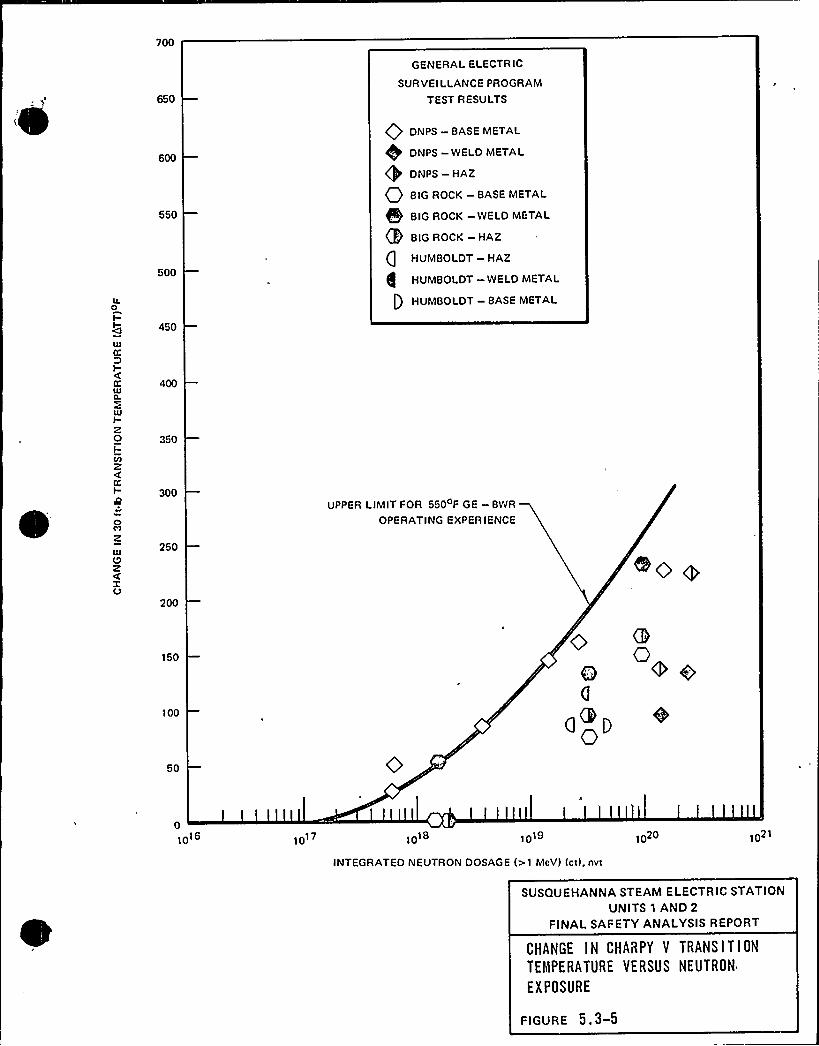
The fracture toughness analysis for in-service inspection or leakpressure tests resulted in the curves labeled A shown in Figures5.3-4a and 5.3-4b. The curves labeled "core beltline" are basedon an initial RTND of +18eP for Unit 1 and +30eP for Unit 2.The predicted shVZt in the RTNpY from Pigure 5 ~ 3<c {based on theneutron fluence at 1/4 of the vessel wall thickness) must beadded to the beltline curve to account for the effect of fastneu tron s.
5 3. 1. 5. 1.5 Temperature Limits for Boltup
A minimum temperature of 70> for Unit 1 and of 100 for Unit 2 isrequired for closure studs. A sufficient number of studs may betensioned at 700P to seal the closure flange 0-rings for thepurpose of raising reactor water level above the closure flangesin order to assist in warming them. The flanges and adjacentshell are required to be warmed to a minimum temperature of 70 Fbefore they are stressed by the full intended bolt preload. Thefully preloaded bolt-up limits are shown on Figure 5.3-4a forUnit 1 and Figure 5.3-4b for Unit 2.
5 3.1.5. 1 6 Reactor Vessel Anneali~n
In-place annealing of the reactor vessel because of radiationembrittlement is unnecessary because the predicted end of lifevalue of adjusted reference temperature will not exceed 2000F,(see 10 CPR 50, Appendix G, Paragraph IV.C)
Rev. 13, ll/79 5. 3-8
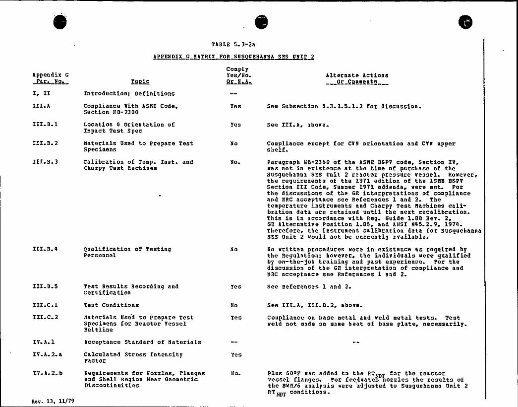
TABLE 5. 3-2a
APPENDIX G HATRIX FOR SUSQUEHANNA SES UNZF 2
Appendix G
Pa r. No.
Z~ IIIIZ A
To~le
Introduction; Definitions
Compliance Mith ASHE Code,Section NB-2300
ComplyYes/No.0 N A
Yes
Alternate ActionsOg QpaagBts
See Subsection 5.3.1.5.1.2 for discussion.
IIZ B 1
ZIZ B 2
Location 8 Orientation ofImpact Test Spec
Haterials Used to Prepare TestSpecimens
Yes
No
See III.A~ above.
Compliance except for CVN orientation and CVN uppershelf.
III B 3 Calibration of Temp. Inst. andCharpy Test Hachines
No. Paragraph NB-2360 of the ASHE BSPV code, Section IV,vas not in existence at the time of purchase of theSusquehanna SES Unit 2 reactor pressure vessel. However,the requirements of the 1971 edition of the ASHE BSPVSection III "ode, Summer 1971 addenda, vere met. Forthe discussions of the GE interpretations of complianceand NRC acceptance see References 1 and 2. Thetemperature instruments and Charpy Test Hachines cali-bration data are retained until the next recalibration.This is in accordance vith Reg. Guide 1.88 Rer. 2,GE Alternative Position 1.88, and ANSI N45. 2.9, 1974.Therefore, the instrument calibration data for SusquehannaSES Unit 2 vould not be currently available.
ZII B
IIZ B 5
Qualification of TestingPersonnel
Test Results Recording andCertification
No
Yes
No vritten procedures vere in existence as required bythe Regulation; however, the individuals vere qualifiedby on-the-gob training and past experien"e. For thediscussion of the GE interpretation of compliance andNRC acceptance see References 1 anil 2.
See References 1 and 2.
IIZC1ZIZ C 2
Test Conditions
Haterials Used to Prepare TestSpecimens for Reactor VesselBeltline
Yes
See III.A, III.B.2, above.
Compliance on base metal and veld metal tests. Testweld not made on same heat of base plate, necessarily.
IV A 1
IV.A.2.a
Acceptance Standard of Haterials
Calculated Stress IntensityFactor
Yes
IV A 2 b
Rev. 13, 11/79
Requirements for Nozzles, Flangesand Shell Region Near GeometricDiscontinui ties
Noi Plus 60~F vas added to the RTNDT for the reactorvessel flanges. For feedvater, nozzles the results ofthe BWR/6 analysis vere ad)usted to Susquehanna Unit 2RT~> conditions.
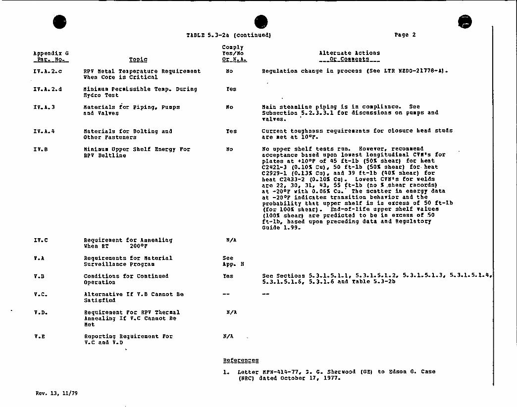
eTABLE 5.3-2a (continued) Page 2
Appendix GPar. No
IVA2cT~oic
RPV Netal Teaperature RequirementWhen Core is Critical
ComplyYes/No0 N A
Alternate ActionsOr Comments
Regulation change in process (See LTR NEDO-21778-A).
IV A 2
IV A.3
IV A 4
IV B
IV~C
Ninimum Permissible Temp. DuringHydro Test
Naterials for Piping, Pumpsand Valves
Naterials for Bolting andOther Fasteners
Ninimum Upper Shelf Energy ForRPV Beltline
Requirement for AnnealingWhen RT 200oF
Yes
Yes
N/A
Hain steamline piping is in compliance. SeeSubsection 5.2.3.3.1 for discussions on pumps andvalves.
Current toughness requirements for closure head studsare met at 104F.
No upper shelf tests ran. However, recommendacceptance based upon lowest longitudinal CVN's forplates at +10oF of 45 ft-lb (50% shear) for heatC2421-3 (0.10% Cu), 50 ft-lb (50% shear) for- heatC2929-1 (0.13% Cu), and 39 ft-lb (40% shear) forheat C2433-2 (0 10% Cu). Lowest CVN's for weldsare 22, 30 ~ 3)., 43, 55 ft-lb (no % .shear records)at -20oF with 0. 06% Cu. The scatter in energy dataat -20oF indicates transition behavior and theprobability that upper shelf is in ercess of 50 ft-lb(for 100% shear) . End-of-life upper shelf values(100% shear) are predicted to be in ezcess of 50ft-lb, based upon preceding data and RegulatoryGuide 1.99.
V B
V C
Requirements for NaterialSurveillance Program
Conditions for ContinuedOperation
Alternative If V.B Cannot BeSatisfied
SeeApp H
Yes See Sections 5.3 1.5.1.1 ~ 5.3.1.5.1.. 2, 5.3.1.5.1.3, 5.3.1.5.1.4,5. 3.1.5.1.6 ~ 5. 3.1.6 and Table 5.3-2b
V D
V E
Requirement For RPV ThermalAnnealing If V.C Cannot BeNet
Reporting Requirement ForV.C and V.D
N/A
N/A
Referen"es
1. Letter NFN-414-77 '. G. Sherwood (GE) to Edson G. Case(NRC) dated October 17 '977.
Rev. 13, 11/79
Appendix G
~ra so T~oic
TABLE 5.3-2a (continued)
ComplyYes/NoOr I A
Alternate ActionsOr Coaaents
Page 3
2. Letter, Robert B..Hinogue (KRC) to G. G. Shervood (GE)dated Pebruary 10, 1978.
Rev. 13, 11/79
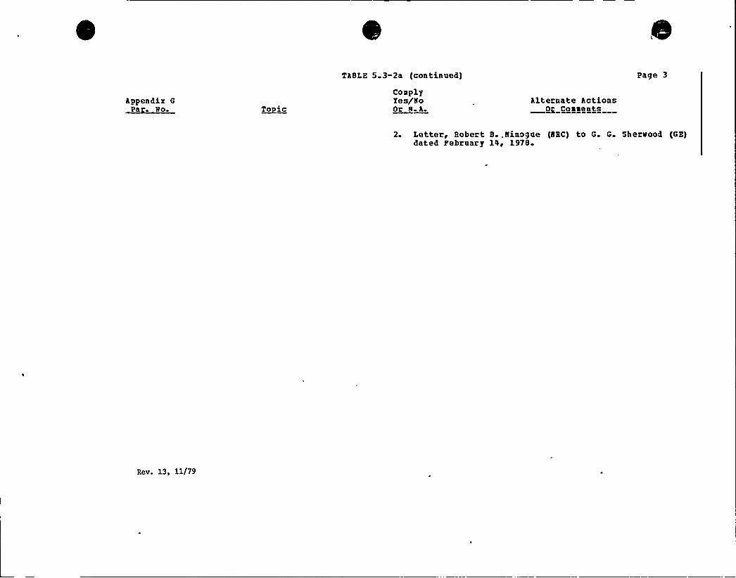
700
650
GENERAL ELECTRIC
SURVEILLANCEPROGRAM
TEST RESULTS
IL0I-I-
IllCC
DI-KlU
lUI-z0I-V)zCCI-80
O
zUJQzxO
550
500
450
350
300
250
Q'NPS —BASE METAL
DNPS —WELD METAL
DNPS —HAZ
O BIG ROCK —BASE METAL
BIG ROCK -WELD METAL
BIG ROCK —HAZ
(] HUMBOLDT—HAZ
(Im HUMBOLDT—WELD METAL
[) HUMBOLDT—BASE METAL
UPPER LIMITFOR 550 F GE —BWR
OPERATING EXPERIENCE
150o 0e + e
an050
101 10 IP18 1019 IP20
102'NTEGRATED
NEUTRON DOSAGE (> I MeVI (ct), nvt
SUSQUEHANNA STEAM ELECTRIC STATIONUNITS 1 AND 2
FINALSAFETY ANALYSIS REPORT
CHANGE IN CHAIRPY V TRANSITION
TEMPERATURE VERSUS NEUTRON
EXPOSURE
FIGURE 5. 3-5

0
SS ES-FS AB
inst umentation and control systems and no discussion isprovided.
b) Non-NSSS — Refer to Subsection 3.11.2b.2 and Section3 13.
7,1.?,6,9 Conformance to Qequlatory Guide 1.47 $ 5/73}
NSSS — The system of bypass indication is designed tosatisfy the requirement of 'IEEE 279-1971 paraqraph 4.13and Regulatory Guide 1. 47 and is discussed for eachsa fet v- related system under Sections 7. 2, 7. 3, 7. 4, and7.6. The desiqn of the bypass indication system allowste .ting durihq normal operation and 'is used tosunDlement adminis+rative procedures by providingindications of safety systems status.
H
The bypass indication system is designed and installedin a manner which precludes the possibility of adverseaffects on the plant. safety system. The bypassindication system is electrically isolated from theprotection circuits such that the failure or bypass of aprotective inunction is not a credible consequence offailures in the bypass indication system and the bypassindication system cannot reduce the independence betweenredundant safety systems.
h) Non-NSSS — Refer to individual systems in Section 7. 3and discussion in Section 7.5
7. 1.2.6. 0 Conformance to Regulatory Guide 1.53 f6/7 3la
a) NSSS — The safety-related system designs conform to thesingle failure criterion. The analysis portions ofSections 7.2, 7.3, 7.4 and 7.6 provide furtherd iscu ssion.
h) Non-NSSS Refer to Section 3.13
7.1.2.6.11 Conformance to Regualtory Guide 1.62 $ 10/73)
a) NSSS — Manual initiation of the protective action isprovided at the system .level in the Reactor ProtectionSvs+em, (primary) Containment and Reactor VesselTsolation Control System and Hmerqency Core Coolinq
Rev. 32, 12/82 7. 1-45
SSES-FS AR
System.".. The analy is portions of Sections 7.2 and 7.3provide further discussion.
h) Non-NSSS — Refer to Section 3.13.
7. 1.2. 6. 12 ConFormance to Regula tory Guide 1 63 (10/73)0 e ~ 0
a.)
h.)
NSSS — Ro..qulatory Guide 1. 63 applies to elect icalpenetration assemblies which are not part of NSSS scope.
Non-NSSS — Refer to Section 3. 13.
7. 1.2.6.13 Conformance to Regulatory Guide j.68 $ 11/73}
Ref er to Section 3. 13.
7. 1.2. 6. 14 Conformance to Regulatory Guide 1.70 QRev. 2}
The format and content of Chapter 7 conform to the requirementsof Requlatory Guide 1.70.
Ref er to Sect.ion 3.13.
7.1.2.6.16 Conformance to Regggagogy Ggide 1.75 $ 1/75}
a) NSSS Regulatory Guide 1.75 is not applicable toSusquehanna SES: however, degree of compliance toseparation criteria of IEEE 384 is discussed inSubsection 7.1.2.5.8.
b) Non-NSSS — Refer to Section 3.13 and Subsection 8.1.6.1,Paraqraph n.
7. 1 2.6 17 Conformance to Regulatory Guide 1.80 (6/74)g ~ g
a) NSSS — Requlatory Guide 1.80 applies to the testing ofinstrument air systems which are not part of the NSSSscope o
Rev. 32, 12/82 7. 1-46
SS ES- FS AR
b) Non-~SSS — Refer to Section 3. 13.
7.1.2.6. 18 Conformagcp to Regulatory Guide 1.89 $ 11/74)
a) NSSS — See the Susquehanna SES Environmental EquipmentQualification Program.
b) Non->! SSS — Refer to Section 3.13.'I
7. 1.2. 6. 19 Conformance to Regulatory Guide 1. 96 $5g75}
Main Steamline Tsolation Valve Leakage Control System is designed+o the requirements of Regulatory Guide 1.96. Furtherdiscu.ssion is provided in Subsection 7.3.2a.3.
7.1.2.7 Technical Design Bases
The technical desiqn bases for RPS are in Subsection 7.2. 1, torengineered -.a fety features .in Subsection 7.3.1, for systemsrequired for safe shutdown in Subsection 7.4.1, and for othersystems req»ired for safety in Subsection 7.6.1.
7.1.2.8 Safety System Settings
The safety system setpoints are listed in the TechnicalSpecifications. The settings are determined based on operatingexperience and conservative analyses. The settinqs are higheno»qh «o preclude inadvertant initiation of the safety action,hut low enouqh to assure that significant margin is maintainedbetween the actual settinq and the limitinq safety systemsettings. Tnstrument drift, setability and repeatability areconsidered in the setpoint determination (soe Subsections7.1.2a.4 and 7.1.2b.4). The margin between the limiting safetysystem settings and the actual safety limits includeconsideration of the maximum credible transient in the processbeinq measured.
The periodic test frequency for each variable is determined from«xperimental data on setpoint Grift and from quantitativereliability requirements for each system and its components.
Rev. 32, l2/82 7. 1-47
SSES-PS AR
equipped for automatic depressurization are identical. Tenadditional safety/relief valves providing only the SRV functionare discussed in Subsection 7.7.1.12.
7.3.1.1a.1.4.2 Eguipmept Design
The control system consists of drywell pressure and reactor waterlevel sensors arranqed in trip systems that control two solenoid-operated pilot air valves )one for each ADS system) for eachsafety relief valve. Each of these two air valves controlspneumatic pressure for safety relief valves actuation. (A thirdsolenoid-operated pilot air valve with each safety relief valveis used for the Relief Valve function. See Subsection 7.7.1.12for details of Relief Valve control.) An accumulator is includedwith the control equipment to store pneumatic energy forsafetv/relief valve operation. The accumulator is sized toprovide air for five actuations of the ADS piston type pneumaticactuator via the solenoid valves, following failure of thepneumatic supply to the accumulator. Cables from the sensorslead to the control structure where the loqic arrangements areformed in cabinets. The electrical control circuitry is poweredby dc from the plant batteries. The power supplies for theredundant control circuits are selected and arranged to maintaintrippinq ability in the event of an electrical power circuitfailure. Electrical elements in the contxol system energized tocause openinq of the safety/relief valve.
7.3 1.1a.1.4.3 Initiating Circuits
The pressure and level switches used to initiate one ADS logicare separated from those used to initiate the other logic on thesame ADS valve. Reactor vessel low water level is detected bysix switches that measure differential pressure. Primarycontainment hiqh pressure is detected by four pressure switches,which are located outside the primary containment and inside thereactor buildinq. The level instruments are piped individuallyso that an instrument pipeline break will not inadvertentlyinitiate auto blowdown. The primary containment high pressuresignals are arranged to seal into the control circuitry; theymust be mapually reset to clear.
A timer is used in each ADS logic. The time delay -setting beforeactuation of the ADS is long enouqh that the, HPCI system has timeto operate, yet not so long that the LPCI and CS systems areunable to adequately cool the fuel if the HPCI system fails tostart. An alarm in the main control room is annunciated wheneither of the timers is timing. Resetting the ADS initiatingsignals recycles the timers.
R EV 30, 5/82 7 & 3 1 3

SS ES- FS AR
7.3.1 1a.1.4.4 Logic and Sequencing
Three initiation siqnals are used for the ADS. namely, reactorvessel low water level, drywell hiqh pressure, and RHR and/or CSpumps runninq. All signals must be present to cause thesafety/relief valves to open, as shown in Pigure 7.3-5. Reactorvessel low water level indicates that the fuel is in danger ofbecoming uncovered. The second (lower) low water level initiatesthe ADS. Primary containment high pressure indicates a breach inthe RCPB inside the drywell. A permissive signal indicating LPCIor CS pump discharge pressure is also required. Dischargepressure on any one of the RHR pumps or either pair of the CS
pumps (ABC) or (BGD) is sufficient to give the permissive signal,which permits automatic depressurization when the LPCI and CS
systems are operable.
After receipt of the initiation signals and after a delayprovided by timers, each of the pilot qas solenoid valves isenergized. This allows pneumatic pressure from the accumulatorto act on the qas cylinder operator. The gas cylinder operatorholds the relief valve open. Lights in the main control roomindicate when the solenoi d-operated pilot valves are ener gized toopen a safety/relief valve.
Manual reset circuits are provided for the ADS initiationsignals. By manually resettinq the initiation signal the delaytimers are recycled. The operator can use the reset push buttonsto delay or prevent automatic opening of the relief valves ifsuch delay or prevention is prudent.
Control switches are available in the main control room for eachsafety/relief valve associated with the ADS. The OPEN positionis for manual safety/relief valve operation.
Two ADS loqics trains are provided as shown in Figure 7.3-8.Division I sensors for low reactor water level and high drywellpressure initiate ADS A (logics A 6 C), and Division II sensorsinitiate ADS B (loqics B 6 D) . One o f the two solenoid-operatedpilot air valves associated with each safety relief valves iscontrolled by ADS A and the other is controlled by ADS B.
The reactor vessel low ~ater level initiation setting for the ADSis selected to depressurize the reactor vessel in time to allowadequate coolinq of the fuel by the LPCI system or CS systemfollowinq a LOCA in which the HPCI system fails to perform itsfunction adequately. The primary containment high pressuresetting is selected as low as possible without inducing spuriousinitiation of the automatic depressurization system. Thisprovides timely depressurization of the reactor vessel if theHPCI system fails to start, or fails after it successfully startsfollowinq a LOCA.
R EV. 30, 5/82 7. 3-14
SS ES- FS AR
7 3.1.1h.8.1.5 Supporting Systems
The ESSW pumphouse HVAC system described in Subsection 9.4.8 is asupportinq system to the emergency service water system.
7.3.1.1h.8.1.6 ESW Instrumentation Not Required for Safety
Non-safety related instrumentation in the control room includes:
a) ESW pump A/C discharge header temperature (loop A)
b) ESW pump B/D discharqe header temperature (loop B)
c) Diesel qenerator A cooler outlet temperature
d) Diesel qenerator B cooler outlet temperature
e) Diesel generator C cooler outlet temperature
f) Diesel qenerator D cooler outlet temperature
q) ESW loop A (B) flow (recording)
Refer to Section 7.5 for instrument ranges, accuracy, and panelj.ocation for the above mentioned instruments.
Control room annunciators are not required for safety, but alertthe operator of abnormal process conditions. The followingalarms are in the main control room:
a) Spray pond low level
b) ESSW structure flooded
c) ESW loop low flow
d) Diese 1 generator coolers hiqh outlet temperature
e) Diesel qenerator rooms flooded
7.3.1.1b.8.2 RHR Service Water System — Instrumentationand Controls
The description, the design basis and the safety evaluation ofthe RHR service water system are in Subsection 9.2.6.
REV. 30, 5/82 7 3-89
SS ES-PS AR
The controls and instrumentation for the RHR service water systemare designed to provide adequate information to the control roomoperator for control and monitorinq of the system during systemoperatinq modes. Capability for test and calibration is providedas descr ibed in Subsection 7. 3. 2b. 2-4. 10.
7.3.1.1b.8.2.1 Iqitiagjon Circuity
The RHR service water system can be manually initiated fromeither the main control room or the remote shutdown panel.
7. 3. 1. 1b. 8. 2,2 Logic~ Bypasses~ Interlocks~ and Seguencing
The BflR service water system control logics are designed usingelectromechanical relays and control switch signals to actuatethe equipment.
7.3. 1. 1h.8.2 2. 1 Loaic Power Source
The BHB service water system loqics are powered from twoindependent divisionalized 125 V dc Class 1E power sources.Refer to Section 8.3 for description.
7.3. 1 1h.8.2.2 2 Pumo Control Loaic
For documentation of the loqic, refer to electrical schematicdiagram E-150 which was submitted under separate cover.
Each BHBSR pump can be started from the ma in control room, or onecan be started from the unit remote shutdown panel (1B/2A) andthe other (1A/2B) from the unit switchgear. In order to startany BHBSM pump the followinq conditions must be satisfied:
a) Power supply bus voltage is available
b) Control switch is turned to pump run position
Any of the followinq conditions trip the circuit breaker to thepump motor:
a) Manual stop by operator in main control room or at theremote shutdown panel (or local circuit breaker controlswitch at the switchqear)
BEV. 30, 5/82 7. 3-90
SSES-PSAR
e) RHR service water radiation monitorinq (refer to Section11. 5)
f) Spray pond temperature
q) Computer inputs for process monitoring
h) Annunciator system
All instrument data and ranqes for the RHR service water systemare listed in Section 7.5.
7.3.1. 1b.8 3 Containment Instrument Gas System Instrumentationand Control
The containment instrument qas system is. described in Subsection9.3.1 5 and qives the desiqn basis, system operation, and safetyevaluation.
The two redundant sets of high pressure nitrogen storage bottlesare designed as an ESF auxiliary supporting system to provide thenecessary compressed qas for the operation of the main steamrelief valves for auto depressurization (ADS) .
Containment isolation of the instrument qas system is describedin Subsection 7 3.1. 1b. 1.. Capability for testing is providedwhen testing containment isolation and further described inSubsection 7. 3. 2b. 2-0. 10.
7. 3. 1. 1b. 8. 3. 1 Initiative@ Logic and Inter locks
A pressure sensinq transmitter is located in piping headers ASB
leading to the ADS relief valves.
A signal from an electronic switch automatically opens theisolation valve of the nitrogen storage bottles if the normalsupply pressure is not available from the gas compressors. A
signal from containment isolation also initiates the automaticopening of the nitrogen storaqe isolation valve.
The manual control of the outboard isolation valves allows theoperator, after determining that adequate supply pressure isavailable from the compressors, to open the normal supply line tothe ADS relief valves. This operation will isolate theinstrument qas storage bottles. However, low instrument gasheader pressure will automatically override this interlock toensure the necessary qas supply.
REV 30, 5/82 7. 3-93
SS ES-PS AB
Refer to electrical schematic diagram E-172 which was submittedunder separate cover.
The loqic power supply for containment isolation valves isdivisionalized from a 125 V dc Class 1E bus.
The instrument panel supply is provided by a 120 V ac Class 1Esource to 120 V ac/24 V dc power supply.
7 3. 1,1b.8. 3 2 Bgpasseg~ Interlocks and Sequencing
The system is not designed with bypass capability.Sequencing is not applicable for this system. This system is notinterlocked with other systems.
7 3.1.1h.8.3 3 Redundancy
Instrumentation and controls are provided on a one-to-one basiswith the mechanical equipment.
7 3.1.1h.8.3.4 Containment Instrument Gas Instrumentation NotRequj,ged for Safety
The instrumentation application discussed in Subsection 9.3.1.5.5describes the monitorinq instruments and controls for*the gascompressors and its controls.
The monitorinq instruments in the auxiliary support system arenot safety-related. Each train of qas bottles has a low headerpressure alarm in the main control room. The isolation valveposition is indicated by status lights on the main control roompanel'. Refer to Table 7.5-7 for listing of instrumentation forthe containment instrument qas system.
7.3 1.1b.8.4 ~ Standby Power System
Descriptions of the standby power system and supporting systemcan be found in the following:
a) Refer to Subsection 8. 3. 1 for description of the dieselgenerators. Refer to Section 7.6.1b 3 for NSSS to non-VASSS diesel initiation signal.
BEV 30 '/82 7. 3- 94

Division 1 Pump Permissive
CSPUMP
A
RHRPUMP
A
RHRPUMP
C
CSPUMP
C
RHRPUMP
A
RHRPUMP
C
AND
STARTADS
Rev. 1,8~ ll/80SUSQUEHANNA STEAM ELECTRIC STATION
UNITS 1 AND 2
FINALSAFETY ANALYSISREPORT
INITIATIONLOGIC ADS > CS > RHR
(SHEET 2)
FIGURE 7 ~ 3

~ SSES-PS AH
Tndicatinq Lamps
(1) Storaqe- tank heaters AGB status
7.4.1.2.5.3 Set points ~
The SLCS has set points for the various instruments as follovs:
(2)
The injection valve position switches are adjusted toindicate the valve is fully open.
'k,
Loss of- continuity activates the annunciator below thetrickle current that is observed when both primers ofan explosive valve are new.
The h iqh a nd low sta ndb y liquid .temperature s ~itch isset to activate the annunciator at temperatures of1100 P and 70~ P, respectively.
(4) The hiqh and lov standby liquid storage tank levelswitch is set to activate the annunciator when thel.ovel is approximately 94% and 89'%f the storage tankcapacity respectively.
(5) The thermostatic controller is set to turn on theoperatinq heater vhen the standby liquid temperaturedrops to 75~P and to turn off the heater at 85~P.
7.4.1.3 RHHS/Reactor Shutdown Coolinq Node-Tnstrumentation hand Controls
7.4. 1.3. 1 System Identification
7. 4.1. 3. 1. 1 punrtion
The shutdown ™oolinq mode of the RHR System (including thereactor vessel head spray) used during a normal reactor shutdovnanR cooldovn is the non-safety portion of the RHRS The shutdovncooling mode utilizes most of the safety classified portions ofthe RHRS.
The initial phase of a normal HCPB cooldown is accomplished byrouting steam from the reactor vessel to the main condenser vhichserves as the heat sink.
Hev. 30, 5/82 7. 4-15

SS ES- FS AR
V
The Reactor Shutdovn Cooling System consists of a set of pumps,valves, heat exchanqers, and instrumentation designed to providedecay heat removal capability for the core. The systemsnecif ically accomplishes tlie folloving:
(1) The reactor shutdown cooling system is 'capable ofnrovtdinq coolinq for the reactor during shutdovnoperation after the vessel pressure is reduced toapproximately 135 psig.
(2) 'The system is capable-of cooling the reactor vater to atemperature at, vhich reac+or refuelinq and servicingcan be accomplished.
The system is capable of diverting'art. of 'he shutdownflow to "a nozzle in the reactor vessel head to condensethe steam generated from the hot walls of the ves.,elwhile it is being flooded.
The system can accomplish its design objectives by a preferredmeans hy directly extracting reactor vessel vater from the vesselvia the rerirulation loop B and routing it to a heat exchangerand bark to the vessel, or by an alternate means by indirectlyex+ractinq the water via relief valve discharge lines to thes»ppres..ion pool and routinq pool water to the heat exchanger andback to the vessel.
7. 4. 1. 3. 1. 2 - Classif ication
Electrical components for the Reactor Shutdown Cooling Node ofthe Residual Heat Removal System are classified as Safety Class 2and Seismic Cateqory X.
7.4.1. 3. 2 Power Sources
This system utilizes standby pover sources, since the RHRS has
!
safety modes of operation (e. g., LPCX) connect'ed to= thisequipment.
7. 4. 1. 3. 3 Fa»igment De."ign
7. 4. 1. 3. 3. 1 general\
The reactor water is cooled by taking suction f rom one of therecirculation loops; the water is pumped through the system heat
Bev. 30, 5/82 7. 4-16

SS ES- PS.AB
7-5 SAFETY RELATED ~ DISPTAY INSTRUNENTATION gSRDXL
Safety Related Display Instrumentation (SRDI) required for safefunctioninq,of the plant duzinq normal operating and. accidentronditions is incorporated in a control zoom complex named theAdvanced Control Room (ACR). It is necessary to consider the ACR
as a vhole to verify conformance to the requirements.
The ACR is a complex of ma]or components, provided vith the NSSS, ~
for monitor'inq and controllinq tvo units and providinq safetyfunctions. The entire complex consists .of the Power GenerationControl Comple(x (PGCC) in the upper relay room at the 754 ft0 in. level .and the lower relay room at the 698 ft 0 in. level,the plant computer system at the 698 ft O,in. level and theplant-operator interface at the 729 ft 0 in. level.
a) PGCC,
The PGCC provides support and interconnections to'hesystems panels of the upper and lover relay rooms and
'hecomputer room of the ACR complexe The plant-o'perator interface noted belov is not mounted on PGCC,hovever, all" other principles of the PGCC concept, eg,separation, are used.
b) Plant-operator Interface1
Na|or romponents are in the main control zoom arrangedas shown on Figure 7.5-1. and include the folloving:Unit OPerating Benchboard Panel (C651/812-P680) - housescontrols, hardvired displays, the control rod positiondisplay and process displays vhich are computerqenerated from the plant computer system described belovand in Section 7.7. The combination of displays on thispanel and panel (C652/H12-P678), Standby, InformationPanel ~ are arranqed by system and are used, for start up,normal operation, and shut down'., See Section 7.7 for adescription of the Display Control System (DCS).
s
Standby Information Panel (C652/H12-P678) — houseshardvired indicators and recorders required to start up,run, and shut down the plant. :It is a hardwired backupto .the DCS. See below and Section 7.7 for.DCSdescription.Beactor Core Cooling System Benchboard (0601/H12-P601)houses hardvired 'indica'tors, recorders, manual controls,'„and. annunciators for ESF systems including containmentatmosphere systems.
R EU. 30, 5/82 7.. 5-1
SSES-FSAR
Unit Services Benchboard (C668/812-P870) - houses'hardvired i'ndicators, recorders, annunciators andcontrols for unit BOP system's functions vhich do notrequire., the operator's immediate attention during normaloperation of the power plant. Functions on this panelhave. been determined to be long time response functions.Plant Operatinq (Common Plant} Benrhboard (C 653/812-P853) - houses hardvired indicators, recorders, controlsand annunciators for systems common to both units.Manual controls for the diesel generators are locatedhere. It also houses tvo CRTs connected to the plantcomputer system.
Unit Monitoring Console {C684/C92-P628) - provides theunit operator with sit down surveillance of the unitoperating benchboard. and access to DCS and PerformanceIonitoring System CRT displays vith the use of aselection .keyboard.
Pla nt Monitorinq Console (C683/C92-P627) - provides sitdown surveillance of both units and keyboard access tocomputer functions of both units. There is alsocomputer qenerated trend recording of variables fromeither unit.Panels vhich support the primary plant-operatorinterface are mounted in back rows of the main controlroom and,on PGCC floor modules on floors above and belovthe main control room.
The annunciator system is a hardwired system whichprovides the operator vith the alarm informationrequired for unit operation, startup, and shutdown.This system is independent of the plant computer system,is not part of the SRDI, and is not Class 1E. "
c) Plant Computer System
The Plant Commuter System is divided into the Display.Control System {DCS) and the Performance MonitoringSystems {PMS). The DCS is the system primarily used formonitoring unit operation by generating graphic displaysto optimize operator surveillance. The PNS is asupporting system capable of displays, NSSS and BOPcalculations, historical recording, data logging andoff-line capabilities. The PMS and DCS are. not part ofthe SRDI and are not Class 1E.
The DCS makes use of redundant computers vhich are both updatedvith current information. Either computer may be automaticallyor manually svitched into operation thus maximizing availability.
BEV. 30~ 5/82 7. 5-2
„SSES-FSARe
|.,c )~
7.5.-1b.7..1. .System Descgi~jonih
k
'
The primary control method, is'dministrative control which isexercised; by. the unit control room operator; hovever, theseadministrative controls are supplemented by an automated Bypass
',IndicationSystem. (BIS) .: Restricted access to va rious in-plantareas is also used to supplement the administrative control.
The BIS indicators annunciate, on .the Reacto'r Core Cooling Systembenchboard in the control'o'om, automatically', at the systemlevel, indicates the bypass or deliberately induced inoperability )
of. a safety related system.
The BIS is provided with the capability 'for manual initiation ofeach system-level indicator.'.'his manual-entry- method is used tocover system components that 'have not been provided withautomatic BIS input capability.'Phe Bypass Tndication ~ System for'on-NSSS,Systems consists of thefollowinq:
a) me indicator lanp boxes each consistinc'of nxd array ofilights and. located in the, control room on the Reactor
Core Coolinq System benchb'oard. Each: window,provided'ith
dual lamps and an integral pushbutton for lamptest, wi.ll indicate a system-level bypass.
b) Tvo annunciator windovs, located above the lamp boxassemblies, will alert the operator that a system-levelbypass has occurred..
c) The'ndication of" the bypass status of components,systems, channels, and/or. divisions is provided on abackrow- panel'n the main control room'. 'This panelcontains the hardware logic required to translate thecombination of component bypasses that constitute system'bypasses.
A manual control, switch for each safety system enables theoperator tn indica'te a system s inoperability vhenever acomponent vhich is not included in the automatic indicationsystem is deliberately bypassed.
The BIS and its logic can, be tested by depressing testpushbuttons.
The follovinq systems provide inputs to the Bypass IndicationSystem:
Emergency. service vater system"Diesel generator control system
REV. 30, 5/82 7. 5-11

SS ES-PS AR
Diesel generator output systemDiesel generator auxiliary systemControl 'room habitability systemStandby gas treatment systemBattery room exhaust systemRHR service water systemRemote shutdown panel
- Containment instrument gas systemContainment hydrogen recombiner systemContainment isolation systemDrywell ventilation svstemReactor building emergency switchgear and
motor control center cooling
Table 7.5-8 identifies the system and components of the automaticBypass Tndicat'ion'ystem.
7.5.2a Analysis of-NSSS Safety-/elated Displays
7.5.P a. l C'ene~al
The safety-related display instrumentation provides adequateinformation to allow the reactor operator to perform thenecessary manual safety function.
f
All protective actions required under accident conditions for theNSSS equipment are automatic, redundant, and decisive such thatimmediate reactor operator information or intervention isunnecessary.
The ACR design improves the availability of the plant byprovidinq the operator with more readily accessible informationand control of the various plant operational parameters. This isaccomplished by the logical organization of functional plantsvstem indicato s, displavs, controls arid- a computer displaysystem+
A complete description- and analysis of design criteria applicableto the hard-wired indicators, disp'1.ays and controls for thevarious safety-related svstems are described elsewhere in Chapter7 with the systems they serve. Redundancy and independence ordiversity are provided in all of those information systems:whichare used as a basis for operator-controlled safeguards action.A complete failure of the Display Control System which serves asan active part of the operator/plant interface does not degrade+he quantity or guality of necessary information presented by
. hard-wired devices needed to determine the status or action ofplant safety systems.
7. 5-12

SS ES-PS AR
7.5.2h.5 Analysis of the Bypass Indication System
The Bypass Indication System (BIS) indicates on panel (C601/H12-P601) that any non-NSSS ESP or ESF supporting system isinoperable. That is indication o inoperability at a system,level. Indication of component inoperability within the non-NSSSESP systems is provided on panel C694. Both panels are locatedin the'operator interface ring of panels.
Table 7.5-8-lists the systems,and components included in thesystem.
manual capability for testing operability of each indication isprovided. The system design maintains the divisionalizedstructure of the ESF and signals to the BIS are mechanically andelectrically isolated from the associated ESP system.
Regulatory Guide 1.47 and Branch Technical Position EICSB 21 arecomplied with in the design of BIS.
REV. 30, 5/82 7. 5-23
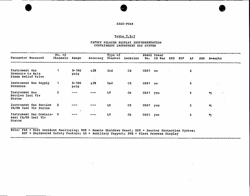
SSES- FSAR
Table 7.5-7
SAPETY RELATED DISPLAY INST RVNENTATIONCONTAINNENT INSTRVNENT GAS SYSTEN
No. of Type of Panel PoverParameter Neasured Channels Range Accuracy Readout Location No. IE Bus RPS ESF AS PPD Remarks
Instrument GasPressure to NainSteam Relief Valve
Instrument Gas Supply 1
Pressure
Instrument GasBottles Isol VlvStatus
Instrument Gas Suction 2IB/OB Isol Vlv Status
Instrument Gas Contain- 9ment IB/OB Isol VlvStatus
0-180 t 2%
Psig
0-100 a 2%
Psig
Ind
Ind
LT
LT
LT
CR
CR
CR
CR
CR
C601 no
C601 no
C601 yes
C601 yes
C601 yes
Note: PAN = Post Accident Nonitoring; RSP = Remote Shutdovn Panel; RPS = Reactor Protection System;ESF = Engineered Safety Peature; AS = Auxiliary Support; PPD = Plant Process Display
S S ES-PS AR
pressure switches actuating on low pressure. Additionally,differential pressure of the common steamline (Piqures 5. 4-13,6.3-1a and 6.3-1b) is monitored by" differential pressureindicating switches to detect HPCI line break. Annunciation isprovided in the main control room. These monitoring systems aredescribed in Subsections 7.6.1a.4.3.9.3 and 7.6.1a.4. 3.9.4.
7.6.1a.4.3.6 Reactor Matey Clean-Up System Leak Detection
See Subsection 7. 3. 1. 1a. 2. 4. 1. 9.
7. 6. 1a.4.3. 7 Safegygpelief Vague Leak Detection
7.6 1a.4.3.7.1 Subsystem Iden tification
Normally, the safety/relief valves are in the shut tightcondition and are all at about the same temperature. Steampassage throuqh the valve= will elevate the sensed temperature atthe exhaust, 'causing an ~'abnormal" temperature reading on therecorder. Switch contacts on the recorder, adjusted to actuateat a predetermined set point, close to complete an annunciatorcircuit. Safety valve operation usually occurs only after eliefvalve actuation. Leakaqe from a valve is usually characterizedby a temperature increase on a single input. As discussed inSubsection 18. 1. 24. 3, each of the sixteen safety/relief valvesare provided with a safety grade accoustic monitoring system todetect flow through the valve.
7.6.1a.4.3.7.2 Safety/Relief Valve Discharge LineTemgegatug~ Nonitorinq
7.6.1a.4.3.7.2.1 Desggiptj,on
A temperature element (sensor) is placed in the discharge pipe ofeach of the sixteen (16} safety/relief valves for remoteindication of leakage. The outputs of the temperature elementsare sequentially sampled and recorded by one common temperaturerecorder. Each temeprature element .is compared against a setpoint valve which if exceeded will be annunciated by one commonanunciator. Thus, when the annunciator sounds, it is possible toascertain -which specific valve (s) may be leaking by observing therecorder print-out.
Rev. 31, 7/82 7.6-15
SS ES- FS AR
7. 6. 1a. 4.3. 7. 2 2 Loaic a nd Seauenc ina~ ~ m ' ~ ' a a a
No action is initiated by the safety/relief valve temperaturemonitoring circuit.
7.6.1a.4.3 7.2,3 BIpasgeg and Ipterlocks
There are no bypasses or int'erlocks associated vith thissubsystem.
7.6. 1a.4.3.7.2.4 Redundancy and Diversity
No redundancy or diversity is required for this system.
7,6 1a,4.3,8 Reactor Vessel Head Leak Deflection
7. 6. 1a. 4. 3. 8. 1 ~ Subsystem Ident'.'fication
A pressure betveen the inner and outer head seal ring will besensed by a pressure switch. If the inner seal leaks, thepressure indicatinq svitch vill monitor the pressure.
The plant vill continue to operate vith the outer seal as abackup and the inner seal can be repaired at the next outage whenthe head is removed. If both the inner and outer head sealsleak, the leak vill be detected by an increase in drywelltemperature and pressure.
7.6 1a.4.3.8,2 Head Sea/ Igtegpity Pressure monitoring
7. 6. 1a. 4. 3. 8. g. 1 Circuit prescriptiont
A pressure indicating switch will monitor the pressure betveenthe inner and outer head seals.
Rev. 31 '/82 7 6-16
SSES-FS AR
Each system provides a continuous, isolated signal to the remoteshutdown panel {RSP) which does not require any transfer actionin the Control Room. Two indicators are provided at each RSP andare divisionalized.The Primary Containment and suppression pool temperature„ elementsand temperature indicators will be qualified. to operate followinga DBA ~
I
7.6.1b. 1.2. 3 Power Sources
f
The safety related instrumentation is powered from divisionalizedpower sources. Division I Class IE bus (120 V ac) powers Loop A,Division II Class IE bus (120 V ac) powers Loop B.
7. 6. 1b. 1. 2. 4 Eguipment Design
7.6.1b.1.2.4.1 Eguipme))t Design-Containment Temperature
Four dual element RTDs per redundant system are located in theprimary containment to sense the temperature at the followinqeleva tions:
a) Reactor pressure vessel head
h) Upper platf orm
c) Lower platform
d) Drywell (below reactor pressure vessel)..
Two redundant temperature elements monitor the suppressionchamber air space temperature.
The selected location for the temperature sensors helps theoperator to define the area of the heat source within the primarycontainment.
The siqnal from the RTD elements is amplified by electronictemperature transmitters to drive meters, recorder channels, andalarm switches in the control room.
Two redundant indicators, for the primary containment are locatedin the main control room. The initiating contacts for the highspeed start of the drywell cooling fans (refer to systemdescription in Section 9.4) are derived from the two redundant
Rev. 31 ~ 7/82 7 6-41
SS ES- PS AR
temperature sensinq elements located in th'e service area of thefans. If high temperature is detected the electronic switcheswill initiate the lov speed operation of the dryvell coolingfans.
Electronic signal converters vith full electrical input-outputisolation are placed betveen safety related instrumentation andthe input channels to the recorders.
Tvo redundant multipoint recorders for the primary containmentpool temperature monitoring system provide a permanent history ofall BTD measurements to the operator in the control room.
Each temperature sensing circuit is equipped with alarm svitchesand initiate one control room alarm per redundant channel.
One temperature indicator for the primary containment is locatedon the remote shutdown panel. Refer to Subsection 7.4.1.4 forsystem description. Instrument ranqes are defined in Section7.5.
!7.6.1b.1.2.4,2 Eguipment. Design-Suppression Pool Temperature
The suppression pool temperature is monitored by tvo redundantsystems, each of which performes as described belov.
Eight RTD~s per redundant system are located in the suppressionpool approximately six inches below the minimum pool water level.These sensors are located around the pool in order to provide agood spatial distribution of pool temperature. Refer to Table7 6-9 for the exact location of these sensors.
The siqnals from the sensors are processed by an electronic unitlocated on a main control room back panel. This electronic unitconverts the RTD siqnals into deqrees Fahrenheit and computes theaverage of the eight temperatures. If one of the RTD's fails, anerror alarm is qenerated, and the failed RTD may be removed fromthe calculation of the average by operator a'ction. The averagevalue is displayed by digital indicators located both on theelectronic unit, the main control board, and a vertical meterlocated on the RSP. A keyboard allovs the operator to displayany individual temperature input.A high temperature alarm is generated by comparing the averagetemperature to several internally stored setpoints. The alarmcondition is displayed by status lights located both on theelectronic unit and on the main control board. Electricallyisolated ouptuts interface vith an annunciator located on'themain control board.
Rev. 31, 7/82 7 6-42

SSES-PShR
TIIPQP 7~6-5
KPE5 sXsgg)) Xgrpsc»
XBXR Z95GXXQ)I- TBXR RQXEX EEKK EHXQE
hPRH dovnscale
APRll upscale(high)
~hPRN upscalefhigh-high)
aPREinoperative
hPRh Bypass
2% to full scale
Setpoint varied vith flov,slope adjustable, interceptsseparately adjustable
2% to full scale
Calibrate svitch or toofev inputs
manual Svitch
Rod block, annunciatorvhite light display
Rod block, annunciatoranber light display
Scraa, annunciator, redlight display
Scraa, rod block,annunciator, red lightdisplay
%hite light
See plant Technical Specifications for setpoints.
R EV 30, 5/82
SS ES- FSAB
eva luation of core thermal limits with subsequent modif ication to+ he LPRN ATS based on the new reactor operating level. Executionof these rapid computations does not exceed 3 minutes and yieldsATS values that are conservative with respect to the moreaccurate periodic power distribution calculation, which requiresapproximately 10 minutes to execute. This range of surveillanceand the rapidity with which the computer responds to reactorchanqes permit more rapid power maneuverinq with the assurance+hat +hermal operatinq limits will not be exceeded.
Flux level and position Bate from the traversing in-core probe(TIP) equipment are read into the computer. The computerrevaluates the data and determines gain adjustment factors bywhich +he LPRN amplifier qains can be altered to compensate forexposure-induced sensitivity loss. The LPRN amplifier gains arenot to be ohvsically altered except immediately prior to a wholecore calibration usinq the TIP system. The gain adjustmentfactor "omputations help to indicate to the operator when such acalibration procedure is necessary.
Using the. power distribution data, a distribution of fuelexposur~ increments from the time of previous power dist"ibutioncalculation is determined and is used to update the distributiono f cumulative fuel exposure. Each fuel bundle is identified hybatch anB location, and its exposure is stored for each of theaxial seqments used in the power distribution calculation Thesedata are printed out on operator demand.
Exposure increments are determined periodically for each quarter-Lenq+h section of each control rod. The corresponding cumulativeexposure totals are periodically updated and printed out onoperator demand.
the oxno. ure increment of each local power range monitor isdetermined periodically and is used to upda+e both the cumulativeion chamber exposures and the correction factors for exposure-dependent LPHN sensitivity loss. These data are printed out onoperator demand.
The NSSS computer system provides on-line capability to determinemonthly anB on-demand isotopic composition for each one-quarter-lenqth section of each fuel bundle in the core. This evaluationconsists of computinq the weight of one neptunium, three uranium,and five plutonium isotopes as well as the total uranium andtotal plutonium content. The isotopic composition is calculatedfor each one-quarter length of each fuel bundle and summedaccordinqly by bundles and batches. The method of analysisconsists of relatinq the computed fuel exposure and average voidfraction for the fuel to computer stored isotopic characteristicsapplicable to the specific fuel t.ype.
P ev. 32, 12/8 2 7. 7-61

SSES-FSAR
7. 7. 1.7. 5. 2 Reactor Ooerator Information
Aajor components are arranqed as shown in Figure 7.7-13.Functional d scription and operational arranqement is as follows:
Unit. Qpegating Benchboard QH12-P680} (Panel C651) — housescontrol., ~ annunciators and displays, including the control rodoosition display. The primary process displays are computergenerated CRT formats from the DCS and P5S computers. Allvariables in the DCS displays that are required for unitoperation, startup and shutdown are displayed on hardwiredindicators on either the Unit Operatinq Benchboa'rd or the StandbyInformation Panel. These variables in both CRT and hardwireddisplays qenerally orqinate from the same sour"e.
Standby Tnformation Panel gH12-P678} (C652) - houses hardwiredindicators and recorders required to startup, run, and shutdownthe Plant without the use of the Display Control System. It is abardwired backup to the DCS.
Reactor Core Cooling System BB gH12-p601} (C601) - houseshardwired indicators, recorders, annunciators and controls forunit BOP system~s'unctions which do not require the operator'simmediate attention during normal operation of the power plant.Functions on this panel have been determined to be long timresponse functions.Common Plant Benchboard gH12-P853} (C653) » houses hardwiredindicators, recorders annunciators and controls for systems whichare common to Units 1 and 2 It also houses two CRT's connectedto the Performance Monitorinq System (PHS).
Jjnit. Monitoring Console gC92-P628} ("680) - provides the unitoperator sit down surveillance of the Unit Operatinq Benchboardand access to DCS and PHS CRT displays with the use of a..election keyboard.
Plant Monitoring Console QC92-f626} (C683) - provides sit. downurveill.ance of both units and keyboard access to computer
functions of both units. There is also computer generated trendrecordinq of variables from either unit.The annunciator system is a hardwired system which provides theoperator with the alarm information required for unit operation,st;artup, and shutdown. This system is independent of the Plant"omputer System although the computer system does provideredundant and auxiliary alarm information as AID's through theDCS and the alarm status summary CRT display from the PNS.
The Display Control System collects unit process information andpresents it on nine of the ten video displays (CRTs) on the Unit
Rev. 32, 12/82 7 7-62
SSES-FSAR
a 0 Any averaqe power ranqe monitor {APRM) upscale rodblock alarm. The purpose of t'his rod hlock function isto avoid conditions that would require reactorprotection system action if allowed to proceed. TheAPBM upscale rod block alarm setting is selected toinitiate a rod block before the APRM high neutron fluxscram settinq i s reached.
h Any APBN inoperative alarm. This assures that nocontrol rod is withdrawn unless the average power rangeneutron monitorinq channels are either in service or.".or rectly bypassed.
Either recirculation flow converter upscale orinoperative alarm. This assures that no control rod iswithdrawn unless the recirculation flow converters,which are necessary for the proper operation of theRPMs, are operable.
Re" irculation flow convertor comparator alarm orinoperative. This assures that no control rod iswithdrawn unless the difference between the outputs oft'.he f1ow converters is within limits and the comparatoris in'ervice.
ei Scram discharqe volume high water level. This assuresthat no control rod is withdrawn unless enough capacityis available in the scram discharge volume toaccommodate a 'scram. The setting is selected toinitiate a rod hlock earlier than the scram that isinitiated on scram discharge volume high water level.Scram discharge volume hiqh water level scram triobypassed. This as..ures that no control rod iswithdrawn while the scram discharge volume high waterlevel scram function is out of service.
The rod worth minimizer (HWM) function of the processcomputer can initiate a rod insert block, a rodwithdrawal block, and a rod select block. The purposeof this function is to reinforce procedural controlsthat limit the reactivity worth of- control rods underlover powe conditions. The rod block trip settingsare based on the allowable control rod worth limitsestablished for the design basis rod drop accidentAdherence to prescrihed control rod patterns is thenormal method by which this reactivity restriction isobserved. Additional information on the rod worthminimizer function is available in Subsection7.7 1.2.8
Rev. 32, 12/82 7 7-21
SSFS-FSAR
h. Rod po ition information system .malfunction. Thisas ures that no "ontrol rod can be withdrawn unless therod position information system is in service.
Rod movement timer malf unction during withdrawal. Thisassures no control rod can be withdrawn unless thetimer is in service.
Th Rod Sequence Control System initiates rod blocks,whenever out of sequence rods are selected. The RSCS
is required to he in operation bel.ow 20% rated power toprevent the operator from establishinq control rodpattern., that are not consistent with a prestored rodsequence.
k. Hither rod block monitor (RBM) upscale ala m. Thisfunction is provided to stop the erroneous withdrawalof a control "od so that local fuel damage does notresult. Although local fuel damage poses nosiqnificant threat in terms of radioactive materialreleased from the nuclear system, the trip setting isselected so that no local fuel damage results from asingle control rod withdrawal -error during power rangeoper'ation.
Either RBN inoperative alarto. This assures that nocontrol rod is withdrawn unless the RBM channels are inservice or correctly bypassed.
(3) With the mode switch in the RUN position, any of thefollowinq conditions initiates a rod block.
'a ~ Any APRM downscale alarm. This assures that no controlrod will he withdrawn during power range operationunless the averaqe power range neutron monitoringchannels are operatinq correctly or are correctlybypassed. All unbypassed APRNs must be on scale duringreactor operations in the RUN mode.
b. Fither RBN downscale alarm. This assures that nocontrol rod is withdrawn during power range operationunless the „RBN channels are operating correctly or arecorrectly bypassed. Unbvpassed RBMs must be on scaleduring reactor operations in the RUN mode.
(4) With the mode switch in the STARTUP or REFUEL position, anyof the followinq conditions initiates a rod block:
a ~ Any source range monitor (SR"I) detector not fullyinserted into the core when the SRN count level isbelow the retract oermit level and any IRM ra nge switchon either of the two lowest ranges. This assures that
Rev. 32, 12/82 7& 7 22'
SSES- FSAR
The interlocks from the refuelinq equipment to the Reactor i1anual"ontrol System actuate circuitry that provides a control roilblock. The rod block prevents the operator from withdrawing anycontrol "ods.
7. 7. 1. 10. 3. 6 Separation
The refuelinq interlocks are not desiqned to nor required to meetthe IEPE 279-1971 criteria for Nuclear Power Plant ProtectionSystems. However, a single interlock failure will not cause anaccident. Befuelinq interlocks and are used in con)un™tion withwdmistra+ion controls during planned refueling operations.
7. 7. 1. 10. 3~7 Tesfgbililg
Complete functional testinq of all refueling interlocks before~ny refuelinq outage will positively indicate that the interlocksoperate in the situations for which they were designed. Theinterlocks can be subjected "to valid operational tests by loadingeach hoist with a dummy fuel assembly, positioninq the refuelingplatform, and withdrawinq control rods. Mhere redundancy isprovided in the logic circuitry, tests are performedautomatically, on a periodic basis, to assure that each redundantlogic element can independently perform its function.
7. 7. 1. 10. 4 Fnvironmenta1 onsiQegations
equipment. (refuelina) will be subjected to the conditions listedin Table 3.11-1 during normal operation. The refuelinqinterlocks are not required to operate under the conditionslisted in Table 3. 11-3.
Refuelinq components are capable of surviving desiqn basis event"such as earthquakes, accidents, and anticipated operationaloccurrences without consequential damage, but are not required tohe functional durinq or after the event without repair.
7;7. 1. 10. 5 Opera t ional Considerations
7.7. 1. 10. 5. 1 General Information
The refuelinq interlocks system is required only during refuelingopera tions.
R ev. 32, 12/82 7 w 7 7 1

SS ES- PS AR
7.7 1.10.5.2 Q~agfog Appgatog Infogmatxgn
In the refuelinq mode, the control room operator has an indicatorliqht for "Select Permissive" whenever all control rods are fullyinserted. He can compare. this indication with control rodposition data from the computer as well as control rod in-outstatus on the full core status display. Furthermore, whenever acontrol rod withdrawal block situation occurs, the operatorreceives annunciation and computer logs of the 'rod block. He cancompare these outputs with the status of the variable providingthe rod block condition. Both channels of the control'odwithdrawal interlocks must aqree that permissive conditions existin order to move control rods; otherwise, a control rodwithdrawal block is placed into effect. Failure of one channelmay initiate a rod withdrawal block, and will not preventapplication of a valid control rod withdrawal block from theremaininq operable channel.
Core flux activity monitorinq is provided during refuelina by theSPA's and/or dunkinq chambers which are specified and controlledin Technical Specification 3/4 9.
I'.n terms of refueling platform interlocks'he platform operatorhas analog type readout indicators for the pla'tform x-y positionrelative to the reactor core.
The position of the grapple is shown on a digital indicatorimmediately below the platform position indicators. Analog loadcel3. indications of hoist loads are given for each hoist bylocallv mounted indicators. Individual push button and rotarycontrol swit"hes are provided .for local control of the platformand its hoists The platform operator can immediately determinewhether the platform and hoists are responding to his localinstructions, and can, in conjunction with the control roomoperator, verify proper operation of each of the three categoriesof interlocks listed previously.
7.7.1.10.5 3 Set Points
There are no safety set points associated with this system.
8 ev. 32, 12/82 7&7 72
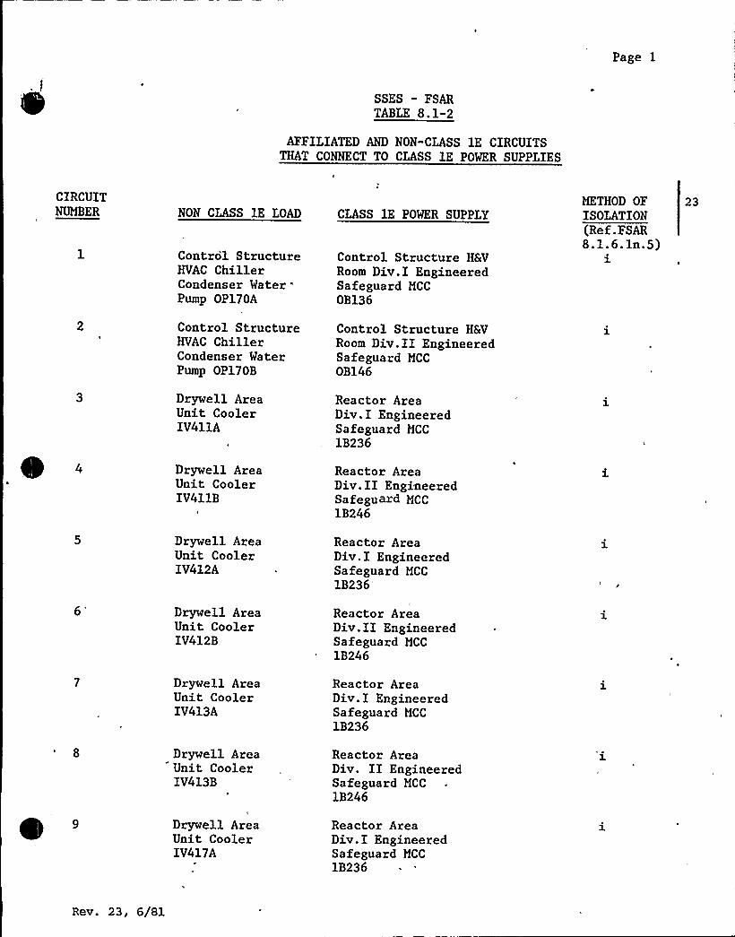
Page 1
SSES - FSARTABLE 8.1-2
AFFILIATED AND NON"CLASS lE CIRCUITSTHAT CONNECT TO CLASS lE POWER SUPPLIES
CIRCUITNUMBER NON CLASS lE LOAD
Control StructureHVAC ChillerCondenser Water
'umpOP170A
Control StructureHVAC ChillerCondenser WaterPump OP170B
Drywell AreaUnit CoolerIV411A
Drywell AreaUnit CoolerIV411B
CLASS lE POWER SUPPLY
Control Structure HSVRoom Div.I EngineeredSafeguard MCC
OB136
Control Structure HSVRoom Div.II EngineeredSafeguard MCCOB146
Reactor AreaDiv.I EngineeredSafeguard MCC
1B236
Reactor AreaDiv.II EngineeredSafeguard MCC1B246
METHOD OFISOLATION(Ref.FSAR8.1.6.ln.5)i
23
Drywell AreaUnit CoolerIV412A
Reactor AreaDiv.I EngineeredSafeguard MCC
1B236'rywell
AreaUnit CoolerIV412B
Reactor AreaDiv.II EngineeredSafeguard MCC
1B246
Drywell AreaUnit CoolerIV413A
Reactor AreaDiv.I EngineeredSafeguard MCC
1B236
Drywell AreaUnit CoolerIV413B
Reactor AreaDiv. II EngineeredSafeguard MCC
1B246
Drywell AreaUnit CoolerIV417A
Reactor AreaDiv.I EngineeredSafeguard MCC
1B236
Rev. 23, 6/Sl

Page 2
~ 5
CIRCUITNUMBER
10
NON CLASS lE IOAD
Drywell AreaUnit CoolerLV417B
CLASS 1E POWER SUPPLY
Reactor AreaDiv.II EngineeredSafeguard MCC
lB246
METHOD OFISOLATION(Ref.'FSAR8.1.6.1n.5)
3.
23
Drywell AreaUnit Cooler2V411A
Reactor AreaDiv.I EngineeredSafeguard MCC
2B236
12 .
13
14
Drywell AreaUnit Cooler2V411B
Drywell AreaUnit Cooler2V412A
Drywell AreaUnit Cooler2V412B
Reactor AreaDiv.II EngineeredSafeguard MCC
2B246
Reactor AreaDiv.I EngineeredSafeguard MCC
2B236
Reactor AreaDiv.II EngineeredSafeguard MCC
2B246
15
16
Drywell AreaUnit Cooler2V413A
Drywell AreaUnit Cooler2V413B
Reactor AreaDiv.I EngineeredSafeguard MCC
2B236
Reactor AreaDiv.II EngineeredSafeguard MCC
2B246
17 Drywell AreaUnit Cooler2V417A
Reactor AreaDiv.I EngineeredSafeguard MCC
2B236
18
19
Drywell AreaUnit Cooler2V417B
Instrument AirCompressor
'A'K107A
Reactor AreaDiv.II EngineeredSafeguard MCC
2B246
Channel B/Div IIEngineeredSafeguard LoadCenter lB220
Rev. 23, 6/81

Page 3
CIRCUITNUMBER
20
NON CLASS lE LOAD
Instrument AirCompressor
'B'K107B
CLASS lE POWER SUPPLY
Channel D/Div IIEngineeredSafeguard I,oadCenter 1B240
METHOD OFISOLATION(Ref;FSAR8.1.6.ln.5)ii
21 Instrument AirDryer Panel
'AB'C142A
Reactor Bldg.Div.II EngineeredSafeguard MCC
1B247
22 Instrument AirDryer Panel
'B'C142B
Reactor Bldg.Div.II EngineeredSafeguard MCC
1B226
23 Instrument GasCompressor
'A'K205A
Reactor Bldg.Div.I EngineeredSafeguard MCC
1B217
24 Instrument GasCompressor
'B'K205B
Reactor Bldg.Div.I EngineeredSafeguard MCC
1B236
25 Instrument AirCompressor
'A'K107A
Channel A/Div.IEngineeredSafeguard LoadCenter 2B210
26
27
28
Instrument AirCompressor
'B'K107B
Instrument AirDryer Panel
'A'C142A
Instrument AirDryer Panel
'B'C142B
Channel C/Div. IEngineeredSafeguard LoadCenter 2B230
Reactor Bldg.Div.I EngineeredSafeguard MCC
2B237
Reactor Bldg.Div.I EngineeredSafeguard MCC
2B216
29 Instrument GasCompressor
'A'K205A
Reactor Bldg.Div.I EngineeredSafeguard MCC
2B217
Rev. 23, 6/81
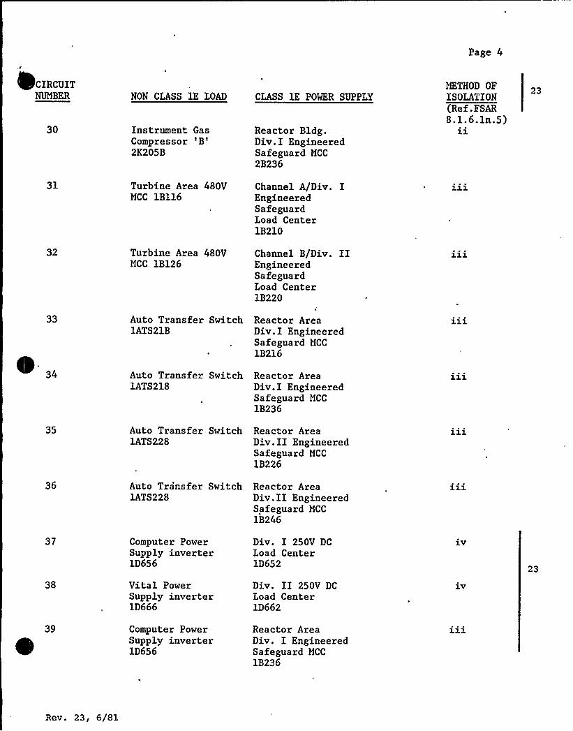
Page 4
CIRCUITNUMBER
30
NON CLASS lE LOAD
Instrument GasCompressor
'B'K205B
CLASS lE POWER SUPPLY
Reactor Bldg.Div.I EngineeredSafeguard MCC
2B236
METHOD OFISOLATION(Ref.FSAR8.1.6.ln.5)
1l.
23
31
32
Turbine Area 480VMCC 1B116
Turbine Area 480VMCC 1B126
Channel A/Div. IEngineeredSafeguardLoad Center1B210
Channel B/Div. IIEngineeredSafeguardI,oad Center1B220
33
I „ Auto Transfer SwitchlATS218
Reactor AreaDiv.I EngineeredSafeguard MCC
1B236
Auto Transfer Switch Reactor Area1ATS21B Div.I Engineered
Safeguard MCC
1B216
35 Auto Transfer Switch Reactor Area1ATS228 Div.II Engineered
Safeguard MCC
1B226
36 Auto Transfer Switch Reactor Area1ATS228 Div.II Engineered
Safeguard MCC
1B246
37
38
Computer PowerSupply inverter1D656
Vital PowerSupply inverter1D666
Div. I 250V DCIoad Center1D652
Div. II 250V DCLoad Center1D662
1.V
l.V
23
Computer PowerSupply inverter1D656
Reactor AreaDiv. I EngineeredSafeguard MCC
1B236
Rev. 23, 6/81

Page 5
CIRCUITNUMBER
40
NON CLASS lE IOAD
Vital PowerSupply inverter1D666
CLASS lE POWER SUPPLY
Reactor AreaDiv.II EngineeredSafeguard MCC
1B246
METHOD OFISOLATION(Ref.FSAR8.1.6.ln.5)
23
41
42
44
45
46
47
48
~ 49
250V DC TurbineBuilding controlcenter A
250V DC TurbineBuilding controlcenter B
125V DCDistributionPanel1D615
125V DCDistributionPanel1D625
125V DCDistributionPanel1D635
125V DC
DistributionPanel1D645
480/277VEssentialLightingPanel
480/277VEssentialLighting Panel1EP08
480/277VEssentialLighting Panel1EP03
Div.I 250V DC
Ioad Center1D6521D155
Div.II 250 V DC
Load Center1D6621D165
Channel A/Div. I125V DCIoad Center1D612
Channel B/Div. IZ125V DCI,oad Center1D622
Channel C
125V DC
Load Center1D632
Channel D125V DCIoad Center1D642
Reactor AreaDiv.I EngineeredSafeguard MCC
1B2171EP07
Reactor AreaDiv.II EngineeredSafeguard MCC
lB227
Reactor AreaDiv. II EngineeredSafeguard MCC
1B226
23
23
Rev. 23, 6/81
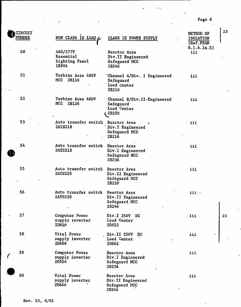
Page 6
CIRCUITNUMBER
,
50'1
52
53
NON CLASS lE IOAD
480/277VEssentialLighting Panel1EP04
Turbine Area 480VMCC 2B116
Turbine Area 480VMCC 2B126
Auto transfer switch2ATS218
'LASSlE POWER SUPPLY
Reactor AreaDiv.II EngineeredSafeguard MCC
1B246
"'Channel A/Div. I EngineeredSafeguardLoad center2B210
Channel B/Div.II EngineeredSafeguardLoad Center
q2B220
Reactor Area'iv.I EngineeredSafeguard MCC
2B216
METHOD OFISOLATION(Ref.FSAR8.1.6.ln.5)
23
54 Auto transfer switch Reactor Area2ATS218 Div.I Engineered
Safeguard MCC
2B236
55
56,
57
58
59
~ „
Auto transfer switch2ATS228
Auto transfer switch2ATS228
Computer Powersupply inverter2D6>6
Vital Powersupply inverter2D666
Computer Powersupply inverter2D656
Vital Powersupply inverter2D666
Reactor AreaDiv.II EngineeredSafeguard MCC
2B226'eactor
AreaDiv.II EngineeredSafeguard MCC
2B246
Div.I 250V DCLoad Center2D652
Div.II 250V .DCIoad Center2D662
Reactor AreaDiv.I EngineeredSafeguard MCC
2B236
Reactor AreaDiv.II EngineeredSafeguard MCC
2B246
23
Rev. 23, '6/Sl
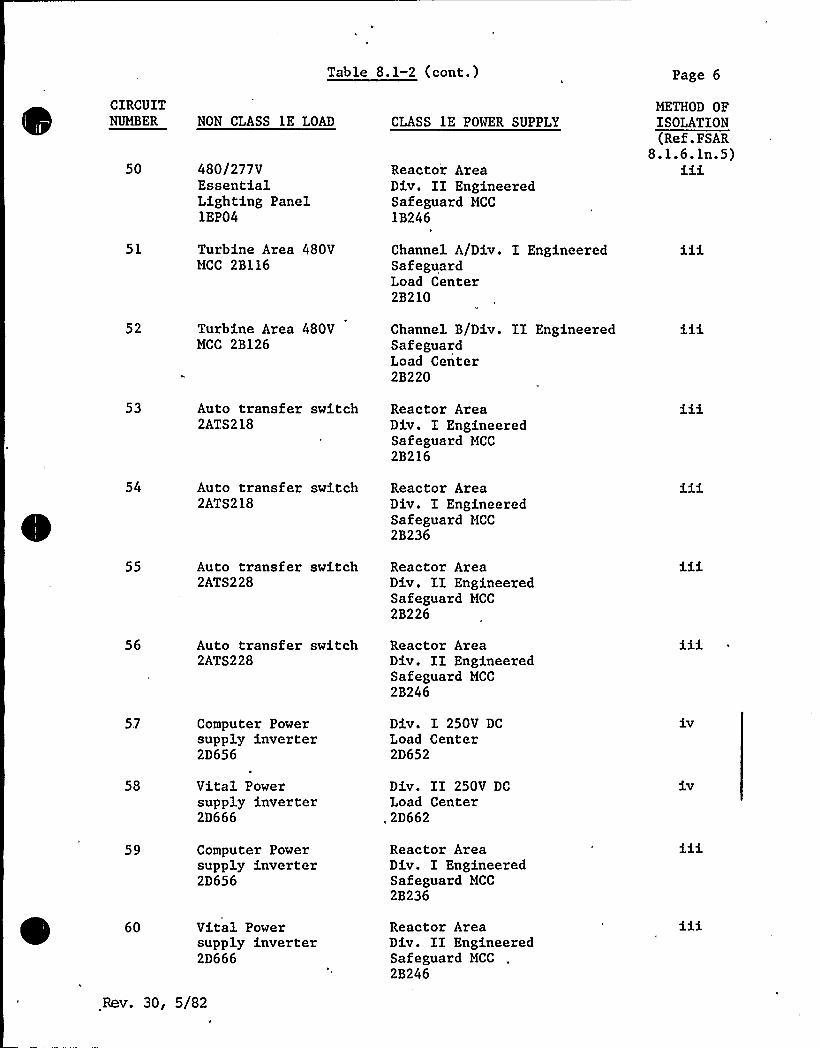
Table 8.1-2 (cont.)
CLASS 1E POWER SUPPLYCIRCUITNUMBER NON CLASS lE LOAD
Page 6
METHOD OFISOLATION
50 480/277VEssentialLighting PanellEP04
Reactor AreaDiv. II EngineeredSafeguard MCC
1B246
(Ref.FSAR8.1.6.ln.5)iii
51 Turbine Area 480VMCC 2B116
Channel A/Div. I EngineeredSafeguardLoad Center2B210
52 Turbine Area 480VMCC 2B126
Channel B/Div. II EngineeredSafeguardLoad Center2B220
53 Auto transfer switch2ATS218
Reactor AreaDiv. I EngineeredSafeguard MCC2B216
54 Auto transfer switch2ATS218
Reactor AreaDiv. I EngineeredSafeguard MCC
2B236
55 Auto transfer switch2ATS228
Reactor AreaDiv. II EngineeredSafeguard MCC
2B226
56 Auto transfer switch2ATS228
Reactor AreaDiv. II EngineeredSafeguard MCC
2B246
5.7 Computer Powersupply inverter2D656
Div. I 250V DCLoad Center2D652
58 Vital Powersupply inverter2D666
Div. II 250V DCLoad Center
„2D662
iv
59 Computer Powersupply inverter2D656
Reactor AreaDiv. I EngineeredSafeguard MCC
2B236
60 Vital Powersupply inverter2D666
Reactor AreaDiv. II EngineeredSafeguard MCC
2B246
Rev. 30, 5/82

Page 7
61
62
63
64
65
66
67
68
69
70
NON CLASS lE IOAD
250V DC TurbineBuilding ControlCenter A
250V DC TurbineBuilding ControlCenter B
125V DCDistribution Panel2D615
125V DCDistribution Panel2D625
125V DCDistribution Panel2D635
125V DCDistribution Panel2D645
480/277VEssentialLighting Panel2EP07
480/277VEssentialLighting Panel2EP08
,480/277VEssentialLighting Panel2EP03
480/277VEssentialLighting Panel2EP04
CLASS lE POWER SUPPLY
Div.I 250V DCLoad Center2D6522D155
Div.II 250V DCIoad 'Center2D6622D165
Channel A/Div.I125V DCIoad Center2D612
Channel B/Div.II125V DCLoad Center2D622
Channel C
125V DCLoad Center2D632
Channel D125V DC
Load Center2D642
Reactor AreaDiv.I EngineeredSafeguard MCC
2B217
Reactor AreaDiv.II EngineeredSafeguard MCC
2B227
Reactor AreaDiv.II EngineeredSafeguard MCC
2B226
Reactor AreaDiv.II EngineeredSafeguard MCC
2B246
METHOD OFISOLATIONref.RSAR8.1.6eln.5)
111
23
23
Rev. 23, 6/Sl

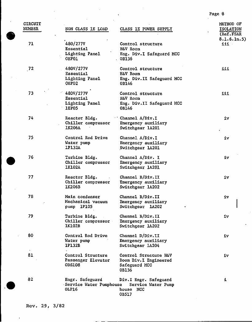
Page 8
CIRCUITN ABER
71
72
73
74
75
76
77
78
79
80
81
NON CLASS 1E LOAD
480/277VEssentialLighting PanelOEP01
480V/277VEssentialLighting PanelOEP02
'80V/277VEssentialLighting Panel1EP05
Reactor Bldg.Chiller compressor1K206A
Control Rod DriveWater pump1P132A
Turbine Bldg.Chiller compressor1K102A
Reactor Bldg.Chiller compressor1K206B
Main condenserMechanical vacuumpump 1P105
Turbine Bldg.Chiller compressor1K102B
Control Rod DriveWater pump1P132B
Control StructurePassenger ElevatorODS108
CLASS 1E POWER SUPPLY
Control structureH&V RoomEng. Div.I Safeguard MCC
OB136
Control structureH&V RoomEng. Div.II Safeguard MCC
OB146
Control structureH&V RoomEng. Div.II Safeguard MCC
OB146
Channel A/Div.IEmergency auxiliarySwitchgear 1A201
Channel A/Div.IEmergency auxiliarySwitchgear 1A201
Channel A/Div. IEmergency auxiliarySwitchgear lA201
Channel B/Div.IIEmergency auxiliarySwitchgear 1A202
Channel B/Div.IIEmergency auxiliarySwitchgear lA202
Channel B/Div.IIEmergency auxiliarySwitchgear lA202
Channel D/Div.IIEmergency auxiliarySwitchgear 1A204
Control Structure H&VRoom Div.I EngineeredSafeguard MCC
OB136
METHOD OF
ISOLATION(Ref.FSAR8.1.6.1n.5)iii
iv
iv
iv
Engr. Safeguard Div.I Engr. SafeguardService Water Pumphouse Service Water PumpOLP16 house MCC
OB517
Rev. 29, 3/82

4
~,
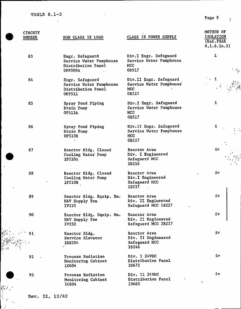
Tgg3T~~ 8. 1-2Page 9
CIRCUITNUMBER NON CLASS lE LOAD CLASS 1E POWER SUPPLY
MFTHOD OFISOLATION(Ref.FSAR8.1.6.1n.5)
83 Engr. SafeguardService Water PumphouseDistribution PanelOPP509A
Div.I Engr. SafeguardService Water PumphouseMCC
OB517
84 Engr. Safeguard,Service Water PumphouseDistribution PanelOPP511
Div.II Engr. SafeguardService Water PumphouseMCC
OB527
85 Spray Pond PipingDrain PumpOP513A
Div.I Engr. SafeguardService Water PumphouseMCC
OB517
86
87
Spray Pond PipingDrain PumpOP513B
1
Reactor Bldg. ClosedCooling Water Pump1P210A
Div.II Engr. SafeguardService Water PumphouseMCC
OB527
Reactor AreaDiv. I EngineeredSafeguard MCC
1B216
88 Reactor Bldg. ClosedCooling Water Pump1P210B
Reactor AreaDiv.I EngineeredSafeguard MCC
1B237
iv
89
90
91,
92
93
Reactor Bldg. Equip. Rm.H&V Supply FanIV232
Reactor Bldg. Equip. Rm.H&V Supply Fan2V232
Reactor Bldg.Service Elevator1DS204
Process RadiationMonitoring Cabinet1C604
Process RadiationMonitoring Cabinet1C604
Reactor AreaDiv. II EngineeredSafeguard MCC 1B227
Reactor AreaDiv. II EngineeredSafeguard MCC 2B227
Reactor AreaDiv. II EngineeredSafeguard MCC
1B246
Div. I 24VDCDistribution Panel1D672
Div. II 24VDCDistribution PanelID682
iv
iv
iv
Rev. 32, l2/82

CIRCUITNUMBER
94
95
96
97
98
99
100
NON CLASS lE LOAD
Control Rod DriveWater Pump2P132A
Turbine Bldg.Chiller Compressor2K102A
Reactor Bldg.Chiller Compressor2K206B
Main CondenserMechanical VacuumPump 2P105
Turbine Bldg.Chiller Compressor2K206A
Control Rod DriveWater Pump2P132B
Turbine Bldg.Chiller Compressor2K102B
CLASS 1E POWER SUPPLY
Channel A/Div. IEmergency AuxiliarySwitchgear 2A201
Channel A/Div. IEmergency AuxiliarySwitchgear 2A201
Channel B/Div. IIEmergency AuxiliarySwitchgear 2A202
Channel C/Div. IEmergency AuxiliarySwitchgear 2A203
Channel C/Div. IEmergency AuxiliarySwitchgear 2A203
Channel D/Div. IIEmergency AuxiliarySwitchgear 2A204
Channel D/Div. IIEmergency AuxiliarySwitchgear 2A204
Page 10
METHOD OFJSOLATEON(Ref�.
FSAR8.1.6.ln.5)
iv
iv
iv
iv
101 Reactor Bldg. Closed Reactor AreaCooling Water Pump Div. II Engineered2P210A Safeguard MCC
2B247
102 Reactor Bldg. ClosedCooling Water Pump2P210B
Reactor AreaDiv. II EngineeredSafeguard MCC
2B226
103
104
105 Process RadiationMonitoring Cabinet2C604
Div. I 24VDCDistribution Panel2D672
Rev. 29, 3/82
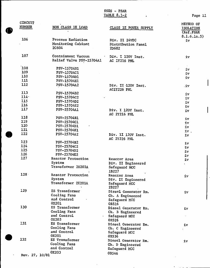
SSES — FSARTABLE 8.1-2 Page ll
CIRCUIT
106
107
108109110ill112
113114115116117
NON CLASS 1E LOAD
Process RadiationMonitoring Cabinet2C604
Containment VacuumRelief Valve PSV-15704Al
PSV-15704B1PSV-15704C1PSV-15704D1PSV-15704E1PSV-15704A2
PSV-15704B2PSV-15704C2PSV-15704D2PSV-15704E2PSV-25704A1
CLASS 1E POWER SUPPLY
Div. II 24VDCDistribution Panel2D682
Div. I 120V Inst.AC 1Y216 PNL
Div. II 120V Inst.AClY226 PNL
Div. I 120V Inst.AC 2Y216 PNL
METHOD OFISOLATION(Ref.FSAR8.1.6.1n.5)
iV
iViViv
,iv
iviViViviV
118119120121e x22
123124125126127
PSV-25704BlPSV-25704C1PSV-25704D1PSV-25704E1PSV-25704A2
PSV-25704B2PSV-25704C2PSV-25704D2PSV-25704E2
Reactor ProtectionSystemTransformer 2X201A
128
129
130
131
~ ZS2
Reactor ProtectionSystemTransformer 2X201A
ES TransformerCooling Fansand ControlOX201ES TransformerCooling Fansand ControlOX203ES TransformerCooling Fansand ControlOX201ES TransformerCooling Fansand ControlOX203
Rev. 27, 10/81
Div. II 120V Inst.AC 2Y226 PNL
Reactor AreaDiv. II EngineeredSafeguard MCC
1B227Reactor AreaDiv. II EngineeredSafeguard MCC2B227Diesel Generator Rm.Ch. A EngineeredSafeguard MCC
OB516Diesel Generator Rm.Ch. B EngineeredSafeguard MCC
OB526Diesel Generator Rm.Ch. C EngineeredSafeguard MCCOB536Diesel Generator Rm.Ch. D EngineeredSafeguard MCC
OB546
iViViV1V1V
iViv1V1Vi,v
iV
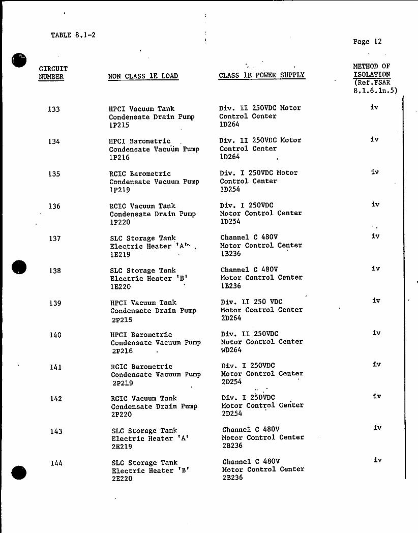
TABLE 8.1-2Page 12
CIRCUITNUMBER NON CLASS 1E LOAD CLASS 1E POWER SUPPLY
METHOD OFISOLATION(Ref.FSAR8.1.6.1n.5)
133 HPCI Vacuum TankCondensate Drain Pump1P215
Div. II 250VDC MotorControl Center1D264
iv
134
135
136
137
HPCI BarometricCondensate Vacuum Pump1P216
RCIC BarometricCondensate Vacuum Pump1P219
RCIC Vacuum TankCondensate Drain Pump1P220
SLC Storage TankElectric Heater
'A'E219
Div. II 250VDC MotorControl Center1D264
Div. I 250VDC MotorControl Center1D254
Div. I 250VDCMotor Control Center1D254
Channel C 480VMotor Control Center1B236
iv
iv
iv
138 SLC Storage TankElectric Heater
'B'E220
Channel C 480VMotor Control Center1B236
iv
139
140
141
142
HPCI Vacuum TankCondensate Drain Pump
2P215
HPCI BarometricCondensate Vacuum Pump2P216
RCIC BarometricCondensate Vacuum Pump2P219
RCIC Vacuum TankCondensate Drain Pump2P220
Div. II 250 VDC
Motor Control Center2D264
Div. II 250VDCMotor Control CenterwD264
Div. I 250VDCMotor Control Center2D254
Div. I 250VDCMotor Control Center2D254
iv
iv
iv
iv
143 SLC Storage TankElectric Heater
'A'E219
Channel C 480VMotor Control Center2B236
iv
144 SLC Storage TankElectric Heater
'B'E220
Channel C 480VMotor Control Center2B236
SSBS-PSlLR
8~~SITJ PORBR SYSTBJ
~8 ~ 'I DRSCRIPTIQN
~8 2.1 1- TnanSsissien SYstes
The bulk500 KV.suppliesand Unitseparateplant issystem.
pover transmission system of PPSL operates a t 230 KV andUnit 81 of the Susguehanna Steam Electric Stationpover to the 230 KV system through a 230 KV svitchyard02 supplies pover to the 500 KV system through a500 KV switchyard. The offsite power system for thesupplied through the 230 KV portion of the bulk 'power
Pigure 8.2-1 shows the Susquehanna 230 KV and 500 KV svitchyardsand the transmission lines associated with each yard and in thevicinity of.,the plant. The figure shows the line arrangementwith both units in operation. The tvo svitchyards are physicallyseparate and are tied together by a 230 KV yard tie line with a230-500 KV transformer in the 500 KV yard.Tvo independent offsite power sources are supplied to theSusquehanna plant. One source is established by tapping theMontour-Mountain 230 KV line north of the plant and constructing1300 ft. of 230 KV line on painted steel pole structures tostartup transformer 510. The Montour-Mountain line shares doublecircuit steel pole structures vith the Stanton-Susquehanna 82 230KV line in the vicinity of the plant. The double circuit lineextends to a point 1.5 miles east of the transformer 010 tap atvhich point the two circuits split as shovn in Pigure 8.2-1. TheMontour-Mountain line extends 16.8 miles north on double circuitlattice towers vith the Stanton-Susquehanna 41 230 KV line andterminates in the Mountain Substation. The Stanton-Susquehanna42 circuit extends southward on double circuit towers vith theStanton-Susquehanna 41 circuit and terminates in the Susquehanna230 RV Switchyard.
fJ
To the vest of the tap into the Susquehanna plant the Montour-Mountain 230 KV circuit extends 1500 feet on double circuit steelpole structures at which point the Stanton-Susquehanna 02 circuitseparates and extends northward to Stanton Substation. TheMontour-Mountain 230 KV circuit then joins the Montour-Susquehanna 230 KV circuit on double circuit steel lattice towersand extends 29. 0 miles to the Mon tour S witchyar d. The totaldistance to Mountain Substation from the tap into the plant is18.7 miles. The distance from Montour to the tap is 29.7 miles.Several lines feed the Montour Switchyard and MountainSubstation, as can be readily seen in Figure 8. 2-3. These lines
Rev. 28, 1/82 8 2-1
offer a multitude of possible supplies for the tap intoSusquehanna startup transformer 810. contour Switchyard issupplied directly by generation fram the contour Steam ElectricStation. Other generating stations are indirectly linked by the ''bulk pover grid system. The conductors for the transfarmer 410tap and the Hontour-tlountain line are 1590 kcmil 45/7 ACSR andare supported by single string insulator assemblies. Maximumconductor tension is limited to 16,000 pounds on steel pole linesections and 21,900 pounds on. lattice tower sections undermaximum anticipated loading conditions.The second offsite power source is supplied at 230 KV from theyard tie circuit between the Susquehanna 500 kV and 230 kVSubstations south of the Susquehanna Steam Electric Statian. Thesource is provided by a single 400 ft. span tap from the 230 KVyard tie circuit to startup transformer 020.
The yard tie line consists of 230 KV double circuit tubular steelpole structures supporting tvo parallel circuits of 1590 kcmil45/7 ACSB conductors on single string insulator assemblies. Thecircuits are tied together ta form a tvo conductor per phasesinqle circuit line. The 400 ft. tap to transformer 420 consistsof one 1590 kcmil 45/7 ACSB conductor per phase. The distancefrom the tap point west to the 500 KV yard is 1500 ft. Thedistance from the tap point east to the 230 KV yard is 1.6 miles.Maximum conductor tension is limited to 16,000 pounds in the yardtie line under maximum loadinq conditions.
The second offsite power supply is furnished by the multiplesources throughout the bulk power grid system through the 230 KVand 500 KV lines emanating from the Susguehanna 230 KV and 500 KV
!
switchyards. See Figure 8. 2-3.
All transmission lines meet or exceed design requirements setforth by the National Electric Safety Code. One or two overheadground vires are employed on the transmission lines above thephase conductors to provide adeguate lightning flashoverpratection. All lines meet the Army Corps of Engineersrequirements for clearance over flood levels. All bulk powertransmission lines are desiqned to withstand 100 mph hurricanewind loads on bare canductors.
The Montour-Mountain 230 KV line is crossed by the Stanton-Susquehanna 42 230 KV line. No transmission lines cross over theSusquehanna 500 KV to 230 KV yard tie line or the two tap linessupplying transformers $ 10 and 820.
No single disturbance in the bulk power grid system vill causecomplete loss of offsite power ta the Susquehanna SES. This is abasic system desiqn criteria.
8. 2-2
SSES-PSAR
8.2.~1 - Transmisgion Interconnection.
PP6L is a member of the Pennsylvania, New Jersey, and )marylandInterconnection which permits economical exchanges of power withneiqhborinq utilities and provides emergency assistance. Directbulk power ties're between PPSL and Philadelphia Electric,Luzerne Electric Division of UGI, Netropolitan Edison,Pennsylvania Electric, Jersey Central Power and Light, PublicService Electric and Gas, and Baltimore Gas and ElectricCompanies.,
8 2.1.3 Switchggrds
8. 2 1.3. 1 Startup Trans~fo mers 010 and 020
The contour-Mountain 230 KV line and the 23'0 KV yard tie linesupply power to startup transformers $ 10 and 420, respectively,through motor operated air break switches. High speed positiveground switches are installed between the motor operated airbreak s~itches (NOABs) and the startup transformers. The startuptransformers and low side bus connections are discussed inSection 8.3.1 The startup transformer yards are physicallyseparated from each other, the Unit tl and 42 main transformeryards and the 230 KV and 500 KV switchyards as can be seen onfigure 8.2-1. 1590 kcmil 45/7 ACSR conductors connect the airswitches to the startup transformers. 13.8 KV cables areinstalled in underqround conduit between the startup transformersand the turbine building. Non-segregated phase bus ductsestablish the tie to the 13.8 KY startup buses within the turbinebuilding. See Piqure 8.2-4 .for a one line diagram of the offsitepower system.
Line relay protection for the contour-Mountain 230 KV line andthe 230 KV yard tie circuit is provided by two independentdirectional comparison carrier blocking pilot relaying and twozone directional distance backup systems which ensure adequateline protection in the event of a malfunction. These relayingschemes detect faults on the transmission line and isolate thepower sources to the transformers by tripping the power circuitbreakers (PCBs) at the line terminals. Breaker failure relaying,applied at each line terminal, detects a failure to trip orfailure to interrupt condition at the line terminal and trips allassociated PCBs necessary to isolate the line. Power to the linerelayinq facilities is supplied from the local switchyard powersourcese
Startup transformers N10 and 020 are protected by high speedpercentage differential, sudden pressure and overcurrent
Rev. 28, 1/82 8 2-3
SSES-PSAB
relaying. Direct transfer trip facilities are utilized as theprimary relayinq scheme to open the PCBs at the transmission lineremote terminals in the event of transformer trouble. Backupprotection is provided by the high speed ground switch'n the 230KV side of the startup transformer This switch is closed toplace a positive fault on the 230 KV transmission line which villbe detected by the remote line'terminal relaying systems if theprimary direct transfer trip scheme fails to function correctly.The motor operated air switch automatically opens after the 230KV system is de-energized to isolate the startup transformer fromthe transmission system and permit reclosing of the transmission-line terminal PCBs.
A time delay undervoltage relay monitors the 13e8 KV startup busvoltaqe. On loss of offsite power the relay trips the startup busincoming feeder breaker and initiates transfer of the bus loadsto the other startup transformer through closure of the startupbus tie breaker. The time delay undervoltage relay also preventsunnecessary automatic trip of the incoming feeder breaker forshort duration disturbances on the transmission line.Pover to transformer 010 and 820 svitchgear, motor operated airbreak switches, and hiqh speed qround switches is supplied fromthe station 125 V DC power supplies.
8 2.1.3 2 88Hqneg888a IJHLQ 81 230 HV Hain rransf orner Leads
Overhead 1590 kcmil 45/7 ACSR conductors, bundled two per phase,tie the Unit $ 1 main stepup transformers, through a high voltageDisconnect switch-Synchronizing PCB-Disconnect switcharrangement, to the 230 KV svitchyard. The synchronizing breakerand disconnect svitch arrangement is provided at the SusquehannaSES site to improve reliability in synchronization andflexibility of operatinq Unit 1. Steel pole structures supportthe strain bus and the 2.2 mile 230 KV tie with'ingle stringinsulator assemblies. The tie line is capable of transmittingthe .full 1280 tlVA output of the Unit 81 generator.
Belay protection between the Unit 8 1 transformer and thesynchronizing breaker is provided by high speed percentagedifferential relays which trip Unit 41 and the synchronizingbreaker by the unit master trip lockout relays. A secondprotection scheme is provided by the Unit 41 overall differentialrelaying vhich also detects fault conditions between Unit 41transformer and the synchronizinq breaker. Tvo directionalcomparison carr'ier blocking pilot and tvo zone directionaldistance backup relaying systems provide fault protection betweenthe 230 KV synchronizing PCB and the Susquehanna 230 KVSvitchyard. Breaker failure protection relaying is applied at
'ev.
28, 1/82 8 2-4
SS ES- PS AH
each terminal to detect a failure to trip or failure to interruptcondition and to electrically isolate the faulty component.
Control power to the synchronizing power circuit breaker andpower to the onsite relaying equipment are provided by the plant125 V DC power supplies.
8. 2. 1 3. 3 S~uguehanna 230 KV
Switchboard
The 230 KV switchyard is an outdoor steel structure, comprised of6 bay positions containinq 14-230 KV power circuit breakersarranged in a breaker and one half scheme. Terminating positionsare provided for seven lines, one generator lead, and a yard tieto the 500 KV switchyard. The switchyard breakers can beoperated by remote supervisory control from the PPSL SystemOperatinq Offices.Service power to the 230 KV switchyard is provided by a local 12KV distribution line with a backup diesel generator in the 230 KVswitchyard. An automatic throwover scheme is employed in theevent of one source failure. Line protection eguipment power is.provided by a sinqle 125 V DC switchyard service battery equippedwith two full capacity chargers.
8.2.1.3.4 Susquehanna Unit «2 500 KU Main7~ns f~ome~ Lead s
Unit «2 generator output is connected to the 500 KV switchyard bya 1400 ft. overhead 500 KV,. transmission line. 2493 kcmil 54/37ACAR conductors bundled two per phase are supported by V-stringinsulator assemblies on steel pole H-frame structures. The tie,is capable of transmittinq the full 1280 NVA generator output ofUnit $ 2 to the 500 KV swi tchyard.
Relay protection for the connection between the Unit «2transformer and the Susquehanna 500 KV switchyard is provided byhigh speed bus differential relays which trip Unit «2 and thethree 500 KV switchyard generator breakers by the master triplockout relays for a fault in the connection. An overalldifferential protection scheme provides a second system to tripUnit «2 and the three PCBs connected to the generator in the 500KV switrhyard for a fault on the transformer leads. Breakerfailure protection is applied at each terminal to detect afailure to trip or failure to interrupt condition and toelectrically isolate the faulty component.
Rev. 28, 1/82 8. 2-5
SSES-FS AR
~8..1. 3. 5~Su SuehanSa 500 KV Saatc~h~a8
The 500 KV switchyard is an outdoor steel structure, comprised ofthree bays containinq five 500 KV power circuit breakers arrangedin a. modified ring bus configuration. The switchyard providesfor ultimate future expansion to 5 bays in a breaker and one halfscheme. Terminating positions are provided for two lines, one500 KV generator lead circuit and a circuit to a bank of threesingle phase 500-230 KV autotransformers. Manual operation ofthe 500 KV qenerator lead synchronizing circuit breakers is bythe plant control room operator. The remaining PCBs can beoperated by PPSL's remote supervisory control or'by the plantsuper visory control.Service power to the 500 KV switchyard is provided by twosources: one from the qeneratinq station, and the second fromthe tertiary winding of the yard tie autotransformers with anautomatic .low voltaqe throwover scheme in the event of one sourcefailure. Line protection equipment is powered by a single 125 VDC switchyard service battery equipped with two full capacitybattery chargers.
8.2 1.3.6 -Nontour and Mop@tain 230=.kV Swit~ch ards
Figure 8.2-5 shows a one line diaqram of the off-site powersystem for Startup Transformer tl0.The Montour Switchyard is an outdoor steel structure comprised offour bay positions containinq 11-230 kV power circuit breakersarranged in a breaker and one half scheme. Two generating leadsfrom the Nontour Steam Electric Station and five transmissionlines are terminated in the yard. The switchyard breakers can beoperated by remote control from the PPGL System Operatingo ffices.
The Nountain Switchyard is owned and operated by UGI Corporation,Luzerne Electric'ivision. Et is an outdoor steel structure withtwo bay positions each containinq, one 230 kV PCB. The two PCBsare arranged hack to hack between the Montour-Mountain andMountain-Lackawanna Lines. Between the two PCBs is a normallyopen NOAH to the Susquehanna-Stanton 41 line. The PCBs and NOABcan be operated by remote supervisory control from the UGXCorporation System operator8s office. PCB and NOAH status ismonitored by PPSL's System Operatinq offices.
Rev. 28, 1/82 8 2-6
SS ES-FS M
~81~4 Offsj,te~ower S~sem Monitoring
PPSI,~s transmission lines are patrolled approximately three timesthroughout a year to ensure that the physical and electricalintegrity of the transmission line supports, hardware,insulators, and conductors is maintained for safe and reliableconti nui ty of service.
The periodi" transmission line patrol is conducted by helicopter.Less frequent foot patrols and selective structure inspectionsar'e performed depending on the age of the line.Monitoring of the Unit 01 and Unit N2 offsite power sources. inthe plant control room is via a hardwired mimic bus arrangementwhich shows startup transformers 010 and 120, the transformer 410and 420 motor operated air break switches, the 13. 8 K V start- upbuses, the 13,8 KV bus,feeder breakers, and the 13.8 KV bus tiebreaker. Annunciation signals abnormal tripping to the controlroom operator. Control and status indication are provided forthe 230 KV HOAB switches and the 13.8 KV breakers. Potentialindication for the PPSL grid and 13.8 KV bus and statusindication of the 230 KV high speed ground switches are provided.
lh
A cathode ray tube (CRT) display is provided by the plantcomputer system which provides the operator with additionalinformation about the offsite power sources. The display is amimic bus arrangement, similar to the hardwired mimic bus, andincludes the status of the PCBs at the remote terminals of thetransformer 010 and 620 supply lines.Monitoring of the Unit 81 main generator output leads to the 230KV switchyard is provided in the control room. A hardwired mimicbus arrangement provides control and status indication of thesynchronizing PCB. ,Potential indication and monitoring ofcurrent, watts, vars, watt hours and voltage are provided.Annunciation signals an abnormal change in status of thesynchronizing PCB. The computer CRT display system provides theoperator with the status of all PCB's in the 230 KV switchyardand the synchronizing PCB via input from PPGL's supervisorycontrol system. Annunciation accompanies a failure of thesupervisory system. Manual control of the 230 KV switchyard isby a supervisory system from selected PPSL System, Operatingfacilities.Monitoring of the Unit $ 2 main generator output leads and the 500KV switchyard is provided in the control room via a mimic busarrangement. PCB open-close status indication and control areprovided for all PCBs in the 500 KV switchyard. Except for themain generator synchronizing breakers which are hardwireddirectly to the control room along with potential indication, all500 KV PCB control and status indication in the control room is
Rev. 28, 1/82 8. 2-7
SS ES- FS AR
provided throuqh a supervisoriy system. Digital displays monitoxoutput current, watts, vags, watt hours, and voltage.Annunciation accompanies uncommanded PCB status changes, loss ofpotential, transformer trouble, fire protection system actuation,carrier equipment failux'e, and fault recorder failure. Controlof the 500 KV switchyard fault recorder and tap change control onthe 500-230 KV transformer are made available to the operator.Similar information is provided to the control room operator viathe computer CRT mimic bus arrangement display through thesupervisory system. Primary control of the 500 KV switchyard is.via the System Operatinq supervisory control system except forthe main generator synchronizing breakers which can be controlledonly by the plant operator.
Preoperational and initial startup testing of all apparatus,equipment, relaying, and. PCBs is conducted at transformers %10and 420 and the 500 KV and 230 KV switchyards to ensurecompliance with design criteria and standards.
PCB protective relay testing, maintenance, and calibration in the230 KV and 500 KV switchyards, Montour switchyard and attransformers 010 and N20 will be conducted approxi'mately onceevery two years. PCB protective relay testing, maintenance andcalibration at Mountain switchyard is performed approximatelyevery year.
8. 2 1.5- I+ustly Stagda~ds
The requirements, cxiteria and recommended practices set forth inthe followinq. documents are implemented in the design of thetransmission system:
,C
D
National Electric Safety Code, 7th Addition.PJM Interconnection Protective RelayingPhilosophy and Design StandardsMAAC Group Reliability Principles and Standards forPlanninq Bulk Power Electric Supply System of ISAACGroup, July 18, 1968 (Appendix 8.2A)In. general, high. voltaqe circuit breakers aremanufactured and tested in accordance with the latestrecommendations and rules of the ANSI, XEEE, NEMA,and AEIC.Pennsylvania Power 8 Xight Company Substationand Relay and Control Engineering InstructionManuals, Engineering and Construction Standards,Operatinq Principles and Practices; Relay andControl Pacilities 3/3/76 and soUn< engineeringprinciples. The design criteria include consider-ation of aesthetics, reliability, economics, andsafety.
Rev. 28, 1/82 8. 2-8
SS ES-PS AR
~8,g. A~na L~gs
8.$ .~2. ~Gi~dvailabiljty
The offsite power sources provide adequate capacity andcapability to start and operate sa fety related equipment. Inaddition, the sources provide both redundancy and electrical andphysical independence such that no single event is likely tocause a simultaneous outage of both sources in such a way thatneither can be returned to service in time ta prevent fuel designlimits and design canditions of the reactor coolant pressureboundary from beinq exceeded. Each of the circuits from the off-site transmission netvork to the safety related distributionbuses has the capacity and capability to supply the assignedloads during normal and abnormal operating conditions, accidentconditions and plant shutdown conditions.
The PPCL bulk power system is planned in,accordance vithestablished PPCL bulk power planning criteria. These criteriaare based an the Reliability Principles and Standards of the Mid-Atlantic Area Council (MAAC). MAAC is a regianal reliabilitycouncil of the Rational Electric Reliability Council {HERC).MAAC is camprised of the electric utility companies of thePennsylvania-Hew Jersey-Maryland {PJM) Interconnection, of whichPPCL is a member. The primary objective of MAAC is to augmentreliability throuqh a continuing review of all planning inconnection with additions or revisions to generating plant orbulk power transmission facilities. The PPCL bulk power systemis designed to meet the MAAC Reliability,Principles andStandards, which are included in Appendix 8.2A.
Digital power flov and transient stability studies vere conductedto demonstrate that bulk pover system is in compliance with theMAAC reliability criteria. The diqital power flow studiesincluded an evaluation of all practical single contingencies,includinq double circuit tower line, outage conditions andseveral abnormal system disturbance conditions.
Based on historical operatinq data for the PPCL transmissionnetwork, the annual forced outage rate per 100 circuit miles for500 KV and 230 KV lines is 0.46 and 6.04 outages, respectively.The number of permanent faults per year per 100 circuit miles for500 KV and 230 KV lines is 0. 23 and 1 79 respectively. Theduration of the individual autaqes varies greatly (from 3 minutesto in excess of 8 hours) depending on the cause of the outage.The major causes of forced outaqes and permanent faults arelightninq 'and weather related phenomena, tree contacts, equipmentfailure or malfunction, and emergency maintenance.
Rev. 28, 1/82 8 2-9

SSBS-PS AR
8. 2.2. 2 Stability Analysis
Transient stability studies vere conducted using a digitalcomputer program. These studies show that for various 230 KV and500 KV bus and line faults, system stability and satisfactoryrecovery voltaqes are maintained resulting in uninterruptedsupply to the offsite pover system. Specifically, the system isstable for any three phase fault cleared in normal clearing timeand for any single phase to ground fault with delayed clearing.The system is also stable for any three phase fault applied tothe 500 KV and 230 KV transmission associated with theSusquehanna plant and cleared with delay. A transient stabilitycase list is included in Table 8.2- 1.
The loss of either Susquehanna Unit 41 or Unit l2 represents theloss of the largest single supply to the network. For the loss ofeither Susquehanna unit, grid stability and the integrity ofsupply to the offsite pover system are maintained: Gridstability and the integrity of supply to the offsite pover systemare also maintained for the loss of any other single generatingunit in the netvork. Supply to at least one of the offsite poversources is also maintained for the following abnormaldisturba nces:
1. The sudden .loss of all lines emanatinq from theSusquehanna 230 KV Svitchyard,
2. The sudden loss of all lines emanating from theSusquehanna 500 KV Switchyard.
!Mo single occurrence is likely to cause a simultaneouall offsite sources during operating, accident, or adenvironmental conditions. Hhile the loss of all offsimprobable'uch an event vould not prevent the safethe station because the onsite batteries and standbyqenerators are able to supply the necessary pover torequired for safe shutdown.
s outage ofverseite power isshutdown ofdieselsystems
Rev. 28, 1/82 8. 2-10
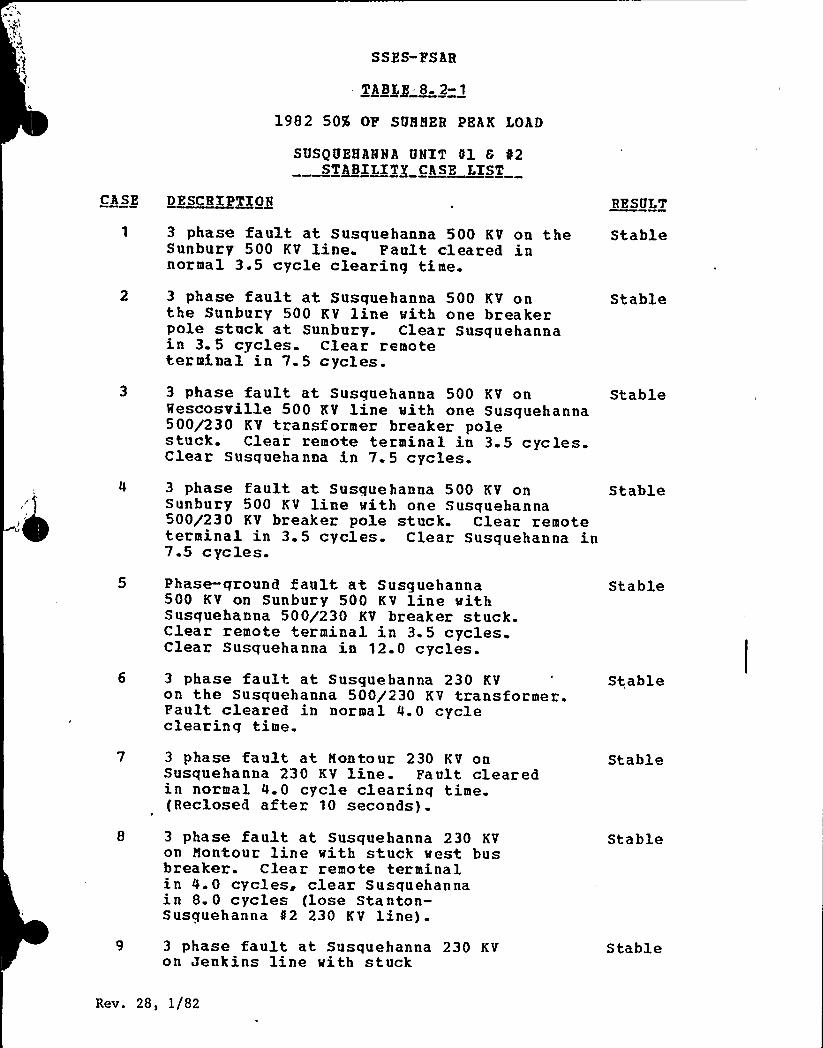
SSZS-CESAR
T$ B$g 8. 2-1
1982 50% OP SUHBER PEAK LOAD
SUSQUEHANNA UNIT el 6 02STABILITY CASE LIST
CASE DESCRY ~XONE RESULT
3 phase fault at Susquehanna 500 KV on the StableSunbury 500 KV line. Fault cleared innormal 3.5 cycle clearing time.
3 phase fault at Susquehanna 500 KV onthe Sunbury 500 KV line with one breakerpole stuck at Sunbury. Clear Susquehannain 3. 5 cycles. Clear remoteterminal in 7. 5 cycles.
Stable
3 phase fault at Susquehanna 500 KV onHescosville 500 KV line with one Susquehanna500/230 KV transformer breaker polestuck. Clear remote terminal in 3.5 cycles.Clear Susquehanna in 7. 5 cycles.3 phase fault at. Susquehanna 500 KV onSunbury 500 KV line with one Susquehanna500/230 KV breaker pole stuck. Clear remoteterminal in 3.5 cycles. Clear Susquehanna in7.5 cycles.
Stable
Stable
Phase-ground fault at Susquehanna500 KV on Sunbury 500 KV line wit,hSusquehanna 500/230 KV breaker stuck.Clear remote terminal in 3.5 cycles.Clear Susquehanna in 12.0 cycles.3 phase fault at Susquehanna 230 KVon the Susquehanna 500/230 KV transformer.Fault cleared in normal 4.0 cycleclearinq time.
Stable
Stable
3 phase fault at Montour 230 KV onSusquehanna 230 KV line. Fault clearedin normal 4.0 cycle clearing time.(Reclosed after 10 seconds).
Stable
3 phase fault at Susquehanna 230 KVon Montour line with stuck west busbreaker. Clear remote terminalin 4.0 cycles, clear Susquehannain 8. 0 cycles (lose Stanton-Susquehanna $ 2 230 KV line).
Stable
3 phase fault at Susquehanna 230 KVon Jenkins line with stuck
Stable
Rev. 28, 1/82

SSBS-FSAR
~A~B$~82-1 ggg~tin ueQ
CASE ~DSgBXPTION RESULT
east bus breaker. Clear remoteterminal in 6.0 cycles, clear Susquehannain 8.0 cycles.
10 3 phase fault at Susquehanna 230 KVon the 500/230 KV transformer vith onepole stuck on vest bus breaker. Cleartvo poles in'4.0 cycles, clear fault in 8.0cycles (lose Stanton-Susquehanna $ 2230 KV line) .
Stable
3 phase fault at Susquehanna 230 KVon Harvood line vith stuck tie breaker pole.Clear tvo poles in 4.0 cycles. Clearstuck pole in 8.0 cycles (lose Sunbury-Susquehanna 230 KV line) .
Stable
12 3 phase fault at Susquehanna 230 KVon E. Palmerton line vith onepole stuck on vest bus breaker. Clear tvopoles in 4.0 cycles. Clear stuck polein 8.0 cycles (lose Stanton-Susquehanna42 230 KV line).
Stable
13 Phase-ground fault at Susquehanna 500 KV onMescosville 500 KV line vith Susquehanna500/230 KV breaker stuck. Clearremote terminal in 3.5 cycles. ClearSusquehanna in 12. 0 cycles.
Stable
14 Susquehanna-Mescosville 500 KV andSusguehanna-Harvood (E. Palmerton) DoubleCircuit 230 KV crossing failure(3 phase fault on all circuits).Trip Susquehanna Unit 81 in 12cycles. Clear Susquehanna-Rescosville500 KV line in 3. 5 cycles. ClearSusquehanna-Harwood and Susquehanna-E. Palmerton 230 KV lines in 4.0 cycles.
Stable
15 3 phase fault near E. Palmerton onall lines in E. Palmerton-Harvood R/Ncorridor. Clear Susguebanna-Qescosville500 KV line in 3.5 cycles. ClearE. Palmerton-Susquehanna and Harvood-Siegfried 230 KV lines in 4.0 cycles.
Stable
Rev. 28, i/82

C
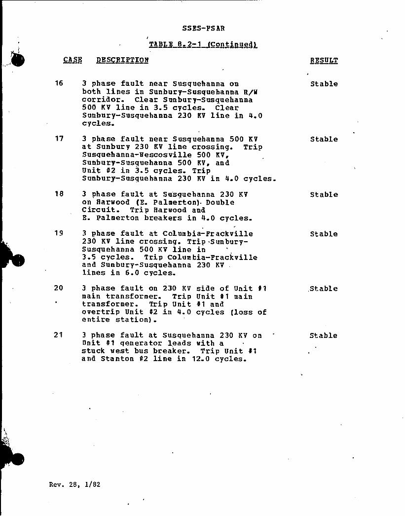
SSES-FSAR
~Tg~ 8 g-1~Cont~u~egCASE ~E~SIPT~I R EXULT
16 3 phase fault near Susquehanna oaboth lines in Sunbury-Susquehanna R/Mcorridor. Clear Sunbury-Susquehanna500 KV line in 3.5 cycles. ClearSunbury-Susquehanna 230 KV line in 4.0cycles.
17 3 phase fault near Susquehanna 500 KVat Sunbury 230 KV line crossing. TripSusquehanna-Vescosville 500 KV,Sunbury-Susquehanna 500 KV ~ andUnit 02 in 3.5 cycles. TripSunbury-Susquehanna 230 KV in 4.0 cycles.
18 3 phase fault at Susquehanna 230 KVon Harvood (Z. Palmerton) DoubleCircuit. Trip Harvood andE. Palmerton breakers in 4.0 cycles.
Stable
S table
Stable
3 phase fa ult at Colum bia-Fr ack ville230 KV line crossing. Trip Sunbury-Susquehanna 500 KV line in3.5 cycles. Trip Columbia-Prackvilleand Sunbury-Susquehanna 230 KV,lines in 6.0 cycles.
Stable
20 3 phase fault on 230 KVmain transformer. Tript ra ns f'rmer. Trip U ni tovertrip Unit 02 in 4. 0entire station) .
side of Unit f1Unit 01 main41 andcycles floss of
,Stable
21 3 phase fault at Susquehanna 230 KV onUnit 01 qenerator leads vith astuck vest bus breaker. Trip Unit 41a nd Sta n ton 42 line in 12. 0 cycles.
Stable
Rev. 28, 1/82
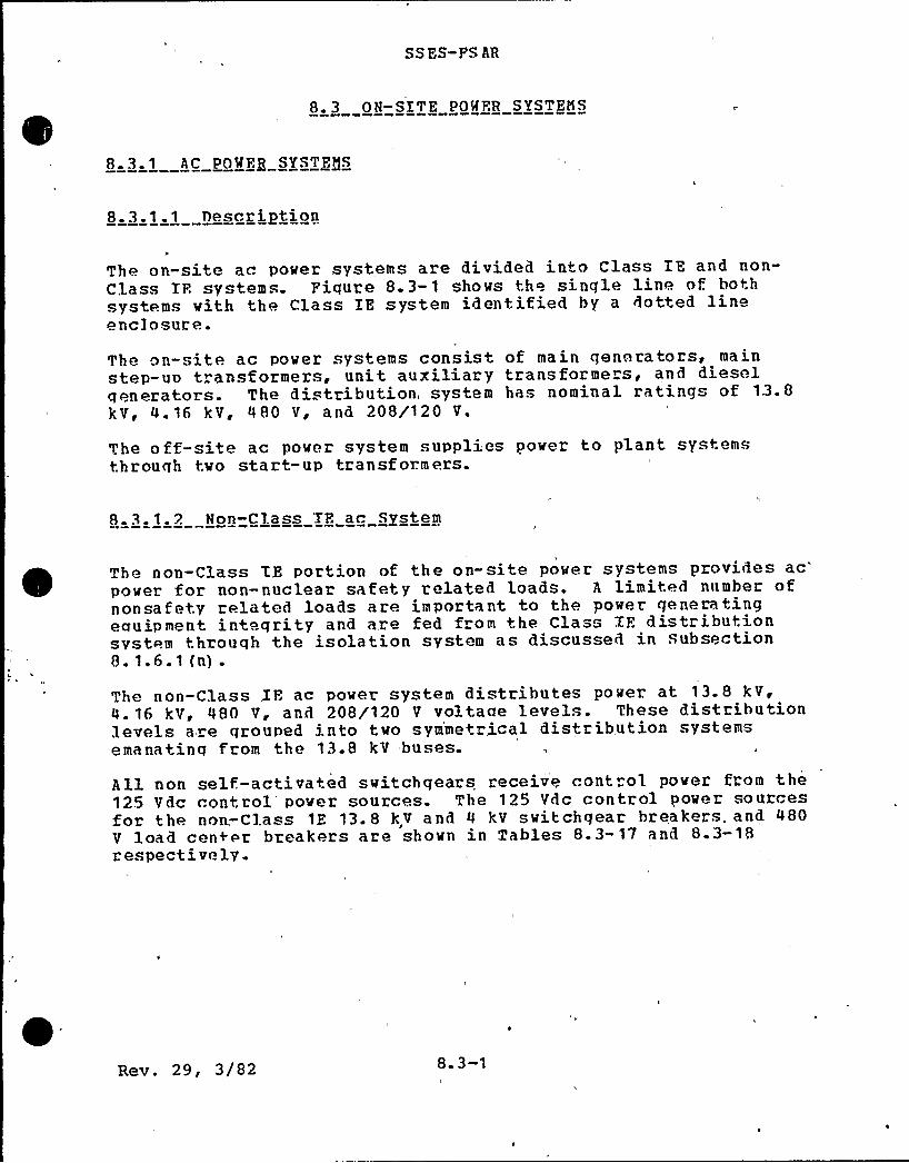
SSES-FS AR
8 3 ON-SITE POWER SYSTEMS
8 3. 1 - AC POWFR SYSTEMS
8.3.1.1 T)escription
The on-site ac power systems are divided into Class IE and non-Class IF. systems. Fiqure 8.3-1 shows the single line of. bothsystems with the Class IE system identified by a dotted lineenclosure.
The on-. ite ac power systems consist of main generators, mainstep-un transformers, unit auxiliary transforme s, and dieselqenerators. The distribution, system has nominal ratings of 13.8kV, 4.16 kV, 480 V, and 208/120 V.
The off-site ac power system supplies power to plant systemsthrough tvo start-up transf ormers.
8.3.1.2 Non-Class 'IF. ac System
The non-Class TE portion of the on-site power systems Provides acpover for non-nuclear safety related loads. A limited number ofnonsafety related loads are important to the power generatingequipment inteqrity and are fed from the Class IF. distributionsystem through the isolation system as discussed in Subsection8. 1.6.1 (n) .
The non-Class XF. ac pover system distributes power at 13.8 kV,4. 16 kV, 480 V, and 208/120 V voltaae levels. These distributionlevels are grouped into tvo sym'metrical distribution systemsemanating from the 13.8 kV buses.
All non self.-activated switchgears receive cont ol pover from the125 Vdc control'over sources. The 125 Vdc control power sourcesfor the non.-Class tE 13.8 kV and 4 kV switchqear breakers. and 480V load center breakers are shown in Tables 8.3-17 and 8.3-18respectively.
Rev. 29, 3/82 8. 3-1
SS ES- FS AR
8. 3. 1. 2. 1 Operation
The unit auxiliary transformer supplies all the non-'Class IE unitauxiliary loads except unit HVAC and Units 1 and 2 common loads,which are fed by the two startup transformers as shown on Piqures8. 3-1 a nd 8. 3-2.
The unit auxiliary~transformer primary is connected to the maingenerator isolated phase bus duct tap (24 kV) while the secondaryof the transformer is connected'to two 13.8 kV unit auxiliarybuses through a nonsegregated phase bus.
Durinq plant startup, shutdown, and post shutdown, power issupplied from the off-site power sources through the two startuptransformers. In addition, capability is provided to transfer .
the unit auxiliary buses to the startup power source to maintaincontinuity'of power at the unit'auxiliary, distribution system.
Tn addition to the loadinq conditions mentioned in the aboveparagraph, the 13.8 kV .tartup buses also supply the preferredpower supplies to the Class IE load groups through theirrespective 13.2 kV - 4.16 kV engineered safeguard transformers asdiscussed in Subsection 8.3.1. 3 {Figure 8.3-1) .
The auxiliary bus feeder breakers from the unit auxiliarytransformers and the startup tie bus section are interlocked toprevent supplying power to the startup bus from the unitauxiliary transformer.
13. 0 k V tie bus is provided for the two'tartup buses. A
separate (not in switchqear line-up) bus tie breaker is locatedin the t ie bus. Xn the even t of a loss o f. star tup power supplyto the 13. 8 kV startup bus, an alarm is initiated and, a timedelay undervoltaqe relay initiates the tripping of the 13.8 kVincoming breaker and the rlosinq of the tie breaker. resultinq ina slow transfer'. However, this transfer is prevented if eitherauxiliarv 13.8 kV bus is beinq fed from the undervoltage tie hussection. This condition is sensed by th~ closure of. two {2)auxiliary»h" contacts in series, one from each nf the unitauxiliary bus to tie-hus circuit breakers- connected to a commontie bus section. manual'nitiation of the ..ie breaker i. alsoprovided. However, the use of. this manual control,isadministrativel'y limited as an overriding means only. Underautomatic operatinq conditions of the tie breaker, auxiliaryswitch»b» contacts of the startup transformer incoming breakersare also utilized as a permissive to close the ti,e breaker toprevent tyinq of. the two startun transformers.
At the 4 kV ESF power distribution suhsystem a three-way transfersystem is provided to enable the ESP loads to connect to eitherof the two off-site power sources or to 'the standby diesel
Rev. 29, 3/82 8. 3-2

SS ES-PS AR
generators. Hach ESP bus i. normally connected to a preferredsource which is one of two ES transformers connected respectivelyto the t.wo startup buses. During loss of one off-site powesource, that is, upstream of the startup bus, the startup husundervoltaqe relay will trip the feeder breaker to the ES
transformer, causinq a transfer at the 4kV ESP bus. If powerloss ocrurs between the 13kV star+up bus and the 4kV ESP bus, a4kV transfer will occur. The. 4kV ESP bus transfer is initiatedby the bus undervoltaqe relay, which trips the normal incomingbreaker and subsequently closes the alternate inroming breaker.This is practically a Read bus transfer. If both off-site powersources'are unavailable, the diesel generator breaker closes assoon as the diesel qenerator power is available.
The above transfer mechanism allows only one source breaker to herlosed at any one time and to ensure this, breaker auxiliaryswitch rontacts are used for interlocking. A manual live bustrans.fer is possible through a synchronizing device in which casean alternate source breaker is first closed and is followed by anautomatic tripping of the preferred supply breaker. In t.his casethe duration of the tie is merely a few cycles. Furthermore, thediesel generator can be tied with any one of the two off-sitesources for an indefinite time under test condition but this doesnot. in any way cause the two off site power systems to be tiedtogether.
>he plant security load center is double ended, each end beingsupplied from one of. the 13 kV start-up buses through a stepdowntransformer and is provided with a normally open tie breaker.Each hus is supplied from its own start-up source. Should onesource be lost the undervoltage relay at the transformersecondary trips the bus incominq breaker. The bus undervoltagerelay then initiates rlosure of the tie breaker provided theincominq hreaker has successfully tripped. Upon return of thefailed source the incominq hreaker will not automatically closeand can only be manually closed after the tie breaker has beentrippeR.
In all of the foreqoinq tie or transfer systems'here is no waythat the two off-site power systems can be tied together at theon-site buses assuminq loss of one off.-site source.
The 13.8 kV switchqear provide power for large auxiliary loadsand 480 V 1'oad centers. The 13.8 kV switchgear feed douhle-ended480 V load centers. A manual tie breaker is provided for eachset of load centers to intertie the two load centers in the eventof .failure of one load center transformer. Load centersqenerall y supply power to 480 V loads large than 100 hp andpower for their respective motor control centers. The motorcontrol renters supply 480 V loads smaller than 100 hp while 480V, 480/277 V, 208/120 V panels provide miscellaneous loads suchas unit. heaters, space heaters, lighting systems, etc.
Rev. 29, 3/82 8. 3-3
SS ES-FS AR
8. 3. 1. 2. 2 Non-Class IE Pguipment Capacities
Refer to.Figure 8.3-1 for interconnections of the followingequipment. Physical locations of each of the following equipmentcan he found in Section 1.2.
. a)'nit Auxiliary Transformer
33/44/55 MVA, 34~ OA/FA/FOA, 550C'37/49.3/61. 6 NVA, QA/FA/FOAL 650C
„23.0-13.8 kV Grd. Y/7.96 kVZ = 9.0% 8 33 MVA
b) Startup Transformer
45/60/75 MVA 3', OA/FOA/FOAi 650C225/129.9 -- 13.8/7.97 kVZ = 15 0% 8 45 MVALTC s 15% in 15/16% steps
c) Engineered Safequard Tran former
10. 5/13. 12 NVA, 3(f, OA/FA, 55 C
11 76/14.7 MVA, OA/FA ~ 65~C13.2-4.16 kV Grd. Y/2.4 kVZ = 6.8% I 10.5 MVA
d) Un it Auxiliary 13. 8 kV Switchgear
Buses
Xncominq breakers
Feeder breakers
2000 A continuous rating, 750MVA bracinq
2000 A continuous rating, 750MVA 3'lass 28,000 A sym,interruptinq rating1200 A continuous rating, 750MVA 3d Class 28,000 A syminterruptinq rating
e) Startup 13.8 k V Switchqear
Ruses
Incoming breakers
3000 A continuous rating, 750MVA bracing
3000 A continuous rating, 750NVA 3g Class 28,000 A syminterrup inq'ating
Rev. 29, 3/82 8. 3-4
SS ES- PS AR
Tie breaker
Feeder breakers
f) 4. 16 k V Switchgear
Buses
3000 A continuous rating, 750NVA 3'lass 28,000 A syminterrupting rating1200 A continuous rating, 750NVA 3'lass 28,000 A syminterrupting rating
1200 A continuous rating, 250HVA bracing
Xncoming breakers
Feeder breakers
g) 480 V J,oad Centers
Transformers
Control structure,Administration,
, Security and machineshop transformersonly
1200 A continuous rating, 250NVA 3p Class 29,000 A syminterrupting rating1200 A continuous rating, 250MVA 3'lass 2 9, 000 A syminterrupting rating
1500/2000 kVA, 3', AA/FA,13 200-4 80 V Grd. Y/277 V
1000/1333 kVA, 3', AA/FA,13200 480 V G d. y/?77 V
Buses
Tncoming breakers
Feeder breakers
Tie breakers
3000 A continuous; 65,000 A
bracing (1500/2000 k VA)
1600 A continuous; 50,000 A
bracing (1000/1500 k VA)
3000 A continuous, 65,000 A
sym interrupting rating(1500/2000 k VA)
1600 A continuous, 50,000 A
sym interrupting rating(1000/1500 k VA)
600 A continuous, 30,000 A syminterrupting rat ing
1600 A continuous, 50 000 A
sym interrupting rating
Rev. 29, 3/82 8. 3-5
SS ES-PS AR
h) 480 V Motor Control Centers
Horizontal bus {main) 600 A continuous; 42,000 A
bracing
Vertical bus ~
Breakers {Molded Case)
150 A frame
400 A continuous; 42,000 A
br
acing'5,000
A symmetricalinter'ruptinq rating
250 A frame 22,000 A symmetricalinterrup"inq rating
i) 480 V Distribution Panel
Bus 225 A ratinq, 14,000 A bracing
Branch breakers 100 A frame, 14,000 A
interrupting rating208/120 V ac Instrument ac Distribution Panels
Main breaker{molded case)
Buses
225 A continuous22,000 A-sym interruptingrating225 A continuous
Branch breakers(mol d ed case)
100 A frame size10,000 A sym interruptinqrating
8.3.1.3 Class IF, ac Power System
The Class .ZP, ac portion of the on-site power system is shown onFigure 8. 3-1.
The Clas., IF. ac system distributes power at 4.16 kV, 480 V ~ and208/120 V to the safety related loads. The safety related loadsare divided into four load groups per generating unit and aretabulated in Table 8.3-1- Fach load group has its owndistribution system and power supplies.The 4.16 kV bus of each Class IF. load group channel is providedwith connections to two off-site power sources designated aspreferred and alternate power supplies. Diesel generators areprovided as a standby power supply in the event of total loss of
Rev. 29, 3/82 8. 3-6
SSES-FS AB
the preferred and alternate power supplies. Standby power supplyis discussed in Subsection 8.3. 1.4.
Preferred and alternate power supplies up to the 4. 16 kV buses ofthe Class IF, power system are considered as non-Class IE.
All non self,-activated switchqears receive control power from the125 Vdc control power sources. The 125 Vdc control power sourcesfor +he Class 1F. 4.16 kV switchgear breakers and 480 V loadcenter breakers are shown in Tables 8. 3-19 and 0.3-20respect ively.In order to achieve adequate separation between channelized loadqroun and divisionalized load qroup, two 125 Vdc control powersupplies are provided for each 4.16 kV swi.tchqear (refer to Table8. 3-1 9) .
8.3.1.3. 1 Power Supply Peeders
Each Class IE 4.16 kV switchqear of a load group channel isprovided with a preferred and an alternate (off-site) powersupply feeder and one standby diesel qenerator feeder. Each busis normally energized bv the preferred power supply. If thepreferred power source is not -available at the 4.16 kV bus,automatic transfer is made to the alternate power source asdescribed in Subsection 8.3.1.3.6. Tf both preferred andalterna+e power feeders become de-enerqized, +he safety-relatedloads on each bus are picked up automatically by the standbydiesel qenerator assigned to that bus as described in Subsection8. 3.1.4.
8. 3. 1. 3. 2 Power Feeder Cables
Power feeder cables for the 4. 16 kV system are aluminumconductor, and are rated 5 kV, 900C conductor temperature withhigh temperaturp Kerite insulation. The cables are provided withan overall flame resistant Kerite jacket covering. For the 480 V
system, cables of size 44/0 AMG and larger are aluminumconductor; cables less than 44/0, AMG are copper conductor. Bothtypes of cables are rated 600 V, 900C conductor temperature withethylene-propylene insulation with a flame-resistant hypalonjacket covering. The conductors are sized to carry the maximumavailable short circuit current fox'he time required for thecircuit breaker to clear the fault. All Clas, IF. cables havebeen desiqned for operation as discussed in Section 3.11.
The 4.16 kV switchgear, D.C. load centers, and T).C. Contxolcenters are equipped with aluminum buses and silver-plated bolted
l
Rev. 29, 3/82 8. 3-7
SSES-FS AR
connections. The 480 V load centers and motor control centersare equipped with copper/aluminum busses and the boltedconnections are also silver-plated. All circuit breakerterminals are copper. For power cable terminations, Burndycompression aluminum. terminals (HYLOG) are used. These terminalsare of seamless tubular construction, tin-plated to resistcorrosion, and factory filled with oxide inhibiting compoundpenetrox A. Compression adapters MAC ADAPT MPT series orequivalent are used for equipment/vendor supplied componentshavinq mechanical luqs which cannot be converted to accept aBurndy compression luq due to physical or practical limitations.A non-oxidizing lubricant such as D50H47 or equivalent will beapplied on all contact surfaces at bolted joints to avoiddamaqing the silver-plated contact surfaces.
8. 3. 1.3. 3 Bus Arrangements
The Class IE ac system is divided into four load qroup channelsper unit (load qroup Channels A, B, C, and D) . Power suppliesfor each load group are discussed in Subsection 8.3.1.3. 1. AllClass IE ac loads are divided among the four -load groups s'o thatany combination of three out of four load groups has thecapability of supplying the minimum required safety loads.
The distribution system of each load group consists of one 4. 16kV bus, one 480 V load center, four or five motor controlcenters, and several low voltage di.,tribution panels. The busarrangements are shown on Fiqure 8. 3-1, 8.3-3, 8.3-4, 8.3-7 and8. 3-8.
8. 3.1.3. 4 ~ Loads Suo2lied from Fach Bus
Table 8.3-1 provides a listing of all the loads supplied fromeach Class IF., bus.
8. 3.1.3.5- Class IF, Isolated Swing Bus
Two redundant 480 V swing buses are provided for each unit forthe RHR injection valve motor operators, recirculation loopbypass valve motor operators, and recirculation discharge valvemotor operators. The single line of the swing bus is shown onFiqure 8.3-9.
A Class IE 480 V load center of one load group channel suppliesthe preferred power to the swing bus through the electricalisolation of a moto -generator (M-G) set. The alternate power is
Rev. 29, 3/82 8. 3-8
SS ES-FS AR
supplied directly from another redundant Class .XF, 480 V loadcenter. The M-G set, is. used for elect ically isolating tvoredundant load groups. Faults at the swing bus cannot bepropagated onto more than one load group.
The svinq buses are Class IF, motor control center constructions.An automatic transfer svitch is provided for transferring thesving bus from the preferred to the alternate pover source uponreduction or loss of voltage at the swing bus. Tf theundervoltage is caused by a fault at the swing bus, the transferwill be prevented even if the alternate power is available. Thesvinq bus vill be retransferred back to preferred power vhen thevoltage is restored within acceptable limits.The svinq bus and transfer switch are designed so that. for a lossof off-site power 'and any single failure, the minimum requiredECCS flov to meet 10CPR50 Appendix I criteria is alwaysavailable.
The follovi,nq is a common mode-common cause failure analysis(CMCCFA) for the automatic transfer svitches:
Figure 8.3-13 depicts a simplified single line diagram for thesving bus system to facilitate the analysis.
Table 8.3-24 provides a step-by-step CRCCFA of the auto transfersvitch'by postulating the various major common causative factors{events) .
Normal conservatism in desiqn and manufacturing margins,mandatory requirements of QA/OC procedures, Tnitial Test program,Preoperationa 1 Tests, applicable administrative procedures andmaintenance proqrams as well as operator actions contribute tominimize the, susceptibility of the auto „transfer svitch to thevarious common causat ive factors as analyzed in Table 8.3-24.
This analysis demonstrates that the transfer switch, as acomponent of the swinq bus system design, will not degrade "heindependence and separation betveen the redundant. Class XF.
channels (load center channels A aRd C or B and D) .
The test, program (Section 14.2 and Technical Specification 314.8)for the 480V svinq bus system (Figure 8.3-13) consists of:
a) Periodic. inspection of virinq, insulation, and connectionsetc.. to assess the continuity of the components and system.
b) Periodic testing to verify the operability and functionalperformance of individual components in the system.
c) Periodic testing of operational sequence and operability ofthe system as a whole.
Rev. 29, 3/82 8. 3-9
SS ES-PSAR
8.3.1.3. 6 Manual and Automatic Interconnections BetveenBuses~ Buses and Loads and Ruses and ~ Supplies
No provision exists for automatically or manually connecting oneClass IP, load group to the redundant Class XE load qroup or forautomatically transferrinq loads between load qroups except thesvinq buses's discussed in. Subsection 8.3.1.3. 5.
For each load group. one 4.16 kV feeder circuit breaker isprovided for the normal incominq'preferred power source, andanother 4. 16 kV feeder circuit breaker is connected to thealternate power source {see Subsection 8.3.1.3. 1) . The normalpreferred pover source to each bus is electrically interlockedwith the alternate power source such that the bus can beconnected to a single power source at any one time. In the event.of loss of preferred power to the load group, undexvoltage relays{le. s than or equal to 15 percent voltage) on the 4.16 kVswitchqear will initiate an automatic transfer to the alternatepover source "if available. In the event of losing both preferred'and alternate pover supplies, the load grouo will be povered fromthe standby die el generator.
Restoration of power Crom standby pover to the preferred sourceof offsite pover is manually initiated in the control room onpanel OC653. eben the stnadby power source is in synchronismwith the offsite pover source, the preferred offsite sourceincoming breaker is closed. Upon closing of this preferredsource breaker ~ the standby source breaker vill automaticallytrip. This tripping is initiated by the preferred offsito sourcebreaker auxiliary switch contact interlock.A similar procedure is used to restore pover from standby to thealternate offsite power.
8. 3.1.3.7 Interconnections Between Safety Related andNonsafety Related Buses, Nonsafety RelatedLoads~ and Safety Related Buses
Discussion of interconnections betweon safety related and non-safety related buses, nonsafety related loads, and safety relatedbuses is prese nted in Subsections 3. 12. 2 and 8. 1. 6. 1.
Rev. 29, 3/82 8. 3-10

SS ES-FS AR
8.3.1.3. 8 Redundant Bus Separation
The engineered safety features switchgear, load centers, andmotor control centers for the redundant Class IE load groups arelocated in separate Seismic Category I rooms in the reactorbuilding to ensure electrical and physical separation.Electrical equipment separation is discussed in Subsection 3.12.2and Subsection 8. 1.6.1. Equipment layout d" awnings can be foundin Section 1.2.
8. 3.1.3. 9 Class XE Equipment Capacities
a) 4.16 kV Svitchqear
Buses 1200 A continuous ratinq, 250NVA bracing
Incominq breakers 1200 A continuous rating, 250NVA 3'lass 29,000 A syminterrupting cating
Feeder breakers 1200 A continuous ratinq, 250NVA 3gf Class 29,000 A syminterruptinq rating
b) 480 V Load Centers
Transformers (Unit 1) 750/1000 kVA 3P, AA/FA,13800»480 V Qrrl. Y/277 V
Transf ormer (Unit 2) 750 kVA, 3P, AAi 13800-480 V
Gr d. Y/277 V
Buses 1200 A continuous, 30,000 A
bracing
Breakers 600 A frame size, 30,000 A syminterruptinq rating
c) 480 V Notor Control Centers
Buses
Horizontal (main) 600 A continuous, 42,000 A
bracing
Vertical 400 A continuous, 42,000 A
bracing
Rev. 29, 3/82 8 ~ 3- 11
SS ES- FS AR
Breakers (molded case)
150 A frame 25,000 A sym interrupting".. ating
250 A frame
d) Automatic transfersw itch
22,000 A, gym interrupt ingrating480 V, 3', 4 00 Acontinuous 31,000 Asym vithstand capability
e) 208/120 V ac Instrument ac Distribution Panel.,
Buses 225 A continuous10,.000 A sym in terruptingrating
Branch breakers(molded case)
100 A frame size10,000 A sym interruptingrating
8. 3. 1.3. 10 Automatic Loading and Load Shedding
If preferred off-site pover is available to the Class 1E 4.16 kVbus follovinq a LOCA signal, the required ES> loads will start asshown in Tables 8.3-1 and 8.3-1b.
Tn the event of loss of preferred and alternate off-site powersupplies, the Class 1E 4.16 kV buses vill shed all loads exceptthe 480 V load centers and connect the standby diesel generatorto the Class 1E bus. The loadinq sequence is shovn on Table 8.3-1.
However, if a slow bus transfer {bus voltage on trans fer is lessthan 15%) at the Class 1E 4.16 kV bus is initiated to thealternate off-site pove as a result of a loss of preferred off-site pover, all loads are shed except the 480 V Road centers.Then the required ESP loads vill start as shown on Tables 8.3-1and 8.3-1b.
Emergency loads are also sequenced vith off-site power because ofthe power system limitation (..ransformer capability). .Loadsequencinq is designed to minimize system disturbance.Tables 8.3-1 and 8.3-1b shov the anticipated starting time of allFBF loails. Both Unit 1 anil Unit 2 buses for a uiven dieselgenerator are normally supplied by the same off-site powersupply. An individual timing unit is Provided for each of the
Rev. 29, 3/82 8. 3-12
SS ES-FS AR
ESF loads vith automatic start function. Failure to stax't on oneLoad vill not affect the startinq initiation of other loads.
The loadinq sequence for a simultaneous LOCA in one, unit and afalse LOCA in the other unit is shown in Table 8.3-1b., A falseLOCA signal as used in this section refers to a non-mechanisticfailure resultinq in a LOCA signal in one reactox'nit when a
Y.OCA has not occurred in that, unit.
The load startinq transient on the diesel qenerators is reducedif the Unit 1, and Unit 2 load sequences do not startsimultaneously.
Tf off-site power is available, the LOCA signal in one unit andfalse LOCA sianal in the other vill shed 2 RHH motors and 2 coxespray motors of each unit and sequentially start 2'RffR and 2 corespray motors as shown. in Table 8.3-1h. This is done in order notto exceed the loading limitations of the ES Transformers and toprovide at least the minimum core cooling requirements of bothuni+s. Under the modified core cooling arrangement, 2 HHR pumps{one in each loop) and 2 core spray pumps {both in the same loop)will satisfy the minimum coolinq requirements of each unit.Approixmately ten minutes after the above event the opera to willbe able to determine which is the false-LOCA unit and shutdownnon-essential loads in the non-LOCA unit. 1n case off-site poweris not available, the loadinq is the same as discussed above, butthe sequencing is slightly altered as shovn in Table 8;3- 16.
Under all conditions discussed in Subsections 8.3.1.3.10.1 and8. 3.1.3. 10.2,'afety functions are met within the time limitsshown in Table 6. 3-1.
8. 3.1,3. 11 Saf ety pela"..e.d Equipment Ident ification
Subsec,ion 8. 3.1. 11.3 provides information xegarding the physicalidentification of. Class XH equipment.
8.3.1.3.12 Xnstrumentation and Control Systems for theApplicable Power Systems with the AssignedPower Supply Tdentified
The dc power supplies for the control of the redundant Class XEequipment are physically and elect" ically separate andindependent. Refer to" Subsection 8.3.2 for a detailed discussionof the dc system.
Rev. 29, 3/82 .8. 3-13
SS ZS-PS AR
8.3.1.3.13 Electric Circuit Protection Systems
Protective relay schemes and direct-acting trip devices onprimarv and backup circuit breakers are provided throughout theon-site power system in order to:
I
a) Isolate faulted equipment and/or circuits Cromunfaulted equipment and/or circuits
b) Prevent damage to equipment
c) Px ot.ect personnel
d) minimize system disturbances
e) Maintain continuity of the power supply
Major types of protection measures employed include thefol lowinq:
a) Bus Differential Relaying
A bus differential relay is provided for''each Class IE4. 16 kV bus. This relay provides high speeddisconnecting of bus supply breakers to preventpropaqation of internal bus .fault to another bus.
b) Overcurrent Relaying
Bach Clas., IE 4.16 kV bus feeder circuit breaker isequipped with thxee extremely invexse-time overcurrentrelays to sense and to protect the bus from anovercurrent condition.The standby diesel qenerator feeder circuit, breaker tothe 4.16 kV bus is equipped with three voltagerestrained overcurrent relays and one inverse-timeground fault relay for feeder circuit protection.Each 4.16 kV motor feeder circuit breaker has threeovercurrent relays, each with one lonq time and oneinstantaneous element for ovexload, .locked rotox, andshort-circuit protection. Each breaker is alsoequipped with an instantaneous ground current relay.Each Class IE 4.16 kV supply circuit breaker to a 480 Vload center transformer i protected by threeovercurrent relays with lonq-time and instantaneouselements. An instantaneous, overcurrent ground sensorrelay provides sensitive ground fault „protection.
Rev. 29, 3/82 8. 3-14
SS ES-'PS AR
c) Under/Overvoltaqe Relaying
Hach 4.16 kV Class IF. bus is equipped with undervoltaqerelays for diesel generator starting and undervoltageannunciation. Each 4kV bus is provided with degradedgrid voltage protection. Hach 480 V Class ZE .loadcenter bus is equipped with under/overvoltaqe relaysfor annunciation.
d) Diesel Generator Differential Relaying
Each diesel generator is equipped with differentialrelayinq protection. This circuitry provides highspeed disconnection to prevent severe damage in case ofdiesel qenerator internal faults.
e) 480 V Load Center Protection
Hach load center circuit breaker is equipped withintegral, solid-state, dual magnetic, ad ju., table,direct-action trip devices providing inverse-timeovercurrent protection. Motor feeders are equippedwith lonq-time overcurrent and instantaneous short-circuit protection.
f) 480 V Rotor Control Center Protection
Molded-case circuit breakers provide inverse-timeovercurrent and/or instantaneous short circuitprotection for all connected loads. For motorcircuits, the molded-case circuit breakers are equippedwi+h an adjustable instantaneous magnetic trip functiononly. Notor thermal overload protection is provided bythe heater element trip unit in each phase of the motorfeeder circuit. The molded-case breakers for nonmotor.feeder circuits provide thermal inverse-timeovercurrent protection and instantaneous short circuitprotection. The thermal overload trip units for safetyrelated motor-operated valves are normally bypassedexcept during maintenance tests.
The circuit protection system is desiqned so that fault isolationis secur ed with a minimum circuit interruption. The combinationof. devices and settings applied affords the selectivity necessaryto isolate a faulted area quickly with a minimum of disturbance+o the rest of the system.< The protective devices erepreoperationally tested in accordance with +he requi ements ofChapter 14. After the plant is in operation, periodic tests willbe performed, to verify the protective device calibration, setpoints, and correct operation in accordance with the requirements
-o f Chapter 16.
Rev. 29, 3/82 8. 3-15
SS ES- FS AR
B. 3. 1. 3. 14 . Testing of the ac System During Power Operation
All Class IP, circuit breakers 'and motor starters, except for theelectric equipment associated with Class ZE loads identified inSubsection 8.3.1.3.15, are testable during reactor operation.Durinq periodic Class IP, system tests, subsystems of tho ESPsystem such as safety in)ection, containment spray, andcontainment isolation are actuated, thereby causing appropriatecircuit breaker or contactor operation. The 4.16 kV and 480 V
circuit breakers and control circuits can also be testedindependently while individual equipment is shut down. Thecircuit breakers can be placed in the test position and exe cisedwithout operation of .the related equipment.
B. 3. 1. 3. 15 Class 1P~ Loads not Tgstable During Power Operations
Peedwater Line Isolation Valves
The feedwa+er line isolation valves (HV-F032 A/8) are of themo+or operated check valve type and'are not +estable withthe feedwater flow present. Motor operation is not requiredfor isolation. Only the outermost isolation valve is Class1P. powered and would be motor operated for long termisolation after isolation of the feedwater line.Conformance with Regulatory Guide 1.22 Section D.4:
1. The feedwater isolation is not designed for isola ionwith Eeedwater flow present as the loss of flow wouldadversely affect operability of the plant.
2. Motor operation is not'equired for isolation.The motor operator of the outermost isolation valve isfully testable durinq shutdown.
B. Mai n Steam Isolation Valves
The'ain 'steam i.solation valves can be tested individuallyto the 90% open posi+ion at full powerOwith the slow actingtest solenoid valve. A fully closed test using the two fastacting 'main solenoids would require a reduction in ractorpower.
Conformance with Requlatory Guide 1.22: See Subsections'. 3. 2a. 2. 2. 1. 2 and 5. 4.5. 4.
C. ADS System - Safety/Relief Valves
Rev. 29, 3/82 8. 3-16
The active components of the ADS system except thesaf ety/relief valves and their associated solenoid valvesare designed so they may be tested during plant poweroperaiton. The relief, valve and associated solenoid are nottested durinq reactor power operation.
Conformance with Requlatory Guide 1. 22:
The safety/relief valves are not tested, during poweroperation because of resultinq adverse affect on
plant'operation.
2. Because of low failure rates of valve actuation, theprobability of failure is acceptably low withouttesting.
3. The safety/relief valves and associated solenoid valvescan be tested durinq startup following shutdown.
Rec ircu la t ion Loop Isolation Valves
The recirculation pump isolation valves are not testedduring reactor power operations.
Conformance with Regulatory Guide 1.22 Section 9.4:
Operation of a recirculation loop isolation valve wouldresult in a reduction of circulation which wouldadversely affect the safety and operability of theplant.
2. The probability of failure is accep'tably low withouttestinq the valve motor during operation.
The valve and motor are fully testable during reactorshutdown.
8.3.1.4 Standby Power Supply
The standby power supply for each safety related load qroupconsists of. one diesel generator complete with its accessoriesand fuel st'oraqe and transfer systems. Each diesel generator israted 4000 kw at 0.8 pf for continuous operation and 4700 kw for2000 hr operation. The ratings for each diesel gene ato are'calculated in accordance with the recommendation of RegulatoryGuide 1. 9 (discussed in Subsection 8. 1. 6. 1) . The diesel-qenerators ran, operate at loads ot from 50 to 100 percent forunlimited periods without harm. Any diesel generatorcontinuously operated at loads of less than 50 percent will beloaded to 75-100 percent for 15-30 minutes approximately every
Rev. 29, 3/82 8. 3-17
SSES-FSAB
six hours and immediately prior to shutdown. Any dieselgenerator continuously operatinq at loads of less than 50 percentfor less than six hours will be loaded to 75-100 percen+ for 15-30 minutes immediately prior to shutdown. Such operation villenhance engine performance and reliability.The four diesel qenerators are sha~ed by the two units. Eachdiesel generator is connected to the 4.16 kV bus of the assiqnedload qroup per unit. The capacity of the diesel generators(assuminq one diesel fails) is sufficient to operate theengineered safety feature" loads of one unit and those systemsrequired for concurrent safe shutdown of the second unit.No provisions axe provided. for parallel operation of. the dieselqenerator of. one load group with the diesel generator of theredundant load group. The diesel, qenerator circuit breaker andthe off-site power incoming circui+ breakers are interlocked toorevent feedback into the off-site power system. Theseinterlocks are bypassed during diesel generator load tests;however, only one unit is tested at any one time. During thetest period, the diesel generator under test is manuallysynch.ronizecl to the. preferred off-site power system. Upon
eceipt of a LOCA signal under the test condition, the dieselgenerator breaker is tripped but the diesel generator continuesto T un.
The diesel generators are physically and electrically isolatedfrom each o+her. Physical separation for fire and missileprotection is provided between diesel generators by separaterooms within a Seismic Category I structure. Power and controlcable for each of the diesel qenexato s and associated switchqeaare routed in separate raceways. Physical electrical equipment.layout of the diesel qenerator rooms i. shown on Figure 8.3-10.
Auxiliaries xequired for startinq and continu'ous operation ofeach diesel qenerator are fed by the Class IE power load qroupassociated with that diesel generator.
Control power for each diesel qenerator is provided by itscorrespondinq 125 V dc system.. from both Uni+ 1 and Unit 2.These two power feeders are not redundant, but have been providedfor ease of maintenance. Indication of which unit is supplyingthe dc control power is not provided in the control room. Manualswitches are installed at the local panel to select the preferredpower feeder. Since each diesel generator is shared by bothunits, either source of DC control pover is adequate. T.oss of DC
power to the Diesel Generator is indicated on the HIS panels as agroup trouble alarm on panel OC653 in the main control room.
Each diesel qenerator is provided wi+h a local engine controlpanel, a qenerator-exci+er contxol panel, a local 4.16 kV
Rev. 29, 3/82 8. 3-18

SS ES-FS AR
distribution panel, and a 480 V motor control center in thediesel generator room.
Local Engine Control Panel — consists of a localannunciator, engine control devices, gauges, andcontrol for diesel generator auxiliary equipment suchas fuel oil transfer pump, standby jacket water pump,et r..
The diesel qenerator control system is desiqned in sucha manner that some control devices are mounted in thefree standing control panel separate Crom the engine,while others are mounted directly on the engine, asrequired for reliable service. All devices that areessential to the start-up or power output of thedi.esel-generator set have been seismically qualified byanalysis or test to acceleration levels consistent withtheir mounting loca tion.
b) 4enerator-Exciter Control Panel - consists of generatorexcitation control equipment, generator protectiverelays and devices, etr..
4.16 kV Distribution Panel — provides connections fordiesel qenerator feeders to Unit 1 and 2. Also housespotential transformers and current transformer, etc.
480 V Motor Control Center — provides power to all 480V auxiliary equipment related with tha> dieselqenerator. This HCC is equipped with an automatictransfer switrh for connection to either Unit 1 or 2480 V Class IE load center. These two load centershelonq to the same load qroup channel as the dieselgenerator.
Physical separation of standby power system is discussed inSection 3. 12.
8. 3. 1. 4. 1 Automatic Stagt in'nitiatin'irc ui th ~
k
'' The diesel generators are automatically started by any of thefollowing conditions:
!a) Total loss of power to the 4.16 kV Class XK bus of
either 'unit to which the diesel qeneratoz i.s connected
t ~
b) Safety injection siqnal — low water level i.n thereactor, hiqh drywell pressure, or manual actuation.
Rev. 29, 3/82 8. 3» 19
SS BS- FS AB
Two redundant control/starting circuits are provided, fo eachdiesel qenerator. Failure of one circuit would not prevent therespective diesel generator from starting or from continuousopera tin,n.
The diesel generators are ready to accept loads within 10 secafter the initiation of the start circuit.
8. 3.1. 0. 2 Diesel Starting Mechanism and System
The diesel qenerator start system is described in Subsection9.5.6. To ensure fast and reliable starting, each diesel enqineis provided with immersion heaters in the engine jacket, water andthe lube oil sy.,tern to maintain the engine coolant and lube oiltemperature at an operable level. The electric jacket waterimmersion heater and the water circulatinq pump are interlockedfor simultaneous operation when the jacket water temperaturedrops below the preset temperature. The electric lube oilimmersion heater and the prelube circulatinq pump axe interlockedfor simultaneous operation when the engine is below 280 rpm.Refer to Subsection, 9.5.5 and 9.5.7 for further des" ription.
8.3.1. 4,3 Alarm and 'stripping - Deyic:e
The nrotective and alarm logic diagrams for the diesel generatorand its associated breakers are shown on Fiqures 8.3-11 and 8.3-12.
While supplying loads followinq an automatic start, each dieselengine and related generator circuit breaker are tripped by
, . protective devices under the followinq conditions only:(
a) Engine overspeed
b) Lube oil low pressure
c) (:one rator differentialTo prevent spurious tripping of the diesel qenerator due tomalfunction of the enqine lube oil low pressure trip device, fourindependent sensors are provided and connected in a coincidenceone-out-of-t wo taken twice tripping logic. An individualtripping alarm is provided by the annunciator at each localcontrol panel.
The startinq circuit. is also equipped with a "fail to start"relay operator that interrupts the sta t.ing of the diesel
Rev. 29, 3/82 8. 3-20
SS ES-FS AR
qenerator if a predetermined speed is not reached wi~ hin a
limited time followinq a start initiation.E
Xn addition to the above-listed trips, each generator circuitbreaker is tripped by the followinq protective relays todisconnect the qenerator from a faulty bus (the diesel generatorcontinues t.o run):
a) Voltaqe restrained overcurrent
b) 0 kV bus different ia 1.
Followinq a manual stark, a diesel generator is in the test modeand ready for a load test. Mhen so operated, in addition to theabove-Listed trips, each diesel engine.and related generatorcircuit breaker are automatically tripped by the followinqprotective devices:
a) Generator loss of fieldt
b) Generator overexcitation
c) Antimotorinq
d) Generator underfrequency
e) Generator overvoltaqe
f) Generator hiqh bearinq temperature
q) Hiqh Jacket water temperature
h) Turbo lube oil, pressure Low
i) Main and connectinq rod bearinq temperature high
jl Pngine vibration
k) Turbo th rust bear in q fa ilure.
An individual alarm is also provided for each of these abno=malconditions at the Local control panel. A group alarm is providedin the main control room as a high priority alarm.
Other relavs and devices are provided to annunciate abnormaldiesel engine and generator conditions at the local control panelas followinq. These conditions are annunciated in the maincontrol room as a low priority alarm.
a) Generator field around
b) Generator voltage unbalance
Rev. 29, 3/82 8. 3-21

SSES-7S AR
c) Generator neutral overvoltage
d) Enqine lube oil pressure high
e) Crankcase pressure high
f) Engine lube oil temp off normal
q) Engine crankcase level low
h) Auxiliary standby pump on
i) Jacket water temperatu e off normal
j)"= Jacket wa+er low pressure
k) Fuel oil pressure high
1) Fuel oil pressure low
m) Fuel strainer hiqh ditferential pressure
n) Fuel filter hiqh differential pressure
o) lube oil filter high differential pressure
p) Starting air system low pressure or malfun,.tion
g) Voltage regulator trans fe". to standby
r) Jacket water standpipe level hiqh
s) Jacket water standpipe level low
t) Fuel oil day tank level high
u) Fuel oil day tank level low
v) Fuel storage tank level high
w) Fuel storage tank level low
x) Motor control center not proper for automatic operation(actuated hy hlown control fuse, e+c.)
Control switches not proper fo remote automaticoperation (diesel generator auxiliaries)Luhe oil circulating pump malfunction
aa) Lube oil heater malfunction
Rev. 29, 3/82 8. 3-22

SSES-PS AR
bh) Jacket wat er heat er mal function
cc) Jacket water circulating pump malfunctionE
The followinq alarms are provided in the main control roomannuncia tor:
a) Diesel genera tor tripped
b) High priority alarm (all trip conditions listedpreviously
c) Low priority alarm (all abnormal conditions listedpreviously
d) Diesel generator breaker tripped
e) Diesel generator fails to sta t ~
f) Diesel generator near full load
q) Diesel qenerator not in automatic mode.
8. 3.1,4. 4 Breaker Interlocks
Interlocks have been provided in the closing.and tripping of the4. 16 kV Class IH circuit breakers to protect against thefollowing conditions:
a) Automatic energizing of electric devices or loadsdurinq maintenance
b) Automatic closinq of the diesel generator breaker toany energized or faulted bus
c) Connectinq two sources ou+ of synchronism
Rev. 29, 3/82 8. 3-23
SS ES- PS AR
8. 3.|~4. 5 Control Pegmissgve
A sinqle key-operated switch at the local control panel isprovided for each diesel qenerator to block automatic startsignals when the diesel is out of service for maintenance. Anannunciator alarm in the main control room and an indication atthe bypass-indication-system panel indicate when the switch isnot in automatic position.A pushbutton in the control room and a local pushbutton at thelocal control panel in the diesel qenerator room are provided toallow manual start of the diesel when all protective systems arepermissive. During periodic diesel generator tests, permissivesand inte locks are designed to permit manual synchronizing andloadinq of the diesel generator with either off-site powersource.
A key operated switch at the local control panel is provided foreach diesel qenerator to regain speed and voltage control of thediesel generators followinq a loss of and subsequent restorationof offsite power. This permits the diesel generators to besynchronized to the offsite power source, while maintaining thediesel generator in the emergency mode of operation. An annunci-ator alarm in the main control room indicates when the switch isnot in the normal position.
8.3.1.4.6 Loading Circuits
Upon automatic starting of the diesel (emergency mode),connection of the diesel generator to the 4.16 kV bus is not madeunless both off-site power sources are lost. As the generatorreaches the predetermined voltage and frequency levels, controlrelays provide a permissive signal for the closing of therespective diesel generator breaker to the corresponding 4.16 kVbus. The diesel generator circuit breaker is closed within10 sec. after the receipt of the starting signal. The requiredsafety related loads are connected in sequential order to theClass XE buses as shown in Table 8.3-1. This prevents dieselgenerator instability and ensures voltage recovery therebyminimizing motor accelerating time. A fast-responding exciterand voltage regulator ensures voltage recovery of the dieselgenerator after each load step.
Rev. 32, 12/82 8. 3-24
SS ES- PS AR
8.3 1.4.7 Testina
Preonerational Test
Each diesel qenerator is tested at the site prior to reactor fuelloadinq in accordance with requirements of Chapter 14.
Periodic Testinq
After beinq placed in service, the standby power system is testedperiodically to demonstrate continued ability to perform itsintended function, in accordance with the requirements of Chapter16.
8.3.1.4.8 Fgeg gjg Sfgggge and transfer System
The diesel qenerator fuel oil system is described in Subsection9. 5.4.
8.3~1.4~9 Die@el Genegatog Cooling gnd Hegt|ng
The diesel generator coolinq system is described in Subsection
8.3.1.4.10 Instrumentation and Control Systems for
The instrumentation and control circuit of each diesel generatoris provided with a manual selector switch for connection toeither Unit 1 or 2 125 V dc power supply. These two powersupplies belong to the same load qroup channel to which thediesel qenerator is connected.
Control hardware is provided in the control room for each dieselqenerator for the followinq operations:
4 h
~,. I
0 '
a) Startinq and stopping')
Synchronization
c) Frequency and voltaqe adjustment
d) Manual or automatic voltaqe regulator selection
e) 'Isochronous and droop selection.
Rev. 32, 12/82 8. 3-25
SSES-FSAR
Control hardware is provided. at each local control panel for thefollowinq operations:
a) Startinq and stopping
c)
Frequency and voltage adjustment
Manual or automatic diesel qenerator mode (key lockselector switch)
d) Automatic or manual voltaqe regulator selection
e) Normal or standby voltage regulator selection
f} Units 1 or 2 dc control power supply selection.
Electrical meterinq instruments are provided in the control roomfor surveillance of the diesel qenerator:
a) Vol taqe
b) Current
c) F requency
d) 'ower output.
Electrical meterinq instruments are provided at the local controlpanel for surveillance of the diesel generator:
a) Voltage
b) Current
c) Frequency
d) Power (watt) output
e) Reactive power (var) output.
8 3. 1.4. 11 Oualification Test Programe a o 0 a 1 q
Rev. 32, l2/82 8. 3-26I
SS ES-PS AR
8. 3. 1 4. 11 1 Class XE Eaui ament Identification« ~ ~ ~ a E 6 D
The diesel-generator sets are designated Class IE since theyperform essential safety-related functions. — Therefore, theequipment was qualified per XEEE 323-1971 and documented inCooper Enerqy Services (CES) Report OCE-0188-1. The dieselengine, synchronous generator, and auxiliaries, such as heatexchangers, air receivers, and fuel tanks were qualified.
8,3,1,4~11,2 Quggifggatjon Techgigues and Doc@mentation
All testinq conducted by CES for the Susquehanna SES diesel-generator sets provides the basis for data evaluation of future,onqoinq, periodic, jobsite testing. Periodic exercising of thediesel-qenerator sets shows availability and reliability. Datataken durinq those tests will be compared to data taken undercorrespondinq load conditions during factory testinq. Bycomparison, trends which may indicate equipment degradation aredeveloped and utilized to predict maintenance intervals.
Testing and analyses completed to verify equipment performance,capability are as follows:
a) Testinq performed on the first generator of thiscontract included the following parameters, withtestinq procedures as outlined in ZEEE 115. Refer toElectric Products test report for generator serialnumber 17402243-200 dated 5-20-76 for documentation oftest results.
2.
Synchronous impedance curve.
zero power factor saturation curve.
3. Losses (for efficiency calculation).4
5.
6.
7.
8.
Direct-axis synchronous reactance.
Negative sequence reactance.
Direct-axis transient reactance.
Direct-axis transient open circuit time constant.
Open circuit saturation curve.
Start circuit test.
Rev. 32, l2/82 8. 3-27
SS ES- FS AB
b) Testinq performed on each generator furnished underthis contract included the followinq parameters withtesting procedure as outlined in IEEE 1 15. Refer toElectric Products test report for generator serialnumbers 17402244/246-200 dated 6/22/76 fordocumentation of test results.
1. 1nsulation resistance.
2. High potential tests.
3. Mindinq resistance.
4. Overspeed.
5. Phase sequence rotation.
6. Nechanical balance. il
c) Testing was performed on each assembled engine-qenerator set per XEEE 387 and included the following.Refer to CES test procedure T1-TS and to CES reportsfor enqine serial numbers 7157-60 for documentation oftest results.1. High potential testing of control wiring.
2. Neasurement of engine vibration;
3. 'ast start capability.Transient performance evaluation.
5. Steady state load capability.6. Load rejection.7. Number of starts from a single air receiver.
8. Performance evaluation of power factordiscriminator and standby voltage regulator.
d) Functional auxiliaries, such as lube oil pumps, )acketwater pumps, heaters, and coolers were evaluated toensure proper operation during the assembled engine-qenerator set testinq described in c above. Thefunctional capability of the auxiliaries is documentedin the test loq section of the CES reports for engineserial numbers 7157-60. The establishment of adequatepressures and temperaures in the lube oil, coolingwater, and fuel oil systems confirms correct operationof auxiliaries.
Rev. 32, 12/82 8. 3-28
SS ES-FS AR
e) Enqine and generator control panels were assembled andtested with their respective engine-generator sets andevaluated for proper control and monitoring. Refer toCES reports for engine serial numbers 7157-60 for testresults. The achievement of engine-generator transientand steady state performance confirms correct operationof control panels.
f) To evaluate the seismic effects on the safe shutdowncapability some tests have been performed, but mostevaluations were achieved by analysis. Both CES andvendor furnished equipment, which are essential to thepower output capability of the generator, have beenseismically evaluated and determined adequate to meetthe specified response spectra with no loss offunctional or structural integrity. Refer to CESseismic reports numbered CES-1 through CES-49 fordocumentation of seismic analyses and tests.
8,3,1,4,11,3 Performance In Service Environment
Actual performance requirements and service conditions areachievable in the field installation only. Simulation ofperformance is attained through computer technigues whichcomparatively analyze motor startinq data taken during factorytestinq with motor load starting characteristics predicted forthe essential pumps-motors to be started at the jobsite.S'imulation of service environments, such as the predicted dieselgenerator room ambient temperature, would require anenvironmental chamber larqe enouqh to store the entire engine-qenerator set. Jn order to ascertain the ability of thisequipmen+ to perform in the predicted environment, operatingexperience and design experience are used. The varied types ofenqines designed, the varied installation applications, and theresultant experience gained have determined the capabilities oft his equipment to perform under different service conditions.This experience is augmented by previous and ongoing RGD testingof a similar CES Type KSV engine where specific, data may beneeded relative to particular performance requirements. However,much of this data is proprietary.
As a result of this experience and testing, it is concluded theservice conditions described in Se"tion 3. 11 can be accommodatedwhile fulfillingthe performance requirements. For example,installation elevations of up to 1500 feet are accommodatedwithout any deratinq or design modification. The 676 feetelevation for the Susquehanna SFS diesel-generator sets fallswell within this ranqe. To accommodate variance in combustionair temperature, coolers/heaters are supplied which either addheat to or take heat from combustion air as needed to provide the
Rev. 32, 12/82 8. 3-29

SS ES-FS AR
necessary manifold air temperature. The range. of -19 F to +lOSDFair 'temperature is therefore accommodated.
In addition, all service water heat exchanqers are designed withfouling factors incorporated permitting the 'buildup of specifiedamounts of dirt or sludge vhile maintaining the necessary heattransfer characteristics under the most adverse load and coolingwater temperature conditions. Particles or minerals in theservice water are therefore accommodated in heat exchangerdesign.
Seismic effects are taken into account analytically and by testfor all essential components and systems of the diesel-qeneratorse ts.
8.3.1.0.12 Cogtgog agd glagg Lyric
The "ontrol and alarm logic for the diesel generators is shown onFiq. 8.3-12. Conditions which render the diesel gene ra torincapable of responding to an automatic emergency start are shownon Table 8.3-16. The follovinq is an item by item analysis of,each of these conditions:
General Note
The diesel qenerator vill be tripped by (1) qeneratordifferential relay, (2) engine overspeed, and (3) lov engine lubeoil pressure (one-out-of-tvo taken tvice logic} under emergencyoperation. For test operation, the diesel generator vill betripped by all conditions listed under "Diesel Generator HighPriority" alarm as shown on Figure 8.3-12. Following a manualstop, no reset is necessary for subsequent emergency or testoperation except the mode selector switch must be returned to»Remote» position. This condition is annunciated locally and inthe control room. Following a trip, the control circuit must bereset. The diesel qenerator trip is also alarmed locally and inthe control room.
There are tvo enqine starting circuits for each diesel generatorfor added reliability. Fach circuit is supplied from the same125 V battery system but through separate circuit breakers. Onlyone circuit is required for starting and keeping the dieselqenerator in a runninq mode. Therefore, any single componentfailure (as listed in Column B of Table 8.3-16) cannot preventthe diesel generator from starting.
1) ID-B. 1 Generator Differential Relay activated
A generator differential relay is provided for each dieselgenerator for internal fault protection. This relay will
Rev. 32, l2/82 8.3- 30
SSES-FS AR
trip the diesel qenerator under any mode of operation. Thediesel qenerator differential alarm is annunciated locallyand repeated as a group alarm»Diesel Generator HighPriority Trouble» in the main control room.
2) ID-B.2 Enqine Overspeed Relay activated
An independent overspeed sensor is provided for each dieselgenerator starting circuit. Activation of any one sensor isalarmed, but vill not prevent the diesel generator fromstartinq or runninq.
ID-B.3 Enqine Lube Oil Lov Pressure Relay activated
Each of the control circuits have tvo independent enginelube oil low pressure switches arranged in a one out of tvoloqic. Pressure switches are bypassed during enginestartinq. Therefore, alarm is initiated for any onepressure switch (or relay) activation. Disabling of thediesel generator can only be accomplished with one enginelube oil lov pressure relay activated in each controlcircuit.
4) ID-B.4 Operatinq Mode Switch in»Local»
Operatinq mode svitch (key locked) is put on "Local" forlocal testing and maintenance services only. "Localposition" is annunciated in the main control room as»DieselGenerator not in Auto.» Alarm is also indicated in theBypass Indication System (BIS) on "Diesel Generator Svitchin Local«(also in the main control room). Automatic bypassof the»Local» operating mode under emergency condition isnot provided. Only one diesel generator vill be tested ortaken out for service at. any one time.
5) ID-B.5 Loss of 125 VDC Engine Control Power
As discussed above, tvo separate control circuits areprovided for each diesel generator. Alarm is indicatedlocally and annunciated in the main control room as "DieselGenerator Hiqh Priority.» Indication is also provided atthe BIS panel. Loss of either circuit vill not prevent thediesel qenerator from startinq or operatinq.
6) ID-B. 6 Control Relay Malfunction
Control. relays can fail in either contact open or closedstate. Since there are tvo circuits provided assuming a
sinqle relay failure, the diesel generator will not beprevented from startinq or operatinq.
7) ID-B.7 Engine 8 Generator Mechanical Trouble
Rev. 32, l2/82 8 3-31
SSES-FS AR
Low priority and high priority trouble alarms are providedfor enqine and generator mechanical" trouble as shown onFiqure 8.3-12 and Table 8.3-16.
8) ID-B.8 Startinq Air Control Solenoid Valve Failure
There are two starting air solenoid valves for each of thetwo startinq circuits for each D/G. Loss of any threestartinq solenoids will not prevent the diesel generatorfrom star tinq.
9) ID-B.9 Startinq Air System Trouble
See (9) ID-B.9 and Section 9.5'.6 for a complete starting airsystem discussion. The startinq air pressure is monitoredat all times with annunciation provided locally and in themain control room.
10) ID-B.10 Fuel Oil Control Solenoid Failure
One fuel oil control solenoid is provided in each of the twocontrol circuits for each diesel-generator. A failure ofeither fuel oil control solenoid will not prevent the dieselqenerator from startinq.
11) ID-B.11 Loss of 125 VDC Generator Control Power
Loss of the qenerator control power will prevent theopera tion of the excitat ion sy stem. Indication is providedat the Bypass Indication System as ~~Excitation Control PowerLoss" (Main Control Room) .
12) ID-B.12 Disabling of Enqine and Generator Mechanical PartsDuring Maintenance Services
Before the diesel generator is taken out of the automaticmode for maintenance services, the operating mode selectorswitch must be in "Local" position as required bymaintenance procedures. This will result in an alarm in themain control room as "Diesel Generator not in Auto" (»DieselGenerator Control Switch in LOCAL" in BIS panel) .
No alarms are specifically provided for monitoring of engine andgenerator mechanical parts under the subject condition.
Conclusi on
go modifications are necessary as a result of this evaluationbecause adequate alarms and indications are pxovided in additionto the alarm redundancy of the control circuits.
Rev. 32, 12/82 8 3-32
SSES-PSAR"
8.3.1.5 Electrical gqgipment Layout
I
Class IE switchqear, load centers, motor control centers, anddistribution panels of redundant load groups are in separaterooms of the reactor buildinq and the control structure.
Standby diesel qenerators and associated equipment are inseparate rooms of the Seismic Cateqory I diesel generatorbuilding. Each room is provided with a separate ventilationsyste m.
Plant layout drawinqs are included in Section 1.2.
The reactor protection system (RPS) power supply is a non-ClassIE system. The normal 120 V ac power to each of the two reactorprotection systems is supplied, via a separate bus, by its ownhigh inertia motor qenerator set. The drive motor is suppliedfrom a 480 V Class IE motor control center. High inertia isprovided by a flywheel. The inertia is sufficient to maintainvoltaqe and frequency within 5 percent of rated values for atleast 1.0 sec following a loss of power to the dr'ive motor.
The alternate 120 V ac power for each of the reactor protectionsystems is supplied by a non-Class IE motor control centerthrouqh a 480-120 V, 1'ransformer. A selector switch isprovided for the selection of., the two power supplies. The switchalso prevents parallelinq the motor generator set with thealternate supply.
The electrical protective assembly {EPA}, „consisting of Class 1E
protective circuitry is installed between the RPS and each of thepower sources. The EPA provides redundant protection to the RPS
and other systems which receive power from the RPS busses byactinq to disconnect. the RPS from the power source circuits.The EPA consists of a circuit breaker with a trip coil driven byloqic circuitry which senses line voltage and frequency and tripsthe circuit breaker open on the conditions of overvoltage,undervoltaqe and underfrequency. Provision is made for setpointverification, calibration and adjustment under administrativecontrol. After tripping, the circuit breaker must be resetmanually. Trip setpoints are based on providing 115 VAC, 60 Hzpower at the RPS logic cabinets. The protective circuitfunctional range is + 10% of nominal AC voltage and -5% ofnominal frequency.
Rev. 32, 12/82 8 3-33
SS ES-FS AR
The EPA assemblies are packaqed in an enclosure designed to bewall mounted. The enclosures are mounted'n a seismic Category Istructure separately from the motor generator sets and separatefrom each other. Two EPAs are installed in series between eachof the two RPS motor-generator sets and the RPS busses andbetween the auxiliary power sources and the RPS busses. Theblock diaqram in Figure 7.2-9 provides an overview of the EPAunits and their connections between the power sources and the RPS
busses. The EPA is designed as a Class lE electrical componentto meet the qualification requirements of IZEE 323- 1974 and IEEE344-1975. It is designed, and fabricated to meet the qualityassurance requirements of 10CPR50, Appendix B.
The enclosures containing the EPA assemblies are located in anarea where the ambient temperature is,between 40~F and 122~P.The circuits within the enclosure are qualified to operate underaccident conditions from 400F to 137~P ~ at 10% to 95% relativehumiditv and survive a total integrated adiation dose of 2x10⁵rads. The assemblies are seismically qualified per IEEE 344-1975, to the Safe Shutdown Earthquake (SSE) and Operating BaseEarthquake acceleration response spectra and environmentallyqualified to the requirement of IEEE 323-1974. The enclosuredimensions are approximately '16x24x8 inches and accommodate powercable sizes from 7 AWG to 250 HCN.
8.3.1.7 Class IE 120 V ac Instrumentation and Control~ -. Power Supply
Four independent Class IE 120 V ac,instrumentation and controlpower supplies are provided to supply the four channels ofengineered safety features load groups. The four bus arrangementprovides a separate sinqle-phase electric power supply to each ofthe four protection channels that are electrically and physicallyisolated from the other protection channels. Each
power supply consists of a 480-120 V transformer and adistribution panel. The 480 V power supply is provided by thecorrespondinq 480 V Class IE motor control center.
There is no manual or automatic transfer between the four 120 V
ac Class IE panels.
There is no automatic loadinq or load shedding of the panels.
Rev. 32, 12/82 8 3-34

SSES-FSAR
8,3.1.g Non-C3.ass IE Instrument and Vital ac power Supply
Two 208/120 V non-Class IE instrument ac power supplies per unitfurnish reliable power to non-Class XE miscellaneousinstrumentation systems.
The non-Class IE instrument ac power supply for each unitconsists of two subsystems, each with a requlatinq transf ormer,an automatic transfer switch, and a 208/120 V distribution panel.Each distribution panel is supplied as an associated circuit fromtwo Class IE motor control centers.
The transfer switch maintains separation between the two Class IEpower supplies, and the redundant breakers act as an isolationsystem between the Class IE power supply and the non-Class IEload.
Two 208/120 V non-Class IE vital ac power supplies(uninterruptible power suppliesj per unit supply essential non-Class lE equipment such as the plant computer. Each vital acpower supply consists of one inverter, automatic transfer switch,manual bypass switch, and distribution panel (s) . Normally, thedistribution panel is supplied by the inverter.Each inverter is supplied by a separate Class IE 250 V dcsub. ystem as described in Subsection 8.3.2. If the inverter isinoperable or is to be removed from service for maintenance ortesting, a transfer to the backup supply is made through themanual bypass switch. The backup supply is a regulating typetransformer from a 480 V Class IE motor control center. A
transfer switch provides the automatic switch-over in case ofinverter failure.
The supply from the Class IE 480 V NCC is an associated circuit.Redundant breakers act as an isolation system between the ClassIE power supply and non-Class IE load.
Rev. 32, 12/82 8. 3-35
SS ES- FS AR
8,3.1,9 Design Criteria fog Class IE Equipment
The followinq design criteria are applied to the Class IF.equipment.
NOTOR SIZE — Motor size (horsepower capability) is equal to orgreater than the maximum horsepower required by the driven loadunder normal running, runout, or discharge valve (or damper)closed condition.
MINIM!JN NOTOR ACCELERATING VOLTAGE — The electrical system isdesigned so that the total voltage drop on the Class IE motorcircuits is less than 20 percent of the nominal motor voltage.The Class IE mo'tors are specified with acceleratinq capability at80 percent nominal voltaqe.at their terminals.
MOTOR STARTING TORQUE — The motor starting torque is capable ofstartinq and acceleratinq the connected load to normal speedwithin sufficient time to perform its safety function for allexpected operating conditions, including the design minimumt er mi na 1 vol ta qe.
MININ!JN NOTOR TORQUE MARGIN, OVER PUMP TORQUE THROUGH ACCELERATINGPERIOD — The minimum motor torque margin over pump torque throughthe acceleratinq period is determined by using actual pump torquecurve and calculated motor torque curves at 80 and 100 percentterminal voltage. The minimum torque margin (acceleratingtorque) is such that the pump-motor assembly reaches nominalspeed in less than 6.5 seconds. This margin is usually not lessthan 10 percent of the pump torque.
MOTOR INS!JLATION — Insulation systems are selected on the basisof the ambient conditions to which the insulation is exposed.For Class I motors located within the containment, the insulationsystem is selected to withstand the postulated accidentenvironment.
TEMPERATURE MONITORING DEVICES PROVIDED IN 'LARGE HORSEPOWERMOTORS — Six resistance temperature detectors (RTD) are providedin the motor stator slots, two per phase, for motors larger than1500 hp. In normal operation, the RTD at the hottest location(selected hy test) monitors the motor temperature and provides analarm on high temperature. RTDs are provided for motors from 250to 1500 hp. Each bearinq that is not antifriction type has achromel-constantan ISA Type F, thermocouple bearing temperaturedevice to alarm on hiqh temperature.
TNTERRUPTING CAPACITIES — The interrupting capacities of theprotective equipment are determined as follows:
Rev. 32, 12/82 8. 3-36
SS ES-PS AR
a) Switchgear
Switchqear interruptinq capacities are greater than themaximum short circuit current available at the point ofapplication. The maqnitude of short circuit currentsin medium voltaqe systems is determined in accordancewith ANSI C37.010-1972. The off-site power system, asingle operatinq diesel generator, and running motorcontributions are considered in determining the faultlevel. High voltage power circuit breaker interruptingcapacity ratinqs are selected in accordance with ANSIC37. 06-1971.
b) Load Centers, Motor Control Centers, and DistributionPanels
Load center, motor control center, and distributionpanel interruptinq capacities are greater than themaximum short circuit current available at the point ofapplication. The maqnitude of short circuit currentsin low-voltaqe systems is determined in accordance withANSI C37. 13-1973, and NEMA AB1. .Low-voltage powercircuit breaker interruptinq capacity ratings areselected in accordance with ANSI C37.16-1970. Moldedcase circuit breaker interrupting capacities aredetermined in accordance with NEMA AB1.
ELECTRIC CIRCUIT PROTECTION — Electric circuit protectioncriteria are discussed in Subsection 8. 3. 1.3. 13 .
GROUNDING REQUIREMENTS — Equipment and system grounding aredesiqned in accordance with IEEE 80-1961 and 102-1972.
8,3,1,10 Safety-related Logic and Schematic Diagrams
Safety-related loqic and schematic diaqrams are provided aslisted in Section 1.7.
Q~3~] .11 gnglysis
A failure mode effects analysis for the ac power system ispresented in Table 8.-3-9.
Rev. 32, 12/82 8. 3-37
SS ES-FS AR
8.3.1.11.1 General Design Criteria and Regulatory GuideCompliance
The followinq paragraphs analyze compliance with General DesignCriteria 17 and 18. All Regulatory Guides are discussed inSubsections 3.13 and 8.1.6.1.
GENERAL DESIGN CRITERION ~ 17~- ELECTRIC POWER 'SYSTEMS
An on-site electric power system is provided to permit functioning ofstructures, systems, and components important to safety.With total loss of off-site power, the on-site power system provides -..
sufficient capacity and capability to ensure that:
a) Specified acceptable fuel design limits and designconditions of the reactor coolant pressure boundary arenot exceeded as a result of anticipated operationaloccurrences
b) The core is cooled and containment integrity and othervital functions are maintained in the event ofpostulated accidents.
Tables 8.3-1 to 8.3-5 list those loads important to safety underdesiqn conditions.
The on-site electric power system includes four load groups. Theload qroups are redundant in that three load groups are capableof ensurinq (a) and {b) above. Sufficient independence isprovided bet ween redundant load groups to ensure that postulatedsinqle failures affect only a single load group and are limitedto the extent of total loss of that load group. The redundantload groups remain intact to provide for the measures specifiedin (a) and (b) above.
Durinq a loss of off-site power, the Class IE system isautomatically isolated from the off-site power system. Thisminimizes the probability of losing electric power from the on-site power supplies as a result of the loss of power from thetransmission system.
Protection, such as voltage restraint overcurrent and 4. 16 kV busdifferential relays, is provided to trip the diesel generatorcircuit breaker, if abnormal conditions occur. This protectionprevents damage to or shutdown of the diesel generator.
The turbine qenerator is automatically isolated from theswitchyard followinq a turbine or reactor trip. Therefore itsloss does not affect the ability of either the transmissionnetwork or the on-site power supplies to provide power to the
Rev. 32, l2/82 8 3-38

SSES-FS AR
Class IE .system. Transmission system stability studies indicate,that the trip of the most critical fully. loaded generating unitdoes not impair the ability of the system to supply plant stationservice. Further discussion is provided in Subsection 8.2.2.
GENFRAL DESIGN CRITERION 18'NSPECTION AND TESTING OFELECTRICAL POWER SYSTENS
The Class IF. system is designed to permit:
a) Periodic inspection and testing, during eguipment- shutdown, of wi'ring, insulation, connections, andrelays to assess the continuity of t5e systems and thecondition of components
b) During normal plant operation, periodic testing of theoperability and functional pezformance of on-site powersupplies, circuit breakers and associated controlcircuits, relays, and buses
c) During plant shutdown, testing of the operability ofthe Class IE system as a whole, including the system'soperational sequence, operation of signals of theenqinqered safety features actuation system and thetransfer of power between the off-site and the on-sitepower system.
8. 3.1.11.2 Safety Related Equipment, Exposed to~ Accigent FFnyironment
The detailed information on all Class IE equipment that mustoperate in an accident environment during and/or subsequent to anaccident is furnished in Section 3. 11.
8.3.1 11.3 Physical Identification of Safety RelatedFguipment
Each circuit and raceway is given a unique alphanumericidentification, which distinquishes a circuit or raceway relat'edto a particular voltaqe, function, channel, or load group. 'nealpha character of the identification is assigned to a load groupon the basis of the following criteria:SEPARATION GROUP CHANNEL A (Red Color Code) - Class IEinstrumentation, controls, and power cables, raceways, andequipment related to Channel A loads, dc subsystem A, 120 V acinstrumentation and control channel A, Division I raceways.
Rev. 32, 12/82 ''' '.' 8 3 3'g
SSES-FSAR
SEPARATION GROUP CHANNEL B (Green Color Code) - Class IEinstr umentation, controls, and power cab'.es, raceways, andequipment related to Channel B loads, dc subsystem B, 120 V acinstrumentation and control channel B, Division II raceways.
SEPARATION GROUP CHANNEL C (Orange Color Code) — Class IEinstrumentation, controls, and power cables, raceways, andequipment related to Channel C loads, dc subsystem C, 120 V acinstrumentation and control channel C.
SFPARATTON GROUP CHANNEL D, (Blue Color Code) - Class IEinstrumentation, controls', and power cables, raceways, andequipment related to Channel D loads, 120 V ac. instrumentationand control channel D.
SEPARATION GROUP N {Black Color Code) — Mon-Class IEinstrumentation, controls, and power cables, raceways, andrelated equi pme nt.
SEPARATION GROUP DIVISION I (Red/Brown Color Code) — Class IEinstrumentation, control, and power cables.
SEPARATION GROUP DIVISION II (Green/Brown Color Cole) — Class IEinstrumentation, control, and power. cables.
The affi1iated cables are routed with the separation groups theyare associated with. The affiliated cables are identified asfollows:
a) Red/Brown — associated with separation group channel A
or division I.b) Green/Brown - associated with separation group channel
B or division II.c) Orange/Brown — associated with separation group channel
C
d) Blue/Brown — associated with separation group channelD
Cable and raceway separation groups are summarized in Table 8.3-10
For identification of raceways and Class IE cables refer toSection 3.12.
Design drawings provide distinct identification of Class IEequipment. The applicable separation group or load groupdesignation is also identified.
Rev. 32, 12/82 8. 3-40
SSES-PS AR
Electrical component identification is discussed, in Subsection1. 8.6.
8-.3.1 11.4 Indeoendence of Redundant Systems9 R 7
Separation Cr iter ia
This subsection establishes the, criteria and the bases forpreservinq the independence of redundant Class XF, power systems.(For PGCC see Section 3.12).
raceway and Cable Routing
Rherever possible cable trays are arranged from top to bottom,with trays containinq the highest voltage cables at the top. A
raceway desiqnated for one voltaqe category of cables containsonly those cables. Voltaqe categories are:
a) 480 V ac, 120 V ac, 125 V dc and 250 V dc power
b) 120 V ac, 125 V dc, and 250 V dc control and digitalsiqnal
c) Low level signal.The 480 VAC power, 120 VAC control, and digital alarm signalcables oriqinated from the same 480 VAC motor control center(NCC) are routed through a common shuttle tray and riser abovethe NCC. The shuttle tray covers the length of the NCC, and itis used to connect the NCC to the main raceway system viavertical tray risers. The cables are routed in accordance withthe above raceway cateqories once they leave the shuttle tray andvertical tray risers.15 kV and 5 kV class cables are routed in conduits only.
Cables correspondinq with each separation group, as def ined inSubsection 8.3.1.3, are run in separate conduits, cable trays,ducts, and penetrations
Refer to Subsection 3.12.3.4. 2 for description of physicalseparation of raceway and cable routing.
Rev. 32, l2/82 8. 3-41
SS ES- PS AR
8.3.1.11.5 Administrative Responsibilities and Controls forEpsugigg Separation Criteria
The separation qroup identification described in Subsection8. 3. 1. 11. 3 facilitates and en sures the maintenance of separationin the routinq of cables and the connections. At the time of thecable routing assiqnment durinq design, those persons responsiblefor cable and raceway schedulinq'nsure that the separation groupdesignation on the scheme to be routed is compatible with asingle-line-diaqram load group designation and other schemesnreviously routed. Extensive use of computer facilities assistsin ensurinq separation correctness. Bach cable and raceway isidentified in the computer proqram, and the identificationincludes the applicable separation group designation. Auxiliaryprograms are made available specifically to ensure that cables ofa particular separation qroup are routed through the appropriateraceways. The routinq is also confirmed by quality controlpersonnel during installation to be consistent with the designdocument. Color identification of equipment and cablinq(discussed in Subsection 8.3. 1.11.3 and Section 3.12) assistsfield personnel in this effort.
8. 3-2 DC POWER SYSTEMS
8. 3.2~1 Description
The dc power systems are divided into Class IB and non-Class IEsyste ms.
The Class IE dc system is shown on Piqures 8.3-5-and 8.3-6 . Thedc system for each qenerating unit consists of four 125 V dcsubsystems, two 250 V dc subsystems ~ and two 124 V dc subsystems.
8,3.2.1,1 1 125 V dc Subsvstems
Four Class IE 125 V dc power subsystems provided for each unitare located in separate rooms in the control structure. Thesefour subsystems are identified as channels A, B, C, and D. Eachsubsystem provides the control power for its associated Class IEac power load group channel: 4.16 kV switchgear, 480 V loadcenters, and standby diesel generator as dicussed in Subsection
Rev. 32, 12/82 8. 3-42
SSES- FS AR
8.3.1. Also these dc subsystems provide dc power to theengineered safety feature valve actuation, diesel generatorauxiliaries, plant alarm and indication circuits, and emergencylightinq system.
Fach 125 V dc subsystem consists of one load center, one Class IEand one non-Class IE distribution panel, one 125 V battery bank,and one battery charqer. The non-Class IE distribution panel isconnected to the Class IE dc power supply through an isolationsystem. The isolation system is defined in Subsection8.1.6.1{n) . The battery charqer of each system is supplied with480 V Class XE ac power from the motor control center associatedwith the same load qroup channel. One spare 125 V batterycharger is provided for both generating units.The charqer output voltage can be regulated at two differentcontrol points. One is a variable resistor located inside thecabinet and is used for rough voltage settings. The other is ascrewdriver adjusted potentiometer located on the front of thecabinet, and is used for fine adjustments. By setting bothcontrols at their maximum positions, the charger output voltagewould be 145.2 volts. All equipment or devices connected to the125 V DC supply are rated 105 V to 144 V DC. Maximum outputvoltaqe resulting from a failure of charqer voltage controlcircuit is not available at the present time.
There are no over voltage protection devices provided for the 125V dc subsystem. "The 125 V dc power is distributed throughcircuit breaker type distribution panels. The 125 V dc loads areshown in Table 8.3-6.'~
d'hefailure mode and effect analysis for the 125 V dc subsystemis shown in Table 8.3-21.
8. 3.2. 1. 1. 2 $ 50 V dc Subsystems
Two Class IE 250 V dc subsystems are provided for each unit andidentified as Divisions I and IX as shown on Figure 8.3-5. The250 V dc subsystems are located in separate rooms in the controlstructure. "The two subsystems supply the dc power required forlarqer loads such as dc motor driven pumps and valves, invertersfor plant computer and vital 120 V ac power supplies. The 250 V
dc loads are. shown in Table 8.3-7.
A 2,000 amp fuse is provided at each pole of the 250 V dc batteryoutput for short circuit protection. These fuses are also usedto disconnect the load center from the battery during batterydischarge and service tests.
Rev. 32, 12/82 8. 3-43
SSES-PS AR
The Division I 250 V dc subsystem is provided with one 250 V
battery bank, one load center, two equal'capacity chargers, andmotor control centers. The Division II 250 V dc subsystem isprovided with one 250 U battery bank, one distribution loadcenter, one battery charger, and motor control centers.
The 250 V dc battery charqers are supplied by 480 V Class IE acmotor control centers.
One spare 250 V battery charger is provided for both generatingunits.There is no load shedding provided for any of these non-Class 1Eloads.
All 250 V dc motor control centers (MCC), including non-Class 1E,are seismically qualified. However, the Class 1E MCC's arelocated in a seismic Category I structure while the non-Class 1EMCC's are located in a non-seismic Category I structure (TurbineBuilding) .
The charger output voltaqe can be regulated at two differentcontrol points. One is a variable resistor located inside thecabinet and is used for rough voltage settings. The other is ascrewdriver adjusted potentiometer located on the front of thecabinet, and is used for fine adjustments. By setting bothcontrols at their maximum positions, the charger output voltagewould be 290.4 volts. All equipment or devices connected to the250 V dc supply are rated 210 V to 288 V dc. Maximum outputvoltaqe resultinq from a failure of charqer voltage controlcircuit is not available at the present time. There are noovervoltaqe protective devices provided for the 250 V dcsubsyste m.
The 250 V dc power is distributed through dc motor controlcenters except for the inverters, which are fed directly from thedistribution load centers.
The non-Class IE 250 V dc loads are supplied by a non-Class IE dcmotor control center. The non-Class IE dc motor control centeris connected to the Class IF. dc distribution load center throughan isolation system as defined in Subsection 8. 1. 6. 1(n) . Thenon-Class IE 250 V dc loads consist mainly of emergency turbineqenerator auxiliaries.The failure mode and effect analysis for the 250 V dc subsystemis shown in Table 8.3-22.
Rev. 32, 12/82 8. 3-44

SSES-PSAR
8. 3.2.1. 1. 3 +24 V dc Subsystems
Two + 24 V dc subsystems are provided for each unit for radiationmonitorinq'ircuits. These two subsystems are located inseparate rooms "in the control structure and are identified asDivisions I and II. Each +24 V dc subsystem consists of two 24 V
battery banks, two charqers, and a circuit breaker typedistr ibution panel.
The 24 V dc charqers are, supplied by 120 V Class IE instrument acpower panels. The +24 V dc loads are shown in Table '8.3-8.
One spare 24 V dc battery charqer is provided for both generatingunits.The 24 V dc subsystem is equipped with under/overvoltage relaysfor tripping of the chargers and annunciation. All 24 V dcequipment. and devices in Susquehanna SES are rated for 20 to 28 V
dc.
8.3.2.1. 1. 4 Class Ig Station Bgtteries and Batte~r Chaggepsf
)
Refer to Subsection 8.3.2 1.1.5 for all Class IE dc systemequipment ratings.The battery charqers are full wave, silicon controlledrectifiers. The housinqs are freestanding, NEMA Type I, and areventilated.'he charqers are suitable for equalizing thebatteries. The charqers are in compliance with all applicableNEMA, and ANSI standards.
IP
The capacity of each battery charqer, or the combined capacity of'othchargers in the case of Division I 250 V dc subsystem, is
based on the largest combined demand of all the steady-stateloads and the charger current required to restore the batteryfrom the design minimum charqed state to the fully charqed statewithin 12 hr.
The battery charqers are constant voltage type with capability ofoperatinq as battery eliminators, and would funct.ion properlywith battery disconnection being a normal condition. The batteryeliminator feature is incorporated as a precautional measure toprotect aqainst inadvertent disconnection of the battery. Thereare no planned modes of operation which would require batterydisconnection. Variation of the charger output voltage has beendetermined by 'testing to be less than 1% with or without thebattery connected." Maximum output ripple for the 24 V and 125 V
dc charqers is 30 millivolts RMS with or without the battery, and200 millivolts for the 250 V charqers.
Rev. 32, 12/82 8.3-45

S S ES-PS AR
The failure mode and effect analysis for the + 24 V dc subsystemis shown in Table 8.3-23.
Each 125 V, 250 V, and a24 V batter y bank has sufficient capacitywithout its charqer to independently supply the required loadsfor 4 hr as shown in Tables 8. 3-6 ~ 8. 3-7, and 8.3-8 respectively.
In accordance with IEEE 450-1972 initial rated battery capacityis 25 percent qreater than required. This margin allowsreplacement of the battery to be made when its capacity hasdecreased to 80 percent of its rated capacity (100 percent ofdesiqn load) .
8 3.2.1.1.5 Class 1E DC ~ Svstem Fauioment Ratinas
a) 125 V dc Subsystems
Battery 60 lead-calcium cells720 amp-hr (8 hrs to1.75 V per cell 8 77~P)
Char qer
Load Center
Main bus (horizontal)
Vertical bus
Brea kers
Distribution Panel
Main bus
Breakers(molded case)
ac input — 480 V, 3gdc output - 100 A continuousrating
1600 A continuous rating,25,000 A short circuit bracing
1200 A continuous rating,25,000 A short circuit bracing
600 A frame size, 2 poles25,000 A interrupting rating
225 A continuous rating,50 F 000 A short circuit bracing
100 A frame size, 2 poles10,000 A interrupting rating
b) 250 V dc Subsystems
Battery 120 lead — calcium cells1800 amp-hr (8 hrs to1.75 V per cell 8 77oP)
Rev. 32, l2/82 8.3-46
SSES-PSAR
Charqers ac input — 480 V, 3gdc output — 300' continuous
Load Center
Main bus (horizontal) 1600 A continuous rating25,000 A short circuit bracing
Vertical bus 1,200 A continuous rating25,000 A short circuit bracing
Breakers 600 A continuous rating25,000 A interrupting rating
Control Center
Main bus (horizontal) 600 A continuous rating10,000 A short circuit bracing
Vertical bus 600 A continuous rating10;000 A short circuit bracing
Breakers(molded case)
100 A, 225 A and 600 A framerating sizes, 2 poles,10,000 A interrupting
c) '+2 4 Volt Subsystems.
Battery 2 groups of 12 lead-calciumcells. 75 amp-hr (8 hrs to1.75 V per cell 9 77 F)
Charqers
Distribution Panels
Main bus
Breakers(molded case)
ac input — 120 V,1p'c
output — 25 amp continuous4
100 A continuous5,000 A short circuit bracing
100 A frame size, 2 poles,5,000 A interrupting rating
8.3.2.1. 1.6 Insoection Maintenance and Testino ~ e a e~ a.ng
Testing of the dc power systems is performed prior to plantoperation in- accordance with the requirements of Chapter 14.
Rev. 32, 12/82 8 3-47

SSES- FS AB
In-service tests and inspections of the dc power systemsincludinq batteries, charqers, and auxiliaries are specified inChapter. 16.
P I 3 D. 38,3,2 1,1,7 Se a at. or and Ve tila+.'n
For each Class IE dc subsystem, the battery bank, chaxgers, anddc switchqear are located in separate rooms of the SeismicCateqory I control structure.'he battery rooms are ventilatedbv a system that is designed to preclude the possibility ofhydrogen accumulation. Section 9.4 contains a description of thebattery room ventilation system.
8. 3.2.1. 1.8 Non-Class IE dc System
Generally, non-Class IE dc loads are connected to a.Class IE dcsystem throuqh a non-Class IE dc distribution panel. These casesare discussed in Subsections 8.3. 2.1. 1.1 and 8. 3-2-1 1 2-
A non-Class IE 125 V dc system is provided for the remote riverwater intake pump house 4.16 kV switchgear control. This 125 V
dc system consists of a distribution panel, two 25A chargers, 60lead-calcium cells and is rated 50 Ah at 8 hr discharqe ratebased on a terminal voltaqe of 1. 75 V per cell when discharged.
8. 3.2. 2 Analysis
8.3.2.2. 1 Compliance with General Design Criteria,Regulatory Guides~ and IEEE Standards
The followinq paraqraphs analyze compliance of the Class IE dcpower systems with General Design Criteria 17 and 18, RegulatoryGuides 1.6, 1. 32, 1. 41, 1.81, and 1.93, and .ZEEE 308-1974 and450-1972.
Rev. 32, 12/82 8 3-48

SS ES- PS AR
a) General Design Criterion 17~ Electric power Systems
Consideration of Criterion, 17 leads to the inclusion of thefollowinq factors in the design of the dc power systems:
1) Separate Class IE 125 V dc subsystems supplycontrol power for each of the Class IE ac loadqroups.
2) The ac power for the battery charqers in each ofthese dc subsystems is supplied from the same acload qroup for which the dc subsystem supplies thecontrol power.
3) Two independent 250 V dc subsystems are providedto ensure the availability of the dc power systemfor maintaining the reactor integrity durinpostulated accidents.
4) The Class IE dc subsystems including batteries,charqers, dc switchqear, and distributionequipment are physically separate and independent.
5) .,Sufficient capacity, capability, independence,redundancy, and testability are provided in theClass IE dc subsystems, ensuring the performanceof safety functions assuminq a single failure.
b) General Desiqn Criterion 18, Inspection and Testingof ~ Flectric power Systems
Each of the Class IE subsystem is designed to permit:
1) Inspection and testing of wirinq, insulation, andconnections durinq equipment shutdown to assessthe continuity of the subsystem and the conditionof its components.,
2} Periodic testing of the operability and functionalperf ormance o f the components of the subsystemsdurinq normal plant operation.
The Class IE dc subsystems are periodically inspected andtested to assess the condition of the battery cells,charger, and other components in accordance with Chapter 16.Preoperational testing's discussed below in assessment ofcompliance with Regulatory Guide 1. 41.
Rev. 32, 12/82 8. 3-49
SS ES- PS AR
The design of the dc system complies with Regulatory Guide1. 6.
Seoarate Class IE 125 V dc subsystems supply control powerfor each of the four Class IE load groups. Loss of any oneof the subsystems does not prevent the minimum safetyfunction from beinq performed. The 125 V dc subsystemcharqers are supplied from the same ac load group for whichthe dc subsystem supplies the control power. Each of thefour 125 V dc subsystems, including battery bank, charger,and distribution system, is independent of other 125 V dcsubsystems. Thus, suf ficient independence and redundancyexist between +he 125 V dc subsystems to ensure performanceof minimum safety functions, assuming a single failure.
Two independent Class IE 250 V dc subsystems are provided.Each subsystem is independent of the other. Sufficientindependence and redundancy exist in these subsyst'ems sothat a single failure in the 250 V dc subsystems does notprevent the performance of minimum safety functions.
Two independent Class IE 124 V. dc subsystems are provided.Each subsystem is independent of the other. Sufficientindependence and redundancy exist in these subsystems sothat a sinqle failure in the x24 V dc subsystems does notprevent the performance of minimum safety. functions.
d), Rygugg,togy Guj,gg 1. 32 f8g72g
The battery charqer capacity for each of the Class IE dcsubsystems complies with this Regulatory Guide.
Each Class IE battery charqer has sufficient capacity tosupnly the larqest combined demand of the various steady-state loads and the charging current required to restore thebattery from the desiqn minimum charge state to the fullycharged state irrespective of the status of the plant duringwhich these demands 'occur.
e) Regulatory Guide 1. 41/3/73}
The Class IE dc subsystems have been designed in accordancewith Requlatory Guides 1. 6 and 1. 32 and testing capabilitiesare provided in accordance with the quidance of RegulatoryGuide 1.41 and will be preoperationally tested as describedin Chapter 14.
Rev. 32, 12/82 8 3-50'

SSES-PS AR
The requirements of the Requlatory Guide are met. Bachqeneratinq unit is provided with separate and independenton-site dc electric power systems capable of supplying powerto the control systems of engineered safety features loadsand loads such as valves, and actuators, required forattaininq a safe and orderly cold shutdown of the unit,assuminq a sinqle failure.
Compliance is discussed in Subsection 8. 1. 6. 1 fq) .
h IPEP Standard 308-19741 D
The Class IE dc systems provide power to Class IE loads andfor control and switchinq of Class IE systems. Physicalseparation and electrical isolation are provided to preventthe occurrence of common mode failures. The desiqn of theClass IE dc systems includes the following:
1) The 125 V dc system is separated into four,subsystems
2) The 250 V dc and + 24 V dc systems are eachseparated into two subsystems
3) The safety action by each group of loads areindependent of the safety actions provided bytheir redundant counterparts
4) Each dc subsystem includes power supplies thatconsist of one battery bank and one or twocharqers as required for capacity as shown onPiq ures 8. 3-5 a nd 8. 3-6.
5) The batteries are not interconnected.
Each Class IE distribution circuit is capable oftransmittinq sufficient energy to start and operate allrequired loads in that circuit. Distribution circuits toredundant equipment are independent of each other. Thedistribution system is monitored to the extent that it isshown to be ready to perform its intended function. The dcauxiliary devices required to operate equipment of aspecific ac load group are supplied from the same loadqro up.
Each battery supply is continuously available during normaloperations and followinq the loss. of power f rom the acsystem to start and operate all required loads.
Rev. 32, 12/82 8 3-51
SS ES- FS AR
The 125 V dc and 250 V dc subsystems are unqrounded; thus,single qround fault does not cause immediate loss of thefaulted system. Ground detection and alarm is provided foreach dc subsystem so that ground faults can be located andremoved. The +24 V dc subsystem is grounded.
Equipment of the Class IE dc system is protected andisolated by fuses or circuit breakers for short circuit oroverload protection. The following instrumentation isprovided to monitor the status of each of the dc subsystems:
1) 125 V dc and 250 V dc subsystems:
System undervoltage
System ground
Battery availabilityBattery charger trouble - ac undervoltage; chargerfailure; charger output breaker tripLoad center breaker trip (250 V dc subsystem only)
All above alarms are annunciated as a group alarmin the main control room.
2) + 24 V dc subsystems:
Positive bus low voltage
Negative bus low voltage
Positive bus high voltage
Negative bus hiqh voltaqe
Battery availabilityBattery charqer trouble — ac failure; chargerfailure; charqer output breaker tripAll above alarms are annunciated in the maincontrol room as + 24 V dc system trouble, a groupalarm for each battery bank and its associatedsystem.
The batteries are maintained in a fully charged conditionand have sufficient stored energy to operate all necessarycircuit breakers and to provide an adequate amount of energyfor all required emergency loads for four hours after losof ac power.
Rev. 32, l2/82 8. 3-52

SSES-FSAR
Each battery charqer has an input ac and output dc circuitbreaker for isolation of the charger. Each battery chargerpower supply is desiqned to prevent the ac supply frombecoming a, load on the battery due to a power feedback asthe result of the loss of ac power to the charqers.
The battery charqer ac supply breaker can be periodicallyopened to verify the load carr ying ability of the battery.
The batteries, battery charqers, and other components of thedc subsystems are housed in the control structure, which isa Seismic Cateqory I structure.
The periodic testinq and surveillance requirements for theClass IE batteries are detailed in Chapter 16.
IEF E S tan dar„d 450- 1972R
The recommended practices of XEEF. 450 for maintenance,testing, and replacement of batteries are followed for theClass IE batteries and are discussed in Chapter 16.
8.3.2. 2. 2 Physical Identif ication of Safety RelatedEguipmggt
Physical identification of Class ZE equipment is discussed inSubsection =8. 3 1. 3.
8. 3.2.2. 3 Independence of Qedundang Systems
The general considerations for the independence of Class IE dcpower subsystems are described in Subsection 8.1.6.1{n)'. Theph'ysical separation criterion is discussed in Section 3.12.
8 3,3 PIRE PROTECTION POR CABLE SYSTEMS
8. 3. g. 1 Cable Degating and- Cable /rag Pill
The power and control cable insulation is designed for aconductor temperature of 90~C. Allowable current carryingcapacity of the cable is based on not=exceeding the insulationdesiqn temperature while the surrounding air is at an ambienttemperature of 65.50C for the primary containment and 400C forall other areas. The desiqn operatinq conditions of all Class IEcables are discussed in Section 3.11.
Rev. 32, 12/82 8. 3-53
SS ES- FS AR
The power cable ampacities are established in accordance vithTPCEA Publications P-54-440 and P-46-426 and are shovn in Tables8 3-11 through 8 3-15
For control circuits, minimum 414 AWS conductors are generallyused.
Tnstr umentation cable is also designed for a conductortemperature of 90~C. Operating currents of these cables are low(usually mA or mV) and vill not cause the design temperature tobe exceeded at maximum design ambient temperature.
Tn aeneral, cable tray fillis limited to 30 percent fill bycross-sectional area. In cases where the limitation is exceeded,a reviev will be performed for each case for the adequacy of thedesign.
In qeneraliChapter 9,values arein sur e t ho..
conduit fillis in compliance with Tables I and II,National Electrical Code, 1975. In cases where theseexceeded ~ a review is performed for each case +oad equacy o f the design.
Pover cables, control cables, and instrumentation cables aredefined as follows:Power Cables
Power cables are those cables that provide electrical energy formotive power or heatinq to all 13.8 kV ac, 4.16 kV ac, 480 V ac,120 V ac, 250 V dc, and 125 V dc loads.
Control Cables
Control c.ables, for the purpose of derating, are generally 120 V
ac, 250 V dc, 125 V dc, and 24 V dc circuits between componentsresponsible for the automatic or manual initiation of auxiliaryelectrical. functions and the electrical indication of the stateof auxiliary components.
Instr umentat ion Cables
Instrumentation cables are those cables conducting low-levelinstrumentation and control siqnals. These signals can be analogor digital. Typically, these cables carry signals fromt hermocouples, resistance temperature detectors, transducers,neutron monitors, etc.
Rev. 32, 12/82 8. 3-54
SSES-FS AR
8.3.3.2 Pire Detection for Cable Systems
Fire detection systems are discussed in Subsection 9.5.1.
8.3.3.8 Pire Barriers and Separation Between Redundant Trays
Electrical equipment and cablinq has been arranged to minimizethe propaqation of fire from one separation group to another.Physical separation of cablinq systems is discussed in Subsection3. 12. 2.
Mher.. th~ minimum physical separation cannot be met as specifiedi.n Subsection 3.12.2 ~ and a fire barrier is selected as theal ternative, a 1/4 in. Haysite ETR-PR-C is installed. The boltsand hardware used to secure the Haysite panel to the tray supportare coated after installation with 1/8 in. of fireproofingmaterial Dynatherm's Plamemastic 71K compound.
8. 3. 3. 4 Pire Stoos'I
Fire stops and seals are provided for cable penetrations in thefloor for vertical runs of raceways, at each access opening inceilinqs and at fire-rated wall penetrations. 'he fire stops arefurnished to provide a method of sealinq off air spaces aroundcable penetrations. The properties of materials andqualification tests are discussed in Subsection 9.5.1.
Rev. 32, 12/82 8. 3-55
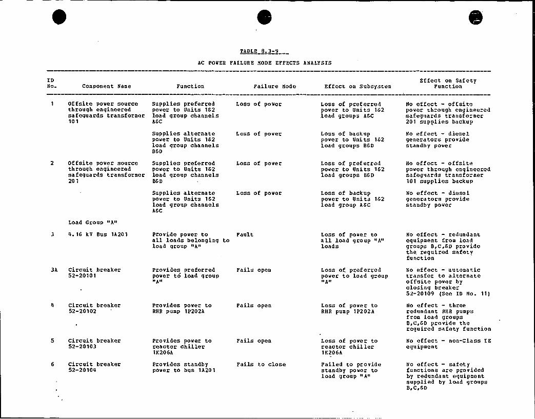
TABLE 8,3-9
AC POWER FAILURE NODE EFFECTS ANALYSIS
IDNo. Component Name Function Failure Node Effect on Subsystem
Effect on SafetyFunction
1 Offsite power sourcethrough engineeredsafeguards transformer101
Supplies preferredpower to Units 162load group channelsAGC
Supplies alternatepover to Units 1C2load group channelsBCD
Loss of power
Less of power
Loss of preferredpover to Unit" 162load groups AGC
Loss of backuppower to Units 162load groups BGD
No effect — offsitepower through engineeredsafeguards transformer201 supplies backup
No effect - dieselgenerators providestandby power
2 Offsite power sourcethrough engineeredsafeguards transformer201
Supplies preferredpower to Units 162load group channelsBGD
Supplies alternatepower to Units 162load group channelsAGC
Loss of power
Loss of pover
Loss of preferredpower to Units 162load groups BCD
Loss of backuppower to Units 1C2load group AGC
No effect - offsitepover through engineeredsafeguards transfo.mer101 supplies backup
No effect - dieselgenerators providestandby pover
Load Group «A«
3 u ~ 16 kV Bus 1A201
3A Circuit breaker52-20101
m Circuit breaker52-20102
5 Circuit breaker52-20103
Provide power toall loads belonging toload group «A«
Provides preferredpover to load group«A«
Provides powe" toRHR pump 1P202A
Provides pover toreactor chiller1K206A
Fault
Fails open
Fails open
Fails open
Loss of pove" toall load group»A«loads
Loss of preferredpover to load group«A«
Loss of power toRHR pump 1P202A
Loss of pove r toreactor chiller1K206A
No effect — redundantequipment from loadgroups B,C,CD providethe required safetyfunction
No effect - automatictransfer to alrernateoffsito power byclo-ing breake"52-20109 (See ID No. 11)
No effect - threeredundant RHR pump"from load groupsB,C,GD provide therequired safety function
No effect - non-Class ZEequipment
6 Circuit breaker52-2010m
Provides standbypower to bus 1A201
Fails to close Failed to providestandby power toload group «A«
No effect - safetyfunctions are providedby redundant equipmentsupplied by load groupsB,C,GD
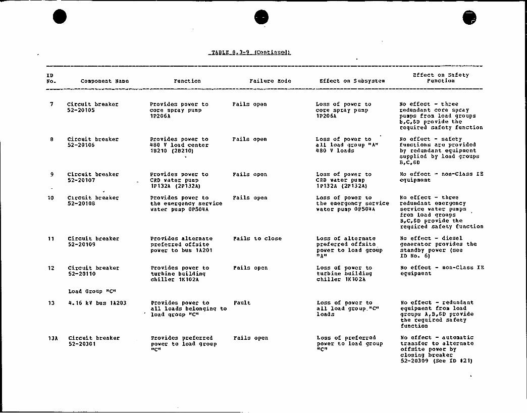
TABLE 8.3-9 (Continued)
IDNo Component Name Punction Failure Node Effect on Subsystem
Effect on SafetyPunction
7 Circuit breaker52-20105
8 Circuit breaker52-20106
9 Circuit breaker52-20107
10 Cxrcuit breaker52-20108
11 Circuit breaker52-20109
12 Circuit breaker52-20110
Provides pover tocore spray pump1P206A
Provides power to480 V load center18210 (2B210)
Provides pover toCRD vater pump1P 132A (2P132A)
Provides pover tothe emergency servicewater pump OP504A
Provides alternatepreferred offsitepover to bus 1A201
Provides pover toturbine buildingchiller 1K102A
Pails open
Fails open
Fails open
Fails open
Pails to close
Fails open
Loss of pover tocore spray pump1P206A
Loss of pover toall load group «A«480 V loads
Loss of power toCRD vater pump1P132A (2P132A)
Loss of power tothe emergency servicevater pump OP504A
Loss of alternatepreferred offsitepover to load groupIIA«
Loss of power toturbine buildingchillec 1K102A
No effect - threeredundant core spraypumps from load groupsb,C,GD provide thorequired safety function
No effect - safetyfunctions are providedby redundant equipmentsupplied by load groupsBrCeSD
No effect — non-Class IEequipment
No effect - threeredundant emergencyservice vater pumpsfrom load groupsB,C,CD provide therequired safety function
No effect — dieselgenerator provides thestandby power (seeID No 6)
No effect — non-Class IEequipment
Load Group «C«
13 4.16 kV bus 1A203 Provides pover toall loads belonqinq toload qroup «C«
Pault Loss of power toall load group «C«loads
No effect — redundantequipment from loadgroups A,B,ED providethe required safetyfunction
13A CiLcuit breaker52-20301
Provides preferred Fails openpover to load group«C«
Loss of preferredpover to load group«C«
No effect — automatictransfer to alternateoffsite pover byclosing breaker52-20309 (See ID $ 21)
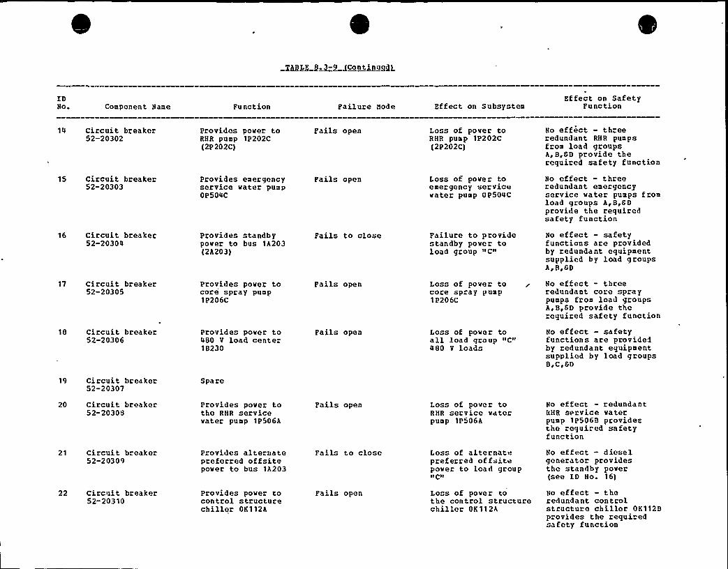
IDNo Component Name Function Failure Hole Effect on Subsystem
Effect on SafetyPunction
14 Circuit breaker52-20302
15 Circuit breaker52-20303
16 Ciccuit breaker52-20304
17 Circuit breaker52-20305
18 Circuit breaker52-20306
19 Circuit breaker52-20307
Provides power toRHR punp 1P202C(2P 202C)
Provides emergencyservice water pumpOP504C
Provides standbypover to bus 1A203(2A203)
Provides pover tocore spray pump1P206C
Provides power to480 V load center18230
Spare
Pails open
Pails open
Pails to close
pails open
pails open
Loss of power toRHR pump 1P202C(2P202C)
Loss of pover toemergency servicevater pump OP504C
Pailure to providestandby pover toload group
''oss
of power tocore spray pump1P206C
Loss of pover toall load group "C"480 V loads
No effect - threeredundant RHR pumpsfrom load groupsA,B,CD provide therequired safety function
No effect — threeredundant emergencyservice water pumps f ronload groups A ~ B,CDprovide the requiredsafety function
No effect - safetyfunctions are providedby redundant equipmentsupplied by load groupsA~B ~ CD
No effect - threeredundant core spraypunps fron load groupsh, B,CD provide therequired safety function
No effect — safetyfunctions are providedby redundant equipmentsupplied by load groupsB,C,CD
20 Circuit breaker52-20308
21 Circuit breaker52-20309
22 Circuit breaker52-20310
Provides pover tothe RHR servicevater pump 1P506A
Provides alternatepreferred offsitepower to bus lA203
Provides pover tocontrol structurechiller OK112A
Pails open
Fail" t o close
Fails open
Loss of power toRHR service waterpump 1P506A
Loss of alternatepreferred offsitepower to load groupv CII
Loss of power tothe control structurechil ler OK 11 2A
No effect — redundantRHR service vaterpump 1P5068 providesthe required safetyfunction
No effect — dieselgenerator providesthe standby pover(see ID No. 16)
No effect - theredundant contcolstructure chiller OK1128provides the requi edsafety function
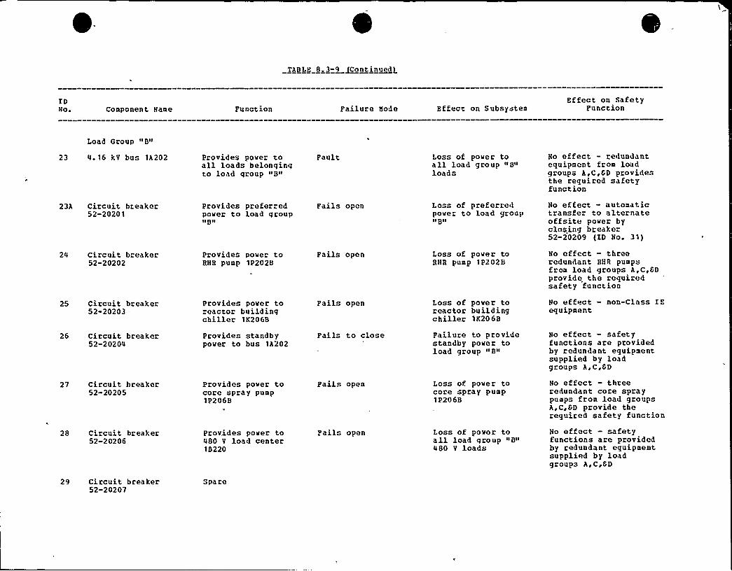
TABLE 8.3-9 fContinued1
IDNo. Component Name Function Failure Node Effect on Subsystem
Effect on SafetyFunction
Load Group »8»
23 4.16 kV bus 1A202 Provides powe" toall loads belongingto load qroup »8»
Pault Loss of power toall load group» 8»loads
No effect - redundantequipmont from loadgroups A,C,CD providesthe required safetyfunction
23A Circuit breaker52-20201
24 Circuit breaker52-20202
25 Circuit breaker52-20203-
Provides preferredmover to load group»8»
Provides power toRHR pump 1P2028
Provides pover toreactor buildingchiller 1K2068
Fails open
Fails open
Fails open
Loss of preferredpower to load group»8»
Loss of pover toRHR pump 1P2028
Loss of pover toreactor buildingchiller 1K2068
No effect - automatictransfe" to alternateoffsite power byclosing breake-52-20209 (ID No. 31)
No effect - threeredundant RHR pumpsfrom load groups A,C,CDprovide the requiredsafety function
No effect — non-Class IEequipment
26 Circuit breaker52-20204
27 Circuit breaker52-20205
28 Circuit breaker52-20206
29 Circuit breaker52-20207
Provides standbypower to bus 1A202
Provides pover tocore spray pump1P2 068
Provides power to480 V load center18220
Spare
Fails to close
Pails open
pails open
Failure to providestandby power toload group »8»
Loss of pover tocore spray pump1P2068
Loss of power toall load group "8»480 V loads
No effect — safetyfunctions are providedby redundant equipmentsupplied by loadgroups A,C,CD
No effect — threeredundant core spraypumps from load groupsA,C,CD provide therequired safety function
No effect — safetyfunctions are providedby redundant equipmentsupplied by loadgroups A,C,CD

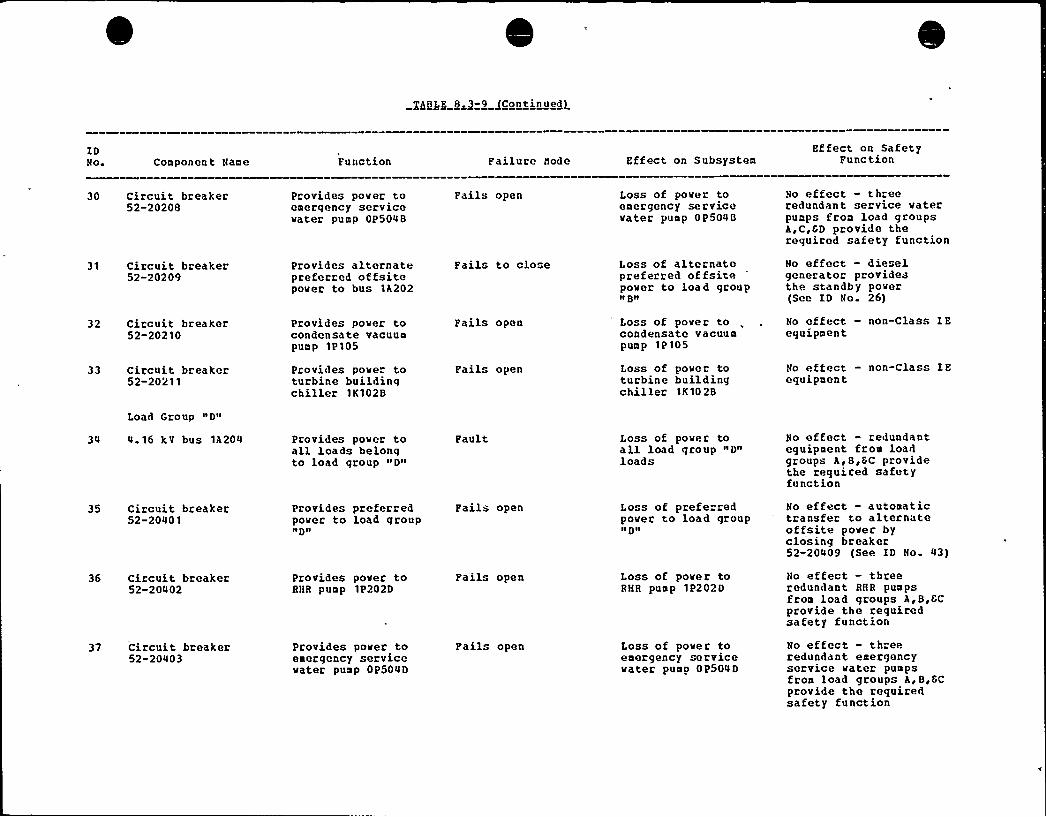
IDNo. Component Name Function Failure Node Effect on Subsystem
Ef feet on SafetyPunction
30 Circuit breaker52-20208
31 Circuit breaker52-20209
32 Circuit breaker52-20210
33 Circuit breaker52-20211
Pcovides power toemerqency servicewater pump OP5048
Provides alternateprefecred offsitepower to bus lA202
Provides power tocondensate vacuumpump 1P105
Provides powe" toturbine buildingchiller 1K1028
Pails open
Fails to clo e
Pails open
Pails open
Loss of power toemergency servicewater pump OP5048
Loss of alternatepreferred of fsitepower to load groupII Blt
Loss of power tocondensate vacuumpump 1P 105
Loss of powec toturbine buildingchiller 1K10 28
No effect - threeredundant service waterpumps from load groupsA,C,SD provide therequired safety function
No effect — dieselgenerator providesthe standby power(See ID No. 26)
No effect - non-Class IEequipment
No effect — non-Class IEequipment
Load Group "D"
34 4 16 kV bus 1A204 Provides power toall loads belongto load group "D"
Pault Loss of power toall load group "D"loads
No effect - redundantequipment from loadgroups A,B,SC providethe requiced safetyfunction
35 Circuit bceaker52-20401
36 Circuit breaker52-20402
37 Circuit breaker52-20403
Provides preferredpower to load groupIt8 tl
Provides power toRHR pump 1P202D
Provides power toemergency servicewater pump OP504D
Fails open
Pails open
Pails open
Loss of preferredpower to load groupnDn
Loss of power toRHR pump 1P2020
Loss of power toemergency servicewater pumn OP504D
Ho effect — automatictransfer to alternateoffsite powec byclosing breaker52-20409 (See ID No. 43)
Ho effect — threeredundant RHR pumpsfrom load groups A,B,ECprovide the requiredsafety function
No effect - threeredundant emergencyservice water pumpsfrom load groups A, B,SCprovide the requiredsafety function
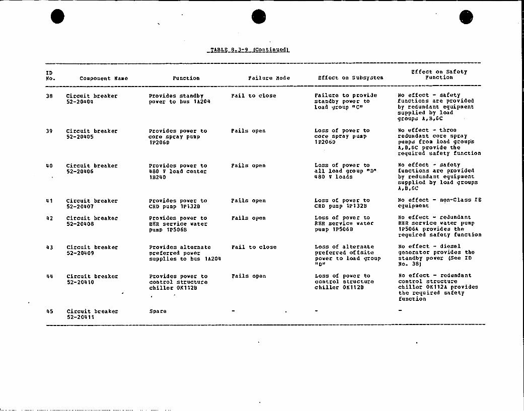
TABLE 8 3-9 (Continued)
ZDNo ~ Conponent Hase Function Failure Node Effect on Subsysten
Effect on SafetyFunction
38 Circuit breaker52-20404
Provides standbypower to bus 1A204
Fail to close Failure to providestandby power toload group "C»
No ef fect - saf etyfunctions are providedby redundant eguipnentsupplied by loadgroups A,B,CC
39 Circuit breaker52-20405
40 Circuit breaker52-20406
41 Circuit breaker52-20407
42 Circuit breaker52-20408
43 Circuit breaker52»20409
44 Circuit breaker52-20410
Provides power tocore spray punp1P206D
Provides power to480 V load center18240
Provides power toCRD punp '1P1328
Provides power toRHR service waterpunp 1P506B
Provides alternatepreferred powersupplies to bus 1A204
Provides power tocontrol structurechiller OK1128
Fails open
Fails open
Fails open
Fails open
Fail to close
Fails open
Loss of power tocore spray puap1P206D
Loss of power toall load group "D"480 V loads
Loss of power toCRD punp 1P132B
Loss of power toRHR service waterpunp 1P5068
Loss of alternatepreferred offsitepower to load group»D»
Loss of power tocontrol structurechiller OK1128
No effect - threeredundant core spraypunps fron load group'sA,B,GC provide therequired safety function
No effect - safetyfunctions are providedby redundant eguipnentsupplied by load groupsA,B,GC
No effect - non-Class IEeguipnent
No effect - redundantRHR service water punp1P506A provides thereguired safety function
No effect - dieselgenerator provides thestandby power (See IDNo 38)
No effect - redundantcontrol structurechiller OK112A providesthe reguired safetyfunction
45 Circuit breaker52-20411
Spare

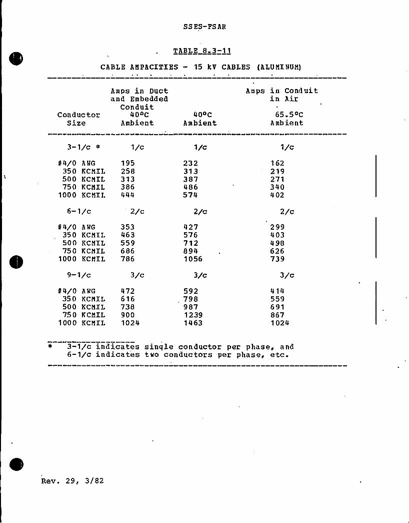
SS ES-PS AR
TABLE 8 3-11
CABLE AHPACITIES — 15 kV CABLES {ALUMINUM)
ConductorSize
Amps in Ductand Embedded
Conduit400C
Ambient40OC
Ambient
Amps in Conduitin Air
65.5oCAmbient
3-1/c ¹
«4/0 ANG350 KCMIL500 KCMXL750 KCMIL
1000 KCMIL
6-1/c
«4/0 A MG
350 KCMIL500 KCMIL750 KCMIL
1000 KCMIL
9-1/c
«4/0 A L'G
350 KCMIL500 KCMIL750 KCMIL
1000 KCMIL
1/c
195258313386444
2/c
353463559686786
3/c
4726167389001024
1/c
232313387486574
2/c
4275767128941056
3/c
59279898712391463
1/c
162219271340402
2/c
299403498626739
3/c
4145596918671024
3-1/c indicates single conductor per phase, and6-1/c indicates two conductors per phase, etc.
Rev. 29, 3/82

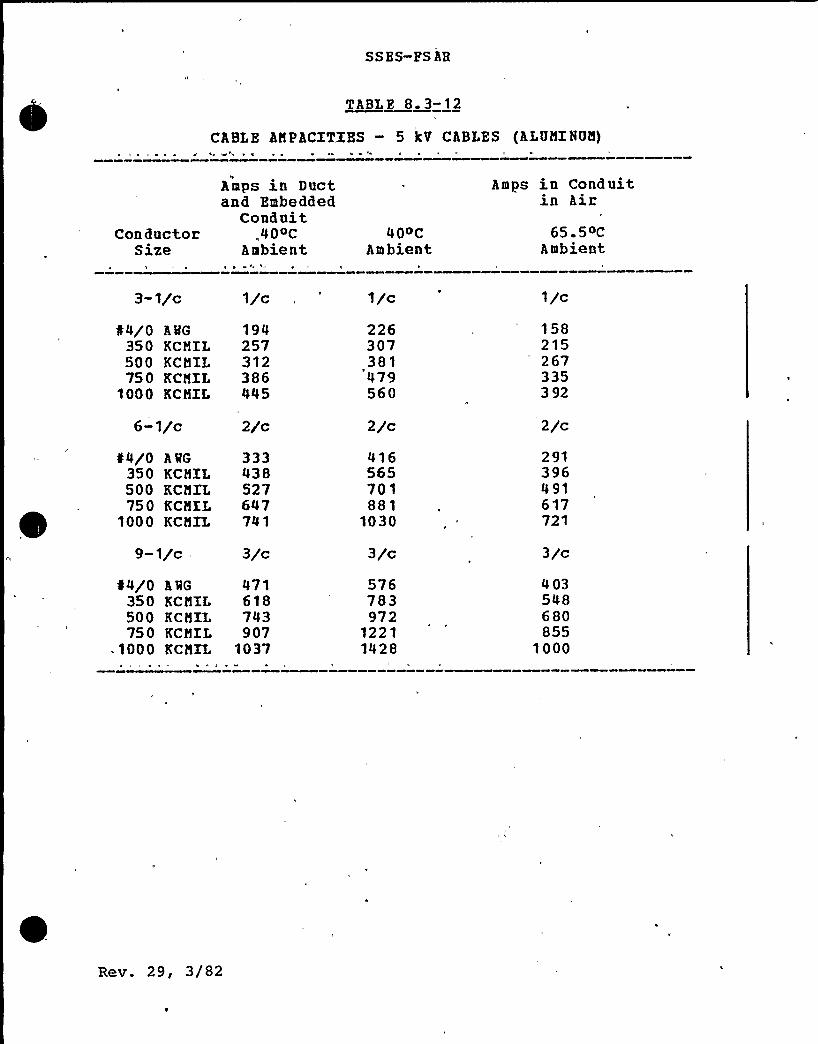
SSBS-FS AH
TABLE 8 3-12
CABLE AMPACXTXBS — 5 kV CABLES (ALUMINUM)
ConductorSize
Amps in Ductand Embedded
Conduit„,40~C
Ambient40OC
Ambient
Amps in Conduitin Air
65 50CAmbient
3-1/c
¹4/0 A MG
350 KCMIL500 KCMIL750 KCMXL
1000 KCMXL
6-1/c
¹4/0 A WG
350 KCMIL500 KCMIL750 KCMXL
1000 KCMXL
9-1/c
¹4/0 A QG
350 KCMIL500 KCMIL750 KCMXL
~ 1000 KCMIL
1942573'l2386445
2/c
333438527647741
3/c
471618743907'037
'l/c
226307381479560
2/c
416565701881
1030
3/c
576783972
12211428
1/c
158215267335392
2 jc291396491617721
3/c
403548680855
1000
Rev. 29, 3/82

SS ES-FS AR
coolinq system alone. It is therefore necessary to connect theRHR system to the spent fuel pool. Mhen this is done the pooltemperature can be maintained well below 125oF.
All pipinq and equipment shared with or connecting to the RHRintertie loop are Seismic Category I, Quality Group C, and can beisolated from any pipinq associated with the non-Seismic Categoryr Quality Group C fuel pool cooling system.
Provisions to minimize and monitor leakage from the fuel pool aredescribed in Subsection 9.1.2. 3.
Makeup for evaporative and small leakage losses from the fuelpool is normally supplied from the demineralized water system tothe skimmer surge tanks of each unit. The intermittent flow rateis approximately 50 qpm to each surge tank.
A Seismic Category I makeup of 60 gpm is provided by a 2 in. linefrom each emerqency service water (ESQ) loop to the RHR fuel pooldiffusers, thus providing redundant flow =paths from a reliablesource of water. The design makeup rate from each ESQ loop isbased on replenishing the boil-off from the MNHL in each fuelpool for 30 days followinq the loss of the FPCCS capacity. Thetime required to reach, boiling after loss of. loading isapproximately 25 hours.
The water level in the spent fuel storage pool is maintained at aheight which is sufficient to provide shieldinq for requiredbuildinq occupancy. Radioactive particulates removed from thefuel pool are collected in filter demineralizer units in shieldedcells. For these reasons, the exposure of station personnel toradiation from the spent fuel pool coolinq and cleanup system isnormally minimal. Further details of radiological considerationsare described in Chapter 12.
An evaluation of the radiological effect of a boiling fuel poolis presented in Appendix 9A.
9. 1.3.4 Tnspectgon and Tegtipg geguipements
No special tests are required because at least one pump, heatexchange , and filter demineralizer are continuously in operationwhile fuel is stored in the pool. The remaining components areperiodically operated to handle increased heat loads during .
refuelinq.The pool liner leak detection drain valves are periodicallyopened and the leak rate estimated by the volumetric method.or dye pressure testing from behind the liner plate may beperformed to locate a liner plate leak.
Gas
Rev. 29, 3/82 9. 1-27

SSES-PSAR
Routine visual inspection of the system components,instrumentation, and trouble alarms is provided to verify systemoperability. Components and piping of the PPCCS designed perASIDE Boiler and Pressure Vessel Code, Section III, Class 3 arein-service inspected as described in Section 6.6.
The system vill be preoperationally tested in accordance with therequirements of Chapter 14.
9~ 1 4 PEEL HA NDLING SYSTEN-
9. 1. 4. 1 Des ign Bases
The fuel-handling system is designed to provide a safe andeffective means for transporting and handling fuel from the timeit reaches the plant until it leaves the plant after post-irradiation cooling. Safe handling of fuel includes designconsiderations for maintaining occupational radiation exposuresas low as practicable during transportation and handling.
Desiqn criteria for ma)or fuel handling system equipment isprovided in Tables 9.1-2 through 9.1-4 which list the safetyclass, quality group, and seismic category. %he e applicable,the appropriate ASIDE, ANSI, Industrial and Electrical Codes areidentified. Additional desiqn criteria 'is shovn below andexpanded further in Subsection 9.1.4.2.
The transfer of new fuel assemblies between the uncratinq areaand the nev fuel inspection stand and/or the new fuel storagevault is accomplished using the reactor building crane or therefuelinq floor jib cranes equipped with a general purposeqrapp le.The reactor buildinq crane auxiliary hoist or a refuelinq floorgib crane is used vith a qeneral purpose grapple to transfer nevfuel from the fuel inspection stand or the new fuel vault to thefuel storaqe pool. Prom this point on, the fuel vill be handledby the telescopinq qrapple on the refuelinq platform.
The refuelinq platform includinq refueling platform rails,clamps, and clips are Safety Class 2 and Seismic Class 1 from astructural standpoint in accordance with 10CZR50, Appendix A andB. Allovable stress due to safe shutdown earthquake loading is120 percent of yield or 70 percent of ultimate, whichever isleast. A dynamic analysis is performed on the structures usingthe response spectrum method vith load contributions resulting,from each of three earthquakes being combined by the RNS
procedure
Rev. 29, 3/82 9 1-28
SS ES-FS AR
9,1.4. 2. 10 Fuel Transfer Description
9. 1.4.2. 10.1 Arrival of Fuel on Site
New fuel arrives in the railway bay of the reactor building Unit1 either by railcar or truck. The access doors are closed tomaintain the secondary containment as required by TechnicalSnecifica+ions. Unloading of the metal shipping contain..rs isdone bv the auxiliary hoist of the reactor building crane.
9. 1. 4. 2. 10. 2 Refueling Procedure
The plant refuelinq and servicinq sequence diagram is shown inFigure 9.1-15. Fuel handling procedures are described below andshown visually in Fiqure 9. 1-16 throuqh Fiqure 9. 1-19.
The Refuelincr Floor Layout is shown in Figure 9.1-4 and componentdrawings of the principal fuel handlinq eguipment are shown inFigures 9.1-7 throuqh 9. 1-14 and Fiqure 9. 1-20.
l
The fuel handlinq process takes place primarily on the refuelingfloor above the reactor. The principal locations and equipmontare shown on Figure 9.1-16. The reactor, fuel pool, and shippinqcask oool are connected to each other by slots, as shown at (A)and (B) . Slot (A) is open during reactor refueling, and slot {B)is open d»rinq spent fuel shipping. At other times the slots areclosed bv means of blocks and qates. which make water-tightbarriers.The handlinq of nev fuel on the refueling floor is illustrated inFiqure 9.1-17. The transfer of the bundles between the crate {C)and the new fuel inspection stand (D) and/or the new fuel storagevault (E) i" accomplished usinq 5-ton auxiliary hoist of thereactor buildi ng crane or a half-ton floor mounted refueling jibcrane equipped with a general-purpose grapple. The fuel bundlecannot be handled horizontally without support, so the crate isplaced in an almost vertical position before being opened. Thetop and front of the crate are opened, and the bundles removed ina vertical position.The auxiliary hoist of the reactor building crane or the jibcrane are also used with a qeneral-purpose grapple to transfernew fuel from the new fuel vault or inspection stand to a storagerack position in the fuel pool. From this point on, the fuel ishandled by the welescopinq grapple on the refueling platform.
Rev. 29, 3/82 9. 1-41

SS ES-PS AR
The storage racks in both the vault and the fuel pool hold thefuel bundles or assemblies vertical, in,an array which issubcritical under all possible conditions.
The new fuel inspection stand holds one or two bundles invertical position. The Inspector(s) ride up and down on aplatform. and the bundles are manually rotated on their axes.Thus the inspectors can see all visible surfaces on the bundles.
The general-purpose grapples and the fuel q apple of therefuelinq platform have redundant hooks, and an indicator whichconfirms positive qra pple enqa qemen t.The refuelinq platform uses a qrapple on a telescoping mast forliftinq and transportinq fuel bundles or assemblies. The
!
",.elescopinq mast can extend to the proper work level; and, in itsnormal up position state, maintains adequate water shieldinq overthe fuel being handled.
The reactor refuelinq procedure is shown schematically in Figure9.1-18. The refuelinq platform (G) moves over the fuel pool,lowers the qrapple on the telescoping mast (H), and engages thebail on a new fuel assembly which is in the fuel storage rack.The assembly is lifted clear- of the rack, and moved through slot{A) and over the appropriate'mpty fuel location in the core (J) .The mast then lowers the assembly into the location, and thegrapple releases the bail.The operator then moves the platform until the grapple is over asoent fuel assembly which is to be discharged f rom the core. Theassembly is qrappled, lifted, and moved through slot (A) to thefuel pool. i!ere it is placed in one of the fuel prep machines(K)
An operator, using a lonq-handled wrench, removes the screws andsprings from the top of the channel. The channel is then held,while a carriage lowers the fuel bundle out of the channel. Thechannel is then moved aside, and the refuelinq platform grapplecarries the bundle and places it in a storage rack. The channelhandlinq boom hoist, (L), moves the channel to storage, ifappropriate.
Ia actual practice, channelinq and dechannelinq may be performedin many seauences, dependinq on whether a new channel is to beused, or a used channel is to be installed on a new bundle andreturned to the core. A channel rack is conveniently locatednear to the fuel prep machines, for temporary storage of channelswhich are to be reused.
To preclude the possibility of raising radioactive material outof the water, redundant electrical limit switches areincorporated in the auxiliary hoists of the refueling platform
Re v. 31, 7/82 9. 1-42
SSES-PS AR
and the gib crane hoist, and interlocked to prevent hoistingabove the preset limit. In addition, the cables on the hoistsincorporate adjustable stops that will jam the hoist cableaqainst the hoist structure, which prevents hoistinq if the limitsvitch interlock system should fail.When spent fuel is to be shipped, it is placed in a cask, asshovn in Figure 9.1-19. The refuelinq platform grapples a fuelbundle from the storaqe rack in the 'fuel pools, lifts it, carriesit through slot (B) into the shipping cask pool, and lovers itinto the cask, (N) .,)(hen the cask is loaded, the reactorbuilding crane sets the cask cover (N) on the cask. Afterd aininq the shippinq cask pool, the cask is decontaminated andlovered through the open hatchways, (P) ~ onto the truck orrailcar in the railway bay at grade level.
Provision of a separate cask loadinq pool, capable of beingisolated from the fuel storage pool, eliminates the potentialaccident of dropping the cask and rupturing the fuel storagepool
Additional detailed information is provided belov.
9. 1.4.2. 10. 2. 1 Nev Puel Preparations
9- 1.4.2. 10 2 1. 1 Receipt and Inspection of Nev Puyl
The incominq nev fuel vill be delivered to a receiving station .The crates should be unloaded from the transport vehicle andexamined, for damage during shipment. The crate dimensions areapproximately 32" x 32" x 18 feet long. Each crate contains twofuel bundles supported by an inner metal container. Shippingveiqht of each unit is approximately 3000 pounds. The receivingstation includes a separate area vhere the crate covers can beremoved. The crates are then moved to the reactor building wherethe metal inner containers are removed and lifted to therefuelinq cloor. Both inner and outer shipping containers arereusable. Handlinq during uncrating is to be- accomplished by useof the reactor building crane extending down from the refuelingfloor through the equipment hatch.
Rev. 29, 3/82 9 1-43
SS ES- PS AR
9.1.4.2.10.2.1.2 .Channeling Hew Fuel
The initial core for both units will be channeled as each newfuel bundle is inspected in the fuel inspection stand. Thisprocess vill be repeated whenever new fuel channels a re to beplaced on new fuel bundles. Usuall j channeling new fuel is doneconcurrently with de-channelinq spent fuel. Two fuel preparationmachines are located in the fuel pool; one used for de-channelingspent fuel and the other to channel new fuel. The procedure isas follows: Using a jib crane and the general purpose grapple, anew fuel bundle is transported to one the fuel prep machine if ithad been residinq in the fuel storage vault. Otherwise it ismoved from a spent fuel pool storage rack to the fuel preparationmachine usinq the refuelinq bridqe. A spent fuel'undle is movedfrom a spent fuel pool storage rack to the other fuel prepmachine. The channel is unbolted from the spent fuel bundleusing the channel bolt wrench. The channel handling tool isfastened to the top of the channel and the fuel prep machinecarriage is lowered removing the Tuel from the channel. Thechannel is then positioned over a new fuel bundle located in thefirst fuel prep machine 02 and the process reversed. Thechanneled new fuel is then stored in the pool storage racks readyfor insertion into the reactor.
9. 1. 4. 2. 10. 2. 1. 3 Egu hymen t Prepagat ion
Prior to the plant shutdown for refueling, all eguipment must bePlaced in readiness. All tools, qrapples, slings, strongbacks,stud tensioners, etc. should be given a thorouqh check and anydefective (or well worn) parts should he replaced. Air hoses ongrapples should be routinely leak tested. Crane cables should beroutinely inspected. 1lll necessary maintenance a nd' nterlockchecks should be performed to assure no extended outage due toequipment fa ilure.
The in-core flux monitors, in their shipping container, should beon the refueling floor. The channeled new fuel and thereplacement control rods should be ready in the storage pool.
9. 1.4. 2. 10. 2. 2 Eeactor Shutdown
The reactor is shut down according to a prescribed procedure.Durinq cool down the reactor pressure vessel is vented and filledto above flange level to equalize cooling. The drywell andsuppression chamber are de-inerted. The eight reactor wellshield pluqs can be removed. This is accomplished with thereactor building crane and the supplied slings.
Rev. 29, 3/82 9 1-44

SS ES-PS AR
This operation can be immediately followed by removal of thethree canal pluqs and the three slot plugs. Thus, a total of 14separate pluqs must be removed and placed on the refueling floor.
"Befuelinq Equipment Storage and Crane Clearance" arrangementdrawing is issued to locate placement 'of these plugs on therefueling floor. The outer fuel pool gate is also removed atthis time. The gate sling is attached to the gate lifting lugsand the reactor building crane lifts the gate and places it onthe fuel pool gate storage lugs.
9. 1. 4. 2. 10. 2. 2. 1 Drgwelg Head Removal
Immediately after removal 'of the reactor well shi'eld plugs, thework to unbolt the drywell head can begin. The drywell head isattached by removable bolts protruding from the lower drywellflange. The nuts on top are merely loosened and the bolt heads,swinq outward. The bolts are then pulled upwards and supportedwith the nuts on a slotted lip of the head.
The sister hook of the reactor building crane is attached to thehook box on top of the unbolted drywell head and lifted to itsappointed storage space on the refueling floor. The drywell sealsurface protector is installed before any other activity proceedsin the reactor well area.
9. 1.4.2. 10.2.2,2 ~ Reactor Well Servicing.
When the drywell head has been removed, an array of piping isexposed that must, be serviced. Various vent piping penetrationsthrough the reactor well must be removed and the penetrationsmade water tight. Vessel head piping and head insula tion must beremoved and transported to storage on the refueling floor.Water level in the vessel is now brought to flange level inpreparation for head removal.
9. 1.4.'2. 10. 2. 3 Reactor Vessel Opening
9. 1.4.2.-10.2.3.1 Vessel Head- Removal
The stud tensioner is transported by the rea'ctor building craneand positioned on the reactor vessel head. Each stud istensioned and its nut loosened in a series of 2-3 passes. When.the nuts are loose, they are backed off using a nut runner untilonly a few threads enqage. The vessel nut handling tool is
Rev. 29, 3/82 9 ~ 1- 45
SS ES-PS AB
engaged in the upper part of the nut and the nut is rotated freefrom the stud. The nuts and washers are placed in the racksprovided for them and transported to the refueling floor forstorage. With the nuts and washers removed, the vessel stud,protectors and vessel head guide caps are installed.The head stronqback, transported by the reactor building crane,is attached to the vessel head and the head transported to thehead holding pedestals on the refueling floor. The head holdingpedestals keep the vessel head elevated to facilitate inspectionand "0" ring replacement.
The six studs in line with the fuel transf er canal are removedfrom the vessel flange and placed in the rack provided. Theloaded rack is transported to the refuelinq floor for storage.
9. 1.4.2. 10.2.3.2 =Dryer Removal
The dryer-separator sling is lowered by the reactor buildingcrane and-attached to the dryer lifting luqs. The dryer islifted from the reactor vessel and transported to its storagelocation in. the dryer-separator storage pool adjacent to thereactor well. The dryer is transported in air. However, if thedryer should become highly contaminated, the reactor well andstorage pool can be flooded and a wet transfer effected.
9. 1. 4. 2. 10. 2. 3. 3 Separator Remova lXn preparation for separator removal, the service platform andservice platform support are installed on the vessel flange.Prom the service'platform work area, the four main steam linesare plugged from inside the vessel using the furnished plugs forthis duty. 'ervicing of the safety and relief valves can thus beaccomplished without adding to the critical refueling path time.Working from the service platform, the separator is unboltedusing the shroud head bolt wrenches furnished.
When the unbolting is accomplished, the service platform isremoved and stored on the refueling floor. The service platformsupport remains on the vessel flange during the remainder of therefuelinq outaqe and acts as .the flange seal surface protector.
The dryer-separator sling is lowered into the vessel and attachedto the separator liftinq lugs. The water in the reactor well andin the dryer-separator storage is raised to fuel pool water leveland the separator is transferred underwater to its allottedstorage -place in the „ad jacent pool.
Rev. 29, 3/82 9 1-46
SSES-FS AR
9. 1.4. 2..10~2 ~ 3. 4 fuel Bundle Sampling
Durinq reactor operation, the core off-qas radiation level ismonitored. Xf a rise in off-gas activity has been noted, thereactor core will be sampled during shutdown to locate anyleaking fuel assemblies. The fuel sampler or sipper rests on thechannels of a four bundle array in the core. An air bubble ispumped into the top of the 4 fuel bundles and allowed to stayabout 10 minutes. This stops water circulation through thebundles and allows'ission products to concentrate if a bundle isdefective. After 10 minutes, a water sample is taken for fissionproduct analysis. If a defective bundle is found, it is taken tothe fuel pool and if reguired, may be stored in a specialdefective fuel storage container to prevent the spread ofcontamination in the pool.
9 1.4 ~ 2. 10. 2.4 Refueling and Reactor Servicing
The remaining gate isolating the fuel pool from the reactor wellis now removed thereby interconnecting the fuel pool, the reactorwell, and the dryer-separator storage pool. The actual refuelingof the reactor can now begin.
9 1.4.2. 10. 2.4.1 Refuel ing
Durinq a normal equilibrium outage, approximately 25% of the fuelis removed from the reactor vessel, 25% of the fuel is shuffledin the core (generally from peripherial to center locations) and25% new fuel is installed. The actual fuel handling is done withthe fuel qrapple which is an integral part of the refuelingplatform. The platform runs on rails over the fuel pool and thereactor well. In addition to the fuel grapple, the refuelingplatform is equipped with two auxiliary hoists which can be usedwith various grapples to service other reactor internals.
To move fuel, the fuel grapple is aligned over the fuel assembly,lowered and attached to the fuel bundle bail. The fuel bundle israised out of the core, moved through the refueling slot to thefuel pool, positioned over the storage rack and lowered tostoraqe. Fuel is shuffled and new fuel is moved from the storagepool to the reactor vessel in the same manner.
Rev. 29, 3/82 9. 1-47
SS ES- FS AR
9. 1. 4. 2. 10 2. 5 Vessel Closure.
The followinq steps, when performed, will return the reactor tooperatinq condition. The procedures are the reverse of thosedescribed in the proceeding sections: Many steps are performedin parallel and not as listed.
a) Install inner fuel pool gate.
b) Core verification. The core position of each fuelassembly must be verified to assure the desired coreconfiguration has been attained.
c) Control rod drive tests. The control rod drive timing,friction and scram tests are performed.
d) Replace separator.
e) Drain dryer-separator storaqe pool and reactor well.
.f) Decontaminate reactor well.
g) Install service platform, bolt separator, and removethe four steam line pluqs. Return the service platformand platform support to storage on refueling floor.
h) Remove drywell seal surface covering.
i) Open drywell vents, install vent piping.
j) Replace fuel pool outer gate.
k) Replace steam dryer.
1) Decontaminate dryer-separator storage pool.
m) Replace vessel studs.
n) Replace slot plugs.
o) Install reactor vessel head.
p) Install vessel head piping and insulation.
q) Replace dryer-separator canal plugs.
r) Hydro-test vessel, if necessary.
s) Install drywell head.
t) Inert reactor drywell and suppression chamber.
Rev. 29, 3/82 9. 1-48

SS ES- FS AR.
u) Install reactor well shield plugs.
v) Startup tests. The reactor is returned to full poweroperation. Power is increased, gradually in,a series ofsteps until the reactor is operating at rated power.At specific steps during the approach to power, the in-core flux monitors are calibrated.
9.1.4.2.10.3 Qepagtuge of Spegt gum], from Sitell
The spent fuel shipping cask arrives by railcar or truck in therailway bay of the reactor building Unit 1. It is lifted fromthere by the 125 ton hook of a reactor building crane through thefloor hatches to the refueling floor and placed into the emptyshipping cask pit between the fuel pools of Units 1 and 2.
The cask outside is decontaminated'from road dirt and the lidremoved by the reactor building crane. One of the inner gates ofthe shippinq cask pit is removed. After filling of the shippingcask pool, the second gate to one of the fuel pools is removedand loading, of the cask with irradiated fuel commences. Therefueling platform is used to transfer fuel bundles ofsufficiently low decay heat level from the spent fuel storageracks underwater into the shippinq cask.
Followinq replacement of the, cask lid, the gates to the fuel poolare inserted, the shipping cask pit drained, and the cask outsidedecontaminated. The reactor building crane then transfers thecask from the storage pit onto the shipping vehicle where acooling system dissipates the remaining decay heat of the fuelduring transport.
9.1.4.3 Safety Evaluation4
9.1.4.3.1 Spent Fuel Cask
The spent fuel cask is equipped with dual sets of lifting lugsand yokes compatible with the reactor building crane main hook,thus preventinq a cask drop due to a single failure.,An analysisof the spent fuel cask drop is therefore not required.
Rev. 29, 3/82 9; 1-49
9. 1. 4. 3. 2 - Reactor Building. Crane
See Subsection 9.1.5.3 for the reactor building crane safetyeva luati on."
9. 1.4. 3. 3 Fuel Servicing Bgui~menf.
Failure of any fuel servicing equipment listed in Table 9.1-2poses no hazard beyond the effect of the refueling accidentanalyzed in Chapter 15.
Safety aspects (evaluation) of the fuel servicing equipment arediscussed in Subsection 9.1.4. 2.3.
9.1.4.3.4 Servicing Aids
The small manual devices listed in'Table 9.1-5 facilitateunderwater viewinq and handling of fuel. Pailure of anyservicinq aid does not pose any hazard beyond the effect of therefuelinq accident.
9. 1.4. 3. 5 reactor Vessel Servicing Equipment
The dryer-separator slinq and the reactor vessel head strongbackare both of a cruciform desiqn providing two redundant sets ofliftinq points compatible with the single failure proof reactorbuildinq crane main hoist and hook. Therefore accident analysisis not required.
9. 1.4. 3. 6 In-Vessel Servicing Equipment
Pailure of any in-vessel servicinq equipment~listed in Table 9. 1-5 poses no hazard beyond the effect of the refueling accidentanalyzed in Chapter 15.
Rev. 29, 3/82 9. 1-50

SS ES-PS AR
r9. 1. 4. 5. 4 Rad iation Nonitorina
The area radiation monitorinq equipment for the refueling area isdescribed in Subsection 12. 3. 4.
9 1 5 REACTOR BUILDING CRANES
Tvo reactor buildinq cranes are provided for the Susquehanna SES.Unit 1 crane is a single failure-proof crane and is designed tohandle the spent fuel cask. The Unit 2 crane is not singlefailure-proof and is de iqned to handle construction loads andall normal plant operation loads except the'pent fuel cask.
The Unit 2 reactor building crane, rated 125 tons (main hoist), 5tons (auxiliary hoist),, is potentially. capable of carryinq anyloads vithin its rated capacity, but net over or
within'estrictedareas of the refuelinq floor. Limits of the. restricted areas are shovn on Figures 9.1-16 A C B.
Admin istrative controls are, used to preclude the Unit 2 reactorbuild inq crane from beinq used for 'handlinq the spent fuel caskwhen stored in the spent fuel shipping cask storage pit.
The follovinq description vill address the Unit 1 crane only,which will be re'fe red to as the reactor building crane or thecrann.
9. 1.5. 1 Des ian Bases
The main purpose of the reactor building crane is to handle thespent fue1 cask betveen the cask transport vehic1e, the caskstoraqe pit, and the wash-down area in the reactor building.Secondary purposes of the reactor building crane include:
Rev- 319. 1-55

SSES-FSAR
a) Handlinq loads related to maintenance and replacementof equipment from the reactor .building which arereceived or shipped through the railroad access, doors
b) Handlinq of shield pluqs, reactor vessel and drywellheads, steam dryer and separator, etc, during refuelingoperations.
The reactor buildinq crane is designed for the following ratings:
Hain hoist capacity
Auxiliary hoist capacity
125 tons
5 tons
Speed o f main hoist {at rated load) ., 5 fpm (see Note 1)
Speed of. auxiliary hoist (atrated load)
Speed of trolley {usinq main hoist)
Speed of trolley (usinq aux hoist)
Speed o f bridge
20 fpm (see Note 1)
30 fpm
50 fpm
50 fp@
Lift of main hook {see Note 2)
Lift of auxiliary hook
Cra ne span
Lenqth of runway (between stops)
Uncontrolled drop
173 ft173 ft130
323 ft
Hain hoistAuxiliary hoist
0.5 in. (max.)8.55 in. (max.)
Note 1: Minimum speed at rated load is less than2 percent of rated speed
Note 2: Unit 2 reactor building crane ratings areidentical to those of the Unit 1 crane,except for the main hook lift, which is68 ft. This, in addition toadministrative controls, precludesinadvertent use of the Unit 2 crane forspent fuel cask handling, since the mainhook does not reach the spent fuel caskplant entry level.
3 ev. 31, 7/82 9. 1-56
SS ES- FS AR
The auxiliary hooks of both cranes are designed for useunderwater, up to 50 ft. depth.
9. 1.5. 2 Eauioment Design
a) General
The reactor buildinq crane is designed, fabricated,installed, and tested in accordance 'with ANSI 830.2.0,CN N A-70, an d OS HA requlat ions.
b) StructuralThe structural portions of the crane bridge and trolleyare desiqned for {1) dead load plus rated lift loadplus impact load of 15 percent of the total dead plusrated live loads, not to exceed allowable stresses; (2)dead load plus rated lift load plus a lateral load of10 percent of the-.total dead pius rated live loads, notto exceed allowable stresses; {3) the'operating basisearthquake (OB E) wh ile lifting the rated load, theworkinq stresses not to exceed 125 percent of theallowable stress: (4) the design basis earthquake (DBE)while lifting the rated load, the allowable stresses tobe less than 90 percent in bendinq, 85 percent in axialtension, and 50 percent in shear of the materialminimum yield stresses; (5) a tornado loading of 300psf, without live load, the allowable stresses to bethe same as for (4) above.
The structure of the crane bridge consists of weldedbox tvpe qirders with truck saddles and truck frames ofwelded steel construction. The trolley side frames,sheave frames, and truck frames are of structural steelwelded construction.
c) Nechanical
The crane is of a sinqle trolley top runninq electricoverhead travelling bridge design'. The generalarranqement of the crane in the reactor building isshown on Piqure 9.1-4.
The main hoist is provided with the following dualcomponents preventinq a single failure to result in adrop of. the spent fuel shipping cask:
Pev. 31, 7/82 9. 1-57
SS ES- FS AR
1) Dual sister hook thook within a hook)
2) Dual reevinq systems complete with redundant vireropes, upper, lower, and equalizinq sheaves
3) Dual main hoist gear boxes with individual brakingsystems.
Each vire rope has a safety factor of five againstbreakinq while liftinq the rated capacity. In case otfailure of one of the two reevinq systems, the dynamicload transfer to the other system vill not cause therope load to exceed one-third of the rope breakingstrenqth.The following holding brakes are provided:
Nain hoist Three, rated for 150 percent of themotor torque, with provision for manualoperation to allov lowering of the load
, af ter a power failureTrolley Two, rated for 50 percent of motor
torque
one, rated for 100 percent nf motorto rque.
Al 1 holding brakes are ac magnet operated. Inaddition the bridqe is provided vith a hydraulic footoperated brake.
d) Controls
Bridge and trolley ac static stepless speed controlvith reversinq plugging control
Hoists dc static reversinq stepless speedcontrol including regenerativebraking, with a minimum speed ofless than 2 'percent of the ratedspeed.
Operation of the crane is from the bridge mounted cabor floor. The floor operation is by pendant or radiocontrol. Control at any one time is from one pointonly.
Rev. 31, 7/82 9 1-58
SSES-PS AR
9.1.5.3 Safety Fyaluation
As described in Subsection 9.1.5.2, the main hoist is providedvith dual main hoist components capable of holding the load inthe event of a single failure.The reactor building crane is provided with limit switches toprevent overtravel of the bridqe and trolley and stop the mainand auxiliary hooks in their highest and lowest safe positions.
Two limit switches, each..of different design, are provided tolimit the upward movement of the main and auxiliary hoist.Two geared limit switches are provided for the main hoist, andone for the auxiliary hoist to limit the dovnvard movement of therespective hoists.When the 125-ton hook is not in the parked upper position, I
movement of the crane bridge and/or trolley will he stopped vhenenterinq the restricted areas shown on Pigures 9. 1-16A 6 B. Thefollowinq means are provided to accomplish the above:
a) A series of proximity svitches mounted on the crane,adjacent to the cra'ne and trolley runways.
b), A series of trip bars mounted on the bridge and trolleyrunways are positioned to trip respective proximityswitches.
c) Relays and logic systems to trip power supplies toaffected drive motors, vhen a proximity switch istripped. This vill result in the setting of respectiveholdinq brakes and cessation of bridge or trolleymovement. «Memory logic«vill then allow the bridge ortrolley to move in the opposite direction avay from the
. restricted area.
d.) Administrative controls.A key locked bypass switch is provided in -the cab and the pendantto allow the use of the main- hoist over the.RPV area for handlinqshield plugs, RPV and drywell heads, steam dryer/separator, etc.
Crane overload protection is provided by an electrical cut-out onthe hoist drive motor. In addition, a loud, cell is provided onthe equalizer to prevent the crane from lifting loads in excessof its rated capacity.
An overspeed svitch activating all spring set motor brakes in thelowering direction holds the load in suspension.
Pev. 31, 7/82 9. 1-59
SS ES- FS AR
See Section 3.13 for discussion of compliance with RegulatoryGuides 1.104 and 1.13.
See Appendix 9B for a discussion of compliance with BTP ASB9-1.
The results of a failure mode and effect analysis are presentedin Table 9.1-6.
The crane is safety related and a quality assurance program hasbeen established and implemented in the design, fabrication,erect ion, and testinq.The crane is designed to remain on the runway i.n a parked andrestrained position (by tornado locks) vith no load attachedunder the following tornado vind loadings:
a) 300 psf on the windvard crane girder
b) a200 psf on the leevazd crane girder.The crane mechanical and structural components are qualified toSeismic Cateqory I requirements. The crane, however, may becomeand remain inoperational after the operating basis earthguake,hut no parts or, the load vill,dislodge oz fall. Manual toweringof the main hoist load is provided.
9 1.5 4 Inspection and Testing Requirements
Crane components tests are performed during the crane fabricationa s follovs:
a) Fach hook: Ultra sonic tests
200 percent load test followedby dimensional check
Dry powder maqnetic particletest
b) Wire ro pe: Rope sample"destructivebreakinq test
c) Gears, gear pinions,swivels, load blockframes. hooktrunnions, seismicrestraints, andtornado locks: Magnetic particle tests
d) Ma ]or structural,
Rev. 31, 7/82 9 1-60
SS ES- FS AR
fields:100 percent magneticparticle testinq.
The crane hoists, trolley, and bridqe drives are operated in theshop to demonstrate their operability and the trolley tracking.
After the crane is erected, it is thorouqhly tested, includingthe crane ratinq test in accordance with ANSI B30.2.0.
The crane periodic operational test" are in accordance withapplicable ASH A regulations, local codes, and ANSI B30. 2. 0.
9. 1.5.5 Instrumentation Requirements
The crane is furnished with dual devices and controls, asdescribed in Subsect.ion 9. 1.5. 3, to prevent or detect a singlecrane failure and thus preclude dropping of the spent fuel cask.
9. 1 6 RFFERENCZS
9 1-2 "'CHEFTAH-B Man'ual, LEAHS Nuclear ~ Fuel Manaqementand Analysis Package, »Control Data Corporation,Publication Number 84006200, Minneapolis,Minnesota, (1974) .
9 1-3 R. F. Barry, "LEOPARD — A Spectrum Dependent Non-Spatial Depletion Code for the IBM-7094, »WCAP-3741, Westinqhouse Electric Corporation (1963) .
9 1-4 »CORC-BLADE Manual, LEAHS Nuclear Fuel Managementand Analysis Package,» Control Data Corporation,Publication Number 84005400, Minneapolis,Minnesota,(1974) .
9 1-5 W. R. Cadvell, ".PDQ-7 Reference Manual"„WAPD-TM-678, January, 1967.
9. 1-6 M. Petrie a nd N. F. Cross, »KENO-IV — AnImproved Monte Carlo Criticality Program,» ORNL-4938, November, 1975.
9. 1-7 N. M. Greene, J; L. Lucius, W. E. Ford, XII, J. E.White, R. Q. Wriqht, and L. M. Petrie, »AMPX — A
Modular Code System for Generatinq CoupledMultiqroup Neutron-Gamma Libraries from ENDF/B»,ORNL-TM-3706, 1974
R ev. 31, 7/82 9. 1-61

SS ES-PS AR
9. 1-8 Desiqn and Fabrication Criteria for SusquehannaFSAR
9. 1-9
9 1-10
PARSP/3157, P. 7-1 and Appendix X.
Summary Report, Nuclear Criticality Analysis forthe Spent Fuel Racks of the Susquehanna PowerPlant; Nuclear Associates International, DR-3157-3 ~ Report NAI78-15, Nay 15, 1979.
Rev. 31, 7/82 9 1-62
SS ES-FS AR
the header start their respective compressor if the compressor isin standby mode.
A pressure transmitter on the header transmits to a pressureindicator in the main control room. Two local pressure gagesindicate the pressure in the manifold of each safety relatedinstrument. qas supply bottle header. A pressure switch on eachheader annunciates safety related header low pressure in the maincontrol room.
Reduced pressure instrument qas is provided via a pressurereducinq valve. Local and control room indication of thispressure is provided, as well as local pressure indication on theinstr ume nt qa s acc um ula to r.
3 2 PROCESS SANPLING SYSTEM
The process samplinq system is provided to monitor the operationof plant equipment and to provide information needed to makeoperational decisions.
The process samplinq system provides remote samplinq facilitiesand the ca@ability for samplinq fluids of various process systemsdurinq normal plant power operation and shutdown conditions.The monitorinq of gaseous and liquid process streams for nuclearradiation is covered separately in Section 11.5.
9. 3.2. 1 Design Bases
The port.ion of the process samplinq system running from thereactor coolant system to t'e first isolation valve outside thecontainment is constructed in accordance with AS.'lE Boiler andPressure Vessel Code, Section III, Class 1. Other sample piping,from the point where it connects to the process system andincludinq the first process shutoff valve {root valve), will bethe same classif ication as the system piping to which itconnects. For ASNE III,.Class l, 2, arid 3 systems the samplingpiping downstream from the root valve will be ASNE III, Class 3up to and includinq the isolation valve above the sample station.All ASIDE Section III Class l, 2 and 3 sample piping and valvesare desiqned to Seismic Category I requirements.
Lines connected to reactor water or main steam systems are ofsufficient length to permit decay of short lived nuclides so thatsampling personnel will not be unnecessarily exposed toradiation. Additionally, shieldinq is installed at points onsamplinq piping to further curtail exposures {as described in
Rev. 30, 5/82 9 3-13

SS ES- FS AB
Chapter 12) and ensure that they be kept below the limits of10cr820.
The process samplinq system is designed to ensure thatrepresentative samples of all appropriate process fluids will beobtained.
Process samplinq system pipinq is large enough to avoid beinqclogged by anticipated solids. Piping size is minimized topermit effective line purging with a minimum loss of fluidvolume.
The process samplinq system is desiqned so that the samplestations will not affect plant safety.The pro"ess samplinq system is designed to provide the capabilityto conduct continuous analysis as well as analysis of discretesample., (grab samples) .
The process samplinq system is desiqned. to prevent hazards tooperatinq personnel f rom high pressure, temperature, or radia tionlevels of the process fluid durinq all modes of operation.
The process samplinq systems for each unit is designed to befunctionally similar but operationally independent.
9.3.2.2 System Description
The process sampling system is illustrated schematically byFigures 9.3-6 thru 9.3-9. Locations of sample points are shownon the appropriate system pipinq and instrumentation diagrams forthe systems to be sampled. The process sampling system consistso f samplinq lines, heat exchanqers, sample vessels, sa'mple sinks,and analysis equipment and instrumentation.
Samplinq stations are located in the reactor, turbine, andradwaste buildings. The liquid radwaste collection samplestation and the auxiliary boiler sample station are common forUnits 1 and 2. The reactor and turbine building sample stationsare operationally independent systems with the followingexception: the spare fuel pool filter demineralizer effluentsample and the common offqas recombiner closed loop cooling watersample are located in Unit 1 stations.Local grab samples rather than permanently installed sample linesto a control samplinq station are provided for process pointsthat require weekly sampling and are in zones where radioactivityis less than 15 mrem/hr (radiation Zones I, II~ or IXIt.Samples of reactor feedwater, reactor recirculation water, mainsteam, and fuel pool water are routed to the reactor building
Bev. 30, 5/82 9 3-14

SS ES-FS AR
9.3.3.5 Tnstrumentation Aoolication
High and low level switches are provided in each sump. For sumpshaving tvo pumps, the level svitch vill actuate the second pumpat a higher level. The first pump to start is alternated on eachpumpinq cycle to equalize run times. Table 9.3-10 shovs theusaqe factors resulting from this provision.
The drvwell equipment drain tank drains by gravity. The draintank~s discharge valves automatically open when a predeterminedhiqh level in the tank is reached. The discharge valves close ata Predetermined low level.Oil sumps are equipped with level switches and high level alarmsin the main control room.
To detect leaks, a level alarm vill be provided in the maincontrol room for each ECCS equipment room.
The drywell floor drain sump and the dryvell equipment drain tanktemperatures are indicated, and a hiqh alarm is annunciated on alocal panel in the reactor buildinq of each unit.The levels in the dryvell floor drain sumps anddrain tanks are recorded, and a hiqh-high levelannunciated in the main control room. Refer toand Section 7.6 for further details of the Leak
drywell equipmentala rm isSubsection 5. 2.5De tee tion System.
9. 3.4 CHEMICAL AND VOLUME CONTROL SYSTEM
Not applicable to BMR's.
9.3.5 STANDBY LzguID CONTROL SYSTEM
9.3.5.1 Design Bases
The standby liquid control system is a special safety system andis desiqned in accordance with Seismic Category I requirements.It shall meet the followinq safety design bases:
la> Backup caPability for reactivity control shall beProvided, independent of normal reactivity controlprovisions in the nuclear reactor, to be able to shutdown the reactor if the normal cont'rol ever becomesinoperative.
Rev. 30, 5/82 9. 3-25
SS ZS- FS AR
(b) The backup system shall have the capacity forcontrolling the reactivity difference between thesteady-state rated operating condition of the reactorwith voids and the cold shutdown condition, includingshutdown marqin, to assure complete shutdown -from themost reactive condition at any time in core life.
(c) The time required for actuation and effectiveness ofthe backup control shall he consistent with the nuclearreactivity rate of change predicted between ratedoperatinq and cold shutdown conditions. A fast scramof the reactor or operational control of fastreactivity transients is not specified to heaccomplished by this system.
(d) Means shall be provided by which the -functionalperformance capability of the backup control systemcomponents can be verified periodically underconditions approachinq ac+ual use requirements.Demineralized water, rather than the actual neutronabsorber solution, can be injected into the reactor totest the operation of all components of the redundantcontrol system.
(e) The neutron absorber shall he dispersed within thereactor core in sufficient quantity to provide areasonable margin for leakage or imperfect mixing.
(f} The system shall be reliable to a deqree consistentwith its role as a special safety system; thepossibility of unintentional or accidental shutdown ofthe reactor by this system shalL be minimized.
9. 3.5. 2 Syste m Description
The s+andby liquid control system (see Figure 9.3-13) is manuallyinitiated through a single keylock switch in the main controlroom to pump a boron neutron absorber solution into the reactorif the operator determines the reactor cannot be shut down orkept shut down with the control rods. The keylocked control roomswitch is provided to assure positive action from the maincontrol room should the need arise. Procedural controls areapp1ied to the operation of the keylocked control room switch.
The boron solution tank, the test water tank, the two positivedisplacement pumps, the two explosive valves, the two pumpsuction valves, and associated local valves and.controls areLocated in the reactor buildinq. The liquid is piped into thereactor vessel and discharged near the bottom of the core shroudso it mi xes with the coolinq water rising throuqh the core {seeSection 5. 3) .
Rev. 30, 5/82 9. 3-26

SS PS-PS AR
The snecif ied neutron absorber solution is sodium pentaborate {Ha2Blp>610H>0). It is prepared by dissolving stoichiometricquantity.es of borax and boric acid in demineralized water. Anair sparger is provided in the tank for mixing. To preventsystem pluqqinq, the tank outlet is raised above the bottom ofthe tank.
The SLC system is sized to deliver enough sodium pentaboratesolution into the reactor {see Piqure 9.3-14) to assure reactorshutd own.
The saturation temperature of the recommended solution is 59~F atthe low level alarm volume and approximately 49 F at the tankoverflow volume (see Figure 9.3-15). The equipment containingthe solution is installed in a room in vhich the air temperatureis to be maintained within the ranqe of 600 to 1000F. Inaddition. a heater system maintains the solution temperature at75~ to 85oF to prevent precipitation ot the sodium pentaboratefrom the solution durinq storaqe. High 'or lov temperature, orhigh or Lov liquid level, causes an alarm in the control room.
Hach positive displacement pump is sized to inject the solutioninto the reactor in 50 to 125 minutes. The pump and systemdesiqn pressure between the explosive valves and the pumpdischarqe is 1400 psiq. The tvo relief valves are set slightlyunder 1400 psiq. To prevent bypass flow from one pump in case ofrelief valve failure in the line from the other pump, a checkvalve is installed dovnstream of each relief va lve line in thepump discharqe pipe.
The tvo c.xplosive-actuated injection valves provide assurance ofopening who.n needed and ensure that boron vill not. leak into thereactor even when the pumps are being tested.
Hach explosive valve is closed by a plug in the inlet chamber.The plug is circumscribed with a deep groove so the end willreadily shear off when pushed with the valve plunger. This opensthe inlet hole through the plug. The sheared end is pushed outof the way in the chamber; it is shaped so it vill not block theports after release.
The shearinq plunqer is 'actuated by an explosive charqe with dualiqnition primers inserted in the side chamber of the valve.Ignition circuit continuity is monitored by a trickle current,and an alarm occurs in the control room if either circuit. opens.Indicator liqhts show vhich primary circuit opened.
The SLC system is actuated by a three-position keylocked switchon the control room console. 'This assures that svitching fromthe»off» position is a deliberate act. Switching to either sidestarts an injection pump, actuates both of the explosive valves,and closes the reactor cleanup system outboard isolation valve toprevent loss or dilution of the boron.
Rev. 30 '/B2 9 3-27
A light in the control room indicates that power is available tothe pump motor contactor and that the contactor is deenergized(pump not runninq) . Another light indicates that the contactoris enerqized (pump runninq) .
Storaqe tank liquid level, tank outlet valve position, pumpdischarqe pressure, and loss of continuity on the explosivevalves indicate that the system is functioning. If any of thoseitems indicate that the liquid may not be flowing, the operatormay immediately chanqe the other switch status to "run" therebyactivatinq the redundant train of the SLC system. The localswitch will not have a "stop" position. This prevents theisolation of the pump from the control room. Pump dischargepressure and valve status are indicated in the control room.
I,"quinment drains and tank overflow are not piped to the radwastesystem but to separate containers (such as 55-gal. drums) thatcan be removed and disposed of independently to prevent any traceof boron from inadvertently reachinq the reactor.
Instrumentation consistinq of solution temperature indication andcontrol, solution level, and heater system status 'is providedlocally at the storaqe tank. Table 9.3-11 contains the processdata for the various modes of. operation of the SLC.
9. 3.5. 3 Sa fety Evaluation
The standby liquid control system is a reactivity control systemand is maintained in an operable status whenever the reactor iscritical. The system is expected never to be needed for safetyreasons because of the large number of independent control rodsavailable to shut down the reactor
To assure the availability of the SIC system, and to facilitatemaintena nce and testinq, two sets o f the components required toactuate the system — pumps and explosive valves are provided inparallel redundancy.
The system is desiqned to brinq the reactor from rated power to acold shutdown at any time in core life. The reactivitycompensation provided will reduce reactor power from rated tozero level and allow coolinq the nuclear system to roomtemperature, with the control rods remaininq withdrawn in therated power pattern. It includes the reactivity gains thatresult f rom complete decay of the rated power xenon inventory.Xt also includes the positive reactivity effects from eliminatingsteam voids, chanqinq water density from hot to cold, reducedDoppler effect in uranium, reducing neutron leakage from boilingto cold, and decreasing control rod worth as the moderator cools.
Bev. 30, 5/82 9 3-28
SS ES- FS AR
The minimum average concentration of natural boron in the reactorto provide adequate shutdown marqin. after operation of the SLCsystem, is 660 ppm. Calculation of the minimum quantity ofsodium pentaborate to be injected, into the reactor is based onthe required 660 ppm average concentration in the reactor coolantincludinq recirculation loops, at 70~P and reactor normal waterlevel. The result is increased by 25'4 to allow for imperfectmixinq and leakaqe. Additional sodium pentaborate is provided toaccommodate dilution by the RHR system in the shutdown coolinqmode. This concentration will be achieved if the solution isprepared as defined in Subsection 9.3.5.2 and maintained abovesaturation temperature.
Cooldown of the nuclear system will require a minimum of severalhours to remove the thermal enerqy stored in the reactor, coolingwater, and associated equipment. The controlled limit for thereactor vessel cooldown is 100oF per hour, and normal operatinqtemperature is approximately 550oF. Use of the main condenserand various shutdown coolinq systems requires 10 to 24 hours tolower the reactor vessel to room temperature (70~P); this is thecondition of maximum reactivity and, therefore, the conditionthat requires the maximum concentration of horon.
The specified boron injection rate is limited to the range of 6to 25 ppm per minute. The lower rate assures that the boron isinjected into the reactor in approximatley two hours. Thisresultinq reactivity insertion is considerably quicker than thatcovered hy the cooldown. The upper limit injection rate assuresthat there is sufficient mixinq so that boron does notrecirculate throuqh the core in uneven concentrations that could,possibly cause reactor power to rise and fall cyclically.The SLC system is required to .be operable in the event of astation power failure, therefore the pumps, heaters, valves, andcontrols are powered from or connectable to the standby a-c powersupply. The pumps and valves are powered and controlled fromseparate buses and circuits so that a single electrical failurewill not prevent injection of sodium pentaborate on demand.
The SLC system and pumps have sufficient pressure margin, up tothe system relief valve settinq of approximately 1400 psig, toassure solution injection into the reactor above the normaloressure -in the bottom of the reactor. The nuclear system reliefand safety. valves begin to relieve pressure above approximately1100 psiq. Therefore, the SLC system positive displacement pumpscannot overpressurize the nuclear system.
Only one of the two standby liquid control pumps is needed forsystem operation. Zf a redundant component (e.q., one pump) isfound to be inoperable, there is no immediate threat to shutdowncapability, and reactor operation can continue during repairs.The time durinq which one redundant component upstream of theexplosive valves may be out of operation should be consistent
Rev. 30, 5/82 9. 3-29
SS ES- PS AR
with the follovinq: the probability of failure of both thecontrol rod shutdown capability and the alternate component inthe SLC system; and the fact that nuclear system cooldovn takesseveral hours while liquid control solution injection takesapproximately two hours. Since this probability is small,considerable time is available for repairing and restorinq theSIC syst: em to an operable condition while reactor operationcontinues. Assurance that the system will still -fulfillitsfunction during repairs is obtained by demonstratinq operation ofthe operable pump.
In the event of a loss of the thermostatically-controlled storagetank heater »A», a low temperature alarm vould eventually beannunciated in the control room and vould alert the operator tocontrol storage tank temperature manually from the local panel bymeans of the mixinq heater «B«.
A lov-temperature alarm vill also annunciate in the control roomif there is a loss of the suction piping heat tracing. The alarmsetpoint. is sufficiently above saturation temperature of thesodium pentaborate solution such that, even in the unlikely eventthat. ambient temperature is belov 70~P, sufficient time vill beavailable to enable the operatinq personnel to take appropriatetemporarv measures to heat the suction piping beforep reci pit at ion occ urs.
The SLC system is evaluated against the applicable General DesignCriter ia as foilovs:
Criterion 2: The SLCS is located in the area outside of thenrimary containment (dryvell) and belov the refueling floor. " Inthis location it is protected by the containment and compartmentwalls from external natural phenomena such as earthquakes,tornadoes, hurricanes and floods and internally from effects ofsuch events and internal postulated events.
Lriterion 4: The SLCS is desiqned for the expected environmentin the containment and specifically for the compartment in whichit is located. Tn this compartment, it is not sub ject to themore violent conditions postulated in this criterion such asmissiles, vhippinq pipes, and discharqinq fluids. This system isonly called upon to perform a 'pseudo-safety function under normaloperation conditions.
Criterion 21: Criterion 21 is applicable to protection systemsonly. The SLC system is a reactivity control system and shouldbe evaluated aqainst Criterion 29.
Criterion 26: The SLCS is the second reactivity control systemrequired hv this criterion. The requirements of'his criteriondo not apply vithin the SLCS itself.
Rev. 30, 5/82 9 3-30
SSES-PS AB
Criterion 27: This criterion applies no specific requirementsonto the SLCS and, therefore, is not applicable. See the GeneralDesign Criteria Section (Section 3. 1) for discussion of combinedcapabilit.y.
rgiterinn 29: The SLCS pumps and valves outboard of theisolation valves are redundant. Two pumps, and two injectionvalves are arranged and cross-tied such that operation of any oneof each results in successful operation of the system. The SLCSalso has test capability. A special test tank is supplied forprovidinq test fluid for the yearly injection test. Pumpingcapability may be tested at any time. A trickle currentcontinuously monitors continuity of the firing mechanisms of thein jection sauib valves.
The SLC svstem is evaluated aqainst the applicable regulatoryguides as follows:
reactivity control system, all mechanical components are at leastQuality Group D. Those portions which are part of the ReactorCoolinq Pressure Boundary are Quality Group A. This is shown inTable 3.2-1.
Regulatory Guide l.29 Revision 1: All GE supplied components ofthe SLCS which are necessary for injection of neutron absorberinto the reactor are. Seismic Cateqory I. This is shown in Table3. 2-1.
Since the SLC system is located within its own compartment withinthe reactor buildinq, it is adequately protected from flooding,tornadoes, and internally and externally generated missiles. SLCsystem equipment is protected from pipe break by providingadequate distance between the seismic and non-seismic SLC systemequipment where such protection is necessary. In addition,appropriate distance is pro'vided between the SLC system and otherpipinq systems. Where adequate protection cannot be assured,barriers have been considered to assure SLC system protectionfrom pipe break (See Section 3.6).It should be noted that the SLC system is not required to providea safety function durinq any postulated pipe break events. Thissystem is only required under an extremely low probability eventwhere all of. the control rods are assumed to be inoperable whilethe reactor is at normal full power operation. Therefore, theprotection provided is considered over and above that required tomeet the intent of APCSB 3-1 and NFB 3-1.
This system is used in a couple of special plant capabilitydemonstration events cited in Appendix A of Chapter 15.Specifically Events 51, 52, and 53 which are extremely lowprobability non-design basis postulated incidents. The analyses
Rev 30, 5/82 9 3-31
SS ES- FS AR
given there are to demonstrate additional plant safetyconsideration far beyond reasonable and conservative assumptions.
A system-level, qualitative-type failure mode and effectsanalysis is presented in Subsection 15A.6.6.
g.3 5.4 Testing and Inspection Requirements
Operational testinq of the SLC system is performed in at leasttwo parts to avoid inadvertently injecting boron into thereactor.
With the valve from the storage tank closed and the valves to andfrom the test tank opened, demineralized water, in the test tankcan he recirculated by locally starting either pump.
Durinq a refuelinq or maintenance outage, the 'injection portionof the system can be functionally tested by valving the suctionline to the test tank and actuatinq the system from the controlroom. System operation is indicated in the control room.
After functional tests, the injection valve shear pluqs andexplosive charges must be replaced and all the valves returned totheir normal positions as indicated.
After closinq a local locked-open valve to the reactor, leakagethrouqh the injection valves can be detected by opening valves ata test connection in the line between the containment isolationcheck valves. Position indicator lights in the control roomindicate that the local valve is closed for tests or open'ndready 'for operation. Leakage from the reactor through the firstcheck valve can be detected by opening the same test connectionin the line between the Containment Isolation Check Valves whenthe reactor is pressurized.
The test tank contains demineralized water for approximately 3minutes of pump operation. Demineralized water from the makeupsystem or the condensate storaqe system is available forrefillinq or flushinq the system.
Should the boron solution ever be injected into the reactor,either intentionally or inadvertently, then after making certainthat the normal reactivity controls will keep the reactorsubcritical, the boron is removed from the reactor coolant systemby flushing for gross dilution followed by operatinq the reactorcleanup system. There is practically no effect on reactoroperations when the boron concentration has been reduced belowapproximately 50 ppm.
The concentration of the sodium pentaborate in the solution tankis determined periodically by chemical analysis. Electrical
Bev. 30, 5/82 9. 3-32
SS ES- FS AR
supplies and relief valves are also subjected to(see Chapter 16).
e o perio ic testing
The SLC system is preoperationally tested in accordance with threquirements of Chapter 14.
e wi e
9 3. 3.5. 5 Instr omen ta t iog Rendu i reme t
The instrumentation and control system for the SLCallow the in 'ec
r e . is desiqned to
maintenance ofjection of liquid poison into the react d th
the liquid poison solution well above the~ ~or an e
saturation temperature. A further discussion o f the S1.Cinstrumentation may be found in Chapter 7.
R ev. 3 0, 5/82 9 3-33
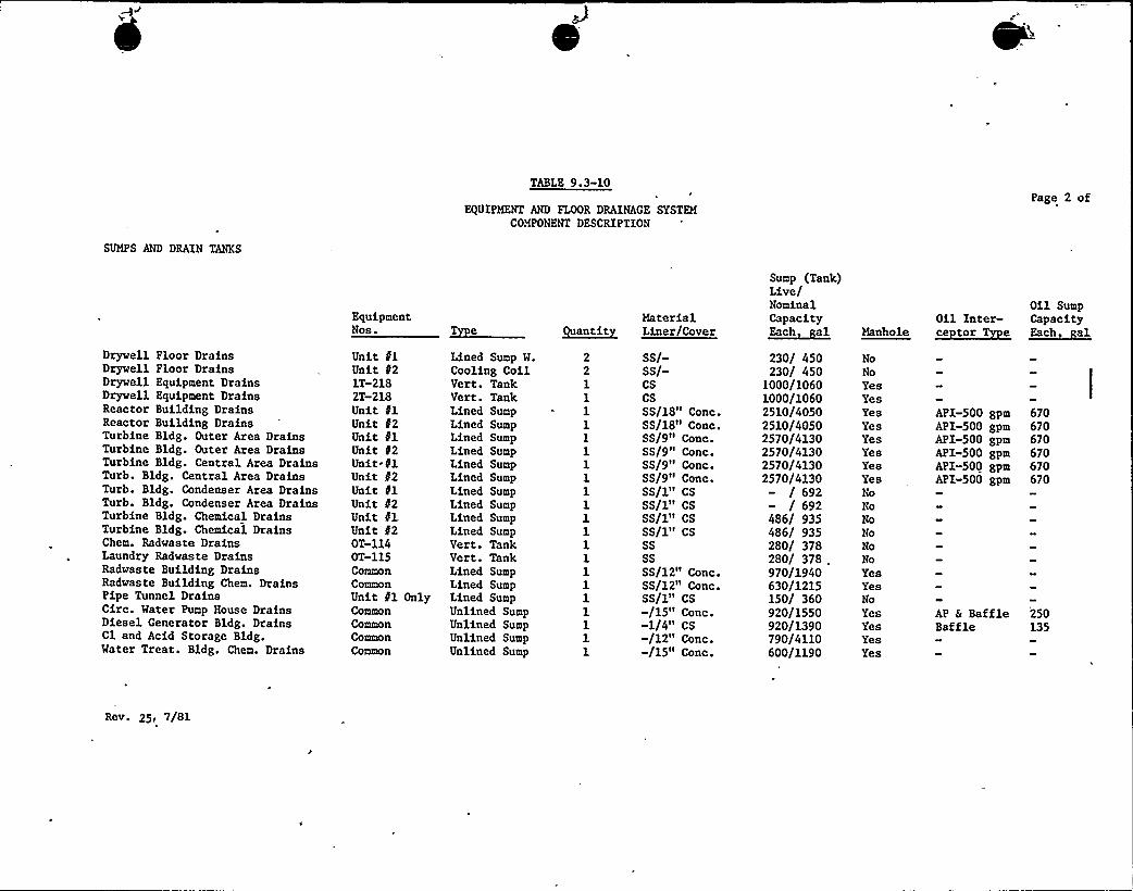
SUMPS AND DRAIN TANKS
TABLE 9.3-10
EQUIPMENT AND FLOOR DRAINAGE SYSTEMCOMPONENT DESCRIPTION
Page 2 of
Drywell Floor DrainsDrywell Floor DrainsDrywell Equipment DrainsDryvell Equipment DrainsReactor Building DrainsReactor Building DrainsTurbine Bldg. Outer Area DrainsTurbine Bldg. Outer Area DrainsTurbine Bldg. Central Area DrainsTurb. Bldg. Central Area DrainsTurb. Bldg. Condenser Area DrainsTurb. Bldg. Condenser Area DrainsTurbine Bldg. Chemical DrainsTurbine Bldg. Chemical DrainsChem. Radvaste DrainsLaundry Radwaste DrainsRadvaste Building DrainsRadvaste Building Chem. DrainsPipe Tunnel DrainsCirc. Water Pump House DrainsDiesel Generator Bldg. DrainsCl and Acid Storage Bldg.Water Treat. Bldg. Chem. Drains
EquipmentNos.
Unit flUnit 021T-2182T-218Unit 41Unit 82Unit flUnit 02Unit.flUnit d2Unit flUnit t2Unit dlUnit f2OT-114OT-115CommonCommonUnit 81 OnlyCommonCommonCommonCommon
Lined Sump W.Cooling CoilVert. TankVert. TankLined SumpLined SumpLined SumpLined SumpLined SumpLined SumpLined SumpLined SumpLined SumpLined SumpVert. TankVert. TankLined SumpLined SumpLined SumpUnlined SumpUnlined SumpUnlined SumpUnlined Sump
Quant~itMaterialLiner/Cover
SS/-SS/-CSCSSS/18» Conc.SS/18» Conc.SS/9» Conc.SS/9" Conc.SS/9» Conc.SS/9» Conc.SS/1» CSSS/1» CSSS/1» CSSS/1» CSSSSSSS/12» Conc.SS/12» Conc.SS/1» CS
15» Conc.-1/4» CS-/12» Conc.-/15» Conc.
Sump (Tank)Live/NominalCapacity~Each al
230/ 450230/ 450
1000/10601000/10602510/40502510/40502570/41302570/41302570/41302570/4130
/ 692/ 692
486/ 935486/ 935280/ 378280/ 378970/1940630/1215150/ 360920/1550920/1390790/4110600/1190
Manhole
NoNoYesYesYesYesYesYesYesYesNoNoNoNoNoNoYesYesNoYesYesYesYes
Oil Inter-~ce torTTpe
API-500 gpmAPI-500 gpmAPI-500 gpmAPI-500 gpmAPI-500 gpmAPI»500 gpm
AP & BaffleBaffle
Oil SumpCapacity~Each al
670670670670670670
250135
Rev. 25, 7/81
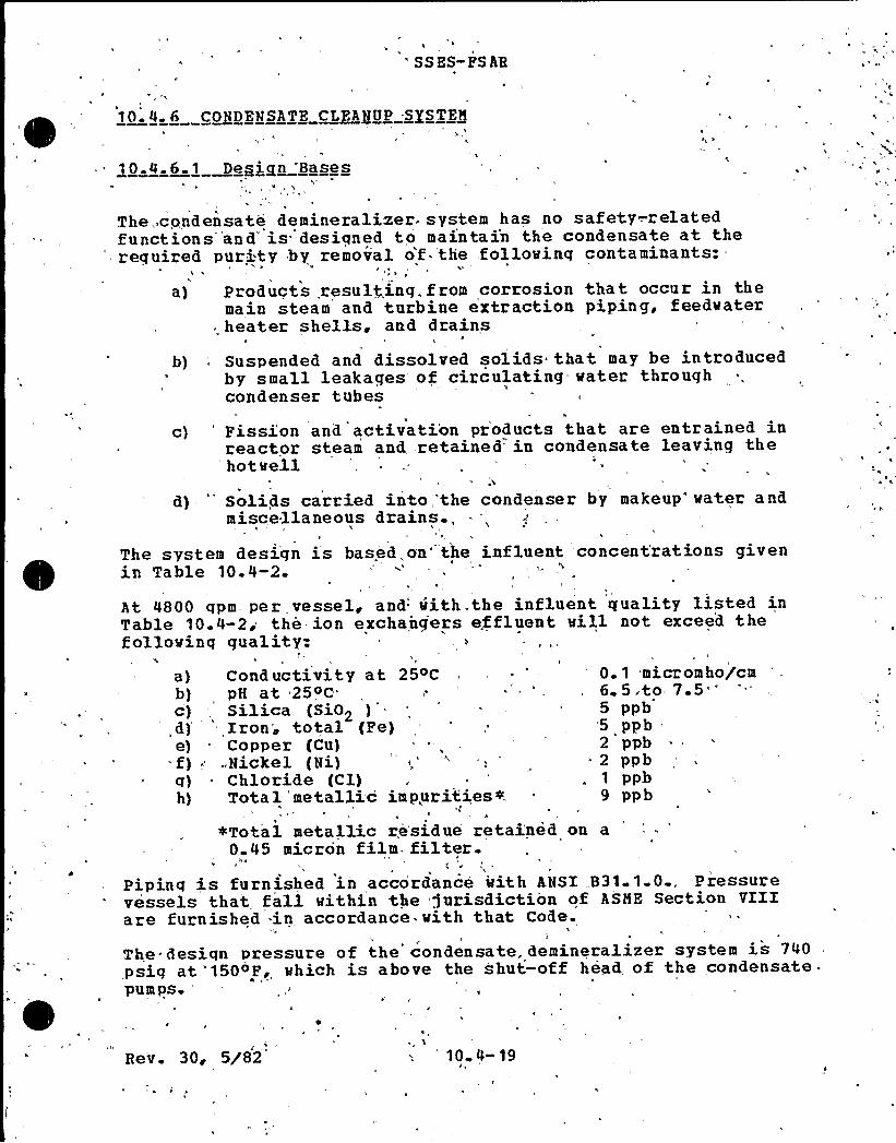
'SES-PSAR
10~ 4 6 CONDENSATE CLEANUP SYSTEM
't 0.4.6.1 presign "Bases
The.,condensate demineralizer.'ystem has no safety-.relatedfunctions'and's"desiqned to maintain the condensate at the
'equired purity by removal of the .following contaminants:'%
a) Products, resulting. from corrosion that occur in themain steam and turbine extraction piping, feedwaterheater shells, and drains
b) ~ Suspended and dissolved solids that may be introducedby small leakages of circulating=-water thxoughcondenser tubes
c) Fission and activati'on products that are entrained inreactor steam and retained in condensate leaving thehot well
~%
d) 'olids carried into,'the condenser by makeup'ater andmiscellaneous drains.,
The system design is- based, on'he influent concentrations givenin Table 10.4-2.
At 4800 qpm per vessel, and with the influent quality listed inTable 10.4-2, the ion exchanqers effluent will not exceed thefollowinq quality:
a) Conductivity at 254C . - ' '.1 micromho/cmb) pH at 254c,; ''., 6.5,to 7.5
')Silica (SiO> ) . '- 5 ppb
,d) 'ron",,total (Pe) ', 5 ppbe) = Copper (Cu) =, .
' ppb= f)...Nickel (Ni),' -: - 2 ppbq) - Chlori.de (Cl) .- ~ . 1 ppb-h) Tota 1 metallic impuri.ties + 9 pp b
4Total metallic residue retained on a0.45 micron film. filter.
hp
Pipinq is furnished in accordance with ANSI „B31.1.0., Pressurevessels that fall within the jurisdiction of ASME Section VIIIare furnished in accordance. with that Code.
The ~ design pressure of the condensate,. demineralizer system is 740psig at '1504P, which is above the shut-off head of the condensate-pum ps.
Rev. 30, 5/82 10 4- 19
4 I
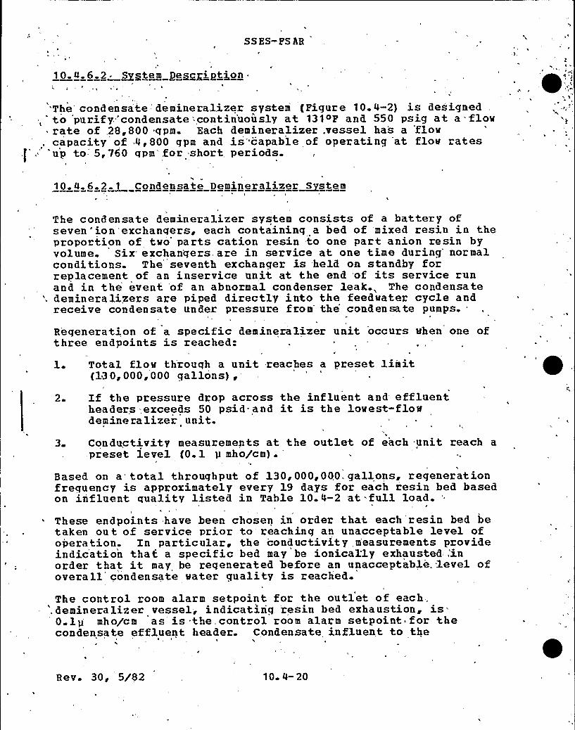
SS ES- PS AR
'The'ondensate 'demineralizer system (Pigure 10.4-2) is designed,-to purify'condensate'=c'ontin'uously at 131~P and 550 psig at a = flowrate of .28,800 qpm. Each demineralizer .vessel has a flow
, capacity of 4,800 gpm and is'capable of operating at flow ratesf'. 'up to 5,760 gpm't'or short perious.
10.4. 6.2 1 Condensate Demiperalizer~Sstem
The condensate demineralizer system consists of a battery ofseven"'ion exchanqers, each containing a bed of mixed resin in theproportion of two'arts cation resin .to one part anion resin byvolume. Six exchanqers are in service at one time during'ormalconditions. The seventh exchanqer is held on standby forreplacement of an inservice unit at the end of its service runand in the event 'of an abnormal condenser leak., The condensate
', demineralizers are piped directly into the feedwater cycle andreceive condensate under pressure from the condensate pumps..
Regeneration- of a specific demineralizer unit occurs when one ofthree endpoints is reached:
1 Total flow throuqh a unit .reaches a preset limit{130,000,000 qallons),
20 If the pressure drop across the influent and effluentheaders -,exceeds 50 psid- and it is the lowest-flowdemine ra lizer unit.
3 Conductivity measurements at the outlet of each unit reach a- preset le vel (0. 1 p mho/c m) .
Based on a total throughput of 130,000,000. gallons, regenerationfrequency is approximately every 19 days for each resin bed basedon influent quality listed in Table 10.4-2 at full load.
These endpoints have been chosen in order that each'resin bed betaken ou t of service prior to reaching an unacceptable level ofoperation. In particular, the conductivity measurements provideindication that a specific bed may be ionical'ly exhausted:inorder that it may be reqenerated 'before an unacceptable. level ofoverall condensate water quality is reached.
The control room alarm setpoint for the outlet of each.'emineralizer vessel, indicatinq„ resin bed exhaustion, is' lp mho/cm as is:the,control room alarm setpoint for the
condensate effluent header. Condensate influent to theII
Rev. 30, 5/82 10 4- 20
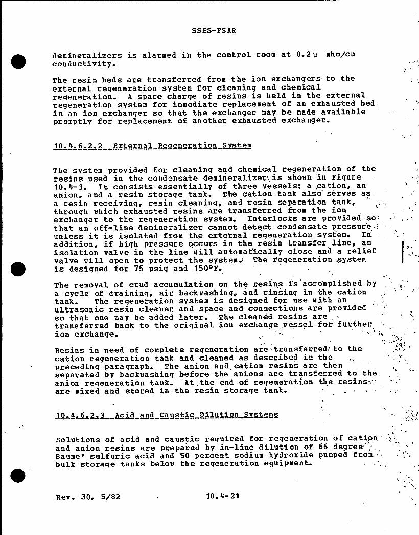
SSES-PS AR
demineralizers is alarmed in the control room at 0.2p mho/cmconductivity.The resin beds are transferred from the ion exchangers- to theexternal reqeneration system for cleaning and chemicalreqeneration. A spare charge of resins is held in the ex'ternalregeneration system for immediate replacement of an exhausted bed'„in an ion exchanger so that the exchariger may be made availablepromptly for replacement of another exhausted exchanger.
10.4.6.2~2 external Regenegation System
The system provided for cleaninq and chemical regeneration of theresins used in the condensate demineralizer. is shown in Pigure10.4-3. It consists essentially of three vessels: a,cation, ananion, and a resin storage tank. The cation tank also'erves asa resin receiving, resin cleaninq, and resin separation tank,through which exhausted resins are transferred from the ionexchanger to the regeneration system. Interlocks are provided
so'hat
an off-line demineralizer cannot detect condensate pressur'eunless it is isolated from the exte'mal regeneration system. Xn.
addition, if hiqh pressure occurs in the ress,n transfer line, anisolation valve in the line will automat'ically close and a reliefvalve will open to protect %he system: The r,'eqeneration systemis designed for 75 psig and 150oP.
The removal of crud accumulation on the resins i:s accomplished bya cycle of draininq, air backwashing, and rinsing in the cationtank. The regeneration system is designed for use with anultrasonic resin cleaner and space and connections are providedso that one may be added later. The cleaned resins aretransferred back to the oriqinal ion exchange..vessel for furtherion exchange.
I ~
Resins in need of complete regeneration are tLansferred to thecation regeneration tank and cleaned as described in thepreceding paragraph. The anion and cation resins are thenseparated by backwashing before the anions are transferred to theanion reqeneration tank. At, the end of regeneration the resins-;."are mixed and stored in the resin storage tank.
10,a,6a$ ,3 Aci.d agd C~gstic g~1~ic~ms stems ada
'olutionsof acid and caustic required for regeneration of cationand anion resins are prepared by in-line dilution of 66 degree" ~
'aume'ulfuricacid and 50 percent sodium hydroxide pumped from.bulk storaqe tanks below the regeneration equipment
Rev. 30, 5/82 10 4-21

SSES-FSAR
Approximatey 5-1/2 percent concentration of acid solution isrequired to regenerate the cation resins. The strong acid ismixed in a„ mixinq tee with clean condensate as needed. Mater issupplied at a constant rate by condensate transfer pumps througha pressure control valve.
Approximately 5-l/2 percent concentration -of caustic at 120oF isrequired to reqenerate the a'nion resins. Strong caustic is mixedwith dilution wa'ter at 120~P in a mixing tee as needed. Dilutionwater is produced by blending 180~P water from the caustic-dilut=ion hot water tank with cool water.
10.4 6 2 4 Mast@ System
Three types of wastes are seqreqated from the regeneration wastedischarqe These are: high conductivity, low conductivity andlow solids content, and low conductivity and high solids content.
High conductivity wastewater (conductivity above 100 micromhos)is channeled to the chemical waste neutralizer tanks where it is,neutralized and pumped to the radwaste evaporators fordistillation. Low conductivity condensate from this process isreturned to the condensate storaqe.tank.
Low conductivity low solids wastewater is channeled to theturbine buildinqs outer area sump where it is pumped to theliquid radwaste collection tanks.
Low conductivity high solids waste water (greater than 3 JTU) ischanneled to the regeneration waste surge tanks. The tanks aredesigned with cone bottoms. From there the wastewater is pumpedat 35 qpm to the waste sludqe phase separator.
See Section 11.2 for the effect of the Condensate Cleanup Systemon the radwaste system.
10. 4. 6. 3 Safety Evaluation
The equipment and controls in the condensate demineralizer systemare of the same. design and operational integrity as those in theradwaste system.
Spare capacity is provided'n the system to negate thepossibility of difficulties in handling radioactive waste whenthe system is operating. If the radwaste handling systemapproaches desiqn capacity, such as when condenser tube leaksreguire maximum rates of regeneration of ion exchanqers, the unit
R e.v. 30, 5/82 10 4- 22

SS ES-PS AR
l
load is reduced to eliminate the possibility of exceedingoperational limits.The effluent water quality stated in. Subsection 10.4.6.1 will notbe exceeded with an 11.5 qpm condenser leak when circulatingwater contains 1000 ppm of'total dissolved solids. The systemwill sustain an effluent conductivity of 0.15,micromho with a
46 qpm condenser leak when circulating water contains 1000 ppm oftotal dissolved solids. The circulatinq water quality used inthe desiqn of the CCS is given in Table 10.4-3. Conductivity is -" *
recorded at '12 locations in the condenser, at analysis stationslocated on the:common influent and effluent healer to thecondensate demineralizer system, on the discharge of each ionexchange vessel, and at the discharge healer of the reactor feed =
pumps. High conductivity alarms are,providel to. alert the plantoperators to an abnormal condition.
E II
Treated condensate conductivity levels are maintained within thelimits of Table: 2 of Regulatory Guide 1.56, Hev. 1 in thefollosinq manner:
Individual demineralizer vessel outlet conductivity is monitoredand continuously recorded locally'at the Turbine Building SampleStation Control Panel. High conductivity, indicating, ionicexhaustion,,i.s alarmed locally'and at the main,.control r'oom-panel.. The hiqh conductivity alarm setpoint's,O'1 p mho/cm, thusan ionically exhausted resin bed is removed"from', service an'd
regenerated before reaching the Table 2 of Regulatory Guide 1.56 'Hev. 1 lower -limit of 0.2pmho/cm. In addition, a regeneratedresin bed beinq-brouqht on line is automatically,recycled to.,thecondenser prior to being placed in service to ensure'.that the
. vessel is,not brought on stream at high..:conductivitylevels.,'he
combined demineralizer outlet conductivity is also monitoredand continuously recorded locally at the-Turbine B'uilding samplestation control. panel. High conductivity of the combinedeffluent is alarmed locally. and at the main control room panel atO.l p mho/cm. Since each vessel is alarmed vhen conductivity
- reaches 0.1 pmho/cm. The likelihood of the combined effluentreaching the alarm point is remote except, under conditions of alarqe condenser lea'k. However, demineralizer inlet conductivityis 'monitorel in the same manner,.'as the outlet flovs, with analarm setpoint of 0.2 p mho/cm indicating condenser leakage.(Table 2 of'Regulatory Guide 1.56, Rev.. 1 lover limit is 0.5p"mho/c m) .
The condensate demineralizer system is designed to operate'in amanner such that, corrective action is initiated "prior to reachingthe"lover limits of Table 2 of Regulatory Guide 1.56, Rev. 1.
The values shown in Table 10.4-4 are arrived at assuming 100percent removal 'efficiency for all dissolved. principal fission
Rev. 30, 5/82 10 4- 23

SS ES-PS AR
and corrosion activation products. However, because the removalefficiency for suspended'olids*is 50 to 75 percent, .the overallremoval of co'rrosion activation products is somewhat less thanl00 percent for the system. fables 10.4-4 anl 10.4-5 provide thedesign bases for radiation shieldinq in the condensatede min erali!z er area.
The effluent strainer in the dischar'ge from each'ion exchangerprotects the feedwater system aqainst a massive discharge ofresins in the event of an underdrain failure.
!
10.4.6 4 Tests and Inspectgogs
Piping is inspected and tested in: accordance with ANSI B31.1.0.All pressure vessels are hydrostatically tested to 1.5 timestheir design pressure.:
The system will be preoperationally tested in accordance with therequirements of Chapter 14.
'!
10. 4. 6. 5 Contgolg'gd Xggtrumgytat ion .
The condensate demineralizer and .re'generation systems, arecontrolled from a local contr'ol panel for all modes .of operation,includinq transfer of resins, for. cleaning and retu'ming 'these,resins to the exchange vessel, 'or the,,transfer of resins forcleaning and regeneration and transferring, previously regeneratedstored resins to the exchanqer*for 'standby,;
!
The conductivities are monitored by 'a, multipoint recorder for thefollowinq: ', " .' ', *
''.
!
a) Influent and effluent. of the'- condensate polishingdemineralizer, system
b) Effluent from each .condensate polishing'emineralizer.!
In addition,',conductivity alarms are provided,'to alert theoperator for!off-normal conditions Resin „condition is monitoredin accor dance with. Regula tory Guide 1..56. 4 differential.pressure transmitter is provided to monitor the differential
, pressure across the condensate demineralizer system. . Flowtransmitters, recorders, and flow totalizers are provided -in theeffluent of each condensate polishing demineralizer."
Rev. 30; 5/82 10 4-24

SSES-FSAR
11. 3 GASEOUS QASTE MANAGEMENT SYSTEMS ~
11. 3 1 ~ DESIGN ~ BASES
11 3. 1. 1. Design Objective
The gaseous waste'anagement systems (GRMS) are designed toprocess and control the release of qaseous radioactive wastes tothe site environs so that the total radiation exposure ofpersons in offsite areas is as low as reasonably achievable anddoes not exceed applicable guidelines. This is to beaccomplished while maintaininq the occupational exposure as lowas reasonably achievable and without limiting plant operation oravailability.
11. 3. 1. 2 Desian Basis
The gaseous waste systems are =.desiqned to limit offsite dosesfrom routine station releases to significantly less than thelimits specified in 10CFR20, and to operate within the doseobjectives established in 10CFR50, Appendix I.The desiqn basis and maximum expected source terms correspond to100,000 and 60,000 p Ci/sec respectively of nob le radiogas aftera 30 minute delay. Table 11.3-1 lists the quantities of nuclidesexpected to be released to the environs when opera, ting at themaximum expected failed fuel levels. The expected doses toindividuals at or beyond the site boundary are shown inSubsection 11.3.4 and Environmental Report Subsection 5.2.4.2.A description of the major equipment items in the offgas systemis Provided in Table 11. 3-5. The seismic and quality groupclassifications of the GWMS components, piping and structureshousinq them are listed in Section 3.2.
Conservative analyses similar to those presented in Ref 11.3-1demonstrate that equipment failure cannot result in dosesexceedinq acceptable guidelines; thus, neither the offgas systemnor the buildings housinq the equipment were designed to meetSeismic Category I requirements; however, the offgas structural
)walls are part of the total structural shear wall system and wereanalyzed to withstand the effects of earthquakes.
The failure of the Ambient Temperature Charcoal Offgas Treatmentsystem is analyzed in Subsection 15.7.1.1. The related failureof the steam jet air ejector lines and failure of the mainturbine gland sealinq system are analyzed in Subsections 15.7. 1.3and 15.7.1. 2 respectively.
Rev. 30, 5/82 1 1 ~ 3
SSES-PSAR
11. 3. 2 SYSTFN DESCRI PTXONS
11 3. 2.1 nffaas System
Noncondensible radioactive offqas is continuously removed fromthe main condenser by the steam jet air ejector {SJAE) durinqplant operation. This is the major source of gaseous releasesfrom the plant and is larqer than all other sources combined.The SJAH offqas will normally contain activation gases,principally N-16, 0-19, and N-13. The N-16 and 0-19 have shorthalf-lives and are readily decayed. The N-13, with a 10-minutehalf-life is present in small amounts that are further reduced bydelay. The SJAF. offqas will also contain various isotopes of theradioact ive noble qases Xe and Kr, precursors of biologicallysiqnificant Sr-89, Sr-90, Ba-140, and Cs-137. The concentrationof. these noble gases depends on the amount of tramp uranium inthe coolant and on the claddinq surfaces {usually extremelysmall) a nd the number and size of fuel cladding leaks. An of fgassystem has been provided to treat these radioactive sources.This system utilizes catalytic recombination and charcoaladsorption as discussed below.
The building layout and equipment location of the offqas systemcorn ponents is shown on Piqures 11. 2-3 through 11. 2-7.
11. 3. 2. 1. 1 process Plow Description
The noncondensible qases in the main turbine condenser areremoved hy a two staqe steam jet air ejector (SJAF) anddischarged to the offqas recombiner system. During startup,clean auxiliary steam maybe used to drive the SJAE and therecombiner system to minimize operation of and untreatednoncondensible releases from the mechanical vacuum pump. Afterstart up, pressure reduced steam from the main steam line is used.
Because of the limited motive steam capacity of the second stage.SJAE, additional dilution steam to maintain the H2 concentrationbelow 4% by volume in the offqas stream, bypasses around thee jector nozzle to the discharge. This arrangement allowsad justinq the total dilute.on steam flow without sacrificing SJAEperformance. The offqas-steam flow then enters the associated orthe common standby catalytic recombiner system through anelect.rically heat traced piping manifold This preventscondensation of the dilution steam particularly during coldstart-up. The purpose of the recombiner system is to reduce theoffqas volume and eliminate the potential for explosion bycontroll ed recombination of the radiolytic hydrogen with oxygento less than 1% concentration by volume on a dry basis of 5 scfm
Rev. 30, 5/82 1 1&3 2

SSES- F SAR
air flow and less than 0.5% concentration for an air flow ofatl east 10 scfm.
The offgas first passes through the recombiner preheater in orderto minimize the moisture contents prior to entering the catalystbed. The recombination pr ocess takes pl ace inside the recombinervessel which is el ectrically preheated during standby to a rangeof 240'F to 270'F strip heaters on the outside. The reactiontemperature is approximately 800'F.
The moisture in the offgas .leaving the recombiner vessel isremoved in the recombiner 'condenser where the offgas is cool ed to150'F. A motive steam jet then boosts the saturated gas streampressure fr om bel ow to sl,ightly above atmospheric pressure.
The reduced pressure main or auxiliary motive steam used in themotive jet is then removed from the offgas stream in the motivesteam jet condenser and the 150'F offgas passes through a delaypipe from the recombiner system in the turbine building to theambient temperature charcoal offgas system in the radwastebuilding.The pressure differential between the condensers in therecombiner systems and the main condenser is sufficient to drainthe condensate without additional motive force to the maincondenser, while the delay pipe is drained by level controlledvalves to the turbine building radwaste sump.
The delay line varies in diameter from 8 to 16..in. and isapproximately 600 ft in length. At the design flow rate of30 scfm, this pipe provides for approximately nine minutes ofdecay of the radioactive products in the offgas stream prior toentering the adsorption train.After exiting this line, the gas is cooled to approximately 40'Fby a refrigerated chiller unit and reheated to approximately 65'Fto prevent condensation. Moisture and temperatureinstrumentation measure the process conditions downstream of thechiller to monitor the performance of the water removalassemblies and to guard against degraded charcoal performancethat might result from either an increase in the moisture contentor temperature of the gas.
Prior to entering the main char coal vessels, the process streampasses through a sacrificial guard bed. The principal functionof this guard bed is to absorb impurities that may be entrainedin the process gas that might adversely affect the performance ofthe charcoal adsorbent. Each guard bed has been sized to absorbthe moisture that might result from a failure of the chiller overa period of 48. hours. This design feature, in conjunction withthe moisture and temperature instrumentation, should provideadequate protection against the contamination of the charcoal
Rev. 33, 4/83 11.3-3
SSES-FSAR
adsorber bed. Differential pressure indication is provided as a
backup to the moisture instrumentation.
After passing through the guard bed, the gas enters the maincharcoal adsorption bed. This bed, operating in a controlledtemperature vault, selectively adsorbs and delays the xenon andkrypton from the bulk carrier gas. This delay on the charcoalpermits the xenon and krypton to decay in place. Afterundergoing a sufficient decay in the charcoal vessels, theprocess stream passes through a HEPA outlet filter, whereradioactive particulate matter and possible charcoal fines areretained. This stream is c'ontinuously monitored and an alarmwill annunciate any abnormal releases from this system.
The process stream is then directed to the turbine buildingventilation exhaust duct where it is diluted with minimum42,000]scfm of air prior to being released from the top of thereactor building. Table 11.3-1 indicates the estimated annualrelease rates from the turbine building of various isotopes.
11.3.2. 1. 1. 1 Process Flow Dia ram
Figure 11.3-1 is the process flow diagram for the system. Theprocess data for startup and normal operating conditions arecontained in Table 11.3-8.
11.3.2. 1. 1.2 Process and Instrumentation Dia ram PAID
The PAID is shown as Figures 10.4-9, 11.3-3, A8B and 11.3-4.
11.3.2. 1. 1.3 Process Desi n Parameters
The krypton and xenon holdup times are closely approximated bythe following equation:
K M (Equation 11.3-1)Y
Where:
holdup time of a given gas
dynamic adsorption coefficient for a given noblegas
mass of charcoal adsorber
Rev. 33, 4/83 11. 3-4
SSES-PS AR
V = flov rate of the carrier qas.
Conservative dynamic adsorption coefficients of 420 cc/gm forxenon and 23.7 cc/qm for krypton vere assumed for the charcoaladsorbent material. They were derived by adjusting the valuespresented in NUREG 0016 for the temperature and humidityconditions of the Susquehanna SES offqas process stream.
Dynamic adsorption coefficients for xenon and krypton have beenreported by Browning {Ref. 11.3-2). General Electric hasperformed pilot plant tests at their Vallecitos Laboratory, andthe results vere reported at the Twelfth AEC Air CleaningConference (Ref. 11.3-6). Further data on a similar systemoperatinq at ambient temperature are reported in Ref 11.3-3.
The temperature adjustment was obtained by a straight-lineinterpolation of the coefficients provided, in NUREG 0016 .for thefollowinq data points: 77~P, dev point OOF and 00P, dew point—20~F. The moisture content of a qas mixture at these two pointsis relatively low and thus the variations in adsorptioncoefficients between these points is mainly a function oftemperature. The coefficients thus obtained were adjusted toreflect the effects of moisture content in a manner consistentwith that employed in NUREG 0016.
With a design condenser air in-leakage of 30 scfm, and aboveadsorption coefficients this system provides a design delay of32 hours for krypton and 23.7 days for xenon. Since the expectedcondenser in-leakaqe is belov the design value, the actual delaytimes should be several times longer than the design delay times.Table 11.3-1 lists isotopic activities at the discharge of theturbine buildinq exhaust vent.
After passing thru the recombiner section, the, off qas streamconsists primarily of the air in-leakage from the main condenser.The air in-leakage design basis is conservatively assumed at30 scfm. The Sixth Edition of the Heat Exchange InstituteStandards for Steam Surface Condensers (Ref 11.3-4, paraqraph5.16(c) (2)) indicates that with certain conditions of stableoperation and suitahle construction, noncondensibles should notexceed 6 scfm for larqe condensers. Dresden-2, Fukushima-1,Tsuruqa, and KRB have all operated at 6 scfm or less.
Re v. 30, 5/82 11. 3-5
SSES-FSAR
11.3.2.2 Com onent Descri tion
11.3.2.2.1 Recombiner S stem
The offgas treatment system is divided into two sections tofacilitate plant arrangement: the recombiner system and thecharcoal offgas system. Three recombiner assemblies are locatedin the turbine building in a shielded area below the maincondenser steam jet air ejectors. Each recombiner assemblyconsists of the following major components: a recombinerpreheater, recombiner vessel, recombiner condenser, motive steamjet, motive steam jet condenser and a condensate cooler.
One recombiner assembly is primarily designated for the serviceof each nuclear unit and the third assembly is a common standbyto both units. Each recombiner assembly is sized to accommodatethe design flow from one nuclear unit. The piping and valvemanifold upstream of the recombiner assemblies permit thetransfer of the offgas stream between a unit designated assemblyand the common standby recombiner assembly.
The materials of construction, design. pressures and temperatures,and the design codes for the components associated with therecombiner assemblies are listed in Table 11.3-5.
11.3.2.2.2 Charcoal Off as S stem
After the radiolytic hydrogen and oxygen have been removed fromthe process stream by the recombiner assembly, the .remaining gasenters a delay line which is approximately 600 ft in length andvaries in size from 8 to 16 in . The purpose of this delay lineis to permit the large quantity of N-16 to decay to a reasonableactivity concentration prior to entering the charcoal adsorptionportion of the offgas system. Although there is a separate delayline for each recombiner assembly, these lines are joined into a
single common header in the radwaste building . However, theprocess offgas stream from each unit is segregated by the use ofisolation valves that are installed in this common header.
After entering the common inlet header, the gas mixture from eachunit can be directed to either of two parallel equipmentsubtrains consisting each of a water removal/temperaturereduction assembly, and a charcoal guard bed. The utilizedcharcoal adsorption train of each offgas treatment system isprimarily designated for the service of the associated nuclearunit. Each adsorption train consists of five charcoal adsorberbeds in series. The trains and subtrains are isolable at both theinlet and outlet by remotely operated valves. The following
Rev. 33, 4/83 11.3-6
S S ES- PS AH
12 .2- - RADIATION SOURCES
Xn this section the sources of radiation that form the basis forshield desiqn calculations and the sources of airborneradioactivity required for the design of personnel protectivemeasures and for dose assessment are discussed and identified.
12.2. 1 CONTArNHD SOVRCZS
The shieldinq design source terms are based on a noble gasfission product release rate of 0.1 Ci/sec (after 30 minutesdecay) and the correspondinq fission, activation, and corrosionproduct concentrations in the primary coolant. The sources inthe primary coolant are discussed in Section 11.1 and listed inTables 11.1-1 through 11.1-5. Throughout most of the primarycoolant system, activation products, prin"ipally nitrogen-16, arethe primary radiation sources for shielding design. Por allsystems transportinq radioactive materials, conservativeallowance is made for transit decay, while at the same timeprovidinq for dauqhter produ"t formation.
Basic reactor data and core reqion description used for thissection are listed in Tables 12.2-1 through 12. 2-5.
ln this subsection the desiqn sources are presented by buildinglocation and system. General locations of the equipmentdiscussed in this section are shown on the shielding and zoningdrawinqs, Figures 12.3-8 throuqh 12.3-27. Detailed data onsour"e des"riptions for each shielie9. plant area are presented inTables 12.2-38 throuqh 12.2-40.
Shiel.ding source terms presented in this section and associatedtables are based on conservative assumptions regarding system andequipment operations and characteristics to provide reasonablyconservative radioactivity concentrations for shielding design.Therefore, the shielding source terms are not intended toapproximate the actual system design radioactivityconcentrations.
Rev. 29, 3/82 12 2-1

SS ES-PS AR
12 2. 1.1 Dcvwell
12 2.-1.:I 1.. Reactor Core
The primary radiations within the drywell ducing full poweroperation are neutron and gamma radiation resultinq from thefission process in the core. Tables 12.2-4 and 12.2-5 list'hemultiqroup neutron and qamma ray fluxes at the outside surfacesof the reactor pressure vessel and the primacy shield at the coremidplane. The qamma fluxes include those resulting from captureor inelastic scattering of neutrons within the reactor pressurevessel and core shroud and the gamma radiation resulting fromprompt fission and fission product decay.
The largest radiation sources after reactor shutdown are thedecayinq fission products in the fuel. Table 12.2-9 lists thecore qamma sources as a function of shutdown time. Secondarysources are the structural material activation of the RPV, itsinternals, and the pipinq and equipment located in the primarycontainment and also the activated corrosion products accumulatedor deposited in the internals of the RPV, the primary coolantpipinq, and other process system piping in the primaryconta inment.
12. 2. 1. 1.2 Reactor ~ Coolant Svstem
Sources of radiation in the reactor coolant system are fissionproducts estimated to be released from fuel and activation andcorrosion products that are circulated in the reactor coolant.These sources are listed in Tables 11.1-1 thru 11.1-5 and theirbases are discussed in Section 11.1. The nitrogen-16concentration in the reactor coolant is assumed to be 61'i/gmof coolant at the reactor re"irculation outlet nozzle.
12. 2. 1.-1.3. Primary- Steam. System
Radiation sources in the primary steam system piping includeactivation gases, principally nitrogen-16, and the corrosion andfission products carried over to the steam system.
The nitrogen-16 concentration in the main steam is assumed to be100 p Ci/gm of steam leaving the reactoc vessel at the main steamoutlet nozzle. Fission product activity corresponds to an offgasrelease rate of 100 ~ 000'i/sec at 30 minutes delay from thereactor steam nozzle. Partition fractions for activity into the
Rev. 29, 3/82 1 2w 2 2
SS ES- PS AR
12.3-1.3 Radiation. Zoning and Access Control
Access to areas inside the plant structures and plant yards isrequlated and controlled. Each radiation zone defines theradiation level range to which the aggregate of all contributingsources must be attenuated by shielding.
All plant areas are categorized into radiation zones according toexpected radiation levels and anticipated personnel occupancy,with consi'deration qiven toward maintaininq personnel externalexposures ALARA and within the standards of 10CPR20. Each zoom,corridor, and pipeway of every plant building is evaluated forpotential radiation sources during normal operation and shutdown;for maintenance occupancy requirements, and for general accessrequirements to determine appropriate zoninq. Radiation zonecategories used and their descriptions are given in Table 12. 3-1and the specific zoninq for each plant area is shown on Figures12.3-8 thzouqh 12.3-27. All frequently accessed areas, ie,corridors, are shielded for Zone I and Zone II access.
The control of ingress or eqress of plant operating personnel tocontrolled access areas and procedures employed to ensure thatradiation levels and allowable working time are within the limitsprescribed hy 10CFR20 as described in Section 12. 5.
1$ .3. 1.4 Contgol of Activated Coggosion Products
In order to minimize the radiation exposure associated with thedeposition of activated corrosion products in reactor coolant andauxiliary systems, the followinq steps have been taken:
(1) The reactor coolant system consists mainly of austeniticstainless steel, carbon steel and low alloy steel components.Nickel content of these materials is low, and it iscontrolled in accordance with applicable ASME materialspecifications.A small amount of nickel base material (Inconel 600) isemployed in the reactor vessel internal components. Inconel600 is required where components are attached to the reactorvessel shell and the coefficient of expansion must match thethermal expansion characteristics of the low alloy vesselsteel. Inconel 600 was selected because it provides theproper thermal expansion characteristics, adequate corrosionresistance and can be readily fabricated and welded.
(2) Materials employed in the reactor coolant system arepurchased to ASME material specification reguirements. No
Rev. 3 0, 5/82 12w37

SSES-PSAR
special controls on levels of cobalt impurities arespecified.
(3) Hardfacinq and wear materials having a high percentage ofcobalt are restricted to applications where no satisfactoryalternate materials are available. Studies currently arebeing made to determine whether, any alternate low cobaltalloys are satisfactory for lonq term use in nuclear reactorapplications. To date, no satisfactory replacement materialshave been found.
(4) A high temperature filtration system was not employed in theReactor Mater Clean-up System. The reasons for thisincluded:
a. Lack of quantitative data on the removal efficiency forinsoluble cobalt by the hiqh temperature filter;
b Uncertainty in the deposition model including therelative effectiveness of cobalt removal on depositionrate;
co Doubtful cost-effectiveness in an area where othermethods under study (such as decontamination) may provebetter at reducing dose rates while also being morecost-ef fective.
(5) Items 1, 2 ~ and 3 above also apply to valve materials incontact with reactor coolant. Ualve packing materials areselected primarily for their properties in the particularenvironment.
(6) Subsections 12. 1. 2.2, 12.3 1. 1, and, 12.3.1.2 describe thevarious flushinq, draining, testing, and chemical additionconnections which have been incorporated into the 'design ofpiping and equipment which handle radioactive materials. Ifdecontamination is to be performed, these connections wouldbe used for that purpose.
!(7} The plant is desiqned with a 1% mixed resin, a pressure
precoat clean-up system for the primary coolant in thereactor and a full flow deep'bed condensate demineralizersystem for the feedwater. See Piqures 10.4-2, 10.4-3, 5. 4-16a nd 5. 4-.18.
12,3,2 SH XELDING
In this subsection the bases for the nuclear radiation shieldingand the shielding configurations are discussed.
Rev. 30, 5/82 12 3-8
SSES-PS AR
12 3. P.1 Design gbgectives
The basic objective of the plant radiation shielding is to reducepersonnel exposures, in conjunction with a program of controlledpersonnel access to and occupancy of radiation areas, to levelsthat are within the dose requlations of 10CPR50 and are as low asreasonably achievable (ALARA) within the dose regulations of10CFH20. Shieldinq and equipment layout and design areconsidered in ensuring that exposures are kept ALARA duringahticipated personnel activities in areas of the plant containingradioact ive materials,.Basic plant conditions considered in the nuclear radiationshieldinq design are normal operation at full-power, and plantshutdown.
The shielding design objectives for the plant during normaloperation, including anticipated operational occurrences, and forshutdown operations are:
a) To ensure that radiation exposure to plant operatingpersonnel, contractors, administrators, visitors, andproximate site boundary occupants are ALARA and withinthe limits of 10CPR20
b) To ensure sufficient personnel access and occupancy timeto allow normal anticipated maintenance, inspection, andsafety related operations required for each plantequipment and instrumentation
area')
To reduce potential equipment neutron activation andmitiqate the possibility of radiation damaqe tomaterials
d) To sufficiently shield the control room so that thedirect dose plus the inhalation dose (calculated inChapter 15) in the event of design basis accidents willnot exceed the limits of 10CPR50, Appendix A, GeneralDesign Criterion 19.
12 3. 2. 2 General Shieldina Desian
Shieldinq is provided to attenuate direct radiation through wallsand penetrat'ions and scattered radiation to less than the upperlimit of the radiation zone for each area shown in Pigures 12.3-8throuqh 12.3-27. The minimum shielding requirements (seeSubsection 12.3.2.3) for all plant areas are presented on thosescaled layout drawings. General locations of the plant areas and
Rev. 30, 5/82 12. 3-9

SS ZS-FS AR
equipment discussed in this -subsection are also shown on thosedrawings.
The material used for most of the plant shielding is ordinaryconcrete with a minimum bulk density of 105 lb/ft~. Wheneverpoured-in-place concrete has been replaced by concrete blocks orother material, desiqn ensures protection on an equivalentshieldinq basis as determined by the characteristics of theconcrete block selected Compliance of concrete radiation shielddesign with Regulatory Guide 1.69 is discussed in Section 3. 13.Water is used as the*'pr'imary shield material for areas above thespent fuel transfer and storage areas.
Special features employed to maintain radiation exposures ALARAin routinely occupied areas such as valve operating stations andsample stations are described in Subsections 12.3. 1.1 and12 3. 1. 2.
12,3,2,2,1 Reacts - Building Shieldincn Design
Durinq reactor operation, the steel-lined, reinforced concretedryvell wall and the reactor building valls protect personneloccupying ad jacent plant str'uctures and yard areas from radiationoriqinatinq in the reactor vessel and associated eguipment withinthe reactor building. The reactor vessel shield vali, dryvellwall, and various equipment compartment valls together with thereactor building valls minimize the radiation levels outside thereactor building.Where personnel and equipment hatches or penetrations passthrough the dryvell wall, additional shielding is designed toattenuate the radiation to below the required level defined bythe radiation zone outside the dryvell va11 during normaloperation and shutdown and to acceptable emergency levels asdefined by 10CFR50 during design basis accidents.
12 3,2,2,2 Reactor Building Integiog Shielding Design\
Tnside Dryvell Stgucture: Areas within the drywell are designedas Zone V areas and are normally inaccessible during plantoperation. The reactor vessel shield provides shielding foraccess in the dryvell during shutdown, and reduces the activationof and radiation damage to dryvell eguipment and materials.
Outside Drywel+Structuge: The dryvell wall is designed to reduceradiation levels in normally occupied areas of the reactorbuilding from sources vithin the dryvell to less than the maximumlevel for Zone IX.
Rev. 3 0, 5/82 12 3-10

SS ES- PS AR
Penetrations and hatch openinqs in the drywell wall are shielded,as necessary, to meet adjacent area radiation zoninq levels.Shieldinq requirements for the personnel, eguipment, and CRDremoval hatch openings are shown on Figure 12.3-19 in the areasnumbered 412 ~ 413, and 402, respectively. Drywell piping andelectrical penetrations are shielded by providing either localshields within the penetration assembly or a shielded penetrationroom. Shielded piping penetration room locations and bulkshieldinq requirements are shown on Figures 12.3-18 through 12.3-20. These rooms, numbered 202, 204, 205; 403, 411, 501, 504,506, 515; are desiqnated radiation Zone V during reactor poweroperation and are provided with personnel access controls.Electrical penetrations which are not located within these roomsare provided with supplementary local shielding as needed to meetoutside zoninq levels. Six inches of lead, in addition to theself-shielding by the electrical cables, is furnished in eachelectrical penetration assembly to attenuate drywell radiationso urces&
The components of the reactor water cleanup (RRCU) systemdescribed in Section 5.5 are located in shielded compartmentswhich are desiqned as Zone V ~ restricted access areas. Shieldingis provided for each piece of equipment in the RWCU systemconsistent with its postulated maximum activity Subsection 12.2. 1
and with the access and -zoninq requirements of the adjacentareas. This equipment includes:
a) Regenerative heat exchanger
h) Nonreqenerative heat exchanger
c) RHCU pumps and pipinqd) RWCU filter demineralizers and holdup pumps
e) RWCU backwash receiving tank and piping.The traversing in-core probe (TIP) system is located inside ashielded compartment to protect personnel from the neutronactivated portion of the TIP cable.
Naia steamlines are located within shielded structures from thedrywell wall to the reactor building wall.Spent fuel is a primary source of r adiation during re fueling.Because of the extremely high activity of the fission productscontained in the spent fuel assemblies and the proximity of ZoneII areas, shieldinq is provided for areas surrounding the fueltransfer canal and pool to ensure that radiation levels remainbelow zone levels specified for adjacent areas.
Rev. 30, 5/82 12. 3-11
After reactor shutdown, the Residual Heat Removal (RHR) Systempumps and heat exchanqers are in operation to remove heat fromthe reactor water. It is anticipated that the radiation levelsin the vicinity of this equipment will temporarily reach Zone V
levels due to corrosion and fission products in the reactorwater. Shielding is designed to attentuate radiation from RHRequipment during shutdown coolinq operations to levels consistentwith the radiation zoninq requirements of adjacent areas.Adequate shielding will also be provided to maintain radiationzoning requirements during hot standby operation of the RHRsyste m.
During functional testinq operations of the Reactor CoreIsolation Cooling (RCIC) System and the High Pressure CoolantIn j~ction (HPCI), the steam driven turbine and the inlet andexhaust pipinq are shielded consistent with the maximum steamactivities in the lines and the access zone requirements ofsurrounding areas.
The concrete shield walls surro'undinq the spent fuel caskloadinq, storaqe, and transfer areas, as well as the shield wallssurrounding the fuel transfer and storage areas, are designed toprovide Zone II maximum dose rates in accessible areas outside ofthe shield walls.
Mater in the spent fuel pool provides shieldinq above the spentfuel transfer and storaqe areas. Direct radiation levels at thefuel handlinq equipment are calculated to be less than2.5 mrem/hr from spent fuel during normal operations.
Water is also used as shielding material above the steam dryerand. separator storage area. Concrete walls and water in the poolare designed to provide Zone II dose rates in adjacent accessibleareas during storage of the dryer and separator.
The Fuel Pool Coolinq and Cleanup (EPCC) System (see Section9.1.3) shieldinq is based on the maximum activity discussed inSubsection 12.2.1 and the access and zoning reguirements ofad jacent areas. Equipment in the PPCC system to be shieldedincludes the PPCC heat exchangers, pumps and piping, filterdemineralizers, and backwash recdiving tank.
Shieldinq is provided as necessary around the following equipmentin the radwaste building to ensure that the radiation zone andaccess requirements are met for surrounding areas.
a) Laundry drain tank and pumps
Rev. 30, 5/82 12 3-12
SSES-PSAR
b) Chemical waste tank and pumps
c) Radwaste evaporators
d) Radwaste evaporator tanks and pumps
e) Liquid radwaste collection tanks and pumps
f) Liquid radwaste surge tanks
q) Liquid radwaste sample tanks and pumps
h) Reactor water cleanup phase separator and pumps
i) Waste sludqe phase separator and pumpsI
g) Spent resin tank
k) Waste filling and capping station
1) Waste liner transfer and storaqe areas
m) Liquid radwaste demineralizer and piping
n) Waste mixing tanks
o) Liquid radwaste filtersp) Gaseous radwaste eguipment.
12.g,2,2.4 Tughiye Building Shielding Design
Radiation shielding is provided around the following equipment inthe turbine buildinq to ensure that zone access requirements(Figures 12.3-10 through 12.3-15) are met for the followingsurroundinq areas:
a) Condensate filter demineralizers and piping
b) Regeneration waste surge tanks and pumps
c) Chemical waste neutralizinq tanks and pumps
d) Reactor feed pump turbines and piping
e) Condensate pumps and piping
f) Main condensers and hotwell
g) Mechanical vacuum pump
Rev. 30, 5/82 1 2w 3 1 3
SSES-FSAR
h) Recombiners and pipinq
i) Steam packing exhauster
g) Condensate demineralizer resin regeneration tanks
k) Air egectors and gland steam condensers
1) Peedwater heaters, heater drains, and piping
m) Main steam piping
n) Steam seal evaporator and drain tank
o) Moisture separator and drain tanks
p) Hiqh pressure and low pressure turbines
q) Offgas piping.Areas within most of these shield walls have high radiationlevels and limited access.
12.3.2.2 5 Cggtgog gong Shgeldipg Design
Figures 12.3-9 and 12.3-28 represent layout and isometricdrawings of the control room, showing its relationship to thereactor building.The design basis loss-of-coolant accident (LOCA) dictates theshieldinq requirements for the control room. Shielding isprovided to permit access and occupancy of the control room underLOCA conditions with radiation doses limited to 5 rem whole bodyfrom all contributing modes of exposure for the duration of theaccident, in accordance with 10CPR50 Appendix A, General DesignCriterion 19.
The desiqn basis LOCA is described in Subsection 15.1. 13 and isbased on Regulatory Guide 1.3. Th'e direct radiation fromairborne fission products inside the reactor building wouldcontribute less than 361 mrem to personnel inside the controlroom for the 30-day period followinq the LOCA, based onradioactivity sources described in Subsection 12. 2. 1. 6..
The parameters used in the demonstration of the control roomhabitability are listed below and in Regulatory Guide 1.3. {Theventilation system parameters are listed in Subsection 12. 3.3).
Rev. 30, 5/82 12 3-10
SSES-FSAR
For all isotopes that escape from the drywell to the reactorbuilding, no credit is taken for shielding by the internalstructures in the reactor buildinq. Shielding credit is takenfor the reactor and control building walls. For all isotopesthat remain within the drywell, shielding credit is taken for thedrywell wall.
1g.3 2.P,6 Diesel Gene@atop Building Shielding Design
There are no radiation sources in the diesel generator building;therefore, no shielding is required for the building.
12.3. 2.2.7 Higcellaneoug Plant Areas agd Plant Yard Areas
Sufficient shieldinq is provided for all plant buildingscontaininq radiation sources so that radiation levels ataccessible areas outside buildings are minimized. Plant yardareas which are frequently occupied by plant personnel areaccessible during normal operation and shutdown. Someoperations, such as loadinq solidified waste into shield casks,require access restrictions in adjacent areas. These areas aresurrounded by a security fence and closed off from areasaccessible to the general public.
12.3. 2.2.8 Countina Room Shieldina
Because the countinq room contains sensitive instruments toradioactivity measurements, it is imperative that .the backgroundradiation levels are minimized. To accomplish this, no flyashwas used in the concrete mix for the walls and slabs surroundingthe countinq room. Flyash normally contains a relatively largeamount of slow decaying radioactive isotopes. 1n addition, theshield walls and slabs were sized to maintain a backgroundradiation level of less than 130 mrem/year .for anticipatedoperational occurrences and 45 mrem/year for normal operation.
12.3. 2.3 Shielding Calcula~ional methods
The shieldinq thicknesses provided to ensure compliance withplant radiation zoning and to minimize plant personnel exposureare based on maximum equipment activities under the plantoperatina conditions described in Subsection,12.2.1. Thethickness of each shield wall surrounding radioactive equipmentis determined by approximating as closely as possible the actual
R e v. 30, 5/82 12 3-15
SSZS-PS AR
geometry and physical condition of the source oz sources. Theisotopic concentrations are converted to energy group sourcesusing data from standard Refs 12.3-1 through 12.3-5.
The geometric model assumed for shielding evaluation of tanks,heat exchangers, filters, demineralizers, and evaporators is afinite cylindrical volume source. Por shielding evaluation ofpipinq, the geometric model is a finite shielded cylinder. Incases where radioactive materials are deposited on surfaces suchas pipe, the latter is treated as an annular cylindrical surfacesource. Typical computer codes that are used for shieldinganalysis are listed in Table 12.3-2. 'hielding attenuation dataused in those codes include gamma class attenuation coefficients(Ref. 12.3-6), gamma buildup factors (Ref. 12.3-7), neutron-gammamultiqroup cross sections (Ref. 12. 3-20), and albedos (Ref. 12. 3-12) .
The shieldinq thicknesses are selected to reduce the aggregatecomputed radiation level from all contributing sources below theupper limit of the radiation zone specif ied for each plant area.Shielding requirements are evaluated at the point of maximumradiation dose through any wall. Therefore, the actualanticipated radiation levels in the greater region of each plantarea is less than this maximum dose and therefore less than theradiation zone upper limit.Where shielded entryways to compartments containing highradiation sources are necessary, labyrinths or mazes are desiqnedusinq a qeneral purpose qamma-ray scattering code G-33(Ref. 12.3-11) . The mazes are constructed so that the scattered
dose rate plus the transmitted dose rate through the shield wallfrom all contributinq sources is below the upper limit of theradiation zone specified for each plant area.
12 3 3 VENTILATION
The plant heatinq, ventilating, and air conditioning (HVAC)systems are designed to provide a suitable environment forpersonnel and equipment during normal operation and anticipatedoperational occurzences. Parts of the plant HVAC systems performsafety related functions.
12.3. 3 1 Design Objectives
The systems are designed to operate such that the in-plantairborne activity levels for normal operation (includinganticipated operational occurrences) in the general personnelaccess areas are within the limits of 10CPR20. The systems
Rev. 30, 5/82 12. 3-16
SSES-PSAR
operate to reduce the spread of airborne radioactivity duringnormal and anticipated abnormal operating conditions.
During post accident conditions the ventilation system for theplant control room provides a suitable environment for personneland equipment and ensures continuous occupancy in this area. Theplant ventilation systems are designed to comply with theairborne radioactivity release limits for offsite areas duringnormal operation.
12. 3. 3. 7 Design Critegia
Design criteria for the plant HVAC systems include the folloving:
a) During normal operation and anticipated operationaloccurrences, the average and maximum airborneradioactivity levels to which plant personnel areexposed in restricted areas of the plant is ALARA andwithin the limits specified in 10CPR20. The average andmaximum airborne radioactivity levels in unrestrictedareas of the plant during normal operation andanticipated operational occurrences vill be ALARA andwithin the limits of Appendix B, Table II of 10CPR20.
b) During normal operation and anticipated operationaloccurrences, the dose from concentrations of airborneradioactive material in unrestricted areas beyond thesite boundary will be ALABA and vithin the limitsspeci fied in 10C PR 20 and 1 OC FR50.
c) The plant siting dose guidelines of 10CPR100 vill besatisfied following those hypothetical accidents,described in Chapter 15, which involve a release ofradioactivity from the plant.
d) The dose to control room personnel shall not exceed thelimits specified in General Design Criterion 19 ofAppendix A to 10CPR50 following those hypotheticalaccidents, described in Chapter 15, which involve arelease of radioactivity from the plant.
12 3. 3.3 Desian Guidelines
In order to accomplish the design objectives, the followingguidelines are followed wherever practicable.
Rev. 30, 5/82 1 2w 3 1 7
SS ES-PS AEt
12. 3. 3.3. 1 Guidelines to djni~mse Rirbonne Radioact~ivit
a) Access control and traffic patterns are considered inthe basic plant layout to minimize the spread ofcontamination.
Equipment vents and drains are piped directly to acollection device connected to the collection systeminstead of allowing any contaminated fluid to flowacross the floor to the floor drain.
c) All-welded piping systems are used on contaminatedsystems to the maximum extent practicable to reducesystem leakage. If welded piping systems are not used,drip trays are provided at the points of potentialleakaqe. Drains from drip trays are piped directly tothe collection system
The valves in some systems are provided with leak-offconnections piped directly to the collection system.
Suitable coatinqs are applied to the concrete floors ofpotentially contaminated areas to facilitatedecontamination.
Where practicable, metal diaphragm or bellows seatvalves are used on those systems where essentially noleakage can be to1erated.
q) Contaminated equipment has design features that minimizethe potential for airborne contamination duringmaintenance operations. These features may includeflush connections on pump casings for draining andflushing the pump prior to maintenance or flushconnections on piping systems that could become highlyradioactive.
h) Exhaust hoods are used in plant areas to facilitateprocessing of radioactive samples by drawingcontaminants away from the personnel breathing areas andinto the ventilation and filter ing syste ms.
Equipment decontamination facilities are ventilated toensure control of released contamination and minimizepersonnel exposure and the spread of contamination.
'Bev. 30, 5/82 12.3-18

SS ES-PS AR
Accuracy: The overall accuracy within the design range oftemperature, humidity, line voltage, and line frequency variationshould be such that the actual reading relative to the truereadinq, iacludinq susceptibility and energy dependence (100 Keyto 3 HeV), should be within 9.5 percent of equivalent linear fullscale recorder output for any decade.
Beproducihilitg: At desiqn center the reading shall bereproducible within 110 percent of point with constant geometry.
Pnvironmenta1 Con)itjoysSensor Location Control Boom
Parameter
Tempera ture(degrees C)
DesignCenter=
25
~a~ne ~
0 to 60
DesignCenter
25
/ange
5 to 50
RelativeHumidity(Percent)
50 20 to 100 50 20 to 90
1Q 3.0.1 2 Criteria for Location of Area monitors
Generally, area radiation monitors are provided in areas to whichpersonnel normally have access and for which there is a potentialfor personnel unknowingly to receive high radiation doses (e g.,in excess of 10CPR20 limits) in a short period of -time because ofsystem failure or improper personnel action. Any plant area thatmeets one or more of the following criteria is monitored:
a) Zone I areas which, during normal plant operation,including refueling, could exceed the radiation limit of0.5 mremfhr upon system failure or personnel error orwhich will be continuously occupied following anaccident requiring plant shutdown
b) Zone II areas where personnel could otherwiseunknowinqly receive h iqh levels of radiation exposuredue to system failure or personnel error
c) Area monitors are in accordance with General DesignCriterion 63 of 10CPR50 Appendix A.
Rev. 30, 5/82 12&323

SSES-PS AH
1 2. 3. 4. 1 . 3
General
sgngem.gedciimt jon pa~en Radiation Moni~torin
The area radiation monitorinq system is shovn in diagram form inFigure 12.3-29. Each channel consists of a combinedsensor/converter unit, a local auxiliary unit (readout withvisual and audible alarm), a combined indicator/trip unit, ashared power supply, and a shared multipoint recorder. Thelocation of each area radiation detector is indicated on theshielding and zoninq dravinqs, Figures 12.3-8 through 12.3-27,and is listed in Table
12.3-7.'ircuit
Descri2tionI
Sensorgconverteg: Each sensor/converter contains all siliconsemiconductors in sealed enclosure with a Cooke-Yarboroughcourtyard circuit vhich combines a long integrating time constantat low radiation levels with fast overall response at highradiation levels.Auxiliary Unit= Each auxiliary unit gives instant local readoutat the senso location with a visual alarm. An audible alarm isconnected to the auxiliary unit to alert personnel of excessivearea radiation.Indicator and Trip Unit: Thechannel control for the area rcircuitry provides an upscaleand a downscale trip that mayof power. The module has an aindicatinq light, a trip testoutput for a multipoint record
indicator and trip unit providesadiation monitoring system. Itstrip that indicates high radiationindicate instrument trouble or lossnalog readout, a low and high tripdevice, an alarm reset and aner.
Ranges and 'Sensitivity: Ranqes and sensitivities are selected foreach location based on the anticipated radiation level asprovided by experimental measurements of levels in similar plantsand shieldinq calculations. Refer to Table 12. 3-7 for detail.Accuracy: The overall accuracy is such that the actual readingrelative to the true reading is vithin a7.5 percent of equivalentfull scale.
12. . 4 1.4 Area Radiation Monitorina Instrumentation
Power- Sources: The power source for the area radiationmonitoring system is the 120 V ac instrument bus and locallightinq panels. The area radiation monitor instrumentation ispovered by a high and lov voltage electrically regulated power
Rev. 30, 5/82 12 3-24
SS ES- FS AR
supply capable of handlinq up,to 10 channels.e merqenc y po we r s up pl y.
Alarm Se t Points: Refer to Table 12. 3-7.
The system has no
Recording Devices: Two multipoint recorders are located in thecontrol room for recording channels pertaining to Unit 1, Unit 2,and channels which are common to both units. - This data is alsostored in computer history files and can be retrieved and printedusing the PMS Historical Recording service program.
Location of Devices: Refer to details in Table 12.3-'7.
Readouts and Alarms: Readouts, visual and audible alarms areprovided locally for each monitorinq channel. Readouts andvisual alarms are provided by each indicator/trip unit in theControl Structure (Upper Relay Room). Multipoint recorders,visual alarms and PMS displays are provided in the ControlStructure (Control Room), with the exception of the threeTechnical Support Center channels (43, 44, 45) .
The followinq annunciators are located in the main control roomto alert the operator:
\
a Reactor Building Area Hiqh Radiation (Units 1 and 2)
b Turbine Building Area High Radiation (Units 1 and 2)
c Radwaste Building Area Hiqh Radiation
d Befuelinq Floor Area Hiqh Radiation (Units 1 and 2}
e Spent Fuel Pool Area Hiqh Radiation (Units 1 and 2)
f Reactor Buildinq Common Area High Radiation
q Administration Buildinq Area High Radiation
h Cont ol Structure Area High Radiation
i Area Radiation Monitorinq Downscale (ganged for all channels)
12.3.4.1.5 Safety Evaluation
The area radiation monitoring system is designed to operateunattended for extended periods and is designed for highreliability. Failure of one monitor has no effect on any other.
The system is not essential for safe shutdown of the plant, andserves no active emergency function during operation. The system
Rev. 32, 12/82 1 2 3-25
SSES-PS AR
is not safety related and is constructed to Quality Group D
R equi rem en ts.
12. 3. 4. 1. 6 Calibration getho d and Testability
Pacilities for calibrating these monitor units are provided,which include a test unit designed for use in the adjustmentprocedure for the area radiation monitor sensor and converterunit. These provide several qamma radiation levels between 1 and250 m rem/h r.A cavity in the calibration unit receives the sensor andconverter unit. A window through which radiation from the sourceemanates is located on the back wall of the cylindrical lowerhalf of the cavity. A chart on each calibration unit indicatesthe radiation levels available from the unit for the variouscontrol settings.An internal trip test circuit, adjustable over the full range ofthe trip circuit, is provided. The test signal is fed into theindicator and trip unit input so that a meter reading is providedin addition to a'real trip. All trip circuits are the latchingtype and must be manually reset in the Upper Relay Room.
The radiation monitors will be calibrated at regular timeintervals in accordance with station procedures'.
12.3.4.2 Airborne Radioactivitiy Nonitorina
Refer to Subsections 12. 5.2.6.3 and 12. 5. 3. 5.4 for information onair borne radioactivity monitorinq.
12 3- 5 REFERENCES
s wu4
12-3-1 J.J. Hartin and P. H. Blichert-Toft, Nuclear Data Tables"Radioactive Atoms, Auger Electrons, and X-Ray Data",Academic Press, October, 1970.
12& 3-2 J.J. Hartin, Radioactive Atoms Supplement 1, ORNL 4923,Auqust, 1973.
12. 3-3 W. W. Bowman and K. W. HacHurdo, Atomic Data and NuclearData Tables "Radioactive Decay's Ordered by Energy andNuclide", Academic Press, Pebruary, ~ 1970.
Rev. 32, 12/82 12 3-26
SSES-FS AR
12. 3-4
12. 3-5
M. E. Neck and R. S. Gilbert, »Summary of X-ray and GammaFnergy and Intensity Data", NED0-12037, January, 1970.
C. N. Lederer ~ et al, Table of Isotopes, LawrenceRadiation Laboratory, University of California, March,1968
12. 3-6
12. 3-7
G Q. Goldstein, X-ray Attenuation Coef ficients from10 KeV to 100 NeV, National Bureau of Standards Circular583 (Issued April 30, 1957).
D ~ K Trubey, »A Survey of Empirical Functions Used toFit Gamma-Ray Buildup Factors», ORNL-RSIC-10, February,1966.
12 3-8
12. 3-9
12. 3- 10
N.M. Engle, Jr., "A User's Manual for ANISN: A OneDimensional Discrete Ordinates Transport Code withAnisotropic Scattering», Union Carbide Corporation,Report No. K-1693 1967.g
R. E. Nalenf ant, OAD, A Series of Point-Kernel General-Purpose Shieldinq Programs, Los Alamos ScientificLaboratory, LA 3573, October, 1966.
E. D. Arnold and B. F. Maskewitz, »SDC, A Shieldinq-DesignCalculation for Fuel-Handling Facilities ORNL-3041March, 1966.
12 3-11
12 3- 12
12m 3 13
R.E. Malenfant, »G~: A General Purpose Gamma-RayScattering Program», Los Alamos Scientific Laboratory,LA 5176, June, 1973.
R. E. Selph»Neutron and Gamma Ray Albedos» ORNL-RSZC-21, February, 1968.
D. S. Duncan and A. B. Spear, Grace I - An IBM 704-709Program presign fog Computing Gamma Rgy Attenuation andHeat ing in Reactor Shields, Atomics 'International (June,1959) .
12 3-14
12. 3-15
12 3-16
D.S. Duncan and A.B. Spear, Grace II — An IBM 709Proaram for Comnutina Gamma Rav Attenuation and Heatinain Cylindrical and gpherical Geometries, AtomicsInternational (November, 1959) .
D.A. Klopp, NAP — Nultigroup Time-Dependent NeutronActivatjon prediction Cope IITRI-A6088-21 (January1966)
E. A. Straker, P. N. Stevens, D. C. Irving, and V. R.Cain NORSE — A Multigroup neutron and Gamma-Ray NonteCarlo Transport Code, ORNL-4585 (September, 1970) .
Rev. 32, 12/82 12. 3-27
SS ES-PS AR
12M317
12. 3- 18
12. 3-19
12. 3-20
12. 3-21
N. A. Rhoades and F. R. Hynatt, The DOT XII Two-Dimenyiopal Qiscgefe Qrdinates Trgnspogt Code ORNL"TN-4280 (1973)-
U.S. ~ Nuclear Regulatory Commission, Regulatory Guide 8 8(Jul'y, 1973) .
H.J. Bell, "OQIGBN - The- ORNL Generation and DepletionCode", Oak Ridge National Laho'ratory, ORNL»4628 (Hay,1973)
ORNL RSIC Computer Code Collection DLC-23 CASK — 40Croup geutgon and Gamma-Rag Cross Sygtion Data.
R. G. Jaeqer, et al, Engineering Compendium on RadiationShielding, Volume I, Springer — Verlag, Neo York Inc.,1968.
Rev. 32, 12/82 12 3-28

TABLE 12. 3-7
AREA RADIATION HONITORIÃG SYSTEN UNIT 1 6 COHHON
Page I
ChannelNo
Honitor Description Bldg. Approx. Elev. Range Set PointLoc. la R/h r) (n R/hr)
chan 1 RX Bldg.Residual heatrenoval area
Chan 2 RX Bldg.RCIC punpturbine roon
BB T/22 645' 1-1000
RB T/21 645 ~ 0 01-100
100
2.5
10
12
13
Chan 3 RX Bldq.HPCI punpturbine .roon
Chan 4 RX Bldq.Radvaste suap area
Chan 5 RX BldgContr. rod driveHvd. Units north
Chan 6 RX Bldq.Contr. rod driveHvd. Units south
Chan 7 Off-GasBVpass Line
Chan 8 RX Bldq..Cleanup recirc.punp access area
Chan 9 RX Bldq-CRD Repair Area
Chan 10 RX BldgPuel pool punp roon
Chan 11 RX Bldq.Sanple Station(1C210) Roon
Chan 12 BX BldgRecirculationfan roon
Chan 13 RX Bldg.Hev Puel Area
RB S/21 64 5 ~ 0 01- 100
BB S/28 645' 1-1000
RB R/21 719' 1-1000
BB R/29 719 ~ 0 1-1000
TB G/25 656' 1-1000
BB R/21 74 9' 01- 100
RB tV27 719' 1-1000
RB R/27 74 9' 1-1000
RB P/26 779 ~ 0 01-100
RB U/27 799 ~ 0 01 100
RB P/26 799' 01-100
2.5
15
15
15
200
2.5
2.5
200
15
15
2 5
Rev. 30, 5/82
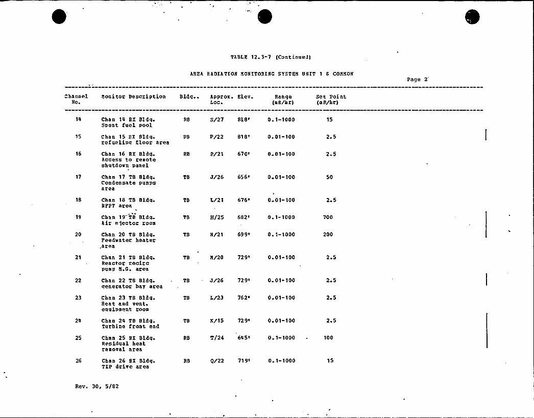
TABLE 12.3-7 (Continued)
AREA RADIATION MONITORING SYSTEM VNZT 1 8 CONNONPage 2
ChannelNo.
Monitor Description Bldg.. approx. Elev. Range Sct PointLoc. (nR/hr) (n R/hr)
14
15
Chan 14 RX Bldq.Spent fuel pool
Chan 15 RX Bldq.rcfuelinq floor area
RB
RB P/22 81 8' 01-100 2-5
S/27 8).8'. 1-1000 15
16
17
18
20
21
22
23
24
25
26
Chan 16 RX Bldq.Access to renoteshutdoun panel
Chan 17 TB Bldqcondensate punpsarea
Chan 18 TB Bldq.RFPT area
k
Chan 19 TB Bldg.A,ir effector roon
Chan 20 TB Bldq-Peedwater heater.area
Chan 21 TB Bldq.Reactor recircpunp N.G. area
Chan 22 TB Bldg.generator bay area
Chan 23 TB BldqHeat and vent.equipnent roon
Chan 24 TB Bldg.Turbine front end
Chan 25 BX BldgResidual heatrenoval area
Chan 26 RX Bldg.TIP drive area
RB P/21 670' 01-100
TB J/26 656' 01-100
TB L/21 676 ~ 0 01-100
TB H/25 682' 1-1000
TB N/21 69 9 ~ 0 1-1000
TB M/20 729'. 01-100
TB — J/26 729' 01 100
TB L/23 762' 01-100
TB K/15 72 9 ~ 0 01-100
RB T/24 645' 1-1000
RB Q/22 71 9' 1-1000
2.5
50
2 5
700
200
2-5
2-5
2 5
2.5
100
15
Rev. 30, 5/82
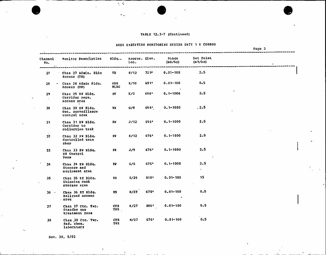
TABLE 12. 3-7 (Continued)
AREA RADIATION HONITOBING SISTER UNIT 1 6 CONNON
Pago 3
ChannelNo.
Nonitor Description Bldq.. Approx. Elev. RangeLoc. (aR/hr)
Set Point(a R/hr)
27 'han 27 Adain. BldgAccess (TB)
TB N/13 72 9' 01-100 2 5
0 5
29 Chan 29 RQ Bldg.Corridor pers.access area
28 Chan 28 Adain BldgAccess (RM)
ADft N/10 691' 01- 100BLDG
RM K/3 64 6 s 0 1-10PP 2 5
30 Chan 30 RM Bldg.Opt. surveillancecontrol area
RM G/8 64 6' 1-1000 .2 5
31 Chan 31 RQ Bldq.Corridor tocollection tank
32 Chan 32 RQ Bldqcontrolled xoneshop
33 Chan 33 Rtf Bldg.RM ControlRoon
Chan 34 BM Bldq.Storaqe andequipaent area
35 Chan 35 RX Bldg.Shippinq caskstorage area
36 ~ Chan 36 RX Bldg.Railroad accessarea
RM J/12 646 ~ 0~ 1-1000
K/12 676 ~ 0 1-1000
RM J/9 676' 1-1000
R'M G/6 676' 1-1000
RB S/29 81 8 ~ 0 01- 100
RB V/29 670 0. 01-100
2 5
2-5
2-5
2 5
15
0 5
37
38
Chan 37 Ctr Ttfr.standby qastreataent roon
Chan .38 Ctr. Ttfr.Rad. chea.laboratory
CTR K/27 806 ~ 0 01-100TMR
CT R N/27 676 ~ 0 0 1-100TQR
0 5
0 5
Rev. 30, 5/82
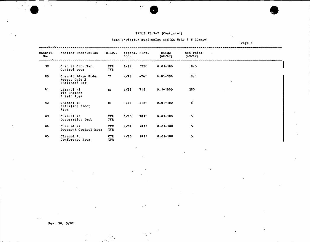
TABLE 12.3-7 (Continued)
AREA RADIATION HONITORING SISTER UNIT 1 8 CONHONPage 4
Charm elNo+
NOnitOr Description Bldg.. Approx. Flev. RangeLoc (mR/h r)
Set Point(m R/hr)
39
40
chan 39 Ctr. Tvr.Control room
Chan 40 Admin Bldg.Access Unit 2(Railroad Bay)
CTRTMR
TB
L/29 729'. 01- 100
H/12 676' ~ 01-100
0 5
0 5
41 Channel 41Tip Chambershield Area
RB P/22 71 9' 1-1000 200
Channel 42Refueling FloorArea
RB P/26 818 ~ 0 01-100
43 Channel 43Observation Deck
CTRTNR
L/30 741' 01-100
Channel 44Document Control Area
CTRTMR
H/32 74 1 ~ 0 01-100
45 Channel 45Conference Roon
CTRTMR
H/26 74 1 I 0 01-100
Rev. 30, 5/82

TABLE 12.3-7 (Continued)
AREA RADIATIOH HONITORIHG SYSTEH UNIT 2 Page 5
ChannelHo
Honitor Description Bldg.. Approx. Elev.Loc.
RangetmR/hr)
Set Point{a R/hr)
Chan 1 RX Bldg.Residual heatremoval area
RB T/31 645'. 1-1000 100
Chan 2 RX Bldg.RCIC puap turbineroon
Chan 3 RX Bldg.HPCI pump andturbine room
RB T/30 645' 1-1000
RB S/30 6'4 5~ 0 1-1000
2.5
2.5
Chan 4 RX Bldg.Radvaste suan area
Chan 5 RX Bldg.Contr. rod driveHvd. Units north
Chan 6 RX Bldg.Contr. rod drivesouth
Chan 7 Off-GasBvpass Line
Chan 8 RX Bldg.Cleanup recircpump access area
Chan 9 RX Bldg.CRD Repair Area
RB S/36 645' 1-1000
RB R/30 71 9' 1-1000
RB R/37 71 9' 1-1000
TB G/33 656' 1-1000
RB R/37 74 9 ~' 01-100
RB 0/35 74 9' 1-1000
15
15
15
15
2.5
2.5
10 Chan 10 RX Bldg.Fuel pool puap rooa
Chan 11 RX Bldg.Sample Station(2C210) Room
RB R/38 749' 1-1000
P/33 779 ~ 0 01-100
200
2 5
12 Chan 12 Recirculation RB U/35Pan Rooa
79 9 ~ 0 1-100 15
13 Cha n 13 RX Bldg.Nev Fuel Area
RB 0/31 799' 01-100 2.5
Rev. 30, 5/82

TABLE 12.3-7 (Continued)
AREA RADIATION NONITORING SYSTEN ONIT 2
Page 7
41 Channel 41TIP ChamberShield Area
RB P/31 719' 1" 100 200
42 Channel 42Refuelinq PloorArea
RB P/34 818' 01-100 2.5
Note: All set points are estimated values. Actual set points may vary depending on operational considerations andvill be determined by measured radiation levels.
Rev. 30, 5/82

SS ES- PS AR
13 2- - TRAINIHG PROGRAN
13 2. 1 PLANT. QE~~SO~~HEL TRAIN~IG. PROGRAH-
The Training Program for the Susquehanna Steam Electric Stationis formulated to develop and maintain an organization qualifiedto assume the responsibility for operation ~ maintenance, andtechnica 1 considerations for the facility. In order toaccomplish these objectives and to provide the necessary controlof the overall plan, three separate training programs listedbelow are utilized:
a. Initial Plant Staff Training Program
b Regualification Training Program, and
c. Replacement Training
The Initial Plant Staff Training Program is designed to producecompetent, trained personnel at "all levels of the. plantorganization. The programs 'are designed to allow placement ofpersonnel into specific levels based on employee experience andintended position.
F
The Requalification Training Program provides continuing trainingfor plant personnel commensurate with their area ofresponsibility.The Replacement Training Program is designed to supply qualifiedpersonnel for the station organization.The Superintendent of Plant may waive portions of the trainingprogram for individuals based on their previous .experience and/orgualifications.
13.2. 1. 1 Pro@ram Descrint'ion.4
13. 2. 1. 1 1 Injtia1 Plagt- Staf f Training-
Figure 13.2-'1 shows the present schedule'for the various InitialPlant Traininq Programs. Should significant differences orchanqes occur in those courses not yet conducted, the appropriatecourse outline and description will be revised by amendment.
REV. 30, 5/82 1 3% 2 1
"SS ES-FS AR
13.2. 1.1.2- Op~ea+ion~Section- Tgyininc{ Pgoggym-,
This program i.s designed „ for. individuals vho. are to assumeresponsibility'or the licensed and non licensed operator-positions and fulfills the general requirements andqualifications set forth 'in ANSX .,818.1-1971. The program is
'tructured,to allow personnel of varying experience and educationto enter the Cold Licensing Traininq Progra~ at, various levelsand still fulfillthe eligibility reguirements for HRC-coldlicensing prior to fuel 'loadinq.
: ~
13,2. 1,1 2 1 -Injti.al Cold~Lcense Tj aing~n
E
C
The program is,desiqned for cold license candidates with noformal power plant experience or training. The prog-ram isdivided into seven phases to ensure proper administration;documentation, and completeness of training.
o
oo
oo
Phase I — Conventional Power Plant Operator- ExperienceProgram.
Phase II — Academic Program for Huclear Power, P1ant..Personnel.
F
Phase IXI — Basic BMRTechnology'o
o. Phase IV — BMR Simulator Training
o. - Phase V — BWR- Observation Training
Phase VI — Systems, Procedures and On'-The-Job 'Training
o. Phase VII — BMR Refresher, Training ',,l
Those plant control operator license candidates with no power,plant experience will participate and qualify in all'seven
'hases,while those with only a conventional power plantbackground will.,participate and, qual'ify in Phases II through VII..Operators, and other staff members, who will be'old licensedwith a nuclear background and/or related acadeiic or technicaltraining will participate and qualify in selected portions ofphases II through. VI and all of Phase VII. '-The 'exterit of theirparticipation in Phases II through VI vill be based on, theirbackground and documented, in station training records.
REV 30r 5/82 13&22
SS ES-PS AR
o Phage= I — Conventional Power Plant Experience P~ro ram
The Conventional Pover Plant Experience Phase of the SusquehannaSES Traininq Proqram is desiqned to provide poser plantexperience to those license candidates vho lack the minimum powerplant experience requirements. This experience vill be providedprior to the start of the formal License Training Program {PhasesII-VII), so that hy the time of the Nuclear Regulatory Commission-Licensing Examination, the candidate- vill have had tvo years ofpower plant experience of which a minimum of one year vill havebeen nuclear pover plant experience. — This program isapproximately one year in duration and includes supervised on-the-gob training in major, operator positions (excluding fossilboiler related positions) at a PPSL conventional power plant.Also included in the one year experience program areapproximately ten weeks of formal classroom training whichincludes but is not limited to the following areas:
Basic Power Plant Operation
Steam Turbine Fundamentals
Power Plant Mathematics
Basic Thermodynamics and Fluid Hechanics
Plant Cycle and Plant Performance
Basic Electrical and Plant Instrumentation
Basic Print Reading
Basic Mater Chemistry
Introduction to Nuclear .Power and Nuclear Plant Systems
o Phase XI - gcgdem~cPgo~gam fog~uclear-Powe~Plant Personnel
This course is conducted by the General Physics .Corporation ofColumbia, Maryland. It is designed to refresh basic coursesreceived in high school and to acquaint those personnel, vithlittle or no nuclear backqround, with nuclear phenomenon and theBWR concept as they apply to practical reactor technology. Thecourse material and the approximate number of classroom hoursallotted to each ma ]or topic are as follovs:
REV 30, 5/82 13&23
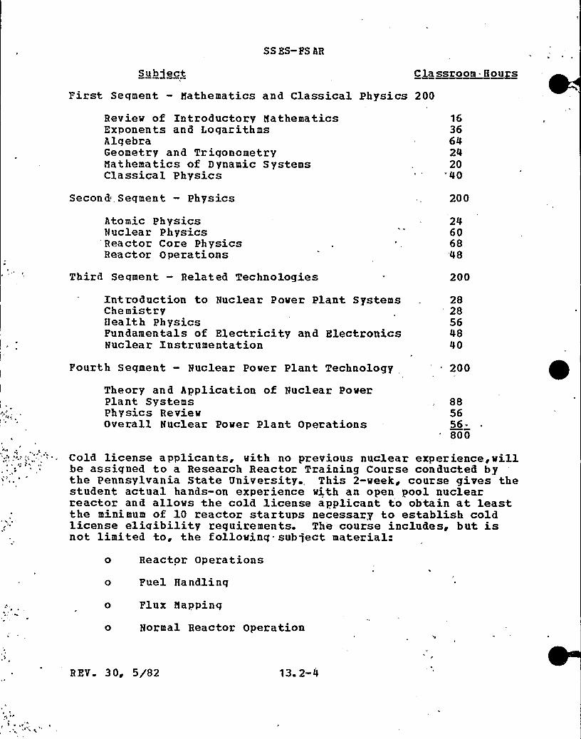
SS BS-PS AR
Subiect Classroom. H~ou s
First Seqment — Mathematics and Classical Physics 200
Review of Introductory MathematicsExponents and LogarithmsAlgebraGeometry and TriqonometryMathematics of Dynamic SystemsClassical Physics
163664242040
Second Segment — Physics 200
Atomic PhysicsNuclear PhysicsReactor Core PhysicsReactor Operations
24606848
Third Segment — Related Technologies 200
Introduction to Nuclear Pover Plant SystemsChemistryHealth PhysicsFundamentals of Electricity and ElectronicsNuclear Instrumentation
28'8564840
Fourth Segment — Nuclear Pover Plant Technology 200
Theory and Application of Nuclear PoverPlant SystemsPhysics RevievOverall Nuclear Power Plant Operations
885656-800
Cold license applicants, with no previous nuclear experience, villbe assigned to a Research Reactor Training Course conducted bythe Pennsylvania State University., This 2-week, course gives thestudent actual hands-on experience with an open pool nuclearreactor and allows the cold license applicant to obtain at leastthe minimum of 10 reactor startups necessary to establish coldlicense eliqibility requirements. The course includes, but isnot limited to, the follovinq subject material=
0
0
0
Reactor Operations
Fuel Handlinq
Flux Mapping
Normal Reactor Operation
R EV 3 Og 5/82 13. 2-4

SS ES- PS AR
o Instrumentation Effects
o Control Rod Calibration
o Laboratory Demonstrations, and
o Control Transient Effects
o Phase III---Basic. BMR Technoloav-
The Basic BUR Technology course is desiqned to impart the detailsof the BMR nuclear'steam supply system to the operator trainees.
The course consists of approximately 5 veeks of classroom lectureon BMR nuclear steam supply system components, fuel description,thermal-hydraulics, radiation monitoring and nuclearinstrumentation system operations.'mportant interfaces vith thebalance of plant systems are also taught.
The lectures are presented by GE BQR Training personnel usingconventional classroom techniques. Classes are scheduled forapproxmately 7 hours per'ay and suggested study assignments arenormally made daily. Progress is measured by veekly vritten andfina 1 co m pre he nsi ve e xam ina tions.
It is anticipated that the course material covered vill be asfolio ws.
Schedule changes and adjustments to course'ontent vill be madeas necessary to meet the particular needs of the students
Meek 1
Introduction to CoursePlant OrientationReactor Principles ReviewReactor Vessel and InternalsBWR Thermal Hydraulics RevievFuel DescriptionNuclear Boiler Instrumentation
Week 2
Examination 1
Control .Rod Drive MechanismControl Rod Drive Hydraulic SystemRod Control and Information SystemRod Pattern Control SystemRecirculation SystemRecirculation Plov Control SystemReactor Water Cleanup System
BE V. 30, 5/82 13. 2-5

SSES-PSAR
Source. Range Nonitorinq SystemIntermediate Range Monitoring SystemLocal Power Range Monitoring -SystemAveraqe Power Range Monitoring System
Week 3
Examination 2Traversing In-Core Probe SystemMain'team SystemReactor Pressure Control (Electro-Hydraulic 'Cont'rpl)Feedwater Control SystemReactor ProtectionContainment and Related SystemsIntroduction to Radvaste Systems(Off Gas,Liquid and Solid Radwaste)
'I
Week 4
Examination 3Introduction to Electrical DistributionReactor Core Isolation SystemIntroduction to Emergency Core Cooling'-SystemHigh Pressure Core Spray SystemAuto Depressurization SystemLow Pressure Core SprayResidual Heat Removal System and Hot Standby OperationEmergency Core Cooling Systems Integrated- Resp'onse'Standby Liquid Control SystemProcess Radiati'on NonitorinqArea Radiation Monitoring
Week 5
Examination 4Performance Monitoring SystemBWR MaterialsBQR ChemistryPuel Pool Coolinq SystemReactor RefuelingPlant OperationsTransient AnalysisReview
Final Examination
REV. 30, 5/82 13. 2-6

SS ES-PS AR
o Phase IV --BMR Simulator Trainina4
The BMR simulator course is taught at the General Electric BMRTraininq Center, Norris, Illinois, and is designed to provide theoperator trainee with the skills necessary to safely operate alarqe Boilinq Mater Reactor pover plant.The course consists of approximately 12 veeks of classroomlectures, simulator control room exercises, and in-plant oralseminars. This combination of instructional techniques affordsthe optimum mixture for successful skill training. The final:examination consists of written, control room performance, andplant oral examinations.
Lectures and exercises are presented and guided hy qualified, GEBMR Training Personnel. Classroom lectures are scheduled forapproximately 8 teaching hours per'ay. Suqgested reading andstudy assiqnments are made daily; written examinations are givenweekly to monitor progress. In addition', at 'approximately themid-point of the course, oral examinations are given to monitorthe progress of each student's'skill acquisition.'he controlroom portion of the course is normally accomplished on nightshifts of 8 hours . Pour hours are spent in the simulatorcontrol room (total approximately 112 hours) with exercises anddemonstrations guided by the licensed instructor. The other 4hours are devoted to oral seminars . Each student rotates toappropriate control room operatinq positions, including shiftsupervisor, so that all personnel have equal opportunity toperform plant evolutions from each operating position.The following is an anticipated'eek-by-week schedule of thecourse. Schedule changes and adjustments to course content willbe made as necessary to meet the particular needs of thestudents.
Meek 1
Introduction to the BMR Training CenterReactor Vessel and InternalsReactor FuelNuclear Boiler InstrumentationControl Rod Drive NechanismControl Rod Drive HydraulicsReactar Manual ControlRecirculation SystemRecirculation Flow ControlReactor Water Cleanup SystemShutdown Coolinq and Head SpraySource Range Nonitoring (SRN)Intermediate Range Monitoring (IRM}
REV 30, 5/82 1 3w 2 7
SSES-FS AR
Local Power Range Nonitoring (LPRN)Averaqe Power Ranqe Nonitorinq (APRN)Rod Block Nonitor
Meek 2
Week l ExaminationTraversing In-Core Probe {TIP)Rod Worth Minimizer (RWN)5ain SteamTurbine and Lube Oil SystemElectro-Hydraulic Control System (EHC)EHC Pressure Control and LoqicCondensate and FeedwaterFeedwater ControlCirculatinq WaterGenerator and AuxiliariesGenerator ExcitationAC Electrical DistributionDiesel Generators and DC Electrical DistributionReactor Protection System (RPS)Primary and Secondary Containment
Week 3
Week 2 ExaminationFuel Pool Coolinq and"Cleanup A
Off Gas SystemLiquid RadwasteWater SystemsIsolation CondenserIntroduction to Emergency Core Coolinq System (ECCS)High Pressure Coolant Infection (HPCI)Automatic Depressurization System (ADS)Low Pressure Coolant Injection {LPCI)Core SprayEmerqency Core Cooling System .Integrated ResponseStandby Liquid ControlProcess Radiation NonitorinqArea Radiation NonitorinqReactor Physics Review
Week 4
Pre-Start and Functional ChecksReactor StartupsHeatupsNanipulation of Auxiliary SystemsPower Changes in the Intermediate RangeSurveillance TestinqTransfer to Run Node
R EV. 30~ 5/82 13 2-8
Turbine Warmup and Roll
Reek 5
SSES-PSAR
Reactor Heatup and Transfer to Run ModeTurbine RollGenerator Synchronization and LoadingSurveillance TestingContinued Loading to 100% PowerOperations at Pull PowerTra nsient AnalysisQuiz 1
Maneuvering by Plow Control'eactorShutdown
Discussion on Decay Heat Operation and RemovalPlant ProblemsDrills on Abnormal and Emergency Conditions
Meek 6
Pre-Startup and Punctiona'1 ChecksReactor Startups and HeatupsManipulation of Auxiliary SystemsPlant ProblemsDrills on Abnormal and Emergency ConditionsPower Changes in the Intermediate Range.Surveillance TestingTransfer to Run ModeTurbine Warmup and RollOperator Synchronization and LoadingQuiz 2Mid-Course Performance Examination
Meek 7
Technical Specificatons Bases ReviewReview Certification Exam Format and ContentPhysics Problem SolvingMid-Course Control Room ChecksSolid RadwasteHealth Physics ReviewBMR
Chemistry'hermal-Hydraulics
Process ComputerCircuit Breaker ControlFuel Handling and Puel Loading Physics
3 0, 5/82 13 2-9
SSES-FSAR
Week 8
Steady-State Operation at 50% LoadSurveillance TestingIncrease to Full LoadDrills on Abnormal and Emergency ConditionsOperations at Pull PowerManeuvering by Flow ControlBegin Reactor ShutdownReactor Shutdown and CooldownFlooding of Reactor VesselPlant. ProblemsReactor Startups and HeatupsScram and Scram Recoveries
Week 9
Operation at Full LoadDrills in Abnormal and Emergency Conditions.Shutdown to Hot StandbyQuiz 3Plant Startup from Hot Standby to Full PowerReactor HeatupGenerator Synchronization and Loading
Week 10
Operation at 50% LoadScrams and Scram RecoveriesSurveillance TestingOperation at Full PowerDrillsIndividual Student OperationsQuiz 0Transient Analysis Review
Week 11
Review and StudyReactor Operator Certification Examination
Week 12
Control Boom and Dresden Plant Oral ExaminationControl Boom Performance DemonstrationSenior Reactor Operator Certif ication Examination
REV 30'/82 13 2-10
,SS ES-FSAR
o, Phase V — BQR Observation Traininn~4 ~
BMR observation training is designed to acguaint the operator,trainee with. the day-to-day routine of an operating BWR. Thiswill involve exposure to plant operating and maintenanceevolutions, station record keeping, and procedures.
The course consists of approximately 4 weeks of guidedobservation of an operating BMR. All observation is conducte'dunder the guidance of an experienced GE training.-personnel.
The course is structured to provide experience in various aspectso f plant operation. The - flexibility is achieved. by allowing thecourse director to adjust the group schedule to'it importantplant evolutions. Daily work and observational assignments aremade at the beginning of each work. day.. - .
The followinq are weekly highlights of a'ypical.BWR observationschedule:
Meek 1
Plant Evacuation Procedures/Station Emergency Plan,Health Physics ProceduresElectrical DistributionReactor InstrumentationControl Rods and Hydraulic Drive SystemRecirc MG set, support systems,'nd controlsMain Steam System Controls and InstrumentationResidual Heat Removal System= — All Modes
Meek 2
Turbine, EHC System, and Turbine. Support Systems.Generator, Generator Excitation, and Generator Support SystemsTurbine and Reactor Building Closed Cooling Water SystemCircula tinq and Service Water SystemsFire Protection SystemsCore Spray System
Meek 3
High Pressure Coolant Injection SystemRea'ctor Core Isolation Cooling SystemReactor Protection MG sets,Automa tic Depressurazation SystemTra versinq In-core Probe SystemNeutron Monitorinq and 'Associated Control SystemsRadioactive Waste Handling Equipment and ProceduresPerformance of Routinq Plant Equipment Checks
REV. 30, 5/82Y
13. 2-11

SSES-FSAR
Meek 4
Instrument and Service.Air SystemsProcess and Area Radiation Monitoring SystemsFuel Pool Cooling SystemStandby'iquid Control SystemPlant Performance LogsObservance of Routine Plant and/or Surveillance Procedures
In ProgressReviewFinal Exam and Haik-Through
o +Pa~g VI — SYSTEMS PROCEDURES and DOTH/-JOB. T8hINING-
The systems, procedures, and on-the-gob training phase will beapproximately 20 weeks in length of which a minimum. of 8 weekswill he class room instruction. However, the weeks may'' not bescheduled consecutively due to plant testing and work, load,considerations. This phase will provide cold license candidateswith an in-depth study of Susquehanna SES systems and equipment;nuclear characteristics; and Normal, Abnormal, Emerqen'cy andAdministrative Procedures and Technical Specifications. Furtheroperational training is accomplished as components, systems, orparts of systems are checked, tested, and placed in routineoperation to provide necessary auxiliary support for othersyste ms.
Instructors for the various Phase VI lectures will be supplied bythe Susquehanna staff, other PPSI.,organizations, vendors orconsultants. Selections of the particular indivi.dual to "conducta specific training lecture will be based upon individualavailability and knowledge of the subject matter involved
The course will consist of, but not be limited to:a. Theory and principles of operations
b. General and specific plant operatinq characteristicsc. Plant instrumentation and control systems
d. Plant protection, safety and emergency systems
e. Normal, abnormal and emergency operating procedures
f. Radiation control and safety
h.
Technical SpecificationsApplicable portions of Title 10, Chapter l, Code ofFederal Requlations
REV 30~ 5/82 13. 2-12
SSES-PSAR
i. Reactor Theory
j. Handlinq, disposal and hazards of radioactive materials
k. Puel handling and core parameters
l. Administrative procedures, conditions and limitationsA comprehensive examination vill be given during this phase todetermine student weak areas.
o Phase.VII -= BWR pre License Refresher Tgaini~n,.
Prior to the initial NRC Operator Licensing examination, a Pre-License Refresher Course will be conducted. This course vill bepresented by PPSL employees or by outside personnel, and will bea summary and review of material presented in previous phases.Xf necessary an update of plant modifications and training toupqrade any identified weak areas will be. presented.
13.2. 1. 1.2. 2 lion-Licensed Ope~ator -Traini ng pgoqram
The proqram is designed for non-licensed, operators and is dividedinto three phases which provide a logical progression from theentry level to final job qualificat ion
o. Phase I — Academic Training
o. Phase II — Susquehanna SES System'ectures
o. Phase III — Susquehanna SES System'ualificati,onThis traininq is progressive and candidates for non-licensedpositions must successfully complete the training appropriate totheir assiqned job. Phase I *may be exempted bypassing a vrittenexam.
0- Phase I: The course consists of basic training in NuclearPower Plant. Fundamentals. The program is about 160 hours.long and consists of classroom training or equivalent self-study time. The areas to be covered will include suchsubjects as math, chemistry, atomic and,nuclear physics,health physics, nuclear instrumentation and reactoroperations. Progress is measured by periodic quizzes andexa minations.
REV. 30, 5/82 13 2-13

SS ES- FS AB
0 Phase II — The phase consists of basic lectures onSusquehanna SES systems and covers, as applicable, thefollovinq areas of each system:
General System DescriptionMajor Components and Flov PathsInstruments and Controlsalarms and TripsPower FeedsOperatinq and Emergency Procedures
The phase vill be approximately 0 veeks in length and duringeach week, approximately 80% of the time vill be spent inclass and the remaining 20% vill be spent in the planttracing systems. There vill be weekly guizzes and a finalexam at the end of tQe course.
o Phase III — This phase must be completed by operators on thesystems for vhich they are responsible. This phase willtake about 10 weeks to complete.. However, the 10 weeks maynot be consecutive due to work-load considerations Operatorswill be checked out on each system to assure they canoperate these systems under normal, abnormal, and emergencysituations. The check out vill consist 'of an oral 'and/orvritten test on each system.
The Supervisor of Maintenance will receive training Level IIIHealth Physics training as described in Subsection 12.5 3.7,selected training in plant systems operation and 'speciaalizedvendor traininq on specific plant equipaent.
t
'Foremen will receive additional experience on-.'the-gob during thepreoperational test program through the supe'rvision of,
. maint ena nce activities.Station Mechanics and Leaders for the initial,plant staff willgenerally be selected from other PPGL facilities and will havepractical experience in one or more crafts, and vill throughtheir previous experience and/or selection testing demonstrate ahiqh degree of manual dexterity and capability of learning and-applying the basic skills in maintenance operations.
I
Maintenance personnel vill receive on-the-gob training during thepreoperational test proqram by performinq. maintenance activities.Selected personnel will receive specialized. vendor tr'aining onspecific equipment or skills such as control rod drive repair andwelding.
RE V. 30, 5/82 13 2-.14

SSES-PS AR
Maintenance personnel requiring access to Radiation cwork PermitAreas will receive Level IX Health Physics training as describedin Subsection 12. 5. 3. 7.
13 2. 1. 1.4= Technical Section Trainina Proaram
The objective of the initial training program of the TechnicalSection is to provide competent personnel to support in the safe,efficient operation of the Susquehanna SES.
Selected supervisory and professional/technical personnel willattend GE's Design Orientation courses (or other formalinstruction with a similar intent) to familiarize them with .thedesign principles of a BMR. The ma)or topics covered willinclude BWR components, core desiqn, thermal-hydraulics, processand nuclear instrumentation design and operation and auxiliarysystems.
13 2.1.1 4.1 Chemistry Pegsognel.
By initial fuel loadinq, in addition to those courses describedin Subsection 13.2.1.1.4, selected chemistry supervisorypersonnel will receive specialized training through a coursesuch as»BMR Chemistry" offered by GE. The course enablesstudents to complete both radiological and chemical analyses -forprocess control, waste disposal, effluent monitoring, process andlaboratory instrument calibration and evaluation. The coursealso covers compliance with and =interpretation of chemical andradiochemical aspects of the technical specifications, licensesand plant warranties.
The Chemistry Leaders and Chemistry Analysts will receive iz-house traininq as developed by supervisory chemistry or otherappropriate personnel, covering topics similar to those in. the»BMR Chemistry" course. As appropriate, they may also attendvendor-sponsored training sessions to assure understanding andproper operation of laboratory instruments. Progress will bemeasured through oral and/or written examinations.
13. 2. 1~1. 4 2 - Inyfgumentafion 8 Control Personnel
By initial fuel loading, in addition to those courses describedin Subsection 13.2. 1 1. 4, appropriate ISC supervisory personneland selected ISC technicians will attend the GB "Nuclear
REV. 30, 5/82 .13. 2-15
SS ES-FS AR
Instrumentation" and "Process Instrumentation and.Controls"courses or other formal instruction with similar intent.The "Nuclear Instrumentation" course is broken into classroom andlaboratory phases. The classroom phase covers the theory ofoperation and equipment demonstrations for the GE BIR nuclearprocess and area radiation monitoring, control rod positioninformation, reactor protection and traversing incore probesystems. The laboratory phase teaches detailed circuitry study,setup, calibration, testing, maintenance and repair for .thevarious components of these systems and where possible for theoverall system.
The "Process Instrumentation and Control<. course teaches thetheory of operation, setup, calibration, testing, maintenance andrepair techniques for the basic instrumentation and control loopcomponents for the GE BWR. Components to be covered includelevel, temperature, electrical properties, movement, chemicalproperties, sensinq devices, transmitters, power supplies, signalcondi tioninq modules and controllers. Primary instrument controlloops will also be studied.
ISC technicians will also receive training covering topics suchas AC/DC circuit fundamentals, transistor circuits, solid statedevices and operational amplifiers and including "hands-on"experience with electrical and electronic circuits andcomponents. As necessary, ISC personnel will attend coursesoffered by equipment vendors on various plant components.
Progress will be measured throuqh oral and/or, written-examinations.
By initial fuel loading, in addition to the courses described inSubsection 13.2. 1.1.4, selected Reactor Engineering. personnelwill receive traininq through a course such as GE's "StationNuclear Enqineerinq". The course covers topics like reactorbehavior, control rods, shutdown margins, technicalspecifications and Fuel Barranty Operation Provisions, core flowand thermal limit calculations, fuel failure and PCIONR and waterchemistry among others.
Proqress will be measured through oral and/or writtenexaminations.
REV 30'/82 13 2-16
SS ES- PS AR
'13,2,1.1. 5 Health physics Tnainj nH~Hno Haa
Selected Health Physics supervisory personnel will receivespecialiezed professional traininq in a course such as«Radiological Enqineerinq«offered by GE or equivalent.Health Physics Monitor Training Program is described inSubsection 12. 5.3.7.
13.2. 1 1.6 General Fmplo~ee Training-
All permanent plant personnel granted unescorted vital areaaccess at the station will be trained in the following areas:
1. Appropriate plans and procedures, including applicableplant security and emerqency procedures.
2. Radiological Health and Safety in accordance -with-Subsection 12.5.3.7
3. Industrial Safety.
4. Fire Protection Proqram.
5. Quality Assurance Program.
This training will be the responsibility of the Plant TrainingSupervisor and will be repeated on a two-year cycle. Personnelwill be examined in the above areas to determine theeffectiveness of general employee training.Temporary Maintenance and Service personnel will be trained inthe areas listed to the extent necessary to assure safe executionof their duties.
13 2. 1- 1 7 ~ Fige Saf et'raining"
The object of the fire safety training proqram is to providetraining for the plant fire brigade, traininq for maintenance andinspection of fire protection equipment and training for the fireprotection staff.
REV. 30, 5/82 13e 2 17

SS ES-PS AH
13. 2. 1 1.7. 1 Fire Briqade - Training
In addition to qeneral employee training, individuals. assiganed tofire fightinq duties will receive training in order that aneffective fire fiqhtinq brigade vill be available for fireemerqencies. FIre brigade training sessions will be held aminimum of four times per year, with the basic program-;-'heingrepeated every t wo years. Tra ining will be. a blend of classroom,sessions, practice sessions and fire' ighting drills. -Pirebrigade members will receive instruction on fixed and 'portable .
fire,fiqhhtinq equipment,, fire protection measures of other plantfeatures and will be trained in hands on experience with firefiqhtinq equipment and,techniques. The local fire departmentswill be invited and encouraged to participate in'=at least
one'raininqsession per year'.'
i~ I
13,2,1. 1,7,2- Pi~e protection St~af -and Tgaini~n
No traininq proqram is planned for the off site fire. protection ~"''
engineer. The position description requires that 'the incumbentbe a qualified fire protection engineer with / suitable'-backgroundexperience to meet the gob requirements-. 'A major part of 'the onsite fire protection engineer~s training will.be- on the gobtraining and informal discussions with the off site fireprotection enqineer. This training,vill'be augmented. by vendortraininq schools and state fire fighting schools as n'ecessary /tocarry out the job responsibilities. The on site fire protection.engineer will have the responsibility of training or arrangingfor the traininq of fire briqade personnel, on site firedepartment traininq and traininq of personnel in charge of themaintenance of fire detection and fire suppression systems..
/
1g 2. 1.2- . Coordigation -with"pgeoperational Tests and Fuel Loadi~n
' /
K
Figure 13.2-1 illustrates the relationship of the Plant StaffTraining to preoperational testing and Tuel.loading.
/
R EV. 30, 5/82 13 2-18
SS ES-PS AR
13 2 2 ~ROQQI PICQTXON AgQ gggLAC~NENT TBQXMINGP
R
13.2". 2 1 "Licensed-O~~eat~o gegualification'-P o ram-I
II
The Requalification. Program for licensed and senior licensedindividuals will'.be. established and ready for implementation no.later than 3. months followinq issuance of the station operatinglicense. The program consists of lectures, plant. operationalevolutions, simulator activities, drills,.evaluations, self-study,. and tests. A minimum of'"40 hours of simulator .trainingwill be scheduled each year. ,The program is based on a 2 yearlicense renewal cycle with periodic quizzes, 'written tests, andannual simulator and oral examinations administered throuqhout toensure training effectiveness and technical competency.
N
13.2 2.1.1 "Lectures
Licensed -operators will be reguired to attend classroom lectureson the f'ollowing subjects annually:
Reactor Theory and Principles of Reactor OperationPeatures of Pacility DesignGeneral and Specific Plant Operating CharacteristicsInstrumentation and Control SystemsProtection SystemsEmergency Core Cooling Systems,Radiation Control and SafetyTechnical SpecificationsCode of Federal RegulationsHeat Transfer and Fluid PlowDesiqn, Procedure, License ChangesRecent LEBs, Industry Events, Plant ActivitiesGeneral and Emerqency Procedure Reviews
Pailing to attend a scheduled lecture, an operator will berequired to achieve mastery of this material prior to theexamination. This achievement can be accomplished by attendinganother lecture if scheduled: or by satisfactorily taking andpassing a quiz on the subject.
REV 30, 5/82 13 2-19
SS ES-PS AR
13. 2. 2.1.2 Plagt Operational Evolutions
Each individual shall perform or participate in a combination ofat least 10 reactivity control manipulations either in the plantor on the simulator. The followinq control manipulations andplant evolutions are acceptable for meeting the ten reactivityrequired by 10CPR55, Appendix A. The use of the TechnicalSpecitications should be maximized during the simulator controlmanipulations. Personnel with senior licenses are credited withthese activities if they direct or evaluate control manipulationsas they are performed. These items should be signed off hy ShiftSupervisor or Instructor. The asterisked items shall heperformed annually.
Performance Item
(1) Plant or reactor startups to include a range thatreactivity feedback from nuclear heat addition isnoticeable and heatup rate is established.
(2) Plant shutdown.
(3) manual control of feedwater during startup andshutdown.
{0) Any siqnificant (>10%) power changes in manual rodcontrol or recircula tion flow.
{5) Loss of coolant.(a) Inside and outside primary containment.(h) Larqe and small, includinq leak-rate determination.
(6) Loss of instrument air.(7) Loss of electrical power (and/or degraded power
sources) .
(8) Loss of core coolant flow/natural circulation.
(9) Loss of condenser vacuum.
(10) Loss of ser vice water.
~(11) Loss of shutdown coolinq.
(32) Loss of component cooling system or cooling to anindividual component.
(13) Loss of normal feedwater or normal feedwater systemfailure.
R EV. 30, 5/82 13. 2-20
SS ES- PS AR
(14) Loss of all feedwater {normal and emergency) .
(15) Loss of protective system channel.
(16) Nispositioned control rod or rods (or rod drops).
(17) Inability to drive control rods.
(18) Conditions requiring use of standby liquid controlsystem.
{19) Fuel cladding failure or high activity in reactorcoolant or offqas.
(20) Turbine or qenerator trip.(21) Malfunction of automatic control systems(s) which
affect reactivity.(22) Nalfunction of reactor coolant pressure control system.
(23) Reactor trip.(7Q) Hain steam line break (inside or outside containment).
{25) Nuclear instrumentation failure(s).(26) Any reactor power chanqe of 10 percent or greater where
load chanqe is performed with load limit control.
13 2. 2. 1. 3 Operator Proof iciencg Evaluations
At least once per year durinq the term of an individual'slicense, he vill be observed and formally evaluated whilerespondinq to actual or simulated casualties. Zn the case ofsimulated casualties, a hypothetical situation would be presentedfollowed by a discussion of plant and operator response. Thesimulator will be used as the ma5or basis for operatorproficiency evaluation, actual manipulation of plant controls isnot required. A poor performance is defined as not being able tocompetently and expeditiously perform the specified evolution.This will result in the implementation of a performance Review asspecified in Subsection 13. 2. 2.1. 5. All evaluations will becritiqued with the, individual concerned and filed in theindi v idual ' t raininq records.
RE V. 3 0, 5/82 13 2-21
SS ZS- FS AR
13.2 2 1 4 Tests
(a) Periodic quizzes will be administered during and/orafter each lecture series to monitor programef fectiveness.
{b) Comprehensive written tests which are similar in scopeand difficulty to the NRC exam will be givenperiodically and will cover the following topics over a2 year period:
1)2)3)4)5)6)7)8)
9)
Theory and Primciples of OperationsGeneral and Specific Plant Operating CharacteristicsPlant-Instrumentation and Control SystemsPlant Protection SystemsNormal, Abnormal, and Emergency Operating ProceduresRadiation Control and SafetyTechnical SpecificationsApplicable Portions of Title 10, Chapter 1, Code ofFederal RegulationsThermal Hydraulics, Heat Transfer, and Fluid FlowTraininq.
To successfully complete this exam, the license holder must scoregreater than or equal to 70 percent on each quarterly exam andqreater than or equal to 80 percent average over the two yearperiod. Any license holder who scores less than 80 percentaveraqe overall or less than 70 percent on any test will receiveaccelerated upgrade traininq and a re-examination will beadministered within 2 weeks. If the re-examination is failed thelicense holder shall be removed from license duties immediatelyand the Performance Review Proqram per 13.2.2.1.6 shall beimplemented.
13.2. 2. 1. 5 Performance Review Program
The Performance Review Proqram shall be implemented whenever anyone of the followinq situations occurs. During such reviewproqrams the individual shall not perform any license dutiesuntil the individual has been properly evaluated and judgedcompetent.
{a) The quarterly examination score of less than.70 percentor less than 80 percent average during the 2 yearlicense period.
(b) <Poor" rating on operator proficiency evaluation.
R EV. 30, 5/82 13. 2-22
SS ES- FS AR
(c) Pv'olonqed absence from license duties.
The Superintendent of Plant, Supervisor of'Operations, andManager Nuclear Traininq will meet to determine a course ofaction necessary to upgrade the individual's performance to anacceptable level. This reviev shall determine the minimumrequirements on an individual basis. The nature of the actiontaken vill be dependent on such factors as examinationperformance, operatinq perf ormance, observed operational andtheoretical understandinq and overall operator competence.
Shen receiving less than 80 percent overall average or less than70 percent on any test, an oral examination may be administeredto determine vhether or not an individual may resume licensedduties. However, the individual shall remain on the PerformanceReview Proqram until a score of greater than 70 percent orareater than 80 percent averaqe is obtained on a vrittenexamination which specifically covers those areas of the examwhere the licensee receives less than satisfactory marks.Management will complete a performance review summary vhich, uponcompletion, vill be filed in the individual s training folder.
13.2.),t.6 Pgogonged gbsence Prom license Responsibilities
In the event a licensed individual is absent from the site for aperiod of four months or lonqer, he vill not be permitted toresume operational responsibilities until the following criteriahave been met:
fa) The satisfactory completion of an upgrading programdetermined'nder the provisions of Subsection 13.2. 2.
1) This proqram shall include as a minimum, thereview of any facility desiqn, operatinq procedureor license changes which have taken place duringthe absentee period.
2) The individual must receive greater than or equalto 70 percent on a written or satisfactory on anoral exam covering the material in item 1 above.Mhen an oral exam is used, it shall beadministered by the Supervisor of Operations ordesignated senior licensee.
(b) This certification shall be documented in theindividual s traininq record.
R EV. 30» 5/82 3& 2 23

SS ES-PS AB
13. 2. 2. 1. 7 - Record pete nt ion
The Manaqer-Nuclear Training vill be responsible for maintaininglicense holder requalification training records. Records of therequalification program shall be maintained to document eachlicensed operator's and senior operator's participation in therequalification program. The records shall contain copies ofwritten examinations administered, the answers given by thelicensee. results of evaluations and documentation of anyadditional traininq administered in areas in which an- operator orsenior operator has exhibited deficiencies. Records shall bemaintained for the duration of the unit operating license.
13.2. 2.1 8 Licensed Staf f Participation
Licensed staff personnel participate in the following areas ofthe requalif ication program:
(a) Complete the quarterly written examination andparticipate in the lecture series based on the results.
(b) Manipulate the controls or supervise the manipulationof controls through 10 reactivity chanqes.
(c) Review day-to-day changes in the facility designprocedures, and technical specification.
(d) Review abnormal and emergency procedures annually.
(e) Are evaluated regarding actions to be taken duringsimulated abnormal and emerqency conditions by awalkthrouqh of the applicable procedure.
13. 2. 2. 2 Re fresher Traininq for NonlicensedPersonnel
As a minimum, all non-licensed personnel shall receive refresherinstruction on administrative, radiation protection, emergencyand security procedures once every two years.
13.2. 2.2.1 Refresheg Training for Nonlicensed ~Oerators
Nonlicensed operators assigned on shift will participate in arequalification program and be trained, tested, and evaluated ona two year schedule.
RZV 30, 5/82 13. 2- 24
SS ES-FS AR
13 2,2 2,2 Refgesh~e Tggining fog Maintenance Personnel
A retraininq proqram is provided for maintenance personnel toensure t.hat they remain proficient in their particular gob..
Retraining in specific areas is provided to the extent necessaryfor personnel to safely and efficiently carry out their assignedresponsibilities in accordance with established policies andproce dur es.
Such training may consist of vendor presentations, technicaltraininq sessions, on-the-gob work experience or programmedinstruction. Maintenance personnel are evaluated on an annualbasis where individual needs for retraining will be identified.
13. 2. 2. 2 3 Refresheg Training fog Technical Section Personnel
Refresher 'courses will be provided to maintain an individual'slevel of expertise equal to or exceeding that, required by his orher job responsibilities.
13.2 2.3 Reolacement Training
Replacement traininq is desiqned to supply qualified personnelfor all levels of the plant organization. It is the policy ofPPGL to promote qualified personnel into job vacancies fromcandidates that are next in the line of promotion. Suchindividuals" will receive traininq appropriate to the newposition. Permanent replacement personnel procured from othersources will meet or exceed the requirements of the vacantposition.
13.2.2.3.1 NRC Licensed Ooerator Replacement
Throuqh a system of required operator qualification steps,personnel assigned as nonlicensed operators are provided trainingthat prepares them for eventual NRC licensed operator positions.At such time as a need exists for replacement of licensedoperators, individual preparation in theory, systems, operatingprocedures, emergency procedures, and health physics isconducted. Additionally, individual on-the-gob traininginvolvinq manipulation of the nuclear reactor plant controlsduring day-to-day operation, startups and shutdowns of thereactor or appropriate reactor simulator, is conducted.
R R V. 30, 5/82 13. 2-25
SS ES-FS AR
Progress is reviewed as the replacement moves through theprogram. The reviev consists of periodic vritten and/or oralexaminations.
13 2. 2.3.2 Non-licensed Operator Replacement Training
Replacement traininq is designed to insure fully qualifiedpersonnel for all levels of plant operation. To the extentpossible, persons who have already achieved the level of trainingrequired for a specific gob will be advanced. In all cases therequirements of Subsection 13. 2.1. 1.2.2 or equivalent will besatis fied.
13. 2. 2.3. 3 Naintenagge Personnel Replacement Training
Replacement training is designed to supply qualified personnelfor all levels of the Haintenance orqanization. It is the policyof PPGL to promote qualified personnel into job vacancies forcandidates that are next in the line of promotion. Permanentreplacement personnel will meet or exceed the requirements of thevacant position by virtue of previous education and experience.The Maintenance orqanization is specifically intended to providethe opportunity for personnel in lover level gobs to receive on-the-job-traininq that will prepare them for advancement.
The same quality of traininq provided for the original staff willbe provided to personnel desiqnated to fillvacancies in themaintenance organization.
13. 2. 2.3.4 Tgchn ical Sec(ion Personnel Replacement Traini~n
Replacement traininq is designed to assure fully qualifiedpersonnel for all levels of the Technical 'Section. To the extentpossible, persons who have already achieved the level of trainingrequired for a specific job will be advanced. In all cases therequirements of Subsection 13.2.1.1.4 or equivalent will besa tis fied.
13 2.2 4 Records
Traininq records are established for each permanent plantemployee. These records include, but are not limited to,lecture/annual examination questions and answers, lecture
RP V 30r 5/82 13. 2-26
SSES-PS AR
attendance records, performance evaluation records, and otherrecords as may be required to adequately document all trainingreceived bv station personnel.
Training records vill be periodically reviewed in accordance withstation procedures.to assess the effectiveness of the trainingproqram.
13.2.2.5 Responsible Individual
The Plant Traininq Supervisor is responsible for theadministration and conduct of the Susquehanna SES trainingproqram.
REV 30, 5/82 13 ~ 2 27
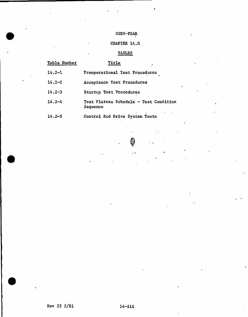
SSES-FSAR
CHAPTER 14,.0
TABLES
Table Number
14.2-1
14.2-2
14.2-3
14.2-4
Title
Preoperational Test Procedures
Acceptance Test Procedures
Startup Test Procedures
Test Plateau Schedule - Test ConditionSequence
14.2-5 Control Rod Drive System Tests
Rev 23 2/81 14-iii
SSES-FSAR
CHAPTER 14.0
FIGURES
Fi ure Number Title
14 . 2-1
14. 2-2a
14.2-2b
14.2-3
14.2-4a
14.2-4b
Integrated Startup Group Organization
Preoperational Test Procedure Standard Format
Startup Test Procedure Standard Format
Initial Test Program Schedule
Unit 1 Preoperational Test Sequence
Unit 2 Preoperational Test Sequence
14.2-5 Sh. 1 Individual Startup Test Sequence
14.2-5 Sh. 2 Individual Startup Test Sequence
14.2-6 Sh. 1 Power Flow Map and Startup Test Conditions
14.2-6 Sh. 2 Power Flow Map and Power Test Conditions
Rev 23 2/81 14-iv
SSES-PS AR
14 2 SPECIPIC INFORHATIOR TO BE INCLUDED IH FINAL SAFETYMQLXSIP. ~ORT-
As construction'f systems/components is completed, theconstruction organization relinquishes Jurisdictional control ofthese systems/components through a formal turnover to PPSL.Eventually all plant systems/components are turned over to PPSL
The Initial Test Proqram encompasses the scope of events thatcommence with system/component turnover and terminate with thecompletion of power ascension testing. The Initial Test Programis conducted in two separate and sequential subprograms, thePreoperational Test Program and the Startup Test Program. At theconclusion of these subproqrams the plant is ready for normalpower operation. Testing during the Initial Test Program isaccomplished in five distinct and sequential phases:
a. Phase I - Component Inspection and Testing Phase
b. Phase II — Preoperational and Acceptance Testing Phase
c. .Phase XIX — Initial Puel Loading Phase
Phase IV — Initial Heatup and Low Power Testing Phase
e. Phase V — Power Ascension Test Phase
Phase I and Phase II- are seguential on a system basis whilePhases III, IU and V are seguential on,a plant basis.
'l4-$.~~1P gg~gt~~g Test ~Pggam
F
The Preoperational Test Program is defined as that part of theInitial Test Program that commences with system/co'mponent.turnover and terminates with commencement of nuclear fuelloading. The proqram is subdivided into two phases in whichplant equipment and systems are prepared for a higher degree ofoperability. The phases are:
1) Component Inspection and Testing Phase (Phase I)2) Preoperational and Acceptance Test Phase (Phase II)
Component inspection and testing will insure that components andequipment are calibrated and checked, construction work on aparticular system has been completed to the degree reguired and
Re v. 30, 5/82 14 2-1
SSES-FSAR
the system is initially operated and prepared for subsequenttesting. After component inspection and testing is complete on asystem, formal tests denoted as preoperational or acceptancetests are conducted durinq the Preoperational and Acceptance TestPhase. The Preoperational tests demonstrate, to the extentpracticable, the capability of safety-related structures,systems, and components to meet their safety-related performancerequirements. The completion of preoperational testingconstitutes completion of Phase XI of -the Initial Test Program-Tests similar to preoperational tests denoted as acceptance tests(Table 14.2-2), may be conducted on additional non safety-relatedstructures, systems, and components to demonstrate theircapability to perform their nonsafety-related performance
'' requirements.
To the extent practicable, the objectives of the PreoperationalTest Proqram are to:
a 0 Verify the adequacy of plant design
b. Verify that plant construction is in accordance vithdesiqn.
ci Demonstr'ate proper sys'em/component response toanticipated transients and postulated accidents
d. Confirm the adequacy of plant operating and emergencyprocedures
e. Familiarize plant staff operatinq, technical, andmaintenance personnel with plant systems
14. 2. 1.2 Startuo Test Proqram
The Startup Test Program is defined as that part of the InitialTest Proqram that commences with the start of nuclear fuelloading and terminates with the completion of power
ascension'esting.Formal tests, denoted as startup tests, are conducteddurinq this proqram. These tests confirm the design bases anddemonstrate, to the extent practicable, that the plant villoperate in accordance vith design and is capable of responding asdesigned to anticipated transients and postulated accidents.Startup testinq is sequenced such that the safety of the plant isnever totally dependent upon the performance of untestedstructures, systems, or components. The completion of startuptestinq constitutes completion of Phases III, IV, and V of theInitial Test Program.
The obgectives of the Startup Test Program are to:
R ev.,31, 7/82 14. 2-2
SS ES-FS AH
a. Accomplish a controlled, orderly, and safe initial coreloadinq
b. , Accomplish a controlled, orderly, and safe initialcriticality and heatup
n
ce Conduct low power testing sufficient to ensure thatdesign parameters are satisfied and safety analysisassumptions are correct or conservative
d. Perform a controlled, orderly, and safe power ascension
14 2. 2 ORGANIZATION AND STAPFXNG
The Superintendent of Plant — Susquehanna, has overallresponsibility for the Initial Test Program. The Plant Staff andIntegrated Startup Group (ISG) conduct the different phases ofthe test program. Responsibility for the ISG may be delegated tothe Assistant Superintendent of Plant-Outaqes. In addition tothese basic orqanizational units the Superintendent of PlantSusquehanna is assisted by two review organizations, the PlantOperations Review Committee (PORC) and the Test Review Board(TRB). The orqanization, authority, responsibility, and degreeof participation of each of these organizational units during theInitial Test Proqram are described in the following sections.
14.2.2.1 Plant Staff
The Plant Staff consists of the permanent onsite PPGL personnelresponsible for the safe operation and proper maintenance of theplant. Chapter 13 describes the Plant Staff organization. Thissection also establishes responsibilities, reportingrelationships, and'inimum qualification reguirements forprincipal Plant Staff supervisory personnel.
The Plant Staff also includes the Startup Test Group which is atemporary group established to prepare for and implement theStartup Test Program. The Startup Test Group Supervisor reportsto the Technical Supervisor and supervises the activities of theStartup Test Group. Activities include; preparation andimplementation of startup tests; review and analysis of startuptest results; preparation of startup test reports; andparticipation in test planning meetings. During theimplementation of startup tests, the Startup Test Directors willreport to the Startup Test Group Supervisor. The Shift TechnicalAdvisors, Reactor Engineers and other qualified Personnel willfunction as the Startup Test Directors during the Unit 1 Startup
'ev.
31, 7/82 14 2-3

SS ES- FS AR
Test .Program. Also reporting to the Startup Test GroupSuper visor is one or more S tar tup Test Engineers.
The Plant Staff, is utilized, to the fullest extent practicable,durinq the Initial Test Program. Specific responsibilities ofthe'Plant Staff durinq, the Initial Vest Program are:
Performing selected preventive and correctivema intenance.
b. Operating plant equipment.
Co Calibrating instruments, meters.
d., Performinq chemical and radiological inspections andtests
e. Providinq required replacement and spare parts
Providinq operator, technician, and maintenance supportto the XSG
Ensurinq that vendors, consultants, or other temporarypersonnel assisting the Plant Staff work. in accordancewith established project procedures
h. confirming the adequacy of plant operating andemerqency procedures to the extent practicable.Authorizinq and ensuring proper documentation,identification, and restoration of temporarymodifications mage during the Startup Test Program.
Authorizing and monitorinq rework, modification,testing and maintenance during the Startup TestProq ram.
k. Coordinatingstartup testCoordinating
preparation, review and approval ofprocedures.
performance of startup .testing.Coordinatinq review and approval of startup testresults.
n. Planninq and schedulinq Startup Test Programactivities.
Rev. 31, 7/82 14 2-4
SS ZS-PS AR
14. 2,2,2 Xntegggted Stagggg Ggoup — Orqag ization and pesponsibilities
The Integrated Startup Grou'p (ISG) is a temporary organizationalunit established to augment -the Plant Staff during the InitialTest Program. The ISG is comprised of individuals of variousorqanizations (Bechtel, General Electric, PPSL, and others) .Piqure 14.2-1 shows the orqanizational structure of the ISG. Theresponsibility and qualification requirements of principal ISGsupervisory personnel, the structure of the basic constituentscomprising the ISG, and„the responsibilities delegated to the ISGare described '.in the followinq sections.
14.2.2.2.1 XSG Supervisor
The ISG Supervisor has overall responsibility for supervising theconduct of the ISG. The ISG Supervisor reports to theSuperintendent of Plant - Susquehanna, or the AssistantSuperintendent of Plant-Outages, on matters pertaining to theInitial Test Proqram. The minimum qualifications for the ISGSupervisor are one of the following:
\
a. Graduate of a four-year a ccredited engineering orscience colleqe or university, plus five years of
- experience in testing or operation (or both) of power~ plants, nuclear facilities, or similar industrial
installations. At least two years of this experienceshould be associated with nuclear facilities; or ifnot, the individual shall have training sufficient toacquaint him thoroughly with the safety aspects of anuclear facility; or,
b High school qraduate, plus ten years of experience intesting or operation (or both) of power plants, nuclearfacilities, or similar industrial installations. Atleast two years of this experience should be associatedwith nuclear facilities; or if not, the individualshall have traininq sufficient to acquaint himthorouqhly with. the safety aspects of nuclearfacilities.
14.2. 2.2.2 Assistant XSG Supervisor
The Assistant ISG Supervisor performs a line function and reportsto the XSG Supervisor. The Assistant XSG Supervisor isspecifically responsible for supervision of Systems Group Leadersand assumes the responsibilities of the XSG Supervisor in hisa bsence.
'ev.
31, 7j'82 14 2-5
SS ES-PS A R
The minimum qualifications of the Assistant ISG Supervisor arethe same as the ISG Supervisor and are as described in Subsection14 2.2 2 1
14.2. 2.2.3 Group Leaders
Group Leaders perform line functions and report to the AssistantISG Supervisor. Group Leaders are assigned a staff of SystemStartup Enqineers. Group Leaders have overall responsibility forassigned systems.
14. 2. 2. 2. 4 ISG Coordinatop
The ISG Coordinator performs a staff function and reports to theISG Supervisor. The ISG Coordinator is responsible forcoordinatinq ISG interfacinq activities with Plant Staff,Construction and various prospect support organizations involvedin the Initial Test Program.
The ISG Coordinator is respons1ble for all ISG administrativeactivities, which includes tracking the development, review,approval and revision of all Preoperational and Acceptance TestProcedures. This also includes the development, review, approvaland revision of all ISG Startup Administrative manual and StartupTechnical Manual Procedures.
1 4,2, 2. 7. 5 ISG Spec iglis gs S uperyi sor
The ISG Specialist Supervisor performs a staff function andreports the ISG Supervisor. The ISG Specialist Supervisor isresponsible for the coordination and supervision of activitiesrelatinq to Design Change Packages, Material ProcurementExpediting, Advance Control Room/Poster Generation Control Complexwork coordination, Scoping, and ISC coordination.
14. 2. 2. 2. 6 ISG Schedule Super v isor.
The ISG Schedule Supervisor performs a staff function and reportsdirectly to the ISG Supervisor. He is responsible for thedevelopment and coordination of all startup schedules.
R ev. 31, 7/82 14. 2-6
SS ES-PS AR
14.2.2.2.7 'SG Quality Engineer/Record ControlGroup Supegyigog
The ISG Quality Engineer/Record Control Group Supervisor performsa staff function and reports to the ISG Supervisor. The QualityEngineer/Record Control Group Supervisor is responsible for thecoordination and interface of quality matters within and externalto the ISG Orqanization. He is also responsible for the controLand review of records associated with ISG System/Componenttesting.
~ =2= =14 2.~>.2.8 GE STO S +~e M na e
The General Electric Startup Test Organization Site Managerperforms a staff function reporting to the ISG Supervisor duringthe Preoperational Test Program and to the Superintendent ofPlant during the Startup Test program. The General ElectricStartup Test Organization Site Manager is responsible fordirectinq and coordinating activities of the GE field engineersassigned to him for the,conduct of test or surveillanceactivities an NSSS systems.
14. 2. 2. 2.' He soonsibilities
Specific responsibilities of the ISG during the Initial TestProgram are:
a. Recommendinq acceptance or refection ofsystem/component turnover to PPGL
b. Coordinating initial instrument, relay, and meter. calibration
co Coordinating initial diqital and analog control loopcheckout
/
Coordinatinq initial eguipment operatione..- Coordinating system cleanliness verification af ter
turnover
f. Ensuring that assigned vendors or other consultantsperform work in accordance with approved procedures
q. Authorizing and ensuring proper identification,documentation, and restoration of temporarymodifications made during the Preoperational Test
Bev. 31, 7/82 14. 2-7
SSES-FSAR
Program ffor selected systems/components th isresponsibility may be assumed by 'the Plant Staff priorto conclusion of the Preoperational Test Program).-
h. Documenting and reporting design problems identifiedduring the Initial Test. Program until, PPSL permanent
" plant procedures are implemented -to perform thisfunction, at which time this becomes a. Plant Staffresponsibility. Implementation of permanent plant
'procedures may be on a system„ unit, or plant basis.
Documenting and reporting construction problemsidentified during the Initial Test Program until PPSLpermanent plant procedures are implemented to performthis function, at which time this becomes a Plant
Staff'esponsibility.Implementation of permanent plantprocedures may be on a system, unit, or plant basis.
Authorizing and monitoring rework, modification, andmaintenance during the Preoperational Test Program (forselected systems/components this responsibility may beassumed hy the Plant Staff prior to conclusion of thePreoperational Test Program) .
\
Coordinating preparation, review, and approval ofcomponent and preoperational test procedures.
Coordinatinq performance of component andpreoperational testing.
n.
Coordinatinq review and approval of component, andpreoperational test results.Planning and scheduling Preoperational Test Programactivities.
14,2,2,3 Plant„Operation@ geview Committee
The Plant Operations Review Committee (PORC) consists of theindividuals assigned independent review responsibility inaccordance with the requirements of Chapter 13. Theresponsibilities', reporting relationships, and qualificationrequirements of PORC members are also described in Chapter 13.During,the Initial Test Program additional responsibilities ofPORC include reviewing and recommending approval of startup testprocedures prior to testinq and reviewing- and recommendingappro va1 of star tup test results followinq testing.
R ev. 31, 7/82 14. 2-8

SS ES-PS AR
14.2.2.4 Test Review Board
The Test Review Boa d {TRB) is a temporary review organizationestablished specifically for the Preoperational Test Program.Test Review Board members may consist of individuals of variousorganizations {Bechtel, General Electric, PPSL, or others) . TheTest Review Board is responsible for review of preoperationaltest procedures prior to testing and for review of preoperationaltest results after testing. The TRB recommends approval to theSuperintendent of Plant.
The Superintendent of Plant is responsible for the assignment ofindividuals to the Test Review Board. These assignments may beon a permanent or temporary basis. The TRB Chairman isresponsible for the conduct of the TRB and is directlyresponsible to the Superintendent of Plant. The minimumqualifications of the TRB Chairman are the same as identifiedin Subsection 14.2.2.2.1.
14. g 3 TEST PQOCEDlJQES
\
The Initial Test Program is conducted in accordance with detailedcomponent, preoperational, and startup test procedures. PPSLmaintains overall responsibility for test procedure preparation,review, and approval. These activities are completed in a timelyfashion to ensure that these procedures are suitable for NRCreview at least 60 days prior to their intended use.
14.2. 3. 1 Procedure Pre@aration
Component test procedures are initially prepared by designated.organizatons {Bechtel ~ General Electric, PPGL or others) . The
. completed drafts are reviewed by other cognizant organizations..And approved by the ISG Supervisor.
Preop'erational and Startup test procedure drafts are initiallyprepared by desiqnated orqanizations (Bechtel, General Electric,PPGL, or others) in accordance with the standard format ofFigures 14 2-2A 6 B. The completed drafts are then reviewed bycoqnizant design organization representatives to ensure that testprocedure objectives and acceptance criteria are consistent withcurrent desiqn document requirements. Review comments areresolved between the writinq organization and the cognizantdesiqn orqanization representative.The followinq items are the responsibility of the ISG forcomponent and preoperational test procedures and the Plant Stafffor Startup test procedures:
Hev. 32, 12/82 14 2-9

SSES-FSAR
a ~
b
co
d
e.
Updating procedure referen'ces to latest revisions.VerifVing the procedure has been revised to incorporatedesign changes.Verifying procedure compatibility with field installationof equipment.Resolving comments on procedures received from TRB~PORC or the„ Superintendent of Plant.Evaluating reactor operating and testing experiencesas supplied by the Manager-Nuclear Support in thedevelopment of the procedures.
14 g.~~ Pggcedg~e- R~ei~ew nd ~Approval
Following initial preparation the component tests are reviewed bycognizant organizations and sent hack to the XSG for inclusion ofcomments. The ESG Supervisor then approves the component testprocedures.
Following initial preparation, the Preoperational and Startuptest procedures are processed through a formal review andapproval cycle. The responsibility for coordinating this processand for resolving review comments lies with the ISG Supervisor orhis designee for preoperational tests and with the TechnicalSupervisor or his designee for startup tests.Specific review responsibilities are as follows=
a. For preoperational and acceptance test procedures theTest Review Board, under the direction of the TRB .
Chairman, is responsible for:1. Verifying procedure conformance with the FSAR,
environmental technical specifications, and plantoperating technical specif ications.
2. Ensuring technical adequacy of procedures.
3. Recommending approval of test procedures.
4 The Test Review Board is responsible for review ofpreoperational test procedures prior to testingand for review of preoperational test resultsafter testing.
4P
For the Startup Test Program test procedures the PlantOperations Review Committee, as described in Chapter 13is responsible for:
Rev. 30, 5/82 14 2- 10

SSBS-FS AR
1. ' Verifying procedure conformance with the PSAR,environmental technical specifications, and pl'antoperating technical specifications.
2. Performinq a nuclear safety review as required bythe plant technical specifications.
3. Ensuring technical adequacy of the procedures.
4. Recommendinq approval of test procedures.
Upon completion of review and inclusion of required changespreoperational and startup test procedures are submitted forapproval by the Superintendent of Plant.
14.)~4 - Conducf of Test P~ogam
The administrative controls that govern conduct of the PlantStaff and of the Integrated Startup Group during the Initial TestProgram are specified by administrative procedures. Theseadministrative procedures, are PPSL controlled and approveddocuments. A'dministrative 'procedures define tasks to beperformed, prescribe methods, and assign responsibilities forperforming them.
The administrative procedures governing conduct of the IntegratedStartup Group are contained in the Startup Administrative Manualwhich is approved by the Superintendent of Plant. Theseprocedures do not establish the administrative controls of otherproject groups or organizations except as they interface with theIntegrated Startup Group. The Startup Administrative Hanual villbe approved for use prior to start of the Initial Test Program.The administrative procedures governing conduct of the PlantStaff are as specified in Chapter 13. The schedule forpreparation, review, and approval of these procedures is alsodescribed in Chapter 13. This schedule provides sufficient, timefor procedures to be available for use prior to the time they arerequired to be implemented.
Preoperationa'l and Startup testing performed during the InitialTest Program is in accordance vith approved test procedures. Themethod for preparing, reviesing, and approving these testprocedures is detailed in Subsection 14.2.3. Prior to start oftestinq, a test director(s) is assigned to each procedure.. Thetest director(s) is the individual designated as beingresponsible for coordinating test performance. Test directors
Rev. 30, 5/82 14 2-11
SS ES-FS AH
for preoperational tests are assigned from the XSG or the PlantStaff by the ISG Supervisor or his designee. Test directors forstartup tests are assigned by the Technical Supervisor or hisdesignee.
Specific responsibilities of the test director include but arenot limited to=
a 0
b
Verifying test prerequisites are complete and properlydocumented, except as provided by Subsection 14. 2. 9.2
Ensuring that required test apparatus/equipment isavailable and calibrated.
c. Documentinq test performance on a single copy of theprocedure, denoted as the official test copy
d Ensuring that test precautions are observed duringtesting
e. Adherinq to the detailed instructions of the approvedprocedure, except as provided by Subsection 14.2.4.3
Ensuring 'test personnel'ave been properly briefed
q. Documenting and reporting test exceptions
The plant operating staff is responsible for the safe and properoperation of equipment during testing. „Should an unsafecondition arise, the plant operating staff shall take whateveraction is necessary including, but not limited to, stopping thetest in order to restore safe plant conditions. During startuptesting, the plant operatinq staff is specifically responsiblefor compliance with operating technical specifications, andcompliance with the provimons of the operating license.
Specific test prerequisites are identified in,.each preoperationaltest procedure. The test director verifies that eachprerequisite is completed and properly documented prior tosignoff in the official test copy of the procedure. If aprerequisite-in a preoperational test cannot be satisfied, thetest director vill institute a procedure modification to thePreoperational Test.
As a prerequisite to preoperational testing, proper operation ofeach alarm loop is verified and listed in an appendix to thetest. During the preoperational test, system parameters arevaried and interlocks -are tested shich cause alarms to actuate.
Ee v. 30 ~ 5/82 14 2- 12
SS ES-FS AR
Those alarms which are actuated during the course of the testwill be documented in the body of the preoperational test.
1 4. 2. 4. 3 Procggugg Qgg j,fgcgfj,ops
Tests are conducted in accordance with approved procedures. Ifnecessary, these procedures may be modified to complete testing.Such procedure modifications are documented on a test changenotice form. In addition to generation of a test change notice
!form for preoperational tests, the test director marks up theofficial test copy of the procedure and initials/dates thechang e.
Review and approval for test chanqe notices on preoperationaltest procedures is provided by the TRB.
Review and approval for test change notices on startup testprocedures is provided by the PORC.
Preparation, review and approval activities are accomplishedbefore or after performance of associated testing based on thefoliowing criteria:
a) Non-Intent Changes
For procedure modifications that do not changeacceptance criteria and do preserve the intent of thetest, the test change notice may be approved afterperf ormance of associated testing. Non-Intent changesfor startup tests shall be initialed/dated by an on-shift licensed senior operator in addition to the testdirector prior to performance of associated changes.
b) Intent Changes
For procedure modifications that alter the acceptancecriteria or the intent of the test, the test changenotice is approved before performance of associatedtest inq.
14 2.4.4 Design Problems
In the process of checkout, initial operation, and preoperationalor startup testinq design problems may be encountered. Suchdesign problems are formally documented and reported toappropriate design organization representatives for resolution.Typical design problems include:
Rev. 31, 7/82 14. 2-13

SSES-FS AH
a. Errors or discrepancies in approved prospect design.documents
b. Items that represent a potential hazard to personnelsafety
Ce Proposed facility modifications to meet designobjectives
d. Pailure of a tested system or component to satisfydesign requirements -or acceptance criteria
e. Operating problems where operation is in accordancewith desiqn xeguirements
Design response for all such reported items is mandatory. " Shouldthe response require a facility modification, the appropriatedesign documents are revised and issued to the field. Subsequentcontrol of these modifications is described in Subsection14 2-4 5
14,2,4,5 . Cogtgo3.- of . gewgg~k Nodif~ition~s and- R~eaigs
.A comprehensive listing of outstandinq work items is maintainedfor each system'during the Initial Test Program. This listing ismaintained to ensure that identified work is performed. Typicallisted work items include:
a. Incomplete or incorrect equipment installationb. Equipment repairs {corrective maintenance)
c. Approved facility modifications
d. Hew or additional construction
This work is performed by the construction organization, theplant maintenance staff or a contract organization in accordancewith approved procedures. In any event, in order to maintain therequired controls, formal authorization is required to performthe work. During the Preoperational Test Program, this writtenauthorization is obtained from the ISG through implementation ofthe appropriate XSQ or Plant Staff administrative procedure.During the Startup -Test Program, this written authorization isobtained from the Plant Staff through implementation of theappropriate Plant Staff administrative procedure. Theseadministrative procedures, in addition to authorizing performanceof the work, specify any retestinq required as a result of thework and document completion of both the work and associated
Rev 30, 5/82 )4. 2-14
SSES-PSAR
retesting. Closure. of the work list item requires completion ofboth the specified work and the speci'fied retesting, if required.
14.2.4.6 Test Phase prerequisites
Completion of Phase I is a prerequisite of. Phase II for eachsystem. The completion of Phase II on safety-related systems isa prerequisite for commencement of the Startup Test Program withthe followinq exception: Startup Testing required to becompleted prior to fuel loadinq as indentified in Pigure 14.2-5may be implemented during Phase II.
Completion of each major phase of the Startup Test Program is aprerequisite to starting the succeeding phase. Subsection14.2. 11 identifies the specific testing scheduled to be conductedduring each 'of these phases. A phase is considered complete onlyafter the results of required testing are evaluated, reviewed,and approved, and test exceptions resolved per the requirementsof Subsection 14.2.5.
14 2. 5 REVIEW~ EVALUATION~ AND APPROVAL OP TEST RESULTS
PPSL has overall responsibility for reviev, evaluation, andapproval of test results. The following sections establish therequirements for review, evaluation, and approval of individualtest results, major test phase test results, and test plateautest results.
14.2,5.1 Individual Test Results
Upon completion of a component test, the System Engineerassembles the test results and submits them to the Group Leaderfor approval.
Upon completion of a preoperational or a startup test, the testdirector assembles a test package that includes the official testcopy of the procedure and all related documentation. Thepreoperational test package is submitted to the Test Reviev BoardChairman who disseminates copies of the test package to TRBmembers responsible for performing an in-depth review andevaluation of test results. Por startup test results the packageis submitted to the chairman of PORC.
Test discrepancies, deficiencies, and omissions identified Curingtesting or durinq review of test results are documented as, test
R e v. 31, 7/82 14. 2-15
SS ES-FS AR
exceptions. Test exceptions occurring because of design problemsare reported to appropriate design organization representativesfor resolution per Subsection 14.2.4.4. Followinq TRB or PORCreview and resolution of TRB or PORC comments, the chairmen havethree options:
a. Recommend that the entire test be repeated.
b. Recommend that test results are unacceptable until allor par't of the outstanding exceptions are resolved, inwhich case the"test, packaqe is returned to the testdirector for further action.
co Recommend acceptance of test results with or withoutexceptions, in which case the test package is submittedto the appropriate approval authority for final reviewand approval.
Final review and approval of preoperational test and startup testresults is by the Superintendent of Plant. Final review andrecommendation for approval of startup test results is by thePlant Operations Review Committee. Approval is by theSuperintendent of Plant.
rFor test results approved with exceptions, each exception will be~valuated and assiqned a required completion date relative to thedifferent phases of the Initial Test Program. Test exceptionsare .resolved by processinq them through the same review andapproval cycle as associated test results.
14. 2. 5. 2 Ma jor Test. phase — Test Result s
Commencement of each major test phase of the Startup TestProqram, requires that outstanding work items be reviewed and theEollowinq commitments be. satisfied:
Commencement of Initial Fuel Loading requires that thepreoperational test results of Figure 14.2-4 bereviewed and approved.
b. Commencement of Initial Heatup and Low Power Testingrequires that the Phase III startup test results bereviewed and approved.
c Commencement of Power Ascension Testinq requires thatthe Phase IV startup test results be reviewed andapproved.
R ev. 31, 7/82 14. 2-16
SS ES-PS AR
14,2,5,3 Power Ascension Testing — Test Results
Testing during the Power Ascension Test Phase is sequenced indistinct test plateaus. Prior to proceeding from one. Plateau tothe next, the startup test results of the preceeding plateau arerequired to be reviewed and approved.
14 2. 6 TEST RECORDS
A single copy of each approved procedure, denoted as the officialtest copy, is used as the official record of the test. Becauseof. the format of startup test procedures,'here will be oneofficial test copy of a subtest for each Test Condition or plantoperatinq condition in which the subtest is implemented. Thecompleted official test records are assembled into a test packageat the end of testing. This test package is retained inaccordance with PPSL requirements for record retention.
14.2.7 COMFORNANCE OP TEST PROGRAMS HITH REGULATORY GUIDESl
The safety-related performance requirements of the safety-relatedstructures, systems, and components identified in Chapter 3 aretested in conformance with the regulatory positions establishedin the followinq regulatory guides or justification forexceptions is provided.
Number Title1- 20 Vibration measurements on Reactor Internals
{Revision 2, Hay 1976) .
1. 41 Preoperational Testinq of Redundant On-siteElectric Power Systems to Verify Proper Load GroupAssiqnments {March 16, 1973) .
1.52 Desiqn, Testing, and Maintenance Criteria fo"Engineered-Safety-Peature Atmosphere CleanupSystem Air Piltration and Absorption Units ofLight-Hater-Cooled N uclear Power Plants (Revision
July 1976) .
Testing will be performed on the Control StructureEmergency Outside Air Supply System in accordancewith the exceptions taken on Regulatory Guide 1. 52in Section 3.13.
Rev. 31, 7/82 14. 2-17
SS ES- PS AR
1.56 Maintenance of Hater Purity. in Boiling MaterReactors (Ju ne 197 3) .
1. 68 Initial Test Proqrams for Hater-Cooled ReactorsPower Plants (Revision 1, January 1977) .
(1) Reference: Section C. 1 of the RegulatoryGuide.
Testinq vill be conducted on safety-relatedstructures, systems, and componentsidentified in Table 14.2-1 as required by10CFR50
(2) Reference: Section C.9 of the RegulatoryG uide.
The requirements of Preoperational Testresults documen tation and. reportinq a resatisfied by the format and content of thecompleted test procedures; genera tion ofadditional reports is not contemplated.
(3) 'eference: . Appendix A, Section 1. h (10) ofthe Regulatory Guide.
Not applicable because SSES does not usecontainment recirculation fan for postaccident containment heat removal.
(4) Reference: Appendix A, Section 5.1.1 of theRegulatory Guide. The tvo pump trip is doneat Test Condition 3 (approximately 100% coreflov and 75% power) .
{5) Reference: Appendix A, Section S.c.c of theRegulatory Guide.
Demonstration of the operability of liquidradioactive vaste system is provided in thepreoperational test program. No additionaltesting is necessary during the power-ascension test phase.
1. 68. 1 Preoperational and Initial Startup Testing ofFeedwater and Condensate systems for Boiling MaterReactor Power Plants (Revision 1, January 1977).
Testing may be limited by the availability ofauxiliary steam.
Rev. 31, 7/82 14. 2-18
SSES-PSAR
1 68 2 Initial Startup Test Program to Demonstrate RemoteShutdovn Capability for Mater-Cooled Nuclear PoverPlants (January 1977) .
1. 70 Standard Format and Content of „Safety AnalysisReports for Nuclear Power Plants (September 1975) .
1. 80 Preoperational Testing of Instrument Air Systems(June 1974) . ~
The Instrument Air System is not safety related.However, the various components in the InstrumentGas System vill be tested to verify that they failas designed per the statement in Section 3.13.The movement of affected valves will be verifiedas part of the test associated with eachrespective valve's corresponding system test.The action and flow of decay air is not anessential criteria of operation in relation to theaffected valves. The valves are to fail with lossof qas to a safe position. Hhether decayingpressure vill h old some or all of the valves(except for those on the affected line) in normaloperating positions is not of critical importance.
1. 104 Overhead Crane handlinq Systems for Nuclear PowerPlants (Pebruar y, 1976) .
Exceptions for testing of the cranes are. outlinedin Section 3. 13.
1. 108 Periodic Testing of Diesel Generators Used asOnsite Electric Pover Systems at Nuclear PowerPlants (Auqust 1977) .
The testing of diesel generators will conform toRegulatory Guide 1. 108 per regulatory position20 ao
Since sequence of events capability was not partof the desiqn, testing will also take the sameexceptions as outlined in Section 3.13.
1. 140 Design. Testing and maintenance criteria fornormal ventilation exhaust system air filtrationand absorption units of light-water-cooled nuclearpower plants (Revision 1) .
Preoperational testing vill comply with regulatoryposition C.5.
Rev. 31, 7f'82 14. 2-19
SSES-FS AR
14 2 8 UTXLIZATXON OP REACTOR OPERATING AND TESTINGPXPEQIENCE IN THE DEVELOPMENT OF THE TEST PROGRAM
The Manager-Nuclear Support is responsible for ensuring thatreactor operatinq and testinq experiences of similar power plantsare made known to the ISG and the Plant Staff during the InitialTest Proqram. The primary sources of experience information areNBC License Events and experiences of 'industry contacts. Thisinformation will be sorted and reported for a period of two yearsorior to fuel load on the first unit. The Manager-Nuclear., Support is addressed in Subsection 17.2. 1.
14.2.9 'TRIAL USE Og PLANT OPERATING AND EMERGENCY PROCEDURES
The adequacy of Plant Operating and Emergency Procedures will beconfirmed by trial-use during the Initial Test Program. Thoseprocedures that do not require nuclear fuel are confirmedadequate to the extent practicable furing the Preoperational TestProgram. Those procedures that require nuclear fuel areconfirmed adequate to the extent practicable during the StartupTest Program.
The plant operating staff is responsible for confirmation ofoperatinq and emergency procedures. The Superintendent of Plant
~ ;,'i..„ responsible for ensurinq that comments/changes identifiedduring confirmation are incorporated in finalized procedures.
It is not intended that preoperational test procedures explicitlyincor porate or. refere nce plant oper ating and em er gene yprocedures. These tests are intended to stand on their own sincethey are not necessarily compatible with configurations andconditions required for confirmation of facility operating andemerqency procedures. Startup test procedures will incorporateand reference plant operatinq and emergency procedures to theex ten t prac tica 1.
14. 2. 10 I(ITILL CRUEL LOADING A$D INITIAL CRITICALITY
Initial fuel loading is accomplished in accordance with startuptest procedure, ST-3 Fuel Loading. Initial criticality isaccomplished in accordance with startup test procedure ST-4, PullCore Shutdown Marqin. These procedures comply with the generalquidelines and. regulatory positions contained in'Regulatory Guide1.68 (Revision 1 ~ January 1977). Test abstracts establishing theobjectives, prereguisites, test method, and acceptance criteriafor these procedures are presented in Subsection 14.2.12.
Rev. 31, 7/82 14 2- 20
SSES-FS AR
14 ~ 2. 11 TEST PROGRAM SCHEDULE
The Preoperational Test Program is scheduled for 15 monthsduration on the Unit 1 and Common components and for 12 monthsduration on the remaininq Unit 2 components {see Figure 14.2-4aand 14.2-4b) . The subsequent Startup Test Proqrams are scheduledfor six months on each unit.The Preoperational Test Program sequential test schedulespresented on Fiqures 14.2-4a and 14.2-4b offer one possible planfor an orderly and efficient proqression of the proqram. Mhilethese sequences may be preferred, numerous alternatives exist.The schedule will be updated periodically at the jobsite toreflect construction status, manpower availability, a nd therequired test prerequisites.
The safety-related structures, systems, and components will bepreoperationally tested. The Preoperational Test Procedures arescheduled to be developed from September 1977 to January 1979.
The schedule of Unit 1 and Unit 2 Startup Tests is presented inFigure 14.2-5. This schedule establishes the required testing asa function oX test condition. The test conditions are describedon Fiqure 14.2-6. All testing is assigned to a specific testcondition for convenience even thouqh some testing, as identifiedin fiqure 14.2-5, is performed outside the bounds of the assignedtest condition. Not all subtests of a Startup Test are performedat each assigned test condition. Startup testing will be dividedinto three Najor Test Phases, and, within the Power AscensionTest Phase„ into distinct test plateaus. The testing included ineach Major Test Phase and test plateau is described in Table14.2-4. Even though this basic order of testing is required,there is till considerable flexibility in sequencing the startuptestinq specified to be conducted at each plateau. Detailedstartup testing schedules, commensurate with the requirements ofthis schedule, will be developed at the job site.
14 2. 12 INDIVIDUALTEST DESCRIPTIONS
The individual preoperational tests to be conducted on safety-related structures, systems, and components are listed in Table14.2-1. The abstracts of these preoperational tests arecontained in Subsection 14.2.12.1 in numerical order. The
'tartupTest Proqram procedures are listed in Table 14. 2-3. Theabstracts of Startup Test procedures are contained in Subsection14. 2. 12. 2 in numerical order. The abstracts identify each testby title and number, describe the test objectives, specify thetest prerequisites, provide a summary description of the testmethod, and establish the test acceptance criteria.
Rev. 31, 7/82 14. 2-21
SSES-FSAR
10. 2. 12. 1 pgeogerational Test Procedure Abstracts
QP2,1) 125 Volt DC System Preoperationa1 Test
Test Objective — To demonstrate the ability of the 125 Volt dcsystem to perform the followinq:
The batteries can endure a complete discharge, based ontheir ampere hour ratinq, without exceeding the battery bankminimum voltaqe Iimit. (Performance Test)
. B. - The batteries can provide reliable stored energy to selectedloads, indicated in Table 8. 3-6, in the, event of a desiqnhase accident. (Service Test)
C. The battery charqers can deliver their rated output.
D The battery chargers can fully charge their associatedbatteries .from design minimum charged state (i.e., after theservice test) simultaneously providinq power to thedistribution panels for normal station loads.
-;.';...,"~..E. That .the alarms operate and annunciate at their specifiedabnormal condition.
F. The reliab'le 125V DC power is delivered to the ESF DCdistribution panels.
Ppere guisites — Construction is complete to the extent necessaryto perform this test and the system is turned over to the ISG.Required calibration and operation of instruments, protectivedevices, and breakers is verified. 080V AC Power, Resistor LoadBank, Battery Room Ventilation and Emergency Eyewash is available
,'and/or in service.Test method — The Battery Performance Test is manually initiatedby connectinq the battery bank to "the resistor load bank anddischarqinq the batteries at a constant current,. for a specifiedperiod of time. The Battery Service Test is manually initiatedby connectinq the battery bank to the resistor load bank andsimulatinq, as closely as possible, the load-"the batteries willsupply during a desiqn base accident. Then the battery chargeris connected to the batteries and the distribution
panels.to'erifythat they can charge the batteries while simultaneouslyprovidinq power to- the normal plant loads. The battery charqeris also connected to the resistor load bank and current isincreased to its maximum rating with the charger isolated fromits associated battery bank. Alarms are simulated and verifiedto be operated properly.
Re v. 31, 7/82 10 2- 22
SS ES- PS AR
Acceptance criteria - The batteries can satisfactorily deliverstored enerqy for the specified amount of time as required forthe Performance and Service Test. The battery chargers candeliver rated output and can charge their associated battery bankfrom minimum voltage to a fully charged state in a specifiedamount of time while simultaneously supplying normal plant loads.The alarms operate at their engineered setpoints and annunciatein the Control Room.
/F4.1$ 4.16 kV System Preoperational Test
Test Objective — To demonstrate the proper operation and load-carrying capability of .breakers, switchgear,'ransformers, andcables. Also to demonstrate proper operation of protectivedevices, relaying and logic, transfer and trip devices,permissive and prohibit interlocks, and instrumentation andalarm s.
Prereguisites — Construction is completed to the extent necessaryto perform this test and the system is turned over to the ISG.Required instruments are calibrated and controls are operable.Required electrical power supply systems including 125 volt dcsystems are operable.
Test rtethod — The 4. 16 KV system is energized. Required controlsare operated or simulated signals are applied to verify properoperation of protective devices, relaying and logic, transfer andtrip devices, permissive and prohibit interlocks, instrumentationand alarms, breakers, switchgear, transformers and cables.
Acceptance Criteria - The system performance parameters are inaccordance with applicable desiqn documents.
QP5.1) 480 Volt System Pgeoperational Test
Test Objective — To demonstrate the capability of the 480 VoltLoad Centers and 480 Volt No)or Control Centers systems toprovide electrical power to connected 480 Volt Load Centers andMotor Control Centers by demonstratinq the prope'r operation ofbreakers, transfer and trip devices, relaying a nd logic,permissive and prohibit interlocks, instrumentation and alarms,motor-generator sets, and automatic transfer switches.
Preregui~ites — Construction is completed'o the extent necessaryto perform this test and the system is turned over to the ISG.Required electrical power supply systems are available toenergize the 480 Volt system. Required instruments andprotective relays are calibrated and controls are operable.
Test method — Peeder breakers are opened and closed by operatingor simulatinq controls. Voltaqes on the bus being fed aremeasured to verify breaker operations, relaying and logic,
R ev. 31, 7/82 14. 2-23

SSFS-FS AH
permissive and prohibit interlocks and alarms. Signals areapplied to verify alarms and instrumentation. Buses are de-enerqized and energized to verify automatic transfer, switchtransfer ~ and re-.transfer and motor-generator set operation.
Acceptanre CX;itegia — The system performance parameters are inaccordance with applicable design documents.
/Pl'.3,1} Fire Protection Water Systems
Test Objective - To demonstrate the proper operation of the FireProtection Water System. The test will specifically demonstratethe followinq:
For Unit «1 testing:1) Automatic and manual operation and reliability of thefire pumps OP511 and OP512.
2) Yard Loop Integrity and ability to provide water'hroughany flow path to yazd fire hydrants.
3) Hose Stations in Unit 1 and common are operational. andwater is available to the stations.
4) Automatic and manual operation of the Unit one andcommon sprinkler systems.
='or Unit «2 testing:1) Hose stations in Unit 2 are operational and water is
available to the stations.2) Automatic and manual operation of the Unit 2 sprinkler
systems.
Prerequisite — Construct'ion is complete to the extent necessaryto perform t'his test and the system is turned over to XSG.acquired instruments are calibrated and controls are operational.The river water makeup system, instrument air system, and therequired electrical power supplies are available.Test Nethod — The operating modes are initiated manually and,where applicable, automatically. Fire pump per formance isdetermined for OP511 and OP512. Automatic and. manual initiationof the individual sprinkler systems are conducted. Flow testsare conducted on end of line fire hydrants. Flow verification isestablished at the hose stations. Required controls are operatedor simulated signals are applied to verify proper operation andproper alarm annunciation locally and remotely.
Rev. 31, 7/82 14. 2-24
Acceptance Cgiterga — The system performance parameters are inaccordance with applicable codes and design documents.
QP13,2} Carbon Dioxide Pire Protection System
Test Objective — To demonstrate the proper operation of the COfire extinguishing system. The test will specificallydemonstrate the following:
1) The CO2 storage tank and refriqeration system operateautomatically to maintain the concentration of CO2 in thetank.
2) The proper operation of the CO2 automatic flooding systems.
3) The proper operation of the manual spurt C02 systems.
Prerequisite — Construction is complete to the extent necessaryto perform this test and the system is turned over to ISG.Required instruments are calibrated and controls are operational.The required electrical power supplies are available.Test method — The operating modes are initiated manually and,where applicable, automatically. Required dampers and ductsclose off the hazard area. The timers for CO2 discharge agreewith design criteria. The required controls are operated orsimulated signals and are applied to verify system interlocks andalarms.
Acceptance Cgiteria — System performance parameters are inaccordance with applicable codes and design documents.
QP13. 3Q Fire and Smoke Detection = Systems
Test Objective — To demonstrate the proper operation of thePire'nd
Smoke Detection System and related alarms.
Prerequisite — Construction is complete to the extent necessaryto perform this test and the system is turned over to ISG. Therequired instruments are calibrated and controls are operational.The required electrical power supplies are available.Test method — The fire and smoke detector system requiredcontrols and instruments are operated or simulated signals areapplied to ensure proper operation of interlocks and alarms.
Acceptance Criteria — The system performance parameters are inaccordance with applicable codes and design documents.
Be v. 31, 7/82 14. 2-25

SS ES-FS AR
Test Objective — To demonstrate proper operation of the tkalonFire Protection system and related alarms.
Prerequisite - Construction is complete to the extent necessaryto perform this test and the system is turned over to ZSG.Required instruments are calibrated and controls are operable.Required electrical power supplies are available.
Test Method — The operatinq. modes are initiated manually andautomatically. The required controls are operated or simulatedsiqnals are applied to verify system interlocks and alarms.
Acceptance Criteria — The system performance parameters are inaccordance with the applicable codes, and design documents.
(P14.1) Reactor Buildinq Closed Cooling Water System„RKeopergtigQg],
Test objective — To demonstrate the Reactor Building ClosedCooling Water System functions as designed.
Prerequisite — Construction is comple'te to the extent necessaryto perform this test and the system is turned over to the ISG.Required instruments are calibrated and controls are operable.Required electrical power supply systems are available. TheService Mater System, Instrument Air System and 'a makeup watersource for the RBCCM System are available.
~"
Test Method — The system operation is initiated manually and .theperformance of the pumps is determined. Required controls areoperated or simulated siqnals are applied to verify; automaticchanqe of Service Mater flow from RBCCM System with changes inthe closed cycle water temperature; and system interlocks andalarms.
Acceptance Criteria — The system performance parameters are in.-',':" accordance with the applicable design documents.
(P16.1) RHR Service Water Svstem Preooerational Test
Test Qbjectiye — To demonstrate the capability of RHB ServiceMater System to provide cooling water to connectedcomponents/systems and the ability of the system controls toalarm when abnormalities occur in the system and to operate inaccordance with design intent.Pgegeguisites — Construction is complete to the extent necessaryto perform this test and the system is turned over to the ISG.Required instruments are calibrated and controls are operable.Required electrical power supply systems are available. The
R ev. 32, 12/82 14. 2-26
SS ZS- FS AR
spray pond and a make-up water source to it are available. RHR
Emerqency Service Water is required to conduct the flow balancingtest.'Fest Method — System operation is initiated manually and whereapplicable automatically. The system is operated in the systemdesign modes and RHR service water pump performance isdetermined. Required controls are operated or simula ted signalsare applied to verify automatic loop/valve aliqnments, systeminterlocks and alarms.
Acceptance Criteria — The system performance parameters are inaccordance with applicable design documents.
QP17,1$ Instrument ac power System Preoperational Test
Test Objectives — To demonstrate the ability of the 120VInstrument AC Power System to perform the following:
A. That full load power is delivered to the four class 1Eelectrically independent ESP load groups.
That full load power is delivered to the two non-class 1Edistribution panels azd that their automatic transferswitches shift load to their emergency sources upon loss oftheir normal sources, and back to normal power when it isrestored.
C. That the alarms operate and annunciate upon loss of power.
D. That the four class 1E ESP distribution systems areelectrically isolated from each other.
Pxereguisites — Construction is complete to the extent necessaryto perform this test and the system is turned over to the ISG.The alarms operate properly, and 480V AC power and resistor loadbank are available.Test Method — The four class 1E ESP distribution=panels areenergized by manually closing their re'spective feeder breakers.A resistor load bank is connected to each distribution panel andcurrent is increased to full load while maintaining requiredvoltage of the three other distribution panels still energized.The remaininq panel is de-energized to show that it does notaffect the operation of the other three distribution panels.-(This is performed for all four distribution panels.) Also, theundervoltaqe alarms are checked when each panel is de-energized.The two non-class 1E distribution panels are also energized b ymanually closinq their respective feeder breakers. A resistorload bank- is connected to each distribution panel and current isincreased to full load. The automatic transfer switch normalsupply breaker is manually opened to simulate a loss of normal
R ev. 31, 7/82 14..2- 27
SS ES-7S AR
power and the output voltage of the distribution panel ismonitored to verify that the supply voltage switched from normalto emerqency in a specified time period. The emergency supplybreaker, is opened and the output voltage of the distributionpanel is monitored to verify that output voltage is not present.The emezqency supply breaker is closed and the normal supplybreaker is closed to restore normal power..Output voltage ismonitored to verify that supply voltage switched from emergencyto normal in the specified period of time. The 'non-class 1Edistribution panel undervoltaqe alarms are verified when bothnormal and emergency supply" b'reakers in the automatic transferswitches are opened.
Acceotance C:rigeria — That reliable 120V AC Power, at designload, is supplied to all instrument buses. That loss of normalsupply to the automatic transfer switches causes a shift, in aspecified time period, to the emergency supply and vice-versawhen normal supply voltage is restored. That the four class 1Edistribution panels are electrically isolated from each other andthat loss of power alarms operate and annunciate in the ContxolRoom
A/23 1) Diesel guyl Oil System preoperationgg Test\
Tegt. objectivye - To demonstrate that the diesel fuel oil systemis capable of supplying fuel oil to connected plant equipment.
Prerequisite - Construction is complete to the extent necessary" to perform this test and the system is turned over to the ISG.
Required instrumentation is calibrated and controls are operable.Required electrical power supply systems are available. Thediesel oil storage tank is at its normal operating level.Test Method - System operation is initiated manually. Theperformance of the diesel transfer pumps is determined and thediesel day tank capacity is verified. Simulated siqnals areapplied to verify system interlockp and alarms.
Acceptance Criteria — The system performanco parameters are inaccordance with the applicable design documents.
QP24.1$ Diesel Generator System preoperational Test
Test Objective — To demonstrate system reliabi'lity, propervoltaqe and frequency regulation under transient and steady-stateconditions, pxoper loqic correct setpoints for trip devices, andproper operation of initiating devices and permissive andprohibit interlocks. Startinq, cooling, heating, ventilating,lubricating and fueling auxiliary systems will also be tested todemonstrate that their performance is in accordance with design.
Rev. 31, 7/82 14. 2-28
SS ES- PS AR
Pregeguisiteg — Construction is complete to the extent necessaryto perform this test and the system is turned over to the ISG.Required instruments are calibrated and controls are operable.Emergency service, water, Diesel Building HGV, 125 Volt dc Power,and Instrument Air are available. The diesel oil day tank isfilled and a make-up source is available.
Test Method - System operation is initiated manually and dieselgenerator capability to start and attain rated voltage within thespecified time are verified. Diesel qenerators are loaded to therated load and the performance is determined. Required controlsare operated or simulated signals are applied to verify automaticstart, sequential loadinq, D-G protection, load rejectioncapahility and other system interlocks and alarms. Reliabilityis demonstrated throuqh 69 consecutive v'alid start. tests ofstation diesel qenerators, with a minimum of 23 valid start testsper individual diesel generator.
Acceggagce Criteria — The system performance parameters are inaccordance with the applicable design documents.
tP25. 1) Primary Containment Instrument Gas System PreoperationalTest
Test Objectives - To demonstrate that the Containment InstrumentGas s yst em fu nc tions as des iqn ed.
Prerequisite — Construction is complete to the extent necessaryto perform this test and the system is turned over to the ISG.Required instruments are calibrated and controls are operable.Required electrical power supply systems, the Reactor BuildingClosed Coolinq Rater System and Instrument Air System areavailable.Test Method — System operation is initiated manually to determinethe performance of compressors, moisture separators, dryers andfilters. Required controls pre operated or simulated signals areapplied to verify; instrument air system backup, isolation onprimary containment isolation signal, and other system interlocksand alarms.
Acceptance Criteria - The system performance parameters are inaccordance with the applicable desiqn documents.
QP28,1} ESSQ Pumphouse HSV System Preoperational Test
Test objective — To demonstrate the capability of ESSN PumphouseHeating and Ventilating System to maintain the required ambienttemperature inside the ESSH Pumphouse.
Pgegequisite - Construction is complete to the extent necessaryto perform this test and the system is turned over to the ISG.
Rev. 31, 7/82 14. 2-29
SSZS- FS AR
Required instruments are calibrated and controls are operable.Required electrical power supply systems and the Instrument AirSystem are available.Test Method — System operation is initiated manually and the fanair flow, damper operation, heater operation and ambientconditions inside the pumphouse are determined. Requiredcontrols are operated or simulated signals are applied to verifyfan(s) automatic starts with associated pump starts and systeminterlocks and alarms.
Acceptance Cgitegia — The system performance parameters are inaccordance with the applicable desiqn documents.
(P28. 3) Diesel Generator Building Heating and Ventilation Systempreoperationag Test
Test Ohjective - To demonstrate the capability of the system tomaint ain the required ambient tern pe ratures inside the dieselgenerator building.Prereguisite - Construction is complete to the extent necessaryto perform this test and the system is turned over to the ISG.Required instruments are calibrated and controls are operable.Required electrical power supply systems, the Instrument AirSystem and Control Structure Chilled Mater System are available.
Test Method — System operation is initiated manually and fan airflow, damper operation, heater operation and ambient temperaturesinside the diesel generator buildinq are determined. Regulredcontrols are operated or simulated signals are applied to verifyfan automatic starts with associated D-G starts and systeminterlocks and alarms.
Accep+ance Criteria — The system performance parameters are inaccordance with applicable design documents.
QP30,jg Control Structure HCV system Preoperational Test
Test Objective - To demonstrate the operability of the ControlStructure HCV System and its interlocks inside the controlstructure buildinq to demonstrate this system's'bility tomaintain a positive pressure above atmospheric during normaloperation and high radiation signal when the emergency outsideair supply mode i.s runninq. To demonstrate the ability of theControl Structure HCV to isolate before chlorine reaches theisolation dampers when chlorine is detected in the outside airintake.
Prerequisite — Construction is complete and the system is turnedover to the ISG. Required instruments are calibrated andcontrols are operable. The Contxol Structure Chilled Mater
Rev. 31, 7/82 10. 2-30
SSES-PS AR
System, Instrument Air System and turbine building vent areavailable. Required electrical power supply systems area va ila hie.
Test Nethod — The system operation is initiated manually and fanperformance, damper operations and heating element operation aredetermined. The differential pressures with respect to outsideatmosphere are measured. Required controls are operated orsimulated signals are applied to verify the emergency filteroperation on hiqh radiation signal, automatic recirculation onhigh chlorine signal, system manual isolation and other systeminterlocks and alarms.
Acceptance Criteria — The system performance parameters are in*accordance with the applicable desiqn documents.
QP3g,g) Control Structure Chilled pater System Preoperational Test
Test Objective — To demonstrate the ability of the ControlStructure Chilled Mater System to 'provide chilled water flow toControl Structure Heating/Ventilating Units and Control roomfloor and computer room floor cooling units.Prereguisite,— Construction is complete to the extent necessaryto perform this test and the system is turned over to the ISG.Required instruments are calibrated and controls are operable.The Service Mater System, Emerqency Service Mater System, andInstrument Air System are available. Required electrical powersupply systems are available.Test method — The system is operated to demonstrate chilleroperation and chilled water pump performance. Required controlsare operated or simulated signals are applied to verify automaticalignment of the system under emergency conditions (start ofemerqency condenser water recirculation pump) and other systeminterlocks and alarms.
Acceptance Criteria — The system performance parameters are inaccordance with the applicable design documents.
QP34,1$ Reactor Building HSV ac@stem preopergtj,onal Test
Test objective - To demonstrate the capability of the ReactorBuilding HSV System to maintain the required thermal. environmentinside the reactor building.
Prerequisite~ — Construction is complete to the extent necessaryto perform this test and the system is turned over to the ISG.Required instruments and controls are operable. The InstrumentAir System is available. Required electrical power supplysystems and Reactor Building Vent are available. The ReactorBuilding ventilation flow balancing, High Efficiency Particulate
Re v. 31, 7/82 14. 2-31
S S ES- FS AR
Air (HEPA) filter and charcoal absorber efficiency, and in-placeleak tests are completed.
Test Method - The system is operated to measure the fanperformance and determine the capability to maintain the ReactorBuilding at negative pressure within the required thermalenvironment and areas of qreater potential contamination at a
lower pressure than the rest of the building.
Required controls are operated or simulated signals are applied'to verify the system isolation on LOCA and/or high radiationsignal, and other system interlocks and alarms.,
Acceptance Criteria — The system performance parameters are inaccordance with the applicable design documents.
-'A&34. 2} Reactor Bhilding Chilled Mater System Preoperational Test
Test Objective — To demonstrate that the Reactor Building ChilledMater System provides the required cooling water to connectedcoolers under normal and emergency conditions.
Prerequisite - Construction is complete to the extent necessaryto perform this test and the system is turned over to the ISG.Required instruments are calibrated and controls are operable.The Reactor Buildinq Closed Coolinq Mater System, Service MaterSystem, Instrument Air System, Make-up Demineralizer Mater Systemand required electrical power supply systems are available.
Test Method — The system is operated to demonstrate the chillerand chilled water pump operation. Required controls are operatedor simulated signals are applied to verify system isolation,automatic valve aliqnment, equipment operation under emergency
-,c:ondition and system interlocks and alarms.p'cceptance Criteria — The system performance parameters are inaccordance with the applicable design documents.
)P45,1) Peedwateg System preoperational Test
Test objectives — The general objective of this test is todemonstrate proper operation of the Feedwater System. This willbe accomplished to the extent possible utilizing the AuxiliaryBoilers as a steam supply. The test will specificallydemonstrate: ~
1) All RFP and RFPT instruments have been calibrated inaccordance with the vendor's instruction manuals andinst rumen t da ta sheets.
\
2) All RFP and RFPT alarm and trip points have been setproperly.
Rev. 31, 7/82 14. 2-32

SS ES- PS AR
3) - All recorders, indicators,,annunciators, and computerinputs function correctly.
Preregui sites1) Construction is complete to the extent necessary to
perform this test and the system is turned over to theISG
2) The Service Mater System is operational.
3) The Hain Turbine Lube-Oil System is filled andoperational.
4) The Instrument Air System is operational.
5) The Computer is operational to the extent necessary toverify inputs from the feedwater system.
6) The 480 volt motor control centers necessary for thistest are operational.
7) The 250 volt DC control centers necessary for this testare operational; ~
8) RPPT A ~ B, and C Lube-Oil reservoirs are filled.Test Nethod — Normal and emergency responses of the lube oil andturbine trip systems are, verified following simulation or processmanipulation of the controlling variable.
Acceptance Criteria1) Interlocks of, the reactor feed pump turbine (RPPT) and of
the alternate and emergency lube oil pumps and theircorresponding alarms function as designed.
2) All abnormal conditions providing trip signals to the RPPTsfunction as designed.
(P45.2l Feedwater Control Svstem Preotierational Test
Test Qbgectiyes - The qeneral objective of this test is todemonstrate proper operation of the Peedwater Control System.This will be accomplished to the extent. possible without actuallypumpinq water with the feed pump turbines. The test willspecifically demonstrate:
1) All feedwater control instruments have been calibrated overtheir full ranqe in accordance with the vendors instructionmanuals and instrument data sheets.
Re v. 31, 7/82 14. 2-33
S S ES- FS AR
2) All feedwater alarm and trip points have been set properly.3) All recorders, indicators, annunciators, and computer inputsfunction correctly.4) Interlocks to the main turbine, recirculation system, and
feed pumps function correctly.Feedwater control signals to the start-up regulatinq valveand turbine-dri ven feed pumps function correctly vithsimulated inputs and step commands oriqinatinq from theirrespective control stations.
Prereguisites - The prerequisites for this test are as follows:Construction of the system is complete to the extentrequired to conduct this test and the system is turned overto the ISG.
The 125 Volt DC system is operational.The Instrument AC system is operational.
4) The 24 Volt DC system is operational.
5) Panel 1C651 annunciator is energized.
Test Method — Various level, flov, pressure, and speed signalswill be simulated and the proper responses vill be verified.Acceptance Criteria
The reactor, main steam, and feedvater pressure and flowindicators, recorders, computer inputs, and trip pointsrespond within designed tolerances.
2) Speed requlation re'sponse of each RPP Turbine is withindes ign limits.
3) The response of the startup regulating 'valve is vithindesign tolerances.
Chanqes in the control mode, selection of control channels,or integrity of incoming signal do not produce adversechanges in the controlled variables.
~$ 49. 1~ Residua~ Heat Removal System ~>reo~erationa l Test
Test Objective - To demonstrate that the Residual Heat RemovalSystem (RHRS) delivers cooling water as designed for each of thefollowing system modes of operation: shutdown coolinq,
Rev. 31, 7/82 14. 2-34
SSES-FSAR
suppression pool spray, low pressure coolant injection (LPCI),suppression pool cooling, and fuel pool coolinq.
Demonstrate operability of interlocks and isolation valvesprovided for overpressure protection from the reactor coolantsystem.
Testing will include demonstratons of proper operation ofinitiating devices, correct logic, proper operation of bypasses,proper operation of prohibit and permissive interlocks, andproper operation of equipment protective devices that could shutdown or defeat the operation or functioning of such feature..
'I
Pregeguisites — Construction is complete to the extent necessaryto perform this test and the system is turned over to the ISG.Required instruments are calibrated and controls are operable.Required electrical power supply systems and the Instrument AirSystems are available. Reactor pressure vessel, suppressionpool, fuel pool, and fuel pool skimmer surge tank are filled upto required level to provide enough suction head to the BHR
pumps. Makeup water sources are available.
Test Method — The operatinq modes of the system are initiatedmanually and ~where applicable, automatically., RHR pumpperformance is determined for each operating mode. Controldevices are operated or simulated signals are applied to verifyvalve alignment, LPCI mode operation for low reactor water leveland high drywell pressure, and other system interlocks andalarms.
Acceptance Criteria — The system performance parameters are inaccordance with applicable engineerinq design documents.
gP50,1$ Beactor Core Isolation Coolinq System Preoperational Test
Test Objective — To demonstrate the capability of the ReactorCore Isolation Coolinq (RCIC) System to deliver water to thereactor pressure vessel.
Prereguisites — Construction is complete to the extent necessaryto perform these tests and the system is turned over to ISG.Required instruments are calibrated and controls are operable.Required electrical power supply systems and the Instrument AirSystem are available. Suppression pool and condensate storagetank are filled to provide enouqh suction head to RCIC pump andreactor pressure vessel is available to receive water. Auxiliarysteam is available for RCIC turbine operation. Part of the RHR
system will also be available to provide a suction flov path forRCIC pump
Vest Method — The system operation is'nitiated manually andautomatically. The system is operated to determine the
R ev. 31, 7/82 14. 2-35
SS ES-FS AR
performance parameters for the RCIC turbine and pump and thebarometric condensate pump. Control devices are operated orsimulated signals are applied to verify automatic valve alignment(system isolation), turbine trip and start modes, and othersys te m inter locks a nd alarms.
Acceptance Criteria — The system performance parameters are inaccordance with applicable engineering design documents.
Test Objectives — To demonstrate the ability of the Core SpraySystem to accept water from both the suppression pool (normal)and the condensate storage tank (backup) and deliver flow atadequate pressure to the reactor pressure vessel in an acceptablespray pattern.Prerequisites — Construction is complete to the extent necessaryto perform these tests and the system is turned over to the ISO.Power and control voltage is available for the motors, valves andinstruments associated with this system. Reguired instrumentsare calibrated and controls are operable. The suppression pooland condensate storage tanks are filled to the required level.The. reactor pressure vessel head. is removed and the. vessel canaccept water. The condensate transfer system is available.
Test Method — The normal system operation is initiatedautomatically by simulating a Design Base Accident. The pumpsare started and the appropriate valves and instruments areoperated to ensure that water flow is established to the reactorpressure vessel. System logic, interlocks, and alarms areverified to be in accordance with design intent and system flowsand pressures are verified to ensure that they are adequate toinject water into the reactor pressure vessel via the core sprayspargers. The system is operated manually through the test lineback to the suppression pool. Also, the system is manually linedup to accept water from the condensate storage tank and delivercore cooling water to the reactor pressure vessel.
Acceptance Criteria,a — That the core spray system can delivercooling water at design flow and pressure to "the reactor pressurevessel within a specified period of time for-'arious simulatedoperating conditions.
JP51. 1A} Core Saga)( System Pattern preo~egatio~nl Test
Test Objective — To demonstrate the ability of the Core SpraySystem to deliver a proper spray pattern at rated'nd runoutconditions. This procedure shall also verify satis factory
"physical response of system components within the reactorpressure vessel. The system discharge line restriction flow
R ev. 31, 7/82 14. 2-36
SS ES-FS AR
orifices shall be verified as being properly sized such thatrunout flow does not exceed system de'sign values.
Prereguisites — Construction is complete to the extent necessaryto perform this test and the system is turned over to the ISG.Power and control voltage is available for the'motors'alves andinstruments associated with this system. Required instrumentsare calibrated and controls are operable. The suppression 'poolis filled to the required level. The reactor pressure vesselhead is removed and the vessel can accept water. The condensatetransfer system i.s available.
Test Method — System operation shall be manually initiated,monitored and controlled such that vessel injection is achievedin accordance with test objectives.
Acceptance Criteria — The Core Spray System can deliver coolingwater at desiqn flow with an acceptable spray pattern to thereactor pressure vessel. Durinq this test photographic recordsshall be made, no system abnormalities shall be observed,restriction flow orifices shall be properly sized, and free routefrom the core spray junction box vent holes shall be verified.
(P52. 1) High Pressure Coolant Injection System PreoperationalTest
Test objective — To demonstrate that the High Pressure CoolantInjection System (HPCIS) delivers coolant water to the reactor.
Pregeguisites — Construction is complete to the extent necessaryto perform this test and the system is turned over to ISG.Required instruments are calibrated and controls are operable.The suppression pool and condensate storage tank are filled toprovide the required suction head to the HPCI pump. The reactorpressure vessel head is off and the vessel is ready to receivewater from the HPCI system. Required electrical power supplysystems, Standby Gas Treatment, required ventilation systems andInstrument Air System are available. The Auxiliary Boiler oranother source of steam supply is available to run the HPCIt urbine.
Test Method — System operation is initiat'ed manually and whereapplicable automatically. Reactor water low level and drywellhigh pressure signals are simulated to verify HPCI turbineautomatic functions. System isolation is verified by operatingrequired controls and or simulated signals. Steamline highdifferential pressure signals are simulated to verify automaticfunctions. Limited turbine and pump operation {depending uponauxiliary steam conditions) and automatic valve alignment aredemonstrated. Containment isolation valves are functionallytested. Required controls are operated or simulated signals areapplied to verify interlocks trips and alarms.
Rev. 31, 7/82 14. 2-37
SS ES-7S AR
Acceptance Criteria — The system performance characteristics arein accordance with applicable design documents.
Test Objective — To demonstrate the operation of the system withdemineralized water. Demonstrate operability of inst rumentation,controls, interlocks, and alarms. Verify operability of heaters,air sparqers, and heat tracinq. Conduct test firings of squib-actuated valves, and demonstrate design injection capability.Tests should be conducted as. appropriate to verify redundancy andelectrical independence.
Prereguisites — Construction is complete to the extent necessaryto perform this test and the system is turned'over to the ISG.Required instruments are calibrated and controls are operable.The reactor vessel is available to receive water injected fromthe Standby Liquid Control System. Required electrical powersupply systems and a source of demineralized makeup water area va ilah 1 e.
Test. Method — System operation is initiated manually.Demineralized water is used for testing the system. The pumpsare run taking suction from the'standby liquid storage tank andthe test tank. Squib valves are fired and the rate ofdemineralized water injection into the reactor vessel from eachpump is measured. Required controls are operated or simulatedsignals are applied to verify interlocks and alarms.
Acceptance Cgitegja — The system performance characteristics arein accordance with the applicable design documents.
gP54,1) Bpergency Service Mater System Preoperational Test
Test Oh]ective — To demonstrate that the Emergency Service MaterSystem provides a supply of cooling water to the plant emergencyequipment, to demonstrate the ability to start the ESM pumps fromthe remote shutdown panel, to demonstrate the ability of an ESM
pump to start automatically when the associated diesel-generatorunit starts, to demonstrate the proper operation of systemautomatic valve transfer schemes, and to demonstrate the properoperation of spray pond components.
Pgereguisites — Construction is complete to the extent necessaryto perform this test and the system is turned over to the ISG.Required instruments are calibrated and controls are operable.Required electrical power supply systems are available. Thespray pond is filled to provide enough suction head for the ESM
pumps, and a makeup source to the spray pond is available. TheRHR service water system is in operation.
R e v. 31 ~ 7/82 14. 2-38
S SES- PS AR
Test Method — The system is 'started manually and automaticallythrouqh the associated diesel generator start siqnal. Pump flowpaths are established and pump flows are measured for each loop.Plow balancing of the RHR Service Water System and EmergencyService Water System is performed. Proper operation of the linebreak detection system is verified. Required controls areoperated and simulated siqnals are applied to verify interlocksand alarms.
Acceptance Criteria — The system performance parameters are inaccordance with the applicable design documents.
Test Objective - To demonstrate the operation of the Control RodDrive System including control rod drive hydraulic system and CRDmecha nis ms.
Prereguisites — Construction is complete to the extent necessaryto perform this test and the system is turned over to the ISG.Required instruments are calibrated and controls are operable.Required electrical power supply systems are available. Thecondensate storaqe tank is filled to provide enough suction headto the CRD pump. The TBCCW System and Instrument Air System areavailable. The Reactor Manual Control System is operational tothe point required for continuing with this test. Initialcouplinq and ventinq is completed.
Test Nethod — System operation is initiated manually and thesvstem flow and pressure control stations are adjusted. CRD pumpperformance parameters are measured. Control rod drives areexercised to verify, position indication and insert/withdrawspeeds. Scram tests are conducted and scram times are measuredfor each control rod drive. Required 'controls are operated orsimulated signals are applied to verify system 'interlocks andalarms. R od bu ffer per formance is also tested.
0Acceptance Criteria — System performance parameters are inaccordance with the applicable design documents.
QP56. 1AQ Reactor manual Control System Preoperational Test
Test Objectives — To verify the operation of the Reactor ManualControl System, includinq relays, control circuitry, switches,rod blocks, indicatinq lights and control valves.
Prereguisites — Construction is complete to the extent necessaryto perform this test and system is turned over to the ISG.Required instruments are calibrated and controls are "operable.Required electrical power supply systems are available.
Rev. 31, 7/82 14. 2-39

SS ES- FS AR
Tc.st Nc./had — System inteqrated operation i'nitiaterl manually.Controls are operated and simulated siqnals are applied t.overif y: rod blocks, alarms and intr rlocks of the reartor modeswitrh; proper operation of the rorl position information sy tern;«nd rorl drift alarm circuit directional control valvr. timesequence for insert and withdraw commands.
Appar pgaLicr. (:gigc gga - The system performanc» par«metr rs «re inacrordanre with the applicable desi qn documents.
Tegt. ghgc.ctj,yr.s - To demonstrate and verify the opera ti.on of the~Borl Sr qu~nre Control Systr m ~ i.nclud inq the Bod Pattern (:ont(oilerhand i t. a.,sociated external test rirruitry.Pl:r.gc.gui.;it~~s — (:on.=truction is complete to the r xtr~nt necessaryto»erform this test and ystc m i.. turned over to th". TSG.Pr quirerl instrumr nt.- arc ra]ibraterl anrl c:ontrols ~re opr rablr..Required elc ctrical pover supply systems are available.Test.verif0 pet'the B
vr rifinsr rhy co»A» a
gr.thorl — The Bod Pattern Controller vill be tested «ndic.rl to operate correctly in thr!»Self Test» mode. All BSCStor display functions and rontrols as well «s.thr ability of.SCS to suh titutc rod position «lata wi.ll be demonstrated indir d. Syst«ms oper«tions of all rontrol. ro<l vithdrav andt h lock ~ anrl forcerl .,inq1 e match rorl motion vt.ll. he verifiednductinq rod movements under the control. of both sequencenrl
Arrr Litapc:r! ('.gjtr.gaia — The System performance par«metr! rs are in«rcnrdance wit.h t hc> appl icablr. desir)n rlocuments.
gp!h. 1C) god WoLgb gipigggc~r Qyz~tom err,opegatgona1 Test
Truest Ohgr ctive. — Tn rlemonstrate anrl verify the opera tion of, theBorl Worth Ni nimizr!r System, inrlurlinq the ability of thc. sy. ternto»rovicl« insert and vithrlrav hlock.. helow lov power set point,when thr rontrol rorl insert/withdrav sequenres are not vt.thinpre-set sequences, anrl the ability to provide visual dispilays andalarm, h«tvc~~n lov power setpoint and low power alarm point.
@genic guigjtc.s - Construction is complete to the extent necessaryto perform this test and system .is turned over to thr. IS(:.Requirerl instrument. are calibraterl and controls are opeable.Rr quired elr.ctrical power supply systems are available.Test gc.t hod — The Bod Worth Minimizer will he tested anrl veri fiedto operate under various acceptable and non-acceptable rorlposit.ion modes, while demonstratinq rod blocks and alarms for lowpovr r in tr rlorks.
Be v. 31 ~ 7/A 2 14. 2-40

SS ES- PS AR
Acceptance Criteria — The system performance parameters are inaccordance with the applicable desi qn'ocuments.
JP57,1) Oninterrugtable AC Pokey System Pgeoperational Test
Test Objective — To demonstrate the ability of theUninterruptable AC Pover System to perform the following:
1) That full load pover is supplied to the distribution panel
2) That the static transfer switch will automatically shiftload from the preferred to the alternate source upon loss ofthe preferred source
3) That the static transfer svitch will automatically shiftload from the preferred source to the alternate source vhenthe preferred source becomes overloaded and shift back tothe preferred source when the overload condition is cleared
4) That loads can manually be switched from preferred toalternate source and vice-versa
5) That alarms operate and annunciate at their specifiedabnormal condition
Prereguisites — Construction is complete to the extent necessaryto perfor'm this test and the system is turned over to the ISG.Required calibration and operation of instrument, protectivedevices and breakers is verified. 480V AC Pover, 250 V DC Pover,and Resistor Load Bank are available.'Pest method — The Uninterruptable Power Supply is energized bymanually closinq the 250 V DC preferred breaker (inverter) andthe 480 V AC Alternate Breaker (Voltag'e Regulating Transf ormer) .With the static transfer switch in normal mode, the load isincreased by use of the Resistor Load Bank vhile the voltage andcurrent is monitored. The current is gradually increased abovenormal ratinq until the automatic transfer svitch shifts theoverload to the alternate source. Then the load .is slowlydecreased to clear the overload and to verify that the automatictransfer svitch shifts the load back to the preferred source. A
loss of the preferred source is simulated to verify that theautomatic transfer switch vill shift the load to the alternatesource. Then vith both sources available the transfer switch ismanually switched from the preferred to alternate source and viceversa by means of the bypass mode and normal mode pushbuttons.Alarms are either simulated or functionally checked throughoutthe above procedure.
AccePtance Criteria — That reliable 120 V AC Poser, at designload is supplied to the distribution panel. That the automatictransfer switch vill shift loads from the preferred to the
Rev. 31, 7/82 14. 2-41

SS ES-'PS AR
alternate source with neqliqable power interruption upon loss ofpreferred source. That the automatic transfer svitch vill shiftload from the preferred to the alternate source in an overloadedcondition and back to the preferred source vhen the overloadcondition is cleared and, that the load can manually be shiftedfrom the preferred to the alternate source and vice-versa thatalarms operate at their enqineered set points and annunciate inthe control room.
QP58. 1) Reactor Protection System Preoperational Test
Test Objective — To demonstrate the proper operation of theReactor Protection System (RPS) in all combinations of logic andto demonstrate redundancy, electrical independence, mode svitchoperation, and safe failure on loss of power.
Pgereguisites — Construction is complete to the extent necessaryto perform this test and the system is turned over to the ISG.Required instruments are calibrated and controls are operable.Required electrical power supply systems are available. TheControl Rod Drive System preoperational test is completed to theextent necessary to perform this test.Test Method — Inteqrated system operation is initiated manuallyto verify N-G set performance and electrical independence.Required controls are operated or simulated signals are appliedto verify: sensor relay-to-scram trip actuator response time,the ability to scram CRDs in conjunction vith the CRD hydraulicsystem, scram reset delay time, mode svitch operation, and systeminterlocks and alarms.
Acceptance Criteria — System performance is in accordance withthe applicable desiqn documents.
QP59. 1 P xmP59,1} Pgxmggy Cgntaxnment Sggtem Preopegatzonal gestA
Test objective — To demonstrate the operability and isolationcapability of the Primary Containment System. Containmentisolation valve functional tests vill be performed.
To test the vacuum breakers and show proper operation of thecontrols and actuators, which vill demonstrate the ability tolimit the drywell and suppression pool internal and differentialpressures.
Prereguisites — Construction is complete to the extent necessaryto perform this test and the system is turned over to the ISG.Required instruments are calibrated and controls are operable.The suppression pool is filled with demineralized water to therequired level and the hotvell is available. The ContainmentInstrument Gas System, Instrument Air System and required
Rev 31 ~ 7/82 14 2- 42
SSES-FS AR
electrical power supply systems are available. All primarycontainment isolation valves are operable.
Test Method — The suppression pool cleanup system will be testedfor proper operation; the primary containment isolation systemwill have signals simulated with the valves in the non-isolationposition, to verify the primary containment isolates when anisolation signal is received. Valve closure times are verifiedfor those valves specified in the PSAR in the various systempreoperational tests. The test method is described in theGeneral Test Statement.. Vacuum breakers will be actuated to showproper directional movement when permissives are available tocontrol circuitry. I
7
Acceptance Criteria — The Suppression Pool Cleanup Systemfunctions are as desiqned.
The Primary Containment isolation functions are designed whenappropriate isolation signals are present.
TP 2. 14 Nuclear Boiler System Level Instrumentation VerificationTest
Test Objective - To demonstrate that the nuclear boiler levelinstruments function as desired.
Prereguisites — Construction is complete to the extent necessaryto perform this test and the system is turned over to the ISG.Required instruments are calibrated and controls are operable.Required Electrical Power Supply Systems are available. A methodto raise and lower the reactor vessel water level is available.
Test method — The actual reactor vessel water level will hechanged to verify level switch trip points, indicating functionsand alarms.
Acceptance Cgiteria — The system performance parameters are inaccordance with the applicable desi qn documents.
(P59,.2) Containment Intearated Leak Rate Test
'Pest Objective — To demonstrate that the total leakage from thecontainment does not exceed the maximum allowable leakage rate(La) at the calculated peak containment internal pressure (Pa),as defined in 10 CFR50, Appendix J.
Prerequisities — Construction of the primary containment,including installation of all portions of mechanical, fluid,electrical, and instrumentation systems penetrating containmentis complete. Type B and Type C local leakage rate issatisfactorily complete. Required test equipment instruments and
Rev. 31, 7/82 14 2- 43

SS ES-FS AR
data acquisition systems are operable. Systems required tosupport the ILRT are operational.
Test Method — The test shall be conducted in accordance with therequirements of Subsection 6.2.6 of the FSAR.
Acceptance Criteria — Acceptance criteria for this test are inaccordance with the requirements of Chapter 16 of the FSAR.
QPS9,3) Pgimgrg Contginment Isola tion Valve Timin~
Test Objective — To demonstrate that containment isolation valvesreceivinq an automatic isolation signal meet the 'clo'sing timerequirements as stated in Table 6.2-12. t
Pre-requisites — Construction is complete to the extent necessaryand the various systems are turned over to the ISG. Requiredinstruments are calibrated and control schemes have been checkedand are operable. The required electrical power supply systemsare available.Test Method — Each valve receiving an automatic isolation signalwill be closed (opened) by simulating the isolation signal of theinterlock relay co'ntacts. Upon,'initiation of the simulatedsignals, the valve(s) will be timed from their pre-isolation totheir post-isolation position.Acceptance Crit'.ria - Valve receiving automatic isolation siqnalsclose (open) within the required time noted in FSAR Table 6.2-12.
(P60. 1) Containment Atmosphere Circulation System PreoperationalTest
Test Objective - To demonstrate the capability of the ContainmentAtmosphere Circulation System to cool and circulate air insidethe Containment.
Prerequisites - Construction is complete to the extent necessaryto perform this test and the system is turned over to the ISG.Required instruments are calibrated and controls are operable.Required electrical power supply systems are..available. TheReactor Building Chilled Mater System or an 'alternate coolingwater supply is available.Test method — The system operation is initiated manually andflow for each fan is determined. Required controls are operatedor simulated signals are applied to verify; automatic start ofstandby units and other system interlocks and alarms. No heatloads are simulated during the test.Acceptance Criteria — The system performance is in accordancewith the applicable design documents.
8 ev. 31, 7/82 1'4 2-44
SS ES- PS AR
(p61,1> React. or Water Cleanup Svstem Preonerat ional Test
Test Objectives — To demonstrate the operability of the ReactorWater Cleanup and Filter Demineralizer System. In particular thefollowinq items are to be demonstrated:
1) The ability of individual components, instrumentations,alarms and interlocks to function properly.—
2)
3)
Verify proper system performance by verifying all flovpaths, flov rates and component performances to be inaccordance vith design specifications.
I
The ability of the system and filter to isolate bysimulatinq each sensor to its trip point.
4) Verify the RWCU system containment isolation valves villrespond properly to all control signals and closinq timesare w itbin required speci ficat ions.
5) The ability of the filter/demineralizer valve and pumpoperatinq sequence to operate properly.
Prerequisites — Construction is complete to the extent necessaryto perform this test and the system is turned over to the ISG.The Reactor vessel is filled to provide enough suction head tothe React'or Mater Cleanup Recirculation Pumps. The ReactorBuilding Closed Coolinq Water System, Instrument Air System,condenser hotwell or Liquid Radvaste Collection System, and theHWCU Precoat System are available. Required electrical powersupply systems are available.Test,(ethos — System operation is initiated manually. Pump flowand filter and demineralizer differential pressures aredetermined. Precoat and backwash cycles are tried. Controls areoperated or simulated signals are applied to verify systemisolation upon initiation of the respective HSSS isolation relay,other system interlocks and alarms.
Acceptance Criteria — The system performance parameters are inaccordance with the applicable desiqn documents.
QP64,1) Reactor recirculation System Preoperational Test
Test Objectives — To demonstrate the operability of the ReactorRecirculation components and the system.
Prereguisites. — Construction is complete to the extent necessaryto perform this test and the system is turned over to the ISG.Required instruments are calibrated and controls are operable.Required electrical power supply systems are available. TheReactor Buildinq Closed Coolinq Water System, is available. The
Rev. 31, 7/82 14. 2-45

SS ES- FS AR
reactor vessel is filled with demineralized water to the reguiredlevel.Test Method — System operation is initiated manually. The systemis tested by individual and integrated operation of .M-G sets,pumps, and valves. Performance of the N-G sets, recirculationpumps, and get pumps are determined to the extent possible duringthis test. Required controls are operated, or simulated signalsare applied to verify interlocks and alarms.
Acceptance Criteria — The system performance parameters are inaccordance with the applicable design documents.
I
TP g,16 Reactor Igtegnglq Vibgation gnd Ensgection
Test Objective - The test objective is to detect damageexcessive wear, loose parts, or other evidence of'nacceptablevibration which could result from assembly errors or undesirabledeviations from the previously qualified prototype plantconstruction.
This test is a quality assurance measure which experimentallyconfirms the absence of excessive vibration of core supportstructures, get pumps, lower plenum components, and other majorinternal structures. The test is conducted without fuel and isnot intended to be a test of fuel or incore instrument vibration.However, the specified test conditions, without fuel present,provide a level of vibration excitation of major internalstructures which is at least as high as that measured in normalpower operation.
/
Prereguisites — To the extent necessary to perform this test allreactor internals components are installed except as follows.
The core matrix is empty; there are no fuel assemblies,incore instrumentation tubes, or neutron source rods.Control blades are 'withdrawn or not installed. Fuel supportcastinqs are installed.
2.< The dryer assembly need not be installed.3. One or both of the access hole covers on the shroud support
plate must remain unwelded until after the test to provideaccess for inspection. Temporary closures must be provided.
The reactor vessel is closed, filled, and ready forpressurization. The recirculation pumps are operable. The RHRsystem pumps are operable to provide necessary temperature rise.Clean-up system heat exchanqers are operable for temperaturecontrol.
Rev. 31, 7/82 14 2-06
SS ES- FS AR
Test Method — A visual inspection is, made before and after therequired maximum allowable speed pump'uns. These flow runsinclude 35 hours of two-loop operation and 14 hours each forloops A and B. These hours may not be sequential, but they mustbe between the initial and final inspections.
I
Acceptance Criteria '- Initial and final inspection results areaccep table.
QP69,1} Liquid Radwaste Collection System Preoperationaal Test
Test Objective — To demonstrate the capability of the LiquidRadwaste Collection System to collect liquid waste.
Prereguisites — Construction is complete to the extent necessaryto perform this test and the system is turned over to the ISG.Required instruments are calibrated and controls are operable.Reguired electrical power supply systems are available. LiquidRadwaste Collection System and storage tanks are available.
Test Method — Sump pumps are operated and performancecharacteristics are determined. Level controls are operated toverify pump starts and alarms. Liquid radwaste discharge valvesfrom primary containment are verified to close upon containmentisolation signal .
Acceptance Criteria — The system performance parameters are inaccordance with the applicable design documents.
(P70. 1) Standby Gas Treatment System And Secondary ContainmentIsolation Pgeopegationgg Test
Test Objective — To demonstrate the capability of the Standby GasTreatment System (SGTS) to function as designed.
Prereguisites — Construction is complete to the extent necessaryto perform this test and the system is turned over to the ISG.Required instruments are calibrated and controls are operable.Required electrical power supply systems are available. TheReactor Building Heatinq and Ventilation System, SGTS vent, andInstrument Air System are available.Test Method — System operation is initiated manually and whereapplicable automatically. Required controls are operated orsimulated signals are applied to verify secondary containmentisolation and start of SGTS. SGTS performance is determined bymeasurinq secondary containment pressures, system pressures andfan flow rates. System interlocks and alarms are verified.acceptance Cgitygia — The system performance parameters are inaccordance with the applicable design documents.
Rev. 31, 7/82 „14 2-47
SS ES- PS AR
gp73,1} Conta j,nm~et Atpospgeggg Contgo~ System Pgeopegational TestTest Objective — To demonstrate the operabi1ity of the purgeupply and. exhaust systems, and to show the valves work according
to the designed permissives and interlocks.Prerequisites — Construction is complete to the extent necessaryto perform this test and the system is turned over to the ISG.Required instrumentation are calibrated and controls areoperable. Required electrical power supply system are available.Test Method - The system valves will be operated to demonstrateproper operation. Simulated siqnals are applied to verifyinterlocks and alarms.
4
Acceptance Criteria — The ssystem performance parameters are inaccordance with the applicable desi qn documents.
QP73.2} Contajnmegt Hydrogen Recombiner Pgeoperationgl Test
Test Objective — To demonstrate the operability of the hydrogenrecombiners (actual process is not demonstrated at this," time) .
Prerequisites — Construction is complete to the extent necessaryto perform this test and the system is turned over to the ISG.Re'quired instrumentation is calibrated and controls are operable.Required electr'ical power supply system is available.Test Method — The Hydrogen Recombiner System will be operated tothe extent practical.Acceptance:- Criteria - The system performance parameters are inaccordance with the applicable desiqn documents
Test Objective — To demonstrate the Containment Oxygen-HydrogenAnalyzer System to analyze containment hydrogen and oxygencontent.
Prereguisites — Construction is complete to the extent necessaryto perform this test and the system is turned over to the ISG.Required instrumentation is calibrated and controls are operable.Required electrical power supply system is available.Test Method — The oxygen and hydrogen analyzers are utilized todetermine the containment atmospheric analysis.Acceptance Cgitegia- — The system performance parameters are inaccordance with the applicable design documents.
Rev. 31, 7/82 14 2-48

SS ES- PS AR
Test gbgectiye — To demonstrate the ability of the + 24 Volt DC
System to perform the follovinq:1) That the batteries can ensure a complete discharge, based on
their ampere-hour. rating, =without exceeding the battery bankminimum voltage limit. (Performance Test)
2) That the batteries can provide reliable stored energy totheir design loads as indicated in Table 8.3-8 in the eventof a Desiqn Base Accident.
.3) That the battery chargers can deliver their rated output.
4) That the battery chargers can fully charge their associatedbatteries from design minimum discharge (i.e., a fter theservice test) while simultaneously providing power to thedistributed panel for normal station loads.
5) That alarms operate and annunciate at their specifiedabnormal condition.
6) That reliable + 24 Volt DC is delivered to the distributionpanels.
Pregeguisites — Construction is complete to the extent necessaryto perform this test and the system is turned over to the ISG.Required calibration and operation of instrument protectivedevices and breakers is verified. 120 V AC, Resistor Load Bank,Battery Room Ventilation and Emergency Eyewash is availableand/or in service.
Test Method — The battery performance test is manually initiatedby connecting the battery bank to the Resistor Load Bank anddischarqinq the batteries at a constant current for a specifiedperiod of time.
The Battery Service Test is manually initiated by connecting thebattery bank to the Resistor Load Bank and simulating, as closelyas possible, the load the batteries will supply during a DesignBase Accident.
Then the battery charger is connected to the batteries and thedistribution panels to verify that they can equalize charge thebatteries while simultaniously. providing power to the normalplant loads. The battery charger is also connected to theResistor Load Bank and current is increased to its mximum ratingwith the charger isolated from its associated battery bank.
Alarms are simulated and verified to operate Properly.
Rev. 31 ~ 7/82 14 2-49
SSES-FSAR
"'cceptanceCriteria — The batteries can satisfactorily deliverstored energy for the specified amount of time as required forthe performance and service tests. The battery 'chargers candeliver rated output, and can charqe their associated battery"bank from minimum voltaqe to a fully charged state. in a specifiedamount of time while simultaneously supplying normal plant loads.The alarms operate at their engineered setpoints and annunciatein the control room.
gP76.1) Plant Leak Detection System Preoperational Test
Test Objective — To demonstrate the operability, of the'PlantLeak Detection System.
Prereguisites - Construction is complete to the extent necessaryto perform this test and the system is turned over to the ISG.Required instruments are calibrated and controls are operableRequired electrical power supply systems are available.Test N~t hod — Sump levels will be varied (if practicable) orsimulated signals are applied to level sensors to verify the leakdetection system alarms.
Accept..ance Criteria — The system performance parameters are inaccordance with the applicable desiqn documents.
Test objective — To demonstrate the capability of the postAccident Sampling System (PASS) to function as designed.
Prereguisites — Construction is complete to the extent necessaryto perform this test and the system is turned over to ISG.Required instruments are calibrated and controls are operable.Required electrical power supply systems are available.Test Method — Control switches will be manipulated and properrelay and indicating light operation will be verified. Responseof valves will be checked functionally (i.e. voltage used as anindication that the valve is open or closed.) The system willthen be operational checked by taking actual samples.
Acceptanre Criteria — Control switches and associated =interlocksfunction properly and the system shall be capable of obtaining asample in less than one hour from initiating the samplingoperation.
(p78. 1l Source Ranae Monitorina Svstem Preonerational Test
'gest Objective — To demonstrate the operability of the SourceRange Monitorinq (SRM) System.
Rey. 32, 12/82 14 2-50
SSES-PSAR
Prerequisites - Construction is complete to the extent necessaryto perform this test and the system is turned over'to the ISG.Required reactor internals'are installed, instruments arecalibrated and controls are operable. Required electrical powersupply systems are available.
Test Method - Source Range Monitor Detector insert/retract drivemechanisms are operated to verify proper operation. Requiredsimulated siqnals are applied to verify SRM channel trips,indica ting ligh ts a nd ala rm s.
Acceptance Crit'eria — The system performance parameters are inaccordance with the applicable design documents.
gP78,$ ) Intermediate-gange monitoring System preoperationgg ~est
Test Objective - To demonstrate the operability of theIntermediate Range Monitoring (IRMj System.
Prereguisites — Construction is complete to the extent necessaryto perform this test and the system is turned over to the ISG.Required reactor internals are installed, instruments arecalibrated and controls are operable. Required electrical powersupply systems are available.Test Method — Intermediate Range Monitors detector insert/retract'drive mechanisms are operated. Required simulated signals areapplied to verify IRM channel trips, rod blocks, indicating1 igh ts a nd ala rms.
Acceptance Criteria - The system performance parameters are inaccordance with the applicable desiqn documents.
(P78.3) Average Power Ranqe Neutron Monitoring System
Test objective — To demonstrate the operability of the AveragePower Range Neutron Monitorinq (APRM System) including LPRM's,Recirc. flow bias signals and Rod Block Monitor.
Prerequisites — Construction is complete to the extent necessaryto perform this test and the system is turned over to the ISG.Required reactor internals are installed. Instruments arecalibrated and'controls are operable. Required electrical powersupply systems are available.Test Method — Each LPRM is checked from detector to its endfunction. Required input signals are simulated-to verify LPBMchannel trip lamps, remote meters and alarms. Required signalsfrom the LPRM System are simulated to each APRM channel to verifytrip functions, indicatinq meters, lights and alarms. Each flowtransmitter is checked from flow element to its end function.
Rev. 32, 12/82 14 2-51
SSES-PSAR
Signals are simulated'to verify flow inducted trips, remotemeters and alarms. Required siqnals from the LPRH and flow biassystems are simulated to each RB5 channel to verify tripfunctions, indicating liqhts, and alarms.
Acceptance Criteria — The system performance parameters are inaccordance with the applicable desiqn documents.
gP78.4} Traversing I@core probe System preoperationag Test
Tegt objective — To demonstrate the. proper operation of theTraversing In-Core Probe System. Specific objectives are toRemonstrate the following:1) Manual and automatic Operation.
2) Proper operation of all interlocks, overrides and automaticfunc tion s.
3) Proper operation of all indications and alarms.
4) Simulated operation of the shear valves.
5) Proper interface between the TIP system and processcomputer.
PlelPguisites - Construction is complete to the extent necessaryto perform this test and the system is turned oVer to the ISG.LPRt1s are installed inside the reactor vessel and requiredinstruments are calibrated and controls are operable. TIPtracinq X-Y recorder and purqe system are available.Test Method — system operation is initiated manually. Theindexer interlock, shear valve control and monitoring, ball valvecontrol and monitorinq, squib circuits and purging operations areverifieR. Required controls are operated or simulated signalsare applied to verify interlocks external to the system andsystem alarms.
Acceptance Criteria — The system performance parameters are inaccordance with the applicable desiqn documents.
fP79. 1 6 P79. 2I) Area Radiation Monitorinq System PreoperationalTegt
Tegt oh/ective- — To demonstrate the operability of the AreaRadiation Nonitorinq System.
Pgegeguisites - Construction is complete to the extent necessaryto perform this test and the system is turned over to the ISGRequired instruments are calibrated and required electrical power
R ev. 32, 12/82 14 2-52

SS ES-FS AR
supply systems are available.' 'The required radioactivity sourceswith known strengths are available.
it
Test Method - The radioactive sources are used or simulatedsignals are applied to verify area radiation monitor channeltrips, indicatinq lights, and alarms.
Acceptance Criteria — The system performance parameters are inaccordance with the applicable.'desiqn'ocuments.
(P79.2A-H) Process Radiation Monitoring System PreoperationalTegt= I
'h
Test Ohjective — To demonstarte the operability of the ProcessRadiation Monitorinq System.
k
Pregeguisites — Construction is complete to the extent necessaryto perform this test and the system is turned over to the XSG.Required instruments are calibrated and required electrical powersupply systems are available. The required radioactivity sourceswith known strenqths are available.
gP80. 1) Reactor Non-nuclear Instrumentation System Preoperat
Test Ohgective — To demonstrate that the Reactor Non-nuclearInstrumentation System functions as designed.
Test Methorl - The radioactive sources are used or simulated-siqnals are applied to verify process radiation monitor channeltrips, locatinq lights, interlocks, and alarms.
Acceptance Criteria — The system performance parameters are inaccordance with the applicable desiqn documents.
ional Test
Pregeguisites-- Construction is complete to the extent necessaryto perform this test and the system is turned over to the ISG.Required instruments are calibrated and the controls areoperable. All relays that are initiated from reactor vessellevel and pressure sensors are placed in the untripped condition.
Test Me.thod — Simulated signals are applied to instrument loopsand trip functions, indicatinq functions and alarms are verified.Arceptance Criteria - The system performance parameters are inaccordance with the applicable desiqn documents.
(P81,1) Fuel Handlina Svstem Preonerational Test
T~st Ohgect.iye — To demonstrate that the refueling platform,refuelinq grapple and the reactor servicing tools function asdesigned.
Bev. 32, 12/82 10. 2-53
SSES-FSAR
Prereguisites — Construction is complete t'o the extent necessaryto perform this test and the system is turned over to the ISG,Required instruments are calibrated and controls are operable.Required electrical power supply systems are available. The fuelpool or reactor cavity are available to test the fuel grapple.The Reactor Hanual Control System is available to test therefuelinq platform interlocks.Test Method - The refuelinq platform travel speed and interlockswith the Reactor, Manual Control System are verified. Allservicinq tools are tried for proper operation. Load tests forthe. fuel qrapple are performed and the fuel grapple is operatedat designated speeds. System alarms are verified by operatingthe controls or simulatinq the required siqnals.Acceptanc".e Criteria - The system performance parameters are inaccordance with the applicable design documents.
(P83.1A) Hain Steam — Nuclear Steam Supply Shutoff SystemPreooerational Test
Test Objectives — The qeneral objective of this test is todemonstrate the ppoper operation of the Nuclear Steam SupplyShutoff System.'pecific objectives are to demons'trate thefollowinq:
{1) The ability of the Main Steam .Isolation Valves (MSIV~ s) toclose on receipt of the appropriate signals.
(2) The ability of the Main Steam drip leq drains to functionproperly.
(3) The ability of the valve isolation logic to functionproperly.
(4) The ability of the. steam jet air ejector steam supply valvesto function properly.
pgeg~guisit.eg — Construction is complete to the extent necessaryto perform this test and the system is turned over to ISG.Required instruments are calibrated and controls*are operable.Required electrical power supply systems, Instrument Air- System,and the Containment Instrument Gas System are available.
Tegt Method — The Main Steam Isolation Valves are exercised andfunctionally checked for closure by their logic circuit trips,loss of control powor and loss of normal air supply using theircharged accumulator. The Nuclear Steam Supply Shutoff Systemisolation logic is tested by verifyinq it sends appropriatesignals to isolate the RHB System, the RMCU System and the MainSteam drains. The Main Steam Line Drip Leg Drain Valves and the
Rev. 32 '2/82 14 2-54
SSES- PSAR
Main Steam Line branch valves are functionally checked for properopera tion.Acceptance Criteria — The system performance parameters are inaccordance with the applicable desiqn documents.
{P83. 1B) Main Steam Relief Valves/Automatic DepressurizationSystem Qgeop erat j.o nial Test
Test Objectives — To demonstrate the proper operation of the MainSteam Safety Belief Valves to operate correctly in the safety and.automatic depressurization modes.
Prer~guisites — Construction is complete to the extent necessaryto perform this test and the system is turned over to ISG.Required instruments are calibrated and controls are operable.Required electrical supplies are available and the ContainmentInstrument Gas System is available.
«
~ *
Test Method — The Automatic Depressurization System isfunctionally checked for proper in automatic and manual modes.Fach Safety/Relief valve is verified operational when any one ofits control solenoids is energized. The Remote Shutdown Paneloperation is also demonstrated. Valves are also checked for thefollowinq: fail close on loss of air, loss of power, and fullstroke operation. The acoustic Monitor System is functionallytested to verify proper operation.
Acceptance Cgit.er ia — The system performance parameters are inaccordance with the applicable documents.,
~ ~
«
A(83.1C} Nain Steam Leakage Control System Preoperational Test
Test objectives — To demonstrate the proper operation of the MainSteam Isolation Valve Leakage Control System to collect steamlines by operation of its air blowers, heaters, and motoroperated valves.
Prereguisites - Construction is complete to the extent necessaryto perform this test and the system is turned over to ISG.Required instruments are calibrated and controls are operable.The required electrical power supply systems are also available.
«,
Test Method — The Main Steam Isolation Valve Leakage ControlSvstem interlocks are verified, and the system is initiatedmanually and checked for proper operation.
Acceptance Criteria — The system performance parameters are inaccordance with the applicable design documents.
A/83,1DQ Naj,n Steam peak Qetection System Preoperational Test
R e v. 32, 12/82 14 2-55
SSES-FSAR
Test Objectives — To demonstrate the proper operation of theSteam Leak Detection System to monitor area temperatures and giveisolation signals to the Nuclear. Steam Supply Shutoff systemisolation loqic.Prerequisite s — Construction is complete to the extent necessaryto perform this test and the system is turned over to the ISG.Required instruments are calibrated, controls are operable, andelectrical power supplies are
available.'est
Method — The Main Steam "Leak Detection System isfunctionally tested to verify the ability of the area temperaturemonitors to monitor changes in temperature and t'o give isolationsignals into the Nuclear Steam Supply Shutoff System logic.
Acceptance Criteria — The system performance parameters are inaccordance with the applicable design documents.
Test objective — To demonstrate the capability of the 250 volt dcsystem to provide dc power to connected buses.
prereguisites — Construction is complete to the extent necessaryto perform this test and the system is turned over to the ISG.Required instruments are calibrated and controls are operable.Required electrical power supply systems and a load resistor bankare available. The Battery Room Ventilation system is alsoa va ila hie.
Test. Me t hod — Theconducted for the
.Required controls',:;.,:~",. to verify battery
* alarms.
system is operated and a load capacity test isbattery with the battery charger disconnected.are operated or simulated signals are appliedcharqer perf ormance, system interlocks and
Arceptance Criteria — The system performance parameters are inaccordance with the applicable desiqn documents.
gP9$ .1} Reactor Buildinq Crane Preoperational Test
Test Objective — The general objectives of this test are todemonstrate the followinq:
1) The performance of the reactor building crane' components.
2) Establishment of baseline data for all functional.corn pon en ts.
3) That- all warninq signals are working per design intent..
R e v. 32, 12/82 14. 2-56
SS ES-PS AR
4) The capability of the crane to operate in a designated areain accordance with design requirements.
Pregegnisites — Construction is complete and the system is turnedover to the ISG. Required electrical power supply systems areavailable and controls are operable. Required loads areavailable to perform load testing of this crane. Constructionphase static load testinq {125% of rated load) is completed.
Test Nethod - The liqhtinq system for the crane is energized andobserved for proper operation. The bridge and the trolley arespeed-tested in both directions. Current and voltage readingsare taken in both directions. The proximity'switches are testedfor both the bridge and the trolley including trolley movementrestriction switches in zones A, B, and C.
The main hoist and the auxiliary hoist are speed-tested travelingup and traveling down. Current and voltage readings are taken inboth directions. All limit switches are tested. A loss of powersituation is created for both hoists to check the brakes abilityto hold without power. An overspeed test is simulated for eachhoist. The main hoist load limit switch is also tested.
The above listed tests are run from the pendant pushbuttoncontrol system. Operability of the crane is also demonstratedfrom the cab and by radio control. The anticollision system istested and the crane power source is verified.Acceptance Criteria — The system performance parameters are inaccordance with the applicable desiqn documents.
OBJFCTIVE;
To supplement load testing of the reactor building overheadcrane.
PRERPQUTSXTES:
Construction is complete to the extent required to perform thetest, and the crane is available for service.
TFST METIIOD.
1. Brakinq capability of the main and auxiliary hoist underrated load is verified {all brakes operational).
2. The ability of each individual main and auxiliary hoistbrake to stop and hold rated load while lowering at ratedspeed is tested.
R ev. 32, 12/'82 14. 2-57

SSES-PSAR
3 The capa'bility of limitinq movement of the main 'hook to1/32" and the auxiliary hook to 1/16" in both. raise andlower direction at rated load is tested from a completestandstill over an averaqe of ten successive movements.
4. Voltage and current of all crane, motors is recorded whilerunninq at rated load and rated speed.
5 The capability of the main hoist to limit an uncontrolleddrop at rated load and rated speed to less than 1/2«hookmovement is verified. "
6. Simultaneous bridge and trolley movement at'ated load andthe ability of the zone proximity switches to restrict cranemovement within safe limits is also verified.
All crane parameters are within design limits.
Test oh/ective — To demonstrate that the plant systems arecapable of operatinq on an inteqrated basis in normal andemerqency modes, to demonstrate that adequate power supplies forthe class ZE equipment will exist, and to assure that optimum tapsettinqs have been selected for transformers supplying power fromo ffsite sources to class IE busses.
Prerequisites — Requir'ed system preoperational tests have beencompleted and plant systems are ready .for operation on anintegrated basis.
Te~t Method — Emergency Core Coolinq Systems (RHR 6 Core Spray)are lined up in their normal standby mode. The plant electrical
..system is lined up per normal electrical system lineup (For Unitthis lineup may be different than the lineup for two unit
operation) . Loss of coolant accident signals are initiated withand without a loss of offsite power. Voltages and loads areadjusted, as practical, to simulate the anticipated ranges ofvariations. Proper response of the electrical distributionsystem, diesel qenerators, and ECCS pumps will be verified.Acceptance Criteria — Systems performance parameters are inaccordance with the applicable desiqn documents.
14. 2. 12 2 Startuo Test Proaram Procedure Abstracts
All those tests comprising the Startup Test Program (Table 14.2-3) are discussed in this section. For each test a descriptionis provided for -test purpose, test prerequisites, testdescription and statement of test acceptance criteria, where
Bev. 32, 12/82 14 2-58
SS ES-PSAR
applicable. Additions, deletions, and changes to thesediscussions are expected to occur as the test program progresses.Such modification to these discussions will be reflected inamendments to the FSAR.
In describing the purpose of a test,, an attempt is made toidentify those operating and safety-oriented characteristics ofthe plant which are being explored.
Where applicable, a definition of the relevant acceptancecriteria for the test is. qiven and is designated either Level 1
or level 2. A Level 1 criterion normally relates to the value ofa process variable assigned in the design of the plant, componentsystems or associated equipment. Zf a Level 1 criterion is notsatisfied, the plant will be placed in a suitable hold-conditionuntil resolution is obtained. Tests compatible with this hold-condition may be continued. Following resolution, applicabletests must be repeated to verify that the requirements of theLevel 1 criterion are now satisfied.
'I
A Level 2 criterion is associated'ith expectations relatinq tothe performance of systems. If a Level 2 criterion is notsatisfied, operatinq and testinq plans would not necessarily bealtered. Investigations of the measurements and of theanalytical techniques used for the predictions would be started.For transients'involvinq oscillatory response, the criteria arespecified in terms of decay ratio (defined as'he ratio ofsuccessive maximum amplitudes of the same polarity). The decayratio must be less than unity to meet a Level 1 criterion andless than 0. 25 to meet Level 2.
ggT-g} Chemjcgl gnd gggjoghemgggl
Tepee Objectives — The principal objectives of this test are a) tosecure information on the chemistry and radiochemistry of thereactor coolant, and b) to determine that the samplinq equipment,procedures and analytic techniques are adequate to supply thedata reguired to demonstrate that the chemistry of all parts ofthe entire reactor system meet specifications and processrequ ire me nt s.
Specific ob electives of the test program include documentation ofradwaste liquid discharge, documentation of baseline pipingradiation levels, determination of steam quality, evaluation ofthe Condensate polishing system, and evaluation of the ReactorWater Cleanup system. Data for these purposes is secured from avariety of sources: plant operating records, regular routinecoolant analysis, radiochemical measurements of specificnuclides, and special chemical tests.
Rev. 32, 12/82 14 2-59
SS ES-PS AR
Ppereguisites — The required preoperational tests have. beencompleted. Xnstrumentation has been checked or calibrated asappropriate.Test Met:hod"-- Prior to fuel loading, chemical samples are takento ensure that reactor coolant and Fuel Pool Cooling and CleanupSystem sample stations are functioning properly and to determineinitial concentrations. Additionally, subsequent to fuelloadinq, durinq reactor heatup, and at each major power levelchange, a complete set of samples are taken to verify that allplant sample stations are functioning properly and to determinethe chemical and radiochemical quality of reactor water andreactor feedwater, and performance of filters and demineralizers.
Acceptance Cgiterjg — Level 1 — Chemical factors defined in theTechnical Specifications and Fuel Warranty must be maintainedwithin the limits specified The activity of gaseous and liquideffluents must conform to license limitations. Mater qualitymust be known at all times and should remain within thequidelines of the Mater Quality Specifications.
Level 2 — Not applicable.
tST-21 Radiation Measurements
gest ghjectiyes The objectives of this test are (a) to determinethe background radiation levels in the plant environs prior tooperation for base data on activity buildup and (b) to monitorradiation at selected power levels to assure the protection ofpersonnel during plant operation.
Prepegnisites-- The required preoperational tests have beencompleted; the Superintendent of Plant has reviewed and approved
'he test procedures and initiation of testing. Instrumentationhas been checked or calibrated as appropriate.
,. 'Test Method — A survey of natural background radiation atselected locations throughout the plant will be made prior tofuel loading. Subsequent to fuel loading, during reactor heatup
.;„and at power levels of approximately 25%, 60% and 100% of rated';.'".,power, gamma radiation level measurements and, where appropriate,
thermal and fast neutron measurements will be made at selected;locations throuqhout the plant.
Acceptance Cgitegia — Level 1 — The radiation doses of plant'oriqin and the occupancy times of personnel in radiation zonesshall be controlled consistent with the guidelines of thestandards for protection aqainst radiation outlined in 10CPR20.
Level 2 — The radiation doses of plant origin shall meet thefollowing limits dependinq upon which Radiations Zone the
..'.:radiation base survey point is located:
Rev. 32, 12/82 1Q. 2-60
SSES-PSAR
Lj,g|tIIIIIIIV
0.5- mRem/hr.2.5 mRem/hr.
15 m Rem/hr.100 m Rem/hr.
Note: All areas desiqnated Radiation Zone V have potentialradiation doses of 100 mRem/hz. - 'Readings taken in Zone V duringthe Startup Test Proqram may be less than 100 mRem/hr; however,since Zone V is defined. in terms of potential levels, there areno Acceptance Criteria for Zone V base survey points'.
(ST-3'l Fuel LoadinaA
Test Ohjective — The objective of this test is to achieve thefull and proper core complement of nuclear fuel assembliesthrouqh a safe and efficient fuel loading evolution.Prereguisites — The required preoperational Tests have beencompleted. In. addition, prior to starting this test procedure,the following prerequisites vill be met:
a. Fuel and Control Rod inspections vill be complete.
b. Control Rods will be installed and tested.
c. Reactor vessel water level will be established andminimum level prescribed.
d. The standby liquid control system will be operable andin readiness.
e. Fuel handlinq equipment will have been checked and dryruns completed.
f. The status of protection systems, interlocks, modeswitches, alarms, and radiation protection equipmentwill be prescribed and verified.
q. Mater quality must meet required specifications.The following prerequisites vill be met prior to commencingactual fuel loading to assure that this operation is performed ina safe manner:
The status of all systems required for fuel loading will bespecified and will be in the status required.
b At least three movable neutron detectors sill be calibratedand operable. At least three neutron detectors will beconnected to the hiqh flux scram trips. They will be
Rev. 32, 12/82 14 2-61

SSES-PSAR
located so as to provide acceptable signals during fuelloading.
ci Source range monitoring Nuclear instruments will be checkedwith a neutron source prior to fuel loading or resumption offuel loadinq if sufficient delays are incurred.
d. The status of secondary containment vill be specified andes ta bl ished.
e. Reactor vessel status vill be specified relative to internalcomponent placement and this placement established to makethe vessel ready to receive fuel.
f. The hiqh flux trip points vill be set for a relatively lowpower level.Neutron sources vill be installed near the center of thecore and at other specified locations.
Test Net:hod — Before the first fuel assembly is taken from thefuel pool and inserted into the reactor, core components (fuelsupport castings, blade guides, control rod drives, etc.) will beinstalled, tested'and/or verified. This procedure begins withthe steps required to assemble and load neutron sources, includesthe activities necessary to monitor neutron population usingspecially constructed fuel loadinq chambers (PLCs), andculminates with the insertion of fuel assemblies into the reactorcore. Puel loadinq continues until the core is fully loaded,verifieR and ready to perform subsequent Startup Tests.
Control rod functional tests, subcriticality checks, and shutdownmargin demonstrations will be performed periodically during the
.loadinq;
.Acceptance Criteria — Level 1 — The partially loaded core must besubcritical by at least 0.38%4k/k with the analyticallydetermined, highest worth rod fully withdrawn.
fST-01 Pull Core Shutdown Mar@in
Test Objective — The purpose of this test is to demonstrate thatthe reactor will be subcritical throughout the first fuel cyclewith any sinqle control rod fully withdrawn.
Pgereguisites — The followinq prerequisites vill be completeprior to performinq the full core shutdown margin test:a) The predicted critical rod position is available
b) The Standby Liquid Control System is available
Rev. 32, )2/82 10 2-62
SS ES-PSAR
c) Nuclear instrumentation is available with neutron count rateof at least three counts per second and signal to noiseratio greater than two to one
d) Hiqh-flux scram trips are set conservatively low
e) Instrumentation has been checked or calibrated asappropriate
Test Method — This test will be performed in the fully loadedcoze in the xenon-free .condition. The shutdown margin test willbe performed by withdrawing the control rods from the all-rods-inconfiquration until criticality is reached. 'If the highest worthrod will not be withdrawn in sequence, other rods may bewithdrawn providing that the reactivity worth is equivalent. Thedifference between the measured K ef~and the calculated K eff forthe in-seguence critical will be applied to the calculated valueto obtain the true shutdown margin.
Acceptance criteria — Level 1 — The shutdown margin of the fullyloaded, cold (68~F), xenon- free core occuring at the mostreactive time durinq the cycle must be at least 0.38%4k/k withthe analytically stronqest rod (or its reactivity equivalent)withdzawn. If the shutdown marqin is measured at some timedurinq the cycle other than the most reactive time, compliancewith the above criterion is shown by demonstrating that theshutdown margin is 0.38%6k/k plus an exposure dependentcorrection factor which corrects the shutdown margin at that timeto the minimum shutdown margin.
Level 2 — Criticality should occur within +1.0%Bk/k of thepredicted critical.tST-51 Control Rod Drive System
Tegt ghjectiye — The objectives of the Control Rod Drive Systemtest are; a) to demonstrate that the Control Rod Drive (CRD)System operates properly over the full range of primary coolant
'temperatures and pressures from ambient to operatinq, and b) todetermine the initial operatinq characteristics of the entire CRDSystem.
- - -',:".';--,:,.'"' pregeguisites.— The required preoperational tests have been~..': ' 'ompleted.
Test Method — The CRD tests performed during the startup test.program are designed as an extension of the tests performedduring the preoperational CBD system tests. Thus, after it isverified that all control rod drives operate properly wheninstalled, they are tested periodically during heatup to assurethat there is no significant binding caused by thermal expansion
Be v. 32, 12/82 10. 2-63

SSES- PS AB
of the core components. A list of all control rod drive tests tobe performed during startup testing is given in Table 14.2-5.
Acceptance Criteria - Level 1 — Each CRD must have a normalwithdraw time greater than or equal to 40 seconds.
il
The mean scram time of all operable CRDs must not exceed thevalues specified in the plant technical specifications. (Scramtime is measured from the time the pilot scram valve solenoidsare deenergized.)
The mean scram time of the three fastest CRDs in a two by twoarray must not exceed the values specified in th'e plant technicalspecifications. (Scram time is measured from the time the pilotscram solenoids are deenerqized)
Level 2 - Each CRD must have a normal insert speed of 3.0 k 0.6inches per second indicated by a full 12-foot stroke in 40 to 60seconds. With respect to the control rod drive friction tests,if the differential pressure variation exceeds 15 psid for acontinuous drive in, a settling test must be performed, in whichcase, the differential settling pressure should not be less than30 psid nor should it vary by more than 10 psid over a fu'lls troke.(ST-6) SRN Performance and Control Rod Seauence
Test Objectives — The objective of this test is'o demonstratethat the operational sources, SRM instrumentation, and rodwithdrawal sequences provide adequate information to achievecriticality and increase power in a safe and efficient manner foreach of the specified rod withdrawal sequences.
Prereqiiisit~s — The required preoperational tests have been,completed.
Test method — The operational neutron sources will be installedand source ranqe monitor count-rate data will be taken during rodwithdrawals to. critical and compared with stated criteria onsignal and signal count-to-noise count ratio.A withdrawal sequence has been calculated which completelyspecifies control rod withdrawals from the all-rods-in conditionto the rated power configuration. Each sequence will be used toattain cold criticality.Movement of rods in a prescribed sequence is monitored by the RodNorth Minimizer and rod sequence control system, which willprevent out of sequence withdrawal
Acceptance Criteria — Level 1 — There must be a neutron signalcount-to-noise count ratio of at least 2 to 1 on the required
Rev. 32, 12/82 14 2-64
SSES-PSAR
operable SRMs. There must be a minimum count rate of 3counts/second on the required operable SRMs.
The IRMs must be on scale before the SRMs exceed the rod blockset point.t ST-7) Reactor Mater Cleanuo Svstem
Tegt Obgertiyes — The objective of this test is to demonstratespecific aspects of the mechanical operability of the ReactorMater Cleanup System. (This test, performed at rated reactorpressure and temperature, is actually the completion of thepreoperational testing that could not be done without nuclearheating) .
Prer~guisites — The required preoperational tests have beencompleted. Instrumentation has been checked or calibrated asa ppr opria te.Test method — Mith the reactor at rated temperature and pressurenrocess variables will be recorded during steady state operationin three modes as defined by the System Process Diagram:Blowdown, Hot Standby, and Normal. Additional systemconfigurations'ill also be aligned to verify proper performanceof the bottom head flow and temperature indicators.Acceptance Criteria — Level 1 — Not applicable.
Level 2 — The temperature at the tube side outlet of the non-reqenerative heat exchanqers fNRHX) shall not exceed 130~P in theblowdown mode and 120~P in the normal mode.
The pump available NPSH will be 13 feet or greater during the hotstandby mode defined in the process diagrams.
The cooling water flow to the NRHX's shall be limited to 6'5 abovethe flow corresponding to the heat exchanger capacity (asdetermined from the process diagram) and the existing temperaturedifferential across the heat exchangers. The cooling wateroutlet temperature shall not exceed 1800P.
During two pump operations at rated core flow, the bottom headtemperature as measured by the bottom drain line thermocoupleshould be within 30oP of the recirculation loop temperatures
Bottom head flow indicator PI-1R610 shall indicate within 25 gpmof RMCU flow indicator PI-8609 when total system flow is thru thebottom head drain.
Rev. 32, 12/82 14 2-65
SSES-PSAR
Test Objectives — The objectives of this test are to demonstratethe ability of the Residual Heat Removal (RHR) System to: 1}remove heat from the reactor system so that the refueling andnuclear system servicing can be performed and 2) condense steamwhile the reactor is isolated from the main condenser.
Prereguisites - The required preoperational tests have beencompleted. Instrumentation has been checked or calibrated asappropriate
Test ge.thod — The suppression pool cooling mode and shutdowncoolinq mode will be used to measure the RHR heat exchangercapacity. Data will be obtained to determine the heat transferrate with rated flow on both sides of the heat exchanger. Porthe suppression pool cooling mode test, attempts'ill be made toestablish a larqe temperature differential between the serviceand suppression pool water bv extended RCIC or relief valveoperations. (An ideal demonstration of the RHR heat exchangercapacity would consist of measurinq the heat transfer rate in theshutdown coolinq mode with the reactor at 50 psig or less.Unfortunately, the decay heat load is insignificant during thestartup test period. Use of this mode with low core exposureresults in exceedinq the 100~P/hr cooldown rate of the vessel.)The shutdown cooling mode will be demonstrated after a trip or acooldown from Test Condition 6.
The RHR system steam condensinq mode is used to condense steamwhile the reactor is isolated from the main condenser and reactor'vessel water level is being maintained by RCIC. This test willdemonstrate system operability and stability.Acceofance. Criteria — Level 1 — The transient response of anysystem-related variable to any test input must not diverge.
Level 2 — The RHR system shall be capable of operating in the"'steam condensing, suppression pool cooling and shutdown cooling
m'odes at the heat exchanger capacities indicated on the processdiagrams. Both simultaneous operation of RHR loops and singleloop operation shall be tested in the steam condensing andshutdown coolinq modes. Each RHR loop shall be testedindependently in the suppression pool cooling mode. System-
s related, variables may contain oscillatory modes of response. In... thes'e cases, the decay ratio for each controlled mode of response
'*must be less than or equal to 0.25.
The time to place the RHR heat exchangers in the steam condensingmode with the RCIC usinq the heat exchanger condensate flow forsuction shall average one half hour or less.
Rev. 32, 12/82 1Q- 2-66

SS ES- PSAR
Test Objectives — The objective of this test is to determineactual reference leg temperature and recalibrate instruments ifnecessary-
Pregeguisites — The required preoperational tests have beencompleted. All system instrumentation is installed andcalibrated.Test method — At rated temperature and pressure under steadystate conditions, the reference leq temperature vill be measuredand compared to the value assumed during initial calibration. Ifthe difference of the tvo temperatures exceed the AcceptanceCriteria, then the instruments vill be recalibrated using themeasured va lue.
Acceptance Criteria — Level 1 — Not applicableLevel 2 — The difference between the actual reference legtemperature(s) and the value(s) assumed during calibration shallbe less than that amount which vill result in a scale end pointerror of 1% of the instrument span for each range.
Test gbgectives - The objective of this test is to adjust theIntermediate Ranqe Monitor System to obtain the desired overlapwith the SRM and APRM systems
Pregequisites — The required preoperational tests have been
incompleted.
gest method — Initially the IRM system is set durinq thePreoperational Test Program. SRH-IRM and IRM-APRM overlap isverified the first time sufficient neutron flux conditions arise.After the APRM calibration, the IRM gains vill be adjusted asnecessary to optimize the IRM overlap with the SRHs and. APRMs.
Acceptance Cgj,tegj,g — Level 1 — Each IBM channel must be adjustedso that overlap with the SRMs and APRHs is assured.
t ST-11k LPRM Calibration
gegt objectives — The objective of this test is to calibrate theLocal Pover Range Monitorinq System.
prereguisites — The required preoperational tests have beencompleted. Instrumentation for calibration has been checked.
Test method — The LPRM channels vill be calibrated to make theLPRM readings proportional to the neutron flux in the water gapat the chamber elevation. Prior to this calibration, LPRM
Rev. 32, 12/82 10 2-67

SSES-FSAR
!response to control rod movement is verified. Calibrationfactors will be obtained through the use of either an off-line ora process computer calculation that relates the LPRM reading toaveraqe fuel assembly power at the chamber height.
Acceptanre Criteria - Level 1 — Not applicable.
Level 2 — Each LPRM will be within 10% of its calculated value.
(ST-12) APRM Calibration
Test Objective - The objective of this test is to calibrate theAveraqe Power Ranqe Monitoring (APRM) system.
prereguisites — The required preoperational tests have beencompleted. Instrumentation Xor calibration has been checked.
Test method. — A heat balance will be made after initiallyachievinq power level associated with each test plateau. EachAPRM channel readinq will be adjusted to be consistent with thecore thermal power as determined from the heat balance. Duringheatup a preliminary calibration will be made by adjusting theAPRM amplifier gains so that the APRM readings agree with theresults of a constant heatup rate heat balance. The APRMs shouldbe recalibrated in the power range by a heat balance as soon as
.adequate feedwater indication is available.
Acceptance Criteria — Level 1 — The APRM channels must becalibrated to read equal to or greater than the actual corethermal power.
Level 2 — Not applicable.,', (ST-13k NSSS Process Computer
Test Objective — The objective of this test is to verify the NSSSperformance of the process computer under plant operatingconditions.
prerequisites — The required preoperational tests have been
corn
pleted.
Test Method - The Dynamic System Test Case will be run to verifythat the results of NSSS performance calculations are correct.
Acceptance Criteria — Level 1 — Not applicable.
Level 2
(1) The MCPR calculated by an independent method and theprocess computer either:
.:„„Re v.,32, 12/82 14 2-68
S S ES- FS AR
a.'re in the same fuel assembly and do not differ invalue by more than 2% or,
b. For the case in which the MCPR calculated by theprocess computer is in a different assembly thanthat calculated by the independent method, forboth assemblies, the NCPR and CPR calculated bythe tvo methods shall agree within 2% for. the sameassembly.
(2) The maximum LHGR calculated by the independent methodand the process computer either:
Are in the same fuel assembly and do not differ invalue by more than 2%, or
For the case in which the maximum LHGR calculatedby the process computer is in a different assemblythan that calculated by the iindependent method,for both assemblies, the maximum LHGR and LHGRcalculated by the tvo methods shall agree within2g for the same assembly.
(3) The MAPLHGR calculated b'y the independent method andthe process computer either:
Are in the same fuel assembly and do not differ invalue by more than 2%, or
b. For the case in which the MAPLHGR calculated bythe process computer is in a different assemblythan that calculated by the independent method forboth assemblies, the MAPLHGR and APLHGR calculatedby the tvo methods shall agree within 2% for thesame assembly.
(4) The LPRM calibration factors calculated by theindependent method and the process computer agree tovithin 2%.
Test Objective — The objectives of this test are to verify theproper operation of the Reactor Core Isolation Cooling (RCXC)system at the minimum and rated operating pressures and flowranges, and to demonstrate reliability in automatic mode startingfrom cold standby vhen the reactor is at power conditions.
Prereguisites — The reguired preoperational tests have beencompleted. Initial turbine operation (uncoupled) must have beenperformed to verify satisfactory operation and over-speed trip.Instrumentation has been installed and calibrated.
Rev. 32, 12/82 14 2-69

SS ES- FS AB
Test Method- — The RCEC System is desiqned .to be tested in twoways: (1) by flow injection. into a test line leading to theCondensate Storage Tank (CST), and. (2) by flow injection directlyinto the reactor vessel.
The earlier set of CST injection tests consist of manual andautomatic mode starts at approximately 150 psig and near ratedreactor pressure conditions. The pump discharge pressure duringthese tests is throttled to be approximately 100 psi- above thereactor pressure to simulate the largest expected pipelinepressure drop. This CST testing is done to demonstrate generalsystem operability and stability.Reactor vessel injection tests are also done which consist ofmanual and automatic mode starts near rated reactor pressure andautomatic mode start at approximately 150 psig reactor pressureconditions to demonstrate operability and stability.After all final controller and system adjustments have beendetermined, a defined set of demonstration tests must beperformed with that one set of adjustments. Two consecutive
. reactor vessel injections startinq from cold conditions in the:automatic mode must satisfactorily be performed to demonstrate'system reliability. Followinq these tests, a set of CSTinjections starting from cold conditions in the automatic modeare done to provide a benchmark for comparison with futuresurveillance tests. {»Cold» is defined as a minimum three dayswithout any kind of RCIC operation.)
After the manual start portion of certain of the above tests is,- completed, and while the system is still operatinq, small step
' distrubances in speed and flow command are input (in manual andautomatic mode respectively) in order to demonstrate satisfactorystability. This is to be done at both low (above minimum turbinespeed) and near rated flow initial conditions to span the RCXCoperating range. During testinq at 150 psig, this is done onlynear rated flow initial conditions.
,A demonstration of extended operation of up to 2 hours (or untilpump and turbine oil temperature is stabilized) of continuousrunning at rated flow conditions is to be scheduled at a
. convenient time during the Startup test program.t
Arceptance Cgitegia — Level l — The averaqe pump discharge flowmust be equal to or greater than the 100% rated value in 30seconds or less from automatic initiation at any reactor pressurebetween 150 psiq (+15, -0) (10.5 kg/cm>) and rated.
The RCXC turbine shall not trip or isolate during auto or manualstart tests
Rev. 32, 12/824
14. 2-70
SS ES-FSAB
Note: If any Level 1 criteria are not met, the reactor will onlybe allowed to operate up to a restricted power level defined by
'iqure14.2-7 until the problem is resolved. Also consult theplant Technical Specifications for actions to be taken.
Level 2 — In order to provide an overspeed and isolation tripavoidance margin, the transient start first and subsequent speedpeaks shall not exceed 5$ above the rated RCIC turbine speed.
The speed and flow control loops shall be adjusted so that thedecay ratio of any RCIC system related variable is not greaterthan 0. 25.
The turbine gland seal condenser system shall be capable ofpreventing steam leakage to the atmosphere.
The delta P switch for the RCZC steam supply line high flowisolation trip shall be calibrated to a differential pressurecorresponding to less than or equal to 300% of the maximumrequired steady state flow, with the reactor assumed to be nearthe pressure for main relief valve actuation.
/ST-15} HPCI System
Test Object:iye — The objective of this test is to verify theproper operation of the High Pressure Coolant Injection (HPCZ)system at the minimum and rated operating pressures and flowranqes, and to demonstrate reliability in automatic mode startingfrom cold standby when the reactor is at rated pressureconditions.
, Prereguisites — The""; completed. Initial
performed to verifyInstrumentation has
required preoperational tests have beenturbine operation {uncoupled) must have beensatisfactory operation and over-speed trip.been installed and calibrated.
Test Mei:hod — The HPCI system is designed to be tested in twoways: '1) by flow injection into a test line leading to theCondensate Storaqe Tank (CST), and (2) by flow injection directlyinto the reactor vessel.
The earlier set of CST injection tests consist of manual andautomatic mode starts at approximately 150 psiq and near ratedreactor pressure conditions. The pump discharqe pressure duringthese tests is throttled to he approximately 100 psi above thereactor pressure to simulate the largest expected pipelinepressure drop. This CST testinq is done to demonstrate generalsystem operability and stability.Reactor vessel injection tests are also done which consist ofmanual and automatic mode start near rated reactor pressure todemonstrate operability and stability.
Bev 32, 12/82 14 2-71
SSES-PSAR
After all final controller and system adjustments have beendetermined, a defined set of demonstration tests must beperformed with that one set of ad justments. Two consecutivereactor vessel injections startinq from cold condidtions in theautomatic mode must satisfactorily be performed to demonstratesystem reliability. Following these tests, a set of CSTinjections startinq from cold-conditions in the automatic mode{"cold" is defined to a minimum three days without any kind ofHPCI operation) are done to provide a benchmark for comparisonwith future surveillance tests.After the manual start portion of certain of the above tests iscompleted, and while the system is still operatihg, small step .
disturbances in speed and flow command are input {in manual andautomatic mode respectively) in order to demonstrate satisfactorystability.: This is to be done at both low (above minimum 'turbinespeed) and near rated flow initial conditions to span the HPCIoperatinq range...During testing at 150 psig this i's done onlynear rated flow initial conditions.
A continuous runninq test is to be scheduled at a convenient timeduring the Startup Test Program.. This demonstration of extendedoperation should be for up to 2 hours or until steady turbine andpump conditions are reached or until limits on plant operationare encountered.
Pump flow testing will also be verified since auxiliary boilersupply is insufficient to fully test the sytem during thePreoperational Test Program.
Acceptance Cgiterga — Level 1 — The average pump discharge flowmust be equal to or greater than the 100% rated value in 25seconds or less from automatic initiation at any reactor pressurebetween 150 psiq {+15, -0) (10.5,kg/cm~) and rated.
The HPCT turbine shall not trip or isolate during auto or manualstar t tests.Level 2 — In order to provide an overspeed and isolation tripavoidance margin, the transient start first peak shall not comecloser than 15% (of rated speed) to the overspeed trip, andsubsequent speed peaks shall not be greater than 5% above ratedturbine speed.
The speed and flow control loops shall be adjusted so that thedecay ratio of any HPCI system related variable is not greaterthan 0.25.
The turbine qland seal condenser system shall be capable ofpreventing steam leakage to the atmosphere.
Rev. 32, 12/82 14. 2-72

SSES-FS AB
The delta-P switch for the HPCI steam supply line high flowisolation trip shall he calibrated to actuate at no greater than300% of the maximum required steady state flow, with the reactorassumed to be near the pressure for main relief valve actuation.
t ST-16) Sel e c ted Process Tem @erat ur es
Test Objectives — The objective of this procedure is to establishthe proper setting of the low speed limiter for the recirculationpumps to avoid coolant temperature stratification in the reactorpressure vessel bottom head region.
Prereguisites — The required preoperational tests have beencompleted. System instrumentation has been calibrated.
Test Qetbod-- Durinq initial heatup while at hot standbyconditions, the bottom drain line temperature, recirculation loopsuction temperature and applicable reactor parameters aremonitored as the recirculation flow is slowly lowered to minimumstable flow Utilizinq this data it can be determined whethercoolant temperature stratification occurs when the recirculationpumps are on and if so, what minimum recirculation flow willprevent it.Monitoring the preceedinq information during planned pump tripswill determine if temperature stratification occurs in the idlerecirculation loops or in the lower plenum when one or more loopsare inactive.Acceptance Criteria — gevyl 1 — The reactor recirculation pumpsshall not be started nor flow increased. unless the coolant,temperatures between the steam dome and bottom head drain arewithin 145~F.
The recirculation pump in an idle loop must not be started unlessthe loop suction temperature is within 50oF of the active loop.
T.eyel 2 — Not Applicable.
(ST-171 Svstem FxvansionX" M P
Test Objectives — The purposes of this test are to demonstratethat reactor recirculation, main steam inside containment, andthose piping systems identified in Table 3.9-33 respond tothermal expansion consistent with stress analysis results. (Notethat this test now includes piping previously contained in ST-38.)
Prereguisit~es — Instrumentation has been installed andcalibrated.
Rev 32, 12/82 14. 2-73

SSES-FSAR
Test Nethod — Hanger positions of major.eq'uipment and piping inthe Nuclear Steam Supply System and auxiliary systems in thereactor drywell are recorded prior to initial heatup and after a,planned cold shutdown. During intitial heatup, a visualinspection is made at an intermediate reactor water temperatureto assure components are free to move as designed. Adjustmentsare made as necessary. Devices for measurinq continuous pipedeflections are mounted on main steam, recirculation and otherselected lines. Notion durinq heatup is compared with calculatedvalues.
Acceptance Criteria - Level 1 — There shall be no obstructionswhich will interfere with the thermal expansion of the main steamand recirculation piping systems. Piping systems identified inTable 3.9-33 will not be restrained against thermal expansionexcept by design intent.
The measured displacements at the established transducerlocations on the main steam and recirculation systems shall notexceed the allowable values calculated for the specific points.
Level 2 — The measured displacements.at the establishedtransducer locations on the main steam and recirculation systemsshall not exceed the expected values calculated for the specificpoints. The measured displacements at the established transducerlocations on the piping systems identif ied in Table 3.9-33 shallbe within the acceptable ranqe calculated for the specificpoin ts./ST-'18} TIP Uncertainty
Vegt. Objectives — The objective of this test is to determine theuncertainty of the TIP system readings.
Pregeguisites — System installation completed and requiredpreoperational tests completed and verified. Instrumentation hasbeen 'calibrated and installed.Vest Method — The TIP uncertainty consists of a random apoisecomponent and a qeometric component, the geometric componentheing due to variation in the water gap geometry and TIP tubeorientation from TIP location to location. Neasurement of these
-components is obtained by takinq repetitive TIP readings at asinqle TIP location, and by analyzing pairs of TIP readings takenat TIP locations which are symmetrical about the core diagonal offuel loading and control rod symmetry.
The random noise uncertainty is determined from successive TIPruns made at the common location (32-33) with each of the TIPmachines making six runs at index position 10. The TIP data willbe obtained by simultaneous operation of the Process computer OD-
Rev. 32, 12/82 14 2-74
SSES-FSAR
2 program which provides 24 nodal TIP values for each TIPtraverse. The standard deviation of the random noise is derivedby taking the square root of the average of the variances atnodal levels 5 through 22, where the nodal variance is obtainedfrom the fract,ional deviations of the successive TIP values abouttheir nodal mean value.
The total TIP uncertainty is determined by performing a completeset of TIP traverses as required by Process Computer program OD-1. The total TIP uncertainty is obtained by dividing thestandard deviation of the" symmetric TIP pair nodal ratios by thesquare root of 2. The nodal TIP ratio is def ined as the nodalBASE value of the TIP in the lower right half'f the core dividedhy its symmetric counterpart in the upper left half.The qeometric component of TIP uncertainty is obtained bystatistically subtracting the random noise component from thetotal TIP uncertainty.
The TIP data will be taken with the reactor operating with anoctant symmetric rod pattern and at steady state conditions. Oneset of TIP data will be taken at approximately 50% power and atleast one other set at 75% power or above. The acceptancecriteria for this subtest uses the »average uncertainties» forall data sets. Therefore additional performance of the subtestmay he scheduled and the previous values of uncertainty will beused in the averaqinq to determine the acceptability of theresults.Ac:ceptance Cgiterga - /eve/ l — Not applicableLevel 7 — The total TIP uncertainty {including random noise andgeometrical uncertainties} obtained by averaging theuncertainties for all data sets must be less than 6.0%.
NOTE: A minimum of two and up to six data sets may be used tomeet the above criteria.
/ST-19$ Core Performance
Test Objectives — The objectives of this test are a) to evaluatethe core thermal pover and b) to evaluate the following coreperformance parameters: 1) maximum linear heat generation rate{NLHGR), 2) minimum critical power ratio (NCPR) and 3) maximumaverage planar linear heat generation rate {HAPLHGR).
Pregeguisites — The required preoperational tests have beencompleted.
Test Method — The core performance evaluation is employed todetermine the principal thermal and hydraulic parametersassociated with core behavior. These parameters are:
R ev. 32, 12/82 14. 2-75
SSES-PSAR
Core flow rate
Core thermal power level
MLHGR
MCPR
MAPLHGR
Prior to the verification of the Process Computer in ST-13, anindependent method will be used to calculate these parameters.After the successful completion of ST-13 'he pr'ocess computervill be used.
Acceptance Criteria — Level 1 — The Maximum Linear HeatGeneration Rate (MLHGR) of any rod during steady-state conditionsshall not exceed the limit specified by the Plant TechnicalSpecifications.
The steady-state Minimum Critical Pover Ratio (MCPR) shall notexceed the limits specified by the Plant TechnicalSpecifications.
\
The Maximum Averaqe Planar Linear Heat Generation Rate (MAPLHGR)shall not exceed the limits specified by the Plant Technical
.. Specif ications.Steady-state reactor power shall be limited to the rated MMT andvalues on or below the licensed analytically determined pover-f..low line.
V
. Level 2 — Not applicable.
(ST-20>„- Steam Production Verification
, Test Objective - The objective of this test is to demonstrate'-; that the NSSS is providing steam sufficient to satisfy all
appropriate warranties.
Prereguisites — Required preoperational tests have beencompleted. All required instrumentation is installed andcalibrated.gest Method — A NSSS steam output performance test of 100 hoursof continuous operation at the warranted steam output will beperformed.
Acceptance Cgitepia-- Level 1 — The NSSS parameters as determinedby usinq normal operating procedures shall be within theappropriate license restrictions. Each NSSS shall be capable ofsupplying 13,432,000 pounds per hour of steam of not less than
Rev. 32, 12/82 14. 2-76
SSES-PSAR
99.7% quality at a pressure of 985 psi~ at the outlet of thesecond main steam line isolation valve, as based upon a finalfeedvater temperature of 380oP, measured as near the reactorpressure vessel as practicable, and a control rod drive feed flowof 39,000 pounds per hour at 80oP. The reactor feedvater flowmust equal the steam flow less the rod drive feed flow. Thermal-dynamic parameters are consistent with 1967 ASHE Steam tables.Correction techniques for conditions that differ from thepreceeding vill be mutually agreed to prior to the performance ofthe test.Level 2 — Not applicable.<ST-21) Core Power-Void Node ResponseK ~ 0 9 2
Test Objectives — The objective of this test is to verify thestability of the core power-void dynamic response.
Prerequisites - The required preoperational tests have beencompleted. Instrumentation has been calibrated.Test Method — The core pover void loop mode that results from acombination of the neutron kinetics and core thermal hydraulicdynamics is le'ast stable near the natural circulation end of therated 100 percent power rod line. A fast change in thereactivity balance is obtained by moving a very high worth rodonly 1 or 2 notches and by simulating a failure of the pressureregulator.Acceptance Criteria — Level 1 — The transient response of anysystem related variable to any test input must not diverge.
-Level 2 — Not applicable.(ST-22) Pressure - Reau 1 at or
Test Objectives-- The objectives of this test are to demonstratethe takeover capability of the backup pressure regulator uponfailure of the controllinq pressure regulator and to demonstratesmooth pressure control transition between the control valves andbypass valves vhen reactor steam generation exceeds steam flovused by the turbine.Prereguisites — The required preoperational tests have beencompleted. Instrumentation has been checked or calibrated asappropriate.Test Net.hod - The pressure set point vill be decreased rapidlyand later increased rapidly by about 10 psi and the response ofthe system vill be measured in each case. It is desirable toaccomplish the set point chanqe in less than 1 second. Atspecified test conditions the load limit setpoint vill be set so
R ev. 32, 12/82 14 2-77
SS ES-PSAR
that the transient is handled by control valves, bypass valvesand both. The backup requlator vill be tested, by simulating afailure of the operating pressure regulator so that 'he backupregulator takes over control. The response of the system will bemeasured and evaluated.
Acceptance Criteria — Level 1 — The transient response of anypressure control system related variable to any test input mustnot diverge
Level 2
a) Pressure control system related variables may containoscillatory modes of response. In these case , thedecay ratio for each controlled mode of response mustbe less than or equal to 0. 25 vhen operatinq abovelover limit of the automatic load folloving range.
b) When in the recirculation manual mode, the pressureresponse time from initiation of pressure setpoint stepchange to the turbine inlet pressure peak shall be (10seconds.
'
4
c) Pressure control system deadband, delay,'tc., shall besmall enouqh that steady state limit cycles (if any)shall produce steam flow variations no larger than +0.5percent of rated steam flow
The normal difference betveen regulator set points mustbe small enouqh that the peak neutron flux and/or peakvessel pressure remain below the scram settings by 7.5percent and 10 psi respectively, fo r the Regula torFailure Test performed at Test Condition 6.
tST-23k Feedwater System
Test Objectives — The objectives of this test are a) todemonstrate acceptable response to the feedwater control systemfor reactor water level control, b) to demonstrate stable reactorresponse to subcoolinq changes, i e., loss of feedvater heating,c) to demonstrate the capability of the automatic core flow
. runback feature to prevent low vater level scram following thetrip of one feedwater pump, and d) to demonstrate the maximumfeedpump runout capability is compatable with licensingassumptions.
'rer~guisites — The required preoperational tests have been'completed. Instrumentation has been checked or calibrated asappropriate.
Tegt Method — At Test Condition {TC) 1 with the vater level beingautomatically controlled using the lov load, valve and the
Hev. 32, 12/82*
1 4 2-78
SSES-,PSAR
recirculation system in Manual, +5 inch step changes in the waterlevel setpoint vill be made to demonstrate proper response andoperability of the feedvater system at lov reactor power.
At Test Conditions 2 ~ 3 and 6, vith one feedvater pump in manualand the others in auto, a +5% change in the manually controlledfeed pump will be made. The, response of the feedwater system tothese steps will he analyzed and compared to the applicableacceptance criteria. The recirculation system vill be in manualfor these tests. At Test Conditions 1, 2, 3, 4, 5 8 6 ~ vith therecirculation system in..manual, +5 inch changes in the vaterlevel setpoint will be made to demonstrate proper response andstability of the feedwater system. At TC 6, this test vill alsobe done with the recirculation system in auto.
At approximately 80$ power, a simulated loss of power to theextraction steam bleeder-trip valves vill be initiated vhich villresult in the most severe restriction of extraction steam to onefeedwater heater string. Recordings of th'e transient'vill be asanalyzed and compared to the predicted response and acceptancecriteria.At Test Condtion 6, one feedvater pump vill be tripped todemonstrate the capability to avoid a scram and prevent a lovreactor water level trip due to the loss of one feedwater pump.
A maximum feedvater runout capability test will be done todemonstrate that the actual capability is compatible vithlicensinq assumptions.
Acceptanre Criteria — Level 1 — The transient response of .anylevel contxol system-related variable to any test input must notd iverqe.
h~ ., e
For the feedvater heater loss test, the maximum feedwatertemperature decrease due to a single failure case must be lessthan or equal to 1000P. The resultant HCPR must be greater thanthe fuel thermal safety limit.The increase in heat flux cannot exceed the predicted Level 2value by more than 2%. The predicted value will be based on the,art'ual test values of feedvater temperature change and power
~ level.The feedvater flow runout capability must not exceed the assumedvalue in the PSAR.
Level 2 — Level control system-related variables may containoscillatory modes of response. In these cases, the decay ratiofor each controlled mode of response must be less than or equalto 0. 25
Pev. 32, 12/82 14 2-79

SSES-FSAH
The open loop dynamic flow response of each feedwater actuator{turbine or valve) to small (<10%) step disturbances shall be:
(1) Maximum time to 10% of. a step disturbance(2) Maximum time from 10$ to 90% of a step disturbance(3) Peak overshoot (% of step disturbance)
1. 1 sec.l. 9 sec<15K
The averaqe rate of response of the feedwater actuator to large()20'5 of. pump flow) step disturbances shall be between 10 percentand 25 percent rated feedwater flow/second. This averageresponse rate will he assessed by determining the time requiredto pass linearly through the 10 percent and 90 percent responsepoi nts.
The increase in heat flux cannot exceed the predicted valuereferenced to the actual Feedwator temperature change and theinitial power level.h scram must be avoided from lov water level with at least a 3
inch marqin followinq a trip of one of the operating feedwaterDumps+
l ST-241 Tu rhine Valve SurveillanceA ~ ~
Test Ahjectives — The objective of this test is to demonstrateacceptable procedures and maximum power levels for periodicurveillance +estinq of the main turbine control, stop, intercept
and bypass valves without producinq a reactor scram.
Prerequisites — The required preoperational tests have beencompleted. Instrumentation has been checked or calibrated asa ppropriate.
Test Nethod — Starting at 45 to 65% power, and continuing atproaressively higher power levels, each turbine control, mainstop and intermediate stop valve will be closed individually andt he response of the reactor will be observed. The margin toscram for reactor pressure and neutron flux and the margin tomain steam line isolation will be plotted for each tested powerlevel. 'hese plots will be used to determine the maximum powerlevel at which turbine valve surveillance testinq can beperformed. The test of the control, main stop, intermediate stopand bypass valves are performed near the predicted highest powerlevel to demonstrate that the Acceptance Criteria are satisfied.Rate of. valve strokinq and timinq of the close-open sequence villbe such that minimum practical disturbance is introduced and thatPCIOMH limi ts a re not e xc ceded.
Acceptance Criteria — Level 1 — Not applicable.
Level p— Peak neutron flux must remain at least 7.5% below the
Neutron flux .cram trip value. Peak vessel pressure must remain
,Rey. 32, '2/824..'-;,
14 2-80
at least 10 psi below the high pressure scram setting. Peaksteam flow in each line must remain at least 10$ below the highflow isolation trip setting. peak simulated heat flux mustremain at least 5% below its scram trip point.
/ST-25) pain Stgam Isolation Valves
Test objectives — The objectives of this test are (a) tofunctionally check the main steam isolation valves (MSIVs) forproper operation at selected power levels, (b) to determinereactor transient behavior durinq and following simultaneous fullclosure of all MSIVs, (c) to determine isolation valve closuret ime and (d) to determine the maximum power at which a singlevalve closure can be made without a scram.
Preregui~ites — The required preoperational tests have beencompleted. Instrumentation has been checked or calibrated asappropriate.
Test L!ethos — The Main Steam Isolation Valves {MSIVs) areoperated durinq this test to verify their functional performanceand +o determine closure times. While functionally testing theoperation of the HSIVs, the time necessary for closinq eachindividual valve will be noted. The fastest MSIV will then betested +o determine what power level an MSZV can experience fastclosure without causinq a scram. All MSIVs will later be used todemonstrate a full isolation subsequently leading to a scram.(The Nuclear Steam Supply Shutoff System (NSSSS) logic will beused to ini tiate the full isolation) . The acceptability of thefast criteria (3 seconds) is determined by utilizing the fullstroke time without dealy extrapolated from measured stroke timesbetween 10% closed and 905 closed. The acceptability of the slowcriteria (5 seconds) is determined by utilizinq the full stroketime with delay extrapolated for the final 10% of stroke.
The positive chanqe in vessel dome pressure occurring within 30seconds after closure of all MSIVs must not exceed predictedvalues by more than 25 psi.The positive change in heat flux followinq closure of all MSIVsshall not exceed predicted values by more than 2% of rated value.
Fol lowinq the closure of all MSIV's, the reactor must scram.
The. averaqe of the closure times for the fastest, MSIV in each,steam line, exclusive of delay, shall not be less than 3. 0second s.
Closure time for any MSIV, includinq delay, shall not be greatert ha n 5. 0 second s.
Rev. 32, 12/'82
SSES-PS AR
Closure time for the fastest MSIV shall be. greater than or equalto 2.5 seconds.
Feedwater control settinqs must prevent flooding the main steamlines durinq the full isolation test.
The time delay between the close initiation signal and theextrapolated initial valve movement from 100% open for any MSIVshall be less than or equal to 0.5 seconds.
Level. 2 — The positive change in vessel dome pressure occurringvithin the first 30 seconds after the closure of all MSIVs mustnot exceed the predicted values. Predicted values vill bereferenced to actual test conditions of initial power level,scram timing and dome pressure and vill use beginning of lifen ucl ear data.
The positive change in heat flux occurring within the first 30seconds after the closure of all MSIVs must not exceed thenrehicted values. Predicted values will be referenced to actualtest conditions of initial pover level, and dome pressure andvill use beqinninq of life nuclear data.
If water level reaches Level 2 setpoint during the MSIV full„. closure test ~ RCIC shall automatically initiate and reach rated
'"lov.'""",'-,':«"Diirinq the NSIV full closure test, the relief valves must reclose
oroperly (without any detectable leakage) following the pressure[ transient.
During full closure of individual MSIVs, peak vessel homepressure must remain at least 10 psi below the flow biased scramsett inq value.
Durinq full closure of individual MSIVs, peak neutron flux mustremain at least 7.5% below its scram value.
Durinq full closure of individual MSZVs, steam flow in individuallines must remain at least 10% helow the high flow isolation tripsett ing.
Durinq full closure of individual MSIVs, the peak simulated heat-,. flux. must remain at least 5% less than its scram value.
sT-26> Relief ValvesR lTegt. Qhjectiyes - The objectives o5 this test are to verify thatthe relief valves function properly, reseat properly afteroperation and contain no ma|or blockages in the relief valvedischarge pipinq.
R ev. 32, 12/82 10. 2-82
SS ES-FS AH
Pregeguisiteg — The required preoperational tests have beenrompleteÃ. Instrumentation has been checked or calibrated asappropriate. Factory test results on SHV flow and operating timeshave been reviewed.
Test Method — Testing done at 250 psiq reactor pressure consistsof cycling each relief valve to verify proper operation. Thetransient monitorinq system will be used to record the results ofthis test. The data collected will compare the operation ofindividual relief valves against the operation of all reliefvalves. During relief valve operation, core power — andtherefore steam generation rate — is maintained constant. Thepressure control system will close the bypass valves an amountproportional to the relief valve steam flow to maintain constantreactor pressu e. This bypass valve motion will be monitored anda comparison of the response for each relief valve operation willbe made. If differences exist, it could suggest a partialobstruction of the relief valve or its tailpipe. Tailpipetemperature will be recorded to verify the relief valve hasproperly reseated. Reactor variables will also be recorded toverify system stability during opening and closing each reliefvalve-
Testing done at rated reactor pressure consists of manuallyoperatinq each relief valve at rated reactor pressure. Thedecrease in Main Generator output will be monitored during theoperation of each relief valve to provide an indication of relief
.valve flow. By comparison of the generator output response for.each'relief valve operation, any flow obstruction in the valve orits tailpipe can. be identified. Each valve will be opened forapproximately 10 seconds to allow for variables to stabilize.Reactor variables will also be recorded to verify systemstability durinq openinq and closing each relief valve.
hccentance Criteria — Level lThere should be a positive indication of steam discharge duringthe manual actuation of each valve.
Level 2 — pressure control system-related variables may containoscillatory modes of response. In these cases, the decay ratiofor each controlled mode of response must be less than or equalto 0. 25.
The temperature measured by thermocouples on the discharge sideof the valves shall return to within 10~F of the temperaturerecorded before the valve was opened.
During the low pressure functional tests, the change in bypassvalve position for each SRV opening shall be greater than orequal to a value corresponding to the average change minus 10% ofone bypass valve.
,:P ey. 32; 12/82 14. 2-83
SS ES- FS AR
Durinq the rated pressure tests, the change in NMe for each SRV
oponinq shall be greater than or equal to a value correspondingto the average chanqe minus 0.5% of rated HMe.
/ST-27) Turbine Trig hand Generator Load Reaction
Test Objertiyes — The objective of this test is to demonstratethe response of the reactor and its control systems to protectivetrips in the turbine and qenerator.
Prereguisites — The required preoperational tests have beencompleted. All instrumentation has been calibrated.
Test Me.t.hod — At Test Condition 3, a turbine trip will bemanually initiated by depressing the Turbine Trip pushbutton inthe main control room. At Test Condition 6, a generator loadrejection will be manually initiated by remotely opening theqenerator synch onizinq breaker from the control room. Duringhoth transients, reactor water level, pressure, neutron flux andsimulated heat flux will be recorded and compared to predictedresults and acceptance criteria.At approximately 24% power, a qenerator load rejection withinbypass capacity will be manually initiated as described above.This will demonstrate the ability to ride through a loadrejection within bypass capacity without a scram.
During all 3 transients, main turbine stop, control and bypassvalve positions and reactor water level will be recorded andcompared to the acceptance criteria.Acreotance Criteria — Level 1
a) For Turbine and Generator trips there should be a delayof no more than 0.1 seconds followinq the beginning ofcontrol or stop valve closure before the beginning ofbypass valve opening. The bypass valves should beopened to a point corresponding to greater than orequal to 80 percent of full open within 0.3 secondsfrom the beqinninq of control or stop valve closuremotion.
h) Peedwater system settinqs must prevent flooding of thesteam line followinq these transients.
c) The positive change in vessel dome pressure occurringwithin 30 seconds after either generator or turbinetrip must not exceed the Level 2 criteria by more than25 psi.
Rev. 32, 12/82 14. 2-84
SS ES- FS AR
d) The positive chanqe in simulated heat. flux shall notexceed the Level 2 criteria by more than 2%%d of ratedvalue.
Level 2
a) There shall be no NSIV closure in the first 3 minutesof the transient and operator action shall not berequired in that period to 'avoid the NSIV trip.
b) The positive chanqe in vessel dome pressure and insimulated heat flux which occur within the first
30'econdsafter the initiation of either qenerator orturbine trip must not exceed the predicted values.
(Predicted values vill be referenced to actual testconditions of initial pover level, dome pressure, scramtiming, and the time from the start of stop/controlvalve motion to start of control rod motion, and villuse beginning of life nuclear data. )
c) For the Generator trip within the bypass valvescapacity(initial thermal power values less than orequal to 25 percent of rated) the reactor shall notsera m.
', [ST-28) Shutdown from Outside the Main Control Room
Tegt. Objective — The objective of this test is" to demonstratethat. the reactor can be shutdown, maintained in a hot shutdowncondition, and cooled down from outside the main control room.Also, the adequacy of the Emergency Operating Procedures vill beverified.
E
'1,~'
i'
I
Pregeguisites - The required preoperational tests have beencompleted. Instrumentation has been checked or calibrated asa ppropria te.Yes't Method — While operatinq at approximately 20% powersynchronized to the grid with normal electrical system alignment,the reactor will be scrammed and the NSIV's will be closed frominside the main control room. The control room vill then beevacuated, and reactor level and pressure vill be controlled fromoutside the main control room. The Shutdown Cooling mode of RHRvill be placed into service vith coolinq water supplied from theultimate heat sink. During this demonstration, some supervisoryand operatinq personnel vill remain in the control room toprotect non-safety-related equipment from unnecessary damage ifconditions arise and to assume control of the plant if conditionswarrant. A test will be run to demonstrate that the reactor canbe scrammed and isolated from outside the control room.
, '.."".,'; ","-.".''.'= ~-..'; Rev., 32, 12/82-*
lf 4,'I
14- 2-85
SS ES- PS AR
Acregt'anre Crjtegia — Level 1 — Not applicable.
Level 2 — During a simulated control room evacuation, the reactormust be brought to the point vhere cooldown is initiated andunder control, and the reactor vessel pressure and water levelare controlled usinq equipment and controls outside the controlroom. The test is deemed successful when reactor pressure is
!
less than 98 psiq fpermissive setpoint) and the RHR shutdowncoolinq mode has been put in operation.
The reactor must be capable of beinq scrammed and isolated fromoutside the control room.
(ST-291 Recirculation Plow Control System)
The objectives of this test are:
a) To demonstrate the flow control capability of the plantover the entire pump speed range, including individuallocal manual, combined Master Manual Operation andAutomatic Load Pollovinq.
'L
b) To determine that all electrical compensators andcontrollers are set for desired system performance andstability.
Pregeguisites — The required preoperational tests have been.completed.
All instrumentation has been calibrated.
Test Net.hod — At Test Conditions 2, 3, 5 and 6, the stability ofthe recirculation flow control system is demonstrated byperforminq step chanqes in recirculation pump speed vhile in themanual mode. This testing is also done in the auto mode at TestConditions 3. 5 and 6. Step changes in recirculation pump speed
-;,, are done alonq the 100% rod line to demonstrate operability andstability in the auto mode and to set the lover limit of automode operatio.n.
Acceptance Cgiteri,a — J,evel 1 — The transient response of anysystem-related variable to any test input must not diverge.
'.evel
2 - A scram shall not occur due to recirculation flowcontrol maneuvers.
The APRH neutron flux trip avoidance margin shall be greater thanor equal to 7.5X ynd the simulated heat flux trip avoidancemarqin shall be greater than or equal to 5% when the powermaneuver effects are extrapolated to those that vould occur alongthe 100'0 rated rod line.
R ev. 32, 12/82 10 2-86

SSES-FSAR
7he decay ratio of any oscillatory controlled variable must beless than or equal to 0.25.
Steady state limit cycles (if any) shall not produce turbinesteam flov variations greater than +.5% of rated steam flow.
In the scoop tube reset functions, the speed demand meter mustaqree with the sPeed meter within 6% of rated generator speed,alonq the 100'5 rated rod line.
Y„~ST-30~„Rec'ulat on S. stem
Test Objectives — The objectives of this test 'are:
a. Obtain recirculation system performance data duringpump trip, flow coastdovn, and pump restart.
b. Verify that the feedvater control system cansatisfactorily control water level vithout a resultingturbine trip and associated scram.
c. Record and verify acceptable performance of therecirculation two pump circuit trip sytem.
't
Verify the adequacy of the recirculation runback tomitiqate a scram.
P. ~ Verify that no recirculation system cavitation willoccur in the operable region of the power-flow map.
,Prerequisites — The required preoperational tests have beenrompleted. Instrumentation has been checked or calibrated asa ppropriate.
Test Method - Sinqle recirculation pump trips vill be made atTest Condition (TC) 3 and TC-6. These trips will be initiated bytrippinq the M-G Set Drive Notor Breaker from the control room.Reactor Parameters vill be recorded during the transient and
- analyzed to verify non-divergence of oscillatory responses,adequate marqins to RPS scram set points, and capability of thefeedwater system to prevent a high level trip. The capability torestart the recirc. pump at a high power level vill also bedemonstrated. At TC-3, both recirculation pumps RPT breakerswill be simultaneously tripped using a temporarily installed testswitch. The data gathered vill be used to demonstrate acceptablePump coastdown perf ormance prior to high power turbine trips andgenerator load re sects.
Appropriate conditions will be simulated at TC-3 to demonstratethe proper operation of the recirculation pump runback circuits.This is done prior to an actual planned feed pump trip at ratedpover.
R ev. 32, 12/82 14 2-87

SSES-PSAR
Goth the jet pumps and the recirculation pumps vill cavitate atconditions of high flow and lov power where HPSH demands are highand little feedwater subcoolinq occurs. However, therecirculation flov vill automatically runback upon sensing adecrease in feedwater flov. The maximum recirculation flov islimited by appropriate stops which vill run back therecirculation flow from the possible cavitation region. At TC-3,it. will be verified that these limits are sufficient to preventoperation where recirculation pump or jet pump cavitation occurs.
Acceptance. Criteria — Lyvgl 1 — The response of any level relatedvariables durinq a single pump trip must not diverge.
The two pump drive flow coastdovn transient, during the first 3
seconds of an RFT trip, must fall vithin the specified bounds.
Level 2 — The reactor shall not scram during the one pump trip.The APRN margin to avoid a scram shall be at least 7.5% duringthe one pump trip recovery.
The reactor water level marqin to avoid a high level trip shallbe at least. 3.0 inches during the one pump trip.peak simulated heat flux must remain at least 5X belov its scramtrip point.Runback loqi" shall have settings adequate to preventr ec ircu la t ion pum p opera t ion in a reas of pote n tia 1 ca vita tion.
,.7he recirculation pumps shall runback upon a trip of the runback';:,; circuit.
/ST-31) Los@ of Tggbine-Generator aHQ Offsite Power
Test obgec".tives — The objectives of this test are to demonstratethat the required safety systems vill initiate and functionproperly vithout manual assistance, the electrical distributionand diesel generator systems vill function properly, and the HPCIand/or BCIC systems will maintain water level if necessary duringa simultaneous loss of the main turbine-generator and offsitepower.
Preregiiisites — The required preoperational tests have beencompleted. Instrumentation has been checked or calibrated as~ ppropriate.
>est t1ethod - Mith the unit synchronized to the grid atapproximately 30% power, the main turbine-generator vill bemanually tripped immediately followed by a manual trip of theunit~s offsite power source breaker, both trips initiated fromthe control room. To ensure a full simulation of the loss of all
R ev. 32, 12/82 14 2-88
SSES-PSAR
o ffsite power to Unit 1 during Unit 1 testing, all Unit 1 andCommon loads vill be transferred to Unit 1 Auxiliary and StartupBusses and appropriate breakers racked out to prevent automatictransfer of the loads to Unit 2 sources. During Unit 2 testing,to ensure a full simulation of the loss of all offsite pover toUnit 2 while minimizing the impact on Unit 1 operations, all Unit2 loads vill be transferred to Unit 2 Auxiliary and Startupbusses, all Unit l and common loads vill be transferred to Unit 1
Auxiliary and Startup Busses, and appropriate breakers will beracked out to prevent automatic transfer of Unit 2 loads to Unit1 sources
Reactor water level and the operation of safety systems will bemonitored to verify that the acceptance criteria are satisfied.The- proper response of the electrical distribution system vill bechecked.
The l.oss of offsite power condition will be maintained for atlea .t 30 minutes to demonstrate that necessary eguipment,cont.rois, and indication are available folloving station blackoutto remove decay heat from the core using only emergency powersupplies and distribution system.
Ac:ceptance Cgitegia — Level l — All'safety systems such as theReactor Protection System, the diesel-generator, RCIC and HPCImust function properly without manual assistance, and HPCI and/orACMIC system action, if necessary, shall keep the reactor waterlevel above the initiation level of Core Spray; LPCI and ADS
Level 2 — Not applicable.
/ST-3>l Containment atmosphere gnd gain Steam gunnel Cooling
Test Object.iye — The objective of this test is to verify theability of the dryvell coolers/recirculation fans and the reactorbuildinq portion of the main steam tunnel coolers to maintaindesiqn conditions in the dryvell and reactor building portion ofthe mainsteam tunnel, respectively, during operating conditionsand post scram conditions. This test also demonstrates thatcontainment main steamline penetrations do not overheat adjacentconcrete.C
Preroguisites — The required preoperational tests have been'completed. Instrumentation has been checked or calibrated asappr'opriate.-
Test Method — During heatup, at test conditions 2 and 6, andfollowinq a planned scram from $ 00% power, data vill be taken toascertain that the containment atmospheric conditions are withind e s ign limits.Acceptance Criteria — Level 1 — not applicable
Rev. 32, 12/82 14 2-89
SSES-FS AR
Level 2 — The qeneral drywell area is maintained at an averagetemperature less than or equal to 1350F, with maximum local+emperature not to
exceed'150~F.'he
area beneath the reactor pressure vessel is maintained at anaverage temperature less than or equal to 135<F ~ maximum localtemperature not to exceed 165~P, with minimum local temperatureabove 100~P.
The area around the recirculation pump motors is maintained at anaverage tempera+ure less than or equal to 'l28oF, with maximumlocal temperature not to exceed 135~P.
The inside base of the shield wall in the HPV skirt area ismaintained at temperatures greater than 100oF.
The reactor buildinq portion of the mainsteam pipeway ismaintained at or below 120~F.
The concrete temperature surroundinq the main steamlime,penetrations is maintained at less than 200~P.
)ST.-33} Piping Steady State Vibration
Test objectives — The objectives of this test is to demonstrate+hat steady state vibration levels on reactor recirculation, -mainsteam inside containment, and those piping systems identified inTable 3.9-33 are within acceptable limits. (Note that this testnow includes piping previously contained in ST-40. Also notethat dynamic transient vibration testinq previously contained in
.:+his test have been merqed into ST-39.)
~i'-:"i~."=:-."-'" Prepreguisites — Instrumentation has been installed andcalibrated.7est Method — Devices for measuring continuous vibration aremounted on main steam and recirculation lines and vibration
; ';.- ". — during steady state operation is compared with calculated values.
Acceptance (:gitgrga — Level l — The measured amplitude {peak to;,>:<.", ' -,neak) of each remotely monitored point on the main steam inside
containment and reactor recirculation lines shall not exceed theallowable value for that point.
Level 2 — The measured amplitude {peak to peak) of each remotelymonitored point on the main steam inside containment and reactorrecirculation lines shall not exceed the expected value for thatpoint.
The vibratory response of. non-remotely monitored systems orportions of systems indentified in Table 3.9-33 shall be judgedto be within acceptable limits by a qualified test engineer.
Rev. 32, 12/82 14 2-90
SSES-PSAR
The. maximum measured amplitude of the piping response for eachremotely monitored point on systems identified in Table 3.9-33shall not exceed the acceptable value for that point.
fST- 34>„Con t rol 8 od Seau en ce Exc ha na e
fThis test number vas previously assigned to the RPV InternalsVibration test which is nov performed during the PreoperationalTest Program. The test description for the RPV InternalsVibration test is now in TP2. 16 which follovs the abstract forP64.1 )
Test Objective — The objective of this test is to perform arepresentative sequence exchange of control rod patterns at thepower level at vhich such exchanges vill be done during plantoperation and demonstrate that core limits and PCIOMR thresholdlimits will not. be exceeded.
Prereguisites - Instrumentation has been checked or calibrated asappropriate.
Test NethoB — The control rod sequence exchange begins on thedesiqn flov control line with core flov near minimum. Controlrods vill be inserted as necessary to increase the margin to3ocal core thermal limits. Core power is maintained above thelow power setpoint of the Rod cnorth Minimizer and Rod SequenceControl System and belov the power vhich vill keep fuel assemblynodal power at the PCIOMR threshhold. The exchanqe is performedin accordance vith the plant operating procedure RE-TP-009. Datataken during the exchange will be reviewed to verify that theAcceptance Criteria vere satisfied.Acceptance Criteriarod pattern for thesatis faction of all
~ of the requirements
peyel l — Completion of the exchange of onecomplimentary pattern with continuallicensed core limits constitutes satisfactionof this procedure.
t,evel 2 — All nodal povers shall remain below their PCIOMRthreshold limit durinq this test./ST-35$ Becigculagjon System Plow Calibration
Test Ohjertiyes — The objective of this test is to perform acomplete calibration of the installed recirculation system flovinstrumenta tion.Prereguisites — The required preoperational tests have beencompleted. Instrumentation has been checked or calibrated asa ppropriate.Test Method — During the testing program at selected operatinqconditions vhich allov the recirculation system to be operated at
Bev. 32, 12/82 14. 2-91
SS ES-PSAR
speeds required for rated flov at rated power, the jet pump flosinstrumentation vill be adjusted to provide correct flowindication based on the jet pump flow.
After the relationship between drive flov and core flow isestablished. the flov biased APBM/RBM system sill be adjusted tomatch this relationship.Acceptance Cgiteria — geyel 1 — Not applicable.
t.eyel g — Jet pump flov instrumentation shall be adjusted suchthat t.he jet pump total flov recorder vill provide a correct coreflow indication at rated conditions.
The. APRM/RRM flov-bias instrumentation shall be adjusted tofunction properly at rated conditions.
Test. Qhjectiyes — The objective of this test is to verify thatthe performance of the Reactor Building Closed Cooling Mater(RBCCM) ~ the Turbine Buildinq Closed Coolinq Mater (TBCCW), andService Mater Systems are adequate with the reactor at ratedtemperature.
Prereguisites — The required preoperational tests have beencompleted. Instrumentation has been checked or calibrated asa ppropriate.Test Method — Mith the reactor operatinq at 100% poser, data sillbe obtained to verify that the heat exchanger outlet temperaturesare within design values.
Acceptance Criteria — level l — Not applicable.
Level 2 — The Service Mater pump discharqe header temperature isless than 9SOP. The RBCCM Heat Exchanger RBCCM outlettemperature is at 100o + 5oP. The TBCCM Heat Exchanger TBCCMoutlet temperature is at 100> + 5~p.
(ST-37l Gaseous Radwaste System~ ~
Test Objectives — .The objective of this test is to demonstratethat the Gaseous Badwaste System operates within the TechnicalSpecification and design limits durinq a full ranqe of plantpover operation and to demonstrate the proper operation of thecontainment nitrogen inertinq system during plant operation.
Prereguisites. — The required preoperational tests have beencompleted. Instrumentation has been checked or calibrated asappropriate. In addition, the 100% power trip testing shall have
R e v. 32, 12/82 14. 2-92
SSES-PSAR
been completed or 120 effective full power days shall not haveelapsed prior to performing the nitrogen inerting test.Test Met:hod — The test will consist of collecting data andPerforminq quantitative analysis of the off gas system influentand effluent to determine if the Performance is acceptable perdesiqn and Technical Specification. Por the nitrogen inertingsystem, the proper nitroqen concentration will be verified by theas installed plant oxygen detectors/instruments in the two majorvolumes of the primary containment
Acceptance Criteria — Level 1 — The release of radioactivegaseous and particulate effluents must not exceed the limitsspecified in the site technical specifications.
Level 2-The system flow, pressure, temperature,, and relativehumidity shall comply with desiqn specifications. The catalyticrecombiner, the hydroqen analyzer, the activated carbon beds andthe filters shall be performinq their required function. Thereshall he no less than 8000 lb/hr. of dilution steam flow when the.,team jet. air ejectors are pumpinq. The containment nitrogeninertinq system shall be capable of inerting the primarycontainment free volume within 24 hours .from the start of thetest and the resultinq oxygen concentration shall be less than or
coequal
to 4%.
/ST-38/ Rgp pggigg System gxpapsion
(The system expansion testing previously contained in this testhas been merged into ST-17.)
(ST-39l Pioina Vibration Durina Dvnamic TransientsW
Test objective - The objective of this test is to demonstratethat vibration levels on main steam inside containment, reactorrecirculation, and system piping identified in Table 3.9-33 meetacceptable limits durinq selected dynamic transients.Prereguisites: Instrumentation has been installed andcalibrate ion.
Test Nethod — Devices for measurinq continuous loads,displacements, accelerations and pressures are mounted on pipingsystems and responses during transients are compared withcalculated values. Those portions of the systems which are non-safety related are visually inspected prior to, during andsubsequent to the transient loadinq condition.I
N
Acceptance Criteria — Level l — The measured vibration amplitude(peak to peak) for each remotely monitored point of main steaminside drywell and/or reactor recirculation piping shall notexceed the allowable value for each specific point.
R ev. 32, 12/82 14- 2-93
SS ES-FSAR
Level 2 — The maximum measured loads, displacements,accelerations and pressures on those systems listed in Table 3.9-33 shall not exceed the desiqn maximum expected, values at eachspecific point.The vibratory response of non-remotely monitored systemsidentified in Table 3.9-33 shall be judged to be withinacceptable limits by a qualified test engineer.
Based on visual inspection during a post transient walkdown,there shall be no siqns of excessive piping response (such asdamaged insulation, markings on piping, structural or hangersteel, or walls, damaqed pipe supports, etc.) on 'systems listedin Table 3. 9-33.
The measured vibration amplitude (peak to peak) for each remotelymonitored point of main steam inside drywell and/or reactorrecirculation piping shall not exceed the expected value for eachspecific point.(ST 401„BQP Piscina Steady State Vibration
{The steady state vibration testinq previously contained in. thistest has been merq'ed into ST-33.)
14. 2. 12. 3 Peauested Acceotance Test Procedure Abstracts~ au, A ota Te A r
Tests comprisinq the Acceptance Test procedures are listed inTable 14.2-2. For each test a description is provided for
;:„.objective, prerequisites, method and acceptance criteria, whereaoplicable. Modifications to these descriptions will bereflected in amendments to the FSAR.
A3 1 13. 8 KV SYSTFM ACCEPTANCE TgST
Test objective. - To demonstrate the capability of the 13.8 kVsystem to provide electrical power to the Startup and UnitAuxiliary 13.8 kV Busses by demonstrating the proper operation ofbreakers, relaying and logic, permissive and prohibit interlocks,a nd inst rum en ta tion a nd alarms.
Preregiiisites - Construction is completed to the extent necessary;to perform this test and the systems are turned over to the ISG.Required 230 kV transmission lines are available to energize the13.8, kV system. Required instruments and, protective relays arecalibrated and controls are operable.
Test 'getho0 — Breakers are opened and closed by operating orsimulatinq controls to verify breaker operation, relaying and
R e'v. 32, 12/82 14. 2" 94
SSES-PSAR
logic, permissive and. prohibit interlocks, instrumentation andalarms, and automatic transfers.Acceptance Criteria — The system performance parameters are inaccordance with applicable desiqn documents.
A7 1 LIGHTING SYSTEM AND MISCELLANEOUS 120V DISTRIBUTIONACCEPTANCE TEST
Test Objectives — To demonstrate the ability of the St'ationBattery Liqhtinq System to automatically transfer on loss of theNormal power feed, to demonstrate the ability of the Control RoomFmerqencv Liqhtinq Units to provide limited i'llumination uponloss of the Essential Lighting System, and to provide a formatfor tabulation of Technical Procedures (TPs) performed on systemcomponents durinq startup testing.Prereguisites — Construction is complete to the extent necessaryto perform this test and the system is turned over to the ISG.Normal a nd essential 480 volt AC and 125 volt DC power isavailable. Requixed test instruments are calibrated and controlsa re'perable.'Pest Method - The Station Bat tery Lighting System and ControlRoom Emergency Lighting System are tested by interrupting normalpower supply feeds and verifying proper switchover from normal toemerqency power.
Arceptan're Criteria — The system performance parameters are inaccordance with the applicable design document.
A 11. 1 STATION SERVICE WAgER SYSTEM ACCEPTANCE TEST
Test Objective — To demonstrate the capability of Station ServiceWater Sy tern to provide coolinq water to connectedcomponents/systems.
Prereggisites — Construction is complete to the extent necessaryto perform this test and the system is turned over to the ISG.Required instruments are calibrated and controls are operable.Required electrical power supply systems are available. Matersupply from the coolinq tower is available.Test Method — System operation is initiated normally. The systemis operated in the different desiqn modes and Service Water Pumpperformance is determined. Required controls are operated orsimulated siqnals are applied to verify automatic features,system interlocks and alarms.
Acceptable Criteria — The system performance parameters are inaccordance with applicable desiqn documents.
Rev. 32, 12/82 14 2-95
SSES-FSAR
TBCCM SYSTEM ACCEPTANCE TQST
Test Objective — To demonstrate proper operation of the TBCCMsystem, specifically to furnish coolinq water to miscellaneousturbine plant heat exchanqers, coolers, and chillers, and todemonstrate the abiltiy of a standby pump to automaticallyr eplace the operatinq pump in case of pressure loss in theheader.
Prereguisites — Construction is completed to the extent necessaryto perform this test and the'system is turned over to the TSG.Required electrical power supply systems are available toenergize the necessary 480 volt motor control centers. Requiredinsruments are calibrated and controls are available. Theservice water system is available. The instrument air system isavailable.Tc st g~tbod — The system operation is initiated manually, andwhere applicable automatically. The syste~ is operated in thesystem design modes and TBCCM pumps performance is determined.Required controls are operated or simulated to verify automaticsystem functions and alarms.
Ic
1)
Acceptance CriteriaEach of the two TBCCM pumps is capable of delivering aminimum flow of 292.5 qpm.
2) With one pump in operation, the standby pump startsautomatically at a low header pressure of less than or equalto 70 psiq.
3) The TBCCM system provides cooling water to the following:
4 ~
a. Control rod drive pump bearing and oil coolersb. Condensate pump motor bearing coolersc. Instrument air compressor coolersd. Service air compressor coolerse. EHC fluid coolersf. " Turbine Buildinq sample station chillersq. Auxiliary Boiler sample station chillers
A18.1 INSTRUNENT AIR SYSTEM ACCEPTANCE TPST
Test Objective — The general objective of this test is todemonstrate proper operation of the Instrument Air System.Specific objectives are to demonstrate the followinq:
1) The ability of the Instrument Air System to provide air tooutlets located throughout the plant.
hI
2) System "ontrols function in accordance with design intent.
~ Rev 32, 12/82 14 2-96
SSZS-PSAR
3) Alarms function properly to provide alert of an abnormalityin the Instrument Air System.
4) Instrument air dryers reduce instrument air moisture inaccordance with desiqn requirements.
5) Standby Instrument Air Unit, under AUTO Mode, startsautomatically when the system pressure is down.
Prerequisites — Construction turnover of the system is completeto the extent required to.conduct the test. The system has beenwalked through, verified complete and air blowing hah beencompleted. The required Technical Tests have been completed andthe required instruments are calibrated.
Test Method - Both compressors are fully tested in both Manualand Auto mode of operation. The Dryer packaqes are tested foreffectiveness and all automatic trips and alarms are verified.
Acceptance Criteria — The system performance parameters are inaccordance with applicable enqineerinq design documents.
4
PP
44
A 19 1 S EH VICE AIR S Y~STgg ACCEPT ANCE T EQT4
Test ohjectives — The objectives of this test 'are as follows:
1) To demonstrate that the compressors can provide pressurizedair (115-130 psiq) to outlets located throughout the plant.
2) To Remonstrate that system controls and alarms function inaccordance with the desiqn intent.
4 P,
4
P
3) To demonstrate that. the standby compressor will startautomatically if the system pressure is lov.
Prerequisites — The prerequisites of this test are as follows:
1) Construction is complete to the extent necessary to conductthis test and system is turned over to XSG.
4
4
2) 'llcomponent inspections, tests and calibrations have beencompleted satisfactorily.
Test Method — The system will be pressurized by starting therompressors Compressor modes and functions will be checked forproper operation. Alarms will be verified as they are induceddurinq normal operation or simulation.
'-4
,,P ~
4
Acceotance Criteria
Rev. 32, 12/82 14 2-97
SSES-FSAR
1) The service air compressors have the capacity to deliver 440scfm of air each and provide air to outlets
located'hrouqhoutplant.
2) The compresors will automatically trip when an abnormalcondition exists and alarms perform their, design function.
3) The standby compressor will automatically start if the leadcompressor fails or if its operation cannot meet service airsystem demand.
4) The Service Air System is capable of providing backup supplyto the Instrument Air System
A/0+1 BtlILDING DRAIN/: NON QADIOQCgIVP ACCEPTQNCg TEST
Tegg objectives - The objectives of this test are as follows:
1) To demonstrate that system controls and alarms function inaccordance with the desiqn intent.
2) To demonstrate the waste filter is capable of automaticallydewaterinq sludge.
\
.3) To demonstrate the diesel generator floor drain sump pumpsoperate automatically.
Prereguisites — Construction is complete to the 'necessary extentand the system is turned over to ISG. Required instrumentationis calihrated and controls are operable. Required electricalpower supply systems are available. Instrument.air is available.
)
Test Method — Low Hiqh and High-High sump levels are simulatedto verify pumps start and stop as required.
Acceptance Criteria — The system performs in accordance withdesign documents..
A22. 1 MAKENP ~ DEMINERALIZER SySTEM ACCEPTANCE TEST
Test Object.ive — To demonstrate the capability of theMakeup'emineralizerSystem to provide quality water consistant with the
requirements of the Final Safety Analysis Report.
Prereguisit~s-- Construction is complete to the extent necessaryto perform this test and the system is turned over to ISG. Allinstrumentation contained in this system is calibrated and, the
., controls are operational. The Mater Pretreatment System and the'.,;- Neutralization Basins are available.
gest gethorl — A normal, automatic regeneration of makeupdemineralizers shall be perfo'rmed verifying all regeneration
Rev. 32 12/82 14 2-98

SS ES- PS AR
sequence interlocks and verifying that the Nakeup Demineralizerconforms to FSAR requirements.
All interlocks shall be verified that will remove the MakeupDemineralizer from service upon its effluent water quality notmeet inq speci fications.AccPgtance Criteria — The makeup Demineralizer shall be capableof makinq water in accordance with FSAR requirements at, a flowrate between 20 and 120 qpm. Xt shall also be capable ofnerforminq automatic shutdowns, startups and reqenerations perits desiqn requirements.
430~3 CONTROL STQUCTUPE QISCQLLQNEOUS HSV SYSTgl ACCEPTANCE TEST
Test objectives — To demonstrate that the Control StructureMiscellaneous HGV maintains temperature and delivers an adequateair supply and exhaust to various areas in accordance with designrequirements.
Prereg«isites — Construction is complete and the system is turnedover to the ISG. Required instruments are calibrated andcontrols are operable. The Turbine Building Vent and InstrumentAir Systems are in service. Required electrical power supplysystems are a va ilab le.Test Method — The system operation is initiated manually and fanperformance, damper operations and heating or cooling operationfwhere applicable) are determined. Required controls are operatedor simulated signals are applied to verify fan interlocks, high-high temperature from charcoal filters (where applicable),.electric duct heater operation and associated alarms.
Acceptance Cgjtegia — The system performance parameters are inacco„dance with the applicable desiqn documents.
gegg objective — The general ob|ective of this test is todemonstrate proper operation of the Computer UninterruptiblePower Supply. Specific objectives are to demonstrate thefollowing:1) The ability of the static transfer switch to provide
automatic transfer of the 120 VAC distribution panel loadsfrom the preferred to the alternate supply on loss of thepreferred supply or overcurrent or in case of load sidefa «lt.
2) The ability of the manual transfer switch and manualoperation of the static transfer switch to transfer
Rev. 32, 12/82 14 2-99
SS ES-FS AR
distribution panel loads between the preferred and thealternate source. p
P
Prereguisites - Construction turnover of the system is completeto the extent required to conduct this test. The system has beenwalked throuqh and verified complete. The reguired TechnicalTests have been completed and the required instruments arecalibrated.Test method — The power supply is operated at full load, thestatic transfer switch is tested, the manual transfer is testedand all alarms and computer inputs associated with the system areverified.Acceptance Criteria — The system performance parameters are inaccordance with applicable enqineerinq design documents.
A31 P PROCESS COQPfJTQQ ACCEPTANCE TEST
Test Objective — The objective of this test is to demonstrateproper operation of the computer. Specif ic ob jectives are todemonstrate the ability of the DCS to monitor unit operation andvenerate video displays for operator use; the PNS to perform BOP
calculations, loq data, make historical records, generate videodisplays and generate alarm status summary displays; the NSSsubsystem proqram to provide an accurate determination of thecore thermal performance and data loading, and to supplementprocedural requirements for control and manipulation duringreactor startup and shutdown.
Preregnisites — Construction turnover of the system is completeto the extent required to conduct this test. The system has beenwalked throuqh and verified complete. The required TechnicalTests have been completed and the required instruments areca libra ted.
Test. Nethod — Computer inputs are verified, the software programsare tested and computer self-protection and alarm functions areverified.Acceptance Criteria — The system performance parameters are inaccordance with applicable enqineerinq design documents.
A32 1 SECURITY 125V DC SYSTEH NO 1 ACCEPTANCE TEST
Test Objective — To demonstrate the ability of the 125 Volt DC
s Vs
tern
t. o p er fo rm the folio wing:
1) The batteries can endure a complete discharge based on theirampere hour rating without exceedinq the battery bank
. minimum voltaqe limit.
R e v 32, 12/82 14 2-100

SS ES- F SAR
2) The batteries can provide reliable stored energy to selectedloads in the event of a loss of normal power.
3) The battery charqers can deliver their rated output.
4) The battery charqers can fully charge their associatedbatteries from design minimum charged state simultaneouslyproviding power to the distribution panels for normalsecurity loads.
5) That the alarms are. simulated and verified to operateproperly.
6) The reliable 125V DC power is delivered to the security'Cdistribution panel.
Prereguistes — Construction is complete to the extent necessaryto perform this test and the system is turned over to the ISG.Required calibration and operation of instruments, protectivedevices, and breakers is verified. 480V AC Power, Resistor LoadBank, Battery Room Ventilation and Emergency Eyewash is availableand/or in service.Test Method — The Battery Performance Test is manually initiatedby connectinq the battery bank to the resistor load bank anddischarqinq the batteries at a constant current for a specifiedperiod of time. The Battery Service Test is manually initiatedbv connectinq the battery bank to the resistor load bank andsimulating, as closely as possible, the~load the batteries willsupplv during a desiqn basis accident. Then the battery chargeris connected to the batteries and the distribution-panels toverify that they can charge the batteries while simultaneouslyp oviding power to the normal security loads. The batterycharger is also connected to the resistor load bank and currentis increased to its maximum rating with the charger isolated fromits associated battery bank. Alarms are simulated and verifiedto be operated properly.Acceptance Criteria — The batteries can satisfactorily deliverstored enerqy for the specified amount of time as required forthe Performance and Service Test. The battery chargers candeliver rated output and can charge their associated battery bankfrom minimum voltage to a fully charged state in a specifiedamount of time while simultaneously supplying normal securityloads. The alarms operate at their engineered setpoints andannunciate in the Security Control Center.
A32 2 SECURITY UNINTERRUPTIBLE POMER SUPPLY NO 1
ACCEPTANCE TEST
R ev. 32, 12/82 14 2-10 1
SS ES- FS AR
Test objective — The qeneral objective of this test is todemonstrate proper operation of the Security UninterruptiblePower Supply. Specific objectives are to demonstrate thefollowinq:
The ability of the static transfer switch to provideautomatic transfer of the 120 V AC distribution panel loadsfrom the preferred to the alternate supply on loss of thepreferred supply or overcurrent or in case of load sidefault.The ability of the manual transfer switch and manualoperation of. the static transfer switch to 'transferdistribution panel loads between the preferred and thealternate source.
t rereguisites — Construction turnover of the system is completeto the extent required to conduct this test. The system has beenwalked throuqh and verified complete. The required Technical<ests have been completed and the required instruments arecalibrated.T~st Method — The power supply is operated at full load, thestatic transfer switch is tested, the manual transfer is testedand, all alarms associated with the system are verified.Acceptance Criteria — The system performance parameters are inaccordance with applicable enqineering design documents.
A32 4 SECflRZTY BACKUP DIESEL AND ASSOCIATED 480 VOLT DISTRIBUTIONACCEQTQQCg T$$ T
'Pest Objective — To demonstrate system reliability, propervoltage and frequency regulation under transient and steady-stateconditions. proper logic, correct setpoints for trip devices andproper operation of initiating devices and permissive and'prohibit interlocks. Startinq, cooling, heating, ventilating,lub'ricating and fuelinq auxiliary systems will also be tested to
'emonstrate that their performance is in accordance with design.
To demonstrate the capability of the 480 Volt Load Centers and480 Volt Motor Control Centers systems to provide electricalpower to connected 480 Volt Load Centers and Motor ControlCenters hy demonstrating the proper operation of breakers,transfer and trip devices, relaying and logic, permissive andprohibit interlocks, instrumentation and alarms.
Preregnisit~s — Construction is complete to the extent necessaryto perform this test and the system is turned over to the ISG.Required instruments are calibrated and controls are operable.
Rev. 32, 12/82 14. 2-102
SSES-PSAR
24 Volt DC Po wer is available. The diesel oil day tank is filledand a make-up source is available.
Required electrical power supply systems are available toenergize the 480 Volt system. Required instruments andprotective relays are calibrated and controls are operable.
Test Net.hod — System operation is initiated manually and dieselqenerator capability to start and attain rated voltage within thespecified time are verified. Diesel generator is loaded to therated load and the performance is determined. Required controlsare operated to verify automatic start, D-G protection.
Feeder breakers are opened and closed by operatinq or simulatingcontrols. Voltage on the bus being fed are measured to verifybreaker operations, relayinq and logic, permissive and prohibitinterlocks and alarms. Signals are applied to verify alarms and
'nstrumentation.Buses are de-enerqized and energized to verifyautomatic transfer, switch transfer, and re-transfer and motor-generator set operation.
Arceptnace Cgitegia — The system performance parameters are inaccordance with applicable design documents.
A32 9 SECURITY 125 V DC AND UNINTERRUPTIBLE POWER SUPPLYNo. 2 ACCEPTANCE TEST
Test Objective — To demonstrate the ability of the 125 Volt DCsystem to perform the followinq:
1) The batteries can endure a complete discharge, based ontheir ampere hour rating, without exceeding the battery bankminimum vol taqe limit.
2) The batteries can provide reliable stored enerqy to selectedloads in the event of a design basis accident.
The battery charqers can deliver their rated output.
4) The battery charqers can fully charge their associatedbatteries from design minimum charged state simultaneouslyprovidinq power to the distribution panels for normalsecurity loads.
That the alarms operate and annunciate at their specifiedabnormal condi tion.
6) The reliable 125 V DC power is delivered to the security DCdistribution panel.
Rev. 32, 12/82 14 2-1 03

SS ES-PS AR
'Ehw II
C=
7) The ability of the static transfer switch to provideautomatic transfer of the 120 V AC distribution panel loadsfrom the preferred to the alternate supply on loss of thepreferrred supply or overcurrent or in case of load sideside fault.
8) The ability of the manual transfer switch and manualoperation of the static transfer switch to transferdistribution panel loads between the preferred and thealt erna te source.
Prereguisites — Construction is complete to the extent necessaryto perform this test and the system is turned over to the ISG.Required calibration and operation of instruments, protectivedevices, and breakers is verified. 480 V AC Power, Resistor LoadBank, Battery Room Ventilation and Emergency Eyewash is availableand/or in service.Test ")ethos — The Battery Performance Test is manually initiatedhy connectinq the battery bank to the resistor load bank anddischarqinq the batteries at a constant current for a specifiedperiod of time. The Battery Service Test is manually initated byconnecting the battery bank to the resistor load bank andsimulating, as closely as possible, the load the batteries willsupply during a design basis accident. Then the battery chargeris connected to the batteries and the distribution panels toverify that they can charge the batteries while simultaneouslyprovidinq power to the normal security loads. The batterycharqer is also connected to the resistor load bank and currentis increased at its maximumrating with the charger isolated fromits associated battery bank. Alarms are simulated and verifiedto be operated properly. The power supply is operated at fullload, the static transfer switch is tested, the manual transferis tested
Acceptance Criteria — The batteries can satisfactorily deliverstored enerqy for the specified amount of time as required forthe Performance and Service Test. The battery charqers candeliver rated output and can charge their associated battery bankfrom minimum voltage to a fully charged state in a specifiedamount of time while simultaneously supplying normal plant loads.The alarms operate at their engineered setpoints and annunciatein the Security Control Center. The system performanceparameters are in accordance with applicable engineering designdocuments.
A33 1 TURBINE BUILDING HEATING 6 VENTILATING SYSTEM ACCEPTANCE TEST4
Test. Object ives — The ob electives of this test are as follows:
1) To provide filtered and tempered air to all areas of theTurbine Building.
R e v. 32, 12/82 14 2-104

SS ES-FS AR
2) To maintain air flow from areas of. lesser potentialcontamination to areas of greater potential contamination.
3) To exhaust air from potentia1ly contaminated spaces toparticulate and charcoal filters.
4) To maintain .the Turbine Building at a sliqhtly negativepressure with respect to atmosphere to minimize exfiltrationto outside atmosphere.
5) To recirculate and cool Turbine Building air to reduceexhaust volume.
6) To discharqe all exhaust air through the Turbine BuildingExhaust Vent.
7) To supply cool air to the Reactor Recirculation Motor—Genera tor sets.
>ra requisites
1) Flow balancinq is completed
2) Instrument'ir System is operational.
3) Fire Protection System is operational.
Test Method — The system vill be tested vith manual controls and,automatically where applicable. All interlocks, start and tripschemes will also be verified.
Maintain buildinq temperature above 40oF.
Maintain building spaces belov the folloving maximumtemperatures:
a) General areas 104'
b) Electrical rooms 104~ F
c) Mechanical areas 1200 F
533 2 TORBTPE BUILDING CHILLED WATER SgSTEQ ACCEPTANCE TEST
Test Ohjectives — The objectives of this test are as follovs:
1) To demonstrate the ability of the Turbine Building ChilledWater System to maintain desiqn temperature.
Rev. 32, 12/82 14 2-105

SSES-PSAR
2) To demonstrate the ability of the Service Mater System toremove the chiller condenser heat.
Prereauisites
1) Construction is complete to the extent required to completethis test.
2) The followinq systems are operational:
a) Instrument Air System
b) Turbine Building Hfy is functionally checked
c) Service Mater System
d) Makeup Demineralizers
e) Expansion tank IT-123 is filled halfway and pressurized,to 20 psi
Test Method — The system will be initiated manually andautomatically with a3.1 automatic functions verified. Allinterlocks will be verified and alarms checked as -they occurdurinq normal process variation.Acceptance Criteria — Turbine Building Chilled Mater System willsupply water at 50oF.
A 3'5 ' FfJFL POOL COOLING AND CLEA NLJP SYSTFM ACCEPTANCE TEST4
vegt objective — To demonstrate that the Fuel pool Coolinq andCleanup System filters, demineralizes and cools the fuel poolwater. The system is able to maintain a minimum differentialpressure in the heat exchanqers and will prevent siphoning ofwater from the .fuel pool to any cooling water supply line.Prerequisite - Construction is complete to the extent necessaryto perform this test and the system is turned over to ISG.Required instruments are calibrated and controls are operable.The Demineralized Water Transfer System, Service Water System,Sample System, Condensate System, Instrument Air System, ResidualHeat Removal System, Liquid Radwaste Drain System, EmergencyService Water System, Solid Radwaste System and requiredelectrical. power supply systems are available.
Test Method - The system is operated to demonstrate thedemineralizer heat exchanqers and fuel pool cooling pumpsoperation. Required controls are operated or simulated signalsare applied to verify system operation, automatic valve alignmenta nd system in ter 1oc ks and a la rms.
.Rev. 32, 12/82 10 2-106

SSES-FSAR
Arcegtance Cgigeria — The system performance parameters are inaccordance with the applicable design requirements.
A 37 1 DEMINFRALIZED MATER TRANSFER SYSTEM ACCEPTANCE TEST
Test objectives — To demonstrate proper operation of theDemineralized Mater Transfer system by verifying the following:The. abilitv to supply condensate for various plant systems,including the condenser hotwells. The ability to supplycondensate to the suction of the hiqh pressure coolantinjection (HPCI), reactor core isolation cooling (RCIC), coresnrav, and control rod drive (CRD) pumps. The ability to supplydemineralized water as makeup to the reactor,'adwaste, andclosed coolant systems. The ability to supply demineralizedwater to the condensate storage tank 8 refueling water storagetank.
frere«tuisites — Construction is complete to the extent necessaryto peform this test and the system is turned over to ISG.Hydrostatic testing, velocity flushing and air blowing have been..omplete to the extent required to perform this test. Requiredinstruments are calibrated and controls are operable. Requiredelectrical power supply systems, makeup demineralizers, andinstrument air are available. The'ssociated plant systems whichare capable of receivinq water from the Demineralized MaterSystem are available to the extent required to perform this test.Yest Method — The operatinq modes of this system are initiatedmanually and, where applicable, automatically. The system isoperated to determine performance of all pumps. Control devicesare operated or simulated siqnals are applied to verify system
. automatic functions and alarms.
Acceptanre Criteria — The system performance parameters are inaccordance with the applicable design documents. All automatictrips and alarms actuate within their allowable limits.A 38. 1 LOM PRESSURE AIR SYSTEM ACCEPTANCE TEST
Test Objectives- — The objective of this test is to demonstrateoroper operation of the Low Pressure Air System; specif ically to'demonstrate the ability to provide air for the liquid radwastefilters, and the liquid radwaste demineralizers, as theseprocesses require. The ability to provide backup air to thecement silo and to operate intermittently on demand isdemonstrated. The protection of the compressor aqainst low oilpressure, high oil temperature, high air discharge temperature,hiqh coolinq water temperature and low cooling water pressure is«)emonstrated.
Prereguisites — Construction is complete to the extent necessaryto perform the test and the system is turned over to the ISG.
R ev. 32 ~ 12/'82 14 2- 107

SSES-FSAR
Required instruments are calibrated and Technical Tests arecomplete.
'Pest Method — The system is operated in the Manual and Automaticmodes of operation. The Flow Rate is verified and all trips andalarms are tested.
Acceptance Criteria — The system performance parameters are inaccordance with the applicable design documents.
A39 1 CONDENSATE DENXNERALI'KER SYSTEM ACCEPTANCE TEST
Test objective — To demonstrate the ability of t'e CondensateDemineralizer System to process full condensate flow producingeffluent of acceptable quality thereby providing reasonableassurance that contaminants which may be introduced to thecondenser durinq normal and abnormal plant operation will beremoved. Also demonstrate that resin transfer, cleaning andregeneration are pushbutton initiated, fully automatic processesthat clean and regenerate for reuse. Demonstrate valving andcontrols are such that a ready standby unit can be placed inservice, or any operating unit can be taken out of service fromthe local control panels.
\
Prereguisites — Consruction is complete to the extent necessaryto perform this test and the system is turned over to the ISG.Component technical procedures component calibrations have beencompleted satisfactorily.Test method - 'The system will be tested while processing water at100% rated flow and at 120% rated flow, verifying that monitoredinfluent and effluent parameters do not exceed desiqn values.Resin capacity will be tested (one bed minimum} by processing thedesign quantity of water and verifying that monitored effluentparamenters do not exceed, design values prior to achieving thedesign output. Control functions related to all modes ofoperation shall be demonstrated. Flow paths will be verifiedunder actual operation as will all valve operations, motor-drivenequipment performance, demonstration of all monitoring controland support equipment while pzocessinq dirty, exhausted resincharges exposed to condensate flow, through the regenerationmodes, returninq the resin charge to inservice processingcondensate to design quality effluent. Simulation of functions.will be used where off-normal conditions cannot he established orredundant testinq of the same function under actual conditionsserves n'o purpose.
E
Acceptance criteria — Each vessel passing rated flow will producewater quality at desiqn spec or better. Each vessels is capableof passinq 120% rated flow for a short period of time. Thecondensate demineralizer and reqeneration systems are pushbuttoninitiated, automatically controlled from a local control panel
Re v 32, 12/82 10- 2-108
SSES-PSAR
for all modes of operation. An automatically controlledisolation valve protects the resin trans'fer system fromcondensate system pressure. A proper concentration of acidsolution is supplied to regenerate the cation resins and theproper concentrations of caustic solution at the propertemperature is supplied to regenerate the anion resins.
A40. 1 LUBE OIL TRANSFERS STORAGE' PURIPICATION SYSTEMACCEPTA NCE TEST
gest Objective - To demonstrate the ability of the system totransfer lube oil from one lube oil reservoir to anot'her at ratedflowrates and to demonstrate proper operation -of the controls andt,he alarms of the lube oil centrifuge.
Prereguisites - Construction is complete to the extent necessaryto perform this test and the system is turned over to ISG.Required instruments are calibrated and the controls areoperable. Demineralized water transfer system and Instrument airsystem are operational. Required electrical supply systems areavailable and lube oil is available in sufficient quantity
Test Methnd - The lube oil transfer pump performance parametersare measured and recorded. The batch oil tank pump performanceparameters are measured and recorded. The centrifuqe and oilheaters cont.rol and alarm circuits are tested and the operatingparameters are measured and recorded. All flowpaths are thenverified.Arceptance Criteria — The system performance is in accordancewith the applicable design documents.
A41 1 NAZN CQQLIQG gQMgP /AD gggXQTQQIQS QCCQPgANCE TgQT
%egg Qbjectiyes — To demonstrate the proper operation of thecooling tower, coolinq tower makeup and level control,
; chlorination system, 'sulfuric acid addition system, and the'b lowdown treatment system.
Prereguisites — Construction is complete to the extent necessaryto perform this test and the system is turned over to the ISG.
Required instruments are calibrated and controls are operable.Required electrical power supply systems, instrument air system,plant makeup water system, and. chlorination building HSV area va i lab 1 e.
Test method — Sliding gate valves and bypass valve operation isverified Makeup system is verified to keep basin ~ater level atthe proper level. Chlorination addition capabilities areverified, and the acid system is verified to control pH at theproper value. The blowdown treatment system will remove enough
R ev. 32, 12/82 14 2-109
SSES-FSAR
chlorine to allov the plant to meet the requirements of itsenvironmental discharqe permit.
Acceptance Critsegia — The system performance parameters are inaccordance vith the applicable desiqn documents.
A42 1 CXRCOLATING WATQQ $ YQTEN ACCEPTANCE TEST
Tegt Objectives — To demonstrate proper 'operation of theCirculatinq Water System.
I'
Pr~regnisites — construction is complete to.the extent hecessaryto run this test and the system is turned over to the ISG.
Required instruments are calibrated and controls are operable.Required electrical power supply systems and the cooling toversystem are available.Test method - Pump protective interlocks and. system designpressures and flows are verified.Acceptance Criteria — The system performance parameters are inaccordance with the applicable design documents.
I
Tegt Qbjectives — The objectives of this test are as follovs:
1) To demonstrate the ability of the mechanical vacuum pump topull a vacuum on the condenser.
I
',qR), . To demonstrate the ability of the SJAEis to maintain,condenser vacuum vhen pump is tripped.
I
3) To demonstrate system ability to remove noncondensible gasesfrom the main condenser and discharge them to the off-gassystem.
4) To condense any steam removed from the condenser with thenoncondensible qases and return the condensate to thecon den se r.
Prereguisites — The prerequisites for this test are as follovs:
,pI
s
1) Construction is complete to the extent necessary to perf ormthis test and system is turned over to ISG.
2) The main turbine is on turning gear.
3) The aux. boiler is operational and the main turbine sealsare established.
R ev. 32, 12/'82 14. 2-110

SS ES-FSAR
4) Instrument Air System is operational.
5) Turbine Bldg. HGV is operational.
fi) The Condensate System is operational.
7) The Off-Gas System is operational.
8) The separator-silencer 1T-107 is filled to the proper level.
9) All steam lines are properly drained of condensate.
Vest Method — A vacuum will be pulled on the 'condenser using themechanical vacuum pump and it will be maintained using theS JAE'. Valve interlocks will be checked as will all automaticfunctions. Alarms will be verified as they are induced duringnormal system change or simulation.
Acceptance CriteriaThe mechanical vacuum pump can pull a vacuum of 5 in. Hga in95 min. on the main condenser.
The SJAE's can maintain the vacuum after .the mechanicalvacuum pump is shutdown.
3) Valve sequencing operates per design.
A44 1 CONDFNSATE SYSTEM ACCEPTANCE TPST
Test objective@ — To demonstrate the following:
{1) The ability of the condensate pumps and their associatedvalves to function properly.
{2) The ability of the system to maintain minimum recirculationflow through each condensate pump.
(3) The ability of the Turbine Building Closed Cooling HaterSystem to provide sufficient cooling Slow for the condensatepump bearings.
{4) The ability of the Hotwell Load Control to maintaincondenser at normal operating level.
Prer~quisites — Construction is complete to the extent necessaryto perform this test and the system is turned over to the ISG.power and control voltage is available for the associated motors,valves and instruments. Required calibration and operation ofinstruments, protective devices and controls is verified. Motorbearing coolinq and pump seal water and instrument air isavailable. Main condensers are cleaned and filled with water
Rev. 32, 12/82 14. 2-111
SS ES- FS AR
Test Method — The system operation is manually initiated bystartinq the condensate pumps and establishing flow throughvarious paths. System l'oqic, interlocks and alarms are verifiedto be in accordance vith design intent and system flows,pressures are vithin enqineerinq specifications under varioussimulated operatinq conditions.
Acceptance Criteria — The system performance parameters are inaccordance with the applicable desiqn documents for theconditions simulated during the test.
t
A46. 1 P~XTP ACTION ST/AM SYSTEM ACCEPTANCE TEST
vest obgectives — The general objective of this test is todemonstrate proper operation of the Extraction Steam System andFeedwater Heaters — Drains and Vents System. Specific objectivesare to demonstrate the follovinq:
2)
The isolation valves in the Extraction Steam Sytem, thePeedwater Heater Drain System, and the Peedwater HeaterVents operate as required by their'design.
All associated systems that drain to the feedvater heatersystems isolate when required by the Peedvater Heater Systemdesign.
3) The alarms function to provide indication of an abnormalityin the system.
Pregeguisites — Construction is completed to the necessary exteritand the system is turned over to ISG. Required instrumentationis calibrated and controls are operable. Required electricalpover supply systems are available. plant demineralized vatera nd instrument air is a va ilable.Test Method — Fxtraction Steam and Peedvater Heater System testsare simualted and performed vith no steam present to the turbine.All system interlocks are tested.
'Acceptance Criteria — The system performance parameters are inaccordance with the applicable design documents.
A65 1 RADWASTE BQILDING AIR PLOW SYSTEM ACCEPTANCE TEST
Vest Oh)ective — To demonstrate the ability of the RadvasteBuildinq Air Plow System to provide an adequate amount offiltered air to the Radwaste Building and to exhaust an adequateamount of air from the Radwaste Building.
* preregnisi.tes - Construction is complete to the extent necessary'or the test and the system is turned over to the ISG. 480 V
Rev. 32, 12/82 14 2-1 12
SSES-FSAR
power and instrument air are available.. The required instrumentsare calibrated and controls are operable.
Test Method — The system is put into operation manually. Properoperation of all interlocks between system components isverified. The system air balance report and filter test reportsare reviewed to ensure conformance with design specifications.
Acceptance Criteria — The system performs in accordance with,desiqn documents.
A65 2 RADMASTE BUILDING CHILLED RATER SXSTEM ACCEPTANCE TEST
Test objectives — To demonstrate the ability of the RadwasteBuildinq Chilled Mater System to provide an adequate amount ofchilled water to the Radwaste Building Air Supply System coolingcoils.Pgereguisites — Construction is complete to the extent necessaryfor performing this test and the system is turned over to theZSG. 480V power and instrument air are available. The MakeupDemineralized Mater System is available to provide makeup wateras needed. The required instruments are calibrated and controlsare operable.
Test Method — The system is placed in operation. Properoperation of all interlocks between system components isverified. All safety switches on both chillers are tested toensure that they will shut down the associated unit whennecessary. The system flow balance report is reviewed to verifythat flowrates are within design specifications.Arceptance Criteria — The system performs in accordance withdesiqn documents.
A67.1 Loose Parts Monitorina System
Test Ohjectiyps — To demonstrate that the Loose Parts MonitoringSystem is capable of detection of a loose part resulting in analarm and automatically startinq the tape recording equipment.
Prereguisites — Construction is complete to the extent necessaryand the various systems are turned over to the ZSG. Requiredinstruments are calibrated and control schemes have been checkedand are operable.
Test Method - Each Loose Part Detection (LPD) channel is testedby causinq an impact on the pipinq monitored and verificationthat a correspondinq visual alarm is activated. The DigitalLoose Part Location (DLPL) is functionally tested by placing anytwo LPDs in alarm test condition and then verifying that the DLPL
Re v. 32, 12/82 14. 2-113
SS ES- PS AR
visible and audible alarms annunciator are activated and that thetape recorder starts recording the signal on the alarmingcharm el.Acceptance Cgiteria — A predetermined impact on a specifiedcoolant pipinq will result in a corresponding visual alarm. A
series of impacts, based on the loqic indicating a loose part,will initiate an audible and. visual alarm and the tape recorderwill start automatically.
A68 1 RADQASTE SOLIDS HANDLING SYSTEM ACCLPTANCE TEST
Test Objective — To demonstrate the capability of the RadwasteSolids Handlinq System to control, collect, handle, process,packaqe, solidify and temporarily store the wet waste sludges,spent resins and evaporator concentrates.
Pre.requisites — Construction is complete to the extent necessaryto perform this test and the system is turned over to the ISG.Required instruments are calibrated and controls are operable.Required electrical power supply systems are available.
Test Method — System operation is initiated manually. Reguiredcontrols are operated and process is 'varied to verify interlocksand alarms.
Acceptance Criteria — The system perf ormance parameters are in~ accordance with the applicable design documents;
%68~/ SPENT R~FSIN HANDLING $ XSTQM ACCEPTANCE TEST
'
Tost Object.iye — To demonstrate the capability of the spent resincollection system to control, collect,, handle and discharge spentresin to the liquid radwaste filters.The Prerequisites, Test Method, and Acceptance criteria are thesame as those for A68.1.
A69.2 LIQUID RADWASTE SUBSYSTEMS ACCEPTANCE TEST
~ )'„-'„
&
&
Test objective — To demonstrate the capability of the subsystemsto collect, process, store and monitor for reuse or disposal allpotentially radioactive liguid waste.
Prereguisites — Construction is complete to the extent necessary.;,to perform this test and the subsystems are turned over to the
ISG. Required instruments are calibrated and controls are„operable. Required Electrical Power Supply Systems areavailable. Liquid radwaste subsystem storage tanks and sampletanks are available to be filled with water.
Re v. 32, 12/82 14. 2-114
&&
SS ES-PS AR
Tegt method — Subsystem pumps are operated anrharacteristics are determined. Level controverify alarms, pump starts and pump shutoffs.liquid radwaste filtration, demineralization,neutralization, chemical radwaste evaporationradwaste filtration and effluent isolation isextent possible durinq this test.
d performancels are operated to
performance of thechemical vastesystem, laundrydetermined to the
Acceptance Criteria — The system performance parameters are inaccordance with the applicable desiqn documents.
V,o..st ohjectiye — To demonstrate the proper operation of theGRRccM system ~ specifically, that the coolinq pumps supply therated flow to the system, the coolinq water is temperaturecontrolled ~ and the chemica1 addition tank has flov capabilitiesfor addinq chemicals to the system.
Prereguisites - Construction is completed to the extent necessaryto perform this test and the system is turned over to the LSG.Required electrical pover supply systems are available. Requiredinstruments are calibrated and controls are available. Theinstrument air'ystem is available. The service water system isoperational and lined up to the GRRCCM heat exchangers.
y ~
Vest,'tet hod - The system operation is initiated manually, andvhere applicable automatically. The system is operated in thesystem design modes and GRRCCW pumps performance is determined.Required controls are operated or simulated to verify automaticsystem functions and alarms.
4 ~
grceptapce Criteria — The Unit One (1) and Common cooling waterflow through the heat exchanqers is temperature controlledthrough a ranqe of 900 to 120~P. The Unit One (1) and commoncoolinq water pumps deliver 1124 gpm to the respective system.Chemicals can be added to the system when flow is establishedt hrough the Unit One f1) and common chemical addition tanks.
A72 1 QgP GAS RECONBIQER SYSTEM ACCEPTANCE TEST
~,Vest. ohjectiye — To demonstrate the operation of the Off-GasRecombiner System, specif ically, that the system vill operate inthe standby, pre-start and process modes and that the standbyrecombiner can be brouqht on line within 10 minutes.
R,
h
Prerequisites — Construction is completed to the extent necessaryto perform this test and the system is turned over to the ISG.Required electrical power supply systems are available. Requiredinstruments are calibrated and controls are available. Theinstrument air system is operational. The following systems are
Rev. 32, 12/82 14 2-115
SSES-PSAR
operational as needed: Condensate system, GRRCCW System, RBCCW,Auxiliary Boiler, and Hain Condenser.
~.est Method — The system operation is initiated manually, and,where applicable, automatically. The system is operated in thesystem desiqn modes, required controls are operated or simulatedto verify automatic system functions and alarms.
Acceptance criteria - The Unit I and common Off-Gas RecombinerSystems perform the followinq:
1) The Off Gas Recombiner System will operate in the Standby,Prestart and Process modes.
2) A standby recombiner can maintain recombiner temperatureclose to 3000P and can be brought on line in 10 minutes.
3) 'The Off Gas Recombiners can be transfered and shut downZocally and from the main control room.
4) The Charcoal Absorber subtrains are capable of beinqtransfered and isolated locally and from the main controlroom.
I
A74. 1 NITROGEN STORAGE AND SUPPLY SYSTEM ACCEPTANCE TEST
Test Objective — To demonstrate the capability of the NitrogenStoraqe and Supply to provide and control the supply of nitrogengas for primary containment purging and to maintain an inertatmosphere in containment.
Prereguisites - Construction is complete to the extent necessary'to perform this test and the system is turned over to the ISG.Required instruments are calibrated and controls are operable.
. Required electrical power supply systems are available.
Test. method — System operation is initiated manually. The systemis operated in the different desiqn modes, system performance isdetermined and a purge flow will be established to demonstrateproper operation. Required controls are operated or simulated
'-';.:~ ;",...signals are applied to verify automatic features, system
'..'''„";-."~,,'.," interlocks and alarms.85l
Acceptance Criteria — The system performance parameters are inaccordance with applicable design documents.
'A76 2 PROCESS SCAPI ING SQQTEQ ACCEPTANCE /EST
Test Objective — To demonstrate proper operation of the ProcessSampling System. This is performed by proving:
Rev. 32, 12/82 14. 2-116
SS ES- FS AR
1) The operability of the reactor and,.turbine building thermalbaths.
2) The ability of the chemical fume hood to control out-leakagewhen drawinq grab samples.
3) The ability of the system to provide required monitorinq ofsample fluids.
4) Capability of obtaininq grab samples.
Prereguisites — Construction is complete to the extent necessaryto peform this test and the system is turned over to ISG.Required instrumentation is calibrated and controls are operable.Required electrical power supply systems are available. Plantdemineralized water is available. Turbine Bldg. and Reactor91dq. closed coolinq water is available.
Te~t Net:hod — Tests whenever feasible will be performed when theprocess being sampled is in operation. Other tests such as mainsteam samples, will be simulated. All sampling devices will becalibrated and alarm conditions set.
Acceptance Criteria-- The system performance parameters are inaccordance with the applicable design documents.
A84 1 NOISTURE SQPARATOQS ACCEPTANCE TEST
Test Objective — To demonstrate the ability of the moistureseparator drain tank level controls to maintain level and providea main turbine trip signal as a result of high level.
PREREgOIsITES — Construction is complete to the extent necessaryto perform this test and the system is turned over to ISG.Hydrostatic testinq, velocity flushinq and air blowing have beencompleted. Required instruments are calibrated and controls areoperable. Required electrical power supplies, water supplies andinstrument air are available. The associated plant systems whichare capable of receivinq water are available to the extentnecessary to peform this test.TFST NFTHOD - The water level in the drain tank will actually bevaried and the proper operation of the level controls, levelalarms and level trips will be verified.ACCFPTANCF. CpITEQIA — The system performance parameters are inaccordance with the applicable desiqn documents. All automatic+rips and alarms actuate within their allowable limits.A85. 2 FREF7g PROTECTION SYSTPQ ACCFQTANCE TEST
R ev. 32, 12/82 14 2-1 17
SSES-PS AR
Test objective — To demonstrate the ability of the system tosupply and interrupt power to the individual heater circuits att he correct voltaqe and current in both the AUTO and MANUAL modesof operation and to demonstrate the sytem's ability to detect aloss of source supply voltage on a faulty heater circuit.Prereguisites '- Construction is complete to the extent necessaryto perform this test and the system is turned over to ISG. Therequired instruments are calibrated and the controls areoperable.
Test Methocl — Each control panel is energized and proper sourcesupply voltaqe verified. The required controls will be operatedand siqnals simulated as necessary to verify the individualheater circuits function per design in the AUTO, OPF, and Manualmodes, and are providinq the design specified heat requirementsfor the a pplica tions.ACCEPTANCE CgIT~PHIA — The system performance parameters are inaccordance with the applicable design documents, technicalspec's. and vendor prints.A 91. 1 A NNU NCIAQOR SQSTgg ACCQPTQQCP, TEST
Test Objective — The objective of this test is to demonstrate theability of the main control room annunciators to provide audibleand visual indication of an alarm condition.
prereguisites — Construction turnover of the system is completeto the extent required to conduct this test. The system has beenwalked throuqh, verified complete and the component technicaltests have been completed.
Test Method — Simulated alarms are applied and the audible andvisual indication verified. Annunciator loss of power and grounddetection feature are also tested, where applicable
Acceptance Criteria — The system performance parameters are inaccordance with applicable enqineerinq design documents.
A92.1 TURBINE STEAM SEALS 6 DRAINS ACCEPTANCE TEST
Test Objective — The objective of this test is to demonstrate theproper operation of the turbine steam seal system and drainsusinq the auxiliary boiler steam supply to the turbine steam sealheader. Also, the test will demonstrate the ability of the steampacking exha uster to maintain a proper vacuum on the steam sealexhaust header.
Prereguisites — Construction is complete to the extent necessaryto perform this test and the system is turned over to the ISG.Required instruments are calibrated and controls are operable.
R ev 32, 12/82 14. 2-118

SSES-FSAR
Required electrical supply systems are available. The instrumentair system is operational. The auxiliary boilers are availableand in the standby mode. The condensate system is operational.The main turbine and feedsater turbines are available to beplaced on turning qear. The main condensers are lined up toreceive drains and to provide support to seal the main andreactor feed pump turbines.
Vest Nethod — The auxiliary boilers sill provide a continuous andregulated supply of steam to the steam seal evaporator header.The performance of the steam packing exhauster to maintain aproper vacuum on the exhaust header is verified. Simulated andautomatic signals are applied to verify systeh interlocks andalarms for the seal steam evaporator drain tank, seal steamsystem and steam packing exhauster.
Acceptance Criteria — The steam packing exhauster vill maintaina n approximate vacuum of 5. 0 inches H20 on the seal steamevaporator exhaust header during normal operating conditions.The auxiliary steam system can provide a continuous amount ofclean steam to the seal steam evaporator header at approximately4 psiq to supply the follosinq sith sealing steam: the mainturbine shaft seals, the stem packings of the main steam stopvalves, control valves, and bypass valves, the combinedintermediate valves, the shaft seals of the reactor feed pumpturbines, and the stem packinqs of the reactor feed pump turbinestop and control valves.
A 93~1 Tl1QBINE LUBF, OIQ SYSTEN ACCEPTANCE TgST
Vest objectives — To demonstrate the proper operation of theTurbine Lube Oil System.
Prerequisites — Construction is complete to the extent necessaryto perform this test and the system is turned over to the ISG.Eeguired instruments are calibrated and controls operable.Required electrical poser supply systems are available. TheService Mater System and the Hain Turbine-Generator Assembly isavailable.Test Method — System operation is initiated manually andautomatically testing all trips and interlocks. The mainreservoir vapor extractor is tested manually and automatically toverify proper vacuum in the main reservoir and isolation ondetection of fire. All main lube oil pumps are tested for propermanual and automatic start to verify proper bearing oil Supplypressures durinq all conditions including loss of AC poser.Bearing lift pumps are tested manually and automatically toverify proper bearing lift for turning gear operation. The mainturbine turning gear is tested for both manual and auto engagingand starting to ensure proper rotation during shaft cooldosn.
Hev. 32, 12/82 14. 2-119
SSES-PS AR
Acceptance Cgjtepia — The system performance parameters are inaccordance with the applicable design documents.
A93 2 TURBINE VALVES VALVE TEST EHC AND SUPERVISORY SYSTEMS
ACCEQQQQCE Tg$ T
Test Ohgectiyes — To demonstrate the proper operation of theturbine EHC and supervisory system.
Prerequisite~ — Construction is complete to the extent necessaryto perform this test and the system is turned over to the ISG.Required instruments are calibrated and controls operable.Required electrical power supply systems are available. The MainCondenser, Stator Cooling and Instrument Air Systems areavailable.
gest Method — Hydraulic System Manual and Automatic Modes aretested. All turbine trip paths are verified. All system stop,control and bypass valves are tested for EHC operation. Turbinewarm-up, speed selects and load ramp functions are verified.Turbine steam lead drain valves are tested for proper operation.
Acceptance Criteria — The system performance parameters are inaccordance with the applicable desiqn'ocuments.
A98 1 NllIM ( FNFRATOR AND RXCITAYION SYSTEM ACCEPTANCE TEST~ ~ ~ ~
Test Objectives — To demonstrate the ability of .the protectiverelays and their associated interlocks to shutdown the generator.
Prereguisites — Construction is complete to the extent necessaryto perform this test and the system is turned over to the ISG.Component calibrations and alarm verifications are complete to
:;t,he extent nece sary to perform this test.
Test Method - Throuqh the use of jumpers, lifted leads, pulledfuses, and manual manipulation of relay contacts conditions aresimulated to initiate automatic responses of the generatorprotection circuitry. Proper operation of the generatorprotection circuitry is verified.Arreptance Criteria - The followinq is verified:
(1) The ability of the voltage regulator to transfer fromauto to manual upon initiation of design events.
(2) The ability of the exciter -field breaker to functionaccording to design basis events.
(3) The ability of the primary and backup lockout relays totrip the qenerator upon initiation of design basisevents.
Rev. 32, 12/82 14. 2-120
SS ES-FSAR
A99 2 Communications System Acceptance, Test
Test Objective — To demonstrate the ability of the three partcommunications system (PA, Plant Maint./Test Jack, and PlantEvacuation and Alarm Systems} components to function as anintegrated system. The PA system to provide communications and amedium for transmitting plant alarms in conjunction vith thePlant Evacuation Alarm System. The P'lant Evacuation Systemsability to qenerate the necessary tones and freguencies and thePlant Maint./Test Jack Systems ability to provide an additionalindependent means of communication.
Prereguisites - Construction is complete to the extent necessary+ o perform this test and, the system is turned over to ISG. Therequired instruments are calibrated and the controls areoperable.
Test method — By operatinq the required controls each PublicAddress station vill be tested in the transmit and receive modeson all channels. The associated speakers vill be tested forfunctional audibility. The systems loop separation and mutingfeatures vill be operationally verified.
C.
The Plant Maint./Test Jack System vill be tested by operating therequired controls and verifying each Jack Stationstransmit/receive capability on all of the systems 23 channels.An integrated test with several remote Jack Stations attachedwill also be performed.
The Plant Fvacuation and Alarm System vill be used in conjunctionwith the PA system to broadcast all 5 of the possible tones andfrequencies generated by the system. Also the systems isolation
. and silencinq features vill be operationally verified.Acceptance Cgiterja — The systems performance is in accordancewith the applicable design documents.
Test Objective — To verify the operability of the seismicmonitorinq instrumentation {digital cassette accelerographs,playback unit, response spectrum analyzer and triaxialaccelerometers} and to demonstrate proper integrated response ofthe system to activate upon occurance of a seismic event asdesiqned.
prereguisites — Construction is complete to the extent necessaryto perform this test and the system is turned over to the ISG.Reguired instruments are calibrated and controls are operable.The required electrical power supply system is available. All
Rev. 32, 12/82 14 2-121

recorders have ample paper and all accelerographs are loaded withthe proper magnetic tape cassettes.
Test Method — Both an internal calibration(seismic monitorinq recorder) and a simulateach triaxial accelerometer are used as»trseismic monitorinq system to verify automatalarm actuations. Playback (production ofgraphsj is demonstrated by manual transferthe digital cassette accelerographs to therecorder.
feature on the SHB-102ed seismic event atigger input> to theic initiation andtime-history seismicof cassette tapes fromseismic monitoring
Acceptance Criteria — The system performance par'ameters are inaccordance with the applicable desiqn documents.
"l
~ tR
Bev. 32, 12/82 10. 2-122
SS ES-PS AR
Test ~Ob. ective — To demonstrate the ability of the three partcommunications system (PA, Plant Maint./Test Jack, and PlantEvacuation and Alarm Systems) components to function as aninteqrated system. The PA system to provide communications and amedium for transmitting plant alarms in conjunction with thePlant Evacuation Alarm System. The Plant Evacuation Systemsability to generate the necessary tones and freguencies and thePlant Haint./Test Jack Systems ability to provide an additionalindependent means of communication.
Prereguisites - Construction is complete to the extent necessaryto perform this test and the system is turned over to ISG. Therequired instruments are calibrated and the controls areo perable.
Test Method-- By operating the required controls each PublicAddress station will be tested in the transmit and receive modeson all channels. The associated speakers will'be tested forfunctional audibility. The systems loop separation and mutingfeatures will be operationally verified.The Plant Maint./Test Jack System will be tested by operating therequired controls and verifying each Jack Stationstransmit/receive capability on all of the systems 23 channels.An inteqrated test with several remote Jack Stations attachedwill also be performed.
The Plant Evacuation and Alarm System will be used in conjunctionwith the PA system to broadcast all 5'f the possible tones andfrequencies qenerated by the system. The siren will beoperationally tested. Also the systems isolation and silencingfeatures will be operationally verified.~Acce tance Criteria — The systems performance is in accordancewith the applicable design documents.
+9~96 -SeifmoSSaS~hc~a-NondtoriSS System Ac~em tance Test
Test ~Ob ective-- To verify the operability of the seismicmonitoring i,nstrumentation (digital cassette accelerographs,playback unit, response spectrum analyzer and triaxialaccelerometers) and to demonstrate proper integrated response ofthe system to activate upon occurance of a seismic event asdesiqned.
~P ereguisites — Construction is complete to the extent necessaryto perform this test and the system is turned- over to the XSG.,Required instruments are calibrated and controls are operable..The required electrical power supply system is available. All
Rev. 30, 5/82 14 2-119
recorders have ampl.e paper and all accelerographs are loaded viththe proper maqnetic tape cassettes.
Test Nethon — Both .an internal. calihration feature on the SBB-102(seisnic monitoring recorner) ann a siaulate8 seisaic event ateach triaxial accelerometer are used as "trigger input" to theseismic monitorinq system to verify automatic initiation andalarm actuations. Playback (production of time-history seismicqraphs) is demonstrated by manual transfer of,cassette tapes fromthe digital cassette accelerographs to the seismic monitoringrecorder.
Acce~tance~Ciferia — The system performance parameters are inaccordance vith the applicable design. documents
Rev. 30, 5/82 10 2-120
SS ZS-PS AR
Pre~re uisites — construction is complete to the extent necessaryto perform this test and the system is .turned over to ZSG Therequired instruments are calibrated and the controls azeoperable.
Test Method — By operating the reguized controls each PublicAddress station will be tested in the transmit and receive modeson all channels The associated speakers will be tested forfunctional audibility. The systems loop separation and mutingfeatures will be operationally verified.
20
The Plant Maint./Test Jack System will be tested by operating therequired controls and verifying each Jack Stationstransmit/receive capability on all of the systems 23 channels.An integrated test with several remote Jack Stations attachedwill also be performed.
The Plant Evacuation and ALRH system will be used in conjunctionwith the PA system to broadcast all 5 of the possible tones andfrequencies generated, by the system. The siren will beoperationally tested. Also the systems isolation and silencingfeatures will be operationally verified.Acceptance Criteria — The systems performance is in accordancewith the applicable design documents
n99.6 seism~ora~hical sonitorincisrstem ncc~etance 1est
~est Objective — To verify the operabil'ity of the seismicmonitoring instrumentation (digital cassette accelerographs,playback unit, response spectrum analyzer and triaxialaccelerometers) and to demonstrate proper integrated response ofthe system to activate upon occurance of a seismic event asdesiqned.
20
Pre~re uisites — Construction is complete to the extent necessaryto perform this test and the system is turned over to the ISGRequired instruments are calibrated and controls are operable.The required electrical power supply system is available Allrecorders have ample. paper and all accelerographs are loaded withthe proper magnetic tape cassettes.
Test Method — Both an internal calibration feature on the SABIR-102(seismic monitoring recorder) and a simulated seismic event ateach triaxial accelerometer are used as »trigger input" to theseismic monitoring system to verify automatic initiation andalarm actuations. Playback (production of time-history seismicqraphs) is demonstrated by manual transfer of cassette tapes fromthe diqital cassette accelerographs. to the seismic monitoringrecorder.
REV..20, 2/81 10 2-121

SSPS-PSAR
Acceptance-Criteria-- The system performance parameters are inaccordance with the applicable design. documents.
REV. 20, 2/81 14 2-122

SS ES-FS AR
T~AB y- 1~42-0
gest-Humheg. ~est-~fini~t on.
Page 1
P2.1
P4 1
P5 1
P13.1
P13. 2
P13.3
P13 4
P14. 1
P16 1
P17.1
P23.1
P24 1
P25 1
P28.1
P28. 3
P30.1
P30 2
P34.1
P34 2
P45.1
P45.2
P 49.1
P50.1
125 volt dc System
4.16 KV System
480 volt System
Pire Protection Water System
Pire Protection S Generator Parge Systems
Smoke Detection System
Control Room Halon System
Reactor Building Closed Cooling Water System
RHR Service Water System
Tnstrument ac Power System
Diesel Fuel Oil System
Diesel Generator System
Primary Containment Xnstrument Gas, System
ESSQ Pumphouse HGV System
Diesel Generator BuildingHSV System
Control Structare HSV System
Control Structure Chilled Mater System
Reactor Building HSU System
Reactor Building Chilled Mater System
Peedwater System
Peedwater Control System
Residual Heat Removal System
Reactor Core Esolation Cooling System
Rev. 30, 5/82

SSES-FS AB
TA~BL "1~4$ -~CONTINUED ~ Page 2
P51. 1 Core Spray System
P51.1A Core Spray System Pattern
P52.1
,P53.1
P54.1
P55.1
Hiqh Pressure Coolant Injection System
Standby Liquid Control System
Emergency Service Water System
Control Rod Drive System
P56 ~ IA Reactor Manual Control System
P56.1B Rod Sequence Control System
P56.1C Rod Worth Minimizer System
P57.1
P58.1
P59.1
P59 2
P60.1
P61 1
P64 1
P69. 1
P70 1
P73 1
P73 2
P73 3
P75.1
P76. 1
P78 1
Uninterruptable ac Power System
Reactor Protection System
Primary Containment System
Containment Integrated Leak Bate Test
Containment Atmosphere Circulation System
Reactor Hater Cleanup System
Reactor Recirculation System
Liquid Radvaste Collection System
Standby Gas Treatment System andSecondary Containment IsolationContainment Atmospheric Control System
COntainment Hydrogen Recombiner System
Containment Oxygen and Hydrogen Analyzer System
24 volt dc System
plant Leak Detection System
Source Range Monitorinq System
Rev 30, 5/82
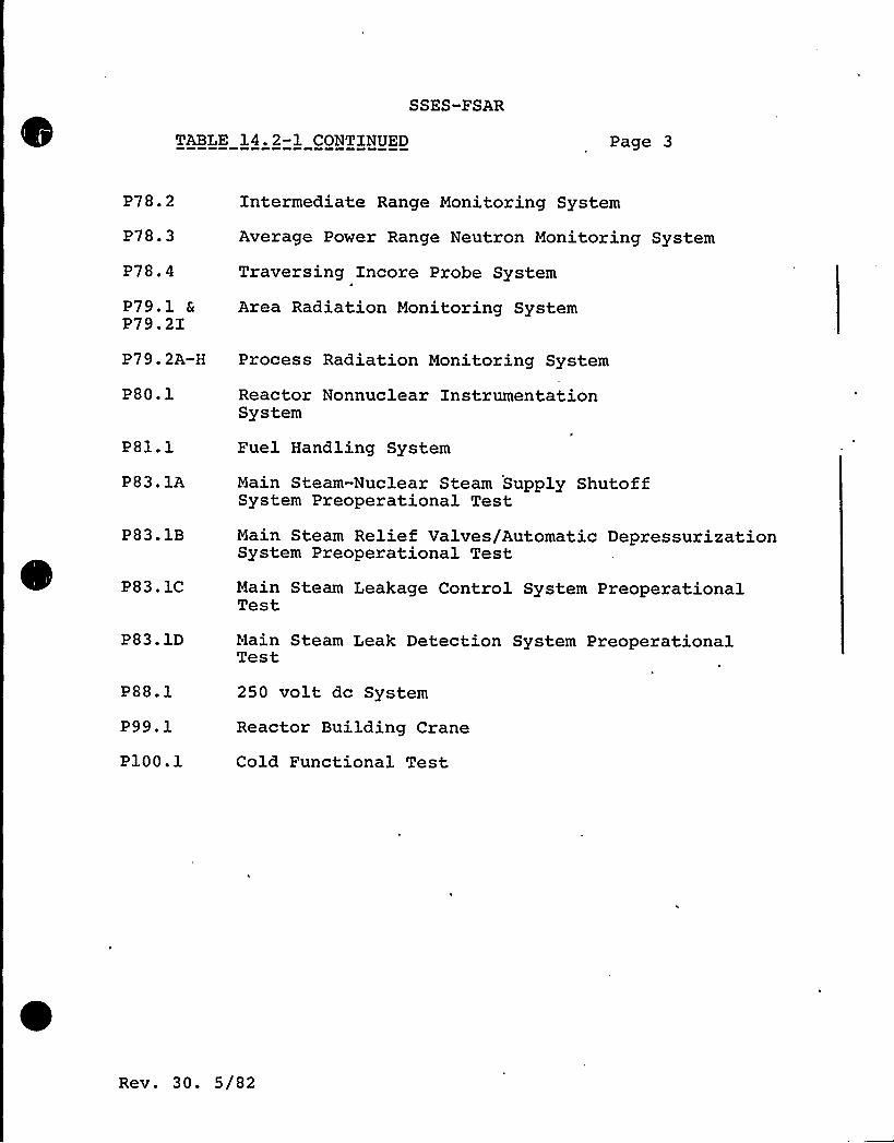
SSES-FSAR
TABLE 14.2-1 CONTINUED Page 3
P78. 2
P78.3
P78.4
P79.1 aP79.2I
Intermediate Range Monitoring System
Average Power Range Neutron Monitoring System
Traversing Incore Probe System
Area Radiation Monitoring System
P79.2A-H Process Radiation Monitoring System
P80.1
P81.1
P83.1A
P83.1B
P83.1C
Reactor Nonnuclear InstrumentationSystem
Fuel Handling System
Main Steam-Nuclear Steam Supply ShutoffSystem Preoperational Test
Main Steam Relief Valves/Automatic DepressurizationSystem Preoperational Test
Main Steam Leakage Control System PreoperationalTest
P83. 1D Main Steam Leak Detection System PreoperationalTest
P88. 1
P99. 1
P100.1
250 volt dc System
Reactor Building Crane
Cold Functional Test
Rev. 30. 5/82
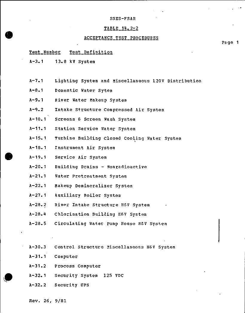
SSES-F SAR
TABLE 14. 2-2
ACCEPTANCE TEST PROCEDURES
Test Number Test DefinitionPage 1
A-3. 1 1 3. 8 k V System
A-7 1
A-8 1
A-9 1
A-9 2
A-10 1
A-11. 1
A-15. 1
A-18. 1
A-19 1
A-20 1
A-21 1
A-22 1
A-27 1
A-28 2
A-28-4
Lighting System and Miscellaneous 120V DistributionDomestic Mater Sytem
River Mater Makenp System
Intake Structure Compressed Air System
Screens 8 Srreen Hash System
Station Service Mater System
Turbine Building Closed Cooling Mater System
Instrument Air System
Service Air System
Building Drains — Nonradioactive
Mater Pretreatment System
Makeup Demineralizer System
Auxiliary Boiler System
River Intake Structure HSV System
Chlorination Building HF'V System
A-28.5 Circulating Mater Pump House HbV System
A-30.3
A-31. 1
Control Structure Misrellaneons HGV System
Computer
A-31.2 Process Computer
A-32 ~ 1 Security System 125 VDC
A-32. 2 Security UPS
Rev. 26, 9/81

SS S-FSAR
TABLE 14- 2-1 CONTINUED Page 2
e-P52.1 High Pressure Coolant Injection System
P53.1 Standby Liquid Control System
PS4.1 Emerqency Service Wate System
P55.1 Control Rod Drive System
P56.1 Reactor Manual Control System
P57.1 Uninterruptable ac Power System
P58.1 Reactor. Protection System
P59.1 Primary Containment System
P59.2 Containment Integrated Leak Rate Zest
P60. 1
P61.1
Containment Atmosphere Circulation System
Reactor Water Cleanup System
P64.1 Reactor Recirculation System
P69.1 Liquid Radwaste Collection System
P70.1 Standby Gas Treatment System andSecondary Containment Isolation
P73.1 Containment Atmospheric Control System
P75.1 24 volt dc System
P76-1 Plant Leak Detection System
P78.1 Source Range Monitoring System
P78. 2
P78 3
Intermediate Range Monitoring SystemI
Average Power Range Neutron Monitoring System
P78 4 Traversinq Incore Probe System
P79.1 Area Radiation Monitorinq System
P79.2 Process Radiation Monitoring System
P80.1 Reactor Nonnuclear InstrumentationSystem
P81.1 Fuel Handling System
REV. 20, 2/Sl

TABLE 14. 2-1 CONTINUED
SSL'S-FSAR
Page 3
P88 1
P99.1
llain Steam System
250 volt dc System
Reactor Building Crane
P100.1 Cold Functional Test
REV. 20, 2/81

0
'
0'

SSES-PSAR
TABLE 14.2-2
ACCEPTANCE TEST PROCEDURES
Test Number Test Definition
Page 1
A-3.1 13.8 kV System
A-7.1
A-8.1
A-9.1
A-9.2
Lighting System and Miscellaneous 120V Distribution
Domestic Water Sytem
River Water Makeup System
Intake Structure Compressed Air System
A-10.1 Screens 6 Screen Wash System
A-ll.l Station Service Water System
A-15.1 Turbine Building Closed Cooling Water System
A-18.1 Instrument Air System
A-19.1 Service Air System
A-20.1 Building Drains - Nonradioactive
A-21.1 Water Pretreatment System
A-22.1 Makeup Demineralizer System
A-27.1 Auxiliary Boiler System
A-28.2 River Intake Structure HSV System
A-28.4 Chlorination Building HRV System
A-28.5 Circulating Water Pump House HGV System
A-29.1 Administration Building HSV System
A-30.3 Control Structure Miscellaneous H&V System
A-31.1
A"31.2
Computer
Process Computer
A-32.1 Security System 125 VDC
A-32.2 Security UPS
Rev. 23, 6/81

,V
fl l
I 'I
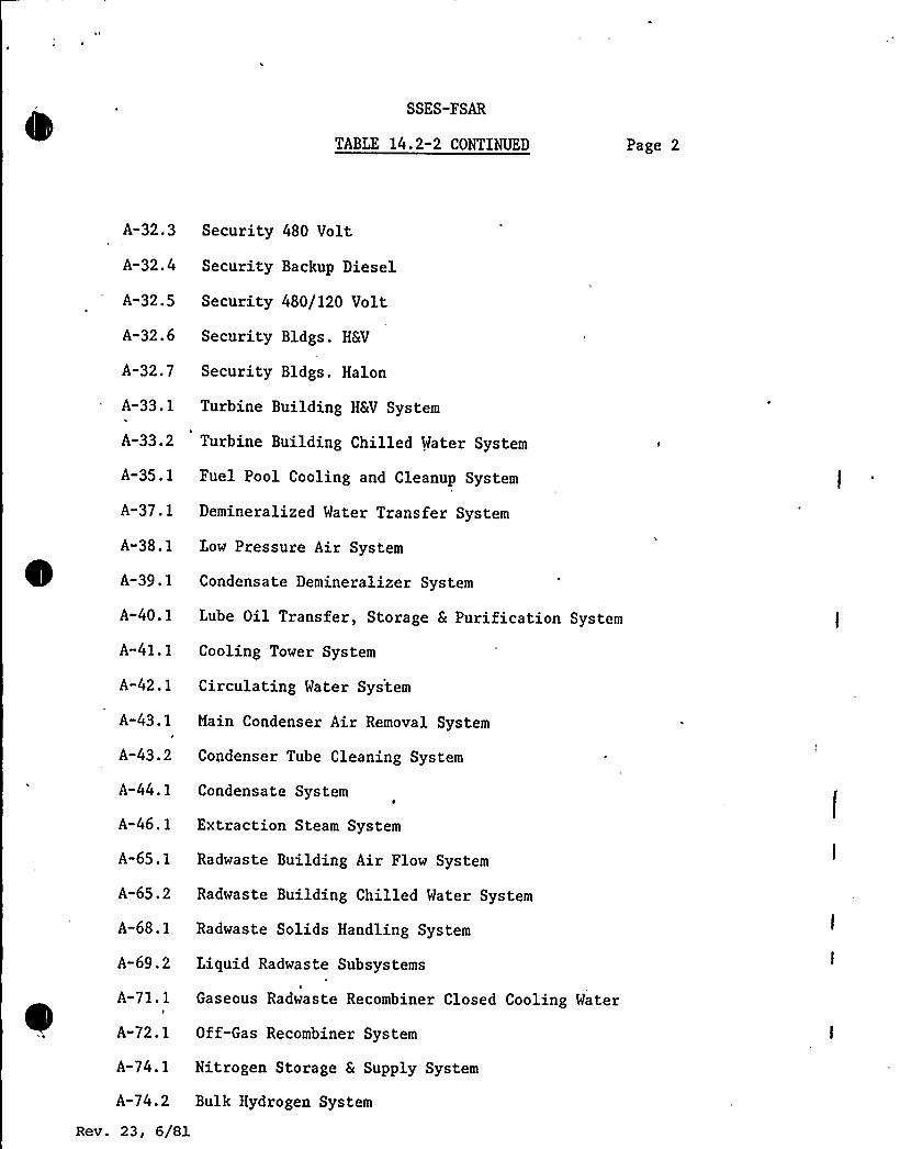
SSES-FSAR
TABLE 14.2-2 CONTINUED Page 2
A-32.3 Security 480 Volt
A-32.4 Security Backup Diesel
A-32.5 Security 480/120 Volt
A-32.6 Security Bldgs. HRV
A-32.7 Security Bldgs. Halon
A-33.1 Turbine Building HSV System
A-33.2 Turbine Building Chilled Water System
A-35.1 Fuel Pool Cooling and Cleanup System
A-37.1 Demineralized Water Transfer System
A-38.1 Low Pressure Air System
A-39.1 Condensate Demineralizer System
A-40.1 Lube Oil Transfer, Storage 6 Purification System
A-41.1 Cooling Tower System
A-42.1 Circulating Water System
A-43.1
A-43.2
A-44.1
Main Condenser Air Removal System
Condenser Tube Cleaning System
Condensate System
A-46.1 Extraction Steam System
A-65.1 Radwaste Building Air Flow System
A-65.2 Radwaste Building Chilled Water System
A-68.1 Radwaste Solids Handling System
A-69.2 Liquid Radwaste Subsystems
Gaseous Radwaste Recombiner Closed Cooling Water
A-72.1 Off-Gas Recombiner System
A-74.1 Nitrogen Storage S Supply System
A-74.2 Bulk Hydrogen System
Rev. 23, 6/81

SSES-FSAR
TABLE 14.2-2 CONTINUED Page 3
A-76.2 Process Sampling System
A-84.1 Moisture Separators
A-85.1 Cathodic Protection System
A-85.2 Freeze Protection System
A-91.1 Annunciator System
A-92.1 Turbine Steam Seals 5 Drains
A-93.1 Turbine Lube Oil Systems
A-93. 2 Turbine Valves, Valve Test, EHC and SupervisorySystems
A-95. 1 H2 Seal Oil System
A-97.1 Stator Cooling System
A-98.1 Main Generator 5 Excitation System
A-99.2 Communications System
A-99.4 Radiation Area Doors
A-99.6 Seismographical Monitoring System
Rev. 23, 6/81

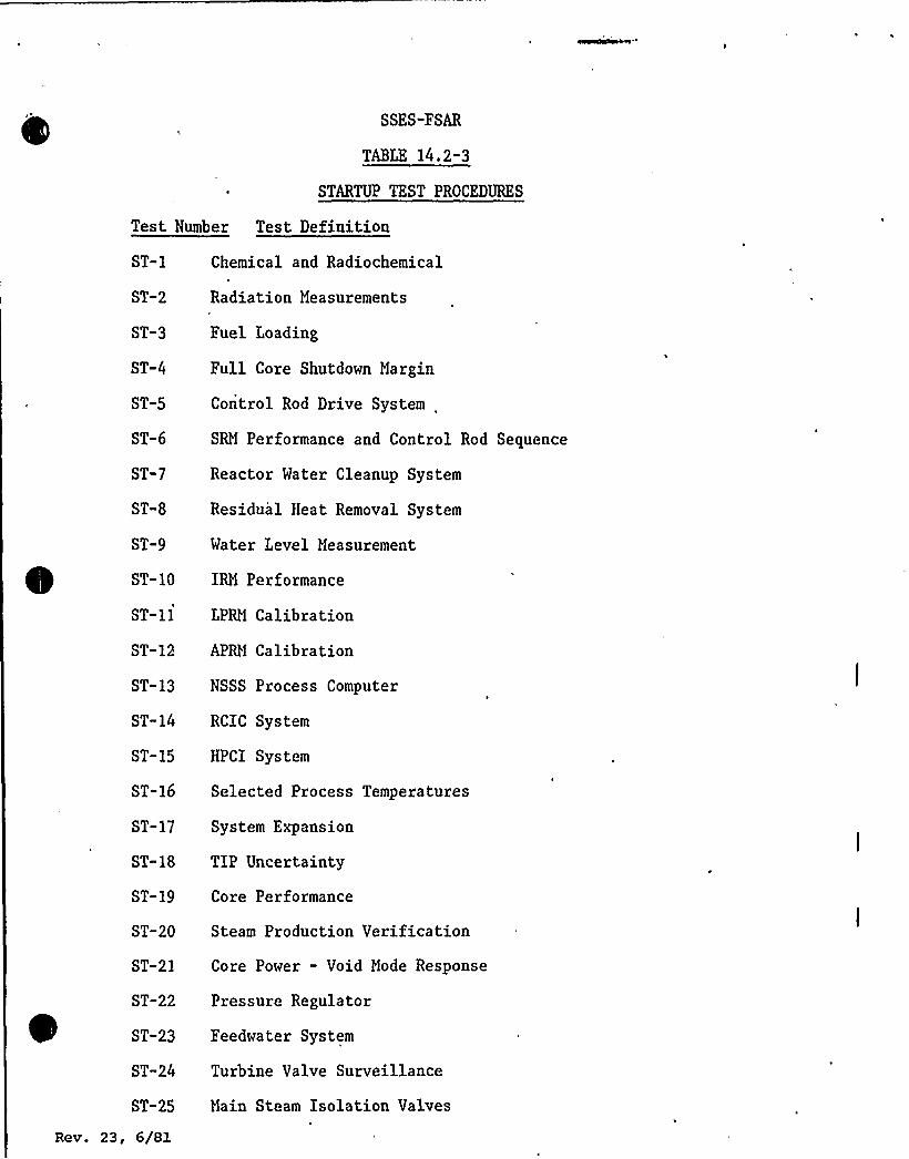
SSES-FSAR
TABLE 14.2-3
STARTUP TEST PROCEDURES
Test Number Test Definition
Chemical and Radiochemical
Radiation Measurements
ST-8
Fuel Loading
Full Core Shutdown Margin
Control Rod Drive System
SRM Performance and Control Rod Sequence
Reactor Water Cleanup System
Residual Heat Removal System
Water Level Measurement
ST-10 IRM Performance
ST-11 LPRH Calibration
ST-12 APRM Calibration
ST-13 NSSS Process Computer
ST-14 RCIC System
ST-15 HPCI System
ST-16 Selected Process Temperatures
ST-17 System Expansion
ST-18 TIP Uncertainty
ST-19 Core Performance
ST-20 Steam Production Verification
ST-21 Core Power - Void Mode Response
ST-22 Pressure Regulator
ST-23 Feedwater System
ST-24 Turbine Valve Surveillance
ST-25 Hain Steam Isolation Valves
Rev. 23, 6/81

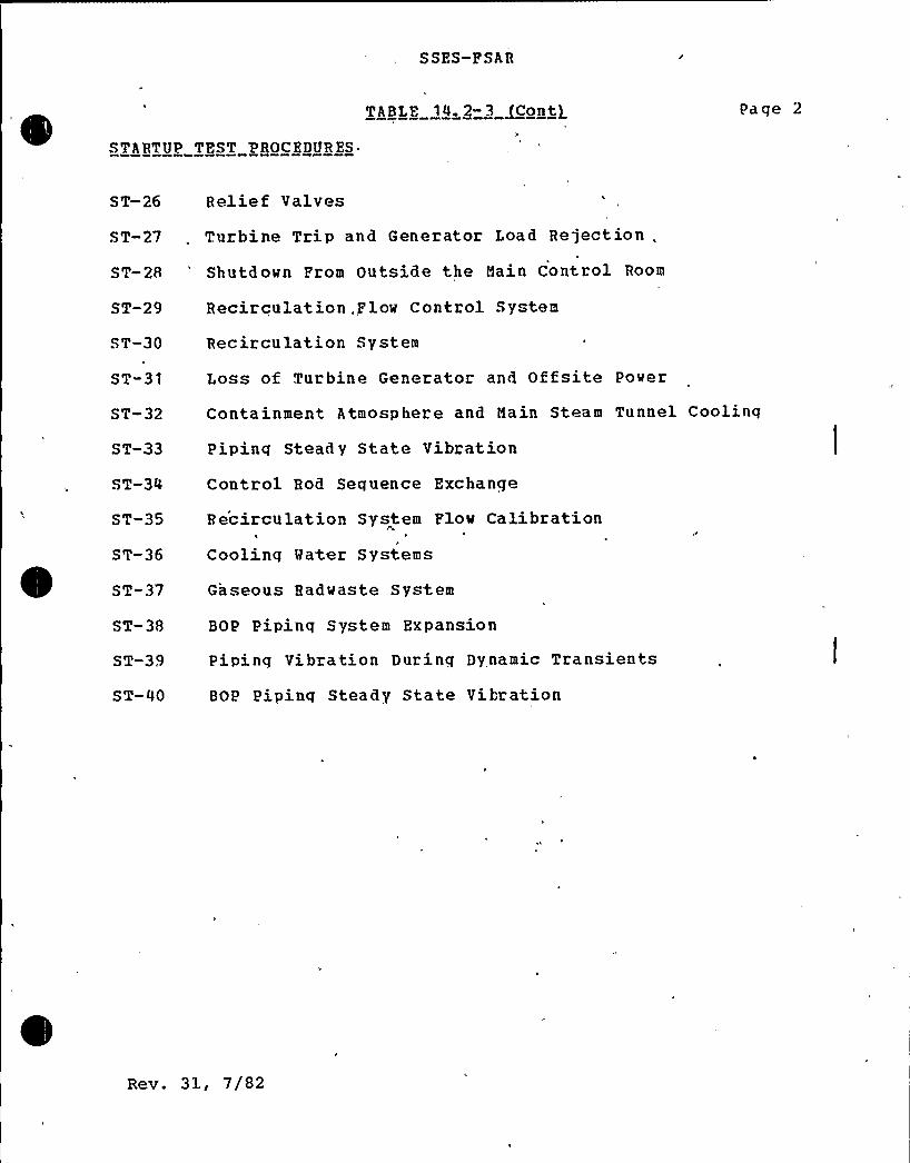
SSES-FSAR
TABLE 14 2-3 [Conti Page 2
STARTUP TEST PROCEDURES
S T-26
ST-27
Re1i e f Valves
Turbine Trip and Generator Load Rejection
.ST-28 'hutdown From Outside the Hain Control Room
ST-29
ST-30
ST-31
ST-32
ST-33
ST-34
ST-35
ST-36
ST-37
ST-38
ST-39
ST-40
Recirculation, Flow Control System
Recirculation System
Loss of Turbine Generator and Offsite Power
Containment Atmosphere and Hain Steam Tunnel Coolinq
Piping Steady State Vibration
Control Rod Sequence Exchange
Recirculation System Flow Calibration
Cooling Water Systems
Gaseous Radwaste System
BOP Pipinq System Expansion
Piping Vibration During Dynamic Transients
BOP Pipinq Steady State Vibration
Rev. 31, 7/82
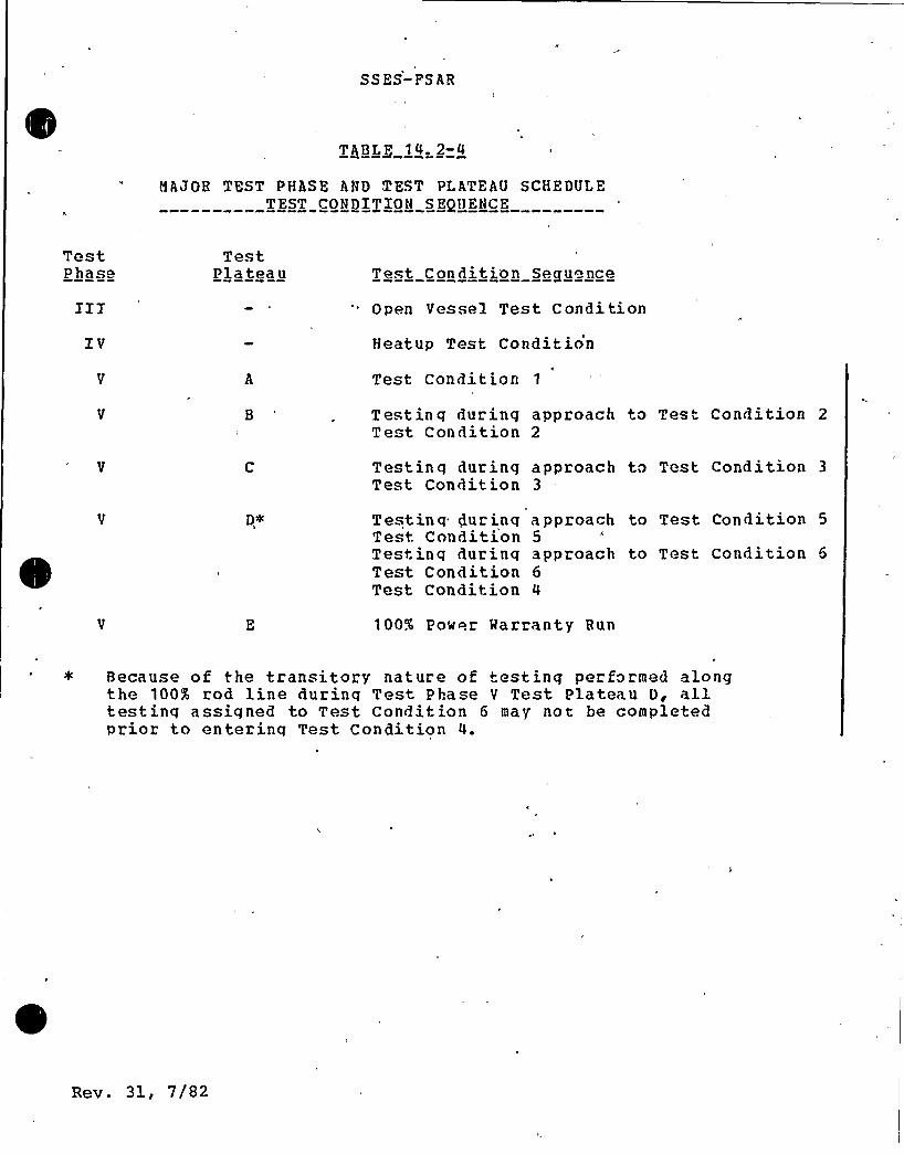
SSES-PSAR
TABLE 14,2-4
MAJOR TEST PHASE AND TEST PLATEAU SCHEDULETEST CONDITION SEQUENCE
TestPhase
TestPlateau Test Condition Sequence
Open Vessel Test Condition
IV Heatup Test Condit ion
Test Condit ion 1
Testinq during approach to Test Condition 2Test Condition 2
Testing during approach to Test Condition 3
Test Condition 3
V D,+ Testinq PurinqTest ConditionTesting duringTest ConditionTest Condition
approach to Test Condition 55approach to Test Condition 66
100% Power Marranty Bun
Because of the transitory nature of testing per formed alongthe 100% rod line durinq Test Phase V Test Plateau D, alltestinq assigned to Test Condition 6 may not be completedprior to enterinq Test Condition 4.
Rev. 31, 7/82
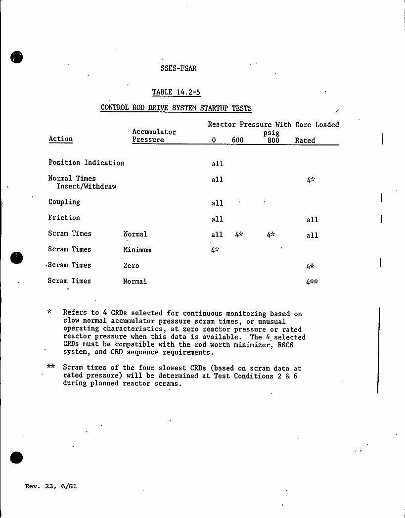
SSES-FSAR
TABLE 14.2-5
CONTROL ROD DRIVE SYSTEM STARTUP TESTS
ActionAccumula to rPressure
Reactor Pressure With Core Loadedpsig
0 600 800 Rated
Position Indication allNormal Times
Insert/Withdrawall 4
~
Coupling
Friction
Scram Times
Scram Times
Normal
Minimum
allallall 4"
4)I
4~
allall
.Scram Times
Scram Times
Zero
Normal
4J
4JA
n Refers to 4 CRDs selected for continuous monitoring based onslow normal accumulator pressure scram times, or unusualoperating characteristics, at zero reactor pressure or ratedreactor pressure when this data is available. The 4 selectedCRDs must be compatible with the rod worth minimizer, RSCSsystem, and CRD sequence requirements.
Scram times of the four slowest CRDs (based on scram data atrated pressure) will be determined at Test Conditions 2 6 6during planned reactor scrams.
Rev. 23, 6/Sl
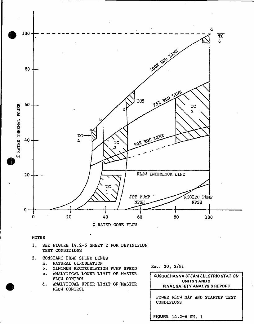
100TC6
80
~o>@$4
60
40
a
TC~4 TC
.2
TCS~C) |4
)Q ~,( go>
TC3
20 FLOW INTERLOCK LINE
TC1
JET PUMP
NPSHRECIRC PUMP
NPSH
20 40 60
X RATED CORE FLOW
80 100
NOTES
1. SEE FIGURE 14.2-6 SHEET 2 FOR DEFINITIONTEST CONDITIONS
2. CONSTANT PUMP SPEED LINESa. NATURAL CIRCULATIONb. MINIMUM RECIRCULATION PUMP SPEEDc. ANALYTICALLOWER LIMIT OF MASTER
FLOW CONTROLd. ANALYTICALUPPER LIMIT OF 'MASTER
FLOW CONTROL
Rev. 20, 2/81
SUSQUEHANNA STEAM ELECTRIC STATIONUNITS 1 AND 2
FINALSAFETY ANALYSISREPORT
POWER FLOW MAP AND STARTUP TESTCONDITIONS
FIGURE 14.2-6 SH. 1
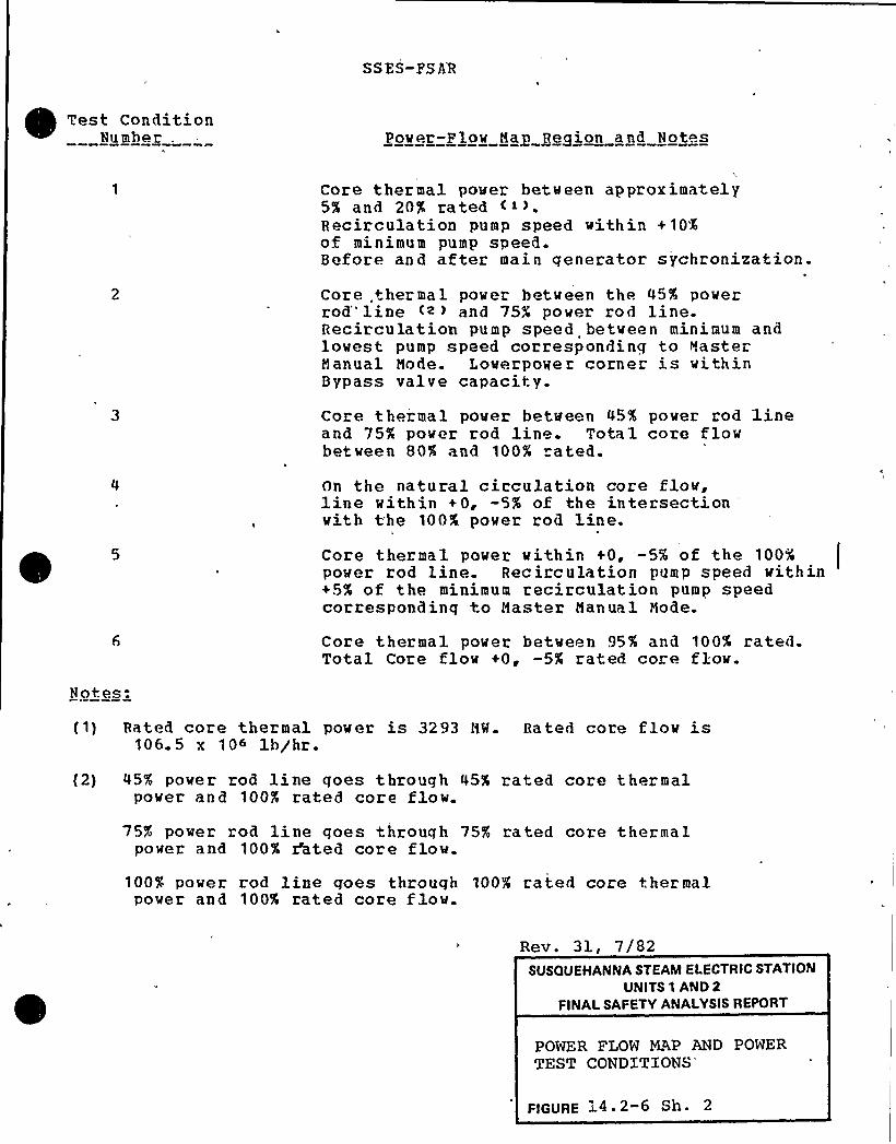
SSES-PS A'R
Test ConditionNumber . Power-Plow May Region and Notes
Core thermal power between approximately5% and 20'$ ratedRecirculation pump speed vithin +10%of minimum pump speed.Before and after main generator sychronization.
Core ther ma l power between the 45% powerrod" line <» and 75$ pover rod line.Recirculation pump speed betveen minimum andlowest pump speed corresponding to MasterManual Mode. Lowerpower corner is vithinBypass valve capacity.
Core thermal pover between 45% pover rod lineand 75% power rod line. Total core flowbetween 80% and 100% ated.
On the natural circulation core flow,line within +0, -5% of the intersection
'iththe 100% power rod line.Core thermal power vithin +0, -5% of the 100%pover rod,line. Recirculation pump speed vithin+5% of the minimum recirculation pump speedcorresponding to Master Manual 'tode.
Core thermal pover betveen 95% and 100% rated.Total Core flov +0, -5X rated core flow.
Notes:
(1) Rated core thermal pover is 3293 MII. Bated core flow is1065 x 106 1b/hr.
(2) 45% power rod line goes through 45% rated core thermalpower and 100% rated core flow.
75% power rod line goes through 75% rated core thermalpower and 100% dhted core flow.
100% power rod line goes through 1004 rated core thermalpover and 100% rated core flow.
Rev. 31, 7/82SUSQUEHANNA STEAM ELECTRIC STATION
UNITS 1 AND 2
FINALSAFETY ANALYSISREPORT
POWER FLOW MAP AND POWERTEST
CONDITIONS'IGURE
14.2-6 Sh. 2
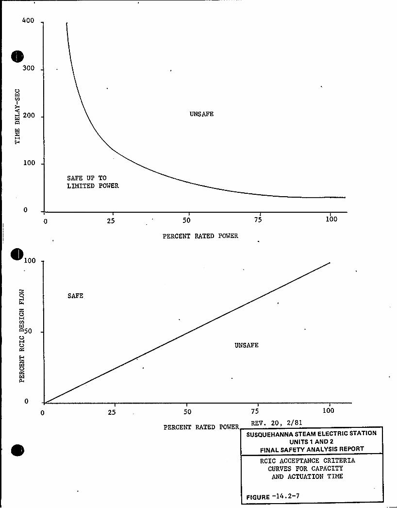
400
300
I
~~ 200A
M
UNSAFE
100
SAFE UP TOLIMITED POWER
25 50 75 100
100
PERCENT RATED POWER
O
C3M
A50OMOC4
DQl$4
SAFE,
UNSAFE
25 50 75 100
PERCENT RATED POWER
SUSQUEHANNA STEAM ELECTRIC STATION
UNITS 1 AND 2
FINALSAFETY ANALYSISREPORT
RCIC ACCEPTANCE CRITERIACURVES FOR CAPA'CITY
AND ACTUATION TIME
FIGURE 14 ~ 2 7

SSFS- FSA R
16.2 PROPOSED FINAL TECHNICAL SPECIFICATIONS
This section vill be submitted later using the NRC's StandardTechnical S pecif ications.
16.2-1

SS ES-FS AR
17 2 QUALITY ASSURANCE DURING THE OPERATIONS PHASE
17 2 0 TNTRO DUCTION
PPCL is fully responsible for testing, operating, maintaininq,refueling and modifying the Susquehanna SES in compliance withFederal, Sta te, and local laws and the plant operating licensereguirements. These activities are also performed in response torequired codes and specified QA related NRC regulatory guides.These regulatory guides and associated ANSI standards are listedin Ta ble 17. 2-1.
To assure compliance with 10CFR50 ~ Appendix 8 requirements, PPCLhas established and implemented a management control plan forassurinq the quality of saf ety-related activities during theoperations phase. The plan consists of a) this OperationalQuality Assurance (OQA) Program which contains PPCL's qualityassurance commitments to the Nuclear Regulatory Commission; b)the OQA Manual which contains Operational Policy Statements (OPS)and defines PPCL's policies for meeting these commitments; and c)Nuclear Department Instructions and functional unit procedureswhich contain, the detailed steps. necessary for a functional unitto. comply with the OQA Program requirements. The relationshipsbetween these documents are shown in Figure 17. 2-1.
Xn implementing the OQA Program, PPCL assures that its activitiescomply w.ith Federal Bequlations which are designed to protect thehealth and safety of the public.
The OQA policie, qoals and objectives of PPCL are stated in thefollowinq Nuclear Quality Philosophy and Intent statement:
For the Susquehanna Steam Electric Station, PennsylvaniaPower 6 Liqht Company will comply with the requirements of
, 10CFR50, Appendix H, Quality Assurance Criteria for NuclearPower Plants ahd Fuel Reorocessina Plants and otherapplicable federal regulations with respect to all safety-related activities which include engineerinq,< design,procurement, construction, preoperational testing, powertesting, operation, maintenance, re fueling, repairing,modification and in-service inspection. PPCL is alsocommitted to be responsive to the applicable RegulatoryGuides, Industrial Codes and Standards, or parts thereof, asspecifically noted in controlling documents. Theapplicability of these Guides, Codes, and Standards, orparts t.hereof, and their effectiveness shall be interpretedby the responsible managers. If Guides, Codes, or Standardsare nonexistent or inadequate, PPCL shall develop therequired practices and procedures with the controlsnecessa ry,for their implementation.
Rev. 28, 1/82 17% 2 1
SS ES- FS AR
17. 2 1 ORG ANIZATION
PPGL has es+ablished the Nuclear Department in order to provide acohesive management team with the primary objective of providinglonq term technical and management support for Susquehanna SES.In addition +o the resources within the Nuclear Department,auxiliary support is provided by the Construction .'.tanager and theManaqer-Procurement. The key management positions responsiblefor the performance of safety related activities are described inthe fo] lowinq subsections,. Fiqure 17.2-2 shows theorganizational structure and lines of responsibility for thegroups that provide technical and management support forSusquehanna SFS.
The positions listed below are described in the followinqsubsection.:
Son ior Vice Presid en t- NuclearVice President-Enqineerinq and Construct
(Project Director)Vice Pre ident-Nuclear OperationsA.,sistant Project DirectorsManaqer-Nuclear Plant Engineerinq (NPE)Project Cons+rue+ion Manage"Manaqer-Nuclear Dual i+ y Assuranre (NQA)Superintendent of PlantAssistant Superintendent of PlantAssistant Su perintendent-OutaqesIntegrated Startup Group SupervisorManager-Nuclear SupportManager-Nuclear TraininqManager-Nuclear Safety AssessmentManaqer-Nuclear LicensinqManaqer-Nuclear AdministrationConstruction ManaqerManaqe r-Procurement
ion (EGC) -Nuclear
ln addition to the above individuals, the Susquehanna ReviewCommittee (SRC) is established as a review, audit and advisorygroup, comprised of at least five key Nuclear Departmentmanagers, whose function is to verify independently that theSusquehanna SES is beinq tested, operated and maintained inaccordance with all safety related, ALARA and environmentalrequirements. The SBC will perform the independent reviewmandated by ANSI H18.7.
Rev. 33, 4/83 1 7 ~ 2 2

SSES-FS AR
17. 2. 1. 1 Senior Vice President — Nuclear
The Senior Vice President — Nuclear has overall authority andresponsibility for the Susquehanna OQA Program and, as a result,he:
(a) Requires the performance of an annual, preplanned anddocumented assessment of the OQA Program in whichcorrective action is identified and tracked.
(b) Sets OQA Poli'cies,. qoals and objectives for safeoperation of Susquehanna SES.
(c) Commits PPGL to an OQA Program designed to assurecompliance with requlatory requirements.
(d} Requires compliance with the provisions of the OQAProqram and causes periodic assessments of PPGLcommitments and established practices for safe planto per at ion.
In order to maintain a continuing involvement in QA matters, theSenior VP-Nuclear receives monthly written reports on the statusand adequacy of the OQA Program issued by the Manager-NQA
and'eviewsand approves the Operational Policy Statements containedin the OQA Manual prior to their issuance.
The Senior VP — Nuclear delegates to the VP — EGC — Nuclear andthe VP-Nuclear Operations those responsibilities for attainingspecified quality levels and, to the Manager-Nuclear QualityAssurance those responsibilities for verifying that those'ualitylevel s have been met.
The Senior VP — Nuclear delegates to the Manager-Nuclear SafetyAssessment the responsibility for performing the on-.,iteIndependent Safety Enqineerinq Group (ISEG) function mandated byNUREG-Q731.
In addition, the Senior Vice President-Nuclear has overallcorporate responsibility for Susquehanna SES activities relatedto enqineerinq, constru'ction, startup and operations. The SeniorVP-Nuclear delegates these responsibilities to the VicePresident-EGC-Nuclear, and the Vice President-Nuclear Operations.The reportinq relationships are shown in Figure 17.2-2.
Rev. 28, 1/82 17& 2 3
SSES-FSAR
17. 2. 1. 1. 1 Vice President — Enqineerinq 6 Construction (HGC)
nuclear
The VP — F~C — Nuclear (also identified as the Project Directornn Fiqure 17.2-2) has overall corporate responsibili y for theSusquehanna engineerinq, construction and licensing activities asdeleqated by the Senior VP-Nuclear. In addition, as ProjectDirector, he directs and is accountable for all facets of project,performance +hrouqh project completion.
17. 2. 1. 1. 1. 1 Assistant Project Directors
The Assis+ant Project Directors at the site (APD-S) and Allentown(APD-A) are responsible to the Project Director for theenqineerinq and construction aspects of the pro ject. Theirresponsibilities encompa s the day-to-day decision-makingprocess, conduct of pro ject activities, and contractadministration. They also coordinate the support functions ofother company departments as they interface with the project.
The (APD-S) has a direct coordination and inteqrationrelationship with the NQA Resident Nuclear Quality AssuranceEnqineer (RMQAE) . The RNQAE, in tu n, has the responsibility tosupport the APD-S objectives by alertinq the APD-S to qualityrela+ed matters which have the potential for adversely affectingconstruction activities.
17. 2.1. 1.1. 2 Nanaaer — Nuclear Plant Enaineerinq
The Nanaqer — NPE is responsible .for enqinee" ing activities!
(includinq those related to nuclear fuel) and +heir qualitymanagement. The. e activities include a) desiqn and designverification related to plant modifications, b) the technical
!evaluation and approval of acceptable suppliers of parts,components, equipment, and systems, c) specifyinq technicalrequirements for tho procurement of spare parts, d) modificationsto the "as-built" plant, and e) enqineerinq outage support.
17. 2. 1. 1. 1. 3 pro ject Construction lfanager
The Projec+ Construction Manager is responsible for thenerformance of construction activities at Susquehanna SHS,includinq that of prime contractors, and fo" the preparation ofequipment and systems for turnover to the Integrated StartuoGroup for +estinq. The Project Construction Manager receives
Rev. 33, 4/83 17. 2-0
SS ES- FSA R
administrative and project technical direction from the ProjectDirector throuqh the Assistant Project., Director-site.
17.2.1 1.1.4 Manage — Nuclear Licensing
The Manager-Nuclear Licensinq is responsible for directing thelicensinq aspects for Susquehanna SES. This includes interfacingwith the Licensinq Branch of the NRC, updating and changing theCESAR to reflect as-built conditions or modifications, andcoordinatinq responses to the NRC relative to IE Bulletins.
17. 2.1.1.2 Vice president — Nuclear Operations
The Vice President-Nuclear OperationsInitial Test Program and operation ofincludes formulatinq and establishinqadministrative staff and planning andof these personnel.
is responsible for theSusquehanna SES. Thisthe necessary technical andcoordinating the activities
The Vice President-Nuclear operations delegates responsibilitiesto the Superintendent of Plant, Manaqer-Nuclear Support, Manager-Nuclear Traininq, and Manaqer-Nuclear Adminstration.
17 g,1,1,2,1 Supegintendeng of Plant
The Superintendent of Plant is responsible for Susquehanna SESdurinq plant testing, startup, and operation and has
overall'esponsibilityfor the Initial Test Program conducted by theIntegrated Startup Group.
The Superintendent of Plant is responsible for the safe operationof Susquehanna SES and has overall responsibility for theexecution of the administrative controls at the plant to assuresafety. The Superintendent of Plant ensures that plantoperations are conducted in accordance with the plant operatinglicense, technical specif ications, the FSAR, and the OQA Proqramwith its implementing documents. 'he Superintendent of. Plantdelegates his authority for performing activities related tooperation of the plant to the Assistant 'Superintendent of Plant,Assistant Superintendent-Ou taqes, Supervisor of 0 pe rations,Supervisor of Maintenance, Technical Supervisor, and otherpersonnel assiqned to the staff organization.
The Superintendent of Plant reports to and is 'directly accoutableto the Vice President-Nuclear Operations for activities directlyrelated to plant support of preoperational testinq.
Rev. 33, 4/83 17. 2-5
SSFS-FSAR
17.2 1 1.2,1,1 Assistant Superintendent of Plant
The Assistant Superintendent of Plant assists the. Superintendentof Plant in all matters and assumes the responsibilities of theSuperintendent of Plant in his absence.
17 2.1,1. 2.1,2 Assistant Supegigtendent-Outgoes
The Assistant Superintendent-Outaqes reports to theSuperintendent of Plant and is responsible for outaqe managementat Susquehanna SES includinq planning, establishment of qoals,and performance.
17 2. 1- 1. 2. 1. 2. 1 Integrated Startup Group Supervisor
The Integrated Startup Group Supervisor has the responsibilityfor supervisinq the conduct of the Integrated Startup Group{ISG) . The ISG Supervisor reports to the AssistantSuperintendent-Outaqes on matters pertaining to the Initial Test.Program (ITP). The qualifications for this position are listedin Chapter 14.2.
17. 2. 1. 1. 2. 2 Manager. — Nuclear support
The Manager. - Nuclear Support is responsible for coordinatingboth Nuclear Department activities and selected outside serviceorganization activities in support of Susquehanna SFS startup andoperation.
The Manaqer — Nuclear Support provides technical assistance tothe Susquehanna SES Plant Staff in the areas of operation andmaintenance.
The Manager — Nuclear Support advises the VP-Nuclear Operationsof activities within or affecting the Nuclear Department andadvises the Susquehanna SFS Plant Staff of potential changes toplant operatinq and maintenance reguirements by reviewing changesto Requlatory Guides, .Industry Standards and other industryliterature.
17.2. 1. 1.2. 3 Manaaer — Nuclear Trainina
Rev. 33, 4/83 17 2-6
SSZS-FSAR
The Manager-Nuclear Training is responsible for assessing thelong term training needs reqardinq Susquehanna SES and developingtraining proqrams commensurate with those needs.
17. 2. l. 1. 2. 4 Manaaer — Nuclear Administration
The Manager-Nuclear Administration is responsible for developingand implementing a nuclear records management sy"tern anddirectina all interfacinq organizations toward the implementationof the system. The Manaqer-Nuclear Administration is alsoresponsible for establishing and maintaining a document controlsystem for Susquehanna SES.
17.2. 1. 1. 3 Nagaqer — Nuclear Saf et'ssessment
The Manager-Nuclear Safety Assessment is responsible forindependently reviewinq and monitoring all nuclear activities toensure that they are performed in a manner which results in safereliable operation.
17.2.1.1.4 Manaaer — Nuclear.Ouality Assurance
The Manager-NQA is responsible for:
(a) Directinq and coordinating the development and updatingof PPSL~s OQA Proqram.
(b) Assurinq overall implementation of the OQA Program.
(c) Tnterpretinq the OQA Proqram, subject to the approvalof the Senior Vic'e President — Nuclear.
(d) Auditinq, monitoring, inspecting and witnessinq, asnecessary, contractor, vendor and plant safety-relatedactivities to assess compliance with the requirementsof the OQA program and/or procurement documents, andreportinq the results of these activities toresponsible manaqement.
(e) Beviewinq Nuclear Department Instructions andfunctional unit procedures to assure compliance withthe OQA Proqram.
(f) Providing traininq assistance in OQA Programrequirements.
Rev. 33, 4/83 17 2-7

SS HS- FS AB
(q) Implementinq the QA and site QC activities identifiedin the OQA Proqram.
(h) Reviewinq and auditinq the OQA Proqram provisions thatare applied to the fire protection program andreportinq the results of these activities toresponsible manaqement.
(i) Implementing the nondestructive examination traininq,qualification and certification program.
{j) Evaluating potential suppliers of material eguipmentand services to determine their capabilities forprovidinq quality products or services.
(k) Overseeinq the administrative integration of the OQAand Environmental auditinq proqrams for SusquehannaSES.
(1) Reviewinq and approving quality assurance requirementsin proc urement documents.
The Manaqer — NQA is responsible for taking action (includingwork stoppage), as necessary to correct conditions adverse toactuality. The Manaqer — NQA is responsible for informing theSuperintendent of Plant when it is determined that safety-relatedcomponents or the activities performed on these components failto comply with approved specifications, plans, or procedures.The Superintendent of Plant retains the responsibility for theevaluation of conditions adverse to quality with regard to plantoperation and is responsible for determining when an operatingunit(s) is to be shut down.
PPGL requires that the Manager-NQA shall have qualifications thatare commensurate with the responsibilities of that position. Asa minimum, these shall include a B. S. in Engineerinq and tenyears experience in Enqineerinq and/or Construction. At leastone year of this ten years experience shall be nuclear powerplant experience in the overall implementation of the qualityassurance program.
The Manaqer — NQA and the NQA Staff are independent oforganizations responsible for performinq safety-relatedactivities. The NQA Section has sufficient authority andorganizational freedom to identify quality problems, to initiate,recommend or provide solutions through designated channels, andto verify implementation of solutions.
The PPGL Nuclear Quality Assurance functional structure is shownin Fiqure 17.2-3. The Manager — NOA delegates functionalresponsibilities for accomplishing quality assurance activitiesas foliows:
Rev. 33, 4/83 17. 2-8
SSES-FSAR
Quality Enaineerina 6 Procurement
l. Quality Enqineerinq
(a) Interface with engineering organizations toaccomplish the incorporation of qualityrequirements in design, test, 6 procurement
.documents via the specification, review andapproval process.
{b) Interface to provide QA coverage of nuclear fuel.
(c) Review and maintain cognizance of applicable codesand standards
(d) Review and support responses to NRC Bulletins,Circulars, and Information Notices.
(e) Review and support for reporting items per10CPR50. 55 (e) and 10CPR21.
(f) Provide technical support for auditing.
(q) Coordinate responses to NRC Inspections.
{h) Provide administrative support functions.
2. P roc ure ment
(a) Perform'endor QA program evaluations, surveys andperformance trendinq and rating, vendor audits.
(b) Perform technical review/acceptance of vendor QLrecords.
(c) Provide for post award vendor meetings {reviewP.O. pro visions) .
(d) Perform Source surveillance/verification.Construction
{a) Interface with QA'nd QC organizations for plantconstruction support.
(b) Interface with NRC construction inspectors.
(c) Provide direct support of the preserviceinspection activities.
(d) Retain direct responsibility for the review of NDEprocedures.
Rev. 33, 4/83 17 2-9
SS ES-FS AR
{e) Provide QA support for specified majormodifications during plant operations.
(f) Interface with the Authorized Nuclear Inspector.
(q) Perform audits of construction activities.(h) Review of construction procedures and
instructions.
(i) Perform field checks and verification of responsesto NRC citations, bulletins, circulars andreportable conditions related to constructionactivities.
(5) Provide for completion of N-3 Forms.
(k) Perform quality trending of construction relatedac tivities.
Operations
'1.. Quality Assurance
(a) Interface with the Plant Staff and ISG fo" the QAsupport of preoperational, startup testing andplant operations.
(b) Review administ ative, preoperational and startuptest procedures.
(c) .Interface with NRC operations inspectors.
(d) Perform field checks and verification of responsesto NRC citations, bulletins, circulars andreportable conditions related to operationsacti vities.
(e) Perform audits of operations.
(f) Perform quality trending of plant operationsrelated activities.
2. Dual.ity Control
(a)
(b)
Inspect maintenance, modification, repair, testingand PPGL Construction activities.
I
Perform and interpret the results of NDE.
(c) Per for m rece ipt inspection a nd acceptance ofmaterial, equipment and consumables.
Rev. 33, 4/83 17 2- 10
S SES- FS AR
(d) Fvaluate NCRs for trends.
(e) Review procedures for insertion ofhold/notification points.
(f) Perform inspection planning.
3. Quality Systems 6 Training
(a) Provide for auditor training, qualification andcertification.
(b) Provide for Inspector training, qualification andcertification.
(c) Coordinate QA indoctrination and training fo" theNQA section and other PL orqanizations.
(d) Maintain the Construction QA Program.
(e) Develop and maintain the Operational QA Program.
(f) Develop and maintain NQA Section procedures.
D. Auditing
fa) Schedule and scope proqrammatic audits of PPGL andother orqanizations.
(b) Coordinate the implementation of programmaticaudits and the allocation of auditor resourcesthrouqh the other NQA supervisors.
(c) Perform audits of other NQA subsections.
(d) Evaluate and trend the results of the auditingeffort.
(e) Perform audit follow-up and verification/close-out.
The Manager-NQA is responsible for initiatinq correspondence suchthat the NRC is notified of changes to (1) the accepted FSAR QA
program description prior to their implementation, and (2)organizational elements within thirty (30) days after theirannouncement. (Note--editorial changes or personnelreassiqnments of a non-substantive nature do not require NRC
notification.)
Rev. 33, 4 /83 17. 2-11

SS ES- FS AR
The Construction Manager is responsible for providing thenecessary orqanization, trained resources and equipment for theperformance of maintenance tasks during normal operations and foroutages. The same organization and resources will also beresponsible for completion of plant modif ications, repairs and/oradditions to the operatinq plant. These operations willencompass prospects/tasks assigned hy the Superintendent of Planteither directly or through the on-site organization.Activities will be defined in procedures developed in accordancewith OQA Program requirements.
17. 2.-1.3 Manager — Procurement
The,Manaqer — Procurement is responsible for the purchase ofequipment,'aterials. supplies and se'rvices that conform to allapplicable purchasing specifications and for procurinq equipment,materials, supplies. and services from approved suppliers (exceptfor nuclear fuel as specified in Subsection 17. 2. 1. 1..2. 5) .Procedures shall define how the procurement process is controlled'n
accordance with OQA Program requirements.
17 2 2 OOALITY ASSURANCE PROGRAM
The Operational Quality Assurance {OQA) Program is applied to allsafety-related Susquehanna SES structures, systems, components,and activities.SAFETY RELATED is a generic term applied to:
Those systems, structures, and components that meet oneor more of the followinq requirements:
(a) Maintain.the integrity of the Reactor CoolantSystem pressure boundary.
(h) Assure their capability to prevent nr mitiqate theconsequences of accidents that could cause therelease of radioactivity in excess of 10CFR100limits.
(c) Preclude failures which could cause or increasethe severity of postulated accidents or couldcause undue risk to the health and safety of thepublic due to the release of radioactive material.
(d) Provide for safe reactor shutdown and immediateor'onqterm post accident control.
Rev. 33, 4 /83 17& 2 12
SSES- FSAR
2 ~ Those activities that affect the systems, structuresand components discussed in'Item l above such as theirdesiqn, procurement, construction, operation,refuelinq, maintenance, modif ication and testing.
The Manager - NPE is responsible for maintaining a listdesignating those structures, systems, and components which aresafety-related based upon the applicable portions of Table 3.2-1.
The OQA Program vill be .implemented at least 90 days prior tofuel load. Safety-related activities occurrinq prior to theimplementation of the 'OQA Proqram will be controlled by theSusquehanna QA Proqram. The Susguehanna QA. Program will bemodified throuqh amendments to the PPSL QA Manual, as necessary,to cover nev activities occurring durinq the preoperationaltest ing pha se.
The Senior Vice President — Nuclear has assigned to the Manaqer-Nuclear Safety Assessment the responsibility for reqularlyassessinq the scope, st'at us, implementation, and ef fectiveness ofthe OQA Proqram. This will assure that the Proqram is adequateand complies with 10CFR50, Appendix B.
The OQA Program requires that safety-related activities beperformed usinq specified equipment under suitable environmentalconditions and that prerequisites have been satisfied prior toinspection and test.The Manaqer — NQA is responsible for establishing and maintaininqthe OQA Program and for insurinq that it provides adequatecontrol of all activities. The Manager — NQA is responsible forassurinq that functions delegated to principal contractors arebeing properly accomplished. Supplier QA programs are evaluatedto determine that the requirements of 10CFR50 Appendix B will beimplemented and this evaluation is documented-.
The corporate OQA policies, goals, and objectives are transmittedto the persons performinq activities vhich are required by theOQA Program and supportinq documents. The commitments of the OQA
Program are described in Chapter 17 vhich also assiqnsresponsibilities for implementing OQA Program commitments. TheOQA Manual contains Operational Policy Statements (OPS) whichstipulate PPGL QA policies, goals and objectives for implementingthe OQA Program commitments. These policies give genericdirection for the performance of activities. A synopsis of theOPS and a matrix which cross-references them to each criterion ofAppendix B to 10 CFR Part 50, is contained in Table 17.2-2.
The OQA Proqram is patterned after and fully complies with ANSIN18.7-1976 as modified by NRC Regulatory Guide 1.33, Revision 2
except for the review frequency of certain procedures (i.e.reaqent preparation) vhich employ standardized methods for
Rev. 33, 4/83 17& 2 1 3
SS ES-FS AR
performance of plant-support evolutions. The reviev frequency,for these procedures vill be established appropriate to thenature of the activities addressed by the procedures. The degreeof compliance with:other regulatory quides and associated ANSIStandards is listed in Table 17.2-1. Where quides, codes orstandards are nonexistent or inadequate, PPGT. will developmethods to provide the necessary control.
The OQA Proqram requirements are mandatory for all safety-relatedactivities. Fach functional unit manager is responsible forassuring that safety-related activities performed by that.functional unit, meet the requirements of the OQA Program. TheManager — NQA is responsible for the audit, review, inspectionand verification of activities both- onsite and offsite to assurethat they are accomplished accordinq to the OQA Programrequirements. OC activities shall be performed in compliancewith the OQA Program requirements.
Disagreements betveen NQA and other department personnel (such asEnqineerinq, Construction, Fuels, Plant Staff, and Procurement)concerninq the OOA Program and related activities will beresolved between the Manager-NQA and the affected department'ssupervisor or manaqer. Disagreements not resolved at theselevels vill he referred to the Senior Vice President — Nuclearfor resolution.The OQA Manual, which contains OPS, is controlled and distributedby the NQA Section. All manaqers responsible for the performanceof safety-related activities will be issued controlled copies ofthe OQA Manual.
The Manager — NQA is responsible for obtaining appropriate reviewand approval of the content and chanqes to the OQA Proqram andManual. Any group performing activities governed by the OQA
Program and Manual may propose changes to these documents. AllOOA Proqram (FSAR Section 17.2) changes require review by theManager — NQA, the Vice President — EGC — Nuclear and the V.P.Nuclear Operations, and approval by the Senior Vice President—Nuclear. All OQA Manual chanqes shall be reviewed by functionalunit managers affected by the change and reviewed and approved bythe Manaqer — NOA, Vice President — EGC — Nuclear, V.P. -.NuclearOperations and Senior VP - Nuclear. Nuclear DepartmentInstructions vhich implement the OQA Program shall be reviewed bythe Manaqer-NQA and approved .by the appropriate Vice President.Functional unit procedures shall be reviewed by t.he Manager — NQA
and revieved and approved by the appropriate functional unitmanaqer. Control of QA programs other than the applicant's isaddressed in Subsection 17.2.7.
Individuals performinq inspection, examination and testingfunctions associated with normal operations of the plant, such assurveillance testing, routine maintenance and certain technical
Rev. 33, 4/83 17 2-14
SSES-FSAR
revievs normally assigned to the on-site ope ation organizationshall be qualified to ANSI 3.1-1978. Personnel whosequalifications are not required to meet those specified in ANS
3.1 and who are performinq inspection, examination and testingactivities during the operational phase of the plant shall bequalified to ANSI 3.1-1978 N45.2.6-1978, except that the QA
experience cited for Levels I, II and III shall be interpreted tomean actual experience in carrying out the types of inspection,examination and testinq activity heing performed.
Managers are responsible for assuring that their personnelreceive the indoctrination and training necessary to properly
- perform their activities. The indoctrina.tion and trainingproqram shall be such that personnel perform'ing activities areknowledgeable in procedures and reguirements and proficient inimplementing those procedures. The program assures that:
(a) Personnel responsible for performing activities areinstructed as to the purpose, scope, and implementationof the safety-related manuals, instructions, andprocedures which control their activities.
(b) Personnel performing activities are trained andqualified in the principles and techniques of theactivity being performed.
(c) The scope, the objective, and the method ofimplementing the indoctrination and training programare documented.
(d) Proficiency of personnel performing activities ismaintained by retraininq. Re-examination and/orrecertification vill be utilized as applicable.
(e) Methods are provided for documenting training sessions,includinq a description of the content and results anda record of attendance.
The Manaqement and technical interfaces betveen Bechtel, GeneralElectric and PPGL during the Initial Test Program are describedin the Start-up Administrative Manual. The Susguehanna SES QA
Proqram as modified by amendments to the QA Manual will describethe receipt and processinq of QA'ecords by PPGL.
In addition, certain provisions of the OQA Program are applied tofire protection. These provisions apply to those items withinthe scope of the fire protection program such as fire protectionsystems, emerqency liqhtinq, communication, and breathingapparatus, as well as the fire protection requirements ofapplicable safety-related equipment. Specifically, the OQA
Proqram applies to the 10 criteria listed in Regulatory Position
Rev. 33, 4/83 17 2-15
SS ES- FSA R
C.3 in the O.S. NRC Regulatory Guide 1. 120 Revision 1, FireProtection Guidelines for Nuclear Power Plants.
The OQA Program is also structured and implemented such that therequirements of 10CFR71, Appendix F., Quality Assurance Criteriafor Shipping Packaqes for Radioactive Material, a re fulfilled.17 2 3 DESIGN CONTROL
The OQA Program documents 'identify those managers responsible forperforminq design activities and describe their. responsibilitiesand methods for meeting the OQA Program requirements.
The functional unit's procedures detail the steps necessary forits compliance with the requirements for its associated designactivities. These procedures assure that design activitiesincludinq changes in the design are carried out in a planned,controlled, and orderly manner.
Applicable desiqn inputs such as regulatory requirements, codesand standards, and desiqn bases shall be reflected in designoutput documents, such as specifications, drawings, writtenprocedures, and instructions. These design output documentsshall specify the appropriate quality standards and anydeviations from these quality standards will be accomplished inaccordance with OQA Program requirements.
The design control process shall include, but not be limited to,the followinq, where applicable:
{a) Reactor physics
(b) Seismic, stress, thermal, hydraulic, radiation, andaccident analyses
(c) Material compatibility
(d) Accessibility of items for in-service inspection,maintenance, and repair
(e) Verification that the design characteristics can becontrolled, inspected and tested
(f) Identification of inspection and test criteriaThe desiqn enqineer shall evaluate and select suitable materials,parts, equipment, and processes for safety-related structures,systems, and components. This evaluation and selection shallinclude the use of appropriate industry standards and .
specifications. Materials, parts, and equipment which are
Rev. 33,. 4 /83 17. 2-16
SSES-FSAR
standard, commercial {off the shelf), or which have beenpreviously approved for a different application, shall bereviewed for suitability in the intended application prior touse.
Internal and external interfaces between orqanizations performingwork affectinq quality of desiqn shall be identified. Proceduresshall be established to control the flow of design informationbetween organizations. These procedures shall include thereview, approval, release, distribution, and revision ofdocuments involvinq desiqn interfaces with other organizations.
Designs shall be reviewed to assure that design characteristicscan, be verified and acceptance-criteria are identified.Desiqns shall be verified by reviewinq, alternate calculations,or qualification testinq. Desiqn verification shall be performedbv a qualified person or qroup other than the original designeror the desiqner~s immediate supervisor. However, supervisors mayperform desiqn verification subject to the restrictions ofParaqraph C. 2 of Requlatory Guide l. 64, Revision 2. Proceduresfor desiqn verification shall identify the responsibility andauthority of persons or groups performing design verifications.Rhen a test program is used to verify the adequacy of a design,the test will'he performed on a prototype unit or initialproduction unit and shall demonstrate adequacy of performanceunder the most adverse desiqn conditions.
Changes to design output documents, including field changes,shall be subjected to design control measures the same as, orequivalent to, the original measures.
Responsible plant personnel are made aware of designchanges/modifications which may affect the performance of theirduties by:
{a) Plant Operations Review Committee review of allmodification packages prior to installation.
{b) Installation of modifications are controlled hy theplant work authorization system.
{c) Nuclear Plant Engineerinq notifies plant supervisors ofdesiqn changes to,allow updating of procedures.
{A) Fffects of modifications are incorporated into theplant training proqram.
Errors and deficiencies in the desiqn or the design process thatcould adversely affect safety-related structures, systems, andcomponents will be documented and corrective action will be taken
Rev. 33, 4/83 17& 2 1 7

SS ES-FS AR
in accordance with Subsection 17. 2.16. Design documents,includinq chanqes are filed as described. in Subsection 17.2.17.
17 2 4 PROCUREMENT DOCUMENT CONTROL
OQA Program documents identify those managers re"ponsible foractivities related to the control of procurement documents anddescribe their responsibilities and methods for meeting the OQAProqram requirements. Procedures detail the steps to beaccomplished in the preparation, review, approval and control ofprocurement documents. Managers are responsible forestablishing, maintaining and implementing procedures as reguiredfor their functional unit to comply with OQA Programrequirements.
Pzocurement documents shall contain or reference as applicable:
{a) Design basis technical requirements including theapplicable requlatory requirements.
{h) Component and material identification requirements.
{c) D ra w inqs.
{d) Specifications.
{e) Codes and industry standards.
{f) Manufacturers'est and inspection requirements.
{q) Special process .instructions.Procurement documents shall identify a) the applicable qualityrequirements which must be met and described in the supplier's QApzoqram, b) the documentation {such as drawings, specifications,procedures, inspection and fabrication plans, inspection and testrecords, personnel and proceduze qualifications and material,chemical and physical test results) to he prepared, maintainedand submitted to FPGL for review and approval, and c) thoserecords which shall be retained, controlled, maintained ordelivered to PPGL prior to use or installation of the purchaseditems. Procurement documents shall also contain provisions forPPSL or its aqent, as applicable, to have the right of access tosuppliers'nd subtier suppliezs'acilities and records forsource inspection and audits. Procurement documents shall alsorequire that the supplier submit, when required, its QA Programor portions thereof to PPSL for review and approval by qualifiedQA personnel prior to initiation of activities controlled by theProgram.
Rev. 33, 4/83 17 2-18
SS ES-PS AR
Procurement documents shall be reviewed by qualified personnelfor adequacy of quality requirements {surh as acceptance andrejection criteria). Quality reguirements shall be correctlystated, inspectable and controllable. Prior to their release,procurement documents shall have been prepared, reviewed andapproved in accordance with OQA Proqram requirements. Theprocurement document review and approval is documented and filedas described in Subsection 17 2. 17.
When"procurement documents are revised, they are subject to thesame or equivalent review and approval as the original document.
Procurement documents for safety-related spare or replacementparts for structures, systems and components are subject tocontrols the same as or equivalent to those used for the originalequipment. All activities described in this subsection are to beperformed by personnel qualified to perform the activity.
17~2 5 INSTRUCTIONS~ PROCEDURES AND DRAWINGS
Activities shall be accomplished in accordance with documentedinstrurtions. procedures or drawings. This subsection applies tointernal PPF L instructions„procedures and drawings. Suchrequirements for contractors and vendors are included inprocurement documents as discussed in Subsection 17.2.4.
There are three qeneral levels of OQA Program doruments which areused to implement the OQA Proqram. The first document level iscomprised of Operational Policy Statements {OPS) which describePPSL's policies for complying with 10CPR50, Appendix B and OQAProqram requirements. These OPS delineate the requirements forpreparinq, reviewinq, approving, and controlling instructions,procedures, and drawings.
The second level of documents used to implement the OQA Programconsist.s of Nuclear Department Instructions (NDI) . Thesedocuments describe inter- and intra-department interfaces and mayprovide detailed instructions for implementinq the OQA Programrequirements. The third level of documents consists offunctional unit procedures, which detail the specificinstructions required to impleme'nt the Operational QualityProgram requirements. These documents require that instructions,procedures or drawinqs specify the methods utilized in complyingwith OPS requirements. Instructions, procedures and drawingscontrolled by the OQA Proqram shall include quantitative (such asdimensions, tolerances, and operating limits) and qualitative(such as workmanship samples) acceptance criteria for use indetermininq that important activities have been satisfactorilyaccomplished.
Rev. 33, 4/83 17 2- 19
SSES-FSAR
The functional unit manager shall prepare, obtain the appropriatereview, approve, issue, and revise the Nuclear DepartmentInstructions and the functional unit procedures which control theactivities of that qroup. These procedures are reviewed bycognizant functional unit personnel for accuracy and workabilityand by QA personnel for compliance with OQA Program requirements.
Inspection 'lans; test, calibration, special process,maintenance, modification and repair procedures; drawings andspecifications; and chanqes thereto are subject to audit fortheir compliance with OQA Program reguirements.
17 2 6 DOCUMENT CONTROL
The document control system described in OQA Program documentsrequires that, prior to their release, documents and changesthereto are reviewed for their adequacy and approved and releasedbv authorized personnel and distributed for use at the locationwhere the prescribed activity is to be performed. The documentscontrolled under this subsection as a minimum include:
(a) Desiqn Specifications
(b) Procurement Documents
(c) Test Procedures
(d) Desiqn, Manufacturinq, Construction and InstallationDra winqs
(e) Manu facturinq, Inspection, and Testing 'Instructions
{f) Final Saf ety Analysis Report
fq) OQA Proqram Documents
(h) Maintenance and Modification Procedures
fi) Non-conformance Reports
The NQA Section or other qualified individuals delegated by NQA,but other than the person who generated the document, shallreview and concur with the document and changes thereto, withregard to QA-related aspects prior to implementation.
Each manaqer who is responsible for issuinq a document is alsoresponsible for obtaininq the proper review and approval of thatdocument. Changes to documents are reviewed and approved by thesame organizations that performed the original review andapproval unless specifically delegated to other qualified
Rev. 33, 4/83 17. 2-20

SS ES- FSA R
organizations. This review will be completed prior to issuinqthe document except for temporary pro'cedures/instructions issuedby the Susquehanna SES Plant Staff. This special case isdescribed in Section 6 of the Technical Specifications and theSusquehanna Plant Administrative Procedures.
Each functional unit manager is responsible for preparing andperiodically issuinq distribution lists and/or revision statuslists, where necessary, for the control of quality documentsissued by that functional unit. These lists identifv theadditions and chanqes made to documents since the previous reportperiod and assist recipients in maintaining up-to-date files.Each recipient is responsible for reviewing the latest list(s) toconfirm that the current revision of each document is available.Prior to implementation, approved changes are included ininstructions, procedures, drawings, or other documents hyprocedurally controlled change mechanisms.
It is the responsibility of each functional unitsupervisor/manager to assure that the proper documents such asinstructions, procedures, and drawings are available at thelocation where the prescribed activities are performed.
The issuinq department is responsible for describing andimplementinq measures which provide controls to prevent theinadvertent use of obsolete or superceded documents.
Individuals or qroups responsible for preparation, review,approval, issue and distribution of quality documents and theirrevisions are identified in the OQA Program documents.
17 2 7 CONTROL OF PJJBCHASED MATERIAL~ EQUIPMENT 8 SERVICES
PPGL OQA Proqram documents list those managers responsible forperforminq activities related to the control of purchasedmaterial, equipment and services. .describe theirresponsibilities; and specify their methods for meeting the OQArequirements. Each functional unit's procedures detail the stepsnecessary for complying with these requirements for theiractivities.PPGL's system for control is comprised of supplier evaluation,surveillance of the supplier durinq production, receiptinspection of items or services, and evaluation of supplierrecords. The extent and methods of control used assurecompliance with applicable technical, manufacturing, and qualityrequirements.
Prior to the award of a purchase order or contract, PPCLevaluates the prospective suppliez~s ability to provide material,
Rev. 33, 4 /83 17. 2-21
SSES-PSAR
equipment, and, services which comply with the technical, design,manufacturinq and quality requirements. The suppliers judgedcapable of meeting the requirements are considered approvedsuppliers for the specific article. The results of supplierevaluations are documented and the records maintained inaccordance with Subsection 17.2.17.
The evaluation includes, as necessary, reviews of the records andperformance of suppliers who have previously supplied similararticles, surveys of their facilities, and evaluations of theirquality assurance proqrams to determine their ability to meet thedesign, manufacturinq and quality requirements of the procurementdocument. These quality requirements include the applicableelements of 10CFR50 Appendix B.
Suppliers'ctivities during the design, fabrication, inspection,testinq, and preparation for shipment of material, equipment andcomponents are subject to surveillance to assure their compliancewith the procurement document requirements.
The surveillance of suppliers is planned and performed inaccordance with written procedures as described in Subsection17.2.18. These procedures specify the characteristics orprocesses to be witnessed, inspected or verified and accepted;the method of surveillance; the extent of documentation required;and those responsible for implementing these procedures. Theseprocedures also specify the audits and surveillances required toassure that the supplier complies with the quality requirementswhere compliance cannot be determined by receipt inspection.
As applicable, qualified personnel perform receipt inspection ofmaterial, eauipment and services to assure that:
(a) The material, component or equipment is properlyidentified and corresponds with the receivingdocumentation.
(b) The material; component or equipment and its acceptancerecords are judqed acceptable in accordance with pre-determined inspection instructions prior toinstallation or use.
(c) Inspection records or certificates of conformanceattesting to the acceptability of material, components,and equipment: are available at Susquehanna SES prior toits installation or use.
Upon completion of the receipt inspection, items accepted andreleased are identified as to their inspection status prior toforwardinq them to a controlled storaqe area or releasing themfor installati.on or further work.
Rev. 33, 4/83 17 2-22

SS ES- FSAR
Supplier furnished records shall be reviewed and accepted by aqualified indivi'dual knowledqeable i.n.quality assurance. Theserecords shall, as a minimum, contain:
(a) Documentation that specifically identifies by purchaseorder number the purchased material or equipment andthe specific procurement requirements, such as codes,standards, and specifications met by the items.
Documentation that identifies any procurementrequirements which have not been met toqether with adescription of those nonconformances dispositionednaccept as isn or «repair
The requirements of th'is subsection shall also be applied to thepurchase of spare and replacement parts and shall assure thatthese parts have a level of quality consistent with theirimportance, complexity, and quantity.
Supplier certificates of conformance are periodically evaluated- to verify their validity.
The effectiveness of the control of quality by suppliers isassessed by PPGL at intervals consistent with the importance,complexity. and quantity of an item.
17,2,8 IDENTIPICATION AND CONTROL OP MATERIALS PARTS 8 COMPONENTS
OOA Proqram documents list those managers responsible forperforming activities related to the identification and controlof materials, parts and components, includinq.partiallyfabricated subassemblies describe their responsibilities, andspecify the methods for meetinq the OQA program requirements.Detailed steps necessary to comply with these requirements arespecified in procedures.
procurement documents specify the requirements that PPGLsuppliers must comply with for the identification of material,parts, and components (includinq partially fabricatedsubassemblies) .
Item identification is maintained either on the item or onrecords traceable to the item to prevent the use of incorrect ordefective items throuqhout fabrication, erection, installationand use. The location, type, and application method of theidentification shall not affect the fit, function, or quality ofthe item beinq identified.Materials and parts, as required by their importance to plantsafety and applicable codes, standards and regulatory
Rev. 33, 4/83 17. 2-23
SSES-PSAB
requirements, shall be traceable to appropriate documentationsuch as drawings, specifications, purchase. orders, manufacturingand inspection documents, deviation reports and physical andchemical mill test reports.
The correct identification of materials, parts, and components isverified and documented prior to release for fabrication,assembly, installation or shippinq.
17 2 9 CONTROL OZ SPECIAL PROCESSES
Special processes are those that require interim in-processcontrols in addition to final inspection to assure quality. OQAProqram documents identify those managers responsible for thewriting, qualifyinq. approvinq and issuing of procedures forspecial processes. Procedures for special processes are preparedin accordance with applicable codes. standards, specifications,criteria, and other special requirements to control processessuch as weldinq, heat treating, nondestructive examination (NDE),and chemical cleaninq. Personnel performing special processesand the procedures and equipment used for this activity arequalified in accordance with applicable codes, standards andspecifications. The procedures for special processes specify therequirements for their control, the parameters to be considered,the methods of documentation, and applicable codes, standards,specifications or supplementary requirements which govern theirqualification. The special processes are accomplished inaccordance with written process sheets, or equivalent, withrecorded evidence of verification. When special processes arenot covered by existinq codes and standards, or when item qualityrequirements exceed the requirements of established codes orstandard."„ the necessary qualifications for personnel, proceduresor equipment are defined.
I
Records verifyinq the qualification of personnel to performspecial processes are maintained in a current status.
Procurement documents specify contractor responsibility forcontrollinq special processes and for maintaining records toverify that special processes are performed in accordance withestablished requirement s.
17 2. 10 INSPECTION
OQA Proqram documents identify those managers responsible for thepreparation, approval, and issuance of inspection procedures.The documents also identify those managers responsible for theperformance of inspections. Onsite and offsite activities
Rev. 33, 4/83 17. 2-24
SSES-FS AR
affecting quality are inspected in accordance with writtencontrolled procedures to verify confo'rmance with applicableprocedures, design documents, codes and specifications foraccomplishinq the activity. Activities affecting quality aresubject to inspections in areas such as:
(a) Special Processes as identified in Subsection 17.2.9.
(b) Modifications to the Plant.
(c) Receipt of Materials, Parts or Components.
(d) Plant Operations.
(e) Repairs or Replacement of Equipment.
(f) Inservice Inspection.
Inspection activities conform to the following requirements:
(a) Inspection personnel are qualified individuals otherthan those who performed or directly supervised theactivity beinq inspected.
(b) Mandatory inspection hold points are identified ininspection procedures.
(c) Modifications repairs and replacements are inspectedin accordance with the original design and inspectionrequirements or approved alternatives.
(d) Maintenance and modification procedures are reviewed byqualified personnel knowledqeable in quality assurancerequirements to determine the need for (a) inspection,(b) identification of inspection personnel, and (c)documenting inspection results. The criteria forperforminq inspections are based upon an activity'scomplexity, uniqueness and impact on safety.
(e) If direct inspection of processed material or productsis impossible or disadvantageous, indirect control bymonitorinq processinq methods, equipment, and personnelis provided.
(f) Inspectors are trained and qualified in accordance withappropriate codes, standards, and company trainingproqrams and their qualifications and certificationsare kept current.
(q) Inspection instrumentation is calibrated and has anuncertainty (error) equal to or less than the tolerancestated in the acceptance criteria.
Rev. 33, 4/83 17. 2-25
SSES-FS AR
(h) Inspection of activities is accomplished accordinq toapproved procedures, instructions, and check lists.These inspection documents contain the following:
(1) Identification of the items or activities to beinspected.
(2) Identification of the characteristics of the itemsor activities inspected.
(3) Identification of the individuals or groupsresponsible for performinq the inspection.
{4) Identification of acceptance and refectioncriteria.
(5) A description of the method of inspectionincludinq necessary measuring and test equipment.
{6) Evidence of completion and verification of amanufacturinq inspection, or test.
{7) A record of the inspector, or data recorder, thedate and results of the inspection.
(i) Inspection procedures or instructions contain orreference necessary procedures, drawings andspecifications to be used when performinq inspectionoperations.
{j) Provisions for inspection results to be documented ~
evaluated and accepted by the supervisor responsiblefor the inspection function.
17.2.11 TEST CONTROL
The OQA Proqram documents identify those managers responsible fortesting structures, systems and components durinq thepreoperational testing, power testing and operations phases ofSusqueha.nna SES. {Prior to implementation of this OQA Programpreoperational testing will be performed under the control of theSusquehanna Quality Assurance Program as supplemented by interimprocedures to the PPGL Quality Assurance Manual.) The testproqram described herein and further detailed in OperationsPolicy Statements is desiqned to assure that structures, systemsand components will perform satisfactorily in service.Modifications, repairs and replacements are tested in accordancewith the original design and testing requirements or by approveda lter nates.
Rev. 33, 4/83 17. 2-26

SS ES- FS AR
Testing is e'stablished, documented and accomplished in accordancewith written controlled procedures. These proced ures contain orreference:
{a) The requirements and acceptance limits specified in theapplicable desiq'n and procurement documents.
(b) The instructions for performing the test.
(c) The test prerequisites such as:
1 That test instrumentation is calibrated andhas an uncertainty (error) equal to or lessthan the tolerance stated in the acceptancecriteria.
2 That testing equipment is adequate andappropriate for the test.
3 That personnel performinq the test areproperly trained, qualified and licensed orcertified as required.
That the item is sufficiently complete to betested.
5 That environmental conditions are suitableand controlled.
6 That. provisions are made for data collectionand storage.
(d) The mandatory inspection hold points. for witness byPPGL, their contractor or agent.
(e) The test acceptance and rejection criteria.(f) The methods of documenting or recording the test data
and test results.Tests are required to be performed:
(a) Periodically to provide assurance that failures orsubstandard performance do not remain undetected andthat the required reliability of sa,fety-related systemsis maintained.
(b) Followinq maintenance, modification or proceduralchanges to demonstrate satisfactory performance.
The test results are documented and evaluated to determine theacceptability of .he test. The individuals or groups responsible
Bev. 33, 4/83 17% 2 27
SSES-FSAH
for evaluating the test results shall be qualified to performthis evaluation.
When by evaluation of the test results, the structure, system orcomponent is determined to be nonconforminq, it shall becontrolled in accordance with Subsection 17.2.15.
17 2 12 CONTROL OF MEASURING AND TEST
PPGL's OQA Proqram documents provide measures to assure thattools, gauges, instruments and other measurinq and testingdevices are controlled., Calibrations are scheduled withsufficient frequency to maintain required accuracy. Themeasurinq and test equipment controls assure that:
{a) Procedures are used to control measuring and testequipment. These procedures describe the calibrationtechnique and frequency, maintenance and method ofcontrol of measurinq and test equipment (such asinstruments, tools, qauges, fixtures, reference andtransfer standards, and nondestructive examinationequipmept) which are used in the measurement,inspection, and monitorinq of components, systems andstructures.
{b) Measuring and test equipment is identified andtraceable to the calibration test data.
(c) Measurinq and test instruments are calibrated atspecific intervals based on the required accuracy,.purpose, deqree of usaqe, stability characteristics andother conditions affecting the measurement.
(d) Measuring and test equipment is labeled or tagged toindicate the date of. the calibration and the due dateof the next calibration.
(e) When measurinq or test equipment is found to be out ofcalibration, measures are taken and documented todetermine the validity of previous inspectionsperformed since the last v'alid calibration.
(f) Calibration standards have an uncertainty (error) of nomore than 1/4 of the tolerance of the eguipment beingcalibrated, unless limited by the "state-of-the-art".
(q) A complete status of all items under the calibrationsystem is recorded and maintained.
Rev. 33, 4/83 17. 2-28
SSFS-FSAR
(h) Reference and transfer standards a"e traceable tonationally recognized standards; or, where nationalstandards do not exist, provisions are established todocument the basis for calibration.
17 2 13 HANDLING~ STORAGE~ AND SHIPPING
OQA Program documents list those managers responsible for thehandling, preservinq, storing, cleaning, packaging and shippingof materials, parts and components; and, describe t he irauthorities and methods for meeting the. guali ty requirements.
procedures control each functional unit's act,ivities and assurecompliance with the quality requirements contained in drawings,specifications and procurement documents. These requirementsinclude those necessitated by the design, as outlined in thedesign output documents, and those submitted by the supplier.These procedures provide control to prevent damage and loss ordeterioration by environmental conditions, such as temperature orhumidity, and specify the personnel qualifications required toaccomplish the activity satisfactorily.
Consumables such as chemicals, reagents, weld rod, lubricants,etc. shall be stored in accordance with manufacturer'sinstructions or other approved methods to prevent harmfuldeterioration of the i em. Materials with an identified shelflife shall he controlled such that they are used or discardedprior to expiration date.
17 2 14 INSPECTION~ TEST~ AND OPERATING STATUS
OOA Program documents list those managers responsible for thedevelopment and implementation of procedures to assure that theinspection, test, and operating status of structures, systems,and components is properly identified and controlled.
These procedures incorporate the following provisions:
{a) The inspection, test, and operating status ofstructures, systems, and components is identified tothe a ffected part ies.
(b) Application and removal of inspection and weldingstamps and status indicators, such as tags, markings,labels, and stamps are procedurally controlled.
Rev. 33, 4/83 17. 2-29
SS ES- FSAR
(c) Methods for bypassing of required inspection, tests,and other critical operations are controlled throughdocumented functional unit procedures.
(d) The status of nonconforari.nq, inoperative, ormalfunctioninq structures, systems or components isidentified to prevent their inadvertent use.
17. 2. 15 NONCONFORMING MATERIALS~ PARTS OR COMPONENTS
OQA Program documents list those manaqezs responsible and theirmethods for handlinq nonconforming materials, parts, components,or services. Procedures control the identification,documentation, seqreqation, review, disposition and notificationto affected organizations of nonconforminq materials, parts,components, or services.
Materials, parts, components or services which do no+ meetestablished drawinq, specification, or workmanship requirements,are identified as nonconforminq and documented. Nonconformingitems are identified as discrepant and segreqated from acceptableitems until they are properly dispositioned.
The manager of each functional unit is responsible for the reviewand disposition of nonconforminq items which fall under the scopeof zesponsibility of that manager. The manager is alsoresponsible for notifying or obtaininq input from otherfunctional units who may have a specific interest in thenonconforminq item.
Documentation related to the identification, disposition andcorzection of nonconformances is maintained in accordance withSubsection 17.2.17.
Documentation pertaininq to nonconfozminq items or services shallinclude the details of .the nonconformance, the disposition, andthe approval siqnature(s) .
Acceptability of rework or repair of materials, parts,components, systems, and structures is verified by re-inspectingand re-testing the item by a method 'which is the same as orcomparable to the original inspection and test and in acc'ordancewith written procedures.
Inspection, testing, rework, and repair procedures aredocumented. Vendor nonconformance reports dispositioned»acceptas is" or "repair" are made part of the inspection records andforwarded with the hardware to PPSL for review and assessment.
Rev. 33, 4/83 17. 2-30
SS ES-PS AR
Nonconformances are periodically analyzed for quality trends, andthe results are reported to manaqement, for review and assessment.
17,2,16 CARR ECTI VE ACTION
PPGL's OQA Program establishes the reguirements for controllingconditions adverse to quality (such as nonconformances, failures,malfunctions, deficiencies, deviations, and defective materialand equipment) .
Conditions adverse to quality are promptly identified, reported,evaluated, corrected and documented. OQA Program documentsidentify the methods used and personnel responsible for theseactivites.Conditions adverse to quality are identified and reported to theappropriate levels of manaqement of the affected organizations.The responsible organization evaluates the conditions- todetermine if they are siqnificant conditions adverse to qualityand to determine the corrective action required.
If siqnificant-conditions adverse to quality are detected, thecause of the condition and the corrective action taken arereported to the appropriate management levels of affected homeoffice organizations, plant staff and quality assurance forreview and assessment.
The corrective action for conditions adverse to quality shallcorrect the specific conditions. For conditions detormined to besignificant, the corrective action provides measures to correctspecific conditions and preclude recurrence.
The responsible organization shall implement the correctiveaction and document the details of the conditions including theirresolution. Follow-up action is conducted to determine that therequired corrective. action has been completed and that thecorrective action documentation has been closed out.
17. 2. 17 QUALITy ASSURANCE RECORDS
A QA record system, detailed in OQA Program documents, has beenestablished by PPGL which assures that records are identifiable,retrievable and that sufficient records are maintained to providedocumentary evidence of the quality of items and services. Thesystem assures that requirements and responsibilities for r'ecordtransmittal, retention (such as duration, location, fireprotection and assigned responsibilities) and maintenance,
Rev. 33, 4/83 17& 2 3 1
SSES-FSAR
subsequent to completion of work, are consistent with applicablecodes, standards and procurement documents. QA records include:
(a) Plant Historical Records
(b) Operating Loqs
(c) Principle Maintenance and Nodification Activities
(d) Reportable Occurrences
(e) Results of Independent Reviews, (e. g., Plant OperationsReview Committee or Susquehanna Review Committee),Inspections, Tests, Audits and Materi'als Analysis
(f) Monitorinq of Work Performance
(q) Qualification of Personnel, Procedures and Equipment
These records also include other documentation such as drawings,specifications, procurement documents, calibration procedures andreports, nonconformance reports, and corrective action reports.
Each manager is responsible for developing procedures whichcontrol the origination and transmittal of QA records within thatfunctional unit. Each manager is responsible for transmitting QA
records to the storage location designated for that record.
PPGL record storage facilities are constructed, located, and .-
secured to prevent destruction of the records by fire, flooding,theft, and deterioration by environmental conditions such astemperature or humidity.
17. 2 18 'UDTTS
The PPGL audit program requires the planning, performing,documentinq, and evaluating of audits. It assures compliancewith license commitments, OQA Program requirements, TechnicalSpecifications, and other applicable requirements. It alsoassures that corrective measures are taken in response to auditfindings to resolve the original problem and minimize theprobability of its recurrence.
Audits of selected operational phase activities are performed byNOA. These audits include areas which reguire implementation of10CFR50, Appendix B. These areas include activities associatedwith:
(a) Plant Operation, Maintenance and Modification.
Rev. 33, 4 /83 17& 2 32
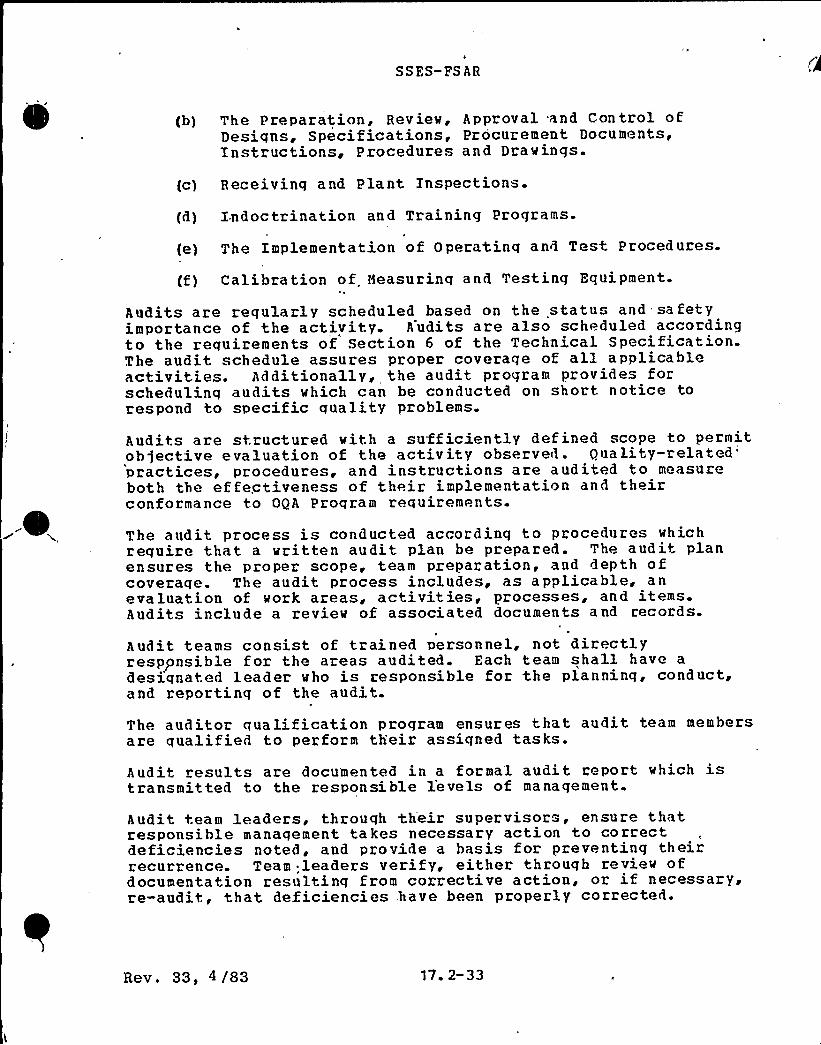
4
SSES-FS AR
(b) The Preparation, Review, Approval and Control ofDesiqns, Specif ications, Procurement Documents,Instructions, Procedures and Drawings.
(c) Receivinq and Plant Inspections.
(d) Indoctrination and Training Programs.
(e) The Implementation of Operatinq and Test Procedures.
(f) Calibration of Measuring and Testing Equipment.
Audits are reqularly scheduled based on the statu and safetyimportance of the activity. Audits are also scheduled accordingto the requirements of Section 6 of the Technical Specification.The audit schedule assures proper coverage of all applicableactivities. Additionally, the audit program provides forschedulinq audits which can be conducted on short notice torespond to specific quality problems.
Audits are structured with a sufficiently defined scope to permitoh jective evaluation of the activity observed.
Duality-related'ractices,
procedures ~ and instructions are audited to measureboth the effectiveness of their implementation and theirconformance to OQA Proqram requirements.
The audit process is conducted according to procedures whichrequire that a written audit plan be prepared. The audit planensures the proper scope, team preparation, and depth ofcoverage. The audit process includes, as applicable, anevaluation of work areas, activities, processes, and itemsAudits include a review of associated documents and records.
Audit teams consist of trained personnel, not directlyresponsible for the areas audited. Each team shall have adesiqnated leader who is responsible for the planning, conduct,and reportinq of the audit.
The auditor qualification program ensures that audit team membersare qualified to perform their assigned tasks.
Audit results are documented in a formal audit report which istransmitted to the responsible levels of management.
Audit team leaders, throuqh their supervisors, ensure thatresponsible manaqement takes necessary action to correctdeficiencies noted, and provide a basis for preventing theirrecurrence. Team leaders verify, either through review ofdocumentation resulting from corrective action, or if necessary,re-audit, that deficiencies have been properly corrected.
Rev. 33, 4 /83 17% 2 33
SSES-FSAH
Formal audit reports are reviewed bv NQA management to determinethe effectiveness of the OQA program, and .indications of quality
'rends.If additional ma nagement action is required, the resultsof these reviews are formally reported to the appropriate managerof the responsible organization.
Rev. 33, 4/83 17 2-34

Table 17.2-2OPERATIONAL POLICY STATEMENT CROSS REFERENCE MATRIX
WITH 10CFR50 APPENDIX B CRITERIA
OPS TITLE
1 Operational QualityAssurance Program
SYNOPSIS
Defines the scope and applicability of the OQA Program. Establishes requirements forthe OQA Manual and defines the tiers of documents comprising the OQA Program.
CRITERIA 1> 2
II,V,VI
2 Terms and Definitions Defines those terms having particular meaning within the context of the OQA Program
3 Control and Issuance ofDocuments
Establishes controls for the issuance and use of documents. Defines those documentscontrolled by the OQA Program and requires review, approval, and use of documents atrequired locations.
V, VI
4 Document Reviews
5 Deficiency Control System
Establishes the requirements for performing and documenting document reviews.
Delineates those activities associated with the control and correction of nonconformingmaterial, parts or components; other conditions adverse to quality; and significantconditions adverse to quality.
IIII IVI VI
VIII, XV, XVI
6 Qualification, Trainingand Certification ofPersonnel
Establishes the requirements for the training, qualification and certification ofpersonnel performing activities affecting quality to assure that they achieve andmaintain suitable proficiency.
II, IX, XVIII
7 Auditing and SurveillanceActivities
Establishes the requirements for the development of programs for auditing and monitoringquality related activities and includes performance, qualifications, reporting, andfollow-up action.
II, XVIII
8 The Collection, Storage,and Maintenance of QualityAssurance Records
Establishes the requirements for the collection, storage, and maintenance of qualityassurance records.
XVII
9 Control of Modifications &
Design ActivitiesEstablishes the requirements for ensuring that the quality of modified structures, systemsor components is at least equivalent to that specified in the original design bases,material specifications, and inspection requirements.
10 Procurement Control Establishes the requirements for the procurement of material, parts, components, servicesand spare parts.
IV, VII
11 Nuclear Fuel Management Establishes the requirements for the management of nuclear fuel activities IV, VII
12 Administrative Control ofPlant Operations
Establishes the requirements for the administrative and procedural controls that ensurethe plant is operated in a safe and efficient manner.
13 Maintenance, Installationof Modifications andRelated Activities
Establishes the requirements for ensuring that structures, systems, and components aremaintained in a condition to perform their intended function. The field activitiesassociated with modifications are also included.
IX, XIV
Rev. 28, I/82
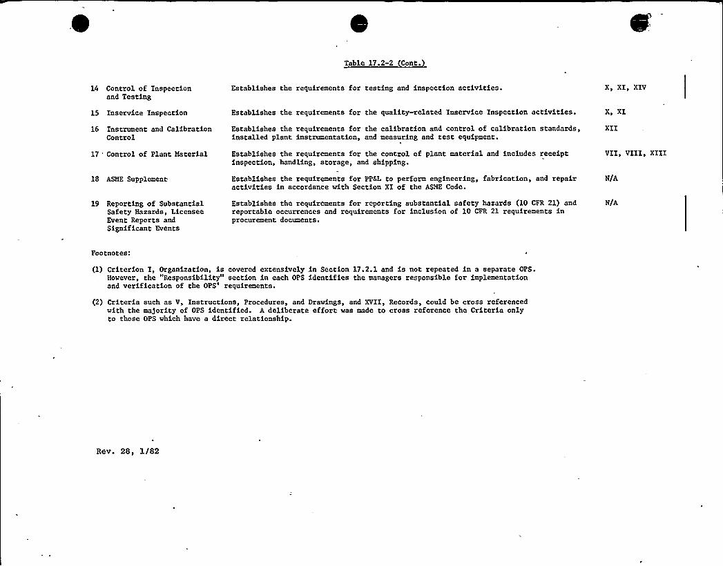
Table 17.2-2 Cont.
14 Control of Inspectionand Testing
Establishes the requirements for testing and inspection activities. X> XI, XIV
15 Inservice Inspection Establishes the requirements for the quality-related Inservice Inspection activities. X, XI
16 Instrument and CalibrationControl
Establishes the requirements for the calibration and control of calibration standards,installed plant instrumentation, and measuring and test equipment.
XII
17 Control of Plant Material
18 ASME Supplement
Establishes the requirements for the control of plant material and includes receiptinspection, handling, storage, and shipping.
Establishes the requirements for PP&L to perform engineering, fabrication, and repairactivities in accordance with Section XI of the ASME Code.
VII'III>XIII
N/A
19 Reporting of SubstantialSafety Hazards, LicenseeEvent Reports andSignificant Events
Establishes the requirements for reporting substantial safety hazards (10 CFR 21) andreportable occurrences and requirements for inclusion of 10 CPR 21 requirements inprocurement documents.
N/A
Footnotes:
(1) Criterion I, Organization, is covered extensively in Section 17.2.1 and is not repeated in a separate OPS.However, the "Responsibility" section in each OPS identifies the managers responsible for implementationand verification of the OPS'equirements.
(2) Criteria such as V, Instructions, Procedures, and Drawings, and XVII, Records, could be cross referencedwith the majority of OPS identified. A deliberate effort was made to cross reference the Criteria onlyto those OPS which have a direct relationship.
Rev. 28, I/82
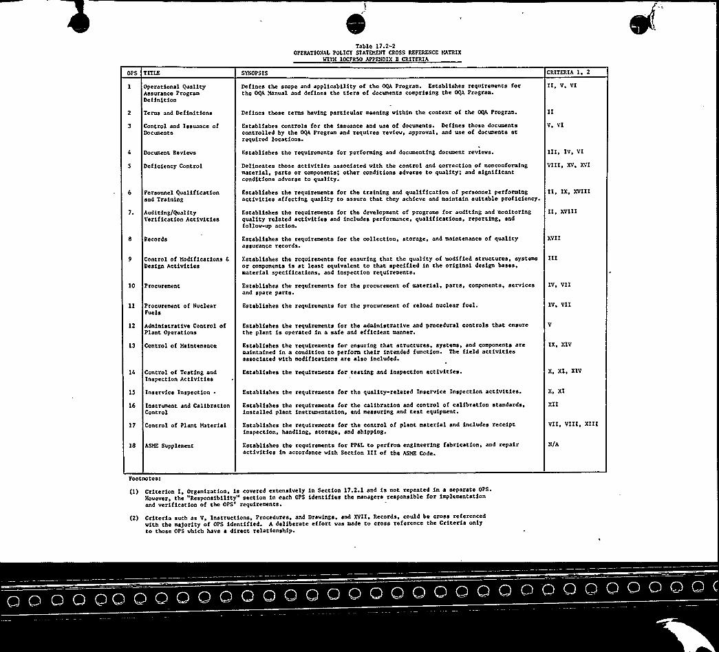
Table 17.2-2OPERATIONAL POLICY STATEMENT CROSS REFERENCE MATRIX
HITH 1OCFR50 APPENDIX B CRITERIA
OPS TITLE
Operational QualityAssurance ProgramDefinition
SYNOPSIS
Defines the scope and applicability of the OQA Program. Establishes requirements forthe OQA Manual and defines the tiers of documents comprising the OQA Program.
CRITERIA I, 2
II~ VI VI
2 Terms and Definitions
Control and Issuance ofDoc~ate
Defines those terms having particular meaning within the context of the OQA Program.
Establishes controls for the issuance and use of documents. Defines those documentscontrolled by the OQA Program and requires review, approval, and use of documents atrequired locations.
Vs VI
Document Reviews
5 Deficiency Control
Personnel Qualificationand Training
Auditing/QualityVerification Activities
8 Records
Establishes the requirements for performing and documenting document revievs.
Delineates those activities associated with the control and correction of nonconformingmaterial, parts or components; other conditions adverse to quality; and significantconditions adverse to quality.
Establishes the requirements for the training and qualification of personnel performingactivities affecting quality to assure that they achieve and maintain suitable proficiency.
Establishes the requirements for the development of programs for auditing and monitoringquality related activities and includes performance, qualifications, reporting, andfollow-up act ion.
Establishes the requirements for the collection, storage, and maintenance of qualityassurance records.
111, IV, VI
VIII, XV, XVI
II, IX, XVIII
II, XVIII
XVII
Control of Modifications &
Design Activities
10 Procurement
Procurement of NuclearFuels
Establishes the requirements for ensuring that the quality of modified structures, systemsor components is at least equivalent to that specified in the original design bases,material specifications, and inspection requirements.
Establishes the requirements for the procuremenr of material, parts, components, servicesand spare parts.
Establishes the requirements for the procurement of reload nuclear fuel.
IV, VII
IV, VII
12 Administrative Control ofPlant Operations
Establishes the requirements for the administrative and procedural controls that ensurethe plant is operated in a safe and efficient manner.
13 Control of Maintenance
Control of Testing andInspection Activities
15 Inservice Inspecrion
Establishes the requirements for ensuring that structures, systems, and components aremaintained in a condition to perform their intended function. The field activitiesassociated wirh modifications are also included.
Establishes the requirements for testing and inspection activities.
Establishes the requirements for the quality-related Inservice Inspection activities.
IX, XIV
X, XI, XIV
X, XI
16 Instrument and CalibrationControl
Establishes the requirements for the calibration and contxol of calibration standards,installed plant fnstrumentatfon, and measuring and test equipment.
XII
VII, VIII, XIII17 Control of Plant Material
18 ASME Supplement
Establishes the requfrements for the control of plant material and includes receiptinspection, handling, storage, and shipping.
Establishes the requirements for PP6L to perfrom engineering fabrication, and repairactivities in accordance with Section IIIof the ASME Code.
N/A
Footnotes:
(1) Criterion I, Organisation, is covered extensively in Section 17.2.1 and is not repeated in a separate OPSY
However, the "Responsibility" section in each OPS identifies the managers responsible for implementationand verification of the OPS'equirements.
(2) Criteria such as V, Instructions, Procedures, and Drawings, and XVII, Records, could be cross referencedwith the majority of OPS identified. A deliberate effort was made to cross reference the Criteria onlyto those OPS which have ~ direct relationship.
SS ES-PS AR
18 0 ORGANIZATION
This chapter contains a response for each,TNI-relatedrequirement. The chapter is divided into sections which containthe responses to all requirements for applicants for operating1icenses. The table of contents identifies which sectionprovides the responses for a given document.
Each section 'addresses all the requir'ements 'in its correspondingdocument. A response is only given to the most recent in theseries of requirements which contains an explanatory text. Porexample, if an explanatory text of requirement I.A.l.l appears onboth NUREG 0737 and NUREG 0694, a response is provided to NUBEG0737 since it supersedes all previous requirements. Ifrequirement I. A.1.2 appears in both NUREGs 0737 and 0694, but theonly explanatory text is in NUREG 0694, the response is providedto NUREG 0694 utilizing the implementation dates of NUREG 0737.
The responses in this chapter are applicable to Unit 1 andsystems common to Units 1 and 2.
Rev. 27, 10/81 18.0-1

I
'J ! ~
0

SSES-CESAR
18.1. 1.'1 Stafement of Qegag~ement"
Each licensee shall pz;ovide an on-shift technical advisor to theshift supervisor. The. shift technical advisor {STA) may servemore than one unit at a multiunit site if qualified to performthe advisor function for the various
units."'he
STA shall have a bachelor~s degree or equivalent in ascientific or engineering discipline and have received specifictraining in the response and analysis of the plant for transientsand accidents. The STA shall also receive training in plantdesign and layout, including the capabilities of instrumentationand controls in the control room. The licensee shall 'assignnormal duties to the STAs that pertain to the engineering aspectsof assuring safe operations of the plant, including the reviewand evaluation of operating experience.
\
The need for the STA position may be eliminated when thequalifications of the shift supervisors and senior operators havebeen upgraded and the man-machine interface in the control roomhas been acceptably upgraded. However, until. those long-termimprovements are attained, the need for an STA progra~ willcontinue.
The staff has not yet established the detailed elements of theacademic and training requirements of the STA beyond the guidancegiven in the Vassallo letter on November 9, 1979. Hor has thestaff made a decision on the level of upgrading required forlicensed operating personnel and the man-machine interface in thecontrol room that ~ould be acceptable for eliminating the need ofan STA. Until these requirements for eliminating the STAposition have been established, the staff continues to requirethat, in addition to the staffing requirement specified inSubsecpion 18.1.3, an STA 'be available for duty on each operatingshift when a plant is being operated in Hodes 1-3 for a BHR. Atother times, an STA is not required to be on duty.
Since the Hovember 9, 1979 letter was issued, several effortshave been made to establish, for the longer term, the minimumlevel of experience, education, and training for STAs. Theseefforts include work on the revision to AHS-3'.1, work by theInstitute of Huclear Power Operations (XHPO), and, internal staffefforts.
Rev. 27, 10/81 18 ~ 1-0
SSES-PSAR
INPO has made available a document entitled "Nuclear Power PlantShift Technical Advisor--Recommendations for PositionDescription, Qualifications, Education 'and Training.» Sections 5and 6 of the INPO document describe the education, training, andexperience requirements for STAs. The NRC staff finds that thedescriptions as set forth in Sections 5 and 6 of Revision 0 tothe IHPO document are an acceptable approach for the selection"—and traininq of personnel to staff the,STA positions. "'{Note:This should not be interpreted to mean that this is an NRCrequirement at this time. The intent is to refer to the IHPOdocument as acceptable for "interim guidance for a utility inplanning its STA proqram over the long term -{i.e., beyond theJanuary 1, 1981 requirement to have STAs in place in accordancewith the qualification requirements specified in the staff'sNovember 9, 1979 letter).Applicants for operatinq licenses shall provide a description oftheir STA training and requalification program in theirapplication, or amendments thereto, on a schedule consistent withthe NRC licensinq review schedule.
t
Applicants for operating licenses shall provide a description oftheir long-term STA program, including qualification, selectioncriteria, training, and possible phaseout. The description shallbe provided in the application, or amendments thereto, on aschedule consistent with the HRC licensing review schedule. Thedescription shall include a comparison of the 3.ong-term program
'iththe above mentioned IHPO document.
18. l. l. 2 Intervretation
The applicant is to develop a training program in compliance withthe November 9, 1979 letter and submit a description to the HRC.The applicant is to provide STA coverage for all operatingshifts. Candidates vill complete a training program and pass acertification examination prior to assumption of duties..Theapplicant is to develop a long-term program to maintain orphaseout STAs.
18.1. 1.3 Statement of Response
The proqram for the selection and training of STA~s is detailedL
in the Nuclear Department Instruction NDI-0.2.2 ~ Selection,Training and Certification of Shift Technical
Advisors".'TA
coverage vill be provided on operating shifts in accordancewith Subsection 6.2.2 of the Technical Specifications. STA's
Rev. 31 ~ 7/82 18 1-2

SSES-PS AR
will perform the duties and have the responsibilities outlined inplant procedure AD-QA-400, "Conduct of Technical Support."
STAs will meet the qualification requirements of the Vassalloletter of November 9,'979. All STA training will be completedand STAs will be ready for shift assignment pri.or to fuel load.The STA program described above will be maintained long-termuntil such time as phaseout is permitt'ed i.n accordance with NRC
instr uctions.
18.1 2 SHIFT SUPERVISDR RESPDNSXBILITIES (I A 1 23
No requirement stated in NUREG 0737. Refer to Subsection 18.2.2which contains the response to the requirement stated in NU]EG0694
18. 1-. 3 SHXPT QA N NI~G gI A 1 3)
18 1 3 1 Statement of Reauirementt nt R a n
Applicants for operating licenses shall include in theiradministrative procedures (required by license conditions)provisions governing required shift staffing and movement of keyindividuals about the plant. These provisions are required toassure that qualified plant personnel to man the operational-shifts are readily available in the event of an abnormal oremergency situation. Interim requirements for shift staffing aregiven in Table 18.1-1.
These ad min istrative procedures shall also se t forth a policy,the objective of which is to prevent situations-where fatiguecould reduce the ability of operating personnel to keep thereactor in a safe condition. The controls established shouldassure that, to the extent practicable, personnel are notassigned to shift duties while in a fatigues condition that couldsignificantly reduce their mental alertness or their decisionmaking ability. The controls shall apply to the plant staff whoperform safety-related functions (e.g. ~ senior reactor operators,reactor operators, auxiliary operators, health physicists, andkey maintenance personnel).
XE Circular No. 80-02, <Nuclear Power Plant Staff Mork Hours,"dated Pebruary 1,'980 discusses the concern of overtime work formembers of the plant staff who perform safety-related functions.The guidance contained in the XE Circular No. 80-02 was amendedby the July 31, 1980 letter. In turn, the overtime guidance ofthe July 31, 1980 letter 'was revised in Section X.A.1.3 of NUREG-
Rev. 31, 7/82I
18 1-3

SSES-ZS AR
0737. The HRC has issued a policy statemeat which furtherrevises the overtime guida'nce as stated in::NQRBG„0737. Thisguidance is as follows:
Enough plant operating personnel should be employed. to maintainadequate shift, coverage without routine heavy use of overtime.The objective is to have operating personnel -work a normal 8-hourday, 40-hour week while the plant is operating. . However,'in theevent that unforeseen problems require:substantial amounts ofovertime to be used, or during extended periods of shutdown forrefueling, ma|or maintenance . or ma)or plant modifications, on. atemporary basis, the following quidelines shall be followed:
(a) An individual should not be permitted to work more than16 hours straight (excluding shift turnover time}.
(b) An individual should not be permitted to work more'han16 hours in any 24-hour period, no more than 24 hoursin any 48-hour period, no more than 72 hours in anyseven day period (all excluding'hif t turnover time) .
(c)
(d)
A break of at least eight hours should be allowedbewteen work periods (including shift turnover time)-
'L
Except during extended shutdown periods, the use ofovertime should be considered on an individual basisand not for the entire staff on shift.
Recoqnizinq that very unusual circumstances may arise requixingdeviation from the above guidelines, such deviation shall beauthorized by the plant manager or his deputy, or higher levels.of management. The paramount consideration'n such authorizationshall be that significant reductions in the effectiveness ofoperating personnel would be highly unlikely. Authorizeddeviations to the working hour guidelines shall be documented andavailable for NRC review.
In addition, procedures are encouraged that would allow licensedoperators at the controls to be periodically relieved andassigned to other duties away from the control board during theirtours of duty.
Operatinq licen'se applicants shall complete these administrativeprocedures before fuel loading.
18. 1. 3. 2 Integpgefgtj,on
Hone required.
Rev. 31, 7/82 18. 1-4
SSES-FS AR
18. l. 3. 3 St atemen t of Resnonse
The facility staffinq requirements are presented in Subsection =- ~
.6.2.2 of the Technical Specifications. These requirements areconsistent with those qiven in Table 18.1-1.
The plant policy on operations personnel working hours isdiscussed in administrative procedure AD-QA-300, itConduct ofOperations.i' ~
18 1 4 IMMEDIATE UPGRADING QF REACTOR OPERATOR" AND. SENIOR REACTOR
l,
18.1.4.1 Statement of peguigement
Applicants~ for senior operator licenses shall have 4 years ofresponsible power plant experience. Responsible power plant "
,experience should be that obtained as a control room operator(fossil or nuclear) or as a power plant staff engineer involved
.in the day-to-day activities of the facility,. commencing with thefinal year of construction. A maximum of 2 years power, plantexperience may be fulfilled by academic or. related technicaltraining,'n a one-for-one time basis. Two years shall benuclear power plant experience. At least 6 months of the nuclearpower'plant experience shall be at the plant for which he seeks alicense. Effective date: Applications received on or after May1 ~ 1980.
Applicants for senior operator licenses shall have held anoperator's license for 1 year. Effective Date: Applicationsreceived after December 1, 1980. -The NRC - has not imposed the 1-year experience requirement on cold applicants for SRO licenses.Cold applicants are to work on a facility not yet in operation;their training programs are designed to supply the equivalent ofthe experience not available to them.
Senior operator+: Applicants shall have 3 months of,shifttraininq as an extra man on shift.Control room operator+: Applicants shall have 3 months trainingon shift as an extra person in the control room. Effective date:Applications". received after Auqust 1, 1980.
+Precritical applicants will be required to meet uniquequalifications designed to accommodate the fact that theirfacility has not yet been in operation.
R ev. 31 ~ 7/82 18 1-5
SS ES-PS AR
Train ing
3)
programs shall 'be modified, as necessary, to 'provide:1i
Training in heat,tran'sfer, fluid flow andther mod ynamics.
II
Training in the use of installed, plant systems tocontrol or mitiqate an accident i'n which the''core isseverely damaged.,
Increased emphasis on reactor and plant transients.".Effective 'date:,'Present programs have b'een modified .in
'esponseto Bulletins and Orders. Revised programsshould be submitted for OLB review..by August 1,.1980.
Content of the licensed operator requalification programs shallbe modified to include instruction in heat transfer,'luid flow,thermodynamics, and mitiqation of accidents involving a degradedcore. Effective date: May 1,. 1980.
The criteria for requirinq a licensed individual to participate'n accelerated requalification shall be modified to be consistentwith the new passing grade for, issuance of a license; 80A overalland 70% each category. Effective date. Concurrent with the nextfacility administered annual requalification examination afterthe issue date of this requirement.
~ g
Programs should be modified to require the control manipulationslisted in Enclosure 4 of HUBEG 0737, item I.A.2.1. Normalcontrol manipulations, such as plant reactor startups, must beperformed. Control manipulations during abnormal or emergency'.operations must be walked through with, and evaluated by, a.
>member of the training staff at a minimum. An
appropriate'imulator
may be used to satisfy the requirements, for -controlmanipulations. Effective date: Programs modified by August 1,1980. Renewal applications received, after November 1, 1980 must„reflect compliance with 'the program.
Certifications completed pursuant to Sections 55.10(a) (6) and55.33a(4) and (5) of 10 CPR Part 55 shall be; signed by, thehighest level of corporate manaqement for plant opera ti:on (forexample, Vice President for Operations). Effective'dat,e:Applications received on or after Nay 1, 1980.
18.1. 4. 2 Interoretation
None required.
Rev. 3f, 7/82 18. 1-6
SSES-PS AR
18 1 4.3 Statement of Response~C.
A program is established to assure that all reactor operator andsenior reactor aperator license candidates {beyond the initialcompliment required to startup Units 1 6 2) have the prescribedexperience, gualifications, and training. Candidates sill beprepared and certified in accordance pith Nuclear DepartaentInstruction NDI-4.2.1. Administrative procedure AD-QA-304, I"Operator Selection Training and Qualifications," details the process
'y
which the qualifications of candidates for operationspositions vill be evaluated in the future.
The initial startup crews sill have completed extensive trainingdevised in part to recoqnize the non-operational status of theunits. This program includes real time training an theSusquehanna SES simulator which duplicates the actual unit andthus in many respects equates to the experience requirements.Subsection 13.1.3 describes the qualifications commitments forthe existinq plant staff.
18 $ ~ 5 ~ ADgI$ISgRAT~IN gg
//BRINING
PROG~RMS /~A ~2. 3
Pending accreditation of train ing institutions, licensees andapplicants for operating licenses vill assure that tnainingcenter and facility instructors who teach systems, integratedresponses, transient, and simulator courses demonstrate seniorreactor operator (SRO) qualifications and be enrolled inappropriate requalification programs.
Training center and facility instructors who teach systems,integrated responses, transient and simulator courses shalldemonstrate their competence to NRC by successful completion of asenior operator examination. Effective date: Applicationsshould be submitted no later than August 1, 1980 for individualswho do not already hold a senior operator license.
Instructors shall be enrolled in apprapriate regualificationprograms to assure they are cognizant of current operatinghistory, problems, and changes to procedures and administrativelimitations. Effective date: Programs should be initiated Hay1, 1980. Programs should be submitted to OLB for review byAugust 1 1980
Rev. 30 ~ 5/82 18. 1-7
SSES-FSAR
18.1.5.2 Interpretation
The "instructors" referenced in this requirement are thoseindividuals vho teach systems specific to BMBs, integratedresponses, transients, and simulator courses to licensedoperators or license candidates.
18.1.5 3 Statement of Response
Certification of instructors is described in Nuclear DepartmentInstruction NDI-QA-4.1.3.. This procedure delineates whichinstructors are required to pass an examination for certificationof senior reactor operators (SRO). All instructors who teachmaterials identified in Subsection 18 1.5.2 are certified asSROs.
18.1 6 REVISE SCOPE AND CRITERIA POR LICENSING EXAMINATIONSgr.A.3 1g
18.1. 6.1 Statement of RgqgiremeRt
A new cateqory shall be added to the operator written examinationentitled, "Principles of Heat Transfer and Pluid Mechanics.«
A new cateqory shall be added to the senior operator writtenexamination entitled, ~~Theory of Fluids and Thermodynamics.<
Time limits shall be imposed for completion of the writtenexaminations:
l. Operator: 9 hours.
2. Senior Operator: 7 hours.
The passing qrade for the written examination shall be 80%overall and 70% in each cateqory.
. All applicants for senior operator licenses shall be reguired tobe administered an operating test as veil as the written
. examination. Effective date: Examinations administered on ora fter Nay 1, 1980.
Applicants vill grant permission to NRC to inform their facilitymanaqement reqardinq the results of the examinations for purposesof enrollment in requalif ication programs. Applications receivedon or after May 1, 1980.
Simulator examinations will be included as part of the licensingexaminations.
Rev. 32, 12/82 18. 1-8
SS ES-FS AR
18.1. 6.2 Xnteroretation
None required.
18.1. 6.3 Statement of Response
The reactor operator and senior reactor operator training programhas been upgraded to include the subject material described inthis requirement. Refer to Subsection 18.1.0.3 for the responseto requirement I-.A.2.1, ~~Immediate Upgrading of Reactor Operatorand Senior Reactor Operator Traininq and Qualifications."Candidates will be prepared and certified in accordance withNuclear Department Instruction NDI-QA-0.2. l. The Susquehanna SESsimulator is available for the simulator'portion of exams.Application packages will include a release which permits the NRCto inform PPSL management of exam results.
18 $ 7 EVALUATION OP ORGANIZATION AND MANAGENENT fI B. 1 2)
18.1. 7.1 Statement of Requirement
Each applicant for an operatinq license shall establish an onsiteindependent safety engineering group (ISEG) to performindependent reviews of plant operations.
The principal function of the ISEG is to examine plant operatingcharacteristics, NRC issuances, Licensing Information Serviceadvisories, and other appropriate sources of plant design andoperating experience information that may indicate areas forimproving plant safety. The ISEG is to perform independentreview and audits of plant activities including maintenance,modifications, operational problems, and.operational analysis,and aid in the establishment of programmatic reguirements forplant activities. Where useful improvements can be achieved, itis expected that this group vill develop and present detailed
ecommendations to corpox:ate manaqement for such things asrevised procedures or equipment modifications.
Another function of the ISEG is to maintain surveillance of plantoperations and maintenance activities to provide independentverification that these activities are performed correctly andthat human errors are reduced as far as practicable. The ISEGwill then be in a position to advise utility management on theoverall quality and safety of operations. The ISEG need notperform detailed audits of plant operations and shall not be
R ev. 31, 7/82 18 1-9

SSES-PS AR
responsible for sign-off functions such that it becomes, involvedin the operating orqanization.
The new ISEG shall not replace the plant operations revievcommittee (PORC) and the utility's independent reviev and auditgroup as specified by current staff guidelines (Standard RevievPlan, Regulatory Guide 1.33, Standard Technical Specifications) .Rather, it is an additional independent group of. a minimum offive dedicated, full-time engineers, located onsite,
but'eportinqoffsite to a corporate official who'holds a high-level,technically oriented position that is not in the management chainfor power production. The ISEG will i.ncrease the ava ilabletechnical expertise located onsite and vill provide continuing,svstematic, and independent assessment of plant activities.Integrating the shift technical advisors: (STAs') into the ISEG insome vay would be desirable in that it could enhance the group'scontact with and knowledge of day-to-day plant operations:andprovide additional expertise. However, the STA on shift isnecessarily a member of the operating staff and cannot beindependent of it.It is, expected that the ISEG may interface vith the qualityassurance (QA) orqanization, but preferably 'should not be anintegral part of t'e QA organization.
'hefunctions of the ISEG require daily contact vith theoperatinq personnel and continued access to plant -facilities andrecords. The ISEG review functions can, therefore, best becarried out by a qroup physically located onsite. Hovever, forutilities vith multiple sites, it may be possible to performportions of the independent safety assessment function in acentralized location for all the utility's plants. In suchcases, an onsite qroup still is required, but it may be slightlysmaller than would be the case if it were performing the entireindependent safety assessment function. Such cases will berevieved on a case-by-case basis.
This requirement shall be implemented prior to issuance of anopera tin q lice nse.
Refer to Subsection 18.2.6 for .the response to.additionalrequirements contained in NtJREG 0694.
18.1. 7. 2 Interpretation
None required.
18.1.7 3 Statement of Response
Hev. 31, 7/82 18. 1- 10
SSES- FS AR
The functions of the ISEG will be performed by the Nuclear SafetyAssessment Group (NSAG) . PPGL~s commi'tment to the NSAG isaddressed in a letter from N. N. Curtis to B. J. Youngblood onDecember 8, 1980 (PLA-585) and are further addressed in NuclearDepartment Instruction NDI-1.1.2. NSAG will be functional byfuel load.
18.1.8 - SHORT-TERM ACCIDENT AND PROCEDURE EEVIEM QI C.l)
18.1. 8.1 Statement of Reguirement
Reanalysis of small break LOCAs, transients, accidents, andinadequate core cooling and preparation of guidelines fordevelopment of emergency procedures should be completed andsubmitted to the NRC for review by January 1, 1981. The NRCstaff will review the analyses and quidelines and determine theiracceptability by July 1, 1981, and will issue guidance tolicensees on preparinq- emerqency procedures from the guidelines.Followinq NRC approval of the guidelines, licensees andapplicants for operatinq licenses issued prior to January 1,1982, should revise and implement their emergency procedures at
'hefirst refuelinq outage after January 1, 1982. Applicants foroperating licenses issued after January 1, 1982 should implementthe procedures prior to operation. This schedule supersedes theimplementation schedule included in NUREG-0578, Recommendation2.1.9 for item Z. C. 1 (a) 3, Reanalysis of Transients and Accidents.For those licensees and/or owners groups that will have
'ifficultyin attaining the January 1 ~ 1981 due date forsubmittal of quidelines, a comprehensive proqram plan, proposedschedule, and a detailed justification for all delays andproblems shall be submitted in lieu of the guidelines.
18.1. 8. 2 Interpretation
The BMR Owners'roup quidelines may. be utilized to developemergency procedures for accidents and transients.
18.1.8.3 Statement of Response
In the Clarification of the NURBG-0737 requirement »for- reanalysis of transients and accidents and inadeguate corecooling and preparation of guidelines for development ofemerqency procedures," NUREG-0737 states:
Rev. 31, 7/82 18 1- 11
SS ES- FS AR
Owners'roup or vendor submittals may be referenced asappropriate to support- this reanalysis. If'wners ~ "group orvendor submittals have already been forwarded to the'ta'fffor review, a brief description of the submittals andjustification of their adequacy to support guidelinedevelopment is all that is required.
I
PPSL has participated, and will continue to. participate, inthe BMR Owners 'roup program to develop Emergency ProcedureGuidelines for General Electric Boiling Mater Reactors.Followinq are a brief description of the submittals -to date,and a justification of their adequacy to support guidelinede v elo pm en t.
A Description of Submittals
(l) NED0-24708A, "Additional Information Required for NRCStaff Generic Report on Boiling Mater Reactors,"Revision 1, December 1980.
(a} Description and analysis of small break loss-of-coolant events, considering a range of breaksizes, location ~ and cond itions,,includingequi.pment failures and 'operator errors;description and justification of analysis methods.
(b) 'Description and analysis of loss of feedwaterevents, including cases involving stuck-openrelief valves, and including equipment failuresand operator errors; description and.justificationof an'alysis methods.
(c) Description and analysis of each FSAR Chapter 15event resultinq in a reactor 'system transient;demonstration of applicability 'of analyses to eachevent; demonstration of applicability of EmergencyProcedure'uidelines to each event.
(d) Description of natural and forced circulationcoolinq; factors influencing natural circulation,including noncondensibles; reestablishment offorced circulation under transient and accidentconditions.
(e) Description and analysis of loss-of-coolantevents, loss of feedwater events, and stuck-openrelief valve events, including severe multipleequipment failures and operator errors which„ ifnot mitiqated, could result in conditions ofinadequate core'cooling.
Rev. 31, 7/82 18. 1-12
SS ES-PS AR
(2)
4
(f) Description of indications available to the BMR
. operator for the'etection of adequate corecoolinq
(q) Description and justificati'on of analysis methods.for extremely degraded cases.
NEDO 24934, »BMR Emergency Procedure Guidelines BMR 1-6," Revision 1, January 1981.
Guidelines for BMR -Emergency Procedures based onidentification and response to plant symptoms;including a range of equipment fa'ilures and operatorerrors; includinq severe multiple equipment failuresand operator errors which, if not mitigated, wouldresult in conditions of inadequate core 'cooling;,includinq conditions when core cool'ing status, isuncertain or unknown.
B ~ Adeauacy of Submittals
The submittals described in paragraph A have been discussedand reviewed extensively amonq the BMR Owners'roup,
the'eneral'lectricCompany, and the NRC staff. -=The, NRC staff ~
has found (NUHEG-0737, page I.C.1-3) that »the analysis andguidelines submitted by the General Electric Company (GE)Owners'roup...comply with the requirements (of the 'NUREG- -
'737clarification) ." In Reference 18.1-1, the Director of.the Division of Licensing states, »we*find the EmergencyProcedure Guidelines acceptable for trial implementation (onsix plants with applications for operating licensespendinq) ."PPSL believes that in view of these findings, no furtherdetailed justification of the analyses or guidelines isnecessary't this time. Ref erence 1 further sta tes, "duringthe course of implementation we may identify areas, thatrequire modification or further analysis -and justification.»The enclosure to Reference 18.1-1 identifies several suchareas. PPSL will work with the BM,R Owners~ Group inrespondinq to such requests.
By our commitment to. work wi;th the. Owners'roup on suchrequests, on'chedules mutually agreed to by the NRC and the.Owners'roup, and by reference to the BMR owners'roupanalyses and guidelines already 'submitted, our response tothe NUREG-0737 requirement »for reanalyses of transients andaccidents and inadequate core cooling and prepara'tion ofguidelines .for development of emergency procedures» byJanuary 1, 1981, is complete.
0'ev.
31, 7/82 18.'- 13
SS ES-FS AR
Emergency procedures based on those guidelines have beendeveloped and are currently in trial,use on the SusquehannaSES Simulator. These procedures have been reviewed by theNRC. Final versions which incorporated NRC comments .weresubmitted in a letter from N. M. Curtis to B. J.. Youngbloodon Nay 15, 1981 (PLA-791) .
.18 l. 9 SHIFT RgLIgF APD TURNOVER PROCEDURES gI. C 2L
No requirement stated in NUREG 0737. Refer to Subsection 18.2.8which contains the response to the requirement in NUREG 0694.
18. l. 10 SHIFT SUPFRVISQR RQSPOgSIBILITY g'I C 3}
No requirement stated in NUREG 0737. Refer to Subsection 18.2.9which contains the response to the requirement in NUREG 0694.
18. 1. 11 CONT ROL ROON ACCESS gI C 4)
No requirement stated in NUREG 0737. Refer to Subsection 18. 2. 10which contains'the response to the requirement in NUREG 0694.
18.1. 12 FEEDBACK OF OPERATING EXPER'IENCE (I C.5)
lR. l. 12. 1 Statement of Requirement
Applicants for an operatinq license shall prepare procedures toassure that information pertinent to plant safety originatinginside or outside the utility organization is continuallysupplied to operators and other personnel and is incorporatedinto training and retraining programs. These procedures, shall:
(1) Clearly identify organizational responsibilities forreview'of operating experience, the feedback ofpertinent information to operators and other personnel,and the incorporation of such information into trainingand retraining programs;
{2) Identify the administrative and technical review stepsnecessary in translatinq recommendations by 'theoperatinq experience assessment group into plantactions (e. q., chanqes to procedures, operatingorders);
Rev. 31, 7/82 18 1- 14
S S ES- PS AR
(3) Identify the recipients of various'ategories ofinformation from operating experience (i.e.,supervisory personnel, shift technical advisors,operators, 'aintenance personnel, health physicstechnicians) or otherwise provide means throuqh whichsuch information can be readily related to the gobfunctions of the recipients;
(4) Provide means to assure that affected personnel becomeaware of and understand information of su.fficientimportance that should .not wait for emphasis throuqhroutine traininq and retraining programs;
(5) Assure that plant personnel do not routinely receiveextraneous and unimportant information on operatingexperience in such volume that it would obscurepriority information or otherwise detract from overallgob performance and proficiency;
(6) Provide suitable checks to assure that conflicting orcontradictory information is not conveyed to operatorsand other personnel until resolution is reached; and,
(7) Provide periodic'nternal audit to assure that the ..
feedback program functions effectively at all levels.
This requirement shall be implemented prior to issuance of anoperatinq license.
18. l. 12. 2 Interpretation
Hone required.
18.1.12. 3 Statement of Response
PPGL has developed a comprehensive proqram for feedback ofoperatinq experience. Components of the program are as follows..
Operatinq experience from other utilities and other industrysources is initially reviewed and dispositioned by the IndustryEvents Review Program (IERP). The XERP is designed to assureplant personnel do not routinely receive extraneous andunimportant information, that information is not contradictory orconf lictinq, that information is resolved prior to disseminationand that important information is rapidly routed to theappropriate personnel. A description of the organization,responsibilities and proced,ures of the IERP can be found inNuclear Department Instruction NDI-QA-6. 2. 2.
Rev. 31, 7/82 18 1-15
SS ES- FS AR
The Shift Technical Adviser (STA) as part of the OperationsAssessment Function will be the focal point for dissemination ofoperating experience information to appropriate plant personnel.This vill include:
o Feedback of pertinent information to operators and otherstation personnel and transmittal of information to theNuclear Traininq Group for incorporation into appropriatetraining programs.
o Initiatinq, when required, plant procedure changes and/orplant modification requests.
o Discussinq with shitt personnel operating experienceinformation of sufficient importance that it cannot bedef erred to the retraining program.
o Editinq information provided to plant personnel to minimizeexcessive or conflicting information and distributinginformation to appropria te functional units.
Administrative Procedure AD-QA-406 is being developed to furtherdefine this function and the interfaces among the STAs and theNuclear Safety Assessment Group, Nucl'ear Training, Operations andthe Industry Events Review Program.
General information from the nuclear industry and, information ofgeneral interest from inside the company will be disseminated toappropriate personnel. The details of this proqram are describedin rnclear Department znstrncticn NDX-ga-6.2.1.
The NQA organization will audit selected portions of the feedbackprogram to assure it functions effectively at all levels.
18 '1 13 VERIFY CORRECT PERFORMANCE OF OPERATING ACTIVITIES(I. C 6)
18.1.13.1 Statemegg of geguiggment
Licensees~ procedures shall be reviewed and revised ~ asnecessary, to assure that an effective system "of verifyinq thecorrect performance of operatinq activities is provided as ameans of reducinq.human errors and improvinq the quality ofnormal operations. This will reduce the frequency of occurrence
Rev. 31, 7/82 18. 1-16

SSES-PSAR
of situations that could result in or contribute to accidents.Such a verification system may include automatic system statusmonitorinq, human verification of operations and maintenanceactivities independent of the people performing the activity (seeNUREG-0585, Recommendation 5), or both.
Implementation of automatic status monitoring if required. will~
reduce the extent of. human verification of operations andmaintenance activities but vill not eliminate the need for suchverification in all instances. The procedures adopted by thelicensees may consist of two phases —one before and one afterinstallation „of automatic status"monitoring equipment, ifrequired, in accordance with item I.D. 3.
Procedure's .must be reviewed and revised 'prior to fuelload.'8.1.13.2
Interpretation
None„required.
18.1. 13.3 Statement of Response
Administrative procedure AD-QA-306, "System Status and EquipmentControl,~'ill provide the means to verify correct performance ofsurveillance and maintenance activities. Status ve rif icationwill utilize control room indications, presently available,operability testing where appropriate, or independentverification by a second qualified person. The, procedure definescircumstances when independent human verification is required.The procedure also incorporates the requirements of itemII.K.1.10 (see Subsection 18.2.26) for the removal from andrestoration to service of safety related systems and componentsduring normal operations,and maintenance activities.
18 1 14 NSSS VENDOR REVIEW Og P ROCBDURES QI C 7)"
No requirement stated in NUREG 0737. Refer to Subsection 18. 2.12which contains the response to the requirement in NUREG 0694.
18.1 15 PILOT MONITORING. OF SELECTED EMERGENCY PROCEDURESFOR NEAR TERM OPERATING LICENSES gI C 8)
No requirement stated in NUREG 0737. Refer to Subsection 18. 2.13which contains the response to the requirement in NUREG 0694.
Rev. 27, 10/8118 1-17
SS ES-FS AR
18. 1 16 CONT'ROL RQOH DESI GN REVIEW ~ID. 1)
18. 1. 16. 1 Statement of Requirement
All licensees and applicants for opexating licenses vill berequired to conduct a detailed contro1-room design reviev toidentify and correct design deficiencies. This detailed control-room design reviev is expected to take about a yeax. Therefore,the Office of Nuclear Reactor Regulation {NRR) requires thatthose applicants for operating licenses vho are unable tocomplete this reviev prior to issuance of a license makepreliminary assessments of their control rooms to identifysiqnificant human factors and instrumentation problems andestablish a sched,ule (to be approved by NRC) for correctingdeficiencies. These applicants vill be required to complete themore detailed control room reviews on the same schedule aslicensees vith opexating plants.Applicants vill find it of value to refer to the draft documentNUREG/CR-1580, "Human Engineering Guide to Control RoomEvaluation," in performing the preliminary assessment. NBB'illevaluate the applicants preliminary assessments including theperformance by NRB of onsite review/audit. The NRR onsitereviev/audit will be on a schedule consistent with licensingneeds.
I
This requirement shall be met prior to fuel load.
18.1. 16. 2 Interpretation
Applicants for operating licenses are required to perform apreliminaxy control room design assessment vhich should be basedon NUREG/CR-1580. This assessment will be revieved by the NRC,vho vill subsequently recommend changes for correctingdeficiences. Applicants must submit for NRC approval a schedulefor correcting these deficiencies.Applicants will be xequired to perform a detailed control roomdesign assessment following NUREG 0700 issuance. This assessmentis not xequired to be completed prior to issuance of an operatinglicense.
18.1.16 3 Statgmept of Response
A detailed control room review to identify significant humanfactors problems was conducted by PPSL with assistance from
Rev. 27, 10/81 18.1-18

SSES-FS AR
experienced human factors personnel from General PhysicsCorporation. This review was based on the criteria given indraft N 0 REG/CR-1580.
During the week of October 27, 1980, the NRC performed an onsitereview of the Susquehanna control room. The results of th- ".
review were formally transmitted to PPSL on January 31, 198'- Ameeting was held on February 3, 1981 in Bethesda to discuss andclarify the NRC findings. On February 27, 1981 PPSL submitted aformal response to all NRC findings (refer to PLA-648). Thisresponse included a schedule for implementing the findings-addressed in the NRC report.
18.1.17 PLANT SAFETY PARAMETER DISPLAY SYSTEM JI.D.2$
18.1. 17. 1 Statement of Qeguirement
Each applicant and licensee shall install a safety parameterdisplay system (SPDS) that will display to operating personnel aminimum set of parameters which define the safety status of theplant This can be attained through continuous indication ofdirect „and derived variables as necessary to assess plant safetystatus.
The operational date for the SPDS is October 1, 1982.
18.1. 17. l. 1 Function
The purpose of the safety parameter display system (SPDS) is toassist control room personnel in evaluating the safety status ofthe plant. The SPDS is to provide a continuous indication ofplant parameters or derived variables representative of thesafety status of the plant. The primary function of the SPDS isto aid the operator in the rapid detection of abnormal operatingconditions. The functional criteria for the SPD'S presented inthis section are applicable for use only in the control room.
Xt is recognized that, upon the detection of an abnormal plantstatus, it may be desirable to provide additional information toanalyze and diagnose the cause of the abnormality, executecorrective actions, and monitor plant response as secondary SPDSfunctions.As an operator aid, the SPDS serves to concentrate a minimum setof plant parameters from which the plant safety status can beassessed. The grouping of parameters is based on the function ofenhancinq,the operator's capability to assess plant status in a
Rev. 27, 10/81 18 1-19
SS BS-PS AR
timely manner without surveying the entire control room.However, the assessment based on SPDS is likely to be followed byconfirmatory surveys of many non-SPDS control room indicators.Human-factors engineering shall be incorporated in the variousaspects of the SPDS design to enhance the functionaleffectiveness of control room personnel. The design of theprimary or principal display format shall be as simple aspossible, consistent with the reguired function, and shallinclude pattern and coding techniques to assist the operator'smemory recall for the detection and recognition of unsafeoperatinq conditions. The human-factored concentration of thesesignals shall aid the operator in functionally comparing signalsin the assessment of safety status.All data for display shall be validated where practicable on arealtime basis as part of the display to control room personnel.For example, redundant sensor data may be compared, the range ofa parameter may be compared to predetermined limits, or otherquantitative methods may be used to compare values. Mhen anunsuccessful validation of data occurs, the SPDS shall containmeans of identifying the impacted parameter(s) . Operatingprocedures and operator traininq in the use of the SPDS shallcontain information and provide guidance for the resolution ofunsuccessful data validation. The ob jective is to ensure thatthe SPDS presents the most current and accurate status of theplant possible and is not compromised by unidentified faultyprocessinq or failed sensors.
The SPDS shall be in operation during normal and abnormaloperatinq conditions. The SPDS shall be capable of displayingpertinent information during steady-state and transientconditions. The SPDS shall be capable of presenting themagnitudes and the trends of parameters or derived variables asnecessary to allow rapid assessment of the current plant statusby control room personnel.
The parameter trendinq display shall contain recent and currentmagnitudes of the parameter as a function of time. Thederivation and presentation of parameter trending during upsetconditions is a task that may be automated, thus freeing theoperator to interpret the trends rather than generate them.Display of time derivatives of the parameters in lieu of trendsto both optimize operator-process communication and conservespace may be acceptable.
The SPDS may be a source of information to other systems, and thefunctional criteria of these systems shall state the requiredinterfaces with the SPDS. Any interface between the SPDS and asafety system shall be isolated in accordance with the safetysystem criteria to preserve channel independence and ensure theintegrity of the safety system in the case of SPDS malfunction.
Rev. 27, 10/81 1 8.1-20
Design provisions shall be included in the interfaces between theSPDS and nonsafety systems to ensure the integrity of the SPDSupon failure of nonsafety equipment.
A qualification program shall be established to demonstrate SPDSconformance to the functional criteria of this document.
18 1. 17. 1~ I,ocation
The SPDS shall be located in the control room with additionalSPDS displays provided in the TSC and the EOP. The SPDS may bephysically separated from the normal control boards; however, itshall be readily accessible and visible to the shift supervisor,control room senior reactor operator, shift technical advisor,and at least one reactor operator from the normal operating area.If .the SPDS is part of the control board, it shall be easilyrecognizable and readable.
18.1.17 1.3 Size
The SPDS shall be of such size as to be compatible with theexisting space in the control area. The SPDS display shall bereadable from the emergency operating station of the control roomsenior reactor operator. It shall not interfere with normalmovement or with full visual access to other control roomoperating systems and displays.
18. 1. 17. l. 4 S ta ffinq
The SPDS shall be of such design that no operating personnel inaddition to the normal control room operating staff are requiredfor its operation.18.1.17 1.5 Display Considerations
The display shall be responsive to transient and accidentseguences and shall be sufficient to indicate the status of theplant. Por each mode of plant operation, a single primarydisplay format designed according to acceptable human-factorsprinciples (a limited number of parameters or derived variablesand their trends in an organized display that can be readilyinterpreted by an operator) shall be displayed, from which plantsafety status can be inferred. It is recognized that it may bedesirable to have the capability to recall additional data onsecondary formats or displays.
Rev. 27, 10/81
SS ES-FS AR
The primary display may be individual plant parameters or may becomposed of a number of parameters or derived variables giving anoverall system status. The basis for the selection of theminimum set of parameters in the primary display shall bedocumented as part of the design.
The important plant functions related to the primary displaywhile the plant is qenerating power shall include, but not belimited to:
00000
Reactivity controlReactor core cooling and heat removal from primary systemReactor coolant system integrityRadioactivity control
'Containment integrityThe SPDS may consist of several display formats as appropriate tomonitor and present the vari.ous parameters or derived variables.For each plant. operating mode, these formats may either beautomatically displayed or manually selected, by the operator toKeep control room operating personnel informed. Flexibility toallow for interaction by the operator is desirable in the displaydesigns. Also, where feasible, the SPDS should include someaudible notification to alert personnel of an unsafe operatingcondition.
The SPDS need not be limited to the previously stated functions.It may include other functions that aid operating personnel inevaluating plant status. It is desirable that the SPDS besufficiently flexible to allow for future incorporation ofadvanced diagnostic concepts and evaluation techniques andsystems.
I
18 l. 17. l. 6 Design * Criteria
The total SPDS need not be Class 1E or meet the single-failurecriterion. The sensors and signal conditioners (such aspreamplifiers, isolation devices, etc.) shall be desighed andqualified to meet Class 1E standards for those SPDS parametersthat are also used by safety systems. Furthermore, sensors andsignal conditioners for those parameters of the SPDS identical tothe parameters specified within Regulatory Guide 1.97 shall bedesigned and qualified to the criteria stated in Regulatory Guide1.97. For SPDS applications it is also acceptable to have Class1E qualified devices from the sensor to a post-accident-accessible location, such as outside containment, and then non-1Edevices from containment to the display (or processor) on thepresumption that these components can be repaired or replaced inan accident environment. The processing and display devices ofthe SPDS shall be of proven high quality and reliability.
Rev. 27, 10/81 18-1-22

SSES-FSAR
The function of the SPDS is to aid the operator in theinterpretation of transients and accidents. This function shallbe provided during and following all events expected to occurduring the life of the plant, including earthquakes. To achievethis function, the display system shall not only take adequateaccount of human factors —the,man-machine interface —but shallalso be sufficiently durable to function during and afterearthquakes. Because of current technology, it may not bepossible to satisfy these criteria within one SPDS system.
From an operational viewpoint, it is preferred that only onedisplay system be used for evaluating the safety status of theplant. One display system simplifies the man-machine interfaceand thus minimizes operator errors. However, in recognition ofthe restraints imposed by current technology, an alternative isto design the overall SPDS function with a primary and backupdisplay system: (1) the primary SPDS display would have highperformance and flexibilityand be human factored but need not beseismically qualified; and (2) the backup display system would beoperable during and following earthquakes, such as the normalcontrol room displays needed to comply with Regulatory Guide1.97. The display system (or systems) provided for the SPDS
function shall be capable of functioning during and following alldesign basis events for the plant.
In all cases, both the primary SPDS display and the backup SPDS
seismically qualified portion of the display shall besufficiently human factored in its design to allow the controlroom operations staff to perform the safety status design toallow the control room operations staff to perform the safetystatus assessment task in a timely manner. Dependence on poorlyhuman-engineered Class 1E seismically qualified instruments thatare scattered over the control board, rather than concentratedfor rapid safety status assessment, is not acceptable for thisfunction. An acceptable approach would be to concentrate theseismically qualified display into one segment of the controlboard.
The dynamic loading limitations of the SPDS design shall bedefined and incorporated into the training program. The controlroom operations staff shall be provided with sufficient,information and criteria to allow for performance of anoperability evaluation of SPDS is an earthquake should occur.
The SPDS as used in the control room shall be designed to anoperational unavailability goal of 0.01, as defined in Section1.5 of NUREG 0696. The cold shutdown unavailability goal for theSPDS during the cold shutdown and refueling modes for the reactorshall be 0.2, as defined in Section 1.5 of NUREG 0696.
Technical specifications shall be established to be consistentwith the unavailability design goal of the SPDS and with the
Rev. 27, 10/81 18.1-23
SS ES- PS AR
compensatory measures provided during periods when the SPDS isinoperable. Operation of the plant with the SPDS out of serviceis alloved provided that the control board is sufficiently humanfactored to allow the operations staff to perform the 'safetystatus assessment task in a timely manner. Dependence on poorlyhuman-engineered instruments that are scattered over 'the controlboard rather than concentrated for rapid safety status assessmentis not acceptable for this function.The operational date for the SPDS is October 1, 1982.
18,1. 17. 2 - In terpreta tion
None required.
18. 1.17. 3 Statement of Response
The proposed method of responding to this requirement vassubmitted by a letter to B. J. Youngblood from N. M. Curtis'nApril 2, 1981 (PLA-700). Details on the SPDS are presented inAppendix I of the Emergency Plan.
18 1. 18 TRAINING DURING LOW-POWER TESTING gI. G 1}i
No requirement stated in NUREG 0737. Refer to Subsection 18. 2.15vhich contains the response to the requirement in NUREG 0690.
18 1 19 REACTOR COOLANT SYSTEM VENTS (II B ll
18,1.19.1 Statement of Reguigement
Each applicant and licensee shall install reactor coolant system(RCS) and reactor pressure vessel (RPV) head high point ventsremotely operated from the control room. Although the purpose ofthe system is to vent noncondensible gases from the RCS vhich mayinhibit core coolinq during natural circulation, the vents mustnot lead to an unacceptable increase in the probability of aloss-of-coolant accident (LOCA) or a challenge to containmentintegrity. Since these vents form a part of the reactor coolantpressure boundary, the design of the events shall conform to therequirements of Appendix A to 10 CPR Part 50 'General DesignCriteria." The vent system shall be designed with sufficientredundancy that assures a lov probability of inadvertent orirreversible actuation.
Rev. 27, 10/Sl 1 8.1-24

SS ES-PS AR
Each licensee shall provide the following information concerningthe design and operation of the high point vent system:
(1) Submit a description of the design, location, size, andpower supply for the vent system along with results ofanalyses for loss-of-coolant accidents initiated by abreak in the vent pipe. The results of the analysesshould demonstrate compliance with the acceptancecriteria of 10 CPR 50.46.
(2) Submit procedures and supporting analysis for operatoruse of the vents that also include the informationavailable to the operator for initiating or terminatingvent usage.
Documentation, shall be submitted by July 1, 1981. modificationsshall be completed by July, 1982.
VIk
18.1.19. 2 Internretation2
None required.
18.1. 19. 3 Statement Of Response
The present design of reactor coolant and reactor vessel ventsystems meet these requirements.
The RPV is eguipped with various means to vent the reactor duringall modes of operation. All the valves involved are safetyqrade, powered by essential busses and are capable of remotemanual operation from the control room.
The largest portion of non-condensables are vented throughsixteen (16) safety relief valves (PSV 141F013A-S) mounted on themain steam lines. These power operated relief valves satisfy theintent of the NRC position. Information regarding the design,qualification, power source of these valves has been provided inSections 5.1, 5.2.2, 6.2, 6.3, 7. 3 and 15.
In addition to power operated relief valves, the RPV is equippedwith various other means of high point venting. These are:
Normally closed RPV head vent valves (HV141-F001 andF002) ~ operable from control room which discharges todrywell equipment drain tank., {Subsection 5.1 andFigure 5.1-3a) .
Rev. 27, 10/Sl 18-1-25
SS ES- PS AR
2. Normally open reactor head vent line 2 DBA-112 which.discharges to main steam line "A". (Subsection 5.1 andPiqure 5.1-3a) .
3 Hain steam driven RCIC and HPCE system turbines,operable from the control room which exhaust tosuppression pool. (Subsections 5.3 and 6.3 and Figures5.4-9a and 6.3-la).
Although the power operated relief valves fully satisfy theintent of the NRC requirement these other means also provideprotection against accumulation of non-condensables in the RPV.
The design of the RCS and RPV vent systems is in agreement withthe qeneric capabilities proposed by the BMR Owners'roup, withthe exception of- isolation condensers Susquehanna SES is notequipped with isolation condensers. The BMH Owners'roupposition is summarized in NED0-24782.
Operation of the equipment described above during abnormaloperatinq conditions is controlled by the Emergency OperatingProcedures. While these procedures do not specifically addressventinq of non-condensable qases, they do address properutilization of equipment to recover from undesirable conditionspresented by the presence of non-condensables or by othercircumstances.
The RCS and HPV vent systems are part of the original SSES designbasis. A pipe break in either of these systems would be the sameas a small mainsteam line bre'ak. A complete mainsteam line breakis within the design basis (see Subsections 6.2.1.1.3.3.2 and6.3.3). Smaller size breaks have been shown to be of lesserseverity (see Subsections 6.2.1;1.3.3.5 and '6.3.3.7.3) .Therefore, no new supporting analysis is necessary in response toNUREG 0737. In addition, no new 10CPR50.46 conformancecalculations or containment combustible gas concentrationcalculations are necessary. Non-condensable gas releases due toa vent, line break would be no more severe than the releasesassociated with a mainsteam line break. Hainsteam line breakanalyses included continuous venting of non-condensable gaseswith high hydrogen concentrations. These analyses demonstrateconformance to 10CFH50.46.
18.1. 20 Plan t Shielding QZI. B. 2g
18.1.20 1 Statement of geguirement
With the assumption of a postaccident release of radioactivityequivalent to that described in Regulatory Guides 1.3 and 1.4
Rev. 27, 10/81 18 1-26
SSES-FS AH
(i.e. ~ t he equivalent of 50 A o f the core radioiodine, 100% of thecore noble qas inventory, and 1% of the core solids are containedin the primary coolant), each licensee shall perform a radiationand shielding-desiqn review of the spaces around systems thatmay, as a result of an accident, contain highly radioactivematerials. The design review should identify the location ofvital areas and equipment, such as the control room, radwastecontrol stations emergency power supplies, motor controlcenters, and instrument areas, in which personnel occupancy maybe unduly limited or safety equipment may be unduly degraded bythe radiation fields during postaccident operations of thesesy stems.
Each licensee shall provide for adeguate access to vital areasand protection of safety equipment by design changes, increasedpermanent or temporary shielding, or postaccident proceduralcontrols. The design review shall determine which types ofcorrective actions are needed for vital areas thoruqhout thefacility.
18.1. 20. l. 1 Documentation Reguiged for Vital Area Access
For vital area access, operating license applicants need toorovide a summary of the shielding design review, a descriptionof the review results, and a description of the modificationsmade or to be made to implement the result of the review'. Alsoto be provided by the licensee:
(1) Source terms used including time after, shutdown that wasassumed for source terms in systems.
(2) Systems assumed to contain high levels of activity in apost-accident, situation and jusitification for excluding anyof those given in the "Clarification" of NUREG 0737.
(3) Areas assumed vital for post-accident operations includingjustification for exclusion of any of those given'n the«Clarification«of NUHEG 0737.
(0) Projected doses to individuals for necessary occupancy timesin vital areas and a dose rate map for potentially occupieda reas.
18-1 20.1 2 Documentation Required for gguipment Qualification
Item II.B.2 states, «Provide the information reguested by the CommissionMemorandum and Order on equipment qualification (CLI-80-21) ." Thismemorandum, with regard to equipment qualification, requests infor-
Rev. 27, 10/81 1 8 1-27
SS ES-FS AR
nation on environmental qualification of safety related electricalequip me nt.
18.1. 20 2 Interpretation
18. l. 20. 2. 1 Source Terms
The source term for recirculated, depressurized coolant need notbe assumed to contain noble qases, therefore the RHR shutdowncooling system which may iriitiate at low reactor pressure onlywill be assumed to contain solely halogens and particulates. TheHPCI and .LPCI systems do not recirculate reactor coolant but,rather, suppression pool water. They will also be essentiallyvoid of noble gases.
Leakage from systems outside of containment need not beconsidered as potential sources. Also, containment and equipmentleakage (from systems outside containment) need not be consideredas potential airborne sources within the reactor building. It.follows that airborne sources and any other uncontained sourcesin the reactor building do not need be considered in thisshieldinq review.
18 l. 20. 2. 2 Post-Accident Systems
The standby gas treatment system, or equiva'lent, is given as asystem which may contain hiqh levels of radioactivity after anaccident. Airborne activity from leakage of equipment outsidecontainment has been clearly established as being outside thereview requirements. Drywell leakage must then provide theactivity processed by the SGTS. This review will assume thedrywell does indeed leak to the reactor building to provide asource within the SGTS. However, this airborne source will notbe evaluated any further in the review.
18.1. 20. 2.3 Equipment @uglification
Provide a description of the environmental qualification Programand results for safety related electrical equipment both insideand outside of containment. It is our understanding thatradiation qualification of non-electrical safety relatedequipment need not be reported.
Rev. 27, 10/81 1 8.1-28
SS ES- PS AR
18,1.20 3 Statement of ge~s onse
The required post-accident study is divided into tvo parts; onedealinq with a summary of the shielding design review plus vitalarea access, another dealinq vith equipment qualification. Asummary of the shieldinq design review, results, and methodologyused to determine radiation doses is presented below. Theresults of the eguipment qualification program axe scheduled to.be submitted separately, and in compliance with commissionmemorandum and order CLI-80-21.
The results of the shielding review of contained sources are thatall vital areas are accessible post-accident and no shieldingmodifications are necessary to comply to NUHEG 0737.
18. 1. 20. 3. 1 Introduction
If an accident is postulated. in vhich large amounts of activityare released from the reactor core, then pathways exist which cantransfer this activity to various areas of the reactor building.These large radiation source terms present a hazard regardingpotentially high doses to personnel. In order to deal vith thispxoblem it has become necessar y to quantify these source terms,trace their 'presence and determine their ef fects on the efficientperformance of post-accident xecovery operations. To this end,the plant shielding of Units 1 and 2 has been reviewed for post-accident adequacy.
This summary presents the analytical bases by vhich the reviewvas carried out. Systems required or postulated to processprimary reactor coolant outside the containment during post-accident conditions were selected for evaluation. Largeradiation sources beyond the original selected systems. Radiationlevels in adjacent plant areas due to contained sources in pipingand equipment of these systems were then estimated to yield thedesired information. Also included herein is a discussion ofradiation exposure guidelines for p.lant personnel, identificationof areas vital to- post-accident operations and availability ofaccess to these areas.
As a byproduct of this review, several radiation zone maps andassociated curves have been produced. The maps will allovoperations personnel to identify potential high exposure vitalareas of the plant should an accident occur which contaminatesthe system considered in this study. The curves vill allow themto estimate radiation levels in the'se areas at various timesfollovinq an accident.
Rev. 27, 10/81 18-1-29
SSES-FS AB
18.1.20.3 2 - Desicrn Reviev Bases
18.1. 20. 3.g. 1 Systems Selected for Shielding Review
A reviev vas made to determine which systems could be reguired tooperate and/or be expected to contain highly radioactivematerials followinq a postulated accident where substantial coredamage has occurred. The documentation governing the approach tothe shielding review is NUREG-0737.
A reviev of containment isolation provisions vas conducted inaccordance with item II.E.4.2. This vas done to assure isolationof non-essential systems penetrating the containment boundary.Thus, systems other than those identified as having a specifiedfunction following an accident are assumed not to contain post-accident activity and do not need to be considered in theshielding reviev.
18 l. 20.3.2 1.1 Cope SRgay~HPC~I RCIC and BHR ~LPCI mode/I
The Core Spray, RHR (LPCI mode), HPCI {water side) and RCIC{water side) systems would contain suppression pool vater beinginjected into the reactor coolant system. Although the HPCI andRCIC systems could also drav from the condensate storage tank,suppression pool vater is assumed to be their only source ofvater for injection. The steam sides of the HPCI and RCICsystems would operate on reactor steam and would not be requiredwhen the reactor is depressurized. Hovever, as a first estimatefor equipment qualifications it is assumed that these systemsshould also be available until one year post-accident.
18.1. 20. 3.2. l. 2 RHB /Shutdown Cooling Node)
The RHR system recirculates reactor waste heat when it'peratesin the shutdown coolinq mode. Operation in this mode reguiresthat the reactor be in depressurized condition. Depressurizationis expected to remove substan tially all of the noble gasesreleased into the reactor coolant whether it be by direct ventingto the drywell or by quenching reactor steam in the suppressionpool. Another consideration is, following a postulated seriousaccident, the HPCI, RCIC, R HR (LPCI Node) and/or Core S praysystems vould inject a substantial amount of water into thereactor coolant system. This shielding review vill assume thatthere are no noble gases in the reactor vater in the RHR systemfrom the shutdovn coolinq mode. However, since the exact amount
Rev. 27, 10/81 1 8.1-30
SSZS-PSAR
of dilution. of the reactor water is difficult to determine, nodilution in addition to the reactor coolant volume is assumed.
18.1 20.3 2 1 3 RHQ /Suppression Pool Cooling Mode} .
The RHB system in this mode circulates and removes heat fromsuppression pool water to prevent pool boiling. This assuresavailability of suppression pool water as a source for coolingthe reactor and increases the efficiency of a given coolingoperation with this source.
18 1 20. 3.2 1 4 RHR /Containment S~ra~Mod~e
Under post-accident conditions, water pumped from the suppressionpool through the RHR heat exchanger may be diverted to sprayheader system loops located high in the drywell and above thesuppression pool. This mode of operation provides the ability toreduce containment pressure by condensing atmospheric steam whilecooling the suppression pool water. No credit is taken for sprayremoval of iodines.
18. 1 20. 3. 2. 1. 5 CRD Hydraulic System
The operation of the CRD system was reviewed to determine if thescram discharge headers will contain highly radioactive waterfollowinq a postulated accident. Prior to a scram the CRDhousinqs contain condensate water delivered by the CRD pumps."When a scram occurs some of this condensate water from the CRDsystem is discharged to the scram discharge header. After thescram, some condensate and reactor water flows to the scramdischarge header which fills in a matter of a few seconds.
Since the vents and drains in the scram discharge headers areisolated by the scram, all discharge flow then stops. Since itis not reasonable to assume that significant core damage occursin the first few seconds following a scram, the scram dischargeheader will initially contain only a mixture of condensate andpre-accident r'eactor water following this postulated accident.After the reactor scram, the scram discharge and instrumentvolumes vill contain about 700 gallons of pre-accident water,isolated by a single drain .valve leak tested to 20 cc/hr. If theinitial scram closed the drain valve, then this leakage isinsiqnificant compared to the scram discharge volume andinsignificant as a post-accident concern. If the drain valvefails to close, operator action is required to reset the scramand close the soft-seated scram discharge valve. If this action
Rev. 27, 10/81 18 1-31

SSES-PS AR
is not taken or fails to close the valve, then post-accidentsources can enter the liquid radwaste system by leaking past theCRD seals. The CRD withdraw line does not directly communicatewith the reactor coolant.
In liqht of the anticipated small leak rates and the lack ofsingle failure criteria consideration requirements, the scramdischarqe drain valve was assumed to remain closed and anyleakaqe was disregarded.
18 1.20.3 2.1 6 RQCU System
For a ma)or accident with resulting core damage, the RICO systemwould automatically isolate on a low reactor coolant level signaland would contain no hiqhly radioactive materials beyond thesecond isolation valve. Since the cleaning capacity for thissystem is small, it would be impractical to use it for THE typeaccident recovery and it is excluded from this shielding review.
18.1.20 3.2.1.7 L~iui~dad waste System
Equipment drains and compartment floor drains servicing ECCSsystems are isolated from the reactor building sump.. All pipingthat may contain high activity post-accident water is alsoisolated from the reactor buildinq sump and radwaste systemsCRD system isolation is discussed in Subsection 18.1. 20.3.2.1.5Since no significant amounts of post-accident activity can reachthe liquid radwaste system, it is excluded from this shieldingrevie w.
18.1.20.3.2.1 8 MSXV Teakage Control System.
Subseguent to a postulated accident, system operation may beginupon actuation of the manual switches in the control room. Thissystem may only be activated upon a permissive reactor pressuresignal (35 psiq) . The method used to depressurize the reactor tothis level has a larqe effect on the amount of activitypotentially available for passaqe through this system., Forexample, the HPCX system can deplete the reactor steam activityconsiderably with only a few minute's operation. Whicheverdepressurization method is chosen,.the NSIV-I,CS system remains asone that must be included in the shielding review.
Rev. 27, 10/81 18 1-32
SS ES- PS AR
18.1. 20. 3 2. 1 9 Saaplincn-Systems.
Sampling systems required or desired for post-accident useinclude the Containment Atmosphere Monitoring System, the PlantVent Sampling System and the Post-Accident Sampling System. Eachof these systems/stations may contain post-accident sources andis included in the shieldinq review.
18.1. 20. 3.2. 1. 10 Standbv Gas. Treatment System
The Reactor Building Recirculation system is used after anaccident. This disperses airborne activity throughout thereactor building and refueling floor. The SGTS system collectsairborne activity, concentrating ha logens within the charcoalfilters while releasing noble gases outside the secondarycontainment The charcoal filter is considered to be a source ofcontained activity and is included in this shielding review. Theassumptions used in determining this contained source are:
1) Drywell leakage at 1% per day.
2) SGTS process rate of 1 reactor building/refueling floorvolume per day.
3) 99% charcoal filter efficiency for halogens. 0% charcoalfilter efficiency for noble gases.
g8 1.20.3.2 1.11 Containment Atmosphere $ 0rgwellgf
The free volume of the primary containment is assumed toinitially contain larqe amounts of post-accident activity, namelyl00% of the core noble gases and 25% of the core halogens. Shinethrough the drywell wall was examined to determine the effects onreactor building radiation levels. Results indicate the six footthick drywell shield wall reduces shine to radiation 'Zone Ilevels. Shine through penetrations presents no additional hazardbecause piping is directed to penetration rooms where area loserates will be dominated by internal piping.
18. 1. 20. 3. 2. l. 12 Supgresgion Pool QQetwell)
The suppression pool is assumed to initially contain 50% of thecore haloqens and 1% of the core particulates post-accident.Shine through the wetwell wall was examined to determine theeffects on radiation levels in the reactor building. It was
Rev. 27, 10I81 18 1-33
SSES-FS AR
determined that the six foot thick vetvall shield wall reduceswetvell shine to radiation Zone I levels in the reactor building.
18,1,20 3,2,2 Radioactive Source Release Fractions
The followinq release fractions vere used, as a basis fordetezmininq the concentrations for the shielding reviev:
Source A: Containment Atmosphere: 100% noble gases ~ 25% halogens
Source 8: Reactor Liquids: 100'%oble gases, 50% halogens, l% solidsSource C: Suppression Pool Liguid: 50% halogens, 1% solids
Source D: Reactor Steam: 100% noble gases, 25% ha loge ns
The above release fractions were applied to the total curiesavailable for the particular chemical species (i.e., noble gas,halogen, or solid) for an equilibrium fission product inventoryfor Susquehanna as listed in Table 18.1-2.
The Regulatory Guide 1.7 solids release fraction of 1% vas usedfor Cs and Rb on this review. Further evaluations of the THIradioactivity releases may conclude that higher release fractionsare appropriate. However, until the release mechanisms andrelease fractions have been quantified, the existing regulatoryguidance will be followed. No noble qases vere included in thesuppression pool liquid (Source C) because Regulatory Guide 1.7has also set this precedent in modeling liquids in the pool (SeeReferences 18.1-0 and 18.1-10) . Furthermore, cursory analyseshave indicated that the halogens dominate all shieldingrequirements and that contributions to the total dose rates fromnoble qases are negliqible for the purposes of shielding designreview.
18.1.20. 3.2.3 Source Term guantification
Subsection 18.1.20.3. 2.2 above outlines the assumptions used forrelease fractions for the shielding design review. These releasefractions are, however, only the first step in modeling thesource terms for the activity concentrations in the systems underreview. The important modeling parameters, decay time anddilution volume obviously also affect any shielding analysis.The folloving sections outline the rationale for the selection ofvalues for these key parameters.
Rev. 27, 10/81 18.1-34
SSES-PSAR
'8.1.
20 3 2.3.1 ~ Decay-Time
For the first stage of the shielding design review process,minimal decay time credit was used with the above releases.. Theprimary reason for this was to develop a set of accidentradiation zone maps normalized. to 1 hour decay.
18.1.20. 3 2.3.2 ~ Dilution Volume
The volume used for dilution is important, affecting thecalculations of dose rate in a linear fashion. The followingdilution volumes were used with the release fractions and decaytimes listed above to arrive at the final source terms for theshielding review:
Source A: Drywell and suppression pool free volumes.
Source B: Reactor coolant system normal liguid volume(based on reactor coolant density at the operatingtemperature and pressure) .
Source C: The volume of the reactor coolant systemplus the suppression pool volume.
Source D: The reactor steam volume.
18~1. 20 3.2.4 SgstemgSou~ce Summygg
0
0
Core Spray. System: Source C
High Pressure Coolant Injection System
Liquid: Source CSteam: Source D (with credit for steam specific activity
reduction due to turbine opera ti'on)
0 Reactor Core Isolation Cooling System
LiguidSteam:
Source CSource D (with credit for steam specific activityreduction due to turbine operation).
Residual Heat. Removal 'System
LPCX 'Mode. Source C
Rev. 27, 10/81 18-1-35
SS ES-ZS AR
shutdown coolinu Mode: source B (with credit for noble gas ~release during vessel depressurization) .,Suppression Pool Cooling and Containment SprayModes: Source C
0 Main Steam Isolation Valve-Leakage Control System
Steam: Source D (with credit for steam specif icActivity reduction due to RCIC turbineoperation) .
0 Sampling Systems
Containment air sample: Source AReactor coolant sample: Source BPlant vent sample: 1% per day Drywell leakage
following the filtration bythe Standby Gas TreatmentSystem (see subsection 18.1.20.3.2.1.10for discussion of SGTSsource assumptions)
0 Standby Gas Treatment System
Charcoal filter: 1% per day drywell leakage (SeeSubsection 18.1.20 3.2.1.10 for discussionof source assumptions) .
o Drywell: Source A
o Wetwell: Source C
For each of these systems, piping associated with the appropriateoperating mode was identified on piping and instrumentationdrawings and traced throughout the plant to thei.r finaldestination.
18.1 20.3 2.5 Doge Integration factors for Pegsonnel-
Cummulative radiation exposure to personnel in vital areas(continuous occupancy) is determined based upon a maximum oneyear exposure period. The integrated doses are modified usingReference 18.1-8 occupancy factors listed below.
Reve 27, 10/81 1 8.1-36
SS ES- FS AB
TimedaggK Occupancy Factors
0 to 11 to 4over 4
1 00.60.4
Exposures for areas not continuously occupied (frequent andinfrequent occupancy) must be determined case by case, that is,multiply the task duration by the area dose rate at the time ofexposure.
18 1.20. 3.3 Shielding Review Methodology
18. 1. 20. 3. 3. 1 Radiation Dose Calculation tfodel;
The previous sections outlined the rationale and assumptions forthe selection of systems that would undergo a shielding designreview as well as the .formulation of the sources for thosesystems. The next step in the review process was to use thosesources along with standard point kernel shielding analyticaltechniques (Bef. 18.1-14 and 18.1-15) to estimate dose rates fromthose selected systems.
Scattered radiation fe.g. ~ shine over partial shield walls) wasconsidered but was not significant since the net reduction indose is, several orders of magnitude and no vital area isseparated from a high activity source solely by a partial wall.Radiation levels for compartments containing the systems underreview were based on the maximum contact dose rate for anycomponent in the compartment. Radiation levels in areas notcontaininq unshielded sources were based on maximum dose ratestransmitted into areas through walls of these adjacentcompartments. Checks were also made for any piping or equipmentthat could directly contribute to corridor dose rates, i.e.,pipinq that may be runninq directly in the corr'idor orequipment/pipinq in a compartment that could shine directly intocorridors with no attenuation through compartment walls. Thereis no field routed small piping (i.e., piping less than 2» indiameter) for FCCS systems.
Dose rates are cummulative and are summed over all systems insimultaneous operation in most cases. The exception is steampiping for the RCXC and HPCI systems. Both are high pressuresystems and cannot be operated simultaneously with low pressuresystems such as core spray. This becomes a moot point, sincethese steam lines are routed in well shielded compartments,causing no appreciable personnel doses.
Rev. 27, 10/81 18 1-37
SS ES- PS AR
18 l. 20. 3.3.2 Post-Accident-radiation Zone Na~s
One of the principal products of this review is the series ofaccident radiation zone maps (Figures 18.1-2 to 83. The zoneboundaries used in the maps are defined in Table 18.1-3. Thezone maps present the calculated dose rates at one hour after theaccident due to the sources described in Subsection 18.1.20.3.2.4in various areas of the plant site. The principal sources ofradiation in each area are identified in Table 18.1-5.
The dose rates presented do not include contributions from normaloperatinq sources vhich may be contained in the plant at the timeof. the accident since these contributions vill be minor outsideof well defined and shielded areas. They also do not includedose rate contributions due to potential airborne sourcesresulting from equipment or drywell leakage.
The zone maps vere used to determine the accessibility of vitalareas described in Subsection 18.1.20.3.3.4.
18.1.20.3.3.3 personnel radiation Exposure Guidelines
In order that doses to occupied areas take on meaningfulproportions, it is necessary to establish exposure goals orguidelines. The general design basis for these guidelines is10CFR50, Appendix A, GDC 19. That material addresses controlroom habitability, including access and occupancy under worstcase conditions. Erposures are not to exceed 5 rem whole body/or its equivalent to any part of the body, for the duration ofany postulated accident. GDC 19 is also used to govern designbases for the maximum permissible dosage to personnel performingany task required post-accident. These requirements translaterouqhly into the objectives to be met in the post-accident reviewas qiven below.
Occupanc yRadiation Exposure Guidelines
Dose Bate Objectives Dose Objective
Conti nuousF requentInfre quentAccesswa y
15 mR/hr100 mR/hr500 mR/hr
5 R/hr
5 Rem for duration5 Rem for all activities5 Rem per activityIncluded in above doses
Rev. 27, 10/81 18 1-38
0
SS ES-FS AH
18 ~ 1.20 3 3 4 Vital Area Identification and Access
18. 1. 20. 3.3 4 1 V tal Area Clarification
Vital areas are those «which vill or may require occupancy topermit an operator to aid in the mitigation of or recovery froman accident«. Reference (18.1-16) further defines recovery froman accident as, «when the plant is in a safe and stablecondition. «'his may eithez be hot or cold shutdovn, dependingon the situation. «The 10 CFR 73.2 definition of vital areashall not apply here.
For the purposes of this study, the evaluation to determinenecessary vital areas considers all of those listed in Reference{18.1-3) . Upon examination several plant areas were determinednot to be vital. Instrument panels vere excluded becauseessential equipment control and alignment has been established inthe control room and requires no local actions. The radwastecontrol room is excluded because 1) no local actions are requiredto prevent spread of postaccident sources into the liquidradwaste system; 2) gaseous radvaste processing is not required,and; 3) activity sources early in the post-accident transient aremuch too high to be effectively processed through the liquid andeventually solid radvaste systems. Also excluded are the post-LOCA hydrogen control system and the containment isolation'esetcontrol area {which are operator actuated from the main controlroom) . Lastly the emergency power supply (i.e., dieselgenerators) was exc1uded since system initiation comes from thecontrol zoom and requires no local actions.The resultinq list of areas considered vital for post-accidentoperations at Susquehanna appears in Table 18.1-4. Note thatsecurity facilities are included as vital areas with regards tomaintaininq plant security.
18. 1. 20. 3. 3. 4. 2 . Vital Area Access
Those operator actions required post-accident vere reviewed toassure that first priority safety actions can be achieved in thepostulated radiation fields. This review assures that access isavailable and required operator actions can be achieved.
Ingress and egress area dose rates to those vital areasidentified in Table 18 1-4 vere examined to ensure compatibilitywith the areas beinq accessed.
Plant effluent monitoring stations are located at five (5) plantvents: two (2) for the Reactor Building, two (2) for the Turbine
Rev. 27, 10/81 18 1-39

SSES-FS AR
Building ~ and one (1) for the Standby Gas Treatment System. Thereactor buildinq monitors are automatically isolated post-LOCAand will contain no post-accident activity. The SGTS effluentsample station will contain post-accident activity in samplecartridges: one (1) volumetric and one (1) charcoal filter. Thesamples are locally shielded and present no access problems inthe area of the station. However, transportation and handling ofthe filter cartridges will require local shielding.The Turbine Building Plant Vent Sample Station (PVSS) may alsocontain post-accident activity. Doses, if any, will be of alower maqnitude than that of the SGTS effluent filters because ofenvironmental dispersion and re-entry to the Turbine Buildingventilation system. In the worse case, the Turbine Building PVSSdoses will be much lower than those of the SGTS. In the bestcase, control room personnel may shut down the Turbine BuildingHVAC system (which is non-safety related) . In this case, theTurbine Buildinq PVSS may be void 'of post-accident activity.
18. l. 20 3. 4 Results
P
18.1. 20. 3.4 1 Radioactive Decgg Fffects
Results of the radiation level evaluation for the shieldingdesiqn review are presented .in Figures 18.1-1 to 8. Table 18.1-5identifies the sources contributing to dose rates in each of theplant areas shown on those fiqures. This table can be used inconjunction with the decay curves (Figures 18.1-9 and 10) toestimate radiation levels at times other than one hour. Theprocedure for times less than one day, is to multiply theradiation level fi.e., radiation zone limit) by the decay factorqiven in Figure 18.1-9. For times qreater than one day, it isnecessary to multiply by the decay factor in Figure 18.1-9 at 24hours and by the decay, factor in Ziqure 18.1-20 at the desireddecay time. This procedure is conservative for areas in whichthe sources are shielded because it does not rigorously take intoaccount the softening of the energy spectrum an consequentincrease in attenuation for longer decay times. A decay curvefor source D, reactor steam, is not included because thedepletion -effects due to steam usage by HPCI or RCIC removes muchof this source shortly after the accident. Zn addition, HPCI andRCIC piping containing source D is run in shielded cubicles anddoes not contribute significantly outside those cubicles.
Rev. 27, 10/81 18 1-40
SS ES-ZS AR
18.1.20-3.4 g Integrated Pegsognel Exposures
Personnel integrated exposures in continuously occupied areaswere calculated based on 100% occupancy for the first day, 60%occupancy from day one through four and 40% occupancy for theduration (1 year). These calculations shoved that personnelexposures would be vithin the design objective of 5 Rem.Exposures in Zones I, II and III of the control structure are0.24, 1.6 and 3.1 Rem, respectively. These doses do no includethe shielding effects of interior walls, equipment, etc.,therefore they represent the maximum dose to control buildingpersonnel due to contained sources. Personnel doses to the NorthGate House (ASCC) and Security Control Center from containedsources vere found to be insignificant (i.e, ( 0.1 Rem) . Theseareas are a minimum of 300 feet from the reactor building whosevalls are a minimum of 2.5 feet of concrete.Personnel doses at the Post-Accident Sample Station, ChemistryLaboratory, and Plant Vent Sample Station are calculated based onan estimated task duration at specified times post-accident for aone person task force (Refer to Table 18.1-4)
18.1 20 3.4.3 Reactor Building Accessi'bility
The results shov that the reactor building vill be generallyinaccessible for several days after the accident due to containedradiation sources. High radiation levels can be expected atElevation 645 ~ -0" (Figure 18.1-3) regardless of which system (s)is (are) in operation. Radiation levels at Elevation 719'-0"(Figure 18.1-5) and above are expected to generally be withinZone IV limits "if the core spray and RHR containment spraysystems have not been-operated following the accident. This isbecause these are the only unshielded post-accident systemsources, at these elevations. Other system sources are containedin shielded cubicles.Exceptions to these general Zone IV levels are 'areas in thevicinity of reactor coolant and containment atmosphere samplinglines which are routed to the reactor building sample station at'levation 779'-0". The dose rate 10 feet from the reactorcoolant sampling line one hour after the postulated accident mayexceed 100 R/h r.Results for contained radiation sources show that the vital areain the Reactor Building is accessible post-accident.
Rev. 27, 10/81 18 1-41
SS ES-PS AR
18.1.20.3.4.4 Control Building Accessibglity
Results for contained radiation sources show that vital areas inthe control structure are accessible post-accident.
18 1 21 POST-ACCIDENT SAMPX,ING- (XI B 3LA
18.1. 21 1 Statement of Requirement
A design and operational review of the reactor coolant andcontainment atmosphere sampling line systems shall be performedto determine the capability of personnel to promptly obtain (lessthan 1 houz) a sample under accident conditions without incurringa radiation exposure to any individual in excess of 3 and 18-3/4zem to the whole body or extremities, respectively. Accidentconditions should assume a Requlatory Guide 1.3 or 1.4 release offission products. If the review indicates that personnel couldnot promptly and safely obtain the samples, additional designfeatures or shieldinq should be provided. to meet the criteria.
design and operational review of- the radiological spectrumanalysis facilities shall be performed to determine thecapability to promptly quantify (in less than 2 hours) certainradionuclides that are indicators of the degree of core damage.Such radionuclides are noble gases (which indicate claddingfailure), iodines and cesiums (which indicate high fueltemperatures), and nonvolatile isotopes (which indica te fuelmelting) . The initial reactor coolant spectrum should correspondto a Regulatory Guide ~ 1.3 or 1.4 release. The review should alsoconsider the effects of direct radiation from piping andcomponents in the auxliary building and possible contaminationand direct radiation from airborne effluents. If the reviewindicates that the analyses required cannot be performed in aprompt manner with existing equipment, then design modificationsfor equipment procurement shall be undertaken to meet thecriteria.In addition to the radiological analyses, certain chemicalanalyses are necessary for monitoring reactor conditions..Procedures shall be provided to perform boron and chloridechemical analyses assuming a highly radioactive initial sample{Requlatozy Guide 1.3 or 1.4 source term) . Both analyses shallbe capable of beinq completed promptly (i.e. ~ the boron sampleanalysis within an hour and the chloride sample analysis within ashift).
Rev. 27, 10/81 18 1-42

SS ES- PS AR
The followinq items are clarifications of requirements identifiedin NUREG-0578, NUREG-0660, or the September 13 and October 30,1979 clarification letters.
li
The licensee shall have the capability to promptlyobtain reactor coolant samples and containmentatmosphere samples. The combined time allotted forsamplinq and analysis should be 3 hours or less fromth'e time a decision is made to take a sample.
(2) The licensee sha11 establish an onsite radiological andchemical analysis capability to provide, within the 3-hour time frame established above, quantification ofthe followinq:
(a) certain radionuclides in the reactor coolant andcontainment atmosphere that may be indicators ofthe degree of core damage (e.g., noble gases:iodines and cesiums, and nonvola tile 'sotopes);
(b) hydrogen levels in the containment atmosphere;
(c) dissolved gases (e.g., hydrogen), chloride (timeallotted for analysis subject to discussionbelow), and boron concentration of liquids.
(d) Alternatively, have inline monitoring capabilitiesto perform all or part of the above analyses.
(3) Reactor coolant and containment atmosphere samplingdurinq postaccident conditions shall not require anisolated auxiliary s ystem {e. g., the letdown system,reactor water cleanup system to be placed in operationin order to,use the sampling system.
Pressurized reactor coolant samples are not required ifthe licensee can quantify the amount'f dissolved gaseswith unpressurized reactor coolant samples. Themeasurement of either total dissolved gases or hydrogenqas in reactor coolant samples is consi'dered adequate.Measuring the oxygen concentration is recommended, butis not mandatory.
The time for a chloride analysis to be performed isdependent upon two factors. (a) if the plant's coolantwater is seawater or brackish water and {b) if there isonly a single barrier between primary containmentsystems and the coolinq water. Under both of the aboveconditions the licensee shall provide for a chlorideanalysis within 24 hours of the sample being taken.For all other cases, the licensee shall provide for the
Rev. 27, 10/81 18 1-43
SSES- FS AR
analysis to be completed within 4 days. The chlorideanalysis does not have to be done onsite.
(6) The design basis for plant equipment for reactorcoolant and containment atmosphere sampling andanalysis must assume that it is possible to obtain andanalyze a sample without radiation exposures to anyindividual exceeding the criteria of GDC 19 {AppendixA, 10 CFR Part 50) (i.e., 5 rem whole body, 75 remextremities). (Note that the design and operationalreview criterion was changed from the operationallimits of 10 CFR Part 20 (NURZG-0578) to the GDC 19criterion (October 30, 1979 letter from H.R. Denton toall licensees) .)
(7) The analysis of primary coolant samples for boron isrequired for PWBs. (Note that Revision 2 of RegulatoryGuide 1.97, when issued, will likely specify the needfor primary coolant boron analysis capability at BMRpla nts. )
(8) Ef inline monitorinq is used for any sampling andanalytical capability specified herein, the licenseeshall provide backup sampling through grab samples, andshall demonstrate the capability of analyzing thesamples. Established planning for analysis at offsitefacilities is acceptable. Equipment provided forbackup sampling shall be capable of providing at leastone sample per day for 7 day's following onset of theaccident and at least one sample per week until theaccident condition no longer exists.
(9) The licensee's radioloqical and chemical sampleanalysis capability shall include provisions to:
(a) Identify and quantify the isotopes of the nuclidecateqories discussed above to levels correspondingto the source terms given in Regulatory Guide 1.3or 1.4 and 1.7. Mhere necessary and practicable,the ability to dilute samples to providecapability for measurement and reduction ofpersonnel exposure should be provided.Sensitivity of onsite liquid sample analysiscapability should be such as to permit measurementof nuclide concentra tion in the ra nge 'fromapproximately 1 p Ci/q to 10 Ci/g.
(b) Restrict background levels of radiation in theradioloqical and chemical analysis facility fromsources such that the sample analysis will provideresults with an acceptably small error(approximately a factor of 2) . This can be
Rev. 27, 10/81 18 1-44
SS ES- FS AR
accomplished through the use of sufficientshielding around samples and outside sources, andby the use of ventilation system design which willcontrol the presence of airborne radioactivity.
(10) Accuracy, range, and sensitivity shall be adequate toprovide pertinent data to the operator in order todescribe radiological and chemical status of thereactor coolant systems.
(ll) In the design of the postaccident sampling and analysiscapability, consideration should be given to thefollowinq items:
fa) Provisions for purging sample lines, for reducingplateout in sample lines, for minimizing sampleloss or distortion, for preventing blockage ofsample lines by loose material in the RCS orcontainment, for appropriate disposal of thesamples, and for flow restrictions to limitreactor coolant loss from a rupture of the sampleline. The postaccident reactor coolant andcontainment atmosphere following a transient oraccident. The sample lines should be as short aspossible to minimize the volume of fluid to betaken from containment. The residues of samplecollection should be returned to containment or toa closed system.
(h) The ventilation exhaust from the sampling stationshould be filtered with charcoal adsorbers andhiqh-efficiency particulate air (HEPA) filters
Operatinq License Applicants—Provide a description of theimplementation of the position and clarification including PSIDs,together with either (a) a summary description of procedures forsample collection, sample transfer or transport; and sampleanalysis, or (b) copies of procedures for sample collection,sample transfer or transport, and sample analysis, in accordancewith the proposed review schedule but in no case less than fourmonths prior to the issuance of an operating license.
18.1. 21. 2 Interpretation
None required.
Rev. 27, 10/81 18 3.-45
SSZS-FS AR
18. l. 21. 3 Statement o f Response
18 g. 21. 3 1 ~ Introduction
A design and operational review of the existing reactor coolantand containment atmosphere sampling system vas performed todetermine its ability to meet this requirement. The existingsampling system does not meet this requirement and therefore anadditional system dedicated to post-accident sampling vill beinstalled. This system vas designed to satisfy all therequirements as stated in NUREG-0578 and the clarification ofitem IT..B.3. The system vill be installed and operational byfuel load.
The Post-Accident Samplinq System tPASS) concept is based uponobtaininq grab samples for remote laboratory analysis, having aminimum of operating complexities, having very little "in-line"instrumentation, having modular construction for maintenance andcontamination control purposes, and being compact in size so asto require less shieldinq and to better fit into existing plants.This concept results in a three-step sampling/analysis process.The samples are obtained via a Post Accident S'ample Stationlocated adjacent to secondary containment. They are thentransported to a sample preparation area which consists of a vetchemistry laboratory with the capability to perform the requiredchemical analyses as well as prepare the samples forradioisotopic analysis. The final step involves transporting thesamples to a counting area with a sufficiently low background topermit accurate gamma-ray spectroscopic analysis.
18.1.21.3 2 Descriotion of Samnlina System
The underlvinq philosophy in the design of the sampling system isto meet the requirements of item IX.B.3, to minimize exposure byminimizing the required sample sizes, to optimize the weight ofthe shielded sample containers in order to facilitate movementthrouqh potentially high-level radiation areas, and to provideadequate shielding at the sample station. The system is designedto provide useful samples under all- conditions, ranging fromnormal shutdown and power operation to post-accident conditions.
The PAID for the PASS is shovn in Figure 18.1-11. The equipmentincludes isolation and control valves, piping station, samplestation, and control panels.
Rev. 27, 10/81 18+i-06
SS ES-PS AR
$ 8.1.2 .3.2 1- S m le oz.nts8.1. 2~3.2 1- Sy~mle~oz.nts
a) Retwell and,Drywell Atmosphere
Provision will be made to obtain gas samples from twoseparate areas in both the drywell and wetwell. The samplelines will tap into the containment air monitoring systemsaaple lines outside of priaarr containaent and after thesecond containment isolation valve. The two drywell sampletaps are on the highpoint line, sampling at elevation 790.~,and the midpoint line, sampling at elevation 750'.
Secondary Containment AtmosphereJ
A sample line will be installed to allow sampling of thesecondary containment atmosphere. The location of thispoint has yet to be determined. This sample point would beuseful in determining the post accident accessibility of thereactor building.
c) Reactor Coolant and Suppression Pool Liquid Samples.
Rhen the reactor is pressurized reactor coolant samples villbe obtained from a tap off the get pump. pressure instrumentsystem. The sample point will be on a non-calibrated )etpump instrument line outside of primary containment andafter the excess flow check valve. This sample pointlocation is preferred over the normal reactor sample pointson the reactor water clean up system inlet line andrecirculation line since the reactor clean-up system isexpected to remain isolated under accident conditions, andit is possible that the recirculation line containing thesample line may he secured. The get pump instrument linehas been determined to be the optimum sample point foraccident conditions since: 1) the pressure taps are wellprotected from damage and debris, 2) if the recirculationpumps are secured, there is normally excel.lent circulationof the bulk of the coolant past these taps (naturalcirculation), and 3) the taps are located sufficiently lowto permit sampling at a reactor water level wliich is evenbelow the lower core support plate.A single sample line is also connected to both loops in theRHR system. The sample-lines will tap off the high pressureswitch instrument lines coming off the common section of theRHR system return line. This sample point provides a meansof obtaining a reactor coolant sample when the reactor isnot pressurized and at least one of the RHR loops isoperated in the shutdown coolinq mode.. Similarly, asuppression pool sample can be obtained from an RHR looplined up in the suppression pool cooling mode.
Rev. 30 5/82 18 1-47
SS ZS-PS AR
18.1. 21 3 2.g -Isglatjon- Valvey-and Sample Lines
Containment isolation for the dryvell and wetwell gas samplelines is provided by the existing containment air monitoringsample line isolation valves. The get pump instrument sampleline containment isolation is provided by an existing isolationvalve and excess flow check valve upstream of the sample tap.All gas sample lines from the sample taps to and including thefirst flow control valves are seismic category 1 except for thesecondary containment sample line which has no control valvebefore it enters the sample panel. The sample lines from the RHRsystem are seismic cateqory 1 through . both system isolationvalves and a flow restricting orifice. The sample, line from thejet pump instrument system is seismic category 1 to the flowcontrol/isolation valve. All containment isolation valvesupstream of the sample taps can be overridden from the controlroom. All isolation and control valves shovn in Piqure 18 1-11which are within the Q boundary are controlled by a singlepermissive switch in the control room and individually controlledat the sampling control panel located adjacent to the samplestation.The solenoid isolation and control valves which are part of thepost accident sample system to the g boundary will beenvironmentally qualified. The gas sample lines are heat tracedto prevent precipitation of moisture and the resultant loss ofiodine in the sample lines.
~18,~l. 3./~3. +ipQg Stat~on
The piping station, which is to be installed within the'eactorbuilding, *includes sample coolers and control 'valves vhichdetermine the liquid sample flow path to the sample station. Thelocation for the piping station is shown in Pigure 18.1-12.Cooling water will come from the Reactor Building Closed CoolingRater Syste m.
18.1,~2~8. sn sdm8~ std~t'~odPd C~ont o1 Panels
The location of the sample station, control panels and associatedequipment is shown in Piqure 18.1-13. The sample stationconsists of a wall mounted frame and enclosures. Included withinthe sample station are equipment, trays which contain modularizedliquid and gas samplers. The lover liquid sample portion of thesample station is shielded with 6 inches of lead brick, whereasthe upper qas sampler has 2 inches of lead shielding. Thecontrol instrumentation is installed in two control panels. One
Rev. 30, 5/82 18 1-48

SS ES-PS AR
of these panels contains the conductivity, and radiation levelreadouts. The other control panel contains the flow, pressure,and temperature indicators, and various control valves andswitches. A graphic display directly below the main controlpanel which shows the status of the pumps and valves at alltimes. 'Xhe panel also indicates the relative position of thepressure qauges and other items of concern to the operator., Theuse of this panel will improve operator comprehension and assistin trouble shootinq operations. The various sample lines andreturn lines enter the sample station enclosure (which is mountedflush against the secondary containment wall) throuqh the back byway of a penetration in the steam tunnel wall.
18 ~ 1 21. 3.2 4.1 Gas
Samplers
The gas sample system is desiqned to operate at pressure rangingfrom sub-atmospheric to the desiqn pressures of the primarycontainment one hour after a loss-of-coolant accident. The gassamples may be passed throuqh a particulate filter and silverzeolite cartridqe for determination of particulate activity andtotal iodine activity by subsequent gamma spectroscopic analysis.A radiation monitor is mounted close to the filter tray tomeasure the activity buildup on the cartridges. Alternately, thesample flow bypasses the iodine sampler, is chilled to removemoisture, and a 15 milliliter grab sample can be taken fordetermination of qaseous activity and for gas composition by gaschromatography. The qas is collected in an evacuated vial usinghypodermic needles in a manner analogous to the normal off-gassamples. When purqinq the drywell and wetwell gas sample linesto obtain a representative sample, the flow is returned to thewetwell; however, durinq purging of the secondary containmentline and when flushinq the sample panel lines with air ornitrogen, flow is returned to secondary containment. The samplestation design allows for flushing of the entire sample panelline from the four position selector value through the needleswith either air, nitrogen, or the qas to be sampled. Thiscapability will minimize any possible cross contamination betweenthe various samples.
18.1. 21 3. 2 4.2 Li uid Sa miler
The liquid sample system is desiqned to operate at pressures from0 to 1500 psi. The design purge flow of 1 gpm is sufficient tomaintain turbulent flow in the sample line and serves toalleviate cross contamination between samples. The purge flow isreturned to the suppression pool. The liquid sampling system isdesiqned to allow routine demineralized wa ter flushing of thesystem lines from a point between the two coolers in the piping
Rev. 27, 10/81 18.1-49

SS ES-PS A R
station throuqh the sampling needles. Using the hydro-testconnection which is outside the sample panel, it is also possibleto backf lush all the liguid sample lines through the sample tappoint. This vill allow for clearing of plugged lines. Allliquid samples are taken into 15 milliliter septum bottlesmounted on sampling needles. Xn the normal lineup, the sampleflows through a conductivity cell (0.1 to 1000 micromhos/cm andthrough a ball valve bored out to 0.10 milliliter volume. Afterflow through the sample panel is established, the ball valve isrotated 90O and a syringe, connected to a line external to thepanel, is used to flush the sample plus a measured volume ofdiluent (generally 10 milliliters) through the valve and into thesample bottle. This provides an initial dilution of up to 100:l.The sample bottle is contained in a shielded cask and remotelypositioned on the sample needles through an opening in the bottomof the sample enclosure. Alternately, the sample can be divertedthrough a 70 milliliter bomb to obtain a large pressurizedvolume. This 70 milliliter volume can be circulated anddepressurized into a qas samplinq chamber. A 15 milliliter gassample can then be obtained through a hypodermic needle for gaschromatographic and radioisotopic analyses of the dissolved. gasesassociated with the 70 milliliter liquid volume. Ten milliliteraliquots of this degassed liquid can then be taken for off-site(or on-site depending on activity level) analyses which require arelatively large undiluted sample. This sample is obtainedremotely using the large volume cask and cask positioner through
, needles on the underside of the sample station enclosure.
18,1,21. 3.2.4.3 ~ Sample-Station Ventilation.
The sample station enclosure will be vented to secondarycontainment via the main steam line tunnel. Ventilation ismotivated by differential pressure between the turbine andreactor buildinqs. The ventilation rate required for heatremoval durinq operation is about 40 scfm. The ventilation ductis sized for less than 100 scfm at 1/4 inch of water differentialpressure when the enclosure is opened for maintenance Standbyair flow vill be about 3 scfm and can be reduced by taping allopenings. A pressure gauqe is attached to the sample stationenclosure to monitor the pressure differential between theenclosure and the general sampling area in the turbine building.This vill assure the operator that airborne activity in thesample enclosure will be swept into secondary containment.
I
18- l. 21. 3. 2. 4. 4 Sample Sta tion Sump
The sample station is provided with a sump at the bottom of thesample enclosure which will collect any leakage within the
Rev. 27, 10/8118 1-50
SS ES-PS AR
enclosure. This sump can be isolated and pressurized,discharging into the sample station liquid return line to andhence into the suppression pool.
18 1-21.3 2 4.5 Sample Handling Tools and TransportContaigers
Appropriate sample handling tools and transporting casks areprovided. Gas vials are installed and removed by use of a vialpositioner throuqh the front of the gas sampler. The vial isthen manually dropped into a small shielded cask directly fromthe positioning tool. This allovs the operator to maintain adistance of about three feet from the unshielded vial. This caskprovides about l-l/8 inches of lead shieldinq. A 1/8 inchdiameter hole is drilled in the cask so that an aliquot can bewithdrawn from the vial with a qas syringe vithout exposing theanalyst to the unshielded vial.The particulate and iodine cartridges are removed via a drawerarranqement. The quantity of activity which is accumulated onthe cart idge is controlled by a combination of flow orificingand time control of the flow valve opening. In addition thedeposition of iodine is monitored durinq sampling using aradiation detector installed in the sample station next to thecartridqe. These samples vill hence be limited to activitylevels which will not require shielded sample carriers.The small volume (diluted) liquid sample cask is a cylinder witha lead wall thickness of about tvo inches. The cask weighsapproximately 65 pounds and has a handle which allovs it to becarried by one person.
The 10 milliliter undiluted sample is taken in a 700 pound 1eadshielded cask which is transported and positioned by a four-wheeldolly. The sample is shielded by about 5-1/2 inches of lead.
18. 1. 21. 3. 2. 4. 6 Sample Station Power Supply
The PASS isolation and control valves, 'sample station controlpanels, and auxiliary equipment are connected to an Instrument ACDistribution Panel which is powered from an Engineered SafeguardSystem fESS) bus. Following a loss of off-site power, the ESSbus is powered from the on-site diesel generators and backed upby batteries. The Reactor Building Closed Cooling Mater System,which is needed for the sample coolers, is also powered from theemerqency diesel generators following a loss of off-site pover.Compressed air for the air-operated valves comes from compressed
Rev. 27, 10/81 1 8. 1-51
SS ES- PSAR
air cylinders, thus eliminating any dependence on the plantcompressed air system.
18. 1. 21. 3. 3 Description of Sampl e Preparation/Chemistry andgucleag Counting gacilifies
After the samples are obtained from the sample station, they willbe transported to a sample preparation/chemistry area. Therethey vill be diluted as necessary and appropriate aliquots takenfor chemical and radioisotopic analyses. The radioisotopicanalysis will be done in a separate counting area vherebackground radiation can be kept to a minimum. Tvo differentfacilities vill be available to plant personnel to perform theabove tasks. The primary facility is the existing chemistrylaboratory and counting room which is at elevation 676 ' theground level of the control structure. A backup samplepreparation/chemistry area and counting room will be built aspart of the Emergency Operations Pacility (EOP) which is located2500 feet south-vest of the control structure. Tn addition tothese on;site and near-site facilities, which are intended tohandle the qas samples and the diluted liquid samples, priorarrangements vill be made vith an independent off-site laboratoryfor analysis of the undiluted 10 ml liguid samples.
18.1 21 ~ 3. 3.1 On-Site Chemistry Laboratory and Counting Room
The plant shielding study results, presented in Subsection18.1. 20. 3, show that following an accident, the chemistrylaboratory will be a Zone 1X area (<100 mR/h) . Therefore, theexistinq facilities will be accessible at least for intermittentuse followinq an accident. The most direct route between thesample station and these facilities is- through areas of theturbine buildinq which should be Zone I areas (<15 mR/h)followinq an accident. ~ The chemistry laboratory is or will beequipped to provide the capability to handle the gas samples andthe O.l ml diluted liquid samples. The maximum activity of thesesamples vill be 0.7 Ci and 0.3 Ci, respectively, using one-hourdecay and the fractional releases of core inventory specified byNUREG-0578 (see Section 18.1.21.3.5).
The laboratory will maintain a dedicated inventory of items suchas lead bricks for shielding, qas syringes, gloves, reagents foranalyses, etc., which vill be needed in case of an accident. Thelaboratory will be equipped with a gas chromatograph, pH meter,conductivity meter, turbidimeter and other instrumentation neededto perform the required analyses. This equipment however, maynot be dedicated exclusively to post-accident analysis. Suppliedair or self-contained breathing masks will be available in the
Rev. 27, 10/81 18. 1-52
SS ES- PS AR
event of hiqh activity levels in the ventilation supply oraccidental spills in the laboratory.
The existinq counting facility located adjacent to the chemistrylaboratoxy is veil eguipped to handle the gamma spectra analysesrequired for post-accident samples. The counting room isequipped vith tvo Ge (Li) detectors with four inch lead shieldsconnected to a computer based analyzer system. The system hasautomatic peak search and isotope identification capabilities.The Ge (Li) detector and shelf assembly in the lead shield can beveil isolated and the capability to purqe the volume within theshield with compressed qas will be provided. This will helpprevent atmospheric noble qas activity released during anaccident from swamping the detector.
18.1. 21. 3. 3. 2 EOP Sample Preparation/Chemistry and Countingfacilities
The sample preparation and countinq rooms located in the near-site EOP will serve as backups to the on-site facilities. TheEOF is 2500 feet from the contxol structure and is directlyaccessible from the site by road. Travel time from the samplestation to the EOF vill be less than 30 minutes. The backupfacilities will be activated whenever the on-site facilitybecomes inaccessible or if additional 1ab space'or countingequipment is needed to handle the increased work load in the on-site facility resulting from an accident. The samplepreparation/chemistry room vill be furnished with a radioisotopelaboratory hood, about 14 feet of laboratory cabinets andbenchtop working space, a small sink draining to a removablecarboy, and at least a 5-qallon supply of demineralized vater inplastic carboy mounted on the va11 ovex the sink. The hood villbe equipped vith a HEPA filter unit. Although some analyticalinstrumentation may be kept in this room, it is not meant tocompletely duplicate that in the on-site laboratory. However,the facility vill be fully equipped to handle the necessarydilutions and manipulations to prepare samples which comedirectly from the sample station for gamma spectroscopicanalysis. Additional instrumentation for the required chemicalanalyses vill be brought from the on-site laboratory as needed.Chemical reaqents, glassware and other miscellaneous eguipmentvill be stocked in the facility. A supply of lead bricks willalso be kept in this room for use as temporary shielding. A leadbrick cave for storage of samples vill also be provided. The EOPcountinq room vill contain .as a minimum a'high resolution gamma-ray spectrometer system. The system will be capable ofcharacterizing and quantifying the gamma activities of reactorcoolant and containment atmosphere samples. The intent is tomake this system similar to the on-site system.
Rev. 27, 10/81 1 8.1-53

SS ZS- FS AR
The EOF will have its own diesel generator which vill be capableof supplying the electrical power needs for the facility duringloss of off-site power.
18.1. 21. 3.3. 3 - Arrangements for:Off-Site Analyses
A key part of the SSES approach to post-accident sampling is theestablishment of prior arrangements with an off-site independentlaboratory for confirmatory and supplemental analyses. Thecapability of the off-site laboratory vill also be used to meetthe requirement for chloride analysis. The reason for using theoff-site laboratory for chloride and as a backup for otheranalyses is to prevent having to handle and analyze undilutedcoolant samples which may have activity levels in the curie permilliliter ranqe. The on-site and EOP facilities are notdesigned to handle sources of this magnitude. The analyses ofundiluted. samples can be done in a safer manner by laboratorieswith facilities and personnel specifically built and trained tohandle hiqh-activity sources. The following is a description ofthe siqnificant features being requested of the off-sitelaboratory:
a) A formal mechanism will be established to allow forinitiation of post,-accident services at any time (24hoursj'day) .
b) Written procedures will be established, controlled, andmaintained for each of the analyses described in Table 18.1-6. The analysis procedures must be qualified for use at theactivity levels qiven in the table. This requirement may besatisfied by referencing the appropriate literature, bycalculations, or 'by undertakinq a testing program.
c) Laboratory equipment and facilities for the requiredanalyses must be available and maintained in working ordersuch that analyses may be completed within 24 hours of thereceipt of the sample.
d) Provision will be made for the practice or exercise of eachaspect of the off-site analysis work at the option of theutility.
e) Eguipment will be available for the timely transmission andrec eipt of infor mati on an d res ults (telecopier a nd/or telex)
f) The laboratory will be operational for at least chlorideanalysis by fuel load.
Rev. 27, 10/81 18 1-54
SS ES-FS AR
18-1 21 3.4 Summary Desc rip tip n. of~Poced use s
18.1. 21. 3.4 1 Sample Collection and Transport Procedures
After a decision is made to obtain, a sample, the designatedsample station operators (2) will proceed to the sample stationwith the necessary equipment.
Since all the post-accident sample lines (except for thesecondary containment atmosphere) tap off-lines which areisolated followinq a containment isolation signal, the samplestation operator must confirm with the control room that thenecessary isolation valves are open. (A telephone extension tothe control room will be installed close to the sample controlpanels for this purpose). The control room must also activatethe "Accident Sample Station Permissive Switch« to allow thesample station operator control, of the «isolation and controlvalves" which are part of the post-accident sampling system.
After switchinq the «Master Shutoff Valve Control" to the "open"position, the operator is ready to open the valve(s) controllingflow from the desired source to the sample station..Afteropening the necessary control valve (s), the operator goes to the"sample station control panel«. This panel controls the valveswhich are part of the pipinq station and those i.n the samplestation enclosure in the turbine buildinq.Following a series of presampling checks and proceduresincludinq: adjustment of the enclosure damper to insure adequatecooling, checks of demineralized water and nitrogen supplies,flushing of system with demineralized water, draining the trapand sump, etc.; the system is ready for obtaining the samples.
18 1 21. 3.4. 1. 1 P~ocgduge for Obtaining |:as Sample8
A standard 14 7 milliliter off-gas vial is placed in the gas vialpositioner and inserted into,the gas port on the front of thesample station. The desired sample location is selected byswitch and the qas is circulated until the sample lines areflushed out with the qas being sampled. The vial and a smallvolume of tubinq remains unflushed; however, the vial and thistubing volume are then evacuated. The sample is then drawn intothe vial by pressing and holding a pushbutton switch. Xf cross-contamination is suspected due to incomplete evacuation of thevial, the evacuation and fill sequence can be repeated using airor'itrogen flush before taking the final sample, or the sequencecan be repeated with the desired sample gas until the operator isassured that he has a representative sample. Following an air or
Rev. 27, 10/81 1 8.1-55
SS ZS-FS AR
nitrogen purqe of the sample lines, the gas vial positioner isthen removed from the port and the vial inserted into the gasvial cask. The length of the vial positioner allows the operatorto remain about three feet from the vial during this operation.The cask has a 10-inch carrying handle and can be easily carriedby one @erson down the stairs in the turbine building to thechemistry laboratory.
18. l. 21. 3 4. l. 2 Procedure for Obtaining an Iodine ParticulateSample
The desired filter cartridge fs) are placed into a cartridgeretainer which is placed into the qas filter drawer. This drawerslides into an opening in the front of the sample stationenclosure. The appropriate critical orifice is also chosen andplaced in the cartridge retainer. This will determine the flowrate through the sampler and thereby control the amount ofactivity deposited on the filters. The operator then selects asample location and flushes the sample line except for a shortpiece of tubing qoinq to the sample drawer. However, this linecan be flushed with air or nitrogen prior to sampling if
cross-'ontaminationbetween samples is suspected. In addition, as partof the normal samplinq procedures, this line is flushed with airor nitrogen after completion of each sample seguence and shouldtherefore be free of contamination for the following sample. Theoperator has the option of usinq an automatic timer to obtainsamples with collection times between 0 and 30 seconds or ofmanually timing the sample for longer collection times. Afterstartinq the sample collection sequence, the operator will beable to follow activity buildup on the filters by observing theradiation level readout, on the control panel from the probeinserted next to the. cartridges in the gas sample panel. Aftersample collection is completed, the cartridges are evacuatedusing the vacuum from the qas pumps and then flushed with air ornitrogen to remove the noble gases. The filter drawer iswithdrawn and the cartridqe retainer with filters is placed in aplastic baq. The. baq is then closed, and depending on themeasured dose rate, it is carried by hand or attached to a poleand carried to the chemistry laboratory. No shielding cask isprovided for these samples since it is possible to regulate theamount of activity deposited on them. In addition, for ease ofcounting, it is desirable to keep the activity levels on thesesamples low.
18 l. 21 3. 4. ~3 p~oceduge for O~baining a Qiluted Liquid Sample
A 15 milliliter sample bottle with a neoprene cap is placed inthe small volume cask which is then placed into a positioner
Rev. 27, 10/81 18 1-56
SS ES-PS AR
attached to the sample station support frame. The sample needlesare exposed by pullinq out the lead shielding drawer under thesample station enclosure. The cask holding the sample bottle isthen swung into position under the sample station and the samplebottle raised into position so the needles penetrate the neoprenecap. After aliqning the proper valves, the sample lines from theselected source through the pipinq station are flushed withreturn flow to the wetwell. After these lines are flushed, thebypass valve in the pipinq statio'n is closed and the sample flowsto the sample station through the calibrated volume sample valveand back to the wetwell. After sufficient flushing, thecalibrated valve is rotated 90o into alignment with the line tothe samnle bottle. A syringe filled with up to 10 ml ofdemineralized water is connected onto a line at the front of thesample station and this water is injected to wash the samplecaptured in the ball valve into the sample bottle. The syringeis then removed, filled with air, re-attached and the airinjected to force out all water remaining in the line through thesample needle and into. the sample bottle. The rinsing action ofthe water followed by the air purge of'he line should reducecross-contamination between different samples. The calibratedsample valve is returned to the purge position and the samplelines, from the second cooler in the piping station, through thesample valve and back to the suppressor pool are rinsed with,demineralized water. The operator then returns to the samplestation, remotely lowers the sample bottle'nto the cask, screwsa top plug with carrying handle into the cask. The cask is thencarried down the stairs to the chemistry laboratory. Althoughone person can carry the cask, a pole with a hook in the middlewill be available to allow two people to carry the cask moreeasil y.
18. l. 21. 3. 4. l. 4 Procedure for Obtaining a Large Liquid Sample/undiluted),and~or a Dissolved Gas Sample
A standard off-gas sample vial is placed in the gas vialpositioner and inserted into the dissolved gas sampling port onthe front of the liquid sample panel and a 15 milliliter samplebottle is placed in the larqe volume sample cask. The samplecask is Dositioned under the sample enclosure using a four-wheeled cart. The cask is raised into position and the samplebottle raised out of the cask and onto two needles using a remotemechanism. When the cask is properly positioned, the operatorsvill be shielded from the sample during all subsequentoperations. After attaining the proper valve lineup, the samplelines are first flushed through the piping station and thenthrough the sample station lines including the 70 milliliter holdup cylinder and gas breakdown circulation loop. After completingthe flush cycle a fixed volume of the pressurized liquid isisolated and a measured amount of a tracer gas is injected. The
Rev. 27, 10/8l 18.1-57,
isolated volume is then depressurized by opening a valve to apreviously evacuated 15 milliliter gas collection chamber. Theoperator nov has the option of either collecting the dissolvedgas sample in an evacuated vial or releasing it to thesuppression pool atmosphere. If a dissolved gas sample iscollected, it is handled and transported in the same manner asthe containment qas sample discussed previously. The operatoralso has the option of collecting a 10 milliliter sample of thedegassed liquid or allowing it to be flushed to the suppressionpool during the subsequent demineralized water flush cycle. If alarge volume sample is desired, it is dravn into the evacuated14.7 milliliter sample bottle. To minimize cross-contamination,the system can be cycled several ti~es through all the abovesteps before takinq the final large volume sample. -The dissolvedqas and liquid sample system is then flushed with demineralizedwater to minimize radiation levels vhile removing samples fromthe station.The sample bottle is then remotely lovered from the needles intothe shielded sample cask which is lowered on the cart and pulledout from under the sample enclosure. A lead plug is theninserted in the opening of the cask and the cask can be easilymoved to the elevator in the control structures using thepositioninq cart. By using this elevator no steps areencountered vhen moving the cask from the sample station toqround level. The shielding study results (see Subsection18.1.20. 3) indicate that this eleva'tor should be accessible froma radiation level standpoint. In case of loss of off-site power,the elevator vill be out of service since no emergency pover isprovided. Hovever, the undiluted sample is only essential fordetermininq the chloride concentration which is not requireduntil four days after sampling. This vill allow a reasonabletime for the restoration of off-site power. However, if aftertwo days off-site pover is not restored, arrangements can be madeto lower the sample cask from the turbine operating floor toground level through one of three open hatches. Since theundiluted sample is to be sent to an off-site laboratory, priorarrangements will be made to have a shipping container sent fromthe off-site laboratory or have one available on-site. Thecurrent intent is to have several shipping containers built whichwill hold the large volume casks, thus avoidinq the exposurewhich vould result from trying to transfer the sample from thesampling cask to another container.
Rev; 27, 10/Sl 18.1-58
SS ES-PS AR
18.1. 23.. 3. 4. 2 Chemicalggadiochem ical Procedures
18 1 21.3 4 2 1- Introduction
The PASS provides a means of obtaining primary coolant,suppression pool, and primary and secondary containment airsamples for radiochemical and chemical analysis following a majorreactor accident. Because of the extremely high radioactivitylevels associated vith extensive fuel damage, the PASS and itsauxiliary support was developed with the philosophy of providingthe capability of obtaining the necessary" samples and ofperforming on a timely basis those analyses, as required, forimmediate plant needs, or as defined by regulatory requirements.Procedures and arrangements vill be established for shippingsamples to facilities having the experience and equipmentappropriate to performinq detailed and accurate chemical analyseson multi-Curie level samples.
The analytical procedures chosen vill satisfy the philosophy ofperforming only those analyses as reguired for operationalsupport, of minimizing personnel exposure and contaminationhazards, and of dependinq upon outside analysis for extensiveanalysis and long-range operational needs. Tests were performedby General Electric to assess the effects of high fission productlevels on the suggested analytical methods. The type of fueldamage associated vith the release of megacurie quantities ofiodine and other activities also has the potential for releasingkilogram quantities of stable or very long lived fissionproducts. Xt is conceivable that the primary coolant mightcontain 10-20 ppm of iodide and bromide. Also, the release of amajor fraction of the core inventory of cesium and rubidium maysliqhtlv raise the primary coolant pH. Such releases vill alsocause an increase in the coolant conductivity while radiolysis ofthe vater vill probably contribute to the formation of low levelso f hydrogen peroxide. Depending upon the concentrations, theseare all possible analytical interferences,with the requiredanalysis. Of these, the iodide/bromide interference with thechloride procedure is probably the most severe. 'owever, sincethe requirement for chloride analysis will be satisfied bysendinq the samples to an off-site laboratory, the chlorideprocedure being proposed for the on-site laboratory is only toobtain a rough upper limit. The ef fects of radiationinterference have been qenerally evaluated and are summarized inS uhsect ion 18. l. 21. 3. 6.
Rev. 27, 10/81 18.1-59
SSES-FSAR
18 1-. 21 3. 4. 2~/ Sample Preparation
All. sample bottles, iodine cartridges, etc., will be numbered orotherwise identified prior to sampling. This will eliminateunnecessary exposure as a result of handling high level samplesfor the purpose of attaching labels. A centralized loggingsystem will be developed to keep track of sample aliquotidentification, dilution factors, sample disposition, etc.Liquid samples will be taken at the sample station in septum typebottles and transported to,the analysis facility in leadcontainers.. Sample aliquots are then taken from the septumbottles for analysis or further dilution. Aliguotinq andtransfer will be performed using shielded containers, or behind alead .brick pile. Calibrated hypodermic syringes will be used foraliquotinq the higher activity samples. Tongs or otherholding/clampinq devices will be available for holding the samplebottle Rurinq the transfer and di1utions to reduce hand and bodyexposure. Unless prohibited by the intended analysis, dilutionsvill be done using very dilute fabout 0-01N) nitric acid as thediluent to minimize sample plate-out problems.
Reactor coolant activity levels on the order of 1 to 3 Curies perqram would require a dilution factor of lxl0~, or larger, forgamma ray spectroscopy samples. As an example, a typical seriesof dilutions miqht be 0.1 ml (100 lambda) added to 10.0 ml at thesample station, followed by further diluting of O.l ml to 100 mlin the laboratory. An aliquot of 0.1 ml would then be taken fromthe second dilution for counting purposes.
Gas samples are taken at the sample station in the same 14.7 mlseptum bottle used in the normal offgas sampler. A lead carrieris furnished with a small hole at the septum end so that a gassample can be withdrawn from the carrier using a hypodermicsyrinqe without having to handle the bottle.Samples taken from the qas sample bottle wil either be injectedinto a qas chromatoqraph for analysis or used to dilute theqa seo us activity for gamma spectroscopy purposes. The 'ilutionswill be performed in a manner analoquous to the liquid samples.Fractional milliliter samples can be transferred to new 14.7 mlqas bottles without concern for sample leakage due topressurization. For larger volume aliquots a gas syr inge will beused to draw a partial vacuum in the bottle prior to sampletrans fer.Since there is no initial dilution of the gaseous activity at thesample station, extensive dilution may be required in thelaboratory.
Rev. 27, 10/81 18 1-60

SS ES-PS AR
18 1 21 3.4~2 3 Chemical'. A~na gsis
a. IntroductionThe chosen procedures are not necessarily the most sensitive northe most accurate. They vere chosen primarily on the basis ofsimplicity, stability and availability of reagents, minimumradiation exposure, and least likely to cause major contaminationproblems. They have been tested for radiation sensitivity andare suitable for use, at the PASS design basis source term of 2.8Ci/qm, and where applicable, with the design basis 0. 1 ml to 10ml dilution at the sample station.b. Boron Analysis — Carminic Acid Method
The chosen HACH method closely follows the ASTM D3082-74,"Standard Test Method for Boron in Water, Method A — CarminicAcid Colorimetric Method." The HACH procedure is suggestedbecause the reagents and standards are available in smallquantities, are conveniently packaged, and can be quicklyprepared. It is estimated that the complete analysis, includingreaqent preparation, can be performed in 40 minutes.
This method was tested to be satisfactory for use at the maximumexpected activity levels. The analysis is designed for boronconcentrations in the range of 0.1 to 10 ppm of boron. Thissensitivity is particularly suited to the sample station s 0. 1 mlto 10.0 ml dilutions since this corresponds to a range of 100 to1000 ppm in the undiluted coolant.c. Chloride Analysis — Turbidimetric Method (see also the
discussion on conductivity)
The chosen method was developed by the General Electric ReactorChemistry Traininq group. The procedure is very similar to aHACH Chemical Co. procedure, "Turbidimetric Determination ofTrace Chloride in Water".
The minimum quantity of measurable chloride by this procedure is0.5 q. If 5 ml of the 0. 1 to 10 ml primary coolant dilution isused for analysis, the minimum measurable concentration would be10 ppm.
Using the 10 ml. direct primary coolant sample greatly increasesthe sensitivity for measuring chloride. A one ml of aliguot ofthis sample could be analyzed at the 0.5 to 1.0 ppm level.
r
Tests of the radiation sensitivity of the method showed thatactivity levels comparable to the PASS design basis source termsresulted in the equivalent of 1.8 ppm Cl- in the primary coolant
Rev. 27, 10/81 18 1-6't

SS ES-PS AR
for the O.l to 10 ml dilution. This was deemed to beinsiqnificant, as it is below the sensitivity limit, and moreimportantly, interference from the large amount of stable fissionproduct halides potentially associated vith the source terms villfar out-shadov the radiation effect itself.Tests were also performed on the addition of 500 p g of boronadded to 0. 5 to 20 p g of chloride. No interference was observedwith the turbidimetric procedure.
d. measurement of pH
Indicator paper for pH vill be used for activity levels belov 10%of the design basis source terms.
The irradiation tests indicated that at 10% of the design basissource terms, the color stability vas adequate given only a dropof solution and less than a 5-minute exposure.
Using this method, pH measurements can be taken at the smallvolume sampler by placing a piece of the paper into the samplebottle and using an air filled syringe to blow severalapproximately O.l ml aliquots from the sample valve into thebottle to moisten the paper.
This type of sampling approach can also be used to obtain a smallsample for possible electrochemical pH measurement. LazarResearch Labs, Inc. manufactures a micro-pH electrode whichfunctions on microliter samples. This electrode or similarmicro-probe is currently being evaluated for use at source termgreater than 10% of desiqn basis.Indicator paper for pH can cover the range from l-ll anddistinqu ish differences of 0. 25 pH units.At very low 'conductivities, conductivity itself may be the bestindicator of the pH. Por instance, at 0. 2 micromho/cm, the pH isbounded by 6.3 to 7.6, which is well within the technicalspecifications for normal operaton. Thus, the conductivityshould serve as an adequate indicator of pH as long as
'onductivityis sufficiently lov that it is impossible to beoutside, the technical specifications limit.e. Conductivity Measurements
The Post Accident Sample Station is equipped vith a 0.1 cm-iconductivity cell. The conductivity meter has a linear scalewith a~ six position range selector switch to give conductivityranqes of 0-3, P-10, 0-30, 0-100, 0-300, and 0-1000. micromho/cmvhen using the O.l cm-i cell. This conductivity measurementsystem vill be used to determine the primary coolant orsuppression pool conductivity. During normal operation, the BMR
Rev. 27, 10/81 18 1-62
SSES-FS AR
technical specifications require maintaining the primary coolantbelow 1 micromho/cm, and conductivity measurements are theprimary method of coolent chemical control.Conductivity measurements are, of course, non-specific, but theyserve the important function of indicating changes in chemicalconcentrations and conditions. perhaps even more important, inthe case of the BMR primary coolant, the conductivitymeasurements can establish upper limits of possible chemicalconcentrations and can eliminate the need for additionalanalyses. For example, if the conductivity is measured to be 5.0micromho/cm, the upper limit on the chloride concentration is 1.4ppm
The conductivity measurement can also be used to bound thepossible range of pH values. This relationship is shown inF igur e 1 8. 1-14.
At a specific conductance of 1 0 micromho/cm the pH must bebetween 5.6 and 8.7. Furthermore, a pH of 5 and a specificconductance of 1.0 is an impossible situation since theconductivity is not large enough to support a hydrogen ionconcentration of 10-~N. Figure 18.1.21-4 can< therefore, be usedto qreat advantage in checking on agreement between pH andconductivity measurements and possibly eliminating the need forpH measurement if the conductivity is very low. In general,accurate pH measurements are difficult to make in very lowconductivity water as the impedance of the solution may besignificant compared to the impedance of the measuring device,and conductivity measurements are usually considered a betterindicator of the maximum H4 or OH- concentration.'.
18. 1. 21 3 4 2.4 Radiochemical A~nal sis--Gamma R~a Spectroscopy
After the samples have been brought to the chemistry laboratoryand appropriately diluted, they can be carried without shieldingto the counting room which is adjacent to the chemistrylaboratory. The appropriate dilution factors w'ill be somewhatdependent upon the detector and shelf arrangements available. Aprior determination of the maximum desirable dose rates for thevarious shelf configuration will be made to minimize thisproblem. The present hiqh resolution, high eff iciency Ge (Li)detectors, coupled with the multichannel analyzers, and computerdata reduction in the on-site counting room will easily handlethe analysis of these samples.
The gas samples will be counted in the standard off-gas samplevials and the liquid samples will be counted in the standardsample bottles used durinq normal operation since calibrationcurves for these qeometries will be available and regularly
Rev. 27, 10/81 1 8.1-63
SS ES- FS AR
Kr-85, Kr-85m, Kr-87, Kr-88,Xe-131m, Xe-133, Xe-133m, Xe-135
updated. Calibration curves vill also be available for theparticulate filter and iodine cartridge geometries. Xn general,the countinq of the past-accident samples vill follow the normalcounting room procedures. A special post-accident library willhave to be developed for use by the computer peak search andidentification routine to supplement the normal isotope library.The post-accident peak search and identification library villcontain the principal gamma rays of the followinq isotopes inaddition to the standard activated corrosion products:
a
Noble gases:
Iodines:Cesiums:Others:
I-131, I-132, I-133, I-135Cs-13 4, Cs-1 37Ba/J.a-140, Ce-141, Ce-144, Ru-106,Te-129, Te-129m, Te-131, Te-131m, Np-239
If the levels of noble gases in the ambient atmospheresurrounding the detector is hiqh enough to cause significantinterference or overload the detector, a compressed air ornitroqen purge of the detector shield volume will be maintained.
18 1. 21-3.4 2 5 Gas Ana1ysis-Gas Chromatography
A qas chromatograph vill be used to measure hydrogen, nitrogenand oxygen concentrations in containment atmosphere and dissolvedqas samples. The gas chromatograph will be located in thechemistry laboratory and vented to a laboratory hood. Samplesfor gas analysis will be used undiluted from the sample vials andinjected into the gas chromatoqraph. Since the sample sizesneeded for the analysis vill range from O.l to 1 milliliter, itmay be necessary to place a temporary lead shield around theinstrument. The analysis of the drywell, wetwell, and secondarycontainment samples will be done using standard procedures.Calibration curves for the instrument will be prepared andperiodically updated.
In the mixture of hydrogen, oxygen, nitrogen, and possiblykrypton, the analysis sensitivity should be sufficient to detectany of these constituents at the 0.1% by volume level, or lower,providinq the Kr:N ratio in this mixture does not vary by morethan a factor of 10 in either direction. At the 0.5% level theanalysis should be accurate to within 20% of the measuredconcentration. At concentrations above 1%, the analysis shouldbe accurate to within 5$ of the measured concentration.
The dissolved gas sample vill contain krypton or other tracer inaddition to oxyqen, nitrogen, and possibly hydrogen. Althoughthe analysis of the dissolved gas sample for hydrogen should be
Rev. 27, 10/81 1 8.1-64

SS ES-FS AR
reliable, the analysis for oxygen and nitrogen presents severaldifficulties. The major problem is due to the incompleteevacuation of the sample vial which initially contains air., Apartial vacuum (4-5 psia) is drawn on the vial before the sampleis taken, however, this leaves a significant amount of air in thevial. This may not be a significant problem if 'the amount ofdissolved oxygen or nitrogen stripped from the coolant is largecompared to that left in the evacuated vial, since a correctioncan be made based on the pressure measurements taken before andafter taking the sample. However, dissolved oxygen and nitrogenis not required by NUREG-0737, which states that determination ofdissolved hydrogen gas in the coolant is adequate. In case theneed should arise, a procedure will be established to tap off thesample line in,the sample station and run this to an in-lineoxygen monitor. The flow would then return to the liquid'eturnline to 'the wetwell.
18,1.21.3.4.3 Stoppage and Djsgosag of Sample ~
Short term sample storaqe areas will be provided in the chemistrylaboratory and countinq rooms in both the on-site and EOFfacilities. An area for long term storage of the samples will bedesignated at a later date. Low level wastes qenerated by thechemistry procedures will be flushed to radwaste in the on-sitechemistry laboratory and collected in removable carboys in theEOF. The carboys will then be taken to an on-site location fordisposal to the radwaste system. Ultimate procedures fordisposal of the samples will be determined later; however, aftera sufficiently long decay period, the activity levels will besignificantly reduced. This will ease exposure problems duringdisposal.
18.1. 21. 3. 4~4- System Testing and Operator Traini~n
To ensure the lonq-term operability of the PASS, it will betested semiannually. Samples vill be taken from all gas samplepoints; however, the number and type of liquid samples taken willbe based on the operating status of the reactor at the time. Thesemiannual functional testing will also serve to maintainoperator proficiency In addition to the scheduled tests, thesystem will be used for operator training on an as-needed basis.To ensure an adequate pool of qualified PASS operators, a formaltraininq program vill be established. This program will be partof the chemistry technician qualification program. All plantchemistry. technicians and chemistry management personnel will berequired to show competence in the operation of the samplestation and the chemical analysis procedures.
Rev. 27, 10/8l 18.1-65
SSES-PS AR
18.$ .21. 3.5 - Dose Rate Analysis-
Radioactivity source terms were calculated for use in design ofthe PASS shielding. These source terms are for a LOCA assuming arelease of fission product activity as defined by NUREG 0578.Source terms were„ calculated for a. three year reactor operationat 3293 MWt. Por the purposes of specifying shielding designsource terms, a decay period 'of one hour has been assumed betweenreactor shutdown and initial sampling. Although there is nodecay period specified, in NUREG 0578 the source terms calculatedfor PASS still result in a conservative design. The PASS isdesigned to limit operator whole body exposure to 100 mRem as aresult of taking and analyzinq the sample. NUREG 0737, on theother hand, limits the operator exposure to less than 5 Rem wholebody exposure for the entire operation.Using a one hour decay and the fractional releases of coreinventory specified by NUREG 0578, the primary coolant andprimary containment atmosphere fission product concentrations arecalculated to be 2.6 Ci/gm and 0.046 Ci/cc, respectively. Usingthese fission product concentrations, gamma radiation sourceterms were determined in terms of MeV/sec for ten gamma energygroups. These radiation source terms were used for shieldingdesign and sample dose rate ca'lculations. Assuming pointsources, the calculated dose rates per unit volume of coolant andcontainment atmosphere are 125 R/h/gm and 1.8 R/h/cc at 4 inches,respectively.Thus, the 0.1 milliliter reactor sample would have a maximumexposure rate of about 12 R/h at 4 inches and 14.7 millilitervial of containment atmosphere at STP would have an exposure rateof 25 R/h at 4 inches. Using the calculated source terms, doserate estimates resulting from activity in the sample station andsample casks were calculated for various distances. The resultsare given in Table 18.1-7. These dose rates vill be used in atime-motion study to estimate the total integrated dose expected,during sampling and analysis after the sample station isopera tiona l.
18,1.21 3.6 Irradiation Effect On Analytical Procedures
Some scopinq tests were performed to study the effect of highfission product levels on the proposed analytical procedures.The core inventory of individual nuclide beta energies in termsof HeV/second/NWt after one hour decay was taken from the sameCINDER run as used to calculate the PASS activity source terms.The NUREG-0578 release fractions were used to determine thefraction of the core inventory dissolved in the primary coolant.The «all other«category was ignored as at a 1% release fraction
Rev. 27, 10/81 18 1-66
SS ES-FSAR
the dose contribution from these nuclides is negligible comparedto the", 50% halogen and 100% noble gas releases. The results areshown in Table 18.1-13. For the sake of simplicity, it wasassumed that the gamma energy deposition in the. sample wasnegligible compared to'the beta energy deposition. It was alsoassumed that 100% of the beta energy was absorbed in the
sample.'he
net result, 1.92x10~ Rads/hr, is conservative as the gammaenergy absorption for small samples vould be much less than thebeta energy escaping the solution.Dose rates approaching 2X10~ R/h are available in the VNC Co-60irradiation facility. At 93 ergs/g/R/h, this corresponds to1.8xl0~ Rads/hr, and approximates the calculated maximum energydeposition possible for the reactor coolant. Tests were run todetermine the effects of radiation on the conductivity, pH,chloride, and boron analytical procedures. The true energydeposition vithin the irradiated sample holders was determined byFricke dosimetry using the sample holders as dosimeters. Exceptfor conductivity and pH measurements, the dose rates wereconsiderably larger than vould be encountered with the PASSsource terms. These higher dose rates vere used to achieve abetter measurement of the radiation effect, and it was thenassumed that this effect would be linear with dose rate. It ishoped to ver].fy this assumption in later studies.
18. l. 21. 3. 6. 1 Cond uctivitg Cell
A O.l cm Balsbaugh conductivity cell and stainless steel holderwas irradiated at various positions in the 4 1/4-in. dia. Co-60irradiation tube. The flow path from this conductivity cell vasconnected to a O.l cm Beckman conductivity cell downstream of thecell under irradiation. Both static and flowing irradiationtests were performed. The flov tests vere performed at ca. 125cc/min vith a 3 to 4 min flow delay betveen the Balsbaugh andBeckman cells. The Beckman cell, therefore, served to determineif there vere any relatively long lived radiation productsremaining in solution. An in-line thermometer was mounted in theflow system downstream of the Beckman cell.
18.1. 21. 3.6. 2 Purification
A Gelman Water-I purification unit was installed in theconductivity cell flow loop. The output conductivity of thewater from the purification unit was 0.055 y 5/cm, as indicated bythe purification units built in the conductivity meter. Thewater flow was from the purification unit through the twoconductivity cells under study and back to the reservoir of thepurification unit. The output of the conductivity meter
Rev. 27, 10/81 18.1-67
SSES-PSAR
associated with the irradiated cell vas continuously recorded.The highest radiation field in the 4 1/4 in. irradiation tube, asmeasured by a Victoreen R Heter, was 7. 4xl0~ R/h. The actualcell energy absorbtion rate at this position was determined by
'emovingthe conductivity element and using the cell holder as aFricke dosimeter container. The result, 9.8xl05 Rads/hr was alsoused to convert the R/h measurements at the other elevations toRads/hr by assuming a constant ratio between the field intensityand t.he energy absorbtion. (This is not strictly true as thephoton energy distribution varies with the elevation in theirradiation facility. Consequently, the fraction of the photonspenetrating the stainless steel cell holder vill vary slightly.)The results of these experiments are summarized in Table 18.1-14.There was apparently some pickup of impurities from the flov loopmaterials as 0.10 p S/cm was the lowest loop conductivityobserved The 0.06pS/cm at the output of the purification unitwas confirmed by connectinq one of the flow cells immediately asthe output.
In the case of the floving measurements, there was a steadyincrease in conductivity from O.ll to 0.65 p S/cm as theirradiation intensity increased from 1.3xl04 to 6.6x10~ Rads/hr.The conductive species which were formed were relatively stableas there was little difference between the conductivity asmeasured at the irradiated cell and the downstream cell. Infact, when the flow was stopped and the conductivity of theirradiated cell was allowed to come to equilibrium, the cellcould be removed from the radiation field and the conductivewould remain constant, at least up to several hours, the longestperiod observed. The flow was secured at each irradiationintensity and the conductivity was monitored until a steady-statecondition was attained. From the data in Table 2 it vould appearthat a maximum conductivity is attained at about 2.2 S/cm, andthat the conductivity diminishes vith increasing radiationintensity. The steady-state difference in cell behavior at6.6xl05 and 9.8xl05 Rads/hr is unexplained.
Tt is suspected that the conductivity is due to the formation ofhydroqen peroxide, but this has not been confirmed. It isobvious that there will be some radiation effect on theconductivity at very hiqh fission product concentrations. Thisdoes not appear too serious, however, as 2.2 p S/cm corresponds toa NaC1 concentration of 1.0 ppm. The concentration of stablefission products, particularly I-127 and I-129, associa ted withthe high Curie concentrations will at the same time result inconsiderably higher conductivities.
Rev. 27, 10/81 18.1-68
SSES-PSAR
18.1. 21.3.6. 3 Conductivity of 10 gym Chloride QC~l- Solution
'Irradiation tests were performed to determine the radiationeffect on the conductivity of a dilute NaCl solution. It wasanticipated that if the pure water conductivity increases underirradiation were due to the formation of H~O~, this might besuppressed by the presence of the Cl- ions. In this experimentthe NaCl solution was pumped from a reservior throuqh the twoconductivity cells and back to the reservior. A commonconductivity bridge was used to alternately determine theconductance of each cell-, and thereby eliminate any bias betweendifferent bridges. The testing was done at the highest availableirradiation level, 9.8x10⁵ Rads/hr. The solution temperature, asindicated by a flow thermometer downstream of 'the unirradiatedcell, ranged from 59.5 to 60.2oF. Several alternate conductivityreadinqs were taken on each cell approximately five minutes aftereach change in condition, and when the cell conductances hadreached a steady value. The average result for each condition isqiven in Table 18.1-15. The difference between the cell readingsfor any qiven set conditions is attributed to errors in thestated cell constants. The conductivity of the flowing streamincreased by approximately 0. 6 p S/cm for both cells before andafter irradiation, which may be the result of the generation ofsome long lived species. This possibly is supported by theBeckman cell, which althouqh located outside the radiation field,showed a 0.6 p S/cm increase in conductivity during irradiation.The puzzlinq observation was the large drop in conductivity ofthe static solution during irradiation. This should beinvestiqated further.
18.1. 21. 3.6 4 pH
Solutions of pH 3.8 and 10.0 were made up using HC1 and NaOH,respectively. LO-Ion pH test paper was placed. in aliguots ofthese solutions and the solution was inserted into the 9.8xl0~Rads/hr position fas determined by Pricke dosimeter) . A 10 0minute exposure for a total dose of 1.6x10~ Rads completelydestroyed the color in the acid solution and reduced the colorintensity of the basic solution to a pale green. This test wasthen repeated using a 1.0 min exposure at the same intensitylevel for an exposure of 1.6xl0~ Rads. This exposure shiftedboth solutions about 1/2 pH unit to the more acid side. Theresults would not necessarily indicate that pH indicator papercannot be used at the highest dose rates, but more importantly,that the paper cannot be immersed in a relatively large volume ofsolution. Xf the paper were merely moistened by a drop or so ofsolution, most of the beta particles would escape the paper withlittle energy deposition and the paper would not be surrounded bya highly radioactive solution with the resultant beta field and
Rev. 27, 10/8118 1-69
SSES-FSAR
water excitation products. This subject is still underconsideration.
At source terms on the order of 10% or less of the maximum*, theirradiation effect, for even an immersed strip, would betolerable at exposures less than 5 min, as it would result inless than an 0.5 pH unit shift.Some measurements were also made to determine the effect ofirradiation on pH electrodes. Long leads are needed on the pHelectrodes in order to reach in the Co-60 irradiation facility,and these electrodes were not available. We intend to order somenew electrodes and will continue this study. In the meantime, wehave irradiated a glass membrane pH electrode to 1.6x10& Rads ata 9.85x10& Rad/hr intensity and found it still functionsfollowing irradiation.
18.1.21.3.6.5 Turbidmetric Chloride Procedure
Using the maximum source term of 2x18& Rads/hr, ml dilutedprimary coolant sample would have an internal beta exposure of2x10& Rad/hr. The turbidimetric method calls for a total volumeof 25 ml. Therefore, even if the entire 10 ml of diluted samplewere used, the dose rate of the final analysis solution would beless than 8xlO& Rad/hr. Test solutions containing 0, 1, 5, and20 /gm of chloride in 25 ml were processed through the chloridetest methods in pairs'uring the 15 min turbidity-formationperiod, one sample of each set was irradiated at an absorbed doserate of 4.4xlO& Rad/hr as determined by Fricke dosimetry. The
The originally calculated source -term was 1.9x10& Rads/hr.Thirty-five percent of this source intensity, however, isdue to noble gases which would escape solution in thesampling process. A 10% source term for pH measurementwould then be approximately 1.2xl0& Rads/hr and a 5-minexposure would correspond to a lxlO& Rad energy absorption,which is approximately the exposure causing a 0.5 pH shift.
Rev. 27, 10/81 18.1-70
SSES-FSAR
maximum observed radiation effect was a. difference of about 10turbidity units between the irradiated and unirradiated 1 gm Clsolutions. This difference is equivalent to about 10 p/gm ofchloride in the 25 ml of solution being processed. Assuming thisincrease in turbidity is proportional to the dose, the maximumeffect would be (10 pgm) {8x10³/4.4x105) = 0. 18 gm. Zf only 0.1ml of reactor water were used -for the original sample, this wouldbe equivalent to 1.8 ppm of Cl- in the primary coolant. Thiserror is probably insignificant as the interference from all thestable iodine associated with the high radiation intensity islikely to be far larger.,
The test data also indicates that as little as 5 pgm of Cl= inthe 25 ml of test solution inhibits the formation of theradiation-induced turbidity. Xt is suspected that the increasedturbidity is due to the precipitation of silver peroxide and the5 pqm Cl- inhibited the formation of hydrogen peroxide. In anyevent, it was concluded that the test method is useful forhiqhyly radioactive solutions above the 10 ppm level, or for lessradioactive solutions above the 1 ppm level. Por low activitysamples which do not need to be diluted and where at least a 1 mlof sample is available, the method is useful above the 100 ppblevel.
18.1.21. 3.6.6 Carminic Acid Boron Analysis
Using the maximum source term of 2xl0~ Rad/hr, an 0.1 ml to 10 aldiluted primary coolant sample would have an internal betaexposure of ca. 2xl04 Rad/hr. The colorimetric method calls fora total volume of 25 ml. Therefore, even if the entire 10 ml ofdiluted solution were used, the dose rate of the final analysissolution would be less than Sxl03 Rad/hr. Test solutionscontaining 0 and 20 gm of boron were processed through the borontest methods in pairs. During the 40-min color developmentphase, one sample of each pair was irradiated at an absorbedgamma-radiation dose level of 4.4xl0~ Rad/hr as determined byPricke dosimetry. The maximum irradiation effect observed was adifference of 0.854 absorbance units between the irradiated anunirradiated blank solutions. This difference is equivalent toabout 27 p qm of boron in 25 ml of solution being processed.Assuminq this difference is absorbance is proportional to thedose, the maximum affect would be (27 pgm) (Sxl03/4.4x10~) = 0.49@qm. If only 0.1 ml of reactor water were used for the originalsample, this is equivalent to a 5 ppm error in the primarycoolant analysis. This error is totally negligible in terms ofthe levels of boron required for reactor shutdown.
Rev. 27, 10/Sl 18 1-71
SSES-PS AR
18 g 22 TRAINING FOR HITIGhTING CORE DANZIG/ /XI B 0}
18.1.22 1 Statement of Reauirement
Licensees are required to develop and implement a trainingprogram to teach the use of installed equip~ent and systems tocontrol or mitiqate accidents in which the core is severelydamaqed.
Shift technical advisors and operatinq personnel from 'the plantmanaqer through the operations chain to the licensed operatorsshall receive all the training indicated in Table 18.1-8.
Nanagers and technicians in the instrumentation and control,health phvsics, and chemistry departments shall receive trainingcommensurate with their responsibilities.Applicants for operating licenses should develop a trainingproqram prior to fuel loadinq and complete personnel trainingprior to full-power operation.
18.1.22.2 Interpretation
None required.
18. 1. 22 3 Statement of Response
A course titled »Mitigating Core Damage» has been developed.This course or a similar one will have been given to all shifttechnical advisors and operations personnel from the plantmanaqer throuqh the operations chain to and including licensedoperators prior to fuel load to fulfillthis trainingrequirement. A course outline is provided in Table 18.1-9..
Nanaqers and technicians in instrumentation and controls, healthphysics, and chemistry will be given training commensurate withtheir responsibilities during accidents which involve severe coreda maqe.
Rev. 32, 12/82 18 1- 72

SSZS-ZS AR
18 1 23 ~ BELIEF AND ~SFJTY-VA~LV TEST ~ REQUIBEEENTS ~ /II.D~1
18.1. 23.1 .Statement of Requirement
Bailing-water reactor licensees and applicants shall conducttesting to qualify the reactor coolant system relief and safetyvalves under expected operating conditions for design-basistransients and accidents.
Licensees and applicants shall determine the expected valveoperatinq conditions through the use of analyses of accidents andanticipated operational occurrences referenced in RegulatoryGuide 1.70, Revision 2. The sinqle failures applied to theseanalyses shall be chosen so that the dynamic forces on the safetyand relief valves are maximized. Test pressures shall be thehighest predicted by conventional safety analysis procedures.Reactor coolant system relief and safety valve gualificaitonshall include qualification of associated control circuitry,piping, and supports, as well as the valves themselves.
Preimplementation review vill .be based on EPRI, BHR, andapplicant submittals with regard to the various test programs.These submittals should'e made on a timely basis as noted below,to allow for adequate review and to ensure that the followingvalve qualification date can be met:
Final BUR Test Program —October 1, 1980
Postimplementation review will be based on the applicants'lant-specific submittals for gualification of safety relief valves.To properly evaluate these plant-specific applications, the testdata and results of the various programs will also be required bythe following dates:
BMR Generic Test Program Results —July 1, 1981plant-specific submittals confirming adequacy of safety and'eliefvalves based on. licensee/applicant preliminary
review of generic test program results —July 1, 1981Plant-specific reports for safety and relief valvequalification--October 1, 1981'lant-specific submittals for piping and support evaluations—January 1, 1982
18 1~23. ~2- I ter~ygytion.
None required.
Rev. 27, 10/Sl 18 1-73
SSES-PS AR
3.8.3.. 23. 3 Statement of - Ressonse-
PPCT. is participating in the BQB Ov'ner's Group {BMROG) progra'm totest safety/relief valves (SBVs). Hyle Laboratories inHuntsvi3.le, Alabama has been contracted to design and build atest facility. The design is complete and construction is wellunderway. The facility vill be capable of high .and lov pressurevalve tests.Docunentation of the BQBOG testing program was sent to the NBC onSeptember 17, 1980 by a letter from D.B. Haters to R. N. Vollmer.A summary of this document is provided belov.
An enqineering evaluation vas done to identify the expectedoperatinq conditions for SRVs during design basis transients andaccidents. This evaluation indicates the SRVs may be required topass low pressure liquid as a result of the Alternate ShutdownMode (described in Subsection l5.2.9) . No other significantlyprobab1e event, even combined with a single active failure orsingle operator error, produces expected operating conditionsthat justify qualification of SRVs for extreme operatingconditions. Therefore a test program vas developed todemonstrate the SRVs'apabilities as may be necessary during theAlternate Shutdown Node'.
The test results were submitted by a letter to A. Schwencer frogN. W. Curtis on July 1, 1981 {PLA-'865). A plant specific SBVqualification report was, submitted to the NRC on October 1 ~ 1981
)(PLA-900) . This report includes all necessary evaluations ofpipinq and supports.
l8 l. 20 ~ - SAPRT YQQQLXgg V~LV~OSITZON INDICATION~II D 3)„.
18 1 70 1 Statement of Reauirement
Reactor coolant system relief and safety valves shall be providedwith a positive indication in =the control room derived from areliable valve-position detection device or a reliable indicationof flow n the discharge pipe.
The basic requirement is to provide the operator vith unambiguousind cation of valve position (open or closed) so that appropriateoperator actions can be taken.
The valve position should be indicated in the control room., Analarm should be provided in con/unction with this indication.
Rev. 3n, 5y82 18 1-70
SS BS-FSAR
The valve position indication may be safety grade. If .theposition ind,ication is not safety grade, a reliable single-channel direct indication-powered from a vital instrument bus maybe provided if backup methods of determining valve position areavailable and are discussed in the emergency procedures as an aidto operator diagnosis of an action.
The valve position indication should be seismically qualifiedconsistent with the component or system to which it is attached.
The position indication 'should be qualified for its appropriateenvironment (any transient or accident which would cause therelief or safety valve to lift) and in accordance with theCommission order on Hay 23rd, 1980 (CLI-20-81) .
It is important that the displays and controls added to thecontrol room as a result of this requirement do not increase thepotential for operator error. A human-factor analysis should beperformed taking into consideration:
fa) the use of this information by an operator during bothnormal and abnormal plant conditions,
(b) inteqraCion into emergency 'procedures,
(c) inteqration into operator training, and
fd) other alarms during emergency and need for prioritization ofala rms.
Documentation should be provided that discusses each item of theclarification, as well as electrical schematics and proposed testprocedures in accordance with the proposed review schedule, butin no case less than four months prior to the scheduled issuanceof the staff safety evaluation report. Implementation must becompleted prior to fuel load.
18.1. 24. 2. Intergretat jon-
Hone required.
18 1. 24. 3 Statement of Regponge
Each of the 16 safety/relief valves (SBYs) will be provided witha safety qrade acoustic monitoring system to detect flow throughthe valve. An acoustic sensor will be mounted on the dischargepiping, downstream of each valve.
Rev. 27, 10/81 1 8.1-75
SS ES- PS AR
The monitors will be qrouped into two divisions with 8 valveseach. Each division will have qroup annunciation for valveopening and for division loss of power. A red annunciator windowwill be provided for valve opening and white annunciator windowfor loss of power on a front row control panel for theseannunciations. Each division will be powered from a lE vitalinstrument bus.
Individual indication of an open valve will be provided by a redliqht (1 light for each valve) on front row control room panel1C601. Individual indication of valve position is also availableon a hack row control room panel where the signal conditioninginstruments are located.
The acoustic monitorinq system is designed to be safety grade.This equipment has been qualified to IEEE-344-1975, IEEE-323-1974and NUREG-0588 in accordance with the Commission order on May 23,1980 (CLI-20-81) .
Additional desiqn information vill be presented in Subsection7. 6. 1b. 1. 7.
A human factors review of the front row control panel on whichthese indicators are located has been 'completed. This sameanalysis is beinq applied to the SRV position indicators whichare beinq added to this panel.
Installation of this system will be complete by fuel load.
For modifications to plant systems and components such as the SRVposition indicators, procedures are developed or revised asnecessary and appropriate traininq is provided when the finaldesiqn documents are approved and the equipment is available foruse ~
The use of tailpipe temperature detectors in the emergencyprocedures is discussed in a letter from N. M. Curtis to B. J.Younqblood on April 30, 1981 (PLA-736) .
18 l. 25 AUXILIARY PEEDRATER SYSTEM EVALUATION /II E 1.1)
This requirement is not applicable to Susquehanna SES.
18 1 26 AUXILIARY PEEDRATER SYSTEM INITIATION AND FLOM
XXI=I=3,~2K
This requirement is not applicable to Susquehanna SES.
Rev. 31, 7/82 18 1-76
SSES-PSAR
18 1 27 - ENERGENCY POMER FOR PRESSURIZER HEATERS /II E 3~1
This requirement is not applicable to Susquehanna SBS.
18 1 28 DEDICATE/ HYDROGEN PENETRATIONS /II.E 4 1)
18. 1. 28. 1 Statement of /equipment
Plants 'using external recombiners or purge systems forpostaccident combustible gas control of the containmentatmosphere should provide containment penetration systems forexternal recombiner or purqe systems that are dedicated to thatservice only. These systems must meet the redundance and single-failure requirements of General Design Cr'iteria 54 and 56 ofAppendix A'to 10 CPR 50, and that are sized to satisfy the flowrequirements of the recombiner or purge system.
The procedures for the use of combustible gas control systemsfollowinq an accident that results in a degraded core and releaseof radioactivity to the containment must be reviewed an revised,if necessary.
Operatinq license applicants must have design changes completedby July 1, l981 or prior to issuance of an operating license,whichever is later.18. l. 28. 2 In teroreta tion
None required.
18.1.28.3 Statement ~o Response
Susquehanna SES desiqn includes 100'5 redundant internal hydrogenrecombiner systems for postaccident combustible gas (hydrogen)control. Therefore this requirement is not applicable toSusqu eha nna SES.
Rev. 27, 10/81 1 8. 1-77

SS ES- FS AR
18 ~ 1-29 CONTAINMENT ISOIQQION DEPENDABILITY /II.E.4 2)
18.1.$ 9. 1 Statement of Beguigement
(1) Containment isolation system designs shall corn'ply with therecommendations of Standard, Review Plan (SRP) Section 6.2.4{i.e., that there be diversity in the parameters sensed forthe initiation of containment isolation) .
(2) All plant personnel shall given careful consideration to thedefinition of essential and nonessential systems, identifyeach system determined to be essential, identi'fy each systemdetermined to be nonessential, describe the basis forselection of each essential system, modify their containmentisolation desiqns accordingly, and report the results of thereevaluation to the NRC.
(3) All nonessential systems shall be automatically isolated bythe containment isolation signal.
(4) The desiqn of control systems for automatic containmentisolation valves shall be such that resetting the isolationsignal will not result in the automatic reopening ofcontainment isolation valves. Reopening of containmentisolation valves shall require deliberate operator action.
(5) The containment setpoint pressure that initiates containmentisolation for nonessential penetrations must be reduced tothe minimum compatible with normal operating conditions.
(6) Containment purqe valves that do not satisfy the operabilitycriteria set forth in Branch Technical Position CSB 6-4 orthe Staff Interim Position of October 23, 1979 must besealed closed as defined in SRP 6.2.4, item II.3. f duringoperational conditions 1, 2, 3, and 4 Furthermore, thesevalves must be verified to be closed at least every 31 days.
(7) Containment purge and vent isolation valves must 'close on ahigh radiation siqnal.
Applicants for an operating license must be in compliance withpositions 1 through 4 before receiving an operating license.Applicants must be in compliance with positions 5 and 7 by July1 ~ 1981, and position 6 by January 1, 1981 or before they receivetheir operatinq license, whichever is later for each position.
Rev., 27, 10/81 18 1-78
SSBS-PS AR
18~$ . 29. 2 Xnte~gegat+ons
Prom item 4, the -opening of containment isolation valves mustrequire a deliberate operator action..Prom item 5, the containment isolation setpoint pressure shouldbe optimized to prevent unnecessary isolations .during normaloperations. However, containment isolation must not be preventedor delayed during an accident.
18 1,29.~Statement-of Re~s onse.
Containment, isolation signals are actuated by several sensedparameters (refer to Table 3.3.2-1 in the TechnicalSpecifications) . This complies with'RP Subsection 6.2. 4,Paragraph IE-6.
{2) Each process line penetrating containment was reviewed todetermine whether it is an essential or non-essential linefor purposes of isolation requirements. The classificationfor each line is given in Table 18.1-10.
Justification for the classification as an essential or non-essential line was alamo developed and is provided in Table18.1-11. Systems identified as essential are those whichmay be required to perform an indispensable safety functionin the event of an accident. Non-essential systems arethose not reguired during or after an accident. Sinceinstrument lines are not governed by isolation signals butare equipped with a manual isolation valve followed by anexcess flow check valve outside the containment, the reviewof these lines was limited to ensure compatibility with thepenetration listinq in Table 6.2-12a.,
All lines to non-essential systems are provided withisolation capability. All isolation valves in these lines,except the reactor water clean-up system (RWCU) dischargevalves {G33-1PC042 and 1P104 receive auto-isolation signals(refer to Table 18.1-10). The isolation function for the
RVCU discharqe lines is provided by three series checkvalves (141-1F010A,B, HV-14107A,B and 633-1P039A,B) whichprevents back flow from the reactor vessel. The RWCUdischarge isolation valves are not closed to prevent theloss of the filter cake in the RWCU filter demineralixersystem and injection of resin into the vessel on restart ofthe 'RWCU system.
(4) All containment isolation valves, except those listed below,vill not automatically open on logic reset. Some valves
Rev. 27, 10/81 18 1-79
SS ES- PS AR
require corrective action to camply with this requirement.All such actions will be completed prior to fuel load.Refer to a letter from N. M. Curtis to B. J. Youngblood onApril 10, 1981 (PLA-715) for this commitment. An overrideof any isolation signal will not cause automatic opening ofany isolation valve.
a) The folloving valves in the Liquid Radwaste, ReactorMater Sample, and Reactor Building Chilled Matersystems are normally open valves, and vill close upon acontainment isolation signal
HV-16116HV-16108HV-18781H V-18782HV-18791HV-18792B31-1F019B31-LP020
Al 8 A2Al S A2Al S A2 S Bl S B2Al S A2 S Bl S B2Al S A2 S Bl S B2Al S A2 S Bl*S B2
Mhen the containment isolation logic is reset the abovevalves would have reopened. The logic for these valveswill be modified by fuel load to ensure that they villnot reopen an logic reset. Table 18.1-10 reflects, themodified configuration of these valves.The RCIC and HPCI turbine steam supply line isolationvalves (HV-lP007, HV-1P008, HV-1P002 and HV-LF003) arenormally open valves and vill close upon a steam linebreak isolation signaL. These valves are essentialvalves and do not receive a containment isolationsiqnal. Reopening of these valves vill occur if thehand switches are not placed in the closed position bythe operator prior to actuation of the reset switch andthe isolation parameters have cleared.These valves are equipped with key-locked maintainedcontact switches to insure that these valves are opendurinq BCCS initiat'ion. If a pi,pe break condition veredetected, then these valves vill be automaticallyclosed. After the pipe break problems are clearedthese valves can be reopened to their normal emergencypositions by deliberate operator action usinq the key-locked. reset switches for each system. The operator isrequired to ensure that the valve switches are in thecorrect position prior to operating the keylock resetswitch.
c) The inboard HPCI and RCIC isolation valves each have apressure equalization valve (HV-1P100 and HV-1P088jaround them. The equalization valves are normally
Rev. 30 ~ 5/82 18. 1-80
SS ES- FS AR
closed and are only used to equalize the pressurea round the inboard isolation valve in order to openthem. If open, the valves vill close upon a steam linebreak isolation signal. Reopening of these valves villoccur if the hand svitches are not placed in the closedposition by the operator prior to actuation of thereset switch and the isolation parameters have cleared.
As with the HPCI/RCXC isolation valves the equalizationvalves vill reopen upon deliberate manual logic resetusing the key-locked reset switches. These valves mustopen in order to allow the inboard isolation valves toreopen to their normal emergency positions when thepipe break problems have cleared. If t;he egualizationvalve svitches are not i.n the open position theoperator must manually open them to egualize thepressure around the inboard HPCI/RCIC valves.
The RHR containment isolation valves {HV-1P016A,B, andHV-lF028A,B) associated with the drywell andsuppression pool spray lines will reopen if theirhandsvitches are placed in the open position prior toactuation of the reset switch, the LPCI injectionsignals are clear, and the LPCI injection valves areclosed. These spray line valves are normally closedand are provided key-locked hand switches and receivean isolation siqnal as described in Tables 18.1-10 and18 1-12. If t: he va1ves were open before an LPCIinjection event, these valves vill automatically closeand can not be reopened if the LPCI injection signalsstill exist or the LPCI injection valves are stillopen. This is to insure that the LPCI injectionfunction vill not be inadvertently jeopardized byopeninq of the spray line isolation valves. If thesespray line valves were closed before the LPCI injectionevent. the valves vill remain closed after reset evenafter all injection signals are clear and the LPCIin jection valve are closed.
hs noted in Table 18.1-10 only the outermost valve isconsidered a containment isolation valve for thesepenetrations. The three inboard valves HV-lP021A, HV-1P-27A and HV-1P024A are spring return to "AUTO"switches and will not automatically reopen after logicreset and all signals clear. These inboard valves havenot been considered containment isolation valvesbecause they can not be leak tested in the "forward"direction. Since these valves ef fectively function ascontainment isolation valves, a logic reset will notautomatically result in a breach of containmentinteqrity for these penetrations.
10/81 18 1-81'

S S ES- FS AR
5) The BMR Owners'roup has performed a generic analysiswhich is summarized as follows. The containmentisolation analytical setpoint pressure for Nark I, XI,and XII containments is approximately 2 psig (drywellpressure). Under normal operating conditions,fluctuations in the atmospheric barometric pressure aswell as heat inputs {from such sources as pumps} canresult in containment pressure increases on the orderof 1 psi. Consequently, the isolation setpoint of 2psiq provides a 1 psi margin above the maximum expectedoperating pressure. The 1 psi margin to isolation hasproved to be a suitable value to minimize thepossibility of spurious containment isolation'. At thesame time, it is such a low value {particularly in viewof the small drywell volume of Nark I, II, and XXXcontainments) that it provides a very sensitive andpositive means of detecting and protecting againstbreaks and leaks in the reactor coolant system. Nochanqe of the setpoint is necessary for thesecontainment types.
PPGL concurs with this position. Therefore, nomodifications to the containment isolation pressuresetpoint are necessary in response to this requirement.
6) The design of the containment atmosphere purge valveswas reviewed against Branch Technical Position CSB6-4.This review identified several valves that do not meetthis criteria. These valves will be qualified to meetthis criteria as stated in a letter to B. J. Youngbloodfrom N. Q. Curtis on April 1, 1981 (PLA-700). Valveswill be qualified to the interim criteria in NUREG-0737item XI.E.4.2 by fuel load. Valves will be fullyqualified prior to the first refueling.
(7) Tvo redundant safety grade radiation monitors areinstalled down stream of the Standby Gas TreatmentSystem. A high radiation level vill trip the StandbyGas Treatment System. This signal will be used toclose the followinq containment isolation val'ves in thevent and purqe system: HV-15703, HV-15704, HV-15705,HV-15711, HV-15713, HV-15714, HV-15721 HV-15722» HV-15723, HV-15724, HV-15725, SV-15736A, SV-15737, SV-15767 and SV-15776A.
The radiation setpoint vill be set to so that the lOCFR.100 limits are not exceeded. The high radiation alarmfor these detectors is annunciated on control roomfront rov panel 1C653. The radiation level measured bythese detectors is recorded on control room backrovpanel 1C600.
Rev. 27, 10(81 18 1-.82

SS ES-PS AR
These modifications vill be corn'piete by fuel load.
18 1.30 ACCIDENT-NOHITORXNG XNSTRUNENTATIOH (II 7.1)
18.1. 30. 1 Statemeng of Requirement
The follovinq equipment shall be added:
(1) Noble gas effluent radiological monitor;
(2) Provisions for continuous sampling of plant" effluentsfor postaccident releases of radioactive iodines andparticulates,and onsite laboratory capabilities;
(3) Containment high-range radiation monitor;
(4) Containment pressure monitor;
(5) Containment vater level monitor; and
(6) Containment hydroqen concentration monitor.
It is important that the displays and controls added to thecontrol room as' result of th'is requirement not increase thepotential for operator error. A human-factors analysis should beperformed which considers:
t
(a) the use of this information by an operator luring bothnormal and abnormal plant conditions,
(b) integration into emergency procedures,
(c) inteqration into operator training, and
(d) other alarms durinq emerqency and need forprioritization of alarms.
Each piece of equipment is further discussed below.
18.1. 30. 1.1 Noble Gas Effluent monitor
Noble. qas effluent monitors shall be installed with an extendedranqe designed to function during accident conditions as veil asdurinq normal operating conditions. multiple monitors areconsidered necessary to cover the ranges of interest.
Rev. 27, 10/Sl 1 8.1-83
SSES-PS AR
(1), Noble gas effluent monitors with an upper rangecapacity of 10~ p Ci/cc (Xe-133) are considered to bepractical and should be installed in all operatingplants.
(2) Noble qas effluent monitoring shall be provided for thetotal range of concentration extending from normalcondition {as low as reasonably achievableconcentrations to a maximum of 10~ p Ci/cc (Xe-133) .Nultiple monitors are considered to be necessary tocover the ranqes of interest. The range capacity ofindividual monitors sho'uld overlap by a factor of ten.
Licensees and licensing applicants should have available forreview the final design description of the as-built system,includinq piping and instrument diagrams together with either (1)a description of procedures for system operation and calibration,or (2) copies of procedures for system operation and calibration.License applicants will submit the above details in accordancewith the proposed review schedule, but in no case less than fourmonths prior to the issuance of an operating license.
18. l. 30. 1. 2 Sa mgli~n a nd An algsis of Plant Eff1uen ts
Because iodine qaseous effluent monitors for the accidentcondition are not considered to be practical at this time,capability for effluent monitorinq of radioiodines for theaccident condition shall be provided with sampling conducted byadsorption on charcoal or other media, followed by onsitelaboratory analysis.Licensees shall provide continuous sampling of plant qaseouseffluent for postaccident releases of radioactive iodines andparticulates to meet the requirements of Table II.P.1-2 in NUREG0737. Licensees shall also provide onsite laboratorycapabilities to analyze or measure these samples. Thisrequirement should not be construed to prohibit design anddevelopment of radioiodine and particulate monitors to provideonline samplinq and analysis for the accident condition. Ifqross gamma radiation measurement techniques are used, thenprovisions shall be made to minimize noble gas interference.
The shieldinq desiqn basis is qiven in Table IX.P.1-2 of NUREG0737. The samplinq system design shall be such that plantpersonnel could remove samples, replace sampling media andtransport the samples to the onsite analysis facility withradiation exposures that are not in excess of the criteria of GDC19 of 5-rem whole-body exposure and 75 rem to the extremitiesduring the duration of the accident.
Rev. 27, 10/Sl 18. 1-84
SSES-FS AR
The design of the systems for the sampling of particulates andiodines should provide for. sample nozzle entry velocities whichare approximately isokinetic (same velocity) with expected inductor instack air velocities. For accident conditions, sampling maybe complicated by a reduction in stack or vent effluentvelocities to below design levels, making it necessary to,substantially reduce sampler intake flow rates to achieve theisokinetic condition. Reductions in air flow may well be beyondthe capability of available sampler flov controllers to maintainisokinetic conditions; therefore, the staff will accept flovcontrol devices which have the capability of maintainingisokinetic conditions vith variations in stack or duct designflow velocity of +20%. Further departure from the isokineticcondition need not be considered in design. Corrections for non-isokinetic sampling conditions, as provided in Appendix C of ANSI13.l-1969 may be considered on- an ad hoc basis.
Effluent streams which may contain air vith entrained water, e.g.air ejector discharqe, shall have provisions, e.g., heaters, toensure that the adsorber is not degraded while providing arepresentative sample.
License applicants will submit final design details in accordancevith the proposed review schedule, but in no case less than fourmonths Prior to the issuance of an operating license.
n
18.1. 30 1.3 Containment High-Range Radiation Monitor
In containment radiation-level monitors vith a maximum range ofl0~ rad/hr shall be installed. A minimum of tvo such monitorsthat are physically separated shall be provided. Monitors
shall'e
developed and qualified to function in an accidentenvironment.
The specification of 10~ rad/hr in the above position vas basedon a calculation of postaccident containment radiation levelsthat include both particulate (beta) and photon (qamma)radiation. A radiation detector that responds 'to both beta andgamma radiation cannot be qualified to post-LOCA floss-.,of-coolantaccident) containment environments but qamma-sensitive',instruments can be so qualified. In order to follov the courseof an accident. a containment monitor that measures only gammaradiation is adequate. The requirement vas revised in theOctober 30, 1979 letter to provide for a photon-only measurementvith an upper ranqe of l0~ R/hr.
The monitors shall be located in containment(s) in a manner as toprovide a reasonable assessment of area radiation conditionsinside containment. The monitors shall be widely separated so asto provide independent measurements and shall «view« a large
Rev. 27, 10/81 1 8. 1-85
fraction of the containment volume. Monitors should not beplaced in areas which are protected by massive shielding andshould be reasonably accessible for replacement, maintenance, orcalibration. Placement hiqh in a reactor building dome is notrecommended because of potential maintenance difficulties.The monitors are required to respond to gamma photons withenerqies as low as 60 keV and to provide an essentially flatresponse for gamma enerqies between 100 keV and 3 NeV, asspecified in Table II.F.1-3 of NUREG 0737. Monitors that usethick shieldinq to increase the upper range will under-estimatepostaccident radiation levels in containment by several orders ofmagnitude because of their insensitivity to low energy gammas andare not acceptable.
License applicants will submit the required documentation inaccordance with the appropriate review schedule, but in no caseless than four months prior to the issuance of the staffevaluation report for an operatinq license.
18.1.30.l.l Containment Pressure Monitor
continuous indication of containment pressure shall be providedin the control room of each operating reactor. Measurement andindication capability shall include three times the designpressure of the containment for concrete, four times the designpressure for steel, and -5 psiq for all containments.
Operatinq license applicants with an operating license datedbefore January 1, 1982 must have design changes completed byJanuary 1, 1982; those applicants with license dated afterJanuary 1, 1982 must have all design modifications completedbefore they can receive their operating license. Documentationis due 6 months for the expected date of operation.
18. l. 30. 1. 5 Cogtagnment Wat'ry Level Monitor
A continuous indication of containment water level shall beprovided in the control room for all plants. A wide rangeinstrument shall be provided to cover the range from the bottomto 5 feet above the normal water level in the suppression pool.
The containment vide-range water level indication channels shallmeet appropriate design and qualification criteria. The narrow-ranqe channel shall meet the requirements of Regulatory Guidel. 89.
For BWR pressure-suppression containments, the emergency corecoolinq system suction line inlets may be used as a starting
Rev. 27, 10/81 18 1-86
SS ES-FS AB
reference point for the narrow-range and wide-range water levelmonitors, instead of the bottom of the suppression pool.
The accuracy requirements of the water level monitors shall beprovided and justified to be adeguate for their intendedfunction.
Operating license applicants with an operating license datebefore July 1, 1981 must have desiqn changes completed by July 1,1981, whereas those applicants with license dates past July 1,1981 must have all design modifications completed before they canreceive their operaitnq license.Submittals from operatinq reactors, licensees and applicants foroperating licenses fwith an operating license date before January1, 1982) shall be provided by January 1, 1982. Applicants withoperatinq license dates beyond January 1, 1982 shall provide therequired desiqn information at least 6 months before the expecteddate of operation.
18,$ . 3 0. 1. 6 Containment Hydrogen Monitor
A continuous indication of hydrogen concentration in thecontainment atmosphere shall be provi'ded in the control room.Measurement capability shall be provided over the range of 0 to10% hydrogen concentration under both positive and negativeambient pressure.
Operating license applicants with an operating license datebefore January 1, 1982 must have design changes completed byJanuary 1, 1982 must have all desiqn modifications completedbefore they can receive their operating license.Operatinq reactors and applicants for operatinq license receivingan operatinq license before January 1, 1982 will submitdocumentation before January 1, 1982. Applicants with operatinglicense issued after January 1, 1982 shall provide the requireddesign information at least 6 months prior to the expected dateof operation.
18.1.30.2 Zntegggetation
None required.
Rev. 27, 10/811 8 1-87
SS ES-FS AR
18.1. 30. 3 Statement of Response
The response for each equipment requirement is given below. Allequipment will be installed by the reguired dates. A humanfactors evaluation vill be performed for changes that involvecontrol room instrumentation. Drawings shovinq the location ofequipment vere submitted in a letter from N. W'. Curtis to A.Schve neer on June 15 fP1.A-842) .
For modifications to plant systems and components such asaddition of nev post-accident, monitoring capability, proceduresare developed or revised as necessary and appropriate training isprovided vhen the final design documents are approved and theequipment is available -for use.
18 1,30.3. 1 Noble - Gas F.f flu erat Nonitor
Each of the five plant vents vill be monitored by an EberlineModel FAAM (Fixed Airborne Activity Monitor) . The FAAM's analyzerepresentitive samples which are provided by isokinetic probesvhich are in compliance with ANSI 13.1-3.969. Each FAAM has threenoble gas detectors which provide overlapping ranges of 1 x 10-~Ci/cc to 1 x 10~ pCi/cc for Xe-133 qas. The sample stream isfiltered by a HEPA filter and a charcoal filter, vhich arecontained in a SA-13 assembly before passing the noble gasdetectors. The charcoal filter can be replaced vith a silverzeolite filter when required.
The plant effluent noble qas data is continuously monitored andstored in solid state memory. The flov through the sample lineis also measured and stored in solid state memory. The FAAM thencalculates and stores active.ty per unit of volume. Thisinformation can be displayed upon request and is periodicallyprinted out for record keeping purposes. This information isdisplayed and recorded on backrow panel 1C669.
High activity alarms for the reactor and turbine buildings villbe annunciated on control room front rov panel lC651. Highactivity alarms for the Standby Gas Treatment System will beannunciated on control room front rov panel 1C601.
The lov-range noble gas channel is calibrated using Kr 85 and Xe133 qas standards traceable to the National Bureau of Standards.The mid-range noble 'qas channel is calibrated using a Cs 137stick source. The hiqh-ranqe noble gas channel is calibratedusing a Kr 85 qas standard traceable to the National Bureau ofStandards.
Rev. 27, l0/81 1 8.1-88
SS ES-PS AR
The system is powexed from non-class IE instrument AC power. Anindependent battery backup is- provided which is capable of
'rovidinqpower for 8 hours.
This equipment is installed and will be operational by fuel load.
l8.1,30.~ - ~S~mli~n and Ana~lis of Plant~ffluents
Each of the five plant,. vents has a continuous isokinetic sampledrawn from it in accordance with ANSI-N13.1. Each sample's thentaken through short runs of heat traced tubing to a EberlineModel PAAM (Fixed Airborne Activity Monitor). In the PAAM thesample stream then passes through a HEPA filter which removesparticulates. Upon leaving the HEPA filter the sample streampasses through a charcoal filter which -removes iodines. Whenrequired this filter can be replaced with a silver zeolitefilter. Capabilities for purging the sample line with compressedair are provided under manual control. The sample stream is nextmeasured for noble qas activity and then returned to the plantvent. During normal operation the HEPA and charcoal filters aremonitored by radiation detectoxs and this information ispresented to 'the operator .in the'ontrol room;.. Under accidentconditions these detectors will saturate and the filters must beremoved, placed in a shielded container, and analyzed in alaboratory. The PAAM also has provisions for obtaining a grabsa mples.
The isokinetic sample is in compliance with ANSI-N13.1-1969. Toaccomplish this, each vent has an air profile (final gas
, treatment) station to eliminate turbulent and rotating gas flow.The average stack velocity and volume are then measured by meansof a multipoint, self-averaging Pitot transverse station. An airflow controller then simultaneously withdraws a multipoint sampleunder isokinetic flow conditions by means of an isokinetic samplerack., This isokinetic sample is .then directed to the FinalAirborne Activity Monitor.
The system is designed such that plant personnel can removesamples, xeplace sample media and transport the samples inshielded containers to an analysis facility. Radiation exposuresfor this process are not in excess of 3 rem whole-body exposureand 18.5 rem to the extxemities during the-duration of theaccident.
Procedures for analyzing samples both normal and accidentconditions are described in Subsection 12.5.3.5.5. The equipmentused to analyze these samples is described in Subsection1.2.5.2.7.1. Additional instrumentation and procedures forsamplinq and analyzing implant iodine are described in Subsection18. 1 70.
Rev. 27, 10/81 18 1-89

SS ES- FS AR
The installation plant vent samplinq and monitoring system iscomplete.
18.$ . 30.3.3 Cogfagggegg Hj'g~gyggeRadiation'onjtor''edundant
Class 1E in-containment radiation monitors will beI provided. The monitors will be General Atomic high rang'e
radiation monitors. These monitors are capable of measuringradiation levels of 1R/hr to 1 x 10⁸ R/hr (Gamma) for = photonenergies of between 80 KeV to 3 MeV. An accuracy of + 20% isobtained on lower decades.
The detectors vill be unshielded and physically separated onopposite sides of the reactor pressure vessel.
Loqarithmic indicating recorders will be provided for Channels A
and 8 on front row panel 1C601.
A common red high radiation annunciator for both channels will beprovided on control room front row panel 1C601. A common whitesystem trouble liqht will also be provided for both channels oncontrol room front row panel 1C601.
The containment radiation monitorinq system is designed to besafety qrade. This equipment will be qualified to IEEE-344-1975,IEPE-323-1974 and NUREG-1588 in accordance with the Commissionorder on May 23rd, 1980 (CLI-20-81) .
The installation of the containment radiation monitoring systemw ill be comple te by fuel load.
18.1. 30. 3.4 Containment Pressure Monitor
Two Class 1F. redundant drywell chamber pressure measurements willbe provided as follows:
SERVICE
LOCA RangeHI Range
/ANGE
0 to 65 psia0 to 250 psiq
The LOCA and HI ranges are divided into two divisions.Continuous, individual indication of all four Division I and IIpressure measurements will be provided by inBicating recordersfor the operation on front row panels 1C601.
Normal operatinq pressures in the drywell, and wetwell aremonitored by a -1 to +3 psiq instrument installed in each
Rev. 31, 7/82 18 1- 90

SSES-FS AR
chamber. An indicator on control panel 1C601 vill display thesepressures. A selector switch is provided to allow the operatorto monitor either dryvell or vetvell pressure. These instrumentsare non-safety qrade with the exception of the transmitters,which.are designed to meet containment pressure boundary service.
The accuracy of these instruments is + 2'5 of full scale.
The cantainment accident range pressure monitors are designed tobe safety qrade. This equipment will be qualified to IEEE-344-1975, IEEE-323-1974 and NUREG 0588 in accordance vith theCommission order on Nay 23rd, 1980 (CLI-20-81).
The containment pressure instrumentation will be installed byfuel laad.
l
18.1. 30. 3. 5 — Containment Qater Level Nonitar
Redundant wide and narrov range safety grade instruments will beinstalled to continuausly monitor suppression pool vater level.The channel A measurements, will be displayed on control roomfront rov panel 1C601. The channel B measurements vill berecorded on front row panel 1C601.
The narrow range instruments measure between 18 and 26 feet. Thevide range instruments measure between 4.5 and 49 feet. Thiscovers the required range of from the lowest ECCS suction to 5feet above normal water level. Normal vater level isapproximately 23 feet.The accuracy of these instruments is +2% of full scale.
Installation of the suppression pool water level instrumentationwill be complete by January 1982.
1 8 1~~0. ~6 Cogtaj,~ent Hydg~oen -~onitor
Continuous and redundant indication and recording of hydrogenvill be provided on control roam front rov panel 1C601. Theseinstruments'vill have a range of 0 to 30%.
The containment hydrogen monitoring system is designed to besafety qrade. The equipment vill be qualified to IEEE-344-1975/IEEE-323-1974 and NUREG-0588 in accordance with the Commissionorder on May 23rd, 1980 (CLX-20-81) .
The accuracy of these instruments is +2% of full scale.
Rev. 30, 5/82 18. 1-91

SS ES-PS AR
Installation of the hydrogen monitoring instrumentation will beI complete by fuel load.
18 1 31 XNSTBUNEHTATXON FOR DETECTION OP INADEQUATE CORE COOLING(II P 2l
18. 1. 31. 1 Statement of geguigement.
Licensees shall provide a description of any additionalinstrumentation or controls (primary or backup) proposed for theplant to supplement existing instrumentation {including primarycoolant saturation monitors) in order to provide an unambiguous,easy-to-interpret indication of inadequate core coolinq {ICC) . Adescription of the functional design zequirements for the systemsha11 also be included. A description of the procedures to beused with the proposed equipment, the analysis used in developingthese procedures, and a schedule for installing the equipmentsh all be pro v ided.
18 1.31 2 Interpretation
None required.
18 l. 31. 3 Statement of ResponseD ~ 9
The Susquehanna SES reactor vessel water level instrumentsutilize redundant cold reference legs. The reference legs areconnected to redundant and diverse level instru ments by parallelinstrument lines. The level instruments provide a range ofmeasurement from below the active fuel to above the main steamlines. The fuel zone instruments are calibrated to LOCAconditions. This configuration provides optimum performance forall operatinq conditions and credible transients. The reactorvessel water level instruments are standard for .BMR/5's and laterBWR/4's and were evaluated by the BMR Owners'roup and found tobe adequate to detect inadequate core cooling (ICC) . Thisinstrumentation is described and documented in NFD0-24708,~'Additional Information Reguired for NBC Staff Generic Report onBoiling Mater Reactors<. Since the present design uses theoptimum reference leg confiquration, no additionalinstrumentation or modifications to instrumentation are neededfor detection of ICC.
Symptom based procedures are being developed {in response torequirement I.C. 1) for proper ident ification of:KCC. These
Rev. 30, 5/82 18.1-92
SS ES-FS AR
procedures will assist the operator in detecting the approach toICC. Refer to Subsection 18.1.8 for the response to requirementI~ C 1
PPSL has developed a Display Control Sub-system (DCS) format topromote operator detection of i.nadeguate core cooling. Theformat consists of three distinct functional areas: a graphicrepresentation of reactor water level, a twenty minute reactorwater level trend, and water level supporting data.
The graphic display will provide a qualitative representation ofreactor water level from -150 to + 170 inches relative toinstrument level zero. Several vessel components are staticallydepicted as points of reference. The water level indication isnormally displayed in yellow, however, of level decreases to orbelow -38 inches it will turn from yellow to red.
The reactor water level trend portion of the display will providea twenty-minute history, in one minute increments, of the watertrend. Slowly increasing or decreasing levels should be apparentfrom this trend. The trend display will turn from yellow to redif the level decreases to or below -38 inches.Other supportive data, which may be useful in monitoring reactorwater level, has also been pro vided.
The format is sub ject to possible revisions or refinements,however, the fundamental concept of graphically indicatingreactor water level will always be provided by the display. Atypical format sample is provided in Figure 18.1-16.
18 1- 32 EMERGENCY POWER FOB PRESSURIZER EQUIPMENT~II.G.l}
This requirement is not applicable to Susquehanna SES.
18,1,33 'EvIEN EsF vALvEs XII K 1 5}
No requirement stated in NUREG 0737. Refer to Subsection 18. 2.25which contains the response to the requirement in NUREG 0694.
18. 1 34 OPERABILITY STATUS /II.K 1.10}I
No requirement stated in NUREG 0737. Refer to Subsection 18. 2.26which contains the response to the requirement in NUREG 0694.
Rev. 27, 10/81 18 1-93
SS ES-FS AR
18 l. 35 TRIP PRESSURIZER LOM-LEVEL COINCIDENT SIGNAL BISTABLES~ ~II K. 1 17)
This requirement is not applicable to Susquehanna SES.
18 1 36 OPERATOR TRAIHIHG FOR PROMPT MANUAL REACTOR TRIP(II K.l 20)
This requirement is not applicable to Susquehanna SES.
18 1 37 AUTOMATIC SAFETY GRADE ANTICIPATORY REACTOR TRIP(II.K..1 211
This requirement is not applicable to Susquehanna SES.
18 $ . 38 AUXILIARY HEAT~EMOVAL SYSTEM PROCEDURES /II K l.22'o
requirement stated in NUREG 0737. Refer to Subsection 18.2.30vhich contains the response to the requirement in NUREG 0694.
18 1 39 REACTOR VESSEL LEVEL PROCEDURES III.K 1.23'l~ ~
No requirement stated in NUREG 0737. Refer to Subsection 18.2.31which contains the response to the requirement in HUREG 0694.
18 1 40 COMMISSION ORDERS ON BABCOCK AND WILCOX PLANTS /II.K 2Q
These requirements are not applicable to Susquehanna SES.
18 1 41 AUTOMATIC POMER-OPERATED RELIEF VALVE ISOLATIONSYSTEM /II.K~ 3
This requirement is not applicable to Susquehanna SES.
Rev. 27, 10/81 18 1-94

SS ES-FS AR
18.1 42 REPORT ON POWER-OPERATED RELIEF VALVE FAILURES- - - (II K.3.2)-
This requirement is not applicable to Susquehanna SES.
18.1 43 REPORTING SAFETY/RELIEF VALVE FAILURES ANDCHALLENGES /II~K,3 3)
No requirement stated in NUREG 0737. Refer to Subsection 18.2.33which contains the response to the requirement in NUREG 0694.
18 1 44 AUTOMATIC TRIP OF REACTOR COOLANT PUMPS DURINGA LOCA '/II.K 3. 5}
This requirement is not applicable to Susquehanna SES.
18.1 45 EVALUATION OF POWER-OPERATED RELIEF VALVEOPENING PRQQABILZTY /II.K. 3 7g
This requirement is not applicable to Susquehanna SES.
18.1.46 PROPORTIONAL 'INTEGRAL DERIVATIVE CONTROLLERMODIFICATION /II K Q. 9g
This requirement is not applicable to Susquehanna SES.
18 l. 47 PROPOSED ANTICIPATORY TRIP MODIFICATION ~IX K 3 10)
This requirement is not applicable to Susquehanna SES.
18 1 48 POWER OPERATED RELIEF VALVE FAILURE RAT~EII K 3 llew
This requirement is not applica'ble to Susquehanna SES.
18.1.49 ANTICIPATORY REACTOR TRIP ON TURB1NE TRIP XII-K 3.1&2
This requirement is not applicab'le to Susquehanna SES.
Rev. 27, 10/81 18.1-95

SS ES-FS AR
18 1. 50 SEPARATION OF HIGH PRESSURE COOLANT INJECTION ANDREACTOR CORE ISOLATION COOLING SYSTEM INITIATION LEVELS/IX~ K 3~13}
18.1. 50.1 Statement of Requgpement
Currently, the reactor core isolation cooling (RCIC) system andthe high-pressure coolant injection (HPCZ) system both initiateon the same low-water-level signal and both isolate on the samehigh-water-level signal. The HPCI system will restart on lowwater level but the RCIC system will not. The RCIC system is alow-flow system when compared to the HPCI system. The initiationlevels of the HPCI and RCIC system should be separated so thatthe RCZC system initiates at a higher water level than the HPCIsystem. Further ~ the initiation loqic of the RCXC system shouldbe modified so that the RCIC system will restart on low waterlevel. These changes have the potential to reduce the number ofchallenges to the HPCI system and could result in less stress onthe vessel from cold water injection. Analyses should beperformed to evaluate these changes. The analyses should besubmitted to the NRC staff and changes should be implemented ifjustified by the analyses.
All applicants for operating license should submit the results ofan evaluation and proposed modifications four months prior to theexpected issuance of the staff safety evaluation report for anoperatinq license or four months prior to the listedimplementation date (July 1, 1981), whichever is later.
18 l. 50. 2 In te rprety tipn
None required.
18.1. 50. 3 Statement o f Response
PPSL concurs with the BMR Owners'roup position on theseparation of the HPCI and RCXC setpoints which was transmittedto the NRC by letter from R. H. Buchholz (GE) to D. G. Eisenhut(NRC), October, 1, 1980 (NFN-169-80) .
This letter forwarded a GE study which showed that HPCI and RCICinitiations at the current low water level setpoints is withinthe desiqn basis thermal fatigue analysis of the reactor .vesseland its internals. Separatinq HPCI and RCIC setpoints as a meansof reducing thermal cycles has been shown to be of negligiblebenefit. In addition, raisinq the RCIC setpoint or lowering the
Rev. 27, 10/81 18 1-96
SSES-FS AR
H'PCI setpoint have undesirable consequences which outweigh thebenefit of the limited reduction in thermal cycles. Therefore,when evaluated on this basis, PPGL concludes that no change inRCIC or HPCI setpoints is required.
PPGL also concurs with the BMROwners'houldrestart automatically folloving
hiqh reactor vessel water level. Thisto the NRC by letter from D. B. Maters(NRC), December 29, 1980.
Group position that RCICa trip of the system atposition was transmitted(BMROG) to D. G. Eisen hut
PPGT. vill implement the recommended option 2 vhich is describedin detail in the GE study forvarded with the BMR Owners'roupposition. Implementation is discussed in a letter from N. W.
Curtis to B. J. Younqblood on May 20 ~ 1981 (PLA-792) .
18 1 51 MODIFY BREAK-DETECTION LOGIC TO PREVENT SPURIOUSISOLATION OF HIGH PRESSURE COOLANT INJECTION ANDREACTOR CORE ISOLATION COOLING /II-K.3. 15)
3.8.1.51.1 Statement of geguirement
The hiqh-pressure coolant injection (HPCI) and reactor coreisolation cooling (RCIC) systems use differential Pressuresensors on elbov taps in the steam lines to their turbine drivesto detect and isolate pipe breaks in the systems. The pipe-break-detection circuitry has resulted. in spurious isolation ofthe HPCI and RCIC systems due to the pressure spike whichaccompanies startup of the systems. The pipe-break-detectioncircuitry should be modified se that pressure spikes resultingfrom HPCI and RCIC system initiation will not cause inadvertentsystem isolation.All apnlicants for operating license should submit documentationfour months prior to the expected issuance of the staff safetyevaluation report for an operating license or four months priorto the listed implementation date (July 1, 1981), whichever islater.
18.1.51.2 Interpretation
None required.
Rev. 27, 10/Sl 18 1-97
SSES-FS AR
18.1. 51. 3 Statement of Response
The BWR Owners'roup has performed an evaluation and recommendsthe follovinq modification to the steamline break detectionloqic. In order to minimize inadvertent HPCI/RCIC isolation dueto pressure transients durinq system initiation, a time delayrelay, set at approximately three (3} seconds, is to replace theexistinq relay in the steamline high differential pressurecircuitry. The time delay feature assures that the steamlinebreak isolation signal is, in fact, due to continuous high steamflow. See Subsections 7.3.1.1a.1.3.4, 7.6.la.4.3.3.4.2 and Fig. 18.1-13.The time delay relay shall be class lE, vith an adjustable timedelay settinq of 0-5 seconds. This classification is compatiblewith the system's existing circuitry. Tvo time delay relays arerequired for the trip system logic for both the HPCI and RICIsystems.
A desiqn assessment study shall confirm the appropriate time-delay settinq. Implementation is discussed in a letter from N.W. Curtis to B. J. Younqblood on Hay 20. 1981 {PJ.A-792) .
18. l. 52 REDUCTION OP CHALLENGES AND FAILURES OP RELIEF VALVES/II.K- 3 1~6
18.1. 52. 1 Statement= of Requirement
:* The record of relief-valve failures to close for all boiling-vater reactors {BWRs) in the past 3 years of plant operation isapproximately 30 in 73 reactor-years (0.41 failures per reactor-year) . This has demonstrated that the failure of a relief valveto close vould be the most likely cause of a small-break loss-of-coolant accident (LOCA) . The high failure rate is the result ofa high relief-valve challenge rate and a relatively high failurerate per cha1lenge (0.16 failures per challenge) . Typically,five valves are challenged in each event. This results in anequivalent failure rate per challenqe of 0.03. The challenge andfailure rates can be reduced in the following ways:
{1) Additional anticipatory scram on loss of feedvater,
(2) Revised relief-valve actuation setpoints,
(3) Increased emerqency core cooling (ECC) flov,(4) Lover operatinq pressures,
(5) Earlier initiation of ECC systems
Rev. 32, 12/82 '„- 18 -1-98
SS ES-FS AR
{6) Heat removal throuqh emergency condensers,
(7) Offset valve setpoints to open fewer valves per challenge,
(8), Installation of additional relief valves with a block- or,isolation-valve feature to eliminate opening of thesafety/relief valves (SRVs), consistent with the ASME Code,
(9) Xncreasinq the high steam line flow setpoint for mainsteam'ineisolation valve (MSIV) closure,
(10) Lowering the pressure setpoint for MSXV closure,
(ll) Reducing the testing frequency of the NSXVs,
(12) Nore-strinqent valve leakaqe criteria, and
(13) Early removal of leakinq valves
An investigation of the feasibility and contraindications ofreducinq challenges to the relief valves by use of theaforementioned methods should be conducted. Other methods shouldalso be included in the feasibility study. Those changes whichare shown to'reduce relief-valve challenges without compromisingthe performance of the relief valves or other systems should beimplemented. Challenges to the relief valves should be reducedsubstantially (by an order of magnitude) .
Results of the evaluation shall be submitted by April 1, 1981 forstaff review. The actual modification shall be accomplishedduring the next scheduled refuelinq outage following staffapproval or no later than 1 year following staff approval.Modification to be implemented should "be documented at the timeof implementation.
18 1 52.2 Interpretation
None required.
18. l. 52. 3 Sta tement o f Response
The BWR Owners~ Group (BWROG) has performed an eva1uation anddeveloped recommendations to comply with this requirement. Theserecommendations were transmitted by a letter from B. D. Waters toD. G. Eisenhut on March 31, 1981. This evaluation shows thatCrosby SRVs (as will be installed in Susquehanna) have aprobability of sticking open which is approximately a factor often less than the three staqe Target Rock valves. Xt is our
Rev. 27, 10/81 1 8.1-99
SSES-FS AR
understanding that the goal of this requirement is to reduce theprobability of a stuck open SRV by a factor of 10 relative to areference valve, which is the Target Rock valve. Therefore wemeet the intent of this requirement without modifications.Implementation of the modification proposed by the BQROG will,notsignificantly reduce this failure probability. Therefore nomodifications are necessary in response to this requirement.,18.1.53 REPORT ON OUTAGES OF EMERGENCY CORE COOLING SYSTEMS(II~ K 3 171
1
18.1.53.1 Statement of Requirement
Several components of the emergency core-cooling (ECC) systemsare permitted by technical specifications to have substantialoutage times (e.q., 72 hours for one diesel-generator; 14 daysfor the HPCI system) . In addition, there are no cumulativeoutage time limitations for ECC systems. Licensees should submita report detailinq outaqe dates and lengths of outages for allECC systems for the last 5 years of operation. The report shouldalso include the causes of the outaqes (i.e., controller failure,spurious isolation) .
18.1. 53. 2 Interpretation
Hone required.
1 8. 1. 53. 3 Stat emen~og Re~sonse
PPSL vill submit a report which summarizes emergency core coolingsystem outages accumulated during the first five years ofopera tio n.
18 1- 54 MODIFICATION OF AUTOMATIC DEPRESSURIZ ATION SYSTEMLO GIC g II. K. 3. 1 8}„
18.1. 54. 1 Statement of Requirement
The automatic depressurization system (ADS) actuation logicshould be modified to eliminate the need for manual actuation toassure adequate core coolinq. A feasibility and risk assessmentstudy is required to determine the optimum approach. One
Rev. 27, 10/81 18.1-100
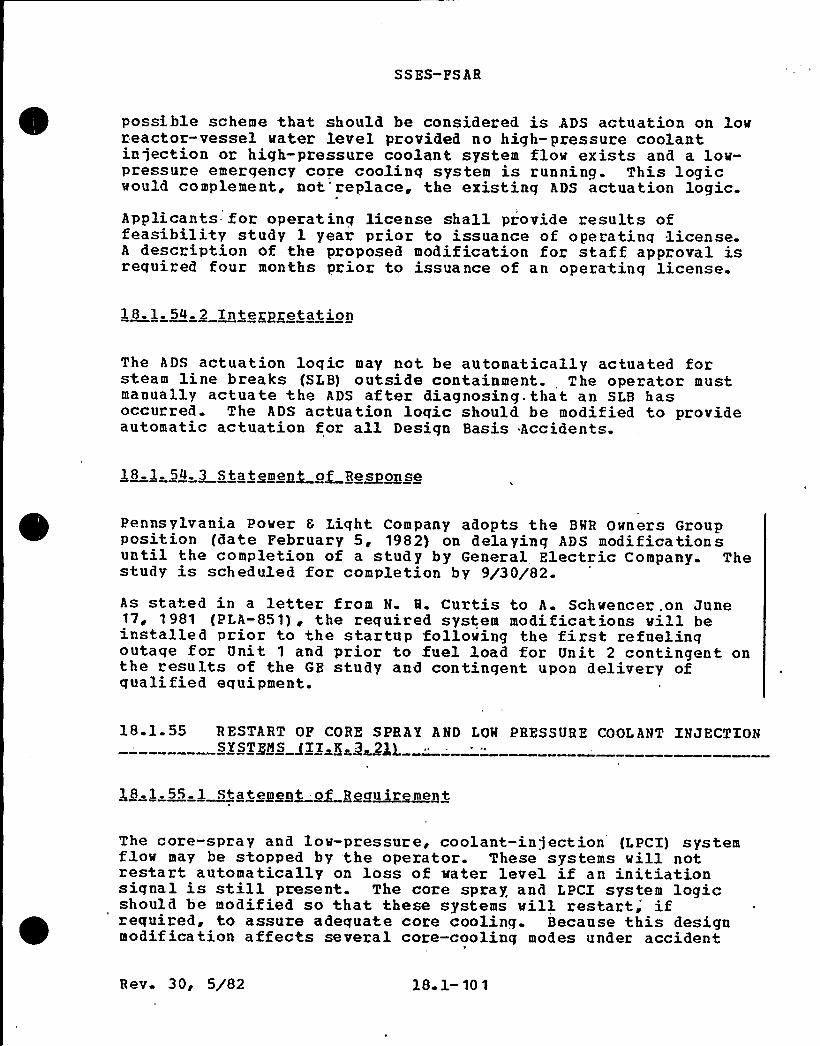
SS ES-FS AR
possible scheme that should be considered is ADS actuation on lovreactor-vessel water level provided no high-pressure coolantinjection or high-pressure coolant system flov exists and a low-pressure emergency core coolinq system is running. This logicwould complement, not'replace, the existing ADS actuation logic.Applicants- for operating license shall provide results offeasibility study l year prior to issuance of operatinq license.A description of the proposed modification for staff approval isrequired four months prior to issuance of an operatinq license.
18.1. 54. 2 Interpretation
The ADS actuation logic may not be automatically actuated forsteam line breaks (SLB) outside containment. The operator mustmanually actuate the ADS after diagnosing. that an SLB hasoccurred. The ADS actuation loqic should. be modified to provideautomatic actuation for all Design Basis Accidents.
Pennsylvania Power 6 Light Company adopts th'e BWR Owners Groupposition (date February 5, 1982) on delaying ADS modificationsuntil the completion of a study by General Electric Company. Thestudy is scheduled for completion by 9/30/82.As stated in a letter from N Q. Curtis to A. Schwencer.on June17, 1981 (PLA-851), the required system modifications vill beinstalled prior to the startup following the first refuelingoutage for Unit 1 and prior to fuel load for Unit 2 contingent onthe results of the GE study and contingent upon delivery ofqualified equipment.
18.1.55 RESTART OF CORE SPRAY AND LOW PRESSURE COOLANT INJECTION
The core-spray and low-pressure, coolant-injection {LPCI) systemflow may be stopped by the operator. These systems will notrestart automatically on loss of water level if an initiationsignal is still present. The core spray and LPCl system logicshould be modified so that these systems vill restart," ifrequired, to assure adequate core cooling. Because this designmodification affects several core-cooling modes under accident
Rev. 30, 5/82 18 1- 10 1
S S BS- PS AR
conditions, a preliminary design should be submitted for staffreview and approval prior to making the actual modification.
All applicants for operating license should submit documentationfour months prior to the expected issuance of an operatinglicense or four months prior to the listed implementation date,whichever is later.
18.1. 55. 2 Interpretation
None required.
18.1.55. 3 Statement of Ee~sonse
PPSL concurs with the BMR Owners~ Group position which wasforwarded to the NRC by letter from D. B. Maters (BMROG) to D. G.Eisen hut fNRC), December 29, 1980.
The BMROG report states that the current ECCS design representsthe optimum approach to BRR safety. No modifications to existingLPCI and core spray systems are necessary in response to thisrequirement.
18 1 56 A UTOHATIC SQITCHOVER OP REACTOR CORE ISOLATIONCOOLING SYSTEN SUCTION /II K 3 22)
18.1.56 1 Statement of Eeguig~ment
The reactor core isolati'on cooling (RCXC) system takes suctionfrom the condensate storage tank with manual switchover to thesuppression pool when the condensate storage tank level is low.This switchover should be made automatically. Until theautomatic switchover is implemented, licensees should verify thatclear and cogent procedures exist for the manual switchover ofthe RCIC system suction from the condensate storage tank to thesuppression pool.
Documentation must be submitted four months prior to issuance ofthe staff safety evaluation report or four months prior to theimplementation date, whichever is later. Hodifications shall becompleted by January 1, 1982.
Rev. 27, 10/8118. 1-102
SS ES- FS AR
None required.
Manual switchover of the RCIC suction from the condensate storagetank (CST) to the suppression poo3. on lov CST level is covered inthe Emergency Operating Procedures.
Specifically, this item is addressed in the folloving EmergencyOperatinq Procedures:
EO-00-022 (Cooldovn) Section 2.C.EO-00-023 (Containment Control) Section 2. D.
This procedural guidance is an interim measure and vill berevised to discuss automatic switchover of the RCIC suction vhenthe desiqn chanqe is implemented.
The desiqn chanqes for automatic svitchover are being developed.All modifications vill be completed by January 1982.
18.1.57 CONFIRM ADEQUACY OF SPACE COOLING FOR HIGHPRESSURE COOLANT'INJECTION AND REACTORCOB/ X~SAT~IN CQQLI NG SY ST EMS g IX. K 3. 24)
18.1. 57. 1 Statement ~o-geguigement-
Lonq-term operation =of the reactor core isolation cooling {RCIC)and high-pressure coolant infection {HPCI) systems may requirespace coolinq to maintain the pump-room temperatures withinallowable limits. Licensees should verify the acceptability ofthe consequences of a complete loss of alternating-current {AC)power. The RCIC and HPCI systems should be designed to vithstanda complete loss of offsite AC pover to their support systems,including coolers, for at least 2 hours.
All applicants for operatinq license should submit documentationfour months prior to the expected issuance of the staff safetyevaluation report for an operating license or four months priorto the listed implementation date, vhichever is .later.
Rev. 30, 5/82 18 1-103
SSES-FSAR
18. l. 57. 2 In te @greta t ion
Confirm that HPCI and RCIC room cooling can be maintained toenable continuous operation d.uring a loss of offsite AC power for2 hours.
18.1. 57. 3 Statement. of Response
The HPCI and RCIC room unit coolers and their support systems aredesigned to vithstand the consequences of a complete loss ofoffsite AC power since these are povered from onsite dieselgenerators Each HPCI and RCIC room is provided with a 100%capacity redundant unit cooler. Refer to. Subsection 9.4.2. 2.
18-1.58 EFFECT OP LOSS OF ALTERNATING-CURRENT POWER ON
R FCI RCULATION P~UP S ZALS AXE K~ 3 25) ~ - ~ - ~
18.1.58.1 Statement of geguiresenf
The licensees should determine, on a plant-specific basis, byanalysis or experiment, the conseguences of a loss of coolingvater to the reactor recirculation pump= seal coolers. The pumpseals should be designed to withstand a complete loss ofalternating-current (AC) pover for at least 2 hours. Adequacy ofthe seal design should be demonstrated.-
Applicants for operatinq licenses shall submit the evaluation andproposed modifications no later than 6 months prior to expectedissuance of the staff safety evaluation report in support oflicense issuance, vhichever is later. modifications must
bc'ompletedby January 1, 1982.
18.1. 58. 2 Interpretation
Evaluate the effect of a loss of offsite AC power for 2 hours onth'e recirculation pump seals.
18.1. 58. 3 Statement of Response
The system(s) providing cooling water to the recirculation pumpseals vill be modified to automatically receive emergency powerfollowinq a loss of offsite power. These modifications will becompleted prior to the first refueling outage.
Rev. 27, 10/81 1 8.1-104
SS ES-FS AR
18 1 59 PROVIDE A COMMON . REFERENCE LEVELFOR VESSEL LEVEL +ISTRUMENT~AION -/II K ~327} .
18.1 59 1 Statemeng og Rggujge~mnt-
Different reference points of the various reactor vessel waterlevel i,nstruments may cause operator confusion. Therefore, alllevel instruments should be referenced to the same point. Eitherthe bottom of the vessel or the top of the active fuel arereasonable reference points.
All applicants for operating license should submit documentationfour months prior to the expected issuance of -the staff safetyevaluation report for an operatinq license or four months priorto the listed implementation late, whichever is later.
18 1. 59. 2 In te rage ta tjon
None required.
18.1. 59 3 Statement of Response.
Susquehanna SES will be modified so that all reactor water levelindications use the same reference point, the bottom of the steamdryer skirt. This commitment was previously stated, in lettersfrom N. W. Curtis to A. Schwencer on July 21 and August 4, 1981(PLA- 888 ~ -987)
18 1. 60 VERIFY QUALIFICATION OF ACCUMULATORS ON AUTOMATICDEPBESSURIZATION SYSTEM VALVES (II K 3 281
18. 1. 60. 1- Statement of Reguirement-
Safety analysis reports claim that air or nitrogen accumulatorsfor the automatic depressurization system {ADS) valves areprovided with sufficient capacity to cycle the valves o~n fivetimes at design pressures. GE has also stated that the emergencycore cooling (ECC) systems are desiqned to withstand a hostileenvironment and still perform their function for 100 daysfollowinq an accident Licensee should verify that theaccumulators on the ADS valves meet these requirements, evenconsider ing normal leakage. If this cannot be demonstrated, the
Hev. 27, 10/8118 1-105
S S ES- PS AR
licensee must show that the accumulator design is stillacceptable.
The ADS valves, accumulators, and associated equipment andinstrumentation must be capable of performing their functionsdurinq and followinq exposure to hostile environments and takingno credit for nonsafety-related equipment or instrumentation.Additionally air (or nitrogen) leakage through valves must beaccounted for in order to assure that enough inventory ofcompressed air is available to cycle the ADS valves.
All applicants for operating license shall submit documentationfour months before the expected'ssuance of the staff safetyevaluation report for an operating license or four months beforethe listed implementation date, whichever is later.
18.1. 60. 2 Xnteroretation
None required.
The desiqn basis'and justification for the ADS accumulators aregiven below. This design basis is different than stated in NUREG0737, Requirement Xl.K. 3. 28.
The criteria for short-term and lonq-term ADS operations, asspecified in the PSAR, are as follows:
(a) Short-Term ADS Operation
Accumulator capacity is sufficient for each ADS valve toprovide two actuations against 31.5 psig (70% of 45 psig)drywell pressure (see PSAR Subsection 5.2. 2. 4.1 and responseto guestion 211. 67) .
(b) Long-Term ADS Operability of 100 Days
The safety related nitrogen storage system contains adequateOas in storase (a -bottles conld be replaced periodically toprovide capacity or at least 100 days operation of the ADS.
Justification for meeting .these criteria is given below.
Short-term is defined for this discussion as the timerequired to depressurize the reactor to the residual heat
Rev. 30, 5/82 l8. 1-106

SS ES-PS AR
removal (BHR) shutdovn cooling pressure permissive setpoint,stabilize the reactor water level and place the reactor inthe shutdown cooling mode.
Each ADS accumulator is presently sized to provide tvo ADSsa fety/relief valve (S/RV) actuation s a t 70% o f dryvelldesiqn pressure. This is eguivalent to six actuations ofthe ADS S/RVs at atmospheric pressure in the drywell. TheADS valves are desiqned to operate at 70% of drywell designpressure because that is the maximum pressure for whichrapid reactor depressurization through the ADS valves isrequired (qreater dryvell pressures are associated only viththe short duration primary system blovdown in the drywellimmediately folloving a large pipe break)'. Por large breakswhich result in higher drywell pressure, sufficient reactordepressurization occurs due to the break to preclude theneed for ADS. One ADS actuation at 70% of dryvell designpressure is sufficient to depressurize the reactor and allowinventory makeup by the lov pressure ECC systems. Hovever,for conservatism, the ADS accumulators are sized to allowtwo ADS actuations at 70$ of dryvell design pressure.
This design provides sufficient nitrogen to the ADS valvesto permit depressurization until the RHR shutdown coolingmode can be initiated.Preoperational testing of the ADS valves at 70% of designdrywell pressure is not practical because it ~ould requirepressurizing the drywell during the ADS valve testinq.Thus, an equivalent number of valve actuations atatmospheric pressure is normally included in the ADS systemtest specification.
The basis for the long-term ADS requirement is derived fromthe long-term coolinq acceptance criterion (Criterion 5) of10CPR50. 06. Criterion 5 states:
'~Long-/edam Cooling. After any calculatedsuccessful initial operation of the ECCS, the cal-culated core temperature shall be maintained at anacceptably low value and decay heat shall be removedf'r the extended period of time required by thelong-lived radioactivity remaining in the core
This criterion requires that either ADS be operable inconjunction vith the low pressure ECCS pumps or that RHRshutdovn cooling and vater makeup capability be operable, toensure long-term core 'coolinq.
30, 5/82 18. l-107
S SES-F S AR
The primary purpose of long-term ADS- is to keep the reactorpressure low enough so that low pressure .ECCS systems can beused to keep the core cooled. The ADS is not required afterthe decay heat is low enough so the vessel will not bepressurized above the shutoff head of the low pressure ECCSpum ps+
The duration for which the ADS must be available isdependent on factors such as the power of the reactor at thetime of the LOCA, break size and location, availableinjection systems, and availability of RHR shutdown cooling.The long-term ADS design reguirement is 100 days. This isbased on a judqment of the time required to make anynecessary repairs to the RHR shutdown coolinq system or ADS,thus ensuring the 'core would be kept cool.
Based on the 10CFR50 reguirement, a lonq-termdepressurization capability is provided by supplyingnitrogen to the ADS accumulators using a safety gradesystem. The safety related nitrogen storage (N2bottles)system contains adequate gas in storage for 30 days after apostulated DBA. However, these nitrogen bottles could bereplaced periodically by brinq'ing portable N2 -bottles toprovide long-term operation of the ADS. (At Susquehanna,these bottles are located in an area that is accessiblefollowinq a loss-of-coolant accident.)
From the above discussion, PPSL concludes that the Susquehannadesign of ADS pneumatic supply system meets the intent of NUREG-0737, Item II.K.3.28.
18 1 61 REVISED SHALL-BREAK LOSS OF COOLANT ACCIDENT HETHODS(II.K.3. 30)
18,1.61.1 Statement of gecCuirement
The analysis methods us'ed by nuclear steam supply system vendorsand/or .fuel suppliers for small-break loss-of-coolant accident(LOCA) analysis for compliance with Appendix K to 10 CFR Part 50should be revised, documented and submitted for NRC approval.The revisions should account for comparisons with experimentaldata, includinq data from the LOFT test and -Semiscale Testfacilities.The Bulletins and Orders Task Force identified a number ofconcerns reqardinq the adequacy of certain features of small-break LOCA models, particularly the need to confirm specificmodel features (e.g., condensation heat transfer rates) againstapplicable experimental data. These concerns, as they applied to
R ev. 30, 5/82 18 1-108
SSZS-PS AR
each light-water reactor {LQR) vendor~s models, were documentedin the task force also concluded that, in light of the TNI-2accident, additional systems verification of the small-break LOCAmodel as required by II;4 of Appendix K to 10 CPR 50 was needed.This included providinq=experimental verification of the variousmodes of single-phase and two-phase natural circulation predictedto occur in each vendor's reactor during small-break LDCAs.
Based on the cumulative staff requirements for additional small-break LOCA model verification, including both integral system andseparate effects verification, the staff considered modelrevision as the appropriate method for reflecting any potentialupgradinq of the analysis methods.
The purpose of the verification was to provide the necessaryassurance that the small-break LOCA models were acceptable tocalculate the behavior and consequences of small primary systembreaks. The staff believes that this assurance can alternativelybe provided, as appropriate, by additional justification of theacceptability of present small-break LOCA models with regard tospecific staff concerns and recent test data. Such justificationcould supplement or supersede the need for model revision.The specific staff concerns regarding small-break LOCA models areprovided in the analysis sections of the BSO Task Force reportsfor each LWR vendor, (NURZG-0635, -0565, -0626 ~ -0611, and—0623) . These concerns should be reviewed'in total by each holderof an approved emergency core coolinq system model and addressedin the evaluation as appropriate.The recent tests include the entire Semisca1e small-break testseries and LOFT Tests (L3-1) and L3-2). The staff believes thatthe present small-break LOCA models can be both qualitatively andquantitatively assessed aqainst these tests. Other separateeffects tests (e.g., ORNL core uncovery tests) and future tests,as appropriate, should also be factored into this assessment.
Based on the precedinq information a detailed outline of theproposed proqram to address this issue should be submitted. Inparticular, this submittal should identify {1} which areas of themodels, if any, the licensee intends to upgrade, {2) which areasthe licensee intends to address by further justification ofacceptability (3) test data to be used as part of the overallverification/upgrade effort, and (4) the estimated schedule forperforming the necessary work and submitting this information forstaff r'eview and approval.
Licensees shall submit an outline of a program for modeljustification/revision by November 15, 1980. Licensees shallsubmit additional information for model justification and/orrevised analysis model for staff approval by January 1, 1982.Licensees shall submit their plant-specific analyses using the
Rev. 30, 5/82 18 1-109
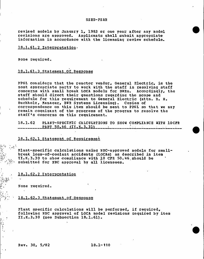
SSES-PS AR
revised models by January 1, 1983 or one year after any modelrevisions are approved. Applicants shall submit appropriateinformation in accordance with the licensing review schedule.
18.1. 61. 2 Interpretation ~
None required.
18. 1,61~Statemegt~ORe~sonse
PPSL considers that the reactor vendor, General Electric, is themost appropriate party to work with the staff in resolving staffconcerns with small break LOCA models for BWRs. Accordingly, thestaff should direct their guestions regardinq the scope andschedule for this requirement to General Electric (attn. R. H.Buchholz, Manager, BQR Systems Licensing) . Copies ofcorrespondence on this item should be sent to PPGL so that we mayremain cognizant of the proqress of the program to resolve thestaff~s concerns on this requirement.
18 1 62 PLANT-SPECIFIC CALCOLATIONS TO SHOW COMPLIANCE WITH 10CFR~PRT 50 46 ~II $ Q 3$l
18 l. 62. 1 Statement of Reouirement
Plant-specif ic calculations using NRC-approved models for small-break loss-of-coolant accidents (LOCAs) as described in itemII K.3.30 to show compliance with 10 CFR 50.46„should besubmitted for NRC approval by all licensees.
18 1.62.2 Interpretation
None required.
$ 8.l.~62. ~S gfgmgpf of Regpogge
Plant specific calculations will be performed, if required,followinq NRC approval of LOCA model revisions required by itemII.K.3.30 (see Subsection 18.1.61).
Rev. 30, 5/82 18 1-110

SSES-PS AB
18 1 63 EVALUATION OP, ANTICIPATED TRANSIENTS WITH SINGLE- ~ PAILUBg gO'V/I+ NO~EL -CLADDING FAILURE /II.K~3 44)
18.1.63.1 Stateme~n of Requirement
For anticipated transients combined with the worst single failurean assuminq proper operator actions, licensees should demonstratethat the core remains covered or provide analysis to show that nosignificant, fuel damage results from core uncovery. Transientswhich result in a stuck-open relief valve should be included inthis category.
All applicants for operatinq license should submit documentationfour months prior to the expected issuance of the staff safetyevalaution report for an operating license or four months priorto the listed implementation date, whichever is later.
18.1.63 2 Interpretation
None required.
18.1. 63 3 Statement "of Response~P
The BWB Owners'roup has prepared a generic response to thisrequirement. The report was transmitted to D. G. Eisenhut by aletter from D B. Waters on Decembe'r.29, 1980. This responsecontains an evaluation of analyses performed to demonstrate thecore remains covered or no significant fuel damage occurs from ananticipated transient with a sinqle failure. PPSL has reviewedthis response and finds it is applicable to Susquehanna SES. Thereport concludes that the core remains covered for all evaluatedcombinations of anticipated transients and single failures.
18 1.64 EVALUATION OP DEPRESSURXZATION WITH OTHER'HAN THE
18,$ . 64. 1 Statement of Requirement
Analyses to support depressurization modes other than .fullaetna tion of the automatic depressurization system {ADS) (e.g. ~
early blowdown with one or two safety relief valves) should beprovided. Slower depressurization would reduce the possibilityof exceeding vessel integrity limits'y rapid cooldown.
Rev. 3 0, 5/82 18 1-111
SSES-PS AR
All applicants for operating license should submit documentationfour months prior to the expected issuance of the staff safetyevaluation report for an operating license or four months priorto the listed implementation date, whichever is later.
1 8. l. 64. 2 Inte rgreta tion
None required.
The BWR Owners'roup submitted a generic response to thisrequirement. This response was transmitted by letter to D. G.Eisenhut from D. B. Waters on December 29, 1980.. PPSL hasreviewed this response and find it applicable to Susquehanna SES.The report. concludes that no improvement can be gained by aslower depressurization and actually could be detrimental to corecooling. Therefore no additional action is necessary in responseto this requirement.
18-1.6'5 MICHELSON CQNCE~NS~~XX K 3 46}-
18 1 65.j, S~ttement of Reguigement
A number of concerns related to decay heat removal following avery small break LOCA and other related items were questioned byMr. C Michelson of the Tennessee Valley Authority. Theseconcerns were identified for PWRs. GE was requested to evaluatethese concerns as they apply to BWRs and to assess the importanceof natural circulation during a small-break I.OCA in BWRs.
18 1.65.2 Intersretation
None required.
18.1.65 3 Statement of Response
The General Electric Company has responded to the questions posedby Mr. Michelson. This response was sent by letter from R. H.Buchholz to D. F. Ross on February 21, 1980. These responses are
Rev. 30, 5/82 18. 1- 112
SS ES-PS AR
applicable to Susquehanna SES and no further response isnecessary.
18 1.66 ENERGENCY PREPAREDNESS SHORT- TERN (XII A 1 1)
No requirement stated in NUREG 0737. Refer to Subsection 18.2.38which contains the response to the requirement in NUREG 0694.
18 1. 67 " UPGQADg gNggGEN~CSUggOQT PACILITIES ~III A 1 2}
l8~l,67. 1 Statement of Reguggemegt.
A detailed statement of the requirement can be found in NUREG-0696. The implementation schedule was announced in GenericLetter 81-10 on Eebruary 18, 1981. This schedule is as follows:Desiqn information for emergency response facilities should beprovided in connection with the operating license review process.These facilities shall be operational by October 1, 1982 or priorto fuel load, whichever is later. Interim facilities, asdescribed in NUREG-0694 shall be provided by fuel load.
18. 1.67.$ Xnfe~gefation
None required.
The proposed method of responding to this requirement wassubmitted by a letter to B. J. Younqblood from N. W. Curtis onApril 2, 1981 (PLA-704) . Details on the emergency responsefacilities are presented in Appendix I of the Emergency Plan.
Each nuclear facility shall upgrade its emergency .plans toprovide reasonable assurance that adequate protective measurescan and vill be taken in the event of a radiological emergency.Specif ic criteria to meet this requirement is delinea ted in
Rev. 30, 5/82 18. 1-113
SSES-FSAR
NUREG-0654 {PENA-BEP-l), »Criteria for Preparation and Evaluationof Radioloqical Emerqency Response Plans and Preparation inSupport of Nuclear Power Plants.>
NUREG-0654, Revision 1; NUREG-0696, »Punctional Criteria forEmerqency Response Pacilities;» and the amendments to 10 CPB Part50 and Appendix E to 10 CPB Part 50 regarding emergencypreparedness, provide more detailed criteria for emergency plans,desiqn, and functional criteria for emergency response facilitiesand establishes firm dates for submission of upgraded emergencyplans for installation of prompt. notification systems. Theserevised criteria and rules supersede previous Commission guidancefor the upgradinq of emergency preparedness at nuclear powerfac ilities.Requirements of the new emergency-preparedness rules underparagraphs 50.47 and 50.54 and the revised Appendix E to Part 50taken toqether with NUREG-0654 Revision 1 and NUREG-0696, whenapproved for issuance, qo beyond the previous requirements formeteorological programs. To provide a realistic time frame forimplementation, a staged schedule has been established withcompensatinq actions provided for interim measures.
Specific milestones have been developed and are presented below.
Milestones are numbered and tagged with the following code; a-gape, b«activity g-mini@urn acceptance criteria. They are asfollows:
{17 a. Fuel load.
b. Submittal of radiological emergency responseplans.
C» A description of the plan to include elements ofNUREG-0654, Revision 1, Appendix 2.
(2) a. Fuel load.
b. Submittal of i'mplementing procedures.
c Nethods, systems,monitor actual orof a radiologicalpro vided.
and equipment to assess andpotential offsite consequencesemergency condition shall be
(3) a. Puel load.C
.Implementation of radiological emergency responseplans.
R ev. 30, 5/82 18. 1- 114
SS ES-PS AR
c. Pour elements of Appendix 2 to NUHEG-0654 with theexception of the Class B model o f element 3, or
Alternative to item (3) requir ing compensating actions:
A meteorological measurements program which isconsistent with the existinq technical specificationsas the the baseline or an element "1 program and/orelement 2 system of Appendix 2 to NUREG-0654, or twoindependent element 2 systems shall provide the basicmeteoroloqical parameters (wind direction and speed andan indicator or atmospheric stability) on display inthe control room. An operable dose calculationalmethodology (DCN) shall be in use in the control roomand at appropriate emerqency response facilities.The followinq compensating actions shall be taken bythe licensee for this alternative:{i) If only element 1 og-element 2 is in use:
The licensee {the person who wi11 beresponsible for making offsite doseprojections) shall check communications withthe cognizant National Heather Service (NWS}first order station and NQS forecastingstation on a monthly basis to ensure thatroutine'eteorological observations andforecasts can be accessed.
0 The licensee shall calibrate themeteorological measurements program at afrequency no less than guarterly and identifya readily available source of meteorologicaldata {characteristic of site conditions) towhich they can gain access during calibrationperiods.
0 During conditions of. measurements systemunavailability, an alternate source ofmeteorological data which is characteristicof site conditions shall be identified towhich the licensee can gain access.
0 The licensee shall maintain a site inspectionschedule for evaluation of the meteorologicalmeasurements program at a frequency no lessthan weekly.
0 It shall be a reportable occurence if themeteorological data unavailability exceeds
Rev. 30, 5/82 18. 1-115
SS ES- FS AR
the goals -outline in Proposed Revision 1 toRegulatory Guide 1.23 on a guarterly basis.
The portion of the DCM relating to the transportand diffusion of gaseous effluents shall beconsistent with the characteristics of the Class A
model outlined in element 3 of Appendix 2 toNUBEG-0654
(iii) Direct telephone access to the individualresponsible for making offsite dose projections(Appendix E to 10 CFR Part 50(XV) (A) (4)) shall beavailable to the NRC in the event of aradiological emergency. Procedures forestablishing contact and identification of contactindividuals shall be provided as part of theimplementing procedures.
I
This alternative shall not be exercised after July 1, 1982.Further, by July 1, 1981, a functional description of theupgraded programs (four elements) and schedule forinstallation and full operational capability shall beprovided (see milestones 4 and 5).
March 1, 1982.
b. Xnstallatian of Emergency Response Facilityhardware and software.
co Four elements of Appendix 2 to NUREG-0654, withexception of the Class B model of element 3. „
(5) a. July 1, 1982.
b Full operational capability of milestone 4.
C ~ The Class A model (designed to be used out to theplume exposure EPZ) may be used in lieu of Class Bmodel out to the ingestion EPZ. Compensatingactions to be taken for extending the applicationof the Class A model out to the ingestion EPZinclude access to supplemental information (mesoanP synoptic scale) to apply judgment regardingintermediate and long-range transport estimates;The distribution of meteorological information bythe licensee should be as described in Table 18.1-13 by July 1, 1982.
July 1, 1982 or at the time of the completion ofmilestone 5 ~ whichever is sooner.
b. Mandatory review of the DCM by the licensee.
Be v 30, 5/82 18 1-116
SS ES-FS AR
C« Any DCH in use should be reviewed to ensureconsistency with the operational Class A model.Thus, actions recommended durinq the initialphases of a radiological emergency would beconsistent with those after the TSC and,EOF areactivated.
t7) a. September 1, 1982.
b. Description of the Class B model provided to theNRC
c. Documentation of the technical bases andjustification for selection of the type Class Bmodel hy the licensee with a'iscussion of thesite-speci fic attributes.
(8) a. June 1 1983.
b. Full operational capability of the Class B model.
c. Class B model of element 3 of Appendix 2 to NUREG-0654, Revision 1
Applicants for an operating license shall meet at leastmilestones 1, 2, and 3 prior to the issuance of an operatinglicense. Subsequent milestones shall be met by the samedates indicated for operating reactors.= For the alternativeto milestone 3, the meteorological measurements programshall be consistent with the NUREG-75/087, '<Standard ReviewPlan for the Review of Safety Analysis Reports for NuclearPower Plants,~'ecton 2;3.3 program as the baseline orelement 1 and/or element 2 systems.
18. 1. 68. 2 Interpretation
None required.
18. 1. 68 3 =Statement of Resoonse«.
Hilestones 1, 2 and 3 are beinq addressed as a part of the shortterm emergency preparedness requirement III.A.l.l. Refer toSubsection 18.2.38 for response. Responses to these and othermilestones vill be incorporated into Appendix I of the EmergencyPlan..
Rev. 30, 5/82 18 1-117
SS ES-PS AR
18 1 69 INTEGRITY OP SYSTEMS'UTSIDE CONTAINMENT LIKELY TO CONTAIN~RA IOACTIVB.Jf AT~XAK, ~II~D
18 1.69.1 Stateme~n of geguirement
Applicants shall implement a program to reduce leakage fromsystems outside containment that mould or could contain highlyradioactive fluids during a serious transient or accident to as-lov-as-practical levels. This program shall include thefollovinq:
(1) Immediate leak reduction.
(a) Implement all practical leak reduction measuresfor all systems that could carry radioactive fluid
'utsideof containment.,
(2)
(b) Measure actual leakage rates with system inoperation and report them to the NRC.
Continuinq Leak Reduction —Establish and implement aproqram- of preventive maintenance to reduce leakage toas-low-as-practical levels. 'his proqram shall includeperiodic inteqrated leak tests at intervals not toexceed each refuelinq cycle.
This requirement shall be implemented prior to issuance of afull-power license.
Applicants shall provide a summary description, together withinitial leak-test results, of their program to reduce leakagefrom systems outside containment that would or could containprimary coolant or other hiqhly radioactive fluids or gasesdurinq or follovinq a serious transient or accident. Applicantsshall submit this information at least four months prior to fuelload.
18 1 69.2 Interpretation
None required.
$ 8~ 69,~Stgtgeegt of Re~aonae
1. Proqram summary description:
Rev. 30, 5/82 18 1-118
SS ES-FS AR
1.1 The follovinq systems will be leak tested (thefreguency is indicated in ( ) after each eachitem):
A
BCiD
EF.G
H
I
Residual Heat RemovalReactor Core Isolation CoolingCore SprayHigh Pressure Core InjectionScram DischargeReactor Water Clean-up+Standby Gas TreatmentContainment Air HonitorsPost Accident Sampling
(18 months)
Initial leak-test results vill be available whenthe first measurements are made, prior tocompletion of the startup test program.
~ NOTE: The R$fCU system will not havesignificant post-accident radioactivity becausethe suction is isolated by containment isolationsignals (refer to Table 18.1-10) . However, thissystem may conceivably be used in some post-accident scenarios, and vill therefore be leaktested.
1.2 The following systems contain radioactive materialbut are excluded from our program (justificationfor exclusion follovs each item):
Hain Steam — identified by NEDO-20782 as notto be regarded as containing highlyradioactive fluid following'an accident.
B Feed vater — same justification as A.
C Hain Steam Line Drain — this system isisolated following a LOCA.
Di Reactor Mater Sample — this system will notbe used following an'ccident, a separatepost- accident sampling st. at ion is beingdeveloped in response to item XI. B.3.
Recirculation Pump Seal Mater (from CRDpumps) - lines.are protected by check valvesand an excess flov check valves.
Floor 8 Equipment Drains — this sytemisolated following a LOCA and will not beused following an accident.
Rev. 30, 5/82 18 1- 119
SS ES-PS AR
'G. Suppression Pool Clean-up 6 Drain — samejustification as P.
1.3 Method for obtaininq actual leak rates
Mater — leakage vill be collected in agraduated measuring device and timed todetermine GPM leak rate. Implementingprocedures will establish criteria forinitiation of leak rate quantification.,Steam — an estimate of the size of the leakwill be made (i.e. equivalent pipe diametersteam flow). Flovrate will be determinedusing standard Handbook data. This vill beconverted to a GPM flowrate using thespecific volume of the steam at the givenconditions.
The two gaseous systems are tested as follows:
A Standby Gas Treatment System — This system issubject to filter efficiency testing in accordancevith the Technical Specifications vhich includes"DOP" and refrigerant injection.
B. Containment Air Monitors - These are tested vhilethe system is under normal runninq conditions bycheckinq each mechanical joint with liquid soap.
Consideration vas given to the Standby Gas systemregarding the incident at North Anna Unit 1 in 1979.The standby gas piping and duct work from thecontainment to the filters are gas tight and do notinclude any pressure relief devices vhich would allovgases to escape to the Reactor Building. The piping israted at 150 psiq and the duct work is HVM-GS-G (HighVelocity Medium Pressure — Galvanized Steel — Gastiqht3 .
In light of the above, the actions stated in 1.1.G and2. A have resulted.
4 Technical Specifications vill incorporate an acceptancecriteria of 5 GPM total leakage rate for the systemslisted in 1.1 with the exception of:
Standby Gas Treatment — which is limited to theacceptance criteria stated in TechnicalSpecifications Subsection 4.6.5.3 and
Rev. 30, 5/82 18. 1- 120
SS ES- PS AR
B The containment air monitors - which has anacceptance criteria of zero leakage as determined .
by a liquid soap test.
The program is implemented.
18.1 70 1 'Statement of Reauirement
Each licensee shall provide equipment and associated training andprocedures for accurately determining the airborne iodineconcentration in areas within the facility where plant personnelmay be present during an accident.
Effective monitorinq of increasinq iodine leveLs in the buildingsunder accident conditions must include the use of portableinstruments usinq sample media that will collect iodineselectively over xenon (e. g., silver zeolite) for the followingreasons: 'L
(1) The physical size of the auxiliary and/or fuel handlingbuilding precludes locating stationary monitoringinstrumentation at all areas where airborne iodineconcentration data miqht be required.
(2) Unanticipated isolated »hot spots« may occur inlocations where no stationary monitoringinstrumentation is located.
(3) Unexpectedly high background radiation levels nearstationary monitorinq instrumentation after an accidentmay interfere with filter radiation readings.
(4) The time required to retrieve samples after an accidentmay result in high personnel exposures if these filtersare located in high-dose-rate areas.
A fter Ja nuary 1, 1981, each applicant and licensee shall have thecapability to remove the sampling cartridge to a low-background,low-contamination area for further analysis. Normally, countingrooms in auxiliary buildings will not have sufficiently lowbackgrounds for such analyses following an accident. In the lowbackground area, the sample should first be purged of anyentrapped noble gases usinq nitroqen gas or clean air free ofnoble gases. The licensee shall have the capability to measureaccurately the iodine concentrations present on these samplesunder accident conditions. There should be sufficient samplersto sample all vital areas.
Rev. 32, l2/82 18 1- 121

SSES-FSAH
].8.1.70.2 Interpretation
PPSL is in basic aqreement with the technical discussion asoutlined in this requirement. It should be noted thatSusquehanna SES is a BMR and does not possess an auxiliarybuilding. Consequently, it is premature to suqgest that ourcounting facilities within the control structure will beinarlequa+e to effectively count air amples. Add itionally,purqinq of the air sample cartridqes may not be necessary if aneffective collection media- is used for radioiodine air sampling.
18. l. 70. 3 Sta tement of Resnonse
PPGI. will meet the requirements defined in this item. Tosummarizo the proqram, three (3) particulate and gaseouscontinuous air monitorinq systems are provided for air samplingplant areas where personnel may be present during accident
!conditions. The systems are cart mounted for ease of relocation.
crap sa mples are obtained usinq the equipment s pecif ied inSubsection 12.5.2.6.3. During accident conditions silver zeolitecartridges will be used for radioiodine analysis in conjunctionwith two (2) Eberline stabilized assay m ters (SAN-2) oro.qui valent.
Air samples are evaluated as specified in Subsection 12.5.3.5.5.In addition to initial training provided for Health Physicspersonnel, periodic drills are conducted in accordance with theSusquehanna Emerqency Plan Section 8.1. 2 (See Amendment 25 ofOperatinq I,icense Application) .
Analysis of iodine cartridqes will be performed in a lowbackqround, low contamination area. During accident conditions,preliminary analysis will be perf ormed by onsite radiationmonitoring teams in the countinq room, if accessible using a SAN-2. Final analysis will be performed in the emergency off-sitefacility where appropriate sensitivity can be achieved. Prior toanalysis, cartridqes will be purqed using station service air or
)hot~led nitroqen, if necessary to reduce noble gas interference.
All equipment and procedures will be available for use by fuelload
Rev. 32, 12/82 18. 1-122

SSBS-FS AR
18. 1-71 COQTJQ~RO~~H JB~XTA IIIXX-R~EUIREMENTS ~III.D. 3~4
18.1.71. 1 Statement- of Reauirement-
Licensees shall assure that control room operators will beadequately protected against the effects of accidental release oftoxic and radioactive qases and that the nuclear power plant canbe safely operated or shut down under design basis accidentconditions tCriterion 19, "Control Boom," of Appendix A, "GeneralDesign Criteria for Nuclear Power Plants," to 10 CPR Part '50) .
All licensees must make a submittal to the NRC regardless ofwhether or not they met the criteria of the Standard Review Plans(SRP) sections listed below. The new clarification specifiesthat licensees that meet the criteria of the SRPs should providethe basis by referencinq past submittals to the NBC and/orprovidinq new or additional information to supplement pastsubmittals.
18.1. 71. 1.1 - Requirement@ fog Licensees. that Meet Criteria
All licensees with control rooms that meet the criteria of thefollowinq sections of the Standard Review Plan:
221-2222 2.36.4
Identification of Potential Hazards in Site VicinityEvaluation of Potential Accidents;Habitability Systems
shall report their findings regarding the specific SRP sectionsas explained below. The followinq documents should be used forguida nce:
(a) Regulatory Guide 1.78, "Assumptions for Evaluating theHabitability of Regulatory Power Plant Control Boom During aPostulated Hazardous Chemical Release»;
(b) Regulatory Guide 1.95 ~ "Protection of 'Nuclear Power PlantControl Room Operators Against an Accident ChlorineRelease"; and,
(c) K. G. Murphy and K. M. Campe, »Nuclear Power Plant ControlRoom Ventilation System Design for Meeting General DesignCriterion 19 ' 13th AEC Air Cleaning Conference, August1974
Licensees shall submit the results of their findings as well asthe basis for those findings by January 1, 1981. In providingthe basis for the habitability finding, licensees may referencetheir past submittals. Licensees should, however, ensure that
Rev. 30 '/82 18 1-123
SSES-PS AR
these submittals reflect the current facility design and that theinformation requested in Attachment 1 of NUREG 0737 is provided.
18.1.71.1.2 Requirements for Licensees that Do NotJeeps ifegjy
All licensees with control rooms that do not meet the criteria ofthe above-listed references, Standard Review Plans, RegulatoryGuides, and other references shall perform the evaluations andidentify'ppropriate modifications, as discussed below.
Each licensee submittal shall include the results of the analysesof control room concentrations from postulated accidental releaseof toxic gases and control room operator radiation exposures fromairborne radioactive material and direct radiation resulting fromdesign-basis accidents. The toxic qas accident analysis shouldhe performed for all potentia1 hazardous chemical releasesoccurrinq either on the site or within 5 miles of the plant-siteboundary.
* Requlatory Guide l. 78 lists the chemicals mostcommonly encountered in the evaluation of control roomhabitability but is net all inclusive.The desiqn-basis-accident (DBA) radiation source term should befor the loss-of-coolant accident LOCA containment leakage andengineered safety feature (ESP) leakage contribution outsidecontainment as described in Appendix A and B of Standard ReviewPlan Chapter 15.6.5. Xn addition, boiling-water reactor (BQR)facility evaluations should add any leakage from the main steamisoaltion valves (MSIV) (i. e., valve-stem leakage, valve seat
:leakaqe, main steam isolation valve leakage control systemrelease) to the containment leakage and ESP leakage followinq aLOCA. This should not be construed as altering the staffrecommendations in Section D of Regulatory Guide 1.96 (Rev. 2)regardinq NSIV leakaqe-control systems. Other DBAs should bereviewed to determine whether they might constitute a more-severecontrol-room hazard than the LOCA.
In addition to the accident-analysis results,,which should eitheridentify the possible need for control-room modifications orprovide assurance that the habitability systems will operateunder all postulated conditions to permit the control-roomoperators to remain in the control room to take appropriateactions required by General Design Criterion 19, the licenseeshould submit sufficient information needed for an independentevaluation of the adequacy of the habitability systems.Attachment 1 of NUBEG 0737, item III.D.3.4 lists the informationthat should be provided alonq with the licensee's evaluation.
Rev. 30, 5/82 18. 1-124
SS ES-PS AR
18. 1. 71. l. 3 Documentation and Implementa tion
Applicants for operatinq licenses shall submit their responsesprior to i.ssuance of a full-powez license. Notifications neededfor compliance vith the control-room habitability requirementsspecified in this letter should be identified, and a schedule forcompletion of the modifications should be provided.Implementation of such modifications should be started vithoutawait inq the results of the staf f rev iew. Additional neededmodifications, if any, identified by the staff during its reviewwill be specified to licensees.
18. l. 71. 2 Interpretation
None required.
18.1.71.3 Statement of response
The control room HVAC system layout and functional designincludes protection of the control zoom from radioactive andtoxic gases. Subsection 6.4 provides a complete description ofthis system and compliance to habitability requirements. Referto Subsection 6.4 for the response to this requirement.
The revision to Subsection 6.4 vill incorporate the follovingcommi tme nts:
1. Supplies of food and potable vate'r adequate to support 10people for 5 days will be maintained onsite.
2. Supplies of potassium iodide adequate to protect 30 peoplevill be maintained onsite.
3. Self contained breathinq apparatus and bottled air supplyadequate to support 5 operations personnel for 6 hours vill bemaintained onsite. Por those situations requiring use of SCBA swithin the control zoom HVAC envelope, the Technical SupportCenter activities will be rel.ocated to the Emergency operationsFacility.REFERENCES
Rev. 31, 7/82 18. 1-125

SS ES-FS AR
Letter, D. G. Eisenhut (NRC) to S. T. Rogers (BMROwners'roup), regarding Emergericy ProcedureGuidelines, October 21, 1980
U. S. Nuclear Requlatory Commission, «TMI-2 LessonsLearned Task Force Status Report and Short-TermRecommendations" USNRC Report NUREG-0578, July 1979,Recommenda tion 2. 1. 6 b.
U.S. Nuclear Requlatory Commission, «NRC Action PlanDeveloped as a Result of the TMI-2 Accident," USNRC-0660, Vols. 1 and 2, May 1980, Section II.B.2.Letter from D. G. Eisenhut (NRC) to All Licensees ofOperatinq Plants and Applicants for 'Operatinq Licensesand Holders of Construction Permits, Subject:Preliminary Clarification of TMI Action PlanRequirements, dated September 5, 1980.
U. S. Nuclear Requlatory Commission, "Clarification ofTMI Action Plan Requirements," USNRC Report NUREG-0737,November, 1980, Item II.B.2.U. S. Nuclear Regulatory Commission, I E Bulletin No. 79-01B, "Environmental Qualification of Class IEEquipment", January 14, 1980
U.S. Nuclear Requlatory Commission, "Interim StaffPosition on Environmental Qualification Report 'NUREG-0588 ~ December 1979.
USNRC Standard Review Plan 6.4, "Habitability Systems",Re vision l.USNRC Requlatory Guide 1.3, «Assumptions Used forEvaluating the Potential Radiological Consequences of aLoss of Coolan't Accident for Boiling Mater Reactors«,Revision 2 ~ June 1974.
USNEC Requlatory Guide 1.7, «Control of Combustible GasConcentrations in Containment Following a Loss-of-Coolant Accident,> Revision 2, November 1978.
USNRC Regulatory Guide 1.89 ~ «Qualification of Class IEEquipment for Nuclear Power Plants," November 1974.
Code of Federal Regulations, lOCFR Part 50, Appendix A,GDC 19, Revised as o f January 1, 1980.
C. Michael Lederer, et al., Table of Isotopes LawrenceRadiation Laboratory, University of California, March1968
o ~:7/82 18 1- 126
SS ES-PS AR
18 1-14
18.1-15
18. 1- 16
18. 1-17
18. 1-18
D. S. Duncan an,d A. B. Spear, GRACE I — An IBM 704-709Pgogram Design fog. Computin'g Gamma Ray Attenuation andHeating in reactor Shields~ Atomics Inter'national,(June 1959) .
D. S. Duncan and A. B-. Spear, GRACE .IX — An IBN 709Pgoggam fog Computing Gamma gay Attenuation and Heatingin Cylindrical and Spherical'eometries, AtomicsInternational, November 1959.
Nemorandum of Telephone Conversation, S. Ford of LIS toN. Anderson of NRC ~ s Lessons Learned Task Force,Subject: TNI Requirements at SHNPP, April 9, 1980.
USNRC Regional Heetinq Minutes, Region I, Sub ject: TNIReview Requirements at SHNPP, April 9, 1980.
USNRC Regional Meeting Minutes, Region IY and V,Subject: TH I Reviev Requirements, 9/26/79.
Rev. 31, 7/82 18 1- 127

0
SS ES-FSAR
BgQ$ R$ S ~
Essential or non-essential classification basis codes aredescribed in Table 18. 1-11.
(2) Automatic actuation siqnal codes are described in Table18. 1-12
{3) Where the control power source is left blank, the controlpower sourc'e is the same as the valve motor power source.
(4) E32-1P001B automatic actuation signal is dependent uponaction of QSIV's, time, RPV pressure. 'he valve is normallyclosed and interlocked when RPV pressure is greater than 35psiq. The valve cannot be opened unless the inboard tiSIV isclosed. Information presented is representative of that formain steam lines B, C and D.
(5)
(6)
Automatic signal code UA .for B21-1P028A, et al (ReactorVessel pressure) prevents operation of condenser low vacuumbypass.
\ T
Reactor recirculation system sample line valves B31-1P019and 1P020 receive hiqh radiation signals for isolation butsince the line does not provide an open path from thecontainment to the environs, the radiation isolation signalmay be considered a diverse signal in accordance withStandard Review Plan 6.2. 4. This judgement is based on ourdefinition of an open path as a direct, untreated path tothe outside environment.
Hand Switch Mos. are from'the PSID rather than referencedSch ematic Diagra m.
(8) Automati" actuation signals for E11-1P015A and B: codes UBand F. are isolation siqnals; codes G and T are initiationsignals.Automatic actuation signals for E11-1P050A and B, and1F122A, B: code 2 is an isolation signal; no initiationsiqnals
(10) Either valve opening (or closing) will energize a commonopen (close) status light. HS-11314 controls both valves.Typical for HV-11345 and HV-11346.
Closes on "LOCA" signal but can be reopened after 60minutes. Valves can be administratively reopened if thehigh drywell pressure is due to plant heat up or loss ofdrywell cooler.
(12) Closes on «LOCA« signal but can be reopened after 10minutes
Rev. 3l, 7/82

FOR THE P&ID FOR PASSSEE FIGURE 9.3-9a
Rev. 30 5 82SUSQUEHANNA STEAM ELECTRIC STATION
'NITS 1 AND 2FINALSAFETY ANALYSISREPORT
PASS PAID
FIGURE 18; l-ll

FOR LOCATION OF PASSSEE FIGURE 1.2-20
Rev. 30, 5/82SUSQUEHANNA STEAM ELECTRIC STATION
UNITS1 ANO2FINAI SAFETY ANALYSISREPORT
LOCATION OF PASSEL. 719'-1"
FIGURE 18. 1-12

FOR THE LOCATION OF PASSSEE FIGURE 1.2-4
Rev. 30, 5/82SUSQUEHANNA STEAM ELECTRIC STATION
UNITS 1 AND 2FINALSAFETY ANALYSISREPORT
LOCATION OF PASSEL. 729
FIGURE 18. 1-13
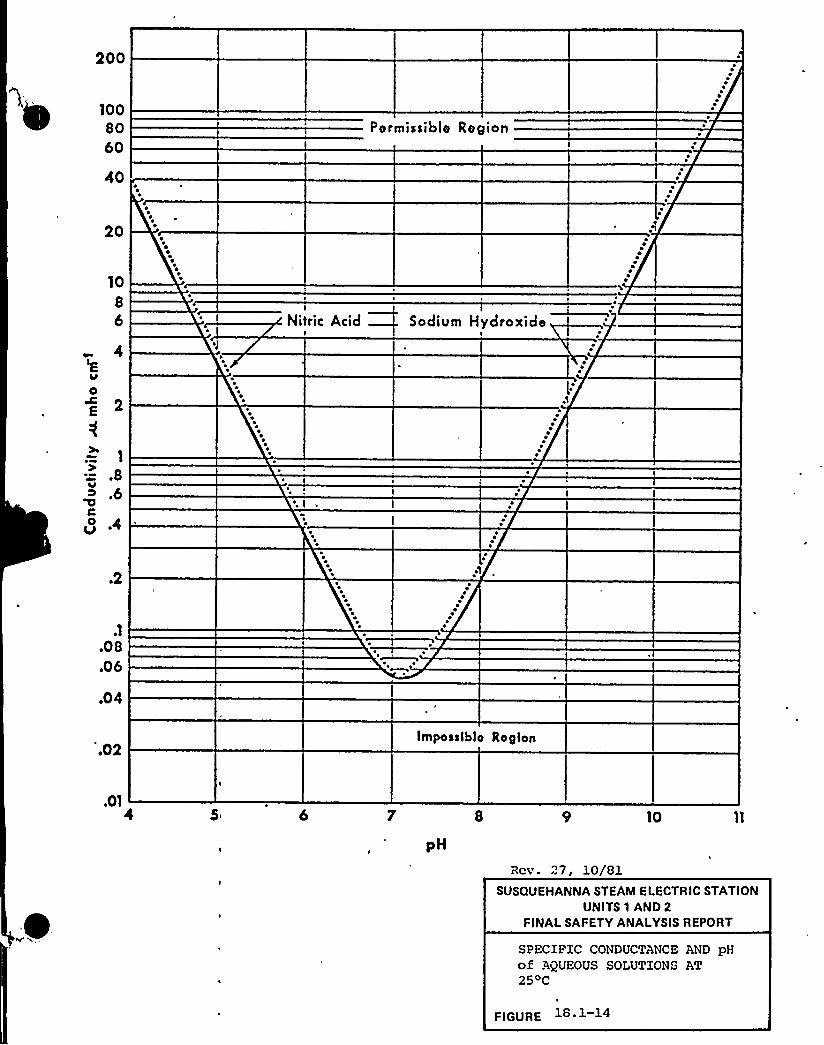
200
1008060
40
Pormissiblo Region
20
10
86
4
a
C
1
~ 8.6
O
I
Nitric Acid
~2
.1
~08~06
~04
~02Imposstbte Region
~015 6 10
Rcv. 27, 10/81SUSQUEHANNA STEAM ELECTRIC STATION
UNITS 1 AND 2FINALSAFETY ANALYSISREPORT
SPECIFIC CONDUCTANCE AND pHof AQUEOUS SOLUTIONS AT2 5oC
FIGURE 1S. 1-14
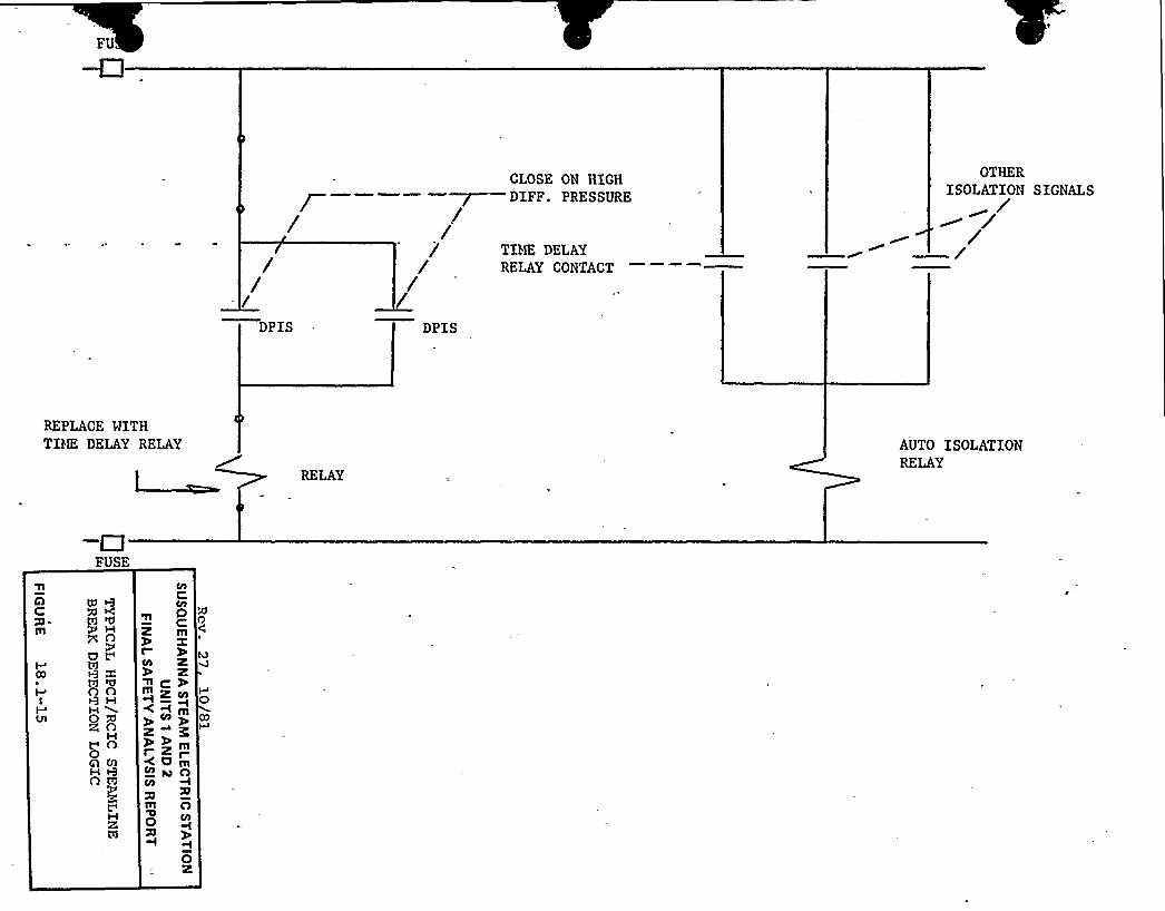
CLOSE ON HIGHDIFF. PRESSURE
OTHERISOLATION SIGNALS
//-/DPIS
////DPIS
TIHE DELAYRELAY CONTACT
REPLACE WITHTDK DELAY RELAY AUTO ISOLATION
RELAY
FUSE
CO
I
Vl
Ill KgZ> O
U t"
'llO O
HH 40 XR O
M> O0A CllHO Fi
MRÃ
OCZ IllX
Icn Z
Zll~ Z CIl
++mCO
+~mC Z~0mCIl u O
mChO
I
0Z

f
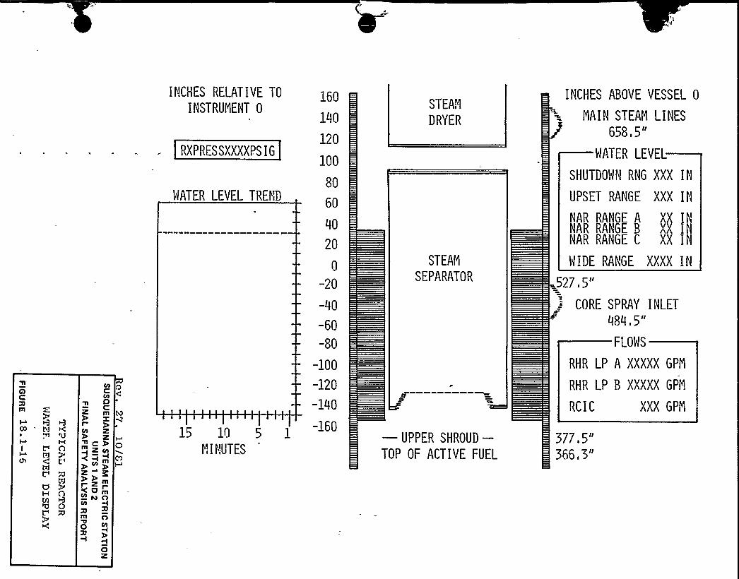
AC
FI
t1
I t'iTi
t''
UH AU)'0 0C'
0Cz
P
z~ofm ZCH
CO
zz m
<<mH~oCO
m0 co
'i
Oz
O
INCHES RELATIVE TO
INSTRUMENT 0
RXPRESSXXXXPSIG
MATER LEVEL TREND
15 10 5
S" INUTES
160
140
120
100
80
60
40
20
0
-20
-00
-60
-80
-100
-120
-140
-160
STEAN
DRYER
STEAN
SEPARATOR
—UPPER SHROUD-TOP OF ACTIVE FUEL
INCHES ABOVE VESSEL 0
NAI N STEAM LINES
658,5"
MATER LEVEL
SHUTDOMN RNG XXX IN
UPSET RANGE XXX IN
NAR RANGE A XX NNAR RAt'GE 8 XX INNAR RANGE C XX IN
MIDE RANGE XXXX IN
527,5"
CORE SPRAY INLET484.5"
FLOMS
RHR LP A XXXXX GPN
RHR LP 8 XXXXX GPN
RCIC XXX GPYi
377.5"366,3"

SSES-FS AR
18 2 RESPONSE TO REQUXRENEQTS IN NUREG 0694
NUREG-0694 supersedes NUREG 0578. The clarificat.ions given inthe Vassallo letter on November 9, 1979 were used in thedevelopment of applicable responses.
I
18 2 1 SHIFT TECHNICAL ADVISOR ZI. A 1. lj
Requirement superseded by NUBEG 0737. Refer to Subsection 18. l. 1for response.
18. 2. 2 SHXFT SUPER VISOR ADMINISTRATIVE DUTIES ~I. A l. 2}
18.2. 2 1 Statement of Requirement
Review the administrative duties of the shift supervisor anddelegate functions that detract from or are subordinate to themanaqemont responsibility for assuring safe operation of theplan+ to other personnel not on duty in the control room. Thisrequirement shall be met before fuel load;
18. 2. 2. 2 Interpretation
None .required.
18.2.2.3 -Statement of Response
PPGL has restructured the operations organization and redefinedresponsi bilitie of shift personnel to relieve the shiftsupervi. or of routine administrative duties.
Administrative procedure AD-QA-300, "Conduct of Operations,"implemen ts this policy.
The Vice President — Nuclear Operations will review and approveassignment of the Shift Supervisor's responsibilities to ensureproper delegation of duties that detract from or are subordinateto the safe operation of the plant.
Rev. 27, 10/8l 18. 2-1
SSES ZSAR
18 2 3 SHIFT MANNING ~I A 1 3)
Requirement superseded by NUREG 0737. Refer to Subsection 18.1.3for response.
18 2 4 IMMEDIATE UPGRADING OF OPERATOR AN D SENIOR OPERATORTRAINING AND QUALIFICATION ~I. A. 2 lg
Requirement superseded by NUREG 0737. Refer to Subsection 18.1.4for response.
18 2. 5 REVISE SCOPE AND CR,ITERIA FOB LICENSINGEXAMINATIONS JI A 3. 1$
Reguirement superseded by NUREG 0737. Refer to Subsection 18.1.6for response.
18.2. 6 EVALUATION OF ORGANIZATION AND MANAGEMENT IMPROVEMENTSOF NEAR-TECUM OP ERATING LICENSE APPLICANTS gI. B. 1. 2~
18 2.6.1 Statemept of Beguiremgnt
The licensee orqanization shall comply vith the findings andrequirements generated in an interoffice NBC review of licenseeorganization and management. The review will be based on an NRCdocument entitled Draft Criteria for Utility Management andTechnical Competence. The first draft of this document was datedFebruary 25, 1980, but the document is changing with use andexperience in ongoing reviews. These draft criteria address theorganization resources, training, and qualifications of plantstaff, and manaqement (both onsite and offsite) for routineoperations and the resources and activities (both onsite andoffsite) for accident conditions. This requirement shall be metprior to fuel load.
18 2. 6. 2 In terpretat ion
None required.
Rev. 27, 10/Sl 18-2-2

SS ES- PS AR
18. 2. 6. 3 Statement of Resnonse.
A review of orqanization and management has been completed inaccordance with draft NUREG 0731, "Guidelines for UtilityNanaqement Structure and Technical Competence.'~ An NRC audit ofthe organization was conducted March 2-6, 1981.
18 2.7 SHORT. TERN ACCIDENT ANALYSIS AND PROCEDUREREVISION (Z.- C 1l
Requirement superseded by NUREG 0737. Refer to Subsection 18.1.8for response.
II
18 2.8
18 2. 8.1 Statement of Reauirement
SHIFT RELIEF A$D QURQOVER PROCEDURES ~I C.'2j
jRevise plant'rocedures for shift relief and turnover to requiresigned checklists and logs to assure that the operating stafffincluding auxiliary operators and maintenance personnel) possessadequate knowledge of critical plant parameter status, systemstatus, availability and alignment. This requirement shall bemet prior to fuel load.
18.2. 8. 2 Interpretation
None reguired.
18,2.8.3 Statement of response
Administrative procedure AD-QA-300, "Conduct of Operations,"discusses operations personnel responsibilities at shiftturnover. Administrative procedure AD-QA-303, "Shift Routine,"specifically defines the shift turnover process.
Rev. 27, 10/81 18 2-3
SSES-FS AR
18.2. 9 SHIFT SUPERVISOR RESPONSIBILITIES'I C. 3}
18.2.9.1 Statement of Reguigement
Issue a corporate manaqement directive that clear3.y establishesthe command duties of the shift supervisor and emphasizes theprimary manaqement responsibility for safe operation of 'theplant. Revise plant procedures to clearly def ine the duties,responsibilities and authority of the shift supervisor and thecontrol room operators. This requirement shall be met prior tofuel load.
1 8. 2. 9. 2 In te rore ta tion
None required.
l8. 2. 9. 3 Sta ggyegt of Re@yon se
The Senior Vice President — Nuclear shall issue prior to fuelload a statement of policy establishing the primaryresponsibility of the Shift Supervisor for safe operation of theplant under all conditions and establishing authority to directactions leadinq to safe operation in the Shift. Supervisor. TheSenior Vice President - Nuclear shall re-issue this statement ofpolicy on an annual basis.
Administrative Procedure AD-QA-300, «Conduct of Operations," setsforth the plant policy on Shift Supervisor duties.
Training for Shift Supervisors includes plant Administrative!
Procedures, and will encompass AD-QA-300.
18 2. 10 CONTROL ROON ACCESS lI C 4}
18.2.10.1 Statement of gegujgement
Revise plant procedures to limit access to the control room tothose individuals responsible for the direct operation of theplant, technical advisors, specified NRC personnel, and toestablish a clear line of authority, responsibility, andsuccession in the control room. This requirement shall be metprior to fuel load.
Rev. 31, 7/82 18. 2-4
SS ES-PS AR
18,2. 10. 2 Inte~g~eation.
None required.
~18 2. 10. 3 Statement of*Response
Administrative procedure AD-QA-300, "Conduct of Operations,"provides the authority and instructions for control'oom accesscontrol.
18 2 11 PROCEDURES FOB PEEDBACK OP OPERATING EXPERIENCE TOPQAQT STAg~E g ~5
Requirement superseded by NUREG 0737. Refer to Subsection18.1.12 for response.
18.2.12.1 Statement of Reauirement
Obtain nuclear steam supply system vendor review of low-powertestinq procedures to further verify their adequacy. Thisrequirement shall be met prior to fuel load.
Obtain NSSS vendor review of power-ascension test and emergencyprocedures to further verify their adeguacy. This requirementmust be met before issuance of a full-power license.
None required.
The General Electric Company, through its site startuporganization, will review all startup tests associated with NSSSsystems and will review all Emergency operating procedures thatwere submitted to NHC in response to item E.C.8 (see Subsection18.2. 13) The startup tests encompass the low power testing and
Rev. 30, 5/82 18. 2-5
SS ES-PS AR
the pover ascension testing phases. These reviews will becompleted prior to fuel load.
18 2.13 PILOT HOHITOBXNG OP SELECTED EMERGENCY PROCEDURES FOBNEAR TERM-Op@RATING. LICENSE-APPLICANTS ~I C 8Q
18.2.13.1 Statement of Requirement
Correct emerqency procedures, as necessary, based on the NRC
audit of selected plant emergency operating procedures {e. g.,small-break LOCA, loss of feedwater, restart of engineered safetyfeatures folloving a loss of AC power or, steam-line break).
18 2.13.2 Interpretation
Hone required.
18.2. 13.3 Statement of Resnonse
Emergency procedures based on those quidelines have beendeveloped and are currently in trial use on the Susquehanna SECSimulator. These procedures have been reviewed by the NRC.Pinal versions vhich incorporated NBC comments vere submitted ina letter from N. W. Curtis to B. J. Youngblood on May 15, 198 1.(PLA-791 ) .
18 2 ~4 CONTROL gOON DESIGN JZ~D ~1
Reguirement superseded by NUBEG 0737. Refer to Subsection18. 1. 16 for re sponse.
~8 g- 15 TRAINING~ DURING LQW gOWER TESTING ~I G ~I
18.2 15.1 Statement of Reauirement
Define and commit to a special low-power testing program approvedby NRC to be conducted at power levels no greater than 5 percentfor the purposes of providinq meaningful technical informationbeyond that obtained in the normal startup test program and to
Rev. 30, 5/82 18 2-6
«%V ~'«
\SSZS-TSAR
provide supplemental training. This reguirement shall be metbefore fuel load.
Supplem'ent operator traininq by completinq the. special low-povertest proqram. Tests may he observed by other shifts or repeatedon other shifts to provide training to the operators. Thisrequirement shall be met before issuance of a full-power license.
18 2 15.2 Interpretation
None required.
18.2.15.3 Statement og Re~s ogive
The BQR Ovners'roup has prepared a generic response to thisrequirement. This vas transmitted to D. G. Ei;senhut by a letterfrom D. B. Waters on February 0, 1981. PPSL concurs with thisresponse. This generic approach outlines an extensive testingproqram desiqned to contribute to and provide for extensivetraininq opportunities during the start-up program. Theobjectives of this program are to,provide:
l. A plant, that has been thoroughly tested.
2. An operating staff that has received the maximumexperience and in-plant training to safely operate it.
3. Plant procedures that have been reviewed and revised toprovide the staff vith proven directions and controls.
Susquehanna's Operator Training Program has been in progresssince 1977 and is completinq the final phases of training at thistime. This program utilizes the Susguehanna Simulator located atthe plant site, and provides the operators with extensive trainingvrior to actual operations in the plant itself. The Simulator isalso used for procedure development and check out.
The Operator Traininq Proqram that is being developed for thePreoperational and Lov Power Testing Pxogram incorporates andbuilds on the extensive traininq already completed by theoperations section. It vill include the recommendation presentedin the BWR Owners'roup position but goes beyond thoserecommendation's by maximizinq the use of the SusquehannaSimulator in preparinq the operators for the start-up tests to beperformed.
The objective of the Operator Training Program is to provide eachoperator with the maximum learning experience during the start-up
Rev. 30, 5/82 18 2-7

SS ES-PS AR
phase. In order to achieve this objective, a comprehensivetraininq proqram is being developed that utilizes the manytraininq opportunities that are available during this period andensures actual testinq. This program covers the period fromPreoperational/Acceptance Testing through the Power Test Programon Unit I. To support this amount of training the operationssection which is staffed for six sections has reorganized intofour sections. This reorganization provided the benefit ofallowinq more operators off shift to attend formal training aswell as provide more operating experience for each shift team.Every effort is beinq made to keep the shifts intact and providetraininq that promotes the >Shift Team~~ concept.
The training program being developed covers the areas ofactivities listed below but recognizes the overlap that existsbetween some of the areas.
IIIIII.XVV
Preoperational/Acceptance TestingCold Functional TestingHot Punctional TestingSta rt-up TestsAdditional Testing
Each area of testinq has activities that lend itself to operatortraininq. The major ones are outlined in Table 18.2-1. The ..
traininq program provides a vehicle to identify activities thathave a significant benefit for training, documents this training,and ensures that all shift crews ~eceive equal experienceopportunities. The proqram also attempts to schedule repeats ofcertain evolutions that are considered critical and cannot beroutinely performed at a later time. The training program wild.identify areas of testing/training that while not required bystart-up program would have additional training benefit. Thistesting/traininq could then be scheduled into the testinq programas additional testing.Pinally this program will develop the basis for the In-PlantDrill Proqram. This comprehensive approach to testing/trainingmore than adequately satisfies the requirements of NUREG 0737.
4Susquehanna SES vill conduct a test which simulates a loss. of ACpower condition for the reactor and containment systems. Thepurpose of this test will be to obtain data relative to theperformance of these systems under the imposed condition of no ACpower available for mitiqation of transient effects. Several keyfactors associated with performance of this test include:
(a) No blockinq of low pressure ECCS functions will be provided.Transient conditions imposed by the test are not expected toinitiate these systems on low water level. Adequate datawill be obtained prior to injection of low pressure ECCSflow on a hiqh drywell pressure signal in conjunction with a
Re v. 30, 5/82 18. 2- 8

confirmatory lov reactor pressure signal. If initiationpoints are reached earlier in the test, this would representa criteria for test termination and the ECCS vould be'allowed to function as designed.
{b) Xn most if not all cases, Limiting Conditions forOperation vi3.1 not be violated. It is possible that astest plans are developed certain LCO's vill beidentified as inhibitinq test performance. Hovever,for LCO's that are being approached as a result oftransient effects during the test, this will represent'criteria for test termination to insure plant safety.
(c) Loss of power to plant instrumentation will not besimulated. To accomplish the major goal of this test,instrumentatin vill be maintained functional .for properdata collection. This constraint is also considerednecessary to insure plant sfaety. Training of licensedoperators in response to the loss of all station ACcondition vill be provided at PPSL's plant specificsimulator. This will provide the opportunity toexperience the instrumentation blackout conditionvithout placing the plant in jeopardy.
(d) Plant AC busses will remain energized, the emergencydiesel generators wi11 be available or operating, andbreakers to safeguards equipment vill not be rackedout. These precautions are considered necessary forplant safety.
(e) Test termination criteria will be established .forparameters such as reactor vessel temperature limits,containment pressure and temperature, reactor vessellevel, suppression pool temperature, HPCI and RCIC roomtemperatures, and CRD temperatures.
The test will be conducted at a convenient point during the firstfuel cycle, with the constraint that adequate decay heat existsto provide a valid test. Several options are being explored fortest initiation {e.q.,'turbine trip from 5% power following loadreduction, turbine trip from 85% pover, etc.) It is our positionthat the method finally selected will have'little bearing on thetest, since plant performance during the initial state of suchtransients is adequately tested in startup tests.The commitments previously made in response to Item I.G.l foradditional testinq and traininq vill be fulfilled, as it is feltthat valuable input will be obtained for the loss of ACpovertest.
The test may cause certain conditions vhich are inconsistent withNBC req'uirements. Re therefore vill provide the NRC with the
Rev. 30, 5/82 18 2-9
SS ES-PS AR
test plan and pertinent documents for review and approval..Performance of this test is continqent upon a favorable safetyevaluation and obtaininq appropriate commission approvals.
Since the NRC has indicated that they may not require a test atSusquehanna SES if results from a test at another plant resolvetheir concerns, PPSL's commitment is contingent on a continuingNRC requirement for this test.18. 2~6 ~RACTOg ~0~ANT SYSTEM/ VENTS ~IX B,lj
Requirement superseded by NUBEG 0737. Refer to Subsection18.1. 19 for response.
18 2-~7 PLANT SHIEL2ING /XI B Qi
Requirement superseded by NUREG 0737. Refer to Subsection18. l. 20 for response.
Requirement superseded by NUREG 0737. Refer to Subsection18.1. 21 for response.
18 g,l9. TRAINING $08 MITIGATING CORE DAMAGE /II B 4g
Requirement superseded by NUREG 0737. Refer to Subsection18. 1. 22 for re sponse.
Requirement superseded by NUREG 0737. Refer to Subsection18.1. 23 for response.
18 2,21 NELIgP AN/ SAFETY VALVE 'POSITION INDICATION~II D.SQ
Requirement superseded by NUREG 0737. Refer to Subsection18.1. 24 for response.
Re v. 3 0, 5/82 18- 2-10
SSES-FSAR
18 2. 2g CONXA~X~N~N ISOLATXO~ND QNNDABILITY
XIX.8~4~2'equirement
superseded by NUREG 0737. Refer,to Subsection18.1. 29 for response.
I
18,2 23 ADDITIONAL ~ACIDENT MONITORING INSTRUMENTATION ~II ~P. 1
Reguirement superseded by NUREG 0737. Refer to Subsection18.1.30 for response.
Reguirement superseded by NUREG 0737. Refer to Subsection18.1. 31 for response.
18 2,25 A SSUg ANCE Og --/ROAR ESP FUNCTIONING ~ /II K 1 5g
18,$ .25 1 Statement gf Requirement
Review all valve positions,'ositioning requirements, positivecontrols and related test and maintenance procedures to assureproper ESP functioning. This xeguirement shall be met by fuelload.
None required.
18.2.25~ Stag~em ~n og 'Response
Operating and surveillance procedures are currently beingdeveloped. Writing the procedures to reflect ESP requirement isa key ob 5ective of procedure originators. Additionally, theseprocedures will receive a review {independent of the originator)to provide further assurance that the procedure is technicallycorrect and provides for accomplishment of procedural objectives{including maintenance of proper safety function).
Rev. 30, 5/82 18 2- 11

SS ES-FS AR
18,2,26 - SAggTY R~EL ~TD SIST H OPgiLABYLYTY STATB~SZY-K.~10$
18 2,26. 1 Sta tement of Reauirement
Review and modify, as required, procedures for removing safety-related systems from service (and restoring to servic'e) to assureoperability status is known. This reguirement shall be met byfuel load.
18.2. 26. 2 YnterRRetation
None required.
l8,$ . 26,3 Statement of R~es onse
Surveillance testinq vill be controlled by administrativeprocedure AD-gA-422. This procedure,.- which is currently beingdrafted, will require that surveillance implementing procedurescontain a review of redundant component operability prior toremovinq the system to be tested from service, (if such removalis required by the test), a review of proper system status priorto return of the tested system to'service, and provide fornotification to Operations of the need for system status changes.
Administrative Procedure AD-QA-306, YYSystem Status and EquipmentControl," (see Subsection 18.1.13.3) establishes control ofsystem status as an operations responsibility and will providethe same reviews described above during normal operations andmaintenance activities. Haintenance procedures will only coveractivities while systems and components are removed from service,the Operations section will actually accomplish changes in systemstatus as controlled by the described Instruction.
18 2 27 TRIP PRESSURIZER LOtI-LEVEL COINCIDENT SIGNAL BXSTABLESXXX=K~k&7).
This requirement is not applicable to Susguehanna SES.
18 2 28 OPERATOR TRAINING FOR PROHPT MANUAL REACTORXRXR LXIaK~L=ZOM-
This requirement is not applicable to Susquehanna SES.
Re v. 30, 5/82 18. 2-12

SSZS-FS AR
18 2 29 - AUTONATIC SUETY GEA~DAN~TCIgATORg T~I~PII K ~12
This requirement is not applicable to Susquehanna SES.
18 2 30 AUXILIARYHEAT REMOVAL SYSTEMS OPERATING PROC'EDURES/II K~$~2$
Describe the automatic and manual actions necessary for properfunctioning of the auxiliary heat .removal systems that are usedvhen the main feedvater system is not operable. This requirementshall be met by fuel load.
18~2. 30. 2 Integggetatian
None required.
A generic response to this reguirement vas provided by GeneralElectric in NEDO-24708, vAdditional Information Required for NRCStaff Generic Report an Boiling Mater Reactors," (August, 1979)and supplement I. A plant specific description is providedbelow.
If the main feedvater system is not operable, a reactor scramwil1 be automatically initiated when reactor water level falls toLevel 3 (540.5 inches above vessel bottom or 178.2 inches ab'ovethe top of the active fuel) . The operator can then remotemanually initiate the reactor core isolation cooling system fromthe main control room, or the system vill be automaticallyinitiated vhen reactor water level decreases to Level 2 (489. 5inches above vessel bottam or 127.2 inches above the top of theactive fuel) due to boil-off. At this point, the high pressurecoolant infection system vill also automatically start supplyingmakeup vater to the vessel. These systems vill continue.automatic injection until the reactor vater level reaches Level 8(581.5 inches above vessel bottom or 219.2 inches above top ofthe active fuel), at which time the high pressure coolantinjection turbine and the reactor core isolation cooling turbineare automatically tripped.
Rev 30 ~ 5/82 18 2- 13
SS ES-PS AR
In the nonaccident case, the reactor core isolation coolingsystem is utilized to furnish subsequent makeup water tvo thereactor pressure vessel. The Reactor core isolation coolinqsystem and the high pressure coolant injection system villrestart automatically shen the level falls to Level 2 (Thereactor core isolation coolinq system is being modified toautomatically restart, see subsection 18.1.50). No manualactions are reguired for these systems to restart. Reactorvessel pressure is regulated by the automatic or remote manualoperation of the main steam relief valves which hlov dovn to thesuppression pool
To Kemove decay heat, assuming that the main condenser is notavailable, the steam condensing mode of the residual heat removalsystem is initiated by the operator. This involves remote manuala liqnment of the residual heat removal system valves. If thesteam condensinq mode is unavailable for any reason, the mainsteam relief valves can be manually actuated from the controlroom. Remote manual alignment of the residual heat removalsystem into the suppression pool cooling mode is then requiredfor suppression pool heat removal. Makeup vater to the vessel isstill supplied by the reactor core isolation cooling system undermanual control.For the accident case with the reactor pressure vessel at highpressure, the hiqh pressure coolant injection system is utilizedto automatically provide the required makeup flov. No manualoperations are required since the'high pressure coolant injectionsystem vill cycle on and off automatically as water level reachesLevel 2 and Level 8, respectively. If the high pressure coolantinjection system fails under these conditions, the operator capmanually depressurize the reactor vessel using the automaticdepressurization system to permit the low pressure emergency corecoolinq systems to provide makeup coolant. Automatic,depressurzation vill'ccur if all of the folloving signals arepresent: high dryvell pressure 1.69 psig, Level 3 water Levelpermissive, Level 1 water level (398.5 inches above vessel bottomor 36.2 inches above the top of the active fuel), pressure in atleast one lov pressure injection system and the run out of a 120second timer {set at 105 seco'nds) vhich starts with thecoincidence of the other four signals.
18,2 31. 1 Statement of Reauirement
For boilinq water reactors, describe all uses and types ofreactor vessel level indication for both automatic and manualinitiation of safety systems. Describe other instrumentation
3ev. 30, 5/82 18. 2-14
SS ZS-FS AB
that might give the operator the same information on plantstatus. This requirement shall be met before fuel load.
18,2. 31. 2 Interpretation
None required.
18. 2. 31. 3 S ta tem en t o f R es pon se
The response to this requirement was provided by General Electricin NEDO-24708. Additional Information Required for NRC StaffGeneric Report on Boilinq Mater Reactors," {August 1979) andSupplement I.
$ 8 2,32 COMMISSION ORDERS +0 QBCQCK AND MILCOX PLANTS /II K 2}
These requirements are not applicable to Susquehanna SES.
18 2 33 REPORTING REQUIREMENTS FOR SAFETY/RELIEF VALVEPRILU HS ~ OR ~ CHRLLBNGRS ~ I?I H 3.3'IR ~ I . 'I
18 2. 33. 1 Stytemegt og Hggu'igggegg
Assure that any failure of a PCBV or safety valve to close vill'ereported to the NRC promptly. All challenges to the PORVs or
safety valves should be documented in the annual report. Thisrequirement shall be met before issuance of a full-power license.
18. 2 33. 2 Interpretation
Prompt reportinq to the NRC consists of notification within 24hours by telephone with confirmation by telegraph, mailgram orfacsimile transmission, followed hy a written report within 14days.
The annual operating report has been supplanted by more detailedMonthly Operatinq Reports. Documentation required to be includedin the annual report will be supplied in Monthly OperatingBe por ts.
Rev. 30, 5/82 18- 2-15

SSES-PS AR
18.2 33.g Stagemenf of Response
Subsection 6.9.1.8 of the Technical Specifications will bechanqed to require prompt reporting with vritten follovup forfailures of main steamline Safety/Relief Valves to reclose afteractuation. Procedure {s) for reporting of Reportable Occurrencesare beinq written addressinq Technical Specificationrequirements..
] Subsection 6.9.1.6 of the Technical Specifications currentlyrequires documentation of all challenges to main steamlineSafety/Relief Valves to be included in the monthly ReactorOperatinq Report. Procedure{s) for preparation and submittal ofthese monthly .reports are beinq written incorporating this
'eportinqrequirement.
$ 8 2 34 PROPQRTIQQAL ~ XQTEGRPL DERIVATIVE CONTBOLLER /II K-3~9
This requirement is not applicable to Susquehanna SES.
gS 2. 35- ~AN ICIPQTQBJ REACTOR gRIQ~DIPICATION - /II K 3 10)
This requirement is not applicable to Susquehanna SES.
$ 8.2. 36- POWDER OP~RATED- RELIJP VALVE FAILURE RATE /II K 3 lip
This requirement is not applicable to Susquehanna SES.
18 2.37 ANTICIP~ARY BQACTOQ TRIP ON TURBINE ~ TRIP /II K 3 1~2
This requirement is not applicable to Susquehanna SES.
$ 8,$ ,88 EHERGEHC1 g~RPQR~RBDH $8-HHORT TER/ /III.H 1 11
Comply vith Appendix E, »Emergency Facilities,» to 10 CPR Part50, Regulatory Guide 1.101, »Emergency Planning for. Nuclear PoverPlants," and for the offsite plans, meet essential elements of
Rev. 30, 5/82 18 2-16
SS ES- FS AR
TABLE 18.2-1 /Continued)
2. Conduct preselected start-up tests on the simulatorprior to the actual test in the plant.
3. Feedback of data/response to the Nuclear TrainingDepartment to update the simulator 6 materials.
4. Provide each shift with training on testing that theydid not perform.
V. Additional Testing
A qroup of supplemental tests will be developed, to heperformed durinq the Preoperational Test Program, which willprovide meaninqful technical information in addition toestablished tests programs. The followinq procedures willbe written or revised to incorporate the supplemental testsas developed by the BMR Owners'roup. The FSAR will berevised as appropriate.
1. TP 2.14 will be revised to incorporate the «integratedReactor Pressure. Vessel Level Instrument Test."
7. P59.2 will be revised to incorporate the «IntegratedContainment Pressure Instrumentation Test."
3. Hew Technical Procedures (TP's) will be written toincorporate three RCIC System Tests.
a. Start-up of the RCIC system after a loss ofalternating current (AC) power to the system.
h. Operation of the RCIC system with a sustained lossof AC power to the system.
c. Operation of the RCIC system to verify directcurrent power separation.
4
A new test procedure will be written to 'perform a stationblackout test durinq the first cycle as "described'n subsection18. 2. 15.

J
,t
k
A
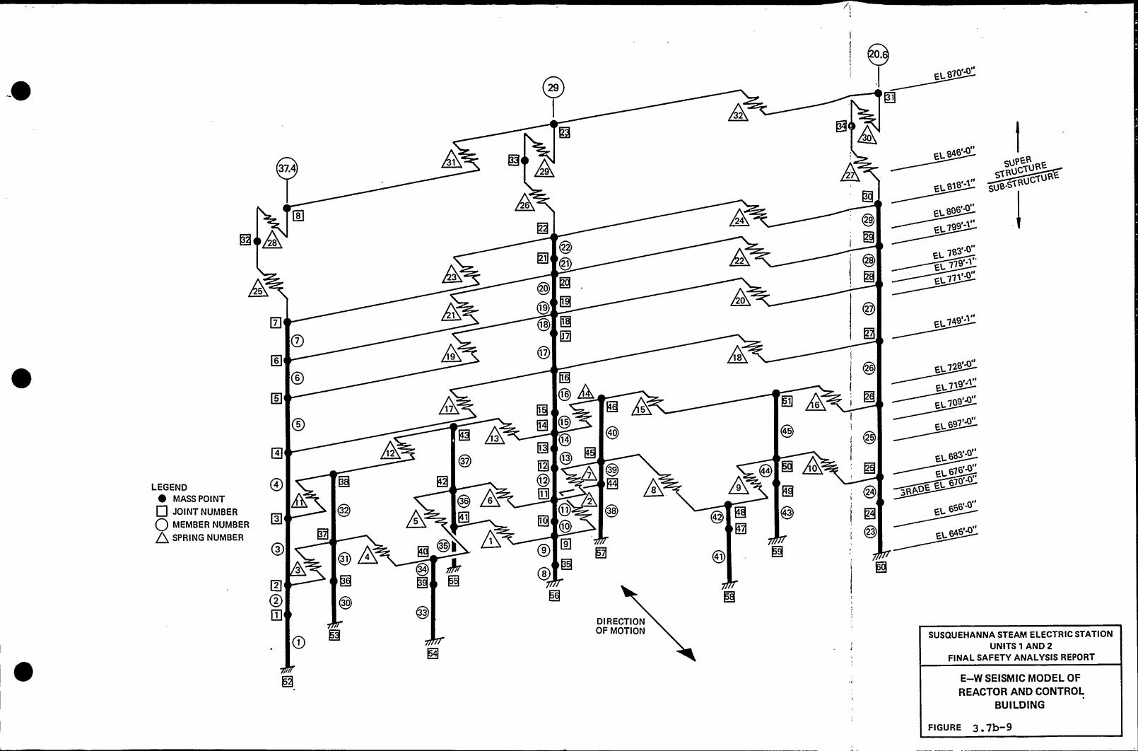
EL 870'<
37.4
e Qs
P7
ps
5
0>
Qe
05
p4
04 m
QS oAQQso
P2
P1
LEGEND~ MASS POINT
P JOINT NUMBER
0 ----"- P'
SPRING NUMBER
+17
gQS7
gO0 Qe
g
,oio~ kg Q
I~oo~
g08 8
Q7
gg 05
014
Q1Sg62P11 c
011
~ oo
QPo~
g
gQ4o
Q, QSg
Q2
QSB
Q
D I R ECTIONOF MOTION
+18
8 @0
O44 mI +10
gg4
Pg Q4S
gQ41
Q
Q
026
gg
!
IiQ24
-.awoke
g; 02S
5upER<Ruc~uR
uc~ua~EL 818' Sug s<
806-0
7gg'1
I ~
EL 783
EL771
+ 74g'-0
EL728'+
EL719
„7og
EL 683
670.0"
~ -0"
EL646'"
SUSQUEHANNA STEAM ELECTRIC STATIONUNITS 1 AND 2
FINALSAFETY ANALYSISREPORT
E—W SEISMIC MODEL OF
REACTOR AND CONTROLBUILDING
FIGURE 3.7b-9

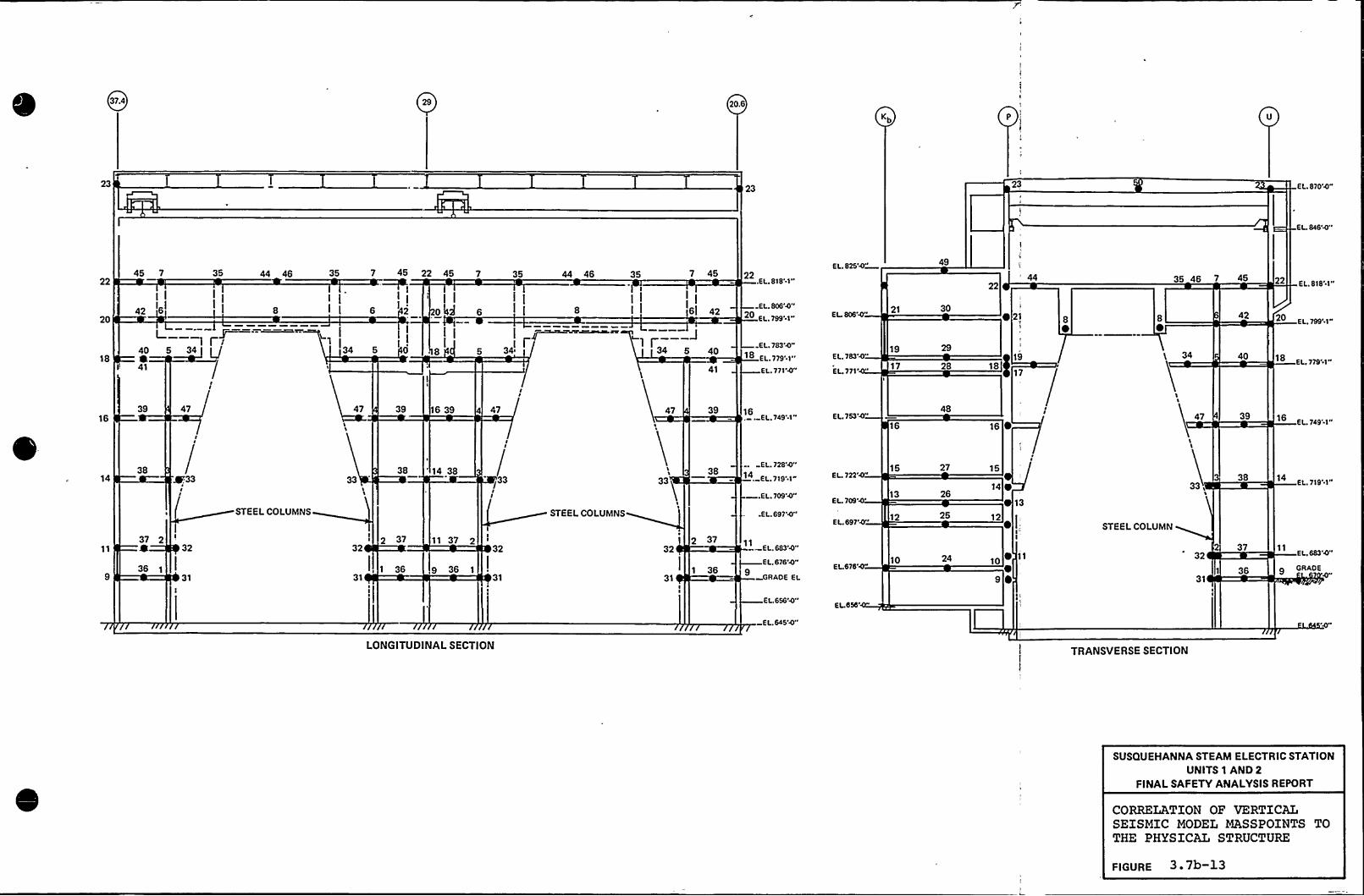
0314 Qs 20.6
Kb
23 23 23 E L. 870'4"
E L. 846'4"
22
20
18
45 7 35
I I
4. "I
L40 5441
—-I r~r
34 U
44 45 35 7 45 22 45~II I III I e '2 o43
1 I34 5 O
7 35 44 45
I )
5 II e
35 7 45
II
Iel 42
41
.EL. 818'-1"
EL. 806'4"20 EL. 799'-1-
E L. 783'4"18 EL. 779'.1"
EL. 771'4"
EL. 825'4"
EL 806'4"
E L. 783'4"
EL.
771'119
17
49
30
28
22
~ 21
1973 I
44
8 8 42
34 40
35 45 7 45 22 E L. 818'1"
E L. 799'1"
18 EL.779'1-
1539 47 47 39 15 39 47 47 39
E L.749'-1 " E L. 753'4"15
48
15 ~47 39
EL 749'1"
1438
~33
STEEL COLUMNS
3338 14 38
/33
STEEL COLUMNS
38EL. 728'4"
1 EL 719..1"
—.EL. 709'4"
.EL. 697'4"
E L. 722'4"
EL 709'
L. 697'4"
15
13
12
27
25
25
15
14 0
12
13
STEEL COLUMN
331I
38EL. 719'1"
37 2
35
32
I
31
2 3732
1 3531
11 37 232
31
3732
1 3531
-El.. 683'4"
E L.676'4"9 GRADE EL
E L676'4" 10 24 10 ~ 11 32
31
37
35
EL, 683'4"
g GRADE 4"
E L.656'4"
E L.645'4"EL.656'ONGITUDINAL
SECTION TRANSVERSE SECTION
SUSQUEHANNA STEAM ELECTRIC STATIONUNITS 1 AND 2
FINALSAFETY ANALYSISREPORT
CORRELATION OF VERTICALSEISMIC MODEL MASSPOINTS TOTHE PHYSICAL STRUCTURE
FIGURE 3 'b

0
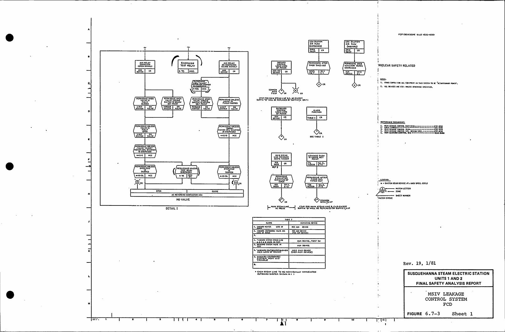
~ CsltosxatslK rw.ct scat Klscf
LOV DKUTIONAIR TlO'W(OUTDOARD)
OP( 5NI ~
LOW DILUTIONAIR (LOW
(INSOARD)
OPIS (R
AUX RCLIYfata(QCD
(Ofta 51(RAL)
AUXDr TICK
AUxO(YICC CR
AUX RTLIYDf fata(lrCD
(CLOSC 5ICRIL)
IXSOIRDcoarxoL
LOIIC LOSSOF POvta
IUT (5)OCYICK
PCRHISSIVK afTCRTIHKR TIHts ovr
1OS)X t I
ftaWSHYC VIENAVIILIIRYDtvlrfKNKRLIZKD
IUl Sa.t
NUCLEAR SAFETY RELATED
/CONNORvlrN
T(sf Ca» Ca
A CR A CR
1. FOKR STFILT fsa all (EYINKXT la 'lsaS 51(1(N '10 I( ICSIIC(/HID FDCR
2. I(L anuS aaC Csr- VKCSS orsta 15( (St(I(I(0
PCRNI55IVC VISCNYILYC ISfULLYCLO5CO
pfRN155lrc vvcaYILVC TOIOUC
svs 1(N 15 5(LovSt( POINT
~KRHISSIVt WvtNvALYK 'toaovE
swsrcw ts 5\UtwSKT POIN1
TCRHISSIYP, IP,KSSFVLLVCICISKO
('tYP FOR Naia 5TCIN Lsaf 5 0, 50 CXCEPTSVfflX 'O VILLSf RCFLICKD l(r 5VfflX(lKORP I
LINI't5 VITCN
ONYILYC
TDRDUK5vlrcv ON
YILYCTDNOVI5VI(CN
ONVALVE
LIMITSsvtrrv
ONYILYC OVTSOIRD
COIIIROLLOIIC LOSSOf PCvta
ALIRNfVNCTION
flaal551YE UXLC55YILYC ISfULS.Y
OffN
L IN I 1 ONSVI1CN VALVE ~ I2/O NCC
PERNISSIYf UNLC55Ofta
NOTOR COll STARTERIS tafRCIIKD
IUT01 YI(t CR
ICR
'TASLE 1 CR
Aca
5CC TASLC 1
REFtaCN(X OOCVHENrs
Ntsr l(lsau CDNIIX tt(N SILL g)).VHOLi(IC SNNILS ail ~ 10105, N)IT L(AIAu COlta(L f(10 C)l 1010~, lsllr L(aaau (0SIRSL 515. 0(SIDI 51(( Art-IOSI5 ILNY Ltaa/NCOONTR(L 5)$ sst s(IIO
FCRNISSIYC UUI.CSSOrtaLOID
15TRIFFCD
~I5/OL
/R/ LCR
NCC
FCRNI55lrf UIKC55~ VILYK
CLOSt'O)OR
COIL 5TIRTCR15 CatÃ511CO
~ it/C NCC
Offa
(PERHISSIVC IPILKS
TLST arurELERCIEKO
~ TS VCC
AC RCYCR5IXC COXTICTOR I2~
)(0 VALVE
CLO5C
~ IT/OL NCC
C,,CR
PCRNISSIYC UNLESSOrfa(OAD
15TalfffD
NIUI STCINLsac fa(550acASOYC YACI/VN
P15airi
PCRNISSIYE~ I(IN IFTCR
INITIAT.ONOFTlatR
~05 SN ~,NIOI E 5
N
Ca
LKAXACCfLOWIs Asovc st'1
poIHT
FS SH. 't,~ LSSS K Is
PCRHISSIVE AFTER'(INCR HAS
TIHCD OV'1
tD5 SH. t,NLO2 5
COWHOWWl'tH FK ~ P
'~cca01~ 5VITO( CfAa OfYICf 0' AN51 SPEC. Ctree
X NATOI
Lt'1'(fan
2OXK
Sat Et NUNSfR
(NATCN CIRCLE
OETAIL THAIN STCAH LINK I (TVP fOR HAIN STtAH LINK4 CID EXCEPT
Hl PRESS f SUFFIX 5 WILL OC R'EPLACCD lbv THJFSIX fX ~ P
TIH( tlatria(IN( 0(rl(c
I. Isaslaa ICar(a LOSS Cft2 ~ lasraa0 (Dirt(ACI) YILY( IK(
IKC IYX Scn(c
FKL IT( 0(rl(c~ s
i. I as(ALS 5TIIVI 51(aa l lac
$ 00150saa 5T)ua sass( Is1st'I
I 'INDOAAD(OUTIOARD)SLOVVTRMCC LOSS 0/ PUYVCR
T. IssaOARD (OUTIOAAD)SYSTCIVI MSIV LCSTROUSLK
AVX OCVILK, TCST Sw
AVX DKVKK
(C AUX OIVCC
MCC AUX OtVKC)
Rev. 19, 1/81
~ CACIS STCAH LINC TO OK INOIVIDVALSVAHNUCIATCDOVTDOARD SVSTKH SHOWN IN ( I SUSQUEHANNA STEAM ELECTRIC STATION
UNITS 1 AND 2FINALSAFETY ANALYSISREPORT
MSIV LEAKAGECONTROL SYSTEM
FCD
FIGURE 6.7-3 Sheet 1
I 4


'TINK%1INCD OU'1
x')t a
~ ttNI$5IYf UNLC$5CON'ILOL 5YITCN
IS 11 OFFtot)NON
%15 0 5
~5NSCI 5 D Io
~ KRNI55IVC VNCNHAIN STKAN LINC
RK$5. 15 SKLOV NICFRCSS SCT toINT
5KAL IN
LJXDKY ICE 0 2
ttkNI55IYKvNKNLUX ofTICK 15DK CNCRCIZCD
OCVICCLUX
5CAL IN
LUXOCvlCC
tCRNI$5IVE VNtN
Q Nsstd CWN )
CONTROL SVIN Ot(RATE
POSITION
RNS Ck
PK%1155lvl UXLCstCON)ROL SV It IN OFF
P0511101
RN5 ~ 5
5 po)ITIDN RKVLD(x Ssarol011 1(ORPAL
'OPERATC'MNNC
RCTURN TO NORMAL(HEY NESS(APKAE a( N(RSIAL POQTXPI
N JVSIXH0'clrCNCRU CEO
OCVCC C 4
PDN10$ 1VT.WHCH OVSTCAI
C 4
RC AC TON PRC 0$ASOVC NICN tRESSSCT WINT
PSNSSORCF 5
~5%$ 50 C 11
Pftalttlvc VHKNackcroa tatss. TtStcov NICN ~ ktts
SK1 POIN1
tlkNI551vt VafN~ fAcro% tkl$5. IS~ KLOV HICN a%f55
SCT POINT
accoPS
ttawsslvc vHKNRC4CTDR PRKSS. ISCfLOV NICN ttlst
Str PONIT
%ceo D-II~5 tt1450 C 0
Plkalttlvt VHl1ttkc)0% PRC55.
5 SKLov HICN PRKSS,SK'1 F0111
t toll(IPN 5111(NHAIN(Ala(S SDNTA(lHOSHAI 1(ST CPOI
SS
PC NNSSAICWH()IOVSTCSSIXII'CRCSXCD NAIN STEAN LINK
ttC5$ . LSOVC HICH~RC$ 5. 5ET POI11
NCSI S~5
~CtNI$5IVK VHCNttkc10% k%f55. IsAaovf HICH tktst.
5C1 PRESS.
1440~5
ACF 5
RNS ~ 5
coN1%0(, svIN OFFtot( 1 IDN
5'IELN LINCPRCSSURE ksovC
pRE55 50 axxr
NC510 ckt$
LUX DCVICCCNCRCIKCD
LUX DEVICE ~KRHI5$1
NAIN Srt~RESS IS S
ttNCSIC 0 10
Vf VHKNAM LINt
CLOU HCN
Rvd CR
Ck Ck
HOT CHCRD(tf0CH
swlr(N s~lPOSITION
OVERLOADTRIPPKD
O.T ~ ~ 4$ (OL HCC
VI IS
51CAN LINCLCLXLCK FLOV
IS LSOVK5ET PONIT
FtNCS)a
PKtNISSIVCs)wlUNc (as(
~RESS OIFASS RSS(R
NCOOS105
LOV DILUTIONAIR FLOV
1454 CRkts
(111141C TINCR
~ 05
LUX DCVICCCHCkcltf0
LUX DCV
S'taalttlvc vafaDILUTION klk FLOV
1$ Lsovc LOV5KT F0111
START
LC CON)ACTOR 4t ~
STOP -0
gk)C)) RKF Ccat
1454 D I) AIR BLOWER COOI(Nlsokko)
ttkNI5$lvt V%ENLKLXLCCFLOV~ VPL5$ 111tt
TINED 001~ 0$
Ilsoto
Ial IVILVEVIANN
UII IA St)YPASS VUNKI(
(DSNSOI 0
cr( 105 CNNaotd
Wl IA AMPkfSL drPASS TlVFlt
~ 05 CICNHOO(S
~ (%11551vf FROHat(ATION UNTIL STCAM
LINK Lov PRC5t avtk$$1lalk 11NE5 OUT
Ptt1155IVC VHKN5'IK4N LNICtat $5. Is SKLov Lo
tkE5$ . 5tr t0111
Ntrs 5 ID5NCOOS NC51$ D It
5 tosmCN( HCVLCXXISVITCN'TEST Foots'O%HASTttr Fooo't%Lac
RC'(URN To 'NORNLLXCY C)a)SAOLCY(sHORSIAL~) TC5T 5VITCN IN
FoolsTCSI'0511101
RNS Ck
f)1 5
HSSSS ca
PttM15$ IYC NHU(Axkct rtov Ts
DKLOS( SCT POINT
~ERHI5SIVC PRONINITIA'I(ONUNIIL
Lfkxkcc FLov avtk551(Ntk TIHl5 OUT
Ncota105
YCSV SWINNWOOCSS
TCST'OSITION
Ck ~ Ck/R *
Ore(Sokar(ltt(D
~40()L
1 toNrMH MAINTAIN(ocovrkcrg'HOANAL v 1(ST CDOI ~
V)„PfRNIsslvf VNKN
HOV F001$IS FULLY CL05CD
L IN I 1SVI1CN
01VALVE )0 5
LC COII1ACTOR kt ~
LIHIT5VITCN
ONVALVE
tCRNI551vt VNf1Hov Foo)a
15 FULLT CLOSKD
INBOARD PIPE HEATER BOOIB(1YPICLL Fot tlat Hfkrtk aoolt, SOOIX a aoolt
Ckcttr 5UFFIX CHLNCKS 10 Cokkt5t010115 LCT)CttFOR EACH VALVE)
ttt1155IYC VH)NLUX OCVICK 0DC tatttlrtD
(Oat%ATE 51CIILL)LUX
OCVICCi
YCST OWIVCSIIN TEST Sooo
R)ld II tTtdr OWITCSIll 1 CSVSXNHTION
TCSV OWNCH
IXNSTION
R~ Fk
(HISQV'c HIRNT(51 SHINV101
IN '1(51 (SPIC')NOON
THS N
F(111)SIVf WINHOV IPDI ~
vcr Fts(Y clos(o11111SVNIN
t((HNSIV( VH(1HOV 14414
NOT S VS('( CLOS(O
LIHITSvll(v
t((HI)Pl( VN(H14 NVX( ~ (V((41 (t
Nt((AI( SNVAL)
C 4
LUX RELAY CNCRCllCO (OtCN 5ICNLL)
LUX OKVICC
IL '1
I
II SCC OCTAIL 1 II ta I I
INBOARD VALVE HO FOOIB(TVPICLL Fok VALYC5No FOOIF, TOO)X ~ Fool ~ ffcttT SUFFIX ~
'CtLLCKDV(TH CORRC5totolac LCTICR Fot CLCN VLLVf~ Dtvltf
LUX %CLAY OC CNCkCIKCD (CLOSKD SICNLL)
Rev. 19, 1/81
SUSQUEHANNA STEAM ELECTRIC STATIONUNITS 1 AND 2
FINALSAFETY ANALYSISREPORT
MSIV LEAKAGECONTROL SYSTEM
FCD
FIGURE 6.7-3 Sheet 2)0 )2


Dtvltt
PER HISSIVE IAIKNAVIOCYXC ISCNCRCIZEO
05
SLRROSIIC MItNNUX SICLN URC SSDS5 SIL4W LONtttllSt'I
'lESS 5VIICNIS IC
TCSISOOT'olll ION
RNS 0 I
ttRHIS'MVE WHCNAUI OCVICE I'5Ot ENLRCIIEO
40PERAI C SICHALS
MNN 5IENl LIIS~RESSURE 15
AIOVK IDWSCT tONI
PSNCSL
C"~
ICSI 5VIICNIS IC'f0025'C5
I'OSIIION
RNS SC 2N.'2
~tRRIISIYC VNCIINOY f0015l5 SVLL'IC\.05tO
NILOC4ACC SILA,C t AUI SN 4
OEYICC C 2 LICITIVIICNOC
VALVE
fAUX RCLAT CCCRLICCO
AVX DCVNC Ct AUXDCVNC
SN 4t I
PCRNISLIVC WCCUAUX RtLAY
ls ICCRCIltD
LICITSVIICN
ORVALVE
ttRCI55IYK VRCRNOY FOOCIS SVLLYCL05to
~IRUISSIYK WISHTEST SCIICN l4Ji
R4 TK\I FOOlPOSITlON
tACT AUI Slt 4RMS D4 SWIICH DEICE K t 1
~CRNIISIVC VINSNOY fCol 5
l5 SULLYCLOICO
LICIT OCSVIICN VALVE
RKNCWAOLCIH5401WML
255$ SWIICN
"QelP~CR
PCRHNRNC WNEH
V
LIMIT ONSWITCH VALVC
AUX RCLAN tNCRWICD TILT(OPEN DISHLLI CNASLK IWKRUNO
AVXDEVICE
I
lOUISOARO YNVT i@i SOOT
NN RELAY DC CIKRCCCO(005C SNIML)
PCSUCSOIVC WNCNALI RRLAV IS
1~&cMu5CI
CZV 5 E-4
P
3
AUX RtLAVCHUNSICOJIOPCSI SNHAL)
AVI DEVICE
I
PUCCSSIYK WHIMIKST 'SWITCN NOT
Pl TEST FootSPOSITNN
tERMISSIYK VACI4AUX RELAY 5IS EHIRCIIIOOPKRATK SXINAL
'ERMISSIVE VANNVALVE UIOV FOOSSNor SULLY aOSCO
IIST AUX IA'I OE f)ERCCEOOIIAUVDCOCLCIC QCDSE SNHLL)
CN 2 IHt LANT LANTRMS. DKVNC ~ C.4 SIRIDI C.S SWIIDI
P'ICNtRCICCDOSC RATt 5 CHILI
UUUT AUX SH 4O.l SWITCH I< DEVCK E 2.INBOARD VALVE MO FOOEES
OYPICAL SOR VALVCS MO foolf footx t FootP CIC'CtT SUFFIX 5RCSLACCO WITH CCRRCSSONSnaO LETTERS SOR EACH VALVE
AHO DEICE)
AUX RELAY ESNRNIIO(OPEN SNIIAL)
AVI OCYICC
TESTCNASLK OYKRUND OXIUCTS
StK OCTAL 1SH I
OUTDCARO VALVE MO fooc
AUX RELAY DC K)C)ULLEDg(4LOSK NCHAL)
~tlSO055 TESTSVIICN IS UIIIII SOD
l5'05IIIOR
RN5 CR
I to'IITIOC XfvtottSVIICNVCXRHAL'ESTf0055SPRICC RCIVRC TO 'NORMAL POSlllONSKY RtNOYARLC IC'NIDRHAL PDSIIX)N
~CRHCRUVC WUCNAUX RELAY 45Dt'NKNIHIED
FOS SH 2NLOS
lDS SH INLCS F I
QFMS Dl
IKETSWITCH NTCCT SDOI~DSITION
TK5T CMTCH INYKST FOOStOSITION
RMS D 'I
TE5T SWITDI 5thYEST F005
POSITION
AVI SN 2DCV 5'4PCRNI55IYC VVIIIVAl.vt NO S0015
l5 fULLYCLOSED
LICIT ORSVIICH VALVE
tIN 3
~ERSRSIIYt tRONRCNIIN UIIR SIPRSS
V4LVC TNlR TIHCSCUI
IOS SN 2Rfolo S I
PERMISSIYC IAEIITEST SWITCH HOT
Rl TEST F0055POSITION
RMJ IPS
PERMISSIVE WHENAUX DEVICE'5'H
t4
PCRMSSIYC WICHUILVE MOF0015IR)T FIALY COSCO
UMIT
5t IUC
S445444-Hl AUX RELAY NNCSUSIED
(CPCN OCNAL)
AVX OCYICE
AUX RELAY DE TNERCIEEO(CLOSE ETAIAL)
SEE OCTIR. I5H I
Rev. 19, 1/81
INBOARD VALVE MO FOOBB
TYPICAI. fOR VALVES MO FOOSF FOOSX 5 FOOSP CXCttl SUSFOI 5RCSIACCO Wlllt 054RESIONNC LXIICRS IDR EACH 'VALVE
SUSQUEHANNA STEAM ELECTRIC STATIONUNITS 1 AND 2
FINALSAFETY ANALYSISREPORT
MSIV LEAKAGECONTROL SYSTEM
FCD
FIGURE 6.7-3 Sheet 34 l I 4 10


scil IN
JUXDE TICK
5 tOCIIION KCTLOCK 5VITCKOIF 104NJL Ot(RJTC
5tllKC RCTUXN TO KOI\KJL[X(f l(MOYATL( I( 'NON(A( f(ODOR)
PERI(ISSIYC WHENAUX OCYICC 45OE CNCXF ICED
PCJKI55IYK VKKNlVXRCLJY
I5 EXKRCI(CD
CORTROl CVITCNIN OICXJIC
totl(lollAVX F '544. 5
OCVCC ~ C-l lVX 51 5DKYICC F l RKC CR
t(RKI55IYC UVLC55COIIROL 5VIICK
I5 IK 'offtotl'(ION
RNS 5 4
It NI OFFPOS ITIOII
KLICTCN PRCSSUREAROYC
IIVJH PRESSUREstT f(XIII
ttRNI55IYK VKENR(ACTOR tRC$5 IS(X(OW NCK PRESSI
1455t5
5 t05ITION 5VIICN-I(5( JLOV(1 A. -NORHAL)TEST SLOV(1 t
NJI1'(JIX(D C01IACT
L 414SFS
DW 4 JSS 4 CS'5
RCF 5
PCRKI5$ IYK VKKNHAIN SICAN LINC
~RESC IS SCloW IJCK
AUUUARI DEYXCtNCR CIEED
DLOWCR TESTSWITCH IS IN
T TXOJKRA'T
N4$ $ D O AU(DEYXK RNS CR ~ 45 Ol E 5
AU( FLOWTIK'ER OUTDOAND
TDS CN
KSI REF.S
'II((Algal RELAYCNtRDICEO
ICI'1
'll ALJ(IYACVUM ALARMTIVCN
REF. 5
HNN SILJNViPC~
~5RlXJ
WINI4UNttRD5 Stl
E 4
I 5 S
$045-(X. MCC
CR CR/ 'L MlA
F
OFF
PERAVSSIYE IPILLSS5(DJKR TtST SMIOI41 IK5T OIOWU( AF
POSITION
RMS (HSTCSI'WITCH
IS M J NOR((ALePOSI TIOII
OUR(HE IKST
5TKJN LINC~R(SS TXJDW loWPRESS SCT t(XKT
~ atlttRt(5
I
ITPT SNICK UIN IltlF(0$
'(SIIXN.
JC CON(ACTOR 4l~
AIR BLOWER C002A(TVP fOR AIR SLOWER CooltEXCttT IEST SWIN ICSI 0(DW(R C POSITION(
TEST 5YI'ICKIS IN
TKSIF005'05IIION
RN5 EI
t(11155IYt WKtNAUX RCLAV 'IS
DC EHtACICKO(OPERATE SICKAL'I
OCVXCAVX
!
t OILUKONAllIlo)IKICR RCLAT
(14144 JCD
OtYICT.JUL
I
! PUU(ISSIYC VN(CSSCONTROL SWII(N IS(N OFI tOSITION
RNS D4
ocxxc C Cl
OSI NICNAY
LINIT5VIICN
ONYJLYK
tCRNI55IYC VHtNYJLYK KO Fool
IS FVLLYCLOSED
~XllllltSIYCWHXHTEST SWII(4 IJTT
Ol ITSY FOODPOSITION
RMS C I
PUVJSSAN. WHhMIX DCYICC Is
CHCRCNCODPCIUUC SICKA(.
~CRMFJSIYE YACNVALVE MO I%OS
IS NOT FULLY (XDSED
LMITsxm(4 4~
ttRHISSIYt INCRRTJCIOR PRtss IS
DKlOV KNKPRt55
N550Ps
WICKI( NJ (404
0 INLTCUD(D
(OPCK 5I(1JLIAUX DMCE
Stt DETAIL ISH I
OUTSOARD YAlYE IIO FOOD
AIX (AY DCWHC CIC(D
I
PERXIISSIYE WKCNVALVE MO FOO'INOT FULLY ((OLEO
SWITCH
PERMISSIVE WHKHJUX DCYICC IS
CHCROIIEOOPUIATE SNIIAL(
(CVCC
~tRFUSSIYE WXEN44E PRCSS ls
OELOW 4144 PRESS
PCNMOSIYC WHEN PsN JSSTEST 5WIT(4 NOT
IN TCSI fOOS-~TKX(.AUX DEVICE KNCRCIZCO
AVX DEYX CR
AVXIL(lRTRCLJY KRKRCITCO (DtCN 5ICXlL)
AUXILIARYDKYICC
JUXIL(ART RELAY DE-ENERClltD (CL05K SICRALI
I ttt DC'(AIL II 5N I
Rev. 19, 1/81
OUTJOARD YJLYK NO F005 SUSQUEHANNA STEAM ELECTRIC STATIONUNITS 1 AND 2
FINALSAFETY ANALYSISREPORT
MSXV LEAKAGECONTROL SYSTEM
I I D (0
FIGURE 6. 7-3 Sheet 4

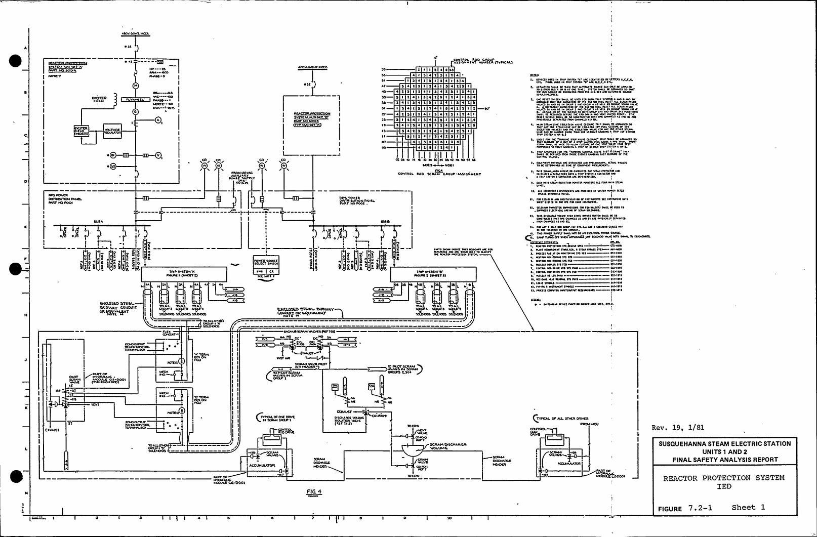
M)
SIOT4 '7 PHASC 5
PLVANE(CL
I CEO
5
IDLWA
.)I .)I ,'),)
2$ I
li. t. s ~ )i*:@
23(CX(35tO OETttaL25UOV/AV OOL(OL)IToaecvulvALtsjT
N01 5 l«
OR 44E«C ItOPHASC I~47(72NVAP I015
E
/VV Vf
'5 SVP SVS(2$ 4 'XPWLOW S <SEKST 2)
H IC I N
s I5 I 5
I I'TD AU 10 AIL TD WLCROUP 7 CKLIP3 CIDUE~'A''5(LSFOCS 5(A(7DCO 5(AOOOD
10 ALLOSCTLCAOVD I XSOJFCTCO
~BLBRICCB522~COMM I~CRT~aRT HO SOCIOQVD M~$47 'A 5
'P /VV/
flUTUIZOVAOAULIIJANV
PDVVCR DV»PLT
)
/VV
RPS DOPIERDWTRIOUTEON PAAICLPANT HO tOOt .
));)I.iI,) .,
POVFCO SDVCCC5CLECT 5EFITCN
avw Ctjtj IEIT t
OTEt IN(
OPC»UO SCTEAM INLVCS~ Tlat
U4CU)%D 5%%1 25()0(IVAYCAUS+ Ojt TETE)(T(LNARSCT
5( I
47 3 4
43 4 2 3 5
3 5 t 4
3$ t 4 ID( I 5 4
27 4 t 3 t25—3 C 't 4CO 2 4 I 0IS
S 5
4 (
I 5 4
4
3 5 2
2 4 I
1 3 44 t 3
3 I
4 I
5 3 4
4 2 0
3 I
4 1
coNTRDI. 100 caoupASSICNUCNT NUMSCN QVPICAl)
2 455 t4 I 3 43 4 2 3 I
0 5 2 4
C 2 4 C 3I 3 4
3 4 2 5
2 3 I 2 4
5 2 4 5 3~ 5 0 4
5 ~ 2 5 I2 3 t 2
0$
~I
'c~Earl \EOEI INNCC OEIS SOIDEAT kK FIRKr(EDNC «o akc anal oar Io (uwnac KECt(N PEOIECTIOI SIITEEI
TAP STSTS74 W~vc(DW 2 (saNST 0)
TO TONL TOWLCEDED 4 CR(SAE S CIEXAE2
$(XETETCC EJAITOCS j(LCKRSS
/
4 2 5
I.I I I IW CT TODD 14 OD 02 aa so 54 so
NCC I
CONTAOL ROO $CRAEI CROUP 'A$51CNUENT
1
I
TCETJI
5 CCVIC(5 WCO IN taIP SVSIDI k Akt ICCNTlflnlaf LCNCES A C,C CtTC TKAC INCO la TEIP $ISIDI ~ AK ND f N tIC
1, kCANTIOI Srau, K OIDI Oaf WIDE«It SEUKC CNI OEV DC kffllnl10 CNKA N«k Ia ~ kt Oc NK STSTDI SPalL K Na«vca $0 fWTIK WS I«Ear K DCWllta INM Dc» C Kl ND WIDHlvt NEKCSIWLIklCO«LT,
OC ECSC1 O«tCN SMll K WCO fin DOI lrl~ STITDO k NO 0 ND 10kla«NCD PIET Oc ECAEENOI af TW 5VINNIEIILKICT kll RANI PllatVALVES (E NO 01 la Ma«1 ND CAO« ~ kj KllES WCIU'CANIVWK
a OlffuuvlACIVEDOI VF Tlc a«TOI VIU K5CT Ell ICANI PllaTVELVCS (k ND 05 la CNNP 1 klcl IAIVP 1 ES Kllkj AICNIP SCMN VILK0, ECANNEN Cc Dc 1«TCN 10 NIIEI IANP I ~ ND INIU' 1 FVNNOONNLL SC KONKD Kfac TK IAD MAls EEO VDET Vkl'K$ SEIET, (OcK5cT INITDI DNLL ac sa Dasnlcno IMT afs DN«cLs ll ND Sl MCNNIICALLVICINMTCD FWN CNN»CLS EI ~ Ol
~ Iala SNEN Lac ISILlTIOE vklvC C(05«c IHP SMLL K EEEENCCD 50avkt ENT Oc SICAEI Lac Pkr K 15IMICD (IT Dal ELVA«C af ITSEscunos valvcsl No ac ESRAIIM »ave raa Nn oc ovca Sr(NE.LEK CNE K CLOUD IKIKDM 111 ET INDI Ckl«laC A ISI ~ (OF Clacanip Tnvul a a 0.!
5 LODC fl« tlc NNNK SIVI'ELIC CLOA«E Ial ~ SINLL K EEENNCD 50Oar NOAK M 1 Ol~ M ~ 510P VIEWS Eall CWK A EPS IEIP IalvISNN IraLL Ic IaCC Ta ELLEN CLNVIC af Oc INP Va'K (FM ItjtPVNPCS(jj VITIDR CN«IEO A IEIP Cf Cl IKA IEIP shlul k M'0,Ial p Dvvacls n« Dc INENK cD«EIL valve fIIIIlasvac Tn pSlall K SEklvtD WOI DICE( CVD«1 CNOINL Iksl CLOMK af Tlcconaal. IALrcs
I CVVIflcllvEETIKA Nc Esllaklta ND PKLIPENEP, Kfl»lVELICSTD EC CCT(«EIKD lj lac Ic CONIKK P«NEKKIIT
~ Ial5 snaN,»ca EWNT,N IKWIt(1 ac SCWN COIIKNN EWnl lnns k $(IVII«la WTN k Illf 5KTCN k COEUCIIE NDk IN~ Ifnla ~ CCEIK'ISE EEC SC (aEWKIS,
EIOI Wl~ Stna NDUTIW IDUTW NNIWE5 kll fa« Ial~ $1(kaLIKL
)ss. an (Nlacar ~ Ilsvl«cah aac patrn(o sv svjrca «pals ((vtt
INL(liNINA«I( I«ICSI
n, flE LTCITIW IIO lOENIIICEIIWN IENAPCth Slt IE5IMCK Nvlac(1 LINE~ la TK IPC FW Ekuv IWIAICET,
[IL 5NC ~ IW TENN(CIW Inrnluas ON tWINE(nr 5INLl K 15(a 10
~ 5IPN(55 CL(CI~ ICW EKIEE Ic ICWN IELCI«IDL
o. D«5 ~Isoawt IN«c NIOI Kvn mass o«vur sw(E Ic wCNNIWCKD iv«1 Efl DwaCLS ~ 1 NO ~ I AK INNICEIITSnnlt(0FMI Daaclj kt AIO It
I~ FM In SIW(t WS CESVP.NI IT(,tp NO ~ NLCWID CAIL(5 MTIC O«TTNTWI N NC CODNT
h TNS FON(A SVPFLT SNNL NV( DC NI ($5(IITVLPWCA SSVICL
CIC UAO'IPVO Cff OICN APPUC Nt NO 10IJNCO IALVC ICIS II«PL
5((tt(j(244555(jk (ELJL1
1, Nkal EISNECKNI (NW.IW, ~ STtu ITNIS 1115 All»KSI, Pcc($ $ EWIINOI ICARSEIEC STS I(0 Nt IN~
1, KWON KNITIEEEI lvs ICD ~ CII INEI, KTISW NNITNIWSh FW CN lna~ acnkl wnca srs na sn Itw1 CWIVN OO WIN Nra ETS PNO Cn INSL cNTIN No wnc cra Sh Fw CN IIW1 acl(U WUEE PHE Wi INSI~ K'DIEM Klt ICWWI lh INO (n IN~
II, LNK $0«NS Nl IIWIt, ~ IPIW a IWTNKN 5VOIU Nl INS~L HIC(l( C001TES INITTOCIKKWUOCNl CTOENE
LE(ESVL
O SVNCKME Nll(tFOCI IW NDVW IWI NtC CnJ
(37
txuAU57
((7 ~
5(
CCHODunlffTO H(jfCOINKI,TETDNNILooc
PART Crf
~cJS IIOOS
TENT
ECSCS CSTITVT~ ~
1(RAVIEELDEN
! II I! I
II
IIIIIIIII
I
IIIIIII
II/ I/
DA rcj ~- ~pcj SA
RSe RL
LaSC(SEA« VALVEta(ETTAIR HCACCSS
L«AVOC Da SCRAM
OS(RAINE VOLTAIC
/ SCRAP«
ACOETH(XATOR HCAOCR~»TV
SANT ON
VELWVOV SCRAMCROVPS 2,5(4
PC
NS
OOETATA D4CLLANCSETTOI ETLA%,
CRA«a~VOOD IONINN7
~CCCOO(
Rev. 19, 1/81
SUSQUEHANNA STEAM ELECTRIC STATIONUNITS 1 AND 2
FINALSAFETY ANALYSISREPORT
LCXAAR C/2 DOO(
F!G. 0
REACTOR PROTECTION SYSTEMIED
5 l 4 'IO
FIGURE 7. 2-1 Sheet 1

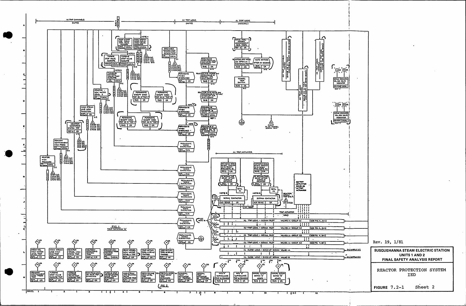
Al TAP LO(/C
(AUTO)Al 'TRIP LOGIC
( MANUAL)
MAW STEAMWE IS(LATIDN VALVE
ASSURE
NOGLA LOCAL NODLB
~IAAISICAMIINE ISOLAVIOL VALVECLOSURE
CISI ~ (AtlCISIC OCI
DISCNAIC,'E'MILUMLNANWATLRLLV(L%CRAM TRIP
LOCAL
C
IOADWL~NT444S TRIPS
EEACIDCOVS MOOS A(ttO BYPASSSW OPEN IN ISMFTOOWN F(t(IXS( ~PNS CR CR
MY/
U
n
REACTOR ~
IOW INLTCRLEVEI. S
C IDOT (Pa)C IS'Sb QblCISSSC IS LO CCI
tRMSSIVKEXCEPT rVGV
TEST Slr N TtST
CR
RtACIOC 'SYS HOOLSW~FCAMISLNC M(XMRNXP
"IAAS CA
M"D
CTACTORWYD NIODCSWS CRMVISACIN 'IEF
IEL'TAIITUP 0 ltSHUT CONN
CA
MAIMAL
ONIALM
MT
VOLVO NEVENDCATDR
Clt.F LOCAL
t(F T
/ /A R
SYSTEM TRP
MAINLTE/44LINC HKHAA(NATXP4
Lt
(AI)CI1 tC ISI 'I
CISCT UttDISCO Oa
CISO (44)C ISCC ISC Itt1 (At)C ILL 4 OC)
PERNOSIVEEX(EPT NIEM
I(ST Sr Sl ttttRNS CR
ITSY SN TI TEST
CR
IEF I
L\«4 PNC SAGE
RNLLA SO NLANICO PWR
At C
CISDT
AERIALMIMNI
Vtl ISO VALVE
L ..'-J
PERMISSIVE'WNLN
ENLRGISLD
Ml Al TRIP ACTUATOR
REACTOR
NIGNPRESSURt
Lt
S(N)'ttlr (NlC ISIS 'gLISIL
PCSMP/NYEWNLN
ErtRCILLD
TAT«ZTSSLT SWIt
~ IN RLLLT(ICITC S)
IOL1 C'R
IMTlkTSSNIRNLSLT ONNICN
IS I'4 NASLTPO'L (MTIL'S)
RHS CIA
CACO Olt) PERMVLSIVEWNLI4
.LI4LLGI'LT.D
Clt
IG S(CIICI TLEDELAY AFTER
SCRAM ISTIITMIED
DELAY AFTERS(F4AM IS~CTIATTO
PLRNISSIVEWNtr
ENtRGlttD
v
PERMISSIVEWrtNtrt'AlitLD
Y CR
I
N SCRAM EONTACTDR
t NIX DEVCE CR
4I lI
IV CR I I
II YINP AGTUaoA
I
~ ETIR O
SCRAM CON(ACTOR+
AIIE DEVCE CR LS C(SSS
I
~CI . ITRIP 'SYS'EM
'A'tRMILSIYLWNLNENLR( ItLD
PEEN ISOtVB
ENCE//ICED A
/'r (R/
TISP L(XNC SCRAM PL4VT VALVES A. GRXXV Ol (XE FVG 4 SHI)
Ilt IT(SR LOGIC SCAAAI Fr(IT YALVSSA OAOUPOt (SEE LTG4 SH()/ I I I I Ir I,I I I I I~ Vt TIMIUXNC SCRAWL IC(TP WAVES A IP/FAIP GS (SEE FXL 4, SHI)/ ~
II
~I I
I ~
Vt WSPLOF«C - SCRAM Fat( WCWS A-CFNXIP 44 (SEEPED 4.BII) Rev. 19, 1/81
trSCH VOI.NIGH WATERLCVtl.TRIP
MA4N STEAMUNE NIGHRAO YACV
RE/CIOAVESSEL NOHHMSS VISP
AEPG CR
fIA
CR
ftA fSA
AfNA fSA SA
*3Ut CLKC LSX)IC BACICNXI SCR/4«4«LFVE ~I,I IIlt CUDSC L4XNC BACA«XI SCAAM VAIAE O
O CSUN«tv SUSQUEHANNA STEAM ELECTRIC STATIONUNITS 1 AND 2
FINALSAFETY ANALYSIS REPORT
FNIMARVCONTNIGH
O4VIYNOLYIRENNC
'I«4.VE FASTCUDIURE wNA
NNN tt(ANUrtOO WAVE TRP~VPASSLO
'SYS HODC SNF MAHUA(TRIPACTUATORA'I TNVFPCO
7 I
L-PPS D
SURVELLNIXN ~IOGNES
Swt(OI AAIDIEO
(O
RMS CR 'MS CR
REACTOR PROTECTION SYSTEMIED
FIGURE 7. 2-1 Sheet 2

4
I
h
I
N
I
0
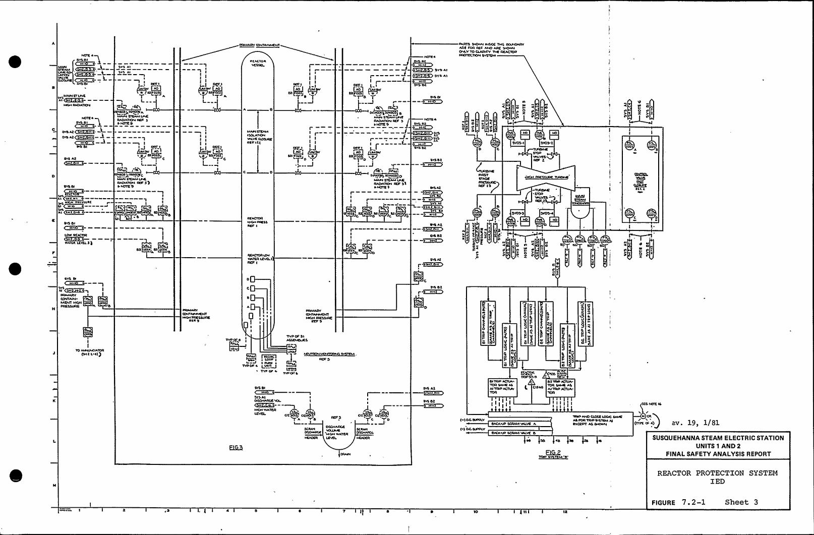
NOIR 0
~RIMARYCONVASNMSNT
NCACIONvESSEl. M I
SARTO Dsovna INsscE lans oapsoARYARE PDR Rto 0006 ARE 9SOWNCIVLVTD CLARsoV TIVE REACTORPROTECTION tVSISM
MAINSl LNEAa~~
~04M SACIATICPI
SYS At~2~
SYS Ds
~MIDVV RCACICRC~M~OS~ ———VvAIIR LSVCL 3 )
svS eI M-s~-- ~N~~~ )
RIAIARYCONTAINMENT NICNICIKSSISRE 6
SYS Os
gM~Ol0~ ~svs Nsc ls Pslaalst'I ISa NoSVSAl '\sat OM
Svs As
SVS AsI
)I
SEC I
tt OROT'"I L
RF~~ ACv)
MANYSlsaan LINERADIATC00 ISIS4 NOIE 9
I
f~a..9C
aaAPI LIEAMapssRACSATSON ISO 3 QP AUDIE 9
I1 II I
IOS,I P~Q fW~l,~9
III
RSA'
~+9 C~I~~ICC
r CII—
MAPISIEAAIISCLATsQNNVLVECIDDISDSEL I)C
VSATSR tgVCLIRSR I
I
TD YI
RAcaATxpa IES 30 NOTE '9
I
~0D QIM&V
D~ J4''.
MAINSIEAM LPKRADsAllCPI IXR 330 NOTE 1
I II
~IS~
StsJC D )4
~~ SVO AI~,~ OYO Aa
DYO Ot
NOTS 4
~SO~s
's s SYSAt,
~s~sSv4 St
SVSOR
'IN 0 6 ss
V StN at
DsS At--+~isSIS 6t
~EICO
SVS At)-~o~i
SVS Dt
NNV
nl~
N
V
~s ss4
~I
NOSVa c<
S gI I
D C
n
a
o
CI
~ n
oI0Z anZl
laI I
,)aa
osoI
z
aso
ta
o
on
anaLYES QIER RS
I
I
I)
I)o
O
))
00$4
f)t))B)L
I I
d d
Z
II
lD SPAAVCSATCRd )EMt 4 0))
PISMARICONTAINMENTNsCN TRESSIIRE
RRS 9
TVOCOS
PI4IM
Jlvoca 0
I asloa~ LOOP II IESW ~
) INII~TVP ca'
'Tvoco SaSSCMDLSES
SIVM)
L~TVOOO 4
Inas
4 n
4
S0X
SYS Os
STS Al II
SVS At
SYS Ot
Ot TosO 0CTDA0
Cltm AITlto 0CTIIA.lCR SAME AS
IDSCIIARCE'vOatavsE
304M WATER
DtM~QC VO <-) DC Waav
I ) Dc «ssav
TISO 00SS CLDMEDDIC SAMEAS ICR TRsO SYSTEM ssat
EIICEDT As EMD000
~4 '35 04 34
/av. 19 1/81
SUSQUEHANNA STEAM ELECTRIC STATIONUNITS 1 AND 2
FINALSAFETY ANALYSISREPORT
REACTOR PROTECTION SYSTEMIED
7 ) ID
FIGURE 7. 2-1 Sheet 3

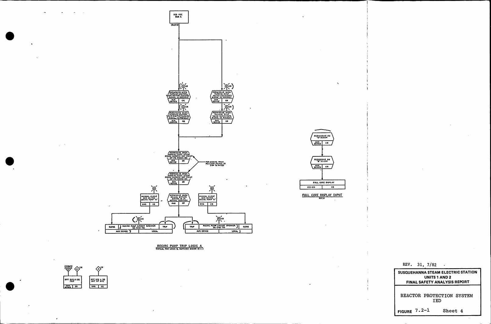
ICS VCCCVS A
if rt cc
IC l4'CN
ltcltxa closcfcOIONll, 5 tca04l'C
XVI\
/(CCC/
tfg4IISSIVS WVCNTVXO4$ ~5~4 IS ROC SCV
OCVVC
c cc)
tCRVISSIVC NVCNIVROIRC Sfct
VALVC I I(ICLCI(0I RR Nl
XVXOCOCC
c cc)tfRNI$5IVC NVCN
TON SIR( '5 IVRLVC SISICI'55(0
SICNJL IS RRLSLRTAVX
DCVICC
tCCNISSIVC DNA SCCAN
AVXSCVICC
tfJIIRSSIVC NNCNTVRSISC tiRST STRCC
MCSS CXC(f 'I S(f RONITOt 1$ RSOSl IS)
AVXCCOCC ~OI NSSIVC NVLN
ACR 'ION RO*CR IS>SO $ lllfCD AVX
DC VICC CC
tfXNISSIVC ON4 CAM
/0r
NRNVAL CLOSCOlf SA tclCIOXC tVNR 'A
CNS CC
tfNIRSS VT VN~NTVRSIiC RIRST 5'4a
tRc$ $ cxaf Js scf ROVRTOt RS 400$ C IOI
XVXCCVIa
t(XVISSIVC NN(NNkWJL SIRASS
SWITCN IS INNORVl tOSI'fION
~IJVVAL CLOSC~ ICR I~ lol
SICISC tVNt 'A
CNS CC
TOLL COCC OISRLAT
CIC 00
FULL C028 DISPLAY INPUTSIR 0
/CA
PACCIXC tVNt CIIIOAT SACAKCA
SA (RA) TCI
WX OCVCC '7
XCON tV~ CVIOXT SACANTA$ 4 (IOl TCI
RECIRC PUMP TRIP LOGIC ATftlllcSON LOCIC 4, 5VTSIXCS SNOWI IN I I
)CISAJl CCA
REV. 31$ 7/82
Ctf SVS A (4)5Clt
CC
Stf SVS l ISIOVT Ot SVC
CNS CC
SUSQUEHANNA STEAM ELECTRIC STATIONUNITS 1 AND 2
FINALSAFETY ANALYSISREPORT
REACTOR PROTECTION SYSTEMIED
FIGuRE Sheet 4


ktlC'VDRVK5$KL
LOV LKYKL2TRIP
LI5 l2I LtNO) IA
/'EACTOR
[(DW ltKL 2 TOP
«0)tl ) Lt
NCN (VIVV(ttPIKSSURt
Lt
fCSI 2llxllolr OLO'L (CAI IDSO)
ISOLAVKS No fool ONLY
LI5 02INo)to 5
Lt
REACTORVC5$tL
LOV LKYKL2TRIt
LI)4(tJ Lt
acacia VlslEI. Llor t(KL 2 farl KCN ORYWlll
fatssva(MINVAL
t«lvtavxvr 51$ 'ftitkr
W/$(ACCT NITD lstcau VITAR($(1
ISOLITIONPVSNDUTTON
tsNOI)0 Lt
NICN 'VURSINCCXNAU51lilt«PRESS
ISOLATION5ICNAL
LOCIC 0RfSK1
RNS
2 posiTIO«SIYIVC«aHDRKAL 'RESET'A
I«VII « tD CONVICTSrcvlocrto t«woaaIAL'
)4
PER«1$ 5lvt VNKNIKTIATION
SICNAI.)5 PRK5KN1
URSINC~N
SURK
NICN '1
OIItats
Ck /V
SEAL INAUTO SICNALIINTILRtst'I
AVXOt YICC LP t5
NOI20AVX
DKYICt CR
0 CI)
a cot~ 5 rr(IDEN owv(N 'c«5("svrt"ort«'D«TROL
5WU(N
~OSITOM NMITLN(0 ()VSDCTS ltvlocxtl IN'cr(N
k«$ .CR
cAUTO ISOLATID«SICNIL
(MOVE I)SLOI51IVC IAA($$
AUTO 50IAVI0«stotAL ta(vt«v
tovr've« MCA
1
I
L
Svf AN LINENtc«AI'RINST Rv ME Irf
~ LINE SRKAX
LtCPIS
tovt~ a« YckvAK Ialtv ~
OUTLt1 NICNOlfr, Tc«t
~15NI0I~
KNKRCKNCYAkflCOOL'lRNICN Tt«t
NCO(01$
SUPP POOL AktlVtltiAla INLCTA OUTLET NICN
cist vert~15 1.st
NCOio
Iatf lf
ttRNI55IVKVNEN 15OL A1 IONPUSN0UTTON Is
OCPRCSSCO ~
RNS
««PIC
I5 )
5ttttlf55ION~OOL ARCANICN Tf«t
15 tlt CRNlollafric $
I
tCRNI55IYCIrvcaTNIK DELAY
IDS CCIRCO) ~
RKS If)
NtCI 'STCAN\VPPLV
~RK55URE LOV
P5NOD IO LP
NPCI Sita«5vttLT
PRC$ 5URK LOV
NOOISts
I, VK NKI 51$ IS uauc(0 SOR Tlsi Of rtrar lv Aal fta 4 ILL Vuvts folDKN AIO Clos( CISACIIV li AAT 1«R ll<lrlIVCN INIIIAIIOI5lsau IkAUTO ISKIION 5tcau 15 IC'IIVII(D IN lvtav VK IIIVIIIIOI SIC«IIcccvh «VILE 1(w n Ivo(awv or Ivs awo«ilculv ativaas io svuvvrICOE
2. au tora ra ohalvia or D.c. Yuvt Novas sttut atculv( raot aILAIT D.C. Ivs. Pork ftN A.C. IO1 IN,DKllv10 VNVK5 DULL OIICIAITESlot lav (Klcttrv I,C 4th
l, lllC(VINKai AIO IINVRWOI15 Alt atilt(0 51 5T5, (lol ) URE55DVNDtt«5C NW(0, I
5 IvvlllIAVRfllvs 4 DKVICES IOT SaOK a SN'5 (VC(ri MNIE R(0415010 CLAIIST II«III OI
I1. Isulila stcau svivots $KLL a cr TK Twc n«v close cavuvs ra
TK SIECISI(D l5clliltNEKAT «tax lvl llllTS Akt UIED I~ OR 1$4lhaDNIUClS ORT sruL IC VORACD Slot 0« 51lllot IllitlltS(IICf, '0),
ll 05 NKI ST51DI Sruf 0C 0(510«0 la Ac(UOMI(t VI DI Cllitlllrtk~trltllPIKR ILIIIT SR011CT NVI $ 151DI l(tt 210
I) ul laWNS 1«ul 0( MDI(cv(a $ 1 Vta(otu ovtllcll 'NIPS IIO IRtll(aslaNT C IlclllCvauav PINE(I(YE illrs.
J
I na)Aswr( VK« skt Na(s~sVK AA(fElfv(D Yurt DKRTORAUE
or(MNC
trav I
CONT Itol SVIJCNa 'closePOSITION
R«$ C t~
IIIIILELEI)EUESIE1 NVCLEAk loll(a ttl02, NUCLEAR ~ Dlltk NI5C, 5TS fto$ . ON 5'51DI rill~, NN SVSTDI fCD5, CNtt SIRAV 515TDI fCD4, Nrc( shv(N filo1, RCIC ST1TCN SED~, NVCI IIA4IK COlt. 55TEN5. )KCTTIvcu tovrv(NT $(suavo« SCR SMKDtro svs
~ 10 lOSIC SVINILSll, Ittl(TININT(l cttlavt 5T$ rill'I). LEIC DETECT IOI shvfr1$ . ACIC 5151DI SIID
tKJILLJQ411 1010lll vt50ill IWOt II~ O)0Ell 1050tlv~ 1010($ 1 ~ 1020VIV 110) AN
Ill INN
Icvs IVID
ICH IOIO
f(RMISSIK IVN($$ALYE fvllV or(N
to«V~CWITC«
NEVE Aalv (LI5(0
VALVE
LLE CE IO a
~ - (NITDN(u Dcncc ra(via No. alsl srcc. cs).2.SVNIISKD VITN1IAlat ($(c k(S.S) Rev. 19, 1/81
CLOSE
DC RCYERSINS CON(ACTOR T2 ~
ST IN SIMPLY Liat 15ollvloa YILYtNo r lSCC NO)f5 2 ~ 0
'VH(S ()RAWING SU(IESE()ESE)WG « ft'9ESP27 REV QFCEE S()S(ar)EHANHA t Ea 2.
SUSQUEHANNA STEAM ELECTRIC STATIONUNITS 1 AND 2
FINALSAFETY ANALYSISREPORT
HPCI SYSTEMFCD
FIGURE 7.3-7 Sheet 1I I 4 10


SEE REI'l IOR INSTRIIIAENT SE't P(RNC
LP
5 IOSITKN. SNIT(N
TIRDPC ST(PWAVE IIllY
CDS(0
a.?
Sl(MI APPLEMLVE MD IONI(LIT(LOSE0
NKS 0.3
Svpp plxLVlfAIENT AIKLMXTt (KRIET NNN
REF FS RfF IS
(CAPP Rll VENT
Ma/lit(IJ
CR
tl(R(fNCTAREa CO(LCR
NKkl TOAD
COMP R(YYIAR(A Mal TENP
rIfRMSS5C WICN
Dn(NAA(t PRESSINN IOMTKN
RM5 CR D ~
I(KPI SSIEII(LATION POSE ~
DVTRN n (CPICNED
REF IS
ITAAOINL AFT(TRAE OELal
CR
KCI' 5
IIIOV%IYE IAKNIOT IN TEST
OC CNWRM TEA
OI5 CR
MLVCNO OC ROTC t ~ 5
IP OR PISIRMac Oafar
t. IO5ITION SWITCN
-St(SET'TNNCI
CCITACTSLCILOCKEO IN 1KNY\AL
n(LATINSONICLOMC'A'RISC
RIAS CR
KPC STfAMSOPPLY LOWPRE SSME(
NYAI TLNSPR(DIAOST DAIN
N/O 15(CAPONSMNAL(IOIE I)
N004ERI
Aol
NPCI Sl(AMSUPPLY LOWPR(SSIRE
NYiN TVANN((YAADST DMTNPA(SSRE
g PDRTON SMOCKa05(S b(NAM&TAWED CNTlKT
N CPINKE SWPCNKYTY(IFNNITKN
CNTNL 5WITCNIN TTDS( IOSITON CIN(tASA't
SRYIA(C TANKLDw I(VEL
ST(MNCLDW LEVEL
DRPA(SSONCAAIAOER NYAILET(L
I
SMYRE5IKNCNAMECR NIONLEVEL
PLNNSSVE MrlSSALITD l5(LAZKASENAL PRESENT PENWSSAIE WIKN fafaaffD NANSVEIMOI
5(L(IKO IS 5(L(NOO PLOT 5(LCIKO l5EN(AC(fD VALVE DE OCR(YE(D ~POSITKN
~Wilful,
lilLCSSaosto
NRIN5%% OM(55VALV( OVER KRNCD
WINE
CPIINLSWINNCCIFPOSITON
LSI
SEAL IN
LNC
~ENNSRVE MNE$5
LP
FAAS COSEDONCSS CF VR
PERIASSIVf IFKISSFMLY CF(N
P0055IVE IPL($5OVERT(R(atoCORNS
~YAM DPPLY L AT
5(t IOT(
l4(E C ISIQATKN@DIAL
t~
TA(TDA I ~
FD(PA 50(N CNAMSER VAIN MO POACSt NOT EAT
Rev. 19, 1/81
SUSQUEHANNA STEAM ELECTRIC STATIONUNITS 1 AND 2
FINALSAFETY ANALYSISREPORT
HPCI SYSTEMFCD
IO
FIGURE 7. 3-7 Sheet 2

I
N
K P
I
y ~t
0
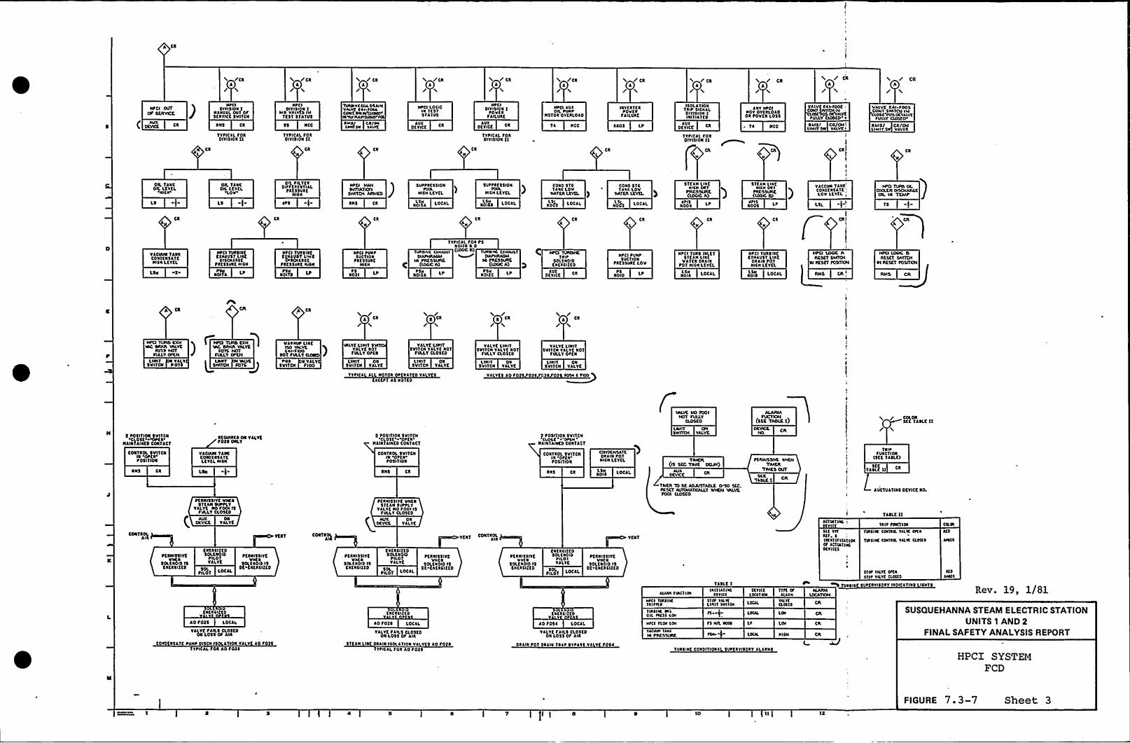
/CaI//ca
A/CR
A// ca
J//Ca
// Ca
// CN
A
CR
A/CR
A
HPCI OUTop SKNIAEK
( DKVXE
JHPCI
DIVISION 1NINUILDU1 OF5KRYICt 5VITCH
TVPICIL SoaDIYISION 11
NPCIDIYI5ION 1
NO VAIVCS HITEST STATUS
tt NCC
TYPICJL SoaDIVISION 11
ca
TlwffVlOUI DRAINVALVC CII SOLICO«tSW.NltNWUIk«IV
«INCUS'ssII
CR/IWLP«f SV Vlllf
HPCI loCICIN 'lltlSTATUS
OfYIKEIUX
HI'CIDIVISION 1
~ovlaFAILURE
JUTOKYICK Ca
TYPICAL FORDIYISION 11
CRN
HPCI IUXOIL PU« ~
Hofoa OYCRLOID
TI NCC
INYERTKRPOVtR
FAILURE
Xtot LP
ISOLATIONTRIP 5IC«LLDIVISION 1HNTIATCD
DKVICE CaJUX
TYPICJI. FORDIVISION 11
INY HPCIHOV OYKRLOIDOa Povfa l055
TI HCC
Alvt tII.SOOtIN
CIt ILVKSULLYYffXOCDiI
RIISI CR/ON flNIITSIV YALVCI
KRI
II
VAlVC CII SootCONT SWITCSI IIICSOSC POS CIVIIVC
FUILY Cxosco
RSISI CR/OslLISnr VALVC
OIL 1INXOIL LCYKL
NICN
sLS
OIL TINXOIL llYCL
'LOV'S
OIL SILTKRDIFFfRKNTILL
PRK$ 5URKNISN
JPS RNS Ca
SUPPRESSION
HICH LfVKL
N0IIL LOC L
SUPPIK55ION~OOL
HIC«LEVEL
N011$ LOCAL
) CORD 51C COND tTCTI1X Lov 1L«r lOV
WATER LEYa. ) WATER LEVEL
LOCAl NOIIX LOCAL
STEIN LINCHICH lsff
PRES%IRK(IOGIC A)
NOOI~ PI5
STK LH lUIE~
)HICH OUI
)aoosSPIS
VJCCUHTJNX'O«DE«SITE
Ilov LCYKl I
TS
Ca CR CR CR
YJCUUN 1JNXCoatfaslffNISH LEVEL
L5N
HPCI TURSIRKCXNJUlf LINK
OISCNIICtPRCSSURC NICN
NNL L
NPCI TURSIRKEX«JUST slat
OISOI LICEpacssuaf «ISN
NOII'5
HPCIPUNPSUCTION
PRC55'UafHINI
~Off~5
TYPICAL SOR PSNOI2$ I 0
Iswsssc uAwsl (~+ 0) TU«wvl u«AUICPHRIGII
IN PNESSINss Hl PRESSURE(IoffcA)
NolgA L Nolgc LP
HPCX TIIUNHE1 II P
50LTNOIDKNKICITC0
JUXDKYICK Ca
HPCI PUNP5UCTION
PRESSURE LOV
NOIO lPPS
HPCI TUIS INLETSTT JH LINC
NITER DIANA~01 NISH LETfL
LOCLLLSN
HPCI TURlalfEXHAUST LINE
DRAIN POTRICH LEVEL
NO+) LOCAL
HPCI LOGIC A
Rws ca I
* Cass /
CR//Ca/ C1
/ca
VIP«UP llNCllo VILYKCII SIOO
101 SULLT Clcmo )VILYCLIHIT 5
YILYC101SULLY Otta
VALVELNIIT5VITCN YILYKNof
SULLY CL05KD
VALVE LIHI15VITCH YLLYt IIOTfULLY CLOSED
VALVELIHITSVITCN VLLYK101
SUlLY OPK N
LIHIT YLLVSVITCN 101$ LSWITCN SmS g
S'0$ 1 YALTSVITCN SIOO
LIHIT 01SVITCN YILYf
LIHIT 015VITCN YJLVC
TVPICI Ilf10101 OPTIITTD YLLYttXC Pf AS No'I 0
LIHIT ON5VI'TCN VALVE
VL V 5 JOSO
LI HIT ONSVI1CN VALYK
5 POSITION Svlfffl~CI.05t 4PEN
HAINTJINKD CONTACT
CONTROL SVITffl11 OP K1'
05I 1 ION
11$ Ca
RfOUIRtD ON TLLYKSoft ONLY
VJCUUN TINECONOKRSAT CLCYKLHIS«
L5N
t P05ITION SVITCN'CL05E'PEN'LI1
1 IVIED COIITACT
CONTROL SVITCNI1 OPt1POSITION
RN5 Ca
CONTROL SVITCHIN
'OPCN'O5I
1 101
RN5 Ca
2 POSITION 5VITCH'Clost ' 'OPCH
'll«TAINKDCONTACT
COHDKNSITKDRAIN POT
HICH LfYlL
Ij LOCJL
ICIT SILLYCLOSED
UMIT ONSWITCH VALVE
TNACII(IS SEC TULE OCIAY)
AUXOCYXK
(5KE TADIK1)
sxaTANIE 1
COLORSlf 1JSLf 11
/
TRI~I'UNC'IION
(SfC TAaff
TASLt ff5KC
LUCTUJ1INC DCYICE 10
CONTROI
~KRNI$5ITCVHC1
SOLKROO ltKNKRCIKKD
PERNI551YC IowaSf fAH SUPPLY
YILYt No SOOIISSULLY CLOSCD
OKVXE T JLYC(CNKRCITED50LKNOIO
PILOTYJLYK
PN.OTSol
PC RNIS5 IYK1
SOLEI ID ISDK KataCIKKD
PKRNI55IYCVNKN
SOLKNOID l5KRKICIKKD
t«KRCIllDtoit«OID
FILO 1YLLYK
PILOT LDCLL50L
PfRHI55IVCV1'l1
50LKROID ISOf-KNtRCIlto
PER«15511 f VNta5'ltIN SUPPLYYILYKNo SOOI I5
SULLY CL05KD
NIX 01DKYICC 1JLYK
VENT CONTROLAIR
PKRNI55IYCV«11
50I.CXOID I5f«laffltD
KN'KRCI11050LtlOID
PILOT1 JLYK
~Ilof lOCAL5OL
PKRNI55IYCV«t«
50LKROID 15Ol KNKRfflfD
YK1T
LCTINTINI -„
TASLK nTRIP fwrf la
5TDP Yslll OFT N
51IP VllltCllllt
illVlfITS, I1lllfIfI CATIONOf ACTIN'IIICDlfICK5
IURTIIR CDXIRIX YILYK Dfla
Tlfl~ Ilf COITIOL YLLIK CLOIKD
C@KIffl 0
Ao Sots loCJL
VLLVtSAILS CL05tD01 Lots OS *Ia
Co 15LTC PU«P DI5OI 15 ITION VL Y I SoftTTPICLL Soa Jo SOll
KNlaffllD
Jo Sotl LOCAL
YILYKfJILS CloSKD01 lo5$ OF AIR
STEIN LINK DIIINISOLLTION YILVKS Lo SoTTPICLL SOR Ao F025
t1lIC I 2 C 0
Ao F051 LOCJL
VJLVK SLIL5 CLOSCDONL05$ Of AIR
DRIIN Pof RLIN TRIP ~ YPISS VI V SOSI
Lula SIHCTIa
«PCI TINIIXTIII FILD
TIRIIW. PIOIL IVISS losHICI fLOI loIVlfNl~ ISS IHl PRESffWR
TJSLE 1
1l1f III INCDlfllt
51IP YN.YTLIIITSVIICH
Fl ~
S5 IUL INDI
~DI
DlllitlIll1 NW
LOCAL
LP
TURSINC COXDITIONI SUPERVISORY I II15
fffllfJul«
YILYlCLOITS
HlI«
CH
Tol IX SUPC RYI5ORY INDICITHIClICNTSRev. 19, 1/81
HPCI SYSTEMFCD
SUSQUEHANNA STEAM ELECTRIC STATIONUNITS 1 AND 2
FINALSAFETY ANALYSISREPORT
FIGURE 7.3-7 Sheet 310

l
III
I
I
l
IlII'I
I '
II ~
ll
t!.
l t
~ I
I
I I
I
'I
I
I
I
I"
Ij
I
II
tI l
I
. It,
1 I
Ii
4
II
Il
tl

ICD VCCDUS A
(DUD4)
C CR .
RMISSIVC WHENTURIMNR CONTXOL
v ANfFNsf aosvcRSIGNAL IS PRX»VT
/( CCR
PCRllISSIYM WHEN
VALVEOOS FN~gS IS PTX»
C CR)
fKRM1$5IYE WHENTUREINE STOP
YALYKICCI ClOSKDI A ISPR5NT
AVXDEVICE CR
/C CR)
t(RIA$5IYC WNKNTVROINE
5'fOI'ALYE
$ 1$ f C(OSKOSIGNAL IS PRESENT
AUXDE TICE
PERMISSIYC ON'A SCRAM
AVXDEVICE CR
PKRUISSIYE WNKNTVRSINK SIRST SfACE
PRESS EXCEEDS SCT POINTOF PS NOO'SA (SI
AUXDEVICE t(RIRSSIYE WHCN
SIEACTOR FOEKR IS>DO 5 RATED
PEAN]5$IVE ON'4 SCRAH
AVXDKVICC
/4/
NANGAL ClOSCEXR SA SO/
CICITC PUHtA'NS
CR
PKRMI'SSIYE WNKNTVRSINK FIRST STACE
tRE$ 5 CXCKEOS SK'f POINTOF PS NOOSE ID)
AUXDKYICE
POIMISSIYE WNKNMANUAL 4YPASS
SWITOI IS INI'lON
/G/
HANUAl CLOSCGXR 14 SOR
CT4$( tVNP'A'NS
CR
FVLL CORC DlstLAY
CI t ~ G
FULL CORK D!5PLAY KIIPUTRCF. 4
aDSE j XKCIRC PUMP aRCUIT SREAXKXSA(EAT Ta
RKCUIC tUMt CYLCUIT SXKAXEII)$$ (AEY Ta
RECIRC PUMP TRIP LOGIC ATYPICAL FOR LOGIC 4, SVFFIXE'5 SHOWN IN ( ) Rev. 19, 1/81
fCISGS>
C R CRA
SUSQUEHANNA STEAM ELECTRIC STATIONUNITS 1 AND 2
FINALSAFETY ANALYSISREPORT
Rt'T 5'YS A (4)TRIP
CR
Rff 51$ A (SfOUT Ot SVC
CHS
REACTOR PROTECTION SYSTEMIED
FIGURE 7..2-1 Sheet 4I I

y
~ 'I
4
t
tI
h
I'l P
tl
t
tj
y
y
tl

5(ALSl
C.t
I 2 POSIT)01 SVITCN0051 'px JlKKTLOCKOPCN P05IIION
RNS a
klktC tIitkJ I0 1
fCN LOCJL IN(V $(IYNYNHSXSP(
'5 SO)IT)VII SWIYOI'CLO5('I'JUYPJ UKU'5KUND
I R(YUkH TD 'AUTO
1005)TIOH Sv)YCHrcfakf.- avfo - tfot
15 RETURN VOfROII
'STOP'AIN'fJill(O CONTACTSIN "START
NP IPO s(IYIAIHNQ
XRSSII( vakHIJI IR(V OKN
SLOVCONYRDLLCR
AVID'VllNVlL51 JTION
FIC1500
LIIUI5 VIYCN
ONYJLYK
tKRNISSIYE VNKNYUkli1t STOPYJLYC IS 101FULL T CLOSED
~FOR VALVC
CONYROL SUITCHl1 DP( ~to'llIIok
RN5 CR
CONTROL 5VITCHIN C(05ttotlfION
RNS Ck
(ONTROL SVITCHIN '5'flRYPOSITION SKJL III
I1lIllTION5)CHAI.
JV1Dffit
I totlf(01 5VITCN Itfakf JV)0 Sfot5tklks Rtflikk 10 'JVIOSRON 'OttN CLOSE
LOVSICNJL
5(LECTOR
5flL l1tfkN155IYC VNEN
TVkslat EallVJLYKSoll ISFVLLV 'Ottk'1
YJLYEl)1 CON t 5 LINII
Tt~ '5VITCH
SEAL IN
VX (0112k
P(llNttlvfVITNCONTROL SVITCH
)1AUTO'OSITION
CokfROL SVIICNIN Sf laftot)1)01
RNS 0-)2 RNS Ck
OPCN CL05t
ttf 5 LOCJL Pk R LrJSS IVk
YJIJJLC CLOSIIIC
PNRLJISSIVA~OIXLL55VALVRPIALV CIX)SCO
CDHTRDI. 5VITCHI~ 510("POSITION
RNStfRNI5$ IYE VNtN
Cokf OIL~k($5. It LOV
CONTROL SVITCNw 'STOPPCS II)01DC RCvtktlkl CokflCTOR T2 ~
Yl Y N Soll TVXSIX XNlUST0 50ttl Stlok OOL
CLCCTRONIC IVkllXCCOYERNDR C01110LLtkAND Rlkt/SICNJL C01YCR(tk
LOCJL ~
Rtf ~
IVRSIRE StCfD CokfloLLfk
TOCOVN OLISW ifCH VALVC
LILIIY OLISw(TCal UALVCCj
/ La/1/ L
Jl'S RN5
xtkr warl A
DRVVELLINSNtkt1 SIIRC
~5 11 si(I~015 (l) a 5)e
RTS 5
DRTVCLLNISHtlf5SVlf
nck wc I~0<ID <c) $ -src
Rtf 5
5 P05ITION SVITCNSfot JVYO 'STJRIStlal REYVXN TO AUfo
PULL 10 LOCK
CLOSf
OC RfYfkslkl CONT ~ C TON It 1
SftllltVPtLYYlY 'I YVXSI11 1 S OI\ vtlcaL soa cooalas valtk SUPSLv vaLvt No Sots)
5 IART $10tOC STARIER Ttk
START 5IotOC 51AkIKR TtkLSTART Yl(UUNPUNP Jvxklakv 01. pipit ao p kvs 1
RKS ~ START ANXILIARVOIL PUVIP
Tlill)RC AUTONATIC INIT(lf)01CONTROL
REACTOR
Ms'~n Ca)-Doll (l
ktlCTDkLOVtat 5SVRE
~5 TAIOoio (C Lt
Rtf 5
CONTROL SVITCHIN 'Sflkft05)1)01
YJCVVN TANKC0101ESJYCLET(I. NICII
L51 1
ktr ~
C01fkoL SVIICHik SYOrt05ITION
RNS
VACVO)a VALIKC(PIPE))safeLEV I. LOW
LSL
RfPO
5()a IN
5 SOSJYOI SXOa
ROUT( )0 SCPO R5 (1(
START
Ck /'
r
STOP
OC 51ARICR (12) INI ~L(cakoirfvklc cauofa)SKR Yacvvkvlaxcok Ntlv FONS
TINSINC JIIXIL)lkTtoVltktNI
RClCTORHICII VAICR
LEYEL
LI5 ~ tl102as
Rff I
NlkoltRtttfPVSHSVITON
I%XVI))ilfISKDSYIAIIOP(1
Lt v
Lt
FUROILICOUKRSPCKO
AIIXJtOCNCt LOCAL
HICN TURSIKCKXNJVSYtkt55VRC
10llat
Hill(TVklklfEXNJVSYtk($$VRC
NO)I'5~5
5I l
LOV PUNPlVCTI01 tltstVKC
(NtCI PVHP)
NNOP5
N-
~V51$ UII015VIIOIDKPRC55
TO IkltRNS CR
I.I5 ~ tlNot(D Lt
REf I
RCACYORNISH VJTER
LCYEL5KAL-HI
g ~~ KVI )NOT PERNI55IV E
VNEN LOVLEYEL sita JL
IS tkttCkT
OtYiCEAUX
V
I C-2
KOV)UKNR(SSISXAIOI OVIRtR(5(HT
RYISIN( Vk(55fever skaf ao)o
Ilk5aiika
Ittivfllk(55Y( (a(xf(RUED
NNLE aostofktkslft SOL TO
lo'ff 5TRIP TURSINE
ofvicf > LOCaLJUX
ktf 5AVTONJT)C T1IP 5 RCNDYC TRIP
TVR~ lkt flitCONTROl Rev. 19, 1/81
CC A(KJSRs COHYJKS)k It ~
flklR( (XJJNJST Ya(VUJ
(a(aa(a v(K po lo) ~ OUI(IT)KM, Fok Fl)1 sl)JVO)
SUSQUEHANNA STEAM ELECTRIC STATIONUNITS 1 AND 2
FINALSAFETY ANALYSISREPORT
HPCI SYSTEMFCD
FIGURE 7.3-7 Sheet 50
IYO

4 4 A JDQ
~,D
~4
D
N
ll, ':-,I,
*D
t
*""'9
4 4$
I„"2 <
I lD
II*D4
~
C'4
4
Ni
4
~ I
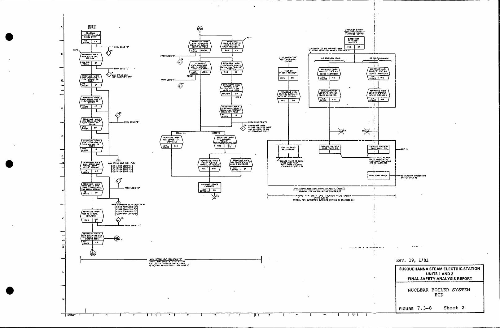
lDQO 'A(NOTE al
RKACIOAHATK2 L(V(LADOV(
LKVKL2 Taw
UsNO25 4
R(F 5
PfA«55IVt IHCN~law 5TKAM LPC
AAO lOW
RAU DttA$$$4
Dfaaesslvt «CNUAN 5T(AN LDC '4FLOW NOAMAL OA
D(LOA'els
NOOsa
P(lHtsSN( tec(NMAIN $1(AM
Lo('0'(OV
NOlHAL 024(LOV
eatsMOOTA L ~
SAON
LOQO'C'AON
LOCC'C'A
* UAM ST(aM LACICSH RAPAIION TRP
CAA
FROM LOQC'C
PfRMISSIVEleCH COWCCNSE RVAO IS La(AT(a
THAN SET DONT
vsNOSCA
FI(f,2I
LO(a'
taM 55IVK WHftcUala 5TKAM ONE
Pa(55 AT TURD Nfaaovf sf laoa I
lOCAL
~IPMI$5lvtIPI'55 a(AC(PIMOO( SWITCH IN
'PUN'05tltONDIES
Pfatesstvt NHKNCOIIOEN sta CIDASS
TCH IS IN DVPA5$
aHs
PEIbesstvf IectaTUIIDIIE 5(OP
VALVfS Aac LK55ltc ate 90'4
PDS Sw CD
P(f 4
Dtlaesstvf WtCNa(ACTOI DDESSIIAE IS
Ow «QC PRfSSUIC5OAAM SET DONT
PSNOt04
~ll ~
1(ST SNITCH OFF'TfSI'ANTAWCOCONCIH
1()1 SWP( 'I(ST P05ITION
AMS CA
Itw$ aa
PERMISSIVE wHKNCONTROL SWITCH IsIN'TEST'OSITION
2 POQTION SwlTCHCLOSE AUTO'(51MAAIIA:a(0 CONTACT
$ IATPI NOTIN 'ROSE
'OQIION
CR
AC SOLKNOCI LOQC
Pfatesstvt wHENLOQC'C'('9') AUXotect (ataQ(KD
kUXOCVICK
PKRMtsstvt IHCNLOQC A ('0') AUXDKVICf tNEASIZE0
~ NSCOMMON TO lll tNROAAD MAINslcaw IsRaltoe vaLVES sottatl,o.o
DC QX.KNOIO lOQC
PEA«55IYE wlcENLOQC '0''A') AUXOEIACK fkfaQ(to
AUX'EVICE
II
pfatesstvf wHENLOQtC R')'0')AUXCEVISE EN(RQZKO
N.s
pl ace sstv( NWC NMate ST(AH LQ('CSLOV WOlell 04
D(LOVWFISNooaa
F((HIS(M( WH(NMate Sl(AH Lw( DSLOW NOIHAI Oa
~(IOV4NOD(A
FROal
LOQC'C'UX
DEVIN 5
(StAL M)
P(AID5QVt lecENAUX DEVICt
'A'N(RQZEO
(A(5KT)
PKAUI'sstvt NHKNpv) vcaOaao
A(5(1Tl
SH ID I
FROM LOQC'C', C;Zl
CA ANMINPATE WHENCTPA55 SW STOP VAlvfAIIO IKACTOR PS ALLAT Ptale55IVK STATE
TKST SRKNODFILOI vALvf
KNfRQZt SOLKMOIOPAD( VAI.VK AC
rw Ca
/ ICR
/ c
ENEIOIZC 50LKMOO~ILOI VALVE
RCF. IS
pfAIA55tvE MINNMAIN 5'lfAllTUNNtL T(MDafLOW 5t'(PONT
NLOOA1$
C
~Iatl STtAM LDC «Ql fiear
!
CIS4I fOa IDQC 'A'1Ctsat fOA lDQC'
'ISlsSOR IOQO'C'oil
Foe LDQO'D'US 0 I I
PERMISSIVE WICfaSOtt A.D.C,D
MANUAL SW 'CLO(KD
PCIaa55tvt wtcealx Ofvlft'R'ANO'0Il DM 0 ENEAQ(co
AUXDEVICE C
CL05($ VALVC AT SLOwSPK(D INCN 1(51~I(01 VALVE SOLENOIDIS ENERCUKD (NOTE I)
I
I VALVEL.1
LNRT SWIIPI
ROS($ vaLUE aT IASHCD(ED WHEN DOTH~AOI MILVK5OLtNODSAal R IN(eccl(a
10 AKACTOA PAOTECIIOISTSTCM (atf, ~ )
lsN40$ 4 LP
~EAUISSNE wtCNNOT DI MANUAL
I SOKA DON
RUS C4
~fale5SIvt WICN~IAIN 51(kw LDCIUMCLPFffa(NTIlL
TEND 9(IDW S(TPON'IFROM LOQC 'C
~WMN $1jhMLNC LCAA CCTECIICWI
C Isa(c SCS( LOS IO
0'A
A
AIDULIART DtVICKKNEAQZK0
AUXOEVICt A C
/CaW
UAIN STCAM l5OLATION VALVE AO f0224 FOtak(TTPICAL FDR AO SOtt ~,C,D) FO(2 ~,C.D
INDOAAD Male STEAM LINK ISO(ADON VALVE STSTtw(NO'IC I,S(9)
TTDICAL FOR OUTDOARD (OITDOAAD DEVICKS DI DAACXETS())
StOW LOCIC C'
((HNSIV( Wtl(NIIAIIISlllH lta( ax(al(IIPa(IOV Sll IONI
((vista( a(os)illOlvt(C
kallftl
5 laUaw SlfAU lINf ISOLATION A
TTPIOAL SOR LOQC 0 I KXC(PTFOR LETTER SUFFIXES w«CH MaLl,Dt 0:X'(T) RCSDCCIIVCLT (sff NOTC 5)
Rev. 19, 1/81
SUSQUEHANNA STEAM ELECTRIC STATIONUNITS 1 AND 2
FINALSAFETY ANALYSISREPORT
NUCLEAR BOILER SYSTEMFCD
FIGURE 7. 3-8 Sheet 2
IO

0
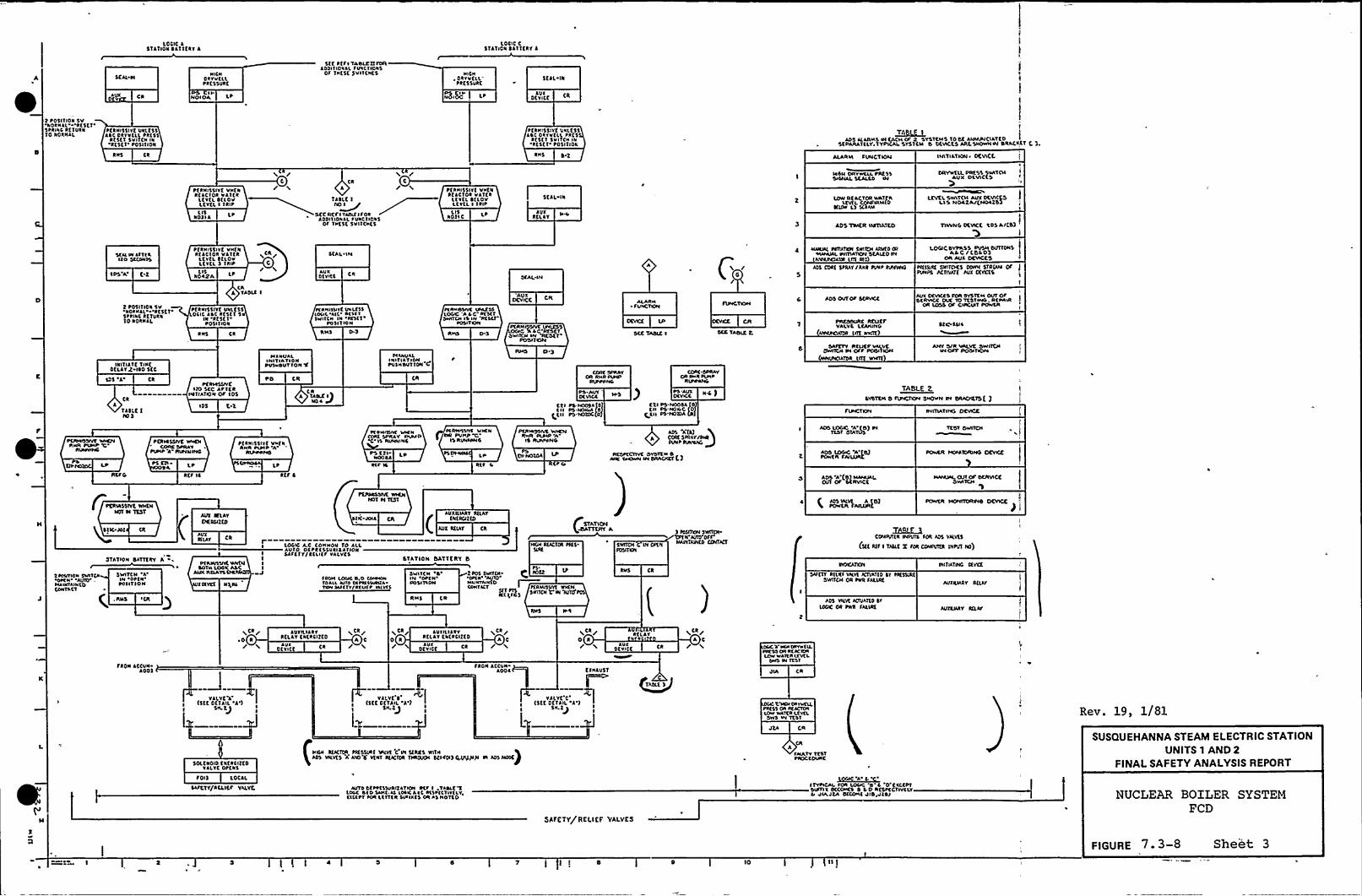
LOCIC A5TATIDR all(EAT 3
LOCIC CSTATION CAT'ifRv 3
SEAL N
ca
NICHOavvfLL~ RESSURK
Ad CII-HOIOA
5(f Pff ~ YADLC)lroftADDIIIOVALfUVCTIOVS
Of THESE SVNCN(S HICH, Davv(LI.
PRKSSURC
«5II)c LP
SEAL Ia
AUTOCVICK
z P05ITIDA SvRORHAL a(5Cl
SPRIVC Rf fURN10 ROIIHAL
~ CRNI5$ IVC Ual(5$ASC Oavvlll Pa(55
a( 5( I SMTCH laRK5cr Posl(IDR
Pf RKI5$IYK UVLE55A ~ C OVVVllLPa(5
RES( I 5V ITCH INRK5CT'0511IOL'
~TO 1
ADS I(ARMS W CACH Ot 2 SYSTEMS Todf AHHUHUATCOSKPARATELY.TYPICAL SYS1cll 5 OENCES ARLSHDWHW DRACKE'1 f ).
aas ca D.z ALARM fUHCTIOM INITIATION~ DENCI
Pf RHISSI VK VV(VatACIOR VASKALtvflttlov
LfTEL I IRIPL IS
No)1 A L
I'
/ CR
A
Taalt 1
NO~II
SCC RKI'ITA(k(IFORAoolvcovlt FUVCTIOVS
OF Tutst Svntvts
IC
LIS10) I C
LP
pfawsslvE VHKAafAC'loa VA'ICRlfvCL tfLovLfv fL I Iala
SCIL UI
acllvAUV
MOH OHCWlllPAESS5IGMAL,SLALCD M
LOW REACTOR WAT(ALtvfLCONFIRM(D
lftov L) SCRAM
AOS TRIER INTIATCP
DRYWEU. PRESS SVATCMAVH DEVICES I
LEVELSYATCH AVV DEVI(fSLIS HOAZAIKHOAZ53
I
I
TINING CICVICC tDS AIKD)
SCM W (f1(AIlo SECCNVS
K-z
1 P05ITIOR 5VVORHAL at5CT ~
5talac RCTVRR10 RORHAL
IRITIATK 'TIN(DELAYS Iso 5EC
P(RHISSI YK VH(NRtac'loa VATER
LtvEL t(Lovl(Vtl. 3 IRIP
ROA2A lLIS
tea/C/
LATAOll I
HA lc u ALINITIATIONPUSPDVTTON't
Pf RHI 5 SITE VVLf55ocic Asc RK5(1 5
IV RfslvPOSII IDR
SCAL ~ IH
AUXD(YI('l
IYAHISVIKUvt($$IOLIL All A(lftSNITCH IH a(SCT
POSITION
RHS
tvAHUALICHTIATIDH~USHIWTION C
t(AVINticuwllslLOGC ACC A(5(TDIVITCH IS IH 'acscl
POSIT KIN
Ds
5(AL Itl
Otv"CC
OWIICH HV Rtot1'ODITCPC
RMS t) 3
ALAltw*IUNCTION
OEVCE LP
5tC TAO(X I SCX TAOLC g
Mu(UL lvttlTCN SAISKH ARV(o (RVVVAIALPIITIATCWSCALED INAticvc)ARA to( aio)
A55 Coal SPRAY IRKR PUMP RUHNNO
~ FICUCFVALVE LVAHIHO
AIIVPCUT(A (lvf wlgt()
OAIITY RELIEF VAlvcOWIICH M OFF POOITIOH
UNDATDR tlvf Wwvl
LOG(fDYPAss PUSH OUT(DMS IA( CIC5(0)
Olt Aua PCVCC5
FV(SSAK SVITCIE5 OSRW 5TR(AM OfPUMPS AETNA(( AV( CEYC(S
1
AUV OCVICCS IOR OYSTKH OUTOI'(RVICCOUC IP Tt5TIHG. RCPAIR
OR (005 OF CUCIPT P(MCR
5(C Ruc
AHY 5IA VALVE DWIIIH~H Ofr PCXNTHHY
$55 '3 ca
CR
1ACLK 1N) 3
~CRCVSSIVEllp 5to APTKR
URIIA1ION OF ID5
IOS K.l
Pd CR
CATASLE)l
CltCOAC SPRAY
OA RHA HPCPRUNNING
CONC SPRAYOA Nca
PIPU'IPYFAHG
~5 Auv H.C }ctl ps tcootA)OI
+EH PS'HOIOA
TABLE 2SVDTtH 5 IlPCTVM OHOVH M ORICHETS ( )
MITIATIHG OCVCC
PCAHISSAFK WH(IIItHR PIPCP CC
AUHHIHC
PCRI45NVC WICENCONC SPRAY
RIMHIHO
PS Cti- LPVARff IC
PERNI55IVf VV(AAHN PIPIP A
AIPPP ted
LP
RKF 6
~T PHINllC IPC H(Oat SPltAY NUMD
C ll RIPWINC
LPIIOORA
P(AHISSIV( 'VINNNA PUMP
0's
IIVHHW6
LP
R(f I
PTICHIDSIVC WICIItuv\ piper A
IS Ruutcw6AOS SlS)
A COR( SFRAVIRHltPUM~ RIRNAG
DCYCVIVC OVDTCH dAIN (ccoccw uc DAAEHETf)
I APS LOGC 'A'fd) MT(51 OTATISS
APO LOGC~A')
ADS A'fd)MAIAULOUT OF DCRVICC
HAHLUI atl Or OcRVCc
1
PCTUASSIYE WHENNDT N lIST
~ (IC JO( CR
STATION dlvvtltY A
THAI(ION SWITCH SWITCH AOcc H Auto IN OP(H
HAWIMNCP POIITIOHCONTR c'1
(,Rus ICIL )
AUV ALLAYKFC foll (0
AUXNLAT CR
P(AMISVYEVia(4~OTH LOOK ASC
AIPI IICIAY5DA
l(tvc( Nfl
FKTUSIVE VAENNOT N TK51
lOCC A.C COICHON TO ALLAUTO 0(PR(5$ URICAIIONSaf I 1 V/C(LI(IVAlVCS
IROH LOAILD,D catctctWTDAIL WIO DEFMSSVVIIA~
THH lcc(vc a(u(F IMYIS
AURIUARY a(LAY( N(aoiz to
AU( RE(AT CR
HGH R(ACTOR fa($
STATION f)ATTERY (S
SWITCH 5IN OP(NPo SI TV0H
RHS CR
ZOOS PHICH-Ot(a AUlo
HUHTMH(pCIWTALT I f(AMIS)IV( 'VHM
N(CIC) SNITCH T.'Al Nlitf
Nt
5WITCH C IN ol(NSO)ITEN
3 FOSITCFI SWITOlVSF( N'AUTO'OffMANTAIN(D CONTKT
( AOSWLVT~AD) ROVER HOHIIT)RMO OCVCCJi
scf(TT a(LRS Yllv( ICTIAI(o Sv fa(SSIR(SWiTCH OR PAR ffASPE
AOS IALVt ACIUAT(O SY
lOOC OR PWR FALURE
IVITUTINO CfY(K
AUTIUARY a(LAY
COMRR(R IHVUIS f(R AOS YALV(5
(Stt R(f I TACLC X FCA COMFUTN IHVUS NO)
XC I'0
Aufllllava(CAT Ca(RCI(foAVI
O(vl(t
ica/A C
ica/ AUIILIARV
0 RtlAv Eat RCIzf0
/ x Dtvlct CaAUI
i FR IA/
XCR/0/
a(lccAV
AVVDCYICC
i,CR/A C/ VIH(CCACV(il
PA(55 CH lt(KIIVILOW WAIfA IXVTL
tcls Vl lttlfRON ACCUN
PoolFRDH ACCVN
AOOC (THRUST
C
TACLK )
JIA CA
VALVE Afstc oc TAIL'*')
II
VALVE a(stt OCVAFL A )
SH.C
VALVE'C'Sf
K OCIAIL A ) ttcpl Cwvv(tlPII(5$ OA ACKTCHLOW WaltA LTVTL5HS IN ltlv Rev. 19, 1/81
SOLKVDID tatacllCDVALVC Otfas
FOI) LOCAL
SAIITY/RELIEF YALvf.
(Hda R(A(IDR Pa(55(A( IAIY( C Vi 5(ats WITHAOS WLVtS Sf AVOW VKNT a(aciOR THROUt)I SCIV(V) fc(N)IN N AOS MDVK)
AUTO o(PP(SIUAIKAvcu Atr I Tcall'ILDLC AID 5MIC A$ LOLAA IC AtsvtcvlctlY,CVC(PV COA l(TTTR SUCIXCS OR AS HOTCD
SAFETY/RCUCF VALVES
CRA
FAIAVVTtSTvfcccouac
(TYPICAL FOA LOCK 0 5 'D'EVCCPTOIPVIV 5(COCC(S 5 5 0 ACSP(CTIVCLYu JIA.JCA 0(CONC Jld,J(tt
SUSQUEHANNA STEAM ELECTRIC STATIONUNITS 1 AND 2
FINALSAFETY ANALYSISREPORT
NUCLEAR BOILER SYSTEMFCD
FIGURE 7-3-8 Sheet 3
7 I ) ( 0 'IO

If
IIf
f~
. ~
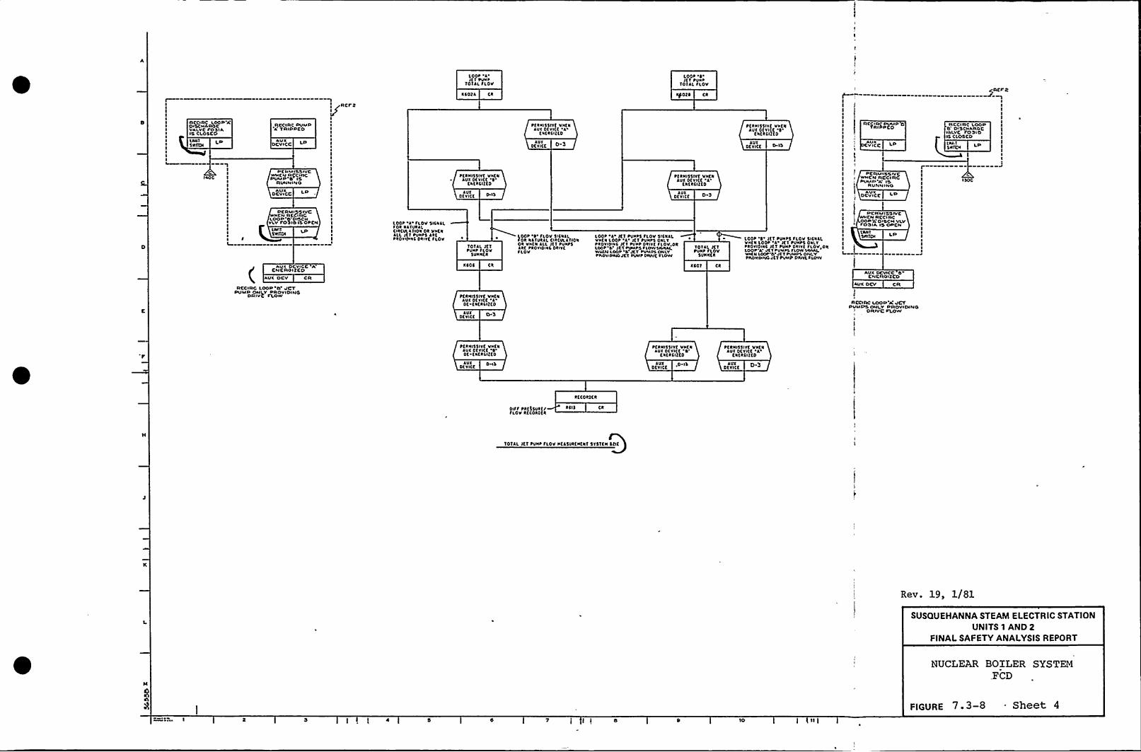
LOOP 'I'tI PUNPTOTAL SLOP
Loot ~'ETtiJNP
TOTAL SLOVREF 5
RCCIRC LOOP'ADISCNAROCVALVCI'OSIA15 CLOSCDUMI1SNICN
1C I
IAOC 1I
RCCIRC PUMP'A'RIPPCD
AUIocwcc
PCRMI55ivcWVCN RlgCIRCPUMP 5 I5
RUNN IN 0
AUXocwcc
PCRMIQQIVC
YLV IDSIPISOPCN
(AUX DCVICC A
CNCROiZCDAUX DCV CR
RCCIRC LOOP'5'CTPUMP ONLY PROVIDING
DRIVC FLOW
I ~RCFR
IIIIIIIIIIII1
III
IIII1
II
III
I
Lppt I'LOVSill<At1 OR NATIIRALCIRCIILA1101 Ok Vvt1AlL Jtf tiliit5lkt~RDWIVVC DRIVE fLOV
ICOEl Ck
~tkNISSlvt VNENAUI Dtvltt 4f1fklI? Eo
AUXDfvlCK W 5
TOTAL Jt'1tilvtfloV
$UNNER
XXDS Ck
ttkill55IYEVIIENAUX otvlft 'IDt fktkCIEKD
AUIotvift
tfRNI55lvf VNENAUX DEVICE A
fNfl LIE ED
AUXDKYICE D-3
LOOP '4' LOU 5ISNALfok NATURAL DRCULAII01Ok VVEN ALl JET PUNt5ARE PROYIDiiilDkivtSLOV
Kfot~ Ck
~KRNI55lvt VNfkAUI DEYIEE 'I
ENERCIEED
AUIDEYICf
101AL JETPUIIP flov
SUNNER
XEDT
loot l Jt I tUNPS fLOV SIENlL'VVtk Loot 'l'ET PUNPS ONLY~ROVIDtVC JTT PUVP Dklvf SI.OV,DRLOOP'4 JCT PUIAPD FLOW 5XJIALWUEN LOOP 4 JCT tUMPA ONLYPADYIPINDJtT PUMP PANE FLOW
tERIIISSIYE VVENAUX OEYIEE 4
ENERCITt0
AUXDtvltf 0 15
LOOP '4'ET PUIIPS SLOV SICIIALVIIEN Loot l JET tUNtS ONLY~ROYIDINS Jtl tUNt DRIVK SLOVqpklOOP'1 JtvtUMPL IIOWSANll,VARN LOOP'0't IPUMPS ONI YPIIDYIDINGJET PUMP ORIYLFLOW
RC)IRV PUMP TSRI PCD
AUlivlcc LP
PCRMISNIVCWNCN RCCIRCPUMP A'S
RUNNINO
DCVICC LPAUX
!
PCRMISOIVCCN RCCI RC
OOF 'Tc DINCH VLVFDOIA l5 DPCN
L. L
AUX DCVICC 5CNCROIXCD
WX DCV CR
RCCIRC LOOP'A'CTPUIAPSOIILY PROVIDING
DR iYC FLOWl,t
J
IS CLOSCDINI I5NITEN
LP
ISOC
R CC I RC LOOPO'I5CNAROCYALYC FD DID
ttki155IVE VVENAUX DfVICE
4't
ENER LIE ED
AUX P,ISDEVICE
PKRNISSIYE ViitNAUI DEVICE
1'lltktiff0
AUI 0 ISDEVICE
ttkNISSlvt VlifkAUX DEVICE
'A'NKRCIEED
Dt'V"itt
Rftokotk
Diff PRESSURE/SLOV ktfokotk
RCI5
TOTAL JKT tilNP SLOV IIEA5URKNE11 51$ 'TEN SCIE
Rev. 19, 1/81
SUSQUEHANNA STEAM ELECTRIC STATIONUNITS 1 AND 2
FINALSAFETY ANALYSISREPORT
NUCLEAR BOILER SYSTEM.FCD
FIGURE 7. 3-8 - Sheet 4
I t i 5 10

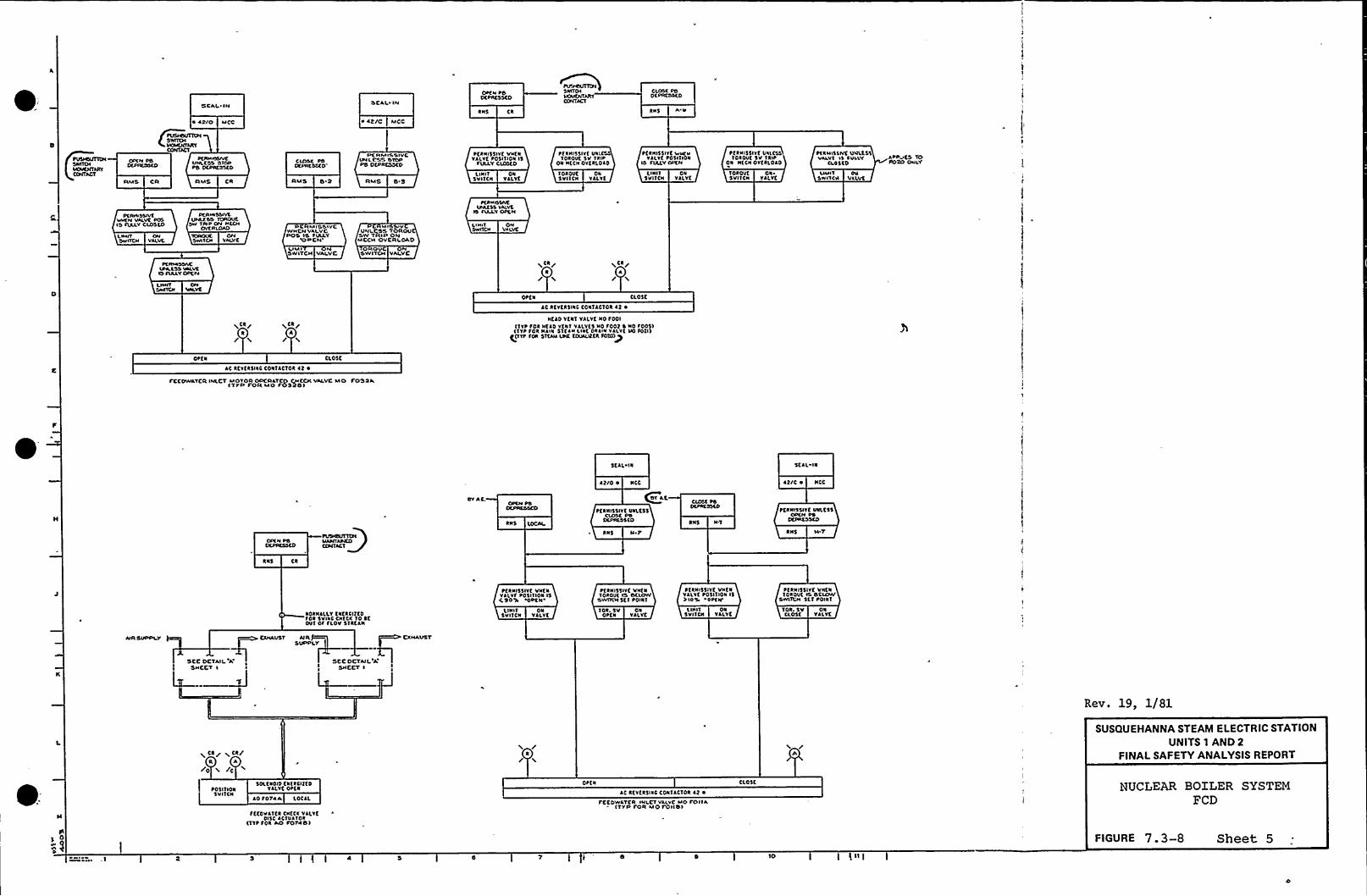
SEAL'IM
~ 42/0 MCo
C=VNLCSS STOPPS D(PAC5'SEO
CIOSE PSOEPRC SAD
SCAI IN
~ Nt/C MCC
PERMISSIVEVN LESS STOPPS DEPRESSED
RNS
PER/N55lvt vNCNYl(VfPOSI (ION 15
AXAYEIOSCD
Pt RNI55IVE VN'IOROVE SV IRI~
ON NECN OVtr(olo
CLOSC PSOCPRCSSLO
RNS
PtRNISSIVC Wv(vVALVt POSIIION
IS IVLLYOPEN
P(RN15$ IVE VVLESSIOROVC 5V 'I RIP
ON Nt(ROVER(DAO
P(RHISLIVE V@LESSVALVt IS POLLY
O 05(OAPPVES TOPORO OHIV
AMS CR AMS CR RMS 8 2 RMSL IN I I
SVIICNON
YALYEIOROVE5 VIICN
ONVALVE
L IN I I5VIICN
ONVALVE
Tolouf ON ~
5VIICN VALVEUlflv ON
SHIV<4 VLLVt
PVVVSSIVEWVTN VALVC P(6I'5 RXLV CLOSED
LANT ONSwlfov VALVE
PEAHISNVLVNlf.ss IOROVE
SW TAIP ON HCCHOVERIOAO
OMVAI.VC
D MISSIVCWHEN VAIVCPOS IS fVLLY
YPPCN'IMI
'5WITCH YALVC
M I SIVVNLCSS TOROV
SW TRIP ONMECH OVERLOAD
0 OVSWITCH VALVC
LI HITSWIICH
ONVALVC
rfRHISSIVCIPAESS VALVE
IS flAAYOPCN
P(AMSSACVNLLSS VLLVC15 I(RAYOPC N
LIMITSWIICN
OPCN
v CR/
/ 'l4
v,(R/A/
CLOSE
~CR/A/
AC RtvERSINC CONIACTOR lt ~
NERO YEN( VALVE No 1001(IvP fol Ntlo vtrv vl(vtS NO foot 5 NO r0051(IVP fol Nllr SlflvLlvt Ovllv VLLVC Vo fotl)
g(TTP fol 51tlN LPC EOV/Ll?ER IDIO)p
OPEN CLOSE
AC REVERSINC CON(ACTOR (t ~
PCCDWATCR IMLCT MOTOR ODCRlTCO CHECK VALVC MO FOSSA(TYD I OR MO POSODI
SEAL IN 5(lL IN
SV AC,oprM ps
OCRC55CD
RNS
~ t/0 ~ NCC
QSV AC
PCRN155IYC VNLC55CLOSE PS
DLPRCSSCD
RNS NI'N5 NT
lt/0 ~ NCC
PCRNISSIYE VNLESS
RNS HT
RNS
~CRNI55IVC VNENYRLVf f051(ION 15E 9051 OPC N
PERNI55IVE VNENIOROVE fs DELOW
SWIICH 5f I POINT
PtRNI'15lvt VNENVALVE POSI'(ION 15>IOV 'OPCN'
tRNISSIVf VNCNIOROVE 11 SCLOW
SWITCH Stv POINT
NORNl(LYtrtRCIItorov SvAE CN(cr vo stOVI Of fLOV512(lN
LI NIT5VIICN
ONVALVE
IOR. 5V01'EN
ONVALYC
'LINIT ONSVIICN VALVt
ION. 5V ONCLOSf YALYE
AIRSVPPLV CXHAVST AIR ~ CXHAVSTSVPPLV
SCC DCTAILA'CCDCTAII'A'HCCT
I SNCCT ~
Rev. 19, 1/81
X CR/ ~ CA/R A
/0 i /C
P0511145SVIICN
SOLENOIO EvtRClttoYRLYC Ortr
lo TOTAA LOCAL
OPEN
AC RCY(25INC CON(l(TOR lt ~
I CCDWLTEA INLCT VALVE MO POIIA(TYP POR MO Toll(if
CL05(
SUSQUEHANNA STEAM ELECTRIC STATIONUNITS 1 AND 2
FINALSAFETY ANALYSISREPORT
NUCLEAR BOILER SYSTEMFCD
fttovlv(R CvfCR vlLYfDISC ACIVAIOR
(IYp IOR Ao roTAD)
10
FIGURE 7. 3-8 Street 5

ff
I
L
Il

~* $(is IIIIIISI(CLCAECXI loooi
!
I
START I. Dr(AITINC 5(DKV(t AST(ksickle ls n r(A(oc
I. 1K CINTtcl 5151(H ls IalvN THOrl 5r5T(alcv vli(k LCT(L (1 HNH (NHRLL rt(ssa(
1 0 ilk
a(ACTORVK55(L
Lov LCvfL I
LIS 411Nol/0 LP
t(ACTORYE$$tL
LOv LfvCL I,
LCR/W/
CR
V/
iCA/ iCR/V V
~
/'IOH
0'AVWCLIptCSSURR
~$ 'CHHO I IA
tfACTOR Pk(SSPCRNISSIVEVHCN LOV
101/A
RCS I
NICHOkvvfLLPkf55URC
PS CN LPNOHC
kfJCTOR PRESSPtklu55lvfVN(1 LOV
1IIII
IIIIIIII stf afs'. 5 ~ c rotI JODITIOIIALSUNCTIONS
sft 0$ 5vliclvcsIIIIIII
SVSTCN t Us(5I 0 ~ D 5VITCHCSIIII
COOITIOI lCool I/IC 0011/0
f(lf(b$ 005lf0054fDl1kS015l$ 051lf(014
Cool l/CCcol I/DLkkcs SIN 5((RXN(t JS
0SIST(H I 51lA'15 ~ 105(C 0((kv5T51(II I I 5TAATS ~ Ni 5(C 0(ilv
t. 515TOV II CIACWT ID(NTI(JL 10 CltCDIT~JAIS Jki IKAI(fitDJs fCLLOC>
SIST(H IIOiilC 001A.Cr011A$ 005ASooik$ 001 ~So l slfDoll
T(sikR( Oc(k YlLVC lvrk55ANSINHI Silu IISJ55 VI(V($Iasolko 15LN Vliv($1(sikR( oc(a vliv($rvv 5U(ilol vk(lfcT(SI 4Trl55 VN'KOu(4(ako VlLvt
$15«/I I tx(tri ccHroaai
Ivs(u I If0111COOI 1,D$ 0111$ 0051~ C014Soo is$ 0154S Doll
51ST(H I Cr(VS l«CA RCAC LCH rktn. $(IH.$ 151(H II ~ Or(as utta t(lc. Lo/ racss $(ol.5151(H I C(05(s It Or(1 No 0(ulSVSita 11 ~ C(05(5 «Crta ~ NO 0(LJVSIST(H I Clo«5 Jfi(a flcv t51JRIOCD5T5'ita I I ~ RIH(silr'l(k Slo/ (sikf(ISH(~au
10 5(c10 5tC,CDNIIiIOI 4
PCRNISSIVt VNCIVpuup'A (c I ak/0
LVNLAAL
OCVICKAUX
LPNot(0
RCS I
HlvulcRC5C'I
PO
LICNT ONVata
SCALED 11 /
SEAL IN
AUXDtYICC
~ N
LloltfON Wvtu ON~JAHUALor\Rsuoa
LCRW
IN
NJNI/ALIkiTIATION
RNKD P
SfkkiflkttH 0/K5KLS
A 0COT JK
Tk/P ORYVCLLCOO(.11C KOUIP
AOv Jf
RClC101 PRCSLPCRINSSIVCVNK1 LDV
LPNOXIA
kff I
AfACTOR PRCSSPCRNI55IVCVNK1 LOV
kfLCTOR Pktss~CRNISSWCVNCN Lov
LPNot/0
RCS I
AELCTOR Pttss,PftalsslvcVaf1 Lov
5(f AOTK 10
CONTROL 5VIN Oat 1$0$ 1110N
RHS
PCRN/SSIVE VNKNAUI SICNJLIS PRESCN'I
AUXDEVICE
PCRNISSIVE VNCNVkiVKCtI $ 004A
IS SULLT,CL05to'
NUT 01SYITCH VLLYC
LlollvDN WH1N OH~JAHOILDVKRRIO0
LCR/W/
ORAL Nl
DCVICC
PKRNVLSTVRAPVCR CLOSC
Svavtu 'OlCHALI'0 PRCSCNT
CONTROL SVIN CLOst$ 0511101
RN5 P-b
L I HITSVI(CH
01VALVE
PKRN/5$ ivt UNI.K$$VALVE IS
fULLTCLOSKD
Ref tttNcc OuclkkvviI, STI 10101. 111 H/Io0, Cl1 1010~, 11 10105 11&0104. ~ I ll«01, Sl '1010~, All~ 10'10Y. (11 ~ 1010
10. ACIN050
NY(L(kt Soiitk STITOI SCID ~~u(L(kk Doll(t Sisiol SCDk(5 IDull Iali toavkl ST51(/I fCD(Oa Srkkv 5TTI(1 rli0cac srkkv s iu 0(s. sr(c.HPCI 5T51(H fIDRC IC STII(H ICD10CIC 51NCLSAR 5(51(H PC IDtilC, toulr. 5tr fok Slf(cukko 515.
roo Ho(as IMLL tc raoiccno vITH Dvtk(ao raonciiov. onaiolottil15 10 SC lrrll(D50 li 10 Mlavll1 rota OI INTDR ls lOC JS$055IRT V«Hot(1 IHCOIAI( DAM(c 10 ITITa5 ca Hkul '10 CH(ACCN(vrota 515. Ov(k(IWI fairs '10 lt Iirl55(D Uat55 Vlivt NINA i(51Vkiv( Novas SM(L I( IROVID(0 vl Yi TH(IML Dvtk(IID TAI$5 JNDANNH(lk(la Ia 400«IOI. Vliv( HOT/R Cll(UII5 lk( 10 4( rtoviltoVIIH IA(Alta SHa( CILCVIT Cak(IT rtoi(CIIV( Ill/5,
~, Ho(lv( Pock Sa 5Tsiu I SOVS IMLL DICIIITC fkol J Dlfrtt(11crckc(acv lc aus THNI rock sa 5TST(/I I, Hfvs,~Oak Sca YN'Ks I~ IlCH 51ST(H SHNL okiCIaln flol TIE 5NC 405svrr(TIac Hrv rota. ((HiloL Soak soa puus 4 wlv(s Dr sv5rta IOClc Cc SROI 4 tiff(IXAT50tACC Ivla Ca(a(L POCR fiR ST51OI 1,
5 SVITOC(lk 0(vie( SUN((I(a IASN(ks NCI 5$ tC, C'Ii.t.I
4. kil 100«H(1'I NO IISTRORITS Jai rk(SIKD IT 5TiitN 10 (tii) OkC55
1, 5tt ltf(NVC( PCID'5 ra JIDITIONL IaraMTIOI Ol ALAIHS, YAlYKINIICAIINC LIONS JND rao( 55 IasfauaaIAII(H,
0 Irk CaC srtkv 5151CII 5MLL CC 0(51(N(0 Ia ACCDRDNCC VITH kCf 10,
10. Tkk(SSDOCANI5C NDT(D. JLL a/0 5MLL Sc 5 $05IIIOI 5VIIOK5 Clos(MVTIPJ'DPtlP SPA«1 k(TIRX '10 AUTO flol ((05( Ol OP(a
ll Ho roolk/I, fotÃJ/l,.SOIIJ/4 VAK5 Alf/ID(0 VITH k(V(k51liil'iiScl(af,
OOVICC CRAvlPS Otl LPNOXIC
~ Rtf I
Ps OtlNot/0
RCS I
LP otVICCAUX
'TINK OCLAYPt ANISSIVC IOSCCJSICR 1111 SICNAL
AUXOCV/CC
~talkN\IVRAPTtA STOPOICHAL IS
PRZSONT
DCYICE CAI/I
PKRHI55IYK VNtaJUYO CICHAI
IS PRLSLHV
CONTROL SVIN STOPPOSITION
0/C
PLRlHSSIVOUNLASS closC
Sr CHAL15 PIIK5taf
otVICE CkAUX
Pfkalsslvf VHKNkl/fu Ol CHAI~a patSANT
AUXDfv ICE
Tokol/C5VIICN
01VJLYC
PERH/SSIVC I/NLC$5VAI.VC IS
OVKAIOROU(DVN/LfCL0511C
X P0511101 SVITCNSTOt AUTO Silt(Spaac acfuaa vo.kuvo.
SRON $ (OP 5TAR(
COIITROL SVIN StktiPOSITION
kHS CR
ptauvsovt IkcxlsSTOP YkOHJL
IS PRC5taf
OfvICCkut
STAR1
JUIOfVICE
RHS
STOP
PCRNISSIVC Ulv(,CSSVJI.VC IS
SULLY OPCN
L
IN�«ON
5VI'tCN YALYC
OPC N
CR LCRR A/ L /
CLOSE
REV. 31$ 7/82
SUSQUEHANNA STEAM ELECTRIC STATIONUNITS 1 AND 2
FINALSAFETY ANALYSISREPORTJlk CIRCI/Il OktLXCR St ~
Cok SPRAY PUHP CoolkITPICAL SOA Pi/HP Coo/C
(10TC$ C ~ 5)
TYPICAL SOR ST51(H C
tcvcaslac CONTJCTOR 4t ~
CORK 5PRLV INSOARD Vkivt NO f005k YTLt(0 TftQAoltS t 1 5
TYPICAL FOR ST$ 1EN tCORE SPRAY SYSTEM
FCD'
FIGURE 7 . 3-9 Sheet 1
D I I ( 0

t
r
t
1
4I
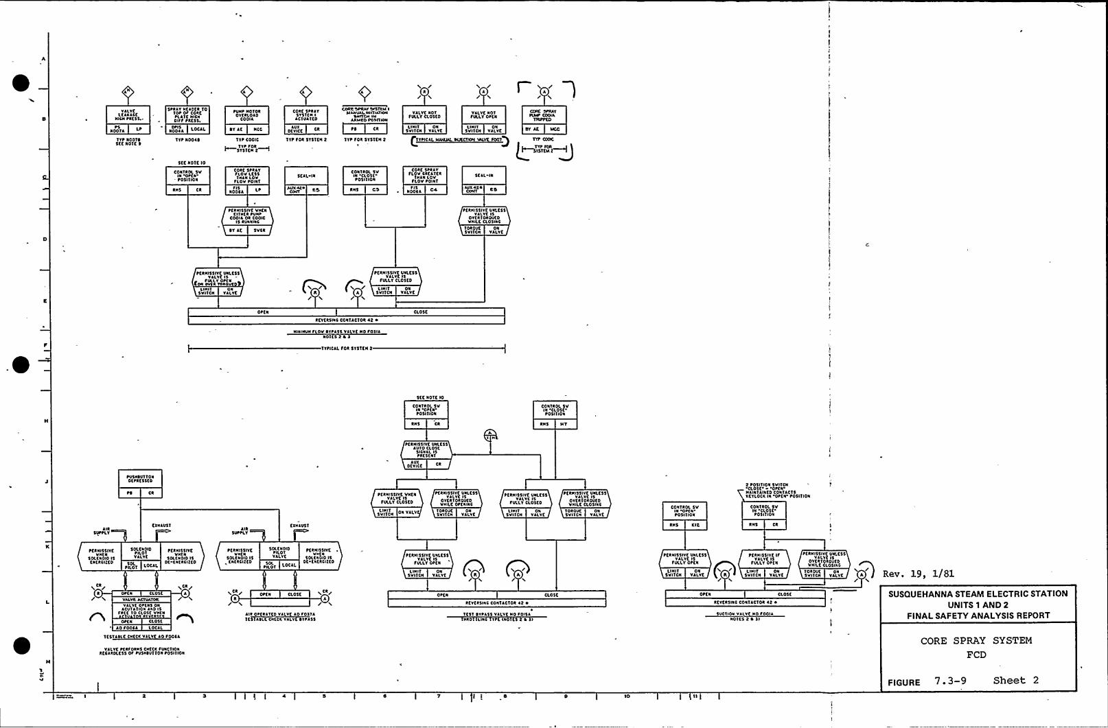
/'
/Vklrt
ltAKACtNICN tkfst ~
NOOTA Lt~5
TYt N0014StC NOIC 4
ttkAYNE ADER Torot Of CokftlkrfNICNDIFF PRE55.
NOOAA LOCALDtls
TYP NOOK 4
tUNP NorokOVERLOAD
COOIA
DY AK NCC
TYP COOIC
TYP Fok~SYSICN 2~
CORE 5PRAYSY5TfN I
ACTUATED
AVXDEVICE
TYP FOR SYSTEN 2
CORK 'SPRAY SVSTYAI IIAANVAI INaIATICNI
SWITCII INACU AO PataKNI
IYP FOR 5YSTEN 2
VALYtNOTFULLY CLOSED
L IN I I ONSVIICN YALYf
TYPICAC. COAXIAL
C
VALVE NOTfVLLYOtfk
LINII ON5VIICN VALYC
CORE SPRAYPIAN'OOIA
TIUPPEO
DY At llco
Stt NOTC lo
CONIROL SVIN OttN'POSITION
Cokf ttkAYFLOV LKSSIVANLOV
FLOV POINTSEAL IN
CONrkol SVIN 'CLOSEtot l ICON
Cokt SPRAYfloV CAEATKR
CNAN LOVfLOV toINT
SEAL IN
RNS CA NOOCAFIS RNS FIS
NOOCA 04 AvxAc4CoNT
tfRNI$5IYK VNKNElrkfk PVNP
COOIA Ok COOICl5 RVNNNIC
tfRNISSIYE UNLCSSVALVE IS
OYEAIOROVEDVNILE CL05INC
OT Ac SVCR TOROVESVI'ION
ONVALVE
tfkNISSIYC UNLESSVALVE IS
fVLLYOtfNCON avlk Yakavr
LI NIT ONSVITCN VAI.YE
ttANI$5IYt UNLESSYALVC IS
fULLYCL05fo
uNIT ONA SVI'ICN VALYC
OttkAKYERSINC CONTACIOR 42 ~
NINNNINfloVOrtkts VALVfNO foIIANort$ 2 O 5
TTPICAL FOR 515IEN 2
CLOSE
SEC NOTE lo
CONTROL SVIN OtfNPOSI CION
RN5 Ck
tfRNISSIYK VkltstAUCD ELDSC
SICNAL ISPRESENT
DEVICEAVX
AI N
CONTROL 5VIN
CLOtt'OSIIION
RNS IIT
AIRSUPPLY
~VSNOVTTONDKPRESSED
CR
CXNAVSTAlk
SVttLTCXNAUSI
tfkNIStlrtVNENVALVE IS
fVLLICLOSCD
SVnCNI.I NIT TDRDUE
SVIICNON
VALVE
tfANISSIYE UklftsVALVE 1$
OYKRIOAOUKOVNILE OP KNINC
L I NITtv lrcb
ONYALYt
~ tkNIstlYE UNLtssVALVE IS
FVLLT ClotfDTOAOUtSVIICI~
ONYALYt
~ tkNISSIYE UNLK55VALVE IS
OrtkrokOVtoVNILC CL05INC CONrkol SV
INOPEN'OSITION
RNS KIC
2 totITION SVI'ICN~aosc. - .Optk-N ANTCANIED CONTACTtKCYLOCK IN 'Ottk POSITION
CONTROL 5VIN CLOSEP05I CION
RNS Ck
PERNISSIYEVkfN
SOLENOID IStNfkCIIfo
SOLCNOIDPILOTVALVE
PILOT iociiSOL
tEANISSIYCVNC N
SOLENOID ISDf ENKRCIIfD
tfRNISSNCVNKN
SOLENOID ISfNfktlff0
$0ltNOIDPILOTVALVE
ALLOTSOL
ttkNISSIYK ~VNKN
SOLE Nolo ISDc ENKACILED
ttkNI5$IYf UNLC5$VAI.YK l$
FULLY OPEN
LINIT ON / /tVIICN VALVE S A
PEANISSIYE UNLESSVALVE IS
FULLY OPEN
u NIT okSVITCN VALVE Q Cl
LI NITSVITCN
ONVALVE
PfkNISSIYt lfVAI.YC ISfVLLY OtfN
PKRNISSIYE VNLK$$VAI.VC IS
OYKATOAOVEDVNILtCLOSINC
IOAOUESVIICN
ONVALVE A Rev. 19, 1/81
Ck
R
VALVRACTUATOR
YALYKOPENS DIDACVCAIION AND 1$
FAKE 10 CLOSE VNEN
OttN CLOSE
Ao foOCA loCAL
I Ck/A ~CA/
R/aosc
A/AIR OPERATED VALV Ao FOITAIC51AOLE CNECK YALYt4YFASS
REVtRSINC CONTACIOR 42 ~
rfsr OYPAss vklvc No Folsk'INAOIILUIC Crt CROCKS 2 4 sl
aosc OPEN
RCYfkSNIC CONTACTOR 42 ~
SUCTION VALVE NO PODIANOCE$ 2 ~ sl
CLosf. SUSQUEHANNA STEAM ELECTRIC STATIONUNITS 1 AND 2
FINALSAFETY ANALYSISREPORT
ICSTAOLC CNECK VA Vf Ao FOOCA
VALVEttkfokks CNECK fVNC'CIONRKCARDLESS OF tV5NOVTTON toSICION
CORE SPRAY SYSTEM
FCD
i I b 10
FIGURE 7-3-9 Sheet 2

4k
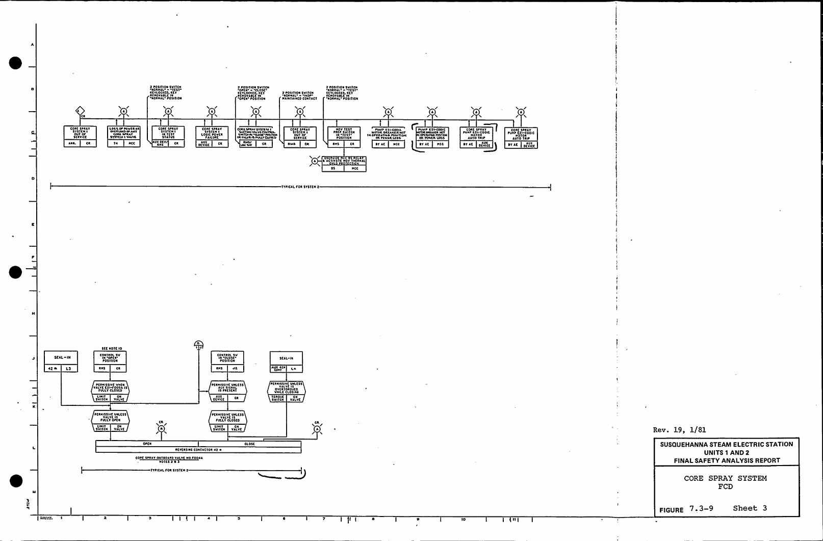
2 POSITION SVITCNNORNIL TEST
XEYLOCXK0, XETRKNOYASLf INNORNAL tOSITION
2 tosITION 5VITCNOtfN 'CLOSE
XETLOCXKO, XCYRKNOYASLE IN'OtfN t051TION
t t051'CION SVITCNNORNIL NNOP
NAUITIINKOCONTACT
2 P05IT ION SVITENNORNIL 'Icsn
XCVLOCXKO XfYRKNOVISLK'IN'NORNAL P05ITION
A
CORK 5PRAYSYSTKN IOVT OfSfRYICC
ANN. CR
LOSSOP POWCRPRUVCRLIIOCP PITY
CORA CPRAYSYSTCIC I VALYS
5 ~ NCC
CORK SPRAYsvsnN IIN TESTSTATUS
UX OCY CRRNS
CORE SPRAYsvsnN I
LOCIC tovcaTAILURE
OfvlCCAUX
CUR\YPRAY SVSIS CC I'SUCYNNVIIVC CCPNNDLSPITOI H CIISC CCCVINN
OlVCLVNlS PIILVCuylf0
CORK StRIYSVSTCN IOVT Of5C RYICC
NICS CR
NOY TESTtact svl TENIN 'I
EST'051'I
ION
RNS Ca
PINIP 22140OAIICTCR SRCANAR NOT
IN OPIRAYINP Posm IVICN'CWIR LOSS
~ Y lf NCC
~VWP f'tl COOICSNCIXCN lcfv
H OCKIATINIIUUIXHOR POWCIL LOSS
cost spal~v~UNP Ctl COOIC
ROTORAVYO Tait
OCV ICEAINC
cole stalvPUNP ftl-COOIC
ROTORAUTO TRIP
ST AE ofvlccIVX
~ AC'IIVATENOV TNCRNAL
$ $ NCC
TYPICAL foa SYS'nN t
SEAL IN
5EC NOTE 10
CONTROL 5VIN 'OPEN~05ITION
CONTROL SVIN CLOSEPOSITION
SEAL IN
RNS CR RNS VC
tfaN1$5IYE VNKNVALVE Ctl f005I IS
fVI.LTCL05KO
~KINI5$lvf UNLESSAUX SICNILIS PRESE NT
tfRNI55IYE VICLK$5VALVE 1$
OVKRTOROVKOVNILC CLOSINC
LINIT ONSYITCN VALVE
AVXOfvlCC
TOROUCSVITCN
ONVALVE
LI NITSVITCN
ONVILVC
tfRNI$5IYC UNLE5$YALYC IS
fVLLYOtfN /CR
IC/LI NIT
SVITCNON
VALVE
tfRNI5$IVC UNLESSVII.VC IS
fVLLYCLOSEOCR
*/ Rev. 19, 1/81
OPEN
RKYERSINC CONTACTOR It ~
CORK SPRIY OVTROIRO YILVC NO foollNOTES t ~ I
TTtlCALfoa STSTEN t
SUSQUEHANNA STEAM ELECTRIC STATIONUNITS 1 AND 2
FINALSAFETY ANALYSISREPORT
CORE SPRAY SYSTEMPCD
5 l I 0 TO
FIGURE 7; 3-9 Sheet 3

'
II
ff
4 4
fl
I'I j
1
I,
I
ll
I
4
I1
ffk4
If1
lf
Il
I
It
4
'f

CCC'3$ trtd AE, CJ Cf Elk K)')
k(ACIDR I(SS(LlOW L(V(L'I
k(KIIRYfSSELILDP L(v(MI
4.7
RHI IMIIMKNCC
DIV k IOOC
~dd
HKH 0AYWfliPP(SSVR(
(dry LP
/FASOSSr/Fpc!rhp
CASPNh'CK 3(br
v CR
MAHIJl'NfTMTOV
$(AL IN
tllllPVTMIONSKJVIL
td CR
CR
rvDT PtklvtSSIIKWvKN STOPSr(NJL IS PA(ma
/AWLkNVl/ /iv!rr(N W!TMTED
5(Al' I
ItfI('I IMTATDIISKNL
kvh CVTJ04VVSAOM DW 1 ID(K
NrhC
I I low L(t(LH I PIESSICK, II
. IE Low uv(ol .1 NKSSVRE - ~
I I
5TARI
p(RM!slrvl vw(NO(S(L PDW(k Avhk
IS«t tvwt C
NI
C0NT (04VVD SOL ~
FD(tvCD(4k CLOSE.IVOPKN.IAOIVAIILYMNNIrLN(0CD(t A CDSEDJSO( IA
ICAI 1 !Kll VALVE Cold A ~ CLOSE OS CP(N)Sfkvrg WT(k PVMPS CD«rh(LCI STOP IC RLIVNINCr
T It/ttSINN(DORAPLWP COE IPLAIPCOC( CPVMIMCOC I
JEANS NO C(IAYSTJAI5 I0 C(LA"5'thltTS NO ICAvSTARTS ND D(itv
4 A I H J H krASSN( WtCNND!I IN 1(ST
5&1 (M(00(NCV0($rl FIv DTIERS
Pf RVA55W( WHENNORMAl SYJ!vP CPOH(k hhkhtkf
Pf PJNSS!Vf WHENNDT IN CHA!A(iTlST
RMS
PlkwSS!vt wH(T LN CHANNEL
T(51
RAMSSV( ASI(kS CA't)ND
77rtCJP Df(JCY
C(RVISSAI WH(N0(S(l SIM(k AlrAILFOR PVMP
~~@ ~"S«ttk Jtvhhht(
Ck
P(RIJIISVE Avt(k5 SIC«40 TPJE(CAY
EFvf v
VNITI rrAS PIVDR!TS Cdh PVMPS COO(A ANDI.IJVHT E trAS PRCRTY Sok PJVPS CDDCC A!00IHE C«awk 5151fM AS OAAAN SHOWS SYSTEM L THE OPLI4AYPJO
5(DIEM(LAST(k LDV lttl(RL(v(L SKhhi Ort HCH Dkvhftf ACCCWVMNKDDY LDW tt(JCIDR tvt55VIIE IS AS FCKIOWS 'lolart
PVVP Cloth SMATS NO OllA>tvtvv Ct!0(4 STAITS AO NIAVRtvk(OOCC STARTS 5 SC D(ihvPVNPCDOE D SMJtTS 5 Sf'OCtv~vvS«14 (PENS htl(k klh'.T«t IDW tv(SS!tf
Itktk33!I(f«5A DIKHS r!STER AEKI«t Low SHESDJAE
IKRYISSYE
5 SYS CCATS SEOJPA!I( SH(MN 5<d CHYSSEDVPAJM
IDENTKJIL ff(ftT Cokk(SPOIKSHD EDIAPND 5VSSLt(5 hk(AS CCLDWS Ok A5 NOT(D
SYSI A
SYSE 40
4 ttww MOTORS SHNL (( PASTE(I(0 W!TH (H(RLO!o PASECTKA
OV(klOAS I!CATS TO IfJPPL(0 50 AS To MANTAIN PDA(R OttMOTOR AS(«VO A5 P(55(LE WITHOVT VMMgtAT( (AMIDE to ILJRDR'HARM 10 Ew(NANCY PDATR SYST(ththvf MOTORS(rrhti 44IHIOVID(D WIT!I CIKRLOAO Tk!PS hvo LOSS CC PDAER A;AILVSINAD(HTKN.IPLVE MDIDR CVKVITS ARE TO df IDROVCKO WlTH Dh(AHEPSIKRT ORCVIT Cttk(NT tACTfCTNT TRPS
I
5 AVYLIARYR(LAYS AND D(VK(5 Art( ICST 5!rOAN ON THf Cvrv(TKNLCONTR« (VA(RAM (K(tfWH(RE MEDEOTOCNRSVTH( SVACTIDNHE
RfOrhk(MENTS.
I MDTIVl PDV(R SDR SIST(M I RPAPS SHALL (PISH!rtt( Ck«J ADiff(RfNTKMlkl(NCYAC IVS THAN IVE PVMPS CW 51ff(MIPOA(RSth OIIKR IALVES IN (KH SYS SHML okrDPMTK ROM 'fHE SLM((555!JPPLYINC P/rt POW(R LOCK CINTIKKPOAER 5YSCMI Svhtt(( SIIDN A OFS(R(NT SOVRCC THLV SYSTEM!E
2 5ihTVS llOITSSHALLDE AS C41DWSVHLVK5 AMEER ON CDR CIOI(0 POSITI«4
R(0 COA OP(N PCODI)N
IDTH «l Sok INTERNE«htf POSIDON
tttrtPS k(0 ON fok tvNP thtvrvNOAIAIER ON fOR P/AP St(P
I ALLAVT TIMPK CVK(5 SNAIL 4( ATAISIASLK CROM o IIKSILL5CAL( Aht SCALE Srrh(L IE Al LEAST I tv TrNE5 CRfAT(k THANSr(CFKO Tw( Sf TTNSS, 1
'l hll EOVIPMtNIQLNSIRJIJKNIS AS( Pk(Crt(0 dv (k VNL(S5OIH(RWM NDT(O,SE( R(C I rl
40 IHE 5(NStki ORCAI AR IA(hh 0(TECIKN ANS trt4VK 5fi(CTKNIS 10 EC Akkhtr((0 SO TMTCALLO( OC A SPCE D(VKE OR CIA(IIIf0 SVIKTON CN f(MANI Whl NDT tkfv(AT CORA((I SEifCT!DN OC
lOOP FOR INNCKN
ll THE k(SKIP( trfhfP(MOIAL SYSIEAI SHALL df NSK!1(0 N~Wlftt PROPC(EO (!ITlRA SOIMKL(hk tOWDt FLINT PAOTEC43NSIST(MS IE(f EN;.AS APPLKN To TIK CD!IT!tDL CIKVITRY
IE 1td RE(OVAL PEA I k(MOVHL SfSTEIA SHALE I( 0(SICNIO IN~WITH k(S ro
~I~LEQEX5%I bl IDO ~(SDVAL KAT ACOVAL SIS PHDdhtt 4030 L!OC SYIJDCSSd(IKO Nt(XEAR DIRER SYST(M ttb~ dfl M30 !Vvct(rh IttL(R svzxM (co$ (b 1030 Ck( SPL4Y SY5 C(ft$ 431-KTO RECFK Sltw CNINL sv5 CcD7(IPI030 CISC SI5 C(04(SPD30 ILCK SVS SCC
NDSPKIO RDKTDR AECI4C SYS ttrtIO AII 4030 (I(CIRCA( KOLIP SftfkATKtt fOR SASEDVARD $Y5
SEC(Ed)
+ 5W'IKHC(AR D(VKE CVNCKN Mhtl(k JJISI 5tfC. CITY
CR
S PDSttrtN gW'SMRT-)VIO STOP.SPRP!0 k(DAIN TO AVIDFk«4 Sthkf'TCF
N I'AWIIDVTKN
NST P(IW15!VKWHfN 510P SKtrhK
IS tR(SLNI
PAL M
CDHOIT!ON
pfRM!isrvl wHENAVY CVKIEIKAD!(ID
Hrl
VHLVJ HCE SILLYOP( N
~HOT RLLT VAL~NDI/ILLY
Vl ltrl4'Ar AI I~
P(AIASSVE lwrlNVMVI NOT Sthtv
W C«CDKL/ LN slop pvtr5KNIR~SKJL(D vt
,I lotrTKN PW,SVRIFNJTD STDP
SPNIS k(PJ!rN TO St/0SADM
SAlt'OP'NTIKL
SW5'Akt FOTNKN
NDT PERMSSrvfwHEN 5t«'(rrrt
45 sama
Stop ptvrp cCIKIA IPPY 1
N Rtw Phrw15 RtPPPHO
NOT PfRIAStrvfWIKN STCP SKNAL
IS PR(5(NI
CR
RMS CR CR
~ SCAI ktSTOP
CONOITKP4
CR
PLRIRSSIVC vrtKNAIJX OCVVX(NKRIVKED
CR
N1
V( NOt ALLYN
W LIOHY ONNWHC4 SVATIH
CSIN 'STOP POSIT!«hSTOP SKALDIC N
Sttp ItprpFROM! tphv 4
VAKNRHrt tlhrrtRLNHNO
IM!
P(RMSSYK wr(NVLVE NDT Sth(YOPEN
WLVE NOT Akhv
kMS Ck
10 ttrwv tSTDP IPCT 4 ~CV4I PIAIP A
Cll
Jv! I CR
Rev. 19, 1/81
/ CRR/
START
Ark 'I
krw pvrvp ~ .coo(A (3f{ Not(5 St ~ )
/A R
STARf
A,k CIA(VII Dt(AH(0 Sf F
Rrrk Ih!MP I I 44
Ck 5A/
SUSQUEHANNA STEAM ELECTRIC STATIONUNITS 1 AND 2
FINALSAFETY ANALYSISREPORT
RHR SYSTEMFCD
FIGURE 7 - 3-10 Sheet 1
7 IE 1 0 10 12 CI

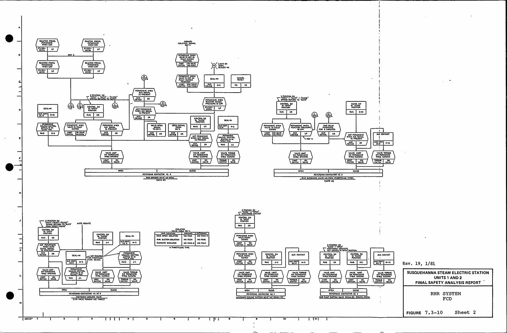
Rt&CTU4 PICSS.PUUA55llt
LPNbtlAPS dtlNOtld
REACTOR PRE55.PUORSSIV\WHEN IDW
PS dtlNOtlC
RKACIDR PRESS.Pt$ 04SSIVEWICN IOW
PS dtl-NOtlO
0I P
PCRIRSSIVK WICNV&LVEIS NOT Al
TIALYOCSKDPOSITION
Ptf&RSSIK WICNVALVEIS NOT NITALY QDSED
POSITIONUNT ON VlLYC
5WITOI NO SOOd
< LICNT ONW WHEN
X SEALED-N
AUX OXITlt ~
) POSITKN SWOPtN'AUTO CLOS
S 'T LI I 5 CONTIIX. 5W t I
N 'ltd~OSITKN
RHS CR
PC$ RRSSIVC MCNAUX SNNALIS PIIESKNT
PtRI&55IVK WICNREACTOR VKSStl.PRES SIXIE ls IDW
P5 dslNOISA
SCIL N
CONTROLPW
RNS CRMp
CLOSC SWN QOSt~OSITKN
PUORSUYE WICNVALVE IS SIALY
ClDStb
LRRT ON Y&UCSWITOI VO fOITA
NOT PE$ tlOSIYEWICN AUX SIONIL
$ 5 PRESENT
lUICCNT42t
IPCESS 00NTROI.SwWI IS N
RMS CR
~tRIASSIYE WHENVALVE IS ARLY
QDSCD
UIRT QI IALYCSWIIDI &KI$0ISA LP
TMK CQAYPtfbaSSIVK
FOR S MNUTES
AUX42 ~ f I'2
LRAT CNSWITCH V&LVC
VALVC L&RTSW Ptf&RSSIVE&IHLKQDSNO
L&RT ONSWITOI VALVE
VALVE TORQIESW PCIORSSIVEMCE QDStli
TORQC ONSMTCH 'IALVE
VALVE L&KTSY PERMISSIYCWNIKQDSNO
VALVETCRCLCSW PQURSSIYEMCE QD504$
RCVtRSNC CONT&ETON 42 ~
Tt Kl
RKVKRSNO CONTACTOR 4t 4~ RHR OUT VALVT MO f00& RIO
-52$ $SK
CONITKE SW S4
RIIS CRSt&L N
NIIONT ~S~ t ~
ICAO SPRAT ISQATaN MO $022 MO Sots R
LAAT ONSWITOI VALVE
SEN. N
NJX Q&ITAt&
i&RESS CONIROLPlfltttl IS N
RMS 4$ UIAT CNSMTOI VALVE
POSIIXXI
RNS 45
KKT $00$KD N'CPO4'POSIIXN
MME NNCPOSIT KN POSITON
fblS IQ, AUX CCNK M-Qdt A Rev. 19, 1/81VlLVKIART
5W P\$ &RSSAEWIRE OPKNNO
PtRNI55IYCUAESS Q&IUKL
SWITOI ls N VALVE LART5$$ PUbRSSIVElACE QDSNS
VALVETO&I&IXSW PCI&RSSNEIACE CLDSNO
TOIKXIC ONSMTCH VNVC
YlLVC tACTSW~MCE OPTIAHS
UNIT CNSWITOI VALVE
WLVK LWKTSW PC$ bASSWEMCC, QOStQ
VALVETORCIIESW PERMISSIVEWHLE Q05NO
LNRTSWITCH
ONVNVE
VALVE I&ATSW PKRIASS&CM4IE OPUINO
VALVE IARTSW PKRMISSVEwHLE QDSNO
VALVE TOIK&CSW PUUJIISNVEIACE QDSNO
TCAQIC, ONSWITCH VALVE
SUSQUEHANNA STEAM ELECTRIC STATIONUNITS 1 AND 2
FINALSAFETY ANALYSISREPORT
RCYCRSNO CONTACTOR 42 AC ~
Ns VALVEIQ4 VALVE I&ANNAStt Tldl.t
RKVKRSNO CONTACTOR Ct 4%4t PI&It5UCTION 'IALVt f004A f004 $005&
RHR SYSTEMFCD
l I 0 $0
FIGURE 7. 3-10 Sheet 2

4
ll
I
h
lb
W
4
h
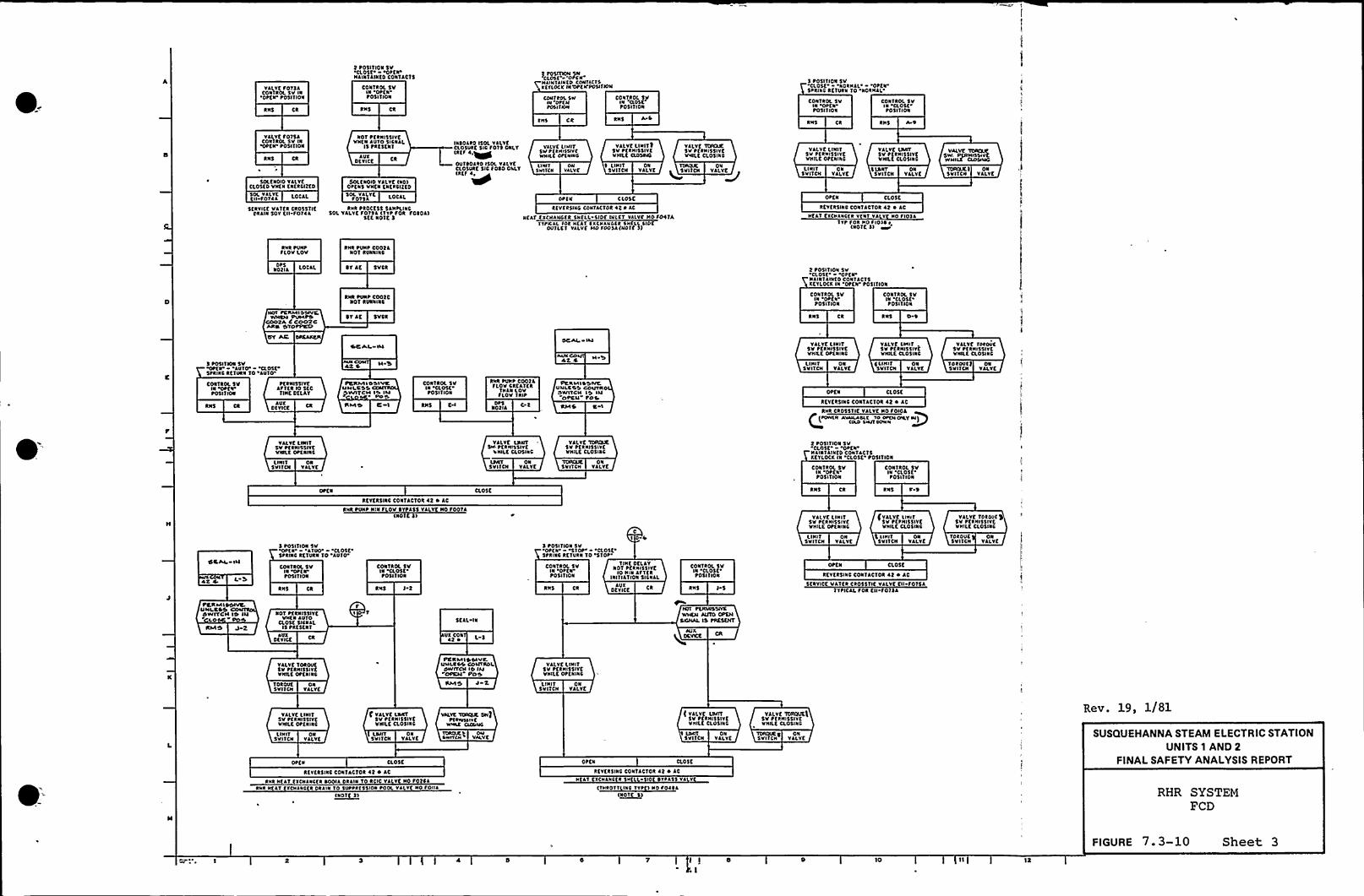
VALVE101stCONTROL Sv IN
'OtCN tosl1ION
RNS CR
I tosITION 5V'aost ottaNAINTAINEDCONTACTS
CONTROL SVIN Oaf Ntosl1ION
RH5 Ca
)a~~ --oPi.-HAINTAHICD CON(t(1$K(T(OCK IN'OPE N'POSITN)N
CONTROL SWIN OP(NPOsl (ION
coa1aol skiPX '((OSCPOSITION
CDNTROL 5VN .a 05(.tosl(ION
CON)aa SvIN OPKNt05lTION
5 POSITION SVClost 'NORHAL'tta
SPRINC RCTVaN 10 NORHAL.
RHS CR RHS ACRHs ca RH5 A.v
YALYEfo)54coanoL sv INOPtN toSI (ION
SOLENOID Yt(.VECLOsto VKKNfNtaClttoSOL YtLYE LOCALKN foltt
SERVICE Vt)fkCR0$ $1)t('AIN50Y tll fo)ta
N01 ttaNI55IYCVNtN AUTO SICNAL
15 tkfSKNT
AUXDtVI(t Ca
SOLE NOIO VALvf(ND)OPCN$ vata KNKRCI(ED
SOL YaLYt LOCALTO)ItaHa taoCtss 5ANPLINC
SOL VALVE avant (Tvt fok foIOA)5ft NOTE I
IasotkO ISOL VALVECL05VRC 5IC fo)5 ONLTiktf4,~OUTIOARD ISOL YALvfCL05vkt 5IC TOIO OILY(Rtf 4~
YA(vc UNIT5WP(XHr5SIVCWHILE Dt(xHNG
ONVALVE
LIHITSWI1(N
VALVE LIKI1 I5v t(RNISSIYCVailt ClDSWO
~ LIHIT ONSVI1CN VALVE
YALYK Tcacat5V t(RHI5$IYCV'NLt C(.05INC
TDAOIK ON~SVITCK YALYK~
DP(N CL05K
k(VCRSINC CON(AC(ok 42 ~ AC
NEAT CX(HANCCR SNAL SIDE IN(C'1 Yt(VC Hofoa)A(TPNAL fok H(A1 (X(HXHI(a SK(ll SIDC
OUTLE'1 VAlvf HO POD)A(N01t S)
VALVE 'LHII1SV ttaHISSIYEVHILC OttNINC
VALVE OMITSV PKRHI$5IYCvailt CLOSINC
LIKITSV ITCH
ONVALVE
5 (ANT5v(1CH
ONVALVE
OPKN CL05E
REYERSINI CONTACTOR 42 ~ AC
Hft) CXCHANC(a Y N1 Yt Y Ho fl lt)Yt fOR Ho flo)IS
(NOTE 5)
VALVC YORCUE
!SW. P(NNISNYEHNILK ao(xucTDIY)UE) ONSVI(CH VALVE
DtsNo)IA LOCAL
RHR pvapPLOY Lov
RHR tVHP CoofaNOT RVNNHII
IT At SYCR 2 POSI'(ION SVaostoats'tiaiti'RfoCONTACTS
KETLOCK NI 'OtEN t05((ION
HO( PCKMISDIVC,WHCN PUN'PD
COOXA C COO2CANC STOPP(CO
RHR tlalt COOICNOT RvaalkC
~1 At 5VCR
coa)RDL 5vINtosi1ION
RNS Ca
coNTRDL 5vIN 'Cl05Kt05ITION
RNS 0 ~
SC Al INOCAI Itt
AUXCO4t 4
YALYKI.IKIT5V PERNI5$ IYtVHILE OtKNHIC
VALVE LNNT5V tfRHISSIYKVIULE CL05INC
Ytlvt fttovc5V P(RNI55IYCVKILKCLOSINC
I POSITION 5Vma - av(o aostStklNC kt1VRN 10 AU'10
42 S i(HI'15VI1CN
ONVALVE
C LIKIT5VITON
ONVALVE
Toaovcs oa5VITCN YALYC
coa)RDL svIN OPKN~OSITION
ttRHISSIYKAfTta lo StcTNIE DKLA'f
AVXotwct
PDJWIISSIVCUNI.CSSPVVITCI( IS Ilt
PO S((MS C
coa)RDL sv)N CLOSKt05I TION
RKS C I
RHR PUHP C0024rlOv Cata(ca
THaa lov1loV TRIP
OP5Notla
PtKMISSIVtUulcsS couYKSWITCH IS Iuopcu- ros%MS C I
OPKN aoscREYERSINC CONTACTOR 42 ~ AC
CRHR CROSSTIE VALYC No POIOA
Itcwaa Avtltaalc To oto( okv NI)(ULD tHUT OOHH
YtlvtLIKITSv ttkalssl YtVINLE OttNINC
La(IT ONSVITCN VALVE
VALVE L)MITSW- ttkalsslvt
VHILC CLOSINC
LANT ONSVITCK VALVE
'Toa(UE5VI1CH
ONYALYE
VALVE TDROUE5V ttaHI55IYfVNILKCLOSIRC
CON1ROL SVIN Otf
N'osl(ION
CONTROL SVIN CL05CPOSITION
2 t05I110N 5VCLOSE Ott N
Hata1alato Coal ac1$xtvlocr pa aost. tosltloa
REVERSINC CONTACTOR 42 ~ AC
RHR PVHP NIN 1 LOV IYPA$5 VALVE Ho fop)a
aosc RH5 Ck Ras c I
OLLA( lu
AtiI POSITION SV
OPK N ATVO'CLOSEStk(NC ktfvkN 10 AVTO
CON'fROL SVla OtfNt05ITION
(No if I)
RK5 1 2
CONTROL SVIN CLOSKP05(1)ON
RNS AVXDtv(CE Ca
C
I 0
I POSI'(ION 5V'0l'EN'10k'L05C5tRINC RfTURN 10
STOP'ON)aol
Sv NOT PCRHI$ 5lvf(INC DELAY
IN otfN lo HIN Af'(CRPOSI1)ON INITIATION5ICNAI.
coa1aol 5VKI
'CLOSE'05l
1 ION
RKS )5
YALYKLHHTsv pcawsslvcWHILE OPENINC
LI NIT ONSVITCN YALYC
CYALYE MHITSV PCPHISSIVEVallt CLOSINC
IIXI1 ONSVITCH VALVE
OPEN
REYKRSINC CON)ACTOR 42 ~ AC
Stavlct VATKR ckoss(lt YtlvtEN f0154TvtlCAL fok ta fo)lt
TOROVC5V ITCH
ONVALVE
YALYC 'TORDU( $Sv PKRH15$ IYEWHILE CLOSINC
Pta MISSIVVUNI CSSSWITCH (S It(
LO POCMS
No'1 tfRKI55IYCVICN AVTO
CLOst SICNALIS tRf$EN 1
avxDtv(CK
f~ 1
5ttL IN
VX CON42 P
N)i PEKNSSIYCw)cu A(lTO OPKH
SIONAL IS PRESENT
QDKVCK
VALVE TOROUCSV PKRHI5uvt'VNllfOttalas
PCKMISSIVC.Uulacs couvaolOHIITCH lo INOPCN PCS
VALVELIHITSV ttkalsSIvtVHILKOPf NHIC
(DROVESV I1CN
ONVALVE
llHIT5VI(CN
ONYalvf
VALVE LIHITSV P(RHISSIYCVNILE Ot(NIRC
fvalve LNNTSV ttkHI5$IYCVKILC CLOSINC
VALVETDNOUE SW)p(aaxt(lr c
WHIC CU)NKC
(valvt LDUT5V ttaHISSIYCVNILC Cl05INC
VALVE TOROUEISV tfkNISSIYEVHILC CL05INC
Rev. 19, 1/81
LINIT ONSVI1CN VALVE
LANT5VITCN
ONVALVE
CL05E
TOROIC t OMawr((H valvt
OPEN
~ LINT ONSNITCH VALVK
a05c
ONSvil(K VALVE SUSQUEHANNA STEAM ELECTRIC STATIONUNITS 1 AND 2
FINALSAFETY ANALYSIS REPORTREVER5LNC CON(ACTOR 42 ~ AC
RHR Hftl txcatvcta Ioolt IRAN 10 aoc vtlvf Ho 101stRHR K(AT txcvaac\a DR(la To svppaf55ION pool vtlv Ho foaa
(No)t I)
RCYKR5INC CONTACTOR ~ I ~ AC
Htt'I KXCHANC(a SH(l SID (Pass vt ~v
(THROTT INC Tvt ) Ko fo(IA(~NOTE I RHR SYSTEM
FCD
FIGURE 7. 3-10 Sheet 3
I I 0~ I
10 12


CONTROL SVIN OttaP051'lloa
115 CR
Dklla tDTLCYCI. ASOYE
5K'l Polar
LOCALLS
collrRDL svIN Otf1toSITION
RNS Ck
ilk5uttLT
~tka155IYEVttf1
50LtNDID ISKktRClltD
1 0 l ~ C 1 11$ 51 V Kvata auro5llalL ISPRESENT
AUXOKVICE Ck
tatklllt50LCaotD
PILOTYJLYK
ptlor iOta~COL
I DS
CXNlurr
tf111$ 5IYKVafN
SoltaOID 15OK CNKRSIZKD
ilk5WtLY
tKRNISSIYCVat 1
SOLCNOID IStktalllfD
fNCRCllt5OLC ROID
tlLOTYALYC
~ ILOT LOCALCOL
KXNlUST
~ C R NI5 5 IYCvtttaSOLKNOIO 15
DE ENERCIZEO
CONTROL 5V11 OtlaP05ITION
RN5 Ck
VALVEroollrULLT CLOSf0
LINIT ONSVITCN VALVE
coaTRDL svIN Ott 1Poctlloa
RNS Ck
otta vtt 1 PILDT
lo PIZSA LOCAL
Rttk NX 5'tfla INLKT ttklla Poratk ottaano Yalvt 1-rltll
TTPICAL fOR STCAN Clat Dkll1 Por Dalla INSolRD150LJTION Ylcvc Ca rill1 OulcolRD YJLYK Ca rill
Otta vata atLOT
lo rll0 LOC AL
STCla IN Ok ~ 11 Por Dkll1 Tkl~ SYPJSata otckalco vaLY w-tNO
NOT ttkn551VCVNCN Auro SlclllL
1$ Pkt5ttll
OtnCC CkAUX
4I
L
IN
I�'I
svtrcN01
YJLVK
PtkNISSIYK VatNYALYKroaT JrULLYCLOSto
JUXOKYICC CR
10'I PKRNISSIYCVltta Attro5ICNAL ISPRK5tal J
I OD
\ t05ITI01 SVNJNUAL orr RE5KT
SPRINS kCTURN To 'Orr
tckatrtlvt Vkf1YALYE rioca
15 CL05ED
tCRNI55IYC VNf1Dklla PO'I LCYCLkSOYE Stl total
5CLCCTOR SVIN 1ANIIAL. tocl'llok
SELECTOR 5Vla 'orrtDSllloa
t05SVITCN
01YALYK 1021k LOCALLS
RNS
Oaf SV fORCAEN ST5TCII
RN$ El
SClL 11 Vtttakut DfVICC
15 ENCRCIZKD
AUXOCnCC
JI15ut tLY
PSNolll LOCAL
Nor tfkal551VEVtttN Ytltr PLOVASOYC 5tl POINT
fXklu5TAIR
5UPPLY
toc5VITCN
ONYJLYK
PKRNISSlvf VataVALVErltSA Ott1
KXNAIIST
ILICNTONat ttf4
A I . AYX Dtvlcr.0 etc 1 f ttJZI0
ttRNI551YKVat N
SOLC1010 15Eatklllto
t1fkilltSOLCNOID PKRNISSIYCPILOT VIIC1
SOLtaotD 1$50L DC KIitRSIZKO
ttLOT
PERNISSIYEVttta
SOCK%DID 15tatkcllfD
Ck RC:Zt50LCNOID
PILOTYALYE
PILOT LOCALSOL
tfkatSSITKVNC1
50Lt1010 ISOE tktkcllto
NEOUINCD ONVLIVIRS IORIAg PO CDAOtvlà 1 toSIT ION SV
CLULC luro OPEN(5PRI1$ 1'ETURN TO~aulo- roa vaLvc$
02 Otv IIaatalatato C01TACTSacvloca 11 CLoSC roavaLvf1 volta 4 rolaA '
POSITION 5VOtr OYtkRIDCllllarllatDcoalacrcRKTLock Ia orr
rtckttoatac wvc4IttJtc'vla4 'YALYC1$ PULLY CAUSED
Uk~ POIDA
Otta Vata PILOT~ ~
lo r I Ilk LOCAL
kttk NX INLCT Y 1Tklk OttkA'lco YkLYC CN talk
CLOlc DPCNNAINTAINK0 CONTACTS
OtfN Vltt1 tlLOT
lo ltltJ LOCJL
kak NX DRAIN POT Dklla Tait art J5$AIR Ottkalto VALVE Cu Still
rtKRNIISSIVD4NLDSSDWITON IS IllOLO tONttt~ J
coaTRDL Sv11 Dtla~051 ~ 101
C1
atnocx svt Tca~tkNI55IYC la
OYtkRIOK POSITION
aNS Ck
rfRNISJtvc tvatvAUX ataaat ll
ttt5CNT
AUXOCYICC
CDNTXD) SVITCNw OPXNtDSITION
RNS CR
Itor ~ fRNI$51YKVNKN CL05C
stcaal15 PRE SE1T
DtvlCEAUX
trlvtlllvfvat NAUX SIANALIl
tat Sral
DCYNf CkAux
NOT tlklnlltvCvttfv AUX StlaALIS PRLSCNT
DfvarAux
CDNTtDL SvtrckIa 'CLDSCPOLI T I ON
R45
ORAL IN
112 ta
IOR YALvf5raltk ~ ttllADIILT
PNNLIISSIVEUNL111 CONTROL
DWIYCN ~ '0 14tRIVIS J P
tfRNI55IYC WalltPINA cL05co
PDS ONSat YALYC~
~C11155IVK VNKNrltSA Ott1
POSsvlrca
01YALYE
Rev. 19, 1/81YJLYK LINIT5V tfRat5$ 1vfVtalt OtfNINC
Llalr 01SVITCN YILYC
YkLvt 1141'I5v ttkal5$ IYKVNILC CLOSINC
IINIT 01SUIT CN YALvt
RCvfkltac Cokracroa lt ~
CLDSE
coaralaalar Stagy vllvtNo rolla Irakor rnac Tvttl10'lt 1'tTtlCALroa Ya~rt5 10 rotla ~ 10 rota J IINROIILIal lrtO
No r021J 1 roti J
YALVf TDROUC5V tfkal$51VtvatLC CLOSNIC
TORDUX 015VITCN YJLYK
NOT ttRNISSIYCVltlNJUTO
5ICNJL15 PRC5lal
OCvlCCAUX
Socfaolo YALYC (kolOPC15 VNKN CNtalllCO
LocaL105 JRNRNXI CTVJ Y
50L YJLYE tll rloll
.5)SUSQUEHANNA STEAM ELECTRIC STATION
UNITS 1 AND 2FINALSAFETY ANALYSISREPORT
RHR SYSTEMPCD
7 I ! I 0 10 I 1vtvtkfrT
FIGURE 7. 3-10 Sheet 4

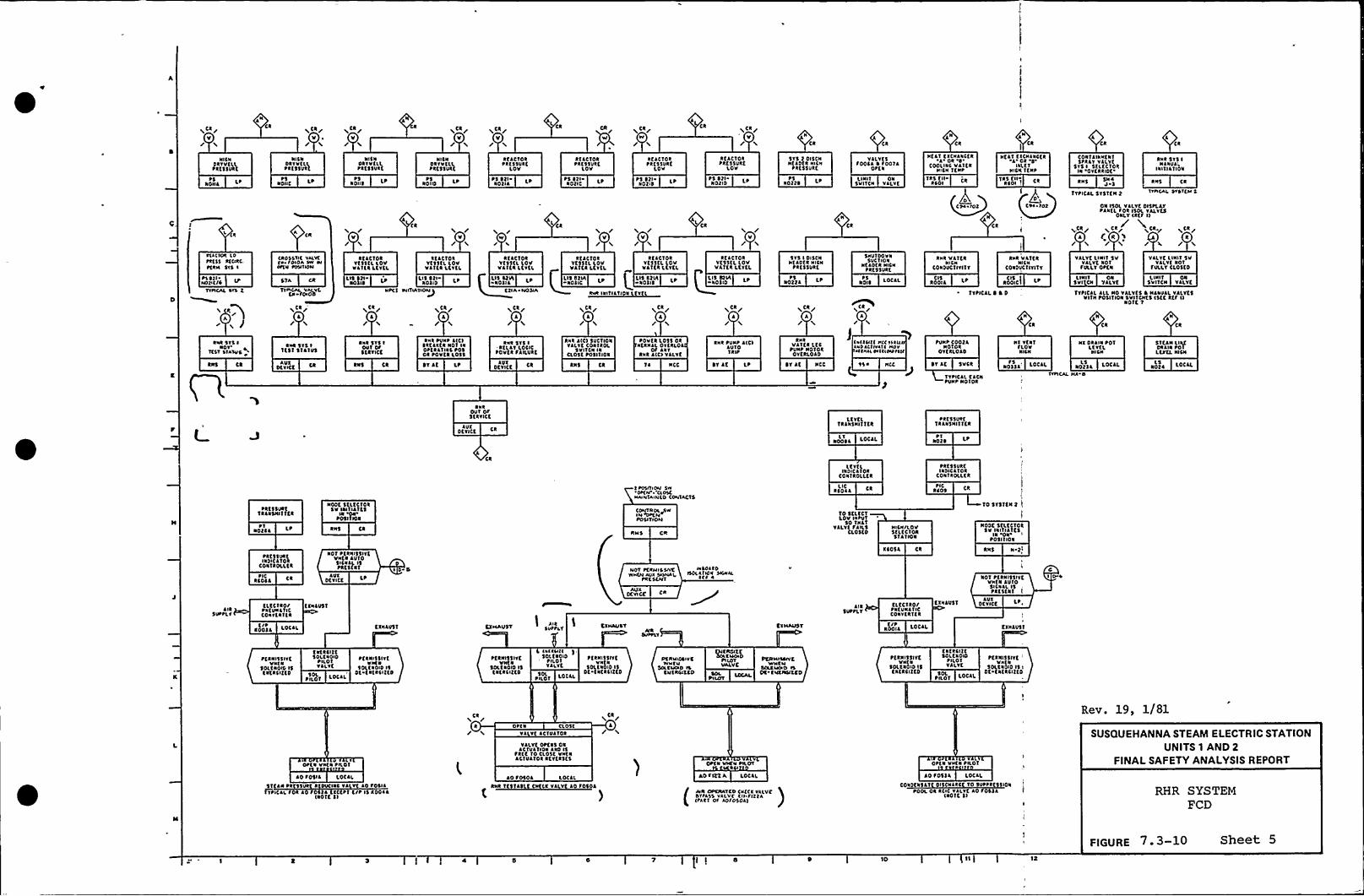
ACI/V/
~5141L LP
NICNolvvtll~ IESSURC
1Ck afar
V/
~5NONC lP
1151DRVVCLL~ RESSVRC
~Ck/v
NIC1OIYVELL~ IESSVIK
1011$ LP~I
ACI/V
NISIDkvvtlL~RESSVIC
Ps1010
~carV
RELCTOIPRCSSVRE
Lov
~ S Itl-Notli
CR
/RflCTOkPRESSURE
Lov
~S In-Notlf
~ Ca/W/
RELCTORPRE$ 5VRElov
Ps Itl LPNot(I
CkXCR/
v
REACTORPRESSUkf
Lov
~5 ItlNotio
Ck
515 t OISCNWELDER IWCW
PRC5$ VRK
10»IP5
YLLYESSODCL ~ SOOTA
OPEN
LI NIT ONSVITCW YLLYt
Ck
TIS EII CkRLOI
NEAT C ~ CNLWCEk'I'k 'ICOO(INC Vlitk
NICN TENS
Ck
11$ CN ~Rloi )
NtlfEICWLNCfkl 41 ISlit 1
IWCN TENS
lCk
CONTLINWENTSPRlv Yllvt
SVS I 5ELtCTORIW OYENlof
aws J L
1YPICLL 5151EN I
lca
Rwk 51$ 1Nlwvl'I I 'IIA ') I0 N
RWS Ck
11)l(AL ITLVCM5
RIA(141 IVpkt5$ a((wlc.PERIL 51$ I
P) ltlMoiltllTYPICAL IVS t
L Ckg*i f
(RDSSTIC YALYC(4 SOIDA LW WlOSEW SVSITIDM
STA ca
TYPICAL YAIVf,Cw SC44
V
RELCTOIYE$51L LovVillaLtvtL
LIIIt( L'I
/V/
IELCTOIYtsiilLOUYlTEI LCYEL
LIS Stl10110
Ckr
/ACR/
L/
WPC 1 NNTSATSOMJ
RtlCTORVESSEL LOVVlitkltVti
Lls Ltv( lP14)ILftlA MOSIA
XCI/l
/V
h /V/
ACI/
/~CR/
I
RCLCTOR RELCTOIYKSSKL LOV YE55CL LOVvAita LCvtL vlifa ltvtl
L($ 8111 LP I lls CTIA LP1011K 14115
kwk IWITIlilow Evil
RK LET 0 IYE55tL loV
VA ifI LfYflLIS IT(A LP10110
~Ca/
515 I DI5(NNfLD'Kk wlcw
PRE55VRE
10»lPS
1
Ck
5woioovaSUC1101
NfLots IUCwPIC55vkt
101 ~ LOCAL~5
CP4 IOL
Awl VLTfkNICN
CONDVC1IYI'1Y
ROOILC IS
Rwk VlTKRNlCW
CONDVCTIYITT
aoolciCI\
CR
TYPICAL I I 0
01 lsol YLLYC 0(SILLYPANEl Sok ISOL YAIYES
ONLY (RKS I)
E R 'I/s„tkr
A/ACR/
I/YLLYC LINIT 5V
YLLYE 101SULLY CLOSEO
YllvC LINIT 5VYLLYC 101SIALV OPCN
Llwli 01SVIICN VALVE
LI1 I 1 415VI CN YAlvt
N
Ck Ck
TYPICLI. LLL No VALVES ~ NLNVLLVALVESVITN P05ITION SUIT CWt5 (SC C RES I)
Noif 1
RWI 5151~
Ov'CSVSIAYUlikwl Sv'5 I
TEST SYLTVS
AUXOtvlCE
Iwk 5YS IDUT OS5E ITIC C
RNS
RWR PUll~ l(CI~ktlltk101 11OPEILTIIC P4$01 ROUEN loss~Vlf LP
RWR SVS I-NELLY LOCICP4VCI SLILUIC
OtvlCELVY
kWI L(C) 5VCTIONYLLYE CONIROL
SV IT CN IWCL05C POSITION
RNS Ck
~ OVER l4SS OkWERNLL OVtklol
OS lwvRwk l(C) VALVE
1 ~ NCC
RWR PUWP l(C)LUTOTRIP
Iv LK LP
RwkVLTER LKC
PVNP 14141OYERLOLD
IY LC NCC
(~INII(1(('SN((WLL(IIVLI(MVV4((wl( LMIISMSlll
PUNP COOEAN014R
Ovfklolo
~ T LC SVCR
TTPICLL C ~ CwPVWP NOIOR
NY VENTSLOVNICN
NOTSAS LDCLLr5
NI DRAIN POTLCYEL1 ICW
Notll LOCALLs
VVPICAL MA 0
STCLN LlkfDlllwPOTLEIEL INCR
Noti LotllL5
IwkOVT OSSERYICC
LVIOEWCE
LEVELTRLNSNliifk
woosl loclLLi
~ lt55VkfTRLNSNIiifI
~ 1Roti
~ItvsoktTRLWSNITTEI
~ 1NOtll
NODE StltCIOI5V IN(IILTKS
IN OaP0511 loa
kws Ck
Ck
1 IV)IIIOM SW'OP(M CIVSCMMWTAINCDCONTACTS
C~ROL YSW
POSITION
RM5 CR
ltvtLINDICL10R
CONTROLLER
Noii ckLIE
10 SELECTLov INPUT
$ 0 TILTYLLYC SAILS
CLOSEDWICW/LOV5tltCTORSTATION
PRE55VREINDICATOR
CONTROLLER
PICRios
iosvsicwt I
NODC 5KLECTORSv IWITILTE5
Iw OkPOSITION
~RESSVIE(NDICLTOI
CONTIOLLEI
NCO@l C~ IC LVY
Dtvltt lP
101 PCRNI$ 5IVKVNCI LVTO5ICWLL ISPRESENT I D 4 NOT PCRMISSlvc
ww(M wx SsLMAI,PIC 5CMT
OC YlCCAUX
lwiol1 4IID(AIIll ShWLL
~ (S 4
RCOSl Ck RNS 1 I(
10'I Pt RNI$51 YtVwtN AVIDSICNLL 15pkc5tai
4144
ilkSUP PL S
CLECM4I EEWLVST~ WfVNLIICCow(tlitl
IDDIL I,OCLLtl~ ClalVS'1 KIMAUST l.,SUPPLY
KINAUI'1
illSUPPLY
CLtCTROI tYWLU51~ NEUNL1ICCowvtlitk
LOCllESP
LVIOCVICE
Cfwlosi
PEINI55(VEVw(1
SOLENOID 15twtlc»to
t NERCITCSolCWOSD PtkwlislytPILOT vwfIYLlvt 10(ENOID IS
Dt twilCIEEDPILOT LOCAL
PfRalsslvfvwtw
Soli 1010 IStatkiltto SOLPILOT LOCll
~ l(kill(SOLCNOID
Pho'IYLLVE
PCRNISSIYCvwtw
SOLCNOIO ISOC tw1RCIEED
Pf NMallYClvwivso(CM(wo Il
CMKNCIKED
QKIVNKt~ILOTVALVE
SOLPILOT
PERM(vali CYYNCM
5(AKIWWD 15OC Es(EINUXED
PfawlsslitVNEI
50(CWOID 15CktkCIECD
CwfkilifSOLCIOIO
PILOTVLLYK
~ h01 L4C l50l
PCRNISSIYE'w(I
50ltkolo 151Dt Eatkiitto
4PKN VwC~ PILOT
lo Sosll LOClL
\itlwPk $ 1 I DVCINI Yl Yt LO S45llTVNCil SOI lo SOS)i tlttliCSP 1$ ROD(i
(NOTE 11
Sl /Ck
I/ OP(w CLOS(Yl YC LCTUlTOR
YlLYCOPC15 01LCTUL'IIOW 410 15
~ Rtt To Clost VWENLCIVLTOR IEYCR515
lo Sosol LOCAL
RWR TtsTlslt Cvfla YllvfLO Sosol
)
'OPtw vwfw Phov
AO Sift A LotlL
(AIR OPCNAYED (wfck YilvcI'ISL)5 YALVC (II SlttA(tiki Of AOSDSDA)
opia vwtw phoi
AO S051L LOCLL
CONYCWSL'I 15(NLICt To SUPPlt5$ 141POOL Ol ICIC YilYflo Soltl
INOTC 1)
Rev. 19, 1/81
SUSQUEHANNA STEAM ELECTRIC STATIONUNITS 1 AND 2
FINALSAFETY ANALYSISREPORT
RHR SYSTEMFCD
l f 4 10 11E
FIGURE 7 3-10 Sheet 5

*
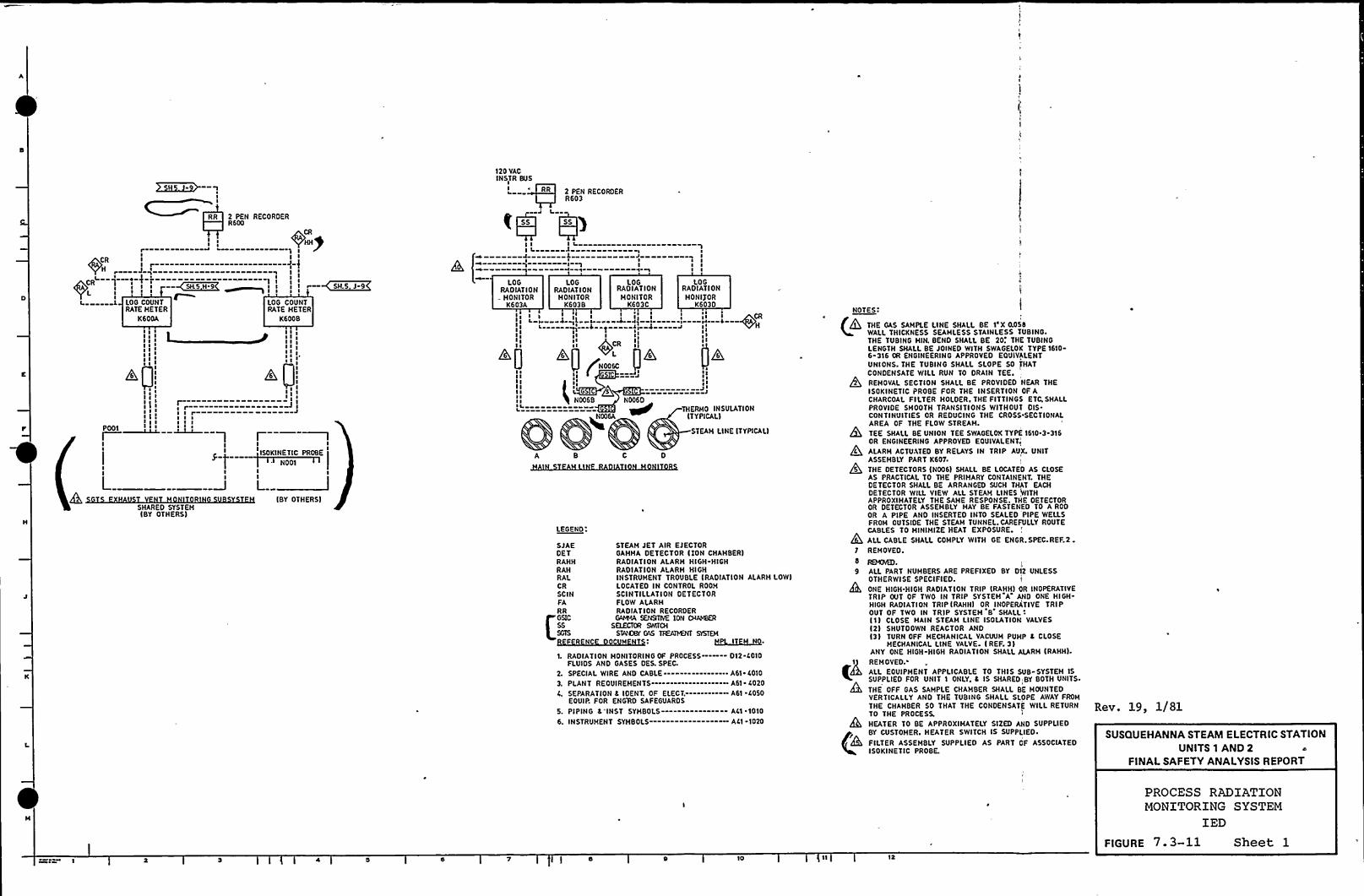
I
L
s g ~
g g gsss~ s
g g s
g g s
ggI g
s ss
rs r rs s s
s s s
g g
g g
g ~ g.
a).;g
gI
~
J g
J
I 1
ISOKINETIC PROBE
N001
(BY OTHERS)SHARED SYSTEMIBY OTHERS)
G~gs
RR 2 PEN RECORDERR 600
s +-pr—---—-—— —-———-——1 g
CR
H s grP ) s
L > y g 6 gs . g I
g I —~5k 5 9 s I s g r— SIL5J-9
g. i LOG COUNT LOG COUNTRATE HETER RATE HETER
K600A K6008
120 VACINSTR BUS
L ~RR 2 PEN RECORDERR603
~6 '6~I g
s
g s
s
3
Js s
g'g s
A 8 C D
LEGEND:
SJAEDETRAHHRAHRALCRSC INFARRGSIC
F RENC
STEAH JET AIR EJECTORGAMMA DETECTOR lION CHAHBER)RADIATION ALARH HIGH HIGHRADIATION ALARH HIGHINSTRUMENT TROUBLE (RADIATION ALARMLOW)LOCATEO IN CONTROL ROOM
SCINTILLATION DETECTORFLOW ALARHRADIATION RECORDERGAgs14IA SENSITIVE ION CggAMBER
SELECTOR SWITCHSTg)6)Bg'AS EATAI)69(T SISTEM
OC ~I~N ~
L RADIATION MONITORING OF PROCESS--- - 012.C010FLUIDS AND GASES DES. SPEC.
2. SPECIAL WIRE AND CABLE------------A61. 6010
3. PLANT REOUIREMENTS----.-------.--- A61. 6020
gl, SEPARATION 4 IDENT. OF ELECT.---. --- A61 6050EOUIP. FOR ENG'RD SAFEGUAROS
5. PIPING 4'INST SYMBOLS--------—----- AL( ~ 1010
6. INSTRUMENT SYHBOLS—---------------.ACI -1020
LOG LOG LOG LOGRADIATION RADIATION RADIATION RADIATIONHONITOR HONITOR MONITOR MONIJORK603A K6038 K603C K603D
gg
gs gg g s ~CR
g. t 3 L s ~ w- s~ sg'---—-Np--6--0--—-Jg--~------'ss) H
g g sgg ss gsgg gg
ALP k.P ~ gk. tjk,s
sg ~s
J ~ ss A ~ s
gs g G
N006 8 N006DI.-============= ~ THERMO INSULATION
N006A (TYPICAL)
STEAM LINE (TYPICAL)
i
0U BING.
E TUBINGTYPE 1610-
LENTHAT
NEAR THEOF A
ETC. SHALL0 IS.
SECTIONAL
1610 3 316
X. UNIT
D AS CLOSENT. THE
AT EACHWITHE DETECTOR
EO TO A RODPIPE WELLS
LLY ROUTE
. SPEC. REF.2.
2 UNLESS
R INOPERATIVED ONE HIGH-
TIVE TRI P
VALVES
P 6 CLOSE
LARM (RAHHl.
8 SYSTEM 15i BY BOTH UNITS.
E MOUNTEDOPE AWAY FROM
wlLL RETURN R(g~ ] 9 1/81
SUSQUEHANNA STEAM ELECTRIC STATIONUNITS 1 AND 2 ts
FINALSAFETY ANALYSISREPORT
NOTES:I
THE GAS SAMPLE LINE SHALL BE 1'X 0.05WALL THICKNESS SEAMLESS STAINLESS T
THE TUBING HIN. BEND SHALL BE 20. THLENGTH SHALL BE JOINED WITH SWAGELOK6-316 OR ENGINEERING APPROVED EOUIVAUNIONS. THE TUBING SHALL SLOPE SO $CONDENSATE WILL RUN TO DRAIN TEE.
jh, REMOVAL SECTION SHALL BE PROVIDEDISOKINETIC PROBE FOR THE INSERTIONCHARCOAL FILTER HOLDER. THE FITTINGSPROVIDE SHOOTH TRANSITIONS WITHOUTCONTINUITIES OR REDUCING THE CROSSAREA OF THE FLOW STREAM.
TEE SHALL BE UNION TEE SWAGELOK TYPEOR ENGINEERING APPROVED EOUIVALENT.
ALARM ACTUATED BY RELAYS IN TRIP AUASSEMBLY PART K607.
THE DETECTORS(N006) SHALL BE LOCATEAS PRACTICAL TO THE PRIMARY CONTAINEDETECTOR SMALL BE ARRANGED SUCH THDETECTOR WILL VIEW ALL STEAH LINESAPPROXIMATELY THE SAME RESPONSE. THOR DETECTOR ASSEMBLY MAY BE FASTENOR A PIPE ANO INSERTED INTO SEALEDFROM OUTSIDE THE STEAM TUNNEL.CAREFUCABLES TO MINIMI2E HEAT EXPOSURE.
@ ALL CABLE SHALL COMPLY WITH GE ENGR
1 REHOVED.
9 ALL PART NUMBERS ARE PREFIXEO BY 01OTHERWISE SPECIFIED.ONE HIGH.HIGH RADIATION TRIP (RAHH) 0TRIP OUT OF TWO IN TRIP SYSTEM A ANHIGH RADIATION TRIP(RAHH) OR INOPERAOUT OF TWO IN TRIP SYSTEM 8 SHALL(1( CLOSE HAIN STEAM LINE ISOLATION(2) SHUTDOWN REACTOR AND(31 TURN OFF MECHANICAL VACUUM PUM
MECHANICAL LINE VALVE- ( REF. 3)ANY ONE HIGH-HIGH RADIATION SMALL A
1$ REMOVED.
t~ ALL EOUIPHENT APPLICABLE TO THIS SUSUPPLIED FOR UNIT 1 ONLY. 6 IS SHARED
THE OFF GAS SAMPLE CHAMBER SHALL 8VERTICALLY ANO THE TUBING SHALL SLTHE CHAMBER 50 THAT THE CONDENSATTO THE PROCESS.
HEATER TO BE APPROXIMATELY SIZED AND SUPPLIEDBY CUSTOMER. NEATER SWITCH IS SUPPLIED ~
FILTER ASSEMBLY SUPPLIED AS PART OF ASSOCIATEDISOKINETIC PROBE.
gg 10 g2
PROCESS RADIATIONMONITORING SYSTEM
IEDFIGURE 7.3-11 Sheet 1

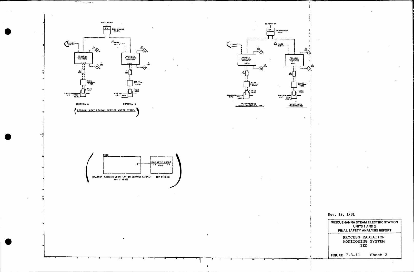
IIDVlCall alSnov Scan Rus
Rk2 RIII RtCOROIR
RDOORR
2 Ita RICDRDCRDCO4
(2 CLUDCDU)'A
I
L
ICC.~Du'I D'
I
.—R„c C4VDC
DUS A
L I,
( CLUDCDuS''
I Q4
RROCCSSRLDILtIONIADNITOR
fLulo TTOW(UR) wCLL
CHANNEL A
II IO
I I L RA
0=-=.SC INNOII
RROC'CSSRADILTION
~AONITOR
I +RA
CHANNEL 8
II4 II
I
I II
Q RR"-,-
'SClNNOIC
(UA) WCLI,
RROCCSS'2 LOILTION~AONITOR
RCOS
L
RCACTDR ctatTNCCIDSCD CCDND WLTTR sttsta.
RROCC S'S2LDILTlOll~AONITOR
II L RLI ~L
~AW'
I
SCTNNODD
ISIADISO'UR) WCIL
i
Stoatt TattotIIURRT sraaoR
fR H AT R MOVA RYI )NAT R Y M
PO02
ISOKINETIC PROBE
(BY OTHERS)AU (BY OTHERS)
Rev. 19, 1/81
SUSQUEHANNA STEAM ELECTRIC STATIONUNITS 1 AND 2
FINALSAFETY ANALYSISREPORT
PROCESS RADIATIONMONITORING SYSTEM
IED
12
FIGURE 7. 3-11 Sheet 2

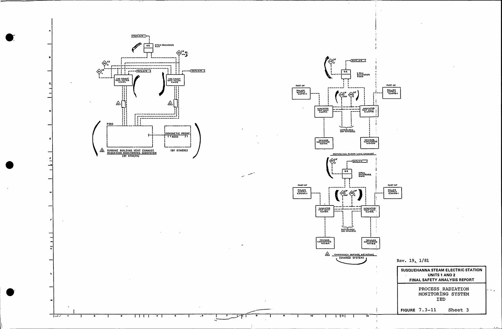
SuS,K 9lI
I. C.LOC COVIIT
RATC rkCICRKtrICA
LOC covu'1RLTC Net CRKtrlto
~0!11 II I II I
1 I~ I II I II I 1
P003 I »I
~ I~ II I
I I II I I
Ir- 3111 r 31' r—---—-—-——-"—-"I I ~
r-—-~I
ISOKINETIC PROBE
)N003
iPCN QCCOQDCIIQrr I I
I I
Ir J I 9 I
I II Ir rW
J J I II II II I r ~aS. K"+I I
PA'RT OCDPovvC RSVPPLYK4094 I
IIIII
luolCATOQTQlP VulT
lC409 A
T PCl4'QCCO'QDCRQLOS
PART OC
PoviC RS'VPPLY«40441
I
~ II
IIIII I
~41CRLOCKIDY OT OCCAM
luDlCATDRTQlP VulT
K4090
1
1
IIIII
QAerr r~44
lI
I
II
1
~-o;)I
j&L TURBINE BVPLOING VENT EXHAUSTRA IATI N MONITORING S B Y T M
IBY OTHERS)
L LIBY OTHERSI
SCNSORCONVCQlCR
NOIOA
SCNSOQCONVCQTCQ
~4010b
QC.CV'CLluo CLOD'Q WALL CTNLVST
uSK +II I
ItR IC PCNRKKORDRRRCJO
PART OCOPourCRSV'PPLYKPO9A I 1
lII (0-
II
LPART
OC'V~V
r K4094 I
r
lutwtATOQTQlP VNIT
KiriOA I r——II
1I IIl II I
I
QSY otucRsl
INDICATORTRlP Vul'1 lIL trio b
Cou'vaMRNO I 6 A
'SCNSOQCONvCRTCR
No too
2 CNCQDCNCY OVTSIDC AlQ lNTAII
ISHAREO SYSTEM)Rev. 19, 1/81
SUSQUEHANNA STEAM ELECTRIC STATIONUNITS 1 AND 2
FINALSAFETY ANALYSISREPORT
PROCESS RADIATIONMONITORING SYSTEM
IED
10 I »IFIGURE 7.3-11 Sheet 3

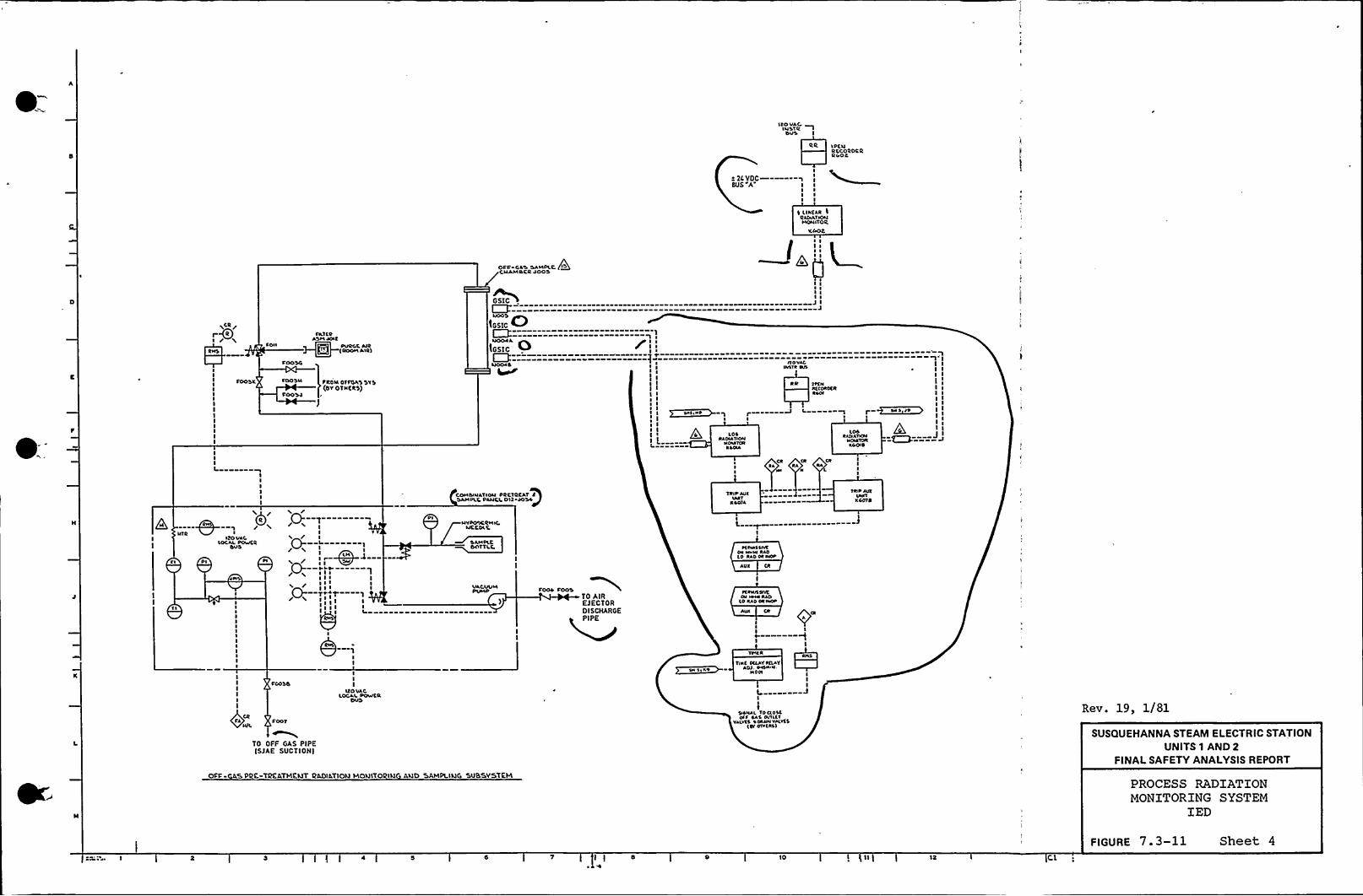
IXOVARINSTRELIS
l(CNRCCOROCRRIOR
I~ 2LVDC———-qSUS A I I
I ~
I ~
I I
E LINEAR IItSPLAT lONMONITOR
CAOC
CNAMOCR POOR
~CR /I /
COII
CATSltASM AOIE
IROOlL Alit)
G~SI C
IGSIC ~0IGSIC
Y'
lII IJ I
J
COOSC
IIIL
IIIIII
COOSN
COO SR
PROM 0 (ET(AS O'I S(OY OTNCRS)
COMblNATION PRCTRCAT 0'bAMPLC PANCC 0'll ROSA/
I
I( '
II I
IIl II I
I
LPSRAPIA SION
NPMVCRNSOIA
TR10 APXLAPT
0 SPIA
ll0 VARINSTR NO
CR CRRA
If(NlNCORICRRSOI
L00RANATKN
NORTONAS OIR
TNS AVXVN(T
N AP(0
I II I
I
I II I
II
II
J I
Cl Pl
(b'EO
VAC
/0- lII/ I0- I/ N I I
MLN
I(0- PNt/I I I II ( ~ I/ ((I I
/ v ( I0- Tv(T 1
I(( I
Pl~IVPXPICRMK,
~ICCOLC
SAMPLCOOTTLC
VACWMPLPAP COOP COOS
TO AIREJECTORDISCHARGEPIPE
M(NOSERON Nl Nl RAO(0
CARIN�
(NSP
A OX (R
KANNS(VCOl le+0 RAO
'LO RAP litNv(P
CA COOTNIL
TO OFF GAS PIPEISJAE SVCTIONI
III
IXOVAR.LOCAL POVICR
SN I K'PllN( SILATRELAY
AOI PSSNVN,N OP(
II II-
ORNAL TO CLOSERIC SAS 0/ILL'I
VALVSS 'S (ANNVALV(S(SY 0(NLRSI
Rev. 19, 1/81
SUSQUEHANNA STEAM ELECTRIC STATIONUNITS 1 AND 2
FINALSAFETY ANALYSISREPORT
OFC ASPK TlKAT(RELJT DAD(ATIOLJ LROLIITORILI ALIO oAMPLILIG 'SUBSYSTEMPROCESS RADIATIONMONITORING SYSTEM
IED
I I s 12
FIGURE 7.3-11 Sheet 4

h
0

e= NlSllv)Il
Sll S llIII
AH
t PtNRCCORD'CRRC OS+
TPTNRCCORDtRel Oo
OPART OC
SVPPCV
«409A I III
Il
III
II))IL 'I
II
PART OC
SVPPCY)I ICDO981
I
PA,RT OC'
Powt RSVPPl.V
«DO9l \II
II
Ill
PART OT
Povlt 2SVPPCVI'KPD9'8 Il
II
IVDcCATORTRIP UNIT
«Pl'8 A1 TI II II II II II I
INTC.RC.OC1((SY Ollitt))
OICwCATDPTRIP VVO
KC CSD
INDICATORTCDP VNIT
C C)I0A
~CTCRlOCKSV OC sitRS)
INDICATORTC)lP VNCT
Kolob
CONVERT~COCS A
StNSORCONVCRTCR
NOISD
SCNSDRCONVCRCCR
AID ISA
SCNSORCONVCRCCR
NOID8
REFT)EL) C)() FLOOR CC)())4 EXHAUST
SNS,A 9III
ACl
RR t PCNTtCORDCRR CrO9
PART OPDIIIII
JIIIII
IL
IIIII
PART OP
POVICRSV PPCY
I KCso9DCIII
I
INVCRTCRI
ITS VDC -- «„9„—TQN~DD 9I
I
I'Sll I C
FILTERASM
)ANPCR PT ~
ISOKINETIC PROBE I
INDICATORTRIP VVIT
K4e)TA
I Il lIl
CNTCRVDC«(O'C OllltR))
lVDCCA)ORTRIP lhllT
Ko CT C)
F~SN )~P'
IIC.piMl)
~)VCR)CRItS VDC 'SN 'S Cr«D998 ICONDESATE
SCNSORCONVCRTCR
NOCT A
'SCNSORCONVCRCCR
Nol)8
IS)l A. C-CO
Rev. 19, 1/81
+t SCTS 'EXHAV'STVENT @AD)AT)ON NOIR)TO)E)N(c SL)SSYSTEP)
(SHARED SYSTEH)DRAIN
TYP(BY OTHERS
SUSQUEHANNA STEAM ELECTRIC STATIONUNITS 1 AND 2
FINALSAFETY ANALYSISREPORT
PROCESS RADIATIONMONITORING SYSTEM
IED
l ) 8 10 12
FIGURE 7. 3-11 Sheet 5

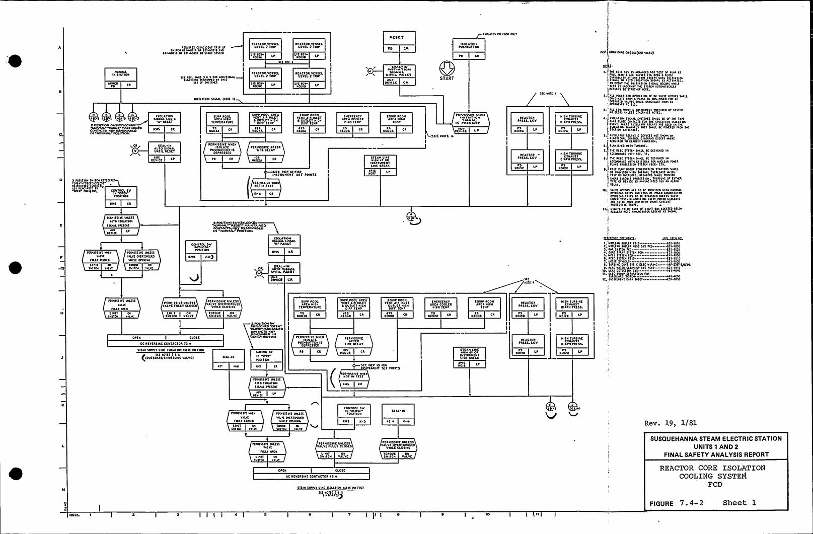
Rftflkts cola(ID(av ikIP ofSVIICH C214v0214 Ok 121A02IS AVI
$ 2IHVY)IC Ok $2lwnlo 'io 51AIT Sisi(ii
RtaCTOR Vt$5ELLEYKI. 2 1RIP
Lls StlNo 1 la
5n R 1 I
REACTOR VtssELLEVEL 2 lait
LIS Stl LPN01IS
SaCSCT
PS ER150LATION
PVSHSViiok
PS
150(ans Ho fDoc CILT
FCP CSC«SIAC Olgok(CSI-IOSO)
Es
N ANVILIIIITIAilok
ARHtoPS
$(l a(s. DKa 1 1 5 sck Aoslvlaacfacvlos l(ISOVID YT IHI$
5(l CS Svllocs
Ialnlnol SICAAL (ROTE I)
RfacTDR vc55cLLEVEL 2 1RIP
Lls StlNO)IC
REACTOR VC55CLLCYEL t TRIP
LIS Sf i LPNolio
/'
/CCAL IH
IHIP I AVIONSIOH AL
UHTII SIICCYAVX
OCYICC CiaSTART
nf IIOT( ~
IK Iclc $ 1$ Is aaaaac(0 sok 1c51 as pa ~ 41
II(AILONI AYIID IIOtPlla'II(aai. 15 4'CIIlll(~+'a fV(a'I TK lalnailoi SI(AAL OCCUts WILEnsv is ao(kvav TK svncH aviaanca(cvRETIRVS lo SIAITHP SHOE
D P 04A 4 ~ 1
2 PUOIYRW OW CDYIOCHDO~Rsaor MawvAIHCD
OOHVACVD ~ NRMOUAOLRIN NORMA POSITION
I COL AT IVIIsicaaL LUCIO'I'K5KT
a Ck/V
SCIL INAUTO SICNALUN«L RCSCT
AUXDCV ICE LP
~tRHI5511( Okt$5AYVO Is(EAT IVI
Slcaac NC5taVAva
Dtncf
~tNH5511( ilkaVALVE
rlaav EaouslUili Oi
SVITOI YALV
SCNH55(YC VICSSYalv( OIERTOV)IRDIHILC CP(alaC
Iokoil OiSvl TOI ia
S Fonna Svna a( ILDCIE
ilv KHOIAAE laDi(a F051)l(H CONTROL SV
IN OP( IP05IEION
RNS Ck
$VPP POOLAkfI RICH
TEHPERATVRK
NCola C1$
SUPP POOL AREAVENT Alk INLtfI OUTLtv RICH
DISS ltHP
NC044~ 1$
EOVIP ROONYEN T Aik IALKT~ OUTLtf NICH
DISS IfHP
~ TsNCOIA
PKRHISSIVt ViitNIsolaic
PVSHSU ITON ISDfPkf SSKD
PtkHI$5IVK AfvtknHC OKLAT
PS CR IDSHcota CR
KC RCP. IO PoitIHsfkiiHCII'f scf POINTS
Sf tHISSIVt WKND'I la t(51
CHC Ck
CONTROL SW~ICLOSCPOSIT HW
CRP
ISOlATIONacHAL LOOIO
0 RDSOY
RHS CR
DCAI INAlivo OioliALUNTIL RDSDY
0 POSITION DW VLOCHD0'NORMS. RRSDV MAINVAI~4$O
COWS~AUTO ~RRMOVADLL
fHERCKNCYAREA COOLER
NICH TENP
NCOCA1$
5T CAN LINERICH it Ok
INSTIUHENTLINE DREAR
~ PISNO I 1
LP
KOUIP ROONAkfI RICH
vfHP
Ncooa1$
A$~04
PCPPVLLIVI VHCNIHITIATIOHslaHAI
IS PAIS CNV
AVIDcvtcc
SCC NOTE 4.
I
REaclokPRKSS. LOV
PSNOISA LP
REaCTORPRESS. LOV
PSNOISC
5tCaDTE ~
HICN TURSINf.KYHAVST
DiaPH PaESS.
~5Noita LP
PsNOI20 LP
HICH TVRSINKEYHAU$1
OIAPH PRESS.
Ll OCR Sik OICallloi Cs DC Yllvt HDTDR$ SHALL
iCIICI Aif Ska I FLALI DC as.soKI foR a
, oifaano vilv(s sw(L aiciaaif ska Av;. (KALE<1 AC Cia.
1 ~ 4ll EON SK«1 a Iasiaonav PRES lifo cv $ 151(H"0 n$ 1) ac(55 OTKkai5( Nono.
Is(lan ol SICAAL 5ViiCKSSHA(l cf CS TK 'fliclail CLOS( CDNIAC'IS Foa DC SPCClfl(0 Isclal loEvlal. lick( alvllllkvkllavs aif II5ED Ia 'TK150lan(H aaaa(LS TKY salll 1C Soak(0 fkoi THES lail oi lanla l(5av«LIAAT Illai5 4 DCVI(fs NOT SHOR af0 CNOUIL Coaiall DIACIAHS llCESI HKA(I(ovla(0 10 CLAAlfv facnoiflkalsKD VIIH Tike la( ~
TK RCIC ST5nH SHALL cf 0(SI(AED IaAC(otsaaCt Vllkk(t n,THE RCIC 515T(N 5HAlL 5( 0(51(NED litA(CDksAICE VITH SAli(IIASok NUCLEAR SOI(k~laa'( PIDRCTI ON 5YSI(H I(EC ~ 2)Y.ICIC Pilia H)TCR CoiliaiTIa 5IAITCIS SHALl1( IIOVIDIDVITH tKIHiL sita(DADS WIaIII1 Oi Ov(k(DAD lk(li(R5 SHALL PROVIDE
SKNT CIACinv PROT(C'noi. vklvtlac OS tlofk'Iii( Of 0(YICC Is Ala'UVCIlTED YIA All ALAINIfllI10.„'alvt Hlnk5 Aat To sf SRDYI(f0 VITH.TKNIAL
OvtalCAD TRIPS Aao L0$5 Of POIA ANNIHCIAIDIoitklcls TRIPS '(0 1( CTSA55(D URCSS YA(vtUIDCI itSY~ Ia Aiolilca TlLVE HDIOR CIICUI15Akl 10 IC PIOVIND Viol 5HCRI CIRCiillSaonC'nv( lllSS,
nt Lloi'1$ TD Yc PAAT 01 LICHI 101 LCCITED a(caI(ciaal RCIC AANUvclank Ltc(ND AS SHIW.
II
gSI ~VUSE)KESIb ~~4l. NUCL(aa lollCR PCID Nil 1010T,,VDCL(ak iofllkH15( 51$ fCD Kll 10201 IHR STREH SCD ~ ~ Kn 1020~ . Cckt 5NAY ST5TEH fCD~ ~ ~ ~ ~ WTI IDSD
C. ICIC Svsna PCID ~ Ksv 1010
c/iikcfK C(H1 5T5 C t(CC VlkRC Ytf.Eisa~lac0, KlC VARI CL(AVAV515 PliD ~ <Sl 1010
10. Ltaa DCTCC'ntH Sfs ~ ~ ~IM040n. fllC toll~ SflliAn(H fck
12, la5TIIPEV'I DAia SK(f KSI 20$ 0
~(IHI55 IYE Iaaf 5$
Yalv(Sialv Difii
LIIIIIV 1
L IN I 1SVITCH
ONVALVE
PERNI$5IYK UNLESSVALVKfVLLYCLosto
TOIIOVESVITCN
ONVALVK
PKRNISSIVK VNLKSSALVK OVCITOROVCD
VIIILCCLOSINC
I POSIVlOH CWNavux Hco 'opcsl/
'CAUSE" IIAIHTAWID
SVPP tOOLAREA RICH
TKHPEIIATVkf
1$NCO)S
4TSNloa ~ Ck
5VPP tOOt. AktaVKNT Alk INLKTI OU1LET RICH
DIFF TKNP
COUIP ROONVfNl Alk INLET
OUTLCt HISHDIFF 1ENP
~1$NOD IS
tktkCKICYAREA COOLER
RICH TEHP
scots1$
EOVIP ROOHAkta RICH
TfHP
NCOOS1$ PS
NOISS LP
RtACTORPRKSS. LOV
PSNo ita LP
HICH TURSINKKYHAU51
OIAPH PRESS.
OPEN CL05K
OC RCVCRSINC CONTACTOR Tt ~
51tla 50tilv llK 15ikailoi YllYC HD 1001
C5tl aoTt5 2 4 5
(DVTDDARQTNIOVTLINCVALVC) 5(AL IN
COIViik $VIR OPCN
~0511 NH
PERHI$5lvf VHENI50LI'lC
PVSHSUTTON ISOKPRK$5(D
PS Ck
PKRNISSIYEAF'ICI
TINE DELAY
HCOtaID$ 51KAll 'LINC
HICH ~ P OkINS'IRUHCIITLINE SRtak
acacvokPRESS LOV
PsN 0190
PsNOICD LP
HICH TVRSINKCYNAUST
OIAPH PRE 55
ar
~Eaalsslvf Oa(5$avis 150(anoSICAAL Sa(5faT
AYIDC«cf
SEE REP IO SCYAVTIYIVKNTSET Pot(To
RHI55IV( WKNOT Ni ic51
Iiic Ck
~ PICIIDK LP
PCUH55IYC HKNV1 lv(
SILLY CuotsCoo 1 Ol
SVI ICH Ya(YE
S(IHI55 IYE Ilk($5IALVE OVER TOOK D
IHllt (PCNIIC
v(IDIE aTa va vt
CONTROL SWIII CLOSEPO$ I«DN
RHS X 0
5(AL IU
42 ~ N 4
tla 1
J1 1 ID
Rev. 19, 1)r 81
~EIHISSIYE iikt55VALVE
FIILY Oifa
LIHI1 OISV TCH Yl
PKRHISSIVC VNLKSSVALVCSVLLT CLOSED
LI NIT ON5VI'ICN VALVE
VOROUCSVI'ICH
ONVALVE
PfRHISSIYt UVLE55VALVE OVCITOIOUKD
VHILE CL05INC
SUSQUEHANNA STEAM ELECTRIC STATIONUNITS 1 AND 2
FINALSAFETY ANALYSISREPORT
Nr'40
OPE N CLOSE
AC REVKRSINC CONTACTOII 42 ~
ST(IH 50PSlv liat 150lAIIa Valvf NO foci5(( aoits 2 1 5
(IN DDAR0)Q
REACTOR CORE ISOLATIONCOOLING SYSTEM
FCD
FIGURE 7. 4-2 Sheet 1
lc)

0

A
I
u PR($$ RR0
15 ~
LO PRK$5 DR$IR TEIP
1$
~ lROHK'IRICCONDtNSCRWC, TAIJGW lfv(L
LSH 40120 LPPSHNOI24
PSHNDITC LP~ SN
NOIIAPS
CaAFMUGM IR (ufMUCMN FR($$ ~M~SRCIC STEAM (ac RCIC KTtAMLfc"P~A(" J "Qc e)55 JNUIT4PIS LP NOIR
4PIS LP
ICDC TIRIS EftlMI PRESS
PSN00$ A LP
CR
) —-jNOO14
~5
5(t Holt 4 5(( NDTt 4
A CR/
4PS
R CR/
RCIC PUNPSUCTION
Io FR(5$
NOSOPS
RAROHCIRIC
( CONDtN5tlYJC TAISlo Ltv(L
LSL
RCIC PUNPSUC'I ION
LO PRESS
0004 LPPS
5(t NOI 4
RCIC TURR INlCT51KAN LIIICVlltcDRN
POT IU LEVEL
LSHNO I 0
A $ CCNOTC II
( DEYCE
i~/ SCCNOTE II
IMIHUf Ll&Ilo YLVfav Ifl fit(1
ClouoLINI I ON
5Y IIOI WLVE
NDT flllfOf(NllHII ON5YITOI WAVE
SCC
/ HOTC N
ROC TIROS EYHvlc illvuvf lou i
NDT TIALV ONN
LIHI ONSYITGH VALVC
stc/ NOTE II
FOGO DOSED SNIIDI ARM(D
llHI1SVITCH
$ CK
/(T/w NOTE II
ON POVVEN (DSS OR POVV(R IDSS
ISKK NOTE
lho MCTAI0 C(VIDCIJSCIAYALIAJMPUMP 1 GJHJD JYHA
f5UPPI,JCD WIZJ4 IIJADIHCjI
VALVCLINIT5V YALVKN01
1 ULLY OP(N
VALVC LINITSV VALYC NOTFULLY CL05CD
VALVC t5I f050PIALY CLOSCD
RC IC
ISOlllIOIl(C(loi I
RCIC LOGIC~a(R flit5(CI IOI I
RCIC DIV 2
ofl Cf5(RVICt
AHV ACIC YALYC:Dvth(OAD OhFOVffh .(Dss
(NY I MOV TESTSMITCH IN
TEST
DIV 2 HOV TESTSNITCH NI
Test
A CR
/fl CR/
WLVK POS SW VALVE POS SWVALVE HOT VALVE NOT
FIALY OPEN FIALY DDSKD
CUNT OIJ (NUT ON5NITCH VALVE SNITDI WLYE
TYP AIL MOTDR OPERATED WLYKS
LINI1 ON LINIT ONSVITCN VALVE SYITCN WLYKTYP JLL JJR OPERATED VALVES /~
Movrv N/RCIC
~YHJ
( DEVICE
NOTE II
III(RT(RflIlUI(
( C.
SCC NOTE ~
sccq* NO'fE N
RCIC K(VSOUT 0
~ TAVIGt GIN(tJI
RHI CR
API0(YN(
* Ch
RCICOUT Of5(RYICC
AUXDKYICC CR
sccNOTE 4
RCICISDlAIION
$(C'fIOI 4
AVIDl 1 I (t
AVID(VI(t ~/ $ (C
/QiHOTC II
RCIC lOGICPOCR (IIL$(C11OI 4
lVI0(flit 'CR
RMS CR
/ 5tt9 ROTC n
VALVC CSJ'OODHOT FULLY OM/4
AUtDEVICE
/SCtQA HDTK 11
VALVC CVJ FOOTMof FILLYOPLH
/NDft II */ I
CA(AMLt IVAJJO JGIVJVIS
Vv AIIJVlFIJV
NOTE II A/IHJ C VI IIVIQ AllvllllJOJ
ovluJHP IIIIHCAMIs CnII
/RCIC INITIATIONSIGNAL
I C I
TIRIIIKSvftlvllav lvlTIIH(NTIIIOINARIO 4 vuvt IIOICA(la5
5 foll(la SV MvurJYIIP/$10PSJIING RtIIRN
10 JVIO IIOI51MT Dl51 4 I
CONTROL SVIN OP( 4POSIYION
CONTROL 5VIN
'CLOSC'OSI'(ION
CONTROL 5VIN
START'0$
11ION
RHS CR
SKAL IN
UR CON @412 ~
(CR VILVt IO f045 OCT$ (AL'IN
AIN CONT
Sift VN(NC 'KIHAU$1
1 05$ IS1 OftN
PtRNIS1 VCR IN
VALVEfULLLINI1
SV11CN
LINIT ONSVI'\CH VlLYK
OPCN
PfRNISSIYC UNl($$YALYKFVLLV OffN
StlL IN
0* CONTt ~
PKIGIOSSIVK lhl(NVh'lYKVULLT Oft N
LIIVIT . OHSIJIVCM VALVE
. PDWSSITE ((E(55YALYKOVCRTORCU(D
YTIULK CLOSINO1DJOVC ON
HITCH VALVC CONTROL SVIN STOPPO5 I 1 I ON
RNSColoh $(CTA4LC Tl
TABLE IIDC RtvtR5INC CONTACT ('Tfl ~
RI JJA PPLY 'U4 VO VvJVOHT Mo VOITYP f0R coo(JH4 wAICR SUPPLY YALYRIJo IUJAT
CA
/ TTIIP fINCDON(5(f TA8LK tt
~tf, ~
TllfTHIOTflt VILY( Df(N1llf TIRDTTL( VJLVt CLOG(0Covulol YALY( Df(NGOV(INCR VILVK CloltD
: START STOPDKVICE NYND(h I IVDICITING I(HIT
VALvt No voltNOT fULLY
Cl05(0
LI NIT ONSVITCH VALYK
tICRGI(t TUC
1 OCR(IS $(C TIIC l(llf
AII0(YJNT
'TIER 10 4( LLRISTllltDOD $(C l($(I Aual(I(ILLY~VCN VILVK IDI5 CLIN(0
ALARNFUNCTION
(StE TARLE D
DKVICt CRNO,
P(RNISSIVt VHtN1IHKR 1IN(5 OUT
.DE CDNTACTD(5 7to8AROIIETRIC CDNDENSKIR VACUUFFPIPIP
AIAAJI 1aCI la
Vtc AulM
RCIC f(OJ LOI
TABLEIIIIIIIIHH
vl
f5L VCOT
D(II GlIII
$(( NOI( 4
5(t NOI( 4
LP
III( OfI IIH
Hlof
Rev. 19, 1/81
SUSQUEHANNA STEAM ELECTRIC STATIONUNITS 1 AND 2
FINALSAFETY ANALYSISREPORT
REACTOR CORE ISOLATIONCOOLING SYSTEM
FCD
10 '12
FIGURE 7.4-2 Sheet 2

0
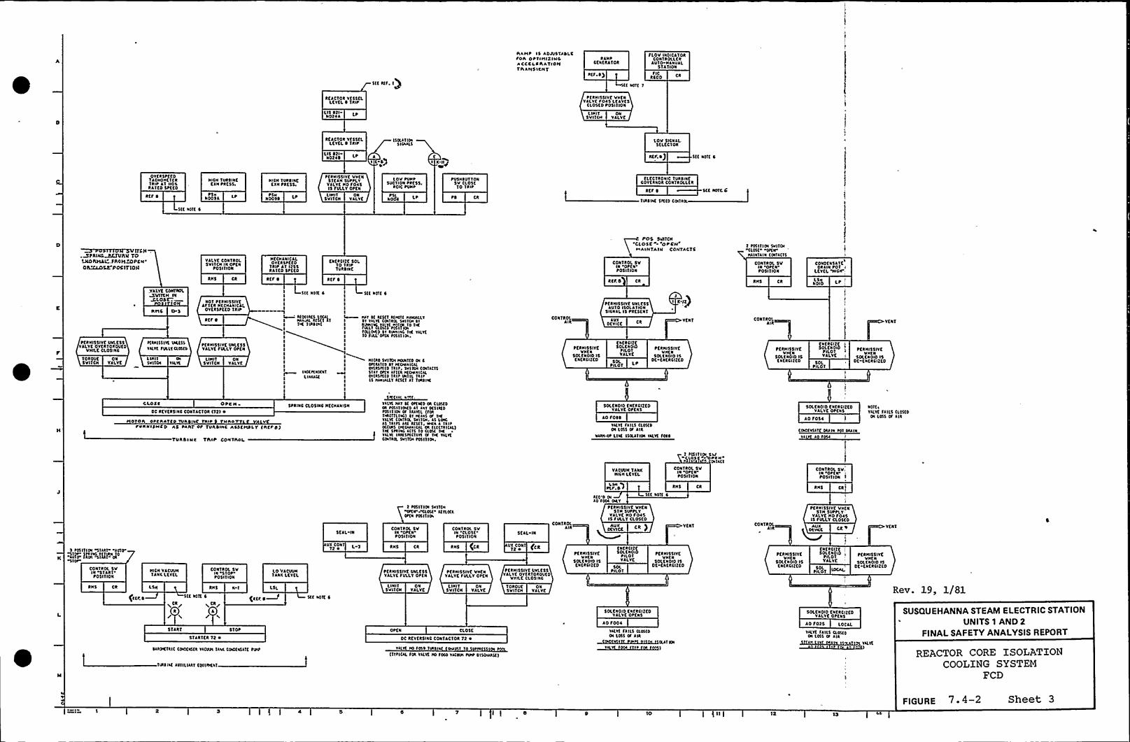
5(( «S. TP
hATIP 15 ADAI5TADLCtoh OPTINIZINGACCCI,AAATIDN1 h ANS IfNT
RINPCKNERJTOR
a(F 4$
l( NOT( 1
FICRSOO Ck
FLOV INDICATORCONTROLltk
AUIO HJNUJLSTATION
kCACTOR VTSSKLLfYLL0 TRIP
tCRHISSIVC VHCNYILVCSOISLCAVKS
CLOSto tosnloaLls 421 ltN02IA LI HIT
svnEHON
VALVE
ktJCTOR VESSELLCYtl.0 Tait
LIS 421NOZIS t-4)
15llJ'I ID«5 NAILS
I Kigi
Lov SISNAL-SELCCTOR
atr. 4) $(t NOT( 4
OYCRSPCEDTACHOHCTCRTRIP AT No\RA(CO 5tt(D
ktt 4
NICN TUASINECXN PRESS.
~SHNOOSA l
NISH 1URSINCtXN tktss.
rsaN00$ 4 L La«IT
5 VWCNON
YJLVK
PKAHISSIYE VHtN51CAH SUttLYVJLVt HO SOISIS FULLY OPEN
loV PUHPSUCTION tk(55.
RCIC toat
aohs
tU5NSUT TONSV CL05KTo lait
tl CR
tLKCTRONIC TURIINECOYfkaok CONTAOLLCR
ktt 4
TIAII«51((D COITIOL
5(t aolcC
5tt NOT( I
~5TTTVTPSVETC H.MFA(~h)E TOM>h)IAL,FAO)5&»PCN'SCECOS2
POSETTO)E
VALVE CON(ROE.5VITCN Ia otCN
t05ITION
NECHINICAI.0 Y(R SPC tDlait AT 1255
RkltD Sttfoca(kent'DL
10 (kit1URSINE
POS SUIT(H«CLOSE» OPCN
HAINTAIN CONTACT'5
CONIAOL SVIN Or( Ntosl(ION
2 tll illol 5»1101ELOE( DPI IPHAIN'IIINCoiil(15
CON(ROE, 5VIN OPENPOSITION
CONDTNSATKI
ORIHI tolLCYCL 'H>SIP
RHS Ck k(F 0 RtF 0 ktF 0 CR RHS Ck NOIIILS Lr 1
(DROUKSVITCN
ONVALVE
PCRHISSIVK UNI.CSSYALVtOYfk'IOAOU(0
VHILKCLOSHIS
VALVE CONTROL~N DiSLOSC
HITS 0 5
LUNIDNTOI Yk«
~(AH15511( UAt5$Y«Y( FULL(Cl05(l
NOT t(AHISSIYCAFT(k HfCHINICIL
OYKR5PCKO TRIP
RCF 0
L I HIT5VITCH
ONVALVE
tCRHI55IVE UN'ltssVALVE SULLY Otta
Wl NOK 4IIII14 «OYI«5 UK«I HIAAL «5(l Il
'l«C TIA$1%(
IIIIIIIIII
I llCtt(a«a(Llllllt
III
5(( ~ Sr( 4
II Hll ll «5tl a«01( Iaalkl1I 'll TILT( EDITIS. 5»llol II
4iI"aRtMll"K"I«I(LID»(2 II kiaa1 a TY( Y«Yt10 SYLL 0«a tllllisa
III
Nlllo TVITEN )KANT(0 Ol II 0«IATID ll laoaal(kI ONISNID Tilt. SHIIEH (OCTA(ISSill DI(a III(kIaoaal(ILI 0«lllltll(lit INTIL TiltI 15 Iaalk(T «5(1 ll Tilill«II
CONTROLJ IA
~tRHI55IVEVH(N
50ltaoio ISta(RSI(to
t(RNI$5IYC Ualf$$AUIO ISOlATION
SICNIL IS PRESENT
OKYICC CkAUX
NflCIZCOLENOIDtILO1VALVE
SNOT50L
VENT
PKRNI5$ IYtVH(N
50(CNOIO ISDC fatkCIZCD
CONTROLAil
tfkalssi YtVI«(N
SoltaoIO 1$tatRSIZKO
LOLtN0lfltILOIVALVE
$ 01.tH.OT
VENT
PKRHISSIYCVH(N
SOLENOID 15Dt-tatksIZKO
CLOSE OPCN
TUADINC Thlt COHYADC
OC RCYfk5HIC CON(ACTOR (12) ~
Otoh OtfAATC0 YUA laf Talk THAOT Vtvaall«IC D AS WART or TUADNVC Asst)IALT (Ntt 5)
StRINC CLOSINC NKCHANISNYILY( HAT «Ott«D Ok CLOI(DOl PDSITIDHD Il lal 0(5llfD~olnlOI CS 'lllltt (IiaTaklilloa) ll Iaial OS THIYkY( EOITIOL lvl'IEH. Il LEAKAl IIIIS Alt l(5tl, HHN I lIltOl(INS E«KEHI»IEk Ea ill(TII(IL)IIK 5IIHN I(15 10 (loll Da ~
YILW Ik«51(ETIY( CS T«f YALY(COI'lkk svlT(H 1051'IIOI.
$0(ENDED cNfkcnfoVALVE OPENS
Jo FollY«Yt Illls ELDS(DOI l015 CS AIR
VAAHAP LIIK IS((ATION Ykit Soll
SOLCNOIO tN(ASIZKDVALVE Ottas
Ao 105I
EOHSITITF (alla Pll DlllaYlltf lo IOII
alit «
Y«W Fills (LDE(DON ills OS Ilk
2 tolnliaLos '0
«
LIrl«I ~OIIACI
2 10511101 SVITO«it(a'loll «TLO(lltta tllnlo
VACUUH TJNKNISH LCTEL
PCF.D i5(l AOT( 4Rll'0 Di
AO IIOI (allt(AHI$5IVf VHKN
51H SUttLYVALVE No rois
IS SULLY CLOSto
Coa(aoL SVIN OP(N~0$ 1 (ION
RHS Ck
coa(aoL sv,IN 'OPENtosnloa 1
AHS CRl
tCAHI$5IVC VHENSIN 5UttL'1
VJLVC Ho FOISIS SULLY CL05(O
SEAL HICONTROL SV
IN Ott NPOSITION
CONTROL SVIN 'CLOSEPOSI'I ION
SCIL Ia
CON1ROLJ la VENT CONTROL
J la Dt's CA 0AUX YEN(
5 PDII1 I DI 5TAIT IYTEP
„-IZo-'I%«EIWD5101
CONTROL SVIN STARTPOSW ION
RHS CR
(2(r. 4
HICH V A(DUN1JNK LEVEL
CONTROL 5vIN Slottosl(ION
loVACUUHTANK LKYCL
LSH RHS
5(t NOTE 4
~CAP iCRP
R I~»
LSL
<Itf0~
STAR'(
STARTER TZ ~
STOP
Tlall« IYXILIAAT(OSIIH(IT
silos TAIC COO(as(k YA(UN TAIKCDOCNEITC tiht
5(f aOT( C
UX CON L 112 ~ RHS Ck RNS (CR UX CON f(212 ~
PEAHISSIYf UNLCSSVALVEFULLT Otfa
tfkalssIYE VHKNYki,VC SULLY OPCN
tCRHISSIVC UIA.E$$VALVE OY(ATOAOUfo
VHILt CL05las
LIHI1SVITCN
ONVAI.VE
LIHITSV ITCH
ONVALVE
(DROUKSvnca
ONVJLYK
CL05C
DC kfVfRSINS CONTACTOR 12 ~
(TIPI(k SEA VALVE HD 1040 YICYUI tv«t 01501AIL()
Ykll HD Soll TIHIIIE
tfRHISSIYEVHtN
SOLENOID ISta(RSIZKO
IÃtacozlotILOTVALVE
~fRNISSIYCVH(N
50Ltaol 0 ISDt tatksn(D50Ltl LOT
SOLENOID CNfRI IZEDVALVE Otfas
Ao FOUI
YILY( SIIL5 ElOlfoOl (055 CS Alk
I » ELI'IKNI I ~ )
PKRNISSIYKVI«EN
SoltaoID IStatkCIZKO
KNOTSOL
EN(ACIZESOLENOID
PILOTVALVE
PKRHISSIYEVHEN
$0(taolo ISDt KNKRCIZEO
$0LKNOID tatklittoYALVC Ottas
Ao FOZS
YILYt Sl i(5 ((05(5OI lOSS Of llkI« Yklt
)
REACTOR CORE ISOLATIONCOOLING SYSTEM
PCD
Rev. 19, 1/81
SUSQUEHANNA STEAM ELECTRIC STATIONUNITS 1 AND 2
FINALSAFETY ANALYSISREPORT
i I 0 IO CI
FIGURE 7. 4-2 Sheet 3


CovttOL SVIN'otfHtosflaoN
tNA Ct
~IAHI55IVI WNN
TALVK fILLTCIOSCD
tttHIASIVC WHIRNo SOIS
VAlvffVLLT CLPICD
LIHI1 ON5IIITCH VALVE
tCRHISSIV'f UNLESSVALVC OVERTOROUfD
VNILK OPCHINO
CONTROL SVIN
Cl05K'oSITION
RNS CR j
RCIC IIITIATIOISICNAL
FI C 2
\VALVE No FOSI
tlaLLT OFCH
LINIT ONSNITCH VALVE
VAlVC HO foISSULLY OtfN
AUXOl V>CC
CONTtol SVIN otKNtoslt lot
RNS
RCICfLOVLov
( FDSL Lt jtttaUSSIvt VHtN
RCIC PUIIPOISCHARCf
tRESS. AYATLkcl.f
Noto Ltts
RCICfLovHl CN
( 'NVo'2
5CAL IN
Ux CON12 ~
RHS cc)
CONTROL SVIN 'CLOCKPOSI1ION
51tkN 5lattI.YVALVE F045
FULLY CLOSED
L IVI1 ONSVITCN VALVE
5KAL IN
VX CON
1 Vtscvt I$ 'tot VALVE
fULLY CLOSED
LIHIf ONSNITCH VALVE
LIHIT ON5vliOI VALIt'OROVf
SNITCHON
VALVE
tfRNISSIVC UNLESSVkLVC FULI.Y OttN
PtRHISSIYE UNLESSYALYC FULLY CLOSED
ttRHISSIVC UN'lfSSVkLVC OYER'IOROUEO
VHILC CLOSINC
PttNISSIVK UNLf$ $YALYtfvLLYOttN
tftHISSIYC UNLESSVALVEFULLY CL05tD
tc AMISSIVC UvlfssVALVR~
VHILC Closaaak
LINI1SNITCH
ONVALVK
TotovfSNITCH
ONVALVE.
TOROUESVITCN
ONVALVE
LINI1 ONSVITCN VALVt
lINIT5VI'TCH
ONVALVE
TOROUCSNITCH
ONVALYC OPEN
DC RKVKRSINC CON1ACTOR 12 ~
NINIWIIFLDI 4TSASS 10 SvtfttSSION CIAINKR YALVK Ho 1010
OC RtvfllSRIC CONtAC10R lttl0
VklVT Ho SOIt 1(5'I SISAIS 1 4 NTAT A Ia(THXOTllf ttt YALYKT NOTE 5
AC ICII I'1 IAT I ON
5 ICIAL 5TEAN 5vttLTVAI.VC 4045fULLT Closto
Notf 5
TUR0INCSTOP VALVCfULLT Cl.osto
CONTROL SVIN 4405KPOSITION
RCICI xi I IXIIox
c 5
I 0 2
LI NITSVITCN
ONVALVE
VALVE No F01I'01 SULLY CL0540
Cotttol 5VNI'CL05C'051110N
RN$ CR )
CONTROL SvIN
'OttN'05I1ION
RNS AUXDC V ICt Lt
Not tftNlsslvtVIICN AU'10 CLOSE5ICNAL IS PRESENT
lINIT ON5VITCH VALVE
L SHIT5VITCH )
5CAL IN 5fAL-IN
Rto'0
fleet
Ho VALVE FOll DCT
RHS ct)
5KAL-INCONTROI. 5V
IN OtfNtosl tION
NOT tttNI55IYKVNTN YALVK
CLOSURC 5ICNAL15 PRESENT
SEAL IN
UI CON f fa'V UX CONt2 ~ 12 ~ F Io
UI CONT2 ~ RH5 CR DfVICE LtAUX UI CON P 0$
tCRHI55IVC UNLESSVALVCfvLLYOttN
~KRHI55lvt UNLESSALYC Oxtt'IOROUED
WHILE CLOSINC
PKRHISSIYC VHENVALVEFUU.Y OtfN
PKRNI$5IVC UtltssVALvffvLLYOtCN
PERHI55IYK UNLKSSVALVESULLY CLOSED
tERHISSIYE UNLC5$ALYC OYKRTORovto
vvalK CLOSHIC
L IN I 1
5VITCHON
VALVETOROUESVITCH
ONVALVE
LLNI15VITCN
ONVAI.YE
LIHI1SNITCH
ONVALVE
llHIT ONSV ITCH VALVE
TOROUCSVITCH
ONVALVE
DC RfVfRSINC CONTACTOR 12 ~
CLost
CL05E
DC REYKRSNIC CONTACTOR Tt ~
Silat 0ISOIAAÃ VAIVT No Toit RIODARO 5
(Ttt fol tvat DISCN VALYK Ho 1011)NTTK 5
PUITP SVCTIOSFYNDIT COHDKTIS~~NNYILYFYICPVDIDTIDTK..S
REACTORLOV
PRESSURC
Nolsk Ltts
REACTORLOVttt$5URC
NOISC LtPC
REACTORLOV
tRCSSURK
ROIS DPS
REACTORLOV
ttTSSURt
NOIUD Lts
ts KNNO I 0 A
RICHDtvvtLLttt$$URC
PS KIINOIOC
RICHDRYVttltttssvtt
N 0100
NICIIDRVvtLL
PRESSURE
ts CIINO I 00
ValYK foot oal'1C vklvt foscoklaf
SEAL NI
Waa)tt tt 7
CONTROL SVIN Ott NtoSI1 ION
RN'5 CR
CON1ROL SVIII CLOSEPOSITIOI~
RNS C RQ
ttRNISSIVl'NKNVALVE FULLY CL05KO
tCRHISSIvt UNLCSSVALVfOYERTOROUKO
VNILE CL05INC
5 tolI'IIOI SNITCH(molt- *UFO. mx-SIN INC tltlNY "NURHAL1 Aol cloil UIIN
CONTROL SVFN OPKNtosITION
(RHS Ct P
~KRNISSIYC VNLK$$YALYKflA.LTOttv
SEAL IN
UX CON IT 1 AI
CONTROL SVIN CL05tPOSITION
RNS Ct )
tttavsslvf vNKNVALYCSVlLY OtKN
SEAL HI
UX CON12 ~
PCRHISSIYC UNLESSVALVE OYCRTOROUKO
VNILKCLOSINC
lI
HI�'I
SVI1CNON
VALVE
LIHI1Svl1CH
ONVALVE
PCNIAassavt UvacssAvf0"caaa$ 4sa AAIAL paw sc N 'F
tfRNISSIYC UvltssYALYCFVLLT OPEN
TotovtSVI'ICH
ONVALVC
tttHISSIYC UNLESSYklvt FULLY CLOSED
SKAL IN
tct 'Pl d)
tfRHISSIVE UNLESSALYK OVKRTUROUEO
VNILKCLOSINC
SUSQUEHANNA STEAM ELECTRIC STATIONUNITS 1 AND 2
FINALSAFETY ANALYSISREPORTLII~It
5vITCHON
VALVEL I HIT
SNITCH
CLOSE
DC REVKR5INC CONTACIOR 12 ~
ONVALVE
TotoofSVIICN
ONVALVE DtvICK LtAUX
OtEN
LIHITSVITCH
CL05E
DC RKVfRSINC CONTAC10R 12 ~
ONVALVE
TOROUCSVI'ICH
ONVALVE REACTOR CORE ISOLATION
COOLING SYSTEMFCD
NOTE 5 YALYE STD lokt VAKVWDRCAKTAL ISOLATION
( ltYP FOIL VALVE FDDT)
FIGURF 7 ~ 4-2 Sheet 410 12

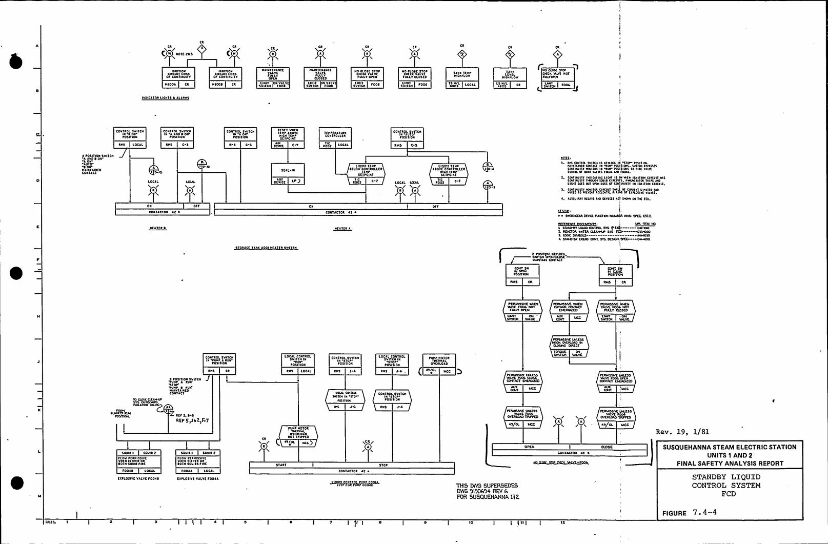
Ck
f W NOTK205
I C NIT I ON
CIRCINT LOSSOf CONT INVI'11
HCOOJ Ck
Ck
4
ICNliltlNCIRCUIT LOSS
OF CONTINVI'fY
t,CR/
HAINTKNANCKVJLVKfULLYOtfN
LINIT N VALTSVI1CH FOOD
Ck
J
NAINT K NANCEVJLYCfUllYClosf0
I.IHIT N VALTSVITCH FOOD
CR /'
/NO CLOSE Siot
CHKCK YJI.VCfVLLYOPEN
SVNCHLIHIT
CR /4/
No Closf STOPCHECK VJLVC
F IILLYCLOSED
SvITCH OOCLIHI1
TANK TKIIPRICH/LOV
lOCAl,NODS
T JNKlfYKLRICH/LOV
ls H/LNCOO
~tko suet STOPCAECK 'IALYT NDTTVILYCfiN
LMTSNITCH
IIIDICJTOR LICNTS D JLARNS
CONTROL 'SvITCHIN SONtoSI 1 ION
CON'IROL SvITCHIN 4 AND SON
POSITION
CONikot.sVITCNIN koNtosl1ION
RKSKT VHKN'IKNP JSOYC
HICN 1ENPSf TPOIN1
TfNtfR AT VRCCON'ikoLLKR
CON1kol SVITCHIN 'AUTOPOSI'I ION
RNS LOCAL, kHS C RNS C 3 CfYKL1 IC
Root LOCAL RIAS C 5
~ POSITION 5VITCH4 JNDSON4 ONAVID'
ONHJINTJHIKDCONTJCT
AI D KI
LOCALIl
R
ON
CON1JCTOR 4t 4
HfJifk 0
I/XAL/A/
Off
D loSf Jl. IN
JUXOfYICC
ON
1 I02002 C-1
CON1AC10R 42 ~
HKJTKR 4
OOV'ID 1 1 NPSKLOV CONTItOLLfk
'IKHP'SKltOINT
LOCJL uKAL
2 4/'A JI'
ICRoot 0 1
LIQUID TfNPASOYK CON'Ikollfk
NISH TKNP5KTPOINT
BI .4
AID 5
II
IttffbI RIB CINIRIL 5vl lot IS ffTLDCA I~ "STOA f05 IT IOA
HAIN'IAIINDCIN'tki'I IN "ktu FVSIIIINS SVIIOI ~ 'IFA$51$CINTINVIITIKNIIIN IN "RVY'DIIIIVNS10 flkf Villi50HSS Of SDTH YALIKS FDDIA ANI fDDAS.
1, CIINTINYITT Itoukllk ltoo IS Ot IACN IOIITIOI Clk<011 HASCINTIIIVllfTHIDINH SBHS ClkiUIIS. ANKNCIATIRTiltS ANDlICHI CCKS OVI SPIN lOSS Cf CINTINVITT IN ICNITIIN ClkCVII,
5 CONT IVIIITYHDIIIOA CIRCVTT W N CUtklkl LNIIIIDANDVIATD ID FAKYKNI ACCIDITAL FIJIAC of fiflollliYkllf5.
4 AUXILIARYkilATS uo CCYICK5 NN SHDN ON TIE fio.
~ ~ STCHCKAR OKYKE TIACTKN IASASKR AN5l SPEC, Csl t.
EEKXEE~hfftQXI IAFL ITDA HO,
5 sfutokif LKIIJD emoL SYS FFf4--—- KAPKAOE IIEACTOR PATER OCNPUP SYS fCD - 0554010S. Iootc SYIADas AAHI0504 sfuAPBY Lksko CONT. 55. OESION,NVCJ CAA4ao
STORJCK TANK JOOI HfJTKR SY5TKII
t POSITPI KEYVXIASWITCH OPTN~IAANTAN CONTACT
CONT 5WN DPCHt05ITCN
PEIIAUSSIYE VANNINLYE Food NOT
FIALY OPEN
ONVALVE.
lo oosc oCul UPSYS OUTBOARDISOLATKN YAL
5 toslTION SVI1CH'PVNP A
RVN'for
VUHt 0 RINFN AINTLINEDCONTJC'I
CONTROL SVITCNIN 'PUHP 4
RIIN'O5I1I
ON
RNS
lOCAL CONTROLSNITCH IN'4
VN'05I'I
ION
LOCAL
CONTROL SVITCNIN
'STOP'OSITION
RNS 5 4
Lofti CtkikaSVI'iol lk 5TOI
~ tS l1 ION
LOCAl Cokikol.SNITCH IN
~siop.tosl'llok
RNS Ud
CONTROL SVITCHIN
Siof'osl
1 ION
44
tVNP NOTORTHKRNAl
OVERLOAD
( 45/OL
TORQUE ON'SWITCH VALVE
FEIDAISSIYE \NIESSVALVE FOOI OPKNCONTACT ENKRIXZKD
CONT
Sotlts I SOVIS 2FLOV tfkNISSIYEVHKN NTHIR OkSOIH SQUID FIRE
FODAS LOCJL
EftL05IYE VALVESODAS
I 4 Rff 2, S-S
RQF 5 )SIT 2) F 7
SQUID I SOVIS 2
FLOV Pf RNISSIYEVkfNKtlkfkOkSO IN SQUIDS FIRE
FOOAA LOCAL
EXPLOSIVE VJLVC 10044
Ck/tokt NOTOR
IHCRHkl.OVERLOAD
Noi iklttfo( Nf/OL
START
pcs/A
CONTACTOR 42 4
VI VTR
STOP
FKVAISSIYK IRRCSSVAlVE food
OVERIOAD TRPPED
45/OL MCC
OPEN
THIS DI|IG SUPERSEDESDWG 919DSH REV 6FOR SUSQUEHANMA 1) P
J'
J
CONTACTDR 4E 4
~EIVLSSIYE IRCCSSVALVC Fool
FYVKAVDADSTUFFED
45/OL MCC
Rev. 19, 1/81
SUSQUEHANNA STEAM ELECTRIC STATIONUNITS 1 AND 2
FINALSAFETY ANALYSISREPORT
STANDBY LIQUIDCONTROL SYSTEM
FCD
I I 0 10 12
FIGURE 7 4-4

I
V
h

n nQ 'I.
4 C C
n neases ~ QQssC A 8 D
j"n nQ esses e.ss
D D t ] 14
DRYTEISEBll DI31(ATNBIN)
(J
FLElsol,E DNAPTESSCL
SR II/IRPIDRIVE uNITS 1
EIH215((SI ' g(A'lsaRVHP ~
(0 tt)
MOTORMODULE
Scei
PRS4ARYCCINTAINMENT
w V LTAGE IPR'EA Dl.lcle0 'C 0
PESLSE PRE AMPLICIERS,EEOOE~0 A 6
w VOLTAG'E PRFAMPLICIERS, XCOt8 0 F
SW
K INTFRMEDIAT'E RA GEMOHI ORS~CN G
II \ 's ~)CSLE~ OLC~CN. A
ENTERMETNATERANGE MONITORS~K SOEIRCE RANCaEMONITORS~
I .. LI. I
e'bYPASS IRM
CH.D>D>C(RS(bt PASS IRMCILAQC'E COG
(IITERMED(ATERANGE CEE ANNE).S0
bYFASSSRMOLA)ACCRD
SOURCE RANGIE CHANNEL'5 INTER)I(ED I AT E RANGE, CHANNELS
REA(TORPROTCRTEOLI QRIP SYSTEM DQ TREIECTOR PR(FTECTEON TREP SYSTEM TS
ECC(huNT PERIODtATE RCOi.RCO0 SEE
SEE Nhtc 2,NOTE t.
~~CTOHM~~SWITCH AIIC.SWETCNES luTINS
QOEVICE
IIEITERMEDIATE.AANCiE MOIEIITOQ
KGC)I
SOUISICE IKIANCiE )YIONITORKCOOTO
RE(ORDER(StAEONCCOi
S SEC'EOTC Icf TRIPSuPSCALE uPScALE (XNINSCALE V~CEO ~'TRIP ON ALARM ON ALARM ONLEVCE LEVEL LEVEL NDt(LATIVC
TRIPSPSCALE VPSC ALE DOWNss(ALE ALAR.VEON UPSCALE (SCSNNSCACC'I RIP 0N ALARMoN ALARMdu ENsituwENT ALAR'M0'N RETRY(ctL'EVEL LEVEL LEVEL 'NhtttATIV PERIOD DCRSVSSIVEI
4 Sec RE ODVY4.4coR cuucTIDNALvse oc T Nese DEv leesCTYP. OC4SRMQS)
13E.TAIL'A"
SCC RRC Dwca 4 FOR CONCTIOHALIISEOCTuest. DEvicES. (TTp.oc BERM'S)
'DETAIL B
5TART- I=S RANGE NEUTRON MONITORING
SDECEAL COASIALSCERSRAtscu(lVPECAC) .J....
bEALDIHG
RGESw
SRMDRMDRIVECONTROL
SEC REC.TsfsaS 4
DFTEGTOR DRIV'ECTYP.CC 4SRM'SCS IRM'3) couTROI
'ROOM
—RECORT)EQcl—
I
Ral IR M/APR saRCO2 RCOSA RCO30 RC036 RCOSD
ttN 0Q(O aO 4 O
oi
1320MItillteitSSATTRaat IscuirDREWE CNtAL4)
a 8u
CROM POWER RANGC t4COTRONNCN 'Ssa.e
0
rco Aassctsst lo Es ps 1K leuw. Esullleasas tea SosI tetra sssaco S ar LocitEaflaas 4 1st fseNISC IN>EEAIED
t, tialt NR Erasco os DC aas ~ EDNSN tsclcosless eafswalNP Is swl EKw I leos, flitEEKE Iefosclsss Is ecshtater 1 secsts Es vssepwse
$ . «E EDNADN ~ IKscatsss aac rrrleo of srlRN ID. Esl stlsl DrKANIEKICD
I fet localssa ats lalalsfscillss of ealrasettll Wt eall ~Iitsrt Dali SKEIEISIED I~ sol foa EItis salsastal
I flo usl ~ cleats fss seats, tDKQ spear I ssasJ, Dot fssclsDK ilsass os Kfcacalc Esa I
' + +0'0++++++++(++ITJI
0+ + +~+ +~+ +~+0+ + ++ + + A4. + + + + +„34 + ++ + + + + + + + +'+ + +++++++++++++h m m I 4+Q+++ + +0+~+ + +Q+ + ++ + + + + + + + +I+.+ +++++++ /++0(+ 1 ++ + +„P + + 4 + +PI + ++ + + + + + + + +'+ + +++++++++++++
+ +0+ +0+ +0+ +0+ + ++ + + + + + + + +
it. I ZO I ZB I 3'C I .4
33
43—al + +
+++Q++++0++++ ++
33
tsZS
13
F(G 4
08 IC ZA 3L 40 40 SCFIG 4
DETECTORCCCD4TROL ELEMEHTARRANGE'MENT (CPVCR OF(ORE)
+ (ONTROL ROD
X sR ~TEG oRI4) 0 ccsuER E224208 DRTRCTOR AsscacEEIcs
~ SRMsouRCA ET)SRM SPARE Shut Ph I'TI N 1
Cl CSCCPT ttr PART NO so YIKRSACT ASSIONMRNT osvsp clues tuscs tpoM opens lc lupcxeuo leccHAulslesYoopccspsc towct RAuoc ocYWCYOR ASDCMSLIcsluc Rcsptcvsvcsotoups Dwowu ls ocTRRMINO1NCRS ALIOWILL OC OCLINCAYCO LATCSC
I/2) sRIA olANNTLC tlctcc NON coeucBEHT YIEP,sISNALs to THENCSCIOR n OTCCTVIN SYSTEM ESIRDEO NmAL,RIEL LCAO (SL<~I
i ZSVDEC BUS A itO V.A.C,SN ~ C t
ssrs A,
CK A CILCw- SRtrt'S~
'tav.(LG sus s
CK A CKC CH.C CtLG~ I Ct tsT3~ Ctlh CKC CH.Cw LPRM'S (dc)K «APRllt'3»
SCITASEE IAtOR~Asll4ssatNT 4
K-(2 TECTORS ~LI
FLOW FLOWRDM uus'T VNI'T'A'4
NOTB 3
Ito V.A.C. sil FtDuo ~
CJE 6 Ctt Dw- SRS(S —wCILB CIEO Oct CN.N
(RM'3 K LPRM'3 (dd) ~Ett TASEC Id tht
sites T
CNO CN 0 OE.F~APRDCS ~ CKO
CSIEFLOW CLOwVNIT uus'T
8 0
NOT RN
itOV44 (IHIHTERRutvfABLC Bus
K-DETECTORS ~LJ
Ith ZOO V.A.C. '3 EO
4'COt RSOSA RteASB RCOSC RCOSD
aseaaaeasA 0 C 0 E C H J K L M
ERIC (Ftvt SIOTORS
LJLJw iRM DREVE MOTORS
LJLJLJLJLJLJ
POWE R 0 ISTRI 5JTIOIsI
CHA OLd OEC CIED CNA OES CNC OEO OLE DLT crl4 OEH
Itd t08 V.A.C.. 3 Ed*TIP DRIVE MECNINE3
LJLJLJA 8 c D E
$5ST
SS
SI45
I ...1I+++++++ I I
ia 'I Cf 9 10 '+++++ + +++ +<+ +0+ +o+ +0+ + +
IZ 13 14 IS IC 11+ + + + + + + + + + + + +al+ + + + + + + + + + + + +
I'5 ZO tl ZZ 23 Za ZS+ + + + + + + + + + + + +
++++++++++ +ZT 28 25 30 31 3(, 33+ + + + + + + + + +.+ + ++ + + + + + + + + + + ++
SC SC. 31 38 33 40+ + + + + + + + + +-+ + +
++++++++++4.W
'39
31
t'1ZS
t3Is
14I 'I
IS'43 44 '5 4c 41 48
+ ++++++++0 ~ ~ C +$1+ «+St+ S303
ZC ~
I 34 ~
Od IC Z4 32 40 ad SC
OLOC 10 )4 ld tt ZC 30 3438 at NC $0 34 SdF(G. t
~Ks 4 co eo Klttlta M ssf tost'IN ESK Kstceea allssslts atlsesND Ia sail asaspIwt IN II ct DFsso fl~ Dt lass 10 1st Ks'I Nus ISAI IK a I 'E EEKl KHEIIPssessis co» ass a' rK ~ I a Etetl ocnclaa Neacs cs ro ap o. QK» a~tasctaset co Ilwlto I~ 1st ~ I Is sotERD, IK cp' QK wspssaaswa, IKErw Islets AIR carttD lo 1st Ee» EIKl eilsp osaasrf il sess sa 1 el, ssacs i ltetclN iulssle ll Cll aaEWS1 I ~ i Sass fit EPCEPDtaK SEIDDIIS la1st Itss lcKE lalta Ds Seear villK ttsN,
LpRM DCTCCTORS IN PoescR RNI41ASStiAOEICS tMDQVN 1OR Rtt
TD seeDw cORc Lcvcc)0c C(RE (EVEL r C
a rdsTTcu DF
CORE I
(CRE L(VTLI
DFIG 3
(ttttRRNCCO RO CORNYOP Vscw>..
CISCIISL . CLttOLRLI ~ SK Esr ossesw tlsst oa ~ lrrcatr r srs IN tfrsrl. rua KWIOS KCSK Sra - - - ~ - - - - - - - - - - s - lli-IHe
rco Esaesssx ro oasr ssoassAIE ses Eti lalfrt stvsass ccsuasr srsKI, cll 1124
~ .. Kuus srcc. Kssaas csnealK srs. CH-e«l~ ~ ssaaal KvlasisossloassN Irlrus EH INDI, illsssr SSSASA Kicraa IN tallc. Ilo swrroo poorccvsore ovstcM---....- crsittCDlo PVe+ ~
I
19, 1/81~N ~
IRQA INTIRMtOIATC RANSV MOesITORSsteA SDVNCV RANSC MONITORRSM RDO SEDCK MONS'1OR
ArERADS tusvtR Resect NcasroRLPSSA LOCAL PDWIR RANM MOS1DNTeo TRAvlRPNri INCDRC otooc
NEUTRON MONITORING SYSTEM
SUSQUEHANNA STEAM ELECTRIC STATIONUNITS 1 AND 2
FINALSAFETY ANALYSISREPORT
IED
'IO EN
FIGURE 7.6-4 Sheet 1


C Z}e4)I ~ 4
DP
dd
4 I IIAYCCICI4DPI
~Vn
HVLTlLAYCCldlV
TABLE IAADDM A
Ir V
lllC
CET 4
LEVEL
24.ST
40 ST
'0 LEYCL
C LEVEL
0 LEVEL
A LEVELSDTTDMDP VESSEL
DCXIVCR RAN)EDETECTORASSCMEI Vtll DISS(TYPICAL DF 4S)
TRAVERSDXi~P CODE DRCCENODS
DUMMYTIPVCXO
DETt4>
LEVLL 4
4
IG.S1C
A
St S1C
TABLE IB
RDM ADAMcHANN(4 8 JLMIlvcAA ~ADR ADRM
HANNCL EI
I 2$ ~ SCTSD 2+444209 TQCSSTSD 2$ ~ SLTSS l 2$ 4442490TIP INDEXING MECHANISMS
TABLE 2 ACSXDDXCNTOF TIP DX)CVDvcMEDIANICM RXXTS TD RXACR DANCE DFTECICR ANDS
XSt 49
tl CI
I ~ ~~ Ol
~'
I
SNL
DICEXINGMECHANISMJCDt
Pl )
HdtXDI
4
2+ 49CD
C
C
ADRMNEI. F
APRM APRML D CHANNELS
ROMHANNELA
ARRL~ OF DLPLEL HII/)»2.PDOO
TYVINAXIALICNETRATIQNS (TYCXCAL)
HXMARV}
LPRMS(CETAILC)
SEE TA8LE IA FOR LPRMlO APRM ASSFDIMENTSSIS SVDASS SIS (NDASS t IG PVDASS Ds EYDAS Dt
SH, llIC SS
II VALVEL
CHAMSERSHI 'EID
»)»C
A
DSSSC
N SS
OG SYDASS
LPRMS(DETAILS
SEE TADLE ID FOR LPRM10 APRM ASSXiNMENTS
L
I
SYPALSCXCACYDR L
IACRC
I
Tl LPSSKKIIEOLFOJCUDX)ISUSED AS RECLDCEMEICT VDIEN~SSARYC SEETX8(ELCWAS»SHED
TOIT
INIT V.DARTGFP+Tbl(J4T'A
IO IXX)VV IIPvft AFIX)4WIT'0
I O)ETDFSlaw
SM llHRXF 1
H HH00 tS
14 tS
NP2$
NLTAIRIX»CD
TID LSYRIMCNTATCN
RXOEDDVll
ECDI
XX VVlle»ltID4YRIDCDCD
YlAODNCCL SYV
CPDPDCDSAec.at NnES TRAV
A I
I (flP)SYSTTM CHANHELttVPDDS)LIY4'lllX V DSCCRDER
DCL Rla
~4.1S
Sl 14
49 TS
ten
24.flC0
HHHH IMHD 4) Vl VlE5E%f„~pJJJJ)4 IU Xl IP
,4,U,D P
UVITAYO FUXVINITTT
DART DFFLOWVI()T'g
IPDT '8VNI~T
PART OFsLowuNITD'
l4RCF
SCR DET)A.'P (tYPVJL)
tt WASSLNEO I)42MDUTCXITSISEDAS REICACEMENT YklEI4NECESSARY. SEETADLEY(FVNASSCJED
SYDALeClltl,DDR P
FROM FIDNLNtt'A'HA
I APLT ADLAIDED SIGNAL DDM
NCL'A'2
IT
40-n
LDDM SELECTMURIX A4 CLEVEL4N DDMCHAIVHQ A)
J ~
I!I(
Ell 4
IDDM CCLCLTMATRPX 4 IDL~EVXL Dl DDM
I 8)
~NERLAI
4
S24)9C
4
C
CHANNEI. 0
RCD SCLSCTED INPUtXIXXXCDD HYDSYS10 RSM CPVNNCL A
ON UDCZARfvlDR I}XV4METER
D SCE IXXTEI
LOCAL POWERRANGE MONITOR
(tvPEAL CFnt IPRMS)
010»OMVOTOFIAL CCALEAISCO AXXTI
AVERAGEFCM/ER RANGE MONI1CR(TYPICALCF e ADRMS)
REACTOR PROTECTK)N SYSTEM 'TRIP SYSTEMA'DDRPOVIERASQGNMENTS SEE D4EET I)
O'IO ICD MVOTD ltS'k PARAICTI AIC42
TO
LDRM (XSDLAYITVPCAI,CD 4)USED DI~DRMMkv
Alatta4404 (TYDcp tp)
RPD BLOCK MONITOR(TYPICAL OF t 4048)
FLP)}IIUNITTD~ (TYPCALCF 4 FUXV(DlI 4 l0)
NOTS 7
REACTOR PROTECTION SYSTEM TRIP SYSTEM B(FAR POIYER ASDGNMENTS SCE SHEET I)
0 10 ltS14 ICVIER
D SEE ICDTE ILOCALREADOUT
ALAI45E DI~~~ ~ Rev. 19, 1/81gu ST~a.
WELTLOYVESTLEVEL SIGNAL SUSQUEHANNA STEAM ELECTRIC STATION
UNITS 1 AND 2FINALSAFETY ANALYSISREPORT
DEI'AIL
C'DASCAIEALARMCRHtvt IX» ALARM AIARM TRPCNSNLEVEL ONIEVEL ONIEVEL
DETAIL'D'llltvtl.
Jt.
RTFERENCE (44LALE PCARM ONAPRM AlARM ALARMDC)AN DN IEVEL DN LEVEL
DETAIL E DETAILF
NEUTRON MONITORING SYSTEM
IEDFOR FVNCTlONALUSE OF TRFlS ON T)CEDE DEVICES SEE REFERENCE 4
R N TRP M I IDNSTRUMENTS PART OF ACIDS UNLESS DINEINXSE NOTED)
I 8 'IO
FIGURE 7.6-4 Sheet 2

ln~
li
0
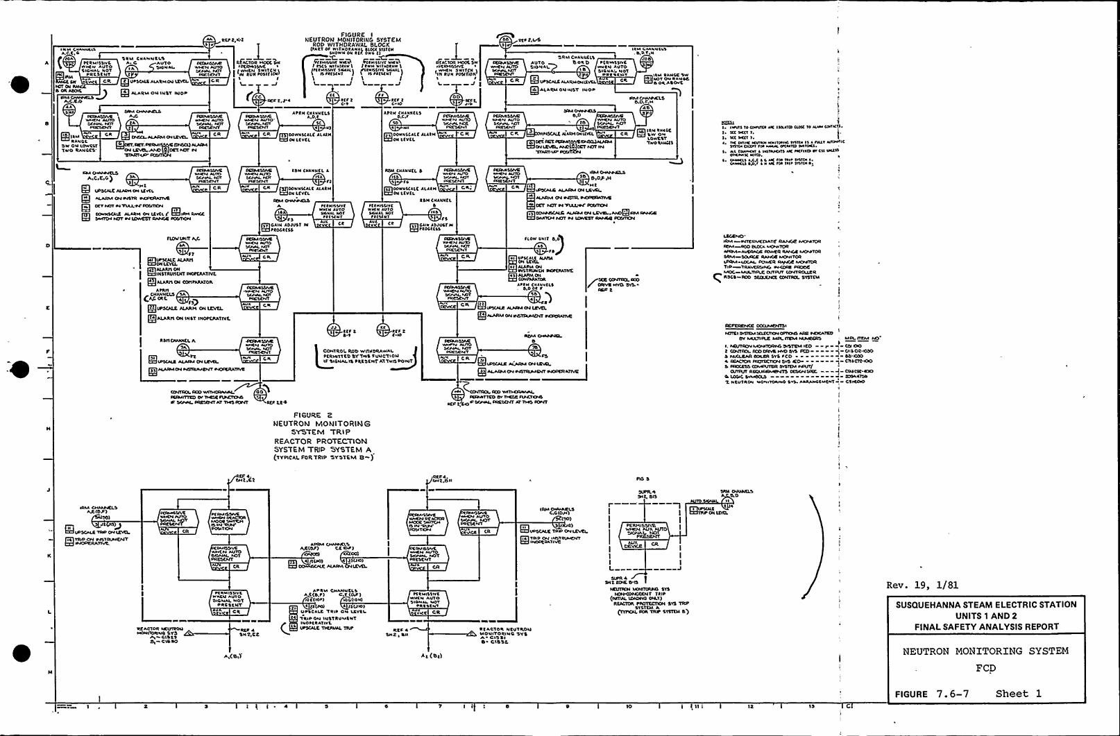
I RIP CffrffffclsA.C.C,G
(/DA
tc R Ml5 5W CWNCN AUTO
R-,SIGNAI, NDT
frc DRCSCNT
CW 5 CILIOT (N RPHGt
4A5
Hfd ltflRANOC
'SW ON Lowtsttwo RANCCS'R
SRLI CNANNCL\A C AUTOIA SIGN Al
tQt VtscllkAIARMOV LEVCS
R ALARIAON INST IVOD
5/DP PMPIPCLSAJtA
RVCPK I
oc/tposMI RE~voa ~WIDCR\4 55/VC ~
sf(PPPL Nsv I wfftN SwITcN INICSOVT IN PVN toclfloltICR /'E
FIGURE INEUTRO)I MONITORING SYSTEM
ROD WIT)IORaWa(. e(.OCK(tART Of Wl'TNDtAWAlSLO(l 5555(N
SIIOWN ON t(f, DW4 t)Fctrfssfvc rftv( Itctrfssfvc rfc>vI tsC5 WHKltlr\ I tww wllVDllwIP t fffl51VC 5NM(I INtNILSIVC \ICPIPL
)IS ttcscr'f I I Is tt(s(NT\ \ I
)-
C,CC IZF T.J. ~ ttf t0"I tcf lC 10
CR
DCPPA SSIVCwrtf4PWTO'ffPPALPOT
PRESE!45
C,R
AttH Celvv(LSA,D,t
5Ce)
Q DOWNSCALE ALACH011 LCVCL
AttH CffteffcssD.CF
5D~ NII
ls DOWNSCALE PlllllON LCVCL
dtACTOR MCOC SW~ DCRIIfssfvt ~
VVfftr SWlf(N I(IH RUN to5/fON'
I5 J I
DtctPISSACvvMCN Af/IO
PRESO41
CR
CR
DEPM SSIVCWfrtfr AUTOSISPIPL POTtetscMT
5'PM CNANVCLSDoe D t(RVPSSIVC
WrtN AIPTO'SIGNA'OT
QDe t 5 c pie
?UPSCALE ALARMCN(EVEL CR
Q4 ALAIDPGIJ INST INOD
AVTOSIGNAL
5/M OIPPWCLSEVO
Af/IO
PIPPNDNI(VCL " CR
ElDET. /Kt CAO)fsw C Ct45CL)P(PJSP(N LEVCI PPC'CT 047T IN
Illf4 CPANNCLS, S,D.'F,N
COD
QltM PANGC 'SW
10 Nof O'NRANOESORASOVC
RM P/PJJVELSO,P, F,M
40
IRN RANCEQ SW ONLowtsfTfvo RPIPG(5
CM PPPOVELS FECMI
/4PCPEPG)5
Q Pf t PVlfUPSCALE ALARMON lEVCL
Q» ALARMON WSTR IPCVRIPIATIVC
Q OET PIOT W VVLL.OF OSITI(t4~el
E ~IE ALARIA ON LtVCLI'ZII/SE PP/IGCSMID4 NST 04 (c)PISSY RA/4GC A))ITKN
CR
fLDWUNIT A,C
QSA
I~4) ALARNOHPiSIHSTRUNCHT IHOFCRAT/VEIALAR/5CN Cotl tARATOR
AtRIICHANNELS SA
(AF OCE 4 )gg I/DSCALE PLARN ON LEVEL
QAALAR/5ON INST INODCRATIVE
tdN CNANNCL 4~ll fl
E DOWN5CALC ALACHON LCVCL
CE54 PJVP425fA14 A
CR
155IVCIf/ONdtNt
tttrWff/N 451511PLtres(
FS
Qlt GAIN AD/VST INttOGt CSS
Efl
FESMOSVCIMEPP PVTOSIIPPPL POT
~5/ESOIT
CP.
GR
RDN CNAVNCL S15
fsCP ~lt DDWV(CALC ALAtNQ ON l(VCL
tSN CNANIICLS
lid/5
ce ~»CAIV PDJVsf/N~N ttostcss
NtNHSIVCWIHN PVTOSICNAL Nottt(SCUT
~CRMISSSCVPPCN AUlDSKPPAL IE)t
CR
flOW Deft S,DQld ft
OPSCA(C HJ/IH
ll A(AINAONDISTRVNDI INDtERATIVE
APAN CVPVVCLS
Q IDS(pcc pcpce4 04 LcvttQ4 PPAPM DN DDTDVMC)4T~
~SEC Cet/tft)L IOO
CIED t
P E/SW SSVC ICM OPPPDCSS50 BID+ IN
Ilt~ IFISCPAC ALARMCN LCVCS
plpRM (t4 e4STR. DOfftcSLTlvC4 cef NST w VTASWF CO5/TCDJ
Q15 PPVSCP4% ALPCM ON LCVCL,ANDICIRM RPPPGCOMTCN tetr t4 LDP/EST RPJVSC DCS/OCN
I ~ Ifvvls 50 (IIVV/CtPK I /till(0CLOIC 50 AlMa lo/Ill 5
l ~ 5CC DECI I,HC SEll I
~, DE Dllffcftvfrrfwf1104/f4 Pfsfof 15 4 IIIPT r/fovlH551101 Offltl/fr fWPAL OPIMND SNNK5Nl cotffOII ~ IIGISPOIIS MC tK/Ilolev CN INC»OIICWIH frtlle,
~ Owrcll l,l,c ~ 5 Pfc /fw 511 ~ 515IDI 4Iffff4455 OJIJf ~ r lfc lit INP llllof05
LEGEIVD'RM —WTERME(/IATE RANGC fvOMIDRROM ODO EL(CA M(tff)OR
AVERAGE AP/VER RP/4)E MCPP TDRSRM SCVPGC RANGE MD/41TOPIPRM IOCAL I/OP/ER RSIVGE MOIOTORTIP TRAVERSING WCQRC DIC)OEMOC MIATIPLE OUTR/T CCVPTROLLER/ISCS RCO St/UUCPNCE CONTROL SYSTCVI
RS/5 C/VJDICL Pf
TA
El~~IPLAPMCN04S/55/MENT 04COCRATIVC
WMCP4 NFIO
I
JJ KCtlf 2 CF tSvt C 10lCOHTROI Rll'0 WITHtfRAWAI
0 (RIOT'TC'D tffTWS FVNC'tlONIF JIGNALIS DRC'5CNT A'5'TNISDONIT
C(NTCCL RCD WITNCRAPAS OO~DC/SPITTED (W ROSE F(DETCNSK SIGMA PRES()4T AT 1145 FCD/f PEF Lt+
F I 6URE 2NEUTRON MONITORING
SYS'EM TRIPREACTOR PROTECTIONSYSTEM TRIP SYSTEM A(TYDICA(.FOR TR(P 5YSTE)U( 8 )
llwrfv AU10S/P4AL Pfot
Pf/RSR f41
RDM CPPPJDJCL.0
PVff
5 IC/DOTTED Ov S5ESC APIC/f(t45PCP t,SOW SGPIAL PRESENT Pt TIES IE)NT
CR El~~a——-~
PCFCPCNCC CCAPEN)51
~OICI SISICM NLECTICNCPTKNS APC OE)HATEDOV MIASIDLC Mol. /TCM APP(fCRS
I, PICVTPGN~t/G DfSTCM IED Pt (CNT/OL fr)D DRIVE 14/0 SVS DCD0 NUCLEAR COILCR SYS tCD4 ICPCIOR CCC/ICCTX)N SVS ICCM - - - - - - qS Neo(ESS~ SvSTDP IPIA/T/
(5/IDI/T RCICXPCSMCIKO CCSON USK.0 LD(ifC SVMDCLS I1 NtUTRDN Noffavotfro Svs ASAANGCMCNT
I
CP IS OC KOODll'KO)CTISC)t-OID
Col st(C. EDD2/OAATSSC5 IODIO
REF 4SHt,A RCP 4.SHE,OII
IPM PHIAPPVELSAF. (DF)
50)
QNIFISGALE 'TIVDON LEYCL
V/OD OI4 WSTRVME/JTu4ODERATIVC.
CR
PNIOSfvcfPPPEN AVTOSIGPPAL NOTPRESENT
ADRM PIAPO4(LSPLE(DF) CE OF )
OC(OD)
4 R(PO) Js(JO)g~~
WMCN PE PIDCRMOOC SIV/ICPP15 IPJ 1fftfODSITCIP4
I
PRESENT
CR
VVCN AUTOSKfPJPL 14CITDPEStt4T
CR
C~GIOPI(50)
H SP 0)IOSCPLE TPCI ON LEVEI
Q TRD OP4 INSTIIVACNTIIIDOEPATIVE
IL
5(PHL hSHt, O'IS
DE tJEI SS/VEV/IIEN NJX NITD
Sfol DIPHNCLSS,D
~ I
I IDSCNEKITRDCN LCY(L
REACTOR NCVlROHMONI50RIVR 'SYS
Gl'Sts0 IS SO
v r CR
RCP 4'SN'E,EE
tcllfllssfVCWNCV AVTOSICPIAL NOT
DRCSCNT
ADRVI CNANNClsA C(d,f) C t ((lt)IOC(IOP) 100(ION)
N 41 W
~ 5(/O) 4 /5(410)VDSCALC 'TRI~ ON LCVtl'TRIP ON INSTRVMSNT
( Q '""'""'"'CF4
SNE I ~ 11
~5 5 14 Isslv 5WNCN *I/TOSIOPP PL NOTtrrstkv
CR
RCA010k Ntl/TRON~PONITORINO SVSA 0 15 5 Itl Clb SE
SftfR 45HC CONE Ctls
ICUTRN MDNITORNG STSl40ht(DNGIDCNT 5 5 It
(IHITVLICPOefa (DRT)RCACTOR tPOTECTION S'fb TTSD
STSTEPA a(TT/ICALDDR 1RS STSTC/4 S)
Rev. 19, 1/81
SUSQUEHANNA STEAM ELECTRIC STATIONUNITS 1 AND 2
FINALSAFETY ANALYSISREPORT
A,(C)IT *t(bt) NEUTRON MONITORING SYSTEM
FCD
10 15 C
FIGURE 7.6-7 Sheet 1

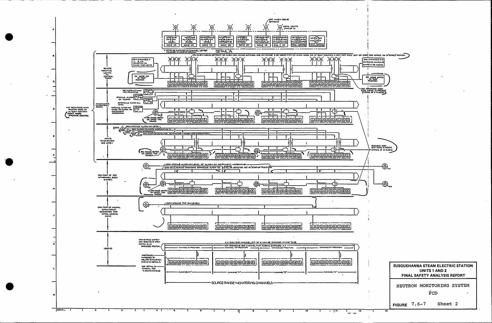
'I /R/
/ 'I / / /A/
VINSI4 ACFFVC
/IVOCAL LC/VTB
L (TTROF 'I)
IR«PS% CCT OV CCT FellN CIV 'Oos 44'5 VPRO
OO 1 ONO
lbtNP CR RMS CR
OC IOL
RCMOTSAOCAT «VC
I/C/«TBIN
CONT RolROOI(
«3M «APPVCLS 4( c. r,cRA«SC SW O«RAI CC 3ORACOVL
CETAJL'A~~ AOOVB 5CTF(TIVT OR W«RN IRM R//CR VVIT(NRBARB OIV RAIVCB/W / /5
( t)b/ / / /
3 OR ACC«s ITVPI OR W«CN MOOI, 5W. IN RON POSITION 4 OCT, NOT POLL O5IT OR/ /5
I 4 A/ / / 5/ i / 5/ V/
'I
WIICN BRM BIPISS SW 54'BIFFOS POSIOON,
IRM C«AN«CLS O.arj«RANCC SNIT(NRA«45 3 OR AB(PVtf
I
utI RCTRALTW«PINOT PCRMIItlo
A(PS(AIR ALARM
ON PCRIOO
Nl
3 3 QA 5 QL T gdKl * KIRRKI EKII I~ I
NOT PCRNISSIVC VIP(«RtACIOR MOOR 4W
A«MNCIATO~ N CONTROIROOM
VI«5(/LRAIARIIOI4ltl%L
IIPSCALB AIARllOI4 AlCVCI OR AIAAMONI«STRVNCNT1 OPCIOXWB
Otp
+ON t(WAIST ITIS lgl 3 5 4 5 I QTl
g)O ~-—'Kl*'"E::R* 3 E El..J I
I "1~ g.3 3 4 5 AQTBQN.J
~4«/tsTO (AAPIFTSR
SCC N(ffs I
QstocK SIOC
CRM CTAOV
Q Q Kl . m'I
I ~ 3 4 4 4 ) ~ t Q 4 fg g Q 'Q QB g I BL
I'gtg«QATPQI——
F(INISIVC VPCNftffO 5ICML IS Pl(St«T(tff«au. Or Lt tu(CS)
IAI At
ICRM IF%CALO ALAFPACIVLRLCL OR ALARMON INSIRIAICI41 PVOPCRATI5R)
(SRN OCI CtTRACT PCTMISSIVC POP«IS(/AL ALARM ON (CVCl OR OCIICIOR 144T Ct STN(F(P FOSIIIIB
IIATAr
ot
PVI RNOCBNITOI)gi Kl 4 g g Q«: :KI k ' E Eg 'LKI E Kl K~I:
15I
BF
BRM IN!ItOF M«APL5(RAMOIKlFT
(PORCC.RO PORPATIALIOA43NO
OR T)
I1' KEIElKIEElR!Kl ~KlRIEREIQIEK~I' 'l@E!lmR!GEE~
' QQ'QQQQ~KIK!:
CR« O/F455 SWIT(NNOt PCCMI55IVC N«t«swIT(M 45 P4
IOfIIV34
P «ONLV OAR (IIANNCLa/T OF 4 MkvOR OVFNOCCO AT ONO TMBNOT FCAV%gf4 ICR C«NP+, TVVATIB OCP4'p~ P «
C«L««CL C POSIT«/I ~ W C«A««tL A/POSITION ~W C«A«NCL'O>POSITION C«ANNCL O POSITION
4/VOCPLO 10RaAIB TO 45PCf(34N«PMI Pl OCINLh,
SCS CRTA«, )I(TVPCAL RSC8 54M (MNPRSB)
' EIRlEIKIR EIR'KlKlKRKKl EKJ 'KIKIEKIER~EKIII I;Qlgtgggsg T QOQ I
SUSQUEHANNA STEAM ELECTRIC STATIONUNITS 1 AND 2
FINALSAFETY ANALYSISREPORT
SOLD)CE RAhGE MCNIKANCICHANNELSNEUTRON MONITORING SYSTEM
FCD
l 4 10
FIGURE 7.6-7 Sheet 2

0
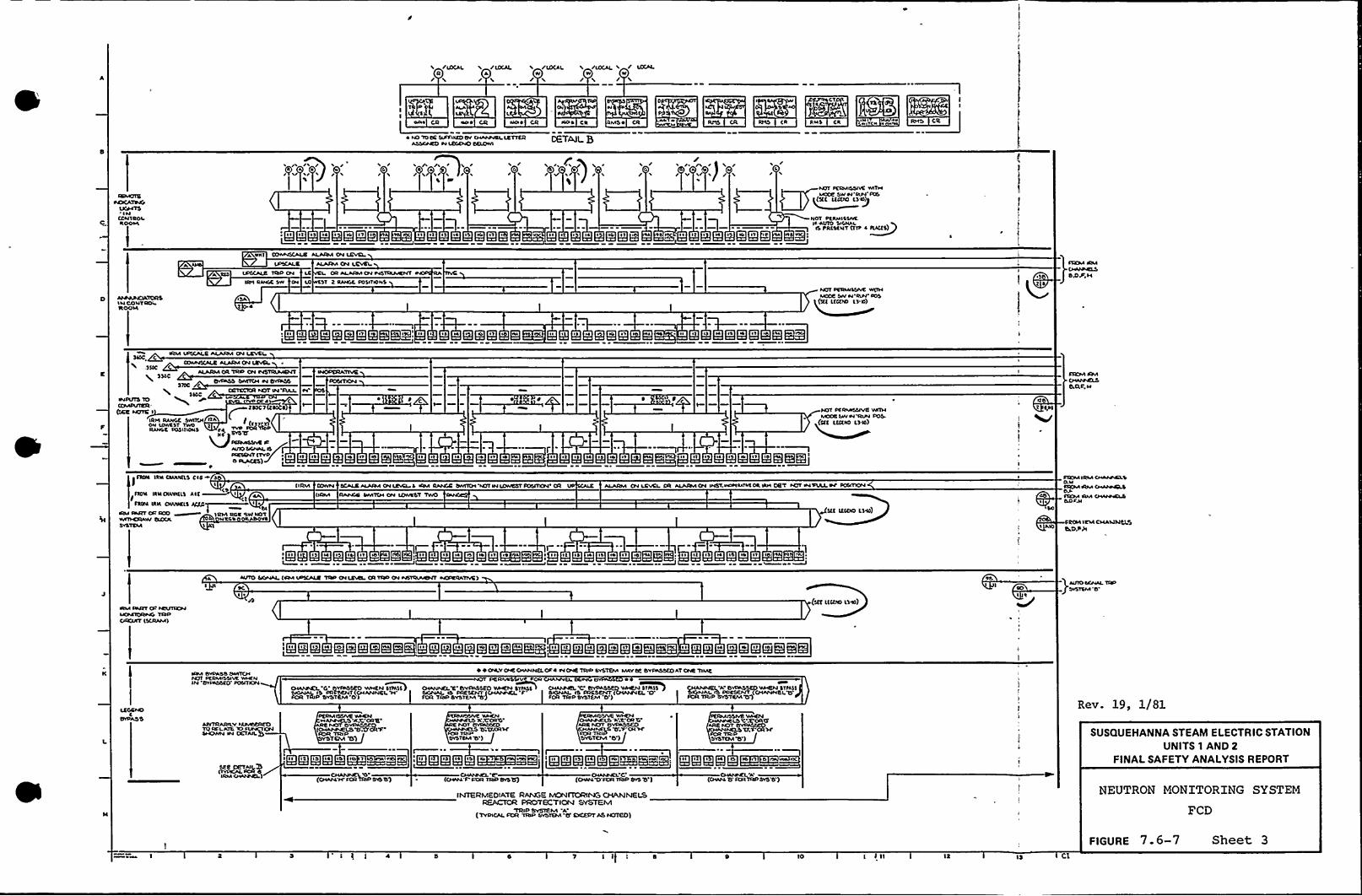
/IC}CALR/
/(OCALA/
/(DCALw/
/IOCAL v / SCCALW w/ L /
DI
AAI~ CR 44s ~
5QkRt1S CR RHS CR RMS CR ssNI RHS CR
4 NO '1O OE SVFSYSSRD CV CHAAP4CL LETTERASSSGSCO W LCGCNO OCLOM
DETAILB
G/ /e
f//
G / V
s//Y r)
/ V 5/ V //
4i
SCMCITE
INCCIITROI
s ~ st IS gs ~ I QH @IT
(
II I St ~ 3 S ~ IS SG ~ 1 S I ~ IR s I4 I
NIT SCRIAOSIVC VATHSICOC SW H'RIW PCS
(I
NOT PRRHISSIVCIfAVTO SIGNAI.
IS PRCSRNT (11P 4 t(ACTS)IG It e 44 I't ~ e4 IS s4 l1 IT vA IeQQQ m QQQ S
APAPVCIATQRSII4 COI4T ROLROOSA
A NNI (RtevtssCALC ALARM CN LEVEL
SPHCALE ALASSVI CN LEVCITIED (SV LC L OR ALARMON WSTINtvCNT
IRts Rssesc sw pe Lo st 2 RANGE posstsovs
t 4
MCCC SVV sl RIFF POS(3(( C(CPR} ts ls)
~ ss R H Qss @vs gs ss @~i'n s ss H ggoges vs Q»(
IRM VPSCALE ALARMCN LCVEI36}C. C
StfSCALE ALARI4(T4 LEVEL,3 SIC C
ALARMOR TRD ON HS~
ss st is QHQNlgev s g . ss R D ggsgwgt g»gg
STR}M Fsvl
E aF.H
WPVIS lOSVNIPVTCR
'SECNCng I ~ZRCCT 6
IRH RANCC SWIICN RA /oN LowRST Tsvo I (TJICI}RAI446 FOSITIONS 44 ~ ~ sNSP
DCRVNSSAC CfsttO SIGtesL O~VCSetfT (TVP ~ ee n st ~tl INACES)>
) 1 )m~» „,1,, ~ 4 gee vs @mfa I' ss Is '4 ' 'ERBH 5l5Q
Mccc Lvvw YIVN PDS.(S(I L(6(NO Cs-6})
RSS)lt
t
el~ IRN CSINN(LS CI 6I I
IROIR IRM CIWINttS At(~CS
IfROM IRS( CNt/PC($ RCCC
SRM DART OS SCO ~ IRIVI ROC SW NO'TS sl Ct.s ON VR
( I RM C(ssvN SCACE 44A(44 CN (CVCI L IRM RAACE OIVIT(HYCIT IN IOAICST IOSITCN CR ALARM CN LCvel OR AIARMCH INST. Vsswsets4 CR VRH DET tCIT INSTAL IN'OSITN}N(IRNI RAACC SMTCH ON (Ctt/RST TIIIO
I(( ICS(NS (344) Sss
STCSM IRM eeAIIAELSO.lfFR(M IRIVI~SOFslKM IRM HGIPVELSCLOP.N
6C(64 ICMCHAS434CLSOsOP)I
~ Q l I 1s 4 1 ss(El, g s ~ IW 4 gv ~ «& ~ CRQt is H gis 4 g Sgssm», s Qt s H gs 4 gnCES ~
I
PIM De(TT Cs ICCINRSNSIOMTOSStVC TCSDCFCV(T (SCRAMI
A 44(TO Sf(sf4AL (ISSA VPSCALC TOP CN LCSCL OR TSSD ON WSRVsf(NT se(SICCATIVEI
(SIT I(C(NO (346)
)ADIOSsseeAL CCI
I ~ I Qtgss H Qoggmg»I
~ \ glt Qll4 Qss m gl mmm \ ~ I Qlt Qs
l4 g QG pit QC mm}g I Igs Qe
l4 @IS Qss Qst Qs gg mgIRM BYPASS OesltCHte0( FRIIMssslvR vvsecNlt4 CVRiSSRO'OSITION
SIAAPsEL 'O'~ VVSIEN~SVMSS
FOR I P SY~STEIVI B'
4 OILYOSC CHANNG. OP 4 H ONC TRSD SYSTEM MAYSP BYSSSSSCD AT ONC TIIAEpcRsvsS ~FDR
SefveNELv'vRAsseo vvseeN svtsss ) cseAApcs. Y," BvpssseD YAVEN~srtsss cHANNEL'A BvssssscD vssecN sttsssBONA( IS PRESENT(~ F'ONAL IS ¹?CSCtsT(CHAtFVCL CS ANALIS PSIRSCNT (CH44VNCLTSSOR TRIP SVSTCM tf) sOR TRID SYSTR}vl O ) IC}R Tt(ID SYSTCIVI 'OQ
Rev. 19, 1/81
SseCNvN IN DET~AIL
see mvNL>(tYSNCALICR O
(CsfANtvCLO~EF.S'ORTttlP
YSTEM TS)
I@II Qlt @IS Qls IS ~ITCHAIVNCLY}
(CHAtAT<SCR TRIP Ck}OQ
@~CORO.ACST~
TCTT/tRSCfOR TRIASYSTEM 'B')
:R!RIIKQ" IK!$5~85!'CHI44T'SOR
TSNDCvSlfjCtessPCL C
CIIAAFVRLS A S ORBARC tVOT OYS(SSSCO
sv(LS TTP'CHSCsOR ~iPSVSTCIVI 'O')
I
IQs g QS Q4 s Q»@/~~I
(Os/44 D PCRTRSPOvST}')
CsesspcL''CR
TRsDSYSTCM B )
gsi QigigH o ~wn ~oi Rc
CHstPC( 'A(cHAIGo soRSRDOIBT} )
SUSQUEHANNA STEAM ELECTRIC STATIONUNITS 1 AND 2
FINALSAFETY ANALYSISREPORT
INTERMEDIATE RANGE MON(TORIN(s CHAINNELSREACTCR PROTECTION SYSTEM
'TRID SVCICMA'TYPICALFOR TRIP SYSTEM Cf ESSCEPT AS NCITED)
NEUTRON MONITORING SYSTEM
FCD
FIGURE 7. 6-7 Sheet 3I I 4 IO (2 IS C1

0
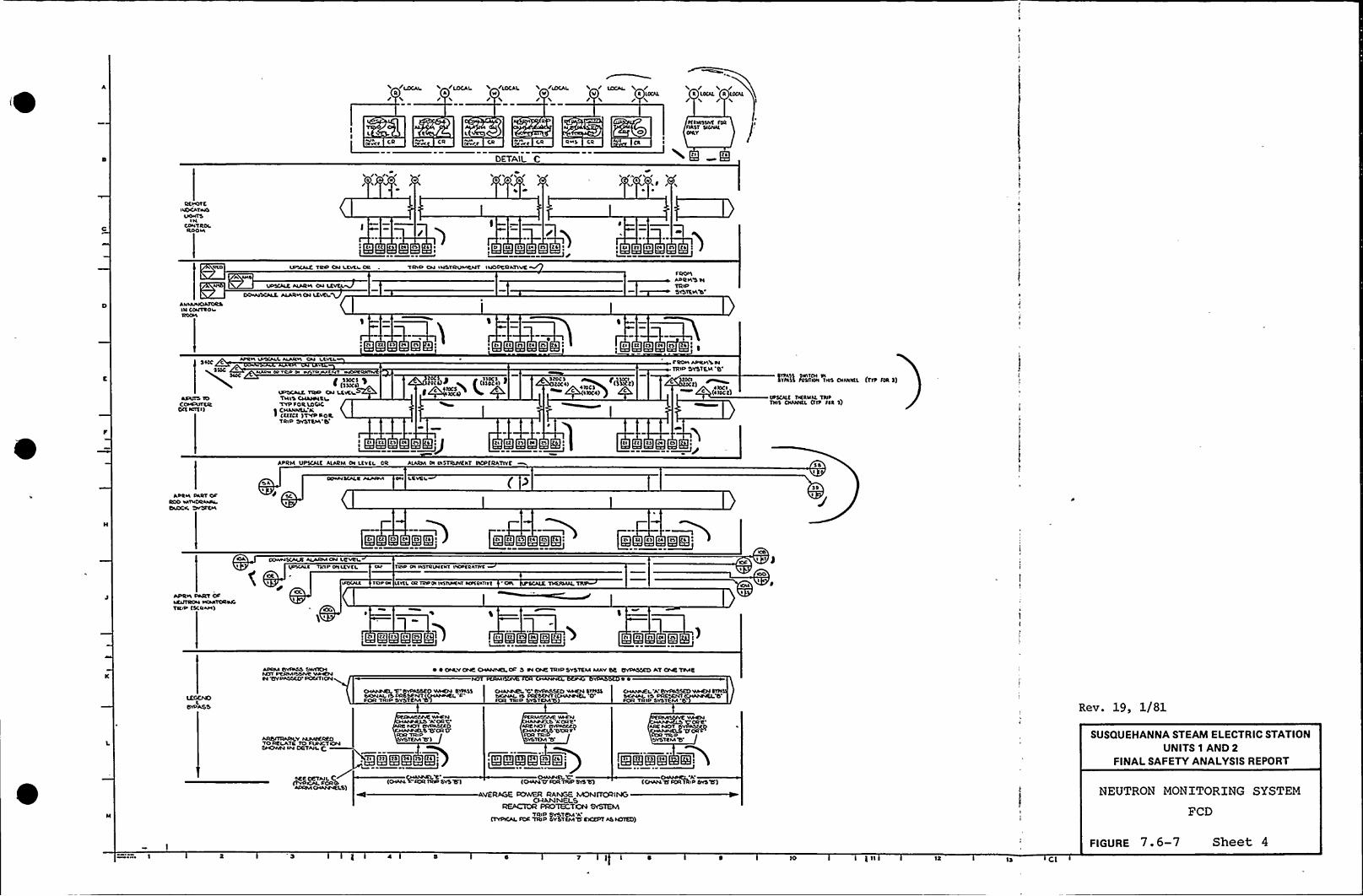
/LOCAI + /LOCALR A/ /
/LOCAL
//LOCAL
V//
V R LOCAL/
CA I,/r C,R s CR RMS
MTAIL C
CII
CR
~IRHsslvr fok IASST ssohaaONLY
g~P
'\ /. /aa h
a ~V/
RcrorcIACSCArsHS
LSOsSTSIH
CDIITROLRODHI
I /ts tt ta
I
TA P ON IHSTAIINICNT INOPERATIVE
s ts cl ll ta n ca:
fROMAt'RH'5 HTRIPSVSTSIAW
AIIIAHOAIORSIH COJTROI
AFRH IDSCPAL AIARH CN I.I.Vtl.C
SIPRV aa TAP I Vill S SITC
SIOC
l(',IFISCALS TT)SP CH LEVEL
ADIIIS lO THIs Catalpa RlCOHPATCR TYP fOe LOCjCOtc Noirl) 5 CHAIIRSL'A
~ (IIICI )'T'YP DORTRID SMSTRIA
Ea'OCS)P < (SSOCI) >g aloe)
g ~ttl)CS+ c a)oct) )
fROH PPILH S HTRIP SYSTEM 'B
) ~ IOC I(Hoot)
svfass fosirAN rsas CNINNLL (rro foR 5)SYFA'ss swlrna oi
VF5CAL( rh(RMAL TRIOTNls CNANNLL (frr fat S)
Ltl ta ta ta ts a s ] tt t'I lia t
APRM a)PS(ALE ALARM OI Lcvca. OR ALARIA Oh INSTRuMENT INCA(RATITE
AHlsa DART OFRoo M Hcvtahsw
SA
JI
oowH scpLR papsavs DH Lcvol ( 0so
J'ts
tt t'I ta@QADI J Qn rt a t Qts ga.)
)g tt cs ta gngti
DospsSCAaS ALARMON LRYRa,Lssacpat TRIp paatvtL TRIA PI IhSTRVH thr INOFtahrlvt
ros ah acres oa rap(A IVIIYHchrsavcasnvr -osa asjaasJIAL
jsOOI
OFAPRH PART~RljllKHIKSATRIP (5CRIPI
ti Qlt ta gs cc;$I
I
)ci Qct cl oa Qca
ADAMOYAsSS SWACHtglr PRAMISSIVR VPIENOl TIVPASSE(r DOcaT ION
~ ~ ONLYOVE CHANNELOP S Pl CAR TRIP SYSTEM MAYSE OVDA)SEO AT OAR TOVIE
CHAIsDAN 1 'VAISSCO WHEN SlrascSSSNAL IS DACSENT (CHANNEL
'O'CA'TRIP SYSTEM
CHI/avFL A Ef/AISSEO VIHENSvssSANAL sS ~ SFOR TRIP SYSTEM'ev. 19, 1/81
sSTRTAINICY NPPSEAEOTOAELATC TO FUNCTIONSHCNVN IN OC'TAIL E
SEE DETAILC(rvpicpL FAR0ADAMCHANYELS)
ISLA', VPIENA OAO~R~-~8
YSTEIVI1f)
CHAAARLE'OIAMT'OR TAFISVS Tf)
FtRSPIRSIVE VPEN'A OR'E
~EQQR~Q'SYSTR MTa
KIKEg3 EDOIAHSA'A
'A'CHActrfION TjaiP EIIS Tf)
VER)IGE CC)WER RANGE MON(TQRIN(oCL(ANNELS
RECTOR PADTECT)OCR SYSTEMTRiP SYSTEM 'A
(TYPICAL FOC TRIP SYSTGvl15 EXXCIT ASM)TE())
SUSQUEHANNA STEAM ELECTRIC STATIONUNITS 1 AND 2
FINALSAFETY ANALYSISREPORT
NEUTRON MONITORING SYSTEM
FCD
i 4 7 I ) )0 )R CI
FIGURE 7.6-7 Sheet 4

0

/ / / LDCAL W /A A A .Lraatl/ / / L /
~ uCk .- .: '. - -' %R M '~12 K&,~J:R
yaa~ CR A~v~at CR @~at Clt y~a CR RII5 CR
ttbtrtLPRLE
ILDLJlALLT//TYP OP /ss /
A ITT LPRLCS va/ /
"~g~g %$ KSgL
et~ttLPCLT MGI
LY/atSIN
CONTROl
d1
DETAIL D
/aa
PEDsarsslvc vrsrcuIS NOT DOCSENT
RCYOTCINOSCATIIJS
LISIITSINRN'TOOL
M
/ a a /a
DETAIL E DETAIL F
DECLASSIVEVr)SN LIIIO
RPOOIEAOCATIVS
LISNTSIN
CONTROlRDOLa
!
«At tissu IrisossLAwtvp DLtoe~TCP SYS. AJDD SDE, aTTPSYS'8 g ~ r
OA'LE
DELE t(D
CE.V CR.
~ QOO lr lt 4 ll IIiQlt ~
IALAura Ost
LCLRM ou wstdvaacut aaopcRLtsvcOOaruN/ALC ALARMCN I CVCS. RSN Iu TOsD
SISTER bTLDN Etltetaec
A DST PLOau t)LTT O.CDR DLLJ 'TRIP SVSTtLLS Aab
II
Ir
s ROILLPRICS IV TRrDSYSttu
8'N
RODaalaACAL ATORS
COIJTROIIrl
~ Yaacu Jalso DGLNLIS uOT PRCSCNT
:aai- IIEIIEEIIme
Ira coaJTRDIROOat
~ I al al Q4
JJJAPRILTORSIN CONYRD'L
LDOCEV CR
QC» 5
Cfrt(cult
sufVSS TOCOaaPVTC ROCC IrDTC I)
d PCRNISSIYC~5 LIST
daa Vs/JCILEALAJCNLOLILOVELC R
pou aa/aavrafs «I wwlaapt a lrua MMaaral ~Iauruav tvsvoup
La 0 aavPsaSS SO
fDOra ltd/I lu TRsPOVSTtat TL
'NNEN LVIOPRESENT
(WOC
CCarsPVT C R($CE NDTC I)
SLCIAIOust ATLCDR 0 vpscALR ALARLADN LEYELIpas4MEMT paCPC DATIVE)
cvt cp Lpal)SJLARIL OLI CaONYurt CDafaRAtocl
~ g ls ta 'll Ta tl 'IL QTI QOO g1 ~
I
SITE TPRNNJID SIGNAL N)t
PART OPROO vatasDRLsaaaLSIJDClC SYSTC aa
AL ou Nrlt. Td~sept fatrvc 'TRID
SYSTEM b~l d
9=.aL/COrruSCALC ALACMOrl LCYCL~lI
d
lA DAIN ADJLLat pa pfcccss/ITL alt ALAR caa tvt OR LPM I RSul
PART OarRoo aft~
SLOCIC SYSttat
t LOWULNA C Gd PLO'Irltlaft b DR '0Ij INTRIPDYDTDIA b
UPSCALE ALaaRM OM LtVEI. ORJLLARM Ou PJSTRLPJCNT INOPEOLTIVE ORALARaa Ou COMPLRLTOR
DERMrssrvc YARNAUTO Sa)IIAL NOTPRESENT
Id5
pcaassSSVC vraeuJVSO SIOIJLL NCIT
~RCSCNT
~I 1 lt 1 Qba QSQTL ls IIQ$1
I
at al W4OOI ~
.DOJCS,SS ITS
SLO/r UNIT '/ I/JDYVN TYPICAL PORIpaltdtt.x att except As Motto
Trsrl SVNCtsDN ACTVATC\TfC RSN sNSTRaMCNTINDPCRA'TIVE
ALLAN'YITwraTNS asuItvp s SAAcsl) I))I
aa AOJVST DOJ)MSluapa PRDCECS
I— .G~saarra
NIGH
AI
STRMISOrVC sf AVTOTrcrraAL rot sfcscrrt
PCM ICSDcarrf)LACE SIDSERATIYT DDmvcaLt
strlspNI.RAI aa/JJM No aeotfafsl at)o spa(NT ESLEctto
rr
Ieo DUTr/AardlT
~ p DNLYouc storvt/Jlt oc 't au DareTOP TITS. MAVDE ISPLSSEO A't ONC TIME
/sot JClaaotsvc IoR a Iosv vrpT capaG DIDIOAoopSLOrr IPJITTC SVCaaSECO SLIDSV afrite'SVPLSSED
N/IO'LcsNLL IS JVIO SGIJAL SaJRtssaat tstcsrv Iplstt( LDJT(atcauvrAT)torl TRIO svsTELJ'R TRD prL'tcM 's
I 4 la 1
LDSSIVC tttstuJJJ)D SIGNAL N)T
ARSrTRARILV IIVMSECEDTD AELATE to ttsactlDN
DETAIL
:IIIIBIRIRISI!KIIIQ:CNANNCLS) RQO eUOCK(YON)TV)RING
«CANNEL AItvP COR ~ d)
LCGCLOa
BrPASSMISSIYE Yvtatu
SLOP vaat C ISNDT vflaSOEOICMAIJIJ1LTT
YSTEM'8')
VAICNslova vrrst Yc rlNOT OYPASSCO
Ararac LTTCCR TRIP
VSTESA 'tt )JRCI TRISR Y~aavda Rlp IoRELA1% to tssraOTSON trrrOVIN taCRTAILg~
as ~ IQRscut SLow trait
A'towvralIS) (TIOJ/vult 'OTORI
steal/ISNITT'SLDSIIAJIT1/fCR
'tRID STSTCAA'd')~ PI.OLM UNIT A lb~REACTOR PROTECTCN Sa(EI
(TYPICALcoR TLo/IIPJIT'T(LTTEYOEPTAS NOTEO)
ARJNTCSLCtr V usaaaSEREO
SIIOaru Iu DCTML F.
ttsR COR J))LORNI
LOCAL POWERRAMIE IYIO)I%%lh6
OIARMEL IhlTRIP SYSTEM A
ETYSICLL Soe o)
Rev. 19, 1/81
SUSQUEHANNA STEAM ELECTRIC STATIONUNITS 1 AND 2
FINALSAFETY ANALYSISREPORT
NEUTRON MONITORING SYSTEM
FCD
7 I I I 10 )S
FIGURE 7 6-7 Sheet 5

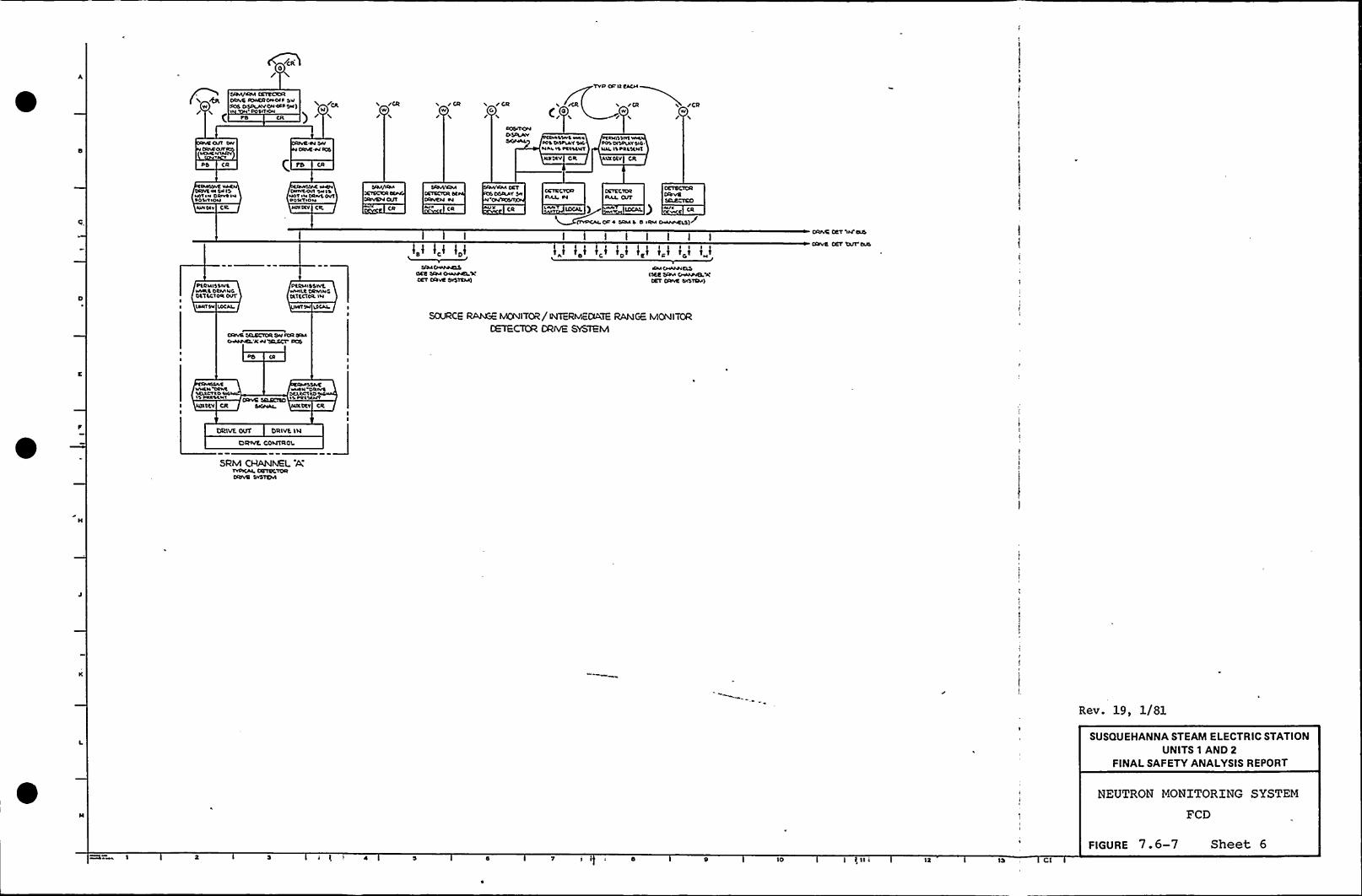
SIOII/4)M CSTECKXtDolve ID4ER DNOII sv
W OOS DSONOWCNDOOSII) Ck. rCRW
r CRW
/ CRG/
TVD OD It EOCII
Y /CR rCRW
DD CR
OOS4TOMatotNY
SSWS witNot IS ottttNfNootv OR
Iollt'IIVINNSOOS DISOISV SIO.NN. IS OOSSSNS
imotv CR
OVNSYEDIOVS Ol SN ISMIVIN OWYOI IOOS4VION
tott44 CR
~CION044WSCNI 'SN lo
NOV IN OO4YS OVTOO 4 4 'VI0 44
NIIIDSV Clt N4 4 I'M4 )OCg ) 44444 g(g ) Nlt
clYDcoooc0 sRM s D IRM o4Maets)r
I I I I I I IDRIve DET 54I'04s
Stove DET T)tn Dos
DSONISSWSWIOIC Dta/IIICDSTSCV044
DVI'tRVOSS'lvtwltltoDolvlNGDot tCT44t IN
0404 44ooICSScKE wo44 0444/IELscCET DIDYE SYSTEM)
4CM cN44MIEDS4 SEE DRvl C4444NS).'ICDET DIVYE DYDT404)
II DN(ISN toCOl DN Socol
I SOURCE RAh6: MONITOR/ IIYITER)vIEDIATERANGE MONITORCETEC'TOR DRWE SYSIEM
444444th'N /4 DRSCD DCS
NNSN OOIYt WNtN DOWSSVMOVt0 %4OIW OttoOVIOI'toototl 4 ~ 4S oott444V
I N)totV CR DCV CRI
1)))))VE OVT 'DR)V't )S)
C)RIVE. OO44TROS.
5RM CHANIVIEL A,CVDVe SYSTEM
44
Rev. 19, 1/81
SUSQUEHANNA STEAM ELECTRIC STATIONUNITS 1 AND 2
FINALSAFETY ANALYSISREPORT
NEUTRON MONITORING SYSTEM
FCD
7 I )0 CI
FIGURE 7.6-7 Sheet 6

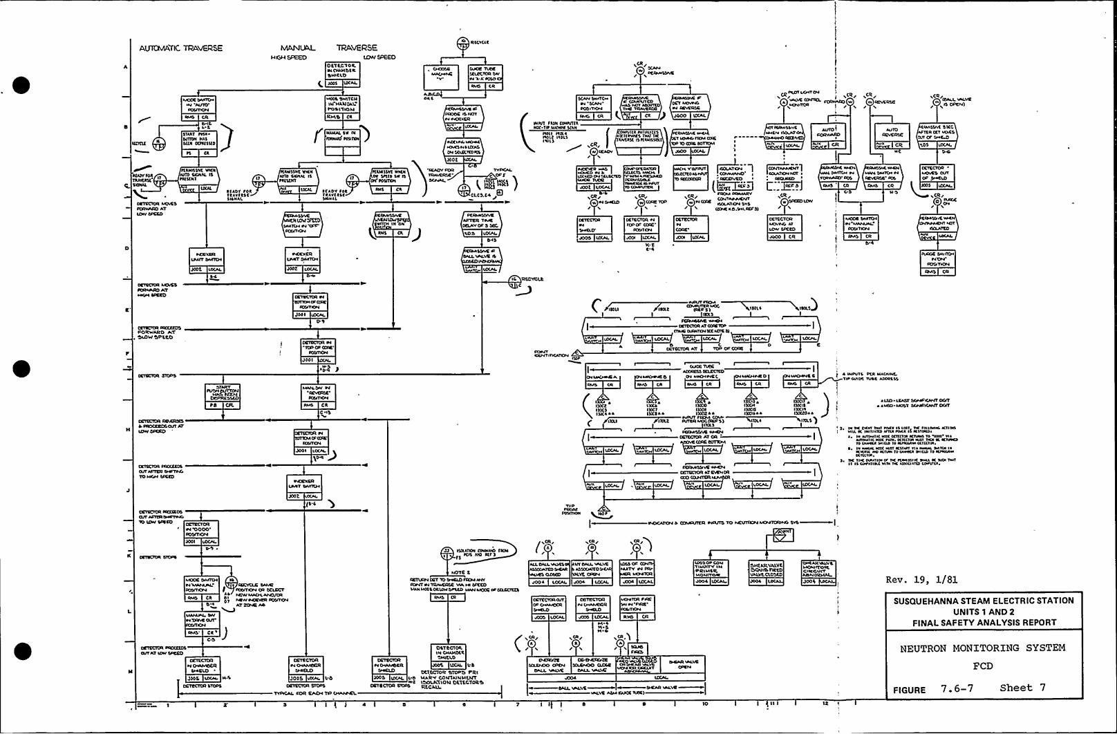
AUTOMATICTPA~SE MANUAL TRAVERSEtt)vv SPEED
0 ST 5 0'I0 R.os OuH OCRSNICLD
)(05
CH)OSRMAO«HCV'UCE Tcc)E
SELECTOR SW«I 'A X4050
RM5 CR
/~CR
/ DCCOVIS5SIVE
MIXR5«III(H~H ASIRY
0 ItSVAAT ttlasonoN NASSt(N O(tct 5 t(D
~aoot Sv«T CI4IN HLL)L)Alt05 11 IO)4
f ~"
AORC
INCCI«ILsa(N«4~OLNS H 5 LO05DH MLS(no t(s
S(AH SWITCH
S(AH'OS
IVI(«4
CR
ossut SAON CO«tvt(ANOC Tlt lu(ant 5(AN
Roll Viol ~Iao($ I~ OLS
tilt(a «IRALII(S~ c(tlavt»s not 1stAav(AS( IS NANISSTL(
Rs«SSACLovwo ncM (DIC
RMOISVRc (DMDutcn«as HIVaoontoTIVE TRAVERSE
CR J JODO IO(AL
DCOI ut/ITOa
vaLVC CHVICL.LCHROR
v(R/ CR/w w RENCRSE
v r
AU10REVERSE
Iava
/(SALL~VEVCR/
/ %ISCPEH)
AMSIAC 55CCAOICR CCT MACSCut Ct Ss«CA)
<DS uXAL
RlASVTOR
CRICCIOR ACHESSCRAARO AT
~tRottllvt sta(NNlto SCNVL t5~R(5(N1
RIAD't OORtaavtcsc5 ION AL
SASS)AC TINKA'JIO SIC«At IStvcsnlt
OS'5)jat 5TXDMICH44 OSS
~Costs(OI
tss)tlvt wa(NO» Stt(o 5» IS
ON totnl(N
~ (ADV tot RNSlaavta\cSK«al
IN ON
Soot IOCAa.
t 'ISLL)vtCI.CS.C4
ADER TIMEDElAVOD 5 SOC,
INC»VCR vvAS~C«KO «4 Isex«co c«4 ssco(tsoOUKR TVDE
400( LOCAL
ACR/w «4 SHC)0l
Ca%RAIL»ITS aaana
«sos Atocss«40ICRNVSDILRIa«v(RA «I«IIIV
CCMVIRR
ACR/«I CORE IOP/
CCVCCICR HRSV OD
CORE'onlcta
I( tC'4
~IKILv ounastTTO AS
lRCCOC(tt
~" 1
(I:—.,mVCR/
ILOLAIS)HSVSI((HC KO.SH I.Rtt5)
~(OH ~]L ~
w noxt)cow/
CR
RMS CR
tMccR swnCH~4 MAIIUAL
Do(uTcou
CETECIOR MOvC5SCR«ARO AT~«caa socEO
LC Cc(CVCLRI
~VC
PORWARO ATOIJ)W 'bPCCO
JO4 I
EEO(i[St IH
JOOI
~ 0-S P
DO«VVIOCHTIOSCATCV4
to«LITER MDC
cctoa4ssvE «av(HCRISCICR AT C(VR1(P
(TMO (ANAT(HXtIC(IE t)LOCAL lCCAI
0 C 0CCTCCIOR AT ICP C» CORE
tO CSC CR
C.sy
JOD I LOCII
c0
l ~I)OCtINC)l)Xl~ 4
IXLI
CII)OCSIXCVSX(S a ~
'PIXCO 4IXCOl)XNIXO( 4 4
CaIIRR ~MCC S)
~AISSIVC WHCH(CIO(lPR AT OR
0IXCI ~IXCNIÃCISIX(IS~ 4
MICHHE 5 4 I«tule DCR NACNINC1st o«o tuoc «tool.SS
atn) LCACV SOVADCAI(T0(/I~ 4 Mso- M051 5/vta»scatcT o(AT
2 DI oa tvoo o«l toca Is losT VK tolcoal4 Ktloo'asa al Iasnatco ansa toaa st Hstocosa. H «ao«nc «oc cctccta actvvo to 'SON'a
«Rolal sc Iacc taov octcclos Not ons sc Knnaoto owaM val(ID 'fo Kt«v/«4 acti(Vs«,
~ Ia l«la«l Ncc vusI Kstaal via Na«IIL svltcll sa~I«case «D AIRIIIlo Dwaca ossnD Io Kt«IIA«lattcsoa,
5 tsc nvc oloanos ot Rc tl«sl IIIvc osalL Ic Rao osats ~ ss cot an«t laos oc assalatco cotvlca.
LOCAL
(S.C TIP
SootD-I JJ lt(RATION (oalo«O ACN
tCIS NO Rtt)
VCR�/
R/
Mocc o«ncH~4'MAHLAALDOSIICVV
RMS CR
CR ~
CRCVCLC SAAA(] ICD/(OH (R SELECTtaW MLOCAHO/OR
oDlAT t(OR( AO
HOTC tCRTcRO4 CRT 10 0«ELO etta H4VRNVT IH IRAACRSE vlAIN sscc0MHIsaoo'S ORLDLIDotco MAta MCCC ot SLRCCC(S
400 4 L(XAL 4004 lo(AL Uooa LOCAL
OEIECIOR«4 (HAAN)RR
~L
LOSS OI'OI4'TINUITVIHPRINISR.LAONITORJO04 LOCAL
Osttl)C VALVEOCSUIIS tstCOVALItCLOS(O
Joo4
nsvcaRLO«vllLAOHITOICCIRCUITASSHORSSAL
Rev. 19, 1/81
SUSQUEHANNA STEAM ELECTRIC STATIONUNITS 1 AND 2
FINALSAFETY ANALYSISREPORT
5
JSD5
COTE CIOR~4 CHAMOCR
Slo(SJ)
JOSS «DIAL. L 0EElttt(tt STOPS
TVDICAL ct)R EACH ISS caaotvCL
CCTSClOR~4 Os«MOOR
)COS ID(AI. II(IN.C
CCTECTCR CIODS
OST tCtOO.IN CSIAHDSR
LOCSL L 5OCTOCTOCt «AIOPO PRIl4«RV CONTA)NMCHTLOOLATLOS( DETECTOR Ut(LCALL
VCR rR/
7 5 5 ( 0
Alt»ES
v«LvC A(MI(AAOC RI(E)
'lo
NEUTRON MONITORING SYSTEM
PCD
FIGURE 7. 6-7 Sheet 7

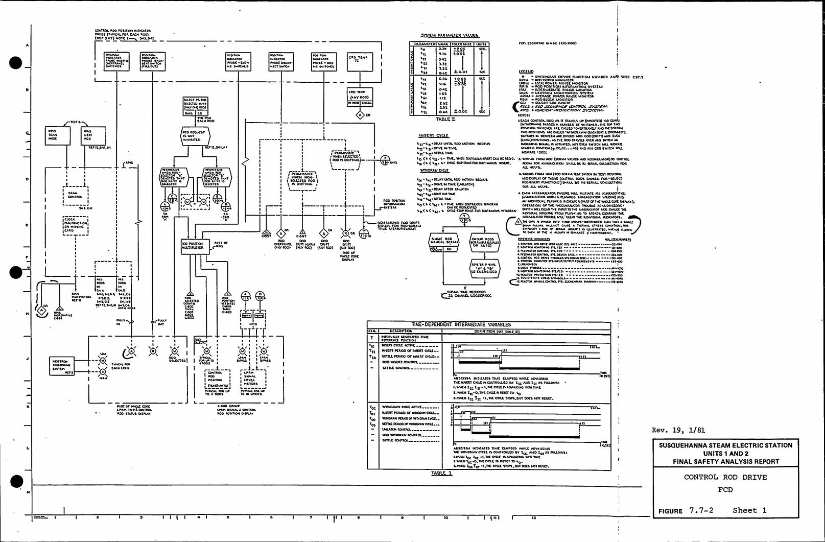
CONTROL AOO POSITCN aNDa(ATOLtA001 ('IftCALFGR EACH AOD)( )
PARAMETER VALUE TOLKIANCC UNI1$ Ftfa tSSXNTAL Gllct tCI2 IOSO)
ACF 5
I tao
HOOC
APISNCIT~lOD
Rtf It,tnl,AI
I I
1 1SCAN
ICONTROA
1 I
I5 4
SH 5. Col
r—----aI CLOCK(HALfONCTIGHI1OI H<SSING
1CAID
4IIII
f CR
~ I1
I I
ALL
Ol. AAH5 5«0 H,>a Sa ~ .CcHalftello« P$ IPL ~ IG4Rtf tt 5«I,C-S C«LNS
SKF lt.UILN 5«l llIlf4 la
ION TONMOKATOApAGSK sacaac«I 5«ITOIiflaL OUT)
~GN IH«4MtaCAVOAtaco( -tvCN«1 5«AOCS
Ill.CCT 05 IOGIILICTIOO.VY(oaAV INK 040)
Tvn roaKAi'NROD
IOO ICCtvttYIS IKITM«ISIZED
AtfllSHI AI
fta«aa%lvtCN AOO
atltCTOR 'ADCNOTtl THATAoo aa.vf flMLKCTCG
ftaaallPYCa«at« AoolfIACIOP
Cl«OTtS Y«ATICO aa-vf ilIllccllo
A~ «.5
10ASH
I'Iv 85 tva
D~ arl'IOISN
0
ACO PORN444LYIFLEX(ST
.'-o.N20'ottnICLxiltt514
0.'3 ifatl ta
0423.323.22alt
ltoFGHTHaawoKATOI~aoat OSIIMNC 1 Saatt«
CAD TCH« ITC
~ONIONMSKAIGItaott GGDaao p/ITOKS
IOOatlttTtD
(&WINCN00T«a«
IooFGVTCN
'GIWTSSCHOO
KEG(LSD
SIVITCHGtAR tlEVCE IUISCTIOM NVMDER Au\I SPEC CST.'tRWII Rco VCIHIH MINIMIZERLPRM Locll POWKA RANGE MCPIITOARPIS «Roo POSITION NIFORMATHNISYSTEMIRU INTERMEDIATE RAIIGE MGNITDRl4MS NKUTROI4 Moultoaluo SYSTEMAPRM AVtSIAGK POWER RAVGC Uoui'ToaRDU Aoo blOCK MONITOR,(tai SELECT Roo lliltat p
ARCS P A'ISSP SEOVEh'C/F 42H//RCC ~FA/.IA204C4201 /Hxo/AL//KSYV~/2 /IrNOTES I I
LCACN COIITIOLROO,AS IT IRAYKLSVP (ScttfttO) oR towv(Nit«CIA«IIIPALSC5 A NvusKR oF SNITOats. TNE Tot Tao~OLITKaa TWIIOES Aat CALLED.OfunaAV4« IIIITUE SottouTWO IONIIONS AICCAILto 'Wl'IHDSAWK'(SICITKITL DVII4ME4),SMX«tt Pl Sctwttv ARC cfnoto Piio coo (ORIFO AND K@II(IAICH)iclNTIONS AS THC RCD tAAVI15 OVKR ftff54VRCN AHMDCISNO DGVN. IS ICIUATID.NST EVUI tWl'ICN MIL SIGCITENANIIGfotnlON (1.00,01,45) IND LVY 000 SWITCH WRL~IGNISE 'ODDT
k o.oz
0.30G. Il0421.02I. I22022.$2802
lat
LSIlitLGZ
~ Tt
-'3.Vs20 02
CIO Yt«t(ANY ROD)
jO43t
TA(3LE T(
I «-t.a ~ DKIAT UNTm. aOO MGTCN DCOIVSI It 5 0 TRITE IN TIIAC,
141 I Kt TETRE TINE
ltl (5 ( ttta t TILC, aNKV UNtnulDIFARTCAN SC SKOG
IN (5 ( ~ tta t CVTIZ CCPSONtf4400atallfa45 INSERT,
IIIIIIIII
I PKRMI$$IVE 3I WHEN NON. ~
I ttltCTKO ROO )I 45 OVFIING I
II
I
I Cauittlvt 3~ WVEH Ltxtctcota I( aoo flORIITINO)I I 'I a Ill
ItI1
II
III
t. Wlalvo IRSM NCU (ICRIIIVALVES Atoll ACCVIALITOR)lo CGV104.RGGU FOR ANIISNCIITlclt SNAIL St al SERIAL CGIS4ECTIGN foaAIL Nclrs
~WYSU L~WCYS.WSSNO FTCM Ncv (Rco 5CRIIA TCST SNITCH Pl Ttll FolllioH
AtotllpiAYGF Tacit colitRGl Pool cnottu FCR sEI.CGTAOO 545KRT FUNCTION I)SHILL DC lu SERIAL couvccTVGHFOR AILNtlfl.
I4. CACN ACCUMUIAtoilFNIIIAEWLL NNTIATK IH LlnaiUOATKU
(AI4ILLICIATORNORU 1 I1AtHIVG AVNVNOA10R WI400W) INOAN NennovAL FIAIHSIS SIOCLTOR (Paat cF TKC WHIZctnt GVVIAY).OttRATION OF TNK aACCVMVlATOR TIOVSLC ACKVGWICDGC5IITCN WILOZAATNtIUSUT totiC ILIIUUOATGALlflCWQIGK THE544VatUIL lvtacatoa facu FLA5«ING 10 LIKLGV.4EIAIVOlTKK
lal CEIAY INDUC aoo NOT VGN SISHNS
tlt-LN OVVKM TIME (IIILLTCH)l4 'L51 TELLY Aftta LSKATOI
151 ttl ORYKORTOSE
55( KCTIIETatto ('I ( att, 'I Tait fatv cctnllaaat MTICIIW
CAll SE RKIAE\TID'la( t( tlta \ OCLK STOP@ANT FOR COITSAIOU5 MTIOIAW
ROD FOIITHAIINIOAMATKaiSYSTEM
c~loa Taovtat waL clcIR Tile woiviovAL NIIKLTGasAK 44«f 4 N«440 MVO ~ NN Iafvrf PNTfaaitto IVOR T«af I awaitPNUP faIVII WllNol tavac I T«IANAL STAC55 40«SV TAIN foaP«fvcllf I Ilo ir 40IAN IIOUPI la NLU5VIATZD.I«AIUS 44GNcsa lac«of THK I aaovta N 54«aaATc F I«OfPI«DINT
NOII IITCIHD Aoo ORI'FTWGNIL FOA ROO SCRAM'TIMt MCAtvaCMCUI
I I'0
C A R CR/ 3I'CO
talft(INY RGG)
IIRT CFWHSIE COIL
DISPLAY
CISS1IOO ROD
tfoft ALARM ORifl(AUV IOO) (INYRCD)
40051
oftat IIVKL(IVY500)
Slvclt RODMANUAL SCRAU
CROVP Roottcaau(uNSUIILV
OR AUTO) lco«tait NO onvc Ifoaaoac wL taio ~ Ol iooL IRUTIGN afnnoaao SIL Ilo Oa 00I ftto«ATI~ onataoL SYE Ito 454400Iftlo«attf co«TIGL 5YLGINPI Utc. 444501 CONTHL loo oflat HYSNIISIIVIotaaa fact. CG 400L taoCIN CGWTO IYLMIUV/OIIIUTaliuft«(VTS 455400t IIINOVCOI
LONI IV«SOLI All~Iacotfoa NaanoN«5 fitf(D . Ol lOCOIQafatlot taotftTNN IYLlto 414.00
C.IL aotlo STAVI LOIC SYaaaott NI'Oloat Atacloa «ANNIco«TAILIYL.404NPAV P«I«IN CR.IHO
Rps Tat p GYS'A L 0
DE KNERGIZCD
A 0~ ~ ~ 4 '4
WorlIIIIvtRHS
c455Ial
fIAAYGUT TIME-DEPENDENT INTERMEDIATE VARIABLES
DEFSHITOH Sff Nivf tt
N CUT ICNHGNTOIVICSTITCHItfI
It«4/--0/ /--Qi/I IILN
1vtICAl foaKACN LPIH
II
;0',SCLCCT to I
I
:0','VI
Ut 10~ A005 I
I
IcoaataotAGO
I PGIITVIN
<I ~t)(V«ata) 1
TVICALfoa UrTo ~ AOOS
I I I I
X'',X
I ILtVCI.NCTtaS ~
I JVYPKALfoa 0«10 IS LPRIYS
TtcTxx
Yxs
PITKRValL1 CENtaAtto TIVEatft IEICE IIACTCNINltat CYCLE ACTIVE
~4$ERT Ftacs) of DAERT 4cltCCTILC plaloo OF sittat ctcltRoo patcRT GGISTICL
~C'ITIE OGNTRCL
aN ~
ASSC1$ $ A DIGICATKS Tlut ELLPSto VAIAE ADVIUCIIGTNC Atttkt CV4E IlCONTROLLED DY ZTC 4440 Ztt Al tattffitaNWNUI Ztc Xxt I,DC OCLE IS ADVI44440 Wtol TNAE
t.MCN Ztt O,TNt CVOEIIRCIKTTO LoD.vntv 11c Ttt I'Tat cvctt Stott'svt oxt wt Rtstt
TWC0 ttf4)
PARI OF MCLC CDACLtan TNPLCIVITAGLAGO STAlUS calflAY
I AOO GROUPatIN SCNILI CGNTAGLAGO IONTIOH OSPIAY
Toc
Tox
Too
Tol
wltnoalw cv42 Activt~Ittat PKRICO OF WDCSIIIVCellNITCRAW $O040 cf VITICIVNCKIE
TETIIE IKSOGOa VATWHIIWCVOE..MILATCHCCIITRSL
ICO wttaGAAw CONTROL
CEITLE CCISTAOL
I0
Ia IN
ASSCISSA 04D'CATKS TIMC ELAPSED WIIILC ADVAVCIVGTIC lntHDAIWCClt IlColiTROILED SY xoc AND Z01 Al foLIOWSILVAICNxtc Tot L DE cvclt ItuavANCMG wna TIMEt'watN xtc 0'Nc 4ILE ls Iclcl lo
to'VAEN
ZOG TIKI I TVE CCLE Stoft IIR GOES 'Nol INSET
Rev. 19, 1/81
SUSQUEHANNA STEAM ELECTRIC STATIONUNITS 1 AND 2
FINALSAFETY ANALYSISREPORT
CONTROL ROD DRIVE
FCD
I 8 Io 12
FIGURE 7. 7-2 Sheet 1

E
C
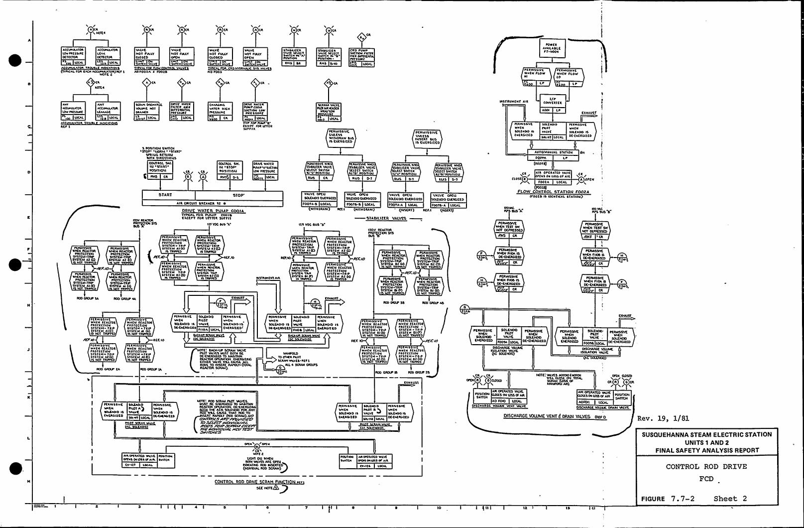
l
HH5RH~ ~

r

DOWERAullLAOLC
/I/ACIIJP /NPIffr/f/I/dY&fJ/ A/fdCd/PIICA/6/ArEXNNY Afft/fC dr/CPPC//D AOl'r/PI/Dd7'/VEIV /Nt/I/r///K/cJJI/rJfr-/Ifr/ddt»cr /I/Ahull /vtd/IICM/ R/r . /CI ~
~ PTO/» /Nf/A/d/NR/CP//c/5'/r/JN/
KRNISSIVC V/IOICNMDvtl A RCPVCI«DOC ONE ROD CDN
SvvNALIS PRESENT
PS
DEAMILSIVC WNEOIAMXL'O'REITNL
NDOC EAC IOO EOITSDLSISOLLTS PRESENT
CO
/I/P/M//Z'nudJ/dtD /O'P
/c/s/r/fp//I/IS 511{Et
RCP IO
QCC
PEAN'ODYE W
RSCS WITNDRAWAMSSIVE 5/DNALIS PRESENT
'SII5, J 5SND // d
PC RMISSll% INCNRWM WITIORAW
PttNISSIVL
15 PRESENT
D 66v L-S/fr9 Rfr9OIANNtL A
KSNISSIVCNNIN ALLIODS AAtDl
SN LN.C
CN«N «EL '4~tANISNVCLINEN ALI,RODS AAC DI
( Nfl I ( NDIII RSM A) (RSM 41 I N
IIIII
l
tl/ICON l«DNIlDRINCCVSRCtf SNI
~EN«55/vtV/NEN ANY ROOIS 5CLtCTCD
~Il/v$51vtNNCN ANYRDD15 Stl.Elite
ANS
Rtt O
d/YVK1f/LXEI/
~CRMISSIYCVNLCS'5 fltfVCI.
PEATIORM IS CREACOAt ARtA
PERM ISCIVtIPRESS REEVCL
DIATftvl4 6 4/IRCONC ARtA
KRNI55ntWLCSS CllffltIS tVCLLOADED(IEVDCASS LSS)
APvSSNf P//kttÃ~/AS///",/ICK/
/f/sir/d//RN5 RLI(EP)
CNAI«ICL A'lttuCLIVXXONC AOD C441SOL4 S.N.SSNC,PC,M 6Rtf R
I /MPAVESACCSPXfJP /vCIW"
/PLCIII/IA/'NS(6/)
PERMISSIVECIWDCL 4'StfIXLIODC IAAESS RtflICL46 SDD CONTROL PEATITIOIIS IIIEROC 1$ CORE AREAXII,NCvN 6
KRMISSIVC PERINSSIVCVNLESS CRAPPIE VIAISS RC PVCL15 tIRLLOADED PLlTIDRMIS ENtt(IDADLADS LPS) CORE ARCA
PCAN155IVE V«LESSSCAAN 45ENMOClOWNE t«SNIIVCLTAIPCCv«L IS SVVMSE6
ANS Svt(CS)
ACtP
~tNNSSN C Nut NSCR//I OSOV NltVXVNC MATERLCVCL IS lDW
Rtf IC 5
SIAMI4%CNARLCVAIDCMICRLEVEL IS LDW/u« LOCAL
N.8
t(N«551vt IMLCS'5SC P//V 45CNAACC
vuu/NE NNN ICVCL TAPSNNAL IS SVPMSEO
~ NS Mt/CD)
RSCSLL
MD MSTONTRAPI A
6I DN
RO0410CK
J5 L ~
ACTTVlffCENTIDL
A RCt 11
6I 4
RIOSEOCK
4N
L'O
ACTIVITT
'6'SCS
NN4 J 6
REO NITCW i
TRON '4'
Rtt
ITVAC IOISTe ftxLtolcto(LOAD5 «DO LSS)
VE LKECV IOIST
6 fua. IOAOEOC AOS l65)
fIIAlteMXSTe ILRLSEPOCOEDIOC «EO LSS)
VtIIIXLET IOOTe fINLLEXOEO(ICADC«DD 145)
DOOWVÃVEMMENNNVPJCRLtvtLADDOIOCKCNOI
DTNINC IVLSETRAPI
)
/VADIDRAWCE ROO DLOCX
DTNMIC RIES('TRMV
I
ICOMPARATOR
~ ~ IL
515'NALIN(SENT
CDX SECONDlflER flREOCOMDARISOII
OILY'A'S TRANSMITCD'IO NCV
LCR /W RDOCELEC~I/
oOD C CISO'5
I O.
CSISO
'DARAELCL'OKRMISSIVC 5(RIES CONT(AXON
WNIN ANTOCICNALIS NO't
PRESENT
AOO INSERTWllRDRAW L
SETTLE CON
CNANNCL ANINVNCIAtINC AODSVDCK CDNTAOL
CNANNCLANIAINCIATWS IODDLOCK EC«ITIOL
Rev. 19, 1/81
445 /I//
AS'/, 0J
I N-It
Rlt Il
MI vvS
Te() CAIVE CE)SI)TECH SVST MSUSQUEHANNA STEAM ELECTRIC STATION
UNITS 1 AND 2FINALSAFETY ANALYSISREPORT
CONTROL ROD DRIVE
FCD
( 6 10 16
FIGURE 7.7-2 Sheet 3

f
0
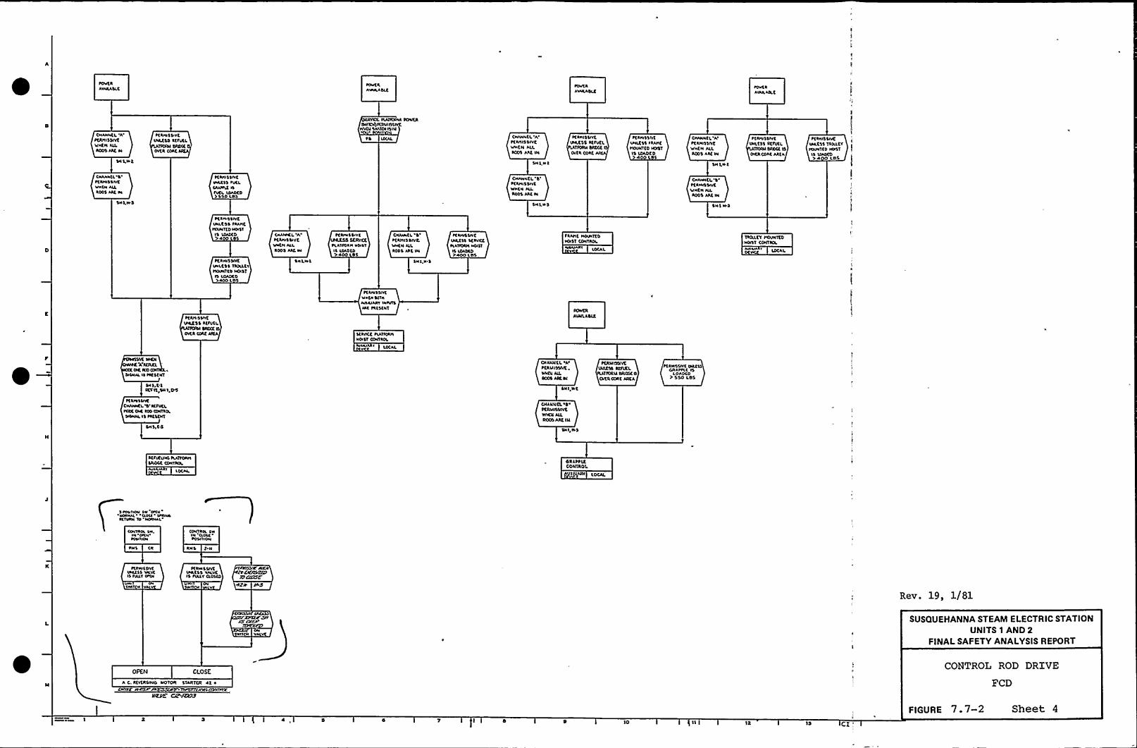
lowfR
AWAASLC~OWCRAWVLASLC
IOVCA
AVMLASLC
CHANNEL'A'ERHI
SSI VfVHEH AU.AOOS AAK M
\N I.lit
KAMSStvtVNLESS AflVEI.
SHOCKOYER CORK
LATIVO+VlSOWTROVOOO ttRM85
VAKV5AIIOIIS IN
tS LOCAL OWINEI'A'AHISSIVE
WHEN ALLAOOS AAt Vl
tt AH I 5\I V tVNI.CS5 AKAVEL
TFGRM SRCGKOJK R COIIC
KANISSIVEVNIKSS IIIAHEHOVNT1 0 HOST1$ IDAOCD>40OL \
CHANNEL AKANISSIVE'VIIEN ALL800$ *AfM
SH LNt
ttAIVSStltVNL'KS'5 RCTVKL
IIORM BRCCK 15
DVKRCDAC AREA
ttAHI5$/vtMlE55 TCCUtvHCVNTKD NOI51
IS IOADED5>4 0L8
CHANNEL'\'tAWSSIVC
Vwtw AU,COOS IAC M
KAWSSIVEINAESS fulLCAAttifISluCI. IDADCD>5>0 LOS
CHANNEL 5'EAH155lVC
'VHCN ALLRODS IAC M
CJILN 5
EHAJMCIttAHISI/VCVHKN NLADDS AAC IN
'581 wt
~CAWSCIVEVNLtSS TRANKHowTf0 HOST
IS IDIOED>4 585
~tAWSSIVEVlttS5 TROLLEYIIVVNTK0 HSSTIS LOAOCD>400 LH
CHAVRL AKAMSSIVCVtttw All.COOS AAE NI
Wl.N 1
KAwCSJVCLRRXSS SKRVEE~LATIOAHNotttIC LOADED> 400 8$
CNAVNtl.KRHISSIVCVHKN ALLRODS AAE IN
SHI.N 5
ttAw$5JV CIJNLKSC \flwktALAOVAHHaSTl5 IDAOtO>400 L8$
TAAHC HOVNTTDICVSI CONTAOC
LOCAL.
IACALEY tv>JN TEDHa>1 COIIIOL
LOCAL
KAHt>SHEIt\255 AttVtl.
SO>X 8Ovtt CCRC AAKA
~% Aw$>tvtV tttN SCDIWLAIAAYINIVTSAlt IRtttNT
\tAYRE tIATVOAHHatt caOAOL
IDEAL
VOJJTRAUNLASIX
SNK NIEHOVJJC A'ATRIAL
OR KDSICH/L IC WfSKNT
~NS,C tRKTlt/CNl,tt$
KAw$5tvtCHAwlEI.'0'KTVKLHCCC OJC ICO COIIAOLSNIHAI, IS tlCSCNT
CHANNEL vAJ
tCRMISSIVE,WNtR AlL800$ JRC IN
CH I,lit
CHANNEL 8VKRMISMVCVAEN AILRODS AAKIN
SNIJN 5
ttRMISNVEURKSS RCTIXL
TIORU SRIOGC 0OJKR CORK ARE*
KANILSIVCIALKTGGAAtllE I5
LOAOCD> 550 LOS
Attutu HS ILATTOAH~NOCK CXMIAOL
LOCAL
ORAAALECONIil,OL
LOCAL
5 loltIHM 5W '0/IuNOAHAL'ICCI 5/AJNCAITVANTO 'NIHNAL
CONTROL 5vlIN Cllu~OIJTION
CONTAIL CwIN 'Cloltt05ITlON
ANS JN
~ttwtttvtIA4555 IWVCIS HALT OKN
5WIT tl
KAMCSIVCVNLKSS VALVEIS VIALY ILOSCO
I5WIT
hZR. JAB
Rev. 19, 1/81
CH VAlVC
SUSQUEHANNA STEAM ELECTRIC STATIONUNITS 1 AND 2
FINALSAFETY ANALYSISREPORT
CLOSE.
A C, AEVKACINO HOTOIT STARTTR 4C ~
CHVtF Jth/FF'AROJOAV TJ//J//tt///ted Jl/JATJKGPVKDZ
CONTROL ROD DRIVE
FCD
I 8 10 12
FIGURE 7.7-2 Sheet 4


poN CA
AVAILASLC
Al
N
l 4, It
Ka/IISSIYCWHEN COVVTE1IVAS'NAAChCPtAATINC
SIEAM PION ISVIORE THAMTltP SETTWO
Atr S
~taNISLITSln EN coNPIIIEASOITWC ISOrtAATING
rttta/AttaCENTAOI.SYSII/I LOWPYA/CA LEVCLALAAHCISS4
ROOTEST4CltCTC1444
SNI.C 2
~faHSSNCvnNN ANY~OO ISSCLCCTCO
REF R,SHI,CS
KfIn/ATERCONtacl. PSISTCN VIN I S/FV/RARA LEMLlvvfalOOLCI4 4 4
C 11EF T
INOICATOA
CATCHES
IWIAOYIPOSSNIIOS ITRMPESWVOG LWOOII\III
ans caF 1/P. 0
lntN4/Ã~
S /RWWLP/vP
SEOVENCCA laaoaca
~ I
Lett/ROO
LTCST
L~OSIER Or~CLCCTEO OASCANNCEIcoNT aoL Ioo
PYLEIT CONTAOL
JSNT.P/S
P EP-C
~ t
~lANIS INCNNE N /tt/r
/rr
CR'CLCCT
EIAORCa
ItaHSS/vtIPACSS Nalll/RYSI CHAL IS~at \EAT
~\IHSWVCWHEN OVIPVTNITEAMCASNAILI'\ patstNt
AEF C
IWMSIPASSSWIIOttIERIA
WHOI tkttca IlIII~1 atvssn c
WNEN NNIUAAYWCNAL ISPAfSENT
P4 OS
Pf AHSSWCVNEN OVTPVT
INTER LOCA WGNALh PIE SCAT
ptr 4
(RWM SYPASSSNITEg PfttlAO4WatN SNOOI h OI
EN
~tAHSSWCvnYEN AFYILIAATSIGNAl ISPACSENt
P' PS
KAHLLNE
(
VNLtSSCOPIIVIlaI~ STALLCO
/wpptnaCRWWI
A
CR
aoo GAovplOENAPNATIOI4
NNI
TCOO CR
1NI4LYITHOAAWCONTROL
~N 1/ ~ .IOREF R,SV 1,04
av/N ROO4/ITN4 AAV/PEAHISSIYCfCNOCI41E
AVIIINltATCONTAOL
Rtr tt/SNIFC ITPYMNS
RNN AOO
PISCISKPPVSWVtECHOCI444
~WCRMATCMSYSTEM CK
IS NORMAL
ERRIRCOOROWATE
XX TY
FYSEII EINMIII COOROWA'.f
rr-TrPCOO CA
NNEIT EMOANlt
PCOO CR
SA-O
1 /I/ca~
//ca 1
Rev . 19 , 1/ 81
SUSQUEHANNA STEAM ELECTRIC STATIONUNITS 1 AND 2
FINALSAFETY ANALYSISREPORT
CONTROL ROD DRIVE
FCD
I O 10 12 12FIGURE 7.7-2 Sheet 5

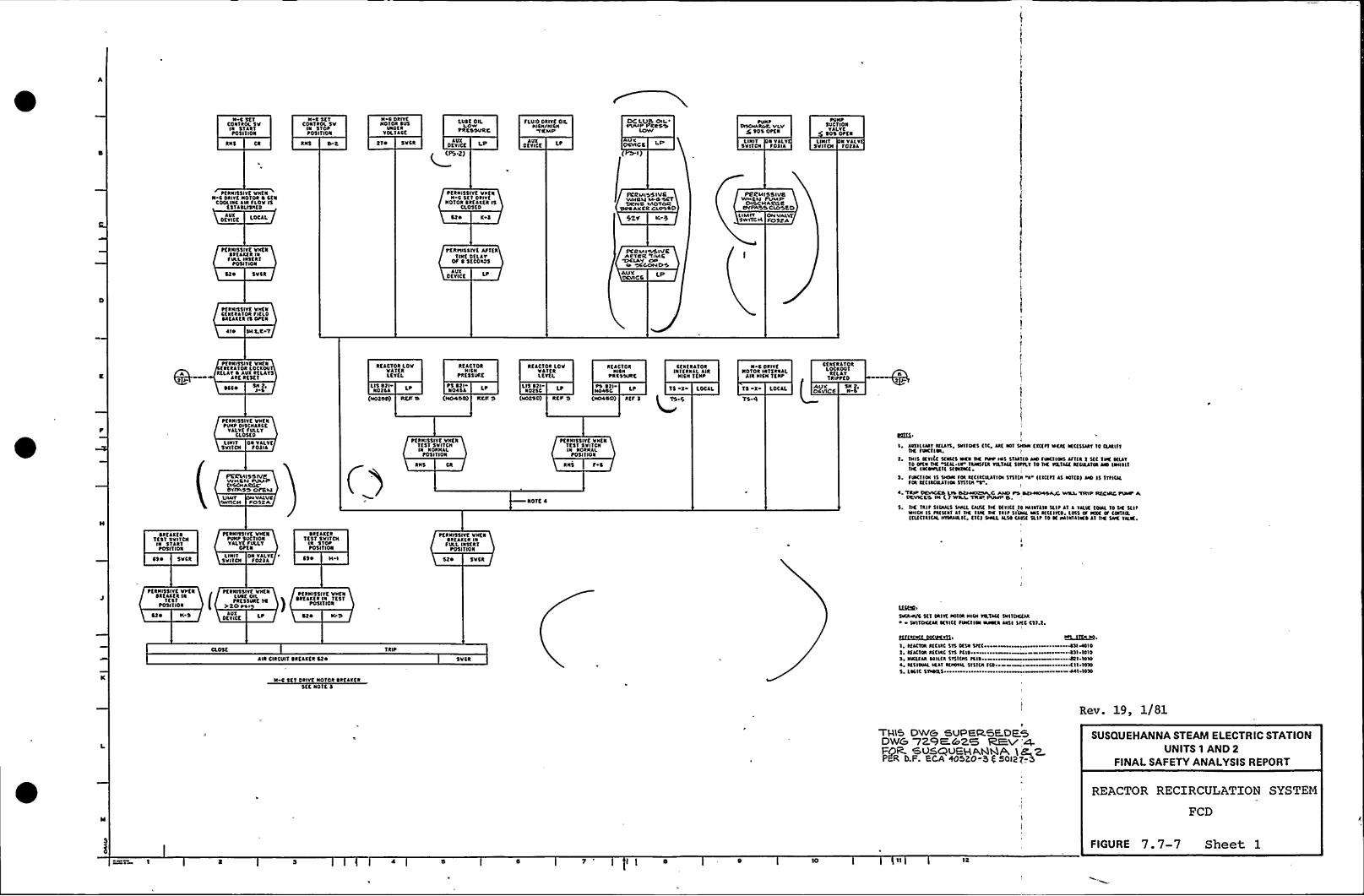
N CttfCONTROL SVIN $ 1LRTtOSI 1 ION
N C St'fCONTROl. SV
IN 5'I Ott05I 1 ION
N C DRIYKNOTOIt SUS
Uatt RYOLfACt
LUSC OILLOW
PRLSSVRC
fLUIDDttlft Oll.NlCN/NlCN
'TCM'P
t)C LL)(5 CNIPlhlP PRRSS
LCWV
PUN PDOCNAROt VLV
5 tOS OPCN
tVNPSUCTIONYALYK
g t05 OPEN
RHS lfo SYCR AUXOt YIKE LP AUX
DtnCK Lt VXOCVICC lIllT
SNITCHN YALY1 USIA
LNHT5VITCH
N YALYfofll
Ptkkt$5IYK VICNN C ORIYt NOTOR 0 CEN
COOLINC ltk fLOV ISKSTASLISNKD
PKRNI5'1lvt VttfNN 0 SKT DRIYK
ROTOR SktlKKR ISCLOSED
ECRMISSIVCwNNu Loa sefSattVC MOYOR
SNRAKKR CLOSRO
PER u I5S IVCWNKM PUMP
CIKCNARCCOY 55 CLOSET)
DEVICE LOCAL Clo K-5 52V U MftSW ITCN
ON VALVEPC)SRA
PKRNISSIYC VNKNSltlatk lafVLL la5tafPOSI 1 ION
ttltnl55IYE AfftaTINE DKLLY
Of 0 5tCOND5
PKRMISSIVCANTNR 'TIMC
'EIKIAV caoCs'COCIND'5
Slo 5vCR AVXOtYICt LP AU'K
DEVICC LP
ttlNISSIYt VNtNClatllTDR ftfLOSRKAKKR IS Ot(N
LI~ Slit.C 7
~TRNI$5IYC VNKNtktll'IORLOCKOVRELAY 0 AUX RKLA15
Akt Rt5tf~cco
REACTOR LOVHATERLEYKI.
LIS ttl LtNOXCA
(NOEOS) RES S
REACTORNICN
tttK55VKE
ts ta-N0454
(HOLDS) REN 5
RtlCTOR LOVVl'ltkLKYKL
us ea-aolst
(HDCSO) RCP '5
RCACTORNICN
PRCSSURE
NDLUCPS tflNO400) Ittf l
CKNERATORINIKkRLI.Alk
RICH TCNP
TS X LOCAL
Q» 4
0 C DRIYtROTOR altaalL
Alk HICN 1CNt
TS X ltclLT5.4
CKNERATORLOCKOVTRtllf
SH f'TRIttCO
AUXDcvtce
PCRMI5SIVCWHCN PUMPTXCCN
ARSc'IYIM55 OPCYALNAIY
OwiICNVALVC
POSXA
PKRNISSIYt VN'KNPVNP DISCNAkCE
YlLYKfVLLYCLOSt 0
LIll1 Ok YALYK5 VI'TCH 1 OlIL
PtlNISSIYC VNtNTEST SVITCNIN NORNLL
tOSI'fION
NOTE 4
~CRNI55IYC VNKNTEST SVITCNNI NORHAL
t05ITION
RNS f 4
ttC(bI AUXILIARYLKILT5, NHTOCS 1'll, Aat IOT 5NOLI KlltflILCal KCESSAAT 'lt ClllfT
IIC fNKNa.1 1HIS IEYI(C 50015 NCN TK TVV Iol STMND lIO ftocnal Lft(k t SKC TNC SltlT
1D DPll TK llll IV'RNCEER nafact SSTILT 10 TK IILTLCE atctaata NO lNN~ 11TK Iacoocttl Sttoact
l. facllcN 1$ SIKIN fal KCIRCILAIIOISntfa "4" ((l(illl5 IOND) NO IS TTPIULra atclactalna SNNN ~.~ 'TRP OCVICKS Lto SRILIOXNA C ANO Pt NCPNOLDAA WNL 'TRIP NECINC PI»It A
VYVICCS IN ( 1 WM YYttt,PUMP 5,5. SC 'lait SlaLLS TMll CAINE TtC Dlncl '10 Mtalala ILI~ ll l Yll'lK EONl 10 tK Sli ~
wlOI IS PRKNLT ll TK IVC IK liltSIIML INS ATCEIITD l015 Of IKOC IP catalLNLKCTRICALHISALILIC, EN I TMIL ILSO cant 5llt 10 lt Pllallkkt ll TK SNC YILK.
tltlKKRTCST SNITCH
IN 51ARTP0511 IOR
01 ~ 5vcR
ttnNSSIYE VICNtVNP SUCTION1 ALYt fULLT
OftN
LHHT ON YALYK ~
5VITCN TOfll
SRKAKtkTt$1 5 VI ICN
IN STOPP05l 1 ION
CS ~ N I
~KRNI$5IYE VNKNDRKLKKR INfULL INSERT
P05l'TION
5VCR
PKRNI55IYK Vttk~Rtlltk lk
1151POSITION
Clo N '5r
e KRNISSIYK VNtkLVSK OILPRESSURE IC
PRO Psl
DKY ICELUX
~Elkt'SSIYt VHKN
)tkKAKKRIN 'IK5T
t05IIION
Slo IOS Svco»vc St 1 a IIX Hola aot nl Tact Dn tocua~ SIN TONKAR anct 1VKTta NILNKR NCI SHC csf.f.
Cl05tAlk CIRCUIT SRKLKKR CKO
N C SCT Dllvt NOTOR tktlatk5tt aOTK 5
Tait5VCR
tt(L(SLJSS)CL(EI
l. Lfacta LICIRC STS 1514 ~ all 10105, NYCIKLR SSILKR STTNIN f114 4t I 10104 RESISINL ICl'I IKIIINILSTSTIN ICD~ ~ ~ ~ Kll IS$05. cocle SINNRS- 441 IDSD
Rev. 19, 1/81
THLS DW& SVPER5E.DE5DW&7Z9E&Z5 REv 'gFOR. 5VSQVEHA,tlgA,
'IIC'ER
t).F. ECA %520-3 ( 50(2)-3
SUSQUEHANNA STEAM ELECTRIC STATIONUNITS 1 AND 2
FINALSAFETY ANALYSISREPORT
REACTOR RECIRCULATION SYSTEM
FCD
FIGURE 7.7-7 Sheet 1TO 12

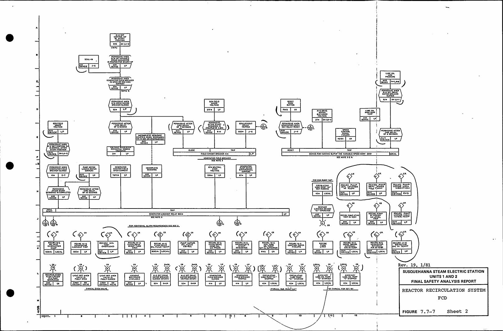
N C 5K'IC4NTROL SvIN tlat ltosl lion
RNS SN I,l 2
KSIA)
5KAL IN
~ftnl'ISIYKVVKNSll~ OS
Yltlltlf'ottoConvfkltkIS tRotfR SOR STAR l UP
AUXOtvltt
~ftnl55IYC VntaCKRKRATDR fltao SRKlXCR
Is OtK ~ Ok CCN NICNCvtttklAUX
DCYICK L
NUTt 2.
LUSC OILLDV
PRESSURE
OKVRE
PKRNISSIYC VNKNN C Sf 1 DRIYC
NOTOR SttlttkCl05fD
ttknl55IVK VntNN C DRIYC NO'IokSttlXKR CL05to
52k
CKV SIKIOUaof t
VOLTlCC
21S ~ Lt
ktstlPVSN
SUTTON
SINS CkN C Dklvf
Noloksvs UnofkYOLIACE
LUSC OILNICN MCN
TKNt
52k 5N 1M~I
~ C ~ flCLOUkofk
YOLTACC
LUCEX AUX
DEVICE LP
tftnl55IYC Afvfa'nNC ofalv
OS'5 5KCORD
INCOMPLETE SCG/DCCSTARTCD YNICN cntkolftoTD IS 5IC ON CNCROIDN
AUXOCT ICt Lt
tfkNI55IVElflfkTlat DKLAY
OF 1 5fconos
tftNI5 5 IYKASTtk 51ltlSKDUKNCC l5
COMPlETE Info )AUX
OKV ICE 5CC ~ J 5
CfN lottovlRtalv
TklttKD
AUKORVICE J 5
~ttNI15lvt VntNCtkfallot lOCKDvl RKLAY Rfsf'1
21 ~ SNIS l
stfCDCONTROLsltnaa
FAILURE
KCISA tk
AUXOKYICK LPI
~tkkl55ITt lfltkTnlt Dttlv
OF C 5ftok45
AUXOSVICR
PKRNISSIYC Vnfa5 stl coaltol 5
IN Notnla lflfk5TART P05I'IION
DEVA:E
tOTKNUAL SOURCE
SI ~ Lt
AVXDCNC C
Lt
CLOSE TaitFltLD CIRCUIT SREAXCR ll~
Ctnttllok Sltto Sttlttk5tf NO
L SI
Rt5tl Tait
Dtvltt Soa vlantc SLIPPF 'INK vlkuSLT. 5ttfo conv 5001 t
5KK Nolf 3 E S
AL
PKRNISSIYK VNCNCtnf tllOR SIKLOSXEAXCR CL05fo
~ I~ f 1
tUNP N410tLOCXKD ROTOR
tvakfNT
XVICE
Cfaf allotKXCUKR SRLOOYKR CIRttnl
TCFX~ Lt AUXDCYICC Lt
TACONPLCTC5tOUCNCE
CKN NfUTRALOvft
YOL'IACC
5sao Lt Sl ~ Lt
Cfattllot~Vnt NOTOR
OIFSKRK NTIALCURRENT
CkI
Ck
TTP $ 4t ~ l
Pf tNI55 IvclfIfR Slat'1SKOVKNCE IS CONPLETED
PKRNI55IYC lfltkTINt DtLAY
Of lo 5ttokos
ClkCULA'IIRCLVSE PVNP
'Al'OTkvnklkt
of~ LOCAL
kfCICC PUMPLCAKAOS
Hl FLOW
NCCIRC PUMPSEAl OTAGSw/LO PLOW
2CCIRC PUMPMOTOR HIGH
VI0 kATICOJ
OIUVICCAVX
DCYICf Lt AUXD'KYICf Lt
'44CfktklTOR LOCXOUT ktLAT SCC ~
5KK R41E 3
TRAP
~ l ITI III l atn t at
LP AUXDC TICK
Lt
/A/ a Ck
RCCNK tvvt AlafcTRIP NI 'Ifsl
AUXDKYICK L AUX
DKYICtAUVOUV ICE
RCCVXC M%OIL Mliv
CLNIINATORNIK)t
SDOIA
RCCIIC al 00c H C RATok
LOCKOUT TRP
SCCo
RCCIRC SYUMOV
CIVERLCSAO
RCCNIO al 0fl.UIUCRIYCScoot 1USC
LOCK
AUXDtyltf L
ta ( ca
Rttltc M CfLIADDRIVCI Hl/UO'TEMP
SOOIA LOCAL
Ck
~UMP MIITORav Mlgatt
AUXOfvltf
( tk
RKCIRC M CFLUID DRIVE
LUSC OnLO I'Atat
AUXDKY ICE
L
( CR
ACCIRC M Canco alt at Tt
STARTSCOUCNCC
DCvltf LtlUX
ca
Rftlkt M 0AUL MI'SCon. Pvaap
Nlfl IN Al/TINRUII
RNS
RlsllklLOCKOUT Dfvga*I OtfaAIEO
tkI
CR
Recant PUMPNl ~ AC'5'l/I.o LCVCL
'1 Alt
acclac aa-0Oklvt Maloll
INT C %Nil.Al'R Nl
TCMI'CCMC
M.oCONT RUL toavfa
FAILURE
RttlkofLOWLIMIT
OCvKCAUX AUX
OCVICK CRYICK LotlLl
�AUA
(- c-RCtlkCM 0OCNtRATORInltnnltAln NITCNP
RCCIIZC M~ONARIuoaL Hl TEMS
LoclL Of.VICE
CCCI CCMTXTOR HIGHIMTER,TCMP
g Ckr0
tfCNCULATI4NfLOU I NNTCD(fV tVN~
UITERLOCXI
otntf CkAUX
Ck/
LICNT OfF VNENYALVKls
SVlLY OPKN
LINI'I ONSVITCN VALYC
LICKS OFS VNKNYALYKIS
fULLYCLOSED
LNUT ON5VIICN YALYK
TYPICAL KACN VALYK
Ck
W
lOCXOUTsvs povlaAYAILASLK
AUXOCVICC
Ck 5VCR
R rN 5 5CT DRIYKNolot StflttkCLOSED 151ll\II
Ck(aa /JI'VCR
N C Stl DRIVCNolok Stllttk1 RIFI'ED Is'IDPI
52o 5YCRa 52 ~ 5VCR
Ck
k
ll~ Lt
Lt/k
CKNERATORSIKLD SRKAXKR
CL05KD
CfkftllokfltloSktlltk'lklttf4CIRCULATINC
LUCK PVNt AlSlotttD
Ck LtrR
CI R COL ll INCLUST PUNO
'Al ''IAklfDll~ ~ 2 ~ LOCAL lf~ LotlL
~TYPICAl fan PVMt At
Ck Ltr L lick/ il.t/al W
y )$0CAP Ck
R R I/
AUXILIARY ILvtc on. PUNN
0'TARTEDAUXILIARY
lUSK OIL PVNPt'TOPPKD
O'vtltllfok 5tl
of~ LollL LOCAL
SUSQUEHANNA STEAM ELECTRIC STATIONUNITS 1 AND 2
FINALSAFETY ANALYSISREPORT
Rev. 19, 1/81
REACTOR RECIRCULATION SYSTEM
FCD
I I 0FIGURE 7.7-7 Sheet 2

~ .

UI~ K OILPVNP 'llRUNIINC
Lt
CONTROL 5VAl M Sfsskaaf I
t0511101
RAIS H.l
LLISROt PRCSSCSOPM) LOW
PSL
(PSH)
LVNCOl PRKSSc SO f\g LOW
AMIOCVICK Lt(PS 2)
lVSK OllPIMP atkvkklkl i
COklROL SV'at IN 510tFTSS ITIOAI
PO f tl
tfRNISSIVfVNEN LVVE OILPUMP'Al
Rvk1INC
Pt RMISSI VRwNNNI al6 WOIOVS MOTOR
KV LINN NCS
PCRMISSIVCWl»MIALSNTTfkiVU MOTOR
RIIMMINIG
Pf RNISSIYfVNEN LVIC OIL )PUMP
RV11I1C
LtAUI 52» Tt-t SSv N IK
AUIOKYICC l
OPERATE
AVIILIARYOEYICE
RK5ET Ottkl1CAUIILIARYOfYICt
RC5KT
LtRt51lkf lOCIOVT OfVICE ll kt5TlkT LOCIOVT Of VICE
lt'ONTROL
Svll IN Sf lkf~05ITION
~ fkNISSIVK VNEN1151lkf LOCIOUT
OfVICE llRKSC'1
AVIOfYICK 0 3
K5 J4
P1 1
ttRNI55IVC VNKNRESTART LOCIOVTOEVICC lt'fSET
OtYICC 0 ItAUI
fNTLLTTTW51tTCIIMOMINTARY CONTACT5wlTH SIILIIS RETURN
CKNITNOL SWAK Rt START
POSITION
RMS Ck
SEAL Rt
QST s
5KAL IN
VI CONCt ~
tfkNI55IYE Vkf1RK51lkf LOCIOUT
OKVICE -aPRt5tf
AUIOKYICK
CONtkOL 5VITCNAl IN NORVAL
tOSI 1 ION
RMS It 2Luce
Oll, PRUSSC SOPMy LOW
LtlafO<l PRCSS
CROP 5 LO
PtRNI55IYK Vkf1CONTROL 5VITIN
At 11 NVRNALtOS IT ION
RMS f-1
RESTARTLOCIOVT OfYICC
At RK5K1
OKYICK 4 ItAVI
~ CPtTROL SW,A~KNOT IN STOP
RARS f tl
COI. SwAl MOT IMSIOP PVTSITION
RMS K 2
PS 1. LP PSf- I P
~UIOt VICE
Lt
ttkNISSIYC VNK1LVIKOILtvkt Al
101 RV11115
~ SMTOIMIMEITTARTCONTACTSlkTH 5tRMI NETISN
TO NORMAI.
COHTICL 5WtTOIAt'N STOPIltSETI
RM'3 CR
AUIOfVICE LP
~KRNI55IYC VNKNLVIKOILatRVNNINC
SF 5
PK RVIIS 5 IVSAF 'I8 R1 SKOttff OETAY
LAY'OO3A
COMTROC 'SWC IM AVTO
POSITION
PS o.b
PO LP
CONTROL SvC'N STARTF POSITION
SEAL IN
VI COIIats
CONTROl 5V5'N 510PPOSITI01
'51lkf
AC ROTOR STARTER ~ I~
CIRC ATINC LOSE PVNP at5ff NOTE 5
STOP
CONTROt. SVAt IN STOtkfftf
POSITION
RM5 f 1
LOCAL
STOP
AC IIOTOR 51ARTKR lts51AR1
LOCALRev. 19, 1/81
CIICVllTINC VTK PUN ~'ll'EC
101t I51lkf
OC IIOTOR STlkftk ltaSTOP
LOCAL
lVIILIARYlVSC OIL PVNP 'C IO POR 511 SlSff NOTE I
SUSQUEHANNA STEAM ELECTRIC STATIONUNITS 1 AND 2
FINALSAFETY ANALYSISREPORT
REACTOR RECIRCULATION SYSTEM
FCD
FIGURE 7.7-7 Sheet 3
I 0 10 12

4
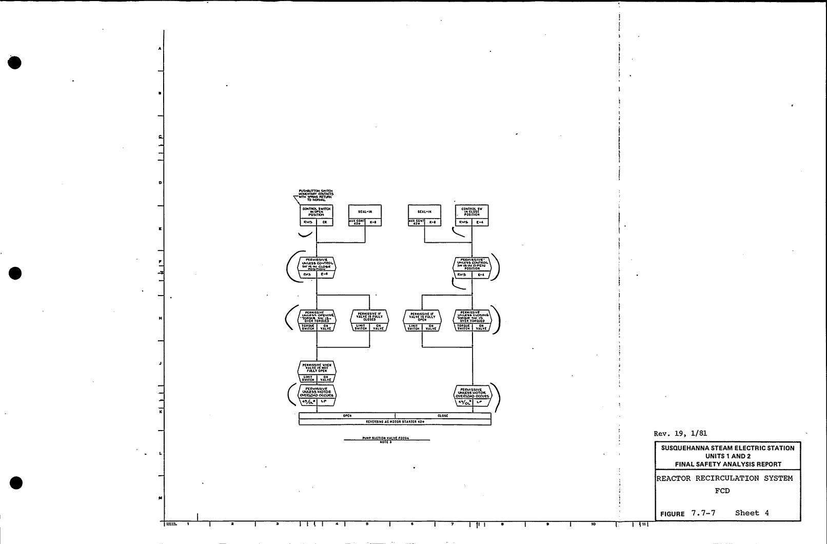
CONTROL 5YNTCNH OttN
POSI TSNI5CAL NI SfAL IN
CONTNOL SVLN CL05Kt05ITION
RMS VI CON42 ' 5 VX CON
42 ' 5 RIJI4 E
FKRMISINILNSS COOV IS IM
~VI rrR 4
PSCMISSIVC'NILNSSCOLITROL
SN ISIM OPENt0511ION
E 4
tfNNI55IYfuMm55 OFSIIINKI
'TOROVS Sw QFCNNI55IYC IF
VALVE IS FOLLYCLOSES
FCNNISSIVK IFVALVE IS FVLLY
OtCN
tfNNI55IVRVMINSN CIOSVI4TOCOVS SW I5
OYtN TONOVf0
TONOVKSVITCN
ONYALYK
L IN I 1
SVITCNON
YALYCLINIT
SVITCNON
VALVETONOVCSVITCN
ONVALVE
ttNNI55IVt VNCNVALVE IS NOTFVLLY OFCN
LI NIT5VI1CN
ONVALVE
PERMISSIVEINALESS MOTOR
OIERLOAO OCCVNCS
49/OLN LP
PERMISSIVELNIIESS MOTOR
OVERIOAO OCCVRS
49/O 5
OttN
NKYKN5INC AC NOTON STANCE 5 42 ~
CL05t
tVNF COCTION VALVC FOWLNOTE 5
Rev. 19, 1/81
SUSQUEHANNA STEAM ELECTRIC STATIONUNITS 1 AND 2
FINALSAFETY ANALYSISREPORT
REACTOR RECIRCULATION SYSTEM
FCD
FIGURE 7 ~ 7-7 Sheet 4
I I 0 'IO

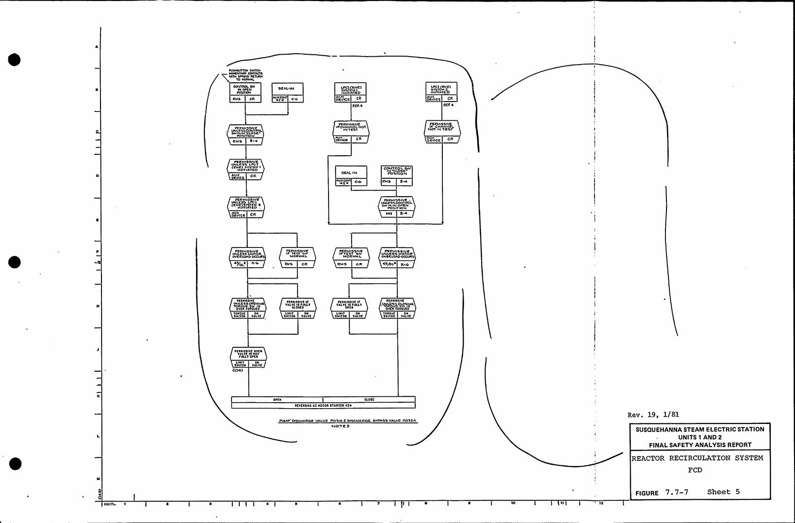
CONTROL SWRI Ott)l
POSIT ONSEAL IIA LPCT (RHR)
SYSTEM IINITIA'TED
LPCT (RHR)SYS'IEM 2INITIATE0
IZMS CR UX KC CR
REF. 5
AUrDEVICE CR
REF, +
PCRIAISSIVCUNLESSCCNTROLSWVMN'CLO'SE
FOSITIOIJ
PE RMILSlveINCHANNELNDT
INTEST
DUNCE
PERM OSIVEIt CHANNElNOT PA teST
AUNDEVICE
PERMISSI VeUNLP'SS Ltol(RNR) SYSTEM I
INITIA'TF0AUXDEVIC S.
SEAL IN
4ZN K~
OCAI~TR IPOSITION
RMS SHL
PS RMISS IVE
(RHR) SYSTEM 2INITIATED
AVNDEVICE
PERMISSIVE .INARSSCONTROi,SW IS IN OPEN
POSITIONRNS
PC RM IS SI VeUNLESS MOTOROVE RLOLD oCCURS
K 5
PERMISSIVEIt TEST swNORMA
E)IS CR
PERMISSIVEIPTEST
NORMAL
RMS CR
PERMISSIVEUNLESS MO'FOROVERLOADOCCURS
49+LA
)DROVE5VI)cN
ONVALVE
FCRNI5$ IYfUNI.E SS OFT4INO'TOROUR SW IS
OYER 'IOROVf5LNIIT
SVITCNON
VALVE
FCRNI55lYf IFYALYE FS FOLLY
CLO5tD
LI NITSVITCN
ONVALVE
tCRNISSIYC IFYALYtIS FOLLy
Otf5
TOROSE5 VI 'I CN
ONVALVE
~tR NI55IYf.~P CLOSIyoOY R )OR4'JCD
~ tRNI55IYt VvtNVALYC IS NOTFVLI.TOttN
LINITSvl)CN
ELSE)
ONVALVE
RCYCRSINS AC NOTES STARTER AEN
PUMP (NSCHARGC VALVE POSIA C DISCHARGE t)YPASS VALVE PO32AA)ote S
Rev. 19, 1/81
SUSQUEHANNA STEAM ELECTRIC STATIONUNITS 1 AND 2
FINALSAFETY ANALYSISREPORT
REACTOR RECIRCULATION SYSTEM
FCD
10 12
FIGURE 7.7-7 Sheet 5

I

tfKAC,tt)tf 1 EVEL. Q'TEAtvt FLDW FKKDNAY(R FUtW
c ca
rW NDDAA
g lake I)sl55
ltVll OUYOt Strrtt
8=
irk'ItrNFSD 3
REF I[Not)fJRCN 2
I
+2I MKR CR
KNool) atr. 2
I)atr. I
IW I Ls
1Ut
I I
4 O'tat ovt wtrOt ttrrtt
CRER
II1
I Qo
one
tII
II1
I
tIt
2005
I stFtDFF
I
II
IffI
II
I
I
II
I
(tI I
llCAg
IREACTOR
CR
IsttteN1 NOYCC
11
I It I I1 I
II I I
')I ~ 1 I
I
Il)II
CR
5 I CR CR
J 4 g ) aiosa ~RJ 5RJOSA
0 ICR )I
1 i~0 I
I
II
II
1 caF Osl
44 + LL~u
NIJII/LDW ca etsteN haWAtca uvcl,ALARllUNrt
II)
III
I (,„rw ptNAF tap ietce
wAV OR LDUN/atcsac Loop ALevee ) t'4 Flow ttcoocTION (RUTE 1)
I
LPOfi
I 10 A v/CCJYDTJL etiANrio
OVF0 i 1 OOClov PDNtil Lov POFCR$('1 PONT ALARii PotNT
I
r—$
uveL
I f =l,
tcoct I Floes I ttocN JLVEL II
I ~ 1 IN CAI
ANCSOA t 1 NC.TOO
IVATTR 4 ——i I 4 I~ atskioa
level. I tats 03 f I I (k(k C)( ) FFAYORA Ltvtl
NtCNLCVCt. [ CR Q V Tilt( 1 N«Nure.TV%SINE VURONiik
t tat i500 TRIPI NOTE 'I uvtL1F NOTF. S
I
I ~ ttvtLsttlttto~ R R ~'O'Ltv(LStlttttqo
,~rr'V. )02~2rtsj
REF 2
rtJOO *~2
i.DOAL
tNDDSA
ieCIIFcccssattaiNLEY AFLOW
Ft reDR(rt RKS 2
A ~ AF/t
«CAT ~ I «Cl3lttostirtk FLL(OVtkoktt oa.it .C..
0 R Flost CRNODJD %JOJC
Loee DFPUN$OXMYACYev otst.ND'Te 051
LDIS orI PFNP 4
PctACt
!
NDVPqitt
Ni
aPote $2
1
I I It i I
I It gI II I
I
I
I II I II 2
II I )1I 1
J
II
rtoOL lDDO'Al'eMAIN Rtk>ac PFNP ~~+ 1 1cevsretscN SNS D.t
-;«4 4 ~lI
F«et UTJCE PRO5S RLAC'toa PRLSO
tata tNTERLDCR1
s
l. All (CVIPFCNT AICI IN5TRUFCNTS ARK tklflt(DIY $151tHNO. Clt UNL($$ OtlCRNISE NOT(0.
2. FOk LCCATION. lDENT IFICAT lON l RECORDINC INSTRVHEN1RANLES Stt INSVRtrCNT DATA SHE(1 DEEP l2).
t
0(VICtS XO2ll,I I C iklr CONTACTS iO IK VIRt0$ 0 THll 2 OVI Of 3 DtVICtS WST TRIP 10 INlllllfallaAND R,F.P. TVRSINf TRIP.
tTHE PEMER SCVRC( FOR iiC Ft((MATER I INSTRVH(ittlllONAitDCONTROL $ 151(H 5HAll HAVE Ai L(ASTIttC SANE 0(ClifRtllltlllttAS Ttif POACR SOVRCK fOR 'tat RUC'10R/FUOISCOST(k/CONDENSATK PtriPS.
AEICUSTOCR Sal(L PROVED( tvo NORHllLV Orta CONTlCTS Ftk1Vitelitt DRIVEN RflCTOR'Ff(0 PUHP 10 OPERATE tACN TURSlitKtttD PUHP UNIT HA$ 1RIPPKD OR S(ENISNVTOCMN. THE CONTACTS
5HllL PR(ttMSLT IE DKRltfD FRCH A]FUMSVtt(H HOUN110ACROSS liC R.F.P. tOV FUM k(CIRCUutlON FLOV flfiCNfPROVECCO SY liC At/CUSTCFCR OR R.f.P. Dt5(HARL( YAlVtStt TH(tf AUTOWtllCAlLYRUN CLOStD ON k.f.r. TklF C.f.tlr(01 klDttlIt( liC5t CONTACTS FOR tel 1 IA'1 lON OF REACTORklCIRCVlATION PUFF RUN SACC lli KV(NT Of A 1 OUT Of 3R.F.P. 1RIP Al HELN lOADS.
SVttttCS Siull St SNAP ACTION SUET(tCS CCNTACT CP(MTICNSKINS ESCEP(iCCNT CF SPEED Of Ctatkft ROC« OPEMTOR AC'110N
10 AVOID CONTROL ST$ 101 ERANSIENTS'DVklNC SVITCHINC.
INDEPENDENT ALARti 'VNI1 R(LAYS Oa INT(RPOStNC RfllTS10 St PROVIDED TO (NSURf $ (PAMTEON Of RlCIRC lOOP ACONIROL CIRCUIT FROH LOOP I.
S. fUNCTION C(NEMTORS Srttullt CHIRl(TERIEED SAStDON tVRSINt kt PUFF Uatlf M SICNAL YS FV fUM lSIHRCalMCTKRISTICS TO Sf SVIH11UO 10 Cf DYCVSTCFCR/Af fok AP(0 DlSILN CONPLK'(ION.
'3. TK((MAT(kfUM ENT(CMTEON IS AVAlllSLEVll NSSSCCFPUT(k.
I
l0. PEACE 10 DC PtACR SVPPLt($ tlltttef fkt« tetCP(NO(et$00kC($ .
II. FNittATFNC DIURNAL FOR CRY POtNY CET DOWN FVNCYSCNONAMUE LEVOI S(keteasttNttL'DCRAFtCICNAlssDJAYVFN OfVita DELUMEI AVAILADJE
CR1 iaido
tait NAN
II CrCk''R1 F~l5 CR ~
2(ant RI Ot 1 ~t«sr c Jo F/ACTOR RCACTOO! STCAM FN I
E +%i t~o-~>
I CaIrsst I ttliiFlit
II
OCLACT DEMANDOFONAL,. ih
I 0 '11 ~ SFL i 1 ~ ~ i I ca ca
1 NJFFA rJirli I Nisse rsstrt t Fttft.''R%( 1
~NNF t
ALAtii istti I ALARM llllil4 ) AvtU Stttct) ~«4 0~ ) Ark'tttct) ~«4ca I toto tatct 5 TAILK t
I NJZlb I II I
I I If
1 1 i I1
I I, J1 1 1
NFR I g Fete I $$0 I X secs
I FANtra1
FAIMFC FAItorteI
I1
)N007
20 AAMAWttaeOTCAMFLUFF
tockNAOF toitewt5'll Jss FLOw
L J
FOKlltatvttofvat
tVRil RClltoaUTOJM Paeeerttrr
LLY(L CONTROLLER
illCArto SELECT
LKQJNNg
+t
ft)VtrtCNT SVPPLltD IT 011CRS.
PERFONNANCE HOFFTUFSNC Uvs CDMattta
ooFLAV CONTROL CVS COMFtltta
tttf~GAL'ttt(litt I lRLJIEEUClIl. F(t(MATER CONikOL STS DKSICN 5P(C -'-- ~ . ~ Cti.l010
2. NUCLEAR SOIL(k $ 1$ PllO .—. ~ ~, ~ Oil 1010
3, REACTOk kfCERCERATION $ 1S MID ~ ~ Stl 101D
CONTROL ROO Dkltt HYDMtREC $ 1$ FCO Ctl~ 10305. F(KEMAT(k STS VOID «. ~ ~ ~ ~ ~ - ~ . ~ ~ : ~ ST OTICRS
C. HAIN IVRSINK CtN(RATOR TRIP lOCIC tl(H IT 01HKRS
i. RFP TtktttlC SrtED CONTROlttk lCCH OIAC --. OT 01ICRSRFP TEN«IN( Stlt0 CCNTROLL(k VIRINC OIAC IT OTHERS
ENStkttCNT SYHSOLS ~ ~ ~ lll 102010. PIP INC C tettktrCNT STHSOLS ~ ~ ~ All~ 1010
bll. AVX. IVRSINt F(10 PVHP TRIP LOCEC tl(H ~ Of OTIIERSil. ilietRUMLNY CATA ONCET 'I2 5050
I
Rev. 19, 1/81
SUSQUEHANNA STEAM ELECTRIC STATIONUNITS I AND 2
FINALSAFETY ANALYSISREPORT
FEEDWATER CONTROL SYSTEMTURBINE FEED PUMP
IED
s I 4 Xt 4 4 10 Ctt
FIGURE 7- 7-9


woro 5
I EONrroc sH:/AI srrrr/05rrloNFNJ cr 42 A co
TVP„FOR tUSIP COOI8
(N044OOYE 1
LP
NICNFLOW
REACTOR'WATER
LKVCL '2
CYASQIQV LHHIO (IAQQDLs«5rcvr RArp AM5
Qcrr rr/c(vr.s)rrcrresDH I
SC
Qts. 5lc
VIQIrrrvM5rvc
~««4« 45 SCC.FINcr occrvrs FINco ovr
ALTtR DRETTtMP NRJI
rr
IIFF(2(N~T
CR «krr ~ C r«err r~~«Ster]
CF I R.EF I 1
RVVCU SYS.l(AA NGHflOW
J.rAWS 4 «to 4
AOIC D~RO20]
IDCQDEYEQtNTIAL2(MFEQAYUQ(
trtc«crrrrj
ISOTK 1
Q ISICH
Dsf(QtNTIALYCMSCQATUQK
CE
~c/]NA1
R(FS
HlcrHVQR.
[«4004)NCYC 1
[«Arto]SOTC 1
J Eoc'IN
Ivors 5CONTROL SW.IN
'OPEN'O'DITION
CONTROl. SWIN Cla5EPOSITION
ssoc'SNMANUALCONT R Ol.STATION
Acr.sP(QIAISLIV(1541555 SVPASSSWIYCN CLOLCD
CSR EE RMC CR RMS C.S Jco Cr CR RHS CR
ST R HISS IVCIt PIPN'tALCAVI'fY I'tHP
HOT IIICH «8 Horaoc~ SOT PULLS/
IPL5kr mH LIILC
IHYIT,I
PUIrr(HSCH ARC CUDW FLOW
LrPEFN /55 IrcvA'cc55 rrrro
IJOCrrrkv /4«rQIS pres EAIrrr«re
cow prcssurevp.srrc JN 0/WCIT FOSS
coCCIC
VIA«rrtJfvrfotrlv.s rrrrN0/rrrrs Joss
NOTCH
COHHONALAQH FORPUHP A 5 Tk
CAV(lY TKSSP,NIGH
CONTROL SWIN STOPPOSITION
LP R F45 2 I
/ k /R A/ k /
CR CQ
START STOP
rvNp Jrorrcr 4J ~
Ecvrk«crr rrcrrc pr/Arr roororrprorc Fov Ecrovcrr rJcrtc rr/Np Eooro
CRCEPT AS NOTCO
~E RHISSIVEUHI.ESS (rtrrDW ID IH DYAQ(
POSITION
RHS 8 I
ttRHISCIVGSt TIHCR IQ
VWSfa CUT
TFHEA cR
PEQMISSIVCWHEN VALVE ISARLY CLOS(G
psrrrrlsrvcUNLESS M(CHart QLOAD(IIQON OPENWC
ttfrvk55trcVALVE
ISRALY Or(VPERMICSIVtUNIESS M(CN
OVCRLOAO OCCURSlot I
LWI/«Hvr ~Hkvc RHrrc»
'L /R A/ 1 /
CRNOSE 2
OPEN CLOSE
REVERSING CONTACTOR 42
Ecor/prrr JrsrEN /so(Fr ON rrcrs No/oor oc opvrorcbrvrwrc For /IV«/coc Ercrrr Fercesr«E Elr«rrcroe rce(oc o/err')
coNFEE rcR
CVHAUST
PEENrstrrcIvrrcN/vcoF rsE NcrsrJso
PERMISSIVE45OJCJ(t(2 VARSI PR(YT IS
(2E ESRYTrlt(D
sLOT ICNAA
WRWQ ckctooaPROT Dt EH(QGIECOoo ross cocrc
ocorvooHIY F(ON corveoc st(vs Jo /oss
I, 141(olocl tOO 5'illf ot CIR(olf WIYII HHS DI5(HlRC( lorSLOI 5WIYOI 10 ttNHY tIHt 10 oc 51llho, SIHt IS 10 flitoff Aff(R 51lll lf SLO4 IS kof, tSIllll(H(DlfY(R l YIH(0(ill DR IS 111(MOtitD
2, ISSDNIAYIOI Or MMII( VALV( IVII(AYNGLlarl Rc(OIR(HCHYS,Aro tkoc(54 Ik(MQfkflllokMONROEVIS IHI(H AA( Ilol 5HIMIOI 1 CO. MAVOC oolllkCO SROI QC tr(ICH t(10 R(f. 2.
'Cokllol SW S.t0511104 5VIYOt 5MIHC R((IQW To NARRorlt55 DYIERWI(t St(CI fr(0
I~,
5, SDR lo(AYIDHAIO ID(kllfltll(OIOf 14$YR'Jfkf(5(t lk5YRIH(olDlh Oft'I ll51(0 IQ HFL SDR CADI UGIQJEV'I,
4, ALL (oolrtfol 5 IVI'(RISEVIS Mt SR(f1 2(D OY 51(ltrl Ilo. CTS
1, ALl INYDII ot(RAY(0 Cllt VALV(5 R(DVIR( ttAL~ IN. HDYOI ot(RAY(0CLOS( Yftt VMV($ 00 Wof R(00(RC ltll IV.
SI(PAL 55(0 10 Clolt 2(IRA(IOI VALVt Fool DHL1,
t. VISHr(024.(.c Ara \SHICDDA,C,T AIO IF541502A, vt(SHI044A Ccolt150LATIOI VALV! Stol.cfsHN025.0,f Ako 2$ HI(002,0,E Alo SFSHNDIS, ctllrsolll c(0$ (1$ 0lAYIOH VSLVY fool
I
10, ALL torts AWI HDYIQ ottlslto YALVt5 HDYIRS SHALL IQV( TH(RIQL01(RLolo Yllr.
N. Fool Craoo AQR NQSGQ WALvcc, AHD HAvc an. Qrrr SL
Nots JCarcYQOL YAVHI s(SMAS
QVIS CR
ackcrQGU QwIsr 'CLOQRPOYHTRsrc
CDAS J I
scrc IN
ECQ
A'vorf5
P(VDITNIII
SOAS J J
S 5JC 'IN
JJE EE
rrlltRDLNINQ(FLUENTICGN/LOWCON
RMI I C'R
FILYKRD(MINCSSLUE NTHIGH/LOW
~ 5 ~
ALDS.R CR
FILTCR U(MINFAILURE
FQXKR UOAINTCMP Ngc(ISO
S LOCAL
ttfitt2~ SWIYCHC(AR 0(VICC for(11(N QJO(R5 Stt ANSI Sl(2 CS22,
P(RMISMV'tVAIE14 VALVt 15ARLY ClGSCO
PLQN GSIVKVAENVRVE hALLYOPEN
H'r/ X /R A/ 1 /
CR/Hors 2
PCQMISSIVCLAL(51MECN0 TQIDL1 OCCNISOUR INC CLDUNG
FERNNSIVCVACNVRLVC 18flALYCLOSED
PK RMISSSIEIJRESS MCCN
ro«HAr«rrr« /R/
Arors
SNSOkr Qsr WR
IS ALLYOPEN
rrnrr/A/
CR
PERMGSIVEUVIESS IICCNOvtRLOADOIIVHDClOSINC,
IASHIrl~ CNat
CL(AHUOSYSY OAT(LET FLOW
CIKAN04'VSTEIA
CXSYLKTFLOW
CLEAN UP'SYSYKMIHltf TCMP
SfL'[~ALII& [email protected], Qo(l(AR Oolltf t151UI S(0 121 ~ 1020
2, 5'(clair LIDVID coIYRCL 515'1tH fco ~ 441 1020
1 Rtl(YDR Vllto Cl(AHVt $15'IUI tlID~ ~ ~ 425.UA
D. STESM(tr44 OLYECTSDN SY8 KLOR J522.22$ O
C RCACTOR WA'fCR CLCAN UP C15 CLEM,, JSS IOID
NuuEAQ cfo 5(sotv SMncrr svs............utf.crvo
rfrroe rsrvrs/IS/os//rorovf, rco/ove.Mosvr(,N(stfc
QRWQRQISACs CCPAYQC Tct(L 42 4
aRYR krkLSIR'4 SRQ. 1Trp /oc rrcvrsNoros 8 tftsos 5 MCFNSLLITRULM(A(x
Alllo CR A(242 CR A(MI CR
Rev. 19, 1/81
SUSQUEHANNA STEAM ELECTRIC STATIONUNITS 1 AND 2
FINALSAFETY ANALYSISREPORT
REACTOR WATERCLEANUP SYSTEM
FCD
FIGURE 7.7-11j I 4 7 I i I O la 12

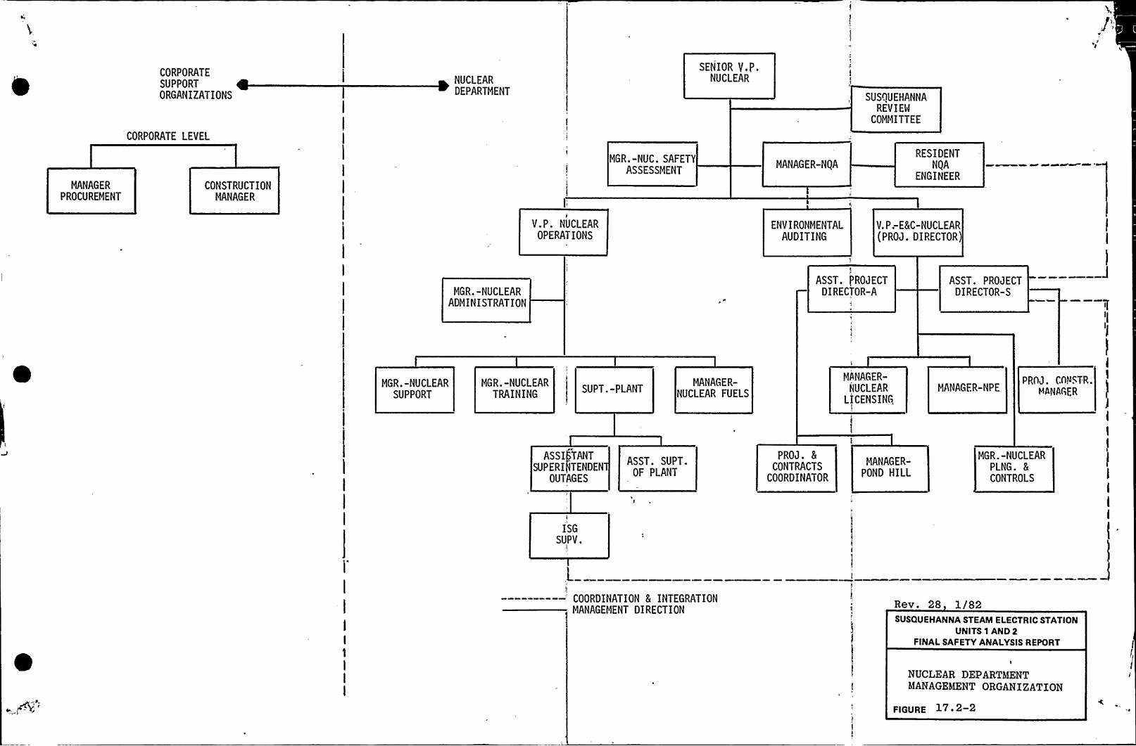
MANAGER
PROCUREMENT
CORPORATESUPPORTORGANIZATIONS
CORPORATE LEVEL
CONSTRUCTIONMANAGER
NUCLEARDEPARTMENT
V.P. NUCLEAROPERATIONS
MGR.-NUC. SAFETYASSESSMENT
SENIOR Y,P.NUCLEAR
MANAGER-NQA
ENVIRONMENTALAUDITING
SUSQUEHANNAREVIEW
COMMITTEE
RESIDENTNQA
ENGINEER
V.P;E8EC-NUCLEAR(PROJ. DIRECTOR)
MGR.-NUCLEARADMINISTRATION
ASST. PROJECTDIRECTOR-A
ASST. PROJECTDIRECTOR-S
MGR.-NUCLEARSUPPORT
MGR.-NUCLEARTRAINING
SUPT.-PLANTMANAGER-
NUCLEAR FUELS
MANAGER-NUCLEAR
LICENSINGMANAGER-NPE
PROJ. CnNSTR.MANAGER
ASSI) PANT
SUPERI)TENDENOUTAGES
ASST. SUPT.OF PLANT
PROJ. 5CONTRACTS
COORDINATOR
MANAGER-POND HILL
MGR.-NUCLEARPLNG. 5CONTROLS
ISGSUPV.
L
----—--—'OORDINATION 8( INTEGRATIONMANAGEMENT DIRECTION
Rev. 28 1/82SUSQUEHANNA STEAM ELECTRIC STATION
UNITS 1 AND 2FINALSAFETY ANALYSISREPORT
NUCLEAR DEPARTMENTMANAGEMENT ORGANIZATION
FIGURE 17.2-2

t
I,

PROCESS I/O
HSS RAU
AHALOC PROCESS I/O ~ 250 AHA(.OC Ik )150OICI)K IN 22)2OICITAL SEO 244P(LSE IN )$OICITK OVT 107
IN ACOITICH TO PROCESSI/O RAV 4 RCV CAPACITYNILL SE IHCL(X)EO TOTHE t(NCTI(NS SO STATEDIN T)% DCS 4 PHS DESICHSPEC
/ Y Y(NCOHHCN PLANT I)KL(X)EO IN GCH Wlt
HISTORY POCESSOR
(4400 12K CORE)
DISC 2HIKROS
2OISPL
CEH
HAC TAPE(NITS I/2
SCP ROV Wlt I
LINE PRHTRSHITO(
OICITK PR(XXSS I/O2$Y CCNTACt IN ~ lit
(Atl)
NSS PROCESS&
(4400 02K CO(EI
PR )HIERRES(LTS
HAROHARE/S(PT)(AREHh INTO(ANCE I/O IXVICE
OICITK O)TPVT 40OISPLAT O()TERS 14
SCPANALOC PROCESS I/DWlt ANALOC IN ~ 700CON(N AHALCC IN ~ 100TOTAL SYSTD(
SY (NIT > $00SCP RIXIWlt 2
SCP R(X)WIT I
LINES(PTER
INTERFACE
)EHX(Y
(SD( CERE) ) CRT
ISPL 2CEN
I
tlLSE IH(lNIT) ~ StlLSE IN(WIT (CQ$KN)) ~ 10
TOTK P&K IN ST Wlt ~ IS
DICITK PROCESS I/O28Y CCHTACT IH ~ ISCO R(XI ISE((SCE Ct EYO(TS ~ 244
2
(API) 5Dht
14400 SIK CCRE)
SCP/0 I 0 PROCESSC
(4400 C(K C(X(E)
CR(N11)CK)CROS
($
TROD REC tX( 2 EhC$4PSSO
DCSAHALCC PR(CESS I/OANALOC IH i 000 RAV I (12) PT SH
C(XSCNCRW11)CK
RAU T (12) tT SH
)I I t$4)
n 1 ($4) Pr
DAP I1
4400 2(K CERE)
D,C. RR(XXSSO( I
(4400 SCK C(X(E)
R(XJ (12$ ) PTS
CC)CRT
OISPL KSCD(I
SCP
10
RASTERDISA(ATC(NT)KL
R(I) t)2$ ) PTS
OICITK 1N a 200
RX) 4 ($4)
4COP)0(X(ATICN
WIT (TRV)
R(X) S ($4) R(X) tl2$) PIS
RAV ~ (12)
10
12
RAV 14 (12) (4400 24K CORE)
R(X) t)2$ ) PTS
D,Ce ~ OCESSCR 2
t4400 22K C(REI
IKP WIT 2 (X)4KS Otl
IKP (NIT 2 DOSKS O(2
IKP WIT 2 D04 CRt OUIKP lltlt2 DC2 Ott CH2
SIP Wtt 2 004 CRT O(2IXP Wlt t DOS CRt O(2
(KP WIT 2 AOV
)KNI
R(sv- 31, 7/82SUSQUEHANNA STEAM ELECTRIC STATION
UNITS 1 AND2FINALSAFETY ANALYSISREFORT
PLANT COMPUTER SYSTEMBLOCK DZAQRAM
FIGURE 7. 7-12

J
r,
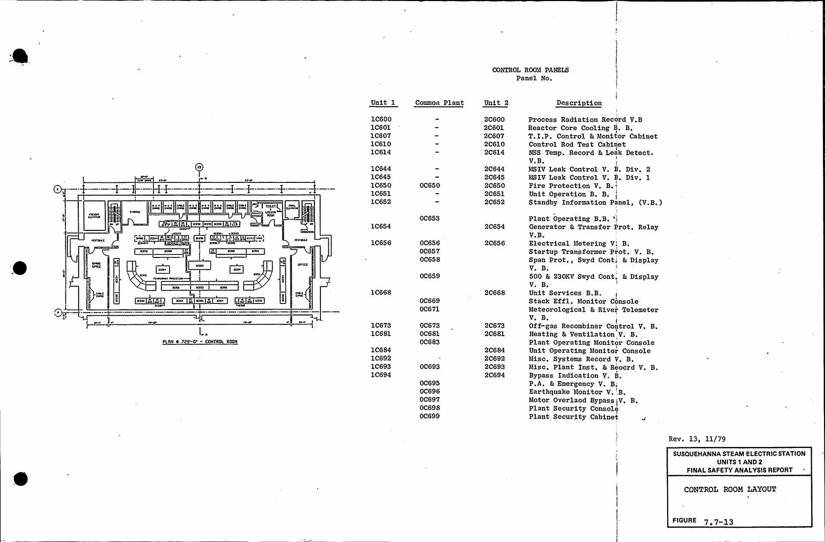
CONTROL ROOM PANELSPanel No.
ccclocsceo scsoo
s r
scr core
oc ~ o ~ ~ ~C Ilesssrsc csrsc csrsc cscoc
occso occss occsc
csoccto
ssoc
occso oc est
cess srcc
occso %col
cocosscoooooos cocsssoos
PLAN I 729cO' CONTROL ROON
Unit 1
1C6001C6011C6071C6101C614
1C6441C6451C6501C6511C652
1C654
1C656
1C668
1C6731C681
1C6841C6921C6931C694
Common Plant
OC650
OC653
OC656OC657OC658
OC659
OC669OC671
OC673OC681OC683
OC693
OC695OC696OC697OC698OC699
Unct 2
2C6002C6012C6072C6102C614
2C6442C6452C6502C6512C652
2C654
2C656
2C668
2C6732C681
2C6842C6922C6932C694
DescriptionI
Process Radiation Record V.BReactor Core Cooling B. B.T.I.P. Control Er, hfonitor CabinetControl Rod Test CabinetNSS Temp. Record & Leak Detect.V. B.
I
hISIV Leak Control V, B. Div. 2hISIV Leak Control V. B. Div. 1Fire Protection V. B.IUnit Operation B. B.Standby Information Panel, (V.B,)
Plant Operating B.B. 'IGenerator & Transfer Prot. RelayV.B.Electrical h'tetering V! B.Startup Transformer Prot. V. B.Span Prot., Swyd Cont. Er, DisplayV. B.500 & 230KV Swyd Cont. Er, DisplayV. B.Unit Services B.B.Stack Effl. h!onitor ConsoleMeteorological &, River TelemeterV. B.Off-gas Recombiner Control V. B.Heating &, Ventilation V. B.Plant Operating Monitor ConsoleUnit Operating h'tonitor Consoleh'tisc. Systems Record V. B.htisc. Plant Inst. 8r, Reocrd V. B.Bypass Indication V. B.P.A. & Emergency V. B;Earthquake htonitor V.",B.h'totor Overlaod Bypass IV. B.Plant Security ConsolePlant Security Cabinet
Rev. 13, ll/79SUSQUEHANNA STEAM ELECTRIC STATION
UNITS 1 AND 2FINALSAFETY ANALYSISREPORT
CONTROL ROOM LAYOUT
FIGURE

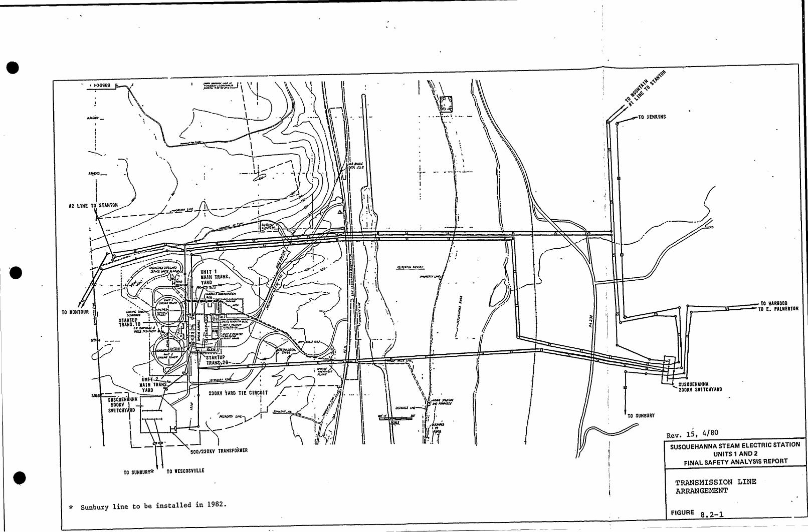
i I.MSOO JNSlt ~ 44Ut 4t f g gi~A I~~~J>Nw&4 '%'p g
) ~~l
~q+~E
+~~4
TO JERKINS
4 &gaff4 @SAN
$ 2 LIHE TO STANTOHI
Wi+SPQ ~r'>K'NITI
NAIH TRANS.TAIID
TO HOHTOUR44CWXW~r
S'TARTUPTRAHS.IO
Ce ~catiI
carr zCIRC 1CWJF
I
C>
~ AJC
«gtfg
STARTUP
'nTO NARROOO
TO E, PAUIERTON
SUSOUEHlHHA50DKV
SRITCHY RD
UNR-2NAIH TRANS
YARD23DKV YARD TIE CIRCUIT
PCtljllY[INES~
Wl
500/230KV TRAHSFORHER
TO SUNBURY
~SUSOUEHAHHA23DKV SlllTCHYARD
Rev. 15 4/80
TO SUHBURYA'O RESCOSVILLE
SUSQUEHANNA STEAM ELECTRIC STATION
UNITS 1 AND 2
FINALSAFETY ANALYSISREPORT
* Sunbury line to be installed in 1982.
TRANSMISSION LINEARRANGEMENT
FIGURE


Jfi/lgid4
EACH WANIVA
PECKVIEEE'AIICNASCIllrCK
~ICNKINS
Ar/KINTA/r/
drodhIIIV6daovt
ttdNTDVR
h'IVA
d//Ar/I/ttdtCEAND
5 II
IErr/IDP.PPrpor
RD/Ev2xavdoosTR/awoaSNOT/ONt ODVION6ENtaATIIVdoTA/IDN
ddd KVSSO KVOI/d5TATIDNORdi///oNING t/ATIDNGENEAATINd STAT/4N
LWfW/lib
KITTATIIVIVY wEST/roNA/44N4 IVNAETDH$lotgrr/rirt
/C~ RdttEAND
ACRID IvlllppAHr/o/
h/ART/I/5catcK
PE'/ Ov IIGIEGPRIED //DATNwodo
GARDHER
que~rI ]~
6/EGERT SiVC/fdVRG
< r /r rr//OSENEACIC
PICA5AHTvaa.cr
dVXAI / /
Coca/NG HA/II~«~
TINITPAII/t,vr<
PlVNIDIITIINIEETIIVG
+c~DC
4XC/I/6/AIvaETDN
I/AtWOOD
dc//vdvRY
par cav/IEEPACHECToiv
WCSC /EEC
Al RTIG
I/E Nttad/HGd. EtdANOIV dtaaf
/g/rl/i/Elsro/I/v 5 r
1
NIID/ac/owa
ddr/TNA/ANNE/A/ AKCDN
KIClQVCI/rrs/RLAHD
/trANDtA/lit
o/TE
WE5THEN/PE/alp~ <ie» /r// IOtKANA r r
/ II/AIVOR a NENVNVIIEECNw/rirdTrodi/4/V / ~Mgwotoao
@~~Ksou /EA Erg/NAAOOR r / rrr/~wJPEACHroEHndnvAN A Tg/A ~ Bt/IDTTINoIIAI/
//IARTCAHD
/ COICNIN~,geese ~ KCENErCDNAdTO//E
SUSQUEHANNA STEAM ELECTRIC STATIONUNITS 1 AND 2
FINALSAFETY ANALYSISREPORT
DPCRATC AT EsoKVBULK POWER SUPPLY SYSTEMOF PPGL AND ADJOININGSYSTEMS PLANNED THRU 1982
FIGURE

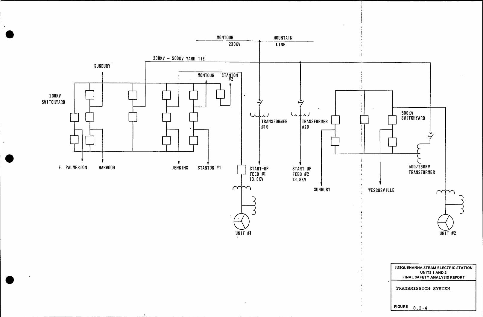
MONTOUR
230KV
MOUNTAIN
LINE
SUNBURY
230KV — 500KV YARD TIE
MONTOUR STAN
230KV
SWITCHYARD
TRANSFORMER
¹10TRANSFORMER
¹20
500KVSWITCHYARD
E. PALMERTON HARWOOD JENKINS STANTON ¹1 START-UP
FEED ¹113.8KV
START-UP
FEED ¹213. BKV
SUNBURY WESCOSVILLE
500/230KVTRANSFORMER
UNIT ¹1 UNIT ¹2
SUSQUEHANNA STEAM ELECTRIC STATIONUNITS 1 AND 2
FINALSAFETY ANALYSISREPORT
TRANSMISSION SYSTEM
FIGURE 8 2 4

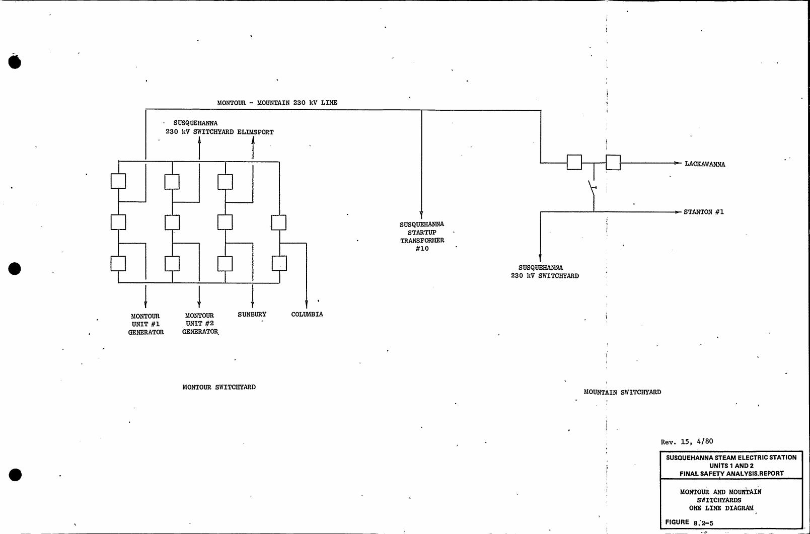
hIONTOUR — hIOUNTAIN 230 kV LINE
SUSQUEHANNA
230 kV SWITCHYARD ELIhISPORT
LACKAWANNA
SUSQUEHANNASTARTUP
TRANSFORhIERglO
STANTON fl
SUSQUEHANNA230 kV SWITCHYARD
hIONTOURUNIT 01
GENERATOR
hIONTOURUNIT g2
GENERATOR
S UNBURY COLUh!BIA
h!ONTOUR SWITCHYARDhfOUNTAIN SWITCHYARD
Rev. 15> 0/80
SUSQUEHANNA STEAM ELECTRIC STATIONUNITS 1 AND 2
FINALSAFETY ANALYSIS.REPORT
MONTOUR AND MOUNTAINSWITCHYARDS
ONE LINE DIAGRAM
4'IGURE

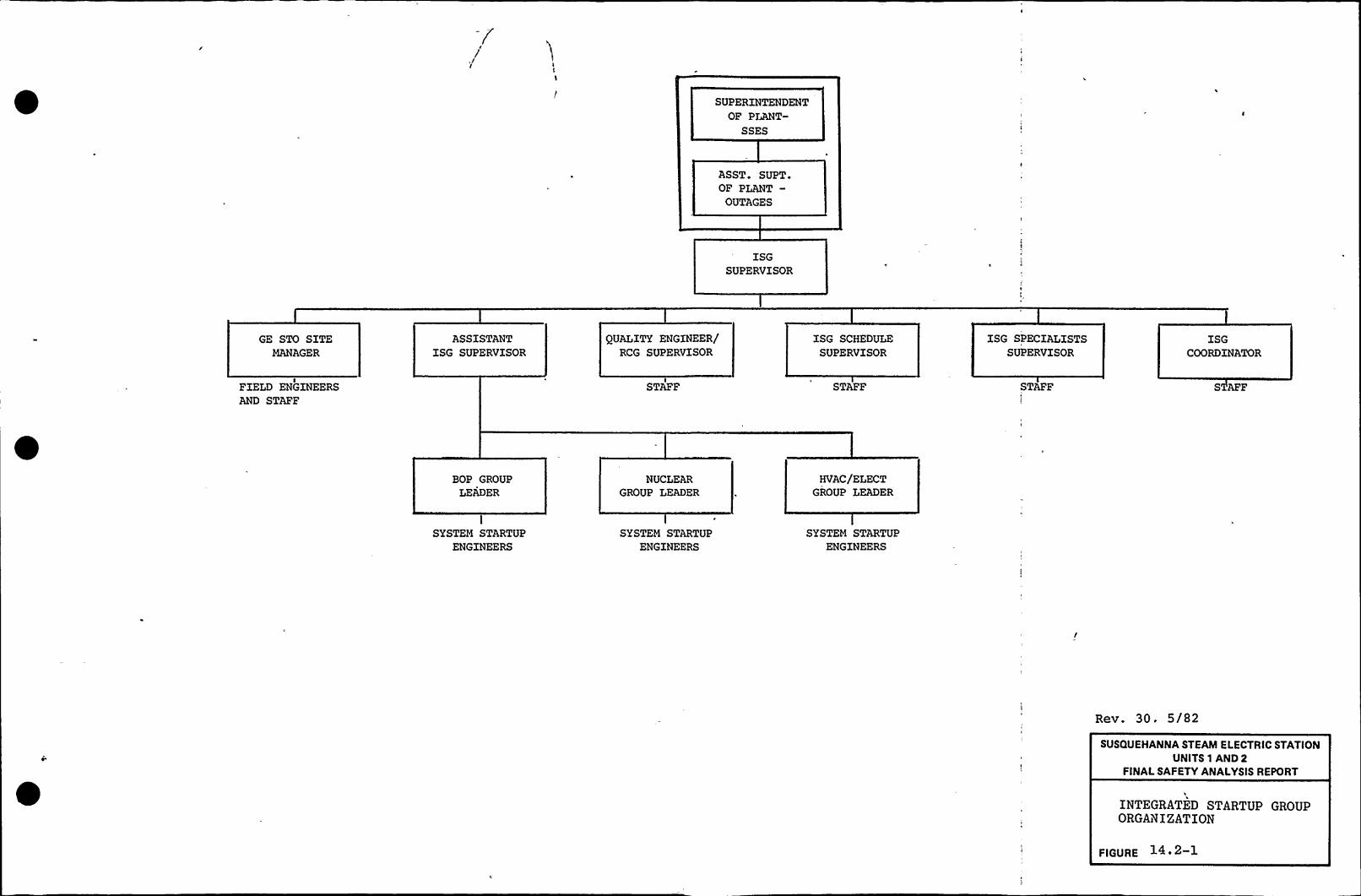
SUPERINTENDENTOF PLANT-
SSES
ASST. SUPT.OF PLANT-
OUTAGES
ISGSUPERVISOR
GE STO SITEMANAGER
ASSISTANTISG SUPERVISOR
QUALITY ENGINEER/RCG SUPERVISOR
ISG SCHEDULESUPERVISOR
ISG SPECIALISTSSUPERVISOR
ISGCOORDINATOR
FIELD ENGINEERSAND STAFF
STAFF STAFF STAFF S AFF
BOP GROUP
LEADERNUCLEAR
GROUP LEADERHVAC/ELECT
GROUP LEADER
I
SYSTEM STARTUPENGINEERS
SYSTEM STARTUPENGINEERS
SYSTEM STARTUPENGINEERS
Rev. 30. 5/82
SUSQUEHANNA STEAM ELECTRIC STATIONUNITS 1 AND 2
FINALSAFETY ANALYSISREPORT
INTEGRATED STARTUP GROUPORGANIZATION
FIGURE

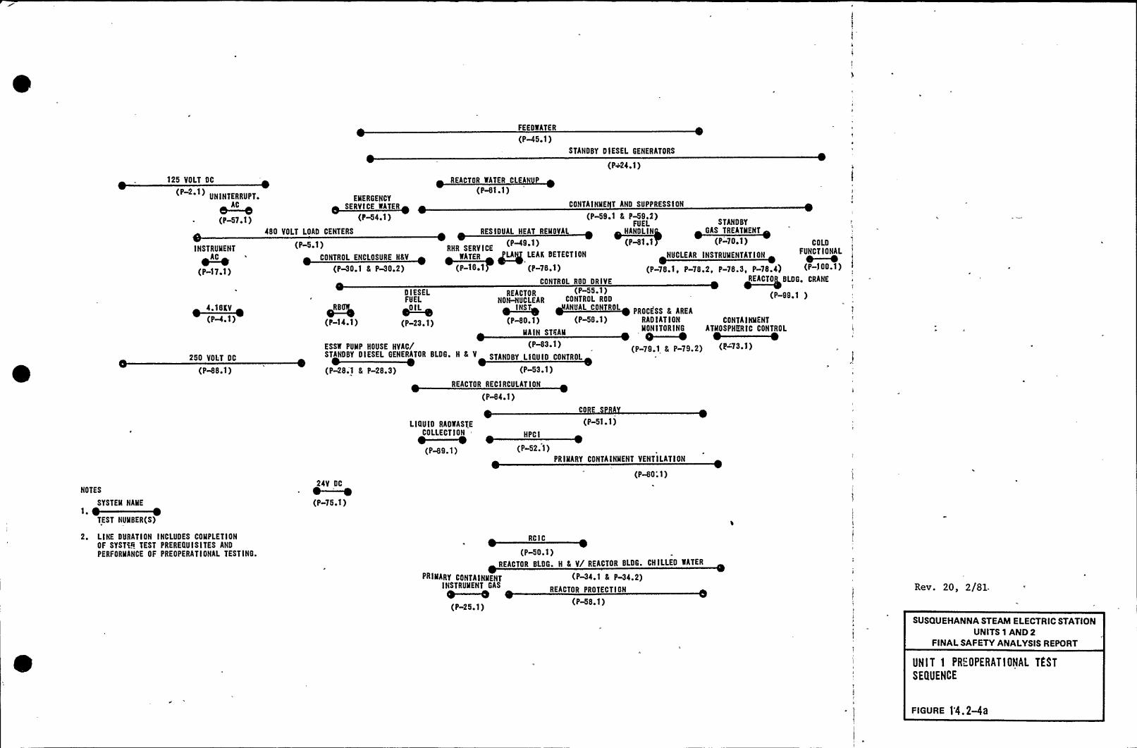
125 VOLT DC
FEEOWATER
(P-45 F 1)
REACTOR WATER CLEA P
STANDBY DIESEL GENERATORS
(P~24 F 1)
UNINTERRUPT~
~AC(PW7.1)
INSTRULIENT
~AC
(P-17.1)
(P-4.1)
250 VOLT DC
(P-88.1)
(P-6'l.1)EMERGENCY
SERVICE WATER
(P-54.1)CONTAINME T AND SUPPRESSION
(P-58 ' 8 P-59,2)FUEL
HANOLIN
(P-81.1480 VOLT LOAD CENTERS RESIDUAL HEAT REMOVAL
(P-5.1)CONTROL ENCLOSURE H&V
RHR SERVICEEATEC ~LA LEAK EETECTTCE
(C-TE.T (P-78.1)
CONTRDL ROD DRIVE
(P-30,1 & P-30 ~ 2)
DIESEL REACTOR (P-55 1)FUEL NO&NUCLEAR CONTROL ROD
ODIL IN~ST ANUAL CONTROL
(P-14.1) (P-23.1) (P&0.1) (P-58.1)MAIN STGAM
(P-83.1)
(P-28;1 8 P-28.3) (P-53.1)
REACTOR RECIRCULATION
(P-64.1)
~RB
DOE A
STANDBY I
COLD
NUCLEAR INSTRUMEN'TAT(ON FUNCTIONAL0—~
(P-78.1, P-78.2, P-78.3, P-78.4) (P-]00 ~ 1)
READ~TO BLDG'RANE
(P-99.1 )
PROCESS 8 AREARAD I AT IONMONITORING
' —M(P-79.1 & P-79.2)
CONTAINMENTATMOSPHERIC CONTROL
(E 73.1)
NOTES
SYSTEM NAME
TEST NUMBER(S)
2. LINE DURATION INCLUDES COMPLETIONOF SYSTi9 TEST PREREGU ISITES AND
PERFORMANCE OF PREOPERATIONAL TESTING.
24V DC
~—~(P-75 1)
LIGU ID RAOWASTECOLLECTION
0—~(P-69.1)
(P-51.1)HPCI
(P-52. 1)PRIMARY CONTAINMENT VENTILATION
(P-60;1)
RCIC
(P-50.1)REACTOR BLDG. H & V/ REACTOR BLDG. CHILLED WATER
PRIMARY CONTAINMENTINSTRUMENT GAS
0—~(P-25.1)
(P-34.1 & P-34.2)REACTOR PROTECTION
(P-68.1)
Rev. 20, 2/81.
SUSQUEHANNA STEAM ELECTRIC STATIONUNITS 1 AND 2
FINALSAFETY ANALYSISREPORT
UNIT 1 PREOPERATIONAL TEST
SEQUENCE
FIGURE )'4. 2-4a

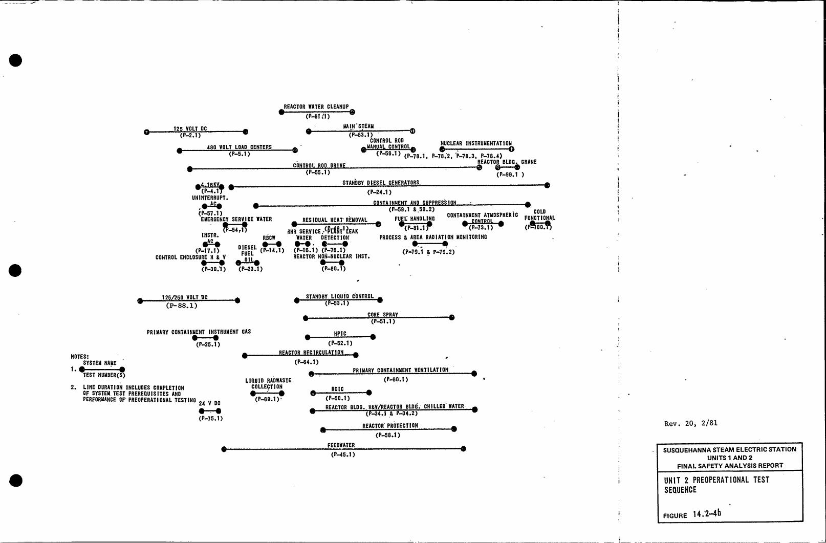
12 VOLT OC
REACTOR WATER CLEANUP
(P-61 II )MAIN STEAM
(P-2.1)
480 VOLT LOAD CENTERS
(P-5.1)
CO
(P-55.1)
(P-83.1)CONTRDL ROD
MA A N ROL
(P&8.1) (P 78 1
NUCLEAR INSTRUMENTATION
P-78.2, P-78.3, P-78.4)REACTOR BLDG CRANEO~I
(P-99.1 )
(P~.1UNINTERRUPT.
(P-57.1)EMERGENCY SERVICE WATER
~541INSTR ~
RB
CONTROL ENCLOSURE H & V
~-~ 0- ~(P-30.1 ) (P-23.1)
STANDBY DIESEL GENERATORS
(P-24.1)
RES IDUAL HEAT'EMOVAL
AHR SERVICE: kNT ?EAKWATER DETECTION
0—~(I'-18.1) (P-76 ~ 1)REACTOR NON-NUCLEAR INST.
~-~(P-80.1)
(P-59.1 & 59.2) COLD
FU L- HANDLINGCONTAINMENT ATMOSPHERIC
FUNCTIONALl~(P-81.1 (P-7341) (%000)
PROCESS 8, AREA RADIATION MONITORING
(P-79.1 & P-79.2)
NOTES:
125 0 VOLT DC
(P- SS. Z)
PRIMARY CONTAINMENT INSTRUMENT GAS
0—~(P-25.1)
STANDBY. LIQUID CONTROL
(M3. )
CORE SPRAY
(P-51.1)
HPIC
(P-52.1)A
(P-64.1)
2. LINE DURATION INCLUDES COMPLETIONGF SYSTEM, TEST PREREQUISITES ANDPERFORMANCE OF'REOPERATI ONAL TESTING
24 V OC
~-~(P-75.1)
LIQUID RADWASTE
COLLECTION
e—~(P-69.1)=
PRIMARY CONTAINMENT VENTILATION
(P-80'.'I )
(P-50.1)REACTOR BLDG. HAV/REACTOR BLDG. CHILLED WATER-
( -34. L -34.2)
REACTOR'ROTECTION
(P-58.1)
FEEOWATER
(P-45.1)
Rev. 20, 2/81
SUSQUEHANNA STEAM ELECTRIC STATIONUNITS 1 AND 2
FINALSAFETY ANALYSISREPORT
UNIT 2 PREOPERATIONAL TEST
SEQUENCE
FIGURE 14. 2<"


FIGURE 14.2-5i Sht. 1
TestNo. Test Name
OpenVessel
HeatUp
Test Condition (1)3 4
W
5.I Warranty
ST-1ST-2ST-3ST-4ST-5ST-6ST-7ST-8ST-9ST-10ST-11ST-12ST-13ST-14ST-15ST-16ST-17ST-18ST-19ST-20ST-21ST-22ST-23ST-24ST-25ST-26ST-27
ST-28ST-29ST-30ST-31ST-32
ST-33ST-34ST-35ST-36ST-37ST-38ST-39
ST-40
Chemical 6 RadiochemicalRadiation MeasurementsFuel LoadingFull Core Shutdown MarginControl Rod DriveSRM Perf. 5 Control Rod Seq.Reactor Water CleanupResidual Heat RemovalWater Level MeasurementsIRM PerformanceLPRM CalibrationAPRM CalibrationProcess ComputerRCICHPCISelected Process TempsSystem ExpansionTIP UncertaintyCore PerformanceSteam ProductionCore Power-Void Mode ResponsePressure RegulatorFeedwaterTurbine Valve Surv.MSIVsRelief ValvesTurbine Stop Valve Trip
Generator Load RejectionShutdown From Outside Control RoomRecirculation Flow ControlRecirculation SystemLoss of T-G 6 Offsite PowerContainment Atmosphere and
Main Steam Tunnel CoolingPiping Steady State VibrationRod Sequence ExchangeRecirculation System Flow CalibrationCooling Water SystemsGaseous Radwaste SystemBOP Piping System ExpansionPiping Vibration During Dynamic
TransientsBOP Piping Steady State Vibration
X(2)X(2)X(')
(2,3)
XX
x(')X(3)
(6)X
(6)
XX
(6)
XX
XX
X
XX
X(3)
X(7)
X(7)X
X(7)
M
X
X
XX
XX
x(') X(3)
X")XX
XX
M
XM,A
XXX
(10)
M(11)
XX
XXX
X(8)X XX X
(8 9)
x(")
XXX
(12)
XI
(8,9)
MrXXX',
M,A
f
X;
X
XX
x"'12)
X(9,13)
XX
X(14)X(9, 13)
XX
X(17)
(8,15)X"
(8,16)
M,AM
(")K(8, 13,9)
XXX
XX
Re>-. 32. I2 82SUSQUEHANNA STEAM ELECTRIC STATION
UNITS 1 AND 2FINALSAFETY ANALYSISREPORT
INDI%'IDUAL STAR ~ UPTEST SEQUENCE
FIGURE 4.2-5g Sheep

j
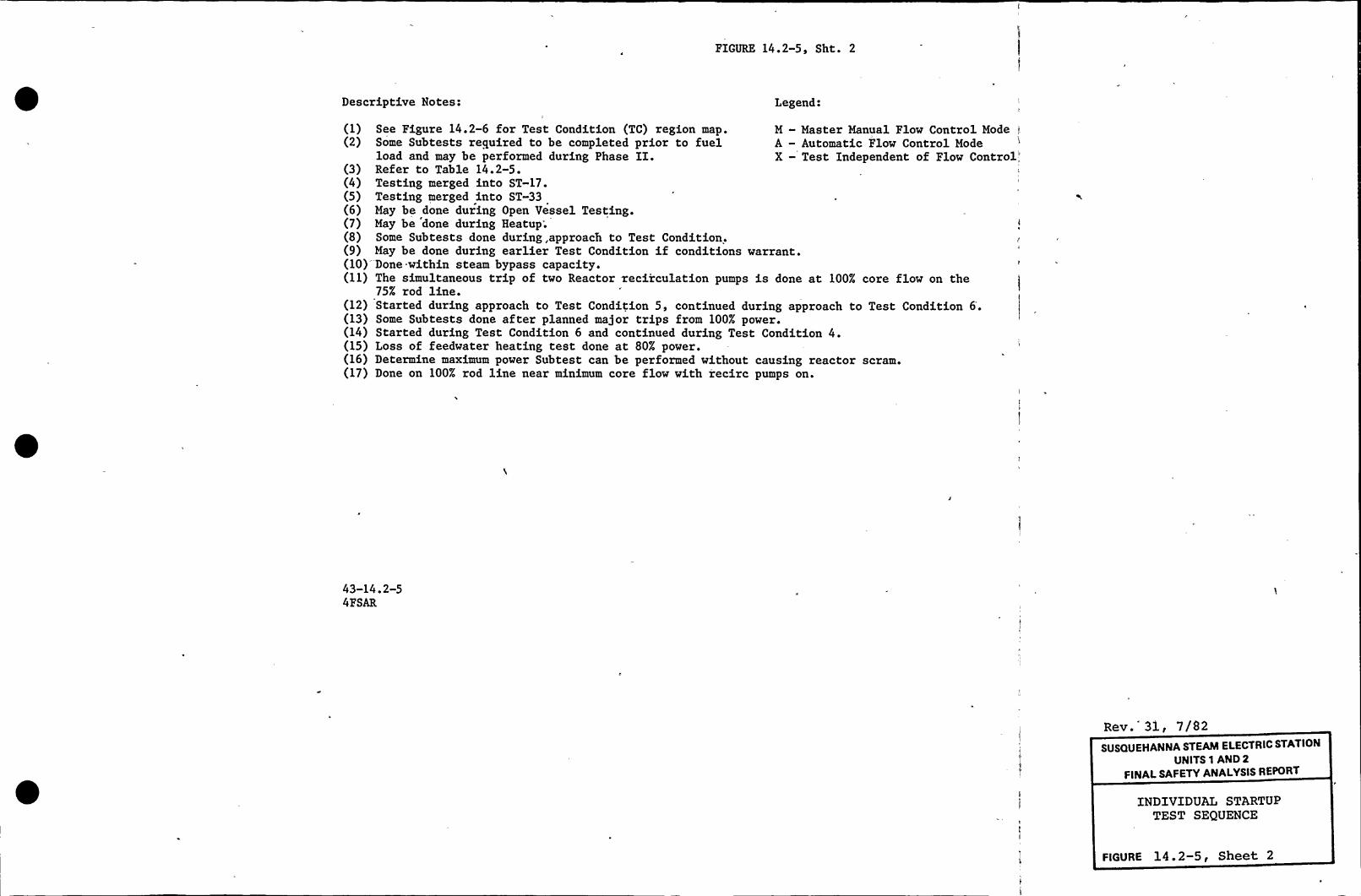
FIGURE 14.2-5, Sht. 2
Descriptive Notes: Legend:
M —Master Manual Flow Control Mode,tA — Automatic Flow Control ModeX —Test Independent of Flow Control,'1)
See Figure 14.2-6 for Test Condition (TC) region map.(2) Some Subtests required to be completed prior to fuel
load and may be performed during Phase II.(3) Refer to Table 14.2-5.(4) Testing merged into ST-17.(5) Testing merged into ST-33(6) May be done during Open Vessel Testing.(7) May be done during Heatup;(8) Some Subtests done during, approach to Test Condition.(9) May be done during earlier Test Condition if conditions warrant.(10) Done within steam bypass capacity.(11) The simultaneous trip of two Reactor recirculation pumps is done at 100% core flow on the
75% rod line.(12) Started during approach to Test Condition 5, continued during approach to Test Condition 6.(13) Some Subtests done after planned major trips from 100% power.(14) Started during Test Condition 6 and continued during Test Condition 4.(15) Loss of feedwater heating test done at 80% power.(16) Determine maximum power Subtest can be performed without causing reactor scram.(17) Done on 100% rod line near minimum core flow with recirc pumps on.
43-14.2-54FSAR
Rev. 31, 7/82SUSQUEHANNA STEAM ELECTRIC STATION
UNITS 1 AND 2
FINALSAFETY ANALYSISREPORT
INDIVIDUALSTARTUPTEST SEQUENCE
FIGURE 14.2-5, Sheet 2

h''

MPI'JAG";R-
NQA
Interna,External, &
Managanent Audits
QUALITY. ENGINEERING &
PROCU REMEND
OPERATIONSQh
I
I
I
I
I
I
OffsiteOnsite
CON STRICTION
Audits & Reviews ofConstruction Activities
PR(ZUMHENT
Incorporation Supplier surveysand Review of and AuditsQuality Heguire-aents
QUM.HVSYSTl'l'B &
TRAINING
Program & 'Proce-dure Developnantand Training
hpcrations and[PreoperationalTesting Auditsand Reviews
Inspection Activitiesfor Operations Main-tenance and Modifica-tions
Rev. 22, 4/8$
SUSQUEHANNA STEAM ELECTRIC STATIONUNITS 1 AND 2
FINALSAFETY ANALYSISREPORT
NUCLEAR QUALITY ASSURANCE
FUNCTIONAL STRUCTURE
FIGURE 17 ~ 2-3

S
1'

gs
QoQ3 EL.870'4"
Q9
07
8Q7
QS
QS
Q20 Q30
Q29Q28
4 Q1921
Q21
Po
+49EL.825'4"
Q39 EL.818'-1"
+30EL.806'4"
Q38 EL.799'-1"
STEELCOLUMNS
Q4
Qs
+47
8
Qe
Qe
Qs
0'e
05
41 Q2
25
24
819
17
17
Q19
Q16
Q15
CONCRETE WALLS
EL.783'4"EL.779'-1"
37
QsEL.771'4"
P48E L.753'-0"E L.749'1"
g33
Q3
Q3
P38
REACTOR BUILDINGFLOOR SLABS
015Q4
p4
Q3
Q11
Q27E L.728'-0"
Q E L.719'-1"&34
26 E L.709'-0"
33 —E L.697'-0"
32
@31
36
02 21
10
9
10
EL.683'-0"
Q4EL.676'-0"
REACTOR BUILDINGCANTILEVEREDSLABS
QS
m
CONTROLBUILDINGSI.ABS
EL.645'4"
LEGEND0 MASS POINT
Q JOINT NUMBER
QMEMBER NUMBER-Q SPRING NUMBER
SUSQUEHANNA STEAM ELECTRIC STATIONUNITS 1 AND 2
FINALSAFETY ANALYSIS REPORT
VERTICALSEISMIC MODEL
OF REACTOR AND CONTROLBUILDING
FIGURE 3, 7b-~>
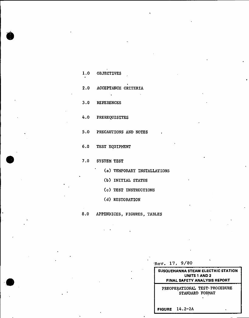
1.0 OBJECTIVES
2.0 ACCEPTANCE CRITERIA
3.0 REFERENCES
4.0 PREREQUISITES
5.0 PRECAUTIONS AND NOTES
6.0 TEST EQUIPMENT
7.0 SYSTEM TEST
(a) TEMPORARY INSTALLATIONS
(b) INITIAL STATUS
(c) TEST INSTRUCTIONS
(d) RESTORATION
8.0 APPENDICES, FIGURES, TABLES
Rev. 17, 9/80SUSQUEHANNA STEAM ELECTRIC STATION
UNITS 1 AND 2FINALSAFETY ANALYSISREPORT
PREOPERATIONAL TEST PROCEDURE
STANDARD FORMAT
FIGURE 14. 2-2A
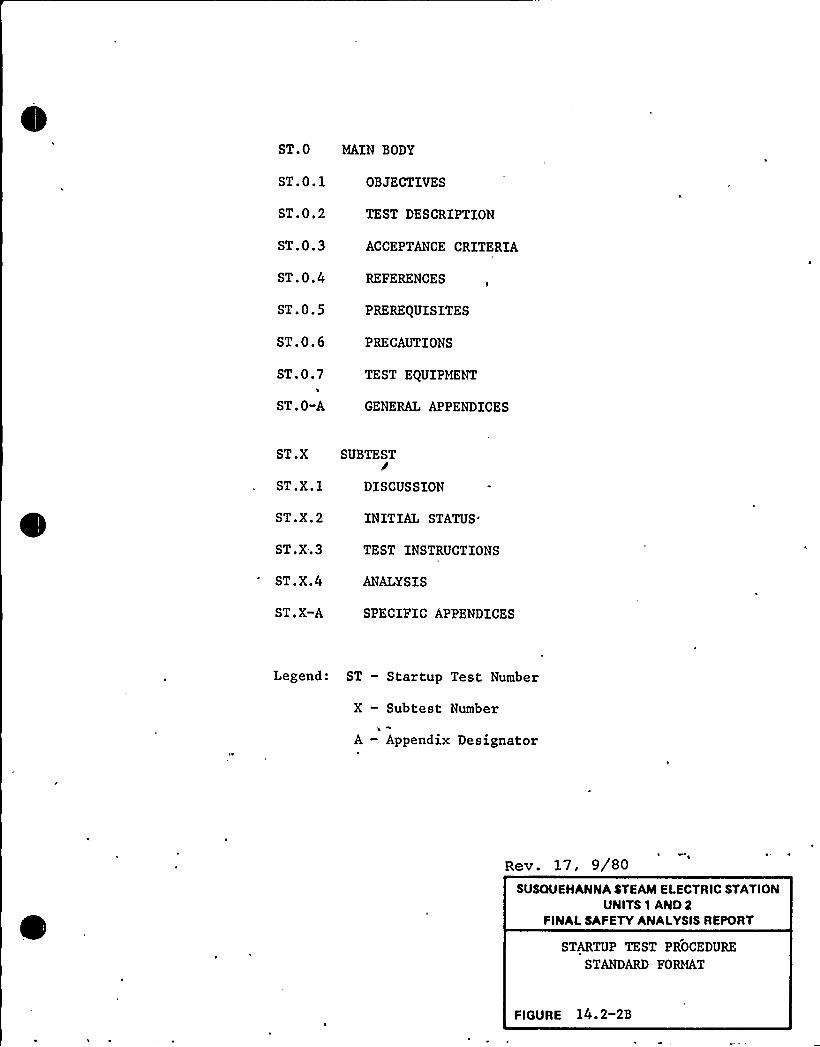
ST.O MAIN BODY
ST.0.1 OBJECTIVES
ST.0.2
ST.0.3
ST.0.4
ST.0.5
ST.0.6
ST.0.7
ST.O-A
TEST DESCRIPTION
ACCEPTANCE CRITERIA
REFERENCES
PREREQUISITES
PRECAUTIONS
TEST EQUIPMENT
GENERAL APPENDICES
ST.X SUBTEST/ST.X.l -DISCUSSION
ST.X.2 INITIALSTATUS'T.X..3
ST.X.4
ST.X-A
TEST INSTRUCTIONS
ANALYSIS
SPECIFIC APPENDICES
Legend: ST — Startup Test Number
X — Subtest Number
A — Appendix Designator
Rev. 17, 9/80SUSQUEHANNA STEAM ELECTRIC STATION
UNITS 1 AND 2FINALSAFETY ANALYSISREPORT
STARTUP TEST PROCEDURE
STANDARD FORMAT
FIGURE 14. 2-2B
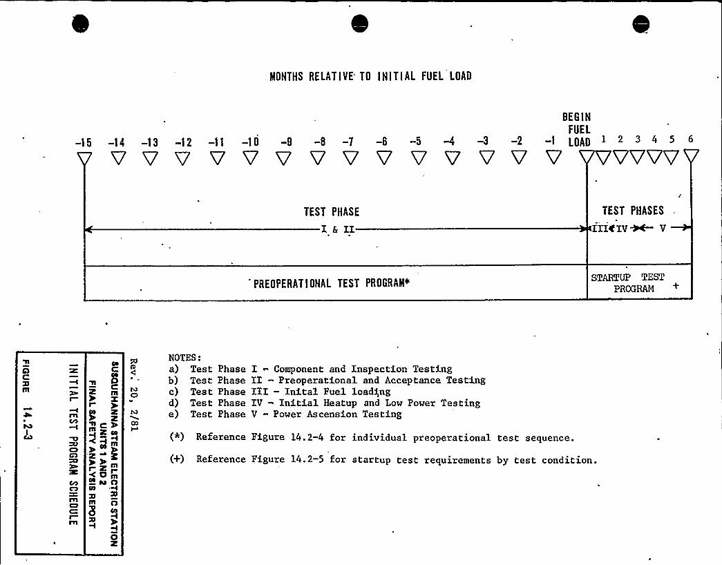
MONTHS RELATIVE TO INITIAL FUEL LOAD
BEGINFUEL
-15 -14 -13 -12 -11 -10 -9 -8 -7 -6 -5 -4 -3 -2 -1 LOAD 1 2 3 4 5 6
TEST PHASE
I&IITEST PHASES
IIIfIV~ V
PREOPERATIONAL TEST PROGRAM~STARTUP TEST
PROGRAM +
ICD
CA
mEDC
I
CO
2rg 2
m++rAa 0
CO
37m n8
I
NOTES:a) Test Phaseb) Test Phasec) Test Phased) Test Phasee) Test Phase
I Component and Inspection TestingII - Preoperational and Acceptance TestingIII—Inital Fuel loadingIV - Initial Heatup and Low Power TestingV - Power Ascension Testing
(*) Reference Figure 14.2-4 for individual preoperational test sequence.
(+) Reference Figure 14.2-5 for startup test requirements by test condition.
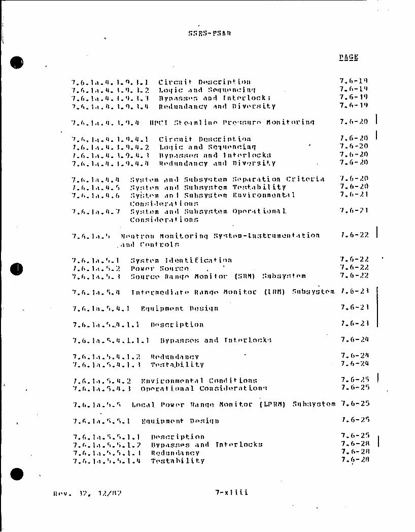
~>5FS- FS5 11
PA( f.
7. 6.'1. 6.'1. 6.7 6
11.I .1 .1»I i.
4. 1.
Il. I.
q. 1.1<)
l. 1. Il
(. ircll i t- D<i."cL i Pt i<)»l.oq 1(. «I 1'l(l .<nq Il<> n<. L n'Illyn ass<>.". one 1iit ('r LockR«'u»<ln»cy in<I I) i v<>l.s it:y
7. ()-1<I7 f>- i <I
7. F)- 1<)
7 6-19
'1.(.1,1. Il. l.'l. Il III'(.I ! t oiml i»n Pr.<.;;:Pi(1m Il<)» it<irinq 7. (-2() I
'1 61. 6.1. F>.
7 6.
11.1.1.I .I .I .1 .
IlIlIl 1
Il. I
'1.4. 1
<l 4 2<) Il<) Il II
(, irr.ilit I)(.:.icr. i lit, i<i(i1. o < I i c;I n (1 S n 1» < n <.. in qlly» 1:I:1< ~ .'In <1 I n t < r I <ic 4 il» <~<I il» (I«illcy i)n<l 1) I v'>l's Lty
1. f -2O7. 6-2()7. 6-201. ri-2O
7. (.. I;i.4. 41.6. I.i. Il. '>
7.6. I,I. Il. 6
7.(>. I '1 Il. '1
.'> y.: I < m» n il
.' t< m In<i.'> y.; t.<«III,)n I
(. no). i «I <" 1'i\ 1 I.'. y. I t <) m <1 n < I
(. nn."-i <I c r i 1 i
.">ill)sy ", t(>.m<> Il h «1 y i
« t Q III
," Il h .. V 1 t <> m
nli I"«
!.ilI) ~y 1 1 <> m
.',> P 1 r l t l. on (. l.' t( L'. 1
T('."t, 1 I) Ll Ltyl'.»v i 1. nomont)1
()linr I t i<)nn l.
'1. 6-2()7 6- 2(1
7. 6-21
'1. (i-21
'1. F). I.i. '> )I <» tl'nli Nnnitori nq .'>y:tnm-l.li tLIlm<'» t 1 t ionii<1 ( <>»t 1:Ol 6
l. 6- 22
7. (>. In.'> 1
I. (>. I,i . '>. '.)
'1 . I) . I n . '>
.'>yet('m I <I <)o t.i f ico t io»P <) If <> 1' .> Oil L (; <)
!.>Oil r( (> All »qn Man i t nr (!lltd) .'»11)11yii 1 nm
'1 r)-22'1. 6-227. 6-2:?
).6. I.i. <i. Il 1 lit( L'mn<I I,it <> Bnnq<> Anni I:oL (l ltN)
'1. f>. I:i. '>. ll. I F.qil ipm<>nt. I)<.!ui(to
7. 6. I .i . '> ..ll . 1 . 1 l) < ", r 1.. i p t i (i o
'1. (i. In. ~. Il. I.. 1.1 IIVI)n.)..c s an<1 Tot <>L lnrk"1
~ i<i I) '> yg t. ( «II 1. (>-2 1
7 6-21
1 C>-2 1
7. ()-2Il
7.(>. I.i.'>. ll. 1.;!7. f) . I n . r) . 4 . I . l
4 ('(I illi < I 1 » (. V
Tn.. tn,hi 1 i t,y7 6- 2ll7. 6-24
1 6 I I ~'"> ll;? 'l".»v i L n»mr nt.s 1 (.on<I i t inn::
(> I I ) Il I 01)nL I t i <>on 1 ( nn.".i<I<!r lt i <)»7 6-)'i7 6- 2')
'1 f). 1).'>."> I.ocol, POII( 1. 11;inq<) anni t.nL (LPIIN) .">Ilh:1yotnm 1.6-25
7 ~ F> 1«1 ~ '> "> 1 Y,qill.pl)I(>»t')<>;.i(l» 1. fi-2 )
7. f'>.
7 fi7.6 ~
7.6.
11.11.I i.1).
>» >er
> ~ >e
1.1l.. 21 I
l)nscL i pt.i.nn13yp.cg..ng on<i Tnt< r lock<~IIn(ill»<Il 0( yT(>.".to hi l i t,y
7. 6- 2".i
7 6- 2 f1
7. 6-2117. 6- 211
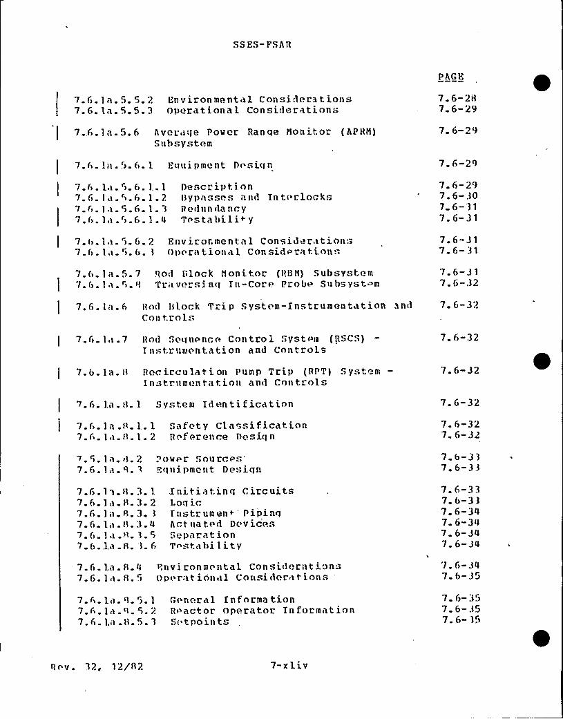
SS ES- PS A R
PAGE
7. fi. la. 5. 5. 2 Environmental Considera tions7.6.1a. 5.5.3 Operational Considerations
7. 6-287. 6-29
7..<).la 5.6 Aver<3<)e Poser Ran qe Nonit or (APHID)Subsystem
7 6-29
7.6-29
7. f> . la. ~>. f>. 1 . 1
7. 6> 1<3.'>. 6.1. 27 C. la >.C. l. 37. f>. 1<s r> f> 1
De.,cript i onl3y passes <and Tn t< clock.,Redun da ncyTc sta bili+y
7. 6-297. 6- 307 6- '31
7. 6-31
7 <>.1«. ">. f>. 2 Environmental Consid» ration.-7.f>. la. 5>. f>. 3 0»< r<ition<~1 Consid< rations
7. 6-317 6-;31
7.6. 1«. 5. 7 Ro1 L>lork monitor (RU33) Subsyst em
! 7.6.1 s.">. <3 Tr <vrrsi nq Tn-Core Prob» Subsystem7.6-317. 6-.32
R»d Block Trip System-Instrumentation andCon trois
7. 6-32
7.C> 1 3.7 Hnd S>oquPnc< Control S>yst<'m (RSCS>)T nstr umentation and Controls
7. 6-32
7.6.1a.>3 Recirculation Pump Trip (RPT) SystemIn -tr«mentation and Controls
7. 6-32
7. 6 1.a. t3. 1 System Identi ficatinn 7. 6-32
7.f>. la.R. 1..1 S>safety Classification7.C» 1<i 0.1. 2 Rc ferenre Desiqn
7.6-327 6>- 332
>. ">. 1a. <3. 27. fi. 1a. ',3. 3
+ 0 >«e r ." o u rc <>.""
'qui.pmentDesiqn7 6-337.6-33
7.67.67. fi7. C>
7. f>
7 6
1 i <3.3.. 1<>. B. 3..)a.f3.3.la. A. 3.
.1a.n. '3.
.la f3. 3
l.
2
4
C>
Initiatinq Circuits1.oq ir.1'nstrumen<. 'ipinqAct»at,< d DevicesS>< p<arat ionTr stabi1ity
7.6-337. 6-3 3
7. 6-347 6-347. 6-347. 6-34
7. f>. l,a. f3.47~6» 1<< 0 .'>
Environm< ntal ConsiderationsOp<»ration sl Consider itious
7. 6-347 6-35
7. Fi
7 67.6
. 1«. '3. S.
. 1<).n. >.
. l<<.H. 5>.
1 G< neral Knformation2 R< actor Operator Information'3 S< tpoint
7. 6-:357 6 357 6- .3r
Rr v. 32, 12/f32 7-xliv
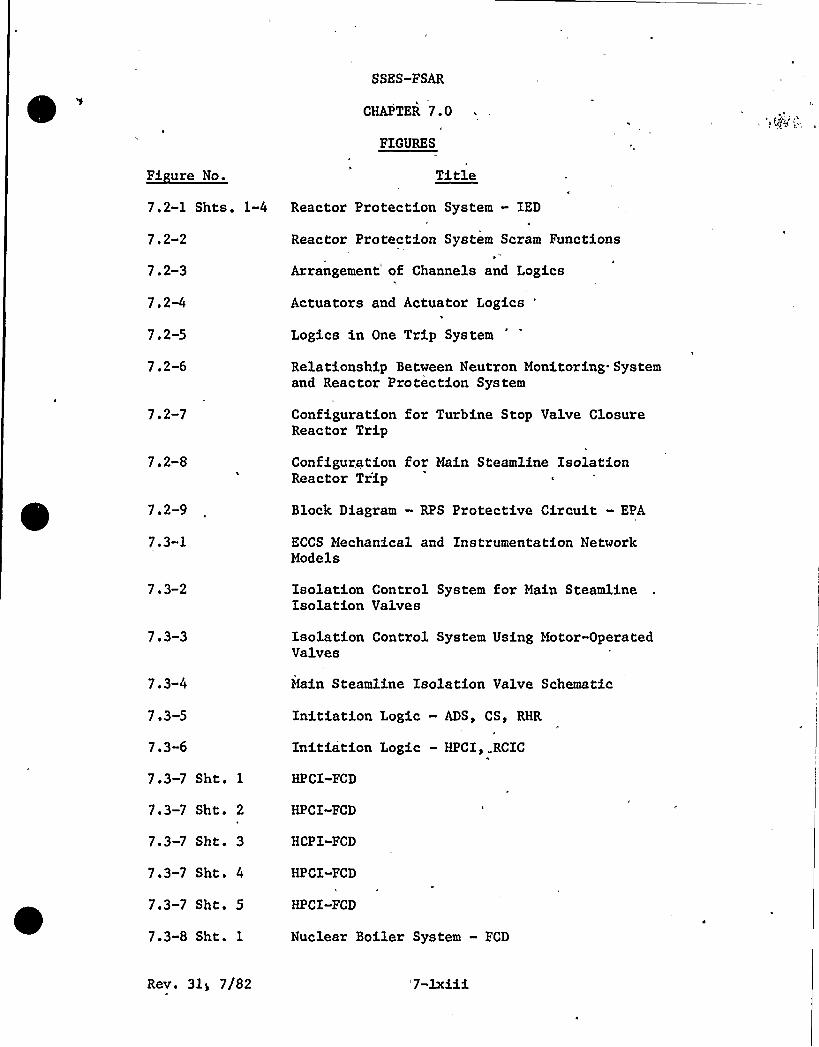
SSES-FSAR
CHAPTER 7.0
FIGURES
1ft18
7.2-1 Shts. 1-4
712-2
7. 2-3
7. 2-4
7, 2-5
7.2-6
Reactor Protection System — IED h
Reactor Protection System Scram Functions
Arrangement of Channels and Logics
Actuators and Actuator Logics "
Logics in One Trip System
Relationship Between Neutron Monitoring Systemand Reactor Protection System
712-7
7.2-8
Configuration for Turbine Stop Valve ClosureReactor Trip
Configuration for Main Steamline IsolationReactor Tr'ip
7.2-9
7.3-1
Block Diagram - RPS Protective Circuit - EPA
ECCS Mechanical and Instrumentation NetworkModels
703 2 Isolation Control System for Main SteamlineIsolation Valves
7 ~ 3 3 Isolation Control System Using Motor-OperatedValves
7.3-4
7 ~ 3 5
7. 3-6
7.3-7 S}lt. 1
7.3-7 Sht. 2
7.3-7 Sht. 3
7.3-7 Sht. 4
7.3-7 Sht. 5
7.3-8 Sht. 1
Main Steamline Isolation Valve Schematic
Initiation Logic — ADS, CS, RHR
Initiation Logic — HPCI, RCIC
HPCI-FCD
HPCI-FCD
HCPI-FCD
HPCI-FCD
HPCI«FCD
Nuclear Boiler System — FCD
Rev. 3ly 7/82 '7-1xiii
SSES-FSAR
7.3-8 Sht. 2
7.3-8 Sht ~ 3
7.3-8 Sht. 4
7.3-8 Sht. 5
7.3-9 Sht. 1
.7.3-9 Sht. 2
7.3-9 Sht. 3
7.3-10 Sht. 1
7.3-10 S}lt. 2
7.3-10 Sht. 3
7.3-10 Sht. 4
7.3-10 Sht. 5
Nuclear Boiler System — FCD
Nuclear Boiler 'System — FCD
Nuclear Boiler System — FCD
Nuclear Boiler System — FCD
Core Spray - FCD
Core Spray - FCD
Core Spray — FCD
RHR-FCD
RHR-FCD
RHR-FCD
RHR-FCD
RHR-FCD
7,3-11 Sht. 1 Process Radiation Monitoring - IED
7.3-11 Sht. 2
7.3-11 Sht. 3
7.3-11 Sht. 4
7.3-11 Sht. 5
7.4-1 Sht. 1
7.4«1 Sht. 2
7.4-2 Sht. 1
7.4«2 S}lt, 2
7.4-2 Sht. 3
7.4-2 Sht, 4
7.4-3
7.4-4
7.5-1 Sht. 1
Process Radiation Monitoring — IED
Process Radiation Monitoring — IED
Process Radiation Monitoring — IED
Process Radiation Monitoring —IED
P&ID-RCIC
P&ID-RCIC
FCD-RCIC
FCD-RCIC
FCD-RCIC
FCD-RCIC
P&ID — Standby Liquid Control System
FCD — Standby Liquid Control System
Unit Operating Benchboard
Rev. 31, 7/82 7 1xiv
SSES-FSAR
7.5-1 Sht. 2
7.5-1 Sht. 3
7.5-1 Sht. 4
7.5-1 Sht. 5
7.5-1 Sht. 6
7.5-2 Sht. 1
7.5-2 Sht. 2
7.5-2 Sht. 3
7.6-1
7.6-2
Unit Operating Benchboard
Unit Operating Benchboard
Unit Operating Benchboard
Unit Operating Benchboard
Unit Operating Benchboard
Reactor Core Cooling Benchboard
Reactor Core Cooling Benchboard
Reactor Core Cooling Benchboard
Recirculation Pump Leak Detection Block Diagram
RHR Area Temperature Monitoring System BlockDiagram
7.6-3
7.6-4 Sht. 1
7.6-4 'Sht. 2
7.6-5
7.6-6
7.6-7 Sht. 1
7.6-7 Sht. 2
7.6-7 Sht. 3
7.6-7 Sht. 4
7.6-7 Sht. 5
7.6-7 Sht. 6
7.6-7 Sht. 7
7. 6-8
7. 6-9
7.6-10
Vessel Penetrations for Nuclear Instrumentation
Neutron Monitoring System — IED
Neutron Monitoring System - IED
SRM/IRM Neutron Monitoring Unit
Detector Drive System Schematic
Neutron Monitoring System - FCD
Neutron Monitoring System — FCD
'eutron Monitoring System - FCD
Neutron Monitoring System - FCD
Neutron. Monitoring System — FCD
Neutron Monitoring System — FCD
Neutron Monitoring System — FCD
Functional Block Diagram of SRM Channel
Functional Block Diagram of IRM Channel
Power Range Monitor Detector Assembly Location
7.6-11 Sht. 1 . Reactor Recirculation System « PAID
Rev. 31, 7/82 7 lxv
SSES-FSAR
7.6-11 Sht. 2 Reactor Recirculation System — P&ID
7.6-11 Sht. 3 Reactor Recirculation System - P&ID
7.6-12
7.6-13
7.6-14
7.6-15
7.6-16
7.6-17
7.7-1
7.7-2 Sht. 1
7.7-2 Sht. 2
7.7-2 Sht. 3
7.7-2 Sht. 4
7.7-2 Sht. 5
7.7-3 Sht. 1
7.7-3 Sht. 2
7.7-4
7.7-5
7.7-6
7.7-7 Sht. 1
7.7-7 Sht. 2
7.7-7 Sht. 3
7.7-7 Sht. 4
7.7-7 Sht. 5
7.7-8
7. 7-9
(This Figure intentionally left blank)
Water Level Range Definition
Control Rod Drive Hydraulic System — FCD
Control
Control
Rod Drive Hydraulic System — FCD
Rod Drive Hydraulic System — FCD
Control Rod Drive Hydraulic System - FCD
Control Rod Drive Hydraulic System — FCD
Reactor Manual Control System
Reactor Manual Control System
Reactor Manual Control System Operation
Reactor Manual Control Self-Test Provisions
Eleven-Wire Position Probe
Reactor Recirculation System —FCD .
Reactor Recirculation System — FCD
Reactor Recirculation System — FCD
Reactor Recirculation System — FCD1
Reactor Recirculation System — FCD
Recirculation Flow Control Illustration
Feedwater Control System — IED
APRM Circuit Arrangement for,Reactor ProtectionSystem Input
(This Figure intentionally left blank)
Ranges of Neutron Monitoring System
(This Figure intentionally leftblank)'This
Figure intentionally left blank)
Rev. 31, 7/82 7-lxvi
SSES-FSAR
7.7-10
7.7-11
7.7-12
7.7-13
7.7»14
7 07-15
7. 7-16
7.7-17
Detector Drive System Schematic
Reactor Water Cleanup System - FCD
P"
Plant Computer System — Block Diagram
Control Room Layout
Traversing In-Core Probe Assembly
Main Turbine Control System Block DiagramI
Assignment of LPRM Input to RBM System
RBM Response to Control Rod Motion (Channels Aand C)
7.7-18 RBM Response to Control Rod Motion (Channels B
and D)
Rev. 31, 7/82

SS ES- FS AR
7.6.1a.4.3.8.2.2 Logic and Seguencing
No action is initiated by the reactor vessel head pressuremon itoring c ircuit.
7~6.la.4.3.8.2.$ Bypasseg ape Interlocks
There are no bypasses or interlocks associated with thissubsystem.
I
7.6.1a.4.3 8~2.4 Redundancy and Diversity
Redundant pressure-sensinq instrumentation for detecting innerseal failure is not provi'led. The outer seal assembly providesback-up in the event that inner seal leak should occur.
7 6.1a.4. 3. 9 HPCI System. Leakage Detection
7.6.1a.4.3. 9.1 Subsystem Identification
The steamline of the hiqh pressure coolant injection (HPCI)system are constantly monitored for leaks by the leak detectionsystem. Leaks from the HPCI steamline vill cause a change in atleast one of the follovinq monitored operating parameters:sensed area temperature, steam pressure, or steam flov rate. Ifthe monitored parameters indicate that a leak may exist, thedetection system responds by activating an alarm and, dependingupon the activating parameter, initiates HPCI autoisolationaction.The HPCI leakage detection system consists of three types ofmonitorinq circuits. The first of these monitors area ambienttemperature, triqqerinq the alarm circuit when the temperaturerises above the preset maximum. The second type of circuitutilized by the leakaqe detection system monitors the flow rate,or differential pressure, through the steam line, triggering analarm circuit when the flow rate exceeds a preset maximum. Thethird type of circuit utilized by the HPCI leakage detectionsystem monitors the steam line pressure upstream of thedifferential pressure element. Alarm outputs from all threecircuits are also used to generate the HPCI auto-isolationsiqnal. The ambient temperature monitorinq is similar to thatdescribed in main steamline leakaqe detection system.
Rev. 31, 7/82 7. 6-17
SS ES-ES AR
7. 6.1a.4.3. 9. 2 HPCI Area Temperature Nonitorina
7.6. 1a.4.3.9.2.1 Circuit Description
The HPCI area and tunnel ambient and differential temperaturesensing elements are thermocouples. Their outputs qo totemperature switches set to activate at a preset temperature.Closing the temperature switches will light the point modulealarm indicator and sound th'e high temperature alarm in the maincontrol room. In addition, activation of the tunnel temperatureswitches will start the timer, which after a suitable delayperiod, initiates HPCI isolation valve closure.. If at any timedurinq the timing cycle, the temperature switch contacts areopened, the timer will automatically reset and no isolation valveclosure will result. Before timer timeout, the operator caninitiate isolation by depressinq pushbutton switch HPCI ISOLATE.This action will bypass the timer circuits and, providing nologic test is in proqress, the HPCI isolation valves will close.
High ambient and differential temperature from the HPCI areain'itiates immediate, isolation valve closure.
7. 6. la. 4. 3. 9. 2. 2 Logic a nd Segue ncin'he
two division HPCI temperature monitors work on a one out oftwo logic that initiates the isolation logic. There are fivetemperature monitors per division which consist of three area(two ambient and one differential) and two tunnel (one ambientand one differential) temperature monitors. The tunneltemperature signals are time delayed before initiating theiso la tion log ic.
7. 6. 1a. 4. 3. 9. 2. 3 ~ Bagasse s an d Interloc ks
A bypass/test switch is provided in each logic division for thepurpose of testing the HPCI logic without initiating HPCX systemisolation. Placinq the keyswitch in Bypass position in onedivision will not prevent operation of the temperature monitor inthe opposite division when required for HPCX system isolation.No interlocks are provided from this subsystem.
R ev. 31 ~ 7/82, 7 6-18
SS ES- PS AR
7.6.1a.4.3-.9.$ .4 redundancy and Diversity
There are two independent HPCI leakage detection divisions. TheHPCI area ambient temperature monitoring is a diverse method ofHPCI leak detection to the HPCI steam line pressure and flov rate{differential pressure) monitoring.
7.6.1a.4.3.9.3 ~ HPCI Steam Plow Monitoring
7.6.1a.4.3.9 3.1 Description
The steamline from the nuclear boiler leading to the HPCI turbineis instrumented so that the steam flov rate throuqh it, and itspressure, can be monitored and used to indicate the presence of a
leak or break. In the presence of a leak, the HPCI systemresponds by operatinq the auto-isolation signal. This portion ofthediscussion on HPCI system leakaqe detection is limited to theflow rate instrumentation and does not cover the system isolationprocedures. Steam flowing through the steam line vill develoP adifferential pressure head across the elbov located inside theprimary containment. The magnitude of the head proportional tothe square of the flov rate is measured by a dPIS. Plow rates inexcess of the predetermined maximum indicative of a line leak orbreak vill generate differential pressure heads of sufficientmaqnitude to cause a dPIS actuation. Actuation occurs followinga preset. time delay to prevent inadvertent isolation. HPCIisolation is discussed in Subsection 7.3. 1. 1a. 1.3.7.
7.6.1a.4.3.9.3.2 Logic and Sequencing
Osinq one-out-of-tvo loqic, the HPCI steam flow monitoringcircuit initiates a HPCI isolation signal when the flow rateexceeds a preset limit.
7.6.1a.4 3. 9. 3 3 Bvoasseg and Interlocks
See paragraph 7.6.1a. 4. 3. 9. 2. 3.
7 6~1a.4.3.9~3.4 gedugdagcy and Diversity
There are two independent HPCI leakage detection channels.
Rev. 31, 7/82 7. 6-19
SS ES-PS AB
7,6,1a,4,3,9,4 HPCI Steamline Pressure monitoring
7.6.1a.4.3. 9.4. 1. Circuit Description
Steamline pressure to the HPCZ turbine is monitored to detectqross system leaks that may occur upstream of the dP element,causinq the line pressure to drop to an abnormally low level.Line pressure is"monitored by. pressure switches, actuating on lowpressure to also qenerate the auto-isolation signal.
7.6.1a.4.3.9.4.2 logic and Sequencing
Usinq two-out-of two logic, the HPCI steamline pressuremonitoring circuit initiates a HPCX isolation signal when thepressure falls below a preset limit.
7 6.1a.4.3.9.4.3 Bypasses and ~nteglocks1
See Subsection 7.6. la.4.3.9.2.3 for discussion
7.6 1a.4 3.9.4.4 - Pgdundagcy aced Diversity
There are two independent HPCI leakaqe detection channels.
7.6.1a.4.4 System and Subsystem Separation Criteria
See Section 3.12 for discussion on separation.
7. 6.1a.4.5 System and Subsystem. Testabilitg
The proper operation of the sensor and the logic associated withthe leak detection systems is verified during the leak detectionsystem preoperational test and, during inspection tests that areprovided for the various components during plant operation. Eachtemperature switch, both ambient and differential types, isconnected to dual thermocouple elements.
Rev. 31, 7/82 7. 6-20
SS ES-PS AR
Each temperature switch contains a trip light which lights whenthe temperature exceeds the set point. Xn addition, keylock testswit"hes are provided so that logic can be tested without sendingan isolation signal to the system involved. Thus, a completesystem check can be confirmed by checking acti'vation of theisolation relay associated with each switch.
RWCU differential flow leak detection alarm units are tested byinput'ting a millivolt signal to simulate a high differentialflow. Alarm and indicator lights monitor the status of the tripcircuit.Testing of flow, reactor vessel level, and pressure leakdetection equipment is described in Subsections 7.3.1.1a.1 ~ and7.3.1.1a.2.
7.6.1a.4.6 System and Suhsystem gnvironmental Considerations
The sensors, wirinq, and electronics of the leak detection systemwhich are associated with the isolation valve logic are designedto withstand, the envelope. conditions that follow a LOCA. (SeeTables 3.11-1, 3.11-2, and 3. 11-3.)
All portions of the leak de'tection system which provide forisolation of other systems or portions of systems areenvironmentally qualified to meet the requirements for Class Ielect r ica 1 e qu ipmest (See Sec t ion 3. 11. ) .
7,6,1a,4,7 System and Suhsystem Operational Considerations
The operator 'is kept aware of the status of the leak detectionsystem through meters and recorders which indicate the measuredvariables in the control room. If a trip occurs, the conditionis continuously annunicated in the main control room.
Leak detection system bypass switches a'e provided on a backrowpanel in the main control room to allow bypassing of certain tripfunctions during testinq.The operator can manually operate valves which are affected bythe leak detection system during normal operation. When a tripconditions exists, the isolation logic must be reset beforefurther manual valve operations can be performed. Manual resetswitches are provided in the main control room.
There is no vital supportinq system which .supplies direct supportfor the leak detection systems.
Bev. 31, 7/82 7. 6-21
SS ES-FS AR
7.6.1a.5 Neutron Monitoring System-Instrumentation andControl@
The neutron monitoring system consists of six major subsystems:
(1) Source range monitor subsystem (SHN),4
(2) Intermediate range monitor subsystem (IRN),
(3) Local power range monitor subsystem (LPRN),
(4) Average power range monitor subsystem (APRN),
(5) Rod block monitor subsystem (RBM), and
(6) Traversinq in-core probe subsystem (TIP) .
7.6.1a.5.1 System Identification
The purpose of this system is to monitor the power in the coreand provide siqnals to the RPS arid the rod, block portion of thereactor manual control system. It also provides information foroperation and control of the reactor.The XRN and APRN subsystems provide a safety function, and havebeen designed to meet particular requirements established by theHRC. The LPRN subsystem has been designed to provide asufficient number of LPRH inputs to the APRM subsystom to meetthe APRN requirements. All other portions of the Neutr'onMonitoring System have no safety function. The system isclassified as shown in Table 3.2-1. The safety relatedsubsystems are qualified in accordance with Sections 3. 10 and3. 11.
7.6.1a.5.2 Power Source
The power sources for each system are discussed in the individualdescriptions.
7.6.1a.5.3 Source Ranae Monitor [SRNl Subsvstem
The SRN is a non-safety subsystem. See Subsection 7.7.1. 13
Re v. 31, 7/82 7. 6-22

SS ES- PS AR
7.6.1a.5.4. Integyediafe Rynge monitor. gTRg} Subsystem
7. 6.1a.5.4. 1 Eauioment Desian
7. 6.1a. 5.4. 1. 1- Description
The IRM monitors neutron flux from the upper portion of the SRM
range to the lower portion of the power range. The IRM subsystemhas eiqht IRM channels, each of which includes one detector thatcan be positioned in the core by remote control. The detectorsare inserted into the core .for a reactor,startup and arewithdrawn after the reactor mode selector switch is turned toRfJN.
(1) 'ower Supply
Power is supplied separately from two 24 V dc sources.The supplies are split according to their uses so thatloss of a power supply will result in loss of only onetri,p system of the reactor: protection system.
(2) Physical Arrangement
Each detector assembly consists of a miniature fissionchamber attached to a low-loss, quartz-fiber-insulatedtransmission cable. Shen coupled to the signalconditioninq equipment, the detector produces a readingof full scale'on the most sensitive range with',neutron flux of 4 x 10~ nv. The detector cable isconnected underneath the reactor vessel to a triple-shielded cable that carries the pulses generated in thefission chamber to the preamplifier.
The detector and cable are located in the drywell.They are movable in the same manner as the SRM
detectors and use the same type of mechanicalarranqment (see Piqures 7.6-5'and 7.6-6 and Reference7. 6-1)
(3) Siqnal Conditioninq
A voltage amplifier unit located outside the drywellserves as a preamplifier. This unit 'converts thecurrent pulses to voltage pulses, modifies the voltagesignal, and provides impedance matching. Thepreamplifier output signal is coupled by a cable to theIRM signal conditioning electronics {see Pigure 7.6-9).
Rev. 31, 7/82 7. 6-23

SSES-FS AR
Each IRM channel receives its inpu't siqnal from thepreamplifier and operates on it with variouscombinations of preamplif ication gain and amplifierattenuation ratios. The amplification and attenuationratios of the IRM and preamplifier are selected by aremote range switch that provid'es 10 ranges ofincreasing attenuation {the first 6 called low rangeand the last 4 called high range) acting on the signalfrom the fission chamber. As the neutron flux of thereactor core increases from 1 x 10⁸ nv to 1.5 x 10~3nv, the signal from'he fission chamber is attenuatedto keep the input signal to the inverter in the sameranqe. The'utput siqnal, which is proportional toneutron flux at the detector, is ampli.fied and suppliedto a locally mounted meter. Outputs are also providedfor a remote meter and recorder.
(4) Trip Functions
The IRM Scram Trip Functions are discussed in Section7.2. The IRM trips are shown in Table 7.6-3. The IRMRod Block, Trip =Functions are. discussed in. Subsection7.7. 1.2. 6.
7.6.1a.5.4.1.1.1 Byoasses and Interlocks
The arranqement of IRM channels allows one IRM channel in eachgroup to be bypassed without compromising intermediate. rangeneutron monitoring.
7.6. 1a. 5.4. 1. 2 Redundancy
The IRM system consists of 8 IRM channels, four of which areconnected to one trip system, and the other four are connected tothe other trip system. The redundancy and single failure,requirements are met because any single failure with the IRMsystem cannot prevent needed safety action of the IRM system.{See also Subsection 7.2.1. 1.4.2).
7.6.1a.5.4 1.3 Testability
Fach IRM channel is tested and calibrated using the procedureslisted in the IRM instruction manual. The IRM detector drive
Rev. 31, 7/82 7. 6-24
SS ES-FS AR
mechanisms and the IRM rod blocking functions are checked in thesame manner as for the SHN channels. Each IRM chanpel can bechecked to ensure that the IRN high flux scram function isoperable.
7. 6. 1a. 5. 4. 2 Environmental Conditions
The wirinq, cables, and connectors located in the drywell aredesigned for the same erivironmental conditions as the SRNs.
The IRM pre-amplifier, located in the reactor building and themonitor, located in the control room, are designed to operateunder all expected environmental conditions in those areas. TheIRM system components are designed to operate during and aftercertain desiqn basis events such as earthquakes, accidents, 'andanticipated operational occurrences.
7,6,1a,5,4.3 Operational Considerations
Pl,
The IRN range switches must be upranged or downranqed. >o followincreases and decreases in power within the range„ of the -IRN toprevent either a scram or a rod block. The IRNpdetectors must beinserted into the core whenever these channel~„,are needed, andwithdrawn from the core, when permitted, to prevent their burnup.The identification scheme for the IBM subsystem is given inSubsection 7. 2. 2. 1. 2. 3. 1. 22.
The method used for identifying power and signal cables andraceways as safety-related equipment, and the identificationscheme used to distinguish between redundant cables, raceways,and instrument panels is in accordance with the recommendationsof IEEE 279-1971, Paragraph 4. 6.
7. 6.1a. 5.5 Local Power Range Monitor gLPRNL St> bsystem
7.6.1a.5. 5 1 ~ Eguigment Design
7. 6.1a. 5. 5. 1. 1 Description
The LPRM consists of fission chamber detectors, signalconditioninq equipment, and trip functions. The LPRN alsoprovides outputs to the APRM, the RBN, and the process computer.
Rev. 31, 7/82 7.6-25
S S P. S- FS AR
(1) Power Supply
Power for the LPRH is supplied by the two RPS buses.Approximately half of the LPBMs are supplied from eachbus. Each, LPRM amplifier has a separate power supplyin the control structure, which furnishes the detectorpolarizing potential. This power supply is adjustablefrom 75 to 200 V dc. The maximum current output isthree milliamps. This ensures that the chambers can beoperated in the saturated region at the maximumspecified neutron fluxes. For maximum variation in theinput voltage or line frequency, and over extendedranqes of temperature and humidity, the output voltaqevaries no more than two volts. Each !'page» ofamplifiers is supplied operatinq voltages from aseparate low voltage power supply.
(2) Physical Arrangement
.The LPRN includ,es 43 LPRM detector strings havingdetectors located at different axial heights in thecore; each detector string contains four fissionchambers., These assemblies are distributed to monitorfour horizontal planes'throughout the core'. Figure7.6-3 sgows the LPRM detector radial layout scheme thatprovides 'a detector assembly at every fourthintersection not containing control crosses of thewater channels around the fuel bundles. Thus, theuncontrolled water gap has either an actual detectorassembly or a symmetrically equivalent assembly in someother quadrant. The detector assemblies (see Figure.7.6-10) are inserted in the core in spaces between thefuel assemblies. They are inserted through thimblesmounted permanently at the bottom of the core latticeand penetrate the bottom of the reactor vessel. Thesethimbles are welded to the reactor vessel at thepenetration point. They extend down into the accessare@below the reactor vessel where they terminate in a
, flange. The flange mates to the mounting flange on thein-coze detector assembly. The detector assemblies arelocked at the top end to the top fuel "quide by means ofa sprinq loaded plunger. Special water sealing capsare placed over the connection end of the assembly andover the penetration at the bottom of the vessel duringinstallation or removal of an assembly. This preventsloss of reactor coolant water on removal of an assemblyand also prevents the connection end of the assemblyfrom being immersed in the water during installation orremoval.
Rev. 31 ~ 7/82 7 6-26
SS ES-FS AR
Each LPRM detector assembly" contains .four miniature ionchambers with an associated, solid sheath cable. The
.chambers are vertically spaced in the LPRM detectorassemblies in a way that qives adequate axial coverageof the core, complementinq the radial coverage given bythe horizontal arranqement of the LPRM detectorassemblies. Each ion chamber produces a current thatis coupled with the LPRM siqnal conditioning equipmentto provide the desired scale indications.
Each miniature chamber consists of two concentriccyclinders, which act as electrodes. The innercylinder (the collector) is mounted on insulators andis separated from the outer cylinder by a small gap.The qas between the electrodes is ionized by thecharged particles produced as a result of neutronfissioninq of the uranium-coated outer electrode. Thechamber is operated at a polarizing potential ofapproximately 100 V.dc. The negative ions produced inthe qas are accelerated to the collector by thepotential difference maintained between the electrodes.In a qiven neutron flux, all the ions produced in theion chamber can" be collected if the polarizing voltageis hiqh enouqh. 'hen this situation exists, the ionchamber is considered to be saturated. output currentis then independent of operating voltage,.(Reference7. 6-1) .
Hach assembly also contains a calibration tube for atraversing in-core probe. The enclosinq tube aroundthe entire assembly contains holes that allowcirculation of the reactor coolant water to cool theion chambers. Numerous tests have been performed onthe chamber assemblies including tests of linearity,lifetime, qamma sensitivity, and cable effects,(Reference 7.6-1) . These tests and experience inoperatinq reactors provide confidence in the ability ofthe LPRM subsystem to monitor neutron f3.ux to thedesign accuracy throughout the design lifetime.Siqnal Conditioninq The curre'nt signals from the LPRMdetectors are transmitted to the LPBM amplifiers in thecontrol room. The current signal from a chamber istransmitted directly to its amplifier through coaxialcable. The amplifier is a linear current amplifierwhose voltage output is proportional'o the currentinput and therefore proportional to the magnitude ofthe neutron flux. Low level output signals areprovided that are suitable as an input to the computer,recorders, etc. The output of each LPRM amplifier isisolated to prevent interference of the signal by
7/82 7. 6-27
SS ES-FS AR
inadvertent grounding or application of stray voltageat the signal terminal point.The LPRN amplifier signals are indicated on the unitoperating benchboard. Subsection 7.7.1.1 describes theindications on the reactor control panel.
" (4) Trip Functions
The trip circuits for the LPRN provide trip signals toactivate lights, instrument inoperative signals'ndannunciators. These trip circuits use the dc powersupply and are set to .trip on loss of power. They alsotrip when power is not available for the LPRNamplifiers. Table 7.6-4 indicates the trips.The trip levels can be adjusted to within + 0.5% offull-scale deflection and are accurate to + 1X of full-scale deflection in the normal operating environment.
7.6.1a.5.5.1.2 Bypasses aod InterlocksT
Fach LPHN channel may be individually bypassed. Mhen the maximumnumber of bypassed LPHNs associated with any APHM channel hasbeen exceeded, an inoperative trip is generated by that APRN.
7.6.1a.5.5.1.3 Redundancy
The LPRM channels meet the redundancy criterion because of themultiplicity of sensing channels. The minimum number of LPRMsthat must be in service is shown in Figure 7.6-4.
7. 6. 1a.5. 5- 1. 4 Testa bility
LPRN channels are calibrated using-data from 'previous full powerruns and TIP data and are tested with procedures in the
'pplicableinstruction manual.
7.6.1a 5.5.2 Environmental Considerations
Each individual chamber of the assembly is a moisture-proof,pressuresealed unit. The chambers are designed to operate up to600oF and 1250 psiq. The wiring, cables, and connectors located
Hev. 31, 7/82 7.6-28
SS ES-PS AR
within the drywell are designed 'for continuous duty up to 270>F;100% relative humidity and a 4-hour single exposure rating of482~F at 100% relative humidity. The LPRMs are capable offunctioning during and after certain design basis events such asearthquakes and anti:cipated operational
occurrences.'.
6.1a. 5.5. 3 Operational Considerations
The LPRN is a monitorinq system with no special operatingconsiderations.
7.6.1a.5.6 Avegagy Power Range Monitor gAPRN) Subsystem
7.6.1a.5.6.1 Eguigment Design
7.6.1a.5.6. 1. 1 Description
The APRN subsystem has six APRM channels. Each channel usesinput siqnals from a number of LPRN channels. Three APRN
channels are associated with each trip system of the reactorprotection system.
(1) Power Supply
The APRM channels receive power from the 120 V acsupplies used for RPS power.„ Power for each APRN tripunit is supplied from the same power supply as the APRN
it services. APRN Channels A, C, and E are poweredfrom the .ac bus used for Trip System A of the reactorprotection system; APRM Channels B, D, and F arepowered from the ac bus used for Trip System B. The acbus used for a given APRN channel also supplies powerto its associated LPRMs.
(2) Siqnal Conditioninq
The APRN channel uses electroni'c equipment thataverages the output signals from a selected set ofLPRNs, trip units that actuate automatic devices, andsignal readout equipment. Each APRN channel canaverage the output siqnals from as many as 24 LPRNs.Assiqnment of LPRMs to an APRM follows the patternshown in Figure 7.6~4. Position A is the bottomposition, Positions B and C are above Position A, and
Rev 31, 7/82 7. 6-29
SS ES- FS AR
Position D is the topmost LPRN detector position. The,pattern provides LPRN signals from all .four core axialLPRH detector positions.The APRN amplifier gain can be adjusted by combiningfixed resistors and potentiometers to allowcalibration. The averaging circuit automaticallycorrects for the number of unbypassed LPR5 amplifiersprovidinq inputs to the APRN.
Each APRN channel receives two independent, redundant—flow signals representative of total recir"ulationdrivinq flow. Each signal is provided by summing theflow signals from the two recirculation loops. Theseredundant flow siqnals (Figure 7.6-11) are sensed fromfour pairs of elbow taps, two in each recirculationloop. Ho single active component failure can causemore than one of these two redundant signals to readincorrectly. To obtain the proper (most conservative)reference signal under single failure conditions, theseflow signals are routed to a low auction circuit. Thiscircuit selects the lower of the two signals for use asthe reference in the .thermal power scram trip for thatparticula'r APRN. Becau e there are two redundant flowunits assigned to each trip system, one flow unit ineach trip system can be bypassed for a short time.This desiqn meets the intent of IEEE 279-1971.
f3) Trip Function,
APRM system trips are summarized in Table 7.6-5. TheAPRM Scram Trip Function is discussed in Section 7.2.The APRN circuit arranqment for RPS trip input is shownin Piqure 7.6-12. The APRN Rod Block Trip Function isdiscussed in Subsection 7.6. 1a.6.2.
7.6. 1a.5.6. 1.2 Bypysses apd Interlocks
One of the two flow units in each trip system" may be bypassed atany time. One of the three APRNs in each trip system may bebypassed at any time. An interlock circuit provides aninoperative trip output from an APRN whenever the minimum numberof LPRN inputs to it is not met./
Rev. 31, 7/82 7. 6-30