ML101050346.pdf - Nuclear Regulatory Commission
47
UF/NRE Project ID: QA-I UFTR QUALITY ASSURANCE DOCUMENT Revision 0 Copy I Page I of 47 Project Title: UFTR DIGITAL CONTROL SYSTEM UPGRADE UFTR-QA1-06.2, Factory Acceptance Test (FAT) Plan Prepared by, Reviewed by. Prof. Edward Dugan /4,-or i )•~.. •../..57 Signature) Date: .f / .[.0 Dr. Gabriel Ghita .. .. ... . (Signature) Date: . . .- -ce" Approved by, Prof Alireza Haghighat /• -4.....--./.. ••• (Signature) Date: ... .Ztl '1. /. 2 l 0
-
Upload
khangminh22 -
Category
Documents
-
view
1 -
download
0
Transcript of ML101050346.pdf - Nuclear Regulatory Commission

UF/NRE Project ID: QA-I
UFTR QUALITY ASSURANCE DOCUMENT Revision 0 Copy IPage I of 47
Project Title: UFTR DIGITAL CONTROL SYSTEM UPGRADE
UFTR-QA1-06.2, Factory Acceptance Test (FAT) Plan
Prepared by, Reviewed by.
Prof. Edward Dugan
/4,-or i )•~.. •../..57 Signature)
Date: .f / .[.0
Dr. Gabriel Ghita
.. .. ... . (Signature)
Date: . . .- -ce"
Approved by,
Prof Alireza Haghighat
/• -4.....--./.. • • • (Signature)
Date: ... .Ztl '1. /. 2 l 0

UFNRE Prepared by Reviewed by QA-I, UFTR-QA1-03-106.2Name: Name: Revision 0 Copy I
UFTR Date : Initials: Date : Initials: VoL 1 Page 2 of 47
THE DISTRIBUTION LIST OF THE DOCUMENT ID: ...........................
No. Name Affiliation Signature Date
1.
2.
3.
4.
5.
6.
*1- + 4
4- 4- 1
1- I + 4
1- I 1- 4
4- I + 4
_________ a & .1- 1

UF/NRE Prepared by Reviewed by QA-1, UFTR-QA I-03-106.2Name: Name: Revision 0 Copy I
UFTR Date : Initials: Date : Initials: Vol. I Page 3 of 47
THE LIST OF THE REVISED PAGES OF THE DOCUMENT ID: .......................
Revision no. Reviewed by Approved by I The Modified Pages Date
4 4 4 4-
4 4 4
4 4 4
t 4 4
4 4 4 1
4 4 4

UFINRE - Prepared by Reviewed by QA-1, UFTR-QA 1-03-106.2
UFR Name. Name: Revision 0- copy 1
Date: In itials: Date: Initials: Vol. I Page 4 of 47
Table of Contents
1. Introduction........................................................................................ 7
1.1 Purpose......................................................................................... 7
1.2 Scope ........................................................................................... 7
1.3 Quality Assurance Program (QAP)........................................................ 7
1.4 Configuration Management Plans ......................................................... 81.4.1 Software Configuration Management Plan (SCMP) ........................... 81.4.2 Hardware Configuration Management Plan (HCMIP) ......................... 8
1.5 Software V&V Plan (SVVP) ................................................................ 9
1.6 Software Safety Plan (SSP).................................................................. 9
2. Reference Documents............................................................................ 10
2.1 UFTR Documents ........................................................................... 10
2.2 AREVA Documents......................................................................... 10
2.3 Industry Standards ......................................................................... 10
2.4 NRC Documents............................................................................. 10
2.5 ANSI Documents............................................................................ 11
3. Definitions, Abbreviations, and Acronyms................................................... 12
3.1 Definitions.................................................................................... 12
3.2 Abbreviations, and Acronyms............................................................. 13
4. Test Items ......................................................................................... 14
4.1 Software ...................................................................................... 14
4.2 Hardware .................................................................................... 14
5. Features to be Tested............................................................................ 16
5.1 Test Specification/Procedure Alignment................................................. 16
5.2 System Interfaces............................................................................ 16
5.3 RPS function................................................................................. 16
5.4 Additional Features to Test................................................................ 17
6. Features Not to be Tested....................................................................... 19
7. Approach........................................................................................... 20
7.1 General Approach .......................................................................... 20

UFINVRE Prepared by Reviewed by 1A-I UFTR-Q41-03-106.2UFTR Name: Name: Revision 0 ý Copy I
Date: Initials: Date: Initials: Vol 1 Page 5 of 47
7.2 Comprehensiveness .............. . .............................. 22
7.3 Coverage and Overlap of SW and HW ..................................... 22
7.4 Major Activities .............................................. 24
7.4.1 FAT Plan .............................................. 247.4.2 FAT Validation Procedure ....................................................................... 24
7.4.3 FAT Procedures ........................................................................................... 277.4.4 FAT Reports................................................................................................ 29
7.5 Constraints .................................................................................................................... 30
8. Item Pass/Fail Criteria ............................................. 31
9. Suspension Criteria and Resumption Requirement ................................................... 32
9.1 G eneral ......................................................................................................................... 32
9.2 Test Suspension Criteria ......................................................................................... 32
9.3 Test Resumption Requirements .............................................................................. 33
10. Test Deliverables ......................................... ..................................................................... 34
10.1 Software Test Documentation .................................... 34
10.1.1 Test Specification ....................................... 3410.1.2 Test Procedure ................................................................................................ 3510.1.3 Software Test ............................................................................................. 36
10.2 Hardware Test Documentation ............................................................................. 3610.2.1 Test Procedure ......................................... 3610.2.2 Hardware Test ................................................. ................................................ 37
10.3 Overall Test Documentation ................................................................................. 37
10.3.1 Test Log ...................................................................................................... 3710.3.2 Test Incident Report ..................................... 38
10.3.3 FAT Summary Report .............................................. 38
11. Testing Tasks ....................................................................................................................... 39
12. Environmental Needs ...................................................................................................... 40
12.1 Physical Control ................................................................................................... 40
12.2 Environmental Control ......................................................................................... 40
12.3 Access Control to Test Field ................................................................................ 40
12.4 Required Software ...................................................... 40
12.5 Special Test Tool Needs ........................................ 41
12.6 Other Testing Needs .............................................................................................. 41
UFINRE Prepared by Reviewed by QA-1, UFTR-QAI-03-10&2
UFTR Name: Name: Revision 0 Copy IDate: Initials: Date: Initials: VoL 1 Page 6 of 47
13. R esponsibilities .................................................................................. o ................................. 42
13.1 O rganization ....................................................... ................................................. 42
13.2 Supplier - ARE V A NP Inc ................................................................................... 4213.2.1 G eneral ...................................................................................................... 4213.2.2 Test Field M anager ........................................................................................ 42
13.3 Purchaser - University of Florida (UF) ............................................................... 42
13.3.1 Project Manager ........................................ 4213.3.2 Project Coordinator ........................................................................................ 4213.2.3 Test Lead - Hardware and Installation GroupLead ............................ 43
13.2.4 Test Supervisor(s) ..................................................................................... 43
13.2.5 Test Engineer(s) ............................................................................ ........... 4313.2.6 V & V Personnel .......................................................................................... 4313.2.7 Q uality A ssurance ..................................................................................... 43
14. Staffing and Training N eeds .......................................................................................... 45
14.1 Staffi ng ........................................................................................................................ 45
14.2 Training ....................................................................................................................... 45
15. Schedule ................................................................................................................................ 46
15.1 M ilestones .................................................................................................................... 46
15.2 Basis for M ilestones .................................................... ............................................ 46
15.3 Project Schedule.................................................................................................... 46
16. R isk and Contingencies ............................................................................... , .................. .... 47

UF/NRE Prepared by Reviewed by QA-I, UFTR-QA1-03-106.2Name: Name: Revision 0 Copy IUFTRDate : Initials: Date: Initials: Vol. 1 Page 7 of 47
1. Introduction
1.1 Purpose
The purpose of the Factory Acceptance Test (FAT) Plan is to establish the frameworkfor conducting Factory Accepting Testing on the University of Florida Training Reactor(UFTR) TELEPERM XS (TXS) System. This FAT Plan provides top level specification forthe development of the individual Test Specifications/Procedures, the Test Log, the TestIncident Report, and the FAT Summary Report. The FAT Plan also provides the guidance forpreparing, performing, documenting, resolving, and finalizing tests associated with FactoryAcceptance Testing.
Testing activities follow the guidance of IEEE Std 829-1983, /21/, as endorsed byRegulatory Guide 1.170, /23/. This FAT Plan addresses the subjects to meet and/or exceedthe recommendations in IEEE Std 829-1983, /21/. Additionally, this FAT Plan addresses theapplicable subjects in IEEE Std 7-4.3.2-2003, /19/, as endorsed by the Regulatory Guide1.152,/22/.
The UFTR "Functional Requirements Specifications (FRS)," /10/, provides the generalcriteria and requirements for FAT activities as addressed in this FAT Plan.
1.2 Scope
The scope of the FAT includes the hardware and software supplied by AREVA NP Inc.for the UFTR RPS TXS System, from the cabinet input terminals to the output terminals. Thescope also includes the TXS Service.Unit (SU), the TXS Gateway (GW), and the TXSQualified Display System (QDS).
The LabVIEW Data Acquisition Equipment, Test Machines and additional testequipment are used to simulate the UFTR conditions and to monitor system outputs.
Tests shall be performed to verify functional requirements in design and UFTR FRS,/10/. The correct implementation of the Application Software will be tested. The successfulexecution of the Application Software for different cases or a combination of different casesand under different conditions will provide further assurance for the System Software overallfunctions and operations reliability (see Section 4.1 for a list of the software items to betested). Functions that are verified by analysis or inspections will not be tested.
Note: The TXS System features and functions were previously deemed acceptable bythe NRC within the scope described in the TXS Safety Evaluation Report (SER), /15/.
1.3 Quality Assurance Program (QAP)
The activities of the FAT Plan correspond with the design validation and test controlsections of the UFTR "Quality Assurance Program (QAP)," /1/, and the UFTR "Conduct ofQuality Assurance," /2/, according to the UFTR "Quality Assurance Project Plan (QAPP),"/3/. The FAT Plan and subsequent FAT documents comply with ANSIIANS-15.8-1995;R2005 (R=Reaffirmed), "Quality Assurance Program Requirements for Research Reactors,"/24/. Software Quality Assurance is governed by the UFTR "Software Quality Assurance
Plan (SQAP)," /4/.

UFINRE Prepared by Reviewed by QA-1, UFTR-QA 1-03-106.2Name: Name: Revision 0 Copy IDate : Initials: Date : Initials: VoL 1 Page 8 of 47
Test Procedures are prepared and maintained for inspection and testing in order toverify that the specified requirements for the product concerned are in compliance.
1.4 Configuration Management Plans
1.4.1 Software Configuration Management Plan (SCMP)
The UFTR SCMP, /5/, is established to provide the methods and tools toidentify and control the Application Software developed for the UFTR RPS TXSSystem.
The primary users of the UFTR SCMP, /5/, are those that are planning andexecuting Software Configuration Management activities or conducting SoftwareConfiguration Management audits.
This plan applies to all software and related documentation for the design,modification, or testing of the Application Software developed for the UFTR RPS TXSSystem. In addition, the UFTR SCMP, /5/, applies to Graphic Service Monitor (GSM)Screen development, and QDS. The SCMP, /5/, is applicable from the Basic DesignPhase to the completion of the Final Documentation Phase in the TXS Project Phases.
The identification and reporting of Application Software anomalies apply to allpersonnel working on the UFTR RPS TXS System.
The UFTR SCMP, /5/, does not apply to the TXS system platform or to thetools for software development or changes. TXS system platform and tools softwaredevelopment and changes are performed by AREVA NP GmbH (Germany) on aproject-independent (generic) basis and are handled by their respective Configuration
Management Plan.
1.4.2 Hardware Configuration Management Plan (HCMP)
The purpose of the UFTR HCMP, /9/, is to provide an overview of theorganization, activities, and requirements for conducting Configuration Managementfor a TXS Hardware system. The UFTR HCMP, /9/, shall ensure the following:
• TXS Hardware meets customer and regulatory design requirements• TXS Hardware input and output documents are consistent with contract
requirements• TXS Hardware Configuration is controlled continuously from contract award
through final documentation• TXS Hardware Configuration records are controlled, maintained and
distributed through records management to ensure hardware documents anddatabases are consistent and accurate with the latest approved design
The identification and reporting of Application Hardware anomalies apply to allpersonnel working on the UFTR RPS TXS System.
The hardware configuration shall be controlled per the UFTR HCMP, /9/.

UFINRE Prepared by Reviewed by QA-1, UFTR-QAI-03-106.2Name: Name: Revision 0 Copy 1UFTRDate : Initials: Date: Initials: VoL 1 Page 9 of 47
1.5 Software V&V Plan (SVVP)
The purpose of the UFTR SVVP, /6/, is to specify the V&V activities to be performedduring software planning, development, and implementation that will demonstrate high levelsof quality and confidence in the software being developed. The V&V activities providetraceable, documented evidence that a high level of quality and a low level of risk have beenachieved. The UFTR SVVP, /6/, provides the methods and tools to determine whether theconfiguration items of the UFTR RPS TXS System conform to the project requirements forthe Application Software.
The UFTR SVVP, /6/, defines methods and processes for assuring the following:
" A structured V&V process is applied to the project" The tools, techniques, and methods for the V&V process are described to ensure the
product is complete, correct, accurate, reliable, consistent, and traceable" The products of the V&V activities are stated and described
The UFTR SVVP, /6/, applies to the Application Software throughout the life cyclephases of the UFTR RPS TXS System. The V&V activities corresponding to FAT shall be in
accordance with the UFTR SVVP, /6/.The responsibilities for the different V&V tasks are assigned in detail in the UFTR
SVVP, /6/.
1.6 Software Safety Plan (SSP)
The purpose of the UFTR SSP, /7/, is to achieve high functional reliability and designquality for the Application Software.
To ensure that application software development is consistent with the defined systemanalyses, planned and documented software safety analysis activities are conducted duringthe basic design and detailed design phases of the software development life cycle. Theanalyses must ensure that:
* System requirements as specified in the customer specifications have been metcorrectly
• No new hazards have been introduced* Software elements that can affect safety are identified• There is evidence that other software elements do not affect safety
" Safety problems and resolutions identified in this analysis are documented
The UFTR SSP, /7/, applies to the design or modification of Application Softwarethroughout the life cycle phases of the UFTR RPS TXS System.
Software test documents associated with the FAT Plan shall comply with the UFTRSSP, /7/.

UFINRE Prepared by Reviewed by QA-1, UFTR-QA 1-03-106.2Name: Name: Revision 0 Copy IUFTRDate: Initials: Date: Initials: Vol. 1 Page 10 of 47
2. Reference Documents
2.1 UFrR Documents
/1/ UFTR-QAP, "Quality Assurance Program (QAP)"/2/ UFTR-QAP-01 -P, "Conduct of Quality Assurance"/3/ UFTR-QA1-QAPP, "Quality Assurance Project Plan (QAPP)"/4/ UFTR-QA1-01, "Software Quality Assurance Plan (SQAP)"/5/ UFTR-QA1 -02, "Software Configuration Management Plan (SCMP)"/6/ UFTR-QA1 -03, "Software Verification and Validation Plan (SVVP)"/7/ UFTR-QA1 -05, "Software Safety Plan (SSP)"/8/ UFTR-QAI-10, "Software Training Plan"/9/ UFTR-QAI -13, "Hardware Configuration Management Plan (HCMP)"/10/ UFTR-QAI-100, "Functional Requirements Specifications (FRS)"/11/ UFTR-QAI-101, "Software Design Description (SDD)"/12/ UFTR-QA 1-105, "TELEPERM XS Cyber-Security"/13/ UFTR-QAl-109, "Software Library and Control"/14/ UFTR-QAI-1 13, "Software Generation and Download"
2.2 AREVA Documents
/15/ AREVA NP Inc. Document No., 38-9033245-000, "Safety Evaluation by the
Office of Nuclear Reactor Regulation Siemens Power Corporation Topical ReportEMF-21 10(NP), "TELEPERM XS: A Digital Reactor Protection System, ProjectNo. 702," May 5, 2000
/16/ TELEPERM XS Service Unit Installation Manual/17/ TELEPERM XS Gateway Installation Manual/18/ TELEPERM XS Qualified Display System Installation Manual,
2.3 Industry Standards
/19/ IEEE Std 7-4.3.2-2003, "IEEE Standard Criteria for Digital Computers in Safety
Systems of Nuclear Power Generating Stations"/20/ IEEE Std 610.12-1990, "IEEE Standard Glossary of Software Engineering
Terminology"/21/ IEEE Std 829-1983, "IEEE Standard for Software Test Documentation"
2.4 NRC Documents
/22/ Regulatory Guide 1.152, Rev. 2, January 2006, "Criteria for use of Computers inSafety Systems of Nuclear Power Plants"
/23/ Regulatory Guide 1.170, Rev. 0, September 1997, "Software Test Documentation
for Digital Computer Software Used in Safety Systems of Nuclear Plants"

UFINRE Prepared by Reviewed by QA-1, UFTR-QA I-03-106.2Name: Name: Revision 0 Copy 1UFTRDate : Initials: Date: Initials: Vol. 1 Page 11 of 47
2.5 ANSI Documents
/24/ ANSFANS-15.8-1995; R2005 (R=Reaffirmed), "Quality Assurance ProgramRequirements for Research Reactors"
/25/ ANSI Std. N45.2.2-1972, "Packaging, Shipping, Receiving, Storage and Handlingof Items for Nuclear Power Plants"
UFNRE Prepared by Reviewed by QA-1, UFTR-QAI-03-106.2Name: Name: Revision 0 Copy IUFTRDate: Initials: Date: Initials: VoL I Page 12 of 47
3. Definitions, Abbreviations, and Acronyms
3.1 Definitions
NOTE: Additional definitions can be found in the IEEE Std 610.12-1990, /20/.
Application Software, [UFTR SCMP, /4/]:The Application Software reflects the plant specific functionality of the TXS I&C system.It is documented and generated by the SPACE Engineering System. The platform systemsoftware uses this configuration data in order to carry out the application specific
functionality of the I&C system.
Cyber-Security, [TXS Cyber Security, /12/]:The extent to which unauthorized or inappropriate access and use of computer-based systems(hardware and software) is prevented.
ERBUS (see Test Machine)
System, [IEEE 610.12-1990,/20/]:A collection of components organized to accomplish a specific function or a set of functions.
System Software, [IEEE 610.12-1990, /20/]:Software designed for a specific computer system or family of computer systems to facilitatethe operation and maintenance of the computer system and associated programs such as
operating systems, compilers, and utilities.
Test Machine (ERBUS)Test Equipment used to simulate field inputs and monitors outputs on the TXS System.
Test ScriptProgram used by the Test Machine to simulate plant condition inputs on the TXS System andto automate steps in the individual Test Specifications/Procedures.
Test Specification/Test procedureAs described in detail in Section 10.1, for all software related tests two documents will beprovided in order to comply with IEEE Std 829-1983,/21/. The first document incorporatesthe Test-Design Specification and Test-Case Specification as defined in IEEE Std 829-1983,/21/. The second, the Procedure, contains the practical instructions and the script. Generallyboth documents must be applied in the course of software testing. Test specifications containthe check-off boxes for various tasks (i.e., verification checks, manual actions and expectedresults) Test procedures have sign-offs for completion of the test steps. For a detaileddescription see Section 10.1.For Hardware related tests (as for all of the prerequisite tests) only procedures are provided.They contain much of the information that is provided in the test specification of the softwaretests.

UFINRE Prepared by Reviewed by QA-), UFTR-QA 1-03-106.2Name: Name: Revision 0 Copy 1UFTRDate : Initials: Date: Initials: VoL 1 Page 13 of 47
Validation, [IEEE 610.12-1990,/20/]:The process of evaluating a system or component during or at the end of the developmentprocess to determine whether it satisfies specified requirements.
3.2 Abbreviations, and Acronyms
ANSI American National Standards InstituteCPU Central Processing Unit
FAT Factory Acceptance TestFRS Functional Requirements SpecificationsGSM Graphic Service MonitorGW GatewayHCMP Hardware Configuration Management Plan
HW Hardware
I&C Instrumentation and ControlI/O Input/OutputICS Instrumentation & Control System
IEEE Institute of Electrical and Electronics EngineersNI Nuclear InstrumentationNRC Nuclear Regulatory CommissionQA Quality AssuranceQAP Quality Assurance ProgramQAPP Quality Assurance Project Plan
QDS Qualified Display SystemPCA Physical Configuration Audit
RPS Reactor Protection SystemSCMP Software Configuration Management PlanSDD Software Design DescriptionSER Safety Evaluation Report
SIVAT Simulation Based Validation ToolSMS Service Monitor ServerSQAP Software Quality Assurance Plan
SPACE Specification and Coding EnvironmentSSP Software Safety Plan
Std StandardSVVP Software Verification and Validation PlanSU Service Unit
SW SoftwareTXS TELEPERM XSUFTR University of Florida Training ReactorV&V Verification and Validation

UFINRE Prepared by Reviewed by QA-I, UFTR-QA1-03-106.2
UFTR Name: Name: Revision 0 Copy 1Date: Initials: Date: Initials: Vol. 1 Page 14 of 47
4. Test Items
4.1 Software
Project-independent software is used to establish the software environment for .theFAT. The project-independent software under test is:
" TXS System Platform Software (Part of SPACE)" TXS SU Software (Part of SPACE)" TXS GW Software" TXS QDS Software" GSM Application (Part of SPACE)
" TXS Test Machine Software
The project-specific software operates with the project-independent software in order to
satisfy the UFTR required specifications. The project-specific software under test are:
" Application Software (including project-specific GW software)" Application Specific GSM Software" Application Specific QDS Software
The requirements for the Application Software are detailed in the UFTR FRS, /10/.The software items under test are to be transferred to the test field on electronic media
(e.g., CD) as governed by the UFTR "Software Library and Control," /13/. Installation of thesoftware items on the TXS processors is governed by the UFTR "Software Generation andDownload" procedure, /14/. Installation of the software items on the TXS SU, TXS GW andTXS QDS is handled by the TXS SU Installation Manual, /16/, the TXS GW InstallationManual, /17/, and the TXS QDS Manual, /18/, respectively.
4.2 Hardware
The hardware for the UFTR RPS TXS System consists of items that are speciallydesigned for use in TXS applications. Such items include TXS subracks and the modules thatpopulate the subracks. Other hardware in the UFTR RPS TXS System is purchased fromapproved suppliers. Such items include breakers, isolation devices, etc.
The hardware items to be tested are as follows:
TXS Hardware Equipmento CPU Moduleso Communication Moduleso I/O Modules
o Isolation Moduleso Signal Conditioning Moduleso Subracks
o Subrack Power Supplieso Key Switches" Miscellaneous TXS Support Modules

UFINRE Prepared by Reviewed by QA-1, UFTR-QA 1-03-106.2Name: Name: Revision 0 Copy IDate : Initials: Date : Initials: Vol. 1 Page 15 of 47
o Cabinet Power Supplieso Nuclear Instrumentation Equipment
Peripheral Equipmento Isolation Deviceso Breakerso Fiber Optic Cableso Internal Wiring and Cabling" Miscellaneous Support Modules

UFINRE Prepared by Reviewed by QA-1, UFTR-QA 1-03-106.2Name: Name: Revision 0 Copy 1Date: Initials: Date: Initials: Vol. 1 Page 16 of47
5. Features to be Tested
The FAT tests are designed to validate the correct functionality of the RPS as an integratedsystem (i.e., with all software implemented, with all interfaces and all peripheral equipment thatis in the scope of the delivery). Additional tests providing sufficient overlap with the functionaltests are performed for equipment that cannot be involved in the functional channel tests.
5.1 Test Specification/Procedure Alignment
For software tests, Test Specifications are utilized to provide the approach and Test-Case clarification for each test. A Software Test Procedure will then follow the test stepsdescribed in the Test Specification. Therefore Software Test Procedures will mainly consistof Test Scripts and the necessary steps for executing them. The Test Scripts allow for the teststeps to be performed automatically.
"Hardware tests" on the other hand only utilize Test Procedures. The hardware TestProcedures may use auxiliary Test Scripts to facilitate the process, but the Test Scripts willnot make up a majority of the work as they do in software Test Procedures. Section 10provides more information on Test Specifications and Test Procedures.
5.2 System Interfaces
The Application Software operates in conjunction with the hardware to provide systeminterfaces. Test Specifications / Procedures shall validate the following:
• User Interfaces (Refer to Sections 7.4.2.5, 7.4.3.4, 7.4.3.5, 7.4.3.6 and 7.4.3.9)• Hardware Interfaces (Refer to Sections 7.4.2.5 and 7.4.3.3)• Software Interfaces (Refer to Sections 7.4.3.4, 7.4.3.5, and 7.4.3.6)" Communications Interfaces (Refer to Sections 7.4.3.4, 7.4.3.5, 7.4.3.6 and 7.4.3.9)
5.3 RPS Functions
The following RPS Functions shall be tested to verify compliance with the design andthe requirements specifications. This testing will be performed using a series of overlappingtests. The approach for this test includes testing each trip function independently. Table 1lists the required UFTR automatic and manual trips, and their specifications and types.

UFINRE Prepared by Reviewed by QA-1, UFTR-QA I-03-106.2Name: Name: Revision 0 Copy 1UFTRDate: Initials: Date: Initials: Vol. 1 Page 17 of 47
Table 1. List of RPS Trips, their types and specifications
Automatic
Period < 3 sec
Power >_ 119% of full power
Loss of NI high voltage (<90%)Loss of electrical power to control consolePrimary cooling system
Loss of primary pump powerLow water level in core (_< 42.5")No outlet flowLow inlet water flow (< 41 gpm)
Secondary cooling system (> 1 kW)Loss of flow (well water < 60 gpm)Loss of secondary well pump power
High primary coolant inlet temperature (> 99 0F)
High primary coolant outlet temperature (> 155TF)
Shield tank low water level (6" below established normal level)
Ventilation systemLoss of power to stack dilution fanLoss of power to core vent fan
Manual
Manual scram bar
Console key-switch OFF
Full
Full
FullFull
Blade-drop
Blade-drop
Blade-drop
Blade-drop
Blade-drop
Blade-drop
Refer to Section 7.4.3.2 for the test that covers the above functions.
5.4 Additional Features to Test
In addition to the RPS functions listed above, tests shall be performed to verify thefunctionality of the support equipment, monitoring equipment, and other functionality asrequired by the design and UFTR FRS, /10/. These additional features to be tested include:
" Cabinet Alarm Monitoring (Refer to Section 7.4.2.4)* Nuclear Instrumentation (Refer to Section 7.4.3.1)" RPS Hardware Failures (Refer to Section 7.4.3.3)* GSM (Refer to Section 7.4.3.4)* GW to T3000 control system (Refer to Section 7.4.3.5)

UFINRE Prepared by Reviewed by QA-1, UFTR-QA I-03-106.2Name: Name: Revision 0 Copy IDate: Initials: Date : Initials: Vol. 1 Page 18 of 47
" QDS (Refer to Section 7.4.3.6)" System Test (Refer to Section 7.4.3.7)" RPS Response Time (Refer to Section 7.4.3.8)* Cyber Security (Refer to Section 7.4.3.9)

UFINRE Prepared by Reviewed by QA-1, UFTR-QAJ-03-106.2Name: Name: Revision 0 Copy 1UFTRDate: Initials: Date: Initials: Vol. 1 Page 19 of47
6. Features Not to be Tested
Features of the UFTR RPS TXS system not to be tested are those validated by other means orare of a nature that does not impact overall system functionality. These items are associated withthe following categories:
1) Features validated by inspection (e.g., physical configuration audits).2) Features validated by analysis.3) Existing plant external I/O interface devices (e.g., status lamp / light, trip pushbuttons,
etc.) or equipment (e.g., control room alarms, control rod trip relays, transmitters, etc.)4) TXS System features and functions that were previously deemed acceptable by the NRC
within the scope described in the TXS SER, /15/.
UFINRE Prepared by Reviewed by QA-1, UFTR-QAI-03-106.2
UFTR Name: Name: Revision 0 Copy IDate: Initials: Date: Initials: VOL I Page 20 of 47
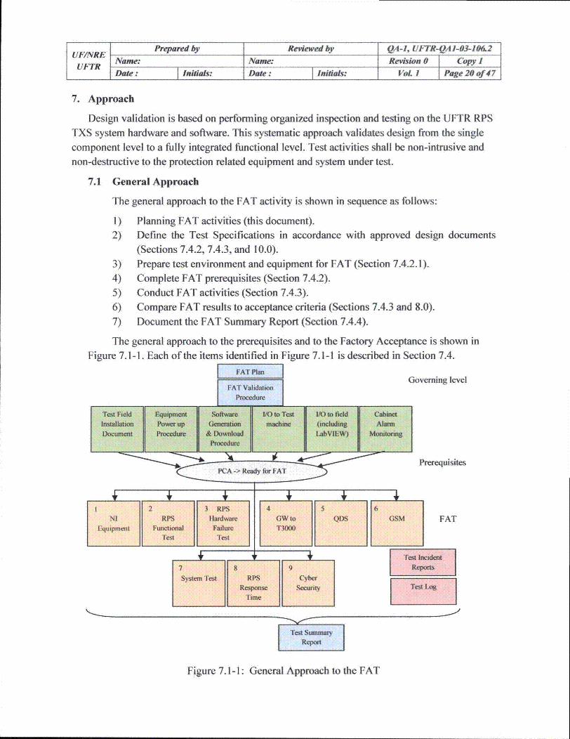
7. Approach
Design validation is based on performing organized inspection and testing on the UFTR RPSTXS system hardware and software. This systematic approach validates design from the single
component level to a fully integrated functional level. Test activities shall be non-intrusive andnon-destructive to the protection related equipment and system under test.
7.1 General Approach
The general approach to the FAT activity is shown in sequence as follows:
I) Planning FAT activities (this document).2) Define the Test Specifications in accordance with approved design documents
(Sections 7.4.2, 7.4.3, and 10.0).3) Prepare test environment and equipment for FAT (Section 7.4.2.1).
4) Complete FAT prerequisites (Section 7.4.2).
5) Conduct FAT activities (Section 7.4.3).
6) Compare FAT results to acceptance criteria (Sections 7.4.3 and 8.0).7) Document the FAT Summary Report (Section 7.4.4).
The general approach to the prerequisites and to the Factory Acceptance is shown in
Figure 7.1-1. Each of the items identified in Figure 7.1-1 is described in Section 7.4.
FA lani i Governing levelFAT Validation
Procedure
Test Field Equipment Software I/O to Test IVO to field CabinetInstallation Powerup Generation madcine (including AluDocument Prcedure & Download LabVIEW) Monitoring
Procedure
"A PrerequisitesPCA -> Ready for FAT
12 3 RPS 45 6NI RPS Hardware GW to QDS GSM FAT
Equipment Functional Failure T3000Test Test
System Test RPS CyberResponse sectunty Tso
Time
Test Sunmr
Repr
Figure 7.1-1: General Approach to the FAT

UF/NRE Prepared by Reviewed by QA-), UFTR-QA 1-03-106.2
UFTR Name: Name: Revision 01 Copy IDate: Initials: Date: Initials: VoL 1 Page 21 of 47
The prerequisites to the FAT and the FAT itself utilize an overlapping approach toensure that all segments of the UFTR RPS System are tested. Figure 7.1-2 provides anillustration of the major system segments of the UFTR RPS System. The items listed inSection 4.0 are included in the major system segments identified in Figure 7.1-2.
S SIS
GWV
Ssteva [Modules&Application Cabinet Intelrnal
Software Wiling
Nuclear
(NI)
Figure 7.1-2 Major System Segments of the UFTR RPS System
Table 7. 1-1 provides a breakdown of which FAT Specifications/Procedures (asnumbered in Figure 7.1-1) correspond to each major system segment.
Table 7. 1-1: Major System Segment and Test Specification/Procedure
Major System Segments Corresponding Tests (From Figure 7.1-1)Field Connections & Isolation Devices 1, 8Test Machine Connections 2, 3, 7Communication Modules & Cabling 2,4, 5,6, 9TXS GW 2,4TXS QDS 2,5TXS SU (including GSM) 2, 6,9System & Application Software 2, 3, 7, 8, 9TXS Modules & Cabinet Internal Wiring 1, 2, 3, 8Nuclear Instrumentation Equipment 1, 8

UFINRE Prepared by Reviewed by QA-1, UFTR-QA 1-03-106.2Name: Name: Revision 0 Copy 1Date: Initials: Date: Initials: VoL 1 Page 22 of 47
7.2 Comprehensiveness
The FAT shall be comprehensive and complete in that all components and functions ofthe UFTR RPS System shall be exercised under a set of realistic operating conditions thattakes into account all credible combinations.
For each of the features or groups of features to be tested as listed in Section 5, ageneral approach is described to validate the functionality of the equipment under test. Wherecomplete functionality is not tested in a single procedure, there will be overlap testing toensure the complete feature or group of features are tested. Each feature of the system shall,however, be formally tested under at least one test.
7.3 Coverage and Overlap of SW and HW
The following tables provide an overview of which tests check what parts of thesystem. It also illustrates how sufficient overlap between the tests and for Hardware and
Software is ensured.
Table 7.3-1a: List of tested parts/components and the necessary input channels usedInput Channels
Tes-to-TedistMachaione
Eqipen Input Inputinptoxcaeg/uaiur
Cabinet Alarm MonitoringNI Functional Test X X XRPS SW Functional Test X X X FGSM SW Functional TestGW to T3000SW Functional TestQDS SW Functional Test
RPS Response Time X X X XTesting
Cyber Security
RPS Hardware Failure FTesting

UFINRE Prepared by Reviewed by QA-1, UFTR-QAI-03-106.2Name: Name: Revision 0 Copy IDate: Initials: Date: Initials: VoL 1 Page 23 of 47
Table 7.3-1 b: List of tested parts/components and the tested functions
Functions
functions ait
(downloaded SW) on SU SW) wiTest field installation X XDocument
Equipment Power UpProcedure
I/O-to-Field
110-to-Test Machine
Cabinet Alarm Monitoring XNI Functional Test XRPS SW Functional Test X F
GSM SW Functional Test X XGW to T3000 X FSW Functional Test
QDS SW Functional Test X FRPS Response Time Testing X X X
Cyber Security X X XRPS Hardware Failure F FTesting
Table 7.3-1c: List of tested parts/components and the corresponding output channelsOutput Channel ISuperordinated
Test field installation document XEquipment Power Up Procedure X X
1/0-to-Field X X1/0-to-Test Machine X X
Cabinet Alarm Monitoring X
NI Functional TestRPS SW Functional Test X X X
GSM SW Functional Test
GW to T3000 SW Functional Test X
QDS SW Functional Test
RIPS Response Time Testing X X X
Cyber Security
RPS Hardware Failure Testing F
Legend:
I F includes testing of failure behavior

Prepared by Reviewed by QA-1, UFTR-QA I-03-106.2UFNR Name: Name: Revision 0 Copy 1
F Date: Initials: Date: Initials: VoL 1 Page 24 of 47
7.4 Major Activities
The Test Administrator shall check out the following activities prior to test activities.
7.4.1 FAT Plan
The FAT Plan establishes the framework for conducting Factory AcceptanceTesting on the UFTR RPS TXS System. The FAT Plan is the highest tier testdocument.
7.4.2 FAT Validation Procedure
The FAT Validation Procedure is used to control activities that must becompleted prior to the start of FAT (i.e., FAT Prerequisites) and to record pertinentinformation during the course of FAT (i.e., FAT Activities). This information includes:
" FAT Prerequisites:
o Documenting the service and test network setupo Test Machine connections and wiring test resultso LabVIEW Data Acquisition Equipment connections and wiring test resultso Installation and setup of the TXS SU per the SU Installation Manual, /16/o Installation and setup of the TXS GW per the GW Installation Manual,
/17/o Installation and setup of the TXS QDS per the QDS Installation Manual,
/18/o Ensuring calibrated temperature and relative humidity recording devices
are installed and operational in the test field prior to the start of FATo The System and Application Software are loaded on the appropriate TXS
processorso Ensuring that all prerequisites to starting FAT are complete. An example
of such a requirement is the status of the physical configuration audit to becompleted prior to the start of FAT
" The Test Supervisor and/or Test Lead shall declare that the UFTR RPS TXS
System prerequisites are complete to the extent that there is no adverse impacton the commencement of FAT activities. This "Ready for FAT" statementshall be recorded in the FAT Validation Procedure and in the Test Log.
" FAT Activities:
o Recording the initiation of each of the Test Specifications/Procedureso Recording the completion of each of the Test Specifications/Procedures
o Maintaining the Test Log activitieso Recording the temperature and humidity levels daily during the
performance of FAT.o Recording any lifted leads or inserted jumpers

UFINRE Prepared by Reviewed by QA-I, UFTR-QA 1-03-106.2Name: Name: Revision 0 Copy IUFTRDate: Initials: Date : Initials: VoL. 1 Page 25 of 47
o Recording which piece of calibrated test equipment was used on whichtest
7.4.2.1 Test Field Installation Document
This document includes all connection and setup information requiredto prepare the UFTR RPS TXS system for the FAT. This information includes
such items as the power and grounding connections for the TXS cabinets, thenetwork configuration of the equipment (including the test equipment), and theconnections of the Test Machine and the LabVIEW Data AcquisitionEquipment.
7.4.2.2 Equipment Power-Up Procedure
Equipment power-up testing shall be performed to validate theconfiguration and functional design of the UFTR RPS TXS system powerdistribution. The test shall perform functional testing of cabinet power to verifythe appropriate voltage is present and distributed to the correct terminal pointsthroughout the equipment as designed. This test shall also verify thefunctionality of the redundant power supplies. This test shall be performed on acabinet by cabinet basis.
7.4.2.3 Software Generation and Download Procedure
The UFTR "Software Generation and Download" procedure, /14/, isrequired to be performed before proceeding to the remaining prerequisites andFATs. The purpose of this procedure is to provide instructions for the TXS
software processes on the UFTR RPS TXS system:
" Generation and storage of the Application Software
" Loading of the Application Software onto the SU* Loading of the Application Software onto the TXS GW
" Loading of the Application Software onto the TXS QDS
* Loading of the System Software onto the TXS processors
* Loading of the Application Software onto the TXS processors* Loading of the L2-CP Firmware onto the TXS communication
processors
" Loading of the H1-CP Firmware onto the TXS SCP2 communicationprocessor
" Preparation of the Configuration File for the TXS communication
processors* Parameterization of the L2-CP Firmware for the TXS communication
processors
The steps in this document ensure that the correct tools are used for thecode generation and that the correct System Segment Software components are

UFINRE Prepared by Reviewed by QA-1, UFTR-QAI-03-106.2Name: Name: Revision 0 Copy 1UFTRDate: Initials: Date : Initials: VoL. 1 Page 26 of 47
installed for the Application Software. The TXS SPACE Environment andassociated tools configuration is checked and documented with each SoftwareRelease created by the steps in this document.
This procedure, /14/, is not controlled by the FAT plan or by the FATvalidation procedure, but as it is an important process within the Software lifecycle it is controlled and maintained by the Software Development group. Thedownload of the software in the test field, however, is the responsibility of thetest team and is governed by the FAT plan.
7.4.2.4 Cabinet Alarm Monitoring
This testing will verify that the internal monitoring alarms of thecabinet monitoring system (including internal indications and signals) operate asdesigned. Where practical, cabinet alarm conditions will be generated to createthe cabinet alarm conditions, otherwise the alarm will be simulated. These tests
shall be performed on a cabinet by cabinet basis. The Hardware Failures test(Section 7.4.3.6) for each cabinet provides the overlap to verify the proper alarmsignal is output from the TXS cabinet.
7.4.2.5 The I/O to Field
The purpose of this test is to verify the correct cabinet internal wiring
from the terminal points to the TXS input modules and from the TXS outputmodules to the terminal points. This internal wiring includes any hardware logicthat may exist. Examples of this hardware logic include the Manual Bypass
Keyswitch actuation of the RPS Trip Relays, the AND/OR logic associated withactuating outputs, etc.
Manual injection of test signals to the system inputs and manualrecording of the system outputs at the field terminals is the method used for thistest. This test utilizes calibrated test equipment and is responsible for validatingthe accuracy of the supplied equipment. When available, actual keyswitches,pushbuttons, lights, etc. should be used to simulate inputs and outputs.
7.4.2.6 The I/O to Test Machine
The purpose of this test is to validate the correct hardware and
software configuration of the TXS ERBUS test machine interface to TXSsystem hardware Inputs and Outputs. This means all connections of the testmachine to and from the TXS system are checked for the followings:
* Correct assignment to the corresponding (internal cabinet) terminal.
* Correct assignment of signal IDs.
* Correct simulation of the measuring ranges (analog) / signal levels(binary).
UF/NRE Prepared by Reviewed by QA-1, UFTR-QA 1-03-106.2Name: Name: Revision 0 Copy 1
UFTRDate: Initials: Date - Initials: VoL 1 Page 27 of 47
Upon completion of this test, the Input/Output interface of the testmachine is ready to support the subsequent FAT tests.
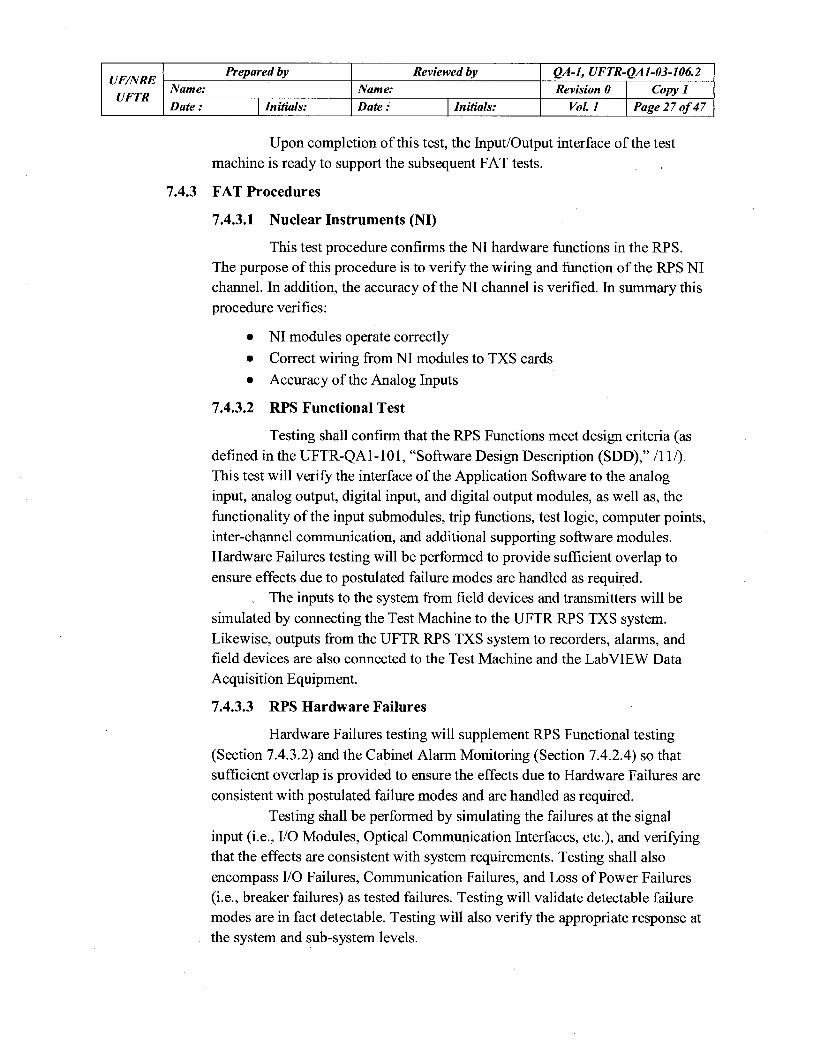
7.4.3 FAT Procedures
7.4.3.1 Nuclear Instruments (NI)
This test procedure confirms the NI hardware functions in the RPS.The purpose of this procedure is to verify the wiring and function of the RPS NIchannel. In addition, the accuracy of the NI channel is verified. In summary thisprocedure verifies:
" NI modules operate correctly
" Correct wiring from NI modules to TXS cards" Accuracy of the Analog Inputs
7.4.3.2 RPS Functional Test
Testing shall confirm that the RPS Functions meet design criteria (asdefined in the UFTR-QAl-101, "Software Design Description (SDD)," /11/).This test will verify the interface of the Application Software to the analoginput, analog output, digital input, and digital output modules, as well as, thefunctionality of the input submodules, trip functions, test logic, computer points,inter-channel communication, and additional supporting software modules.Hardware Failures testing will be performed to provide sufficient overlap toensure effects due to postulated failure modes are handled as required.
The inputs to the system from field devices and transmitters will besimulated by connecting the Test Machine to the UFTR RPS TXS system.Likewise, outputs from the UFTR RPS TXS system to recorders, alarms, andfield devices are also connected to the Test Machine and the LabVIEW DataAcquisition Equipment.
7.4.3.3 RPS Hardware Failures
Hardware Failures testing will supplement RPS Functional testing(Section 7.4.3.2) and the Cabinet Alarm Monitoring (Section 7.4.2.4) so thatsufficient overlap is provided to ensure the effects due to Hardware Failures are
consistent with postulated failure modes and are handled as required.Testing shall be performed by simulating the failures at the signal
input (i.e., I/O Modules, Optical Communication Interfaces, etc.), and verifyingthat the effects are consistent with system requirements. Testing shall alsoencompass 1/0 Failures, Communication Failures, and Loss of Power Failures(i.e., breaker failures) as tested failures. Testing will validate detectable failuremodes are in fact detectable. Testing will also verify the appropriate response atthe system and sub-system levels.
UFINRE Prepared by Reviewed by QA-1, UFTR-QA 1-03-106.2Name: Name: Revision 0 Copy 1
UFTR Date : jInitials: Date : jInitials: Vol. 1 Page 28 of 47
These tests cover mainly the effects of communication failures on thesignaling to the T3000 control system and in the control room.
7.4.3.4 Graphic Service Monitor (GSM)
This testing will verify that the proper connections are made betweenthe Application Software and the GSM Screens that operate on the TXS SU.
The signals from each TXS processor to the GSM Screens will bemanipulated and the values of the signals will be visually verified on the GSMScreens themselves. The signals that are written from the GSM Screens will bemanipulated on the GSM Screens and verified on the SU through the use of theproject-independent portion of the GSM and/or the dynamic Function DiagramEditor.
7.4.3.5 GW to T3000 control system
The purpose of this test is to verify the correct connection to the TXSGW and the correct functionality of the Application Software implemented onthe TXS GW. This test shall also verify that the data link between the TXS GW
and the on-line system can support an update rate of one (1) second for allparameters.
To perform this test, the GW signals from each TXS processor will bemanipulated and the values of the signals will be recorded on the GW utilizingthe GW Historical Application.
7.4.3.6 Qualified Display System (QDS)
The purpose of this test is to verify the correct connection to the TXSQDS and the correct functionality of the Application Software implemented onthe TXS QDS.
The signals from each TXS processor to the QDS will be manipulated
and the values of the signals will be visually verified on the QDS themselves.
7.4.3.7 System Test
The purpose of this test is to demonstrate the ability of the UFTR RPSTXS system to function during specified event scenarios. A testing simulatorshall be used for this test. The simulator is comprised of the following
equipment:
9 the test field setup with the TXS ERBUS as primary simulation andrecording device,
* the LabVIEW equipment (visualizing panel indicators that are notavailable in the test field), and
the additional mockup panel.

UFINRE Prepared by Reviewed by QA-1, UFTR-QA 1-03-106.2Name: Name: Revision 0 Copy IDate: Initials: Date: Initials: Vol. 1 Page 29 of 47
Note that a plant simulation model will not be implemented in this
setup.The following test has been selected to demonstrate performance of
the UFTR RPS TXS System over a range of realistic operating conditions:0 Controlled Start-up/Shutdown Simulation:
The purpose of this test is to demonstrate that the UFTR RPS TXS
System will operate correctly during a simulated start-up andshutdown of the plant. The test will demonstrate when the combinationof inputs corresponding to the plan starting-up or shutting down isapplied to the UFTR RPS TXS System, the appropriate systemresponse occurs.
7.4.3.8 RPS Response Time
This testing will validate the response time of the UFTR RPS TXSsystem. The method for performing response time testing shall be to initiate atrip from simulated inputs, monitor system trip outputs, and shall be based uponthe slowest output response. This testing shall include all hardware and softwareitems that make up each trip path in the UFTR RPS TXS system.
The test will verify the response time of each trip function of theUFTR RPS TXS system. The test will be performed by simulating each input tothe trip function and monitoring that input as well as monitoring thecorresponding trip relay outputs. The time between the change in the input andthe change of the output is the response time.
7.4.3.9 Cyber Security
The purpose of this test is to validate the Cyber Security of the UFTRRPS TXS system, and shall demonstrate that requirements for ensuring cybersecurity protection of the UFTR RPS TXS system are met. The Cyber Securitydocument, /12/, provides requirements for cyber security testing. The Cyber
Security test shall cover the following areas:
* Hardware security* Software security
" Network security
7.4.4 FAT Reports
7.4.4.1 Test Log
The Test Log is the chronological record of activities in the test field.
This includes a record of start and stop times of individual tests, all encounterederrors, day-to-day activities, etc. Any error that results in an Open Item and/orCondition Report shall have the corresponding Open Item and/or Condition

UFINRE Prepared by Reviewed by QA-1, UFTR-QAJ-03-106.2Name: Name: Revision 0 Copy IUFTRDate: Initials: Date: Initials: Vol. 1 Page 30 of 47
Report identifier listed with the error. Refer to section 10.3.1 for additional
information on the Test Log.
7.4.4.2 Test Incident Report
The Test Incident Report documents any event that occurs during thetesting process which requires investigation. If the event resulted in an OpenItem and/or a Condition Report, then the corresponding number from thoseitems shall be listed in the Test Incident Report. Refer to section 10.3.2 for
additional information on the Test Log.
7.4.4.3 FAT Summary Report
The FAT Summary Report is a document summarizing testing
activities and results. The FAT Summary Report also contains an evaluation ofthe corresponding test items. The completed Test Procedures may be attached to
the FAT Summary Report or they may be incorporated into a separate, standalone document (a summary test report that is referenced in the FAT SummaryReport). If the completed Test Procedures are collected into a separate, standalone document then the identity of each component document shall be retainedin the new document. The new document shall be referenced in the FAT
Summary Report.
7.4.4.4 Test Data Retention
Upon the successful completion of FAT, the resultant data files fromall test runs of the Test Specifications / Procedures identified in Section 7.4.3
shall be collected on electronic media such as a CD or DVD. The electronicmedia shall then be stored into the Software Library as governed by the UFTR
"Software Library and Control," /13/. The data will become available toauthorized entities for review.
7.5 Constraints
The Test Lead (see Section 13.2.3) is responsible for identifying and resolving
significant constraints with regards to testing. These constraints include test item availabilityand test resource availability.

UFNRE Prepared by Reviewed by QA-I, UFTR-QA 1-03-106.2Name: Name: Revision 0 Copy IDate : Initials: Date: Initials: Vol. 1 Page 31 of 47
8. Item Pass/Fail Criteria
All test specifications and test procedures shall define the required acceptance criteria for theUFTR RPS TXS system in order to decide if the test is completed successfully. These criteriashall be developed from design and customer specifications. Test results shall be evaluatedduring testing to ensure compliance with the stated qualitative and/or quantitative testrequirements.
Any deviations between test results and the acceptance criteria (i.e. the expected results) shall
be controlled in accordance with Section 9.0.The role of IV&V with regard to Item Pass/Fail Criteria (i.e., the V&V test acceptance) is
described in the UFTR SVVP, /6/.
UFINRE Prepared by Reviewed by QA-1, UFTR-QAI-03-106.2Name: Name: Revision 0 Copy IDate: Initials: Date: Initials: VoL 1 Page 32 of 47
9. Suspension Criteria and Resumption Requirement
9.1 General
An orderly approach to suspend and resume testing activities is required during testingin accordance with IEEE Std 829-1983,/21/. The following sections provide details for thetest suspension and resumption criteria.
9.2 Test Suspension Criteria
If an error that does not change the Scope, Intent, or Acceptance Criteria of a test isencountered during the performance of a Test Specification/Procedure, it is acceptable tohave two (2) cognizant test personnel mark a single line through the error, make the
necessary correction, initial and date the correction, and continue on with the test. Any suchcorrection shall be recorded in the Test Log along with the names of the personnel makingthe correction. If any doubt exists whether or not the error falls in this category, the test shallbe suspended and the Test Supervisor shall be contacted. An Open Item shall be generated totrack all such corrections to ensure that the Test Specification/Procedure is updated with the
correction for future use.If an error in the Test Specification/Procedure that affects the Scope, Intent, or
Acceptance Criteria and/or an error in system operation or behavior are encountered, the testpersonnel shall perform the following actions:
1. Suspend test activities2. Evaluate condition and place test and equipment in known, controlled condition3. Notify the Test Supervisor and/or Test Lead4. Record the relevant information (e.g., test being performed, step number, recognized
error, etc.) in the Test Log5. Perform troubleshooting (if applicable):
Prior to performing any troubleshooting activities the desired troubleshooting steps
shall be prepared, independently reviewed, and approved by the Test Supervisorand/or Test Lead in a manner that can and shall be attached to the affected TestProcedure. The creation and performance of these steps shall be documented in the
Test Log. Troubleshooting activities shall:
" Not alter test objectives or acceptance criteria
" Not introduce the use of different types of test equipment or test tools* Align with an existing test section* Restore the hardware and software configuration to original state prior to
completion of activities
* Place the test and equipment in a known, controlled condition upon completion ofactivities
The names of all personnel that perform and witness troubleshooting activities shallbe recorded in the Test Log.

UF/NRE Prepared by Reviewed by QA-1, UFTR-QA 1-03-106.2Name: Name: Revision 0 Copy 1UFTRDate : Initials: Date : Initials: Vol. 1 Page 33 of 47
6. Initiate an Open Item and/or Condition Report (if required). The thresholds for OpenItems and Condition Reports are controlled according to the processes which govern
each, /1/ and /2/. The Open Item and/or Condition Report number shall be enteredinto the Test Log. The Open Item and/or Condition Report will be evaluated todetermine the cause of the problem (e.g., test procedure error, test script error,software or hardware design or manufacturing error), whether tests must be repeated,and whether regression tests are needed to validate the correctness of the correctivemeasures.
7. Record incident in the Test Incident Report (including the Open Item and/orCondition Report number). The incident report form is to be signed by both AREVA
and UFTR representatives.
9.3 Test Resumption Requirements
After an error is encountered that requires testing to be suspended, the test personnel
shall perform the following actions:
1. Evaluate and dispose of applicable resolution (Disposition of Open Item or ConditionReport shall document the required actions and conditions to resume testing activities,including items to be retested)
2. Verify Open Items and/or Condition Report resolutions are complete to the extent thatTesting/Retesting may continue/resume
3. Enter relevant information in the Test Log4. Resume testing and retesting as applicable
The Test Lead shall determine if another Test Specification/Procedure may be performedafter one test has been suspended provided that no adverse conditions exist that impact testingcommencement/continuation. This action shall be recorded in the Test Log.

UFINRE Prepared by Reviewed by QA-1, UFTR-QAI-03-106.2Name: Name: Revision 0 Copy IUFTRDate: Initials: Date: Initials: VoL 1 Page 34 of 47
10. Test Deliverables
Test deliverables are outputs from the test document set and from UFTR procedures thatintegrate with the Test plan. These include the following:
" FAT Plan
" FAT Validation Procedure (including the Test Log)* Test Specifications (for the SW related tests only)* Test Procedures (for both SW and HW related tests)* Test Incident Reports (including references to Open Items and Condition Reports)* FAT Summary Report
Test deliverables are also derived from the UFTR QAP, /1/. Though it is hard to draw theline between HW and SW related tests, when integral testing is conducted, this plan describestwo (2) groups of tests:
1) The HW related tests focus mainly on the validation of the performance of the hardwarerather than the specific SW logics implemented. For these tests a procedure is preparedwith the structure presented in section 10.2.1.
2) The SW related tests focus mainly on the validation of the implemented software and itslogics. Of course these tests also include features dependent on the performance of thehardware. According to IEEE Std 829-1983, /21/, for the validation of software a testdesign specification, a test case specification and a test procedure must be prepared. Thetest design specification and the test case specification are comprised in the "Testspecifications" that are provided only for the SW related tests of the UFTR FAT. Section10.1.1 describes the structure of the test specifications.
For most of these tests, specific test scripts must be provided that are designed according tothe UFTR SDD, /11/. The test procedures for the HW related tests follow a similar structure as'the SW related tests (see section 10.1.2). The HW test procedures contain the informationaddressed in the SW test specification and in the SW test procedures, but they leave a few titlesto be addressed in the test specification. The test procedures for the SW related tests contain thespecific test scripts, in order to complete FAT.
10.1 Software Test Documentation
10.1.1 Test Specification
The Test Specification shall incorporate the Test-Design Specification and TestCase Specification as defined in IEEE Std 829-1983, /21/, into a single document. EachTest Specification shall have the following information and structure:
* Test Design Specificationo Test Specification identifier (i.e., document number)o Features to be testedo Approach refinements
o Test identification

UF/NRE Prepared by Reviewed by QA-1, UFTR-QAI-03-106.2
UFTR Name: Name: Revision 0 Copy 1
Date: Initials: Date : Initials: VoL 1 Page 35 of 47
o Features pass / fail criteria
* Test Case Specification
o Test itemso Input specificationso Output specifications
o Environmental needso Special procedural requirementso Intercase dependencies
* Attachments (including description of procedural steps and in some cases the
expected test results)The Test Specifications shall test, verify, and document that the UFTR RPS
TXS System meets design specifications. Test Specifications shall validatefunctionality under a comprehensive set of realistic operating conditions. Specificacceptance criteria shall be defined in the individual Test Specifications. IndividualTest Procedures shall be developed using the Software and Hardware designdocuments. Each Test Specification shall identify the tools required to perform the test.
10.1.2 Test Procedure
Each Test Procedure shall have the following information and structure:
* Test Procedure Identifier (i.e., document number)
• Purpose
o References
o Definitionso Abbreviations/Acronyms
• Special requirementso Test equipmento Other equipmento Prerequisites
o Safety requirementso Test Supervisor requirements
* Procedure steps
* Restoration
* Test Completion* Attachments
Each FAT Procedure shall also contain the following sections/information, asapplicable, required by the UFTR FRS, /10/. For SW related tests, the followinginformation is specified in the test design sections of the test specification:
* Functions to be tested and not tested
* A listing of inputs and outputs
* Test software descriptions and listings

UFINRE Prepared by Reviewed by QA-1, UFTR-QA 1-03-106.2Name: Name: Revision 0 Copy IUFTRDate: Initials: Date: Initials: Vol. 1 Page 36 of 47
" Expected results* Pass/Fail criteria* Acceptance criteria, expressed in engineering units, including timing and
propagation delay* Data/Data Collection/Data Sheets.
The Test Procedures shall test, verify, and document that the UFTR RPS TXSSystem meets design specifications.
Specific acceptance criteria shall be defined in the individual Test Procedures.Test Procedures may utilize Test Scripts to perform the steps specified in the
corresponding Test Specification. If Test Scripts are utilized as the Test Procedure, thenthe Test Scripts shall be entered into the Test Procedure documentation in the exactformat in which they exist without modification. The Test Scripts shall also be enteredinto the Software Library as governed by the UFTR "Software Library and Control,"/13/.
A field shall be provided in each procedure to allow the UF representative toenter comments. A signature field to indicate test completion shall be provided for theUF representative.
10.1.3 Software Test
The following tests are considered software tests and therefore fall under thescope of Section 10. 1:
* RPS Functional Test" GSM
* GW to T3000 control system
• QDS
* Controlled Start-up/Shutdown Simulation
* Cyber Security
10.2 Hardware Test Documentation
10.2.1 Test Procedure
The hardware test portion of the FAT is not governed by IEEE Std 829-983,/21/, however, the standard is used as guidance for developing and performing thehardware tests. The Test Procedures shall have the following information:
a Test Procedure Identifier (i.e., document number)
a Purpose
o Referenceso Definitionso Abbreviations/Acronyms
* Special requirements

UFINRE Prepared by Reviewed by QA-1, UFTR-QA 1-03-106.2Name: Name: Revision 0 Copy IUFTRDate: Initials: Date: Initials: Vol. 1 Page 37 of 47
o Test equipmento Other equipmento Prerequisites
o Safety requirementso Test Supervisor requirements
* Procedure steps
* Restoration
* Test Completion
* Attachments
Individual hardware Test Procedures shall be developed using the Hardwaredesign documents. If a Test Procedure uses a Test Script to perform any actions, the
Test Script shall be included as part of the Test Procedure.Each Test Procedure shall identify the tools required to perform the test.
10.2.2 Hardware Test
The following test procedures (as discussed in Section 7.4.3) are consideredhardware tests:
* Nuclear Instrumentation (NI)
* RPS Hardware Failures
* RPS Response Time
Note: The Hardware failure tests and the Response Time tests cover Softwarerequirements as well. Therefore the corresponding test procedures may be subject toV&V review activities, though these documents are issued in the form of testprocedures as described in section 8.2.1. Whether these procedures are reviewed by
V&V or not, is to be determined by the IV&V team.Furthermore the following prerequisite tests (as discussed in Section 5.4.2) are
considered hardware tests and therefore follow the structure specified in Section 8.2:
0 Equipment Power-Up Procedure* Cabinet Alarm Monitoring* 1/0 to Field
• 110 to Test machine
10.3 Overall Test Documentation
10.3.1 Test Log
The Test Log provides a chronological record of relevant details about the
execution of tests following the guidance of IEEE Std 829-1983, /21/. The Test Log hasthe following format:
" Test Log identifier
" Description

UFINRE Prepared by Reviewed by QA-1, UFTR-QA1-03-106.2Name: Name: Revision 0 Copy IDate : Initials: Date: Initials: Vol. 1 Page 38 of 47
Activity and event entries
The Test Log shall be included as an attachment to the FAT Validation
Procedure. Therefore the Test Log identifier (or document number) is the same as theFAT Validation Procedure.
10.3.2 Test Incident Report
The Test Incident Report documents anyevent that occurs during the testingprocess that requires additional investigation. The Test Incident Report shall have the
following information and structure:
* Test Incident Report identifier
* Summary
* Incident description
* Impact
10.3.3 FAT Summary Report
The FAT Summary Report will be generated to document the successfulcompletion of FAT and to document any variances incurred during testing. The TestSummary Report shall have the following information and structure:
• Test Summary Report identifier
* Summary
* Variances
* Comprehensive assessment
* Summary of results
* Evaluation
* Summary of activities
The UFTR Project Manager shall review and approve the FAT Summary Reportto acknowledge acceptance and completion of FAT. Completion of the FAT signifiescompletion of the testing phase and establishes a final configuration. The FATSummary Report shall include reviews and approvals including:
* Test Lead
* Project Manager
* QA Lead

UFINRE Prepared by Reviewed by QA-1, UFTR-QA 1-03-106.2Name: Name: Revision 0 Copy IDate: Initials: Date: Initials: VoL 1 Page 39 of 47
11. Testing Tasks
The tasks necessary to prepare for FAT prerequisites and performance are listed in Section7.4.2 and the tasks necessary to perform the FAT are listed in Section 7.4.3.
Successfully completing the training as specified in Section 14.2 provides the necessaryskills needed to perform the testing tasks.
The intertasks dependencies between the performance of the prerequisites and the FATprocedures are as follows:
1. The Test Plan must be approved and released before executing any of the FATprerequisites or tests.
2. The FAT prerequisites listed in Section 7.4.2 must be completed before performing any
of the FATs.3. The FAT prerequisites shall be executed in the following order:
i. Test Field Installation
ii. Equipment Power-upiii. Software Generation and Downloadiv. Remaining Prerequisites (1/0 to Test machine, 1/0 to field, and Cabinet alarm
monitoring)
4. The FAT for NI equipment may be performed following the completion of the FATprerequisites.
5. The validation of the initial conditions setup as specified in the RPS Functional Testsmust be successfully completed prior to proceeding to the following tests (which may be
done in any order):
i. RPS Hardware Failuresii. GSM
iii. GW to non-safety T3000 systemiv. QDSv. System Tests
vi. RPS Response Timevii. Cyber Security
Tasks may proceed without satisfying the stated intertask dependencies provided no adverseconditions exist that impact test commencement/continuation as identified in Section 9.3.

UFINRE Prepared by Reviewed by QA-1, UFTR-QA 1-03-106.2Name: Name: Revision 0 Copy IDate : I Initials: Date: Initials: Vol. 1 Page 40 of 47
12. Environmental Needs
12.1 Physical Control
The UFTR RPS TXS System shall be placed into a controlled environment inconformance with ANSI Standard N45.2.2-1972, Level B, /25/. These requirements include,but are not limited to the following:
" UFTR RPS TXS System shall be placed into a controlled environment that is wellventilated, protected from water intrusion, and protected from fire, flooding, or
animal intrusion.
" UFTR RPS TXS System shall be placed into a secure environment that is protectedfrom vandalism or tampering.
" UFTR RPS TXS System cabinets shall remain locked at all times whenever the testarea is unoccupied or authorized UFTR personnel are not present.
* Only authorized personnel shall have access to the TXS cabinet internals.
12.2 Environmental Control
The location of the UFTR RPS TXS System under test shall comply with designrequirements regarding environmental requirements per ANSI Standard N45.2.2-1972, LevelB, /24/, and design and customer specifications.
12.3 Access Control to Test Field
Access to the test field shall be controlled to ensure an orderly and safe conduct of
testing. These requirements include, but are not limited to the following:
* Personnel access to the test field shall be minimized to reduce disturbances to the
testing activities* No personnel shall enter the test field without Test Supervisor authorization
* Only authorized personnel shall access the test field without escort
The test field, and therefore the system under test, shall not be connected to anyexternal network or have any outside communication connection. The use of USB storagedevices is permissible. The mode of usage (in accordance with IEEE Std 829-1983, /21/) is
therefore considered to be stand-alone.
12.4 Required Software
The required communication and system software for the test field is identified in the
Project-Independent Software listed in Section 4.1.Other software packages (e.g., Excel macros) and/or scripts may be used as an aide in
the process of reviewing test results, however, these software packages and/or scripts shall
not be credited as the method for performing final review of test results.

UF/NRE Prepared by Reviewed by QA-I, UFTR-QAI-03-106.2Name: Name: Revision 0 Copy 1UFTRDate: Initials: Date: Initials: VoL 1 Page 41 of 47
12.5 Special Test Tool Needs
The special tools needed for performance of the FAT are the Test Machine and theLabVIEW Data Acquisition Equipment.
Calibrated equipment shall be available to record the temperature and relative humiditylevels of the test field environment throughout the course of FAT. This equipment shall beable to display the current temperature and relative humidity levels and record the peakvalues of each. Other special tools needed include calibrated low level current sources (in theVA range) and fast response recording devices for performing the NI and Response Timetests. The requirements for this equipment shall be specified in the corresponding TestSpecifications/Procedures.
Other needed test tools are to be specified in the individual Test Specifications orProcedures, but are of a standard nature (e.g., digital Multimeter) and are not considered to
be special.
12.6 Other Testing Needs
There shall be a document library readily accessible to the test field. This library shallcontain software and hardware detailed design documentation and general productinformation and/or user manuals. These documents are only intended to be used forreference. A means of connecting to the UFTR Document Server shall be available in closeproximity to the test field. This allows test personnel to access controlled documentation thatmay not be available in the test field library.
Office space shall also be made available to test personnel to perform validation of therecorded, resultant test data from the operation of the Test Procedures. The evaluation ofresults (especially for software tests) may be performed outside of the test field to allow for
other tests to be performed.Any need (tool, document, etc.) that is not currently available to the test team shall be
obtained by the Test Lead (see Section 13.2.6). Each Test Specification/Procedure discussedin this section shall identify the tools required to perform the test. The use of calibrated testequipment shall be recorded as described in Section 7.4.2. Accuracy requirements are to meetgeneral industry standard practices.

UFINRE Prepared by Reviewed by QA-1, UFTR-QAI-03-106.2Name: Name: Revision 0 Copy )UFTRDate : Initials: Date: Initials: Vol. 1 Page 42 of 47
13. Responsibilities
13.1 Organization
The overall project team organization and responsibilities are defined in UFTR QAPP,/3/. The individuals and groups identified in the following sections will be involved withFAT. For conducting the FAT tests, all personnel shall adhere to the FAT test specificationsand test procedures.
Note: Many of the following roles are not ruled by this FAT plan; they are ruled byother plans, e.g. by the V&V plan, the safety plan etc.
The Test Field Manager is provided by AREVA NP INC. He is responsible forenforcing the NL-G Test field manual.
13.2 Supplier - AREVA NP Inc.
13.2.1 General
Roles and responsibilities of AREVA NP Inc. and AREVA NL-G include:
* Provide the replacement RPS System
* Provide test hardware and software" Provide special test and calibrated test equipment (see section 12.5)* Provide testing simulator (Test Machine)
* Provide and maintain test field environment
" Observe and participate in FAT including setup and monitoring of test results
13.2.2 Test Field Manager
* Enforce the NL-G test field manual
" Establish and maintain test field access control list
* Provide infrastructural support for the FAT activities
* Responsible for maintaining the test field access control
* Maintain configuration control FAT activities
13.3 Purchaser - University of Florida (UF)
13.3.1 Project Manager
* Manage project scope* Ensure qualified personnel are available for testing* Approve the release of the FAT documents for testing
* Sign as approving Open Item resolution and closeout
* Provide the test items defined in Section 4
* Ensure acceptable environment requirements are met as defined in Section 12
13.3.2 Project Coordinator
o Approve Test Specifications/Procedures

UFINRE Prepared by Reviewed by QA-I, UFTR-QAJ-03-106.2Name: Name: Revision 0 Copy IUFTRDate: Initials: Date : Initials: Vol. 1 Page 43 of 47
* Approve FAT Summary Report
13.2.3 Test Lead - Hardware and Installation Group Lead
* Maintain and implement the FAT Plan* Maintain and implement the FAT Prerequisites* Coordinate the FAT activities* Resolve test group needs (e.g., tools, documents, etc.)* Primary responsibility to maintain configuration control• Generate Open Items and Condition Reports
13.2.4 Test Supervisor(s)
* Responsible for ensuring that pre-job briefs and safety briefs are conducted• Assist in the preparation of Test Specifications/Procedures and Test Scripts• Responsible for maintaining the Test Log* Responsible for maintaining the test equipment* Responsible for maintaining the test field cleanliness and decorum
* Responsible for supervision of test engineers and technicians• Coordinate FAT activities• Review FAT results
* Maintain configuration control• Ensure test documentation is retained as a permanent record• Generate Open Items and Condition Reports
13.2.5 Test Engineer(s)
* Prepare Test Specifications/Procedures and Test Scripts
• Perform FAT activities
* Review FAT results
* Prepare FAT Summary Report
* Ensure configuration control* Generate Open Items and Condition Reports
13.2.6 IV&V Personnel
* Perform V&V activities* Produce Software Test Review Report
" Maintain configuration control
* Generate Open Items and Condition Reports
13.2.7 Quality Assurance
* Witness/verify FAT, as required• Review and approve FAT procedures, as applicable* Responsible for ensuring independence from design and testing activities

UFINRE Prepared by Reviewed by QA-I, UFTR-QA I-03-106.2Name: Name: Revision 0 Copy I
UFTR Date : Initials: Date : Initials: Vol. 1 Page 44 of 47
* Maintain configuration control* Ensure test documentation is retained as a permanent record* Generate Condition Reports* Acceptance of Condition Report resolutions

UFINRE Prepared by Reviewed by QA-I, UFTR-QA1-03-106.2Name: Name: Revision 0 Copy IDate : Initials: Date: Initials: VoL I Page 45 of 47
14. Staffing and Training Needs
14.1 Staffing
Members of the FAT group are staffed with the following qualified personnel:
" Test Field Manager (AREVA NP Inc)" Test Lead/Test Supervisor (UF+AREVA NP Inc)
" Test Engineer (UF)" IV&V Personnel (UF)" QA Personnel (UF)
The method for providing the independence for the FAT is achieved by having all TestPlans, Test Specifications, Test Procedures, Test Logs, and Test Reports reviewed bypersonnel that are independent of the design process. Personnel that were involved with thedesign are allowed to participate in the preparation of any of the previously mentioned
documents, but are prohibited from performing any of the independent reviews of them.Independent V&V (IV&V) personnel report to the IV&V Lead. The 1V&V personnel
also report indirectly to Quality Assurance Lead, who has oversight authority over the V&Vactivities.
14.2 Training
The Test personnel will be qualified in accordance with the UFTR Training Plan, /8/,and AREVA's assistance. The Test Lead shall be responsible for verifying Test Personnelunder his/her supervision are qualified to perform the testing being conducted.

UFINRE Prepared by Reviewed by QA-1, UFTR-QA 1-03-106.2Name: Name: Revision 0 Copy IDate: Initials: Date: Initials: Vol. 1 Page 46 of 47
15. Schedule
15.1 Milestones
The FAT Plan schedule corresponds to major project milestone events that include
completion of:
" FAT Plan development
" Test Specification / Procedure development and checkout
" FAT prerequisite activities
" FAT activities
" FAT Summary Report
The preparation of the FAT test specifications and procedures as well as the FAT
activities themselves are not controlled by this FAT plan; they are set by the overall projectschedule. Therefore, dates and durations must be retrieved from the overall project schedule.
15.2 Basis for Milestones
Milestones are established based on the following logic:
* The FAT Plan is the basis for the development and performance of individual TestSpecifications/Procedures
" The TXS System must be assembled prior to performance of the Test Specification orProcedure Checkout and FAT
* Test Specification/Procedure Development and Checkout must be performed prior tothe start of FAT
" FAT completion is signified by approval of the FAT Summary Report
15.3 Project Schedule
The overall project schedule is the responsibility of the Project Manager, and the FAT
activities shall be included in the overall project schedule. Additional information onrequirements for establishing schedules and activities is governed by the UFTR QAPP, /3/.
The overall project schedule provides estimates required to perform each of theidentified testing activities. The schedule also specifies the required staff for each of thetesting activities. The period of use of the test field and testing tools (e.g., the Test Machine)can be ascertained through the use of the project schedule and identifying the testing
activities.

UFINRE Prepared by Reviewed by QA-1, UFTR-QA I-03-106.2Name: Name: Revision 0 Copy 1UFTRDate : Initials: Date: Initials: VoL 1 Page 47 of 47
16. Risk and Contingencies
Because of the safety features of the UFTR, risk management is not applicable.