"Receiving Inspection." - Nuclear Regulatory Commission
86
FRO 'HOJRN A LTi)MPT W r E 0 8L. E a O P14'BE .5 QUALITY INSTRUCTION NO. 120 REV. _ 0*10INAL AlI 671 ECEIow O GEI L '. ILEAS4 OAT• i tE.,;. - PAGE, RECIVNGINSPECTION 2/1/7] RVSOCA _________ APPIOV EV MNGA. OVAL ITV £(If 1161-114 1-0 INTRODUCTION 11Scope This document has been prepa'red to provide detailed instructions for controlling the receipt and inspection of purchased articles and services, 1.2 Application The requirements contained herein are applicable to all articles and services purchased by T$3I which are ultimately deliverable to TASI customers. Specifi :-ally excluded from the controls defined in this document are purchased tools, gages, fixtures, templates, jigs, machine too.lis, stardard supplies, and similar articles not normally deliverable to TASI Customers. 2.0 ASSOCIATED DOCUMENTS 2.1 Applicable Documents DOD (Juality Program Requirer~snts 2.2 Reference Documents TASI Q.I. '110 Statistical Accpetance Sampling TASI Q.I. 108 Instructions for Completing Failure and Rejection Report Form F-3807 3.0 REQUIREMENTS 3.1 Responsibility 3.1.1 Quality Engineering - Th.:! Quality Engineering section shall be responsible for planning and auditing the requirements of this docu.:ment and for identifying and providing for any unique customer requirements affecting the controls maintained in the Receiving Inspection pkrea. In addition, Quality Engineering shall be respon sible for preparing, issuing, and contralling detailed inspcction instructions ý.or each purchased article or service. I, b5 --
-
Upload
khangminh22 -
Category
Documents
-
view
1 -
download
0
Transcript of "Receiving Inspection." - Nuclear Regulatory Commission

FRO 'HOJRN A LTi)MPT W r E 0 8L. E a O P14'BE .5 QUALITY INSTRUCTION NO. 120 REV. _
0*10INAL AlI 671 EC EIow O GEI L '. ILEAS4 OAT• i tE.,;. - PAGE, RECIVNGINSPECTION 2/1/7] RVSOCA _________ APPIOV EV
MNGA. OVAL ITV £(If 1161-114
1-0 INTRODUCTION
11Scope
This document has been prepa'red to provide detailed instructions for controlling the receipt and inspection of purchased articles and services,
1.2 Application
The requirements contained herein are applicable to all articles and services purchased by T$3I which are ultimately deliverable to TASI customers. Specifi :-ally excluded from the controls defined in this document are purchased tools, gages, fixtures, templates, jigs, machine too.lis, stardard supplies, and similar articles not normally deliverable to TASI Customers.
2.0 ASSOCIATED DOCUMENTS
2.1 Applicable Documents
DOD (Juality Program Requirer~snts
2.2 Reference Documents
TASI Q.I. '110 Statistical Accpetance Sampling
TASI Q.I. 108 Instructions for Completing Failure and Rejection Report Form F-3807
3.0 REQUIREMENTS
3.1 Responsibility
3.1.1 Quality Engineering - Th.:! Quality Engineering section shall be responsible for planning and auditing the requirements of this docu.:ment and for identifying and providing for any unique customer requirements affecting the controls maintained in the Receiving Inspection pkrea. In addition, Quality Engineering shall be responsible for preparing, issuing, and contralling detailed inspcction instructions ý.or each purchased article or service.
I,�b�5�
-- �

T ,; . •7 L
QUALITY INSTRUCTION NO. 12 REV. , TITLE•. C , ATi OF PAGE 2
|NI[LEA$E DA.T5[ R #I•[lSk:ao*-'--:
RECEIVING INSPECTION4 2/1/87 OF 3 PAO"S AKNOWEDGO:. . .I APPRgVI-:
3.3.2 Receiving Inspection - T'he Receiving Inrspection section shall be responsible for perforTring the required inspection operations, acceptiLng or rejecting articles as required, and for docunmenting and maintaining records of inspection results.
3.2 System
3.2.1 Purchased articles shall be moved to the Receiving Inspection Area after receipt and identification by the Receiving Clerk.
3.2.2 All purchased articles -twaiting inspection shall be separated from accepted articles and shall be identified as awaiting inspection.
3.2.3 Prior to the starting oJi the actual inspection operation, the Inspector shall verify that definitive inspection instructions have been provided and are available.
These instructions, for purposes of this document, shall include as i minimum:
a) The required engineering drawing (and when necessary,
supporting specificitions, operation sheets, etc.)
b) A copy of the applitable TASI Purchase Order
c) The detailed inspection planning instructions
The revision status (letter change) of these documents shall be reviewed, and if not in agreement, shall be reported to the Inspect:ion Supervisor.- NO further inspection shall be accomplished unless the required inspection instructions are available.
3.2.4 The vendor supplied dat:a (test reports, certificates of conformance, certified test data, processing certificates, etc.) requested by the coded quality requirements of the purchase order (refere:'hce 0.1. 104) sball be reviewed for accuracy and compl:!teness. If the required data package is not completecd, this situation shall be reported to the Inspecti,)n Supervisor. The decision to complete or terminate the inspection operation at this time is reserved to thi! Inspection Supervisor, but in any case, the article(:3) may not be accepted or forwarded for further processing until the required data has been received and reviewed by Receiving Inspection.
I,

QUALITY INSTRUC" 0N NCO, 120 -REV. TI .LE: 0tI .oAL CAT9 O, PAGE 3
RI ll.IA$SI DATE: At~IllON"...
RECEIVING INSPECTION 2/1/87 or 3 PAGES
ACROW0,LEOGEOT APPROVEI. • I • _L•.•,~tj , _ I Ci5', t".- .ti. #MARAO•RQLALITY ENOX1IIR,1N@
3.2.5 The actual inspection (oL: bench test) of purchased article(s) shall be accomplished as directed by the specific instructions, using only calibrated instrumentation.
3.2.6 Specific instructiors for the recording of inspection results are contained in TASI Quality Instructions (Q.I.) 110.
3.2.7 Accepatble completed ari.tcles shall be forwarded to Stores. The authority for such mvement shall be indicated by appropriate Inspection tq partment completion of a "TO STOCK TAG", Form F2398.
3.2.8 Acceptable articles which are to be subjected to further processing operations 0311 be forwarded to the respective processing or manufacturing area.
3.2.9 Articles requirinq further inspection or testing by other .departments (functional testing, non-destructive testing, laboratory verificationt; etc.) shall be forwarded to the respective department ar.igned this responsibility and shall be routed for retuvn to the Receiving Inspection Department after the completion oW testing operations. Upon return of the article(s) and the required test or laboratcry reports to the Receivin. :Inspection Area, the test reports shall be roviewed and shall become part of the inspection record package.
3.2.10 Articles rejected durinq. inspection or test or which are not in complete conformance with the requirements of this document shall be ident.fied as descrepant, separated from acceptable articles or those awaiting inspection, and be subjected to Preliminary Material Review Action. Specific instructions for the handling of! rejected material are contained in TASI Qualihy Instruction 108.
3.3 Records
3.3.1 Documented evidence of inspections performed shall be maintained in the Receiving Inspection Area for a minimum of one (1) year from tho date oe last entry.
.0

" F R M 7 O R ý T O M A T IE D W L . K E0 " .• ' 0 . . ) a 1 4 1 2 .. H0 . P 14 G E '
QUALITY INSTRUCTION No. 120 REV. ; Onto) rAL I A71 Or RCLIA8( O"AT y UItII PAO E F RECEIVING INSPECTION 21/17 oF Zgs A CK N O W L EO GED .. ... 2 / In . .. a - -! P P J•O ý-E t "/ e ,,
_$AAGýt,QUA ITY E6EIINQ
1.0 INTRODUCTION
1.1 scope
This document has been prep:ired to provide detailed instructions for controlling the receipt and inspection of purchased articles and services,
1.2 APilication
The requirements contained h:erein are applicable to all articles and services purchased by Tri.sI which are ultimately deliverable to TASI customers. Specifically excluded from the controls defined in this document ara purchaved tools, gages# fixtures, templates, jigs, machine tocls, standard supplies, and similar articles not normally deliverable toc TASI Customers.
2.0 ASSOCIATED DOCUMENTS
2.1 Applicable Documents
DOD Ouality Program RequirerEnts
2.2 Reference Documents
TASI 0.I. '110 Statistical Accpetance Sampling
TASI Q.I. 108 Instructions for Completing Failure and Rejection Report Form F-3807
3.0 REQUIREMENTS
3.1 Responsibility
3.1.1 Quality Engineering - The Quality Engineering section shall be responsible for planning and auditing the requirements of this docuiment and for identifying and providing for any unique customer requixements affecting the controls maintained in the Receiving Inspection Ikrea. In addition, Quality Engineering shall be responsible for preparing, iss-uing, and controlling detailed inspcction instructions J.or each purchased article or service.

QUALITY INSTRUC'tON NO. 120 REV. __.....
op PA~ CEIVING INSPECTIONA i DAT2/ O-iZE
AKNOWLEOGE): APPR9VI'D: _ _'_--_ _
M*AI,ovut.rTy emospoempiM
3.3.2 Receiving Inspection - 'he Receiving laspection section shall be responsible for perforring the required inspection operations, accept".ng or rejecting articles as required, and for documnriting ard maintaining records of inspection results.
3.2 System
3.2.1 Purchased articles shall be moved to the Receiving Inspection Area after receipt and identification by the Receiving Clerk.
3.2.2 All purchased articles E-waiting inspection shall be separated from accepted articles and shall be identified as awaiting inspection.
3.2.3 Prior to the starting c-: the actual inspection operation, the Inspector shall verify that definitive inspection instructions have been provided and are available.
These instructions, for purposes of this document, shall include as i minimum:
a) The required engine-aring drawing (and when necessary,
supporting specificitions, operation sheets, etc.)
b) A copy of the appli:able TASI Purchase Order
c) The detailed inspection planning instructions
The revision status {letter change) of these documents shall be reviewed, and if not in agreement, shall be reported to the Inspect:ion Supervisor. NO further inspection shall be accomplished unless the required inspection instruction.- are available.
3.2.4 The vendor supplied dai:a (test reports, certificates of conformance, certified test data, processing certificates, etc.) requested by the coded quality requirements of the purchase order (referen•ce 0.1. 104) shall be reviewed for accuracy and compl:!teness. If the required data package is not completEsd, this situation shall be reported to the Inspectiv)n Supervisor. The decision to complete or terminate the inspection operation at this time is reserved to thet Inspe-ction Supervisor, but in any case, the article(n•) may not be accepted or forwarded for further processing until the required data has been received and reviewed by Receiving Inspection.
'i
.- I

QUALITY INSTRUC.7ON NC. 120 REV. ;WTITLE:.. o.. A,. PAGE 3
REQVIVING INSPECTION 2/1/'7 OP 3 PAGES
ACKNOWLIEOGE 0. APPROVED:
JA bA A O~f,OIA i. ITY •_IN q U RN -~l
3.2.5 The actual inspection (Dr bench test) of purchased article(s) shall be accomplished as directed by the specific instructions, using only calibrated inE:trumentation.
3.2.6 Specific instructions for the recording of inspection results are contained in TASI huhlity Instructions (Q.I.) 110.
3.2.7 Accepatble completed arti.cles shall be forwarded to Stores. The authority for such movement shall be indicated by appropriate Inspection tpartment completion of a "TO STOCK TAG", Form F2398.
3.2.8 Acceptable articles whic! are to be subjected to further processing operations 0311 be forwarded to the respective processing or manufacturing area.
3.2.9 Articles requiring further inspection or testing by other departments (functional testing, non-destructive testing, laboratory verificationt:, etc.) shall be forwarded to the respective department a.riqned this responsibility and shall be routed for return to the Receiving Inspection
.- Department after the completion oA testing operations. Upon return of the articLe(s) and the required test or laboratcry reports to the Feceivin-. Inspection Area, the test reports shall be reviewed and shall become part of the inspection record package.
3.2.10 Articles rejected during inspection or test or which are not in complete conformance with the requirements of this document shall be identified as descrepant, separated from acceptable articles or t:hose awaiting inspection, and be subjected to Preliminary Material Review Action. Specific instructions for the handling of rejected material are contained in TASI Quality Instruction 108.
3.3 Records
3.3.1 Documented evidence of inspections performed shall be maintained in the Receiving Inspection Area for a minimum of one (1) year from the date of last entry.
tI
'.

PIN THXL Automated Sy* t m's
THORN Automated Systems 11 Corporate Offices
October 10, 1991 835 Sharon Drive Westiake. Ohio 44145
(216) 871-9900 FAX (216) 871-8320 Ms. Susan L. Greene
U.S. Nuclear Regulatory Commission 11555 Rockville Pike Rockville, MD 20852
Dear Ms. Greene:
Pursuant to our recent communications, THORN Automated Systems, Inc. is requesting the N.R.C. amend our Distribution License Number 34-23772-02E, to-include Autocall/Nittan smoke detectors: . .
Device Model Am-!:.41 p Device __ _ _ __ _ _ _ __ _ _ __ _ _ _ __ _ _ _ Am rcut .21 . ...De.ic. ..
NID-68 1.0 Microburi6 -.. .
NID-68AS 1.0 Microu•ii- .
NID-68AS-1 1.0 Mictod.u.e
IOB2 (PIN PU90-2000-1 & 4.0 Mierocugie--. - - -.- -" P/N PU90-41000-1)
We also request the N.R.C. teriinate Autc tan Distributidn Lid6nseNo. 12-fIk29-03E in conjunction with the transfer of authorization to THORN Automat .ystems, Inc.
The following information is submitted toaccomplish this transfer:,,
(a) The name of the organization is THORN Aulmated Systems, Inc. -.
" " (b) Radiation Safety Officer reipdiisibitities will -t-rns?ýr frm' Mr. Ken Kimura, Autocall/Nittan, to E. Joseph Martini, THORN Automated Systems, Inc,.
- (c) The transferrer will not remain in business in the United States. withqut, helicense. (d) On December 5, 1990, THORN. Automat•l Systenms, Inc. p birc e Auted, Inc..by
means of a stock purchase arrangement. pOinpI 1,. '1991,'a orporate reoganization took place which resulted mi the trinstrbf assets 'of Autocall's field offices to the parent company, THORN, by resolution of the Board of Directors of Autocall.
(e) Organization changes include the . .aiisfer of-Radiation Safety , sibiliti.s and l c t o o f s o a e a d d s b t r a nsf e S a fe p ffk c e r re sp o s bini~ n ,-olocation of storage and distributionfaiity; no equipment or prdeedures will chanige. All licensed material will be posseiic[ in finished product authorized for distribution:.to persons exempt from license.
6!ITH) A* 0l.-
A r;W .4 0 ý --------I -, -^ -%-- --- --- - - -- - -- - w safety systems

•II•en T (n raonvi ^LI TWj*toae sy0 e-
A October 8, 1991
(f) There is no change in the use, possession, or storage of licensed material. The change in ownership, contact person, and facilities require an amendment of the THORN license and- termination of the-Autocall/Nittan-icense. Autoeall-was4he-sole-customer-of-Nittm for-the-products-contafinig-Iicensed-materials. Nittan-wasthe-only-..-7-=approved-soure f°-ese-smk-tectofs-in-AutoeaFs-fire--protectior-systems-.
Product lines will continue as they are; there will be no product changes made.
(g) All required surveillance items and records, including radioactive material inventory, accountability requirements, and records of transfer of persons exempt from license, are current and will be maintained by THORN Automated Systems, Inc. 1 • •.5 ,t ý C :- 7ý z /z ` Az, .'7 '-- - , r z- týý ,r-c--_2- • .
(h) The new facility has previously been used for licensed activity. An inventory audit of licensed material for the Autocall/Nittan facility has been completed, and an instrument survey will be performed. THORN Automated Systems, Inc. agrees to assume full liability for decontamination of the Autocall/Nittan facility.
, (i) No decontamination plans or financial assurance arrangements are required for this license.
- (j) THORN Automated Systems, Inc. agrees to abide by all commitments or representations , previously made to the N.R.C. by AutocaillNittn-with-regard-to-erditioJ 4 of License Noe.-2-16029-03E. It is our desire that the amended license when issued be without reference to any other previously submitted documents.
; (k) Announcement of change of ownership ad-contro " ts (ineludin-licensed-material)-by THORN is attached.
S(1) THORN Automated Systems, Inc. agrees to abide by all constraints, conditions, requirements, representations, and commitments made in the existing license.
-• Please contact me if you have any questions or require additional information.
Sincerely yours, THORN Automated Systems, Inc.
E. Joseph Martini
Vice President, Manufacturing
EJM:cs
Attachments
THORN Automated Systems Inc. Corporate Offices 835 Sharon Drive Westlake, Ohio 44145
(216) 871-9900
News Release FAX (216)
December 6, 1990 Contact: Bob Elzer, C.E.O. For Immediate Release THORN Security North America (216) 871-9900
Casey Kroll, President & C.O.O. THORN Automated Systems, Inc. (216) 871-9900
Jim Frankow, President & C.O.O. Autocall, Inc. (419) 347-2400
THORN EMI ACOUIRES- AUTOCALL
Wesake. Ohio THORN EMI, the UK-based group with international businesses in electronics, music and rental, has acquired, through its subsidiary, THORN Security North
America, 100% of the shares of Autocall, Inc.
THORN Security North America, which represents THORN Security's interest in the North
American fire and security industry already has substantial U.S. market presence through its
subsidiaries, Malco Plastics and THORN Automated Systems, Inc.
Autocall, Inc. is a major provider of state-of-the-art fire detection and control equipment.
Headquartered in Shelby, Ohio, Autocall sells and services its fire products through an extensive
network of sales representatives as well as its nine full-service field offices, located throughout
the U.S.
## MORE ##
A THORN EMI Company

1 01 TH. Auomte Sstm
THORN EM[ ACOUMRES AUTOCALL
Page 2
Bob Elzer, CEO of THORN Security North America, commented, "The acquisition of Autocall
is a quantum step forward in our strategy of aggressive growth through both organic
development and selective acquisitions. We are certain that Autocall's excellent fire product line
will greatly enhance THORN Automated Systems' security products and integration capabilities."
THORN Automated Systems is a leading security systems integrator as well as a manufacturer
of fire control, detection and access control equipment, and is based in Westlake, Ohio, with
offices throughout the U.S.
Autocall will be an integral part of a coordinated strategy with THORN's other operating
companies to expand THORN's position in the fire and security market throughout North
America.
Jim Frankow, Autocall's President, commented, "The combining of Autocall's expertise in the
alarm and detection industry with THORN Automated Systems' recognized integration
capabilities catapults THORN into a front runner position in the fire and security industries.
This winning combination will enable us to capitalize on the decade of the nineties and emerge
as the leader."

i
SECTION TWO
CONTENTS:
1. Copy of current license 34-23772-01 Amendment No. 02
2. Application
3. Attachment B I - Certificates of Recognition for RSO and Assistant RSO
4. Attachment B2 - Legal transfer documents
5. Attachment B3 - Site Map of 835 Sharon Drive
THORN Automated Systems, Inc.
Corporate Offices 835 Sharon Drive Westlake, Ohio 44145 (216) 87 1-0000 FAX (2 1.6) S71-8_320
April 25, 1994
Carl J. Paperiello Director, Division of Industrial and
Medical Nuclear Safety U. S. Nuclear Regulatory Commission Washington, D.C. 20555
Subject: THORN Automated Systems, Inc. Docket Nos. 030-31616, 030-31617 Request for NRC Consent to the Indirect Transfer of Control of THORN Automated Systems, Inc.'s Interest in materials License Nos. 34-23772-02E and 34-237772-01
Dear Mr. Paperiello:
THORN Automated Systems, Inc. ("TASI") hereby requests that the Nuclear Regulatory Commission ("NRC"), pursuant to 10 CFR, Sec. 30.34 (b), consent to the indirect transfer of control of TASI's interest in Materials License Nos. 34-23772-02E and 34-237772-01 that will occur as the result of the purchase of TASI's parent company, KAS Holdings, Inc. by Mattingly One Limited, either directly or through intermediate holding companies.
TASI, a Delaware Company, is a manufacturer and distributor of smoke detection devises containing Americium-241. Pursuant to Materials License Nos. 34-23772-02E and 34-237772-0 1, TASI is authorized to possess and distribute Americium-241 in the form of foil sources (Amersham Int., Inc. Model No. AMK 1001IH).
The following information, regarding the proposed purchase of KAS Holdings, Inc., relates to the NRC Information Notice No. 89-25:
a. There will be no change in the name of the licenses organization.
b. There will be no change in the personnel named in the license.
c. The current licensee will continue to manufacture and distribute smoke detection devices.
d. See Attachment I.
e. There are no plans to change the organization, location, facilities, equipment, featuring
' I -.. , •. A . life safety systems

procedures, or personnel. THORN Automated Systems, Inc. Corporate Offices 835 Sharon Drive f. There are no plans to change. the use, possession, or storage •t-tft•, j-bý d5 materials. (216) 871-9900 FAX (216) 871-8320
g. All required records such as calibrations, leak tests, surveys, radioactive material inventories and personal exposure records are current and will be kept current up to, at, and after the transaction.
h. There are no plans for any changes in the status of TASI's Westlake, Ohio facility. There is no contamination present at the TASI Westlake, Ohio facility.
i. TASI will retain control of the assets involved in the production of the smoke detection devices.
j. TASI will retain control of the materials licenses.
k. TASI will continue to abide by all constraints, conditions, requirements, representations, and commitments to assure compliance with the license and regulations.
Please contact the undersigned if further information is required. The sale of KAS Holdings, Inc. is scheduled to close on April 29, 1994. I would appreciate receiving a response from your office prior to that date. Thank you for your attention to this matter.
Very truly yours,
THORN Automated Systems, Inc.
H. T. Swanson III Vice President of Administration
Enclosure: Attachment I
CC: John B. Martin, Administrator Nuclear Regulatory Commission Region 3 801 Warrenville Road Lisle, Illinois 60532
Bramble\NuclearLet
featuring
life safety systems

THORN Automated Systems, Inc.
Corporate Offices 835 Sharon Drive Westlake, Ohio 44145
(216) 871-9900
FAX (216) 871-8320
ATTACHMENT I
Description of Transaction
THORN Automated Systems, Inc. ("TASI"), a Delaware Company, is presently owned by KAS Holdings, Inc. ("KAS"), a Delaware Company. KAS owns 100 percent of the common stock of TASI. THORN EMI North American Inc. ("TENA"), a [Delaware] Company currently owns 100 percent of the common stock of KAS. Mattingly One Limited ("Mattingly"), a British Company, will acquire control of TASI as an ongoing entity (the "Transaction"). To effectuate the Transaction, Mattingly will either (i) acquire from TENA 100 percent of the common stock of KAS or (Ui) acquire from KAS 100 percent of the common stock of TASI.
TASI will retain its name and personnel and will continue to operate in Westlake, Ohio. TASI will remain the license holder of its two Materials Licenses issued by the NRC.
The Transaction, which also contemplates the acquisition of several overseas companies, is scheduled to be completed in 2 - 3 weeks.
BrambleNuclear.Let
featuring
life safety systems

THORN Automated Systems, Int Corporate Offices 835 Sharon Drive Westlake, Ohio 44145 (216) 871-9900 August 18, 1994 FAX (216) 871-8320
Ms. Michelle Burgess U.S. Nuclear Regulatory Commission Mail Stop T-8F5 Washington, D.C. 20555-0001
Re: Change of Status
Dear Ms. Burgess:
I am writing to report certain changes which have transpired in recent months which may have a bearing on the Distribution License held by Thorn Automated Systems, Inc. Those changes are as follows:
1. Change of Address for the Thorn Security Technology Centre - Our Technology Centre, which includes research & development and approvals activities has been relocated to our new UK head office site:
Thorn Security Ltd. Technology Centre The Summit Hanworth Road Sunbury-on-Thames Middlesex TW16 5DB
Tel: 0932 743333 Fax: 0932 743155
2. Change in Parent Company - Prior to May 27, 1994, Thorn Automated Systems, Inc. was a wholly owned subsidiary of THORN EMI plc., a corporation based in the UK. On May 27th, the security division of THORN EMI underwent a Management BuyOut which included Thorn Automated Systems. Therefore, we are now a wholly owned subsidiary of Thorn Security Ltd. of the UK (THORN EMI retains a 40% ownership share in Thorn Security). In effect, this change in ownership has no effect on the conduct of business and continues to reflect the same management reporting structure as existed before the MBO.
3. Change in Radiation Safety Officer - These responsibilities are being transferred from E. Joseph Martini to H.T. Swanson III.
featuring
life saTety systems

I
4. Change in Primary Warehousing Location - Thorn Automated Systems has been licensed for the storage of smoke detectors in two locations, 799 and 835 Sharon Drive, Westlake, Ohion 44145. We previously designated our primary warehousing location as 799 Sharon Drive. This location has since been closed. Thorn now does all of its warehousing at the 835 Sharon Drive location.
All other matters relating to the conduct of business remain unaltered. If you have any questions, or require any additional information, please feel free to contact me.
LH4f. Swanson III Vice President of Administration
cc: E. Joseph Martini

NITYAN REPRESENTATIVE OFFICEPOA em 3K4 Des Phinee, Uncle UO4,SA.
Phone (312) 6404=? FAX (312) 640-00o
November 15. 1989
US NUCLEAR REGULATORY COMMISSION WASHIIGTON, D. C. 20555
Attention:
Subject:
Mr. Bruce Carrico
Updated Documents For License Renewal No. NR-481-D-1O1-E / License No. 12-16029-01E
Dear Mr. Bruce:
In accordance with our telephone conversation in the early part of October, 1989, we have prepared an updated documents as requested and are sending it along with a check of $320 as for the renewal fee.
We have eliminated those models which are no longer being marketed from the list. As a result, we have decided to keep the following models:
1). 2). 3). 4).
•Model ID-58 Model NID-68AS Model NID-68AS-1 Model OIB (P/N PU90-2000-1 and P/N PU90-41000-1)
Please note that there are 2 sets of documents, one for the models 1). through 3).o and the other for 4). above. We regarded that those models 1). through 3). can be regarded as being In a same category. The reason for this is that they are built same way using many identical parts. The differences among them are electrical circuits.
We hope that the enclosed Information will meet your requirement. If there Is any additional information is necessary, please do not contact with us.
Very truly yours, CekO
KeX n rmur *a "-
t --
NOV z0 an / 'If-,
o30 - ý/qi q
cd 0ý'97ý

TIMMICAL INRRIATICNI CtN NITrAN ICjJIZATIC*4 TYPESnGl~ DLMfL'lii
MOMSB: NID-58v NID-68-ASs and NID-68AS-1
Octfober, 1989
&hflu9

TABLX OF (X*TET
C~trE
SECTION I
SECrTIO II
SECTION III
SECTION IV
SECTION V
1.0 2.0 3.0
1.0
2.0 3.0 4.0 5.0
1.0 2.0 3.0
1.0 2.0
3.0 4.0
Fig. Fig. Fig. Fig. Fig. Fig. Fig.
Descripticn Intended use Radioactive Foil Assembly
General Type and Quantity of By-Product Material Chemical and Physical Solubility in Water and Body Fluids Externa-l Radiation Levels Degree of Access of Human Being to the RI Foil Quantity Expected Life of Product
Prototype Test Method Proto-Type Teat Result Qulity Control Procedures
External Dose Internal Radiation Dose Coitment under Nornal Use Conditions External Radiation Dose under Sever Condition Internal Radiation Dose Commitment under Sever Condition
1 2 3A 3B 3C 3D 4
Technical Data 1, 2
Construction of Assembled Detector RI Foil Assembly Drawing Label Drawing: NID-58 Label Drawing: NID-68A3 Label Drawing: NID-68AS-1 Caution Label RI Foil Construction
RI Test Data
October, 1989
iI=

SErfIC* I
LO Description of Products
The All Models of Nittan Ionization Type Smoke Detectors which discussed in this report are product which detect products of ccmbustion mterial in an early stage of fire an send a signal to the control panel which, in turn, so•nds an alarm both audibly and visibly. They are intended to be used as a part of an early fire warning system.
The following models are covered in this report: NID-58, NID-68AS, and NID-68AS-1. All of these models use the same radioactive sealed source, which will be described in the following sections.
Construction-wise the all models are built with the same parts and ccmponents as illustrated in the attached drawing. The only difference among then are slight variation in the electrical circuits.
- OGeneral Structure of the Detector.
The complete unit of all three models consist of a detector head and a socket as a complete unit. The major parts and components of the detector head are an outer cover, an ionization chamber with a radioactive source, a printed circuit board with all electrical parts and a body. The Socket consists of only wiring terminala to the control panel.
The outer cover, the body, and the head, which house all internal parts and ccuponents are mae of a modified polycarbonate plastic manufactured by Teijin Chemical Co., Ltd. The brand name of this plastic is "l?1ltilon". It is UL-Liasted as flamable cls form 94 V-O.
The Socket is also mde of "Mutltilon".
1-2 Structural Details
The schematic diagram of each model is shown below.
(a) Moe ID-6
' {Voltac. O lratioa • L
C
CShmabl D Circuii i Ampn ifeir Switching Circut ;
S:'gnal Disposition Circuit
October, 1989 Page I
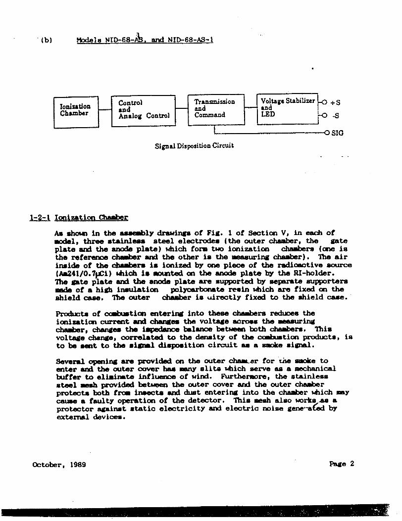
Models NID-68- 2&. ard NID-68-AS-I
Transmission Voltage Stabilizer s and and and IChamber Analog Control Corn-and LED ýO-S
SIG
Signal Disposition Circuit
1-2-1 Ionization Chamber
As shown in the asembly drawings of Fig. 1 of Section Vp in each of models three stainles steel electrodes (the outer chamber, the gate plate and the anode plate) which form two ionization chambers (one is the reference chamber and the other is the measuring chamber). The air inside of the chambers is ionized by one piece of the radioactive source (Aa241/0.7pji) which is mounted on the anode plate by the RI-holder. The gate plate and the anode plate are supported by separate supporters made of a high insulation polyoarbonate resin which are fixed on the shield case. The outer chamber is uirectly fixed to the shield case.
Products of oamtion entering into these chambers reduces the ionization current and changes the voltage across the measuring chamber, changes the impedance balance between both chambers. This voltage change, correlated to the density of the combution producta, is to be sent to the signal disposition circuit an a smoke signal.
Several opening are provided on the outer chamar for the smoke to enter and the outer cover has many slits which serve as a mechanical buffer to eliminate influence of wind. Furthermore, the stainless steel mesh provided between the outer cover and the outer chamber protects both from insects and dust entering into the chamber which may cause a faulty operation of the detector. This mesh also works nm a protector against static electricity and electric noise gene-a~ed by external devices.
October, 1989
.(b)
Page 2

i-_ Sigsal Disposition Circuit
Each detector is used as a part of fire alarm consists of a control panel, alarm indicating alarm indicators) and remote control devices. below.
system which riormally devices (&xiio and visual
Two examples are shown
Typical Awlication of Model NID-58
Detectorlsine
Fire Alarm Demces
IControl for Automatic Fire Pnt•tion Equipment
/"
Page 3October, 1989
I
The s e signal fra the ionization chambers is amplified in the
amplifier, and when the density of the combustion products reaches a
predetermined level, the switching circuit is triggered and the
operation indicator is lit.
Since the smoke signal voltage in the ionization chamber varies with the voltage supplied to the chamber, and the voltage supplied to the amplifier is limited in normal operation. The voltage stabilizer controls the voltages of to the chamber and to the amplifier. The
rectifier produces non-polarity of the external terminals L and C.
2.0 Intended Use
I
I

Typical Application of Models NID-68AS and NID-68AS-1
D)etector line•
Detector Detector r
"Fire Aharn Devices
Control for Automatic Fie Protection Equipment
ThO control panel supplies the power to the detectors. The lines are also tUsed as signal lines. Removal of any the detector head and the interruption of lines are supervised by the end-of-line device.
2-1 Condition of Use
2-1-1 Under norml condition
When the necessary electric power for normal operation of the detector is supplied form the control penelr• an no combustion products are present in the ionization chambers, only a very small quiescent current of the detector and line supervising current are fed to the endof-line device through the detector lines. Under these conditions the control panel indicates "Normal Condition".
2-2 Conditions When Fire is Present
When the products of o~mbustion enter the ionization ciambers of the detector, the signal voltage (smoke signal) corresponding to the density of this smoke is sent to the gate section. When this voltage exceeds the fixed barrier value in the amplifying circuit, the amplified signal is transferred to the switching circuit which switch to ON condition. At this time, the detector current increases by approximately 1000 times more than that of normul conditions triggers the signal detectjon circuit in the control panel so that a fire condition is indi~ated boLh axziibly and visibly, while the operation indicator in the detector is lit. Furthermore, the control for automtic fire protection equipment is activated by the signal from the control panel if so connected.
October, 1989 Page 4

Tampering and Remo'Al of the Detector
For all models of detectors, the following protection is provided to
prevent the detector from theft of the installed detector or system
trouble due to tampering.
In the case of intentional removable of the detector head results in a
line interruption condition and th, --ontrol panel gives an adxiible line
trouble warning signal. On the other hand, in the case of attempted
destruction of the detector mouted on the socket, that is to say,
removal the outer cover and outer chamber, no ionization current in the
measuring chamber and, thus, resulting in the same condition as fire, in
this case, the control panel sounds an alarm. With these protection
features, it is less likely that theft or tampering of the detector to
will be enco•ntered.
3.0 Radioactive Source AssemblY
The radioactive source employed in each model is exactly the same. It
is a sliver foil covered with a gold-palladium alloy and held between
the anode plate and the RI-holder which are mde of stainless steel and
are fixed together by spot welding.
The anode plate supported by the anode supporter is covered with the
outer chamber. All of these parts are covered with the outer cover.
The anode supporter, the gate supporter and the outer chamber are fixed
on the shield case. The outer cover and shield cased are fixed on the
body. The' gate plate, the outer chamber and the shield case are made of
stainless steel, while the outer cover and the base are made of IL
Listed polycarbonate, "tilltilon" classified as a self-extinguishing
group 0. Horeover the anod supporter anid the gate supporter are made
of the UL-Listed Polycarbonate classified as a self-extinguishing group.
0. As explained above the radioactive source is covered with threefolld
covers mede of strong material which withstand against strong mechanical
stress and high te;prature and so located in the inner-most part of the
detector, thus, providing extremely high safety features.
October, 1989 Page 5
2-_3

sBM~Ct iI-.j
1.0 General
1-1 All 1odels of detector ame equipped with oýne piece bt Americium- 2:4 l
sealed foil radioactive source.
This radioactive foil is manufactured by R.C.C. in England, and is sent
to Japan Isotope Association where the foil is cut into the approprkate
sizes needed for use U the detectors in question prior to shipment to
Nittan Ccmpany, Ltd,. Each piece of foil is washed clean with water and
is subject to a wipe test to assure its leakage does not exceed the
standard level (0.005ja Ci). The dose is measured. The manufacturing
process is show in the attached Technical Date #1.
Manufacturing Process
The radioanhleoide, amrecium oxide, is uniformly distributed and
sintered in a matrix of pure fine gold at temperatures in excess of 800
deg. C. It is further contained between a baecking of pure fine silver
and front covering of gold palladium alloy (94% gold and 6% palladium)
by hot forging. The metal layers now continhously welded together are
extended by mean of a power rolling mill to give the required active and
overall foil ares.
1--1 Tpe and QnAtity of By-product Material
By-product material: Am-2-41 Activity . Typical 0.7j3i, Max. 0.91uCi
Base Material : Silver Active Layer : A +) + Fine Gold
Face Covering : Gold Palladium Alloy
Total Thickness 0.15M - 0.20
Code ukmber : AMQ-423
1-1-2 Chemical and Physical Form
The radioactive suce Am241-umed in each of the model is an oxide
(AiA2), is insloltable in water and stable to chemicals. This
radioactive souroe is & sealed source sandwiched between two layers of
pure fine silver and told palladium alloy. This sealing method is
considered to be the most effective and safest means of capsule
enclosins for obtainin a-particles, and neither physical nor chemical
change ever occur during its time of use.
October, 1989 Page 6

1-1-3 Solubility in Water and Body Fluids
a. Solubility in Water
Three pie ces of 312.5•Ci Am-Z4.1 foils having the same structures as tlhe"
actual radioactive foil used in the detectors in .qeston csow aivty
leaching-out activity of max. 0.00045% (14.0 x 10u pAi) after five
hours immersion in water at room temperature4 with 760m Hig atmospheric
pressure amounts to max. 0.00031% (9.6 x 10 jIpi). Since the used
dosage in each of detector is max. 0.91iCi, its leaching-out amount will
be max. 4.1 P~i. This amount can be negligible. (See the attached
Technical Data #1, Immersion test (b) and (c)).
b. Solubility in Body Fluids
The radioactive foil Am-241 1.1 jwCi with the same structure as the foil
used in each detector were imersed in W/10 hydrochloriC. solution for 4
hours at 98 deg F. In all tests less than 0.37%(4 x 10 uCi) of Am-241
was extracted. -N110 hydrocholi- acid solution was selected for this
test to closely simulate acid body fluids. (Test by Japan Isotope
Association).
2.0 External Radiation Level
2-1 The external radiation level was measured with ga-n ray at distance of
Scm and 25cm from the surface one detector, Model ID-58. The external
gam radiation level was found to be extremely low and alost identical
quantities in the back-ground.
Takirg the ratio of dosage into account, the amount of external game
radiation of ae detector was calculated as follows:
In the case of 5cm distance fibm thp detector surface: 0.701 pram/hr.
For distance of 25cm from the detector surface: 0.0025 prem/hr.
2-2 The alpha particles of the foil are absorbed by the gold palladium of
the front cover of the foil as well as by air, therefore, the distance
the particles reach is about Scm in the atmospherio air. Acoordingly,
no alpha particles can be detected at the distance of 5cm or 25cm from
the surface of the detector.
October, 1989 Page 7

3.0 Degree of Access of the Product to Human Being to the Product During Use
3-1 Possible access of human being to the radioactive foil of the detector
is restricted only to cases when the detector is mechanically destroyed and radioactive foil is exposed. It is not likely for this to happen to
ordinary people because the detector is handiled and maintained for
industrial and commercial buildings exclusively by professional experts.
As such, there exists no chance to come in contact with the foil
directly. Although a person may intentionally have an access to the
detector if he wishes, direct access to the detector, as described in
the preceding paragraph, cannot be made because of its structural
features. These feature are as follows:
a. The main portion of the outer surface of the detector is made of
modified Polycarbonate plastic of high impact proof strength.
b. The radioactive foil is covered with three-fold covers:
1. Outer cover made of modified polycarbonate plastic, which can not be removed without special tools.
2. Outer chamer wade of stainless steel 3. Gate plate • of stainless steel
3-2 As a rule, the detector is installed an 8 feet high ceiling of the room,
which exclude people from reaching it.
3-3 The installation of the detector is made by a well-trained professional
installer. First, the detector socket (con tainirg no radioactive
material foil) is installed. The wiring from the control panel are
conected to the socket. The detector head is plugged into the detector
socket during the final stage of installation. Therefore, the time
required to install the detector is very short, and there exists no
chance for ordinary people to be effected,especially, since the installation is to be done only by a professional installer. Furthermore, any detector found to defective during testing or
maintenance or any other time is to be returned to Nittan without
disassembling by installer or maintenane personnel.
4.0 Quantities
4-1 Annual quantity of the by-product material to be distributed:
4-1-1 Annual Sales Qumntities: 20,000 pos.
4-1-2 Radiation Activity Per One Detector: 0.9 )JCi
Page 8October, 1989

4-1-3 TotJ1 annual amount of radioactive material: 18.20 mCi.
4-2 Number of units expected to be stocked at the warehouse.
4-2-1 At Nittan Corporation ---------- 1,000 pcs.*
4-2-2 At an installation site ---------- 50 pcs. average.
4-3 Marketing and Sales Method
Marketing and sales of these detectors are to be done only through one
or two authorized companies. Nittan Corporation provides a necessary
technical assistance and supervision with respect to installation and
maintenance.
Therefore, handling of the detector is to be done only by those person
who are well trained and are capable of 'professional installation, thus,
any access by ordinary people to the detector during its norml handling
and distribution is completely excluded.
5.0 Expected Useful Life of Product -7 The expected useful life of the detector is about 15 years. The half
life of the Am-241 employed in the smoke detector section is 458 years,
therefore, any sensitivity change of the foil is expected during this 15
year's of use.
However, it is apropriate to state that the useful life of the detector
is 15 years swen taking into consideration the probable dust
accumalation on the awoke entering slits which may affect the
performnce of the detector.
October, 1989 Page 9
SECrTIC III
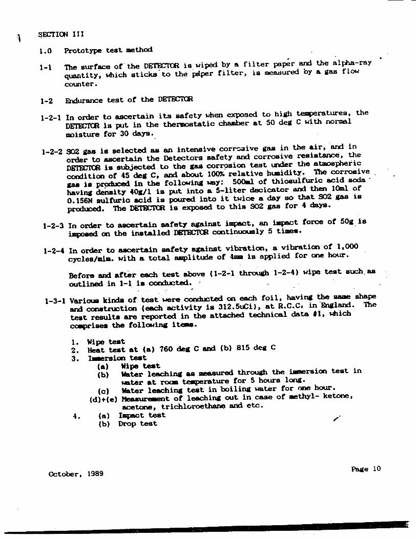
1.0 Prototype test method
1-1 The surface of the DETEMM is wiped by a filter paper and the alpha-ray
quarrtity, which sticks to the pdper filter, is measured by a gas flow
counter.
1-2 Endurance test of the DETBCUM
1-2-1 In order to ascertain its safety when exposed to high temperatures, the
DEW= is put in the thermostatic chamber at 50 deg C with normal
moisture for 30 days.
1-2-2 S02 gas is selected as an intensive corrosive gas in the air, and in
order to ascertain the Detectors safety and corrosive resistance, the
DM1SM is subjected to the gas corrosion test under the atmospheric
condition of 45 deg C, and about 100% relative humidity. The corrosive
gas is prpduced in the following wy: 500al of thiosulfuric acid soda"
having density 40g/1 is put into a 5-liter decicator and then 10ml of
0.156N sulfuric acid is poured into it twice a day so that S02 gas is
produced. The DEIMMM is exposed to this S02 gas for 4 days.
1-2-3 In order to ascertain safety against impact, an impact force of 50g is
imposed on the installed DETBMC( continuoumly 5 times.
1-2-4 In order to ascertain safety against vibration, a vibration of 1,000
cycles/aim, with a total amplitude of 4m is applied for one hour.
Before and after each test above (1-2-1 through 1-2-4) wipe test such. as
outlined in 1-1 is conducted.
1-3-1 Varioum kinds of test were conducted on each foil, having the same shape
and construction (each activity is 312.5uCi), at R.C.Ca in England. The
test results are reported in the attached technical data #1, which
ccmprises the following item.
1. Wipe test 2. Heat test at (a) 760 deg C and (b) 815 deg C
3. Imersion test (a) Wipe test (b) Water leaching as measured through the immersion test in
water at rocm temperature for 5 hours long.
(c) Water leaching test in boiling wter for 'rae hour.
(d)+(e) Measurement of leaching out in case of methyl- ketone,
acetone, trichloroethane and etc.
4. (a) Impact test -V
(b) Drop test
October, 1989 Page 10

1-3-2 In order to ascertain the validity of safety features under worst
conditions of 160y i foil with sa shape and construction various tests
were cond0ixtAd at R.C.C. an shown in the attached Technical tDta 02,
ccprised the following:
Corrosion testing
Samples of foils were exposed to various corrosive games, to which the
DF M will probably be exposed to it when installed in building such
as factories.
1. S02 test 2. HCU test 3. Ammonia test
Heating tests in consideration of fire
I. Heat test at 800 deg C for 10 mis.
2. Heat test at 1200 deg C for 1 hour.
2.0 Prototype test results
2-1 The wipe test result of the DETBMM surface showed the same figure as
that of backgroun.z
2-2 The wipe test result of the DE R before and after the exnd-anoe test
showe the same figure as that of background.
2-3-1 1) The wipe test result showed 1.42 x 10"! jCi rximum, which
correspoxx to 0.000045% and can be considered as 0%.
2) The heat test resulted in almst same amount of leahng mount as
in 2-3-1. 3) The immersion test results showed a maxim= leaching of 0.00045%.
For solvents such as acetone, the leching amount was found to be
about 0.001%. 4) The impact as well as drop tests showed only 0.000029% leacn,
which can be considered as zero.
2-3-2 The heat tests, which wexe set up for worst condition in the came of
fire, e leakage of 0.1%. Applying this figure to 0.7tCI foil, we
get 7 x 10 "Ci.
October, 1989 Page 11

3.0 Quality Control Procedure
3-1 Tests of Am-241 foils.
3-1-1 The production control tests of the foil cornducted at the manufacturer
R.C.C.
(a) Visual inspection.
All production is inspected visually for surface damage of the
active area. Careful inspection with a low power microscope is
carried out on samples from each production run.
(b) An autoradiograjhy examination is carried out on all production
foils by placing then in contact with single weight bromide paper
for a predetermined time before exposed film is developed and
fixed. Distribution of activity and dimensions are carefully
examined.
(c) Dust sampling Laing a continuus airflow sample is performed in
the vicinity of the manufacturing equipment during all production.
Foil storage areas are similarly monitored.
(d) Five samples of 2.5cm length are taken from each 50as production
batch and subjected to the tests described in the attached
Technical Data e1, namely (1) Wipe test, (2) Heat and thermal
shock test and (3) Immersion test to ensure uniform integrity of
product.
3-1-2 Next, the source foils are cut by the Japan Isotope Association to the
appropriate activity for use with the detectors and are cleaned with
water. Then, after making it sure that the leaching amount does not
exceed the limit of 0.005uCi by wipe test, the activity is measured.
3-1-3 Only the those foils, which have passed the above-mentioned tests at
R.C.C. and the Japmn Isotope Association, and whose sealing has moreover
been proved sufficient, . iirto Nittan Ccsany, Ltd.
3-2 Nittan CbanY, Limited cormx~tsc the following tests to the Am-241
foils, which are already clamped on the anode plate of the DETBUM by
the RI-holder.
3-2-1 All of the AL-241 foils are examined visually to ascertain whether there
exists any defect o- stain on their surface. (100 inspection)
October, 1989 Page 12

3-2-2 The wipe test is conducted by wiping am-241 foil with filter peper arad
examing for any leeching. The standard allo•able amount found through
the wipe test is set up for maximum 0.005 PCi.
This wipe test is conducted based on the statistical sampling plan as
per the item 3-2-3. The measuring apparatus is a 2r proportional
counter consisting of a scaler (Model TDC5: Japan Radio Corp.) and a
radioactive ray detector (Model FC-IF. Japan Radio Corp.).
3-2-3 Number of defective
Lot Size Sample Size pieces allowed in sample
500 - 624 7 0
625 - 799 8 0
800 - 999 10 0
1000 - 1249 11 0
1250 - 1574 13 0
1575- 1999 15 0
2000 - 2499 17 0 2500 - 3000 20 0
Nittan receives, are lots of 500 - 3,000 at a time, for which the severe
test standard of JIS Z9015, namely Ab=0.4, is applied. From each lot,
acording to 3-2-3 list, the required number of samples are extracted
raxkinly and these samples are tested in compliance with the standard.
If no samples are rejected amng those samples tasted, products
belonging to the sam lot numer are accepted.
If even one piece in the tested samples is found as defective, all
products with the sam lot nuber are not to be accepted, and every
piece of foil in the sam lot is to be individually tested on the sam
stamlard.
The foils which are accepted are used in DUIBMt1s, while the defective
nes are not used and are disposed of in the proper way. This test
method con eliminte the probebility that a defective foil would be used
in the DRW1UM.
3-3 The Amricium-2 4 1 foil is cramped on the anode plate by the RI-holder
which is fixed to the anode plate by spot-welding. (Please refer to the
Fig. 2 of SB TMIC V). Since the strength of the spot-welding is greater
than the pull force of the RI-holder, the foil, RI-holder and the anode
plate are considered to be one rigid body.
Page 13October, 1989

The anode plate has the dimension of 12in diameter, 1. 5= of thickness
and its screw part is 4m diameter and 5.7m length. This anode plate
is firmly screwed to the center pole by special tool 'and is tied
together with the shield case through the anode supporter. Even if the
anode plate should be removed from the center pole, it will not come out
from the opening of intermediate electrode (gate plate), but remins
inside of the reference chamber (inner ionization chamber).
3-4 All finished products are subjected to a 100% of visual inspection to
ascertain the proper clamping of the foil to the anode plate. Even if
this total check fails to find a defect, the next inspection covers
every detector, as described under item 3-5 (inspection of the finished
detector) will back it up.
For an example, if the foil were to be removed from the anode plate (.
this does not happen in actuality), this defect couild be easily -found
through DMWM operation tests, because withbut the foil the DETECTR
will not operate (in the smoke operation test of 3-5-2 and electrical
sensitivity test of 3-5-3). Before shipment every DETtOMC is
individually inspected in steps of three 3 stages:
* Visual inspection of source foil
s Inspection through operation in the smoke test
$Inspection of electrical sensitivity operation
Thus, any defect, such an loosening of the source foils, is ccmpletely
eliminated.
3-5 The final inspection is done to every DErETCR.
3-5-1 Visual test:
To check if the DgFM1MR is assembled in the proper way.
3-5-2 Smoke operation test:
To determine whether the DET•rM responds properly to the smoke
concentration of a predetermined density.
3-5-3 Electrical sesAitivity test:
To ascertain the test of 3-5-2 electrically.
3-5-4 Tgrature and Thmidity cycle test:
To ascertain the stability of the D•.CTCR.
Through this final inspection, it is confirmed that the asse y as per
SE•rION II has been executed properly and only the DE7SCIMA siich have
passed this final inspection are to be shipped as final products.
Page 14October. 1989

SECTION IV ESTIMAT1() OF RADIATION DOSE AND DOSE (OXM IMOW
1.0 ExplanStion and reason of the does commitment compliance to 32:27a of
the NIBC regulations.
1-1 Normal Use
The gain radiation dose of the detector is less than O.025yrea/hr at the
25cm distance fros the surface of the detector as shown in SBCTICN III.
For effective detection of any fire breakott, one unit of detector is
usually installed on a ceiling surface, each unit covering 100 square
meteas. Since the height of a ceiling is generally considered to be 8
feet (2.4m), it is impossible for an ordinary person occupying the roam
to reach the detector under ordinary daily circumstane.
Assuming that S..Aie occupant carry out his daily life for a period of one
year at 25cm from the surface of the-detector, be-would likely receive
an external radiation dose. of only Z.2 (area/year) according to the
following calculation:
0.025(prew/hr) x 24(hr/day) x 365(day/year) = 0.22(area/year)
Furthermoreg assuming that the occupant living directly under the
detector and the distance between the detector and the occupant is to be
1 meter, t#en he would likely to receive an external radiation dose of
1.57 x 10, (urei)hr) according to the following calculation:
0.025()wrm/hr) x J.Ua 1.57 x ~10 (prem)
Asw.ning he wuld rein in this position for a period of 50 weeks, 8
hLa/day and 5 days/week, then he would likely receive an external
radiation dose of only 3.14urem/year which is calculated as follows:
1.57 x iO1O•3 rea/hr) x 8(hru/day) x 5(da.•y/h-) x 50 = 3.14(yrem/yr)
From the above, under norml condition of use, it is imposaible for
anyone to receive an external dose of 5 are/year. Accordingly, the
dose omitmrent of the detector satisfies to colum I of t32-28.
1-2 Noral Disposal
The int of the detectors is carried out by well trained
professional installers who are strictly instructed to return any
defective detectors to Nittan Corp., and this is also indicated on the
labels of the detector. NittAn Corp. condicts necessary periodical
training professional installers who are to be engaged in insazllation
and minten•nce in conjunction with authorized comndes.
October, 1989 Page 15

1-3 Normal Handling
It is reasonable to assume that the most of the normal handling of the
detector is done during installation of the anit. The heads and the
sockets are packaged separately. The most t im consuming task during
the insLallation is the mounting of the socket to the ceiling which
requires two screws and wiring connection with control panel. After
these tasks, the head can be mounted on the socket by simply twisting it
clock-wise. The time required to install the detector head is
considered to be less than one minute per detector.
Since the radioactive foil employed in the detector is located 30m
inward from the surface the detector, the external radiation dose at
25cm from the surface is found to be Z."-8 prem/hr according to the
following calculation: I )4
1 x 0.025 pre-/hr = prm/hr
Awnoing that a maximu of 20 detectors are to be installed at a
construction site, the time required to install these detectors will be
4 days and the number of installation jobs be 50 a year, then the
external radiation dose is found to be 36.4urem/year aocording to the
following calculation:
2.18 e-m/hr x 1 (min/pc) x 20 (pcs/job site)
60 min/hr
x 50 (jobe/year) 36.4 prem/year
This satisfies the value stipulated in the column I of J32-28.
1-4 Estimate of External Radiation Dose During Maintenance
To ensure a proper operation of a fire alarm system, routine periodical
mintenwice is required by professionally trained maintenance personnel.
Principally the following are required:
a. Routine Cbeck b. Operation test o. Functional test
a) The routine check shall be a visual inspection of the outer
Sa eof the detector installed on a ceiling. The primrY
purpose of this inspection is to find any apparent damage and dust
acctinlation which way affect smoke entrance into the detector.
The external dose to the maintenance personal is found 6 be
0.78urem/yr as calculated below.
October, 1989 Page 16

We have asstmed that the time required to complete a routine check
to be 5 minutes, the distance from the detector during this check
to be I meter directly under the detectors- and the ntmber of the
detector to be inspected by this person to be 6,000 pcs per year.
IM251 x 0.025 (Prem/hr) x ij.. (hr)
x 6000 (pcs/yr) = 0.78 Prem/year , ,
b) The operational test shall be made at least every three months.
In this test, each detector shall be tested with actual smoke
using the Nittan Sk. Tester which consists of smoke generator
and. an extension rod to reach the detector installed on ceiling.
During this test, each detector must confirm its operation within
I minute of introduction of smoke to the detector.
The external radiation which maintenance6 personnel wo~uld likely
receive dhring this test is found to be 0.1r17-W-r with the
followin" asumption and calculation. It is assumed that the tim
required to complete one operational test to be one and one-half
minutes, the person engaged in testing is directly I meter below
the detector a"u the number of detectors to be tested by this
person in one year is 3,000 pcs.
IT I~U x 0.025 (pre/hr) x (hr)
x 3000 (pcs/yr) = 0. Prm/year
c) The functional test shall be mo- at least every 6 months. The
purpose of this test is to mitase the sensitivity of the detector
using The Nittan Delta V Tester. The tister is a monitoring
device s"i hem the ca aility of electrically sending gradual
smoke buildup similar to that of an actual fire breakout
electrically to smoke detector. The sensitivity of detector can
be measured by simply plugging the detector into the socket an the
tester a"d, pressing the test button. It only takes on- minute.
During the functional test, it Wuld be confirmed that the
msurit taken during this test be within the ranges indLicated
on the label. If the m ur-mnt is not within the specified
rses on the label, the unit should be returned to Nittan
Corporation without disassmlY.
The external radiation coe %hich the mninten.ce person wwld7
likely to receive during this functional test is found to be A-2
amlyr according to the following assumption aid calculation.
October, 1989 Page 17

It is assumed that the handling time required to ccoplete one
functional test be 5 minutes, the e:ternal radiation dose on Ute
surface of the detector be 2.18 urea/hr from 1.3 of SIrION V and
the number of the detectors to be hwidled in year by this person
be 1,000 in total.
2.18 fywea/hr) x 5 (hr/pc) x 1,000 (pcs/yr) = 2zrem/yri
From the above, it is concluded that the total external radiation
dose auhich the person would likely receive as a result of
performing jobs of a), b), and c) amounts to 183prie/yr.
Therefore, the person for maintenance never receives 5 urem/yr of
the external radiation dose. This satisfies the value in the
colum I ofJ32:28. ,
1-5 warehouse Storage "
The external radiation dose from the detector presumably a=t1lated at
one location during distribution is found to be less than 5mres per year
even under the extremely worst assmed condition aocording to the
following calculation, the value of which satisfies that of table I of
32-28.
Five detectors are packed into a cardboard box. The dimension of this
this box is 100= x 130 x 565.. Wen of cardý d boxes packed into
a large shipping box having dimensions of 280 x 520 x 580m.
The external radiation dose on the surfaces of the cardbord box
containing 50 detectors as mnesured using lzw Energy Gams Ray Survey
Meter (Model IC3-501, Arrow Co.. Ltd.). The -surt showed that
only the bottom surface of the box resistered 1 urea/hr activity.
Based on this 00dmet, we calculated the activities of 1,000 pcs,
uhich is mot like to be AxtLated at the warehouse of Nittan Corp. at
any one tims. 20 boxes ec containing 50 tii ts are to staaed up as 2
boxes in direction of width, 5 boxes in direction of length, and 2 boxes
in direction of height. For a calculation of the mximm extarnzl
radiation dome for this storage arra•agent, we amsmmd that the
external radiation dome will be concentrated at the center of the bottom
sufacs of the pile. Te maximm external radiation does is found to be
1.8 ropn/hr according to the following calcustion: t
x I Premhr x (100015) 1.8 prea/hr
^.:* -,' *$ y yd
If,(-. . lV.
18. Pge 18 October, 1989 '

The maxin external radiation dose for a person, o is .en Iawed in e flg o inethis erehue 8_ hours ... a day. 5 days a week, nd 50 eks a
year, in found to be 3.12 mrea/Y•- ,..or..v t e l n
calculation.
1.8 prem/hr) x 50 (weeka/Yr) x 5 (days/week)
x 8 4hIrs/dsY) = 3.6 area/yr
This value satisfies Column I of §32:28.
Since it Is not likely that the person is to rmiL on the surface of
the shippingbxsataltm during his working hours, the actual
external radiation dose the person liel receives is less than 3.0
area/year.
2.0 Internal Radiation Dose Camit~ient Under Noruml Condition
Internal radiation dose c~.itaent is cause either by taking the
radioactive foil through aruth or inhaling it.
2-I Orally
Takig the foil into huan body orally my happen only when the outer
chaer is taken off, the gate plate is removed and moreover 2 spotdading parts of RI-holder are destroyed. only after this may the foil
be removed and brought to the mouth. Such a series of prkenogme never
taken place.
2-2 Inhalation
The internal radiation dose ccmitni t through inhalation can be
considered in case of the fire, and during the handling PxKce55 of detectors or wnder installed Ooftions it is absolutely impo"sible.
3.0 Externai Radiation Dose C4MitMnt Uinder Severe Condition
3-1 Direct MMtrna•l dl tion Dos from Foil
As dencribed in 2-1. this never happens in actuillity. However,
assum~izi the foil wouald be rmovad by an accident and people would
ait. thmn the external dose integrated in 50 Yenr is found to
be133proacyershiid is very small and are safe in ccmpaiohi bith tht of thm valuO specified in Column II of §32:28 as indicated in
the calculation below.
October, 1989 Pae 19

We mks an asumptton that & person be e 4 osed continuously for 50 years
at distance of 28cm f"rm the foil. Since the foil is located about 3(a
irward from the surface of the detector, the external radiation dose at.
the 28as distance from the foil can be calculated below by taking into
consideration the doseage In the cuae of 25"m distance from the detector
1 281 x 0.025 (ure/hr) 0.314 urea/hr
AccordinllY, the external dose of 50 years will be:
0.314 (urem/hr) x 24 (hr/day) x 365 (days/year) x
St- - dt 2 13.3 torer/50 years .
4.0 Internal Does Cxmltment Uinder Severe condition
4-I Intetal Does Comitment by Inhalation in Case of Fire
4-1-1 Warehouse Fire
The worst caue of the dose commitment, w will consider would be if a
fire brek out a warehouse where 1,000 units of the detectors were
stocked. Acording to the attached technical data #2, 0. 1% of the
leaksae of radioactive foil was detected in the heating test aassming
fire conditions. This total quantity can be asstmed to be particle
which my be possibly inhaled.
To calculate internal dome commitment of a person who remains in a fire
condition for 5 aimntes, Iit is asrsi that the air volume of a stmaradwd
w4horehouse is 200,000 ft (5.6 x 10"oc) with no air exchange taking
pla. We calculated the Internal dose amount which an occupant would
raive in 5 minutas at time of fire an follow.
Mx exdift to the a I� tion of ICRP - Report of C imttee II on
Allomwble Dome Amount of Radioactive Radiation in Human Body(1959), the
most critical oremn for inhalation of insoluble radioative dust
.0V particles -- be onidered to the be lung and the ratf fa, at which the
inhaled particles reach the critical organ, is 0.12.10 oc/Shrs acxcording
to the .. re. t. Thereforein 5 minutes the person w-.ld inhale
" ~ , 1.05 x 1•0' of air am calculated below:
cc.4 x _D_ hr s 1.05 x 10s °8 hr 60
SOctober, 1989 Page 20

In case of storing 1,000 units of detectors each with radioactive
material of 0.7)ci on an average, the following calculation is
(0,7 x.1000)4 x(Ix1 x (.05 x11)
(5.6 x 10') c
"% . 2.2 x 101 din x 0.12 x
(1.6 x 10"|) ergs
x1000 it
(Weight of Ia")
•.7 1eV dis
g.Rad 10' erg.
10 rem Rod
(5.26 x 1 mh sin years
e dt
- 0.08 ren/50 years
"The situation just described above nerve actally takes place : however,
even in such a came, the dome owitment satisfies the value specified
in Colum II of f32:28.
4-1-2 Building fire in which the detector are installed.
Amestlni that the ceiling -ht of a stanlard size building be 8 ft.
12.4m), one unit covers I f floor area, considering that there is
no air exchnge amd a person remain in the fire for 5 minutes, then the
dome comitment integrated 50 years would be 2.5 re/5 0 years shown
in the calculation below:
1 00.91 0Ci) (2 x 10 ) Vvm(10 ii 10~xl x 2.4 x 1(oo~c
2.2 x log dis (5.,)MDeV x x Kin - )ci dim (00)
(1.6 x 10") erts g.Rad 107 e-r~s
10 1 Rad.
(5.26 x 101) sin yeas"
- .ML*dt
- 2.5 reas/50 year.
Therefore, the value satisfies the that of value of Colum II of ý32:28.
October, 1989 Page 21
x
x
(ý.05 x 10)0•C

1 4-2 Internal dos coitmet due to taking foil into hiban body in aworst
cwm of scenario worst socident.
An already mentioned, the installation of the detectors is carried out
by only well-trained profissional installers. Therefore, the detectors
can not be easily destroyed or disassmbled so that radioactive foil
could be stalled.
Under normi codLitions of use, one my attempt to gain direct access to
the radioactive foil by removing the detector heed froa the socket with
intention of destroying or tampering with it. However, the detectors
are monitored by a control panel so that any removal of the detector
head send & trouble signal to the control panel. In this case, the
control panel will sand out a trouble signal by mans of audible or
visual alanz tbr1ohout the building.
This enables a supervisor of the building to prevent any theft or
teampering of the detectors. It is a preventive masure. Furthewrmore,
in case of removal of the outer chamber located inside of the outer
cover, the detector mint be remove froa the socket which result in a reaction similar to that stated above.
As such, it is slmit impossible for anyone to swallow the foil of the
detectors that have sucth preventive measures.
Nevertheles, we assumd that some one swalled the foil mal calculated
the resulting dome comitment exposed in 50 years to be 11 areo/50 yr.
whidc is negligible low in comparison with the value specified in the
Colunm II of 02:28.
The maxim activity of the radiation foil in the detector is 0.91
pCi/pc. The foil stalled trough mouth leaks into the gastrio Juice in
the stmch. This leak can be comsidered an leak amncunt to N/1O HlL
liquid acording to SKTION III, and it is 0.37%. We assum all of the
leaked radiotive mterial would be dissolved into body fluids.
According to the a mtiTm.Id ICRP report, the rate of transferring
fro, intestine to blood is 10 .
Furthbe•x, according to the said ICW data the rate f2 between the
deposit amunt in bones and the mount deposited in the whole body is 0.9.
October, 1989 Page 22

Under lhe5e conditions, the internal do* ccmitaent for bones for 50
years is celoilated as below.
Dose (0.91)FCI x 0.37 x 16" x" 10-6 x 0.9
(2.2 x 10⁶)dis x x
&in ýCi
(1.6 x 10⁶ )erg X MeY
28.3MeV din
g.Rad X1 10 ergs
x 7000i
(weight. of Bone)
lOrem Rad
x(1.6 x 106"| ergo g.Rod
W 0 ergsJ10 rem Rad
dtyears
= 11.0 rem/50 years
4-3 Those value cslculated in 4-1 and 4-2 are figures an the asmsution of such socidents wdhch never hap in actuality.
vma i r those severe conditions. the values do not exxceed those valuea specified in Colum II of 432:28. N-mly the radioactive foil
aid its aplication sethod in the detector is cmpletely safe and
reliable.
October, 1989 Pag:e 23

DR[AWINGS AND T"MI1CA. DATA
This section contains the followings:
Fig. I Fig. 2 Fig. 3A Fig. 3B Fig. 3C Fig. 3D Fig. 4 Technical
Construction of Assembled RI Fox l Assembly Drawing Label Drawing: NID-58
Label Drawing: NID-68A3
Label Drawing: NID-68AS-1 Caution LAbel
RI Foil Construction Data 1, 2 (RI Test Data)
Page 24October, 1989
Detector
SECTION• V
01B2 (PIN: PLI90-2000-1 & PU90-41000-1)
TM'BLE oF CONTENTS
CONTEFTS
SECTION I
SECTION II
SECTION Ill
SECTION IV
SECTION V
1.0 2.0
3.0
is-rtiption
Intemded I !%e
Radioartive Soijr.e Assemhlv
1.0 General
Type and 0uantitv of Bv-Prodiuct Material
Che.nical and Phvsical form
Soluhilitv in Water and Body Fluids
2.0 External Radiation Level
3.0 Dearee of Access of Human Being to the product during use
4.0 Ouantities
5.0 Expected Useful Life of Product
1.0 2.0
3.0
Proto-Type Test Method
PrQto-Tvpe Test Results
Qualitv Control Procedure
1.0 Estimation of Radiation Pose and Dose Ctomrmtment
2.0 Internal Radiation Dose Commitment under Normdl Condition of
Use
3.0 External Radiation Pose under Severe Condition
4.0 Internal Radiation Dose Commitment under cevo-re Condition
Fig.l Fig.2
Fig.3
F ig.4
Technical Data 1.2
Construction of Assembled Detector
RI Foil Assembly Drawing
Main Label Drawing
RI Foil Construction
RI Test Data
!s�V Z �
I

SECTION I
L.#) flescriptio
The Ionization Comhustion fletector, Model 0)l12 detects product of combustion in an
early stage of fire and sends a fire signal to the control panel which gives a fire alarm hv
operation alarm wunders and visible indicators.
I.1 Ce'neral %trStrt'e' of the thWtowtor
The detector consists of a detector head and a %ocket as a complete unit. The detector
head consists-of somre mao parts, namely an outer cover, ionization chamber parts
including a radioactive source, a printed circuit hoard with all electric parts and a hody.
The Oulte'r rover and the Body which cover all internal parts are made of the
polycarhonate plastic which is tlL-listed as flame resistant %trade, 94 v-o.
The to'ket made of polvcartonate plastic has external terminals to he connected to a
control panel.
1.2 Striocture Details
The schematic diagram of the detector is shown as below.
Operation Indicator OT L
0- C
Test C irtit C ,
! OC.
Signal Disposition Circuit
1-2-1 Ionization Chamber
As shown in the assemhlv drawine fikt.l of section T1, three electrodes (the ('Ntr
Chamber, the Gate Plate and the Anode Platelmake a formation of two iontiAt!•n
chamhersithe Reference Chamher and the Measuring Chamher), which are tonlfblc !n
common hv one piece of the radioactive sourcelAm-241. (.•,Ci0 fixed on tVe, Anode Plat-. /ý
-I -

which is fixed directly on theicenter of the Body. The Gate Plate is supported by the
supporter made from high insulation resin "Polycarbonate" which is fixed on the Body.
The Outer Chamber is directly. fixed on the Shield plate by tapping screw. Combustiorn
product entering. these chambers reduces the ionization current and changes the Voltage
across the measuring chamber by the change of impedance balance between both
chambers. This voltage change correlated to the density of the combusiton product sent
to the Signal Desposition Circuit as a smoke signal. Several openings are provided in the
Outer Chamber for the smoke entrance and the Outer Cover having many slits serves as
a mechanical buffer to eliminate influence of wind. Furthermore the stainless steel
mesh provided between the Outer Cover and the Outer Chamber protects insect and dust
which may cause a fault ooeration of the detector. This mesh works also as a protector
against a static electricity and electric. noises eenerated by external devices.
1-2-2 Signal Disposition Circuit
The smoke signal from the ionization chambers is amplified in the Amplifier, and when
the density of the combustion product reaches the predetermined level, the Switching
Circuit is triggered and the Operation Indicator is lit. A fire signal is given through the
terminal P. The Voltage between the external terminals L and C is kept to operational
voltage range.
-2-

7.0 Intended Uth
This detector Is used in a fire alarm system by combination with a control panel or as
on& part of $@If combined alarm device which contains sounder and sipnal transmitter. i
•C C
L P
Lir Al- lm
ot po ee r for autls, athc i r odprot aciion oon f4Upent
2. .-. n Pownor supply cnrcuit
pw*e th neesr lcrcpwrfranra prto ftedtcto sple
frown ~ ~08 thCoto ae rtepwrsp ircuit i iBannocomutoerdc
&sto "I nilil tn ansmbetinl vy ll uit c otde r w
aamDevice indlateNrm a C ondiion"
Fix A shows fire alarm c control system using this detector. The power from the
control Panel is eneslied to the detector throuh L and C lines, and the line P is used as a
signal line by forming a closed circuit with the line i when the detector is operated. Fit
5• shows an exarnole of the circuit diagram for self combined alarm device.
2-1 condltln of UNq
2-1-1 Under normal con~di ti on.
We the necessary electric power for a normal operation of the detector is supplied
from th~e control panel or the power supply circuit in Fig 15 and no combustion product
exists in the ionization chambers, only very small quiescent current of the detector flows
through the detector lines. Under this condition the control panel or the sell combined
alarm device indicates "Normal Con~dition".
2-1-2 t-Inder firtcondition
!'When combustion p)roduct enters into the ionization chamhers of the detector, the sianal
voltatle(smoke siginallc•orrespond init to the density of the smoke is eiven to the

amplifylng circuit. When this voltage exceeds the threshold value, the amplified signal is
transfered to the switching Circuit which turns to "ON" condition. The operation
indicator In the detector is lit by the current through the terminal L and C .and fire
signal is given through a closed circuit between termnal P and C to the control panel or
the alarm circuit in the self combined alarm device.
2-2 Protection against tampering and removal of the detector
This detector provides lock-up feature to prevent from any removal caused by vibration
and etc. When this detctor is installed with surface mounting adaptor, a special tool is
required for removing detector head from its socket.
In the case of attempting to destroy the detector mounted in its socket, that is to say,
breaking the Outer Cover and the Outer Chamber, it causes no ionization current in the
measuring chamber and results in the same condition as fire, when the control panel
gives an alarm.
3.0 Radioactive Source Assembly
The radioactive source Am 241 employed in the detector is a silver based foil with a gold
-palladium alloy cover and is held between the Anode plate and the RI-Holder, which
made of stainless steel and are fixed together by means of curling.
The Anode Plate is covered with the Gate Plate supported on the Gate Supporter, which
is furthermore covered with the Outer Chamber. All of these parts are covered with the
Outer Cover. The Anode Plate is directly fixed to the Body. The Gate Supporter is fixed
through the Shield Plate to the Body. The Outer Chamber, the Shield Case and the Outer
Cover are fixed all together to the Body. The Gate Plate, the Outer Chamber and the
shield plate are made of stainless steel, while the Outer Cover, the Gate supporter and
the Body are made of UL-listed polycarbonate classified as a self-extinguishinR group 0.
As explained above, the radioactive source is covered with threefold covers made of
strong material against mechanical stress and high temperature end is located in the
inner-most part of the detector, thus, an extremely high safety feature is provided.
-4 -
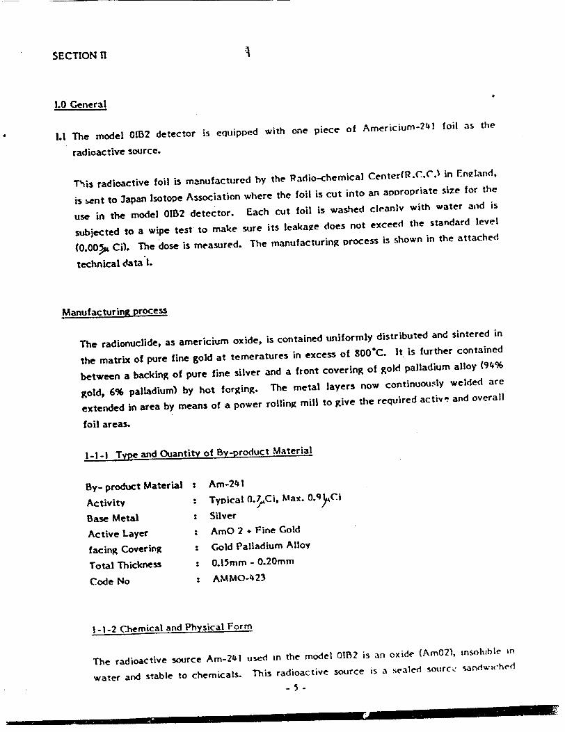
SECTION II
1.0 General
1.1 The model 01B2 detector is equipped with one piece of Americium-24 1 foil as the
radioactive source.
This radioactive foil is manufactured by the Radio-chemical Center(R.C.C.1 in England,
is 6ent to Japan Isotope Association where the foil is cut into an appropriate size for the
use in the model 01B2 detector. Each cut foil is washed cleanly with water and is
subjected to a wipe test to make sure its leakage does not exceed the standard level
(0.00• Ci). The dose is measured. The manufacturing process is shown in the attached
technical data 1.
Manufacturing process
The radionuclide, as americium oxide, is contained uniformly distributed and sintered in
the matrix of pure fine gold at temeratures in excess of 800°C. It is further contained
between a backing of pure fine silver and a front covering of gold palladium alloy (94%
gold, 6% palladium) by hot forging. The metal layers now continuously welded are
extended in area by means of a power rolling mill to give the required active and overall
foil areas.
1-1-1 Type and Ouantity of By-product Material
By- product Material : Am-241
Activity : Typical 0.7Ci, Max. 0.'9qCi
Base Metal : Silver
Active Layer : AmO 2 + Fine Gold
facing Covering : Gold Palladium Alloy
Total Thickness : 0.15mm - 0.20mm
Code No : AMMO-423
1-1-2 Chemical and Physical Form
The radioactive source Am-241 used Ln the model 0132 is an oxide (Am02), insoluble in
water and stable to chemicals. This radioactive source is a sealed source" sandwiched

between two lmetals of pure fine silver and gold palladium alloy. This sealing method is
considered to be the most effective and safest means of- capsule enclosing in order to
obtainm-particles, and neither physical nor chemical changes ever happen during its time
of use.
1-1-3 Solubility In Water and Biody Fluids
a. Solubility in Water
Three pieces of 312.5 Ci Am-241 foils having the same structure as the actual
radioactive foil used in the model 01B2 show activity leaking-out of max. 0.00045% (14.0
x 10-4 Ci) after five hours immersion in water at room temprature. On the other hand,
the activity leakingout after immersing in boiling water for one hour at 760mm Hg
amounts to max.
0.00031% (9.6 x 10⁻⁴ Ci). Since the used dosage in 01B2 is max. 0.9ACi its leaking-out
amount can be max. 4.1 PCi. This amount can be negligible. (See the attached technical
date 1, Immersion test (b) (c) .)
b. solubility in Body Fluids
The radioactive foil Am-241 1.h Ci of the same structure as the foil employed in 01132
were immersed in N110 hydrochloric and solution for 4hours at 98 F. In all tests less
than 0.37% (4 x 1O-3 Ci) Am-241 extracted. N/1O hydrochloric acid solution was
selected for this test to simulate most closely the acid body fluids. (Test at Jaoan
Isotope Association)
2.0 External Radiation Level
2-1 The external radiation level was measured by gammaray at distance of 5cm from the
surface of the model 012B2 detector. The gamma external radiation heve& was found to be
extremely low and actually it amounts to near nearly same quantity as that of the back
ground in case of 01B2 foil. Taking the ratio of dosage into account the gamma external
radiation amount of one 01B2 detector was calculated as follows.
In the case of 5cm distance from the detector surface:
0.24ýp rem/hr.
In the case of 25cm distance from the detector surface:
0.015 rem/hr.

-The alpha particles of the foil are absorbed by gold palladium of the fornt cover of thr!
foil as welt as by air, therefore, the reaching distance of the particles is about 5cm in
the atmospheric air. Accordingly, no alpha particle can be detected at the distance of
5cm or 25cm from the detector surface of 0112..
3.0 Degree of Azct is of Human Beings to the Product During use
3-1 Possible access of human beings to the radioactive foil of 01132 is restricted only when
the detector is mechanically destroyed and the radioactive foil is exposed. Such a case is
not likely to happen for oridnary people because the detector is handled, installed and
maintained exclusively by professional exDerts. Therefore there exists no chance to
touch the foil directly. Although a person may have an access to the detector
intentionally if he wishes, a direct access to the foil, as described in the preceeding
paragraph, is very hard because of its structural features. These features are as follows:
a The main portion of the outer surface of the detector is made of modified
Polycarbonate plastics of high impact oroof strength.
b The radioactive foil is covered with threefold covers:
I Outer Cover made of modified Polycarbonate plastics, which can not be
removed without special tool.
2 Outer Chamber made of Stainless steel
3 Gate Plate made of Stainless steel
c The detecter can not be removed from its socket without special tool.
3-2The installation of the detector is made by a well-trained professional installer. At the
first step, the detector socket(containing no radioactive foil'is installed in connection
with the detector lilies coming from the control planel, and then, the detector head is
put and locked In the detector socket.
Therefore, the time required to install the detector is verty short, and there exists no
chance of affecting ordinary people at all, since the installation is to be done only !v a
professional installer.
Furthermore, any defective detector found during the test or maintenanc- or anything
else is to be returned to the manufacturer without disa-semh'ing by installers or
maintenance aeople.
-7-

4.0 Quantities
4-1 Annual quantity of the detector containing the by-product material to be distributed:
4-1-I Annual Safes Ouantities; 5,000 pieces
4-1-2 Radiation Activity per One Detector; 0. 9pCi max.
4-1-3 Total annual amount of radioactive matertai, 4a.55 mCi
4-2 Number of units expected to be stocked at the warehouse.
4-2-1 At Nittan Corporation - Max. 500 pcs.
4-2-2 At an installation site -Spcs. in average
4-3 Marketing and Sales Method
Marketing and sales of the model 01B2 are handled by Nittan Corporation who is also
responsible to give a full technical supervision with respect to installation as well as to
withdraw of any defective units.
Therefore, the handling of the detector is to be done only those persons who are well
trained and are capable of professional installation, thus, any access of an ordinarv
person to the detector during its normal handling and distribution is completely
excluded.
5.0 Expected Useful life of product
The expected useful life of the detector product is about 15 years. The half life of the
Am-241 employed in the smoke detection section is 458 years, therefore any sensitivity
change of the detector due to decreasing of radioactivity of the foil is not expected
during 15 year's of use at all
However, it is appropriate to state that the useful life of the detec.or is 15 years
considering the probable dust accumulation on the smoke enterinq slits which may
affect the performance of the detector.
SECTION 111
1.0 Prototype test method
1-1 The surface of the DETECTOR is wiped by filter paper and the ray auantity, which
sticks to the paper filter, is measured by the qasf low-counter.
-8-
-�

1-2 Endurance tes of the DETECTOR.
1-2-1 In order to ascertain its safety when exposed to high temperature,the
DETECTOR is put in the thermostatic chamber at 50WC with nomal moisture for
30 days.
1-2-2 So gas is selected as an intensively corrosive gas in the air and in order to
ascertain its safety for corrosive resistance the DETECTOR is exposed in the
atmospheric condition of 450C, about 1001K moisture. The corrosive gas is
produced in the following way: 500 ml of thiosulfuric acid soda having density
40g/I is put into a 5L desiccator and then 10 ml of 0.1 56N sulfuric scid is poured
into it twice a day so that So g as is produced. The rnETECTOR is exposed to
this So gas for 4 days.
1-2-3 In order to ascertain safety against impact,, an impact force of 50g is imposed
on the installed DETECTOR continuously 5 times.
1-2-4 In order to ascertain safety against vibration, a vibration of 1,000 cycles/rmin
with 4mm total amplitude is applied for one hour.
Before and after each test of 1-2-. to 1-2-4 above mentioned a wipe test as in 1-I is
conducted.
1-3-1 Various kinds of test were conducted on each foil, having the same shape and
construction (each activity is 312.5 Ci) at R.C.C. in England. The test results
are reported in the attached technical dada No.1, which comprises the following
items.
1. Wipe test
2.Heat test at (a) 7600C and (1W) S°15C
3. Immersion tests
(a) Wipe test
(b) Measurement of water leaching by the immersion test in water at room
temperature for 5 hours long
(c) Water leacking test in boiling water for one hour
(d) and (e) Measurement of leaching out in case of methvl-ethvlI-ketone,
acetone, trichloroethane etc.
4. (a) Impact test
(b) Drop test
1-3-2 In order to ascertain the safety features of 160 Ci foil with same shape and
construction under the worst conditions various technical data No.2, which
comprises the following items.
-9-

Corrosion testing
Samples of foils were exposed to various corrosive gases, which the D[ETECTOR
will probably suffer when installed in such building as factory.
1. SO2 test
2. HCI test
3.Ammonia test
Heating tests in consideration of fire
I.Heat test at 800C for 10 minutes
2. Heat test at 1,2000C for 1 hour
2.0 Prototype test results
2-1 The wipe test result of the DETECTOR surface showed the same figure as that of hack
ground.
2-2 The wipe test result of the METECTOR before and after the DETECTOR'S endurance
test showed the same figure as that of back ground.
2-3 (1) The wipe test result showed 1.42 x io0.. Ci at the maximum, which corresponds
to 0.000045% and can be considered as 0%
(2) The heat test resulted in the nearly same leaching amount as 2-3 (1)
(3) The immersion test result showed the maximum leaching of 0.00045%. Against
solvents souch as acetone the leaching amount of about 0.001% was found.
(4) The impact as well as drop tests showed only 0.000029% leaching, which can be
judged as zero.
(5) The heat tests, which were set up under the worst conditions in consideration of
fire, showed leakage of 0.1%.
Applying this figure to 0.JjCi foil, we get 7 x 10⁻⁴ Ci.
3.0 Quality Control Procedure
3-1 Tests of Am-241 foils.
3-1-1 At first the foils passed the production control tests conducted at the
manufacturer R.C.C
(a) Visual inspection. All production is inspected visually for surface darnage in :he
- 10-

active area. Careful inspection with a low power microscope is carried out on samDles
form each production run.
(b) An autoradiograph is carried out on all production foils by placing them' in contact
with single weight bromide paper for a predetermined time before exposed film is
developed and fixed. Distribution of activity and dimension are carefully examined.
(c) Dust sampling using a continuous airflow sampler is performed in the vicinity of the
manufacturing equipment during all production. Foil storage areas are similarly
monitored.
(d) Five samples of 2.5cm length are taken from each 50m production batch and
subjected to the tests described in the attached technical data No.1, namely 1. Wipe
test, 2. Heat and thermal shock test, and 3. Immersion test to ensure uniform integrity
of product.
3-1-2 In the next place, the source foils are cut by 3apan Isotope Association at the
appropriate activity and are cleaned hy water. Then, the activity is measured
after making it sure that the leaking amount dose not exceed the limit of O.009
Cl by wipe test.
3-1-3 Only the source foils, which have passed the above-mentioned tests at R.C.C.
and Japan Isotope Association and moreover whose sealing has been proved
sufficient, are supplied to the manufacturer of this detector
3-2 Nittan Company, LTD conducts the following tests to the Am-241 foils, which are
already fixed on the anode plate of 01B2 detector.
3-2-1 To examine all of the Am-241 foils visually if there exists any defect or stain
on their surface.(To check quantity)
3-2-2 To conduct wipe test by wiping Am-241 foil with filter paper and by examining
any leaking. The standard allowable amount be the wipe test is set up at
maximum O.00OtCi.
This wipe test is conducted based on the statistical samoling plan as oer the
item 3-2-3. Measuring apparatus is a 2 proportional counter consisting of a
scaler (Model TDCS : 3apan Radio Corp.) and a radioactive rays detector (FC-IE
: 3apan Radio Corp.)
-Il -

3-2-3 • Number of defective
Lot size Sample size pieces allowed in sample
500- 624 7 0
625- 799 8 0
800- 999 10 0
1,000-1,249 11 0
1,250-1,574 13 0
1,575-1,999 15 0
2,000-2,499 17 0
2,500-3,000 20 0
The lot size, which Nittan Corporation receives, are 500-3,000, for which the
severe test standard 31S Z9015, namelv AOL=0.4, is applied. From each lot,
according to the 3-2-3 Iistthe samples of required numbers are extracted and
these samples are tested in compliance whith the standard.
If no rejected sample is found in the tested samples, all lot numbers belonging
to these samples are acceptable.
If even one piece in the tested samples is found as defected, all lot numbers
belonging to these samples are unaccepted, and every piece of, foil in the same
lot is to be individually tested on the same standard
The foils, which are accepted, are applied to DETECTORS, while the defected
ones are not used and are disposed of in the proper way. This test method can
eliminate any probability that a defect foil may be applied to the DETECTOR.
3-3 The Americium-241 foil is fixed on the Anode Plate by curing. (Please refer the Firz. 2
in Section VI
The Anode Plate has the dimensions of 12.7mm diamter, 2.0mm thickness and its screw
part is 3mm dia. and 4.0mm length. This Anode Plate is firmly screwed to the center of
the Body by special tool. Even if the Anode Plate should be removed from the center,
it will not come out from the opening of of the intermediate electrode (Gate Plate), but
remains inside of the reference chamber (inner ionization chamber).
- 12-

3-4 1 All of the finished products are subjected to 100% of visual inspection to ascertain the
proper fixing of the foil on the anode plate. Even if this totaf check would fail to find a
defect, the next covering every detector, described under item 3-5 (inspection of the
finished detector) can follow up.
For example, even if the foil should removed from the anode plate (this does
not happen actually), this defect can be found hvr)ETECTORtests, namely:
the D)ETECTORdoes not ooerate properly when the tests (items 3-5-2 and 3
5-3: Operation by smoke, and Electrical sensitivity check) are conducted.
Accordinaly, before shipment, every DETECTORis individually inspected
through three stages;
Visual inspection of source foils
Inspection by smoke operation
Inspection of electrical sensitvity
Thus, any defect such as loosening of source foils, is completely eliminated.
3-5 The final inspections are done to every DETECTOR.
3-5-1 Visual test: To check if the DETECTOR is assembled in proper way.
3-5-2 Smoke operation test: To check if the DETECTOR gilves a right reaction to the
smoke of predetermined density.
3-5-3 Electrical sensitivity test: To ascertain the test of 3-5-2 electrically.
3-54t• Temperature and moisture cycle test: To ascertain stability of the DETECTOR.
Through this final inspection it is confirmed if the assemhley as Der Section V
has been executed in the right way and the DETECTORS which have passed this
final inspection only are to be shipped as final products.
SECTION IV 1.0 Estimation of Radiation Dose and Dose Commitment
Explanation and reason why the dose commitment complies to the articcie
32:27 a of the NRC regulations.
1.1 Normal Use
The gamma radiation dose of the model 01B2 detector is less than 0.01 rem/hr at the
25cm distance from the surface of the detector as shown in Section II. Under the
following conditions, the estimation of the extermal radiation dose which occupant in
Lavatory receives in any one year is as follows.
- 13 -

Conditions ;
I. distance from occupant to ceiling on which the detector installed ; 25cm
2. Occupancy : 5 times/day
3. Occupation timi; 30 minutes/time
The external radiation dose per year is
O.015( rem/hr) x Y (hr/time) x 5(times/day=1 3.•rem/year
From the above result, under normal condition of use it is imoossible for anybody to
receive 5mremlyear of the dose. Accordingly the dose commitment of the detector
OIB2 satisfies the column lof 32-28
1-2 Normal Disposal
Since the maintenace of the model 01132 smoke detector is made only by well trained
professional installers and they are strictly instructed to return any defective detector,
if found, to the address indicated on the labels, every defective detector shall be
returned to the sole Distributor, Nittan Corporation, without fail.
Nittan Corporation conducts necessary periodical training to those of professional
installers who are to be engaged in installation or maintenance.
1-3 Normal Handling
As stated above, the model 01B2 detector can be separated into two parts of the socket,
and the head containing the radioactive source.
In case of the detector's installation the authorized installer connects the detector lines
from the controlpanel or the self combined alarm device with the socket, which is fixed
on the ceiling by two screws. After fixing the wiring as well as the socket the head is
locked In the socket.
The external radiation dose which likely be received by the installer is calculated as
below.
The time required to install the detector is considered less than one minute per one
detector as the detector head is relatively easily mounted on the detector socket.
The measured value of the radiation dose on the surface of the detecter is 3.ýrem/h.
Therefore, assuming that the maximum 100 detectors be installed in one construction
site, and the numbers of the installation jobs be 50 in one year, then the external
radiation dose is found to be 29h rem/year according to the following calculation.
- 14 -

3.5 rem/hr 60mnm/hr x 1(min/pcs) x 100 (pcs/ job site)
x 50(jobs/year) z291 . rem/year.
This satisfies the value stipulated in the column I of 32-28.
1-4 Estimate of External Radiation nose During Maintenance
To ensure proper operation of a fire alarm system employing the model 01112, in
principle the following periodical tests will he made by the authorized maintenance
person.
a) operational test
h) Functional test
a)The operational test shall be made at least every three months, In this test, each
detector installed on ceilling shall be operated by introducing actual smoke into the
detector with the specified Smoke Tester which consists of smoke generation section
with the rod attached to reach the detector on ceiling. In this test, then it shall be
confirmed If each tested detector shall operate properly with in 1 minute.
The external radiation dose which the maintenance person would likely receive is found
to be 0.37ý&rem/year according to the following calculation. It is assumed that the
time required to complete one operational test be one and a half minute, the person
engaged in testing stay 25cm directly under the detector to be tested by this person in
one year be 1,000 pieces.
0.015.arem/year) x !- (hr/pcs) x t,000(psc/year) = 0.37!*rem/vear.
b)ln pr.-ciple, the functional test shall be made at least every 6 months. The purpose of
the test is to measure the sensitivity of the detector with the use of Delta V Tester.
The Delta V Tester is a monitoring device which can simulate electrically similar
condition as gradual smoke entering into the detector in order to measure the
sensitivity of the detector (Vt). The sensitivity of the detector can be measured by
plugging the detector head into the socket of delta V Tester, which can be done very
easily and requires only one minute.
During the functional test, it shall be confirmed if the measured operating sensitivity
(V') be within that of the range indicated on the label. If the measured sensitivity is not
within this range, it shall be returned to Nittan Corporation without disassembling it.
- 15 -

,The external radiation dose which the maintenance personal would likely receive dfirin)
the functional test is found to he 7'9urem/year according to the following assumotions
and calculation.
It is assumed that the handling time recuired to comolete one fuinction test he 5
minutes, the external radiation dose on the surface of the detector be 3.5 rem/hr from
the measured result and the number of the detectors to be handle in one year by this
person be 1,000 pieces in totsal.
3.5 ýrem/hr) x 5 (hr/hcs) x I,000(r>cslvear) = 291yem/year
60
From the above, it is concluded that the total external radiation dose which the person
would likely receive as a result of performing Jobs of a), b) amounts to 292 rem/year.
Therefore, the person for maintenance never receives 5 mrem/year of the external
radiation dose. This satisfies the value in the column ! of 32:28.
1-5 Warehouse Storage
The external radiation dose from the model 01B2 detector presumably accumulated at
one location during their distribution is found to be less than 5 mrem per year even
under the extremely worst assumed condition according to the following calculation,
the value of which satisfies the value of table I of 32-28.
10 detectors are packed into a cardboard box, which has the dimentions of 5.5cm
height, 9.5cm width and 22cm length.
The external radiation dose on the surface of this cardboard box containing 10 detectors
was measured by the gamma ray survey-meter.
As a result of measurement, the maximum extermal radiation dose on the surface of
the cardboard box was found to be 7Crem/h.
In view of convenience of transportation or storage, the shipping box (46cm x 30cm x
30cm) accommodates 30 cardboard boxes. In that case, each cardboard box was located
to diminish the total external radiation dose, that is, the location of cardboard box was
arranged so as that the surfaces of maximum radiation dose face each other. In this
case, the external radiation dose of shipping box was nearly negligible, 0.ýrem/h.
The maximum external radiation dose of a person, who is engaged in working in this
warehouse for a year at the rate of 8 hours a day, 5 days a week and 50 weeks a year, is
found to be 0.2 mrem/year according to the following calculation:
- 16 -

0.1 urem/hr) x 50(weeks/year) x 5(davs/week) x 8(hours/day)
z 0.2 mrem/year
This value satisfies Column I of§32:29
2.0 Tnternal Radiation I)ose Commitment Uinder Normal Condition
Internal radiation dose commitment is raused either by taking the radioactive foil
through mouth or by inhaling it.
2-1 Taking through mouth.
Taking the foil into human body through mouth may happen only when the outer
chamber is taken off, the gate plate is removed and moreover parts of the RI-Holder
are destroyed. And thereafter the removed foil is to be brought into mouth. Such a
series of phenomena never takes place.
2-2 Inhaltion
The internal radiation dose commitment through inhalation can be considered only in
case of fire, and under handling. process of detectors or under installed condition it is
absolutely impossible.
3.0 External Radiation Dose Commitment Under Severe condition
3-1 Direct External Radiation P'sose from Foil
As described in 2-1,thls never happens practically. However, assuming the foil would be
removed by any accident and people would aoproach it, then the external dose
integrated In 50 years is found to be 6.9 mrem/50 years which is absolutely small and
safe in comparison with that value specified in Column 11 of§32:28 as the below
mentioned calculation indicates.
We take an assumption that a person be exposed continuously for 50 years at the
distance of 25cm from the foil. Since the foil is located about 15mm from the detector
surface, the external radiation dose at the 25cm distance from the foil can be
calculated as below takng into consideration the dose in case of 25cm distance form the
detector surface.
- 17 -

V ,
C---2 x 0.015 remlhrl = O.C612rem/hr. 25 I /
Accordingly the external dose exposed in 50 years will be:
0.0162(prem/hr) x 24(hrldav) x 365(dayslyear)
50
e -20.693 t dt =6.9 mrem/50 yeares
458
00
4.0 Internal radiation Dose Commitment Under severe Condition
4-1 Internal Radiationi Dose Commitment by inhalation in case of warehouse fire.
As the worst case we consider the dose commitment when a fire breaks out in the
warehouse where 500 units of the detectors are stocked.
According to the attached technical data 2, 0.1% at the heating test assuming a fire, All
of this quantity can be assumed as particles to be possibly inhaled. To calculate
internal radiation dose commitment of a person who remains in a fire condition for 5
min., it is assu.med that the air volume of a standard warehouse is 200,000 ft (5.6 x 10•
cc) and air shall not be exchanged. We calculate the internal radiation dose amount
which an occupant would receive for 5 minutes at fire.
According to the recommendation of ICRP "Reprot of Committee 11 on Allowable Dose
Amount of Radioactive Radiation in Human Body (1959)", the most critical organ for
inhalation of insoluble radioactive dust particles can be considered to be lung and the
rate fa, at which the inhaled particles reach the critical organ, is 0.12. The air amount
to be inhaled by this person is 107 cc/Shrs according to the same ICRP report. Therefore
in 5 minutes the person would inhale 1.05 x 10 cc of air as below calculation:
7 - -cc hr = 1.05 x 10 cc f hr x60
In case of storing 500 units of detectors with each radioactive material of 0.!A('i on
average, the following calculation is made:
-Is-

(0.7x O00 ,Ci (I"x 10' Dose = (.6 x 104)cr
x (I.o05 x 10A)cc
X0.12x 2.2 x 106 dis 5.7 MeV
min -,Aci dis
x (1.6 x 10" 6 )ergs MeV. g.Rad 1,000 R 102 ergs
10 rem (5.21; x A$ minm RAD year
e -4--69-t dt = 0.041 rem/50 years 459
The situation just described above never takes place actually; however, even in such a
case, the dose commitment satisfies the value specified in Colun 11 of532:28
4-2 Internal radiation dose commitment due to taking foil into human body at the worst
accident.
As already described, the installation of the model O0B2smoke detectors is carried out
by well-educated professional installers.
Therefore, the detectors cannot be sofar destroyed or disassembled so that the
radioactive foil could be swallowed.
Under normal condition of use, one may attempt to alain direct access to the
radioactive foil by removinR the detector head from the socket with an intention of
destrovini or tampering it. However, the model 01B2 is connected electrically with a
control panel to form a fire alarm system and if the detector head should be removed
from its socket a trouble signal shall be sent to the control panel.
Upon receiving such a signal from the detector, the control panel sends out the trouble
signals by means of audible and/or visible alarms.
As such, the detector is provided completely with a preventive measure against theft
and tampering and, therefore, it is absolutely not possible that any one would swallow
the foil.
Never-the less, assuming the case of swallowing the foil, we get the calculation result
of the dose commitment exposed in 50 years as 11.0 mrem/50 years which is negligible
low in comparison with the value specified in the Column 11 of02:28.

The max. activity of the radiation foil in the model OIB2 detector is i/c%. PIC
foil swallowed through mouth leaks. to gastric juice in the stomach.
This leak can be considered as a leak amount to N/10 HC'L liquid accordin2 to Section I,
and it is 0.3796. We assume all of leaked radioactive material would be dissolved into
body fluids. According to the above-mentioned ICRP reDort, the rate of transferrins!
from intestine to blood is 10-4.
Furthermore, according to the said ICRP data the rate 12 between the deoosited
amount in bones and the amount deposited in the whole bodv is 0.9.
Under these conditions, the internal dose commitment for bones for 50 years is
calculated as below.
Dose = (0.91) Ci x 0.37 x 10-2 x l0-4 x 0.9
(2.2 x 10⁶)dis 28.3 Mev I x mintCi "dis x 7000
(weight of bones)
(1.6 x 10 )erg g.Ra lxren Mev 10 ergs Rad
(5.26 x lOlmin ( 0.693.t ( x x e-d
year ) 458
0
= 11.0 mrem/50 year
4-3 Those values calculated in 4-1 and 4-2 are figures on assumption of such accidents, which
never happen in actuality.
Even under those severe conditions, the value do not exceed those values specified in
Column 11 of J32:28.
Namely the radioactive foil and its application method in the detector is completely
safe and reliable.
- 20 -

Description External Wire
Socket
External T~rminal
Contact Pin
Anode Plate
Gate Plate
Cathode Pin
Outer Chamber
Outer Cover
Smoke Inlet
Indicator
<S> NIHAN
coal* boo
Ma'
Construction Drawing for 01112
M-Ak U
I
Index No. 1
2
3
4
5
6
7
8
9
10
11
I , i ,/ • ,' ý • ý - - - - I . . ! |
I

R I Holder
m-241
Assembly Drawtng of 0IB2 RI Source
A 4) 0e 'JP U A A£ 6
* * * * * * � N�fl�' "A�� -� tV'A F � -�

DO NOT DISASSEMBLE [ SMOKE DETECTOR IONIZATION TYPE
MODEL 01B2 SERIAL NO MFD. OATE
Am241 0. 7j•Ci bil 4
CONTAINS RADIOACTIVE MATERIAL DO NOT DISASSEMBLE RETURN TO NITTAN FOR DISPOSAL
NITTAN i378W3SSVSI 0
ION 00
<q> NIlTIAN
SCA,
ARE N w PIOAfCwIn
L.abrl of u1i12
mOO(L NO
DRAWII NO
A b
= , ,, , i ' • ' ' 'r - i imm • 6l • • mA LL•,

* ftCiL 0 �Y �-'�.-'. *.... *-- - - - --
G.7. d
Technical. D-ita - IOct. 1967
Tests carried out on Americium-241 alohia particle emittin~ foil carnufactured by the Radiochemical Centre
a..

OSED2Ž]
R
12.0
3iI 'I
0
a
IJOB No.
PROJECT No.
DRAWN
H. 1.L. TCD.
CHKD.
A PPD.
Uk a,0
bACK OF FOIL 1NIDICACTED 5Y GAOLD LINE
QV7.4
IQA423
THI'Rr) ANCLE PROJEcriol",
I
2
.�1���J �I �I �' �
IL �! �i
�1�
0
IOVEMALL NONET~V I LU)I.EAR rA,.CE 5ASE JWIDTA -1 /IDTH jACTIVITY ICOVOMJC
to 0.
MATERIAL & SPEC
REMOVE ALL BURRS
0-5 O.
FINISH
I , CL/0M GOIL/pjt" a)M S"E
I- AILOV].1
SURFACE TEXTURE
VUNLESS STATED
-4
-. 9 4
4-
DIMS. TOLERANCES -UNLESS STATED I i IN M. m. A_ 14.5.71___
SCALE I SSUE DATE D.0.I. -~ I ___ MOD
Ur1t: KAU10CHEM~fICAL CENTRE AMERSHAM BUCKS
TITLE
ICONTRACTOR
I RG.--2 5 ý7 ARC <552/uI
- ýýW
I

. .it I t t ,!
TyPG of toil
.imri,.in-~1foil, 100 ..C/cm",
..,r.'t.� of a.ir�p1os•~: • .oC.
C; 5. ,• .
'nnt:'act',ri.. nrnce ii
The ra:Iionuclide, ns ao.crict-an oax'61, q. co.wid--.ed uniformly dio'trihlto. ar.• ointered in the matrix of pur-? fine rold at te-por..tures in e~ce;z of •IWO:. It io furtyo.er contained between a ca¢li' of sure fine oilvcr and a frcnt c-'/er'r.n of Cold or. gold palladium alloy (94',*4 eold, 6".palladium) b', hot forin-n. The , et.al layero now continuoualy welded are exte,-ded in area by r.ea's o! a power rollit., mill to gjive the re-,uired active ard overall foil areas,
elipe test based nn tritish 30tand;,rd 3513: 194,2
All wipe toots carried oist usin'- I inch diameter discs of -JhatmA.-n No. I filter paper moistened with .-t.iyl Alcohol, ar.d alloved to dry befrao n•esurer-*nt. dip. testa are carried out in every case o-, the act;ve face and back of the foil and t.%e two cit edres. rreasure of filter pp.er -in foil 40-50 cr rs. .- cich disc is placed in a glass vial wi.ich io filled with a dioxane/tolue.e:.e ht'od li.Puid sctntillant, and counted in a Nuclonr Chica':o .Vk. I licuid scintillation counter. "This counter has a duil photomultiplier detector a erbly, dezi~nid for h' h efficiency countinC nf low o.•ergy O-emittera like C and H. In t i1 .5yatem the (t pimrticlea from an.ricium-241 record with '603, efficiency rro:t, •ourcos in solutiont in tOa sc'ntillant. The counter )-"s been culibr:.ted for ar,.rci:-.-4 1 dried on to filter paper diucs, and for t;iose, detection efficiency of about 90; is determined. Results corrected for this efficiency, and reported a:, microcuries americium-241.
Foil Type. Gold/nallndiun alloy (94,, Au, 6., rd) covering over active layer
Sample Number
1, A4ipe test on samples after manufacture
I
1.42 x 10⁻⁴ 1.39 x 10⁻⁴ 0.45 X 10-
2.Ireat and thermal ahock toots
(a) Wipe test 'before heating
"dipe test after heating to 7600 C
'.lipe test after immersion in liquid nitrogen (-195.840C)
(b) Aipe test before heating
Jipe test after hcatinC to 815 C
Aije 'test after immrersion in lif:uid nitrogen (-195.34OC)
1.42 x 10⁻⁴ 1.39 x 10⁻⁴
0.6.5 x 10-4 0.465 x: 10-4
0.69 x 10⁻⁴
0.52 x 10⁻⁴
0.15 x 10⁻⁴
0.55 x 10⁻⁴
0.51 x 10⁻⁴
0.17 x 10⁻⁴
0.47 x 10⁻⁴
0.45 x i0"
1.53 x 10
0.95 x 10
0.54 x 10"
0.05 x 10
0.49 x 10"
- 1 -

:.". , .1;e
3. tnm.orsior. teass.
(a) .444 teats as -#st 1 or. three
(b) After 5 hours ai-.,.ersion in water
at ro.m terperut~re
i)ipe test before ir.,:ersaion
ii);ctivZ:ty leuc!ied out 9.
iii),lipe teot after immorsion 0.
(c) After I hro imrmersion in boiling water. Temp 980C at 740 mm &Il
i).ipe test before immersion 0.
ii)Activtty leached out 4.
iii)A;ipe test after immersion 1.
(d) ".1ter 5 hrs immersion in methyl-ethyl haetone.
)aiipo toot before immeroion 2.
*ii)Activity leached out 0.
iii)Wipe test after immersion 0.
(e) In t:.is test, solutions were neaoured to determine the americium-241 extract during immersion.
Acetone i)after 24 hrs 33
ii)after 48 hrs
iii)after 72 hra 5.,
iv)after 168 hrs 8.
Trichloroethane i) after 24 hrs 33
ii) after 48 hrs
iii) after 72 hrs
iv) after 168 hrs 5.
42 x
,NIL
3 x 10"4
65 x 10"4
03 x 10-4
85 x 10-4
I x 10-4
79 x 10-4
26 x 10-4
5 x 10-4
ed
x 10-4
NIL
2 x 10⁻⁴
1 x 10"4
x 10-4
NIL
NIL
4 x 10⁻⁴
1. -3) 10"'
1.6 x 4
14.0 x 10⁻⁴
1.0 X 10"4
0.83 x 10⁻⁴
3.03 x 10⁻⁴
1.4 x 10⁻⁴
0.5 X 10⁻⁴
1.73 x 10"4
0.39 x 10⁻⁴
31 x 1o-4
16 x 10-4
2.1 x 10⁻⁴
4.3 x 10⁻⁴
33 x 10-4
NIL
4.7 x 10⁻⁴
4.1 x 10⁻⁴
V V
- 2-
T Ememe
1_ I
1.03 x 10"1
8.5 x 13"4
1.0 x 10"4
2.68 x 10"1
9.6 x 10⁻⁴
2.9 x 10⁻⁴
1.57 x 10"i
0.530 x 10"1
1.02 x 10
32 x 10-4
NIL
3.9 x 10⁻⁴
5.4 x 10⁻⁴
23 x 10-4
NI L
0.9 x 10⁻⁴
9.0 x 10⁻⁴

.'o•, ':h. ,
Jaxple %t-ber
I'er¢;c-%roethano tn after 2. :.r-)
it) -ift'r 3 .. r3
Ili i fter 72) hr
iv) after 16..• kr
23
2.5
6.7
1 - 4- : A 3 x A3•,
:. L .....
x x 1 - 3 ..7 A 1:"
x -4 x 10 7.2 .4
4. 1) Impact 7Tot:
iteel ball dia.,tor 12.7 rm., ýe-'eit 8.3 C,.,, drop;ed t- ro-,ii verticac I .-. t ir frea fAll I metre. After ±i.ti3o wispe tost on foil, t;,& ball ;,•3 drno.:ed five times on to t*;.o ".Aco of 3 .:,r-plea. ?oýs13 rounted on ao2iJ bras ba3e.
Initial wipe test 1.04 x 10"4 NIL 2.33 x 10"
dipe test after let impact on 4 4 foil face 0.91 x 10⁴ 0.66 x 10- 0.11 x 10"
WJilm test after 2nd impact on 4 foil face 0.37 x 10 0.03 x 10 0.41 x 10"
'ipe test after 3rd impact on 4 4 foil face 0.03 x 10 0.18 x 10 0.49 x 10"
Wipe test after 4th impact on 4 -4 foil face 0.25 x 10 0.45 x 10 0.65 x 10"
Vipe test after 5th impact on 4 foil face 0.30 x 10 0.60 x 10⁶ 0. 4 7 x 10"
Visual ir.spection showed that all sar-ples had mechanical darage in the form of indentations about 5 nma diameter and 2 mm deep. No evidence of covering metal breakdown.
ii) Drop Test:
Foil samples mounted centrally in aluminium alloy case, 34.2 mm x 24.95 mn x 7.7 m)). The case was dropped five times with each sample t-:roujrh a vertic height of 1 metre in free fall on to a solid brass base.
Initial wipe test 1.24 x 10⁻⁴ 0.13 x 10⁻⁴ 0.07 x 10"
Wipe test after 1st drop 0.51 x 10⁻⁴ 0.44 x 10⁻⁴ 1.03 x 10"
tape test after 2nd drop 0.03 x 10- 4 0.36 x 10- 1. 2 x 10
4ipe test after 3rd drop 0.71 x 10⁻⁴ 0.67 x 10⁻⁴ 1.2 x 10
Wipe test after 4th drop 0.03 x 10- 4 0.21 x 10⁻⁴ 1.1 x 10
-lipe te3t after 5th drop 0.57 x 10⁻⁴ 0.59 x 10⁻⁴ 0.13 x 1$3I V
-3-

Foil Ty~e .
Sample ;umber 4
1. •&ipe tust on samples after manu.Lacture 0.59 x 10-40.57 xz3-4 0
2. Heat and thermal shock tests
(a) ;i;,e test before h.eatitn.
• 'iye test after heating to 760 oz
aipe test after imaersion in liquid iitrogen (-195.84'C)
(b) 4ipe test before heating
Jipe test after heatinz-. to 815°0
Jipe test after immersion in liquid nitrogen (-195.84OC)
0.59 x 10⁻⁴
1.4 x 10⁻⁴
0.56 x 10⁻⁴
0.04 x 10⁻⁴
0.58 x 10⁻⁴
0.3 x 10⁻⁴
0.57 x 10"4
0.4 x 1o-4
0.64 x
0.97 x
0.53' x
10-4
0-4
10-4
0.26 x 10⁻⁴
0.42
0.02
x 1"
x 10
0.4 x 10
o.60 x 1 L
1.24 x 10⁻⁷
0.36 x 10"L
3. Immersion tests
(a) ;Iipe teats as Teat 1 on three control samples (
(b) After 5 hnura imv,,ersion in water
at room temperature
i)Jipe test before ir.mersion (
ii)Activity leached out
iii)•i•e test after imlersion
(c) After I hra imm.ersion in boiling
water. Temp 580C at 740 mm g
i)Vip. teat before immersion (
ii)Activity leaci-ed out
iii).lipe test after imm=ersion (
(d) After 5 hra im-ersion in methyl-ethyl ketone
i)Jipe test before irwrersion
ii):7ctivity leacied out
iii)uipe test after im-ersion
0.59 x 10⁻⁴ 0.57 x 10⁻⁴
).49
18.9
1.45
x
x
x
10-4
10-4
10-4
0.045 x 10⁴
10.1 x 10⁻⁴
).65 x 10-4
a.16 x 10-4
).015 x 10
?.17 x 10-4
0.61
14.2
1.52
x
x x
10 -4
10-4
10-4a
1.53 x 10⁻⁴
3.03 x 10⁻⁴
5.0 x 10⁻⁴
0.43
0.25
4.69
x 10-4
x 10-4
x 10-4
0.42 x 10-L
4.0 x 10⁻⁴
7.4 x 10⁻⁴
1.39 x 10
1.48 x 10
7.3 x 10⁻⁴ .1
1.77 x 10
-l 0.51 x 10
_!
0.12 x 10
3.6 x 10
-4-
6
.102 x 10L
F V
F
H

".oil typet:re f" , ,o , f
4 2~
%in ople N:u m.ber
(e) In thi3 teat ;oLjtlo:jz, were r.:.=.red to determine t..e Azericium-241 extracted dur-hnt imr-earion.
Acetone i) after 24 hr- 30 x
ii) aft.,r 43 hrs NlJ
iii) after 72 hrs 5.7 x
iv) after 163 hrs 3.4 x
Trichloroethane i) after 24 hrs 27 X
ii)
iv)
Perchloroethane i)
ii)
iii)
iv)
after 48 hrs
after 72 hrs
after 168 hrs
after 24 hrs
after 48 hrs
after 72 hrs
after 168 hrs
10"4
;L
S10-4
1 0-4
jn-4
NIL
0.52 x 10⁻⁴
7.0 x 10⁻⁴
5 x 10⁻⁴
NIL
3.7 x 10⁻⁴
5.2 x 10⁻⁴
4.5 x
5.2 x !0-4
5.8 x 10⁻⁴
27 x 10-4
NI L
4.95 x 10⁻⁴
28 x .o-4
NIL
4.2 x 10⁻⁴
10.0 x 10⁻⁴
27 X
3.7 x 10-1
5.3 x l0-4
33 x 10-4
tI~L 6 x i0-4
29 x 10-4
12 x 10-4
3.6 x 10⁻⁴
5.4 x 10"4
|54,,
4. i) Impact test: 4.
Jteel ball diameter 12.7 mm, weight 8.3 gm, dropped through vertical hcight'ir free fall 1 metre. After initial wipe test on foil, the ball was dropped five times on to the face of 3 samples. Foils mounted on solid brass base.
Initial wipe test
Vipe teat after 1st impact on foil face
Aipe test after 2nd impact on foil face
WJipe test after 3rd impact on foil face
Aipe test after 4th impact on foil face
.Iipe test after 5th impact on foil face
0.63 x 10⁻⁴
3.9 x 10⁻⁴
3.3 x 10⁻⁴
0.05 x 10⁻⁴
0.01 x 10⁻⁴
0.79 x 10⁻⁴
1.27 x 10⁻⁴
0.56 x i0-4
0.50 x -0-4
0.20 x 10⁻⁴
0.20 x 10⁻⁴
0.57 x 10 -4
Visual inspection shoded that all san1ples had mechanical damase in the 4orz= of indentations about 5 rmn diameter and 2 mm deep. No evidence of covering metal breakdown.
1.2 x 10
0.61 :x 10-4
0.54 x 10⁻⁴
0.60 x 10⁻⁴
0.22 x 10⁻⁴.
-5-
t £
6
0.56 x l0-L

Foil type j,: Pure fine mis," covorir- over
octive !n.'r
Sample Numbei 46
4. ii) Drop test:
Foil sAmples mounted centrally in aluninium alloy case, 34. r.m- x 24.95 mm x 7.7 nn. The case was dropped five t1mCs with each san-ple th.-ou:h a vertical hcieht of 1 metre in free fall on to a solid brass base.
Initial wipe test 19.3 x 10- 7.9 x 10⁻⁴ 0.65 x 10
";ipe test after 1st drop 9.1 x 10⁻⁴ 0.64 x 10⁻⁴ 0.60 x 10 4 "4
Wipe test after 2nd drop 5.0 x 10- 0.21 x 10- 0.60 x 10-i
Wipe test after 3rd drop 7.0 x 10⁻⁴ 0.10 x 10⁻⁴ 1.0 x 10⁻⁴
Wipe teat after 4th drop 6 .8 x 10- 0. 4 2 x 10 0.57 x 10⁻¹
Wipe test after 5th drop 1.53 x 10⁻⁴ 2.7 x 10⁻⁴ 0.05 x 10 -1
5. Abrasion Test / Repeated Wipe Test
Two foils samples, one with gold front covering and one with gold/palladium alloy front covering, were subjected to repeated wipe tests. Each wipe test recorded was carried out as described earlier under "Wipe Test", excepting that it was repeated five times with the same filter paper and on the whole alpha emittinE surface only. Total activity removed from sample with 'old front 'covering. 4.48 x io-3 IC in 122 wipe tests' (five wipes each). Total activity removed from sample with gold/palladium alloy front covering 5.63 x 10⁻³ pc in 122 wipe tests (five wipes each).
The graph shows total activity removed; the increasing percentage being achieved by the addition of each wiped amount. No detectable activity was found on the last 20 wipe tests, representinS 100 wipes across the surface of the foil for the sample with the gold front covering and~ 2.25 x 10⁻⁴ Ie for the sample with the gold/palladium alloy front covering. 1
The total activity removed by 610 wipes is 4 of the total activity of sample. in each test. 6 x 10
Production Control
(a) Visual inspection. All production is inspected visually for surface damage in the active area. Careful inspection with a low power microscope is carried out on samples from each production run.
(b) An autoradiograph is carried out on all production foils by placing then in contact with single weight bromide paper for a pr1-determined tine before exposed film is developed and fixed. Distribution of activity and dimensions are carefully examined.
(c) Dust sampling usinZ a continuous airflow: sampler is performed in the vicinity of the manufacturing equipment during all production. Foil stornge areas are similarly conitored.
(d) Five samples of 2.5 cm length are taken from each 50 m production batch and subjected to the tests 1, 2 and 3 above to ensure uniform integrity of product

GO0L D FA C L
Graph ih6owing removable --oatanirnation by contin%.ýz~ wir;e
testng rom241A-3 foil Until wjipe eln filterFaer
gaxve zo detectabl.e a:ro-.nt.
100 roproeczntr total activity rec:.cd .1 .
-in*-122 :wipe--te3tzl - 4 . 4 &.-- .-.---- -
TITVIT: .............
7- ____--.___
rIj T T. 7 7r77yitf7 � � .1 -- Il--
i.L .1** I.:. . 7 ...... -.... 7T.P.I ITT~t IV.± IJ I.. L* u_
A V .4;1 2FY '70
7 .7-I-.__ ___
jT I~ -.: - ;7! *~~~I~~~~I Tt~ imf ____
2Y' 1
... ... I. .1. _ _ _.. ....... ...~ ... A~EI - - 4 - r
_ _ _ _ _ _ _ _ _ _ _ _ _.. ... ....1
4o _________________
0 ~~~ .. ... 7.........io
'cc
C1
04
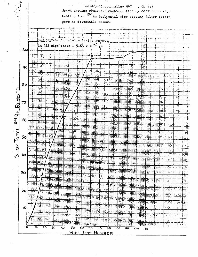
*1
V . .. ... -, I I:'V
_ _ _ ... . ..... ..
. .. 1w ..... LO~.. .......t..
ri4 Ii4 _H __ _
~~~~~~2 T, j' _____
....t ... . . _ _ ..... _ _ 11
:;: L~ .1
._ _ _ _ ._ _ .... 1....
- -:%~ IJ ~ I 40 V 10 10 I. ~
Grahon rv.~ Contarmr.ation zy continýz -ýs
teutinT3 fromz Am .10i ilutlwipe tetin- filter ;zg;crs gave no dctectabl aout
11C0 rep.resenrtfi total act.vit y r'c ___ .-.!,in 122 wieateatc 3 5 . 6 3 xi 10 c --.. I J;C .
H ~ -7T
100
C
CE
C'
.. V P T.0r lo 1 3 COM0 Io 3PIS

~~1 Technical Dat~a -2
'r%.,tisv, ot' AZ'.riejuw.-241 Alr..i.fu1
&MvaplvG of foil. typ .r¶ * 1 CM 101r., &cLLIVU Width 12.5 L:M. ovorall w~dt'20cm. conaLia±1dý. 160 I.C1. americium-..;,41. Xflitiul Izjmerzton To--!I. < 0.005 UiCi extrL~cted durinC 105 houre ih4¶.orziorL test.
T~eqt 1. Sulphur dioxi dt
S anyles were expoesuI for 6 ayia to R643%t afr cantaiznine 15 SO I'favraion te.t - < 0.2 1&M extractepd.2 Iip. toot - < 0,0U5 UCie
2., iydronen chloride to
Sample& veto exposed f.3- 1t') days to dry &ir conzoir.±.xg I me IiCl Lptj/Iitre. .Lmamrsion test - < 0.0U~, *.C±1 vxtr_-tvd.
3. Ammo~nia teat
Samples wore exposed1 for: 16 days to dry air Cort&ifling 10 mi; i~it Cuss/litre. -immersion to#;t - < 0.002 uCL extrztcted~.>
I@ Saxplen woe. wAis.,'4r.eu &.: ;Xi00 for 10 niz jn~~~d th~en rz~pidly coolc~d bY im~'ruolo in wat.zr. TLnfl3 wau carriu. out 30 tim.es on each aampht. IAiiaJrVIGA tQ41s - < O.A: U&Ci t.AtrbiC,;td.
2o Sz-plao were si.AjitL;.'Lj at 120Z3% fo~r onu hour and then rupidly cool1.d by iamsatrzion in wv:,46-*0* Izuwi4rdiofl tvdt - < 0.015 uCi extriectvtJ. hip. tesit - < 0.2 0

THORN Automated rystems Inc Corporate Offices 835 Sharon Drive Westlake, Ohio 44145 (216) 871-9900 FAX (216) 871-8320
AFFIDAVIT
I, E. Joseph Martini. Vice President Manufacturing Operations. on behalf of
THORN Automated Systems, Inc. have read and understand all commitments
made in the named supporting documents in Nittan Corporation's registration
documents NR-481-D-101-E and NR-481-D-102-E and agree on behalf of THORN
Automated Systems, Inc. to be legally bound by all statements and representations
both express and implied made by Nittan Systems, Inc. in said registrations.
E. Joseph Martini
• TORN A•utomated Systems, Inc.
Vice President Manufacturing Operations
State of Ohio County of Cuyahoga
On the day of 13th March 1992 before me came E. Joseph Martini , of THORN Automatec Systems, Inc. who executed the foregoing and acknowledge he ecuted the same.
Noty M11 Commission expiresF2T14/92
featufina
life safety systemsk7ý44*tr Ail

SECTION THREE
CONTENTS:
1. Copy of current license 34-23772-02E Amendment No. 02
2. Application
3. Attachment El - Copy of Registry for Amersham dated October 26, 1979
4. Attachment E2 - Amersham Data Sheet 11262
5. Attachment E3 - Detail drawings and bill of materials for 6121 and 9121
6. Attachment E4 - Amersham Data Sheet 11247
7. Attachment E5 - Copies of point of sale labels
8. Attachment E6 - Loss Prevention Certification Board Test Reports
9. Attachment E7 - Copies of 1SO 9001 Registrations
10. Attachment E8 - Procedures
0,)-/ Y-60
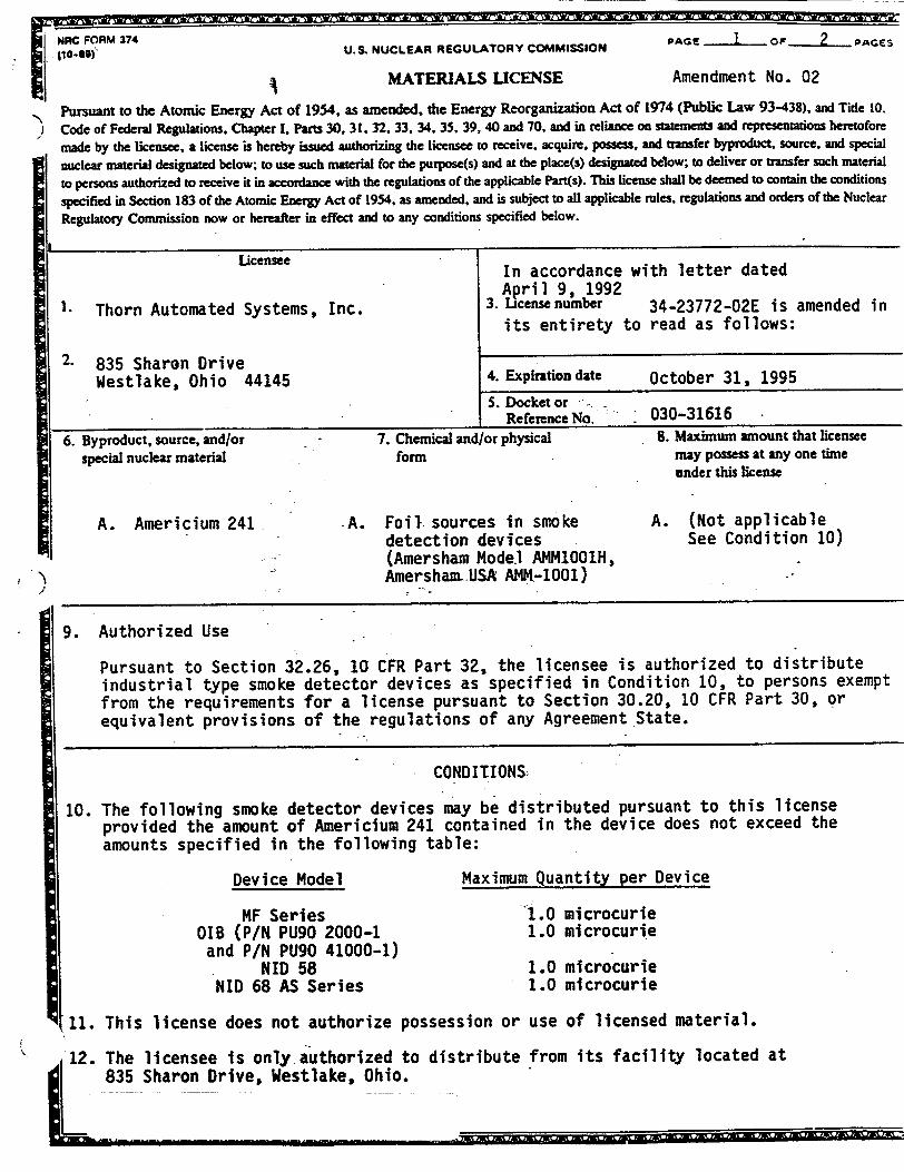
NC U.S. NUCLEAR REGULAT
MATERIALS
ORY COMMISSION
LICENSE
PAGE I -OF 2 PAGES
Amendment No. 02
Pursuant to the Atomic Energy Act of 1954, as amended, the Energy Reorganization Act of 1974 (Public Law 93-438), and Tide 10. Code of Federal Regulations. Chapter I, Parts 30, 31. 32, 33.34. 35. 39, 40 and 70, and in reliance on statements and representations heretofore
made by the licensee, a license is hereby issued authorizing the licensee to receive, acquire. possess, and transfer byproduct, source, and special
nuclear material designated below; to use such material for the purpose(s) and at the place(s) designated below; to deliver or transfer such material
to persons authorized to receive it in accordance with the regulations of the applicable Part(s). This license shall be deemed to contain the conditions
specified in Section 183 of the Atomic Energy Act of 1954. as amended, and is subject to all applicable rules, regulations and orders of the Nuclear
Regulatory Commission now or hereafter in effect and to any conditions specified below.
6. Byproduct, source, and/or special nuclear material
A. Americium 241
I
7. Chemical and/or physical form
*A. Foil sources in smoke detection devices (Amersham Model AMM1001H, AmershauL.USA AZM-1001)
S. Maximum amount mat lcensee may possess at any one time under this license
A. (Not applicable See Condition 10)
9. Authorized Use
Pursuant to Section 32.26, 10 CFR Part 32, the licensee is authorized to distribute industrial type smoke detector devices as specified in Condition 10, to persons exempt from the requirements for a license pursuant to Section 30.20, 10 CFR Part 30, or equivalent provisions of the regulations of any Agreement State.
CONDITIONS
10. The following smoke detector devices may be distributed pursuant to this license provided the amount of Americium 241 contained in the device does not exceed the amounts specified in the following table:
Device Model
MF Series OIB (P/N PU90 2000-1 and P/N PU90 41000-1)
KID 58 NID 68 AS Series
Maximum Quantity per Device
1.0 microcurie 1.0 microcurie
1.0 microcurie 1.0 microcurie
t11. This license does not authorize possession or use of licensed material.
12. The licensee is only authorized to distribute from its facility located at L835 Sharon Drive, Westlake, Ohio.
!!Lýt -revr a, -7*rka' -toy -4% -im. -fair = 7.7-
^l~dl "V'. 'ejLW
(licensee In accordance with letter dated
April 9, 1992 I. Thorn Automated Systems, Inc. 3. License number 34-23772-02E is amended in
its entirety to read as follows:
2. 835 Sharon Drive Westlake, Ohio 44145 4. Expiration date October 31, 1995
S. Docket or Reference No. 030-31616

MNRC lrm 374A U.S. NUCLEAR REGULATORY COMMISSION PAGE 2 oF 2 PAGES [ (S-m) n uumbet 34-23772-02E MATERIALS LICENSE Docket m ltef 34-23a772
SUPPLEMENTARY SHEET 030-31616
Amendment No. 02
CONDITIONS
(continued)
13. The licensee shall file periodic reports as specified in Section 32.29(c), 10 CFR Part 32.
14. The licensee shall perform tests for leakage and/or contamination in accordance with procedures described in letter dated September 28, 1990. The test shall be capable of detecting the presence of 0.00.5 cractuo•[ef radioactive material on the test sample. If the test reveals tt~e presence4 6f "O•.Ol uicrocurie or more of removable contamination, the detector jotshall not be tran strrj9d without additional
evaluation, the manufactu .ef should be informed of tlid rW'ults and further sampling be performed in order.ta.characterize the problem. IndT?*4dual detectors shall not be
transferred if furtheiztesting reveals the presence of OOWFjmicrocurie or more of
removable contaminatjoi?•.:
15. Except as specifically pro~idqie-otherwise by thisicnse, the licensee shall distribute licensed material:, r*bed-iiý-Condit.qF1Z10 of thislicense in accordance with the statements, repres tiýtIFois, and proce ives'contained-in the documents, including any enclbsures, lIt- belowok...l.Th~e NuJ ._a,. Regulatory Commission's regulations shal1-.overn-"unles- -. saem -eesentatio..and procedures in the licenseee's llct and' t"ef rae. m est rtftive than the
" •*'•• 't i . 4. " •• . . -
regulations. .. r0
A. Application dated •M arc .-4- .
B. Letters dated October 25, 1989;•May 31;--199QV`,July 20,-1990; August 9, 1990; September 28, 1990--vOctober 1, 1990; and October 2,1990.
C. Letters dated Novembe!r 4 5, 1989; October 10, 199,,\.March 13, 1992;
March 30, 1992; and April lj ,- 1fr *
D. Letter dated April 9, 1992.
FOR THE U.S. NUCLEAR REGULATORY COMMISSION
DATE: APR 15 1992 BY: MichaeTA. Lamastra Medical, Academic, and C0onnercial
Use Safety Branch Division of Industrial and
Medical Nuclear Safety, NMSS Washington, D.C. 20555
Q mx••• , , , r • • • • • _•.i ' l.m • • 'x.•/• r aW• •• • zB L"%L•

PAUL MELLOR PAGE 10 .!,,•,..•?,•:.•.!•jj• -- r c|xg • •
05/26/1998 11:3G 560 - '0- * - - ~ *- -V .--
REGISTRY OF RADIOACTIVE SEALED SOURCES AND DEVICES SAFETY EVALUATION OF SEALED SOURCE
(Correcte Copy)
NO.: NR136S174U
SEALED SOURCE TYPE:
MOD0EL:
DATE: October 26, 1979 PAGE 1OF 4
Foil Source
AMI41001. A441,•OO1H
MANUFACTURER/DISTRIBUTOR: Amersham Corporation 2636 S. Clearbrook Drive Arlington Heights, IL 60005
HANUFACTURER/DISTRIBUTOR:
Americiumn-241 MAXIMU?4 ACTIVITY: SO etcrocudes per square cm of foil
LEAK-TEST FREQUENCY:
PRINCIPAL USE:
CUSTOM SOURCE:
\~Art~o1#t~v'
Ion Generstors, Smoke Detectors
YES X HO
F/
ISOTOPE:

PAUL MELLOR05/26/1998 11:36
qEGISTRY OF RADIOACTIVE SEAED SOURCES 1 00EY!ICES SAFETY EVALLATION OF SALED SOURCE
140.: '$R136S174U DATE: October 26, 1979 FAGE 2 OF 4
SEALEC SOURCE TYPE: Foil Source
DESCR!PT!ON
The Nodel AI 1001 sealed source consists of americium oxide uniformly distributed and sintered in a pure gold matrix which Is further contained between a backing of gold coated pure silver and a front covering of either gold or gold-palladium alloy and fabricated by hot forging methods. The continuously welded metal layers are rolled so that the minimum thickness of the layers are:
gold-palladium alloy 0.0015 mm americium oxide plus gold 0.0001 mm gold 0.0001 mm substrate 0.20 mm
Sub-division of the rolled foil is accomplished by cutting or punching into discs of 5 m• diameter or strips of say Z mm x 10 mm diameter. At the activity loading specified above. there is no loose or wipable contamination above the wipe test limit of 0.005 microcurles.
The Model A•1 1001H mounted sealed source consists of a sized foil mounted in a "T" shaveo standard holder constructed of tin plated brass. Lips of the source holder are rolled over the edge of the foil so the cut edges of the foil are not exposed. The larger diameter of the holder is approximately 5 nn and the length is approximately 6 mm. The useful life is 20 years.
LAECNG:
Nleither the foils nor mounts are labeled. This evaluation does not describe possible A/S foil sources distributed under other model designations nor sources previously aistributed under "AW4"designation.
PAGE 11

05/26/1998 11:36 560 PAUL MELLOR I Cd.. ILl J;, (
REGISTRY OF RADIOACTIVE SEALED SOURCES AND DEVICES SAFETY EVALUATION OF SEALED SOURCE
NRI36SI74U DATE: October 26, 1979 PAGE 3 OF 4
SEALED SOURCE TYPE: Foil Source
DIAGRAM%
A- Cover Co4,Az- v
4
A-. ,20- ,20 2i
PROTOTYPE TESTING:
Prototype Model AMM 1001 blanked sealed sources and Model AiI 100IH mounted sources have been tested to conditions described by USASI standard NS.10-1968 and respective classifications of C54545 and C44444 have been demonstrated. Results of wipe tests of the tested foils were acceptable to less than 0.005 mlcrocurles. In addition, AMM 1001 samples have successfully passed 'special form" testing conditions.
Model AMM 1001 foils have experienced the following additional tests:
1. Immersion in water of prototype foils for 3 weeks at room temperature: less than 0.001 mlcrocurte per foil loaded at maximum activity was found in the weter.
2. Immersion in 0.1 N hydrochloric acid for 24 hours at room temperature: less than 0.004 microcurie activity was leached out.
3. Foils were subjected to tests In moist air, dry air, sulfur dioxide fumes. hydrochloric acid fumes, ammonia vapor, to repetitive wipe tests (SO00X) and welding tests: less than 0.005 mlcrocurle wipable contamination was found. Shelf-life tests of foils with 50 mlcrocuries/cml loading show no deleterious aging effects after 6 years.
PAGE •'t4 *(r•
12
NO. :
"Z

85/26/1998 11:36
i
REGVS?:Y .R ACOACTIVE SEALED SOURCES A D OEVICES .FETY EVALUATION OF SEALED SOURCE
;'C.: XR1ZSI74IM
SEALED SOURCE TYPE:
DATE: October 26, 1979 PAGE A OF 4
%oil Source
PROTOTYPE TEST!NG (CONT'D!:
Foils and !cunted foils have been subjected to ozone at 0.75 ppm for days and salt spray for 16 days without deleterious results.a Period of 60
QUALITY ASSURANCE ANO CONTROL:
Not less tnan 10 percent of the Model AIM 1001H sources are checked by ganra counting tc ensure that the activity in each foil is within specified limits. Each product is visually inspec:ed to check that the rolled-over edge Is satisfactory and that the alpha emitting surface is free from surface defects. Each source is wipe tested to an acceptance limit of 0.005 mlcrocuries.
In addition to the above, each Model AMt4 1001 foil is checked by alpha soectrometry to determine the adequacy of the gold cover.
REFERENCES:
,ctober 16. 1979
October Z6. 1979
Reviewed By
Concurrence
/s/ Joseph M. grown, Zr.
/E, Earl •. Wrlght
ISSUING AGE!ICY:
U.S. Nuclear Regula•ory Coemission
a
a:
Date
Date
PAGE 135B0 PAUL MELLOR