API 653 Inspection Report Internal Inspection and Out-of ...
45
API 653 Inspection Report Internal Inspection and Out-of-Service or Internal Inspection w/ External Checklist Report Prepared For U.S. CHEMICAL SAFETY AND HAZARD INVESTIGATION BOARD FREEDOM INDUSTRIES CHARLESTON, WV 4-METHYLCYCLOHEXANEMETHANOL (MCHM) Tank Number 397 Inspected on APRIL 29 – MAY 1, 2014 Report Prepared By ENGINEERING & INSPECTION, INC. PO BOX 1928 BENICIA, CA 94510 TEL 707 334 3400 FAX 707 922 2284 WWW.POWERSEI.COM Gary Powers, P.E. Authorized Inspector 0691 California Civil Engineer 60589 Inspection History Constructed Re-Erect Second Bottom External Inspection Internal Inspection Shell UT Inspection 1940? N/A N/A 5/1/2014 5/1/2014 5/1/2014 Next Inspection: N/A N/A N/A Revisions Rev. 0 6/12/2014 Initial Report
-
Upload
khangminh22 -
Category
Documents
-
view
0 -
download
0
Transcript of API 653 Inspection Report Internal Inspection and Out-of ...
API 653 Inspection Report
Internal Inspection and
Out-of-Service or
Internal Inspection w/ External Checklist
Report Prepared For
U.S. CHEMICAL SAFETY AND HAZARD INVESTIGATION BOARD FREEDOM INDUSTRIES
CHARLESTON, WV
4-METHYLCYCLOHEXANEMETHANOL (MCHM)
Tank Number
397
Inspected on
APRIL 29 – MAY 1, 2014
Report Prepared By
ENGINEERING & INSPECTION, INC.
PO BOX 1928 BENICIA, CA 94510
TEL 707 334 3400 FAX 707 922 2284
WWW.POWERSEI.COM
Gary Powers, P.E. Authorized Inspector 0691
California Civil Engineer 60589
Inspection History Constructed Re-Erect Second Bottom External Inspection Internal Inspection Shell UT Inspection
1940? N/A N/A 5/1/2014 5/1/2014 5/1/2014
Next Inspection: N/A N/A N/A
Revisions
Rev. 0 6/12/2014 Initial Report
PO BOX 1928 BENICIA, CA 94510 TEL 707 334 3400 FAX 707 922 2284
U.S. CHEMICAL SAFETY AND
HAZARD INVESTIGATION BOARD
API 653 POST REPAIR AND INSPECTION FREEDOM INDUSTRIES CHARLESTON, WV
ENGINEERING & INSPECTION, INC www.powersei.com Tank 397
API653 Internal Inspection Freedom Industries Tank 397 rev 0 © 2014 PE&I Inc.
Page 2 of 16 Date Printed: 6/12/14 12:14 PM
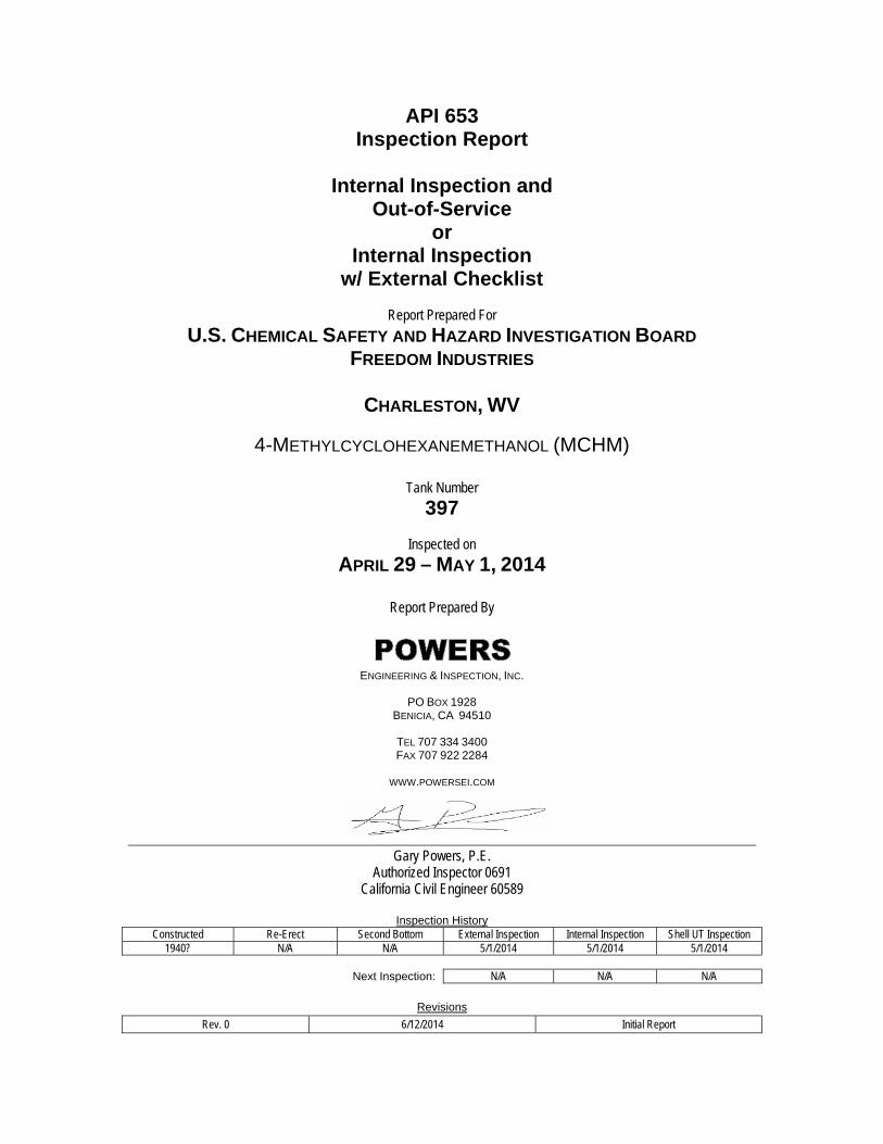
EXECUTIVE SUMMARY Powers Engineering and Inspection, Inc. was contracted by the U.S. Chemical Safety and Hazard Investigation Board Inc. to provide API 653 Internal Inspection services for Tank 397 at the Freedom Industries Facility in Charleston, WV. Tank 397 was most likely constructed during the 1940s. The tank is 20-ft diameter x 20-ft tall and has a lap-riveted shell, cone roof, and a 1/4-in lap-welded bottom. It is the inspector’s opinion that the existing lap welded bottom is at least 25 years old and was installed to replace the original lap riveted bottom and riveted shell to chime angle. The tank was recently in 4-methylcyclohexanemethanol (MCHM) service. In January 2014 a leak was detected on sister tank 396 and the tank(s) removed from service. After this inspection the tank(s) will be dismantled. The report and executive summary are based on field inspection and evaluation in accordance with the API 653 Standard. Since this tank is to be dismantled, no repair recommendations were provided to return the tank back to service. If for some reason the tank is returned to service all the requirements of API 650 and 653 should be met.
INSPECTION SUMMARY 1. Inspect the tank and identify any current leak paths resulting from corrosion, internal or
external.
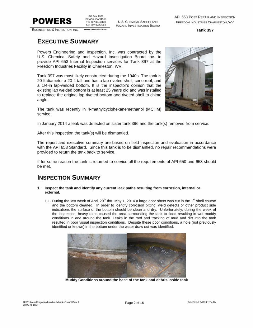
1.1. During the last week of April 29th thru May 1, 2014 a large door sheet was cut in the 1st shell course and the bottom cleaned. In order to identify corrosion pitting, weld defects or other product side indications the surface of the bottom should be clean and dry. Unfortunately, during the week of the inspection, heavy rains caused the area surrounding the tank to flood resulting in wet muddy conditions in and around the tank. Leaks in the roof and tracking of mud and dirt into the tank resulted in poor visual inspection conditions. Despite these poor conditions, a hole (not previously identified or known) in the bottom under the water draw out was identified.
Muddy Conditions around the base of the tank and debris inside tank
PO BOX 1928 BENICIA, CA 94510 TEL 707 334 3400 FAX 707 922 2284
U.S. CHEMICAL SAFETY AND
HAZARD INVESTIGATION BOARD
API 653 POST REPAIR AND INSPECTION FREEDOM INDUSTRIES CHARLESTON, WV
ENGINEERING & INSPECTION, INC www.powersei.com Tank 397
API653 Internal Inspection Freedom Industries Tank 397 rev 0 © 2014 PE&I Inc.
Page 3 of 16 Date Printed: 6/12/14 12:14 PM
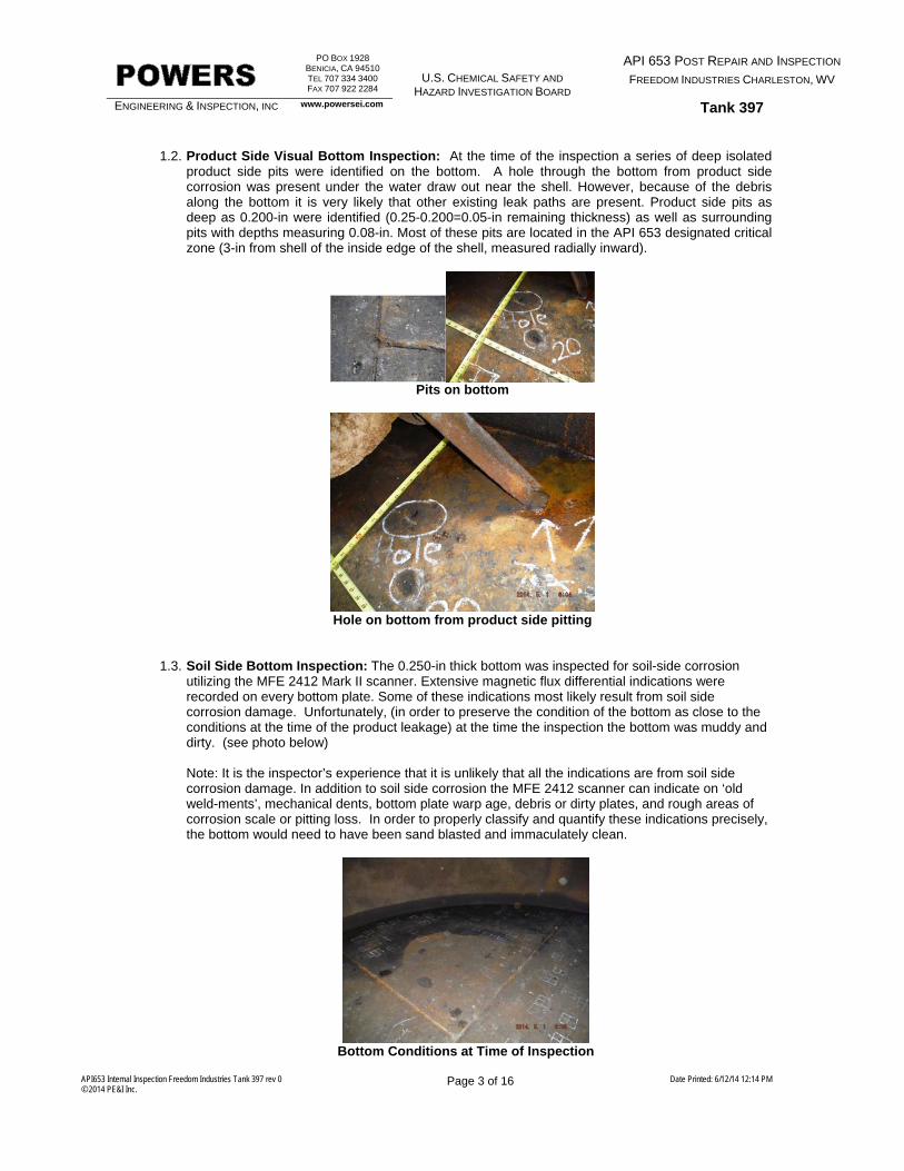
1.2. Product Side Visual Bottom Inspection: At the time of the inspection a series of deep isolated
product side pits were identified on the bottom. A hole through the bottom from product side corrosion was present under the water draw out near the shell. However, because of the debris along the bottom it is very likely that other existing leak paths are present. Product side pits as deep as 0.200-in were identified (0.25-0.200=0.05-in remaining thickness) as well as surrounding pits with depths measuring 0.08-in. Most of these pits are located in the API 653 designated critical zone (3-in from shell of the inside edge of the shell, measured radially inward).
Pits on bottom
Hole on bottom from product side pitting
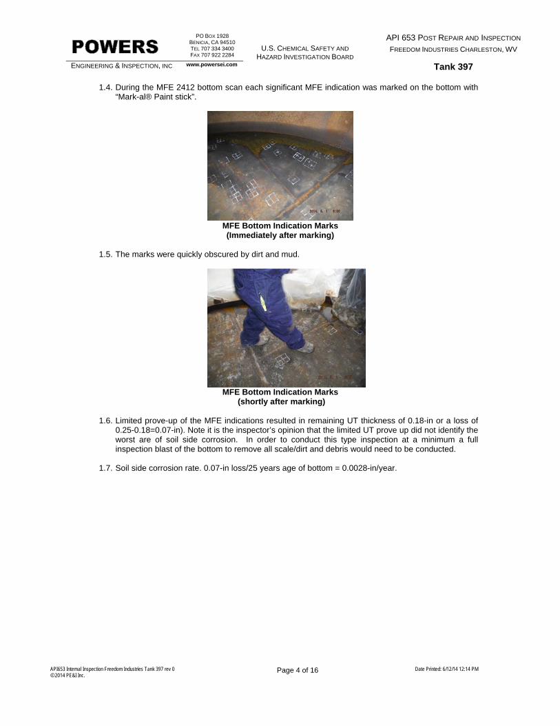
1.3. Soil Side Bottom Inspection: The 0.250-in thick bottom was inspected for soil-side corrosion utilizing the MFE 2412 Mark II scanner. Extensive magnetic flux differential indications were recorded on every bottom plate. Some of these indications most likely result from soil side corrosion damage. Unfortunately, (in order to preserve the condition of the bottom as close to the conditions at the time of the product leakage) at the time the inspection the bottom was muddy and dirty. (see photo below)
Note: It is the inspector’s experience that it is unlikely that all the indications are from soil side corrosion damage. In addition to soil side corrosion the MFE 2412 scanner can indicate on ‘old weld-ments’, mechanical dents, bottom plate warp age, debris or dirty plates, and rough areas of corrosion scale or pitting loss. In order to properly classify and quantify these indications precisely, the bottom would need to have been sand blasted and immaculately clean.
Bottom Conditions at Time of Inspection
PO BOX 1928 BENICIA, CA 94510 TEL 707 334 3400 FAX 707 922 2284
U.S. CHEMICAL SAFETY AND
HAZARD INVESTIGATION BOARD
API 653 POST REPAIR AND INSPECTION FREEDOM INDUSTRIES CHARLESTON, WV
ENGINEERING & INSPECTION, INC www.powersei.com Tank 397
API653 Internal Inspection Freedom Industries Tank 397 rev 0 © 2014 PE&I Inc.
Page 4 of 16 Date Printed: 6/12/14 12:14 PM
1.4. During the MFE 2412 bottom scan each significant MFE indication was marked on the bottom with “Mark-al® Paint stick”.
MFE Bottom Indication Marks (Immediately after marking)
1.5. The marks were quickly obscured by dirt and mud.
MFE Bottom Indication Marks
(shortly after marking)
1.6. Limited prove-up of the MFE indications resulted in remaining UT thickness of 0.18-in or a loss of 0.25-0.18=0.07-in). Note it is the inspector’s opinion that the limited UT prove up did not identify the worst are of soil side corrosion. In order to conduct this type inspection at a minimum a full inspection blast of the bottom to remove all scale/dirt and debris would need to be conducted.
1.7. Soil side corrosion rate. 0.07-in loss/25 years age of bottom = 0.0028-in/year.
PO BOX 1928 BENICIA, CA 94510 TEL 707 334 3400 FAX 707 922 2284
U.S. CHEMICAL SAFETY AND
HAZARD INVESTIGATION BOARD
API 653 POST REPAIR AND INSPECTION FREEDOM INDUSTRIES CHARLESTON, WV
ENGINEERING & INSPECTION, INC www.powersei.com Tank 397
API653 Internal Inspection Freedom Industries Tank 397 rev 0 © 2014 PE&I Inc.
Page 5 of 16 Date Printed: 6/12/14 12:14 PM
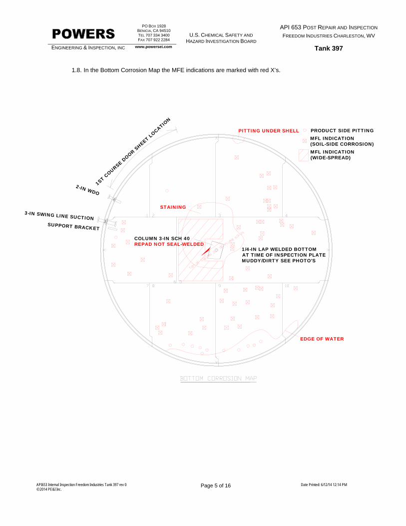
1.8. In the Bottom Corrosion Map the MFE indications are marked with red X’s.
PRODUCT SIDE PITTINGMFL INDICATION(SOIL-SIDE CORROSION)MFL INDICATION(WIDE-SPREAD)
PITTING UNDER SHELL
1ST C
OURSE DOOR S
HEET LOCATIO
N
2-IN WDO
3-IN SWING LINE SUCTIONSUPPORT BRACKET
EDGE OF WATER
STAINING
1/4-IN LAP WELDED BOTTOMAT TIME OF INSPECTION PLATEMUDDY/DIRTY SEE PHOTO'S
COLUMN 3-IN SCH 40REPAD NOT SEAL-WELDED
PO BOX 1928 BENICIA, CA 94510 TEL 707 334 3400 FAX 707 922 2284
U.S. CHEMICAL SAFETY AND
HAZARD INVESTIGATION BOARD
API 653 POST REPAIR AND INSPECTION FREEDOM INDUSTRIES CHARLESTON, WV
ENGINEERING & INSPECTION, INC www.powersei.com Tank 397
API653 Internal Inspection Freedom Industries Tank 397 rev 0 © 2014 PE&I Inc.
Page 6 of 16 Date Printed: 6/12/14 12:14 PM
2. Identify any risk of future leak paths resulting from corrosion, internal or external.
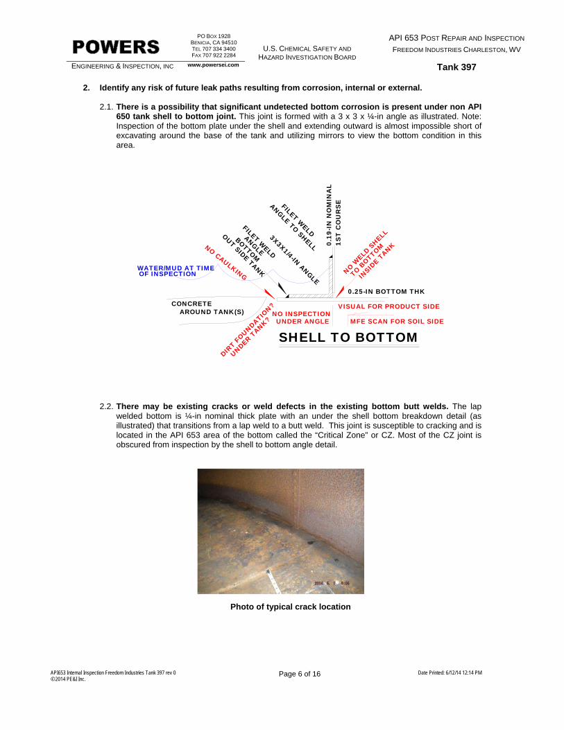
2.1. There is a possibility that significant undetected bottom corrosion is present under non API 650 tank shell to bottom joint. This joint is formed with a 3 x 3 x ¼-in angle as illustrated. Note: Inspection of the bottom plate under the shell and extending outward is almost impossible short of excavating around the base of the tank and utilizing mirrors to view the bottom condition in this area.
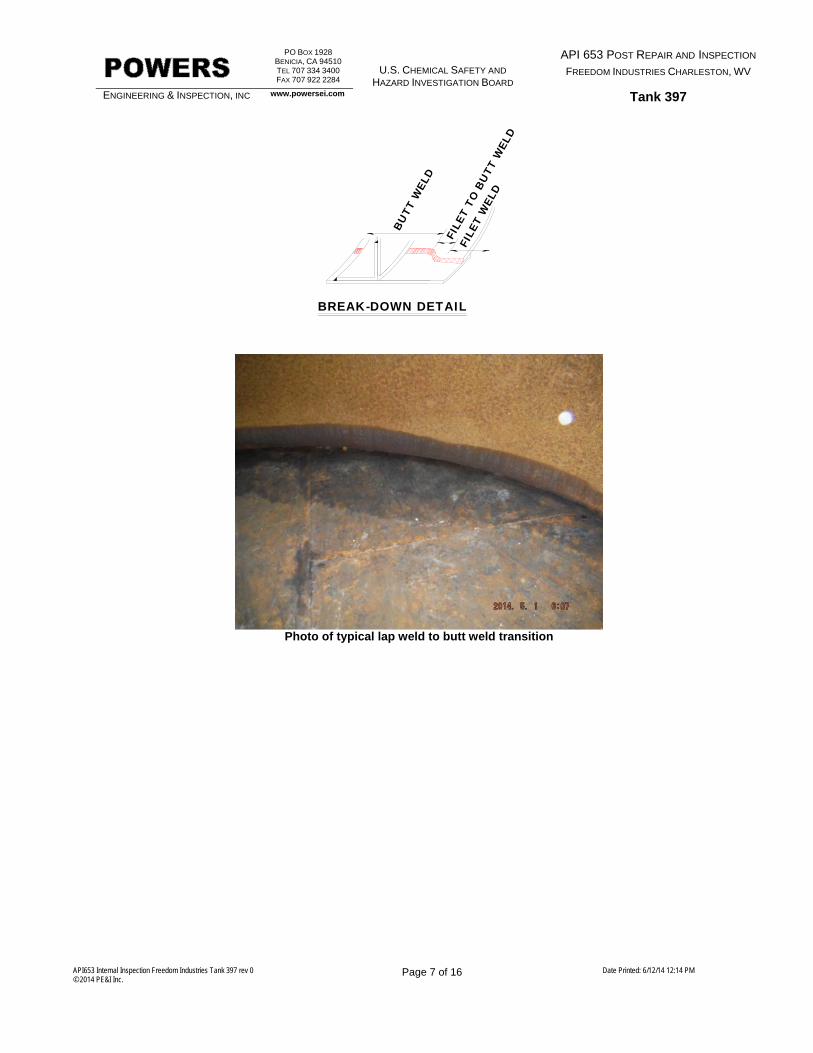
2.2. There may be existing cracks or weld defects in the existing bottom butt welds. The lap
welded bottom is ¼-in nominal thick plate with an under the shell bottom breakdown detail (as illustrated) that transitions from a lap weld to a butt weld. This joint is susceptible to cracking and is located in the API 653 area of the bottom called the “Critical Zone” or CZ. Most of the CZ joint is obscured from inspection by the shell to bottom angle detail.
Photo of typical crack location
0.19
-IN
NO
MIN
AL
1ST
CO
UR
SE
0.25-IN BOTTOM THK
3X3X1/4-IN ANGLE
ANGLE TO SHELL
FILET WELD BOTTOM
FILET WELD
ANGLE
SHELL TO BOTTOM
NO WELD
SHELL
TO BOTTOM
INSID
E TANK
OUT SIDE TANK
DIRT F
OUNDATION?CONCRETE
AROUND TANK(S)
UNDER TANK?
NO CAULKING
MFE SCAN FOR SOIL SIDE
VISUAL FOR PRODUCT SIDENO INSPECTION
WATER/MUD AT TIMEOF INSPECTION
UNDER ANGLE
PO BOX 1928 BENICIA, CA 94510 TEL 707 334 3400 FAX 707 922 2284
U.S. CHEMICAL SAFETY AND
HAZARD INVESTIGATION BOARD
API 653 POST REPAIR AND INSPECTION FREEDOM INDUSTRIES CHARLESTON, WV
ENGINEERING & INSPECTION, INC www.powersei.com Tank 397
API653 Internal Inspection Freedom Industries Tank 397 rev 0 © 2014 PE&I Inc.
Page 7 of 16 Date Printed: 6/12/14 12:14 PM
Photo of typical lap weld to butt weld transition
BREAK-DOWN DETAIL
BUTT
WEL
D
FILE
T TO
BU
TT W
ELD
FILE
T W
ELD
PO BOX 1928 BENICIA, CA 94510 TEL 707 334 3400 FAX 707 922 2284
U.S. CHEMICAL SAFETY AND
HAZARD INVESTIGATION BOARD
API 653 POST REPAIR AND INSPECTION FREEDOM INDUSTRIES CHARLESTON, WV
ENGINEERING & INSPECTION, INC www.powersei.com Tank 397
API653 Internal Inspection Freedom Industries Tank 397 rev 0 © 2014 PE&I Inc.
Page 8 of 16 Date Printed: 6/12/14 12:14 PM
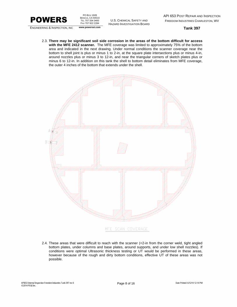
2.3. There may be significant soil side corrosion in the areas of the bottom difficult for access
with the MFE 2412 scanner. The MFE coverage was limited to approximately 75% of the bottom area and indicated in the next drawing. Under normal conditions the scanner coverage near the bottom to shell joint is plus or minus 1 to 2-in, at the square plate intersections plus or minus 4-in, around nozzles plus or minus 3 to 12-in, and near the triangular corners of sketch plates plus or minus 6 to 12-in. In addition on this tank the shell to bottom detail eliminates from MFE coverage, the outer 4 inches of the bottom that extends under the shell.
2.4. These areas that were difficult to reach with the scanner (<2-in from the corner weld, tight angled
bottom plates, under columns and base plates, around supports, and under low shell nozzles). If conditions were optimal Ultrasonic thickness testing or UT would be performed in these areas, however because of the rough and dirty bottom conditions, effective UT of these areas was not possible.
PO BOX 1928 BENICIA, CA 94510 TEL 707 334 3400 FAX 707 922 2284
U.S. CHEMICAL SAFETY AND
HAZARD INVESTIGATION BOARD
API 653 POST REPAIR AND INSPECTION FREEDOM INDUSTRIES CHARLESTON, WV
ENGINEERING & INSPECTION, INC www.powersei.com Tank 397
API653 Internal Inspection Freedom Industries Tank 397 rev 0 © 2014 PE&I Inc.
Page 9 of 16 Date Printed: 6/12/14 12:14 PM
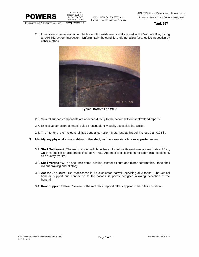
2.5. In addition to visual inspection the bottom lap welds are typically tested with a Vacuum Box, during
an API 653 bottom inspection. Unfortunately the conditions did not allow for affective inspection by either method.
Typical Bottom Lap Weld
2.6. Several support components are attached directly to the bottom without seal welded repads.
2.7. Extensive corrosion damage is also present along visually accessible lap welds.
2.8. The interior of the riveted shell has general corrosion. Metal loss at this point is less than 0.05-in. 3. Identify any physical abnormalities to the shell, roof, access structure or appurtenances.
3.1. Shell Settlement. The maximum out-of-plane base of shell settlement was approximately 2.1-in, which is outside of acceptable limits of API 653 Appendix B calculations for differential settlement. See survey results.
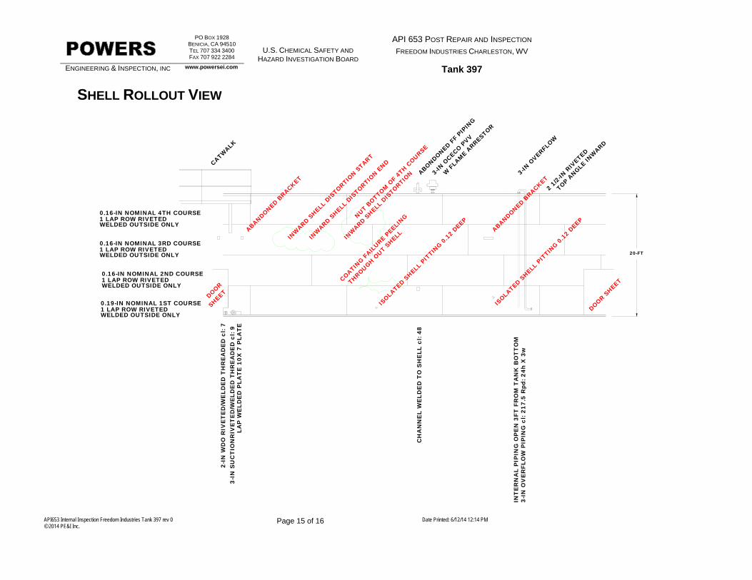
3.2. Shell Verticality. The shell has some existing cosmetic dents and minor deformation. (see shell
roll out drawing and photos)
3.3. Access Structure. The roof access is via a common catwalk servicing all 3 tanks. The vertical handrail support and connection to the catwalk is poorly designed allowing deflection of the handrail.
3.4. Roof Support Rafters. Several of the roof deck support rafters appear to be in fair condition.
PO BOX 1928 BENICIA, CA 94510 TEL 707 334 3400 FAX 707 922 2284
U.S. CHEMICAL SAFETY AND
HAZARD INVESTIGATION BOARD
API 653 POST REPAIR AND INSPECTION FREEDOM INDUSTRIES CHARLESTON, WV
ENGINEERING & INSPECTION, INC www.powersei.com Tank 397
API653 Internal Inspection Freedom Industries Tank 397 rev 0 © 2014 PE&I Inc.
Page 10 of 16 Date Printed: 6/12/14 12:14 PM
3.5. Roof Support Column. The roof support column is a pipe design and is susceptible to undetected
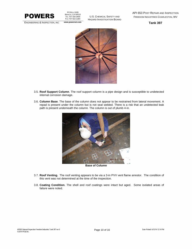
internal corrosion damage. 3.6. Column Base. The base of the column does not appear to be restrained from lateral movement. A
repad is present under the column but is not seal welded. There is a risk that an undetected leak path is present underneath the column. The column is out of plumb 4-in.
Base of Column
3.7. Roof Venting. The roof venting appears to be via a 3-in PVV vent flame arrestor. The condition of this vent was not determined at the time of the inspection.
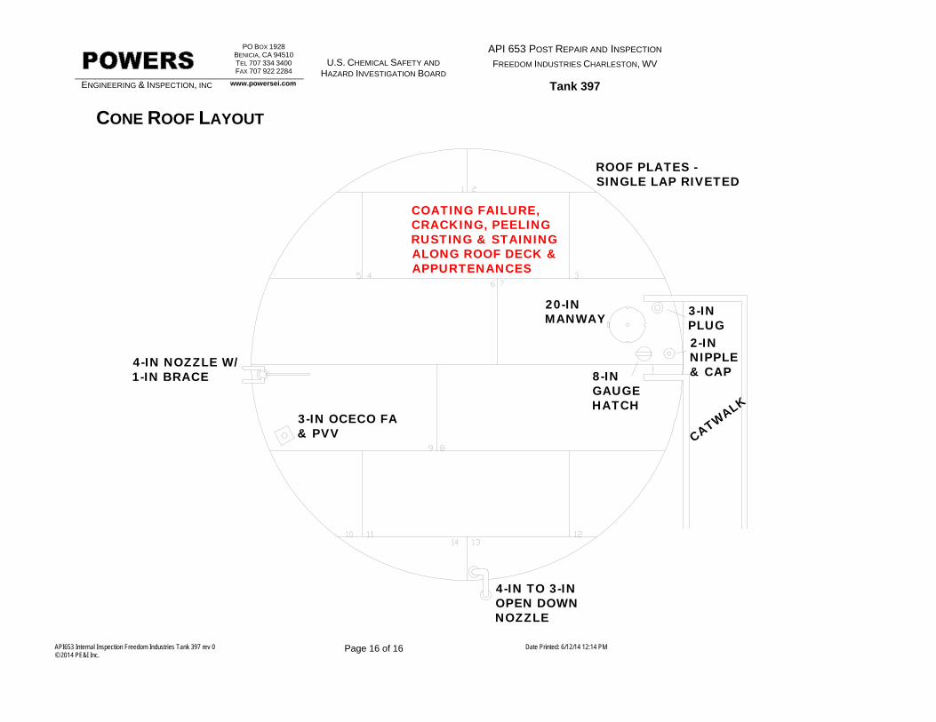
3.8. Coating Condition. The shell and roof coatings were intact but aged. Some isolated areas of
failure were noted.
PO BOX 1928 BENICIA, CA 94510 TEL 707 334 3400 FAX 707 922 2284
U.S. CHEMICAL SAFETY AND
HAZARD INVESTIGATION BOARD
API 653 POST REPAIR AND INSPECTION FREEDOM INDUSTRIES CHARLESTON, WV
ENGINEERING & INSPECTION, INC www.powersei.com Tank 397
API653 Internal Inspection Freedom Industries Tank 397 rev 0 © 2014 PE&I Inc.
Page 11 of 16 Date Printed: 6/12/14 12:14 PM
Table of Contents Executive Summary ......................................................................................................................... 2 Inspection Summary ........................................................................................................................ 2 Basic Tank Information .................................................................................................................. 12 Shell Settlement Survey ................................................................................................................ 13 Shell Thickness Calculation ........................................................................................................... 14 Shell Rollout View .......................................................................................................................... 15 Cone Roof Layout .......................................................................................................................... 16 Appendix A API 653 Checklist Appendix B Photo’s
Inspection Significant Photos Inspection General Photos
PO BOX 1928 BENICIA, CA 94510 TEL 707 334 3400 FAX 707 922 2284
U.S. CHEMICAL SAFETY AND
HAZARD INVESTIGATION BOARD
API 653 POST REPAIR AND INSPECTION FREEDOM INDUSTRIES CHARLESTON, WV
ENGINEERING & INSPECTION, INC www.powersei.com Tank 397
API653 Internal Inspection Freedom Industries Tank 397 rev 0 © 2014 PE&I Inc.
Page 12 of 16 Date Printed: 6/12/14 12:14 PM
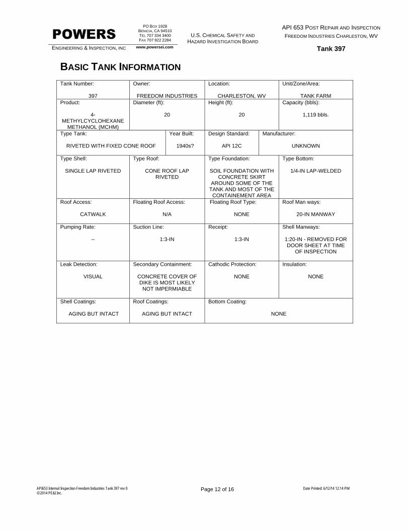
BASIC TANK INFORMATION Tank Number: Owner: Location: Unit/Zone/Area:
397
FREEDOM INDUSTRIES
CHARLESTON, WV
TANK FARM Product: Diameter (ft): Height (ft): Capacity (bbls):
4-METHYLCYCLOHEXANE
METHANOL (MCHM)
20
20
1,119 bbls.
Type Tank: Year Built: Design Standard: Manufacturer:
RIVETED WITH FIXED CONE ROOF
1940s?
API 12C
UNKNOWN
Type Shell: Type Roof: Type Foundation: Type Bottom:
SINGLE LAP RIVETED
CONE ROOF LAP RIVETED
SOIL FOUNDATION WITH
CONCRETE SKIRT AROUND SOME OF THE
TANK AND MOST OF THE CONTAINEMENT AREA
1/4-IN LAP-WELDED
Roof Access: Floating Roof Access: Floating Roof Type: Roof Man ways:
CATWALK
N/A
NONE
20-IN MANWAY
Pumping Rate: Suction Line: Receipt: Shell Manways:
--
1:3-IN
1:3-IN
1:20-IN - REMOVED FOR DOOR SHEET AT TIME
OF INSPECTION
Leak Detection: Secondary Containment: Cathodic Protection: Insulation:
VISUAL
CONCRETE COVER OF DIKE IS MOST LIKELY
NOT IMPERMIABLE
NONE
NONE
Shell Coatings: Roof Coatings: Bottom Coating:
AGING BUT INTACT
AGING BUT INTACT
NONE
PO BOX 1928 BENICIA, CA 94510 TEL 707 334 3400 FAX 707 922 2284
U.S. CHEMICAL SAFETY AND
HAZARD INVESTIGATION BOARD
API 653 POST REPAIR AND INSPECTION FREEDOM INDUSTRIES CHARLESTON, WV
ENGINEERING & INSPECTION, INC www.powersei.com Tank 397
API653 Internal Inspection Freedom Industries Tank 397 rev 0 © 2014 PE&I Inc.
Page 13 of 16 Date Printed: 6/12/14 12:14 PM
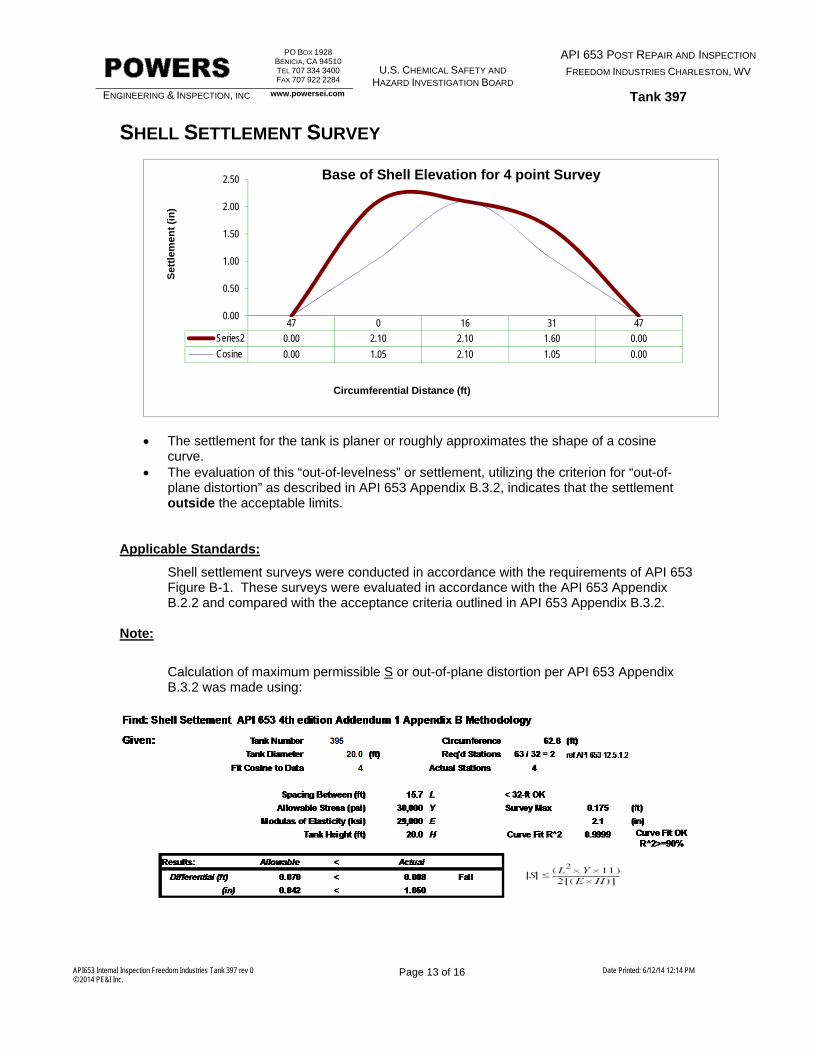
SHELL SETTLEMENT SURVEY
The settlement for the tank is planer or roughly approximates the shape of a cosine
curve. The evaluation of this “out-of-levelness” or settlement, utilizing the criterion for “out-of-
plane distortion” as described in API 653 Appendix B.3.2, indicates that the settlement outside the acceptable limits.
Applicable Standards:
Shell settlement surveys were conducted in accordance with the requirements of API 653 Figure B-1. These surveys were evaluated in accordance with the API 653 Appendix B.2.2 and compared with the acceptance criteria outlined in API 653 Appendix B.3.2.
Note:
Calculation of maximum permissible S or out-of-plane distortion per API 653 Appendix B.3.2 was made using:
47 0 16 31 47
Series2 0.00 2.10 2.10 1.60 0.00
Cosine 0.00 1.05 2.10 1.05 0.00
0.00
0.50
1.00
1.50
2.00
2.50S
ettl
emen
t (i
n)
Circumferential Distance (ft)
Base of Shell Elevation for 4 point Survey
PO BOX 1928 BENICIA, CA 94510 TEL 707 334 3400 FAX 707 922 2284
U.S. CHEMICAL SAFETY AND
HAZARD INVESTIGATION BOARD
API 653 POST REPAIR AND INSPECTION FREEDOM INDUSTRIES CHARLESTON, WV
ENGINEERING & INSPECTION, INC www.powersei.com Tank 397
API653 Internal Inspection Freedom Industries Tank 397 rev 0 © 2014 PE&I Inc.
Page 14 of 16 Date Printed: 6/12/14 12:14 PM
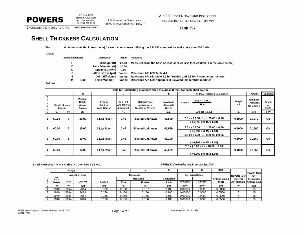
Find: Minimum shell thickness (t min) for each shell course utilizing the API 653 standard for tanks less than 200 ft dia.
Given:Variable Identifier Description Value Reference
H Fill height (ft) 20.00 Measured from the base of each shell course (see column H in the table below)D Tank Diameter (ft) 20.00G Specific Gravity 0.96S Allow stress (psi) Varies Reference API 653 Table 4-1E Joint Efficiency Varies Reference API 653 table 4.2 for Welded and 4.3 for Riveted constructionM 1.00 Temp Modifier Varies Reference API 650 Appendix M Elevated temperature modifier
H E S Actual Solution
2.6 ( H - 1) DG
SEM
(in) (ft) (ft) % (psi) (in) (in) OK?
240.00 20.25
Shell Corrosion Rate Calculations API 653 6.3 © POWERS Engineering and Inspection, Inc. 2014
A B N RCA
CalculatedPrev Current As Built Prev Current t min Previous Current
(yr) (yr) (yr) (in) (in) (in) (in) (in/yr) (in/yr) (in) (yr) (yr)
1 1940 2014 2014 0.188 0.188 0.187 0.100 0.00000 0.0000 0.0870 5 152 1940 2014 2014 0.156 0.156 0.156 0.100 0.00000 0.0000 0.0560 5 153 1940 2014 2014 0.156 0.156 0.156 0.100 0.00000 0.0000 0.0560 5 154 1940 2014 2014 0.156 0.156 0.156 0.100 0.00000 0.0000 0.0560 5 15
Sum
RCA/4N Next External
API 653 6.3.2
RCA/2N Next UT
InspectionAPI 653 6.3.3
Date(s)
YearBuilt or
Replaced
Inspection Year Thickness
Measured
Corrosion Rate(s)
API 653 6.3.2.1(A-B)
Co
urs
e
0.1000 0.1560 Ok( 46,209 x 0.45 x 1.00)
2.6 x ( 5.00 - 1 ) x 20.00 x 0.960.1000 0.1560 Ok
( 46,209 x 0.45 x 1.00)
2.6 x ( 10.00 - 1 ) x 20.00 x 0.9646,209
46,209
1 Lap Rivet
1 Lap Rivet
0.45 Riveted Unknown
0.45 Riveted Unknown5
5 10.00
5.00
3
4
60.00
60.00
1 Lap Rivet 0.45 Riveted Unknown 41,999 0.1000 0.1560 Ok
1 60.00 5 20.00 1 Lap Rivet 0.45 Riveted Unknown 41,999 2.6 x ( 20.00 - 1 ) x 20.00 x 0.96( 41,999 x 0.45 x 1.00)
0.1000 0.1870 Ok
2.6 x ( 15.00 - 1 ) x 20.00 x 0.96( 41,999 x 0.45 x 1.00)
2 60.00
Type of Joint for
each Course
Joint EffAPI 653 Tbl 4.2 and 4.3
Material Typeor Unknown
Welded or Riveted
Solution:
Table for Calculating minimum shell thickness (t min) for each shell course
Product Height Above Course
Maximum Allowable
Stress
t min =Req'dt min
API 653 Required Calculation
ActualVs
Req'd
Course
Height of each Course
API 653 4.3.3.1
MinimumThicknessfor Course
5 15.00
SHELL THICKNESS CALCULATION
PO BOX 1928 BENICIA, CA 94510 TEL 707 334 3400 FAX 707 922 2284
U.S. CHEMICAL SAFETY AND
HAZARD INVESTIGATION BOARD
API 653 POST REPAIR AND INSPECTION FREEDOM INDUSTRIES CHARLESTON, WV
ENGINEERING & INSPECTION, INC www.powersei.com Tank 397
API653 Internal Inspection Freedom Industries Tank 397 rev 0 © 2014 PE&I Inc.
Page 15 of 16 Date Printed: 6/12/14 12:14 PM
SHELL ROLLOUT VIEW
3-IN
SU
CT
ION
RIV
ET
ED
/WE
LDE
D T
HR
EA
DE
D c
l: 9
LAP
WE
LDE
D P
LAT
E 1
0X 7
PLA
TE
INW
ARD SHELL
DIS
TORTION S
TART
INW
ARD SHEL
L DIS
TORTION E
ND
INW
ARD SHELL
DIS
TORTION
NUT BOTTOM O
F 4T
H COURSE
ISOLA
TED SHELL
PIT
TING 0
.12
DEEP
CH
AN
NE
L W
ELD
ED
TO
SH
ELL
cl:
48
ISOLA
TED SHELL
PIT
TING 0
.12
DEEP
3-IN
OV
ER
FLO
W P
IPIN
G c
l: 21
7.5
Rpd
: 24h
X 3
wIN
TE
RN
AL
PIP
ING
OP
EN
3FT
FR
OM
TA
NK
BO
TT
OM
2-IN
WD
O R
IVE
TE
D/W
ELD
ED
TH
RE
AD
ED
cl:
7
ABONDONED FF
PIPIN
G
W F
LAME A
RRESTOR
3-IN
OCECO P
VV
3-IN
OVERFL
OW
1 LAP ROW RIVETED0.19-IN NOMINAL 1ST COURSE
WELDED OUTSIDE ONLY
1 LAP ROW RIVETED0.16-IN NOMINAL 2ND COURSE
WELDED OUTSIDE ONLY
1 LAP ROW RIVETED0.16-IN NOMINAL 4TH COURSE
WELDED OUTSIDE ONLY
1 LAP ROW RIVETED0.16-IN NOMINAL 3RD COURSE
WELDED OUTSIDE ONLY
CATWALK
2 1/2
-IN R
IVETED
TOP ANGLE
INW
ARD
ABANDONED BRACKET
ABANDONED BRACKET
DOOR SHEET
DOORSHEET
20-FT
THROUGH OUT S
HELL
COATING F
AILURE P
EELING
PO BOX 1928 BENICIA, CA 94510 TEL 707 334 3400 FAX 707 922 2284
U.S. CHEMICAL SAFETY AND
HAZARD INVESTIGATION BOARD
API 653 POST REPAIR AND INSPECTION FREEDOM INDUSTRIES CHARLESTON, WV
ENGINEERING & INSPECTION, INC www.powersei.com Tank 397
API653 Internal Inspection Freedom Industries Tank 397 rev 0 © 2014 PE&I Inc.
Page 16 of 16 Date Printed: 6/12/14 12:14 PM
CONE ROOF LAYOUT
20-INMANWAY
3-IN OCECO FA& PVV
4-IN NOZZLE W/1-IN BRACE
4-IN TO 3-INOPEN DOWNNOZZLE
CATWALK
8-INGAUGEHATCH
3-INPLUG2-INNIPPLE& CAP
COATING FAILURE,CRACKING, PEELINGRUSTING & STAININGALONG ROOF DECK &APPURTENANCES
ROOF PLATES -SINGLE LAP RIVETED
APPENDIX A API 653 CHECKLIST
ENGINEERING & INSPECTION, INC
P.O. BOX 1928 BENICIA, CA 94510TEL 707 334 3400 FAX 707 922 2284
API 653 Inspection Checklist
Freedom Industries
Charleston, WV
Tank: 397
WWW.POWERSEI.COM
POWERS
Wednesday, June 11, 2014
Appendix A Page 1 of 14
© 2008 PE&I, Inc API 653 Appendix C Checklist
ENGINEERING & INSPECTION, INC
P.O. BOX 1928 BENICIA, CA 94510TEL 707 748 0540 FAX 707 922 2284
API 653 Inspection Checklist
Freedom Industries
Charleston, WV
Tank: 397
WWW.POWERSEI.COM
POWERS1.1 FOUNDATION
1.1.0 AllSee Report 1.0-in overall out-of-level
C.1.1 Measure foundation levelness and bottom elevations (see Appendix B for extent of measurements).
1
1.1.1 Concrete RingFoundation type undetermined.C.1.1.1.a Inspect for broken concrete, spalling, and cracks, particularly under backup bars used in welding
butt welded annular rings under the shell.2
N/AC.1.1.1.b Inspect drain openings in ring, back of waterdraw basins and top surface of ring for indications of bottom leakage.
3
Visually AcceptableC.1.1.1c Inspect for cavities under foundation and vegetation against bottom of tank.4
rain water drains towards base of shell and tank bottom
C.1.1.1d Check that runoff rainwater from the shell drains away from tank.5
no obvious indications of settlement observed
C.1.1.1e Check for settlement around perimeter of tank.6
1.1.2 AsphaltN/AC.1.1.2.a Check for settling of tank into asphalt base which would direct runoff rain water under the tank
instead of away from it.7
N/AC.1.1.2.b Look for areas where leaching of oil has left rock filler exposed, which indicates hydrocarbon leakage.
8
1.1.3 Oiled Dirt or Sandthe concrete containment around the perimeter of the tank slopes towards the base of the shell . . Inspectors opinion that condition is asbuilt and not from settlement
C.1.1.3.a Check for settlement into the base which would direct runoff rain water under the tank rather than away from it.
9
1.1.4 RockNo access at time of the inspection however coupons to be recovered when tank is removed.
C.1.1.4.a Presence of crushed rock under the steel bottom usually results in severe underside corrosion. Make a note to do additional bottom plate examination (ultrasonic, hammer testing, or turning of coupons) when the tank is out of service.
10
1.1.5 Site Drainagesite drains towards tankC.1.1.5.a Check site for drainage away from the tank and associated piping and manifolds.11
NOT PERFORMEDC.1.1.5.b Check operating condition of the dike drains.12
1.1.6 HousekeepingVisually AcceptableC.1.1.6.a Inspect the area for buildup of trash, vegetation, and other inflammables buildup.13
1.2 SHELLS
1.2.1 External Visual InspectionIsolated areas of failure and active corrosion. (see photos and report
C.1.2.1.a Visually inspect for paint failures, pitting, and corrosion.14
the bottom extension was visually inspected
C.1.2.1.b Clean off the bottom angle area and inspect for corrosion and thinning on plate and weld.15
no seal present . .C.1.2.1.c Inspect the bottom-to-foundation seal, if any.16
1.2.2 Internal (Floating Roof Tank)N/AC.1.2.2.a Visually inspect for grooving, corrosion, pitting, and coating failures.17
1.2.3 Riveted Shell InspectionVisually AcceptableC.1.2.3.a Inspect external surface for rivet and seam leaks18
None identified, however when tank is filled inspector expects some seeps would be present
C.1.2.3.b Locate leaks by sketch or photo (location will be lost when shell is abrasive cleaned for painting).19
some corrosion loss was observed (see photos)
C.1.2.3.c Inspect rivets for corrosion loss and wear20
OkC.1.2.3.d Inspect vertical seams to see if they have been full fillet lap welded to increase joint efficiency21
shell and roof are single rivet row lap construction (see photos)
C.1.2.3.e If no record exists of vertical riveted seams, dimension and sketch (or photograph) the rivet pattern: number of rows, rivet size, pitch length, and note whether the joint is butt riveted or lap riveted.
22
Wednesday, June 11, 2014
Appendix A Page 2 of 14
© 2008 PE&I, Inc API 653 Appendix C Checklist
ENGINEERING & INSPECTION, INC
P.O. BOX 1928 BENICIA, CA 94510TEL 707 748 0540 FAX 707 922 2284
API 653 Inspection Checklist
Freedom Industries
Charleston, WV
Tank: 397
WWW.POWERSEI.COM
POWERS1.2.4 Wind Girder (Floating Roof Tanks)
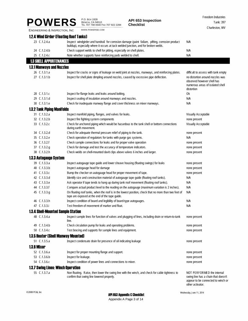
N/AC.1.2.4.a Inspect windgirder and handraiI for corrosion damage (paint faiIure, pifting, corrosion product buildup), especially where it occurs at tack welded junction, and for broken welds.
23
N/AC.1.2.4.b Check support welds to shell for pitting, especially on shell plates.24
N/AC.1.2.4.c Note whether supports have reinforcing pads welded to shell.25
1.3 SHELL APPURTENANCES1.3.1 Manways and Nozzles
difficult to assess with tank emptyC.1.3.1.a Inspect for cracks or signs of leakage on weld joint at nozzles, manways, and reinforcing plates.26
no distortion around nozzles was observed however shell has numerous areas of isolated shell distortion
C.1.3.1.b Inspect for shell plate dimpling around nozzles, caused by excessive pipe deflection.27
OkC.1.3.1.c Inspect for flange leaks and leaks around bolting.28
N/AC.1.3.1.d Inspect sealing of insulation around manways and nozzles.29
N/AC.1.3.1.e Check for inadequate manway flange and cover thickness on mixer manways.30
1.3.2 Tank Piping ManifoldsVisually AcceptableC.1.3.2.a Inspect manifold piping, flanges, and valves for leaks.31
none presentC.1.3.2.b Inspect fire fighting system components32
Visually AcceptableC.1.3.2.c Check for anchored piping which would be hazardous to the tank shell or bottom connections during earth movement.
33
none presentC.1.3.2.d Check for adequate thermal pressure relief of piping to the tank.34
N/AC.1.3.2.e Check operation of regulators for tanks with purge gas systems.35
none presentC.1.3.2.f Check sample connections for leaks and for proper valve operation36
none presentC.1.3.2.g Check for damage and test the accuracy of temperature indicators.37
none presentC.1.3.2.h Check welds on shell-mounted davit clips above valves 6 inches and larger.38
1.3.3 Autogauge Systemnone presentC.1.3.3.a Inspect autogauge tape guide and lower sheave housing (floating swings) for leaks39
none presentC.1.3.3.b Inspect autogauge head for damage40
none presentC.1.3.3.c Bump the checker on autogauge head for proper movement of tape.41
N/AC.1.3.3.d Identify size and construction material of autogauge tape guide (floating roof tanks).42
N/AC.1.3.3.e Ask operator if tape tends to hang up during tank roof movement (floating roof tanks).43
N/AC.1.3.3.f Compare actual product level to the reading on the autogauge (maximum variation is 2 inches).44
N/AC.1.3.3.g On floating roof tanks, when the roof is in the lowest position, check that no more than two feet of tape are exposed at the end of the tape guide.
45
N/AC.1.3.3.h Inspect condition of board and legibility of board-type autogauges.46
N/AC.1.3.3.i Test freedom of movement of marker and float.47
1.3.4 Shell-Mounted Sample Stationnone presentC.1.3.4.a Inspect sample lines for function of valves and plugging of lines, including drain or return-to-tank
line.48
none presentC.1.3.4.b Check circulation pump for leaks and operating problems.49
none presentC.1.3.4.c Test bracing and supports for sample lines and equipment.50
1.3.5 Heater (Shell Manway Mounted)none presentC.1.3.5.a Inspect condensate drain for presence of oil indicating leakage51
1.3.6 Mixernone presentC.1.3.6.a Inspect for proper mounting flange and support.52
none presentC.1.3.6.b Inspect for leakage.53
none presentC.1.3.6.c Inspect condition of power lines and connections to mixer.54
1.3.7 Swing Lines: Winch OperationNOT PERFORMED the internal swing line has a chain that doesn't appear to be connected to winch or other activator.
C.1.3.7.a Non floating. Raise, then lower the swing line with the winch, and check for cable tightness to confirm that swing line lowered properly.
55
Wednesday, June 11, 2014
Appendix A Page 3 of 14
© 2008 PE&I, Inc API 653 Appendix C Checklist
ENGINEERING & INSPECTION, INC
P.O. BOX 1928 BENICIA, CA 94510TEL 707 748 0540 FAX 707 922 2284
API 653 Inspection Checklist
Freedom Industries
Charleston, WV
Tank: 397
WWW.POWERSEI.COM
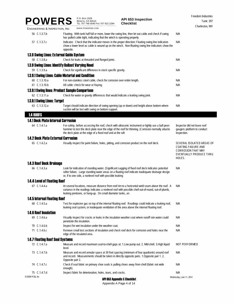
POWERSN/AC.1.3.7.b Floating. With tank half full or more, lower the swing line, then let out cable and check if swing
has pulled cable tight, indicating that the winch is operating properly.56
N/AC.1.3.7.c Indicator. Check that the indicator moves in the proper direction: Floating swing line indicators show a lower level as cable is wound up on the winch. Non-floating swing line indicators show the opposite.
57
1.3.8 Swing Lines: External Guide SystemN/AC.1.3.8.a Check for leaks at threaded and flanged joints.58
1.3.9 Swing Lines: Identify Ballast Varying NeedN/AC.1.3.9.a Check for significant difference in stock specific gravity.59
1.3.9.1 Swing Lines: Cable Material and ConditionN/AC.1.3.10.a For non-stainless steel cable, check for corrosion over entire length.60
N/AC.1.3.10.b All cable: check for wear or fraying.61
1.3.9.1 Swing lines: Product Sample ComparisonN/AC.1.3.11.a Check for water or gravity differences that would indicate a leaking swing joint.62
1.3.9.1 Swing Lines: TargetN/AC.1.3.12.a Target should indicate direction of swing opening (up or down) and height above bottom where
suction will be lost with swing on bottom support.63
1.4 ROOFS1.4.1 Deck Plate Internal Corrosion
Inspector did not leave roof gaugers platform to conduct inspection.
C.1.4.1.a For safety, before accessing the roof, check with ultrasonic instrument or lightly use a ball peen hammer to test the deck plate near the edge of the roof for thinning. (Corrosion normally attacks the deck plate at the edge of a fixed roof and at the raft
64
1.4.2 Deck Plate External CorrosionSEVERAL ISOLATED AREAS OF COATING FAILURE AND CORROSION THAT MAY EVENTUALLY PRODUCE THRU HOLES.
C.1.4.2.a Visually inspect for paint failure, holes, pitting, and corrosion product on the roof deck.65
1.4.3 Roof Deck DrainageN/AC.1.4.3.a Look for indication of standing water. (Significant sagging of fixed roof deck indicates potential
rafter failure. Large standing water areas on a floating roof indicate inadequate drainage design or, if to one side, a nonlevel roof with possible leaking
66
1.4.4 Level of Floating RoofN/AC.1.4.4.a At several locations, measure distance from roof rim to a horizontal weld seam above the roof. A
variance in the readings indicates a nonlevel roof with possible shell out-of-round, out-of-plumb, leaking pontoons, or hang-up. On small diameter tanks, an
67
1.4.5 Internal Floating RoofN/AC.1.4.5.a Test for explosive gas on top of the internal floating roof. Readings could indicate a leaking roof,
leaking seal system, or inadequate ventilation of the area above the internal floating roof.68
1.4.6 Roof InsulationN/AC.1.4.6.a Visually inspect for cracks or leaks in the insulation weather coat where runoff rain water could
penetrate the insulation.69
N/AC.1.4.6.b Inspect for wet insulation under the weather coat.70
N/AC.1.4.6.c Remove small test sections of insulation and check roof deck for corrosion and holes near the edge of the insulated area.
71
1.4.7 Floating Roof Seal SystemsNOT PERFORMEDC.1.4.7.a Measure and record maximum seal-to-shell gaps at: 1.Low pump out. 2. Mid-shell. 3.High liquid
level.72
N/AC.1.4.7.b Measure and record annular space at 30 foot spacing (minimum of four quadrants) around roof and record. Measurements should be taken in directly opposite pairs. 1.Opposite pair 1. 2. Opposite pair 2.
73
N/AC.1.4.7.c Check if seal fabric on primary shoe seals is pulling shoes away from shell (fabric not wide enough).
74
N/AC.1.4.7.d Inspect fabric for deterioration, holes, tears, and cracks.75Wednesday, June 11, 2014
Appendix A Page 4 of 14
© 2008 PE&I, Inc API 653 Appendix C Checklist
ENGINEERING & INSPECTION, INC
P.O. BOX 1928 BENICIA, CA 94510TEL 707 748 0540 FAX 707 922 2284
API 653 Inspection Checklist
Freedom Industries
Charleston, WV
Tank: 397
WWW.POWERSEI.COM
POWERSN/AC.1.4.7.e Inspect visible metallic parts for corrosion and wear.76
N/AC.1.4.7.f Inspect for openings in seals that would permit vapor emissions.77
N/AC.1.4.7.g Inspect for protruding bolt or rivet heads against the shell.78
N/AC.1.4.7.h Pull both primary and secondary seal systems back all around the shell to check their operation.79
N/AC.1.4.7.I Inspect secondary seals for signs of buckling or indications that their angle with the shell is too shallow.
80
N/AC.1.4.7.j Inspect wedge-type wiper seals for flexibility, resilience, cracks, and tears.81
1.5 ROOF APPURTENANCES
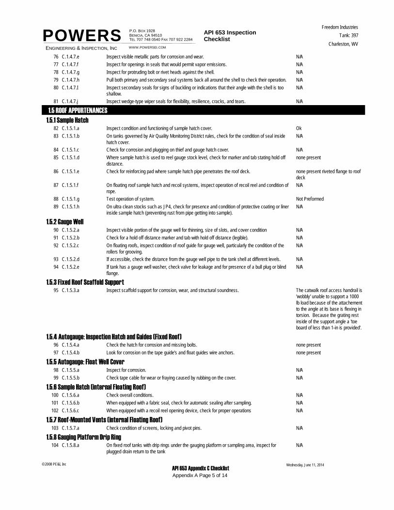
1.5.1 Sample HatchOkC.1.5.1.a Inspect condition and functioning of sample hatch cover.82
N/AC.1.5.1.b On tanks governed by Air Quality Monitoring District rules, check for the condition of seal inside hatch cover.
83
N/AC.1.5.1.c Check for corrosion and plugging on thief and gauge hatch cover.84
none presentC.1.5.1.d Where sample hatch is used to reel gauge stock level, check for marker and tab stating hold off distance.
85
none present riveted flange to roof deck
C.1.5.1.e Check for reinforcing pad where sample hatch pipe penetrates the roof deck.86
N/AC.1.5.1.f On floating roof sample hatch and recoil systems, inspect operation of recoil reel and condition of rope.
87
Not PreformedC.1.5.1.g Test operation of system.88
N/AC.1.5.1.h On ultra clean stocks such as JP4, check for presence and condition of protective coating or liner inside sample hatch (preventing rust from pipe getting into sample).
89
1.5.2 Gauge WellN/AC.1.5.2.a Inspect visible portion of the gauge well for thinning, size of slots, and cover condition90
N/AC.1.5.2.b Check for a hold off distance marker and tab with hold off distance (legible).91
N/AC.1.5.2.c On floating roofs, inspect condition of roof guide for gauge well, particularly the condition of the rollers for grooving.
92
N/AC.1.5.2.d If accessible, check the distance from the gauge well pipe to the tank shell at different levels.93
N/AC.1.5.2.e If tank has a gauge well washer, check valve for leakage and for presence of a bull plug or blind flange.
94
1.5.3 Fixed Roof Scaffold SupportThe catwalk roof access handrail is 'wobbly' unable to support a 1000 lb load because of the attachement to the angle at its base is flexing in torsion. Because the grating rest inside of the support angle a 'toe board of less than 1-in is provided'.
C.1.5.3.a Inspect scaffold support for corrosion, wear, and structural soundness.95
1.5.4 Autogauge: Inspection Hatch and Guides (Fixed Roof)none presentC.1.5.4.a Check the hatch for corrosion and missing bolts.96
none presentC.1.5.4.b Look for corrosion on the tape guide's and float guides wire anchors.97
1.5.5 Autogauge: Float Well CoverN/AC.1.5.5.a Inspect for corrosion.98
N/AC.1.5.5.b Check tape cable for wear or fraying caused by rubbing on the cover.99
1.5.6 Sample Hatch (internal Floating Roof)N/AC.1.5.6.a Check overall conditions.100
N/AC.1.5.6.b When equipped with a fabric seal, check for automatic sealing after sampling.101
N/AC.1.5.6.c When equipped with a recoil reel opening device, check for proper operations102
1.5.7 Roof-Mounted Vents (internal Floating Roof)N/AC.1.5.7.a Check condition of screens, locking and pivot pins.103
1.5.8 Gauging Platform Drip RingN/AC.1.5.8.a On fixed roof tanks with drip rings under the gauging platform or sampling area, inspect for
plugged drain return to the tank104
Wednesday, June 11, 2014
Appendix A Page 5 of 14
© 2008 PE&I, Inc API 653 Appendix C Checklist
ENGINEERING & INSPECTION, INC
P.O. BOX 1928 BENICIA, CA 94510TEL 707 748 0540 FAX 707 922 2284
API 653 Inspection Checklist
Freedom Industries
Charleston, WV
Tank: 397
WWW.POWERSEI.COM
POWERS1.5.9 Emergency Roof Drains
N/AC.1.5.9.a Inspect vapor plugs for emergency drain: that seal fabric discs are slightly smaller than the pipe ID and that fabric seal is above the liquid level.
105
1.5.9.1 Removable Roof Leg RacksN/AC.1.5.10.a Check for leg racks on roof.106
1.5.9.2 Vacuum BreakersN/AC.1.5.11.a Report size, number, and type of vacuum breakers. Inspect vacuum breakers. If high legs are
set, check for setting of mechanical breaker in high leg position.107
1.5.9.3 Rim VentsN/AC.1.5.12.a Check condition of the screen on the rim vent cover.108
N/AC.1.5.12.b Check for plating off or removal of rim vents where jurisdictional rules do not permit removal.109
1.5.9.4 Pontoon Inspection HatchesN/AC.1.5.13.a Open pontoon inspection hatch covers and visually check inside for pontoon leakage.110
N/AC.1.5.13.b Test for explosive gas (an indicator of vapor space leaks).111
N/AC.1.5.13.c If pontoon hatches are equipped with locked down coves, check for vent tubes.Check that vent tubes are not plugged up. Inspect lock down devices for condition and operation
112
1.6 ACCESS STRUCTURES
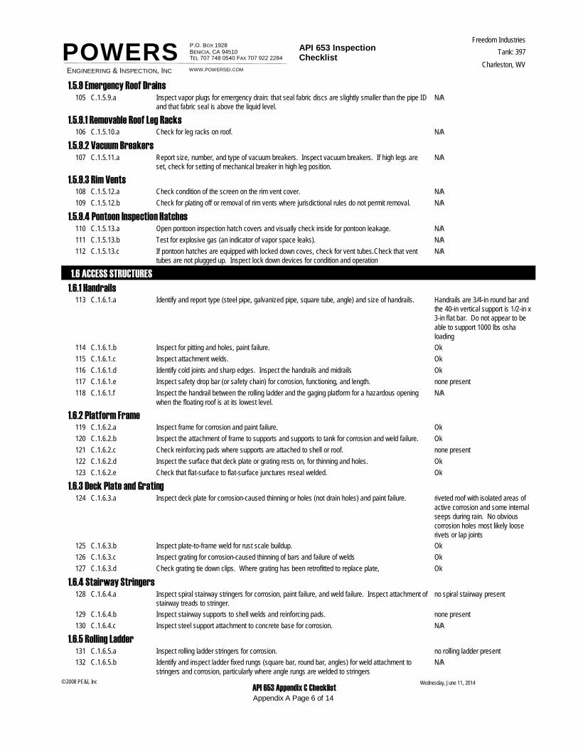
1.6.1 HandrailsHandrails are 3/4-in round bar and the 40-in vertical support is 1/2-in x 3-in flat bar. Do not appear to be able to support 1000 lbs osha loading
C.1.6.1.a Identify and report type (steel pipe, galvanized pipe, square tube, angle) and size of handrails.113
OkC.1.6.1.b Inspect for pitting and holes, paint failure.114
OkC.1.6.1.c Inspect attachment welds.115
OkC.1.6.1.d Identify cold joints and sharp edges. Inspect the handrails and midrails116
none presentC.1.6.1.e Inspect safety drop bar (or safety chain) for corrosion, functioning, and length.117
N/AC.1.6.1.f Inspect the handrail between the rolling ladder and the gaging platform for a hazardous opening when the floating roof is at its lowest level.
118
1.6.2 Platform FrameOkC.1.6.2.a Inspect frame for corrosion and paint failure.119
OkC.1.6.2.b Inspect the attachment of frame to supports and supports to tank for corrosion and weld failure.120
none presentC.1.6.2.c Check reinforcing pads where supports are attached to shell or roof.121
OkC.1.6.2.d Inspect the surface that deck plate or grating rests on, for thinning and holes.122
OkC.1.6.2.e Check that flat-surface to flat-surface junctures reseal welded.123
1.6.3 Deck Plate and Gratingriveted roof with isolated areas of active corrosion and some internal seeps during rain. No obvious corrosion holes most likely loose rivets or lap joints
C.1.6.3.a Inspect deck plate for corrosion-caused thinning or holes (not drain holes) and paint failure.124
OkC.1.6.3.b Inspect plate-to-frame weld for rust scale buildup.125
OkC.1.6.3.c Inspect grating for corrosion-caused thinning of bars and failure of welds126
OkC.1.6.3.d Check grating tie down clips. Where grating has been retrofitted to replace plate,127
1.6.4 Stairway Stringersno spiral stairway presentC.1.6.4.a Inspect spiral stairway stringers for corrosion, paint failure, and weld failure. Inspect attachment of
stairway treads to stringer.128
none presentC.1.6.4.b Inspect stairway supports to shell welds and reinforcing pads.129
N/AC.1.6.4.c Inspect steel support attachment to concrete base for corrosion.130
1.6.5 Rolling Ladderno rolling ladder presentC.1.6.5.a Inspect rolling ladder stringers for corrosion.131
N/AC.1.6.5.b Identify and inspect ladder fixed rungs (square bar, round bar, angles) for weld attachment to stringers and corrosion, particularly where angle rungs are welded to stringers
132
Wednesday, June 11, 2014
Appendix A Page 6 of 14
© 2008 PE&I, Inc API 653 Appendix C Checklist
ENGINEERING & INSPECTION, INC
P.O. BOX 1928 BENICIA, CA 94510TEL 707 748 0540 FAX 707 922 2284
API 653 Inspection Checklist
Freedom Industries
Charleston, WV
Tank: 397
WWW.POWERSEI.COM
POWERSN/AC.1.6.5.c Check for wear and corrosion where rolling ladder attaches to gauging platform.133
N/AC.1.6.5.d Inspect pivot bar for wear and secureness.134
N/AC.1.6.5.e Inspect operation of self-leveling stairway treads.135
N/AC.1.6.5.f Inspect for corrosion and wear on moving parts.136
N/AC.1.6.5.g Inspect rolling ladder wheels for freedom of movement, flat spots, and wear on axle.137
N/AC.1.6.5.h Inspect alignment of rolling ladder with roof rack.138
N/AC.1.6.5.i Inspect top surface of rolling ladder track for wear by wheels to assure at least 18 inches of unworn track (track long enough).
139
N/AC.1.6.5.j Inspect rolling ladder track welds for corrosion.140
N/AC.1.6.5.k Inspect track supports on roof for reinforcing pads seal welded to deck plate.141
N/AC.1.6.5.l Check by dimensioning, the maximum angle of the rolling ladder when the roof is on low legs.142
N/AC.1.6.5.m If rolling ladder track extends to within five feet of the edge of the roof on the far side, check for a handrail on the top of the shell on that side. Max. angle
143
2.10 OVERVIEW
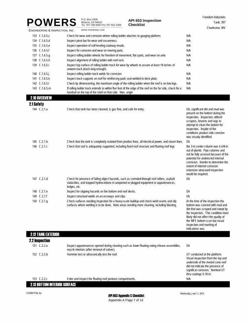
2.1 SafetyOk, significant dirt and mud was present on the bottom during the inspection. Inspectors utilized scrapers, brooms and rags to attempt to clean the bottom for inspeciton. Inspite of the conditions product side corosion was visualy identified.
C.2.1.a Check that tank has been cleaned, is gas free, and safe for entry.144
OkC.2.1.b Check that the tank is completely isolated from product lines, all electrical power, and steam lines.145
the 3-in center column was 6 6/8-in out of plumb. Pipe columns and not be fully assesed because of the potential for undetected internal corrosion. Inorder to determine the extent of internal corrosion extensive utrasound inspection would be required.
C.2.1.c Check that roof is adequately supported, including fixed roof structure and floating roof legs146
OkC.2.1.d Check for presence of failing object hazards, such as corroded-through roof rafters, asphalt stalactites, and trapped hydrocarbons in unopened or plugged equipment or appurtenances, ledges, etc.
147
OkC.2.1.e Inspect for slipping hazards on the bottom and roof decks.148
OkC.2.1.f Inspect structural welds on accessways and clips149
At the time of the inspection the bottom was covered with mud and dirt that was scraped and swept by the inspectors. This condition most likely did not affect the quality of the MFE bottom scan but visual inspection and marking of indications was.
C.2.1.g Check surfaces needing inspection for a heavy-scale buildup and check weld seams and oily surfaces where welding is to be done. Note areas needing more cleaning, including blasting.
150
2.12 TANK EXTERIOR
2.2 InspectionOkC.2.2.a Inspect appurtenances opened during cleaning such as lower floating swing sheave assemblies,
nozzle interiors (after removal of valves).151
UT conducted at the platform. Visual inspection from the top and underside of the riveted cone roof did not indicate the presence of significat corrosion. Nominal UT thru coatings 0.18-in.
C.2.2.b Hammer test or ultrasonically test the roof.152
N/AC.2.2.c Enter and inspect the floating roof pontoon compartments.153
2.13 BOTTOM INTERIOR SURFACE
Wednesday, June 11, 2014
Appendix A Page 7 of 14
© 2008 PE&I, Inc API 653 Appendix C Checklist
ENGINEERING & INSPECTION, INC
P.O. BOX 1928 BENICIA, CA 94510TEL 707 748 0540 FAX 707 922 2284
API 653 Inspection Checklist
Freedom Industries
Charleston, WV
Tank: 397
WWW.POWERSEI.COM
POWERS2.3 Inspection
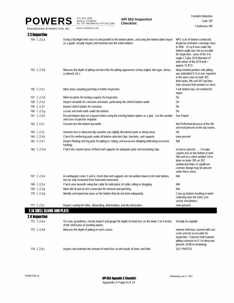
MFE scan of bottom conducted. Inspector estimates coverage close to 90%. 15 sq ft area under the bottom angle was not accessable for inspection. (area of the 3-in angle x 2 plus 20-ft diameter of tank minus of the 20 ft tank = approx 15 ft^2)
C.2.3.a Using a flashlight held close to and parallel to the bottom plates, and using the bottom plate layout as a guide, visually inspect and hammer test the entire bottom.
154
deep isolated product side pitting was indentifed 0.15-in loss reported in the worst area on tank 395. Both tanks 396 and 397 had thru hole corosion from product or stock
C.2.3.b Measure the depth of pitting and describe the pitting appearance (sharp edged, lake type, dense, scattered, etc.)
155
Tank bottom was not marked for repair.
C.2.3.c Mark areas requiring patching or further inspection.156
OkC.2.3.d Mark locations for turning coupons for inspection.157
OkC.2.3.e Inspect all welds for corrosion and leaks, particularly the shell-to-bottom weld.158
OkC.2.3.f Inspect sketch plates for corrosion.159
OkC.2.3.g Locate and mark voids under the bottom.160
See ReportC.2.3.h Record bottom data on a layout sketch using the existing bottom plates as a grid. List the number and sizes of patches required.
161
Not Performed because of the dirt and mud present on the lap seams.
C.2.3.i Vacuum test the bottom lap welds.162
OkC.2.3.j Hammer test or ultrasonically examine any slightly discolored spots or damp areas.163
none presentC.2.3.k Check for reinforcing pads under all bottom attached clips, brackets, and supports164
N/AC.2.3.l Inspect floating roof leg pads for pitting or cutting, and excessive dimpling (indicating excessive loading).
165
no bases present . . . 3-in pipe column rest on the bottom in tank 396 and on a stitch welded 1/4-in plate on tanks 395 an 397. undetected holes or significant corroion damge may be present under these areas.
C.2.3.m Check the column bases of fixed roof supports for adequate pads and restraining clips.166
N/AC.2.3.n In earthquake zones 3 and 4, check that roof supports are not welded down to the tank bottom, but are only restrained from horizontal movement.
167
N/AC.2.3.o Check area beneath swing line cable for indications of cable cutting or dragging.168
N/AC.2.3.p Mark old oil and air test connection for removal and patching.169
Cone up bottom resulting in water collecting near the shell. (see survey and photos)
C.2.3.q Identify and report low areas on the bottom that do not drain adequately.170
none presentC.2.3.r Inspect coating for holes, disbanding, deterioration, and discolorization.171
2.14 SHELL SEAMS AND PLATE
2.4 InspectionVisually AcceptableC.2.4.a On cone up bottoms, closely inspect and gauge the depth of metal loss on the lower 2 to 4 inches
of the shell (area of standing water).172
internal shell was covered with rust scale and not accessable for inspection. External shell isolated pitting corrosion to 0.1-in deep was present. (0.08-in remaining)
C.2.4.b Measure the depth of pitting on each course.173
SEE PHOTOSC.2.4.c Inspect and estimate the amount of metal loss on the heads of rivets and bolts174
Wednesday, June 11, 2014
Appendix A Page 8 of 14
© 2008 PE&I, Inc API 653 Appendix C Checklist
ENGINEERING & INSPECTION, INC
P.O. BOX 1928 BENICIA, CA 94510TEL 707 748 0540 FAX 707 922 2284
API 653 Inspection Checklist
Freedom Industries
Charleston, WV
Tank: 397
WWW.POWERSEI.COM
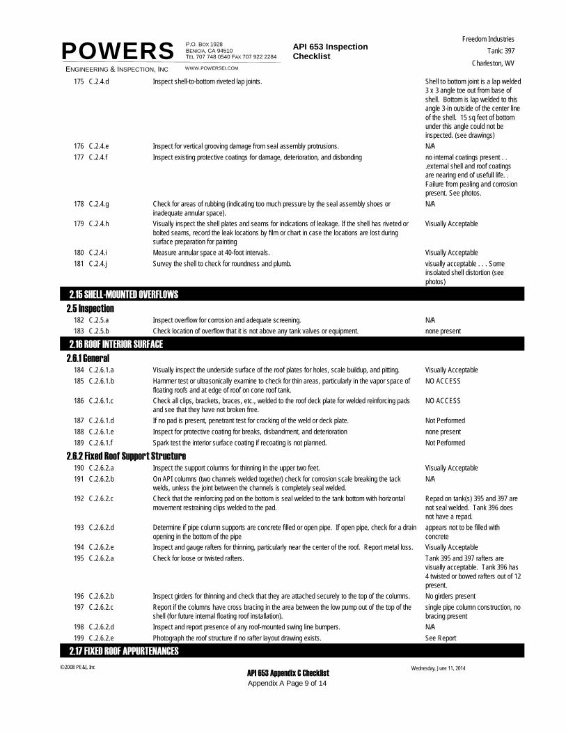
POWERSShell to bottom joint is a lap welded 3 x 3 angle toe out from base of shell. Bottom is lap welded to this angle 3-in outside of the center line of the shell. 15 sq feet of bottom under this angle could not be inspected. (see drawings)
C.2.4.d Inspect shell-to-bottom riveted lap joints.175
N/AC.2.4.e Inspect for vertical grooving damage from seal assembly protrusions.176
no internal coatings present . . .external shell and roof coatings are nearing end of usefull life. . Failure from pealing and corrosion present. See photos.
C.2.4.f Inspect existing protective coatings for damage, deterioration, and disbonding177
N/AC.2.4.g Check for areas of rubbing (indicating too much pressure by the seal assembly shoes or inadequate annular space).
178
Visually AcceptableC.2.4.h Visually inspect the shell plates and seams for indications of leakage. If the shell has riveted or bolted seams, record the leak locations by film or chart in case the locations are lost during surface preparation for painting
179
Visually AcceptableC.2.4.i Measure annular space at 40-foot intervals.180
visually acceptable . . . Some insolated shell distortion (see photos)
C.2.4.j Survey the shell to check for roundness and plumb.181
2.15 SHELL-MOUNTED OVERFLOWS
2.5 InspectionN/AC.2.5.a Inspect overflow for corrosion and adequate screening.182
none presentC.2.5.b Check location of overflow that it is not above any tank valves or equipment.183
2.16 ROOF INTERIOR SURFACE
2.6.1 GeneralVisually AcceptableC.2.6.1.a Visually inspect the underside surface of the roof plates for holes, scale buildup, and pitting.184
NO ACCESSC.2.6.1.b Hammer test or ultrasonically examine to check for thin areas, particularly in the vapor space of floating roofs and at edge of roof on cone roof tank.
185
NO ACCESSC.2.6.1.c Check all clips, brackets, braces, etc., welded to the roof deck plate for welded reinforcing pads and see that they have not broken free.
186
Not PerformedC.2.6.1.d If no pad is present, penetrant test for cracking of the weld or deck plate.187
none presentC.2.6.1.e Inspect for protective coating for breaks, disbandment, and deterioration188
Not PerformedC.2.6.1.f Spark test the interior surface coating if recoating is not planned.189
2.6.2 Fixed Roof Support StructureVisually AcceptableC.2.6.2.a Inspect the support columns for thinning in the upper two feet.190
N/AC.2.6.2.b On API columns (two channels welded together) check for corrosion scale breaking the tack welds, unless the joint between the channels is completely seal welded.
191
Repad on tank(s) 395 and 397 are not seal welded. Tank 396 does not have a repad.
C.2.6.2.c Check that the reinforcing pad on the bottom is seal welded to the tank bottom with horizontal movement restraining clips welded to the pad.
192
appears not to be filled with concrete
C.2.6.2.d Determine if pipe column supports are concrete filled or open pipe. If open pipe, check for a drain opening in the bottom of the pipe
193
Visually AcceptableC.2.6.2.e Inspect and gauge rafters for thinning, particularly near the center of the roof. Report metal loss.194
Tank 395 and 397 rafters are visually acceptable. Tank 396 has 4 twisted or bowed rafters out of 12 present.
C.2.6.2.a Check for loose or twisted rafters.195
No girders presentC.2.6.2.b Inspect girders for thinning and check that they are attached securely to the top of the columns.196
single pipe column construction, no bracing present
C.2.6.2.c Report if the columns have cross bracing in the area between the low pump out of the top of the shell (for future internal floating roof installation).
197
N/AC.2.6.2.d Inspect and report presence of any roof-mounted swing line bumpers.198
See ReportC.2.6.2.e Photograph the roof structure if no rafter layout drawing exists.199
2.17 FIXED ROOF APPURTENANCES
Wednesday, June 11, 2014
Appendix A Page 9 of 14
© 2008 PE&I, Inc API 653 Appendix C Checklist
ENGINEERING & INSPECTION, INC
P.O. BOX 1928 BENICIA, CA 94510TEL 707 748 0540 FAX 707 922 2284
API 653 Inspection Checklist
Freedom Industries
Charleston, WV
Tank: 397
WWW.POWERSEI.COM
POWERS2.7.1 Inspection and Light Hatches
N/AC.2.7.1.a Inspect the hatches for corrosion, paint and coating failures, holes, and cover sealing.200
N/AC.2.7.1.b On loose covers, check for a safety chain in good condition.201
N/AC.2.7.1.c On light hatches over 30 inches across, check for safety rods202
N/AC.2.7.1.d Inspect the condition of the gaskets on bold or latched down hatch covers.203
2.7.2 Staging Support ConnectionN/AC.2.7.2.a Inspect the condition of the staging support for corrosion.204
2.7.3 Breathers and VentsN/AC.2.7.3.a Inspect and service the breather.205
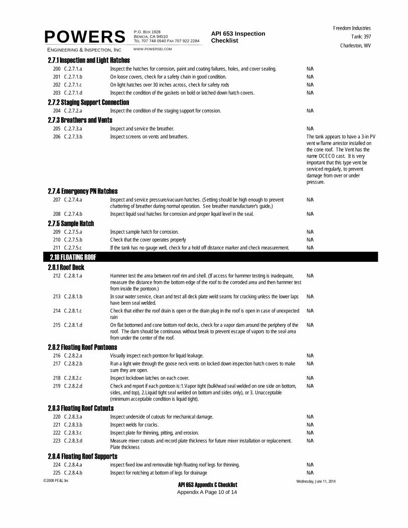
The tank appears to have a 3-in PV vent w flame arrestor installed on the cone roof. The Vent has the name OCECO cast. It is very important that this type vent be serviced regularly, to prevent damage from over or under pressure.
C.2.7.3.b Inspect screens on vents and breathers.206
2.7.4 Emergency PN HatchesN/AC.2.7.4.a Inspect and service pressure/vacuum hatches. (Setting should be high enough to prevent
chattering of breather during normal operation. See breather manufacturer's guide,)207
N/AC.2.7.4.b Inspect liquid seal hatches for corrosion and proper liquid level in the seal.208
2.7.5 Sample HatchN/AC.2.7.5.a Inspect sample hatch for corrosion.209
N/AC.2.7.5.b Check that the cover operates properly210
N/AC.2.7.5.c If the tank has no gauge well, check for a hold off distance marker and check measurement.211
2.18 FLOATING ROOF
2.8.1 Roof DeckN/AC.2.8.1.a Hammer test the area between roof rim and shell. (If access for hammer testing is inadequate,
measure the distance from the bottom edge of the roof to the corroded area and then hammer test from inside the pontoon.)
212
N/AC.2.8.1.b In sour water service, clean and test all deck plate weld seams for cracking unless the lower laps have been seal welded.
213
N/AC.2.8.1.c Check that either the roof drain is open or the drain plug in the roof is open in case of unexpected rain
214
N/AC.2.8.1.d On flat bottomed and cone bottom roof decks, check for a vapor dam around the periphery of the roof. The dam should be continuous without break to prevent escape of vapors to the seal area from under the center of the roof.
215
2.8.2 Floating Roof PontoonsN/AC.2.8.2.a Visually inspect each pontoon for liquid leakage.216
N/AC.2.8.2.b Run a light wire through the goose neck vents on locked down inspection hatch covers to make sure they are open.
217
N/AC.2.8.2.c Inspect lockdown latches on each cover.218
N/AC.2.8.2.d Check and report if each pontoon is:1.Vapor tight (bulkhead seal welded on one side on bottom, sides, and top), 2.Liquid tight seal welded on bottom and sides only), or 3. Unacceptable (minimum acceptable condition is liquid tight).
219
2.8.3 Floating Roof CutoutsN/AC.2.8.3.a Inspect underside of cutouts for mechanical damage.220
N/AC.2.8.3.b Inspect welds for cracks.221
N/AC.2.8.3.c Inspect plate for thinning, pitting, and erosion.222
N/AC.2.8.3.d Measure mixer cutouts and record plate thickness for future mixer installation or replacement. Plate thickness
223
2.8.4 Floating Roof SupportsN/AC.2.8.4.a inspect fixed low and removable high floating roof legs for thinning.224
N/AC.2.8.4.b Inspect for notching at bottom of legs for drainage225
Wednesday, June 11, 2014
Appendix A Page 10 of 14
© 2008 PE&I, Inc API 653 Appendix C Checklist
ENGINEERING & INSPECTION, INC
P.O. BOX 1928 BENICIA, CA 94510TEL 707 748 0540 FAX 707 922 2284
API 653 Inspection Checklist
Freedom Industries
Charleston, WV
Tank: 397
WWW.POWERSEI.COM
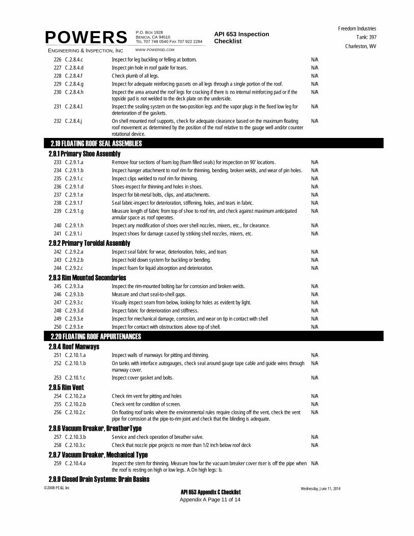
POWERSN/AC.2.8.4.c Inspect for leg buckling or felling at bottom.226
N/AC.2.8.4.d Inspect pin hole in roof guide for tears.227
N/AC.2.8.4.f Check plumb of all legs.228
N/AC.2.8.4.g Inspect for adequate reinforcing gussets on all legs through a single portion of the roof.229
N/AC.2.8.4.h Inspect the area around the roof legs for cracking if there is no internal reinforcing pad or if the topside pad is not welded to the deck plate on the underside.
230
N/AC.2.8.4.I Inspect the sealing system on the two-position legs and the vapor plugs in the fixed low leg for deterioration of the gaskets.
231
N/AC.2.8.4.j On shell mounted roof supports, check for adequate clearance based on the maximum floating roof movement as determined by the position of the roof relative to the gauge well and/or counter rotational device.
232
2.19 FLOATING ROOF SEAL ASSEMBLIES
2.9.1 Primary Shoe AssemblyN/AC.2.9.1.a Remove four sections of foam log (foam filled seals) for inspection on 90' locations.233
N/AC.2.9.1.b Inspect hanger attachment to roof rim for thinning, bending, broken welds, and wear of pin holes.234
N/AC.2.9.1.c Inspect clips welded to roof rim for thinning.235
N/AC.2.9.1.d Shoes-inspect for thinning and holes in shoes.236
N/AC.2.9.1.e Inspect for bit-metal bolts, clips, and attachments.237
N/AC.2.9.1.f Seal fabric-inspect for deterioration, stiffening, holes, and tears in fabric.238
N/AC.2.9.1.g Measure length of fabric from top of shoe to roof rim, and check against maximum anticipated annular space as roof operates.
239
N/AC.2.9.1.h Inspect any modification of shoes over shell nozzles, mixers, etc., for clearance.240
N/AC.2.9.1.i Inspect shoes for damage caused by striking shell nozzles, mixers, etc.241
2.9.2 Primary Toroidal AssemblyN/AC.2.9.2.a Inspect seal fabric for wear, deterioration, holes, and tears242
N/AC.2.9.2.b Inspect hold down system for buckling or bending.243
N/AC.2.9.2.c Inspect foam for liquid absorption and deterioration.244
2.9.3 Rim Mounted SecondariesN/AC.2.9.3.a Inspect the rim-mounted bolting bar for corrosion and broken welds.245
N/AC.2.9.3.b Measure and chart seal-to-shell gaps.246
N/AC.2.9.3.c Visually inspect seam from below, looking for holes as evident by light.247
N/AC.2.9.3.d Inspect fabric for deterioration and stiffness.248
N/AC.2.9.3.e Inspect for mechanical damage, corrosion, and wear on tip in contact with shell249
N/AC.2.9.3.e Inspect for contact with obstructions above top of shell.250
2.20 FLOATING ROOF APPURTENANCES2.9.4 Roof Manways
N/AC.2.10.1.a Inspect walls of manways for pitting and thinning.251
N/AC.2.10.1.b On tanks with interface autogauges, check seal around gauge tape cable and guide wires through manway cover.
252
N/AC.2.10.1.c Inspect cover gasket and bolts.253
2.9.5 Rim VentN/AC.2.10.2.a Check rim vent for pitting and holes254
N/AC.2.10.2.b Check vent for condition of screen.255
N/AC.2.10.2.c On floating roof tanks where the environmental rules require closing off the vent, check the vent pipe for corrosion at the pipe-to-rim joint and check that the blinding is adequate.
256
2.9.6 Vacuum Breaker, BreatherTypeN/AC.2.10.3.b Service and check operation of breather valve.257
N/AC.2.10.3.c Check that nozzle pipe projects no more than 1/2 inch below roof deck258
2.9.7 Vacuum Breaker, Mechanical TypeN/AC.2.10.4.a Inspect the stem for thinning. Measure how far the vacuum breaker cover riser is off the pipe when
the roof is resting on high or low legs. A.On high legs: b.259
2.9.9 Closed Drain Systems: Drain BasinsWednesday, June 11, 2014
Appendix A Page 11 of 14
© 2008 PE&I, Inc API 653 Appendix C Checklist
ENGINEERING & INSPECTION, INC
P.O. BOX 1928 BENICIA, CA 94510TEL 707 748 0540 FAX 707 922 2284
API 653 Inspection Checklist
Freedom Industries
Charleston, WV
Tank: 397
WWW.POWERSEI.COM
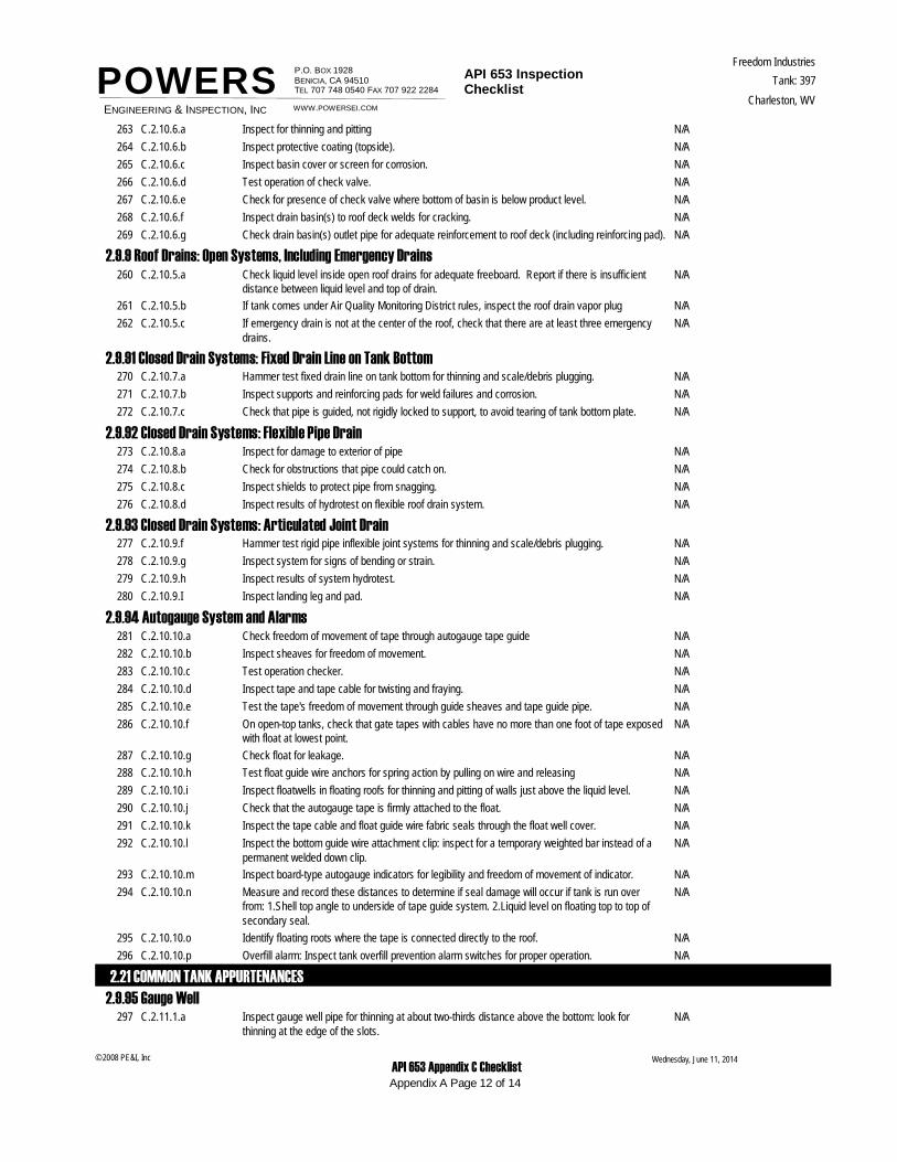
POWERSN/AC.2.10.6.a Inspect for thinning and pitting263
N/AC.2.10.6.b Inspect protective coating (topside).264
N/AC.2.10.6.c Inspect basin cover or screen for corrosion.265
N/AC.2.10.6.d Test operation of check valve.266
N/AC.2.10.6.e Check for presence of check valve where bottom of basin is below product level.267
N/AC.2.10.6.f Inspect drain basin(s) to roof deck welds for cracking.268
N/AC.2.10.6.g Check drain basin(s) outlet pipe for adequate reinforcement to roof deck (including reinforcing pad).269
2.9.9 Roof Drains: Open Systems, Including Emergency DrainsN/AC.2.10.5.a Check liquid level inside open roof drains for adequate freeboard. Report if there is insufficient
distance between liquid level and top of drain.260
N/AC.2.10.5.b If tank comes under Air Quality Monitoring District rules, inspect the roof drain vapor plug261
N/AC.2.10.5.c If emergency drain is not at the center of the roof, check that there are at least three emergency drains.
262
2.9.91 Closed Drain Systems: Fixed Drain Line on Tank BottomN/AC.2.10.7.a Hammer test fixed drain line on tank bottom for thinning and scale/debris plugging.270
N/AC.2.10.7.b Inspect supports and reinforcing pads for weld failures and corrosion.271
N/AC.2.10.7.c Check that pipe is guided, not rigidly locked to support, to avoid tearing of tank bottom plate.272
2.9.92 Closed Drain Systems: Flexible Pipe DrainN/AC.2.10.8.a Inspect for damage to exterior of pipe273
N/AC.2.10.8.b Check for obstructions that pipe could catch on.274
N/AC.2.10.8.c Inspect shields to protect pipe from snagging.275
N/AC.2.10.8.d Inspect results of hydrotest on flexible roof drain system.276
2.9.93 Closed Drain Systems: Articulated Joint DrainN/AC.2.10.9.f Hammer test rigid pipe inflexible joint systems for thinning and scale/debris plugging.277
N/AC.2.10.9.g Inspect system for signs of bending or strain.278
N/AC.2.10.9.h Inspect results of system hydrotest.279
N/AC.2.10.9.I Inspect landing leg and pad.280
2.9.94 Autogauge System and AlarmsN/AC.2.10.10.a Check freedom of movement of tape through autogauge tape guide281
N/AC.2.10.10.b Inspect sheaves for freedom of movement.282
N/AC.2.10.10.c Test operation checker.283
N/AC.2.10.10.d Inspect tape and tape cable for twisting and fraying.284
N/AC.2.10.10.e Test the tape's freedom of movement through guide sheaves and tape guide pipe.285
N/AC.2.10.10.f On open-top tanks, check that gate tapes with cables have no more than one foot of tape exposed with float at lowest point.
286
N/AC.2.10.10.g Check float for leakage.287
N/AC.2.10.10.h Test float guide wire anchors for spring action by pulling on wire and releasing288
N/AC.2.10.10.i Inspect floatwells in floating roofs for thinning and pitting of walls just above the liquid level.289
N/AC.2.10.10.j Check that the autogauge tape is firmly attached to the float.290
N/AC.2.10.10.k Inspect the tape cable and float guide wire fabric seals through the float well cover.291
N/AC.2.10.10.l Inspect the bottom guide wire attachment clip: inspect for a temporary weighted bar instead of a permanent welded down clip.
292
N/AC.2.10.10.m Inspect board-type autogauge indicators for legibility and freedom of movement of indicator.293
N/AC.2.10.10.n Measure and record these distances to determine if seal damage will occur if tank is run over from: 1.Shell top angle to underside of tape guide system. 2.Liquid level on floating top to top of secondary seal.
294
N/AC.2.10.10.o Identify floating roots where the tape is connected directly to the roof.295
N/AC.2.10.10.p Overfill alarm: Inspect tank overfill prevention alarm switches for proper operation.296
2.21 COMMON TANK APPURTENANCES2.9.95 Gauge Well
N/AC.2.11.1.a Inspect gauge well pipe for thinning at about two-thirds distance above the bottom: look for thinning at the edge of the slots.
297
Wednesday, June 11, 2014
Appendix A Page 12 of 14
© 2008 PE&I, Inc API 653 Appendix C Checklist
ENGINEERING & INSPECTION, INC
P.O. BOX 1928 BENICIA, CA 94510TEL 707 748 0540 FAX 707 922 2284
API 653 Inspection Checklist
Freedom Industries
Charleston, WV
Tank: 397
WWW.POWERSEI.COM
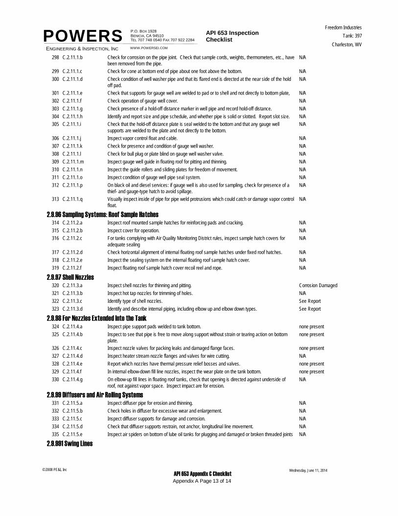
POWERSN/AC.2.11.1.b Check for corrosion on the pipe joint. Check that sample cords, weights, thermometers, etc., have
been removed from the pipe.298
N/AC.2.11.1.c Check for cone at bottom end of pipe about one foot above the bottom.299
N/AC.2.11.1.d Check condition of well washer pipe and that its flared end is directed at the near side of the hold off pad.
300
N/AC.2.11.1.e Check that supports for gauge well are welded to pad or to shell and not directly to bottom plate,301
N/AC.2.11.1.f Check operation of gauge well cover.302
N/AC.2.11.1.g Check presence of a hold-off distance marker in well pipe and record hold-off distance.303
N/AC.2.11.1.h Identify and report size and pipe schedule, and whether pipe is solid or slotted. Report slot size.304
N/AC.2.11.1.i Check that the hold-off distance plate is seal welded to the bottom and that any gauge well supports are welded to the plate and not directly to the bottom.
305
N/AC.2.11.1.j Inspect vapor control float and cable.306
N/AC.2.11.1.k Check for presence and condition of gauge well washer.307
N/AC.2.11.1.l Check for bull plug or plate blind on gauge well washer valve.308
N/AC.2.11.1.m Inspect gauge well guide in floating roof for pitting and thinning.309
N/AC.2.11.1.n Inspect the guide rollers and sliding plates for freedom of movement.310
N/AC.2.11.1.o Inspect condition of gauge well pipe seal system.311
N/AC.2.11.1.p On black oil and diesel services: if gauge well is also used for sampling, check for presence of a thief- and gauge-type hatch to avoid spillage.
312
N/AC.2.11.1.q Visually inspect inside of pipe for pipe weld protrusions which could catch or damage vapor control float.
313
2.9.96 Sampling Systems: Roof Sample HatchesN/AC.2.11.2.a Inspect roof mounted sample hatches for reinforcing pads and cracking.314
N/AC.2.11.2.b Inspect cover for operation.315
N/AC.2.11.2.c For tanks complying with Air Quality Monitoring District rules, inspect sample hatch covers for adequate sealing
316
N/AC.2.11.2.d Check horizontal alignment of internal floating roof sample hatches under fixed roof hatches.317
N/AC.2.11.2.e Inspect the sealing system on the internal floating roof sample hatch cover.318
N/AC.2.11.2.f Inspect floating roof sample hatch cover recoil reel and rope.319
2.9.97 Shell NozzlesCorrosion DamagedC.2.11.3.a Inspect shell nozzles for thinning and pitting.320
N/AC.2.11.3.b Inspect hot tap nozzles for trimming of holes.321
See ReportC.2.11.3.c Identify type of shell nozzles.322
See ReportC.2.11.3.d Identify and describe internal piping, including elbow up and elbow down types.323
2.9.98 For Nozzles Extended Into the Tanknone presentC.2.11.4.a Inspect pipe support pads welded to tank bottom.324
none presentC.2.11.4.b Inspect to see that pipe is free to move along support without strain or tearing action on bottom plate.
325
none presentC.2.11.4.c Inspect nozzle valves for packing leaks and damaged flange faces.326
N/AC.2.11.4.d Inspect heater stream nozzle flanges and valves for wire cutting.327
none presentC.2.11.4.e Report which nozzles have thermal pressure relief bosses and valves.328
none presentC.2.11.4.f In internal elbow-down fill line nozzles, inspect the wear plate on the tank bottom.329
N/AC.2.11.4.g On elbow-up fill lines in floating roof tanks, check that opening is directed against underside of roof, not against vapor space. Inspect impact are for erosion.
330
2.9.99 Diffusers and Air Rolling SystemsN/AC.2.11.5.a Inspect diffuser pipe for erosion and thinning.331
N/AC.2.11.5.b Check holes in diffuser for excessive wear and enlargement.332
N/AC.2.11.5.c Inspect diffuser supports for damage and corrosion.333
N/AC.2.11.5.d Check that diffuser supports restrain, not anchor, longitudinal line movement.334
N/AC.2.11.5.e Inspect air spiders on bottom of lube oil tanks for plugging and damaged or broken threaded joints335
2.9.991 Swing Lines
Wednesday, June 11, 2014
Appendix A Page 13 of 14
© 2008 PE&I, Inc API 653 Appendix C Checklist
ENGINEERING & INSPECTION, INC
P.O. BOX 1928 BENICIA, CA 94510TEL 707 748 0540 FAX 707 922 2284
API 653 Inspection Checklist
Freedom Industries
Charleston, WV
Tank: 397
WWW.POWERSEI.COM
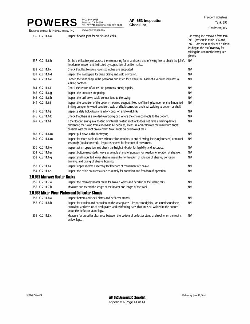
POWERS3-in swing line removed from tank 395. (present in tanks 396 and 397. Both these tanks had a chain leading to the roof manway for raising the upturned elbow.) see photos
C.2.11.6.a Inspect flexible joint for cracks and leaks.336
N/AC.2.11.6.b Scribe the flexible joint across the two moving faces and raise end of swing line to check the joint's freedom of movement, indicated by separation of scribe marks.
337
N/AC.2.11.6.c Check that flexible joints over six inches are supported.338
N/AC.2.11.6.d Inspect the swing pipe for deep pitting and weld corrosion.339
N/AC.2.11.6.e Loosen the vent plugs in the pontoons and listen for a vacuum. Lack of a vacuum indicates a leaking pontoon.
340
N/AC.2.11.6.f Check the results of air test on pontoons during repairs.341
N/AC.2.11.6.g Inspect the pontoons for pitting.342
N/AC.2.11.6.h Inspect the pull-down cable connections to the swing343
N/AC.2.11.6.i Inspect the condition of the bottom-mounted support, fixed roof limiting bumper, or shell mounted limiting bumper for wood condition, weld and bolt corrosion, and seal welding to bottom or shell.
344
N/AC.2.11.6.j Inspect safety hold-down chain for corrosion and weak links.345
N/AC.2.11.6.k Check that there is a welded reinforcing pad where the chain connects to the bottom.346
N/AC.2.11.6.l If the floating swing in a floating or internal floating roof tank does not have a limiting device preventing the swing from exceeding 60 degrees, measure and calculate the maximum angle possible with the roof on overflow. Max. angle on overflow (If the c
347
N/AC.2.11.6.m Inspect pull down cable for fraying.348
N/AC.2.11.6.m Inspect for three cable clamps where cable attaches to end of swing line (singlereeved) or to roof assembly (double-reeved). Inspect sheaves for freedom of movement.
349
N/AC.2.11.6.o Inspect winch operation and check the height indicator for legibility and accuracy.350
N/AC.2.11.6.p Inspect bottom-mounted sheave assembly at end of pontoon for freedom of rotation of sheave.351
N/AC.2.11.6.q Inspect shell-mounted lower sheave assembly for freedom of rotation of sheave, corrosion thinning, and pitting of sheave housing.
352
N/AC.2.11.6.r Inspect upper sheave assembly for freedom of movement of sheave.353
N/AC.2.11.6.s Inspect the cable counterbalance assembly for corrosion and freedom of operation.354
2.9.992 Manway Heater RacksN/AC.2.11.7.a Inspect the manway heater racks for broken welds and bending of the sliding rails.355
N/AC.2.11.7.b Measure and record the length of the heater and length of the track.356
2.9.993 Mixer Wear Plates and Deflector StandsN/AC.2.11.8.a Inspect bottom and shell plates and deflector stands.357
N/AC.2.11.8.b Inspect for erosion and corrosion on the wear plates. Inspect for rigidity, structural soundness, corrosion, and erosion of deck plates and reinforcing pads that are seal welded to the bottom under the deflector stand legs.
358
N/AC.2.11.8.c Measure for propeller clearance between the bottom of deflector stand and roof when the roof is on low legs.
359
Wednesday, June 11, 2014
Appendix A Page 14 of 14
© 2008 PE&I, Inc API 653 Appendix C Checklist
POWERSENGINEERING AND INSPECTION,INC
SIGNIFICANT PHOTOS
FREEDOM INDUSTRIES
TK 397
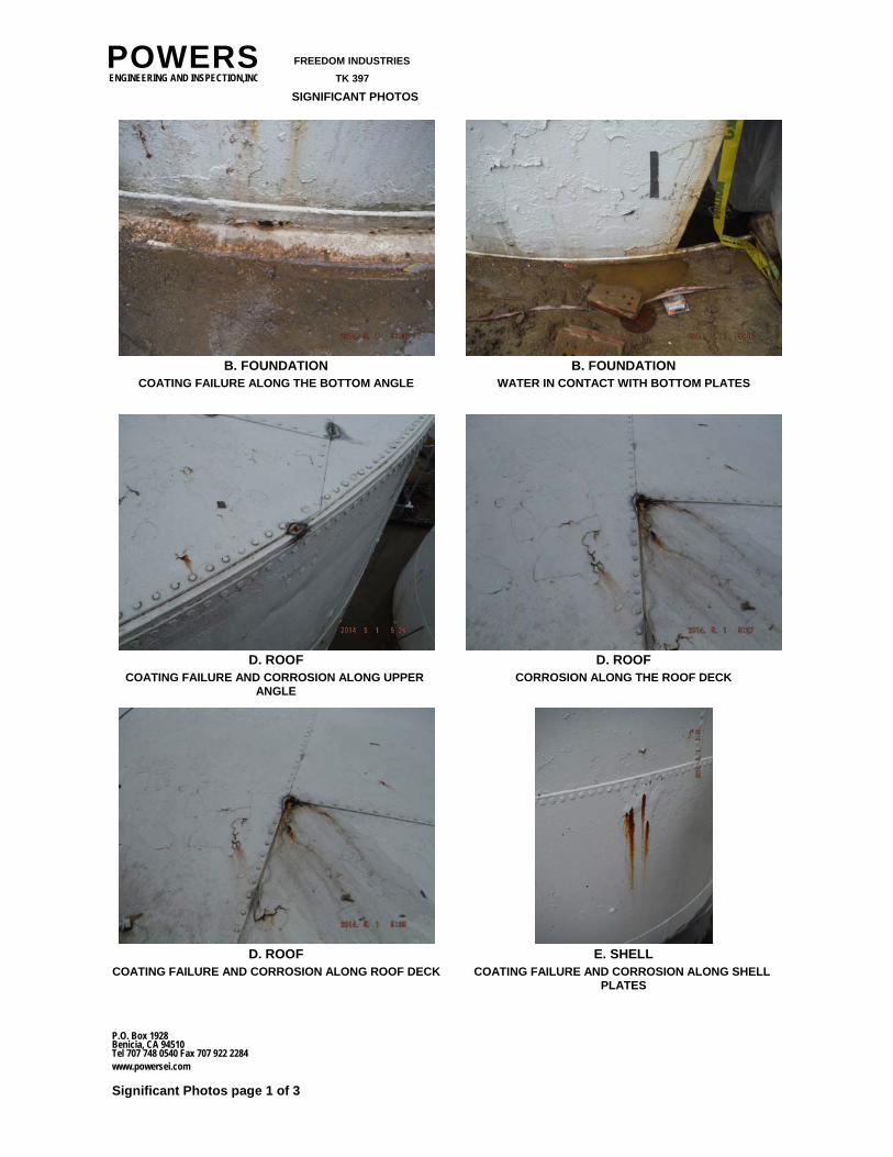
B. FOUNDATIONCOATING FAILURE ALONG THE BOTTOM ANGLE
B. FOUNDATIONWATER IN CONTACT WITH BOTTOM PLATES
D. ROOFCOATING FAILURE AND CORROSION ALONG UPPER
ANGLE
D. ROOFCORROSION ALONG THE ROOF DECK
D. ROOFCOATING FAILURE AND CORROSION ALONG ROOF DECK
E. SHELLCOATING FAILURE AND CORROSION ALONG SHELL
PLATES
Significant Photos page 1 of 3
P.O. Box 1928
www.powersei.com
Benicia, CA 94510Tel 707 748 0540 Fax 707 922 2284
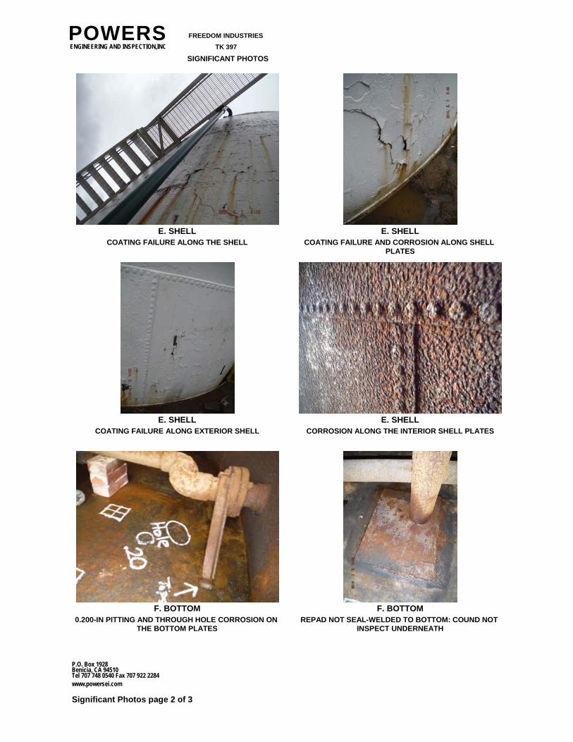
POWERSENGINEERING AND INSPECTION,INC
SIGNIFICANT PHOTOS
FREEDOM INDUSTRIES
TK 397
E. SHELLCOATING FAILURE ALONG THE SHELL
E. SHELLCOATING FAILURE AND CORROSION ALONG SHELL
PLATES
E. SHELLCOATING FAILURE ALONG EXTERIOR SHELL
E. SHELLCORROSION ALONG THE INTERIOR SHELL PLATES
F. BOTTOM0.200-IN PITTING AND THROUGH HOLE CORROSION ON
THE BOTTOM PLATES
F. BOTTOMREPAD NOT SEAL-WELDED TO BOTTOM: COUND NOT
INSPECT UNDERNEATH
Significant Photos page 2 of 3
P.O. Box 1928
www.powersei.com
Benicia, CA 94510Tel 707 748 0540 Fax 707 922 2284
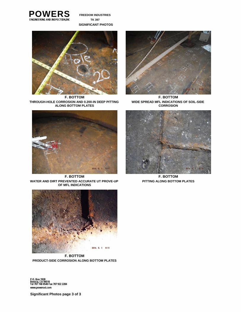
POWERSENGINEERING AND INSPECTION,INC
SIGNIFICANT PHOTOS
FREEDOM INDUSTRIES
TK 397
F. BOTTOMTHROUGH-HOLE CORROSION AND 0.200-IN DEEP PITTING
ALONG BOTTOM PLATES
F. BOTTOMWIDE SPREAD MFL INDICATIONS OF SOIL-SIDE
CORROSION
F. BOTTOMWATER AND DIRT PREVENTED ACCURATE UT PROVE-UP
OF MFL INDICATIONS
F. BOTTOMPITTING ALONG BOTTOM PLATES
F. BOTTOMPRODUCT-SIDE CORROSION ALONG BOTTOM PLATES
Significant Photos page 3 of 3
P.O. Box 1928
www.powersei.com
Benicia, CA 94510Tel 707 748 0540 Fax 707 922 2284
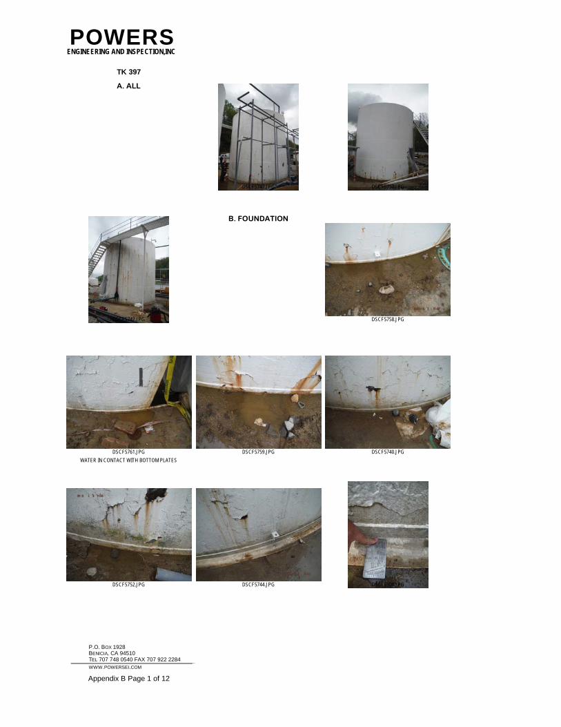
POWERSENGINEERING AND INSPECTION,INC
TK 397
A. ALL
DSCF5747.JPG DSCF5757.JPG
DSCF5742.JPG
B. FOUNDATION
DSCF5758.JPG
WATER IN CONTACT WITH BOTTOM PLATES
DSCF5761.JPG DSCF5759.JPG DSCF5740.JPG
DSCF5752.JPG DSCF5744.JPG DSCF5308.JPG
P.O. BOX 1928 BENICIA, CA 94510 TEL 707 748 0540 FAX 707 922 2284
WWW.POWERSEI.COM Appendix B Page 1 of 12
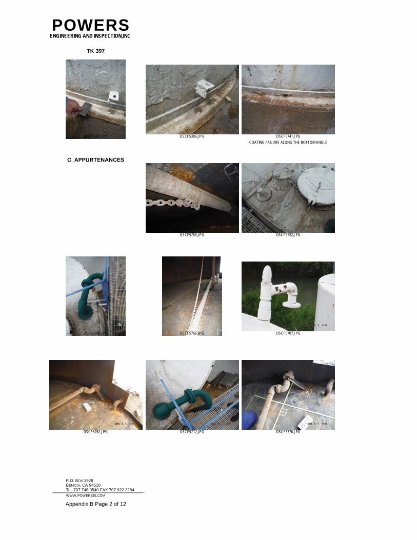
POWERSENGINEERING AND INSPECTION,INC
TK 397
DSCF5307.JPG DSCF5306.JPG
COATING FAILURE ALONG THE BOTTOM ANGLE
DSCF5741.JPG
C. APPURTENANCES
DSCF5789.JPG DSCF5722.JPG
DSCF5703.JPG DSCF5766.JPG DSCF5707.JPG
DSCF5762.JPG DSCF5712.JPG DSCF5776.JPG
P.O. BOX 1928 BENICIA, CA 94510 TEL 707 748 0540 FAX 707 922 2284
WWW.POWERSEI.COM Appendix B Page 2 of 12
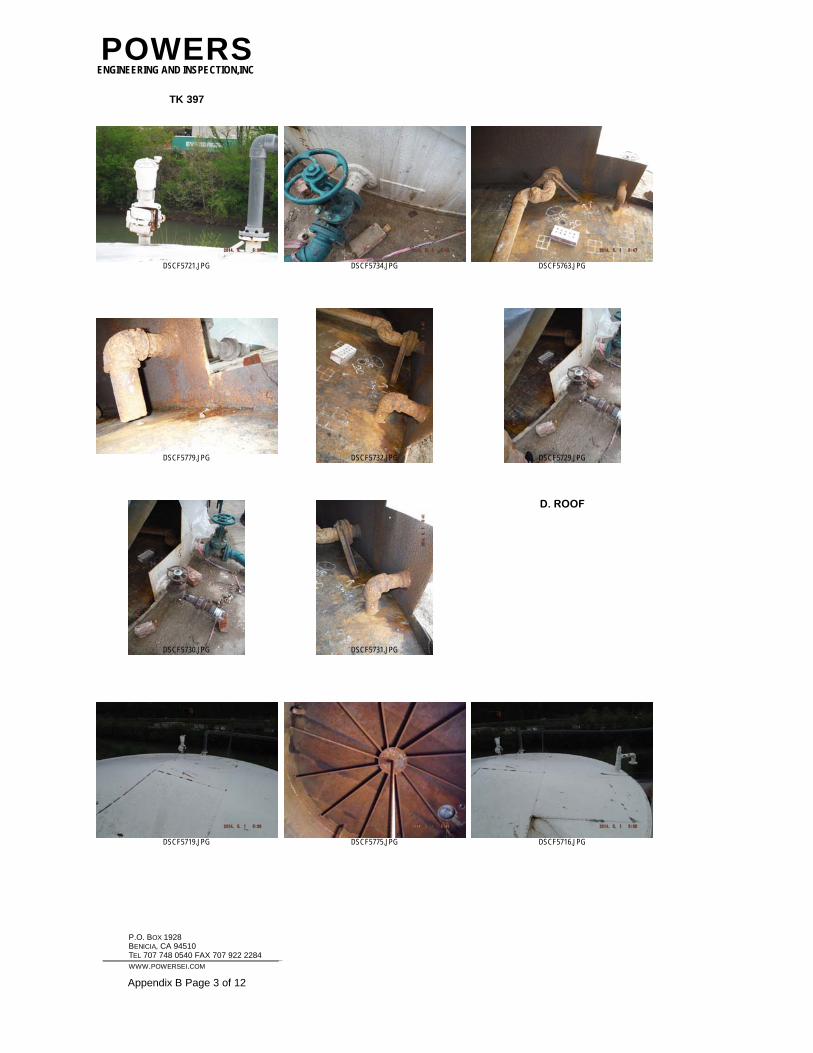
POWERSENGINEERING AND INSPECTION,INC
TK 397
DSCF5721.JPG DSCF5734.JPG DSCF5763.JPG
DSCF5779.JPG DSCF5732.JPG DSCF5729.JPG
DSCF5730.JPG DSCF5731.JPG
D. ROOF
DSCF5719.JPG DSCF5775.JPG DSCF5716.JPG
P.O. BOX 1928 BENICIA, CA 94510 TEL 707 748 0540 FAX 707 922 2284
WWW.POWERSEI.COM Appendix B Page 3 of 12
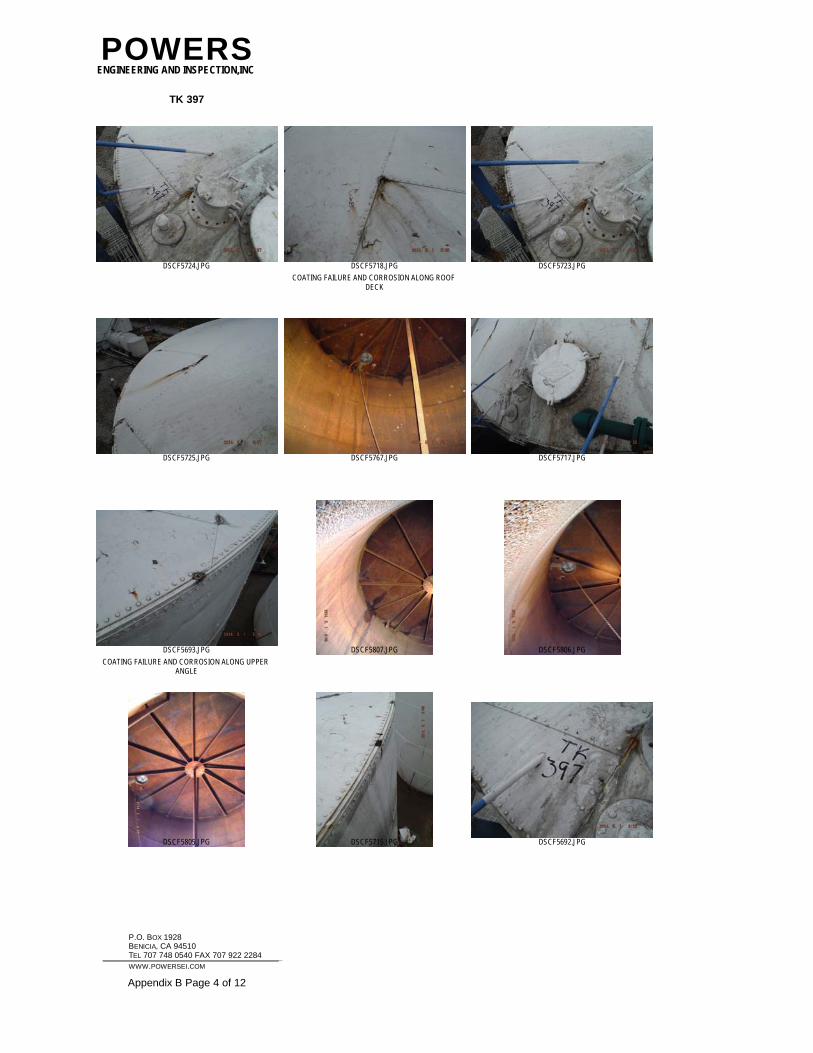
POWERSENGINEERING AND INSPECTION,INC
TK 397
DSCF5724.JPG
COATING FAILURE AND CORROSION ALONG ROOF DECK
DSCF5718.JPG DSCF5723.JPG
DSCF5725.JPG DSCF5767.JPG DSCF5717.JPG
COATING FAILURE AND CORROSION ALONG UPPER ANGLE
DSCF5693.JPG DSCF5807.JPG DSCF5806.JPG
DSCF5805.JPG DSCF5715.JPG DSCF5692.JPG
P.O. BOX 1928 BENICIA, CA 94510 TEL 707 748 0540 FAX 707 922 2284
WWW.POWERSEI.COM Appendix B Page 4 of 12
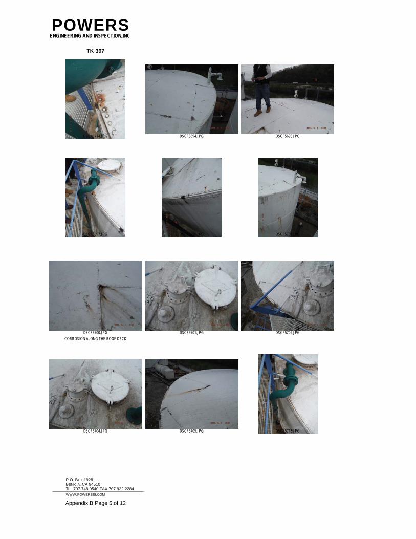
POWERSENGINEERING AND INSPECTION,INC
TK 397
DSCF5714.JPG DSCF5694.JPG DSCF5695.JPG
DSCF5697.JPG DSCF5698.JPG DSCF5709.JPG
CORROSION ALONG THE ROOF DECK
DSCF5700.JPG DSCF5701.JPG DSCF5702.JPG
DSCF5704.JPG DSCF5705.JPG DSCF5713.JPG
P.O. BOX 1928 BENICIA, CA 94510 TEL 707 748 0540 FAX 707 922 2284
WWW.POWERSEI.COM Appendix B Page 5 of 12
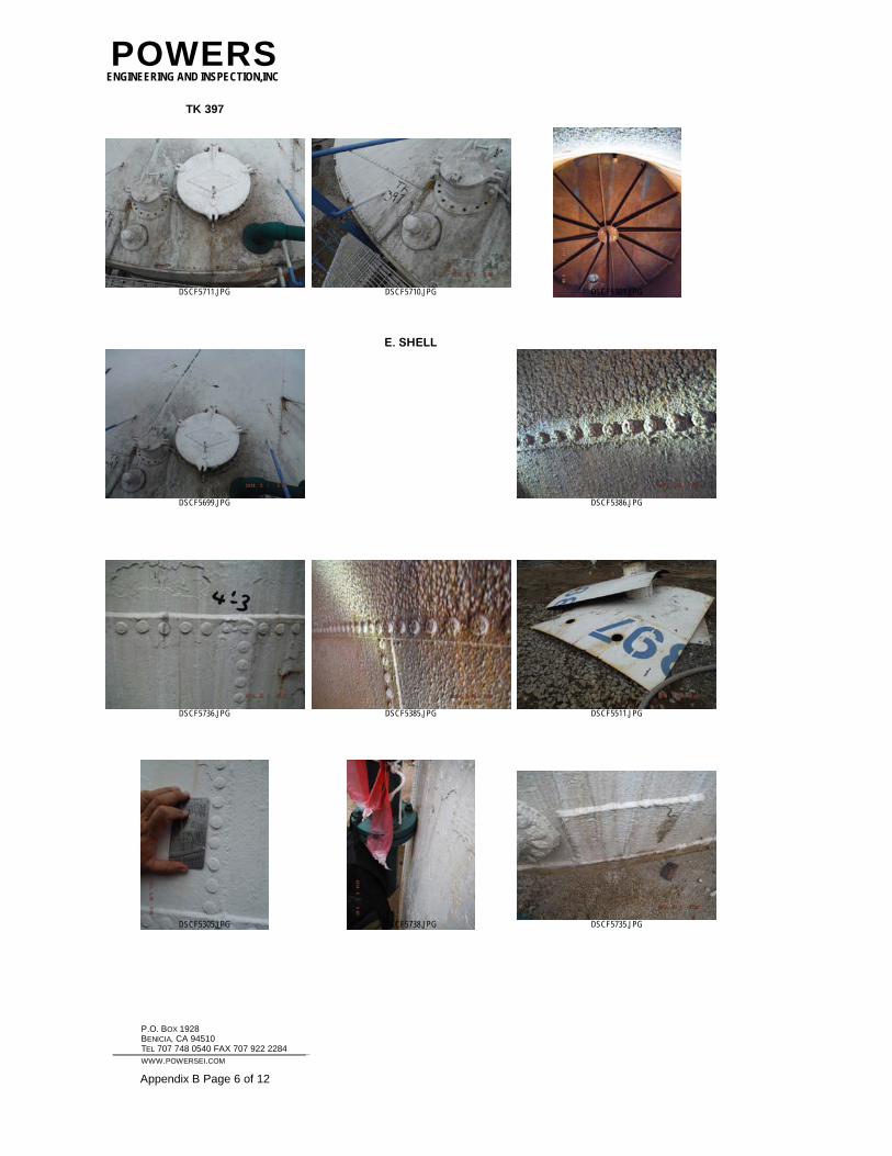
POWERSENGINEERING AND INSPECTION,INC
TK 397
DSCF5711.JPG DSCF5710.JPG DSCF5801.JPG
DSCF5699.JPG
E. SHELL
DSCF5386.JPG
DSCF5736.JPG DSCF5385.JPG DSCF5511.JPG
DSCF5305.JPG DSCF5738.JPG DSCF5735.JPG
P.O. BOX 1928 BENICIA, CA 94510 TEL 707 748 0540 FAX 707 922 2284
WWW.POWERSEI.COM Appendix B Page 6 of 12
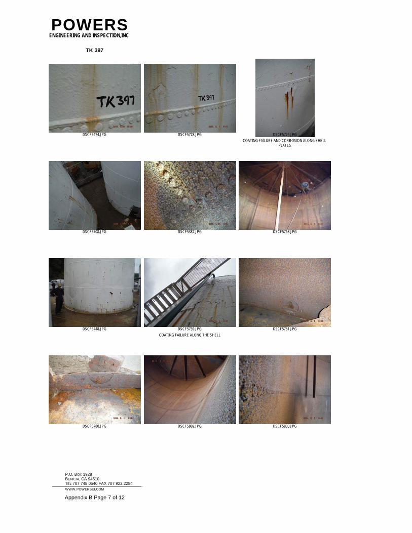
POWERSENGINEERING AND INSPECTION,INC
TK 397
DSCF5474.JPG DSCF5728.JPG
COATING FAILURE AND CORROSION ALONG SHELL PLATES
DSCF5726.JPG
DSCF5708.JPG DSCF5387.JPG DSCF5768.JPG
DSCF5748.JPG
COATING FAILURE ALONG THE SHELL
DSCF5739.JPG DSCF5781.JPG
DSCF5780.JPG DSCF5802.JPG DSCF5803.JPG
P.O. BOX 1928 BENICIA, CA 94510 TEL 707 748 0540 FAX 707 922 2284
WWW.POWERSEI.COM Appendix B Page 7 of 12
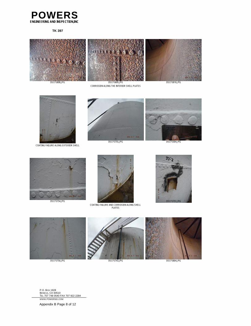
POWERSENGINEERING AND INSPECTION,INC
TK 397
DSCF5808.JPG
CORROSION ALONG THE INTERIOR SHELL PLATES
DSCF5809.JPG DSCF5810.JPG
COATING FAILURE ALONG EXTERIOR SHELL
DSCF5760.JPG DSCF5755.JPG DSCF5304.JPG
DSCF5754.JPG
COATING FAILURE AND CORROSION ALONG SHELL PLATES
DSCF5753.JPG DSCF5751.JPG
DSCF5750.JPG DSCF5743.JPG DSCF5804.JPG
P.O. BOX 1928 BENICIA, CA 94510 TEL 707 748 0540 FAX 707 922 2284
WWW.POWERSEI.COM Appendix B Page 8 of 12
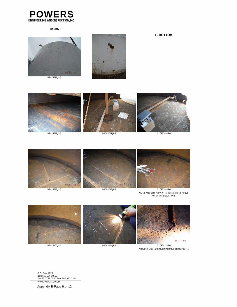
POWERSENGINEERING AND INSPECTION,INC
TK 397
DSCF5746.JPG DSCF5745.JPG
F. BOTTOM
DSCF5793.JPG DSCF5794.JPG DSCF5795.JPG
DSCF5796.JPG DSCF5797.JPG
WATER AND DIRT PREVENTED ACCURATE UT PROVE-UP OF MFL INDICATIONS
DSCF5798.JPG
DSCF5800.JPG DSCF5811.JPG
PRODUCT-SIDE CORROSION ALONG BOTTOM PLATES
DSCF5813.JPG
P.O. BOX 1928 BENICIA, CA 94510 TEL 707 748 0540 FAX 707 922 2284
WWW.POWERSEI.COM Appendix B Page 9 of 12
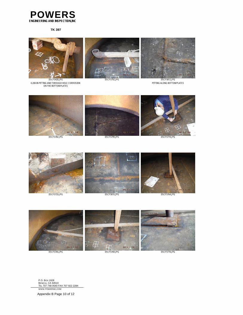
POWERSENGINEERING AND INSPECTION,INC
TK 397
0.200-IN PITTING AND THROUGH HOLE CORROSION ON THE BOTTOM PLATES
DSCF5420.JPG DSCF5792.JPG
PITTING ALONG BOTTOM PLATES
DSCF5812.JPG
DSCF5782.JPG DSCF5799.JPG DSCF5774.JPG
DSCF5733.JPG DSCF5815.JPG DSCF5764.JPG
DSCF5765.JPG DSCF5769.JPG DSCF5770.JPG
P.O. BOX 1928 BENICIA, CA 94510 TEL 707 748 0540 FAX 707 922 2284
WWW.POWERSEI.COM Appendix B Page 10 of 12
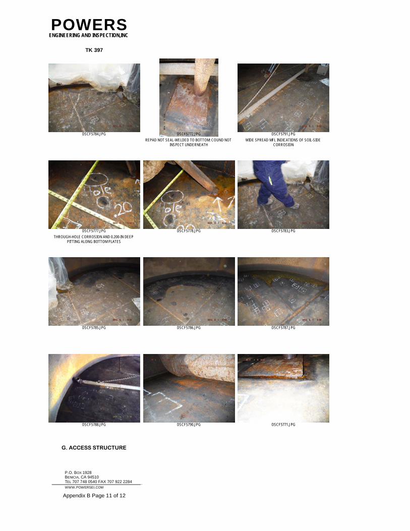
POWERSENGINEERING AND INSPECTION,INC
TK 397
DSCF5784.JPG
REPAD NOT SEAL-WELDED TO BOTTOM: COUND NOT INSPECT UNDERNEATH
DSCF5772.JPG
WIDE SPREAD MFL INDICATIONS OF SOIL-SIDE CORROSION
DSCF5791.JPG
THROUGH-HOLE CORROSION AND 0.200-IN DEEP PITTING ALONG BOTTOM PLATES
DSCF5777.JPG DSCF5778.JPG DSCF5783.JPG
DSCF5785.JPG DSCF5786.JPG DSCF5787.JPG
DSCF5788.JPG DSCF5790.JPG DSCF5771.JPG
G. ACCESS STRUCTURE
P.O. BOX 1928 BENICIA, CA 94510 TEL 707 748 0540 FAX 707 922 2284
WWW.POWERSEI.COM Appendix B Page 11 of 12
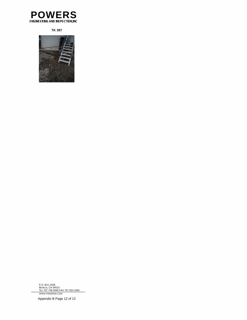
POWERSENGINEERING AND INSPECTION,INC
TK 397
DSCF5727.JPG
P.O. BOX 1928 BENICIA, CA 94510 TEL 707 748 0540 FAX 707 922 2284
WWW.POWERSEI.COM Appendix B Page 12 of 12