ML012890481.pdf - Nuclear Regulatory Commission
141
APPENDIX C CATEGORY C TRANSIENT FUEL ROD ANALYSIS PHENOMENA DESCRIPTIONS AND RATIONALES FOR IMPORTANCE RANKING, APPLICABILITY, AND UNCERTAINTY This appendix provides a description for each phenomenon appearing in Table 3-3, Transient Fuel Rod Analysis PIRT. Entries in the Table C-1, columns 1 and 2, follow the same order as in Table 3-3. Table C-1, column 3, also documents the PIRT-panel developed rationales for three types of Panel findings. First, rationales are provided for the importance (High, Medium, or Low) assigned by the panel to each phenomenon. Because importance ranking was established by a vote of the panel members, a rationale is provided whenever one or more panel members voted a particular rank, i.e., High, Medium or Low. If there were no votes for a given importance rank, "No votes" is entered. Second, the PIRT panel considered the applicability of the baseline PIRT to a broader set of circumstances, e.g., different fuel arrays, cladding types, reactor types, and burnups to 75 GWd/t. The specific question addressed by the PIRT panel was as follows: "Could the importance ranking assigned for the given phenomenon in the baseline PIRT be for different for other fuel arrays, cladding types, reactor types, or burnups?" If this question is answered with a "no", the following entry appears in Table C-1: "Baseline PIRT importance rank is applicable." If this question is answered with a "yes", the rationale is entered. Additional details are presented in the footnotes to Table 3-4. Third, the PIRT panel considered the current state of knowledge or uncertainty regarding each phenomenon. The phenomenon is characterized as "known (K)" if approximately 75-100% of full knowledge and understanding of the phenomenon exists. The phenomenon is characterized as "partially known (PK)" if between 25 75% of full knowledge and understanding of the phenomenon exists. The phenomenon is characterized as "unknown (UK)"if less than 25% of full knowledge and understanding of the phenomenon exists. Because the uncertainty ranking was established by a vote of the panel members, a rationale is provided whenever one or more panel members voted a particular uncertainty, i.e., known, partially known, or unknown. If there were no votes for a given uncertainty level, "No votes" is entered. C-1
-
Upload
khangminh22 -
Category
Documents
-
view
3 -
download
0
Transcript of ML012890481.pdf - Nuclear Regulatory Commission
APPENDIX C
CATEGORY C TRANSIENT FUEL ROD ANALYSIS
PHENOMENA DESCRIPTIONS AND RATIONALES FOR IMPORTANCE RANKING, APPLICABILITY, AND UNCERTAINTY
This appendix provides a description for each phenomenon appearing in Table 3-3, Transient Fuel Rod Analysis PIRT. Entries in the Table C-1, columns 1 and 2, follow the same order as in Table 3-3. Table C-1, column 3, also documents the PIRT-panel developed rationales for three types of Panel findings.
First, rationales are provided for the importance (High, Medium, or Low) assigned by the panel to each phenomenon. Because importance ranking was established by a vote of the panel members, a rationale is provided whenever one or more panel members voted a particular rank, i.e., High, Medium or Low. If there were no votes for a given importance rank, "No votes" is entered.
Second, the PIRT panel considered the applicability of the baseline PIRT to a broader set of circumstances, e.g., different fuel arrays, cladding types, reactor types, and burnups to 75 GWd/t. The specific question addressed by the PIRT panel was as follows: "Could the importance ranking assigned for the given phenomenon in the baseline PIRT be for different for other fuel arrays, cladding types, reactor types, or burnups?" If this question is answered with a "no", the following entry appears in Table C-1: "Baseline PIRT importance rank is applicable." If this question is answered with a "yes", the rationale is entered. Additional details are presented in the footnotes to Table 3-4.
Third, the PIRT panel considered the current state of knowledge or uncertainty regarding each phenomenon. The phenomenon is characterized as "known (K)" if approximately 75-100% of full knowledge and understanding of the phenomenon exists. The phenomenon is characterized as "partially known (PK)" if between 2575% of full knowledge and understanding of the phenomenon exists. The phenomenon is characterized as "unknown (UK)"if less than 25% of full knowledge and understanding of the phenomenon exists. Because the uncertainty ranking was established by a vote of the panel members, a rationale is provided whenever one or more panel members voted a particular uncertainty, i.e., known, partially known, or unknown. If there were no votes for a given uncertainty level, "No votes" is entered.
C-1

Table C-1. PWR Rod Ejection Accident. Category C - Transient Fuel Rod Analysis PIRT
Subcategorv I Phenomena I Definition and Rationale (Imnortance. Anrolicabilitv. and U~ncertaintv•I e i ii n an a i n l ( m o t n e A p i a ii a d U c r a n -I1 -
Initial conditions Gap size The dimension (size) of the space between the pellet and cladding.
H(13) The gap size is essential for the determination of the PCMI loading. M(1) Gap size is less important but perceived to be less important than other
phenomena to be voted on (relative importance argument). L(O) No votes.
Fuel: N Clad: N Reactor: N Burnup: There is more swelling, stored fission gas, and oxidation and hydriding.
Phenomena that influence the forces that can arise from these factors become more important.
K(9): The gap size is one of the fundamental inputs, not only for input but also prediction with time in any fuel rod analysis, including steady state as well as transient. This parameter is well known.
PK(5): There is some uncertainty with respect to gap size for high burnup fuel. The scatter in the comparison of measured to calculated fuel temperature predictions indicate a substantial amount of unpredictability possibly associated with the gap size.
UK(O): No votes.
C-2

Table C-1. PWR Rod Ejection Accident. Category C - Transient Fuel Rod Analysis PIRT (continued)
Subcategory I Phenomena I Definition and Rationale (Importance, Applicability, and Uncertainty)
Initial conditions Gas pressure The total pressure input to the code as the initial condition.
H(1) Highly important to calculate this as one of the loadings on the clad at the beginning of the transient.
M(10) Moderately important to calculate this as one of the loadings on the clad at the beginning of the transient. Pressure can be important after PCMI failure.
L(2) The gas pressure leads to a loading that is less significant than the PCMI, because the clad gap is bonded. There is no axial gas communication, so the localized pressure has a low influence on the loading of the cladding.
Fuel: N Clad: N Reactor: N Burnup: There is the potential for a significant increase in pin internal pressure due to
fission gas at extended burnups.
K(7): With regard to test calculations for transient analysis, the gas pressure is well known.
PK(7): Within the design variations of the fuel pin and the rod, situations where the gas pressure can be almost double or minus 50 percent at the same set of release factions can exist.
UK(0): No votes.
C-3
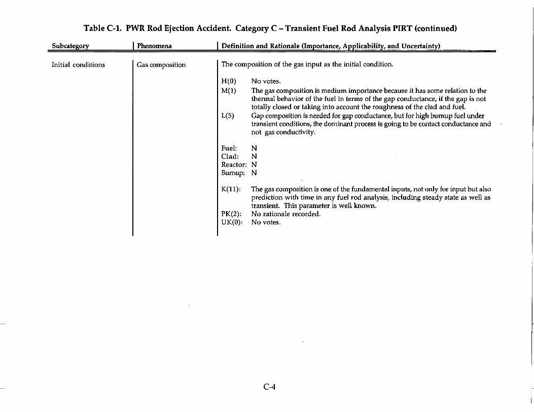
Table C-1. PWR Rod Ejection Accident. Category C - Transient Fuel Rod Analysis PIRT (continued)
Subcategory I Phenomena I Definition and Rationale (Importance, Applicability, and Uncertainty)
Initial conditions Gas composition The composition of the gas input as the initial condition.
H(O) No votes. M(1) The gas composition is medium importance because it has some relation to the
thermal behavior of the fuel in terms of the gap conductance, if the gap is not totally closed or taking into account the roughness of the clad and fuel.
L(5) Gap composition is needed for gap conductance, but for high burnup fuel under transient conditions, the dominant process is going to be contact conductance and not gas conductivity.
Fuel: N Clad: N Reactor: N Burnup: N
K(1 1): The gas composition is one of the fundamental inputs, not only for input but also prediction with time in any fuel rod analysis, including steady state as well as transient. This parameter is well known.
PK(2): No rationale recorded. UK(O): No votes.
C-4

Table C-1. PWR Rod Ejection Accident. Category C - Transient Fuel Rod Analysis PIRT (continued)
Subcateaorv I Phenomena I Definition and Rationale (Importance, Applicability, and Uncertainty)
Initial conditions Gas distribution The axial and radial distribution of the gas input as the initial condition (inter, intra, porosity)
H(7) Fission gas expansion will have a very strong effect during the early phase PCMI failure via loading the cladding. Grain boundary inventory has a strong effect on the PCMI. Gas distribution is also related to grain boundary and if there is a post-DNB failure, the gas distribution will drive fuel fragmentation.
M(5) Fission gas release is highly empirical and confirmed with experiments. It needs to be quantified in the experiments that there is actually an effect here before you go into modeling in detail.
L(O) No votes.
Fuel: Tests in CABRI have shown that the MOX fuel demonstrates different behavior with respect to fission gas effects. Several differences are related to the intergranular and porosity gases, which seem to play a stronger role.
Clad: NReactor: Bumup:
K(1): PK(10): UK(1):
N There is the potential for a significantly different fission gas distribution within the pellet as burnup is extended.
No rationale recorded. There is no real good way to measure or verify the gas distribution. No rationale recorded.
C-5
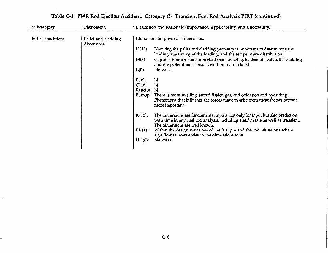
Table C-1. PWR Rod Ejection Accident. Category C - Transient Fuel Rod Analysis PIRT (continued)
Subcategory I Phenomena I Definition and Rationale (Importance, Applicability, and Uncertainty)
Initial conditions Pellet and cladding dimensions
Characteristic physical dimensions.
H(10) Knowing the pellet and cladding geometry is important to determining the loading, the timing of the loading, and the temperature distribution.
M(3) Gap size is much more important than knowing, in absolute value, the cladding and the pellet dimensions, even if both are related.
L(O) No votes.
Fuel: N Clad: N Reactor: N Burnup: There is more swelling, stored fission gas, and oxidation and hydriding.
Phenomena that influence the forces that can arise from these factors become more important.
K(13): The dimensions are fundamental inputs, not only for input but also prediction with time in any fuel rod analysis, including steady state as well as transient. The dimensions are well known.
PK(1): Within the design variations of the fuel pin and the rod, situations where significant uncertainties in the dimensions exist.
UK(O): No votes.
C-6

Table C-1. PWR Rod Ejection Accident. Category C - Transient Fuel Rod Analysis PIRT (continued)
Subcategorv I Phenomena I Definition and Rationale (Importance, Applicability, and Uncertainty)
Initial conditions Burnup distribution The radial and axial burnup magnitude and distribution in the fuel specified as the initial condition
H(1) Can't calculate the power distribution unless you know where the fissile isotopes are and that's driven by the burnup calculation.
M(9) This parameter influences the thermal behavior of the fuel pellet, which is important for the mechanical behavior of the fuel and the clad loading.
L(O) No votes.
Fuel: N Clad: N Reactor: N Burnup: Analysis method will remain the same but the predicted response could be
different.
K(11): This is a calculation parameter that can be performed with a small uncertainty.
PK(3): The distribution of the burnup across the pin as well as the size of the rim effect has a degree of uncertainty associated with the evolution of the rim effect.
UK(O): No votes.
C-7
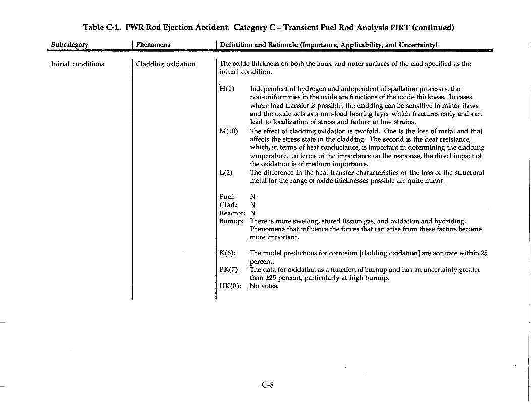
Table C-1. PWR Rod Ejection Accident. Category C - Transient Fuel Rod Analysis PIRT (continued)
Subcategory Phenomena I Definition and Rationale (Importance, Applicability, and Uncertainty)
Initial conditions Cladding oxidation The oxide thickness on both the inner and outer surfaces of the clad specified as the initial condition.
H (1) Independent of hydrogen and independent of spallation processes, the non-uniformities in the oxide are functions of the oxide thickness. In cases where load transfer is possible, the cladding can be sensitive to minor flaws and the oxide acts as a non-load-bearing layer which fractures early and can lead to localization of stress and failure at low strains.
M(10) The effect of cladding oxidation is twofold. One is the loss of metal and that affects the stress state in the cladding. The second is the heat resistance, which, in terms of heat conductance, is important in determining the cladding temperature. In terms of the importance on the response, the direct impact of the oxidation is of medium importance.
L(2) The difference in the heat transfer characteristics or the loss of the structural metal for the range of oxide thicknesses possible are quite minor.
Fuel: N Clad: N Reactor: N Burnup: There is more swelling, stored fission gas, and oxidation and hydriding.
Phenomena that influence the forces that can arise from these factors become more important.
K(6): The model predictions for corrosion [cladding oxidation] are accurate within 25 percent.
PK(7): The data for oxidation as a function of burnup and has an uncertainty greater than ±25 percent, particularly at high burnup.
UK(O): No votes.
C-8

Table C-1. PWR Rod Ejection Accident. Category C - Transient Fuel Rod Analysis PIRT (continued)
SSubcategory I Phenomena I Definition and Rationale (Importance, Applicability, and Uncertainty)
Initial conditions Hydrogen concentration The average hydrogen concentration in the cladding specified as the initial condition
H(3) There are two effects of hydrogen on the mechanical response and mechanical properties. One is the change in the constitutive properties, which change with hydrogen content and will change the ability of the cladding to deform plastically. The other is the failure of the cladding. Both distribution and the total amount of the hydrogen will define the cladding integrity, under reactor conditions and in the experiment.
M(9) No impacts of the concentration of the cladding mechanical properties were observed in the tests. Concentration is much less important than hydrogen distribution. Only small variations in hydrogen concentration are observed.
L(O) No votes.
Fuel: N Clad: N Reactor: N Burnup: With higher burnups, the hydrogen concentration will increase and the
potential will exist for increasing the embrittlement of the cladding.
K(5): The model predictions for hydrogen concentration are accurate within 25 percent. Hydrogen concentration is directly related to the cladding oxidation. If one is known, the other is also known.
PK(6): The data for hydrogen concentration as a function of burnup and has an uncertainty greater than ±25 percent, particularly at high burnup.
UK(O): No votes.
C-9

Table C-1. PWR Rod Ejection Accident. Category C - Transient Fuel Rod Analysis PIRT (continued)
Subcategorv I Phenomena I Definition and Rationale (Imvortance. Avvlicabilitv. and Uncertainty)
Initial conditions Hydrogen distribution The local distribution of hydrogen in the cladding and hydride orientation specified as the initial condition.
H(13) The distribution of hydrogen, i.e., hydrides, has a significant impact on cladding response and survival while undergoing a RIA. Increased brittleness, i.e., reduced ductility is the outcome.
M(O) L(O)
No votes. No votes.
Fuel: N Clad: N Reactor: N Bumup: There is more swelling, stored fission gas, and oxidation and hydriding.
Phenomena that influence the forces that can arise from these factors become more important.
K(2): Hydrogen distribution is relatively well known, at least for the purpose of characterizing cladding behavior.
PK(7): The data for hydrogen distribution as a function of burnup and has an uncertainty greater than ±25 percent, particularly at high burnup.
UK(2): No rationale recorded.
C-10
Definition and Rationale (Importance Avolicabilit and Uncertaintv)

Table C-1. PWR Rod Ejection Accident. Category C - Transient Fuel Rod Analysis PIRT (continued)
Subcategory I Phenomena I Definition and Rationale (Importance, Applicability, and Uncertainty)
Initial conditions Fast fluence Time integrated fast neutron flux to which the cladding is exposed.
H(1) Lacking full knowledge of the effects of high fast fluence, especially at higher burnups, it is important to characterize its impact so we can analyze the data well.
M(1) Even though there is a limit at which the effect saturates and doesn't change much, it's important to model and include this effect as it affects properties of the clad and how the cladding responds.
L(7) The phenomenon is inherent to the modeling; the fast fluence must be known for the mechanical properties of the cladding. In terms of relative importance, it is low.
Fuel: N Clad: N Reactor: N Bumup: Higher but the analysis is the same.
K(13): The uncertainty in this calculated parameter is less than 25 percent. PK(O): No votes. UK(O): No votes.
C-11
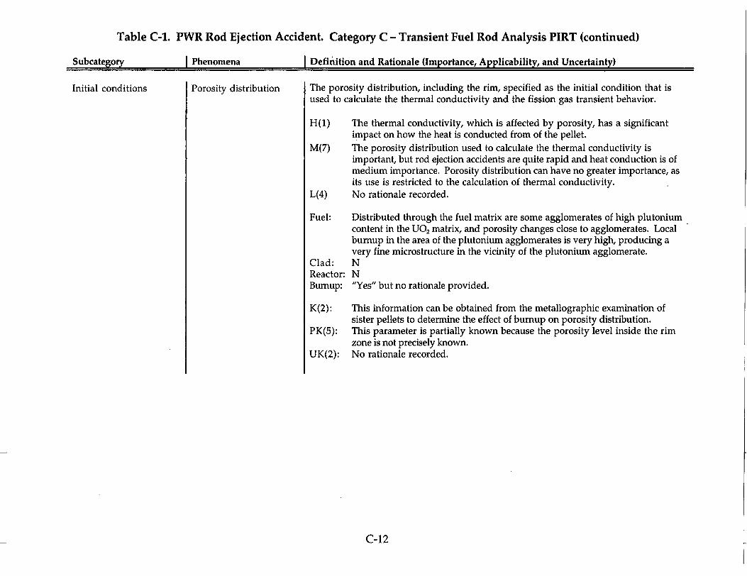
Table C-1. PWR Rod Ejection Accident. Category C - Transient Fuel Rod Analysis PIRT (continued)
Subcategory I Phenomena j Definition and Rationale (Importance, Applicability, and Uncertainty)
Initial conditions Porosity distribution The porosity distribution, including the rim, specified as the initial condition that is used to calculate the thermal conductivity and the fission gas transient behavior.
H(1) The thermal conductivity, which is affected by porosity, has a significant impact on how the heat is conducted from of the pellet.
M(7) The porosity distribution used to calculate the thermal conductivity is important, but rod ejection accidents are quite rapid and heat conduction is of medium importance. Porosity distribution can have no greater importance, as its use is restricted to the calculation of thermal conductivity.
L(4) No rationale recorded.
Fuel: Distributed through the fuel matrix are some agglomerates of high plutonium content in the U0 2 matrix, and porosity changes close to agglomerates. Local burnup in the area of the plutonium agglomerates is very high, producing a very fine microstructure in the vicinity of the plutonium agglomerate.
Clad: N Reactor: N Bumup: "Yes" but no rationale provided.
K(2): This information can be obtained from the metallographic examination of sister pellets to determine the effect of bumup on porosity distribution.
PK(5): This parameter is partially known because the porosity level inside the rim zone is not precisely known.
UK(2): No rationale recorded.
C-12
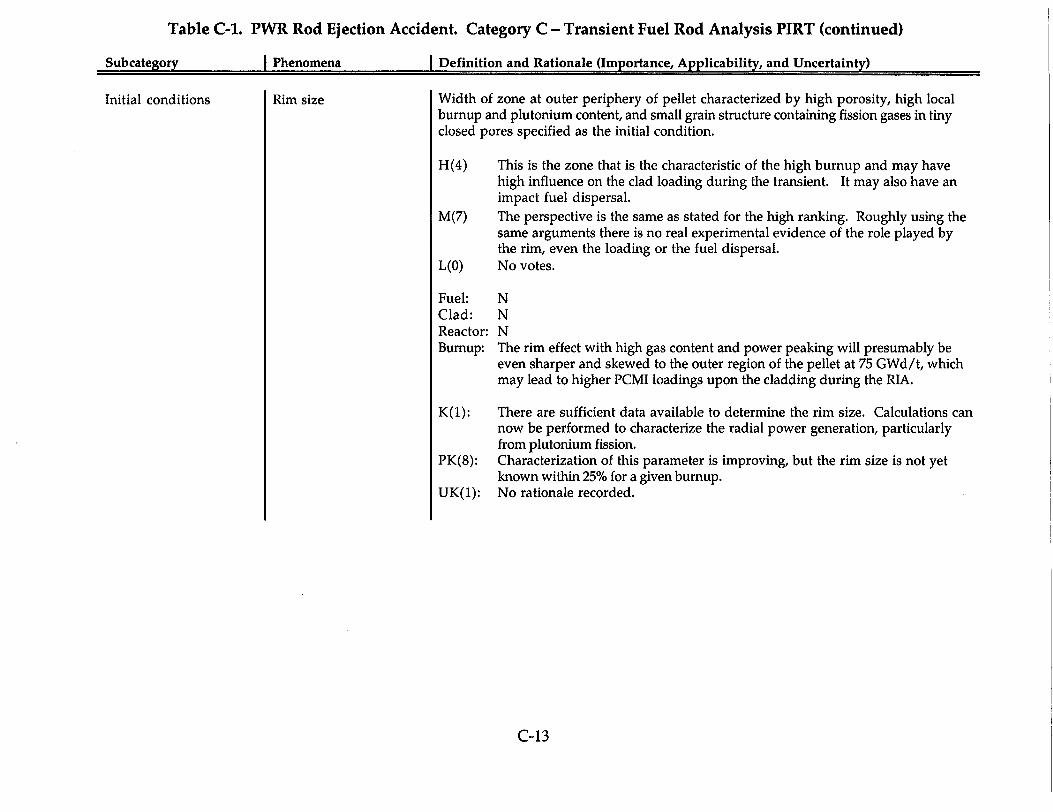
Table C-1. PWR Rod Ejection Accident. Category C - Transient Fuel Rod Analysis PIRT (continued)
Subcategory I Phenomena I Definition and Rationale (Importance, Applicability, and Uncertainty)
Initial conditions Rim size Width of zone at outer periphery of pellet characterized by high porosity, high local burnup and plutonium content, and small grain structure containing fission gases in tiny closed pores specified as the initial condition.
H(4) This is the zone that is the characteristic of the high burnup and may have high influence on the clad loading during the transient. It may also have an impact fuel dispersal.
M(7) The perspective is the same as stated for the high ranking. Roughly using the same arguments there is no real experimental evidence of the role played by the rim, even the loading or the fuel dispersal.
L(O) No votes.
Fuel: N
Clad: N Reactor: N Burnup: The rim effect with high gas content and power peaking will presumably be
even sharper and skewed to the outer region of the pellet at 75 GWd/t, which may lead to higher PCMI loadings upon the cladding during the RIA.
K(1): There are sufficient data available to determine the rim size. Calculations can now be performed to characterize the radial power generation, particularly from plutonium fission.
PK(8): Characterization of this parameter is improving, but the rim size is not yet known within 25% for a given burnup.
UK(1): No rationale recorded.
C-13

Table C-1. PWR Rod Ejection Accident. Category C - Transient Fuel Rod Analysis PIRT (continued)
Subcategorv I Phenomena I Definition and Rationale (Importance, Applicability, and Uncertainty)
Initial conditions Power distribution The radial and axial distribution of the power produced within the fuel rod.
H(14) Power distribution is important; it is skewed to the rim zone in high burnup fuel.
M(O) No votes. L(O) No votes.
Fuel: N Clad: N Reactor: N Burnup: N
K(11): Neutronic tools are available to provide the power distribution with relatively good accuracy.
PK(3): There is sufficient uncertainty relative to the radial power distribution, particularly in the rim zone with its higher concentration of plutonium to designate this parameter as partially known.
UK(O): No votes.
C-14

Table C-1. PWR Rod Ejection Accident. Category C - Transient Fuel Rod Analysis PIRT (continued)
Subcategory I Phenomena I Definition and Rationale (Importance, Applicability, and Uncertainty)
Initial conditions Fuel-gap friction The friction coefficient between the pellet and cladding specified as an initial condition coefficient to represent the initial-state interaction between the two.
H(5) The friction coefficient will affect, to a large extent, the stress state and the ability of the cladding to resist the transient.
M(5) Although the friction coefficient is an integral part of the mechanical response calculations, the results of the PCMI loading are not highly sensitive to this parameter.
L(O) No votes.
Fuel: N
Clad: N Reactor: N Bumup: N
K(O): No votes. PK(6): It is difficult to determine the value of the friction coefficient under all
conditions within 25 percent. It can be estimated for an open gap and for a closed gap, but in between these two limit conditions it's very difficult to determine within 25 percent.
UK(4): Same rationale as for PK but the uncertainty is greater.
C-15

Table C-1. PWR Rod Ejection Accident. Category C - Transient Fuel Rod Analysis PIRT (continued)
Subcategorv I Phenomena I Definition and Rationale (Importance, Applicabilitv, and Uncertainty)
Initial conditions Condition of oxidation (spalling)
The condition of the oxide layer specified as the initial condition.
H(15) There is clear evidence in past CABRI tests that the condition of oxidation, such as spalling, contributed to rod failure in the experiments. There is a demonstrated mechanism, namely blister formation that occurs under local cooled spots in the oxide.
M(O) No votes. L(O) No votes.
Fuel: N Clad: N Reactor: NBumup: There is more swelling, stored fission gas, and oxidation and hydriding.
Phenomena that influence the forces that can arise from these factors become more important.
K(1): Almost all of the rods are spalled in the upper level of the rods at very high burnup.
PK(9): There is a large variation in the occurrence of spalling; it occurs with as little as 50 to 60 microns oxide depth but may not occur even with oxide depths as much as 120 microns.
UK(2): This is a somewhat statistical phenomenon, i.e., predicting that the oxide layer in a particular location for a particular calculation will detach and leave the rod, leading to high uncertainty.
C-16

Table C-1. PWR Rod Ejection Accident. Category C - Transient Fuel Rod Analysis PIRT (continued)
Subcategory I Phenomena I Definition and Rationale (Importance, Applicability, and Uncertainty)
Initial conditions Coolant conditions The collection of coolant conditions making up the coolant environment, e.g., coolant type, velocity, temperature, pressure, etc. specified as the initial conditions.
H(12) In terms of the heat loss during the transient, the coolant condition is not so important, but when simulating fuel dispersal, the coolant condition assumes a very high importance. It's important at least to know the initial coolant temperature for defining the response of the cladding.
M(2) Within the normal range of operations, the mechanical properties are not going to change much with moderate variations in coolant conditions.
L(O) No votes.
Fuel: N Clad: N Reactor: N Burnup: N
K(12): With respect to transient fuel rod analysis, this is an imposed boundary condition.
PK(1): No rationale recorded. UK(O): No votes.
C-17

Table C-1. PWR Rod Ejection Accident. Category C - Transient Fuel Rod Analysis PIRT (continued)
Subcategory I Phenomena I Definition and Rationale (Importance, Applicability, and Uncertainty)
Initial conditions Bubble size and bubble The fission gas bubble distribution and the size distribution of these bubbles as an initial distribution condition.
H(8) It defines the contribution of the fission gases to the loading, especially because the bubbles may reach high pressures during the transient, thereby contributing to the cladding failure and to fuel dispersal. Important to know bubble size and bubble distribution because of the impact on grain boundary separation and fuel dispersal.
M(4) It is needed to calculate the transient gas release that occurs. The contribution of that gas release to the overall response of the fuel rod has yet to be finally determined. So in terms of the overall importance of the rod response, it's of medium importance.
L(O) No votes.
Fuel: Distributed through the fuel matrix are some agglomerates of high plutonium content in the U0 2 matrix. The fission gas inventory in these regions is very high because of very high local burnup.
Clad: N Reactor: N Burnup: N
K(O): No votes. PK(4): The bubble size and bubble distribution affect the fission gas behavior, but it's
not well known, mainly because there is no available technique to precisely determine this parameter.
UK(6): A precise measurement technique does not exist so it is difficult to validate models. The uncertainty associated with this model is high.
C-18

Table C-1. PWR Rod Ejection Accident. Category C - Transient Fuel Rod Analysis PIRT (continued)
Subcategory I Phenomena I Definition and Rationale (Importance, Applicability, and Uncertainty)
Initial conditions Rod free volume The plenum and other free volumes within the fuel stack specified as an initial condition.
H(O) No votes.M(9) It is moderately important to accurately characterize the internal pressure of
the rod, including the porosities and all the free volumes available in the rod during the transient.
L(1) Gas communication over a fairly long distance during a few millisecond transient is not easily accomplished, if the pellets are compressed into the cladding.
Fuel: N Clad: N Reactor: N Burnup: There is more swelling, stored fission gas, and oxidation and hydriding.
Phenomena that influence the forces that can arise from these factors become more important.
K(6): Rod free volume is composed of two parts. The first, the plenum volume, is well known. The second, which consists of whatever remains of the gap and cracked volumes within the pellet, is more difficult but it too can be determined with reasonably high certainty.
PK(5): This measurement is not easy to do. Data scatter is large, depending upon what techniques are used. The local parameter is of more interest and the uncertainty is higher for it.
UK(O): No votes.
C-19
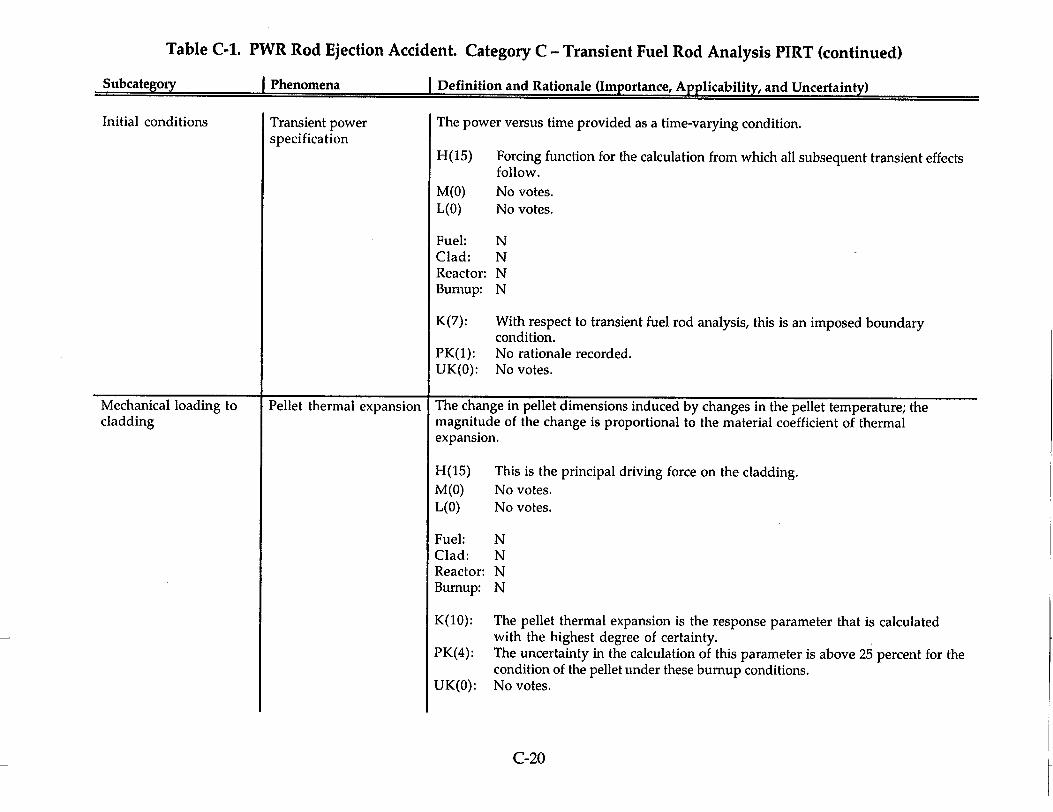
Table C-1. PWR Rod Ejection Accident. Category C - Transient Fuel Rod Analysis PIRT (continued)
Subcategorv I Phenomena I Definition and Rationale (lmrvnrtanice. Annlh'nhil~tv. aini Tlng, prhin~nu1
Initial conditions
Mechanical loading to cladding
Transient power specification
I 4.
Pellet thermal expansion
The power versus time provided as a time-varying condition.
H(15) Forcing function for the calculation from which all subsequent transient effects follow.
M(O) L(O)
No votes. No votes.
Fuel: N Clad: N Reactor: N Bumup: N
K(7): With respect to transient fuel rod analysis, this is an imposed boundary condition.
PK(1): No rationale recorded. UK(O): No votes.
The change in pellet dimensions induced by changes in the pellet temperature; the magnitude of the change is proportional to the material coefficient of thermal expansion.
H(15) This is the principal driving force on the cladding. M(O) No votes. L(O) No votes.
Fuel: N Clad: N Reactor: N Burnup: N
K(10): The pellet thermal expansion is the response parameter that is calculated with the highest degree of certainty.
PK(4): The uncertainty in the calculation of this parameter is above 25 percent for the condition of the pellet under these burnup conditions.
UK(O): No votes.
C-20
I Definition and Rationale (Im ortance A licabilit and Uncert-inf I

Table C-1. PWR Rod Ejection Accident. Category C - Transient Fuel Rod Analysis PIRT (continued)
Subcategory I Phenomena I Definition and Rationale (Importance, Applicability, and Uncertainty)
Mechanical loading to cladding
Direct gas pressure loading
The contribution of available fission gas combined with the fill gas in determining an internal pressurization.
H(1) Gas pressure may have a significant impact on the overall failure of the cladding (part of the rationale for the high vote was uncertainty about the impact).
M(7) Possibly of medium importance following PCMI loading, when significant fission gas release can occur, and it can act as a mechanical loading on the cladding.
L(3) The impact of the gas directly on the cladding is still speculative. There is no real experimental evidence of the role played by the gas.
Fuel: There is a higher fission gas release with MOX and this results in more loading in that the gases are not trapped inside the matrix; they are available for loading the cladding,
Clad: N Reactor: N Burnup: Very high burnup will result in higher fission gas inventory, more extended
grain boundary separation and higher gas availability for direct cladding loading.
K(O): No votes. PK(8): The distribution of gas within the rod is not very well known. There are closed
gaps and open gaps, cracked pellets, etc. The parameter can be estimated but not within an accuracy of 25 percent.
UK(3): Same rationale as for PK but the uncertainty is sufficiently large to render this unknown.
C-21

Table C-1. PWR Rod Ejection Accident. Category C - Transient Fuel Rod Analysis PIRT (continued)
Subcategory I Phenomena I Definition and Rationale (Importance, Applicabilitv, and Uncertaintv)
Mechanical loading to cladding
Pellet-cladding contact (gap closure)
The evolution of the pellet-cladding contact and associated friction coefficient evolution during the transient.
H(13) The pellet-cladding contact response is a time evolution that will change during the event. Because the pellets are cracked and the cracks are closing during the heatup, the manner in which this occurs and the loading it imposes on the cladding are important.
M(O) No votes. L(O) No votes.
Fuel: N Clad: N Reactor: N Burnup: There is more swelling, stored fission gas, and oxidation and hydriding.
Phenomena that influence the forces that can arise from these factors become more important.
K(5): At high burnup, the gap is closed. The only gap size to be considered is the roughness of the fuel pellets.
PK(6): The processes undergone by the fuel lead to a higher uncertainty. The fuel has been in a reactor to high bum, brought back to a cold conditions, and returned to hot zero power. The gap closure is not known with 25 percent.
UK(O): No votes.
C-22
IL

Table C-1. PWR Rod Ejection Accident. Category C - Transient Fuel Rod Analysis PIRT (continued)
Subcategory I Phenomena I Definition and Rationale (Importance, Applicability, and Uncertainty)
Mechanical loading to cladding
Fission gas induced pellet swelling
The fission gas contribution to swelling of the pellet with the rapid increase in gas temperatures and pressure.
H(6) The fission gas induced pellet dynamic expansion is primarily linked to the burnup effect during the PCMI stage.
M(6) It's a plausible process, but it's a controversial process in its relative contribution to failure. There are tests with very high cladding temperature and very high fission gas release, which didn't exhibit any cladding ballooning. There is no experimental evidence of the importance of this parameter.
L(2) The experimental data does not really provide any indication that fission gas induced pellet swelling contributes to the mechanical loading on the cladding.
Fuel: There is a higher fission gas release with MOX and in addition to direct gas pressure loading, the higher gas release may manifest itself in increased fuel pellet swelling.
Clad: NReactor: Bumup:
N With the changes in pellet microstructure, e.g., cracks, porosity, rim formation, etc., the extended burnup will result in an increased fission gas release and higher potential for cladding loading during the entire transient.
K(1): No votes. PK(7): Fission gas-induced swelling is related to burnup and gas content. It's not well
quantified. UK(3): Based on the level of disagreement on how fission gas induced swelling impacts
the PCMI loading, this parameter is currently unknown.
C-23

Table C-1. PWR Rod Ejection Accident. Category C - Transient Fuel Rod Analysis PIRT (continued)
Subcategorv I Phenomena I Definition and Ratinnalp (Ininnrtane�. Ann1ie�hu1�tu� �na�l TTnt'�,4�nhA
Mechanical loading to cladding
Fission gas release The release of fission gas during the transient through the pellet into the matrix of the rod.
H(4) Fission gas release is an important phenomenon to describe how much of the loading and how rapid the loading occurred during the transient. Timing of the release is important and this is uncertain. If fission gas release occurs during a late phase, the fission gas induced swelling can be very important. If it is early, it is less important. Uncertainty, then, plays a role in the vote to declare this phenomenon of high importance. Fission gas can only do work after it's been released from the U0 2.
M(6) Most of the gas release is occurring later, not really loading the cladding, but it is important that there be a transient fission gas release model.
L(2) After examining the experimental data base information, there is no direct correlation between the transient fission gas release and the cladding strain, for instance, which is more related to the enthalpy.
Fuel: There is a higher fission gas release with MOX and this results in more loading in that the gases are not trapped inside the matrix; they are available for loading the cladding.
Clad: NReactor: Burnup:
N With the changes in pellet microstructure, e.g., cracks, porosity, rim formation, etc., the extended burnup will result in an increased fission gas release and higher potential for cladding loading during the entire transient.
K(O): No votes. PK(8): Fission gas release, even for steady state conditions, involves a lot of scatter in
the data, and most models are not even within 25 percent even for well-known steady-state regimes. For transient regimes, it is between 70 to 80 percent and 70 percent is specified for partially known.
UK(2): No rationale recorded.
C-24
L f LL L/ L I Definition and Rationale (Im ortance A licabilit and Uncettaillf I

Table C-1. PWR Rod Ejection Accident. Category C - Transient Fuel Rod Analysis PIRT (continued)
Subcategory I Phenomena I Definition and Rationale (Importance, Applicability, and Uncertainty)
Fuel and cladding temperature changes
Heat resistances in fuel, gap, and cladding
The resistances offered by the fuel, gap, and cladding to the flow of thermal energy from regions of high temperature to regions of lower temperature. The resistance is dependent upon path length and thermal conductivity.
H(9) The heat transfer resistance is highly important for determination of fuel and cladding temperature changes.
M(6) The phenomenon must be modeled in the code but code-calculated results to date indicate that the important outcomes, e.g., cladding failure, are not sensitive to significant variations in the resistances, e.g., factors of 2-3.
L(1) Similar to the medium ranking but assigning less importance.
Fuel: N Clad: N Reactor: N Burnup: The heat resistance will increase due to microstructure changes and increased
fission gas concentration. Importance may vary from the base PIRT ranking.
K(7): Resistance can be calculated with 25 percent. PK(6): Although heat transfer resistances with new cladding are known, under
oxidized conditions, with thick or delaminated oxides, it's not well determined experimentally.
UK(O): No votes.
C-25

Table C-1. PWR Rod Ejection Accident. Category C - Transient Fuel Rod Analysis PIRT (continued)
Subcategorv I Phenomena I Definition and Rationale (Ininnrtan� Annlh-abili*u. anti ITti.'a�w4a�nfub
Fuel and cladding temperature changes
Transient cladding-tocoolant heat transfer coefficient (oxidized cladding)
The correlation that determines transport of energy at the interface by one or more of the following modes: forced convection-liquid, nucleate boiling, transition boiling, film boiling, or forced convection-vapor.
H(O) No votes. M(16) Properties of the cladding are sensitive to temperature and important to
calculate. L(O) No votes.
Fuel: N Clad: N Reactor: NBumup: The heat transfer will change due to microstructure changes and increased
fission gas concentration. This event can lead to a departure from nucleate boiling, a significant change.
K(3): We can predict coolant heat transfer within 25 percent. PK(9): There is higher uncertainty for a post-DNB transient CHF because there is
larger scatter of the experimental results. The initial conditions for the cladding to coolant heat transfer are known; it's not entering DNB that the uncertainty increases.
UK(1): No votes.
C-26
L I LL L I efirifflon and Rationale ilm ortance A licabilif and IT-wer"im I

Table C-1. PWR Rod Ejection Accident. Category C - Transient Fuel Rod Analysis PIRT (continued)
Subcategorv I Phenomena I Definition and Rationale (Importance, Applicability, and Uncertainty)
Fuel and cladding temperature changes
Heat capacities of fuel and cladding
The respective quantities of heat required to raise the fuel and cladding one degree in temperature at constant pressure.
H(13) The calculated outcome is sensitive to the heat capacity. M(2) Heat capacity certainly affects the stored energy. However, the accuracy of
the model that's needed for calculating heat capacity is not of high importance.
L(1) No rational recorded.
Fuel: N Clad: N Reactor: N Bumup: N
K(12): These are well-known material properties. PK(2): The steady state fuel performance codes over the last several years for
evaluation of the high burnup situation and the work is still in progress. UK(O): No votes.
C-27

Table C-I. PWR Rod Ejection Accident. Category C - Transient Fuel Rod Analysis PIRT (continued)
Subcategory I Phenomena I Definition and Rationale (Importance, Applicability, and Uncertainty)
Fuel and cladding Coolant conditions The collection of coolant conditions making up the time varying coolant environment, e.g., temperature changes coolant type, velocity, temperature, pressure, etc.
H(9) It determines the heat transfer that occurs. It also determines the pressure increase due to fuel dispersion. Coolant conditions might be relevant in the onset of the DNB.
M(4) Most of what was said in favor of high would be in the early part of the transient, a later portion of the transient, which we don't actually know to date is as important as PCMI.
L(O) No votes.
Fuel: N Clad: N Reactor: N Burnup: N
K(10): These calculations are made on a routine basis and the results have been shown to be in reasonable agreement with data.
PK(3): There is some uncertainty as to when the accident moves from one phase to another, that is, into the nucleate boiling regime.
UK(O): No votes.
C-28

Table C-1. PWR Rod Ejection Accident. Category C - Transient Fuel Rod Analysis PIRT (continued)
Subcategory I Phenomena I Definition and Rationale (Importance, Applicability, and Uncertainty)
Fuel and cladding temperature changes
Transient spalling effect Spalling of the rod oxide layer during the transient associated with transient clad straining as already evidenced in CABRI Rep NA tests. It may increase the clad to coolant heat transfer and affect the coolability via the transport of oxide debris.
H(2) It affects the fuel and the temperature of the clad; it may be important in the subsequent sequence of phenomena.
M(6) A local calculation taking into account this local transient spallation was performed. It showed a short-term increase of the cladding temperature. The impact on overall cladding behavior is expected to be small.
L(1) The loss of the thermal resistance of the oxide in that spot will lead to a cooler cladding.
Fuel: N Clad: N Reactor: N Burnup: Phenomenon becomes more important as bumup increases.
K(O): No votes. PK(3): Transient spalling is very likely but it is difficult to calculate with a high
degree of certainty. UK(4): Spalling will likely be consider in a statistical framework because it is
difficult to predict and the uncertainty is very high.
C-29
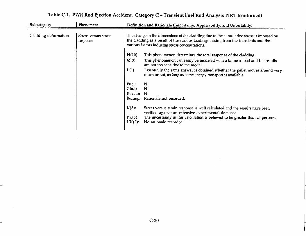
Table C-1. PWR Rod Ejection Accident. Category C - Transient Fuel Rod Analysis PIRT (continued)
Subcategory I Phenomena I Definition and Rationale (Importance, Applicabilitv, and Uncertainty)
Cladding deformation Stress versus strain response
The change in the dimensions of the cladding due to the cumulative stresses imposed on the cladding as a result of the various loadings arising from the transients and the various factors inducing stress concentrations.
H(10) This phenomenon determines the total response of the cladding. M(3) This phenomenon can easily be modeled with a bilinear load and the results
are not too sensitive to the model. L(1) Essentially the same answer is obtained whether the pellet moves around very
much or not, as long as some energy transport is available.
Fuel: N Clad: N Reactor: N Burnup: Rationale not recorded.
K(5): Stress versus strain response is well calculated and the results have been verified against an extensive experimental database.
PK(5): The uncertainty in this calculation is believed to be greater than 25 percent. UK(2): No rationale recorded.
C-30

Table C-1. PWR Rod Ejection Accident. Category C - Transient Fuel Rod Analysis PIRT (continued)
Subcate~orv I Phenomena I Definition and Rationale (Importance, Applicability, and Uncertainty)
Cladding deformation Strain rate effects Strain rate effects as they change the stress strain curve in terms of affecting the yield stress and the deformation behavior in the plastic regime
H(0) No votes. M(O) No votes. L(7) Strain rate effects are minor with respect to changes in the stress strain curve in
terms of affecting the yield stress and the deformation behaviors in the plastic regime are minor.
Fuel: N Clad: N Reactor: N Bumup: Rationale not recorded.
K(4): The French experimental program on mechanical properties investigated different strain rates and came to the conclusion that the effect of the strain rate was not too important.
PK(5): The degree of uncertainty in these rate effects could well be greater than the 25 percent.
UK(1): No rationale recorded.
C-31
Subcateaorv

Table C-1. PWR Rod Ejection Accident. Category C - Transient Fuel Rod Analysis PIRT (continued)
Subcategory j Phenomena [ Definition and Rationale (Importance, Applicability, and Uncertainty)
Cladding deformation Anisotropy The variation of cladding properties along the different coordinate directions.
H(1) It's important to determine the anisotropy of the cladding to see how the deformation is divided among the different directions and how that changes with radiation damage.
M(2) It is not clear how much of the effect exists in the existing cladding material and this uncertainty was expressed as of medium importance.
L(5) The available information indicates these effects are very small for irradiated material.
Fuel: N Clad: N Reactor: N Bumup: N
K(1): Anisotropy is a material characteristic that is well characterized. With high bum-up anisotropy disappears.
PK(7): This parameter this now combines in the transient analysis the different states of the clad, hydrides. This is more than a material property.
UK(2): No rationale recorded.
C-32

Table C-1. PWR Rod Ejection Accident. Category C - Transient Fuel Rod Analysis PIRT (continued)
Subcategory I Phenomena I Definition and Rationale (Importance, Applicability, and Uncertainty)
Cladding deformation Pellet shape Changes to the pellet shape from its initial state such as dished or chamfered ends, barreling or hourglassing.
H(0) No votes. M(5) Same explanation as for low but the deformation is thought to be on the order
of 10 to 25 percent. L(2) The experimental data on cladding deformations indicate a majority of the
deformation response is due to thermal expansion. Pellet shape effects can be discerned through the deformation traces, but they're rather small, on the order of roughly 10 percent of the total deformation.
Fuel: N Clad: N Reactor: N Burnup: N
K(6): Pellet shape is well characterized for manufacturing and there isn't much deviation allowed for that to grow into the void regions with bumup.
PK(3): There is some degree of uncertainty in exactly what the shape is leading into this analysis, with the uncertainty associated with high burnup, the rim effect, cracking, etc.
UK(1): No rationale recorded.
C-33

Table C-1. PWR Rod Ejection Accident. Category C - Transient Fuel Rod Analysis PIRT (continued)
Subcategory I Phenomena I Definition and Rationale (Importance, Applicability, and Uncertainty)
Cladding deformation Cladding temperature The effect of cladding temperature in determining cladding properties and leading to cladding deformation.
H(12) Stiffness and ductility are functions of cladding temperature and these strongly impact cladding deformations.
M(1) For PCMI, there is a low flow of energy into the cladding. Considering relative importance, the importance ranking is lower than it would be if both PCMI and DNB failures were considered.
L(O) No votes.
Fuel: N Clad: N Reactor: N Burnup: N
K(7): The cladding temperature response can be modeled with good accuracy. PK(5): The cladding temperature reflects the response of the entire fuel system,
including all the combined uncertainties and all the material models, particularly in the pellet, and the interaction of the pellet with the cladding. These uncertainties are believed to exceed 25 percent.
UK(O): No votes.
C-34

Table C-1. PWR Rod Ejection Accident. Category C - Transient Fuel Rod Analysis PIRT (continued)
Subcategory I Phenomena I Definition and Rationale (Importance, Applicability, and Uncertainty)
Cladding deformation Localized effects Stress risers within the cladding at discrete locations arising from various sources, including the pellet shape factors listed above, as well as undetected defects in the cladding.
H(1) Local effects such as barreling produce stress inside the cladding, Deformation will probably start wherever there are stress risers.
M(1) Same rationale as High but importance is deemed to be only medium. L(O) No votes.
Fuel: N Clad: N Reactor: N Burnup: N
K(0): PK(8): UK(1):
No votes. Localized effects are partially known inside the rod. There might be unknown manufacturing defects that would give local stress risers.
C-35

Table C-1. PWR Rod Ejection Accident. Category C - Transient Fuel Rod Analysis PIRT (continued)
Subcategory [ Phenomena I Definition and Rationale (Importance, Applicability, and Uncertainty)
Cladding deformation Biaxiality The dependence of cladding deformation and failure strain on the multidimensional stress state.
H(1) The ability of the material to load transfer is going to impact the failure criterion.
M(6) Calculating the deformation response for the cladding requires that you determine the axial stress and strain response as well as the radial and the hoop, and biaxiality gives you those different directions. It must be modeled, but pretty many any models will do.
L(O) No votes.
Fuel: N Clad: N Reactor: N Bumup: N
K(O): No votes. PK(7): The biaxiality condition is a created condition as a result of the pellet
cladding mechanical interaction and that is not certain within 25 percent. UK(2): No rationale recorded.
C-36

Table C-1. PWR Rod Ejection Accident. Category C - Transient Fuel Rod Analysis PIRT (continued)
Subcategory I Phenomena Definition and Rationale (Importance, Applicability, and Uncertainty)
Pellet deformation Fracture stress The stress at which U0 2 forms a brittle crack during tensile deformation. The fracture stress is a function of temperature, porosity and possibly burnup.
H(2) Fracture stress is directly linked to the grain boundary decohesion. It determines the weakness of the fuel in response to gas bubble pressurization and the fission gas effect. It is a fundamental process linked to fuel behavior.
M(3) Fracture stress acts toward the latter end of the transient rather than during the front end of the transient and it does not immediately affect the loading mechanism of the cladding during the transient.
L(O) No votes.
Fuel: N Clad: N Reactor: N Burnup: N
K(4): This parameter has been used for the last 30-40 years; we know understand fracture stress for fuel.
PK(2): For high burnup fuel, dynamic behavior and loading are only partially known. UK(0): No votes.
C-37
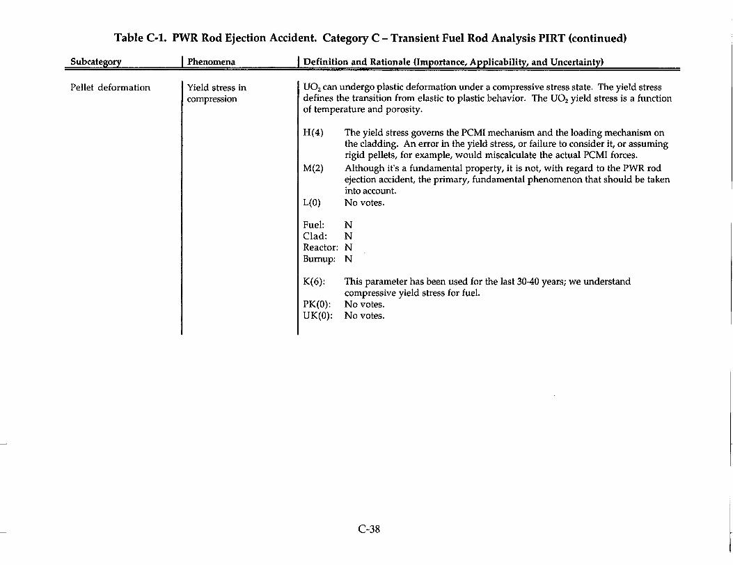
Table C-1. PWR Rod Ejection Accident. Category C - Transient Fuel Rod Analysis PIRT (continued)
Subcategory I Phenomena I Definition and Rationale (Importance, Applicability, and Uncertainty)
Pellet deformation Yield stress in compression
U0 2 can undergo plastic deformation under a compressive stress state. The yield stress defines the transition from elastic to plastic behavior. The U0 2 yield stress is a function of temperature and porosity.
H(4)
M(2)
L(O)
The yield stress governs the PCMI mechanism and the loading mechanism on the cladding. An error in the yield stress, or failure to consider it, or assuming rigid pellets, for example, would miscalculate the actual PCMI forces. Although it's a fundamental property, it is not, with regard to the PWR rod ejection accident, the primary, fundamental phenomenon that should be taken into account. No votes.
Fuel: N Clad: N Reactor: N Burnup: N
K(6):
PK(O): UK(0):
This parameter has been used for the last 30-40 years; we understand compressive yield stress for fuel. No votes. No votes.
C-38
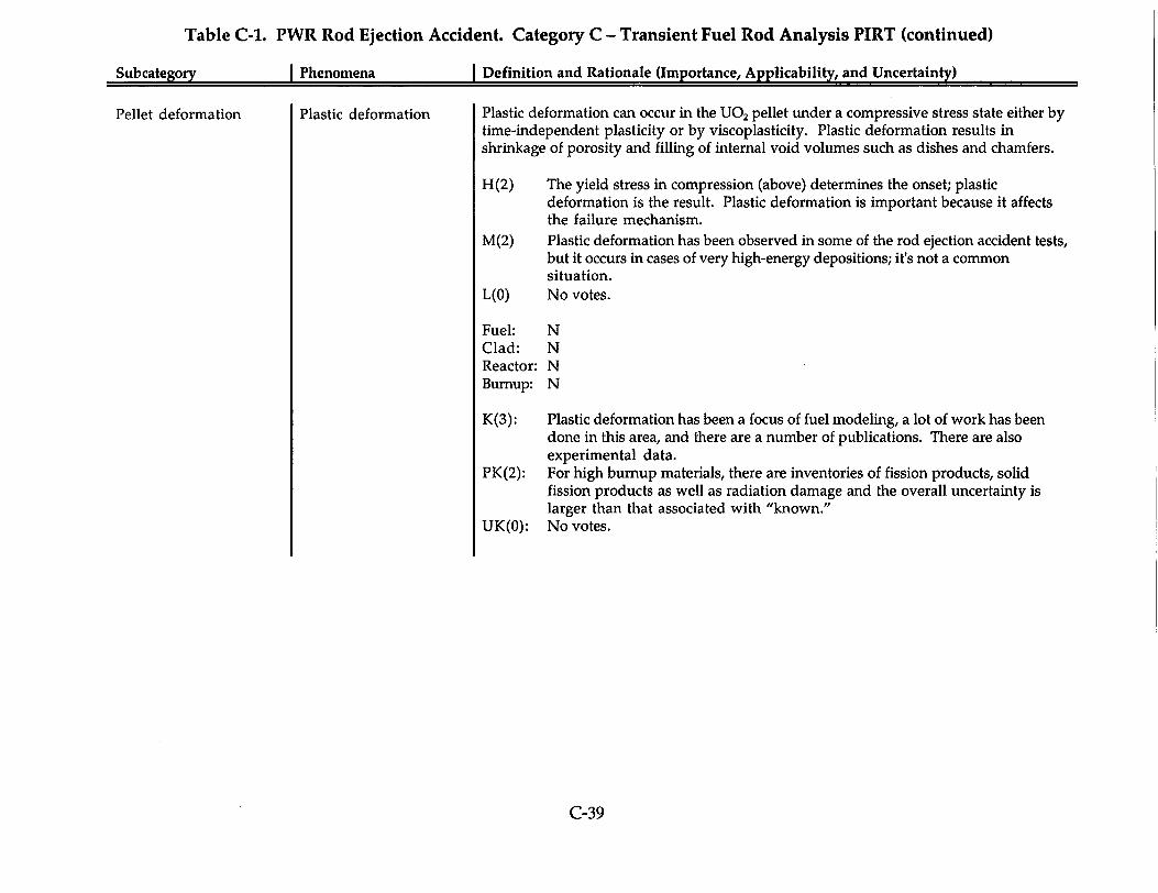
Table C-1. PWR Rod Ejection Accident. Category C - Transient Fuel Rod Analysis PIRT (continued)
Subcategorv I Phenomena I Definition and Rationale (Importance, Applicability, and Uncertainty)
Pellet deformation Plastic deformation Plastic deformation can occur in the U0 2 pellet under a compressive stress state either by time-independent plasticity or by viscoplasticity. Plastic deformation results in shrinkage of porosity and filling of internal void volumes such as dishes and chamfers.
H(2) The yield stress in compression (above) determines the onset; plastic deformation is the result. Plastic deformation is important because it affects the failure mechanism.
M(2) Plastic deformation has been observed in some of the rod ejection accident tests, but it occurs in cases of very high-energy depositions; it's not a common situation.
L(O) No votes.
Fuel: N Clad: N Reactor: N Burnup: N
K(3): Plastic deformation has been a focus of fuel modeling, a lot of work has been done in this area, and there are a number of publications. There are also experimental data.
PK(2): For high burnup materials, there are inventories of fission products, solid fission products as well as radiation damage and the overall uncertainty is larger than that associated with "known."
UK(O): No votes.
C-39

Table C-1. PWR Rod Ejection Accident. Category C - Transient Fuel Rod Analysis PIRT (continued)
Subcategory I Phenomena I Definition and Rationale (Importance, Applicability, and Uncertainty)
Pellet deformation Grain boundary decohesion
Weakening of the grain boundary surface tension by accumulation of fission gas bubbles or overpressure of existing bubbles due to fast heating can result in grain boundary separation. Grain boundary decohesion or separation occurs under high temperature when the pressure within the fission gas bubbles leads to a high stress field at the grain boundary. The result of grain boundary decohesion is fragmentation of the fuel into individual U0 2 grains.
H(6) Cracking will affect the heat transfer to the clad. It will also result in an additional loading on the cladding. It can cause additional fragmentation in the rim and possibly contribute to fuel dispersal if the cladding fails.
M(1) Grain boundary decohesion can only occur as the compressive stresses on the matrix are relieved, and that can only occur during the latter part of the transient; it will not contribute much to the loading, if any, during the actual event.
L(O) No votes.
Fuel: N Clad: N Reactor: N Bumup: N
K(O): No votes. PK(3): This phenomenon is qualitatively known but not sufficiently quantified. There
is a need to do well characterized separate effects tests to better to understand some of these phenomena.
UK(3): Grain boundary decohesion is the outcome of several underlying phenomena and the submodels are not yet fully integrated into a comprehensive model. It is very difficult to have a real idea of what is happening in the steep gradient rim material. The onset of decohesion cannot be predicted well at this time. Experiments being conducted currently, which implies to me that in order to provide additional data that we don't know about.
C-40

Table C-1. PWR Rod Ejection Accident. Category C - Transient Fuel Rod Analysis PIRT (continued)
Subcategorv I Phenomena I Definition and Rationale (Importance, Applicability, and Uncertainty)
Pellet deformation Evolution of pellet stress state
The stress distribution throughout the pellet can influence the fission gas bubble behavior during a RIA. The power peaking in the pellet rim region of high bumup fuel produces larger thermal expansion is this region than in the pellet center. Depending on the level of confinement provided by the cladding and the rate of energy deposition, high compressive stresses can occur in the pellet rim, decreasing towards the pellet center. This stress-state in the pellet rim provides confinement to the fission gas bubbles, limiting any expansion during this phase of the event. As heat conduction reduces the pellet rim temperature, the stresses begin to relax and cracking can occur, liberating fission gases trapped in inter-granular bubbles and porosity.
H(6) The pellet stress state is the outcome of the other pellet deformation phenomena listed above. Therefore, as others of these phenomena were considered to be of high importance, this phenomenon must also be of high importance.
M(O) L(O)
No votes. No votes.
Fuel: N Clad: N Reactor: N Burnup: N
K(1): The science of constitutive modeling of pellet behavior, and the state of the art is quite well developed, and the predictions are quite well in line with the experimental evidence.
PK(3): A vote for PK in any of the contributing phenomena must of necessity dictate that this overall phenomenon be only partially known.
UK(O): No votes.
C-41

APPENDIX D
CATEGORY D SEPARATE EFFECT TESTING
PHENOMENA DESCRIPTIONS AND RATIONALES FOR IMPORTANCE RANKING, APPLICABILITY, AND UNCERTAINTY
This appendix provides a description for each phenomenon appearing in Table 3-4, Separate Effect Testing PIRT. Entries in the Table D-1, columns 1 and 2, follow the same order as in Table 3-5. Table D-1, column 3, also documents the PIRT-panel developed rationales for three types of Panel findings.
First, rationales are provided for the importance (High, Medium, or Low) assigned by the panel to each phenomenon. Because importance ranking was established by a vote of the panel members, a rationale is provided whenever one or more panel members voted a particular rank, i.e., High, Medium or Low. If there were no votes for a given importance rank, "No votes" is entered.
Second, the PIRT panel considered the applicability of the baseline PIRT to a broader set of circumstances, e.g., different fuel arrays, cladding types, reactor types, and burnups to 75 GWd/t. The specific question addressed by the PIRT panel was as follows: "Could the importance ranking assigned for the given phenomenon in the baseline PIRT be for different for other fuel arrays, cladding types, reactor types, or burnups?" If this question is answered with a "no", the following entry appears in Table C-1: "Baseline PIRT importance rank is applicable." If this question is answered with a "yes", the rationale is entered. Additional details are presented in the footnotes to Table 3-5.
Third, the PIRT panel considered the current state of knowledge or uncertainty regarding each phenomenon. The phenomenon is characterized as "known (K)" if approximately 75-100% of full knowledge and understanding of the phenomenon exists. The phenomenon is characterized as "partially known (PK)" if between 2575% of full knowledge and understanding of the phenomenon exists. The phenomenon is characterized as "unknown (U7K)"if less than 25% of full knowledge and understanding of the phenomenon exists. Because the uncertainty ranking was established by a vote of the panel members, a rationale is provided whenever one or more panel members voted a particular uncertainty, i.e., known, partially known, or unknown. If there were no votes for a given uncertainty level, "No votes" is entered
There were several phenomena for which no importance rank was recorded. In such cases "No rationale recorded" is entered.
D-1
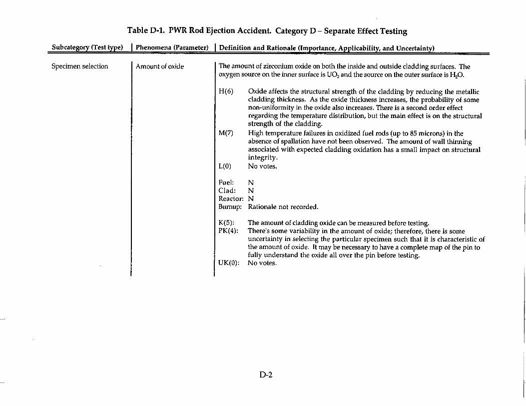
Table D-1. PWR Rod Ejection Accident. Category D - Separate Effect Testing
Subcategory (Test type) I Phenomena (Parameter) I Definition and Rationale (Importance, Applicability, and Uncertainty)
Specimen selection Amount of oxide The amount of zirconium oxide on both the inside and outside cladding surfaces. The oxygen source on the inner surface is UO2 and the source on the outer surface is H20.
H(6) Oxide affects the structural strength of the cladding by reducing the metallic cladding thickness. As the oxide thickness increases, the probability of some non-uniformity in the oxide also increases. There is a second order effect regarding the temperature distribution, but the main effect is on the structural strength of the cladding.
M(7) High temperature failures in oxidized fuel rods (up to 85 microns) in the absence of spallation have not been observed. The amount of wall thinning associated with expected cladding oxidation has a small impact on structural integrity.
L(O) No votes.
Fuel: N Clad: N Reactor: N Burnup: Rationale not recorded.
K(5): The amount of cladding oxide can be measured before testing. PK(4): There's some variability in the amount of oxide; therefore, there is some
uncertainty in selecting the particular specimen such that it is characteristic of the amount of oxide. It may be necessary to have a complete map of the pin to fully understand the oxide all over the pin before testing.
UK(O): No votes.
D-2

Table D-1. PWR Rod Ejection Accident. Category D - Separate Effect Testing (continued)
Subcategory (Test type) I Phenomena (Parameter) I Definition and Rationale (Importance, Applicability, and Uncertainty)
Specimen selection Extent of spalling Peeling of the oxide layer from the cladding leaving the underlying material exposed to the coolant. Can lead to a local cold spot and hydride blister formation
H(14) Spalling is important because it leads to high localized concentrations of hydrides (blisters), and the formation of a preferential failure spot.
M(O) No votes. L(O) No votes.
Fuel: N Clad: N Reactor: N Bumup: N
K(2): No rationale recorded. PK(6): Lacking a full understanding about how spallation occurs in a reactor, it's
difficult to make the link between test rod and how to select the rod to bound reactor rods.
UK(2): Spallation occurs at very high oxide thicknesses, and there isn't as much experience with the new alloys at these higher oxide thicknesses. This is a local phenomenon that may or may not occur. It could depend upon such abstract things like vibration of the rod within the reactor or a shock wave during a transient.
D-3

Table D-1. PWR Rod Ejection Accident. Category D - Separate Effect Testing (continued)
Subcategory (Test type) I Phenomena (Parameter) I Definition and Rationale (Importance, Applicability, and Uncertainty)
Specimen selection Extent of oxide delamination
Separation of an outer oxide layer from the underlying oxide or base metal. Can lead to increased temperature and enhanced localized corrosion.
H(14) Delamination is important because it leads to high localized concentrations of hydrides (blisters), and the formation of a preferential failure spot.
M(O) No votes. L(O) No votes.
Fuel: N Clad: N Reactor: N Burnup: N
K(2): No rationale recorded. PK(6): Lacking a full understanding about how delamanation occurs in a reactor, it's
difficult to make the link between test rod and how to select the rod to bound reactor rods.
UK(2): Delamination occurs at very high oxide thicknesses, and there isn't as much experience with the new alloys at these higher oxide thicknesses.
D-4

Table D-1. PWR Rod Ejection Accident. Category D - Separate Effect Testing (continued)
Subcategory (Test type) I Phenomena (Parameter) I Definition and Rationale (Importance, Applicability, and Uncertainty)
Specimen selection Alloy Cladding utilized (e.g., ZIRLO, M5, ) including thermo-mechanical processing.
H(3) It is important that testing be done on prototypic cladding materials because mechanical properties may differ. Test results on one cladding may not be directly applicable to another cladding material.
M(4) The changes in cladding alloy content are not large and thus limited testing should address differences from the primary cladding database.
L(3) There will be a full characterization of mechanical properties will allow extrapolation of the behavior under accident conditions from alloy to alloy.
Fuel: N Clad: N Reactor: N Burnup: Phenomenon becomes more important as burnup increases.
K(9): The alloy is a specified element in the test specification and there is no uncertainty.
PK(O): No votes. UK(1): No rationale recorded.
D-5

Table D-1. PWR Rod Ejection Accident. Category D - Separate Effect Testing (continued)
Subcategory (Test type) I Phenomena (Parameter) I Definition and Rationale (Importance, Applicability, and Uncertainty)
Specimen selection Amount of hydrogen Total amount of hydrogen in the cladding.
H(9) Hydrogen, even if it's evenly distributed, will still affect the mechanical properties and may affect the failure criteria of zirconium alloys. There is clear correlation between how much hydrogen exists in the cladding and whether fuel fails or will not fail.
M(4) Separate effect tests indicate that the amount of hydrogen has a weak impact on the mechanical properties of the cladding, up to 700 PPM.
L(0) No votes.
Fuel: N Clad: N Reactor: N Bumup: N
K(3): For the regular fuel rod at high burnup is pretty constant. It's always around 600 to 700.
PK(7): The accuracy requirements have a degree of uncertainty. UK(O): No votes.
D-6
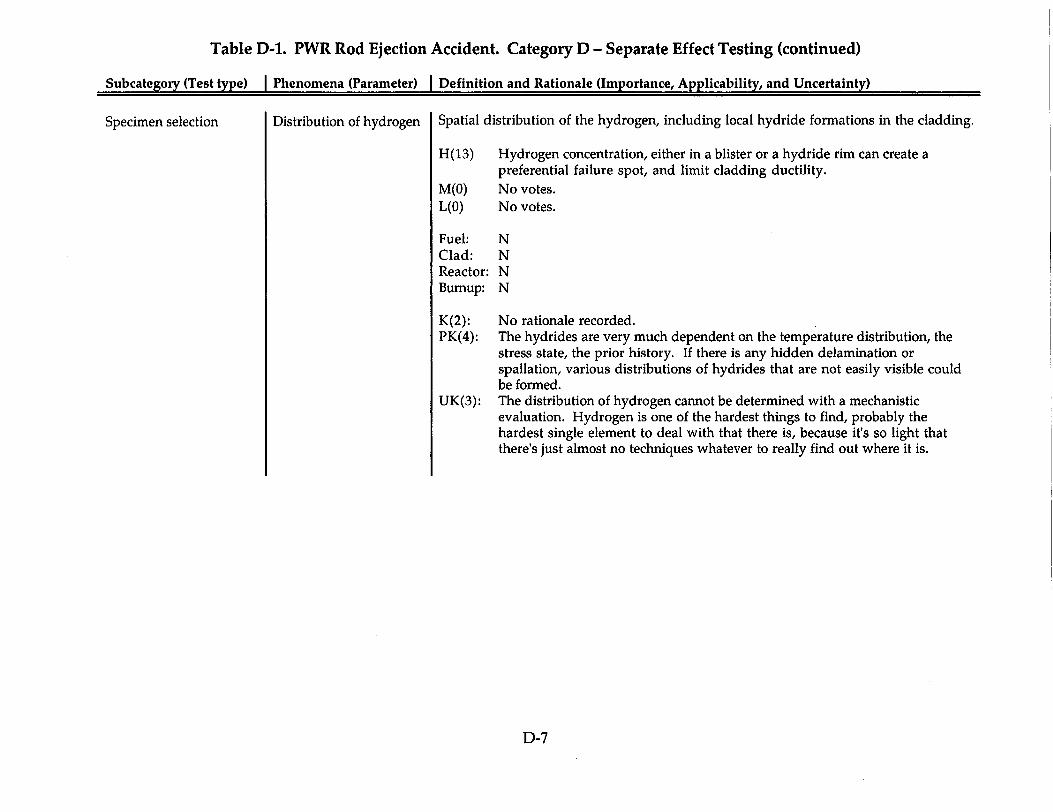
Table D-1. PWR Rod Ejection Accident. Category D - Separate Effect Testing (continued)
Subcategory (Test type) I Phenomena (Parameter) I Definition and Rationale (Importance, Applicability, and Uncertainty)
Specimen selection Distribution of hydrogen Spatial distribution of the hydrogen, including local hydride formations in the cladding.
H(13) Hydrogen concentration, either in a blister or a hydride rim can create a preferential failure spot, and limit cladding ductility.
M(O) No votes. L(O) No votes.
Fuel: N Clad: N Reactor: N Burnup: N
K(2): No rationale recorded. PK(4): The hydrides are very much dependent on the temperature distribution, the
stress state, the prior history. If there is any hidden delamination or spallation, various distributions of hydrides that are not easily visible could be formed.
UK(3): The distribution of hydrogen cannot be determined with a mechanistic evaluation. Hydrogen is one of the hardest things to find, probably the hardest single element to deal with that there is, because it's so light that there's just almost no techniques whatever to really find out where it is.
D-7
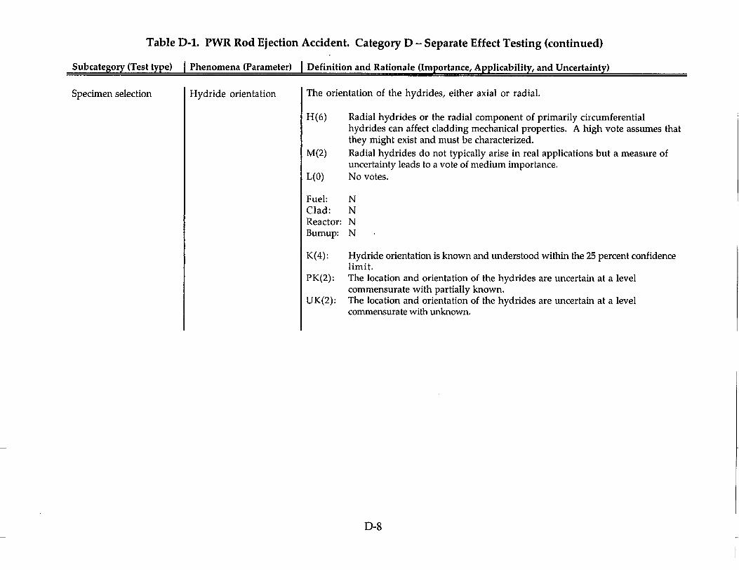
Table D-1. PWR Rod Ejection Accident. Category D - Separate Effect Testing (continued)
Subcategory (Test type) I Phenomena (Parameter) I Definition and Rationale (Importance, Applicability, and Uncertainty)
Specimen selection Hydride orientation The orientation of the hydrides, either axial or radial.
H(6) Radial hydrides or the radial component of primarily circumferential hydrides can affect cladding mechanical properties. A high vote assumes that they might exist and must be characterized.
M(2) Radial hydrides do not typically arise in real applications but a measure of uncertainty leads to a vote of medium importance.
L(O) No votes.
Fuel: N Clad: N Reactor: N Bumup: N
K(4): Hydride orientation is known and understood within the 25 percent confidence limit.
PK(2): The location and orientation of the hydrides are uncertain at a level commensurate with partially known.
UK(2): The location and orientation of the hydrides are uncertain at a level commensurate with unknown.
D-8

Table D-1. PWR Rod Ejection Accident. Category D - Separate Effect Testing (continued)
Subcategory (Test type) I Phenomena (Parameter) I Definition and Rationale (Importance, Applicability, and Uncertainty)
Specimen selection Fluence Time-integrated particle flux to which the cladding is exposed.
H(1) No votes. M(2) Radiation damage saturates at a low value, but our knowledge about cladding
alloys is incomplete; we don't know if there are processes that are accelerated at higher fluence and change how the cladding behaves. A medium vote represents uncertainty about its importance. Also, prototypicality is important.
L(6) There is a saturation effect after one or two cycles.
Fuel: N Clad: N Reactor: N Burnup: N
K(9): Because the reactor power history can be calculated with reasonable accuracy, it is possible to also determine what occurred in the fuel rod.
PK(O): No votes. UK(O): No votes.
D-9

Table D-1. PWR Rod Ejection Accident. Category D - Separate Effect Testing (continued)
Subcategory (Test type) I Phenomena (Parameter) I Definition and Rationale (Importance, Applicability, and Uncertainty)
Specimen selection Cladding integrity Whether the cladding is leak-proof, and whether it has any non-representative defects.
H(12) Non-representative defects can strongly affect the test results (including cladding failure).
M(O) No votes. L(O) No votes.
Fuel: N Clad: N Reactor: N Bumup: N
K(4): the integrity of the rod and the specimen preparation is controlled. PK(5): There is some uncertainty because there are inconsistencies relative to visual
examinations and more elaborate or electronic examinations, i.e., partial failures detected by ultrasonic testing cannot be seen visually.
UK(1): No rationale recorded.
D-10

Table D-1. PWR Rod Ejection Accident. Category D - Separate Effect Testing (continued)
Subcategory (Test type) I Phenomena (Parameter) I Definition and Rationale (Importance, Applicability, and Uncertainty)
Test conditions Heating rate: (>5500 C) Identification and specification of a heating rate that is prototypic of the reactivity insertion accident and such that non-prototypic effects are not introduced.
H(4) The heating rate must be considered in the test design. The French have conducted some high-temperature tests in which annealing occurred. This is to be avoided by selecting the correct heating rate.
M(2) The heating rate for rod ejection accident conditions are below the conditions at which annealing in the cladding occurs, although it may be on the borderline.
L(O) No votes.
Fuel: N Clad: N Reactor: N Burnup: N
K(3): It is both feasible and possible to do such tests, while taking into account the heating rate that's prototypical of the rod ejection accident conditions.
PK(1): There is some uncertainty in knowing the correct heating rate that is prototypical of actual test conditions.
UK(0): No votes.
D-1I

Table D-1. PWR Rod Ejection Accident. Category D - Separate Effect Testing (continued)
Subcategory (Test type) I Phenomena (Parameter) I Definition and Rationale (Importance, Applicability, and Uncertainty)
Test conditions
Test conditions
Temperature range (test)
Strain rate
Identification and specification of a testing temperature range that is prototypic of the reactivity insertion accident and such that non-prototypic effects are not introduced.
H(6)
M(O) L(O)
It's important that the test temperature be prototypic of the event. No votes. No votes.
Fuel: N Clad: N Reactor: N Burnup: N
K(5): It is possible to specify the needed test temperature range using the computational tools to guide the selection.
PK(1): The temperature range to be tested is not yet fully defined. UK(O): No votes.
The specified rate of elongation imposed upon a test article.
H(5) The French experimental program on the mechanical properties investigated different strain rates and it was concluded that the effect of the strain rate was not very important.
M(3) The degree of uncertainty in strain rate effects could well be greater than the 25 percent.
L(2) No rationale recorded.
Fuel: N Clad: N Reactor: N Burnup: N
K(3): PK(2): UK(O):
No rationale recorded. No rationale recorded. No rationale recorded.
D-12

Table D-1. PWR Rod Ejection Accident. Category D - Separate Effect Testing (continued)
Subcategory (Test type) I Phenomena (Parameter) I Definition and Rationale (Importance, Applicability, and Uncertainty)
Test conditions Stress state imposed on The type of stress that is applied to the material being tested. specimen
H(6) It's important that the test stress state be prototypic of the event. M(O) No votes. L(O) No votes.
Fuel: N Clad: N Reactor: N Bumup: N
K(1): No response recorded. PK(2): No response recorded. UK(O): No votes.
D-13

Table D-1. PWR Rod Ejection Accident. Category D - Separate Effect Testing (continued)
Subcategory (Test type) I Phenomena (Parameter) I Definition and Rationale (Importance, Applicability, and Uncertainty)
Test conditions Tensile test specimen Design of the test specimen such that the appropriate, well-characterized stress state is design invoked.
H(8) Having the proper specimen design is necessary to have the appropriate and well-characterized stress state. It helps ensure that the test is applicable to the RIA.
M(O) No votes. L(O) No votes.
Fuel: N Clad: N Reactor: N Bumup: N
K(3): This type of test has been done enough in the past that there is a high confidence level in the ability of those performing the experiments to do so in the future.
PK(3): Same as "K" but a little more needs to be known to successfully perform these tests in the future.
UK(O): No votes.
D-14

Table D-1. PWR Rod Ejection Accident. Category D - Separate Effect Testing (continued)
Subcateizorv (Test type) I Phenomena (Parameter) I Definition and Rationale (Importance, Applicability, and Uncertainty)
Test conditions Burst specimen design Design of the test specimen such that the appropriate, well-characterized stress state is invoked. When running a pressurized tube burst test, either with gas or oil, the stress state is such that there is twice as much stress in the hoop direction as in the axial direction. This factor is addressed in the design effort.
H(8) It is important to develop the dependency of the material property on biaxiality and testing is the only way to accomplish this outcome.
M(O) No votes. L(O) No votes.
Fuel: N Clad: N Reactor: N Burnup: N
K(1): It is possible to design and conduct this experiment with high confidence that the results returned will be those for which the test was designed.
PK(4): The technology is not fully mature for irradiated cladding and in the desired temperature range. The local stress state that's in the cladding is not precisely known, because, for the bonded specimen or the fueled specimen test, a local stress state due to fuel and the cladding interaction superimposed on an applied test. There are more things to think about, not only with respect to how to do the standard tests but whether there are new and innovative ways of obtaining the desired data.
UK(O ): No votes.
D-15

APPENDIX E
EXPERIMENTAL DATABASES
The experimental databases identified in Section 4 of this report are further discussed in this appendix. The author of each contribution is identified. The contributed documentation exhibits some style differences. References providing additional details for each test program are provided at the end of each contributed entry.
E-1. Separate Effect Tests
E-1.1. Cladding Mechanical Properties Tests (United States)
The information regarding this test series was provided by panel member A. Motta of The Pennsylvania State University and M. Billone of Argonne National Laboratory.
Argonne National Laboratory (ANL) and The Pennsylvania State University (PSU) are working together on a NRC-funded program to investigate cladding properties and to test loss-of-coolant accident (LOCA) acceptance criteria at high burnups. Although the main focus of the program is to investigate fuel behavior under LOCA conditions, related mechanical properties testing is being done under both LOCA conditions and rod ejection accident conditions. The tests at relatively low temperatures and high strain rates appropriate for rod ejection accident conditions are described briefly here.
The objectives are two-fold: to understand the degradation in cladding failure behavior at high burnup and to obtain stress-strain relationships that will serve as inputs to codes. High-burnup fuel rods of about 70 GWd/t from the H. B. Robinson PWR are expected to be available for these tests along with related archive fresh tubing. Although the fuel has not arrived at the time of this writing, high-burnup specimens (about 50 GWd/t) from TMI-1 are available and have been used for preliminary testing along with nonirradiated Zircaloy-4 tubing.
Ring-Stretch Tests. A ring tensile specimen design has been developed and tested at ANL to generate tensile properties in the hoop direction.' A related ring specimen design was developed and tested at PSU to provide a near plane-strain stress state that approximates the stress state produced by expanding fuel pellets during an RIA.2' Tensile testing of cladding samples from archival tubing and high burnup rods will be performed over a temperature range from room temperature to 800 °C with strain rates from 0.1%/s to 100%/s on irradiated an nonirradiated specimens. Because hydrogen is expected to play an important role on the mechanical properties of the irradiated material, testing is also being done by PSU on artificially hydrided specimens of nonirradiated materials. These artificially hydrided samples allow us to investigate not only hydrogen content, but hydrogen distribution, i.e., when concentrated in a hydride rim or in blisters. Stress-strain relationships, along with tensile strengths (yield and ultimate) and elongations (uniform, total, and
E-i
I________
local) will be measured as a function of temperature, strain rate, radiation damage, hydrogen, and oxygen content.
Axial Tensile Tests. Similar testing will be done on axial tensile specimens electromachined from de-fueled portions of irradiated fuel rods and from nonirradiated tubing specimens. These tests will be performed over the same temperature range and strain-rate range as the ring-stretch tests. The combination of the axial and the hoop stress-strain properties will allow validation and improvement of the models used in fuel rod codes for predicting the mechanical behavior of an anisotropic alloy such as Zircaloy. Biaxial Tube Burst Tests. Biaxial tube burst tests are the most informative and the most difficult to perform, and they consume the largest amount of specimen material, which is a significant consideration when testing irradiated fuel material. These tests will be done in a more limited 300 'C-400 'C temperature range, but they will explore the effects on deformation and failure of stress biaxiality ratios from 1:1 to 2:1 at high strain rate. In principle, the tests can be run with the fuel intact or with the fuel removed. Some tests will be run with the fuel removed to generate baseline data for code validation along with data that can be compared to other such studies on nonirradiated and medium-burnup cladding.
References for Cladding Material Properties Tests
1. A. B. Cohen, et al., "Modified Ring Stretch Tensile Testing of Zr-lNb Cladding," Proc. USNRC Water Reactor Safety Information Meeting, NUREG/CP-0162 2, 133-149 (October 20-22, 1977).
2. T. M. Link, D. A. Koss, and A. T. Motta, "Failure of Zircaloy Cladding under Transverse Plane-strain Deformation," Nuclear Engineering and Design 186, 379-394 (1998).
3. D. W. Bates, et al., "Influence of Specimen Design on the Deformation and Failure of Zircaloy Cladding," Proc. ANS International Meeting on Light Water Reactor Fuel Performance, Park City, Utah, 1201-1210 (April 10-13, 2000).
E-1.2.The PROMETRA Program (France) The information regarding this test series was provided by panel member N. Waeckel.
Background. The Cabri REP-Na RIA program has been carried out jointly by EDF and IPSN to determine a criterion which will guarantee no fuel dispersal during a rod ejection accident for cores containing high-burnup fuel. To transpose the Cabri REP-Na tests results to PWIR conditions will require computer simulations using thermomechanical codes. An accurate cladding mechanical behavior model is needed to reproduce the stress-strain state of the cladding during a rod ejection accident, as it is during this accident that strong and fast pellet-cladding mechanical interaction (PCMI) occurs. A large experimental mechanical properties database is needed to calibrate such a model. The PROMETRA (derived from PROpri6t6s MEcaniques en TRAnsitoire or Transient Mechanical Properties) program has been
E-2

conducted by EDF, IPSN, and CEA in order to provide experimental data on highly irradiated cladding materials.
Purpose of the program. The objective of the PROMETRA program is threefold:
" determination of a ductile/brittle transition as a function of temperature, strain rate, and cladding condition of the specimen (waterside oxidation, in-reactor zirconia spalling, cladding hydriding);
" definition and quantification of the impact of outer surface defects such as microcracks, zirconia layer, hydriding, and local hydride blisters in case of in-reactor spalling on the mechanical properties; and
"* calibration of a mechanical behavior model for fast PCMI transients.
Program Description. The PROMETRA program, initiated in 1993, consists of several test series.
A first campaign of mechanical tests was carried out at CEA-Saclay in 1993. Zircaloy-4 machined cladding specimens ("two-legged" specimens) with a large range of zirconia layer thickness (20-75 gm) were tested in axial tensile tests with 400 'C-1100 'C temperatures and of 0.01-5 s' strain rates.
A second campaign of mechanical tests, i.e., hoop tensile tests on plain cladding ring specimens, followed by post-test examination (scanning electron microscope [SEM], fractographies, metallographies with hydride revelation, and local hydrogen content measurements) was performed at CEA Grenoble in 1995-96. These tests showed a ductile/brittle transition that strongly depends on temperature and the presence of hydride blisters.
A third campaign was performed at CEA-Saday in 1996 in order to complete the first test series with hoop tensile tests on machined ring specimens and axial tensile tests on "two-legged" specimens. Temperatures ranging from 280'C to 600'C were investigated. These tests have been interpreted by finite element model (FEM) calculations in order to calibrate mechanical behavior models for both axial and hoop directions.
The last campaign was performed at CEA-Saclay in 1997. It focused on low temperatures (20 'C-150 °C) and spalled claddings. Room temperature tests showed a brittle behavior, and tests on spalled rings showed a strong correlation between the fracture mode and the total elongation.
In parallel, tensile ring tests and biaxial burst tests, with different values of the stress biaxiality factor (between 0.5 for pure gas pressure and 1 for pure PCMI), have been carried out at EDF on as-received and prehydrided nonirradiated specimens. These tests were performed at room temperature and 350 'C and a strain rate of 0.01 to 5 s'.
E-3

Current Work. The main thrusts of current PROMETRA program efforts are as follows:
" the interpretation, using FEM calculations, of the tests performed at CEA, in order to calibrate a mechanical behavior model for cladding subjected to a rod ejection accident;
"* quantification of the adverse impacts of surface defects by testing highly corroded, spalled and unspalled, irradiated claddings;
" other experimental improvements already completed (A new plain strain hoop tensile ring specimen has been designed. A more realistic heating system, which allows very fast thermal transients [200 °C/s up to 1000 'C-1200 °C] and eliminates artifacts due to low heating rate at high temperature [thermal annealing, recrystallization], has been installed. New data will be provided with this improved equipment.); and
"• additional mechanical planned tests, using samples from REP-Na test rods, to assess potential sodium damage impact on mechanical properties.
Conclusions. Transient mechanical properties of highly irradiated Zr-4 cladding are influenced mainly by the level of the waterside corrosion as shown by the axial tensile tests and most of the hoop tensile ring tests. As long as there is no oxide spallation, the cladding ductility is comparable with that of the nonirradiated cladding; the cladding is ductile under RIA-simulation conditions. In case of inreactor spalling, with the likely formation of hydride blisters, the cladding is brittle, at least up to 480 °C, with a negligible ductility (zero necking strain) and with a significant strength reduction. An iterative FEM procedure has been developed to deduce the constitutive laws of the material from the raw data of the tensile ring tests. Such laws are not the real constitutive equations that would apply to purely uniaxial tension; they are practical approximations for the description of the biaxial loadings which are experienced by the actual rods during a reactivity accident. They can be used to calculate the critical strain energy density of the material.
References for the PROMETRA Program
1. F. Lemoine and M. Balourdet, "RIA related Analytical Studies and Separate Effects Tests," Proceedings of the ANS International Topical Meeting on Light Water Reactor Fuel Performance, Portland, Oregon, 693-703 (March 2-6, 1997).
2. M. Balourdet, C. Bernaudat, V. Bassini, and N. Hourdequin, "The PROMETRA program assessment of mechanical properties of Zircaloy-4 cladding during a RIA," SMIRT-15 Meeting, Seoul, South Korea (August 1999).
E-1.3. Fission Gas Transient Behavior (France)
The information regarding this test series was provided by panel-member J. Papin.
E-4
Background. The analysis of the Cabri-REP-Na tests has underlined the role of fission gases on the high burnup behavior under the conditions of a rod ejection accident. In particular, a strong influence of the grain boundary gases on the dad loading, in addition to PCMI loading, is dearly suggested in the rim zone of a high burnup U0 2 fuel and from the UPu0 2 clusters of MOX fuel.
Indeed, extensive fuel fragmentation (grain separation) has been observed in most of the REP-Na tests. This phenomenon is attributed to the high overpressure which is developed in the small intergranular bubbles during fast heating rates and which induces high stress fields between the grains, leading to the grain boundary cracking. Subsequent grain separation depends on the respective influences of gas pressure and external fuel constraint. Largely observed in U0 2 fuel, it appears also clearly in the fuel matrix with MOX tests, in spite of the relatively low burnup level. The main consequences of this phenomenon are as follows:
"* a degradation of fuel mechanical properties,
"* the fast availability of all the grain boundary gases with associated driving pressure leading to solid fuel pressurization and swelling,
"* clad loading with risk of failure, and finally
"* gas release.
However, insufficient knowledge is presently available to quantify this potential loading. Separate effect experiments have been defined in order to obtain quantitative information on
"* fuel fragmentation and associated loading mechanisms with estimation of driving pressure,
"* gas release kinetics and identification of the main parameters.
Planned Tests. These tests will be performed in the SILENE reactor using a doublewall capsule with two independent cells and various on-line instrumentation, e.g., thermocouples, pressure transducers, and acoustic and strain sensors. Pre- and posttest measurements will be also performed. Different capsule designs and fuel-dad geometry are foreseen, which should permit the test program to test the following sample types:
"* thin slices with expansion volume to study the fuel fragmentation and the associated fuel expansion or dispersion,
"• thin slices without expansion volume to quantify the driving force from fission gases,
"* fuel pieces (10-cm height) to determine the fission gas release kinetics, using intact rod piece or modified geometry specially designed for analysis of rim behaviour, radial and axial transfers under representative restraint
E-5

conditions, and study of the influence of fuel microstructure change on gas flow.
Starting from room temperature, the "pulse" operation mode in SILENE reactor leads to a rapid power excursion (width - 6 ms) and a fast energy injection in the tested fuel. Fuel-clad cooling occurs by heat transfer across solid body and gaseous gaps. Major on-line diagnostic comes from the pressure transducer signal, which, depending on the capsule and fuel-clad design, will give an indication on the gas release kinetics or on the fuel dispersion and expansion rate. Presently, the test matrix includes 20 tests, using high burn-up U0 2 fuel (5 cycles) and MOX fuel (3 and 4 cycles, coming from the father rods of REP-Na-6 and Na-7). Two filling pressure conditions (0.1 and 5 MPa) and the different capsule and fuelclad designs will lead to a better understanding of the high bum-up U0 2 fuel and MOX fuel under rod ejection accident transients, in spite of the relatively low performance of the SILENE reactor in terms of energy deposition. The first tests with irradiated fuel are planned during the second semester of 2001.
E-1.4. Cladding Mechanical Property Tests (Japan).
The information regarding this test series was provided by panel-member T. Fuketa.
Mechanical property tests for the fuel cladding have been carried out at JAERI, applying various testing methods and specimen configurations according to the purpose of the specific test. Ring tensile test and burst test data are used to identify mechanical properties in the circumferential direction. Uniaxial tensile tests are often used to examine the representative mechanical property of the cladding; the relation between strain and stress is easily obtained in the testing configuration.
Modified Ring Tensile Test. The mechanical properties of the cladding in the hoop direction are required to evaluate cladding deformation and failure by PCMI. The ring tensile test is the easiest for obtaining this information and the necessary specimen volume is small. The specimen configuration features a gauge section, which is adopted in order to acquire highly reproducible and quantitative data. JAERI has conducted many tests with various specimen geometries. Stress and strain distributions have been analyzed with the finite element method and have successfully determined the appropriate specimen geometry to obtain the uniform hoop stress condition in the gauge section. JAERI is currently investigating the influence of a radially localized hydrides layer (hydride rim) on the cladding mechanical properties and preparing equipment for the test of the irradiated cladding in the hot cell._
Tube Burst Test. Tube burst tests of artificially hydrided fuel daddings have been performed in order to investigate failure behavior of the high burnup fuel rod under a reactivity initiated accident condition. The pressurization rate is increased to 3.4 MPa/ms to simulate the rapid PCMI that occurs in the high burnup fuel rod during a pulse irradiation in the NSRR. Nonirradiated Zircaloy-4 cladding with
E-6

various hydrogen concentrations and radial hydride distributions were pressurized to rupture at room temperature and 350 °C. The results from the present tube burst tests indicate an important role of the periphery hydride layer in the process of PCMI failure of high burnup PWR fuels. Because it has been shown that the influence of pressurization rate was relatively small, the test of the irradiated cladding will be performed with a conventional low pressurization rate.
Uniaxial Tensile Test. The most general and reliable method to quantitatively examine the mechanical property of materials is the uniaxial tensile test. A cladding tube specimen, with or without gauge section, is axially stretched. Nonirradiated Zircaloy-4 cladding is artificially hydrided and irradiated in order to systematically examine the effect of hydrogen absorption and neutron irradiation on cladding ductility. Split-tube specimens with gauge section of 4 x 14 mm were used in the test. Hydrogen concentration ranged from 10 to 1200 wtppm. The specimens were irradiated in an inert atmosphere at about 360 'C. The maximum fast neutron fluence was 3.6 x 10² n/m 2 (E>1MeV). Ductility changes as a function of hydrogen concentration and neutron fluence were examined. Significant ductility reductions were observed in dadding samples that were highly hydrided and irradiated. This outcome is attributed to the combined effect of hydrogen absorption and irradiation.
Other Tests. Tube burst test, tube tensile test, and ultramicro hardness tests can be performed in the hot cell as part of the general post-irradiation examination of irradiated fuel claddings.
References for Cladding Mechanical Property Tests
1. T. Fuketa, F. Nagase, T. Nakamura, H. Uetsuka, and K. Ishijima, "NSRR PulseIrradiation Experiments and Tube Burst Tests," Proceedings of the 26th Water Reactor Safety Information Meeting, Bethesda, Maryland, October 26-28, 1998, NUREG/CP-0166 3,223-241 (1999).
2. T. Fuketa, F. Nagase, T. Nakamura, H. Sasajima, and H. Uetsuka, "JAERI Research on Fuel Rod Behavior during Accident Conditions," Proceedings of the 27th Water Reactor Safety Information Meeting, Bethesda, Maryland, October 25-27, 1999, NUREG/CP-0169, 341-354 (2000).
3. T. Fuketa, T. Nakamura, H. Sasajima, H. Uetsuka, K. Kikuchi, and T. Abe, "Behavior of PWR and BWR Fuels During Reactivity-Initiated Accident Conditions," International Topical Meeting on Light Water Reactor Fuel Performance, April 10-13, Park City, Utah, CD-ROM (2000).
E-1.5. Separate Effect Tests in the NSRR (Japan)
Particle Fuel Test for Mechanical Energy Generation. Particle fuel experiments were carried out in the NSRR to demonstrate mechanical energy generation due to thermal interaction between solid fuel fragments and coolant, and to clarify dependence of thermal to mechanical energy conversion ratio on fuel particle size.
E-7

Nonirradiated UO2 particles of 30 g were packed in a vinyl bag with water and subjected to pulse irradiation. Average particle size was varied from 20 to 250 gm. The mechanical energy generated was measured as the maximum kinetic energy of the jumping water column in the test capsule. Results from four experiments with different particle sizes dearly showed the dependence; the finer particles caused the higher energy conversion ratio. The highest conversion ratio obtained is 0.41% for the particles with average diameter of 20 Am. Extrapolation for these results suggests the conversion ratio of approximately 1% for 10-pm particles, which is the initial size of fuel grain.
Effect of Cladding Preoxidation on Rod Coolability. A series of NSRR experiments with nonirradiated fuel rods were performed to evaluate the effect of a cladding oxide layer on rod coolability during an RIA. NSRR experiments with irradiated fuel rods showed cladding surface temperature lower than those observed in fresh fuel tests. A possible speculation for the temperature difference is that oxide layer at the cladding outer surface of irradiated fuel rods enhanced heat transfer at the surface. In order to verify the speculation, pulse irradiation tests were performed on three kinds of fuel rods with three different surface states; nonoxidized, with oxide layer of a 1-Am thickness, and with that of a 10-pm thickness. ransient records of the cladding surface temperature showed raised critical heat flux and raised minimum heat flux for the oxidized cladding. These effects depend on the presence of the oxide layer, not on the thickness of the layer. The results support the theory that the most possible mechanism of the enhanced heat transfer is wettability increase at the cladding surface due to oxidation.
Unconstrained Pellet Slice Test. Considerable fission gas releases and large hoop deformation were observed in pulse irradiation tests of high burnup fuels at the NSRR under simulated RIA conditions. Significant grain boundary separation was seen in the post-test fuels with the large deformation. Thus, fission gases accumulated at the grain boundaries during the base irradiation are believed to be the primary sources for the deformation and the gas releases. However, thresholds for the grain boundary separation and for the gas release are not known. A set of separate effect tests to investigate the threshold under various constraint conditions by cladding are being prepared. Round slices of high burnup fuel will be pulseirradiated in the NSRR. Pellet Transient pressure change due to the fission gas release and the post test fuel morphology at various enthalpies will be examined in the tests.
References for Separate Effect Tests in the NSRR
1. T. Sugiyama and T. Fuketa, "Mechanical Energy Generation during High Burnup Fuel Failure under Reactivity Initiated Accident Conditions," Journal of Nuclear Science and Technology 37(10), 877-886 (2000).
2. T. Sugiyama and T. Fuketa, "Effect of Cladding Outer Surface Pre-oxidation on Fuel Rod Coolability during Reactivity Initiated Accident Conditions (working title)," JAERI-Research, in preparation (text in Japanese).
E-8

3. H. Uetsuka (ed.), "Fuel Safety Research 2000," JAERI-Review, in preparation (text
in Japanese).
E-2. Integral Tests
E-2.1. Cabri REP-NA Tests (France)
The information regarding this test series was provided by panel-member J. Papin.
Launched in 1992, the first part of the Cabri REP-sodium (Na) experimental program
(tests 1-10) has been performed by the French IPSN in collaboration with EDF and
with the support of NRC.
One objective of this part of the program was to investigate the potential high
burnup effects on U0 2 and MOX fuel behavior. Another objective was to verify the
safety criteria for high burnup fuel during RIA transients and in anticipation of
future licensing requests on irradiated MOX fuel behavior.
In parallel, the development of the SCANAIR code is being conducted together with
support programs concerning the cladding transient mechanical properties
(PROMETRA), the cladding to coolant heat transfer (PATRICIA), and the fission gas transient behaviour (SILENE-RIA).
Ten experiments have been performed in the sodium loop of the Cabri reactor
(seven U0 2 tests and three MOX tests; see Tables E-1 and E-2). These tests focused on
the first phase of the power transient when dad-coolant heat exchange has a minor effect.
The following parameters were considered:
"* the fuel burn-up (33 GWd/t to 64 GWd/t);
"* the clad corrosion (4 /tm in REP Na2 to 130 [tm thickness in REP Na8, with more or less spalling in REP Nal, REP NalO, and REP Na8;
"* the energy deposition from 95 cal/g to 210 cal/g; and
"* the pulse half width from 9 ms (REP Nal, 3, 5) to 75 ms (REP Na4) leading to different energy injection rates.
With the exception of REP-Na2, which used an entire BR-3 rod with only a
modified plenum pressure (0.1 MPa of helium), all experiments are carried out with
EDF rods which must be adapted to dimensions compatible with Cabri. In the
reconditioning process, a given span with adjoining grid regions is cut off from the
parent rod; equipped with hafnium plugs, spring, and end caps; and filled with new gas (0.3 MPa of helium except REP-Na-i: 0.017 M[Pa of xenon and 0.083 MIPa of
helium). The resulting test rod, with about 0.6 m fissile length, undergoes checks
and nondestructive examinations (leak test, radiography, gamma spectrometry, eddy
E-9
current inspection of the dad soundness, eddy current measurements, of the outer oxide thickness, diameter measurements, visual inspection). The results of these examinations, in addition to knowledge on the parent rod, help to characterize the pre-test condition.
The single test rod is inserted into a test-section, where it is surrounded by a Zircaloy shroud (ID x OD = 14.2 x 17.2 mm), which is placed in the sodium loop in the center of the driver core with 0.8 m fissile height.
Initial conditions in the channel with 280 'C temperature and 4 m/s coolant velocity are intended to simulate hot zero-power operation in a commercial reactor (except the pressure level which is 0.2 MPa).
Thermal neutrons, hence with a radial flux depression, are delivered to the test rod by the light water driver core, which can be controlled by hafnium rods. Transient reactivity insertions can be triggered by voiding 3He reservoirs. Many diagnosis capabilities are provided by the Cabri facility, thereby facilitating the assessment of the following sequence of events:
1. temperatures at several axial positions (thermocouples),
2. inlet and outlet sodium flow rates (flow meters),
3. channel pressures below and above the rod (pressure sensors),
4. acoustic events allowing to trace the time and location of rod failure (microphones) with an uncertainty of ± 0.25 ms,
5. rod elongation (displacement transducer and hodoscope),
6. channel voiding at the outlet (void detector), and
7. fuel dispersal if any (hodoscope).
Before a test, the neutronic coupling factor between core and rod power is determined, as well as the axial profile, during steady-state runs at reduced power levels. Transient linear powers are then deduced from the transient core power, as measured by fission chambers using the coupling factor and the axial profile previously established. The energy input is thus determined with ± 4% relative accuracy. The precision on timing is ± 250 As. Obviously, enthalpy values can only be estimated through code calculations. In addition nondestructive examinations are performed on the Cabri site before and after testing. X-ray, and sometimes neutron, radiography, and gamma spectrometry provide information (hints) on geometrical changes and material redistributions. These serve as a basis for defining further, more detailed, examinations.
E-10

Post-test examinations are carried out in hot cells of CEA-DRN, mostly in Cadarache. They are intended to provide qualitative and, if possible, quantitative information on phenomena of interest, principally PCMI and gas release given through gas volumetry and analysis, metallographic and scanning electron microscope observations for fuel and dad structures, and electron probe microanalyzer measurements. In case of rod failure (e.g., REP-Na-1), post-test examinations consist of metallographic examinations; but, in most cases, nondestructive examinations can be performed, such as visual inspection, diameter measurements, eddy-current test, and gamma spectrometry
The REP-Na tests, which showed the possibility of rod failure at enthalpy levels from 30 to 120 cal/g, revealed that the present safety criteria for high burnup U0 2 and MOX fuel were not adequate. A similar conclusion was derived from NSRR tests with high burnup U0 2 fuel.
The REP-Na experiments have mainly emphasized the following:
" the deleterious effect of a high clad corrosion level with spalling and hydride concentration, reducing the clad ductility (also confirmed by the PROMETRA mechanical testing);
" the contribution of fission gases on clad loading in addition to the classical thermal expansion effect (Such gas contribution and fission gas release are increased with bumup and in case of MOX fuel due to its unhomogeneous structure with UPuO2 agglomerates.);
"* the energy injection rate (pulse width) influence on cladding loading and the potential for fuel dispersal in case of rod failure; and
"* the possibility of transient dad oxide spalling linked to clad initial corrosion and clad straining.
References for the Cabri REP-Na Tests
1. J. Papin, M. Balourdet, F. Lemoine, J. M. Frizonnet, and F. Schmitz, "French studies on high burnup fuel transient behavior under RIA conditions," Nuclear Safety 37, 289-327 (1996).
2. J. M. Frizonnet, J. P. Breton, H. Rigat, and J. Papin, "The main outcomes from the interpretation of the CABRI REP-Na experiments for RIA study," Proceedings of the ANS Intenational Topical Meeting on Light Water Reactor Fuel Performance, (March 2-6) Portland, Oregon (1997).
3. F. Lemoine and M. Balourdet, "RIA related Analytical Studies and Separate Effects Tests," Proceedings of the ANS Intenational Topical Meeting on Light Water Reactor Fuel Performance, (March 2-6), Portland, Oregon, pp. 393 (1997).
E-11

4. J. Papin and F. Schmitz, "The status of the CABRI REP-Na test programme: present understanding and still pending questions," WRSM 2 5 ', Bethesda, Maryland (October 1997).
5. F. Schmitz and J. Papin, REP Na-10, another RIA test with spalled high burnup rod and with a pulse width of 30 ms, WRSM 26th, Bethesda, Maryland (October 1998).
6. F. Schrnitz, J. Papin, and C. Gonnier, RIA tests in CABRI with MOX fuel, AIEA Symposium on MOX fuel, Vienna, Austria (May 1999).
7. B. Cazalis, J. Papin, and F. Lemoine, "The MOX fuel tests in the Cabri REP-Na programme: analysis and main outcomes, International Topical Meeting on LWR fuel performance, Park City, Utah (April 2000).
8. F. Lemoine, B. Cazalis, and H. Rigat, "The role of fission gas on the high burnup fuel behavior in reactivity initiated accident conditions," 10' International Symposium on Thermohydraulics of Nuclear Materials (STNM 10), Halifax, Canada (August 2000).
9. M. Balourdet, C. Bernaudat, V. Bassini, and N. Hourdequin "The PROMETRA program assessment of mechanical properties of Zircaloy-4 dadding during a RIA," SMIRT-15 Meeting, Seoul, South Korea (August 1999).
10. E. FHd6rici, F. Lamare, V. Bessiron, and J. Papin, "Status of development of the SCANAIR code for the description of fuel behavior under Reactivity Initiated Accident (RIA)," International Topical Meeting on Light Water Reactor Fuel Performance, Park City, Utah (April 2000).
11. F. Schmitz, J. Papin, "High Burnup Effects on Fuel Behaviour Under Accident Conditions: The Tests CABRI REP-Na," Journal of Nuclear Materials 270, 55-64 (1999).
E-12

Table E-1. The CABRI REP-Na Tests with UO, Fuel
GRA 5 4.5% U
64 GWd/t
110 (at 0.4 s)
80 initial
spalling
0
0
0
0
Failure, brittle type tor Hf = 30 cal/g Hydride accumulation Fuel dispersion 6 g, including fuel fragments outside RIM (> 40 R) Pressure peaks in sodium of 9-10 bars
Na2 BR-3 [?] 9.1 211 4 No failure Hmax = 210 cal/g (6/94) 6.85% U (at 0.4 s) Maximum strain: 3.5% average,3.1% mid-pellet
33 GWd/t FGR: 5.5%
Na3 GRA 5 9.5 120 40 100 No failure Hmax = 125 cal/g (10/94) 4.5% (at 0.4 s) Maximum strain: 2% FGR: 13.7%
53 GWd/t
Na4 GRA 5 64.0 95 80 200 No failure Hmax = 99 cal/g (7/95) 4.5% U (at 1.2 s) no initial Cladding spalling under transient
62 GWd/t spalling Maximum strain: 0.4% FGR: 8.3%
Na5 GRA 5 9.5 105 20 200 No failure Hmax = 115 cal/g (5/95) 4.5% U (at 0.4 s) Maximum strain: 1.1% FGR: 15.1%
64 GWd/t
Na8 GRA 5 75 106 130 200 Failure Hf < 82 cal/g, Hmax = 110 cal/g (07/97) 4.5% (at 1.2 s) limited No fuel dispersion
60 GWd/t initial spalling
*FGR is an acronym for fission gas release during transient.
E-13
Nal (11/93)

Table E-2. The CABRI REP-Na Tests with MOX Fuel
126 at 0.66 s 165 at 1.2 s
4U No tallure Hmax = 146 cal/g Maximum Strain: 2.65% FGR: 21.6%
Na7 MOX 40 125 at 0.48 s 50 Failure, Hf = 120 cal/g (1/97) 4 cycles 175 at 1.2 s Strong flow ejection, pressure peaks of 200-110b, fuel
55 GWd/t motion in the lower half zone; Examinations currently carried out
Na9 MOX 34 211 at 0.62 s < 20 No failure Hmax = 210 cal/g (04/97) 2 cycles 241 at 1.2 s Maximum strain: 7.3% (mean)
28 GWd/t I I I___IFGR: 35% to be confirmed; Examinations underway
*FGR is an acronym for fission gas release during transient.
E-14
Na6 (03/96)
MOX 3 cycles
47 GWd/t
35

E-2.2. NSRR Pulse-Irradiation Experiments with PWR Fuels (Japan)
The information regarding this test series was provided by panel-member T. Fuketa.
To provide a database for the regulatory guide of light water reactors, behavior of reactor fuels during off-normal and postulated accident conditions such as reactivity-initiated accident (RIA) is being studied in the NSRR program of the JAERI. Numerous experiments using pulse irradiation capability of the NSRR have been performed to evaluate the thresholds, modes, and consequences of fuel rod failure in terms of fuel enthalpy, fuel burnup, coolant conditions, and fuel design. A series of experiments with irradiated LWR fuel rods were newly initiated in July 1989 as a part of the NSRR program after the completion of necessary modifications of the experimental facilities.
The NSRR is a modified Training, Research, Isotopes, General Atomiucs-AnnularCore Pulse Reactor (TRIGA-ACPR) featuring a large pulsing power capability and large dry irradiation space located in the center of the reactor core. The experimental capsule used for the irradiated fuel rod test is a double-container system. The capsule contains an instrumented test fuel rod with stagnant water at atmospheric pressure and ambient temperature. The data obtained during the pulse irradiation includes the following:
"* cladding surface temperatures at three elevations (thermocouples spot
welded on cladding surface),
"* water coolant temperatures at two axial positions (sheathed thermocouples),
"* axial pellet stack and cladding tube elongations (linear variable differential transducer [LVDT] sensors),
"* fuel rod internal pressure (pressure sensor),
"• capsule internal pressure (pressure sensor),
"* fuel dispersal and mechanical energy generation (float-type water column velocity sensor),
"• fuel rod plenum gas temperature (sheathed thermocouples, to be used), and
"• transient rod swelling (three eddy current sensors, under development). A new capsule for high-temperature and high-pressure conditions is under development.
Before the pulse-irradiation experiment, nondestructive examinations on test rod and destructive examinations on sibling fuel specimens are performed in the Reactor Fuel Examination Facility (RFEF), large hot cells, in JAERI. The nondestructive examinations include the following:
E-15

"* visual inspection,
"* x-ray radiography,
"* dimensional measurement,
"* y-ray scanning and y-ray spectrum measurement, and
"* eddy current test. The destructive examinations on sibling specimens are as follows:
"* rod puncture and gas analysis,
"* optical microscopy of polished samples, "* optical microscopy of polished and etched samples, "• pellet radial y-ray scanning, "* a and 03-y autography, "* SEM and Electron Probe Micro-Analyzer (EPMA) on rod round slices, and "• cladding hydrogen measurement.
After the pulse-irradiation experiment, extensive examinations on the test rod are
also conducted. The examinations include the following:
"* capsule internal gas sampling and analysis (if fuel failed),
"• visual inspection,
"* x-ray radiography,
"* dimensional measurement,
"* y-ray scanning and y-ray spectrum measurement,
"* eddy current test,
"* rod puncture and gas analysis,
"* optical microscopy of polished samples,
"* optical microscopy of polished and etched samples,
"* optical microscopy of cladding inner surface,
"• pellet density measurement,
"* pellet radial y-ray scanning,
"• cladding hardness measurement, and
"* SEM and (EPMA) on fuel round slices and cladding inner surface.
E-16

Fuel pellet porosity, grain size, and cladding hydrogen distribution are obtained from photo-image analyses.
In addition to the fuel examinations, gamma-ray measurement of sample solution from post-pulse fuel pellet is performed to evaluate the energy deposited to a test fuel during the pulse irradiation. Short-life fission products, such as Ba-140, are used for evaluating the number of fissions during the pulse irradiation. In order to reduce high gamma ray background from Cs-137 and other fission products, a chemical separation scheme is applied to the sample solution.
In the irradiated PWR fuel experiments, seven different test articles have been refabricated from full-size commercial reactor fuels and subjected to the pulse irradiation. The test fuels consist of the Mihama (MH), Genkai (GK), Ohi (01), High Burnup fuels irradiated in the reactor 01 (HBO), and Takahama reactor (TK) test fuels. The HBO and TK test fuels include types A and B fuels that are manufactured by different fuel vendors. In addition, short fuel rods preirradiated in the Japan Materials Testing Reactor (JMTR) of JAERI were also subjected to the pulse irradiation in 22 experiments of the JM, JMH, and JMN test series (Table E-3).
In the HBO and TK tests, specimens from higher reactor elevation and with a thicker oxide layer failed at values as low as 251 J/g (60 cal/g) for fuel enthalpy. The results indicate that the critical factor is whether cladding has enough ductility to survive until the time that cladding temperature reaches a certain level. The data also suggest that the fission-gas-induced expansion in combination with thermal expansion provide PCMI loading to the cladding during the early stage. Larger fuel deformation occurred at higher fuel enthalpy levels and a 25% maximum increase in cladding outer diameter. In the experiment producing fuel failure, fuel fragmentation and mechanical energy generation were observed. Collected fuel particles were not previously molten. The results indicate vigorous thermal interaction between the particles and coolant water.
References for NSRR Pulse-Irradiation Experiments with PWR Fuels
1. T. Fuketa, Y. Mori, H. Sasajima, K. Ishijima, and T. Fujishiro, "Behavior of High Burnup PWR Fuel Under A Simulated RIA Condition in the NSRR," OECD/NEA CSNI Specialist Meeting on Transient Behavior of High Burnup Fuel, September 12-14, 1995, Cadarache, France, OECD/GD(96)197 (1996), pp 59-85.
2. K. Ishijima, Y. Mori, T. Fuketa, and H. Sasajima, "Postulated Mechanisms on the Failure of 50 MWd/kgU PWR Fuel in the NSRR Experiment and the Related Research Programs in JAERI," OECD/NEA CSNI Specialist Meeting on Transient Behavior of High Burnup Fuel, September 12-14, 1995, Cadarache, France, OECD/GD(96)197 (1996), pp. 87-105.
3. T. Fuketa, F. Nagase, K. Ishijima, and T. Fujishiro, "NSRR/RIA Experiments with High Burnup PWR Fuels," Nuclear Safety 37(4), 328-342, (1996).
4. T. Nakamura, H. Sasajima, T. Fuketa, and K. Ishijima, "Fission Gas Induced Cladding Deformation Under Reactivity Initiated Accident Conditions," Journal of Nuclear Science and Technology 33(12), 924-935, (1996).
E-17

5. T. Fuketa, H. Sasajima, Y. Mori, and K. Ishijima, "Fuel Failure and Fission Gas Release in High Burnup PWR Fuels Under RIA Conditions," Journal of Nuclear Materials 248, 249-256, (1997).
6. T. Fuketa, T. Nakamura, and K. Ishijima, "The Status of the RIA Test Program in the NSRR," NUREG/CP-0162, Proc. 25th Water Reactor Safety Information Meeting, Bethesda, Maryland, 2 (October 1997), 179-198.
7. H. Sasajima, J. Nakamura, T. Fuketa, and H. Uetsuka, "Fission Gas Release Behavior of High Burnup U02 Fuel under Reactivity Initiated Accident Conditions," Journal of Nuclear Science and Technology 36(11), 1101-1104 (1999).
8. T. Sugiyama and T. Fuketa, "Mechanical Energy Generation during High Burnup Fuel Failure under Reactivity Initiated Accident Conditions," Journal of Nuclear Science and Technology 37(10), 877-886 (2000).
9. T. Fuketa, H. Sasajima, and T. Sugiyama, "Behavior of High Burnup PWR Fuels with Low-Tin Zircaloy-4 Cladding Under RIA Conditions," Nuclear Technology 133 (January 2001).
E-18

Table E-3. Irradiated PWR fuel tests in the NSRR
Test Test Fuel Fuel Burnup Peak Result ID (MWd/kgU) Enthalp
Y
M--1 14 x 14 type A 38.9 196 No failure 3V_ span, 1.5% Sn Zry-4 Rod prepressurized to - 5 MPa
MH-2 14 x 14 type A 38.9 228 No failure 3_ span, 1.5% Sn Zry-4 Rod prepressurized to -5 MPa
MH-3 14 x 14 type A 38.9 280 No failure e span, 1.5% Sn Zry-4 Rod prepressurized to -5 MPa
GK-1 14 x 14 type A 42.1 389 No failure 3 span, 1.5% Sn Zry-4 Rod prepressurized to -5 MPa
GK-2 14 x 14 type A 42.1 377 No failure 3rd span, 1.5% Sn Zry-4
0-1 r 17 x 17 type B 39.2 444 No failure 3rd span, 1.5% Sn Zry-4
01-2 17 x 17 type B 39.2 453 No failure 4th span, 1.5% Sn Zry-4
HBO-1 17 xl 7 type A 50.4 306 Failed at 251 J/g, 3rd span, 1.5% Sn Zry-4 100% fuel dispersed
HBO-2 17 x 17 type A 50.4 155 No failure, FGR = 17.7% 4th span, 1.5% Sn Zry-4 Rod prepressurized to -5 MPa
HBO-3 17 x 17 type A 50.4 310 No failure, FGR = 22.7% 5th span, 1.5% Sn Zry-4
HBO-4 17 x 17 type A 50.4 209 No failure, FGR = 21.1% 6th span, 1.5% Sn Zry-4
HBO-5 17 x 17 type B 44 335 Failed at 322 J/g, 2nd span, 1.5% Sn Zry-4 5% fuel dispersed
HBO-6 17 x 17 type B 49 356 No failure, FGR = 10.4% 4th span, 1.5% Sn Zry-4
HBO-7 17 x 17 type B 49 368 No failure, FGR = 8.5% 3rd span, 1.5% Sn Zry-4
TK-1 17 xl 7 type A 38 527 No failure, FGR=20.0% 5th span, 1.3%Sn Zry-4
TK-2 17 x 17 type B 48 448 Failed at 251 J/g 2nd span, 1.3% Sn Zry-4 7% fuel dispersed
TK-3 17 x 17 type B 50 414 No failure, FGR = 10.9% 4th span, 1.3% Sn Zry-4
TK-4 17 x 17 type A 50 410 No failure, FGR = 8.3% 3rd span, 1.3% Sn Zry-4 1 1 1
*Fuel type A and B are manufactured by Mitsubishi Heavy Industries, Ltd., and Nuclear Fuel
Industries, Ltd., respectively. **Span of 1st denotes the highest. 'FGR is an acronym for fission gas release during transient.
Table continued on next page
E-19

Table E-3. Irradiated PWR fuel tests in the NSRR (continued)
Test Test Fuel Fuel Burnup Peak Result ID (MWd/kgU) Enthalpy
U(J/g) TK-5 17 x 17 type A* 48 423 No failure, FGRW = 11.1%
2nd span,** 1.3% Sn Zry-4 TK-6 17 x 17 type A 38 523 No failure, FGR = 16.2%
3rd span, 1.3% Sn Zry-4
TK-7 17 x 17 type B* 50 398 Failed at 360 J/g 3rd span, 1.3% Sn Zry-4
TK-8 17 x 17 type A 50 - 250 No failure 4th span, 1.3% Sn Zry-4
TK-9 17 x 17 type B 50 -410 No failure 5th span, 1.3% Sn Zry-4 Rod prepressurized to - 5 MPa
*Fuel type A and B are manufactured by Mitsubishi Heavy Industries, Ltd., and Nuclear Fuel
Industries, Ltd., respectively. **Span of 1st denotes the highest. TFGR is an acronym for fission gas release during transient.
E -2.3. PBF Test Reactor Data (United States)
The information regarding this test series was provided by R. Meyer, US NRC.
The earliest tests on irradiated PWR fuel rods under the transient conditions of a reactivity accident were performed in the Power Burst Facility (PBF) in the US. PBF tests of interest were performed 1978-1980. An important review article on this work was published in 1980 by MacDonald et al.,' and this work was discussed more recently by Meyer et al.2
Table E-4 lists the characteristics of the irradiated fuel tests in the PBF reactor. These tests were performed with PWR fuel rods from the Saxton PWR prototype reactor. Tests RIA 1-1 and 1-2 each contained four fuel rods, but they were in individual flow shrouds so that they behaved as single-rod tests. Tests RIA 1-4 was a true multi-rod test with a 3 x 3 array of nine fuel rods. Test energies were relatively high in the PBF test series because that program was designed to examine fuel behavior near the 280-cal/g fuel rod enthalpy licensing limit.
From these results it can be seen that a transition is already occurring from hightemperature related failure (RIA 1-1) to PCMI failure (RIA 1-2, 1-4) around 5 GWd/t. Hence the effects of reduced cladding ductility are showing up at a very low burnup and oxidation level in these early tests with Zircaloy-clad fuel rods.
References
1. P. E. MacDonald, et al., "Assessment of Light-Water-Reactor Fuel Damage During a Reactivity-Initiated Accident," Nuclear Safety 21, 582-602 (September-October, 1980).
2. R. Meyer et al., "A Regulatory Assessment of Test Data for Reactivity-Initiated Accidents," Nuclear Safety 37, 271-288 (October-December 1996).
E-20
I

Table E-4. Characteristics of PWR-Type Specimens Tested in Flowing Water at an Initial Temperature of 265°C in the PBF Test Reactor
Test No. Bumup Oxide Pulse Peak Fuel Clad. Fail Comments (GWd/t) Thick. Width Enthalpy (Yes/No) (A) (ms) I ,(cal/g)
801-1 4.6 5 13 285 Yes Fragmented and blocked flow during transient
801-2 4.7 5 13 285 Yes (same) 801-3 0 0 13 285 Yes Failed after transient 801-5 0 0 13 285 Yes (same)
802-1 5.2 5 16 185 No 802-2 5.1 5 16 185 No
802-3 4.4 5 16 185 Yes Enthalpy at failure <140 cal/g by PCMI 802-4 4.5 5 16 185 No
804-1 6.1 5 11 277 Yes Enthalpy at failure << 255 cal/g by PCMI 804-3 5.5 5 11 277 Yes (same) 804-7 5.9 5 11 277 Yes (same) 804-9 5.7 5 11 277 Yes (same)
804-10 4.4 5 11 255 Yes (same) 804-4 5 5 11 255 Yes (same) 804-6 5.1 5 11 255 Yes (same) 804-8 4.7 5 11 255 Yes (same) 804-5 5.5 5 11 234 Ye• Cladding melted as result of contact with
other rods
E-21
E-2.4. IGR and BIGR Test Reactor Data (Russia)
The information regarding this test series was provided by R. Meyer, US NRC.
During the 1980s and early 1990s, a large series of rod ejection accident tests was carried out in the Impulse Graphite Reactor (IGR) by the Russian Research Center-Kurchatov Institute. The IGR is a uranium-graphite pulse reactor with a central experimental channel. Tests were performed with specimens in capsules under ambient conditions. As a rule, an experimental capsule contained two fuel rods: one high-burnup fuel rod and one fresh fuel rod. For safety reasons, instrument penetrations were not used when irradiated specimens were being tested, so the tests with high-burnup fuel were not instrumented. The natural pulse width for this reactor is about 700 ms, which is much broader than pulses expected in power reactors (- 30 ms). Results from these tests are described in detail in a three-volume NRC International Agreement Report.'
Table E-5 lists the characteristics of the high-burnup fuel tests in the IGR reactor. These tests were performed with standard fuel rods from a commercial VodoVodyannoy Energeticheskiy Reactor (VVER) in Russia. The main differences between the VVER fuel rods and PWR fuel rods is that the VVER rods have a Zr-1% Nb cladding alloy rather than Zircaloy, and the VVER rods have a centerline hole in the fuel pellets. The cladding of these fuel rods had very little oxidation for highburnup rods, and the failures occurred by a ductile ballooning due to high internal rod pressure rather than a PCMI.
After completion and analysis of the IGR tests, additional tests were planned to see if the broad pulse width of the IGR reactor had influenced the results. Six additional tests were performed in the BIGR test reactor with the help of the Bochvar [Verify spelling.] All-Russian Research Institute of Inorganic Materials.2 The BIGR reactor has a homogeneous core made from a mixture of U0 2 and graphite; and the experimental capsules containing water were located outside of the core, but directly adjacent to it. This test reactor has a pulse width of about 3 ms, which is much narrower than pulses expected in power reactors.
Table E-6 lists the characteristics of the high-burnup fuel tests in the BIGR reactor. Five of the test rods were fabricated from commercial fuel rods from a VVER-1000, as with the IGR tests, whereas the sixth rod was fabricated from a VVER-440 fuel rod irradiated to - 61 GWd/t. Maximum energy depositions were limited because of the unusual location of the test capsule outside of the reactor core, but sufficient energy was available to show that PCMI failures did not occur and that ductile cladding behavior was experienced just as in the IGR tests.
References for IGR and BIGR Test Reactor Data
1. L. Yegorova et al., Data Base on the Behavior of High Burnup Fuel Rods with Zr-l%Nb Cladding and U0 2 Fuel (VVER Type) under Reactivity Accident Conditions, NUREG/IA-0156 1-3 (1999).
E-22
2. Y. Bibilashvili et al., "Experimental Study of VVER High Burnup Fuel Rods at the BIGR Reactor Under Narrow Pulse Conditions," Proceedings ANS International Topical Meeting, Park City, Utah (April 10-13, 2000).
E-23

Table E-5. Characteristics of VVER Fuel Specimens Tested in Stagnant Water at an Initial Temperature of 20'C in the IGR Test Reactor
Test Burnup Oxide Pulse Peak Fuel Cladding Comments No. (GWd/t) Thickness Width Enthalpy Fail
(A) (ms) (cal/g) (Yes/No)
HIT 49.2 5 800 151 No -3% maximum measured strain in two locations H2T 47.9 5 760 213 Yes 11%-13% measured strain in two rupture zones H3T 49.3 5 820 252 Yes Localized cladding melting prevented strain meas. H4T 48.7 5 760 114 No No measurable residual strain H5T 49 5 840 176 Yes 6.5% measured strain in rupture zone H6T 49.3 5 800 87 No No measurable residual strain H7T 47.3 5 630 187 Yes 10%-23% measured strain in two rupture zones H8T 46.8 5 850 61 No No measurable residual strain
Table E-6. Characteristics of VVER Fuel Specimens Tested in Stagnant Water at an Initial Temperature of 20'C in the BIGR Test Reactor
Test No. Bumup Oxide Pulse Peak Fuel Clad. Fail Comments (GWd/t Thick. Width Enthalpy (Yes/No) ) (A) (ms) (cal/g)
RT No.1 49 3-5 2.6 142 No -4_% measured strain RT No.2 48 3-5 3.2 115 No -1% measured strain RT No.3 48 3-5 2.6 138 No -4% measured strain RT No.4 61 3-5 2.6 125 No -6% measured strain RT No.5 49 3-5 2.6 146 No -5%measured strain RT No.6 48 3-5 2.6 153 No -6-% measured strain
E-24

APPENDIX F
TRANSIENT FUEL ROD ANALYSIS CODE FEATURES
During the first meeting of the PIRT panel, the capabilities of three fuel rod transient analysis codes were presented. The capabilities were presented relative to phenomena expected to arise in the fuel, pellet-cladding interface, cladding, and coolant during the following periods: (1) normal operation from fresh fuel to high burnup, and (2) during an accident in which the fuel is at high burnup, e.g., greater than 60 GWd/t.
The three codes are FALCON, FRAPTRAN, and SCANAIR. Only the tabulated assessment of code capabilities is provided here. Development and assessment of the FALCON code is sponsored by the Electric Power Research Institute. Descriptions of the FALCON code and code assessment efforts are found in Refs. F-1 through F-3. Development and assessment of the FRAPTRAN code is sponsored by the NRC. Documentation for the FRAPTRAN code is in progress. Development and verification of the FRAPTRAN code are described in Ref. F-4. FRAPTRAN was derived from the FRAP-T6 code (Ref. F-5). Development and assessment of the SCANAIR code is performed by the Institute for Protection and Nuclear Safety, with tlectricit6 de France collaboration. Descriptions of the SCANAIR code and code assessment efforts are found in Refs. F-6 through F-9.
References
F-1. Y. R. Rashid, R. 0. Montgomery, and A. J. Zangari, "FREY-01: Fuel Rod Evaluation System," Electric Power Research Institute report EPRI NP3277 1-4, Rev. 3 (August 1994).
F-2. R. 0. Montgomery, Y. R. Rashid, 0. Ozer, and R. L. Yang, "Assessment of RIA-Simulation Experiments on Intermediate- and High-Burnup Test Rods," Nuclear Safety 37(4), 372-387 (October-December 1996).
F-3. R. 0. Montgomery, Y. R. Rashid, J. A. George, K. L. Peddicord, and C. L. Lin, "Validation of FREY for the Safety Analysis of LWR Fuel Using Transient Fuel-Rod Experiments," Nuclear Engineering and Design, 121(3), 395-408 (1990).
F-4. C. E. Beyer, M.E. Cunningham, and D. D. Lanning. "Development and Verification of NRC's Single-Rod Fuel Performance Codes FRAPCON3 and FRAPTRAN," Proceedings of the Twenty-fifth Water Reactor Safety Information Meeting, NUREG/CP-0162, pp. 167-168 (October 2022, 1997).
F-5. L. J. Siefken, G. A. Berna, and V. N. Shah, "FRAP-T6: A Computer Code for the Transient Analysis of Oxide Fuel Rods," Nuclear Engineering and Design 88(3), 341-355 (October 1985).
F-1

F-6. J. Papin, H. Rigat, F. Lamare, and B. Cazalis, "The SCANAIR Code for the Description of PWR Fuel Rod Behavior Under RIA: Validation on Experiments and Extrapolation to Reactor Conditions," Proceedings of the ANS International Topical Meeting on Light Water Reactor Fuel Performance, (March 2-6), Portland, Oregon (1997).
F-7. J. Papin, M. Balourdet, F. Lemoine, F. Lamare, J. M. Frizonnet, and F. Schmitz, "French Studies on High Burnup Fuel Transient Behavior Under RIA Conditions," Nuclear Safety 37(4), 289-327 (October-December 1996).
F-8. J. C. Latche, F. Lamare, M. Cranga, "Computing reactivity initiated [accidents?] in PWRs," SMIRT-13 meeting, Porto-Alegre, Brazil (August 13-18, 1995).
F-9. J E. Federici, F. Lamare, V. Bessiron, J. Papin, "Status of development of the SCANAIR code for the description of fuel behavior under reactivity initiated accident", International Topical Meeting on Light Water Reactor Fuel Performance, April 10-13, Park City, Utah, CD-ROM (2000).
F-2
_j

Table F-1. The FALCON Code
Sub-Level Phenomena How Represented in Code CommentsReactor kinetics Reactivity insertion with ejected Simulated through input of rod Adequate for typical rod ejection
control rod average power and axial power accident pulses Doppler neutronic response profile Moderator temperature neutronic response Moderator void neutronic response Negative reactivity insertion by reactor trip
Shift of high power density region Yes, TUBRNP Model Verified by data Energy transport Total energy deposition Input Power-Time curve Pre-defined
Energy deposition rate Heat conduction Yes Code solution
Fuel transformation Burnup Computed from power history. Definition Varies axially and radially
Rim formation Radial profiles of: porosity, bur- Evolution model limited by data nup, power generation, isotopic concentrations
Fuel microstructure changes No No data, unknown effect Porosity changes Densification is modeled Need evolution model Oxide grain size reduction No Small effect Thermal conductivity degradation Model based on Halden/NFIR
data Fuel temperature changes YesFuel melting Yes
F-3
FUEL Primary Phenomena

Table F-1. The FALCON Code (continued)
Primary Phenomena Sub-Level Phenomena How Represented in Code CommentsFission gas generation Fission gas attachment No evolution model available Insufficient information and transport Fission gas migration Steady-state inventory can be
Gas bubble coalescence Initialized through input Fission gas release Transient fission gas release model
Fission gas expansion Not modeled but evaluated Highly controversial, requires Grain boundary gas pressurization Separately Careful evaluation using separate
effect experiments Fuel movement Thermal expansion Yes I
Fuel swelling Solid swelling, gas swelling ig- Gaseous swelling is compliant nored
Fuel separation Thermo-mechanically induced Post failure effect can be explained Pellet fragmentation Yes Fuel particle expulsion No Not possible to model
PELLET-CLADDING INTERFACE
Primary Phenomena JSub-Level Phenomena J How Represented in Code Comments
Reactor kinetics Not applicable Energy transport Fuel-to-cladding heat transfer Gap conductance model: Ross and
Stoute, Mikic-Todreas Gap transformation Fuel-to-clad bonding development Yes, initiation, requires evolution Requires data as a function of bur
model nup Fission gas generation Pressurization Yes and transport Gap movement Gap closure Yes
Mechanical interaction (PCMI) YesLockup Yes
F-4

Table F-1. The FALCON Code (continued)
CLADDING Primary Phenomena I Sub-Level Phenomena How Represented in Code CommentsReactor kinetics Not applicable Energy transport Localized temperature gradients Yes, in R - 0 geometry Requires 3-D code
Cladding heatup Yes Heat conduction Yes Annealing Yes
Cladding transforma- Decreased ductility Yes, fluence and temperature detion Decreased fracture toughness pendent
(Radiation embrittlement)
Hydrogen uptake New models under development Hydrogen migration (global) based on NFIR program; considered Hydrogen migration (local) in CSED failure model
Hydrogen precipitation No Material properties Oxidation Yes; high temperature Cathcart Corrosion PFCC/Input Crud deposition Input Micro-cracking oxide layer Oxide assumed ineffective, chemi- Small effect
cally and mechanically Melting Yes
Fission gas generation Fission gas release No Not applicable and transport Cladding movement Oxide spalling No, considered in CSED
Ballooning Yes Expansion Yes Cladding creep or plastic deforma- Yes tion Crack propagation Radial crack propagation Axial crack requires 3D codeCladding failure 4 models depending on conditions
F-5
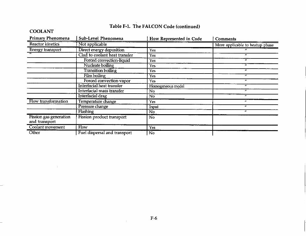
Table F-1. The FALCON Code (continued)COOLANT Primary Phenomena Sub-Level Phenomena How Reoresented in CodeReactor kinetics Not applicable More applicable to heatup phase Energy transport Direct energy deposition Yes "
Clad to coolant heat transfer Yes Forced convection-liquid Yes Nucleate boiling Yes Transition boiling Yes Film boiling Yes Forced convection-vapor Yes
Interfacial heat transfer Homogeneous model Interfacial mass transfer No Interfacial drag No
Flow transformation Temperature change Yes Pressure change Input Flashing No "
Fission gas generation Fission product transport No and transport Coolant movement Flow YesOther Fuel dispersal and transport No
F-6
Comments

Table F-2. The FRAPTRAN CodeFUEL
Primary Phenomena Sub-Level Phenomena How Reoresented in Code ICommentsReactor kinetics Reactivity insertion with ejected Power is an input variable;
control rod input time-dependent power Doppler neutronic response history plus axial and radial Moderator temperature neutronic profiles of power (profiles are response not time dependent) Moderator void neutronic response Negative reactivity insertion by reactor trip Shift of high power density region
Energy transport Total energy deposition Input variable via power Energy deposition rate Heat conduction Yes; modified 1D or 2D Finite difference modeling is satisfac
tory if have adequate submodels and properties
Fuel transformation Burnup Input by user or from Assumed bumup does not change during FRAPCON3 duration of a transient
Rim formation Radial burnup profiles from Thermally models bumup degradation FRAPCON3 of thermal conductivity; no mechanical
or microstructure modeling. Fuel microstructure changes No No data; no models are dependent on Porosity changes changes in these phenomena with burOxide grain size reduction nup; phenomena important to steady
state performance Thermal conductivity degradation Yes; due to irradiation and Same as FRAPCON3 with bumup de
fission products pendency Fuel temperature changes Yes Radial heat conduction with axial
variations in parameters affecting radial heat transfer
Fuel melting Fuel melting is accounted for in thermal and mechanical calculations
No bumup dependence for fuel melting temperature
F-7

Table F-2. The FRAPTRAN Code (continued)
Primary Phenomena Sub-Level Phenomena How Represented in Code CommentsFission gas generation Fission gas attachment Yes; calculate total gas generation Need high bumup transient data; and transport Fission gas migration but no modeling of bubbles, release, User has option to specify tran
Gas bubble coalescence or transport from fuel. sient fission gas release history Fission gas release which affects composition and Fission gas expansion pressure. Grain boundary gas pressurization
GRASS model is in FRAPTRAN but not assessed by PNNL.
Fuel movement Thermal expansion Yes Fuel swelling No Limited data only recently avail
able; fuel cracking and gaseous swelling should be modeled based on new CABRI and NSRR data
Fuel separation No Pellet fragmentation NoFuel particle expulsion No
F-8

Table F-2. The FRAPTRAN Code (continued)
PELLET-CLADDING INTERFACE COMPONENTPrimary Phenomena Sub-Level Phenomena How Represented in Code CommentsReactor kinetics Not applicable Energy transport Fuel-to-cladding heat transfer Yes Same model as used in FRAPCON3
and qualified against large data base
Gap transformation Fuel-to-clad bonding development No Chemical bonding observed intermittently; no data an impact an thermal-mechanical performance
Fission gas generation Pressurization Yes; dependent cx user input gas Instantaneous equalization of presand transport release, void volume, and tempera- sure and gas mixing; no modeling of
ture gas blanketing or time-dependent mixinmg
Gap movement Gap closure Yes; steady-state fuel swelling and No gaseous swelling cladding creepdown input to define condition at time of transient
Mechanical interaction (PCMI) Yes; FRACAS-I or FRACAS-II FRACAS-I assumes rigid pellet; FRACAS-TI has deformable pellet but model doesn't always converge
Lockup Yes Arising from fuel thermal expansion, steady-state fuel swelling
F-9

Table F-2. The FRAPTRAN Code (continued)
CLADDING
Primary Phenomena Sub-Level Phenomena How Represented in Code CommentsReactor kinetics Not applicable Energy transport Localized temperature gradients No (radial through-wall gradient No modeling of spalling and crack
only) ing of oxide Cladding heatup Yes Cladding heatup from cladding
oxidation Heat conduction Radial conduction of heat through No bumup dependence for cladding
cladding, include outer oxide layer or oxide fuel thermal conductivity Annealing Yes Model to be assessed by PNNL
Cladding transforma- Decreased ductility Yes; mechanical properties as a Additional mechanical data tion function of burnup; limited to less needed from high burnup cladding
than 60 jim of corrosion Decreased fracture toughness (du- No Outside scope of code; data needed plicate?) Radiation embrittlement Yes; steady-state irradiation ef- Additional data needed for high
fects are included in mechanical bumup cladding properties
Hydrogen uptake Yes; from steady-state modeling Hydrogen concentration is an input only, excess hydrogen concentration variable; additional data needed used in models for high burnup cladding
Hydrogen migration (global) No Outside scope of code; difficult to Hydrogen migration (local) model spallation and subsequent
thermal variations Hydrogen precipitation Yes; calculates excess hydrogen; Effect of excess hydrogen included
does not calculate orientation of in mechanical properties hydrides
Oxidation Yes; Cathcart and Baker-Just models for high-temperature oxidation in water only
Model being assessed by PNNL
F-10

Table F-2. The FRAPTRAN Code (continued)
Primary Phenomena Sub-Level Phenomena How Represented in Code CommentsCorrosion No Outside scope of code; corrosion Crud deposition and crud are steady-state phenomMicro-cracking oxide layer ena; condition of cracking is diffi
cult to model because of lack of good quality data
Cladding strain hardening Yes Function of fluence and excess hydrogen content
Cladding strain rate effects Yes Small effect Melting Yes Checks to see if melting tempera
ture has been exceeded Fission gas generation Fission gas release No Outside of scope of code; no modeland transport ing of release of fission products
from rod
Cladding movement Oxide spalling No Outside of scope of code Ballooning Yes Model to be assessed by PNNL Expansion Yes; elastic and plastic strain mod
eled by FRACAS-I Cladding- creep or plastic deforma- Yes; long-term creep input from tion FRAPCON3; transient plastic de
formation modeled Crack propagation Yes; simple models for stress corro- Model not assessed by PNNL
sion crack growth and crack fatigue growth
Cladding failure Semi; code flags cladding exceeded FRAIL failure probability packfailure conditions age has been removed
F-11

Table F-2. The FRAPTRAN Code (continued)
COOLANT Primary Phenomena Sub-Level Phenomena How Reoresented in Code Cnmmnt~nh
Reactor kinetics Not applicable Energy transport Direct energy deposition No Outside scope of code
Clad to coolant heat transfer Yes; coolant conditions are input Multiple thermal-hydraulic opForced convection-liquid variables tions available to the user; No Nucleate boiling two-phase flow Transition boiling Film boiling Forced convection-vapor
Interfacial heat transfer Interfacial mass transfer Interfacial drag
Flow transformation Temperature change Yes; coolant conditions are input Pressure change variables Flashing_
Fission gas generation Fission product transport No Outside scope of code; no modeling and transport of fission product transport by re
actor coolant Coolant movement Flow No Outside scope of code; no modeling
I I_ of coolant flow in channelsOther Fuel dispersal and transport No Outside scope of code; no modeling
of fuel transport by reactor coolant
F-12

Table F-3. The SCANAIR CodeFUEL
Primary Phenomena Sub-Level Phenomena How Represented in Code CommentsReactor kinetics Reactivity insertion with ejected Input data
control rod Doppler neutronic response Moderator temperature neutronic response Moderator void neutronic response Negative reactivity insertion by reactor trip Shift of high power density region
Energy transport Total energy deposition Input data Axial and radial power profiles (conEnergy deposition rate stant during the transient) must be
given as input data. Then, either the total power generated in the fuel (W) is given together with its time evolution, or the maximum radially averaged mass deposited energy (J/g) a t some reference time is given with its time evolution.
Heat conduction Yes Control-volume formulation Fuel transformation Bumup Input data Axial and radial bumup profiles (con
stant during the transient) must be given as input data. The only use of the bumup is to-calculate the fuel thermal conductivity and the fuel melting temperature.
Rim formation Input data Axial and radial profiles of burnup, porosity and grain sizes must be provided as input data.
F-13
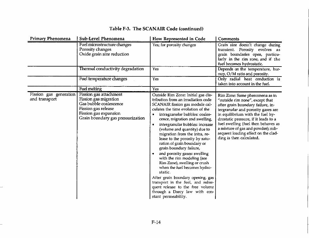
Table F-3. The SCANAIR Code (continued)
Primary Phenomena Sub-Level Phenomena How Represented in Code CommentsFuel microstructure changes Yes; for porosity changes Grain size doesn't change during Porosity changes transient. Porosity evolves as Oxide grain size reduction grain boundaries open, particu
larly in the rim zone, and if the fuel becomes hydrostatic.
Thermal conductivity degradation Yes Depends an the temperature, burnup, O/M ratio and porosity.
Fuel temperature changes Yes Only radial heat conduction is taken into account in the fuel.
Fuel melting YesFission gas generation and transport
Fission gas attachment Fission gas migration Gas bubble coalescence Fission gas release Fission gas expansion Grain boundary gas pressurization
Outside Rim Zone: Initial gas distribution from an irradiation code SCANAIR fission gas module calculates the time evolution of the "* intragranular bubbles: coales
cence, migration and swelling, "* intergranular bubbles: increase
(volume and quantity) due to migration from the intra, release to the porosity by saturation of grain boundary or grain boundary failure,
"* and porosity gases: swelling with the rim modeling (see Rim Zone), swelling or crush when the fuel becomes hydrostatic.
After grain boundary opening, gas transport in the fuel, and subsequent release to the free volume through a Darcy law with constant permeability.
Rim Zone: Same phenomena as in "outside rim zone", except that after grain boundary failure, intergranular and porosity gases are in equilibrium with the fuel hydrostatic pressure, if it leads to a fuel swelling (fuel then behaves as a mixture of gas and powder); subsequent loading effect on the cladding is then calculated.
F-14
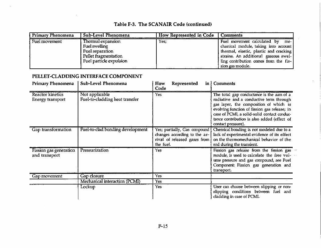
Table F-3. The SCANAIR Code (continued)
Primary Phenomena Sub-Level Phenomena How Represented in Code Comments Fuel movement Thermal expansion Yes; Fuel movement calculated by me
Fuel swelling chanical module, taking into account Fuel separation thermal, elastic, plastic and cracking Pellet fragmentation strains. An additional gaseous swelFuel particle expulsion ling contribution comes from the fis
sion gas module.
PELLET-CLADDING INTERFACE COMPONENT
Primary Phenomena Sub-Level Phenomena How Represented in Comments I I_ Code
Reactor kinetics Not applicable Yes The total gap conductance is the sum of a Energy transport Fuel-to-cladding heat transfer radiative and a conductive term through
gas layer, the composition of which is evolving function of fission gas release; in case of PCMI, a solid-solid contact conductance contribution is also added (effect of contact pressure).
Gap transformation Fuel-to-clad bonding development Yes; partially, Gas compound Chemical bonding is not modeled due to a changes according to the ar- lack of experimental evidence of its effect rival of released gases from on the thermomechanical behavior of the the fuel. rod during the transient.
Fission gas generation Pressurization Yes Fission gas release from the fission gas and transport module, is used to calculate the free vol
ume pressure and gas compound, see Fuel Component: Fission gas generation and transport.
Gap movement Gap closure Yes Mechanical interaction (PCMI) YesLockup Yes User can choose between slipping or non
slipping conditions between fuel and cladding in case of PCMI.
F-15

Table F-3. The SCANAIR Code (continued)
CLADDING
Primarv Phenomena Sub-Level Phenomena How Represented in Code CommentsReactor kinetics Not applicable Energy transport Localized temperature gradients Yes A fine meshing of the cladding is
Heat conduction used, with a control-volume numerical formulation, same as the one used for the fuel; effect of a ZrO 2 layer and possible heat generation in the cladding are taken into account.
Cladding heatup Yes Annealing No
Cladding transforma- Decreased ductility Yes Function of temperature. tion
Decreased fracture toughness No Radiation embrittlement No Implicitly taken into account in the
irradiated cladding mechanical properties used in the code.
Hydrogen uptake No Hydrogen migration (global) No Hydrogen migration (local) No Hydrogen precipitation No Oxidation Yes; input data Corrosion No Crud deposition
I Micro-cracking oxide layerCladding strain Yes A preliminary update of the UTS,
function of temperature only, has been tested with the PROMETRA hoop and axial tensile test results.
F-16

Table F-3. The SCANAIR Code (continued)
Primary Phenomena Sub-Level Phenomena I How Represented in Code CommentsCladding strain hardening Yes Capability of treatment of strain
hardening with laws derived from PROMETRA
Cladding strain rate effects No The present results of the PROMETRA program have not shown a significant incidence of the strain rate on the mechanical properties.
Melting Yes Fission gas generation Fission gas release No Outside of scope of present code and transport,_.... Cladding movement Oxide spalling No
Ballooning No Expansion Yes Cladding creep or plastic deforma- Yes Only transient plastic deformation tion is modeled Crack propagation NoCladding failure No The code calculates all the me
chanical properties that could be used in a failure criterion, not presently implemented. Failure criterion should depend on the loading mechanism, which is not well simulated in the present mechanical tests.
F-17

Table F-3. The SCANAIR Code (continued)
COOLANT
Primary Phenomena Sub-Level Phenomena How Represented in Code CommentsReactor kinetics Not applicable Energy transport Direct energy deposition No Negligible effect
Clad to coolant heat transfer Yes Only single phase water or sodium Forced convection-liquid (for CABRI REP-Na tests) are Nucleate boiling taken into account. Boiling curve Transition boiling has been implemented in the comFilm boiling ing version (V3.1), as well as a Forced convection-vapor coupling to a 2D 2-phase homoge
Interfacial heat transfer neous code. Interfacial mass transfer Interfacial drag
Flow transformation Temperature change Yes Same as preceding energy transPressure change port Flashing
Fission gas generation Fission product transport No Outside scope of present code. and transport No modeling of fission product
transport by the coolant. Coolant movement Flow Yes Coolant flow is calculated (axial
temperatures and mass flow rates); coolant pressure is constant and set up in the input data deck.
Other Fuel dispersal and transport No Outside scope of present code
F-18
APPENDIX G
AVAILABILITY AND APPLICABILITY OF A BOUNDING APPROACH FOR HIGH BURNUP FUEL
Background
Although a case can be made to pursue research to reduce uncertainties for highly ranked PIRT phenomena which are either partially known or unknown as defined in Tables 3-1 through 3-4, it is unlikely that the Office of Nuclear Regulatory Research will have sufficient resources to resolve all such uncertainties identified by the PIRT panel. Given the above and the relatively low probability of a rod ejection accident, the panel was asked to respond to the questions posed in the following paragraph.
Office of Nuclear Regulatory Research Request to PIRT Panel Members
1. Is there a bounding approach that can be used? Would that approach lead to undue conservatism resulting in the imposition of unnecessary burdens on vendors or licensees?
2. Would the bounding approach result in masking fuel or plant behavior that might be risk significant?
3. Are there data or analyses that can shed light on the significance of some of the identified uncertainties?
Panel Member Responses
The PIRT panel members expressed varying insights and viewpoints. There was no prevalent viewpoint. Therefore, the responses of the panel members are presented with minor editing in this appendix, as the members submitted them.
B. Dunn
Question 1
The combination of keeping the approved analysis approaches simple while using the current acceptance criteria offers something along this line. Rod ejection accidents probably can't happen but some control on how reactive to make the core is needed. Just as LBLOCA is now a somewhat arbitrary sizing calculation for the ECCS systems (leak before break has eroded any real confidence that a true LBLOCA could occur), the rod ejection could become an arbitrary sizing calculation for the core inherent reactivity. Whether or not this approach could be accepted is of concern.
G-1

Question 2
I do not know the answer to this question relative to the answer provided for question 1. We would certainly keep the inherent reactivity in check but would something be missed?
Question 3
No response.
K. Higar
Question 1
Depending upon the bounding approach implemented, it may impose unnecessary burden. If each parameter's uncertainty is explicitly and individually modeled, then the outcome would be overly conservative, and not very useful. However, if the uncertainties were handled collectively - via an approved combination of uncertainties method - then it would not be overly-conservative, and would be more consistent with acceptable engineering practices (an example would be the Code Scaling, Applicability and Uncertainty approach). The concern from a licensee's point of view would be consistency (or lack of) between the limit determination (magnitude of cal/gm) and the approved licensing methodologies for rod ejection events. Clearly, if conservative restrictions are placed upon the licensees' and vendors' method submittals, the potential exists for non-compliance to the new limit. An example is the statement that 60 cal/gm is easily supported by best-estimate 3-D analyses. However, if more typical licensing assumptions were utilized in the 3-D analysis, the calculated enthalpy could be > 100 cal/gm.
Question 2
The highly ranked phenomena encompass the behaviors that would be risk significant; therefore, the bounding approach for the medium ranked phenomena should not mask the important processes. However, it is not cdear whether the Medium rankings would need to be reconsidered given this issue.
Question 3
The only thing that comes to mind would be the CSAU approach utilized for some of the vendor's best-estimate LOCA methods. What new analyses were submitted in support of advanced reactor design licensing?
G-2

L. E. Hochreiter
Question 1
To respond to this question, the licensing basis must be defined. Currently, with the licensing basis of 280 cal/gr, fuel failure will occur with some fuel dispersal. The real issue is core coolability, and not fuel rod failure. It appears, however, that some members of the panel wish to change the criteria to no fuel rod failure so as to guarantee no fuel dispersal into the coolant. Apparently this is the approach adopted at EdF. I believe that this is an overly conservative approach for a transient which is not supposed to occur over the plant lifetime and will penalize the vendors and the utilities.
The core coolabiity approach has more of a direct appeal to me since fuel rods will be allowed to fail and some fuel will be allowed to be dispersed into the coolant. The core coolability can be related to the number of rods which would be allowed to fail, but my guess is that you would have to fail a very large unrealistic number of rods which give significant fuel dispersal into the coolant before flow blockage becomes an issue. The reactor is essentially shut down, the reactor pumps are operating, and my understanding is that the fuel is highly fragmented (like sand was one statement that I hear at the meetings) such that of the fuel which does enter the coolant, some fraction will be essentially swept out of the core into the upper plenum and will not contribute to fuel assembly blockage at the spacer grid. As long as we retain the coolability limit, I don't think that the 280 cal/gr needs to be changed. However, where some work has to be done is a more careful examination of the fuel dispersal and potential blockage issues that could occur. I would suggest as a start, that the existing data from the French and Japanese experiments be examined for fuel dispersal and a fuel particle size distribution be obtained. As indicated earlier, some fraction of the fuel particles will be so small that they will flow through the spacer grids without causing blockage, the remainder can be treated as blockage. Using the current analysis methods, the number of rods that could fail can be estimated, and if all the rods have fuel dispersal, then a potential blockage could be calculated. I would then run some three-dimensional subchannel calculations with the postulated blockage to see if there is a coolability problem. This would hopefully answer two questions, is the failure limit of 280 cal/gr causing unacceptable blockages such that core coolability is impaired, and the analysis would indicate the additional conservatism that would occur if the 280 cal/gr limit was reduced, so as to reduce the number of rod failures.
I contacted Toyoshi Fuketa and Joelle Papin regarding the fragment sizes observed in their experiments. The fuel particles sizes that they were able to measure so small that the particles would have been able to fit between the fuel rods and the spacer grid without any significant blockage. While there is very limited data, the data we do have indicates that there should not be any
G-3

significant blockage within a fuel assembly do to fuel rod failure at high calories/gram. Therefore, any limit below the present limit should have conservatism built-in and there should not be a need for additional conservatism.
As I understand, if three-dimensional kinetics calculations are performed, the amount of energy deposition is significantly reduced and a limit of approximately 100 cal/g will result for conservative analysis. Such a lower limit will further reduce any fuel failure and dispersal which could lead to blockage such that core coolability is not impaired. I believe that one needs to perform the sensitivity study I have outlined above before estimates of conservatism can be made for other limits. We could find that the current limit is already conservative enough for this transient.
Question 2
No, as long as one uses the coolability criterion, I don't think this will happen since one is assuming that the fuel rods will fail and fuel will be dispersed. Using such an approach, I believe that you are less dependent on the details of the fuel rod calculations and their associated models and failure mechanisms, which to a thermal-hydraulics person, are very complex and have high uncertainty. This rationale also depends to a large degree how the experimental data are used in such an approach and how prototypical the data are for the transients of concern. If we are to address Burnup to 75,000 MWd/t, we need data at this burnup for the reasons that Dr. Motta stated. If the fuel rod degrades further at the higher burnup, then more could fail and fuel dispersal and blockages would be larger. They may not be limiting, but they could be larger such that some margin is lost. Again based on the current data for fuel dispersal, there should not be a problem using a bounding approach.
Question 3
If I were the NRC, the first thing I would try to do is to determine the limits of coolability by doing the types of sensitivity studies indicated above. Such studies should indicate if the current 280 cal/g limit is adequate of if the allowable limit needs to be reduced because of the risk of loss of core coolability. I believe that we have relatively good and accurate subchannel methods that can predict flow starvation due to blockages within an open lattice fuel assembly for full flow conditions. Again, as I understand the transient, the reactor is shut down and is at 100% flow. It is very hard for me to understand that there would be a coolability problem.
G-4

Again, based on the existing data, there really should not be a coolability problem. However, I would still recommend that the NRC perform the sensitivity calculations as indicated earlier.
F. Moody
Question I
There is enough horsepower on the PIRT panel to be able to write describing equations for all of the phenomena involved in every process and system. Rather than indiscriminately throw out terms to obtain a bounding analysis, an appropriate normalization (like is done in the Severe Accident Scaling Methodology or SASM) would show dearly how a bounding analysis could be performed - that is, which parameters can be neglected without adversely affecting the results.
Question 2
The SASM process essentially guarantees that no significant phenomena, process, or system is masked by simplifications which are based on relative frequencies (reciprocal of period) of various phenomena, or comparison of nondimensional coefficients associated with the behavior.
Question 3
The Severe Accident Scaling Methodology is a natural for determining the relative significance of phenomena, and hence the uncertainties associated with them.
1. Papin
Questions I and 2
The use of a bounding approach may be justified if the phenomenology of the accident sequence is known, but some uncertainties on some of the parameters governing the main phenomena exist.
For the rod ejection accident phenomenology at present, many parameters are involved but not all are sufficiently studied. For instance, for a high burnup rod with significant corrosion (more than 80Rm) without any spalling, the possible impact of hydride concentration at the pellet interface during the strong PCMI phase is not known.
Similarly, the impact of transient spallation of the oxide layer is not known under prototypical conditions, nor is the rod behavior after clad temperature increase. Specifically, we do not know for a highly corroded cladding, if the
G-5

temperature increase will be of sufficient duration to improve the ductility of the clad material and prevent failure.
The range of burnup higher than 62 GWd/t has not been analyzed
As it has been reported at the NRC-sponsored Water Reactor Safety Information Meeting, no extrapolation of the new cladding behavior is presently reliable
The post failure consequences have not been investigated anywhere.
It seems that a bounding approach is premature without any additional knowledge of the whole phenomenology.
Question 3:
Studies have been done with the SCANAIR code in order to try to develop information on fuel rod behavior in the post PCMI phase. However, due to the necessity of introducing hypotheses without sufficient guaranty for the parameters used, the results were not found to be sufficiently conclusive and demonstrated the need for additional knowledge.
In some domains, separate effects tests may be of very high interest and useful for improving physical understanding and the quantification of some parameters. For example, the planned experiments for the study of transient fission gas behavior in the SILENE facility will provide some answers to the questions arising from the first CABRI tests results. However, such tests cannot provide the total answer because their range of applicability is often limited and because they do not express the physical couplings that exist in the actual case.
L. Peddicord
Question 1
The control rod ejection accident occurs at hot zero power critical conditions at full core flow. Such an accident would be a life-limiting event for a plant and the reactor would not operate again. In such a context then, the principal requirement is to assure that the response of high burn up fuel (and less extensively burned fuel rods) does not exacerbate the situation and make the rod ejection accident a more severe event than it already is. A more severe event is interpreted, for example, as resulting to additional release of fission products that could lead to offsite dose which could impact the health and safety of the public. It is assumed that this could only happen if the containment vessel is compromised. However, since the control rod ejection accident is in effect a small break event, it appears unlikely that it could lead
G-6

to an overpressurization, which would result in the breach of the pressure vessel. However, tests have shown that a reactivity insertion event can result in dad failure. A principal question then becomes if clad failure occurs along with dispersal of fuel, does this lead to impaired coolability with the possibility of blockage or propagation across the core resulting in a more severe situation.
One possible approach as discussed by the panel is to impose limits on core design such that clad failure does not result in a reactivity insertion accident. However, this approach may be overly restrictive, particularly for a highly unlikely event such as a control ejection accident. It is suggested that a bounding approach would be to construct a set of experiments and supporting analysis to determine if fuel failure and fuel dispersal can impair core coolability. If coolability can in fact be assured during the course of the event, this would avoid further deleterious effects and any propagation of the accident. Although high burnup fuel assemblies will have significantly lower power levels during an REA, this is an area where high burnup fuel could exhibit different response than less highly burned rods. This would be because of the degradation of the clad through high exposure making it more susceptible to failure. In addition, the presence of the rim effect in the fuel with fine- grained fuel with very high local burnups could be contribute to enhanced fuel loss through a breach, potential blockage, and possible propagation of clad failure to adjacent pins or assemblies. However, since there will be full core flow for the entire course of the event, with the loss of fine grain particles from the rod, there may be a sufficiently high probability that these will be swept out of the core passed grid spacers and not cause coolant channel blockage or loss of coolability.
The key question then is the behavior of the extended burnup fuel under these conditions and especially the possibility of fuel dispersal leading to degradation or loss of coolability. It would be worthwhile to undertake a research program to determine if, or to what extent, blockage or loss or coolability can occur for particles characteristic of high burnup fuel. Such a research program might have the following components.
1. Determine the nature of the clad failures for high exposure dad. This first part of this would be a literature study to look at failed dad from many sources including power reactor fuel and any information from other tests. In addition, it may be necessary to use irradiated dad specimens to produce loadings to produce breaches similar to what might occur in a REA event. However, it is assumed that these would not have to be inpile tests, thereby reducing costs and requirements.
2. Once a range of dad failures has been determined, then the next step would be to examine how much fuel dispersal could occur. Given the possible dad failures and with bundle designs with a pitch-to-diameter
G-7

ratio of 1.3 or so, whole pellets cannot leave the clad and move into the coolant channel. Even if entire pellets could relocate from the fuel pin in to the channel, they probably would not reduce coolability. Instead, it is assumed that the fine- grained fuel in the rim region would be the most subject to loss. Fortunately the extent of the rim is fairly well characterized already through a variety of PIE tests. The particle size of this fuel and the volume that could be ejected into the coolant should be able to be reasonably estimated based on already available information. The thickness of the rim and the amount of fuel that might be lost would probably be the main difference between fuel at 62 GWD/MTU and 75 GWD/MTU.
3. The next step would be given the size of breaks and the amount of fuel which could be ejected into the coolant channel, does this impact the coolability of the core. To study this, it is suggested that first a set of small scale, out-of-pile separate effects tests be conducted in which simulated particles are ejected or washed out through breaks to examine potential blockage of coolant channels. The key issue will be the interaction with grid spacers, and perhaps the upper fuel assembly mechanism. Very likely that most of the important information about blockage could be gained with unirradiated material in tests at room temperature and low pressurized conditions.
From the data and information presented, it is not clear that extended burnup fuel will have any limiting consequences on the rod ejection accident event. In addition, choosing a criterion which eliminates clad failure may be unnecessarily restrictive for such an unlikely accident. If fuel is dispersed into the coolant channel, the flow will be more than sufficient to sweep it out so that a more severe situation does not occur. In addition, it appears to be possible to conduct a set of small scale, out-of-pile separate effects tests which will be much less cosily yet yield valuable information to determine if fuel dispersal is a concern and lead to blockage. Conversely, it may be possible that loss of fuel from extended burnup rods (or fuel rods at any levels of burnup) does not lead to flow blockage and loss of coolability. Such an investigation would be a worthwhile, and perhaps not overly costly, component of the research program. Understanding the effect of fuel dispersal on core coolability would be valuable knowledge in assessing the response to a rod ejection accident. It would not lead to undue conservatism but in fact address the most fundamental and important question relating to the behavior of fuel rods in a rod ejection accident. The strategy could result in avoiding other overly conservative, but unnecessary, approaches.
Question 2
There is a possibility that the proposed bounding approach might overlook some effect which could impact core coolability by not considering a
G-8

mechanism which is not included or recognized. Careful selection of experimental designs will be important to encompass all relevant scenarios.
Question 3
It is presumed that there is a rich literature on the behavior of entrained solids of varying particle sizes in liquid flow. Liquids transporting solids are used in a number of engineering and production operations. In addition, blockages of flow channels are of prime importance in these situations, so relevant information may already be available. This would be a good starting point for review in order to construct an effective research program.
1. Rashid
Question 1
A bounding approach can be constructed from the rod ejection accident test data if we direct our attention to the surviving test rods and try to explain why those rods have not failed. A great deal of work has been done to explain the failures, from various perspectives, but not enough work was done to explain the successes, at least not with the same degree of vigour and emphasis.
Let us first address the high burnup issue. For similar burnup rods, similar fuel conditions exist, including the fuel microstructure, the pellet rim and the fission gas distribution. Therefore, the loading mechanisms are the same, whether PCMI, gas pressure or a combination of both. Consequently, we must conclude that the non-failed rods survived because of good cladding condition, i.e. no spallation and no hydride blisters or other defects that we consider unsuitable for reactor service. This is dearly demonstrated by REP Na-4 and Na-5. It is reasonable to expect, therefore, that similar quality rods will survive in-reactor rod ejection accidents of similar characteristics as the test rod ejection accidents.
Using the above rationale, we would postulate that a bounding enthalpy, as function of burnup or other operation-related state variable, exists such that all surviving-rods' enthalpies plot below it. Since we cannot be assured that slightly higher enthalpies will not result in failure, this bounding curve becomes the absolute lower bound for the failure enthalpy as function of burnup or oxide/thickness ratio. Moreover, this bounding curve, by definition, represents end-of-pulse failure; i.e. it is also the absolute lower bound for no fuel dispersal.
To derive a core-coolability criterion for high bumup, we use the failed-rods data. The CABRI tests include three failures: Na-1, Na-8, and Na-10 at delta enthalpies of 15 cal/g, 57 cal/g and 67 cal/g respectively, with failures
G-9

occurring during the pulse. Na-1 resulted in fuel dispersal driven by a AH of 85 cal/g, which is the difference between the total deposited energy and the deposited energy at the time of failure. The failures of Na-8 and Na-10, however, resulted in no fuel dispersal, with an average All of 30 cal/g above the failure enthalpies. Using similar rationale as above, we can assume that fuel dispersal can occur at AH in the range 30-85 cal/g above the aforementioned envelope curve, with zero dispersal at AH=30 cal/g and partial dispersal at AH=85 cal/g above the failure envelope. Clearly, the 30cal/g value is the more conservative value to use for setting the coolability limit.
The above bounding approach precludes cladding localized hydrides damage, a condition that is already self imposed by fuel vendors. However, to ensure compliance, it will be necessary to impose a limitation for oxide spallation. The zero or low burnup condition remains the same as in the past, i.e. governed by fuel/clad melting. The existing rod ejection accident licensing criteria, for both rod failure and core coolability, remain valid. The midrange of 35-50 MWD/MTU can be treated by linearly interpolating between the low and high burnup criteria.
The above response to the above question is, in the writer's opinion, a bounding approach that will also satisfy the second part of the question, namely, would not lead to undue conservatism that result in imposing unnecessary burdens on vendors or licensees.
Question 2
If the approach is truly bounding, it should not mask any behaviour regimes that are within the phenomenon or phenomena being bounded. The approach described above captures the behaviour regimes simulated in the rod ejection accident tests, which are bounding to the in-reactor rod ejection accidents.
Question 3
The analysis tools that are available can, and should, be used to evaluate the significance of these uncertainties. Some of the phenomena identified are not data-related or measurable, and therefore are not amenable to evaluation analytically. These have to be evaluated on the basis of expert judgment. The majority of the phenomena, however, can be evaluated by varying the relevant models in the computer code over their range of uncertainty, provided of course that the computer code has the needed capabilities.
G-10

1. Tulenko
Question 1
Yes, I believe that there is a bounding approach that can be used. Additionally, we can further rank the medium ranked phenomena with regard to their contribution to risk. I believe that in the panel's ranking the panel leaned to the side of inclusion as opposed to exclusion. Therefore, I believe that the panel evaluated risk in a very conservative manner. However, when one uses a bounding approach, there is additional conservatism that is generated that makes the criteria more binding.
Will a bounding approach that we might use in this case be too conservative? One cannot tell until one spells out the approach. In this case, I believe that we can develop a program with a bounding approach that vendors and licensees can live with.
Question 2
No, I don't think that the bounding approach that we are developing would mask fuel or plant behavior that would be risk significant. There would not be zero risk, but I believe that there would be acceptable levels of risk.
Question 3
This is the work of the panel, to identify where data may exist and to determine what additional experimental/analysis will minimize the identified uncertainties. I think that working as a team that we can get there.
N. Waeckel
Question 1
The French safety authorities asked for the validation of physical parameters bounding a safety domain, which guarantees no fuel dispersal in the core, which can be conservatively assured by no cladding failure during a RIA.
In order to define and defend the safety domain, EDF has adopted the following approach:
- evaluate the rod ejection accident simulation tests conducted in CABRI;
- use SCANAIR thermal mechanical code to analyze the tests and identify the major operating mechanisms;
- assess the applicability of CABRI tests results to PWR conditions; - EDF proposed Safety Domain assess this domain.
G-11

Data base evaluation
The complete experimental database includes ten rod ejection accident simulation tests on U0 2 fuel rods, from 33 to 64 GWd/tM (peak pellet bum-up), and MOX fuel rods, from 28 to 55 GWd/tM.
The CABRI experimental database and the associated analyses guarantee the fuel cladding integrity in the following conditions:
- local burnup : up to 64 GWd/tM; - waterside corrosion level: up to 120 pim, based on the highest
corroded test fuel rod, induding spalled spots with hydride blisters ; - energy deposition : up to 57 cal/g, based on local failure threshold
of a heavily spalled rod; - pulse width at mid-height : larger than 30 ms; - maximal cladding temperature : up to 700'C (this value is based on
the maximum cladding temperature experienced by a CABRI test rod ).
Major operating mechanisms
The CABRI data base has been extensively interpreted using the SCANAIR code. The main measured phenomena (cladding plastic strain, maximum and residual fuel rod elongation and fission gas release) are fairly well reproduced. This conclusion indicates that there is a good understanding of the dominant operative mechanisms during a rod ejection accident. For high bumup UO2 fuel rods the failure mechanism is PCMI (pellet cladding mechanical interaction) assisted by hydride embrittlement of the fuel cladding. No fuel failures occurred in CABRI tests up to 64 GWd/tM as long as the rods didn't exhibit in-reactor spallation and local hydride blisters.
We show thus that the key parameter which governs the behaviour of highly irradiated fuel rods during a rod ejection accident is the cladding material ductility, which depends on two other parameters : the cladding temperature during the transient and the cladding waterside in-reactor corrosion and hydriding. It seems also that the pulse width plays an important role on the dadding loading: a narrow pulse enhances the local radial temperature gradiant in the fuel pellet and influences the kinetics and maybe the type of the loading on the cladding.
G-12

Applicability to the PWR conditions
In parallel, we show that the differences between the CABRI (nonpressurized sodium loop) and PWR environments are not an obstacle to the representativity of CABRI tests : DNB, which is unreachable in CABRI, is not a limiting phenomenon in a PWR, where an RCCA ejection accident (REA) leads to low enthalpy levels with a very low risk of DNB onset.
Nevertheless, as it has been observed in some CABRI tests, the in-reactor corrosion layer spalls off during the rod ejection accident and brings into contact the overheated underlying base metal with the coolant. In PWR conditions that could lead to a local and ephemeral DNB onset. Conservative thermal hydraulic calculations show that the local heat exchange coefficient degradation lasts only a few seconds ; the cladding temperature doesn't go beyond 600 0C. At that level of temperature the cladding mechanical properties are significantly degraded. As the local internal overpressure related to the transient fission gas release may be high, a risk of cladding balloning and subsequent cladding failure can be speculated. Now some CABRI RIA simulation tests on MOX fuel rods exhibited cladding temperatures as high as 700 0C. No local cladding balloonings were observed after the tests despite very high level of transient fission gas release (up to 35 %, to be compared to less than a few % expected in the case of an REA transient applied to a high burn-up U0 2 fuel rod). The post-DNB failure scenario is thus unfounded in case of PWR REA. Furthermore, the analysis of NSRR RIA tests, which are performed in a non-pressurized water loop, show that the temperature elevation due to DNB is rather a favorable phenomenon, because it restores the cladding material ductility. The limiting configuration is thus the one without DNB, so the CABRI tests are fully representative and demonstrative for our analysis.
Proposed Safety Domain
Based on these very conservative experimental results, EDF has proposed to the French Safety Authorities, for design purpose, a set of physical parameters that define a safety domain in the range 45-64 GWd/TM (the midrange of 35-45 GWd/MTU can be treated by linearly interpolating between the current low burnup criteria and the high burnup proposed criteria):
- in-reactor waterside corrosion limited to 100 A.m (in order to prevent in-reactor cladding spallation and localized hydriding);
- enthalpy increase limited to 60 cal/g; - pulse width at mid-height larger than 30 ms; - maximal cladding temperature limited to 700 'C.
G-13

This safety domain is not considered as a fuel rod failure criterion but as a conservative way to guarantee no fuel failure. The physical parameters defining the safety domain (enthalpy, pulse width and dad temperature) have the advantage to be directly used in reload neutronic calculations. The Safety Domain allows nuclear designers to identify and rank the penalizing rod ejection accidents. A mechanistic failure criterion can be defined later when more representative mechanical property tests become available to define the transient cladding ductility at high burn-up.
During rod ejection accident in a PWR, the energy deposition level is limited to 25 cal/g (1). The transient conditions are thus adequately bounded by the limits of the Safety Domain. Therefore, the absence of dad failure during an REA in a PWR is fully assessed (the fuel dispersal threshold is more than 30 cal/g higher than the proposed failure limit).
Question 2
No. The approach described above is based on the understanding of the key mechanisms involved in any type of rod ejection accident. The proposed limits are consistent with other test reactor results, including the impact of DNB.
Question 3
Sensitivity calculations within the range of input data or models uncertainties will help us to evaluate the relative importance of some of the identified uncertainties.
G-14

APPENDIX H
PANEL PERSPECTIVES ON APPROACHES TO INCREASING THE BURNUP LIMIT FROM 62 GWd/t TO 75 GWd/t
Background
The current licensing limit for fuel burnup is 62 GWd/t: However, there are economic incentives to extract additional energy from the fuel by proceeding to even higher burnups, for example, 75 GWd/t.
As the burnup increases from 62 to 75 GWd/t, the fuel and the cladding are exposed for a longer time to the irradiation field present in the reactor, as well as to the corroding environment represented by the coolant.
Extending burnup beyond currently approved limits (62 GWd/t) requires licensing criteria against which the. fuel rod transient response (fuel failure and core coolability) under rod ejection accident conditions can be judged. Once these criteria are formalized, it will be necessary to demonstrate that the given fuel and cladding satisfy the criteria.
Office of Nuclear Reactor Regulation Request to PIRT Panel Members
Given industry desire to proceed to higher fuel burnups, the Office of Nuclear Reactor Regulation has asked members of the panel to respond to the following question: "With respect to the rod ejection accident, what is needed to justify increasing the burnup limit from 62 to 75 GWd/t?"
Panel Member Responses
The PIRT panel members expressed varying insights and viewpoints. There was no prevalent viewpoint. Therefore, the responses of the panel members are presented with minor editing in this appendix, as the panel members submitted them.
R. Deveney
The below 3 items need to be tested, analyzed, and/or inferred at the higher burnups (62 to 75 GWd/t) relative to the impact on rod ejection accident limit solution for burnups up to 62 GWd/t.
1. Physical properties of the fuel that are important to rod ejection accident need to be defined for the higher burnups.
2. Physical properties of the clad that are important to rod ejection accident are needed. In particular, corrosion effects seem to be the most likely
H-1

properties to be affected by burnup. Opinion: Since only advanced cladding will most likely be used at the extended burnups, testing of Zr4 at the higher burnups needs to be carefully scrutinized in order to get the most meaningful data at.
3. Determine whether the hypothesis that gaseous swelling in the rim is significant. Opinion: This hypothesis can be best tested by ignoring it. If the results can be explained without it, it does not exist.
B. Dunn
The following is a reasonable way to proceed to 75 GWd/t.
1. Generate reference 3-D calculations sufficient to bolster our belief that energy depositions of around 100 cal/g are valid for fuel exposed to 50 or 60 + GWd/t. There would need to be some work done to pick actual numbers, 80, 100, or 120 cal/g; 50, 55, 60 or 65 GWd/t; whatever. These studies could be industry or individual vendor. It seems possible that some of Diamond's work already shows this.
2. A set of physical properties that are expected to trend with, not predict, the ability of the cladding to withstand rod ejection accident loads should be identified. These properties do not need to predict the current experiments. They need to trend with the current results and give us confidence that, as a set, their fractional deterioration is a reasonable measure of the increase in cladding susceptibility to failure. Lead test assembly (LTA) programs with the ability to determine these properties should precede the extension and the measurements should provide assurance that asymptotic behavior to acceptable levels of degradation are expected. We can currently license to 62 GWd/t because of some perceived margin. If there is only a 5 % degradation of properties up to 75 GWd/t, I doubt that the margin has been seriously eroded. However, this requires some real work on the NRC's part to get a reasonable hold on the criteria and the current margin.
I would expect that the existing set of strain tests would be part of the set. Another member would probably be the degree of spalling. There is good evidence that spalled cladding is likely to have problems in an rod ejection accident. Therefore, significant spalling of the cladding should probably not be allowed for the extension of burnup. Perhaps something like 95 % confidence that only 1 % of the pins in the high burnup fuel have spalled locations. Again particular numbers are a mater for more detailed consideration.
Another example would be the acceleration of corrosion for Zircaloy with burnup. This is not asymptotic to acceptable levels. Other materials or
H-2

coatings, however, may not experience the Zircaloy corrosion acceleration until burnups higher than 75.
3. With the acceptable variation of this set of parameters established, I believe that the risk to the public health and safety is not increased from what that risk is today. Therefore, allowing burnup to 75, or whatever would be reasonable given the characteristics of the measured parameters, could be allowed.
L. E. Hochreiter
Dr. Motta had an excellent answer to this question, which I support. The one thing that I would add is that you do need data at the intended burnup to confirm the fuel behavior and to make sure there are no run-away processes that occur at the higher Burnup. By data I mean examination of fuel rods which have been subjected to the higher burnup from lead test assemblies or other sources. The issues are corrosion, oxide spalling, hydride formations, etc. Without such data, the plant could be outside the known and relatively well-understood operating envelope. This should never be allowed to happen. Therefore, the justification has to be experimental data, which covers the burnup ranges that the fuel will operate at.
A. Motta
There are two possible scenarios in going from 62 to 75 GWd/t.
1. More of the same: In this scenario, the degradation processes present at burnups lower than 62 GWd/t continue up to 75 GWd/t, at rates similar than before. In that case, the behavior of the material at 75 GWd/t is similar to that at 62 GWd/t; the rates and processes that occur are well known and can be predicted with a reasonable degree of confidence. As far as I can tell, the extrapolation of current degradation rates does not appear to give problems at 75 GWd/t.
2. New stuff or faster old stuff: In this scenario, either new degradation processes start to occur that were not prevalent before 62 GWd/t or processes that did occur get accelerated between 62 and 75 GWd/t, leading to disproportionately higher material degradation. For example, if between 62 and 75 GWd/t the cladding material undergoes corrosion breakaway, such that the corrosion rate markedly increases, the increased hydriding, and increased probability of oxide delamination and spalling, could be a cause of concern. This could occur for example due to increased lithium concentrations during higher burnup operation (this is from the need to balance pH as a result if higher B for reactivity control).
H-3
Thus, in my view to demonstrate that 75GWd/t is a safe operation level, it is necessary to:
" Demonstrate that there are no changes in rate in processes such as corrosion and hydriding. This mainly means in my view, the possible onset of breakaway corrosion, and it may be a much easier regulatory burden to meet for the newer alloys, which corrode much less than Zircaloy.
" Be convinced that new degradation processes of the fuel and cladding do not become operative at 75 GWd/t. This is a "coefficient of ignorance" type of item; maybe by discussing this with cladding and fuel experts, we can get a sense of whether there is something to worry about. Processes such as creep and growth change rate at high burnup, mechanical properties change, the starting chemistry of the coolant is different, so maybe Crud deposition would change, etc.)
In addition, for high burnup fuel, the likelihood of larger reactivity insertions increases with enrichment, so it is also necessary to demonstrate that the reactivity insertions are still acceptable at high burnup. (i.e., an rod ejection accident at 62 GWd/t in fuel designed to go to 63 is less serious than and rod ejection accident at 62 in fuel designed to go to 75 GWd/t.)
J. Papin
The present data base and related knowledge for high burnup fuel behaviour during a rod ejection accident concerns fuel rods up to 64 GWd/t (local value, corresponding to 58 GWd/t rod average) with Zircaloy-4 cladding, under NSRR conditions (stagnant water, ambient conditions) or Cabri conditions (sodium coolant, 280'C, 1b).
In the range of investigation, the following key influence factors have been identified:
- Clad corrosion with hydride accumulations (due to oxide spalling or hydride layer cf. Cabri, NSRR tests) promotes rod failure in decreasing clad ductility,
- High gas content in the rim zone with inter-granular gases leads, under fast heating, to grain boundary failure with possible contribution to clad loading in addition to fuel thermal expansion,
- Power pulse, which determines the energy injection rate and influences the dad loading (fission gas dynamic behaviour, thermal expansion) and also the available driving force of the gases for fuel ejection after rod failure.
H-4

Going to higher burnup implies justifying under rod ejection accident conditions that the new cladding alloys keep sufficient ductility. Specifically, the hydride concentration resulting from the extended stay in the reactor should be checked and the mechanical properties evaluated for the realistic loading of a rod ejection accident.
For increased burnup levels, the overall fission gas content will be higher and the rim zone extended with more gases in intergranular 'bubbles and porosity. Similarly to what has been suggested from the analysis of the failure of the high burnup MOX fuel rod Cabri REP Na7, the gas pressure loading might cause rod failure with low dad straining.
In case of failure, higher fission gas inventory may be an increased driving force for fuel ejection of finely fragmented fuel resulting from grain boundary separation.
The following are needed to justify going to higher burnup values, e.g., 75 GWd/t.
- A correct knowledge of the fuel state with precise quantification of the fission gases, mainly inter-granular and porosity gases (inventory, detailed distribution) at the end of irradiation; this requires adequate fuel examinations,
- A better understanding and evaluation of the fission gas behaviour under transient conditions,
- A sufficient understanding of the global rod behavior under representative transient conditions of an rod ejection accident with an evaluation of the rod failure levels and of the conditions for fuel ejection into the coolant which should be bounding for the reactor case.
D. Pruitt
Justification of an increased bumup limit of 75 GWd/t would need to address the changes in the fuel and cladding properties that are limiting with respect to the rod ejection accident. From the discussions thus far, the important issue is the ductility and integrity of the cladding with a secondary concern associated with the material changes of the fuel pellet.
The characterization of cladding materials at 75 GWd/t would need to be accomplished through a lead test assembly (LTA) program. The idea would be to determine cladding characteristics that would correlate with the limited experimental data. These correlating parameters (oxide thickness, level of hydriding, spallation, etc.) should provide a reasonable confidence in the level of cladding ductility degradation with burnup. The LTA would then demonstrate that the proposed fuel design exhibits, at worst, only a minor
H-5

deterioration in these characteristics compared to those observed at 62 GWd/t with current designs.
If the cladding characteristics are shown to be the same or only slightly worse than that observed at the lower exposure, then the concern is limited to any degradation in the pellet response during the rod ejection accident or in the amount of energy content and particle size of the fuel dispersed upon cladding failure. These issues are related to the energy deposition in the rim section and the structure of the rim region. The microstructure of the rim region can probably be characterized by hot-cell examination during the LTA program. The energy deposition in the rim region is burnup dependent. As the burnup is increased, the energy deposition in the pellet rim increases for a given power pulse. A set limit on the rim energy deposition (based on either cladding failure or core coolability) may provide a natural limit on the severity of the power pulse as burnup increases.
1. Rashid
Extending burnup beyond currently approved limits (62 GWd/t) requires licensing criteria against which the fuel rod transient response (fuel failure and core coolability) under rod ejection accident conditions can be judged. Given the present state of uncertainty of redefining the current rod ejection accident criteria, formulating a response to the above question is subject to the same uncertainty. Although the NRC does not intend to apply the back-fit rule to burnups below 62GWd/t, it is not realistic to base burnup extension to 75 GWd/t on the current licensing criteria.
Thus, the response to the NRR question is dependent to a large extent on the response to the first question in Appendix G, which states" Is there a bounding approach that can be used? Would that approach lead to undue conservatism that result in imposing unnecessary burdens on vendors or licensees?" (See Appendix G for the author's response to this question). Thus, if licensing criteria can be found which conservatively bounds presently known fuel rod response, it is reasonable to expect that the same conservative bound would be maintained, if the fuel rod's relative behavior at burnup above 62 GWd/t is similar to that at the lower burnup. Defining the conditions for which the aforementioned statement remains valid would constitute the response to the NRR question.
Review and analysis of the experimental data for high burnup fuel clearly indicate that cladding ductility is the primary cause of fuel rod failures during rod ejection accident simulation tests. The ability of the cladding to accommodate the fuel loading, from both thermal expansion and gas bubble expansion, is key to the survivability of the fuel rod. As has been demonstrated in the Cabri tests, fuel rod failure occurs only for cladding with spallation-induced ductility loss. Rods with uniform corrosion up to 80
H-6
microns have not failed in rod ejection accident tests. This has been confirmed up to 64 GWd/t, indicating little influence from pellet rim or fission gas enhanced loading. It should be stated, however, that the role of fission gas enhanced loading, as described above, is less dear for mixed oxide fuel, which is excluded from the present discussion.
Thus, what is needed to justify increasing the burnup to 75 GWd/t is to use advanced cladding alloys with improved corrosion performance to ensure that cladding ductility at 75 GWd/t will be higher than at 62 GWd/t. This can be easily demonstrated through separate-effects mechanical property tests. Once cladding ductility is demonstrated, compliance with the established licensing criteria can be accomplished through analytical means using validated and verified fuel behavior codes such as FALCON/SED or other similar codes. Additional rod ejection accident tests may be conducted to confirm the established criteria.
D. Risher
With respect to the rod ejection accident, in order to increase the burnup limit to 75 GWd/t, a reasonable assurance is needed that the increased burnup does not result in cladding failure or significant fuel dispersal at a significantly lower limit than is indicated by the current rod ejection accident test results, which cover burnups up to about 64 GWd/t.
The Cabri data indicates that the dad failure threshold (and the "fuel dispersal" threshold) is reasonably high (greater than 60-100 cal/g) provided the cladding is in "good" condition (defined as an amount of oxide not exceeding 100 microns, no spalling, and no hydride blisters or other defects). Moreover, this threshold does not appear to be decreasing significantly with fuel burnup once the burnup exceeds about 50 GWd/t. For fuel with cladding in "good" condition, the test results have been adequately characterized by fuel mechanical analysis computer codes. This analysis method could be used to extend the current rod ejection accident data to address advanced cladding materials without further rod ejection accident testing. Therefore, it would appear that the fuel burnup limit could be extended from the current 62 GWd/t to 75 GWd/t (with a safety analysis limit based on current rod ejection accident test results) provided: 1) the fuel rod mechanical analysis code shows that advanced cladding materials have equivalent or better response than conventional low-Tin Zirc, and 2) there is sufficient high-burnup lead test assembly data up to near 75 GWd/t that shows that oxidation does not exceed 100 microns and that there is no spalling.
This method would allow extending the burnup limit with no need to extend current rod ejection accident tests to cover higher burnup or advanced cladding materials, although additional advanced cladding material properties data may be needed at high burnups.
H-7

1. S. Tulenko
In response to the questions posed by the Office of Nuclear Reactor Regulation concerning what justifications are required to increase the fuel burnup limit from 62 to 75 GWd/t with respect to a PWR rod ejection accident, the following comments are made.
1. The physical properties of the cladding and fuel at 75 GWd/t must be understood and bounded to encompass the significant majority of the fuel.
2. The expected behavior of the rim region in particular under rod ejection accident conditions at a burnup of 75 GWd/t should be analytically understood and experimentally verified.
H-8

APPENDIX I
MEMBERS OF THE HIGH BURNUP FUEL PIRT PANEL
Carl A. Alexander
Carl Alexander is Chief Scientist of Battelle's government sectors operation. He has a B.S. in Mathematics from Ohio University, a M.S. in Physics from the same institution, and a Ph.D. in Ceramic Engineering received in 1961 from The Ohio State University. From 1962 to 1985 he was a member of the engineering and graduate faculty of The Ohio State University, with joint appointments as Adjunct Professor of Nuclear Engineering as well as Ceramics and Materials Engineering. He has also served as Adjunct Professor at the University of Maryland and Southampton University in the U.K. His specialty is nuclear fuels and thermodynamics. He performed some of the first loss-of-coolant simulations in the late 1950s early 1960s. He contributed to Wash-1400 in which he showed the importance of cesium iodide as a transport medium in a LOCA. He performed several studies of fission product release with real fuels at very high temperatures and has evaluated a number of complexes involving urania and Zircalloy at very high temperatures.
Brent E. Boyack
Brent E. Boyack is the facilitator for the High Burnup Fuel PIRT Panel. He is a registered professional engineer. He obtained his B. S. and M. S. in Mechanical Engineering from Brigham Young University. He obtained his Ph.D. in Mechanical Engineering from Arizona State University in 1969. Dr. Boyack has been on the staff of the Los Alamos National Laboratory for 20 years; he is currently the leader of the software development team, continuing the development, validation, and application of the Transient Reactor Analysis Code (TRAC). Dr. Boyack has over 30 years experience in the nuclear field. He has been extensively engaged in accident analysis efforts, including design basis and severe accident analyses of light water, gas-cooled, and heavy-water reactors; reactor safety code assessments and applications; safety assessments; preparation of safety analysis reports; and independent safety reviews. He chaired the MELCOR and CONTAIN independent peer reviews and was a member of the Code Scaling, Applicability and Uncertainty or CSAU technical program group. He has participated in numerous PIRT panels. He has over 70 journal and conference publications and is an active member of the American Nuclear Society.
R. C. (Dick) Deveney
R. C. (Dick) Deveney is a PIRT expert from Framatome Cogema Fuels (FCF) on 3-D kinetics. He is currently the Leader of the Nuclear Technology Group that is responsible for the development of neutronic codes and methods. He has a B.S. in Physics from Dickinson College and a M.E. in Nuclear Engineering from University of Virginia. He has worked with FCF for 22 years in the neutronic related activities.
I-1

Those activities include reload licensing activities, support of safety analyses, code development, and code benchmarking. Support (neutronic inputs) has been provided for numerous transient simulations such as ejected rod, steam-line break, rod withdrawal, rod drop, large-break LOCA, small-break LOCA, and other Chapter 14 events. He is the co-author of the NEMO and NEMO-K Topical reports. NEMO is FCF's 2 energy group nodal neutronic simulator and NEMO-K is the 3-D kinetic simulation.
Bert M. Dunn
Bert M. Dunn obtained his B. S. in Physics from Washington State University in 1968 and his M. S. in Physics from Lynchburg College in 1973. Mr. Dunn has worked in LOCA and Safety Analysis for the Babcock and Wilcox Company (B&W) and Framatome Technologies (FTI) for 28 years. Mr. Dunn has served as the lead technically for the development of the B&W and FTI LOCA evaluation models for once through and recirculating steam generator plants. He has worked with both deterministic and best estimate LOCA evaluation techniques. He has also been technical lead for method development and application of boron dilution accident methods and pressurized thermal shock evaluation methods. He is currently employed as an Advisory Engineer with responsibility for the development of LOCA and Safety Analysis techniques for evaluation of advanced cladding materials. This includes test specification development, review and correlation of results, and the incorporation of results into requisite analytical methods. Mr. Dunn has been primary author on several company topical reports covering both methods development and accident analysis.
Toyoshi Fuketa
Toyoshi Fuketa is a Principal Engineer in the Fuel Safety Research Laboratory at the Japan Atomic Energy Research Institute (JAERI). He obtained his B. S., M. S. and Ph.D. in Mechanical Engineering Science from Tokyo Institute of Technology, Japan, in 1982, 1984 and 1987, respectively. Dr. Fuketa has been involved in the Nuclear Safety Research Reactor (NSRR) project to study behavior of LWR and research reactor fuels under reactivity accident and severe accident conditions and to evaluate the thresholds, modes, and consequences of fuel failure in terms of the fuel enthalpy, fuel burnup, coolant conditions, and fuel design. His research interests include fuel-coolant interactions, fuel failure mechanisms and transient fission gas behavior. He was engaged in small-scale steam explosion experiments at Sandia National Laboratories, Albuquerque, from 1988 to 1990, as a visiting scientist.
Keith E. Higar
Keith E. Higar is the PWR Transient Lead Engineer in the Nuclear Analysis and Design (NAD) group at Northern States Power (NSP) Company. He obtained his B.S. in Nuclear Engineering from Iowa State University in 1991. Mr. Higar has been employed at NSP for 8 years in the Transient Analysis Section of NAD; he is currently the Lead Engineer in the PWR Transient Analysis group responsible for
1-2

the development, validation, application, and maintenance of PWR transient analysis methodologies. During his term at NSP, Mr. Higar has been primarily engaged in design basis safety analyses and plant modification support. He has presented and defended, to the Nuclear Regulatory Commission, deterministic analyses in support of Prairie Island modifications. Mr. Higar is NSP's representative to the Westinghouse Owner's Group (WOG) Analysis Subcommittee. He serves as the ECCS and LOCA technical point of contact for Prairie Island Nuclear Generating Plant, responsible for technical aspects of analysis and evaluation of LOCA related issues, including 10 CFR 50.46 compliance. Additionally, Mr. Higar has acted as technical specialist for all Northern States Power's audits of Westinghouse's small and large-break LOCA analyses, including methodology review and compliance.
Lawrence E. Hochreiter
L.E. (Larry) Hochreiter is a professor of Nuclear and Mechanical Engineering at the Pennsylvania State University and does research and teaching in the areas of twophase flow and heat transfer, reactor thermal-hydraulics, fuel rod design, and nuclear reactor safety. He received a BS degree in Mechanical Engineering from the University of Buffalo and a MS and Ph.D degrees in Nuclear Engineering from Purdue University. While at Pennsylvania State University, Dr. Hochreiter has developed a detailed reflood heat transfer PIRT to guide the design and instrumentation of the NRC Rod Bundle Heat Transfer program, located at Penn State. Before joining the Penn State University in 1997, Dr. Hochreiter was a Consulting Engineer at the Westinghouse Electric Corporation for nearly 26 years and was responsible for the development, testing validation, and licensing of Westinghouse safety analysis methods. He developed the large-break Loss Of Coolant Accident (LOCA) PIRT for the Westinghouse Best-Estimate Methodology. He also participated in and helped develop the Westinghouse small-break LOCA PIRT. Dr. Hochreiter also developed several PIRTs for the Westinghouse advanced AP600 design for the accident analysis methods and presented these PIRTs to the NRC and the ACRS.
Siegfried Langenbuch
Siegfried Langenbuch is head of the reactor dynamics division of GRS. He obtained his Diploma in Physics from the University of Munich in 1969. The objective of his Dr. degree work was the development of an efficient spatial- and time-dependent 3D-neutronics model for studying reactivity initiated accidents. His research interests were code development for neutron dynamics and thermo-fluid dynamics of the reactor core, including the coupling of 3D-neutronics models with plant system codes. In addition, he has experience in safety review of nuclear design, thermal design, and accident analysis of BWRs and PWRs as well as of VVERs and RBMKs of Russian design. He is a member of national and international working groups for the requirements of nuclear design. He has numerous publications in the field of reactor core dynamics.
1-3

Frederick 1. Moody
Frederick J. Moody is a Consulting Engineer in Thermal-Hydraulics, who has participated in numerous NRC - sponsored peer review groups and Technical Program Groups, involving the analysis of postulated nuclear reactor accidents. He received his Ph.D. in Mechanical Engineering from Stanford University in 1971. He completed 41 years of reactor and containment safety analyses at the General Electric Nudear Energy Division, where he developed various industry-standard analytical models for studies involving pipe and component rupture blowdown of high pressure steam and water mixtures, containment pressure and jet impingement loads, waterhammer forces associated with pipe flow accelerations, dynamic and thermal response of nuclear reactor core components during accident conditions, and fluid-structure interaction of submerged structures. He has taught numerous engineering courses as an adjunct professor for 28 years at San Jose State University, as an in-plant instructor at General Electric, and more recently as an instructor for professional development courses sponsored by the American Society of Mechanical Engineers. He has authored numerous journal papers, written an engineering textbook, Introduction to Unsteady Thermo-Fluid Mechanics (Wiley Interscience, 1990), and co-authored The Thermal-Hydraulics of a Boiling Water Nuclear Reactor, 2nd Ed., ANS Press, 1993.
Arthur T. Motta
Arthur T. Motta has worked in the area of radiation damage to materials with specific emphasis in Zr alloys for the last fifteen years. He received a B.Sc. in Mechanical Engineering and an M.Sc. in Nuclear Engineering from the Federal University of Rio de Janeiro, Brazil, and a Ph.D. in Nuclear Engineering from the University of California, Berkeley. He worked as a research associate for the CEA at the Centre for Nuclear Studies in Grenoble, France for two years and as a postdoctoral fellow for AECL at Chalk River Laboratories, Canada, before joining Penn State in 1992. The research programs he developed at Penn State include mechanical behavior of Zr alloys, advanced techniques for characterization of Zr alloys, and its oxides, defects in intermetallic compounds and phase transformation under irradiation. He has expertise in transmission electron microscopy, charged particle irradiation, mechanical testing, positron annihilation spectroscopy and theoretical expertise on phase transformations under irradiation and microstructural evolution under irradiation. He has recently authored review articles on amorphization under irradiation and on zirconium alloys in the nuclear industry. He was recently guest editor for a special issue of the Journal of Nuclear Materials, and was a member of a DOE panel to evaluate research needs on radiation effects on ceramics for radioactive waste disposal.
Mitchell E. Nissley
Mitchell E. Nissley obtained his B. S. and M. Eng. degrees in Nuclear Engineering from Rensselaer Polytechnic Institute. Mr. Nissley has been on the staff of the Westinghouse Electric Company for 18 years; he is currently the leader of the team
'-4

responsible for the development, licensing and application of the various realistic large break LOCA analysis codes and methodologies employed by Westinghouse. His contributions to the nuclear industry include the development and licensing of critical heat flux correlations for advanced PWR and VVER fuel designs, and the development and licensing of realistic large break LOCA evaluation models for Westinghouse PWR designs (cold leg injection, upper plenum injection and AP600). He has numerous journal and conference publications.
J6elle Papin
J6elle Papin obtained her Ph.D degree in thermal hydraulics of two-phase flow in 1976 and joined the CEA staff at Cadarache center at that time. She has been involved in the safety studies of fast breeder reactors (FBRs) dealing with code development and interpretation of experiments of core degradation (multiphase, multicomponent systems). From 1988 to 1990, she was also involved in severe core damage analysis for light water reactors (PHEBUS CSD programme). Since 1990, she has been in charge of the study of the fuel behavior under reactivity accidents for both LWRs and FBRs and is chairman of international working groups. She is presently the head of the laboratory of Physical Studies on Reactivity Accidents (LEPAR) at the Institute for Nuclear Safety and Protection (IPSN). She has a large number of journal and conference publications (-50)
Kenneth L. Peddicord
Kenneth L. Peddicord is Associate Vice Chancellor and Professor of Nuclear Engineering at Texas A&M University. He received his B.S. degree in Mechanical Engineering from the University of Notre Dame in 1965. He obtained his M.S. degree in 1967 and his Ph.D. degree in 1972, both in Nuclear Engineering from the University of Illinois at Urbana-Champaign. From 1972 to 1975, Dr. Peddicord was a Research Nuclear Engineer at the Swiss Federal Institute for Reactor Research (now the Paul Scherrer Institute) where he worked in the plutonium fuels program. From 1975 to 1981, Dr. Peddicord was Assistant and Associate Professor in the Department of Nuclear Engineering at Oregon State University. From 1981 to 1982, he was a Visiting Scientist at the EURATOM Joint Research Centre in Ispra, Italy where he was involved in the Super Sara Severe Fuel Failure Programme. In 1983, Dr. Peddicord joined Texas A&M University as Professor of Nuclear Engineering. He has served as Head of the Department of Nuclear Engineering (1985-88), Associate Dean for Research (1988-91), Interim Dean of Engineering (1991-93), and Director of the Texas Engineering Experiment Station (1991-93). Since 1994, he has been Associate Vice Chancellor of the Texas A&M University System. Dr. Peddicord serves as the representative of the A&M System to the Governing Board of the Amarillo National Resource Center for Plutonium. Dr. Peddicord's research interests are in the performance and modeling of advanced nuclear fuels. Since 1995, he has been a participant in joint DOE-Minatom activities on excess plutonium disposition and nuclear materials safety. Dr. Peddicord has 120 publications in technical journals and conferences. He is a registered professional
1-5

engineer in the state of Texas and has been a member of the American Nuclear Society since 1975.
Gerald Potts
Mr. Potts of Global Nuclear Fuel received a Bachelor of Science degree in Mechanical Engineering from the University of California, and a Master of Science degree in Mechanical Engineering from Santa Clara University. Mr. Potts has accumulated 28 years experience in the commercial nuclear power industry within the General Electric Nuclear Energy division. Mr. Potts' responsibilities and experience include fuel rod thermal-mechanical design, fuel rod thermalmechanical performance and licensing basis analytical model development, and fuel integrity assessment under normal steady-state operation, anticipated operational transient, and accident conditions.
Douglas W. Pruitt
Douglas W. Pruitt is a staff engineer with Siemens Power Corporation. He obtained his B. S. E. from the University of Washington and M. S. in Nuclear Engineering from the University of Michigan. Mr. Pruitt has been on the staff of Siemens Power Corporation 21 years; he is currently a development engineer in Safety Analysis Methods. He has been engaged in both BWR and PWR development including core monitoring, stability measurement and analysis and transient analysis.
Joe Rashid
Joe Rashid is a Fellow of the ASME and a registered Nuclear Engineer. His general field of expertise is computational thermo-mechanics, structural mechanics and material constitutive modeling. He acquired his graduate and undergraduate education in mechanics at the University of California Berkeley, receiving the PhD degree in 1965. Having received his education at the birth place of the Finite Element Method in the early sixties, Dr. Rashid was among the pioneering contributors to its development, in particular three-dimensional computations. Dr. Rashid's three and a half decades career in the nuclear industry began with the gascooled reactor technology at General Atomics in San Diego, followed by an eightyear career in BWR technology at General Electric in San Jose, and finally at ANATECH Corp. which he founded in 1978. At General Atomics, his work in the mechanics of concrete reactor vessels and nuclear fuel particles led to the development of the smeared-crack model, which was adopted in finite element codes as the basic model for the cracking analysis of brittle materials. At GE, he was responsible for the development of the industry's first two-dimensional fuel rod behavior code for the analysis of the then-emerging pellet-clad interaction (PCI) problem. At ANATECH, Dr. Rashid undertook the development of the transient fuel analysis code FREY for the Electric Power Research Institute (EPRI). In the aftermath of the Three Mile Island accident, EPRI's collaboration with Sandia in reactor containment research, with Dr. Rashid as the principal investigator for EPRI, led to the institutionalization of the leak-before-break concept for reactor
1-6

containment structures, thereby profoundly affecting risk assessment of loss of coolant accidents. He participated in severe accident work with Sandia and EPRI, which included the development of constitutive models and analysis methods for the creep rupture of pressure vessel lower head under loss of coolant accident. He participated in the expert review process for NUREG-1150, and was nominated by NRC to chair an international expert panel for OECD's Vessel Investigation Project. Dr. Rashid's publications in the various fields of activity in which he had primary contributions exceed 100, which include journal articles, reports and white papers.
Daniel H. Risher
Daniel H. Risher is a participant on the PWR Reactivity Insertion Accident (RIA) PIRT panel, representing Westinghouse Electric Company. He obtained his B.S. in Mechanical Engineering from the University of Notre Dame. He obtained his Ph.D. in Nuclear Engineering from the University of Virginia in 1969. Dr. Risher has over 30 years of nuclear experience with Westinghouse, in the fields of Systems Engineering, Core Engineering, and Nuclear Safety and Transient Analysis. During this period, he has been responsible for the functional design and evaluation of safety-related systems for Westinghouse PWRs, the calculation of the transient response of the reactors to non-LOCA accident conditions, the safety evaluation of advanced plant and fuel cycle designs, and the preparation of safety analysis reports. Currently, he is a Fellow Engineer in the Transient Analysis group with the responsibility for the development and utilization of advanced transient analysis methods at Westinghouse, using three-dimensional core neutronics methods. Specific areas of expertise include the safety evaluation of PWR response to reactivity-related accidents, including the dropped rod, rod withdrawal and rod ejection accidents.
Richard 1. Rohrer
Richard J. Rohrer serves as a member of the High Burn-up Fuel Phenomena Identification and Ranking Table (PIRT) Panel. He is a registered professional engineer in the state of Minnesota. He obtained a B.S. in Nuclear Engineering from the University of Illinois, and an M.S. in Nuclear Engineering from the University of Wisconsin in 1983. He also holds an M.S. in Management from Cardinal Stritch College, and a Senior Reactor Operator Certification for the Monticello Nuclear Generating Plant. Mr. Rohrer has over 16 years experience supporting operations of nuclear power reactors, including licensing, reactor engineering, probabilistic safety assessment, core design, accident analysis, and transient analysis. He currently manages projects for the Monticello Nuclear Generating Plant in the Nuclear Analysis and Design group with Nuclear Management Company. Mr. Rohrer is a member of the American Nuclear Society and has published five technical papers on probabilistic safety assessment and Boiling Water Reactor stability. In addition, he is an active participant in the Electric Power Research Institute's Robust Fuel Program.
1-7

James S. Tulenko
James S. Tulenko is Chairman of the Nuclear and Radiological Engineering Department and a Professor of Nuclear Engineering at the University of Florida. He received his B.A. with honors in Engineering Physics from Harvard College and his M.A. in Engineering Physics from Harvard University in 1960. After military service in the Corps of Engineering, he obtained a M.S. in Nuclear Engineering from the Massachusetts Institute of Technology in 1963. In 1980 he obtained a M.E.A. from George Washington University. Professor Tulenko's professional activities have included all aspects of the nuclear fuel cycle. He has over 35 years of experience in fuel design, fuel operation and fuel performance. Professor Tulenko was Manager of Nuclear Development at United Nuclear Corporation where he patented the water hole thermalization concept now utilized in all boiling water reactors. He also was project engineer for one of the first Plutonium reloads in a commercial reactor. He served as Manager of Physics for Nuclear Materials and Equipment (NUMEC) Corporation where he headed up nuclear physics activities. He later served as Manager of Physics and Manager of Nuclear Fuel Engineering for the Nuclear Power Division of Babcock and Wilcox. In 1979 he was made a Fellow of the American Nuclear Society (ANS) for his contributions to the fuel cycle. In 1980 he received the Silver Anniversary Exceptional Service Award of the ANS for his outstanding contributions to the Nuclear Fuel Cycle in the first 25 year of the ANS. In 1997 he received the Mishima Award of the ANS given for outstanding contributions to Nuclear Material Research. He also was awarded the Glenn Murphy Award of the American Society of Engineering Education given to the Outstanding Nuclear Engineering Educator. He is a Board Member of the National Nuclear Accrediting Board of the Institute of Nuclear Power Operations and a Board Member of the American Nuclear Society. He is also a Commissioner of the Engineering Accreditation Commission. He has over 100 journal and conference publications and has consulted for a variety of government agencies and commercial companies.
Keijo Valtonen
Keijo Valtonen is a Chief Inspector with the Radiation and Nuclear Safety Authority of Finland. He obtained his degree from the University of Helsinki where he majored in reactor physics and thermal hydraulics. His primary duties since 1975 have been fuel, nuclear and thermal-hydraulic design of reactor cores; transient and accident analysis for Loviisa (VVER-440 type PWR) and Olkiluoto (ABB-Atom type BWR); and operator qualification, including oral licensing examinations and review of operator instructions. He has reviewed plant feasibility studies, including those for the VVER-1000, ABB-Atom BWR 90, Siemens PWR, and SECURE and PIUS. He has reviewed numerous feasibility studies for new fuel designs, including VVER Zr 1% Nb, BNFL-VVEF fuel, ABB 8x8, SVEA 64, SVEA 100, Siemens 9x9, GE12 and Siemens ATRIUM 10. He has participated in safety reviews for the RBMK. He has engaged in research work on the transient behavior of BWR and PWR reactor cores, BWR stability analysis, validation of TRACB and
1-8

RAMONA computer codes, PWR boron dilution, and several fuel transient behavior studies for VVER and BWR reactors. He has been engaged in international cooperative efforts including IAEA and OECD development of safety criteria for future nuclear reactors, regulatory approaches to severe accident issues for the OECD/CNRA, a state-of-the-art report on BWR stability, the European Union's safety RBMK safety review, the OECD/CSNI task force of fuel safety criteria.
Nicolas Waeckel
Nicolas Waeckel is a visiting senior engineer from EDF to EPRI. During his stay at EPRI he managed the Working Group 2 (response in transient) within the Robust Fuel Program. Nicolas Waeckel was the Technical Leader and Manager of the Nuclear Fuel design and Survey Group at Electricit6 de France (EDF) Septen. At EDF he developed and managed fuel R&D programs including fuel R&D programs addressing RIA and LOCA issues. He developed and managed activities in areas of nuclear fuel rod and nuclear fuel assembly design, design methodologies and fuel rod performance code development (normal operation conditions and accidental conditions). He represented EDF in interacting with the French Safety Authorities on many key issues (RIA, LOCA, fuel assembly distortion, burn-up extension, etc...). From 1984 to 1990, he was in charge of the FBR and the LWR Structural Mechanics Design Group thereafter. He has developed several design methodologies (buckling of thin shells, creep-fatigue and progressive deformations) and participated to the writing of the RCCMR (design rules for the FBRs). He managed 15 PhD students and 20 contracts with Universities, CEA and Novatome. He has authored papers and reports in areas of mechanical design of thin structures (buckling, creep-fatigue, ratchetting and fracture mechanics) and nuclear fuel design and performance (PCMI, High burn-up properties, RIA and LOCA). He obtained an MS in Civil Engineering from the National Institute of Applied Sciences in Lyon (France) in 1978, a PhD in 1981 and a Sciences Doctorate in 1983 from the same Institute. The topic of his Sciences Doctorate Thesis was the impact of initial geometrical defect on buckling of FBR related thin structures.
Wolfgang Wiesenack
Wolfgang Wiesenack is the acting general manager of the OECD Halden Reactor Project. He obtained an MS in nuclear engineering from the University of Hanover, Germany, in 1976 and a PhD in nuclear engineering and LWR fuel behavior modeling from the same university in 1983. Dr. Wiesenack had a research assistant position at the University of Hanover, working on LOCA analysis (RELAP 4) and modeling of LWR fuel behavior in normal operating conditions. He joined the OECD Halden Reactor Project in 1984. As senior reactor physicist he was responsible for the core physics calculations of the Halden reactor, including nuclear design studies of experimental rigs, core loadings and updating of the reactor's safety report. He was also responsible for the data acquisition of the reactor and implemented a completely renewed system. As the head of the Data Acquisition & Evaluation division, he was in direct contact with many aspects of fuels and materials
'-9

behaviour under steady state and ramping and transient conditions. He was actively engaged in the execution of the IAEA code comparison exercise FUMEX to which the Halden Project provided the data. He was also a member of the FRAPCON peer review team. He is a member of the German nuclear society.
1-10

APPENDIX J
THE CONTROL ROD EJECTION ACCIDENT
A Review Prepared for the PIRT Panel by David J. Diamond
J-1. Objective
The objective of this review paper is to provide a description of the control rod ejection accident (REA) in a pressurized water reactor. This review is a first step in developing "Phenomena Identification and Ranking Tables" (PIRT) for the event-a process being undertaken in order to understand the effect of high burnup fuel on reactivity initiated accidents. The event is described in terms of the phenomena that take place during the event and the conditions such as plant design that determine the outcome. These in turn can be categorized according to two phases of the accident and three core components (pellet, clad, and moderator). The important regulatory requirements and related criteria that are used to evaluate the event are also given.
J-2. General Description
The REA is defined as the mechanical failure of a control rod mechanism housing such that the reactor coolant system (RCS) pressure ejects a control rod assembly1 and drive shaft to a fully withdrawn position. This would require a complete (or almost complete) and instantaneous circumferential rupture of the control element drive mechanism (CEDM) housing or of the CEDM nozzle. The ejection and corresponding addition of reactivity to the reactor core occurs within approximately 100 ms; the actual time being determined by the reactor pressure and the break size.
If the reactivity insertion is sufficient, the reactor will become prompt critical and power will rise rapidly until the negative fuel temperature reactivity feedback (primarily due to the Doppler effect) terminates the power rise within another few hundred milliseconds. After the power surge is terminated, the power level is still significant with respect to energy deposition. Eventually more negative reactivity is added by moderator feedback and by the insertion of control rods due to reactor trip. Although the reactor is quickly shut down, the concern is the potential for fuel damage due to the localized energy deposition around the position of the ejected control rod.
The general behavior of the REA can be seen on the graph of relative reactor power versus time given in Figs. J-1 and J-2. The initial power is 1.0E-6 times the nominal 100% power. Figure J-1 shows the short-term behavior and the almost symmetric power pulse that occurs immediately after the reactivity insertion. For this example the ejected control rod worth was $1.2 and it was
1The terminology control rod assembly is used in the industry as is rod cluster control assembly and control element assembly
J-1

assumed that reactor trip was delayed so that no effect is seen during the fivesecond period shown on the second figure. The corresponding pellet average fuel temperatures near the top of the core for three assemblies near the ejected rod are given in Fig. J-3. At 2.5 s the maximum value corresponds to a fuel enthalpy of approximately 50 cal/g.
J-3. Consequences and Acceptance Criteria
The consequences of an REA must be presented as part of the Safety Analysis Report (SAR) for every licensed PWR. This accident is one of the few for NRC has written a Regulatory Guide (Ref. J-1) discussing the specific assumptions to be used in doing the analysis (as opposed to the general guidance for doing accident analysis for a SAR which is found in other documents). The licensing analysis typically consists of three different types of calculations.
The first type of calculation is of the extent of the fuel damage (if any) as determined by limits on the local fuel enthalpy and temperature and the departure from nuclear boiling ratio (DNBR). Since the REA is a low probability design-basis accident, certain fuel damage is not precluded in the acceptance criteria for analyzing this event. (Recently, the frequency of fuel damage has been calculated to be less than 1.OE-6/reactor-year in one study (Ref. J-2) and less than 1.OE-8/reactor-year in another (Ref. J-3). In both studies, conservative criteria were used to estimate when fuel damage takes place.) The calculations of fuel damage involve computer programs that model the reactor physics, thermal-hydraulics, and fuel behavior.
The regulatory position is that the "excursions will not result in a radial average fuel enthalpy greater than 280 cal/g at any axial location in any fuel rod." This precludes catastrophic fuel damage that might lead to flow blockage and/or changes in geometry. In order to bracket all possible operational conditions of interest, this type of calculation is done for beginning and end of cycle (BOC and EOC) and both at hot zero and full power. At lower fuel enthalpies fuel damage is still possible but it would not be catastrophic. It has been argued that a limit of 100 cal/g might be suitable for determining the onset of fuel damage (Ref. J-4) (in addition to the existing DNBR criterion). Historically, conservative calculations for Westinghouse plants indicate less than 10% of the fuel would experience DNB. As bestestimate methods are applied to the REA fewer rods are estimated to reach DNB.
In addition to using fuel enthalpy to define unacceptable fuel damage, some licensees in the past have used fuel centerline melting as a criterion. For some no centerline melting was allowed to occur whereas for others a self imposed limit of less than 10% by volume was imposed. Since fuel melting occurs at a fuel enthalpy of approximately 280 cal/g (depending on burnup and the oxygen to metal ratio), and since no realistic calculations come close to this limit, no fuel melting is expected.
J-2

600
500
o00
C,
200
100
0 0.0 0.1 02 0.3 0.4 0.5
ime (s)
Fig. J-1. Reactor Power During an rod ejection accident (0.-0.5 s).
600
500
200
100
0 0.0 0.5 1.0 1.5 2.0 2.5 3.0
Tine (s)
Fig. J-2. Reactor Power During an rod ejection accident (0-3.0 s).
J-3

480
Node 9-9-24
440
420 .
•" 400 .
380
C. E 360
== U. 340
320
300
280 .
260 I I I 0 0.5 1 1.5 2 2.5
Time (s)
Figure J-3. Average Pellet Temperatures for Three Nodes.
Although fuel damage is determined through surrogate parameters such as fuel enthalpy and DNBR, it should be noted that the actual mechanism for damage is pellet-cladding mechanical interaction (PCMI): [4]
"LWR [light water reactor] fuel with Zircaloy cladding fails by PCMI as the result of limited ductility. The PCMI failure threshold declines with increasing cladding oxidation and fluence because these processes progressively reduce cladding ductility. Cladding oxidation appears to be the more important of these two processes.
"Zircaloy cladding that has a large accumulation of oxidation and has experienced spallation may contain hydride blisters and radially oriented hydrides. Such material exhibits very little resistance to PCMI failure. A similar effect might be expected for fuel rods with large gaps between pellets.
"High burnup fuel will experience pellet fragmentation and enhanced release of fission products during a reactivity transient. This is the result of the altered microstructure of high-burnup oxide fuel. Pellet fragments and fission products can be released into the coolant if the cladding fails."
The second type of calculation needed for licensing uses the fuel damage information and calculates the off-site dose consequences. The regulatory
J-4

position on this calculation is that the consequences "will be within the guidelines of 10 CFR Part 100, Reactor Site Criteria."
The third type of calculation is of the RCS pressure to determine the integrity of the RCS boundary. The regulatory position is that "the maximum reactor pressure during any portion of the assumed transient will be less than the value that will cause stresses to exceed the Emergency Condition stress limits as defined in Section III of the ASME Boiler and Pressure Vessel Code."
In addition to the above analysis, Regulatory Guide 1.77 states that the effects of the loss of primary system integrity as a result of the failed control rod housing should be included in the analysis, and that it should be shown that failure of one control rod housing will not lead to failure of other control rod housing. The break in the RCS (in the reactor pressure vessel head) because of an REA results in a small loss-of-coolant accident (LOCA) with a break area less than 0.1 ft2 (93 cm2). The operator would follow the same emergency instructions as for any other LOCA to recover from the event.
This paper addresses the calculation of fuel response only. The PIRT exercise will not consider the radiological consequences, the over-pressurization, or the concurrent loss-of-coolant accident.
J-4. Accident Phenomena and Conditions
Because the REA is judged according to the thermal parameters fuel enthalpy and DNBR, it is useful to focus on fuel, clad, and moderator as the three core components of interest. Furthermore, the accident can be described in terms of two phases: the first is the rapid power excursion terminated by fuel temperature feedback, and the second is the longer term behavior characterized by a further decrease in power due to moderator feedback and reactor trip. The bulk of the energy deposition occurs during the first phase but energy deposition continues and the limiting conditions do not show up until the second phase. Hence, the following discussion focuses on phenomena, and the conditions that influence these phenomena, relevant to the three components and the two phases.
Table J-1 provides the relevant phenomena and conditions for the accident. The first four phenomena are neutronic in nature and describe the event sequentially according to the two phases. The last three phenomena are thermal in nature and relevant to the acceptance criteria for the event. For each phenomenon there are key conditions and then secondary conditions which determine how the phenomenon progresses.
The first two phenomena, the initial reactivity insertion and the prompt fuel temperature feedback, are very important during the first phase of the event when most of the power generation takes place. The initial power
J-5

distribution is determined by three key conditions, which are interrelated. For example, the control bank positions are determined in part by administrative procedures that are based on a power level that, in turn, is one of the initial conditions that also directly determines the initial power distribution.
Table J-1. Phenomena and Conditions Relevant to the Rod Ejection Accident
Phenomena j Conditions
Reactivity Insertion from Ejected Initial power distribution Control Rod Control bank positions
Core design (fuel assembly design and loading) Initial conditions (temperature, flow, power, boron concentration, xenon distribution, burnup)
Control rod worth Fuel assembly design (fuel enrichment, burnable poison loading, geometry, control rod material) Bumup (nuclide concentration distribution)
Delayed neutron fraction Fuel assembly design Bumup
Ejection Time Reactor pressure Break size Mechanical design (weight and cross section)
Prompt Feedback from Fuel Fuel temperature distribution Temperature Pellet heat capacity
Pellet thermal conductivity Gap conductance Pellet power distribution Direct energy deposition fraction
Fuel temperature feedback Fuel design and burnup
Delayed Feedback from Moderator Moderator temperature and density Heat transfer from clad Heat capacity Void generation rate Direct energy deposition
Moderator feedback Initial water temperature, pressure and boron concentration Fuel design and burnup
Power Shutdown due to Reactor Trip Timing Trip setpoint Delay time
Control rod bank worth Initial power distribution Fuel design and burnup
J-6

Table J-1. Phenomena and Conditions Relevant to the Rod Ejection Accident (continued)
"MO pay i plf 4. ' T-t
Fuel Pellet Enthalpy Local energy deposition Fuel assembly power distribution
Heat capacity and conductivity Bumup
Heat transfer to gap Fuel Cladding Temperature Heat transfer from gap
Heat capacity and conductivity Moderator Heat Flux Channel thermal-hydraulic conditions
Temperature, flow rate, pressure Local temperature and density
Core design in this context is meant to include both the detailed design of the fuel assemblies as well as the layout of the core. The control rod worth refers to the local properties of the rod and its surroundings as opposed to the initial power distribution. Since reactivity insertion is important relative to the delayed neutron fraction, the latter parameter becomes one of the key conditions. Note, too, that the control rod worth of interest is the integral worth. Because of the speed of ejection of the control rod, differential worth can be assumed to be unimportant. However, the ejection time should be considered.
The prompt feedback from fuel temperature is primarily due to the Doppler effect, although there are small contributions due to the changes in scattering properties of the fuel material (primarily oxygen) and any changes in fuel density. The fuel temperature distribution within each rod is determined by material properties and the pellet power distribution which, in turn, is determined by the bumup distribution throughout the pellet. The feedback is determined by fuel design parameters, such as the initial concentration of fertile material and the radius of the pellet, and the burnup.
During the second phase of the accident, delayed feedback from the moderator depends on all the factors that lead to heat transfer from the fuel into the moderator plus the neutronic properties of the moderator (i.e., moderator feedback). The power shutdown due to reactor trip depends primarily on timing; generally, the control rod bank worth is sufficiently large to cause the necessary shutdown The phenomena describing pellet, dad, and moderator heatup depend on local properties, as it is the region near the ejected rod that is of most concern. Hence, the local energy deposition that must be known is that of each pellet as a function of axial position. These phenomena also are involved in determining the first four phenomena listed.
Bumup affects the neutronic, thermal, and mechanical properties of the fuel. Hence, many of the conditions given in Table J-1 are dependent on the
J-7

burnup in the fuel; indeed it is easier to list those that do not depend on burnup rather than those that do. In addition to the average burnup of the fuel pellet being important, the distribution within the pellet is also of concern. This is because fissile plutonium (primarily Pu-239) builds up preferentially along the rim of the pellet. This has an effect on the power and temperature distribution within the pellet as well as an effect on the thermalmechanical properties.
J-5. References
J-1. Regulatory Guide 1.77, "Assumptions Used for Evaluating a Control Rod Ejection Accident for Pressurized Water Reactors," U.S. Atomic Energy Commission (1974).
J-2. D. J. Diamond, "A Probabilistic Profile for Reactivity Accidents," Technical Report FIN W-6382, Brookhaven National Laboratory (March 1998).
J-3. S. Sancaktar, B. Johansen, S. Ray, D. Risher, and L. Grobmyer, "A Probabilistic Evaluation of a Prompt-Critical Rod Ejection Event in a PWR," Transactions American Nuclear Society 80 (June 1999).
J-4. R.O. Meyer, R.K. McCardell, H.M. Chung, D.J. Diamond, and H.H. Scott, "A Regulatory Assessment of Test Data for Reactivity-Initiated Accidents," Nuclear Safety 37 (October-December 1996).
J-8

NRC FORM 335 U.S. NUCLEAR REGULATORY COMMISSION 1. REPORT NUMBER (2-89) (Assigned by NRC, Add Vol., Supp., Rev., NRCM 1102, and Addendum Numbers, if any.) 3201.3M2 BIBLIOGRAPHIC DATA SHEET
(See instructions on the reverse) NUREG/CR-6742
2. TITLE AND SUBTITLE LA-UR-99-681 0
Phenomenon Identification and Ranking Tables (PIRTs) for Rod Ejection Accidents in Pressurized Water Reactors Containing High Burnup Fuel 3. DATE REPORT PUBLISHED
MONTH YEAR
September 2001 4. FIN OR GRANT NUMBER
W6245
5. AUTHOR(S) 6. TYPE OF REPORT
B.E. Boyack, A.T. Motta, K.L. Peddicord, C.A. Alexander, R.C. Deveney, B.M. Dunn, Technical T. Fuketa, K.E. Higar, L.E. Hochreiter, S. Langenbuch, F.J. Moody, M.E. Nissley, J. Papin, G. Potts, D.W. Pruitt, J. Rashid, D.H. Risher, R.J. Rohrer, J.S. Tulenko, 7. PERIOD COVERED (inclusive Dates)
K. Valtonen, N. Waeckel, W. Wiesenack 8/99 to 11/00
8. PERFORMING ORGANIZATION - NAME AND ADDRESS (If NRC, provide Division, Office or Region, U.S. Nuclear Regulatory Commission, and mailing address; if contractor, provide name and mailing address.)
Los Alamos National Laboratory
Los Alamos, NM 87545
9. SPONSORING ORGANIZATION - NAME AND ADDRESS (If NRC, type 'Same as above; if contractor, provide NRC Division, Office or Region, U.S. Nuclear Regulatory Commission, and mailing address.)
Division of Systems Analysis and Regulatory Effectiveness Office of Nuclear Regulatory Research U.S. Nuclear Regulatory Commission Washington, DC 20555-0001
10. SUPPLEMENTARY NOTES
H. Scott, NRC Project Manager11. ABSTRACT (200 words or less)
In the United States, two types of regulatory criteria have been used in safety analyses to address reactivity accidents. One criterion is a limit of 280-calorie per gram fuel on peak fuel-rod enthalpy. The other criterion consists of several threshold values that are used to indicate cladding failure. In the 1970s, high bumup was thought to occur around 40 GWd/t (average for the peak rod). Data out to that bumup had been included in databases for criteria, codes, and regulatory decisions. It was believed that some extrapolation in burnup could be made and fuel bumups in licensed reactors up to 62 GWd/t (average for the peak rod) were permitted. By the mid-1 980s, however, unique changes in pellet microstructure had been observed from vendor and international data at higher bumups, along with increases in the rate of cladding corrosion. It thus became clear that other phenomena were occurring at high bumups and that continued extrapolation of transient data from the low-bumup database was not appropriate. The US Nuclear Regulatory Commission (NRC) is addressing these issues. It is performing research with respect to high bumup fuel to acquire and develop the requisite understanding of the performance of high bumup fuel under accident conditions. The NRC is also preparing to develop a new criterion to replace the current 280-cal/g coolability limit. To support these efforts, the NRC has commissioned the formation of a Phenomena Identification and Ranking Table (PIRT) panel to identify and rank the phenomena occurring during selected transient and accident scenarios in both pressurized water reactors and boiling water reactors containing high bumup fuel. Because the PIRT identifies and ranks phenomena for importance, currently existing experimental data, planned experiments, computational tools (codes), and code-calculated results can be screened to determine applicability and adequacy using the PIRT results. This PIRT identifies and ranks phenomena for a control-rod ejection accident in pressurized water reactors containing high bumup fuel.
12. KEY WORDS/DESCRIPTORS (List words or phrases that will assist researchers in locating the report.) 13. AVAILABILITY STATEMENT
cladding energy deposition unlimited 14. SECURITY CLASSIFICATION
control-rod ejection accident primary evaluation criterion (This Page)
unclassified expert elicitation plant transient analysis (This Report)
unclassified
15. NUMBER OF PAGES
16. PRICE
NRC FORM 335 (2-89)
I m

Federal Recycling Program

UNITED STATES NUCLEAR REGULATORY COMMISSION
WASHINGTON, DC 20555-0001
OFFICIAL BUSINESS PENALTY FOR PRIVATE USE, $300