ML013390234.pdf - Nuclear Regulatory Commission
87
September 26, 1996 Mr. T. F. Plunkett President - Nuclear Division Florida Power and Light Company P.O. Box 14000 Juno Beach, Florida 33408-0420 DISTRIBUTION Docket File PDII-3 Reading GHill (4) T-5/C3 THarris [TLH3] (ltr/SE) PUBLIC SVarga 14/E/4 ACRS CGrimes, 13/H15 SUBJECT: TURKEY POINT UNITS 3 AND 4 - ISSUANCE OF AMENDMENTS RE: THERMAL POWER UPRATE (TAC NOS. M94314 AND M94315) Dear Mr. Plunkett: The Commission has issued the enclosed Amendment No. 191 to Facility Operating License No. DPR-31 and Amendment No. 185 to Facility Operating License No. DPR-41 for the Turkey Point Plant, Unit Nos. 3 and 4, respectively. The amendments consist of changes to the Technical Specifications (TS) in response to your application dated December 18, 1995, as supplemented on May 3, June 11, July 1, July 3, and August 22, 1996. The amendments increase the authorized rated thermal power from 2200 Megawatt thermal (MWt) to 2300 MWt. The amendment also approves changes to the TS to implement uprated power operation. A copy of the Safety Evaluation is also enclosed. The Notice of Issuance will be included in the Commission's biweekly Federal Register notice. Docket Nos. 50-250 and 50-251 Enclosures: 1. Amendment No.191 to DPR-31 2. Amendment No.185 to DPR-41 3. Safety Evaluation cc w/enclosures: See next page Document Name: G:TURKEY\TPg43I4.AMD Sincerely, Original signedby Richard P. Croteau, Project Manager Project Directorate 11-3 Division of Reactor Projects - I/II Office of Nuclear Reactor Regulation -•j' ,% 9- ~ OFFICE LA:PDII-3 PM:PDII-3 PERB * OGC I/ D:PDI 1-3 , SRXB NAME BCtl _roe CMiIter * •FFHebdon RJones DATE 1101/96 1 4 /96 5/A/'6/96 -- 6 /96 /96 COPY Yes/No CYfeeNo Yes/No Yes/No J(eNo No OFFICE EMEB EMCB HICB •- SPLB . EELB l(" D:DRPE SCSB NAME RWessman JStrosnider JWermieL TMarsh JCaLvo g CBertinger DATE 8 /e,7)/96 b 1 /96 b, /</96 ý) / /96 8 / S /96 1'ý' V/96 8 f/9 COPY Yes/No Yes/No Yes/No Yes/No Yes/No Yes/No Yes/No NAME RZiime n ussett ~ • i 7 j DATE / V /LS /96 / 96 /96 /96 , •Py3 ,- Yes/No _es/No ......... .. / Y /N. o /Yes/No ' Yes/No 9610030100 PDR ADOCK P 960926 05000250 PDR n-FICIAL RECORD COPY * V,ý '\ J
-
Upload
khangminh22 -
Category
Documents
-
view
1 -
download
0
Transcript of ML013390234.pdf - Nuclear Regulatory Commission

September 26, 1996
Mr. T. F. Plunkett President - Nuclear Division Florida Power and Light Company P.O. Box 14000 Juno Beach, Florida 33408-0420
DISTRIBUTION Docket File PDII-3 Reading GHill (4) T-5/C3 THarris [TLH3] (ltr/SE)
PUBLIC SVarga 14/E/4 ACRS CGrimes, 13/H15
SUBJECT: TURKEY POINT UNITS 3 AND 4 - ISSUANCE OF AMENDMENTS RE: THERMAL POWER UPRATE (TAC NOS. M94314 AND M94315)
Dear Mr. Plunkett:
The Commission has issued the enclosed Amendment No. 191 to Facility Operating License No. DPR-31 and Amendment No. 1 8 5 to Facility Operating License No. DPR-41 for the Turkey Point Plant, Unit Nos. 3 and 4, respectively. The amendments consist of changes to the Technical Specifications (TS) in response to your application dated December 18, 1995, as supplemented on May 3, June 11, July 1, July 3, and August 22, 1996.
The amendments increase the authorized rated thermal power from 2200 Megawattthermal (MWt) to 2300 MWt. The amendment also approves changes to the TS to implement uprated power operation.
A copy of the Safety Evaluation is also enclosed. The Notice of Issuance will be included in the Commission's biweekly Federal Register notice.
Docket Nos. 50-250 and 50-251
Enclosures: 1. Amendment No.191 to DPR-31 2. Amendment No.185 to DPR-41 3. Safety Evaluation
cc w/enclosures: See next page
Document Name: G:TURKEY\TPg43I4.AMD
Sincerely, Original signedby Richard P. Croteau, Project Manager Project Directorate 11-3 Division of Reactor Projects - I/II Office of Nuclear Reactor Regulation
-•j'
,%
9- ~
OFFICE LA:PDII-3 PM:PDII-3 PERB * OGC I/ D:PDI 1-3 , SRXB
NAME BCtl _roe CMiIter * •FFHebdon RJones
DATE 1101/96 1 4 /96 5/A/'6/96 -- 6 /96 /96
COPY Yes/No CYfeeNo Yes/No Yes/No J(eNo No
OFFICE EMEB EMCB HICB •- SPLB . EELB l(" D:DRPE SCSB
NAME RWessman JStrosnider JWermieL TMarsh JCaLvo g CBertinger
DATE 8 /e,7)/96 b 1 /96 b, /</96 ý) / /96 8 / S /96 1'ý' V/96 8 f/9
COPY Yes/No Yes/No Yes/No Yes/No Yes/No Yes/No Yes/No
NAME RZiime n ussett ~ • i 7 j DATE / V /LS /96 / 96 /96 /96
, •Py3 ,- Yes/No _es/No ......... ../ Y /N. o /Yes/No ' Yes/No
9610030100 PDR ADOCK P
960926 05000250
PDR
n-FICIAL RECORD COPY*
V,ý'\ J

Mr. T. F. Plunkett Florida Power and Light Company
cc: J. R. Newman, Esquire Morgan, Lewis & Bockius 1800 M Street, N.W. Washington, DC 20036
Jack Shreve, Public Counsel Office of the Public Counsel c/o The Florida Legislature 111 West Madison Avenue, Room 812 Tallahassee, Florida 32399-1400
John T. Butler, Esquire Steel, Hector and Davis 4000 Southeast Financial Center Miami, Florida 33131-2398
Mr. Robert J. Hovey, Site Vice President
Turkey Point Nuclear Plant Florida Power and Light Company P.O. Box 029100 Miami, Florida 33102
Armando Vidal County Manager Metropolitan Dade County 111 NW 1 Street, 29th Floor Miami, Florida 33128
Senior Resident Inspector Turkey Point Nuclear Generating
Station U.S. Nuclear Regulatory Commission P.O. Box 1448 Homestead, Florida 33090
Mr. Bill Passetti Office of Radiation Control Department of Health and
Rehabilitative Services 1317 Winewood Blvd. Tallahassee, Florida 32399-0700
Turkey Point Plant
Mr. Joe Myers, Director Division of Emergency Preparedness Department of Community Affairs 2740 Centerview Drive Tallahassee, Florida 32399-2100
Regional Administrator, Region II U.S. Nuclear Regulatory Commission 101 Marietta Street, N.W. Suite 2900 Atlanta, Georgia 30323
Attorney General Department of Legal Affairs The Capitol Tallahassee, Florida 32304
Plant Manager Turkey Point Nuclear Plant Florida Power and Light Company P. 0. Box 029100 Miami, Florida 33102
Mr. H.N. Paduano, Manager Licensing & Special Programs Florida Power and Light Company P.O. Box 14000 Juno Beach, Florida 33408-0420
Mr. Gary E. Hollinger Licensing Manager Turkey Point Nuclear Plant P.O. Box 4332 Princeton, Florida 33023-4332
Mr. Kerry Landis U.S. Nuclear Regulatory Commission 101 Marietta Street, N.W. Suite 2900 Atlanta, Georgia 30323-0199
IUNITED STATES
NUCLEAR REGULATORY COMMISSION WASHINGTON, D.C. 20585-0001
FLORIDA POWER AND LIGHT COMPANY
DOCKET NO. 50-250
TURKEY POINT PLANT UNIT NO. 3
AMENDMENT TO FACILITY OPERATING LICENSE
Amendment No. 191
License No. DPR-31
1. The Nuclear Regulatory Commission (the Commission) has found that:
A. The application for amendment by Florida Power and Light Company (the licensee) dated December 18, 1995, as supplemented by letters dated May 3, June 11, July 1, July 3, and August 22, 1996, complies with the standards and requirements of the Atomic Energy Act of 1954, as amended (the Act) and the Commission's rules and regulations set forth in 10 CFR Chapter I;
B. The facility will operate in conformity with the application, the provisions of the Act, and the rules and regulations of the Commission;
C. There is reasonable assurance (i) that the activities authorized by this amendment can be conducted without endangering the health and safety of the public, and (ii) that such activities will be conducted in compliance with the Commission's regulations;
D. The issuance of this amendment will not be inimical to the common defense and security or to the health and safety of the public; and
E. The issuance of this amendment is in accordance with 10 CFR Part 51 of the Commission's regulations and all applicable requirements have been satisfied.
9610030107 960926 PDR ADOCK 05000250 P PDR

-2-
2. Accordingly, Facility Operating License No. DPR-31 items c. and 3.A are hereby amended to read as follows:
c. There is reasonable assurance (i) that the facility can be operated at steady state power levels up to 2300 megawatts thermal in accordance with this license without endangering the health and safety of the public, and (ii) that such activities will be conducted in compliance with the regulations of the Commission;
3.A Maximum Power Level
The applicant is authorized to operate the facility at reactor core power levels not in excess of 2300 megawatts (thermal).
3. Accordingly, the license is amended by changes to the Technical Specifications as indicated in the attachment to this license amendment, and paragraph 3.8 of Facility Operating License No. DPR-31 is hereby amended to read as follows:
(B) Technical Specifications and Environmental Protection Plan
The Technical Specifications contained in Appendix A, as revised through Amendment No. 191 , are hereby incorporated in the license. The Environmental Protection Plan contained in Appendix B is hereby incorporated into the license. The licensee shall operate the facility in accordance with the Technical Specifications and the Environmental Protection Plan.
4. This license amendment is effective as of its date of issuance and shall be implemented within 120 days.
FOR THE NUCLEAR REGULATORY COMMISSION
William T. Russell, Director Office of Nuclear Reactor Regulation
Attachment: Changes to the Technical
Specifications
Date of Issuance: September 26, 1996

1
UNITED STATES 0 NUCLEAR REGULATORY COMMISSION SWASHINGTON, D.C. 20566-000
FLORIDA POWER AND LIGHT COMPANY
DOCKET NO. 50-251
TURKEY POINT PLANT UNIT NO. 4
AMENDMENT TO FACILITY OPERATING LICENSE
Amendment No.185
License No. DPR-41
1. The Nuclear Regulatory Commission (the Commission) has found that:
A. The application for amendment by Florida Power and Light Company (the licensee) dated December 18, 1995, as supplemented by letters dated May.3, June 11, July 1, July 3, and August 22, 1996, complies with the standards and requirements of the Atomic Energy Act of 1954, as amended (the Act) and the Commission's rules and regulations set forth in 10 CFR Chapter I;
B. The facility will operate in conformity with the application, the provisions of the Act, and the rules and regulations of the Commission;
C. There is reasonable assurance (i) that the activities authorized by this amendment can be conducted without endangering the health and safety of the public, and (ii) that such activities will be conducted in compliance with the Commission's regulations;
D. The issuance of this amendment will not be inimical to the common defense and security or to the health and safety of the public; and
E. The issuance of this amendment is in accordance with 10 CFR Part 51 of the Commission's regulations and all applicable requirements have been satisfied.

-2
2. Accordingly, Facility Operating License No. DPR-41 condition 3.A is hereby amended to read as follows:
3.A Maximum Power Level
The reactor shall not be made critical until the tests described in the applicant's letter of April 3, 1973, have been satisfactorily completed. Thereafter, the applicant is authorized to operate the facility at reactor core power levels not in excess of 2300 megawatts (thermal).
3. Accordingly, the license is amended by changes to the Technical Specifications as indicated in the attachment to this license amendment, and paragraph 3.B of Facility Operating License No. DPR-41 is hereby amended to read as follows:
(B) Technical Specifications and Environmental Protection Plan
The Technical Specifications contained in Appendix A, as revised through Amendment No.185 , are hereby incorporated in the license. The Environmental Protection Plan contained in Appendix B is hereby incorporated into thellicense. The licensee shall operate the facility in accordance with the Technical Specifications and the Environmental Protection Plan.
4. This license amendment is effective as of its date of issuance and shall be implemented within 120 days.
FOR THE NUCLEAR REGULATORY COMMISSION
William T. Russell, Director Office of Nuclear Reactor Regulation
Attachment: Changes to the Technical
Specifications
Date of Issuance: September 26, 1996

ATTACHMENT TO LICENSE AMENDMENT
AMENDMENT NO. 191 FACILITY OPERATING LICENSE NO. DPR-31
AMENDMENT NO. 185 FACILITY OPERATING LICENSE NO. DPR-41
DOCKET NOS. 50-250 AND 50-251
Revise Appendix A as follows:
Remove pages
1-5 2-2 2-4 2-5 2-7 2-8
2-10 3/4 2-4 3/4 2-11 3/4 2-16 3/4 3-23 3/4 3-26 3/4 3-27 3/4 4-7 3/4 4-8 3/4 4-31 3/4 4-32 3/4 4-33 3/4 5-5 3/4 6-14 3/4 7-2 3/4 7-6 3/4 7-7 3/4 7-11 3/4 7-17
6-20 6-21 B 2-1 B 2-2 B 2-7
B 3/4 2-1 B 3/4 2-4 B 3/4 2-8 B 3/4 4-2 B 3/4 4-8 B 3/4 4-9 B 3/4 6-3 B 3/4 6-4 B 3/4 7-2 B 3/4 7-3 B 3/4 7-4 B 3/4 7-5 B 3/4 7-6 B 3/4 7-7
Insert gages
1-5 2-2 2-4 2-5 2-7 2-8
2-10 3/4 2-4 3/4 2-11 3/4 2-16 3/4 3-23 3/4 3-26 3/4 3-27 3/4 4-7 3/4 4-8 3/4 4-31 3/4 4-32 3/4 4-333/4 5-5 3/4 6-14 3/4 7-2 3/4 7-6 3/4 7-7 3/4 7-11 3/4 7-17
6-20 6-21 B 2-1 B 2-2 B 2-7
B 3/4 2"1 B 3/4 2-4 B 3/4 2-8 B 3/4 4-2 B 3/4 4-8 B 3/4 4-9 B 3/4 6-3 B 3/4 6-4 B 3/4 7-2 B 3/4 7-3 B 3/4 7-4 B 3/4 7-5 B 3/4 7-6 B 3/4 7-7 B 3/4 7-8

DEFINITIONS
OUADRANT POWER TILT RATIO
1.23 QUADRANT POWER TILT RATIO shall be the ratio of the maximum upper excore detector calibrated output to the average of the upper excore detector calibrated outputs, or the ratio of the maximum lower excore detector calibrated output to the average of the lower excore detector calibrated outputs, whichever is greater. With one excore detector inoperable, the remaining three detectors shall be used for computing the average.
RATED THERMAL POWER
1.24 RATED THERMAL POWER shall be a total reactor core heat transfer rate to the reactor coolant of 2300 MWt.
REPORTABLE EVENT
1.25 A REPORTABLE EVENT shall be any of those conditions specified in Section 50.73 of 10 CFR Part 50.
SHUTDOWN MARGIN
1.26 SHUTDOWN MARGIN shall be the instantaneous amount of reactivity by which the reactor is subcritical or would be subcritical from its present condition assuming all full-length rod cluster assemblies (shutdown and control) are fully inserted except for the single rod cluster assembly of highest reactivity worth which is assumed to be fully withdrawn.
SITE BOUNDARY
1.27 The SITE BOUNDARY shall mean that line beyond which the land or property is not owned, leased, or otherwise controlled by the licensee.
SOLIDIFICATION
1.28 SOLIDIFICATION shall be the conversion of wet wastes into a form that meets shipping and burial ground requirements.
SOURCC~E CH
1.29 A SOURCE CHECK shall be the qualitative assessment of channel response when the channel sensor is exposed to a source of increased radioactivity.
STAGGERED TEST BASIS
1.30 A STAGGERED TEST BASIS shall consist of:
a. A test schedule for n systems, subsystems, trains, or other designated components obtained by dividing the specified test interval into n equal subintervals, and
b. The testing of one system, subsystem, train, or other designated component at the beginning of each subinterval.
TURKEY POINT - UNITS 3 & 4 1-5 AMENDMENT NOS. 191 AND 185

680
670 2455 psi a
660 UNACCEPTABLE 2400 psia • OPERATION
650
640
0630 %ft- 2000 ps ia'•" •
0620
610 -1805 psla--- -
600 '
ACCEPTABLE 590 OPERATION
580
5700 0.1 0.2 0.3 0.4 0.5 0.6 0.7 0.8 0.9 1 1
Power (fraction of nominal)
Figure 2.1-1 Reactor Core Safety Limit - Three Loops in Operation
TURKEY POINT - UNITS 3 & 4
.1 1.2
2-2 AMENDMENT NOS.191 AND185

rIn
-U
CA
V~) o
TAIA 2-9
REACTOR TRIP SYSTEM INSTRIIMFNTATION TRIP SETPOINTS
ALLOWABLE FUNCTIONAL UNIT VALUE
1. Manual Reactor Trip N.A
2. Power Range, Neutron Flux a. High Setpoint !112.0% of RTP** b. Low Setpolnt -28.0% of RTP**
3. Intermediate Range, !31.0% of RTP** Neutron Flux
4. Source Range, Neutron Flux !1.4 X 10⁵ cps
5. Overtemperature aT See Note 2
6. Overpower &T
7. Pressurizer Pressure-Low
8. Pressurizer Pressure-High
9. Pressurizer Water Level-High
10. Reactor Coolant FlQw-Low
11. Steam Generator Water Level Low-Low
* Loop design flow = 85,000 gpm ** RTP = Rated Thermal Power
See Note 4
!1817 psig
:2403 psig
-92.2% of instrument span
188.8% of loop design flow*
k8.15% of narrow range instrument span
See Note 3
:1835 psig
:2385 psig
s92% of instrument span
k90% of loop design flow*
k1O% of narrow range instrument span
TRIP SETPOINT
N.A.
!109% of RTP** :25% of RTP**
!25% of RTP**
loI5 .cps
See Note 1
(
m
X M
C) 0
o cU
K
I
I

-4 C=
m 30
-04
-4
c-J go)
TABLF 2-2-1 (Continued)
REACTOR TRIP SYSTEM INSTRUMENTATION TRIP SETPOINTS
ALLOWABLE FUNCTIONAL UNIT .VAUIE
12. Steam/Feedwater Flow Feed Flow !23.9% Mismatch below rated Steam Flow Coincident With
Steam Generator Water -8.15% of narrow Level-Low range instrument
span
13. Undervoltage - 4.16 kV Busses A and B
14. Underfrequency - Trip of Reactor Coolant Pump Breaker(s) Open
15. Turbine Trip
a. Auto Stop Oil Pressure
b. Turbine Stop Valve Closure
16. Safety Injection Input from ESF
17. Reactor Trip System Interlocks
a. Intermediate Range Neutron Flux, P-6
k69% bus voltage
k55.9 Hz
!42 psig
Fully Closed***
N.A.
>6.Ox1O" 1 1 amps
270% bus voltage,
z56.1 Hz
245 psig
Fully Closed***
N.A.
Nominal 1x10"I 0
*** Limit switch is set when Turbine Stop Valves are fully closed.
(
6np
1.
TRIP UETPOINT
Feed Flow s20% below rated Steam Flow
210% of narrow range instrument span
(
rn ci
m ;z
C) -4
0
C,
I

M
-4
LJ
m
00
.-4
C1 Co
U1.
(-
m 0
m
0
co
1 T'
K3
P
P -P) . f1 (AI)}
TARIF 2.2-1 (Continued) TABLE NOTATIONS
NOTE 1: OVERTEMPERATURE AT
AT C + 1S } (1 1 ) ATo {K1 K2 (1 + T45) [T (i +i6S) - T'] + K 3(
1 + T2S (1 + 1 5 S)
Where: AT = Measured AT by RTD Instrumentation
1 + 1S = Lead/Lag compensator on measured AT; l1=Os, T2 =Os
1 + 12 S
1 = Lag compensator on measured AT; 13 = Os
1 + 3S
AT = Indicated AT at RATED THERMAL POWER
K1 = 1.24;
K 2 = 0.017/ 0 F;
1 + r4 S = The function generated by the lead-lag compensator dynamic compensation;
1 + 1 5 S
T14 15 = Time constants utilized in the lead-lag compensatoi
for Tavg
r for Tav , 14 = 25s,
T 5 = is;
= Average temperature, 0 F;
= Lag compensator on measured T Tvg 6 Os
S577.20 F (Nominal Tavg at RATED THERMAL POWER);
= 0.001/psig;
= Pressurizer pressure, psig;
(
i I
I I

--A
U TABLF 2-2-1 (Continued) M -< TABLE NOTATIONS (Continued) ~ NOTE 1: (Continued)
SP 2235 psig (Nominal RCS operating pressure);
S = Laplace transform operator, s1
Sand fl(AI) Is a function of the indicated difference between top and bottom detectors of the
0 power-range neutron ion chambers; with gains to be selected based on measured instrument response during plant startup tests such that:
(1) For qt - qb between - 50% and + 2%, f 1 (Al) = 0, where qt and qb are percent RATED THERMAL POWER in the top and bottom halves of the core respectively, and qt + qb is total THERMAL POWER in percent of RATED THERMAL POWER;
00 (2) For each percent that the magnitude of qt - qb exceeds - 50%, the AT Trip Setpoint shall be
automatically reduced by 0.0% of its value at RATED THERMAL POWER; and
(3) For each percent that the magnitude of qt qb exceeds + 2%. the AT Trip Setpoint shall be
automatically reduced by 2.19% of its value at RATED THERMAL POWER.
NOTE 2: The channels maximum trip setpoint shall not exceed its computed setpoint by more than 0.84% I of instrument span.
m
-4
:z
L1)
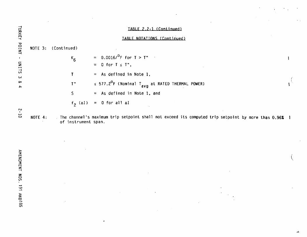
TABLE 2.2-1 (Continued)
TABLE NOTATIONS (Continued)m
-I
Z
-i
(A=
S
f2 (aI)
= 0.0016/°F for T > T"
= 0 for T : T",
= As defined in Note 1,
S577.2°F (Nominal Tavg at RATED THERMAL POWER)
= As defined in Note 1, and
= 0 for all al
The channel's maximum trip setpoint shall not exceed its computed trip setpoint by more than 0.96% of instrument span.
(
(
NOTE 3: (Continued)
K6
T
I-.
NOTE 4:
M
--I
0 U,
I

POWER DISTRIBUTION LIMITS
3/4.2.2 HEAT FLUX HOT CHANNEL FACTOR - FO (Z)
LIMITTNG CONDITION FOR OPERATTON
L 3.2.2 FQ (Z) shall be limited by the following relationships:
FM LZ : FJ1LX F(Z) FL [K(Z)]'for P > 0.5 P
F M(Z) .< EF I LX F() F [K(Z)J for P : 0.5
0.5
where: [FQ]L = F0 limit at RATED THERMAL POWER as specified in the CORE OPERATING LIMITS REPORT
P = Thermal Power Rated Thermal Power
[F0) = The Measured Value, and
K(Z) for a given core height, is specified in the K(Z) curve, defined
in the CORE OPERATING LIMITS REPORT.
APPLICABILITY: MODE 1
ACTION:
M With the measured value of F0 (Z) exceeding its limit:
M L a. Reduce THERMAL POWER at least 1% for each 1% F0 (Z) exceeds FQ (Z)
within 15 minutes and similarly reduce the Power Range Neutron Flux-High Trip Setpoints within the next 4 hours; POWER OPERATION may proceed for up to a total of 72 hours; subsequent POWER OPERATION may proceed provided the Overpower Delta-T Trip Setpoints (value of K4 ) have been reduced at least 1% for each 1% M L
FQ (Z) exceeds the FO (Z); and
b. Identify and correct the cause of the out-of-limit condition prior to increasing THERMAL POWER above the reduced power limit required by ACTION a., above; THERMAL POWER may then be increased provided M F0 (Z) is demonstrated through incore mapping to be within its limit.
TURKEY POINT - UNITS 3 & 4 3/4 2-4 AMENDMENT NOS.191AND185

POWER DISTRIBUTTON LIMITS
3/4.2-3 NUCLEAR ENTHALPY RISE HOT CHANNEL FACTOR
LIMITING CONDITION FOR OPERATION
3.2.3 FaH shall be limited by the following relationship:
N RTP F6H s FaH [1.0 + PFaH (1-P)],
_RTP Where: F H = FAH limit at RATED THERMAL POWER as specified
in the CORE OPERATING LIMITS REPORT
PFaH = Power Factor Multiplier for FH as specified in the CORE OPERATING LIMITS REPORT
THERMAL POWER P = RATED THERMAL POWER
APPLICABILITY: MODE 1.
ACTION:
With FaH exceeding its limit:
a. Within 2 hours either:
N 1. Restore FAH to within the above limit, or
2. Reduce THERMAL POWER to less than 50% of RATED THERMAL POWER and reduce the Power Range Neutron Flux - High Trip Setpoint to less than or equal to 55% of RATED THERMAL POWER within the next 4 hours.
b. Within 24 hours of initially being outside the above limit, verify through incore flux mapping that F8H has been restored to within the above limit, or reduce THERMAL POWER to less than 5% of RATED THERMAL POWER within the next 2 hours.
c. Identify and correct the cause of the out-of-limit condition prior to increasing THERMAL POWER above the reduced THERMAL POWER limit required by ACTION a.2. and/or b., above; subsequent POWER
N OPERATION may proceed provided that F6H is demonstrated, through incore flux mapping, to be within the limit of acceptable operation prior to exceeding the following THERMAL POWER levels:
1. A nominal 50% of RATED THERMAL POWER,
2. A nominal 75% of RATED THERMAL POWER, and
3. Within 24 hours of attaining greater than or equal to 95% of RATED THERMAL POWER.
TURKEY POINT - UNITS 3 & 4 AMENDMENT NOS. 191AND1853/4 2-11

4
POWER DTSTRTRIITION LITMTTS
3/4.2.5 DNB PARAMETERS
LIMITING CONDITION FOR OPERATION
3.2.5 The following DNB-related parameters shall be maintained within the
following limits:
a. Reactor Coolant System Tavg : 581.2 0F
b. Pressurizer Pressure > 2200 psig*, and
c. Reactor Coolant System Flow > 264,000 gpm
APPLICABILITY: MODE 1.
ACTION:
With any of the above parameters exceeding its limit, restore the parameter to within its limit within 2 hours or reduce THERMAL POWER to less than 5Z of RATED THERMAL POWER within the next 4 hours.
SURVEILLANCE REOUTREMENTS
4.2.5.1 Reactor Coolant System Tavg and Pressurizer Pressure shall be verified to be within their limits at least once per 12 hours.
4.2.5.2 RCS flow rate shall be monitored for degradation at least once per 12 hours.
4.2.5.3 The RCS flow rate indicators shall be subjected to a CHANNEL CALIBRATION at least once per 18 months.
4.2.5.4 After each fuel loading, and at least once per 18 months, the RCS flow rate shall be determined by precision heat balance after exceeding 90% RATED THERMAL POWER. The measurement instrumentation shall be calibrated within 90 days prior to the performance of the calorimetric flow measurement. The provisions of 4.0.4 are not applicable for performing the precision heat balance flow measurement.
*Limit not applicable during either a THERMAL POWER ramp in excess of 5% of RATED THERMAL POWER per minute or a THERMAL POWER step in excess of 10% of RATED THERMAL POWER.
TURKEY POINT - UNITS 3 & 4 3/4 2-16 AMENDMENT NOS. 191 AND 18 5

-I
rm
-0
-
--I
c. Containment Pressure--High
d. Pressurizer Pressure--Low
e. High Differential Pressure Between the Steam Line Header and any Steam Line.
f. Steam Line Flow--High
<4.5 psig
>1712 psig
< 114 psig
<A function defined as follows: A aP corresponding to 44% steam flow at 0% load increasing linearly from 20% load to a value corresponding to 116.5% steam flow at full load
TABLE 3.3-3 ENGINEERED SAFETY FEATURES ACTUATION SYSTEM
INSTRUMENTATION TRIP SETPOINTS
FUNCTIONAL UNIT ALLOWABLE VALUE
1. Safety Injection (Reactor Trip, Turbine Trip, Feedwater Isolation, Control Room Ventilation Isolation, Start Diesel Generators, Containment Phase A Isolation (except Manual SI), Containment Cooling Fans, Containment Filter Fans, Start Sequencer, Component Cooling Water, Start Auxiliary Feedwater and Intake Cooling Water)
a. Manual Initiation N.A.
b. Automatic Actuation Logic N.A
(
N.A.
N.A
<4.0 pslg
>1730 psig
<100 psi
<A function defined as follows: A AP correspondi to 40% steam flow at 0% load increasing linearly from 20% load to a value corresponding to 114% steam flow at full load
ng
I
TRIP SETPOINT
CW
CA
-n
0
0
Um,
I

TAB.L_3-3-3 (Continued)
ENGINEERED SAFETY FEATURES ACTUATION SYSTEM INSTRUMENTATION TRIP SETPOINTS
FUNCTIONAL UNIT
4.
ALLOWABLE VALUE-- I
0
-Z
Coincident with: Steam Line Pressure--Low
or Tavg--Low
5.
N.A.
<22.6 psig
Steam Line Isolation (Continued)
b. Automatic Actuation Logic and Actuation Relays
c. Containment Pressure--HighHigh Coincident with: Containment Pressure--High
d. Steam Line Flow--High
TRIP SETPOINT
N.A.
S20.0 psig
<s4.0 psig
<5A function defined as follows: A 0P corresponding to 40% steam flow at load increasing linearly from 20% load to a value corresponding to 114% steam flow at full load.
>614 psig
->5430F
Feedwater Isolation
a. Automatic Actuation Logic and Actuation Relays
b. Safety Injection
N.A. N.A.
See Item 1. for all Safety Injection Allowable Values.
See Item 1. above for all Safety Injection Trip Setpoints.
s 4.5 psig
<A function defined as follows: A aP corresponding to 44% steam flow at 0% load increasing linearly from 20% load to a value corresponding to 116.5% steam flow at full load.
a588 psig
>542.5°F
--I (/)
-sb.
N) M~
(
m
m
-. t
0 M
X
C)
(

L.F 3-=3=-1 (Continued)
ENGINEFRED SAFETY FEATURES ACTUATION SYSTEM INSTRUMENTATION TRIP SFTPOTNTS
FUNCTIONAL UNIT ALLOWABLE VALUFr-
m
Qo
4h.
:81.9% of narrow range instrument span
IRIP SaETPINT
S80% of narrow range instrument span
6. Auxiliary Feedwater (3)
a. Automatic Actuation Logic and Actuation Relays
b. Steam Generator Water Level--Low-Low
c. Safety Injection
d. Bus Stripping
e. Trip of All Main Feedwater Pump Breakers
7. Loss of Power
a. 4.16 kV Busses A and B (Loss of Voltage)
N.A. N.A.
a_8.15% of narrow range instrument span.
see Item 1. for all Safety Injection Allowable Values.
See Item 7. below for all Bus Stripping Allowable Values.
N.A.
N.A.
>10% of narrow range, instrument span.
See Item 1. above for all Safety Injection Trip Setpoints.
See Item 7. below for all Bus Stripping Trip Setpoints.
N.A.
N.A.
5. Feedwater Isolation (Continued)
c. Steam Generator Water Level High-High
r'3
CA)
X rlr
-:z Cr X
(.
0o
,n
I

. . . . . . . . . . . . . . . . . . . .. . . . .-. -. ~.. . ..-...
- REACTOR COOLANT SYSTEM
3/4.4-2 SAFETY VALVES
•.mLT.flWli
LIMITING~ CONDITION FOR OPERATION
3.4.2.1 A minimum of one pressurizer Code safety valve shall be OPERABLE* with a
lift setting of 2485 psig + 2%, -3%.** ***
APPLICARTILITY: MODES 4 and 5.
ACTONI:
With no pressurizer Code safety valve OPERABLE, immediately suspend all operations involving positive reactivity changes and place an OPERABLE RHR loop into operation in the shutdown cooling mode.
SURVEILLANCE REOUtIREMENTS
4.4.2.1 No additional requirements other than those required by Specification 4.0.5.
*While in MODE 5, an equivalent size vent pathway may be used provided that the vent pathway is not isolated or sealed.
"**The lift setting pressure shall correspond to ambient conditions of the valve at nominal operating temperature and pressure.
***All valves tested must have "as left" lift setpoints that are within ± 1% of the lift setting value.
TURKEY POINT - UNITS 3 & 4
I
I I
AMENDMENT NOS.191AND1853/4 4- 7

REACTOR COOLNANT SYSTEM F
OPFRATIN
LIMITING CONDITION FOR OPFRATION
3.4.2.2 All pressurizer Code safety valves shall be OPERABLE with a lift setting of 2485 psig + 2%, -3%.* **
APPLICABILITY: MODES 1, 2 and 3.
ACTION:
With one pressurizer Code safety valve inoperable, either restore the inoperable valve to OPERABLE status within 15 minutes or be in at least HOT STANDBY within 6 hours and in at least HOT SHUTDOWN within the following 6 hours.
SURVEILLANCE REQUIREMENTS
4.4.2.2 No additional requirements other than those required by Specification 4.0.5.
*The lift setting pressure shall correspond to ambient valve at nominal operating temperature and pressure.
**All valves tested must have "as left" lift setpoints ± 1% of the lift setting value.
conditions of the
that are within
TURKEY POINT - UNITS 3 & 4
I
I I
3/4 4-8 AMENDMENT NOS. 191AND185

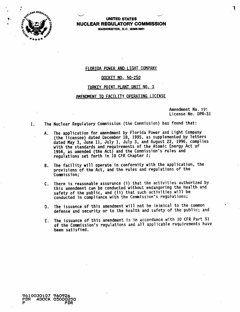
MATERIAL PROPERTY BASIS
CONTROLLING MATERIAL: CIRCUMFERENTIAL WELD INITIAL RTNDT: 1O0F
SERVICE PERIOD: 19 EFPY RTNDT q HEATUP RATES: UP TO 60°F/HR RT NDT NOTE: NO MARGINS ARE GIVEN FOR POSSIBLE INS
2500 i i ... .
'/," C,,
z
1/4 THICKNESS - 252.5*F • 3/4 THICKNESS = 200.4*F
TRUMENT ERRORS.
INDICATED TEMPERATURE (OF)
FIGURE 3.4-2
TURKEY POINT UNITS 3 & 4 REACTOR COOLANT SYSTEM HEATUP LIMITATIOS (606F/hr) * APPLICABLE
UP TO 19 EFPY
TURKEY POINT - UNITS 3 & 4 3MENDIENT NOS.191 AND 185
I
I3/4 4-31

MATERIAL PROPERTY BASIS
CONTROLLING MATERIAL: CIRCUMFERENTIAL WELD INITIAL RTNDT: IO0F
SERVICE PERIOD: 19 EFPY
HEATUP RATES: UP TO IO0*F/HR
RT NDT * 1/4 THICKNESS = 252.5*F RT NDT 4 3/4 THICKNESS = 200.40F
NOTE: NO MARGINS ARE GIVEN FOR POSSIBLE INSTRUMENT ERRORS.
LEAK TEST LIMITA1fi
- UNACCEPTAE
_ tNs CRITICALITY R-LIMIT (BASED ON -INSERVICE HYDRO
SSTATIC TEST TEMPERATURE (380"F) FOR THE SERVICE
-PERIOD UP TO Fff19 EFPY
OPERATION
I
I:ACCEPTABLE. OPERATION -
HEATUP RATES UP TO 100°F/HR
ACCEPTABLdE OPERATION
A-I I I II I I
I
50 100 15C 200 250 300 350 4W 450 500
INDICATED TEMPERATURE (F)
FIGURE 3.4-3
TURKEY POINT UNITS 3 & 4REACTOR COOLANT SYSTEM HEATUP LIMITATIONS (100OF/hr) - APPLICABLE
UP TO 19 EFPY I
TURKEY POINT - UNITS 3 & 4AMENDMENT NOS.191 AND 185
250
2250
2000
1750
1250
Goc
C,a C,,
CLi
750
500
250
0
p_+-
I
I
I
3/4 4-32

MATERIAL PROPERTY,-s .
CONTROLLING MATERIAL: CIRCUMFERENTIAL WELD INITIAL RTNOT: 10%. RTNDT 01 SERVICE PERIOD: 19 EFPY COOLDOWN RATES: UP TO 100°F'/.R RTNDT Qo•
NOTE: NO MARGINS ARE GIVEN FOR POSSIBLE INSTRUMENT ERRORS.
2250 I t5
2000
175c
f4 THICKNESS - 252.50'
f4 THICKNESS - 200.40F
avsJ
1250
1000
750
50
250
C0 50 10 150 200 250 300 !X 400 450 5w
INDICATED TEMPERATURE (OF)
FIGURE 3.4-4
TURKEY POINT UNITS 3 & 4
REACTOR COOLANT SYSTEM COOLDOWN LIMITATIONS (1OOF/hr) - APPLICABLE UP TO 19 EFPY
TURKEY POINT - UNITS 3 & 4
Aq
I
I3/4 4-33 AMqENDMIENT NOS.1 91 AND 185

..............................-...--. *.,.. -.
EMERGENCY CORE COOLING SYSTEMS
SURVEILLANCF REOUtRFMENTS
4.5.2 Each ECCS component and flow path Shall be demonstrated OPERABLE:
a. At least once per 12 hours by verifying by control room indication that the following valves are in the indicated positions with power to the valve operators removed:
SValve Function Valve Position
864A and B Supply from RWST to ECCS Open 862A and B RWST Supply to RHR pumps Open 863A and B RHR Recirculation Closed 866A and B H.H.S.I. to Hot Legs Closed HCV-758* RHR HX Outlet Open
To permit temporary operation of these valves for surveillance or maintenance purposes, power may be restored to these valves for a period not to exceed 24 hours.
b. At least once per 31 days by:
1) Verifying that the ECCS piping is full of water by venting the ECCS pump casings and accessible discharge piping,
2) Verifying that each valve (manual, power-operated, or automatic) in the flow path that is not locked, sealed, or otherwise secured in position, is in its correct position, and
3) Verifying that each RHR Pump develops the indicated differential pressure applicable to the operating conditions in accordance with Figure 3.5-1 when tested pursuant to Specification 4.0.5.
c. At least once per 92 days by:
1) Verifying that each SI pump develops the indicated differential pressure applicable to the operating conditi-ons when tested pursuant to Specification 4.0.5.
SI pump Ž 1083 psid at a metered flowrate 2 300 gpm (normal alignment or Unit 4 SI pumps aligned to Unit 3 RWST), or
Ž 1113 psid at a metered flowrate 2 280 gpm (Unit 3 SI pumps aligned to Unit 4 RWST).
*Air Supply to HCV-758 shall be verified shut off and sealed closed once per 31 days.
TURKEY POINT - UNITS 3 & 4 3/4 5-5 AMENDMENT NOS.191 AND185

CONTAINMENT SYSTEMS
EMERGENCY CONTAINMENT COOLING SYSTEM
LIMITING CONDITION FOR OPERATION
3.6.2.2 Three emergency containment cooling units shall be OPERABLE.
APPLICABILITY: MODES 1, 2, 3, and 4.
ACTION:
a. With one of the above required emergency containment cooling units inoperable restore the inoperable cooling unit to OPERABLE status within 72 hours or be in at least HOT STANDBY within the next 6 hours and in COLD SHUTDOWN within the following 30 hours.
b. With two or more of the above required emergency containment cooling units inoperable, restore at least two cooling units to OPERABLE status within 1 hour or be in at least HOT STANDBY within the next 6 hours and in COLD SHUTDOWN within the following 30 hours. Restore all of the above required cooling units to OPERABLE status within 72 hours of initial loss or be in at least HOT STANDBY within the next 6 hours and in COLD SHUTDOWN within the following 30 hours.
SURVETLLANCE REOUIREMENTS
4.6.2.2 Each emergency containment cooling unit shall be demonstrated OPERABLE:
a. At least once per 31 days by starting each cooler unit from the control room and verifying that each unit motor reaches the nominal operating current for the test conditions and operates for at least 15 minutes.
b. At least once per 18 months by:
1) Verifying that two emergency containment cooling units start .1 automatically on a safety injection (SI) test signal, and
2) Verifying a cooling water flow rate of greater than or equal to 2000 gpm to each cooler.
TURKEY POINT - UNITS 3 & 4 AMENDMENT NOS.191 AND 1853/4 6-14

:I
MAXIMUM ALLOWARLE POWER LEVEL WITH INOPERABLE STEAM LINE SAFETY VALVES DURING THREE LOOP OPERATION
MAXIMUM NUMBER OF INOPERABLE SAFETY VALVES ON ANY
OPERATING STEAM GENERATORMAXIMUM ALLOWABLE POWER LEVEL
(PERCENT OF RATED THERMAL POWER)
53
33
14
STEAM LINE SAFETY VALVES PER LOOP
VALVE UMER
Loop A Loop
1. RV1400 RV1405
2. RV1401 RV1406
3. RV1402 RV1407
4. RV1403 RV1408
LIFT SETTING (+3%)* **
LoopC
RV1410
RV1411
RV1412
RV1413
1085
1100
1115
1130
psig
psig
psig
psig
ORIFICE SIZE SQUARE INCHES
16
16
16
16
*The lift setting pressure shall correspond to ambient conditions of the valve at nominal operating temperature and pressure.
"**All valves tested must have "as left" lift setpoints that are within ±1% of the lift setting value listed in Table 3.7-2.
TURKEY POINT - UNITS 3 & 4 3/4 7-2 AMENDMENT NOS.191 AN
1
2
3
D1,85
I I
I
I I

PLANT SYSTEMS
CONDENSATE STORAGF TANK R
L IMITING CONDITION FOR OPERATION
3.7.1.3 The condensate storage tanks (CST) system shall be OPERABLE with:
Opposite Unit in MODES 4. 5 or 6
A minimum indicated water volume of 210,000 gallons storage tanks.
in either or both condensate
Opnosite Unit in MODES 1. 2 or 3
A minimum indicated water volume of 420,000 gallons.
APPLICABILITY: MODES 1, 2 and 3.
ACTION:
Opposite Unit in MODES 4. 5 or 6
With the CST system inoperable, within 4 hours restore the CST system to OPERABLE status or be in at least HOT STANDBY in the next 6 hours and in HOT SHUTDOWN within the following 6 hours.
Opposite Unit in MODES 1. 2 or 3
1) With the CST system inoperable due to indicating less than 420,000 gallons, but greater than or equal to 210,000 gallons indicated, within 4 hours restore the inoperable CST system to OPERABLE status or place one unit in at least HOT STANDBY within the next 6 hours and in HOT SHUTDOWN within the following 6 hours.
2) With the CST system inoperable with less than 210,000 gallons indicated, within 1 hour restore the CST system to OPERABLE status or be in at least HOT STANDBY within the next 12 hours and in HOT SHUTDOWN within the following 6 hours. This ACTION applies to both units simultaneously.
TURKEY POINT - UNITS 3 & 4
I
I
I I
3/4 7-6 AMENDMENT NOS.191 AND185

I
PLANT SYSTEMS
SURVEILLANCE REOUIREMENTS (Continued)
4.7.1.3 The condensate storage tank (CST) system shall be demonstrated OPERABLE at least once per 12 hours by verifying the indicated water volume is within its limit when the tank is the supply source for the auxiliary feedwater pumps.
TURKEY POINT - UNITS 3 & 4 AMENDMENT NOS. 191 AND 1853/4 7-7

PLANT SYSTFMS
STANDBY FEEDWATER SYSTEM
LIMITING CONDITION FOR OPERATION
3.7.1.6 Two Standby Steam Generator Feedwater Pumps shall be OPERABLE* and at least 135,000 gallons of water (indicated volume), shall be in the Demineralized Water Storage Tank.**
APPLICARII TY: MODES 1, 2 and 3
ACTION:
a. With one Standby Steam Generator Feedwater Pump inoperable, restore the inoperable pump to available status within 30 days or submit a SPECIAL REPORT per 3.7.1.6d.
b. With both Standby Steam Generator Feedwater Pumps, restore at least one pump to OPERABLE status within 24 hours, or:
1. Notify the NRC within the following 4 hours, and provide cause for the inoperability and plans to restore pump(s) to OPERABLE status and,
2. Submit a SPECIAL REPORT per 3.7.1.6d.
c. With less than 135,000 gallons of water indicated in the Demineralized Water Storage Tank restore the available volume to at least 135,000 gallons indicated within 24 hours or submit a SPECIAL REPORT per 3.7.1.6d.
d. If a SPECIAL REPORT is required per the above specifications submit a report describing the cause of the inoperability, action taken and a schedule for restoration within 30 days in accordance with 6.9.2.
SURVEILLANCE REOUITREMENTS
4.7.1.6.1 The Demineralized Water Storage tank water volume shall be determined to be within limits at least once per 24 hours.
4.7.1.6.2 At least monthly verify the standby feedwater pumps are OPERABLE by testing in recirculation on a STAGGERED TEST BASIS.
4.7.1.6.3 At least once per 18 months, verify operability of the respective standby steam generator feedwater pump by starting each pump and providing feedwater to the steam generators.
*These pumps do not require plant safety related emergency power sources for operability. and the flowpath is normally isolated.
**The Demineralized Water Storage Tank is non-safety grade.
TURKEY POINT - UNITS 3 & 4 3/4 7-11 AMENDMENT NOS 1'91 AND185

PLANT SYSTFMS
SURVEILLANCF RFOIIREMFNTS (Continued)
1) Verifying that the air cleanup system satisfies the in-place penetration and bypass leakage testing acceptance criteria of greater than or equal to 99% DOP and halogenated hydrocarbon removal at a system flow rate of 1000 cfm ±10%.
2) Verifying, within 31 days after removal, that a laboratory analysis of a representative carbon sample obtained in accordance with Regulatory Position C.6.b of Regulatory Guide 1.52, Revision 2, March 1978, and analyzed per ANSI N510-1975, meets the criteria for methyl iodine removal efficiency of greater than or equal to 99% or the charcoal be replaced with charcoal that meets or exceeds the criteria of position C.6.a. of Regulatory Guide 1.52 (Revision 2), and
3) Verifying by a visual inspection the absence of foreign materials and gasket deterioration.
d. At least once per 12 months by verifying that the pressure drop across the combined HEPA filters and charcoal adsorber banks is less than 6 inches Water Gauge while operating the system at a flow rate of 1000 cfm ±1O%;
e. At least once per 18 months by verifying that on a Containment Phase "A" Isolation test signal the system automatically switches into the recirculation mode of operation.
TURKEY POINT - UNITS 3 & 4
I
3/4 7-17 AMENDMENT NOS.191 AND 185

ADMINISTRATTVF CONTROLSI
PEAKING FACTOR LIMIT REPORT
6.9.1.6 The W(Z) function(s) for Base-Load Operation corresponding to a ±2% band about the target flux difference and/or a ±3% band about the target flux difference, the Load-Follow function Fz(Z) and the augmented surveillance turnon power fraction, PT, shall be provided to the U.S. Nuclear Regulatory Commission, whenever PT is <1.0. In the event, the option of Baseload Operation (as defined in Section 4.2.2.3) will not be exercised, the submission of the W(Z) function is not required. Should these values (i.e., W(Z), Fz(Z) and PT) change requiring a new submittal or an amended submittal to the Peaking Factor Limit Report, the Peaking Factor Limit Report shall be provided to the NRC Document Control desk with copies to the Regional Administrator and the Resident Inspector within 30 days of their implementation, unless otherwise approved by the Commission.
The analytical methods used to generate the Peaking Factor limits shall be those previously reviewed and approved by the NRC. If changes to these methods are deemed necessary they will be evaluated in accordance with 10 CFR 50.59 and submitted to the NRC for review and approval prior to their use if the change is determined to involve an unreviewed safety question or if such a change would require amendment of previously submitted documentation.
CORE OPERATING LIMITS REPORT
6.9.1.7 Core operating limits shall be established and documented in the CORE OPERATING LIMITS REPORT (COLR) before each reload cycle or any remaining part of a reload cycle for the following:
1. Axial Flux Difference for Specification 3.2.1.
2. Control Rod Insertion Limits for Specification 3.1.3.6.
3. Heat Flux Hot Channel Factor - FQ(Z) for Specification 3/4.2.2.
4. All Rods Out position for Specification 3.1.3.2.
5. Nuclear Enthalpy Rise Hot Channel Factor for Specification 3/4.2.3
The analytical methods used to determine the AFD limits shall be those previously reviewed and approved by the NRC in:
1. WCAP-10216-P-A, "RELAXATION OF CONSTANT AXIAL OFFSET CONTROL F0 SURVEILLANCE TECHNICAL SPECIFICATION," June 1983.
2. WCAP-8385, "POWER DISTRIBUTION CONTROL AND LOAD FOLLOWING PROCEDURES TOPICAL REPORT," September 1974.
The analytical methods used to determine F0 (Z), FAH and the K(Z) curve shall be
those previously reviewed and approved by the NRC in:
1. WCAP-9220-P-A, Rev. 1, "Westinghouse ECCS Evaluation Model - 1981 Version," February 1982.
2. WCAP-9561-P-A, ADD. 3, Rev. 1, "BART A-i: A Computer Code for the Best Estimate Analysis of Reflood Transients - Special Report: Thimble Modeling W ECCS Evaluation Model."
3. WCAP-10054-P-A, (proprietary), "Westinghouse Small Break ECCS Evaluation Model Using the NOTRUMP Code", August 1985.
AMENDMENT NOS. 191 AND 185TURKEY POINT UNITS 3 & 4 6-20

ADMINTSTRATIVF CONTROLS
4. WCAP-10054-P, Addendum 2, Revision 1 (proprietary), "Addendum to the Westinghouse Small Break ECCS Evaluation Model Using the NOTRUMP Code: Safety Injection in the Broken Loop and Improved Condensation Model", October 1995.*
5. WCAP-10266-P-A, Rev 2 (proprietary), and WCAP-11524-NP-A, Rev 2 (non-proprietary), "The 1981 Version of the Westinghouse ECCS Evaluation Model Using the BASH Code," May 1988.
6. NTD-NRC-94-4143, "Change in Methodology for Execution of BASH Evaluation Model," May 23, 1994.
The analytical methods used to determine Rod Bank Insertion Limits and the All Rods Out position shall be those previously reviewed and approved by the NRC in:
1. WCAP-9272-P-A, "Westinghouse Reload Safety Evaluation Methodology," July 1985.
The ability to calculate the COLR nuclear design parameters are demonstrated in:
1. Florida Power & Light Company Topical Report NF-TR-95-01, "Nuclear Physics Methodology for Reload Design of Turkey Point & St. Lucie Nuclear Plants".
Topical Report NF-TR-95-01 was approved by the NRC for use by Florida Power & Light Company in:
1. Safety Evaluation by the Office of Nuclear Reactor Regulations Related to Amendment No. 174 to Facility Operating Lic.ense DPR-31 and Amendment No. 168 to Facility Operating License DPR-41, Florida Power & Light Company Turkey Point Units 3 and 4, Docket Nos. 50-250 and 50-251.
The AFD, FQ(Z), FnH, K(Z), and Rod Bank Insertion Limits shall be determined such that all applicable limits of the safety analyses are met. The CORE OPERATING LIMITS REPORT, including any mid-cycle revisions or supplements thereto, shall be provided upon issuance, for each reload cycle, to the NRC Document Control Desk with copies to the Regional Administrator and Resident Inspector, unless otherwise approved by the Commission.
*This reference is only to be used subsequent to NRC approval.
6-21 AMENDMENT NOS.TURKEY POINT UNITS 3 & 4 191 AND185

2.1 SAFETY LIMITS
RASES
2.1-1 REACTOR CORF
The restrictions of this Safety Limit prevent overheating of the fuel and possible cladding perforation which would result in the release of fission products to the reactor coolant. Overheating of the fuel cladding is prevented by restricting fuel operation to within the nucleate boiling regime where the heat transfer coefficient is large and the cladding surface temperature is slightly above the coolant saturation temperature.
Operation above the upper boundary of the nucleate boiling regime could result in excessive cladding temperatures because of the onset of departure from nucleate boiling (DNB) and the resultant sharp reduction in heat transfer coefficient. DNB is not a directly measurable parameter during operation and therefore THERMAL POWER and reactor coolant temperature and pressure have been related to DNB. This relationship has been developed to predict the DNB flux and the location of DNB for axially uniform and nonuniform heat flux distributions. The local DNB heat flux ratio (DNBR) is defined as the ratio of the heat flux that would cause DNB at a particular core location to the local heat flux and is indicative of the margin to DNB.
The DNB design basis is as follows: there must be at least a 95 percent probability with 95 percent confidence that the minimum DNBR of the limiting rod during Condition I and II events is greater than or equal to the DNBR limit of the DNB correlation being used. The correlation DNBR limit is established based on the entire applicable experimental data set such that there is a 95 percent probability with 95 percent confidence that DNB will not occur when the minimum DNBR is at the DNBR limit.
The curves of Figure 2.1-1 show the loci of points of THERMAL POWER, Reactor Coolant System pressure and average temperature for which the minimum DNBR is no less than the design DNBR value, or the average enthalpy at the vessel exit is equal to the enthalpy of saturated liquid.
These curves are based on an enthalpy hot channel factor, FH, and a reference cosine with a peak of 1.55 for axial power shape. An allowance is included for an increase in FAH at reduced power based on the expression:
RTP F•H . FAH [1+ PFAH (l-P)]
Where P is the fraction of RATED THERMAL POWER. RTP
FAH = FH limit at RATED THERMAL POWER as specified in the CORE OPERATING LIMITS REPORT. {
PFAH = Power Factor multiplier for F8H as specified in the CORE OPERATING LIMITS REPORT.
TURKEY POINT - UNITS 3 & 4 AMENDMENT NOS. 191 AND1 85B 2-1

SAFETY LIMITS
BASES
2.1-1 REACTOR CORE (Continued)
These limiting heat flux conditions are higher than those calculated for the range of all control rods fully withdrawn to the maximum allowable control rod insertion limit assuming the axial power imbalance is within the limits of the f (,M) function of the Overtemperature trip. When the axial power imbalance is not within the tolerance, the axial power imbalance effect on the Overtemperature aT trips will reduce the setpoints to provide protection consistent with core Safety Limits.
Fuel rod bowing reduces the values of DNB ratio (DNBR). The penalties are calculated pursuant to "Fuel Rod Bow Evaluation," WCAP-8691-P-A Revision 1 (Proprietary) and WCAP-8692 Revision 1 (Non-Proprietary). The restrictions of the Core Thermal Hydraulic Safety Limits assure that an amount of DNBR margin greater than or equal to the above penalties is retained to offset the rod bow DNBR penalty.
2.1.2 REACTOR COOLANT SYSTEM PRESSURE
The restriction of this Safety Limit protects the integrity of the Reactor Coolant System (RCS) from overpressurization and thereby prevents the release of radionuclides contained in the reactor coolant from reaching the containment atmosphere.
The reactor vessel and pressurizer are designed to Section III of the ASME Code for Nuclear Power Plants which permits a maximum transient pressure of 110% (2735 psig) of design pressure. The RCS piping, valves and fittings are designed to ANSI B31.1 which. permits a maximum transient pressure of 120% of design pressure of 2485 psig. The Safety Limit of 2735 psig is therefore more conservative than the ANSI B31.1 design criteria and consistent with associated ASME Code requirements.
The entire RCS is hydrotested at 125% (3107 psig) of design pressure, to demonstrate integrity prior to initial operation.
TURKEY POINT - UNITS 3 & 4 B 2-2 AMENDMENT NOS.191 AND185

LIMITING SAFETY SYSTEM SETTINGS
BASES
Undervoltage and - 4.16 kV Bus A and B Trios (Continued)
power the Undervoltage Bus trips are automatically blocked by P-7 (a power level of approximately 10% of RATED THERMAL POWER with a turbine first stage pressure at approximately 10% of full power equivalent); and on increasing power, reinstated automatically by P-7.
Turbinae T '
A Turbine trip initiates a Reactor trip. On decreasing power, the Reactor Trip from the Turbine trip is automatically blocked by P-7 (a power level of approximately 10% of RATED THERMAL POWER with a turbine first stage pressure at approximately 10% of full power equivalent); and on increasing power, reinstated automatically by P-7.
Safety Injection Input from ESF
If a Reactor trip has not. already been generated by the Reactor Trip System instrumentation, the ESF automatic actuation logic channels will initiate a Reactor trip upon any signal which initiates a Safety Injection. The ESF instrumentation channels which initiate a Safety Injection signal are shown in Table 3.3-3.
Reactor Coolant Pump Breaker Position Trip
The Reactor Coolant Pump Breaker Position Trips are anticipatory trips which provide reactor core protection against DNB. The open/close position trips assure a reactor trip signal is generated before the low flow trip setpoint is reached. Their functional capability at the open/close position settings is required to enhance the overall reliability of the Reactor Protection System. Above P-7 (a power level of approximately 10% of RATED THERMAL POWER or a turbine first stage pressure at approximately 10% of full power equivalent) an automatic reactor trip will occur if more than one reactor coolant pump breaker is opened. Above P-8 (a power level of approximately 45% of RATED THERMAL POWER) an automatic reactor trip will occur if one reactor coolant pump breaker is opened. On decreasing power between P-8 and P-7, an automatic reactor trip will occur if more than one, reactor coolant pump breaker is opened and below P-7 the trip function is automatically blocked.
Underfrequency sensors are also installed on the 4.16 kV busses to detect u nderfrequency and initiate breaker trip on underfrequency. The underfrequency trip setpoints preserve the coast down energy of the reactor coolant pumps, in case of a grid frequency decrease so DNB does not occur.
TURKEY POINT - UNITS 3 & 4 B 2-7 AMENDMENT NOS. 191 AND185

3/4.2 POWER DISTRIBUTION LIMITS
BASES
The specifications of this section provide assurance of fuel integrity during Condition I (Normal Operation) and II (Incidents of Moderate Frequency) events by: (1) maintaining the minimum DNBR in the core greater than or equal to the applicable design limit during normal operation and in short-term transients, and (2) limiting the fission gas release, fuel pellet temperature, and cladding mechanical properties to within assumed design criteria. In addition, limiting the peak linear power density during Condition I events provides assurance that the initial conditions assumed for the LOCA analyses are met and the ECCS acceptance criteria limit of 2200°F is not exceeded.
The definitions of certain hot channel and peaking factors as used in these specifications are as follows:
FQ(Z) Heat Flux Hot Channel Factor, is defined as the maximum local heat flux on the surface of a fuel rod at core elevation Z divided by the average fuel rod heat flux, allowing for manufacturing tolerances on fuel pellets and rods;
FNH Nuclear Enthalpy Rise Hot Channel Factor, is defined as the ratio of the integral of linear power along the rod with the highest integrated power to the average rod power; and
Fxy(Z) Radial Peaking Factor, is defined as the ratio of peak power density to average power density in the horizontal plane at core elevation Z.
3/4.2.1 AXIAL FLUX DIFFERENCE
The limits on AXIAL FLUX DIFFERENCE (AFD) assure that the FQ(Z) limit defined in the CORE OPERATING LIMITS REPORT times the normalized axial peaking factor is not exceeded during either normal operation or in the event of xenon redistribution following power changes.
Target flux difference is determined at equilibrium xenon conditions. The full-length rods may be positioned within the core in accordance with their respective insertion limits and should be inserted near their normal position for steady-state operation at high power levels. The value of the target flux difference obtained under these conditions divided by the fraction of RATED THERMAL POWER is the target flux difference at RATED THERMAL POWER for the associated core burnup conditions. Target flux differences for other THERMAL POWER levels are obtained by multiplying the RATED THERMAL POWER value by the appropriate fractional THERMAL POWER level. The periodic updating of the target flux difference value is necessary to reflect core burnup considerations.
TURKEY POINT - UNITS 3 & 4 AMENDMENT NOS. 191 AND185B 3/4 2-1

POWER DISTRIBUTTON LIMITS
BASES. .
3/4.2-2 and 3/4.2.3 HEAT FLUX HOT CHANNEL FACTOR AND NUCLEAR ENTHALPY RISE HOT CHANNEL FACTOR
The limits on heat flux hot channel factor and nuclear enthalpy rise hot channel factor ensure that: (1) the design limits on peak local power density and minimum DNBR are not exceeded and (2) in the event of a LOCA the peak fuel clad temperature will not exceed the 2200°F ECCS acceptance criteria limit. The LOCA peak fuel clad temperature limit may be sensitive to the number of steam generator tubes plugged.
FQ(Z), Heat Flux Hot Channel Factor, is defined as the maximum local heat flux on the surface of a fuel rod at core elevation Z divided by the average fuel rod heat flux.
FNH Nuclear Enthalpy Rise Hot Channel Factor, is defined as the ratio of the integral of linear power along the rod with the highest integrated power to the average rod power.
Each of these is measurable but will normally only be determined periodically
as specified in Specifications 4.2.2 and 4.2.3. This periodic surveillance is sufficient to ensure that the limits are maintained provided:
a. Control rods in a single group move together with no individual rod insertion differing by more than ± 12 steps, indicated, from the group demand position;
b. Control rod groups are sequenced with overlapping groups as described in Specification 3.1.3.6;
c. The control rod insertion limits of Specifications 3.1.3.5 and 3.1.3.6 are maintained; and
d. The axial power distribution, expressed in terms of AXIAL FLUX DIFFERENCE, is maintained within the limits.
When an F0 measurement is taken, both experimental error and manufacturing tolerance must be allowed for. Five percent is the appropriate allowance for a full core map taken with the movable incore detector flux mapping system and three percent is the appropriate allowance for manufacturing tolerance. These uncertainties only apply if the map is taken for purposes other than the determination of PBL and PRB.
N F6H will be maintained within its limits provided Conditions a. through d.
above are maintained.
N In the specified limit of FnH, there is an 8 percent allowance for
uncertainties which means that normal operation of the core is expected to N RTP RTPi N
result in FAH FH/1.08, where FAH is the FAH limit at RATED THERMAL POWER (RTP) specified in the CORE OPERATING LIMITS REPORT. The logic behind the larger uncertainty in this
TURKEY POINT - UNITS 3 & 4 AMENDMENT NOS. 191 AND 185B 3/4 2-4

POWER DISTRIBUTTON LIMIT.
BA S PS
3/4.2-4 OUADRANT POWER TTLT RATIO
The QUADRANT POWER TILT RATIO limit assures that the radial power distribution satisfies the design values used in the power capability analysis. Radial power distribution measurements are made during STARTUP testing and periodically during power operation.
The limit of 1.02. at which corrective action is required, provides DNB and linear heat generation rate protection with x-y plane power tilts. A limit of 1.02 was selected to provide an allowance for the uncertainty associated with the indicated power tilt.
The 2-hour time allowance for operation with a tilt condition greater than 1.02 but less than 1.09 is provided to allow identification and correction of a dropped or misaligned control rod. In the event such action action does not correct the tilt, the margin for uncertainty on FQ(Z) is reinstated by reducing the maximum allowed power by 3% for each percent of tilt in excess of 1.
For purposes of monitoring QUADRANT POWER TILT RATIO when one excore detector is inoperable, the movable income detectors or incore thermocouple map are used to confirm that the normalized symmetric power distribution is consistent with the QUADRANT POWER TILT RATIO. The incore detector monitoring is done with a full incore flux map or two sets of four symmetric thimbles. The two sets of four symmetric thimbles is a unique set of eight detector locations. These locations are C-8, E-5, E-11. H-3, H-13, L-5, L-11, N-8.
3/4.2.5 DNB PARAMETERS
The limits on the DNB-related parameters assure that each of the parameters are maintained within the normal steady-state envelope of operation assumed in the transient and accident analyses. The limits are consistent with the initial FSAR assumptions and have been analytically demonstrated adequate to maintain a minimum DNBR above the applicable design limits throughout each analyzed transient. The indicated Tavg value of 581.2 0F and the indicated pressurizer pressure value of 2200 psig correspond to analytical limits of 583.2 0 F and 2175 psig respectively, with allowance for measurement uncertainty.
The measured RCS flow value of 264,000 gpm corresponds to an analytical limit of 255,000 gpm which is assumed to have a 3.5% calorimetric measurement uncertainty.
The 12-hour periodic surveillance of these parameters through instrument readout is sufficient to ensure that the parameters are restored within their limits following load changes and other expected transient operation. The 18-month periodic measurement of the RCS total flow rate is adequate to ensure that the DNB-related flow assumption is met and to ensure correlation of the flow indication channels with measured flow. Six month drift effects have been included for feedwater temperature, feedwater flow, steam pressure, and the pressurizer pressure inputs. The flow measurement is performed within ninety days of completing the cross-calibration of the hot leg and cold leg narrow range RTDs. The indicated percent flow surveillance on a 12-hour basis will provide sufficient verification that flow degradation has not occurred. An indicated percent flow which is greater than the thermal design flow plus instrument channel inaccuracies and parallax errors is acceptable for the 12 hour surveillance on RCS flow. To minimize measurement uncertainties it is assumed that the RCS flow channel outputs are averaged.
TURKEY POINT - UNITS 3 & 4 AMENDMENT NOS. 191 AND185B 3/4 2-8

• I REACTOR COOLANT SYSTEM
BASES
3/4.4.2 SAFETY VALVES
The pressurizer Code safety valves operate to prevent the RCS from being pressurized above its Safety Limit of 2735 psig. Each safety valve is designed to relieve 293,330 lbs per hour of saturated steam at the valve Setpoint. The relief capacity of a single safety valve is adequate to relieve any overpressure condition which could occur during shutdown. In the event that no safety valves are OPERABLE, an RCS vent opening of at least 2.50 square inches will provide overpressure relief capability and will prevent RCS overpressurization. In addition, the Overpressure Mitigating System provides a diverse means of protection against RCS overpressurization at low temperatures.
During operation, all pressurizer Code safety valves must be OPERABLE to prevent the RCS from being pressurized above its Safety Limit of 2735 psig. The combined relief capacity of all of these valves is greater than the maximum surge rate resulting from a complete loss-of-load assuming no Reactor trip until the first-Reactor Trip System Trip Setpoint is reached (i.e., no credit is taken for a direct Reactor trip on the loss-ofload) and also assuming no operation of the power-operated relief valves or steam dump valves.
In Mode 5 only one pressurizer code safety is required for overpressure protection. In lieu of an actual operable code safety valve, an unisolated and unsealed vent pathway (i.e., a direct, unimpaired opening, a vent pathway with valves locked open and/or power removed and locked on an open valve) of equivalent size can be taken credit for as synonymous with an OPERABLE code safety.
Demonstration of the safety valves' lift settings will occur only during shutdown and will be performed in accordance with the provisions of Section XI of the ASME Boiler and Pressure Code. The pressurizer code safety valves' lift settings allows a +2%, -3% setpoint tolerance for OPERABILITY; however, the valves are reset to within +1% during the surveillance to allow for drift.
3/4.4.3 PRESSURIZER
The 12-hour periodic surveillance is sufficient to ensure that the maximum water volume parameter is restored to within its limit following expected transient operation. The maximum water volume (1133 cubic feet) ensures that a steam bubble is formed and thus the RCS is not a hydraulically solid system. The requirement that both backup pressurizer heater groups be OPERABLE enhances the capability of the plant to control Reactor Coolant System pressure and establish natural circulation.
TURKEY POINT - UNITS 3 & 4 B 3/4 4-2 AMENDMENT NOS. 191 AND185

REACTOR COOLANT SYSTEM
BASES
PRESSURE/TEMPERATURE LIMITS (Continued)
1. The reactor coolant temperature and pressure and system heatup and cooldown rates (with the exception of the pressurizer) shall be limited in accordance with Figures 3.4-2 to 3.4-4 for the service period specified thereon:
a. Allowable combinations of pressure and temperature for specific temperature change rates are below and to the right of the limit lines shown. Limit lines for cooldown rates between those presented may be obtained by interpolation; and
b. Figures 3.4-2 to 3.4-4 define limits to assure prevention of nonductile failure only. For normal operation, other inherent plant characteristics, e.g., pump heat addition and pressurizer heater capacity, may limit the heatup and cooldown rates that can be achieved over certain pressure-temperature ranges.
2. These limit lines shall be calculated periodically using methods provided below,
3. The secondary side of the steam generator must not be pressurized above 200 psig if the temperature of the steam generator is below 700 F,
4. The pressurizer heatup and cooldown rates shall not exceed 1000F/h and 2000 F/h, respectively. The spray shall not be used if the temperature difference between the pressurizer and the spray fluid is greater than 320'F, and
5. System preservice hydrotests and inservice leak and hydrotests shall be performed at pressures in accordance with the requirements of ASME Boiler and Pressure Vessel Code, Section XI.
The fracture toughness properties of the ferritic materials in the reactor vessel are determined in accordance with the NRC Standard Review Plan, the version of the ASTM E185 standard required by 10 CFR 50, Appendex H, and in accordance with additional reactor vessel requirements.
The properties are then evaluated in accordance with Appendix G of the 1983 Edition of Section III of the ASME Boiler and Pressure Vessel Code and the additional requirements of 10 CFR 50, Appendix G and the calculation methods described in Westinghouse Report GTSD-A-1.12, "Procedure for Developing Heatup and Cooldown Curves."
Heatup and cooldown limit curves are calculated using the most limiting value of the nil-ductility reference temperature, RTNDT, at the end of 19 effective full power years (EFPY) of service life. The 19 EFPY service life period is chosen such that the limiting RTNDT, at the 1/4T location in
TURKEY POINT - UNITS 3 & 4 AMENDMENT NOS. 191 AND 185B 3/4 4-8

REACTOR COOLANT SYSTEM
BASES
PRESSt]RE/TEMPFRAT[RE LIMITS (Continued)
the core region is greater than the RTNDT, of the limiting unirradiated material. The selection of such a limiting RTNDT assures that all components in the Reactor Coolanit System will be operated conservatively in accordance with applicable Code requirements.
The heatup and cooldown limit curves, Figures 3.4-2, 3.4-3 and 3.4-4 are composite curves prepared by determining the most conservative case with either the inside or outside wall controlling, for any heatup rate up to 100 degrees F per hour and cooldown rates of up to 100 degrees F per hour. The heatup and cooldown curves were prepared based upon the most limiting value of predicted adjusted reference temperature at the end of the applicable service period (19 EFPY).
The reactor vessel materials have been tested to determine their initial RTNDT; the results of these tests are shown in Tables B 3/4.4-1 and B 3/4.4-2. Reactor operation and resultant fast neutron (E greater than 1 MeV) irradiation can cause an increase in the RTNDT. Therefore, an adjusted reference temperature, based upon the fluence and chemistry factors of the material has been predicted using Regulatory Guide 1.99, Revision 2, dated May 1988, "Radiation Embrittlement of Reactor Vessel Materials." The heatup and cooldown limit curves of Figures 3.4-2, 3.4-3, and 3.4-4 include predicted adjustments for this shift in RTNDT at the end of the applicable service period.
The actual shifts in RTNDT, of the vessel materials will be established periodically during operation by removing and evaluating, in accordance with the version of the ASTM E185 standard required by 10 CFR Appendix H, reactor vessel material irradiation surveillance specimens installed near the inside wall of the reactor vessel in the core area. Since the neutron spectra at the irradiation samples and vessel inside radius are essentially identical, the measured transition shift for a sample can be applied with confidence to the adjacent section of the reactor vessel.
Since the limiting beltline materials (Intermediate to Lower Shell Circumferential Weld) in Units 3 and 4 are identical, the RV surveillance program was integrated and the results from capsule testing is applied to both Units. The surveillance capsule "T" results from Unit 3 (WCAP 8631) and Unit 4 (SWRI 02-4221) and the capsule "V" results from Unit 3 (SWRI 068576 were used with the methodology in Regulatory Guide 1.99, Revision 2, to provide
TURKEY POINT - UNITS 3 & 4 AMENDMENT NOS.191 AND185B 3/4 4-9

CONTAINMENT SYSTFMS• ...
BASES
.CONTAINMENT VENTILATION SYSTEM (Cont4.nued)
resilient material seal degradation and will allow opportunity for repair before gross leakage failures could develop. The 0.60 L, leakage limit of Specification 3.6.1.2b. shall not be exceeded when the leakage rates determined by the leakage integrity tests of these valves'are added to the previously determined total for all valves and penetrations subject to Type B and C tests.
3/4.6.2 DEPRESSURIZATION AND COOLING SYSTEMS
3/4.6-2-1 CONTAINMENT SPRAY SYSTEM
The OPERABILITY of the Containment Spray System ensures that containment depressurization capability will be available in the event of a LOCA. The pressure reduction and resultant lower containment leakage rate are consistent with the assumptions used in the safety analyses.
The allowable out-of-service time requirements for the Containment Spray System have been maintained consistent with that assigned other inoperable ESF equipment and do not reflect the additional redundancy in cooling capability provided by the Emergency Containment Cooling System. Pump performance requirements are obtained from the accidents analysis assumptions.
3/4.6.2.2 EMERGENCY CONTAINMENT COOLING SYSTEM
The OPERABILITY of the Emergency Containment Cooling (ECC) System ensures that the heat removal capacity is maintained with acceptable ranges following postulated design basis accidents. To support both containment integrity safety analyses and component cooling water thermal analysis, a maximum of two ECCs can receive an automatic start signal following generation of a safety injection (SI) signal (one ECC receives an "A" train SI signal and another ECC receives an "B" train SI signal). To support post-LOCA long-term containment pressure/temperature analyses, a maximum of two ECCs are required to operate. The third (swing) ECC is required to be OPERABLE to support manual starting following a postulated LOCA event for containment pressure/temperature suppression.
The allowable out-of-service time requirements for the Containment Cooling System have been maintained consistent with that assigned other inoperable ESF equipment and do not reflect the additional redundancy in cooling capability provided by the Containment Spray System.
The surveillance requirement for ECC flow is verified by correlating the test configuration value with the design basis assumptions for system configuration and flow. An 18-month surveilance interval is acceptable based on the use of water from the CCW system, which results in a low risk of heat exchanger tube fouling.
TURKEY POINT - UNITS 3 & 4 AMENDMENT NOS. 191 AND 185B 3/4 6-3

CONTAINMENT SYSTEMS
BAS ES
3/4.6-3 EMERGENCY CONTAINMENT FILTERING SYSTEM
The OPERABILITY of the Emergency Containment Filtering System ensures that sufficient iodine removal capability will be available in the event of a LOCA. The reduction in containment iodine inventory reduces the resulting SITE BOUNDARY radiation doses associated with containment leakage. The operation of this system and resultant iodine removal capacity are consistent with the assumptions used in the LOCA analyses. System components are not subject to rapid deterioration. Visual inspection and operating/performance tests after maintenance, prolonged operation, and at the required frequencies provide assurances of system reliability and will prevent system failure. Filter performance tests are conducted in accordance with the methodology and intent of ANSI N510- 1975.
3/4-6-4 CONTAINMENT ISOLATION VALVES
The OPERABILITY of the containment isolation valves ensures that the containment atmosphere will be isolated from the outside environment in the event of a release of radioactive material to the containment atmosphere or pressurization of the containment. Containment isolation within the time limits specified in the In-Service Testing Program is consistent with the assumed isolation times of those valves with specific isolation times in the LOCA analysis.
3/4.6-5 HYDROGEN MONITORS
The OPERABILITY of the Hydrogen Monitors ensures the detection of hydrogen buildup within containment following a LOCA to allow operator action to reduce the hydrogen concentration below its flammable limit.
3/4.6-6 POST ACCIDENT CONTAINMENT VENT SYSTEM
The OPERABILITY of the Post Accident Containment Vent System ensures the capability for emergency venting of containment following a LOCA to reduce the hydrogen concentration to below its flammable limit.
PACVS systems components are not subject to rapid deterioration, having lifetimes of many years. even under continuous flow conditions. Visual inspection and operating tests provide assurance of system reliability and will ensure early detection of conditions which could cause the system to fail or operate improperly. The performance tests prove that filters have been properly installed, that no deterioration or damage has occurred, and that all components an,- subsystems operate properly. The tests are performed in accordance with the methodology and intent of ANSI N510-1975 and provide assurance that filter performance has not deteriorated below required specification values due to aging, contamination or other effects.
TURKEY POINT - UNITS 3 & 4 B 3/4 6-4 AMENDMENT NOS. 191 AND185

3/4.7 PLANT SYSTEMS
BASES
3/4.7.1.1 SAFETY VALVES (Continued)
Operation with less than all four MSSVs OPERABLE for each steam generator is permissible, if THERMAL POWER is proportionally limited to the relief capacity of the remaining MSSVs. This is accomplished by restricting THERMAL POWER so that the energy transfer to the most limiting steam generator is not greater than the available relief capacity in that steam generator. Table 3.7-2 allows a ± 3% setpoint tolerance for OPERABILITY; however, the valves are reset to ± 1% during the Surveillance to allow for drift.
3/4-7-1-2 AUXILIARY FEEDWATER SYSTEM
The OPERABILITY of the Auxiliary Feedwater System ensures that the Reactor Coolant System can be cooled down to less than 350°F from normal operating conditions in the event of a total loss-of-offsite power. Steam can be supplied to the pump turbines from either or both units through redundant steam headers. Two D.C. motor operated valves and one A.C. motor operated valve on each unit isolate the three main steam lines from these headers. Both the D.C. and A.C. motor operated valves are powered from safety-related sources. Auxiliary feedwater can be supplied through redundant lines to the safety-related portions of the main feedwater lines to each of the steam generators. Air operated fail closed flow control valves are provided to modulate the flow to each steam generator. Each steam driven auxiliary feedwater pump has sufficient capacity for single and two unit operation to ensure that adequate feedwater flow is available to remove decay heat and reduce the Reactor Coolant System temperature to less than 350°F when the Residual Heat Removal System may be placed into operation.
ACTION statement 2 describes the actions to be taken when both auxiliary feedwater trains are inoperable. The requirement to verify the availability of both standby feedwater pumps is to be accomplished by verifying that both pumps have successfully passed their monthly surveillance tests within the last surveillance interval. The requirement to complete this action before beginning a unit shutdown is to ensure that an alternate feedwater train is available before putting the affected unit through a transient. If no alternate feedwater trains are available, the affected unit is to stay at the same condition until an auxiliary feedwater train is returned to service, and then invoke ACTION statement 1 for the other train. If both standby feedwater pumps are made available before one auxiliary feedwater train is returned to an OPERABLE status, then the affected unit(s) shall be placed in at least HOT STANDBY within 6 hours and HOT SHUTDOWN within the following 6 hours.
ACTION statement 3 describes the actions to be taken when a single auxiliary feedwater pump is inoperable. The requirement to verify that two independent auxiliary feedwater trains are OPERABLE is to be accomplished by verifying that the requirements for Table 3.7-3 have been successfully met for each train within the last surveillance interval. The provisions of Specification 3.0.4 are not applicable to the third auxiliary feedwater pump provided it has not been inoperable for longer than 30 days. This means that a unit(s) can change OPERATIONAL MODES during a unit(s) heatup with a single auxiliary feedwater pump inoperable as long as the requirements of ACTION statement 3 are satisfied.
TURKEY POINT - UNITS 3 & 4 AMENDMENT NOS.191 AND185B 3/4 7-2

-13/4.7 PLANT SYSTEMS
BASES
AUXILIARY FEFFWATER SYSTEM (Continued)
The monthly testing of the auxiliary feedwater pumps will verify their operability. Proper functioning of the turbine admission valve and the operation of the pumps will demonstrate the integrity of the system. Verification of correct operation will be made both from instrumentation within the control room and direct visual observation of the pumps.
3/4.7-1-3 CONDENSATE STORAGE TANK
There are two (2) seismically designed 250,000 gallons condensate storage tanks. A minimum indicated volume of 210,000 gallons is maintained for each unit in MODES 1, 2 or 3. The OPERABILITY of the condensate storage tank with the minimum indicated volume ensures that sufficient water is available to maintain the Reactor Coolant System at HOT STANDBY conditions for approximately 23 hours or maintain the Reactor Coolant System at HOT STANDBY conditions for 15 hours and then cool down the Reactor Coolant System to below 350°F at which point the Residual Heat Removal System may be placed in operation.
The minimum indicated volume includes an allowance for instrument indication uncertainties and for water deemed unusable because of vortex formation and the configuration of the discharge line.
3/4.7-1-4 SPECIFIC ACTIVITY
The limit on secondary coolant specific activity is based on a postulated release of secondary coolant equivalent to the contents of three steam generators to the atmosphere due to a net load rejection. The limiting dose for this case would result from radioactive iodine in the secondary coolant. One tenth of the iodine in the secondary coolant is assumed to reach the site boundary making allowance for plateout and retention in water droplets. The inhalation thyroid dose at the site boundary is then;
Dose (Rem) = C * V * B * DCF * X/Q * 0.1
Where: C = secondary coolant dose equivalent 1-131 specific activity
= 0.2 curies/ m3 (pCi/cc) or 0.1 Ci/m3 , each unit
V = equivalent secondary coolant volume released = 214 m3
-4 B = breathing rate = 3.47 x 10 m3/sec.
X/Q = atmospheric dispersion parameter = 1.54 x 10 sec/m3
0.1 = equivalent fraction of activity released
DCF = dose conversion factor, Rem/Ci
The resultant thyroid dose is less than 1.5 Rem.
TURKEY POINT - UNITS 3 & 4 AMENDMENT NOS. 191 AND185B 3/4 7-3

3/4.7 PLANT SYSTEMS
BASES
.3/4-7-1-5 MAIN STEAM LINE ISOLATION VALVES
The OPERABILITY of the main steam line isolation valves ensures that no more than one steam generator will blow down in the event of a steam line rupture. This restriction is required to: (1) minimize the positive reactivity effects of the Reactor Coolant System cooldown associated with the blowdown, and (2) limit the pressure rise within containment in the event the steam line rupture occurs within* containment. The OPERABILITY of the main steam isolation valves within the closure times of the Surveillance Requirements are consistent with the assumptions used in the safety analyses. The 24-hour action time provides a reasonable amount of time to troubleshoot and repair the backup air and/or nitrogen system.
3/4.7.1.6 STANDBY STEAM GENERATOR FEEDWATER SYSTEM
The purpose of this specification and the supporting surveillance requirements is to assure operability of the non-safety grade Standby Steam Generator Feedwater System. The Standby Steam Generator Feedwater System consists of commercial grade components designed and constructed to industry and FPL standards of this class of equipment located in the outdoor plant environment typical of FPL facilities system wide. The system is expected to perform with high reliability, i.e., comparable to that typically achieved with this class of equipment. FPL intends to maintain the system in good operating. condition with regard to appearance, structures, supports, component maintenance, calibrations, etc.
The function of the Standby Steam Generator Feedwater System for OPERABILITY determinations is that it can be used as a backup to the Auxiliary Feedwater (AFW) System in the event the AFW System does not function properly. The system would be manually started, aligned and controlled by the operator when needed.
The A pump is electric-driven and is powered from the non-safety related C bus. In the event of a coincident loss of offsite power, the B pump is diesel driven and can be started and operated independent of the availability of on-site or off-site power.
A supply of 65,000 gallons from the Demineralized Water Storage Tank for the Standby Steam Generator Feedwater Pumps is sufficient water to remove decay heat from the reactor for six (6) hours for a single unit or two (2) hours for two units. This was the basis used for requiring 65,000 gallons of water in the non-safety grade Demineralized Water Storage Tank and is judged to provide sufficient time for restoring the AFW System or establishing make-up to the Demineralized Water Storage Tank.
The minimum indicated volume (135,000 gallons) consists of an allowance for level indication instrument uncertainties (approximately 15,000 gallons); for water deemed unusable because of tank discharge line location and vortex formation (approximately 50,300 gallons); and the minimum usable volume (65,000 gallons). The minimum indicated volume corresponds to a water level of 8.5 feet in the Demineralized Water Storage Tank.
The Standby Steam Generator Feedwater Pumps are not designed to NRC requirements applicable to Auxiliary Feedwater Systems and are not required to satisfy design basis events requirements. These pumps may be out of service for up to 24 hours before initiating formal notification because of the extremely low probability of a demand for their operation,
TURKEY POINT - UNITS 3 & 4 B 3/4 7-4 AMENDMENT NOS. 191 AND185

3/4.7 PLANT SYSTEMS'
BASFS STANDBY STFAM GENERATOR FEEDWATER SYSTEM (Continued)
The guidelines for NRC notification in case of both pumps being out of service for longer than 24 hours are provided in applicable plant procedures, as a voluntary 4-hour notification.
Adequate demineralized water for the Standby Steam Generator Feedwater system will be verified once per 24 hours. The Demineralized Water Storage Tank provides a source of water to several systems and therefore, requires daily verification.
The Standby Steam Generator Feedwater Pumps will be verified OPERABLE monthly on a STAGGERED TEST BASIS by starting and operating them in the recirculation mode. Also, during each unit's refueling outage, each Standby Steam Generator Feedwater Pump will be started and al-igned to provide flow to the nuclear unit's steam generators.
This surveillance regimen will thus demonstrate operability of the entire flow path, backup non-safety grade power supply and pump associated with a unit at least each refueling outage. The pump, motor driver, and normal power supply availability would typically be demonstrated by operation of the pumps in the recirculation mode monthly on a staggered test basis.
The diesel engine driver for the B Standby Steam Generator Feedwater Pump will be verified operable once every 31 days on a staggered test basis performed on the B Standby Steam Generator Feedwater Pump. In addition, an inspection will be performed on the diesel at least once every 18 months in accordance with procedures prepared in conjunction with its manufacture's recommendations for the diesel's class of service. This inspection will ensure that the diesel driver is maintained in good operating condition consistent with FPL's overall objectives for system reliability.
3/4.7.2 COMPONENT COOLTNG WATER SYSTEM
The OPERABILITY of the Component Cooling Water System ensures that sufficient cooling capacity is available for continued operation of safety-related equipment during normal and accident conditions. The redundant cooling capacity of this system, assuming a single active failure, is consistent with the assumptions used in the safety analyses. One pump and two heat exchangers provide the heat removal capability for accidents that have been analyzed.
3/4.7.3 INTAKE COOLING WATER SYSTEM
The OPERABILITY of the Intake Cooling Water System ensures that sufficient cooling capacity is available for continued operation of safety-related equipment during normal and accident conditions. The design and operation of this system, assuming a single active failure, ensures cooling capacity consistent with the assumptions used in the safety analyses.
TURKEY POINT - UNITS 3 & 4 B 3/4 7-5 AMENDMENT NOS.191 AND185

3/4.7 PLANT SYSTEMS
BASES
3/4.7.4 ULTIMATE HEAT SINK
The limit on ultimate heat sink temperature in conjunction with the SURVEILANCE REQUIREMENTS of Technical Specification 3/4.7.2 will ensure that sufficient cooling capacity is available either: (1) to provide normal cooldown of the facility, or (2) to mitigate the effects of accident conditions within acceptable limits.
With the implementation of the CCW heat exchanger performance monitoring program, the limiting UHS temperature can be treated as a variable with an absolute upper limit of 100°F without compromising any margin of safety. Demonstration of actual heat exchanger performance capability supports system operation with postulated canal temperatures greater than 1000 F. Therefore, an upper Technical Specification limit of 100F is conservative.
3/4.7-5 CONTROL ROOM FMERGENCY VENTILATION SYSTEM
The OPERABILITY of the Control Room Emergency Ventilation System ensures that: (1) the ambient air temperature does not exceed the allowable temperature for continuous-duty rating for the equipment and instrumentation cooled by this system, and (2) the control room will remain habitable for operations personnel during and following all credible accident conditions. The OPERABILITY of this system in conjunction with control room design provisions is based on limiting the radiation exposure to personnel occupying the control room to 5 rems or less whole body, or its equivalent. This limitation is consistent with the requirements of General Design Criterion 19 of Appendix A, 10 CFR Part 50.
System components are not subject to rapid deterioration, having lifetimes of many years, even under continuous flow conditions. Visual inspection and operating tests provide assurance of system reliability and will ensure early detection of conditions which could cause the system to fail or operate improperly. The filters performance tests prove that filters have been properly installed, that no deterioration or damage has occurred, and that all components and subsystems operate properly. The tests are performed in accordance with the methodology and intent of ANSI N510 (1975) and provide assurance that filter performance has not deteriorated below returned specification values due to aging, contamination, or other effects.
3/4.7.6 SNUBBERS
All snubbers are required OPERABLE to ensure that the structural integrity of the Reactor Coolant System and all other safety-related systems is maintained during and following a seismic or other event initiating dynamic loads.
The visual inspection frequency is based upon maintaining a constant level of snubber protection to each safety-related system during an earthquake or severe transient. Therefore, the required inspection interval varies inversely with the observed snubber failures and is determined by the number of inoperable snubbers found during an inspection. Inspections performed before that interval has elapsed may be used as a new reference point to determine the next inspection. However, the results of such early inspections performed before the original required time
TURKEY POINT - UNITS 3 & 4 B 3/4 7-6 AMENDMENT NOS.191 AND185

PLANT SYSTEMS
RASES
interval has elapsed (nominal time less 25%) may not be used to lengthen the required inspection interval. Any inspection whose results require a shorter inspection interval will override the previous schedule.
When the cause of the rejection of a snubber is visual inspection is clearly established and remedied for the snubber and for any other snubbers that may be generically susceptible, and verified operable by inservice functional testing, that snubber may be exempted from being counted as inoperable for the purposes of establishing the next visual inspection interval. Generically susceptible snubbers are those which are of a specific make or model and have the same design features directly related to rejection of the snubber by visual inspection, or are similarly located or exposed to the same environmental conditions such as temperature, radiation, and vibration.
When a snubber is found inoperable, an evaluation is performed, in addition to the determination of the snubber mode of failure, in order to determine if any Safety Related System or component has been adversely affected by the inoperability of the snubber. The evaluation shall determine whether or not the snubber mode of failure has imparted a significant effect or degradation on the supported component or system.
To provide assurance of snubber functional reliability, a representative sample of the installed snubbers will be functionally tested during plant refueling SHUTDOWNS. Observed failure of these sample snubbers shall require functional testing of additional units.
In cases where the cause of the functional failure has been identified additional testing shall be based on manufacturer's or engineering recommendations. As applicable, this additional testing increases the probability of locating possible inoperable snubbers without testing 100% of the safety-related snubbers.
The service life of a snubber is established via manufacturer input and information through consideration of the snubber service conditions and associated installation and maintenance records (newly installed snubbers, seal replaced, spring replaced, in high radiation area, in high temperature area, etc.). The requirement to monitor the snubber service life is included to ensure that the snubbers periodically undergo a performance evaluation in view of their age and operating conditions. These records will provide statistical bases for future consideration of snubber service life. The requirements for the maintenance of records and the snubber service life review are not intended to affect plant operation
TURKEY POINT - UNITS 3 & 4 AMENDMENT NOS. 191 AND185B 3/4 7-7

PLANT SYSTEMS
BASES
3/4.7.7 SEALED SOURCE CONTAMINATTON
The limitations on removable contamination for sources requiring leak testing, including alpha emitters, is based on 10 CFR 70.39(a)(3) limits for plutonium. This limitation will ensure that leakage from Byproduct, Source, and Special Nuclear Material sources will not exceed allowable intake values.
Sealed sources are classified into three groups according to their use, with Surveillance Requirements commensurate with the probability of damage to a source in that group. Those sources which are frequently handled are required to be tested more often than those which are not. Sealed sources which are continuously enclosed within a shielded mechanism (i.e., sealed sources within radiation monitoring or boron measuring devices) are considered to be stored and need not be tested unless they are removed from the shielded mechanism.
3/4-7-8 EXPLOSIVE GAS MIXTURE
This specification is provided to ensure that-the concentration of potentially explosive gas mixtures contained in the GAS DECAY TANK SYSTEM (as measured in the inservice gas decay tank) is maintained below the flammability limits of hydrogen and oxygen. Maintaining the concentration of hydrogen and oxygen below their flammability limits provides assurance that the releases of radioactive materials will be controlled in conformance with the requirements of GeneraT Design Criterion 60 of Appendix A to 10 CFR Part 50.
3/4 7.9 GAS DECAY TANKS
The tanks included in this specification are those tanks for which the quantity of radioactivity contained is not limited directly or indirectly by another Technical Specification. Restricting the quantity of radioactivity contained in each Gas Decay Tank provides assurance that in the event of an uncontrolled release of the tank's contents, the resulting whole body exposure to a MEMBER OF THE PUBLIC at the nearest SITE BOUNDARY will not exceed 0.5 rem.
TURKEY POINT - UNITS 3 & 4 B 3/4 7-8 AMENDMENT NOS.191 AND185

UNITED STATES o n10 • JNUCLEAR REGULATORY COMMISSION WASHINGTON, D.C. 205W-0001
SAFETY EVALUATION BY THE OFFICE OF NUCLEAR REACTOR REGULATION
RELATED TO AMENDMENT NO, 191 TO FACILITY OPERATING LICENSE NO. DPR-31
AND AMENDMENT NO. 185 TOFACILITY OPERATING LICENSE NO. DPR-41
FLORIDA POWER AND LIGHT COMPANY
TURKEY POINT UNIT NOS. 3 AND 4
DOCKET NOS. 50-250 AND 50-251
1.0 INTRODUCTION
By letter dated December 18, 1995, as supplemented on Nay 3, June 11, July 1, July 3, and August 22, 1996 (hereafter, collectively referred to as power uprate submittal) Florida Power and Light Company (FPL or the licensee) requested changes to the Facility Operating License (FOL) and Technical Specifications (TS) to increase rated thermal power from 2200 Megawatt thermal (NWt) to 2300 Mwt (approximately 4.5 percent) for Turkey Point units 3 and 4. The results of the uprate evaluations and analyses were documented in Westinghouse WCAP-14276, Revision 1, "Florida Power & Light Company Turkey Point Units 3 and 4 Uprating Licensing Report," (WCAP-14276) dated December 1995 and submitted by the licensee with the December 18, 1995 request.
The-original Federal Register notice included information from the licensee's December 18, 1995, May 3 and June 11, 1996 letters. The July 1, July 3, and August 22, 1996 letters provided clarification and amplification of the analysis in the previously noticed letters and were not outside the scope of the original Federal Register notice.
2.0 BACKGROUND
Detailed evaluation of the Nuclear Steam Supply System (NSSS) (including Loss of Coolant Accident (LOCA), non-LOCA, Containment Responses and Dose Consequences), engineered safety features, power conversion, emergency power, support systems and environmental issues were performed by the licensee and Westinghouse. The licensee stated that the results of these evaluations and analyses confirmed that Turkey Point Units 3 and 4 can safely operate at the increased power level.
The capability of Turkey Point Units 3 and 4 to operate at uprated conditions was verified by the licensee in accordance with guidelines contained in Westinghouse topical report WCAP-10263, "A Review Plan for Uprating the Licensed Power of a Pressurized Water Reactor Power Plant". This WCAP methodology, although not formally approved by the NRC, was followed by North Anna, Salem, Indian Point Unit 2, Callaway and Vogtle for their core power upratings.
9610030108 960926 PDR ADOCK 05000250 P PDR

The licensee stated that Turkey Point Units 3 and 4 have as-designed equipment and system capability to accommodate steam flow rates of at least 5 percent above the original rating and the increase to higher power is obtained by effective utilization of existing systems and equipment.
3.0 ACCIDENT ANALYSES EVALUATION
The accident analyses were reanalyzed or evaluated to support operation at the uprated NSSS power level as discussed in the following sections.
3.1. Evaluation of Non-LOCA Events and Standby Safety Features Analysis
The licensee has reviewed all of the Updated Final Safety Analysis Report (UFSAR) Chapter 14 non-LOCA analyses for Turkey Point Units 3 and 4 to determine their continued acceptability based on plant operation at the uprated power level. The following non-LOCA events were either evaluated or reanalyzed for plant conditions at uprated power level. The licensee's reanalyses were performed using NRC-approved methods and computer codes. The analyses incorporated a Revised Thermal Design Procedure (RTDP), which is a part of the current licensing basis for Turkey Point Units 3 and 4.
3.1.1 Uncontrolled Rod Cluster Control Assembly (RCCA) Bank Withdrawal from a Subcritical Condition
The uncontrolled RCCA bank withdrawal from a subcritical condition is analyzed to ensure that the core and the reactor coolant system (RCS) are not adversely affected. This has been demonstrated since the results of the analysis show that the minimum departure from nucleate boiling ratio (DNBR) remains greater than the safety analysis limit and that the maximum fuel temperatures predicted to occur are much less than those required for clad damage (2700°F) or fuel melting (4800°F) to occur. The staff considers that the effect of the power uprate on this event is, therefore, acceptable.
3.1.2 Uncontrolled RCCA Bank Withdrawal at Power
The uncontrolled RCCA bank withdrawal at power is analyzed to ensure that the core and the RCS are not adversely affected. This has been demonstrated since the results of the analysis at the uprated conditions show that the high neutron flux and overtemperature AT reactor trip functions provide adequate protection to ensure that the minimum DNBR remains greater than the safety analysis limit and that the RCS and main steam systems are maintained below 110 percent of the design pressures. The staff considers that the effect of the power uprate on this event is, therefore, acceptable.
3.1.3 RCCA Drop
Dropping of a full length RCCA into the core is analyzed to ensure that any resulting adverse power distribution does not violate the DNB design basis. The analysis shows that following a dropped RCCA event, without automatic rod withdrawal, the plant will return to a stabilized condition at less than or equal to the initial power. The staff considers that, since the DNBR remains

3
above the limit value, the event does not adversely affect the core and the results due to the power uprate are acceptable.
3.1.4 Chemical and Volume Control System (CVCS) Malfunction
Unborated water can be inadvertently added to the RCS via the CVCS and cause a reactivity increase. The event is analyzed to ensure that there is sufficient time for mitigation of an inadvertent boron dilution event prior to the complete loss of shutdown margin (criticality). The results show that the maximum reactivity addition due to the dilution is slow enough to allow the operator sufficient time to determine the cause of the addition and take corrective action before shutdown margin is completely lost. For Mode 1, at least 15 minutes are available for operator action from the time of alarm to preclude a complete loss of shutdown margin. For Modes 2 and 6, at least 15 minutes and 30 minutes, respectively, are available for operator action from the time of initiation of the dilution. This meets the Turkey Point licensing basis for the inadvertent dilution event and is, therefore, acceptable to the staff.
3.1.5 Startup of an Inactive Reactor Coolant Loop
This event is precluded by the current Turkey Point TS, which do not allow operation with an inactive loop.
3.1.6 Excessive Heat Removal Due to Feedwater System Malfunctions
An example of this type of event is one of the feedwater control valves is inadvertently fully opened while the reactor is operated at full power. The reactor protection systems, including power range high neutron flux, overpower AT, and turbine trip on high-high steam generator water level, are available for mitigating this event. The reanalysis results indicate a transient minimum DNBR of 2.0, which is above the minimum DNBR limit, and a transient peak RCS pressure of 2300 psia, which is less than the maximum allowable limit. Therefore, the results of this transient analysis are acceptable.
3.1.7 Excessive Load Increase Incident
This event assumes a rapid increase of steam demand that causes a power mismatch between the reactor power and steam load. If the load increase exceeds the capability of the RCS, the transient would be terminated by the reactor protection system to keep the transient DNBR above the minimum DNBR. The reactor protection systems reactor trip setpoints, including overtemperature AT, overpower AT, power range high neutron flux, and low pressurizer pressure, are available for mitigating this event. The results of the reanalysis show a transient minimum DNBR of 2.1, which is above the minimum DNBR limit, and a transient peak RCS pressure of 2260 psia which is less than the maximum allowable limit. Therefore, the results of the transient are acceptable.

4
3.1.8 Loss of Reactor Coolant Flow
The licensee has performed reanalysis of both a partial and complete loss of forced reactor coolant flow and compared the results to the American Nuclear Society (ANS) condition II criteria. These incidents may result from a mechanical or electrical failure in one or more of the reactor coolant pumps (RCPs). The transient would be terminated by the reactor protection systems to keep the transient DNBR above the minimum DNBR. The reactor protection systems reactor trip setpoints, including undervoltage or underfrequency on RCP power supplies, underfrequency RCP breaker trips, low reactor coolant loop flow, and pump circuit breaker opening, are available for mitigating this event. The results of the reanalysis for the limiting case (complete loss of flow) show a transient minimum DNBR of 1.55, which is above the minimum DNBR limit and a transient peak RCS pressure of 2370 psia, which is less than the maximum allowable limit.
The RCP locked rotor/shaft break events were reanalyzed as ANS condition IV events. In this analysis, the off-site power is assumed available, which is consistent with the original licensing basis of the plant. While the consequences of a locked rotor are very similar to those of a pump shaft break, the analysis considers a scenario which represents the most limiting condition for the locked rotor and pump shaft break event. Following this event, a reactor trip will be actuated on a low RCS flow signal. For this event, DNB is assumed to occur in the core. The number of rods in DNB are conservatively calculated for use in dose consequences evaluations. The results of the reanalysis show that the number of rods in DNB is less than 10 percent and the radiological consequences are within a small fraction of the 10 CFR 100 guideline values. The peak transient RCS pressure is 2700 psia, which is less than the maximum allowable limit. The results of the analysis meet the acceptance criteria for the condition IV event and are, therefore, acceptable to the staff.
3.1.9 Loss of External Electrical Load and/or Turbine Trip
The licensee has performed a reanalysis of this event for the cases with and without pressure control and with maximum and minimum reactivity feedback. For this event, the reactor protection systems reactor trip setpoints, including overtemperature AT, high pressurizer pressure, and low-low steam generator water level, are available for mitigating this event. The results of the reanalysis for the most limiting case (without pressure control) show that the peak transient RCS pressure is 2700 psia, which is less than the maximum allowable limit. Since this is a heatup event, transient DNBR generally remains above the initial point for all cases analyzed. Therefore, the results of this transient are acceptable to the staff.
3.1.10 Loss of Normal Feedwater and Loss of Non-emergency Power to the Plant Auxiliaries
In these events, plant protection is provided by either the reactor trip setpoints for the low-low steam generator water level or the steam flow and feed flow mismatch coincident with low steam generator water level in any loop. The results of the reanalysis show that the consequences of these

5
events are bounded by the loss of external electrical load and/or turbine trip event, which were found acceptable to the staff as indicated above.
3.1.11 Main Steam Line Break (MSLB) Core Response
An MSLB could cause excess cooldown of the RCS. With a negative moderator temperature coefficient, the RCS cooldown results in a reduction of core shut down margin. Assuming the most reactive control rod is stuck in its fully withdrawn position, it is possible that the core will return to critical. However, the core will be ultimately shut down by the injection of borated water from the refueling storage tank via the safety injection pumps. The licensee states that the most limiting MSLB event is performed at hot zero power (HZP) conditions, which did not change for the power uprating. In a letter dated June 11, 1996, the licensee provided its results of an analysis which reflected the uprated power conditions. The transient minimum DNBR for a typical cell is 1.48 which is above the minimum allowable DNBR limit of 1.45. Therefore, the results of the MSLB analysis meet the acceptance criteria for this event and are acceptable to the staff.
3.1.12 Rupture of a Control Rod Drive Mechanism (CRDM) - RCCA Ejection
The mechanical failure of a CRDM pressure housing could cause the ejection of the RCCA and drive shaft, resulting in a rapid reactivity insertion and possible localized fuel damage. The results indicate that the radially averaged enthalpy remains well below 280 cal/gm at any axial fuel locati.on and, therefore, there is no danger of sudden fuel dispersal into the coolant. Since the peak pressure does not exceed that which would cause stresses to exceed the Service Limit C, as described in the American Society of Mechanical Engineers (ASME) Code, Section III, there is no danger of further consequential damage to the RCS. Therefore, the effect of the power uprate on the results of the RCCA ejection accident are acceptable to the staff. The radiological consequences are evaluated in section 3.6 of this SE.
3.2 Evaluation of LOCA and LOCA Related Events
3.2.1 Large Break Loss-of-Coolant Accident (LBLOCA) Analysis
The licensee has performed a reanalysis of LBLOCA to demonstrate conformance with the 10 CFR 50.46 requirements for the conditions associated with the uprating. Peak cladding temperature (PCT) of 2103OF and 2082*F were calculated for the RCS low (562.7 0 F) and high (585.7 0 F) Tavg conditions respectively. After assessing the PCT effect for top skewed power shapes and containment purge on the most limiting case, the resulting maximum PCT for a
.LBLOCA is 2144°F. The results of the reanalysis of a LBLOCA show that all requirements of 10 CFR 50.46 are met and are, therefore, acceptable to the staff.
3.2.2 Small Break LOCA
The small break LOCA analysis utilizes the NOTRUMP computer code to calculate the transient depressurization of the RCS as well as to describe the mass and energy release of the fluid flow through the break. The 3-inch equivalent

6
diameter cold leg break, high nominal vessel average temperature, was found to be the limiting case with a PCT of 1688 0F. The small break LOCA analysis for the uprate condition was previously approved by the NRC by Amendment numbers 184 and 190 on August 13, 1996, for implementation pending approval of WCAP10054-P, Addendum 2, Revision I (proprietary), "Addendum to the Westinghouse Small Break LOCA ECCS Evaluation Model Using the NOTRUMP Code: Safety Injection in the Broken Loop and Improved Condensation Model," October 1995.
3.2.3 Hot lea Switchover (HLSO)
The licensee has performed a calculation to determine the new HLSO time and minimum hot leg recirculation flow based on an uprated core power of 2300 MWt. The new HLSO time is 12 hours. The new hot leg recirculation minimum flow is 33 lbm/sec. This hot leg recirculation minimum flow has been shown to be available. The licensee has concluded that with the above HLSO time and flow rate, the core geometry will remain acceptable. The staff finds these results acceptable.
3.2.4 Post-LOCA Long Term Cooling
The licensee has performed an evaluation to determine the effects of power uprating to post-LOCA long term cooling. It is concluded that the Tavg range has a negligible effect on the post-LOCA sump boron concentration. Therefore, the core will remain subcritical post-LOCA and that decay heat can be removed for the extended period of time required by the long-lived radioactivity remaining. The revised post-LOCA long term core cooling boron limit curve is used to qualify the fuel on a cycle-by-cycle basis during the fuel reload process. The staff finds the results acceptable.
3.3 Evaluation of Steam Generator Tube Rupture (SGTR) Event
The licensee has performed a reevaluation of the SGTR event using the methodology consistent with that used in the UFSAR. This method does not include a computer analysis to determine the plant transient behavior following an SGTR. Rather, simplified calculations were performed, based on the expected SGTR transient response, to determine the primary to secondary break flow and the steam release to the atmosphere for use in calculating the offsite doses during the event. Also, a single failure was not assumed in this analysis. Although no single failure is explicitly modeled, the licensee considered the analysis provides a conservative estimate of the offsite doses following an SGTR. The analysis assumes that the primary to secondary break flow is terminated at 30 minutes after the event initiation. The residual heat removal (RHR) system is operating at 24 hours after the SGTR and steam release is terminated at this time. The radiological consequences are evaluated in section 3.6 of this SE.
3.4 Containment Integrity Analysis
The licensee has performed containment integrity analyses at uprated power to ensure that the maximum pressure inside the containment will remain below the containment building design pressure of 55 psig if a design basis LOCA or MSLB inside containment should occur during plant operation. The analyses also

7
established the pressure and temperature conditions for environmental qualification and operation of safety related equipment located inside the containment. The peak pressure is also used as a basis for the containment leak rate test pressure to ensure that dose limits will be met in the event of a release of radioactive material to containment. The licensee indicated that although the current licensed power is 2200 MWt, safety related systems (with the exception of the emergency core cooling system) were originally evaluated for core power level of 2300 MWt. The emergency core cooling system was analyzed at the higher power as part of the uprate request.
The licensee indicated that the containment functional analyses included the assumption of the most limiting single active failure and the availability or unavailability of offsite power, depending on which resulted in the highest containment temperature and pressure. Bounding initial temperatures and pressures for analyses were selected to envelop the limiting conditions for operation. Previously, all three emergency containment cooling (ECC) units were automatically started on a safety injection (SI) signal. The licensee indicated that to support post-LOCA long-term containment pressure/temperature analyses, a minimum of one ECC is required to start immediately with a second ECC unit starting within 24 hours following the event. The revised design and TS would require only two ECCs.units to automatically start on SI signal and that the third (swing) ECC unit be maintained in an operational condition and available for manual starting. This change is required to limit the component cooling water system (CCWS) operating temperature during injection and/or recirculation phase of the LOCA at uprated conditions.
3.4.1 Main Steamline Break Containment Integrity Analysis:
The licensee has performed analyses to determine the containment pressure and temperature response during postulated MSLBs inside containment for limiting conditions for operation at uprated power. As in the current licensing basis FSAR, the uprated analyses were evaluated for initial power levels of 102 percent, 70 percent, 30 percent, and zero percent and spectrum of break sizes similar to that in the current FSAR. The MSLB mass and energy release and the pressure and temperature analyses have included the effects of various single failures. The MSLB mass and energy releases were calculated using the LOFTRAN computer code and Containment temperature and pressure using the COCO computer code. The LOFTRAN and COCO computer codes were used in the current design bases analyses and the staff has found the use of these codes acceptable.
As in the current analysis, the licensee indicated that the most limiting case with respect to peak containment pressure was determined to be a full doubleended rupture (DER) downstream of the flow restrictor in main steamline at hot zero power (1.4 ft DER at HZP). The most limiting single failure was found to be a failure of the main steam check valve (MSCV) on the faulted loop with offsite power available. Initial containment pressure and temperature conditions for this limiting case were assumed to be +3.0 psig and 130°F. For the MSLB, the uprating analyses calculated a peak containment pressure of 48.1 psig and a peak temperature of 269.4°F for the limiting case. The current FSAR had calculated a peak containment pressure of 42.8 psig for MSLB case. The peak containment pressure and temperature at uprated conditions remains below the containment design pressure of 55 psig and temperature of

8
283°F. It also remains below the FSAR transient analysis which calculated a peak accident pressure of 49.9 psig and a peak accident temperature of 2760 F.
Based on its review, the staff finds the proposed change due to uprate in peak containment pressure and temperature as a result of postulated MSLB is acceptable since the containment design and original peak accident pressures and temperatures are not exceeded.
3.4.2 LOCA Containment Integrity Analyses
The licensee has performed analyses to determine the containment pressure and temperature response during postulated LOCAs using mass and energy releases which incorporate revised design parameters corresponding to 2300 MWt with updated computer modeling. As in the current licensing basis FSAR, the postulated LOCA analyses were performed for the double ended hot leg (DEHL) guillotine break of reactor coolant pipe and the double ended pump suction (DEPS) break. The cold leg break (between pump and vessel) has been found in previous studies to be-much less limiting in terms of overall containment energy releases. The ana-lyses were performed for a diesel failure, a containment spray pump failure, no failure with minimum and maximum initial containment pressures. These cases are shown to result in maximum pressure and temperature response.
The licensee indicated that the mass and energy releases in the containment are calculated using methods described in Westinghouse Topical Report WCAP10325-A and the containment pressure and temperature response is calculated using the COCO computer codes. Westinghouse Topical Report WCAP-8312A and COCO code were used for the current design bases analyses. The updated Westinghouse WCAP-10325 computer code with same methodology and assumptions (except the Turkey Point specific data) have been used for Catawba, McGuire, Sequoyah, Watts Bar, Surry, Millstone Unit 3, and Beaver Valley Unit 2 and Indian Point Unit 2.
For the DEHL break, the Turkey Point uprating analyses calculated a containment peak pressure of 48.1 psig and peak temperature of 273.9 0 F. For the DEPS breaks, the uprating analyses calculated a containment peak pressure of 46.2 psig and a peak temperature of 271.1°F with loss of offsite power and initial containment pressure of 0.3 psig. The uprated calculated LOCA peak pressure and temperature of 48.1 psig and 273.9°F remains below the FSAR transient analysis peak accident pressure and temperature of 49.9 psig and 276 0 F and containment design pressure and temperature of 55 psig and 283 0 F. In addition, all long-term cases were well below 50 percent of the peak value within 24 hours.
The licensee indicated that the reductions in the calculated peak pressure and temperature for the uprate power analyses were due to the use of revised methods for calculating the mass and energy releases to the containment and updated plant parameters. The updated calculated pressure and temperature curves for LOCA and MSLB cases will remain bounded by the curves used for equipment qualifications and for containment leak rate test pressure. The licensee indicated that a CCW thermal performance analysis was performed for the thermal uprate program. This analysis also considered the LOCA and MSLB

9I
transients. When only one or two ECCs are assumed to start in a postulated accident, CCWS acceptance criteria are met.
Based on the above discussion, the staff finds the licensee analyses for determining the containment peak pressure and temperature for design basis LOCA acceptable as the methodology and assumptions used for calculating mass and energy release and for calculating pressure and temperature transients have been used previously for plants of similar design to meet the requirements of Standard Review Plan (SRP) Section 6.2.1.3 for mass and energy analyses and Section 6.2.1.1.A for dry pressurized water reactor (PWR) containment integrity peak pressure analyses. The proposed change for power uprate will not affect the containment integrity as the calculated peak containment pressure of 48.1 psig remains below the containment design pressure of 55.0 psig and containment leak rate test pressure of 49.9 psig.
3.4.3 Short-Term Subcomeartment Analysis
The licensee has indicated that the original design basis short-term LOCA mass and energy releases resulting from DERs of the primary loop piping for the subcompartment analyses will remain bounding for uprated power. This is due to the application of the Leak-Before-Break (LBB) Technology to the short-term LOCA mass and energy releases. Under LBB, the most-limiting break would be a DER of one of the largest RCS loop branch lines (pressurizer surge line, accumulator/SI line, or RHR suction line). Based on the above review, the staff concludes that the uprating is acceptable as the subcompartment pressure loading analysis from high-energy-line ruptures remain bounded by the current FSAR analysis. The staff notes that use of LBB methodology has' been prevously approved by the'NRC for use at Turkey Point.
3.5 Additional Design Basis and Programmatic Evaluations
3.5.1 H-drogen Generation Rates
The licensee indicated that an analysis of containment post-LOCA hydrogen generation rate was performed for the uprated core thermal power of 2336 MWt (102 percent of 2300 MWt). The analysis showed that with no recombiner in service, the hydrogen concentration will not exceed four percent by volume for 17 days following a LOCA. Placing a hydrogen recombiner in service prior to the 18th day following a LOCA will maintain containment hydrogen levels below the lower flammability limit of 4 percent. Based on the above review, the staff finds that the power uprate will not impact the post-LOCA hydrogen control system.
3.5.2 Plant Programs
The licensee performed evaluations to determine the impact of plant operations at the proposed power level on the following generic issues/programs:

10
3.5.2.1 Comoliance with 10 CFR 50, Appendix R
The licensee evaluated the analyses which were performed in support of the Appendix R evaluation for potential impact resulting from plant operations at the proposed power level. The licensee stated that the evaluation did not identify changes to design or operating conditions that will adversely impact the ability to provide post-fire safe shutdown in accordance with Appendix R.
Since there are no physical plant configuration or combustible load changes resulting from the uprated power level operations, the staff concurs with the licensee that plant operations at the proposed power level will have no impact on the Appendix R evaluation previously performed.
3.5.2.2 Station Blackout (SBO)
The licensee performed evaluations of the impact resulting from plant operations at the proposed uprated power level on system response and coping capabilities for SBO events. The licensee stated that with the exception of the minimum inventory of condensate required to be stored in the condensate storage tank (CST) to provide safe shutdown following an SBO event, no other changes to system design or operating conditions were identified. The licensee stated that the CST minimum required volume would be higher. The minimum usable volume which is required to support the design basis that the plant be maintained at hot standby for 15 hours followed by a 4-hour cooldown to RHR cut-in temperature (350 0 F) was determined to be 199,000 gallons for plant operations at the proposed power level. Consequently, the licensee proposed to revise the TS to increase the CST minimum required volume from 185,000 gallons to 210,000 gallons.
Based on our review and the experience gained from our review of power uprate applications for similar PWR plants, the staff finds that the impact on system response and coping capabilities for an SBO event resulting from plant operations at the proposed uprated power level will be insignificant, and that the licensee's proposal to increase the TS CST minimum required volume from 185,000 gallons to 210,000 gallons is acceptable.
3.5.2.3 Generic Letter 89-13, "Service Water System Problems Affectinq Safety-Related Eauipment"
The licensee performed evaluations of the effects of plant operations at the proposed power level on component cooling water (CCW) system. In the CCW heat exchanger thermal analysis, revised heat exchanger parameters (e.g., fouling factor, CCW and intake cooling water flow rates, etc.) were used. These revised heat exchanger parameters are to be included in the licensee's Generic Letter 89-13 program for monitoring the system and heat exchanger performance.
Based on our review, the staff finds that the above licensee's commitment meets the intent of Generic Letter 89-13 and, therefore, is acceptable.

I
11
3.6 Radioloaical Conseauences
The licensee reevaluated the effect of the power uprate on design basis accident (DBA) radiological consequences. The original licensing DBA source terms for Turkey Point were considered. The licensee also reevaluated the control room habitability under DBA conditions.
The licensee stated that the original radiological consequence analyses could not be exactly reconstituted. Therefore, the licensee reconstituted analyses performed using methodology described in the UFSAR with the original licensing basis assumption at 2346 MWt (102 percent of requested power level). The analyses also considered changes that had occurred since the original analyses were performed, including burnups, enrichments, fuel masses, and operating times. The licensee's reconstituted analyses indicate that, for all DBAs, the calculated offsite radiological consequences doses are within the dose acceptance criteria stated in the SRP and 10 CFR Part 100 and also comply with the dose acceptance criteria for control room operators given in General Design Criterion (GDC) 19 of Appendix A to 10 CFR Part 50.
The staff independently performed confirmatory evaluations at the uprated power level of 2400 MWt by increasing the previously calculated doses in the original safety evaluation report' by 4.3% (from 2300 to 2400 MWt, 104 percent of requested power level). The events reevaluated by the staff for the uprated power were the LOCA, MSLB, SGTR, and the fuel handling accident (FHA). The whole body and thyroid dose were calculated for the exclusion area boundary (EAB), the low population zone (LPZ), and the control room. The following table contains the results of the staff.calculations compared to the licensees results.
Accident at Exclusion FPL NRC Area Boundary @ 2346 MWt @ 2400 MWt
--- (102%) (104%) Fuel Handling Accident 33 rem thyroid 44 rem thyroid
0.1 rem whole body <1 rem whole body Steam Generator Tube 0.068 rem thyroid 1.5 rem thyroid Rupture 0.4 rem whole body <1 rem whole body Steam Line Break 0.042 rem thyroid 1.5 rem thyroid
0.5 rem whole body <1 rem whole body LOCA 24 rem thyroid 66 rem thyroid
1.4 rem whole body 2 rem whole body
Safety Evaluation by the Division of Reactor Licensing U.S. Atomic Energy Commission in the matter of Florida Power and Light Company, Turkey Point Units 3 and 4, Dade County, Florida, Docket Nos. 50250 and 50-251. March 15, 1972.
I

.12.
Accident at Low Ponulatinn 7oneFuel Handling accident 3.2 rem thyroid 4.3 rem thyroid
0.24 rem whole body <1 rem whole body Steam Generator Tube 0.01 rem thyroid <1 rem thyroid Rupture 0.002 rem whole body <1 rem whole body Steam Line Break 0.01 rem thyroid <1 rem thyroid
0.00005 rem whole body <1 rem whole body LOCA 2.7 rem thyroid 14 rem thyroid E 0.02 rem whole body I rem whole body
pControl Room 15 rem thyroid 14rem thyroid 0.5 rem whole body <.2 rem whole body
The staff finds that the offsite radiological consequences and control room operator doses at the uprated power level of 2300 MWt will continue to remain within the acceptance criteria stated in the SRP and within the 10 CFR Part 100 and the GDC 19 dose reference values for all DBAs. Therefore, the staff concludes that the licensee's request to uprate the authorized maximum reactor core power level by 4.5 percent to 2300 MWt from its current limit of 2200 MWt is acceptable.
4.0 SYSTEMS. STRUCTURES. AND COMPONENTS EVALUATION
4.1 Reactor Vessel Integrity
4.1.1 Pressurized Thermal Shock (PTS) (10 CFR 50.61) Assessment
The staff reviewed FPL's PTS assessments of the Turkey Point reactor pressure vessels (RPVs) under the current and uprated power conditions for the plants. The current PTS calculations for Intermediate Shell-to Lower Shell Circumferential Weld SA-1101 (the limiting material in the Turkey Point RPVs) are based on a chemistry factor (CF) value of 180°F and a margin term ("M") of 56.00, as determined in accordance with Regulatory Position 1.1 and Table 1 of Regulatory Guide (RG) 1.99, Revision 2, for a ferritic weld containing 0.26 percent copper and 0.60 percent nickel. Tables 2.1-1 and 2.1-2 provide a comparison of the calculated end-of-life (EOL) RTPTs values for Weld No. SA-1101 before and after the uprated power levels are licensed for the plants. The data in Row 2 of the Tables correspond to the values for the current power levels (2200 MWt); the data in Row 3 of the Tables correspond to the values for the uprated power conditions (2300 MWt). The RTPTS values in Tables 2.2-1 and 2.2-2 are based on a CF of 180*F, as determined from Table 1 of RG 1.99, Revision 2, for a ferritic weld material containing 0.26 percent copper and 0.60 percent nickel.
10 CFR 50.61 requires that the RT values for ferritic circumferential weld materials in RPVs be less than 300FF at EOL. Tables 2.2-1 and 2.2-2 indicate

I
13
that the RTPTS values at EOL for limiting material SA-1101 in the Turkey Point RPVs have increased by 2-30F. However, the new RTPTs values for the limiting materials in the Turkey Point RPVs will still be within the PTS screening criteria even under the uprated conditions for the plants. Therefore, the staff concludes that, in regard to the integrity of the Turkey Point RPVs, FPL will continue to comply with the requirements of 10 CFR 50.61 under the uprated conditions for the plants.
4.1.2 Basis for Evaluating P-T Limit Curves
The staff evaluates the P-T Limit Curves used for heatup, cooldown, and normal operation of PWRs based on the following NRC regulations and guidance: 10 CFR Part 50, Appendix G; GL 88-11; GL 92-01, Revision 1; GL 92-01, Revision 1, Supplement 1; RG 1.99, Revision 2; and Standard Review Plan (SRP) Section 5.3.2. In GL 92-01, Revision 1, the staff requested that licensees submit the RPV data for their plants to the staff for review. This data is used by the staff as the basis for the staff's review of P-T Limit submittals, and as the basis for the staff's review of PTS assessments (10 CFR 50.61 assessments). Appendix G to 10 CFR Part 50 requires that P-T Limits for the reactor pressure vessel (RPV) be at least as conservative as those obtained by applying the methodology of Appendix G to Section XI of the ASME Boiler and Pressure Vessel Code.
SRP 5.3.2 provides an acceptable method of calculating the P-T Limits for ferritic materials in the beltline of the RPV based on the linear elastic fracture mechanics (LEFM) methodology of Appendix G to Section XI of the ASME Code (Appendix G). The basic parameter of this methodology is the stress intensity factor K which is a function of the stress state and flaw configuration of the material in question. The methods of Appendix G postulate the existence of a sharp surface flaw in the RPV that is normal to the direction of the maximum stress. The flaw in the RPV is postulated to have a depth that is equal to one-fourth of the RPV beltline thickness and a length equal to 1.5 times the RPV beltline thickness. The critical locations in the RPV beltline region for this methodology are the 1/4 thickness (1/4t) and 3/4 thickness (3/4t) locations, which correspond to the depth of the maximum postulated flaw, if initiated and grown from the inside and outside surfaces of the RPV, respectively.
4.1.3 Summary of the Previous Basis for Approving the Current Set of P-T Limit Curves TS
FPL's current set of P-T Limit Curves were approved by the staff in the License Amendments Nos. 134 and 128 to the respective Facility Operating Licenses DPR-31 and DPR-41, and the staff's Safety Evaluation (SE) to FPL, dated January 10, 1989. In the staff's SE of January 10, 1989, the staff concluded that the current P-T Limit Curves for Heatup and Cooldown would be acceptable until 20 effective full power years (EFPY). The staff based its assessment of the P-T Limit Curves on the methods of SRP 5.3.2, and on the plant-specific RPV data.
It should be noted that FPL's current set of P-T Limit Curves for the Turkey Point units are based on the adjusted reference temperature (ART) values for

14
the 1/4t and 3/4t RPV locations (252.5°F and 200.4°F, respectively), and on a chemistry factor (CF) of 200.2°F. The CF of 200.2°F was determined in accordance with the criteria of Position 2.1 of RG 1.99, Revision 2, as determined from data obtained from Turkey Point Surveillance Capsules "T" and "V" from Unit 3, and Capsule "T" from Unit 4. The surveillance capsules were removed in accordance with FPL's Integrated Surveillance Program for the Turkey Point units, which was previously determined by the staff to meet the requirements of 10 CFR Part 50, Appendix H, "Reactor Vessel Material Surveillance Program Requirements." The staff approved the Turkey Point Integrated Surveillance Program by letter dated April 22, 1985. Table 2.3-1. provides a summary of the Turkey Point surveillance capsule data used to establish the CF (200.2 0 F) for the limiting RPV beltline material.
It should be noted that the staff's SE of January 10, 1989, did not address the credibility of the Turkey Point surveillance capsule data. For this review, the staff performed a review of the Turkey Point surveillance capsule data. The staff determined that, for the Turkey Point Unit 4 Surveillance Capsule T, the measured value of ART differed from the calculated value of LRT T by 74 0F. This value exceeds the scatter of ARTNDT data for ferritic wel materials by 46 0 F. With the existing surveillance information, the staff considers that the data from Turkey Point Unit 4 Surveillance Capsule T would not be used. However, the use of the surveillance data is within the Turkey Point licensing basis and, as discussed below, use of the surveillance data does not have a significant impact on the results.
Use of surveillance capsule data for establishing the adjusted reference temperatures listed in the Turkey Point P-T Limit Curves (TS Figures 3-4.2, 3-4.3, and 3.4-4) differs from the methodology used for FPL's latest PTS assessment (use of Position 1.1 and Table I of RG 1.99, Revision 2). The staff performed an independent calculation to determine what the adjusted reference temperatures would be at the 1/4t and 3/4t vessel locations if methodology of Position 1.1 and Table 1 of RG 1.99, Revision 2, were used for the calculation. Tables 2.4-1 and 2.4-2 compare the adjusted reference temperatures, at the 1/4t and 3/4t locations, respectively, if the methodology of Regulatory Position 2.1 of RG 1.99, Revision 2 and surveillance data are used, and if the methodology of Regulatory Position 1.1 and chemical composition data are used. Tables 2.4-1 and 2.4-2 indicate that, for Weld Heat No. 71249 (the limiting material in the Turkey Point RPVs), the use of chemical composition data and the Table 1 in RG 1.99, Revision 2, yields more conservative ART values than does surveillance capsule data. However, since the P-T Limit curves incorporate the margins of Appendix G to Section XI of the ASME Code, the small differences in the ART values (as summarized in Tables 2.4-1 and 2.4-2, respectively) are not considered to be significant and the staff finds the results acceptable.
4.1.4 Staff Evaluation of FPL's Proposed Changes to the P-T Limit Heatup and Cooldown Curves
FPL's proposed changes to the current P-T Limit Heatup and Cooldown Curves for the Turkey Point units do not involve changes to the actual curves. Instead, to account for the slight increase in the vessel neutron fluence levels, FPL proposed that the P-T Limit Curves be scaled back from 20 EFPY to 19 EFPY.

15
FPL justified the new expiration date based on the results of a plant specific calculation. The licensfe determined the length of time to amass a neutron fluence of 2.022E19 n/cm at the inner surface of the RPVs, based on the new uprated conditions for the units. This calculation was based on a limiting neutron fluence of 1.80E19 n/cm2 at the RPV inner surface after 16 EFPY, and an uprated neutron flux rate of 2.31E10 n/cm -sec. FPL's calculations indicated that the current P-T Limit Heatup and Cooldown Curves would be applicable until 19 EFPY for Turkey Point Unit 3 and until 19.7 EFPY for Turkey Point Unit 4. FPL has conservatively set the amended expiration date for the Turkey Point P-T Limit Curves to the more conservative value from the calculation (i.e., 19 EFPY). This is acceptable to the staff.
4.1.5 Effect on FPL Compliance with 10 CFR Part 50, Appendix G: Upper Shelf Energy (USE) Considerations
In its letter to FPL dated July 24, 1995, the staff requested that FPL assess the effect of the proposed thermal power uprate on EOL USEs and FPL's equivalent margin analyses (EMAs) for the limiting USE materials in the Turkey Point RPVs. On May 3, 1996, FPL responded that the EMA for the Turkey Point RPVs was performed using an inner wall EOL fluence of 2.7E19 n/cm2 , as provided in B&W Proprietary Report BAW-2118P (November 1991, Ref. 17). The staff approved the EMA analysis for the Turkey Point units on October 19, 1993, as supplemented on March 29, 1994.
FPL's estimates for the uprated EOL fluences for the limiting USE materials in the Turkey Point RPVs hive been estimated to increase to 2.74E19 n/cm2 for Unit 3 and 2.68E19 n/cm for Unit 4, respectively. Therefore, since the EOL neutron fluences for Welds SA-110 will not change significantly as a result of the proposed power uprate, the staff concludes that the proposed power uprate will not affect FPL's EMA for the Turkey Point RPVs, nor any of the conclusions stated in the staff's SEs of October 19, 1993 and March 29, 1994 and is, therefore, acceptable to the staff.
4.1.6 Conclusions - Vessel Integrity Considerations
The EMCB staff has reviewed the FPL submittals and determined that FPL will still comply with the requirements of 10 CFR 50.61 and the requirements of 10 CFR Part 50, Appendix G under the uprated power conditions for the plants. The staff has also determined that FPL's proposed scaling back of the current set of P-T Limit Curves to 19 EFPY is acceptable. The staff, therefore, concludes that, with respect to the structural integrity of the Turkey Point reactor pressure vessels, the proposed thermal power uprate is acceptable.
The staff notes that, by letter dated July 1, 1996, FPL committed to provide a new P-T limit curve analysis for NRC review a minimum of 6 months prior to the expiration of the Turkey Point P-T Limit Curves. FPL also committed, by the same letter, to include in the limiting material property evaluation, (1) the data from the three surveillance capsules previously removed from Turkey Point Units 3 and 4, and (2) supplemental surveillance data from capsules being irradiated in the Davis Besse Reactor Vessel. The licensee stated that an evaluation of the temperature and fluence environment between the host plant (Davis Besse) and Turkey Point will be provided demonstrating the
1

16
applicability of the surveillance data to the Turkey Point limiting materials. FPL indicated that it plans to utilize the Linde 80 generic initial RTNDT lower bound value of -27"F.
4.2 Reactor Vessel
The licensee reported that the power increase will result in changing the design parameters given in Table 2.1-1 of WCAP-14276. Table 2.1-1 provides various cases that were developed for use in the power uprate analysis. There are no significant changes in thermal transients and LOCA blowdown forces as a result of the power uprating. The licensee evaluated the design and operation of the regions of the reactor vessel affected by the temperature change and fluence, based on the proposed uprated core power. The evaluation included a review of the reactor vessel design specifications, stress report and fracture mechanics analyses.
The regions-of the reactor vessel affected by the temperature change include the RPV (main closure head flange, studs, and vessel shell), CRDM nozzles, core support pads, vent nozzles and the instrumentation tubes. The licensee evaluated the maximum ranges of stresses and cumulative fatigue usage factors for the critical components at the core power uprated conditions. The evaluation was performed in accordance with the ASME Boiler and Pressure Vessel Code, Section III, 1965 Edition, with addenda through the Summer 1966 to assure compliance with the code of record. The licensee indicated that the core power uprate does not affect the maximum stress ranges in the existing reactor vessel stress reports for Turkey Point Units 3 and 4, and the maximum cumulative fatigue usage factors remain significantly below the allowable ASME Code limit of 1.0. On the basis of its review, the staff concurs with the licensee's conclusion that the reactor vessel is acceptable for the proposed core power uprate.
4.3 Reactor Core Support Structure and Vessel Internals
By letters dated June 11, 1996, the licensee provided the additional information requested, by the staff, with regard to the evaluation of the reactor vessel core support and internal structures. The limiting reactor internal components evaluated include lower core plate, core barrel, baffle plates and baffle/barrel region bolts.
The licensee evaluated the upper and lower internals considering the worst case set of operating parameters provided in Table 2.1-1 of WCAP-14276. Stresses and cumulative fatigue factors for the limiting internal components at the power uprate conditions are below the allowable limits of the original design basis which had been previously reviewed by the staff.
Further, the-licensee performed the flow-induced vibration analysis on the guide tubes and the upper support column at the uprated power level. The evaluation indicated that the existing analysis provides sufficient margins to accommodate the increase in the flow-induced vibration loads due to the power uprate.

On the basis of the above evaluation, the staff concluded that the reactor internal components at Turkey Point Units 3 and 4 will remain within the allowable limits of stress and fatigue usage factor for operation at the proposed uprated power conditions.
4.4 Reactor Coolant Pumps (RCPs)
The licensee evaluated the RCPs by reviewing the design specifications in comparison with the proposed uprated conditions. At the core power uprate, the reactor coolant system pressure remains unchanged. There are no significant changes to the design thermal transients. The small fluctuation (6°F) in the RCP inlet temperature has an insignificant effect on the pressure boundary stresses. On the basis of its review, the staff concurs with the licensee's conclusion that the current Model 93 RCPs, when operating at the proposed power uprated conditions, will remain in compliance with the requirements of the codes and standards under which the Turkey Point Units 3 and 4 were originally licensed.
4.5 Control Rod Drive Mechanisms
The licensee evaluated the adequacy of the CRDMs by reviewing the Turkey Point current Model L106B CRDM design specifications and stress report to compare the design basis input parameters against the operating conditions at the uprated core power. Based on this evaluation, the licensee concluded that the original design basis thermal and structural analyses are bounding for the core power uprate. On the basis of its review, the staff concurs with the licensee's conclusion that the current design of CRDMs continues to be in compliance with codes and standards under which the plant was licensed, for the power uprated conditions.
4.6 NSSS Piping and Pipe Supports
The proposed power uprate of Turkey Point Units 3 and 4 involves the increase of temperature difference across the Reactor Coolant System (RCS). The design input parameters that define the various temperature conditions associated with the full power operating conditions of the plant were given in Table 2.1-1 for both the current and the power uprated conditions. The licensee does not project a change in the RCS loop pressure as a result of the proposed core power uprate.
At Turkey Point, the existing design basis thermal analyses of the NSSS piping and supports were reviewed by the licensee, in comparison with the uprated power conditions, with respect to the design system parameters and transients. The licensee concluded that the existing design basis stress analyses for the RCS system piping and supports and systems connecting to the RCS system, remain valid for the power uprated conditions. The evaluation was performed in accordance with the American Standards Association (ASA) B31.1 Power Piping Code to assure compliance with the code of record at Turkey Point Units 3 and 4.
The staff finds that the increase in temperature difference across the RCS system, will have an insignificant effect on the NSSS piping, and will

18
minimally impact the design basis analysis of the piping and pipe support. Therefore, the existing NSSS piping and supports, the primary equipment nozzles, the primary equipment supports, and the branch lines connecting to the primary loop piping will remain in compliance with the requirements of the design bases criteria as defined in the FSAR, and are acceptable for the power uprate.
4.7 Pressurizer
The licensee evaluated the adequacy of the pressurizer and components including the pressurizer spray nozzle, safety and relief nozzle, upper head/upper shell, manway and instrument nozzle, the pressurizer surge nozzle, lower head/heater well, and support skirt for operation at the uprated conditions. The evaluation was done by modifying the existing Turkey Point pressurizer stress report and design basis analyses of the pertinent pressurizer components. The licensee found that the uprate conditions are bounded by those used in the original pressurizer stress analyses. However, the original fatigue analyses were updated to account for the uprated power conditions. The licensed concluded that stresses and cumulative fatigue usage factors remain in compliance with the requirements of the ASME Code, Section III, 1965 Edition through Summer 1965 Addendum. On the basis of its review, the staff concurs with the licensee's conclusion that the existing pressurizer and components remain adequate for the plant operation at the proposed uprated core power.
4.8 Steam Generators (SGs)
The licensee evaluated the SGs by comparing the power uprate conditions with the design parameters of the Westinghouse Model 44F SGs at Turkey Point. The comparison shown in Table 2.1-1 of WCAP-14276 indicates that critical design system parameters such as the primary and secondary side pressures, as well as the vessel outlet and secondary side temperatures, are not significantly affected by the uprated power conditions. The variation in the primary-tosecondary pressure differential is within about 3 percent. The licensee indicated that there are no significant changes to the design transients as a result of the core power uprate. The stress level and cumulative fatigue usage factors of the critical SG components continue to remain in compliance with the requirements of the 1965 Edition of the ASME Code, Section III through the Summer 1965 Addenda. On the basis of its review, the staff concurs with the licensee's conclusion that the current Turkey Point Units 3 and 4 SGs are acceptable for the proposed core power uprate.
4.8.1 SG Tube Inteqrity Review
4.8.1.1 Effect of the Power Uprate on SG Tube Integrity
FPL contracted with the Westinghouse Corporation to evaluate the structural integrity of SG tubes under the uprated power conditions. The effects of the power uprate on the SG tube integrity are summarized in Westinghouse Topical Report, WCAP-14276, Revision 1. Westinghouse evaluated the effects of the uprated power conditions on structural integrity of the SG tubesheets, tubesheet junctions, tube to tubesheet welds, tubes secondary shell, minor

19
shell penetrations, and feedwater nozzles. Westinghouse evaluated the SG tubes for two different plugging cases: (1) no tube plugging occurs in the SG; and (2) 20 percent of the tubes in the SGs are plugged. Each case used three different multiplying factors as input parameters to account for variations under increased power conditions. Westinghouse estimated that variations in the primary system pressure under uprating conditions were within 1 percent of the reference conditions. Variations in the secondary side pressure were about 6 percent. Variations in the primary-to-secondary pressure differential were about 3 percent. From these variations, a factor of 1.01 was used for the primary side pressure, 1.06 for the secondary side pressure, and 1.03 for the primary to secondary pressure differential. These factors were incorporated in the evaluation to adjust pressure stresses under steady-state conditions to the corresponding pressure stresses under the uprating conditions.
4.8.1.2 Minimum Wall Thickness Considerations
FPL stated that the current plugging limit of 40 percent through wall in the TS would still satisfy the minimum Code wall thickness requirements, even under the uprated power conditions. Using conservative allowances for eddy current measurement uncertainty and continued crack growth, FPL established that an unflawed wall thickness of 0.020 inches would satisfy the minimum wall thickness requirements of the ASME Code for the SG tubes. The average tube wall thickness in the Turkey Point SGs is 0.050 inches. Therefore, FPL concluded that the 40 percent through wall SG plugging limit in the Turkey Point technical specifications would continue to provide adequate margin to the minimum required wall thickness. The staff finds FPL's assessment on this issue acceptable.
4.8.1.3 Tube Wear Considerations
FPL evaluated the U-bend region of the tubes in order to determine whether the uprated conditions would induce additional tube wear from anti-vibration bars. FPL stated that the increase in steam flow and concurrent increase in void fraction could increase vibration in the U-bend region. FPL stated that the additional vibration in the small radius U-bends would not lead to significant increases in fatigue-type degradation or tube wear. FPL also evaluated the larger radius U-bends for increased wear from the anti-vibration bars. FPL stated that the number of U-bends that are subject to wear at the antivibration bar intersections as a result of the uprated power conditions would constitute less than 0.3 percent of the total tube count over the life of the SGs. This number is insignificant in contrast to the total number of tubes in the SGs. The staff concludes that the number of plugged tubes from additional wear by the anti-vibration bars is insignificant under the uprated power conditions.
4.8.1.4 Corrosion and Fouling Considerations
FPL stated that the increase in average heat flux resulting from the power uprating could increase the potential for corrosion and long-term fouling. However, FPL also stated that Turkey Point SGs have not experienced

20
significant corrosion or fouling. The staff reviewed FPL's inservice inspection reports for the Turkey Point Units 3 and 4 SG tubes, dated January 17, 1996 and October 6, 1995, respectively. The inspection reports did not indicate any evidence of significant degradation in the Units 3 and 4 SG tubes. Even if additional corrosion were to occur in any of the Turkey Point SG tubes, the inservice inspection requirements and plugging limit in the TS would provide adequate assurance of the structural integrity of the SG tubes.
4.8.1.5 Regulatorv Guide 1.121 Analysis Considerations
RG 1.121 is a staff guidance for the assessment of the structural integrity of degraded SG tubes. Because no active corrosion or other degradation phenomena are occurring within the Turkey Point SGs, a plant specific RG 1.121 analysis is not necessary. The staff concurs that the SG tubes in Turkey Point Unit 3 and 4 have not shown significant degradation to date; therefore, no RG 1.121 analysis is required at this time.
4.8.1.6 SG Tube Surveillance Considerations
FPL stated that the scope of its SG inspections has exceeded TS requirements in each of the past three refueling outages. These inspections included bobbin coil inspection for 100 percent of full length tubes and motorized rotating pancake coil inspection of tube manufacturing anomalies on a sampling basis. FPL has determined that manufacturing anomalies affect a limited number of tubes in each SG. The anomalies include minor denting at support intersections and minor over-expansion of the tube expansion transition at the top of the tubesheet. The tubes with these anomalies may be more susceptible to inter-granular attack or stress corrosion cracking than tubes without the anomalies. However, FPL added that corrosion has not been experienced in any of Turkey Point SG tubes and no significant amounts of degradation or wear is expected in the future. In addition, FPL has stated that it will follow the protocol in the report, "PWR Steam Generator Tube Examination Guidelines," for future SG tube inspections. The scope of this report covers inspection methods, equipment, personnel training and qualifications. Based on this information and the current status of corrosion in the SGs (i.e., no corrosion mechanisms to date), the staff concludes that the scope of the inspection is sufficient to provide assurance to the structural integrity of the tubes.
4.8.1.7 Conclusions Regarding SG Tube Integrity
The staff has reviewed FPL proposed license amendment in regard to the effect of the uprated power on the SG tube integrity. The staff has determined that the proposed uprated power will not affect the 40 percent through wall plugging limit required by the TS, nor significantly increase the wear of tubes by the anti-vibration bars. The staff has also determined that the uprated power is not expected to cause a significant increase in the corrosion of the SG tubes. Because the corrosion of the Turkey Point SG tubes is insignificant, the staff has determined that a RG 1.121 analysis is not needed at this time, and that the current scope for the inspection of the SG tubes is sufficient to monitor for degradation of the tubes at this time. Therefore, the staff concludes that FPL has provided reasonable assurance that the

21
structural integrity of Turkey Point SG tubes will be maintained under the uprated power conditions.
4.9 NSSS/Balance-of-Plant (BOP) Interface Systems
4.9.1 Auxiliary Feedwater System/Condensate Storage Tank
The licensee performed evaluations of the effects of plant operations at the proposed uprated power level on auxiliary feedwater (AFW) system/condensate storage tank. It was determined that the AFW system components have sufficient margin to provide the required flow and pressure. The minimum usable-CST volume required during an SBO event to maintain the plant at hot standby for 15 hours followed by a 4-hour cooldown to RHR cut-in temperature (350 0F) would be higher and was determined to be 199,000 gallons for plant operations at the proposed power level. Consequently, the licensee proposed to revise the TS to increase the CST minimum required volume from 185,000 gallons to 210,000 gallons.
Based on our review and the experience gained from our review of power uprate applications for similar PWR plants, the staff concludes that the AFW system and the proposed TS CST minimum required volume of 210,000 gallons are acceptable for plant operations at the proposed power level.
4.9.2 Component Cooling Water
The CCW system provides cooling water to various safety systems including three emergency containment coolers (ECCs) and non-safety systems during all phases of plant operations. The CCW system is a closed loop system which serves as an intermediate barrier between the plant ultimate heat sink and systems which contain radioactive or potentially-radioactive fluids in order to eliminate the possibility of an uncontrolled release of radioactivity. Ultimate heat sink cooling flow is provided by the intake cooling water (ICW) system. The licensee stated that the CCW system heat loads resulting from plant operations at the proposed uprated power level will increase slightly. The increases in heat loads are from the spent fuel pool (SFP) cooling system during both power and refueling operations, and RHR system during plant shutdown. The licensee performed evaluations of the effects of plant operations at the proposed power level on CCW system. Results of the evaluations indicate that when all three ECCs are allowed to operate following a loss-of-coolant accident (LOCA), CCW system operating temperature can exceed its maximum allowable limits. When only one (following a LOCA, only one ECC is required to keep the containment temperature and pressure from exceeding design limits) or two ECCs are assumed to start, CCW system acceptance criteria are met. Therefore, the licensee concluded that the CCW system has adequate capacity to perform its intended cooling function providing that no more than two ECCs are allowed to start automatically following a LOCA. The licensee stated that as part of power uprate program, design changes will be made to assure that no more than two ECCs will automatically start in response to an accident.
Based on our review, the licensee's commitment to the CCW design changes above, and the experience gained from our review of power uprate applications

22
for similar PWR plants, the staff concludes that the CCW system is acceptable for plant operations at the proposed uprated power level.
4.9.3 Spent Fuel Pool Cooling System
The spent fuel pool cooling system (SFPCS) was designed to remove the decay heat released from the spent fuel assemblies stored in the SFP; to maintain the SFP water temperature at or below the design temperature of 150F during plant operations and refueling; to maintain its cooling function during and after a seismic event; and to structurally withstand a design temperature of 212°F. The decay heat released from irradiated fuel will increase slightly following plant operations at the proposed power level.
Turkey Point routinely offloads the full core during refueling outages. The licensee analyzed this condition for the uprate condition and concluded that adherence to the current administrative limit of 140OF (i.e., stopping the. offload if the SFP temperature reaches 140°F) will maintain the peak pool temperature below 150°F The analysis assumed that eight fuel assemblies are transferred to the spent fuel pool each hour. The licensee stated that this offload rate exceeds the capacity of the fuel transfer equipment and maximizes heat input into the spent fuel pool. The staff concludes that operation in the uprated condition is acceptable since the SFP temperature will remain below 150°F for normal refueling.
The licensee also performed an analysis for the case of full core offload following a forced shutdown with a 1/2 core recently offloaded (36 days after shutdown) and a complete loss of SFP cooling. The analysis indicated that with a complete loss of SFP cooling', the SFP water temperature will rise and eventually reach boiling. The calculated minimum time from the loss-of-pool cooling until the pool boils is 4.5 hours and the maximum boil-off rate is 76.3 gpm. Makeup water in excess of the boil-off rate can be provided to the pool from the refueling water storage tank or via temporary connections from the fire water system or the primary water storage tank. The minimum time to boil allows ample time to restore the SFP cooling function or align makeup water supplies. Therefore, the minor increase in decay heat resulting from the power uprate does not impair the ability of operators to recover from a loss of cooling and the staff concludes that operation in the uprated condition is acceptable.
Overall, based on our review, evaluations described above, and the experience gained from our review of power uprate applications for similar PWR plants, we conclude that plant operations at the proposed power level will have an insignificant impact on the SFPCS.
Also, an issue associated with spent fuel pool cooling adequacy was identified in NRC Information Notice 93-83 and its Supplement 1, "Potential Loss of Spent Fuel Pool Cooling Following a Loss of Coolant Accident (LOCA)," dated October 7, 1993 and August 24, 1995, respectively, and in a 10 CFR Part 21 notification, dated November 27, 1992. The staff is evaluating this issue, as well as broader issues associated with spent fuel storage safety, as part of the NRC generic issue evaluation process. If the generic review concludes that additional requirements in the area of spent fuel pool safety are

23
warranted, the staff will address those requirements to the licensee under separate cover.
4.10 Turbine Generator Systems
The licensee performed evaluations on turbine operations with respect to design acceptance criteria to verify the mechanical integrity under the conditions imposed by plant operations at the proposed uprated power level. Results of the evaluations showed that there would be no increase in the probability of turbine overspeed nor associated turbine missile production due to plant operations at the proposed uprated power level. Therefore, the licensee concluded that the turbine could continue to be operated safely at the proposed uprated power levels.
Based on our review and the experience gained from our review of power uprate applications for similar PWR plants, the staff agrees with the licensee that operation of the turbine at the proposed uprated power level is acceptable.
4.11 Equipment Qualificition (EO) Inside and Outside Containment
The licensee evaluated the effects of plant operations at the proposed power level on qualified equipment including safety-related electrical equipment and mechanical components.
With regard to the radiological dose used for EQ, the licensee stated that the existing dose used for EQ was calculated based on a reactor power level of 2300 MWt. The licensee reperformed the dose analyses for EQ evaluation based on a reactor power level of 2346 MWt (2300 MWt plus 2 percent) and concluded that the existing EQ is still valid for plant operations at the proposed power level.
With regard to the temperatures and pressures used for qualifying equipment inside containment, the licensee stated that results of the revised containment analysis indicate that containment temperatures and pressures are within the existing EQ profiles, except for the long-term temperature at 31 days. The revised analysis indicates an increase of 2.4°F at 31 days. However, this is within the normal range for containment temperature (104 0F 130°F). Therefore, the temperature profile for the accident duration of 31 days is still acceptable and plant operations at the proposed power level will not have an adverse impact on the EQ program.
With regard to high energy line break analyses which support equipment environmental qualification outside containment, the licensee stated that the existing calculations remain bounding for plant operations at the proposed power level.
Since the EQ parameters affected by the proposed changes remain bounded by the values used in the existing EQ program, and based on the experience gained from our review of power uprate applications for similar PWR plants, the staff concludes that plant operation at the proposed uprated power level will have an insignificant or no impact on the EQ of electrical equipment and mechanical components inside and outside containment and, therefore, is acceptable.

24
5.0 BALANCE-OF-PLANT EVALUATION
5.1 Main Steam System
The licensee performed an evaluation of the effects resulting from plant operations at the proposed uprated power level on the main steam system including the main steam isolation valve (MSIV), main steam check valve (MSCV), main steam bypass valve (MSBV) and main steam safety valve (MSSV). The licensee stated-that the steam flow resulting from plant operations at the proposed uprated power level will be 10,061,000 lb/hr which is approximately 5 percent above the design flow of 9,6000,000 lb/hr. The main steam design conditions of 1085 psig and 600°F remain unchanged and bound all predicted operating conditions for the system and components. The licensee concluded that, with the exception of MSSV discharge piping, plant operations at the proposed uprated power level will have an insignificant or no impact on the main steam system and its associated components.
The licensee stated that MSSV discharge pipe backpressure will be higher at the uprated conditions and a modification to the MSSV discharge piping will be required to ensure adequate margin for plant operations at the proposed uprated power level.
Based on our review and the experience gained from our review of power uprate applications for similar PWR plants, the staff considers that plant operations at the proposed uprated power level will have an insignificant or no impact on the main steam system.
5.2 Steam Dump System
The licensee evaluated the steam dump system for the plant operations at 2300 MWt reactor power level and stated that all of the system operating conditions are bounded by the existing design conditions. Based on the experience gained from our review of power uprate applications for similar PWR plants, we find that plant operations at the proposed uprated power level do not change the design aspects and operations of the steam dump system. Therefore, the staff concludes that operation of the steam dump system at the proposed uprated power level is acceptable.
5.3 Condensate and Feedwater System
The licensee evaluated the condensate and feedwater systems for the plant operations at 2300 MWt reactor power level and stated that all of the system operating conditions are bounded by the existing design conditions. Since these systems do not perform any safety related function, the staff has not reviewed the impact of plant operations at the proposed uprated power level on the design and performance of these systems.
5.4 Extraction Steam System
The extraction steam system is designed to provide steam at various pressures and temperatures to preheat condensate and feedwater as it flows from the main condensers to the SGs. Since the extraction steam system does not perform any
I

25
safety related function, the staff has not reviewed the impact of plant operations at the proposed uprated power level on the extraction steam system.
5.5 Circulating Water System
The circulating water system is designed to remove the heat rejected to the condenser by turbine exhaust and other exhausts over the full range of operating loads, thereby maintaining adequately low condenser pressure. The licensee stated that performance of this system was evaluated for power uprate and determined that the system is adequate for uprated power level operation.
Since the circulating water system does not perform any safety function, the staff has not reviewed the impact of plant operations at the proposed uprated power level on the designs and performances of this system.
5.6 Turbine Plant Cooling Water System (TPCW)
The TPCW system is a closed-loop cooling water system and provides cooling water during normal operation to various non-safety related equipment coolers. The licensee stated that performance of this system was evaluated for power uprate and determined that the system is adequate for uprated power level operation.
Since the circulating water system does not perform any safety function, the staff has not reviewed the impact of plant operations at the proposed uprated power level on the designs and performances of this system.
5.7 Intake Cooling Water (ICW) System
The ICW system is designed to supply cooling water to safety-related CCW .system equipment during a station blackout event and a LOCA or main steam line break accident, and non-safety related TPCW system during normal plant operation. The licensee performed evaluations of the effects of plant operations at the proposed uprated power level on the ICW system and concluded that the ICW system as designed will supply sufficient water to remove the additional heat loads resulting from plant operations at the proposed uprated power level.
Based on our review and the experience gained from our review of power uprate applications for similar PWR plants, the staff finds that plant operations at the proposed uprated power level do not change the design aspects and operations of the ICW system. Therefore, the staff concludes that plant operations at the proposed uprated power level have an insignificant or no impact on the ICW system.
5.8 Heating, Ventilation, and Air Conditioning
The following heating, ventilating, and air conditioning (HVAC) systems were evaluated to ensure that they are capable of supporting the plant uprate conditions:

26
- control room - DC equipment/invertor rooms - Cable spreading & computer equipment rooms - Radwaste building - Fuel handling building - 480 V load centers & 4.16 kV. switchgear rooms - Auxiliary building - Unit 4 emergency diesel generator building - Electrical equipment room - Containment penetrations
During normal plant operation, these HVAC systems cool, heat, and ventilate plant areas to maintain a suitable environment for plant personnel and equipment, as appropriate. The licensee stated that these HVAC systems will continue to maintain normal operating temperatures at or below their maximum normal operating temperatures.
In addition, regarding the control room emergency ventilation system, the existing TS requires a methyl iodide removal efficiency of 90 percent. The licensee stated that the required methyl iodide removal efficiency is being increased to 99 percent to assure consistency between testing efficiency and analysis assumptions- for post accident control room doses. This increase is consistent with the recommendations of RG 1.52, "Design, Testing, and Maintenance Criteria for Post Accident Engineered-Safety-Feature Atmosphere Cleanup System Air Filtration and Absorption Units of Light-Water-Cooled Nuclear Power Plants," and is more conservative. The staff considers it acceptable. The TS change associated with this area is described in section 6.13 of this SE.
Based on our review and the experience gained from our review of power uprate applications for similar PWR plants, we find that plant operations at the proposed uprated power level do not change the design aspects and operations of the HVAC systems (except as previously discussed). Therefore, we concur with the licensee that plant operations at the proposed uprated power level will have an insignificant or no impact on these HVAC systems.
5.9 Miscellaneous Systems
The licensee stated that various systems were evaluated and found not affected by the power uprate. The following are major plant systems that were not affected by power uprate:
- Instrument air system - Auxiliary steam and condensate recovery system - Feedwater heaters - Condensate polishing system - Heater, moisture separator and reheater drain system - Main condenser
Since plant operations at the proposed uprated power level do not change the design aspects and operations of these systems, and these systems do not perform any safety function, the staff did not review the impact of the

27
uprated power level operation on the designs and performances of these systems.
5.10 Radwaste Systems (Liauid and Gaseous)
The liquid and gaseous radwaste activity is influenced by the reactor coolant activity which is a function of the reactor core power. The licensee stated that the existing design of the radwaste systems is based on the core power level of 2300 MWt. Therefore, plant operations at the proposed uprated power level will have an insignificant or no impact on the radwaste systems.
Based on our review, the staff agrees with the licensee that plant operations at the proposed uprated power level will have an insignificant or no impact on the radwaste systems.
5.11 Additional Balance of Plant (BOP) Reviews
The impact of plant operations at the proposed uprated power level on High Energy Line Break (HELB) Outside Containment and Equipment Environmental Qualification is addressed in section 4.11.
5.12 BOP Pioinq
The licensee evaluated the adequacy of the BOP piping systems based on comparing the existing design bases parameters with the core power uprate conditions. The code of record for BOP piping at Turkey Point is ASA B31.11955. In its letter dated June 11, 1996, the licensee indicated that the American National Standards Institute (ANSI) B31.1 Power Piping Code, 1973 Edition with addenda through Summer 1976 (the code) was used for the power uprate at Turkey Point. The staff finds the methodology to be acceptable considering that the stress limits in the code are generally conservative in comparison with the stress limits specified in the Turkey Point UFSAR. On the basis of its analysis, the licensee concluded that the BOP piping, pipe supports and equipment nozzles remain acceptable and continue to satisfy design basis requirements for the power uprate.
In addition, the design bases pipe break analyses were also reviewed by the licensee to evaluate the effects of the uprate conditions on the pipe break locations, jet thrust and jet impingement forces which were used in the plant hazard analyses and the design of pipe whip restraints. The review verified that the existing postulated pipe break locations are not affected by the power uprate since the design bases piping analyses will not change due to the power uprate. The current design bases for jet thrust and jet impingement forces due to postulated pipe breaks for these systems are not affected by the uprate, since the systems do not experience pressure increase as a result of the core power uprate. Based on its review, the staff concurs with the licensee's conclusion that the original design analyses for the pipe break locations, jet thrust, jet impingement and pipe whip restraints are unaffected by the power uprate.

28
On the basis of the above evaluation, for all the secondary-side systems reviewed, the staff concurs with the licensee's conclusion that the power uprate will have no significant impact on the BOP design bases.
6.0 EVALUATION OF CHANGES TO TS AND FACILITY OPERATING LICENSE (FOL)
The FOL and TS changes requested by the licensee in their power uprate submittal are:
6.1 FOL License Condition 3.A
The licensee proposes to change License Condition 3.A for Operating License DPR-31 and DPR-41 "Maximum Power Level" from 2200 MWt to 2300 MWt. As documented in WCAP-14276, the licensee has provided the results of its reanalyses or evaluation including LOCA and Non-LOCA transients and accidents, containment response, radiological consequences, NSSS and BOP systems and components to support the operation of Turkey Point Units 3 and 4 at an uprated power level. The staff has reviewed the licensee's submittal and concluded that, for the reasons stated in this SE, both Turkey Point Units can safely operate at a core power of 2300 MWt.
6.2 TS 1.24 Definition of "RATED THERMAL POWER"
The license proposed changing 2200 MWt to 2300 MWt to reflect the new uprated power level. The staff finds this change acceptable as specified previously.
6.3 TS Figure 2.1-1 and Table 2.2-1
For TS Figure 2.1-1, "Reactor Core Safety Limits - Three Loops in Operation," the licensee proposed revising Figure 2.1-1 to reflect changes associated with the new operating conditions at the uprated power level.
For TS Table 2.2-1, "Reactor Trip System Instrumentation Trip Setpoints," Functional Unit 5, Overtemperature AT and Functional Unit 6 - Overpower AT, the revised core safety limits required changes to the overtemperature AT and Overpower AT setpoints. Use of the Revised Thermal Design Procedure (RTDP) methodology and the inclusion of site specific instrument uncertainties resulted in changes to the other values associated with overtemperature AT and Overpower AT.
For TS Table 2.2-1, "Reactor Trip System Instrumentation Trip Setpoints" Functional Unit 10 - Reactor Coolant Flow-Low, FPL proposed changing the loop design flowrate from "89,500 gpm" to "85,000 gpm" for analyzed increase in the percentage of plugged steam generator tubes.
For TS Table 2.2-1, "Reactor Trip System Instrumentation Trip Setpoints" Functional Unit 11 - Steam Generator Water Level - Low-Low and Functional Unit 12 - Steam Generator WaterLevel - Low, the licensee proposed changing the allowable value to incorporate plant specific uncertainties.
Core safety limits for three loops in operation (TS Figure 2.1-1) have been revised to account for the proposed power uprating using the Revised Thermal

29
Design Procedure (RTDP) methodology. The RTDP methodology has been previously approved by the NRC and implemented at Turkey Point by FPL. The increased power level as well as increased peaking factors and a loop design flow reduction of 4500 gpm were included in the revised safety limits. In addition, new overtemperature AT (OTAT) and overpower AT (OPAT) trip setpoints were generated based on the new core safety limits. Each transient that is sensitive tothe changes in these setpoints (i.e., rod withdrawal at power, boron dilution, and loss of load) has been analyzed by the licensee and in all cases, the applicable acceptance criteria, as stated in NUREG-0800 (Standard Review Plan), were met. The revised trip setpoints provided adequate protection to maintain the minimum value of departure from nucleate boiling ratio (DNBR) larger than the safety analysis limit and to maintain the reactor coolant system (RCS) pressure below 110 percent of the design pressure. Therefore, we find the revised core safety limits acceptable.
RTDP Instrument Uncertainties - Use of the RTDP methodology requires that variances in the plant operating parameters, pressurizer pressure, primary coolant temperature, reactor power, and reactor coolant system flow, be justified. Therefore, in support of the power uprate, FPL submitted Revision 2 to the RTDP methodology (WCAP-13719) which addressed the changes to the instrument uncertainties for the primary system operating parameters as a result of the increase in power level. These uncertainty values are acceptable and they, or more conservative values, have been used in the RTDP analysis.
The revised core safety limits of TS Figure 2.1-1 required changes to the OTAT and OPAT setpoints. The use of the RTDP methodology and the inclusion of Turkey Point specific instrument uncertainties have resulted in revisions to the values associated with these trip function. These revised setpoints in the proposed TS were used in the accident analysis with acceptable results which are documented in WCAP-14276. The reduced RCS loop flow accounts for an analyzed increase in the percentage of steam generator tubes plugged (20 percent). The effects of the reduced RCS flow have been factored in the revised core safety limits. The reduced RCS flow has been assumed in the accident analysis with acceptable results which are documented in WCAP-14276.
The steam generator level setpoints are revised using the Turkey Point specific instrument uncertainties in accordance with the NRC approved setpoint methodology of WCAP-12745. The revised setpoints have been used in the loss of normal feedwater transient with acceptable results which are documented in WCAP-14276.
The licensee indicated that the new setpoints were established using the instrument setpoint methodology identified in WCAP-12745 Revision 1, "Westinghouse Setpoint Methodology for Protection System -- Turkey Point Units 3 & 4," dated December 1995. In August 1991, the staff, had previously reviewed and approved the setpoint methodology in Revision 0 of WCAP-12745 for use at Turkey Point Units 3 & 4. Therefore, the staff asked the licensee to identify the changes in WCAP-12745 between Revision 0 and Revision 1. In response, by letter dated June 11, 1996, the licensee stated that the instrument setpoint methodology is defined in Revision 0 and that Revision 1 documents the calculations conducted based on use of the methodology.

30
Similarly, for determining the OPAT and OTAT setpoints, the licensee used the methodology documented in WCAP-13719 Revision 1, "Westinghouse Revised Design Procedure Instrument Uncertainty Methodology -- Florida Power & Light Company, Turkey Point Units 3 & 4," dated January 1995, and the associated calculations are documented in Revision 2 of WCAP-13719, dated September 1995. The staff has previously reviewed and approved the setpoint methodology documented in Revision 1 of WCAP-13719.
The licensee stated that the proposed setpoint changes are intended to maintain the existing margins between operating conditions and the reactor trip setpoints. Thus, these new setpoints do not significantly increase the likelihood of a false trip nor failure to trip (actuate the protection system) upon demand. Therefore, the existing licensing basis is not affected by the TS setpoint changes. Based on this the staff finds the proposed setpoint .....
changes acceptable.
6.4 TS Table 3.3-3
Plant specific calculations resulted in changes to various engineered safety features values of TS Table 3.3-3, "Engineered Safety Features Actuation System Instrumentation Trip Setpoints" Functional Unit 1, Safety Injection, Functional Unit 4, Steamline Isolation, and Functional Unit 6, Auxiliary Feedwater.
The licensee has modified the setpoints associated with safety injection, steamline isolation, and auxiliary feedwater actuation using the methodology of WCAP-12745. The revised setpoints are used in the transient and accident analysis with acceptable results which are documented in WCAP-14276.
As stated in section 6.3, the existing licensing basis is not affected by the TS setpoint changes. Based on this the staff finds the prok~osed setpoint changes acceptable.
6.5 TS 3.2.5 "DNB Parameters" and Associated BASES
The departure from nucleate boiling (DNB) parameters were modified to reflect the plant specific instrument uncertainties associated with the uprate. The revised values of T, (581.2°F) and pressurizer pressure (2200 psig) correspond to analytical limits of 583.2°F and 2175 psig with allowance for measurement uncertainty. The measured RCS flow value of 264,000 gpm corresponds to an analytical limit of 255,000 gpm (85,000 gpm per loop), which assumes a steam generator tube plugging level of 20 percent and includes a 3.5 percent calorimetric measurement uncertainty. These values are consistent with the values used in the safety analyses, which gave acceptable results, and their effects have been included in the revised core thermal limits of TS Figure 2.1-1. The changes are, therefore, acceptable.
6.6 TS BASES Page B 2-7. Reactor Coolant Pump Breaker Position Trip
This section was changed to indicate that no credit was taken in the accident analyses for operation of these trips. The underfrequency signal does not directly result in a reactor trip, but rather it trips the RCP breakers which
I
31
in turn trip the reactor. The staff agrees with the licensee proposed change which makes its TS more accurate.
6.7 TS 3.7.1.3 and TS 3.7.1.6
The licensee proposed changes to TS 3.7.1.3, "Condensate Storage Tank" and Associated BASES, and TS 3.7.1.6, "Standby Steam Generator Feedwater System" and Associated BASES, to reflect the required water volumes for the uprated condition. These changes are acceptable to the staff as discussed in section 4.9.
6.8 TS 4.5.2 - "Emergency Core Cooling System," and Associated BASES
The licensee proposed a reduction in the safety injection pump discharge head in surveillance tests. The changes are from 1126 psid to 1083 psid for normal alignment for Unit 4 SI pumps aligned to Unit 3 RWST, and from 1156 psid to 1113 psid for Unit 3 SI pumps aligned to Unit 4 RWST. The reduced pump discharge heads have been incorporated in the safety analyses with acceptable results which are documented in WCAP-14276.. The staff finds the proposed changes acceptable since the safety analyses meet the acceptance criteria.
6.9 Safety Valve TS
FPL proposed changes to TS 3.4.2.1 - "Safety Valves," TS 3.4.2.2 - "Safety Valves", TS Table 3.7-2 - "Steam Line Safety Valves Per Loop," and Associated BASES for TS 3/4.4.2 and 3/4.7.1.1.
The licensee proposed changes to increase the pressurizer safety valve tolerances from +/-1 percent to +2 percent,-3 percent and increase the main steam safety valve tolerances from +/-1 percent to +/-3 percent and add the footnote "All valves tested must have 'as-left' lift setpoints that are within 1 percent of the lift setting value." The proposed safety valve tolerances are assumed in the transient and accident analyses with acceptable results which are documented in WCAP-14276. The requirement of making "as-left" lift setpoints within 1 percent of the lift setting value following testing would ensure that the results of any transient and accident would be bounded by safety analyses. The licensee indicated that peak pressure remains below the ASME allowable of 110 percent of design pressure and that valve operability is not affected by the proposed change. The staff finds the proposed changes acceptable since the indicated tolerances have been assumed in the analyses with acceptable'results and peak pressure remains below the allowable pressure.
6.10 TS Table 3.7-1 - "Steam Line Safety Valves Per Loop"
The licensee proposed changing the maximum allowable power level with inoperable main steam line safety valves (MSSV) to reflect the revised power level. Since the maximum allowable power range neutron flux high setpoint is based on the nominal Nuclear Steam Supply System (NSSS) power rating of the plant, the licensee has performed a reanalysis to establish the revised values consistent with uprated power level. The licensee used the method consistent

32
with the current licensing bases to develop the revised values. The-staff finds the proposed changes acceptable.
6.11 Heatuo and Cooldown Curves
FPL proposed changes to TS Figure 3.4-2 - "RCS Heatup Limitations (60 °F/Hr)", TS Figure 3.4-3 - "RCS Heatup Limitations (100°F/Hr)", and TS Figure 3.4-4 "RCS Cooldown Limitations (100°F/Hr)."
The licensee proposed changing the applicability of the curves from up to 20 effective full power years (EFPY) to ig EFPY due to increased fluence projections on the vessel for the uprated power level. The staff found this acceptable, as discussed in section 4.1 of this SE.
6.12 TS 4.6.2.2.- "Emergency Containment Cooling System" and Associated BASES
The licensee proposed revising TS to require that two emergency containment cooling units start automatically on a safety injection (SI) signal since analysis has shown that auto-start of all three units on an SI signal is not required. The staff finds this acceptable, as discussed in Section 3.4.
6.13 TS 4.7.5c.2) - "Control Room Emergency Ventilation System"
The licensee proposed revising the methyl iodide removal efficiency from "90 percent" to "99 percent" to provide consistency between testing efficiency and analysis assumptions for post-accident control room doses. This is acceptable, as discussed in section 5,8 of this SE.
6.14 TS 3.2.2 - "Heat Flux Hot Channel Factor"
FPL proposed relocating the heat flux hot channel factor, F., and the nuclear enthalpy rise hot channel factor, F.., to the Turkey Point Core Operating Limits Report (COLR). The TS will continue to require operation within the COLR parameters and appropriate actions are incorporated if the Fq or F., limits are exceeded. The determination of the F. and FM limits will be performed using NRC-approved methodology as defined in TS 6.9.1.7. Therefore, the staff finds the proposed relocation to the COLR acceptable.
6.15 TS 6.9.1.7 - "Core Operating Limits Report" (COLR)
The licensee proposed revising TS to (1) add the appropriate wording to reflect the inclusion of FQ(Z) and F,, in the COLR, (2) add the following statement - "4. Nuclear Enthalpy Rise Hot Channel Factor for Specification 3/4.2.3" and (3) update references to be consistent with the current analyses.
In addition to the relocation of F. and FN, to the COLR, updated references to the Westinghouse ECCS evaluation model using the BASH code have been included in the COLR list of analytical methods used to determine F. and FAN. This is acceptable since these references have been approved by the NRC.

33
6.16 TS BASES 3/4.7.1.4
The licensee proposed a change to correct the abbreviation for "Dose Conversion Factor" to read "DCF" to ensure consistency within the TS. This change is editorial, has no effect on the technical content, and is therefore acceptable to the staff.
6.17 TS BASES Page B 3/4 2-4
The licensee proposed deleting the reference to steam generator plugging limit of 5 percent to support anticipated future requests for higher plugging limits. The current limit remains at 5 percent. The licensee stated that the analysis in WCAP-14276 assumed up to 20 percent steam generator tube plugging level for the Small Break LOCA and non-LOCA analyses, while the LBLOCA is currently analyzed assuming a 5 percent steam generator tube plugging level. After the NRC approval of the Westinghouse Best Estimate LBLOCA methodology (BELOCA), the licensee intends to reanalyze the LBLOCA event using BELOCA methodology and assuming a 20 percent tube plugging level. The proposed change would avoid future inconsistency in the TS bases. Since TS bases are used as a matter of reference and the 5 percent value will soon be invalidated and because the TS bases are not enforceable, the staff finds the licensee proposed change acceptable.
7.0 STATE CONSULTATION
In accordance with its stated policy, on September 12, 1996 the NRC- staff consulted with the Florida State official, Mr. Harland Keaton of the State Office of Radiation Control, regarding the environmental impact of the proposed action. The State official had no comments.
8.0 ENVIRONMENTAL CONSIDERATION
Pursuant to 10 CFR 51.21, 51.32, and 51.35, an environmental assessment and finding of no significant impact was published in the Federal Register on September 18, 1996 (61 FR 49176). In this finding, the Commission determined that issuance of these amendments would not have a significant effect on the quality of the human environment.
9.0 CONCLUSION
The Commission has concluded, based on the considerations discussed above, that (1) there is reasonable assurance that the health and safety of the public will not be endangered by operation in the proposed manner, (2) such activities will be conducted in compliancl with the Commission's regulations, and (3) the issuance of the amendment will not be inimical to the common defense and security or to public health and safety.
Principal Contributors: C. Liang, L. Kopp, J. Minns, R. Goel, D. Shum, C. Wu, J. Medoff, H. Garg
Attachment: Tables 2.1-1 through 2.4-2
Date: September 26,.1996

Table 2.1-1 Change in RTPTP Values of Limiting Weld Material SA--lOl in the Turkey Point Unit 3 Reactor Pressure Vessel at End-of-License
(Uni Maud.) Fluence Factor Factor ( (OF)R (*F) (E19 n/cm ) (OF)
10 2.64 1.2601 180 226.81 56 2931 10 2.74 1.2682 180 228.22 56 2952,3
Footnotes: 1. Values Under CPrrent Uaxitm Licened Power Level s 2. Values Under Proposed: Uprated Power Levels
3. Value was conservatively rounded up from 294.2*F
Table 2.1-2 Change in RTPT$ Values of Limiting Weld Material SA-1101 in the Turkey Point Unit 4 Reactor Pressure Vessel at End-of-License
RTNDT(u ID Neut. Fluence Chemistry AR TT Margin I T
(Unirrac[) Fl uence Factor Factor (OF) F) (0F) (E19 n/cm2) (0F)
10 2.53 1.2491 180 224.81 56 2911 10 2.68 1.2632 180 227.32 56 2942,3
Footnotes: 1. Values Under Current Maxima Licensed Power Levels 2. Values Under Proposed Uprated Power Levels 3. Value was conservatively rounded up from 293.3 0 F

I
maome 2.3-1. TurKey Point Reactor Vessel Material Surveil ance Program Data
SMeasured Unit No. Capsule Id. Fluence (n/cm2 ) MTasr
Turkey Pt. 3 Capsule T 5.68 x 10¹⁸ 155 Turkey Pt. 3 Capsule V 1.229 x 10'9 180
Turkey Pt. 4 Capsule T 6.05 x 1 0 8s 225
Table 2.4-1 Adjusted Reference Temperatures at the 1/4T RPV Location: Turkey Point Units 3 and 4
Chemistry 1/4T ART' Method Factor Fluence ( b IRTT IRT T Margn 1/4T (OF) (E9 n/cm (F) (OF)
Surv. Cap. 200.2 1.26 214.5 10 28 252.5 Data' _
Table 12' 180 1.26 191.6 10 56 257.6
Footnotes: 1. Surveillance Capsule Data and Part 2 of Regulatory Position 2.1 in
RG 1.99, Revision 2 used to establish chemistry factors and margins values used in calculation of adjusted reference temperatures.
2. Table.1 and Regulatory Position 1.1 in RG 1.99, Revision 2 used to establish chemistry factors and margins values used in calculation of adjusted reference temperatures.
3. ART., = (Chemistry Factor)e(F1' - 0.1o1.,(F3)l
4. Adjusted Reference Temperature (ART) = Unirradiated Value (IRT.,,) + Shift (ART,.,) + Margin ("M")
Table 2.4-2 Adjusted Reference Temperatures at the 3/4T RPV Location: Turkey Point Units 3 and 4
Chemistry 3/4T 1 ART4 Method Factor Fluence () LRT T IRT jT Margin @ 3/4T
(OF) (E19 n/cm ) (Fn (__M (OF) (OF)
Surv. Cap. 200.2 0.48 160.0 10 28 200.4 Data'
Table 12 180 0.48 143.9 10 56 209.9
Footnotes: 1. Surveillance Capsule Data and Part 2 of Regulatory Position 2.1 in
RG 1.99, Revision 2 used to establish chemistry factors and margins values used in calcuLation of adjusted reference temperatures.
2. Table 1 and Regulatory Position 1.1 in RG 1.99, Revision 2 used to establish chemistry factors and margins values used in calculation of adjusted reference temperatures.
3. ART.Q, = (Chemistry Factor)*(FW " O.I1(-)) 4. Adjusted Reference Temperature (ART)
Unirradiated Value (IRTD,) + Shift (ARTm,) + Margin
-2-
Sa . . . . .