ML16340C221.pdf - Nuclear Regulatory Commission
656
0&41-R Unsfrik,4 c8cV-A y3./-q 0 -O OIABLO CANYON - UNITS 1 8 2 TABB.4A 9905040287 990428 PDR ADQCK 05000275 P PDR 'l ) 3/4 1-10
-
Upload
khangminh22 -
Category
Documents
-
view
0 -
download
0
Transcript of ML16340C221.pdf - Nuclear Regulatory Commission

0&41-R
Unsfrik,4
c8cV-Ay3./-q
0 -O
OIABLO CANYON - UNITS 1 8 2TABB.4A
9905040287 990428PDR ADQCK 05000275P PDR
'l
)
3/4 1-10

I'

0941-R
Of
(;
DIABLO CANYON - UNITS 1 & 2TABB.4A
3/4 1-11


DESCRIPTION OF CHANGES TO TS SECTION 3/4.1(Continued)
CHANGENUMBER
05-04
05-05
05-06
O5-O70&41
07-01
07-02
08%1
08-02
08-03
o8-og09-01
10-01
NSHC
LS17
LS19
DESCRIPT(ON
CTS SR requires a SDM verification prior to operation above 5 percentpower after each refueling viith the control rod banks at maximuminsertion limits. SDM in MODES 1 and 2 is determined by shutdownand control rods maintained at their insertion limits. The relevantrequirements regarding the adequacy of the SDM with rods at theirinsertion limits is determined through compliance with ITS 3.1.2, whichrequires a reactivity balance prior to entering MODE 1.after eachrefueling; and ITS SR 3.1.6.1, which requires a verification of controlbank position within insertion limits within 4 hours prior to criticality.Therefore, the requirements of this SR would be performed by otherspecifications in the ITS. []ACTIONS to be taken should the reactivity balance not be within limitsare provided, in lieu of a .3 shu wn. This is 'thNUREG.143 m&ÃeLby vs'=-WZ " ~ 3 I-M>
Iceo a ica e o P. See nversion o i o a ~g.i.
En sure 3Bgati i b6P. SceCcnvcrsenhmparismfnb<6 (Gtd+wrt. PB).
The CTS 3.12.1, "Boration Flow Path Shutdown, and associated SR4.12.1 are relocated outside of the TS.this is consisteNUREG-1431. ~ Insert egg./- k
TheCT .1ZZ, Bo onFlow a pe ting, andas iatedSR4.1 2arerelo edoutsideofthe T . Thisisconsi entwithNUR G-1431.hH . ~Ccsn~idn Qrn~icM~gP~~Not appficable to DCPP. See Conversion Comparison able(Enclosure 3B).
The CTS 3.12.3, 'Charging Pump Shutdown," and associated SRs4.12.3.1 and 4.1Z.3Z are relocated outside of the TS.<This isconsistent with NUREG-1431. Wins ~
Not applicable to DCPP. See Conversion Comparison Table(Enclosure 3B).
Not applicable to DCPP. See Conversion Comparison Table(Enclosure 3B).XnSe tThe CTS 3.12.4, "Charging Pump Operating,'nd associated SRs4.12.4.1 and 4.12A.2 are relocated outside of the TS.+This isconsistent with NUREG-1431. kinwry ~"
'he
CTS 3.1.2.5, "Borated Water Source Shutdown, and associatedCTS SR 4.12.5 are relocated outside of the TS.gThis is cons' nt withNUREG-1431. ~ Insuf 4)SI-I]
The CTS 3.12.6, Borated Water Source Operating," and associatedCTS SR 4 t26 are relocated outside of the TS. This is consistent withNUREG-1431. tnsru4 ~itt31- t2
l~ s
tn
e<
ts
pi%,
rtir,7r
s
ss
DCPP Description of Changes to Current TS

Enclosure 3A
DOC 08-04-A
Insert for 3.1-9Page 5 sl
Rga sR V.l >'t >The MODE 5 and 6 requirements of CTS SR 4.1.2.3.2 are moved by thischange to ITS SR 3.4.12.2. Since there are not technical changes (eitheractual or interpretational) being made, this change is considered,administrative (A) in nature."


CONVERSION COMPARISO E - CURRENT TS 3/4.1 Pag 0
TECH SPECH CHANGE APPLICABILITY
NUMBER
05-05LS17
0548A
0841R
0741R
0742A
DESCRIPTION
ACTIONS to be taken should the reactivity balance not bewithin limits are provided, in lieu of a TS 3.0.3 shutdown.
CTS SRf4.1.1.5. j1requires that the predicted reactivityvalues 'shall be adjusted (normalized) at 60 EFPD afterrefueling. ITS SR 3.1.2.1 states the normalizationrequirement as 'may" be adjusted: This is to recognizethat normalization Is not necessary ifpredicted andmeasured core reactivity are within acceptance tolerance.The scheduling of predicted and measured core reactivitycontinues to be required at 60 EFPD. Therefore, thischange reflects clarification ofexisting intent and isconsidered administrative.
Relocates "Boration Flow Path - Shutdown" TS tolicensee controlled document.
Relocates "Boration Flow Path-Operating TS tolicensee controlled document
Moves limitation on charging pumps ln MODE 4 to ITSSR 3.4.12.2.
DIABLOCANYON
Yes
mai ihinCT wordi
(YQ
Yes, seeAttachment 21Page . r8
,se07 ated
10/ 5,L95
No, not in CTS.
COMANCHEPEAK
Yes
malgainlT wording.
Yes
Yes
5i.e AmnWetfacgIIS
Yes
WOLF CREEK
No, already lnCTS.
Yes
No, seeAmendment 89.
tPSI- Cs
No, seeAmendment 89.
QS.I 7
No, seeAmendment 89.
CALLAWAY
No, already lnCTS.
Yes
No, seeAmendment 103.
No, seeAmendment 103.
No, seeAmendment 103.
0841R
0842M
Relocates 'Charging Pumps - Shutdown TS to licensee Yes, seecontrolled document. Attachment 21
Page -rely
Moves charging pump SR when below 350'F to ITS SR No, already In3.4.12.2 and decreases surveillance frequency to 12 . CTS.hours from 31 days.
Yes
Yes
No, seeAmendment 89.gglrg
No, seeAmendment 89.
No, seeAmendment 103.
No, seeAmendment 103.
08-03LS19
Deletes the method of verificating that charging pumpsare incapable of injecting into the RCS.
No, not in CTS. Yes ~ No, seeAmendment 89.
No, seeAmendment 103.
dS-o7 KnserHL$2$ ~
aa~ reer 0A
bCPP Conversion Comparison Table - Current TS
Na,sec Caos.c5-Lsl 7
pcs
hb,Gee cQo5-o5-LS I7
M, see aut-02
y~ 74 > I-Oo3
h/o, see,Amer&~ illsee
~ ' r ~ ~

Enclosure 3B
DOC 08-04-A
insert for 3.1-9Page 4 'I, )INES SC.
The MODE 5 and 6 requirements of CTS SR 4.1.2.3.2 are moved by thischange to ITS SR 3.4.12.2. Since there are not technical changes (eitheractual or interpretational) being made, this change is consideredadministrative (A) in nature."
Qg. )-'fApplicability:DC YesCP No, See CN 8-02-MWC No, See Amendment 89CA No, See Amendment 103


Attachment BPG8 E Letter DCL-99-063
ADDITIONALINFORMATIONCOVER SHEET
ADDITIONALINFORMATIONNO: DC3.1-ED1(new) APPLICABILITY: DC
REQUEST:Various changes have been identified that do not impact the technical content ofthe submittal or other FLOG members. Changes are noted with DC 3.8-ED1 inthe margin and noted below:
1. Revise the LCO 3.1.2 Bases AOT for Required Actions A.1 and A.2 from 72hours to 7 days per TR 3.1-003 (TSTF-142).
2. Revise the Bases Actions for LCO 3.1.7, Required Action A.1 and B.1, B.2,B.3, and B.4 to supply the missing time.
ATTACHEDPAGES'ncl.
5B B 3.1-8,' 3.1-30


Core ReactivityB ~ 8~4~2
movements are performed within the bounds of the safety analvsis, Aa-SIR
required during tHe'>"r'st sQ'i't'u'p"fo715fi'r'ig o'per'a'tTdhs tti'at coul'd"li'hve"altered core reactivity (e.g., fuel movement. control.rod replacement,control rod shuffling.
ACTIONS A~i"1
Should an anomaly'evelop between measured and predicted core reactivity.an evaluation of the core design and safety analysis must be performed.Core conditions are evaluated to determine their consistency with inputto design calculations. Measured core and process parameters areevaluated to determine that they are within the bounds of the safetyanalysis. and safety analysis calculational models are reviewed to verifythat they are adequate for r tation of the core conditions. Therequired Completion Time of is based on the low probability of aDBA occurring during this peri . and allows sufficient time to assessthe physical condition of the rea tor and complete the eval ecore design and safety analysis. 9 c. g.l" 6'0 I
Following evaluations of the core design and safety analysis, the causeof the reactivity anomaly may be resolved. If the cause of thereactivity anomaly is a mismatch in core conditions at the time of RCSboron concentration sampling. then a recalculation of the RCS boronconcentration requirements may be performed to demonstrate that corereactivity is behaving as expected. If an unexpected physical change inthe condition of the core has occurred, it must be evaluated andcorrected. if possible. If the cause of the reactivity anomaly is in thecalculation technique. then the calculational models must be revised toprovide more accurate predictions. If any of these results aredemonstrated. and it is concluded that the reactor core is„acceptable forcontinued,operation„ then the boron letdown curve Grid(tSe~:boroncitice'Nritiongregui mien:,":fm,'SQH may be renormaliied aiid™5oQe'r'perati oniiiay coA'nttiill'e". IT olp'e'r'ati'one"e'strictions or additional SRs arenecessary to ensure the reactor core is acceptable for continuedoperation, then they must be defined.
The required Completion Time of is adequate for preparing'whatever operating restrictions or s rveillances that may be required toallow continued reactor operation.
7 9~<~ DC D. l - ~ 8 ~
(Continued)
DCPP Mark-up of NUREG-1431. Rev. 1 Bases B 3.1-8


(.
'
ACTIONS(continued)
Rod Position Indication8 Q-.k-S 3+457
gt B,l-colA.1
'hen
one ORPI per group fails. the position, of the ro may still bedetermined„indjrectly py usaf the movable incor'et ctors, .The.)equi'r8,''AKion~m'aV:;;:a'tso>5e:-'.ensujlngMt."-',:."..tei%t=,,";once.':;iier; hourY)5'atgf~saff&i'esggCQ'™p:-Rgb~",F;:"~sit'i'sfi~L 0~352":::2.":;-„'-:.:and+9N.j
.-"'withi'n'"'the-
R!1%'ts prodded:4ii~thi„GQL'R::,;;:p'rovided"';,:the":dijon'j'n'Ncating~rods~v6~igotb~''move'd), Ba'se'd o'n eloper'fericae'. normal. jeer'""opoei'at i'on'"does 'n'ot~'reCiuire ex'cessive movement of banks. ..If. a bank has been. significantlymoved. the Required Action of 6."":1 or C~Z below is required.Therefore. verification of. RCCA p'ositi'or< within the Completion Time of8 hours is adequate for allowing continued full power operation, since,the probability of simultaneously having a rod significantly out ofposition and an event sensitive to that rod position is small.
A.2
Reduction of THERMAL POWER to ~ 50X RTP puts the core into a conditionwhere rod position is not significantly affecting core peaking factors(Ref. 3).
The allowed Completion Time of 8 hours is reasonable. based onoperating experience.'for reducing power to ~ 50X RTP from full powerconditions without challenging plant systems and allowing for rodposition determination by Required Action A.l above.
Sic aa 4 girth
NhejgaoraaaWan'-:.oae,:URojaperggrooao...:fa7giaaS'ti~~li-;:aR~onKarePec8888r;:N;,Emstii.;iLtha&4cceptab1i.",',.'poke'i::,".5~iti;:ib'ut4'an~gfimiM.".,:pr8 „H'0'nta'iiiedgqiiiiami!SQN~jis<iieintai'iied~ridkthe.".potent''a'f'4ef~feits',oi,':p@"'-..'@f841,.'"i'Niment,";::oji~'.,asia~63it'&$ 'ac@d5rk-;analyses@'re/3:;imited ""'i;,'e..'..4r4ii.'~jiosa4aori"-",detaeiiitriaarei~aoai::.fab!'ea!r!a~iiablii joco, deaeetor~~.+iiiliii':~!'*"!!E'h","'t'"'0'tl if'Ã'll!W!;"", ""'ll jt"
""'ail
p/~<g ~~ ~ ~l ~SR'~ ingi5'5'urcg Cin+cnn~ rad ~*oin oui/I~ occur
DCPP Mark-up of NUREG-1431. Rev. 1 Bases B 3.1-30


Insert for revised FLOG Response Q3.1-20
ITS Section 3.1 - Enclosure 5B - page B3.1-30
The immediate Completion Time for placing the Rod Control System in manual reflectsthe urgency with which unplanned rod motion must be prevented while in this Condition.Monitoring and recording reactor coolant T~ help assure that significant changes inpower distribution and SDM are avoided. The once per hour Completion Time isacceptable because only minor fluctuations in RCS tern erature are expected at steadystate plant operating conditions.
Ohp~ g g,(-F81


Attachment 8PG8 E Letter DCL-99-063
ADDITIONALINFORMATIONCOVER SHEET
ADDITIONALINFORMATIONNO: Q 3-08 APPLICABILITY: DC
REQUEST:The DCPP CTS have been revised to include manual initiation of the fuelhandling building and automatic initiation of the control room pressurizationsystem. These systems are not classified as ESF functions in the CTS. Thisrevision incorporates the Actuation Logic, Master Relay, and Slave Relay Testsincluded in NUREG-1431 for the CRVS and the TADOT for the manual actuationof both systems.
Comment: Provide documentation to show staff acceptance of actuation relay logic,master and slave relay testing proposed for the ITS. Where necessary, provideadditional justification based on CTS limits that are changed.
FLOG RESPONSE: The reference to Automatic Actuation Logic is deleted from Function 2 ofTable 3.3.7-1, since the radiation monitor actuation of the CRVS pressurization system is viadirect actuation of the CRVS relays without going through the SSPS. The Sl (via Phase A)actuation of the CRVS pressurization system is via the SSPS and those relays are verifiedOPERABLE via the ESFAS Actuation Logic and Master Relay Tests. DOC 3-08-M is revised toclarify the CRVS instrumentation interface with the SSPS. In addition, the surveillances for theACTUATIONLOGIC TEST (ALT) and MASTER RELAYTEST (MRT) are deleted via new JFD3.3-144, since these tests are performed via the ESFAS ALTand MRT. SR 3.3.7.5 is retainedto verify the OPERABILITYof the CRVS actuation relays as initiated via the CRVS intakeradiation monitors. The ITS Bases for 3.3.7 and 3.3.2 have been clarified to note that a safetyinjection (Sl) signal does not directly initiate CRVS transfer to pressurization, but that the Slsignal initiates Phase A, and Phase A directly initiates CRVS transfer to pressurization. TheBases for ITS 3.3.2 has been clarified to note that the Slave Relay Testing is a test of the CRVSradiation monitor pressurization system actuation relays and does not go through the SSPS.The Bases for SR 3.3.7.5 has been revised to note the above and delete the SSPS SLAVERELAYTEST details.
FLOG RESPONSE (supplement): Based upon conversations with the NRC Staff on March18, 1999, the strike outs of SR 3.3.7.3 and 3.3.7.4 is removed and these SRs, along with SR3.3.7.5, are revised to have a 92 day frequency. These changes are based upon the DCPPdesign that results in meeting the requirements of SR 3.3.7.3, 3.3.7.4, and 3.3.7.5 each timeSR 3.3.7.2 is performed. The Bases of SR 3.3.7.5 are also revised to state that this test doesnot verify the SSPS input circuit to CRVS. LCO 3.3.7 and its Bases are revised to note that theCRVS actuation system is common to both Units. Consistent with the CTS, The Bases of LCO3.3.7 is also revised to note that only two radiation monitors are required (one in each normalair intake). The SSPS input circuit to the CRVS is included under Table 3.3.7-1, Function 4, aspart of the SSPS SLAVE RELAYTESTs.
ATTACHEDPAGES:
~~
~~
Encl. 5A 3.3-69, 3.3-72, 3.3-73Encl. 5B B 3.3-172, B 3.3-174, B3.3-179, B 3.3-180


QKF4 CRVS Actuation Instrumentation3.3.7
3.3 INSTRUMENTATION
3.3.? Control Room'
Vent)|RG on System (QRQ4CRVS) Actuation Instrumentation
LCO 3.3.7 The QRQ4 CRVS actuation instrumentation for each Function inTable 3.3.7=1 shall be OPERABLE.
PS
PS
APPLICABILITY: . coPclkn,.:to',~Tlblye".8 "~3:L7@s"
3.3-TQ
ACTIONS
- ---------------- - --- --NOTEl. eparate Condition entry is allowed for each Function.
pl
4. Rope.fr~
ac%< Hg 0-oF
CONDITION REQUIRED ACTION COMPLETION TIME
A. One or more Functionswith one channel ortrain inoperable.
A.l
Place one Qt945'I|IS trainin eRmyRey )m@~amode.
7 days s.ps
PS
(continued)
DCPP Mark-up of NUREG-1431, Rev. 1 3.3-69


I
', SURVEILLANCE REQUIREHENTS (continued)
SURVEILLANCE
SR 3.3.7.3
QtKFS CRVS Actuation Instrumentation3.3.7
FREQUENCY
0R b~Y~" ~p 3~~
SR 3.3.7.4
SR 3.3.7,5 Perform SLAVE RELAY TEST.
SR 3.3.7.6 -NOTEVerification of setpoint is not required.
Perform TADOT.X8 months
SR 3 ~ 3.7.7 Perform CHANNEL CALIBRATION.B
1'8 months
DCPP Hark-up of NUREG-1431. Rev. 1 3.3-72


QAKFS CRVS Actuation Instrumentation3.3.7
Table 3.3.7-1 (page 1 of I)QKFKRVS Actuation Instrumentation
FUNCTION
'O'POP'CAIIL'ENSEMGR'.OTHER
, SPEOIFIED, REQUIRED~>'COHOITIONS CHAflllELS
SURVEILLANCEREOUIREIiENTS
TRIPSETPOI NT 3.3-79
1. ManualInitiation
2. Automa
qoe ays
3. Control RoomRadiation
...,,. R.C"..e,
PMPP";:;";.4~$5j''~'%~'i':arNgi.i3')"
P,"P2."-:„'5":.,~4',:: 8tjj„'6.'.":.":."'::a
no;,.:(i)'g.,-"2,"p,-..'4'.";6
g'<'6"'"and''~(al
2 trains
2 trains
SR 3.3.7.6
SR 3.3.7.1SR 3.3.7.2SR 3.3.7.7
NA
NA
s 2 mR/hr 33 io2
3.3-iO2$RQ~~
4. SafetyInjection
Refer to LCO 3.3.2. "ESFAS Instrumentation,Function 1. for all= initiation functions andrequirements.
. a,~: r»ng.movement.=,o:s:srra la . ue >'.ass .>es:.'-.
3.3-79
DCPP Hark-up of NUREG-1431, Rev. 1 3.3-73


C
B 3.3 INSTRUMENTATION
B 3.3.7 Control RoomInstrumentation
Qt94 CRVS Actuation InstrumentationB 3.3.7
YerihI1'at1oTt System (QtQ'-S CRVS) Actuation
BASES
The QtQ--S CPS. provides an enclosed control room environment fromwhich 4hebeth units can be operated following an uncontrolledrelease o'f radioactivity.
U onreceiPt of an actuation signa1. the QRQ4 CRVS::,'ShiftahLfurom!caramel::oper'itious;ind initiates filtered ventilation'nd pressuar'izatioii oft e control room. This system is described in the Bases forLCO 3.7.10, "Control Room VentXlati'on System-."p;.
I s IM8%cH hl Ive actuation in rumen atio nsss s o redundant rad ion
mo tors in the ir intake and go~thj control ro as., 'There
i::qtak ",;„'.",:
Nor,t'h') iid~ -",".j1,Ces:","."",<the.'"„.'eechai>i'a~I"ej'iijpttejt,'':.'ice'".,':,."Onlj.~
BACKGROUND
g~~ ~ +fatE Ihiil4Ri he~~e) g ~ ~ CJk"
Cinunl4maa C~+ ~
g~ PgNhedetect ARM,„equi:r;ed.„,. O,",pmrdV„.ide,;-.proteefjoppagpnst',:,':a,,gpn+18th;:4i,'.''.,<A"Phase',:~gA":~i''5pii)i'..'.<iw')i5fobji)'jh'il,."";:;Or~a>h'igh"
87&1(80 radiatioii signa t"'from ~i;thei; of these j;ejiijjed.:"',:detectors g:.'Chi
pressuraiation f arm'e'ers.s uraieaationgri taetpyith:. tbe! o-ee-
rid~at3'o'n"limni".'l':Brae jji'.essur]iat)bii~j'iitikP)g<'one:.,';,in..' ",;::,„ortthe<urbV '":.b uididiig and oneao~im'n:thiij! Souuhtdhaasi tune, dai a~t„,bo'sn
pMess'ur:.: .- oo@+~s by manual switches in the control room. "Nem
QK S7>-t=dTsheZCRVSjhai~~<wo~wddTt10'nal:,":larva'l 1ypsel,ectedr 0yejihjiyj~giiefes~sma egemovalihj'5.':
i%cj;.'r'cU].atj,oi)P':"::;:Ni&"th'i".r'„'.-'"'aRVS:,":to;",:be',OPEML'EflIEutt~thej~j'i e.'uvs'ecf.1Efo'r,,::.:ceik'ain'-:iioii,'=-'DHA="'ircumstanci$
:~
APPLICABLE The control room must be kept habitable for the operatorsSAFETY ANALYSES stationed there during accident recovery and post accident
operations.
The QKF4 KVS acts to terminate the supply of unfiltered outsideair to the control room, initiate filtration, and pressurize thecontrol room. These actions are necessary to ensure the controlroom is kept habitable for the operators stationed there duringaccident recovery and post accident operations by minimizing theradiation exposure of control room personnel.
(continued)
OCPP Mark-up of NUREG-1431. Rev. 1 Bases B 3.3-172


~5 p~vtA~~
~CRcOIH< ]go
Attachment 2PG8 E Letter DCL-98-167
Insert for Q 3-08losure 5B page b 3.3-172
ert B 3.3.7 (1)
Pfhe opposite units pressurization system (the system selects the opposite unit assuming thatpressurization would be the lowest radiation level), or from
E I
I 7)i+ aljS~Z
e ability to swap the pressu (on intake is an added feature of the syste, but@/ notny accident scenarios, thus it is not required f CRVS
PERABILITY.) ly the actuation of the pressurization system vi ~~~signal direct y is processed through the SSPSe he actuation of the pressurizationsystem via an atmosphere intake monitor directly actuates the CRVS actuation relays withoutgoing through the SSPS.
p g-oPInsert B 3.3.7 (3)

QKF4„':";N95 Actuation InstrumentationB 3.3.7
BASES
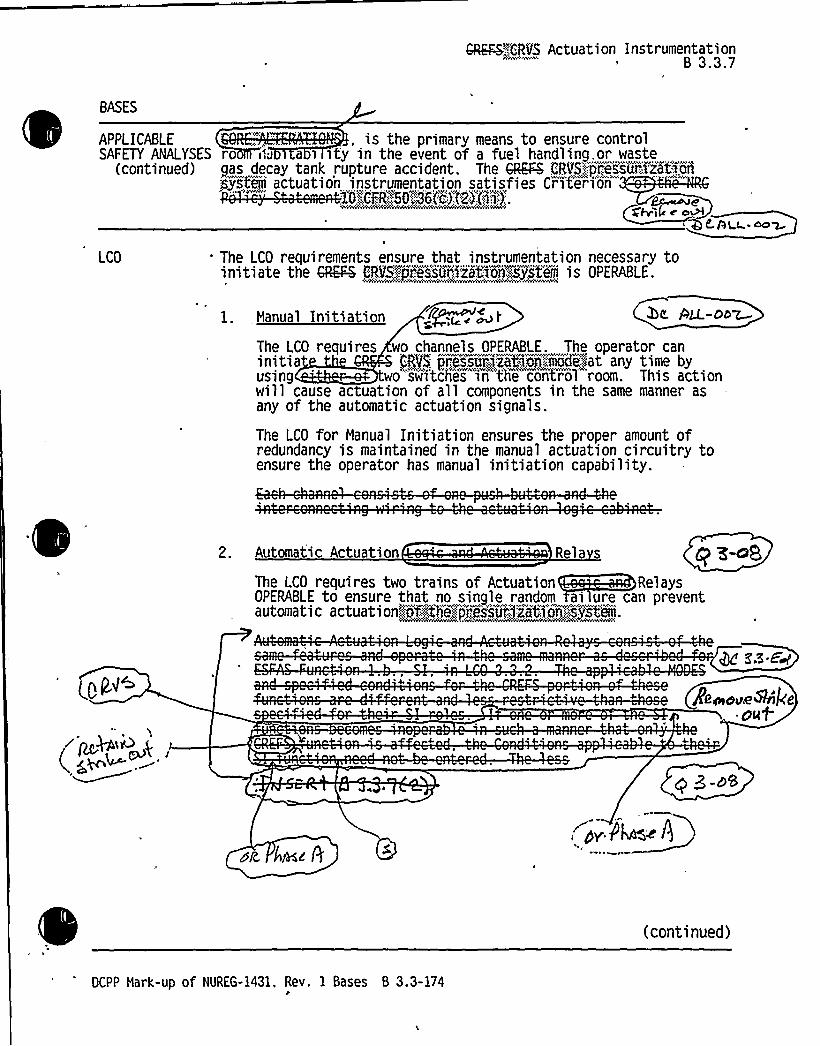
APPLICABLE , is the primary means to ensure controlSAFETY ANALYSES ro I",'J a i sty in the event of a fuel handling. or waste
(continued) gas decay tank rupture accident. The QKF4 CRVS':"::pres's7urXzationjjsteiii actuation instrumentation satisfies Crater'ion
e'ffyseC oWt'u .~~LCO The LCO requirements ensure that instrumentation necessary to
initiate the OREPB CRVS:.,jres'sunitation'jester'a iS OPERABLE.
ALL-ObW
The LCO for Manual Initiation ensures the proper amount ofredundancy is maintained in the manual actuation circuitry toensure the operator has manual initiation capability.
1. Iranual Initiation
The LCO requires wo channels OPERABLE. The operator caninitia CR9$ priKurjF~tion.."age>*at any time byusing wo "sw'irtcfies" in"'the controT room. This actionwill cause actuation of all components in the same manner asany of the automatic actuation signals.
2. Automatic Actuation Rela s
The LCO requires two trains of Actuation RelaysOPERABLE to ensure that no single random ai ure can preventautomatic actuationjlof,.-::,the;,:prelssuc5iiit'i',,:sIrst'raa.
Aewo~e8'kedl4+
~ ~
(continued)
DCPP Hark-Up of NUREG-1431. Rev. 1 Bases B 3.3-174


Attachment 2. PG8 E Letter DCL-98-167
Insert for Q 3-08Enclosur B page b .3-174Insert 3.3.7 (2)
T e CRVS a osphere int e monitors actuate e pressurizat'ystem directl a the CRclays an o not go th gh the SSPS. Th nly actuation the CRVS pre rization e
of oper ion via the S PS is via a Phase signal actuati


GRQ4~CRVS Actuation InstrumentationB 3.3.7
BASES
SURVEILLANCEREQUIREHENTS
SR 3.3.7.1 (continued)
including indication and readability. If a channel is outside thecriteria. it may be an indication that thesensor or the signal processing equipment has drifted outside itslimit.
The Frequency is based on operating experience that demonstrateschannel failure is rare. The CHANNEL CHECK supplements less formal,but more frequent, checks of channels during normal operational useof the displays associated with the LCO required channels.
SR 3.3.7.2 I 4 3-erA 0Ã gFT is performed once every 92 days on each required channelto ensure the entire charm will perform the intended function.This test verifies the cap bility of the instrumentation to providethe QKF4 CRVS actuation.
TheFrequency is based on the known reliability of the monitoringequipment and has been shown to be acceptable through operatingexperience.
SR 3.3.7.3 >NS &s
s pu
SR 3.3.7.4 I v 5,84'f
(continued)
DCPP Hark-up of NUREG-1431. Rev. 1 Bases 8 3.3-179

.~

Attachment BPG8 E Letter DCL-99-063
Encl. 5B B 3.3-179Insert into SR 3.3.7.2
Insert for Q 3-08
The CRVS pressurization system actuation relays are directly actuated by the CRVSatmosphere intake radiation monitors. This signal is not processed through the SSPS, but goesdirectly to the CRVS actuation relays. The pressurization system is also actuated by Phase A,however this signal is processed via the SSPS and the testing of the associated relays isperformed via SR 3.3.2.2, SR 3.3.2.4, and SR 3.3.2.6.
Insert into SR 3.3.7.3
SR 3.3.7.3 is the performance of an ACTUATIONLOGIC TEST. This test verifies the signalpath to the Master Relay Coil. This test is performed every 92 days as part of the performanceof SR 3.3.7.2.
Insert into SR 3.3.7.4I'R
3.3.7.4 is the performance of a MASTER RELAYTEST. This test energizes the Master, Relay and verifies the actuation signal injected into the Slave Relays. This test is performedevery 92 days as part of the performance of SR 3.3.7.2.


GAQ4."CRV3 Actuation InstrumentationB 3.3.7
BASES
SURVEILLANCE SR 3.3.7.4 (continued)REQUIREMENTS
moltage~~vrjected to the slave-re%a~i —. T Cage- is
i Ml N i —.-i i — ii.~WH-iil ii. it -i i f ~ y~en~~~a~8P44QCQ.
J~SsZ SR 3.3.7.5
C
m&on-can-be
5Cer-
+3 w
N ~a~~
SR 3.3.?.6
SR 3.3.7.6 is the performance of' TADOT. This test is a check ofthe Manual Actuation Functions and is performed every fK months.Each Manual Actuation Function is tested up to, and inctiiding. themaster relay coils. In some instances, the test includes actuationof the end device (i.e., pump starts, valve cycles, etc.).
The test also includes trip devices that provide actuation signalsdirectly to the Solid State Protection System, bypassing the analogprocess control equipment. The Frequency is based on the knownreliability of the Function and the redundancy available. and hasbeen shown to be acceptable through operating experience. The SR ismodified by a Note that excludes verification of setpoints duringthe
(continued)
DCPP Hark-up of NUREG-1431. Rev. 1 Bases B 3.3-180


Attachment BPGB E Letter OCL-99-063
Encl. 5B B 3.3-180Insert into SR 3.3.7.5
Insert for Q 3-08
SR 3.3.7.5 is the performance of a SLAVE RELAYTEST. This test energizes the Slave Relaysand veriTies actuation of the equipment to the pressurization mode. This test is performed every92 days as part of the performance of SR 3.3.7.2.


Attachment BPG&E Letter DCL-99-063
ADDITIONALINFORMATIONCOVER SHEET
ADDITIONALINFORMATIONNO: Q 7-09
REQUEST:
APPLICABILITY: CP, WC, CA, DC
Clarification is provided that Channel Checks are only required for normallyenergized instrumentation channels by adding "for each required instrumentationchannel that is normally energized", per ITS [SR 3.3.3.1 and SR 3.3.4.1] toCTS [4.3.3.5.1 and 4.3.3.6].
Comment: [See LS 1 GEN]
FLOG RESPONSE (original): The applicability of DOC 7-09 LS-43 has been revised toinclude DCPP and WCGS.
Per the agreement at the 8/14/98 meeting, a list of the de-energized instruments willbeincluded in LS-43.
FLOG RESPONSE (Supplement): The CTS SR 4.3.3.5.1 markup page which wasinadvertently omitted is added to this response.
ATTACHED PAGES:
Encl. 2 3/4 3-47


INSTRUMENTATION
REMOTE SHUTDOWN INSTRUMENTATIONAND CONTROLS\
LIM)TINGCONDITIONFOR OPERATION
3.3.3.5
d3-d B-yi
The remote shutdown monitoring instrumentation and control functions shown in Table 3.3-9 shall be OPERABLE.
APPLICABILITY: MODES 1, 2 and 3.
ACTION:
With less than the minimum required Function(s) ofTable 3.3-9 operable, restore the inoperablepunodon(s) lo opERABLE status udtNn 30 days or aa in MDDEsuudDntrt 8'tnnii aTld'HUT BHUTDOwNwithin fhaae4 12 hours.
The provisions of Specification 3.0.4 are not applicable.
Separate entry into Action a. Is allowed for each Function in Table 3.3-9.
0- -A
SURVEILLANCEREQUIREMENTS
&}cH /&oui~ I~C ~e P4 ra Lmyd I+i 2-o4.3.3.5.1 Each re ote shutdovm monitoring instrumentation channe s emons ra LEbype o a oftheCHANNEL'CHECKand CHANNELCAUBRATIONat the frequencies shown in Table 4.34'.
4.3.3.5.2 Verii'yeach required control circuit and control transfer switch Is ca pable of performing the intended function at least onceevery ~iiQP
REFOEL4QC ~~Vht.
OIABLO CANYON - UNITS 1 tt 2 3/4 3-47


Attachment BPG8 E Letter DCL-99-063
ADDITIONALINFORMATIONCOVER SHEET
ADDITIONALINFORMATIONNO: Q 3.3-37 APPLICABILITY: DC, CP
REQUEST:Several ITS Required Action Notes are modified to allow a channel to be placedin bypass for surveillance testing.. [This change, incorporating bypass testinstrumentation, was approved for CPSES through Amendments 47 and 33 forUnits 1 and 2, respectively.]
Comment: Reject for CP application to 3.3.1 Action D.18 E.1 8 M.1 - The ITSproposes generic changes to the STS that are not included in an approved TSTF. TheISTS notes allowing bypass for testing are based on WCAP-10271. Provide a referencethat shows staff approval of the proposed deviation from the ITS based on the acceptedanalysis of WCAP-10271.
FLOG RESPONSE (Original): For DCPP, WCAP-10271 was approved via LA 61/60. Duringthe development of the ITS, the portion of CTS ACTION 6 that allows the bypass of oneadditional channel was not included in the mark-up of ITS LCO 3.3.1 ACTIONS E.1 and M.1.The allowed bypass notes of ACTIONS M.1 and E.1 have been revised to reflect the CTSallowance of one additional channel and the FUNCTIONALUNITS affected by the allowance.Refer also to Additional Information Number DC 3.3-003 and to the revised DOCs for 01-19-LS8, 01-45-M, 01-50-A, 01-49-LS18 and their applicable revised NSHC discussions forrevisions related to the missed portion of the CTS note.
For CPSES, the changes in 3.3.1 Actions D.1, E.1 and M.1 have been confirmed to beconsistent with the CTS. In verifying these actions, it was discovered that the note for thecondition for Turbine Trip (condition P in the STS) had not been modified to reflect the bypassfor testing allowed by the CTS. The conditions for Turbine Trip have been revised in theresponse to RAI 3.3-02. In addition to those changes, the note to new Required Action 0.1 isrevised to read "The inoperable channel or another channel may ..." to incorporate the bypasstesting allowed by the CTS.
FLOG RESPONSE (Supplemental): Based upon conversations with the NRC Staff on March25, 1999, the Notes associated with LCO 3.3.1 Conditions E 8 M are revised to differentiate 2-out-of-4 logic and 2-out-3 logic functions for proper configuration for testing in bypass consistentwith WCAP-10271 while maintaining the CTS bypass requirements for the NIS. Similarrevisions are added to the Notes associated with LCO 3.3.2 Conditions D 8 O. The Basesdiscussion for each of these Conditions is also revised consistent with these revisions.
ATTACHEDPAGES:
Encl. 5A 3.3-4, 3.3-7, 3.3-30, 3.3-35Encl. 5B B 3.3-44, B 3.3-49, B 3.3-114, B 3.3-122


RTS Instrumentation3.3.1
ACTIONS (continued)
CONDITIO
D. (continued mid 5b 4~t
REQUIRED ACTION
----NOTE---------------re uired to be erformed
*
ow neeu r n ux
': to
PTR'
5T:
, "',".'..:'
nP5 ', T ".
"'.2.2
Perform SR 3.2.4.2.
COMPLETION TIME
p.g'- i'd%
Once per12 hours
OR
D.3 Be in MODE 3.12 hours
i.'K.E
E. One channel inoperable.
~ ~ g oABAr FO---—--—-----NOTE----
The inoperable channel may bebypassed for up to 4 ho s forsurveillance testin
o otherc anne ~< v c?? s, z4, 3
+bi8'8 )
~~ fga.Qua~ill~ ~~o~ ~4~» ~
Place channe >n tr~p.
OR
E.2Be in MODE 3.
o~) c4~~>
s —'vQ~48
Qeours
12 hours
F.
Intermediate"RangeNeutron Flux channelinoperable.
F.lReduce THERMAL POWER to< P-6.
OR
F.2Increase THERMAL POWER to> P-10.
S S.95our's
3.3-10?
3.3-107ho
urs
(continued)
DCPP Mark-up of NUREG-1431, Rev. 1 3.3-4


RTS Instrumentation3.3.1
ACTIONS continued
CONDITION REQUIRED ACTION COMPLETION TIME
L. Required Source RangeNeutron lux
'hanneinopera e.
L.l Suspend operationsinvolving positivereactivity additions.
ImmediatelyB
P E.E-I2.5
4-@etta s.3 q23
One channelinoperable.
AND
L.Q2 Perform SR 3.1.1.1.
~ p,~-------------NOTE------The inoperable channel may bebypassed for up to 4 hours fsurveilla
~< Fracas'~~, i2c uez ~ >~p~aeP 5af c~~ g4 uc lg .
M.l Place channel in trip.OR
M.2 Reduce THERMAL POWER to< P-7.
1 hour
AND
Once per12 hoursthereafter
I3 3;>7w>cuaouc i~8a
Q~ 10
I5 ddt'hz l 4f~ h0'u v|eill~a A'T.*~+f
3.3Y7 )'hours (~ eg
12 hours
(continued)
DCPP Mark-up of NUREG-1431, Rev. 1 3.3-7


ESFAS Instrume'ntation3.3.2
ACTIONS (continued)
CONDITION REQUIRED ACTION COMPLETION TIME
C. One train inoperable. C 1 -----------NOTEOne train may be bypassedfor up to 4 hours forsurveillance testingprovided the other trainis OPERABLE. WC 3.3-3I'f
OR
Restore train to OPERABLEstatus.
6 hours
C.2.1 Be in MODE 3.
AND
C.2.2 Be in MODE 5.
12 hours
42 hours
D. One channelinoperable.
D.1 ------- --NOTE----------The ino erable channelbfw90e.'"" ddl~i,o, a,I::
channel: may"be bypassedfor up to jf hours forsurveillance
test'ther
channels. Foe R M
3.3 379 J-I<9
C7C 3J 73i>
C,d,.(iTbb rlVF~~8Xaala pWOPS'P iit3=-yuCace c anne n
OR
D.2.1 Be in MODE 3.
AND
D.2.2 Be in NODE 4.
ours ' g,g- 37
12 hours
18 hours
3 ~ 33 '7 Ww3' vLP. w
'7v wh(%N7 wO
(continued)
DCPP Hark-up of NUREG-1431. Rev. 1 3.3-30


ESFAS Instrumentation3.3.2
ACTIONS (continued)
CONDITION REQUIRED ACTION . COHPLETION TIHE
fiiopi'able::,
4'8,",hovi,i'fme~e™d
j;ateXj
DCPP Hark-up of NUREG-1431. Rev. 1 3.3-35


Enclosure 5AInsert 5A-O&P
page 3.3-35
Attachment 2PG8 E Letter DCL-98-167
Insert for Q 3.3-66
O. One channelinoperable
NOTEino erable channel
e bypassedfor up to 4 hours for surveillancetesting of other channels.
Q 3.3-37
0.1 Place channel in trip.
OR6 hours
0.2.1 Be in MODE 3.
AND
0.2. Be in MODE 5.
4
12 hours
8, 3.3-((.42 hours
P. One channelinoperable
NOTEOne additional channel may bebypassed for up to 4 hours forsurveillance testing.
P.1 Place channel in.bypass. 6 hours
OR
P.2.1 Be in MODE 3. 12 hours
AND
P.2. Be in MODE 5.


BASES
ACTIONS(continued)
E, I and E2
RTS- Instrumentation, B 3.3.1
Condition E applies to the following reactor trip Functions:
Power Range Neutron Flux- Low;
Overtemperature hT;
Overpower hT;
Power Range Neutron Flux- High Positive Rate:
Power Range Neutron Flux- High Negative Rate:
Pressurizer Pressure- High; 5nd
SG Hater Level -Low Low; @ad
A known inoperable channel must be placed in the tripped conditionwithin 6 hours. Placing the channel in the tripped conditionresults in a partial trip condition requiring only one-out-of-twologic for actuation of the two-out-of-three trips andone-out-of-three logic for actuation of the two-out-of-four trips.The 6 hours allowed to place the inoperable channel in the trippedcondition is justified in Reference 7.
If the operable channel cannot be placed in the trip conditionwithin the specified Completion Time. the unit must be placed in aMODE where these Functions are not required OPERABLE. An additional6 hour s is allowed to place the unit in MODE 3. Six hours is areasonable time, based on operating experience, to'ace the unit in @><>MODE 3 from full power in an orderl a w' engingunit systems, a. ~e i Wl 8>~~
Fgh3cTl~ ~1)
The Required Actions have been modified by a Note that a lowsplacing the inoperable channel in the bypassed condition for up4 hours whi e erformin routine surveillance testin o thehannels...,,;:, .„.,;, .; .,;,, .;;,, ": = Udb
'>'pe.~ '., % '' ';p;:4 8 '4 c'0>''.gag . >.'> '">'w ~ ~ % .'>%:,'(>> ~
' ''", '' . 0''wNvAwgm'
our >me im> ss gus i ie )nReference
T)».'m*llaurg a>)QW> I>»>/>~ >/»
C4~»c) ~ |.L>&e1<r>MZ 24, g~f)>4 6< kgp~seeP fa0 5'ue4ei fl~4e-j c5f4AE 48 44>./c >
Q3'H7
(continued)
OCPP Mark-up of NUREG-1431, Rev. 1 Bases B 3.3-44

0

BASES
ACTIONS M. 1 and M.2 (continued)
RTS InstrumentationB 3.3.1
OPERABLE channel, and the low probability of occurrence of an event'uring this period that may require the protection afforded by the
Functions associated with Condi '+.< i q g q4 7
a k Cg~al+vv sv
The Required Actions have been mo > e a splacing the inoperable channel in the bypasse ondition for up to4 hours while performing routin oc 2
sur yeillance testing of the other c anrie s. e our mme imitis justified in Reference 7.
QC dtJeska ply'~C '~~wi A~ »<~vvo d 8» q 'a
N.l and N.2 ~ g» t.„f.+ am4A. so ~>>~cljfoT,-.URN
~AC Q lo
O.l and 0.2
+~8.T'RCTlbQ O M~>
(continued)
DCPP Mark-up of NUREG-1431. Rev. 1 Bases 8 3.3-49


ESFAS Instrumentation8 3.3.2
BASES
ACTIONS D.l 0.2.1 and 0.2.2 (continued)
Steam Li,ne Pressure- Negative Rate —High; ~
StiYiFiiiii,*::!Pieasuie,—,:-:.Lo'w,'
SG Wa er eve -Low LaRd
If one channel is'noperable. 6 hours are all ed to restore thechannel to OPERABLE status or to place it in he trippedcondition. Generally this Condition applie to functions that
on - - - 'u'gressui,.zeryressureofo c anne p aces t e unction in"a w'o-out-of-twoconfiguration. @e ~A&~j:Noperabl,ejchannel must be tripped toplace the Function in a one-out-of ~two configurati n thatsatisfies redundancy requirements.
Failure to restore the inoperable channel to OPERABLE status orplace it in the tripped condition within 6 hours requires theunit be placed in NODE 3 within the following 6 hours and MODE 4within the next 6 hours.
The allowed Completion Times are reasonable, based on operatingexperience. to reach the required unit conditions from full powerconditions in an orderly manner and without challenging unitsystems. In MODE 4. these Functions are no longer re uiredOPERABLE. l.d
The Required Actions are modified by a Note hat allows theinoperable channel ae.',.el&:::885)XjenQ::,,::„.chaep8.: to be bypassed forup to 99 hours for s'urveitlance"testing o''ther channels. The6 hours allowed to restore the channel to OPERABLE status or to
ace the inoperable channel in the tripped condition. and e..;: hours allowed for testing, are justified in Reference 8
r~ r c.~~ I.C,'I~~>)'I ~ <~>
/)pal
If+ g g.(i) ~ Q ~ IuopM~8 4 < ~ +"~~ g 3,3 3 7++~< g y p~<~ ~ s w duo rR wcyg gQ ~ Q(~al4",Q, (continued)
OCPP Mark-up of NUREG-1431. Rev. 1 Bases 8 3.3-114

I

ESFAS InstrumentationB 3.3.2
BASES
ACTIONS L. 1 L.2. 1 and L.2.2 (continued)
''nditVo",,"'8,.::app7~jeas>fo',.jthe~Tf i'pp'.;ice',::,", ay< '.;...,. p,,or,;'.~the':!%':.::.I m.-.,
, owjQat,Pjk jVefj'gcblatjon>ef.:,'";:.AFH pumps:.'„~$'Hath,.".':,:o'ne<'9'r'<;,rxirj,.",'TTaD
'i'j'reC'he,"'"
ff'enid:i.
t, 88,,:F.,
w'ater,"".'.;q3'... ekj@low"~ljekc nnel';::;.',cainotj-
>",'pea'redp;, 'e,.I',tr,'i p4<heidunit"tttii'st':::: g'jil.ac&~)fig'.:, N0 "::P:;:!41,thj'ii".'-th"..:"newith"
„~%hi"':-,;To',I.',.'gaea','jangle';:-';;:~bajed',
c„a.'.f'geng.in'.,',u'na,'f j,s~tems.'.'»„:"'':- I"',::.NDBi4.',""'.'':it"'.'j'u'ncic:.::t~doai.":.:nest':.'':.;:hÃve'".,.;:;any':a"'a';jijd<ra'n"".e'nts""'i'r".'-.","i'ond","j;ebs'::'Ch0 o' cQ e c.on.'«..UAc4$ ,0n';:;.,':!a, vt I,
gQ' bc '3.g-oo7
LCO 3.0.3 to initiate shutdown actions in the event of a completeloss of ESFAS function. If the interlock is not in the requiredstate (or placed in the required state) for the existing unitcondition, the unit must be placed in MODE 3 within the next6 hours and MODE 4 within the following 6 hours. The allowedCompletion Times are reasonable, based 'on operating experience,to reach the required unit conditions from full power conditionsin an orderly manner and without challenging unit systems.Placing the unit in NODE 4 removes all requirements f'rOPERABILITY of these interlocks.
SIF' "-'dppR~
«":=:."-„.:.::;':;:HFjTia':f%aftVSt)on.:,.if.:::,':,Stia~"';L';:ee.:.''Isolate:o~,:P end
fili::::„:::'„,:.Hasee: XMte>Kho~a::::ef.:":::::e'eai18~et:, ..FeedNteP!.
f:.".'ea'saoni8l..'e'.",'0'oiiiiderinj:,-avail,abl,'e,.':,redid'dancy,."'.,''-".and„'.%he,,','I.m':"probabil,'~t j..,'i',"av:.event,occii'ii)n'g4dui','ihg';-,',:this'~.';~'ntervalI'',='.'„'-:.,';.If.:,'"the'„F.j"','etu'r™nedgto"'OPERABlKiji'aalu)."';:."ithei.'.'assoc'tedi'umap"'".oeer,:,'.,'v'a'lve',.:,sh'al>l.:be'."declared.~,"i'no jgiaha,e,",-'i~i at'ely',:,'a'nd~the,;:.,RE(NIREO.'4CTION„"',;'of,:
"
3'":;:.7$~!;:oi.":::3!~7g~is!~i'jip'1:::j'c'N ::'i'a'iiijilm'Le''d„.:fijXhi~t'a'eiedi.'ately",',„:=
i xÃc~'T ~8 -o~ P ,. j> s~E-H-, (continued)
DCPP Hark-Up of NUREG-1431. Rev. 1 Bases B 3.3-122


Attachment 2PG8 E Letter DCL-98-167
Insert for Q 3.3-66
q3,$ -r 4
Enclosure 5B page B 3.3-122Insert 5B-0 8 P
0.1 or 0.2.1 0.2.2 g-s~Q'ondition
0 applies to Safety Injection - Containment Pressure —High.
Ifone channel is inoperable, 6 hours are allowed to restore the channel toOPERABLE status or to place it in the tripped condition. Failure of one channelplaces the function in a two-out-of-two configuration since the trip coincidence istwo-out-of-three. The inoperable channel must be tripped to place the Functionin a one-out-of-two configuration that satisfies redundancy requirements.
Failure to restore the inoperable channel to OPERABLE status or place it in thetripped condition within 6 hours requires the unit be placed in MODE 3 within12 hours and MODE 5 in 42 hours.
-
The allowed Completion Times are reasonable, based on operating experience,to reach the required unit conditions from full power conditions in an orderlymanner and without challenging unit systems. In MODE 5, these functions areno longer required OPERABLE.
Q3 3-'llThe Required Actions are modiTied by a Note that allows the inoper annel
to be bypassed for up to 4 hours for surveillancetesting of other channe s. The 6 hours allowed to restore the channel toOPERABLE status or to place the inoperable channel in the tripped condition,and the 4 hours a wed for testing, are justified in Reference 8.
P.1 or P.2.1 P.2.2
Condition P applies to:
~ Containment Spray - Containment Pressure —High-High.
~ Containment Isolation - Phase B Isolation - Containment Pressure - High-High.
Neither of these signals has input to a control function. Thus, two-out-of-threelogic is necessary to meet acceptable protective requirements. However, atwo-out-of-three design would require tripping a failed channel. This isundesirable because a single failure would then cause spurious containmentspray initiation. Spurious spray actuation is undesirable because of the cleanupproblems presented. Therefore, these channels are designed withtwo-out-of-four logic so that a failed channel may be bypassed rather thantripped. Note that one channel may be bypassed and still satisfy the singlefailure criterion. Furthermore, with one channel bypassed, a singleinstrumentation channel failure willnot spuriously initiate containment spray.The containment spray signal is also interlocked with Sl and will not initiatewithout simultaneous Sl and containment spray signals.


Attachment BPG8 E Letter DCL-99-063
ADDITIONALINFORMATIONCOVER SHEET
ADDITIONALINFORMATIONNO: Q 3.3-43 APPLICABILITY'A,CP, DC, WC
REQUEST:Revise ITS 3.3.1 Condition R Notes 1 and 2 per traveler TSTF-168. The 2-hourAOT should not be limited to only UVTA/STAmaintenance.
Comment: TSTF pending NRR review. Based on 8/14/98 meeting TSTF rejectedbased on WCAP-14333 which prohibits "maintenance bypass."
FLOG RESPONSE (Original): TSTF-168 has been approved by the NRC. Therefore, theFLOG continues to pursue the changes associated with JFD 3.3-43.
FLOG RESPONSE (Revised): As discussed with the NRC reviewer on March 17, 1999, ITS3.3.1, Condition R, is revised to delete the words "or maintenance." This wording is not in theCTS. TSTF-168 is withdrawn and all changes to the Condition R Notes are based on the CTS.JFD 3.3-117 is revised by the insertion of "Note 2" to clarify which note the change effects.
ATTACHEDPAGES:
Encl. 2Encl. 3AEncl. 3BEncl. 4Encl. 5AEncl. 5BEncl. 6AEncl. 6B
3/4 3-75425Traveler Status Page, 3.3-10B 3.3-514,98,18


Ervs4wc elhi v. < od TABLE 3.3-1 ContinuedACTION STATEMENTS Continued
Ol-49-LS18'
ACTION'0-
ACTION 11-
ACTION 12-
~1M« ~~< ««a r.p 7 p'a < ~ Ak.+4+ 44@ iQ 4' 4A~™ ~ ~+ sf woo far v~rveI&m
Mit the number of . -,.m,,Required Channels' . store."4%",.-Ynopera5>e,tr.@F7+0,',operable 0-staLus;„:with)n)'ls'hour...~or, be'n at least HDT sTANDBY within 6 7: hours: however. one g,QehYaPeftrain ma be b assed for up to 2 hours for " surveillance 01-13 LS6testing '
d ne OPERABlimni o @a gvye 4v i w~ 41> gQ . c7 Ji) 9
:itT:!'l ...,,ii!iiIChannel s OI'::;"::.trajrii . restore the inoperable channel pi~!5L!aij
next hour,-': "".:, ..',, p,ace~fhe.'::Re~dieNtro.'.I."::„,'Sysfem~Ãfa-:.a~conditlon
: ncapa5 e'.:,:b'f,;",::,rA„:w..r. rawa .CCCv~. ~y«4vir&mm«vw«~
With one of the diverse trip features (Undervoltage or shunt trip attachment)inoperable. restore it to OPERABLE status within 4B hours or
E "'i:, 5% ii: g "tW'I
inoperable except for the time required for performing maintenance to restore the breakerto OPERABLE status.
K«, dChannels. STARTUP and/or POWER OPERATION may proceed provided the followingconditions are satisfied:
01-43-A
-ACTION 26-
, id
Channels. STARTUP and/or POMER OPERATION may proceed provided that within 6 hours.for the affected RCS Loop Delta-T channel(s). either:
ACTION 27-
e,3,%E 01-04-LG
The inoperable channel is placed in the tripped conditions within 6 hours:however. the ino crab channel may be bypassed for up to 72 hours for surveilla
or for performing maintenance~~oR)C. e i4 Hnb~ ta I< ouv~ 4With the number of OPERABLE channels one less than the ~um Re~qu ied Channels 01-04-L
. restore the inoperable Channel to OPERABLE status within 6hours or be in at least HOT STANDBY within the next 6 hours: h ver one channelmay be bypassed for up to 4 hours for surveillance testingprovided the other channel is OPERABLE. 4 8 3g
01-43-A
a. The Trip Time Delay threshold power level for zero seconds time delay isadjusted to OC RTP. or
,'i'!,!,",Channels. the affected Steam Generator Mater Level-Low-Low channels are placed in
he tripped condition.~me g |LcAC~N-QQ—
I
01-43-A
cn
C o 8zcAJcC 7~@.~gjf ~g~ Q ( p 7 gl//fklQ /Z A@V~,p 88-w3
DIABLO CANYON - UNITS 1 8, 2 3/4 3-7


CHANGENUMBER
01-13
01-14
01-15
01-16
01-'I7
NSHC
LS6
LS40
A
DESCRIPTION
fACT( S emen 0] is evispd to nate that th'e 2 hool[tra and eacto 'p br ker ypassallowance forltrain oy)
ake urvei nce t tin an aisle usga for aintenance.his ang oes t i ct theponclu ons of
W AP-1 71-P S plemegQ,Re .1sinc there'o *
ang o the ypa time. 'Nis cha e is nsist twiTrav er TS -16 . CTI tement t10) is [also] revisedto require restoration of an inoperable RTB within 1 hour or theplant must be in HOT STANDBYwithin the next 6 hours,consistent with NUREG-1431. This is less restrictive since anadditional hour is provided for the transition to MODE 3.
In the ISTS Table 3.3.1-1, Function 20, the Reactor TripBreaker (RTB) Undervoltage and Shunt Trip Mechanisms areseparate from the RTB Functional Unit. The CTS have beenrevised to reflect these requirements. ~ 3.3-betNew [footnote (Ij has] been added to the RTB Functiona nitto note that the same OPERABILITYrequirements andACTIONS apply to a bypass breaker if it is racked in andclosed for bypassing an RTB. The bypass breakers werealready handled in this fashion. ACTION 12 in CTS Table3.3-1 has been revised accordingly. Aa i ]-)'f-R
Not applicable to DCPP. See Conversion Comparison Table(Enclosure 3B).
The requirement to verify the setpoint during the quarterlyTADOTfor RCP Underfrequency [and RCP Undervoltage) isdeleted, consistent with NUREG-1431.
Consistent with NUREG-1431, LCO 3.3.1 Re uired ACTIONDNote CTS Table 3.3-1 ACTION Staternent2 rd An@
eenmodiied ya Notethatallows e ypass o 6e used for surveiltance testing orsetpoint adjustment. Setpoint adjustment can be performed atpower and may be required by other Technical Specifications.The reason for placing the channel in bypass does not affectthe impact of having the channel in bypass.
DCPP Description of Changes to Current TS 5


CONVERSION COMPARISON TABLE- CURRENT TS 3/4.3
Page 4 of 31
TECH SPEC CHANGE
NUMBER DESCRIPTION
APPLICABILITY
DIABLOCANYON COMANCHE WOLF CREEKPEAK
CALLAWAY
01-11LS5
01-12M
01-13LS6
[New] ACTION Statement [39) is applied to the Low FluidOil Pressure and Turbine Stop Valve Closure tripfunctions. Rather than entry into LCO 3.0.3 ifcurrentACTION Statements [6 and 11] are not met or ifmultiplelow fluid oil pressure channels are inoperable, the newACTION Statement requires inoperable channels to betripped within 6 hours or power reduced below P-9 within10 hours.
New ACTION Statement [8.1] is created to differentiatebetween those RTS interlocks required to be operable inMODE 1 only, and those interlocks required to beoperable in MODES 1 and 2. If the interlock function isrequired to be operable in MODE 1 only and the LCO andACTION requirements are not met, then new ACTIONStatement [8.1) requires that the unit be taken to MODE 2within 7 hours.
In addition, current ACTION Statement [8] is revised forthose interlocks required to be OPERABLE in MODES 1
and 2. Ifone channel is inoperable, the interlock must bedetermined to be in its required state or the plant must bein at least HOT STANDBYwithin 7 hours.
[ACT)ON Statement[~is re'e o no at~t2hou~[t 5 and]<actor dp breaker bypass allowance for fJr4fn
or) bredf<er s iliance testin can also housed fePmaintenanc .) CTION Statement[ 0~is a so revisedto req e res oration of an inoperable RTB within 1 houror the plant must be in HOT STANDBYwithin the next6 hours. This is less restrictive since an additional houris provided for the transition to MODE 3.
No, seeCN 1P8-LS-4.
Yes
Yes
Yes
Yes
Yes
Yes
Yes
Yes
Yes
Yes
Yes P> 3-YJ
DCPP Conversion Comparison Table - Current TS


IV. SPECIFIC NO SIGNIFICANTHAZARDS CONSIDERATIONS
NSHC LS610 CFR 50.92 EVALUATION
FORTECHNICALCHANGES THAT IMPOSE LESS RESTRICTIVE
REQUIREMENTS WITHINTHF TECHNICAl.SPECIFICATIONS
fAC NS teme 10]is vised ote atthe hour(t 'nd ct trip reaker passa wancetra') br er su illanc stin n al e use r m 'n ce. is chai1ge doe ot impthe nclus's of AP-10 1-P-, upp ent ev. 1 nc ere 'o t as '.ACTION Statement is so revise o require res ora ion o an inoperable Reactor Trip Breaker (RT )within 1 hour or the p ant be in HOT STANDBYwithin the next 6 hours. This is less restrictive thanthe current TS since n additional hour is provided for the transition to MODE 3.
IOThe proposed TS change s been evaluated and it has been determined that it involves no significanthazards consideration. This determination has been performed in accordance with the criteria set forth in10 CFR 50.92(c) as quoted below:
The Commission may make a final determination, pursuant to the proceduresin 50.91, that aproposed amendment to an operating license fora facilitylicensed under 50.21(b) or 50.22 or fora testing facilityinvolves no significant hazards consideration, ifoperation of the faci%tyinaccordance with the proposed amendment. would not:
1. Involve a significantincreasein the probability or consequences ofan accident previouslyevaluated; or
2. Create the possibility ofa new or different kind ofaccident from any accident previouslyevaluated; or
3. Involve a significant reduction in a margin ofsafety."
The following evaluation is provided for the three categories of the significant hazards considerationstandards:
1. Does the change involve a significant increase in the probability or consequences of an accidentpreviously evaluated'
Overall protection system performance will remain within the bounds of the previously performedaccident analyses since no hardware changes are proposed. As noted in the Bases ofNUREG-1431 Rev. 1, the Completion Time of 6 hours is reasonable, based on operatingexperience, to readh MODE 3 from full power in an orderly manner and without challenging plantsystems. The 1 hour and 6 hour Completion Times are equal to the time allowed by currentLCO 3.0.3 for shutdown actions. The proposed shutdown requirement Completion Time changewould result in an additional hour to achieve MODE 3. By allowing a shutdown time based onoperating experience, this change would reduce the chances of an operator error or challenge toplant systems that could result from the more restrictive requirement in the current TS. Theprobabilitythatanaccidentwouldoccurdurin the1hourextensionallowedbythe ro osedchan e isextremel small.
ccfamag&A
proposed change willnot affect any of the analysis assumptions for any of the accidentspreviously evaluated. The proposed change willnot affect the probability of any event initiatorsnor willthe proposed change affect the ability of any safety-related equipment to perform itsintended function. There willbe no degradation in the performance of nor an increase in thenumber of challenges imposed on safety-related equipment assumed to function during anaccident situation. Therefore, the proposed change does not involve a significant increase in theprobability or consequences of an accident previotisiy evaluated.
DCPP No Signficant Hazards Evaluations 25


INDUSTRYTRAVELERS APPLICABLETO SECTION 3.3
TRAVELER¹ STATUS DIFFERENCE ¹ COMMENTS
TSTF-19, Rev. 1 ~ ncorporated NA NRC a roveeffete. s~~ o~Q 7C Z.K Dog
Q RA-3
TSTF-37, Rev. 1 Not Incorporated NA ITS 5.6.8 still addresses PAM reports.Sections after ITS 5.6.7 were notre numbered.
TSTF-51 Not Incorporated NA Requires plant-specific reanalysis toestablish decay time dependence forfuel handling accident.
TSTF-1 11, Rev.
TSTF-135'4<. I
Incorporated
Partially Incorporated
3.3-'7c8.3 lIQ ~)-IDLY
NA
3.341, g.3" 0+)3.3-93,3.3-95,3 3-]
'Z.c-)cd
7(
TSTF-161, 8'. JIncorporated 3.3-79 $ r~vMk AP gZ.5 '7g
TSTF-168 ncorporated 3'.3- g 3
TSTF-169 Incorporated
( ~< ~ Incorporated
Incorporated
3.342
3.3P9
3.3-107
."g FEwP ~ r„g<j

RTS Instrumentation3.3.1
ACTIONS continued
CONDITION REQUIRED ACTION COMPLETION TINE
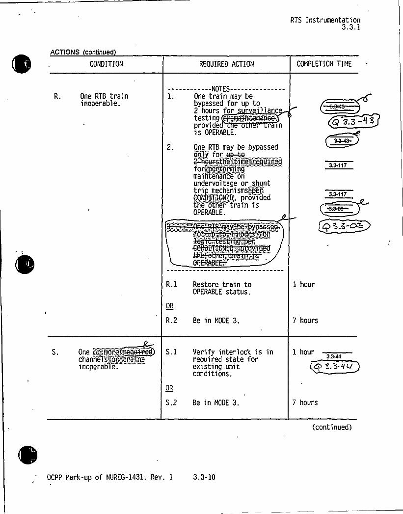
One RTB traininoperable.
------------NOTES---------------l. One train may be
bypassed for up to2 hours for veillancIprovided 'nis OPERABLE.
One RTB may be bypassedortly for vp-4e
or>ipef,', .armingmaintenance "on
undervoltage or shunttrip
mechanisms(jer,'ONOITION$
U, providedthe oth'er train isOPERABLE.
3.3 117
3.3.117
R.l Restore train toOPERABLE status.
OR
R.2 Be in NODE 3.
1 hour
7 hours
One or.;,,'::!mr.";e;—
'"'hannells";..;"o'":'.".','",trains:
inoperable.
S.l Verify interlock is inrequired state forexisting unitconditions.
OR
S.2 Be in NODE 3.
1 hour
7 hours
(continued)
DCPP Hark-up of NUREG-1431. Rev. 1 3.3-10


BASES
ACTIONS
RTS InstrumentationB 3.3.1
.2 ( i di
next 6 hours. The Completion Time of 6 hours (Required Action Q.l)is reasonable considering that in this Condition,,the remainingOPERABLE train is adequate to perform the safety function and giventhe low probability of an event during this interval. TheCompletion Time of 6 hours (Required Action Q.Z) is reasonable.based on operating experience, to reach NODE 3 from full power in anorderly manner and without challenging unit systems.
The Required Actions have been modified by a Note that allowsbypassing one train up to ~ hours for surveillance testingsprovided the other train is OPERABLE.
R.} and R.2
pegvlg )6'i ~2th~ <
j~foalc'
Rexid l<jWon~a-Idl ~
Condition R applies to the RTBs in NODES 1 and 2. These actionsaddress the train orientation of the RTS for the RTBs. With onetrain inoperable. 1 hour is allowed to restore the train to OPERABLEstatus or the unit must be placed in NODE 3 within the next 6 hours.The Completion Time of 6 hours is reasonable, based on operatingexperience. to reach NODE 3 from full power in an orderly manner andwithout challenging unit systems. The 1 hour and 6 hour CompletionTimes are equal to the time allowed by LCO 3.0.3 for shutdownactions in the event of a complete loss of RTS Function. Placing —.
the unit in NODE 3 re E-~ p~~~ Ctrl'+'4AI
The Requir d Action have been modified by Awe 4&ee-. otes. Noteallows one chas~ to be b assed for up to ours forsurveillance testing , provided the other chas~ti'hrliis OPERABLE. Note--2-'a ows-one RTB to be bypassed
bnIy::::,",'fo','.'h'":,'":.tjme'::-"r..equi:red<ii"''':jetfiring~ maintena'nceon uri8ervoltage or shurit" trip echanisms er:,'.:::C'ond'i'iiaAINif theother RTB train is OPERAB . ,;: „...„ ,, ',,:,,, ... ,,,,.. .Passed
e >me sm>ts:-.;::are mjus'tified-in-Refereiice- 7--
3~~4
).3- 'I3
ZE-0:
S.l and S.2
Condition S plies to the P-6 and P-10 interlocks. With one or. 'q i.q .qymore;: channels:- inoperable".:;'-:
'he associated interlock must beverified bj,..observation:.::o'„,::.the.:,':',a'ssap'ated:;,:arm'i'sssve',."':,annunpafor.:.windm:.-'to be 'in i'ts'"'requi'red sta't'e"for" the ex'asti"ng uni't"condition
w'.wa.v'. aZC
(continued)
DCPP Hark-up of NUREG-1431. Rev. 1 Bases B 3.3-51


CHANGENUMBER
I
3.3-37
3.3-38
3.3-39
3.340
3.341
3.342
3.343
3.3M
3.M5
3.M6
3.3<7
3.3<8
3.349
3.3-50
JUSTIFICATION
Several ITS Required Action Notes are modified per CTS to allow a channel to be placedin bypass for surveillance testing. f ]
h
Not applicable to DCPP. See Conversion Comparision Table (Enclosure 6B).s
Not applicable to DCPP. See Conversion Comparision Table (Enclosure 6B).
'Ia&+4ha4otef
ifieetiorH~nhanced by adding thisnetedetaendiTierrE, trtdteeanterrrannenasaendttiono ~ d. o«dt . ~+35 <D
Not applicable to DCPP. See Conversion Comparision Table (Enclosure 6B).
This change deletes ITS 3.3.1 Condition N per Traveler TSTF-169. Condition M isappropriate for Function 10.a to prevent sequential entry into Condition N followed by Mand exceeding the evaluated Completion Time in WCAP-10271-P-A, Supplement 2,Rev. 1. With this change, there is no need to list separate Functions 10.a and 10.b andcombining the Functions eliminates Applicabilityquestions similar to the Condition M vs. Nconcern above.
This c nge vises S3 .1 Co ition otes nd r ravel STF 68. T2-h r AO shou not limi to o UVT TA in ance his is onsist t wi
cu t TS d i cce ble b use spec'ntena e acti whic requi sat eact trip eaker eb sedd snot ec eimp ctofh ving th brea r
'raf A (~CotLg Q 5CPPebeF COAkVRC$tieu d+ ~<~>< ~~~+This change revises ITS 3.3.1 Conditions S and T and I S 3.3.
' '~~eHW9're
ec currenAC tatements [8 and 21]. -The Conditions apply to one or more channels for trains,as Condition T applies to permissive P-7,] because the safety function is served with theinterlock in the appropriate state for existin lant conditions. ~q'Q'3 rrii
A new CONDITION added for the current licensing basis required seis 'c dC. RQ=co
A new CONDITION and SR are added for the current licensing basis required SteamGenerator level low-low time delay trip. These changes affect both ITS 3.3.1 and 3.3.2.
Note 2 of SR 3.3.1.2 is revised to limitthe power increase to less than 30% per the currentlicensing basis before the SR is complete.
Not applicable to DCPP. See Conversion Comparision Table (Enclosure 6B).
ITS SR 3.3.1.8 is revised to extend the conditional COT frequency for power andintermediate range channels from 4 hours after reducing power below P-10 to 12 hours,based on operating experience regarding the time needed to perform the COTs. It standsto reason that if4 hours are allowed for2 Source Range COTs, 12 hours should beallowed for 6 Intermediate Range and Power Range COTs. The SR continues to assurethat the COTs are performed in a timely manner after the requisite plant conditions areentered. This change is consistent with Travele imF -zapNot applicable to DCPP. See Conversion Comparision Table (Enclosure 6B).
DCPP Description of Changes to Improved TS 4s


CHANGENUMBER
ttyo$ ~Iieet Ie *ZL rrt Qe~~ g ~„ regia(tore(morc t 65,
JUSTIFICATION
3.3-109
3.3-110
3.3-111
3.3-112
3.3-113
3.3-114
3.3-115
3.3-116
3.3-117
3.3-118
3.3-119
3.3-120
3.3-121
3.3-122
3.3-123
3.3-124
W&seR.Y Z.Z-)bc(o.o - tide P~f.L-CO
his c ge ad a Note ... source nge in rumentatibn to veint cks P nd P-1 are in th requir state f existin nit co Ifons. is is 3C E ~~'f
nsiste 'th the rrent T nd is enhan ent is e 'erfo ed arovi additi
~ a~M~r g, a- I I 2 Q.~SC'z, e)
o itg Q 2~zCg.b
~gal Z-K,"IJQ cp 3 5-4ill>"~I M~ ~ ~P"~Wu ( CPS.8 ~ iiu
ACTION J of ITS 3.3.2 is not used since DCPP does not rely on motor-driven AFW pumpstart with loss ofboth main FW pumps. The function exists, but is not credited in anyaccident analysis aiId is not part of ESF ion 6 in the CTS.
Nog Q 3.3-'l3This change to ITS 3.3.1 Condition R reflects current TS Table [3.3-1, ACTIONStatement 12) which was based on NRC Generic Letter 8549.
This change is for consistency with ITS 3.7.10 Condition [G].
Not applicable to DCPP. See Conversion Comparision Table (Enclosure 6B).
o Sa e A4)u ~ ~
aersion Comparision Table (Enclosure 6B).Not applicable to DCPP. See Con
~g-lF. 0
ITS 3.3.1 APPLICABIL)TYNote (b for Function 1, 5, 19-21 and Conditions C and K arerevised to replace ACTIONS requi 'ng the RTB to be opened with ACTIONS that ensuresubcriticality is maintained (i.e., by fullyinse all rods and ensuring the Rod Control 7 R 3.3-~4System is incapable of rod withdrawal) yet do not initiate a feedwater isolation (P-4 andIow T~) in MODE 3, consistent with Traveler TSTF-135.
This change deletes ACTION L.2 and renumbers L.3 since the requirement to close theunborated water source valves is not in the CTS and is not part of the current licensingbasis. This new requirement is not applicable to DCPP which has a licensed dilutionaccident evaluation (refer to License Amendment 28/27). The current licensing bases inaccordance with NUREG 0800, Section 15.4.6 provides adequate assurance that adilution event w~i!I ecogntzed and arrested ina timetyfashion.,+Q 8, i EkConsistent with the current TS Table 4.3-1, Note [15), the note for ITS SR 3.3.1.4 ismodified, a note is added to Table 3.3.1-1, and Function 20 are modified to clarify that theSR is required for the reactor trip bypass breaker local manual shunt trip only. The Basesfor SR 3.3.1.14 clearly state that SR 3.3.1.14 includes the automatic undervoltage trip ofthe reactor trip bypass breakers. The Note (k) added to Table 3.3.1-1, Function 20clarifies the Applicabilityof the undervoltage and shunt trip mechanisms to include thosefunctions of the reactor trip bypass breakers when in use.


~ ~ ' ~ I ~ ~ ~
~ ~ ~ ' ~ ~
~- ~ ~ ~ ~ ~ ~ ( ~ II ~ ~-
~ I
~ ~ ~ ~
~ ' e ~
~ ~
~ ~ ~ ~ ~
~ ~P': < ~ ~ i
~ ~ ~ I ~
~ ~ ~
~ Q ~ ~ ~ ~
I ~
~ ~
~ ~ ~ ~ ~ ~ ~ ~
~ ~
~ ~ ~ . ~ ~ ~ ~ ~ ~ ~ ~ ~ ~ ~
~ ~ ~ ~ ~
~ 4
I '. ~-~ ~
~ ~
~ ~
~ ~
~ ~ ~ ~ ~ ~
~ ~
~ ~ ~
o ~ ~
~ ~
~ ~ ~ ~
~ ~ ~ ~
~ ~
~ ~ ~
I . ~
I ~ - ~ ~ ~ . ~ . ~- ~ ~


~ ~ ~ ~ = ~
0 ~ ~
4~/ ~
~ ~ ~
~ ~
~ ~~ ~
~ '~ -
~
~ ~ ~ ~
mNZTt%5~ ~ ~ ~ ~
S
~ ~
~ ~ I ~ I ~
~ ~ ~ ~ ~ ~ ~
~ ~ ~ ~ ~ l~ ~ ~
~ ' ~
~ ~
~ ~ ~ ~ ~ ~ ~ ~ ~ ~
Ilte ~ I ~
s ~ ~ s s ~ ~
~ ~
~ ~
I ~ ~ ~ ~ ~ ~ ~ ~
~ ~ ~ ~
~ ~ ~ ~
~ ~ ~
~ ~ I ~ ~
~ ~
~ ~ I~ ~
~ ~ I ~
~ ~
~ ~ ~
I ~ ~ ~ ~~
~
'
~ ~ ~ ~ ~ I ~ ~ ~


Attachment BPG8 E Letter DCL-99-063
ADDITIONALINFORMATIONCOVER SHEET
ADDITIONALINFORMATIONNO: Q 3.346 APPLICABILITY: DC
REQUEST'new CONDITION and SR are added for the current licensing basis required
steam generator level low-low time delay trip. These changes affect bothITS 3.3.1 and 3.3.2.
Comment: Should action X.2 read "Place the affected SG-low low level channel(s) intrip"?
It may be desirable to include a 3.0.3 alternative in the Required Actions for Condition Wand Condition X.
ITS Table 3.3.1-1, Function 14.b (Steam Generator Water Level-Low Low, > 50% powertime delay) shows the LCO applicable only in MODE 1. The CTS table shows the LCOapplicable in MODE 1 and 2. This is a change from the CTS that is neither identified inthe CTS markup nor discussed in the DOC.
Condition X covers only inoperability of the SG-low low level trip time delays. It shouldcover the entire DT function.
For consistency with the iSTS format the trip time delay footnote (k) should be moved tothe Trip Setpoint and Allowable Value columns. for the RCS Loop delta T equivalentpowei¹ 50% function.
Since the time delay function is required to be operable down through Mode 3 (CTS-Mode 3¹¹¹) for the RCS Loop delta T at equivalent powers ¹ 50% RTP function, thenthe applicability for the time delay in ITS should also extend down through Mode 3.Provide a revised applicability for ITS function 6.d.1.
The CTS allows operation to continue under the equivalent of ITS action M.1 ifone or more channels is inoperable, but the ITS limits this to one channelinoperable. Is the application of the more restrictive requirement hereintentional? (Note the CTS limits the use of action M.2 to the condition of one
.channel inoperable.
There is no "LCO 3.0.3 equivalent" action for Condition M. Is this intentional?
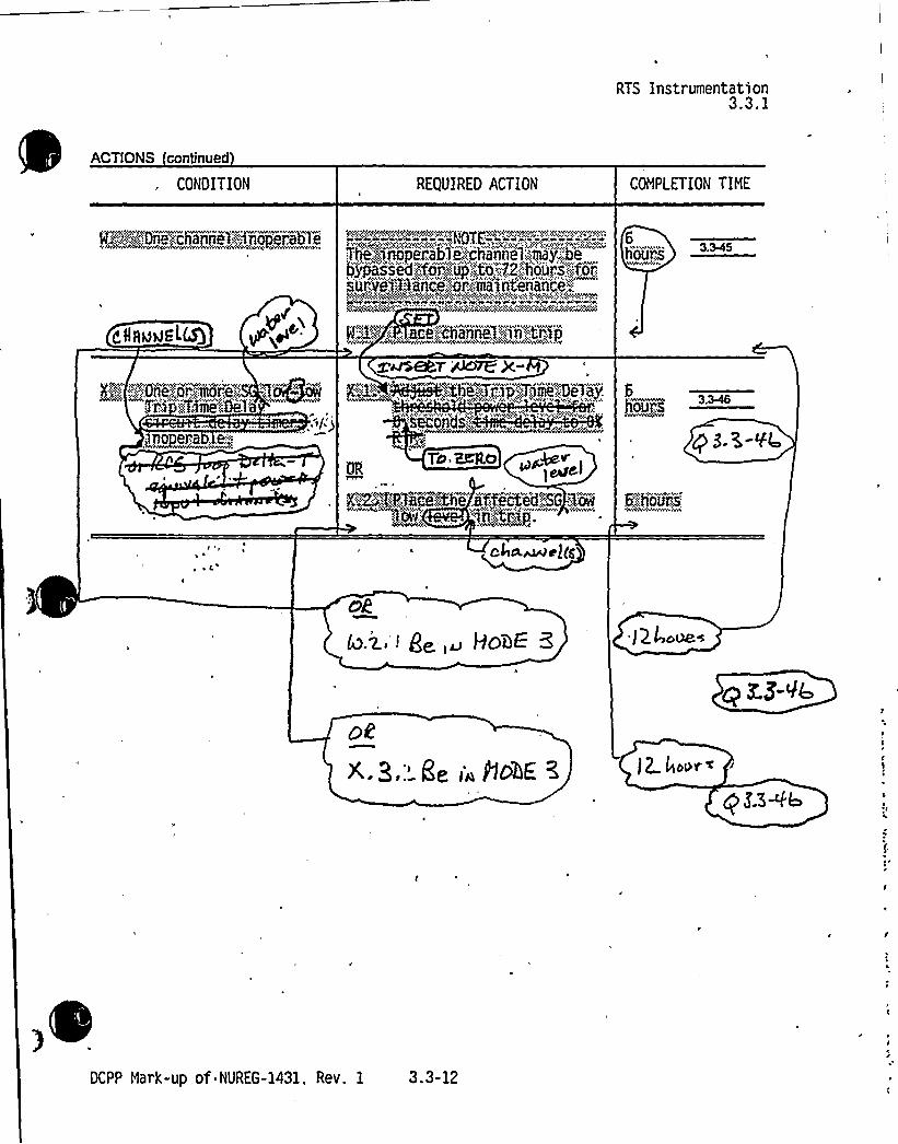
FLOG RESPONSE (Original): Comment 1): The words "water level" and "channel(s)" havebeen inserted into RTS CONDITION X to read as requested.
Comments 2) 8 8): An LCO 3.0.3 alternative has been added to both ACTIONS W and X forRTS and ACTION M for ESFAS, as suggested by the reviewer. This is consistent with otherNUREG-1431 ACTIONS and the intent of LCO 3.0.3. The LCO 3.0.3 alternative will requireMODE 3 entry within 12 hours for ACTIONS W and X and MODE 4 entry within 18 hours forACTION M if the effected channels cannot be tripped. This action is more restrictive by 1 hourthan LCO 3.0.3 and a new M-DOC 01-67 M has been created to describe this revision to CTSACTIONS 29 and 13.


Attachment BPG&E Letter DCL-99-063
Comment 3): Functional, Unit 14.b is revised to indicate that the LCO is applicable in MODES 1
and 2, to be consistent with the CTS.
Comment 4): ACTION X (RTS) has been revised to be applicable to the entire Trip Time Delayand RCS delta-T equivalent power input function, not just the time delays, which is consistentwith the design and the intent of the CTS. CTS ACTION 6 (RTS) and ACTION 20 (ESF) notes,(which are included in ITS RTS ACTION E and ESFAS ACTION D) are incorporated intoACTION X and M respectively. These revisions, although not explicitly stated in the CTS, areinferred from the ACTIONS applicable to SG level. These notes, which have been modified forclarification due to the multiple applicabilities of ACTIONS X and M, allow a tripped SG channelor one additional channel to be bypassed for up to 4 hours for testing. The Bases for ITSACTION X (RTS) and ACTION M (ESFAS) have been revised to clarify the action required foran inoperable Trip Time Delay or RCS delta-T equivalent power input and to incorporate theabove information. For additional information, FSAR 7.2.1.1.1.5 describes this function and theinteraction between the SG level trip, the trip delay and the RCS delta-T equivalent power input.
Comment 5): Footnote (k) and (I) have been moved to the Trip Set point and Allowable Valuecolumns.
Comment 6): The CTS implied MODE 3 Applicabilityfor the Trip Time Delay at equivalentpowers s 50% RTP for CTS ESF function 6.d has been revised to extend through MODE 3. Inaddition, the Table 3.3.1-1 and 3.3.2-1 presentation has been revised to clarify the applicabilityand to make each table consistent with the other.
Comment 7): ITS ACTION M has been revised to apply to one or more inoperable SG waterlevel-low-low Trip Time Delay timers and the associated input from the RCS Delta-T equivalentpower channels. The allowance to trip only a single inoperable SG channel or adjust the timedelay threshold power level of one or more inoperable Trip Time Delay channels is clarified inthe Bases for RTS ACTION X and ESFAS ACTION M.
FLOG RESPONSE (Supplemental): Based upon conversations with NRC Staff on March 26,1999, the requirements of LCO 3.3.1, Condition X has been revised to read "One or more SGWater Level-Low Low Trip Time Delay Channel(s) inoperable." LCO 3.3.2, Condition M hasbeen revised to read "One or more SG Water Level-Low Low Trip Time Delay Channel(s)inoperable." LCO 3.3.1, Required Action X.1, has been revised to state: "Set the Trip TimeDelay to Zero seconds." LCO 3.3.2, Condition M.1 has been revised to state: "Set the TripTime Delay to Zero seconds." Table 3.3.1-1, Functional Unit 14 has been divided into 14.a and14.b. The title of 14.b has been made consistent with Condition X. Table 3.3.2-1, FunctionalUnit 6.d, has been divided into 6.d.(1) and 6.d.(2). The title of 6.d.(2) has been madeconsistent with Condition M. Table 3.3.1-1, Note 3, and Table 3.3.2-1, Note I, have beenrevised to have the same format as Note 1 and 2 in Table 3.3.1-1. The Bases have beenrevised to be consistent with these changes.
ATTACHEDPAGES'ncl.
5A 3.3-12, 3.3-22, 3.3-28, 3.3-34, 3.3-47, 3.3-48Encl. 5B B 3.3-27, B 3.3-28, B 3.3-29, B 3.3-53, B 3.3-98, B 3.3-100, B 3.3-122

RTS Instrumentation3.3.1
ACTIONS continued
CONDITION REQUIRED ACTION COMPLETION TIME
P~Ã::":~@Dn~e~'.chawH.";:,:iiopij'85liTt+%$iioperab1i ih'ann81;.-'.;tm j-':'.be,bgsssed:,;fbi',,:.;-':,Up;;:>to.~72.':.flo0g8:.'„-:.for,;iitiii'.,"j';:,PiiicP:Or'ljaiiitei'iarI'ce',''.:"''.'
g@pg 3 MS
eHAMvst U3
P 3-5-'f4
@2~!(l!?Baca%~'e" SffM8dFS 3'QH 6Eh ours
~ y I c4p.pdrQc J(g
cE
i ( g~ )u HOBE "J Q 4dQB4
Df< a, Ee (» Ac4E ~ )p /~pe~
DCPP Hark-up of NUREG-1431, Rev. 1 3.3-12

0

Enclosure 5A page 3.3-12 and 3.3-34Insert NOTE X-M
Attachment 2PG8 E Letter DCL-98-167
Insert for Q 3.3Q6
NOTEThe inoperable channelor one additiona channelmay be bypassed for up to4 hours for surveillancetesting of other channels.

0
0
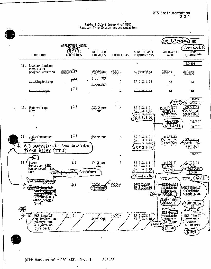
Table 3.3.1-1 (page 4 of-MO)Reactor Trip Sysrem Instrumentation
RTS Instrumentation3.3.1
FUNCTION
APPLICABLE HODESOR OTHERSPECIFIED REQUIRED SURVEILLANCE
CONDITIONS CHANNELS CONDITIONS REQUIRB!ENTS
0 '3 30~ Eo
N~i~AL(cALLOWABLE TRI
VALUE SETPOI NP
11. Reactor CoolantPump (RCP)Breaker Position >.",,::.„".„'"::.),.„;kg) :i„'jeer'iRCP .'!~4;„",'."'4 SR„"3.".3.'1",14
)AVWhC A
3.3-103
12. UndervoltageRCPs
1(g) ~2 perb'us
SR 3.3.1.9SR 3.3.1.10
g g.3, I. Ifo
S.PS
c hu.~
Y-'~80SO Y-".
:.').each"Jms Ieach";:bus~.v3'vrrn'
',,g 3.3 SS
13. Under frequency 1(g)
$ , Sg gpfL~l.~weL- Lg~ low t+tp'~p >eLf (~O)
!3'".„per bus SR 3.3.1.9SR 3.3.1.10
Sg Z.S.I I(
I„'53:9 Hz- AB~:„,
each;bus r <54".6 Hz-eac .'s
S-PS
14. SteamGenerator (SG)Water Level —LowLow
1.2 $4 3 per SR 3.3.1.1SR 3.3.1.7SR 3.3.1.10 (g » (Q'c"AG:m5
3.3-46
AY<
b) 'S Loo 's)T
eouiv ent topower > ',504RTP th noti delay.
1:2
'4( /loop)-'X
3 0 ltW
ra.z. <, I(.Tn)
SR'";3~1~2 & isRCS"„''loop~TSR'.3:;3:-1''.10 z'.,variabTe
'",i',ln~co+),.. RTP
1
'0 TD4 Note„'3)"
O)P
RCS-",1 pop~ T,
SR 3.3.1".7 'var.iableSR 34;.1,.10 .'i gut >
ARCS"::)oopaT';";v'ari'able
50t;Input;s
)~ lTO;(Nate3)
'"""
cg, AJ f~vRCS'1 oops
;~variable'input, 1
>-SO%:RTP
" OTD<
~h QAE,'g
KPP Mark-ut) of HUREG-1431. Rev. 1 3.3-22

~-

Table 3.3.1-1 (page 810 of 810)Reactor Trip System Inst'rumentation
RTS Instrumentation3.3.1
3.3-13
Note 2: Over ower AT
3 o 3 33
3 3 3 t 3
T Overpower AT Function Allowabl Valve shall not exceed the following Trip Setpoint by more thaof AT s an.
B.PS
:,,-,,:s-'~,:j )"l'e:-e:tsselee'l eej,,espy, cEleeee'p. leec, ct:;,,'~,,pfss:;,,':,':,i:,",,;,-:,;„,,",',",:...,.;,",3,;:,.'.!~+Ski~'310
(I+ vp) t~sst T —36 To Ee Es-—T Es -[ T Tej--f(SsI)
(I+ vp) 1+xmas
e 3 t T t 3o
o
o t3 o
3 t T 3 3r-AT, is the n icated AT at RTP. F.
be Au.~s'is the L place transform operator. sec'.
T is the measured R v ra t erature 'F ) g 'fic. 3EfcPIMulT is the nominal ,~ at R . s . .'6,.'.:: gjjjf;;:Q)$4p577~6:,('IJnit;,;2('.
~ rPj0/P~~~:f s
r„~0 sec r>
f>(AI) - OK RTP for all
K, g44QQ@ 6!60'145/'F when
6/'F when T s T
r, Q-319 sec
B.PS
3.3.13
Strike. ~4 M she~~ ids~f3.3-10
g'~Vdz.ag
QAQ I)>9574/'F for increasing T,~
0/'F for decreasing T,~
sec
Re,'3~~84 am':Ceneratov~Qa "e .-.'' C""'1ow ''.T:K:-'kU»"-='NLI'P"'+55::.- 84
pi'i'i~p,:;:-"„":::R'LV.''..I;o'opia",Eq'ulcc'alent%4o~P~r..:::-':fXRTPf.:::.:,".:p,"w.;50PRTP
~iij::t0!Mneme:: Kelsy~1'o~i;.gEeWi!Ceoeietoi!4atep&WNLoe.-.Lo~wRfiohaÃgrgp~<lo:."seooodFS
/O'P 3 343
g g.3-</c
TBB S~ 6'ceBS~ lts4~ gettB[- )csee l~ *~r De l %~chic~ P~g.pl<~e~ v~L~ ~At~ M ec~~w tent@~~ 'p >~ ~~/" ~~$ g QO/f.b ~ LP3$ % I TP ~
OCPP Hark-up of NUREG-1431, Rev. 1 3.3-28


ESFAS Instrumentation3.3.2
ACTIONS (continued)
CONDITION REQUIRED ACTION COMPLETION TINE
inoperab"le.
o move <J y ~lac,>
>we >+
L.l Verify interlock is inrequired state forexisting unit condition.
OR
L.2.1Be in NODE 3.
AND
L.2.2Be in NODE set
1 hour
P 3.5-'fV
7 hours
13 hours
*OWC oe ~ace S<i Q~hmLi~flfR,tp 7IAc8'<~+
yah„~~ gg I~opac,~ate6;,houFs
A'P
dP
H,g <86,P ODDEST
QaD
HI3.rk de I~ 8<><+
yg /2 4~v~k's
/5f wuPU )
DCPP Nark-up of NUREG-1431. Rev. 1 3.3-34


Enclosure 5A page 3.3-12 and 3.3-34Insert NOTE X-M
Attachment 2PG8 E Letter DCL-98-167
Insert for Q 3.3Q6
NOTEThe inoperable hannelor one additional channelmay be bypassed for up to4 hours for surveillancetesting of other channels.


ESFAS Instrumentation3.3.2
Table 3.3.2-1 (page N of 813;:)Engineered Safety Feature Actuation'ystem"Instrumentation
P g,
'3-'oax'UNCTION
APPLICABLEMODES OR
OTHERSPECIFIED
CONDITIONS
ED
IuAL 4REQUIRED SURVEILLANCE ALLOWABLE TRIPCHANNELS CONDITIONS REQUIREMENTS VALUE SETPDIN7
5. Turbine Trip andFeedwater Isolation
a. AutomaticActuation Logicand ActuationRelays
1.2(3).~494
2 trains H ~ SR 3.3.2.2SR 3.3.2.4SR 3.3.2.6
PS
b. SG WaterLevel.—HighHigh (P-14)
c. Safety Injection
1.2(j). !3„'> per SG 3 QQ
Refer to Function 1 (Safety Injection)and requirements.
SR 3.3.2.1SR 3.3.2.5SR 3.3.2
$ (|, 3e3ocL>IO
for all initiati
B-PS
p 5A-I2 I
94-.%
()C BLL~o5n functions
hcbu=aol6. Auxiliary Feedwater
KF+Hanua"I~RQ )r,vwrmw'
b.AutomaticActuation Logic andActuation Relays(Solid StateProtection System)
f2":,'3.
1.2.3
-";;-"1T<~N,
2 trains G
N:"'r5'"
SR 3.3.2.2SR 3.3.2.4SR 3.3.2.6
3.3-58
F~~A
~~S-pa
3-A'.3-01
G N 'I.'44-.4
SG WaterLevel - Low Low
1.2.3 - ';3-".„:,'er SG SR 3.3.2.1SR 3.3.2.5SR 3.3.2.9
SR, B.S.R.)o
J
( ge]>u..~gB-PS
B3.346
wz.~-v~
DCPP Nark-up of NUREG-1431. Rev. 1 3.3-47

0

d.~~ sc'~MLS.-L-4 5~4'pt~e be (at@ ESFAS Instrumentation
3.3.2
bc 3.S-~>
FUNCTION
APPLICABLEMODES OR
OTHERSPECIFIED
CONDITIONSREQUIREDCHANNEl.S
ED
Deft+(, $Q.SURVEILLANCE ALLOifABLE T P,
CONDITIONS REOUIREMENTS VALUE SETPOINP
b2ovet ()aP
SR+2+i'2"
'SR!":.3 "3~d)"-5SR''."3g";2" 9
EE")Loop',aT,="'Var.iabl'i"'(irl
ttt,>sRTP, (QvtCS":LooP:.2 T
S(s. i "" 'ar.iable((tg~ >npuMg.'50" '-rRTP '"-
r~yytx -:;(2.:P()>~TO%%i%
b m(0 Vn
2}~:=,.RCS'op.">Toi.valent':
"
.far r':."'>'-.5 RTP.
Ags>oopj ,:3.-8:2'5ER'.'2"-2'2,'9
RCS',LeQ~~T;":.variable-"
I.PtinPQt~gK3P RTP.
RCS:Loo'p''T'"':varia le$ rtpu .50Zr".'A~:h,'P
Mj 'no;ti""tfay':2 glenii'ii) SR~3" .'-'2':5
SR,„,;"3;:2;„'90-0
~@2-)%
flue
(
ll
@8 3-VC
a 2 ~~~ gQpggp+ llPh@ Luff', LOOP l os'lAlc Ge, Lkp & egg+ ~Cr))t~ag)R tgiue gN(tlr ag)tp(ot'te atr() r)rp'AQ(stat(ng ~ «.fpoi~t ) ~atgym~ ~-y.,vy R'lP.
OC 8 3-e~ «ontia. A channel h OPERABLE viith an actual Trip Setpoint value outside its calibration tolerance band provided the Trip Setpob)t
value ls conservative with respect to Its associated Allowable Value and the channel is adjusted to within the established
calibration tolerance band of the Nominal Trip Setpoint. ATrip Setpoint may be set more conservative than the Nominal Trip
Ra(point as necaaaaly tn taaponan to plant condit tons,
(J) EXCePt,&en 2)t t(F(VS. tlFRVS. endata(C(ated~baSS V'aliieS are Ctnaed and decant(Petal Or-:,(Splat d:by
~a>~~~<5" ~e+le4t'elm'"'<eire'r"ator74@te'r"„Lrevel"-l."Oyr-;L6Ydiann0 irnLrst
.. xbegess,'.,tharl~or,.'equalgtb@64~q~2'
,())'a te'am;Eninetattfrapatej't+ttg::'":- Or
-)(Tt~:„:gray
; pt„::B)'(p)Rr;";:82(R). tatitRRr(p)2atxRd; ',.!+Para"!.'*.P..""--':R(E(aLn.OPrRT,:,:.E(iiiiiiayent'.:toaPonerr(2(()P)tx(rP2+2222-RTP<<>."!+.""'.TD;.:~R(TIme'.",dHaj'aof6i'.4''Genpjatjj'r', pater@.'eveIgg~'.govt'..."I,'g>—,szzzndsl
a
a
OCPP Hark-up of NUREG-1431. Rev. 1 3.3-48


BASES
APPLICABLESAFETY ANALYSES,LCd. andAPPLICABILITY
14.
d.,
r/Cc'. vnMC
RTS Instrumentation8 3.3.1
Underfre uenc Readtor Coolant Pum s (continued)
The LCO requires Underfre uenc RCPs channels—QC ALL.»L>per bus to be OPERABLE
In NODE 1 above the P-7 setpoint. the Underfrequency RCPs tripmust be OPERABLE. Below the P-7 setpoint. all reactor trips onloss of flow are automatically blocked
s'in'ce',":,;th'e'r'e,:.,:;.i: s'"-:..'>nsu'fficiene~heat
the"r'e'actor 'tr'ip 'on loss 'of floww 'i7r two or more RCS loops isautomatically enabled.
team Generator Water Level —Low Low
he SG Water Level —Low Low trip Function ensures thatp t t t p tdd pt t ft ik~
in;;":::the''!eveAtY0'f:.'NwApd,;ddwdf $vf Wtwgvv ~ tdw pw+vg)www vtww'wp'v. 'pw'. Bhvdv.vd v wQ)Qwp Th) wd
SGvwdp X (d ppvdttdhgvddpWv
heat's'irik"fordw the "reactor.""In order"to act as a heat sink, theSGs must contain a minimum amount of water. A narrow range lowlow level in any SG is indicative of a loss of heat sink forthe reactor. The level transmitters provide input to the SGLevel Control System. Therefore, the actuation logic must beable to withstand an input failure to the control system. whichmay then require the protection function actuation, and asingle failure in the other channels providing the protectionfunction actuation. This Function also performs the ESFASfunction of starting the AFW pumps on low low SG level.
Dc.s. 3- ~ >The LCO r uires Per- tdhr e channels of SG Water Level —Low Lowper SG:::. '. 'nd;.,":;;fouy,;,"channel's~of'„:::,PCS,'",-:~T(fail'oo j)':to be 0 -';;:,'.-Thegznsw a::..':,..ati'0'n';.if';,-'.the'-;:;media ji;::;:j)gr)a'.'I:.';:,'sipe'itor.;:'fNSS).;"::jAd.::,':.four'.e3,xiii)))at'es'.',:the-cwaUsept,.:':"a!:,.'cQntv. (ol!:,Sgstevm,""'8ctv'1;0A:;: thdaK'.:!redspU1,'tsjgl fl;,.'8,,'$0053 t'iovn
feedwati"r';.:;:,.'iojiti,',ol".-:.:~'ajd,:::.';:,,"ij'actvor,';:.':p'rot'8'ctj'a'r'i:;::sy'Sd'tppem's::,';";:;in,,':Facpcopr'dance
with.'':::f!,r,ote'ct'w'n'!.:Sy'st~:.:.-,'..far,:::"':,guile'a'i':.Remo)al.:,:';.of.:.:;;::this',.'"::ijtii'aN) 0'n","':il':iiiiin'avtes::.th';,:.need''for';.'.;.:the";:.Am,feiCwatii
'::,"floi,:",':;:isa'fgow"'.:;:low,'.:-s'team".:,':jedndevratot'r.,:"'::water'''1'eII'el.;":tr'i'j:)';,-',";t~;::pp"r',
coiiipl;.:>:apnea',;::.,w'ith,::;IREE',".279:-,'%97,.1::,:::."'andti
sl s'.hjstrip::":,is".;avctudated,"„on"two„'out,":;Of j. three.';:,1:opwg,ow,';iiower,':.":.",'levelsjjn'ass„: 0'ccu'r'i'';i''ga';i'n.';a'rIj."1'eve'I:::.:,".co'midi't)on;";,:is',,';:detected',:jn" onp'e,"::;:steam':"'g'e'n'er'amor,;'::!is'j:gnaws
'hva'U,;:.::::be",.",:jen'er'a'ted::~tvo',."::t'i)'p<heI'!r'e'adctor'.'„'a'nd','star't."'.".:„.':the',:i'i'iiot)r'.."
(continued)
DCPP Mark-up of NUREG-1431. Rev. 1 Bases B 3.3-27


BASES
t~s 4 I9.4
RTS InstrumentationB 3.3.1
dry,ver:",:auxjIl;i'a'ry;:I'feedwat'e'r,;;~'pump's::.::g",'I'fpa i',,'low;,.low...".;water.;~l evel,con'dh'ti'orI)':.:i s;l'detected'"n.".'two ';oj.:;'mo'e,-".',ste'am'.; generato'r's";:,",::a',";:s',,i"g Tral::js,'.:;."gerIej:i'0'ed>'.,'t'o';:,s'ta'r''t';.'.":the",",."t'ur'bi'ne'!,di;;,'~i'eri,''.auxf1:;i@i
DUmD.'i'aS!!we. ': '.".:
j,-".':-:':,:!;,'Tile;,sr,.grla:.rs:;.-":.:,~o.:IBcruaiegreactor,.;,'::tr.,l p,'.and..:start",'aux jl~lary."feedwatei';..:i'ju'mps,":,','tlybeI,"deLay'edqCh'r'ou'gh';the:.",'us'ed~of;':'a..".,'Tr''ip mTimeDe'I,'a'j':,:.':,(Tf0>„"'ayste'ml';for'ireacto'r~
power„'',bilevels,'Ib'el'.N';;BOX)ofjRTP,'.,j:;.
Lrow,'-",:3.ow.:,:.'".watei~$l'i'v'e'1,::."::i'':-',."an'y'„':jj',,'otecKi:oji'::::.se6~iiri~a'jyj'stea'm'*'"
generato'r3:."'w'i'',I;">jerierateL.,a;;!s,':i'gna1Fjwh'hach0'ri'j:,,'de1ay'i tjiiier,';:"."~'jthe'.::.a,g.owf;hi'-.';j'r
de,",I:'a'y,.',.'.-j'i
,r'e';;"dh'Ci'riiif'ned~,.'(:3",'-e'::;.:"::„".",dec
"ow"ei'!,,::slev,
Pie,"",iise';."';of,.:','"'5'i).s~de a'yP'al,:."j'&s,'Jaded~gener'itor„.",'::",1,'e'vj l.'~C'- abj,")~i'zaf;:i,on',:."or'~'~pe'ratan l>ljiidverteAt'~,OtectlNi's 3%em':-'5CtUatiorl~~YAvQYDY04%YQvgvg (h Nw 4 Mvl % NPdwol)(@'0 ~~(((5@I wAwM44A
In NODE 1 or , when the reactor requires a heat sink, the SGHater Level Low Low trip must be OPERABLE. The normal sourceof water f the SGs is the Hain Feedwater (HFW) System (notsafety re ted). The MFW System is only in operation in NODE 1or 2. T AFW System is the safety related backup source ofwater t
Qg pl~p $ t IQ PAW
D< faye~@ zy bj~~~@ ~~~~~Ao+
(continued)
DCPP Mark-up of NUREG-1431. Rev. 1 Bases B 3.3-28


RTS Instrumentation8 3.3.1
BASES
APPLICABLE 14. Steam Generator Water Level —Low Low (continued)SAFETY ANALYSES,LCO. and ensure that the SGs remain the heat sink for theAPPLICABILITY reactor . During normal startups and shutdowns, the AFW System
provides feedwater to maintain SG level. In NODE 3. 4. 5,or 6. the SG Water Level —Low Low Function does not have to beOPERABLE because the NFW System is not in operation and thereactor is not operating or even critical. Decay heat removalis accomplished by the AFW System in NODE 3 (and;-:4;"::,:;:::fiTjiai',"-::.to
T /q Q j'olnj':;,oii:,'.:"RHR~3'.~and by the Residual Heat Removal '(RHR) "System"inNODE-4'; '5, or"6. 99 9-f4
15. Steam Generator Water Level —Low Coincident With SteamFlow/Feedwater Flow Mismatch
(continued)
DCPP Mark-up of NUREG-1431. Rev. 1 Bases 8 3.3-29


BASES
ACTIONSh
RTS InstrumentationB 3.3.1
U. 1 ~A- and U.2-.4 (continued) gee et 440f'e-7Q a.$ o~
Iiiit tt it I IIIIIII, I, it:,'"",tti"„...i",3,",'itii3It,,iiiiit 3:.3::iiiti!.33" I( iii:33 tt!!!I '!i '" 'll "'tl ...II 'IGohnt'i.;oj>Sj~tem'".'i~::",',::,cap'able,.-.."'of<",„"i mt':;..:wt'h'drama]„.'':-'or, '. ",'o'd~s"'':a'r'e.''hott
:4 I.'j',.'I'se.'..'e.".„."':""" " '-'**"'"" "
QPEAAQ4K:. =The affected RTB shall not be bypassed while one of thediverse features is inoperable except for the time required toperform maintenance to res'tore.,": %he',,:;::;jnpparibIe:::;:.",.'trip;.:&chal',srii,-".toQPEAABLE4stitGs":;:.~cons:.'jC~W,'',:.@:.th"~Ref.;'",,",'.l3,'„;-'..'.
The, Completion Time of 48 hours for Required Action U.l isreasonable considering that in this Condition there is one remainingdiverse feature for the affected RTB. and one OPERABLE RTB capableof performing the safety function and given the low probability ofan event occurring during this interval.
. V.1
NOT"".;0$EO
' QN. q 5.'K-94.
Cone,dl.:',t)ePQ.;~appH$ es;::-.t~o, 'he "SK>YmYe:„~7js:p::„''r::,i
i'iV'.::fhYtchamiil'~"4%6WfiaN'e.'."';:!START4VP.';"arklÃok':;POMN'.:OPERAT'ION'.mahy'~-'::6"agog'"'-j
4f"'a:dIrieebion'j j8'"inopepage"-:rthengtbe)cIiapnelkmust
't'ai'3''i'd%'Vo~i:.",":,':.acti'iaido'ii'j4oi.":>th~at,'-:.""at'r't'ia'Aa~.".'.:Iocatiton''~
jThetheqrhrai'-AYt>eaa."'Race k~eamON'f4 eddas::: dtdetata" ~llama'
hht
a
t tW
'jai)'he,
by'jfaaaaed,;:.:;aa'dteriabhe,";:t~ime+e 'i'!'i'ed': j>'iirfa'im':trilie':aevi!i'e'dsddaeigt'atda'eÃtewsat1'eaj'i
x'-:l:,g x.3,Cton'bi" ';-::;.:;.':,:ap ''es~~to::- e,:eTri p:., g~(D .'ash";(:,:: )vcr'trcu. ry,.''t'fo,::„the.
aa e
he
a
a
a
,.Ma. "'r::.";tv, '.,:,",L'i%'>""" -,',:,"trip':: Acti.; ...'II'eh-n''T,RHAL':,'PO3
t 'an::: i,'::',-::i'qua',,:$~,',":,50.,dRTP-':5'n'':: DES,".'::1'': nd,:':.:.':,:2-"'',,::Qitb',:."one';or.,::.;:.':.mo'i'.,;.,:gp0'c'i':r'." itry',.'::. Iay',.t)";i':.Sk~nho .. rabble'- ',a'djus',=.;the',:::thr'i Ow'td',.:':p"" j'',.',lev,,',:: ',:;;i;no,"'-,:tj e."':.:"dela',:to,:~OX'.4n'j't'ri"i:,''::"::aThe':";:, 'l'equi'o ':.„'Timac."::.'y'':;-6.'-::;.:::Ii'-"'::,s.:=,hi';"-:,:b'ahas':.':."h "n",'Ref r'iiiFe,:,; -.':
hhwttwhtwhwm wh ww ' ' a 3 9 the htt3w(hhhwhahwltww 3whwhwhetmwh Iv~lAZM<MV /Czar& g 8~~ s (continued)
DCPP Mark-up of NUREG-1431, Rev. 1 Bases 8 3.3-53


Attachment BPG8E Letter DCL-99-063
Enclosure 5B page B 3.3-53Insert ACTIONX Bases
Insert for Q 3.3%6
Condition X applies to the Trip Time Delay (Tl D) circuitry for the SG Water Level-Low Low tripfunction in MODES 1 and 2. With one or more TTD circuitry delay timers inoperable or theRCS delta-T equivalent power input inoperable, 6 hours are allowed to adjust the thresholdpower level for no time delay to 0% RTP. This sets the TTD timer to zero seconds andeffectively removes its input from the SG water level circuit. Ifthe TTD timer cannot be set tozero seconds for a single SG water level control, then the affected SG water level low-lowchannel must be laced in trip. Onl one SG water level low-low channel can be placed in trip
position without trippin the pla The Completionime of 6 hours is reasonable considering the nature o these functions and the low probability
of an event occurring during this interval as justiTied in Reference 7. cP 8 3-9(-
Ifthe TTD threshold power for no time delay cannot be adjusted to 0% RTP (zero seconds timedelay) or the single SG water level channel cannot be placed in the trip condition within thespecified Completion Time, the unit must be placed in a MODE where these Functions are notrequired OPERABLE. The 12 hours allowed to place the unit in MODE 3 is a reasonable time,based on operating experience, to place the unit in MODE 3 from full power in an orderlymanner and without challenging unit systems.
The Required Actions have been modified by a Note that allows placing the SG water levelchannel or one additional channel in the bypassed condition for up to 4 hours while performingroutine surveillance testing of the other channels.


ESFAS InstrumentationB 3.3.2
BASES
ACTIONS L.l L.2.'1 and L.2.2 (continued)
Dc 3 5-007
LCO 3.0.3 to initiate shutdown actions in the event of a completeloss of ESFAS function. If the interlock is not in the requiredstate (or placed in the required state) for the existing unitcondition, the unit must be placed in NODE 3 within the next6 hours and NODE 4 within the following 6 hours. The allowedCompletion Times are reasonable, based on operating experience.to reach the required unit conditions from full power conditionsin an orderly manner and without challenging unit systems.Placing the unit in NODE 4 removes all requirements forOPERABILITY of these interlocks.
c~d~~j~t/~/f MA'"niffy'>p,.=,:8,;:appM'os~to,.the~Tepy~Tiijie~, ay~.-v,:,. ~-...orate'„.'.%',,';1Qw;.NYi@at """'>%vejkee@KC~Vh''5f~":AFH'ipw's4>Noh'5AHNr':.'IIorjjTMiiri'bi'jij'ii
Y.::he+" restothe~ ffected$ 'water,:::--,:Ievele -„.''.he~,chawel .m~~trfp4'~Th'9
water~~jl,. 83/1.QH,',":ll:Q4(4c QAB:Ig'caQAQK';<:,ap3 Bce'd':.'".,'gtr3 p;:,-'j.thgjUAl$miist',";..„',.ji.t,ace'dk~Hl5l „.;.,""%5egfQ'l4'QHl N5'"':hours.'.""„j>, $8lI10wed~j ',,feC)QA'I.'.: mwesw'''are
i':,ea" 'r'iablj'.:.:."„-".ba'sed"" ':=0pe«
tin, ".,':ie'iChtjoni:i'„,„,', ~5j:8;..',:!p'ow'.'-,g~:wAjpi,: i,"."
c'al~lengiig%6nf:~sjt5tems)Is-."I,;NDE'A.'„'„';t ''un$ t';'doe,.»,'noh
Q.,'.';: . e.'.: r0.8 ". '..QYfl",::UAGf.",QA'l::,, ';;a, fjj.V.
"'~+~A'::.i~."':NaRMA'!~BR..t1'80lQA",;:..QfÃ!'S't98@~L388::.'Isol8tl::GTl..;'.'„''':.8nd
«~~;;:!Harm:.;:,.:frivKiltÃonxijANi1!i'ac!::~eedwater~
Kf':-'a"eha~one Ws'''s napery'abl~e'.-48 hours':~'allowed'.:-'ta'.""r etupn~lhe
Q'ccu'r ji,'ng'.:::,d're'ur'ned;:":,:,'ta,')PERABL'K'lw4ati'ie.';:>g5)i'.".''ii sai)'ated,,':5um«p,::, or',.::',;val ve':.
be":;dec'18red~pl nGp8fjab18$ 3QAedi Btel'jZidAd~jthe'ssRE5IUIREO"".AQPI~ON<'~~of8.-'7,,"„'5!:owr,'';--"3":7~9l"iY."-":aool3'ca6li>cv'ot't,nl
iedi'with.";iiiiiiedf''ate'1.".5'««W4eÃAYAY4WAY~X
A AAAWIYAW@V«YA>XV««~WAVERY'4(A«W«>YW4%HVOYAWAY «A VWW AY YC
xÃcept s8-c 4 p(continued)
,
DCPP Mark-up of NUREG-1431. Rev. 1 Bases 8 3.3-122


Attachment 8PG8 E Letter DCL-99-063
Enclosure 5B page B 3.3-122Insert ACTION M Bases
Insert for Q 3.346
M.1 M.2 M.3.1 and M.3.2
Condition M applies to the Trip Time Delay (TTD) circuitry for the SG Water Level-Low Lowactuation of the turbine-driven AFW pump and is required to be OPERABLE in MODES 1, 2and 3. With one or more TTD circuitry delay timers inoperable or the RCS delta-T equivalentpower input inoperable, 6 hours are allowed to adjust the threshold power level for no timedelay to 0% RTP. This sets the TTD timer to zero seconds and effectively removes its inputfrom the SG water level circuit. Ifthe TTD timer cannot be set to zero seconds for a single SGwater level control, then the affected SG water level low-low channel must be placed in trip.Only one SG water level low-low channel can be placed in tri
osition wi out trip in the lan . The Completion Time of 6 hours is reasonableconsi ering t e na ure o ese functions and the low probability of an event occurring du
'hisinterval as justified in Reference 7. u~,~ -'/4
Ifthe TTD threshold power for no time delay cannot be adjusted to 0% RTP (zero seconds timedelay) or the single SG water level channel cannot be placed in the trip condition within thespecified Completion Time, the unit must be placed in MODE 4 where these Functions are notrequired OPERABLE. A completion time of 12 hours is allowed to place the unit in MODE 3and 18 hours for MODE 4. These completion times are reasonable time, based, on operatingexperience, to place the unit in MODE 4 from full power in an orderly manner and withoutchallenging unit systems. In MODE 4 there are no analyzed transients requiring the use of theturbine-driven AFW pump.
The Required Actions have been modified by a Note that allows placing the SG water levelchannel or one additional channel in the bypassed condition for up to 4 hours while performing
routine surveillance testing of the other channels.


Attachment BPG&E Letter DCL-99-063
ADDITIONALINFORMATIONCOVER SHEET
ADDITIONALINFORMATIONNO: Q3.3-54 APPLICABILITY: CA, CP, DC, WC
REQUEST:Function 18.b (P-7) of ITS Table 3.3.1-1 is clarified. COTs and ChannelCalibrations apply to the P-10 and P-13 inputs, not to the P-7 logic function.
Comment: Reject - Deleting all SRs results in no TS requirements for establishinginterlock operability. Revise the ITS to adopt the STS. This is also an Beyond Scopechange.
Scope issue
FLOG RESPONSE: SR 3.3.1.5 has been assigned to ITS Table 3.3.1-1 Function 18.b (thiswas already discussed in the SR 3.3.1.5 Bases), as previously approved for Vogtle. JFD 3.3-54has been revised for clarification. Except for DCPP, there are no current TS Enclosure 2,3A/3B, or 4 changes required since there is no surveillance listing for P-7 in CTS Table 4.3-1 ..WCNOC will now adopt JFD 3.3-54.
For DCPP, the P-7 permissive is a derivative of permissives P-10 and P-13 and the CTSrequires that the P-7 as well as P-10 and P-13 be surveillance tested via a COT and aCHANNELCALIBRATION. There are no field sensors associated with P-7; there are onlysensors associated with P-10 and P-13. There is also no place outside the SSPS to inject asimulated signal into P-7. There are no adjustable devices directly associated with P-7 and,therefore, no required range or accuracy values except via the P-10 and P-13 functions. Thereare no outputs from P-7 other than to the main annunciator permissive window and a digitaloutput to the plant process computer. There are no interlock or trip functions outside the SSPS.Therefore, the definition of a CHANNEL CALIBRATIONand COT do not apply to P-7. The P-7function does lend itself to testing that would meet the requirements of the definition of anACTUATIONLOGIC TEST. As noted in the Bases for SR 3.3.1.5, "Perform ACTUATIONLOGIC TEST," the P-7 logic is included in the SSPS testing that is conducted monthly on aSTAGGERED TEST BASlS. This testing, however, does not verify the function of the mainannunciator alarm that can only be tested during a refueling outage. Therefore, DCPP willapply SR 3.3.1.17 to the P-7 Function in lieu of the CTS and STS required CHANNELCALIBRATIONand COT, which as explained above are inappropriate.
Refer to Comment Number Q 1-51 response for changes to the CTS.
FLOG RESPONSE (Supplement): Based upon conversation with the NRC Staff on March 18,1999, Table 3.3.1-1, Function 18.b is revised to apply SR 3.3.1.5 rather than SR 3.3.1.17. Thealarm circuit is not required feature to be tested on the 31 day frequency since it is only a"mimic"of the SSPS action.
/
ATTACHED PAGES:
Encl. 5A 3.3-17, 3.3-25Encl. 5B B 3.3-56, B 3.3-63Encl. 6A 5Encl. 6B 9

0

RTS Instrumentation3.3.1
SURVEILLANCE REQUIREMENTS (continued)
SURVEILLANCE FREQUENCY
(continued}
SR 3.3.1.14 - -NOTEVerification of setpoint is not required.
Perform TADOT,
bc hu-ao>
mon s B
SR 3.3.1.15 -NOTEVerification of setpoint is not required.
Perform TADOT.Priorstar
---- -NOTE-----Onl requiredwh notp rformed w thin
revious' days
reactor
SR 3.3.1. 16 -NOTENeutron detectors are excluded from responsetime testing.
nmB
Verify RTS RESPONSE TINEsia within limits
4c RU=cX lB
mont son aSTAGGEBASIS ~SS
B.S -5'S
ms.;,.m A
s~ 49
DCPP Nark-up of NUREG-1431. Rev. 1 3.3-17
( Jln,dh/~1.4A 3, 7-I
ysgor/vlf I g4 v)005
3 I Afvj5 ~ y'jo Q '3~0 7


FUNCTION
APPLICABLE NODES,OR OTHER
SPECIFIED REQUIREDCONDITIONS CHANNELS
RTS Instrumentation3 3.1('-004
ED
Howl'~w(. Cct,
SURVEILLANCE 'LLOWABLE TRIPCONDITIONS, REQUIREHENTS VALUE SETPOINM
18. Reactor TripSystem Interlocks
a. IntenttediateRange NeutronFlux. P-6
b. Low PowerReactor TripsBlock. P-7
c. Power RangeNeutron Flux.P-8
d. Power RangeNeutron Flux.P-9
e. Power RangeNeutron Flux.P-10
2(e)
1.2
1 pertrain
QSR 3.3.1.11SR 3.3.1.13
9.5, l.SRm~
BTtc hu:~
;-'0 amp @ATE'"-'10 amp
3.3.S4
NA
SR 3.3.1.11SR 3.3.1.13
SR 3.3.1.11SR 3.3.1.13
SR 3.3.1.11SR 3.3.1.13
B-PS
c r)Lc~SRT teQQ f54Zcg g
Qzsw'rB
C Ru-ceS
~MS RTP
B-l S
B
Sai ~bL Au.
RTP Ia d s ~:I;04 RTP
RTP
tl z s8 PS
PS0-'L C hrj=~
mjX RTPgTP, H tur'bine
u irle Bewep-h' 'I
~ V4i.: <'!am Ise
giA-Q.'~SR 3.3.1.10 3
sSR 3.3.1.13f. Turbine
ImpulseChamber,.P"res's'u'r'e
P-13
g( $ . -Otb C-
(j) Above the P-9 (Power Range Neutron Flux) interlock.
%gi'm'pulse ~",p'ress'u're,Pi',p'resst'r're,, '.eu'~%a'Le'nt'ejif'va'I'ent:
a. A channel is OPERABLE with an actual Trip Setpoint value outside its calibration tolerance band provided the T 't
''onservative with respect to its associated Allowable Value and the channel is re-adjusted to within the established
rip e poin
calibration tolerance band of the Nominal Trip Setpoint. ATrip Setpoint may be set more conservative than the Nominal TripSetpoint as necessary in response to plant conditions.
(e) Below the P-6 (Intermediate Range Neutron Flux) interlocks.
ED
DCPP Mark-up of NUREG-1431, Rev. 1 3.3-25

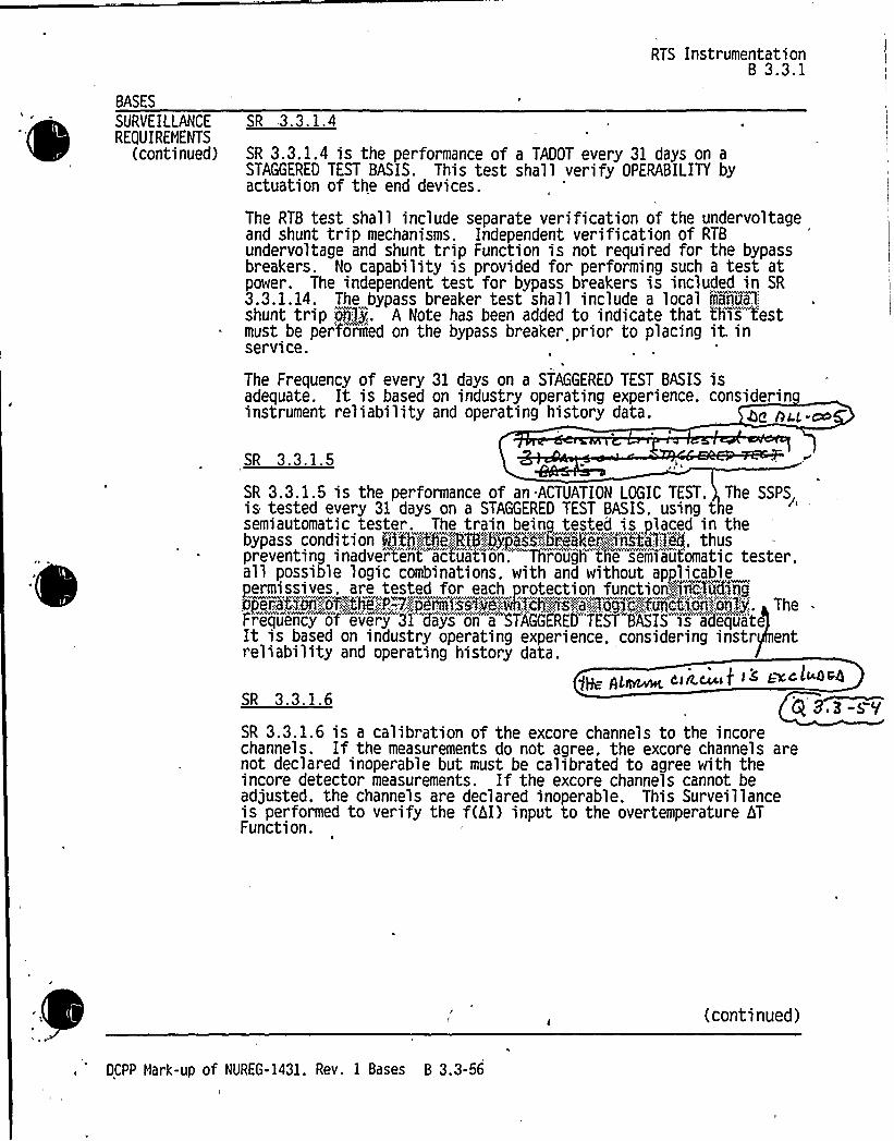
BASES
SURYEILLANCEREQUIREMENTS
(continued)
RTS Instrumentation8 3.3.1
SR 3.3.1.4
SR 3.3.1.4 is the performance of a TADOT every 31 days on aSTAGGERED TEST BASIS. This test shall verify OPERABILITY byactuation of the end devices.
The RTB test shall include separate verification of the undervoltageand shunt trip mechanisms. Independent verification of RTBundervoltage and shunt trip Function is not required for the bypassbreakers. No capability is provided for performing such a test atpower. The independent test for bypass breakers is included in SR3.3.1.14. The bypass breaker test shall include a local maq~a1,-:
shunt trip oddly',. A Note has been added to indicate that this testmust be performed on the bypass breaker prior to placing it inservice.
The Frequency of every 31 days on a STAGGERED TEST BASIS isadequate. It is based on industry operating experience, considerininstrument reliability and operating history data.
SR 3.3.1.5
SR 3.3.1.5 is the performance of an ACTUATION LOGIC TEST. The SSPSis tested every 31 days on a STAGGERED TEST BASIS, using t esemiautomatic tester. The train being tested is placed in thebypass condition Qith;,:t%;::",:RT8".braes'.-':5%akei~~figCi3984, thuspreventing inadvertent a'ctuatiori'hrougli the semiaut'omatic tester,all possible logic combinations. with and without applicablepermissives. are tested for each protection functio~lnckvdjTr gQperatMn';:jf'lthe.',,P,-",7gyermlssfve..::vihlclrAs.","',".a"':":,gag>e-;::",foqcbN'i>'ilailj. The .
Frequency of every 31 days oYi"a STAGGERED"TEST BASIS is adequa'te
It is based on industry operating experience. considering instr entreliability and operating history data.
~H ~t,~ cin.c t >s gal™dSR 3.3.1.6 $ 83-sYSR 3.3.1.6 is a calibration of the excore channels to the incorechannels. If the measurements do not agree, the excore channels arenot declared inoperable but must be calibrated to agree with theincore detector measurements. If the excore channels cannot beadjusted, the channels are declared inoperable. This Surveillanceis performed to verify the f(hI) input to the overtemperature hTFunction.
(continued)
DCPP Mark-up of NUREG-1431. Rev. 1 Bases 8 3.3-56


BASES
SURVEILLANCEREQUIREMENTS
SR 3.3. 1. 16 (continued)
RTS InstrumentationB 3.3.1
determined during unit operation because equipment operation isrequired to measure response times. Experience has shown that thesecomponents'sually pass this surveillance when performed at the18 month Frequency. Therefore, the Frequency was concluded to beacceptable from a reliabi lity standpoint.
SR 3.3.1.16 is modified by a Note stating that neutron detectors areexcluded from RTS RESPONSE TINE testing. This Note is necessarybecause of the difficulty in generating an appropriate detectorinput signal. Excluding the detectors is acceptable because theprinciples of detector operation ensure a virtually instantaneousresponse.@esp~onse,,ieetor.:"'!the,,ipeitro !nfipntnx::::"siippnslt'pogtioan,;".ntP!theiVinnei::-:Shjlp'ibe~~Si'iiel~fi'Oiii';detentnri Oenxtrpnt'Oer'iRrjinet'8't'OARI~X1ikO~rem
Rt.,"":8':"::"::*:i cps ""8!i":::Rti It 8: "ltlinst gE-S'f
VAhASP 'PA
8 I
REFERENCES 1. FSAR. Chapter f73.
2. FSAR, Chapter g3.3. FSAR, Chapter QQ.4. IEEE-279-1971.
5. 10 CFR 50.49.6... „,, '0'.3M82.>@Re,,=,:a2~4M~>nghouse,.5eipoi)t:;.;Nefhodpoleyjgor',,":;,.Protect'iotn':5ystems,"'ebi'OQQ~i''On'- tAet'Ri'Oen.:;:.:Efs'eit2toeeore'teen';;";::...'iieti~A'1998
7. WCAP-10271-P-A. Supplement 2, Rev. 1, June 1990.
8.." CAppp632."-"„:'-.'':.:PA-:,l':.";::Aev,::':2:.«~ Eli,.xiii'hat'.I'os;-"...ot
p'erss erie'Sens or:,. nesponsne'gi'iiiii!:: T'est~Ni ;Le'qoiii'i;xiii"~:n~its":':
p:;:,'-::-:.;!FSN!+Xlhsjitei;@;'"oV'Rii lips%.
i'O:.*,.':,~-,PSiR~~tiRe te~:,::19!3':5'iX'4::.:
ll:::.-"-.:~3,:SAfgg|,"hapter~~8.'3~
if.;,;:~GCH'5".«,;3LA'';.";.";:~P'fant~~.",roCec6i:pn','"„'Sys egRR:::,--::::-:-:::.":.::::-:::-.RRRRpÃRRRBpllt tt RRRtpl'ptpp& '-::::::8:::8'.~mmeR!R'~"8'.":,"'::::
(continued)
OCPP Hark-up of NUREG-1431. Rev. 1 Bases 8 3.3-63


CHAPGENUMBER JUSTIFICATION
3.3-51
3.3-52
3.3-53
Ctbbr~ ASf~~g g E,S.I.g~
sit s.sA-'0-
3.3-56
3.3-57
3.3-58
3.3-59
3.340
3,3%1
3.3W2
3.343
ITS ACTION B.2 of LCO 3.3.7 is deleted, since DCPP cannot operate with bothpressurization systems running at the same time. The design of the system is such thatoperation of two pressurization fans would over pressurize the supply ducting to the filters.
Not applicable to DCPP. See Conversion Comparision Table (Enclosure 6B)..8 s8 ~ I.
The REQUIRED CHANNELS description for Functions%.a and 3.b.(1), of S a e ..2-1, are revised per the CTS to note that only two switches (one per train) xist and thatboth must be moved coincident for manual initiation. + ~~~+ ~~~Function 18.b (P-7) of ITS Table 3.3.1-1 is clarifie C a ne a i ra onsa I totheP-10andP-13in uts not eP- ' Thischangeisan
dministra ve 'i toa e r i 'nt ePlant'sdesign [. Q, %bc ~odLd-4a lg~ <ga.uAt T't~c1
fvayr.hAv @ g gag.g gran ensstsevsisI < pdtrssycct Sv Is'
gA% 3,Not applicable to DCPP. See Conversion Co ansion a e nc osure 6B).
Not used.
P E.'K-CbS
This change adds new ITS 3.3.2 Condition [N] to reflect current TS Table 3.3-3 ACTIONStatement [24] on manual AFW [and manual MSIVclosure) initiation.
Motapplicable to CCPP. See Conversion Comparision Table(Enctosure 6B). r
gE Ru.-rco2.Co sistentvrtth the design and current TS, Surveillance Requireme IE .3 2 3 and 3 32Ka ep t used by any function listed in Table 3.3.2-1 and are deleted.
ZC Au~iThis change revises the ITS SR 3.32.11 Frequency to onths p r c ent TS Table4.3-2 Functional Unit [8.c], which is the ESFAS P-4 permi ive. The onth Freque cy
bror the surveillance of the basic switch logic associated with the opening of the reactor t
'akersis the value specified in the current TS. [Deleted the Note stating that verificationof set point is not required per the CTS.]
Not applicable to DCPP. See Conversion Comparision Table (Enclosure 6B).
This change revises ITS Table 3.3.2-1 [Notes (b) and (g)] per current TS Table [3.3-3]Notes [¹ and ¹¹]. This revision is a cianfication to the operator that describes thecircumstances under which the [Steamline Pressure Negative Rate - High, SteamPressure-low, or Pressurizer Pressure-low functions may be or are blocked relative to the)P-11 permissive.
3.3M
3.3%5
3.346
3.3%7
Not applicable to DCPP. See Conversion Comparision Table (Enclosure 6B}.
Not applicable to DCPP. See Conversion Comparision Table (Enclosure 6B).
The MODE 4 requirement of the CTS is retained and added to Table 3.3.2-1 for Slactuated by Containment Pressure high-hig I
accauhaglg. f'~~ 3„K-bNot applicable to DCPP. See Conversion Comparision Ta le (Enclosure 6B).
d
ah 43-ofP
DCPP Description of Changes to Improved TS 5

0

CONVERSION COMPARISON TABLEFOR ENCES FROM NUREG-1434, SECTtON 3.3 Page9of21
NUMBER
TECHNICALSPECIFICATION CHANGE
DESCRIPTION
APPLICABILITY
DIABLOCANYON COMANCHE PEAK WOLF CREEK CALLAWAY
3.349
3.3-50
3.3-51
3.3-52
ITS SR 3.3.1.8 is revised to extend the conditional COTfrequency for power and intermediate range channels from4 hours after reducing power below P-10 to 12 hours, basedon operating experience regarding the time needed toperform the COTs. It stands to reason that if4 hours areallowed for 2 Source Range COTs, 12 hours should bea11owed for 6 Intermediate Range and Power Range COTs.
ITS SR 3.3.1.12 is deleted per the CTS. Where cited inTable 3.3.2-1, a change to SR 3.3.1.10 has been made.
ITS ACTION B.2 of LCO 3.3.7 is deleted, since DCPP cannotoperate CRVS with both pressurization systems running atthe same time.
Added Note t(l)J to ITS Table 3.3.1-1 per the CTS as anoperator aid to note the dual RTS/ESFAS functions of SGWater Level Low-l.ow.
No, see CN3.3-101.
Yes
No, adopted ISTSformat.
Yes
Yes
Yes
Yes
Yes
Yes
Yes
Yes
No
Yes
3.3-53 The REQUIRED CHANNELS description for Functions 2.aand 3.b.(1), of ITS Table 3.3.2-1, are revised per the DCPPCTS to note that only two switches (one per train) exist andthat both must be moved coincident for manual initiation.
Yes No5 O'I-S
~ c,<e .~~> 4'~/ z/i,xi.ii
No
g'.3. I
3.3-54 Function 18.b (P-7) of ITS Table 3.3.1-1 is cfarifi COTsand Channel Calibrations apply to the P-10 and P- 3 inputs,not to the P-7 logic function.
Yes
reteinecHAWTables@orrequiredFttr &lens.
Yes
Yes
IST44ocrnat
Yes, SRs willberetained in ITSTables forrequiredFunctions.
Ye
g Y.Z-$$
Yes
3.3-56 Revise ITS 3.3.2 Condition J to reflect CTS Table t3.3-3J,ACTION Statement (19) for Functional Unit (6.9].
No, See CN3.3-116.
Yes Yes Yes
DCPP Conversion Comparison Table - Improved TSIM6i~g


Attachment BPG8 E Letter DCL-99-063
ADDITIONALINFORMATIONCOVER SHEET
ADDITIONALINFORMATIONNO: Q 3.3-66 APPLICABILITY'C
REQUEST:The DCPP-specific MODE 4 requirement of the CTS is retained and added toTable 3.3.2-1 for Sl actuated by Containment Pressure High 1.
Comment: A separate condition should be created to handle shutdown tracks forfunctions with required applicability that includes Modes 1, 2, 3, and 4.
FLOG RESPONSE (Original): A separate shutdown track is created via CONDITION 0 thatrequires entry into MODE 5 for function 1.c. ifthe inoperable channel cannot be tripped.ACTIONS D and E are restored to their original NUREG-1431 versions that require a shutdownto MODE 4 ifthe applicable functions cannot be tripped or bypassed, respectively, in theallowed time. A new CONDITION P is created that requires a shutdown to MODE 5 for thosefunctions required to be OPERABLE in MODE 1 through 4 and requiring that the trip bebypassed. JFD 3.3-114 is created to justify the addition of these two new ACTIONS. TheBases is revised to move the affected functions to the applicable ACTIONS.
FLOG RESPONSE (Supplement): Typos occurring in the numbering for Condition 0 and Pare corrected and editorial changes in Bases text are inserted.
ATTACHEDPAGES:
Encl. 5A 3.3-35Encl. 5B B 3.3-122


ESFAS Instrumentation3.3.2
ACTIONS (continued)
CONDITION REQUIRED ACTION COMPLETION TIME
~H','-';;:;:.'„:: OTt.e.;„ch~aqne,333Piii',ab1 "e>":.
N..":3;::;~:,':Restore;,.chirine1g~to'PAERABL':E:;.',Stat'i'~! " 48!!hour,s:4 AA3A'~ 3.3-68
N"'-.2A AWA
F~eHare,,assaci,ate,,puttt, ''.".ot::.,
p;:.:$ iio'i'45leF ' VgAA~W
g< g.3-0<7
ed&, 3AWW/AAAAW
$ $ 44
DCPP Mark-up of NUREG-1431. Rev. 1 3.3-35

0

Attachment 2PG8 E Letter DCL-98-167
Enclosure 5AInsert 5A-08 P
page 3.3-35Insert for Q 3.3-66
0. One channelinoperable
NOTEino erable channel
e bypassedfor up to 4 hours for surveillancetesting of other channels.
Q 3.3-37
0.1 Place channel in trip.
OR 'i
0.2.1 Be in MODE 3.
AND
6 hours
12 hours
0.2 Be in MODE 5.42 hours
P. One channelinoperable
NOTEOne additional channel may bebypassed for up to 4 hours forsurveillance testing.
P.1 Place channel in bypass. 6 hours
OR
P.2.1 Be in MODE 3. 12 hours
AND
P.2. Be in MODE 5.4 3 3-6C


ESFAS InstrumentationB 3.3.2
BASES
ACTIONS L.l L.2. 1 and L.2.2 (continued)
LCO 3.0.3 to initiate shutdown actions in the event of a completeloss of ESFAS'function. If the interlock is not in the requiredstate (or placed in the required state) for the existing unitcondition, the unit must be placed in NODE 3 within the next6 hours and NODE 4 within the following 6 hours. The allowedCompletion Times are reasonable, based on operating experience,to reach the required unit conditions from full power conditionsin an orderly manner and without challenging unit systems.Placing the unit in NODE 4 removes all requirements forOPERABILITY of these interlocks.
/d Q~j . +)7~ tf /4'~ ~ Q ~ H ~:: gdftji „'.'„8,-"':appl!i'es+0,:,their)p'.71IAe„",,: ay:"::: .. p;',.,or,,::;-'the;;:,":68;.":l~NP:
,,W::wat,.@geV8japhgatjOn,:"::of::„'.AN,'~pS.,'::;=".~@pth:';Oqe."',:ag~IOrp': TTOei~j~~i' j:'de,.'l~y~@ " mers'z~'noSh~k'eshgo, d'-„:~
-" i"i~livel,:,.-t'he~'af8C$ 8N., gj%848GQRV83i~c, -„-.'1QHj~ChaW8XglAa".tr4p'":j~a~Th8
0; s'e~Funct,'„%',"::<he'iv'ai." 5lig'i,"ii@ijida'n,'"'"".„';$%.":..th;„,".wrorbab'i5:.'i'i'f~'.-'anjeven5h'."'; cji&~i'ii'9",idUCir '::;:t'h'5;ij:-'i'ii rv'il'i:g$'~X/,'', he
.:,„'„.;-thre,,o~:(f.,-,:poH&~0~18Y,.Pi8iiist'<fe,.', 'sted',:.:oIatB'topi/, B,Iim1GH 'l$$if,:",'c AABlm:canna/ '„:placed;, r',:~trA.p:.,"'.aN Unitmeit;-'","';";:.""licedgij..':-5) ',,:;3..:.,0'3:thjjijt;;,'n'm4'>:;G>h""r's.". ajid~NX
..':,"':.4'i'ih",,',:,''th,i„~:foal;
0, "':.'; e:; ro 8 ':..007~ .UA&'...5Ar,'. $;:8
'C
C P.$ -ooP
9'"4"::~~""'F%+P'''"~"K
»~i:::ii-, nua:. rQ~.-':..hTatron;:;ohmteaat 11ne,::1$+o,at'r E1 r .'::arid
«:.:~:::w;.:,'..Haoii~s:. gfriat-.aNonro&rarnr'bra ror.." eerkate~;;!
ff...'a„:;:::cha~pe,..:r,;,aain.oTrecaob1~e;:.':;air:,:,hours:,:::h,„:y13o ed:,„:toc aeturp.;the,
'cha'nn'ei'ato,',a'.',;:;OIIERABL'',,'et'u'r'ne
bek."::%-"''O',:Qf.,"'3"9:.".:248sQppl',"'i Cabl@,",':,COmL188d4Ãfth,".:lKgd'j ately,"'.r.4 KvCw: xwpcp" %4v@cR4( oY Y((~i/a'p~r4.~~v(h%p w I (4QYY.,„;r&c(v%wg'Qwh&6vov v( w aau A4
rdcepz s8 -a4 p ter o~E-Qr'-(continued)
DCPP Mark-up of NUREG-1431, Rev. 1 Bases B 3.3-122


Attachment 2PG8 E Letter DCL-98-167
Insert for Q 3.3-66
q3,$ -~ 4
Enclosure 5B page B 3.3-122Insert 5B-0 8 P
0.1 or 0.2.1 0.2.2 /~~5~'ff
Condition 0 applies to Safety Injection - Containment Pressure —High.
Ifone channel is inoperable, 6 hours are allowed to restore the channel toOPERABLE status or to place it in the tripped condition. Failure of one channelplaces the function in a two-out-of-two configuration since the trip coincidence istwo-out-of-three. The inoperable channel must be tripped to place the Functionin a one-out-of-two configuration that satisfies redundancy requirements.
Failure to restore the inoperable channel to OPERABLE status or place it in thetripped condition within 6 hours requires the unit be placed in MODE 3 within12 hours and MODE 5 in 42 hours.
The allowed Completion Times are reasonable, based on operating experience,to reach the required unit conditions from full power conditions in an orderlymanner and without challenging unit systems. In MODE 5, these functions areno longer required OPERABLE.
Q 3.3- 31The Required A'ctions are modified by a Note that allows the inoper c annel
to be bypassed for up to 4 hours for surveillancetesting of other channe s. The 6 hours allowed to restore the channel toOPERABLE status or to place the inoperable channel in the tripped condition,and the 4 hours a wed for testing, are justified in Reference 8.
P.1 or P.2.1 P.2.2
Condition P applies to:
~ Containment Spray - Containment Pressure —High-High.
~ Containment Isolation - Phase B Isolation - Containment Pressure - High-High.
Neither of these signals has input to a control function. Thus, two-out-of-threelogic is necessary to meet acceptable protective requirements. However, atwo-out-of-three design would require tripping a failed channel. This isundesirable because a single failure would then cause spurious containmentspray initiation. Spurious spray actuation is undesirable because of the cleanupproblems presented. Therefore, these channels are designed withtwo-out-of-four logic so that a failed channel may be bypassed rather thantripped. Note that one channel may be bypassed and still satisfy the singlefailure criterion. Furthermore, with one channel bypassed, a singleinstrumentation channel failure will not spuriously initiate containment spray.The containment spray signal is also interlocked with Sl and will not initiatewithout simultaneous Sl and containment spray signals.


Attachment 2PGSE Letter DCL-98-1 67
z, s-c.C.To avoid the inadvertent actuation of containment s ra and Phase Bcontainment isolation,'he inoperable channel
s bypassed. Restoring the channel to OPERABLE status,or p acing the inoperable channel in the bypass condition within 6 hours, issufficient to assure that the Function remains OPERABLE and minimizes thetime that the Function may be in a partial trip condition (assuming the inoperablechannel has failed high). The Completion Time is further justified based on thelow probability of an event occurring during this interval.
Failure to restore the inoperable channel to OPERABLE status or place it in thetripped condition within 6 hours requires the unit be placed in MODE 3 within12 hours, and MODE 5 in 42 hours.
The allowed Completion Times are reasonable, based on operating experience,to reach the required unit conditions from full power conditions in an orderlymanner and without challenging unit systems. In MODE 5, these Functions areno longer required OPERABLE.
The Required Actions are modified by a Note that allows the inoperable channelor one additional channel to be bypassed for up to 4 hours for surveillancetesting of other channels. The 6 hours allowed to restore the channel toOPERABLE status or to place the inoperable channel in the tripped condition,and the 4 hours allowed for testing, are justified in Reference 8.


Attachment 8PG8 E Letter DCL-99-063
ADDITIONALINFORMATIONCOVER SHEET
ADDITIONALINFORMATIONNO: Q 3.3-71 APPLICABILITY'C
REQUEST:This DCPP-specific change revises Table 3.3.3-1 per the reviewers note toupdate CTS PAM instruments per the requirements of Reg. Guide 1.97 andrevises Conditions A and C to account for those functions with only one requiredchannel.
Comment: Wording of condition to "at least one valid channel OPERABLE" usesterminology that is not easily understood. It could mean that it is possible to have aninvalid channel that is OPERABLE. Revise the ITS to adopt ISTS.
Need to work on a common solution to the problem of single channel PAM functions.
FLOG RESPONSE (Original): The applicability of this change to CONDITIONA and C isdeleted and the ISTS wording has been adopted.
The only single channel PAM functions are Steam Generator (SG) water level wide range andAuxiliaryFeedwater (AFW) flow rate. These two functions have only one instrument per SG.Even though channel redundancy is not available, diverse indications are available via the SGwater level narrow range, SG pressure, reactor coolant system pressure and temperature aswell as other means of monitoring core heat removal. Having one wide range SG level and oneAFW flow indicator is consistent with NUREG-0737 Item II.E.1.2 for Westinghouse plants. Lossof the single channel for these two functions would be addressed via Condition C.
In response to the reviewer's informal comment, the Bases for LCO 3.3.3, Functions 3 and 4,has been revised to clarify the instrument requirements associated with T-hot and T-cold.
FLOG RESPONSE (Supplemental): Based upon conversations with the NRC Staff on March25, 1999, LCO 3.3.3, Condition C, has been revised to read: "One or more Functions with twoor more required channels inoperable" and Required Action C.1 has been revised to read:"Restore all but one channel to OPERABLE status." Table 3.3.3-1 has been revised toeliminate unnecessary parenthetical information from Functional Units 3, 4, 13, 15, 16, 17, 18,and 19. The Bases have been revised to be consistent with these changes. The Bases hasbeen revised to clearly state that when channels in Table 3.3.3-1 are specified on a per SteamGenerator bases then Separate Entry is allowed for each steam generator.


Attachment 8PG8 E Letter DCL-99-063
ATTACHED PAGES:
Encl. 5A 3.3-52, 3.3-55, 3.3-56Encl. 58 8 3.3-135, 8 3.3-140, 8 3.3-141, 8 3.3-142, 8 3.3-143, 8 3.3-144,
8 3.3-145, 8 3.3-146


PAM Instrumentation3.'3. 3
3.3 INSTRUMENTATION
3.3.3 Post Accident Monitoring (PAM) Instrumentation
LCO 3.3.3 The PAM instrumentation for each Function in Table 3.3.3-1 shall beOPERABLE.
APPLICABILITY: MODES l. 2 and 3.
ACTIONS--NOTES
1. LCO 3.0.4 is not applicable.I
2. Separate Condition entry is allowed for each Function.
CONDITION REQUIRED ACTION COMPLETION TIME
A. One or more Functionswith owe requiredchan ino erable,', "
A.l Restore required channelto OPERABLE status.
30 days
P 8.E-7)
' B. Required Action andassociated CompletionTime of Condition A notmet.
B.l Initiate action inaccordance withSpecification 5.6.8.
Immedi ately
C ----------NOTE----------Not applicable tohydrogen monitorchannels.
oR, reoR,eOne or mor Functionswit 'equi redc anne s
All847C.l Restore one channel to
OPERABLE status.7 days
a~I,)~ ~f~iI'-<o>t.
DCPP Mark-up of NUREG-1431, Rev. 1 3.3-52


PAH Instrumentation3.3.3
FUNCTION
CONDITION, REFERENCED
FROM
REQUIRED CHANNELS REQUIREDACTION E. 1
Table 3.3.3-1 (page 1 of 2)Post Accident Honitoring Instrumentation
l.power-Range Neutron Flux $QSS::"~Ra e.":HIS):
3.3-71
Shia:.6>i'.i fSsurew
P,voer",,'::.'sffamYg'en'eTa'ter,, ~~!::";;,"':.,P;.3. 3-013.3-71
3.rwvrv~Reactor Coolant System (RCS) Hot Leg Temperature-.:.-„.
V@Pj(Wfdi:ange)3.3-71
RCS Cold L'eg Temperature'-„'.«,X~g(Q>'d~e':Aa~nge:.3.3-71
5.RCS Pressure (Wide Range)
6.Reactor Vessel Water Level fiiÃCR$5iVgjsteii
F
3.3-71
7.5)gContainment Remi'rculggm Sump Water LevelTf44e Hat.r% Ra'n e)
b)gContS~A'O'Aiactot':~(laity","5)m'j~Cevel.--.»."@dev swwrwvwrww~rwv.wwwk3wvvwwww.Ar vwr .vrwv . wwrr7wWrwwv .wr
3.3-71
3.3-71
8.,„@+Containment Pressure (Wide Range)
b)Ldonta~ieen@OTessure..".tPam&a,.":::Rage)',:3.3-71
9.Containment Isolation Valve Position
10.Containment Area Radiation (High Range)
11.Hydrogen Nonitors
2 per penetrg)~pflow path '
<WIr)1<i
12.Pressurizer Level
DCPP Hark-up of NUREG-1431, Rev. 1 3.3-55


13. a),"-,Steam Generator Mater Level (Wide Range)
PAN Instrumentation3.3.3
4 3.3-7 >
3.3-71
3.3-71
14. Condensate Storage Tank Level
15.
16.
Quadrant 41$
Quadrant 424
'In'c8NcieBNc" ~l'es - 2 "'~'re-
Jf)wI!8%lldllllocPU~P,8$.
3.3-71
Q 3,3-71
3.3-71
17Quadrant Q3
ineo~re::,. ermoeaqpies- "2 "'e'r"''',eel F 3.3-71
g. 3-7l18.
Quadrant &9'IncoreNhermoco'u~pg- 2 "';"'
'""'-"»':<~~<F 3.3-71
19. Auxiliary Feedwater FlowW'I Wh P V „Q S
3.3-71
PO."'.,"': 'RXf~eX~ng:.;MKt'ei',.'5tii',~g~e,"':Tank;„hei::."'.Revel
o3,3- ) l
3.3-71
(a)
(b)
Not required for isolation valves whose associated penetration is isolated by at least oneclosed and deactivated automatic valve. closed manual valve. blind flange. or check valve withflow through the valve secured.
Only one position indication channel is required for penetration flow paths with only oneinstalled control room indication channel.
'c) A channel, consists of two Incore ~ thermocouples ~.ED
DCPP Hark-up of NOREG-1431, Rev. 1 3.3-56


PAM Instrumentation8 3.3.3
'ASES
LCO(continued)
Neutron Flux ':(%fade':Ra~a
"i.",HIS)'eutron
Flux indication isp sd i h d . 11s>dKi';ange':ltgS~~fs necessary to cover the full range of fluxtha&mhays"occur post accident.
Neutron flux is used for accident diagnosis, verificationof subcriticality, and diagnosis of positive reactivityinsertion.
g~~~:"':8keamNH~, ne:::Pr.'essure
~.-;:::.:,.:.,',„':;,",Stegragpgessure'pj.„'.:;vs~d,-";..t~;:;determjrieyg'..':a,highs)nergy,seooiidaiy!'<il'ine.".,'r'iijtnj e','":hjsi..":on dorred andtth e a«ai1'abi':h!: t,>:-:: ofL heSt'a iag" easer~a!tera aS'ja.':::h eat!Sank':-,,!~„.It~in,'.."a:iSO,;",ii'SeditO«erifj'.,:;the@i'.";:;fi)'ii>te'dpaterah':;:;peneratnrjia ::iSO'-''>ihtedS.::,:pteaNp'rehaaji'i(iiia'S-'.:he«OS'e'di,th'„'::enSiire',:piappr'.:.".".tOO>'dCani-:,'ratea:::Or,,":."::tOPr'o««!'de a',"idi«ers!e'-'::indiicatd'iYii;,::,>nor!nants«r'a1:.':.cire'nlhthonnoo:. own.:'.
3, 4.
Iv>~ W>4~ )a-g~.~~A t~ 4
r
hea
~la 4'I4m!>>
4. kPtse'
c&P~~ jBQ-g p>JIcfkiocP Pofl '6 'lt~ 4~>f4'~&Lae i~ f4c
Ip, ~l p,2vAr nnkl~k k~k c
i~ i~~4)~ ~<~„P ~by~cyvpJ~C&04C. ~ w-CAVq~~gdhiufak ~lore
sni
Reactor Coolant S stem RCS Hot and Cold LeTem eratures ~>o~ CBmcp-
RCS Hot and Cold Leg Temperatures are Category I variablesprovided for verification of core cooling and long tersurveillance. P M-7/RCS hot,('oii9it3~and cold f'ijlit3,':.:)leg temperatures are usedto determTneRCS subcooling maragian. RCS subcooling marginwill allow termination of safety injection (SI), if stillin progress. or reinitiation of SI if it has been stopped.RCS subcooling margin is also used for unit stabilizationand cooldown control. RCS.'::cahot:,:::,-:,1eg;::.temp™eraturepk'ho;
'ro«i'desha,,:,'teaipertraTnrntepo'seantinp';-''signa>:",'::;:::fo'i'.:':: the'!'reaotort«esses> i'1e«el.;4'n'st'risiiie'nt5tion::5>st'err«L<RVL'll>p
In addition, RCS cold leg temperature is used inconjunction with RCS hot leg temperature to verify the unitconditions necessary to establish natural circulation inthe RCS. The,...',RCS~coId~legjteiiipir'ature,"':.'Msi;:.provides::@femperitur'iN'i'iput.:.:.'si'gn'a1,~!fsopafgthi,',! low",:.,tern'ILer'at'u'i'i
'verpressii'ri",:protect'i.on.:.,'kTOp~)"""j..sntaem
Reactor outlet temperature inputs to the Reactor Protectionystem are provided by two fast response resistance
elements and associated transmitters in each loop. Thechannels provide indication over a range of 'F to 700'F.
E7
-d'F Ah q ISP legs a o ~wcH oI=PA- Vc~Q Less Icos dp> <
NIL)e g~qe AD a ~ 5'E'M Se'pACpdf>, ~~ ~ hPAC~O'CuUl Dl'~ /lvptl f IP & 6/E AÃC,~ f'~4+~
con
OCPP Hark-up of NUREG-1431. Rev. 1 8 3.3-135


PAN InstrumentationB 3.3.3
. BASES
LCO(continued)
10. Containment Area Radiation Hi h Ran e
Containment Area Radiation is provided to monitor for thep tl 1 f lg lf1 t dl
for use by operators in determining theneed to invoke site emergency plans. Containment radiationlevel is used to determine if a high energy line break(HELB) ecritaiwjggadioadjve~fwid3has occurred. andwhether the~™event "is inside or outside of containment.
ll. ''""d ~Wd d!Pdd
:.:! Td g ~ .
' .. i.: ...i"'!1 i'$s~rovided'to detect high hydrogen con'centr'atiognconditions that represent a potential for containmentbreach from a hydrogen explosion. This variable is alsoimportant in verifying the adeauacy of mitigating actions"..-',
12. Pressuri er Level
Pressurizer Level is used to determine whether to terminateSI. if still in progress, or to reinitiate SI if it hasbeen stopped. Knowledge of pressurizer water level is alsoused to verify the unit conditions necessary to establishnatural circulation in the RCS and to verify that the unitis maintained in a safe shutdown condition.
(IJ ~~Eauye313. KÃSteam Generat Mater Level Pi de Ran rand"'b;:;«;4%earn
n r..' ~. N rdr:.R n. as.s->I
SG Mater Level is provided to monitor operation of decayheat removal via the SGs.
TP ~g'd" g 1 1 p ffg PSabove the lower tubeshee .
The measured. differential pressure is displayed in ~...., ~mM ~cue~ (~la CC.libr4+on') &~+AC
genes ~SCpaiQm
'Q(.'U.-~>
(continued)
DCPP Hark-up of NUREG-1431. Rev. 1 B 3.3-140


BASES
LCO
PAN Instrumentation
8!In b . G~~ 6 ~SS!i-Iud. L G'V g t iilbtkuuv P!id!! C
13. h. team Generator Water Level Wide Ran e (continued) p 3 3-~t
SG Water Level is used to:
g,-~g'!L ii J iih!Iiii(Ig gii'+~(j)~ g@ygc Q/4ehra.l$
~imp/ Ave- R~~(~FiC!iH
~i!!id!Cg gg P AS!)(!~(ie S(
jj+ /~scA5c- 4'F '~iidgdd78!+ L18S
identify the faulted SG following a tube rupture;
verify that the intact SGs are an adequate heat sinkfor the reactor:
determine the nature of the accident in progress(e.g.. verify an SGTR); and
verify unit conditions for termination of SI duringsecondary unit HELBs outside containment.
. Ilg t ti I h d tl tindication of SG level. The RCS response during a designbasis small break LOCA depends on the break size. For a
...t,i g I h 1 I . th ~ ."!!Agc'otgarig mode of heat transfer is necessary to remove decay
t. -~ggdd g I 11 id Avariable because the operator must manually raise and
t,,l td I I t t hit h~,, ltl''coofiÃg heat transfer. Operator action is initi'ate on aloss o'f subcooled margin. Feedwater flow is increased
11 th I di t d~ "1'd',,greaches the iÃIUR:..
Co!!l~'i'1N
tN'wO:"'p'kAF':-„:":
Yhe,'liiij'Pj's!,;-',i,'iiigi,:;-:.",;:,:tet!!i681':.-'i'i!'client!kb'xiii!'::!thii::-,.ibad'4i'.-,'',:t!ibhiiiiet;.
g Z.P-7t14. Condensate Stora e Tank CST Level
tllen; ~ $ $te4~g~e/~a~ PA44~ <~)<(6 w-l,( P~~«+~c>~8'eafi~
)n„ |m~ thep4 kl(it~
CST Level is provided to ensure water supply for auxiliaryfeedwater (AFW). The CST provides the ensured safety gradewater su ply for the AFW System.
CST Level is displayed on acontrol room indicator, strip chart recorder, and unitcorn uter.
(continued)
OCPP Mark-Up of NUREG-1431. Rev. 1 B 3.3-141


PAN Instrumentati onB 3.3.3
BASES
LCO 14 Condensate Stora e Tank CST Level (continued)
CSTL li id 1 Tp'A i,blt
cess-i4e~ the primary indication used by the operator.
The DBAs that require AFW are the loss of electric power,steam line break (SLB), and small-break LOCA.
The CST is the initialHowever, as the CST isnecessary to replenishpumps from the he4w~a"lternatwe,.sources.
source of water for the AFW System.depleted. manual operator action isthe CST or align suction to the AFW
Firg~btater;:,,Btorage: Tankor, ~cifher
15, 16, 17. 18. 8F.«":Core
I ":"c ~ a ',,: a|,",(i'„p id d fverification and long term surveil'lance" of"core cooling.
An evaluation was made of the minimum number of valid ceR.e44 Yn„-,.cÃ'e thermocouples %GER necessary for measuringcore cowolÃng. The evaluation determined the reducedcomplement of RES'o hn,--,coreMheriiiocaupBii necessary to detectinitial core recovery and"trend"the ensuing core heatup.The evaluations account for core nonuniformities ~ includingincore effects of the radial decay power distribution,excore effects of condensate runback in the hot legs, andnonuniform inlet temperatures. Based on these evaluations,adeye4e core cooling ~~weed Can'.".'",;be,".:..e(feqU8t8>j.',
thearmOCOVpli ChannelS per quadrant With tWO ~ iA'.: r'Owre
ill:i. '"""P!,::, 1 q i d
Core Exit Temperature is used todetermine whether to terminate SI, if still in progress, orto reinitiate SI if it has been stopped. Core ExitTemperature is also used for unit stabilization andcooldown control.
Two OpERABLE channels of 'n'.-,'C'oste ~~atu~7Theroiocou 1R are required in each quadrant t
(continued)
DCPP Hark-up of NUREG-1431. Rev. 1 B 3.3-142

. ~

PAN InstrumentationB 3.3.3
BASES
LC(} 15, 16, 17, 18. Core Exit Tem erature (continued)
gg,S-7(s~T
HFtU gl~/+~My( U f)goolOQ~ g}.cH <6%~C)~ $ 86~~
a 1 1
nsure a sing e ai ure w> no isa e eermine the radial temperature gradient.
19. Auxiliar Feedwater "'lowAFW Flow is provided to monitor operation of decay hearemoval via the SGs. 3,~-71The AFW Flow to each'SG is determined from a differentialpressure measurement calibrated for a range of 0 gpm to4%0 3'09 gpm.
Each differential pressure transmitter provides an input toa control room indicator and the unit computer. Since theprimary indication used by the operator during an accidentis the control room indicator, the PAN specification dealsspecifically with this portion of the instrument channel.
AFW flow is used three ways:\
~ to verify delivery of AFW flow to the SGs:
to determine whether to terminate SI if still inprogress. in conjunction with SG water level (narrowrange}: and
to regulate AFW flow so that the SG tubes remaincovered.
/
(continued)
DCPP Nark-Up of NUREG-1431. Rev. 1 8 3.3-143


PAN Instrumentation8 3.3.3
BASES
LCO 19. Auxil iver Feedwater Flow (continued)
AOlTI 3 Td A 231'3operator action is required to throttle flow during an SLBaccident to prevent the AFW pumps from operating in runoutconditions. AFW flow is also used by the operator toverify that the AFW System is delivering the correct flowto each SG. However, the primary indication used by theoperator to ensure an adequate inventory is SG level'Edl':,. % "ilT.:::"6 .TOE~I%: "3":2.':*'dllTE'"3.
~ R0,fied) Hfoe t m :Pa~e-r.'Bto~,e: W:kVABET:a~jleerXLevN
RRST~jaherpley~ezrssruosoed:ti ver@-'.Fy~e~Ware~r'four'oeiiafkabi3jtj~r~ 'o~5mrgencyairi'-~3%ifg&ystm;-„|.'ECCS)and,:.Conti''nme~ri y::0j~temAs",;+jEt~iaayPi3iii.';j'roy~fde~n"-~iiCh&h@jof»~~for~iilt'iaQejwoIid"'3~~@'rcula. ion':from4he;"sump''fof;I'okrij~a%LOCAP~~BN-."":.RHH@EevBX<'sQpiQ: ~~ne l
add emcflqt'r'~ijisee'e8esi'de)joe'at(Remaiifg)Piiiiy~i'":'
~jii>'pr'ii'jaraQoo> LLoi;..rraesfBTl'!%976AdN8g freosrscWeO1 oeri
APPLICABILITY The PAM instrumentation LCOis applicable in NODES l. 2. and 3
i'tgg::"''remi'M40)h'.;..OPERABL'E',ii'<MODES%,':. i6dg'2. Th
'atables
'a'ra-re I'a'fed to the d'i agnosia s and pre-p Tann&acti o r equired tomitigate DBAs. The applicable DBAs are assum to occur in NODES 1.2, d 3 . , I, tlOOEE 6,,5, d 6, d i'e553! alaAeihood of an eve~t tha'tA woul'd require PAN instrumentation islow: therefore, the PAN instrumentation is not required to beOPERABLE in these NODES.
ACTIONS Note l has been added in the ACTIONS to exclude the NODE changerestriction of LCO 3.0.4. This exception allows entry into theapplicable MODE while relying on the ACTIONS even though the ACTIONSmay eventually require unit shutdown. This exception is acceptabledue to the passive function of the instruments. the operator'sability to respond to an accident using alternate instruments andmethods. and the low probability of an event requiring theseinstruments.
Note 2 has been added in the ACTIONS to clarify the application of ~ >
Completion Time rules. The Conditions of this Specification may bee tered inde l for each Function listed on Table 3.3.3-1./ p~ ~ @gut%~% C hlG 5 sM i .3. 3- A4; Sjc~
p~ SM~ 68lrWA-~ $ +51$ ~ tlat" Oi ~ ++8<f~ggGQ sag ~4 t R' ~Mt-H ~~~ gPFw ting
(continued)
DCPP Mark-up of NUREG-1431. Rev. 1 8 3.3-144

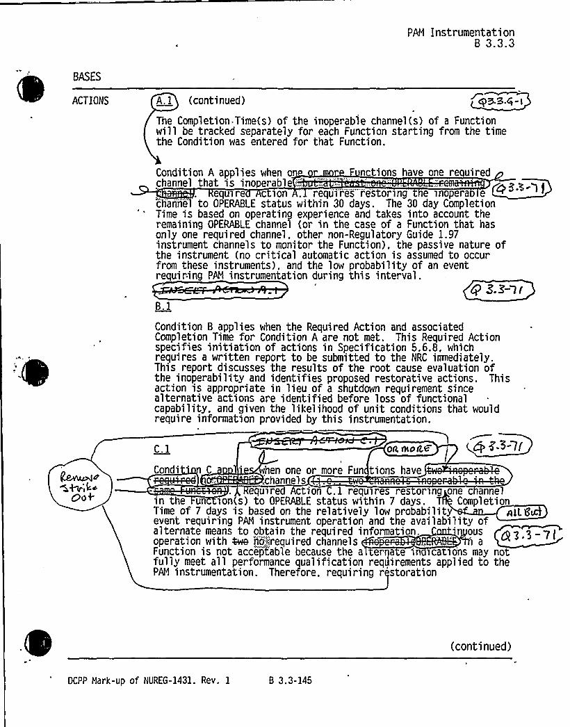
PAM Instrumentati onB 3.3.3
BASES
ACTIONS A.l (continued) AS.S.Q - )
The Completion Time(s) of the inoperable channel(s) of a Functionwill be tracked separately for each Function starting from the timethe Condition was entered for that Function.
-
Condition A applies when o nctions have one re uiredchannel that is inoperable
'qu>rec ion . requires"-restoring e inopera echannel to OPERABLE status within 30 days. The 30 day CompletionTime is based on operating experience and takes into account theremaining OPERABLE channel (or in the case of a Function that hasonly one required channel, other non-Regulatory Guide 1.97instrument channels to monitor the Function). the passive nature ofthe instrument (no critical automatic action is assumed to occurfrom these instruments), and the low probability of an eventrequiring PAN instrumentation during this interval.
g S.3'-l rB,l
Condition B applies when the Required Action and associatedCompletion Time for Condition A are not met. This Required Actionspecifies initiation of actions in Specification 5.6.8, whichrequires a written report to be submitted to the NRC itImediately.This report discusses the results of the root cause evaluation ofthe inoperability and identifies proposed restorative actions. Thisaction is appropriate in lieu of a shutdown requirement sincealternative actions are identified before loss of functionalcapability. and given the likelihood of unit conditions that wouldrequire information provided by this instrumentation.
C.l
Condi'
oa eokc
hen one or more Fun tions have,channels
4 z-3-7(
oof equ~red Action C.l requires res orang one c annelin the un >on(s) to OPERABLE status within 7 days. T CompletionTime of 7 days is based on the relatively low probability nlL8&event requiring PAM instrument operation and the availability ofalternate means to obtain the required information. 'usoperation with 4we n5tirequired channels aFunction is not acceptable because the a erna e in icatsons may notfully meet all performance qualification reqdirements applied to thePAN instrumentation. Therefore. requiring r storation
(continued)
DCPP Hark-up of NUREG-1431. Rev. 1 B 3.3-145


Enclosure page B .3-145Insert A ION A.1
Attachment 2PG&E Letter DCL-98-167
Insert for Q 3.3-71
Ifth single cha el function for AFW flow or G wide range water level are inoperable, entryin ACTION is required ecause the fun on is then unavailaUfe.
Insert AC ON C.1
Cond'n C also plies to the sin I channel AFWflo nd the SG wi range water levelfun ions, since ith the loss of t(ese single channel@the function is navailable.


PAN InstrumentationB 3.3.3
BASES
ACTIONS g3,3-7 lC.j (
wL(, Saxof one inoper e channel of the Function limits the risk thatPAN Function will be in a degraded condition should an accidentoccur. Condition C is modified by a Note that excludes hydrogenmonitor channels.
D.1
Condition D applies when two hydrogen monitor channels are'noperable. Required Action 0.1 requires restoring one hydrogen
monitor channel to OPERABLE status within 72 hours. The 72 hourCompletion Time is reasonable based on the backup capabi lity of thePost Accident Sampling System to monitor the hydrogen concentrationfor evaluation of core damage and to provide information foroperator decisions. Also, it is unlikely that a LOCA (which wcause core dama e) would occur durin thiIWS":,,'I',- ~"'~i""",:-:—;-:.,i,""':-',
0
Condition E app1ies when the Required Action and associatedCompletion Time of Condition C or D are not met . RequiredAction E.l requires entering the appropriate Condition referenced inTable 3.3.3-1 for the channel iaeediately. The applicable Conditionreferenced in the Table is Function dependent. Each time aninoperable channel has not met any Required Action of Condition Cor D. and the associated Completion Time has expired, Condition E isentered for that channel and provides for transfer to theappropriate subsequent Condition.
F. 1 and F.2
If the Required Action and associated Completion'Time ofConditions C or D are not met and Table 3.3.3-1 directs entry intoCondition F. the unit must be brought to a NODE where therequirements of this LCO do not apply. To achieve this status. theunit must be brought to at least MODE 3 within 6 hours and MODE 4within 12 hours.
The allowed Completion Times are reasonable, based on operatingexperience, to reach the required unit conditions
(continued)
DCPP Mark-up of NUREG-1431. Rev. 1 B 3.3-146

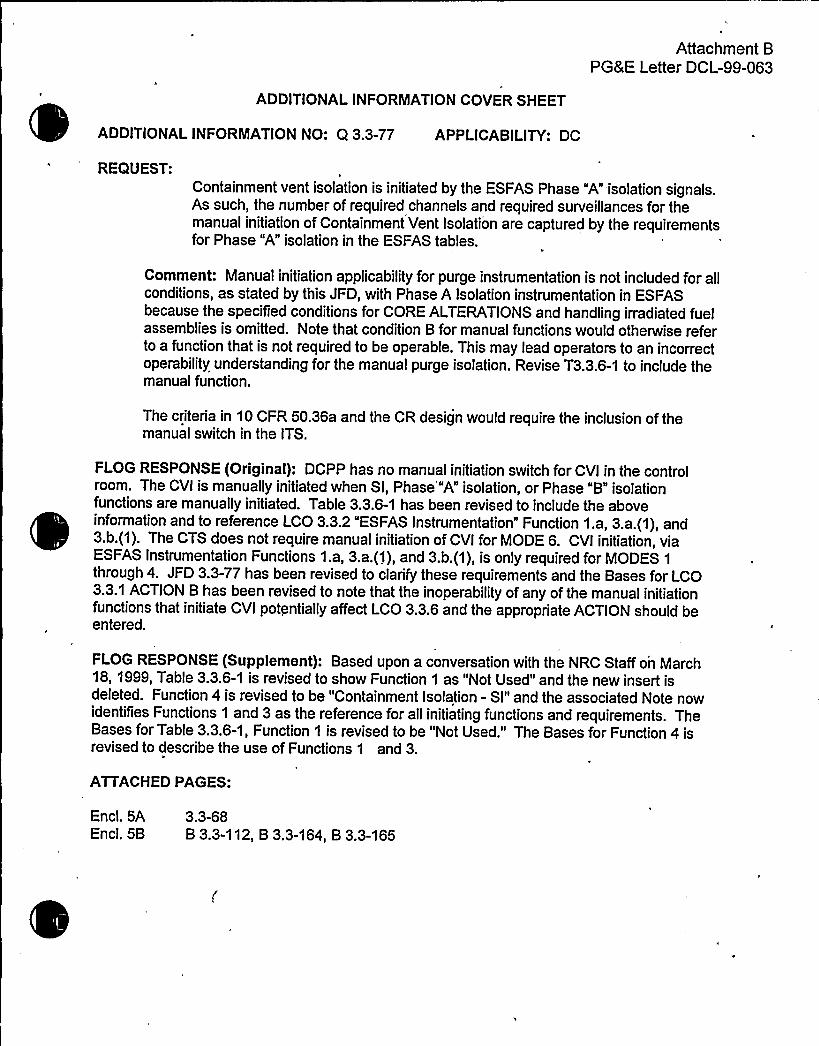
Attachment BPG8 E Letter DCL-99-063
ADDITIONALINFORMATIONCOVER SHEET
ADDITIONALINFORMATIONNO: Q 3.3-77 APPLICABILITY: DC
REQUEST:Containment vent isolation is initiated by the ESFAS Phase "A" isolation signals.As such, the number of required channels and required surveillances for themanual initiation of Containment Vent Isolation are captured by the requirementsfor Phase "A" isolation in the ESFAS tables.
Comment: Manual initiation applicability for purge instrumentation is not included for allconditions, as stated by this JFD, with Phase A Isolation instrumentation in ESFASbecause the specified conditions for CORE ALTERATIONSand handling irradiated fuelassemblies is omitted. Note that condition B for manual functions would otherwise referto a function that is not required to be operable. This may lead operators to an incorrectoperability understanding for the manual purge isolation. Revise T3.3.6-1 to include themanual function.
The criteria in 10 CFR 50.36a and the CR design would require the inclusion of themanual switch in the ITS.
FLOG RESPONSE (Original): DCPP has no manual initiation switch for CVI in the controlroom. The CVI is manually initiated when Sl, Phase'"A" isolation, or Phase "B" isolationfunctions are manually initiated. Table 3.3.6-1 has been revised to include the aboveinformation and to reference LCO 3.3.2 "ESFAS Instrumentation" Function 1.a, 3.a. (1), and3.b.(1). The CTS does not require manual initiation of CVI for MODE 6. CVI initiation, viaESFAS Instrumentation Functions 1.a, 3.a.(1), and 3.b.(1), is only required for MODES 1
through 4. JFD 3.3-77 has been revised to clarify these requirements and the Bases for LCO3.3.1 ACTION B has been revised to note that the inoperability of any of the manual initiationfunctions that initiate CVI potentially affect LCO 3.3.6 and the appropriate ACTION should beentered.
FLOG RESPONSE (Supplement): Based upon a conversation with the NRC Staff on March18, 1999, Table 3.3.6-1 is revised to show Function 1 as "Not Used" and the new insert isdeleted. Function 4 is revised to be "Containment Isolation - Sl" and the associated Note nowidentifies Functions 1 and 3 as the reference for all initiating functions and requirements. TheBases for Table 3.3.6-1, Function 1 is revised to be "Not Used." The Bases for Function 4 isrevised to describe the use of Functions 1 and 3.
ATTACHEDPAGES:
Encl. 5AEncl. 5B
3.3-68B 3.3-112, B 3.3-164, B 3.3-165


Containment
I~S
Isolation Instrumentation3 3.6
Table 3 3.6-1 (page 1 of I)Containment Purge QQ~Rac Isolation Instrumentation
FUNCTION
APIIi1CAHLK .
i%DES";OR>OTHER REOUIREDSPEOIF'I81
™CHANNELS
QSOrI'T1 Gled
SURVEILLANCEREOUIREHENTS
'RIPSETPOINT
3.3-?9
44~44ea3.3-77
gE-4-> 7
AutomatiActuati Logicand uationRel s
ontainmentRadiation
Gaseo
frcub
p>'4.~< 2 tr ins":(Sfkal+4)
~rhca.ga
~gFP b
SR 3.3 6.2SR 3. .6.3SR 3.3.6.5
SR 3.3.6.1SR 3.3.6.4
SK 3.8.fo.F
NA
~Rcpeundf,.Mr4OIOI
PQ3- I
5-5" 6
gceouSf'< k'ec
- b~eunQ
4—.Area
lwoD3 . g 9.3-774. Containment
Isol tion-Refer to LCO 3.3.2. "ESFAS Instrumentation." Functioninitiation functions and requirements.
for
adutnn ', ur>n9 mOVemem O e>nad>at.;;..ue.".WSS leS:'Vtt ~n;vvAvni~wwvnwvrv@vrvv4 vier'vv~r v ' 'N '''~ re 3.3
$33-Zi3.3-'
DCPP Mark-up of NUREG-1431, Rev. 1 3.3-68


Enclosure page 3.3-68Insert 3. 7
Attachm t 2P Letter DCL- -167
Insert r Q 3.3-77
Co ainment ventil on isolation is cons ered manually i iated when Sl hase "A" is tion,Phase "B" is ion functions are nually initiated. efer to LCO 3.. "ESFAS
Instrumentat'," Function 1.a, 3.. 1), and 3.b.(1), spectively for r uired charm s andsurveillan requirements.


ESFAS InstrumentationB 3.3.2
BASES
ACTIONS(continued)
B.l B.2.l and B.2.2
Condition B applies to manual initiation of:
~ SI;
~ Containment Spray:
~ Phase A Isolation; and
~ Phase B Isolation.
This action addresses the train orientation of the SSPS for thefunctions listed above. If a channel or train is inoperable.48 hours is allowed to return it to an OPERABLE status. Note
,that for containment spray and Phase B isolation. failure of oneor both channels in one train renders the train inoperable.Condition B, therefore, encompasses both situations. Thespecified Completion Time is reasonable considering that thereare two automatic actuation trains and another manual initiationtrain OPERABLE for each Function, and the low probabi lity of anevent occur ring during this interval. If the train cannot berestored to .OPERABLE status'he unit must be placed in a MODE inwhich the LCO does not apply. This is done by placing the unitin at least NODE 3 within an additional 6 hours (54 hours totaltime) and in NODE 5 within an additional 30 hours (84 hours totaltime). The allowable Completion Times are reasonable, based onoperating experience. to reach the required unit conditions fromfull power conditions in an orderly manner and without
palJenging unie-ayaaem~l7,g'.l
C.2. 1 and C.2.2
Condition C applies to the automatic actuation logic andactuation relays for the following functions:
~ SI;
~ Containment Spray:
~ Phase A Isolation;
(continued)
DCPP Nark-up of NUREG-1431. Rev. 1 Bases B 3.3-112


Attachment 2PG8 E Letter DCL-98-167
Enclcau 5B page B 3.3-112Inse 3.3.2 A ION B
Insert for Q 3.3-77
ith the in erability of nual initiat of Safety Injecti n, Containrpent Isolation Phase A orhase, the CVI whi is initiated om that functio s also inope Able and the ap fopriate
LCO3..6ACTION houldbe e ered.
g g.3-77

0

Containment0(3 3"Ed
Isolation Instrum i nM'AW VAVAC'IV5
B 3.3.6
BASES
BACKGROUND(continued) purge amenti:,"Igt)ao isolation, which closes
containcmeiit"v'eii8'1'at4ori isolation valvesThese systems are described
in the Bases for LCO 3.6.3 ~ "Containment Isolation Valves." C ALL~+golf ~Wc lac/
APPLICABLE , The safety analyses assume that the containment remainsSAFETY ANALYSES intact with penetrations unnecessary for core cooling isol
in the event. within approximately 60 seconds. The isolatgeese cori)nttleritpverItigit'iori valves has not been analyzed
"tea lly in""the dose calculations, although itsiSOlatiun,:::;,;:,:i:.'a!C: =-iueiiaurl"'~n::.t!ime,';. iS aSSumedcontainment
— ' '- — -- '' i'solation radiatitor c s p o t e signa o ensure closing
'so. "a44.an val ves
$tEt on
ted earlyon of the
Theonf the
They fjSZ -Qainment
Q~gfh) ll/l~ta also the pnmary means or au orna >ca ly isolating cin the event of a fuel handling accident uring shutdown
5%'c3a'tt SD~HThe containment "': '"'' isolationinstrumentation sa isf>es ri er~on ogFaII.=GIf:"36'(c)'('2>Cihg'..
QQ $ '5-Q'1'0
Containment isolation in turn ensures me ting the containmentleakage rate assumptions of the safety a alyses, and ensures thatthe calculated accidental offsite radiol gica doses are 1 Qp<-ooz10 CFR 100 Ref. 1) limits. OV Ct % O'5'aura:w
ts aaJme
LCO The LCO requirementsinitiate Containmenin Table 3.3.6-1, is
ure that the rum ntation necessary toIsolation, listed JII&a.&
1. Manual Initiation % E.'L > 'I
(continued)
DCPP Mark-up of NUREG-1431. Rev. 1 Bases B 3.3-164

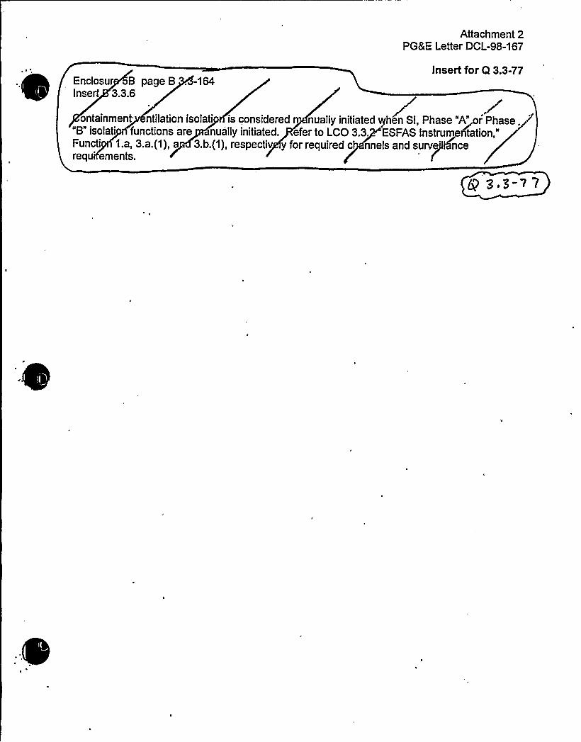
Attachment 2PG8E Letter DCL-98-167
Enclosur B page B . -164Insert 3.3.6
Insert for Q 3.3-77
ontainment ntilation isolati is considered nually initiated qhen Sl, Phase "A~rPhase. ~"8" isolati functions are nually initiated. efer to LCO 3.3. ESFAS Instrum~ntation,"Functi 1.a, 3.a.(1), a 3.b.(1), respectiv y for required c nneis and survjelasncereq
erne
nts.
Q 3 3~) 7


Containment
StG T
' "". '' Isolation Instrumentation8 3.3.6
BASES
LCO(continued)
2. Automatic Actuation Lo ic and Actuation Rela s1
The LCO requires two trains of Automatic Actuation Logic andActuation Relays OPERABLE to ensure that no single randomfailure can prevent automatic actuation.
tbAutomatic Actuation Logic and. Actua on Re ays consist of thesame features and operate in the s e manner as described forESFAS Function 1.b, SI, and ESFAS unction 3.a, ContainmentPhase A Isolation. The applicabl NOD nd s ecifiedconditions for the containment ':
. isolationportion of these Functions are s eren an ess restrictivethan those for their Phase A isolation and SI roles. If one ormore of the SI or Phase A isolation Functions becomes stt 7
le in such a manner that only the ContainmentIsolation Function is affected, the Conditions
app ica e to their SI and Phase A isolation Functions need notbe entered. The less restrictive i s ecified forinoperability of the Containment IsolationFunctions specify sufficient compen atory measures for thiscase.
5
3. Containment Radiation sTThe LCO specifies Aer- two required channels of radi ionmonitors to ensure that""Uie radiation monitoring
trumentation necessary to initiate ContainmentIsol ation remains OPERABLE(~i';:;:-g6E$$ :F:..r. ~;.::,;-. e.",.LCO
Qn; y':xeguygp~m~ epni4~r"„. 'to be;:,.":OPERABL'Ej'dii~'~jjg"'Rf'""M;: TXQNSror;:;::,dui'.:fii"!'moveement'4f':.."8",Fad'i~edHi.'0& .:":,Qasem53:;ASS:.-;:zA
Kp
.x<srr S . a;:,.
KX
4. Containment Isolation-@ 0 3-'l'l
Refer to LCO 3.3.2, Function~, for all initiating Functionsand requirements.
(continued)
DCPP Mark-up of NUREG-1431. Rev. 1 Bases 8 3.3-165


Attachment BPGRE Letter DCL-99-063
ADDITIONALINFORMATIONCOVER SHEET
ADDITIONALINFORMATIONNO: Q3.3-79 APPLICABILITY: CA, CP, DC, WC
REQUEST:Add Applicability columns to ITS Tables 3.3.6-1 and 3.3.7-1 to reflect current TSwith varying Functional Applicabilities.
Comment: Revise submittal to adopt TSTF-161, Rev 1 format. List "core alterations"applicability and "during handling of irradiated fuel" as separate applicability footnotes.
{DC, WC}The applicability for Containment Purge and Exhaust Isolation is broader thanrequired by CTS 3.3.2. This change is neither identified nor discussed.
{DC}ITS Table 3.3.6-1 applicability for the Containment Radiation Function isduplicated. It is not necessary to provide an applicability statement for function 3ifapplicability is provided separately within function 3, in this case for function3.a.
{DC}The required number of channels for function 3.a under applicabi1ity condition (a)is inconsistent with the markup of CTS section 3.3.2.
{CP}Explain the design justification for not including Table3.3.6-1 Note "c" in theapplicability for actuation logic and relays. Specified logic must support radiationisolation function in the table. Ifthe logic supports Phase A Isolation (T3.3.6-1, F4) thenit should not be listed in this table. A single listing of the logic in ESFAS Table 3.3.2-1 isacceptable.
{CW}CTS T4.3-2 F9a, 9b and 9c shows a markup (strikeout) of applicable conditionswithout evaluation. Provide a revised markup and evaluation of proposed CTS changes.CTS T3.3-3 F9a, 9b and 9c shows no changes to applicable conditions. Thesedifferences are not evaluated.
{CW} CTS T3.3-3 Actions 26 and 26****are used in ITS T3.3.6-1. Changes to theseCTS requirements are neither identified nor evaluated.
FLOG RESPONSE (Original): Comment 1: In response to the first comment, ITS Table 3.3.6-1 has been revised to reflect TSTF-161 Rev. 1. Applicabilityfootnote (a) has been divided into"(a) During CORE ALTERATIONS"and "(b) During movement of irradiated fuel assemblieswithin containment." No changes to current TS Table 3.3-3 Functional Unit 3.c or to the ITS3.3.6 Bases are required. For WCGS, DOC 3-20-LS-51 was initiated to revise CTS Table 3.3-6, Functional Unit 1.a, to revise the Mode of Applicability from "All"to "1, 2, 3, 4, During COREALTERATIONS, During movement of irradiated fuel assemblies within containment."
The mark-up of STS LCO 3.3.7 Applicability in Enclosure 5A shows the strike-through of"During CORE ALTERATIONS"under JFD 3.3-79. That JFD has been revised to discuss therationale behind the strike-through. Since ITS Table 3.3.7-1 includes all MODES 1-6, the LCOis applicable any time fuel is in the reactor vessel. Since CORE ALTERATIONS involveactivities conducted while fuel is in the vessel, including this requirement in the LCOApplicability is unnecessarily redundant given the definitions of CORE ALTERATIONand


Attachment BPG8 E Letter DCL-99-063
MODE. This same approach was taken in ITS 3.7.10. DCPP has also made changes to theITS 3.3.7 Bases to correct and clarify the applicability. No changes were required for otherFLOG plants'TS 3.3.7 Bases.
Comment 2: For the second comment, for DCPP, the CVI is required to be OPERABLE as anESFAS function in MODES 1 through 4 via function 3.c. of CTS Table 3.3-3. For CTS 3.9.9,the Containment Ventilation Isolation system is required to be OPERABLE during COREALTERATIONSand during movement of irradiated fuel. - For CTS Table 3.3-6 function 3.a.3)and 3.b.1), the MODE requirements'are MODE 6. The requirements for CTS Table 3.3-6function 3.a.3) and 3.b.1) are revised via new DOC 03-22-LS20 to revise the MODE 6requirement to MODE 6 during CORE ALTERATIONSonly. It does not make sense to requirethe instrumentation to be OPERABLE when the system it actuates is not required to beOPERABLE. Note that DOC 02-05-M already added during movement of irradiated fuel.These CTS requirements were consolidated in ITS 3.3.6.
1k
Comment 3: For the third comment, the duplicate applicability has been deleted and the sub-function "a" has been incorporated under the main function "3." In addition, the title of thefunction has been revised to "Containment Ventilation Exhaust Radiation Gaseous/particulate"since for DCPP a single monitor accomplishes the monitoring for gaseous, particulate andiodine radiation functions for detection of a fuel handling accident as explained in the ITS 3.3.6bases. This title is also consistent with the CTS terminology.
Comment 4: CTS Table 3.3-3 has been marked up for clarity to show the MODE 6 and channelrequirements of Table 3.3-6. In addition, a new DOC 2-51-LG is used to move the descriptivechannel identifiers to the ITS 3.3.6 bases. Changes have been made to the 3.3.7 Bases toclarify the LCO applicability.
Comment 5: For CPSES, other changes to ITS Table 3.3.6-1 are also addressed in responseto this question. The footnote (a) has been incorporated into table 3.3.6-1, Functional Unit 1
directly, rather than by reference. Subsequent footnotes have been re-lettered. Further, thenotatioh describing the strike-out of STS Functional Units 3.b., 3.c. and 3.d has been revised toreference JFD 3.3-79, rather than JFD 3.3-73, as contained in the original CPSES submittal.
Comments 6 and 7: These comments were resolved during meetings with NRC staff onSeptember 16 and 17, 1998. However, Reference 5 is silent on the resolution of comment 7.Changes to CTS Table 3.3-3 ACTION 26 for ESFAS Functional Units 9.a, 9.b, and 9.c areidentified on page 3/4 3-21 and Insert 3/4 3-21 in Enclosure 2 and are evaluated under DOCs1-04-LG, 1-43-A, 2-16-LS-12, and 2-26-LS-21 (see also responses to comments on the last twoDOCs). No DOC is needed for the ****note in CTS Table 3.3-3 since that note is consistentwith ITS 3.0.4 (i.e., 3.0.4 does not apply in MODES 5 and 6).
FLOG RESPONSE (Supplement): Based upon discussions with the NRC Staff on March 25,1999, the format of Table 3.3.6-1, Functions 2 and 3, is changed to provide two separate linesfor each function based upon Applicability.
ATTACHEDPAGES:
Encl. 5A 3.3-68


Containment Isolation Instrumentation3.6
Table 3 3.6-1 (page 1 of I)Containment Purge ~~~ Isolation Instrumentation
C
FUNCTION
'O'PPi.'CCABLC
f%DES";OR'.,",DTII REQUIRED".SPEGIRIEO. 'HANNELSCONDITIONSA p
SURVEILLANCEREQUIREHENTS
TRIPSETPOINT
3.3-?9
g~h <~~ ~~n3.3-77
Cpa.~-11
AutomatiActuati Logicand uation "
Rel s
ontainmentRadiation
F~: ':~ @4~ 2 tr insk. '~<+~CL)
4a.ga
SR 3.3 6.2SR '. .6.3SR 3.3.6.5
c~xz
Pg:3- 1
l MSc@~
Cp 3,5->V
Gaseo
4cu4
g "C&M
&R P'miiw~'m@eh".~
~g
SR 3.3.6.1SR 3.3.6.4
SK 3.8.4.F
Oa4~peva93.3- 2
.;,,Pei:;::,„':OXH
gCOfd \c5tei k'e: ~
$R 'I 'VW3332
SR—3. 'I-.6-.4N '~4 A baa~eveQ 3 3-32@~I '~
'~vaQ 3 3-32$R
4. Containment.Isol tion-
J RoD3
Refer to LCO 3.3.2. "ESFAS Instrumentation." Function .. forinitiation functions and requirements.
g 3'3-77
urban . cA '.:,'. urlno.movemenmo.;:-:.'::>rrad~w.;;.ue mass .,Tesent ~n'onta>nmen
~.
k% A sv% (h h hVhv
3.3
3.31
Q3,3-S1
DCPP Mark-up of NUREG-1431. Rev. 1 3.3-68


Attachment BPG8 E Letter DCL-99-063
insert for Q 3.3-79Encl. 5A Page 3.3-68Insert for Functions 2 and 3
2. Automatic ActuationLogic and ActuationRelays
3. Containment PurgeRadiation Gaseous andParticulate
1,2; 3,4,
(a) and (b)
I, 2,3,4,
(a) and (b)
2 trains
1 train
SR 3.3.6.2SR 3.3.6.3SR 3.3.6.5
SR 3.3.6.2SR 3.3.6.3SR 3.3.6.5
SR 3.3.6.1SR 3.3.6.4SR 3.3.6.7SR 3.3.6.8
SR 3.3.6.1SR 3.3.6.4SR 3.3.6.7SR 3.3.6.8
NA
NA
Per ODCM
Per ODCM


Attachment BPG8 E Letter DCL-,99-063
ADDITIONALINFORMATIONCOVER SHEET
ADDITIONALINFORMATIONNO: Q3.3-82 - APPLICABILITY: DC
REQUEST:The CONDITIONS, REQUIRED ACTIONS, etc. are revised per the DCPPcurrent licensing basis. The plant FBACS does not perform any accidentmitigation functions except during the fuel handling accident.
Comment: CTS markup is missing Actions A.1.2.3.1 and Condition C. Provide thenecessary corrections and justification.
Proposed ITS Action 1.2.3.2 has no stated completion time. Provide a revised ITS andthe necessary corrections and justifications.
FLOG RESPONSE (Original): CTS ACTION 30 and 32 are applicable to the fuel handlingbuilding radiation monitors. ITS ACTION A.1.2.3.1 is part of ACTION 32 via its reference toCTS LCO 3.9.12; however, to clarify the requirements, ACTION 30 has been revised to includeITS ACTIONA.1.2.3.1. CONDITION C is included in CTS ACTION 30 directly, and in ACTION32 via required entry into the Action requirements of CTS LCO 3.9.12.
The completion time has been inserted for ITS ACTIONA.1.2.3.1.
The CTS, via notes (a) and (b) in Table 3.3-6, states that the requirements for Fuel HandlingBuilding Ventilation Change are applicable and that ACTION 32 will not be applicable to theFuel Storage Area Monitors following installation of RM-45A and 45B. The original intent was toinstall these monitors (RMR5A and 45B) as part of the radiation monitor upgrade (LA70/69) toimprove the reliability of the function. However, since the performance and reliability of theexisting Fuel Storage Area Monitors has been improved, and because of the expense ofinstalling these new monitors, the project has been canceled. Since the monitors are notinstalled and there is no intent to install these monitors, the notes regarding their function will bedeleted from the CTS Tables 3.3-6 and 4.3-3 via DOC 3-21-LS52 and will not be incorporatedinto the ITS. The Fuel Storage Area Monitors willcontinue to provide initiation of the Fuelhandling Building Ventilation Mode Change due to a fuel handling accident.
FLOG RESPONSE (Supplement): Based upon discussions with the NRC Staff on March 26,1999, LCO 3.3.8, Condition A is reordered to place the 30-day Action at the end of the logicchain rather then at the beginning. Action 1.2.3.2 is deleted since it is a repeat of the specifiedactions of Required Action A 1.1. The Note "Not Used" in Action B is deleted and Action C isre-labeled as Action B. The inoperability of "Manual Channels" is added to the re-labeledCondition B. The Bases has been revised consistent with these changes.
ATTACHEDPAGES:
Encl. 5A 3.3-75, 3.3-76, 3.3-78Encl. 5B B 3.3-185

C

RQGS FBVS Actuation Instrumentation3.3.8
ACTIONS
CONDITION REQUIRED. ACTION COMPLETION TIME
A. One or more Fu tionswith onchanne or r iinoper 'le.
l.SA
epe-a~R-.R'es't'om:„";:.theisnoparab't'aimoiito'rs'!toOpEMLE::."::si':atoiss';::
730day'
3.3-82
'AND
'A::.4,:.'2!%4gristall.-.;.an:„-oppiopriJtg
s~;.@OR
408''llf4'elj~>,0:~Qadi 840Ajmtect'5"o'n'„.""j'i';:o'ce'diii.'"is
fHt,.,i':8,:"'d0)e!'i8Cj,%On'340lj1'ngq.dBdpCe,';".i,0the'~sjYNtifiiel';.'„"poi3:'
~ MA gNQ
sNaao'lri'',-;;,':".,;:
';@I;;.l,'er8:, ngjFQVS"-', r''N'iifj'gh'e.QodijiRetAQYalNlAOd "~
Kllllladfil'ilia
Q 3,$ -8>
INN8f)''Btgp':.7hVNA+AWA'AINlVlhWm
A7
:,fmped4tejg
5%. ~ '%s',, ' 4~<~m'~u c
CN'''4 ' ''1s
"":"A"'+::.Yb' ' . v vA4w «gf<
AYYP
b +. Raw<~ ~ )s, ~ gmsa
DCPP Mark-up of NUREG-1431, Rev. 1 3.3-76


ARCS P3VS Actuation Instrumentation3.3.8
ACTIONS
CONDITION REQUIRED ACTION COMPLETION TIME
3.3-82
f.ea+uat e4>~~<'
pp L, lcm
~ S g. RequiredassociateTime for o8 not met
tion andCompletionndition A er-
8gkl Suspend movement of
irradiated fuel assembliesin the fuel building.
Immediately
3.3-82
m 6-%ates
DCPP Mark-up of NUREG-1431, Rev. 1 3.3-76


RAGS FBVS Actuation Instrumentation3.3.8
Table 3.3.8-1 (page 1 of 1)FBACS Actuation Instrumentation
FUNCTION
APPLICABLEMODES OR
SPEC IFIEOCONDITIONS
REOUIREDCHANNELS
SURVEILLANCEREQUIREHENTS
TRIPSETPOINT
1. Manual Initiation(a) SR 3.3.8.4
3.3N2
[a8 fffwbLi&
Fuel Building Radiation 3.3-82
a. ~ Synt=;fuejPPa&o.(a)
B-PS
SR 3.3.8.1SR 3.3.8.2 ~,.';/$ mR/hrSR 3.3.8.5
b. Q~~e tingFuel."::MNYjeVa'u>t~ '"
~-.4a4wus-
(a)
~~CW@jg P,.:~«~~
SR 3.3.8.1SR 3.3.8.2SR 3.3.8.5
j,S:.
B-PS
~~iS mR/hr
5.0 W
LiiiIH:r40QI
mQLi(a) During movement of irradiated fuel assemblies in the fuel building. ~
wA C
S/494'A'wv~«c«,« ~~m w m.« ~m~««m.'««« ~ mW «~ .«w«
%Y h «'JAM V
Q Z.E-SZ
SN32-
DCPP Mark-up of NUREG-1431, Rev. 1 3.3-78


RRQSFaHBVS Actuation Instrumentation8 3.3.8
BASES
ACTIONS(continued)
specification. If the Trip Setpoint is less conservativethan the tolerance specified by the calibration procedure. thechannel must be declared inoperable immediately and the appropriateCondi tion entered y",'ORft',"cin'gaj so,:,be="obser yedjdumr'&g,:aa Cliiiinejcheck;jar.',:,:;,Cp',':immi fkobse'rvel',:w'ouTd:'","'romp't".".asctioni4oj cor'rect~then
i serepaoey;:;.-":
Not has(++been added to the ACTIONS to claria ication Zmipletion Time rules
The Conditions of this Speci ica ion may e en ereendently for each Function listed in Table 3.3.8-1 in the
accompanying LCO. The Completion Time(s) of the inoperablechannel(s)/train(s) of a Function will be tracked separately foreach Function starting from the time the Condition was entered forthat Function. 4 3. 3 -8't
g si'u l~
~~~~+O t
err mi'+45 R
~ AhPCL~~
l ~~654< +~h~
t '."„::ACTI, :-;:;,:hiie): 'i':.',.,modi,,: .ed>.by,'-; „::::.NM'e::;"s, tmj','"„".,t'',"';:LCO".:P:.",.:3,"':.',$jW~i p,.i'able':."'.:.:,;:;::. f.:,',".movin jljgad ted.:,.",fue:.;.".,;assW . ei;,'::wh$ 'l..-~ii..'Nd
6>ir"< ": LC9':;3"':: ";:.::.''.':w'ouM-:" ot,';j'p"". fjpanye':>'t'ioYi.:--.'':...:
f~moii5'i"'ra,;atedgf:"„:, piss ':5'es~+ ', e;;,:ij-;NO Ol~:4;" ..or~".,3",!~th ..fnnuN::
mov";,",W:="ij""",.iiihpi"',„,,',,::,';"of"",'r"a'oto're'p,,'at)'in":.:~'-;g.her,if.,"',: ';."':;:;:iri'": ..thenea" "-~„,$.-'flab;,. ltd.'.',"hCo ",''sp'e'nd""" ".i'mi're'~'~(>:i,.'."i',ae'a'ted.:'.;Xi'ii ',:;.,a's's"',i.isw 9:.d>kO ".. weft, —.Rt',."r soi7;to;.;, 'ui:rk<:,"',i;.eactmor':;-s
utt'du'in'..j
h ),9. l 8 l >. Q. A ~ eo~av ep tqn+OrwCcauhmu -~
Condition A applies to theradiation monitor
manual fun on. Condition A applies to thefailure of . n~e'ore,more radiationmonitor channels. o manu channel~ If one or,''maori~channels ortrain% ~re in'operable, period of %trays
'
... amen,;.rnSPPnrtenPriarteePOrtahl'eA~O~Cinniiiaaa>mana,nnf teer ithgth aYmesitpo)R--";;ii",.-::::@i'ji'r'oc'endures';:'w$ ':th:;::,:i:;&s9',:;ice",:~~'n'~",hiig~n">dev'1.c'e"',.:,'.iii'uest!;:.,".be':;"„:,'w-..''-:%he.,::,",;sepen
;,ue„,,:,;poo, ',::;pre: . neVBAQSRIBgS trairi mus't 'b'e 'placid 'i'n""jn.-'.the..".;!IodineRetiovg.:-.".iield,::;::,: '"„'operation~.':iimeg5tely.. This''effects'el''.""aecco~ep ishes the actuatione ins'trumentation function and"places the~ares in a conservative mode or oPeration iY i." rPVrirode 'iaiP 'r 'P'lar'temon t. or.'„. ng.':.,or::„:::icon„TflM:„;,.oe~i::nmeeman
(continued)
OCPP Nark-up of NUREG-1431. Rev. 1 Bases B 3.3-185

1

Attachment BPG8 E Letter DCL-99-063
ADDITIONALINFORMATIONCOVER SHEET
ADDITIONALINFORMATIONNO' 3.3-104 APPLICABILITY: DC
REQUEST:CONDITIONA of ITS 3.3:5 is revised to incorporate CTS ACTIONS 15 and 16.CONDITIONS B and C are not used.
Comment: Beyond Scope - - CTS LAR-97-02 request the addition of Actions toaddress loss of both degraded and LOV channels. PM action to issue amendment. DCaction to provide an A-DOC for the change.
The CTS markup for the loss of power function shows two actions. Action 15applies to the two channel functions and Action 16 applies to the one channelfunctions. Only Action 15 is reflected in the ITS. It may be that Action 16 can beargued to be subsumed by Action 15. Ifso, this should be reflected and justifiedin the CTS markup. Ifnot, Action 16 should be reflected in the ITS markup.
ITS LCO 3.3.5 is modified from the iSTS to incorporate plant design. Use the NEIguidance document to state, using consistent language, the required channels for eachbus for each LOP DG Start Function.
FLOG RESPONSE (Original): LAR 97-02 was approved by the NRC as LA 129/127. Themarkups to incorporate these latest approved revisions are enclosed as Addition InformationNumber DC 3.3-005.
Item 2 was accepted at the September 15, 1998, meeting since CTS ACTION 16 is subsumedby ACTION 15.
'
The ITS LCO 3.3.5 has been. revised to state the required channels for each bus and for eachLOP DG start function.
FLOG RESPONSE (Supplement): Based upon conversations with the NRC Staff ori March26, 1999, and April 6, 1999, LCO 3.3.5 has been revised to eliminate unnecessary information.LCO 3.3.5, Required Action A.1 has been revised to use standard language. The Bases havebeen revised to clarify the operation of the system.
ATTACHEDPAGES:
Encl. 5A 3.3-60Encl. 5B B 3.3-156, B 3.3-159


LOP DG Start Instrumentation3.3.5
3.3 INSTRUMENTATION
3.3.5 Loss of Power (LOP) Diesel Generator (DG) Start InstrumentationL
LCO 3.3.5»he'h " ' Vh»h Yh». ' '.' 'YS'' '»hh hh 'W»»»»» 'l»h»h '8'h» 'h» ' V&h(»'»h»Y lhh'h»»'h»» on
3.3-133
APPLICABILITY:
ACTIONS
Z'H%~T Lt"co %,.B. GMODES 1, 2. 3. and 4, P 33'-lanWhen associated DG is required to be OPERABLE by LCO 3.8.2, "AC
Sources —Shutdown."
------------------------NOTE-Separate Condition entry is allowed for each Function.
CONDITION REQUIRED ACTION COMPLETION TIME
A. One or more Functions. with one ot;.',acr",echannels per businoperable.
A 1 -----------NOTE------------ne channel
may be ypassed for up to 42 hours for surveillancetesting
3.3-104
»h. A'»':h'' ~ ":: '':. h 'q» '» '" "'(X'"'N)%k4'..;.-,.;: .,%...e<.".C....-...~.h i„.,-...»h.....,.hy,
S-he~ImmadiRYl:,hh MvA'~AXOO)XÃ
3 ~ 3- l>'f
3.3-104BP
gpp[icAC lG GPtoGt ~(4J@4 I7E&IIRo 6 8 c A~ (5) ~~ assoc,]ikh DC) ewe~)g OflcQ $ 8 l6 87 LGp 5Cj
5~/ AvfkvAQ~
(continued)
DCPP Mark-up of NUREG-1431, Rev. 1 3.3-60


Enclosure 5A page 3.3-60Insert LCO 3.3.5
Attachment,2PGRE Letter DCL-98-167
Insert for Q 3.3-104
$ ~ 7Q
One channel per bus of loss of voltage DG sta
I
Two channels per bus of degraded voltag~~~c. auO„hMO


LOP DG Start InstrumentationB 3.3.5
B 3.3 INSTRUMENTATION
B 3.3.5 Loss of Power (LOP) Diesel Generator (DG) Start Instrumentation
BASES
BACKGROUND The DGs provide a source of emergency power when offsite power iseither unavailable or is 'graded! b~e,rs'ra~!
p&o, p~t::6%5':.~~Td allow safe unit operation. Unde'rvolrtage protectionwill generate an LOP start if a loss of voltage or degraded voltagecondition occurs 4R aq the sw~wd 49'6kVr'~yritalgbus. There are@wether& LOP start signals. one for each 4.1'6"kV vital bus.
Three undervoltage relays 'reprovided on each 4160 Class lE ~mlea4 lf~ft~l bus for detecting asustained degraded voltage condition or a loss of bus voltage. -74eArelays '"i,':;l.Jgenerate anLOP signal 9'krS51e~te .;:Wnt&~N'Cage,.4jpe,.;:::.,e~y;„"::setje'inf) >if thevoltage is bel~ ISA for a
shoMrt'ime'e>98ggt'.=.."~e,I@s.:„;.('ge::.Wr:;..~hYs)':.":;have,ia;.;:.lover,,'se.::;:44mc. 8.i'.aeter>R)c'A5d'wj<43:ddel'Q„:.,";.a%.'.".j>'9~ ioPhh,,::arid.':".adtwg3'0,„:ieceIds;"-,"foj~~,'„'2583%vgt'if'
I:oad':.(ceIlter,;,','-,trha&fjrmers,',~8%ie-'..o 'em!'.,",aMtosm844,.ca3,;.I jj':bj',,
\~ r
se «h h «8
a
s
8
. fk.vpt,"-alevgl<.,.undI;gag.%age.,;:.,;",gaeh.r.;"0f-'..the.;..;:y>,tel,:< «k:;:; uses
of;,.~era+i:::,'.lOads".,i&rlflg".4;,",IDss,':;;:4f.-.i'403$ 89&$8ithef::,froI.'ajar>ng J8.
ir4psv4n'scant'aneo0sly:.'at~:.,%79'4'ol'ts,'-':.-.-,Th'e'yecondr,'of@th'e',;two;,"r
. ~j1-Qper&lnggcadS,"'ldQf.'.4A9@l,"..ansMtC$ voNagea,",63ps":,",""and': rtojpBr%1st!,', theao~ff'.juste:,='poweksourc&::.''.togkk-'.:,':~<he'goads The COPo start acfuatsi onrs desciida iÃFsirR, sectron 8:8 ihef. Tl.
g o lsus( a„besvots8p)8~on lB:: t~h~re:, i¹!a. dyegdlvlolQ uescoodWltw::~%here!'t hweTobauerofthewy'stii~„!4160,kVabuseshTssiia1'ns~::,aPPm'xlslatas yT'i 788 j,SVt~i:,oirbleeis,:b'ut'=,abov'a~we!!setp'oriits':::,,orrthe:::,'ti jsttQeve'ilier'slderj'oitau'a~ie1'ave,;'~tire'fo',l8'orii'iip:,sa'corn'diriueiretrr!r'ran'dheiii7olte8ae'ihsctr'aliis's'occbr'"",'.autorrrhtecalh j~(%3,.":,-",Axterra:".,e:,TS~Pseconrrb«rse"".,,:,rreTaj,::,:: thee.:rcas~ctrveWreseh 8'
pseneT!ata'ia%'irlu':aatsabtai'2X~".ARer~p,,„:,:~-,:29g~ecopd~<fiiii:,':;d5lay~gf
&e„,''undervao~ta je,,:",condjtionPe'r'S'isis!ir'the",:ci'scuitsb'reeking",:;::'.for",-:.::8'l!!8 bad'sr'to i>tense'iri!'esPaec't'iiieRitaT„-'!4s181'CV,",:bus'es;SeTicepti the"„'l4T60'-;;480!!Vr''le«sar'0:.„',ceiitiir,,t alii'sf ohhi",si:,." irae biSaneihadnke'j'ehblgla,: ji ;le.d.e:h'i i n":thre .0*8
Each,.:,gt'e:I.„.'.";:4$ 66gkV@Ys."'.:.has;:„'5eyec%ddjleve1"';:::uadeivo™l taqep~re aj';~
DCPP Mark-up
a ~O~$ OF'~O 0 it; - C V'J<0~ 4p
gg5 g $ S Q Q iS Qg Q~) Q Jug@ffl yes ) < ( Ont inued )
4tNE Igccqg, IAeMOcP5 pl&$+Q g~~k~ g QQ ~g) ~ o~of NUREG-1431. Rev. 1 Bases B 3.3-156
u i'I,l i~i h~A L-Cm Z&a.-.:.. @3.S- log


LOP DG Start InstrumentationB 3.3.5
BASES
APPLICABLE The LOP DG. start instrumentation channels satisfySAFETY ANALYSES Criterion 3 of lulH
(continued) APg~g ~ 9c ~egg 0
LCO
%cue,'
~Q'+tC i wrrc:p>v ~."<e~-'he
LCO or LOP OG start instrume tation r ires that l'44ree3'hannelper hus het4-i4e loss of voltage eRgbio~nhels-'jer.b:fo F~lntbatffpwT~~oalFpf@"- nd beYchannels'v~r„.les;-".N degrad
vo age W R~o@4)mer~~ggg'.-.for~DBghiwifing:;$ Nt'jillion.'of~goad
LOP DG start instrumentation supports safety sys ems associated withthe ESFAS. In MODES 5 and 6. the Q~e3 channel ust be OPERABLE em~~~whenever the associated DG is required to be OPERABL pK, Scsthe automatic start of the DG is available when needed. Loss of the ~LOP DG Start Instrumentation Function could result in the dela ofsafety systems initiation when required. This could lead tounacceptable consequences during accidents. During the loss ofoffsite power the DG powers the motor driven auxiliary feedwaterpumps. Failure of these pumps to start would leave only one turbinedriven pump. as well as an increased potential for a loss of decayheat removal through the secondary system.
APPLICABILITY The LOP DG Start Instrumentation Functions are required in NODES 1,2. 3. and 4 because ESF Functions are designed to provide protectionin these NODES. Actuation in MODE 5 or 6 is required whenever therequired DG must be OPERABLE so that it can perform its function onan LOP or degraded power to the vital bus.
ACTIONS In the -event a channel's Trip Setpoint is found nonconservative withrespect to the Allowable Value. or the channel is found inoperable.then the function that channel provides must be declared inoperableand the LCO Condition entered for the particular protection functionaffected.
Because the required channels are specified on a per bus basis, theCondition may be entered separately for each bus as appropriate.
A Note has been added in the ACTIONS to clarify the application ofCompletion Time rules. The Conditions of
(continued)
DCPP Nark-Up of NUREG-1431. Rev. 1 Bases B 3.3-159


Attachment BPG8 E Letter DCL-99-063
ADDITIONALINFORMATIONCOVER SHEET
ADDITIONALINFORMATIONNO: CA3.3-006 APPLICABILITY: DC, CA
REQUEST:Clarify Bases for SR 3.3.1.3.
REQUEST (Revised): For Callaway, Based on NRC reviewer comments on March 4,1999, the SR 3.3.1.3 insert has been revised as attached.
For DCPP, based upon conversations with the NRC Staff on March 18, 1999, the insertfor SR 3.3.1.3 is revised to state "The comparison checks for differences due tochanges in core power distribution since the last calibration."
I
ATTACHEDPAGES'ncl.
5B B 3.3-55


BASESh
~
'SURVEILLANCEREQUIREMENTS
RTS Instrumentati onB 3.3.1
SR 3.3 . 1.2 (continued)
th Nld~j"""',,:,'"'"di:"ti"'"«h p p 1 dp d.the channel is declared inoperable.
Two Notes modify SR 3.3. 1.2. The first Note indicates that the NISj...,...:... 2,:*,,',\"..., h 11 h P t d i t t ith
the calorimetric"'results if"the absolute difference between the NIS~a '.hl:,'2 'di,"t":",' h 1 1 t 1 1 '22 tip.The second Note clarifies that this Surveillance is required onl ifreactor power is ~ 15K RTP and that 48 24 houri is
90 3-s Ed.
a owe or performing t e mrs urveiTlance after reaching 15K RTP
5'!pri7)r,.''::to'.",',.",exceedFiij 30@RTP.. At lower power 1 eve s, calorimetricdata ~are" in'a'cecura'te ..'
8 8='tt'-I usen.
The Frequency of every 2 ours is adequate. It is based on unitoperating experience, considering instrument reliabi lity andoperating history data for instrument drift. Together these factorsdemonstrate the change in the absolute difference between NIS andheat balance calculated powers rarely exceeds 2X in any 24 hourperiod;
In additions control room operators periodically monitor redundantindications and alarms to detect deviations in channel outputs.
SR 3.3.1.3
SR 3.3.1.3 compares the incore system to the NIS channel outputevery 31 EFPD. If the absolute difference is ~ 3X. the NIS ha nelis still OpERABLE. but must be readjusted. zjasmrcn e s <I s
crj 8.3~«If the jjIS channel cannot be properly readjusted. the channel isdeclared inoperable. This Surveillance is performed to verify thef(hI) input to the overtemperature hT Function.
Two Notes modify SR 3.3.1.3. Note 1 indicates that the excore NISchannel shall be adjusted if the absolute difference between theincore and excore AFO is e 3K,Note 2 clarifies that the Surveillance is required only if reactorpower is ~SOX RGB RTP and that 24 hours is allowed tor performingthe first Sur'veillance after reaching 50f$4643 RTP.
lMCMT 6 g ~ 3.q(The Frequency of every 31 EFPD is adequate. It is based on unitoperating experience, considering instrument reliability andoperating history data for instrument drift. Also. 5'j'nce':-'~the skewchanges in neutron flux are)slow)during the fuel cyclxe:e~m
j;"-:"::the.;:,gx cted,:-":,:chran" e~'. tn'":the absorb.ut'edi ffeiriendet"ib3EwaeJn',;tphe,:sjiicorjeaa jjdj::":.e'xcoiedaANFO''ijjjI I"::be4ess::.".":than'*,!3'oei c'e nt ',"-',,: i'n'jjcr'irma'".'iS"'iii ejr'i':,".
(continued)
DCPP Mark-up of NUREG-1431. Rev. 1 Bases B 3.3-55

Attachment 2PGRE Letter DCL-98-167
Insert for CA 3.3-006Enclosure 5A page B 3.3-55Insert SR 3.3.1.3
QA g,3-ouzoThe comparisons checgfor differences due to changes in core powerdistribution since the last calibration.


Attachment BPG&E Letter DCL-99-063
ADDITIONALINFORMATIONCOVER SHEET
ADDITIONALINFORMATIONNO: DC 3.3-004 APPLICABILITY: DC
REQUEST'eleteJFD 3.3-111 as being applicable to DCPP and restore Enclosure
5A SR 3.3.1.7 to adopt NUREG-1431. This change also deletes CTSTable 4.3-1 note (8) as applicable to the source range monitors andapplies new note (20) instead. In MODES 3*, 4', and 5*, (the * indicatesthat the Control Rod Drive System is capable of rod withdrawal or all rodsare not inserted), the Intermediate Range and Power Range NISmonitors, the source of the interlocks, are not required to be OPERABLE.Thus, the interlock lights are in their "Intermediate and Power Rangemonitor not powered" condition. Since this information does not verify theOPERABILITYof the interlocks, the note (8) verification is meaningless.Requiring the interlock verification in MODE 2 via new note (22) ismeaningful and has been used in place of note (8). DOC 1-52-LG isrevised to modify the brackets that incorporated WC 3.3-007, since therequested change is no longer applicable to DCPP. The Bases for SR3.3.1.7 are revised to note that ifSR 3.3.1.8 has been performed for thesource range instrumentation in MODE 2 at the required frequency, thenthe requirements of SR 3.3.1.7 are met.
REQUEST (Revised): Based upon discussions with the NRC Staff on March 25, 1999,this revision is withdrawn and the CTS restored. CTS Note 8 is restored, theapplicability of JFD 3.3-111 is restored, and new CTS Note 20 is removed as applicableto the Source Range.
ATTACHEDPAGES
Encl. 2Encl. 3AEncl. 3BEncl. 4Encl. 5AEncl. 5BEncl. 6AEncl. 6B
3/4 3-10, 3/4 3-1310, 13 (information) and 148, 13 (information) and 14NSHC Contents and Insert NSHC LS543.3-14B 3.3-57, B 3.3-58917


TA
REACTOR TRIP SYSTEH INSTRlNE ION SURVEILLANCE RE UIREHENTS
FUNCTIONAL UNIT
1. Hanual Reactor Trip
2. Power Range. Neutron Fluxa. High Setpoint
CHANNELCHECK
N.A.
CHANNELCAL!BRAT!ON
0(2-.4).
CHANNELOPERATIONALTEST
N.A.
TRIPACTUATINGDEVICEOPERATIONALTEST
Cq
QKIKS-$QRQNA
ACTUATION RRVK44A~.BR"LOGIC TEST 4$-8 KQ
N.A.
- G
Dc AtL~ti
b. Low Setpoint
3. Power Range. Neutron Flux.High Positive Rate
4. 5:.""::$2)S 2
@NS;..22)
.A. R 4/5m)g) Q
s/u(i(Vz())0/9!"'..",:hp
N.A.
N.A.
N.A. gag~3('. 8/./=dd 5
4. Power Range. Neutron Flux..AHigh Negative Rate
5. Intermediate Range.Neutron Flux
6. Source Range. Neutron Flu
7. Overtemperature hT
8. Overpower hT
9. Pressuri zer Pressure-Low S
10.Pressurizer Pressure-High S
11.Pressurizer Water Level-High S
12.Reactor Coolant Flow-Low S
4."::5r'Ã)
2VN.A.
N.A
N.A
N.A
N.A
N.A
sd tR 4. 5) S/U(laj2(I) N.A. 4gg~8:@P2Sj
4-6) S/U( .". .Q( ') N.A. N.A. Qg. '~pygmy...,.... ~ ~ ~ m wale)~wctu$
~ g"g+MAa
. 8'!."41::Q(4 6>"(22)k'~>: "~-:8 N.A.
f22$~c-~~~:~~~~Q N.A.2gR fN>'-:-::~M'-":Q N.A. N.A.
gzPP~::P,'.@A N.A.
R $~:;-::,':~i:'„:,',:;g:;0 N.A.
De e<~os
Q Ru=~Z,DC. 3-my
g, P<-dd5
QQ Qu.-d05
-A
DIABLO CANYON - UNITS 1 8 2TAB10.4A
3/4 3-10


TABLE '4.3-1 Continued
TABLE NOTATIONS
When the Control Rod Drive System iscapable of rod withdrawal;>oi;::al]„;:rods!not<',fullyrinserted.
Below P-6 ( Intermediate Range Neutron Flux Interlock) Setpoint.
Below P-10 (Low Setpoint Power Range Neutron Flux Interlock) Setpoint.
(1) - If not performed in previous W 92 days.
(Xa)Y„-:;:::.':."'.;:",'::.':If(i@(":i'r'foriKed,.",jn'"j:r'evi'ou's$315davs>Y v AYhw,A',cd hhYhAv h'IvPYhAvhYAwAY,v4YAP' %4YAhwAv AYwBh, A
(2) - Heat balance only. above 15K of RATED THERMAL POWER. During startup in MODE 1 above15K of RATED THERMAL POWER. the required heat balance shall be performed prior toexceeding 30K of RATED THERMAL POWER. or within 24 hours. whichever occurs first.Adjust channel if absolute difference greater than 2X.
01-55-LS39
01- 4-L
01-24-LS9
1- Sn
(3)-
(4)-.(5)-
Compare incore to excore axial flux difference above within";;:24,-;hours>ia'ft'er+Th'eima'fÃ8jwpr)s;,'"greatiiMCQt:::.or-.".":equaNN 46604 of RATED THERMAL POQER"a'nd:-a'" iea'st once p'er'"31E'ffective FuTI'"Powe'r'ays. Re'-"calibrate if the absolute difference is greater than orequal to 3K.V4DK-4-a~
Neutron detectors may be excluded from CHANNEL CALIBRATION.
g I-M
01-25 fiCq (-zr
01- -L
(6)-
~c 9.3-o>~ron Flux Channels th
-mTEO
and Power Range Nrmedi
2c
Incore - Excore Calibration. abeve wi'thin*.', ":,.herr>s'„."-'3fter~~TfNimelj~Pjwergs~ 75%THERMAL POWER and at least once per"92"E'ff tive Full"Power days."'"
(7)-
hat-jem~ rhe-periAiSett
'9)- Setpoint verification is not applicable.h
Each train shall be tested at least every 42-3)V~days on a STAGGER 0 TE
Q~~yBASIS.
Qe. ~.+-aa~
(11) - Deleted
(12) - Deleted
(13) - Deleted
~ ~
p LRfE~U Vo'LtApc lfM1Ftc 0
P~ppyz~pg ~t M)4 7X & R S
8g ~OI*~g ~ I f7/.
> pg-v~ R,T'P.
NC 3 3 ">>>
OI-vo- m
DIABlO CANYON - UNITS 1 8 2 3/4 3-13


CHANGENUMBER
01-26
NSHC
LG
DESCRIPTION
This change moves the details concerning NIS detectorcalibration to the Bases for ITS SR 3.3.1.11, consistent withNUREG-1431. This information is more appropriatelycontrolled outside of the TS while the calibration requirementitself and its Frequency are unchanged.
01-27 LS10
+I ~My oa.~ QI[~)Act Web AA8 +44RMQoah.~l Q~f~jg p~e~1stiCcc,p4,4Ic df br ogVibhupnenl> afar>Ate
Suiveillances on the Source Range Neutron Flux trip functionare reorganized to reflect plant status in accordance withNUREG-1431. New Note [(19)) requires that the quarterlyCOT be performed within 4 hours after reducing power belowthe respective source range instrumentation Appficabilities, ifnot performed within the previous [92) days. Since the COT isvalid for [92) days, there is no need to repeat it ifone has beenperformed within the prior [quarter]. The 4 hour allowancepermits a normal shutdown to proceed without a delay for ~testin in MODE 2 and for a short time in MODE 3 until~longer provt es protecbon. Since the CTS has noSpecification 4.0.4 exception, this 4 hour allowance is lessrestrictive.
01-28
01-29
01-30
01-31
01-32
01-33
01-34
LG
LG
TR1
Note is rev ed to require the P nd P-10 igterlockv ication be perfo ed during I source ange C s.
hese p issives e verified e in thei rrect te pto en into MOD 3, 4, an during s tdown d aftelea g MODE,4, and uring sta p. Thes chan ega consisten with NUR -14
No applicable tolgt"PP. S'esvConverston o 'rr7abfe(Enclosure 3B).
Not applicable to DCPP. See Conversion Comparison Table(Enclosure 3B).
Not applicable to DCPP. See Conversion Comparison Table(Enclosure 3B).
[] [Note (10) of CTS Table 4.3-1 is deleted since it isredundant; every TADOT requires independent UVTAandSTA verification per ITS SR 3.3.1.4, not just those TADOTsfollowing maintenance or adjustment.) Notes [(14) and (16)applicable to the RTBs and the RTB bypass breakers) of CTSTable 4.3-1 are moved to the Bases for ITS SR 3.3.1.14.These changes are consistent with NUREG-1431.
Not applicable to DCPP. See Conversion Comparison Table(Enclosure 3B).
Not applicable to DCPP. See Conversion Comparison Table(Enclosure 3B).
Krl v
DCPP Description of Changes to Current TS 10


CHANGENUMBER
01-50
01-51
NSHC
A
LG
DESCRIPTION
scieteted ~ /./r</,~o/ 4v zcpr+ Sco Mvvev m
/3. v +ca 7a-bi/''Euclwu(Is -7 inputs, i.e., P-10
and P-13, to the Bases since they are duplicated by FunctionalUnits [20.e and 20.f], The Required Chahnels column for P-7lists "1 per train" since this is a more appropriate conventionfor a logic function. These changes are consistent withNUREG-1431.
. P f-$ I)
01-52
01-53
01-54
LG
.LS37
Thtschange movesthesp cifrc onhowtovertfy permissive.—~functions of ACTIONS [ n 1) to the Bases, consistent bC F3~with NUREG-1431. This information is more appropriatelycontrolled outside of the TS while the underlying requirementto verify proper permissive operation is unchanged.
C 'abte . Tt N Statement fuck reptse o ensist with SR 3.?.4.?~s discussed.ifi
4 S-12 the 3/42'cka e. 4/v f usevvt.
Not applicable to DCPP. See Conversion Comparison Table(Enclosure 3B).
01-55 LS39
01-56
C~Lc ~47
+st 4 cLC Ilde/IP
l>c riu 4/4J 'i
APPLICABILITYNote [ ] and ACTION Statement [11) forFunctional Units [1, 6.b, 20, and 21) of CTS Table 3.3-1 aremodified to provide an alternative to opening the reactor tripbreakers (RTBs) while still assuring that the function and intent,of opening the RTBs is met. As currently worded, theseACTION Statements result in a feedwater isolation signal(FWIS) when in MODE 3 with a T less than [554 F. FSARTable 7.3-3 and FSAR Figure 7.2-1 (sht. 13) detail the FWISgeneration on the coincidenceyf PA and Iow T~.] A moregenenc action, which assureNSe rods are fully inserted andcannot be withdrawn, replaces the specific method ofprecluding rod withdrawal. The revised APPLICABILITYandACTION Statements still assure rod withdrawal is precluded.This change does not involve any safety impact and isconsistent with traveler TSTF-135.
P I-~4~>QPP CTS 3.3.1 ACTION 2.c requires that power bereduced to less than 75% or that SR 4.2A.2 be performed Q ALL-m2.>whenever power is ~ 50%. This power level requirementshould be z 75% since ifpower is decreased below 75% perthe first part of Action 2.c, the required ACTION is completeand in addition, SR 4.2.4.2 is only required for power levels~ 75% with one power range detector inoperable.
DCPP Description of Changes to Current TS 13


~ MT
CHANGENUIUN BE R
O'I-57
01-58
01-59
010
01-61
02-01
02-02
02-03
02-04
gSSC
LG
LG
LG
DESC IPTION
CT8 Table 3.3-1 Functional Units [12.a and 12.b] arecombined per Traveler TSTF-169. The Required Channels,ACTION Statement, and Surveillance Requirements are thesame for both Functional Units. The only difference betweenthe two is the APPLICABILITYwhich could lead to entry intoACTION Statement 6 for Functional Unit [12.a], followed by apower reduction below P-8 exiting the APPLICABILITYandrequired ACTIONs for that Functional Unit, and subsequent re-entry into ACTION Statement 6 for Functional Unit [12.b]. Thiswould involve an improper cumulative AOT of 12 hours beforetripping an inoperable channel, beyond that evaluated inWCAP-1 0271 and its Supplements. The relationships betweenthese Functional Units and permissives P-7 and P-8 are movedto the ITS 3.3.1 Bases.
Not applicable to DCPP. See Conversion Comparison Table(Enclosure 3B).
~st.r I-S9- LsS9 ~QI Sl-([email protected]~~~+ R~Gyll~e~M~AmpsQL T~3 3 oo'7
(~BE~ Zu)Not applicable to DCPP. See Conversion'omparison Table(Enclosure 3B).
The Engineered Safety Features Actuation SystemInstrumentation fl rip Setpoints and] Allowable Values aremoved to ITS Table 3.32-1.
Not applicable to DCPP. See Conversion Comparison Table(Enclosure 3B).
Not applicable to DCPP. See Conversion Comparison Table(Enclosure 3B).
The requirements stipulated in ACTIONS a and b are moved toITS Table 3.32-1, with explicit direction contained in the ITSACTIONS Bases.
02-05W&5EPT 2-O5'ieQ 2-05 3-6
02-06 LS33 Not applicable to DCPP. See Conversion Comparison Table(Enclosure 3B).
. TWSCA I I -4 -AXUsr~7 I- 6,( -~%V
I~( g ~PQ ~QxJ~lo» ~~(Emclosoe~ 88
rP i 84Eu-Q >-ZK
g ~.Z- a( g I.g g Ivor4,$ %
DCP Descn o es o Current TS 14
l -70 -W
fyo u.5~Dg p-oog
QQ 3 ~ 3-0 R3

0

Enclosure 3A page 14Insert 1-68-LS54
Attachment 2PG&E Letter DCL-98-167
insert for DC 3.3-004
1-68 LS
1-69 M
This chan deletes DCPP TS Table 4.3-1 pote (8) which i pplicable to tsource r nge. The verif tion cannot be pErformed in MO 3*, 4*, andsince e power and 'rmediate rangtpdhannets are n required to b
Og RABLE until DE 2. The only verification that an presently be performed's to verify that lights are out, w ich is correct fp the required condition, i.e.,source range owered and pow and intermediate range not powered.
~Sr
This cha ge applies newn e(20) to DCPP STable4.3- function 6, sourcerang eutron flux. This quirement repla es the previo note (8) that wasdely ed by CN 1-68-L and requires that P-6 and P-1 be verified in herequired state prior t entering MODE 2.


~ ~ ~
~ ~ ~ ~ 0 ~
' \ ~ 0 ~ ~~ ~
~ ~ ~ ~
~ ~
~ ~ ~ ~ ~ I ~ ~
~ ~ II ~ l
~ ~
~ ~
~ ~ ~
~ I ~
~ ~ ~ ~ ~ ~ ~ ~ ~ ~
0 ~ ~ I
~ ~ ~ l ~ I ~ ~ ~ ~ ~ ~ ~ ~ ~ ~
~ ~ ~
~ ~
~ ~ ~ I~ ~ ~ I ~
I ~
~ ~
~ ~ ~ I
~ ~
~ ~ ~ ~ ~ ~ ~ ~ ~ ~
~ ~
) ~ 0~ ~ ~ I ~

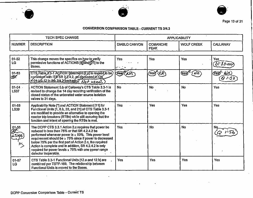
I~ ~ ~, ~
~ Q ~ e o ~ ~ ' ~ '
~ ~ ~ 0 ~
~ ~ ef) ~ ~
~ ~ ~
I ~
I ~ ~ ~
~ ~ ~ ~
~ ~ ~ ~ ~ ~ ~ ~
~ ~ ~ ~ ~
~ ~ I . ~
~ ~ ~ ~ ~ ~ ~ ~ ~ ~ ~
~ ~
~ ~ ~ ~
I ~ ~ ~ 0 ~ ~ ~ ~
~ ~ ~
~ ~ ~ ~ ~ ~
~ ~ ~ ~ ~
~ ~
~ ~
~ ~
~ ~ ~
~ ~ ~ ~ ~ ~ ~
~ ~ ~ ~
~ I ~ ~ ~ ~
/ ~ ~ ~ ~ ~
~ ~- ~ ~ ~ . ~ . ~

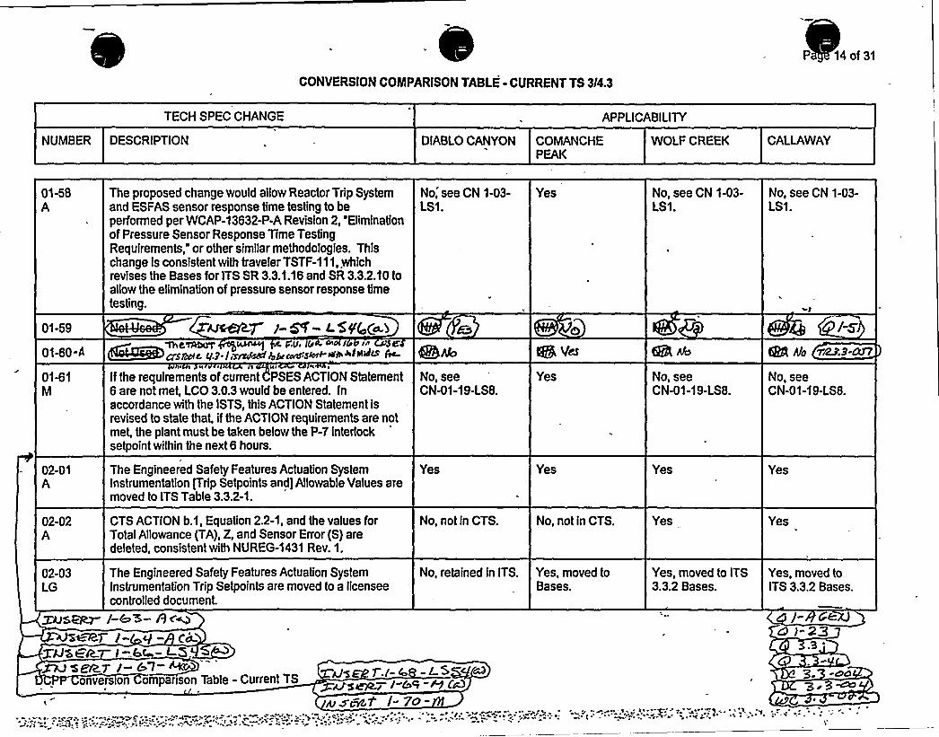
CONVERSION COMPARISON TABLE- CURRENT TS 3/4.3
P 14of31
TECH SPEC CHANGE APPLICABILITY
NUMBER DESCRIPTION OIABLOCANYON COMANCHEPEAK
WOLF CREEK CALLAWAY
01-58A
01-59
0140-4
01-61M
02-01A
02-02A
02-03LG
The proposed change would allow Reactor Trip Systemand ESFAS sensor response time testing to beperformed per WCAP-1 3632-P-A Revision 2, "Eliminationof Pressure Sensor Response Time TestingRequirements, or other similar methodologfes. Thischange is consfstent with traveler TSTF-111, whichrevises the Bases for ITS SR 3.3.1.16 and SR 3.3.2.10 toallow the elimination of pressure sensor response timetesting.
AJAR j-~ - L. 5 fQ(e.bme~ ~ v.v. r
asr~e q.g-farahcd 4b ~:s~+»w™~~ 6
Ifthe requirements of current PSES ACTION Statement6 are not met, LCO 3.0.3 would be entered. Inaccordance with the ISTS, this ACTION Statement isrevised to state that, ifthe ACTION requirements are notmet, the plant must be taken below the P-7 interlocksetpoint within the next 6 hours.
The Engineered Safety Features Actuation Systeminstrumentation tTrfp Setpoints and] Allowable Values aremoved to ITS Table 3.3.2-1.
CTS ACTION b.1, Equation 2.2-1, and the values forTotal Allowance (TA), Z, and Sensor Error (S) aredeleted, consistent with NUREG-1431 Rev. 1.
The Engineered Safety Features Actuation Systeminstrumentation Trip Setpoints are moved to a licenseecontrolled document.
No, see CN 1-03-LS1.
No, seeCN-01-19-LS8.
Yes
No, not fn CTS.
No, retained in ITS.
Yes
Yes
Yes
No, not in CTS.
Yes, moved toBases.
No, see CN 1-03-LS1.
No, seeCN-01-1 9-LS8.
Yes
Yes .
Yes, moved to ITS3.3.2 Bases.
No, see CN 1-03-LS1.
(HE Afo ~8-N7No, seeCN-01-19-LS8.
Yes
Yes
Yes, moved toITS 3.3.2 Bases.
Zns~ /-c 5-R<m
XAISGR. l=6c - L5,~ Z~> i-b;l- %auonvers on Companson Table -'urrent TS ~MS' &
e~nct /-7o-


Enclosure 3B page 14Insert 1-68/69a
Attachment 2PG&E Letter DCL-98-167
Insert for DC 3.3-004
01-68LS54
This ch ge del es DCPP TS Tab! 4.3-1 n e(8) w chisa licablet esourc range. ev 'icatio annotbe erforme 'OD *,4*,
nd 5* 'e,the p erandi rmediat angcha els are n required t e oper e uM E2.
I
eeal N/x a N/0
01-69 his change applies new note (20) to DCPP CTSM able 4.3-1 function 6, source ran e neutron flux.
tec1 k5W!
e,ee
al
8-54.
N+

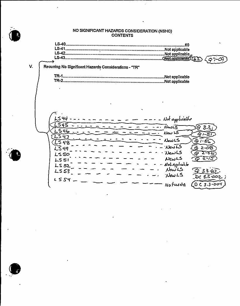
NO SIGNIFICANTHAZARDS CONSIDERATION (NSHC)CONTENTS
L$40.LS-41.LS-42LS-43.
Recurring No Significant Hazards Considerations -'TR
TR-1 . ..........TR-2
.........................60......Not applicable
.Not applicable
Not applicableNot applicable


h
Enclosure 4Insert NSHC LS54
Attachment 2PG&E Letter DCL-98-167
Insert for DC 3.3-004
NSHC LS5410 CFR 50.92 EVALUATION
FORTECHNICALCHANGES THAT IMPOSE LESS RESTRICTIVE
REQUIREMENTS WITHINTHE TECHNICALSPECIFICATION
The CTS 'able 4.3-1 specifies via note (8) that during the Channel Opera)ional Test for thesource ran neutron monitors in MODE 3, 4, and 5, when the Control Ro Drive System iscapable of ro withdrawal or all rods are not inserted, that the P-6 and P- 0 interlocks beveriTied in their equired state. Since P-6 and P-10 are initiated by the wer and intermediaterange neutron fl detectors and they are not required to be OPERA E until MODE 2, the onlyveriTication that ca be performed is to verify that the lights are not i I minated. This is therequired state for th interlocks under these conditions, but does t provide any usefulinformation to the ope tor or technician. Therefore, note (8) is eleted and new note (20) isinserted by DOC 1-69-
The proposed TS change qs been evaluated and it has b n determined that it involves nosignificant hazards consideration. This determination has een performed in accordance withthe criteria set forth in 10 CFR 0.92(c) as quoted belo
The Commission may ma a final detennin ion, pursuant to the proceduresin 50.91,that a proposed amendmen o an operatin license for a facilitylicensed under 50.21(b)or 50.22 or for a testing facilit nvolves n significant hazards consideration, ifoperationof the facilityinaccordance with the pro sed amendment would not:
1. Involve a significantincrease 'he probability or consequences ofan accidentpreviously evaluated; or
2. Create the possibi%ty of ew or different kind ofaccident from any accidentpreviously evaluated; or
3. Involve a significant eduction in a ma i ofsafety."
The following evaluation is pro ided for the three categon s of the significa'nt hazardsconsideration standards:
Does the change 'olve a significant increase in the pr ability or consequences of anaccident previo ly evaluated?
The deletio f note (8) does not change the manner in which (he plant is operated orthe way in hich the surveillance tests are performed. Overall protection systemperform ce will remain within the bounds of the previously performed accidentanalys s since no hardware changes are proposed. The proposed% ange will notaffec he probability of any event initiators nor will the proposed chang affect the abilityof y safety-related equipment to perform its intended function. There
'be no
d radation in the performance of nor an increase in the number of challen s imposedn safety-related equipment assumed to function during an accident situation.


Attachment 2PGSE Letter DCL-98-167
2.
3.
Therefore, the proposed change does not involve a significant increase in th robabilityor consequences of an accident previously evaluated.
D s the change create the possibility of a new or different kind of cident from anyacci nt previously evaluated?
There are o hardware changes nor are there any change in the method by which anysafety-relate lant system performs its safety function e proposed deletion of note(8) which provi no useful information, has no effe on the types of accidentsassumed to occur. o new accident scenarios, t nsient precursors, failuremechanisms, or limiti single failures are intro ced as a result of this change.Therefore, the proposed ange does not cr te the possibility of a new or different kindof accident from any previo ly evaluated
Does this change involve a signi i reduction in a margin of safety?
The proposed change does not ect t acceptance criteria for any analyzed event.Since there are no safety an sis limits a ociated with this trip function, the allowedvalue change does not re ce the margin o afety. There will be no effect on themanner in which safety 'ts or limiting safety stem settings are determined nor willthere be any effect o ose plant systems neces ry to assure the accomplishment ofprotection function There will be no impact on any argin of safety.
' NO S NIFICANTHAZARDS CONSIDERATION DE MINATION
Based on the ove evaluation, it is concluded that the activities associate with NSHC "LS54"resulting fro the conversion to the improved TS format satisfy the NSHC st dards of10 CFR 5 .92(c); and accordingly, a NSHC finding is justified.


RTS Instrumentation3.3.1
SURVEILLANCE REQUIREMENTS (continued)
SURVEILLANCE FREQUENCY
SR 3.3.1.4 -NOTE- ---This Surveillance must be performed on thereactor trip bypass breaker.'>.,for<th2e$ 'loca:I::@nual';.':.'shuritg.trip.',:.'onl'y,-;; pri or"'t'o""plac'i'n*g'hebypaTs breaker in"ser'v'ice.
3.3424
Perform TADOT. 31 days on aSTAGGERED TESTBASIS
SR 3.3.1.5 Perform ACTUATION LOGIC TEST. 31 days on aSTAGGERED TESTBASIS
hours
Calibrate excore channels to agree with incoredetector measurements.
SR 3.3.1.6 -NOTE---------Not re uired to be erformed untilafterTHERMA m > SQ"75K"RTP.
""'"""
B
3.3-06
P8 B c).hg-
941 EFPD
SR 3.3.1.7 -NOTE:.; Not requi red to be performed for source
range instrumentation prior to entering MODE
3 from MODE 2 until 4 hours after entry intoMODE 3.
g~',Fo)": so8rc:ey: n.e.:ge ~mgr! ometoa i 1~no-.':,:,thi',,~
su'rveijlil.iiice.@'ha"':.I::;I::".'".':,iiic.:.l.'iide;.:4v'e'r'i',fi'iat~~n>that'nte'r'loekij::P,,=':8',:ap'd~!P.,"-"'.10,'Are.eon:,::,thes~v,'.::."":r"; 'k''e'd, So@ate,~~efOr,"'i'e'Xi'Stjjg'","4.u'ii'i::t",3C'Om'audit'i'Opd",- --'=:—=-
Perform COT.
92 day 8s
(continued)
DCPP Mark-up of NUREG-1431. Rev. 1 3.3-14

0

BASES
RTS InstrumentationB 3.3.1
SURVEILLANCE SR 3.3.1.6 (continued) inset 5 g, 3,3 1.4. 3a'5-l7REQUIREMENTS
A Note modifies SR 3.3. 1. . The Note states that this Surveillanceis required only if rea or ower is > SQ 78t RTP d that
hours aii:e>rs.......,":,therma i~~ as
~+> ~ i7SKWRTPFi af1'= - orming'the-'rst survei anc'f
e. '5+t4"~4cuv cffltc. os+
The Frequency of 92 E a eq e. It is base on industry'perating experience, considering instrument reliability and
operating history data for instrument drift.SR 3.3.1.7
SR 3.3.1.7 is the performance of a COT every gR days.
A COT is performed on each required channel to ensure the entirechannel will perform the intended Function.
Setpoints must be within the Allowable Values specified inTable 3.3.1-1.
~~assyL 6 t C usa> pc, pg;ao5
c /1',-A@2
S R 3.3.1.7 is modified by" ""
....,. ote:': provides a 4hour delay in the requirem'en o per orm this Survei'llance fot
. source range instrumentation when entering NODE 3 from NODE 2. ThisNote allows a normal shutdown to proceed without a delay fortesting in MODE 2 and for a short time in NODE 3 until the RTBs areopen and SR 3.3.1.7 is no longer required to be performed. If theunit is to be in NODE 3 with the RTBs closed for > 4 hours thisSurveill nce must erformed rior to 4 hours after entr into
o ,: Lra ires:.. a.":,;. . ~ua, er: y ,,::.;, ,;;. ey urce ;angeAS,„,:,, 04'f0,48;-:.I"'„> OC'I', „;,'.vclp: ...,clti, gb9:::l9, crtIata,,On J'Of''-'he
ocf .e'd~"',. fss1": ~piiji ", ato'j'ibid '' that"'', )gP,'-" .''aan'd;:~:.90.
, nt8, OCggg',Mjn":. ',. 8iTgi .eILif.',::t$% ig'Of!:,( ekggl '3n9"':>: m >s ' se 's s ':~xc c VAwcl4N cAkw > > -w e e 44cvc % ~r.> .4vh 'KL
The Frequency of f923 days is justified in Reference 7.
~nP~7
(continued)
DCPP Mark-up of NUREG-1431, Rev. 1 Bases 8 3.3-57


Attachment B
PG8 E Letter DCL-99-063
Enclosure 5B page B 3.3-57Insert SR 3.3.1.7
Insert for DC 3.3-004
Ifthis surveillance or ifSR 3.3.1.8 has been performed within the previous 92 days, therequirements of this surveillance are satisfied.


BASES
RTS Instrumentation8 3.3.1
SURVEILLANCEREQUIREMENTS
(continued
SR 3.3.1.8 S7tw
) SR 3.3. 1. s the performance of as described in SR 3.3. 1.7it is modified b .; Note that this test shall.b"~inc u veri ica ion a e P'- and P-10 interlocks are in their--required state for the existing unit conditions'.-';bj"..Rseriiati'on;ofthe>associated',;peimissi.ve='.,':annunciatory'indow. "The Fr'equency "is
'odifi'ed"bya"Note that aTlows "th'i's su'rveil'lance to be satisfied ifit has been performed within 9Z days of the Frequencies prior toreactor startup.,''::<g,"-'',ho@i.',s'=':aft'ei'.,",:.reducin'g; p~j~bel'ow,':Pg0:;. and fourhours after reducing power"below P:4()-'aid"P"-6,',ka's.'.;>'discussed.'"below;The Frequency of "prior to startup" ensures this surveillance is
"'erformedprior to critical operations and applies to the source.intermediate and power range low instrument channels. The Frequencyof =4 ~'12 hours after reducing power below P-10" (applicable tointermedi'ate and power range low channels) and "4 hours afterreducing power below P-6" (applicable to source range channels)allows a normal shutdown to be completed and the unit removed from
. the MODE of Applicability for this surveillance without a delay toperform the testing required by this surveillance. The Frequency ofevery 92 days thereafter applies if the plant remains in the MODE ofApplicability after the initial performances of prior to reactorstartup, X2',:.houri~$7ter,-.':::redvHvg:,.',.poYver'.":-:bQe.:m','.P,.::KQ> and four hours
for this surveillance is < P-10 for the power range low andintermediate range channels and < P-6 for the source range channels.Once the unit is in MODE 3. this surveillance is no longer required.If power is to be maintained < P-10 fo~Ã'Norehthan'~1Z:;hours or < P-6for more than 4 hours. then the testing required by tiessurveillance must be performed prior to the expiration of the12:ihour.;,,;or 4 ho r limit>;-'as::.a p3::fcablq".::
'7hese:.bme"":-'.l,im'its.:"iiv~reaso)able:."'-'„.'~based@n~operatingexperjiiiice:.'"to"'coiiipTete the requi"red testing or place. the-unit in aHODE where this surveillance is no longer required. This testensures that the NIS source, intermediate. and power range lowchannels are OPERABLE prior to taking the reactor critical and afterreducing power into the applicable MODE (< P-10 or < P-6) for theperiods di'scussed '.ahois',::'-heurs-.
SR 3.3.1.9
SR 3.3.1.9 is the performance of a TADOT and is performed everyf923 days. as justified in Reference 7.
(continued)
DCPP Hark-up of NUREG-1431. Rev. 1 Bases B 3.3-58

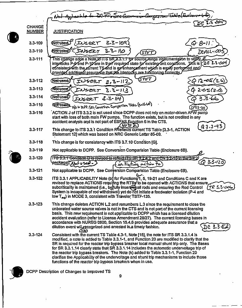
CHANGENUMBER
3.3-109
3.3-110
3.3-111
3.3-112
3.3-113
3.3-114
3.3-115
3.3-'l16
3.3-117
3.3-118
3.3-119
3.3-120
3.3-121
3.3-122
3.3-123
3.3-124
JUSTIFICATION~ xur,eRT.Z.Z-)5%K.E- lip ~-p
@ 8-i):
his c ge ad a Note ... source nge in mentgNn to veint cks P nd P-1 re in th requir state f existin nit co f6ons. is is
nsiste th the rrent T nd is enhan ent 's e 'erfo ed arovi additi
~ %~~Mr g,a-ll 2 '.~C~.4)Q 2~zfp.ob
EA3(rER-T 8 ~5 IJ f CP 3A-~~~ii)I~MI.~4 wow Ce ~'~"~ ~
Cp~,>.»,
ACTION J of ITS 3.3.2 is not used since DCPP does not rely on motorMriven AFW pumpstart with loss of both main FW pumps. The function exists, but is not credited in anyaccident analysis agd is not part of ESF on 6 in the CTS.
h/c R Q 3 3-'f3This change to ITS 3.3.1 Condition R reflects current TS Table [3.3-1, ACTIONStatement 12) which was based on NRC Generic Letter 85-09.
This change is for consistency with ITS 3.7.10 Condition [G),
Not applicable to DCPP. See Conversion Comparision Table (Enclosure 6B).
8e 8 8-IZO
Not applicable to DCPP. See Con ersion Comparision Table (Enclosure 6B).
ITS 3.3.1 APPLICABILITYNote (b for Function 1, 6, 19-21 and Conditions C and Karerevised to replace ACTIONS requi 'ng the RTB to be opened with ACTIONS that ensuresubcriticality is maintained (i.e., by fully inse all rods and ensuring the Rod Control TR 5-5-~System is incapable of rod withdrawal) yet do not initiate a feedwater isolation (PA andlowT~) in hhODE 3, consistent with Traveler TSTF-135.
This change deletes ACTION L2 and renumbers L.3 since the requirement to close theunborated water source valves is not in the CTS and is not part of the current licensingbasis. This new requirement is not applicable to DCPP which has a licensed dilutionaccident evaluation (refer to License Amendment 28/27). The current licensing bases inaccordance with NUREG 0800, Section 15.4.6 provides adequate assurance that adilution event will ecognized and arrested isa timely fashion. e E,3MConsistent with the current TS Table 4.3-1, Note [16), the note for ITS SR 3.3.1.4 ismodified, a note is added to Table 3.3.1-1, and Function 20 are modified to clarify that theSR is required for the reactor trip bypass breaker local manual shunt trip only. The Basesfor SR 3.3.1.14 clearly state that SR 3.3.1.14 includes the automatic undervoltage trip ofthe reactor trip bypass breakers. The Note (k) added to Table 3.3.1-1, Function 20clarifies the Applicabilityof the undervoltage and shunt trip mechanisms to include thosefunctions of the reactor trip bypass breakers when in use.
DCPP Description of Changes to Improved TS


CONVERSION COMPARISON TABLEFOR DIFFERENCES FROM NUREG-1431, SECTION 3.3 Page 17 of 21
NUMBER
TECHNICALSPECIFICATION CHANGE
DESCRIPTION
APPLICABILITY
DIABLOCANYON COMANCHE PEAK WOLF CREEK CALLAWAY
3.3-103
3.3-104
3.3-105
3.3-106
3.3-107
3.3-108
3.3-109
3.3-110
3.3-111
3.3-112
3.3-113
3.3-114
Function 11 of ITS Table 3.3.1-1 is revised per the DCPPCTS to reflect the current plant design of only a two loop trip.With this revision Condition 0 is no longer used, since itwasonly applicable to the single loop trip.
CONDITIONAof ITS 3.3.5 is revised to incorporate CTSACTIONS 15 and 16. CONDITIONS B and C are not used.
Function 4.d.(2) of ITS Table 3.3.2-1 and notes (c) and (h)are revised per the DCPP CTS.
Delete ISTS Required Actions B.2.2 and U.2.2. TheseRequired Actions are not needed due to exiting theAPPLICABILITYvia Required Actions B.2.1 and U.2.1.
Based upon operating experience to change Thermal Powerin a controlled fession without challenging the plant and
'onsistentwith the CTS which does not have a CompletiohTime for restoring one channel to OPERABLE ststus; butdoes pervent going above P-10 until it is restored, the,Completion Time for ITS 3.3.1 Required Actions F.1 and F.2should be increased to 24 hours.
+le&sad-. M~~i Z-9W~~~g F.Z- JD
Add a Note to ITS SR 3.3.1.7 for source rangeinstrumentation to verify interlocks P-6 and P-10 are in theirrequired state for existing unit conditions. This is consistentwith the CTS.
W 8-j/Z(~~~>.ee.r 8 P-)1 3cQgams'~ Z. S ™IIg <~g
Yes
Yes
Yes
Yes
Yes
No, see CN 3.3-131.
No, see CN 3.3-12.
Yes
Yes
Yes
No
No, see CN3.3-99.
No, see CN3.3-12.
Yes
Yes
No-see CN 3.3-48.
No, see CN3.3-99.
No, see CN,3 3-12.
Yes
Yes
pe-
Yes Q8 A3
/ZM
DCPP Conversion Comparison Table - Improved TS

I

Attachment 8PG8 E Letter DCL-99-063
ADDITIONALINFORMATIONCOVER SHEET
ADDITIONALINFORMATIONNO: DC 3.3-006 (new) APPLICABILITY: DC
REQUEST: Revise Table 3.3.1-1 and Table 3.3.2-1 to re-label the "Trip Setpoint" columnas the "Nominal Trip Setpoint" colum'. Assign new Note "a" the Nominal Trip Setpointcolumn of Table 3.3.1-1 and Table 3.3.2-1. Place Note "a" at the bottom of each page.Note "a" reads:
A channel is OPERABLE with an actual Trip Setpoint value outside its calibrationtolerance band provided the Trip Setpoint value is conservative with respect to itsassociated Allowable Value and the channel is re-adjusted to within the establishedcalibration tolerance band of the Nominal Trip Setpoint. A Trip Setpoint may be setmore conservative than the Nominal Trip Setpoint as necessary in response to plantconditions.
This Note is consistent with the Westinghouse methodology for Trip Setpoints. JFD 3.3-147has been added which reads:
The Trip Setpoint column has been re-labeled to read "Nominal Trip Setpoint." Note "a"has been added to interpret the values provided. The Note reads; "Achannel isOPERABLE with an actual Trip Setpoint value outside its calibration tolerance bandprovided the Trip Setpoint value is conservative with respect to its associated AllowableValue and the channel is re-adjusted to within the established calibration tolerance bandof the Nominal Trip Setpoint. A Trip Setpoint may be set more conservative than theNominal Trip Setpoint as necessary in response to plant conditions."
ATTACHED PAGES:
Encl. 5A
Encl. 5BEncl. 6AEncl. 6B
3.3-18, 3.3-20, 3.3-21, 3.3-22, 3.3-23, 3.3-24, 3.3-25, 3.3-26, 3.3-39, 3.3-40,3.3-41, 3.3-42, 3.3-43, 3.3~, 3.3C6, 3.3<7, 3.3<8, 3.3Q9, 3.3-50, 3.3-51B 3.3-4, B 3.3-67, B 3.3-681021


Table 3.3.1-1 (page 1 of 810)Reactor Trip System Instrumentation
RTS Instrumentation3.3.1
D 3. $- 04m
FUNCTION
APPLICABLEMODES OR OTHER
SPECIFIED REOUIREDCONDITIONS CHANNELS CONDITIONS
3.3 j'l-7O,
SURVEILLANCE ALLOWABLE TRIPREOUIREMENTS VALUE SETPOINM
1. Manual ReactorTl ip
2. Power RangeNeutron Flux
a. High
b. Low
1.2
3at) 4(b) 5((t)
1.2
1(c) 2
SR 3.3.1.14
SR 3.3.1.14
SR 3.3.1.1SR 3.3.1.2SR 3.3.1.7SR 3.3 .11
sk 9,3.),lt'R
3.3.1.8S
5%3.8,), lh
NA ~tbp
lI69C RTP
0 rij(Iu= 5]Id
x.a-S'S'5K
RTP
bt Bu~
h
3. Power RangeNeutron FluxRate
a. High.PositiveRate
b. HighNegativeRate
1.2
1.2
h
SR 3.3.1.7SR 3.3.1.11
SR 3.3.1.7SR 3.3
SCs 3 I I
"w'i'tRTPtime
constant«g sec
5RTP
wl lmeconstantL R sec
B-PS
3C /LE-oo
ith timeconstanti(2,'sec
54 RTPwith timeconstant
cau
~S'.
IntermediateRange NeutronFlux
1(c) 2(N FsG SR 3.3.1.1SR 3.3.1.8 ""'-. P~ (T Ar.r-~5SR 3.3.1.11 ~>< B-PS
3.3-95
- r)c) c
a. A channel is OPERABLE with an actual Trip Setpoint value outside its calibration tolerance band provided the rip Setpoint
valve is conservative with respect to Its associated Allowable Valve and the channel ls re ad foaled to within the established
calibre lion tolerance band of Ihe Nomin st Trip selpolnb A Trip selpoint may bs set more cense Native than the Nominal Tr'm bt
Setpoint as necessary in response to plant conditions.
(b) wNh Rod Control System capable of rod withdrawal."or:,~+rods,".,riot";.fUI:..y.":,Qseited.
c))hie c)r H 7 e S,S-ceoOCPP ar -u of REG-1431, Rev. 1 3.3-18


Table 3.3.1-1 (page 2 of 810)Reactor Trip System Instrumen'tation
RTS Instrumentation3.3.1
PC. 3,3 ~&Is
c)nttrala ( Cct
FUNCTION
APPLICABLEMODES OR
OTHERSPECIFIED
CONDITIONSREQUIREDCHANNELS
TRI8 3-IV7
SETSURVEILLANCE ALLOWABLE POI
CONDITIONS REQUIREMENTS VALUE N7
5. Source RangeNeutron Flux
2(e)
3((s) 4(is) 5(h)
3(f) 4(f) 5(f)
SR 3.3.1.1SR 3.3.1.8SR 3.3.1
SR 3.3.1.1—SR 3.3.1.7SR 3.3.1.11
SR 3.3.1.1SR 3.3.1.11
W~p'4bKScps
Pl'-.":4".„-:,IcfpsS
N/A
3.0-b O
gz r-rrs1YO'~Q
'cps '"
Q )noill'h'5
4iRndrir.
e)T Ks5--'/A
6. Overtemperature hT 1,2 SR 3.3.1.1SR 3.3.1.3SR 3.3.1.6SR 3.3.1.7S 3.3.1.& 1l)
<8.S.I I(o
Refer toNote 1
(Page3.3-244)
Refer toNote 1
(Page3.3-244)
3.3-10'l
7. Overpower hT 1.2 SR 3.3.1.1SR 3.3.1.7SR 3.3.1.& i6
W 3.3.l l(o
Refer toNote 2(Page
3.3-2et5)
Refer toNote 2(Page
3.3-23-5)
3.3-101
L)C Sd8 oQ(a A channel h OPERABLE viith an actual Trip Setpoint value outside its calibration tolerance band provided the Trip Setpoint
value is conservative with respect to its assochted Allowable value and the channel is re-adjusted to within the established ~ued)
c Seipoint as necessa(y in response to plant conditions. S. "I 7\ y ~
ED~r Mo~ R K.j-dP&
(b) With od Control System capable of rod withdrawalRor~'{Pp ro'ds'p'hoL(:fuI)yTnsert'e'd.
(e) Below the P-6 ( Intermediate Range Neutron Flux) interlocks.
ii> Rite the RTRS OPen ~O".:, (;,:RTr~nfdale))iiici 'edr". teSaendnseoeb1ete'rn'If(So'drerdt1. In thiS CnnditiOn. SOurCerange Function does not p'r'ovtde reactor trtip"but do'es provide
indication. B-PS
DCPP Hark-up of NUREG-1431. Rev. 1 3.3-20


Table 3r3.1-1 (page 3 of 810)Reactor Trip System Instrumen't'ation
RTS Instrumentation3.3.1
t)('.3-octa
FUNCTION
8. PressurizerPressure
a.Lorr
APPI.ICABLE HOOESOR OTHERSPECIFIEO
CONDITIONSREQUIREDCHANNELS
1(g) " mg;",.gg
B-PS
iy Ru-)W).5
~>:F50 psigsig
%38S
SR 3.3.1.1SR 3.3.1.7
3.1.1
s, Z-lr7 ED
Namtw+r rgSURVEILLANCE ALLOMABLE
CONDITIONS REQUIREHENTS VALUE SETPOIN~
b. High
9. PressurizerMaterLevel —High
1.2
1(g)
$ 43 3I l.
SR 3.3.1.7SR 3.3.1
I3.3r I iih.3.1.
SR 3.3.1.7SR 3.3.1.10
psig
Spsfg Q 'S.'L-SS
AS'7.6
o Au~
10. Reactor Coolant Q'F~r'tilFlaw - Low
P~v~~~ SC@N "FiiSR."r'.3.'O',,X";"'7,
.SR".::::LO
SY3.3 lr f(
$ R '~o HHF Ice(
B-
3.349P 3.~oL
3.342
a. A channel ts OPERABLE with an actual Trip Setpoint value outside its calibration tolerance band provided the Trip Setpolnt ttinued)value ts conservative with respect to its associated Allowable Value and the channel is re-adjusted to within the establishedcalibration tolerance band of the Nominal Trip Setpolnt. ATrip Setpoint may be set more conservative than the Nomina Tdp ~Setpoint as necessary in response to plant conditions.
~tVWJ~uae ~ ~ ~ ~ 4 $ r 7(g) Above the P-7 (Low Power Reactor Trips Block) interlock.
3.$ 42
3.3-42
M Z-'E. 4'Ail"8»::':.i$4I'""-:,::,,':! "I"~I"::I:"
OCPP Mark-up of NUREG-1431. Rev. 1 3.3-21


Table 3.3.1-1 (page 4 of-SIO)Reactor Trip System Instrumentation
RTS Instrumentation3.3.1
FUNCTION
0 '3. 3-0~ EoAPPLICABLE HXES
OR OTHER ~3.9-IV NeeaiaaaL(agSPEC I FIED REOUI RED SURVEILLANCE ALLOWABLE TRI
CONDITIONS CHANNELS CONDITIONS REOUI RBKNTS VALUE SETPOI NP
ll. Reactor CoolantPump (RCP)Breaker Position SR 33.".3"."1'; 14
3.3-103
~K.-.:NAe ah4VAAAl
w~eps
12. UndervoltageRCPs
1(g) ~2 perbOs
SR 3.3.1.9SR 3.3.1.10
gg,g,)PIG
B.PS
S
f4903.. V- ~,'8050 „,V.-",.
heach'hhs Ieaeachah'Caa
ch 3.3 SS
13. Underfrequency l(g)RCPs
$ , 56 P)fh~LCOu.L- LOS ).O4P 'fAIPP Dna(f %et A P~Q)
:3:per bus SR 3.3.1.9SR 3.3.1.10
8'tt8,S-I N
:,',%:9 Hz- A.'."each;bus r .,',54".0 Hz-
"eac '.! us
B.PS
14. SteamGenerator (SG)Water Level - LmLow
P e
b) 'S Loo'.~Tequiv ent:to
ower '.SorTP,th no
ti delay.
1.2
l-'2
4( looj3
SR 3.3.1.1SR 3.3.1.7SR 3.3.1.10
,IGNI,RTP
';0 "fO:> Hote„'3)'
SR'.3: .1'7SR 3'.1;10
V
RCS3loop~T,'.variable
ut"»
sn.~e~cZDD-,D
K.g.g,lelh Tn)SR."'D3.a3;"''I"':at
W:,,RCS:"1oY7j'i'RlS.'3:-3."
10 Miriable-"-:;;in a~4
GO-
~h QAK, /g
RCS;.:loops T'„-svari'able'"'Input'.wSOr
~~-'.TD".{Note""3)""""'"
a RCS" 1 o'op'iT''.variable',
",input'.>-SOZ',RTP
TD<
0"PP Nark-up of NUREG-1431. Rev. 1 3.3-22


RTS Instrumentation3.3.1
FUNCTION
APPLICABLE HODESOR OTHERSPECIFIED 'EOUIRED
CONDITIONS CHANNELS CONDITIONS
OC > ->oC'o'F.Z"lrr AIONLbaALE AT
SURVEILLANCE ALLOWABLE TRIPREQUIREHENTS VALUE SETPOINM
15. If|iT,:P058)
he~-hew
ZR 'k4-.4-4' '~
$R 'I 'I-.I-.I()$A 'I '44-.44
D('„8 3 -Oot'o
a. A channel is OPERABLE with an actual Trip Setpoint value outside its calibration tolerance band provided the Trip Selpointvalue ls conservative with respect to its associated Allowable Value and the channel is re-adjusted to within the establishedcalibration tolerance band of the Nominal Trip Selpoint. A Trip Setpoint may be set more conservative than the Nominal Trip 44Setpoint as necessary in response to plant conditions. 8 3-lY7
(g) Above the P-7 (Lm PoEAter Reactor Trips Block) interlock.
3.3-103
3.3-103
ED
DCPP Hark-up of NUREG-1431, Rev. 1 3.3-23

0

Table 3.3.1-1 (pag~ of&16)Reactor Trip System Instrumentation
RTS Instrumentation3.3.1
L)(: 3. $ - 6OC
FUNCTION
APPLICABLE MODESOR OTHERSPECIFIEO REQUIRED
CONDITIONS CHANNELS
Z. Z-JV7
SURVEILLANCE ALLOAABLECONDITIONS REQUIREHENTS VALUE
ED
TRIPSETPOINM
16. Turbine Trip
a. Low pv44'Aito-',St'op OilPressu're
'.
Turbine StopValve Closure
17. SafetyInjection (SI )Input fromEngineered SafetyFeature ActuationSystem (ESFAS)
1;2 2 trains
0 SR 3.3.1.10SR 3.3.1.15
SR 3.3;1.10SR 3.3.1.15
SR 3.3.1.14
eK PS
q B.8~28@9 -,j
ps'1 psig~s~z, ~ e
~ P open
NA
DCPP Mark-up of NUREG-1433., Rev. 1 3.3-24


FUNCTION
APPLICABLE NODESOR OTHER
SPEC IF IED REQUIREDCONDITIONS CHANNELS
3
RTS Instrumentation3 3.1C. ~ 3-04
X 3-I'I EoWont>~h Cct,
SURVEILLANCE 'LLIABLE TRIPCONDITIONS R EQUI RENE NTS VALUE SETPOINT
18. Reactor TripSystem Interlocks
a. IntensediateRange NeutronFlux. P-6
b. Low PowerReactor TripsBlock. P-7
c. Power RangeNeutron Flux.P-8
d. Power RangeNeutron Flux.
P-9'.
Power RangeNeutron Flux.P-10
2(e)
g4ukc~f
1.2
1 pertrain
SR 3.3.1.11SR 3.3.1.13
3.5, I.58~~
Qc ALt:~i!11 amp g'1E-„tll amp
3.3-54
g 9 8 "5f
SR 3.3.1.11SR 3.3.1.13
SR 3.3.1.11SR 3.3.1:13
SR 3.3.1.11SR 3.3.1.13
BPS
c Qu.~RT 449 SSZ
TP'"
Q gg+Lf B-PS
B
5Chu-oc S
gP BOZ RTP
B-PS
B
tee~4%4~
I)c hu.RTP ,
3mm '~uSRTPRTP
))2 B
SPSPS
0;2 C M-RSss
MINIII'PSW turbine
u iri"e power-3
QR-3 '~SR 3.3.1.10 sSR 3.3.1.13f. Turbine
ImpulseLhaiib'er'.P'res's'ureP-13
:~:.)mpu,1 Ke„'„'pressUre
jeqi'i~ vai'entgyressurse,'equ'iv'a Tent
a. A channel is OPERABLE with an actual Trip Setpoint value outskle its calibration tolerance band provided the Trip Setpoint
calibration tovalue ts conservative with respect to its associated Allowable Value and the channel is re-ad'usted to withi th tabl'ed
olerance band of the Nominal Trip Setpolnt. ATrip Setpoint may be set more conservative than the Nominal TripSetpoint as necessary in response to plant conditions. 8 8-IY(e) Below the P-6 (Intermediate Range Neutron Flux) interlocks.
I)(: S. -oc c(j) Above the P-9 (Power Range Neutron Flux) interlock.
DCPP Nark-up of NUREG-1431, Rev. 1 3.3-25


Table 3.3.1-1 (page-t)8 of 81O)Reactor Trip System Instrumentation
RTS Instrumentation3.3.1
g(',3-0o(o
FUNCTION
APPLICABLE MODES g T-IV7OR OTHER Npdrr serb (tb
SPEC IF IEO REQUIRED SURVEILt.ANCE ALLO(iABLECONDITIONS CHANNELS CONDITIONS REQUIREHENTS VALUE SETPOINM
Breakers~~~
20. Reactor TripBreakerUndervoltage andShunt TripNechanlsms~~
21.. Automatic TripLogic
1.2
3(b) 4(D) 5(D)
1.2
3((t) 4((t) 5((t)
1.2
3((t) 4((t) 5((t)
2 trains
2 trains
1 eachper RTB
1 eachper RTB
2 trains
2 trains
~ SR 3.3.1.4
SR 3.3.1.4
SR 3.3.1.4
SR 3.3.1.4
SR 3.3.1.5
SR 3.3.1.5
3.3-124
NA
"NNA
N NA
NA A78 8 5 (o(ot=b
NA NA ~
3.M5
""'""'lr'r":: ii'i:i"":: aMeitM.(k) Including any reactor trip bypass breakers that are racked in and closed for bypassing an RTB.
I.'2~':.".dSBTSMP~TNJa";-';:P.. K=:"> SR='>."3N>2 K» ".'.
3:.O-'.":P<'5'jI.)t'Aj~) . Q f P)tt~
. ing„ iyC.g,b-OOfcb
lK@tfaae~, A obannst b ppbjtdtttA Wdh an arduat Trip Sebwint value outside ha calibration tolerance band provi ho Trip de&~
vs ills ls c'ones rvativs with nwperd ta lls associated Allowable Value and tha channel Is re adjusted to within the established
calibration tolerance band of the Nominal Trip Setpolnt. ATrip Setpoint may be set more conservative inal rip
Setpoint as necessary in response to plant conditions. EOore or- furore, 7g 83~4
.3-122
DCPP Nark-up of NUREG-1431, Rev. 1 3.3-26

0

ESFAS Instrumentation3.3.2
Table 3.3.2-1 (page 1 of SQ)Engineered Safety Feature Actuation System Instrumentation
FUNCTION
APPLICABLEHODES OR.
OTHERSPEC IF IEO
CONDITIONS
g g (tf ED
Qoa4)ul(. cLREQUIRED SURVEILLANCE AI.LOMABLE TRIPCHANNELS CONDITIONS REQUIREMENTS VALUE SETPOINM
l. Safety Injection
a. HanualInitiation
b. AutomaticActuation Logicand ActuationRelays
1.2.3.'4
1.2.3.4 2 trains
SR 3.3.2.8
SR 3.3.2.2SR 3.3.2.4SR 3.3.2.6
NA ~
c. ContainmentPressure —High
d. PressurizerPressure —Low
1.2.3-,4
1.2.3<" m II
SR 3.3.2.1SR 3.3.2.5S 3.3.2
5g 3,3, F3(O
SR 3.3.2.1SR 3.3.2.5SR 3.3.2.9
Sg g.3.3,.)t)
3.3363.P3
sslg
)p 2 IDYLL-~5
ps4 ae~u~
~~3<B- S
e. Steam LinePressure
(I)Low
<2>t.':"::6%5
Q44evea~
Qe&eeaCleaves
1.2, ~ 3 per
(b)steam line
3 vIIv
SR 3.3.2.1SR 3.3.2.5SR .2
5k 33 pl»~Ps Da Au-~5
g ps
3.3 01
3.3-01
Sf,:,aUSED e);~~e
~@tag-'F-
DCPP Mark-up of NUREG-1431, Rev. 1 3.3-39


FUNCTION
APPLICABLENODES OR
OTHERSPECIFIED
CONDITIONSREQUIREDCHANNELS
ESFAS Instrumentation3.3e2
QQ 3.5GQt'7.Z-/1
nrttwpdsl. (oSURVEILLANCE ABLE TRIP
CONDITIONS REQUIREHENT pc3,y SET POIN~ued)
(b) Above the P-ll (Pressur essure) interloc 1o w.w ~ umn *vmmrv AAv w
a. A channel is OPERABLE with an actual Trip Setpoint value outside its calibration tolerance band provided the Trip Setpoint
value ts conserva ive 'espe ot'ith peat to as associated Allowable value and the channels readjusted towithtniho establishedsrvstivs than the Nominal Trip
calibralioll tolerancs band cfthe Nominal Trip Selpclnt ATri Selpoiat may be set more ccnasnrs 'vs an
Setpoint as necessary in response to plant conditions. Z r IV-7 EO
R-3~s.sns
(ci Time constants used in the lead/tag~ are t, » 50 seconds and t, i E 5 seconds.3.3-105
3.341
3.341
s.bor
Cd AN Ssllsg
~~ g I~ ~~ P-)],&~I~Wl~o~ bio L~Z 4)E3~
~ FIIrocbM
DCPP Mark-up of NUREG-1431. Rev. 1 3.3-40

0
0
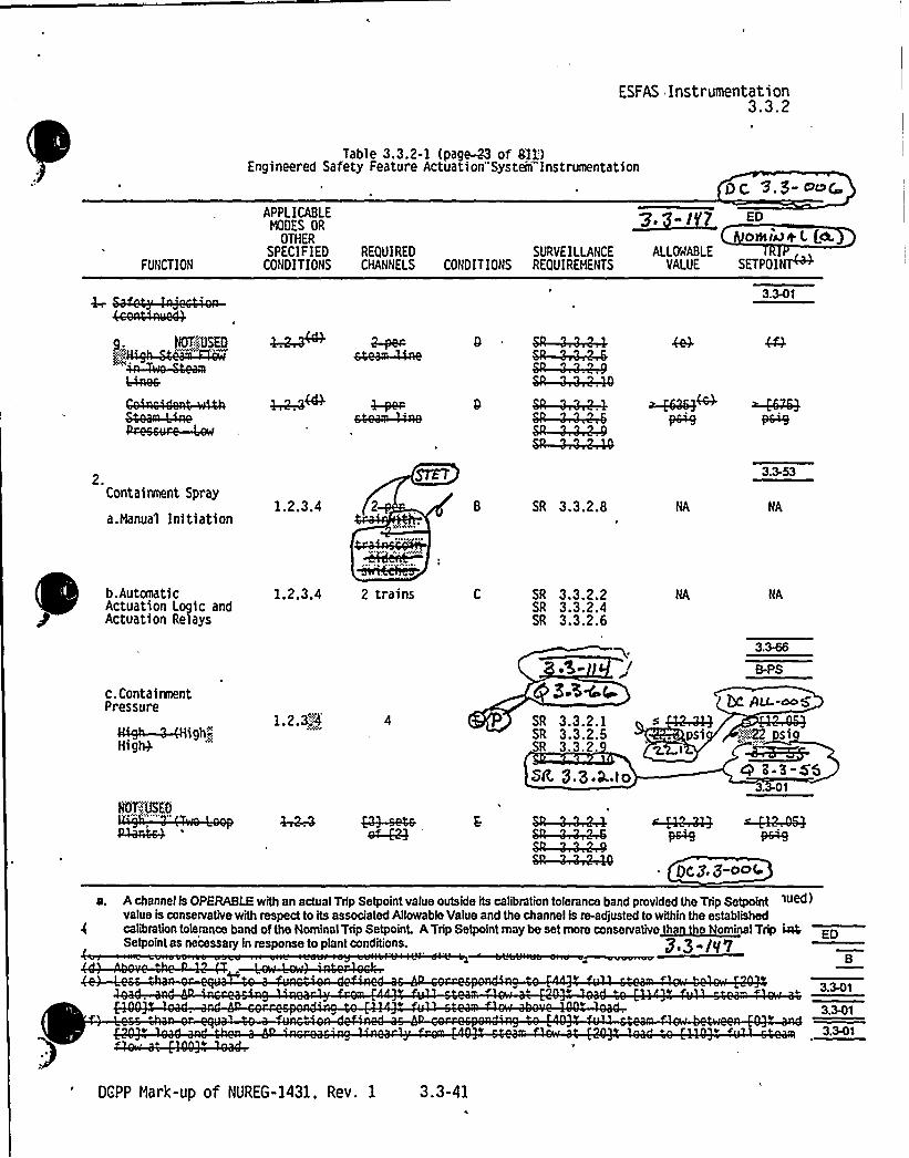
ESFAS Instrumentation3.3.2
Table 3.3.2-1 (page-33 of Sl3::)Engineered Safety Feature Actuation"System"Instrumentation
Ot ~.$ - d~4-
FUNCTION
APPLICABLEHODES OR
OTHERSPECIFIED
CONDITIONS
~3, IrrI Sty
ON isa + L (tdt.REQUIRED SURVEILLANCE ALLOMABLECHANNELS CONDITIONS REQUIREHENTS VALUE SETPOIN~
4cen44aueQ
4$aee
0-per-e4ea~e
2.Containment Spray
a.Manual Initiation1.2.3.4
liana~~elcH:eitea
SR 3.3.2.8
b.Automatic 1.2.3.4Actuation Logic and
P Actuation Relays
2 trains SR 3.3.2.2SR 3.3.2.4SR 3 '.2a6
c.ContaireentPressure
tttgi~l-4High-HigtQ
1.2.S.'4 SR 3.3.2.1SR 3.3.2.5SR 3.3.2.
M 3.3,Q..lo
5psl
1
B-PS
bc au--c
yTdo"'.22 s1
4 a-s-ss3. 01
Qt.g. j-OCrt
a. A channel ls OPERABLE with an actual Trip Setpoint value outside its calibration tolerance band provided the Trip Setpointvalue is conservative with respect to its associated Allowable Value and the channel is re-adjusted to within the establishedoaliblallon toleranoe band of tee Nominal Trip setpotna A Trip setpolllt may be aet mora mnmrvatbe tnrntree NNoormminal Trip ipaSetpoint as necessary ln response to plant conditions. 3'.3-/v7
BC'
C e V 3.341
3.3et
3.3et
DGPP Mark-up of NUREG-1431, Rev. 1 3.3-41n


ESFAS Instrumentation3.3.2
Table 3.3.2-1 (page-34 of 811)Engineered Safety Feature Actuation"System Instrumentation
bC 3. $-~(
FUNCTION
3. ContaireentIsolation
a. Phase AIsolation
APPLICABLENODES OR
OTHERSPECIFIED
CONDITIONSREOUIREDCHANNELS
p,3-/ /7 Eo
wowi~*LCogSURVEILLANCE ALLOWABLE TRIP
CONDITIONS REOUIREHENTS VALUE SETPOIN~,
(1) Hanua1Initiation
(2> AutomaticActuationLogic andActuationRelays
1.2.3.4
1.2.3.4 . 2 trains
SR 3.3.2.8
SR 3.3.2.2SR 3.3.2.4SR 3.3.2.6
NA NA
(3) Safety Refer to Function 1 (Safety Injection) for all initiation functionsInjection and requirements.
b. Phase B Isolation
(1) ManualInitiation
1.2.3.4
eNAQ4eiN
SR 3.3.2.8 NA NA
(2) AutomaticActuationLogic andActuationRelays
1.2.3.4 2 trains C SR 3.3.2.2SR 3.3.2.4SR 3.3.2.6
NA
Dc Pu:~5(3) Containment
Pressure
4N gh~Hi glQ1233 SR 3.3.2:1
SR 3.3.2.5SR 3.3.2.9
fR, g,Z.J,.(o
22.I2. B PS
3.346
psig
4. Steam Line Isolation
a. ManualInitiation
1.2"'.3"' .1"lvaTvj SR 3.3.2.8
3.3.58
ps
NA
DCPP Mark-up of NUREG-1431, Rev. 1 3.3-42


FUNCTION
APPLICABLENODES OR
OTHERSPECIFIED REQUIRED
CONDITIONS CHANNELS
ESFAS Instrumentation3.3.2
LiC, -3.3 -~4
~7, 3 I-7 en
vofyjizn(, aSURVEILLANCE ALLOMABLE
CONDITIONS REQUIREHENTS VALUE SETPOINM
b. Automatic 1.2 .3' trains
Actuation Logicand ActuationRelays
G SR 3.3.2.2 NA NA
SR 3.3.2.4SR 3.3.2.6
(continued)
(t > Except when a 1 l6ivs are closed and ifeaccawaTed. gp eoG
a. A channel is OPERABLE with an actual Trip Setpoint value outside its calibration tolerance band provided the Trip Setpoint
value ls conservative with respect to its associated Allowable Value and the channel h re-adjusted to within the established
calibration tolerance band of the Nominal Trip Setpoint A Trip Setpoint may be set more conservative than the Nominal Trip
Setpoint as necessary in response to plant conditions.sap lV7~p ~ aa7
ED
DCPP Mark-up of NUREG-1431, Rev. 1 3.3-43


ESFAS Instrumentation3.3.2
Table 3.3.2-1 (page 45 of 81')Engineered Safety Feature Actuation"System Instrumentation
X8.'3-Oc'('UNCTION
APPLICABLEHOOES OR
OTHERSPECI F IEO
CONO IT ION S
REQUIREOCHANNELS
ED
NERetsso L ch)SURVEILLANCE ALLOMABLE P
CONOIT IONS REQUIREHENTS VALUE SETPOI~4. Steam Line
Isolation(continued)
c. ContainmentPressure - High 0 .-.8>'.j5
d. Steam LinePressure
(1) Lodl
(2) NegativeRate - High
(i)'(i)
1 2(i) 3 per
3(b)(i) steam line
3 persteam line
0
SR 3.3.2.1SR 3.3.2.5
3.3.2.9
Sg 3.3.X,)o
SR 3.3.2.1SR 3.3.2.5SR 2.9
SQ 3.$ .3..)o
SR 3.3.2.1SR 3.3.2.5SR .3.
SR 3 3.Q;to
B-PS
+ sS19
2 42.
3.3- 37
20 sig7g 8u.-~S
B-PS
~ cawps 1 g 89|1( ps ig
B-PS
5 ~~10,0ps>/s c '" si/s'e
8 t-t.-ms4'.341
are t, ~ ~ 50 seconds and t, ~ j5 seconds3.3-t 55
3.341
3.341
nw'~—hew-hew g4cQ444 SR-+'44KSR ') 'W-.R
(3 3, $ -00 t'continued)a. A ahannel is OPERABLE with an actasl Trip Betpolnt valnn ontslde hs celihlattonioletsnce hend ptovtded inc Tri Belpohlt
value is conservative withrespect to its associated Allowable Value and the channel is re-adjusted to within the established Qg,3 -(o3calibration tolerance hand of the Nominal Trip Setpoint. ATrip Setpoint may be set more consewative than the N minal TripSetpolnt as necessary ln response to plant conditions. 5 3- ED
(b) Above the P-11 (Pressurizer Pi r 'n rloc ...*
. " . 3,343
(c) tme cons an s us >n ea aB
~Quc..lb
DCPP Mark-up of, NUREG-1431, Rev. 1 3.3-44


E5FAS Instrumentation3.3.2
Tab)e 3.3.2-1 (page $6 of-$11)Engineered Safety Feature Artuation'System"'Instrumentation
Z~ 3- epopt
FUNCTION
APPLICABLEMODES OR
OTHERSPEC IF IEO
CONDITIONSREQUIREDCHANNELS
s. s -l'lINomi~AL (45
SURVEILLANCE ALLOMABLECONDITIONS REQUIREMENTS VALUE SETPOINM
NT„:"%N
3.341
4eeatrre-~<4ea~e
etea~w
gg-per- Qt
$R '%44-.QSR—3 '~
NJQ)'SEDetea~e Qt 'I.'I 'M
C 3.3-0+ 4A channel ts OPERABLE with an actual Trip Setpoint value outside its calibration tolerance band provided the Trip Setpointvalue h conservative viith respect to its associated Allowable Value and the channel is re-adjusted to within the establishedcalibration tolerance band of the Nominal Trip Setpolnt. ATrip Setpoint may be set more conservativ than the Nomi al TripSetpolnt as necessary in response to plant conditions. '3 ~ ) "P 7 ED
3.341
DCPP Mark-up of NUREG-1431. Rev. 1 3.3-46'

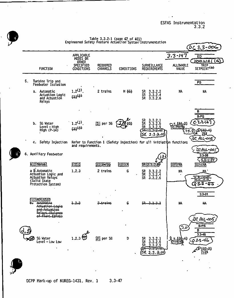
ESFAS Instrumentation3.3.2
Table 3.3.2-1 (page 67. of Sll)Engineered Safety Feature Actuation"Systerii"- Instrumentation
p g,'3-~
FUNCTION
APPLICABLEHODES OR
OTHERSPEC IF IEO
CONDITIONS
pig-l97 Eo0
RE(}UIRED SURVEILLANCE ALLOMABLE TRIPCHANNELS CONDITIONS REQUIREHENTS VALUE SETPOINT
5. Turbine Trip andFeedwater Isolation
a. Automatic 1 2(j)Actuation Logicand ActuationRelays
2 trains H M SR 3.3.2.2SR 3.3.2.4SR 3.3.2.6
NA
PS
b. SG WaterLevel - HighHigh (P-14)
' 2(j) 9'.'«SGSR 3.3.2.1SR 3.3.2.5SR 3.3.2
$g, 3 ~ 3.c'k Io
c. Safety Injection Refer to Function 1 (Safety Injection) for all initiatiand requirements.
6. Auxiliary Feedwater
7s.2 P~(}C WLLmo6
n functions
5'F ihllliA
+ S.AutomaticActuation Logic andActuation Relays(Solid StateProtection System)
c";:,::.:.:.N(tT.'USEDO'Qma44
PRQ
1.2.3
SN":222'."2:
SR 3.3.2.2SR 3.3.2.4SR 3.3.2.6
FP~.;::~NA:
NA
A'53-SK
3.341
SG WaterLevel —Low Low
Qz per SG SR 3.3.2.1SR 3.3.2.5SR 3.3.2.9
SR, 8.S.R,io
B-PS
B
3.~
DCPP Hark-up of NUREG-1431, Rev. 1 3.3-47


g.@ sc SIAM;L-l~l~ 4'p as.s-s4.7 ~ "bE (r)ri) ESFAS Instrumentation
3.3.2
bq ~.S-a C
FUNCTION
APPL ICA8LE%DES OR
OTHERSPECIFIED
CONDITIONS
Z. S./Sr Ro
ontf<A-L C+REQUIRED SURVEILLANCE ALLOWA8LE T P,CHANNELS CONDITIONS REOUIREHENTS VALUE SETPOINP
<davey0 Sear
v'
o 2".wmvo
. Q)
LLv5<vvl
s.sae
SR";3:3.'2v2i ~ui. ES'.L'Tiii'p".aT
S V3';3~9 -'Var.fable"'.".in
ut:~'RTP.(QvtCS-Loop:,iT
Eo. e~'" 'ar.fable'-+-" SS~
SR:,".Sv3 2!S lsvt))n';:(1:."DI).";T, "":TD,.
,ii:.ii:i:.i, i!=ms :~~c4k0 ~t Q~g v
2)g.RCS" oot)'Iaf X'."gf.valent',
"
.owei">",5,'.RTfr.
';Ra":2";23'R'3".822$RCS"'. Loop~aTa';,variable-"s""1 ngdti:.>grFP.)RTP.
'7
RCS) L'oo'p ~T.'"':varia leirlpu,SDxFk:".'
3~vv ~
~@3.)n)DSR~3" "."2."-:5
SR" ,"-3".2„'";9Mf ~ie'.tiiM ":.32
ay"=''"'n'oojQ:
Ea
8 3-'(C
IX; %.3-oQC«ontinue=
a Achannel is OPERABLE with an actual Trip Setpoint value outside its calibration tolerance band provided the Trip Setpoint
value h conservative with respect to Its associated Allowable Value and the channel is re-adjusted to within the established
calibration tolerance band of the Nominal Trip Setpoint. ATrip Setpoint may be set more conservative than the Nominal Trip
Setpolnt as necessary in response to plant conditions. 7 3 "JV(3) Except.men.j) 1 ((Flys. HFRvs. nsd,"aa~ki~~egpXS vaTvm are clos~ and de,activity (solntW.by e
,, RTE) risediisanuE) Sva) vii,,(t)3'!FOiiHOdn235!the<Tet'pcTS'iiihi:Oetay"„:"aii'ao)ht"" 'VOiLiWi eNreSiiii SenrpOa7t""„tRirii' rLrelVeliiii-l''is"-.xiiEib'il;nmauat
, 'rierilesiEthari%ir2e(jiiafi'::tot484eyw"
o(S)" tnamiSrinS raturao(((teLSrve)".::1" an'..TvsmfOeyaaxyy,
0:„.'81(P)r~~,":82(R)'&v83(P3cv" 84e", Reerain(pa',.-.. RES(L'oop'mTDSiuii(iaTeotTRT)rponeMr,-;, rm(PJ:-p tu Sot)RTP
nSv!~',:~iTD»".. iT)mntilelhy)yncrrSte ;:Gprahtaiii"Ala'tiexirrtcebivill'Laii-'.Lai„;(iL(n: seacii d)s
r s
tH; ~W taco@*Q ~++4 "~~All hrii lf o 4lm$Qrr a)df (nRdmdS
8$ 4~ ~ 5'm7 FO
~+m'CPP
Mark-up of NUREG-1431, Rev. 1 3.3-48

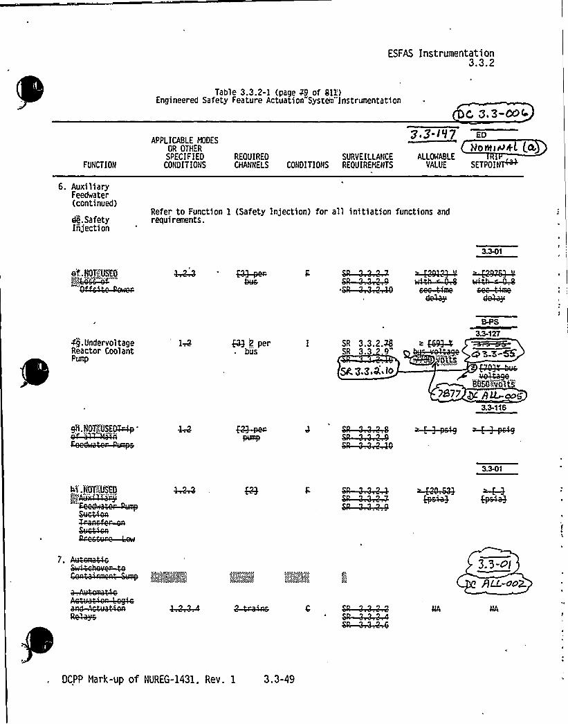
ESFAS Instrumentation3.3.2
Table 3.3.2-1 (page 49 of 811'.)Engineered Safety Feature Actuation"System"'Instrumentation
FUNCTION
6. AuxiliaryFeedwater(continued)
APPLICABLE MODES
OR OTHERSPECIFIED
CONDITIONSREQUIREDCHANNELS
p.g I l7 ED
yoni>a< (aSURVEILLANCE ALLOMABLE
CONDITIONS REOUIREMENTS VALUE SETPOIN~
de.SafetyInjection
Refer to Function 1 (Safety Injection) for all initiation functions andrequirements.
3.341
4g.UndervoltageReactor CoolantPump
~2 perbus
SR 3.3.2.ASR 3.3 g"
5g, 3.gaQ.. Io
i QQ3-4
vblt5
B.PS
3.3 127
co'5-'E-SS
8()59"-vol t7877 + pQ
3.3-116
@~~MSR 'l '4QA
3.341
~e~a$v~aWessvae —Lew
7. Avtewa4$ e
M:PyAYN
).'3 "olALL-ac2.
SR '4'~$R '44-.Q-.4
DCPP Nark-up of NUREG-1431. Rev. 1 3.3-49


ESFAS Instrumentation3.3.2
FUNCTION
APPLICABLE NODESQR OTHERSPEC IF IED 'EOUIRED
CONDITIONS CHANNELS
I 3 I-'l7Leeway( (a
SURVEILLANCE ALLSIABLECONDITIONS REOUIREHENTS VALUE SETPOINM
W~NP4$R 'I '~ ~~4 ~~uf$R
.Qt 'I.'42-.40
(continued)
q. Pc<~j)) & l,p zgR~~~l R ~zTu,goV Ecg Jr~ Ld~far4w~ T~k. ~J-4w
~ fPNK> EIÃ97
a. A channel is OPERABLE with an actual Trip Setpoint value outskle its calibration tolerance band provided the Trip Setpolnt
value ts conservative with respect to its associated Allowable Value and the channel ts re-adjusted to within the established
calibration tolerance band of the Nominal Trip Setpoint. ATrip Setpoint may be set more conservative than the Nominal Trip
Setpoint as necessary in response to plant conditions. 3.3 "I'f7
DCPP Mark-up of NURfG-1431, Rev. 1 3.3-50

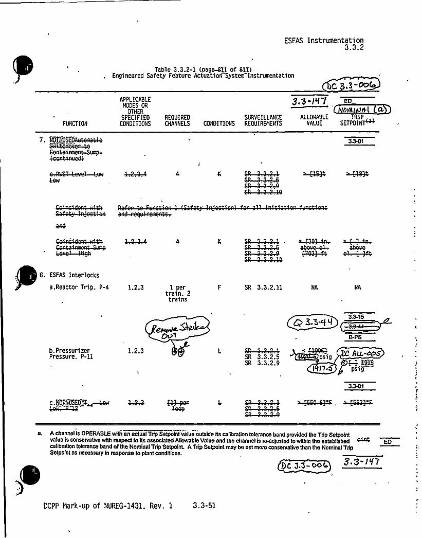
ESFAS Instrumentation3.3.2
Table 3.3.2-1 (page-81I'f 81I)Engineered Safety Feature Actuation Systetir"Instrumentation
,g-Oo4
FUNCTION
APPLICABLEHODES OR
OTHERSPEC IF IEO
CONOI TIONS
s,'$ II-7 ED
ON *l cL
REQUIREO SURVEILi.ANCE ALL%ABLE TRIPCHANNELS CONOITIONS REQUIREMENTS VALUE SETPOIN7
7. @f'j%OAuta~QVCia4YA%cZB
46ent4rruaQ
3.341
Qt '4;~ atre+4Qt 'w~ g0;9-44 ~4-344Qt 'I '4440
8. ESFAS Interlocks
a.Reactor Trip. P-4 1.2.3 1 pertrain. 2trains
SR 3.3.2. 11
B-PS
b.PressurizerPressure. P-11
1.2.3SR 3.3.2.5
"SR 3.3.2.9ZC Au-fezNM XLIS
[cII I.6 f psig
3.341
c. NOTSgSFOO~—hew
a. A channel ls OPERABLE with an actual Trip Setpolnt value outside its calibration tolerance band provided the Trip Setpointvalue is conservabve with respect to its associated Allowable Value and the channel ts re-adjusted to within the establishedcalibration tolerance band of the Nominal Trip Setpoint. ATrip Setpoint may be set more conservative than the Nominal TripSetpoint as necessary in response to plant conditions.
g. 3- I V7Qg g.3- ooC.
EO
DCPP Nark-up of NUREG-1431. Rev. 1 3.3-51


BASES
BACKGROUND
4(era~ cc
RTS Instrumentation8 3.3.1
Si nal Process Control and Protection S stem (continued)
prevent the protection function actuation. These requirements aredescribed in IEEE-279-1971 (Ref. 4). The actual number of channelsrequired for each unit parameter is specified in Reference 1.
y
Two logic channels are required to ensure no single random failure 33of a logic channel will disable the RTS. The logic channels aredesigned such that testing required while t r c o i a be s s~may be accomplished without causing trip. ~essays- 8ae~~ 0>
dt
Tri Set pints and Allowable Values . ~ ~)~~ '~A >~~~'f+bThe Trip Setpoints are the nomi values at which the bistables areset. Any bistable is consider d to be properly adjusted when the"as left" value is within the and for CMANNEL CALIBRATION<@~edX~S~ '5.%- I g|'.C g 5C htc.-n 5
The np Setpoints used in the bistables are based on the analyticalimits stated in Reference 1. The selection of these Trip Setpointsis such that adequate protection is provided when all sensor andprocessing time delays are taken into account. To allow forcalibration tolerances, instrumentation uncertainties, instrumentdrift. and severe environment errors for those RTS channels thatmust function in harsh environments as defined by 10 CFR 50.49(Ref, 5). the Trip Setpoints and Allowable Values specified inTable 3.3.1-1 in the accompanying LCO are conservatively adjustedwith respect to the analytical limits. A detailed description ofth th d 1 y d t 1 1 t th tiP 1 tP 1 t 1 1 d d.th 1 Ply l,, t 1 ti i,p...'d d,i,th,,"
'Pat''!ll'It!it:",-:,::,::.I,,-!hilt:::lilith,"ti,h,,'nye,tm''!thieved,"",'bg V
mseP,:-!"".!!d":::1 ",::*h',fg:it lie'-":"'i e:',"'it
hti"li'-ii!E'.d."!!Slid."':,::i"'iii'**!~d'he
bi'stable is more conser vative than that specified by theAllowable Value to account for changes in random measurement errorsdetectable by a COT. One example of such a change in measurementerror is drift during the surveillance interval. If the measuredsetpoint does not exceed the Allowable Value, the bistable iscon idere OPERABLE.
j:~mz g EP.I 8,v( (b)
(continued) '.
DCPP Mark-up of NUREG-1431, Rev. 1 Bases 8 3.3-4


Attachment BPG&E Letter DCL-99-OXX
Insert for DC ALL-005Enclosure 5B page 8 3.3-4Insert B 3.3.1 BKG (B)
The calibration tolerance, after conversion, should correspond to the rack comparatorsetting accuracy defined in the latest setpoint study. V
Insert B 3.3.1 BKG (D)
Rack drift in excess of the Allowable Value exhibits the behavior that the rack has notmet its allowance. Since there is a small statistical chance that this will happen, aninfrequent excessive drift is expected. Rack or sensor drift in excess of the allowancethat is more than occasional may be indicative of more serious problems and warrantsfurther investigation.
I
In the event achannel's se point is found nonconservative wi respect to e specified Trip Setpoint,but more conservative than the Allowable Value, the setpoint must be adjustedconsistent with the Trip Setpoint value. When a channel's Trip Setpoint isnonconservative with respect to the Allowable Value, declare the channel inoperableand apply the applicable ACTION statement until the channel is returned to OPERABLEstatus with its Setpoint adjusted consistent with the Trip Setpoint value.


ESFAS Instrumentation8 3.3.2
BASES
BACKGROUND Si nal Processino E ui ment (continued)
actuation. Again. a single failure will neither cause nor preventthe protection function actuation.
These requirements are described in IEEE-2?9-19?1 (Ref. 4). Theactual number of channels required for each unit parameter isspecified in Reference Z.
The channels are designed such that testing required to be performedat power may be accomplished wi hqut causing an ES~ctuat!on.
ztasemv ts a.a.m akm cs>> gicRtL oo2.-
Tri Set pints and Allowable Value5 f~ *tea'~cc ~ gP7 ~~.~ -dig
The Trip Setpoints are the no nal values at which the bistables areset. Any bistable is conside ed to be properly adjusted when the oa>,ba w
"as left" value is within the band for ttaccura
The Trip Setpoints used in the bistables are ba e on e ana y ical'dII~~~~>limits stated in Reference 2. The selection of these Trip Setpointsis such that adequate protection is provided wh n all sensor andprocessing time delays are taken into account. To allow forcalibration tolerances, instrumentation uncertainties, instrumentdrift, and severe environment errors for those ESFAS channels thatmust function in harsh environments as defined by 10 CFR 50 '9(Ref. 5). the Trip Setpoints and Allowable Values specified inTable 3.3.2-1 in the accompanying LCO are conservatively adjusted ~with respect to the analytical limits. A detailed descrthe methodology used to calculate the Trip Set oi . inc udingtheir explicit uncertainties, is provided in " Kj9u~~",twtt,-",'-,Ilpttm'tttttmw '%::,:,:",,;:,,t,.',,'."::,,ll, t:,',tt"'"',::.:t"tt't t t.Hethodology,.;:.,:'7o'r:.".:~Fr'okecttfo™ti;„:"'Sytstemsjbi ab]o'.,',Ca'rijoii'ISt)'6.'oiig«'.,'ersion,:."::,'":,::;::.:':,':Hay.:,"yl9t93(Ref�.
6) .'"'Th' "ac't'ual" noesminal'"Trip "Setttpao'int
"'wnterwed'"intwoacthe "bistable is more conservative than that specifiedby the Allowable Value to account for changes in random measurement
Cj: ~~ R~m.~Cet~t ttt t *tt tt t t" tconsequences of Design Basis Accidents (DBAs) will be acceptable.providing the unit is operated from within the LCOs at the onset ofthe DBA and the equipment functions as designed.
errors detectable by a COT. One example of such a change inmeasurement error is drift d ring the surveillance interval. If themeasured setpoint does not e ceeded he Allowable Value he bistable~is c>>nsidered 0 BLE. LL-O~
(continued)
DCPP Hark-up of NUREG-1431. Rev. 1 Bases B 3.3-67


Attachment 2PG8 E Letter DCL-98-167
Insert for Q 2-06 (2.0)Enclos 5B page B.G.3-67
r'nse
.3.2(A)
e Allowable'values are considered to be'the Limiting Safety System Settings (LSSS), asidentified,irl 10 CFR 50.38, and have been selected to'mitigate the consequences o accidents.r/ 0g g,p-aug.


ESFAS InstrumentationB 3'.3.2
BASES
BACKGROUND Tri Set pints and Allowable Values (continued)
Kaeh Ler"'.QRFlgchannelC can be tested on line to verify that thesignal processing equipment and setpoint accuracy is within thespecified allowance requirements of Reference 2. Once a designatedchannel is taken out of service for testing, a simulated signal isinjected in place of the field instrument signal. The'processequipment for the channel in test is then tested, verified, andcalibrated. SRs for the channels are specified in the SR section.
All field sensors andnels are assumed to
certainty magnitudt ~LL~
p psignal processing equipment for these ch
P of these upm~< 8 3.5-2 @KG <a)Solid State Protection S stem
The Trip Setpoints and Allowable Values listed in Table 3.3.2-1 arebased on the methodology described in Reference 6, whichincorporates all of the known uncertainties applicable for eachchannel. The magnitudes of these uncertainties are factored intothe determination of each Tri Set oint.
The SSPS equipment is used for the decisoutputs from the signal processing equipredundancy requirements, two trains of Ssame functions, are provided. If one trfor maintenance or test purposes. the seactuation for the unit. If both trainsplaced in test. a reactor trip will resuin its own cabinet for physical and elecseparation and independence requirements.
on logic processing ofent bistables. To meet thePS, each performing thein is taken out of serviceond train will provide ESFre taken out of service ort. Each train is packagedrical separation to satisfy
The SSPS performs the decision logic foactuation: generates the electrical outrequired actuation; and provides the staannunciator output signa'ls to the main c
The bistable outputs from the signal proby the SSPS equipment and combined intorepresent combinations indicative of var
most ESF equipmentt signals that initiate theus. permissive. andntrol room of the unit.
essing equipment are sensedogic matrices thatous
QA Z.Z~fgMRQ-T'A K~Wlga)
(continued)
DCPP Mark-up of NUREG-1431. Rev. 1 Bases B 3.3-68

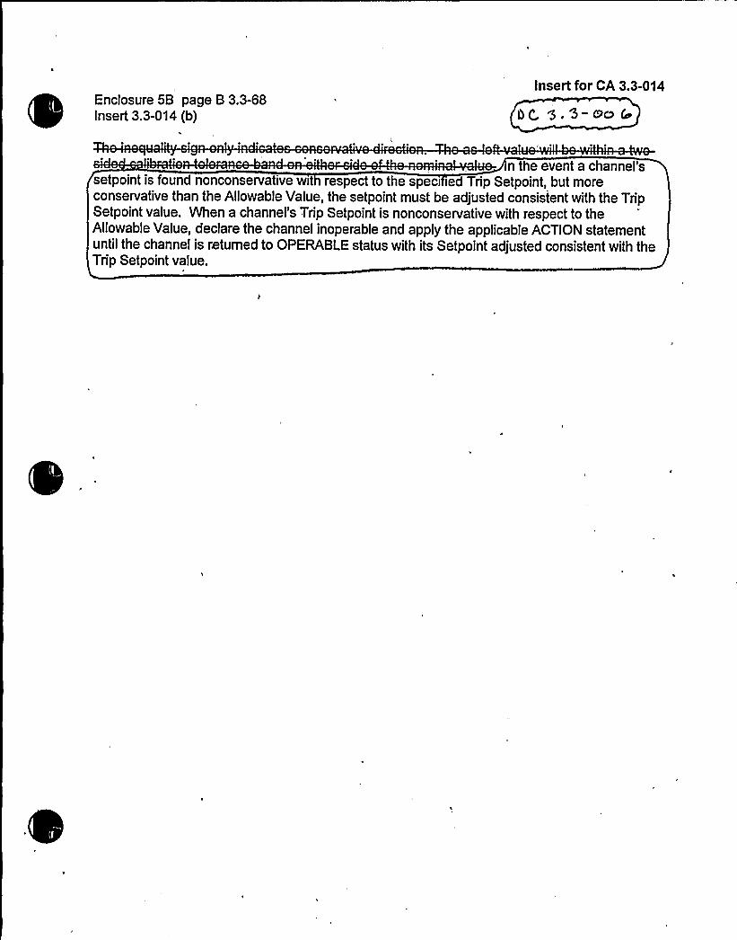
Enclosure 5B page B 3.3-68Insert 3.3-014 (b)
Insert for CA 3.3-014
n the event a channel'ssetpoint is found nonconservative wit respect to the speci ied Trip Setpoint, but moreconservative than the Allowable Value, the setpoint must be adjusted consistent with the TripSetpoint value. When a channel's Trip Setpoint is nonconservative with respect to theAllowable Value, declare the channel inoperable and apply the applicable ACTION statementuntil the channel is returned to OPERABLE status with its Setpoint adjusted consistent with theTrip Setpoint value.


CHANGENUMBER JUSTIFICATION
3.3-125
3.3-126
3.3-127
3.3-128
3.3-129
3.3-130
3.3-131
3.3-132
3.3-133
3.3-'l34
3.3-135
3.3-136
.3-137
ITS SR 3.3.1.11 is modified by a Note that requires verification that the time constants areadjusted to the prescribed values. The addition of this Note is consistent with SR 3.3.1.10and is required because SR 3.3.1.11 is used for the Power Range Neutron Flux - HighPositive Rate [and High Negative Rate ] trip functions which have a time constantassociated with their calibration
s'aQf'ot
applicable to DCPP. See Conversion Comparision Table (Enclosure 6B). ~yzThe MODE 2 applicability for the undervoltage RCP start of the steam4riven AFW pumpis deleted and the surveillance Frequency is revised per the DCPP CTS. Thus, theRequired Actions ofACTINIare revised to include entering MODE 2 for function 6.g andMODE 3 for function 5.~)he required surveillance is changed from SR 3.3.2.7 to SR3.3.2. This anticipatory start of the steam<riven AFW pump is not credited for MODE 2opera G el start signal is used for MODE 2 or 3.
H Akv@ ~
Thischang revisesITS a e3.3.4-1 tobeconsistentwithCTS3.3.3.5. ( +~et~'ivor vsGb
Not applicable to DCPP. See Conversion Comparision Table (Enclosure 6B). cr~fcA WNot applicable to DCPP. See Conversion Compansion Table (Enclosure 6B).
Not applicable to DCPP. See Conversion Comparision Table (Ericlosure 6B).
Not applicable to DCPP. See Conversion Comparision Table (Enclosure 6B).
This change revises ITS LCO 3.3.5 and SR 3.3.5.3 to include the DG start sequencedelay timers from CTS Table 3.3-4.
Not applicable to DCPP. See Conversion Comparision Table (Enclosure 6B).
A MODE change restriction has been added to ITS 3.3.1 Condition C per the matrixdiscussed in CN 1%2-LS-1 of the 3.0 package (see LS-1 NSHC in the CTS Section 3/4.0,ITS Section 3.0 package).
Not applicable to DCPP. See Conversion Comparision Table (Enclosure 6B).
The Condition for Function 4.c is changed from Condition D to E consistent with the CTSI d
'this Function to be bypassed, not tripped ifinoperable 3C Ru=~~
b4 Wdk. 9,q-i3e WS.S -IVe
~c >g-oi'lI ver] @A - i<<
LuCg.3-os-s
if' vo ihgilc'lg& 4 iid, pp spy ~~go~ (o&tpsLlsDP Ate Gi/ 0
3 3.-l<7- i~s~ DC 3.3-NQG
DCPP Description of Changes to Improved TS10


Attachment BPG8 E Letter DCL-99-063
Encl. 6A 10Insert for JFD 3.3-147
Insert for DC 3.3-006
The Trip Setpoint column for Table 3.3.1-1 and Table 3.3.2-1 have been re-labeled toread "Nominal Trip Setpoint." Note "a" has been added to interpret the values provided.The Note reads; "Achannel is OPERABLE with an actual Trip Setpoint value outside itscalibration tolerance band provided the Trip Setpoint value is conservative with respectto its associated Allowable Value and the channel is re-adjusted to within theestablished calibration tolerance band of the Nominal Trip Setpoint. A Trip Setpoint maybe set more conservative than the Nominal Trip Setpoint as necessary in response toplant conditions.


CONVERSION COMPARISON TABLEFOR DIFFERENCES FROM NUREG-1431, SECTION 3.3 Page 21 of 21
NUMBER
TECHNICALSPECIFICATION CHANGE
DESCRIPTION
APPLICABILITY
DIABLOCANYON COMANCHE PEAK WOLF CREEK CALLAWAY
3.3-131
3.3-132
3.3-133
3.3-134
ITS 3.3.5 Condition B is replaced with new Conditions B, C,D, and E. Condition C in the ISTS is changed to Condition F.The CPSES CTS have specific actions for the various busundervoltage and degraded voltage function. These actionsallow an appropriate amount of time to restore an inoperablechannel or declare the associated power source or businoperable and take action to isolate an inoperable powersource. These actions are a proper way to respond to theinoperable channels because the actions result in taking theRequired Actions in ITS 3.8 associated with the affectedpower source or bus. The new Conditions match the Actionsof the CTS.
The trip setpoints for the loss of power diesel generator startinstrumentation are relocated to a licensee controlleddocument. This approach is consistent with a format allowedby a reviewer's note for.the RTS and ESFAS Instrumentation.
This change revises ITS .. SR 3.3.5.3 to includet o DG start sequence de ay timers from DCPP CTS Table3.34.
This change is WolfCreek specific to revise the NOTE inCondition of ITS 3.3.2 consis~tgt wit~CTS Table 3.3-3
c ion or Function 7b
No -adopted ITSformat.
Yes
No
Yes
Yes
No
No, adopted ITSformat.
Yes
No
No, adopted ITSformat.
No
No
3.3-135
3.3-136
.3-137 .
A MODE change restriction has been added per the matrixdiscussed in CN 1-02-LS-1 of the ITS 3.0 package.
The TADOTperfromed under ITS SR 3.3.2.7 includesverification of relay setpoints since the trip actuating devicesbeing tested are the same circuits tested under ITS SR3.3.5.2.
The Condition for Function 4.c is changed from Condition Dto E consistent with the DCPP CTS.
Yes
No, adopted ISTSformat.
Yes
Yes
No, adopted ISTSformat.
Yes
Yes
No
Yes
Yes
N e pcs.~
5EBi c 8 7~/~DC onversion o n Table - Improve T
8.3-l't7 —I~s ~4C C 9,S-OoG,cP 3~$~


Attachment BPG8 E Letter DCL-99-063
Encl. 6B 21Insert for JFD 3.3-147
Insert for DC 3.3-006
The Trip Setpoint column of Table 3.3.1-1 and Table 3.3.2-1 have been re-labeled toread "Nominal Trip Setpoint." Note "a" has been added to interpret the values provided.
Applicability:
DC YESCP NOWC NOCA NO

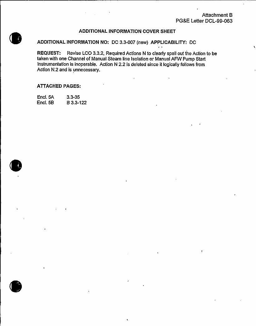
Attachment BPG&E Letter DCL-99-063
ADDITIONALINFORMATIONCOVER SHEET
ADDITIONALINFORMATIONNO: DC 3.3-007 (new) APPLICABILITY: DC
REQUEST: Revise LCO 3.3.2, Required Actions N to clearly spell out the Action to betaken with one Channel of Manual Steam line Isolation or Manual AFW Pump StartInstrumentation is inoperable. Action N 2.2 is deleted since it logically follows fromAction N.2 and is unnecessary.
ATI'ACHEDPAGES:
Encl. 5AEncl. 5B
3.3-35B 3.3-122


ESFAS Instrumentation3.3.2
ACTIONS (continued)
CONDITION REQUIRED ACTION COMPLETION TINE
48::houri'
DCPP Hark-up of NUREG-1431. Rev. 1 3.3-35

0

ESFAS InstrumentationB 3.3.2
BASES
ACTIONS L.l L.2.1 and L.2.2 (continued)
LCO 3.0.3 to 'initiate shutdown actions in the event of a completeloss of ESFAS function. If the interlock is not in the requiredstate (or placed in the required state) for the existing unitcondition. the unit must be placed in MODE 3 within the next6 hours and MODE 4 within the following 6 hours. The allowedCompletion Times are reasonable, based on operating experience.to reach the required'nit conditions from full power conditionsin an orderly manner and without challenging unit systems.Placing the unit in NODE 4 removes all requirements forOPERABILITY of these interlocks.
Z> R~l ~T/dX/ Pf d~e~
"iidit'io"gati'::,;app1iieszt'o,,=,the,,:-",,Tr'ip::,:T1me„s ay:,.':,:.,:,,:::;: orlthe,'.,'-S6:low,=,'Gw",:."wat-;~gkiVgpjaekuatj'on<af~a'AFN::,'pumpS'.;$
'')Mjth':,:::onne.:o',':,morj.::TED'""„'"'od'riiii
jf,"drills:„,$1'm'ers'nhiiope'rabbi.."'.„::,,6:;h,ouis',.".,":bie'","a'liloned,:!to a'dju'st]'the.:::.".: rersh'Nd':,:: "'nr~)evelkfoni;k@o':,tliiiekd0'ay~:.t4",::::Of~,'RTP,-,'pr"..""to:-'lilac"the,'::" fte'oted,.:".-:: m„t:aaerI eeal': on1sm!N; hoaiiiie ii n'ti::i p,";:;:jThii
s'e'::,:.;Fun'<." %.";>;:th'el:,"':avai:. bli, 'i.'edii'ndaii ';:;-;:~inidzthg>g,ow"'== i""rob'abjl'3'i;ofj',:a'nj'eieritI.' cui'„:;i')'rigel'dur''i"":.":t'hjs",',";in'g~rvH~YPIf~the::,,„, ';;-ochre ol'd'„'iy'oweg~lev': jeannot-",:Wja, "vite).'":;:oi'.'Xhi~iffectedP~Gwnate'r,',''"''."l' elqgm,-'le',"::i"".nne1',',,'cd'in',.':", placed,.i ";.'-:.'t'i';ip';"::„"",thi',.juriitmau'st::."'.:;::" .,"'plac&'-:,':6':;.:fg g;;.,i'ithij'>4 ':.''n'ext~:,6„':,4"" ii",;::;a'iid~5$E-':::4s
"with',the-'fo„.t.:lepi,. <,6j:hours) -':.;,,; ':;:i'l)vied.„-,, l&~,on'-+mes';;;are'rea 'nab'l,b";:.ilba'e'ed'-', Isopse'iathnp':"" ap'i'rite'n'oe;-'„b:r'eiiJi,'pe':rejiiireduen, ''conCh.6'one'," "'N<jl,:1:::,';':jow '„'.kiri.',,'ai'~'or,:," i~le';,.',man'ne';.,annd withoutc':ljngiiij'.";iin)"j,",:sjritems',8':.:"';~lI".,'NODE",:i::
anajyzed,.:::;:frag .,ent8jorgcond .:jonsgkhat",require~th t;'exp1jc~ t':.::.use'0'-.,"""': 'e.",'"'rO-'e" ':: Rifi-"-':uerkCt:.'.Oni''e','ban","V",.",l " ' " "=*""
t)c' 3 oo7
gondit~anjH;:~ppÃi,m»ta,.::
'a'~::-:::;::::@anna ~Un,"tiafmntofNSteamrt etne..."cauli'it'ion,::.land
«:.::.,:,,-:;::"Hajj8aier~nttej5at5 ~on o5":,::AoÃilliarj'Veednater:.".:.
Ifq'.a.jhann@>s~snoperableje<48"hours':s~:;:;al.'low'ed:,":to.',;returngthe'channnH,':,=::to,'.-iris'';OPEfVSL'Ejistatius:=:.'j-.,".:jTheÃ~'caffe'd;"'CottIp'IreanSO'nabsle,,"'COnbS) deil'rig'„':;the',.:.natu're."-,Of~lb(See'finCti'On):'-.::,CohenavaT1 able,':",:red5iidaancy,':"„~and "the'.',gow',",::pr'oba5f~l:,~ty,;,.".,o'f'!an"';.'.eventocc'urjgiig",'::,'duriiigMi's.:~Tnt'er'v'al:,j',:,';.If,,:,th'.:.;Funaction''.:."cannot;:;:beret'urine'd':to:-."QPERABgEe!status, .-.:,":th'e'+'as's'o'c).'ate'd-;pumaapn".. o')',vn'alve';:..Shal lbe';deck'ared.,",-iiIo'jierabl,'e'~>miiediitel'j;-".;and!the;,,REQUIREO>'ACTION'-:,.of-"3':':::7'„5::-os~:: '.".7.:.2'a~'~ajip'licasblN:,coI|Ijl'~edewith.':,~mediate'1 ~-',
'7Ã<epz ~8-o4 P.'q o. =- C~
(continued)
OCPP Mark-up of NUREG-1431. Rev. 1 Bases B 3.3-122


Attachment BPG8 E Letter DCL-99-063
ADDITIONALINFORMATIONCOVER SHEET
ADDITIONALINFORINATIONNO: DC 3.3-008(new) APPLICABILITY: DC
REQUEST: Revise the LCO 3.3.6, Condition B and C description to delete Conditionsfor manual actuation inoperable. There is no manual function for the DCPP design forContainment Purge Isolation. Manual isolation is part of the controls for ContainmentIsolation (SI or Containment Spray).
ATTACHEDPAGES'ncl.
5A 3.3-65, 3.3-66


ContainmentV~NiLak4o
~4/
K'solationInstrumenta n3.3.6
M 3.3E
ACTIONS (continued)
CONDITION REQUIRED ACTION COHPLETION TIHE
8 ---------NOTE-----------Only applicable inHODE l. 2. 3, or 4.
One or m r ~~ns.m au orna ic ua son
rains ino r 1
yg $ .3-$
o8'.
1 Enter applicable Conditionsand Required Actions ofLCO 3.6.3. "ContainmentIsolation
Valves'�" for
containment~ee+isola on va es .made inoperable byisolation instrumentation.
Imnediately
aero Bothradiation monitoringchannel s'noperabl e.
OR
Required Action andassociated CompletionTime of Condition A notmet.
3.3-32
(continued)
(DCPP Hark-up of NUREG-1431, Rev. 1 3.3-65


Containmentya hrw~
~
'solation Instrumenta ion3.3.6
ACTIONS (continued)
CONDITION
C ----------NOTE----------duringor
movement of irradiatedfuel assemblies withincontainment.
p8'Qv
m au omatic ac ua ionrai inoperable.
OR
radiation moni t'oringchanne inoperable.
REQUIRED ACTION
v~C. 1 Place and m intain
containment~~valves in c osedposition.
OR
C.2 Enter applicable Conditionsand Required Actions ofLCO 3.9.4, "Containment '
Penetrations ~" .for
containment (f~so o val ves
ma e inoperable byisol ation instrumentation.
COMPLETION TIME
szImmediately
8 6-7'}
P 8.E-79
Immediately
3.3-32
:OCPP Mark-up of NUREG-1431. Rev. 1 3.3-66


Attachment BPG8 E Letter DCL-99-063
ADDITIONALINFORNIATIONCOVER SHEET
ADDITIONALINFORMATIONNO: DC 3.3-009 (new) APPLICABILITY: DCh
REQUEST: Revise ITS SR 3.3.5.3 to identify the setpoint values as being allowablevalues and not nominal values.
ATTACHED PAGES:
Encl. 5AEncl. 5B
3.3-63B 3.3-157

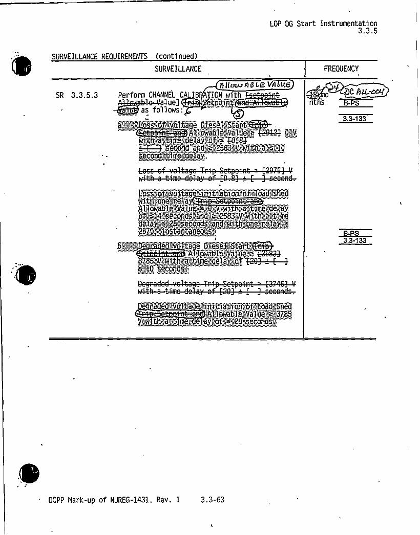
LOP DG Start Instrumentation3.3.5
SURVEILLANCE REQUIREMENTS (continued)
SURVEILLANCE FREQUENCY
SR 3.3.5.3y}([~angl-8 VA LLG
Perform CHANNEL CALI8 A ION withj CR@-'tpojri';
as follows:~':::.oNZvoIX@ge Diesel'::;Shaft';8~
'Alp:ow'abler',""Va'l.iie:,~ $29Q3 0:;-:"„.V:
gl.;4 ':s.@'"tf09.'.:";5&3,8gj9fj< 49.;,".',Q~ set:and and,.-..., '2583:,:V,.'.;:w}tI}~a::.;.B08K~0.~@~me."':69:..8p!.
Qt AQ.~n s Bps
3.3-133
:
$1..'.Ia'w'a'b~,i)Vpl,ice<',a,~,,';.'.,;w~, .;;-;.aj~:~mej,de lay,.i'�.''~>4;.secojCh,,'.:andh';;~,";::.'2583::"")V>.}In,th-'."aj"„tiiiie
dt!. av''«"<:,'g5.',.ji.,cori.s,:.';:;:.wd',~%::ch.oYi8:.'':i.;0„::..a)„':",;p2870:.;!bJYCtiiAtBllBDQSf
Si86!@Pit| i *.it:,-"'":::,:6":.I"'ji":I!~3.3-133
:A'.I'lomb]i4Val'ui'-'~j:::3785V;::g,:th'.::N-:tsmex ..e,:.aP::.:':.",:'Of::::;:-.:"::~:.::::20'::sicYin'ds.'.,
DCPP Mark-up of NUREG-1431, Rev. 1 3.3-63


8LOP DG Start Instrumentation
B 3.3.5
BASES
Allowable Valu set au@
The Trip Setpoints used in the relays are based on the analyticallimits presented in FSAR, Chapter 15 (Ref. 2). The selection ofthese Trip Setpoints is such that adequate protection is providedwhen all sensor and processing time delays are t
sar Gsl'n ~446The actual nominal Trip Setpoint entered into the re ays is normallystill more conservative than that required by the Allowable Value.If the measured setpoint does n xceed Value the ~r is consider MScc~S
le 54uE 5h™ 8~88 I chub'<0 Eg) ~~4 ~<e poin s a justed in accordance with the Allowable Value ensure gc g -ce
that the consequences of accidents will be acceptable, providing thunit is operated from within the LCOs at the onset of the accidentand that the equipment functions as designed.
Allowable Values are s ecified for eFu 'on i he LCO.
e nomina setpoints areec e o ensure that the setpoint measured by the ei ance
procedure does not exceed the Allowable Value it the relay isperforming as required. If the measured setpoint does not exceedthe Allowable Value, the relay is considered OPERABLE. Q eration pzy~pogwith a Trip Setpoint less ve an e nomina npSetpoint. but within the Allowable Value, is acceptable providedthat operation and testing is consistent with the assumptions of theunit s ecific setpoint calculation. Each Allowable Value~59.
specified is more conservative than the analyticalimi assumed in the transient and accident analyses in order to
account for instrument uncertainties appropr ate to the tripfunction. These uncertainties are defined
kieceoliooee;:,, pai'iio";;oiechiodo ogjWor2pr'at~et 'oiiihjs't'ii'ii'DiabloC'eoyoii:„'St'et'1oiiNEa'gioo:21k~Ve""ioiig"':"tR re&)"."
APPLICABLESAFETY ANALYSES
The LOP DG start instrumentation is required for theEngineered Safety Features (ESF) Systems to function in any accidentwith a loss of offsite power. Its design basis is that of the ESFActuation System (ESFAS).
Accident analyses credit the loading of the DG based on the loss ofoffsite power during a loss of coolant accident (LOCA). The actualDG start has historically been associated with the ESFAS actuation.The DG loading has been included in the delay time associated witheach safety system component requiring DG supplied goer following aloss of offsite power. The analyses assume a non-d%echanistic DG
loading. which does not explicitly account for each individualcomponent of loss of power detection and subsequent actions.
(continued)
OCPP Mark-up of NUREG-1431, Rev. 1 Bases B 3.3-157

l

Attachment BPG8 E Letter DCL-99-063
ADDITIONALINFORMATIONCOVER SHEET
ADDITIONALINFORMATIONNO: DC 3.3-ED APPLICABILITY: DC
REQUEST:Various changes have been identified that do not impact the technicalcontent of the submittal or other FLOG members. Changes are notedwith DC 3.3-Ed in the margin and noted below:
1) JFD 3.3-11 is revised to be consistent with Note (f) of Table 3.3.1-1.2) SR 3.3.1.7. is revised per response to Q 3.3-1 11.3) Revise Bases SR 3.3.1.5,,to SR 3.3.1.17 on page B 3.3-63.4) Function 14 on Table 3.3.1-1 is corrected.5) The Containment Purge and Exhaust Isolation has been revised to
Containment Ventilation Exhaust Isolation.6) Inserted Monitor" in function 2.c. of CTS Table 4.3-3.7) The word "emergency" is inserted into the BACKGROUD of 3.3.7 to
be consistent with revisions to the Bases for 3.7.10. This allowsdistinction from the normal operating mode and the three emergencyoperating modes. Pressurization is the only automatically actuatedmode.
8) Corrects the Functional unit reference of DOC 02-08 by deleting 6.d.Enclosure 1 for CTS 3.3.1, Table 3.3.2, DOC 01-35-LG, is revised tostate that the table has been moved to the FSAR not the Bases.
9) The DC ALL-002 insert for ACTION 36 was revised from the "97-09Errata" submittal to refer to the "Required Channels" not "TotalNumber of Channels", and "Hot Standby" and "Cold Shutdown" werecapitalized.
10) Revise JFD 3.3-31 to delete FSAR in the first sentence and substituteCTS.
11) The discussion of preplanned alternate monitoring for RVLIS isdeleted from NSHC LS17, since this is not part of the DCPP CTS forPAMS.
12) Enclosure 3B for 02-19-LG is revised to include all of the functionsand tables where the DOC is applied.
13) Strike out was completed in SR 3.3.1.12.14) The DCPP submittal for NSHC LS8 incorrectly referred to
FUNCTIONALUNIT 14, which for DCPP is a previously deletedFUNCTIONALUNITand instead should have referred toFUNCTIONALUNIT 16. LS8 has been corrected.
15) The bracketed information in the second to last sentence is deletedfrom NSHC LS17 since it is not applicable to DCPP..
16) Inserted "(MMF)"into note (I) to define the MMF used in Function 10.17) DOC is added as being applicable to CTS ACTION 15.18) The frequency of STAGGERED TEST BASIS should be 31 days not
~ 62 per the new STAGGERED TEST BASIS DEFINITIONfromSection 1.0.

1i

Attachment BPG8 E Letter DCL-99-063
19) DOC 1-01-A is revised to include an application not originally in theDOC.
20) DOC 3-06-A is revised to include an application not originally in the'OC.
21) JFD 3.3-22 Enclosure 3A is revised to delete reference to the RCPBreaker indication, which is not part of the DCPP Remote Shutdownindication requirements.
22) Function 2.b is revised to state that the actuation is via controlswitches not push buttons.
23) The DOC applicability for CTS Table 4.3-2 Functional Unit 9, isrevised from 01-29-M to 02-29-M.
24) The explanation of the required action times for ACTION K in the3.3.2 Bases is revised to be consistent with the ITS format.
25) Other minor editorial changes, such as typographical, punctuation,spelling, etc. may not be speciTically identified by page, but areincluded in the markup and will be included in the ITS and Basesclean copy.
REQUEST (Supplement): Under item 5, above the title of LCO 3.3.6 is revised to beconsistent with LCO 3.6.3 as "Containment Ventilation Isolation" where this systemcloses the Containment Purge Supply and Exhaust valves and the ContainmentVacuum/Pressure Relief valve.
ATTACHEDPAGES'ncl.
5AEncl. 5B
3.3-64, 3.3-65, 3.3-66, 3.3-67, 3.3-68B 3.3-163, B 3.3-164, B 3.3-165, B 3.3-166, B 3.3-167, B 3.3-168,B 3.3-169, B 3.3-170, B 3.3-171


~ Containment Isolation Instrumentation3.3.6
Isolation Instrumentation
Isolation instrumentation fors all be OPERABLE.
3.3 INSTRUMENTATIO veA4Lv3.3.6 Containment
LCO 3.3.6 The Containmenteach Function >n a e
APPLICABILITY: .' ordL;,';go,.:~Tab:te" 3:-,'3;"5'83.3-79
ACTIONS
---NOTESeparate Condition entry is allowed .for each Function.
CONDITION REQUIRED ACTION COMPLETION TIME
A ~":.JgOTE.::":.~'~!vAOiil.i',".ip'pl~:c)bk'e:,':h.'ii."::NOOES4 '' ",~4j~ 'e:)iYplwo~+.~
.0 d. ne~ raaiabon monitorincjchannel inoperable.
A.l Restore the affectedchannel to OPERABLE status.
4 hours
3.342
(continued)
cDCPP Mark-up of NUREG-1431. Rev. 1 3.3-64


ContainmentVerdi'
Isolation Instrumenta n3.3.6
4C 3.3F'-ACTIONS (continued)3
CONDITION REQUIRED ACTION COMPLETION TIME
B ---------NOTE-----------Only applicable inMODE I, 2. 3. or 4.
One or m r +unetions
m au orna ic ua ionrains ino r 1
ue. 9s-v~8'.
1 Enter applicable Conditionsand Required Actions ofLCO 3.6.3, "ContainmentIsolation Valves," forcontainment<~~isola,on va esmade inoperable byisolation instrumentation.
Immediately
We-er-R~ 85thradiation monitor ingchannels inoperable.
OR
Required Action andassociated CompletionTime of Condition A notmet.
3.3-32
(continued)
(DCPP Mark-up of NUREG-1431. Rev. 1 3.3-65


ACTIONS (continued)
g8vAAheoContainment Isolation
1
Instrumenta ion3.3.6
4e-s'~
CONDITION 'EQUIRED ACTION, COMPLETION TINE
l, ~
C. ----------NOTE----------duringor
movement of irradiatedfuel assemblies withincontainment.
Nd I
0
m au omatic actua ionrai inoperable.
OR
radiation monitoringchanne inoperable.
v~k.C.l Place and m intain
containment~3valves in c osed
position.
OR
C.2 Enter applicable Conditionsand Required Actions ofLCO 3.9.4, "Containment
'enetrations." .forcontainment
so o valvesma e inoperable byisolation instrumentation.
9'- ~~saImediately
8 6-79
P 8.E-19
Imedi ately
"KbC3~ &
3.3-32
DCPP Mark-up of NUREG-1431, Rev. 1 3.3-66


SURVEILLANCE REQUIREMENTS
Containment
geufi4- E~ Ws3
Isolation Instrumentat on3.3.6—.8. -5
-NOTE--Refer to Table 3.3.6-1 to determine which SRs apply for each Containment
Isolation Function.3I5
SURVEILLANCE FREQUENCY
SR 3.3.6.1 Perform CHANNEL CHECK. 12 hours
SR 3.3.6.2 Perform ACTUATION LOGIC TEST. ,31 days on aSTAGGERED TESTBASIS
SR 3.3.6.3 Perform MASTER RELAY TEST. 31 days on aSTAGGERED TESTBASIS
SR 3.3.6.4 Perform GÃ CF7::. 3.3-75 92days
SR 3.3.6.5 Perform SLAVE RELAY TEST.
Iaonths~ AxsvA PQ PQ 4@5
SR 3.3.6.6 gfJ",jUSEO
3.3-76
SR 3.3.6.7 Perform CHANNEL CALIBRATION.
5-Ru:wonths
SR"'3".":3.'6''":8„'..:::-:.-':-:;;.:;::,'::,":,.;!Verdi,':fy,:,,ES.~CMammenf;so: 8 'fon
A rmV'mvWV44w
Q'gPyP ~ 7/HE ~ 4
I
VEkl lM~,3 thl05s,';.'I INS
hc hu:mhS'.::QIPa
BTAGGEREBi!TEST::BAS'fS
3.3-31
DCPP Mark-up of NUREG-1431. Rev. 1 3.3-67

0

Containmentbeau fiLa~
Isolation Instrumentation3.6
Table 3 3.6-1 (page 1 of I)Containment Isolation Instrumentation
evHa
'UNCTION
. 1|&I.L1NSt.:5ALOES;eVOmh"
SP.EOIFIED'CON017,:10@
REQUIREDCHANNELS
SURVEILLANCEREQUIREHENTS
TRIPSETPOINT
3.3-79
g~.ll~~~ 4~~a3.3-77
-17
I MScAT
Cp 3,>-'7V
AutomatiActuati Logicand uationRel s
ontainmentRadiation
. Gaseo
,'.|S)~I5 jSR 3.3 6.2SR 3. .6.3SR 3.3.6.5
SR 3.3.6.1SR 3.3.6.4
N~~~>SR 3.$ .fog
@ 8X-5
PQ;3- 9
33 2
~Pier~! OXHRt atoll5flt<kec
Q~~Ql '4QAA b ~vaQSR
NSR 'I%A-.4 haskssose6
N-+;44-.4 bae+aeua9
I Ro03 g $ 3-774. Containment
Isol tion-Refer to LCO 3.3.2. "ESFAS Instrumentation." Functioninitiation functions and requirements.
for--- 493-'7f
unlnDnta n
,.',. Urlnn!WOVement".,'o:":::;1.rradlat '..ue;!asS 1eS-.WC 1' 3.3
3.3
33-SJ
DCPP Mark-up of NUREG-1431. Rev. 1 3.3-68


Containment
L
Ot' 3-EQVeitThaYi"ori Isol ati on Instrum i n
B 3.3.6
BASES
BACKGROUNO(continued) ~ ventiLation isolation, which closes
contain'merit, ie'ritual'ation isolation valves'hesesystems are described
in the Bases for LCO 3.6.3. "Containment Isolation Valves." |'u.~XCoifo~ Wc- ~c.h
APPLICABLE The safety analyses assume that the containment remainsSAFETY ANALYSES intact with penetrations unnecessary for core cooling isol ted early
in the event. within approximately 60 seconds. The isolat on of the~ conta~imtent:.'„:vent'i':45@ valves has not been analyzedmechanistical1ay in"the dose calculations, although itsisolation~~pUs," ~;:,ape '~i~e<~~eo ati'on~me.a is assumed Thecontainmeri' '- -- - -- v'engi3ati'on issoTation radiat on
itor s ackup o t e SI signal to ensure closing f theconta.iment'::;;veiti":I'it'im;~iso'Ã,on va1 ves Theyt
Q~4i<w~t'lsothe primary means for auto~ma ically isolating containmen
in the event of a fuel handlin accident uring shutdown.9Containment isolation in turn ensures me ting the containmentleakage rate assumptions of the safety a alyses, and ensures that1td id t1 ffit Chlgigd10 CFR 100 (Ref. 1) limits. Ov au~ atk~ ~t ~cr
a +~9 tm.aD me~ fyegg>,'.latjon isolation
ri erion'3"of"The containmentinstrumentation
9, $ '5.FB
LCO The LCO requirements ensure that the instrumentation necessary toinitiate Containment VeiiKjlitigBIsolation. listed~~tZ84in Table 3.3.6-1, is L .
1. Manual Initiation ~g z.~ >7
(continued)
DCPP Mark-up of NUREG-1431. Rev. 1 Bases B 3.3-164


Containment Isolation InstrumentationB 3.3.6
'ASES
LCO(continued)
Automatic Actuation Lo ic and Actuation Rela s
The LCO requires two trains of Automatic Actuation Logic andActuation Relays OPERABLE to ensure that no single randomfailure can prevent automatic actuation.
Automatic Actuation Logic and Actuation Relays consist of thesame features and operate in the same manner as described forESFAS Function 1.b, SI. and ESFAS Function 3.a, ContainmentPhase A Isolation. The applicable NODES and specifiedconditions for the containment ~ ueob.",taTion isolationportion of these Functions are. different and less restrictivethan those for their Phase A isolation and SI roles. If one ormo'e of the SI or Phase A isolation Functions becomesinoperable in such a manner that only the Containment ~VeTitig'at'lofti Isolation Function is affected, the ConditionsappTifcable to their SI and Phase A isolation Functions need notbe entered. The less restrictive Actions specified forinoperahility of the Containment Range Lenti!I'atron IsolationFunctions specify sufficient compensato'ry measures for thiscase.
Containment Radiation
The LCO specifies Per- km required channels of radiationmonitors to ensure that'he radiation monitoringinstrumentation necessary to initiate ContainmentVenutii!et'ion Isolation remains OPERABLE@nslENEE,":.; ."'-:,The:.'',LCgorily.::regni'Feauene."mensi'tnr":::,.FtO'hee,"::,OPLEllABstrE!'Ou'r'lii'O'"
RE'L
''BOND',"0'r:.',durin'"Ymovegme "'':i"" 'll 'd% 'd".''f. ga'as~bl5es .:.N
'!
4
EIContainment Isolation — t ~4 ~
N 3 3-'l'IRefer to LCO 3.3.2. Function ~. for all initiating Functionsand requirements.
(continued)
DCPP Mark-up of NUREG-1431. Rev. 1 Bases B 3.3-165


Containment Isolation InstrumentationB 3.3.6
BASES (continued)
APPLICABILITY The' '
Automatic Actuation Logic and ActuationRelays, Containment Isolation —Phase A. and Containment RadiationFunctions are required OPERABLE in NODES 1, 2. 3, and 4, and duringCORE ALTERATIONS or movement of irradiated fuel assemblies withincontainment. Under these conditions, the potential exists for anaccident that could release fission produc adioactivit intocontainment. Therefore. the containmentVenDRLatz~N> isolation instrumentation mus e PERABLE in theseNODES.
While in NODES 5 and 6 without fuel handling in progress. the ae aa-~containment ventilatfag isolation instrumenta nneed not be L since e po 'en'fial for radioactive releases isminimized and operator action is sufficient to ensure post accidentoffsite doses are maintained within the limits of Reference 1.
ACTIONS The most cowen cause of channel inoperability is outright failureor drift of the bistable or process module sufficient to exceed thetolerance allowed by unit specitic calibration procedures.Typically. the drift is found to be small and results in a delay ofactuation rather than a total loss of function. This determinationis generally made during the performance of a NNF7~&dÃoPYChvoog-Llal':$5iati'll, when the pro s instrumentation is set up foradjustment to bring it wi i specification. Drifg~t,;can~alsogRobser7ecd".:,:dÃi~~Pghanvne, ckjooltFf !veal dMsoti~eiii'i'd!Ye'i'i1'd'i'ir oePt&Psc.~~h'c8otn: too,corrM~heQ''vs:.ep'anc': j If"the
rip�
"Sitpoint is 1'assconservat'ive than the tolerance specified by the calibrationprocedure. the channel must be declared inoperable imediately andthe appropriate Condition entered.
A Note has been added to the ACTIONS to clarify theapplication of Completion Time rules. The Conditions of thisSpecification may be entered independently for each Function listedin Table 3.3.6-1. The Completion Time(s) of the inoperablechannel(s)/train(s) of a Function will be tracked separately foreach Function starting from the time the Condition was entered for.that Function.
A.1
Condition A applies to the failure of one containment pteget'.IM. vi 1 i di0:. u.s awe
(continued)
OCPP Hark-up of NUREG-1431. Rev. 1 Bases B 3.3-166

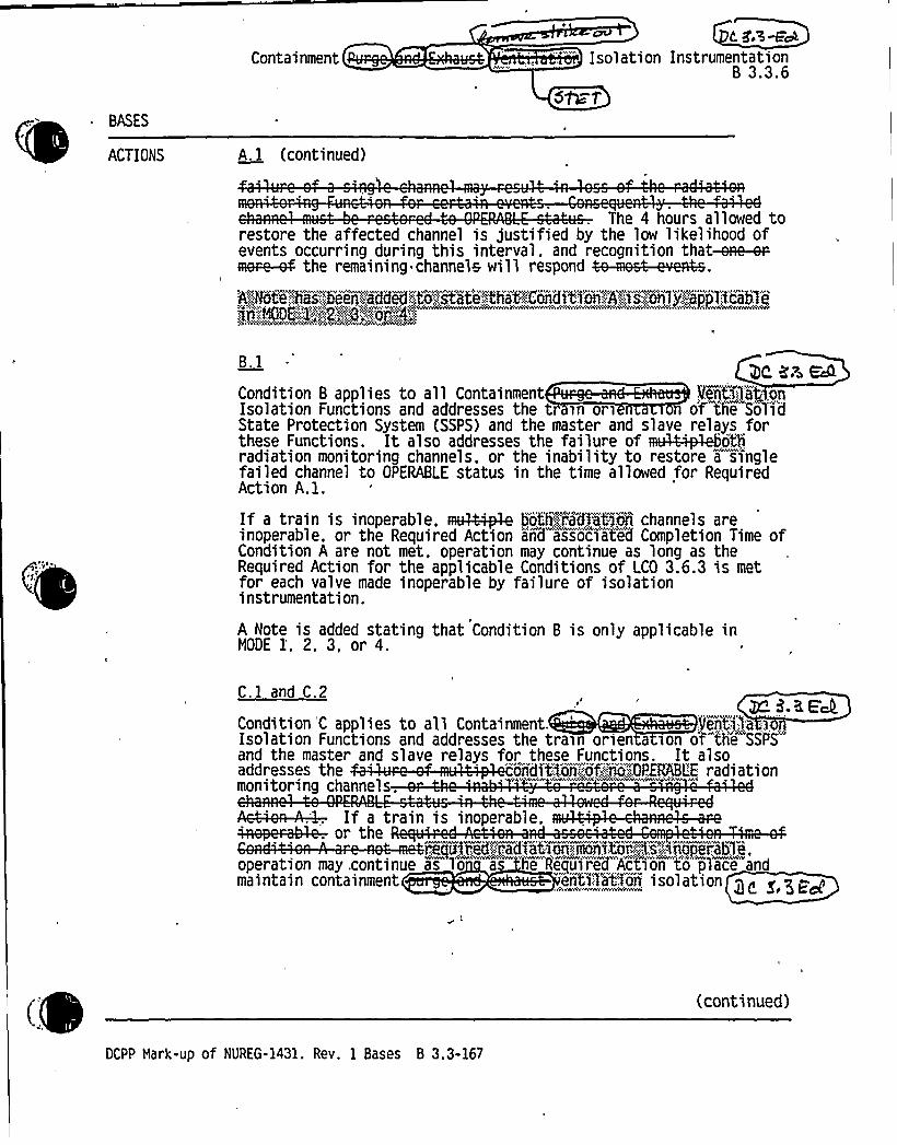
BASES
ACTIONS
Containment
A. 1 (continued)
L feE~ECk
Isolation InstrumentationB 3.3.6
5&1
4
The 4 hours allowed torestore the affected channel is justified by the low likelihood ofevents occurring during this interval, and recognition that-eRe-cr-
t ftp I t ttl p P~.at':::.,ihitse:!hai:;,benet a'ddeedt to'estate!:."that.":,::,:,CoYdi'ti'o'n:;:A:.".":is:!anima'pp1'i'oa5ietin„,=':ii00E-:::."Ii'.;.;2i~i'8l:"::".,:~4':;
rp
3c e.~ aaB.l
Condition 8 applies to all Containment Yeqti1$Q.Os@Isolation Functions and addresses the t in ori othe'SoTidState Protection System (SSPS) and the master and slave relays forthese Functions. It also addresses the failure of [email protected]~oihradiation monitoring channels, or the inability to restore a singlefailed channel to OPERABLE status in the time allowed for RequiredAction A.l.
If a train is inoperable, mme bsothgrcfdfatson channels areinoperable, or the Required Action and associated Completion Time ofCondition A are not met. operation may continue as long as theRequired Action for the applicable Conditions of LCO 3.6.3 is metfor each valve made inoperable by failure of isolationinstrumentation.
A Note is added stating that Condition B is only applicable inNODE l', 2, 3, or 4.
C.l and C.2
Condition 'C applies to all Containment. jferitj ..Ip.i..'solationFunctions and addresses the train orien a ion o'f"the 'SSPS
and the master and slave relays for these Functions. It alsoaddresses the '
"onditi'on,"ot',"::::no:;:;OPERhBL'E radiationmoni oring c anne s.
If t f f t p Ptp
operation may .continue as lo =as 'he Requipred"Action to place"andmaintain containment ei03atfoi isolation g< >,~<g
(DCPP Hark-up of NUREG-1431. Rev. 1 Bases B 3.3-167
(continued)

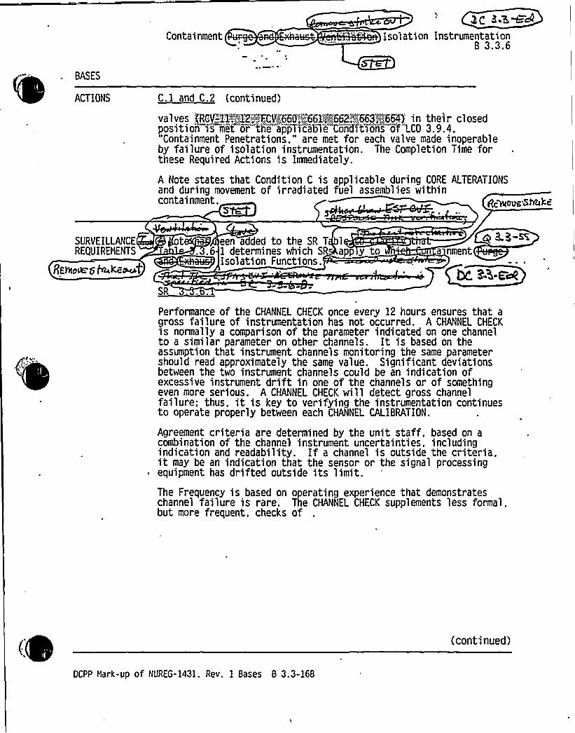
Containment Isol ati on Instrumentati onB 3.3.6
BASES
ACTIONS C.l and C.2 (continued)
va 1 ves gQV-„"Lg~gp~g+II'"'/go"'.,":,,';Qgl„',~662$: 663$ .;.664)'n thei r cl osedposition is met or the appli'c'abTe"Condi'tion~so "LCO 3.9.4."Containment Penetra+ions." are met for each valve made inoperableby failure of isolation instrumentation. The Completion Time forthese Required Actions is Irmediately.
A Note states that Condition C is applicable during CORE ALTERATIONSand during movement of irradiated fuel assemblies withincontainment. ,c~our5hbkc
S'tt:
SURVEILLANCEREQUIREMENTS
RfhoMg %kent
t een added to the SR T 1
.3.6 1 determines which S app y toIsolation Functions.
a nment
Performance of the CHANNEL CHECK once every 12 hours ensures that agross tailure of instrumentation has not occurred. A CHANNEL CHECKis normally a comparison of the parameter indicated on one channelto a similar parameter on other channels. It is based on theassumption that instrument channels monitoring the same parametershould read approximately the same value. Significant deviationsbetween the two instrument channels could be an indication ofexcessive instrument drift in one of the channels or of somethingeven more serious. A CHANNEL CHECK will detect gross channelfailure; thus, it is key to verifying the instrumentation continuesto operate properly between each CHANNEL CALIBRATION.
Agreement criteria are determined by the unit staff, based on acombination of the channel instrument uncertainties, includingindication and readability. If a channel is outside the
criteria't
may be an indication that the sensor or the signal processingequipment has drifted outside its limit.The Frequency is based on operating experience that demonstrateschannel failure is rare. The CHANNEL CHECK supplements less formal,but more frequent. checks of
(DCPP Mark-up of NURfG-1431. Rev. 1 Bases 8 3.3-168
(continued)


BASES
ContainmentD>e s.3-$
Isolation Instrum n at>onB 3.3.6S~
SURVEILLANCE SR 3.3.6.1 (continued)REQUIREHENTS
channels during normal operational use of the displays associatedwith the LCO required channels.
SR 3.3.6.2
SR 3.3.6.2 is the performance of an ACTUATION LOGIC TEST. The trainbeing tested is placed in the bypass condition, thus preventinginadvertent actuation. Through the semiautomatic tester, allpossible logic combinations, with and without applicablepermissives, are tested for each protection function. In addition,the master relay coil is pulse tested for continuity. This verifiesthat the logic modules are OPERABLE and there is an intact voltagesignal path to the master relay coils. This test is performed every31 days on a STAGGERED TEST BASIS. The Surveillance interval isacceptable based on instrument reliability and industry operatingexperience.
SR 3.3.6.3
SR 3.3.6.3 is the performance of a NSTER RELAY TEST. The NSTERRELAY TEST is the energizing of the master relay, verifying contactoperation and a low voltage continuity check of the slave relaycoil. Upon master relay contact operation. a low voltage isinjected to the slave relay coil. This voltage is insufficient topick up the slave relay. but large enough to demonstrate signal pathcontinuity. This test is performed every 31 days on a STAGGEREDTEST BASIS. The Surveillance interval is acceptable based oninstrument reliability and industry operating
experience.'R
3.3.6.4
A GQKFT.: is performed every 92 days on, each required channel toensure the entire channel will perform the intended Function. TheFrequency is based on the staff recoranendation for increasing theavailability of radiation monitors according to NUREG-1366 (Ref. 2).This test verifies the capability of the instrumentation to providethe containment purge and exhaust system isolation.
i.DCPP Hark-Up of NUREG-1431. Rev. 1 Bases 8 3.3-169
(continued)


BASES
Containment Iso ation InstrumentationB 3.3.6~s-
SURVEILLANCE SR 3.3.6.4 (continued)Rt QUIREHENTS
SR 3.3.6.5
SR 3.3.6.5 is the performance of a SLAVE RELAY TEST. The SLAVERELAY TEST is the energizing of the slave relays. Contact operationis verified in one of two ways. Actuation equipment that may beoperated in the design mitigation mode is either allowed to functionor is placed in a condition where the relay contact operation can beverified without operation of the equipment. Actuation equipmentthat may not be operated in the design mitigation mode is preventedfrom operation by the SLAVE RELAY TEST circuit. For this lattercase, contact operation is verified by a continuity check of thecircuit containing the slave relay. This test is performed every@29 days. The Frequency is acceptable based on instrumentreliability and industry operating experience.
SR 3.3.6.6
Thegeigs>rem~nus,~actuatssn~'at t!'gI "e cep'tÃv7a:.phase!A~or,::, !:«::::-:.:. i~
<DCPP Hark-Up of NUREG-1431. Rev. 1 Bases B 3.3-170
(continued}

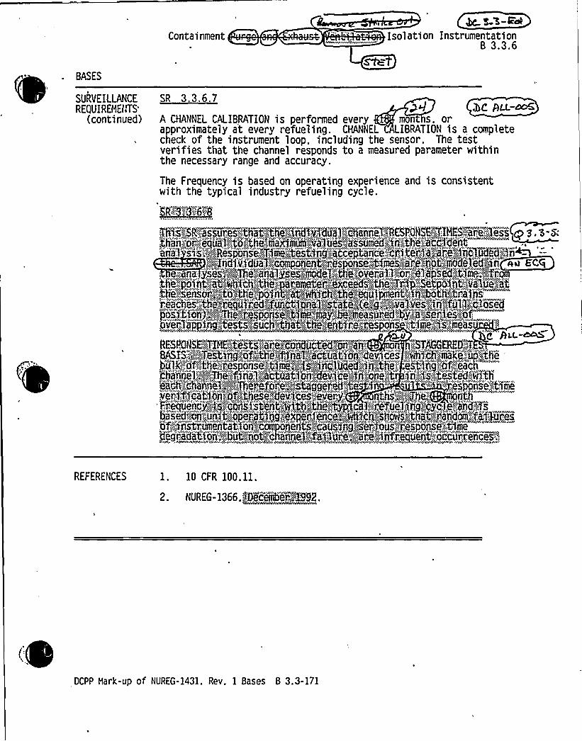


Attachment BPG&E Letter DCL-99-063
ADDITIONALINFORMATIONCOVER SHEET
ADDITIONALINFORMATIONNO: DC 3.3-ED1 (new)APPLICABILITY: DC
REQUEST:Various changes have been identified that do not impact the technicalcontent of the submittal or other FLOG members. Changes are notedwith DC 3.3-ED1 in the margin and noted below:
1) Remove the word "any" on Table 3.3.4-1, Functions 5 and 14 and theassociated Bases.
2) Remove the word "emergency" from LCO 3.3.7, Required ActionB 1.1.
3) Incorporate NRC editorial comments on the Bases for LCO 3.3.1,Function 6, 7, 12, 8 13.
4) Incorporate editorial comments on Bases of LCO 3.3.1, Condition M,and corrects the description of the effect below P-8.
5) Removes unnecessary definition of CHANNELCALIBRATION.
6) Add introductory statement to Insert for Bases of LCO 3.3.2,Condition J.
7) Incorporate NRC editorial comments on Bases of SR 3.3.2.12 and SR3.3.2.13.
8) Re-organize the Bases of LCO 3.3.7, Condition B in accordance withNRC comments.
9) Remove Insert discussing RM-45A 8 RM -45B in Bases for LCO3.3.8, Surveillance Requirements.
10) Other minor editorial changes, such as typographical, punctuation,spelling, etc. may not be specifically identified by page, but areincluded in the markup and will be included in the ITS and Basesclean copy.
ATTACHEDPAGES'ncl.
5AEncl. 5B .
3.3-59, 3.3-70B 3.3-7, B 3.3-14, B 3.3-15, B 3.3-16, B 3.3-17, B 3.3-26, B 3.3-27, B 3.3-36, B 3.3-37, B 3.3Q8, B 3.3-60, B 3.3-61, B 3.3-65, B 3.3-69, B 3.3-76,B 3.3-81, B 3.3-88, B 3.3-89, B 3.3-97, B 3.3-102, B 3.3-108, B 3.3-119(Inserts K & J), B 3.3-1 28 (Insert), B 3.3-129 (Insert B), B 3.3-150 (InsertA), B 3.3-162, B 3.3-175, B 3.3-177, B 3.,3-187

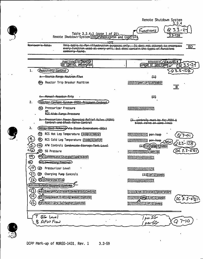
Remote Shutdown System3.3.4
Table 3.3.4- ( a e I of Ql:Remote Shutdown -.System Ins umenta on and Co ro
fvecT14Ns @ 5.'5-z,3.3-128
ED
INSTRUNEOR C ROL %RAN ER
EO h HELDNIB OF
q E.K-IZ.Q
Reactor Trip Breaker Position s~I:.:~r gtrip:.::trasher'.
B
Pressurizer Pressure
Q RCS Hot Leg Temperature gojpM".RIgfRCS Cold Leg Temperature LToap&~Ye~). ")
AFM Controls
SG Pressure
I O (Q Pressurizer Level
CQI tlg Charging Pump Controls
Cgig Iert'iLargNg Fl'm'r
,,::lMergency! gs~~ggheneretor~onhroi:
(Qt Q'YComptnentt'o-",C'os;t,::isa'ter,.hiiitiK:
Qtr g+gaiiTnig'i any."::,ga71hnalte'r.":."CO'ntrjP:
noN.'j'm%,NP('~Qx;o, )~p~i';a~i''pmeps
tig. ~or% :d~iFsg g'.:~enerators
s'." i':.i""'i".'ia":i!ii':'2!ora+'2!!Pumps
8.3- I Z
Qe, 3.5-e Gl
DC S 3-eg)
7 $C L~elg AI=W Fim
/ j~5&'perdG Q 7-JQ
OCPP Hark-up of NUREG-1431, Rev. 1 3.3-59


GAQ'-S CRVS Actuation Instrumentation3.3.7
ACTIONS (continued)
CONDITION REQUIRED ACTION COMPLETION TIME
B. One or more Functionswith two channels or twotrains inoperable.
PS
B.l.l Place one QRQ'-ECRU trainA '
ln
Pl'S SUl.ii'l'Z'd't10Tl lllodd.
AND
B.1.2 Enter applicableConditions and RequiredActions for one GNFSCRVStrain made inoperable" by"inoperable QKI4CRYSactuationinstrumentation.
Imediately < ~ g„t-~~S-PS
Imedi ately
PS
3.3-51
C. Required Action andassociated CompletionTime for. Condition Aor B not met in
'MODE l. 2 ~ 3, or 4.
C.l Be in MODE 3.
AND
C.2 Be in MODE 5.
6 hours
36 hours
(continued)
DCPP Mark-up of NUREG-1431. Rev. 1 3.3-70


BASES
BACKGROUND Reactor Tri Switch ear (continued)
RTS InstrumentationB 3.3.1
the reactor trip or ESF, these diagrams also describe the various"permissive interlocks" that are associated with unit conditions.Each train has a built in testing device that can automatically testthe decision logic matrix Functions whilethe unit is at power. Mhen any one train is taken out of servicefor testing, the other train is capable of providing unit monitoringand protection until the testing has been completed. The testingdhvice is semiautomatic to minimize testing time.
~ s
APPLICABLE The RTS functions to maintain the $4+ plicate',.:-'ljmi97during allSAFETY ANALYSES.AOOs and mitigates the co s gueace~' in
'
LCO, and which the og 4<MIa ~~ <> ~Me wF~ TR ~~APPLICABILITY t wunl wro~w arworw ~ ave Ut &l,~we fed~
Eac o e ana e acct en s an ransien s can e etected by oneor more RTS Functions. The accident analysis described inReference 3 takes credit for most RTS trip Functions. RTS tripFunctions not specitically credited in the accident. analysis arequalitatively credited in the safety analysis and the NRC staffapproved licensing basis for the unit. These RTS trip Functions mayprovide protection for conditions that do not require dynamictransient analysis to demonstrate Function performance. They mayalso serve as backups to RTS trip Functions that were credited inthe accident analysis.
The LCO requires all instrumentation performing an RTS Function.listed in Table 3.3.1-1 in the accompanying LCO, to be OPERABLE.Failure of any instrument renders the affected channel(s) inoperableand reduces the reliability of the affected Functions.
The LCO generally requires OPERABILITY of four or three channels ineach instrumentation Function, two channels of Manual Reactor Tripin each logic Function. and two trains in each Automatic Trip LogicFunction. Genera!qp four OpERABLE instrumentation channels in atwo-out-of-four configuration are required when one RTS channel is
Bt
s
also used as a control system input.;:,.;;:::,$n:,:.-'t4e,'.case;-.-,,Of,.-:,::the . ..„,':.'the
'feature;": jreyentg:.;.:;eoii~ya. 7pTote'ct'$'on',-::$ nter','idion,":'tv'e';:,ougjt":„, e,84%':::,:,iii$p:.':@hi';;eel':iiiifNCS';:iK'.0„'-'g.;«:.;.out,'::-,';Of.:-"::3,:::::loge'C.;-" This
=figuration accounts for the possibility 'of the'hared channel
failing in such a manner that it creates a transient that re uiresRTS action. In Diets( R~b~a~
M EQ I0 Bs $4 > ~ 6 ELM~ dYs*usta~
~ ~ (continued)
OCPP Mark-up of NUREG-1431, Rev. 1 Bases B 3.3-7


BASES
APPLICABLE 5.SAFETY ANALYSES.LCO. andAPPLICABILITY
RTS InstrumentationB 3.3.1
~Onsde W4ske1
Source Ran e Neutron Flux (con inued)7k K-3~+
the Power Range Neutron Flux-'L BR'nNODES 3.
4, and 5. administrative controls a so prevent theuncontrolled withdrawal of rods. The NIS source rangedetectors are located external to the reactor vessel andmeasure neutrons leaking from the core. The NIS source rangedetectors do not provide any inputs.to control systems. Thesource range trip is the only.RTS automatic protectionfunction required in NODES 2>below,:~P.-;;6::,:;-:P. 4, and 5KvifthkkheRod'FGmtr07%~t'.em",;capab.li'~af,';-;:;i":..od.'-":wiithdiaiil.,s'or .,„r„.fgQi:,j4iiis'eurXai. Therefore, the funcii'anal" caps i ity'"at the~ps.s~~@eci4~Trsp Setpoint is assumed to be avail le or HorThe LCO requires two channels of Source Range NeutronFlux to be OPERABLE. Two OPERABLE channels are sufficient toensure no single random failure wi 11 disable this trip
'Function. The LCO also 'requires one channel of the SourceRange Neutron Flux to be OPERABLE in MODE 3, 4, or 5 withRTBs open or,;:CKeÃcait roller od s,':,:"Tnca~ahieii of.', unthdrVaial: In.this case. tlie s'ource range Function is to provide controlroom indication
Tt p, f 1 i RTS1ginot required OPERABLEjirgHOOEg6~ar.;":;.:when the RTBs are openjor'.BlT,--:,r'advs;ai're;;fuiliITy.'Soarer'te'd aiidtthae,:,Rodi!Cfo'ntroI;,SrJ~stelii:fs~iiiiipi5!einhf::.iifthrd~ra7iiI:.
The Source Range Neutron Flux Function provides protectionfor control rod withdrawal from subcritical, boron dilutionand control rod ejection events. The Function also provides
W neutron flux indication in the control room.
In MODE 2 when below the P-6 setpoint during a reactorstartup. the Source Range Neutron Flux trip must be OPERABLEQ...out'.-":Of@co)Ãcid&nCO);:. Above the P-6 setpoint theInter'mediaute Range 'N'eutron Flux trip and the Power RangeNeutron Flux- Low Setpoint trip will provide core protectionfor reactivity accidents. Above the P-6 setpoint. the NISsource range rJe~tran~fgox',4y'ip>ma „-'.he:"m~anua:,::lygblocked and;
he"'.: Vijh~VOl'hiig'ie."ta~th'e>datve'CL'ra;::ia)ii!h'e duie.'an'ergi'Se'O'V, e, ovTtai, ."u,:.,Setpafntl.-,@heeaeroesaa~~Mtrnn.::,f iliua';trtfp!ii'S':ia'uvtea'atioafilireinstated:;::.aindi!the".',high';vNtaga!'to.';the'::detedtor'e':::::i'su =" 'n- s.s ciouautosidhica11v':::.':e
'"i."1aad'..
Ga)s- Oif- A'th~C
, In NODE„3. 4.. with the reactor shut down ~U4<', >jthe
Rod':,!CoITtr@~<kgstem'":'capabl8aof-,":rTN8:"NMriawal! ~OF' '>N)s" flOt
gu,f'1'y'-",;ip's'iit'ed'~ii "the Soiirce"RangeNeutroii Fl'ux"' M Function
'continued)
DCPP Mark-up of NUREG-1431. Rev. 1 Bases 8 3.3-14

1»
b

BASES
APPLICABLE 5.SAFETY
ANALYSES'CO,
andAPPLICABILITY
RTS InstrumentationB 3.3.1
Source Ran e Neutron Flux (continued) ,.
OPERABLE- to provide core protection against a rodwithdrawal accident. If the QQ RodLControl~System is notcapable of rod withdrawals the source range detectors are notrequired to trip the reactor. However. their monitoringFunction must be OPERABLE to monitor core neutron levels andprovide 'indication of reactivity changes that may occur as aresult of events like an"',-'agco5tr@;ted boron dilution.
. 'The requirements for theNIS source range detectors in NODE 6 are addressed inLCO 3.9.3, "Nuclear Instrumentation."
6. Overtem er ature hT
The Overtemperature hT trip Function is provided toensure that the design limit DNBR is met. This tripFunction also limits the range over which the Overpower hTtrip Function must provide protection.."'„and';;.;it>protects'.,;,'agaM0FesNI„::-",'exit.:;:,%N::;:bolljng:.':~ad';:.":ensures.th)t,'".=,thi.'.":'ex'it;-,'quart j'%isj$thiiW%.,',lii@ti'::;-'.Chf'ivied,:-:.:„bj:":::thKQNBR'";,'i';r;el;ati'on".'The" =Viiputs to the Gvertemperatur'e" hT"tr~p fndude'~ pressure.coolant temperature, axial power distribution, and reactorpower as indicated by loop hT assuming full reactor coolantflow. Protection from violating the DNBR limit is assuredfor those transients that are slow with respect to delaysf 1 tt t t
TheOvertemperature bT trip Function uses each loop's hT as ameasure of reactor power and is compared with a setpoint thatis automatically varied with the following parameters:
~ reactor coolant average temperature -the Trip Setpoint isvaried to correct for changes in coolant density andspecific heat capacity with changes in coolanttemperature:
~ pressurizer pressure - the Trip Setpoint is varied tocorrect for changes in system pressure: and
~ axial power distribution —f(61), the Trip Setpoint isvaried to account for imbalances in the axial powerdistribution as detected by the
~ NIS upper and lower power range detectors. Ifaxial peaks are greater than the design limit, as'icated by the difference between the upper and lower NIS
ower range detectors. the Trip Setpoint is reduced inccordance with Note 1 of Table 3.3. 1-1. 'hg QLL a>2
~ Dynamic compensation is included for system piping delays.r the core to the temperature measurement system.
h y, as used in the overtemperature and overpower ~T tri s,'represents the 100 percent RTP value of ~T as measured
(continue
OCPP Mark-up of NUREG-1431. Rev. 1 Bases B 3.3-15

0

BASES
RTS InstrumentationB 3.3.1
DI avX
Qh"
p8g JhttALP
for each loop. Fcore, ~T, is initiallymeasured rT value frommeasured at fullloo s ec»c ~T value
the initialssumed to be
he previous cower. Accura+MMEmad
tartup of a refuelehe same es the@@ KAm~ecle until ~T ise determination of the @>sw-iquarterly when
or other transient conditions). The dicated~T between loops is due to the ho't leg
eratures and hot leg temp'era ure measuremen ia s. Thehot leg temperature variance between loops is prim y
caused by asymetrical flow in the upper plenum, and thedifference in hot leg temperature measurement bases,primarily caused by differences in hot le tern eraturestreaming error between loo s. Theloop ~Ts with burn up c ange sn.the hot eg streaming iases as the radia ower distribution.changes. <p>« . ~Ihip ~~gf F~The Overtemperature hT trip Function is calculated for eachloop as described in Note 1 of Table 3.3.1-1. Trip occurs if
p dpf ddt dt 1 p.The pressure and temperature signals are used for other
1 11 1 .;:! ~m 1logic must be able to withstand an input failure to thecontrol system, which may then require the protectionfunction actuation, and a single failure in the otherchannels providing the protection function actuation. Notethat this Function also provides a signal to generate aturbine runback prior to reaching the Trip Setpoint. Aturbine runback will reduce turbine power and reactor power.A reduction in power will normally alleviate theOvertemperature hT condition and may prevent a reactor trip.
D(FF'rgevcBah ~~
p p sperforming the incore/excore recalibr tion at steady-stateconditions (i.e., power distributio not affected by xenon ggf 3.EBI
The LCO requires all four channels of the Overtemperature hTtrip Function to be OPERABLE
Notethat the Overtemperature hT Function receives input fromchannels shared with other RTS Functions. Failures thataffect multiple Functions require entry into the Conditionsapplicable to all affected Functions.
In MODE 1 or 2, the Overtemperature hT trip must be OPERABLEto prevent DNB .(2;,'out-,:,of'.: 4.„'.:eel'accidence)'.. In MODE 3. 4. 5.or 6, this trip Funcoon"does nmot"*have to be OPERABLE becausethe reactor is not operating and there is insufficient heatproduction to be concerned about DNB.
(continued)
DCPP Hark-up of NUREG-1431. Rev. 1 Bases 8 3.3-16


BASES
'APPLICABLE'AFETY ANALYSES.
LCO. andAPPLICABILITY
(continued)
7.
pQ(e A h)o
'get lac.~s 4txh
We overpower hW +iQQso per'id4$p~~ W m:~g~
~e, consc)uenccs ofmme.Q s4ec~l ne, brcccf>
i~<t4 i'n NM9z~h~g. I(, C,narra i,<~
Wt& CblriCictirl+C J Kid kii~etiCg/Lf(Pe f'. ~).
RTS InstrumentationB 3.3.1
Ove ower T
aT, . as used in the overe resents the 100 perce
for each loop. Focore, ~T, is initially ameasured ~T value frymeasured at fullloo s cs ic ~T values
empera ure and overpower ~T nt RTP value of ~T as measuredthe initial startup of a refue q>.~e-i
sumed to be the same as the Q@he previous cycle until ~T isower. Accurate determination of t
ei%AQ made qua /ca)i)i toQ4p peperforming the incore/excore recalibra ' at steady-stateconditions (i.e.. power distribution) ot affected by xenor. other transient conditions). The ind ed~T between loops is due to the ot leg
ratures and hot leg tempera ur a u n >ases. Thhot leg temperature variance between loops is primarily
caused by asymetrical fl~ in the upper plenum, and thedifference in hot leg temperature measurement biases insprimarily caused by differences in hot 1 t rstreaming error between loops. Theloop ~Ts with burn upthe hot eg streamingchanges.
The Overpower hT trip Function ensures that protectionis provided to ensure the integrity of the tuel (i.e..no fuel llet melting and less than 1X cladding strain)under al possible overpower conditions~7op,CoodItiarig.;:sadQ~ v
"RN~~$ . This trip Function also l"im~ts tTie oem.y.m
requ>re range of the Overtemperature hT trip Function anprovides a backup to the Power Range Neutron Flux-HighSetpoint trip. The Overpower bT trip Function ensures that
he allowable heat generation rate (kW/ft) of the fuel is notIt uses the hT of each loop as a measure of
reactor power with a setpoint that is automatically variedth the following parameters: Qc AQ;~~
~ reactor coolant average temperature-the Trip Setpoint isvaried to correct for changes in coolant density andspecific heat capacity with changes in coolanttemperature; and
If
~ rate of change of reactor coolant averagetemperature- including dynamic compensation for the delaysbetween the core and the t rature measurement s stem
Au.~
The Overpower hT trip Function is calculated for each loop asper Note 2 of Table 3.3.1-1. Trip occurs if Overpower hT isindicated in two loops. . The temperaturesignals are used for other control functions-.~ Ah-h4eeseam Qes~> the actuation logic must be able 'to withstand aninput fai"lure to the control system. which may then requirethe protection function actuation and a single tailure in theremaining channels providing the protection functionactuation. Note that this Function also provides a signal to
(continued)
DCPP Hark-up of NVREG-1431. Rev. 1 Bases B 3.3-17

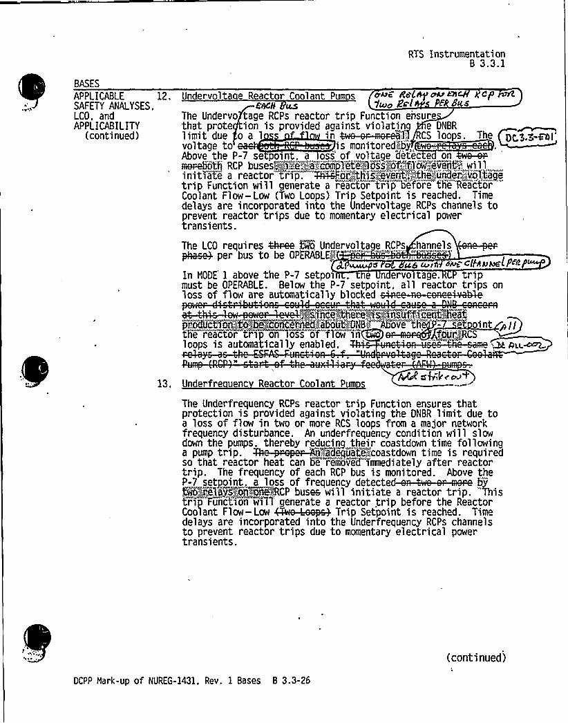
BASES
APPLICABLESAFETY ANALYSES.LCO, andAPPLICABILITY
(continued)
12
RTS InstrumentationB 3.3.1
Undervolta e Reactor Coolant Pum s 4~~ Ro~~~~</'8CH
AS V~o k'~lThe Undervo tage RCPs reactor trip Function ensurethat prote ion is provided against violating e DNBRlimit due o a 1 CC1 p. 1
voltage to is monitored:"':b „Above the P-7 se point. a oss of voltage detec e onmeebot'h RCP buses„::g':-.i".';9;'corn'pletegos's".':of..';f1'ow'„",evecnt'-'.": willinitiate a reactor tAp. ~ir.'-.:.,:.this)eve6t':,:::::;thi':,:.;uncder..':.'.:.volt'agetrip Function wHl generate a reactor ttsr'ip before the'Reactor""Coolant Flow- Low (Two Loops) Trip Setpoint is reached. Timedelays are incorporated into the Undervoltage RCPs channels toprevent reactor trips due to momentary electrical powertransients.
The LCO requires ~ two Undervoltage RCPs hannelsphasek per bus to be OPERABLE'i!'" "."'""; '"
".:" " *
~iIa ~I >stat: <IfhAllahP~~
In NODE 1 above the P-7 setpoi , e n ervo age. tripmust be OPERABLE. Below the P-7 setpoint. all reactor trips onloss of flow are automatically blocked
$:,'"'space';Were':.xs:-."~nsuffsceit"',":heat
loops is automatically enabled.-'' uu.~
13. Underfre uenc Reactor Coolant Pum sCQsk' op+
The Underfrequency RCPs reactor trip Function ensures thatprotection is provided against violating the DNBR limit due toa loss of flow in two or more RCS loops from a major networkfrequency disturbance. An underfrequency condition will slowdown the pumps. thereby reducing their coastdown time following
P P. ~-:-'a 't::".d dso that reactor heat can be removed imediately after reactortrip. The frequency of each RCP bus is monitored. Above the-T,tp,. 1 ff d d ~p"te'o'".",rce'la jsj~on~~mwcP buses ei'll initiate a reactor trip. Thistrip Function wilT generate a reactor trip before the ReactorC Fl —1 ~fi 1 pttt Pd.delays are incorporated into the Underfrequency RCPs channelsto prevent reactor trips due to momentary electrical powertransients.
(continued)
DCPP Mark-up of NUREG-1431, Rev. 1 Bases B 3.3-26


0

BASES
APPLICABLESAFETY ANALYSES,LCO. andAPPLICABILITY
RTS InstrumentationB 3.3.1
Power Ran e Neutron Flux P-8 (continued)P, sP,-VM
power. the reactor trip on low flow in any loois automatically blocked. c ~--+g~
C d/AlCl Ct
The LCO requires four channels of Power Ran e Neu nFlux, P-8 interlock to be OPERABLE in MODE 1. W 8u-~o~
In MODE 1, a loss of flow in one RCS loop could result inDNB conditions. so the Power Range Neutron Flux. P-8interlock must be OPERABLE. In MODE 2, 3, 4, 5, or 6.this Function does not have to be OPERABLE because thecore is not producing sufficient power to be concernedabout DNB conditions.
Power Ran e Neutron Flux P-9
The Power Range Neutron Flux. P-9 interlock is actuated ati1'-e'..,,,m.:Im!5II pdetermined by two-oxut=of=four"NIS power range detectors.The LCO requirement for this Function ensures that theTurbine Trip- Low F44d Auto:Shog0il Pressure and TurbineTrip-Turbine Stop Valve Closure"r'eactor trips are enabledabove the P-9 setpoint. Above the P-9 setpoint,a turbinetrip ~ esp chYf:ledge:,",.the„'.:!presser:>zev'>PORV8:,;d~ue;;:to%he'" -'c',;;
"'mi'"„"r'ea'''.,~'pe'ei',:.';,ta-'"",„'ea™N'Co~lNSystem".
A rea'ctor trip is automaticallyini't>ated on a"turbine trip when it is above the P-9
'nimize the transient on the reactor.t GWChJ< L a ~ Oa) g
e LCO requires —channels of Power Range Neutr n
Flux. P-9 interlock t'o e" OPERABLE in HOOE 1'(E.-:.',oOt',"of:.'o~T
dSlcB.
In MODE 2.3. 4. 5, or 6, this Function does not have to be OPERABLEbecause the reactor is not at a pow t tohave a PgoTt~ea603load re ectio bd B B e'b-
(continued)
DCPP Hark-up of NUREG-1431. Rev. 1 Bases B 3.3-36


BASES
APPLICABLESAFETY ANALYSES.LCO, andAPPLICABILITY
(continued)
RTS InstrumentationB 3.3.1
e. .Power Ran e Neutron Flux P-10
The Power Range Neutron Flux, P-10 interlock is«d ~lIIKdetermined by two-out-of-four NIS power range detectors.If power level falls below 10K RTP on 3 of 4 channels. thenuclear instrument trips will be automatically unblocked.The LCO requirement for the P-10, interlock ensures thatthe following Functions are performed:
on increasing power, the P-10 interlockallows the operator to manually block theIntermediate Range Neutron Flux reactor trip. Notethat blocking the reactor trip also blocks the signalto prevent automatic and manual rod withdrawal;
~ on increasing power, the P-10 interlock allows theoperator to manually block the Power Range NeutronFlux - Low reactor trip;
~ on increasing power, the P-1 interlock automaticallyprovides a back si nal to block the Source RanN tron Flux
detectors .:,sg;,:.vo .tage..",ane: one:.man~e: ',: oc 'o~,:;: -,rod!'st'ij:
~ the P-10 interlock provi one f o inputs tothe P-7 interlock; ~
~ on decreasing power, the P-10 interlock automaticallyenables the Power Range Neutron Flux- Low reactortrip and the Intermediate R n e Neutron Flux reactortrip (and rod stop)Q
«;:::.::;PA''ei;:::,d'eci","eas>~Yp~rY4he;:;,P,—,1t):,:,:Snterlock:;,aiitomati,col'j'fefea'@';
th8; goCK'::;0fp'th'8::.„''sou't'.,~;;::.;i!ange;::„::ij8Mtj',:OA'i?f1@"'"
hr'ip'an~di'mite::P,.-".'.6feiiergiioe&io4oiir 'oo:
araiigii:.higgle'ola'e'9'ei~!
" " -
~ II
The LCO requires . channels of Power Range NeutrFlu . P-10 inter lock to e OPERABLE in MODE 1 or
2(2«.;out'.-,,'f,-
OPERABILITY in MODE 1 ensures the Function is available toperform its decreasing power Functions in the event of areactor shutdown. This Function must be OPERABLE inMODE 2 to ensure that core protection is provided during a
OCPP Hark-up of NUREG-1431. Rev. 1 Bases B 3.3-37
(continued)


0
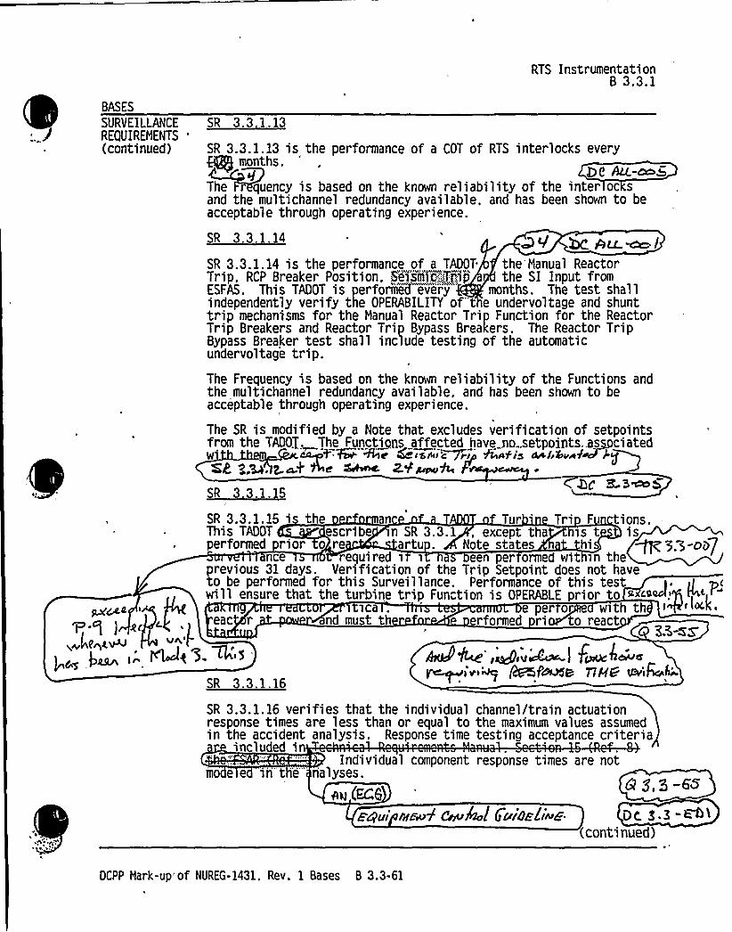
BASES
SURVEILLANCEREQUIREMENTS
'continued)
RTS Instrumentation8 3.3.1
SR 3.3,1.13
SR 3.3.1.13 is the performance of a COT of RTS interlocks everymonths.
The quency is based on the known reliability of the inter oc sand the multichannel redundancy available, and has been shown to beacceptable through operating experience.
SR 3.3 1.14 hc Au ~lSR 3.3.1.14 is the performance of a TADOT the Manual ReactorTrip. RCP Breaker Position, Se>serac',.':~Trip the SI Input fromESFAS. This TADOT is performed every months. The test shallindependently verify the OPERABILITY of-t e undervoltage and shunttrip mechanisms for the Manual Reactor Trip Function for the ReactorTrip Breakers and Reactor Trip Bypass Breakers. The Reactor TripBypass Breaker test shall include testing of the automaticundervoltag'e trip.The Frequency is based on the known reliability of the Functions andthe multichannel redundancy available, and has been shown to beacceptable through operating experience.
The SR is modified by a Note that excludes verification of setpointsfrom the TADOT, The Funct~i .ns affected have no .setpoints..as ciatedW''%e 6 sss's&r~r faiafis srsf ssrf J'gQKg g.~. z.m4 Ae ~ z,V~A~s3... 5
'P.g ) gr4hZ V
I 6s.~~ ~"
SR 3.3.1.15 is the an Tur Tri F tions.This TADOT escribe n SR 3.3. 1 , except tha is t isperformed rior o re arts . Note states Oi ~ p.~-oi>7
nce required i i een per ormed wit in theprevious 31 days. Verification of the Trip Setpoint does not haveto be performed for this Surveillance. Performance of this test >. ilwill ensure that the turbine trip Function is OPERABLE prior to «~~."5 ~'i "
ica . e per or with theac r nd must t rformed ri -to react
Z3-zsUt
~e $ .W's ktkP'Itor qegwWss I Fsos~'arrsy ~>'v~ (i?psf~s nec e'iE
h'R
3.3.1.16
SR 3.3.1.16 verifies that the individual channel/train actuationresponse times are less than or equal to the maximum values assumedin the accident analysis. Response time testing acceptance criteria
included iIndividual component response times are not
mo e e in t -e- nalyses.
~~ bet"zpui nrmV deukol 5uiazliwe De. S.3 "<~>
(continued)
DCPP Hark-up of NUREG-1431. Rev. 1 Bases B 3.3-61


ESFAS instrumentation Q~B 3.3.2
B 3.3 INSTRUMENTATION
B 3.3.2 Engineered Safety Feature Actuation System (ESFAS) Instrumentation
BASES
BACKGROUND The ESFAS initiates necessary safety. systems, based on the values ofselected unit parameters. to protect against violating core designlimits and the Reactor Coolant System (RCS) pressure boundary. andto mitigate accidents.
The ESFAS instrumentation is segmented into three distinct butinterconnected modules as identified below:
Field transmitters or process sensors and instrumentation:provide a,measurable electronic signal based on the physicalcharacteristics of the parameter being measured:
Signal processing equipment including ~g 3i jg]M":„:"-'protectionsystem. field contacts. and protection channel sets: providesignal conditioning, bistable setpoint comparison. processalgorithm actuation, compatible e'tectrical signal output toprotection system devices. and control board/control room/miscellaneous indications; and
l
Solid State Protection System (SSPS} including input, logic.and output bays: initiates the proper unit shutdown orengineered safety feature (ESF) actuation in accordance withthe defined logic and based on the bistable outputs from thesignal process control and protection system.
Fi 1 Transmi r r nsors
To meet the design demands for redundancy and reliability. more thanone. and often as many as four . field transmitters or sensors areused to measure unit parameters. In many cases, field transmittersor sensors that input to the ESFAS are shared with the Reactor TripSystem (RTS). In st cases..the same channels also provide controlsystem 'inputs. To account for calibration tolerances and instrumentdrift, which are assumed to occur between calibrations,'statisticalallowances are provided in the Trip Setpoint and Allowable
g~aci h+Vdr E'-ea'p cJ
PCOHSS~ Q ~g SSpt C 4J S C,~ IR,dksl /p)
heat rrmnru ~s co S ySAm,
t"C'Si dM hei Ct' t n~egg C
PllemsiO ~ip Cl< / p /pe I en) QCWs
S+rC)g, +~k, leo~<i f0& e nts+
SI PALcontinued}
DCPP Hark-up of NUREG-1431. Rev. 1 Bases B 3.3-65


ESFAS InstrumentationB 3.3r2
BASES
BACKGROUND Solid State Protection S stem (continued)
transients. If a required logic matrix combination is completed,the system will send actuation signals via master and slave relaysto those components whose aggregate Function best serves toalleviate the condition and restore the unit to a safe condition.Examples are given in the Applicable Safety Analyses. LCO. andApplicability sections of this Bases.
Each SSPS train has a built in testing device that can automaticallytest the decision logic matrix functions and the actuation deviceswhile the unit is at power. When any one train is taken out ofservice for testing, the other train is capable of providing unitmonitoring and protection until the testing has been completed. Thetesting device is semiautomatic to minimize testing time.
'he actuation of ESF components is accomplished through master andslave relays. The SSPS energizes the master relays appropriate forthe condition of the unit. Each master relay then energizes one ormore slave relays. which then cause actuation of the end devices.The master and slave relays are routinely tested to ensureoperation. The test of the master relays energizes the relay. whichthen operates the contacts and applies a low voltage to theassociated slave relays. The low voltage is not sufficient toactuate the slave relays but only demonstrates signal path .
continuity. The SLAVE RELAY TEST actuates the devices if iroperation will not interfere with continued unit opera on. For the g,>-Fblatter case. actual component operation is prevented y the SLAVERELAY TEST circuit. and slave relay contact operat' is verifi d bya
' it containin th r 1~Y+ r c " . '.
,,„...,.„,,:"::.~:.;„-..e;:-,.:,,ist".',:frequeiic$ !~%i'i:.:: bas'ed'.:;on",,::i,:;elegy':i.':,el':ab'i„"::I'~ty,.',wssesmejts:; alii'",ese5ted@ii'.NCAA'.-,",'„:,:18878.'.::-,:.':!,IRg.:'.i:abi:.]Xtj:hss'ears'me@NExfehs'fan::,'bfi5'Ii14147~~Rel):ab'$9,ltd';As'sessme)if",pelage.;:.@jThesi':~relic>„:l44j::.:issessm'ejit)Oi)gyp:to)P'otteigaridg>'umfj~ldw..'"NS,::,sexes>i,"jul.aj.i)6s'e5',:~ii,'thi.;.:.'KSF;::i<m(~onwyst'e'I.',ii'i'i'rjiied'":appl1c'atieis~>h'easel'ays":::m fbive"'t6"%;"„,:i,.epl'icee'dPe@jiifiPlilP~hii:,'e'ccoijfie eTtiiecieh@h iijiie>'d ee~jii7eoriiiii!iii!AP@3878ffoce
,:1!8,,+SU
(continued)
OCPP Mark-up of NUREG-1431. Rev. 1 Bases B 3.3-69


ESFAS InstrumentationB 3.3.2
BASES1
APPLICABLE d.SAFETY ANALYSES,LCO, and
'PPLICABILITY
]a~Lock.
,M,6;I~e-)I,~ t ~~so~P~g~ —Iuaer Suc k~ ]s
8 Lo c.k.ch
Rc~~ s~k.e~g
Safet In 'ecti on —Pressuri zer Pressure —Low(continued)
The transmitters are located inside containment. with thetaps in the vapor space region of the pressurizer, andthus possibly experiencing adverse environmentalonditions (LOCA, SLB inside containment. rod ejection).erefore, the Trip Setpoint reflects the inclusion ofth steady state and adverse environmental instrumcertainties. P s3-( ~
Thi Function must be OPERABLE in NODES 1, 2, and 3 (aboveP-1 to mitigate the consequences of an HELB insidecontainment. This signal may be manually blocked by theoperator below the P-11 setpoint. Automatic SI actuationbelow this pressure setpoint is then performed by theContainment Pressure —High
This Func on is re ui r PERABLE in NODEbelow the -I,I
4H.~BE-. DES 4, , an , this Function is notnee ed or cident detection and mitigation.
II &kege. Safet In ection- Steam Line Pressure
(1) Steam Line Pressure- Low
Dc 8.3- EGI
Steam Line Pressure —Low provides protection againstthe following accidents:
~ SLB;
~ Feed line break: and
~ Inadvertent opening of an SG relief or an SG
safety valve.
Steam Line Pressure —Low provides ae input ko.,'theOFNCf~ .', i,, 'ib;.WL!I'i",,.'p're'venXi„::"",tpe:.~excu~sTon;"':Qf,,",on'e"':;of'.;".the:;.',::inputs'':;::'.',frollIca'using'4'>'jar'o'cess.-',"dieu'r0'anc~::."tfi'ai!k'ro'uld:.';.„:re'qu'i:.re
'rotect%ve'Klctionjfrom.:;:.th&j78ll93Plug Icahnnel5,"..,~00,".;.918iffi'eked.::":steam+fmk;:~%Thus, three OPERABl.'E'"chan'n'el s oneach steam line are sufficient to satisfy theprotective
(continued).
DCPP Hark-up of NUREG-1431. Rev. 1 Bases B 3.3-76

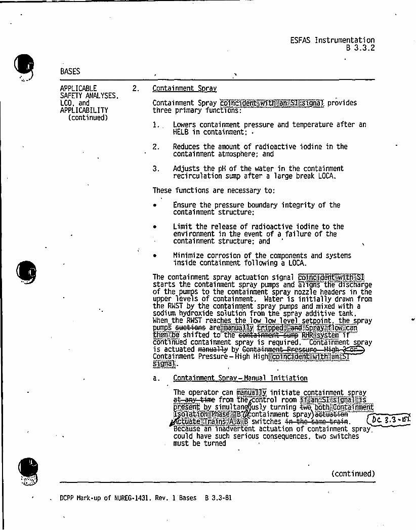
ESFAS Instrumentation8 3.3.2
BASES
APPLICABLESAFETY ANALYSES,LCO, andAPPLICABILITY
(continued)
2. Containment S ra
Containment Spray coiricid'crit vnthranRI:,::."signal providesthree primary font'ti'ons:
1. Lowers containment pressure and temperature after anHELB in containment: .
2. Reduces the amount of radioactive iodine in thecontainment atmosphere; and
3. Adjusts the pH of the water in the containmentrecirculation sump after a large break LOCA.
These functions are necessary to:
Ensure the pressure boundary integrity of thecontainment structure:
~ Limit the release of radioactive iodine to theenvironment in the event of a failure of thecontainment structure; and
~ Ninimize corrosion of the components and systemsinside containment following a LOCA.
The containment spray actuation signal eo~nc>den7':.".,volh':4E:starts the containment spray pumps and aligns the'dischar'geof the pumps to the containment spray nozzle headers in theupper levels of containment. Mater is initially drawn fromthe RWST by the containment spray pumps and mixed with asodium hydroxide solution from the spray additive tank.When the RWST reaches the low low level setpoint. the spraypumps sye4-was are~hmanua.Pi.y: tpjg=d-:-.~755rayjf low;.;:can
conti'nued containment spray is required. Contvainment s rayis actuated Res~ byContainment Pressure —High High,"':$0VoCide'rC~~UH.'th':'„:::ad:::,SÃgfQ'::.
a. Containment S ra —Manual Initiation
The operator can eantia3:;fy. initiate containment sprayf th
"1 ir,:: nt:.:,,:,!Tm,"
pres+if; by simultan usly turning 4e booth:.':;Containment
v~
f 'Q'at'iori)Phase~;,:-B;: ontainment spray)achi~iV'="usta:,';Tfa iri,."'A'."8'-.:,B switches
Be'cause an''nadve'r'tent actuation of containment spray„could have such serious consequences, two switchesmust be turned
(continued)
OCPP Hark-up of NUREG-1431. Rev. 1'Bases B 3.3-81


ESFAS InstrumentationB 3.3.2
BASES
APPLICABLESAFETY ANAI YSES,LCO. andAPPLICABILITY
(2) Phase B Isolation -Automatic ActuationLo ic and Actuation Rela s (continued)
isolation. There also is adequate time for theoperator to evaluate unit conditions andmanually actuate individual isolation valves inresponse to abnormal or accident conditions.
(3) Phase B Isolation —Containment Pressure
The basis for containment pressure NODE
applicability is as discussed for ESFASFunction 2.c above.
4. Steam Line Isolation
Isolation of the main steam lines provides protection inthe event of an SLB inside or outside containment. Rapidisolation of the steam lines will limit the steam breakaccident to the blowdown from one SG, at most. For an SLBupstream of the main steam isolation valves (HSIVs), insideor outside of containment, closure of the NSIVs limits theaccident to the blowdown from only the affected SG. For anSLB downstream of the NSIVs. closure of the HSIVsterminates the accident as soon as the steam linesde ressurize.
a.'team Line Isola ion-Manual Initiationllc. 3 3 . Fh I
Manual ini ation of Steam Line Isolation can beaccompl is d from the control room gii::;.::ari'::.:',;~odi,vidual,Slit, ch'eac l vR,'. ee.
The LCO requires Owe 'onechannels periales to be OPERABLE.
(continued)
DCPP Hark-up of NUREG-1431, Rev. 1 Bases B 3.3-88


ESFAS InstrumentationB 3.3.2
BASES
APPLICABLESAFETY ANALYSES,LCO, andAPPLICABILITY
(continued)
. Steam Line Isolation -Automatic Actuation Lo icand Actuation Re a s
Automatic actuation logic and actuation relaysconsist of the same features and operate in the samemanner as described for ESFAS Function 1.b.
Manual and automatic initiation of steam lineisolation must be OPERABLE in NODES 1, 2, and 3 whenthere is sufficient energy in the RCS and SGs to havean SLB or other accident. This could result in therelease of significant quantities of energy and causea cooldown of the primary system. The Steam LineIsolation Function is re uired in NODES 2 and 3 unlessall NSIVs are closed and Qe-::,aCGy~te . In NODES 4,5, and 6, there is insufficient energ in the RCS andSGs to experience an SLB or other acc dent releasinsignificant quantities of energy.
~gp~ ~ vAILc'+C /~~4Lf'54'Ãf
Steam Line Isolation-Containment Pre
F~ -cnz.
This Function actua s closure of the NSIVs in theevent of a LOCA or n SLB inside containment 4e
dto containment .a~~simgle'.:;.'S8. The transmitters (d/p JX 3.>-Bcells) are loca ed outside containment with thesensing line (high pressure side of the transmitter)located inside containment. ContainmentPressure-High 8 ~9ggh provides no input to anycontrol functions. Thus, three OPERABLE channels aresufficient to satisfy protective requirements withtwo-out-of-three logic. However, for enhancedreliability. this Function was designed with fourchannels and a two-out-of-four logic. Thetransmitters and electronics are located outside ofcontainment. Thus. they will not experience anyadverse environmental conditions, and the TripSetpoint reflects only steady state instrumentuncertainties.
Containment Pressure-High 8 ".-::,:H>jh must be OPERABLE inMODES 1, 2, and 3, when there i'-s'ufficient energy inthe primary .and secondary side to pressurize thecontainment following a pipe
(continued)
DCPP Hark-up of NUREG-1431. Rev. 1 Bases 8 3.3-89

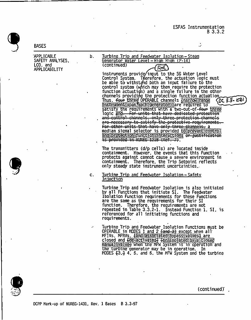
ESFAS InstrumentationB 3.3.2
BASES
"APPLICABLESAFETY ANAI YSES.LCO, andAPPLICABILITY
Turbine Tri and Feedwater Isolation —SteamGenerator Water Level - Hi h Hi h P-14(continued)
instruments provide input to the SG Water LevelControl System. T erefore. the actuation logic mustbe able to withst d both an input failure to thecontrol system (w ich may then require the protectionfunction actuati n) and a single failure in the otherchannels providi g the protection function actuationThus. Seen %braes'PERABLE channels Lnarrtouaranpe QC. B.B- h<lLnsLrument-:: Sj'ajLepehFgenerat'os".':;are requirsed t'o
logic iY .
amedian signal selector is orovided to7jrevent:.',control:Rw ter E:tt -::t'i i:-
The transmitters (d/p cells) are located insidecontainment. However, the events that this Functionprotects against cannot cause a severe environment incontainment. Therefore, the Trip Setpoint reflectsonly steady state instrument uncertainties.
Turbine Tri and Feedwater Isolation- Safet~In ection
Turbine Trip and Feedwater Isolation is also initiatedby all Functions that initiate SI. The FeedwaterIsolation Function requirements for these Functionsare the same as the requirements for their SIfunction. Therefore, the requirements are notrepeated in Table 3.3.2-1. Instead Function 1 ~ SI, isreferenced for all initiating functions andrequirements.
Turbine Trip and Feedwater Isolation Functions must beOPERABLE in MODES 1 and 2 Had-3-;} except when allMFIVs. MFRVs, @ME,assoc:i,atled",',bypsra'st,":viTaveg areclosed and Qfi'«..,'a'%~vite@ Ri,',:)sjl5tej:,'':bj'!a.':::,c osedmais~a, jeg~ve3'when the MFW 'system "is in 'oper'atiori andtTie turbine generator may be in operation. InMODES f3,9 4. 5, and 6, the MFW System and the turbine
(continued)'CPP
Mark-up of NUREG-1431, Rev. 1 Bases B 3.3-97

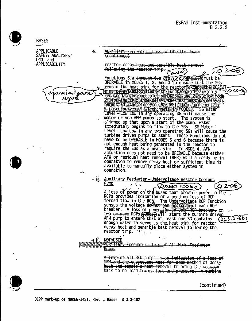


ESFAS Instrumentation8 3.3.2
BASES
APPLICABLESAFETY ANALYSES,LCO ~ andAPPLICABILITY
En ineered Safet Feature Actuation S stemInter ocks —Reactor Tri P-4 (continued)
~ Trip the main turbine:
~ Isolate NFW with coincident low T,„, spBS4,";,,F,,:;
reac uation o'-" "'
~ Transfer the steam dump from the load rejectioncontroller to the ~ p4% trip controlland Re uth
~ Prevent opening of the NFW ',valVes 6<3~< ~+~
op>ypass valves if they were closed on'Slor"'$
jh'MIMater Level~~jh.Each of the above Functions is interlocked with P-4 toavert or reduce the continued cooldown of the RCSfollowing a reactor trip. An excessive cooldown ofthe RCS following a reactor trip could cause aninsertion of positive reactivity with a subsequentincrease in geAer Led Coi'a~power . To avoid such asituation. the noted Functions have been interlockedwith P-4 as part of the design of the unit control andprotection system.
None of the noted Functions serves a mitigationfunction in the unit licensing basis safety analyses.Only the turbine trip Function is explicitly assumedsince it is an iomediate consequence of the reactortrip Function. Neither turbine trip. nor any of theother four Functions associated with the reactor tripsignal. is required to show that the unit licensingbasis safety analysis acceptance criteria areLmet- eAmeeeded.
The RTB position switches that provide input to theP-4 interlock only function to energize or de-energizeor open or close contacts. Therefore, this Functionhas no adjustable trip setpoint with which toassociate a Trip Setpoint and Allowable Value.
(continued)
OCPP Hark-up of NUREG-1431. Rev. 1 Bases B 3.3-108


ESFAS Instrumentati oneB 3.3.2
' BASES
ACTIONS I. 1 and 1.2 (continued)
! Itt'I,,;,;t,:,,!.,:w!I'N',,WI,,*, !,!tT!,.L'!Hpp,.",,!j!%.".~i.;*:.J'!.ul>":,<n'.",Squat"'.f'o@Y~~WBg~ho'urgegget<on"-.'Flame'-;.:ls~~
5isA~Pope'riE4m~mperimi'e,,':to".~ch<NDE:"'2jfrje",s'fuf,:fg joker.iiandi5tiiihjiij,'g,m'aej)y~Riia'iiiiei~mthciiajkisUfnmiig uNt:".'j'j'steiiis >:INiiODE!2l':"!!bi&Funciii'm~lsYie~i%jSMjNNd':.QPBNBL%'::
The Required Actions are modified by a Note allms theinoperable channel to be bypassed for up to hours forsurveillance'testing of other channels. The 6 'hours allowed toplace the inoperable channel in the tripped condition. and the4 hours allowed for a second channel .to be in the bypassedcondition for testing, are justified in Reference 8.
.1 and J.2$~&R.> QC'B~ W G~ae 3 KH2:7
g( (, )g.l.2
K.2 1 and K.2 2ZnP~T K
Co itio K appl/es toL@ye '@<~~4~ MC~~ AOw:nw'A'wr.!!!V.'7rrw twCMi(DNA
(continued)
OCPP Hark-Up of NUREG-1431. Rev. 1 Bases B 3.3-119

0

Attachment 2PGRE Letter DCL-98-167
Enclosure 5B page B 3.3-119Insert ACTION J Bases
Insert for Q 3.3-12?
Ifone channel is inoperable, 6 hours are allowed to restore one channel to OPERABLEstatus or to place it in the tripped condition. Ifplaced in the tripped condition, theFunction is then in a partial trip condition where one-out-of-two logic will result inactuation. The 6-hour Completion Time is justified in Reference 8. Failure to restorethe inoperable channel to OPERABLE status or place it in the tripped condition within6 hours requires the unit to be placed in MODE 3 within 12 hours. The allowedCompletion Time of 12 hours is reasonable, based on operating experience, to reachMODE 3 from full power conditions in an orderly manner and without challenging unitsystems. In MODE 3, this Function is no longer required OPERABLE.
The Required Actions are modified by a Note that allows the inoperable channel to bebypassed for up to 4 hours for surveillance testing of other channels. The 6 hoursallowed to place the inoperable channel in the tripped condition, and the 4 hours allowedfor a second channel to be in the bypassed condition for testing, are justified inReference 8. g g,$ -f'5 I
y y~iih g SAN A c,Bi~a ~ ~> +~<™*+
~ p"~ ~, ~
V

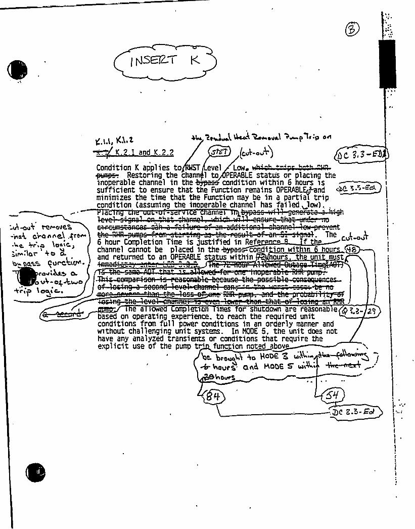
~ ~
..4 wu4 mr-c ve.E
o~ nnq$ ,pro~'
9r 0 $ Peit'I
s(dr 40 O
gee PuW CKN s
<4Mt4.QotP4 og two
'+C'SP ~ ~l Ca ~
g.[,(, Kh.~ 4~ ~eU k l4 ~~ u \ > p l.:p o~
K.2. and K 2. sea (~„~ .„f)Condition K applies to evel Low~ys~pe-. Restoring the charm 1 to PERABLE statu's or placing theinoperable channel in the condition within 6 hours sssufficient to ensure that the Function remains OPERABLE.Andminimizes the time that the Function may be in a partial tripcondition (assuming the inoperable channel has failed ~low),,PTa anne 4»
J iJ sa J 4~ ~
4
The6 hour C etion Time is 'ustified in Ref o f
QL" 8 >-~
s J4 ~ asas J as
ompchannel cannot be placed in the +~condi ion withi h ur HSand returned to an OP@ABLE st tus within ours h n st
t
I
t
It
e a ow omp &son imes or s ut own are reasonab e yg.gbased on operating experience. to reach the required unitconditions from full power conditions in an orderly manner andwithout challenging unit systems. In %DE 5, the unit does nothave any analyzed transients or conditions that require theexplicit use of the pump tr'unc ion noted abov
4t'a~Q Aa Ho~ E ~~~~'"
HOW 5'iA ~
hours,


ESFAS InstrumentationB 3.3.2
SURVEILLANCEREOUIREHENTS
SR 3 3 . (continued)
~Wc IIJc49~a.l Wvge,k~aWTpgJ56'l H5
accident a sis. Response Time testing acceptance criteria areincluded
' " cp 4-h-K'~4R@—R
"", faYQ;." iaido. n >v> ua componen responsetimes are n e a 1yses. The analyses model theoverall or total elapsed time, from the point at which theparameter exceeds the'Trip Setpoint value at the sensor, to thepoint at which the equipment in both trains reaches the requiredfunctional state (e.g.. pumps at rated discharge pressure, valvesin full open or closed position).
For channels that include dynamic transfer functions (e.g.. lag,lead/lag, ratellag, etc.). the response time test may beperformed with the transfer functions set to one with theresulting measured response time compared to the appropriate FSARresponse time. Alternately. the response time test can beperformed with the time constants set to their nominal valueprovided the required response time is analytically calculatedassuming the time constants are set at their nominal values. Thresponse time may be measured by a series of overlapping tests
uch that the entire response time is measured.
ESF RESPONSE TINE tests are conducted on an month STAGGEREOTEST BASIS. Testing of the final actuation devices. which makeup the bulk of the response time. is included in the testing ofeach channel. The final actuation device in one train is testedwith each channel. Therefore. staggered testing resu s inr s o time verification of these devices every months. c au.
he month Frequency is consistent with the typ'ic'a refuelingcycle an is based on unit operating experience, which shows thatrandom failures of instrumentation components causing seriousresponse time degradation, but not channel failure, areinfrequent occurrences.
This SR is modified by a Note that clarifies that the turbinedriven AFW pump is tested within 24 hours after reaching W40 }859 psig in the SGs.
SR
SR 3.3.2.11 is the performance of a TADOT as described inSR 3.3.2.8. except that it-is performed for the P-4 Reactor
~ 4WI )zc4A A '/ /~~~ f aw e ~~~~ ~'P bye Wck ~ vu-': k~ n ~ ~~ ~
FeJCL pn. 48 aojgz. Dc e~-~~
DCPP Nark-up of NUREG-1431. Rev. 1 Bases B 3.3-128

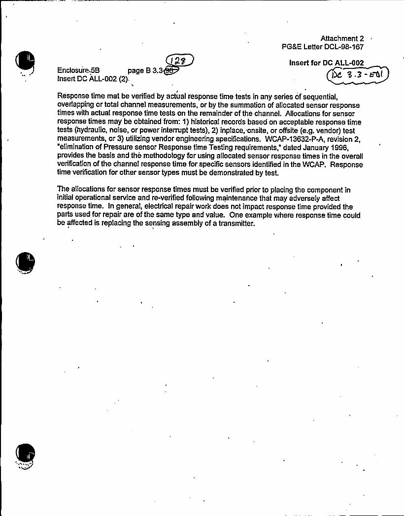
Attachment 2PG8 E Letter DCL-98-167
Insert for DC ALL-002Enclosure,5B page B 3.3Insert DC ALL-002 (2).
IResponse time mat be verified by actual response time tests in any series of sequential,overlapping or total channel measurements, or by the summation of allocated sensor responsetimes with actual response time tests on the remainder of the channel. Allocations for sensorresponse times may be obtained from: 1) historical records based on acceptable response timetests (hydraulic, noise, or power interrupt tests), 2) inplace, onsite, or offsite (e.g. vendor) testmeasurements, or 3) utilizing vendor engineering specifications. WCAP-13632-P-A, revision 2,"elimination of Pressure sensor Response time Testing requirements," dated January 1996,provides the basis and the methodology for using allocated sensor response times in the overallverification of the channel response time for specific sensors identified in the WCAP. Responsetime verification for other sensor types must be demonstrated by test.
The allocations for sensor response times must be verified prior to placing the component ininitial operational service and re-verified following maintenance that may adversely affectresponse time. In general, electrical repair work does not impact response time provided theparts used for repair are of the same type and value. One example where response time couldbe affected is replacing the sensing assembly of a transmitter.


TI'-111, Revision 1
Response time may be veri6 by actual response in any series ofsequential,overlapping or total chnnel m or by stunnurtion ofallocated sensor responsetimes with actual response time on the er ofthe channeL AHocations for sensorresponse times may be obtained &am: 1 cal records based on acceptable response timetests (hydraulic, noise, or power', (2) inplace, onsite, or o6site (e,g. vendor) testmeasurements, or (3) utBizing en 'peci6cations. WCAP-13632-P-A, Revision 2,"Himination ofPressure S W'Wl~"d M3 n 1996,
provides the basis and dology forusing sensor response times in the overallveri6cation ofthe zeqmnse time Sr speci6c identi6ed in the WCAP. Responsetime verHication other mar types must be d
bytes'he
aHo for sensor response times must be veri6ed prio o placing the component in tn 6'a.g
operati service and xe-veri6ed followingmaintentmce that my affect response time.In g eral, electiical repair vrork does not impact response time pram the parts used for repair
ofthe same type and value. One eammple where response time coul e affected is replacingsensing assembly ofa tran.knitter.
D~-i~ Q" scil


ESFAS InstrumentationB 3.3.2
, BASES
SURVEILLANCEREQUIREMENTS
3 3,~1 (continued>'g4 3E Au.-col
Trip Interlock'.Ihe"." "..morith«iFrequency is based on operating experience.":
W
The SR is modified by a Note that excludes verification ofsetpoints during the TADOT. The Function tested has noassociated setpoint.
REFERENCES 1. FSAR. Chapter g.
2. FSAR, Chapter F.
3. FSAR. Chapter XS.
4. IEEE-279-1971.
5.
6.
10 CFR 50.49.S. E. AM~
, EResA~o ';HNMh w~y,.~.or>Pmt~c&on':4jrAemsanil"'"c'" Rhkl " '::"':"1~IR4f:",.-I: "ii."::,"I~ha~93
8. MCAP-10&1-P-A. Supplement 2, Rev. I. Dune 1990.
9. ~3$ EP
:.orna,:..:.." 'i%b1YCN K!I!et '%'8 ll ICulhile~lll""khlst:1'0'~~«NW.-::,14';,,~ e,, e... -„Asieaament:, afPSt'ter and':"hruafioTd
(
%CAP-13632-P-h, ReviYion 2, WBmhnttion ofPnaatre Sensor Response Tnne Testing
"1 mlN6.
IQ, wdiito iio82-, Re@ 5, " .gggiin~housz Se~,'~r Me~uodolo'u
for Pe&cuion Syeirm aiaoio gnaw Cln: .'c'~a'.":
N ~ri< LAC I 5.i " SIILLKC..Or " d~<<v'i'-':;Qg PgG.-WW
DCPP Mark-up of NUREG-1431. Rev. 1 Bases B 3.3-129


Insert 8
SR 3.3.2.12
SR 3.3.2.12 is the performance of an ACTUATlONLOGIC TEST~~This SR is applied to the RHR Pump
Trip on RWST Level-Low actuation logic and relays which are notprocessed through the SSPS. This test is performed every~~. The frequency is adequate based on site and industry operatingexperience, ccnaidering eqtripmant reiiability andiateieri data.
gp g. 9. 2'. 1Sgr
SR 3.3.2.jf is the performance of a TADOT This test is ah k F th N g A*t tt F tl ARI~It is performed every
+18 months. Each Manual Actuation Function is tested upto, and including, the master relay coils. In someinstances, the test includes actuation of the end device(i.e., pump starts, valve cycles, etc.). The Frequency isadequate, based on industr o crating e erience and isconsistent sith The SR ismodified by a N te that excludes verification of setpointsduring the TADO for manual initiation Functions. Themanual initiati n Functions have no associated setpoints.
'f@Cv i F Dc g 7-thl


Remote Shutdown System8 3.3.4
B 3.3 INSTRUNENTATION
B 3.3.4 Remote Shutdown System
BASES
BACKGROUND The Remote Shutdown System. provides the control room operator withsufficient instrumentation'nd controls to place, and maintain theunit in a safe shutdown condition from a location other than thecontrol room. This 'capability is necessary to protect against thepossibility that the control room becomes inaccessible. A safeshutdown condition is defined as NODE 3. With the unit in NODE 3.the Auxiliary Feedwater (AFW) System and the steam generator (SG)safety valves can be usedto remove core decay heat and meet all safety requirements. Thelong term supply of water for the AFW Sys
l,1%8;::extendedFo 'eration'lanm OE!: nntol:::.sucp3tsme;-".:stout-„:'ie««<ther,;jo)tro ossa rans,erre i ac «to«rtee«Control::.!Ro«om";:.o'.:-'."u"-.a'iLldouwiie.:."-::s'nitLasteds from outss«de tlie co«ntrolroom.
If the control room becomes inaccessible. the operators canestablish control at the remote shutdown panel (hot;.".Shgd@e'::;p~8g™iaaf).and place and maintain the unit in NODE 3. Not"'all controls"and""necessary transfer switches are located at the mmes gt':: shutdownanel. Some controls and transfer switches will have to™be operatedocally at the switchgear, motor control panels. or other local
stations. The unit automatically reaches NODE 3 following a unitshutdown and can be maintained safely in NODE 3 for an extendedperiod of time. 4 (dms be ku.-~>
~ The OPERABILITY of the remote s utdown control and instrument ionfunctions ensures there is sufficient information available onselected unit parameters to place and maintain the unit in NODE 3should the control room become
inaccessible'.'meRN
A De S.a-~c
APPLICABLESAFETY ANALYSES
The Remot hutdownp. g,O
pr > , qu>pmen a
approp i e oca >ons ou si e e control r with a capability topromptly shut down and maintain the unit in a safe condition inNODE 3. <mme
The criteria governing the esi n and s ecific s stem re ui rementsof the Remote Shutdownare .located in 10 CFR 50, Appen ix , DC 19 ef. '1).
.3-9
(continued)
«
DCPP Mark-up of NUREG-1431. Rev. 1 Bases B 3.3-150


(Qo
Q3~~
Pressurizer Level
Steam Generator Pressure
Steam GeLevel
NSTRUHENT CONTROL FUNCT ON
1. Reactor Trip Breaker Indication
2. Pressurizer Pressure
READOUT/CONTROL~OCATIO
RE UIRE
~AN ELS
Reactor Trip Breaker 1/trip breaker
Hot Shutdown Panel 1
Hot Shutdown Panel 1
Hot Shutdown Panel 1/stm. gen. yc. 3.'3-ED
Hot Shutdown Pan'el 1/stm. gen.
Condensate Storage Tank WaterLevel
Hot Shutdown Panel 1
QemOOr Si32d ~coed<f)g qLL-C3o~
ff- (CS
) w ji(. C g Flow3
R oop 1 TemperatureIndication
5
Auxiliary Feedwater FlowControl- AFM Pump, and Associated Valves
ansfer SwitchesII
Charging Flow Control- Centrifugal Charging Pump- T nsfer Switch
Component Cooling Mater Control- Component Cooling Mater Pump-. ransfer Switch
lbAuxi iary Saltwater Control- Auxiliary Saltwater Pump- Transfer Switch
13Emergency Diesel Generator Control- EDG Start .
Hot Shutdown Panel 1
Dedicated ShutdownPanel
Hot and Cold LegTemperatureIndication
Hot Shutdown Panel 2 of 2 pumps4kV Switchgear
t
Hot Shutdown Panel ~2 of 3 CCW
4kV Switchgear pumps
Hot Shutdown Panel4kV Switchgear
2 of 2 pumps
EDG Local ControlPanel
3 of 3 EDGs
Hot Shutdown Panel ~ 2 of 3 AFW
4kV Switchgear pumps


LOP DG Start InstrumentationB 3.3.5
BASES
SURVEILLANCEREQUIRENENTS
(continued)
pg All-aorsSR 3.3.5.2
SR 3.3.5.2 is the rformance of a TAQOT. This test is performedevery QQ-4ays9 n4hs. The test checks trip devices thatprovide actuation signals directly, bypassing the analog processcontrol equipment. For these tests, the relay Trip Setpoints areverified and adjusted as necessary. The Frequency is based on theknown reliability of the relays and controls and the multichannelredundancy available, and has been shown to be acceptable throughoperating experience.
SR 3.3.5.3
SR 3.3.5.3 is'he performance of a CHANNEL CALIBRATION
The setpoints. as well as the response to a loss of voltage and adegraded voltage test. shall include a single point verification«iP ill t qi dt's d1Queer-ence-4. g All-oo5'
CHANNEL CALIBRATION is performed every months —.er- ic z.~-e~ tCHANNEL ALIBRATION is a comple e
check of the instrument loop, including the sensor. The testverifies that the channel responds to a measured parameter withinthe necessary range and a racy.
Dt. al( w<The Frequency of . mon s is based on operating experience andconsistency with he typical industry refueling cycle and is [email protected]~~justified by the assumption of an f3@ month calibration intervalthe determination of the magnitude. of equipment drift in thesetpoint analysis.
REFERENCES 1. FSAR, Section Q<@.
2. FSAR, Chapter NQ.3. 'CAt,,'-:".i.::f08':
Re~v,.-:,.'<2,",,.".:.":Meiteeihouse,:":;Setp~spt.",,HethodNogy;:Sir,',Pro'tection=sjileiiis...'N0~carlyoii4~tTiiti~44iITiiigl",ver--ioii-„.,:.Pla~-,:.1993.
DCPP Mark-up of NUREG-1431. Rev. 1 Bases B 3.3-162

0
/

QKFS..,'CRVS Actuation InstrumentationB 3.3.7
BASES
LCO 2. Automatic Actuation Rela s (c tinued)
IkfAIAPCh sk~
~a l-
vc Syil e
3. Control Room Radiation
The. LCO specifies two required Control Room norma:I.:Ffitbke Radiation Monitors
to ensure that the radiationmonitoring, instrumentation necessary to initiate the PRESE CRVSpressurhzation%ystma remains opERABLE,
4h)e MM f <
x'MeRT' E.h.7 q)LC I"I04
APPLICABILITY "The QtQ4 NVS Functions mus be E in MODES 1, 2, 3. 4.and ovement of irradiated fuel assembl'ies.
e unc ions mus so be 0 RABLE in MODES f5,io'd~Q when requiredfor a waste gas decay tank rupture accident. to ensu're a habitableenvironment for the control room operators.
ACTIONS The most comon cause of channel inoperabi ity is outright failureor drift of the bistable or process modul sufficient to exceed thetolerance allowed by the unit specific ca ibration procedures.Typically. the drift is found to be smal and results in a delay ofactuation rather
~ I m
(continued)
OCPP Nark-up of NUREG-1431. Rev. 1'Bases B 3.3-175


QK!4CR15 Actu at ion In atro|ann tati onB 3.3.7
BASES
ACTIONS(continued)
B 1. B.). and 8.2
Condition B applies to the failure of two QA94 PSS actuationtrains. two radiation monitor channels. or two man'ua1 channels. Thefirst Required Action is to place one Qt94 CRg train in the
Pressupizat'i@i mode of operationi y. Thss acc 'es the actuation instrumentation
nction that may have been t and places the unit in aconservative mode of operation. The applicable Conditions andRequired. Actions of LCO 3.7.10 must also be entered for the GRQ4CRN train made inoperable by the inoperable actuationinstrumentation. This ensures appropriate limits are placed upon
Q $ 3train ino rability as discussed 'he Bases for LCO 3.7.10.
tht i~I 1 di ttpr~gf@zgikcQ mod
hWh7 VA 'Y1 VAAVAV w
C nd
Condition C appliesCompletion Time foris in MODE 1, 2. 3.which the LCO requstatus. the unit twithin 36 hours. eon operating e enfull power cond onsunit systems.
he Required Action and associatedd tion A or B have not been met and the unit
The unit must be brought to a MODE ints are not applicable. To achieve thisbrought to NODE 3 within 6 hours and NODE 5
llowed Completion Times are reasonable. basede. to reach the required unit conditions fromin an orderly manner and without challenging
(continued)'CPP
Mark-up of NUREG-1431, Rev. 1 Bases B 3.3-177


AQCSFHBUS Actuation InstrumentationB 3.3.8
BASES
ACTIONS
C.1
Condition C applies when the Required Action and associatedCompletion Time for Condition A er-8 havehas not been met andirradiated fuel assemblies are being moved"in the fuel building.Movement of irradiated fuel assemblies in the fuel building must besuspended imediately to eliminate the potential for events thatcould require RQGS PBV5 actuation.
SURVEILLANCEREQUIREMENTS
A Note has been added to the SR Table to clarify that.Table 3.3;8-1 determines which SRs apply to which ARQSjHBtISActuation Functions.
hC. 3'3-&'l.
Bo>tes 'eeIhreseo',', ed!%ha::.".,, iPfg@itr,. iiii'ot8oe, tll:,::heess t'dljeii4wh'''i,c',h'".'-'" ',:ors':.":.chose.,::.::, =,,ii'wirii"'. tioo:sion'-- rs:,:e";.''4.:~i'.it%St:, ":. 'll "" "li.: 1'll=SR 3.3.8.1
Performance of the CHANNEL CHECK once every 12 hours ensures that agross failure of instrumentation has not occurred. A CHANNEL 'CHECKis normally a comparison of the parameter indicated on one channelto a similar parameter on other channels. It is based on thea'ssumption that instrument
(continued)
DCPP Mark-up of NUREG-1431, Rev. 1 Bases B 3.3-187


Attachment 8PG8 E Letter DCL-99-063
ADDITIONALINFORMATIONCOVER SHEET
ADDITIONALINFORMATIONNO: Q 3.4.11-2
REQUEST:
APPLICABILITY: CA, DC, WC
Change 4-08 LS 34 and Difference 3.4-35
Comment: WOG-60 has not yet become a TSTF.
FLOG RESPONSE (original): WOG-60 has been approved by the TSTF and is designated asTSTF-288. This traveler has been submitted to the NRC and is under review. The proposedwording in TSTF-288 was modified from WOG-60, Rev. 1, and these modifications have beenincorporated into the ITS (editorial SR Bases Note change). The FLOG continues to pursue thechanges proposed by this traveler.
FLOG RESPONSE (revised): WolfCreek, Callaway and Diablo Canyon are withdrawing thechanges proposed by the traveler since the NRC will not approve TSTF-288 to support theissuance of amendments for other plants. We disagree with the compromise wording providedby the NRC. We believe that adopting the compromised wording would raise an unresolvedimplementation issue on when the SRs must be performed in MODE 3. WolfCreek, Callawayand Diablo Canyon will adopt CTS requirements.
In a related change regarding a similar Note, Callaway and Diablo Canyon have revised theBases to SR 3.4.16.2 to reflect the correct interpretation of the Note to that SR. WCGS madesimilar Bases changes in their original conversion submittal.
FLOG RESPONSE (Supplement): This supplement includes a revised Bases page markupproviding a discussion of the Note added to SR 3.4.11.2 but not included in follow-up letter,DCL 99-034, dated March 10, 1999. The wording of the Note to SR 3.4.11.2 is revised to moreclearly reflect the CTS.
ATTACHEDPAGES'ncl.
5AEncl. 5B
3.4-26B 3.4-52

E

SURVEILLANCE REQUIREMENTS
SURVEILLANCE
Pressurizer PORVs3.4.11
FREQUENCY
SR 3.4.11.1 --------NOTE-,:.': Not required to'be-met pi'r,.',foKmed".:'with bl ck'
ve closed in ccordance'w'i'ththe'equired
ActionsWi5 LCD
Aliis B@
g gg,/J- 43;:4<7~
3'4"-2f
cod.V.Ii- 0
Perform a complete cycle of each block valve.
BtlA.lug
g 3.v.n-adays
SR 3.4.11.2
~j;,'~+a~~miM~vÃyN',i.?a~v"N<&ADi > ~~~s9~4%5~<4m w 'yri A" ""%cw,Y44wh hvar) 4 ' w c - P ( P), P w7 god~Perform a complete cycle of each PORV.
Dc-Au.-ada
8In wl~ gg 3 Q.~7-the 1ST PQM
SR 3.4.11.3
B-'P..S
0ettIo 'trafe,,'..OPERABIf'::LTY,";of:."...:the:,'-::. af. tj,'ii,.'.lit'ed:;.'''iii'ti':.ogen:,'':::s'uppl 0',;:,.';:far'ghee:.'„Cl:a'ss'"""::'I
OF,V~:":x'cM6~~>:~i9viwv'A
+-AU.-cQ5
SR 3.4.11.4 gOY,.:;",:.0SEOa>v.
OCPP Mark-up of NUREG-1431. Rev. 1 3.4-26


BASES (continued)
Pressurizer PORVsB 3.4.11
gg+/
(Ref. 3). If he block val e is closed to i olate aIPORV tha is capable ofeing manua y. cycled. th OPERABILITY of e block valve is f importance.
because o ning the bio valve is necess y to permit the P RV to be usedfor manu control of r actor pressure. f the block yalv is closed toisolat an eChe.-~ operable C".Iass~F',. ORV thaC~lÃ'~iiVca ble,„'pf,':::b .)rIQ
'an,;yi',,Cyc3eo,s the aximum CompleGo Time to restore e C'lass':".':-",-I4PORV andope 'the Block val is 72 hours, whi h is well within e aTlowabTe li its( X) to extend t block valve Fre ency of 92 days. urthermore. th seest requirement would be complet by the reopening f a recently c osed
block valve upo restoration of t C.jaYsa:INPORV to 0 RABLE status
o'rii~3di's.'-"p'ech jgoi):;::iiimst.:',s'~iiI."io'ush'ojeriiiig~of.:,"',:.he';!PORV:.'age "j<ca:.: O' Sa " Mcaraao~w '.~y"'~y " '' 'ea ~wtA&Nwxrawaw'AN .wAKwww4wwcP3.f/, //- 2
te!IIrmodifies this SR by stating that it is not required to eper,,',,orged~met- with the block valve closed, in accordance with the Re uired
c ion o mroyech~ca "+~M@a4x:~~rcox~n'. rauaah ~'~eo»kn e¹'aa~'~~:» 'b'xwh ~VCnvt
V W 'te
SR 3.4.11.2P3 /.//-~g 9.a///-9
/ISA,e s,P,,m, g„o, r,.awt P,'P„.'44 m,q,a...oPeYlB 3 .a,3A,I,, E. 3, P or
teo"" 6i'.iR'ji@ h ':..;3k:,~~/his,",:1'1 oT,:t'ai,iv,, egal: ce'@i=: ','.:jerf,,s&-7 > f/.//- ¹
R~<"' r''' ig" rcryowe ~/re+p a/ ~EN
ger rtfji~g~OPER'AJItIgfi;,:oWhejsafe5j~rel aagd"''n~trggen:„;."sugg'Iyi!f os'r! thre iglsass".".'IPQRgs:-.."'m ae";:: be'iahoom'pigs hr'e'd"".;bji.":
gp~:;:-:i=':~gaoa1 ath~~efkkeriif nggthe:::no!7aalr aid r!siipply';.ear'id
o:,"::,-::,-.'.;"::.-:::::;::,:,.":,:,::::-dhTaratgng::itheglas~s"ZiÃIWs :~Lh ogrh".y;u::one;::complete;~ey41e.!of.",::.:fglg~rave::::!,,
SR 3.4. 11.2 requires a complete cycle of each PORV. Operating a PORV throughone complete cycle ensures that the PORV can be manually actuated formitigation of an SGTR.
ddlr S. f/-807
e~MR ':fi ': h
(Continued)D~r/..*q ex~rferc~ @s sho~ ~d 4/esa K«s usu-.upness ~ sur~e,'ile~e ref'vnp-rprryr af/ pQ ~ro recur&~
/nserrrfr e, Mhryf/ M+rrrn ~gurrx c/, 7'~rurncy /sacre pfaarerra~ a r,arraolr;y afanspuinr.
gc 3~ %7
DCPP Mark-up of NUREG-1431. Rev. 1 B 3.4-52


Attachment BPG8 E Letter DCL-99-063
ADDITIONALINFORMATIONCOVER SHEET
ADDITIONALINFORMATIONNO: DC 3.4-004 (new) APPLICABILITY: DC
REQUEST:DCPP LA 129/127 was approved February 19, 1999. ThisAmendment is applicable only during DCPP Units 1 and 2, Cycles 10and 11. This revision provides the CTS mark-ups showing this newmaterial being relocated to the Steam Generator Tube SurveillanceProgram (ITS 5.5.9 and 5.6.10).
ATTACHEDPAGES'ncl.
2 3/4 4-11, 3/4 4-14, 3/4 4-15


Enclosure 5B B 3.4-52Insert for Q 3.4.11-2
In rt A Note odify is SR to allow try int opera '5nin de 3 ortoperfy ming e SR; This allo the te to be erfo ed in ODEunder o rating temperatur and pr ssure onditi s, pri to en ering
OD 1 or 2. n accord ce wit efer ce 4, minis ative ntrolsreqgi ethis fest be perf rmedi MOD 3or4 o adeq atelys ulateoperating 8m eratu 4 and p[ ssure cts o
g P '/, ll->
Inse T Note m ifies this R to allo entry i o and o eration i ODEiortope orming t SR. Thi allows etest t e perfo edin DE
3 under crating mperatur and pr sure c ditions, ior to e eringMOD or 2. In ccordanc with R erence, admini rative co troisrequ ethiste beperfo edin DE3o 4toade atelysi ulateop rating te perature d pres re effe on PO operat'.
sit™7


team generator
4.4.5. 0 Eack Ream-. a@era Dry: e,',integri. y':. shall bedemonstrated 'j"'rforma'n'ce"of the followin augmented Inserviceinspection yrogram.
kuhe,.fiick'egrpxy-:
OM1@
0545 "A
65424'9.~+
-&9=2&4-Bee
-oo 0
iv s cn<<).
~po~plate-veR+g
OIABLO CANYON - UNITS 1 8 2TAB11. 4A
3/4 4-11
p 5-hl—
DC3 g-oo3


/MSiR1')
g~- ol — A
bc Z.V-o< "f


C
J. 4
1 c
CC
8)Crea-4he
IMsw7 h 805444
05424i
~ ~ ~
cable-toQ 3.9-00'5
yl -A
DIABLO CANYO - UNITS 1 & 2TAB11. 4A
3/ 4-14


ghtScYLT 9
~ ~ ~ e
o ~ e '
e o
e ~ e
]+@fated accard~. ~he

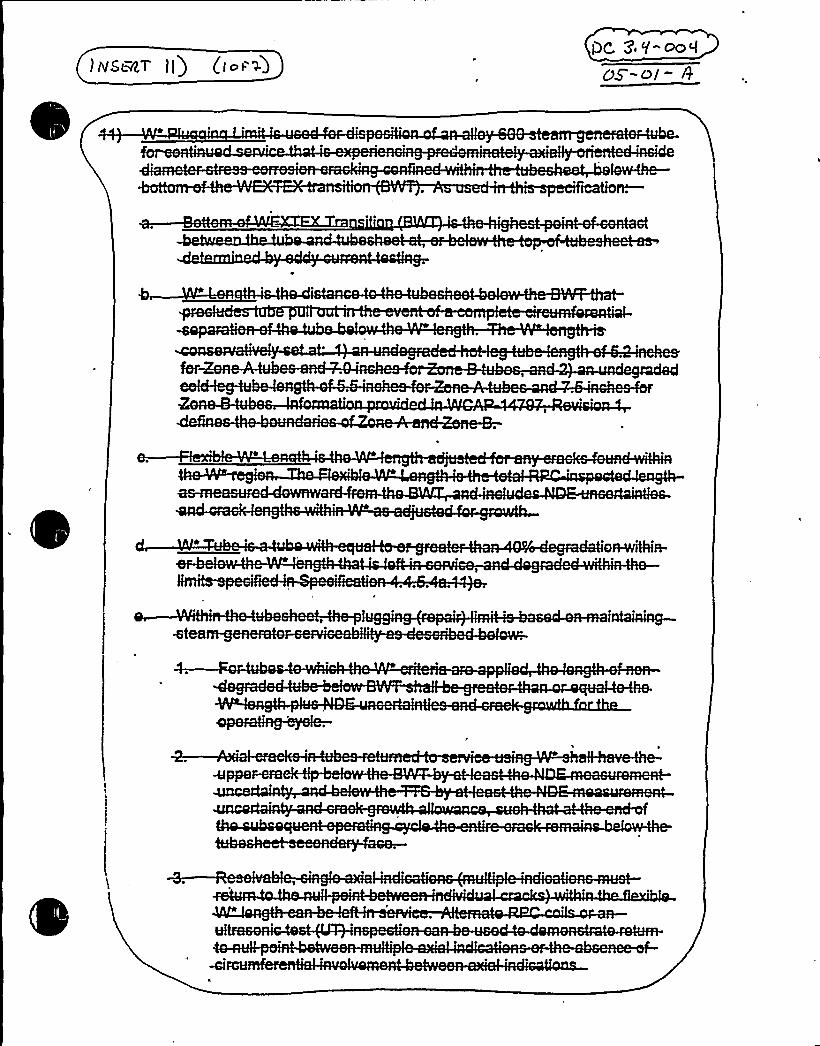
1NSBET II)OC, 7 Y"~0
sheet-,N~


~ ~ ~
gad-or-repaired.—For-.


009
aaNae- brea H'or the.-next-
SF4t
OIABLO CANYON - UNITS 1'8 2TAB11. 4A
3/4 4-15


~ ~ 0


Attachment BPG&E Letter DCL-99-063
ADDITIONALINFORMATIONCOVER SHEET
ADDITIONALINFORMATIONNO: DC 3.4-ED1 (new) APPLICABILITY: DC
REQUEST: Various changes have been Identified that do not impact the technicalcontent of the submittal or other FLOG members. Changes are noted with DC 3.4-ED1in the margin and noted below:
1. Remove unnecessary text added but not used from Bases of LCO 3.4.11,Condition D mark-up.
2. Remove the strike-out to restore "and to MODE 4 within 12 hours." Tosecond sentence of LCO 3.4.11 Condition G Bases.
3. Add "6." to end of last sentence of Applicability Bases of LCO 3.4.15.
ATTACHEDPAGES'ncl.
5B B 3.4-50, B 3.4-51, B 3.4-82


Pressurizer PORVsB 3.4.11
BASES (continued)
ACTIONS(continued)
Regoration,,-„.o'f!Chi. non,;Dcassgl'7PORC~blo!csk~val veto',:.QPKRABLE~stitusi;:is~oo0re'quired',:;Ntfe'ijh'..-;:,'h'aiI'.irig,';:@he~&cipnil" ".',!6'!!!!c'" '!' "u!: '-:"ll '"4'i" """"'!'f!cw~!Ii::"'ii!B!!'w!1')i''
"'sl''-": "m~!i:-''.
!inthe..",block,,:pulse;can,'prot;:,SEW', «DRB,:,fn,:::t'e::.:;sin«ad::pmosjt on::~<per":!A!E«qdi':"""! "-:''-':'-''-"::"'-':i:""""'tia'iiFOia""h'ea';:andfth!e';::u'n'it!muaut':,.bQe:.taiken;,ti'G9' '"i'ing.",;":lw s~f. a...:.,:un'til,;:~the.', block'.'::,"v'al9$Y
~sSCQ~r~Ãpi'0::O~S.,'p3 4 ) IWuba s
D.1 D.2 and "" '5lKTS~ J.+Zb lIf the Required A is not m t, then themus be brou ht t a 0 i onw r s eac i ve this stat mu be brou ht o at
.;; within 6 r ',,'„iti&aI,.'.',.t'iQrl~@$,, quir, -,a.::.:: girj.',,':;,4 diafelg~tji"„continu „:;,;-,,orts'qtiPi,';e or'e:;,"%hi.
'"
,"i„no~),mea',j:s'',.-'ari~4akei',.to~i" ';,™b
on imes are reasona e,"based on opera ing expe ie , to reach the
9 3Ã.i)-~
(Continued)
required plant conditions frcm full power conditions in an order ly manner andwithout challenging plant systems. ln MDDES a,end 5.lmndY6~MKth:"tlie!re«actorve~zTi:,he5«-"glfii:.. uer.hp15Ãmt~u,,!ly,,:.,de;::.tensioned, main'taini'ng 'Clan'asPJt-'",pnDRV"OPER'ABi'L~'iami~~:
'required-'bgm~O-3-.4-.I2.
E.l E2 E.3 E. an E5 / @~' ~, 4'>"'~~
If more than one Ql'Ns PRP1s ino erable a ca able of ' lyled, it is necessary "to
. i8,.9 grani!, ':.' e"::s'':.: Ew or'erat.':;„O':,YesQ 3,,ll ~3 "" d~to,'::e'» n e"Compiet'i'on
er-- so a ow pa 'g and removing the power to theassocia lock valves. The Comp etion Time of 1 hour is'easonable, basedon the small potential for challenges to the system during this time andprovides the operator time to correct the situation. If one Cl~ss57PORV isrestored and one g1S~S'.QPORV remains inoperable, then the plant will be inCondition B with the time clock started at the original declaration ofhaving two ~hree3 Cl'ass+ PORVs inoperable, If no CNssQ!I: PORVs are
AT re ' ™ 'hen the t " to~'aJconw i, ojjhi'fbNYAere< '-...'unct onto„:
;..ew ....,,-,>. ~::::
- - ----'-." e t4>axis'ow "'mneede . o ac ievug t to a eas i't in 6 hours~artd.': 'e'HW
.,: 'g within 12 hours. Pg kl4'&I~I*
„;. zona::,';;;:ar....,„",.gr.; .',:-ti;beiTiiit4:."::.ijmdia e, ~„':,,:;: . isnueye; . -.apts
N5",:.Its':%6$ li,:'.iihiii '. ~A';.-: 'lent'::,cond':, 58i7s'.,-..ab5vi'::: ';',4:;:-'.,'Smriti":less'"':,:t'hYn'-.''500,„"Fp"a o "'mp e ion imes are r , ase
''pera ing
to reach the required plant conditions from full power conditions in anorderly
DCPP Mark-up of NUREG-1431. Rev. 1 8 3.4-50


BASES (continued)
Pressurizer PORVsB 3.4.11
s~7 ACTIONS(continued)
InseraA
Q 3'It-5
manner and without challeng«op~lant systems. In iiDDES 4. and G. and,':«:G~Atlitheg.',evagt'Ctk<VSSK8i":%cad ClOSuvre,,+tJ::::;."nnt':-:::;foui;:lyrde;,t~en inured!:. maintainingC:.":I'ah~i"5~6fGV""OPERABILITYHey"-"b~e~i's",'requiresdf",O'; See"'L'CO 3.4. 12. m
fggll«f34, g,44Ehl IF. 1 F.2 F.3 and:.44 gg,4'V-
If more .than oneFLORV. block valve is inoperable, it is necessary to eitherrestore the block va Ives within the Completion Time of 1 hour, or place theassociated PORVs in manual control and restore at least one block valvewithin 2 hours-5-:a@~res®hhe-";reiai$ ning:"::;blok-'.svalve:within.,72.".'hoyrs ~ThePORC':eoNVN~s@fch"':fiaS ..CIiqee~"..,POwSlt'iovn+4oYiiA"'--il6s94'arid@'uto*~~~Pla~n'gChe-
ppiltfsn«nag'itb'e'~i","i'tchtoutg~of"'!this.".:."autho!!cs ont'ro«T,'„:":".m'o«dre,:',":!4The CompTeti'on Timesare reasana6l'e. based on t'e small potential for clial'lenges to the systemduring this time and provide the operator time to correct the situation.I'";"
tbhees, inowprerbablei bFldk~y biaye,.:t spassoracfated wit h«th e ndn. Class:. IPORog::::;::, thesb'i
',-'«On:::,.'!@«CO'ms'ji 'i'." TO'n!T1 me- reguirbemit S OS':.",:C':nndbtibn:!G.'ded«OL:"happ'jy.':-:.
If,'::„tjlaeetIOOk;!Ve,r eTCevn,,:;:,,;,,P OedWNtheISJm~e,:;: mftfnnn:"'tge uir«
SS:;,'.s: .u "; ': "+~S-, O „"SSV .."h '0 .e '. r4;.OS:hh«':..i.'0..c......... «pmu. II +«A+ oc.3if aa,i
Gl G2 an '- g Ii I.%57If the Requi f C dition F ar no et. then the lant must be
. /on i'. '::~ efunc5jo" "'c '" -: '' " ': '::.'e"
. To "achi'eveis s a us.
"-'=' ----- least "H yn,: rt.,avg.,:,.;within 6 hours ', 7:«:iona,:,~act) on„,-':;::fs:,,equi.,red
0:::,':,». is:.2
';9: 8 . $~»tO>'. $093-,:«» 3 .; @cd"„:f54gj'g~ /he~'in fpb18a'Irveg()~;"t .~Lg~~$~Q< «Thf~QQ: 'egjg@ensIJ~";(pgf jent'asurcesgar
..akei.':,",t'i:":,'i:'KiglhfP'QPMABIX",'.'P(NV'i"Sn',;:N':'""-"""'- a'";is«a " ':le.«ma'i'w'ÃfNg':-';j1:ass"Ond@''.f '
."..«She'8.» +O':='':M'~4~'':-tha" 3'60,:.Fs'.":.The a o'wed omp e i
"" " "'-e
aso , se on opera i experience. o reach the required plantconditions from full power conditions in an orderly manner and withoutchallenging plant systems! In HODES 4, aced 5.
. sefP'~y,,th,;:.':,:they.,eactop".',i~~~e;I;-..'Nead„,-.".:.closurebo. tssnotggj:, jtj8e-,.tens«oned;: ma«nti'iiiinghClhss:".li)::PDRlbOPERAGIL4TiT.";:I'reguIredfbyfLCD:GQH'2
,v)+ 4
SURVEILLANCEREQUIREMENTS
SR 3.4.11.1
Block valve cycling verifies that the valve(s) can be closed if needed. Thebasis, for the Frequency of 92 days is the ASME Q4e,-SeeMea-Q 0~5".'..;,H~„,:":.Ccdeg
Pai:t.<45(Continued)
OCPP Hark-up of NUREG-1431. Rev. 1 B 3.4-51


BASES
APPLICABLESAFETY
ANALYSES(continued)
in the FSAR (Ref. 3).
RCS Leakage Detection InstrumentationB 3.4.15
The safety significance of RCS LEAKAGE varies widely depending on itssource, rate. and duration. Therefore, detecting and monitoring RCS
LEAKAGE into the containment area is necessary.
Quickly separating the identified LEAKAGE from the unidentifiedLEAKAGEprovides quantitative information to the operators, allowing them totake corrective action should a leakage occur that!:;:couldOie!detrimental to the safety of the unit and the 'public.
RCS leakage detection instrumentation satisfies Criterion 1 oft@.
H'IrrsxRE!:-:('a:,::*.:,!Rr!r!r.:'CO
One method of protecting against large RCS LEAKAGE derives from theability of instruments to rapidly detect extremely small leaks. This .
LCO requires instruments of diverse monitoting principles to beOPERABLE to provide a high degree of confidence that extremely smallleaks are detected in time to allow actions to place the plant in asafe condition when RCS LEAKAGE indicates possible RCPB degradation.
The LCO is satisfied when monitors of diverse measurement means areavailable. Thus. the containment sump monitorl~ip ~sya'team. Sn,, the,:":,,particulate radioactivi!ty monitorSI,either,';iur::;V~CO,.,condenueteuoolITewcti~~~l~terr. o~r,. a-'slaseoue
'rdei oatkci'it~yiii~tio!proviriee an accepka6le minimum
'PPLICABILITY
ACTIONS
Because of elevated RCS temperature and pressure in .NODES 1, 2, 3.and 4, RCS leakage detection instrumentation is required to beOPERABLE. In NODE 5 or 6. the temperature 'is to be ~ 200'F andpressure is maintained low or at atmospheric pressure. Since thetemperatures and pressures are far lower than those for MODES l. 2, 3.and 4. the likelihood of leakage and crack propagation are muchsmaller. Therefore, the requirements of this LCO are not applicablein NODES 5 and
C ~ Dg 3.'f-Ed I
'ACTTwOII:,::are;,:meta!dffjRI.'.,'byyp.:IIhitethat ~)caCees, ihat~ the;„prsodvr'si!airs'.,::orf,L CO"::: dgOif r!er niotpe'p/1 iiibf i'ei bAs'rtreisteu'aiNOOE@r':ha'nde~rs::.a!IT'owewds
pa'it).cuffs%'iiiii%itor„'i,'5'oui"red~CfCU>'iiehft'sati>
el!jowa'n'ceai's'od vdcdev'be oa-lfsweeth'itr!i'sotarTiemwiTttbasiuon'isI!av'ai!labia::","toi"""!!-'::::!!!!W-'::::
(Continued)
DCPP Nark-up of NUREG-1431, Rev. 1 B 3.4-82


Attachment 8PG&E Letter DCL-99-063
ADDITIONALINFORMATIONCOVER SHEET
ADDITIONALINFORMATIONNO: Q 3.6.3-10 APPLICABILITY: DC, WC, CA
REQUEST:DOC 11-11 AJFD 3.6-3CTS 3.6.3STS LCO 3.6.3ITS LCO 3.6.3 Note and Associated Bases
ITS LCO 3.6.3 contains a Note not contained in CTS 3.6.3 or STS LCO3.6.3. This Note states that ITS LCO 3.6.3 is not applicable to the MainSteam Safety Valves (MSSVs), Main Steam Isolation Valves (MSIVs)Main Feedwater Isolation Valves (MFIVs), Main Feedwater RegulationValves (MFRVs), their associated bypass valves, and AtmosphericSteam Dump, Relief or Dump Valves. The justifications for adding thisNote (DOC 11-11 A and JFD 3.6-3) state that it is consistent with currentlicensing basis, the valves are not considered containment isolationvalves, and that they have separate ITS LCOs that provide appropriaterequired actions in the event these valves are inoperable. Nothing in theCTS states or implies that these valves are exempt from this LCO.Furthermore, the staff considers these valves to be containment isolationvalves. In addition, the proposed change was submitted to the staff as ageneric change to the STS (TSTF~) and was rejected. The staffconsiders this change to be a generic change that is beyond the scope ofreview for this conversion. See Comment Number 3.6.3-24.
Comment: Delete this generic change.
FLOG RESPONSE (original): Diablo Canyon, Callaway, and WolfCreek desire tocontinue to pursue this change. The justification in DOC 11-11-A and JFD 3.6-3 hasbeen modified to state: "A Note is added to the containment isolation specification thatthe LCO is not applicable to main steam safety valves (MSSVs), main steam isolationvalves (MSIVs), main feedwater isolation valves (MFIVs), and [atmospheric dumpvalves (ADVs)]. The current licensing basis for these valves exempts them from playinga role in establishing or maintaining containment integrity. This is based upon 10 CFR50.36.c.2 and 3 and 10 CFR 50, Appendix J. There are no surveillances associatedwith LCO 3.6.1.1 or LCO 3.6.3 which are applicable to these valves.[] This Note isconsistent with current licensing basis." The application of LCO 3.6.3 to these valves(MSSVs, MFIVs, ADVs (DCPP), ASDVs (CA), ARVs (WC), etc.) would result in twosimilar LCOs being applicable to the same equipment yet having different ACTIONtimes. The role of ITS LCOs 3.6.1, 3.6.2, and 3.6.3 are to establish containment leaktight integrity through the Containment Leak Rate Program and then maintain it duringplant operation. These valves are more complex and have safety functions whichrequire them to be open while containment integrity is established. The isolationfunction would be required as a result of conditions different from those generallyrequiring containment isolation. The applicable ITS 3.7 LCOs recognize these


Attachment BPG8 E Letter DCL-99-063
conditions and provide appropriate actions. These LCOs require valve operability andprovide ACTIONS similar to containment isolation but more conservative for aninoperable valve. An inoperable MSSV-(normal operable condition is closed) under ITSLCO 3.7.1 would require restoration or a power reduction within 4 hours (valve fails toopen). An inoperable MSIV under ITS 3.7.2 would require restoration within 8 hours forDCPP and 72 hours for WC and CA 'or close the valve (in MODE 2) and then proceed toMODE 4. An inoperable MFIVunder ITS 3.7.3 would require closure within 72 hours forDCPP and 4 hours for WC and CA and verification every 7 days or the plant wouldproceed to MODE 4. An inoperable ADV (DCPP), ASDV (CA), or ARV (WC) (normaloperable condition is closed) under ITS 3.7.4 would require restoration within 7 days(failure to open). The most conservative applicable operational requirements are foundin the associated ITS 3.7 LCO.
DCPP S ecific Discussion:
The only CIV requirements that are applicable relate to their design and installation suchthat they are closed or capable of being closed as required by GDC 57. The ITS LCO3.6.3 Bases is revised under the discussion concerning the Note to state: "TheContainment isolation function of these valves is associated with their design andinstallation under GDC 57 as a second boundary in a closed system (passive) when thecontainment environment has potential direct access to the outside environment. Thecontainment isolation valves have no role in establishing or maintaining containmentintegrity unless the closed system boundary has been breached." The containmentisolation function is assured as long as the CIVs are OPERABLE. OPERABILITYisrequired (both opening and closing) under their respective ITS 3.7 LCOs in Modes 1, 2,and 3. In MODE 4, these valves are normally closed. The STS 3.7 applicable BasesSections cite low energy levels and the general lack of credible transients that maychallenge this boundary which is, at that point, operating well below its designcapabilities. While a release of radioactive material to containment is possible in MODE4, the passive type A leak. tested boundary of the closed system is adequate. MODE 4releases of radioactive materials are more applicable to maintenance of containmentintegrity for systems with direct contact with the RCS or containment environment. Theadded Note provides this clariTication to aid Operations personnel in understanding thelicensing requirements. This discussion is consistent with the following: (1) SER 0,10/1 6/74 (states design is consistent with GDC-57), (2) LA 73/72 (relocates containmentisolation valve list outside of the TS), (3) FSAR Table 6.2-39 (Notes that these valveshave a safety function to be open in a DBA and that they are exempt from Type C leakTesting), (4) Containment Leak Rate Program: Type A, B, and C testing, and (5) ISTPlan. The Main Feedwater Regulation Valves (MFRVs) and associated bypass valvesshould not be included in the Note added to ITS LCO 3.6.3. They are not under GDC-57 and are not associated with containment isolation.
Enclosed is the following plant-specific documentation to support the above discussion:
FSAR Table 6.2-39SER 0, 10/16/74LA 73/72


Attachment BPG8 E Letter DCL-99-063
FLOG RESPONSE (supplement 1): For WCGS and Callaway, further review hasdetermined that the licensing basis for MSIVs, MFIVs, MSSVs, and ARVs/ASDs isprovided in the SAR. This note is deleted. Callaway is adding an additional reference toB 3.6.3.LCO to the containment isolation valve table.
For Diablo Canyon, the LCO note in ITS 3.6.3 has been removed; however, the Basesdiscussion regarding the MSSVs, MSIVs, MFIVs, and ADVs remains. The followingdiscussion is provided to address NRC staff questions during the October 13-14, 1998,meeting relative to containment isolation valves.
The ITS LCO 3.6.3 Bases is revised with a note stating that this LCO does not apply tothe MSSVs, MSIVs, MFIVs, and ADVs. These valves currently have an additional butsimilar LCO providing generally equal or more conservative ACTIONS. This changewould leave a single LCO for each group of valves that would assure the required safetyfunctions. Each of the effected valves is a GDC-57 containment isolation valve
„associated with a closed system in containment. LCO 3.6.3 ACTION C provides theonly applicable ACTION other than a unit shut down for failure to meet ACTION C. LCO3.6.3 provides no applicable surveillances to assure OPERABILITYfor any of thesevalves. The function of these valves is more complex than this since they have safetyfunctions that require them to be open while containment integrity is established. Theapplicable ITS 3.7 LCOs recognize these conditions and provide appropriate ACTIONsand SURVEILLANCES for the required open functions as well as isolation. Thefollowing Table provides a comparison of the applicable ITS 3.7 LCOs to LCO 3.6.3,ACTION C:
LCO MODES NormalPosition
Safety Function ACTIONS
LCO 1 -43.6.3,ACTION C
N/A Provide GDC-57 closure to assurecontainment integrity followingfailure of the closed system incontainment.
Close within 72hours. Verifyevery 31 days
LCO371,(MSSVs)
LCO372,(MSIVs)
1-3
1-3
Closed toassurepressureboundary
Open
Open to provide overpressureprotection of the secondary sidethen re-close.
Close to isolate the steamgenerator during HELB, Feedwaterline break or SGTR
One unable toopen upondemand-immediatelyreduce powerRestore or closewithin 8 hours.Verify every 7days.
LVO 3.7.3, 1 - 3(MFIVs)
Open Close to isolate the secondary plantfrom the steam generator.
Close within 72hours. Verifyevery 7 days
LCO3.7.4,(ADVs)
1-3, 84(*)
Closed toassurepressure
Open to provide energy removalwhen the RHR is not available thenre-close.
Restore all valvesin 7 days, (assure2 operable within


Attachment BPG8 E Letter DCL-99-063
boundary 24 hours, assure 3are operable within72 hours).
(") Required in IViODE 4 ifsteam generators relied on for heat removal.
None of these valves are associated with piping systems providing directcommunications between the containment atmosphere or the RCS and the outsideatmosphere. There is no credible transient that would challenge the integrity of theclosed system within containment or require any of these valves,to operate in MODE 4,5 or 6 other then the ADVs. Steam generator energy levels are low in MODES 4, 5,and6.
In summary, the action statement provided for these valves outside of ITS 3.6.3 provideassurance that both the containment integrity (closed) function and process (open)functions are maintained.
FLOG RESPONSE (supplement 2): DCPP has removed the discussion concerningthe LCOs in ITS 3.7 for the MSSVs, MSIVs, MFIVs, and ADVs from the Bases of LCO3.6.3.
ATTACHED PAGES:Encl. 5B 8 3.6-15


Containment Isolation Valves (
B3.6.3
BASES (Continued)
LCO Con tainment isolation valves form a part of the containment boundary. Thecontainment isolation valves'afety function is related to minimizing theloss of reactor coolant inventory and establishing the containment boundaryduring a DBA. The automatic power operated isolation valves are required tohave isolation times within limits and to actuate on an automatic
isolation'"va1
ves"'i'iid~thi>!!P'r'essurel. Ificiiiai.".R'eljet~)'ja'.ling„";must be"
'have blocks""i'nstalied to prevetIt full opening<.-E Nes4 blocked -pe~ valves also actuate ori an automatic Lsolition signal.The valves covered by this LCO are listed along with their ass'ociated
'AO13"OC1'" ' ' |ii'"t 8"'5)
~ Normally closed pagsfve,-;conta>miNit„isolation valves7devices areconsidered OPERABLE when manual vxalves are closed, automatic vaTves arede-activated and secured in their closed osition. blind flanges are inplace and
I pm''4 S I ge-o~9. (.9 -VZ
Cuutaxeeeet$ purgew@gyteuit~ex auettxyal~uea',:;:,:: euieieCoiiteiiiiiieiit
must meet additional leakage rate SO~i'.v8fl38ti~ce,.".freqgeacp':requirements. The other containment isolation valve leakage rates
are'ddressedby LCO 3.6.1, "Containment," . @3.4.3-4B
aequi'n
~i4Thi L 0 'on i ment isolation valves
u eap 'e'"'"e rent'
t'ai GL- wi perform eir esigne sa etyun'ctioii'to minimize the loss o reactor coolant inventory and establish thecontainment boundary during acc dents.
t egI.:s .„Bt)'Ori'":;,',:,:v'esW.e'@&jib',-;I'.Isoxu a,. ori)(Vi1': 's'Q"irid."'miisj 'ifi~ "-'p:|.,,v'es.i';;.:.i,".,;Itot>" Ch',;ess'"'x „-""$j,"4h"es':,~'4
.h'e
5(Mt, Vs')",.'-'.,"';: ':::CO!3".,:,7'..::.";.Hh';,Fwdwak -,„<"'..'Is'i}lit'; o".',Val'..
kl ",i"', '-.,:-"::,':ll'":-,'--:-::ill!'t:." ':::,;:(A'all I'„,,::~ itiiit"-'-;:,0'!'.,'-ll"" .'i::"-::::Iti"""u-'-A'::t'! "..*iii: ii::, (i:: 't:-'-:::i.:1!"'::.'l:.. i!i'"':,",,ll a."-i: r!, -:"-:
'
APPLICABILITY In MODES 1. 2, 3, and 4. a DBA could cause a release of radioactivematerial to containment. In MODES 5 and 6, the probability andconsequences of these events are reduced due to the pressure andtemperature limitations of these MODES.
(Continued)


'nsert for 3.6.3-10
Encl 3A- age 11, insert for D C 11-'11-A: @ $ .( ~ 3 - Io
A Not s added to the co ainment isolatio specification that the L is not applicato m in steam safety v es (MSSVs), m in steam isolation valve MSIVs), mainfe water isolation v ves (MFIVs), an [atmospheric dump val s (ADVs)]. Thi sb sedupon10CF 0.36.c.2 and 3 d10CFR50, Appendix . There are nourveillances as ociated with LC 3.6.1.1 or LCO 3.6.3 w ch are applicab to these
valves. []Th'ote is consiste t with current licensin asis.
/Enc B, pa B3.6-15 insert:
he Con inment 'lation fu ion of the valves ar associat with the design ndinstall on unde GDC 57 a second oundary in closed stem (pa ive) wh n thecont nment e ironment as potenti direct acc s to the utside en ronmen Theyha norole'stablis ngormai ining cont 'entin grityunl sthecl eds tern bo dary has een brea ed.
Enc 6A- page 1, inse JFD 3.6-3:
e current licens bases exempts ese valves from cont 'ent integrityequirements. is is based upo OCFR50.36.c.2 and and 10CFR50, ppendix J.
There are no rveillances ass iated with LCO 3.6.1 or LCO 3.6.3 w ich areapplicable t these valves. []


Attachment BPG8 E Letter DCL-99-063
ADDITIONALINFORMATIONCOVER SHEET
ADDITIONALINFORMATIONNO: Q 3.6.3-39 APPLICABILITY'C
REQUEST:
ITS SR 3.6.3.10 and Associated Bases
DCPP ITS SR 3.6.3.10 ve'riTies that each 12 inch containment vacuum/pressurerelief valve is blocked to restrict the valve from opening >50 to ensure that thevalves will close within the times assumed in the safety analyses. DCPP ITSB3.6.3 Bases- BACKGROUND states the following for the Containment PurgeSystem: "The 48 inch Containment Purge valves are qualiTied for automaticclosure from their open position under DBA conditions. Therefore, the 48 inchContainment Purge supply and exhaust isolation valves must be blocked toprevent opening more than 80 in MODES 1, 2, 3 and 4 to ensure closure within 2seconds under DBA conditions (in order to support the required containmentventilation isolation time) and to ensure that the containment boundary ismaintained." Based on this statement and a similar statement in ITS B3.6.3Bases - LCO, the staff requires that a surveillance similar to ITS SR 3.6.3.10 forthe 48 inch containment purge valves be included in the ITS to ensure thatfacility operation will be within safety limits.
Comment: Revise the CTS/ITS markup to include a SR similar to ITS SR3.6.3.10 for the 48 inch containment purge valves, and provide the appropriatediscussions and justifications for this change.
FLOG RESPONSE: The bases for the current license come from SSER 9, para. 6.2.3(June 1980) which required a 50'lock on the 12 inch vacuum/pressure relief valves.No requirement for the 80'lock has ever been present in the DCPP license. The
80'imit
is an administrative limit resulting from the actual value used in the designcalculations and was added to the ITS Bases to better describe the system foroperations personnel. It does not represent a licensing basis, and therefore the ITSLCO 3.6.3 Bases, BACKGROUND for the Containment Purge System (48 inch purgevalves), has been revised to delete the 80'imit.
FLOG RESPONSE (Supplement): Based upon conversations with the NRC on March11, 1999, PG8 E has placed an insert in the Bases concerning the 80 degree block onthe Containment Purge supply and Exhaust valves. This insert reads:
The Containment Purge Supply and Exhaust Isolation valves are supplied withan internal block which prevents opening the valve beyond 80 degrees.Guidance for this block was provided by the manufacture in case it becamenecessary during the valve's qualification to Branch Technical Position CSB 6-4.Calculations subsequently showed the block to be unnecessary to assureclosure time within 2 seconds under DBA conditions (SSER 9, June 1980 andCalculation M-661). The block is also not necessary to assure the valves abilityto close due to excessive opening. This design assures that ...


Attachment BPG8 E Letter DCL-99-063
ATTACHEDPAGES'ncl.
5B ' 3.6-12


Containment Isolation Valves (
B3.6.3
BASES
CKGROUND
ontinued)
Qs/personnel access. .The sup ly and exhaust lines each c tain two isovalves. IThe W8 inch C . inment4'ur
ationvalves
~ d iifidf t ti l 'f, tl»,dposition under DBA conditions. e 45 'inch Route?nmmnt P„. rge „ .
'SupplFC:,adnndh'e>(jbaluataliauliaati~nna Val yeS.,, inM, an
y «wv'w,.; (v N; ... ',,''', '0:y(jr .St "v:q'x«'N,>s«a S « 'vwNt~yv~ v(tc?)y.c?4frrcdhwhj«xv
xmt: "s se(xm«'c(y',xv..%)m 4;.<. eh«vs '..: m?4cNNr xi '(. «(," ':N«(?(y" .I.te ' t (y.:ax:x?t (xr()(sr xs; yah?«N'm . yac ~ w. yd.,hx ':;;:: ':" »em?(>wv?
'nntainmentbaiindary iS mainta'ined. I|seam:,'j'jata'j(?ea',,'-:m'" b(dde?,~(Y one iiaxtxal'.""neCi Seer(y;
::!:.:-::;dele<;.N~Reduoe":::ndbTe~gaSe@Vith~?n: Cents? nment::;-;pr?Or;.:.'u tantdÃdiiring irper? Snnnreyl!
8cC@sS"::,~,
ate~,.::::,-::::-':b~rad:,I?i'it'igyate;,thje;::,sffvec'ts::;:o-'ff~ tt:.II tiht 2 itis'! W!tlj'l O'-:::. " "2!!t '-ij~i"':"ll'Ityjf".""-."'itcP-: fi':-"--'::Ilt?Su?<2..":-'2'::."::"y<l:.222<I::22 .'Sh~iP hhh::.:: -,:::Tt 22-'::,"::W
vacuullhI,pf,.:BBKQI,',Pal;,Bl(58fg(vs;as~,ope~i',e::-t'6i7i4260.":,'::hi&'4 "pe%i:Red%~ jii~r
C.
2 hl wd
«;.,m?$ >;. 'X,;:: Nh;,X .«,; decay,'m, 4: "~::,.yqy '< >.(mm;q'<y. «: r>'?";:.,„. '. „X('Xv";„''(gbiymSXXaXS '',.' yr N>?Sl 'dgetvt>X'. S.Xt(vrd
v mali'mx? N ..w? .'.I(«vrg<x?xax ..N a?xv?«NS "xt«h " .,"Sr<2('.":>.. 'g(y'e'er '::sdaxv.'. x?«c:9NNrr?r ';?c;. «'<m:<" S(C>r ':
'«'N::;:,. ((b:me>v',:,A.''+.e«mXWI>X(r tg>Xm m''««I X(ryXW::, t;.X','('S','m>.m '. X y((r r«b ':. S?X. ')Sx(vYX iN(va ''::,'',', '',?me«?m SW.XSr mtv?T(vX(c
>sy«x.:'x,' xxm'txN 'b<>.(q'd ': v?xa "xq ?NN>t':m h 4t 'a m(«as '; .'.%tm«NN(, >N?xem'-xh '?'C t? sc«?e:vwt«':t?mhvAc« '::: (N>xmnlh:%««cvl(
Nv. ''j, «e<:" ?: Nt ' ".Cs:~P dv4%?'sake«N(;,'. smv',$ ,:ax ':c«v x;. xvmN(?r)dv<x.'.xxv '@''?w Q>b?h,'?.'P;. Natece Hilt«,'(,kc.y,'qv,. 'y x ';e axv?cda
iet ':.'a?g'mt: '"'('if':.s> ii?x ~%"(«Was, vx':e:w:..«ymt ."a('es(tm:,'(s?(""c::.,:... ': R: j+'<>va:«N 'S«A'"x(, '. (g'.'S .>'v%Nr.'hy;..'A4 .;.@%xc
.((t ...... '. (S.
2:.TPv.: ."a -:--'-:".g:::: il:"4': inch'-"'se aa4:5'ef-va 'ves
Ttes'%ileoessadry., io
coun~a. reen5%ressurejfgacuimj::-RHe,i!Ief@Wafjjes~are I?ertatied
a. Reduce the concentration of noble gases within containment prior to andduring personnel access, and
Iqualize eogCajn~~g internal and external pressures.
h tt St,:,22:;i tl22, 22 lieStfha 2,:,72 tdv:."::TWTe:are designed to meet"th'e regui"reiiients for automatic
containment i so 1 ati on jjelhjee ?r,. 'tQ'aMstec(onidsi!ef".:mec>bÃkg@l <5!fodRVsista Tied t " nt'"" '"-"'"""itliei?'5II th" "I "=
b"''
(Continued)
DCPP Mark-uo of NUREG-1431. Rev. 1 Bases B 3.6-12


Attachment BPG8 E Letter DCL-99-063
Insert for B 3.6-12Insert for Q 3.6.3-39
The Containment Purge Supply and Exhaust Isolation valves are supplied withan internal block which prevents opening the valve beyond 80 degrees. Thisblock was provided by the manufacture to allow limiting the valve's opening.Calculations performed during qualification to Branch Technical Position CSB 6Qshowed the block to be unnecessary to assure closure time within 2 secondsunder DBA conditions (SSER 9, June 1980 and Calculation M-661).Adjustments of this block to values greater than or less than 80 degrees willeffect the valve's ability to close. This design assures that ...


Attachment 8PG&E Letter DCL-99-063
ADDITIONALINFORMATIONCOVER SHEET
ADDITIONALINFORIIATIONNO: Q 3.6.6-19REQUEST'PPLICABILITY:DC
STS B3.6.6A Bases - LCOITS B3.6.6 Bases - LCO
STS B3.6.6A Bases - LCO describes what constitutes an OPERABLEContainment Spray System. The description includes the automatic transferringof the pump suction from the RWST to the containment sump. At DCPP thistransferring of the pump suction is done manually, which is acceptable.However, ITS B3.6.6 Bases - LCO deletes all mention of this capability. Thestaff requires that this be retained in ITS B3.6.6 Bases - LCO because the abilityor capability to transfer the pump suction constitutes part of the description ofsystem OPERABILITY.
Comment: Retain the STS wording modified by DCPP plant specific designfeatures.
FLOG RESPONSE: The requested change for DCPP would be technically incorrect.The DCPP design provides for the spray rings being aligned to an available RHR pump.The decision to do so is one made by the Technical Support Center. Issues associatedwith this transfer are the subject of LAR 98-03 (3/18/98). This LAR also submittedwording changes to the ITS LCO 3.6.6 Bases (Background and Applicable SafetyAnalysis Section) providing DCPP plant specific wording associated with this transfer.The following wording is currently under staff review as part of LAR 98-03:
Background: Containment Spray is not required to be actuated during recirculationphase of a LOCA, but may be actuated at the discretion of the Technical SupportCenter. During the recirculation phase of a LOCA, the Containment Spray Systemmust be capable of transferring the spray function to an RHR System taking suctionfrom the containment sump. OPERABILITYof valves 9003A and B, and thecapability to close valves 8809A and B to divert water from the RCS to the sprayheaders, willensure that this capability exists.
Applicable Safety Analysis: Analyses and evaluation show that containment spray isnot required during the recirculation phase of a LOCA (Ref. 7). Ifonly one RHRpump is available during the recirculation phase of a LOCA, it may not be possible toobtain significant containment spray without closing valves 8809A or B. Ifrecirculation spray is used with only one train of RHR in operation, ECCS flow to thereactor will be reduced, but analysis has shown that the flow to the reactor in thissituation is still in excess of that needed to supply the required core cooling.


Attachment BPG&E Letter DCL-99-063
FLOG RESPONSE (Revised): LAR 98-03 willnot be approved prior to the approval ofthe NUREG-1431 conversion. DCPP has revised the Bases to reflect the currentTechnical Specification position. The following insert has been added to the Bases text:
"Upon actuation of the RWST Low alarm, the suction flow path of the RHRsystem must be capable of being transferred to the containment sump.Containment Spray could then be supplied as required by an RHR pump takingsuction from the containment sump."
ATTACHEDPAGES'ncl.
5B B 3.6-39


BASES (Contin
Containment Spray and Cooling Systems
QoM Aslg~f5'k 5~ M geF~~4) 4 ~WP Ak.'Q
~/ S
During a DBA gGDII, a minimum of tWo";,.CFCUslandone containment spray train are required to maintain the cont inment peakpressure and temperature below the design limits (Refs. A~4). Additionally.
.one containment spray train is also required to remove iodine from thecontainment atmosphere, and mainta ncentrations below thos assumed isafety analysis. To ensure tha 'ese requirements re met. two Q3o 0-2c ainment s ray trains and
' 'CFCU, „COOS)%bingot",;fooras .:, ~;;:, .:::,; ~ a 'uppijedaby,-:;":aj'diiifere~i'it::;:,"ua a:,:.;,:,bii4!!must"'be
syaama oT4ooiitaiiimetite:q>rcptj:;aov ....., .... „. ',jCFCUiI operate. 4s < <assuming the~w™wors" case si'ngle ac ive ai ure occurs. Each Containment praySy4m 0'r.:,.afj typically includes a spray pump. spray headers. nozzles. valves,piping, instruments, and controls to ensure an OPERABLE flow path capable oftaking suction fr u on an ESF actuation si nal
34.0-2Each C'FQN4~~ inc u es . coo ingcoils, dampers, fans, instruments", and controls to ensure an OPERABLE flowpath.
APPLICABILITY
ACTIONS
In NODES 1. 2, 3, and 4, a DBA could cause a release of radioactive materialto containment and an increase in containment pressure and temperatureqiigth p ti fthm ti t p yt i d~In NODES 5 and 6, the probability and consequences of these events arereduced due to the pressure and temperat e limitations of these NODES.Thus, the Containment Spray Systemnot required to be OPERABLE in NODES an ~~+ 5+i+ off
$ 3.Cs,4o 20A.1
With one containment spray train inoperable. the inoperable containment spraytrain must be restored to OPERABLE status within 72 hours. In thisCondition, the remaining OPERABLE spray and cooling trains are Q-adequate toperform the iodine removal and containment cooling functions. The 72 hourCompletion Time takes into account the redundant heat removal capabilityafforded by the Containment Spray System, reasonable time for repairs, andlow probability of a DBA occurring during this period.
(Continued)
OC» Mark-uo of NURE6-!~P'3 Rov ! Baso.s R ~ <-~o


ADDITIONALINFORMATIONCOVER SHEET
Attachment 8PG8 E Letter DCL-99-063
ADDITIONALINFORMATIONNO: DC3.7-011(new) APPLICABILITY: DC
REQUEST: Revised the Bases of LCO 3.7.10, 3.7.12, and 3.7.13 to characterize theBases for the use of a 24 months frequency as derived from LA 119/117 rather than the .identified standard or NUREG-0800.
ATTACHED PAGES:
Encl. 5B B 3.7-57, B 3.7-58, B 3.7-67, B 3.7-68, B 3.7-74, B 3.7-75


CREWSB 3.7.10
I
BASES
SURVEILLANCEREQUIREMENTS
(g%37.en
Once",";.actuated,'due:-.',t'o,,'i::..".f'ue1,':han'dl;1rij,.:ac'pdent:;'the";:CRVS„'":;.:mu's't;-::bi","'pi,'ot'ected,:,,"'aga1nstka''ii'ngi@f'a'i.":loire',„-".,",',Th1s::,'-protecti o''.,"':;:.:.'a'ltIhough
'jiotj~ieq'ui',red,".;for,',',immedi'ale;4cc1"dent"'i'es'ponse:.'":;::.",'.1 s,passu'red'.by='eqiiir')ng',::gh'at-.'-ii";",:ha'Ckup;;pm'„'.,-''supply",;,'be'':prov'i'ded:..';as.,'desi'r'abed
Mvie,:;:4'n'~Appl~icabÃl:it'P'@his;.:back:::;;upjii,,':i'ssu'redid:i~Che"iIej~fiir'iiiaÃCegi'f:,": $~Ui'ieiT!larifeS"::tlirt"::~eii~f,'";.:t'h'e4bI':lftg!.'
tidI.IBf8Pkg'l'NI'i:SIIP"P!IBS .
pie::"3l-,:day,:;."proeedur'a~verjf~ev™a'X$ on<',o7p't'he:;::;se arable;;vfpN:,;--power + qq lo ~siip ,',l:.",.ill„'-'foi~"5ii'':i,edundaiit'~„':.Siis.'J', „;,.:,;.';
""''1"":""i!!::I::'b„"'!I!.,Ii'~IIII II@/"":
4wviwrrw0v~..@&5 i4 in<<~>g ~ ~~lreorn,flora ~h~HEN pilaf'n@ chdtccg, ~~ gs'~~~ of ~and pnsm i~'cn eupply ~SR 3.7.10.1
The31 day Frequency is based on the reliability of the equipment andthe two train redundancy availability.Iv6crk sR 3:7.io 2.
3 r.l0-3SR 3.7.10.
This SR verifies that the required CRESS testing is performed inaccordance with the fVentilation Filter Testing Program (VFTP)9.The CRKFVS filter tests are in'ccordance with Aecyka4ery
%NB&'g'98m(Ref. 3). The fVFTPQ includes testingthe per ormance of he HEPA filter. charcoal adsorber efficiency,minimum flow rate, and the physical properties of the activatedcharcoal. Specific test Frequencies and additional informationare discussed in detail in the fVFTP9.
CQ5.1. lo-Standby systems should be checked periodically to ensure thatthey function roper ly. As the environment and normal operatingconditions on this system are not too severe. testing each trainonce every mon rovides an adequate check of this system.Monthly heater operations dry out any moisture accumulated in thecharcoal from humidity in the ambient air. systems with heatersmust be operated for ~ 10 continuous hours with the heatersener ized ind."-,:":;oper'"%ting'.,iTr6m~a. '0'ia'Uy,:—, ' Dc.S 1-ED
SR 3.7.].0. O4 997.o-3
g 97-@
This SR verifies that each CRKVS train 8@m~pCQ„fjgstarts andoperates inot%i.-:::::jressor iiation',:mode,-'on an actual or simulatedactuation signal~-:::generate5~fi'~e}'Phase:::,,:A~hofaQoa. TheFre uenc of Yiion hs is
bn~K ~ "m8i -~lb'Et=Au:mi~ ~fj his REF.C
1 ll
OCPP Hark-up of NUREG-1431. Rev. Bases B 3.7-57


CREWSB 3.7.10
BASES
SR 3.7.10. IThis SR verifies the integrity of the control room enclosure, andthe assumed inleakage rates of the potentially contaminated air.The control room positive pressure, with respect to potentiallycontaminated adjacent areas, is periodically tested to verifyproper functioning of the CREWS. During the presser'i'za6oneR~eRcy mode of operation. the CRAPS is designed to pressurizethe control room ~ Q.12@ inches water gau e ositive ressurewith respect to Pe,.'.'5@ijde."."a~sphi'pi"":.': inorder to prevent"untilfeied inleakage.
-e „.
is designed tomaintain this positive pressure with onetrain> =The Fre X.5.7- +II,
months on a GERED TEST
PC.-AU=~<SA6W up~
gNQ 0 A6 44 (~W Ca) ~
REFERENCES 1. FSAR. Section ~,";:gf~2. FSAR. Chapter K5.
3. '. Rev~ ANN:.."iÃi98g.
4. NUREG-0800. Section 6.4. Rev. 2. July 1981.
'DC 3.7- E'D
c 3(7-oil
l.g lid/)i7 gakg(ue lo Awhha~) sj~ Fi s tusutrunf b>MABl w~] d[ehg,g Po'0'l~tt/s> P~I'l~ tg ~7
DCPP Mark-up of NUREG-1431, Rev. Bases B 3.7-5B

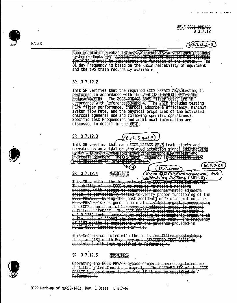
ABLS KCS-mACSB 3.7.12
BA':.S
s',:sgs"'For~=,tNe;.„'.exhaostpP$ ns''..: -a',:::a',
""-:.T . urve.:a
syifeiiim 'un aicp;,,
cd.7. I 2.2 - 3
.:=:,assures
The31 day Frequency is based on the known reliability of equipmentand the two train redundancy available.
3.
This SR verifies that the required EGGS-PREACHY 'ABVS":CEesting isPerformed in accordance with the Ven't'1)at>m,;=:Fluter,:",'.",Tiitinni
,. ~gm:,(VFTPP. The EGGS-PARAGON ASN'iTter tests are inaccordance with Referencesig:::-::end 4. The VFTP,: includes testingHEPA filter performance. cliarcoal adsorbere efficiency. minimumsystem flow rate, and the physical properties of the activatedcharcoal (general use and following specific operations).Specific test Frequencies and additional information arediscussed in detail in the ~VFfP.
SR 3.7 12.3 gpp,3n aI)This SR verifies th t each SCABS-,PRKAGS 5BVS train starts andoperates on an act al or simulated actua ion signal BA6:.':that!:-:08syPs'tm,.;..al'i'.'".."s-:.,4o
.", .aus't."'o "h..",the". coIIiiYin,:.'.:HEPA'CXftei'"'::"
'h"'ic""" .","'"o,"e.'
e mo'nth uency 'i
bC 3 ~ 7-Oll
SR 3.7.12.4 Rat diaeda Basso onwu fI mmi-muamow. esmo ass» /ha 'rfmF.2 .
SR 3.7.12.5 Rot,':::~Used;",
DCPP Mark-up of NUREG-1431, Rev. 1 Bases 8 3.7-67


'ABLS KGS-PIGS8 3.7.12
BASES
~AU ~, K Sr7-Otl
SORVEIL'55GE:,<:;;::=."::;,:-„-::,,':,"" '-', ""..7":
'EgIJaIRNEN.'f;.
"" '
'(iehnt! shed):,::",';.:'::;;,.",e:::.::.!i:".: nJrs;:SR:„iv'eriisres,;:;the~jeak&trr''tjieenrrrraral)</jib!OPeriatt ij'g'.::fiite'r,"",':,t'r,'.'.sic~;:-„'i'Thi'Si.'Srr!:aa'Ss
~so-~ elm::":Pro'I'Nhekiixi4ii'~>hei,fdiiig';.,::p'use's','."sth'rough)th'i:::;:;HEPA.:,fHter'-"
ec qcioa, '" u@C':.,"'~;:,„:the''~ABVS':(Bifid)ngs:::,:-.hand'.:.;Sifejuardsnrj5afeerra.'s=, j,":mrdr'isha'rei hier'ien hate'irat'err eehrd. dire tnisirich 'an-,SI!P%e'i 'iiidnthlFr!ejireniej%i:
2
REFERENCES 1. 'SAR. Section ~~ F':"4:.::2.
0 g. FSAR. Section QSA-.'.Ill.4 3.
4'~ANSBN8$%9M
5. 10 CFR 100.11.
'Ag8'",'073803.-:;3;989
6. NUREG-0800. Section 6.5.1. Rev. 2, July 1981.
st
~
:::-:::::„"!Inieirr~ei:!A.,Tie~lwlai .: Iii'ii!q:: i:t~~~-; erifi letieniSjstiii.=''r.
gg3,7-hali
~ ])jQ rr7 gsrrr elcao 4 k~l6p< crtr+rr eer+r
r sl C)ol s i s< ~4k', pn' r'is
,l1't7.
DCPP Hark-up of NUREG-1431, Rev. 1 Bases B 3.7-68


BASES
SR 3.7.13.3iX3.1-ED
This SR verifies that each ARCS F88VS train starts and operateson an actual or simulated actuation si'gnal 'arid'di:rect'sYftse@aig„'"':flw-.' roeugh~fA'e:.'HEPA"''f~Vlters~and,:~eh'arcoi'];:~ggv-bank's:. "The'onth 'Frequency is "consistent with Reference
SR 3.7.13.4 M-AO;cat
This SR verifies the integrity of the fuel hanSing4uildingenclosure. The ability of the fuel batiKIing„'"huili3ing to maintainnegative pressure with respect to potenti'ally uncontaminatedadjacent areas is periodically tested to verify proper functionof the ARGS FHBVS. During the Qost accidentj-mode ofoperation, the RAGS FHBVS is designed to maintain a slightnegative pressure in the fuel haT@:.:ing building. to preventunfiltered LEAKAGE. The RRGS"FHBVS i's designed to maintain athe,:591'd$ 'ng'pres~aurora glt25 'inches water gauge with respect toaaaospheric- ressur
An 'onth Fre u on a is8hSW tp M fHt Nh>v MME ~ h.
4)RV.i3.i-h'~en
Of domPCr M-29 sS n~~ + C..nSurs ~~ 5yS+~furlCRvns ~rty. M oPaPA8lu~ of- o(ampa N-gg < s vc'n /reefjg jf /~ bC aors�. + gC/ eeg~h Cieguen~ ~> +spn>rain~yearn Re.~ee ~.
(continued)l
DCPP Mark-up of NUREG-1431. Rev. 1 Bases B 3.7-74


BASES
REFERENCES
FSAR. Section [9.4.6 g1.
3 2. FSAR, Section Rf~j 35::.5.
4 3. Regulatory Guide 1.25.
6 4. 10 CFR 100.
6 6.
6~-::::":-;.ANSPNSIO.-,,l989~
888i8888882„-:1989
7., NUREG-0800. Section 6.5.1, Rev. 2, July 1981
8".::-',;,::,.';.::,888'5%89; 8=.,F~W8ha%BÃrt9i-;BiT$1~Tdiii::;RVAC,-Sjstm".,
Qg 3,?-bi(
(~ y, Qzvw>un* /L~lhtc~(g>+'+'~acfrwb~ gael CyaLES 6 >'I ~Afsz iiP«L
) 8E l gg'7,
DCPP Hark-up of NUREG-1431. Rev. 1 Bases B 3.7-75

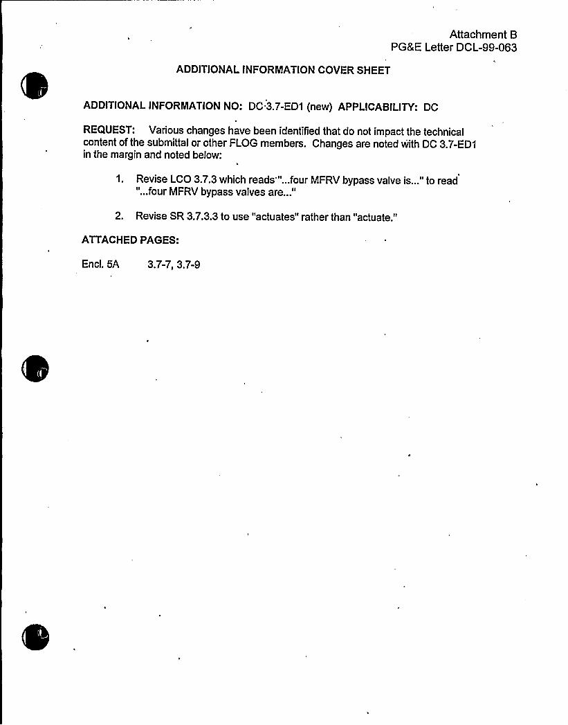
Attachment 8PG8 E Letter DCL-99-063
ADDITIONALINFORMATIONCOVER SHEET
ADDITIONALINFORMATIONNO: DC 3.7-ED1 (new) APPLICABILITY: DC
REQUEST: Various changes have been identified that do not impact the technicalcontent of the submittal or other FLOG members. Changes are noted with DC 3.7-ED1in the margin and noted below:
1. Revise LCO 3.7.3 which reads""...four MFRV bypass valve is..." to read"...four MFRV bypass valves are..."
2. Revise SR 3.7.3.3 to use "actuates" rather than "actuate."
ATTACHED PAGES:
Encl. 5A 3.7-7, 3.7-9

0

MFIVs g@HFRVs and': '',Byjass":ValYi'es
~M.~u
u
3.7 PLANT SYSTEMS
3.7.3 Main Feedwater Isolation Valves (HFIVs),diB M
(MFRVs} arTd,:- ''.Bypass::.":;VB'vgs
QFPv
Four HFIVs. Lo'ur; MFRVs. 'and,.OPERABLE.
LCO 3.7.3
ain Feedwater Valves
cpg,w. 3- I
MC&l,„.,'bypas'i..':~vaLves sha1 l be
APPLICABILITY:
ACTIONS
QA l YE'g 6%8
-NOTE-Separate Condition entry is allowed for each valve.
~~r Mfeu
MODES 1. 2. Bod:;,:-,3 except when MFIV. HFRV. 5r;.',.:,: ..'bypas's'.~. ~ clos'ed and de''-.,"actiuated oigdsil'itid~:: y,,:"~aaolosed',daiiu'al
Qg 3. 7-EA I
CONDITION REQUIRED ACTION COMPLETION TINE
A. One or more MFIVsinoperable.
A.l Close or isolate HFIV.
AND
A.2 Verify HFIV is closed orisolated.
7S.'hours
Once per 7 days
B. One or more MFRVsinoperable.
B.l Close or isolate HFRV.
AND
B.2 Verify MFRV'is closed orisolated.
72 hours
Once per 7 days
bypas'sgjva'1 vE@'inooearabli".'.
C-:;:.K".:::,-"-:..'":;::;:;:-,.Cg'ouse,.",",.Or;,':n".sHoate.";:bypass;.
va: v&.
,C.:2:";;.-',::.:.":::,Ver'i
fy."':.:by'ason!.'valve.':-'i'":-'cl
osed."'or„:; i.sol ated.'nce.":. per'.:".:.7'~days
DCPP Hark-up of NUREG 1431. Rev. 1 3. 7-?

0

~graav ~ra a.s.s-iMF IVs, arRb MFRVs 'aarrd.","~,BJirass!'",Valvas
3':73 XSURVEILLANCE REQUIREMENTS
SURVEILLANCE FREQUENCY
SR 3.7.3.1 Verify the closure time of each MFIVI~Ã~)60secon R.M"XCAWOc
Inaccordance with
the'IAs'Bl',:vlcc&~~::8stlflgi':"ri"-":
FT~
4'3. l.'5- <
ra,. "aCOL4jSHOTGOHI"'<
ariii,',,",'ti!i,,:~ii,,:,:a',, tranth'a'r'i"raiiaa:,.'F'ar~!9P!.':da js"'.",
SR:::.':,3'";:7,,::".'.3'.:9;:;::,".::Ve'i ify,:.eac'h:.:,HFIII actu'at" (to;-.;";the.-.'::s54fjon,'''jmsi'tT6iia!ai Laic'i'ir„i'ai;, s'rrarr a.."adjaata'artsaii sr'qjj5J5(
, l4«~4, dad APE Q~S egleC,
~~,-m
OCPP Mark-up of NUREG-1431, REV. 1 3.7-9


Attachment BPG8 E Letter DCL-99-063
ADDITIONALINFORMATIONCOVER SHEET
ADDITIONALINFORMATIONNO: 3.8.1-33
REQUEST:
APPLICABILITY: DC
CP(3.8.1-20) Bases for ITS SR 3.8.1.8, STS Bases page 3.8-40DC Bases for STS SR 3.8.1.8WC(3.8.1-17) Bases for ITS SR 3.8.1.9, STS Bases page 3.8<2
Bases for STS SR 3.8.1.9Bases for ITS SR 3.8.1.10, STS Bases page 3.845Bases for STS SR 3.8.1.10Bases for ITS SR 3.8.1.11, STS Bases page 3.8-49Bases for STS SR 3.8.1.11Bases for ITS SR 3.8.1.12, STS Bases page 3.8-51Bases for STS SR 3.8.1.12Bases for ITS SR 3.8.1.13, STS Bases page 3.8-52Bases for STS SR 3.8.1.13Bases for ITS SR 3.8.1.14, STS Bases page 3.8-55Bases for STS SR 3.8.1.14Bases for ITS SR 3.8.1.16, STS Bases page 3.8-57Bases for STS SR 3.8.1.16Bases for ITS SR 3.8.1.17, STS Bases page 3.8-59Bases for STS SR 3.8.1.17Bases for ITS SR 3.8.1.18, STS Bases page 3.8-60Bases for STS SR 3.8.1.18Bases for ITS SR 3.8.1.19, STS Bases page 3.8-63Bases for STS SR 3.8.1.19
lThe Bases for ITS SRs 3.8.1.8, 3.8.1.9, 3.8.1.10, 3.8.1.11, 3.8.1.12, 3.8.1.13,3.8.1.14, 3.8.1.16, 3.8.1.17, 3.8.1.18, and 3.8.1.19 state, "This Note does notprohibit the application of LCO 3.0.5." This is a proposed difference relative tothe Bases for STS SRs 3.8.1.8, 3.8.1.9, 3.8.1.10, 3.8.1.11, 3.8.1.12, 3.8.1.13,3.8.1.14, 3.8.1.16, 3.8.1.17, 3.8.1.18, and 3.8.1.19.
Comment: The Notes for ITS SRs 3.8.1.8, 3.8.1.9, 3.8.1.10, 3.8.1.11, 3.8.1.12, 3.8.1.13,3.8.1.14, 3.8.1.16, 3.8.1.17, 3.8.1.18, and 3.8.1.19 do not provide any exceptions. Theproposed differences appear to be in conflict with the Notes. No justification has been providedto support the proposed differences. Revise the submittal to provide the appropriatejustification, or conform to the STS.
FLOG RESPONSE: This response differs from the other FLOG responses for commentnumber Q3.8.1-33DC, 3.8.1-20CP, and 3.9.1-17WC . This response is plant specific for DCPP.
Recent conversations with the NRC indicate that TSTF-283 will not be approved in time tosupport the FLOG ITS conversion schedule. The ITS would therefore be required to be revisedto reflect a defined version of the CTS use of the undefined wording "during shutdown." TheNRC Staff expressed the belief that the current CTS words indicated that none of the SRs


Attachment BPG&E Letter DCL-99-063
covered by this phrase maybe performed on a unit at power. DCPP does not however, agreethat the CTS prohibits performance of all of the effected SRs in MODES 1 and 2. DCPP doesagree that 10CFR50.59 could restrict many of the effected SRs.
However, in order to facilitate the ITS conversion the following actions will be under taken. Theproposed ITS Bases will be revised to remove the statement, "This Note does not prohibit theapplication of LCO 3.0.5."
The following changes are being made in conjunction with the removal of the LCO 3.0.5statement.
1. DCPP will modify the Bases to state that the Note associated with SR 3.8.1.8 does notapply to the manual bus transfers, rather it applies only to automatic action which result inautomatic load shedding and automatic reloading during the transfer process.
2. The Note limiting the MODES in which the SR may be performed would be removed fromSR 3.8.1.10. The removal would be based upon the fact that the DCPP design allows thisSR to be safely performed in all MODES. This SR verifies the ability of the DG to reject aload equal to its continuous rating without tripping or exceeding the allowed voltage rise.
The STS contains a reviewer's Note, which allows removal of the MODE restriction Note forthis SR based upon three criteria:
a.) Performance of the SR will not render any safety system or component inoperable;
b.) Performance of the SR will not cause perturbations to any of the electricaldistribution systems that could result in a challenge to steady state operation or toplant safety systems; and
c.) Performance of the SR, or failure of the SR, will not cause, or result in, an AOOwith attendant challenge to plant safety systems.
Criteria a) and b) for SR performance in MODE 1 or 2 address the safety effects of the initialconditions of this SR where the DG must be paralleled with a bus which is attached tooffsite power and then load the DG to it continuous load rating. This same capability isalready required to be verified functional per SR 3.8.1.3 by loading the DG for a time periodequal to or greater then 60 minutes (no CTS or STS MODE restrictions apply) every 31
days. The performance of SR 3.8.1.10 in MODE 1 or 2 will, therefore, not render any safetysystem or component inoperable nor will it cause perturbations to any of the electricaldistribution systems that could result in a challenge to steady state operation or to plantsafety systems.
Criteria c) for SR performance in MODE 1 or 2 addresses the effects of the load rejectiontest. This test is intended to demonstrate that the DG governor and DG voltage regulatorare functioning properly by opening the output breaker on the DG being tested and verifyingthat the it does not trip and verifying that the DG output voltage does not exceed theallowable value. The only potential risk associated with this test is to the DG (alreadyinoperable) being tested. The bus from which the DG is removed is fully OPERABLE and


Attachment BPG8 E Letter DCL-99-063
'I
supplied by the normal offsite power source (500 kV Auxiliary Power). The normal offsitepower source is also supported by the fully OPERABLE "immediately available offsite powersource" (230 kV Startup Power). The loads remain attached to the nor'mal offsite powersource throughout the test and are, therefore, subject to no apparent transient. The normaloffsite power source is fullycapable of handling the load rejection transient. Since the DGoutput breaker is open, the test poses no risk to the vital bus.
3. The Note limiting the MODES in which the SR may be performed would be removed fromSR 3.8.1.14. The removal would be based upon the fact that the DCPP design allows theseSR to be safely performed in all MODES. This SR verifies the capability of the DG toremain stable while accepting 110% of continuous rated load for 2 hour and then whileaccepting 100% of continuous rated load for the next 22 hours.
The considerations=for performing this test in MODE 1 or 2 must include the effect of thetest's initial conditions on the vital bus and any connected safety loads. Considerationsmust also include the potential effects of the test and of any potential failures of the test onthe vital bus or any connected safety loads.
This endurance test SR is the last major test of the DG prior to declaring it OPERABLE.The ability of the DG to be paralleled to the bus and accept 100% of continuous rated loadfor a time period of equal to or greater then 1-hour would be already demonstrated percompletion of SR 3.8.1.3 (with no MODE restriction in either the CTS or the STS). SR3.8.1.3 does not limit the time period that the DG maybe paralleled to the bus; it onlyprovides a minimum time period. SR 3.8.1.14 differs only in the required duration and the2-hour peak loading to 110% of continuous rated load (this value is also the 2-hour in 24-hour load rating of the DG). The potential for failure of this SR exists principally in the DGwhich is under test. The bus and associated loads remain connected to the offsite powersource throughout the test. The DG is also provided with an output breaker to protect thebus from any potential DG failure. The risk of catastrophic failure of the DG in such amanner as to jeopardize the safety of the bus (protected by a breaker) or safety systemsattached to the bus is not credible.
New JFD 3.8-53 has been created to document the difference from the STS resulting from theremoval of the MODE restriction Note from ITS SR 3.8.1.10 and ITS SR 3.8.1.14.
FLOG RESPONSE (revised): Based upon conversation with the NRC Staff on February 26,1999, the proposed ITS Bases has been revised to remove the statement: "This Note does notprohibit the application of LCO 3.0.5." SRs 3.8.1.8, 3.8.1.10, and 3.8.1.14 are revised toremove "during shutdown" from the manual bus transfer, the full load rejection, and the 24-hourload run surveillances. These changes are described in Enclosure 3A 8 3B by DOC 01-76-LS-29 (new) and are considered to be "out-of-scope." Associated NSHC LS-29 has been added toEnclosure 4.
The ITS markup of SR 3.8.1.8 Note is revised to specify that this Surveillance shall not beperformed for automatic transfers in Modes 1 or 2. The ITS markup of SR 3.8.1.10 and SR3.8.1.14 are revised to remove the MODE restriction Note.


Attachment BPG8 E Letter DCL-99-063
New JFD 3.8-53 (new) is provided in Enclosure 6A and 6B to document the difference from theSTS resulting from the limitation of the Note's applicability to automatic bus transfers in ITS SR3.8.1.8 and the removal of the MODE restriction Note from ITS SR 3.8.1.10 and ITS SR3.8.1.14.
FLOG RESPONSE (Supplement): The CP response to Q 3.8.1-20 CP deleted DOC 01-55-Mand replaced it with DOC 01-74-M. A typo was corrected in NSHC LS-29
ATTACHED PAGES:
Encl. 2 3/4 8-4, 3/4 84a, 3/4 8-5, 3/4 8-6Encl. 3A 9, 11Encl. 3B 9, 11Encl. 4 (new) LS-29


ELECTRICAL POWER SYSTEMS
SURVEILLANCE RE UIREMENTS (Continued)
I! V i!I!lith !,,;,,;„.:.3 h I 3.1 t~and ooerates for oreater than or equal to 0 minutesFit~a~k]M'd@72370ÃkMXjnd'l,,'<726M7kM,"::.
01-53-M
01-20-LG
0148-M
0148-M
01-64-M
DC Ai.(:c5gr- 7(- Ls -Qf
'(nerr}!:.-",VeojtQfig igfre,,:of,:,,',:-::.rnrrenton}aar s::"at:;.feast:;650",:;:g~l .ons,.";::
L".,::,f3~ii:,ii( ner}r:.:"-; gShrrsri'tfj~i;, ngieaehid'r'~~pl;:,geneehgathnryhaa:.atylea StVjvOne:Shf:".-'ting,ajaOr!eL~e'!YBI!.';arith::!8~a:"':pl!9ssohe~i!at:."'g.eashiig89,',,::r}Ls1'g.";i!i'andh
bgg~gfii~}'he!Verge}enag!'easaKh=gtg":"terffmhha r ger!."aTr!!aaar ta~al WeeCel Vei pre S SO»e
ah'hvhv'4@m:hhÃwwPÃhhs:Sohvv'hah''Vrhh'rt EAIELlh$6 rhlA%VAL
b. At least once per , by: aaS I-33
2)
3)3,rit', l -33
01-23-LG9 1
- 1(. "
.,:VV: !.":,I!." iil':i.:hh!Vh!! ':I ': ''! '!3! if!!," . I „tih i'::: I'3: VVI"'.:"I!hit*it!,Vi:i!i! -,I I'3 t!'!: V&V I!I: 'I:. I:.:-'""'I'!l
01-20-LGOr- 7tr- rll
VerifyingP that the load sequence tie|,rs are withh
"' ti ithi tt !!",t,': ll itOutre<} SAfg~ otr-'rs-lrh
01- -Ma
::::":::::,::ii!3:,'.IVW::"hih I:."'. SWa,kh .,'I,:.~ '.:IV~!':*::."::,%%M!i
b,.::~r~! jr'f'thr~ NÃ4!raeeenr(S"";. fN1jrT~rgir~!(}OadTT( graetegean:.";,:cthe':: ~Oltage"""LS!"I'3'..""'3785~}r';:;"ands!~>daOO~Vj~i ff'="" '"""'"'"="
Ogei~i:.":::Qf'th~72:.ItaSSeaenvdshe:,',fe}lrerfrfyWg O~aÃieg.ed t'}O'rig:":„:NheNier}e'nba'ie'r:.":h,":!gfr;'e"',:Hat!'a'rid!':<~61!:,"g:::.ffaa!3
2&0Verifying the ge r capabi1 i to reject a,load of greaterthan, or,„equal .to,".. ':KQp5ndli,.:,'. '/+%7',le,";oui',at1hng-,:,'at„:,".".'.8
0Wmr...:,4'aevi.;:~Of,.."~;:..;.:. Q414=kQ"Wi .:OOC..:tsar'>'pfii'ng'".""Thhveh a
enerat'o'r""volt'a'ge"shall not exceed;.:6200 4Q@ volts during andollowing the load rejection;
01-24-I S13
01-25-M
01-18-LS11
01-26-M01-27-LS9
DIABLO CANYON - UNITS 1 5 2TAB15. 4A
3/4 8-4 Amendment Nos. 93 and 92September 22. 1994


5) Virifyy,:::::by,":;simulatingpar~sontmnaac'tua3',,::sign'a:I',I a loss of offsite oi ii tmi'powse'r'by i'tself, and:"')
Verifying de-energization of the emergency buss s and loadshedding from the emergency busses, and @ d. e.i . ss ~< - 'I- n
b) Verifying the diesel starts rgrom„''.".standby,.„."conditi'onsaon theauto-start signal, energi zes"the emer'genatccy'Ustses"w'1thermanently connected loads within 10 seconds, energizeshe required auto-connected loads through sequencinq timers and
operates for greater than or equal to 5 minutes while itsenerator is loaded with the permanent and auto-connected loads.fter energization of these loads, the steady state voltage and
frequency of the emergency busses shall be maintained at 4160 +240/-375 volts and 60 + 1.2 Hz during this test.
I
<>~~'<:>%X":~>P"""ai" "Age:c''''~i%'m~'ay"""':~'s4<"'>
,,;.<~"..:,:„,omen arj:,::~,:.ransrin. s:,::;,.olitY
"'"'heen'i'/beni„':gerfnrmced."':.'at.".4'ipOWerg-.:ifagnttiik''Ofy.m.; :g".:-g!.
'0l:~~g@Thisirsurue%1'aancue.';;sh~ag'1;! n~oofbe-persformed san"'."HOPES;:.„::::;2':.".:,,~~F 4%
OllCl Irnm~~( Qlctafsnm Aiba~ ShA'd~>Ja
SUC(tSS'Ql pE/+fmencL g SYNC <I I</06
01-1 9-LS12
01-26-M
01-53-M
> l-7'I-g ~Mfl-43 8.l-l+


ELECTRICAl POWERSYSTEMS'URVEILLANCE
RE UIREMENTS Continued
a) Synchronize its isolated bus with the offsite power source whiletile generator is loaded with its emergency loads upon a simulatedrestoration of offsite power,
b) Transfer its loads to the offsite power source. and ~) 7Q Q 5 Q fc) Be restor ' ~~ '<: d s4wdby status.
>>01-14-M'p3.g 1-3
Veri fyingp hat toJ'perating in».~q- ~SMemode. connected to its bus, a simulatedior,'.:-:actual:: SafetyIniection signal opens the auxiliary trann's'former 'breaker andautomatically sequences the emergency loads onto the dieselgenerator: and
01-20-LG
d.
At least once per 10 years„by starting all diesel
generators simul taneousl yl'.fgomii>ndby',,';.":;conditionsand verifying that all d ea5e'l-'6en'er'atOmrASaeCey3'e'rite.tO a.. ]eaSt 905.rpmirt.less,tshaa,..or„,equzal ta,,lj.,saecondss,,and>ach'ibege<<yo'Itage'.,":,e,::3286';:„V.a@a,:::::~F4'aggngrk::::andffreqcuiencp%'.""B9'!Bglit-::.and::~f81:"!2:HzsiiTit'hin!.=1I""-secollds
At least once per 31 daysby
checking for and removing accumula ed water from the day tank
01%6-TR3
01-15-A01-35-M
01-07-LS3
01-33-LS15
e.fftlaRvAL g-pg:g)s . 01-31-A
At least once per y veri ying the diesel generator startsand accelerates to eas 900 rpm in less than or equal to 10seconds. The generator voltaqe and frequency shall be 4160 +240/-375volts and 60 + 1.2 Hz within 13 seconds after the start signal. This 01-19-LS12test shall be performed within 5 minutes of shutting down the dieselenerator after the diesel oenerator has operated at least,2 oi-ia-Lsiiours at a load of greater than or equal to 8484 . kM and';,',<:,~4@9
kR,":). 4~zoom4.8. 1. 1.3 The Diesel Fuel Oil Storage and Transfer System shall be demonstrated OPERABLE:
a. At least once per 31 days by:
1) Verifying the fuel level in the fuel storage tank, and 01-01-A
2) Verifying that each fuel transfer pump starts and transfers fuelfrom the storage system to each engine-mounted tank via installed lines.
DIABLO CANYON - UNITS 1 IE 2TAB15. 4A
3/4 8-6 Unit 1 - Amendment No. 105Unit 2 - Amendment No. 104
June 26, 1995


DESCRIPTION OF CHANGES TO TS SECT(ON 3/4.8
CHANGENUMBER
01-49
01-50
01-51
01-52
01-53
01-54
01-55
NSHC
LS16
LS17
LS18
LS19
DESCRIPTION
The new requirements for lube oil inventory (ITS Condition B. and ITSSR 3.8.3.2) verify sufficient lube oil is available to support DG operation.The lube oil storage volume requirement is based upon a percentage ofthe consumption rate of DFO and the storage assignment is thereforebased upon the DBAcalculation for diesel fuel oil usage.
The new requirements for air start receiver pressures (ITS Condition E., and ITS SR 3.8.3.4) verify sufficient capacity of the air start receivers.
These changes are consiste UREG-1431.Abc/'3 8 3-olNUREG-1431 LCO 3.8.3, "Diesel Fuel Oil, Lube Oil, and Starting Air,"includes Conditions and equired ACTIONS that allow reduced DFOinventoiy for up to 48 ours before requiring that the associated DG bedeclared inoperable. A new Condition would address stored DFO withtotal particulates out of limitand allow 7 days for restoration. A newCondition would address new fuel oil with properties not,within limits andallow 30 days for restoration. The additional allowed outage time (AOT)for DFO is acceptable based on the remaining capacity of the DFOsystem and the low probability of an event occurring during the time thatthe DFO requirements were not met. This change is consistent withNUREG-1431.
CTS 3.8.1.1 ACTION shutdown requirement would be replaced with arequirement to enter the required feature's ACTION statement. TheACTION currently requires that with one DG inoperable, all requiredsafety equipment that depends on the remaining OPERABLE DG(s) beverified OPERABLE. Ifthese requirements are not met, a unit shutdownis required. Rather than requiring a unit shutdown, the proposedchange would require declaring inoperable the required safetyequipment powered from an inoperable DG. This would result inentering the required feature's TS ACTION statement. These ACTIONSwould assure that specific measures, appropriate for a loss of safetyfunction associated with inoperable redundant features, would be taken.From a safety standpoint it is preferable to avoid an unnecessary plantshutdowns. This change is consistent with NUREG-1431 and isacceptable because itwould continue to assure the OPERABILITYofrequired features without requiring an unnecessary plant shutdown.
. Not applicable to DCPP. See Conversion Comparison Table'Enclosure 3B).
Not applicable to DCPP. See Conversion Comparison Table(Enclosure 3B).
A Note would be added to the SR for monthly DG load test to allowtesting on only one DG at a time. Consistent with current practice, thisprevents having two DG synchronized and loaded on offsite power atone time. This reduces the risk of "common cause" failure. This changeis consist t wi UREG-1431.
InsertsNot applica e o CPP. See Conversion Comparison Table(Enclosure 3B). 03.p. -33
Not applicable to DCPP. See Conversion Comparison Table(Enclosure 3B).
h/o /see
DCPP Description of Changes to Current TS

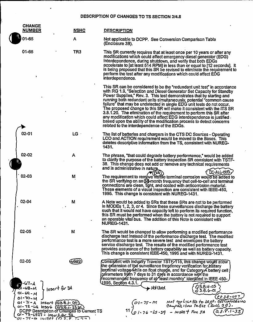
DESCRIPTION OF CHANGES TO TS SECTION 3/4.8
CHANGENUMBER NSHC DESCRIPTION
01%5
01%6
02-01
02-02
"02-03
02-04
02-05
TR3
LG
Not applicable to DCPP. See Conversion Comparison Table(Enclosure 3B).
This SR currently requires that at least once per 10 years or after anymodifications which could affect emergency diesel generator (EDG)interdependence, during shutdown, and verify that both EDGsaccelerate to [at least 514 RPM] in less than or equal to f12 seconds]. Itis being proposed that this SR be revised to eliminate the requirement toperform the test after any modifications which could affect EDGinterdependence.
This SR can be considered to be the "redundant unit test" in accordancewith RG 1.9, "Selection and Diesel Generator Set Capacity for StandbyPower Supplies," Rev. 3. This test demonstrates that by starting andrunning both redundant units simultaneously, potential "common causefailure" that may be undetected in single EDG unit tests do not occur.The proposed change to this SR willmake it consistent with the ITS SR3.8.1.20. The elimination of the requirement to perform this SR afterany modification which could affect EDG interdepeildence is justifiedbased upon the ability of the modification process to detect concernsrelated to the interdependence of the EDGs.
The list of batteries and chargers in the CTS DC Sources - OperatingLCO and ACTION requirement would be moved to the Bases. Thisdeletes descriptive information from the TS, consistent with NUREG-1431.
The phrase, that could degrade battery performance, would be addedto clarify the purpose of the battery inspection SR consistent with TSTF-38. This change does not add or remove any technical requirementsand is administrative in natur
24 DC-Ai.L-oc6The requirement to rem ve e terminal corrosion wou e added tothe SR verifying on an month frequency that cell-to-cell and terminalconnections are clean, tight, and coated with anticorrosion material.These elements of a visual inspection are consistent with IEEEP50,1995. This change is consistent with NUREG-1431.
A Note would be added to SRs that these SRs are not to be performedin MODEs 1, 2, 3, or 4. Since these surveillances discharge the batterysuch that itwould not have capacity left to perform its required function,this SR must be performed when the battery is not required to supportan operable vital bus. The addition of this Note is consistent withNUREG-1431.
The SR would be changed to allow performing a modified performancedischarge test instead of the performance discharge test. The modifiedperformance test is a more severe test and envelopes the batteryservice discharge test The results of the modified performance testprovides assurance of the battery capability as well as battery capacity.This change is consistent IEEE-450, 1995 and with NUREG-1431.
02-06
-4 l-gl "48-lvt
Ol (d9
5l IO~ Q
NLbd @3.e.g-o5q 5.8.9-0l
P /~le» CPO 7Nof Ayp L )<A gp ~ /jan ~ 5c> ~VRCcl~Qe /~st~ ht+Cg (aVucl. 883 ~
- su~/ ~ gw 0.8 > I-34
(ns ill%Ol ll- 4 Inner% 03.S.I- 0+oi- a2-LG Inxrk eS.sn-2
DCPP Description o an es o Current TSOl r5-LS'Z1 - Inse(Oi - 7q-0 iusRP.t '2, 9,
onsi ntwithindu ry Traveler TSTF 15, this c angewo a owhe tension of t surveillance fre ency verification for attely
te inalvoltag hileonfloatcha e,andforCatego batterycellrameters fr 7 days to 31 d s in accordance wi the
ecommen d frequency of a least monthly" ide 'ed in IEEE 450-995, Se on 4.3.1.

Encl. 3A 11Insert for DOC 01-74-M
Attachment BPG8 E Letter DCL-99-063
Insert for Q 3.8.1-33 (Q 3.8.1-20 CP)
A DCPP specific note will be added prohibiting several SRs from being performed inModes 1 '-4. This change is constant with the STS but reduces operational flexibilityand is more restrictive.


CONVERSION COM ON TABLE- CURRENT TS age 9 of 16
TECHNICAL SPECIFICATION CHANGE APPLICABILITY
01-51LS18
DESCRIPTION
The frequency for testing the DFO transfer pumpswould be extended from 31 to 92 days.
Diablo Canyon
No, CTS of 31days is retained.
Comanche Peak
Yes
Wolf Creek
Yes
Callaway
No, CTSfrequency isretained.
01-52M
SR would require the DFO transfer pumps to bestarted automatically.
No, DFO pumpsstarted manually.
Yes No, not a CTSrequirement.
No, nota CTSrequirement.
01-53M
01-54LS19
A Note would be added to the SR for monthly DGstart and load test to allow testing on only one DG at
fnSevg
DG partial load rejection SR frequency lower limit of53.25 Hz would be deleted.
Yes
e38.i- j@
No, frequency limitnot CTS.
Yes
Yes
Yes
No, test deleted byAmendment 101.
Yes
No, not in CTS.
01-55
01-56M
Pfo gg-The required warmup period prior to hot restart DGSR would be changed from 1 hour to 2 hours.
~~ iv/w
a s.8'/-rSNo, CTS is 2 hourwarmup period.
~vs rl/<
5-9 l-zoYes
'Qj rl/A
No, already InCTS.
H/05,'3'g.l -I7. C.
No, alreadyrevised perAmendment 112.
01-57A
The reference to depressurizing and venting theRCS is removed from this TS. The requirements forproviding RCS capacity at low temperatures iscovered in the RCS TS Low TemperatureOverpressure Protection. Removal of this referenceeliminates duplication and is consistent withNUREG-1431.
No, not in CTS. Yes No, not in'CTS. No, not in CTS.
01-58LG
The requirement to verify that the DFO transferpump transfers fuel from each storage tank to theday tank of each DG via the installed cross-connected lines would be moved to licensee-controlled documents.
No, not CTSrequirement.
No, no cross-connected lines.
Yes, moved to theUSAR.
Yes, moved tothe FSAR.
DCPP Conversion Comparison Table - Current TS


~ 0 ~
o s ~
~ ~ ~ ~ I ~ ~
~ ~
~ ~ ~
~ I
~ ~
~ ~
0 I ~ ~ ~ ~ ~ ~ ~ ~
~ ~ ~ ~ I ~
~ ~ ~ I I ~ I ~ ~ ~ ~
~ ~
~ ~ I~ ~
~ ~ ~ ~ ~ ~
~ ~ ~
~ +o ~'F-
~ ~
~ ~ ~ ~ ~ ~
~ -~ ~ I- . ~ ~
-~ ~
~ ~ ~ ~ ~ ~ ~ ~
~ ~ ~ ~
~ ~ ~ ~ ~ ~ I
~ ~ ~ ~ ~ ~ ~
~ ~ ~
~ 4 ~ ~
~ ~ ~ ~
~ .
~ ~
~ ~
I ~ ~ ~ ~
~ ~
~ ~ ~
~ ~ ~ ~ ~


Encl. 3B 11
Insert for DOC 01-74-M
Attachment BPG8 E Letter DCL-99-063
Insert for Q 3.8.1-33 (Q 3.8.1-20 CP)
A DCPP specific note will be added prohibiting several SRs from being performed inModes 1 - 4.
Applicability:
DC YESCP NOWC NOCA NO

Enclosure 4
Attachment BPG8 E Letter DCL-99-063
Insert for Q 3.8.1-33
IV. SPECIFIC NO SIGNIFICANTHAZARDS CONSIDERATIONS
NSHC LS-2910 CFR 50.92 EVALUATION
FORTECHNICALCHANGES THAT IMPOSE LESS RESTRICTIVE
REQUIREMENTS WITHINTHE TECHNICALSPECIFICATIONS
The CTS wording "during shutdown" is removed from the frequency of Surveillance4.8.1.1.1.b.1 for manual bus transfers, Surveillance 4.8.1.1.2.b.4 for emergency dieselgenerator (DG) full load rejection testing, and Surveillance 4.8.1.1.2.b.8 for the DG 24 hour loadrun testing. The removal is consistent with the NUREG-1431 Reviewer's Bases Note, whichallows removal of the MODE restriction Note for these SRs based upon three criteria:
a.) Performance of the SR willnot render any safety system or componentinoperable;
b.) Performance of the SR willnot cause perturbations to any of the electricaldistribution systems that could result in a challenge to steady state operation or toplant safety systems; and
c.) Perfonnance of the SR, or failure of the SR, willnot cause, or result in, an AOOwith attendant challenge to plant safety systems
These changes will make the TS language consistent with the normal method of operation ofthe plant and facilitate post maintenance testing of a DG during power operation withoutrequiring a unit shutdown.
1. SR 3.8.1.8 Note is modiTied to read: "This Surveillance shall not be performed forautomatic transfers in MODE 1 or 2." The Bases is revised to state that the Noteassociated with SR 3.8.1.8 applies only to automatic action which result in a unit trip andreactor trip during the transfer process and that it does not apply to the manual bustransfers. Plant experience supports this conclusion in that the manual transfer is arequired step in any normal plant startup or shut down (placing the 500 kV delayedaccess offsite circuit in service or taking it out of service).
2. The Note limiting the MODES in which SR 3.8.1.10 may be performed would beremoved. The removal would be based upon the fact that the DCPP design allows thisSR to be safely performed in all MODES. The load rejection does not create aperturbation on the ESF bus which is greater then accepted variations (result is a smalldrop in bus voltage).
Criteria a) and b) for SR performance in MODE 1 or 2 address the safety effects of theinitial conditions of this SR where the DG must be paralleled with a bus which isattached to offsite power and then load the DG to it continuous load rating. This samecapability is already required to be verified functional per SR 3.8.1.3 by loading the DG


Attachment BPG8 E Letter DCL-99-063
for a time period equal to or greater then 60 minutes (no CTS or STS MODE restrictionsapply) every 31 days.
, Criteria c) for SR performance in MODE 1 or 2 addresses the effects of the loadrejection test. This test is intended to demonstrate that the DG governor and DG =
voltage regulator are functioning properly by opening the output breaker on the DGbeing tested and verifying that the it does not trip and verifying that the DG outputvoltage does not exceed the allowable value. The only potential risk associated with thistest is to the DG (already inoperable) being tested. The bus from which the DG isremoved is fullyOPERABLE and supplied by the normal offsite power source (500 kVAuxiliaryPower). The normal offsite power source is also supported by the fullyOPERABLE "immediately available offsite power source" (230 kV Startup Power). Theloads remain attached to the normal offsite power source throughout the test and are,therefore, subject to no apparent transient. The normal offsite power source is fullycapable of handling the load rejection transient. Plant experience shows that the loadrejection does not create a perturbation on the ESF bus which is greater then acceptedvariations (result is a small drop in bus voltage).
3. The Note limiting the MODES in which SR 3.8.1.14 may be performed would beremoved. The removal would be based upon the fact that the DCPP design allowsthese SR to be safely performed in all MODES.
The considerations for performing this test in MODE 1 or 2 must include the effect of thetest's initial conditions on the vital bus and any connected safety loads. Considerationsmust also include the potential effects of the test and of any potential failures of the teston the vital bus or any connected safety loads.
This endurance test SR is the last major test of the DG prior to declaring it OPERABLE.The ability of the DG to be paralleled to the bus and accept 100% of continuous rated,load for a time period of equal to or greater then 1-hour would be already demonstratedper completion of SR 3.8.1.3 (with no MODE restriction in either the CTS or the STS).SR 3.8.1.3 does not limit the time period that the DG maybe paralleled to the bus; it onlyprovides a minimum time period. SR 3.8.1.14 differs only in the required duration andthe 2-hour peak loading to 110% of continuous rated load (this value is also the 2-hourin 24-hour load rating of the DG). The bus and associated loads remain connected tothe offsite power source throughout the test. The DG is also provided with an outputbreaker to protect the bus from any potential DG failure. The risk of catastrophic failureof the DG in such a manner as to jeopardize the safety of the bus (protected by abreaker) or safety systems attached to the bus is not credible. The plant design forswitching and control logic is such that it can safely maintain the ESF buses energized ifan accident or loss-of-offsite power were to occur during a 24-hour load run with theplant in Mode 1 power generation (an exception maybe long term degraded grid voltagewhich is not recognized could result in tripping the EDG under test prior to reaching thesecond level undervoltage protection setpoint).


Attachment BPG8 E Letter DCL-99-063
This proposed TS change has been evaluated and it has been determined that it involves nosignificant hazards consideration. This determination has been performed in accordance withthe criteria set forth in 10 CFR 50.92(c) as quoted below:
"The Commission may make a final determination, pursuant to the proceduresin 50.91,that a proposed amendment to an operating license for a facilitylicensed under 50.21(b) or 50.22 or for a testing facilityinvolves no significant hazards consideration, ifoperation of the facilityin accordance with the proposed amendment would not:
1. Involve a significantincreasein the probability or consequences ofan accidentpreviously evaluated; or
2. Create the possibi%ty of a new or different kind ofaccident from any accidentpreviously evaluated; or
3. Involve a significant reductionin a margin ofsafety."
The following evaluation is provided for the three categories of the significant hazardsconsideration standards:
1. Does the change involve a significant increase in the probability or consequences of anaccident previously evaluated?
The proposed change concerning SR 3.8.1.8 manual bus transfers is consistent withnormal plant operation and design. Therefore, it will not effect the probability orconsequences of an accident.
The proposed change regarding the DG load rejection surveillance does not create adifferent plant configuration. The load rejection does not create a perturbation on theESF bus which is greater then normally accepted variations. Consequently, it will noteffect any safety system that could be the initiator of an accident or that is used tomitigate an accident. Therefore, the probability, or consequences of an accident will notbe effected.
The proposed change concerning the DG 24-hour load endurance test does not createa different plant configuration. Evaluation of the extended duration of the test showsthat the plant design for switching and control logic can safely maintain the ESF busesenergized ifan accident or loss-of-offsite power were to occur. Therefore, theprobability, or consequences of an accident will not be effected.
2. Does the change create the possibility of a new or different kind of accident from anyaccident previously evaluated?
The proposed change does not require physical alteration to any plant system orchange the method by which any safety related system performs its function. No newplant operating configuration will result. Thus, the proposed change does not create thepossibility of a new or different kind of accident from those previously evaluated.


Attachment BPG8 E Letter DCL-99-063
Does this change involve a significant reduction in a margin of safety?
The proposed change is consistent with the plant design and operation. No safetyy Idb d RAlukltA p bl .Th g t t y
established by the testing remains unchanged. Thus there is no reduction in the marginof safety from that previously established.
NO SIGNIFICANTHAZARDS CONSIDERATION DETERMINATION
Based on the above evaluation, it is concluded that the activities associated with NSHC "LS-29"resulting from the conversion to the improved TS format satisfy the no significant hazardsconsideration standards of 10 CFR 50.92(c); and.accordingly, a no significant hazardsconsideration finding is justified.


Attachment BPG8 E Letter DCL-99-063
ADDlTIONALINFORIIATIONCOVER SHEET
ADDITIONALINFORMATIONNO: DC 3.8-ED1 (new) APPLICABILITY,: DC
REQUEST:Various changes have been identified that do not impact the technicalcontent of the submittal or other FLGG members. Changes are noted withDC 3.8-ED1 in the margin and noted below:
1. Note * was deleted in the conversation by DOC 01-05-LS-6, but markupof page 3/4 8-2 does not show the removal.
2. The extra words "Not Used" should be removed from page B 3.8-10 andB 3.8-11.
3. The first sentence of the third paragraph on page' 3.8-13 should readA.2 rather than A.3.
4. Several locations in the Bases for the SRs of LCO 3.8.1 are revised to. state that "The 24 month frequency is consistent the intent of Regulatory
Guide 1.108 (Ref. 9)."5. Change the Q 3.8.1-23 insert verb from "is" to "are."6. The last sentence of LCO 3.8.2 Bases for Applicabilityshould end with
"LCO 3.8.1." rather then "LCO 3.8.."7. Remove the word "train" form the end of the last sentence of page B 3.8-
77.8. Remove the term "the NRC Policy Statement" from last paragraph of
Applicable Safety Analysis of page B 3.8-81.9. Revise the first sentence on page B 3.8-110 read "... consistent with the
intent of Regulatory Guide ...."10. Add a statement introducing the presence of Table B 3.8.9-1 to Bases
page B 3.8-165.11. Other minor editorial changes, such as typographical, punctuation,
spelling, etc. may not be specifically identified by page, but are includedin the markup and willbe included in the ITS and Bases clean copy
ATTACHEDPAGES:
Encl. 2Encl. 5B
3/4 8-2B 3.8-10, B 3.8-11, B 3.8-13, B 3.842, B 3.845, B 3.848, B 3.8-55,B 3.8-57, B 3.8-59, B 3.8-60, B 3.8-75, B 3.8-77, B 3.8-78, B 3.8-81,B 3.8-104, B 3.8-110, B 3.8-165

0


B 3.8 ELECTRICAL POWER SYSTEMS
B 3.8.1 AC Sources - Operating
BASES
AC Sources - OperatingB 3.8.1
OC 5 8-Cnl
(Continued)
DCPP Mark-up Of NUREG-1431. Rev. 1 Bases 8 3.8-10

~ ~

B 3.8 ELECTRICAL POWER SYSTEMS
(S 3.8.1 AC Sources - Operating
BASES
AC Sources - OperatingB 3.8.1
ACTIONS A.2 (continued)
gg 3.g-E4C
OCPP Mark-up Of NUREG-1431. Rev. 1 Bases 8 3.8-11


B 3.8 ELECTRICAL POMER SYSTEHS
B 3.8.1 AC Sources - Operating
BASES
AC Sources - OperatingB 3.8.1
ACTIONS A.2 (continued)
potential for a loss of offsite power is increased. with attendantpotential for a challenge to the unit safety systems. In thisCondition, however, the remaining OPERABLE offsite circuit and DGs areadequate to supply electrical power to the onsite Class lE DistributionSystem.
The 72 hour Completion Time takes into account the capacity andcapability of the remaining AC sources, a reasonable time for
repairs'ndthe low probability of a DBA occurring during this eriOC 84'-Bod
The second Completion Time for Required Action A. es a lish s a imion the maximum time allowed for any combination of required AC powersources to be inoperable during any single contiguous occurrence offailing to meet the LCO. If Condition A is entered while. for instance.a DG is inoperable and that DG is subsequently returned OPERABLE, theLCO may already have been not met for up to 72-hears Vgdajs. This couldlead to a total of 444-4+a.-s 19~dayz, since initial fai'lure to meet theLCO. to restore the offsite circui't. At this time, a DG could againbecome inoperable. the circuit restored OPERABLE, and an additional W~ KM'BgN>(for a total of 9 f7< days) allowed prior to completerestoratio'n of the LCO. The 6 g day Completion Time provides a limiton the time allowed in a specified condition after discovery of failureto meet the LCO. This limit is considered reasonable for situations inwhich Conditions A and 8 are entered concurrently. The "NQ" connectorbetween 72 hour and 6 M day Completion Times means that both CompletionTimes apply simultaneously, and the more restrictive Completion .Timemust be met.
The Completion Time allows for an exceptionto the normal "time zero", for beginning the allowed outage time clock.This will result in establishing the
(Continued)
OCPP Nark-up Of NUREG-143l. Rev. I Bases B 3.8-13

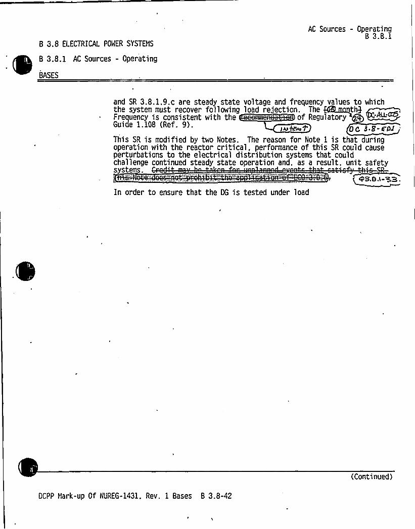
B 3.8 ELECTRICAL POWER SYSTEHS
B 3.8.1 AC Sources - Operating
BASES
AC Sources - OperatingB 3.8.1
and SR 3.8.1.9.c are steady state voltage and frequency values to whichthe system must recover following load rejection. The ~tl6Frequency is consistent with the of RegulatoryGuide 1.108 (Ref. 9).
This SR is modified by two Notes. The reason for Note 1 is that duringoperation with the reactor critical, performance of this SR could causeperturbations to the electrical distribution systems that couldchallenge continued steady state operation and, as a result, unit safetysystems.
QB.B.<-'33.
In order to ensure that the DG is tested under load
(Continued)
OCPP Hark-up Of NUREG-1431, Rev. 1 Bases B 3.8-42


B 3.8 ELECTRICAL POWDER SYSTENS
B 3.8.1 AC Sources - Operating
BASES
AC Sources - OperatingB 3.8.1
In order to ensure that the OG is tested under load conditions that areas close to design basis conditions as possible, testing must beperformed using a power factor s ~ 9787'gaggfig. This power factoris chosen to be representative of the act~ua desig'n basis
'oadingthat the DG would experience. '-ALLroc5The 9@monftg Frequency is consistent with the ofRegulatory Guide 1.108 (Ref. 9) and is intended o e consistent withexpected fuel cycle lengths.
This SR as een mo fied by a Note. The eason for the Note s thatdurin, operation w' the reactor criti 1, performance of is SR coulcau perturbati to the electrical stribution system hat couldch lenge cont'ed steady state op ation and. as a r ult. unit safet
stems., -P'NRF:::.,~ngt>zrohAKNX:,. 'X~5885~n:,,:of'A;:C:; .;,;6.'::8.
(Continued)
OCPP Nark-up Of NUREG-1431, Rev. 1 Bases B 3.8-45


B 3.8 ELECTRICAL POWER SYSTEMS
B 3.8.1 AC Sources - Operating
BASES
AC Sources - OperatingB 3.8.1
In lieu of actual demonstration of connection and loading of loads.testing that adequately shows the capability of the DG systems toperform these functions is acceptable. This testing may include anyseries of sequential, overlapping. or total steps so that t entireconnection and loading sequence is verified. 1
2 Dc-hu.~The Frequency of mon hQ is consistent with the oRegulatory Guide 1.108 (Ref. 9). paragraph 2.a.(l), takes into <3.r-Ehlconsideration unit conditions required to perform the Surveillance, anis intended to be consistent with expected fuel cycle lengths.
This SR is modified by two Notes. The reason for Note 1 is to minimizewear and tear on the DGS during testing. For the purpose of thistesting, the DGS must be started from standby conditions. that is, withthe engine coolant and oil continuously circulated and temperaturemaintained
(Continued)
DCPP Mark-up Of NUREG-1431. Rev. 1 Bases B 3.8-48


8 3.8 ELECTRICAL POWER SYSTEMSq
B 3.8.1 AC Sources - Operating
BASES
AC Sources - OperatingB 3.8.1
SURVEILLANCEREQUIREMENTS
DC 3.1-@ ~
SR 3. 8 1. 14 (continued) -Au:cc5lqq
Th qm tqf q i it t ih h ~ fRegulatory Guide 1.108 (Ref. 9), paragraph 2.a.(3), takes intoconsideration unit conditions required to perform the Surveillance, andis intended to be consistent with expe ted fuel- cycle lengths.
This Surveillance is modified by Noted). Peyote g states thatmomentary transients due to changing bus loads do not invalidate thistest. Similarly. momentary power factor transients above the owerfactor limit will not invalidate the test. e reason or e 2 is
a urban pera n sc , performan of thiSur veill ce could cau perturbations to t electrical istribut nsystem hat could c lenge continued st dy state ope tion an , as aresul , unit safety ystems.
is@ tVNQhsc ;";"; N+. %Neth A8 T3cBtl ,"oNLOIav:-:.8
+3.8.l- ~aSR 3..1.1This Surveillance demonstrates that the diesel'engine can restart from ahot condition. such as subsequent to shutdown from normal Surveillances.and achieve %%b4T~S),",eeachin othe required voltage and frequencywithin Q03 +9 seconds. e
'second time is derived from the
requirements of the accident analysss to respond to a design basis ~hne~gGA acg82mnni. The monthg Frequency is consistent with thereccamendatlons of egulatory Guide 1. 108 (Ref. 9). paragra h 2.a.(5).
2QC,-AIL'his
SR is modified by two Notes. Note 1 ensures that the e sperformed with the diesel sufficiently hot. The load band is providedto avoid routine overloading of the DG. Routine overloads may result inmore frequent teardown inspections in accordance with vendor
CLCe~rX'6 O <Cion ~SrnlS We n~cd~~kc W~ ~s~~ +Iifsoa' m~ an< I ~s/rW. ~,s assurrS M4b:Iv+ of: wfctdas saisccm M +as +r'&cr +en! c~. gfc&nl o'/cady $AeFc
opcr~sLrg Is c)fpcc.~e + oem clyc. a Icaurc t cyf sm. I, ky
clasper
w efpv(e ryorrvvnal
bONa val~a,~ 3. F-Eb
DCPP Mark-up Of NUREG-1431, Rev. 1 Bases B 3.8-55
(Continued)


8 3.8 ELECTRICAL POWER SYSTEMS
8 3.8.1 AC Sources - Operating
BASES
AC Sources - Operating8 3.8.1
~ y'
SURVEILLANCEREQUIREMENTS
(continued)
SR 3.8.1.16
As required by Regulatory Guide 1.108 (Ref. 9), paragraph 2.a.(6), thisSurveillance ensures that the manual synchronization and evCemaNe loadtransfer from the DG to the offsite source can be made and the DG can bereturned to ready to load status when offsite power is restored. Italso ensures that the autostart logic is reset to allow the DG to reloadif a subsequent loss of offsite power occurs. The DG is considered tobe in ready to load status when, the DG is at rated speed and voltage,the output breaker is open and can receive an auto close signal on busundervoltage, and the load sequencing timer s are resg, ""''
)~ih F'N fgAthki Mt t ithth~ fRegulatory Guide 1.108 (Ref. 9), paragraph 2.a.(6), and takes intoconsideration unit conditions required to perform the Surv 'c
~ -E4 I
This SR is modified by a Note. The reason for the Note is thaperforming the Surveillance would remove a required offsite circuit fromservice, perturb the electrical distribution system. and challengesafety systems4M'6-SR C
4 +
cPB.B.1- '3 3SR 3... 7
Demonstration of the test mode override ensures that the DG availabilityunder accident conditions will not be corn romised as the result oftesting~!",:,ps, .,'-. eeBopw~gria'~,. recce. ed~tA$3!.e'„'gsP68~~gs;,:qyexats~
~ I (Continued)
DCPP Mark-up Of NUREG-1431. Rev. 1 Bases 8 3.8-57


B 3.8 ELECTRICAL POWER SYSTEHS
8 3.8. 1 AC Sources - Operating
BASES
AC Sources - OperatingB 3.8.1
SURVEILLANCEREQUIREHENTS
SR 3.8.1.17 (continued)
This testing may include any series of sequential overlapping or totalsteps so that the entire connection and loading sequence is verifie
g:canThe montt9 Frequency is consistent with the recommendations of~ Regulatory Guide 1.108 (Ref. 9), paragraph Z.a.(8). takes intoconsideration unit conditions required to perform the Surveillance, andis intended to be consistent with expected fuel cycle lengths.
This SR is modified by a Note. The reason for the Note is thatperforming the Surveillance would remove a required offsite circuit fromservice. perturb the electrical distribution system. and challengesafety systems.~~ASR 3.8. 1. 18. Q3.5. 1 33
Under accident Qnd loss of offsite powers conditions>': loads aresequentially connected to the bus by :;boa'd .
s'e'quenceii.::,t'0'iiiii':.s. The sequencing logic controls the permissive and""
starti'ng signals to motor breakers to prevent overloading of the DGs dueto high motor starting cunrents. The ~ load sequence time intervaltolerances ensures that sufficient time exists for the DG to restorefrequency and voltage prior to applying the next load and that safetyanalysis assum tions regarding ESF equipment time delays are notviolated. e e ce pro es a su o e u o 0
es.
With>'an„.".ESF.:fire.r<~found,'..;.to.'he'-':ou'tide';the<ransge! of",ac'ceptabIe-settings':the.-':corresponding';l'DG''SIIa'l!l-'..ihe'.""."decl'.aroedh-:.'.~popei',"arble':,:;.ijg HOOES.>1"'.,:.2;",'::'3".?'.and
s";:,ijod th'e:!c'orrespordi'iiijiC5NOITIGN::.;.$411eVed;-@With>%$ 'A'iito".;Tre'osfer:=
~earns'~ li'itt~'~$ far We, ICONS Segu~nCC. A'mt'"S ~ ~rtd in
~J e. 63.5. I-) (E5P 1(mer5) CneL ~>e. 8~ 8. i-'Z- (~~~~for 7~~~4).
pc g.S-W1add Z p"-f~ Inst~+
(Continued)
DC".-P Hark.-up Of NUREG-1431. Rev. 1 Bases 8 3.8-59


B 3.8 ELECTRICAL POWER SYSTEMS
B 3.8.1 AC Sources - Operating
BASES
AC Sources - OperatingB 3.8.1
cp F.8, I-35
Q~~ q5, ~~C+5'g~ CV)A/~~ A~C. VC)QileCjo rn ~c h-eaLvr o4 ~c. ~M< lo4A
KW ~<8<-F~'he
Frequency of months's consistent with the ofRegulatory Guide l. 08 (Ref. 9), paragraph 2.a.(2). ta es intoconsideration unit conditions required to perform the Surveillance. andis intended to be consistent with expected fuel cycle lengths.
This SR is modified by a Note. The reason for the Note is thatperforming the Surveillance would remove a required offsite circuit fromservice. perturb the electrical distribution system. and challengesafety systems.h~-Qt
cd.8.t- 'B3
(Continued)
OCPP Mark-up Of NUREG-1431. Rev. 1 Bases B 3.8-60


AC Sources - Shutdown8 3.8.2
t
The AC power requirements for NODES 1. 2. 3. and 4 are covered inLCO 3.8..
De o.e-mol q8.8.Z-CbZ-
ACTIONS
ACTIONS(continued)
LCO;-;'3!,0~3~;:;gz!.':,,.:QppklcaN8",Wj,'., gF'HNRk~S",;":.,QK'g@-';"p,,„..tNBvQF'@',::.5, „„0.:'r'ridge'd':~f'ej'-Wmkbl
'8pp3!fc85, ',",::ejesbIfs'.:IovJA9:.,~fj,'fl, '.f'atedapl8ljBssembl'os,'-:i8pif''1'8>!IAAF, Ej<5 ofx%6m
mou..a bt.'-.'',OD'fylrra'dI:ate;:::ftuelmtaasasemb1'1'eF'~fItd td!0105."Dbee:",',sued cleat";,'rsea'KOALA'ttsotore-:."::dI::.'::reaCt'Or!":;:,, 'dOWA.'::
A.1
An offsite circuit would be considered inoperable if it were noti ti t ttt t i d \ttd ddtt -*it'tD~~P::, AlPhWA4
V,'C~wo'G]ass':9K,";-ACelectr Iej~: Od'ua.ler.:-„,.;d~stigbtuts, q~suhsystytamrstaeiaresjlraegcu1 „:,,tby",,L'cGP3 8':,1IdI tsi"5'd
'osllue"C6'ass".,.:KidAC',;.5'fear'1icalgj'outersi:,ds'st"trabt'utg'ob,-::„.:5'ubrsyst'5'mih'as of'fs1tepoue r ava i IabTe) td':bee!I'recit}If'll"ft'cl555~4E: @:;e1ktiif'ca i~re.,df5 trafbutfoosubsystem may be capable o suppor Irig sudffIOIeot reqeuIred features toallow continuation of CORE ALTERATIONS and fuel movement. By the
etitt'ttrd tt dti i d i t i d i tinoperable, w'ithd no offsite power available. appropriate restrictionswi11 be implemented in accordance with the affected required featuresLCO's ACTIONS.
A.2.1 A.2.2 A.2.3 A.2 4 B.l B.2 8.3 and 8,4
With the offsite circuit not available to all required AC!838Ctr<ic0."p~i,"."".'Chstr'ibotiinYsfibsy&'e7oa Ma4v; the option would still exist "
OCPP Nark-up Of NUREG-1431, Rev. 1 Bases B 3.8-75


BASES
AC Sources - ShutdownB 3.8.2
de-energiZed AC.;.eieetrieal"'.;:.pOW~er:.dtestriMtaan~SibayStiii~rai~ ~
OCPP.Hark-up Of NUREG-1431. Rev. 1 Bases 8 3.8-77

0
0

BASES
AC Sources - ShutdownB 3.8.2
SURVEILLANCEREQUIREMENTS
SR 3.8.2.1
SR 3.8.2.1 my'.~ )ji4i the SRs from LCO 3.8.1 that are RecesearyBppf4eaQe for ensuring the OPERABILITY of the AC sources in other thanHOOEY l. Z. 3. and 4. SR 3.8.1.8 is not required to be met since onlyone offsite circuit is required to be OPERABLE. SR 3.8.1.17 is notrequired to be met because the-required OPERABLE DG4sk is not requiredto undergo periods of being synchronized to the offsite circuit.SR 3.8.1.20 is excepted because starting independence is not requiredwith the DG4+4 that is not required to be operable.ge5R".'3,"::,8/1.;12p%BNQYg:- SK8~8. 1>gs <far::.~g~lme~3P<ed.".-''SR~QsE8"-.4+lg,~a'r@'eXCe'p't"" OC n rO~h~!%I!iii""-""-""'"':"-,"-!i'".'i!v!i"i"~i'; !l'l!'iw''
QPRR48l. EThis SR is modified bv a NotejgsEE~ilg~wapeplH'caE!e:SRsilftrom!L'CD.":::.': e:!::. a
p~recPude requiriri~ the DPERAGEE"DG4eg from being paralleled with theoffsite power network or otherwise rendered inoperable duringperformance ofa~aA sR;a —,m~K!Tle:rrloteamoulzi.::a.'.isoIprecludedeenergizing a required 4160 V ESF bus or disconnecting a requiredoffsite circuit during 'faggperformance of 8~PRs. With limited ACsources available. a singTe event could compromise both the requiredCirCuit and the DG. i,Thevnute,:,.deceve,'ant~,.eXCy>Pitthe-.".rmwq!uireme!nt.„.";,"fnrtthe08+41'60mlisdds~pee s;,-or'' toffdtii<ci'i''ii'~cetoj be (vcapabl;.ejof EperfiY~i'ii'gthiip'ait$ i)lijgfixh4o8)::";-;)Aj5jt='6i"':jcapabi'l„"ttp
llfBB.'4s '''„djvrem!netrabed'Whi'lorna t; Sluii'iCii:,roc,:""POWe'i@le'"0!eiKgarel'iadiOn:,.at~a~uPPO.'efer
to the corresponding Bases for LCO 3.8.1 for a discussion of eachSR.
'EFERENCESNone.
DCPP Nark-up Of NUREG-1431. Rev. 1 Bases B 3.8-78


BASES
DC Sources - OperatingB 3.8.4
DC 3.p-en 1
If the inoperable DC electrical power subsystem cannot be restored toOPERABLE status within the required Completion Time, the unit must bebrought to a MODE in which the LCO does not apply. To achieve thisstatus, the unit must be brought to at least NODE 3 within 6 hours andto MODE 5
Th~e;:eee1ge;,of~tpepg5'!!G~@l,ecfrf'ce1,„powei,d! strihut~!oo;:,ey,ieem;C:,,'s:ymca
.! i i" ll '-"",cl,t ltt,:ilia': eel",",,-i:"...,,:ii!"!Ihiiit'et!e~ii'""-'W,!birth�.
il '-"'ll':::, i!i!i'1" '5 'chic"'ll!I4''6"j i*:
K~ld . Ill L
DCPP Nark-up Of NUREG-1431. Rev. 1 Bases B 3.8-104

0

BASES
DC Sources - OperatingB 3.8.4
De-g.f-nd
+Qz+ . Ze.-AAA-oo>
The Surv illance Frequency of months's consistent with theof Regulatory Guide 1.32 (Ref. 10) and Regulatory
ui e . ef. 11). which state that the battery service test shouldbe performed during refueling operations or at some other outage. withintervals between tests, not to exceed Rgb months'.
(Continued)
OCPP Mark-up Of NUREG-1431, Rev. 1 Bases 8 3.8-110

0

Distributi on Systems-Operating8 3.8.9
BASES
.i, s'
SURVEILLANCEs. QUIREMENTS
SR 3.8 9.1
This Surveillance verifies that the frequire9 CRXSS$~!':-ETC. DC. and g9~VAC vital bus electrical power distribution systems are"functioning"roperly. with the correct circuit breaker alignment. The correctreaker alignment ensures the appropriate separation and independence of
the electrical divisions is maintained. and the appropriate voltage isavailable to each required bus. The verification of proper voltageavailability on the buses ensures that the'equired voltage is readilyavailable for motive as well as control functions for critical systemloads connected to these buses. The 7 day Frequency takes into accountthe redundant capabi lity of the AC, DC, and~42MVAC vital bus electricalpower distribution subsystems, and other indications available in thecontrol room that alert the operator to subsystem malfunctions.
REFERENCES 1. FSAR; Chapter 6.
2. FSAR. Chapter 15.
3. Regulatory Guide 1.93. December 1974.
~ 5 ~
pf''L
DCPP Mark-up Of NUREG-1431, Rev. 1 Bases 8 3.8-165

0

Attachment BPG8 E Letter DCL-99-063
ADDITIONALINFORMATIONCOVER SHEET
ADDITIONALINFORMATIONNO: DC3.9-001(new) APPLICABILITY: DC
REQUEST'heNSHC text for CN 12-10-LS-9 is not correct for this change. This
change provides the correct addition.
ATTACHEDPAGES'ncl.
4 30, 31


Af(hag QP< 'Iti I h/St"CT PA[ ~~ .
gg $ ,)-co}IV. SPECIFIC NO SIGNIFICANTHAZARDS CONSIDERATIONS
NSHC LS910CFR 50.92 EVALUATION
FORTECHNICALCHANGES THAT IMPOSE LESS RESTRICTIVE
REQUIREMENTS WITHINTHE TECHNICALSPECIFICATIONS
The Applicabili is revised to not require the boron concentration to be greater than 2000 ppm ess fuel in thepool has been m ed and a position verificatio has not been performed. The boron concen tion is required toprevent inadverten riticalitydue to a mis-positioned high enrichment fuel assembly. Ifa p I verificatio hasconfirmed that the fu bundles are in the correct positions, no inadvertent criticalitycan o ur due to the designof the racks. The ITS er require suspension of fuel movement and either restorati of the pool boronconcentration or the ve 'ion of storage of the high enrichment fuel in the proper p I location.
NO SIGNIFICANTHAZARDS
This proposed TS change has b n evaluated and it has been determined th it involves no significant hazardsconsideration. This determination as been performed in accordance with e criteria set forth in 10CFR 50.92as quoted below:
"The Commissionmaymakea aldeterminatr'on, pursuant the proceduresin50.91, thata proposedamendment to an operating licen fora facilitylicensed u er 50.21(b) or 50.22 or fora testing facilityinvolves no signNcant hazards con eration, ifoperatio fthe facilityinaccordance with the proposedamendment would not
Involveasignifcantincreasein probab'rconsequencesofan accidentpreviouslyevaluated; or
Create the possibility ofa new or diffe t kind ofaccident from any accident previouslyevaluated; or
3. Involve a significant reductionin margin of fety.
The following evaluation is provided for the th categories of th significant hazards consideration standards:
1. Does the change involve a signifi t increase in the probab 'r consequences of an accidentpreviously evaluated'P
The proposed changes do n alter the plant configuration, operati or function of any safety system.Consequently the changes o not significantly increase the probabili of an accident as defined in theFSAR. Maintenance of fuel pool boron concentration is an accide revention feature, i.e., criticality,and is only required to maintained ifthere is a potential for a misposi ned high enrichment fuelassembly. Ifthe fuel sitions have been verified the storage racks are d igned to prevent criticality.
Therefore, the p osed changes do not involve a significant increase in the p babiiity or consequencesof an accident viously evaluated.
Does the c nge create the possibility of a new or different kind of accident from an ccident previouslyevaluated
The p posed changes do not require physical alteration to any plant system or change th method bywhi any safety-related system performs its function.
herefore, the proposed changes do not create the possibility of a new or different kind of acci nt fromany accident previously evaluated.


g~i~ r 'hf i~s~ct PqmIV. SPECIFIC NO SIGNIFICANTHAZARDS CONSIDERATIONS
:3.
NSHC LS9(Continued)
Does this cha involve a significant reduction in a margin of safety?
The proposed changes do alter any basic regulatory re 'nts or change any accident analysisassumptions, initial conditions o ults. Consequen e proposed changes do not involve asignificant reduction in a margin of sa
NO SIGNIFICANTH S CON TION DETERIIINATION
Based upon the preceding informa ', it has been determined that the osed changes associated with NSHCLS9" do not involve a signifi increase in the probability or consequences accident previously
evaluated, create the i ilityof a new or different kind of accident from any acci reviously evaluated, orinvolve a signifi reduction in margin of safety. Therefore, it is concluded that the propo hange satisfy theno signifi azards consideration standards of 10CFR 50.92 and, accordingly, a no significan ardscon 'ation finding is justified.


i
IV. SPECIFIC NO SIGNIFICANT HAZARDS CONSIDERATIONS
NSHC LS-910 CFR 50.92 EVALUATION
FORTECHNICALCHANGES THAT IMPOSE LESS RESTRICTIVE
REQUIREMENTS WITHINTHE TECHNICALSPECIFICATIONS
To assure charcoal adsorber OPERABILITY, the SR requires that a laboratory analysis beperformed and the results obtained within 31 days of removing the charcoal sample. Thesample must be sent to an offsite laboratory for this analysis. It is proposed that the timerequirement of "within 31 days after removal" for completion of laboratory analyses be deleted.This requirement is intended to avoid extended plant operation with degraded charcoal filters.This requirement is not contained in the ITS nor is it contained in the Regulatory Guide 1.52 orthe applicable ANSI standards. There is no safety significant basis for maintaining this time limitas a Technical Specification requirement. Laboratory analyses are performed under contractwith a laboratory on a prompt basis, and it is not necessary to prescribe a time limitwithinTechnical Specifications for completing the analysis. Failure to complete an analysis within 31days has insignificant safety consequences because the results would be available withinapproximately the same time period and it is very unlikely that the charcoal would be degradedto the extent that there would be a complete loss of a safety function.
This proposed TS change has been evaluated and it has been determined that it involves nosignificant hazards consideration. This determination has been performed in accordance withthe criteria set forth in 10CFR 50.92(c) as quoted below:
''The Commission may make a final determination, pursuant to the proceduresin 50.91,that a proposed amendment to an operating license for a facilitylicensed under 50.21(b) or 50.22 or for a testing facilityinvolves no significant hazards consideration, ifoperation of the facilityin accordance with the proposed amendment would not:
1. Involve a significantincreasein the probabi%ty or consequences ofan accidentpreviously evaluated; or
2. Create the possibi%ty of a new or different kind ofaccident from any accident'previously evaluated; or If
3. Involve a significant reductionin a margin of safety."
The following evaluation is provided for the three categories of the significant hazardsconsideration standards:
Does the chang'e involve a significant increase in the probability or consequences of anaccident previously evaluated?
The proposed change does not result in any hardware changes or changes to operatingmethodologies. This revision does not affect an accident initiator of any analyzedaccident. The revision recognizes that the frequency of this surveillance will not affectthe probability of any accident.

I

IV. SPECIFIC NO SIGNIFICANT HAZARDS CONSIDERATIONS
NSHC LS-9(continued)
In addition, the results of charcoal filter testing would be available on approximately thesame schedule as before. Thus, the proposed change would not have a significanteffect on the availability of the filters to perform as assumed following an accident.
Therefore, the proposed changes do not involve a significant'increase in the probabilityor consequences of an accident previously evaluated.
2. Does the change create the possibility of a new or different kind of accident from anyaccident previously evaluated?
The proposed change does not require physical alteration to any plant system orchange the method by which any safety-related system performs its function.
Therefore, the proposed change does not create the possibility of a new or different kindof accident from any accident previously evaluated.
3. Does this change involve a significant reduction in a margin of safety?
The proposed change would continued to assure that the charcoal filters perform asrequired although the time period for obtaining test results would be removed fromTechnical Specifications. However, the results would be available on approximately thesame schedule as before. Consequently, it does not have significant effect on a marginof safety.
Therefore, the proposed change does not involve a significant reduction in a margin ofsafety.
NO SIGNIFICANTHAZARDS CONSIDERATION DETERMINATION
Based on the above evaluation, it is concluded that the activities associated with NSHC "LS-9"resulting from the conversion to the improved TS format satisfy the no significant hazardsconsideration standards of 10 CFR 50.92(c); and accordingly, a no significant hazardsconsideration finding is justified.


Attachment BPG&E Letter DCL-99-063
ADDITIONALINFORMATIONCOVER SHEET
ADDITIONALINFORMATIONNO'C ALL-001 APPLICABILITY: DC
REQUEST:
LAs 119/117 and 118/116 were issued 7/13/97 and addressed CTSsurveillance interval increases due to 24-month fuel cycles. Thesechanges on pages affected by NRC comment numbers are indicated with"DC-ALL-001." These changes were previously submitted to the NRC inan errata to LAR 97-09 via DCL-98-003 (dated January 8, 1998).
REQUEST (Supplement): SR 3.9.4.2 should be shown as having a 24 monthfrequency consistent with the CTS (CTS SR 4.9.4.b which has a frequency per SR4.6.3.2.c which was changed to each refueling interval per LA 119/117).
ATTACHED PAGES:
Encl. 2Encl. 5AEncl. 5B
3/4 9-43.9-6B 3.9-10, B 3.9-11


REFUELING OPERATIONS
/4.9. 4 CONTAINMENT PENETRATIONS
IMITING CONDITION FOR OPERATION
3.9.4 The containment penetrations shall be in the following status
a. The equipment deer- h5t'ih closed and held in place by a minimum of fourbolts.
b. A minimum of one door in each airlock is closed. and
Each penetration providing direct access from the cont meatmosphere to the outside atmosphere shall be either: :'q gg 71) Closed by an a utomatiCNisolation valve, blind flange. or
manual val ve,or'jejui.:iaLeiih:;::::<5~or')
Be capable of being closed by an OPERABLE wCemaNecontainmerit ventilation isolation valve.
APPLICABILITY During CORE ALTERATIONS —, or,,'-:";movement of irradiated fuel withincontainment.
04<9-LS14
04-01-LG
04%8-LG
ACTION: With the requirements of the above specification not satisfied.imaediately suspendall operations involving CORE ALTERATIONS, movement of irradiated fuel incontainment.
04-08-LG
RVEILLANCE RE UIREMENTS
.9.4 Each of the above required containment penetrations ~(N4 shall bedetermined to be 04-10-LS20
daysIvn""::/he'retqui,red,::.~s'tatusqonce per 7 o44I2-tea
.Inevvi) "-"Veri'f yi'e'ch,"'::, reqmierd:,,: cotnavrment purgevandveshaust! Ts oietvionaylavheaC"ua ea... O,": e",:,"ia'O at5'Onp":.-';.'Ouefi:'T'Onv'i:: V"
c FQC'4 SA3 Jmyc Vkb-. Stesting the containment ventilation solation valves,p r
Specification 4.6.3.2c. at"'::":-liest-::,::once.c .—
."
,KbyiVse;-;of::,arnac Ua .gor,.'.emu 'a 'e '."'iT na; l".(
':,Except@for,.:„"';perie,at)'oon;.,-.f1 oj.",'pHv'h('s3:-:;ovi Chug,:"direct'.".:."ac ssgf'rom,".theecontajiiiiierii',,i spbii.',.i':;:,::to~the:,'','eitsv:: ''.''.:atmsos ''- '"„""'i'st "avterd'n:iadm'in% 'rati'.voe',"":.'.caonti':oI'i:.:.,
'4-03»LS5-hl(-oe)04-04-TR1
04-10- 20
DIABLO CANYON - UNITS 1 8 2TS39.4A
3/4 9-4 Amendment Nos. 46 and 45October 30, 1989


S URVEILLANCE REQUIREMENTS
SURVEILLANCE
Containment Penetrations3.9.4
FREQUENCY
SR 3.9.4.1 Veri fy each required containment etration isi status x pt",,':for,„'„,:con,@men
n'et;:Vms=".that';;:are::6'""n':i.ondei",:":::idtIi", 4ib itivecon f< 's.
7 days 3 -1
SR 3.9.4.2 Verify each required containment purge andexhaust Veiitj'„:35/i'�';jzolwt'ion".val vew actuatesto the is'olatiori'osi'tion" on an actiial orsimulated actuation signal.
months B-PB
OCPP Mark-up of NUREG-1431. Rev. 1 3.9-6

0

BASES
Containment Penetrations8 3.9.4
ACTIONS A 1 and A2N
If the containment equipment hatch, air locks, or any containmentpenetration that provides direct access from the containmentatmosphere to the outside atmosphere is not in the required status.including the Containment Purge and Exhaust Isolation System notcapable of automatic actuation when the purge and exhaust valves areopen, the unit must be placed in a condition where the isolationfunction is not needed. This is accomplished by imediatelysuspending CORE ALTERATIONS and movement of irradiated fuel assemblieswithin containment. Performance of these actions shall not precludecompletion of movement of a component to a safe position.
SURVEILLANCEREQUIREMENTS
SR 3.9.4.1
This surveillance demonstrates pgnsjntcteonNer:.:":::.,Aifimniste@~vellsJansthat each of the containment penetrations r'eqsuired'"to"be in its closedposition is in that position. The Surveillance on the open purge andexhaust valves will demonstrate that the valves are not blocked fromclosing. Also the Surveillance will demonstrate that each valveoperator has motive power, which will ensure that each valve .iscapable of being closed by ntainmen purge andexh solation si nal. The"::...Rppp8CigpppgtlQC~C..,.,c,igpACP$ 18f;f,,'Bgi'0IISP ik, $8gB.:";::;OP:i'I"'s88fffA3:Nf:8KN'VB',.".CO
c I",9),'S$$WjAOt„"...;W~:.R':: eet;:-wi'".%M ...
The Surveillance is performed every 7 days during CORE ALTERATIONS ormovement of irradiated fuel assemblies within containment. TheSurveillance interval is selected to be commensurate with the normalduration of time to complete fuel handling operations. A surveillancebefore the start of refueling operations will provide two or threesurveillance verifications during the applicable period for this LCO.As such, this Surveillance ensures that a postulated fuel handlingaccident that releases fission product radioactivity within thecontainment will not result in a release of fission productradioactivity to the environment.
SR 3.9.4.2
: This Surveillance demonstrates that each containment purge and exhaustvalve actuates to -its isolation position on manual initiation or on anactual or simulated high radiation signal. The 18 month Frequencymaintains consistency with other similar ESFAS instrumentation and
'alvetesting requirements. In LCO 3.3.6. the Containment Purge andExhaust Isolation instrumentation requires a CHANNEL CHECK every 12hours and a COT every 92 days to ensure the channel OPERABILITY duringI tf N t tl . E y tt CINNNEL CNLINNNTICN I
I!C I!-
(Continued)
Mark-up of NUREG-1431. Rev. 1 Bases B 3.9-10


ES
SURVEILLANCEREQUIREMENTS
(continued)
Containment PenetrationsB 3.9.4
Dzl+OCet-oc )
rformed. The system actuation response time is demons ated evmonths, during*refueling. on a STAGGERED TEST BASIS. SR 3.6.3.5
aemonstrates that the isolation time of each valve is )i QZ.'V.G-Iaccordance with the In service Testing Program requirements. TheseSurveillances performed during MODE 6 will ensure that the valves arecapable of closing after a postulated fuel handling accident to limita release of fission product radioactivity from the containment.
REFERENCES
.Igi!L":it',:,8: I (!C'fll--';I'. t"Fti:2. FSAR. Section ~KB:::4%-3.
3. NUREG-0800, Section 15.7.4. Rev. 1, July 1981.
~ ~
Mark-up of NUREG-1431. Rev. 1 Bases B 3.9-11
'I
I I
,) ~
t ~
~~
~t4
1
qt
(.'„
,IVas'?
'I C


Attachment BPG8 E Letter DCL-99-063
ADDITIONALINFORMATIONCOVER SHEET
ADDITIONA'LINFORMATIONNO: DC 5.0-005 (new) APPLICABILITY: DC
REQUEST'CPPLA 129/127 was approved February 19, 1999. This Amendment is
Applicable only during DCPP Units 1 and 2, Cycles 10 and 11. Thisrevision provides the ITS mark-ups to reflect the changes to the SteamGenerator Tube Surveillance Program (ITS 5.5.9 and 5.6.10) resultingfrom LA 129/1 27.
ATTACHEDPAGES:
Encl. 5A 5.0-17, 5.0-20, 5.0-39

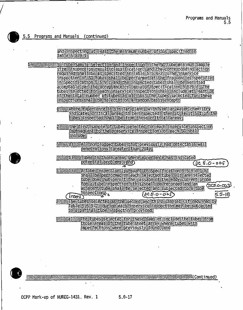
Programs and Manuals5.5
5.5 Programs and Manuals (continued)
S'IZ e.":;!i IIlSp ACt l'GA!'lle5U l t!"Oil asaaif IC'abI'GA':.';~i'a'A'GSthse',COAAI!8Sp OAd7Ag',,''SCtl QA
:j'iisr'P'el'CH'O'ASS"ieehal:: Sibe Seel etoteadsr!OII;:::,i:.'AAA'doer'! bhsriel eadCAPt,,'!
1:,,;~p+Where:;es,p::erhIAAci'pri'nsslsalriar ~~p lahrts jp'trhVSIAIIlpr,.„,water.,;,.:Cheiiiistry,d'AadiiCateaj i'C1 t''i'C'arbaceae'"„to)bei!!I'iisapeCted!i:",:.:'.;.0i~i'ibis;:i'tiipecpte'd;;,lsrha%1::.-,be:,':fk,".oiii the''se',.-',-'".Cb!It'icaf "ilia'r'eas,:"
::is)"beajeeat;.tepe~thii'j~'ii.leXei'err'AC~A%AS'peC'Qti'Oii>';"::oft'Csh'iSBl Stol.:1=-
lrllc
a--,.:,:-:::-,'"':9) .,:'~,':A31,:::liig~nP,...Vgg84'.:.tgbtb8:jth~y, reV~jmj]g.'.hBdYd8408A& Y-'65):OASF;":gf.':,85 8l.:;.: Hfl'::s
>,'.'..'':':;.:.'kgbY.'.":<XT6bes~iqgth~ose. Lareas:;„.':ihei",.eYixpgrlenFe;.',hasH'ndi'cifid
f::::,:~,,:eV~:;::::,"A~tulpinspectfoay',:,."{pdrrsdar At,":to,::,,Speci'frcaation>% „B'l9,:.:d:;1::h3':"Shi„I.::f„'::be„';pe'iifO'IA'ied,.;OII':.""esaCh.seieCte'd:.:.torbaei~i'~liif,g'gabe,."idoi~j'A'opperji't~<the:,"'pa'ssagi:";,0
, dftiiii t~dbepIAspe'ctlQA<th a'si'haiji'be'ji'e c'ioded::tairdja'A'.adjarcent~PtlIbshe'tslibl!h:;::bce'eibrs ted'.-::ail d« sbA'e'c'ted'o!.'aritobeXesspecltl.:G~A"" >
3~;:.":;q::: .,:.:,tebe~SyeleC'tedtxa,;„thee;::Seeoosd arnd:,"';thrcdy~~leS;:!<!i'ff c PA.esdI;c:,:ebj
:troa,'ja At: ial;, tdIbIe'iIiiSpe tCi dGA, pceridfd::—.-—
im7ei'"."Sect'uris':-,::,'.,hei':.e"=ir'eviouSl:.i',:.'"foLIf'td','',."arrr'id'
OCPP Nark-up of NUREG-1431, Rev. 1 5.0-17


Enclosure 5A of ITS 5.0, Page 5.0-17, Item b.2
INSERT for ITS 5.5.9.b.2:
Insert for DC 5.0-003
5.5.9 b.2.d) Indications left in service as a result of application of the tube support plate voltage-based repair criteria shall be inspected by bobbin coil probe during all future refueling outages.
g 5 8 b g. 8) Tubes identified as W'ubes having a previously identified indication within the
'W'ength shall be inspected using a rotating pancake coil (RPC) probe for the
full length of the W'egion during all future refueling outages. 4
DC S 0-oD

I

Programs and Manuals5.5
5.5 Programs and Manuals (continued)
" 'xeeexds'ls'the Ji rlrrggirigg~gliiiiit-,;:A,";,:"tobe.-,::,'c'onto'r'din g',. a!dtefect drs
ii::,:!!if,:l:-;:::,-ii!~lttI hhhhfftttiti',. :,'tih,;', I,',,f, Ii!: rdhlih;,':,tt,:,:,i'hs il"" ""Wi.",gthe<tube,'ph'a,'''iml~'be<";:.'r'emoh'~e'd'.",,fj;:o'm'ipse!re'Ci: ia'ndi."~,:s'.;::~q'u
:.i:.':;::::.i'Itic!i'''I~8""":.I'il'!id',"'sl"",th",::i:, '!s..:.::...'ii ter!'lf!it":::,-:I:"„"I:' 'or: 'contains-:;j'"'defect:::":.;:-::iran'rj'e',:enoua'gh;":-.".:,:to'."!a'f feet';:,:~is;:5.ntegrity,':Qs'n)the'.:,i'ientd~of::::""a,:,dooubli.,".Des'ign):Eii.;thquak'e):,.";";a".Joss;-."of,;, co)biant-,"'acct'de'ii tji~o'n.":aba'te'giii)itei ik 'o'ri fee'eddiVater'i'1r no
'::::!ilia!:::,":,,hh'll'!~t"I:::I th'' 'i..,.::',-„,tll!: .Ii"tl',,,„,:if'I!ii!iNih';i::if:,:::,nith,;'""'tobetifenned:,!<hotch!leagues'ide):::;;:,'cpiii'pii'ettetg j.:':::!ariodoend ht'ceh::::Uib',.e,de''t'o! shed
'"O'p'ii'i tppaef t. nef::.."...'thj:-':: CO'd~!1 ehg,",„::~anrila-
i,:::,:::;::,:h'::,::::::::-:f~ht;-:, .*,;:,,f, I,',-:t::,', 'i .. !!t rtf:,,Ir i!.,... Iiloyfnt,eachhd;:htobedpriy sidecar,'.58gepe'f for'iiied'!bye eddy!go'rrfi est;"techii'i'qiiii'ia
S
e
S
g
h
bI
"'r<3j'r,.-';:ti'„,ii)",~)'centi,gstabj''iifi';,a.;„'bid@',,j''ub')fig;'„~gPjfP)'5;"".::j'ispK40A':~h5''.I>f:,'";:;W,,".
hjd't,:,,frrI!hi'itii,,d'!it,:II!rl!,,'ll,*,"i'-.tW!itsi eld i!!!I'*":-Ilh.':iit!i:-'"*'h":;:"hh"'!I!~i'",'-:':h''::-::,—",-"t;„-".'."'"
'Z..:.w:::.:,,,e,:.-::... guuegqtegprb'0y tst'hal idbsehdi'termrii rIedl'efte<ccTrpl etjngatheacori.',es'p'onjing'w'ct'i,oi'isi:;,'orta
I1:,'tobeta:.,c'oinita'i'riiiig:-.":thi,'edrdrgehi'-,"rial~8::"'elf act's!t>';.-::teriirtrr'cedgbj:;Table
fayg f~t hhghrdf9 tghh'xarmfa
Srrgheyf, llaensoea ip iafiiihh''aa"xel""l'."-bpe::":iiigaC~Caetodantebrith";:."SpeC>fi'Cadtt'ien!5:;6:,:'lg::t,.
pC a,Ch-ood5~5'- i
This Jef ftr%~n c4eS ~ c,pply fo 4 be. 5ugef+ pic% in~ecHiyyts'Mid~ Vol~-tX'Bed V+4il Ce'jltj'idr PA'. Rifi| tapir&. R6~ fO 6 5 t.d I J+C. i e'er'r lrm'h- appl'rCCblr„~ ~CD l'fiWSaCHans'.
ZC 5'0-CD>
g) This definition does noi apply io the portion of thetubesheet below the W length. Acce table tubethe W length shall be defined as in
S,s-,g,d. l. ktubewi in e
all degradation withind +
OM Lf.. bg S. 5-ougto%'i ~',,',ai"" '"'! 'idger+~hhih~~g!Pdf!"'-'~"' qt!:I,hlG'. ~~gaea',:"a,rrNe! fg'-'!grithh',,ntghg",:,,:,idd'.i de.„..oiiSriDt artrgt'i r„(C t d)
DCPP Mark-up of NUREG-1431. Rev. 1 5.0-20

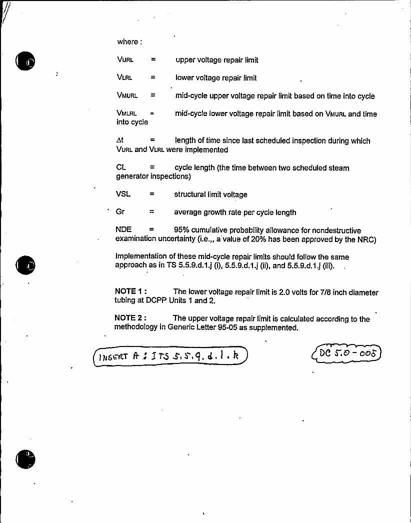
where:
VURL upper voltage repair limit
VLRL = lower voltage repair limit
VMURL = mid-cycle upper voltage repair limit based on time into cycle
VMLRL
into cyclemid-cycle lower voltage repair limit based on VMuRL and time
dt = length of time since last scheduled inspection during whichVURL and VLRLwere implemented
CL = cycle length (the time between two scheduled steamgenerator inspections)
VSL = structural limitvoltage
Gr average growth rate per cycle length
NDE = 95% cumulative probability allowance for nondestructiveexamination uncertainty (i.e.„a'value of 20% has been approved by the NRC)
Implementation of these mid-cycle repair limits should follow the sameapproach as in TS 5.5.9.d.1.j (i), 5.5.9.d.1.j (ii), and 5.5.9.d.1.j (iii).
NOTE 1: The lower voltage repair limit is 2.0 volts for 7/8 inch diametertubing at DCPP Units 1 and 2.
NOTE 2: The upper voltage repair limit is calculated according to themethodology in Generic Letter 95-05 as supplemented.


J M5ECI Dg +,D-oos
~ ri ~ ~ It@) W'plu in Ltmhis used fordispositionofanalloy600steamgeneratortubefor continued service that is experiencing predominately axially oriented insidediameter stress corrosion cracking confined within the tubesheet, below thebottom of the WEXTEX transition (BWT). As used in this specification;
Bottom of WEXTEXTransition (BWT) is the highest point of contactbetween the tube and tubesheet at, or below. the top-of-tubesheet asdetermined by eddy current testing.
( I l)1
~VP Len this the distance to the tubesheet below the BWT thatprecludes tube pull out in the event of a complete circumferentialseparation of the tube below the We length. The W length
is'onservativelyset at: 1) an undegraded hot leg tube length of 5.2 inchesfor Zone A tubes and 7.0 inches for Zone B tubes, and 2) an undegradedcold leg tube length of 5.5 inches forZone A tubes and 7.5 inches forZone B tubes. information provided in WCAP-14797, Revision 1 ~
defines the boundaries of Zone A and Zone B.
(tv)
Flexible W Len th is the W'ength adjusted for any cracks found withinthe W region. The Flexible W Length is the total RPC-inspected lengthas measured downward from the BWT, and includes NDE uncertaintiesand crack lengths within War as adjusted for growth.
r
W'ube is a.tube with equal to or greater than 40% degradation withinor below the Wsr length that is left in service, and degraded within thelimits specified in Specification 4.4.5.4a.1 1)e.
Within the tubesheet, the plugging (repair) limit is based on maintainingsteam generator serviceability as described below:
l) For tubes to which the Wsr criteria are applied, the length of non-degraded tube below BWT shall be greater than or equal to theW'ength pius NDE uncertainties and crack growth for theoperating cycle.
Axial cracks in tubes returned to service using W shalt have theupper crack tip below the BWT by at least the NDE measurementuncertainty, and below the TTS by at least the NDE measurementuncertainty and crack growth allowance, such that at the end ofthe subsequent operating cycle the entire crack remains below thetubesheet secondary face.
Resolvable, single axial indications (multiple indications mustreturn to the null point between individual cracks) within the flexibleW length can be left in service. Alternate RPC coils or anultrasonic test (UT) inspection can be used to demonstrate returnto null point between multiple axial indications or the absence ofcircumferential involvement between axial indications.
ftyfrLtCrt8fC lerf. g'ru fS/ a 0 g„'t u<(66 fp aWh ii,


Z f.S Z, S 9. ot, I (a.s. g)
Tubes with inclined axial indications less than 2.0 inches long(including the crack growth allowance) having inclination anglesrelative to the tubve axis of W5 degrees minus the NDEuncertainty, hNDE~, on the measurement of the crack angle canbe left in service.'ubes with two or more parallel (overlapping,elevation), inclined axial cracks shall be plugged or repaired. Forapplication of the 2.0 inch limit, an inclined indication is an axialcrack that is visually inclined on the RPC C-scan, such that anangular measurement is required; and the measured angleexceeds the measurement uncertainty of END~.
Circumferential, volumetric, and axial indications with inclinationangles greater than (45 degrees - BANDE~) within the flexible Wlength shall be plugged or repaired.
Any type of combination of the tuba degradation below the VPlength is acceptable.

ll

Reporting Requirements5.6
5.6 Re orting Re ui rements (continued)m
ED
stta7:;:I,':..;::.bi)lie'p)r4id~4o„,.:joe'~Cmiiinsihi~i."::,:
~fF;; g~+.'""':Thee,:sn'heft% de': t'oth ie'PAIA'fs sto',n,"." 1nd-"a: esrPosritAihtink'2;,"iiioiitli's"",:,ni„'.."Own)i."0'Omplefi~5fi'Of::.'::,:::tope'::.':ln'Sp'enttOA'.~jTiL1S':ilpeo'1'a'.::i'R~pnrtB B. i i+:,.AC'.0 e~2
:--:-:-::::k!ii'i!eileh-':-::-,.i."::,-i 4 M b *:::-,:-mme!
7!.„'X':",;4P~NÃ~i'k0$KPQA!!BAdPPerceAt":;ofi'Aa'1i1;-:,th1 Qknresa"'"'.Pens'tl'.lat1 on!'!f011eaoli!'!indi'Qetesont'orfn::,,'an:.-::"i'iaps'e'rfeoation:,'",B
rid-::"'e'".:,.';.!„;-:.:::,',.'3)PZi.:":.::.:;;Kdmt$'f::"cd"on,::efKubex"'$ii "~d5
C'":::RBSAYte."Of:"N'tobe'r1ASPedt1AOAS::::Ahioh foal lre'ntn;::::C'ategOrj,!'C:;3!.
dent'ei,ttt joe',:,'eau'se,.::!of,",',4h'e: B,,eA'~ 0'~pr8ven..:.'f.pcUFf.,eActs~
Inse't 5. 5-18
DCPP Hark-up of NUREG-1431. Rev. 1 5.0-39


Enclosure 5A of ITS 5.0, Page 5.0-39
INSERT for ITS 5.6.10.d.:
Insert for DC 5.0-003
(lbttu,r.rtt 8t'ct rn'+4 Ess keyc "de <r't'r~rtLrsMara/E IPeyrtirL d<r ~
Q gg -Oo5
5.6.10.d. For implementation of the voltage-based repair crit ia to tube support plate
intersections, notify the NRC prior to returning the steam generat s to service should any of the
following arise:
1. Ifestimated leakage based on the projected end- -cycle (or ifnot practical, using the
actual measured end-of-cycle) voltage distribution exceeds the leak limit determined
from the licensing basis dose calculation for the postulated main steamline break for
the next operating cycle.
2. Ifcircumferential crack-like indications are detected at the tube support plate
intersections.
3. If indications are identified that extend beyond the confines of the tube support plate.
4. If indications are identified at the tube support plate elevations that are attributable to
primary water stress corrosion cracking.
5. Ifthe calculated conditional burst probability based on the projected end-of-cycle (or if'ot practical, using the actual measured end-of-cycle) voltage distribution exceeds 1 x
10', notify the NRC and provide an assessment of the safety significance of theoccurrence.
j) Q 5'.0 -oo$'.
(g)The results of the ins ection of W'ubes shall be reported to the Commissionithin 90 days following return to service of the steam
generators. This repo s a include:
1) Identification of W'ubes.
2) W'nspection distance measured with respect to the BWT or the top of thetubesheet, whichever is lower.
3) Elevation and length of axial indications within the flexible W distance and the
angle of inclination of clearly skewed axial cracks (ifapplicable).
4) The total steam line break leakage for the limiting steam generator per WCAP-14797.
f. (+)The aggregate calculated steam line break leakage from application of all alternate
repair criteria shall be reported to the Commissionwithin 90 days following return to service of the steam generators.