Pilgrim - Nuclear Regulatory Commission
306
Entergy Nuclear Operations, Inc. En eg Pilgrim Nuclear Power Station 600 Rocky Hill Road Plymouth, MA 02360 September 13, 2007 Stephen J. Bethay Director, Nuclear Assessment U.S. Nuclear Regulatory Commission ATTN: Document Control Desk Washington, DC 20555-0001 SUBJECT: Entergy Nuclear Operations, Inc. Pilgrim Nuclear Power Station Docket No. 50-293, License No. DPR-35 Response to NRC Request for Additional Information Related to Third Ten- Year Pilgrim Relief Request, PRR-42, Examinations of Component Welds with Less Than Essentially 100% Examination Coverage REFERENCES 1. Entergy (BECo) Letter No. 2.95.091, ASME Section Xl, Third Interval Inservice Inspection Plan, Pilgrim Nuclear Power Station, dated September 1, 1995 2. Entergy Letter No. 2.06.054, Third Ten-Year ISI Interval Pilgrim Relief Request, PRR-42, Examinations of Component Welds with Less Than Essentially 100% Examination Coverage, dated June 28, 2006 3. Entergy Letter No. 2.07.051, Third Ten-Year ISI Interval Pilgrim Relief Request, PRR-42, Examinations of Component Welds with Less Than Essentially 100% Examination Coverage, dated May 16, 2007 4. ASME Section XI, Code Case N-460, "Alternative Examination Coverage for Class 1 and Class 2 Welds, Section Xl, Division 1" LETTER NO. 2.07.076 Dear Sir or Madam: By Reference 1, Entergy submitted Pilgrim's Third Ten-Year Inservice Inspection Plan for the interval of July 1, 1995 to June 30, 2005, in accordance with the 1989 ASME Code, Section XI requirements pursuant to 10 CFR 50.55a. During the Third Ten-Year Interval, Pilgrim completed the required in-service examinations in accordance with the plan; with the exceptions of certain components that could not fully meet the volumetric examination requirements stipulated in the 1989 ASME Code, Section Xl, including the clarifications provided in the ASME Code Case N-460 (Ref. 4). Entergy has determined that conformance with the code requirement of essentially 100% coverage of weld volume or area examined was impractical due to various constraints and limitations. Accordingly, pursuant to 10 CFR 50.55a (g)(5)(iii), Entergy submits the attached Pilgrim Relief Request No, PRR-42 (Attachment 1), and Response to NRC Request for Additional Information, PRR-42 Rev. 1 (Attachment 2) for NRC review and approval. 4,-o I
-
Upload
khangminh22 -
Category
Documents
-
view
0 -
download
0
Transcript of Pilgrim - Nuclear Regulatory Commission

Entergy Nuclear Operations, Inc.En eg Pilgrim Nuclear Power Station600 Rocky Hill Road
Plymouth, MA 02360
September 13, 2007 Stephen J. BethayDirector, Nuclear Assessment
U.S. Nuclear Regulatory CommissionATTN: Document Control DeskWashington, DC 20555-0001
SUBJECT: Entergy Nuclear Operations, Inc.Pilgrim Nuclear Power StationDocket No. 50-293, License No. DPR-35
Response to NRC Request for Additional Information Related to Third Ten-Year Pilgrim Relief Request, PRR-42, Examinations of Component Weldswith Less Than Essentially 100% Examination Coverage
REFERENCES 1. Entergy (BECo) Letter No. 2.95.091, ASME Section Xl, Third IntervalInservice Inspection Plan, Pilgrim Nuclear Power Station, datedSeptember 1, 1995
2. Entergy Letter No. 2.06.054, Third Ten-Year ISI Interval Pilgrim ReliefRequest, PRR-42, Examinations of Component Welds with Less ThanEssentially 100% Examination Coverage, dated June 28, 2006
3. Entergy Letter No. 2.07.051, Third Ten-Year ISI Interval Pilgrim ReliefRequest, PRR-42, Examinations of Component Welds with Less ThanEssentially 100% Examination Coverage, dated May 16, 2007
4. ASME Section XI, Code Case N-460, "Alternative ExaminationCoverage for Class 1 and Class 2 Welds, Section Xl, Division 1"
LETTER NO. 2.07.076
Dear Sir or Madam:
By Reference 1, Entergy submitted Pilgrim's Third Ten-Year Inservice Inspection Plan for theinterval of July 1, 1995 to June 30, 2005, in accordance with the 1989 ASME Code, Section XIrequirements pursuant to 10 CFR 50.55a.
During the Third Ten-Year Interval, Pilgrim completed the required in-service examinations inaccordance with the plan; with the exceptions of certain components that could not fully meetthe volumetric examination requirements stipulated in the 1989 ASME Code, Section Xl,including the clarifications provided in the ASME Code Case N-460 (Ref. 4). Entergy hasdetermined that conformance with the code requirement of essentially 100% coverage of weldvolume or area examined was impractical due to various constraints and limitations.Accordingly, pursuant to 10 CFR 50.55a (g)(5)(iii), Entergy submits the attached Pilgrim ReliefRequest No, PRR-42 (Attachment 1), and Response to NRC Request for Additional Information,PRR-42 Rev. 1 (Attachment 2) for NRC review and approval.
4,-o I

Entergy Nuclear Operations, Inc.Pilgrim Nuclear Power Station
Letter Number: 2.07.076Page 2
In March 2007, the NRC requested additional information to complete their review of PRR-42.Subsequently, NRC Staff and Entergy held a conference call to discuss the scope of the NRCrequest and Entergy informed the Staff that they would respond to the NRC request bySeptember 15, 2007 (References 2 and 3).
PRR-42 proposes alternatives where the requirement of "essentially 100%" volumetricexamination was not feasible due to construction limitations, obstructions, accessibility, andexamination techniques. The alternatives and justifications are explained in the attached reliefrequest which provides a list of components that requires relief from the "essentially 100%"volumetric examination requirements pursuant to 10 CFR 50.55a. The alternatives andjustifications provide acceptable level of quality and safety and will not adversely impact thehealth and safety of the public.
There are no commitments contained in this letter.
A similar ISI Relief Request No. B-5 for Vermont Yankee Nuclear Power Station was approved bythe NRC Letter dated September 19, 2005 (TAC. No. MC 0959).
If you have any questions on this transmittal, please contact me at 508-830-7800.
Sincerely,
epdJ.eth~ay
SJB/wgl
Attachments: 1. Pilgrim Relief Request, PRR-42 and Program Data Sheets for Examinationswith less than "Essentially 100% coverage (248 pages)
2. Response to NRC Request for Additional Information, PRR-42 Rev. 152 pages)
cc: Mr. James Kim, Project ManagerOffice of Nuclear Reactor RegulationMail Stop: 0-8C-2U.S. Nuclear Regulatory Commission1 White Flint North11555 Rockville PikeRockville, MD 20852
U.S. Nuclear Regulatory CommissionRegion 1475 Allendale RoadKing of Prussia, PA 19406
Senior Resident InspectorPilgrim Nuclear Power Station

PILGRIM RELIEF REQUEST PRR-42
Attachment 1 to Entergy Letter 2.07.076
Entergy Nuclear NortheastPilgrim Nuclear Power Station
3 rd 10-Year ISI Interval Closeout
Proposed AlternativeIn Accordance with 10 CFR 50.55a(g)(5)(iii)
(Inservice Inspection Impracticality - Alternative Provides Acceptable Levelof Quality and Safety)
1. ASME Code Component(s) Affected
Code Classes: 1, 2
References: Subarticle IWB-2500, Subarticle IWC-2500, GL 88-10, NUREG 0313,ASME Code Case N-460
Examination Categories: B-A, B-D, B-F, B-H, B-J, B-O, C-C, C-F-1 and C-F-2
Item Numbers: B1.12, B1.21, B1.30, B3.90, B5.10, B5.130, B8.10, B9.11, B9.21,B14.10, C3.20, C5.11, C5.51
Description: Volumetric and Surface Examination Coverage
Component Numbers: Various, see Table 3
2. Applicable Code Edition and Addenda
1989 Edition with no addenda
3. Applicable Code Requirements
Subarticle IWB-2500 states in part "Components shall be examined and tested asspecified in Table IWB-2500-1". Table IWB-2500-1 requires a volumetric examination ora surface and volumetric examination be performed on the component based onCategory and Item Number. The applicable examination area or volume and methodrequired are as shown below from Table IWB-2500-1:
TABLE 1
ExaminationExamination Item Requirements
Category Number /Figure Number Examination MethodB-A B1.12 IWB-2500-2 VolumetricB-A B13.21 IWB-2500-3 VolumetricB-A B13.30 IWB-2500-4 VolumetricB-D B3.90 IWB-2500-7 VolumetricB-F B5.10 IWB-2500-8 Volumetric and SurfaceB-F B5.130 IWB-2500-8 Volumetric and SurfaceB-H B8.10 IWB-2500-13 SurfaceB-J B9.11 IWB-2500-8 Volumetric and SurfaceB-J B9.21 IWB-2500-8 SurfaceB-O B14.10 IWB-2500-18 Volumetric or Surface
Page I of 8

PILGRIM RELIEF REQUEST PRR-42
Subarticle IWC-2500 states in part, "Components shall be examined and pressure testedas specified in Table IWC-2500-1 " Table IWC-2500-1 requires a surface examination ora surface and volumetric examination to be performed on the component based onCategory and Item Number. The applicable examination area or volume and methodrequired are as shown below from Table IWC-2500-1:
TABLE. 2
ExaminationExamination Item Requirements /
Category Number Figure Number Examination MethodC-C C3.20 IWC-2500-5 Surface
C-F-1 C5.1 1 IWC-2500-7 Surface & VolumetricC-F-2 C5.51 IWC-2500-7 Surface & Volumetric
The Code requires that the entire volume or area be examined.
4. Impracticality of Compliance
Entire volume or area required is defined by ASME Section Xl Code Case N-460 titled"Alternative Examination Coverage for Class 1 and Class 2 Welds, Section Xl, Division1". Code Case N-460 states in part, "...when the entire examination volume or areacannot be examined.., a reduction in examination coverage.. .may be accepted providedthe reduction in coverage for that weld is less than 10%".
The NRC through Information Notice 98-42 titled "Implementation of 10 CFR 50.55a(g)Inservice Inspection Requirements" termed the reduction in coverage of less than 10%to be "essentially 100 percent'. Information Notice 98-42 states in part, 'The NRC hasadopted and further refined the definition of 'essentially 100 percent' to mean 'greaterthan 90 percent'... has been applied to all examinations of welds or other areas requiredby ASME Section XI."
Pilgrim's piping systems and associated components were designed and fabricatedbefore the examination requirements of ASME Section Xl were formalized andpublished. Since this plant was not specifically designed to meet the requirements ofASME Section Xl, literal compliance is not feasible or practical within the limits of thecurrent plant design.
Physical obstructions imposed by design, geometry and materials of construction aretypical of vessel appurtenances, biological shield wall, insulation support rings, structuraland component support members, adjacent component weldments in close proximity,unique component configurations (valves and pumps), and dissimilar metal weldments.
Therefore, examination of the entire volume or area for some of the components whichare listed in Table 3 cannot be achieved. The specifics of the limitations and restrictionsare also provided in Table 3. The Attachment 2 to this relief request provides the actualdata sheets of examinations with less than essentially 100% coverage.
Accordingly, pursuant to 10 CFR 50.55a(g)(5)(iii), Entergy has determined thatconformance with the code requirement of essentially 100% coverage of weld volume orarea examined was impractical due to various constraints and limitations as statedabove. Entergy requests NRC approval of the proposed alternative as stated below.
Page 2 of 8

PILGRIM RELIEF REQUEST PRR-42
5. Burden Caused by Compliance
To increase the percentage coverage of the volume or area examined, the ReactorPressure Vessel (RPV), Class 1 piping nozzles, portion of the Class 1 piping system, theCRD Housing, and a number of the Class 2 piping system support lugs would have to bere-designed, re-fabricated, or removed. These activities would also require extensiveengineering and design effort, as well as the shutdown of the plant for modificationinstallation. These activities are impractical for the plant to undertake.
6. Proposed Alternative and Basis for Use
A). The components listed in Table 3 have already been examined by the availablemethods to the maximum extent practical. No additional volumetric or surfaceexaminations will be performed on the components for the 3 rd InserviceInspection Interval.
B). A visual inspection (VT-2) is performed by VT-2 qualified operators on thesubject components during the system pressure tests (with no leakage detected)as required by code category B-P (each refueling outage) and category C-H(each period).
Basis for Use
As a minimum, all components received the required examination(s) to the extentpractical with regard to the limited or lack of access available. The examinationsconducted confirmed satisfactory results evidencing no unacceptable flaws present,even though "essentially 100%" coverage was not attained. PNPS has concluded that ifany active degradation mechanisms were to exist in the subject welds, thosedegradations would have been identified in the examinations performed.
For surface examinations PNPS calculated the coverage percentage based on the areathat was examined within the required coverage area divided by the required surfacearea to be inspected. For volumetric (ultrasonic) examinations there are many ways tocalculate coverage. PNPS elected to use the following method. The requiredexamination volume was calculated. The examination was performed in accordancewith an approved ultrasonic procedure that met the governing Code requirements. Theapproved procedure requires a number of angles and a number of beam directions foreach angle. For each angle/beam direction combination the volume interrogated by thatbeam was calculated (within the required coverage volume). Then that value wasdivided by the required examination volume to determine percentage coverage for eachangle/beam-direction combination. Then those required angle/beam-direction coveragepercentages were averaged to determine an overall composite coverage. For example,prior to invoking Appendix VIII, ASME Section V, Article 4 required 00, 450, and 600search units for examining vessel welds from the OD of the vessel. The 450 and 600search units are each required to be scanned in four orthogonal directions. Therefore, atotal of nine angle/beam- directions are required and a coverage percentage iscalculated for each of those nine angle/beam-direction combinations. Then those ninevalues are averaged to determine the overall composite coverage. (Note: SinceAppendix VIII was invoked for vessel welds, the required number of angle/beam-direction combinations now depends on the qualified procedure, and thus the calculationwould be different.)
For the most part, PNPS did not select alternative welds when coverage was limited onthe scheduled weld. A sample plan implies a certain amount of random choice in the
Page 3 of 8

PILGRIM RELIEF REQUEST PRR-42
selection of welds for examination - unless there are more conservative ways to selectthe sample, such as selecting high stress points or welds where industry experienceindicates that damage mechanisms are more likely. This is why for Category C-F-2,terminal end welds are singled out; they are more typically high stressed. The reason forinterferences is usually independent of the flaw mechanism. However, there may becases where this is not true. For example, valve-to-pipe welds and pump-to-pipe weldgeometries may inhibit coverage. But, these welds may actually have higher stressesbecause of their configurations. In these cases, if alternative welds were selected, thesample of higher stressed welds in the population would be diluted. If alternative weldsare chosen, the selection randomness decreases. Flaw mechanisms associated withtest limitations may be missed and it may be better to accept the limited coverage thanto select alternative welds.
There is Code precedent for allowing limited coverage due to inaccessibility. ASMESection Xl exempts certain Class 1 and Class 2 welds from examination based on thecriteria that they are inaccessible. Paragraphs IWB-1220(c) and IWC-1230 exemptwelds that are inaccessible due to control rod drive penetrations or because they areencased in concrete. The Code recognizes that examination of these welds is notpossible, and therefore, a Relief Request would not be necessary. The same logicapplies to portions of welds that are inaccessible and where examination of thoseportions of welds is not possible.
To summarize, PNPS has examined all components in the 3rd Interval ISI Program andassociated augmented programs to the maximum extent possible given the inspectionlimitations discussed above. The portion of the PNPS ISI Program surface andvolumetric inspection sample that could not be examined (expressed in inches of weldmetal) due to limitations/interferences during the 3rd ten year interval is approximately 4%when compared to the total weld length that could have been examined if no limitationshad been present.
When the PNPS ISI Program is viewed in total, the overall degree of coverage obtainedis still greater than 90%, i.e. essentially 100%. For this and the other reasons detailed inthis request, Entergy believes that the limited coverage obtained on the componentslisted in Table 3 is not significant and will provide an adequate level of quality and safetyfor examination of the affected welds, and will not adversely impact the health and safetyof the public.
7. Duration of Proposed Alternative
Relief is requested for the third ten-year interval of the Inservice Inspection Program forPilgrim, which began July 1, 1995 and concluded June 30, 2005.
8. Attachment
Pilgrim 3 rd Interval ISI program datasheets for examinations with less than "Essentially100%" coverage are attached (Table 3).
Page 4 of 8
PILGRIM RELIEF REQUEST PRR-42
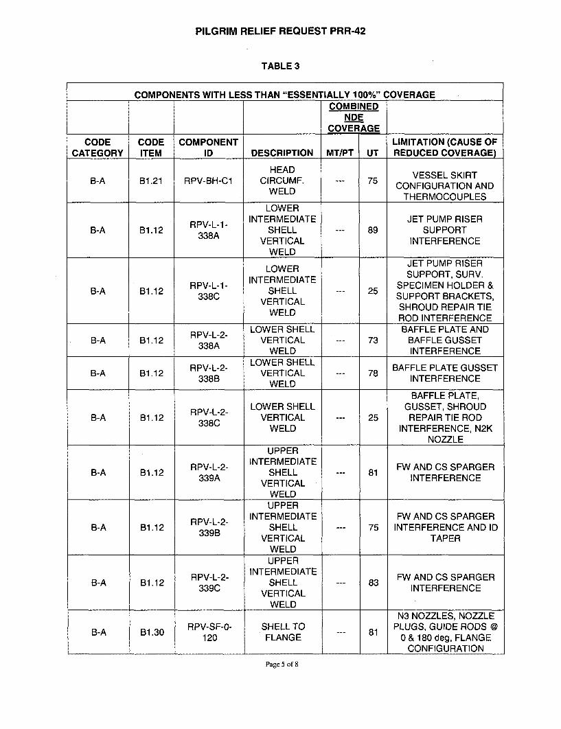
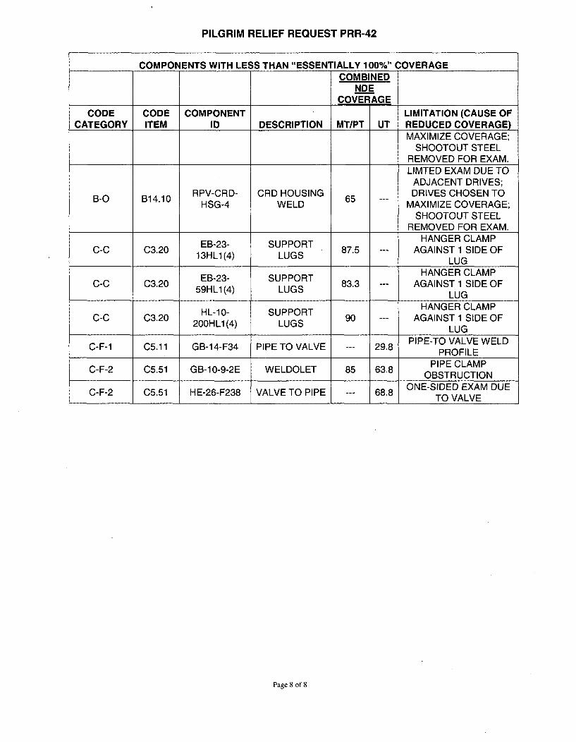
TABLE3
COMPONENTS WITH LESS THAN "ESSENTIALLY 100%" COVERAGECOMBINED
NDECOVERAGE
CODE CODE COMPONENT LIMITATION (CAUSE OFCATEGORY ITEM ID DESCRIPTION MT/PT UT REDUCED COVERAGE)
HEAD VESSEL SKIRTB-A B1.21 RPV-BH-C1 CIRCUMF. --- 75 VESSEL SKRCONFIGURATION AND
WELD THERMOCOUPLES
LOWER
RPV-L-1- INTERMEDIATE JET PUMP RISERB-A B1.12 SHELL --- 89 SUPPORT
VERTICAL INTERFERENCE
WELD
LOWER JET PUMP RISER
INTERMEDIATE SUPPORT, SURV.RPV-L-1- SPECIMEN HOLDER &B-A B1.12 33CSHELL -- 25 SUPRBACE,338C VERTICAL SUPPORT BRACKETS,
VERLD SHROUD REPAIR TIEROD INTERFERENCE
S LOWER SHELL BAFFLE PLATE ANDB-A B1.12 RPV-L-2- LOESHLB-A B1.12 VERTICAL --- 73 BAFFLE GUSSETWELD INTERFERENCE
RPV-L-2- LOWER SHELL BAFFLE PLATE GUSSETB-A B1.12 338B VERTICAL 78 INTERFERENCE
WELDBAFFLE PLATE,
LOWER SHELL GUSSET, SHROUDB-A B1.12 3382 VERTICAL --- 25 REPAIR TIE ROD
WELD INTERFERENCE, N2KNOZZLE
UPPERRPV-L-2- INTERMEDIATE FW AND CS SPARGER
B-A B1.12 339A SHELL --- 81 INTERFERENCEVERTICAL
WELDUPPER
RPV-L-2- INTERMEDIATE FW AND CS SPARGERB-A B1.12 339B SHELL --- 75 INTERFERENCE AND ID
VERTICAL TAPERWELDUPPER
RPV-L-2- INTERMEDIATE FW AND CS SPARGERB-A B1.12 339C SHELL --- 83 INTERFERENCE
VERTICALWELD
N3 NOZZLES, NOZZLERPV-SF-0- SHELL TO PLUGS, GUIDE RODS @
120 FLANGE 0 & 180 deg, FLANGECONFIGURATION
Page 5 of 8
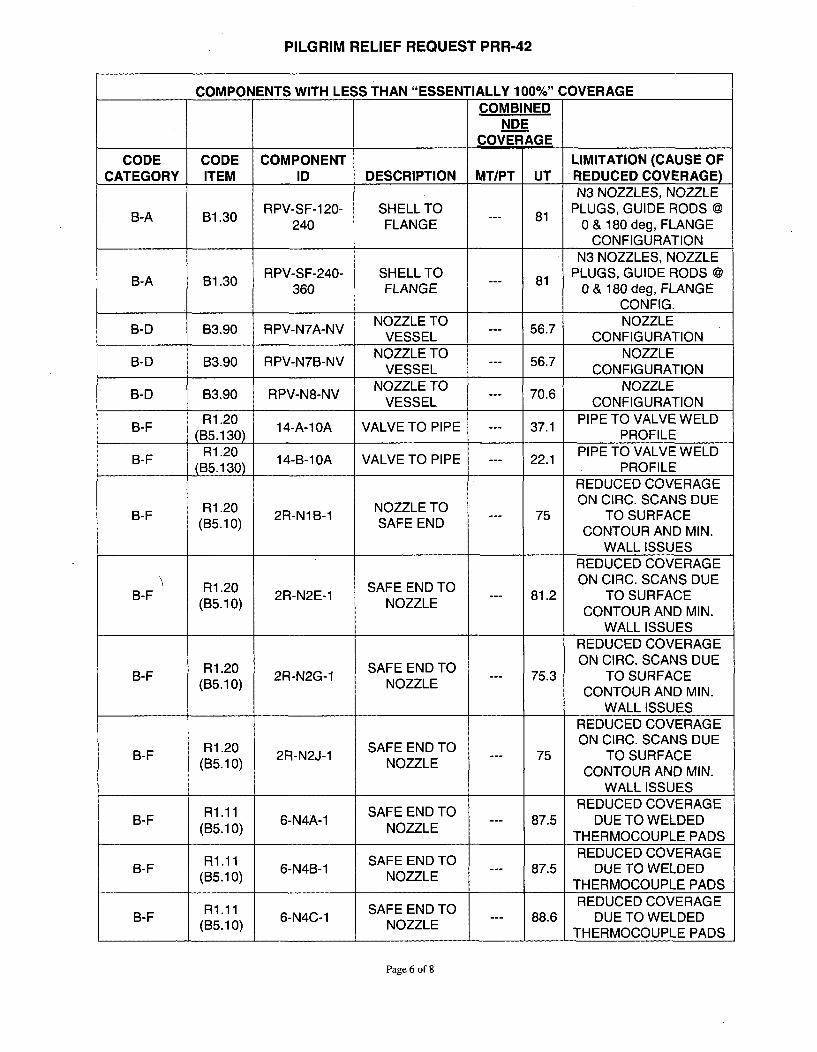
PILGRIM RELIEF REQUEST PRR-42
COMPONENTS WITH LESS THAN "ESSENTIALLY 100%" COVERAGECOMBINED
NDECOVERAGE
CODE CODE COMPONENT LIMITATION (CAUSE OFCATEGORY ITEM ID DESCRIPTION MT/PT UT REDUCED COVERAGE)
N3 NOZZLES, NOZZLERPV-SF-120- SHELL TO PLUGS, GUIDE RODS @
240 FLANGE 0 & 180 deg, FLANGE
CONFIGURATIONN3 NOZZLES, NOZZLE
RPV-SF-240- SHELL TO PLUGS, GUIDE RODS @360 FLANGE 0 & 180 deg, FLANGE
CONFIG.NOZZLE TO NOZZLE
B-D B3.90 RPV-N7A-NV VESSE 56.7 C ON I R OVESSEL CONFIG URATION
NOZZLE TO NOZZLEB-D B3.90 RPV-N7B-NV VESSE 56.7 C ON I R O
VESSEL CONFIGURATIONNOZZLE TO NOZZLE
B-D B3.90 RPV-N8-NV VESSE 70.6 C ONI R OVESSEL CONFIG URATION
R1.20 PIPE TO VALVE WELDB-F R1.30 14-A-10A VALVE TO PIPE --- 37.1 P RO FILE
(135.130) PROFILER1.20 PIPE TO VALVE WELD
B-F 14-B-10A VALVE TO PIPE --- 22.1(B5.130) PROFILE
REDUCED COVERAGE
ON CIRC. SCANS DUEB-F (1.10 2R-NIB-1 NOZE TO --- 75 TO SURFACE(B5.10) SAFE END CNORADMNCONTOUR AND MIN.
WALL ISSUESREDUCED COVERAGE
R1.20 SAFE END TO ON CIRC. SCANS DUEB-F Ri3.20 2R-N2E-1 SAFE END 81.2 TO SURFACE
CONTOUR AND MIN.WALL ISSUES
REDUCED COVERAGEON CIRC. SCANS DUE
B-F Ri3.20 2R-N2G-1 SAFE END 75.3 TO SURFACECONTOUR AND MIN.
WALL ISSUES
REDUCED COVERAGEON CIRC. SCANS DUE
R1.20 SAFE END TO O IC CN UB-F Ri3520 2R-N2J-1 SAFELE --- 75 TO SURFACE
CONTOUR AND MIN.WALL ISSUES
REDUCED COVERAGER1.11 SAFE END TO RDCDCVRG
B-F (1.10 6-N4A-1 SAFE END 87.5 DUE TO WELDEDTHERMOCOUPLE PADSREDUCED COVERAGE
R1.1 1 SAFE END TO RDCDCVRGB-F (3.10 6-N4B-1 SAFE END 87.5 DUE TO WELDED
THERMOCOUPLE PADSREDUCED COVERAGE
R1.1 1 SAFE END TO RDCDCVRGB-F R3.10 6-N4C-1 SAFE END 88.6 DUE TO WELDED
IB50 NOZZLETHERMOCOUPLE PADS
Page 6 of 8
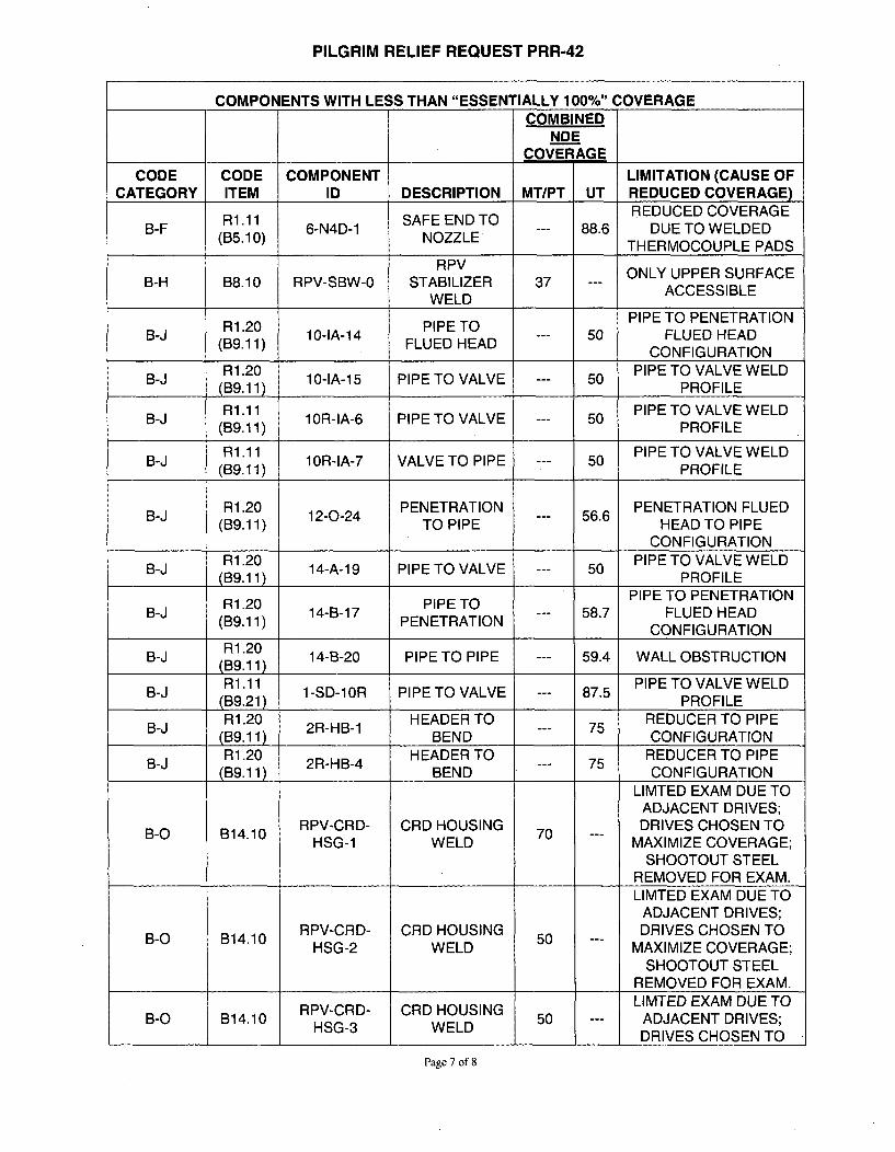
PILGRIM RELIEF REQUEST PRR-42
COMPONENTS WITH LESS THAN "ESSENTIALLY 100%" COVERAGECOMBINED
NDECOVERAGE
CODE CODE COMPONENT LIMITATION (CAUSE OFCATEGORY ITEM ID DESCRIPTION MT/PT UT REDUCED COVERAGE)
REDUCED COVERAGER1.11 SAFE END TO RDCDCVRG
B-F R3.10 6-N4D-1 SAFELE TO 88.6 DUE TO WELDEDTHERMOCOUPLE PADS
RPV ONLY UPPER SURFACEB-H B8.10 RPV-SBW-O STABILIZER 37 ACCESSIBLE
WELDPIPE TO PENETRATION
B-J (3.11 10-IA-14 PIPE TO --- 50 FLUED HEAD(B9.11) FLUED HEAD CNFGURTOICONFIGURATION
R1.20 PIPE TO VALVE WELDB-J (B.ll 10-IA-i5 PIPE TO VALVE --- 50 PROFILE
(139.11) PROFILER1.11 PIPE TO VALVE WELDB-J 10.i) iR-IA-6 PIPE TO VALVE -- 50PRFL
(B9. 11) 1PROFILER1.11 PIPE TO VALVE WELDB-J 10.1) iR-IA-7 VALVE TO PIPE 50PRFL
R1.20 PENETRATION PENETRATION FLUED
(B9.11) TO PIPE HEAD TO PIPE
CONFIGURATION
B-J R1.20 14-A-19 PIPE TO VALVE --- PIPE TO VALVE WELD(B9.11) PROFILE
PIPE TO PENETRATIONB-J (3.11 14-B-17 PEN TO --- 58.7 FLUED HEAD(B9.11) PENETRATIONCOFGRTN CONFIGURATION
R1.20B-J R1.20 14-B-20 PIPE TO PIPE --- 59.4 WALL OBSTRUCTION(139.11)
R1.11 PIPE TO VALVE WELDB-J R1.11 1-SD-1 OR PIPE TO VALVE --- 87.5 P RO FILE
(139.21) PROFILE
R1.20 HEADER TO REDUCER TO PIPE(B9.11) BEND CONFIGURATIONR1.20 HEADER TO REDUCER TO PIPE
(JB9.11) BEND CONFIGURATIONLIMTED EXAM DUE TO
ADJACENT DRIVES;
B-0 B14.10 RPV-CRD- CRD HOUSING 70 DRIVES CHOSEN TOHSG-1 WELD MAXIMIZE COVERAGE;
SHOOTOUT STEELREMOVED FOR EXAM.LIMTED EXAM DUE TO
ADJACENT DRIVES;
B-0 B14.10 RPV-CRD- CRD HOUSING 50 DRIVES CHOSEN TOHSG-2 WELD MAXIMIZE COVERAGE;
SHOOTOUT STEELREMOVED FOR EXAM.LIMTED EXAM DUE TO
RPV-CRD- CRD HOUSING LME XMDETB-O B14.10 HSG-3 WELD 50 --- ADJACENT DRIVES;
DRIVES CHOSEN TO
Page 7 of 8
PILGRIM RELIEF REQUEST PRR-42
A AlllA ...... A ......... AA ......... AAmLImm A m ........ Im AAimmm A AmCOMPONENTS WITH LESS THAN "ESSENTIALLY 1UU%/" UOVEHAGE
COMBINEDNDE
COVERAGE
CODE CODE COMPONENT LIMITATION (CAUSE OFCATEGORY ITEM ID DESCRIPTION MT/PT UT REDUCED COVERAGE)
MAXIMIZE COVERAGE;SHOOTOUT STEEL
REMOVED FOR EXAM.LIMTED EXAM DUE TO
ADJACENT DRIVES;
B-0 B14.10 RPV-CRD- CRD HOUSING 65 DRIVES CHOSEN TOHSG-4 WELD MAXIMIZE COVERAGE;
SHOOTOUT STEELREMOVED FOR EXAM.
EB-23- SUPPORT HANGER CLAMPC-C C3.20 E3 SUPO 87.5 --- AGAINST 1 SIDE OF
13HL1(4) LUGS LUGEB-23- SUPPORT HANGER CLAMP
C-C C3.20 EB23 SUPO 83.3 --- AGAINST 1 SIDE OF59HL1 (4) LUGS LUG
HL-10- SUPPORT HANGER CLAMPC-C C3.20 HL1O- SUPPORT 90 --- AGAINST 1 SIDE OF
200HL1 (4) LUGS LUGPIPE-TO VALVE WELD
C-F-1 C5.11 GB-14-F34 PIPE TO VALVE --- 29.8 PROFILEPIPE CLAMP
C-F-2 C5.51 GB-10-9-2E WELDOLET 85 63.8 OBSTRCTIONOBSTRUCTION
ONE-SIDED EXAM DUEC-F-2 C5.51 HE-26-F238 VALVE TO PIPE --- 68.8 TO VALVE
TO VALVE
Page 8 of 8

Pilgrim 3P Interval ISI Program Data Sheets forExaminations with less than"Essentially 100% coverage
(240 pages)
(Third Ten-Year ISI Interval:July 1, 1995 to June 30, 2005)
APRIL 2006
Pages 1 of 240

Rmen Nf,:
EXAMINATION SUMMARY SHEET PL-AGE ENERGY, NUCLEAR
Site: Pliarim Nucear Power Station Component ID: RPV-BH-C1
OutRF-15 HEAD CIRCUMF WELD
Syw W2 ASME Cat: ft• ASME Rem D= Aug Req WA
Exhm Data Shet Cat Sheet J Procedure Calibration Block Examination :Carl ee! DatePerformed IForsonneiS0T Long. UT-O8 N/A TPO-e IGE-U."-300) 4 PIL-SE I Scot Erickson : _ 4/2&2005
W0 Long. UT-0"7 N/A TPK4-GiS tGE-UT-wOa) CAL-IIW2-033 Scott Erickaon II
60- Long. UT- N/A TPo4-o01 (GE-rT-oO) CAL-INW2-017 Ste" Snyder It U/200560' Long. UT-0OS WA T4-018 (GEurT-300) PL-58 Stew Snyder y1 4P28M00
450 Shear UrT-ogo WA TP04-010 (GE-UT-3o0) PL-5 Steve Snyder II 4/282005
450 Shear UT-A TP04-01 iGE-UT-30) PIL-5 Steve Snyder 1i 4/28/200
Examinalton Rea•eiW
Ultrasonic examinatlon results were acceplable to the reqirements of ASME B&PV Code Section Xi, 198I Edition no Addenda, andSection )0, 1995 Edition with the 19986 Addenda as modied by the PD1 program descpon and the Federal Register, Pu II, NuclearRegulatory Comnrision, 10 CFR Pan 50 for Category B-A Reactor Pressure Vessel (RPV) Assembly Welds.
Manual transerse and parallel scans were performed In accordance wilh procedure GE.UT-300 V8 using 600 RL search units.
Scanning was restricted fronm one side of the weld due to the vessel skMrt configuration and themocouples.
Manual UT exams recorded (3) three Indicallon, that were acceptable to the reqlirements of Section Xl.
Coverage - 75%
Examksfim restls wer con are to dais report 96-E-M2.534,531 hran 1995 Outage WN1 0. AungewThese aurrwanoawere Wp&*'fwid unde ftrk Orde WA oiang
This Summuy and 9wble ofot* dafta Mseta hew bo yf bem erois
Prepared By .L v l Da :E
ANDI Review: Page I of 12
0P-14 2-ALa

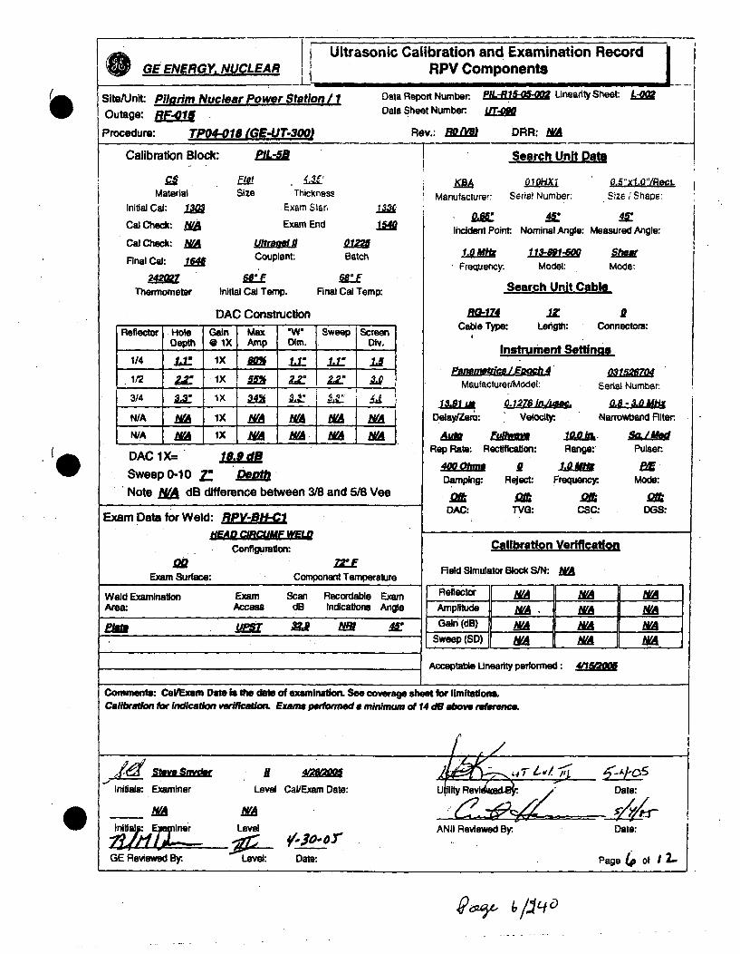
Ultrasonic Calibration and Examination RecordGE ENERGY NUCLEAR i RPV Components ,
SiteAUnlt Plirro Nuclear Power Station / i Data Report Number PIL-k -.0 Uneldty Sheet j.-
Outage: R Data Sheet Number: M I
Procedure: Tp04-018 (GE-UT-300) Rev.: MRw DRR. MA
Calibration Block: PL-SB Search Unit Dato
MalerialInitial Cal: IM
Cal Check: N/A
Cal Check: MVAFlnaJ Cak za
Thermometer
F.IASize Thickness
Exam Stan
Exam End
IManufacturer: Serial Number. Size/ Shape: I
cd Pot , NMIncident Point Nominal Angle: Me'sursed Ang~le:
Couplant:
Initial Cal Temp.
DAC Construction
Batch
WCEFinal Cal Temp:
Frequency. Model: Mode:-
Search Unit Cable
Cable Type: LangtiK Connectors:
Instrument Seftlnas
Reflector Hole Gain Max W Sweep ScreenDepth 0 IX Amp Dim. DIv.
N/A NA IX NA N/A MA MA
N/A MA I x MA LU MA MA
N/A MA IX I I" MA NA IMA
Maufacturst/Model: Serial Number.
DAC lX=Sweep 0-10 X
fl3.0
DelavZero: Velty. Narrowbend Filter
Rep Rao: Rectification: Range: PLASM
Damping: Reject: FreMquency Mods:
DAC: TVG CSC: DGS:
Note NA dB difference between 3/8 and 5/8 Vee
Exam Data for Weld: REPVOHI ClHEAD C11QOUAF HfLW
Configuration:oME
Exam Surface: Component Temperature
Weld Examnaton Exam Scan Recordable ExamAm&a AccesS d. Indications Angle
Plwaft at& 2 RE A
Fleld Simulator Block S/N: MA
Acceptable Uinearity eformed: 415010
Comments: CaVExm ODate to ie dol. of exauinnation. See coverage sheet for lmittions.CaAbadm fekr a vokam n•inaVfaL Emama poftmd to n taidn a i1- 20% FSH clad ro.LExam perlomred from nwidhisl wel RPV-BH-1 to RPV-BHM- and from RPV.-al7W to RPV-BlNl.Singe sided @=em due to component co~guratfoE~xm Ibmitd ftm mnwindr wevd 0 HM # mmuing .L Irom 31.J to 36.5 andwWr of 5 .. * dw to a dtwmxoqlb r.
InitiaLa Examiner Level CaVEXam Date: LIUUy R OVOs ~ Date:
_MA MA __
IE Level AtII Reviewed By: Dat:
GE Reviewed By. Level: Date: page 2. of 12.
0
,-3 /3,4 0

Ultrasonic Calibration and Examination Record0 GE ENERGY, NUCLEAR RPV Components
I.
SiteUnit PRlhrim Nuclear Power Station/ 1 Data Report Number.FX-R 5 ileanty Sheet -0
Outage: RFna Data'Sheet Number
Procedure: TP04-018 (GE-UT-3OOJ Rev.: WJR DRR: NMA
Calibration Block: AL Search Unit Dat.
MaeraA Sizei ThicknesMateilal Size Thicknes!rManulacturer: Serial Number: Size ; Shape:
Initial Cal: 121 Exam Stian
Cal Check: NA Exam End /4 Incident Point Nominal Angle: Measured Angle:
CalChc k : MVA hUrac.Final Cal: /ii4 Couplant Batch 3.0. Mod : Mone
2Fr-quemy- Model: Mods:
Thermometer Initial Cal Temp. Final Cal Temp: Search Unit Cable
DAC Construction A& 174
Reflectolr Hole Gin MWx W Sweep Screen Cable TqW Lenglt Connecton
DIplh * IX Amp Dim. Div. Instrmenttna.
1/4 AE IX M I.= !" -r
NIA WA IX WA MA WA MAdecl~w4WN-A -A Ix N- MA 90 MaufacturdModel: Serial NumberN&A 'I Rx usx 0 -N Alma
N/A IX MA NA &A WA DelayVZýe': Velocity. Narrowband Filter
N/ A ix MA MA NA MA AuM Euflwaz Uek
DAC I • MU0 Rep Rae:. Rectlflcealon: Range: Puleer:,,Qfm oB. A E.•r. i
Sw eep 0-10 2 .0 •u th Da rnp~ g Reject: F roqueno Mode:
Note NA dB difference between 3/8 and 5/8 Ve. Dam . oe F re . M
Exam Data for Weld: EPE-i.1 DAC: TY: . CSC: DGS:
HEAD CIfC=HF NWEL
Conlgiuralon: Calibration Verificationo- zzxi
Exam Surface: Component Temperature lMe Block SIN: MA
Weld Examinatlon Exam Scan Recordable Exam Reflector MA NA NAAm&e Accaes d3 Indiation Angle IArnpilude MA M A VMA220 X1 Z19 MR r Gai (dB) MIA MA M
PE cwlc . as 4 Sweep (SD) MA MA MAAcceptable Unerlty performed: 4o7
CommAnS: Cal/Exam Deti ts Oe dm1 of examinton. See comoee sheet for Umittlone.Caflbraon Amr nr wfmo e xax mll Examm performed a minimum oi 14dB &18 aboimfwExam perfomed frnm menidinl weld RPV-B..MI to RPV-BI-AS end from RPV-B*.7 thru RPV-B-IMI1.Single sided exum dim to compone aon ruift en.
Inaliel: Examiner Leve CaliExam Date: Uilily Date:
_ MA NA___
Inltlas: amlner UPI ANII Reviewed By. Date:
GE Reviewed By. Level: Date: Page 3 of 12,
000-6)z 4/11fo

Ultrasonic Calibration and Examination Record i0 GE ENERGY, NUCLEAR RPV ComponentsI L!I
Site/Unit: Pilgr.m Nuclear Power Station/ 1 Data Report Number PILS. Linearity Sheet. L
Outage: RF-01 Data Sheet Number:.
Procedure: TP04-018 (GE-UT-30OJ Rev.: RD ORR: MA
Calibration Block: ' CAL-IWh2-1Z
Matenral Sizeinitial Cal: 1XK.
Cal Check: _WA
Cal Check: MA AFinal Cal:,
Thermometer Initial Cal
A&CThickness
Exam Start
Exam End
Couplent:
rh
Search Unit Data
t Sra 2B mManufacturer: Serial Number.
Si1.1xS62apeSize I Shape:
M fi . MoIncident Point Nominal Angle: Mebsuret Angle:
Bati 3.0SDFrequency- Model: Mode:
DAC Cc
ITemp.
nfstructiofl
Final Cal Temp: Search Unit Cable
E1Zd .Z ftCable Type: Length: Connectors:
Instrument Settinas
•JLq IP6
Reflector Hole Gain Max. "W Sweep ScreenSDepth * IX Amp Dim. Div.
1/4 U ix M 1 I . UN/A WA 1X _, NA WA W M AN/A I WA I> .A tM A W/A MANIA NA Ix NA J A NA NAN/A MA l MX NA NA NA NA
DAC 1X= " '58.0Sweep 0-10 4.oV QtgifiiNote M dB difference between 3/8 and 5/8 Vea
Exam Data for Weld: RPV-IH-C1HEAD CoMFa WELD
Configuration:
ufPanmtrice/MEodelMaufacturer/Modeh:
031574111
Serial Number:
0.8 - 3.0 UftNarrowband lltsr:.DelayfZsro:
929 kLO4EVeloctf
Aute RectiRep Rate: Rectification:
4phRange:
Damping:
DAtDAC:
Reject Frequenc.
am-/Pulaer.
Mode:
atDGS:
asTVG:
asCS;Q
go,Exam Surface:
o TComponent Temperature
Calibration Verification
ield Simulator Block S/N: MA
Reftletor hA MWA MVAAmplitude hVA M! MGain (dB) M MA
Sweep () NA MA
Weld ExaminationArea:
Exam Scan. Recordable ExamAccess dB Indications Angle
I ZU. NN AVE tao Ys At:
Acceptable Lineerity performed:
Comments: CaiIExan Date is the dime of examination. See coverage 6e=et for Iimitations.Calftwbatn for nwr surface examreaon. Exams performed to maintain a 14 dB above relewncoExam pw fron medkinal weid RPV-BH-MU thru RPV-BH-M7.Single ed exam due to component configuration.
A
Initlals: Examiner Level Cal/Exam Date: Uty Revie•BB• Date:
[i ,e "ne r Level ANIi Reviewed By. Date*
GE Revied By, Level:. Date: Page 4 of 12-
5-/,7A 5y.4-

Ultrasonic Calibration and Examli~ GE ENERGY. NUCLEAR RPV Components
I I II
J.
Site/Unit: Pilgrim Nuclear Power Station / 1Outage: RProcedure: TP04-018 (GE-UT-300J
Data Report Number. PILI Linearity Sheet L-ofData Sheet Number:.
Rev.: fli DRR: NA
Calibration Block: " PL-d Search Unit Dat.
MaterialInitial Cal: IM
Cal Check: NACal Check: hVA
Final Cal: im
Thermometer
EilkSize Thickness
Exam Stan
Exam End
Couplant:
Initial Cal Temp.
m=Batch
Final Cal Temp:
9ma 22BC-03Manufacturer: Serial Number:
Incident Point: Nominal Ang
Frequency. Model:
Search Unit
Cable Type: Length:
Instrument S4
Paufactrice / 6odh92Maufacturer/Model:
2Se1./Sha62"12ec:.Size / ShapDe: I
Is: Mea•sured Angle:
Mode:
Cable
DAC Construction
Reflector Hole Gain Max W" Sweep ScreenDepth 0 IX Amp Dim. Div.
N/A MA Ix MA MN M. MAN/A MA ix hA N/A N(A MAN/A IA" NIA &A &A
A = Ljix 1A NAZ NA= N/AN a m ix MA WA AVA Y
iConnectors:
DelayiZero: Velocity.
ettinas031574111
Serial Number
Narrowband Rlter:
nOfow:P~.etRep Rate: Rectification:
1.Ri
0 Q AC 1X: 60.5Sweep 0-10 je &JamNote NA dB difference between 3/8 and 5/8 Vee
Exam Data for Weld: RPV-BHI-CHEAD CIRCUPAF WEL
Configuration:
Damping:
DAC:
9 &Reject Frequency:. Mode:
OGS:aTTVG:
2aCSC:
E fExam Surface:
M EtComponent Temperature
Calibration Verification
Field Simulator Block S/N: ,A
Refletor T 7FA
Ampitbude NM MA7Gain (dB) MIA 7 T "
Weld Examination Exam Scan Recordable Exam
Area Access dB Indications Anglenim T 65. Ye. 6
Ph" cw/cw r Au fi/ roE Sweep (SD) MA M L VZ
Acceptable Unearty performed: 4(1
Comments: CallExam Date Is the date of examination. See coverage sheet for limitations.Celbration for Ufl volume examination. Exams performed to maintain a 10 - 20% FSH clad rolLExam performed from meridinal weld RPV-BH.M3 thru RPV-BH-M7Single sided exam due to component con#rwmtion.Exam limited at two places for an 'L' of 5$ and a 'W" of 5 to 6 from weld centrline of MS weld ow from 55 to 600 end M3 weldfrom #to 14'• . /t
-' av Tfln~ I If!InitalsA Examiner Level CaVExam Date: Uti R 4 Date:,
MA MAInititalas; aminer Level ANII Reviewed By: Date:
GE.- -R1w BD- OLGE Reviewed By:. Level: Date: Page g" of J2
lfaqt, 5'-J1Q?40
j Ultrasonic Calibration and Examination RecordGE ENERGY, NUCLEAR RPV Components
( Site/Unit Pilarim Nuclear Power Station,/I Data Report Number: EPL-RI Linearty Sheet: L-Outage: • Data Sheet Number: it
Procedure: TPO4-O!8 (GE-UT-300) Rev.: ROiM DAR: NA
Calibration Block: Search Unit Data
MaterialInitial Cai: *LCal Check: "
Cal Check: MAFinal Cal:
Thermometer
FSatSize Thickness
Exam Star,
Exam End
KSAManufacture!: Serial Number; SiZ6 ":Sha,0F:
Incident Point Nominal Angle: Measured Angle:
M11"10dCouplant:
Initial Cal Temp.
92=Batch
Final Cal Temp:
1.0 F ec
Frequency.113fl-6l Sheof
Model: Mode:
Search Unit Cable
DAC ConstructionReflector Hole Gain Max "W* Sweep Screen
Depth @ IX Amp Dim. Div.
1/4 . i. lX 80 x Ii,]1/ I • .X 2.2 -,," .
N/A f( IX IA M MA MAN/A M ix MA M• MA h MA
RGaaCable Type:
I
rl: ILenigth: Connectors:
Instrument Settinas
Panamet'ica I Epoch 4Maufacturer/Model,
1 4a 0. 1278 in~a.
Delay/Zero: Veloclty:
DAC 1X=
Sweep 0-10 ZLIto
AMrRep Rate: Rectification:
4WQhmDamping: Reject:
DAC: TVG:
Range:
Frequency
CSC
w31Serial Number.
0.8 -3.o N&Narrowband Filter:
Pulser.
BIEMods:
;: DOS:Note NA dB difference between 3/8 and 5/8 Vee
Exam Data for Weld: RPV-BI'fClHEAD CIRCUMFWEL
Configuraion: Calibration Verification
Field Simulator Block S/N: bVAExam Surface: Component Temperature
Weld Examination Exam Scan Recordable Exam. ReflectorAAArea: Access dB Indications Angle Amplitude.
rim uU NM M Galn (dB) M NASweep (SD) M NA M
Acceptable Unearity performed 411
Comments: Cal/Exam Date Is the date of examination. See coverage sheet for lmifteslone.Caibration for indication verification. Exams performed a minimum of 14 dB above reftrenee
Initials: Examiner Level Cal/Exam Date: ULilt RevldDate:
I7/a. Level ANII Reviewed By. Date:
G. Riw B Lvl Dt:aept1GE Reviewed By:. Level: Date- Page 4 of I L.
0
407624ýý &/.I tf C)

Ultrasonic Calibration and Examination RecordGE ENERGY, NUCLEAR RPV Components
Site/Unit: Pilgrim Nuclear Power Station /I Data Report Number FLM 15-atinearity Sheet -
Outage: RF-01 Data Sheet Number: Ul l
Procedure: TPO4-018 (GE-UT-3f0i Rev.: RO DRR: MACalibration Block: PIL- Search Unit Daoa
CCCCC__C__CG•€F•4.3•'KBA E02110 ,O.S"xl.0"IFReCL
Material .~Size Thickcness 011 Q.~~l~Manufacturer: Serial Number: Size / Shape:Initial Cal: ' Exam Start /330Cal Check: MAExam End
Incident Point Nominal Angle: Measured Angle:CalCheck: NA IOWm022
Final Cal:. . Couplant: Batch 2.25 11-Frequency: Model: Mode:
Thermometer Initial Cal Temp. Final Cal Tamp: Search Unit Cable
DAC Construction 4It
Reflector Hole Gain Max W. Sweep Scree Cable Type: Lengt Connectors:Depth 0 IX Amp Dim. Div. Intrument Sttinas
1/4 i ./ X 80 .= /"
1/2 Pa ece / Epwh 40322.Maulacturer/Model: Serial Number.
i 1.,4.us 0. 126 inliaw. 0.8.310MI .
NIA NA 1__ X A M A Delay/Zero: Velocity. Narrowbarid Filter.
N/ MIA 1X NA NA WA NA *hAM E.i 10. hiL
DAC 1X= 1e.d Rep Rate. Rectification: Range: Pulser.
Sweep 0-10 Z: Dpt 40 Ohm Z0MFASwe 01 7 enhDamping: Reject: Frequency:. Mode:
Note WA dB difference between 3/8 and 5/8 Vee om. ol . ,qn od:
Exam Data for Weld: RPV-BA-Cl DAC: TVG: CSC: DGS:
HEADOCRMF WELConfiguration: Calibration Verification
ME Feld Sirmulator Block SIN: N/AExam Surface: Component Temperature
Weld Examination Exam Scan Recordable Exam Relector WA MAMArea: Access dB Indications Angle Amplitude NA I JNA
a 11" 3M9 4 Gain (dB) NA NAWA.Sweep(s) WA M WA
Acceptable Unearity performed:
Comments: CaVExam Date is the date of examination. See coverage sheet for limitation..Calibration for indication verificaton. Exams performed a minimum of 14 dB above fereance.For reordabla indication see RPV exam data sheet
P
svj s,.,liY -- -: i $I. - -sInitials: Examiner Level Cal/Exam Date: tility e wC)By:y Date:
_RNA NL A oIild: nr Level ANII Reviewed By: Date:
GE Reviewed Sr. Level: Data: Page 7 ofu12-.
ed6,,'7/ i/-0

Reactor Pressure Vesseli OGE:#cbrEnhergy Examination Data Sheet
_..__,_._ _-,I __________________________•_ f ,
Plant: Pilgrim, Unit 2 RF-01 5Weld: RPV-BH-C1
L Reference: Centerline of Meridinal Weld!
NS 600 Cal. Sheet UT-088FV 60° Cal. Sheet UT-089
Procedure: GE-UT-300 V8Revision: N/A
W Reference: Taper of Vessel
1.0 MHz 450 Cal. Sheet: UT-090
2.25 MHz 450 Cal. Sheet: UT-091
I
P
Max. UP/DN Confirmed / Comments:Ind. No. Angle Amp. Li Lmax L2 Sweep Wmax CW/CCW
Yes / Supplemental exam1 600 RL 80% 27.0' 27.5' 28.0' 1.528" 1.8" LKDN for confirmation
Yes / Supplemental exam2 60° RL 70% 50.0' 50.5' 51.0' 2.48' 3.4' LKDN for confirmation
No / Could not see with3 60' RL 60% 9.5' 12.0" 13.5m 4.0' 3.2' LKDN either 1 MHz or 2.25 MHz.
Comments: * Indications # 1, 2 and 3 have no determinable throughwall and are acceptable to therequirements of IWB-3000. ** Ind. # 1 - Weld # M6 CW, Ind. # 2 - Weld # M5 CW,Ind. # 3 - Weld # M4 CCW
Steve Snyder II 4/28/05 -
PgIm Unit-i,. 2005P agND HeV ofBy.
Pilgrim Unit-1, 2005 P age 3? Of / 2-

-PilgrimWeld RPV-BH-C1
C,,
0e-/ Indication #2
Indication #3
Indication #1
C,
21

i
In
CA
Pilgrim - RFO15Weld RPV-BH-C1 Bottom Head C.ircumference
Spring 2005
CODE CROSS-SECTIONAL AREA TOTAL CODE COVERAGEPercent
Weld Length a 593.8 Required Exam Area Scanned of Area Weld Length PercentExam Volume a 24.5 Area Sq. In. Manual Manual Manual Manual
6W ISS T-Scan A 5.3 3.9 15.9% 578.8. _7.8%600 S6 T-Scan A 16.2 16.1 65.7% 578.8 32.0%
60 S4 T-Scan A 3.0 3.0 12.2% "' 578.8 3.0%I.II .. ,___
6O NS P-Scan A 5.3 3.2 13.1% 578.8 6.4-%60- 86 P-Scan A 16.2 9.9 40.4% 578.8 19.7%60° S4 P-Scan A 3.0 2.0 8.2% 578.8 4.0%
60° NS T-Scan B 5.3 3.9 15.9% 15 0.2%600 88 T-Scan B 16.2 14.4 58.8% ""_15 0.7%60- S4 T-Scan B 3.0 2.5 10.2% 15 0.1%
60 NSIP-,Scan B 5.3 3.2 13.1 15 -0(_.2%60 86 P-Scan B 18.2 9.9 -. 40.4% 15 0.5%60W S4 P-,n B 3.0 2.0 8.2% 15_ 0.1%
4
I =IC.4,0
% Total Composite Coverage = 75%
!Comments: A - T-Scan and P-Scan restricted due to proximity of vessel skirt.B - T-Scan and P-Scan restricted due to proximity of vessel skirt and ther, -tipies.
Note - Rounding methods may affect calculated values./ .• / , '* _ ' -

Pilgrim" n ;Weld RPV-BH-CI0
600 NS Exam Volume = 5.3 S(q. In.*60° FV Exam Volume = 16.2 Sq. In.
60" Inner 15% Exam Volume u 3.0 Sq. In.
60- A600 NS T-Scan achieved = 3.9 Sq. In.60° FV T-Scan achieved = 14.4 Sq. In.
-60OT .00,0" Inner 15% T-Scan achieved = 2.5 Sq. In.
6(0 P-Scan achieved = 3.2 Sq. In.-600 FV P-Scan achieved = 9.9 Sq. In.
60^ Inner 15% P-Scan achieved = 2.0 R'q. In.
Area restricted due to thermocouple ' \
T0
CD
i8

0
-0
Pilgrim-Weld RPV-BH-CI;a1
0
60"T600 NS Exam Volume = 5.3 Sq. In.600 FV Exam Volume = 16.2 Sq. In.60n Inner 15% Exam Volume = 3.0 Sq. in.
60"T
600 NS T-Scan achieved = 3.9 Sq. In.600 FV T-Scan achieved = 16.1 Sq. In.600 Inner 15% T-Scan achieved = 3.0 Sq. In.
600 P-Scan achieved = 3.2 Sq. In.600 FV P-Scan achieved = 9.9 Sq. In.60° Inner 15% P-Scan achieved = 2.0 Sq. In.
(0

-OL0IHIM Sow*hwest TedmologiCMNDE Eaminafion Servces
Pllgnmi Nuclear Power StadmoAprd 2005 -RPI5
EXAMINATION RESULTS
3.1 Examination Results
No recordable indications were detected during the RFOI5 examinations, reference Table Ibelow. The examination results from RF014 are also provided in Table 2. The data records foreach examination are located in Apper, di: F (,at' 9). The actual RPV litrasonic data which wasrecorded with the EDAS data. acquisition system was archived onto 8mm data tapes. The EDASdata tapes are also provided as attachments to this report.
Table 1. Examination Results from RFO 15Weld [ <!Wed 6C;g• •.rat .... :n•tion - .... 4inina
RPV-L-2-338A Ring 1 Vertical Weld at 780 No Recordable Indications 73%RPV-L-2-338C Ring 1 Vertical Weld at 3180 No Recordable Indications 25%RPV-L-I-338A Ring 2 Vertical Weld at 600 No Recordable Indications 89%RPV-L-I-338C Ring 2 Vertical Weld at 3000 No Recordable Indications 25%
Table 2. Examination Results from RFOI4
RPV-L-2-338B Ring 1 Vertical Weld at 1980 No Recordable Indications 78%RPV-L-1-338A Ring 2 Vertical Weld at 600 No Recordable Indications Partial ExamRPV-L-1-338B Ring 2 Vertical Weld at 180I No Recodable Indications 1000/.RPV-L-2-339A Ring 3 Vertical Weld at 3560 No Recordable Indications 81%RPV-L-2-339B Ring 3 Vertical Weld at 1160 No Recordable Indications 75%RPV-L-2-339C Ring 3 Vertical Weld at 2360 No Recordable Indications 83%RPV-L-1-339A Ring 4 Vertical Weld at 600 No Recordable Indications 97%RPV-L-l-339B Ring 4 Vertical Weld at 1800 1 Acceptable Indication 100%RPV-L-I-339C Ring 4 Vertical Weld at 30(r I Acceptable Indication 98%RPV-C-4-339 Upper Shell-to-Flange Weld I Acceptable Indication 81%
3.2 Examination Limitations
The scanning accessibility of the full length and/or width of some areas from the insidesurface of the RPV was limited due to physical obstructions. A description of the examinationlimitations is provided below in Tables 3 and 4. The actual scan areas (scan axis and incrementaxis) are recorded on the ISwT Examination Records (data records).
0
0
7
60,,- ý 13 13, 10

anJ Sauthwist Tecimoiogiesqft DE Examination Sen'Ices
PIlgiM Nucr Power StaticMAprdl 2005 - RF01S
Table 3. Examination Limitations from RFOI5
Weld ~Weld .Configu0ration unto Il taliNo. Description ___
RPV-L-2-338A Rng I Verucal Weld at 79-deg Proximay of Baffl .Plate & Baffle GussetRPV-L-2-338C Ring 1 Vertical Weld at 3 18-d&g Proximity of Baffle Ple, Blffle Gusset, Core
Shroud Tie Rod, & N2K NozzleRPV-L-1-338A Ring 2 Vertical Weld at 60-deg Proximity of Jet Pump Rise SupportRPV-L-1-338C Ring 2 Vertical Weld at 300-deg Proximity of Jet Pump Riser Support,
Surveillance Specime Holder & SupportBrackets, and Shroud Tie Rod
Table 4. Examination Limitations from RFOI4
RPV-L-2-338B Ring 1 Vertical Weld at 198-d&g Proximity of Bafle Plate GussetRPV-L-I-338A Ring 2 Vertical Weld at 60-dfg Partial ExaminationRPV-L-l-338B Ring 2 Vertical Weld at 180-dog NoneRPV-L-2-339A Ring 3 Vertical Weld at 356-dog Proximity of FW and CS SparwgmsRPV-L-2-339B Ring 3 Vertical Weld at 116-dog Proximity of FW and CS Spargus & ID TaperRPV-L-2-339C Ring 3 Vertical Weld at 236-dog Proximity of FW and CS SpiargeuiRPV-L-1-339A Ring 4 Vertical Weld at 60-dog Proximity of N3A Nozzle Nozzle PlugRPV-L-I-339B Ring 4 Vertical Weld at 180-dog NoneRPV-L-1-339C Ring 4 Vertical Weld at 300-dog Proximity of N3D Nozzle & Nozzle PlugRPV-C-4-339 Upper Shell-to-Flange Weld Proximity of N3 Nozzles, Nozzle Plugs,
Guide Rods ( 0 & 180, and lange Configuration
3.3 Explanation of Field Data Records
In addition to the examinations being automatically recorded as desucibed in the previoussection of this report, results of the NDE activities and calibrations peformoed by ISwT personnelwere recorded on standard ISwT forms. The field data records for each weld or area were assembledinto a data package preceded by a Summary Sheet. The examination areas and Summary Sheetnumbers correspond to those listed in the Summary Table and were completed while on site.Therefore, a general explanation of the individual field data forms is provided to further clarify theinformation contained on the summary sheet.
9
161ýP44 tLt,/Z4a

I-'&
I"-*A saw
samM
on af Ie
II* Mhir -U. AftA w *wd bum gow ýd dwkw
be a tb hslm m m 0r at. ~ ad bum ft la#" U"n~w(.. midmi..~i.)hbd
4. 1om .5 dwo so 6= a" b 7.W b M. dhin 134w A~.S ia) ueh ~~gm S.22350 ~L. 1~Mdw at u 5 m i b law b a " E IM - bum MB mob. wa.L pw OinA"do ~mh lg b 2-349-IL Xt L
S. ~ a du mikm.midb M bi i r dkd km. M65 ludee bwaj ftg 2b.32-343-4L AM27.th d a" edm MW b M2 hir k~ h M I pr ML 232r-s-.mu.
PIRLOMM4 nur 17W rir e caudwPilgrim Station21IR ý iM."r liar 71&7 MwID Vessel Rollout
09.4-M Mm an ENIIMNovember 2002
__ __ __ _ __ __ _ __ __ _ ISO___ _IVA__ RPVID

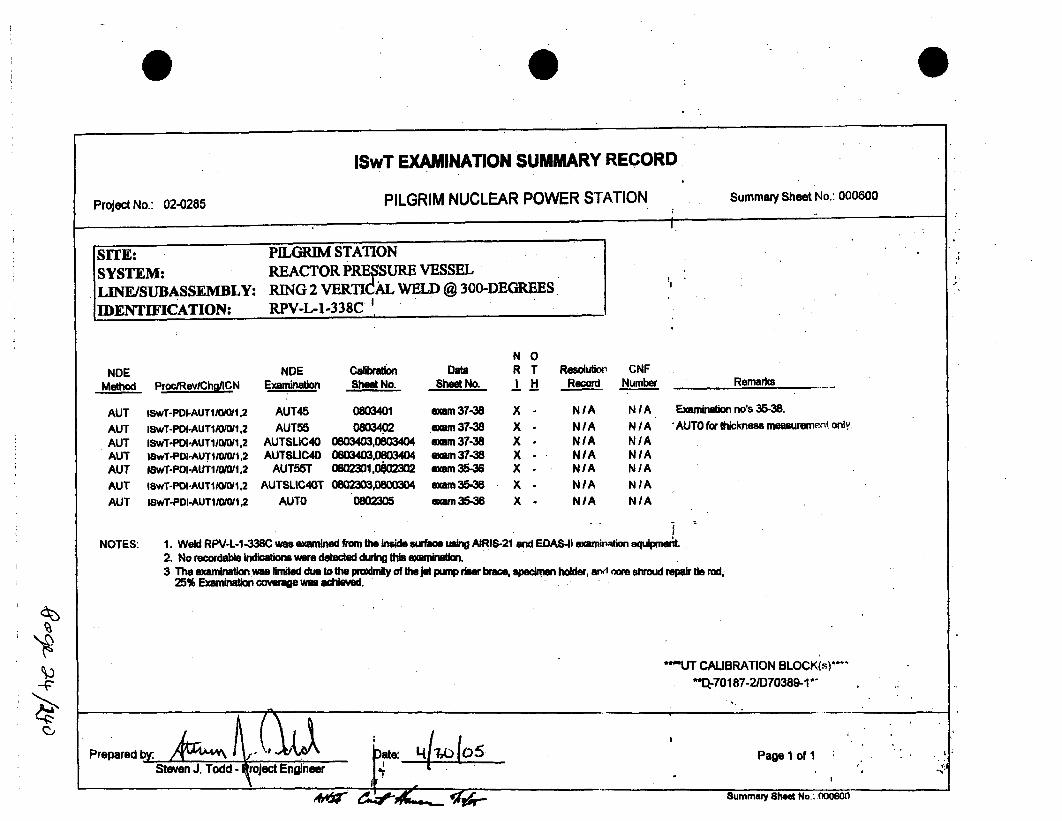
ISwT EXAMINATION SUMMARY RECORD
Project No.: 02-0285 PILGRIM NUCLEAR POWER STATION Summary Sheet No.: 000400
SITE: PELGRR%4 STATIONSYSTEM: REACTOR PRIRSSURE VESSELLINE/SUBASSEMBLY: RING 2 VERTjCAL WELD @ 60-DEGREESIDENTIFICATION: RPV-L-1-338A.
I.
.1
NDEMethod Proc/Rev/Chg/ICN
NNDE Calibration Data R
Examination Sheet No. Sheet No. I
0TH
Resol•kti, CNFRecord Number
AUTAUTAUTAUTAUTAUTAUTAUTAUT
lSwT-PDI-AUT1/f0j01 2lSwT-PDI-AUT1/0/0/,2lSwT-PDI-AUTlM1/0O 2ISWT-PD-AUT1 /0/1.2lSwTr-PDI-AUTljOIO1 .2I~wT-PDI-AUTlM0l,1 2ISwT-PDI-AUTI/0,!1,2ISwT-POI-AUTfi/0/01,2ISwT-PDI-AUT1/0W01 2
AUT55TAUTSLIC40T
AUTOAUT55T
AUTSLIC40TAUTO
AUT55AUTSLIC4O
AUTO
80031,8003280033,80034
80035
OBMM,08003D40800305
0OO3O.080MO2
0800305
exmrn 22-24
exam 22-24exam 22-24
exam 19-21wwn19-21xmn 19-21
amm 25-28exam 25-25exam 25-26
x
xxxxxxxx
NIAN/A
NIAN/AN/AN/AN/AN/ANIA
N/ANIANIANIANIAN/ANIANIANIA
Remarks
Examni•mation no's 22 - 24 vqrq pT ,rwmed
during RFO14.
AUTO for thickness rneasurmnmen- "qy.
NOTES: 1. Weld RPV-L-1 -338A was examined from the Inside surface usng AJRIS-21 and EDAS-I1 examination equipment2. No recordable bidatn were detected during this examlaion3. Examinations 22 - 24 pefemed durng RFO14.4 Examinatiorm 25 and 26 wre divided Ito 2 segments, 25a & 25b; and 26 & 28b.5 The examination was rnited due to the pm=drnity of the Jt pump rer brace, 89% examinationrwersgewaa achieved.
'*UT CALIBRATION BLOCK(.')
"*D-70187-2/07038A 1*__ A
| |
Prepared bYL ki~ jDate: J-60 frý <Steven J. Todd , Project Engineer
Page 4 of1
Of ",e F .d .

0
IHI SOUTHWEST TECHNOLOGIESAUTOMATED ULTRASONIC EXAMINATION RECORD _ _-"
Site/Plant : Pilgrim Nuclear Station Weld i i dentitiation: RPV-L-1-338A Ppr/RevlChgI2CN: ISw2T-PDI-AUTl010/•2 Exam4ination No.: ID-19Project No.: 02-0285 AWesd Dcrition: Ring 2 VIrt I 609 Device ConfigCdation: D-PNPS- 102
Mod.Cone: A-07B AScan Path Draw0nb: SPLONGSH2&3DS Elam Date r Examination Time Surfsce Temperature :F
Data Acquisition Operator (s) SNT Level: David Kleinjan Offse Schaefer t/A 24 Apr. 04 s ftart End start t End-1741 , 1746 '-95- 85,
Scan Controller Parameters Increment Ax5s -Arm. -0Planned Actual evice Pldpned Actual Posiaional ParametersController: lD.Device ,Lower Limit i11266 11282 Loe iit 2!189 2318g8 Beam lDirer*lion]: DD/Up
Scan: Y Axis L I upCr Limit 12526 12503 Upper Limit .... 27880 24404 Transiccr _;_ 1.00Increment: X Axis Iincrement Interval 90 4 i 4 Code ,, 4f Cives-lap: 1 0Mode: Automatic Scan IConversion Counts 100 Conversion Coluins 100 Numl-:r of 1c~ans: 15
Sc~an Motion: Bi-directional IConversion Units tn. 1.00 Conversion Units tn. 1.00 Devir.r. I'osil ion: D (0)
Correction: Default [EDAS Radius In. 113.60""Module Parameters: A-078 Cal103 Calibration Records: 'Examination Notes:
Status Angle Direction Scan Offset Step Offset PNS-03 Chek for limitations due to the proximity of the jet pump dimfser
Channel I On 55 0- - 1.40(in') - 1.21(in) 0800301 .and the baffle plate. .Channel 2 On 55 M+ + l;40(.in) - i.21(in) 0800302'
Channel 3 On SLIC-40 0- - 1.97(in) + 1.69(in) 0800303
Channel 4 On SLIC-40 (+) + 1.97(in) + 1.69(n) 0800304 Examination Remarks:Channel 5 On 0T (+) + 0.00(in) + 1.69(in) 080030.5 Entcrgy/Pilgrim Procedure TP04-0 20Channel 6 Off N/A N/A NIA N/A N/AChannel 7 Off N/A N/A N IA N0A N/AChannel 8 Off N/A N/A N/A N0A N/A
Increment &aSnan Positions Actual0 Recordable Indications Analy,_st Remarks_•Scan No.(s) Increment Position Scan Position Yes, No N/A At 1atn:
Start Stop Start Stop Channel1 0 El 01 [A&[ Yes E_ No!-15 11282 12503 23188 2446 Channel72 [0 1 El F teCEvaluation
lChannel 3 ,0 _E D !Required:Channel 4 [1 P ] 0 1 Yes El No
.. Channel 5 [17 0] Amhiive Tape/CD Noý.:Chanel 6 C1 -0 El IA & 1B
,..Channe1 7 [1 [71 Q] jalysis Tape/CO No.:. ..
Channel2 0 [] EI A&B1Analyst / SNT Level I Date:
Joel G. Godwin /111 /24 Apr. 05
1S%%Wr FORMU• N&.U~ SO |liY. .MI) !
I.'

IHI SOUTHWEST TECHNOLOGIESAUTOMATED ULTRASONIC EXAMINATION RECORD
Site/Plant: PilCo im Nuclear Station Weld IdentifiPation: RPV-L-A-338A SPro/Rev/Chg/eCN: lSwTnPDInAUTI/0-/0/2 Examination No.: ID-2aProject No.n:0 2 Deld LeerLiption: Rin2 2 VertLw@ 60L Device Configuratit n2 D-PNPS-102Mod.Conf.: A-07A SScan Path Drawing: SPLONGSH2&3DS Exan Date 1 Eamination Time Surface Temperature OF
Dar Aecquisition Operator (s) RSNT Level David Kleiujas 11 Also Schaefer IA 24 Apr. 04 1.3 .606 8n 8t
Scan Controller Parameters Increment Axis/Arm lPlanned Actual SCan Axis/Device PlEanbd Actual rsitiona Parameters"'Controller: ID Device Lower Limit 11266- !11266 - Lower Limit. 23188 24360 Beamn Direelion: Up/Dn
Scan: Y Axis Upper Limit 12526 1253O Upper Limit 27880 26960 C d Transd ucfr theize: i .00;Increment: X Axis Increment Interval 90 DCI .4.1 Code. % o1 •)verlap:. 110
Mode: -Automatic Scan Conversion Counts 100 Conversion ClolnLq 100 'Numl-,• of ,'canms: 15Scan Motion: Bi-directional Conversion Units In. 1.00 Conversion Unils In. 1.00 lDevi,:r. posili'll: .D (180)
Correction: Default EDAS Radius In. '113.60
Module Parameters: A-07A •Cal103 Calibration Records: Examination Notes:
Status Angle Direction Scan Offset Step Offset PNS-03 ... Check for limitation~s due to the 'tmmlt•)--!y of the jet pump diffuser
Channel I On 55 (+N + 1.40(in) + 1.21(in) 0800301 and the bafle plate'.Channel 2 On 55 (-) - 1.40(in) + 1.21(in) 0800302Channel 3 On SLIC-40 (+) + 1.97(in) - 1.69(in) 0800303Channel 4 On SLIC-40 (-) - 1.97(in) - 1.69(in) 0800304 Examination Remarks-Channel 5 On OT (+) + O.00(in) - 1.69(in) 0800305 1ntergy/Pilgim Procdure TP04-020Channel 6 Off N/A N/A NIA N/A N/A Upper scan axis limited due to jet ptimp r iser brac. Lower scan axis
Channel 7 Off N/A N/A N/A N/A N/A limtled due to welded lug.Channel 6 Off N/A N/A N/A N/A N/A
I ncrement & Scan Positions Actual Recordable Indications Analyst Re~marks
Scan No.(s) Incremewnt Position Scan Position Yes No' N/A• fttcmehnPt:.Start Stop Start Stp Channel 1" [] [a 0 0- Yes W No .....
- 15 11266 .12538 24360 26960 Channel 2 ] 0 Further Evaluation"_Channel 3 0 [Q 0 Required: .......
-Channel 4 " E ] 10 " Yes 0 No .........._ _Channel 5 [0 0 0ED) Archive Tape/CD No.- .....
,.,___'Channel 6 E 0 [] IA&IB ......._h___ hannel? 7 " 0 Analysis TaprlCY) No.:_.. .....
____Channel 8 0-I 0] [ A& B'" "
Analyst I SNT Level /.Date:
Joel C. Godwin 111 (24 Apr. 05 cf
ISWT FORM No. 1ff 50 (Raw. O5IO2)
'V

IHI SOUTHWEST TECHNOLOGIESAUTOMATED ULTRASONIC EXAMINATION RECORD _ _-"
Site/Plant : Pilgrim Nuclear Station Weld Identification: RPV-L-I-338A Pro/RevlChg/lCN: ISwT'PDI'AUTI/O/O/1,2 Examination No.: I D-2 I
Project No.: 02-0285 Weld Description: Ring 2 Vert (a) 60* Device Configuration: D-PNPS- 102•
Mod.Conf.: A-07B ýScan Path Drawing: SPLONGSH2&3DS Exam Date ;' Examination Time Surface Temperature OF.
Data AcquisitionuOperator (s) JSNT Level: "David Kleinjan/11 Alan Schaefer/NMA ". 24p 4Start End Start I End
24 ... .. .. 1804 1809 .. 5
Scan Controller Parameters Increment Axis/Arm - Planned Actual Scan Axis/Device PlAn ld Actual Positional Parameters
Controller: ID Device Lower Limit .11266 11266 Lower Limit _- Z7877 27877 Beamn I ý'frc inn: Dn/UpScan: Y Axis Upper Limit 12526 12526 Up Limi. 32101 32101 Trans. h,.e" '. i =: 1.00
Increment: X Axis Increment Interval 90 DCI 4 Codc % o" Iverlap: 10
Mode: Automatic Scan Conversion Counts 100 Conversion Coonts 100. Numhr o ":,.ans: 15Scan Motion: Bi-directional Conversion Units In. 1.00 Conversion Units In. 1.00 Devicr. Position: D (0)Correction: Default EDAS Radius In. "113.60 1
Module Parameters: A-07B Cal 03 Calibration Records: Examination Notes:Status Angle Direction Scan Offset Step Offset PNS-03 Check for limitations due to the proximity of the jet pumpdiffuser
C han ne l I O n 55 (-) 1.40(in) - 1.2 1(in) 0 800 30 1 and th e baffl e p late. __ _ __ _ __ _ __ _ _
Channel2 On 55 (+) + 1.40(in) - 1.21(in) 0800302Channel 3 On SLIC-40 (-) - 1.97(in) + 1.69(in) 0800303 ........Chac ron SLIC-40 Pito+ 1.97(in) + 1.69cin) 0800304 Examination Remarks:Channel 5 On ST S+r + S .oC(in) ne+ 1.69(in) 0800305 Entergy/Pilgrim Poocedure TP04-020Channel 6 Off N/A N/A N/A NuA NvA Limited exam due to jet pump ris__" brac___ .Channelh7 Off NA NIA N/R i N/A N/AChannel 8 Off N/A N/A N0A N/A N/A
.____ Canne 5 0 0 Arcve.ap.CDN.. ___..__._______________ .,__ •
..Increment & Scan Positions Actual ReAordabaesludications AnaTyst RemarksSa o() Increment Position Scan Position Yes No N/A Attachment:"
Start Stop start Stop Channel I [] E] 1] 0" Yes El NoS- 15 - 11260 12526 27877 32101 Channel 2 [1 [ 1] [] Further Evaluation
Channel 3 [1 ] 1 Required:
lCharmer 4 0 E] D] 0 Yes El No.lChannel 5 Q El17 Archive Tap~e/D Wo:
.. Channel 6 0] El [ - IA & 113.lChannel 7 [1 1-1 E] Analysis Tape,/C D No.:
-Channel 8 0 f [a A&BAnalyst / SNT Level / Date:
Joel G. Godwin 1111/24 Apr. 05 ~ i /~ w,..
4k)
- 14ý - - 1- -2) I
¢.!
I.
**1

0
qft) I SOUTHWEST TECHNOLOGIESAUTOMATED ULTRASONIC EXAMINATION RECORD
Site/Plant: Pilgrim Nuclear Station Weld Identification4 RPV-L-1-338A Pro/RevlChg/[CN: ISwTLPDIAUTI/0/01112 Examination No.: ID-254Project No.n:0 Axs Rin 2 Vert (90 60 Device Configuration: D-PNPS-101
Mod.ConeA: A-07-SD SCan Path DrawClt: SPLONGSCH3DS Exam Date 0 E0amination Time Surface Temperature nF
Data Acquisition Operator (s) CoSNT Level: Richard Riddles If 25 Apr. 05 In.1.0 0 Start Enn A (0
Scan Controller Parameters Increment Axis/Device Planned ActualC 3l ratn Plned Actual Posinal Parameters
Controller: gD Device Lower Limit S 2413O 24138 Lit 11146 1146 BeaCa th iie.tion:. Copu/Cw
Scan: X Axis Upper Limit 27917 2629i U.imit 12646 12646 Tranacnh bia: 1.00
Increment: Y Axis Increment Interval 90 + 00 34. . Code3% o :2 Qvrlap:.. 1.0Mode: Automatic Scan Conversion Counts 100 Convrsion Colints; 100 Numhw-v ol '.ýcns: 43
Scan Motion: Bi-directional Conversion Units-In. 1.00 Conversion Uniis In. 1.00 Devic__ Posil ion: A (0)Correction: Default JEDAS Radius In. 1 13.601
aodule Parameters: A-07-ID Cal 33 Calibration Records: Examination Notes:
Status AnSle Direction Scan Offset Step Offset PNS-33 Check for limitations due to the pNoo.i iiidof thcjct pump difChannel I On 55 0-4 + 7.00(in) + 0.00(in) 0803301 and the baffle plate.F........Channel 2 On 55 N+) 7.00(in) + 0.00(in) 0803302
Channel 3 On SLIC40 + 4.40(in) + 1.00in) 0803303..
Channel 4 On SLIC-40 (+) - 4.40(in) 1,00in) 0803304 Examination Remarks:
Channel 5 On OT N + 4.40(in) - 1.00_in) 0803305 Entergy/Pilgrim Procedure TP04-020
Channel 6 Off N/A N/A N/A N0A N/A Limited exam de to jet pump riser brace..
Channel 7 Off N/A N/A N/A N/A N/A
Channel 8 Off N/A N/A N/A N/A N/A
Increment & Scan Positions Actual Recordable Indications Analyst Remarks
Sa o() Increment Position Scan Position Yes No N/A Attachmn~t:
nal N Start Stop Start Stop Channel e : e [] 0 Yes L No1- 25 24138 .26298 11i146 12646 Channel 2 E] [• [ Further Evaluslion ....
Channel 3JdA7 v [] Required:Channel 4 [1 0. DU[ Yes El No
IChannel 5 0] [] ] Ar~chv Tape/CD No.:Channelt6 D C ]IA& IBChannel 7 D [ ] Analysis TWACD No.:
Analyst /SNT Level /Date:..
Joel......o....... ..... Apr. 05
ISWT FORiM N& UT 50 (Rev. 034|) 1i r.I

0 0
IHI SOUTHWEST TECHNOLOGIESAUTOMATED ULTRASONIC EXAMINATION RECORD
Site/Plant: Pilgrim Nuclear Station IWeld Identification: RPV-L-l-338A P~ro/Rev/Chz/ICN: ISwT-PDI-AUTIO, OII,2 [Examinatio, No.: [D-25bProject No.: 02-0285 Weld Description: ,Ring 2 Vert @ 60r Dpyke Configuration: D-PNPS-101- •!
Mod.Conf.: A-07-IC Scan Path Drawing: SPLONGSH2&3DS . Exam Date r -Examination Time Surface Temperature OFData Acquisition Operator (s) ISNT LeAvel: Richard Riddles It! . 25 Apr. 05 i 'lart En19 0324t End 5
Scan Controller Parameters Increment Ads/Device Planned Actual Scam Axis/Arm Pla.ued Actual ftnitiobna ParametersController: ID Device ower Limit 24138 26298 Lower Limit 11146 11146 Beam l)iiecrmn: Cw1CcwScan: X Axis Ipper Limit 27918 27542 Upper Limit 12646 12646 Trans(Ihwer :,i%.e: 1.00Inciement: . Y Axis Increment Interval 90 DCI 4 Code % ofC,?-erlap: 10Mode: Automatic Scan. Conversion Counts 100 Conversion Co,.nis 100 Numiofr SF.aus: 43Scan Motion:. Bi-directional Conversion Units In. 1.00 Conversion U nils In. 1.00 Device IVosition: A (180)Correction: Default • EDAS Radius In. 113.60Module Parameters: A-07-IC Cal 33 Calibration Records: Examination Notes:
Status Angle Direction Scan Offset Step Offset PNS-33 Check for limitations due to the proximity of thejet pump diffuserChannel I On 55 (+) - 7.00(in) + 0.00(in) 0803301 and the bfe plate.Channel 2 On 55 (-) + 7.00(in) + 0.00(in) 0803302Channel 3 On SLIC-40 (+) - 4.40(in) - 1.00(in) 0803303Channel 4 On " SLIC-40 Pio + 4.40Ain) + 1.00(in) 0803304 da smination Remarks:Channel 5 On OT (+) - - 4.40(in)- + 1.00(in) 0803305 Entergy/Pilglrim Procedure TP04-020Channel 6 Off N/A N/A N/A "N/A N/A Limited exami due to jet pump riser brace.Channel 7 Off N/A N/A N/A N/A N/AChannel 8 Off N/A N/A N/A N/ANA
Scan No.(s) Increment Position Scan Position Yes No N/A Attachment:Start Stop. Start Stop Channel I 0 [] ] 0 DYes 0 No
25- 39 26298 27542 11146 12646 Channel 2 I- 0 [ Further EvaluationChannel 3 0 0 0 Required:
. Channel4 0 0 Yes (a Noi_._____l5 [[Channel 0 5 Archive TapcCDNo;. _
______ Channel6 0 0 0 IA&IB -I Channel 7 0 fl 0 Analysis Tape/CD No.:l _
I Channel8 0 El 0 A&B .Analyst / SNT Level / Date:
Joel G. Godwin /111/25 Apr. 05.
IWT FORM No. Ur 50 (ltR. 05M2,

0
1HI SOUTHWEST TECHNOLOGIESAUTOMATED ULTRASONIC EXAMINATION RECORD
Site/Plant . Pilgrim Nuclear Station Weld Identification:e .. V-L--338A ProSaevnCh ICN: ISwT-PDne AUTIualOOi2 Examination No.: aa D-26e
Project No.: Y Axs Dt Ring 2 V9t0@ 60 Device Configuration: D-PNPS-101
Mod.Conf.: A-07-ID San PatCh Drawing: SPLOGSH2&3DS Exam Date Examination Time Surface Temperature OF.
Dat Acquisition Operator (s) /SNT Level Richard Riddles e Ste Ofe . N25 Apr. Check f i od the d f S t h j Et 8 d25 Apr 05tart.' n tr n
Scan Controller Parameters Increment AxDleviCj .Planned Actual "Scan AxisA rm I ")d 0EActual rPositioal Parameters
Controller: ID Device Lower Limit 27877. 30307 Lower Limit 1i146 L 1146 Beam dtiretuion: -eCr/CwScan: X Axis Upper Limit 03399 339934 OpperLimit__n 12646 12(A6 Transdh,-er Size: 1.00
Increment: Y Axis Increment Interval 90 DCI 4 Code % Rf q. uerlap: 10M o d e : - A u t o m a t i c S c a n C o n v e r s i o n C o u n t s 1 0 0 C o n v e r s i o n C o ~ m is 1 0 0 N unlu-, , o I ̀ : : *, -'kns : 6 9
Scan M otion: Bi-directional Conversion Units in. 1.00 Conversion I.Jni ,, In. !.00 [• i.-!o i,•:A (0)
Correction: Default EDAS Radius In. 1 13.60
M odule Parameters: A-07 -ID.. C al 33 Calibration Re cords: Examination No we :
•. Status A ngle D irection.. Scan O ffset Step O ffset PN S--3.3- Check for lim itations d ue to the p r'o. xi mity o fr the jet pum p diff user
Channel I On 55 0+ 7.00(in) + 0.00(in) 0803301 and the baffle [late.Channel 2 On 55. (N - 7.00(in) + 0.000Cn) 0803302Channel 3 On SLIC40 + 4.40(in) + 1.00(in) 0803303Ch~annel 4 On SLIC-40 + - 4.4 !ýin) i.00(in) 0803304 E xami~nation Remarks:
C h a n n e l 5 O n OT M+ + 4 .4 0 ( in ) 1 .0 0 ( in ) 0 8 0 3 3 0 5 i~ E n ! Sy / p, ii jri m P ro ,-, d u-re T P 0 4 -0 2 . ( . .. ..
Channel 6 O ff N /A N IA .. N/A N/A N/A L im ite~ d exam du 6 to jet pum p riser brac e." .
Channel 7 Off N/A •_N/A N/A N/A N/AChannel 8 Off N/A N/A NIA N/A N/A"-
in¢• nt Sca Poitins ctua ReordbleIndcatonsAnalyst Remarks
Scan o~ts)-- Strt Stp Stat Sto Channel 2 E]lF [ e. •H
'28~~ ~ ~ ~ ~ ~ ~ ~~~~2 -09337 39- 16 124 hne ] [] Further" Evalual ion."
.. ___,Channel 3 0 0 0 A& . . ..
Channel6 4 0 [ ] Ye El I N... ...
.Channel'/[ 5 ] 0 /slysistTape/C:.i) No.:.....
Channel 6 Q] IPA& .....
A nalyst /SNT Level IDat e:
.l 7
.... .
n n"lnlssTew )N .
Joel G. Godwin / I!l 125 Apr. 05 e" - ,
Iswr FmuM Me. or so fit". OSO) ,
I ,'I

0
Nal"MEWIHI SOUTHWEST TECHNOLOGIES
AUTOMATED ULTRASONIC EXAMINATION REC(Site/Plant: Pilgrim Nuclear Station Weld Identification: RPV-L-l-338A IPro/Rev/Chg/ICN: !:
Project No.: 02-0285 Weld Description: Ring 2 Vert Q 600 Device Configursition: E
Mod.Conf.: A-07-ID Scan Path Drawing: SPLONGSH2&3DS | Exam Date -
JiLIU ____________
-AUTi/0/0/i12 Examinntio" No.: ID-26h01
ination Time Siarfare Temperature oF
EndStirt End.
n71 Ff 8
I
Data Acquisition Operator (s) / SNT Level: Richard Riddles 1.11 S25 Apr. 05 -'a -,~
'-v.'
bcan uontr4Controller:Scan:Increment:
ler rarametersID Device
X Axis.Y Axis
Automatic ScanBi-directional
Default
AxZis/evice ! rianneier Limit , 33907 1 33907 Lower Limit 11146 I 11146
-- - 4 -.
Limit 40027 1 40027 Upper Limit 12646 I 12646
I IACtunt laca ARIBIAkiEU ruaqucu I %MK
Mode:Scan Motion:Correction:
P'ositional Parameters :Beanm N~red.irnn: CCWiCW1Tralsdowa.Cr i'~iC: .
Code n/ 1jr (ý)cIl.-ap: 10Numbc.r nf Scans: 69Devicc. l'nsili#no: -A (0)~
Increment IntervalConversion CountsConversion Units In.EDAS Radius In.
901001.00113.60
DCI.Conversion ConmisConversion Units In.
4.1001.00
Module Parameters: A-07-ID Cal 33 Calibration Rccords: Examination Notes:Status Angle Direction Scan Offset Step Offset PNS-33 Check for limitations due to the proximity of thejet pump diftu.Wr
Channel I On 55 (-) + 7.00(in) + 0.00(in) 0803301 and the baffle plate.
Channel 2 On 55 () - 7.00(in) + 0.0(in) 0803302
Channel 3 On SLIC-40 (-) + 4.40(in) + 1.00(in) 0803303
Channel 4 On SLIC-40 (+) - 4.40(in) - 1.00(in) 0803304 Examination Remarks:
Channel 5 On OT (+) + 4.40(in) - 1.00(in) 0803305 Entergy/Pilgrim Procedure TP04-020 ______
Channel6 Off N/A N/A N/A N/A N/A ,,_ _
Channel 7 Off N/A N/A N/A N/A N/A • NChannel 8 Off N/A N/A N/A N/A N/A___.
Increment & Scan Positions Actual Recordable Indications " "• Analyst Remarks
SaN.() Increment Position Scan Position Yes No N/A Attachment:Sa_ _ Start Stop Start Stop Channel I [] E0 0 " r Yes B No
1-69 33907 40027 11146 12646 Channel 2 C) [9] 0' Further EvaluationChannel 3 0] [2) 0 Required:Channel 4 [1" ".1 ] " Yes 3] No
Channel 5 [ 0 E Archive Tape/CD No.;
Channel 6 Q -0 I&A &_ _Channel 7 E"I' [] 0 Analysis Tape/CD No.: _._.
_ChannelS j 0 A&B -
Analyst / SNT Level I Date:Joel G. Godwin111.25.Apr. 05|7. 4,•
t5WT FORtM N&o Lr so (Rev. NMI)
I.'
0 0
ISwT EXAMINATION SUMMARY RECORD
PILGRIM NUCLEAR POWER STATION Summary Sheet No.: 000600Project No.: 02-0285I.
SITE: PILGRIM STATIONSYSTEM:. REACTOR PRE SURE VESSEL
LINE/SUBASSEMBLY: RING 2 VERTICAL WELD @ 300-DEGREES[IDENTIFICATION: RPV-L-1-338C'
NDEMethod Proo/Rev/Chg/CN
AUTAUTAUTAUTAUTAUTAUT
ISwT-PDI-AUT 1110/t .2
1SwT-PDI-AUT1/O/W01,2ISwT-PDI-AUTl0/0/W1,2lwT-PDl-AUTiIO/Oli,2ISwT-PDI-AUT1/0/0/1,2
ISwT-PDO-AUTIIlO/W1,2
1SwT-PDI-AUTIO 10/1,2
N 0NDE Calibraton Dats R T
Examination Sheet No. Shet No. I H
AUT45 0803401 am 37-38 X -
AUT55 0803402 exam 37-38 X -
AUTSLIC40 0803403,0803404 emm 37-38 XAUTSUC40 0803403,0803404 amm 37-38 X -
AUT55T 0802301,02302 mm 35-36 X -
AUTSLIC40T 0802303,0800304 emmrn 35-3 X -
AUTO 0802305 emu 35-36 X -
N/AN/ANIANIANIA
N/ANIAN/AN/ANIA
Resolution CNFRecord Number Remarks
Examination no's 35-38.
AUTO for thickness measurement only.
NIA NIAN/A N/A
NOTES: 1. Weld RPV-L-1-338C was examined from the inside surface uing AIRIS-21 and EDAS4I ewamination equipmen2. No recordable indications were detected duing this examinaon.3 The examination was linited due to the proimity of the jet pump riser brace, specimen holder, arvn mre shroud repair Ui rod,
25% Examinaion coverage was achieved.
**"UT CALIBRATION BLOCK(s)**Q.-70187-2/D70389-1 *'
Page 1 of I t
Summary Shet No.: 000600Summary Shed No.: 000600

0l11 SOUTHWEST TECHNOLOGIES
AUTOMATED ULTRASONIC EXAMINATION RECORDSite/Plant: Pilgrim Nuclear Station Weld Identification: RPV-L-r-33eC ProRevChg/!aCN: 'AiSwT-PDI-AUPI//01uS,2 ExcmiAationNo.: ID-35aProject No.: 02-0285 tion: Ring 2 VertLm 3083 Dev9eLConfigurmtion: D-PNPS-103n
Mod.ConE: A-07-r B Scan Path Drawin: SPLONGSH2SS Exam Date r Examination Time Surface Temperature sF.
Data Acquisition Operator (s) / SNT Level: D. Klenjan sH Ale Se Offer N/-2A Checkrort i a nsdu rt En t j u
C n lO,,4 0 - ",1in-' t 0"-8- 02303t - . ......... ......
Scan Controller Parameters Innrement Ax4nICv4e. - Planned Actual Sian AxisnArm .0an4ed Actual rks:iionl Parameters
Controller3 ID Device Lower Limit 58938 58950 Lower Limit 2353C 23538 Beam Pirrtion: Dn/UpScan: Y Axis Upper Limit 60018 60018 Upper Limi-t...... 40550 24879 T'ran.sdi•, Size: 1.00
Increment: X Axis Increment Interval 90 D 1. 4. Code• % of Overlap: 10
Mode: Automatic Scan Conversion Counts 100 Conversion r :ounts 160 Numl-.r of Scans: 13Scan Motion: Bi-directional Conversion Units In. 1.00 Conversion Units In. 1.00 Devicp. Position: A (-90)
Correction: Default 0EDAS Radius In. •113.60Module Parameters: A-07-1B Cal 23 Calibration Records: Examination Notes:
Status Angle Direction Scan Offset Step Offset PNS-23 Check for limitations du~e to the proximity of the jet pump, the jet
Channel I On 55 0-) + 7.00(in) + 0.00(in) 0802301 _ pump rime I4=ket, the N2 nozzle, and the surveiilancr, capsule
Channel 2 On 55 M_ - 7.00(in) + 0.00(in) 0802302 0_lder.Channel 3 On SLIC-40 .(-) + 4.40(in) - 1.00(in•) 0802303
Channel 4 CaOn nSLICl40 - 4.40(in) + 1.00(in) 0802304 Examination RemarksaChannel 5 On OT M+ + 4,40(in) + 1.00(in) 0802305 Entergy/Pilgrim Procedure TP04-020
Channel 6 Off N/A N/A N)A N/A N/A E~xam continued on exam ID-35b.Channel 7 Off NIA NIA N/A NIA N/A
Channel 8 Off N/A NCA N/A N/A N/A
Increment & Scan Positions Actual Recordable Indications Analyst Remarks
Sa o() Increment Position Scan Position Yes- No N/A Atah~ t:
a ) Start Stop start Stop Channel I [L : No1-13 58938 60018 23538 24878 Chne2F1 [] I3Further Evh!n
...... Channel 3 0] [l[Required:"JChannel 4 0] 1T 0l 1Yes 21 NoChannel5 0] I' 1 1 ArcitveTape/CD No.: ..
Chainnel 6 [1 I] [ A& IB .Channel 7 [1 El • ] Analysi3 Tape/CD No.:. . .,.
,, ~Channels 8] [ 3 A&B . .
Joel G. Godwin IH/ ,25 Apr. 05 " " '
,nm RM N& eu . I
I.
Avakh%Q&0335&,
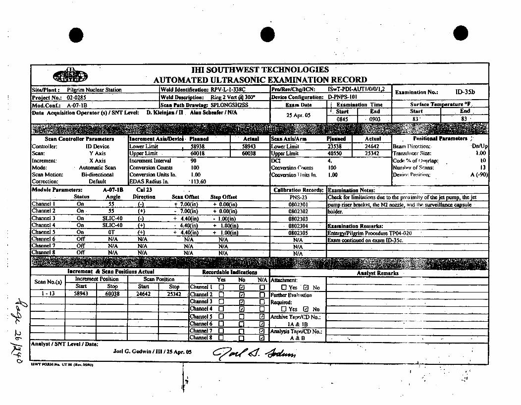
IHI SOUTHWEST TECHNOLOGIESAUTOMATED ULTRASONIC EXAMINATION RECORD
Site/Plant : Pilgrim Nuclear Station Weld Identification: RPV-L-l-338C Pro/RevlChg/ICN: ISwT-PDI-AUTI/0/0/I,2 Examination No.: ID-35bProject No.: 02-0285 Weld i)emription: Ring 2 Vart (4 300' Device Configuration: D-PNPS-101Mod.Conf.: A-07-IB Scan Path Drawing: SPLONGSH2SS Exam Date iExamination Time Surface Temiperature°F
Data Acquisition Operator (s) SNT Level: D. Kleinjan / B!. Alan Schenfer /N/A 25 Apr. 05 .Start End Star( End
0845 •0903 83' 83
Scan Controller Parameters Increment Axis/Devic. Planned Actual Scan Axis/Arm Planned Actual Positional Parameters ;Controller: ID Device Lower Limit 58938 58943 Lower Limit 21538 24642 Beam D)irection: On/UpScan: Y Axis Upper Limit 60018 60038 Upper Limit 40550 25342 Transducer Size: 1.00Increment: X Axis Increment Interval 90 DCI 4. Code. % of O.crlap. toMode: Automatic Scan Conversion Counts 100 Conversion Counts 100 Numni.r of S'ans: 13Scan Motion: Bi-directional Conversion Units In. 1.00 Conversion I Inits In. 1.00 DevirJr Porition: A (-90)Correction: Default EDAS Radius In. '113.60Module Parameters: A-07-1B Cal 23 Calibration Records: Examination Notes:
Status AnIle Direction Scan Offset Step Offset PNS-23 Check for limitations due to the proximity of thejet pump, the jetChannel I On 55 - + 7.00 in) + 0.00(in) 0802301 pump riser bracket, the N2 nozzle, and the surveillance capsuleChannel 2 On 55 (+) - 7.00(in) + 0.00(in) 0802302 holder.Channel 3 On SLIC-40 C-) + 4.40(in) - 1.00(in) 0802303Channel 4 On SLIC-40 + - 44,0(in) + 1.00(in) 0802304 Examination Remarks:Channel 5 On OT + + 4.40(in) + 1.00(in) 0802305 Entergy/Pilgrim Procedure TP04-020Channel 6 Off N/A N/A N?A N/A N/A Exam continued on exam ID-35c.Channel 7 Off ._N/A h/A N/A N/A 0c /AChannel 8 Off N/A N/A N/A N/A N/A
Increment & Scan Positions Actual Recirdable Indications Analyfst R•em~arks
Scan No.(s) Increment Position Scan Position Yes No N/A Attachment:......Start Stop Start Stop hannel I El 0] 0] [ Yes E"l No
1- 13 58943 60038 24642 25342 C1hannel 2 D][• [ Further Ewolvition -Channl 3 D] Require-'.d:Channel 4 [1 El 0] 1 0 Yes 0] NoChannel 5 ] D [] Archive TaprJCD No.:Channel 6 [ []IA& irB:....Channel 7 [0 E 0 Analysis Tape/CD No.:
- Channel 0 - 0 A&B -B__Analyst / SNT Level / Date:
Joel G. Godwin /111/25 Apr. 05 C2P #4•1 $g m
............... .. . • " WN2
I,II,
t *

4ft) MIH SOUTHWEST TECHNOLOGIESAUTOMATED ULTRASONIC EXAMINATION RECORD
SitecPlantr: Pilgrim Nuclear Station Weld ldentification: RPV-L-A-33uC Pro/Rv/chirCN: ISwT-PDI-AUTI/0/0/I,2 Examination No.: a D-35cProject Noec 02-0285 Weld Description: RLoe 2 Vert (3 30( Device Configurationm D-PNPS 30I 9
Mod.Con: A-07-SB CScan Path Drawing: SPLONo Exam Date 0 Examination Time Surface Temperature OF
Data Acquisition Opertor (s)ISNT Level: . KleinjaUn I 1. Alan Sc fer N/A 25 Apr. 05 .Start End Start Endn"
0938 C c0940 80D 80A3
Scan Controller Parameters Increment AIsi I PaAcl aSton Ax RAcrdm Plnhed Actual PosititoNlNts.'.
Controller: ID Device Lower Limit S f5893s 59935 Lower Limit . C . or 30942 Beam Dirneci:ot- Dn/Up
Scan: Y Axis Up5er Limit 60018 59245 . 02Upre Limit 40550 31526 Tranolcr d ice: c1.00
Incrementn X Axis Increment Interval 90 DC( 4. Code0) of iOverlap: . toModec: Automatic Scan Conversion Counts 100 Conversion Counts 100 Numb.r of .Scasns: 1 3
Scan Motion: Bi-dir3ctional Conversion Units +m 4 .00 Cinnverion -nits I0. 8.02 Device_ Po_ ___ __n: A (-90)Correction: Default EDAS Radius In. "113.60
Module Parameters: A-07-1 Cl 23 . Calibration Rcords: Examination Notes:Status Angle Direction Scan Offset Step Offset PNS-23 Check for limitations due to the proxmi!ty of the jet pump, the jet
Channel I On 55 0- + 7.00(in) + 0.00(in) 0802301 pump riser bracket, the N2 nozzle, _nnd th.e surveillance capsuleChannel 2 On 55 (+)- 00(in) + 0.00(in) 0802302 holder.Channel 3 "On SLIC-40 0- + 4.40(in) - .00(in) 0802303...
Channel 4 On SLIC-40 (+) - 4.40(in) + 1.00%in) 0802304 Examination Remarks:' "...
Channel 5 On OT + + 4.4gin) + 1.00in) 0802305 Enteamy/Pilgrim Procedure TP04-020Channel 6 " Off NIA N/A N/A N/A N/A No exam from 25320 to 30942 due to specimen holder an~dIChannel 7 Off N/A N/A N/A NIA N/A riser supponrt brackets.Channel 8 Off N/A N/A N/A N/A N/A_""
Increment &e Scan Positions Actual . Recordable Indicatins Analy•st Remarks
Scan II(a lnr, rne~nt Position Scan Position Yes.' No NIA: Attachrwntn:Start" Stop Stan -Stop Channel 1 0" ".0 7 1 Yes 27 No
- 5 58933 59245 30942 31526 Channel 2 0 - 0 Further Evwluation_Channel 3 0 -, 0 Required:_Channel4 0 0 - OYes E No
Channel 5 0 0 0 Archive Tapr/CD No.:I Channel6 D 0 0 - IA&IB •-__. .........
Channel 7 0 [] G0) Analysis T•JICD No.: ......_Channel8 0 0 A&B "-_" ... ._,_"
Analyst ) SNT Level I Date: 7
Joel G. Godwin 11 /25 Apr. 05 .,_ _,"
ISW FORM No. Urso (Rev. CM_ "
likl>
81'I ':1

0
dftýo . 1I11 SOUTHWEST TECHNOLOGIESAIITTAMATRDIll .EIIThASONIC EXAMINATION RECORD :_
Site/Plant: Pilgrim Nuclear SY on Weld Identification: RPV-Lp-33AC Pro/RevLChg/iCN: ISwT4PDIiAUTI/0/0/r2 an: 1
Project No.: 02-0285 Weld Description Ring 2 Vert ( 300 Device Configuration: D-PNPS-101 o o :
Mode Auomaic can ConersonEounti10aCoverinnCoutse00SumhrfoSanse Tepra3e
Mod.Conu : A-07-IA lec_- Path Drawing: SPLONGSCalS Exam Date R Examination TesS:rt e
Data Acquisition Operator (s) SNT Level: Aian Schaefer t SN/A 25 Apr. 05 ctart nAd p aro t on
Scan Controller Parameters Increment Axis/Arm . )Planned Actual Scan Axis/8 vice Plmnried Actual e onitional Parameters
Controller: ID Device Lower Limit 58938 N/A Lower Limit 23538 N/A Beam +ir8c.020on: Up/Db
Scan: Y Axis Upper Limit 60018 N/A UN= Limit 40550 N/A Trannhictr Size_: 1.00Increment: X Axis Increment Interval 90 ICI 4. Code % of O.verlap: 10Mode: Automatic Scan Conversion Counts 100 Conversion Counts l.00 Numlb.r ol Scans: 13
Scan Motion: Bi-directional Conversion Units In. 1.00 Conversion Units In. 1.00 Device. Po:sil ion: A (90)
Correction: Default IEDAS Radius In. '113.60
Module Parameters: A-07-IA Cal 23 ,Calibration Records: Examination Notes:Status Angle Direction Scan Offset Step Offset PNS-23 Check for limitations due to the proximity of the jet pump, the jet
Channel I On 55 N+ - 7.00(in) + 0.00(in) 0802301 pump riser bracket, the N'2 nozzle, and the surveillance capsuleChannel 2 On. 55 ()+ 7..0•in) + 0.00(in) 0802302 holder.Channel 3 On SLIC-40 H+ - 4;40(in) + 1.00(in) 0802303
Channel 4 On SLIC-40 (-) + 4.40(in) - 1.00(in) 0802304 Examination Remarks:Channel 5 On OT () - 4.40(in) - 1.00(in) 0802305 Entergy/Pilgrim Procedure TP04-020Channel 6 On OT (N) + 4.40(in) + 1.00(in) 0802306Channel 7 Off N/A N/A N/A N/A N/A NO EXAMINATION DUE TO SHROUDChannel 8 Off N/A N/A N/A N/A N/A TIE ROD REPAIR MECHANISM
AaytI SNTLeel/at:. . . . ' . .....S.. •
Increment & Seen Positions Actual Recordable Indications -Anatlyst Remarks
ScnI.s ncaruemmen Position Scan Position Yes No N/A Attachmnent:Starn Stop Start Stop Channel 1 1]I1 El 0] Yes []No
NIA NA N/A N/A N/A Channel 2 [ 1 Q [ Furthe EvalutitonChannel 3 0] Req] uired:-
lChannel 4 0] [ ] 1- Yes, El NolChannl 5 Q] l" ] Ardlivc Tapec'.D NO.:Channel 6 [] • •N/AlChannel 7 0] [] [ Analysis TapeJCD No.:
~F Channei 8 []13[ N/A,. ,' •Analyst / SNT Level IDate: •.JolG.Gdin1012..r 5
1SWIr FORM iklý (R-. OM2) t . .. ,

4
AIHI SOUTHWEST TECHNOLOGIESAUTOMATED ULTRASONIC EXAMINATION RECORD •
Site/Plant : Pilg~rim Nuclear Station Weld Identification: RPV-L,-1-338C Pro/Rev/Chg/ICN: ISwT-PDI-AUTI/OIOII•2 •Examination Noa.: 113-37AProDject No.: 02-0285 LWeeld Description: Ring 2 Vert (a 300" Device Configuration: D-PNPS-102Mod.Conf.: A-08C Scan Path Drawing: SPLONGSH2SS Exam Date Examination Time Surface Temperature °F,
Data Acquisition Operator (s) ISNT Level: D.Kleinjan H 1 Alan Schaefer IN/A 25 Apr. 05 Start En Start 8End"88'
Scan Controller Parameters Increment Axis/Arm I Planned Actual Scan Axis/Device Pl1nded Actual Positional ParametersController: ID Device Lower Limit 24069 24068 Lower Limit 58396 58396 Beam D)irection:. CwScan: X Axis Upper Limit 40089 25766 U Limit 60020 60020 Tranduce.r Size: 1.00Increment: Y Axis Increment Interval 90 DCI 4. Code % o( Overlap- 10Mode: Automatic Scan Conversion Counts 100 Conversion Counts 100 Nui•her of "cans: 179Scan Motion: Bi-directional Conversion Units In. 1.00 Conversion Units In. 1.00 Device. Po,•ition: D (-90)Correction: Default EDAS Radius In. A113.60Module Parameters: A-08C Cal 34 Calibration Records: Examination Notes:
Status Angle Direction Scan Offset Step Offset PNS-34 Check for limitations due to the proximity of the jet pump, the jetChannel I On 45 + + 1.40(in). - 1.21(in) 0803401 pump riser bracket, the N2 nozzle, and I ci surveillacce-apsulLeChannel 2 On 55 (+) - 1.4Q(in) - 1.21(in) 0803402 holder. '_.......Channel 3 On SLIC-40 ++ 1.97(in) + 1.69in) 0803403Channel 4 On SLIC-40 + - 1.97(in) + 1.69(in) 0803404 Examination Remarks:Channel 5 On SLIC-40 - + 0.00(in) + 1.69(in) 0803405 Entwwgy/Pilgrim Procedure TP04-020Channel 6 Off N/A N/A N/A N/A N/A 'Epm limited due to s•urveillance capsule holder..Channel Off N/A N/A N/A N/A N/A Eo-ntinued an exam ID-37b.Channel 6 Off N/A N/A N/A N/A N/A
Incremet & Scan Positions Actual Rectiordable Indications Anplyst RemarksScanNo.s) Incre-ment Position Scan Position "Yes" No N/A • ti•-mn.
Start Stop Start Stop Channel I 0 0 OYes 0I No .........
1-17 24068 25548 58396 60020 Channel 2 Q , 0 FurtherAEvalation18 -20 25638 25766 58396 59430" Channel 3 0 .' 0 Required:
Channel4 0] 0] 0 Yes _D No
"Channel 5 0 01 D Archive TapriCD No.:Channel 6 0 5 0 2A&2B -:_....Channel 7 0 E 0 Analysis Tar, ICD No.: _.....
AChannel, [ n 0] A&BAnal!yst ISNT Level '1Date:
Joel G. Godwin / 111 25 Apr. 05 6~2dr4('6 -1~Wva~nSWr FORMA r.. tir so (n.,. osm~)
I.'

0
H1111 SOUTHWEST TECHNOLOGIESAUTOMATED ULTRASONIC EXAMINATION RECORD
Site/Plant: PilCrim Nuclear Station Weld Identification: RPV-L-s-338C Pro/RevSChg/ICN: e SwT-PDI-AUTI/0/0/ua2 Examination No.: P D-37bProject No.n:0 Ring 2 Vert c 300 Device Configuration: D-PNPS-1020
Mod.Conle: A-08C AScan Path-Drwing: SPLONGSH2SS Exam Dateod Examination Time Surface Temperature sF.
Date Acquisition Operator(s) SNTLeve t D.KleinjSila O en Sch Oefer tN/A 25 Apr. 05 iStart End to Staot pu thEndj
C a e 2O-41431 1619 - -.88' 28 0883,r
Scan Controller Parameters Increment Axis/Arm .Plan Actual SnAx/Device 9lined .Actual 8ositional ParametersR
Controller: ID Device Lower Limit 9 24069 h31163 Lther E5v396 58396 Beaal Di..tion: Cw
Scan: X Axis Upper Limit 40089 40082 Limit 60020 60020 "ransiicc, Size: 1.00
Increment: Y Axis Increment Interval 90 0 I 4. Code. % ___verlap: 10
Mode: Automatic Scan Conversion Counts 100 Conversion Counts 100 Numla/r ofo:Scans: 179Scan Motion: Bi-directional Conversion Units In. 1.00 Conversion U.nits in. 1.00 Decvirr. Posit ion: D. (-90)
Correction: Default 0EDAS Radius In. 113.60Module Parameters: A-08C Cal 34 7Calibration Records: Examination Notes:
Status Angle Direction Scan Offset Step Offset PNS-34 Check for limitations due to the proximiDy of the jet pump, the jetChannel I On 45 M+ + 1.40(in) - 1.2 I(in) 0803401i pump riser bracket, the N2 nozzle, and die€ surveillance capsule.
Channel 2 On 55 M - 1.40(in) - 1.21(in) 0803402 holder.Channel3 On SLIC-40 + 1.97(in) + 1.69(in) 0803403Channel 4 ._On SLIC-40 +)-1.97•(in) + 1.69(in) 0803404 -Examination Remarks:Channel 5 On SLIC-40 -).+ 0.M0in) + 1.69(io) 0803405 E~ntergy/Pilgrim Procedure TP04-0}20Channel 6 .. Off N/A N/A .. N/A N/A N/A E.xam limited due to surveillance rapsule holder andChannel 7 Off N/A N/A N/A N/A N/A holder support bracket.Channel 8 Off N/A N/A N/A. N/A N/A'
I ncrement & Scan Positions Actual Recordable Indications Annil, t Remrearks-
Scan No.(s) Increment Position Scan Position Yes No N/A .Atac~lune:Start Stop Start Stop Channel I E][] [] [ Yes E No
_80 - 106 31163 33546 58396 5J9200 Channel 2 [] • ] Further Evaluation107 -120 .. 33636 34729 5839% 58912' C-hannel 3 C] 0• Require-•wd:121 -171 34819 39329 58396 59200 • Channel 4 "1 El D] Yes [a No172 .- 179 .. 39419 40082 58396 60020 Channel 5 [] [ ] Archive Tape/CD No.:
Channel 6 [] • 1 2A, & 2BlChantnel 7 1-1 [] [ Analysis Tape/CD No'.':
- Channel 8 [] [ ]A &B"-.Analyst / SNT Level / Date: "
tSwT FORtM No. UT 50 (Re.,. ft2) !• '-
p.,

0
IHI SOUTHWEST TECHNOLOGIESAUTOMATED ULTRASONIC EXAMINATION RECORD
Site/Plant: Pilgrim Nuclear Station Weld Identif9ation': RPVN-L-o-3e r iv/AChgL: SwT-PDATI/0/0/,2an:
Project No.: Y Ring 2 Vert Ir 30 Device Configuration: D-PNPS-902
Mod.Cone : A-08D CScan Path Drawingn SPLONGCSH2SS Exam Date Examination Time Surface Temperature F 9
Sat Mo tion :idra tonr Conve rs io U nits In . Start End Start EndCorecqtion O25 Apr. 05 N/A N/A NIA N/An'
Scan Controller Parameer s A Increment AxIs/Arm IPlanned Actual Cai vice Plinatn Actual "Positional Parameters
Controller: ID Device DLower Limit 24069 N/A it 58936 N/A Bde m t e irc,;tion:t Ccw
Scan: X Axis Upper Limit 4. 40089i 1 N/A 0804it0 60m560 rN/A nzTrlesdidt Size: cs 1.00
Increment: Y Axis Increment Interval 5590 A)-4, Code I - of Overlap-: 0__._0Mode: Automatic Scan Conversion Counts too Conversion Counts 100 Numh.9 oi.fn cans: 179Scan Motion: Bi-directional Conversion Units In, 1.00 Conversion I Wnts In. 1.00 Device. Po~iinn: D (90)
Correction: Default _EDAS Radius In. "113.60Module Parameters: A-08D Cal 34 ,Calibration Records: Extamination Notes:
Status. Ang~le .. Direction Scan Offset Step Offset. PNS-34 Check for limitations due to the proximiy of thcjet pump, the jet
Channel I On 45 - -1.40(in) + 1.21(in) 0803401 puprsr bracket, the N2 nozz!c, anld the surveillance- capsuleChannel 2 On 55 -)+ 1.40(in)- + 1.21(in) 0803402 holder. "..Channel 3 On SLIC-40 1- .97(in) - 1.69(in) 0803403
Channel 4 On SLIC-40 - + 1.97(in) - 1.69(in) 0803404 Examination Remarks:Channel 5 On SLIC-40 + + 0.00(in) - 1.69 in) 0803405 Eintergy/Pilgrim Procedure TP04-020Channel 6 Off N/A N/A N/A NIA N/AChannel 7 Off N N/A N/A N/ANA NO EXAMINATION DUE TO SHROUDChannel 8 Off N/A NCA N/A N/A N/A TIE ROD REPAIR MECHANISM
Increment & Scan Positions Actual Recrdable Indicationns . Analyst RemarksScan No.(s) Inremen,•t Position Scan Position Yes No 7N/A Atae-hment:
Statm Stop ! Start Stop; Channel 1 0 [ 2 0 Y'es 0] No ....N/A N/A " N/A NI/A NA Channe'l 2 [17 • ] [ Furhe vl,,ation
' Channel 3: R-equ[ ,,ired: "
Channel4 0 0 0 Yes 0 NoChannels 0 0 ArcbiveTapeCDONo.:Channel 6 0 0 a - N/A "_'---
Channel 7 [1 0 Analysis Tnpe/CD No.:'q ; '• ?C h annel! 8 [] [ ]N /A• -,
Analyst / SNT Level / Date: , N/A._'_.. ..
Joel G. .odwin 1T 25i Apr. 05
IswTl FXORM No. UT So (Rv. OSN2) r . ,". . .--.
VI '*1

0
IHI SOUTHWEST TECHNOLOGIESAUTOMATED ULTRASONIC EXAMIN ATION RECORD-
Site/Plant :. Pilgrim Nuclear Station Weld Identification: RPV-L-1-338C Pro/Rev/Chg/ICN:. ISw.T-PDI-AUTI/0/0/1,2. Examination No.: ID-38bD)S
Prnject No.: Ring 2 Vert I 300 Device Configuration: D-PNPS- 10 1 -
Mod.Cone : A-07-SD Scan Path Drawing: SPLONGSH2&3DS Exam Date 0 Examination 0ime Surface Temperature SFa
Data Acquisition Operator (s) I SNT Level: Richard RiddltsIn 1.00 C rs io Ui Start End Statn End; .2. Apr 0 "0629 0637 . " .85, -"85 , ",
Scan Controller Parameters: Increment Axl3D3 vc. Planned Actual Scan Ax Rc/Arm PEaned NActuals _ositinal Parameters,Controller: ID Device Lower Limit I33907 39397 Lower Limit ... 59728 58728 Beanm Dircxlion: CCW/CW
iScan: X Axis Upper Limit 40027 40098 Upper Limit ._ 60228 60228 Tr'8,stbicerx..Si7e: 1.00
Increment: Y Axis Increment Interval 90 DCI 4 : Code. "% of Overlap: I 0
Mode: Automatic Scan Conversion Counts 100 Conversion Counts 100 Nunilwx of Scans: 69
Scan Motion: Bi-directional Conversion Units In. 1.00 Conversion Units In. 1.00 Devirr. Ponsition: A (0)
Correction: Default EDAS Radius In. ' 113.601Module Parameters: A-07-1D Cal 33. Calibration Records: Examination Notes:
Status Angle Direction Scan Offset Step Offset PNS-33 Check for limitations due to the proximily of the jet pump diffuserChannel I On, 55 0- + 7.00(in) + 0.00(in) 0803301 and the baffle plate.Channel 2 On 55 (+) - 7.00(in) + 0.00(in) 0803302
Channel 3 On SLIC-40 0- + 4.40(in) + 1.000in) 0803303
Channel 4 On SLIC-40 (+) - 4.40(in) - 1.00(in) 0803304 Examination Remaiks:Channel 5 On OT + + 4.40(iny_" - 1.00(in) 0803305 Entey/Pilgrim Procedure TP04-020Channel 6 Off N/A N/A NIA N/A N/A Limit•d exam due to specimen bracket.
Channe2 7 Off N/A N/A N/A N/Ae N/AChannel 8 Off N/A NIA N/A N/A N/A
__man lowe4 9 0 O~s~
Inc~rement &Scan Positions Actual Recrdabl~e Indications Analyst Rema•rks
Sa o() I ncrment Position Scan Position yes No N/A Attach)ment:ScnNo() Start Stop Start Stop Channel I [] • [ ]Yes El No
62- 70 39397 40098 60228 60228 Channel 2 [] [ ] Furthe Evaluation
Channel 3 10 Re[] qu,,red:Channel 4 [1- 0] [ - I Yes El No
Channel 5 0 03 Archive TapeCD No.:Channel 6 [1 0 0] IA& IBChannel 7 [1 fl 0 Analysis Tape/CD No.:
___ _ CannlS 0 [] ] 0] A& B
Analyst I SNT Level / Date:
Joel G. Godwin 111 25 Apr. 05
1SWT FORM N.. UT So Ec.v. OSM0).
! ;

ISwT EXAMINATION SUMMARY RECORD
Project No.: 02-0285 PILGRIM STATION Summary Sheet No.: 000100
SITE: PILGRIM STATIONSYSTEM: REACTOR PRE .SURE VESSELLINE/SUBASSEMBLY: RING 1 VERTICALWELD @ 78-DEGREESIDENTIFICATION: RPV-L-2-338A
11
,
• .|
NDEMethod Proc/Rev/Chg/ICN
AUTAUTAUTAUTAUTAUT
ISWT-POI-AUT1I/0/10f.2I8WT-POI-AUT1/OIOI1.2l8WT-P~l-AUT1/0Q1 .2
ISWT-POI-AUT1/OIW1.2
lSWT-POI-AUT1IOIO/1 .2
lSWT-PDl-AUT1/O/0f1 2
NDEExamination
AUTOAUT55
AUTSUC40AUT55T
AUTSLIC40TAUTO
N OCabrtion Data R TSlhe No. SheetNo. I H
Resolutior CNFRecord Number
0603301,0803302-80303,0803304
0600301,08003020OO303boO30
0800305
exm 7-8
mm 7-8SUIInn 7-8
Mammr 1-6
exam 1-6exam 1-6
x
xxxxx
NIA
N/AN/ANIAN/ANIA
NIANIANIAN/ANIANIA
Remarks
Exanation no's 1-8.
AUTO for thickness measurerni, only.
NOTES: 1. Weld RPV-L-2-338A was examined from the ikmde surface usft AIRIS-21 and EDAS-I ewamination equlpmek.2. No recordable indiation were detected dudn ft us afmmineton.3. The wommation ws imited due to proWndity of baff plate ad baffle plate gusset, 73% exanunRncoverage was acheved.
*-*UT CALIBRATION BLOCK'(s)**-
*D-70187-2/070389-1"
N
Page 1 of I
SummaN Shest No.: 0'010

0 01111 SOUTHWEST TECHNOLOGIES
AIITTAMATI',D lIT TRA5SANIC FXAMTNATION RECORD .
Site/Plant : Pilgrim Nuclear Station Weld edentifi.etion: RPV-LA2-338A PrA/RevuChg/aCN: ISSwc-PDI-AUTA/0/0/l,2 EX mtini Pra NO.: ID-IProject No.n:X o Ring I Vert (n m 78I Device Configuration: D-PNPS-102
Mud.Conf.: A-07B Scan Path Drawing: SpLONGSHI&4DS Exam Date ; Examination Time Surface Temperature IF
Data Acquisition Operator (Cn SNT Level: David Kleinjan 0 Alan ScCiefer I N/A 24 Apnr 04 ' Start DEnd Start .End '• .... .. N/A l N/A NIA " NIA.ý
Scan Controller Parameters A Increment Axi0 ACa Ilrlanned . Actual - ReAieE i Platned Actual _,,stonl Parameters•
Controller: ID Device Lower Limit 14766 N/A Power3LCheck9838 N/A Beafi s t irnximiof: .uDn/Up
Scan: Y Axis Upper Limit O 16026 N/A Upper Limi08001240n66 N/A paran.'h,_he ___r _'.__e. 1.00Increment: X Axis !Increment Interval .90 " DI4 ' Codr. ",,, of 0yevrlap: I0
Mode: Automatic Scan Conversion Counts 100 Conversion C'ornts 100 Numfc, of :cains: 15
Scan Motion: Bi-directional Conversion Units In. 1.00 Conversion Units In. 1.00 Device. 1'osilio: D (0)
Correction: Default EDAS Radius In. 1!13.101
Module Parameters: A-078 Cal 03 1Calibration Records: Examination Notes:Status Angle Direction Scan Offset Step Offset PNS-03 'Check for limitations due to the proximity of the jet pump diffuser
Channel I On 55 -)1.40(in) - 1.2 I(in) 0800301. and the baffle plate.'
Channel 2 On 55 (N) + 1.40(in) - 1.21(in) 0800302 .
Channel 3 On SLIC-40 (-) -" 1.97(in) + 1.69(n) 0800303
Channel 4 On SLIC-40 (+) + 1.97(in) + 1.69(in) 0800304 Examination Remarks:Channel 5 On OT (+) + 0.00(in) + 1.69(in) 0800305 EnterWy/Pilgrim Procedure TP04-020 ... _ _..
Channel6 Off N/A NSA NS A N/A N/AChannel7 Off N/A N/A N/A N/A NCA NO EXAM DUE TO VESSEL TO BAFFLE PLATE GUSSETChannel Off N/A N/A NIA N/A NIA
Increment & Scan Positions Actual RecordabAe Indications Analyst RemarksScan No.(s) Increment Position Scan Position Yes No -NIA Attachment:
Startn Stop Str Stop Channel 1 0- [] E71 D Yes El NoN/A N/A NIA NIA. N/A Channel 2 0" El [ Further Evaluation
l•hannel 3 El [] Q Required:,,Channel 4 (3 [] 07 [Y~s 0 No
Channel 5 0~ 0] [ Archive Tapd3CD No.:
Channel 6 [] Q Q] N/AChannel 7 ] 11 E] lAnalysis Tape/CiD No.:
I_ _I_ _Channel8 0 [0 0 N/AAnalyst / SNT Level I Date: J 'i..
ISWT ORNM ro. UT 5s (Rev. O85mt
t a.
r't

0
•11 IHI SOUTHWEST TECHNOLOGIESAUTOMATED ULTRASONIC EXAMINATION RECORD
Site/Plant : Pilgrim Nuclear Station lWeld Identification: RPV-L-2-338A Pro/Rev/Chg/[CN: ISwT-PDI-AUTI/0/0/I,2 Examination No.: ID-2.Project No.: 02-0285 iWeld Description: Ring I Vert @' 78* Device Configuration: D-PNPS- 102
Mod.Couf.: A-07B Scan Path Drawing: SPLONGSHI&4DS Exam Date ; Examination Time Surface Temperature ° ,.
Scan Controller Parameters Increment Axis/Arm I Planned Actual Scan Axis/Device Plapned Actual Positio'nalParametersController: ID Device Lower LimitI 14766. 14673 Lower Limit 12413 13781 Beam D'iirCI ion: Dn/UlpScan: Y Axis Upper Limit 16026 15948 Upper Limit 15041 15041 Transdi•cer S ize: 1.00Increment: X Axis Increment Interval 90 DC4 4 Code % •)otf erlap: 10Mode: Automatic Scan Conversion Counts 100 Conversion Counts 100 Numi-w' of Sc:ins: 15Scan Motion: Bi-directional Conversion Units In. 1.00 Conversion IUnits In. 1.00 Device loshifon: D (0)Correction: Default EDAS Radius In. 113.10Module Parameters: A-07B Cal 03 Calibration Records: Examination Notes:
Status Angle Direction Scan Offset Step Offset PNS-03 Check for limitations due to the pif imily (if thejet pump diffuserChannel I On 55 -) - 1.40(in) - 1.21(in) 0800301 and the baffle plate.Channel 2 On 55 (+) + 1.40(in) - 1.21(in) 0800302Channel 3 On SLIC-40 (-) - 1.97(in) + 1.69(in) 0800303Channel 4 On SLIC-40 M- + 1.97(in) + 1.69(in) 0800304 Examination Remarks:Channel 5 On OT - +- + 0.00(in) + 1.69(in) 0800305 Entergy/Pilgrim Procedure TP04-020Channel 6 Off N/A N/A N/A N/A NIA Limited examination due to vessel to baffle plate gusseLChannel 7 Off ' N/A N/A N/A N/A N/AChannel 8 Off N/A N/A N/A N/A -NIA-.
In.i+ien &Scn ostinsAcua 'Recordable Indications Analyst RemarksSca No(s)] lc~mnl osiionSca Poitin Yes No N/A: Attahe-nt•:
Scan~(s Start Stop Start Stop Channel 1 11 0 "Yes. No ....
i- 15 14673 15948 13781 15041 Channel2 0 0 0 FurtherEvalimtion ........Channel 3 • 0 Required: ....._ Channel4 9 0 O Yes E No ---Channel 5 0 0 Archive Tape/CD No.: .......Channel 6 0 0 0 IA& IB "
Channel7 0 " ] 0 AnalysisTapdCDNo.:SChannel 8 0 n 0 [ A&B ,__......_,_..
Analyst /SNT Level /Date:Joel G. Godwin / 111/24Apr. 05
ISWT FORM No. UT 5D (Rww. OS•I) "
4
t II

I1I SOUTHWEST TECHNOLOGIESAUTOMATED ULTRASONIC EXAMINATION RECORD
Site/Plant: Pilgrim Nuclear Station IWeld Identification: RPV-L-2-338A . Pro/Riev/Chg/ICN: lSwT-PDI-AUTI/0/0/1.2 Examination No.: [1D-3
Project No.: 02-0285 • Weld Description: RinglIVert@•78 . Device Configuration: D-PNPS-102
Mod.ConE: A-07B ., Scan Path Drawing: SPLONGSHI&DS : Exam Date ! Examination .Time Surface Temperature *F
Bata Acquisition Operator (s) /SNTI Level: David Keioijan 11] Alan Schaefer !N/A .. •I.JStart End. .Sart ]. End
Scan Controller Parameters Increment Axis/Arm " Planned Actual Scan Axis/Device Pla~ined Actual Positional ParametersController: ID Device Lower Limit 14766. 14746 Lower Limit 14988 14988 Beam Direction: Do/UpScan: Y Axis Upper Limit . 16026 . 16021 Upper Limit 17616 17616 Transdi"mer Size: 1.00Increment: X Axis- Increment Interval 90 DCI 4 ' Code % of Overlap: 10Mode: Automatic Scan Conversion Counts 100 Conversion-Cotnts 100 Numbe.r of S.cq s: 15Scan Motion: Bi-directional Conversion Units In. 1.00 Conversion II itis In. 1.00 Device. Pn!:i•.in: D (0)Correction: Default EDAS Radius In. 113.10Module Parameters: A-07B Cal 03 Calibration Rtecords: Examination Notes:'
Status Angle Direction Scan Offset Step Offset PNS-03 Check for limitations due to the pro.,%.mily of the jet pump diffuserChannel I On 55 " - 1.40(in) - 1.21(in) 0800301 and the baffle plate.Channel 2 On 55 (+) + 1.40(in) - 1.21(in) 0800302 " • "Channel 3 On SLIC-40 - 1.97(in) + 1.69(in) 0800303Channel 4 On SLIC-40 + + .1.97(in) + 1.69(in) 0800304 Examination Remarks:Channel 5 On OT + + 0.00(in) + 1.69(in) 0800305 Entergy/Pilgrim Procedure TP04-020Channel 6 Off N/A N/A N/A N/A N/AChannel 7 Off N/A N/A N/A N/A N/AChannel 8 Off N/A 0NA N/A NIAr: N/A
Inrmn & cnPstln:ta Recordable Indications " "Annlyt Remarks
Scan No.(s) Increment Position " '"Scan Position .. Yes No N/A Atachment: ..
Start Stop • Start Stop Channel I [0 EO '- Yes No.1 -15 14747 16021 14988 17616 •hannel12 D] 7 10[ Frte Evah,.mion
Channel 3 0 0l Requread•Channel 4' 0 0 . I- I Yes __ NoChannel• 5] D ] lArhive Tal•CD No.:
Channel 6 0~ [ IA& 113
_Channel 7 0 I-1 E0 0 Analysis Tape/CD No..
__ __ChannelS 8 A'&t B_ _ _ _ _ _
Analyst I SNT Level I Date:Joel G. Godwin 111J24 Apr. 05 v. u
... .ý - - (Rev. GS082)

0
IHI SOUTHWEST TECHNOLOGIESAUTOMATED ULTRASONIC EXAMINATION RECORD
Site/Plant: Pilgrim Nuclear Station Weld Identification: RPV-L-2-338A Pro/Rev/Chg/ICN: nSwTPDI-ATI/0/0/12 Examinatio am No.: ID4Project No.: io ingX IVer Q 78* Device ConfIninration: D-PNPS-102Cr
Mod.ConL:e A-07A Scan Path Drawing: SPLONGSHi&4DS Exam Date r Examination Time Surfsce Temperature sF
Dt Acquisition Operator (s) SNT Level: Alcn Schaefer M/A s S Oe 24 Apr.03 Ce fStart End Start EndCn nl On 1528 1536 105 •b85
Scan Controller Parameters Increment Axis/Arm IPlanned S1Actual Sian AxL+/DeI7i6e "Pinned Actual. n0p.tohl Parameters
Controller: ID Device Lower Limit " 1. 14766 14749 Lower iLimitn0 . 1763 17563 Re ars _ire _-_i _ _: _ _
Scan: Y Axis Upper Limit 16026 "16021 Upper Limit 20191- 20191 Trunsdnr.er Size.: 1.00
ICncrement: X Axis Increm+nt Interval 90 DCI 4 * Code % of Overlap: I0
Mode: Automatic Scan. Conversion Counts 100 Conversion Counts 10 Number of Scans: 15
Scan Motion: Bi-di7ctional Conversion Units In. 1.00 Conversion Units in. 1.00 Device. Posilin: D (180)Correction: Default 1EDAS Radius In. 1 13.10
Module Parameters: ..... A-07A Cal103 Calibration Records: Examination Notes:Status Angle Direction- Scan Offset Step Offset - PNS-03 Check for limitations due to the proximity (if fth jet pump diffuser
Channel I On 55 _ + 1.40(in) + 1.21(in) 0800301 and the baffleplate.
Channel 2 OnC 55 1.40(in) + 1.21(in) 0e0800302
ChannelC3 On SLIC-40 M+e + 0.97(in) - 1.69(in) 0800303 _-__"
Channel 4 On - SLICC0 n- 1.97(in) - 0.69(in) 0800304 Examination Re___arks:Channel 5 On OT + + 0.00%in)_ - i.69(in) 0800305 Fntcrg-y/Pilgrim Proce~dure TP04-020•
Channel6 Off N/A NIA AN/A N/A NIA
Channel 7 Off N/A N/A N/A N/A ...... " NIAChannel 8 Off N/A N/A N/A N/A N/A
Increment & Scan Positions Actual Record-beldeai~m. Analyst Rema_•rks
Scan No.(s) Increme•nt Position Scan Position Yes No N/A -•mmStart Stop .Start Stop Channel !I] [ [1 [ Yes 13 No
I-1is 14749 16021 17563 20191 Channel 2 11 •] [] Further Evabiation
•Channel 3 [] • D nu-rc d:Channel 4 [ [] O 0yes []NoChannel 5 0] "E [ . Archive Tape/CD No.: .
Crhannel 6 L]1 • [ IA& IBCha..,e_- 7 1EI- 17 Analysis TapeCD No.:
I Ch-anne 8 0] [ (A A &B .Analyst ISNT Level Date: •.
.Joel G. Godwin 111l 24 Apr. 05 '"", •
1SwT FORM No. Ur So (lR.v. DM/I) ;|t'
C, I IIL
It,
JS

1• 11SOUTHWEST TECHNOLOGIESAUTOMATED ULTRASONIC EXAMINATION RECORD
S7ite/Pi'ant: ' Pilgrim Nuclear Station Weld Id.entification: RPV-L-2-338A .- : Pro/Rtev/Chg/ICN: ISwT-PDI-AUTII/0/0/,2 •Examination No.: [1-
Project No.: 02-0285 Weld D~escription: Ring I Vert @' 78r Device Configuration: D-PNPS-102
Mod.Conf.-. A-07A ]Scan Path Drawing: SPLONGSHI&4DS Exam Date iExamination Time Surface Temperature *F
•; • b•di o. - •. . .. tw •.s ~ t ~ u m~t " "'15 7 .1552 , 5 • | " " 85 .
Scan Controller Parameters Increment Axis/Arm J Planned Actual Scan Axis/Device Planed Actual Positiomal ParametersController: ID Device Lower Limit - 14766- 14748 Lower Limit 20138 20138 Beam Dirertion: UplDnScan: Y Axis, Upper Limit 16026 16013 Limit 22766 22766 Tran.rkiwcr Size: 1.00Increment: X Axis Increment Interval 90 DCI 4 Code % of Ouerlap: 10Mode: Automatic Scan Conversion Counts 100 Conversion Cotnts 100 Num1C.-er of Srans: 15Scan Motion: Bi-directional Conversion Units in. 1.00 Conversion l11its In. 1.00 Device 1'no-ifiqn: D (180)Correction: Default EDAS Radius In. 113.10Module Parameters: A-07A Cal 03 -, Calibration Records: Examination Notes: "
Status Angle Direction Scan Offset Step Offset PNS-03 Check for limitations due to the roxi•ni•y of the jet pump diffuserChannel I On 55 + + 1.40(in) + 1.21(in) 0800301 and the baffle plate.Channel 2 On 55 (-) - - 1.40(in) + 1.21(in) 0800302 . ... '"Channel 3 On SLIC-40 + + 1.97(in) - 1.69(in) 0800303Channel 4 On SLIC-40 - - 1.97(in) - 1.69in) 0800304 Examination Remarks: -Channel 5 On OT + + 0.00 in) - 1.69(in) 0800305 Entem,/Pilgrim Procedure TP04-020Channel 6 Off N/A N/A N/A N/A NIA
Channel 7 Off N4A N/A N/A N/A N/AChannel 8 Off N/A N/A N/A N/A NIA
S s, ChoinYes No N/A nm et:rop Sr t Channel 0 0 Yes T / No .... _,
1-5 178 102 218 276 •hannel2 [] [• [ Further EValu.9tion
.... _. Channel 3 • R• I_•,i.. Channel.4 17I '-10 .- Yes 13 No....Channel 5 0- 0D [] Amcivi TapeJ/CO o.:'Channel6 0] N 11.. IA.B....
_hanne 7 0[ - lAnay-is Tap1CD No.:_ __"__
Channel 8 E I A&B "___.......
Analyst I SNT Level I Date:Joel.G. Godwin 1H[ /24 Apr. 05
18WT FORM 14. UTr 5o tlm45
'1 '*1

0
IHI SOUTHWEST TECHNOLOGIESAUTOMATED ULTRASONIC EXAMINATION RECORD
Site/Plant : Pilgrim Nuclear Station Weld Identification: RPV-L-2-338A Pro/Rey/Chg/ICN: ISwT-PDI-AUJTi/0/0/l,2 Exasmination No.: ID-6.
Project No.: 02-0285 Weld Description: Ring I Vert a 78* Device Configuration: D-PNPS-102.
Mod.Conf.: A-07A S••Path Drawing: SPLONGSHI&4DS Exam Date . 'Examination Timne Surface Temperature °F .
Data, Acquisition Operator (s) I SNT Level: Alan Schaefer W NA - 24 Apr. 04 .Star E604 -Star End8 .'
Scan Controllei Parameters Increment AxLs/Arm I Planned Actual Scan Axjs/De'idce noed Actual Posilional Parameters
Controller: ID Device LowerLimit 14766 14750 Lower Limit 22713 22713 Beam D)iree.Iiin: Up/Dn
Scan: Y Axis Upper Limit 16026 16033 UpperLimil. 25341 25341 Transl,,r • i:.ze: 1.00
Increment: X Axis Increment Interval 90 DCI 4 Code % of Overlap: 10Mode: Automatic Scan Conversion Counts 100 Conversion Co'unts 100 Numbc, of Scans: i5Scan Motion: Bi-directional Conversion Units In. 1.00 Conversion.Units In. 1.00 Devicr. P'ositin: D (180)Correction: Default EDAS Radius In. 113.10Module Parameters: A-07A Cal 03 Calibration Records: Examination Notes:
Status Angle Direction Scan Offset Step Offset PNS-03 Check for limitations due to the porxnily of the jet pump diffuserChannel I On " 55 + + 1.40(in) + 1.21(in) 0800301 and the baffle plate.Channel 2 On 55 (- - 1.40(in) + 1.21(in) 0800302Channel 3 On SLIC-40 + + 1.97(in) - 1.69(in) 0800303Channel 4 On - SLIC-40 *-) - 1.97(in) - 1.69(in) 0800304 Examination Remarks:Channel 5 On OT + + 0.0in) 1.69(in) 0800305 Entgy/Pilgrim Procedure TP04-020Channel 6 Off N/A N/A N/A N/A - NIAChannel 7 Off N/A N/A N/A N/A NIAChannel 8 Off N/A N/A ChN/A N/A N/A
___ I ' " 0 ' I - I W;_0 H 0h..es -. ,Increment & Scan Positions Actual ReosrdablelIndications , Analyst Remarks
Scan No.(s) Increment Position • Scan Position Yes No N/A Attachment:Start Stop Start Stop Channel 1 I- BI 0- '] ' Yes [] No
1-15 14750 16034 22713 25341 Channel 2 0] [ 11- Further Evaluation
JCbanncl 4 r'-,0; .. fI [ Yes B] No
Channel5 0 0 A rchiveTape/CDNo.:_ __Channel 6 0 0 IA&IB
Channel 7 E- 0 Analysis Tape/CD No.:Channel 8 ] [] [ A&B ,
Analyst / SNT Level I Date: CA._..Joel G. Godwin /111/24 Apr. 05 7 4Ff<$,g.m
, 9.. .'
I.'

0
"IHI SOUTHWEST TECHNOLOGIESAUTOMATED ULTRASONIC EXAMINATION RECORD -__-"
Site/Plant oPilgrim NuPlar r Statin.. Weld.Identificatlon: RPV-L-2-338A ScPranv/ChgCN: ISwT-PDI AUTIu/0a/I2 Examination No.:. ID-7'Project No.: .02-0285 .. Weld Description." Ring I Vedl R 78r Device Configuration: D-PNPS-101•Mod.Conf.: A-07-ID Scan Path Drawing: SPLONGSHW&DS Examr Date iExaminatinn Timne ,Surface Temperature *F,
Data Acquisition OperstorOs) j.SNT L.evehl: Richard Riddles/ 11 1"'2 Ar 5 J Start End Sta rt End".~2 "Apr . ." . "0 " 2228 2240 . " .00 • " 0
Scan Controller Parameters In rem nt Ax~i/Divicel'.Planned .- . ' Actual.... ScanAxbs/A rn... Pl ned •Actual . - . Pas•itidinal Parameters ,
Controller: . ID Device Lower Limit 10488 14718 Lower Limit "14646 14646 Beanm I •ir•i ion: Ccw/Cw
Scan: .. X Axis Upper Limit . 17508 17508 Upper Limit 16146 16146. Translucer Sim: 1.00
Increment: . Y Axis ncrement Interval .90 DC 4 ' Code "f O)ve.rlap: 10
Mode: Automatic Scan Conversion Counts 100 Conversion Comits 100 Numlbr of Scans: 79
Scan Motion: Bi-directional Conversion Units In. 1.00 Conyersion U.inits In. 1.00 Devie. I'osilion: A (0)Correction: Default -. EDAS Radius In. 1 13.10
Module Parameters: .. A-07-1D1 Cal 33 Calibration Records: Examination Notes:Status Angle Direction Scan Offset Step Offset PNS-33 Check fbr limitations due to the proximity of dhe jet pump diffuser
Channel i On 55 (-) + 7.00(in) + 0.00(in) 0803301 and the baffle plate.Channel 2 On 55 (+) - 7.00(in) + 0.00(in) 0803302Channel 3 On SLIC-40 (-) + 4.40(in) -+ 1.00(in) 0803303 "Channel 4 On SLIC-40 (+N -. 4.40(n) - 1.00(in) '0803304 Examination Remarks:
Channel 5 On OT (+) + 4.40(in) - 1.00(in) 0803305 Enter/Pilgrim Procedure TP04-020Channel 6 Off N/A N/A N/A N/A NIA Limited exam due to vessel baffle pte, gusset.Channel 7 Off 'N/A NI~/ A N/A NI NIAChannel 8 Off "' N/A N/A N/A N/A N/A
.. Increment & Scan Positions Actual . .. Recmordable Indications . . .. Analyst Remarks
Scan No.(s) Increment Position ' Scan Position . Yes - No N/A Attachment:"Start . Stop Start Stop .Channel I !"-"IY -1 [IYes [a1 No .. .
48-80 14707 17508 14646 16146 Channel 2 0 0 0 Further Evaluation•_Channel3 0 0 0 Required:
Channelt4 0 0 1 0-Yes B NoChannel 00 0 [ Archivc Tape/CD No.:
Channel 6 0 00 IA-& IB
Channel 7 0 fl 0 AnalysisTape/CD No.: "_"_"_Channel 8 C ] A&B . ,
Analyst / SNT Level I Date: "
Joel G. Godwin /11125 Apr. 05
- - o(A. U !
~:1

0 0
IHI SOUTHWEST TECHNOLOGIESmu AUTOMATED ULTRASONIC EXAMINATION RECORD
Site/Plant: Pilgrim Nuclear Station r Weld Identification: RPVnL-c-33tA ProaAev/Chg/ICN " SwT-PDI-AUTI/0/0u1a2 Examination No.: ID-8Project No.; 02-0285 Weld Description: Ring I Vert (o 78e Device Configuration: D-PNPS-101
Md.Cone : A-07-SD CScan Path Drawing: SPLONGSH 4DS Exam Date sExamination Time Surface Tem9erature OF
Data Acquisition Operator (s) oSNT Level Richard Ridd.es .0 Conrio 24 Aip 0 0.Start End Start End (2345 .001 ! 80 •so :
MIN"
Scan Controller Parameters " Increment AxisDDevicel -Planned Actual 33Scan Axis/Arm PEamned Actual positional Parameters
Controller: A ID Device Lower Limit 17418 17418 Lower Limit 14646 14646a Beam te irr-rfon: CCtu/CwScan: X Axis Upper Limit 24438 24438' Upper Limit 16146 16146 Transdiwe,' Size: 1.00]
Increment: Y Axis Incremen~t Interval 90 DCI 4 ' Code 1/ . f Overlap: 10Mode: Automatic Scan Conversion Counts 100 Conversion C•nints 160 Numw,' of" Scas 79
Scan Motion: Bi-directional Conversion Units In. 1.00 Conversion U11i's In. 1.00 Devicer'. Pnilion: A (0)
Correction: Default jEDAS Radius In. 1 13.10Module Parameters: A-07-ID Cal133 Calibration Records: Examination Notes: "'
•Status Angle Direction Scan Offset Step Offset PNS-3•3 Check for limitations due to the prox!.imity of the jet pump diffuser
ChannellI On 55 - + 7.00(in) + 0.00(in) 0803301 and the baffle plate. ._.....Channel 2 On 55 (N) - 7.00(in) + 0.00(in) 0803302Channel 3 On SLIC-40 - + 4.40(in) + 1.00(in) 0803303Channel 4 On SLIC-40 + - 4.40(in) - 1.00(in) 0803304 Examination Remarks:Channel 5 On OT + + 4.40(in) - 1.00(in) 0803305 Entergy/Pilgrim Procedure TP04-020Channel 6 Off N/A N/A N/A N/A N/A _-Channel .7 Off N/A N/A N/A N/A N/AChannel 8 Off N/A N/A N/A N/A N/A
•Increment & Scan Positions Actual Recordable Indications Analyst R~emarks
Scn '.s Increment Position Scan Position .Yes No N/A Attachment:
Start Stop Start Stop Channel 1 0"l [0 0 0 Yes E] No1-79 17418 24438 14646 16146 Channel 2 0 0 Further Evalli,]on
C Channel 3 01 0l 0 lRequired:Channel4 0- [] 0. 1 -O0Yes [a No ._....
Channel5 0 0 [I AiuiveTaprdCDNo.:Channel 6 0] • [ ], .A& IB,...Channel 7 0-I E_ B0 AnaysisTapriCDNo.: _lChannel 8 E) [] [ A &. .......
Analyst / SNT Level / Date:Joel G. Godwn/111/25Apr.05
ISWT ~ • RMM rSOle U
44
|
I.
1-f

ISwT EXAMINATION SUMMARY RECORD
Project No.: 02-0285 PILGRIM STATION Summary Sheet No.: 000300
SITE: PILGRIM STATIONSYSTEM: REACTOR PREISURE VESSELLINE/SUBASSEMBLY: RING 1 VERTICAL WELD @ 318-DEGREESIDENTIFICATION: RPV-L-2-338C
NDEMethod Proc/RevCha/CN
AUT iswT-POi-AuT110iO,2AUT ISwT-POI-AUITI110OJ.2AUT iswT-PDI-AuT1tiW.2AUT ISw T-PKi-AAJT101,2AUT LqwT-PI-j3,JT1RYW,2
AUT IWwT-PDk'JJT1/OI1.2AUT ISwT-PDI-AUT1 10/i 2
N ONDE Calibraton Data R T
Examination Sheet Nq. Sheet No. I HResolution CNF
Record Number
AUT45AUT55
AUTSUC40AUTSLIC40
AUT55TAUTSLIC40T
AUTO
08034010803402
0&03403,08034040803405
0802305.03023020802303,0802304
0802305
exam 18eoxam 18
esmn 18exam 17
x
xxxx
N/AN/ANIANIANIA
N/AN/AN/AN/AN/ANIANIA
Remarks
Examination no' 17 -18.
AUTO for tdclumss measurement "ly.
exam 17 X - NIAewm 17 X - NIA
NOTES: 1. Weld RPV-L-2-338C was examined from the Inside surface using AIRIS-21 and EDAS-II examrinahon equipmenr2. No recordable indications were detected duing this examination.3. The examination was limited due to prodmity of baffle piste, baffle plete gusset, Jet pump difusers,. r shroud tie rod, and the N2K nozzle,
25% examination coverage was achleved.4. Examination 18w. divided into 3 segments 18@, 18b, and 18o.
""UT CALIBRATION BLOCK(s).
"*D-70187-2/D70389-1l
Prepared by: 4c" Ai -(u 4ate:- 4ilc CSteven J. Todd - Pr~ect Engineer
Page 1 of 1 *:

0IHI SOUTHWEST TECHNOLOGIES
AUTOMATED ULTRASONIC EXAMINATION RECORD
Site/Plant: Pilgrim Nuclear Station Weld Identification: RPV-L-2-338C Pro/Re/Chg/iCN: 2SwT4PDI1AUTI/0/0/,2 Examiniaeion No.: ID-17 .Project No.: 02-0285 Weld Description: Rini t VeCovrso 318U Device Configtsntion: D-PNPS-101
Mod.Cone: A-07-1A Scan Path Drawing: SPLONGSHi&4SS Exam Date R'Examination Time S:rfaceTemperature *F
Data Acquisition Operator (s) SNT Level: Richard Riddles Step OC Start End Start [ EndC.nl2 O55+26 Apr. 05 0255 0309 .88 ".- "0 )88082
Scan Controller Parameters Increment Axis/Device! - Planned Actual Scan Axis/Arm 08P5nned Actual P.iional Parameters
Controller: ID Device Lower Limit i62139 62139 LowerdLimit t9988o 14050 Beam oh.iea Up/Dn
Scan: Y Axis Upper Limit 63399 62693 Upper Limit ion 25040 15550 Transdirr •ize: 1.00
Increment: X Axis Increment Interval 90 ReCui 4 d Code : of Overlap: 10
Mode: Automatic Scan Conversion Counts 100 Conversion Co0nts 100 Numl0rvofv.cas: 15
Scan Motion: Bi-directional Conversion Units In. C.00 Conversion Units in. 1.00 Devic: Posilion: A (90)
Correction: Dafault EDAS Radius In. 113.10Module Parameters: A-07-IA Cal 23. Calibration Records: Examination Notes:
Status Angle Direction Scan Offset Step Offset PNS-23 Check for limitations due to the proximity ofthcjet pump diffuer,
Channel I On 55 N+ - 7.00(in) + 0.00(in) 0802301 the tic rod4 the N2 pnoul-e, and the baffle plate. ,
Channelo2 On 55 + 7.00(in) + 0.00(in) 0802302Channel 3 On SLIC0-40 N 4.40(in) + 1.00(in) 0802303
SChannel 4 On SLIC-40 -)+ 4.40(in) - 1.00(in) 0802304 Examination Remarks: -
SChannel 5 On OT M+ 4.40(in) - 1.00(in) 0802305 E~ntergy/Pilgrim Procedure T?04-020
Channel 6 Off N/A NIA NIA N/A N/A Lilmited_ ,exam due to the proximity of the baffle ph". P
Channel 7 Off N/A N/A N/A N/A N/A
Channel 8 Off N/A N/A N/A N/A -N/A
Incremenit & Scan Positions Actual Recordable Indicationns Analyst Re~marks
Scan No.(s) Increment Position Scan Position Yes No NIA Attachment:
Start Stop Start Stop •Channel i[ 1 [] '-IYes a] No
1- 8 62139 62693 14050 15550 Channel 2 [ " [] Furthe Evaluation
Channel 3 El Re-.•quired:
Channel 4 [] [] 1"1 DYes 2] NoChannel 5 0] [ 7 Amive TapeCD No.':
Channel 6 [] [ [ 2A & 2B
Channel 7 [] [ ] Analysis Tape/CD No.:
Channel 8 ] [] [ A & B ,
Analyst /SNT Level IDate: ..
iSwT FPORM N&. UTr50 (Rev. 05MI) •" '
-4
'4,4 j.

0
. 4lip IHI SOUTHWEST TECHNOLOGIESAUTOMATED ULTRASONIC EXAMINATION RECORD
-- .-. --------------------------------------------I mD..d0.dr'L,.,,f01.
Vitr/PIant : Pilmim Nlwlpar Qtatinn WAld ldAntifirtnn l# DOU-')-1) 19P 0-D -11 t,•Il l h IN TI TO .. q Dr~l| I r" IfnINI"
...... ~** I~' ***~~U* *~ ~ *~ IWO~VIS..II~Ij~I~j WWI~I LJ1~J~U I iguivi I.L
Project No.: 02-0285 IWeld Description: Ring I Vert i 318* Device Configuration: D-PNPS-102
Mod.Conf.: A-08D Scan Path Drawing: SPLONGSHI&4SS Exam Date Examination
Data Acquisition Operator (a) / SNT Level: D. Kleinjan/ I ,U 'M .A AI. start
I
Examination No.: ID- 184
TimeEnd
frace Temperature *Frt •End
0o01- . 1-710
Controller:Scan:Increment:Mode:Scan Motion:Correction:
nailruiigr riruumuaru -
ID DeviceX AxisY Axis
Automatic ScanBi-directional
Default
wcr~rnei Liaitrm I 1r04ne9
Lower Limit 10419.Upe rLimit249Increment Interval 90
I bean AxSIWIevIce
Lower LimitUpper LimitDCIConversion C,'.rntsConversion lhnits In.
6tzLAi6
l'4sutlOnal rarametera .Beam l0irec~tion: .
Transdbicer Size:Code / of Overlap:Numbiw of SCans:Devir:' Posil i-n: D
4
Ccw1.00
10158(90)
Conversion CountsConversion Units In.EDAS Radius In.
1001.00• !13.10
41001.00
Module Parameters: A-08D Cal 34 Calibration Records: Examination Notes:Status Angle Direction Scan Offset Step Offset PNS-34 Check for limitations due to the pr-o imily of the jet pump diffusers,
Channel I On 45 (-) 1.40(in) + 1.21(in) 0803401 the tie rod, the N2 nozzle, and thehaffli_ plate.Channel 2 On 55 (-) + 1.40(in) + 1.21(in) 0803402Channel 3 On SLIC-40 (-) - 1.97(in) - 1.69(in) 0803403 ..............Channel 4 On SLIC-40 (-) + 1.97(in) - 1.69(in) 0803404 Examination Remarks:Channel 5 On SLIC-40 (+) + 0.00(in) - 1.69(in) 0803405 Entergy/Pilgrim Procedure TP04-020
Channel 6 Off N/A N/A NS A N/A N/A iimited exam due to the1jt pump di Nfuo__ _.
Channel 7 Off N/A N/A N/A N0A N oA "Channel 8 Off N/A N/A N/A NAA N/A
Increment & Scan Positions Actual Recordable Indicaifons Analyt RemarksScan No.(s) Increment Position St can Position Yes No N/A Attachment:
Start Stop Start Stop Cha~nnel I [ a [] 0] [ Yes B] No41 -59 13898 .15657 62178 63986 Channel 2 [] [ Further Evaluation
Channel 3, []C] l•euire:....',:Channel 4 0 [a - 1 ] Yes 0 No'"Channel 5 [] ] [] Archive Tape/CD No.:Channel 6 2A &] [ &2B ....Channel 7 FI [ ] Analysis TalvVCD No..1Chjm.cl 8 [] [ ]A &. B.
Analyst / SNT Level / Date:Joel G. Godwin 1111126 Apr. 05 • "
ISw rT WO aM N . IrS 50 (Rev. 05•02-
I
0 '.4

0
A06"br-11,
IQBHM7
IHI SOUTHWEST TECHNOLOGIESAUTOMATED ULTRASONIC EXAMINATION RECORD
Site/Plant: Pilgrim Nuclear Station Weld Identification; RPV-LA2-338C Pro/Rev5Chg/LiCN: ,SwT-PDI-AUTI6OOII9 2 Examination No.: ID- 18bProject No.: Y Axis Ring I VeIt a 3189 Device Configuration: D-PNPS-102
ModeConfm: A-08D Scan Path Drawing: SPLONGSHI&4SS Exam Date u Examination Time SurfaceTemperature:F
Data Acquisition Operator (s) SNT Level: D. r leinjan In. 25 Apr. 05 1. Start End Start 0End1819 -1855 8'8 • • .•"88,
Scan Controller Parameters Increment AxIs/Arm 3planned 4 Actual SCan Axis/Device Planned Actual Positional Parameters
Controller: ID Device Lower Limit 10419. 15728 OsLower Limit 6O2178 6217C Bedet th irection: -e m CcdScan: X Axis Upper Limit .245497 193) 2 Upper Limit 63986 63986 nres ns:t __•_ _ _ Size: 1.00Increment: Y Axis Increment Interval 90 DCi .. 4 ".. Code % of Overlap:. to
Mode: Automatic Scan Conversion Counts 100 Conversion Comits 100 Numb,'r o{" ,r.as: 158
Scan Motion: Bi-directional Conversion Units in. 1.00 Conversion U.Iiits In. 1.00 Devir,ý Pos~ifin" D (90)
Correction: Default EDAS Radius In. 113.101
Module Parameters: A-onD Ca 34. Calibration Records: Examination Notes:Status Angle Direction Scan Offset Step Offset PNS-34 Check for limitations due to the pro0imityof the jet pump diffNusers,
0h- 05nel I On 45 11 6 1.40(in) + 1.21(in) . , a080340i the tie rod, the N2 no__ __ and _ h_ h__at_._pate.Channeau2 On 55 (-) + 1.40(io) + 1.21(in) 0803402Channel 3 On SLIC-40 C-- 1.97(in) - [.69(in) 0803403Channel 4 On SLIC:40 (- ) + 1.97(in) - 1.69(in) 0803404 Examination IRemarks: . .. . .
Channel5 On SLIC-40 0A vC+ 0.D0Nin) _1.69in) 0803405 o ntergy/Pilgrim Prcedure TP04-20-Channel 6 Off N/A N/A N/A N/A NIA Lirmited em due to the N2K nozzle.Channel 7 Off N/A N0A N/A NAA N/AChannel 8 Off N/A NIA N/A NIAN/
Increm;.ent & Scan Positions Actual Recordable Indications Analyst R~e~marks .
Scan No.(s) Ilncrement Position Scan Position Yes No N/A, Attachment:
- - Start Stop Start S!to Channel 1 0" 0]I] [ Yes []No ...60- 100 15728 19382 62178 63986 Channel 2 [] [ ] Further Evaliplion,.....
,., ~ ~~~Channel 3 Re. [ ] Z+quired: ...
_ _Channel 4 Yes 0A No ___- ....Channel 5 [rhive TapCD No.:Channel 6 [] • [] 2A & 2B..... .
Channel 7 [1 [n .r1 lAnalysis Tap--CD No.:.....
Analyst / SNT Level Date:f,- ... ..l 9A
Joel G. Godwin / III / 26 Apr. 05 ~-~1|iS~ArI CORP.. -- frr a m0..ISM.'r RN NaVF 50 law -2
I '*1

1111 SOUTHWEST TECHNOLOGIESAUTOMATED ULTRASONIC EXAMINATION RECORD -
Site/Plant : Pilgrim Nuclear Station Weld Identification: RPV-L-2-338C Pro/Rev/Chg/1CN: ISw-T-PDI-AUTI/0/0/1,2 Examination No.: ID-1 8cProject No.: 02-0285 IWeld Description: Ring I Vert @ 3180 Device Conrignration: D-PNPS-102"
Mod.Con'.; A-08D Scan Path Drawing: SPLONGSHI&4SS Exam Pate I' Examination Time Surfnce Temperature 'F.
Data Acquisition Operator (s) /SNT Level: Richard Riddles/ 11 25 Ap'. 05 Start End Start End- . ~2051 [ 2145 49 -8.I ] 88.i
Scan Controller Parameters Increment Axis/Arm I Planned Actual Scan AxiLs/Device Pl nn'ed Actual ,.ational Parameters
Controller: ID Device Lower Limit 10419 22029 Lower Limit 62178 62178 Beam I lire' lion; CcwScan: X Axis Upper Limit 24549 23019 Upper Limit 63986 63986 Tran.,laice, Size: 1.00
Increment: Y Axis Increment Interval 90 DCI 4. Code. % o( Overlap: 10Mode: Automatic Scan Conversion Counts 100 Conversion Counts 100 Numlhvr of Scans: 158Scan Motion: Bi-directional Conversion Units In. 1.00 Conversion 1.Ulits In. 1.00 Devic: P'osition: D (90)Correction: Default EDAS Radius In. '113.10 1
Module Parameters: A-08D Cal 34 Calibration Records: Examination Notes:Status Angle Direction Scan Offset Step Offset PNS-34 Check for limitations due to the proximity of the jet pump diffusers,
Channel I On 45 (-) - 1.40(in) + 1.21(in) 0803401 the tie rod, the N2 nozzle, and the bame plate.Channel 2 On 55 (.) + 1.40(in) + 1.21(in) 0803402Channel 3 On SLIC-40 (.) - 1.97(in) - 1.69(in) 0803403Channel 4 On SLIC-40 (-) + 1.97(in) - 1.69(in) 0803404 Examination Remarks: ........Channel 5 On SLIC-40 (+) + 0.00mn) - 1.69(in) 0803405 Entergy/Pilgrim Procedure TP04-020Channel 6 Off N/A N/A N/A N/A N/A Limited exam due to the N2K nozzle.Channel 7 Off N/A N/A N/A N/A N/A "Channel 8 Off N/A N/A N/A N/A N/A
Increment & Scan Positions Actual Recordable Indications Analyst RemarksScan No.(s) Increment Position Scan Position Yes No N/A Attachmentt:
Start Stop Start Stop Channel 0 1 1 0 Yes [D No
130-141 21924 23019 62178 63986 Channel2 0 . 0 FurtherEvaluation
Channel3 D ,, 0 Required:Chaimnn]i4 0 0 [] Yes B No
Channel 5 Q 0 0 Archive Tape/CD No.:
Channel 6 0 , 0 2A&2BChannel 7 Q E- 0 Analysis Tape/CD No.:ChannelS 0 fl 0 A&B ,
Analyst I SNT Level I Date:
Joel G. Godwin /Iff 26 Apr. 05 ~.~4hwIS O . .
. ......... .... UT .... . .. f iffl
at
| •
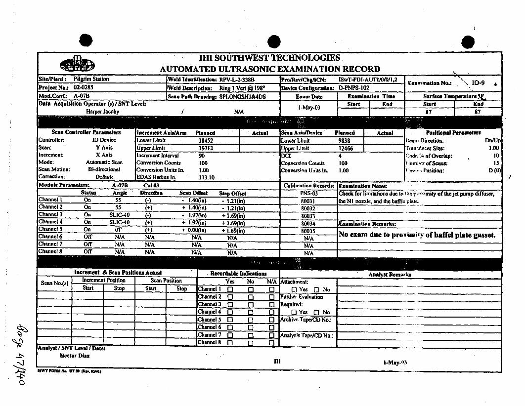
0IHI SOUTHWEST TECHNOLOGIES
P SAUTOMATED ULTRASONIC EXAMINATION RECORDSit";'ant Pilgrim Station Weld Identiflcatioa: RPV-L-2-338B Pro/RevlChg/ICN: ISwT-PDI-AUTI/0/0/I,2 Examination No.:-' ID-9
Project No.: 02-0285 Weld Description: Ring Vert @ 198° Device Configuration: D-PNPS-l02
Mod.Conf.: A-07B Scan Path Drawing: SPLONGSHI&4DS Exam Date Examination Time Surface Tempeature _VData Acquisition Operator (s) SNT Level: I-May-03 Start End Start End
Harper Jacoby /N/A 87 87
Scan Controller Parameters Increment Axis/Arm Planned Actual Scan Axis/Device Planned Actual Poslitioal ParametesController. ID Device Lower Limit 38452 Lower Limit 9838 Iteam Direction: Dn/UpScan: Y Axis Upper Limit 39712 ]Upper Limit 12466 Transducer Size: 1.00Increment: X Axis Increment Interval 90 DCI 4 Code. % of Overlap: 10Mode: Automatic Scan Conversion Counts 100 Conversion Counts 100 t lrmbxr of Scans: 15Scan Motion: Bi-directional Conversion Units In. 1.00 Conversi~n Units In. 1.00 I evi,'-.'• Position: D (0)Correction: Default EDAS Radius In. 113.10Module Parameters: A-07B Cal 03 Calibration Records: Examination Notes: .........
Status Angle Direction Scan Offset Step Offset PNS-03 Check for limitations due to 'ipep,,"ximity of th jet pump diffuser,Channel I On 55 -) - 1.40 (in) - 1.21(in) 80031 the NI nozzle, and the baffle. plat_.,.Channel 2 On 55 (+) + 1.40(in) - 1.21(in) 80032 " " .......Channel 3 On SLIC-40 (-) - 1.97(in) + 1.69(in) 80033Channel 4 On SLIC-40 (+) + 1.97(in) + 1.69(in) 80034 Examination Remarks:Channel 5 On OT + 0.00(in) + 1.69()in 80035 No exam due to proximity of baffel plate gusset.Channel 6 Off N/A N/A N/A N/A N/A No ea detpo myf___pteus
Channel 7 Off N/A N/A N/A N/A N/AChannel 8 Off N/A N/A N/A N/A N/A
Increment & Sean Positions Actual Recordable Indications Analyst RemarksScan No.(s) Increment Position Scan Position Yes No N/A Attachmnent:
Start Stop Start Stop Channel 1 n 1] 0 0 [1 Yes 0 NoChannel 2 Q [: - Further Evaluation ,,,_ _
Channel 3 0 [1 [1 Required:Channel4 Q 0 01 0 Yes [ No ..........Channel 5 [ 1 0 Archive. Tape/CD No.: _-
Channel 6 0] 0 0 ............Channel 7 [1 13 [ Analysis Tape/CD No.: _.........
-ChannelS 0 p n ......Analyst / SNT Level / Date:
Hector Diazill I-May-03
•SWr FRoM Y&. U,3u (An. UM)

0 0AV96110h,
IRI SOUTHWEST TECHNOLOGIESAUTOMATED ULTRASONIC EXAMINATION RECORD
Site/Plant: Pilgrim Station IWeld Identification: RPV-L-2-338B .IPro/Rev/Chg/ICN: ISwT-PDI-ALUTI/0/0/1.24 Fxamination No.: ",.I-10
Project No.: 02-0285 lWeld Description: Ring I Vert A 1980 IDevice Conflguration: D-.PNPS-102]f•=
Mod.Conf.: A-07B JScan Path Drawing: SPLONGSHI&4DS Exam Date Examination Time
Start End I
Surface Temperature q
Data Acquisition Operator (s) i SNT Level:Harper Jacoby N/A
Start I EndI
I I: I 1250 87 I 87 .
Controller:Scan:Increment:Mode: A'Scan Motion: ECorrection:
* rurametersID Device
Y AxisX Axis
utornatic Scanli-directional
Default
Increment AXsIIIrml riannea I ActualLower Limit 38452 1 38451Upper Limit 39712 39712
scau AW RI/ewice rlannuaj Actual
Lower Limit 12413 13700Upper I15041 15041DCI 4
roalllmua rsrameler,
11m Orection:!'annd,w.cr Size:Cndr. 74 of Overlap:r Iffm 1-,,r of Scans:
'vi,-." Position:
Increment IntervalConversion CountsConversion Units In.EDAS Radius In.
90I001.00113.10
JI'n/Up
1.0010
15D (0)
Conver'inn CountsConversion Units In.
1001.00
Module Parameters: A-07B Cal 03 Calibration Records: Examination Notes:
Status Angle Direction Scan Offset Step Offset PNS-03 Check for limitations due to Ahe pr-, imity of thcjet pump diffuser,Channel I On 55 - - 1.40(in) - 1.21(in) 80031 the NI nozzle, and the baffle plate.Channel 2 On 55 (+) + 1.40(in) - 1.21(in) 80032 .....
Channel 3 On SLIC.40 (-) - 1.97(in) + 1.69 in) 80033Channel 4 On SLIC.40 (+ + 1.97(in) + 1.690n) 80034 Examination Remarks:Channel 5 On OT (+) + 0.00(in) + 1.69(in) R0035 Limited exam due to proximity of baffle plate gusset.Channel 6 Off N/A N/A' N/A N/A NIAChannel 7 Off N/A N/A N/A N/A N/AChannel 8 Off N/A N/A N/A N/A-• N/A
Incrmen & San osiionsActal Rcorabl IndcatonsAnalyst Remarks
Scan No.(s) Increment Position Scan Position Yes No N/A Attachment:Start Stop Start Stop Channel l 0 n. 0 Yes Q] No .....
I-5 38471 39552 13621 15041 Channel2 D S 0 Further Evaluation ._ _-_......
6- 15 38909 39728 13700 15041 C"hannel 3 D [a [ Required: .
Channel4 r B' 0 D Yes [a No,.,Channel 0 0 0 Archive Tape/CD No.:
- -Channel 6 0 0 @ 3SA_ _ .. ,Channel 7 D El Analysis Tape/CD No.:
____ hnnl 0 Q0 IA_______ ___________
Analyst / SNT Level -/Date:--_________
Hector DiazI-ll -- May-03
wrf FORM N& .. oUT U 4F.v. ,,+i,

111 SOUTHWEST TECHNOLOGIESAUTOMATED ULTRASONIC EXAMINATION RECORD
Site/Plant: Pilgrim Station Weld Identification: RPV-L-2-338B Pro/RevlChg/ICN: ISwT-PDI-AUTIIO/'0/".2 Eamnatio No.: ID-II
Project No.: 02-0285 Weld Description: Ring I Vert @ 1980 Device Conflguration: D-PNPS-102Mod.ConE: A-07B Seen Path Drawing•: SPLONGSHW&DS Exam Date I Examination Time ... Surface Temperature.4LData Acquisition Operator (s) ISNT Level: I-May-03 Start End Start End
HarnerJacobv N/A 1256 1314 87 1 87
buan UontrcController:Scan:Increment:Mode:Scan Motion:Correction:
fcr rarametersID Device
Y AxisX Axis
Automatic ScanBi-directional
Default
Lower Limit 38452. 38452 ILower Limit 14988 14988Upper Limit 39712 39712 UpperLimit 17616 . 17616
rosluonal rarameversBeam Direction:' ransfilicer Size:Code! % of Overlap:rllhmhrbfv of Scans:"w-.i,, Position:
Increment IntervalConversion CountsConversion Units In.EDAS Radius In.
901001.00113.10
DCIConversion Counts.Conversin Units In.
41001.00
Dn/Up1.00
1015
D (0)
-£
Module Parameters: A-07B Cal 03 Calibration Records: jExamination Notes:Status Angle Direction Stan Offset Step
Channel I On 55 (-) - 1.40(in) - 1.Channel 2 On 55 (+) + 1.40(i) - 1.Channel 3 On SLIC-40 (-) - 1.97(in) + I.Channel 4 On SLIC-40 (+) + 1.97(in) + 1.Channel 5 On OT (+) + 0.00(in) + i.Channel 6 Off N/A N/A N/A 1NChannel 7 Off N/A N/A N/A NChannel 8 Off NIA NA WI/A w
I .....
PNS-03800318003280033
Check for limitations due to 1ýlt ps,-,v imity of the jet pump diffitser,
the NI nozzle, and the baffle plain..
Examination Remarks:
4-
I.
increment a bcau rositions Actual Ahiuylal KmarEUKS
Scan No.(s)L , f
Increment Position Scan PositionStart Stop Start Ston Channel 1 fI
1I15 38451 39712 14988 17616 Channel2 ['
Channel 3 0Channcel 4 0Channel 5 [
P1 0
Aftachilent:DYes B No
Further EvalhationRequired:
El Yes n, No
-I
4.
- - I9 01 Arih,,• 'rape/CD No.:
ChannelI WK r'tane 6 -7 0 (21 SA ____
......... 7 I • t~n~ r;JiI t t 1 I _-_--! ih
Analysis TapeJCD No.:IAChannel ft rI I- rT
d Channeig 0 1~i AV.
AnalI~l| st 11,11 Lv+ l I WntieHector Diaz 00,
Ill I-May-03
ISWT FORM ft. UT So (U.". OS0fl- •..... . W

0AIHI SOUTHWEST TECHNOLOGIES
AUTOMATED ULTRASONIC EXAMINATION RECORDSite/Plant: Pilgrim Station Weld Identification: RPV-L-2-338B Pro/iRevChg/ICN: ISwT-PDI-AUTI/0I0/I,2 Fxamsnatiom No. ID-U2Project No.: 02-0285 Weld Description: Ring I Vert @ 1980 Device Configuration: D-PNPS-102
Mod.Conf.: A-07A .Scan Path Drawin,: SPLONGSHI&4DS Exam Date Examination Time Surface Temperature ý.Data Acquisition Operator (s) /SNT Level: I-May-03 Start End Start End
Harper Jacoby / N/A 1358 1406 87 987
Scan Controller Parameters Increment Ax nned Actual Scan Axis/Device Planned Actual Positional ParameteraController. ID Device Lower Limit 38452 38452 Lower Limit 17563 17563 DIran Direction: tUplDnScan: Y Axis Upper Limit 39712 39712 Upper Limit 2019.1 20191 Transdwier Size: 1.00Increment: X Axis Increment Interval 90 DCI 4 (Me ^I of Overlap: 10Mode: Automatic Scan Conversion Counts 100 Conversinn Coumts 100 til,,mlh, of Scans: 15Scan Motion: Bi-directional Conversion Units In. .1.00 Conversin Units In. 1.00 ',Vk,,. Position: D (180)Correction: Default EDAS Radius In. 113.10
Module Parameters: 'A-0)7A Ca103 Calibration Records: Examination Notes:Status Angle Direction Scan Offset Step Offset PNS-03 Check for limitations due to she. p,---imnity ofthejet pump difliiser,
Channel I On 55 +) + 1.40(in) + 1.21 (in) 80031 the N I nozzle., and the baffle, piatc. _
Channel 2 On 55 (-) - 1.40(in) + 1.21 (in) 80032 ........Channel 3 On SLIC40 +) + 1.97(in) - 1.69(in) 80033Channel 4 On SLIC-40 (-) - 1.97(in) - 1.69(in) 80034 Examination RKemarks:.Channel 5 On 0T (+) + 0.00(in) - 1.609in) 90035 .....Channel 6 Off. N/A NIA N/A N/A N/AChannel 7 Off NIA N/A N/A N/A- N/AChannel 8 Off N/A NIA N/A N/A N/A
Inreen &Saoiin cul eodbiuiai Anallyst-Remarlcs
Increment Position Scan Position Yes No N/A Attachmert- ..........
Start Stop Start Stop Channell I" [I Yes (a No1-15 38451 29796 17563 20191 Channel2 0 "0 Further Evaluation ' _ _ __"'
Channel 3 R [. I Required: ....._ .. _
iChannel4 [0 9 Q I Yes Q No .....
Channel 5 0 9[ 1 0 Archivc Tape/CD No.: ............Channel 6 0 0 0 SA__15AChannel 7 0 1 9 Analysis TapeJCD No.: " . . ........
_ _ _ChannelS 0 [] 0 IA .....___"_"
Analyst / SNT Level I Date: - 8 gild IA
Hector Diaz
Z4III 1-May-03EAWY Ffl*A N& UT7 SO 'RU a--?
I
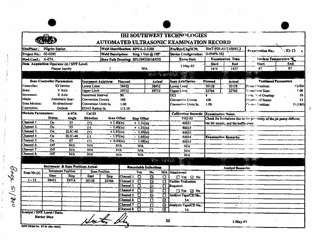
IM SOUTHWEST TECHNOLOGIESAUTOMATED ULTRASONIC EXAMINATION RECORD
0
'S.
Site/Plant : Pilgrim Station IWeld Identification: RPV-L-2-338B APro/Rev/Chg/ICN: ISwT-eDI-A1JT I/10/0/l,2 I1;Project No.: 02-0285 'Weld Description: Ring I Vert @ 1980 Device Canflguration: D-PNPS-102 JMod.Conf.: A-07A Scan Path Drawln: SPLONGSHI&4DS Exam•Date Examination Time
Data Acquisition Operator (s) I SNT Level: ,,,, ,f Start End "
Saup;-atfon No.: "'\ID-13
,Surface Temperature .
Start End87 9"7Harme Jacoby .. I N/A -I M 03ay- 1414 1 1425
Controller:Scan:Increment:Mode:Scan Motion:Correction:
,nroggcr ruraaieaersID Device
Y AxisX Axis
Automatic Scan
Bi-directional
Default
increment Axusi~rm riannea Actual.Lower Limit 38452 38452
Upper Limit 39712 39712
w.siuvevce ý r
Limit
Li- it ..-
S , Actual
I 20138
.L 22766
rosiuwnai rarwmeuxraP~rlm D~irectioni: I lp/Dv1
; -, insf'!c.er Size: 1.00
(:Aic .. rnf Overlap: 101 '•1ml,.' of Scans: 13
•,,i:•. 'osiion:D (1801
Increment IntervalConversion CountsConversion Units In.
EDAS Radius In.
901001.00113.10
4Conversin Counts 100
Conversin Unit, In. 1.00
IModule P'arameters:
StatusA-07A Cal 03
Angle Direction
Calibration Records: IExamination Notes:
Scan Offset ~ta.n flffsma.* PW5S-fllScanOffst Stp Ofset NS-0
r
Check for limitations due to 111c. pr,,- imity of the jet pump diffuser,
the NI nozzle, and the baffle plale.uCannel I On 55 + 1.40(in• + I •lfnin RSffl I
Channel 2 On 55 (-) - 1.40(in) + 1.21(in)
Channel 3 On SLIC-40 (+) + 1.97(in) - i.69(in)
Chnannel4 on SiLIC-4U (-1 - !.97(in) -1.69(1n)A. ---- IS'_-• ... .... .) - 16 (
Examination Remarks:
inelCI On OT + N/Aan .9m_ _ _
Z0 UOf N/A N/A N/A
Off N/A N/AN/AN/A__ _
N/Anft- M/A MIA
Scan No.(s)
Increment &osan P4Increment Position
Actual IRecoScan Positionr
Analyst RemarksI
.wYes
Start Ston Start .•tnn f•hann•,l 1 I'1 .N/Ai--*
Attach-ent:Q Yes nPINo
S..,- 4. ... S,,-- , L1-15 39451 39714 20138R (71f' m *l'a ~ | I I:
39714 0II .~ _ _ L20138iurther Evaluation
Required:flhann.IlA I--I r•u rI-
Channel 5 0 2) 0 ,Archive Tape/,CDNo.:_Channel 6 0 0 0 5A
.. _ •Channel 7 [3 0 Analysis Tape/CD No.:
Channeli 0 p 0 IAAnalyst I SNT Level I Date:
Hector Diaz
iSWr FOIM Na. UW5S jk. i .SeI)

0IHI SOUTHWEST TECHNOLOGIES
AUTOMATED ULTRASONIC EXAMINATION RECORDSite/Plant: Pilgrim Station Weld Identificatiou: RPV-L-2-338B Pro/Rev/Chg/ICN: ISwT-PDI-AUTI/0/0/I,2 Examination No.: ID-14 aProject No.: 02-0285 Weld Description: ' Ring I Veat @ 1980 Device Configuration: D-PNPS-102
Mod.Conu A-07A' Scan Path DrawOino: SPLONGSH(DS amDate Examination Time Surbce Temperature En .Date Acquisition Operator (s) I SNT Level S I -May-03 Start i End Start End
Hamer Jacobv I N/A 1 1433 1443 87 87
ocUE I ^]LIUI
Lower Limitleanned Actual22713 22241Controller:
Scan:Increment:Mode:Scan Motion:Correction:
ID DeviceY AxisX Axis
Aulomatic Scan
Bi-directionalDefault
Lower Limit 38452 I 38452.9
Iocr Limit 39712 39712.9
Increment IntervalConversion CountsConversion Units In.EDAS Radius In.
901001.00113.10
Uppe imit 25341 25341
DC1 4Conversion Counts 100Conversion Ulanits In. - 1.00
Positional IPram Direction:l ransdiscer Size:,,1. % of Overlap:
t-'iam r of Scans:l•,. osition:
JplDn1.00
I015
1) (180)4
I 4-.-.Module Parameters:
Status
A-07A Cal 03
Angle Direction
Calibrntion Records: lExamination Notes:
Scan Offset Step Offset PNS-03.9-..
Channel I On 55 (+) + 1.40(in) - + 1.21(in)Channel 2 On 55 () - 1.40(in) + 1.21(in)Channel 3 On SLIC-40 (+) + 1.97(in) - 1.69(in)
800318003280033
Check for limitations due to 11c ) ,p'vimity of the jet pump difffiser,the NI nozzle, and the baffle. plair.
Channel 4 On SLIC-40 (-• - 1.97(in) 1.69(in) 80034 lExamination Remarks:
Channel 5Channel 6Channel 7
0
OT (+) + 0.00(in) - 1.69(in) 80035.8-
N/A N/A N/A NIA N/AN/A N/A N/A
N/A N/N/A N/A N/A
Increment & Scan Po! tons OAIAUU tecur A "al ,eniri,
Scan No.(s) Increment Position Scan Position YesT - I - I
N/A0
Attachment:El Yes [P NoStart Ston Start Storn Channel 1 fl
61tý,
LA
AQ
Stan S ....... r .. ... .. C1-15 38451 39694 22713 25341 Channel2 0
, Channel 3 0
Channel 4 0Channel 5 0
- I - I
n0"0]
Furthrr EvalhationRequired:
0 Yes ONo
0] Archi",r Tape/CD No.:Channel i' rflChne 6 0 5A. I. SaC......... F-, I- NChanneI7 I C]
ifl
Analysk' Tape/CD No.:IAChannel R I-I i'i 171
I..Chane m...icr4
IA7,. ~ II_____ .J SII .. ~.......Analll•l SN eveI Date:/l ViHector Diaz
HII 1-May 4~
i.S~S.Sp. S *Ul.
Z4ISW ORM Ns. UT SO (nev. swil

0 _ _ 0
qftIM1 SOUTHWEST TECHNOLOGIES
AUTOMATED ULTRASONIC EXAMINATION RECORDSite/Plant: Pilgrim Station Weld ldentirwation: R.PV-L-2-338B - Pro/Rev/Chg/ICN: ISwT-PDI-AUT.I/0/O/l,2 ForProject No.: 02-0285 Weld Description: Ring I Vei 198@ Device Confiiguration: D-PNPS-10I
Mod.Conf.: A-07-ID Scan Path Drawing; SPLONGSHI&4DS Exam Date I Examination TimeData Acquisition Operator (s) I SNT Level: .. I Start I End
aminoaton No.: ID-I5 A
Surface Temperature "tihStart I End
I R.A. RiddlesI-May-4 i Star.. iEn
Scan CQController:Scan:Increment:Mode:Scan Motion:Correction:
ler ParametersID Device
X AxisY Axis
Automatic ScanBi-directional
Default
10488 13635LIUWC4 9111111L
Upper Limit 17508 I 17508
MMn Alxar"rm ronneu Actual
Lower Limit 38332 38332Upper Limit 39832 39832DCI 41 17508
Increment IntervalConversion CountsConversion Units In.EDAS Radius 1n.
901001.00Il l:.(
Dr..-im I ýiction:. CCV/Cw1 si~" rSize: 1.00
0-11C of Overlap: toN11inbc-7 of Scans: 79D-'icr. V~sltion: A (0)
Conversio~n Connts
Conversins, Ulnits In.too1.00
h WAS Radius In 113 10module Parameters:
StatusA-07-ID Cal 33Anrle Direction
Calibration Records: lExamination Notes:Scan Offset .gama fltfro PNc.•.2:
C I Check for limitations due to the pry imity of the jet pump diffuser,th.)J ][I -1T•J hA #hD h Fm I.b l
Cnannel I On 55 + 7.00(inl + fl n0inI 201-11
Channel 2 On 55 (+) -00(in) + 0.00(in) 80332Channel 3 On SLIC40 () + 4.40(in) + 1.00(in) 80333 "
Channel 4 On SLIC-40 -+) - 4.40(in) 1,00(in) 80334 E-xamination Remarks: ....
Channel 5 On CT - . (+ + 4.40(n) - 1.00(in) 80335 LiExami at oiy f hemflaerpi kgse
Channel 6 On OT (+) - 4.40(in) + I.00(in) 80336 .Channel 7 Off N/A' N/A N/A N/A N/A ..... .......... .Channel 8 Off N/A N/A NIA*- N/A N/A
Increment & Scan Positions Actual Recordable Indications Analyst RemarksScan No.(s) Increrent Position Scan Position Yes No N/A _Attachment_
Start Stop Start Stop Channel] 0 Q1 0 - Yes No36-79 13631 17569 38332 39832 Channel 2 n0 0 0 -Further Evaluation Channel 6 inactive,
Channel 3 0 0 0 Required:Channel4 0 a1 D ,Yes (a NoChannel 5 D 21 0'. Archive Tape/CD No.:
__,, _ hannc 6 B" SAChannel 7 0 _l 9 Analysis Tape/CD No..
A-nalyst I SNT Leve I Date: -Channel 8 o 0 IA
Hector Diaz
I-WT FRM N, IT M (ai. e.I-. , In -- May-03

IHI SOUTHWEST TECHNOLOGIESAUTOMATED ULTRASONIC EXAMINATION RECORD -,.._-. _
Site/Plant: Pilgrim Station :Weld Identificatiaon: RPV-L-2-338B Pro/RevlChg/ICN: ISwT-PDI-AIA I/0/0/1,2 Examination No.: ID-I6Project No.: 02-0285 Weld Description: Ring I Vei 198. Device Configuration: D-PNPS-101
Mod.Conf.: A-07-IC Scan Path Drawing: SPLONGSHI&4DS Exam Date Examination Time Surface Temperature-6F
Data Acquisition Operator (s) ISNT Level:R.A. Riddles if
I-May-03End Start End
0649 87 87
tcao voController.Scan:Increment:Mode:Scan Motion:Correction:
ontroier rarametersID Device
X Axis
Y AxisAutomatic ScanBi-directional
Default
Increment AxiWArm ILower LimitUpper LimitIncrement IntervalConversion CountsConversion Units In.EDAS Radius In.
Actual NCAn AXISIlevice rianneu " ActualI. 4~ I
17431 Lower Limit 38332 " 383321 24432 Upper Limit 39832 39832
4. -.. ~---
resumnamFIcam Direction:"l'ran.dic~er" Size:
C•ndcr -41 of Overlap:tin hvl-! of Scans:Frwr~i,,- - osition:
CV/Ccw1.00
1079
A (ISO)1001.00113.10
DCIConvcrminn Counts
Conver•in Units In.
4
1001.00
4.- - IModule Parameters:
StatusA-07-IC Cal 33
Angle DirectionCalibrntion Records: lExaminatios Notes:
Scan Offset SteChannel I On 55 (+) - 7Channel 2 On 55 (-) + 7.Channel 3 On SLIC-40 (N) - 4.Channel 4 On SLIC-40 (-) + 4.Channel 5 On 0T (+) - 4
Channel 6 On OT (M) + 4.Channel 7 Off N/A N/A
00(in) + 0.00(in) + 0.40(in)., - I.1.40(in) + 1.1.40(in) + I.(.40(in) - I.(N/A N,
PNS-33
80331
80332
Check for limitations due to 1ihr. p,'.,imity of the jet pump diffuser,.the NI nozzle., and the baffi, 1lat.
80333 I- -iO-334 Examination Remarks:
- JLimited exam due to proximity of the N2F nozzle.
8 Off N/A N/A-I
ilranmunIu Om OEM" 3191003 Actual KeCOraaoIC 11111CRUOUa Analyst Remarks-f - - -- I I
Scan No.(s) Increment Position Scan Position Yes No N/A- T 1 7Start Ston Start Ston ehannel 1 f-l 1";i f-lS" Stop Start Stop 1Cýanncl 1 0- 11 .1-20 17431 19155 33332 398112 (Channel 2 f"l ri' -
Attachrw.nt:
EIYes [ NoFurther EvaluationRequired:
- Yes a No
Channel 6 inactive.21. . ._ _19...7----- 2..1 39 C n 3
21 -34 !! 1937 2 41 38332 39050 Cjhannel 3 0" 171 0"35-43 20499 21175 38332 39090 lChannel 4 f~l r~I f-l
383 399 Chane 4 C]*** ~ '- -I44 -50 21284 21804 38332 38950 Channel 5 " P1 0
A i . . g. 4. _____--Archi--. Tape/CD No.:
5A
C)
51-73 21897 23886 38332 39560 Channel 6 0 0 "I
74- 79 23978 24427 38332 39832 IChannel7 0 7 'I 4. -t 4- 'Analy;. TapeJCD No.:
IAChanneld 8 [ - 1-~~~~~~~~~~ A___ - .I __~____
Analyslt ST M Level / Uate:Hector Diaz
I!I I-May-6.PSWFFODA41J. IF? In.. *~m~I
MW FORM NO 11T30 (am 8"2)

ISwT EXAMINATION SUMMARY RECORD
PILGRIM NUCLEAR POWER srATION
I
Project No.: 02-0285 Summary Sheat No.: 000700 ",,.,
SITE:SYSTEM:LINE/SUBASSEMBLY:IDENTIFICATION:
PILGRIM STATIONREACTOR PRESSURE VESSELRING 3 VERTICAL WELD @ 356-DEGREESRPV-L-2-339A I
NDEMethod PromcRev/Chg/ICN
N ONDE Calibration Data R T
Examination Sheet No. Sheet No. I HReseoddin CNF
Resw•d Number Remarks
AUTAUTAUTAUTAUTAUT
ISWT-POI-AUTIIWOIOI.2ISWT-PDI-AUT1 iWO/I .2ISWT-POI-AUT1'i/wIf.2ISWT-P0t-AUTI 10/0fl,2ISWT-PDI-AUT1II0/011.2ISWT-PDI-AUT1IOIO1 .2
AUTOAUT55
AUTSLIC40AUT55T
AUTSUC40TAUTO
80335,8033680331.8033280333,8033480031,8003280033,80034
80035
exam 43-46
exam 4346em 43-46exam 39-42
amm 39-42exam 39-42
xxxxxx
N/A
N/A
NIA
NIr
NIANJANIANIANIA
N/A
Exainatinn rno' 39-46.
AUTO for thiduiew mv ie,•nly.
4z
NOTES: 1. Weld RPV-L-2-339A was examined from the Inside surface using AIRIS-21 and EDAS-I4 e•,n•rnatinn equipment.2. No recordable indication were detected during this examinaton".3. The examination was limited due to pmit of teedater and corespay spawr , 81%eyp,m rmti over=age chiskrw.
""UT CALIBRATION BL-ý-)(' K(!)*
-*D-70n187-2/D7030"' 1"
Prepared byA:.•ro'A
Iteven J. Todd - roject EngineerDate: 04-May-03 Pagu h I of 1
Summarvy Sheaf No. nnn700

- .0I.1111 SOUTHWEST TECHNOLOGIES
AUTOMATED ULTRASONIC EXAMINATION RECORDSite/Plant: Pilgrim Station Weld Identiflcation: RPV-L-2-339A Pro/RevlChg/ICN: ISwT-PDI-AUTI/0/0/,2 _R
Project No.; 02-0285 Weld Description: Ring 3 Vert @3560 Device Configuation: D-PNPS-102
Mod.Conf.: A-07B Scan Path Drawing: SPLONGSH2&3DS Exam Date Examination Time'." .... ... .. •, +=,,r ... ,." .#.rl [ F nd
Nsaniihation No.: ID-39 ,
Surface Temperature FStart End96 I 96lData Acquisition uperator (s) I ,NT Level:
H-larper Jacoby29-Apr-03
N/A
Scan Controller ParametersController: ID DeviceScan: Y AxisIncrement: X AxisMode: Automutic ScanScan Motion: Bi-directionalCorrection: Dtclhuit
'm Planned69950
tUppcr Limit
Actual baAa /Vevlee rlanneu ACtUl69950 Lower L.imit 38750 3875071210 13 .imit 42814 42B14
DCi 47'1210
I I 71210
Positional ParametersIke-nn i'ircction:1. ¶:n',hicr Size:
o,,• f Overlap:
Ihml',-.; of Scans:
I ,Vij',:,- I'osition:
Increment IntervalConversion CountsConversion Units In.IV.IAS Radius In.
901001.00113.60
Dn/Up1.00.1015
D (01Conver•i'll CotuntsConversii Inils In.
1001.00
Module Parameters: A-07B Cal 03 __ Calibration Records: lExamination Notes:Statuns Angle Direction Scan Offset Step Offset PNS-03 Check for limitations due to lh, proximity ofthc feedwater and
core spray spargers and the gitidc rod.Channel I On 55 (-) - 1.40(in) - 1.21(in) 80031On 55 -I- 1.40(m) - 1.21(m) 80032On SLIC-40 (-) - 1.97(in) + 1.69(in) 80033 "
4 On S1IC-40 (+) + 1.97(in) + 1.69(in) 90034 Examination Remarks:5 On OT (N) + (6 Off N/A N/A7 Off N/A N/A8 Off N/A N/A
+ 1.69(in) 80035VIA N/A
-4
Increment & Scan Positions Actual KWE01unuamuaureu Ansnyst Kemarus- 4Increment Position Scan PositionScan No.(s) Yes No NIA
Ye4o / Attuachment:If-lYes I-1 NaStart StoD Start Ston Channel I f- rI; I-1
(a Q Q Ye 0 N1-15 69950 71210 38750 42806 Channel 2 •f-Il l -r:~i fl
CiIiIhannc3 [j 0)
Further EvaluationRequired:
rfl vpq 11 lNnChannel 4 I-l IyI I-IChannel5 0 0 - Archive Tapc/CD No.:
Channel 6 0 0 91 .3A
Channel 17 " : [j) Analysis TapeCD No.:_ Channel 0 0 1 IA
A na o eave aeHector Diaz
Ill 29-Apr-0 3
IwrT FoRM w U s0 (Rev. owl5)

IHI SOUTHWEST TECHNOLOGIES
SE AUTOMATED ULTRASONIC EXAMINATION RECORDSite/Plant: Pilgrim Station Weld Identification: RPV-L-2-339A Pro/RevlChg/ICN: ISwT-PDI-AUTIIO/OlI,2 Fxwamination No.: JD-40
Project No.: 02-0285 Weld Description: Ring 3 Vet •@3560 Device Configuration: D-PNPS-102
Mod.Conf.: A-07A Scan'Path Drawing: SPLONGSH2&.3DS Exam Date Examination Time Surface Temperature °
Data Acquisition Operator (s) I SNT Level: 28-Apr-03 Start Fad Start End
Hamer Jacohv N/A 212 1Ar344 96 ES96SrE
mcan Lonlrroner rarametersController. ID DeviceScan: Y Axisincrement: X AxisMode: Automatic ScanScan Motion: Bi-directionalCorrection: Default
tL ICCURg
42763 42763Lower Limit 69950 69950 Lower LimitUpper Limit 71210 71210 jUpperLimit 46827 46827Increment IntervalConversion CountsConversion Units In.EDAS Radius In.
901001.00113.60
DCIConversini CountsConversi,- Units In.
41001.00
Positlonal ParametersIBam Direction: tlp/Dn
Trnsdtc..exr Size: 1.00Cle ,-, of Overlap: 10VIl-nbh of Scans: 1511!......ir.,-. !',Sition: D (ISO)
- 9 1.Module Parameters:____ Status
A-07A Cal 03Angle Direction
Callbrutlion Records:PI-IS-03
Examination Notes:&
Scan Offset Step Offset Check for limilations due to thr. pr.•-'¶"ity of the feedwater andcore spray spargers and the giii,,. rr',Channel I On 55 (+) + 1.40(in) + 1
LChannel 2 On 55 (0) - 1.40(in) + IChannel 3 On SLIC-40 (+) + 1.97(in) - IChannel 4 On SLIC-40 (0) - 1.97(in) - IChannel 5 Oh OT (+) + 0.00(in) - I
FChannel 6 Off N/A N/A N/A
.21(in)
.21(in)
.69(in)
9003180032anon
4Examination Remarks:
41Limited exam due to proximity of •nrc spray sparget.
Ichannel 7 Off N/A N/AChannel 8 Off N/A N/A
4
_____ 4
Scan No.(s) Increment Posan rouan~ons Actual Reeoranale anaaeauloas Analyst Kemari's-~ -1- 4 4~ -ition Scan Position Yes No N/A
I 4 Atachnrnt:[1 Yes 2 NoStart Ston Start Ston Channel 1 f"l 11 f~l
- 7 69950 70339 42763 46115 Channel 2 0 " Further Evalistion6--15 70351 71210 42763 46827 Channel3 0 [1 [ Required: N
._ ,Channel4 0 Q D _. l____ )(e- NoChannel 5 [l '71 nChnn1 E
Archive
Channel 6 'l n~ UIIChannel 7 ] R1 0 Analysi!IChannel8 E] 0 '1
'rap/CD No.:3A
Tape/CD No.:IA
AAnalyst I /I- Level I Date:
Ilector Diaz!!! 29-Apr-.13
~I~~45 flO. UI - IIS~V.I~IU1l15wTl Fong• No. UIr so0 |(P". W

11HI SOUTHWEST TECHNOLOGIESAUTOMATED ULTRASONIC EXAMINATION RECORD
Site/Plant: Pilgrim Station Weld Identification: RPV-L-2-339A Pro/Rev/Chg/ICN: ISwT-PDI-AUTI/0/0/1,2 Examination No.: . ID-41
Project No.: 02-0285 Weld Description: Ring 3 Vet @ 3560 Device Conficuration: D-PNPS-102 '.
Mod.Conf.: A-07B Scan Path Drawing: SPLONGSH2&3DS Exam Date Examination Time Surface Temperature °wData Acquisition Operator (s) / SNT Level: ' Start End Start ::: = End
Harper Jacoby N/A 2I-Apr-03 1 I 1 406
Controller:Scan:increment:Mode:Scan Motion:Correction:
ID DeviceY AxisX Axis
Automatic ScanBi-directional
Default
Lower Limit 69950 69950 Lower Limit, 46776 46760LoUer Limit 946776 . 46760
Upper Limit . 71210 71210 J~~Lmu52096 .50400
Increment IntervalConversion CountsConversion Units in.EDAS Radius In.
901001.001 13.60
DCIConversint, CountsConversi-n Units In.
41001.00
Bctim Direction:1"rinsd-scer Size:Cnci %. of Overlap:
,J'inb,. ,f Scans:
Dn/Up1.00
1015
D (0)
£ ____113.60
Module Parameters: A-07B Cal 03 Calibration Records: Examination Notes:Status Angle Direction Scan Offset Step
Channel i On 55 Q-) - .1.40(in) - !
Channel 2 On 55 (4) + 1.40(in) -Channel 3 On SLIC-40 (-) 1- 1.97(n) + 1Channel 4 On SLIC-40 (+). + 1.97(in) + 1Channel 5 On OT (H) + 0.00(in) + I
Channel 6 Off N/A N/A N/AChannel7 Off N/A N/A N,Channel 8 Off N/A N/AI N/A t
Increment & Scan Positions Actual Records
PNS-038003110032
Check for limilations due to I11- pr,-inmity of the feedwater and
core spray spargers and the gide rd.
8003380034 4-Examination Remarks:80035 Limited exam due to proximily of core spray sparger.
'- ... .I • . w
N/A.,;'; I '-
NIANIAW/A I43
ins Analyst Remarlks
Scan No.(s) increment Position Sican Position Analyst RemarksI - i .1 S N/A
0-Attah-ment:
ElY es flNostart Stou Start Stnn flhnnnpl IP Start Sto Channel I
b1-15 1 6"50 71210 46760 1 ad- aLL JChanne12I
0]Ck,,nnl 2 r-' r•u
Further FvalhotionRequired:
-
Xhannl 3_T_UhnnnI A ril r"7 f'-Channl 4 I [Ies (D No•.umu •a • LJ I,-i it.
Ch l 5. r-*-*' U R . Archive. 'apeCD No.:r~anma I I-'1 I-rI
h l 6 E El I 3AI Ilanlrql•| -I I I •
Ch -w l 7 s Analysis Tape/CD No.:0~nn, I--1 i-~ r~
J Chan 8~ C 0 IA
Ana ,ts / SNT~ Leve ate:I ~qlHector Diaz
a
401 III 29-Apr-o.l
-WT FORM N% UT So (Rev. smI) , -

S OI IHI SOUTHWEST TECHNOLOGIES
AUTOMATED ULTRASONIC EXAMINATION RECORDSite/Plant: Pilgrim Station Weld Identification: RPV-L-2-339A Pro/Rev/Chg/ICN: ISwT-PPI-AUT.I/0/0//,2 FTa*Wi,,tion No.: '".D-42 aProject No.: 02-0285 "Weld Description: Ring 3 Vert @ 356* Device Configuration: D-PNPS-102 -_'_,,_"
Mod.Conf.: A-07A Scan Path Drawing: SPLONGSH2&3DS Exam Date Examination Time Suarface Temperature °1.Data Acquisition Operator (s) / SNT Level: 28-Apr-03 Start End Start End
Harper Jacoby N/A 1004 lw 96 96
Sean Controller Parameters Increment Axis/Arm Planned Actual Scan Axis/t evice Planned Actual Positional Parameters
Controller- ID Device Lower Limit 69950 69950 Lower Limit 46776 50300 ,..Ii V'Drection: Up/Dn
Scan: Y Axis Upper Limit 71210 71210 UpperLiurit. .. 51744 51744 T, s' ize: 1.00
Increment: X Axis Increment Interval 90 DCI 4 (>.ie '." 'f Overlap: 10
Mode: Automatic Scan Conversion Counts 100 Conversion Counts 100 .,•ih,., nrScans: 15Scan Motion: Bi-directional Conversion Units In. 1.00 Conversin Units In. 1.00 .,"ici. "nsition: D (080)Correction: Default EDAS Radius In. 113.60 1
Module Parameters: A-47A Cal 03 Calibration Records: Examination Notes: _ __-_ _ _
Status Angle Direction Scan Offset Step Offset PNS-03 Check for limitations due to thic proximity of the feedwater andChannel I On 55 (+) + 1.40(in) + 1.21(in) 80031 cam spray spanrgers and the guidIe rnd.Channel 2 On 55 (-) - 1.40(in) + 1.21(in) 80032Channel 3 On SLIC-40 (+) + 1.97(in) 1.69(in) 80033 ....Channel 4 On SLIC-40 (-) - 1.97(in) - 1.69(in) 80034 Examination Remarks:Channel 5 On OT (+) + 0.00(in) - 1.69(in) 80035 Limited exam due to proximity nor rore spray sparger.Channcl 6 Off N/A N/A N/A N/A N/AChannel 7 Off N/A N/A N/A N/A N/A .........Channel Off NIA N/A N/A N/A N/A
Incremenet & Sean Positions Actual Recordable Indications Analyst RemarksScan No.(s) Increment Position Scan Position Yes No N/A Attachment: .....
Start Stop Start Stop Channell C] 0 , - Yes No __
- 15 69950 71210 50300 51700 Channel2 0 9 0 Further Evaluation "_._.
Channel3 0 9 0 Required:
_Channel4 0 [ D QYes B No
Channel 5 03 0 Archive Tape/CD No.:Channel6 0 0 9 3AChannel 7 [3 E Analysis Tape/CD No.: "_ 'Channel 0 p 9 IA
Analyst I SNT Level / Date: • C '
Hector DiazIIl rr29-Apr.03
131 Oan roN It.n mflf

11 SOUTHWEST TECHNOLOGIESAUTOMATED ULTRASONIC EXAMINATION RECORD
Site/Plant: Pilgrim Station Weld Identification: RPV-L-2-339A Pro/Rev/ChgICN: ISwT-PDI-AUTI/0/0/I.2 Examination No.: " D-43
Project No.: 02-0285 Weld Description: Ring 3 Vert @ 3560 Device Configuration: D-PNPS-I01 4 _
Mod.Conf.: A-0T-ID IScan Path Drawing: SPLONGSH2&3DS Exam Date Examination Time Surface Temperature .
Data Acquisition Operator (s) I SNT Level: 29-Apr-03 Start End Start EndR.A Riddles A I] f2-r03 " fln, I w7 7I
mean uoController:Scan:Increment:Mode:Scan Motion:Correction:
ntrouer rarametersID Device
X AxisY Axis
Automatic Scan
Bi-directionalDefault
Increment Axis/Arm Planned .Actual Stan Auls/lfevice PLower LimitLower Limit 39650 I -~ 39632
I ] Actual6983071330Upper Limit 43340 433 Upp., Limit
Increment IntervalConversion CountsConversion Units In.EDAS Radius In.
901001.00113.60
DCIConversion ComntsConversi-n Units In.
4
BReam I irection:11r1msdi.0 r Size:(Code % of Overlap:t II•.- of scans:
P'.,t"•nsition:
ParametersCcwvlCW
1.001042
A (0)1001.00
Module Parameters:Status
• • • In
A-07-ID Cal 33Annle Direction
Calibrotion Records: Examination Notes:Scnn Offsnt ~tDfl flfTcu.f
Channel I On 55 (,) + 7.00(in) + 0.00(in)
Channel 2 On 55 (-) 7.00(in) + 0.00(in)
PNS-338033I80332"
Check for limitations due to •Iv: pj-ie-nity of the feedwater and
core spray spnrgcrs and the g•i.1I r,,.i.. . ..
Cnanne13 On SLIC-40 (-) + 4.40(in• + I 00/ in•I"
4.40(in) + 1 ýg (F33-3-ýýCnanne4 q un SLIC-4(I 0 (+ - 4.40(in) - 1.00(in) 80334 Examination Remarks:
---. 5 On OT (+) + 4.40(in) - 1.00(i)n)
6 On OT (+) - 4.40(in) + 1.00(n)7 Off N/A N/A N/A N/A
as Off NIA N/AI
MIA
an'rC"uent 09 acan resin1ous Actual Recordable Indication. • n•llvglr Nmmorl/e
aRecordable-Jindi.ationsScan No.(s) incrcmcnt Posiion Scan Position Yes No NIA
. .... B III
Yes No N/A -
-
Start StoP Start Ston Channel 1 f rn flStPA Stop-- . Channel I C)I - 42 39646 43340 69830 71330 !Clhnnnel 3 ] I• [r's F"I
Atlachim'nt:
O Yes (aNoFurther IvanhbtionRequired:
0 Yes (B No
Channel 6 inactive.-4
-- '- 69830 71330 Channel 2 C1lChannel 3 C1 [37rhannpl4 A ' ra I'1Chane 4 C] C I -.rhonn.I• q I I ri- f"-1Chane 0 C 0 0 Archi-,,. Tape/CD No.:
AAErh. .aI F I--I 1"7t 1- ~ IChanln 6 []i 4At'
.4 -__________•-hmnr | I n i-i r~t .t.elI I i:J
Analyst "rape/CD No.:II'hannl.I U rI i- 17 IA
*-..-.J-,Chane .,iSIY9 ueJ
Hector Diaz.!11 29-Apr-f"
swr~~~~/4 X.l
. niai.,aiMWFOR16114e. ur So (R"4ft2j I.]

I IHI SOUTHWEST TECHNOLOGIESAUTOMATED ULTRASONIC EXAMINATION RECORD
Site/Plant: Pilgrim Station Weld Identification: RPV-L-2-339A Pro/RevCh.g/ICN: ISwT-l!Di-AUTI/0/0/I,2 Firanination No.: ID-44 sProject No.: 02-0285 IWeld Description: Ring 3 Vert @ 356* Device Configuration: D-PNPS-101
Mod.Con.: A-07-1C IScan Path Drawing: SPLONGSH2&3DS Exam Date Examination Time Surface Temperature
Data Acquisition Operator (a) I SNT Level: 29-Apr-03 Start - End Start End
LA. Riddles / II 0213 222 87 78
Scan Controller Parameters Increment Axis/Arm Planned Actual Scan Axis/Device Planned Actual " Positional Parameters
Controller. . ID Device Lower Limit 43213 43215 Lower Limit 69830 69830 1t'rna firection: Cw/CcxvScan: X Axis Upper Limit 46903 45114 Upper Limit 71330 71330 1,•',:,,.er Size: 1.00Increment: Y Axis Increment Interval 90 DCI 4 (-dr. "f Overlap: 10Mode: Automatic Scan Conversion Counts 100 Conversi,-m Cmints 100 fir', f Scans: 42Scan Motion: Bi-directional Conversion Units In. 1.00 Conversinn Unils In. 1.00 N %,,ir•j n'sition: A (Igo)Correction: Default EDAS Radius In. 113.60Module Parameters: A-07-IC Cal 33 Calibration Records: Examination Notes:
Status Angle Direction Scan Offset Step Offset PNS-33 Check for limitations due to Ile prnximity of the feedwater andChannel I On 55 (+) - 7.00(in) + 0.00(in) 80331 core spray spargers and the gfide rod.Channel 2 On 55 (-) + 7.00(in) + 0.000n) 80332Channel 3 On SLIC-40 (N) - 4.40(in) - 1.00(in) 80333Channel 4 On SLIC-40 (-) + 4.40(in) + 1.00(n) - 0334 Examination Remarks:Channel 5 On OT (+) - 4.40(in) + 1.00(in) R0335 Limited exam due to proximity; of core spray sparger.Channel 6 On OT (+) + 4.40(in) - 1.00(in) 80336Channel 7 Off N/A N/A N/A N/A N/AChannel 8 Off N/A N/A N/A NIA NI/A
Increment & Scan Positions Actual Recordable Indications Analyst RemarksScan No.(s) Increment Position Scan Position Yes No N/A Attachmnrnt: __ _ ......
-Start Stop Start Stop Channel I - 9 0 [] - Yes Q No Channel 6 inactive.1-22 43213 45108 69830 71330 Channel2 Q 0 5 Further Evaluation __.... .
Channel 3 - 9 0 Required:
.... .... Channel4 0 0 0 0 Yes E9 NoChannel 5 0 9 0 Archive Tape/CD No.:Channel 6 0 5 1 .4AAChannel 7 r p 9 Analysis Tape/CD No.:
____Channe!S 0 p] C 9 IA
Analyst I SNT Level I Date: ' 0
Ilector DiazHec'VI toI r. Disa /29-A pr-03
mar~D~ .IT4A n.
C)
99wr FORKI No. iTr 50 'RevM-

IHI SOUTHWEST TECHNOLOGIESd AUTOMATED ULTRASONIC EXAMINATION RECORD _.
Site/Plant: Pilgrim Station Weld Identification: RPV-L-2-339A Pro/Rev/Chg/ICN: ISwT-PDI-AUTI/0/0/1,2 Examination No.: "'D45 4
Project No.: 02-0285 Weld Description: Ring 3 Vert @356* Device Configuration: D-PNPS-10I
Mod.Conu: A-07-ID Scan Path Drawing: SPLONGSH2&3DS Exam Date Examination Time Surface Temperature °Aw
Data Acquisition Operator (s) ISNT evel: 29-Apr-03 Start End start 7ndR.A..Riddles It !1 "0213 1 '0222 ' 87 [ 78 9
Scan Controller ParametersController ID Device
Scan: X Axis
Increment: Y Axis
Mode: Automatic Scan
Scan Motion: Bi-directionalCorrection: Default
inc.r.meni ^zIwAT
i~owcr Limit 91 I I 4114
Upper Limit 51186 50620
113vuevice I.imil
imit
' Actual6983071330
Increment IntervalConversion Counts
Conversion Units In.EDAS Radius In.
901001.00I I _6(1
S t'oGslOlSa rarameteri
lýc.,m I lirection: Ccw/Cw
ri.insillwer Size: 1.00
Code % nf Overlap: 10ftnlu•,em , nf Scans: 50
ir. "osition: A (0)Conversion Counts
Conversi-1 Units In.100
1.00
EDAS Radius In. 11360h a 4-- I
Moduile Parameters:Status
A-07-ID Cal 33Angle Direction
Calibration Records: jExamination Notes:
Scan Orfset Stan Offial PN~-VISca Ofse Step ............
I II Check for linuiations due to 1,-.:- jr .mity of the feedwater and
core spray spnrgers and the guiidt,. ri .11.CnannelI On 55 (-1 + 7.00(inl + A O(WinI 803317.00(in) + 000(in)
Cnanne 2 On 55 M - 7.00(in) + if flA'inl RNIUY
t• h.00-n" +- 0 ... 8- ... .
hnamncnl 3 un SLIC-40 (-1 +I 4.40/in) + IlPfinI 2011':4.40(in) + 100(in) 90333
'16annel 4 OnI Sbl+qJ, )r - 's.qUtlfi - I Ilfifini !1fl7.1A •wnm|nlll|nn l•m b• •.
!1 (+1 ----- 7- 440(in) 00(in) 80334 Examinatio R k-a,..lille J "n I U+) + IIWN - Il4if0ni Rfi11• ore spray sparnter.
- 1 --.... 8,0,33,5_______ Li t .ex d I I l0..I•. AT'r IJ-X ,A AAI!A; ,____________......
nI I t'-I-I- 'I..... 1-,,,,.n iIfll1F.
4.40(in) + 100(in) 80136OiffT N/A N/A N/A N/A N/A
NIA N/AMIA MIAIN/A IN/At NIA
Increment & Scan Positionis Actual inatcationa ..... i Ra ... ...
Increment Position AuslystRemarLsScan Position
Scan No.(s) No N/Ar-i I-1
Attach__.nnt:Start Stan Stort Sonn IChannnIl I"Fl
I~~ ~ N -L.. JAA ~ ~ ~ ~ tr Sto Channe 1 0'~ .: ~ ~ ~ 2 IJIUf~IIl~ ISLI
12-" 11" 1S1.10 .}UO"U O~aJU IIl AtU [ hannlal *) I- rI" r'i
IILChanne 3Q 0 P 0Further .'ualbuilion
Required:f-lYf., F• NnChannel 4 fl 17 -F
T 0 0 Yes -J No-'~
... ..... ....... +l + l,.,.J i-• i-J
Ch..nel 3 [] •] []I---hann-,I qL I,- I " ~I";! I-
Channel -- ff
(hnn, I K I'1 I--I rI"Chne 6 0 t 2
Archivr. Tape/CD No.:4A
Analysi. Tape/CD No.:Channel 7 1l I- 171T I I'
I'L...~I0 I-I t,•
Analyst I SNT Level/D . I "'ll Li U Dait-
Hector Diaz
Hew I RIlM Na. lrrc II? • SD..
IA
29-Apr-0n.
I
ISWTFORMN Irrse 1P 05 )

• 0I I11 SOUTHWEST TECHNOLOGIES
AUTOMATED ULTRASONIC EXAMINATION RECORD
0
nminflion No.: "A1D46 4
Surface Temperature ,StoEnd
R17 79
4INDSite/Plant: Pilgrim Station Weld Identification: RPVPL-2-339A -Pro/Rev/Chg/ICN: ISwT-P.DI-AUT1/0/0/I,2 F.Project No.: 02-0285 Weld Description: Rin 3 Ve 356rt 35 6 Device Configuration: D-PNPS-101
Mod.Conf: A-07-IC Sean Path Drawing: SPLONGSH2&3DS J Exam Date Examination Time
Data Acquisition Operator (s) I SNT Level:R.A. Riddles
29-Apr-.6.1 Start rnuII U11I
bean uontrouierController:Scan:Increment:Mode: IScan Motion: E
raramejersID Device
X AxisY Axis
Manual Scanta-directional
Incremuent 1131T --- I ,M~tII
.',. .- I I.tUnner Limit 51276 1 51296 Upper Limit 71330 . 71330DCI 4
rsiltihnnl I
I':•,iSdiwer Size:cl de '4 of Overlap:I',ibiI-" 1 Scans:1 '-i. 'osition:
Cctv/Cw
1.0010
51A.I80)
Increment IntervalConversion CountsConversion Units In.
901001.00I 1Ii rf
Conversi,, Comits 100Conversi'n Units In. 1.00
,IF"
LOCLIetiOfl. VJlauut a',l-"• I us- **'. * IJ.U-
Module Parameters: A-07-IC Cal 33 Calibration Records: Examination Notes:Status Angle Direction Scan Offset step Offset PNS-33 Check for limitations due to dhe proximity of the feedwater and
Channel 1 On 55 (+) - 7.00(in) + 0.00(in) 80331 core spray spargers and the guide r'.d.Channel 2 On 55 (-) + 7.00(in) + 0.00(in) R0332Channel3 On SLIC-40 (+) - 4.40(in) - 1.00(in) 80333 ......Channel 4 On SLIC-40 (-) + 4.40(in) + 1.00(in) 80334 Examination Remarks:Channel 5 On OT N+) - 4.40(in) + 1.00(in) 80335 Limited exam due to proximity or r-ore spray sparger.Channel 6 On OT (+) + 4.40(in) - 1.00(in) 80336Channel 7 Off N/A N/A N/A N/A N/A _________ __________
Channel 7 Off N/A N/A N/A N/A N/A
Increment &Scan Positions Actual Recordale Indications ast RemarksScan No.(s) Increment Position Scan Position Yes No N/A Attachment: ....
Start Stop Start Stop Channel I [] 9 1 0 0 Yes 0 No Channel 6 inactive.43-51 50617 51281 69830 71330 Channel2 [I r Further Evaluation
Channel 3 0 9 0 Required:-Channel4 0 0 [1 Yes 0 NoChanel 5 0 9 0 Archive Tape/CD No.:Channel 6 0 10 [a 4A
Chaniel 7 E 0 9 Analysis Tape/CD No.:Channel8 8 p 0 IA
Analyst / SNT Level /Date:Hector Diaz I 9Ar0
ISWr FOOM Ne. Un ur (O•. MU,)


%'%%ISwT EXAMINATION SUMMARY RECORD
PILGRIM NUCLEAR POWER STATION Summary Sheet Nn.:DOOMO0Project No.: 02-0285
SITE:SYSTEM:LINE/SUBASSEMBLY:IDENTIFICATION:
PILGRIM STATIONREACTOR PRESSURE VESSELRING 3 VERTICAL WELD @ 116-DEGREESRPV-L-2-339B I
NDE NDEMethod Proc/RsviChgOCN Examlaton
N OCalibration Data R TSheet No. Sheet No. I H
Resnh dito CNFRe'wwd NumberW Remarks
Enmlraihnn no's 47-54.'AUTO for I•lickrness .m.. '..ly.
AUTAUTAUTAUTAUT
AUT
ISWT-POI-AUT1IO/OI1.2ISWT-POI-AUTI/0O10/.2I0wT-PIDI-AUTI/O/OI1 .2ISwT-POI-AUTl/OI~l1 2I~wT-PDI-AUTfiO/II 2ISWT-POI-AUT1I/0101 .2
AUTOAUT55
AUTSUC40AUTS5T
AUTSUC40TAUTO
80335.8033680331.som3
'emu03380031i0e38003,03
80035
exam 51-54exam 51-54wam 51-54exam 47-50exsm 47-50exm 47-50
x
xxxx
.x
HfMIAMIA
N'IAMI A
NIANIAN/AN/ANIANIA
NOTES: i. Weld RPV-L-2-3398 was eaumLned from the inside suface usfn ARIs-21 and EDAS4i esvrlnation equipment.2. No recorda Indlrai were detected durng this amminatloan3. The examntlon wvar limited due to pmrm* of feedater and oore spray sparger and ID tir- at cir wel C43-339A. 75% examination c•- "-.-
was ascheved. ID toner In this areaem greats (mr m, seiv)Uhn sp erw-n for weids RPV-L-2-33AA and RPV-L-2.339C..reuating In sight less mmlalon coverage on this weld.
*"*UT CALIBRATION BI .. )Cl -'.l)'**D3-70187-2/D701n".-V:
Prepared hy: . Date: 2 July 2003Steien J. Toddk Project Engineer.
Pag-" I r I
Summary Sb*~f Nn.: flfO80

U 0@1
U IHI SOUTHWEST TECHNOLOGIESAUTOMATED ULTRASONIC EXAMINATION RECORD
Site/Plant: Pilgrim Station Weld Identification: RPV-L-2-339B . Pro/RevlChg/IlCN: ISwT-P-DI-A1!.I/0/0/I,2 rwami-anflon No.: 'JD-47 .4Project No.: 02-0285 IWeld Description: Ring 3 Vert @ 116* Device Configuration: D-PNPS-102 _
Mod.Conf.: A-07B Scan Path Drawing: SPLONGSH2&3DS Exam Date Examination Time Surface TemperatureData Acquisition Operator (s) I SNT Level: 21-Apr-03 Start End Start End
R.A. Riddles 28Ap-0 200 29 787
Scan Controller Parameters Increment Ais/Arm Planned a Sean Axis/Device Planned Actual rosItlonoI ParametersController: ID Device Lower Limit 22368 22348 LowerLimit 38750 38750 t',nm "irection. Do/UpScan: Y Axis Upper Limit 23628 23615 Upper Limit 42814 42402 '1 r.,',,r Size: 1.00Increment: X Axis Increment Interval 90 DCI 4 (Cle ",:. nf Overlap: 10Mode: Automatic Scan Conversion Counts 100 Conversinl Cornts 100 r.,illr 4,r Scans: 15Scan Motion: Bi-directional Conversion Units In. 1.00 Conversin Units In. 1.00 D'"jcc. "'nsition: I (0)Correction: Default EDAS Radius In. 113.60
Module Parameters: A-07B Cal 03 Calibration Records: Examination Notes:Status Angle Direction Scan Offset Step Offset PNS-03 Check for limitations due to l, pre Ný imity of the feedwater and
Channel I On 55 (-) 1.40(n) - 1,21(in) 80031 core spray spargers. ._......Channel 2 On 55 (+) + 1.40(in) - 1.21(in) 80032Channel 3 On SLIC-40 (.) - 1.97(in) + 1.69(in) 80033Channel 4 On SLIC-40 (+) + 1.97(in) + 1.69(in) 80034 Examination Remarks:Channel 5 On 0T (1) + 0.00(in) + 1.69(in) 80035 Limited exam due to proximity o.fr -re spray sparrge.Channel 6 Off N/A N/A N/A N/A N/A 'Channel 7 Off N/A N/A N/A N/A N/AChannel 8 Off N/A N/A N/A N/A N/A
Increment &Scan Positions Actual Recordable Indications Analyst RemarksScan noc(s) Increment Position Scan Position Yes No N/A Attachment:Start -Stop Start Stop Channel 1 0 . I 0 (] Yes 9 No ......
I - II 22376 23144 38750 42402 Channel2 ' .' 0 Further Evaluation12 23317 - 39434 42402 Channel 3 0 [ 0 Required:
13-15 23481 33628 39674 42402 Channel 4 0 91 0 0 Yes [9 No
Channel 5 0 ["1. Archive Tap.CD No.:Channel 6 0 0 9 4AAChannel 7 C] 9 Analysis Tape/CD No.:
Channel 8 9 IAAnalyst I SNT Level I Date:
Hector DiazZil 29-Apr-03
SWT FORM ML N T 6 inay. a I anV. .......... i ....... W

00IHI.SOUTHWEST TECHNOLOGIES
AUTOMATED ULTRASONIC EXAMINATION RECORD .~Stp1PlQnk Pilgrim Rintion IWeld IdentIfication: RPV-L-2-339B lPro/Rev/Chc/ICN: ISwT-PDI-AUT 1/0/01,2
-ie/lat Pigi tto edIetfcto:RVL239 Examination No.: "'-D-48Protect No.- 02-0285 IWeld DescriDtion: Rine 3 Vat 0~ 1160 !Device Configuration: D-PNPS-102
Prjc No:- 0208 Weld Decipin ---- V @116-
Mod.Conf.: A-07AiScm. Path Drawing: SPLONGSH2&3DS
Exam Date lion Time Surface Temperature F
Data Acquisition Operator (s) /SNT Level:V A D;AA1-p
28-Apr03 I -End Start EndI 27
II " 2036 87 I 2"7
Scan Controller ParametersController: ID DeviceScan: Y AxisIncrement: X AxisMode: Automatic ScanScan Motion: Bi-directionalCorrection: Default
rement Axis/Arm Planned Actual jScan Axis/DeviceLower Limit 22368 22348 eower Limit
Actual42400
44800-- .t~ -- -
irosigionni rarnmu'erz
Pream D)irection:
Tn r, n.O!-OcerSizc:C,,de, 1'of Overlap:
Ilp/Dn1.00Upper Limit 23628 23628 !!ýL_'T't
Increment IntervalConversion CountsConversion Units In.EDAS Radius In.
901001.00113.60
DCI 104Conversinn Counts 100Convers•"n Units In. 1.00
?hm1ni'- of Scans-, 15i) (180)
Module Parameters:Status
A-07A Cal 03Anele Direction
Calibralion Records: lExamination Notes:
Scan Offset Step Offset PNS-03 Check for limitations due to " p, ::imity of the feedwater andcare spray spargers.Channel I On 55 + 1.40(n) + 1.21(in) 90031
- . I- - 4 - - ~--~ -
Channel2 On 55 (-1 - 1.40(in) + 1.21(in) 80032-
Channel 3 On SLIC-40 (H) + 1.97(in) - 1.69(in) 80033I-. 4--
Channel 4. On SLIC-40 (-) - 1.97(in) - 1.69(n) 80034 Examination Remarks:____________ .9Channel 5 -
IChannel 67Channel 7Channel 8
On OT (+) + 0.00(in) - 1.69(n) 80035 Limited exam due to proxinmil.,,- of re spray sparge.N/A N/A N/AN/A N/A N/AMIA MIA "I-A
Increment a
Scan No.(s) InrentStart
Actual cordable Indications Analyst Remmarks-. - .-. iScan Position Yes No N/AI
Ye No N/Attach
FMtOD Start Ston Channel I f~l fI1 I-1-15 22368 23628 42390 44815 1Channel2 [I 9 0 Furthe
I ___Channel 3 [] 0 0 ] Requir]Channel 4 0 91 Q [-
,,,.nt:YVes 9 No2
r Evaluation i
-Yes G No'•'.TapPJCD No.:
4AA
I
Channel5 0 M. 0 Archi,T 1 1 1 ~*~-**-~~-----t -.
Channel fl - rn 1:;iPane 6 0 ____ - ..... I
Channel 7 n n Mr 1 I 4- --Analys":" Tape/CD No.:
IAChannel 8 ] In- 9]Channel 9 0 13 El
Analyst I SNT LevelI Date:Hector Diaz
II! 29-Apr-93g=. III 29~Apr~0.tISWl FO)RMb Me. UT]- 50l(Rev. 05U]

_ _ _ 0.db .
IHI SOUTHWEST TECHNOLOGIESAUTOMATED ULTRASONIC EXAMINATION RECORD
-9-Site/Plant: Pilgrim Station Weld Identification: RPV-L-2-339B Pro/Rev/Chg/ICN: ISwT-PDI-AUTI/0/0/I,2
Project No.: 02-0285 Weld Description: Ring3 Vet 1160 Device Configuration: D-PNPS-102 .
Mod.ConE.: A-07B Scan Path Drawing: SPLONGSH2&3DS Exam.Date Examination Time
Dlata Amaulition Onerstor I/ SNT Level: * .1 Start I End
waiqAnfation No.: @.ID-49 :i
SurfaceStart
uperature oFIz •End
I 'r-AA fit Ln-lxr-w ftR In 191 96 I
Scan Controller Parameters Increment Axis/Arm, .PlannedController:Scan:Increment:Mode:Scan Motion:Correction:
ID DeviceY AxisX Axis
Automatic ScanBi-directional
Default
Lower Limit 22368Upper Limit 23628
Actual Scan Axi-Device rtan22368 Lower Limit 46,23622 IUnperlit_ 52(
DCI 4
Actual
4755048350
rosamenai raruuue'ru5
*I*t ai~'w,!c Size:
!,dr ofOverlap:
i.,m.rof Scans:Increment IntervalConversion CountsConversion Units In.EDAS Radius In.
90
1.001.00113.60
IUn1Ur1.00
l015
D (01Converni-'1 CountsConvernu.i Units In.
1001.00
Module Parameters: A-07B Cal 03 Calibration Records: Examination Notes:Status Angle Direction Scan Offset Step Offset PNS-03 Check for limitations due to "ir. pr,"'imity of the feedwater and
Channel I On 55 (-) - 1.40(in) - 1.21(in) 80031 core spray spargers.Channel 2 On 55 (+) + 1.40(in) - 1,21(in) 80032Channel 3 On SLIC-40 (-) - 1.97(in) +.1.69(in) 80033Channel 4 On SLIC-40 (+) + 1.97(n) + 1.69(in) R0034 Examination Remarks:Channel 5 On OT (+) + 0.00(in) + 1.69(in) 80035 Limited exnm due to proximity o (core spray, feedwater spargersChannel 6 Off N/A N/A N/A N/A N/A and ID taper on Weld RPV-C-3-33')A.Channel 7 Off N/A N/A N/A N/A N/AChannel8 Off N/A NIA N/A N/A N/A
Increment &Scan Positions Actual Recordable Indications Analyst Remarks .....Increment Position Scan Position Yes No N/A Attachment:
S Start Stop Stan Stop Channeli 10 9 0 I] Yes el No
I - 15 22343. 23549 47550 48350 Channel 2 0 9 Q Further EvaluationChannel 3 0 0 0 Required: ..
Channel4 [1 0 QYes R No
Channel 5 0 9 0 Archive Tape/CD No.:Channel 6 0 0 4AAChannel 7 0 0 9 Analysis Tape/CD No.:Channell 8 Q 0 IA
Analyst I SNT Level I Date:Hector Diatz Ill 29-Apr-03
lClMT fihlt e I * • tA -- I

011 SOUTHWEST TECHNOLOGIES
AUTOMATED ULTRASONIC EXAMINATION RECORDSite/Plant: Pilgrim Station Weld Identification: RPV-L-2-339B Pro/Rev/Chg/ICN: ISwT-PDI-AUTI/010/I..2 Examination No.: "ID-50 %
Project No.: 02-0285 Weld Description: Ring 3 Vert @ -116* Device Configuration: D-PNPS-102 "
Mod.Conf.: A-07A "Scan Path Drawing: SPLONGSH2&3DS, Exam bate Examination Time Surface Temperature
Data Acquisition Operator (s) i SNT Level: 28-Apr.03 Start End Start End
R.A. Riddles / 2A 01730 1810 96 96
ocun SL.ouur
Controller.
Scan:
Increment:Mode:Scan Motion:Correction:
llcr I-urumclelr
ID Device
Y AxisX Axis
Automatic ScanBi-directional
Default
Lower Limit 22368 22345OCR"l AXISR/U
Lower Limit
'uunnu , Iclual
46776 50300
Upper Limit 23628 23591 Upper Limit 52096 1 52092
Positional Parameters
BDr.m Pirection:Ta•ni.dr.r Size:
Ct-e 1'." f Overlap:
1<,c "O'sitioo:
Increment Interval
Conversion CountsConversion Units In.
EDAS Radius In.
90100
.1.00113.60
DCIConversinn CountsConver•i,, Units In.
4
1001.00
1.001015
D (1801
11360Module Parameters: A-07A Cal 03
Status Angle Direction Scan Offset Step eiChannel ! On 55 +(+) - 1.40(in) + 1.21
Channel 2 On 55 (-) - 1.40(in) + 1.21
Channel 3 On SLIC-40 (+) + 1.97(in) - 1.6'
Channel 4 On SLIC-40 (-)" - 1.97(in) - 1.6!
Channel 5 On ."OT (+) + 0.00(n) - 1.6!
Calibralian Records:
r'NS-0380031
Check for limiitations due to .. ir,'i'nity of the feedwater and
core spray spargers. _pre______fte _________an
Examination Notes:
80032-t
80033
_______ I 80034 j-Examination Remarks:80035 Limited exani due to proximit-y of c'nre spray and feedwater spargers.
Channel 6 Off
Chafinel 7 OffChannel 8 Off
N/A N/A
N/A N/A80034 5"---mination I•marks: .... • --- T n . ?'
NIA* a
N/AWIA t - * -- _____________
NIA
S iucremeiScan.No.(s) .lncr-
Start
Actual I Recu Iullul n Analyst KemarksScan Position
Star t Ston LC•nneil !'bV--
',,. r------------------v - __________________________rNo N/A,P40; r-]1 nnacnnumit:
WtODStart I Ston Channel 1 0 0 DY No.
I - la 2.238G 23629 3(JAIJO t )IIh 5 "h~fnnns '7 I'-' r71 f-1
- 5290han1 E]ane 3 0 0iW L
aChannel 4 l- rn f
.... ..... 2-vl 0lll
Channel I 1I
Further F.valiation
R.equiredI:
DYes El NoArchi. Tape/CD No.:
4A A
Analy:i! Tape/CD No.:
I~~ 0 L~Pl•ann•-I •. I'1 r"l I=':I"
gIh 6 I -i L ~ I.,,,c v L.J LJ •
__._._ * .Io+,L. LI tI.YAnllwf~ ~ ~~C l 7N vllht.IPh•nn•l Q r• r--z
A • MNe. II mi.3 I 3 .-
Hector Diazill 29-Apr-03
IMWT Foam me. Irr so IPAv. ma1

_____ 0dwa
IHI SOUTHWEST TECHNOLOGIESAUTOMATED ULTRASONIC EXAMINATION RECORD
Site/Plant: Pilgrim Station Weld Identification: RPV-L-2-339B Pro/Rev/Chg/ICN: ISwT-PDI-AUTI/0/0/l.2 2Project No.: 02-0285 IWeld Description: Ring 3 Vert @ 116* Device Configuration: D-PNPS-101
Mod.Conf.: A-07-ID "Scan Path Drawing: SPLONGSH_2&3DS Exam Date Examination Time .. Surface Temperature
Data Acquisition Operator (s) I SNT Level: 27..Apr-03 Start I End Start End
R.A. Riddles 2027 1 2102 1 9
Scan Controller Parameters Increment Axis/Arm Planned Actual Scan Axi.ls/Mce Planned Actual Positional Parameters
Controller. ID Device Lower Limit 39650 39637 Lower Limit 22248 22248 r11-m 1 irection: Ccwv/Cw
Scan: X Axis Upper Limit 43340 40783 Upper Limit .23748 23748 "I1 ,Ins.•-er Size: 1.00
Increment: Y Axis Increment Interval 90 DCI 4 (¾•-,c "- of Overlap:. 10
Mode: Automatic Scan Conversion Counts 100 Convers.,,- Counts 100 Iqi.nr. of Scans. 42
Scan Motion: Bi-directional Conversion Units in. 1.00 Conversin Units In. 1.00 i Position: A (0)Correction: Default EDAS Radius In. 113.60Module Parameters: A-07-ID Cal 33"' Calibration Records: Examination Notes: . .. ..
Status Angle Direction Scan Offset Step Offset PNS-33 Check for limitations duc to thpo pr".--imity of the feedwater andChannel I On 55 (-) + 7.00(in) + 0.00(in) 80331 core spray spargers.Channel 2 On 55 () - 7;00(in) + 0.00(in) R0332 .......Channel 3 On SLIC-40 (-) + 4.40(in) + 1.00(in) 80333Channel 4 On SLIC-40 (+) - 4.40(in) - 1.00(in) . 0334 Examination Remarks:Channel 5 On OT (+) + 4.40(in) - 1.00(in) 80335 Limited exam due to proximily of Iltc Core Spray Sparger.Channel 6 On OT (+) - 4.40(in) + 1.00(in) 80336Channel 7 Off N/A N/A N/A N/A N/AChannel 8 Off N/A N/A N/A N/A N/A
Increment &Scan Positions Actual Recordable Indications Analyst RemarksIncrement Position Scan Position Yes No N/A Attachmn:ni-'Scan Start Stop Start Stop Channel 1I 0 0' 0 Yes (a No Channel 6 inactive..
- 14 39666 40807 22248 23748 Channel 2 Q 0 Further Evaluation
Channel 3 - .] 0 Required:Channel4 0 0 0 QYes 0 No
Channel 5 0 [ 3 Archive Tape/CD No.:Channel6 0 0 0 3AChannel 7 0 ] 0 Analysis Tape/CD No.: "-"_"_ _ .....
-Channel 8 [ 0 0 IAAnalyst / SNT Level / Date:
Hector DiazIll&62I 29-Apr-03
UnwT FO~R161 Me. tIT 50 ltr". NMIg) 1>

O 0I
VAD.. 1I SOUTHWEST TECHNOLOGIES
AUTOMATED ULTRASONIC EXAMINATION RECORDSite/Plant: Pilgrim Station Weld Identification: RPV-L-2-339B Pro/RevLCh,/ICN: ISwT-PDI-AUTI/O/0/I,2 Ev.minasion No.: 'JD-52 t
Project No.: 02-0285 Weld Description: Rin 3 Vert 116' Device ConniAuration: D-PNPS-101
Mod.Conf.: A-07-IC" Scan Path Drawinlg SPLONGSH2&3DS ExitnDate Examination Time _____Surface Temperature .,
Data Acquisition Operator (s) / SNT Level: 27-Apr.-03 Start End Start End
R.A. Riddles /11 2118 2251 96 96
Sean Cont r Parameters Increment Axis/Arm Planned Actual Scan AxDevice Planned Actual Positional Parameters
Controller. ID Device Lower Limit 43213 40820 Lower Limit 22248 22248, ll.am ! 'ireclion: Cw/Ccw
Scan: X Axis Upper Limit 46903 45017 Ue l.imit 23748 23748 S'r.n. rSize: 1.00
Increment: Y Axis Increment Interval 90 DCI 4 (:le ".', nf Overlap: 10
Mode: Automatic Scan Conversion Counts 100 Converunn Counts 100 t-lwmlwr,' of Scans: 42
Scan Motion: Bi-directional Conversion Units In. 1.00 Conversinni Units In. 1.00 1 -.viir, Position: A (180)
Correction: Default EDAS Radius In. 113.60
ModuleParameters: A-07-IC Cal 33 Calibration Records: Examination Notes:Status Angle Direction Scan Offset Step Offset PNS-33 Check for limitations due to til. prn'imity of the fcedwaicr and
Channel I On 55 (+) - 7.00(in) + 0.000n) 80331 core spray spargers.Channel 2 On 55 (0) + 7.00(in) + 0.00(in) 80332Channel 3 On SLIC-40 (N) - 4.40(in) - 1.00(in) 80333Channel 4 On SLIC-40 (-) + 4.40(n) + 1.00(in) 80334 Examination Remarks: ..Channel5 On OT (+) - 4.40(in) + 1.00(in.) 10335 Limited exam due to proximity of the Core Spray Sparger.Channel 6 On OT (M) + 4.40(in) - 1.00(in) 80336Channel7 Off N/A N/A NIA N/A NAIAChannel 8 Off NIA N/A N/A N/A N/A
Increment & Scan Positions Actual Recordable Indications Analyat RemarkcsScan No.(s) Increment Position Scan Position Yes No N/A Attachment:
Start Stop Start Stop Channel I 0 0 [Q1 C Yes [a No Channel 6 inactive.
1 -50 40795 45017 22248 23748 Channel 2 0 0 0 Further Evaluation
Channel 3 0 0 0 Required:Channel4 0 D 0 "Yes B NoChannel 5 C) 0 0. Archive Tape/CD No.:Channel 6 .0 0 3A
Channel 7 C) 0 El Analysis Tape/CD No.:
____ ________Channel 8 0] 0 0) IAAnalyst I SNT Level I Date:- /
Hector-Diaz 1 L I2 p
I ý " Ill 29-Apr-03
mw I FUORM Ie. itI 4 (Rev. n5MU)

0,
IM1 SOUTHWEST TECHNOLOGIESAUTOMATED ULTRASONIC EXAMINATION RECORD \. -.
Site/Plant : Pilgrim Station Weld Identification: RPV-L-2-339B Pro/RevlChg/ICN: ISwT-PDI-AUTI/0/0/I,2 Examination No.: '.1D-53
Project No.: 02-0285 Weld Description: Ring 3 Vert @ 116* Device Configuration: D-PNPS-101
Mod.Conf.: A-07-ID Scan Path Drawing: SPLONGSH2&3DS Exam Date Examination Time Surface Temperature ON
SAcqismonOpertor (s) /S Lvl: 27-Apr-03 Start I End Start 96dHamer Jacobv N/A 184 I 19m5 96 96 -
LcAn %.ontrosier rarametersController: ID DeviceScan: X AxisIncrement: Y AxisMode: Automatic ScanScan Motion: Bi-directionalCorrection: Default
ILower Limit 46776 47465 !Lower Limit 22248 22248
Upper Limit 51186 50037 U1012r Limit 23748 23748I. .JJ
rosillaltl I
l.-arn Direction:"Tra nsJcer Size:C.'ee % or Overlap:ril,z,'r~ of Scans:',ic'. "osition:
Increment IntervalConversion CountsConversion Units In.EDAS Radius In.
901001.00113.60
DCIConversi•u CountsConversion Units In.
4I001.00
Ccwv/Cwv1.00
1050
A (0) 4"
-aModule Parameters:
StatusA-07-1 0 Cal 33
Angle DirectionCalibration Records: lExamination Notes:
tScan Offset Step Offset PNS-33Channel I On 55 (-) + 7.00(in) +
Channel 2 On 55 (+) - 7.00(in) +
Channel 3 On SLIC-40 (-) + 4.4 0 (in) +
Channel 4 On SLIC-40 (+) - 4.40(in) -
Channel 5 On OT (+) + 4.40(in) -
Channel 6 On OT (+) 4.40(in) +
I &Check for limitations due to I ,-'--. mity of the fccdwat& and
core spray spargers.0.00(in) R0331
n) 80333I) R0332
R0334 Examination Remarka:R033 Exmnto Rears
80335 Limited exam due to omximilv of tl~~ Core ~nrav SnaroertL---i exam du to prI. of -" Core Sray -par•-80336
Channel 7rkhann~.l A
N/A N/A N/A t -- I.NIA
N/A N/A I- -- ~------ I. - -N/AN/A
Scan No.(s)
Increment 4IncremenStart
IiAciui I ECCOraIRoe Indications Analyst Rematrks- -.. I IScan Position
- I ~~-~~---*----.--.Yes No N/A
-r -Attachnwrti:
Ston Start 5ltnn Channil I I- r]i ra1
Stop-- Y [2) No7- 1 4 78oo 3~iUI O "'GM 1 i7J5 f•h~nnAl• [7i rI' i-
50016 22248 23725 hannel 2lChanne13 D
Further k.-.ahintionRequircei:
IknpA ri 1 -
YChanne14 11 _L Nes (2) o-( I~~] rn "-I
Chanl 0~ 0. Archive.'hn - I--I
Channel 7 0 0 [D 1Analysi5= lChannel - 1-
Tape/CD No.:
3ATape/CD No.:
IAJ
nawyst a.r u Leveli Date:Hector Diaz
.5
Iii 29-Apr-0 3
[SWT FORM w.. lT so (it". "w~)

A"Ir 1HI SOUTHWEST TECH NOLOGIESATITTAMATT.i IIf.TRASONIC EXAMINATION RECORD
Site/Plant: Pilgrim Station Weld Identification: RPV-L-2-339B Pro/RevIChOfICN: ISwT-PDI-AUT.IlI0/O/I,2 2 XminationNo.: 113=54Project No.: 02-0285 Weld De__ription: Ring 3 Vert @ 116* l6vice Confignration: D-PNPS-101
Mod.Conf.: A-07-IC Scan Path Drawing: SPLONGSH2&3DS Exam Date Examination Time Surface Temperature 7OW
Data Acquisition Operator (s) / SNT Level: 27-Apr-03 Start End Start End
Harper Jacoby NIA 1820 1825 96 96
Scan Contr P aters Increment Axi Ice Planned Actual Scan Axis/Arm Planned Actual Positional Parameters
Controller: ID Device Lower Limit 46776 49824 Lower Limit 22248 22248 i,'.m I lirection: Cw/Ccw
Scan: pX Axis Uper Limit 51186 51194 Upper Limit 23748 23748 "r9nndiuc, r Size: 1.00
Increment: Y Axis Increment Interval 90 DCI 4 Cod(,,e % of Overlap: 10
Mode: Automatic Scan Conversion Counts 100 Conversi,,o Counts 100 1-t,,mhir of Scans:. 50
Scan Motion: Bi-directional Conversion Units In. 1.00 Conversin Units In. 1.00 ',wir.• Position: A (180)Correction: Default EDAS Radius In. 113.60
Module Parameters: A-07-IC Cal 33 Calibration Records: Examination Notes:Status Angle Direction Scan Offset Step Offset PNS-33 Check for limitations due to 111c pre,-imity of the feedwater and
Channel I On 55 (+) - 7.00(in) + 0.00(in) 80331 core spray spargers.Channel 2 On 55 (-) + 7.00(in) + 0.000in) 80332 _Channel 3 On SLIC-40 (+) - 4.40(in) - 1.00(in) 80333 ........Channel 4 On SLIC-40 (-) + 4.40(in) + i.00(in) "0334 Examination Remarks:Channel 5 On 0T (+) - 4.40(in) + 1.00(in) 80335 Limited exam due to proximiy of the Core Spray Sparger.Channel 6 On OT J+) + 4.40(in) - 1.00 in) 80336Channel 7 Off N/A N/A N/A N/A N/AChannel 8 Off N/A N/A N/A N/A N/A
_ Increment & Scan Positions Actual Recordable Indications Analyat RemarksScan No.(s) Increment Position Scan Position Yes No N/A Atachment: •
Start Stop Start Stop Channel I ." E 0- Yes 0 No35-50 49828 51186 22248 23748 Channel 2 El F Q urther Evaluation
* Channel 3 [1 0 Required:Channel 4 [). [ 1'. Yes [2) No
..... .... ____Channel 5 0 [ 1 Archive Tape/CD No.:_______ ______ ______Channel6 [10 2 0 Q 3A__________________
_ _ _ __ _ Channel7 " 0 0 Analysis Tape/CD No.: ._ ,,-Channel8 0 " 0 IA
Aaalyst I SNT Level D Date:Hector Diaz
Ill 29-Apr-031
WT FORM HN& trr (tNO. SI21

Eli;.
- 0,
-. . . .!62
-~zz.
A-?~ON.

S
%, "-%
ISwT EXAMINATION SUMMARY RECORD
PILGRIM NUCLEAR POWER ;TATION . Summary Sh').et Hn.: 000900Project No.: 02-0285
SITE: PILGRIM STATION 7SYSTEM: REACTOR PRESSURE VESSELLINE/SUBASSEMBLY: RING 3 VERTICAL WELD @ 236-DEGREESIDENTIFICATION: RPV-L-2-339C I1
NDEMethod
N ONDE Calibralio Data R T
Examination Sheet No. Sheet No. I HResol-ion CNF
Rerxwd NumberProqffieviCha/ICN Remarks
Examination no's 55-62.
AUTO for thicness meas,,r .m-.-t only.AUTAUTAUTAUTAUT
AUT
l8WT-13DI-AUTI/OIO1.2I8wT-PDI-AUT1/OO1W 213wT-PDI-AUT~fiJOi/,2
I8wT-PDl-AUTI /00/1.2
I9wT-POI-AtJT1IOIOI1.2
I8wT-PDI-AUT1/010/il 2
AUTOAUT55
AUTSLIC40AUT55T
AUTSLIC40TAUTO
80335,A033
8033118033280333,8033480031,8003280033,80034
.80035
emm 55-62exarn 59-exm 59-62wMM5942exam 55-58exan 55-58emm 55-58
xxxxxx
-N/AN/A
N/A
N/A
NIA
MI.A
NIAN/AN/AN/ANIANIA
NOTES: 1. Weld RPV-L-2-339C was memrired from the inside surface using AIRIS-21 and EDAS-U ewAmination equipment.2. No recordable Indications ware detected during this examinalIon.3. The examination was Imited due to prodnmy of feedwater and cre spray spargers, 83% eauniatio coveroge was acil,,ed.
***UT CALIBRATION BLOCK(s)"**D-70187-2JT703-189-1
Prepared by: Date: 04-May-03 Pego- I of 1Steven J. Todd - rojet Engineer
--4
SuTmamy ShAAIt No.: ==90
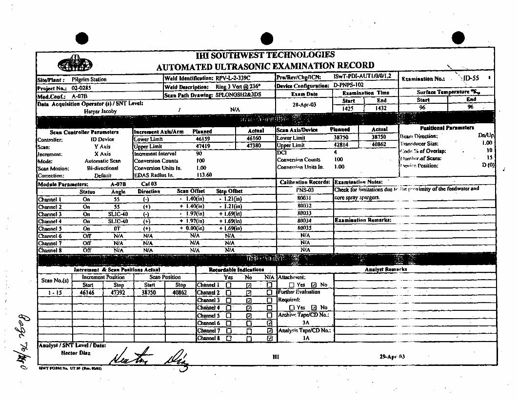
AwarllhýIRE37W
1Ill SOUTHWEST TECHNOLOGIESAUTOMATED ULTRASONIC EXAMINATION RECORD
- .~. .. ~., w..qflflLAIrrIIftlflhIl I -- -srrnx~vII mutt r~: IOW I -rLIr~~., I 5J*C~~ IU/,dA lAanti(h*cdinn- DPV.| .?.I](N-" PP•ReWI •n•IILN: w-DlAUTI10AVI2Efte/Plant: Pilgrim Station eld Identification: RPV-L-2-339C Pro/RevJCh1ICN: Examination No.: -ID-5 I
Project No.: 02-0285 Weld Description: Ring 3 Vert ( 2368 Device Configuration: D-I
Mod.Conf.: A-07B Scan Path Drawing: SPLONGSH2&3DS Exam Date
PNPS-102I
smination Time Surface Temperature I!
Data Acquisition Operator (s) I SNT Level:Haamer Jacoby / N/A
28-Apr-03't End Start - End
I WA11 06 I 96
anned I Actual Scan Axisi/Utvieeican uontrolier rarametersController: ID DeviceScan: Y AxisIncrement: X AxisMode: Automatic ScanScan Motion: Bi-directionalCorrection: Default
Increment AxwAFmLower Limit 46159 1 46160 Lower Limit
.'I ActUal38150.40862 1Upper Limit 47419 47380 Limit
Positional IBteam Direction:1ran.ducer Size:f:odn % of Overlap:r.lunmhcr.Of Scans:,e,;. Position:
rametersDn/Up
1.001015
D (0)
Increment IntervalConversion CountsConversion Units In.
901001.00
DC!Converion CountsConver-;nn Units In.
tOO1.00
1- -Radius InI. 60,.ixmnio f'ots
:Modiuni Parameters: A-07B Cal103 Calibration Kecords: Examinstion Notes.
Status Angle Direction Scan Offset Step Offset
Channel I On 55 (-) - 1.40(in) - 1.21(in)Channel 2 On 55 (0) + 1.40(in) - 1.21(in)
PNS-0380031
Check for limitations due r :ilt r,,ximity of the fecdwater andcore spray spargers. __.........
800324.
Channel 3 On SLIC-40 (-) 1.97(in) + 1.69(inI) 80033_______ 4-.----- 4. - -Channel 4 On SIIC-40 (M) + 1.97(in) + 1.6
Channel 5 On fT (+) + 0.00(in) + 1.6Channel 6 Off N/A N/A N/A N1,Channel 7 Off N/A N/A N/A N1,Channel 8 Off N/A N/A N/A N/,
Increment & Scan Positions Actual Recordab
80034 Examination Remarks:_________80035 A _________
N/A*1 4.
N/Aj!LAl•lJA
adications. Anlalylt laniarks.1 - _____________
Scan No.(s) Increment Position Scan Position Yes No N/A Attachment:Start • Stop Start F-Stop IChannel 1I 171 0 1 ] Yes [0 No
1-15 46146 47392 38750 40862 lChannel 2 [1 n, 0 1I II II~hanne~l 3 _0
Further EvaluationRequired:
D Yes P) NoChannel 4 r- n,4. I IChannel 5 0 El 0[]
4. 4.- 1 1 ______ - -Archiv,, Tape/CD No.:
3AChannel 6 fl n7 [9IChannel 7 E ( 1 Analy.is Tape/CD No.:_Channel 0 p 9 IA
Analyst I SNT Level I Date:tlector Diaz AL !11 29-Ap, 03
isWT FORM ?I&. ITl SO inn. mSll L

A04%w1k
q0zw .IHI SOUTHWEST TECHNOLOGIES
AUTOMATED ULTRASONIC EXAMINATION RECORDSite/Plant: Pilgrim Station Weld Identification: RPV-L-2-339C Pro/Rev/Chb ICN: ISwT.PDi-AtTIJO/0//I2 l -xswinition No. "2-. u . ajti"'N.: .ID-56 4
Project No.: 02-0285 Weld Description.: Rin 3 Vert @ 2360 Device Configuration: D-PNPS-102
Mod.Conf.: A-07A Scan Path Drawing: SPLONGSH2&3DS Exam Date Examination Time Surface Temperature
Data Acquisition Operator (s) / SNT Level: 28-Apr-03 Start - End ' Start End
NHarper Jacoby NA 1324 1420 96 96
Scan Controller Parameters Increment Axis/Arm Planned Actual an is/Device Planned Actual Positional Parameters
Controller: ID Device Lower Limit 46159 46160 Lower .imit 42763 40763 team IDirection: I Ip/Dn
Scan: Y Axis Upper Limit 47419 47420 U .r II imit 46827 44795 iral sIItIcer Size: 1.00
Increment: X Axis Increment Interval 90 DCI 4 Cidi. ".I of Overlap: 10Mode: Automatic Scan Conversion Counts 100 Conversi'n Counts 100 ,imrhrr of Scans: 15
Scan Motion: Bi-directional Conversion Units In. 1.00 Convcrz;,n Units In. 1.00 Pevir-e Position: D (180)
Correction: Default EDAS Radius In. 113.60Module Parameters: A-07A Cal 03 Calibration Records: Examination Notes:
Status Angle Direction Scan Offset Step Offset PNS-03 Check for limitations due to Ifie proximity of the feedwater andChannel'! On 55 (+) + 1.40(in) + 1.21(in) 80031 core spray spargers.Channel 2 On 55 (-) - 1.40(in) + 1.21(in) 80032Channel 3 On SLIC-40 (+) + 1.97(in) - 1.69(in) 80033Channel 4 On SLIC-40 (-) - !.97(in) -. 1.69(in) 80034 Examination Remarks:Channel 5 On OT + 0.00(in) - 1.69(in) 80035 Limited exam due to proximity of the core spray line.Channel 6 Off N/A N/A N/A N/A N/AChannel 7 Off N/A N/A N/A N/A N/AChannel 8 Off N/A N/A N/A N/A N/A
Increment & Scan Positions Actual able Indications Analyst Remarks
Scan No.(s) 'Increment Position Scan Position Yes No N/A Attachment: "0ScanYe No.(),Start Stop Start Stop Channel I 0 9a ( []Yes 9 No
!-15 46159 47318 40763 44840 Channel2 0 9 (' Further Evaluation_Channel3 • E) (2 Required:
_ _ Channel4 0 9 - -Yes 9 NoChannel 5 0 0 0 Archive Tape/Cl) No.:Channel6 (2 0 91 .3A _,
_ _ Channel 7 0 - (] Analysis Tape/CD No.:ChannelS 0 0 2[ IA
Analyst I SNT Level / Date:Hector Diaz
ISWT FORMI NM.L r T So ( . oaOma n
• o4"

0 _ __ 0 _ 0oft). . 1111 SOUTHWEST TECHNOLOGIES
AUTOMATED ULTRASONIC EXAMINATION RECORDSite/Plant: Pilgrim Station Weld Identification: RPV-L-2-339C Pro/RevdChg/lCN: _ SwT.PD[-AUTI/0/0/I,2 " xsminhtlan No.: "Wi-S7 '
Project No.: 02-0285 Weld Description: Ring 3 Vent 2360 Device Configuration: D-PNPS-102 .... _ .
Mod.Conf.: A-07B Scan Path Drawins SPLONGSH2&3DS Exam Date Examination Time Surface Temperature Tw
Data Acquisition Operator (9) /SNT Level: - I Start End Start End28-Apri0
Harper Jacoby N/A 1 1552 1611 96 96
Scan Controller Parameters Increment AxIW/Arm Planned Actual Scan Axis/Device Planned Actual Positional ParametersController: ID Device Lower Limit 46159 46146 Lower Limit 46776 47550 1.3am Direction: Dn/UpScan: Y Axis Upper Limit 47419 47420 Upper .imit 52096 .50402 I'ranrducer Size: 1.00
Increment: X Axis Increment Interval 90 DC! 4 rCode. % of Overlap: . 10Mode: Automatic Scan Conversion Counts 100 Conversion Counts 100 1,lm),er of Scans: 15Scan Motion: Bi-directional Conversion Units In. 1.00 Conversmin Units In. 1.00 f levi' Position: D (0)Correction: Default EDAS Radius In. 113.60Module Parameters: A-07B Cal 03 - Calibration Records: Examination Notes:
Status Angle Direction Scan Offset Step Offset PNS-03 Check for limitations due to- the proximity of the feedwater andChannel I On 55 (-) - 1.40(in) - 1.21(in) 80031 core spray spargers.Channel2 On 55 (N) + 1.40(in) - 1.21 in) 80032Channel 3 On SLIC-40 (-) 1.97(in) + 1.69(in) 80033Channel 4 On SLIC-40 (+) + 1.97(in) + 1.69(in) 80034 Examination Remarks:Channel 5 On OT (+) + 0.00(in) + 1.69(in) 80035 Limited exam due to proximity of core spray sparger.Channel 6 Off N/A N/A N/A N/A N/AChannel 7 Off N/A N/A N/A N/A NIAChannel8 Off N/A N/A N/A N/A N/A
Increment &'Scan Positions Actual Recordable Indicatwoa _________ Analyat RemarksScan No.(s) Increment Position Scan Position Yes No N/A At-tahment: AnalystRemarks_"
Start Stop Start Stop Channel 0 0 0 Yes El No1 - 15 46159 47414 47550 50402 Channel 2 n 0 Q Further Evalation
,Channel 3 0 0 0 Required:_ Channel4 n p 0 0 Yes Q No_Channel 5 0 0 0 Archive Tape/CD No.:_ _Channel 6 0 0 07 3AChannel 7 0 0 E0 Analysis Tape/CD No.: "_ -_"
--- Channel 8 0 0 lAAnalyst SNT Level /Date:._______I
Hector Diaz / - 29-Apr03
!O.i 29-Apr-.313,wT FORM N& Err 5 (Recv. milZ
4
-4

@ 0II SOUTHWEST TECHNOLOGIES
AUTOMATED ULTRASONIC EXAMINATION RECORDSite/Plant: Pilgrim Station Weld Identification: RPV-L-2-339C ProlRev/Chg/ICN: ISwT-PDI-AUTIIO/0I/2 Fxamination No.: ID-58
Project No.: 02-0285 Weld Description: Ring 3 Vert @ 2360 Device Configuration: D-PNPS-101 .
Mod.Conf.: A-07A Sean Path Drawins: SPLONGSH3TOPDS Exam Date Examination Time Surface Temperature o%
Data Acquisition Operator (s) ISNT Level: - -rStrnd Start I End•4~ / 8Ar0 1617 I 1621 96' 96 _
Scan Controller ParametersController: ID DeviceScan: Y AxisIncrement: X AxisMode: Automatic ScanScan Motion: Bi-dircctionalCorrection: Default
Increment ALower Limit
'Arm inned I ACtU2l acon AxisiL•evice4
rlannlel ACUlli46776 5030046159 46160 Lower Limit
Upper Limit 47419 47460 lUpper Limit 51744 1 -51744
Positional Parameterstc.am Direction:
Transducer Size:("ldc % of Overlap:NIumtw.r of Scans:
Ar•.viýr, Position:
Uip/Dn
Increment IntervalConversion CountsConversion Units In.EDAS Radius In.
901001.00113.60
DCIConversion CountsConversi,"n Units In.
4100
1.00
1.00to15
D(ISO)
Module Parameters:Status
A-07A Cal 03Angle Direction
Calibration Records: Examination Notes:Scan Offset Step Offset PNS-03 Check for limitations due (o !1-fepv.ximity of the feedwater and
core spray spargers.Channel I On 55 (+) + 1.40(in) + 1.21(in) 80031
Channel 2 On 55 (-) - 1.40(in) + 1.21(in) 80032 .....Channel 3 On SLIC-40 (+) + 1.97(in) - 1.69(in) 80033Channel 4 On SLIC-40 "() - I.97(in) - 1.69(in) 80034 Examination Remarks:Channel 5 On OTChannel 6 Off N/AChannel 7 Off N/AChannel 8 Off N/A
1+\ + 0.00(in) - 1.69(in)* N/A N/A* N/A NIA
80035WIA
I-
increment at acan roseirons Actuat Keal Indications Analyst KemarksI.-Y
Increment Position-0*
Scan PositionScan No.(s) -- -T 4 .. I-..tNo N/Ar ' n~
Attachment:f"lYes f17NoStart Stop Start Stop Channel I • |
. . .. . . .eI I I1-15 46159 47451 50300 51700 Channel2 n- 11. nI
T 4 4 I-- - -
Channel 3 0 (1] [1Further EvaluationRequireA:
fi"Ies f1-No
I -~
7 1" 4 I - . -,
Channel 4 fI f71 1i11 El Ye B No4~~~-
lChannel S 1l l•'1 F-I-Channe15 Archive Tape/CD No.:.
lChannel 6 "f"- n-I. I I ~ 3A
IChannel 7 1i n- 1"31I 1Ch-nnel 7 Analysis Tape/CD No.:
IAlChnnnel I 1l ni r~CnhnnelS S I~f A.vI,.uiAl
Hector DiazilI 29-Apr-03
r....n. I'U. ~ - ptV. OUSJ|I V O Me rs pI.al

IMI SOUTHWEST TECHNOLOGIESAUTOMATED ULTRASONIC EXAMINATION RECORD __....___
Site/Plant: Pilgrim Station Weld Identification: RPV-L-2-339C " Pro/RevlChga/ICN: ISwT-PDI-AIJTI/0/I,2 EProject No.: 02-0285 Weld Description: Ring 3 Veat @ 2360 Device Configuration: D-PNPS-101 EMod.Conf.: A-07-ID Scan Path Drawine, SPLONGSH2&3DS Exam Date Examination Time Surface Temperature 0Data Acquisition Operator (a) I SNT Level: Start - End Start End
R.A. Riddles II 29-Apr-03 0430 0457 99 99
Scan ControllerParameters Increment Axis/Device Planned Actual Scan Axis/Arm Planned Actual Positional ParanmetersController ID Device. Lower Limit 39650 39657 Lower Limit 46039 36050 Ream Direction: Ccw/CwScan: X Axis Upper Limit 43340 42890 U Limit 47539 47529 Transducer Size: 1.00Increment: Y Axis Increment Interval 90 DCI 4 Code % of Overlap: 10Mode: Automatic Scan Conversion Counts 100 Conversion Counts 100 Number of Scans: 42Scan Motion: Bi-directional Conversion Units In. 1.00 Conversion Units In. 1.00 Device Position: A (0)Correction: Default EDAS Radius In. 113.60Module Parameters: A-07-ID Cal 33 Calibration Records: Examination Notes:
Status Angle Direction Scan Offset Step Offset PNS-33 Check for limitations due to the proximity of the feedwater andChannel ! On 55 (- + 7.00(in) + 0.00(in) 80331 core spray spargers.Channel 2 On 55 (+) - 7.00(in) ÷ 0.00(in) 80332Channel 3 On SLIC-40 (-) + 4.40(in) + 1.00(n) 80333Channel 4 On SLIC-40 (+) - 4.40(in) - 1.00(in) 80334 Examination Remarks:Channel 5 On OT (+) + 4.40(in) - 1.00 in) 80335 Limited exam due to proximity of the core spray sparger.Channel 6 On OT (N) - 4.40(in) + I.00(in) 80336Channel 7 Off N/A N/A N/A N/A N/AChannel 8 Off N/A N/A N/A N/A N/A
SIncrement & Scan Positions Actual* Recordable Indications Analyst RemarksScan No.(s) Increment Position- Scan Position Yes No N/A Attachment:Start Stop Start Stop Channel 1 0 ., 0 Yes [9 No
.1-37 39650 42867 46050 47630 Channel 2 - [• Q Further Evaluation._ _Channel 3 0 - 0 Required:
•___Channel4 0]0 r Yes 0 NoChannel5 [0 3 0 Archive Tape/CD.No.: .'--,
______Channel6 0 0 0 4AChannel 7 0 E0 Analysis TapCD No.Channel 8 [0 0 A_1 1A
Analyst SNT Level I Date:Hector Diaz A
ISM FORM 1l
.29-Apt-03
I
$6 1 -

0Jul1 SOUTHWEST TECHNOLOGIES
AUTOMATED ULTRASONIC EXAMINATION RECORDSite/Plant: Pilgrim Station Weld Identification: RPV-L-2-339C Pro/Rev/Chg/ICN: ISwT-PDI-AUTI/0/0/I,2 Examlaaloa No.: ".ID-60 *
Project No.: 02-0285 Weld Description: Ring 3 Vat @ 2360 Device Confliuration: D-PNPS-101 E ",
Mod.Conf.: A-07-IC Scan Path Drawing. SPLONGSII2&.3DS Exam Date Examination Time Suirface Temperature %Data Acquisition Operator (s) I SNT Level: Start End Start End
R.A. Riddles I 9Ar00512 0522 99 99
Scan Controller Parameters Increment Axi/Device Planned Actual Sean Axis/Arm Planned Actual Positional ParametersController: .D Device Lower Limit 43213 42943 Lower Limit .46039 46030 Beam Direction: Cw/CcwScan: X Axis Upper Limit 46903 45020 Upper Limit 47539 47515 Transducer Size: 1.00Increment: Y Axis Increment Interval 90 DCI 4 Code % of Overlap: . 10Mode: Automatic Scan Conversion Counts 100 Conversion Counts 100 Number.Of Scans: . 42Scan Motion: Bi-directional Conversion Units In. 1.00 Conversion Units In. 1.00 Device Position: A (180)
Correction: Default EDAS Radius In. 113.60 ! .
Module Parameters: A-0T-IC Cal 33 Calibration Records: Examination Notes:Status Angle Direction Scan Offset Step Offset PNS-33 Check for limitations due In the proximity of the feedwater and
Channel I On 55 +) - 7.00(in) + 0.00(in) 80331 core spray spargers.Channel 2 On 55 (-) + 7.00(in) + 0.I0(in) 80332 ! _
Channel 3 On SLIC-40 + - 4.40(m) - 1.00in) 80333 ' 'Channel 4 On SLIC-40 (-) + 4.40(in) + 1.00(in) 80334 Examination Remarks:Channel 5 On OT (+) - 4.40(in) + 1.00(in) 80335 Limited exam due to proximity of the orSe sparg.•--Channel 6 On OT (+) + 4.40(in) - 1.0(in) 80336Channel 7 Off N/A N/A N/A N/A N/A
Channel . Off N/A N/A -NA N/A " NA
Increment & Scan Positions Actual Recordable Indications'! Analyst RemarksScan No.(s) Increment Position Scan Position Yes .No N/A Attachment: _._"__Stamt Slop Start Sto Channel I 0 0 0 0[ Yes E No Channel 6 inactive.
1-24 42943 45015, 46039 47539 tahannel 2[ ] lp " Further Evaluation" Channel 3 [3 [a C0 Required:
, _Channel4 0 p ' C1 QYes 0 No
Channel 5 .0 0 Archive Tape/CD No.: _
,,,_ _Channel 6 0 [ a 4A _
Channel 7 0 9 Analysis Tape/CD No.:
______ ChannelS9 0 p 9I
Analyst SNT Level Date: IA
Hector Diazwo/5 I 29-Apr-03
1SW'II•_pM Me. in" so (any. sm)•__.
A

0IM' SOUTHWEST, TECHNOLOGIES
AUTOMATED ULTRASONIC EXAMINATION RECORD _,_._.
Site/Plant: Pilgrim Station Weld Identification: RPV-L-2-339C Pro•Rev/Chg/ICN: ISwT-PDI-AUTI/O/0/I,2 ExaminitionaNo.: '.JD-61
Project No.: 02-0285 Weld Description: Rin 3 Vert 236* Device Configuration: D-PNPS-1OI
Mod.Conf.: A-07-ID Scan Path Drawing: SPLONGSH2&3DS Exam Date Examination Time Surface Temperature
Data Acquisition OPerator (s) I SNT Level: 29-Apr-03 Start . End Start End2046 2109 82 82
a Scan Axi/Device Planned Actual Positiomal Parameters
Controller " lDDcvice- Lower Limit 46776 47496' Lower Limit 46039 46063 Beam Direction: Ccw/CwScan: XAxis Upper Limit 51186 "5186 UpMeLimit 47539 47523 Transducer Size: 1.00Increment: Y Axis Increment Interval 90 DCI 4 Code % of Overlap: * 10Mode: Automatic Scan Conversion Counts 100 Conversion Counts 100 Number of Scans: 50Scan Motion: Bi-directional Conversion Units In. 1.00 Conversion Units In. 1.00 Device Position: A (0)Correction: Default EDAS Radius In. 113.60Module Parameters: A-07-ID Cal 33 Calibration Records: Examination Notes:
Status Anle Direction Scan Offset Step Offset PNS-33 Check for limitations due to the proximity of the feedwatcr andChannel I On 55 (.) + 7.00(in) + 0.00(in) 80331 core spray spargers.Channel 2 On 55 (+) - 7.00(in) + 0.00(in) 80332Channel 3 On SLIC-40 (-) + 4.40(in) + 1.00(in) 80333 ""Channel 4 On SLIC-40 (+) - 4.40(in) - 1.00(in) 80334 Examination Remarks:Channel 5 ýOn OT (+) + 4.40(in) - 1.00 in) 80335 Limited exam due to the proximity of the core spray sparger.Channel 6 On OT (+) - 4.40(in) + 1.00 in) 80336Channel 7 Off N/A N/A N/A N/A N/AChannel 8 Off N/A N/A N/A N/A N/A
Increment' & Scan Positions Actual Recordable Indications AnalRst RemarksScan No.(s) Increment Position Scan Position Yes No .N/A Auachment:
Start- Stop Start Stop Channel I n 0 - lYes 91 No Channel 6 inactive.9-50 47476 51154 46039 47539 Channc12 Q . 0 Furthe Evaluation
Channel 3 0 ' 0 Required:-Channel4 0 9 0 QYes .B No
.. ____ Channel 5 0 0 0 Archive Tap"/CD No.:'.-Channel 6 E 0 a . 4AChannel 7 n 0 0 Analysis Tape/CD No.:
Analyst I SNT Level I Date:"
Hector Di" . "I30-Apr-03
I- F--•RM r•- . UT N iacv. m•m)

0
1-IH SOUTHWEST TECHNOLOGIESAUTOMATED ULTRASONIC EXAMINATION RECORD ._
Site/Plant.: Pilgrim Station Weld Identification: RPV-L-2-339C Pro/Rev/Chg/ICN: ISwT.PDI-AUTi/0/0/I,2 Examination No.: "..[D-62Project No.: 02-0285 Weld Deseription: Ring 3 Vert @ 236* Device Configuration: D-PNPS-101 "
Mod.Conf.: A-07-IC Scan Path Drawing: SPLONGSH2&3DS Exam Date Examination Time Surface TemperatureliNData Acquisition Operator (s) / SNT Level: 29-Apt-03 Start End Start End
R.A. Riddles !! 0608 0615
SHan Controller Parameters Increment Axislevice Planned Actual Scan Axis/Arm Planned Actual Positional ParametersController:. ID Device Lower Limit 46776 49783 Lower Limit 46039 46039 Beam Direction: Ccw/ICvScan: X Axis Upper Limit 51186 51289 Upper Limit 47539 47539 Transducer'Size: 1.00Increment: Y Axis Increment Interval 90 DCI 4 Code % of Overlap: , 10Mode: Manual Scan Conversion Counts 100 Conversion Counts 100 Number of Scans: 50Scan Motion: Bi-directional Conversion Uniits In. 1.00 Conversion Units In. 1.00 Device Position: A (180)Correction: Default EDAS Radius In. 113.60Module Parameters: A-07-1C Co133 •Calibration Records: Examination Notes:
Status Angle Direction Scan Offset Step Offset PNS-33 Check for limitations due to tie proximity of the feedwater andChannel 1 On 55 (+) - 7.00(in) + 0.00(in) 80331 core spray spargers.Channel 2 On 55 (-) + 7.00(in) + 0.00(in) 80332Channel 3 On SLIC-40 N+) - 4.40(in) - 1.00(in) 80333Channel 4 On SLIC-40 (-) + 4.40(in) + 1.00(in) 80334 Examination Remarks:Channel S On OT (+) 4.40(in) + 1.00(in) 80335 Limited exam due to proximity of the core spray sparger..Channel 6 On OT (+) + 4.40(in) - 1.00(in) 80336Channel 7 Off N/A N/A NIA N/A* N/A____ ________________
Channel 8 Off N/A N/A N/A N/A - N/A
Increment & Scan PositlonsActual Recordable Indications __Analyst RemarksScan No.(s) IncrementPosition Scan Position Yes No N/A Attachment:
Start Stop Start Stop Channel 1 G ) 0 0 Yes 91 No Channel 6 inactive.34-52 49718 51287 46039 47539 Channel 2 0 , , Further Evaluation"
Channel 3 0 .. 0 Required:Channel4 [3 E] 0 0QYes [D NoChannel 5 0 9 0 Archive Tape/CD No.:
Channel 6 [3 0 a 4AChannel 7 0 0 Analysis Tape/CD No.:
_Channelg 0 p E IAAnalyst /SNT LIul/ Date:
Rector DiazIli 29-Apr-03
IUWT FORM InQ UTN ila, 5l5 h I

ISwT EXAMINATION SUMMARY RECORDa
Project No.: 02-0285 PILGRIM NUCLEAR POWER STATION Summary Sheet No.: 001300
r • ,
SITfE:SYSTEM:LINE/SUBASSEMBLY:IDENTIFICATION:
PILGRIM STATIONREACTOR PRESSURE VESSELUPPER SHELLTO-FLANGERPVýC-4-339
NDEMethod Pmc/Rev/haACN
AUT I•WT-PDI-AUTI/0/o1.2AUT l8wT-PDI-AUT1i0/WW,2
AUT 18wT-PDI-AUTlAI/I1,2AUT 18wT-.PDMAUTIW110.2AUT 18WT-POI-AUT1/00I,2AUJT lSwT-PDI-AUTfJO/1,2.-AUT Iw'T-POi-AUTI/oM1.2AUT imwTr.PoWU12MVo.2,3V S
NDE
AUTOAUT45AUT55
AUTSUC40AUTIST
AUTSUC40TAUTO
AU.TSUC35
CA.eNationShed No.
8004180042
803180332
80333.80334
N ODaft R T. -Resoution
Shed No. I H RecordCNF
Number Rema
exon 83M-n83
ow m84
cam 84
-m 8A.RLA
X.
X.
X
,X.¶
:X-x
NIA
NIAN/A
N/A
NIANIA
..:02:01
,NIANIAN/A
NIANIANIA21
Exwrkmtlon no's 83- 64.AUTO for §**rms meauement only.bniadon detected with AUTSLIC40 weaied with AUTSUC35 and found to be db•hl
In a with ihe 1989 Edition of ASME
Section X) Code.
NOTES: 1. Weld RPV-C-4-33 u amined from the Inside sufaoe ugN AIRIS-21 and EDAS4I asm on equem t2. The wexamnon wa Wned due to pmrmlty of the maln tem fraonze, noads pktM gude m'h at0 &nd 180-degrees, and the conflaumtion
of the veed flngs. 81% emAnton vwae waseadcheved.3. One (1) moeptabe flew k ion was m ordedndabd.4. Detection emiopatchem kIduded #83A 83= (6 p anhe) mdi 84A- 84AB (53 patlche).6. Skting examinaion patchee Included 634RLA (I patch).
"".UT CAUBRATION BLOCK(s)'"'
"D-70187-2/D70389- 1
00
Preparedby b1A ~MS aAN.\ Date: 3 July 2003. Page 1 of 1Steven J. Todd \Proiect Engineer
Sum 8ety Shot No.: 001300
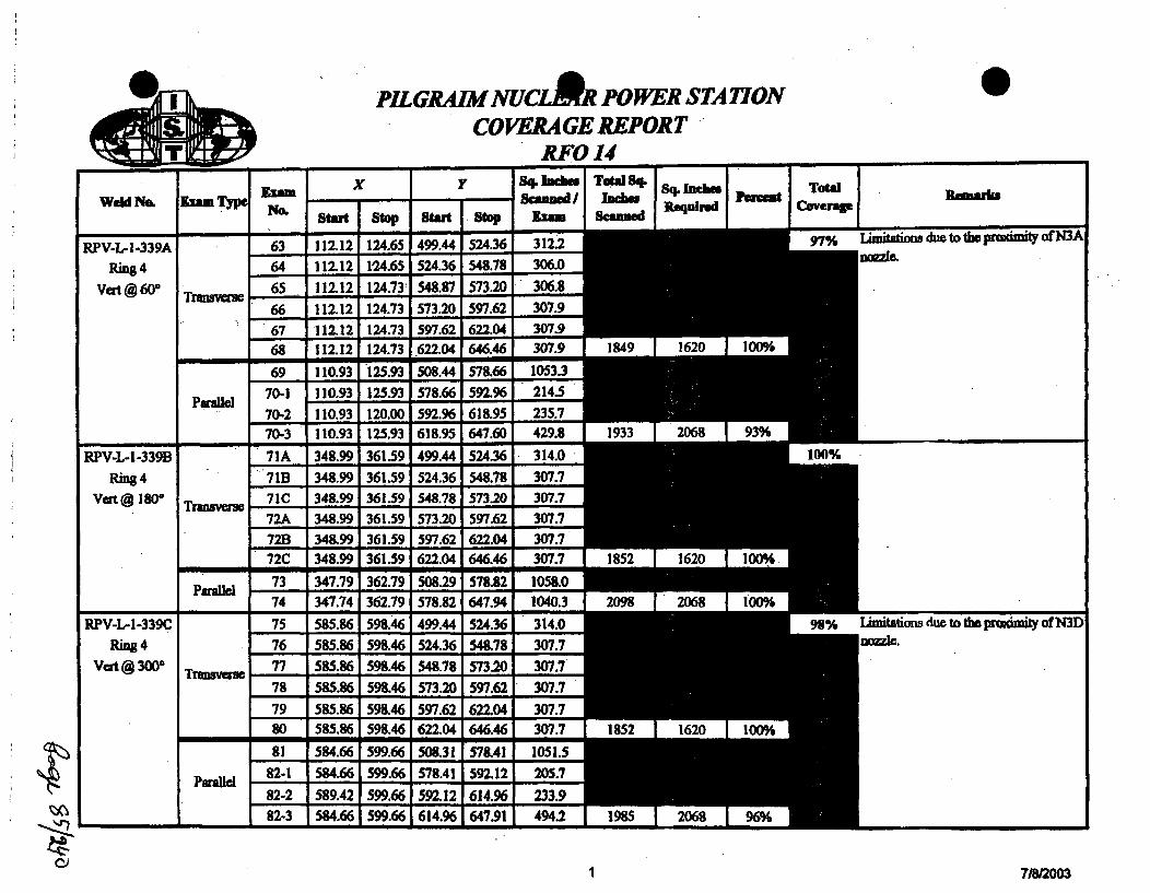
@1 PMLGRAIM NUCAR POWER STA IONCOVERAGE REPORT
RFO 14I I
I I T
WeldfibI EZauTypI x I y Sq. Imcbms Total Sq. 84- Inclow
I
wv.,m ITotal
m
RPV-L-i-339ARing4
Vat @ 60' Transvaer
Parallel
RPV-L-I-339B
Ring 4vat@ go- Transverse
Parallel
RPV-L-I-339C
Ring 4Vat @ 3000 Transverse
Parallel
: No. start Istop •Start - stop xma Scanned lenrdCvrg
63 112.12 124.65 499.44 524.36, 312.2 97%
64 112.12 1-24.65 524.36 548.78 306.0
65 112.12 124.73 548.87 573.20 306.8- - - -8
66 112.12 124.73 573.20 597.62 307.9
67 112.12i 124.73 597.62 622.04 307.9
68 112.12 124.73 622.04 646.46 307.9 1849 1620 100%
69 110.93 125.93 508.44 578.66 1053.3
70-1 110.93 125.93 578.66 592.96 214.5
70-2 110.93 120.00 592.96 618.95 235.7
70-3 110.93 125.93 618.95 647.60 429.8 1933 2068 93%
71A 348.99 361.59 499.44 524.36 314.0 100%
71B 348.99 361.59 524.36 54.78 307.771C 348.99 361.59 154.78 573.20 307.772A 348.99 361.59 573.20 597.621 307.772B 348.99 361.59 597.62 622.04 307.772C 348.99 361.59 622.04 646.46 307.7 1 1852 1620 100%
73 347.79 362.79 508.29 578.82 1058.0
74 347.74 362.79 578.82 647.94 1040.3 2098 2068 100%
75 585.86 598.46 499.44 524.36 314.0 98%
76 585.86 598.46 524.36 548.78 307.777 585.86 598.46 548.78 573.20 307.7
78 585.86 598.46 573.20 597.62 307.7
79 585.86 598.461597.62 622.04 307.7
80 585.86 598.46 622.04 646.46 307.7 1852 1620 100%
81 584.66 599.66 50.31 57&41 1051.582-1 584.66 599.66 578.41 592.12 205.7
82-2 589.42 599.66 592.12 614.96 233.9f 82-3 584.66 599.66 614.96 647.91 494.2 1985 2068 96%
stions due to the prxmity of N3A
Rema'ls
ations due to the puimily of N3D
cJ 1 7/812003

.. * I
AlikrhPILGRAM NUCLA PO WER STATION 0
CO VERA GE REPORTRFO 14
Weld No.
RPV-L-2-339ARing3
Vert@356-
ilyp
Traaveam
Parallel
Exami xf
r 4 .inch=~ Total Sq. B+ lDnCiaiL Totlid
RPV-L-2-339BRsg3
Vert ,@ 116° Tranavae
Paralel
RPV-L-2-339CRing 3 Trmavem
Vert @ 2360
P"Cle!
NO - -mcudI Icm Ruhdrr= Cvnn!No ut Stop Stut Sftp I zm Sumnuw
39 699.50 712.10 387.50 428.061 511.1
40-1 699.50 703.39 1428.06 461.151 128.740-2 703.39 712.10 461.15 468.27 62.0
41 699.50 712.10 476.60 504.00 345.2
42 699.50 712.10 504.00 517.00 163.89 1 1211 1481 82%
43 698.30 713.30 396.50 433.30 552.0
44 698.30 713.30 433.30 451.08 266.7
45 698.30 713.30 477.38 506.20 432.3
46 698.30 713.30 506.20 512.81 99.1 1350 1701 79%
47-1 223.76 231.41 387.50 424.02 279.4 75%
47-2 231.41 234.81 394.34 424.02 100.9
47-3 234.81 236.28 396.74 424.02 40.148 223.68 236.28 424.02 448.15 304.049 223.68 235.49 475.50 483.50 94.5
50 223.68 236.2• 503.00 520.96 226.3 10 !o45 1481 71%
51 222.48 237.48 396.66 408.07 171.2
52 222.48 237.48 408.07 450.17 631.5
53 222.48 237.48 474.68 500.16 382.254 222.48 237.48 500.16 511.861 175.5 1360 1701 8%
55 461.59 473.92 387.50 408.62 260.456 461.59 473.18 408.62 448.40 461.1
57 461.59 474.19 475.50 504.02 359.458 461.59 474.19 504.02 517.00 163.5 1244 1481 84%
59 460.50 476.30 396.50 428.67 508.3
60 460.39 47.5.39 429.43 450.15 310.8
61 460.39 475.39 474.76 511.54 551.762 460.39 475.39 511.54 512.87 19.9 1391 1701 8%
11
Limitatios due to the pmxiit of thefwdwaw-rand core spray o'gc's
Remarks
Limitations due t the proximity Of thef)dwater and cmspraey ld rC3 39dID toape at vite weld C-3-339A.
iitations due to the prkt of theaedwow and om spry spoxrgu
2
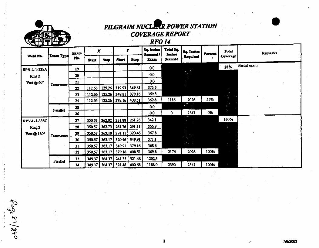
PIL GRAIMNUCfR POWER STATIONCOVERAGEREPORT
RFO 14
0
I-
I x Ir . Sq. Incm ToW Sq. Sq. Inchm I Total Renubm-. ý I~e 2 ý R lu hrd Cow " Co er WgNo. Start Stop Start Stop Rm Scned
19 0 .0 284/6
2000-- - -o.-
22 112.66 125.26 319.93 349.81 376.5
23 112.66 125.26 349.81 379.16 369.8
24 112.66 125.26 379.16 408.51 369.8 1116 2026 55%
250.26 0.0 0 2347 MA
27 350.57 362.02 231.88 261.76 342.1 1
28 350.57 362.73 261.76 291.11 356.9
29 350.57 363.10 291.11 320.46 367.8
30 350.57 363.17 320.46 349.91 371.1
31 350.57 363.17 349.91 379.16 3686
-32 350.57 363.17 379.16 408.51 369.8 2176 2026 100%
33 349.37 364.37 241.33 321.48 1202.3
34 349.37 1364.37 321.48 400.68 1188.0 2390 2347 100%
?Artial cxarrL
3 31/M2003

PiLGRAimNULARPOWER STATiONCO VERA GE REPORT
RFO 14
Transv~em
Pffuaie
Exam y Sq. Inchmesad Total Sq. Sq. Inces• ]e~ TotalNo. Stat' Sto Statm Stop 1x= Seamed Ruv oer
9o.0 78%10-1 384.71 395.52 136.21 'I150.41 153.5
10-2 395.52 1397.28 137.00 1150.41 23.6
11 384.51 1397.12, 150.41 1176.16 324.7
12 384.51 397.12 176.16i201.91 324.7
13 384.51 I397.12 201.91 I227.661 324.7
14 384.51 I396.94 227.66 253.41 320.1 1471 1620 91%
15 383.321 398 .32 136.31 I175.69 590.7.
16-1 38.2383 175.69 1191.55 237.9
•16-2 383.32• 390.5 --.--191.55 I204.10 90.1
16-3 383.32, 390.90 204.101 211.75 5.164 383.32 38. 217 1.4 39
16-5 383.32 3,95.60 218.04! 238.86 255.16-6 383.32, 398.32 238.86,1 244.27 81.1 1352 2068 65%
limitatonsdueWtedity.Of 111C
Remark
I il •
- I
4
4

PILGRAIMNUCLA POWER STATIONCOVERAGE REPORT
RFO 14
0
RFO 14x I y Inebes; Total 4 SQ. Inches - j1-- . I J I " I
Total
- _ __-' o. Start S top Start Stop Exame Scanned
P NO.imu Scn e Inheieq ied pecnt Cvia
84A 1.00 14.40 640.14 652.74 168.8 81%
84B 14.40 27.80 640.14 652.74 168.8
84C 27.80 40.80 640.14 652.74 163.8
84D 40.80 .54.60 640.14 652.74 173.9
M4E 54.60 68.00 640.14 652.74 168.8
84F 68.00 81.40 640.14 652.74 168.8
84G 81.40 94.80 640.14 652.74 168.8
84H 94.80 108.20 640.14 652.74 168.8
84I 108.20 121.60 640.14 652.74 168.8
84J 0.0
84K 0.0
84L 0.0
84M 160.90 175.20 640.14 652.74 180.2
84N 174.20 188.60 640.14 652.74 181.4
840 188.60 202.00 640.14 652.74 168.8
84P 202.00 215.40 640.14 652.74 168.884Q 10.0
MIR 227.80 242.20 640.14 652.74 181.4
84S 242.20 255.60 640.14 652.74 168.8
84T 255.60 269.00 640.14 652.74 168.8
M4U 269.00 282.40 640.14 652.74 168.8
84V 282.40 295.80 640.14 652.74 168.8
84W 295.80 309.20 640.14 652.74 168.8
84X 309.20 322.60 640.14 652.74 168.8
Remark
Limitalou due to thl N3 novIcs,E'lug, therlange ccafiguraion, and thegW&d rods-
Transverse
4V~9
I 4
I ~
6 7/M/2003

PIL GRAIM NUCLOR POWER STATIONCO VERA GE REPORT
RFO 14
Qi
TrfMnvus
Exam x y Sq. Inches TOWl 4 Sq Inces TOWa
N• Start S top Start Stop giam ume
84Y 322.60 1336.00 640.14PI627 168.8
84Z 336.00 349.40 640.14 652.74 168.8
84AA 348.40 362.80 640.14 652.74 181.4
84BB 362.80 1376.00 640.14 652.74 166.3
84CC 376.00 389.60 640.14 652.74 171.484DD 389.60 1403.00 640.14 1652.74 168.8
84EE 403.00 416.40 640.14 652.74 163.8
84FF 416.40 429.50 640.14 652.74 165.1
8400 429.50 1442.92 640.14 652.74 169.184.H-. 442.92 I456.60 640.14 1652.74 172.4
8411 456.60 470.00 640.14 652.74 168.8
84JJ 470.00 483.20 640.14 652.74 166.3SOICK 483.20 1496.20 1640.14 1652.741 163.8
841L 0.0
84MM 0.0-84NN 0.0
8400 536.00 1550.40 640.14 1657.74. 181.4
84PP 550.40 1563.801 640.14 1652.74 16&8.
841titR 0.0
848._.3 589.60 603.551 640.14 I652.74 1175.8
84TT 603.55 617.00! 640.14 i652.74 169.5
84UU 617.00 1630.001 640.14 1652.74 163.8
84VV 630.00 1644.20] 640.14 I652.74 17&.9
PWc rods.;
Remark
a
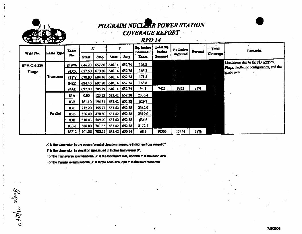
01
.09 ftmrPIL GRAIM NUCLBR POWER STATION
COVERA GE REPORTRFO 14
_______________ - - U - Y
Weld No,
RPV-C-4-339
Fl1ange
Kisan Typ
TrELsvau
I -- x 'I Sq. lacbe Total Sq- - S c a n ne ~ d / l a i e s " e u a [e c vNo.raN o. Start So Start stop " Exa Seamued ln.oerg
84WW 644.20 657.60 640.14 652.74 168.884XX 657.60 670.80 640.14 652.74 166.3
84YY 670.80 684.40 640.14 652.74 171.4
84ZZ 684.40 697.80 640.14 652.74 168.8
84AB 697.80 705.29 640.14 652.74 94.4 7421 8953 83%
83A 0.00 123.23 633.42 652.38 2336.4
83B 161.10 194.31 633.42 652.38 629.7
83C 232.20 355.77 633.42 652.38 2342.9
83D 356.49 478.80 633.42 652.38 2319.0
83E 516.43 549.90 633.42 652.38 634.6
83F-! 586.80 701.36 633.42 652.38 2172.1
83F-2 701.36 705.29 633.42 650.94 68.9 10503 13444 78%- -- -
l.
Remkrk
imihtWans duc to the N3 Ewdles,
guide rods.- ..
Parallel
-I-
X b the dimension In the c•rcumferentil direction mesemure In Inches from vessel 0(.
Y is the dimension In elsevion meemued In Inches from veald Cr.
For the Transierse emmbunaons, X is the Incremnnt a*m and the Y b the scan ads.
For the Prld exasmlnatdons, X Is In the scan a* and Y is the Increment axs.
4-1~
C)~7 7i8/2003

RPv-L- l-336A 01F .-IV -1-%.M PVA-1.--339C
stIfr/2aHLW 233"/467.,N" 3WI 705.Wi
W-LM-2-339 IPV-L-2 3*
* 00.,, "i°6-
to'
W -I-W1• ~• IW1-.5. - 3W-/504.7
WY-L-1-3IM MWA-1332---33ft
Partial--S 0
To b,- =(
To hi, onahS WFOIS-
oTo be .ntnl d
'0- 1 0%O)
/• I" 5-fIII•-I.-3O.Im, '
anRFIS-•, lt m-qOI-- --.-
Pilgrim RPV
OD Vessel Rollout (Umitoions)
May 2003
Limit RPV.dwg

I GE ENERGY, NUCLEAREXAMINATION SUMMARY SHEET
Report P40.:
PIL-R1S-06-O2e
(WI Site: Pilgrim Nuclear Power Station Component ID: RPV-N7A-NV
Outage: RF-015 NOZZLE TO VESSEL
system M ASME Cat.:. -D2 ASME Item NM Aug Req
Exams Data Sheet I Cal Sheet Procedure Calibration Block I Examination jCerl Level; DatePerformed Personnre
Shear UT-029 N/A TP04-02. CG E-UT -311'. J. Kent if 4/22/2005450 Sha T09 PIL-58 .Kn 1220
Monogmery _,,
600 Shear UT-028 N/A TP04-029 (GE-UT-311) 1P-SR J. Kent I 4/22t2005600 Long. UT-003 N/A TP04-08L-SB j Brad Ournmer III
600 Long. UT-004 N/A TPO4-018 (GE-UT-300) CAL-iiW2-017 Brad Dummer 111 4/22/2005
Examination Results:
Ultrasonic examination results were acceptable to the requirements of ASME B&PV Code Section XI, 1969 Edition no Addenda, andSection Xl, 1995 Edition with the 1996 Addenda as modified by the PDI program description and the Federal Register, Part II, NuclearRegulatory Commission, 10 CFR Part 50 for Category B-D Reactor Pressure Vessel (RPV) Assembly Welds.
Manual scans form the outside surface were performed in accordance with procedure TP04-018 Rev. 0 (GE-UT-300 V8) and TP04-029Rev. 0 (GE-UT-311 V10).
No Indications were recorded.
Scanning was restricted due to nozzle configuration.
Manual coverage = 56.7%.t
Examination results were conpaed to data report 95-E-437,439,441 frm 1995 outage wi 0 No Change
These examinations were performed under Work Order N/A C] Change
This Summrry and the following data sheets have been revewed and• by the following personnel: IMP
ANII ,, 4 O Riew:_e PagDose: I Mr.
Prepared By. Level: Date: ___________
ANII Review- ae Page 1 otf
0
60 L'cpA~o

_ 7 Ultrasonic Calibration and Examination Recordt@GE ENERGYP NUCLEAR Rpomb e nts
Site/Unit. Pilgrim Nuclear Power Station/i1 Data Report Number FILMB~ ULiearity Sheet: "MOutage: Rf/lE
Procedure: TP04-018 (GE-UT-300)
Data Sheet Number-
Rev.: R DRR: NO
Calibration Block: PIL-5 Search Unit Data
Material..Initial Cal: 0946'
Cal Check: M/ACal Check: N(A
Final,,Cal: h 4
Thermometer
Size Thicknese
Exam Star,
Exam End
Manufacturer:22BSraNmr
Serial Number: Size / Shape:
1190 Incident Point Nominal Angie: Medsured Angle:
Couptant:
Initial Cal Temp.
DAC Construction
Batch
Final Cal Temp:
3.0 2scFrequency Model: Mode:
Search Unit Cable
PIC&iI 1Z ~ 9Cable Type: Length: Connectors:
Instrument Settings
Reflector Hole" Gain Max W" Sweep ScreenDepth {@X Amp Dim. _ Div.
N/A M ix NMA NA MA YAN/A MA IX _ A WA MA
WNJA. MA N6 6 'MA &A N/A
ID A/ 1X 805 M LC LE MN/A WIA iX MA MA NVA MA
DAC 1X= 62 dB
Sweep 0-10 .Q Det
Note YA dB difference between 3/8 and 5/8 Vee
pEmn trws I EoAc/ 4Maufacturer(Model:
031406
Serial Number
0N11 Ft1.0 FitNarrowban itrDelay/Zero:
0,234 inocsetVelocity.
AMrhRep Rate: Rectification: Range: Pulser.
.400Qoi 1 9.03 paDamping: Reject: Frequency. Mode:
DAC- TVG: CSO DGS:Exam Data for Weld: RpV-NTA-NV
Configuration:Do
Exam Surface: Component Temperature
. Calibration Verification
Field Simulator Block S/N: N(A
Weld Examination Exam Scan Recordable Exam
Area: Access dB Indications Angle
TD 2 PMi
Reflector MA NA NAAmplitude M N NMGain (dB) N/A N/A IW.
Sweep (SID) NVA NYA I N/M
Acceptable Lnearity performed:
Comments: Ca&Wxm Date is the date of examination. See coverage sheet for limitations.Exams pertomrd to maintain a 10% - 20% FSH clad rolL"IniWal cal4.- 4Q2s" Finaldta& 4P245Numerous spot kidicationm seen but noa recordable per procedure.
A Brad Numme /l0 2_- "
Initials: Examiner Level Cal/Exam Date: Utili eviewed B: Date:
InitialNExaqi•".,V Level ANII Reviewed By. Date:
GE ReviewedBy. Level: Date: Page Z-of a

Ultrasonic Calibration and Examination RecordGE ENERGY. NUCLEAR RPV Components
f1
AD Site/Unit Pilarim Nuclear Power Stationl/ Data Report Number: PI-R5I-0- Linearity Sheet LM
Outage: R Data Sheet Number: -
Procedure: TPO4-O18 (GE-UT-3.00i Rev.: R0 DRR: MA
Calibration Block: CAL-IW.2-011 Search Unit Data
MaterialInitial Cal: 20&Cal Check: hVA
Cal Check: NIA
Final Cal: 14W
Thermometer
NIASize Thickness
Exam Star.
Exam End
~SIMAManufacture,:
22BC-0200•Serial Number: Size / Shape:
199.Incident Point Nominal Angle: Measured Angle:
unrage NCouplant:
Initial Cal Temp.
DAC Construction
o2wBatch
Final Cal Temp:
Frequency: Model: Mode:
Search Unit Cable
Cable Type: Length: Connectors:
Instrument Settinas
Reflector Hole Gain Max W" Sweep Screen
Depth 0 IX Amp Dim. ! Div.
1/4 I" lx 80 1s0" .58" 2s1
N/A WA IX WA W/A MAJNAN/A N/A 1XINA N/A MAiLA
N/A IMA lx WA .AjNA IMAN/A MA Ix, NA NMA NA s fAi
PenarnetrfclEnch4Mautacturer/Model:
DelayfZero: Velocity~
031400
Serial Number:
0.b - 3.0 MHFitNarrowbend Filter:
I.
0
Rep Rate: Rectification: Range:DAC 1X= 58 rl,
Sweep 0-10 2.0Q •ent,
Note &A dB difference between 3/8 and 5/8 Vee
D4pWng A &Damping: Reject Frequency.
Pulser
Mode:
DGS:DAC: TVG: CSC:Exam Data for Weld: RPV-NA-
Configuration:nflr
Calibration Verification
Reid Simulator Block S/N: MIAExam Surface: Cor nponent TemperatureWeld Examination Exam Scan Recordable Exam
Area: Access dB Indications Angle
Z 22. 22E
Reflector M/ M/ /AV
Amplitude LIZA 1A N/AGain (dB) NIVA N/A M/A
Sweep (SD) N/A WA " N/A
Acceptable Linearity performed:
Comments: Cal/Exam Date Is the da/ of examinatiom See coverage sheet for limitations.Calibration for near surface examindmi." lnitial cal dat&: 41221" Fi7nsl deft.:. 4123M0Numerous spot iodications seen but not recordable per procedure.
Initials: E Inn Level ANII Reviewed By. Date:
GE Reviewed B. Level: Date: Page3 ofy
4 I 57/t

K I Ultrasonic Calibration and Examination Record* GE ENERGY. NUCLEAR . Inner Radius Examinations
1@_•.J_
Site/Unit: PilGrim Nuclear Power Station/iOutage: RF-o.
Procedure: TP04-029 (GE-UT-31 1)
Data Report Number:. LinearitySheet: LMData Sheet Number.
Rev: RO (V1O) DRR: WA
Calibration Data for Block: PIL-56 Search Unit Dat
MaterialInitial Cal: I=0uCal Check: NA
Cal Check: NA
Final Cal: - o-
Size Thicknes,
Exam Start
Exam End
JAM14.45
BatchCouplant:
KSA 01wa * 0.5'x IGCt!ectLManufacturer: Serial Nr.: Size/Shape:
Incident Point: Nominal Angle: Measured Angle:
A 113-M o Shear
Frequency: Model: Mode:
Search Unit Cable
i.iG,1 .1ZCable Type: Length: Connectors:
Instrument Settinas
Thermometer Initial Cal Temp. Final Cal Temp:
Panametrics / EnAXh4Maufacturer/Model:
DAC1X 41@ d
•SweepO-10 20 Metal path
Zero:
AMnRep Rate:4• bma
Damping:
DAC:
0.12& in imjaVelocity.
Rectification: Rangi
Reject Frequenr
035Z111Serial No.:
0.6 . 3.0 M&z
Narrowband Filter:
1: Pulser/Energy
Mode:
DGS:
Acceptable Linearity performed:
Exam Data for Component: RPV-N7A-NVTVG: CSC
Configuration:
Component Temp.Exam Surface:
Examination Exam RotationArea Angle Angle
WedgeS/N
Scan RecordabledB Indicationa
Field Simulator Block SiN: NA
.41 Reflector I NA IWAI WA I.a ±M Ampllitude F /MA TWA I AVA
4Gain (d) A A M NA_ Sweep (SD) WA N1A A
Commente: CallExam Date Is the date ol initial calibration. See coverage sheet for limilations.
Exams perornmed to maintain a 5% FSH ID rolLScanned CW and CCW.Calibration sweep Is 20 metal pt examination range setUng is 10.Calibration for nozzb to vessel weld.
Initial Cal. 412,2006"Final Cal 4232M
0 inIllar Examiner Level
GE Reviewed By: Level:
Cal/Exam Date: Utility Reviewed By.
6~Zi
-//0;,, nA-Date:
Date:Date: ANII Reviewed By:Page 4 of 5"
4ý_,cE lblc
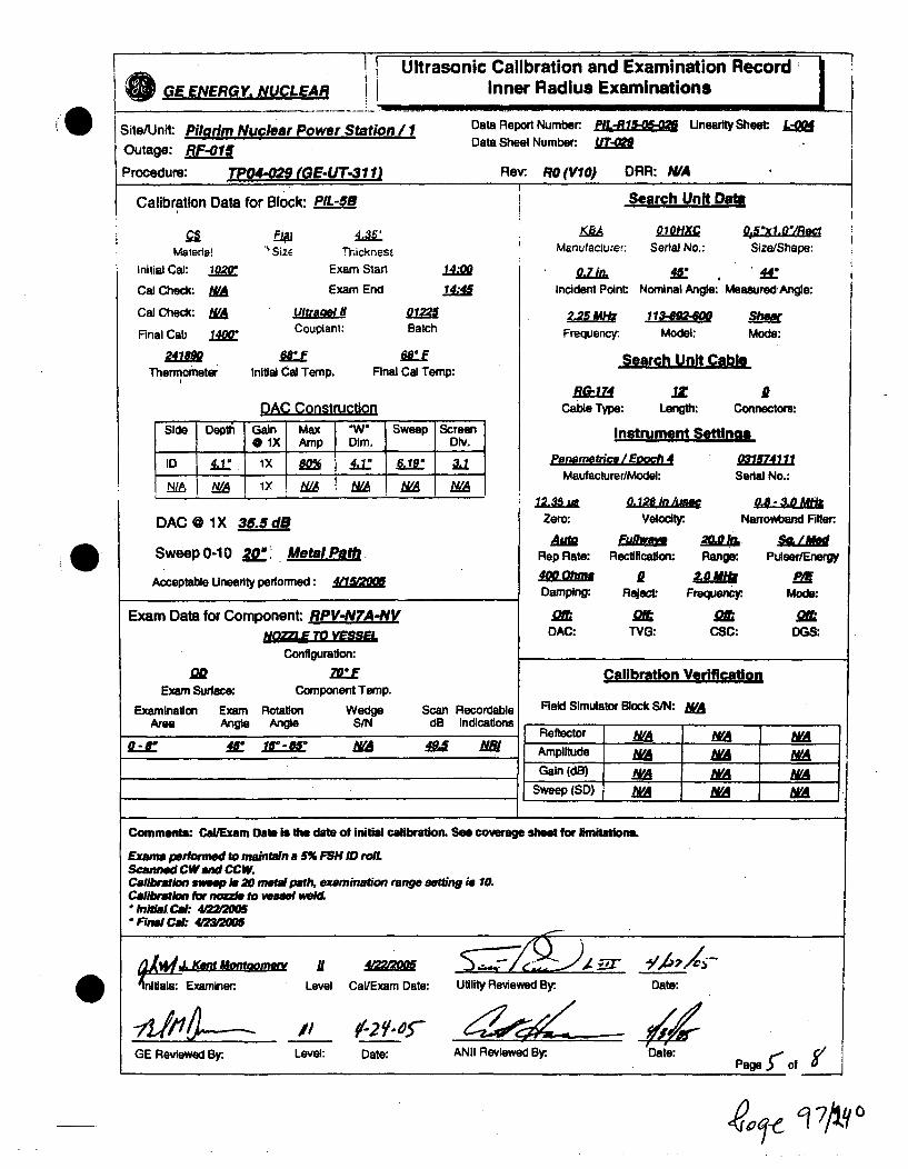
I.
I Ultrasonic Calibration and Examination Record IGE ENERGY, NUCLEAR Inner Radius Examinations
Site/Unit: PilOrim Nuclear Power Station / 1 Data Report Number: U IlnearitySheet: I
Outage: RF-01 Data Sheet Number: A
Procedure: TP04-029 (GE-UT-31 1 Rev- RO (VIO) DRR: N/A
iI
Calibration Data for Block: PIL-53 Search Unit DaOa
Materla!Initial Cal: 0=
Cal Check: MfACal Check: &A
Final Cal) 110
2411Thermometer
"Size T-ickness
Exam Stan
Exam End
AultraelICouplant:
Initial Cal Temp.
Batch
Final Cal Temp:
OBO 01 O.5Oxl.0"/RCManufacturer: Serial No.: Size/Shape:
Incident Point: Nominal Angle: Measured.Angle:
2-25 113- o SwrFrequency. Model: Mode:
Search Unit Cable
EV l .IZ iCable Type: Length: Connectors:
Instrument Settinas
0
0
DAC @ 1X 35.5dB
Sweep 0-10 20"Q Metal Path
Acceptable Unearity performed :
Panametric, / Epoch 4Maufacturer/Model:
12.n 0.128 in/#Zero: Veloci
AM FuimRep Rate: Rectificatlor
40Ohma 2Damping: Rejait
am atDAC: TVG:
Rang i
Frequerx
0s
031674111
Serial No.:
Narrowband Filter:
V PuleertEnergyS PA
Mode:
DGS:Exam Data for Component RPV-N7A-Ny
NO .ZZLETOLmmLConfiguration:
goExam Surface: C4
Examination Exam RotationArea Angle Angle
MQEomponent Temp.
Wedge Scan RecordableS/N dB Indications
Calibration Verification
Field Simulator Block S/N: &A
Reflector WA WA WAAmpintude NWA WAGain (dB) M YA NA
Sweep JSD) NA WA WA
R.LE ic_ 1I* WA NJ N18
Comments: CallExam Date is the date of initial calibration. See coverage sheet for limitations.
Exams perfonned to maintain a 5% FSH ID roll.Scann*d CWand CCW.Caliration sweep is 20 meta path, examination range setting is 10.Calibratbio Obir nzda to vesee welf
Initiai Cal: 4/22*=00F nal Cl.: 4a,-=o
am .J. Kdl AoI
nitiala: Examiner. Level Cal/Exam Date:
A~T
GE Reviewed By- Level: Date:
Utility Reviewed By.
ANII Reviewed By.
Date:
Date:Page r of S/
64,~ 0

NIrPDI Pgm.XLS
MANUAL DETECTION
NOZZLE INNER RAOIUS AND BORE INSPECTION REQUIREMENTS
PLANT Pilgrim
PREPARED BY S.C. MORTENSON DATE 01/10105
NOZZLE 1 SCAN' SOAN BEAM R ROTATION f WED'GE MAXEXAM ZONE R SAJD1 :"= '• ,. ,. ... .-.-....
RECIRC OUTLET .
N/V Weld (M) PLATE Q. .C' 4..( -. :"NN Weld/Zone 1 (M) ODBR 50" - 90g 1432.0 83.0V 6.6" I 15 1 MHzZone I (M) ODBR 35°.- 90' 32.9 822 6.6' t 2.Zone 2a (M) .. ODBR 35'-906 41.2' 489 6 MHz
RECIRC INLET INIV Weld (M) PLATE 0 - 6." 60.3' .. 0 5' -65' FLAT 15.F" 1 MH'
Zone 1 (M) PLATE C - 8.0C -N 30" FLAT 28 0" 1 MHzZone 2a (M) ODBR 55* - 90., 64.8- 20.3' 6.1' 12.2" 1 MHz
TOP HEAD VENTNN (M) PLATE 0 - 5.0" 60.0' 32'- 56' FLtAT 6.8" 2.25 MHzZONE 1-2A (M) PLATE 0 - 7.0' 70.0*1 :L25' FLAT 9.7r 2.25 MHzZONE 2A (M) PLATE 0 - 8.0" 80.0' ±25° FLAT 12.9" 2.25 MHz
TOP HEAD SPARENN (M) PLATE 0 - 8.0" 5. 15" - P5, FLAT 4.6" 2.25 MHzNN (M) PLATE 0- 5.0- 60.0' 15J - 85' FLAT 6.2" 2.25 MHzZONE 1 (M PLP-TE F, - FLAT 2"A " 225TMHz
ZONE 1-2A (M) PLAIE C - ... .. " FL.ZONE 2A(M) PLATE 0-9.0' 80.0' t25' FLAT 17.9, 2.25 MHz1
NOTES: . DESIGN I (FIXTURE) ROTATION FOR 3.0- PKG OFFSET
U DESIGN I (FIXTURE) ROTATION FOR 1.45' PKG OFFSETWEDGE i (FIXTURE) ROTATION ANGLE FOR 2.5' OFFSET
... DESIGN I (FIXTURE) ROTATION FOR 1.8' PKG OFFSET(M) MANUAL
Questions on this NIR requirements sheet shall bedirected to S.C. Mortenson @ 704 948-0253
W-070W-069
W-vC,7
-a-.. 1912005Page 1
P.-If- to of y
A"l-, ý9/2(10

01u::3.
3
0C0('I
Pilgrim - RFO15Weld RPV-N7A-NV Top Head Spray
Spring 2005
CODE CROSS-SECTIONAL ARF. TOTAL CODE COVERAGE
Weld Length = 360.Exam Volume = 28.
Required ExamArea So. In.
Area Scanned
r
Area S. In. Manual60' NS T-Scan A ...I 10.2 1.7860 S6 T-Scan A 14.7 11.3
cent
1%,'•4%
Weld LetigthManual
180S 180
n k w 1 .
"* Co
ou ,.-/ IIRS Scan A 3.1A31 1 1 I,
60* NS P-Scan A 10.2 1.3 , 180 _ 2,.60•S6 P-Scan A 25.6 5.9 .1. " 180 5
60" IRS P-Scan ' A 3.1 3.1 -11.1% 180 8 --. I
60* NS T-Scan B 9.1 2.8 10.0% 180 -5%60° S6 T-Scan B 14.9 14.5 5 1.8% 180
60' S4 /IRS Scan B 2.9 2.9 - .04% 180 2,13__
600 NS P-Scan B 10.2 2.2 7.9% 180 '-60' S6 P-Scan B 25.6 11.8 2.1% 180 Il5%60' IRS P-Scan B 3.1 2.9 i0.4% 180 ,,,,
II- -I .-
w
0
-I otarlcomposite Coverage = 56.7%
Comments: A - Examined from the top side of the nozzle 180°. Scanning limited due to nozzle configuration.B - Examined from the bottom side of the nozzle 180°. Scanning limited due to nozzle configuration
Note - Rounding methods may affect calculated values.

0-a
-n
PilgrimWeld RPV-N7A-NVTop Head Spray
Nozzle Bottorn Sie60 NS Exam VolLir,,' = Sq. In.60' FV Exam Volum =. Sq. In.Inrer 15%T Exam '.:.lui.. 2.9 Sq. In.
60' NS T-Scan acd.!,: ,.8 Sq. In.60' PV T-Scan .. 14.5 Sq. In.60U 1',!w.r 15% 17-1,- :-:ved = 2.9 Sq. In
60=T NS
60 NS• P-Scan acd;, e Z.2 Sq. In.6,0 PV P-Scan a11.'e, ' .8 Sq. In.601 ir.nei ,15% P-ý.. . P ,';ved = 2.9 Sq. In.
I "/P
- 6D'P NS
160""IT MS
Nozzle Top Side600 NS Exam Volume = 10.2 Sq. In.60' FV Exam Volume = 14.7 Sq. In.Inner 15%T Exam Volume = 3.1 Sq. In.
60' NS T-Scan achieved 1.7 Sq. In.60W FV T-Scan achieved = 11.3 Sq. In.60' Inner 15% T-Scan achieved = 3.1 Sq. In.
Scan Plan Coverage T and P scans
60- NS P-Scan achieved = 1.3 Sq. In.6W: FV P-Scan achieved = 5.9 Sq. In.•60' Inner 15% P-Scan achieved = 3.1 Sq. In.
&.00P FV
N
11('-•••". .. :
0.,

h 1 GE ENERGY, NUCLEAREXAMINATION SUMMARY SHEET
Report No.:PIL-R15-06-029
W Site: Pilgrim Nuclear Power Station Component ID: RPV-N7B-NV
Outage: RF-015 NOZZLE TO VESSEL
System a ASME CaL: f-D ASME Item §Mn Aug Req NIMExams Data Sheet I Cal Sheet 1 Procedure f Calibration Block 1 Examination !Cart Levell Date
Performed Personnel
450 Shear UT-033 N/A TPO4-029 'GE-UT-3"i' PIL-5E J. Kent 1; 4122J2005Montgomery
60 Shear UT-034 N/A TP04-029 (GE-UT-11) PIL-5B J. Kent II 4/22/2005Montgomery
60- Long. UT-005 N/A TPO4-018 (GE-UT-300) PIL-5B Brad Dummer 1II 401/200560" Long. UT-006 N/A TP04-018 (GE-UT-300) CAL-IIW2-017 Brad Dummer 111 4/22/2005
Examination Results:Ultrasonic examination results were acceptable to the requirements of ASME B&PV Cod4 Section XI, 1989 Edition no Addenda, andSection )(, 1996 Edition with the 1996 Addenda as modified by the PDI program description and the Federal Register, Part II, NuclearRegulatory Commission, 10 CFR Part 50 for Category B-D Reactor Pressure Vessel (RPV) Assembly Welds.
Manual scans from the outside surface were performed In accordance with procedures TP04-018 Rev. 0 (GE-UT-300 V8) and TP04-029
Rev. 0 (GE-UT-311 V10).
No indications were recorded.
Scanning was restricted due to nozzle configuration.
Manual coverage : 56.7%.A0
Examination results were co'rpemd to data report 95-E-375,377,379 from 1995 outage h [ ANo Change
These exaninations were pewbmd under Work Orde. N/A El Change
This Su; ary an d thellobwing daasheets have .beenrvi'-cme'ts by fte folowing pesonnel: RWP: 0065
___'I ____ ______________ Dose: I mr.
Prepared By , Level: Date: U etil" eview.
ANII Review. D Page 1 of
0
? 1071 o/0t
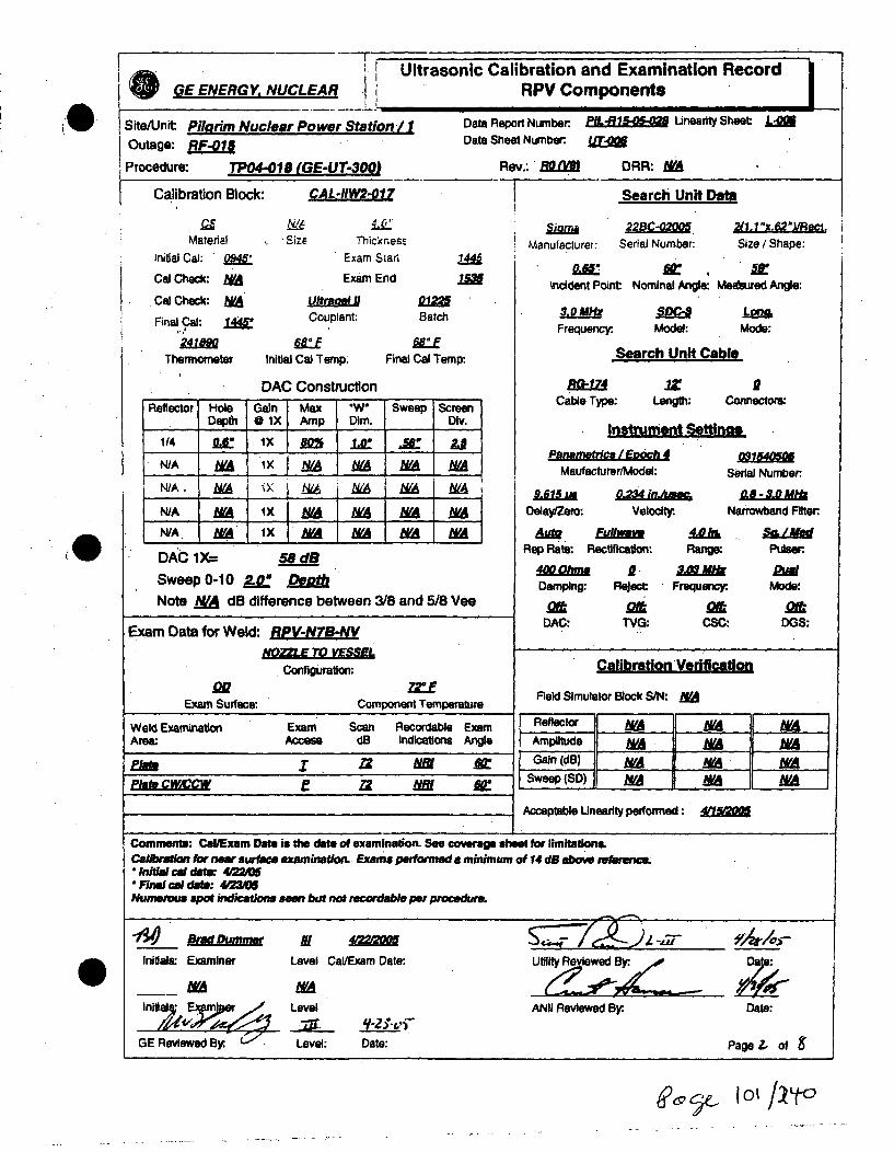
GE ENERGY. NUCLEAR K-
* Site/Unit: Pilarim Nuclear Power Station
Ultrasonic Calibration and ExamihRPV Components
/1 Data Report Number P/L-61-0 Unearity Sheet: L-0
Data Sheet Number:Outage: B"IProcedure: TP04-018 (GE-UT-300) Rev.: ' (R/IJ DRR: MA
Calibration Block: Search Unit Date
MaterialInitial CaJ: '04
Cal Check: hVACal Check: WA
Final Cal: /45
241o tThermometer
Size Thicknesm
Exam Stan
Exam End
U22BC-02005Manufacturer: Serial Number:
2S1z1"e/2SapecSize / Shape: I1
144Z
incident Point. Nominal Angle: Meetured Angle:
Couplant:
Initial Cal Temp.
Batch
Final Cal Temp-
3.0 M xFrequency:. Model: Mode:
DAC ConstructionReflector Hole Gain Max W" Sweep Screen
Depth * lX Amp Dim. Dlv.
1/4 Le ix .M i .- uNIA W IxMA M MA NA NAN A. WA IX. N6 WA NA MWA
N/A NO lx __A MA MA MAN/A N lx MA MA MA MA
DAC 1X= 58 dBSweep 0-10 2-V.Dog
Note NA dB difference between 3/8 and 5/8 Vee
Search Unit Cable
A1.lZ iCable Type: Length: Connector:
Instrument Sttinas
Panemewrla I gmac 4Maufacturer/Model:
9U15LiaDelayfZemo:
o2e4 inAciVeloit
Serial Numberc 0.8 -3.0Mlz
Narrowbend Filter
PlseRange: Pulser:
I.
A,• FuwmdRep Rate: Rectification:
4oo lon & W.Wk DaDamping: Reject Frequency: Mode:
as at at CDDAC-: TVG: CSC: DGS:
Exam Data for Weld: RPV-NTB-NV
Configuration:
E oExam Surface. Component Temperature
Calibration Verific.laon
Field Simulator Block S/N: NA
Weld Examination Exam Scan Recordable Exam Reflector M MArea: Access dB Indications Angle Amplitude NA MA N/Ari;2 m 22 Gain (08) A •N/
Pliko CM/CCW Z 22 NM& At" Sweep (SD) YA M WA
Acceptable Unearlty performed: 411
Comments: Cal/Exam Date is the date of examination. See coverage sheet for limitations.Calibration for nrw surface examinarton. Exams performed a minimum of 14dB abo &ow reternc." Inidl cl dte: 422(0" Finalc ai dait: 423MNumerou apoi indicamions seen but not recordable per procedure.
finitlasa Examiner Level Cal/Exam Date: Utility Reviewed By. a
Initiala _Fpor Level ANII Reviewed By:. Date:
GE Reviewed By- Level: Date: Page Z. of &
6?V9 4C- 1o 1J/1 Lt

I Ultrasonic Calibration and Examination RecordGE ENERGY, NUCLEAR RPV Components
Site/Unit: Pilhrim Nuclear Power Station /1 Data Report Number. L-R1 Linearity Sheet: L-
Outage: RF-01 Data Sheet Number:.
Procedure: TP04-018 (GE-UT-300 Rev.: EQV2J DRR: MA
Calibration Block:
MaterialInitial Cal: 09W
Cal Check: NA
Cal Ceck: NA
Rnal Cal: 1445"
Search Unit Date
Size±IL
Thickness
Exam Stan
Exam End
22BC-0200V
Manufacturer: Serial Number:
217.1 ' x.62")lRect.Size / Shape:
Incident Point: Nominal Angle: Measured Angle:
Couplant: Batch
Final Cal Temp:
3.0 mscFrequency: Model:
Lona.Mode:
241 MOEThermometer Initial Cal Temp. Search Unit Cable
DAC ConstructionReflector Hole Gain Max "W Sweep Screen
Depth @ 1X Amp Dim. Div.
N/A MA iX MA NA NA NAN/A .A lX MA WA MA bVAN/A IA ix A A / NA M_ I
ID L." Ix in .8 .2 M4
N/A WA 1X MN MA NA NA
aalCable Type:
I
/Z 17Length: Connectors:
Instrument Settings
Panametrics I Enoch 4Maufacturer/Model: S
5 0-234 jionue
Delay/Zero: Velocity:. I
Rep Rate: Rectification: Range:
4D mp R 10Damping. Reject: "Frequency.
.i
O3154O0
erlal Number.0. - 3.0 M'
Jarrowband Mlten
Pulser.
Mode:
DGS:
DAC 1 X= 62 dBSweep 0-10 /0.00 REjfNote WA dB difference between 3/8 and 5/8 Vee
Exam Data for Weld: RPV-N78WV
NQCoTO lVoS:Configuration:
DAC: TVG:at
CSC:
Calibration Verification
Field Simulator Block S/N: MAo2Exam Surface: Component Temperature
Weld Examination Exam Scan Recordable ExamArea: Access dB' Indications Angle.
,rimcw&ccw E WC NN fi
Reflector NANAN/Amplitude N/IA N/A NAV
Gain (dB) M M• hVASweep (SD) NWA .YA NVA
Acceptable Uneartty performed: •
Comments: CaUExam Date is the date of examination. See coverage sheet for limitations.Calibration for full volume examination. Exam performed to maintain a 10% - 20% FSH clad rog.* Initial cat do: 4 M" Final cal date: 4/3/0Numerous spot indications seen but not recordable per procedure.
Initials: Examiner Level Cal/Examn Date:. Utility Reviewed Ely,. Date:
NA MA _ _ _ _
Ini Level ANII Reviewed By:. Date:
GE Reviewed By: z Level: Date: Page .3 of 8
?,,I 0,;tOyc

Ultrasonic Calibration and Examination Record'GE ENERGY, NUCLEAR Inner Radius Examinations
SiteUnit: Pilgrim Nuclear Power Station /I Data Report Number. LiUnearity Sheet: L-M0Outage: RF-01 Data Sheet Number I.
Procedure: TP04-029 (GE-UT-31 1J Rev. RO (V10) DRR: N/A
Calibriation Data for Block: PIL-5B Search Unit Dafm
c0Material
Initial Cal: .•
Cal Check: A
Cal Check: &/ARnal Cal! mat
24Thernmometer
SizE ThiCKnesii
KBA 010X O.5xV.0"/Reat
Manulacturer: Serial No.: Size/Shape:
Incident Point: Nominal Angle: MeahuredAngle:
Exam Starn
Exam End
Couplant
Initial Cal Temp. Fin
DAC Construction
0122
Batch
WaEal Cal Temp:
Frequercy. Modal: Mode:
Search Unit Cable
Cable Type: Length: Connectors:
Instrument Settinma
PenametrcalE/och 4Maufacturer/Model:
DAC @ 1X 4EdB
Sweep0-1o 20-. MetalPat
Acceptable Unearity performed:
Exam Data for Component RPV-N78-NV
Configuration-
Exam Surface: Component Temp.
Zero:
Rep Rate:400Oh
Damping:
DAC:
0. 126 InVelocity.
Rectlfication: Rango
2 10Reject Frequent
031574111Serial No.:
0.8 - 3.0 MHzNarrowband Filter:
1: Pulser/Energy9I PAE
Mode:
: DG:at
CSC
Examination Exam RotationArea Angle Angle
Wedge Scan RecordableS/N dB Indications
CallbrationI Verification
Field Simulator Block S/N: NA
Reflector NA NA NAAmplftude WA NA WAGain (dB) NA NA WA
Sweep (SO) M NA WA
9Xu AR: MA
Comments: Cal/Exam Data is the date of initial calibraton. See coverage sheet for limitationk
Exams performed to mainain a 5% FSH ID rolLScanned CW and CCW.Calibration sweep is 20 metal path, examination range setting Is 10.Calibration for nzzlie to vemoi weld.' Inital Cal: 4,2220O* Fn Cal:. 423a05
UYL I KOM
Iniftle: Examiner Level CaVExam Date: Utility Reviewed By: Date:
GE Reviewed By:. Level: Date: ANII Reviewed By:. Date:Page ý of
J~e IO3/~cjO

(0
!] Ultrasonic Calibration and Examination Record IGE ENERGY, NUCLEAR L inner Radius Examinations
Site/Unit: Pilgrim Nuclear Power Station / I Data Report Number PIL.R- bnearity Sheet L0
Outage: RF-015 Data Sheet Number ,
Procedure: Tp04-029 (GE-UT-3= 1) Rev RO (V10) DRR: N/A
Calibration Data for Block: PIL-_ Search Unit Data
MaterialInitial Cal: o2*
Cal Check: "WA
Cal Check: WA
Final Call. 1Am.eo41me
Thermometer
FSizSize ExickneSt
Exam Start
KBA OIOHXC _.__._,___
Manufaclure-: Serial Nc.: Size:Shaps:
ItaIExam End
Ultragel /ICouplant:
Iniltit Cal Temp. Fin
DAC Construction
Batch
at Cal Tamp:
Incident Point: Nominal Angle: Measured Angle:
2.25 M 1 13-8e40 Show,'Frequency: Model: Mode:
Search Unit Cable
Cable Type:.Z 0
Length: Connectors:
Instrument Settinas
Panameo**c / Epoch4Maufacturer/Model:
12.36 La .128 in uAniiZero: Velocity
03157411Serial No.:
0.4 -J.0 MlzNarrowband Filter:
10
DAC@1X 35.5dX
SweepO-10 200 MetalfPatl
Acceptable Linearity performed: 411
Rep Rate: Flectification: Range: Pulser/Energy
Damping: Reject Frequency:. Mode:
o2.t o 2M oaDAC" TVG: CSC: DGS:
Exam Data for Component: RPV-NTB-NV
Configuration:
QR ZOEExam Surface: Component Temp.
Examination Exam Rotat8on Wedge Scan RecordableArea Angle Angle S/N dB Indications
Calibration Verfication
Field Simulator Block S/N: WA
Comments. CailExam Date is the date of initial calibration. See coverage sheet for limilatioka.
Exams performed to maintain a 5% FSH ID roil.Scanned CW and CCW.Calibration sweep a 20 metal path, examination range setting is 10.Calibration for nozzle to vessel weld.* Initial Cak 4/2220* Fnal Cat: 423&t=5
M J. Kant MoItao,,.r II ,/
Initials: Examiner Level CaVExam Date:
GE Reviewed By:. Level: Date:
Utiflity Reviewed By:
ANiI Reviewed By.
Date:
Date:Page 5' of S'
0c4/~t

Nir.PDI Pgm.XLS
0 MANUAL DETECTIONNOZZLE INNER RADIUS AND BORE INSPECTION REQUIREMENTS
PLANT Pilgrim
PREPARED BY S.C. MORTENSON DATE 01/10/05
NOZZLE SCAN SCAN SEAM ROTATION WEDGE f MAX, . . . .':. : . ..7.. . ...... ..... .FR EO
I, I II',E-CIRC OUTLE__-__--__.
NF Weld . . - FL.-, i MHzN/V Weld/Zone 1 (M) ODBR 50" - 90: j 43.0" 83.0" 6.6" 15.9" 1 MHz W-071Zone 1 (M) ODBR 35"- 90" 32.9" 82.2" 6.6" 12.9' 1 MHz W-070Zone 2a (M) ODBR 35". -90. 41.2" 48.9' 6.6" 13.4" 1 MHz W-069
RECIRC INLET _ IN/V Weld (M) PLATE 0- 6.0" 600' 35° - 65' FLA T 15.6* 1 MHzZone 1 (M) PLATE t. - K ' i00" .3C FLAT 28.0" 1 MHzZone 2a (M) .ODBR 55" -90" 64.80 20.3" 6.1'; 12.2". 1 MHz W-072
TOP HIEAD VENTMNN (M) PLATE 0 - 5.0' 60.0" 32 - 56' FLAT 6.8" 2.25 MHzZONE 1-2A (M) PLATE 0 - 7.0" ?U.01 ±25" FLAT 9.7" 2.25 MHzZONE 2A (M) " PLATE 0 - 8.0" 80.0" ±25" FLAT 12.9" 2.25 MHz
TOP HEAD SPARE __
NI (M) PLATE 0- C"[ 45.0' 15" - a, FLAT 4.6" 2.25 MHzNN (M) PLATE 0- 5." 60.0 15' - 8,5" FLAT 6.8" 2.25 MHz
C:' NE i .:' , ,- " . . ,:,. PI" ! . 225 MHz-ONE 1-2A (10) 0, . L.'. 1 E 2.25 MHzZONE 2A M) PLATE 0- 9.0" 80.0 25" FLAT I 17.9" MHz
NOTES: DESIGN! (FIXTURE) ROTATION FOR 3.0" PKG OFFSET•oD OESIGN I (FIXTURE! ROTATION FOR 1.45" PKG OFFSET
WEDGE; tFIXTURE) ROTATION ANGLE FOR 2.5" OFFSET
DESIGN I IFIXTURE) ROTATION FOR 1.5" PKG OFFSETiM) MANUAL
Questions on this NIR requirements sheet shall bedirected to S.C. Mortenson @ 704 948-0253
Page I v4/,-4•S 1ii92005
Ay~e 4
J~4. c9/ý7

'1
;0
-N
0
U'D
Pilgrim - RFO15Weld RPV-N7B-NV Top Head Spray
Spring 2005
CODE CROSS-SECTIONAL AREA. TOTAL CODE COVERAGEPc' cent
Weld Length = 360. Required Exam Area Scanned of 'Area Weld Length Pet-,..-Exam Volume = 28. Area Sq. In. Manual M,-oual Manual
60° NS T-Scan A 10.2 1.7 1- 1% 180 T1 760° S6 T-Scan A 14.7 11.3 18060 0 S4 / IRS Scan A 3.1 3.1 ,1% 180
60' NS P-Scan A 10.2 1.3 4.6% 180 1.2%60* S6 P-Scan A 25.6 5.9 21,. 1% 180 .5...,1060° IRS P-Scan A 3.1 3.1 '1.1% 180 1 2.8%
600 NS T-Scan B 9.1 2.8 1 .0% 180 '2. 5%600 S6 T-Scan B 14.9 14.5 51 8% 180 1__' j%
60* S4 / IRS Scan B 2.9 2.9 11j.4% 180 F '1/0
600 NS P-Scan B 10.2 2.2 -9% 180 2.0%60° S6 P-Scan B 25.6 11.8 2,1 1% 180 10.%600 IRS P-Scan B 3.1 2.9 i0_.4% 180 2. :%
- I
Commnts A Exmind frm te tp sde f th nozle180 Scnnin liite du tonozze cnfiuraion
% Total Composite Coverage = 56.7%
Comments: A - Examined from the top side of the nozzle 1800. Scanning limited due to nozzle configuration.N - Examined from the bottom side of the nozzle 180°. Scanning limited diie to nozzle configuration.
lNote - Roundingmethodsmaafetclutdvles

-D
3'10
00
JIi
-tJ5,cc~
(1,H'0
F----'PilgrimWeld RPV-N7B-NVTop Head Spray
Nozzle Bottomr Si•e60 NS Exam Vohi.,.; Sq. In.60". FVExam Voiu,-,v 1.) Sq. In.Inner 15%T Exam - 2.9 Sq. In.
60" NS r-Scan ac.•e. '8 Sq. In60' FV T.Scan aci-,..,'.' 14.5 Sq. In.60" Inner 15% T-. .:',,ved =2.9 Sq. In
60' NS P-Scan ac..:,.c 2.2 Sq. In.607' FV P-Scan a18. - I .8Sq. In.6r-" Inrner 15% p.!.. -. lved = 2.9 Sq. In
60"TNS
I..
T .IP
160*T HS
Nozzle Top Side60' NS Exam Volume = 10.2 Sq. In.60' FV Exam Volume = 14.7 Sq. In.Inner 15%T Exam Volume 3.1 Sq. In.
60' NS T-Scan achieved = 1.7 Sq. In.60" FV T-Scan achieved = 11.3 Sq. In60° Inner 15% T-Scan achieved = 3 1 Sq. In.
Scan Plan Coverage T and P scans
60' NS P,-Scan achieved = 1.3 Sq. In.60W FV P-Scan achieved = 5.9 Sq. In.60' Inner 15% P-Scan achieved = 3.1 Sq. In.
60'Fl FV
¾,N.
N
K

I GE ENERGY, NUCLEAREXAMINATION SUMMARY SHEET
Report No.:PIL-R15-05-03o
(WI Site: Pilgrim Nuclear Power Station Component ID: RPV-NS-NV
Outage RF-015 NOZZLE TO VESSEL
system ASME Cat.: - ASME ftem 83.N Aug Req NA
Exams 1 Data Sheet Cal Sheet Procedure Calibration Block Examination ICert Leveli DatePerformed I Personnel I__60c Shear I UT-025 N/A, TPOA-02C IGE-UT-31 I' PIL-5 ,. J. Kenf i1 4/22/2005
Montgomery i60" Long. UT-O08 N/A TPO4-016 (GE-UT-300.) CAL-IIW2-017 Brad Dumrner III-. i42005600 Long. UT-007 N/A TP04-O18 (GE-UT-3OO) Brad Dummer III 4/=005
Examination Results:
Ultrasonic examination results were acceptable to the requirements of ASME B&PV Codb Section XI, 1989 Edition no Addenda, andSection X), 1996 Edition with the 1996 Addenda as modified by the PDI program description and the. Federal Register, Part II, NuclearRegulatory Commission, 10 CFR Part50 for Category B-0 Reactor Pressure Vessel (RPV) Assembly Welds.
Manual scans from outside surface were performed In accordance with procedures TP04-018 Rev. 0 (GE-UT-300 VS) and TPO4-029 Rev.0 (GE-UT-311 V10).
Scan was restricted due to nozzle configuration.
No Indications were recorded.
Manual coverage = 70.6%
Examination results were compared to data report 96-E-263,265,267 from 1996 outage with & No Change
These examinatoins were pewomved under Work Order. N/A I] Change
This Summary and the following date sheets have been rev and a Py the following personnel.: RWP: OO65
PrIaedBy.LeelDt:_tiitevew.__ Dose: I MDr.
Prepared By:. Level: Date: Utilty Review. ~ Date: _________
ANII Revi'ew. Date: Page-1 of
1ý67qt 10 7/2 y C)

Ultrasonic Calibration and Examination Record IGE ENERGY, NUCLEA i RPV Components
Sile/Jnit: Pilarim Nuclear Power Station /I Data Report Number. PI-R10- Unearity Sheet: L-Outage: RF-01 Data Sheet Number.
Procedure: TP04-018 (GE-UT-300) Rev.: 8O DRR: MA
Calibration Block: CAL-HW2-01 Search Unit Data
0.Material
Initial Cal: 094P
Cal Check: fVA
Cal Check: MNFinal Cal: /4
Thermometer
hSILI' ixQThicknese
Exam Star,
Exam End
Manufacturer:22SC-02005
Serial Number.S(1,1ie.62VSape:Size / Shape:
1"0
Couplant:
Initial.Cal Temp.
DAC Construction
Batch
Final Cal Temp:
Incident Point Nominal Angle: Meatured Angle:
3.0 M"H LIM12Frnuency. Model: Mode:
Search Unit Cable
R~r-• .z ICable Type: Length: Connectors:
Instrument Settinas
Reflector Hole Gain Max "W" Sweep ScreenDepth * IX Amp Dim. Div.
1/4 I8 x lX 80% /0 .5a 2.e
N/A &A IX M AINA M M_
N/A . N X b& M ,/ bN
N/A NWA lX MA WA NVA N&A
N/A MA 1X MA MA MA WA A
DAC 1 X=
Sweep 0-10 2.0- g Det
Note A dB difference between 3/8 and 5/8 Vee
Pananetrica / Enoch
Maufacturer/Model: Serial Number-.
0.8 -3.0 MfgrNarrowband Filter:Delay/Zero,,
~1OMdimOWVelaclty
AtMRep Rate: Rectification:Range:
SIL 1WtPulser
Damping: t FrDamping: Reject: Frequency:.
DAC: TVG:o1ft
CSC: DGS:Exam Data for Weld: RP"-N-NV
. Conflguration:
Exam Suylace: Connponent Temperature
Calibration Verification
Field Simulator Block S/N: MA
Reflector NA WAAmplitude NU A NWAGain (d1B) N/A NA UAV
ilSweep (SD) MA I YA bA•
Weld ExaminationArea:
Exam Scan Recordable ExamAccess dB Indications Angle
am X i 22 fizrPh"~ .:W&~W E AV P161 l
Acceptable Linearlty performed :
Comments: Cal/Exam Date is the drate of examination. See coverage sheet for limitaelons.Calibration for new surface examination Examm performed a minamum of 14 dB above retsiwnm* Inidal cal det: 4.220" Final cal datin 4'23A0Nunerous Spoi indkition seen but not recordable per procedure.
Initials: Examiner Level Cal/Exam Date: U•evewed Dale:
Initis mir# Level ANII Reviewed By. Date:
GE Reviewed Level: Date: Page 2-of7
OR

Ultrasonic Calibration and Examination Record
GE ENERGY, NUCLEAR RPV Components
Site/Unit Pitarim Nuclear Power Station / 1 Data Report Number: PfLIk8.Z Lineanty Sheet LM
Outage: MAI Data Sheet Number:. Z
Procedure: TPO4-O18 (GE-UT-300i Rev.: EN DRR: MA
Calibration Block: Search Unit Data
MaterialInitial Cal: 0MCal Check: MACal Check: tMAFnal Cal:
Thermometer
FiauSize Thickness
Exam Sian
Exam End
Manufacturer.22BC-0200!
Serial Number:2(n.1 "x.L ReSize / Shape:
Iricident Point: Nominal Angle: Measured Angle:
Couplant:
Initial Cal Tamp.
DAC Constniction
Batch
Final Cal Temp:
3.0Mc ModlFrequency. Model:
Long.Mode:
Search Unit Cable
4Lam 1Z. 0Cable Type: Length: Connectors:
Instrument Settings
Reflector Hole Gain Max "W" Sweep Screen
Depth 0 IX Amp Dim. Div.
N/A MA lx b h VA WA M:.NA A IX MA MA Md _WAJN/A MA Ix 'A Y 1t L9A
ID 4LE lx M L 7.8 fix M
N/A IxA :x M MA NA MA.
Psnametric / Eioch 4Maufacturer/Model:
DAC IX= 62 dB10o0 o"9
AM F ReWtRep Rate: Rectification:
DelayfZer6:&Z4 indlum
Veloclty.
031400
Serial Number:•. 0.8 - 3.0 MHf2
Narrowband Filter:
Range: Puiser.
Sweep 0-10Note N/ dB difference between 3/8 and 5/8 Vee
400 hm
Damping:
DAC:
a 2,0 kReject Frequency.
oMTVG: CSC: DGS:
Exam Data for Weld: RP
Configuration:
E RExam Surfaer: Component Temperature
Calibration Verification
Field Simulator Block S/N: NA
Reflector M NA NAAmplitude M 7,ATGain (dB) M/A M MA
Weld ExaminationArea:
Exam Scan Recordable ExamAccess dB Indications Angle
rim I fil -Ph" IM.MW& P Mii X: Sweep (SD) M NA A
Acceptable Linearity performed:
Comments: CallExam Date is the dats of examination. See coverage sheet for limitations.Calibration for full volume examinatkun Exams performed to maintain a 10% - 20% FSH clad ro&L" Inid ca dof: 42M" Firel cal daf- 12Numerous spot &inaditons seen but not recordable per procedure.
In itial s: E xa miner" Le vel C a l/E xa m D ate : Utlt R e i w ed B y *
GRiewel d By:. Level ANII Reviewed By. Date:
GE Reviewed By.~ Level: Date: Page _? of 7
4dsLey4 log / 29'O

I, Ultrasonic Calibration and Examination Record
GE ENERGY, NUCLEAR fi Inner Radius Examinations•--,L.
Site/Unit: Pilgrim Nuclear Power Station /IOutage: F-01Procedure: TP04-029 (GE-UT-'1I)
Data Report Number: PYLR Linearity Sheet. L-0Data Sheet Number. j, 5
Rev* RO (V10) DRR: N/A
Calibration Data for Block: PIL-58 Search Unit Data
Materialinitial Cal: IMCal Check: NffA
Cal Check: _WA
Fnal Cal: 114 .
ENiaSize
• AaLTh'ckres,
Exam Start
Exam End
KBA a M 0.5"1Q.0"/Rect.Manufacturer Serial Nc.: Size/Shape.
0so-Ircident Point: Nominal Angle: Measured Angle:
2.25 M .i1&Q She..,* Frequency: Model: Mode:
Search Unit Cable
ultreael ICouplant: Batch
Final Cal Temp:.Thermometer Initial Cal Temp.
DAC Construction Cable 'Type:I
it .9Length: Connectors:
Instrument Settings
Panametrfcs / Enoch 4
Maufacturer/Model:
031574111
Serial No.:
0.8 - Jd.0 AMl-Narrowband Filter:
DAC@1X 41dB
Sweep 0-10 20 Metal Path
Acceptable Unearity performed: 4a
Exam Data for Component RPV-N.-NV
Configuration:
Exam Surace: Component Temp.
14.27 LonZero:
AuMRep, Rate:400 Ohme,
Damping:
DAC:
Velocity:
FAilk 20.0k S/Mm dRectification: Range: Pulser/Energy
Reject: Frequency:. Mode:
inTVG:
atCSC:
amDGS:
Examination Exam RotationArea Angle Angle
Wedge Scan RecordableS/N dB Indications
Calibration Verification
Field Simulator Block S/N: WA
Reflector NA &A WAAmnpltude WA NAGain (dB) M WA M
Sweep (SD) M MA WA
At 3 N(A N PW
Comments: Ca~lExam Date is the date of initial calibration. See coverage sheet for limitations.
Exams perrmed to maintain a 5% FSH ID roil.Scanned CW and CCW.Caobation sweep is 20 metal path, examination range setting is 10.Calibration for no*le to veesel we." Initial Cal: 4/2220M" Final Cal: 4V23QO=S
ntil:Examniner~L
Level Cail/Exam Date: Utility Reviewed By:. Date:
GE Reviewed By Level:
9Y-o-Date: ANII Reviewed By: Dale:
Page Z/ 1o
4 110M

Nir.PDI Pgm.XLS
. MANUAL DETECTIONNOZZLE INNER RADIUS AND BORE INSPECTION REQUIREMENTS
PLANT Pilgrim
PREPARED BY S.C. MORTENSON DATE p1/10105
NOZZLE f SCAN ! SCAN BEAM 1 ROTATION I WEDGE r MAXEXAM ZONE. I S0P-." ,' ANGLE L..NGLE MP r-, I, I.E ,p FREQ
IRECIRC OUTLET J I I1,i"V Weld(M, - . - . 'C ' 'C' - " P 0.2 1 MHz
NNV Weld/Zone 1 (M) ODBR 50: - 90: 43.0" 83.0" 6.6" 15.9' 1 MHz .Zone 1 (M) ODBR 35° - 90" 32.9" 82.2" 6.6" 12.9" 1 MHZZone 2a (M) ODBR 35'- 90' 41.2" 46.9" 6.6" 13.4" 1 MHz
RECIRC INLET I _
N/V Weld (M) PLATE 0 - 6.0" 60.0" 1: 35" - 65" FLAT 15,6" 1 MHzZone 1 (M) PLATE 0 - ,.0' 7G.01 ± 30' FLAT 28.0" 1 MHzZone2a (M) •ODBR 55--90- 64.8' 20.3' 8.1" 12.2' 1 MHzTOP HEAD VENTN/V (M) PLATE 0- 5.0" 60.0" 32' - 56" FLAT 6.8" 2.25 MHzZONE 1-2A (M) PLATE 0- 7.0" 70.0" 125" FLAT 9.?" 2.25 MHzZONE 2A (M) PLATE 0 - 8.0" 80.0" 125" FLAT 12.9" 2.25 MHz
TOP HEAD SPARENNV (M) PLCTE . - 8.0" .15.0t 15" - 8.. FLAT A.6" 2.25 MHzN/V (M) !'L,.E 0- u. " 60.0" 15' - FLAT 6.8" 2.25 MHz
17ONE I (Nk Dt. 4,7.. .•v.-- .S' FLAT 6 8" 2.25 MHzP-ONEL.TE ' •9" I .80.0" !:LT 17".E 2.25 MHz
ZONE 2A (M) PLATE 0 -9.0- 80.0" ±i25' FLAT 17.9" .2.25 MHz
W-071"W-070
W-069
W-072
0 NOTES: DESIGN J (FIXTURE) ROTATION FOR 3.0" PKG OFFSET
# DESIGN '(FIXTURE) ROTATION FOR 1.45" PKG OFFSET
WEDGE I IFIXTURE) ROTATION ANGLE FOR 2,5" OFFSET... DESIGN I (FIXTURE) ROTATION FOR 1.5" PKG OFFSET
NM) MANUAL
Questions on this NIR requirements sheet shall bedirected to S.C. Mortenson @ 704 948-0253
Page I 1/9/2005
fýIII jtjpq o

-"
3
n
0
-Os
AI%o_.
Pilgrim - RFO15Weld RPV-N8-NV Top Head Vent
Spring 2005
CODE CROSS-SECTIONAL AREA TOTAL CODE COVERAGEPercent
Weld Length = 360. Required Exam Area Scanned of Area Weld Length PercentExam Volume = 25.3 Area Sq. In. Manual Manual Manual Manual
600 NS T-Scan A 8.2 3.5 13.8% 360 6.9%600 S6 T-Scan A 13.8 13.4 53.0% 360 25.5%
600 S4 / IRS Scan A 3.3 3.3 13.0% 360 65%
600 NS P-Scan A 8.2 2.9 1.5% 360 c..__. n,%
600 S6 P-Scan A 25.6 9.3 3.8.8% 0 360 1 4600 IRS P-Scan A 3.3 3.3 13.0% 360 6S,%
- ----
• o1ql C;omposite Coverage = 7;.5ýý
CComments: A. -Exmined4 qRfl0Q lAI.-an . H ,:....i4...£ i. -. ~~uu ~i~aUUL 1Z1 onu
......... ............ d - ,,,,,,, ,,•=ue to noz~z.e conngurabon.
Note - Rounding methods may affect calculated val,,,'•Note . Rounding methods may affect calculalAd ~jalii~c I - L /

3' PilgrimWeld RPV-N8-NVTop Head Vent600 NS Exam Volume m 82 Sq.-In.60" FV Exam Volume - 13.8 Sq. In.60* Inner 15% Exam Volume w.3.3 Sq. In.
60° NS T-Scan achieved = 3.5 Sq. In.60* FV T-Scan achieved - 13.4 Sq. In.80* Inner 15% T-Scan achieved a 3.3 Sq. In.
60" NS P-Scan achieved "2.9 Sq. In.60 FV P-Scan achieved . 9.3 Sq. In.860 Inner 15% P-Scan achieved - 3.3 Sq. In.
UP 80"1"c¢ I ", _60OT
I
-4:
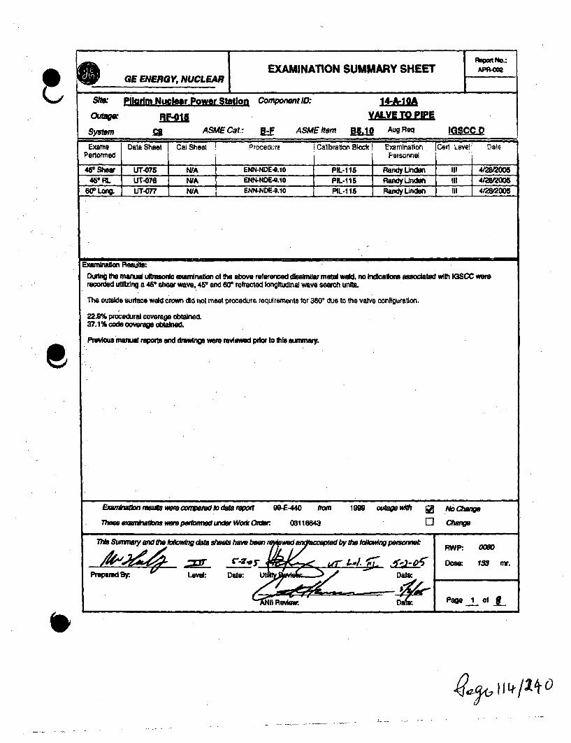
E0 GEERGY, NUCLEAREXAMINATION SUMMARY SHEET APAýCf
Slte. Piardm Nuclear Power Station Component 1D: 14-*A 0A
System C ASME Cat.: I-F ASME item flL.1 Aug Req IGscc D
Exr DaeSho Cal Sheet Procedu~re Calibration Block! Examination, Cerl Leve!l DalePertormed iPeisonnel
4e Shear UT-075 WA EWNDE-0.10 PIL-1 15 Randy linden III 4200545# RL UT-076 N/A ENN -G.io PIL.115 Ra lInden III 4/22005
20° .Lon UT-0 N/A ENN-NDE-S.10 P11-115 Randy Uinden 111 4/2005
Examination Results:During fth manual uftnsori examinatlon of toe above referenced dismilUar metal weld, no Indicailos assoclated wilh IGSCC wererecorded utlizing a 4P shear wave, 45r and 60' refracted longitudinal wave search units.
The outside surlace weld cron did not meet procedure requirements for 380' due to the valve configuration.
22.9% procedural coverage obtained.37.1% code coverage obtained.
Previous manual reports and drawings were reviewed pdor to Ot summury.
Exenkiawkn resuf were wonvaed go deab 'epo 90-E -440 #0MThes exanvnalim w" peetbA~nedder Woik Colerc 03115M4
1999 MA *m*UP JZ NAo wnge
0 azwn
17ha Swmrmui and fte ktw~ing data &WMa haow bow i
Prepared W.y V Level: Dale:
-01(711411+0

I
Wall ThicknessProfile Sheet
Ske: M t ka Unit
PTw~ct El
1Repatt Na.:
Ssemr: c
F31 I- 1.5"Coeqmard~ ID ~Nwnber. 14A-MPodaftn O" w0 1w 270
- .1 - J - .1 - I -4
t WA MA NA m4
2 N/A WA MA WA
A aM WA WA WA
4 0586 MA WA W/A
Crovi NsHW
cra~m ifWd
Al
VALYIP.! T Component I)NST Camponeut
Nominal Dlameter~ I=
Weld Lengft5 NA INA DA
I I I I I I__ _ _ _ _ __ _ _ _ _ _
*-~- :4~A-1O
A7~
-. ..fit
V"
-0
F........ m.
A~" fpva-.s.-bftft E)myinhr: Level: Dows GE R.vbwsd Bevat Dow
I I POPe 7. of I

F
Wall ThicknessProfile Sheet
SK*MM Unit 1 RpmleNort
projec 91
System: an *I 7
PadFa 1 )19r r 2(
D
Curan~oard ID Nimtmr. 144-iM I
I- - I.
N/A I N/A I NA I WACmRI Hegt Al
3 NMA WA WA WA
4 £NWA IWA WA- - - - - i
Crown WkdktL
Non~nel Dkmele..UpST Corponent / ONrST Canipan
I
5 oaWI NAVWel Lerafn a&~
FLOW pI I _______ .L -
I 3
~~7o"" ' I " i n l" '
-W
-
lNftab& E~anhnu Lavek Date: CIE ReVAM By. Leve: Daele ANNI Review Dlpape ' OftI . .1

Ultrasonic Calibration and Examination Record* E Manual Piping and Components
Report NumwbSote/Unht: Piarim Nuclear Power StAtion / oItD Sheet Number UT£AOutage: . LkWearftyShet L-
Calibration Data for Block: PL-11 Procedure: ENN-NDE-. 1
.01Zl LAW Calibralior j C~ajTirnizM a t erala Size, T h ic r a a : 2
full 9 Cal Checkc: ___
Couplant Couplant batch
Thenmenmeter S/N Cal Temp. iRnal Cal:
'ver / Rev: 9 DRR: W
DAC Conebstuton
Scan Direction
Cal Reflector If
Signal AMPlitudeSignsl Sweep: a
Signal dB: I
sweep -1o = J"la
Al
An-d~a ea
earch Unit Dfta
Maruiacturer Seria Number Size/Shape:
Incident Point Nominal Angle: Measured Angle:
Frequen•.c Style: Mode: Elemnots:
Search Unft Cable
Cable Type: Length: Connectors:
Instrument Settina.
Maufacturer/Model: Betel Number
Calbibrastion Verfication
PFied Simulator Block SN:
Reflector LU AMAmplitude fGain (daS) NO W
Sweep(SD) ( 81A
Acceptable Uneaft performed:
Exam Data for Weld: 14-A-1OA
VALV TOCanligunraon:
Zearo0£26!am~m
Velocity: Narrowband Alter
AM MRep Rate: Rectification:
Daming Relech
Pangs:
Frequency.
Puleer/Energy
asMods:
Exam Commnfts / UmittonseSmue &dewem ddb Oui.Did not seen an wec lde ID co miweulam-- b~w ' '5% ta 20% ID rd um ina0en*dSe
Exam Surface:WfE 41
Exam Temp. Exam Thermometer
M Exmn Ern A
Level: DOW.
Date:
Date:page q of 8
iezýt I / -ý/ ý ý(

* GaE ENRGY.N-UCLEAfq Manual Piping and Components
SWe/Unit: Pllafim Nuclear Power Station/ 1Outage: RF-01 Lineaity ShMe
Callbration Data for Block: PIL1? Procedure: ENN-ND-I9. 10
.IQ. ( afictaior, iCalTirrneMae",g Size Thick IiilCkI
CcoJ!at: Coqpant batch !Ch__241= ACE Cal hCCThermomieter SiN Cal Temp. rRniCa: u
Vetl / Rev: P DRR: NA
Scan Direction
Cal ReflectorAn
Serch Unit
Manulacluw. Serial Number SlzShaps:
Incident Point Nominal Angle: Measured Agle:
Frequency. Stye Mode: Egerners:
Search Unit Cable
Cable Type: Length: connectors
Instrument Settinas
Sal, Num,. b•,1n1Mauacturemoelkx: Serial Number
Signal Ampritude
Signal Sweep:
SIMW de
SWeep -10. Ijab hAIDW
FWel Sirmulatr Blod S/W CAL4iiinii1
Reflector AM MAVAmplitudeMGain (d1) AUas
Sweep (SD) AAMA
Acceptablet.Uneartty pedomed: DM
Excam Detb for Weld. IgA-0
VAnLVE TO PIP
Zerc am Loclt uAuNanv~wo Filer
AM MnRep Rate Rec"Cllflon:
&J MlaRange Nu r..•
Damping;Alf 2A•M no
Reject Frecqiene Molde:
92 WEExam Surtace Exam Temp.
241Exam Thermometer
Exam Comnvents / Umlttons:Semreud dobeinmis elds arftOD nat emi mm wedn~o f Wua1M~Kabroud a 25% ID ral durbg exudrdAW
M Exam Enf a
(
*1
Level: Duew,
Date:
Date:Initial Cal/Exam Date: Page C' ofANII Review.
I tv f 9o

Ultrasonic Calibration and Examination RecordGE ENERGY.NUCLEAR Manual Piping and Components
Sits/Unit: Ptlarim Nuclear Power Station / 1 Data Sheet Nweumbsr jOutage: RF,1Q Linearty Sheet L"
' I - l ,
Calibration Data for Block: MIL-? I ! Procedure: OULMC-1v~-v1L
.it LAW ;Cdalblavor; Ca'TlrnM l Size Thick IInitial Cal: go
COrmwo 9 Cal Check:Copat Coupumrt bal:h
2441 Cal Check.: WThermometer SIN Cal Temp. Rnal Cal 1F.
Ver Rev: f DRR: IV6
Scan DIreconCal Raect
Signal AmolitudeSignal Sweep
Signal dB:
Sweepo-lo=. 2A
hi
MS~Lea47.2~ iea
Search Unit Da%
Manufacturer Serial Number Siz/Shape:
Incident Point Nominal Angle: Measured Angle:
Frequency. Stye.. Mode: Elemeitws.
Search Unit Cable
Cable Tye: Length: Connectors:
Instrument Settinat
Mm.•aurer/MSdel: era Nurnber:
Calibration Verification
Field Simulator Block W:. CALE IReflector .. JMAmpitude An MGain (D1113) A Mi
Sweep (SO) UW
Acceptable Uneary performed: sa&
Exam Data for Weld. 14-A-1
Zero: VeOIWWt.
Rep Rate Rectiicatlo Range.
Demplng Reject FreQeno
Narowbend Filter
Pudsedrnerg.
y. Mode:
Q2Exam Surface:
Conrfurtion:
Exam Temp. Exam Thermometer
Exam Commentm I UmitatOns:SONMWe drnAIM11111m11 dde ate.Did not uam cm mWdo~i ID m~ruuoe11 1 1 1d a 20-410% 1D mil dauM OemwrA~len
Axial UPST ISan dBI Reoriable ExamC1- DNST Indicatlons Ange
AM, 1: lJ _ _
2ff
___ Exam Start8 Exam End:
Initialm Exaniner: Level: BY. & Level: Date:
inlsI Ca/ExamDner2: 2.LAvet hi . Date:
Initial Cal/Exam Dale: ANIt2Aev Dte Pago of5
.?2cýIIIIIq(V19)

q ROpm No.:G EXAMINATION SUMMARY SHEET APR-o0SGE ENERGY, NUCLEARi
SIM& Pligrim Nuclear Power Station Component ID& i&IifOutndage: VALVE TO PIPE
system ASME Cat: B-F ASMEItem • AugReq
Exame Data Sheet cat Sheet Procedure Calbration Blixk Examina~tion nCE L atl DatePerformed P ersonnel
460Shear UT-072 N/A ENN-NOE-0.10 PIL-115 Randy Unden III 4/28/2006480 RL UT-073 N/A ENN-NDE4.lO PL-1 15 Randy Unden ' III 4/282005
80" Long. UT-074 N/A ENN-NDE-9.10 PIL-115 -Randy Unden III 4/28/2006
Examnian ResjiDuflng toe manual ulfaaonic exernanation of fie above referenced dssimilar metal weld, no Indicatoiv associated wft IGSCC werrecorded utflzing a 450 shear wnve, 450 and 806 refracted longitudinal wave search units.
The outside surface weld crown did not meet procedure reoulrements for 3600 due to the valve configuration and shrinkage at the weld toe.
10.1% procedural coverage obtained.22.1% code coverage obtained.
Previous manual reports and drawings were reviewed pior to this summary.
Eamlrnhaon Ivsugs wwee cmxauid to dab nwart 99-E-441 from 1999 o0 [] NoAChe
Thus ernVnhtons repedomnd under Work Order 03116643 0 Change
This SwmaT n -wPPy* datR Meets how bowf weUd aId led byf OW Ol1OW1nW PB(OMMfl RWP: 0O-
Doe:- 133 m.•Preparedte .Level: Date U I Date:
At'il Review. Da Page, I Of el
*1
~4ý W vw/oc

Wall ThicknessProfile Sheet
8W. Pflmicm& E W Undt I1eotNL
Systern:
I
Co~mpoma ID Number 140flj
I"I
90"I
180" 27M"
- I - I - J - i -
IWVA IAM
WA
;')NST Convoermt
2 WA WA WA WA
3 L72 WA WA WA
4 d054 WA A WA
Cmwn H*W
Crown Wkdki
Al
Nomkaai Diaimr:e
VALYI (ST Caniporient
...... -%..
5 &W WA WA I WAWeld Lfhgth, am
46-14 8.40A
4V
m. A
4V~~~veXA - E2MmV~
I IDMIK
Pap Z of 4cI
I

FýýINERGY, NUCLEARWall Thickrms
Profile Shestme: P&fmi~~AmUrk
prmeI f0.1
1
p-WWAPOW115
Fsyewn:
I
AL
Crown Wwh:
ACI-'PST Compongnt MWS Component
Weld Langft
FLOWm
p~jA
...... .
// a~
S. -,
4k~(~- 8I~i~ i SZ1'_____bIrliais EixmIur ~ Level Date. GE Revilmd~j 5y Level Oats.ilw-
Dats. ANII Revitew.Dta
Pop 3 014

I Ultrasonic Calibration and Examination RecordGE ENERGYNUCLEAR Manual Piping and Components
Repqt Number.A. hSiteiUnil: Pliarl Nuclr Power Station11D ot shet Number
Outage: fM LineaN ShaftO
f' lk ,WHn l"Imtn f~r Rip-,It. Oil .11 1 P cdr e:.ch ENN-NDE-1917lI•/lIllllJII;iill•lll II•/lililll 11,/1 I,,/llw'•41t,
Ver /Rev: 0 DRR: W(0• /0" LAW94"I Calibratior, Cal Tine .
Material Size Thick Initial Cal:
u11FC1 . 9M Cal Check: WCouplari' Couplabatch C hk
Thermometer S/N Cal Temp. Rnal Cal:
Scan Drection
Signal AmplitudeSignal Sweep
Sweep 0-10 =
DXC Contuto
AN
I" metal ath
Search Unit Date
Manutaclurer Serial Number Size/Shape:
Incident Point: Nominal Angie: Measured Angie:
FreJencr . Style: Mode: Elements:
Search Unit Cable
Cable TWe: Length: Connectors:
Calibration Verifcton
Field Simulator Bloac S/ W. CAL4fj
Rfetr L eLU NAAmplitlide AGaM (dB) 2A• MA
Sweep (SO) U MAh
AcceptiablefLinearitylperformed: AX
Inastument Settinas
VaufacuredModel:
Zero: Velocity:
Rep Rats: Recdilcadln: Range:
Damping: Reject: Frequency:.
Naffowband Filter
Putae~norgy
PAMode:
Exam Data for Weld. 14-&-1A
ConlEgucaTmpn:
Exam Surlaos: Exa= Temp. Exam Thrnnometar
'Exam Comments/ Limitations:Sumned damahesm dcb e*Did ra ainan weld idu lb taagiL111111 darob 99W dw to mid duImI1
abmd 5% lb 20%. ID millduft~~m
an Exam End: 1w
-'J:zT 5 -2-,Level: Date:
Date'
Date:Initial Cal/Exam Date:
AN11 Awfew. Paw Lf Of (
~-'&9

(.01
Ultrasonic Calibration and Examination IOE ENERGY.NUCLEAR . Manual Piping and Components
SfteInlt PfilarMXMNucer PowrSutatonl/Outage: MAI
Repot NUmber~Data Shoot Number~ jUjfLftemuty Shoet i
' Calibratl(n Data for Block: 8. -11 Procedure: ENN-NDE,19.fO
..• "L. : ic..lirat.tor, Cal TimeMaterial SimB Thil~k Initial Cal: go
A1L Cal Check: gT ometerSA Coulemt. batoC
Them,,e,.,., iN,•. •.Temp. ia !•Cal ].1.1.
Ver /Rev: P DRR: -WA
Scani Direction
Call RellectorAN
10 otc
Search Unit Da2M
Manufacture Serial Number SlzalShWe:
Incident Point Nominal Angle: Measured Angte:
UM0 ZffLS-Amt £ 2Frequency: St Mode: ElementB:
Search Unit Cable
Cable Type: Length: Connectors:
Instrument SettinAL
Maufactured•odo." Sedl Nwnbe.
Signal Ampiftide ASigna Sweep:
Signal 0B:
Sweep 0-10= L i MOW hath
Calibration Verification
FlWl Simulato SIOClK SIK* CAL-AMQZ
Refer w AM NWA
Go(O) Au Mi
Sweep (SD) AU MAAccetabe UneaiyprifoIxrmed :
Exam Data for Wekdt. If*:L.h
Confiration:
E 2 u :E 24aExmSurfce Exam Temnp. Exa Thermometr
Zero:92 I &IIIIII
VGWVlty Naow~band F~tw
AM ORep Rate: Recilkfclom:
Dampn: Reject
A" SO
Flange: PuIseIEneiW
2.0 gFrequarafy Mod*:
Exam Comments/ Umriketato9Smuusal @Wamid~ aGvOEd - inw~ dnw.4hIm~tm
"~ Nalwoh wanmi os tld auUSUabwid a 2D me "V iabimdnaf
A Xda U P S T S c n d e o w E xa mrCire IDNST j ~lindaslons
-AM fI w MiE Exam SW, Exam End: .111
Initite: Examiner Level: G Level: Date:
Inifw. AA AiA L13011y R14,-)Date.'einitiae Examiner 2: Level:
Initial CalExa tA Date: t:PAWl A" of 4t
4il-11C 1,9, if P it 0

Ultrasonic Calibration and Examination RecordGE ENERGY.NUCLEAR Manual Piping and Components •
Repo Number APR--SlteUnt: Parim Nuclear Power Station /I Daa Sheet N~wbedw. lL9Outage: ;RFO u Shee -
Calibration Data for Block: PILil11 P-rocedure: CNIY-NLJE-W.&
10" LQW" Calibration CaU Time
Material size Thick Initia Cal.
Coupsnt Coupiant batch241ql ME Cal Check:
Thermometer SRN Cal Temp. iRnal Cal! ' M
DAC Cortstruclon
IVer /Rev: 9 DRR: WA
Scan Direction As
Search Unit Data
Manufacturer. Serial Number SizefShape:
Incident Point Nominal Angle: Measured Angle:
FreqUe. .. SW, Mode: Elements:
Search Unit Cable
Cable Type. Length: Connectors:
Instrument Settidna
E M eModS:edal tNumber
Cal Relector
Signal AmplituSignal Sweep:Sgnal dB:Sweep 0-10 = LflM
Aga
.t .Calibration Verification
Field Simnulator Block Sftt QALZNfMRefector A MIAAmplitude Ag WGai(dn 0) m MA
SWeep (SO) W MIA
Acceptable Lnearity peormied: &d
Exam Data for Weld: 14-&1-OA
Configuraton:
Zem: Velocity:.
Rep Rato Rectflcdon.
Dampng: Releft
. asNarrowband Filter
Range: PulseedEnargy
FrequwW.y Mode:
Exam Commefts / Umiltatlon:
Did not mean an wid dw to daudbme~
Moalnehd a 20 410% 0 n1 dukSfdUExamr Surace:
MEam 241M teExam Temp. Em Thermmeer
Exam End 1W
Level: Date:
Date: Page 4. ofc
ýCglc- I a-9/2Lto

I
ISite: Pilarim Nuclear Power Station Compone
Outage: RF-015
System M ASME Cat.; -fE
it 1D: 2R-N1B-1
NOZZLE TO SAFE END
ASME Item B5.10 Aug Req IGSCC D
Exams i Data Sheet Cal Sheea -rocedure Calibration Block Examination iCarl Level' DaIePerformed Personnel I
450 1 RL NIA APC-001i TF04-Oie iGE-U'7-20,) F.-, (Vi-'; PIL-79. Richard Jaskern 11 4/21/2005450 / RL N/A APC-002 TP04-016 (GE-UT-209) R1 (V17) PIL-79 Richard Jasken II 4/21/2005450 /S N/A APC-003 TP04-016 (GE-UT-209) R1 (VW?) PIL-79 Richard Jasken II 4/21/2005
60' / RL N/A APC-004 • TP04-016 (GE-UT-209) R1 (V17) CAL-OPTH-063 Richard Jasken [I 4/21/2005500 / RL N/A APC-O06 TP04-016 (GE-UT-209) R1 (Vi7) CAL-DPTH-W63 Richard Jasken II F 4/21/2005
N/A APD-001 ' rN/A ,.TP04-O-e (GE-UT-209) Ri (Vw7) J N/A -Richard Jasken .I 4/21/2005
Examination ResultsDtring the automated ultrasonic examination of the above referenced dissimilar metal weld, no Indications associated with IGSCC or anyreportable Indications were recorded with the "SMART 2000" system utilizing a 450 shear wave and 450 & 600 refracted longitudinal wavesearch units.
The 45° shear wave examinations were performed from both the upstream and downstream sides of the weld. Root geometry: beamredirect and non-relevant indications were recorded.
The 450 RL wave examinations ware performed from both the upstream and downstream sides of the weld. Root geometry, acousticInterface and non-relevant Indications ware recorded.
The 600 RL wave examinations were performed from both the upstream and downstream sides of the weld. Non-relevant Indications wererecorded.
Transducer lift off was observed at the carbon steel nozzle to butter Interface due to the surface contour. Reference the data sheet for theparameters. Due to this lift off, the upstream circumferential scans are considered a best effort examination. 73% coverage was obtainedper the procedure and 75% coverage of the code required examination volume.
Previous automated reports and drawings ware reviewed prior to this summary.
Enimnhatlon results wire com pared to data repot 95-E-0643 hm 1995 outage wih fUo QWCange
These examinations ware peformied under Wor*r Ordetr 03116627 r- Change
This Sumrnary and the following data sheets have been reviewed and a a the tfollowing pesonnel:
. 9-23V•L ' .Zjj r4A- Dose: 22W mr.Level: Date:. UtilityReview.Date:-
ANII Review: Date: Page .1 of 12
I -Zj4colt_ "'12V 0

I
Wall ThicknessProfile Sheet
Sitr: MamuwowS Unit I Repoti No.:
Prninx~t: RFl0L AE8~-j
System: REVComponemt ID Number f19L
Positdon 0o 90w 180" 270'
Eil11 1.00" NA MA NJA
2 1.0, N/A N/A NA
3 Z0" N/A N/A N/A
4 1.5" N/A N/A WA
Crown Height
Crown Width
Nominal Diameter
1JIZ
A2
SAFE
DNST Component:
K _ _ _ _
IJPST Component
5 1.9" 1 NA MA NAWeld Length:
FLOW
Flow
Scan Zero45u9hr. 45*RL. 60RL 4"shr, 45RL, GORL
Noue (-) Exam Volume Safe End (+)
Thickness obtained from previous dataWeld preps obtained from drawings; MIABO and MIA73 sheet 2Scale - 1:2* - Concavity found at CSlnc Interface. See page 3 of this report
II
Init'alez Examiner: Level: Date:Date:
Page 2of 1I _______________________ I __________ -

Report Number.:
APA-00
ysmrnm: Component ID Numbw .2"1&1L. confo Nlg on SAE
•\oizzL.E o* C ":.,,,XN % ••_ _ t,
Cý10" c.s /.2Z• c.
C•. /iw.,,c0
Z "/O •...........
I ______________________ ,____
lnftial: Examniner ~ Level: Date: GE Revinavt- Level: Date: Utility Revie~wd By. Date: ANII RevievwPd By: Date:.-( . .Page a of 1
0

00
0
GE Energy, Nuclear
NIB Nozzle to Safe End 45*RL LKUP Typical Geometry
-J
Pilgrim Unit I Page 4 of 12

GE Energy, Nuclear
NIB Nozzle to Safe End 45°Shear LKUP Typical Root Geometry
C) Pilgrim Unit 1 Page 5 of 12

wOG Ultrasonic Data I Scan Parameter Sheet(Automated with Micro TomoScan)Nuclear Energy
Site: P//dIMNu r Pow Stro
Unit:
Projecl No.:
1Procedure:
Version I R•
DRR:
TIP: W&E-UrUYmont: RI, 7
evisi
* System:
Weld No.:
Con on:
NZL
NOiQ.ETO AFEhN
Report No.:
Data Sheet No.:
Calibration Sheet No.
APD-001
Scanner Information
Weld Reference, (GE-ADM-1005): Lo: TWoD:adC0#r We: Woid Ce " Motor Steps: Cir.
'F Thermometer S/N:M2/J2168
Examination Surface: 22 Exam Surface Temperature:
Tra:
Exam Start:
Exam End :
2, oo
Nominal Pipe Size a2Scanner: NOVA
Resolution: S .JW
Scanner Zero Positions: CIR:
Nominal Thickness:
Track Diameter.
Weld Width: Weld Length:
IL Arm Lengh
X Positive Scan Direction: Dj R EM
Axial Scan Speed: s 2.0 in/P ,
Track Location: 8- DOWSTREAM OF§
Y Posifive Scan Direction: .CW
Circ Scan Speed: S /.0 in.jer_. -
M/JNE rlOT Zero:
sf A=E
Index AxlC/rc: s LW s AQ
TRA: WELD LKMVq
Scan Parameters and Results
zaozai
z•/
Skew.
2
aola
File ID:
2RNIBIZ11
2RN1S1Z34
2RNIBIZ41
Disk.
D-0
2-:00-O2M•
X-Stawt
Ar
-X-Stop:
E2"air
Y-Start
o.-910
Y-Stop:
91.0"
7."
L.0"
Gain:
LoLa
Lu'-LLuoLuo
Resuls:ts:.o.2.
R
c2
' ,.mrnents:
Bi--dire tkionwl
Uni-direcdonal
Ui-directonil
A EXAMINATION RESULtTS LEGENp
A- NO RECORDABLE INDICATIONS B - NON-GEOMETRJC INDICATIONS C - NON-RELEVANT INDICATIONS D - ACOUSTIC INTERFACEE- INSIDE SURFACE F - OUTSIDE SURFACE G - WELD DISCONTINUITY " - ROOT GEOMETRY
I- COUNTERBORE J - SHEAR COMPONENT K- BEAM RE-DIRECT
Axial sc were iImted from a'L of 26' to 4 1.2 5 " with a W- of -1.7" to-0.1" and a V of 4".- 86' with a W'of -1.5" 'n 0.Upsteam circ scans were limited from a 'L'.of 11" to 39' and 49.6" to W4.
Richard Jaesn U 4021/2=0
Examiner: Level: Date:Page § of'12

ULTRASONIC CALIBRATION DATA SHEETGE Energy, Nuclear (Automated with Micro TomoScan)
Site Pilarim Nuclear Power Unit 1 Project RF-015 Report Number ACalibration Sheet No. Ap-o01
Weld 12-N 1l
Procedure No. TPO4-016 (GE-UT-209) Version R1 (V17) DRR NIA
Instrument z'ocip . 2J1g 2.22lMMranucturer I Model System Serial No. Acquisition Softwar Analysis Software
Pulser/Receiver AMD Th EQTX 100 Pulser/Receiver R/D Tech EO7X 101 Digitizer: RID TecO EQTX 098Main Boardi Manufacturer I Model Piggy Board: Manufacturer / Model Manufacturr I Model
Search Unit. . TD 2U15x2 m 1.0 MltM 4ICLRL law M LMMamnudcturer Serial No. Element Size Freq. (MI'HZ) Angle I Modm FOFSISARA Measured Inddent to
Cable .wR1& 2w/z/ A Front
Type Length No. of 20terme"t1 Coui.ctom
Calibration Standard LU- SS ./ l2
Serial No. Material Nominal ThIcliness Measured Thickness
Thermometer. 24/157 ZL Couplant in WWaASerial Nc. Temp ( 'F Type Batch No.
Channel Name 45- RL 0!&M3 P1/RI
Orientation.
Type
Depth
Amplitude I dB
Sweep
Gain (dB)
Z1QJ&
-ap
am
10 Nafth
2. 1g InL
-20L?
Los hL
General
Timebase Start L Range La.
Units diE Pah
Digitizer
Syichro Ban [ A Scan Sample Size AMAveraging I Acquisition Rate 3261k
Digitizing Frequency 6.Z Max Recurrence 20WIfLIM
25 dB BoosterScreen Haff P&
Field Simulator CS.Rozi SIN CAL- ConfigurationPulservoltage
Width (Ns)
Pulser / Receiver
El ReceiverScale Type
SIX_ Rectification
Smoothing
Reflector
Max AmplftddB
Sweep
Gain (dB)
Far SDH
-11.30dO
1.06,
+ Log
LMd
Calibration VerificationTime Date Block(s) Operator
lInitial ow0 E/12t200 PL 79 UWfiuVerified 1413 4W2t2O9 CAL-RHO-M RJ
IVerifiedIVerified _ __ ______00_ __L-___O_
IFInall 0M0 I 42== ICAL-AHO-M RSA
Wave TypeVelocity
Wedge Delay
L290,272 AW
ProbeScan offsetIndex offset
AngleSkew AM!
Ni - 45 RL - Circ scan
W_________________ -
U Richard Jasken
Operator
Anral,, ...
II 4/21/2005Level Date
Level Date ANIiI Review
Level Date
laitý- Page Z of 12h I
1-3,.z/ayo

ULTRASONIC CALIBRATION DATA SHEETGE Energy, Nuclear (Automated with Micro TomoScan)
Site Pitarim Nuclear Power Unit 1 Project RF.015 Report Number APR-007Calibration Sheet No. APC-002
Weld 2R-N1B-1
Procedure No. TP04-016 (GE-UT-2091 Version Ri (V17, DRR NIA
Instrument Zetef l u Tom 2.2014 2W1Manufactue I Model System Serial No. Acquisition Software Analysis Software
Pulser/Receiver RID Tech EQ7X 1C Pulser/Receiver R"D Tech EQTX 101 Digitizer: RFD Tech EOTX 098Main Board: Ma ritactumr / Model Piggy Board: Manufacturer / Model Manufacturer / Model
Search Unit RDi-7 2I2 nu is 4L/RL gum: 4M.:Manufactuer Serial No. Element Size Freq. (MHz) Angle I Mode FD.FS/SA.RA Measured Incidert to
C Angle Wedge FrontCabe RG6G5147-7 260'125'13Type Length No. of Inleninedlate Connectors
Calibration Standard aXT2s •Serial No. Material Nominal Thicknese Measured Thickness
Thermometer 24.57@1 ZU7E Couplant Detaina ter fASeral No. T6mp ('F Type Batch No.
Calibration Channel Name 45* RL 03-677 P1R1
Orientation 212 c1 2M General
Type IV.Uc. ID NLJ h ID Match Timebase Start A.0Jn Range A
Depth z 10 2J. 2. 10 units
Ampltude /dB -3&.4 .12. Dialte
Sweep Z.91n L 12M Synchro El e A Scan Sample Size In
Averaging 1 Acquisition Rate .2Digitizing Frequency 6.ZMk Max Recurrence 21=
Screen a hff 25 dB Booster Active Pulser / Receiver
Field Simulator CSlma S/N Q4L-RHM- Configurationnal Pitch
Pulser Receiver R/
Reflector Far SDH Voltage Scale Type -LM
Max Amplitude/dB -15.4 dB Width (Ns) SUP Rectification Uonea
Sweep 1000 Smoothing
Gain (dB) + Log ProbeWave Type Lanitdihf Scan offset in
Calibration Verification Index ofsetTime Date Block(s) Operator Wedge Delay 12.017 sac. Angle M
Ilnital 1315 4'111&=0 PIL 79 U W/m'SkeVedfied 0550 41012005 CAL-RHOM- G RG
Verified I N1 - 450 RL - Ax scan
VerifiedFinal 1329 4/212009 CAL-RHOM-09 G
Richard Jasken II 4/21/2005Operat•• Level Date Utility Review Level Date
Analys Level Date ANIII Review' Page 8 of 12
I0

ULTRASONIC CALIBRATON DATA SHEET
GE Energy, Nuclear (Automated with Micro TomoScan)
Site PU arim Nuclear Power unit I Project RF-o15 Report Number APR.O0W
Calibration Sheet No. AP.,-.
Weld 2R-N1-1
Procedure No. TPo4-016 (GE-UT-209) Version R1 (V1 DRP N/A
Instrument ZotL/u T2mo 1 .2..Manufacturer I Model System Serial No. Acquisition Software Analysis Software.
Pulser/Receiver RID Tech E97X 100 Pulser/Receiver RID Teh EQTX 10 Digitizer: RID Tech EQTX 098Main Board: 'ManufacturerI Model Piggy Board: Manufacturer/ Model Manufacturer / Model
Search UnitD3 f24 m 1. 9M1- /kA 4M- 0manufacter Serial No. Element Size Freq. (MHz) Angle / Mods FDFSISA.RA Measured InddWen to
Cable " .-5-G-174 250'126'1 Angie Wedge Front
Type Length No. Of Interrnedwit, Connectors
Calibration Standard &Z S 2."L.Serial No. Material Nominal Thickness Measured Thicitnesa
Thermometer 241&5 ZE Couplant ewnin Wae NWASerial No.. Tmp F Type Batch Nc.
.10 Orientation
TypeDepthAmplitude/ dB
Sweep
Gain (dB)
Calibration
.- A
Channel Name 45* Shea 03-340 F
GeneralTimebas. starm L Range LIA
Units HatPa0
Di-cifzer
Synchro Eg [ A Scan Sample Size. ALtAveraging I Acquisition Rate 32 ,
Dlgting Frequency 115 Max Recurrence 20I
Screen 25 dB Booster Inah
Field Simulator CS SIN QAL-RlOM-N
Reflector Far SDH
Max AmplitudeldSI -27.9 B
Sweep 1.09
Gain (dB) Log
Calibration VerificationTime Date Block(s) Operator
Initial 1250 4/11 I&= PIL.79 R"/WVerifed 055M 4o21. CALHOM-09 RSGVerified 1410 4021t20 CAL-RHOV,-04 RJVerified 1332 421,200 CAL-RHO-9 RSG3Final 0905 4=2M I R5
ConfigurationPulser
VoltageWidth (Ns)
Pulser / ReceiverConventdioa PulaeEh
P2 Receiver
AScale Type333 Rectification
Smoothing
WA
Wave Type
Velocity
Wedge Delay
Trans
1d1,951 1f~
ProbeScan offsetIndex offsetAngleSkew
N.450 ShearAx scan index offset -2,50"Circ scan offset -2.50
- ~ I ___________________
0 Richard JaekenOperator
Analyst
II 4/21/2005Level Date
*'2L2. 3Level Date
Utility Review
ANIlI Review
Level Date
Date Page 2 of 12
qe--ý 1-3 L, 13,4 0

GlI ULTRASONIC CALIBRATION DATA SHEETGE Energy, Nuclear (Automated with Micro TomoScan)
Site Pilarim Nuclear Power Unit 1 Project RF-O01 Report Number ACalibration Sheet No. APC-004
Weld 2R-NtB-1
Procedure No. TPO4-016 (GE-UT-209) Version R1 1f,7l DRR N/A
Instrument zefcuTm15121-0Manufacturer / Model System Serial No. Acquisition Software Analysis Software
Pulser/Receiver RID Tech EQTX 100 Pulser/Receiver It/fl Tech EQTX 101 Digitizer: R Tech EQTX 098Main Boar-. Manufacturer / Model Piggy Board: Manufacturer / Model Manufacturer / Model
Search Unit .12ar34mm 2 1.0 Uo"LL 1.WSerial No. Element Size Freq. (MHz) Angle / Mode FF ARA Measured Incident to
CableAngle Wedge Front
Type Length No. of Intermediate Connectors
Calibration Standard CAL-gPTh. In.Serial No. Material Nomnhal Thickmess Measured Thickness
Thermometer 2415Z 7. Couplant Demin &ASerial Nc. Temp (°F) Type Batch No.
Calibration Channel Name 60! RL 04-345 PS3/A
Orientation.. MN 2W Genem
Type -'. Timebase Start LOA Ran RA
Depth 140 k 1.4J Units fieaf a
AmplitudeI dB a - A Dioitizer
Sweep Z78 1 2 Synchro..um &W A Scan Sample Siz L"Averaging 1 Acquisition Rate 3.W
Gain (dB) 21.9 L "Digitizing Frequency 6.2fW k Max Recurrence 2=k
Screen Haf 26 dB Booster A0&2 Pulser / Receiver
Field Simulator CSB~em S/N CAL Configuration Conventional ith
Pulser Es Receiverll
Reflector Far SD/H Voltage 2M Scale Type LOQMax Amplltude/dB -11.9d8 Width (Ns) Sao Rectification U
Sweep 1.56' Smoothing I1 •
Gain (dB) + Log Probe
Calibration VerificationWave TypeVelocityWedge Delay
L074ftdifid
02M
13.50
Scan of"setIndex offsetAngleSkew
0

ULTRASONIC CALIBRATION DATA SHEET
GE Energy, Nuclear (Automated with Micro TomoScan),.
Site Pilarim Nuclear Power Unit 1 Project R Report Number APR-0.07
Calibration Sheet No. APC-O0
Weld 2R-NIB-W 1
Procedure No. TP04-016 (GE-UT.209) Version RAi (VI DRR N/A
Instrument IT 21• 201 2'201Manufacturer I Model System Serial No. Acquisition Software Analysis Software.
Pulser/Recelver Rg Tech EQTX 100 Pulser/Receiver R/D Tech EQTX 101 Digitizer: RD Tech gTXMain Board: Manufacturer/Model Piggy Board: Manaturer/Model Manuacturer / Model
Search Unit 04-431 2115x25) m 1.0 60/ RL LW e Am,Marulacttiw Serial No. Element Size Freq. (MHz) Angle I Mode FD.FS/SA.RA Measured Incidert to
Angle Wedge FrontCable RQ54•NQQ- 2so' /2911/3'
Type Length No. ot Intermediate Connectors
Calibration Standard CAL-DPTH063S
Serial No. Material Nominal Thlckness Measured Thlckness
Thermometer 24152E M5"E Couplant Detain.WatSerial No. Temp (-F; Typs Batch No.
Calibration Channel Name 60S RL 04-431 PSERA
* Orientation f& 2 General
Type Timebase Stan0 .0if Range .LOA.
.Depth 0.toI0& hL U190 1,11. units
Ampl•tude' d13a -M.2 -1.4 Diitize
Sweep .h 18h 1.87 or Synchro &M [ A Scan Sample Size •JfAveraging 1 Acquisition Rate 3WfJDigitizing Frequency 6£AW • Max Recurrence 2=00
Screen tafg 25 C0 Booster .Pulser / Receiver
Field Simulator CS S/N C A uJ09 Configuration ConnW&W Pitch CatchPulser Receiver _..
Reflector Far SDH Voltage Scale Type LIZ
Max Amplltuda/dB 4&6 dB Width (Ns) Abua Rectification Umi
Sweep 1.530 Smoothing JAW
Gain (dB) + Log ProbeWave Type LoitudhW Scan offset A&
Calibration Verification Velocity um k/ir,•. Index offset oooin.Time Date Blocic(s) Operator Wedge Delay ., • Angle
Ii'utial am 4(112o05 CAL-OPTH-Or3M AW/iJ Skew ¢ffVerified 1411 4,2142005 CAL-R RJ _
Verified N1 - 600 L- Circ Scan
VerifiedFinal 04222006 CAL-RH - RSG
Richard Jasicen 1I 4/21/2005 - 7 ____
Operat r..-/ Level Date Utility Review Level Date
Anatyst" Level Date ANII ReiwD Page ii of j2
i " -"9, . I.i I

G
Micro-Tomo (Smart.2000) - Auto PipingWeld Examination Checklist
Pilgrim Unit 1, 20052R-NIB-1
Load Offsets Transducers Files named 3600 3600 arc Fulj Volume Scan saved to Data tinderred to DA -• . - cappropriate entered Into SewMed AW 1AW contact coverage Ax CoveragW. computer Mi V ere by E N O"E"
Ua)N setup TV correctly Procedure Scanplan achileve achchieve d ieved bfled readable 0 C C ILo
45s Shear El [] I•, -] -] "1 -u - off due to OD450 RL D 2U [ [ 1*. ,S MJK MJK MJK MJK contour
600 RL El fl [0 Qr-I __
Load Offsets Transducers FRles named 3600 3600 Ckn Full Volume Scan saved to Z .appropriate entered Into Skewed 1AW JAW contact coverage Ax Coverage computer HD Data bunderred to DA 2 0. 1 NOES
LKUP setup TV correctly Procedure Scanplan addeved achieved Adhieved verified readable a: < L
450 Shear ] E .. [1 O -off due to O450 L WK M-K MJK MJK contour
600 RL 2] ,[ a1 .I 2 Q! 0 '
Load Offsets Transducers Foles named 3600 3600 Cre Full Volume Scan s~t cD ~ ~appropriate entered Into Skewed IAW JAW contact coverage Ax Coverage computer D Data Ererred to DA .E 3 0 NOTES:setup TV correctiy Procedure Scanplan achieved adileved Achieved verifed readable e: 8 LS450ShS, ar []t [] due to OD
450 RL ~* * MW MJK MJK MJK MJK contou On
600 RL _•upstream side
Load Offsets Transducers FRes named 3600 36V arc Full Volume ScnsAn o ~ ~ ~ .
LKCQM appropriat enmtered Into Skewed JAW 1AW contact coveage Ax Coverage compufteMDVr ie reeve ACLKCCW setup TV correctly Procedure u Scnpian achieved adhieved A•deved. Verled readale
450 Shear ] " • ] [ UIt off due to OD
450RL El El ] [] 0] E El MW MJK MJK MJK 1CntIuon600 RL Q" [ ,n 1-7 _j.upstream side
,Notme Orc scans separated to upstream and downstream sides of weld metetilne.
Dan 1,r%1
W

Report No.:
, EXAMINATION SUMMARY SHEET NoR-.,• GE ENERGY, NUCLEAR
Site: Pilarim Nuclear Power Station Component ID: 2R-N2E-1
Outage: RF-015 SAFE END TO NOZZLE
System _ _V A SME CaL: B. ASME Item d Aug Req IG5CC D
Exams Data Sheet Cal Sheet Procedure Calibration Bloc.* Examination Cart Level DatePerformed Personne!
450 / S N/A APC-07' TP04-G",6 iGE-LT-20., P.1 PIL-7E . Roberl Scott Getz Ii 4/22/2005450 / RL N/A APC-072 TPo4-016 (GE-UT-209) R1 (V17) PIL-78 Robert Scott Getz Ii 4/22/2005
450 / RL N/A APC-073 TP04-016 (GE-UT-209) R1 (V17) PL-78 Robert Scott Gelz It 4/22/2005
600 / RL N/A APC-074 TPO4-016 (GE-UT-200) R1 (V17) CAL-DPTH-063 Robert Scott Getz II 4/221200560' / RL N/A APC-075 TPO4-016 (GE-UT-209) RI (V17) CAL-DPTH-063 Robert Scott Gelz ii 4122/2005
N/A APD-005 N/A TP04-016 (GE-UT-209) RI (V17) N/A Robert Scott Getz II 4/22/2005
Examination Results:Dudng the automated ultrasonic examination of the above referenced dissimilar metal Weld, no Indications associated with IGSCC or anyreportable Indications were recorded with the SMART 2000( system utlizing a 45' shear wave, 450 and 600 refracted longitudinal wavesearch units.
The 450 shear wave examinations were performed from both the upstream and downstream sides of the weld. Root geometry, beamredirect and non-relevant Indications were recorded.
The 460 RL wave examinations were performed from both the upstream and downstream Wtdes of the weld. Root geometry, acousticInterface, Inside surface geometry and non-relevant Indications were recorded.
The 609 RL wave examinations were performed from both the upstream and downstream sides of the weld. Acoustic Interface and non-relevant Indications were recorded.
The outside surface weld crown did not meet procedure requirements from 11" to 23. 79.1% coverage was obtained per the procedure
and 81.2% coverage of the code required examination volume.
Previous automated electronic data and automated reports and drawings were reviewed prior to this summary.
I.
Exanination results were compared to data report 95-E-403 from 1996 outage wff I No Change
These exanaeionsiwer performed under Work Order: 031166227 0- Change
This Summaly and the liqoqowng data sheets have been reviewed and accepted 4y the foilowing personnel. RWP:
• _Z 's7 - Dose: 1850 mr.Pr Level: Date: Utility Review:. Date - age_1_of_13
ANII Review. Date: Page I of 13
I ý8/jw

Wall ThicknessProfile Sheet
Report No.:
APR-M
Crown Height FUSL
Crown Width:
UPST Component DNST Component:Nominal Diameter 'U:
Weld Length
Flow
Safe End ( - ) Procedural Exam Volume Nozzle (+)
Thickness obtained from previous dataWeld preps obtained from drawings; 137C8066 and MIA73 sheet 2Bottom of nozzle bore to Inc/CS Interface - 4.1'Bottom of SE taper to Inc/CS Interface a 7.5"

Wall ThicknessProfile Sheet
Cro~w" Heit
Crovm Width:
UPST CoMpow-snt DM81 ComponentNominal Diameter.JA~
Weld Length:
FLOWFlow
Safe End ( - ) Code Exam Volume Nozzle ( + )
Thickness obtained from previous dataWeld props obtained from drawings; 137C8066 and M1A73 sheet 2Bottom of nozzle bore to IndCS Interface - 4.1-Bottom of SE taper to Inc/CS Interface - 7.5"
H
d
Date:
Page a of j3

I BG Indication / Coverage site: Urm Nucl.r S.-W unit 1GE ENERGY, NUCLEAR Plot Sheet Project BWE
System: RPV Component ID Number. 2 U - Configuration: S E
Report Number.:
. M
oo
rNc lc.sqO
EM"JL/c S
a~oG
9)
0Chadw
;iMW- Emy*w:i
Level: Date: UtUty Reviewd By- Date: ANII Reviewed RV: Date:
I Page 4 of 13

GE Energy, Nuclear
N2E Safe End to Nozzle 45°RL LKDN Root Geometry
c~ZZ~
4
5%)
0
grigm Unft 1 IRFU15 Page 5 of 13

GE Energy, Nuclear
N2E Safe End to Nozzle 45°RL LKDN Acoustic Interface
17
.... w w.
- . A. in ......... .....
"-i" in..",. 11 "
Pilgrim Unit I RFO 15 Page 6 of 13

:" • Ultrasonic Data /Scan Parameter Shee t •
GE Nuclear Energy (Automated with Micro TomoScan)
Site: Praoedwe NuAh PAM Raw No.:yse
unit: , Version) Revision: .7: Weld No.: Data Sh"po No.:
Project No.: .- DRR: ' . Configuration: SAFE ENDTOMOZZ Calibration Shet No.
Scanner Information
Weld Reference. (GE-ADM-1005):, Lo: Wo:. Moto Steps: Cir. ,, - Tra: 2
Examination Surface: Exam Surface Temperature: .. 2F Thermomneter N: 24187Z Exam Start: 4122&= a&00 P_
Exam End: 7a0. 0
Nominal Pipe Size /2 Nominal Thickness: '. Weld Width: . Weld Length:
Scanner: . Track Diameter: Arm Length: Track Location: 14" FROM INTERFACEz UPSTREAM
X Positive Scan Direction: 9 Y Positi" Scan Direction: DOWNSTREAM
Resolution: <S.036" Index Ax Circ: <s ... S g. Axid Scan Speed: s T.inS/ Ciro Scan Speed: r p0.9in./Sec.
Scanner Zero Positions: CIR: TP DEAD, C R " TRA: W ROT Zero: LOOKIIN DOWNSTREAM
Scan Parameters and ResultsScan: Skew. File ID: Disk: X-Stait X-Stop: "-Start Y.Stop: Gain: Results: Comments:
ZU .ot .o uN2, . AX.L: 4.0" .,a K.t
a20 lea Lv Le (ni-Offrwflq0 .... UZRNWa .'0 &, LeM 2X
A - NO RECORDABLE INDICATIONS B- NON.GEOMETRIC INDICATIONS C - NON-RELEVANT INOICATKIN 0 ACOUSTIC INTERFACEE - INSIDE SURFACE F -OUTSIDE SURFACE G - WELD DISCONTINU1IY H - ROOT GEOMETRYI - COUNTERBORE J - SHEAR COMPONENT K - BEAM RE-DIRECT
Comments:,lgh weld crown from a 'L' of 11"- 23" does not meet procedure requirewmnts
4' Load A01 files for ZlI and Z20 scane.
•~ Sam at .1 42241M T "1- • "ANII R•,vew:
I

,q
ULTRASONIC CALIBRATION DATA SHEETGE Energy, Nuclear (Automated with Micro TomoScan)
• IF
Site Pilarim Nuclear Power unt 1 Project RF-01. Report Number APRE
Calibration Sheet No. APC-071Weld 2R-N2FE-1
Procedure No. TP04-016 LGE-UT-.20Q Version R1 (V DR NIA
Instrument Zbow u Tomo 2M142Z,201
Manufacturer / Model 'Systm Sweri No. Acquisition Softwar Analysis Software
Pulser/Receiver RVD Tech EQTX 100 Pulser/Receiver RD Tech FOTX 1 Digitizer: &V. Tech E. TX 00Main Board Manufacturer Model Piggy Board: Manufcturer / Model Manufacturer / Model
Search Unit, 0"i Eli24xif mm .5 U NA M "..,1..Manufacturer Serial No. Element Size Freq. (MHz) Angle / Mode FDFS/SAFA Meaured Incident to
Cl• Angle Wedge Front
Type Length No. of Intepmedila Conneclors
Calibration Standard /ILiIuSerial No. Material Nomhal Thiclaness Measured Thlclkness
Thermometer 2.418 1 Couplant hminSerilt No. Temp k IF Typ Baltch Nr.
Callbrtlof Channel Name 03341 4° Shear P2
m Orientation c ...... General.TW O - D IV . Timebase Start DO/n Range 4.j&
Depth J 10L _ n_•_ _ _ _ . _ __"
Sweep 11119 i Sychm f I A Scan. Sample Size IAveraging " AcquIsItion Rate JIM kDigitizing Frequency &.. Max Recurrence 20I
Screen Ham 25 dB Pulser Receiver
Fieid Simulator • S/N C Configuration Conventonal PukePulser Receiver NA
Reflector Far SDH Voltage 3V Scale Type LO"Max Amplltude/dfl -19.$dB Width (Ns) .,l3 Rectiflcation Uiad
Sweep Smoothing 2MJ=
Gain (dB) Log ProbeWave Type Tmnvwimr Scan offset Q.WJM
Calibration Verification velorily 0. 1240 WNW. Index offsetlTime Data Block(s) Operator Wedge Delay .11.778 g.. Angle
Initial " 017' 4 4r2 PILE78 RJ Skew]verft I = 4== lCAL-HOM09 SO. .o,
Veified• 103 42 2 ic,,L.•,o" A/ ofse 0,, oIndex oe , o -2.60j~~~~inal~~Ci 010 424 =can-H AI04 P offset: -;2.60 Indegglo1e ..I~inl I 012 . 4/24f"JO HC...RHM.OI PK CO galraon vdfication at 1703. 4r2M4. Block CAL-RHObM-9
Robert Scott Getz i /220Operat~f.¼ Level Date Utility Review Level Date
Analysti' .. Level Data ANIII Review Date Page A of 13
q
64- I 45/dý ý 0
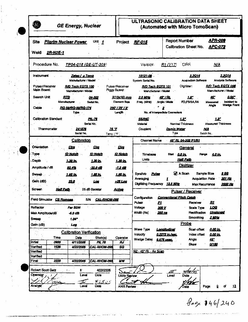
.0
'0
ULTRASONIC CALIBRATION DATA SHEETGE Energy, Nuclear (Automated with Micro TomoScan)
Site Pilarim Nuclear Power Unit 1 Project RF-o1/ Report Number ApR-009
Calibration Sheet No. APC-072
Weld 2R-N2E-1
Procedure No. TP04-016 (GE-UT-209.1 Versior, Ri (V17' DRR A
Instrument Zer/I a Tom 112-10 2.2014 2201Manufcturer I Model System Serial No. Acquisition Software Analysis Software
PulseriRecelver RMD Tech EMTX 100 Pulser/Receiver am Tech E= 101 Digitizer: R-o Tech EQTX 098Main Board: M / Piggy Board: Manufcturer Model Manufacturer J Model
Search Unit RTD &402u18) mm M• 4$LBL 1" 0J..Manufacturer Serial No. Element Size Freq. (MHz) .Angle/ Mode FD.FSISA,RA Measured Indet to
Cable •.- -72H L2S' 2 Angle Wedge Front
Type Length No. of Interniediet Connectom
Calibration Standard .L2 .ISerial No. Material Nominal Thickness Measured Thickness
Thermometer 241 75 ZL Couplant DeminWar NaSerial No. Tamp( F Type Batch Nc.
Ca~flbrtin.1211 Mill
Channel Name 45* RL 04-302 PAVRI
Orientation
,Type
- Depth
Ampliude /dB
SweepG
Gain (dB)
GeneralTimebase Start ARA Range &V&jfl
Units HM
Diatzer
Synchm r u a A Scan Sample Size. AAveraging 1 Acquisition Rate - , fDigitizing Frequency 1.5 Max Recurrence 200
J~ff11Jaim
25 CI Booster
1-8511L
Scren Adnm Pulser / Receivercoynvenoml Pft•cht•
Field Simulator CS Ro . S/N CA-HO ConfigurationPulserVoltage
Width (Na)Reflector Far SDM
rtAu
Receiver filScale Type LM
Rectification UnaneSmoothing 2U"k
Max AMpIltudeldB
SweepGai n (dB)
-5J 8d
1.04,
Log
Calibration VerificationTime Date Block(s) Operator
JInitial 0906 4011 2M( PIL7V AliVeiid 1520 4=200O5 CAL-RH.OU-09i SG
Fnl f 2229 4==/'00 CAL-RHOA""9 . MW
Wave TypeVelocity
Wedge Delay
La~flWL~
MrI~
PobeScan offsetIndex offset
AngleSkew
0.00 kLagg 11L4C
N2 -45 l-Ax Scan.
r r I *~. __________________
Robert Scott Getz I1 4/22/2005-Operato) r,. . Level Date
Analys - Level Date ANIII Review
Il Date
rýýiXt of 13PageI I
I!.2L/)ýtq

ULTRASONIC CALIBRATION DATA SHEETGE Energy, Nuclear (Automated with Micro TomoScan)
Site PilErim Nuclear Power unit 1 Project RF-01 Report Number APR-O0Calibration Sheet No. AP207
Weld 2R-N2E-1
Procedure Nc. TPM4o016 (GE-LUT-209 Versior R1 (V17) DRR WA
Instrument Zabe uTorn 18121T/ 21Manutacturer / Model System Serial No. Acqtuislio Software Analysis Software
Pulse r/Receiver R, Tech EOTX 100 Pulser/Receiver RM Tech EQTX Digitizer: R Tech E0TX pMMain Boal: ~ Manufacturer / Model Piggy Board: Manufacturer I Model Manufacture / Model
Search Unit, R 0", 2a 1}mm 1.0 IF/ L o.u"4Manufacturer Serial No. Element Size Freq. (MHz) Angle I Mode FD,FSISA,RA Measured Incident to
Angle Wedge FrontC able R G 5 R 15 # G r 7 2,51 /1 '/l a
Type Lenglh No. of Intermediat Connector
Calibration Standard •L-/ .L" i.:Serial No. Material Nominal Th~ckens Measured Thickness
Thermometer 24/8it Couplant Dtamin WN/ASerial 14c. Temp ( F) Type Batch No.
CAlibration Channel Name 45!RL M04-i P11MW
1.
Orientation.
Type
Depth
Amplitude I dB
sweep
Gain (dB)
MIX
ID D ftt
3 Booster M
GeneralTimebase Starl Range 4L nUnits lia
Dialtizer
Syncliro fu A Scan Sample Size L.NAAveragig in Acu o Rate
Digitizing Frequency LA-N Max Recurrence 2='
Pulser / ReceiverConfiguration 4onvent/ori Pit9h Q116
I.JLM
Screen tbNf~a . 25dE
Field Simulator &Sawml SIN CAL-RHOMOg
Reflector
Max Amplitude/dB
Far SDH
-17.3dB
1.01
Pulser.Voltage
Width (Ns)
ElA.120o
Receiver 81Scale TWpe LWRectification U na d
Smoothing .1=Sweep
Gain (d1) + Log
Calibration VerificationTime Date Block(s) Operator
Initial 07US 423"2 PIL 78 RJVerfled 10 423/2006 CAL-RHOM-08 RJVerified 17W 423/2005 CAL-RHOMU-09 SG
Verified 1 7Final 0120 4/24 200 iCAL-RHOM-OM PK
Wave Type
VelocityWedge Delay
LnstProbe
Scan offsetIndex offset
Angle
Skew
N2 - 450 L - Circ Scan
* L L ~. ~Jlml
W Robert Scott Getz 11 4/2212005Operta TLevei Date Utilty Review
Anal Level Date ANIII Review
Level Date
Page IQ of
ex64ý' / ( -17/; YLC

(I
ULTRASONIC CALIBRATION DATA SHEETGE Energy, Nuclear (Automated with Micro TomoScan)
Site Pilarim Nuclear Power Unit, Project 1 Report Number A
Calibration Sheet No. APC-074
Weld 2R-N2E-1
Procedure No. TPO4-016 (GE-UT-209 Version R1 (V1T7 DRF NIA
instrument ZeLw/ uT 1.121 Z ZQ-01Manufachtmw I Model System Serial No. Acquisioton Software Analysis Software
PulsRdVcelver pad Tech EQTX 100 PulserlReceiver RAD Tech EQTX 101 Digitizer: RM Tech TX 098Main Board: ManufcPrer/Model Piggy Board: Manufacturer I Model Manufacturer / Model
Search Unit A.m1-) 2tl~ in. M 10 MO'/RL L LVManumacture Serial No. Element Size Freq. (MHz) Angle I Mode FD,FSISA.RA Measured Incident to
Cable ~ 250125L13 Angie Wedge Front
Type Length No. of tn"Illedle Connectors
Calibration Standard CAL-DPT-S 0Serial No. Material Nomrial Thilckness Measured Thickness
Thermometer 241D8 Ziff Couplant Deamin Watr NASerial No. Temp (ype BatchNc.
Calibration Channel Name 600 RL 04-309 P3/RU
* Oientatio C..oC General
Type LD/f, LDH SDU Tlmebase Staid . Rang. DAM
Depth 0.W hLAWk Units
Amplitude I dB DiaSozer
Sweep 1 • k Synchro fJi [ A Scan Sample Size LNAveraging Acqulsition Rate 301
-DI (dB) 24 Lu mDigitizing Frequency 12.5 Max Recurrence 2= I&
Screen Hfaf ethf. 25 dB Booster APuser / Receiver
Field Simulator CS S/N iConfiguration ConymtoMaP/tchPulser PI Receiver m2
Reflector Far SDH Voltage Amy Scale Type LO
Max AmplitudeldB -7.2dB Width (Ns) 25O0 Rectification U~n1d
Sweep Smoothing ZM
Gain (dB) +4 PobeC Wave Type LonAitudhid Scan offset l.Calibration Verification VelOcity O.a'a;P2 in.,w, index offset -L.2i a
Time Date Block(s) Operator Weli y 0 Inde- -- iWedge Delay .10.637 u&c,. Angie "
Iinitial 0M2 4(111&M5 5 CAIIOTH-] . I SkewIVerified 1531 4=,2C ICAL-RHOU-094 SO f_____________________Verified S 2 -60 RL -Ax Scan
IVerified I 1 26 0 LA ca_________[Final 2229 4I20 CAL-R MW
Geira- Level -Date Level Dat
AaytLevel Date ANiIi Review Date Page JI. of J.2
it

I! ULTRASONIC CALIBRATION DATA SHEETGE Energy, Nuclear (Automated with Micro TomoScan)
Site Pilgrim Nuclear Power Unit 1 Project RF-• 1 Report Number A
Calibration Sheet No. APC-07a
Weld 2R-N2E-1
-•rcedure Nc TPO-4-016 (GE-UT-209,1 Versior Ri (V17) DRR ' NA
Instrument 'Ze / u Tom 112 1 . 2.-V/Manufacturer / Model System Serial No. AcquisItion Software Analysis Software
Pulser/Recelver RD Tech EQTX 100 Puiser/Receiver RM Tech EQTX 101 Digtizer: RoD Tech EOTX 09Main Boav• Manufacturer / Model Piggy Board: Manufacturer / Model Manufactur i Model
Search Unit. 2(10108) m .m 0 60rli .50Manufacturer Serial No. Element Sie Freq. (MHz) Angle I Mode FD,FS/SARA Measured Incident to
Cabl -~~ ~ zi:LM1 2Angip Wedge FrontCable RU-07-511I7 250'125!13' ,• rn
Type LengUh No. of Intenredlee Conmectors
Calibration Standard CAL-D!RO II AC .6Serial No. Material Nominal Thiciess Measured Thickness
Thermometer 241878 f Couplant Detin WaSerial Nc Temp (*F Type Batch No.
Calibration Channel Name 60 RL 00.349 Ps/RS
* Orientation.Ii GeneralW TWOe ~R Timebase Stanf Range I~
Depth UOL601 Maw kNL D k units tiLLaU
.Amnplitude/dB MAN 1&0-1& Dialtizer
Sweep iza 1 t 1,S . Synchro E WM A Scan Sample Size LaAveraging 1 Acquisltlon Rate 3.1
Gain (dB) m J +.2 Lo a Digitizing Frequency 6M Rik Max Recurrence 00
Screen Half 25 dB Booster Pulser / Receiver
Field Simulator • l S/N CAL-RHOM-095 Configuration Qgnvent/nePitchCg
Pulser S l B Receiver NReflector Near SDH W/A Voltage A00 Scale Type LOMax Amplitude/dB -1&8.5dM WA Width (Ns) 5Wa RPWCSetiAtaiion
Sweep O.7r WA Smoothing .
Gain (dB) + Log WA ProbeWave Type LoMudinai Scan offset ESmka
Calibration Verification Index offset 0.00ATime Date Block(s) Operator Wedge Delay 9.597 Low Angle W
Initial 0733 42 CAL-VPTH-M3 RJ SkewVefied I12 4205 CiL 7 Ai• k1Verified 1705 423MM005 CL4L-HOM- i SG N2- 60 RL -Circ ScanVled f j iRnai 0120 4242005 CAL-RHOM- PK
0 Robert Scott Getz ,, I 4/22/=05Operat•& . . Level Date Utility Review Level Date
Level Date ANIII Review Date Page 12 of
vlo-ý ~~qA1 1),tfj/Lt C)

i
(.
I.e
ISite: Pilgrim Nuclear Power Station Component ID: -2R-N2G-1
Outage: RF-015 SAFE END TO NOZZLE
System an ASME Cat.: B-F ASME Item M".1 Aug Req NIAExams Data Sheet I Cal Sheet Procedure I Calibration Block Examination iCart Level! Date
Performed' Perscnnei i
45 1 S N/A APC-055 TP04-016 iGE-UT-209) Fil (V17) PIL-78 Kyle Davidson i-L 4i25/2005450 / RL N/A APC-060 TP04-o16 (GE-UT-209) R1 (V17) PIL-78 Kyle Davidson I-L 4/25/2005450 / RL N/A APC-061 TPO4-O16 (GE-UT-20e) R1 (V17) PIL-78 Kyle Davidson I-L 4/2512005
60 / RL N/A APC-062 TP04-oiO (GE-UT-209) RI (V17) CAL-DPTH-063 Kyle Davidson I-L 4/2512005600 / RL N/A APC-063 TP04-016 (GE-UT-209) Ri (V17) CAL-DPTH-063 Kyle Davidson I-L 4/2512005
N/A APD-006 N/A TP04-016 (GE-UT-209) il (V17) N/A Kyle Davidson I-L 4/25/2005
Examination Results:During the automated ultrasonic examination of the above referenced dissimilar metal weld, no Indicallons associated with IGSCC wererecorded with the "SMART 2000" system utilizing a 450 shear wave, 450 and 800 refracted longitudinal wave search units.The 450 shear wave examinations were performed from both the upstream and downstream sides of the weld. Root geometry, insidesurface geometry, beam redirect and non-relevant indications were recorded.
The 450 RL wave examinations were performed from both the upstream and downstream aides of the weld. Root geometry, acousticInterface, welding discontinuity, inside surface geometry and non-relevant Indications were recorded.
The 60W RL wave examinations were performed from both the upstream and downstream sides of the weld. Acoustic Interface, Insidesurface geometry, welding discontinuity, and non-relevant indications were recorded.
A welding discontinuity was detected and sized to IWB 3514-1. It was found to be acceptable. The indication had the following parameters:Length: 8.837-12.43"Through wall: none
This Indication was recorded but not reported In the previous automated data.
The outside surface weld crown did not meet procedure requirements from 0r to 4, 23" to 28, 31" to 34" and 38" to 42" crcumferentially.71.8% procedural coverage obtained.75.3% code coverage obtained.
Previous automated electronic data and automated reports and drawings were reviewed prior to this summary.
Exanmiation results iere conpared to data report 97-E-357 from
These examinations were performed under Work Order 03116627.
1997 outage,, ,h E- No Change
Change
This Summrary and the lbqa~wing data sheeft have been wed*ý a acpebythe Wdlwun1, pefsonne:
Prp d~..?-_ ee: Date: ti~~Dye
6%'9c- ~

Wall ThicknessProfile Sheet
Crown Height
Crown Wkdt- Ic
Dt4ST Component:Noqrinal Diameter:.
NWeld Length: uir
Flow
45sihr. 45PL.. WgRL
Safe End ( - ) Procedural Exam Volume Nozzle ( + )
0
Weld props obtained from drawings; 137C8066 and MIA73 sheet 2Bottom of nozzle bore to IncICS Interface - 4.CrBottom of SE taper to Inc/CS interface = 8.0

Wall ThicknessProfile Sheet
CrovM Height:-
Crown Widtlt
UPST Component DNST Component:Nominal Diameter " iu=
IWeld Leng.•
45"shr, 45"RL, G0"RL 4S*hr, 4V'RL. 60'RL Scan Zero 45'qhr, 45"RL. 80ORL 45"shr. 45'M "n'RL
I
.......
I
Aý
*~*\77.Safe End ( - ) Code Exam Volume Nozzle ( +)
Weld preps obtained from drawings; 137C8066 and M1A73 sheet 2Bottom of nozzle bore to Inc/CS interface - 4.0"Bottom of SE taper to Inc/CS interface = 8.0r
Date:
Page I of JA

Configuration:
o=I
9e so Ic/c-..,.L-
180"I
m
7-70 SAXIGfS
7-7~ - -'
LIate:
Page A of 14
j

CN2G Safe End to
-h-
Pilgrim Unit I RF015
GE Energy, Nuclear
Nozzle 45*RL LKUP Welding Discontinuity.
ww-
Page 5 of 14

GE Energy, Nuclear
142G Safe End to Nozzle 60°RL LKUP Welding Discontinuity
0Pilgrim Unit 1 RFO15 Page 6 of 14
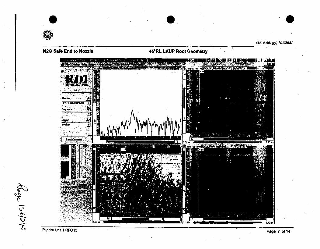
0 .0
GE Eneigy, Nuclear
N2G Safe End to Nozzle 45°RL LKUP Root Oeometry
Plr 1
Pilgrim Unit 1 RFO15 Pg 01Page 7 of14
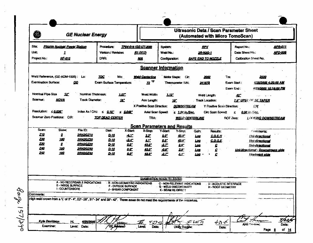
O GE Ultrasonic Data I Scan Parameter Sheet(Automated with Micro TomoScan)Nuclear Energy
Site: Pl/aft Nutafr Pw i
unit:
Project No.: RlE-0/
Procedure: jt'/ Af-E--)
Version / Revision: B1A MDRR: NA
Weld No.:
Confligoalon:
2l-NQ - IReport No.:
Data Sheet No.:
Calibration Sheet No.,. | mm i, •
• Scanner InformationScanner Information
Weld Reference, (GE-ADM-1005): Lo:
Examination Surface: 9DTIN Wo:
Exam Surface Temperature:
wAidOF
Motor Steps: Cir
Thermometer SIN:
Tra:
Exam Start:
Exam End: 4/2¶~jOO5 1O~1 8:00 Paw
Nominal Pipe Size wZ
Scanner:
Resolution: <0.036"
Scanner Zero Positions: CIR:
Nominal Thickness:
Track Diameter: ./a.:Weld Width:
Arm Length:
X Positive Scan Directioi
Axial Scan Spee
TRA:
Weld Length: 2.Track Location: L..ET r-
DO: "fREA Y Positive Scan Direction: TW
=d: s 1L~P, iMSM. Circ Scan Sp.ed: S
MAP.. J1 IiBJ. . ROT Zero: L,..KING...
Index Axl/Circ: !5 gMd s AEiW
Q&-*an Dara mam 0w~ 11# 5ý EEW-I~I ~ IIRawl a RLIV qwipu
-xaQQOKW.
.9-ile IU:
aRNacZao
-NifZ
Diskc: X-Shtar
Ax
X-Sto. y-Steart
2z
46*
Y-top:
Aw
Gain:LoUJimloaLu='i,-
Resits: ('Imments:
Uni-direA I nUni-dkir4d1nal
=u uLukuma d... ftuJlfIzfE5V =- -
0
EXAMINATION RESULTS LEGQENDA - NO RECORDABLE INDICATIONS B - NON-GEOMETRIC INDICATIONS C - NON-RELEVANT INDICATIONS D -ACOUSTIC INTERFACEE - INSIDE SURFACE F - OUTSIDE SURFACE 6 - WELD DISCONTINUITY H - ROOT GEOMETRYI - COUNTERBORE J - SHEAR COMPONENT K - BEAM RE-DIRECT
Comments:* k* ".4UI la-- !U' d~ l-r n -4.ms resd o etterqieet ftenoeue
]OW dww% aL O u 4 4 -,2 , 1--34"and38%42 Thee aeasdo ot eettherequremntsof m noceure
KY08 DaVidion Le9 2 n ANII llptisw . DaDa:Exarmdner Leel -eo DaAte:--~ Date: pg 1 O

I.
0
ULTRASONIC CALIBRATION DATA SHEETGE Energy, Nuclear (Automated with Micro TomoScan)
Site Pliarm Nuclear Power unit 1 Project RF-015 Report Number APR-01 1
Calibration Sheet No. APC-Of,
Weld 2R-6N2G-:
Procedure No. TPO4-016 (GE-LUT-209 Version R1 W1iT, DR, NIA
instrument Zeatcliu To&/ * L2r1 2Q21Manulactuer / Model System Serial No. Acquisition Software Analysis Software
Pulser/Recelver RD Tech EM 100 Pulser/Recelver RM Tech E07X 101 Di~. zR, Teh EOTX OMMain Board: Manufctrer Model Piggy Board: Manufacturer I Model Manufacturer I Model
Search Unit T 03-341 EI24k17 mm 1.5M4 N/A . :Merwfmctwu' SerilJ No. Element Size Freq. (M1z) Angle I Mode FD,FS/SA.RA Measured Incideno to
Cable 250'1L1 Anie - Wedge Fron
Type Length No. of Inlernedile Conrtome
Calibration Standard P, 1J.Serial No. Material Nomhal Thicknees Measured Thickness
Thermometer 241/88 ZLF Couplant Demin..Watr NA
Serial No. Temp ( IF Typ Batch Nc.
Calibration Channel Name
Orientation General
Type ID ID /D .c Timebsue Stt Range
Depth 1.3 L 1. Units
Sweep 1.1 1.ri. Synchro Eu A Scan Sample Size LaAveraging 1 Acquisition Rate 30/LP
Gain (dB)/.Lo Digitizing Frequency 15Mik Max Recurrence
Screen HalfPMf 25 dB Booster /tUedMA Pulser / Receiver
Field Simulator CS Roma S/N CAL Configuration Convntina Puls Echo
Pulser at Receiver WAReflector Far SDH Voltage 3v Scale Type LO
Max Amplituds/dB -19.5dB Wldlh (Ns) 33. Rectification
Sweep 1.01" Smoothing .
Gain (dB) Log ProbeWave Type TrmnsLmw Scan offset -160 hL
Calibration Verification Velcity 1240 Index offset Lrime Date Block(s) Operator Wedge Delay .7Zg MS. Angle 45"
LVerified Data 4Dae Pge o CAL-RH gVertfed 07f 42&200ffCAL-RHO-04 Sa N2 -45* Shear - AxICIrc ScanVerified IS III CIL-RHO" KO A Scan offet- 0.0" Index offet-2.6"
2214a IVDj Clrc: Scan offset - 2.6" Index offset 0.0"2214 4M IICAL-RO- 09o4' KD
Kyle Davidson I-L 4/25J2005 I---,-
T= ///q-OeA, t/ .J- Level Dat . R ateP• • o
449c,

1@
I.
ULTRASONIC CALIBRATION DATA SHEETGE Energy, Nuclear (Automated with Micro TomoScan)
Site Pilgrim Nuclear Power unit 1 Project RF-01 Report Number APR-011
Calibration Sheet No. APC-060Weld 2R-N2G-I
Procedure Nc. TPO4-Oi6; tGi_-UT-209) Versior R7 (VI7 DRR N/A
Ins trument Zow / ~u Tom 181R LimQManufacturer I Model System Serial No. AciuiMflion Software Anrlsi Software
PulserlReceiver R, Toch EOTX in PulserlRecelver RID Tech E 'TX 1 Digitizer1. RID Tech EQTX 0M.Main Board Manufacturer I Model Piggy Board: Manufacturer/ Model Manufacturer / Model
Search Unit. R=D -- Of 20jA18) m 2 0M 45 LW M 4Manufacturer Sedel No. Element Skm Freq. (MHz) Angle / Mod. FDFSISARA Measured Incident to
Cable RQ-5&7 2512-129-1Antgl Wedge Front
Type Length No. of Intermediate Connectoer
Calibration Standard flL /.3"
Serial No. Material Nominal Thickness Measured Thickness
Thermometer 2418 Z5ff Couplant Demin WfrNASerial No. Temp ( F) Type Batch NO.
Calibration Channel Name 45- RL 04-302 P1/RE
Orlentaton 93 21 21 General
Type I.ahTImebase start IR RAnge 4&&
Depth 1JA3a 1.30io 1.30 Units HAMMi~
Amplitude I dB RAN u, 0a-7e
Sweep 1z Ii 1aif Synchro ff [ A Scan Sample Size IAAveragIng 1 AcquisItion Rate 301Digitizing Frequency 12.5 Max Recurrence 2O k
Screen H&alL PEa 25 dB Booster hft. Pulser / Receiver
Field Simulator CS oSN CAL Configuration CanngdonlPitch,_Pulsr 1 Receiver fa
Reflector Far SDH Voltage Au Scale Type Lag
Max Ampifnude/dB AS d8 Width (Ns) 25m Rectlifiation Uoian
Sweep 1.04" Smoothing 2
Gain (dB) Log ProbWave Type Lonaitudioal Scan offset 0
Calibration Verification Velocity .22 imm. Index offset 0.00ATime Date Block(s) Operator Wedge Delay 9.675umaw Angle MC
Initial 0900 4/1 1200M PIL 79 RJ SkewVerinfed 1890 425'0MO CAL-RHOM-* KDOVerifiedVerfled
lFinal 2216 4925= CAL-RHOM KD
Kyle Davidson l-L 4/25/2005
tOr Level Date uti ty A Level Date
Analyst Level Date ANIII Review WDate" Page jfl of JA
4

ULTRASONIC CALIBRATIOLN DATA SHEETOGE Energy, Nuclear (Automated with Micro TomoScan)
Site Pilarim Nuclear Power Unit 1 Project RF-015 Report Number APR-ICalibration Sheet No. APC-061
Weld 2R-N2G-l
Procedure No. TPO4-O 16(GEU72.04f• 'vrsicr, RI A-1; DRF NIA
Instrument ZW U8121 2.2X2Mahufacturer I Model System Serial No. Acquisition Software Analysis Software
Putser/Recelver RD Tech EOTX 100 Pulser/Receiver R'D TeLh EQTX 101 Digitizer RV Tech EO'X 0awMain Board* 'Manufacturer / Model Piggy Board: Manufaclurer/ Model Manufacturer I Model
Searc" Unit T 04-310lo}mm l.0 450/z j L 4.4.Manufactuirer Serial No. Element Size Freq. (MHz) Angle / Mode FD,FS/SA.RA Measured Inckden! to
C Angie Wedge FrontCable RQ-VqQ5 &7 25' ' itType Length No. of intermediale Connectors
Calibration Standard L SSLL iJ.Serial No. Material Nominal Thickness Measured Thik:cness
Thermometer 2418Z Z 7L Couplant Detin WatMrSeril Nc. Ternp (°F Type Batch Nc.
Calibration Channel Name 45- RL 0 /10 P1/R1
O rentation MN 1 2c General
Type ID L " Timebase St J Rage Lo
Depth 1.30 oa 1IVk 1A Units fte
Amplitude Id. -46.4 d-. DiaOtze
Sweep 1.8JL1. I 1EIhIL Synchro • [ A Scan Sample Size LaAveraging 1 Acquisition Rate 301Digitizing Frequency 6-20jf Max Recurrence .21
Screen uhtaM 25 dB Booster A Pulser/ Receiver
Field Simulator S SIN R Conflguration Convental EM Ca
Pulser Receiver Ri
Reflector Far SDO Voltage A0 Scale Twe LM
Max Amplitude/dB -17.3dB Width (Ns) W Rectification
SweeP1.0M Smoothing 1hfGain (dB) + Log Probe
Calibration Verification Wave Type Lonaitudinh Scan offset &.00•Velocity 02= . Index offset 0, 1
Time Date Block(s) Operator Wedge Delay 11, 1 Angle
Initial 0703 4130M PXL78 RJSIVerified 025 402&2M( CAL-RJI -09 SG _____________________Verified 0732 42S2O05 CAL-RHOE SG N2- 450 RL - Clrc &can
IVerifiedL ZI ]FInal 1840 412500S CAL-HO* KD
0 y le DavidsouI D-L 4/25e200 11 of 14Operat r7 Leve, Date U0~ve& ) *CeVel Dal,
Anls/Level Data ANIII Review Date Page 11. of 14
JO4 16oputv

SGE Ehergy, Nuclear ULTRASONIC CALIBRATION DATA SHEETGE________ EN(Automated with Micro TomoScan)
Site Pilgrim Nuclear Power Unit 1 Project RF-01 Report Number APR-O11Calibration Sheet No. AfP.
Weld 2R-N2c-1
Procedure Nc.. TPQ.4-0iQ ,'GE-UT72 ,9" Version Ri (V07) DRR N/A
Instrument -f.Le aI/ U 18121-0 LA~U *Z2M14
Manufacturer I Model System Serial No. Acquisition Sodtwam Analyis Software
Pulser/Recelver RID Tech EQTX 100 Pulser/Receiver r Tech EQTX 101 Digitizer: R.D Tech E07X 0NMain Board:1 Manufacturer / Model Piggy Board: Manufacturer / Model Manufaclurer I Model
Search Unit .1xD -2lu18)m 2.0 M 60L i.Manufacturer Serial No. Element Size Freq. (MHz) Angle / Mods FD.FS/SA.RA Measured Incident to
Cable MORCHI 74- 25W1fL267 2 M&gle Wedge Front
o Type Leth No. of Inlemediata Comectors
Calibration Standard QAL- -20,Serial No. Material Nominal Thickmnes Measured Thickness
Thermometer. 24187. MY Couplent Deamin WaASerial No. Temp ( *F) Type Batch No.
Calibration Channel Name 60° RL 043S P31/S
Orientation. Generl
Type IUIUO Timebms Start D"RangeUh1
Depth 0 so Units Jn EM
Amplitude / CB Al51 Dlafter
Sweep . 16 ,m 1 L Synchro. E•I A Scan Sample Size L.Averaging 1 Acquisition Rate 3011&Digitizing Frequency 12.5 Max Recurrence 2.ik
Screen IaIL E 25 dB Booster A Pulser / ReceiverField Simulator a SIN CAL-RIILU -Of Configuration Conye P/toh CaEM
Pulser Pa Receiver M
Reflector Far SDH Voltage Mau Scale TOe LA .Max AmplftudeldB -7.2dB Width (Ns) 250N Recllfcatlon Unnid
Sweep 1,5" Smoothing L
Gain (dB) + Log Probe
Wave Type Lomwknt/ Scan offset &Clibration verifation Index offset -5JOj
Time Date Block(s) Operator W Delay 10.l7." ne~iniia 0 411,2006 CAL -DPTH-063 Ralf~Verified 1844 4,25&2005 CAL-RHOM K1_Verified N-AVerifiedFined 2212 425/200 I CAL-RHOM KD _
KO ,•e Davidson te_ 4520___
Ope rait7 'level -Date E Dt
Anal" y'.~.. Level Date ANiII Review Date Page J2 of JA
0
Jz(/)#d
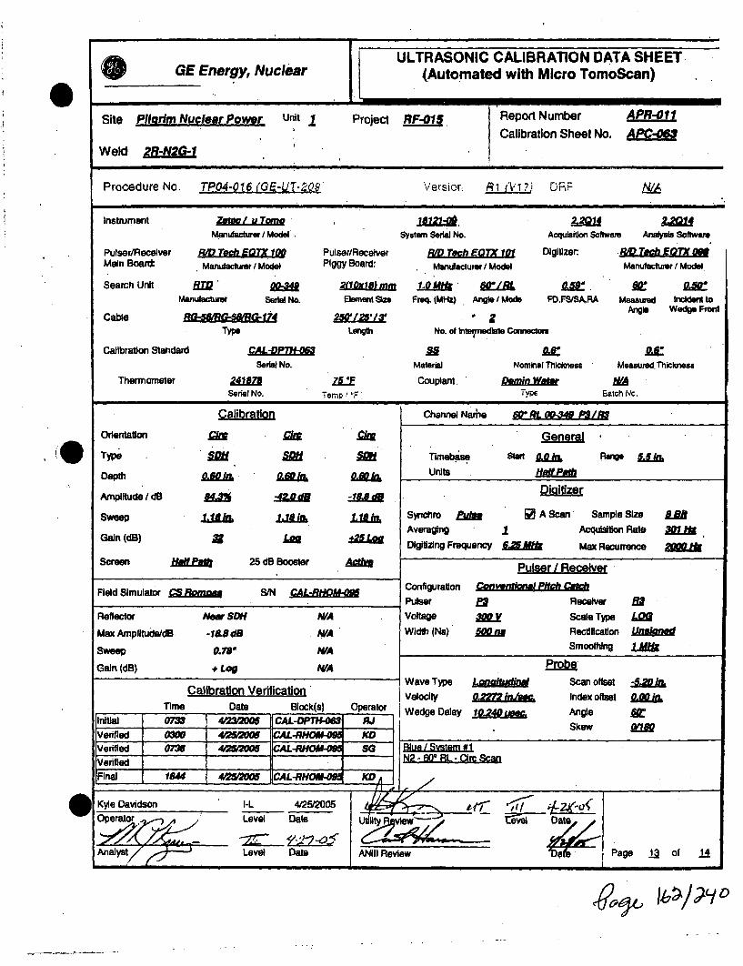
ULTRASONIC CALIBRATION DATA SHEETGE Energy, Nuclear (Automated with Micro TomoScan)
Site Pilgrim Nuclear Power Unit 1 Project RF-01/ Report Number APR-E11
Calibration Sheet No. APW
Weld 2R-N2 -I
Procedure No. TP04.016 (GE-UT.-Qg' Versior R1 A.;?i D7 IVA
Instrument zetac / U Tome 1811 -2-,01
Manufaclurer / Model System Serial No. Acquiition Software Analysis Software
Pulser/Receiver R .TOMh f •7X 100 Pulser/Receiver R D Tech EQTX 101 Digtizere Ri Tech EQ 7X 0.Main Board: Manufacturr / Model Piggy Board: Manufacturer / Model Manufacturer I Model
Search Unit R.0 21lxLLrmm • •LM M LB I.5 .Manutactu Serial No. Element Sin Freq. (MHz) Angle / Mode FD.FS/SARA Measured Incident to
Cable _ _ _I2_ _13_ _2 Angle W edge Fro nt
Type LengWh No. of Intemediefe Connectors
Calibration Standard CAL- .Serial No. Material Nominal Thlcknese Measured. Thicloness
Thermometer 241878 ZLE Couplant. DminASerial No. Temr rF Type Elich 1,c.
Calibration Channel Narhe 60 RL 00-349 P3/R$
Orntation cis MI XI General
0 Type Tlrnebm Start Rang ~JJLMDepth aI al& • units ie201
Amplitude IdB fiats ALIEN -1rSweep is .18In, i Syriliro PuAM E A Scan Sample Size Lo
Averaging 1Acquisition Rate 301' UDigitizing Frequency 6.W$M Max Recurrence 2M I&
Screen HAN 25 dB Booster Pulser / Receiver
Field Simulator S. S/N CAL Configuration Canvedoiom Pitc
Pulser E2 Receiver 81Reflector New SDH N/A Voltage A Scale Type LO•
Max AmplitudeAdB. -18.5dB W A Width (Ns) 500 Rectification Unanem
Sweep 0.78" WIA Smoothing LMU
Gain (dB) + Log N/A Probe
Wave Type Lgnaijudingl Scan offset iJCalibration Verification Velocity o=, SW. Index offset 0n•axose
Time Date Block(s) Operator Wedge Delay 1&Z0.4,,. Angle fieInitial 0733 40'2120M CAL-DIPTIN-MI PJ Skew
IVefified 0____________________________________
Verified 07W 42S2M CAL-RHOU.* SG Blue L Svstsm #1Verified N2 - 600 RL- CiS
Final 184 4 42&.= CAL-R - KD,
OKye Davidson ____- •5"e D 0D_
O eao ,Level Date Dilate
Anls/Level Date ANIII Review Dise'ob Page of j
V&9-11 1ý7ý1 4ýv 0

e,GE Eneruv. Nuclear
00-
Micro-Tomo (Smart.2000) - Auto PipingWeld Examination Checklist
Pilgrim Unit 1, 20052R-N2G
y p y p y
2LKRHLKm
Load
setup
Offsesentered IntoI correctly
TransducersSkewed lAW
Procedure
Res namnedIAW
Scanpian
360*conhaev
achieved
3600 Orecoverageachieved
FuH VolumeAx Coveage
Achieved
Scan saved tocomputer HD
Veried readae
Data transIfered to DAVerte received by OM
71
cc
C , (D
NO.TiQES:
450 Shear ['.1 [] .• [] - MJK I.JK MJK450 RL [] J] KD MW MJK M.JK MJK600 _____ [ [ [] *] [] __ MJK WMJK MJK
Load Offsets Transducers Piesc named 30 36W acric Ful Volume Sva Saved r o sa aeto W < o 1•appropria•t entered hit Skewed IAW JAW conact coverage Ax Coverage cpuberRD OM transferredInDA Z : C NOTEStsetup TV conect Pro.edure Scanpian achieved achieved Achieved Va•fed reada cc < o
450 Shear 12 [a 1 0 El QD [ MJK MJK MJK450 RL M 0 E [] 9D • 9 K MJK MJK MJK
60° RL [ [ [ [ [ Q] [ MJK- MJK MJK
Load Offtets Transducr Rlies named 3600 3600 Carc Ful Volume Scan saved to "approprit*e entered Into Skcewed JAW JAW contact coverage Ax Coeage comfputerHO -d byOTES:
setup TV correctly Procedure Scanplan achieved achieved Achieved Varied •eadable c (T450 She []E 9[ ED [ ] MJK WMK MJK
450 RL E" El RI [a _ [RI 0 s_ SG MJK MJK MJK
600 RL 21 El 91 El 91 W• ]MK MJK MJK
I .e./
2RN2iZ40. Lodw Offsets Transducr Film namned 311? 3600 Orc Full Volurm Scan saved toD V .!qLK W appropuiate aree ha ShweAW JAW contact coerg Ax Coerg byýE:DDtatadndtoD tNTLKCCW ~setup IV cornec* Proicedure Scanplan achieved achiv deved Achiev ed Verified rcie yD
450 Shear M *. ** K MJK MJK450 RL SG so 0 ZMK MJK MJK600 Ri E! W _ __ _ _ _ _MK MJK MJK _ _ _ _
Ndm Weld profile does not meet procedural requlremnwb fromn 0--4-, 23-2-W,.31"-34" and 38"-42"
0Ur
Panp 14 nf 14

GE ENERGY, NUCLEAREXAMINATION SUMMARY SHEET
Report No.:APR-012
,w Site: Pilgrim Nuclear Power Station Component ID: 2R-N2J-1
Outage: RF-015 SAFE END TO NOZZLE
system B.U ASME Cat.: j, ASME Item B01 Aug Req
Exams Data Sheet Cal Sheet I Procedure Calibration Block I Examination ICert Level! DatePerformed Personnel
45/1 RL NtA APC-066 TPO4-016 (GE-UT-209. Rg (V17, PIL-78 I Kye Davidson ____-L__ 4/22(20054V / RL N/A APC-067 TPO4"16 (GE-UT.209) RA (V17) PIL-78 Richard Jasken II 4/27/2006
600 / RL N/A APC-068 TP04-016 (GE-rT-209) R1 (VI7) CAL-DPTH-063 Kyle Davidson I-L 4/25/2006600 / RL N/A APC-069 TPO4"I6 (GE-UT-209) R1 (V17) CAL-DPTH-063 Richard Jasken II 4/27/2005450/ S WA APC-065 TPO4-016 (GE-UT-209) R1 (V17) PIL-78 Richard Jasken II 4/27/2005
N/A APD-008 N/A TPO'16 (GE-UT-209) Ri (W) N/A Richard Jasken 2 2127/2005
Examination Results:
During the automated ultrasonic examination of the above referenced dissimilar metal Weld, no Indications associated with IGSCC or anyreportable Indications were recorded with the *SMART 2000" system utilizing a 450 shear wave and 450 & 600 refracted longitudinal wavesearch units.
The 450 shear wave examinations were performed from both the upstream and downstream sides of the weld. Root geometry, beamredirect and non-relevant Indications were recordec.
The 450 RL wave examinations were performed from both the upstream and downstrearht sides of the weld. Root geometry, acousticinterface, inside surface geometry and non-relevant Indications were recorded.
The 600 AL wave examinations were performed from both the upstream and downstream sides of the weld. Inside surface geometry andnon-relevant Indications were recorded.
The outside surface weld crown did not meet procedure requirements from 13" to 30r on the upstream side of weld centerline and from 0"to 42.0' on the downstream side of the weld centerline to a W of 1.10'.
65.7% procedural coverage was obtained.75% code coverage was obtained.
Previous automated reports and drawings were reviewed prior to this summary.
Eiraninatk~n results wer conraamd to data report 95-E-434 from 1996 Outage Wfth No Change
These examinat/ons were perdormed under Work Order. 03116627 0 Change
This Surmnrny and We following data sheets have been revigwed and apcepted by fte to/lowing pelsonnel:6
., ,C , ~ ' ~ir i i- 1ý$ 6:jL Dose: 1500 mr.Pre arBV Level: Date: Utility Review: Dae:
ANII Review- Date: Page I of 13
4 16 ý/?_ýo

Wall Thickness wProfile Sheet
SU: dftMxwPar k Unit I Report N
PrniEct R"A
Q4 5
Crown Height
Crown Wkft MSAFEH
I IPST Component ONST Component:Nominal Diameter. iu:
Weld Length
Sale End ( - ) Procedural Exam Volume Nozzle ( + )
4P0
Weld preps obtained from drawings; 137C8066 and M1A73 sheet 2Bottom of nozzle bore to Inc/CS Interfae = 4.1"Bottom of SE taper to Inc/CS Interface = 7.5"
GE RB'vgWm By-. -t DaWe: Date.page 2of JA

Wall ThicknessProfile Sheet
Crowm Height oIf
Crown Width IC:UPSTComponent: DNST Component.
Nominal Diameter
Weld Lenqgh:FLOW-
Safe End ( - ) Code Exam Vnlume Nozzle ( + )
The scans above show the limited areas, The entire volume was scanned.Weld preps obtained from drawings; 137C8068 and MIA73 sheet 2Bottom of nozzle bore to Inc/CS interface = 4.1"Bottom of SE taper to Inc/CS interface = 7.5"
xaminer: Level: Date: GE ReviWe ,B. 4" Level: Date: Date: Date.Page of Ia

] ke Miato uharP Unit 1 Report NurProiect ROiI eA"Iz
(). i-;,"pc: plc.,',
XkJCi4-~II
Si)',' a
, X&CIC-5 - . - %
GE Reviewed By " Level: Da•te1 T-I i. 1=- =21i By. Date: ANII Reviewd BY: Date:
Page -4 oft]2

09 C.
G.I FEnergy, Nuclear
N2J Safe End to Nozzle 45°RL LKDN Root G-eometry
'z~j40__ ini -- --
Pilqcrill Unit 1 RFO15 *j. Page 5 ot•13
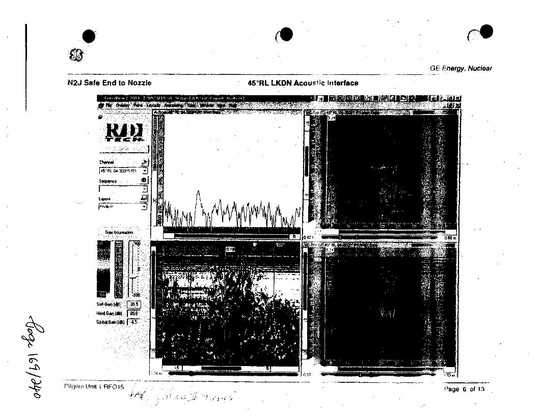
Q.GE Energy, Nuclear
N2J Safe End to Nozzle 45°RL LKDN Acoustic Interface
piljiiii Unit I RFOIS !"age 6 of 13

Ultrasonic Data I Scan Parameter Shee"GE Nuclear Energy (Automated with Micro TomoScan)
1rt eso eiin 1 nWl o:Dt ho No.: -A uProject No.: liE415 DRR: Configuration: SAFE JEW TO NM=E Calibration She~et NO.
Sanner Information
Weld Reference, (GE-ADM-1O05): Lo: Wo: Wea.dgntilon MotorSteps: C.ir - Tra:
Examination Surface: ap Exam Surface Temperature: 1/ OF Thermometer •VN: 24/W Exam Start: 4.2•L.• fl
Exam End: .4,,QA
Nominal Pipe Size 12" Nominal Thickness: Weld Width: .8 Weld Length: 42
Scanner: HIM Track Diameter: Arm Length: /8 Track Location: 15.5' UPST FROM CS/IN INTERFA
X Positive Scan Direcilon: DWNSTREAM Y Positive Scan Direction:
Resolution: :s2AM& IndexAx/Circ: ! 0J= s A Axial Scan Speed: < A 0oin,/j c, Clrc Scan Speed: S 1.0 in.Sec
Scanner Zero Positions: GIR: TPEAD CE•jNZIB TRA: W ROT Zero: LOOKING DOWNS TREAM
Scan Parameters and ResultsScan: Skew:. File ID: Disk: X-Start X-Stop: Y-Start Y-Stop: Gain: Resuits: Comments:
z11 2R-13O 4,11 24 .. L• UJVnidirectkng
z, .. li oo"a J.- n•. ao La • unidectinna•
EXAMINATION RESULTS LEGEND
A - NO RECORDABLE INDICATIONS B -NON-GEOMETRIC INDICATIONS C - NON-RELEVANT INDICATIONS D - ACOUSTIC INTERFACEE - INSIDE SURFACE F - OUTSIDE SURFACE G - WELD DISCONTINUiTY H - ROOT GEOMETRYI- COUNTERBORE J - SHEAR COMPONENT K - BEAM RE-DIRECT
Comments:Inside surface geometry outside to exam volume.
LKDN Imiled from aVL' of 13" to 304 on the upstream side of dot weld centerline due to do 0D contour.7 LKUP ,rmited from a'L' of 0" to 42.0* on the downstream side of the weld centerine due to the 00 contour.
R~cwd~ekw -~ 4~7~ / ./ ~ I '-2t-- ' •ANII.Review: Dom:Examiner: Level: Date: ELve: Dt:eiw:De:Page Z of Ij1
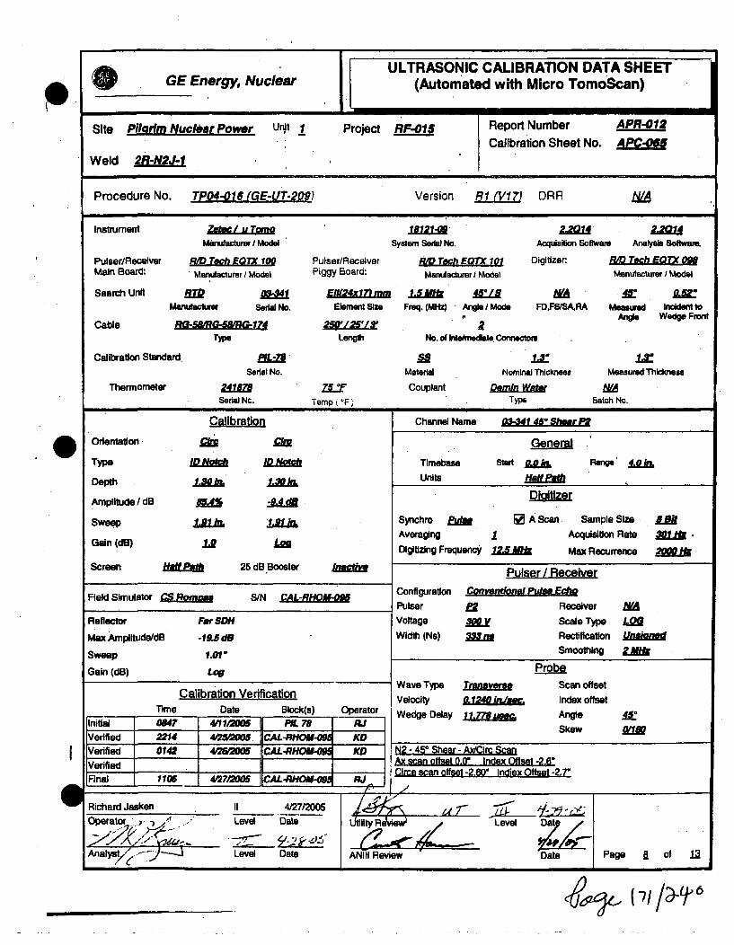
___ULTRASONIC CALIBRATION DATA SHEETGE Energy, Nuclear (Automated with Micro TomoScan)
Site Pilarim Nuclear Power un.t 1 Project RF-01 Report Number APR-012
Calibration Sheet No. AP -OWeld 2R-N2J-1
Procedure No. TP04-016 (GE-UT-209) Version R1 (V!7J DRR NIA
Instrument Zet./l u Tome 18121- 2,201M L2QManufacturer / Model System Serial No. Acquisition Software Analysis Software,
Pulser/Recelver RID Tech E0TX 100 Pulser/Receiver PD Tech EQTX 10 Digitizer: RPD Tech EOTX 098Main Board: Manufacturer I Model Piggy Board: Manufacturer I Model Manufacturer I Model
Search Unit 1ID EN24 mll .11• 45/1 NA A4Manufacture Serial No. Element Siz Freq. (MHz) Angle I Mode FD,FS/SA.RA Measured Incident to
Cable ______________ Angle Wedge Front
Type Length No. of Intehnedste Connectlo .
Calibration Standard RL- • ixSerial No. Material Nominal Thickneas Measured Thicknesa
Thermometer 2418 MY Couplant Detain Wafe N/ASerial Nc. Temp (IF" Type Batch No.
Orientation
Type
Depth
Amplitude / dB
Sweep
Gain (dB)
ID~
GeneralTimebase Stan PLRnge 4.k,.
Units H Pafa
Di-giftie
Synchro ffM E A Scan Sample Size f
Averaging 1 Acquisition Rate 301 .
Digitizing Frequency 125 Max Recurrence 2
Channel Name 03-341 451 Shear F
MA0
1A A-
25 dB 'BoosterScreen Ha&f ft
Field Simulator CS Rom S/N CAL-:RHBM-Ag ConfigurationPulserVoltage
Width (Ns)
Pulser / ReceiverConvendonal PulseEcho
/ez Receiver
am Scale Type
33m RectificationSmoothing
Reflector
Max Amplitude/dB
Sweep
Gain (dB)
For SDH
-19.5 d8
1.01"
Loa
YAllU"a~
Calibration VerificationTime Date Block(s) Operator
Initial 084? 411120 IM PIL 78 hJVerified 2214 425005. CAL-RH KOIVerifie 014 41625 CAL-RH KD
Final I 1106 4272005AL o M -4 RJ
Wave Type
Velocity
Wedge Delay
T-a. 1240 in.sec.
11. 7"7 usshm
ProbeScan offsetIndex offsetAngleSkew
4sM
N2 - 45* Shear - AxIClrc ScanAw sc~an ntfr~tqa flf Inriay tff it -2 Er'; . ýff..t 13 An- I-A;-. n"--t 13 -P-
-I
Richard Jasken II 4/27/2005
Operator .-. / Level Date
Anai"y-! - -Level Date
L 1dllty Re' Iew• Level D 8 /
ANIi Review Date Page a of 13I i
(64(-7/ /0%1/6

I l ULTRASONIC CALIBRATION DATA SHEETGE Energy, Nuclear (Automated with Micro TomoScan)
Site Pilgrim Nuclear Power unit 1 Project RF-O01 Report Number APR-012Calibration Sheet No. APC-Op,
Weld 2R-N2J-1
Procedure No. TP04-016 (GE-UT-209t Version R1 (V17) DRR NIA
Instrument zetf.u/ u Toaa 18121 120. LaiManutacturer / Model System Serial No. Acquisiton Softwar Analysis Softwaem.
Pulser/Receiver R/D Tech EQTX 100 Pulser/Receiver FO Tjch EQIX 101 Digitizer: 8#D Tech EQTX 0•Main Board: Mamnfacturer IModel Piggy Board: Manutacturer / Model. Manufacturaer Model
Search Unit W " 0 2 2k10alkamw L8 4 RL 0 46V 4",.Manufacturer Serial No. Element Siz Freq. (MRO A"gle I Mode FD.FS•ISA.RA Measue Incident to
Cable 25'1513 Angle Wedge Front
Type Length No. ot Intedndiate Connectors
Calibration Sta•nard fLf" .LaSeram No. Materlal Nominal Thicimeus Measured Thlcknesa
Thermometer 24l18 ZLT Couplant Demin ater MASerial No. 'remp (*F) TypS Batch 14o.
.0 Orientation
TWpe
Depth
Amplitude I dB
Sweep
Gain (dB)
Calibration
c/LIN
2M
-7.2
1,affim
+2F
A0212
Channel Name 45*RL 04-30P1M
General-
Tlimebise Start OeA Range IUnits H5u119201
Diaitzer
Synchro &W • A Scan Sample Size LUAveraging I Acquleldon Rate M .Digitizing Frequency 1ES Max Recurrence 21=
Pulser I Receiver
Conftiguraton Com tkw t ch
Pulser Pl Receiver liVoltage A Scale Type LW
Width (Ne) jQJE Rectifiation UnLBt
Smoothing &g"Probe-
Wave Type L.ondgf ty Scan offset 0,Li1S
Velocity 0.2272 inlee. Index offset 0.00 i.
Screen HaLmJ 25 dB Booster
Field Simulator CS SIN
Reflector
Max Amplitude/dB
Sweop
Gain (dB)
Far SDH
-5.3 dB
1.040
Lop
Calibration VerificationDate Bloc Wedge Delay 9,675 usm - Angle
Skew
I
jxzý,ý f 7)-/1 ý L)

0e
ULTRASONIC CALIBRATION DATA SHEETGE Energy, Nuclear (Automated with Micro TomoScan)
Site Pilarim Nuclear Power Unit Project RF-01p Report Number - APR-01•
Calibration Sheet No. APC-06'Weld 2R-N2J-1
Procedure No. TPO4-016 (GE-UT-209) Version RI (V17) DRR N/A
Instrument Zf / Y 22014 , 2.4v/
Manufacturer / Model System Serial No. Acquisition Software Analyslis Software
Pulser/Receiver RAD Tech EOTX 1O Pulser/Receiver RD Tech EQTX 101 Digitizer. RD Teh EATX oMain Board, 'Manufacturer I Model Piggy Board: Manufacturer / Model Manufacturer / Model
Search Unit B= 04-310 2110x18J mm 1.0 4*MI 4 RL M 4
Manufactr'er Serial No. Element Sin Freq. (MHz) Angle / Mode FD,FS/SARA Measured Incident to
Cable 176-MMG-'8AR 4 25'1:2E LX a ANoe Wedge Front
Type Lenglo No. of Intermediate Connectors
Calibration Standard PFL-
Serial No. Material Nominal Thilmkns Measured Thickness
Thermometer 2418 75 Couplant Demin WaSerial Nc. Temp (=F' Type Batch No.
Channel Name 48' RL 04-10OP1A?1
Odentatlon.
Type
Depth
Amplitude / dB
Sweep
Gain (dB)
1.8 h
Ali
45.41.8 JI
Mto
General
"nmebase Start Range
units Hi~AMMDligitzer
Synchro EI [ A Scan Sample Size LeB
Averaging 1 AcquLstion Rate 30LW
Digitizing Frequency 6M Max Recurrence 2.L
Screen HaNea 25 dB Booster
Field Simulator, CS S/N A1.B-RHOM- ConfigurationPulser
Voltage
Width (Ns)
Pulser / ReceiverConvertiowd Pitch Catch
f1 ReceiverA V Scale Type
SRectificationSmootning
Reflector
Max Arnplitude/diB
Sweep
Gain (dB)
Far SDH
-17.3dB
1.r
+ Log
ill
LMt
Calibration VerificationTime Date _ Block(s) Operator
Initial 0708 423 Q0O5 PIL 78 RJ
Verified 2212 4P25P2005 CAL-RHOM-09_ KD
VenfledVenfiedFinal 1105 4272005 'CAL-RHO-M __RJ
Wave TypeVelocityWedge Delay
aaL E
ProbeScan offsetIndex offsetAngleSkew
0.0Z k&
N2 - 45* RL - Circ Scan
mu ~ -
W Richard Jasken II 4/27/2005Operator Level Date
AnaN,/e ý Level Date
U il:tyR
ANIII Review
&J, 173/,-19-c)
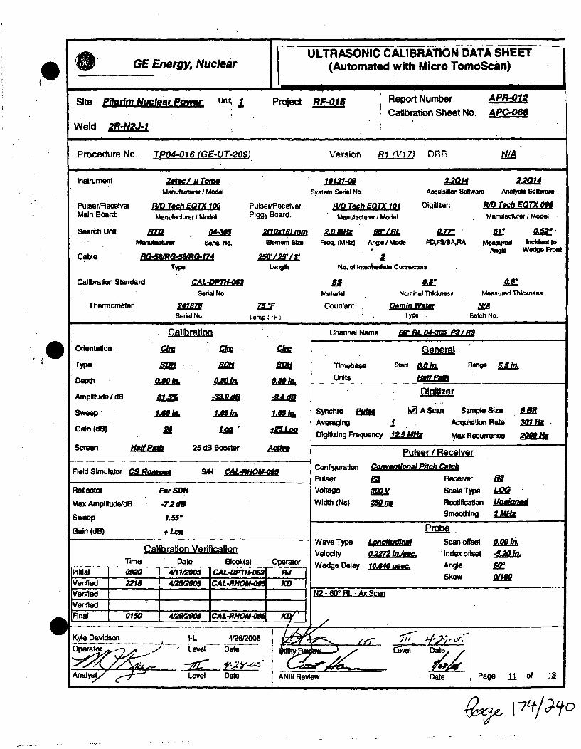
ULTRASONIC CALIBRATION DATA SHEETGE Energy, Nuclear (Automated with Micro TomoScan)
Site Pilgrim Nuclear Power unit 1 Project RF-01 Report Number APR-012
Calibration Sheet No. AWeld 2R-N2J-1
Procedure No. TP04-016 (GE-UT-209) Version RI (%117) DRR N/A
Instrument Z" /u Tom 1 " 2,2214Manufacturer Model System Seial No. Acquisition Software Analyts Software.
Pulser/Recelver RID T*Ch EQTX 10 Pulsea/Receiver. RAD Tech MTK 101 Digitizer: R/D Tech EQTX 098Main Board: Manufacturer I Model Piggy Board: Man'tiactur I Model Manufacturer I Mod•l
Search U ni RT 0l-3 2fLxir 0 f0i /RL " 61Manulactiur Serial No. Element Size Freq. (MHz) Angle / Mods FD,FStSARA Measured Incident to
C e Angle Wedge FrontCable IRQ4L- 6"&174,!R' 2W I 2 '/2's
Type Length No. of Intenttedlale Connecton;
Calibration Standard CALPT
Serial No. Material Nominal Thickness Measured Thickness
Thermometer 2418 7.F Couplant Demin WateSerial No. Tamp (IF) } Typ . Batch No.
SClibratin Channel Name 60* RL 0"M30 P-3 I
Orientation.
Type
Depth
Amplitude dB
2..
Sa-
flab1.96
AM
1.6d S
General.
Timebase Start Ok Range LJkI
Units HKEM
Digltizer
Sýychro E•H A Scan Sample Size UjAvemging I Acquisition Rate 30 .Digitizing Frequency 12.5 Max Recurrence 2M
Pulser I Receiver
1L65
Gain (dM)
Screen Hoiff~ 25 dB Booster Aeffi
Field Simulator C.BSgin S/N CAL-RHOM-0• ConfigurationPulser
Voltage
Width (Ns)Reflector
Max Amplitude/dB
sweep
Gain (dB)
Far SONt
-7.2 dB
1.58"
+ Loy
Conventional Pitch Ca1
ra Receiver filIO y Scale Type LOu2Mm Rectification Unaned
Smoothing LMk
Calibration VerificationTime Date Block(s) Operator
initial 0o2 411110O6 CAL-OPTH-M5 RJVerified 2218 4#2WIW0 CAL-RHOIAllMsIVerifiedVerified I
IFinal 0150 4o•2S 5 CAL-RHOM-M KCV/
Wave TypeVelocityWedge Delay
Lga0,= injew,10,640 mom
Probe .Scan offsetIndex offset
AngleSkew
N2 - 60* RL - Ax Scan
A-I- - -i--.- d _______________________
w Kyle Davidson -L - 426/2005Operator Level Date
AnalYs r Level Date ANIII Review
Date
Date Page 11 of 12
169 ý-

GE =Nul ULTRASONIC CALIBRATION DATA SHEETGE Energy, Nuclear I (Automated with Micro TomoScan)
Site Pilarim Nuclear Power unit 1 Project RF-o/5 Report Number APR-012
Calibration Sheet No. ACWeld 2R-N2J-1
Procedure No. TP04-b16 (GE-UT-209) Version R1 (V17 DRR N/
Instrument " ae / TomI o 1 2201' "Manufacturer I Model System Serial No. Acquisition Software Analysis Software
Pulser/Rec~ever. -RID Tech EQTX 100 Pulser/Receiver RMID ch EOTX10 Digitizer RV Tech E2TX 0Main Boar& Manufacturer I Model Piggy Board: Manufacturer/ Model Manufacturer / Model
Search Unit 21 1&L1 kIL J.0 6UL AEManufacturer Serial No. Element Size Freq. (MHz) Angle I Mode FD.FS/8A,RA Measured Incident to
Angie Wedge Front
Type I.engt No. of Intermedlate Connectouw
Calibration Standard CAL-ta- 0
Serial No. Material Nombal Tclfmeas Measured Thickness
Thermometer 2418 ZLE" Couplent emnin MWarAI ' Serial Nc. Ternp (F) Type Batch No.
Channel Name 60- ML 0-349 E Ife
Orientation,'
Type
Depth
Amplitude / dB
Sweep
Gain (dB)
2W
1,18 &-410
1. i 1,
Lua
-1~&8
1. is 1
- - General.
Tfmebase Staut £ Range I5"k
Unite MlUM
Diatizer
Synchro f• [ A Scan Sample Size AMAverag•ng 1 AcW o Rate AIfDigitizing Frequency f Max Recurrence 201V
Pulser / ReceiverScreen ilMEa~ 25 dB Booster
Field Simulator CS S/N CAL-RHOConfigurationPulser
Voltage
Width (Ns)Reflector Now SDH
Max Amplltude/dB
N/A
N/A
N/A
N/A
Conventicna/ Pitch Ca#eb
/l Receiver
Scale Type.5.na Rectification
Smoottig
illLQG
SweepGain (dB)
0.780
+ Log
Calibration VerificationTime Date Block(s) Operator
Initial 0M 4#23,'0 CAL-DPTh-063-- RJ
Veerifed 0155 4Q5ao , CAL-RH =00
lFinal j 1107 42720 CAL-RHON49 RJ.
Wave TypeVelocityWedge Delay
Loa~iProbe
Scan offsetIndex offsetAngleSkew
N2 - 60* RL - Circ Scan
W
I
Zql6 07 6717.

.
0 GE Energy. Nuclear
Micro-Tomo (Smart 2000) - Auto PipingWeld Examination Checklist
Pilgrim Unit 1, 20052R-N23
2RNMZ10 Load Offsets Transducers, Ris named 360W 360w m Full Volume Scan saved lo Datstran toDA-• ®approrate entere into Skewed IAW IAW contac coverage AxCoverage computerHD Ze M E
LMsetup TV correctly Procedure Scanplan achdieed achilee Achieved VeriWfed readale • .
450 Shear [a -' 0 1 0 MJK MJK JMJK
450 RL * [ " [ [ * [ Mw MWI MJK MJK MJK
60° -] 12] [ D .2 __ MJK MJK MJKLoad Ofsdes Transducers RFs named 3600 360* Orc Full Volume Scan saved to D n DA "
appropriate entred into Skewed LAW LAW contact coverage Ax Coverage mputer HD .. %setup TV correctly Procedure Scanplan achieved acilemwl AdN:eed Veofied readable VD 0N
- - - (_0_
450o .S0ar 0 fl EM .MJK MJK MJK45- RL - MW MW -MJK MJK MJK600 RL 0. ., 0 n] U] J • MJK MJK MJK
Load Offsets Transducers Files named 360W 3600 arc Full Volume Scan saved to E =
appropriate entered into Skewed IAW IAW contact coeage A.e co--t. Vt m b ?%INTFS
.5 covLa Ax [•eaI copue HD D[]trfifre to 0 CX SG 6(MJKMJKMJsetup TV correctly Procedure Scanplan adhneived &*Wed ADch*eved Veffled readable m E E
450 Se 0 MJK MJK MJA450 R I Q 11 . SG SO MJK MJK MJK600 RL M -- n -l 0 WK IK MAK __,_,_
Load Offs, Transducers File named . 3600 3600 ac Full VolSt me Scan saved toerAappropriate entered Into Skewed .AW JAW naa A A e imveri to DA, a -
setup TV correctl PRceure Scanpian adileved adnle,ed Adhlmru Verified readablel
450 Shear El *~ J MJ MKI450 RL E0 I l SG SGMJMK K
-~~~0 L2f f n MJ0 ]MJK MJK ___
N!tess Transducer lfiftoff due to the Outside Surface contour. See the data sheet for parameters
G

UT CALIBRATION DATA SHEET
c.D.s. No..-zXj7U.T.V. NO S:ig&q,1
L.D.S. NO .-- 2,iu•
ZOCEDURK NO. s,. tic-1REV. 4 DATE S . --1 q2.T7
LAMNIATION~ PERSOMML: NAMJal4M 1 -LEVEL -I NK% 9lk...-LVE
ISTRUMET DATA: MAKE _MDELh% SERIAL NO. _i".g - fr
CARCH UNIT DATA: MAU W.. . TYPE •A•h@L cCh
SERIAL NO. qQ1 &-f SIZE -s FREQQENCY 2.2S V•4i.BEAW ANGLE 4f BEAM 6vtDE % WEDGE TYPE IL,-.•
BLE DATA: LENGTH . TYPEx Mt.-UPLANT DATA: TYPE R BATCH NO. _i_____ýLIBRATION STANARD DATA: SERIAL NO. -. l THICKNESS %.G.'. DAMETER
follh-m AL C ý25A-1f& 69.BLIBRATION REFECTOR(s) DATA: TTPE 2 ,...j . SIZE .- K, --A%,-
ORIENTATION (TO PIPE AXIS) C-)R DUEL ELElMET TRANSDUCERS: SPLIT ORIENTATION (TO HOLE CENTERLINE) FOR
MAXIMUM RESPONSEPARALLEL AMPLITIYDNE .5Iý.TRANSVERSE AMPLITUDE l
C CUVE-SCREEN REPRESENTATION1. 3 . s 7 ,9
I-,' 1~
I-.1~
,' .1~I-
I.II.1I1j
I.IIII1.1
-I.--I-
-I-~.1~-I--I-
- 1l I I i - I
t I t ~I ] I -I.
I I I J_ I I !
CALIBRATION TIME - RECORDS00 O0 02 03 04 Os
ORIG. CAL. LAST LAST VERIFY-DATE CAL. CHECK-E.D.S. E.D.S. 25OF LIMIT
TIME TIME # LINE # YES/NO
I.D. OF WER/COmpomlT
C.- baAA.. I
6~-MA-
E m i K
0 2 4 6 8 .0SWEEP RANGE POSITION OR METAL PATH
REVIEWED BY: 4
Pr .-
mu w- - -
DATA 1(BVIEWER
A1 SECTION
ACCEPTED BY:
•I EWED BY:
XI EXAMINATION; __A_ YES A-!I SIGNATURE REQUIREDNO ARIZ SIGNATURE NOT REQUIRED
BECO LEVEL III OR DESIGNE|DATE
DATE JANII (I
64c

0
BOSTON EDISON COMPANYULTRASONIC EXAMINATION DATA SHEET
EXAMINAT; PERSONNEL:Name • Level i-
Neam Age A& Leve
Beam Angle AS'
M. R. No.\9OoqCouplant -
Scanning Gain 4
.Exam proc.50-1l Rev._5
EDS No. 99'. -S98CDS No. lf"C-SV_L. D. S . 2 2-"( - _=-UTV No. Ce2I1 ADATE _lzzi'i(W) DIMENSION (L) DIMENSION
WELD CONFIG I IND # SCAN NO. MAX. LO W. L, L. L2 TIME OF EXAM COMP. jREMARKSCOMP# DIRECTION AMP. WO SP, SP1, SPL2 START STOP TEMP.
& SURFACE I
I & A4.. i =-A . hl T_4_ -/-_- '3 4Z I ' "T t
•..•.•,•-,,o. 4 ,. T•1.I- b .,o o
4/_A/" •"'
Components meet ASME Section %Is Acceptance Criteria:
YES 0 NO &--FURTHER EVALUATION REQUIREDA<
REMARKS: ) U,-,-va 12•.ar,-,• SI 2-•-t'm mf.• D bO
ASME Section XI Examination:
_.&YES-ANII Signature Required.NO-ANII Signature Not Required
Evaluated By:p2w... -Level Date s-/.zi
Accepted By:7Level1:- Da t e/2W7BeCo Level Ijjor Designee
ANII Review By: 04. Da e _____ _
Pagc I of

0
BOSTON EDISON COMPANYULTRASONIC EXAMINATION DATA SHEET
EXAMINATION PERSONNEL:
Name e Level Ir
Beamsý- -A eLevel
Beam Angle 4606
M. R. No.\•e.-Couplant tjL-g,.n_7 SMS5
Scanning Gain 4
Exam procYo. 11 Rev.__,
EDS No. 7 - ' •9CDS No. I-e-SV7L. D. S. Y7" -Z - 3-SlUTV No. oZlkDATE ____, __ _____(W) DIMENSION (L) DIMENSION
WELD CONFIG WIND # SCAN NO. MAX. LO Wo L, L. L2 TIME OF EXAM COMP. iREMARKSCOMPiI DIRECTION AMP. WO SP S SP. S PL2 START STOP TEMP. i
& SURFACE I_A- I
i(.r 4 .. j ~_ r . 1- -7 -m t Liao
_____ ~ ~ ~ j 1'F I~UA)
Components meet ASME Section _6_ Acceptance Criteria:
YES D NO /@FURTHER EVALUATION REQUIRED 0
~)REMARKS: -l&wiwW PLIJ .AI thk~~a.J 2W.~laU.U4~h 2.c. i~' -~ ~ ~
.W• r6-, To, "T,4-ra-. C,---.N.e lo go Q&. - Ir
ASME Section ,I Examination:
,_&YES-ANII Signature Required- NO-ANII Signature Not Required
Evaluated By: -. • - Uevel_•Date _
Accepted By: :Level_----_Date 10BeCo Level III or Designee
ANII Review By: A 2 4 -. Date
PagcJo .oZ

UT CALIBRATION DATA 'SHEET
C.D.s. NO '?f-e-•'vU.T.V. No-L.D.S. NO
WdCSDmR NO. &I otREV. Ak DATESItAKINMTON ESNE:NMEA/ SSr _A2I~Vf LEVEL.g
ISTR~MC DATA: MAKS SR4 mHmODELoL.(L.. SERIAL . NO. 12&..ARCH UNIT DATA: UM14UACTURER TYPE M ac- 6b.A .
SERIAL NO. eoim. SIZE .SO FREQUENCY 1.,Is &UBElM AIul Coco BEANM MODS ... LA, . WEDGE. TYPE L.•fu
ILK DAT: LENGTH %14 TYPE 0- 14
93 LAIR DATh: TYPE L%=AIfLam. BATCH no. %112S~
JLIRATlOU STANDAXD DATA: SMUAL 1O. 'ALfl&1_ICKTH SS 0o0 DIAMTERMATERIAL gc.4 :91 -1& 6A. IR
I-IBRATION RPLEFCTOR(a) DATA: TYPES -.SIZE %Owsl 7hi. L a I-
ORIENTATION• (TO PIPE AXIS) C-%G.-..,R DUEL EL8,IEW TRANSDUCERS: SPLIT ORIENTATION (TO HOLE CENTERLINE) FOR
MAXIMUM RESPONSEPARALLEL AMPLITUDE -4LTRANSVERSE AMPLITUDE f41A
.C CUR-SCREEN REPRESRTATION
IL.
0 2 4 6 a 10SWEEP RANMS POSITION OR METAL PATH
REIWED BY: 7 .a2w!Ld .c&6,9
CALIBRATION TIME - RECORDS00 02. 02 03 04 0S
OR-t. CAL. LAST LAST VERZFYDATE CAL. CHECK-- E.D.S. E.D.S. 2S5F LIMIT
TIM TIME # LINE # YES/HO
I.D. OF WED/C0t•PONENT
L,. iAA.-I
1.. ,& c- I"
• d M7 ,zT!
DATA 1(EVIEWER
ASHE SECTION
ACCEPTED BY:
EVI EED BY:
XI EXAMINATION; X YES - JUNINO - ANII
SIGNATURE REQUIRED,SIGNATURE NOT REQUIRED
DATEBECO LEVEL III OR DESIGNEE
VIfe!,,AN•I
-pacýt
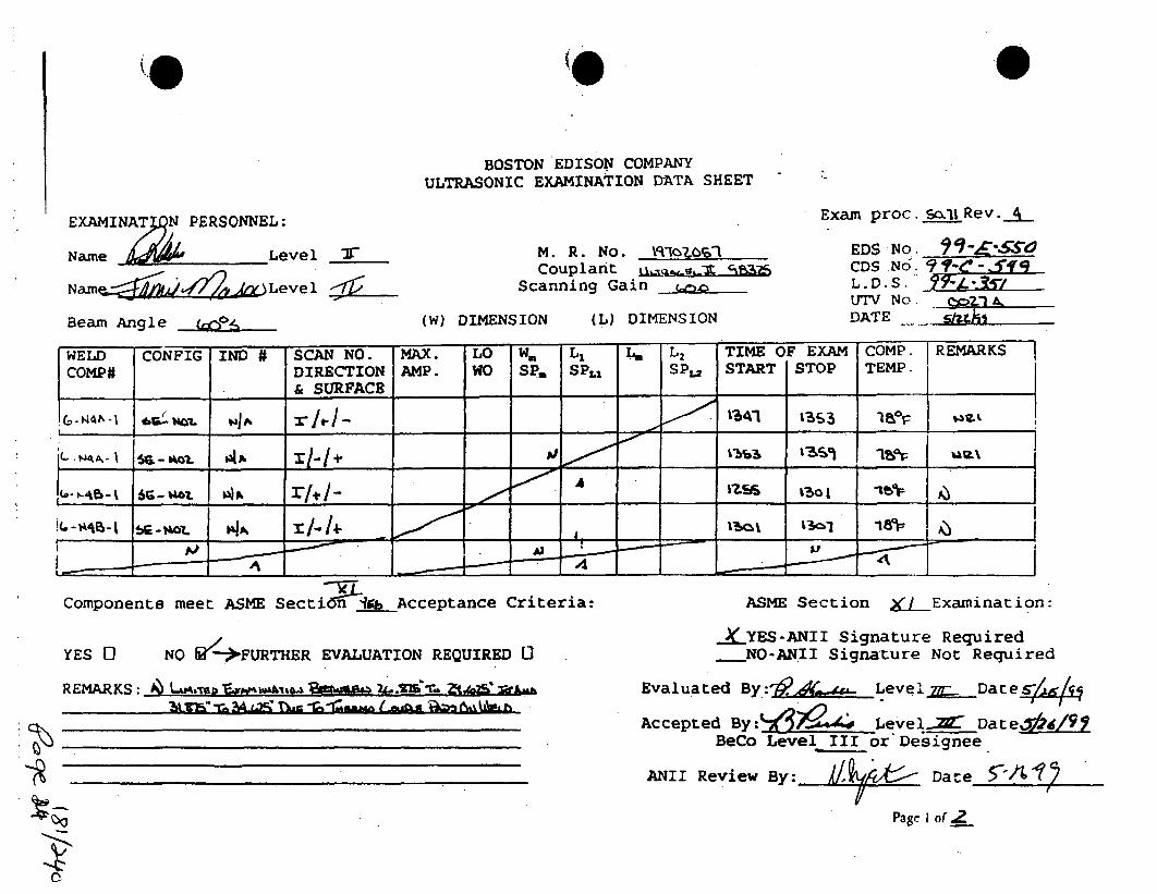
0
BOSTON EDISON COMPANYULTRASONIC EXAMINATION DATA SHEET
EXAMINAWN PERSONNEL:
Name 1 ," Level J-
Namrn-,49 . _, Level
Beam Angle c:N
M. R. No. \Rqla•0olCouplant
Scanning Gain _10
(W) DIMENSION (L) DIMENSION
Exam proc. Soi Rev..-.
EDS No -CDS NO. 91C-•"- ...L. D. S. -7
UTV No. Q.'4. A,DATE sh;'ki
WELD CONFIG IND # SCAN NO. MAX. LO W= L, La L2 TIME OF EXAM COMP. REMARKSCOMP# DIRECTION AMP. WO SP. SPi, SP,2 START STOP TEMP.
& SURFACE I
L•--, - 66-baa. ___,, i/-l- _____ ____ s __,_ ____ ____ __13c1 18p
Components meet ASME Secti;T-n4 Acceptance Criteria:
YES 0 NO [/- 4 FURTHER EVALUATION REQUIRED
REMARKS: i~ Lb#rmwA-s@A~i.i~*ih 2L.K1~~~2-e- -I- f- - n IA-....
~I1B kA ~ I AL~ hI~ IM ~ I .~ALtU TM.1~ I U~1 IAI~LA3
ASME Section 0__Examination:
__KYES-ANII Signature RequiredNO-ANII Signature Not Required
Evaluated By: 9,A _Level•.__Date•
Accepted By:ýdx jevel... DateZ&t/9 YBeCo Level III or Designee
ANII Review By: Date 5-'1
Page I of 2.

BOSTON EDISON COMPANYULTRASONIC EXAMINATION DATA SHEET
EXAMINATION PERSONNEL:
Name A i4 Level -:i.
Naeý'ý Leve,5r
M. R. No. LaozoslCouplaan nt g in ..-M-
Scanning Gain •
Exam proc.s11 Rev.__,
EDs No. 9-"""CDS No. 77-_-____L. D. S. -- SUTV No.DATE 5kBeam Angle (.es (W). DIMENSION (L) DIMENSION
WELD CONFIG I IND # SCAN NO. MAX. LO W. L, L. L2 TIME OF EXAM COMP. REMARKSCOMP# DIRECTION AMP. WO SP. SPA, SPL2 START STOP TEMP.
COi & SURFACE i
x 13-4f 1,1. 16
14 1 -A -8 . ia%-____ _ __MIN
Components meet ASME Section__&.Acceptance Criteria:
YES 0 NO W--FURTHER EVALUATION REQUIRED 1]
ASME Section >(LIExamiinat-ion:
X_ YES-ANII Signature RequiredNO-ANII Signature Not Required
Evaluated By :T60.A Level _____Date4
Accepted By Leve; Date4/,TBeCo Leysel.JJor Designee
REMARKS: UA 1ruw v£.agya. F-w. ~ 2Si a.-r%__ ...............................
ANII. Review By:. f/..A,,,•• Date-'C-- d-6-1
P38C $.4f J

BosTON EDISON COMPANY DATA SHEET 0
RECORD OF MAGNETIC PARTICLE E•• INATION
IM ID/PIECE 0 SYSTE (..4 MR 0 ISO/DWG NUMBER.
.. ..-s , v,- LOCATION,A. MATERIAL TYPE
CROSS SECTION 1MAX N PIPE PLATE ROD OTHERTHICKNESS I I GEOMETRY -
FABRICATION PROCESS- CAST 'WORKED (~) OTHER.______
SURFACE MACHINED GROUJND oTHE INSPECTION HOLD PT
. FA" R .CT5,. #MI - d.- .XSSURPACE IS SUITABLE FOR S CHEDULED I XT t/AUT EXAMINATION' -~~N
SKETCH 01 OTHER DETAIL ATTACHED. YES WEIGHT _&O1 LB. 40 LB
B. PROCEDURE O Mcx •o.Zo EQUIPMENT IDENTIFICATIEONVALIDATION * VI/A ~AC _HWACPOLE SPACING ~ 4
2 3
COMANS E NTS 4DCP NTT IW O SECTION XI ACCE
( ICETS) , FRTHE EVALUATCOCPT RQ REDO., REES C . NO
COMME'T ANE R.)
1 n ýP oDT
________O LEVEL__ III DW 4"_r&m AN()IZ y-- 70, DATE
62

Calibr IData Sheet CDS No:___ _C_ __ _LDS No* O o IJ/Enteg
Plant/Unit: h4evi-, 57,u'mo- WoWrkG o.:if 3J Isystem: R.aA A DWONo.: X&M-XComponent: ' CalChecks Tf/s
Une No.: 711 -__ ._,_-_ /a -___ Q,,- : /z/Procedure: , -, , Rev.;... ... Cn .: I.Thermtometer S/N: AM, a,-
Cal. elk Temnp.:. ._/_Comp Temp,:- -. ' nt. CaL: ICal Block No.- P14. aB A, . __IDte.,
a Carbon Steel 1 St;leS Sleet Co./Size: 11_Sch.: 9601
Cal Direction [I Axial 0 Omi rY Both oim
Semi~nl~iSeelchUnflt# 2Sarah UnitC 0 1 IV- I
ScanArea i . toweldScan Area N U to weld
Type: jIfr~a
\ Recowdakle i ExamExamiriatio Ame I Weld Access yesNo GN es
F'III ma- A41 4
FurtheEly EvJk ~ sNo
Model: C.- or&eralNo.:. OOE5cy IL-
Measured Aiigle:Z.......Wedgepe~
L~ngth-._6.4O NCOn.* A
ModeL 5&wwc- 4&"ia No.: IJ&g 4PI2A'oiM
Mneat. VL4&PiUE
Pep ROW.-Y&Jr~Q%: 2
onrs SsnsotvitY
Serial No.:---0 O- f zsize:. 4If4Sape: 5-f
measured AnglVW;......--Wedge Sty1.o:.. "~ i
Search Unit C"blType: ~Q -of ZLength:. tgJ G'on.: 0-
Modei: AJC. I /Op. Seuila No.: f-g* 020 sfO *if
Linearity 1Due: 41 Z
Darpnq:_g2QO.ect..Or.Rep Rate:!VFreq-: A"iFiler _tdd: nPL.
Axiai:- i...Cl7 '31 A
1:1
ExmnlnroExaminer~ReviewerANII: -
14 Dow~
L

rEntepry Examination Data Sheet EDS No: 0" -55- C41 - i ICDS No: OS-- C- q- -i15LfOSNo: -sC-'?•L-(SaPage: of "z
? Procedure: .-.0A6 - 40f- - ')-A3Revision:
~1 V
Plant/Unit: System: Component
1 --/1 -/45rFA r iOt/Work Order:
e9 3114:1/3
4. I
DWG No.:
._ -3 . " - " .
o Carbon Steel
ýYStainless .SeAelI
Start Time/Date: 1.q'" ,/A/'i
Finish Time/Date: /Iq,5
Lo Location: 7--1-
Wo Location: IL
-4Examination Area / Weld No.: Une. No.:
Jf• _ ?)c_ -/,ASize: i/`Schedule: ,./i,
/ . .. ) -- 1•, •Ind. # Angle % of Indication Length Max Location OD SU Scan Marks:
DAC LiILMax L2 -w P LOc. DirAct.
Further Evaluation Required: o Yes (3Jo Umitations. " L•
Remarks
Examiner: Level:7t I e. Level: Date:Revewer Exm-- Level:-~ Date:LL
Reviewer:.- "AzA4Xe Level-,(Ll- Date: 3d__ffL_.A1-*-i IANti: [)ate: •• '
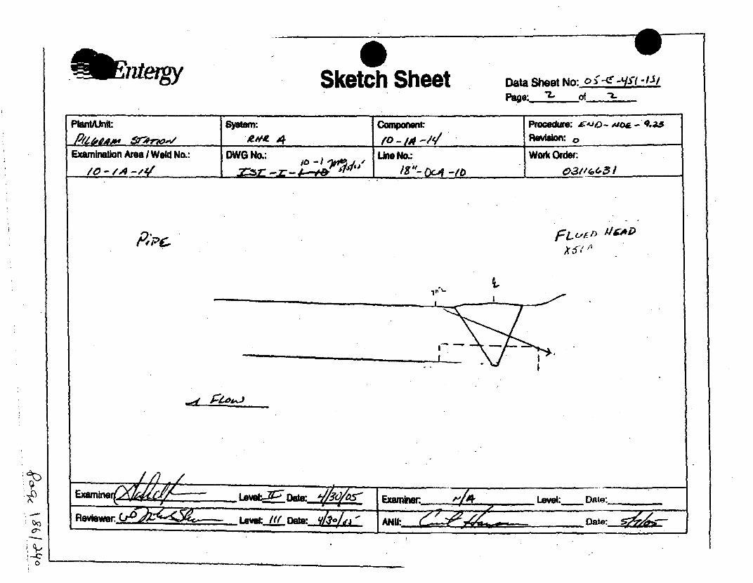
Fnter& Sketch Sheet Data Shee No: 0 - '( - /Page: ý. of " I
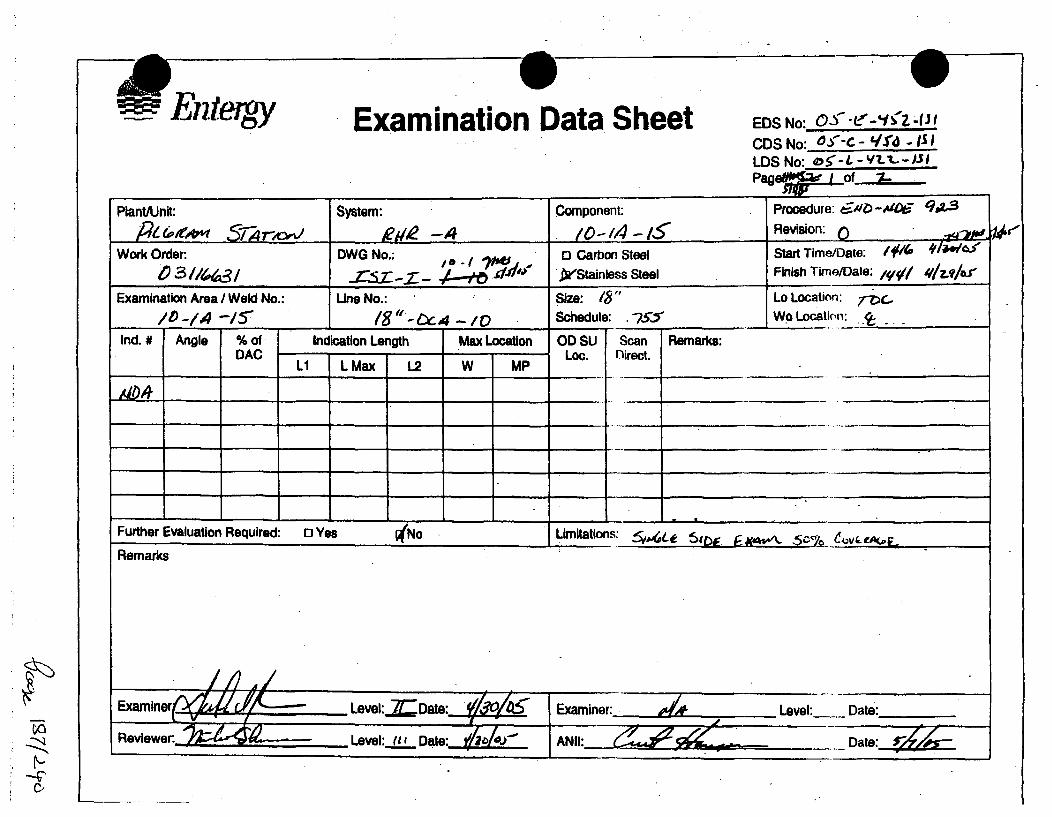
Entergy Examination Data Sheet EDS No: O-S"-Lf-"frZ fI ICDS No: O"- - - ISILDS No: ••L-v'-3
Plant/Unit: System: Component: Procedure: /t•. -A,09-.
p le,*"' 571T",,'-4 "t•-/,!54 Revision: ()--Work Order: DWG No.:; 1 Carbon Steel Start Time/Date: $/ I 41""/•
.zL-.z- ,L.• 'I" .stainss steei Finish Time/Date: i/ ,lz.ilo
Examination Area / Weld No.: Line No.: Size: /6" Lo Location: '
/to - /1 /8 15Y1.4 -/0 Schedule: .-75", WoLocation: A
Ind. # Angle % of Indication Length Max Location OD SU Scan Remarks:DAC - Loc. flirect.
___ L1 L Max 1.2 W MP
Further Evaluation Required: o Yes WNo Limitations:
Remarks
Examiner ,l Level:___Date:.//, Examiner:.. Level: Date:Reviewer:.- Level: fit.••_ Date:. j& -- _NI Dae . _i

Data Sheet No: D~S-~'S--
PfatAntut S~e:Cooneanwt Procedur; ' J d .A____________ /0 -441 - 1R PSvsion: 0
Examiron Area i Weld No., DwGo.: fit" No.•: Work Order:
A.qA
Examierm. LsVel.:- Date: EW= mkwer- "4j Level:._. Date.____
Reviewer: -ate:' -, Leel Date
-z

Plant/Unit P/g~rh4 IC ompany..•,,,,'+
comptSysimr i• '. ,,-Procedwure No. -0 07Rev/Clng. No.
Cal Block No. uZ,- ZCal Mock T.np A_ herm SINSize ZO Sch. .-a7iZ.,'T
0 Ferdli asliloEach Major C~RT Div..Cal. Direcilon 4P Clio. BothScan Area: to Weoi w
II toWeldo
Calibration Data Sheet.cos day - ._e] - ' "
Los 1__93 ____ _
Page /....Latl. .j.==.g;I itii tI
Figure 5
-Ai-f
CIL cheat. Time
Infital Calb. L IlnMa Cab. Date
Intermediate
Intermediate
Rina Calb. /Da•e
Coupliant
Type:B a a zBatc: 6O 2
Search Unit II
Manufacture: ARASedial No.: &d5I'%A
SIz: 0.50" Shape: =MdFreq: 1•,-/,. Style: -Exam Angle:.*± Mode:5&UCMeured Angie: 25Wedge Style: 45IRC
Samrh Unit Cable-Type: i9/) -6anh_ . No.g
RecoI rda"111
Examination Aree/Wekl AccessIndicationsYes N O asOM
ExamBenax
2S 1.-I
___________ ~7LI )( I______- t - -
Search Unit #2
Manufacture:Serial No.: __ _ _ _Size: !f2(5x i) Shape:
Freq: .2 .. style:Exam Angle: 4 -Measured Angle:Wedge Style: I.. 7 .2e ZZ.
Search Unit CableType: - - Rd- Orf'Lewgh: . _ No. 2r
Instrument Settings
Make/Modei:,5Pi/,_,,;, /46Serm No: OR50K "Delay. , 10 RFange: .1Z ýMU COWLei .25 Pulser . 72
Dampng.:- Reject: gLLRep.Rale: ., H Freq:
Filletr Mods: ode:
Reference Sensiltvfty (Sons.)
SCAN SHNs:
L1 -_ MakeftModel: 4&13Remadie/Ra!7nl p im... Serial No:
KA Of#g 70n DeOW.Z:.. aneO•,,,,,. 41V) MI CaVwe ' ,.+uiere33
Damplg-F.DL. RelectQJE.6~'4? //r~D 1/ epJle:3"A'AI.. leq &2~.2
Examiner - Level :;- Date .?~~ Filter -.. Moadea: B.Level Date Relerence Senullvity (Sons.)Level Date •. -•.' • I•
Reviewers: Fuer Evaluation Required? yes SCAN SENS-: 76,
-'if-

Asrbi Ultrasonic Examination Indication Report Sheet
flemwks
0
0~Compougni 10 Meets, 0 Does Not MeetASME Section X1 1909Fuil1er Evaluallon BIqedf _Ye 110- -
Figure 6

cv,/of1,•l.' o'-/Ae-6
V'afv-e./~oe
fi2Ci9~'((
60PL.1
II.
II
/
' , vbmewed owol I,,
fo,• *4 cv,,pl/o?
pi~7 ~ i//a 0/o
a
71
Zevc/ -V

Plan VunI &tn
RewIhng. NO.Cal. six* No. p• -6" fCal. Mocki Temp6O iU~ftnh SIN
Each Ma o ,.r o .- '/- -CaL leo"lkln O Gao. Bot08can Arme t.L to Wold
II •Iwel""
Calibration Data SheetFigure 5
CoS 63-C- -/37LOS /3-±-1A3Pap. _ .of
Cal. Checks TlimeWOO ciwok. 0r17
NUmld CaUb. Dale
Inlanned•ile
Ineimeodlale
Final Cath.
Final Oath. Date
.Coupin,
Type: ifmo/lBatch. .•A2§
7
Search Unit i1
-~ S -
Acce•sRecordableIndlcationsyes I'No I Geom Exan.
Bonn.-
"Mmn¢o • Syl:
Exam Angle- -,o ModkIeAs CMeumured Angle: .---
Wedge Style:, Afi4.1
S•aeh Unit CableTOMp -'& -. o.,
. u•tr.,. m l No /..•
Emninaifo AeateOld
IOX - 44 .-7•o•,r X ..,x ;my, . l-Pe=nl
Searich Unit 12
Seaial No.:. Xr'Z71LSlze:-±25. ShMpe: xf-Ir-
Exam Angle:MeasuredAngle: ".OWedge 81)4e:-L, L
Search Unit CableType: Ao-- If'fL.ngi•.: .6' No. ."
Inslrument Selling.
SOmtl No. oDelar. XJ Rang: .192M14 CaiNe: .2 Pulser. .2SOoapkwlo/a Reie• gf__RepMOat:~Af Freq: ..Z;f.Filler. - -- Mo ad :je: v-Reference SenslIMly (Sens.)
CAN -M,1 r:-' c:* 40 4
SCAN SOS
*
0~
'~~k77 ~ /?~VD 1
e,*'~e'~dP7ZAV
hVrd/l
Level Dale
0' CEvG a aluatkni Ri ed? Yes• • • _•'-.... ;-;F•] -' -',•• ,:2,
IUIUw/ b 1
801101 NO.-
hf UCaY~I. at Pde Mw±.,33
nep.Rale: . FuqU 2,,.2,2.Filer . 1 ...... Mode: 19Reference Senalift (Sem,)
SCAN SENS-. 3f ,
LR664yIOF

Page " ..- , , , f .of .LUltrasonic Examination Indication Report Sheet
C1S NO: EDS No L•OCmdugg Sai TIM Euns,. TC4/A-L--oJ-C 37 03-E-136 C &12" weld:.. IX-? u I- . 8 I--,
c .. .ens !,/ ;u.f .o, Pi-d/a N..;1i wwd"
Th,, .mkn.: '. , 50. /..dbfloillo IangLugb Max . mOaikslInd 'Ag %of SM.= I BC LI MAN I W p Lo J./~d U9 •X 66' LL3W 0-iT .L II7~
-00 - -- -:-4r - -0171'V -4 "07ye
ort c" AZ wove
NI: . -"Componenl 2 Meels, 0 Does Not Meet.,, O "eviewls) F1mEl.oASME SectIon X 9 890.Ino ~ Rvee~)...... .. Fusihar Evalualuslonlegalieil Yes-
etO~ a% l Figure 6

I
>~l I ,, T d- IoA -7Q~r7 AeeT l .a-&. 13
I a
a I
* I-i.. a
3-i Li
I I
I I
~ I a
I a
I I I a
a I
I I 1 tI a
I I I
I>~. ,i
I j ; 1
I II t I a
I I I
b.i
~E Qi~e irv~eeod lP f"

1.
Planl/Unil. P S
Company 6mggga i
Comp/Syslem Rt&KUProcedure No. M03 15 7Rev/Cling. No.Cal. Block No.. PL " RACal. Block Temp.Ad 1lSITherm S/NSize ULf Sch. "T
C] Fernlic G Austenitic
Each Major CRT Div. = a 2-/a 2.'4Cal. Directlon: ,.cJ • BothScan AreaWel
Calibration Data SheetA. V.t .4V. 01-A,.- /9 9
e.. Data Sheet P /"C 3/0Page I ol
Cal. Checks Time
Initial Calib.
Initial Cb DaleDate
Intermediate
Intermediate
Final Calib.
Final Callb. Dale
Couplant
Type: (:L.M
Balch: 005•5
:TT
Figure 5
Search Unit #1Manufacture: K6ASerial No.: 00 bv(,o
Size: J " Shape:&i.b_Freq: J ._&Style-. Style:Exam Angle: , '4 'Mode:'t.-Measured Angle: tj "
Wedge sly, ,- Ils.a
1 1 .1 .1-11 -1-- -Solrch Unit #2
Manulaclure: V61Serlal No.: QAUSPS-
Size: .1154P Shape: 4MOLFreq: Z-519 Slyle:A10--
Exam Angle: 700 Mode: "• ...
Measured Angle: ,. °
Wedge Style: WOO- I pxf-(3-
S
'p3
~0t4
'-I
Recordabire
Examinalion Area/Weld AccessIndications j Exam
Yes No I Ge(m I Sons.
05- , 4A, A w/
f2-o~ CurY) 0~S1/A 41 tJA&5.M
Remarks/Reason for Incompilete Scan(s)
~-•
SearckhI Unit CableType: (6k-1Length: W No. . 0
I=
Instrument Settings
Make/Model m,. /S-.Aj ISerial No: look ..
Delay: -i53; Range:MIlI CalNet/VaJ2 Pulser: Z2ZaDamping: f5O.. Reject: CW.Rep.Rale: F Freq: Z2Filter. Mode: -E
Reference Senitvl~y (Senis.)Axial: 5?.OJ46 Ctrc:SDH Sensitivity-~A
Search Unit CableType: M2o- fl'I U
Length: - No. ____
Instrument Settio s
Make/Model: &'W AC( 0t.'ewISerial No: IW{LDelay: 0 Vl" Range: Z.•.
Ml1 Ca/el: 4 Pulser:
Damping: • Relecl:
Rep.Rale: 14 i3 Freq:
Filler: I Mode. 0-6
Relerence Sensilivily (Sons.)
Axial:.. Cm.::SDH SensitivIly*:F;55.ZJ6
Examiners:VJAUi lM4JŽ. E Level ". Dale !.E'.Dt
Level Date
Reviewers: ~ .. Further Evaluation Required? Yes
20
0'OO(.n00-4
J3(D
0

0w
Page / fZ
Ultrasonic Examination Indication Report SheetCalibration Daal sliest Number zOs: LO, =Z.,dier T -A-LAWu/I-cr .- 317 , .52.0 =Item Idandfliallon: OC A01:/0A14Component Information.'f Prmwharkte NO. Rev. Dete: Wald Crown Width. 5
SeAdilan. Aaark
Indication LengFthibu, OD scanrd RInd A n le % of S .U .DFre c
l sd DAC L• Max L 2 W MO LC. J.I
Addiiona Rears 4AI4 , d4
JVfrAf~f V~WROVIOWOF(B):~ ~ ~ ~ Fute•vlainRqie e- N
•• /- -• ......:3
M~ 0
(0 CDC
4 0 -

S c&-..'.
LO6t-o) 12. 0- q
IFUAofkAo
- - I
; ý P Z r-• Y40/
51 "': i4-0
(AxJ b=w -. SAO
" Cc •,) C14ofl •.0
(.c,-C-) C• 0dA s. '
r t..,oaU WAU
NJ
c~j

t%alibratioftata SheetEntergPlant/Urnt __ _ -. __,__ _ _ _
System: L •PAYComponent: /" 7/9
Une No.: , 0 4-Z -/9Procedure: ,WA,•- 7Z..S Rev.: 0Thermometer SIN: Z.-7
Cal. BIk Temp. : ,AComp Temp.:- lo7Cal. Block No.: - - .P -d
0 Carbon Steel A Stainless SteelSize: /Oj" IBalh., Me5'#,(
Cal Direction ,S Axial 0 Circ 0 Both
ScanAreaZ .L toweld
Scan Area 0 II to weld
CDS NO: _-_- ____
LDSNO: __ - -___ -_ ,Page:._L_._f.L_
Work Order: O3,/4104 V13DWG No.: XZ WJ±L/Cal Checks I TmeInitial Cal.:I .Q/WDate: Y- V-A.Inter. Cal.:Date:Inter. Cal.:Date:Finl Cal.:Date. r- zq-o
CoupTlawTyp ,,-~ 6~.I
Batch: 'e z z
-4-A 1 1 It-
Exannaton Aea Wel Acess Recordable Indications Examyes No Georn.8n.
Rernarks
Furter.vauationRequired: 0Yes.. JkNO'
Search Unit # 1Manufacturer. A8' "
Model: L1AP I-Serial No.:- !n ,sc--, 5Size: SY7- Shape:,e-,Freq.: ,.- #Elm: .Angle:.. Mode;-: 4Measured Angle: f".Wedge Style: ,'12cd6e,• ,
Searh Unit CableType: .,6 -/,7j(
Length:, e' Con.:_Qlnsmfumsnt Satings
ManufacturerModel: ' J'xk.Serial No.: z,2:!W )/".7Unearity Due: 1'- Z-&-Delay: . z_23 Range: 7.00MU. Vel.:LauL Pulwe &.._,Damping:o'42 Re4ct:•,,.Rep Rate:_teFreq.: 2.zFilter. Z. Mode: P.
Referevnce nslluvityAxial: 33, . ircn: 33-.0
Search Unit#
ManufwAcurer..:E~1Model: - W; 74-4 " ,-Seral No.: eo- 7-0
Freq.: z.c') #Em .
Angle: &7 -.Mode-.Ž,4..Meassued Angle WO.Wedge Style: i'oe .
Search Unit CableType:- (2-) 4,6-A qLength: &- .#Con.:..-
" Inltrument Satinge
M an uf acturer: (!VXLI4gLrModel: -5:ý/c •/24:'
Serial No.: _.,C Q#•L/7.X,/.7
Unearity Due: -,.-Z--O"Delay:•.9 . . Range: '?Mdl. VeL.:. • PulSr: 2-50
Damping:Mfec&OO 'Rep R ate: Y. Freq.: Z. 2.5 •Filter: 2.. Mode:ZX .
Referenca Sanel~vty
Examiner XJA f•M0 11 *
Examiner _ _ _ _ _ _ _
ReviewerANII:
/~4 Level~g Date: :-410.-Level:.nLDate:
-41-
Lavdd Iiiint7/uo-
- Date:j~ZII I I

F7E1te qy Examination Data Sheet EDS No: 6 Y•-(•-Y$'5-1CDS No: O -C- -,V5'7 -i/$LDS No: O.S'- -L /.-I-/)Page: of
Plant/Unit: System: Component: V eLk: 90 "ploe -Procedure:,-v4/,%- .2'zs,P/L..,•,•PIA/ 1£'Z:•" S _~ J'/"-A -/9 Revision: •
Work Order: DWG No.: M] Carbon Steel Start Time/Date: /1./1 ",q010.3//1,6 '/6 xs .x- iV/-/ 1 Stainleqs Steel Finish Time/Pate: ,%'
Examination Area/Weld No.: Une No.: Size: /t2' Lo Location: - 9..-/ ,I'he: .- 930" T7*e Wo Location: '.o _
Ind. # Angle % of Indication Length Max Location OD SU Scan Remarks:.DAC L Loc. Direct.
........ //D ,•_FA ZOTL'/_. ., vLZ(.,7•.VJ"
Further Evaluation Required: 0 Yes ,No Umltations: Vl? Y.6"
Remarks
Examine: All/- Zf Level:,KI IDat'K 9-zt5 Examiner: Level:-ý11 Date:~R . p -
Reviewer L-60,ZUE, LeveI:ILL_ Datý _'2ý/ij- AMII"m II V Date:-"L-

-T iztergy, Sketch Sheet Data Sheet No: a5"-C- q4l-I JiPage: -. of "2-
PlantVUnit System: Component Pro edure:' VA- 223___ -__________"_ coc _a- I' /A-MA'-/9 Revision: Z
Examination Area / Weld No.: DWG No.: LUme No.: Wouk Order: t 46,Y.J?
een
LvC9 :. ,W aZe): -</" "e
AY A". F)AI" -CXZI :5V
,4_<~~- -E 0.VV-,'• •z• Tv.• P'•/,<
Re ie e -Lo......ll

@'!
Planl/Unll POPE
Company 6'l'=,e QtyComni"Syslln~Ploceduie No. IT I 'b. 81Rev/Ctug. No.Cal. Block No .. ACal. Block Temiip.4 Q Thann SINSize 100 Sch. " 0513 a[1
0 Fetrilic [I Austenillo
Each Major CnT DIv. = *
Cal. DirociloswsL3kilr. 00ollhScan Area:Q .o .
Calibration Data Sheet
ODSO--?
in-.IIO 1
Cal. Checks Time
Inillal Callb.
Inlital Callb. Dale
Inlermedtale
Inlermedlale
Final Calib.
Final Callb. Dale
Couqplarl
Type: LLM ")6 CTBatch: 0s'
Access
RecordableIndications
Yes INo IGeomExaminalion AreaiWeldExamSaels.
.II
- - ---------
3.6.Snarch Unit l1
Manulachita: KBASedal No.: 002k04-9
Size: a.' 6" Shape: Rwutp•Frq: I.'V 046, slyio:(Amp Gz
E*wn.Angle: H Mode•a-S•Measured Angle: ' 4 "
Wedqe Sle-: , IPrJ •e..L
Search Unit CableType:,i-.• J&,-,'•/4 V
Lenglh: -JeL No. 0
Instruluiell Settings
Sedal No: 1 1o L.
Delay: 0-32-5. Range: •
WO CaMiA~el4L1%'ulsir: 320aD : ~~ Relect: 9E0
,ep.falrs: 1 1 Freq: 1--_&_. ILFilter. 2.. Mode:
Relermence Sensilivily (Sens.)
Axial: 362-.z16 Citr: "SCAN SENS.: -47,42.,_/14.1"
Figure 5
-"-.----- -i_----.-------
Senrch 0nit 112
Manuflacture: _____________
Seodal No.: "_ ,, _
Freq: 7.ZMAL Slyle: Cwb
Exam Angle: (.w Modo:4,40A
Measured Angle: • e. 1Wedge Style: .
Search Unit CableType: RA? - i.7' 4IVLength: •. Nn..__ . n. 0
hislrunseW Sellhigs
Make/ModelFbIt&4k.i
Serial No: 10OgL
Delay: 0-(44' - Range: 2-._M1l Cawael:-." Pulser: •
Damping: S0641 Rejecl:t,.r-"
Rep.Ral@e:.L L" Freq: =Ak
Filler: ~ Mode:
Relorence Sensilivily (Sens.)
SCAN SENS. 0 "/,
Ransaiksifloason lor hIncomupleie Scan(s)
A ~ ( 0 K1/4 40U&
-g
0D
-U >W -t
)U3 M Z
J4 Level Z~ Dale
Reviewers: ~d Furthrer Evaluation Required? Yes ON.q.

0
4
C,
30
0
0.0
NO. OD"40"4
Figure 6

Ultrasonic Examination Indication Report SheetIDS No: CDS No: Lo [tlon: Start Time Examiner. TC-l A-LeM v C
-. sy 'xv' 4C /1f3 Also a QAi
Item Identification: ITEMP. gs. WO L.MOctn Finiash Time T-
Component Inlormatlon:. Procedure No. Rev. Date Weld Crown Width:
Diummole no. m);. Thickness:. /r1 50 P7 41O- "4.1
Indication Length OaD Scan Remarks
Ind An %le % oi Direc.U.
A Used DAC L I Max L 2 W HP Lao. II
N/A fOaA __ ...L ý
Component R. Meets, D Does Not Met
Reviewer(s) _______Riew__s ASME Section X1 1989Further Evaluation Required Yes . ..... No
Figure 6
2-U
N)i':x; *
0 M J1%.< P

0D• s //.//_
to3 •r.ý t4-5i- r7?6iJ &WMV-t
(po.o"i5 a
PIP&
' I L r ,
(CAxL) VS(CsL~) 5WCG"V
25w L7.,*145S7
Col. -:
370, d) %
0-C-
'Tr*L
C~u~eAc, &

d~' __________
(elisp
•d~' /?* -2 II2 -••,4 I , A eA-,
(AX) bs S51oE
(ax~) u S Yfae
(6,4,-) CCJ'ýCA
.26W
ia'" 3-,rill 230. .0%
'5o. '"
23'. (.1% ~
0ý
.zd
~q2af 7~?I& &&#JeALS~;:
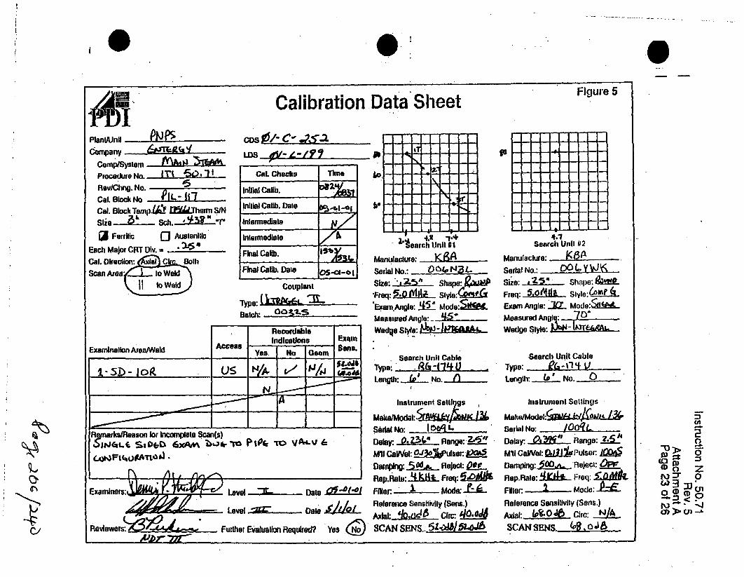
to 0* S
I U Calibration Data Sheet Figure 5
Plant/UnI P ,J
Company 6 a('TComp/System A'W
Procedure No. 6 , -O,1lR e v /Cl in g . N o . is . --Cal. Block No . PL-11"7
Cal. Block Temp.t! M~j(Thelrm S/N
Shie -k--..- Sch. 51IMr(J Ferrlic Q Auelenltic
Each Major CRT Div. = 15
Cal. Dlrection . j lh
Scan Areaa Mo~k'
LDS
Cal. Checks Time
Initial Cellb.
Initial Callb. Dale...t1.IInlarmediale i/
IntermediateFinal Callb. 15*3
Fina Cafib. Daies 5•-
Couplant
Type: i= LBatch '0031,-.S.
Access
RecordableIndications
Yes. I No Geom
-4-
' t .t
"tearch Unit 11
Manulaclure:Serial No.: ,Size: 1 ?ýh Shape: R• req' 5- 06 Slyle:r•
Exaam.Angle: !5 Mode:S- .Measmed Angle:. ý-W -Wedqe Slyle:&NJPMAI
Search Unil CableType. . .,&-(1_ +Length: _L._ No.
MakaJ1•odal:5-ff& XSbrial No: _04I. _5g
Delay: 0o?(V Range: "IWO CGalWel: O u9sM:Ujer:,
Dawpning: 50.& Reject: OOPRep.Rale: _'.•t Freq:6"W
Relerence Sensitivity (Sans.)Ax•I, : /.1 GicL : CrSCAN SENS..- 5-W6L&2OA
EximSons.
go
Search| Unil 02
Examination ArealWeld
Cl/
R iarks/Reason or Incomplete Scan(s)
,L.O,• I hg 4,1". e' • ,,t=.C . /) W• .rTL_"
Manufacture: X8A - .Seral No.: WUMy •Size: 4 Sha9e',-.Freq: 5AMAILF Slyle:61 4
Exam Angle: ..J Mode:&#l6...
Measured Angle: .w "Wedge Style:
Search Unit CableType: - &-11 k!Length: W No. 0)
listrunienl SettingsMake/Model:/ .
Serial No: /OO-L
Delay: AM" Range:34if
Mll CaYel: w03gPuiser jQWSDamping: 50.1. Reject: O
Rep.Rale: 41CLIL Freq: -OAmkFilter: .- Mode:Relerence Sensiilvily (Sans.)
Axial: 06.oJ0 C circ:SCAN SENS.(•.046AL.
0~" > .I ::: 0
0 C) Z]
ۥ>, tn ..
Examine Level :3r Date 0I-6f.o
Level .!.. Dale
Reviewers Further Evalualion Requkred? Yes.( )AJbr 77r"

I.0
w>0-
(D 0 z
N .--xO)CJ l
Figure. 6
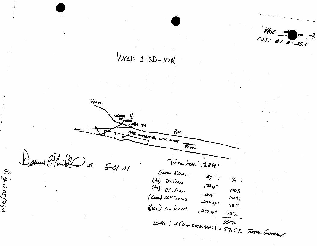
il
0/4~,f_
~,j*
t4J-o I-sh~-jok
VAL4JL.,
-I.'
SŽ*NJŽOM
.(dwj D . ~ A
IAs)
11/0
"75
57ra

0 0
Company. F ra xCotnp/Syslem 2D-2•-4Q|
Procedure No. ! 1=
ReviChng. No. fCal. Block No. P-1Cal. Block Temp."2.. Thern S/N
Size 2la" scl". -
O Ferrllc ( AusieiilEach Major CRT Div. -
Cal. Direction: Axial Circx:(B MScan Arel... Ejt Weld
Weld
Calibration Data SheetFigure 5
ios ,w• 0/- /- -,,*110C. Data Shoal II1101" C -
Pago of_ _ e 2
Cal. Checks TimeInitial Callb. . •
inilial Callb. Dale
Intermediate
Intermedlale
Final Caflb.
Final Callb. Dale
Couplant
Type: ()L f•am r4iBatch:
Recordable
AccessExamination Area/WeldIndications
Yes No GmExamsone.
lbSearch Unit 0l
Manulaciwe: 98/Serial No.: O AR .Size: -57- Shape: 422IFreq: .._ if Slyle: *0f 'pExam A'gie: AU- ModeL, i.A
Measured -apia: Al W
Wedge:Slyls: AJIJLV 1MG
Search Unit CnbleType: A&- 1-7'qLenglh: /2 No. I
Instrument seii.n s
Moae/Modýal: SA idkt.Serial No: I OR LDelay-. -29.3 Range: .2.05MI CaINel: -JL Pulser. 335Damping: 5Q Reject: &ERop.Rale: _4VAL Freq: 2Filter. - I. Mode: -,k.Relerence Son4illvily (Sons.)Axial: .LA1 0 Circ: ýi±.o
SOH Sensitivity:_
T___3
Search Unill 112
~R-k~-~H~oJ60'- (,Ono
Manulacture: .__ A __
Seial No.: 16L1 L(,--z_Size: -60 Shole:QUcb
Freq: Ic5,ii. Slyle: .•t•1•
Examr Agle.'(•._ Modwe'A6&tR..Measured Angle: . L52 IfWedge Slyle: -
Seprch Will Cable
Type: 1-74Length: . Noo.
Instrument SP.litliS s
Mako/Model: Be3j/iL i9C4*
Sorial No: I ()t• .Delay: -2r).1.4. Range: M al•MI CaWlel: a Pui.or:Damlpiig: .5CO•'., Ilejerl: - _Rep.Rale:-H Freql: _-a
Filler, Mode: -EL
Reloronco Sersilivily (Sells.)
.Axial:ensivuy Ci)c: 5nSDV .Sen~sllivily:__ ) 19
Remarks/Apason for lncozpiple~ Scan() t (A ~&51VE OLZL", "ToliL Ct1% ZQP6'JE
~J5~. ~ ~-uPcwb Romr+ . .P • •
Exatadnes Leel.. Ov l .... Dale
1 ~Leeve Dale
ReVIeWe3r8:FuteEvlainRqid? YsGA/or . Fute EautonRqTrd e
:3
-D ZK) 0
O(DK.) 0D
-1 0 -'l
• +.I

0A E-
FigJure 5Calibration Data Sheet
LZ$OSAvW : 01-z- /,VolPlanl/Unll . P I .
Company Ly-r'FAZ,Camp/Systriai a - IProcedure No. " " -X)Rev/Chng. No. 0
Cal. Block No. PIL- -Cal. Block Temp.'.. r? nqC:erha SIN
Size 9"850 "
0 Ferdlic IR Auslonlll "
Each Major CRT Div.Gal. D,,eclo !! I . ir.Scan Area4 Weld
I lo Weld
C. Data Sheeto I OZ . / SIPage 2 Of
Cal. Checks Time
Inillal Calib.
Inillal Callb. Dale -2-ol
Inlarnediale
InalCmediale 1 .Final Calib. 1 <
* -
I
-'---I
FInal Calb. Dale Y42.Couplant
Type: t)LTP•P ¢-T-
RecordableIndications
yes I No Geonit
ExamSons.AccessExamlnallon Area/Weld
Search Usit 1 Search UiIt 112
Manulaclure: . Manulacluwe:
Serial No.: .PF Q('). SBieal No.:
Size: a Shape: 13..r. Size: Sho,.:Freq. 2 611 Style: .ShP Freq: Slyle:
Exam'/ Angle: -(QQ Mo.de:L00 Exam Angle: - Mode:Measured inple: . Measured Angle:Wedge Style: L Wedge Slyle:
Searcli Unit Cable Search Un beType r /Type:Uenolh--(ý No. _1.__ Length: _ .
Inslrument Settings hnstrunt oit SctilUs
Make/Model: E51f r/EL•, . JL.-ý. Make/Model:
Serial No: ICr9= L_ Serial No:
Delay: 'A41 Raago:2OdL Delay: I'lale:-
M'Il Galval: 0 X-3Pulssr.%a 5 wuMl Ca 1: __ Pulser:.
Damping:A fejecl: Q ;ftI- ,iD l/i I: -- _ rlele: -
Rop.Rale: Frcr ;! @req: 5 Rep. -Io: __ Fraq:
Filler -_cL. - Mode: Fille,. Mode: -
Rolerpnce Sensllivily (Sons.) " ronco Sonsilvily (Sons.)
Axial: - Clrc: ql:_ Cisc:
SDH ~ ~ ~ ~ 11 Sensitiiy-h80- S~ llVl1y:.
Remarks/Reason for Incomplele Scan(s
sc-A36IMPV e -~ &y 6 .- rXf
ExrinrLevel Daleii7~~~Leveln,, Dale %."2'
Reviewersi: em.Further Evaluation Required?. YesA07- 777-
-D
K)
0
<r"•-,I
(3
-"1
0'-.
(Jl
0
03"%
_ _ .. , --- ,
I :

0A ý "Page of of
Ultrasonic Examination Indication Report Sheet
wtS No: CoS No: IOLo cation: Start Time Examlner: TCG.1 AA-Av"l
Item Identlflcalln*jJ4 Wo Location: FlrshTn~ e Time~.TCI-LVI
Prcdr No.. Rev 003" loll 'i Irm otP 6wl)Indication Length mEaut OD DirsctionraInd Angle % of .W .U. orc~n
I Used DAC L 1 max .L 2 a MP: L'. ' 11I
q 5
/r
' ~ ~ ~ ý IAI:•• Component• Weels, DOGS oeNot Wet
I'/•J•" Further E~va huauo " Requi'_red Yes - No ")•
(I)z
C'n
404
Figurg 6

,eR.7 R- 3_
w _ . _ _ _L -$/ -0 /-
FrLou.•.>
CotipIll* Q l
A E. •
IP4-
Pipe4o

S0pb 45-1
IA
060
QJ
Cov•AS
C C, Clockwise ,
3 c
c OLIiXAu .
OA~<
b-
t- ̂

0 6
PlanU/Un11 r" ul: , - - C
Company, .J)-XJrtComp/System •L"• V'9- M-
Procedure No. "T0_-,
Rev/Chng. No. 0'Cal. Block No. PCal. Block Temp." Therm S/N
sizea Sch.,a-
o Forrilic .N AusloeIiit
Each Major CRT Div. . #
Cal. Direction: Axial Cir Bo
Scan Arev Weld
Q II11I,,r Weld
Calibration
Data Sheet I - C - IS
Page ' ol _ _,
Cal. Checks nineInitial Calb. -aaa
Initial Callb. Dale
Inlermediale
Intermediate A
Final Calb.
Final Callb. Dale
Couplant
Type: t)3L,..'"•T .,wBatch: _683A6
Data SheetFigure 5
Examination Area/Weld
RecordableIndications
AccessExamSels.
-J-- _-- _--- -
Search Unit Il1Manulaci ure: - & A /J
Serial Na.: Qg$QA- Z
Size.: Shape: ~Freq:..- IML. Style: g0ACXafExam Angle: AL5I Mndel AI..Mea'sured J141 4Wedge Style: A200
Searchi Unit Cableiype: Art- 1-7yLength-. 1 No. I
Instrumenli Seltleqo
Make/Model: !(aSerial No: I OOK" L -Delay: ± -•2S.... Rasge:,10.
Mt cawlel: &IL Puser. 3-4Damping:. 5TQ Reject: 4EERep.Rale: ŽSL. Freqr 2L.5.Filler | Mode:Releririmce Sonilivily (Solls.)
ASD S:en-s , 1;l.iy j: jj.C:
- -- -- -- I- - -,
Seach U-it - 2 - .- -
Manduaclure: aASelial No.: H J1 - _
Size: An" il.'*. Shol~p: •i-b
Freq: le S 4 Styln: f
Exam Angle,(,Q•_•. ••m
Measured Angle: & 6Wedge Style- &)w
S rclt Unit CatleTypeO: .,-_ A f--7Length: - - No. -
tIstrumertl Selll.igs
Make/Model: 11~f3a/-e.Le-Uf4/-JdI (CJ
Serial No: I nn a L-..
Delay: -9,714 fange: 2.I,M-II Ca/Vvel: • tdo
DaiplrAg: .5 ! feri.cl: -
Rep.Rale: 44bIISL. F 2.q:
Filler: . I Mode: ._Relera|ce Sensilivity (Sells.)
Axial: 5 ,r ( Cilc::- 56,SDI- Se.,tisilviy:-.~
Ye 'l N ieo--- -53. 0
Remarks/Reason lor Incompllete Scan(s)0,. S6bFb EXAM bce*. -To ,~j.*b16 OPA-4 - tb--rpýL CovepC3E AtCtRF-E
Examiners: DaleDate
Level Dale
Reviewers: , .Further Evaluallon Required? YesApr, -.m-
:n
:•0
QI\ 0
0(DN~ Oo ID
-Si0 'J
!

S
1PUPAPlanlIUnll - _2 PCompany. - Lr. 613EC-ý
Comp/SysleinProcedure No. Mxr - ~Rev/Chng. No.Cal. Block No. --4 2Cal. Block TempliA l16woflergi S/NSize I 2 .a" Sch. .850 q.
o] Ferrllic 9 uloiiEach Major CRT Div. = *-a (efa.Cal. Direction-...!)a1,Ir CBothScan AreaL....o Weld
to I Weld
Calibration,0S No: 4/P. -/A'i'
C.Dala Sheel U OL-i 0 - L.T 7Page A l of 6
Data SheetFigure 5
Cal. Checks Time
Initial Callb.
Initial Callb. Dale"
inlenediale
Inlermedalte
Final Calib.123
Final Calib. Dale
Couplant
Type: -OLTIra•G•_,L.
Batch:
Access
RecordableIndications
Yes I No ILeo5
ExamSons.Examination Area/Weld
Manufacture: 1cz1A
Serial IN.: 22•.FA •'CO%•
Size: A•i.C-. Shape: B .mFreq. C2 k slt lyle-Sni
Exam A•r g•le: ia• Moe•J1:±c^0Measured .t.npte: .--.....Wedge Style: T--1 -"d6
, Searchi Unit Cablel ype: - 1 •
Length: (e No. .j."
Instrument Settings
Make/Model: %5MM EN L.,,at£.Serial No: I..-,n - "• .- .
Delay:, - 4 Reange:2 9
Search UWIt 112
Manulaclure:
Selal No.: ____/
Size: Shaip":Freq: - Slyle:
Exam Angle: - Mode:
Measured Angle:
Wedge Style: -
W- ýASearch UWill
Type:
Length: Ij
lIstrulsli
Make/Model:/
Serial No: .Delay: IRemarks/Reason for Incoirplele Scan(s)
ao% tb ~L
,scxýarnv#14. tARvvmm flanjo: -
C-
I -7 Dale Q1A]I
MWO CaVel: s PCal/V 50."U cav: Puser.
Daping: •. . ReJect: Q +E Dapis. , oo nelect. -
Rep.al,: Freq.A 5 Rep..i a: Frq:Filler. C.- 'M ode: t .-- , Filler Mde:Rolerpnce Sonsilivily (Seas.) Rol rOnco Sonsillvily (Soens.)
Axial: !7 .._L Circ: l al: -Cli: _Ol
SDH Sensitiviy: .,J/I .. DI-, Sensitivity:_ _
Level Jr Dale ,A -a
Further Evaluation Required? Yes
-UIN(D
,.%1 0
3-
0
0(Jt0
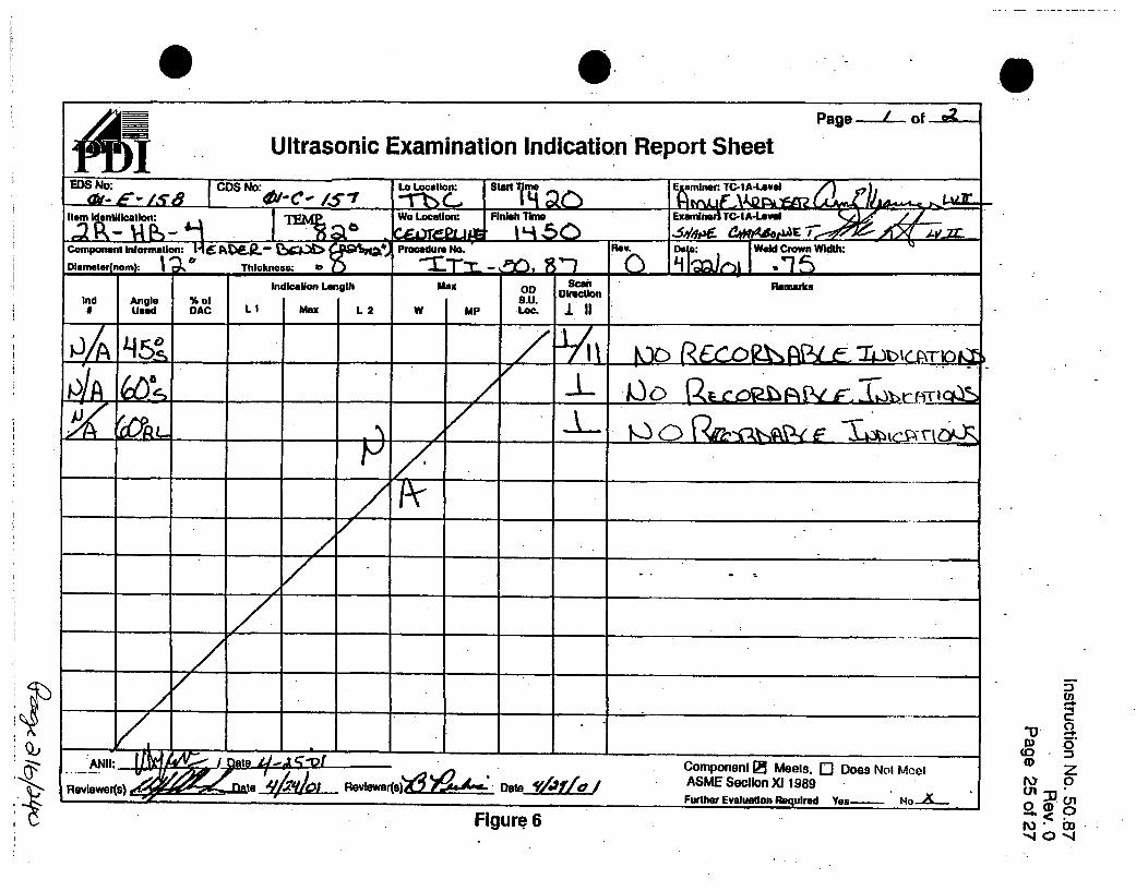
0,Page--....- of
SUltrasonic Examination Indication Report SheetWDS No: Lo Location: SW~t~ Em aminer. TC1IA-LAvei
,tem,- 11c -i 71.W. Location. Finish Tine Exa,•i-erTC-A4,•,eve
Compnent II om: o:H6 Ik•.R.- b Procedure No. Cmo. DI Wald Orown WithM:
Scan ~mnarksIndication Length max
SD DirectionInd Angle %of I.U.
PIA
.......-. ,''A "omo. ,1Mels DesNo..e. ROIW4)Rvlewerqs) •Jae•'#'' ASME Secllon Xl 1989
Further Evaluation Re~quired Yes- No-A
Figure. 6
S
3-
(D
4-4.

0 0 leoslw*.4p ?
co-AP .GO•
i Lo
,,-%3 3 Ci•, C•.,oc,4, - .o, Op

p
-OEnteigyENN
NUCLEARMANAGEMENT
MANUAL
QUALITY RELATEDNoN-ADMINISTRATIVE PROCEDURE
INFORMATIONAL USE
ENN-NDE4A1 Revision 0
Page 18 of ?Im
ATrACHMEN'r 9A LIQUID PENETRANT EXAMINATION REPORT
Page 1 of i
0"P lF E JA .. iNPS 0 VY R Irt'o: 5 P". 0/T
WORK A ORIZATION ISO IDW COMPONENT/WELDIETMn Procedurm Nw. REV.031 I CI/JA. R, 0 NI•CeI.IMAT'L TYP_ TEMPERATURE TEMP. INST. #1 •2 SUACE CONDITION" Cs [S *" . DUEpATE '•-')s [WELDED r'GROUND 0 FORGED OCOATEDE1 MS EXAM SURF. •.0 [•JITE LOGGED rBRUSHED [3 MACHINED 0 SAND-BLASTED 0-
TECHNIUEUE <XVENT REMOVABLE [WATER WASHABLE
~METOD BLACK UIGHT BLACK LIGHT METER: "A433FLUORESCENT MODEL mv14 SN Jh/d. CAL DUE DATE;- _ ___ __'
CLEANER PENETRANT DEVELOPERMme ufctuEiAWIsOMnfdrrCLa Maiuftchw.JI!Csr.S--Type: .CH,. -4O Type: P;06L CeIeK 1 0 P-q Type:2 k -IBATCH 0 5 .q I BATCH 1 8ATCH o,,/ C?/" -7G6SIN 's; . i "7 - e l
EXAMINATION RESULTS
PART IDENTIFICATION ACC R IND. CODE REMARKS
-.-~ o 3o-c 7-6__ 90~70 we'-b R4ee-
*bue m- AcciagABI LJ,TY!c-• Le..- Loc. /Y-51 I=,,, 7"b ,, ,E.. i,&7
~ Af42E ~ - ,bu e 'To A C:Zf~5M (,Lrr$"
S COMPLETE: LIMI~n TATIONS:-5 ( 1 ~A KINDICATION CODE: 1: ROUNDED 2: UNEAR 3: NO INDICATIONS 4: NO RELEVANT INDICATIONS. 5; OTHERSKETCHES OR COMMENTS SKETCH-Inicate size, locaton, ornatlion, and dltabibdon of hIndftions. Provde dhmenslon an allsketchem. Use addional sheat If required.
EXAMN B] FEUDEXAMINED BYILEVEIJDA 1'
C~on~~an~, ISAZIRDATEANtI REVIEWIDAT
* QA Category and ASME Xl Class
42

IE-- ' NN QuALmry RELATED ENN-NDE-9.41 Revision 0
.. 'nter ýNUCLEAR NON-ADMINISTRATIVE PROCEDUREI) MANAGEMENT
MANUAL INFORMATIONAL USE Page 15 of 20
ATTACHMENT 9.4 LIQUID PENETRANT EXAMINATION REPORT
Page I of I
E3 1P2 0 IP3 - JAF IfPNPS VY Report No: P-" -
WORK AUTHORIZATION IsOImy0 COMPONENTIWELDfiTIEM P---duremNo:.~, REV. o)o31 to t7 NI b 4-
MAT'L TY'PE .TEMPERATURE TEMP. INIT. ,20g URFACE COXOrnONQCS [SS R w DATE - NELDED [-GROUND [3 FORGED OCOATED[] EXAM SURF. r2 ITE LcED B [3BRUSHED El MACHINED [3 SAND-BLASTED []TECHNIGUE ' ESOLVENT REMOVABLE [3NATER WASHABLE
MgTHOID ' BACK LIGHLSLACK LIGHT METER:_400[]FLUORESCENT MODEL ,011 N 40% CAL DUE DATE:
CLEANER PENETRANT DEVELOPERManuf=cture.'.2L Manufacturer. Manufactur. -.oHJ.Type: - Type:"* CE- Type: DQ..LCHF_.C- D-I..
"SATCH#,! - BATCH#Icigu/ -g'7"
EXAMINATION RESULTSPART IDENTIFICATION ACC REJ IND. CODE REMARKS6
la en- L-Oc- 57 0%__ we~ 1A.1~~~~~ (~~Laf o xsaaA
fQt.D -C :24 urie -fl C05/ (wvc~ttdL 1o mcces&.'JoAztY
ACCEPTANCE CRITERI#~A5A &11..6x% COMPL.EThL UMITATIONS: $ , f,4'/"
INDICATION CODE: 1: ROUNDED 2: LINEAR 3: NO INDICATIONS 4: NO RELEVANT INDICATIONS. 5: OTHER
sketches. Use additional sheets If required.
EXAMINED BXflJEUDAJ TIEEXAMINED BYILEVELJDATE
Company FINAL REVIEW LEVEIJTLDI#DATE ANII REVIEWIDATE
QA Category and ASME Xl Class
edprp, ;z IV -')-Y 0

I BOSTON EDISON COMPANY 1.RECORD OF MAGNETIC PARTICLE EXAMINATION.
DATA SHEET # 11 iy .
97-M- 33 _"m
InEM ID/PIECE *
EB-2-5-13;4L 6q) ISYSTEk -at IMR ISO/DWG NMMER.LOCATION/•,, r //..%1iiI ' =.1
A. MATERIAL TYPE___ ___ ___ _I CIS
CROSS SECTION MAX MIN PIPE PLATE ROD 'O71IERTHICKNESS 0)GEETy-- -
FABRICATION PROCESS- CAST WORKED WEDD OTHER______
SRAE MACHINED GROUND INSPECTION HOLD PTSUBRACEDA.L "
SURFACE IS SUITABLE FOR SCHEDULED &_.T %UT EAMINATION
SKETCH OR OTHER DETAIL ATTACHED ('OWEIGHT ýcl.i LB. 40 LB
B. PROCEDURE # ) C T 50, Z.-0 EQUIPMENT IDENTIFICATIONVALIDATION # 0. ,A ,&.AC HWACPOLE SPACING "1"T , t- 5 "Is-c ,
C. EVALUATION-
CATION. SIZE(INCHES)
DESCRIPTION ACTION(ACCEPT, REWORK, REJECT AND
COMMENT AS NECESSARY.)
46 A)8 ..)g b I it L
2 c7e( Ta Alwja eL&wt sEd
4
__co_ CbE Co erzr&a 27S.6
7
ID. CRITERI ae -qg
E. ATTEST
CRITERIA, FUt EVALUATION REQUIRED __YES >,NO
Sl•aS C FIWVE lDATEI
BECO LEVEL III DATE A~ DATEI1 J
V

477-M- 33 -Y
lot ýf -ýSK -T CP S"EE TV
Xifl rb A f~d- 23 - I10lLI 1 (4) ,it a -/qceo OZ Is**
'.4
K" -~i4.*4
LaI&3
TYPI (,A L/oa4'.
-- a
9A t46 E C.A(inP ri-PI" (AL
7;5/41-flviflo &-k.4^f 16cw
A.- 4;x

Instruction No. 50.20Rev. 7
Attachment GPage 1 of 1
SRECORD OF MAGNETIC PARTICLE EXAMINATION DATA SHEET#" #7-:
ITEM ID/PIECE # .. MSYSTE . MR# ISO/DWG NUMBER
ib -Z•-2 4LI '(4) LOCATION (PCI&A on
A. MATERIAL TYPE A.& r-
CROSS SECTION MAX MIN PIPE PLATE ROD OTHERTHICKNESS A, H/A GEOMETRY ' .
FABRICATION PROCESS CAST RKED WELDED OTHER
SURFACE 'MACHINED GROUND AS OTHERJ- INSPECTION HOLD PT.EABRICAIEDr • -. i.1
SURFACE IS SUITABLE FOR SCHEDULE &IMT. UT EXAMINATION 0"YES I NO
SKETCH.OROTHER DETAIL ATTACHED YES/NQ I WEIGHT Vf 10 LB I I 40 LB
B. PROCEDURE # o EQUIPMENT IDENTIFICATION.VALIDATION #AC HWAC _ _.,,,POLE SPACING (aA-" S/N HA
C. EVALUATION
LOCATION SIZE DESCRIPTION ACTION(INCHES) ( CCEPT, REWORK, REJECT AND
_COMMENT AS NECESSARY)1.3.
4.
6.
D. CRITERIA COMPONENT ME/DO NOT MEE ASME SECTION Xi CRITERIAD._CRITERIA FURTHER EVALA OT[N REOUIRED E YES 0 NO
E. ATTEST RI P--' R- - -7 -
NUT__LEVELIITLEVATE Aq DATE
ATENTERLGY M DATE
6c,99 5ý1p

BOSTON EDISON COMPANY- DATA SHEET P7/72RECORD'OF MAGNETIq PARTICLE EXAMINATION 97, - 3e'.z
I"' ' .oIECE SY S , ISQ/DWG NUMBER I,•'b/b200LIW LOATO LwLh lo-cI IS--t
A. MATERIAL TYPE
CROSS SECTION IMAX MIN PIPE ROD OTHER
THICKNESS I GEOMETRY - _~
FABRICATION PROCESS- CAST WORKED ED THU _ _ _
SURFACE M CIE.AS oTHEL INSPECTION HOLD PTI (yFA R ICATED I /,F BRC7-.
SURFACE IS SUITABLE FOR SCHEDULEDAMTU4T EXAKMINTION'. (ý9NO
SKETCH OR OTHER DETAIL ATTACHED ( /NO WEIGHT /1o LB. 40 LB
B. PROCEDURE # QCi 5.2 0 EQUIPMENT IDENTIFICATIONVALIDATION # .- ___AC ,HHWACPOLE SPACING e'- L.' 55.
C. EVALUATION
I ON SIZE D ESCRIPTION ACTION(INCHES) (ACCEPT. REWORK, REJECT AND
COMMENT AS NECESSARY.)
1!2 -,I /ILpaTfb *+A UPTLAtE#'w"k1 _£O•u DATE
3.
4.
7
D.CIEI A Tier :Z- -..... ICOMPONENTV(E990 NOT MEETASt SECTION XI ACCEPTANCECRITERIA, FURTHER EVALUATION REQUIRED.__YES ,,XNO
E. ATTEST _____...w- L~L''S SIB CT 2p NNELs DATE
1 7.BECO LEVEL III DATE N DAl/ A.
~PCa5{ ~3/~4O

£KETC H 54EET
z HL-(O-20HL &') t Mot IA~AIr` ?7-A1- Jaa
5"'
I
I3..
LO &
& I -
5 CL4mP 5--7 i CAlL 1 d; q
0., a c cc, v ex-4, p r go Pa
ý-71*ef4..v: - -/fr-17

Calibrati(~Entergy
Plant/Unit: PIL, e• m /ISystem: C6 9C sfgE- 4
Component: 66-t/,- F'/
Line No.: (p" - Q8- IV
Procedure: E:ALd-"E- ?Jo Rev.: OfThermometer S/N: A. 3:--
Cal. Blk Temp.: (P 3*F CompTemp.: (Pq*F
Cal. Block No.: FIL - It0 Carbon Steel QfkStainlem Steel
Size: _ _ Sch.: .
Cal Direction 9 Axial 0 Circ o Both
Scan Area D I- to weld
Scan Area o 1I to weld
WorkOrder 031I1444;-DWG No.: I S 1: 1 1 lf:-.I.
CalChck _Time
Initial Cal.: CDate: *I-;s--6O17Inter. Cal.: IDate:Inter. Cal.:.Date:FinalCal.: UI.t6,,Date: q-;-s-, y-
Couplant
Type: U L79*61L -jBatch: 9D I2
Recordable Indications ExamExamination Area I YeeNldom Sti.Aces Yes No Georr. son
Remark
Vh Evalutio 9;C• uec bmX M *4j. 11esr L tN
Further Evaluation. ftqig.~ o yes i0 No
a Sheet.
Search Unit # 1Manufacturer. R,_'L •.
model: TL- ASerial No.: 'IS -/6 .
Size: 2 (1&17x ,i Shape: J _T
Freq.:.Z A .# Elm: --I-
Angle: -10 Mode: LooJe
Measured Angle: 7/
Wedge Style: .,rJrf.CSearch Unit Cable
Tympe__17Lent: C" 4iCon;: J6
Instrument SettingsManufacturer. 3AgLLE
Model: $,oIcA 13r-Serial No.: / 3 6 - 8 7,5.Linearity Due: S"- -P- -
Delay . S't'- Range:.•2.MU. Vel.: ._...Puler:..'Damping:Wk Reject:_F_
Rep Rate:_ X Freq.:..Filter ,r.2- _Mode:_hyj
Reference Sensitivity
Axial: T•,,•.- Circ: J/L
CDS No: OS. -5W-c. --LDS No: o5-L -M.51.- AL.#.Page:_oL.qfL_
Search Unit #2ManuflrtlJrer:
Model:---Serial No.:
Size:... Shape:Freq.: - # Elm:
Angle: __MAMeasured Angle:
Wedge Style:Search Unit
Type:Length:__ # Con.:
Instru SettingsManufa• N/AModel:-
Serial No.,Unearity ue:
8Delay:eMo. V .: _ Pulser:
UDam ng: Reject:
Re ate: Freq.:
Fl• r: Mode:
RIeference Senithvitypal: ___Clic:__
I
Examiner:ExaminerReviewer.ANII:
ALevel:___WDate: q-ar-or-.Level:..A Date: *//A
.evel:.JLL-D to.~~
T

M_ Entergy Examination Data Sheet0DS No: -
*LDS No: Oy~~~~d -IL~
page: /.. o-f
Plant/Unit: I System: Component: Procedurm: J-AJAJA4 -A, ioPIL-C-7eIM. J I .eoej. s~p~t' Cg-4 Iq - F3ý Revisiow, j
Work Order: DWG No.: X Carbon Steel Start TirneJDate: I3 1 5- -'- ,0511I (644, zs-r T 5 • I -;z X, Stainless Steel Finish Tirne!Date: q/--
Examination Area / Weld No.: Une No.: Size: 4 Lo Location: AJ/As- iS- F3." - . -,Schedule. .. 28 Wo Locaon. ,,/A
Ind. # Angle % of Indication Length Max tion OD SU Scan Remarks:D A C . .-.- - L oc. D irect.___ Li LMax L2 W MP
-ý -d
IJ, K.3
Further Evaluation Required: . D Yes a ft N Limitations: op C ,£ $ "b tb E .k •.-. ,7. "1-&l9 C • .. J
Examiner:_ •Lvl., Date: q-.,•7-bs•- Examiner. '.AI/.A-, Level:-L/A Date: NA
-eiee C-0 Le-v_ _ _
-At -ae 470 -N:Dae

'Entergy Data Sheet No: 6 .6-,f'-i rPage: 2. of q
Sketch SheetJ.
Plant/Unit:PII_- e_1A / ISystem: Component: Procedure: A4 " "
Revision: 4Examination Area I Wield No.:/-- a -I'- C* Sz
DWG No.:r:S.T .'
Line No.: Work uroer:T , -Z
T (VV IV4 -/J C/-
O0
I-.V
FOA~t o~e ~~ ~ /~ee(WA~
C
Examiner:r Leve:..• Date: 'V-2s-o- Examiner: ___ ___ Level:..±2 - Dlt:.jI/A a A78[RevlewerV* _' Level: it, Date: 4-/zL!Z.... JANII:* - ý fý Y-1 , zlý

FEntergy Sketch Sheet "93DataSheet No: os- E-W4-I %s 'Page: .oL !
Plant/UnitL System: Component: Prooedure: EX) J ub- C.
Examination Area W Weld No.: DWG No.: Line No.: Work Ordoar:
-7 o'40-N. F•_' 151 _.:• -,4. •.jj________,__.
ExIinIer LeVeI:V a A-o Eamfn WA- ievm t1A Date:______
Revilewer .1 Loved &i ofte:..4i AN N ('~ D a 1e:~~~ydý
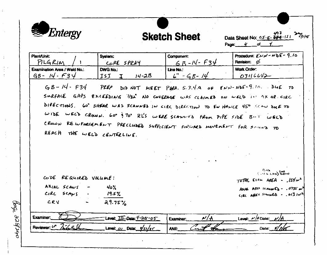
EnItergy Sketch Sheet Data Sheet No: 6S-6- 4.e - 1 r/,/_ r
Page: of L.
Plant/Unit: System: Componenr: P ro (':ceue b '-. o01/ L~qco E SPEA L .~L 3V ReflWsfl
Examination Area I Weld No.: DWG No.: Une No.: Work Order:GO_- 14- f__ _151-1-1 4"-L 53I (1?-
C,3- /4l- F34( 1'Pfi/ bibO 06T Af(T f; 10-/ - D'f b lz
5'~.R~Aci jAP. C~jbij&4 '1/3,x! AJb Co*JUA-6f uA• eCLAkIPAb b)£~4 "'K0C
bllIc-noaTjS 4o'ý j~~ wA5 SCAsvp.'b )#-J CiE-C 'blf-eýT~vJ Tb fWi Ni+,ApjCf S (~ 1 ~ b&tfL Tb
RCSi-j~ i-fr4W sc-n-r F04Ai<bLwr L
A-AIAL SCAW. -
L--V --
VOLUM~E:'
110761T5%
, .," .. • -) .4 s-@J
TDlX. r4. -g i2A - ./slY i-1 "
MA)L A~5f A*~~-*~S
WE.~~~A S'IlMAit 613 ,ia

iInstruction No. 50.20
Rev. 7Attachment G
Page 1 of 1
I RECORD OF MAGNETIC PARTICLE EXAMINATION I DATA SH.E, # ,-,, ,
ITEM ID/PIECE #0 SYSTEM I MR# I ISO/DWG NUMBER
It _______A ý'_d~ 011-5 10 -4I0
A. MATERIAL I TYPE C,.5, 1
ICROSS SECTION MAX IMIN IPIPE PLATE ROO OTHER1THICKNESS J,) JGEOMETRY -it __
I FABRICATION PROCEI5S CAST WORKED QW83L OTHER
SURFACE eAHINED_ ROUV A 07HER INSPECTION HOLDPT jIAIBRICATED 1.5.1.
SURFACE IS SUITABLE FOR SCHEDULE 6D MT j. UT EXAMINATION V• YES U NOU
-I SKETCH OR OTHER DETAIL ATTACHEEF-ME-O I WEIGHT 4 10 LB 40LBB. PROCEDURE# z._ 7 EQUIPMENT IDENTIFICATION .
VALIDATION # • . AC I•. HWAC rlPOLE SPACING _ S/N 17e
C. EVALUATION
LOCATION SIZE DESCRIPTION ACTION([INCHES) (ACCEPT, REWORK, REJECT ANDINESI COMMENT AS•NECESSARY)
12. 1 1- o5 .i-.se"3. I ,o4. . ..5. __ 7,6. I.,,, ! / S'7. . /•-j .. ,,
C. CRITERIA COMPONENTNOT MEASME SECTION XI CRITERIA
FURTHER EVALAUTON REOUI-R'' YES [7 NO
'E. ATTEST A. t---- • 3/O_,•..SCERTIFIED PERSONNEL LATE
NDT LEVEL DATE ' DATE

'a
'1COMtoP'--O-A M6A /o-94, 0
CA
V I CwDrp-of. 7'o'PtOOKIl 4)&W/OuA
ci~d o8nfA uz ARC"excm ~fEWE=,3
>/foa * ~tii~ 417- 03)t"
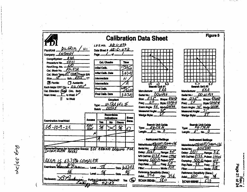
copany PI f6RIM
CommSyhmra
PmenNo. O,•RNo, • No.
CaL Maock No.
Isetle adLustmnluc
CaL Dlrel Omxe . BothScan Are, : J._ to Weld
II to wow
CalibrationDataSIm# r.e-0D
OaL Oheska Thea
i,,. Ca.- Date
kitetuidlAte
Final Cek Dateb 74cOsupten
l~e7w. UaIL ,
Data Sheet Figure 5
Semlt Uldt #2
Se,,r No-.' Q2,U 61
Eaim kst"2Q WeMM(
MmwfedAunet 2Lwed Sto .
c a_. e, .
Umoc p w -/0J/-
8umfh u~nit
• w. f 6--7f ,
1eng 07L R
N~ ~WROWZ5
Fftr "71a:
-UAPL± 63.5 SMonamPI
Exain,. tevi .U.J.. Date___
Revinwes:-oý d i4 -j uMMinauo!InI~eu~tlO yet ~
Rter..RtT 6 M
Remforen Swnelt~y (Sena.)4
(

-> gOff
C(

iFO.pý NO 507.3
PA6F.1 0F. OF
IA)N6P. I 6 oe(TYi1•XAe ,A..CA . ,,' e,,
j9 4 '?- I7•o 7O~,P PiT; e. ,/
I O q 1007-
~~;oG::S01 3,-~ ACA44 fe-AlU OiU& V4iaE70 /tjo.3 q E4 = ^0, 30 Sm
'70° /093.1• cq ýfP C m u O7E1"70 it 10.o s•; ciss~ oji &ai -r oee i4^ C riri
-- .. ,

Calit )ata Sheet~~EIler
Planti~nft: PIL C-1 Zf I
CDS NO: c5e.3~-JLDS No: OX - L-32 3 -/V'.Page:4....o!-l..L
I ISystem: XCICComponent: E£-2.(a- f* X38
Line No.: (e- 14E -2- (
Procedure: MO-,I; L-'. .g Rev.:, IThermometer S/N: _ , _._ _
Cal. Blk Temp.: ,8' Comp Temp.:"lrfJCal. Block No.: PIL.- 39 A
O Carbon Steel 0 Stainless Steel
size: 4" Sch.: .. Z"CalDirection 1K Axial c3 Cirn 0 Both
Scan Area A I to weld
Scan Area jL 11 to weld
Work Order 03 1161?.2DWG No.: SX 2 1 -
-Calhes If . I
InitialCal: I/4.1ac / A a .-Date: 3- 22-bs"Inter. Cal.:Date: NInter. Cal.: 'Date:FinalCal.: 111io it MaDate: .-. ~•
Couplant
Type: d LLCJ• L & --, Batch: 01 jg€;
*11 -
ReoofdbMe Indications ExamExamination Ame I Weld Acces Yesso Gom m
YeE-.. N- ob. ien3.51104116 -
Remarks
Further Evaluation Required: 3 Yes WINo
Search Unit # 1 Search Unit # 2Manuiacturer..... iA. Manufacturer .1.j 15A
Model: lg, P - -, Model:- 6DAF -,SerialNo.: 011I PT" SerialNo.: l 11LF.WSize:.." Shape:I_±'t Size: , k" Shape:k.W*bFreq.:-_j # Elm: I Freq.: 5-m./z# Elm: IAngle: 70" Mode:.Mf Angl: q-* Mode: S/.AI,Measured Angle: (,'/ Measured Angle: ('I'V
Wedge Style: A Sw A C Wedge Style: Mt%'3&C..Search Unit Cable Search Unit Cable
Type: F•. |'7( Type: 67 1-74L
Length.'L_ Con.:_o Length : k Con.:_Insm•ument Settings Instrument Settings
manuiacturew..!'ý.ýi g manufacture r - c_Model: US .SXL Model: d4.f) s5;LSerial No.: iE14F .P, Serial No.:"•004t EKAUnearity Due:--#"fr&5E Linearity Due:Delay jj#31Range: I.ft Delay: ;k .13 r. Range:1- g%MIL VeI:41 3137 Pulser~ ie4LL MUJ. VeI.:,1U2Pulser ALLDamping:Ib Rejectn Damping:Lu1!2_Reject": GfI'Rep Rate: WE/4!Freq.: L-"6 Rep Rate:/#6 H Freq.:- ,L-Filter_.F L-Mode:-.&Q Filter F.4 L mode:s 6JX
R .ne61n.. SensMlv, ty Referen Sensitivity,,xial: 9-D, airc:'•• .xia =: I[ ai:. 0m
Examiner~Examiner. . "O low a .-Reviewer.ANti: '- •
Leel /IAData:
.... ii •
Da
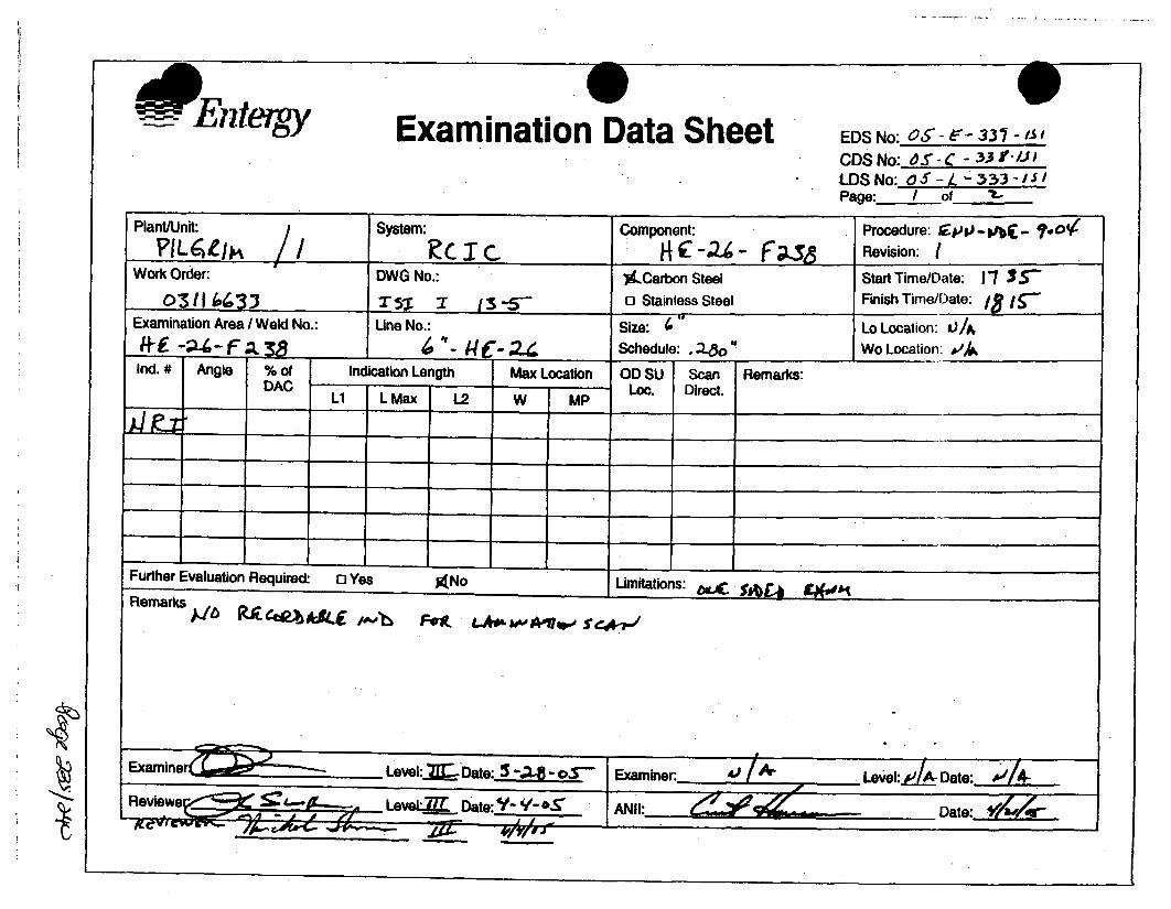
EntergySExamination Data Sheet
EDS No: OS- - 5" 331 -f' I
CDS No:.dS"- 'C -33 I-'/JJ
LDS No: QS -/ 4- 333- IJSPage: / of It-
Plant/Unit: System: Component: Procedure: gps'.-,'b- f .to'(
?FIL•vt/ I / /, -C T. C R -2- Revision: .,IWork Order: DWG No.: %..Carbon Steel Start Time/Date: 11 35
03 1 I , 7- 5'1 3 13 5- 0 Stainless Steel Finish Time/Date: IS -
Examination Area I Weld No.: Une No.: Size: ' Lo Location: Li/A
WE~-4 8..__ ~ -~t~- Schedule: , & Wo Location: ~4Ind. # Angle % of Indication Length Max Location OD SU Scan Remarks:
DAC Lo. Direct.Li L Max L2 W MP
Further Evaluation Required: 0 Yes ANo Limitations: £)•,- .
Remarks
-T- Examiner: Level:e- xlA Date:
Reiw eaj1 Date: ANH: eL-@• A*J Il:Date: /ar-~
•f wf - -

.1- Enteigy Sketch Sheet Data Sheet No: Of-c- 3q-,j 1
pap ._ "_ f ".
Page: e: E AJo 2.Aj IbC-
Revision:
Work Order:
i
AXAKpL 5CAi' - 87,57%CjutI kc s 'k - S- /
T-DTM 'obC IitQ 4 vaLctxa -
.Level: JAI-- Dat.: ..:-
~~~~f Dao -''.hS

This page intentionally left blank
Page 237/240

This page intentionally left blank
Page 238/240

This page intentionally left blank
Page 239/240

This page intentionally left blank
Page 240/240

RESPONSES FOR PRR-42 RAI (PRR-42 Rev. 1)
Attachment 2 to Entergy Letter No. 2.07.076
Response to NRC Request for Additional Information
Page 1 of 52

RESPONSES FOR PRR-42 RAI (PRR-42 Rev. 1)
2.2.1 The licensee requested relief for several RPV longitudinal shell welds. It was noted that norelief for circumferential shell welds (with exception of RPV-BH-C 1) was included, and it isassumed that PNPS has submitted an alternative in accordance with "BWR [boiling-waterreactor] Vessel and Internals Project, BWR Reactor Pressure Vessel Shell Weld InspectionRecommendations (BWRVIP-05)" to exclude examination of the RPV circumferential shell welds.Please list the date of the NRC SER which authorizes the use of BWRVIP-05, or include a copyof the SER when responding to this RAI.
2.2.1 RESPONSE:
NRC approval of Pilgrim Relief Request (PRR)-28, Rev. 1 provides for the use of BWRVIP-05 toexclude circumferential shell welds [Reference: NRC SER, "Pilgrim Nuclear Power Station-Pilgrimrelief Request No. 28, relief From ASME Code , Section X1, Examinations of Reactor PressureVessel Circumferential Shell Welds (TAC No. MB6074), dated April 11, 2003].
Page 2 of 52

RESPONSES FOR PRR-42 RAI (PRR-42 Rev. 1)
2.2.2 The coverage sketches included in ultrasonic reports for bottom head-to-shellcircumferential Weld RPV-BH-Cl are unclear. Please re-submit cross-sectional sketches, or fullwritten descriptions, describing ASME Code-required volumes and areas of completed coveragefor each of the techniques (near surface, inner 15%, and full volume) used on this weld.Summarize the scanning directions and techniques, list the materials for the base metal andweld, and clarify whether the methods used have been qualified in accordance with performancedemonstration requirements per ASME Section XI, Appendix VIII.
2.2.2 RESPONSE:
Total ultrasonic examination coverage of weld RPV-BH-C1 is impractical due to obstructions orlimiting component configuration that adversely affect the scan paths for required ultrasonic beamprojections required to achieve complete examination coverage.
Weld RPV-BH-C1 is the Reactor Pressure Vessel bottom head to shell weld. Both the base andweld material are carbon steel.
This weld was ultrasonically examined manually utilizing General Electric Energy NuclearProcedure GE-UT-300 Version 8. This procedure is qualified by EPRI PDI to ASME Section XI,Appendix VIII, Supplements 4 & 6 for ultrasonic examination of reactor pressure vessel weldswith dual or single side access. Report No. PIL-R15-05-002 is attached as Reference A.
Scanning was performed from one side of the weld due to the configuration of the reactor vesselsupport skirt assembly configuration. Scans were performed in both the Transverse (scanningtransverse or perpendicular to the weld) and Parallel (scanning parallel to the weld in twodirections 180 degrees to each other) directions. In the attached UT report, the Transverse scansare referred to as 'T-Scans" and the Parallel scans as "P-Scans."
Limitations in weld coverage were identified due to both the Reactor Pressure Vessel (RPV)support skirt configuration (proximity to the weld) and three thermocouple pads each about 5" inlength. The limitation caused by the support skirt exists for the entire weld length. Thethermocouple limitation locations are identified on Report No. PIL-R15-05-002, Data SheetNumbers UT-086 and UT-089 in the "Comments" section. Modified coverage sketches fromReport No. PIL-R15-05-002, identified as Attachment A Sketch 1 and Sketch 2, are also attachedand indicate the weld examination volume required by ASME Section Xl, Appendix VIIISupplements 4 & 6. These sketches also indicate the limited coverage areas for both the T andP scans. The Table on page 10 of 12 of Report No. PIL-R15-05-002, summarize the limitationpercentages. Total composite coverage for this weld is 75%.
Page 3 of 52

RESPONSES FOR PRR-42 RAI (PRR-42 Rev. 1)
2.2.3 Similarly, the examination reports for the remaining RPV longitudinal shell and shell-to-flange welds do not adequately describe completed examination coverages. Please submitcross-sectional sketches, or full written descriptions, describing ASME Code-required volumesand areas of completed coverage for each of the techniques (near surface, inner 15%, and fullvolume) used on the following welds:
Veid IDw ~Weld Type
RPV-L-1-338A Lower Intermediate Shell Vertical Weld
RPV-L-1-338C Lower Intermediate Shell Vertical Weld
RPV-L-2-338A Lower Shell Vertical Weld
RPV-L-2-338B Lower Shell Vertical Weld
RPV-L-2-338C Lower Shell Vertical Weld
RPV-L-2-339A Upper Intermediate Shell Vertical Weld
RPV-L-2-339B Upper Intermediate Shell Vertical Weld
RPV-L-2-339C Upper Intermediate Shell Vertical Weld
RPV-BH-C1 Bottom Head-to-Shell Circumferential Weld
RPV-SF-0-120 Shell to Flange Weld (0 to 120 degrees)
RPV-SF-120-240 Shell to Flange Weld (120 to 240 degrees)
RPV-SF-240-360 Shell to Flange Weld (240 to 360 degrees)
In addition, summarize the scanning directions and techniques, list the materials for the basemetal and welds, and clarify whether the methods used have been qualified in accordance withperformance demonstration requirements per ASME Section XI, Appendix VIII.
2.2.3 RESPONSE:
Total ultrasonic examination coverage of welds RPV-L-1-338A, RPV-L-1-338C, RPV-L-2-338A,RPV-L-2-338B, RPV-L-2-338C, RPV-L-2-339A, RPV-L-2-339B, RPV-L-2-339C and RPV-C-4-339is impractical due to obstructions or limiting configuration that adversely affect positioning of theautomated scanning tool and thus the scan paths for required ultrasonic beam projectionsrequired to achieve complete examination coverage.
These welds are carbon steel RPV shell course vertical welds and RPV shell to flange weld.These welds are all carbon steel component parts welded with carbon steel weld metal.Ultrasonic scanning was performed using the equipment described in Attachment B. Thephysical dimensions and mode of operation of this tooling are important relative to understandingthe limitations described in the table below. All of the limitations associated with these welds aredirectly associated with issues of the scanner access to the required locations to allow completeultrasonic coverage. Ultrasonic coverage is based on scanner encoder inputs and calculatedfrom automated data parameters.
These ultrasonic examinations were conducted in accordance with IHI Procedures ISwT-PDI-AUT1, Rev.0 and ISwT-PDI-AUT2, Rev.0. These procedures are qualified by the PerformanceDemonstration Initiative (PDI) and satisfy the examination requirements of ASME Section XI,Appendix VIII, Supplements 4 and 6. Scanning was performed both in the transverse and paralleldirections relative to the welds unless limited by access or configuration.
Page 4 of 52

RESPONSES FOR PRR-42 RAI (PRR-42 Rev. 1)
Attachment B describes the ultrasonic techniques that were utilized for these examinations aswell as a sketch of the various projected beam angles and the Code required examinationvolume.
Attachment C is a roll out sketch of the RPV identifying the location of the various obstructionsrelative to specific welds. For each of the welds identified in the table below, a number isassigned in ( ) after each identified limitation in the "Description of Obstruction / Limitation"column. The corresponding number appears on Attachment C for that location.
:..':Weld Number Weld Description Description of. Obstruction I Limitation
RPV-L-1-338A Intermediate Shell Weld Jet Pump riser brace welded to the RPV wall is@ 60° directly in the scan path for the transducer array.
(1)RPV-L-1-338C Intermediate Shell Weld Jet Pump riser brace (2) and RPV Surveillance
@ 300° Specimen Holder and Support Brackets (3)welded to the RPV walls are directly in the scanpath for the transducer array. Shroud Tie Bar @3152 prevents maneuvering of the scannertooling to fully access the weld. (4)
RPV-L-2-338A Lower Shell Vertical The Shroud Support and associated gussetWeld @ 75- plates would not allow the scanner tooling to
completely position the transducer array to thebottom of the weld, i.e. where the RPV verticalweld intersects with the shroud support plate.(5)
RPV-L-2-338B Lower Shell Vertical The Shroud Support and associated gussetWeld @ 195- plates would not allow the scanner tooling to
completely position the transducer array to thebottom of the weld, i.e. where the RPV verticalweld intersects with the shroud support plate.(6)
RPV-L-2-338C Lower Shell Vertical The Shroud Support and associated gussetWeld @ 3152 plates would not allow the scanner tooling to
completely position the transducer array to thebottom of the weld, i.e. where the RPV verticalweld intersects with the shroud support plate.(7) Shroud Tie Bar @ 3152 preventsmaneuvering of the scanner tooling to fullyaccess the weld. (8) N2K Nozzle radiusprevents even contact of the scanner toolingthus scanning in area of the N2K Nozzle innerradius is not possible. (9)
RPV-L-2-339A Upper Shell Vertical Feedwater (10) and Core Spray Spargers (11)Weld @ 355- prevent maneuvering of the scanner tooling to
fully access the weld.RPV-L-2-339B Upper Shell Vertical Feedwater (12) and Core Spray Spargers (13)
Weld @ 115- prevent maneuvering of the scanner tooling tofully access the weld. Angle of ID taper due toRPV shell course plate thickness change (14)
RPV-L-2-339C Upper Shell Vertical Feedwater (15) and Core Spray Spargers (16)Weld @ 2352 prevent maneuvering of the scanner tooling to
fully access the weld.
Page 5 of 52

RESPONSES FOR PRR-42 RAI (PRR-42 Rev. 1)
Weld Number Weld Description Description of.Obstruction: Limitation..
RPV-C-4-339 Shell to Flange Weld The proximity of the Main Steam Nozzles (17),(previously from 0° to 3602 Main Steam Nozzle Plugs (and necessaryidentified as support tooling) (18), Dryer/Separator GuideRPV-SF-0-120, Rods at O- and 1802 (19) and configuration ofRPV-SF-120- the Shell to Flange weld (see Attachment C).240 and RPV-SF-240-360)
Page 6 of 52
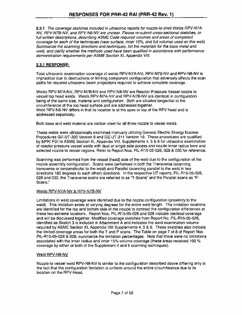
RESPONSES FOR PRR-42 RAI (PRR-42 Rev. 1)
2.3.1 The coverage sketches included in ultrasonic reports for nozzle-to-shell Welds RPV-N7A-NV, RPV-N7B-NV, and RPV-N8-NV are unclear. Please re-submit cross-sectional sketches, orfull written descriptions, describing ASME Code-required volumes and areas of completedcoverage for each of the techniques (near surface, inner 15%, and full volume) used on this weld.Summarize the scanning directions and techniques, list the materials for the base metal andweld, and clarify whether the methods used have been qualified in accordance with performancedemonstration requirements per ASME Section Xl, Appendix VIII.
2.3.1 RESPONSE:
Total ultrasonic examination coverage of welds RPV-N7A-NV, RPV-N7B-NV and RPV-N8-NV isimpractical due to obstructions or limiting component configuration that adversely affects the scanpaths for required ultrasonic beam projections required to achieve complete coverage.
Welds RPV-N7A-NV, RPV-N7B-NV and RPV-N8-NV are Reactor Pressure Vessel nozzle tovessel top head welds. Welds RPV-N7A-NV and RPV-N7B-NV are identical in configurationbeing of the same size, material and configuration. Both are situated tangential to thecircumference of the top head surface and are addressed together.Weld RPV-N8-NV differs in that its location is at the apex or top of the RPV head and isaddressed separately.
Both base and weld material are carbon steel for all three nozzle to vessel welds.
These welds were ultrasonically examined manually utilizing General Electric Energy NuclearProcedures GE-UT-300 Version 8 and GE-UT-311 Version 10. These procedures are qualifiedby EPRI PDI to ASME Section XI, Appendix VIII, Supplements 4, 5 & 6 for ultrasonic examinationof reactor pressure vessel welds with dual or single side access and nozzle inner radius bore andselected nozzle to vessel regions. Refer to Report Nos. PIL-R1 5-05-026, 028 & 030 for reference.
Scanning was performed from the vessel [head] side of the weld due to the configuration of thenozzle assembly configuration. Scans were performed in both the Transverse (scanningtransverse or perpendicular to the weld) and Parallel (scanning parallel to the weld in twodirections 180 degrees to each other) directions. In the respective UT reports, PIL-R15-05-026,028 and 030, the Transverse scans are referred to as "T-Scans" and the Parallel scans as "P-Scans."
Welds RPV-N7A-NV & RPV-N7B-NV
Limitations in weld coverage were identified due to the nozzle configuration (proximity to theweld). This limitation exists at varying degrees for the entire weld length. The limitation locationsare identified for the top and bottom side of the nozzle to contrast the configuration differences atthese two extreme locations. Report Nos. PIL-R1 5-05-026 and 028 indicate identical coverageand will be discussed together. Modified coverage sketches from Report No. PIL-R15-05-026,identified as Sketch 3 is included in Attachment A and indicates the weld examination volumerequired by ASME Section XI, Appendix VIII Supplements 4, 5 & 6. These sketches also indicatethe limited coverage areas for both the T and P scans. The Table on page 7 of 8 of Report Nos.PIL-R15-05-026 & 028, summarize the limitation percentages. Note that there were no limitationsassociated with the inner radius and inner 15% volume coverage (these areas received 100 %coverage by either or both of the Supplement 4 and 5 scanning techniques).
Weld RPV-N8-NV
Nozzle to vessel weld RPV-N8-NV is similar to the configuration described above differing only inthe fact that the configuration limitation is uniform around the entire circumference due to itslocation on the RPV Head.
Page 7 of 52

RESPONSES FOR PRR-42 RAI (PRR-42 Rev. 1)
A modified coverage sketch from Report No. PIL-R15-05-030, identified as Sketch 4 inAttachment A is also attached and indicates the weld examination volume required by ASMESection XI, Appendix VIII Supplements 4, 5 & 6. This sketch also indicates the limited coverageareas for both the T and P scans. The Table on page 6 of 7 of Report No. PIL-R15-05-30,summarizes the limitation percentages. Note that there were no limitations associated with theinner radius and inner 15% volume coverage (these areas received 100 % coverage by either orboth of the Supplement 4 and 5 scanning techniques).
Page 8 of 52

RESPONSES FOR PRR-42 RAI (PRR-42 Rev. 1)
2.4.1 Table 3 of relief request PRR-42 contains a listing of multiple limited examinations forClass 1 dissimilar metal piping and nozzle-to-safe end welds that have occurred during the third10-year interval. The table lists ASME Code Examination Category B-F for each piping andnozzle-to-safe end weld, which would normally indicate that a conventional ISI program has beenimplemented. Typically, if a risk-informed inservice inspection (RI-ISI) program is beingimplemented, a new Examination Category R-A is used, which lists welds, or elements, accordingto expected forms of degradation. However, ASME Item Numbers for both a conventional and RI-ISI program are listed, e.g., R1. 11 (B5. 10). Item Number RI. 11 refers to welds susceptible tothermal fatigue and B5. 10 is the conventional designation for RPV nozzle-to-safe end butt weldsin piping greater than 4-inch NPS. In addition, Item Number R1.20 (B5.130) is also referenced,but no such Item Number exists within the framework of ASME Code RI-ISI methods (CodeCases N-577 and N-578). Confirm that all Class 1 dissimilar metalwelds are part of a RI-ISI program at PNPS, and clarify the designation of Item NumberR1.20.
State the total number of Category B-F (new Category R-A) Class 1 dissimilar metalwelds that exist at PNPS, the examination sample population of these that are includedin the RI-ISI program, and clarify the extent of limited volumetric coverages that resultedduring each weld examination. In addition, describe whether PNPS consideredperforming additional examinations on welds not in the initial RI-ISI examinationpopulation to supplement the limited volumetric coverages.
2.4.1 RESPONSE:
Pilgrim received NRC approval on May 2, 2001 to implement a risk-informed inspection programfor Class 1 category B-F and B-J piping welds based on the methodology detailed in EPRITopical Report TR-1 12657 revision B-A and Code Case N-578 as an alternative to therequirements of the 1989 edition ASME XI code.
The risk-informed methodology used at Pilgrim includes all category B-F and B-J welds in thedetermination of the final risk-informed inspection sample of 71 Class 1 welds. There are a totalof 29 Class 1 dissimilar metal welds at Pilgrim Station with 7 of the DM welds included in theClass 1 risk-informed inspection sample. In accordance with the EPRI risk-informedmethodology, augmented programs are relied upon for the inspection of welds not whollysubsumed by the risk-informed process, including IGSCC-susceptible welds. All carbon steel andIGSCC category A austenitic stainless steel welds are subsumed into Pilgrim's risk-informedinspection process while all IGSCC category B, C, D, E and G welds are examined in accordancewith the augmented inspection schedules and methods outlined in BWRVIP-75A.
Inspection coverage obtained for six of the seven dissimilar metal welds included in the PNPSrisk-informed inspection sample exceeded 90% combined coverage. Reduced coverage for oneof the seven welds, Core Spray weld no. 14-A-1OA (see PRR-42 Table 3), was caused by asevere valve-to-pipe weld profile (seen in the adjacent photo) that could not be modified toincrease inspection coverage without reducing designmargin for the configuration. Since this weld is a dissimilarmetal weld made with Inconel 182 weld metal, all othersimilar welds are currently inspected in accordance withBWRVIP-75A Category D weld inspection schedules andmethods. As a result, there are no other similarlyconstructed welds that are not already being inspected thatcould be added to the risk-informed inspection sample toaccount for the reduced coverage obtained on 14-A-1i A.Additional clarification of the extent of limited volumetriccoverages resulting from each weld examination isdiscussed in LO-WPOLO-2007-00027 CA-7.
Page 9 of 52

RESPONSES FOR PRR-42 RAI (PRR-42 Rev. 1)
Section Xl code item numbers such as B5.10 were included in PRR-42 Table 3 in addition to thenew risk-informed item numbers for the sake of completeness as risk-informed inspections werenot implemented until the second period of the Pilgrim third ten year inspection interval.Inspections performed during the first period of the Pilgrim third ten year inspection interval werecompleted in accordance with the 1989 ASME XA code.
In 2001, as part of the risk-informed inservice inspection program application, Class 1circumferential piping welds were assigned alternate examination category and code itemnumbers that were consistent with ASME Section XI Code Case N-578-1. The numberingsystem established in Code Case N-578-1 is similar to the one used in Code Case N-578.However, the Code Case N-578-1 numbering system is more complete and more accuratelyreflects the technical criteria established in EPRI Topical Report No. TR-1 12657. For thesereasons, the numbering system established in Code Case N-578-1 was used instead of the oneshown in Code Case N-578, and is carried forward into the fourth interval. Item number R1.20 asshown in Table 3 of PRR-42 is not listed in Code Case N-578 but was included in Code Case N-578-1 as a means to categorize elements that are not subject to a damage mechanism. Inclusionof item number R1.20 in Table 3 has no substantive impact on relief request PRR-42.
Page 10 of 52
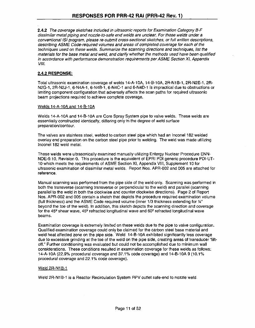
RESPONSES FOR PRR-42 RAI (PRR-42 Rev. 1)
2.4.2 The coverage sketches included in ultrasonic reports for Examination Category B-Fdissimilar metal piping and nozzle-to-safe end welds are unclear. For those welds under aconventional IS! program, please re-submit cross-sectional sketches, or full written descriptions,describing ASME Code-required volumes and areas of completed coverage for each of thetechniques used on these welds. Summarize the scanning directions and techniques, list thematerials for the base metal and weld, and clarify whether the methods used have been qualifiedin accordance with performance demonstration requirements per ASME Section X1, AppendixVIII.
2.4.2 RESPONSE:
Total ultrasonic examination coverage of welds 14-A-1OA, 14-B-1i A, 2R-N1 B-i, 2R-N2E-1, 2R-N2G-1, 2R-N2J-1, 6-N4A-1, 6-N4B-1, 6-N4C-1 and 6-N4D-1 is impractical due to obstructions orlimiting component configuration that adversely affects the scan paths for required ultrasonicbeam projections required to achieve complete coverage.
Welds 14-A-1OA and 14-B-1OA
Welds 14-A-10A and 14-B-10A are Core Spray System pipe to valve welds. These welds areessentially constructed identically, differing only in the degree of weld surfacepreparation/contour.
The valves are stainless steel, welded to carbon steel pipe which had an Inconel 182 weldedoverlay end preparation on the carbon steel pipe prior to welding. The weld was made utilizingInconel 182 weld metal.
These welds were ultrasonically examined manually utilizing Entergy Nuclear Procedure ENN-NDE-9.10, Revision 0. This procedure is the equivalent of EPRI PDI generic procedure PDI-UT-10 which meets the requirements of ASME Section Xl, Appendix VIII, Supplement 10 forultrasonic examination of dissimilar metal welds. Report Nos. APR-002 and 005 are attached forreference.
Manual scanning was performed from the pipe side of the weld only. Scanning was performed inboth the transverse (scanning transverse or perpendicular to the weld) and parallel (scanningparallel to the weld in both the clockwise and counter clockwise directions). Page 2 of ReportNos. APR-002 and 005 contain a sketch that depicts the procedure required examination volume(full thickness) and the ASME Code required volume (inner 1/3 thickness extending for 1/4"
beyond the toe of the weld). In addition, this sketch depicts the scanning direction and coveragefor the 45- shear wave, 45- refracted longitudinal wave and 60- refracted longitudinal wavebeams.
Examination coverage is extremely limited on these welds due to the pipe to valve configuration.Qualified examination coverage could only be claimed for the carbon steel base material andweld heat affected zone on the pipe side. Weld 14-B-10A exhibited significantly less coveragedue to excessive grinding at the toe of the weld on the pipe side, creating areas of transducer "lift-off." Further conditioning was evaluated but could not be accomplished due to minimum wallconsiderations. These conditions resulted in examination coverage for these welds as follows:14-A-1OA (22.9% procedural coverage and 37.1% code coverage) and 14-B-1OA 9 (10.1%procedural coverage and 22.1% code coverage).
Weld 2R-N1 B-1
Weld 2R-NI B-1 is a Reactor Recirculation System RPV outlet safe-end to nozzle weld.
Page 11 of 52

RESPONSES FOR PRR-42 RAI (PRR-42 Rev. 1)
The safe-end is 316 stainless steel with an Inconel 182 weld overlay end preparation, welded tothe carbon steel RPV inlet nozzle which also has an Inconel 182 welded overlay end preparation.The weld was made utilizing Inconel 82 (root pass) and 182 weld metal.
This weld was ultrasonically examined utilizing General Electric Energy Nuclear Procedure GE-UT-209 Version 17. This procedure is qualified by EPRI PDI to ASME Section XI, Appendix VIII,Supplement 10 for automated ultrasonic examination of dissimilar metal welds with single sidedaccess. Report No. APR-007 is attached for reference.
Automated scanning was performed from both sides of the weld in both the Transverse (scanningtransverse or perpendicular to the weld) and Parallel (scanning parallel to the weld in both theclockwise and counter clockwise directions). Page 2 of Report No. APR-007 contains a sketchthat depicts the procedure required examination volume (full thickness) which incorporates theASME Code required volume (inner 1/3 thickness extending for '" beyond the toe of the weld). Inaddition, this sketch depicts the scanning direction and coverage for the 459shear wave, 45°refracted longitudinal wave and 60° refracted longitudinal wave beams.
The weld examination coverage percentage stated on page 1 of the report was calculated by theUT data analyst utilizing his discretion as to where the ultrasonic transducers were "lifting off" thecomponent surface due surface contour irregularities rendering the data acquired in those areasto be unusable. The data analyst performed coverage calculations using transducer positioninginformation in the analysis software. These calculations resulted in the following UT examinationcoverage percentages: 2R-N1 B-1 73% procedure coverage & 75% code required coverage.
Welds 2R-N2E-1, 2R-N2G-1 and 2R-N2J-1
Welds 2R-N2E-1, 2R-N2G-1, 2R-N2J-1 are Reactor Recirculation System RPV inlet safe-end tonozzle welds. These welds are essentially constructed identically, differing only in the degree ofweld surface preparation/contour.
The safe-end is 316 stainless steel with an Inconel 182 weld overlay end preparation, welded tothe carbon steel RPV inlet nozzle which also has an Inconel 182 welded overlay end preparation.The welds were made utilizing Inconel 82 (root pass) and 182 weld metal.
These welds were ultrasonically examined utilizing General Electric Energy Nuclear ProcedureGE-UT-209 Version 17. This procedure is qualified by EPRI PDI to ASME Section Xl, AppendixVIII, Supplement 10 for automated ultrasonic examination of dissimilar metal welds with singlesided access. Report Nos. APR-009, 011 and 012 are attached for reference.
Automated scanning was performed from both sides of the welds in both the Transverse(scanning transverse or perpendicular to the weld) and Parallel (scanning parallel to the weld inboth the clockwise and counter clockwise directions). Pages 2 and 3 of Report Nos. APR-009,011 and 012 contain sketches of both the procedure required examination volume (page 2 [fullthickness]) and the ASME Code required volume (page 3 [inner 1/3 thickness extending for '"beyond the toe of the weld]). In addition, these sketches show the scanning direction andcoverage for the 45-shear wave, 45L3 refracted longitudinal wave and 60o refracted longitudinalwave beams.
The weld examination coverage percentages stated on page 1 of the reports was calculated bythe UT data analyst utilizing his discretion as to where the ultrasonic transducers were "lifting off"the component surface due surface contour irregularities rendering the data acquired in thoseareas to be unusable. The data analyst performed coverage calculations using transducerpositioning information in the analysis software. These calculations resulted in the following UTexamination coverage percentages: 2R-N2E-1 79.1% procedure coverage & 81.2% coderequired coverage, 2R-N2G-1, 71.8% procedure coverage & 75.3% code required coverage, 2R-N2J-1, 65.7% procedure coverage & 75% code required coverage.
Page 12 of 52

RESPONSES FOR PRR-42 RAI (PRR-42 Rev. 1)
Welds 6-N4A-1. 6-N4B-1, 6-N4C-1 and 6-N4D-1
Welds 6-N4A-1, 6-N4B-1, 6-N4C-1 and 6-N4D-1 are Reactor Feedwater System RPV inlet safe-end to nozzle welds. These welds are essentially constructed identically.
The safe-end is carbon steel as is the RPV nozzle. These welds were made using carbon steelweld metal, thus they do not meet the criteria of a Category B-F dissimilar metal weld. The B-Fcategory was assigned to these welds early in the third interval to ensure that all of the weldsimmediately off of the RPV were examined (Category B-F required 100% of the population beexamined). These welds have since been re-categorized asCategory R-A and examined under the Risk Informed Program.
These welds were ultrasonically examined manually utilizing Boston Edison Company (BECo)procedure QCI 50.71, Revision 4. This procedure was not qualified by EPRI PDI to ASMESection XI, Appendix VIII, although the UT examiners that performed the examinations did haveferritic weld examination PDI qualifications. Report Nos. 99-C-547 and 99-C-549 are attached forreference. Scanning was performed from both sides of the welds in both the transverse(scanning transverse or perpendicular to the weld) and Parallel (scanning parallel to the weld inboth the clockwise and counter clockwise directions) utilizing both 45° and 60° shear wavetechniques.
Since no cross sectional sketches were made of these welds at the time of examination, anassumption was made in calculating the limited examination coverage. This assumptionconcluded that for areas not identified as being limited, total coverage was achieved. Therefore,the total lengths of limited examination areas were divided by the total weld lengths to determinethe percentage of limited examination coverage for each weld resulting in the percentagesidentified in Table 3.
Page 13 of 52

RESPONSES FOR PRR-42 RAI (PRR-42 Rev. 1)
2.4.3 In light of recent industry experience with cracking in these weldments, confirm that allCategory B-F piping dissimilar metal welds containing Alloy 600, 82, and 182 are beingvolumetrically examined at PNPS with techniques that have been qualified through ASMESection XI, Appendix VIII, Supplement 10.
2.4.3 RESPONSE:
There are 21 dissimilar metal welds at Pilgrim that are constructed with Inconel weld material.These welds are classified in accordance with BWRVIP-75A and Generic Letter 88-01 guidancebased on their metallurgy, construction history and environmental conditions. One weld isclassified as Category A, 17 welds are Category D and 3 are Category E weld overlays asdiscussed below. Currently, 20 of these 21 DM welds have been volumetrically examined usingAppendix VIII/Performance Demonstration Initiative (PDI) methods. The one weld that has notyet been examined using PDI procedures is the Category E jet pump instrumentation nozzle safeend weld (weld no. RPV-N9A-1) that was repaired by weld overlay in 1984. This overlay weldwas last examined with pre-PDI UT procedures in 1999 and is currently scheduled for re-examination with PDI procedures in April 2009.
Page 14 of 52
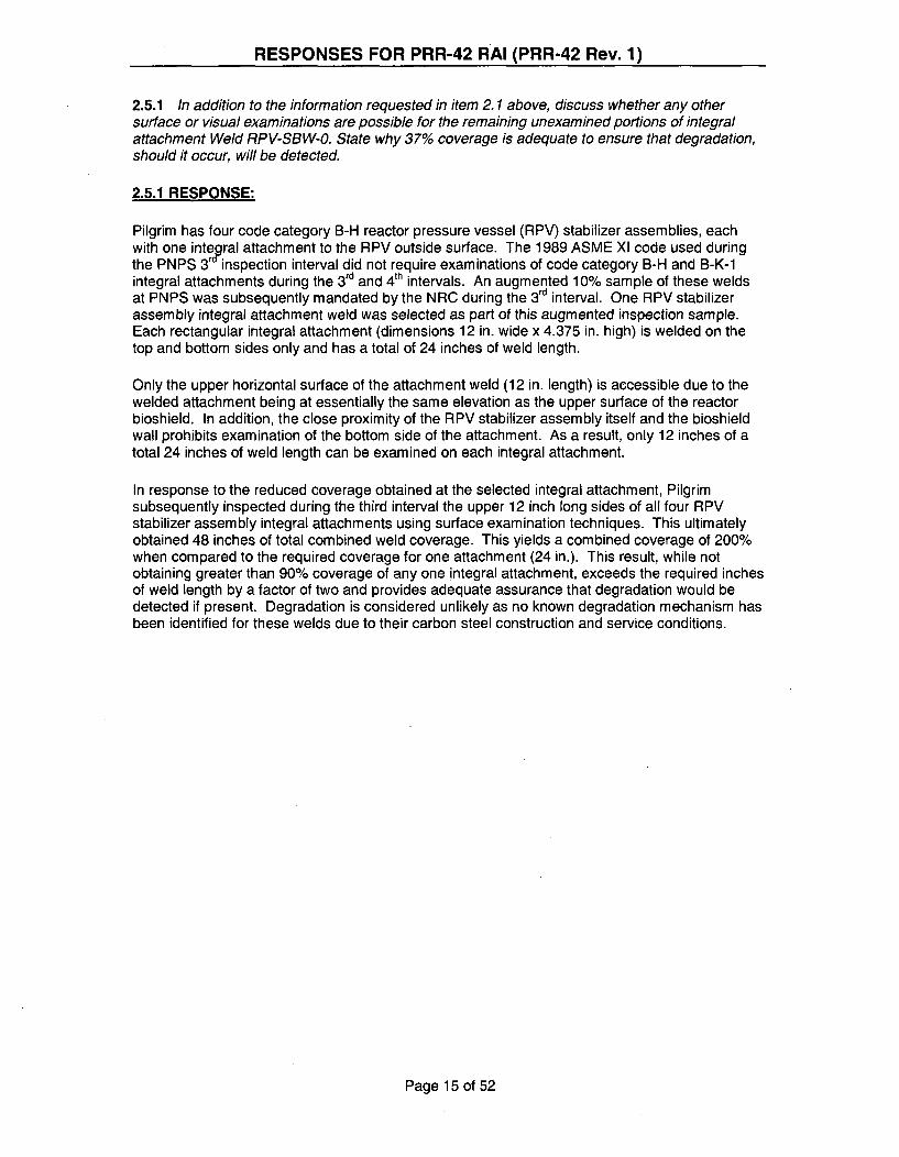
RESPONSES FOR PRR-42 RAI (PRR-42 Rev. 1)
2.5.1 In addition to the information requested in item 2.1 above, discuss whether any othersurface or visual examinations are possible for the remaining unexamined portions of integralattachment Weld RPV-SBW-O. State why 37% coverage is adequate to ensure that degradation,should it occur, will be detected.
2.5.1 RESPONSE:
Pilgrim has four code category B-H reactor pressure vessel (RPV) stabilizer assemblies, eachwith one integpral attachment to the RPV outside surface. The 1989 ASME Xl code used duringthe PNPS 3r inspection interval did not require examinations of code category B-H and B-K-1integral attachments during the 3 d and 4 th intervals. An augmented 10% sample of these weldsat PNPS was subsequently mandated by the NRC during the 3 rd interval. One RPV stabilizerassembly integral attachment weld was selected as part of this augmented inspection sample.Each rectangular integral attachment (dimensions 12 in. wide x 4.375 in. high) is welded on thetop and bottom sides only and has a total of 24 inches of weld length.
Only the upper horizontal surface of the attachment weld (12 in. length) is accessible due to thewelded attachment being at essentially the same elevation as the upper surface of the reactorbioshield. In addition, the close proximity of the RPV stabilizer assembly itself and the bioshieldwall prohibits examination of the bottom side of the attachment. As a result, only 12 inches of atotal 24 inches of weld length can be examined on each integral attachment.
In response to the reduced coverage obtained at the selected integral attachment, Pilgrimsubsequently inspected during the third interval the upper 12 inch long sides of all four RPVstabilizer assembly integral attachments using surface examination techniques. This ultimatelyobtained 48 inches of total combined weld coverage. This yields a combined coverage of 200%when compared to the required coverage for one attachment (24 in.). This result, while notobtaining greater than 90% coverage of any one integral attachment, exceeds the required inchesof weld length by a factor of two and provides adequate assurance that degradation would bedetected if present. Degradation is considered unlikely as no known degradation mechanism hasbeen identified for these welds due to their carbon steel construction and service conditions.
Page 15 of 52

RESPONSES FOR PRR-42 RAI (PRR-42 Rev. 1)
2.6.1 Table 3 of relief request PRR-42 contains a listing of multiple limited examinations forClass 1 piping welds that have occurred during the third 10-year interval. The table lists ASMECode Examination Category B-J for each piping weld, which would normally indicate that aconventional ISI program has been implemented. Typically, if a risk-informed inservice inspection(RI-ISI) program is being implemented, a new Examination Category R-A is used, which listswelds, or elements, according to expected forms of degradation. However, ASME Item Numbersfor both a conventional and RI-ISI program are listed, e.g., R1. 11 (B9. 11). Item Number R1. 11refers to welds susceptible to thermal fatigue and B9. 11 is the conventional designation forCircumferential butt welds in piping greater than 4-inch NPS. In addition, Item Number R 1.20(B9. 11) is also referenced, but no such Item Number exists within the framework of ASME CodeRI-ISI methods (Code Cases N-577 and N-578). Confirm that all Class 1 piping welds are part ofa RI-ISI program at PNPS, and clarify the designation of Item Number R1.20.
State the total number of Category B-J (new Category R-A) Class 1 piping welds that exist atPNPS, the examination sample population of these that are included in the RI-IS! program, andclarify the extent of limited volumetric coverages that resulted during each weld examination. Inaddition, describe whether PNPS considered performing additional examinations on welds not inthe initial RI-ISl examination population to supplement the limited volumetric coverages.
2.6.1 RESPONSE:
Pilgrim received NRC approval on May 2, 2001 to implement a risk-informed inspection programfor Class 1 category B-F and B-J piping welds based on the methodology detailed in EPRITopical Report TR-1 12657 revision B-A and Code Case N-578 as an alternative to therequirements of the 1989 Edition ASME XI code.
The risk-informed methodology used at Pilgrim includes all category B-F and B-J welds in thedetermination of the final risk-informed inspection sample of 71 Class 1 welds. There are a totalof 598 Class 1 code category B-J (now R-A) welds at Pilgrim Station with 60 of these weldsincluded in the Class 1 risk-informed inspection sample. In accordance with the EPRI risk-informed methodology, augmented programs are relied upon for the inspection of welds notwholly subsumed by the risk-informed process, including IGSCC-susceptible welds. All carbonsteel and IGSCC category A austenitic stainless steel welds are subsumed into Pilgrim's risk-informed inspection process while all IGSCC category B, C, D, E and G welds are examined inaccordance with the augmented inspection schedules and methods outlined in BWRVIP-75A.
Section XI Code item numbers such as B9.11 were included in PRR-42 Table 3 in addition to thenew risk-informed item numbers for the sake of completeness as risk-informed inspections werenot implemented until the second period of the Pilgrim third ten year inspection interval.Inspections performed during the first period of the Pilgrim third ten year inspection interval werecompleted in accordance with the 1989 ASME XI code.
In 2001, as part of the risk-informed inservice inspection program application, Class 1circumferential piping welds were assigned alternate examination category and code itemnumbers that were consistent with ASME Section Xl Code Case N-578-1. The numberingsystem established in Code Case N-578-1 is similar to the one used in Code Case N-578.However, the Code Case N-578-1 numbering system is more complete and more accuratelyreflects the technical criteria established in EPRI Topical Report No. TR-1 12657. For thesereasons, the numbering system established in Code Case N-578-1 was used instead of the oneshown in Code Case N-578, and is carried forward into the fourth interval. Item number R1.20 asshown in Table 3 of PRR-42 is not listed in Code Case N-578 but was included in Code Case N-578-1 as a means to categorize elements that are not subject to a damage mechanism. Inclusionof item number R1.20 in Table 3 is administrative in nature and has no substantive impact onrelief request PRR-42.
Page 16 of 52

RESPONSES FOR PRR-42 RAI (PRR-42 Rev. 1)
Clarification of the extent of limited volumetric coverages resulting from each weld examination isdiscussed in LO-WPOLO-2007-00027 CA-1 1. To summarize, the examinations of seven welds inthe PNPS risk-informed inspection program during the 3 rd interval failed to obtain greater than90% coverage. Of those seven welds, one is a dissimilar metal Core Spray pipe-to-valve weld(14-A-10A). All similar DM welds are already included in the BWRVIP-75A inspection sample.Another weld, Main Steam Drain carbon steel pipe-to-valve weld 1-SD-1 OR had obtainedcoverage of 87.5%, amounting to one inch of weld length that could not be obtained due to thepipe-to-valve configuration. This difference was considered insignificant when the examination of21 additional inches of weld metal from the three new welds being added to the inspectionsample are considered.
For the remaining five welds in the PNPS risk-informed inspection program that failed to obtaingreater than 90% coverage, Entergy will revise the risk-informed inspection program by addingthree additional weld examinations to account for the limited volumetric coverage obtained duringthe third interval risk-informed inspections. Three additional welds are from the same systems,are of equivalent risk ranking and have been scheduled for examination during the next refuelingoutage in 2009. The table below provides details of the extra coverage provided by the newwelds.
WELDIJUT• " LENGTH
COVERAGE . MISSED WELDIN3 3 d DIA. FROM 100%/1 LENGTH
WELD INTEV AL. RISKI I l COVERAGE ADDEDNo.*.... RANKING .In lin.5ll lln.) REMARKS
1OR-IA-6 50 HIGH 18 281OR-IA-7 50 HIGH 18 28 ---
1OR-IB-4 --- HIGH 18 --- 57 to be added to RISIProgram
2R-HB-1 50 MEDIUM 12 19 ---2R-HB-4 50 MEDIUM 12 19 ---2R-HB-3 --- MEDIUM 22 --- 69 to be added to RISI
Program
12-0-24 50 MEDIUM 6 9 ---12R-O-8 --- MEDIUM 6 --- 19 to be added to RISI
Program
14-A-10A 37.1 MEDIUM 10 20 --- All DM welds currently
included in BWRVIP-75A
inspection program1-SD-10R 87.5 HIGH 3 1 ---
TOTAL ... --- 124 in. 145 in.
• welds added to PNPS risk-informed program to account for reduced coverage in 3rd interval are
shown in bold font.
Page 17 of 52

RESPONSES FOR PRR-42 RAI (PRR-42 Rev. 1)
2.6.2 Several of the coverage sketches included in ultrasonic reports for Examination
Category B-J circumferential piping welds are unclear. For example, the sketch shown for Weld10-iA-14 lists only a 70-degree longitudinal examination; however, the calibration report indicatesthat both a 45-degree shear and a 70-degree longitudinal technique were used. For those weldsunder a conventional ISI program, please re-submit cross-sectional sketches, or full writtendescriptions, describing ASME Code-required volumes and areas of completed coverage foreach of the techniques used on these welds. Summarize the scanning directions and techniques,list the materials for the base metal and weld, and clarify whether the methods used have beenqualified in accordance with performance demonstration requirements per ASME Section Xl,Appendix VIII.
2.6.2 RESPONSE:
Total ultrasonic examination coverage of welds 10-1A-14, 10-lA-15, 1OR-1A-6, 1OR-1A-7, 12-0-24, 14-A-1 9, 14-B-17, 14-B-20, 1-SD-1OR, 2R-HB-1 and 2R-HB-4 is impractical due toobstructions or limiting component configuration that adversely affects the scan paths for requiredultrasonic beam projections required to achieve complete coverage.
Welds 10-1A-14 and 10-1A-15
Weld 10-1A-14 is a Residual Heat Removal (RHR) System stainless steel pipe to stainless steelflued head penetration weld utilizing stainless steel weld metal. Weld 10-1A-15 is a ResidualHeat Removal (RHR) System stainless steel pipe to stainless steel valve weld utilizing stainlesssteel weld metal. These welds are essentially constructed identically, differing only in the degreeof weld surface preparation/contour and in this case utilize the same ultrasonic systemcalibration.
These welds were ultrasonically examined manually utilizing Entergy Nuclear Procedure ENN-NDE-9.23, Revision 0. This procedure is the equivalent of EPRI PDI generic procedure PDI-UT-2which meets the requirements of ASME Section XI, Appendix VIII, Supplement 2 for ultrasonicexamination of austenitic piping welds. Refer to Report CDS No. 05-C-450.
Manual scanning was performed from the pipe side of these welds only. Scanning wasperformed in both the transverse (scanning transverse or perpendicular to the weld) and parallel(scanning parallel to the weld in both the clockwise and counter clockwise directions). Page 2 ofData Sheets EDS No. 05-E-451-1SI and 05-E-452-1SI of Report No. CDS No. 05-C-450 containsa sketch that depicts the ASME Code required volume (inner 1/3 thickness extending for ¼"beyond the toe of the weld). In addition, this sketch depicts the scanning direction and coveragefor a 702 refracted longitudinal wave beam.
Procedure ENN-NDE-9.23 paragraph 5.3.6.1 states "Search units designed to produce nominalinspection angles of 45°, 60o or 702 shall be used. The actual angle produced in austeniticmaterial shall be used for technique selection, coverage calculations, and plotting of allindications. All the previously required angles are nominal with a deviation allowance of + 32."Further, paragraph 5.3.7.2.1.3 states, 'When accessibility is limited to a single side in materialsgreater than 0.50" thick, a longitudinal wave search unit that provides adequate coverage on thefar side of the weld shall be used for the detection and length sizing of flaws on the far side of theweld." In the case of welds 10-1A-14 and 10-lA-15, the examiner conservatively utilized twoangles and modes of propagation for the greatest achievable coverage. The 45- shear wave wasutilized for pipe side coverage and the 70- longitudinal wave for total coverage. Only the 70L'longitudinal wave is portrayed on the sketch to demonstrate complete procedure requiredcoverage on both sides of the weld.
Page 18 of 52

RESPONSES FOR PRR-42 RAI (PRR-42 Rev. 1)
Examination coverage is limited on these welds due to the pipe to component configurations.Qualified examination coverage could only be claimed for the base material and weld heataffected zone on the pipe side. Procedure ENN-NDE-9.23 paragraph 1.81 states, "Detection oflength sizing of circumferentially oriented flaw indications when only single side access isavailable and the flaw is located on the far side of the weld, however guidance is provided. Thetechniques identified in this procedure have been demonstrated to be representative of "besteffort" technology for single side detection of far side defects parallel to the weld." This conditionresulted in claimed examination coverage for these welds as follows: 14-A-1 0A, 50% codecoverage and 14-B-1i A, 50% code coverage.
Welds 10R-1A-6 and 1OR-1A-7
Welds 10R-1A-6 and 10R-1A-7 are Residual Heat Removal (RHR) System stainless steel pipe tostainless steel valve welds utilizing stainless steel weld metal. These welds are essentiallyconstructed identically, differing only in the degree of weld surface preparation/contour and in thiscase utilize the same ultrasonic system calibration.
These welds were ultrasonically examined manually utilizing Procedure 50.87, Revision 1. Thisprocedure is the equivalent of EPRI PDI generic procedure PDI-UT-2 which meets therequirements of ASME Section XI, Appendix VIII, Supplement 2 for ultrasonic examination ofaustenitic piping welds. Refer to-Report Nos. CDS 03-C-135 and 03-C-137.
Manual scanning was performed from the pipe side of these welds only. Scanning wasperformed in both the transverse (scanning transverse or perpendicular to the weld) and parallel(scanning parallel to the weld in both the clockwise and counter clockwise directions). Page 2 ofData Sheets EDS No. 03-E-136 and 03-E-138 of Report Nos. CDS 03-C-1 35 and 03-C-137contain a sketch that depicts geometric reflector plotting. The Code required volume forinspection of these welds is the inner 1/3 thickness extending for ¼4" beyond the toe of the weld.Coverage for these welds can only be claimed from one side due to the pipe to valveconfiguration. Procedure 50.87, Revision 1, paragraph 1.4 states in part, 'Where access to bothsides is not possible, this procedure is qualified for detection of circumferentially oriented flawsfrom one side of the weld. This procedure is not qualified for the detection of axially orientedflaws or length sizing of any flaw located on the far side of the weld when performing single sideaccess examinations." Therefore, these weld examinations met the single side accessrequirements of the procedure and thus only 50% Code required volume inspection coveragewas achievable for welds 1OR-1A-6 and 1OR-1A-7.
Weld 12-0-24
Weld 12-0-24 is a Reactor Water Cleanup (RWCU) System stainless steel pipe to stainless steelflued head weld utilizing stainless steel weld metal.
This weld was ultrasonically examined manually utilizing Procedure 50.87, Revision 0. Thisprocedure is the equivalent of EPRI PDI generic procedure PDI-UT-2 which meets therequirements of ASME Section Xl, Appendix VIII, Supplement 2 for ultrasonic examination ofaustenitic piping welds. Refer to Report No. CDS 01-C-316.
Manual scanning was performed from the pipe side of this weld only. Scanning was performed inboth the transverse (scanning transverse or perpendicular to the weld) and parallel (scanningparallel to the weld in both the clockwise and counter clockwise directions). Page 2 of DataSheets EDS No. 01-E-317 of Report No. CDS 01-C-316 contains a sketch that depicts the ASMECode required volume (inner 1/3 thickness extending for 'A" beyond the toe of the weld). Inaddition, this sketch depicts the scanning direction and coverage for the 45° and 70o shear wavebeams,
Page 19 of 52

RESPONSES FOR PRR-42 RAI (PRR-42 Rev. 1)
Procedure 50.87, Revision 0, paragraph 1.4 states in part, 'Where access to both sides is notpossible, this procedure is qualified for detection of circumferentially oriented flaws from one sideof the weld. This procedure is not qualified for the detection of axially oriented flaws or lengthsizing of any flaw located on the far side of the weld when performing single side accessexaminations." Paragraph 4.1.8 of this procedure states in part, "Search unit wedges thatproduce a nominal angle of 45L' shall be used when the examination volume can be effectivelycovered in two directions. When geometric configuration(s) prohibit full coverage with the 45°search unit a 60- search unit shall be selected. When geometric configurations prohibit coveragewith the 45- and 60- search unit, a 70- search unit shall be selected." Page 2 of Data SheetsEDS No. 01-E-317 of Report No. CDS 01-C-316 contains a sketch that depicts the scanningdirection and coverage for the 45Q and 70- shear wave beams. Since this is single sidedexamination coverage, greater than 50% of the required examination volume cannot be claimedand therefore the coverage should be revised to 50% not the stated 56.64%.
Weld 14-A-19
Weld 14-A-19 is a Core Spray (CS) System stainless steel pipe to stainless steel valve weldutilizing stainless steel weld metal. Refer to Report CDS No. 05-C-457-IS1.
This weld was ultrasonically examined manually utilizing Entergy Nuclear Procedure ENN-NDE-9.23, Revision 0. This procedure is the equivalent of EPRI PDI generic procedure PDI-UT-2which meets the requirements of ASME Section XI, Appendix VIII, Supplement 2 for ultrasonicexamination of austenitic piping welds.
Manual scanning was performed from the pipe side of this weld only. Scanning was performed inboth the transverse (scanning transverse or perpendicular to the weld) and parallel (scanningparallel to the weld in both the clockwise and counter clockwise directions). Page 2 of DataSheet No. 05-E-458-1SI contains a sketch that depicts the ASME Code required volume (inner 1/3thickness extending for 1¼" beyond the toe of the weld). In addition, this sketch depicts thescanning direction and coverage for both 45- shear wave and a 70- refracted longitudinal wavebeam.
Procedure ENN-NDE-9.23 paragraph 5.3.6.1 states "Search units designed to produce nominalinspection angles of 45L), 60L3 or 70L shall be used. The actual angle produced in austeniticmaterial shall be used for technique selection, coverage calculations, and plotting of allindications. All the previously required angles are nominal with a deviation allowance of + W."Further, paragraph 5.3.7.2.1.3 states, 'When accessibility is limited to a single side in materialsgreater than 0.50" thick, a longitudinal wave search unit that provides adequate coverage on thefar side of the weld shall be used for the detection and length sizing of flaws on the far side of theweld." In the case of weld 14-A-1 9, the examiner conservatively utilized two angles and modes ofpropagation for the greatest achievable coverage. The 45- shear wave was utilized for pipe sidecoverage and the 70- longitudinal wave for total coverage. Only the 709 longitudinal wave isportrayed on the sketch to demonstrate complete procedure required coverage on both sides ofthe weld. Because the weld contour is flat enough to scan across the entire weld surface, thecoverage sketch depicted on Page 2 of Data Sheet No. 05-E-458-ISI indicates the projectedbeams on both sides of the weld even though coverage can only be claimed for one side.
Examination coverage is limited on this weld due to the pipe to valve configuration. Qualifiedexamination coverage could only be claimed for the base material and weld heat affected zoneon the pipe side. Procedure ENN-NDE-9.23 paragraph 1.81 states, "Detection of length sizing ofcircumferentially oriented flaw indications when only single side access is available and the flawis located on the far side of the weld, however guidance is provided. The techniques identified inthis procedure have been demonstrated to be representative of "best effort' technology for singleside detection of far side defects parallel to the weld." This condition resulted in claimedexamination coverage for these welds as follows: 14-A-19 50% code coverage.
Page 20 of 52

RESPONSES FOR PRR-42 RAI (PRR-42 Rev. 1)
Welds 14-B-17 and 14-B-20
Welds 14-B-17 and 14-B-20 are Core Spray (CS) System stainless steel pipe to stainless steelpenetration fitting welds utilizing stainless steel weld metal. These welds are essentiallyconstructed identically, differing only in the degree of weld surface preparation/contour and in thiscase utilize the same ultrasonic system calibration. Refer to Report No. CDS 01-C-1 93.
These welds were ultrasonically examined manually utilizing Procedure ITI 50.87, Revision 0.This procedure is the equivalent of EPRI PDI generic procedure PDI-UT-2 which meets therequirements of ASME Section XI, Appendix VIII, Supplement 2 for ultrasonic examination ofaustenitic piping welds. Refer to Report No. CDS 01-C-1 93.
Manual scanning was performed from the pipe side of these welds only. Scanning wasperformed in both the transverse (scanning transverse or perpendicular to the weld) and parallel(scanning parallel to the weld in both the clockwise and counter clockwise directions). Pages 3and 4 of Data Sheets LDS No. 01-L-141 of Report No. CDS 01-C-193 contains a sketch thatdepicts the coverage projections for the 45 - shear wave and 6 0° refracted longitudinal wave. TheCode required volume for inspection of these welds is the inner 1/3 thickness extending for 1/4"
beyond the toe of the weld. Coverage for these welds can only be claimed from one side due tothe pipe to penetration fitting configuration. Procedure 50.87, Revision 0, paragraph 1.4 states inpart, 'Where access to both sides is not possible, this procedure is qualified for detection ofcircumferentially oriented flaws from one side of the weld. This procedure is not qualified for thedetection of axially oriented flaws or length sizing of any flaw located on the far side of the weldwhen performing single side access examinations." Therefore, these weld examinations met thesingle side access requirements of the procedure and thus only 50% Code required volumeinspection coverage was achievable for welds 14-B-17 and 14-B-20. Since this is single sidedexamination coverage, greater than 50% of the required examination volume cannot be claimedand therefore the coverage should be revised to 50% for both welds not the stated 58.7% forweld 14-B-17 and 59.42% for weld 14-B-20.
Weld 1-SD-10R
Weld 1-SD-10R is a Main Steam (MS) System carbon steel pipe to valve weld utilizing carbonsteel weld metal. Refer to Report CDS No. 01 -C-252.
This weld was ultrasonically examined manually utilizing Procedure ITI 50.71, Revision 5. Thisprocedure is the equivalent of EPRI PDI generic procedure PDI-UT-01 which meets therequirements of ASME Section XI, Appendix VIII, Supplement 3 for ultrasonic examination offerritic piping welds.
Manual scanning was performed from the pipe side of these welds only. Scanning wasperformed in both the transverse (scanning transverse or perpendicular to the weld) and parallel(scanning parallel to the weld in both the clockwise and counter clockwise directions). Page 2 ofData Sheet EDS No. 01-E-253 of Report No. CDS No. 01-C-252 contains a sketch that depictsthe ASME Code required volume (inner 1/3 thickness extending for 1/4" beyond the toe of theweld). In addition, this sketch depicts the scanning direction and coverage for 45 - and 7 0L' shearwave.
Paragraph 4.1.8 of procedure ITI 50.71, Revision 5 states in part, "Search unit wedges thatproduce a nominal angle of 459 shall be used when the examination volume can be effectivelycovered in two directions. When geometric configuration(s) prohibit full coverage with the 452search unit a 60t' search unit shall be selected. When geometric configurations prohibit coveragewith the 459 and 60- search unit, a 70- search unit shall be selected." Page 2 of Data SheetsEDS No. 01-E-317 of Report No. CDS 01-C-316 contains a sketch that depicts the scanning
Page 21 of 52

RESPONSES FOR PRR-42 RAI (PRR-42 Rev. 1)
direction and coverage for the 45° and 70- shear wave beams. In this case 100% axial scancoverage was achieved but only 75% circumferential coverage due to the downstream weld tovalve profile causing transducer "lift-off." The resultant composite coverage for weld 1-SD-10R is87.5%.
Welds 2R-HB-1 and 2R-HB-4
Welds 2R-HB-1 and 2R-HB-4 are Reactor Recirculation System 316 stainless steel pipe to 316stainless steel pipe welds utilizing stainless steel weld metal. These welds are essentiallyconstructed identically, differing only in the degree of weld surface preparation/contour and in thiscase utilize the same ultrasonic system calibration. Refer to Report Nos. CDS 01-C-1 55 and 01-C-157.
These welds were ultrasonically examined manually utilizing Procedure ITI 50.87, Revision 0.This procedure is the equivalent of EPRI PDI generic procedure PDI-UT-2 which meets therequirements of ASME Section XI, Appendix VIII, Supplement 2 for ultrasonic examination ofaustenitic piping welds. Refer to Report Nos. CDS 01-C-155 and 01-C-157.
Manual scanning was performed from the pipe side of these welds only. Scanning wasperformed in both the transverse (scanning transverse or perpendicular to the weld) and parallel(scanning parallel to the weld in both the clockwise and counter clockwise directions). Page 2and 3 of Data Sheet EDS No. 01-E-156 and page 3 of Data Sheet EDS No. 01-E-158 of ReportNos. CDS 01-C-155 and 01-C-157 contains a sketch that depicts the Code required volume forinspection of these welds is the inner 1/3 thickness extending for 1/•" beyond the toe of the weldand the projected scans for the 45° shear, 60 shear wave and 609 refracted longitudinal wavebeams.
Procedure ITI 50.87, Revision 0, paragraph 1.4 states in part, 'Where access to both sides is notpossible, this procedure is qualified for detection of circumferentially oriented flaws from one sideof the weld. This procedure is not qualified for the detection of axially oriented flaws or lengthsizing of any flaw located on the far side of the weld when performing single side accessexaminations." Therefore, these weld examinations were performed utilizing the single sideaccess requirements of the procedure and thus only 50% Code required volume inspectioncoverage can be claimed for welds 2R-HB-1 and 2R-HB-4. Since this is single sided examinationcoverage, greater than 50% of the required examination volume cannot be claimed and thereforethe coverage should be revised to 50% for both welds not the stated 75%.
At the time these examinations were conducted, it was believed by the inspector that these weldswere configured as a pipe to reducer and they were only scanned from the downstream side ofthe welds. In fact, these welds are a unique pipe to larger pipe configuration and could potentiallybe scanned from both sides. PNPS will evaluate scanning from both sides of these welds whichshould yield inspection coverage of > 90%. These welds are currently scheduled for re-examination in the 41h ISI Interval.
Page 22 of 52

RESPONSES FOR PRR-42 RAI (PRR-42 Rev. 1)
2.7.1 The licensee elected to perform liquid penetrant examination of the subject control roddrive (CRD) housing welds, as shown by examination reports on pages 218 and 219 of thesubmittal. However, no sketches indicating the exact cause of the limited examinations areprovided. In addition, it is unclear whether the licensee has completed the ASME Code-required10% of peripheral CRD housing welds by the examinations that were performed.
Confirm that the four CRD housing welds submitted in PRR-42 represent 10% of the peripheralCRD housing welds on the RPV at PNPS. Alternatively, discuss whether other peripheral CRDhousing welds could be examined to compensate for the limited coverage on the subject welds inorder to complete the ASME Code-required 10% surface areas.
2.7.1 RESPONSE:
The 1989 ASME Section XI Code, Category B-0, Examination Item B14.10, requires a volumetricor surface examination of 10% of the peripheral CRD housings during the 3 rd Interval.
The control rod drive housings are inserted through the control rod drive penetrations in thereactor vessel bottom head and are welded to the Inconel stub tubes extending into the reactorvessel. The housings are fabricated of type 304 austenitic stainless steel. (Refer to AttachmentE for a schematic of the CRD housings undervessel.)
PNPS elected to perform a surface examination at 4 locations using the liquid penetrant methodduring RFO#1 5 (ref. exam reports 05-P-432-ISI and 05-P-433-ISI). Due to accessibility issues,the surface examinations of the four selected locations were limited to 50%-70% of the weldareas. The undervessel area is congested with horizontal beams, hanger rods, support bars,grids, etc. severely limiting access in this area and the available work space. This and theproximity of adjacent CRD drives accounted for the limited examinations in this area.
Attachment E shows that there are 36 peripheral CRD housings with 2 assembly welds perhousing. 10% of 36 peripheral housings rounds ups to 4 housings per Interval requiringinspection. The four CRD housing examinations submitted in PRR-42 (ref. exam reports 05-P-432-ISI and 05-P-433-ISI) represent -11% of the peripheral CRD housings at PNPS.
The net surface examination coverage obtained on the 4 housings that were inspected wasapproximately 60%. Even though this was performed on >10% of the required housings, the netsurface examined still accounts for less than 100% of the Code-required coverage.
To account for the limited surface examination coverage obtained during the 3rd Intervalinspections, Entergy will be revising the ISI Program to select additional CRD housings forexamination during the 4 th Interval in order to be certain that an equivalent 100% inspection of10% of the peripheral housings is obtained. Assuming an average 55% coverage per housing,examination of 3 additional housings (7 total) will provide the equivalent code required coverage.This will satisfy the examination requirements of the 1998 ASME Code Section Xl / 2000Addenda which is utilized for the 4th Interval.
Page 23 of 52

RESPONSES FOR PRR-42 RAI (PRR-42 Rev. 1)
2.8.1 Please list the applicable component (vessel, piping, pump, or valve) and system for eachof the subject welded attachments:
EB-23-13HL 1(4) EB-23-59HL 1(4) HL- 1 O-200HL 1(4)
2.8.1 RESPONSE:
The applicable component (vessel, piping, pump, or valve) and system for each of the subjectwelded attachments is as follows:
EXAM POINT SYSTEM DRAWING COMPONENT CAT. ITEM NO.TYPEPIPING
EB-23-13HL1(4) HPCI ISI-1-23-2 WELDED C-CATTACHMENT C3.20
PIPINGEB-23-59HL1 (4) HPCI ISI-1-23-2 WELDED C-C C3.20
ATTACHMENT
ISI-I-b- PIPINGHL-10-200HL1(4) RHR 4ASH1 WELDED C-C C3.20
ATTACHMENT
Page 24 of 52

RESPONSES FOR PRR-42 RAI (PRR-42 Rev. 1)
2.9.1 There are several discrepancies with the licensee-submitted examination reports for pipe-to-valve Weld GB- 14-F34 which affect this evaluation.
1) On the Calibration Data Sheet (page 224) a 70-degree refracted longitudinaltechnique is shown, but on the cross-sectional coverage sketch (page 226) both 60- and70-degree examinations are indicated. Please confirm the ultrasonic techniques used forexamining this weld, and confirm these methods have been qualified by performancedemonstration in accordance with ASME Section X1, Appendix VIII. In addition, in theremarks section of this calibration sheet, it is stated that the weld was "scanned belowreference due to high noise levels." Further explain the cause of this excessive noise,and state whether scanning below reference level has been successfully demonstratedvia Appendix VIII.
3) The licensee reports relatively low volumetric coverage (approximately 30%) for WeldGB- 14-F34. From the coverage sketch sheets and remarks (pages 226, 227, and 228), itis unclear which examination techniques produced portions of the cumulative coverage.Please re-submit cross-sectional sketches, or full written descriptions, describing ASMECode-required volumes and areas of completed coverage for each of the techniquesused on this weld.
4) From the remarks on the sketch sheet on page 228, it appears that the outsidesurface geometry and/or weld crown was not in compliance with the licensee's ultrasonicprocedure ENN-NDE-9. 10, and displayed surface roughness, or gaps, that exceeded1/32-inch which significantly impacted the ultrasonic examination. Discuss the surfacesmoothness criteria, as stated in the procedure, and whether the surface conditions onWeld GB- 14-F34 prevented the methods qualified through performance demonstrationper ASME Section XI, Appendix VIII to be effective on the subject weld.
2.9.1 1), 2.9.1 3). and 2.9.1 4) RESPONSES:
Total ultrasonic examination coverage of weld GB-14-F34 is impractical due to obstructions orlimiting component configuration that adversely affects the scan paths for required ultrasonicbeam projections required to achieve complete coverage.
Weld GB-14-F34 is a Category C-F-1 Core Spray (CS) System carbon steel pipe to stainlesssteel valve weld utilizing stainless steel weld metal having a nominal wall thickness of 0.432".Refer to Report CDS No. 05-C-492-ISI and Attachment D.
This weld was ultrasonically examined manually utilizing Entergy Nuclear Procedure ENN-NDE-9.10, Revision 0. This procedure is the equivalent of EPRI PDI generic procedure PDI-UT-10which meets the requirements of ASME Section XI, Appendix VIII, Supplement,10 for ultrasonicexamination of dissimilar metal piping welds.
Manual scanning was performed from the pipe side of this weld only. Scanning was performed inboth the transverse (scanning transverse or perpendicular to the weld) and parallel (scanningparallel to the weld in both the clockwise and counter clockwise directions). Page 2 of DataSheet No. 05-E-493-1SI contains a sketch that depicts the ASME Code required volume (inner 1/3thickness extending for 1/•" beyond the toe of the weld). In addition, this sketch depicts thescanning direction and coverage for both 60o and a 700 shear wave beams.
Entergy Nuclear Procedure ENN-NDE-9.10, Revision 0, Section 5.4 required that dissimilar metalwelds having thickness < 0.50" be scanned in the axial direction with 609 and 700 shear andlongitudinal beams and 45 o shear and longitudinal beams in the circumferential direction. Thesketch identified above depicts the maximum forward movement for the shear wave transducers
Page 25 of 52

RESPONSES FOR PRR-42 RAI (PRR-42 Rev. 1)
which was the most limiting aspect of this examination. Coverage calculations are based ontransducer positions prior to lifting off the component due to weld crown configuration. Page 4 ofData Sheet 05-E-493-ISI presents the calculation for a total Code required volume coverage of29.75%. In should also be noted that ENN-NDE-9.10, Revision 0, paragraph 1.0[8] does notallow scanning from the cast stainless steel side of a weld, therefore no scanning could beperformed from the valve side even if the physical profile was acceptable.
Page 26 of 52

RESPONSES FOR PRR-42 RAI (PRR-42 Rev. 1)
2.9.1 There are several discrepancies with the licensee-submitted examination reports for pipe-to-valve Weld GB- 14-F34 which affect this evaluation.
2) The Examination Data Sheet (page 225) shows the component materials to be bothcarbon steel and stainless steel. List the materials for the base metals and weld, clarify ifany Alloy 600/82/182 or stainless steel buttering exists, and if so, discuss whetherultrasonic techniques qualified for dissimilar metal welds should be used for Weld GB- 14-F34.
2.9.1 2) RESPONSE:
Weld GB-14-F34 is a pipe-to-valve weld in the Class 2 portion of the Core Spray system withcarbon steel pipe welded to the stainless steel valve body of motor-operated valve M01400-4B.This weld is original plant construction, made in January 1972, and consists of Schedule 40 A106Gr B carbon steel pipe welded to an A182 F316 forged stainless steel valve body using E309weld filler metal. No Inconel weld metal or stainless steel buttering was used to make this weld.This weld is not exposed to reactor coolant as it is a Class 2 weld with normal service conditionsof 80 degrees F and 300 psig in accordance with Entergy piping specification M-300. Operatingtemperatures for this weld are well below the accepted IGSCC initiation temperature of 200F asdetailed in Generic Letter 88-01 and NUREG 0313. Consequently, IGSCC is not considered tobe a potential degradation mechanism for this location. As such, ultrasonic techniques qualifiedfor examining dissimilar metal welds are not applicable to this weld.
This weld has been scheduled to be radiographed during Pilgrim's 2009 refueling outage inaccordance with the 1998-2000 addenda ASME Section Xl code volumetric inspectionrequirements in lieu of ultrasonic methods due to the pipe-to-valve configuration which caused UTexamination coverage results obtained during the 3 rd interval to be less than required.
Page 27 of 52
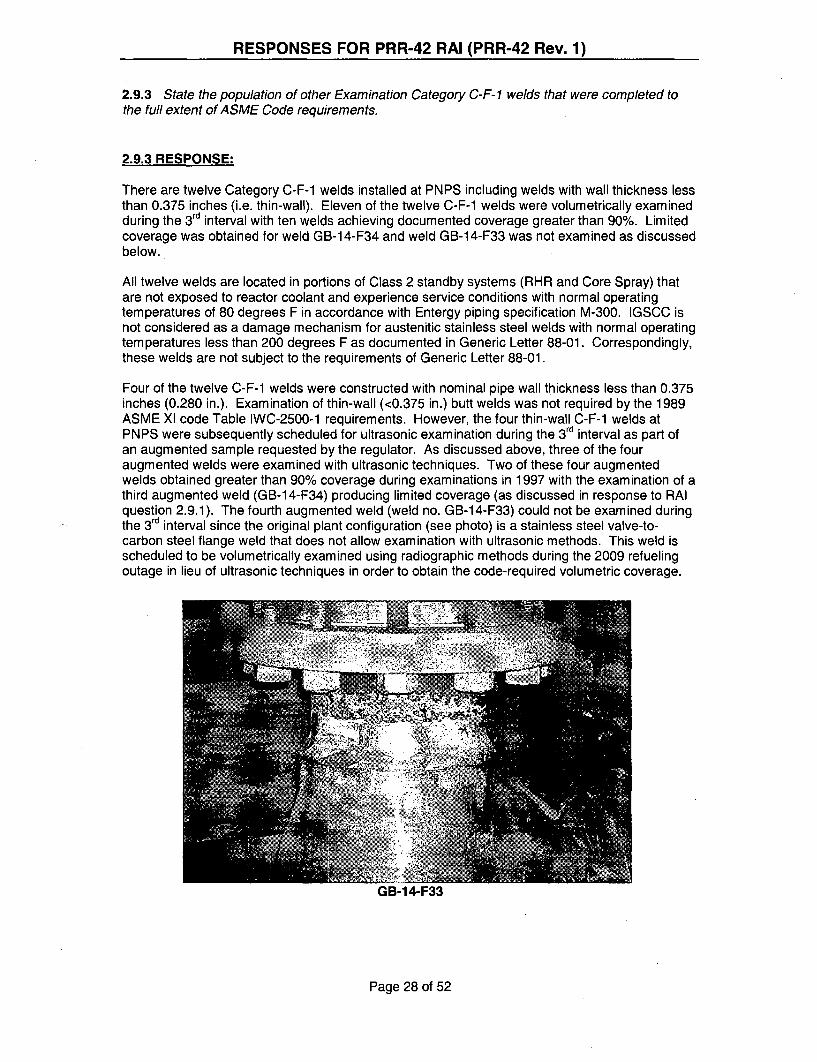
RESPONSES FOR PRR-42 RAI (PRR-42 Rev. 1)
2.9.3 State the population of other Examination Category C-F-1 welds that were completed tothe full extent of ASME Code requirements.
2.9.3 RESPONSE:
There are twelve Category C-F-1 welds installed at PNPS including welds with wall thickness lessthan 0.375 inches (i.e. thin-wall). Eleven of the twelve C-F-1 welds were volumetrically examinedduring the 3 rd interval with ten welds achieving documented coverage greater than 90%. Limitedcoverage was obtained for weld GB-1 4-F34 and weld GB-14-F33 was not examined as discussedbelow.
All twelve welds are located in portions of Class 2 standby systems (RHR and Core Spray) thatare not exposed to reactor coolant and experience service conditions with normal operatingtemperatures of 80 degrees F in accordance with Entergy piping specification M-300. IGSCC isnot considered as a damage mechanism for austenitic stainless steel welds with normal operatingtemperatures less than 200 degrees F as documented in Generic Letter 88-01. Correspondingly,these welds are not subject to the requirements of Generic Letter 88-01.
Four of the twelve C-F-1 welds were constructed with nominal pipe wall thickness less than 0.375inches (0.280 in.). Examination of thin-wall (<0.375 in.) butt welds was not required by the 1989ASME XI code Table IWC-2500-1 requirements. However, the four thin-wall C-F-1 welds atPNPS were subsequently scheduled for ultrasonic examination during the 3 interval as part ofan augmented sample requested by the regulator. As discussed above, three of the fouraugmented welds were examined with ultrasonic techniques. Two of these four augmentedwelds obtained greater than 90% coverage during examinations in 1997 with the examination of athird augmented weld (GB-14-F34) producing limited coverage (as discussed in response to RAIquestion 2.9.1). The fourth augmented weld (weld no. GB-14-F33) could not be examined duringthe 3rd interval since the original plant configuration (see photo) is a stainless steel valve-to-carbon steel flange weld that does not allow examination with ultrasonic methods. This weld isscheduled to be volumetrically examined using radiographic methods during the 2009 refuelingoutage in lieu of ultrasonic techniques in order to obtain the code-required volumetric coverage.
Page 28 of 52

RESPONSES FOR PRR-42 RAI (PRR-42 Rev. 1)
2.9.4 State whether 100% of the ASME Code-required surface examination was completed onWeld GB- 14-F34.
2.9.4 RESPONSE:
100% of the required surface examination was completed.
Page 29 of 52

RESPONSES FOR PRR-42 RAI (PRR-42 Rev. 1)
2.10.1 The licensee has shown 85% surface examination coverage obtained for Weld GB-10-9-2E, using the magnetic particle (MT) examination method. The sketch (page 230) shows a boltedpipe hanger clamp as being the cause of the obstruction to this MT examination. Discuss whetherthe examination coverage could be increased by use of other surface methods, e.g., liquidpenetrant. Also, state the population of other Examination Category C-F-2 welds that were.completed (surface and volumetric) to the full extent of the ASME Code requirements.
2.10.1 RESPONSE:
There are a total of 1003 category C-F-2 welds at PNPS including those with wall thickness lessthan 0.375 inches (i.e. thin-wall). The category C-F-2 inspection sample consists of 82 welds thatwere examined with surface and volumetric techniques during the 3rd ten-year inspection interval.Acceptable (>90%) code coverage was obtained for 80 of the 82 welds in the inspection sample.The two welds where less than the required coverage was obtained are GB-10-9-2E and HE-26-F238, both of which are discussed in detail in this submittal.
The magnetic particle (MT) surface examination of weld GB-10-9-2E (ref. datasheet 03-M-064)yielded a combined coverage of 85% due to a large pipe clamp obstructing access to portions ofthe weld inspection boundary. As shown in Figure IWC-2500-7 of ASME XI, the surfaceexamination inspection boundary includes the weld surface plus the pipe surface out to adistance of 1/2 inch from each weld toe. To achieve acceptable coverage, greater than 90% of thissurface area must be examined.
The use of other surface examination methods such as liquid penetrant (PT) have beenevaluated for the purpose of increasing coverage for this weld. The configuration of weld GB-10-9-2E consists of a vertical 12 inch diameter weldolet (16.9 inch diameter) joined to a horizontal 18inch diameter carbon steel pipe. No known degradation mechanism affects this weld due tobeing fabricated entirely of carbon steel materials and the standby operating status of this Class 2system (RHR) eliminates fatigue as a potential failure mechanism. A heavy-duty 3-bolt 18 inchpipe clamp, a component part of pipe support H-1 0-1 -81, is located on the downstream side ofthe welded pipe intersection and butts directly against the downstream toe of weld GB-10-9-2E.The pipe clamp is 4.5 inches wide and 0.875 inches thick. The horizontal centerline of the 18inch horizontal pipe and the associated pipe clamp is 29 feet above the Torus Room floor. Forthe clamp to be loosened and slid upstream far enough to provide unobstructed access to weldGB-10-9-2E, cribbing or other supports would have to be installed to temporarily support the pipe.Due to the remote location of this pipe support in the ceiling of the Torus Room, no practicalmeans exists to temporarily support this pipe so the clamp can be loosened and moved orcompletely removed to provide increased inspection access to weld GB-10-9-2E.
The MT examination performed in 2003 reported that an arc length of 8 circumferential inches ofweld and adjacent pipe surfaces was obstructed by the adjacent pipe clamp. It is estimated thatan additional 2 inches (1 inch at each end of the 8 inch obstructed region) of weld and vertical (12in.) pipe surface might be gained by the use of PT methods as opposed to the original MTmethod. No additional coverage however is possible on the horizontal (18 in.) pipe surface dueto the pipe clamp obstruction. This 2 inches of potential added coverage on the vertical pipesurface using PT methods adds only approximately 1.5% to the combined coverage, raising thetotal coverage to only 86.5%. To obtain greater than 90% coverage for this weld, more than 3inches of additional coverage would need to be examined on both the vertical and horizontal pipesurfaces, an outcome which is not possible without moving the pipe clamp. For these reasons, itis concluded that the use of alternate surface examination methods for weld GB-1 0-9-2E in orderto obtain the required >90% coverage would not be successful.
Page 30 of 52

RESPONSES FOR PRR-42 RAI (PRR-42 Rev. 1)
2.10.2 In addition, the licensee has reported 63.8% volumetric coverage for Weld GB-1O-9-2E,which is described as a "weldolet", and a cross-sectional sketch is included on page 233.However, from this sketch, Weld GB- O-9-2E appears to be a branch connection (Item C5.81)configuration similar to that shown in ASME Figure IWC-2500- 12. As such, only a surfaceexamination is required to be performed on this weld. Please confirm whether this weld is a fullpenetration circumferential butt weld, or a branch connection, as shown in the licensee-submittedsketch.
2.10.2 RESPONSE:
The configuration of weld GB-10-9-2E consists of a vertical 12-inch diameter weldolet (16.9-inchdiameter) joining line 12"-GB-10 to a horizontal 18-inch diameter carbon steel pipe (line no. 18"-GB-10) in the RHR System. This configuration. is depicted on drawing ISI-1-10-4B Sheet 1 and isa branch connection using a circumferential full penetration fillet weld to connect the weldolet tothe 18" diameter run pipe, similar to Figure IWC-2500-10. As such, this weld should have beenclassified as Examination Category C-F-2 Item No. C5.81 instead of Item No. C5.51. Therequired examination method for this weld is surface only per Table IWC-2500-1. The lastinspection of this weld consisted of both surface (MT) and volumetric (UT) examinations.
The station's ISI tracking database has been updated to reflect Code Item No. C5.81 as being thecorrect classification for this weld. Any future examinations at this location will consist of the MTsurface examination method only. As stated in the response to RAI Question 2.10.1, the lastmagnetic particle (MT) surface examination of this weld (reference datasheet 03-M-064) yielded acombined coverage of 85% due to a large pipe clamp obstructing access to portions of the weldinspection boundary. The use of the PT (liquid penetrant) method does not provide anappreciable gain in the 90% required coverage. Due to the remote location of the obstructingpipe support in the ceiling of the Torus Room, no practical means exists to temporarily supportthis pipe so that the clamp can be loosened and moved, or completely removed, to provideincreased inspection access to weld GB-10-9-2E. As such, future MT surface examinations areexpected to average 85% coverage only.
Page 31 of 52

RESPONSES FOR PRR-42 RAI (PRR-42 Rev. 1)
2.10.3 If Weld GB- 10-9-2E requires a volumetric examination, discuss whether the coveragecould be increased by performing scans from the "branch pipe" side of the weld.
2.10.3 RESPONSE:
Total ultrasonic examination coverage of weld GB-10-9-2E is impractical due to obstructions orlimiting component configuration that adversely affects the scan paths for required ultrasonicbeam projections required to achieve complete coverage.
Weld GB-10-9-2E is a Residual Heat Removal (RHR) System carbon steel pipe to fitting(weldolet) branch connection weld utilizing carbon steel weld metal. Refer to Report CDS No. 03-C-072.
This weld was ultrasonically examined manually utilizing Procedure ITI 50.71, Revision 6. Thisprocedure is the equivalent of EPRI PDI generic procedure PDI-UT-01 which meets therequirements of ASME Section XI, Appendix VIII, Supplement 3 for ultrasonic examination offerritic piping welds.
After review of NRC comments regarding this weld, PNPS agrees that a possibility exists thatadditional ultrasonic coverage may be possible. In view of this fact, PNPS has rescheduled thisweld for ultrasonic examination in the upcoming refueling outage (RFO-17). Based on the sketchfrom the above referenced UT report it appears that additional UT coverage can be achieved byscanning from the fitting side. It should be noted however that > 90% coverage may not beachieved due to the adjacent pipe support clamp that cannot be removed due to function andlocation. Further, given that all Category C-F-2 branch connections are required to be examined,there are no additional branch connections remaining to supplement the required sample.
Page 32 of 52

RESPONSES FOR PRR-42 RAI (PRR-42 Rev. 1)
2.10.4 Weld HE-26-F238 is listed as a valve-to-pipe configuration. However, from the cross-sectional coverage sketch (page 236), it appears that scans could be performed from both sidesof this weld. Please confirm the ultrasonic techniques used for examining this weld, and confirmthese methods have been qualified by performance demonstration in accordance with ASMESection X1, Appendix VIIL In addition, state whether the surface examination was completed tothe full extent of ASME Code requirements for Weld HE-26-F238.
2.10.4 RESPONSE:
Total ultrasonic examination coverage of weld HE-26-F238 is impractical due to obstructions orlimiting component configuration that adversely affects the scan paths for required ultrasonicbeam projections required to achieve complete coverage.
Weld HE-26-F238 is a Category C-F-2 Reactor Core Isolation Cooling (RCIC) System carbonsteel pipe to valve weld utilizing carbon steel weld metal. Refer to Report CDS No. 05-C-338-ISI.
This weld was ultrasonically examined manually utilizing Entergy Nuclear Procedure ENN-NDE-9.04, Revision 1. This procedure is the equivalent of EPRI PDI generic procedure PDI-UT-01which meets the requirements of ASME Section XI, Appendix VIII, Supplement 3 for ultrasonicexamination of ferritic piping welds.
This weld was examined in the third ISI Interval as part of an NRC directed augmented inspectionrequirement of thin wall (<0.375") piping welds since these welds were not required to beexamined under the 1989 Edition of ASME Section XI, Category C-F-2 selection criteria. ThePNPS fourth Interval ISI Program Plan basis is the 1998 Edition though 2000 Addenda of ASMESection XI. As a result of this upgrade, this weld is included in the total required count ofCategory C-F-2 welds, but was not selected as part of the required examination populationpercentage. Given this fact, PNPS believes that no further action is required for this weld.
Page 33 of 52

RESPONSES FOR PRR-42 RAI (PRR-42 Rev. 1)
2.10.5 List the system(s) on which Welds GB-10-9-2E and HE-26-F238 exist.
2.10.5 RESPONSE:
GB-10-9-2E is in the RHR System as shown on Drawing ISI-1-10-4B Sheet 1.
For ISI purposes, HE-26-F238 is considered to be in the RCIC System as shown on Drawing ISI-1-13-5. This component is in the RCIC Pump suction (condensate transfer) line from theCondensate Storage Tank (CST).
Page 34 of 52

RESPONSES FOR PRR-42 RAI (PRR-42 Rev. 1)
TABLE 3 (UPDATED)COMPONENTS WITH LESS THAN "ESSENTIALLY 100%" COVERAGE
COMBINED* NDE
* ~ COVERAGECODE CODE> COMPONENT
-CATEGORY
B-A
B-A
B-A
B-A
B-A
B-A
B-A
B-A
B-A
B-A
B-A
B-A
B-D
B-D
B-D
B-F
B-F
ITEM .ID0 DESCRIPTION
HEAD CIRCUMF.B31.21 RPV-BH-C1 ELWELD
LOWERINTERMEDIATE
B13.12 RPV-L-1 -338ASHELL VERTICAL
WELD
LOWERINTERMEDIATEB13.12 RPV-L-1 -338C SHELL VERTICAL
WELD
LOWER SHELLB1.12 RPV-L-2-338A VERTICAL WELD... ........................... ............................. .. .... ......... ... ..... . ..~i ..s. ~..i............ ....... .B1.12 RPV-L-2-338B VERTICAL WELD
LOWER SHELLB1.12 RPV-L-2-338C VERTICAL WELD
UPPERINTERMEDIATE
B1.12 RPV-L-2-339A SHELL VERTICAL
WELDUPPER
INTERMEDIATEB1.12 RPV-L-2-339BSHELL VERTICALi WELD
.. ...... ........ .. ........ .... .. ............ ........................ ................ .... . ... ..... WJ P EL D . .. . .. .UPPER
INTERMEDIATEB13.12 RPV-L-2-339C S E~SHELL VERTICAL
~WELD.. ...... .. .. .... ... ................... .. .......
131.30 RPV-SF-0-120 SHELL TO FLANGE
. M"LIMITAT1.9A(CAUSE OF
IT/PT UT REDUCED.COVERAGPE
VESSEL SKIRT--- 75CONFIGURATION AND
.......... T H E RS................. ...... . . .. .
8 JET PUMP RISER SUPPORTINTERFERENCE
JET PUMP RISER SUPPORT,SURV. SPECIMEN HOLDER &
25 SUPPORT BRACKETS,SHROUD REPAIR TIE RODINTERFERENCE
BAFFLE PLATE AND BAFFLEGUSSET INTERFERENCE
78 BAFFLE PLATE GUSSET.... I R........................... ... . ..FE R E N C E .......... ............
BAFFLE PLATE, GUSSET,25 SHROUD REPAIR TIE ROD
INTERFERENCE, N2K NOZZLE
FW AND CS SPARGER_u 81 INTERFERENCE
FW AND CS SPARGER--- 75 INTERFERENCE AND ID
TAPER
FW AND CS SPARGER-- 83 INTERFERENCE
N3 NOZZLES, NOZZLE PLUGS,81 GUIDE RODS @ 0 & 180 deg,
FLANGE CONFIGURATIONN3 NOZZLES, NOZZLE PLUGS,
81 GUIDE RODS @ 0 & 180 deg,FLANGE CONFIGURATION .........
..............................i ............................... .... .........LN 3 No z zE s C NF IG U R A T I G SNN3 NOZZLES, NOZZLE PLUGS,
81 GUIDE RODS @ 0 & 180 deg,..FLANGE CONFIG.
56.7 NOZZLE CONFIGURATION
--- 56.7 NOZZLE CONFIGURATION.............................. i . . . . . .......... . ..... .. . ... ...... . ... .......................................................................i
70.6 NOZZLE CONFIGURATION
PIPE TO VALVE WELD-- . 3 .1 .P R O F IL E .. . . ...........................................................
P IPE TO VALVE WELD22.1 PROFILE
RPV-SF-120-B1.30 24240
RPV-SF-240-B1.30 36360
B3.90 RPV-N7A-NV
B3.90 RPV-N7B-NV
B3.90 RPV-N8-NV
R1.20 14-A-10A(B5.130)
R1.20(5.130) 14-B-A
SHELL TO FLANGE
SHELL TO FLANGE
NOZZLE TOV E S S E L ..........................
NOZZLE TOVESSEL
NOZZLE TOVESSEL
VALVE TO PIPE
VALVE TO PIPE
Page 35 of 52

RESPONSES FOR PRR-42 RAI (PRR-42 Rev. 1)
TABLE 3 (UPDATED)COMPONENTS WITH LESS THAN "ESSENTIALLY 100%" COVERAGE
CODE CODE COMPONENTC. GAT•EGORY• ITEM ID DES
B-F
B-F
B-F
B-F............................................. . .
B-F
B-F
B-F
B-FB-
R1.20(B5.10)
R1.20(B5.10)
R1.20(B5.10)
R1.20(B5.10)
R1.11(B5.10)
R1.11(B5.10)
R1.11(B5.10)
R1.11(B5.10)
i NOZZL2R-N1B-1 i
2R-N2E-1
2R-N2G-1 .
2R-N2J-1
6-N4A-1
6-N4B-1
6-N4C-1
6-N4D-1
RPV-SBW-0
10-IA-14
10-IA-15
1 0R-IA-6
SAFEN
SAFEN
SAFEN
COMBINED.NDE -
'; • COVERAGE' ' • "LIMITATION (CAUSE OF
CRIPTIONW MT/PT: UT REDUCED.COVERAGEIREDUCED COVERAGE ON
E TO SAFE CIRC. SCANS DUE TO-- 75END SURFACE CONTOUR AND MIN.
....................... ....................W A L L IS S U E S..... ..... ... .... ... .... .. .... ... .... .... .. .............. ............. ... ...... .W .A... !...E ........... ............ .. .. ..................... ......... ... .. .. .. ....
REDUCED COVERAGE ONEENDTO CIRC. SCANS DUE TOOZZLE SURFACE CONTOUR AND MIN.
WALL ISSUESREDUCED COVERAGE ON
E END TO 1 CIRC. SCANS DUE TO.. .75.3OZZLE SURFACE CONTOUR AND MIN.
WALL ISSUES
REDUCED COVERAGE ONE END TO CIRC. SCANS DUE TO-- 75OZZLE SURFACE CONTOUR AND MIN.
__ WALL ISSUESENDTO REDUCEDCOVERAGE DUE TO
OLE EN-'- 87.5 WELDED THERMOCOUPLEOZZLE P...... .. ... AD S
EREDUCED COVERAGE DUE TOE END TO87.5 WELDED THERMOCOUPLE
OZZLE PADS
REDUCED COVERAGE DUE TOE END TO--- 88.6 WELDED THERMOCOUPLE
OZZLE P
E ENDTO 8 REDUCED COVERAGE DUE TOOZZLE 8.6 WELDED THERMOCOUPLEOZLEPADS ___
TABILIZER 50 - ONLY UPPER SURFACEWELD ACCESSIBLETO FLUED PIPE TO PENETRATION FLUEDHEAD jHEAD CONFIGURATION...... ... ........................................ ...... ....... . .: .......... ........ . .. ..... T O .._ V W. i. ......... ..............................................
PIPE TO VALVE WELDTO VALVE PROFILE
..... .. .. ....... ...... ...... ... ............. ............. .................. ...... ...... ...... ...... ................... ...... ..................... ..... ....
PIPE TO VALVE WELDTO VALVE --- 50 PPROFILE
SAFEN
SAFEN
SAFIN
SAFEN
RPV S
PIPE
PIPE
PIPE
B-H B8.10
R1.20B-J (9i). . .. • ..... . ..... l " ' l( 13 l9 . ll1 ll) . . .
B-J R1.20
B-J Rl
[ ...... ................. . .................................. . ( 13 9 . 1 1 )
B-J ',R1.11
(139.11). . .. . . .. •I I I I I I I 1 1... ....
B-J R1.11. ............................... (.... .............. i(B.B 9 .1 1.)
R1.20B-J 1(B9.11)
B-JR1.20B-J
B-J R1.20S .................. (B9.11).11
B-J Ri.i(139.11)
R1.20B-J (19.11)
10R-IA-7 VALVE TO PIPE ---
1 2-0-24 PENETRATION TO20-4PIPEii
14-A-19 PIPE TO VALVE. .. . . . ... .. . .. . ! ... ... ... ... ... ... ... ... ... .. . ............................................................. .. .
14-B-17 PIPE TO
14-B-20 PIPE TO PIPE
1-SD-10R PIPE TO VALVE
2R-HB-1 HEADER TO BEND.. . .......... ......................................... i .................................... . . ... .................... ... ... . ... ...
PIPE TO VALVE WELD50PROFILE
50 PENETRATION FLUED HEADTO PIPE CONFIGURATION
IPE TO VALVE W ELD50 ........ PROFILEPIPE TO PENETRATION FLUED
50 HEAD CONFIGURATION
50 WALL OBSTRUCTION
PIPE TO VALVE WELD87.5 PRFL.. . .......... ......... ........ .. ......... ......... ............................................................... .. .. .. ......... ..
REDUCER TO PIPE50............... N....... F........ IG. .. ....................A.T I.O.........................
Page 36 of 52
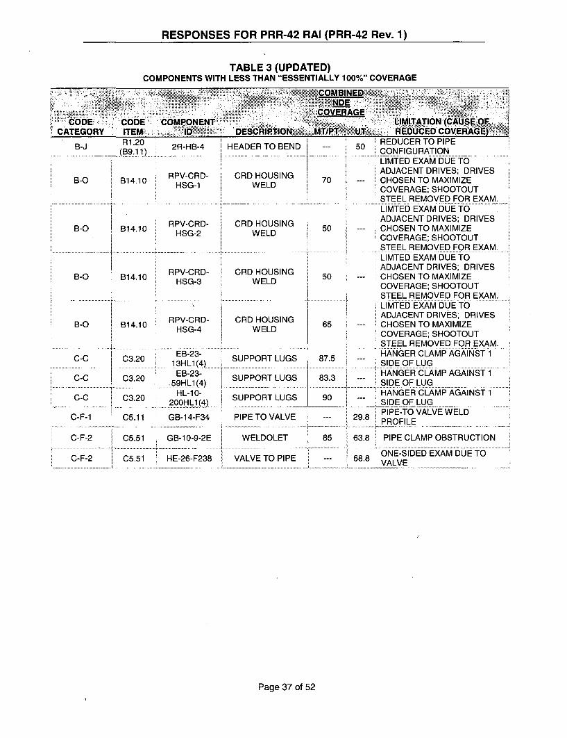
RESPONSES FOR PRR-42 RAI (PRR-42 Rev. 1)
TABLE 3 (UPDATED)COMPONENTS WITH LESS THAN "ESSENTIALLY 100%" COVERAGE
CODE CODE COMPONENT-CATEGORY ITEM ~ 210 DESCRIPTION MT/PT
BINED..
ERAGE
B-J R1.20
B-0 B14.10
B-0 B14.10
2R-HB-4.. . . . .... . ......... ..
RPV-CRD-HSG-1
HEADER TO BEND
CRD HOUSINGWELD
RPV-CRD- CRD HOUSINGHSG-2 WELD
RPV-CRD- CRD HOUSINGHSG-3 WELDB-O B1 4.10
B-O RPV-CRD-HSG-4
LIMITATION (CAUSE OFUT REDUCED COVERAGE)
REDUCER TO PIPES50 CONFIGURATION
. LMTED EXAM DUE TOADJACENT DRIVES; DRIVESCHOSEN TO MAXIMIZECOVERAGE; SHOOTOUTSTEEL REMOVED FOR EXAM.' i~~~~~~ ~~~ ....... .iMT X M - UE T ....... ....... ........:LIMTED EXAM DUE TOADJACENT DRIVES; DRIVESCHOSEN TO MAXIMIZE
I iCOVERAGE; SHOOTOUT•STEEL REMOVED FOR EXAM."' .. ....... ....l E E ... X... . ... .. .. .... ....... ....... .. ............. T E . . O . .F 0 9 E A ......
LIMTED EXAM DUE TOADJACENT DRIVES; DRIVESCHOSEN TO MAXIMIZECOVERAGE; SHOOTOUTSTEEL REMOVED FOR EXAM.LIMTED EXAM DUE TOADJACENT DRIVES; DRIVESCHOSEN TO MAXIMIZECOVERAGE; SHOOTOUTSTEEL REMOVED FOR EXAM.HANGER CLAMP AGAINST 1
i""iSIDE OF LUG
HANGER CLAMP AGAINST 1S ID E .O F L U G ...................................... . . .. .........HANGER CLAMP AGAINST 1SIDE OF LUG.......... ... ... ... ......PIPE-TO VALVE WELD
29.8PRFL.... .2 ,8... .P R O .FIL.E ... .. ......... . .. .... ........
63.8 PIPE CLAMP OBSTRUCTION
ONE-SIDED EXAM DufE TO68.8 VALVE
• . :.:.
B14.10CRD HOUSING
WELD
C-C C3.20C....... ......................... ... .. . .............................
i C-C C3.20
C-C C3.20
C-F-1 C5.11
C-F-2 C5.51
......................... .... . .. . .. I .....
.: .. .. .. . .... .. ....... . . . . ............... . ............. .. ... . . . . . .
EB-23-13HL1"4" ,SUPPORT LUGS 87.5.. ............ .. .. .1 3 L ( 4 ........... ........ ... ................. . . ..................... ..................................
EB-23- SUPPORT LUGS 933, 5 9H......) .. ............. ................................ . .. . .. . . . .. ..... .. ....HL-10- g!SUPPORT LUGS 9
200_ HL (4) . . .. . .... . .
GB-14-F34 PIPE TO VALVE
GB-10-9-2E WELDOLET 856..... .V. .......... .P................I..E.. ...... ...... . ..........
SHE-26-F238 I VALVE TO PIPE | "_[ . . ........ .. . . ~ ~ ~ ~ ~ ... . .... .. ... ............. . .. . .._ _ . . .
Page 37 of 52
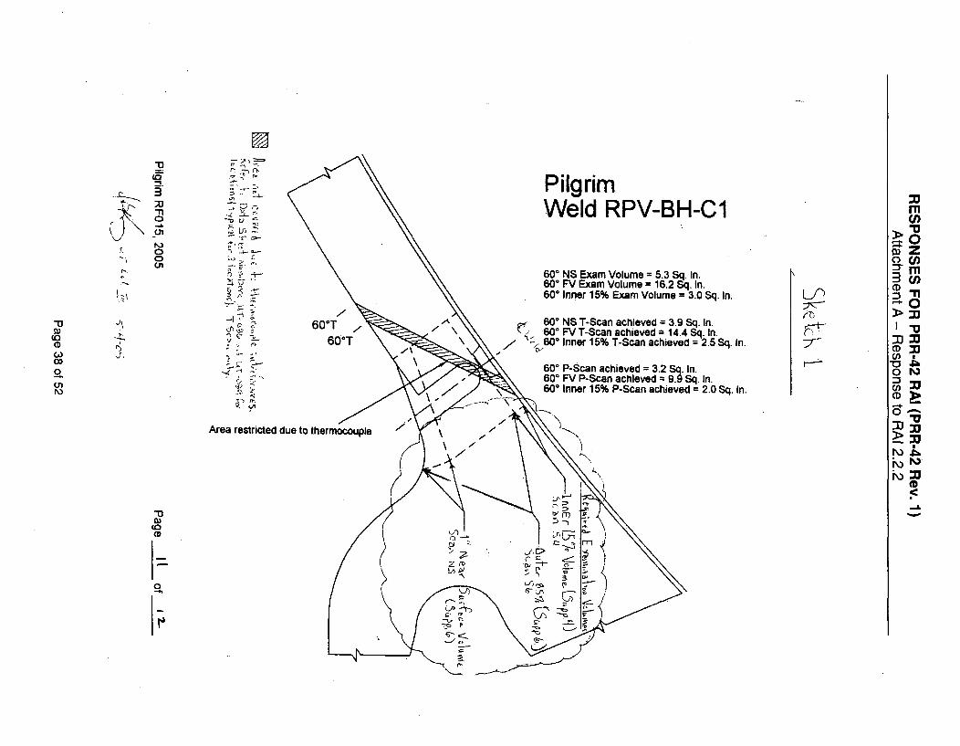
3 ~ e- Pilgrim-n' =""Weld RPV-BH-C1 I
-\ -n rn.-
"' 0 -. l600 NS Exam Volume = 5.3 Sq. In."3 in600 FV Exam Volume = 16.2 Sq. In. CD
-' 600 Inner 15% Exam Volume = 3.0 Sq. In. -n•" 609T 600 NS T-Scan achieved = 3.9 Sq. In. I-
\60 FV T-Scan achieved = 14.4 Sq. In.o --. .-- 0°T6 T 600 Inner 15% T-Scan achieved = 2.5 Sq. In. C-"CO DOD, -(Z - - 0o- - 60' P-Scan achieved = 3.2 Sq. In.
S- 600 FV P-Scan achieved = 9.9 Sq. In.oL 600 Inner 15% P-Scan achieved = 2.0 Sq. In. M
~~0Area restricted due to thermocouple \
r\
(D
7- rCOD -t
0
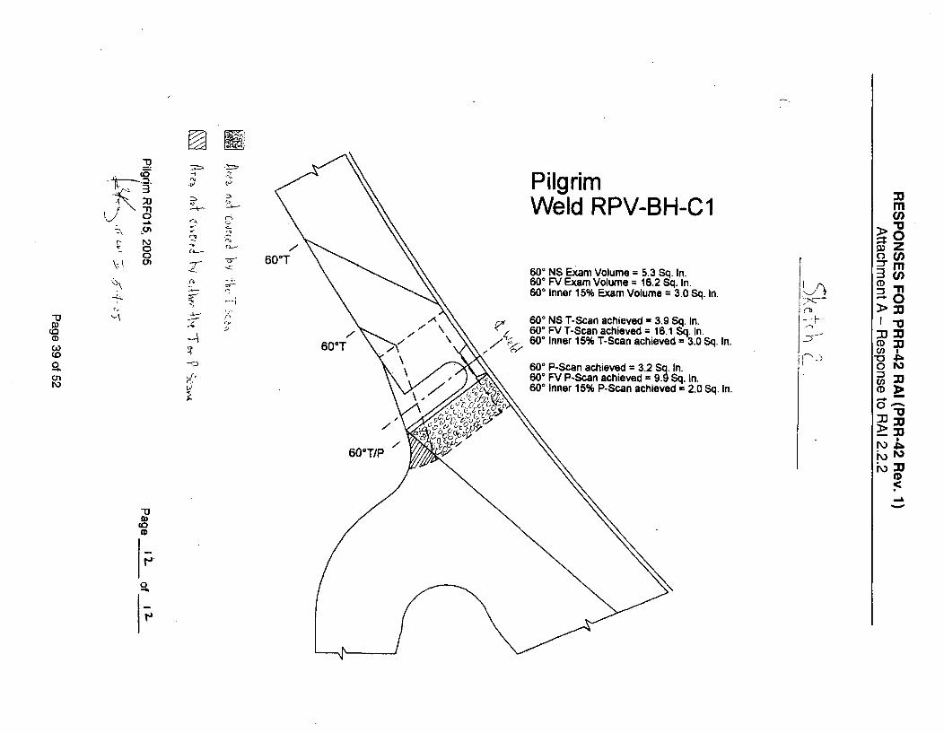
"313
X 0
t - 0
0
'7'
-1
-4-
c~.
7-.n.
-A
0-
PilgrimWeld RPV-BH-Cl
60T600 NS Exam Volume = 5.3 Sq. In.60' FV Exam Volume = 16.2 Sq. In.600 Inner 15% Exam Volume = 3.0 Sq. In.
-'
CaCDC~o
0
01
CrTJ
60°T
* I0 S NS T-Scan achieved = 3.9 Sq. In.60° FV T-Scan achieved = 16.1 Sq. In.
, 60° Inner 15% T-Scan achieved = 3.0 Sq. In.
600 P-Scan achieved = 3.2 Sq. In.60* FV P-Scan achieved = 9.9 Sq. In.60° Inner 15% P-Scan achieved = 2.0 Sq. In.
M
"a> n
CD U
=3-n>:jj
oM
CD M
0
60"T/P
-D
0IJ
0

0l 0(0
0
00c-ti
60' cT NIS
60rd./P J
Pilgrim -Weld RPV4-.--NVTop Head Spray
Nozzle Botto.'. c:.
In -.';,T E.ýan.
6,., -, _ Cai
6C
. Sq. In.29 Sq. In<9 Sq. In
45Sq In
•ed = 2.9 Sq In
CD
00(.nN\)
6...................Sq In-ved.2 Sq In
4~~ ~~~~~ 9 Sq intX-.~c~\cu' "
rnCl)
0(I
3 rn=CDn
* 0
CD~(ni
CDb
(0
f-,
0 A(C, nJ Ooviqiý
R Are-, . \ \_ 1 TI P
Nozzle Top Side30ý NS- Exan, Volune = 0 2 Sq In6'13 .. .arr, Volume = 14 7 Sq. In I'.,i "•0 VD1, t I
1nne. T am Volum e 3 I S q. I q
is , rn Vcolueved = 1 7 Sq In ,-6& , r-Scan achieved = 13 Sq In L60 FnVl T-scan achiev ed = 3 1Sq I
Scan Plan -o-verage T and P scans
i
60 PI•F Scan achieved = 1.3 Sq In.60 FV P-Scan acnle'ed = 5.9 Sq. In.60" inner 5'%. P-Scan achieved = 3.1 Sq. In.
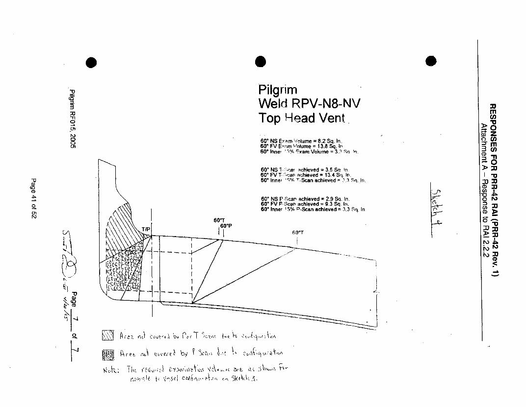
0 0
;U
InOr
PQ-7C9
PilgrimWeld RPV-N8-NVTop Head Vent
600 NS Eyam Violume = 8.2 Sq..In.600 FV E,'m Volume = 13.8 Sq. In.600 Innet 17 yram Volume = 3.? 5'a !n.
(rD
N,
60' NS 17-;rar achieved = 3.5 Sq. In.600 FV T. 'can achieved = 13.4 Sq. In.60* Inner ',% T-Scan achieved = 3.3 Sq, In.
600 NS PRScan achieved = 2.9 Sq. In.600 FV P.-can achieved = 9.3 Sq. In.600 Inner 1.5% P-Scan achieved = 3.3 Sq. In.
60*T
6O0 T
1 O
"J
0(I
3 ch
CD
C n
10
OMM Mi: M
r\)
-D
R E-3 A Lk;1\Jf+-\ 60 rcýr r.A
kfet ribi Ql-ýVe,,ý,-

RESPONSES FOR PRR-42 RAI (PRR-42 Rev. 1)Attachment B - Response to RAI 2.2.3
IHI Southwest ,'j,,.hrt'l s /it.*rim .\Nuclear Polir ,PS'IIlion
.VDE E__ai__n n_.•_ _ _ _ __i_ _'_ ..Ipril 12005 - RFO15
Positional. location of the AIRIS .t:3o0scanner is accomplished using acombination of measurements integrated ~and displayed by the control system. Anorigin reference point is established foreach examination zone by locating aspecific elevation and azimuth. Elevationcan be determined by the use of two high-accuracy water depth sensors, one on thedevice and one located at a fixed locationsuch as the vessel flange, or it can bedetermined visually by driving the device %Cý C 2ý ",r 5L. " 41,',,Lto a fixed component inside the vessel Figure 2. AIRIS-21 Scannerwhose elevation is known. Azimuthreference location can be accomplishedusing optical beam transmitter/receiver system to determine azimuth location based on theknown location of internal reactor components. or a physical reference can be obtainedfrom other components such as sparger piping, steam dryer lugs, surveillance specimenholders, or guide rod brackets.
Once the device is on the vessel wall in the referenced position, the encoded drivewheels provide travel distance and a gravity sensor keeps track of device orientation. thecontrol unit integrates this information and provides constant positional informationrelative to the device location. A graphic display unit also shows the orientation of thedevice and direction of movement.
The device is controlled through a single umbilical cable bundle, which contains allinputs and outputs to the control system as wNell as the AUT transducer cables. [his devicecontrol cable also contains a steel braided cable so that the cable can also function as adevice retrieval mechanism in the unlikely e•ent of a power failure or thrust propellerfailure. Device operation is monitored visually during the inspections using. independentremote x ideo cameras.
Page 42 of 52

RESPONSES FOR PRR-42 RAI (PRR-42 Rev. 1)Attachment B - Response to RAI 2.2.3
1HI Southwest Technologies Pi1qrin ,N"uclear Power Station.VDE ['-.taiflatian Ser'ices April 27005 - RF015
2.3 NDE Techniques
The RPV vertical welds were ultrasonically examined utilizing ISwT's PerformanceDemonstration Initiative (tPDf) qualified detection procedures. These procedures werepreviously qualified for both double-sided and single-sided detection and sizing usingSLIC40 and Duplex transducer designs.
For flaw detection on the inner 3.25" of the vessel wall (which includes theSupplement 4 volume). SLIC 40. search unit are used for the detection of both parallel andtransverse flaws. When scanning can be accomplished from both sides, two opposingSLIC 40 transducers are used, When scanning can only be accomplished from one side,two SLIC 40s are used side by side.
For flaw detection on the outer portion of the vessel shell, lSwT's "Duplcx"transducers were used. These specially designed transducers significantly improve signal-to-noise ratios over standard transducers and were especially valuable during theSupplement 6 qualification for discrimination of buried flaws in the "'mid-wall" region ofthe shell. Two Duplex 55-degree transducers are used in opposing directions whenscanning was accomplished from two sides. When scanning can only be accomplishedfrom one side. two Duplex transducers are. again used in the same direction, however, oneis a 45-degree Duplex. This approach again, allows retention of the "two-hit" criterion, butprovides a slightly different angle for more reliable flaw confirmation.
Fi gr 4.__DeetonTcniusfo_
,-----.... •. • •"•'N- ------
L _ _ " ." O 5,-- 0 _ _.
Figure 4. PDI Detection Techniques for RPV
Page 43 of 52

027424
(2.. 7.4.4.22.4
(Vo~2s 7.00402 £242..)
212-..
CA *~42.54---
4412
CA 522.44'
- -\ I
(~pjfL22C~4OA.~ i~j Lcic14N'~'5
h/It / 2W/343.2rIL '!! I (204 Sf04.4. COSMIC 4)
i (04w. 1404.0 N 42774480240202427
~'Loo~
OVOOC
4.42 CAI 04G.02*
C/L e•,4"
CA "40W
'Mor
24-.00
TV .
4.4 CA 14464
Mi-C-4-)M
0w CA 01.-4W7424-C-3-m3
ýQt7
MI 1. t1 (-- "-2 I ii=d 2442 - 74210
Ifmi., 444/,20r
lop 4 Fl....
(~447~4,/24744~
:21/V44.4
20441 .wso~IorI ~JH~
N.
ý-Iý
r-oa0
-,--ouI #11sa, •
-X"= -_, - .II =•CA 4424 0--74" 0-:
II
022-7. 2 3240 4404-7.-I-mn225/ 44 324/f34.17
~zjzzz="1~ ~ŽJL1
,2C/434.2r xun...rn2 /0 "g . - III ir 7'ri i i i1
a I ,j ,
D)(0
CD
CA/
C/L . W -
U
CA 244.40
V0 T 20054..P)-
t U:L~~421I II I
Itl•.-t.- 1-3MIC
3W/694.70
t0
ifILI
20il* 710.2i"4i2i.0. 2224,4 - 824
LD - 227.14"3W r. - 133.7r
.,W.J. 'u70.24'
S2 -1 2.2 I02.4 24 - e.x
MIu
CDOz
-nCD 0
44I
-i III illl II I I II II I II I II 11 I IJl v II I II 71lI]'• lI• •l 11 ,
~'.-.'' )C/SW 1'~ Ill I t4' 01)
4J1 41
2~ ~
I' l2/21133We0,p5I
I !1 Ill 1RII Igl lli Igl I•l •11 ¢ I1,1w 0.417 CA204 2'9 .- - - __±,~~~Im..
.7 / \ 'N~2 N,/ \
/
I ,17/'1." [~.lll 242/ lTlrTi42/4?T~l I0t4S/" it/44 11114.?1" Iltlt/'?," [k 11134/042? 04/0214.4? 117 05InfO 2/W W/U0.CN 04 I 5217/224A2' 2W1473.Yr 222/03.04 N4 W4 337'142
I 1 0040247 .20472 (4,) amoo honed m 1h) ID o th, Shl Co- an i 1b Naa,(.0, vL. -1d 1. I d,
Wank~ 1i '0:°Intl Ieln(47 diarnle." f-u N's -AJi€lmel par Caorbunton .Engkwdngr1 DwV. Na. 232-345-a1. wie. F-.3. IG.. h .4 b.. . 3112.2.7.02' d27 0 ........ xi 7 d02 c42l0m04). p .Cobnori E ..gh-41 wmg. No. 232-345-4. 1-Ji . L.h. -off h.... of ,.22 -. 0 7.04)' 24. moon 1 42. 0 2.in 4 -2 .0 ,,11,). W Co ... ,ff4 o2 N.. 4, . 232-345-11..4. C.5.Th14kn4.oo . 2. .40 444. niofo 74d 7.02' 44. 46. nqfoo (10.04 dko074r 0.o 24 no.24. oe~tena.), poi C02222424.kn 24420424424444 D . 04. 232-45 . 2248R . 0..
VESSEL INSIDE DIAMETER VARIES ACCORDING 1O SHELL COURSE AS FOLLOWS:
Pilgrim Station
ID Vessel Rollout
November 2002
RPVID

... ii!
i0
qcE
~cY
cJ
N00
CL0
CL)
LUO("4-Zco a
CLEco) 0WUcos
C\J
0)
IU
.~.' WINA

RESPONSES FOR PRR-42 RAI (PRR-42 Rev. 1)Attachment C - Response to RAI 2.2.3: RPV Rollout
i"
4'
an- a:. up
Ann .~, C-a &.r
fr. *C~~~CC .~C ~ --
*'0
.4-
4,-.- 'C.
b. ,j ,A
C.C P
.1 -
Page 46 of 52

Entergxmy Calibratio 3ata Sheet CDS No: Os- e-- ý4ý- 11LDS No: 05L-UWs 7*wd"Page: I o-Z
Plant/Unit: PILGT -I. M / ISystem: . ef-. S IPRAr.l-
Component: _ "- G13 -IF q/Line No.: e," - G ' - /4
Procedure: F'v-,,A -%Io Rev.: 6Thermometer S/N: A3 J-
Cal. BIk Temp.: __ F Comp Temp.: (jFCal. Block No.: PIL - 317A
K-,Carbon Steel n Stainless Steel
Size: 4," Sch.: , 9o6"Cal Direction K Axial r i Circ D Both
Scan Areac1 J toweld
Scan Area X I to weld
Work Order: 0311 4q4-
DWG No.: .ISX • •" -•-2Cal Checks I TimeInitial Cal.: J locio
Date: 4 -. S7- C,Inter. Cal.:*Date:Inter. Cal.: 6Date:
CE)
Date: 14 - 2L•-W
CouplantType: ti L-'A 6 fiý(L .FBatch: 6) 1
Examination Area I Weld
.-iq_- .__F3q
Remarks
LA/A-
Access
51•J6L1[
Recordable Indications Exam
Yes No Geom. Sens.
61A N'ffi -.
Search Unit # 1
Manufacturer: KModel: C6Me A eSerialNo.: ObT "-yL"
Size: , j-" Shape:l,•.,
Freq.: Z ,'SM-tND Elm:_l
Angle: 4r Mode:_fd.Measured Angle: qý--
Wedge Style: e:tA5_j 4 C_Search Unit Cable
Type: 1 G- 174Length: &' #Con.: aý
Instrument Settings
Manufacturer: .. VIE•'ELY
Model: SuIC 171(.,
SerialNo.: 13( -875<K
Linearity Due: -- C-.- - s-
Delay: ,.2. Range: /.b..Mtl. Vol.:, ,1-., Pulser: .2.;•..
Damping: 5;__Reject: oFir
Rep Rate:j... Freq.:,2.±-s-
Filter: A, Mode: P-nIEReferqnce Sensitivity.
Axial: d/LA Circ: ?0• •
m
rCl)
-n
DM
Further Evaluation Required: [I Yes o No
Model:_
Serial No:
Linearity ue:
Delay: Range:
MtI. V .: Pulser:
Dam ng: Reject:Rep ate: Freq.:
Fil r: Mode:
Reference Sensitivity
Axial: Circ:
Examiner:
Examiner:
Reviewer:
ANII:
e$ý ý,-
(.-o
Level: M___.. Date: 4-32..-OSLevel:_N2 Date:___I _Level: Date: I
Date: Valor-"

E;4.77ergy CalibratioYData Sheet CDS No: O,,-c A -ILDS No: o0-L-Page: :2- of -1
Plant/Unit: ilLe/-M /System: C c'RC' 5 PeA YComponent: G 6 - V- F3q/
Line No.: L" - C78- IVProcedure: .'-mAb•- - q.io Rev.: 0
Thermometer S/N: .. -3,-)-Cal. elk Temp.:. 43 3F Comp Temp.: 6 •/F
Cal. BlockNo.: PIL - 3 AK.Carbon Steel 0i Stainless Steel
Size: _" _ Sch.: . 6Cal Direction M4..Axial n] Circ [1 Both
Scan Area J J to weld
Scan Area 1 1 to weld
Work Order: 6J13t46VA-DWG No.: .TJ 1 14-26
Cal Checks I Time /Initial Cal.: /0 ao t/lb Y'/
Date: I/.s--sInter: Cal.:Date:Inter. Cal.:Date:Final Cal.: 114q'1, 'eDate: 4/- A.,S--oS-..
CouplantType: tA LA (n EL _T
Batch: C) / -S-
Lb 711
Q3
(1)
Evamination Arp. ./Weld
RPmarks
AccessRecordable Indications Exam
Yes No Geom. Sens.
Search Unit # 1Manufacturer: t'Model: %LP0 -G
SerialNo.: C-O l 8-,Size: ,3"/5"' Shape: -4',bFreq.:;,,S- A!J # Elm: IAngle: ýb° Mode: SkWf4,e_
Measured Angle: ,o .
Wedge Style: ,-t1 5 ,- /j C
Search Unit Cable
Type: le! 17Length:_C it Con. :__.4__
Instrument Settings
Manufacturer: 577AýVL(-
Model: SDoIjC 11Z
Serial No.: /74 -•2S',&
Linearity Due: - -e)-Delay: -/o f Range:/-_L7Mil. Vel.: , /al Pulser:,..•_
Damping: "_5._. Reject: 0 FP-
Rep Rate: jjyFreq.: Z_-Filter: .- Mode: 'P- I
Reference Sensitivity
Axial: V;,,, Circ: V 7,6
Search Unit # 2Manufacturer: ./13AModel: c.•m P_-
Serial No.: o-T U X__
Size:_, _ _7 _ " Shape:_J& b
Freq.: -. jR- _. Elm: I
Angle:_'76 Mode: $/-/4i
Measured Angle: _
Wedge Style: ._ft- G.6C._
Search Unit CableType: P,6 1B7•/ ZLength:__ Con-
instrument Settings
Manufacturer: 5 'IE-L .
Model: ý)t,,v r C / 34
Serial No.:_ / __-__ 7_-_
Linearity Due: S - -. s-Delay: -W._--• Range: 2.M tl. Vel.: . ,,L _ Pulser: ,- -Damping: S-b'b Reject: 0
Rep Rate:J____Freq.:.2-,45
Filter. -- Mode: P- "
Reference SensItIvit,
Axial: 5,,- 1 Circ:1/
rn
(CJn
00
-nm00
6na Ix5., cieC bigr-V-O77 ý EAMlA--.c~Ir 4V Sc.A",'

Entergy CalibratiofData SheetLDS No: 0-5.--44-4-d4 4'-
5 'Page: 3of FN
Ir~ma ,- ~
Plant/Unit: r I L..L-l- 'l / ISystem: Co" se- " yComponent: g- I'q- F3,1Line No.: '(, " - ci •-1(4
Procedure: j',A,*VJbl-q -.16 Rev.: .
Thermometer S/N: -•13;.2-
Cal. BIk Temp.: &-TF Comp Temp.:
Cal. Block. No.: PIL - -76r.1 Carbon Steel DStainless Steel
Size: &- " Sch.:_.__/__- _
Cal Direction K Axial ri Circ n1 Both
Scan Area X I to weld
Scan Area . I1 to weld
Work Order: 031( 4,,qo/"DWG No.: Z5 I- -.
Cal Checks TimeInitial Cal.: 0 '/o oDate: - 25-o65-Inter: Cal.:Date:Inter. Cal.Date:Final Cal.: I)I T37~ LI-5Date: CJ2--O.___
CouplantType: L4 -Z--A(L XýBatch: 0 1~.
CD
(0
!a Examination Area / Weld
iiemarks
Further Evaluation R uired:
Examiner:
Access
5/,,ulf
Recordable Indications
Yes No Geom.
&IIA I- k/A
Exa
Search Unit # 1Manufacturer: •--'T)
Model: T7- L ASerial No,: ge -17FSize: :Z(7 k ft,' Shape: ifCC-Freq.: .2, Ajt j# Elm: .2__
Angle: qS7 Mode:LO.,,
Measured Angle: qS-
Wedge Style: /Ar•07CAL
Search Unit Cale
Type: ' 17qLength: i UCon.:
Instrument SettingsManufacturer: S• "Th._JLf_
Model: SOAJlC. 136{
Serial No.: / 3(, -87,75SKLinearity Due: 5-- -o-
Delay: .7777 -Range: 1 .0
Mtl. Vel.:. -32-Pulser: Z 5-0
Damping: 5"be Reject: 6F F
Rep Rate: k /-- Freq.:_..
Filter: -2- Mode: D 4 A-L
Refererce Sensitivity
Axial: 7/A Circ: g 9 _
,I Cf 014 IF T% 14-1 'CP
Search Unit It 2
Mani farchirer: R T1?Model: -IL ASerial No. 7Size: . (I kto) Shape:-KCT-
Freq.: ,2 -A4-. # Elm: _
Angle: _,0* Mode:LoJO
Measured Angle: •, 0Wedge Style: /,uTEL
Search Unit Cable
Type: f. i /I (/!Length: 6 VCon.:,K__
Instrument Settings
Manuflacitirer: 5JLModel: So~ j • /3(,
Serial No.: 13( - 7 -5- k'Linearity Due: _R-, -O"
Delay:.._1/7 Range:/..
Mtl. Vet.: . .23,-Pulser:.25D-
Damping: S-O Reject: .__E
Rep Rate:_...Freq.: Z.__
Filter: -2- Mode: -)A L
Reference SensitlvIty
Axial: 7J, Circ: dA
C0 C
>-o
3DM
-n
0 Yes "D Yes
I•o
Examiner:Reviewer:
ANII:
Level:.j= Date:_________
Level: i'4- Date:_______
Level: il Date: 1,/fo
Date:

RESPONSES FOR PRR-42 RAI (PRR-42 Rev. 1)Attachment E - Response to RAI 2.7.1: CRD Housings
Fa.1
FI'IPJE 3.S-CONTRQýL ROD DRIVEHOIUSING SVPFOR1T ISOMETRIC
)IF4-rA' NUICLUAR PowtF, E.ITIsFINIAL. AFErV AMALYTsil ~P(
Page 50 of 52

RESPONSES FOR PRR-42 RAI (PRR-42 Rev. 1)Attachment E - Response to RAI 2.7.1: CRD Housings
ATTACHMENT 5Sheet 6 of 68
2.3 LOWER PLENUM ACCESS
The CRD housings, CRD housing caps, and stub tubes shall be inspected by the VT-3 methodwhen accessible. On each of the 145 CRDs there are three welds in this area. CRDH-1 is theCRD cap-to-tube weld, CRDH/ST-1 is the CRD housing-to-stub tube weld,. and ST/RPV-1 isthe CRD stub tube-to-vessel weld. The housing tubes are 304 stainless steel, the stub tubesare NiCrFe Alloy 600, and the vessel bottom head is low alloy steel. Inspection locations areidentified by their CRD location followed by the weld number; e.g., 34-15-CRDH/ST-1.
CONNECTioN TOCONTROL RO
G ms UN
11 X
OWH TUNB NO. 2
I
ASNLWLD. (-
RPV cuoEUMMUM \
OWNIUSE NO. I
A~ -- A-
VWWA.A
EUVAITON VIEW
Figure 13-2.3.- CRD Stub Tube and Housing
PNPS Reactor Vessel Internals.Inspection Program
Report No. PNPSrEP-06-00001
Page 51 of 52

RESPONSES FOR PRR-42 RAI (PRR-42 Rev. 1)Attachment E - Response to RAI 2.7.1: CRD Housings
ATTACHMENT 5Sheet 9 of 68
Figure B-3.1 - Core Plate
Figure B-3.2 - PNPS Core Plate Section
PNPS Reactor Vessel InternalsInspection Program
Report No. PNPS-EP-0O00001
Page 52 of 52