Luminant - Nuclear Regulatory Commission
625
Rafael Flores Senior Vice President & Chief Nuclear Officer [email protected] Luminant Luminant Power P.O. Box 1002 6322 North FM 56 - Glen Rose, TX 76043 T 254 897 5590 C 817 559 0403 F 254 897 6652 CP-201101038 TXX-11093 Ref: 10 CFR 50.90 August 1, 2011 U. S. Nuclear Regulatory Commission Attn: Document Control Desk Washington, DC 20555 SUBJECT: COMANCHE PEAK NUCLEAR POWER PLANT (CPNPP) DOCKET NOS. 50-445 AND 50-446, LICENSE AMENDMENT REQUEST (LAR) 11-001, APPLICATION FOR TECHNICAL SPECIFICATION CHANGE REGARDING RISK-INFORMED JUSTIFICATION FOR THE RELOCATION OF SPECIFIC SURVEILLANCE FREQUENCY REQUIREMENTS TO A LICENSEE CONTROLLED PROGRAM REFERENCE: Technical Specification Task Force (TSTF) Traveler 425, Revision 3, "Relocate Surveillance Frequencies to Licensee Control - Risk Informed Technical Specification Task Force (RITSTF) Initiative 5b" (Accession No. ML090850642) Dear Sir or Madam: Pursuant to 10CFR50.90, Luminant Generation Company LLC (Luminant Power) hereby requests an amendment to the CPNPP Unit 1 Operating License (NPF-87) and CPNPP Unit 2 Operating License (NPF-89) by incorporating the attached change into the CPNPP Unit 1 and 2 Technical Specifications (TS). This change request applies to both Units. The proposed amendment would modify the CPNPP Unit 1 and 2 Technical Specifications by relocating specific surveillance frequencies to a licensee controlled program with the implementation of Nuclear Energy Institute (NEI) 04-10 "Risk-Informed Technical Specification Initiative 5b, Risk-Informed Method for Control of Surveillance Frequencies." CPNPP is a member of the Strategic Teaming and Resource Sharing (STARS) alliance. This amendment request has been prepared in conjunction with STARS and utilized the lessons learned from previous STARS amendments requests. The STARS alliance has previously obtained approval for two member utilities to utilize the provisions of NEI 04-10. Additional STARS utilities are considering similar risk informed application requests. The STARS alliance plans on using the experience and resources of the alliance in order to share programs, training, and procedures relative to a licensee controlled surveillance frequency control program. All required information is provided in the attachments to this letter. Attachment 1 provides a description of the proposed changes, the required confirmation of applicability, and plant-specific verifications. Attachment 2 provides documentation of PRA technical adequacy. Attachment 3 provides the existing TS pages marked up to show the proposed change. Attachment 4 provides the marked up existing TS Bases in support of the proposed change. Attachment 5 provides revised (retyped) TS pages. Attachment 6 provides the revised (retyped) TS Bases pages. Attachment 7 provides the No Significant Hazards Consideration. Attachment 8 provides a cross-reference between Technical Specification Task Force (TSTF)-425 (NUREG-1431) and the CPNPP Unit I and Unit 2 Technical Specifications. A member of the STARS (Strategic Teaming and Resource Sharing) Alliance Callaway • Comanche Peak . Diablo Canyon - Palo Verde - San Onofre • South Texas Project • Wolf Creek A001
-
Upload
khangminh22 -
Category
Documents
-
view
3 -
download
0
Transcript of Luminant - Nuclear Regulatory Commission

Rafael FloresSenior Vice President& Chief Nuclear [email protected]
Luminant
Luminant PowerP.O. Box 10026322 North FM 56
- Glen Rose, TX 76043
T 254 897 5590
C 817 559 0403
F 254 897 6652
CP-201101038TXX-11093
Ref: 10 CFR 50.90
August 1, 2011
U. S. Nuclear Regulatory CommissionAttn: Document Control DeskWashington, DC 20555
SUBJECT: COMANCHE PEAK NUCLEAR POWER PLANT (CPNPP) DOCKET NOS. 50-445 AND50-446, LICENSE AMENDMENT REQUEST (LAR) 11-001, APPLICATION FORTECHNICAL SPECIFICATION CHANGE REGARDING RISK-INFORMEDJUSTIFICATION FOR THE RELOCATION OF SPECIFIC SURVEILLANCEFREQUENCY REQUIREMENTS TO A LICENSEE CONTROLLED PROGRAM
REFERENCE: Technical Specification Task Force (TSTF) Traveler 425, Revision 3, "Relocate SurveillanceFrequencies to Licensee Control - Risk Informed Technical Specification Task Force(RITSTF) Initiative 5b" (Accession No. ML090850642)
Dear Sir or Madam:
Pursuant to 10CFR50.90, Luminant Generation Company LLC (Luminant Power) hereby requests anamendment to the CPNPP Unit 1 Operating License (NPF-87) and CPNPP Unit 2 Operating License(NPF-89) by incorporating the attached change into the CPNPP Unit 1 and 2 Technical Specifications (TS).This change request applies to both Units. The proposed amendment would modify the CPNPP Unit 1and 2 Technical Specifications by relocating specific surveillance frequencies to a licensee controlledprogram with the implementation of Nuclear Energy Institute (NEI) 04-10 "Risk-Informed TechnicalSpecification Initiative 5b, Risk-Informed Method for Control of Surveillance Frequencies."
CPNPP is a member of the Strategic Teaming and Resource Sharing (STARS) alliance. This amendmentrequest has been prepared in conjunction with STARS and utilized the lessons learned from previousSTARS amendments requests. The STARS alliance has previously obtained approval for two memberutilities to utilize the provisions of NEI 04-10. Additional STARS utilities are considering similar riskinformed application requests. The STARS alliance plans on using the experience and resources of thealliance in order to share programs, training, and procedures relative to a licensee controlled surveillancefrequency control program.
All required information is provided in the attachments to this letter. Attachment 1 provides adescription of the proposed changes, the required confirmation of applicability, and plant-specificverifications. Attachment 2 provides documentation of PRA technical adequacy. Attachment 3 providesthe existing TS pages marked up to show the proposed change. Attachment 4 provides the marked upexisting TS Bases in support of the proposed change. Attachment 5 provides revised (retyped) TS pages.Attachment 6 provides the revised (retyped) TS Bases pages. Attachment 7 provides the No SignificantHazards Consideration. Attachment 8 provides a cross-reference between Technical Specification TaskForce (TSTF)-425 (NUREG-1431) and the CPNPP Unit I and Unit 2 Technical Specifications.
A member of the STARS (Strategic Teaming and Resource Sharing) Alliance
Callaway • Comanche Peak . Diablo Canyon - Palo Verde - San Onofre • South Texas Project • Wolf Creek
A001

U. S. Nuclear Regulatory CommissionTXX-1 1093Page 2 of 208/01/2011
Luminant Power requests approval of the proposed License Amendment by July 31, 2012, to beimplemented within 180 days of the issuance of the license amendment. The approval date wasadministratively selected to allow for NRC review but the plant does not require this amendment to allowcontinued safe full power operations.
In accordance with 10CFR50.91(b), Luminant Power is providing the State of Texas with a copy of thisproposed amendment.
This communication contains no new or revised commitments.
Should you have any questions, please contact Mr. Robert A. Slough at (254) 897-5727.
I state under penalty of perjury that the foregoing is true and correct.
Executed on August 1, 2011.
Sincerely,
Luminant Generation Company, LLC
Rafael Flores
By:FDrecdW. MOrad /denDirector, Oversight and Regulatory Affairs
Attachments 1. Description and Assessment2. Documentation of PRA Technical Adequacy3. Proposed Technical Specifications Changes (Markup)4. Proposed Technical Specifications Bases Changes (Markup for Information Only)5. Retyped Technical Specification Pages6. Retyped Technical Specification Bases Pages (For Information Only)7. Proposed No Significant Hazards Consideration8. TSTF-425 (NUREG-1431) vs. CPNPP TS Cross Reference
c - E. E. Collins, Region IVG. D. Replogle, Region IVB. K. Singal, NRRResident Inspectors, CPNPP
Alice Hamilton Rogers, P.E.Inspection Unit ManagerTexas Department of State Health ServicesMail Code 1986P. 0. Box 149347Austin TX 78714-9347

Attachment 1 to TXX-11093Page 1 of 608/01/2011
ATTACHMENT 1 to TXX-11093
DESCRIPTION AND ASSESSMENT

Attachment 1 to TXX-1 1093Page 2 of 608/01/2011
LICENSEE'S EVALUATION
1.0 DESCRIPTION
2.0 PROPOSED CHANGE
3.0 BACKGROUND
4.0 TECHNICAL ANALYSIS
5.0 REGULATORY ANALYSIS
5.1 No Significant Hazards Consideration
5.2 Applicable Regulatory Requirements/ Criteria
6.0 ENVIRONMENTAL CONSIDERATION
7.0 PRECEDENTS
8.0 REFERENCES

Attachment 1 to TXX-11093Page 3 of 608/01/2011
1.0 DESCRIPTION
By this letter, Luminant Generation Company LLC (Luminant Power) requests an amendment tothe Comanche Peak Nuclear Power Plant (CPNPP) Unit 1 Operating License (NPF-87) and theCPNPP Unit 2 Operating License (NPF-89) by incorporating the attached change into the CPNPPUnit 1 and 2 Technical Specifications (TS). Proposed change LAR 11-001 is a request to revise theTS for CPNPP Units 1 and 2.
No changes to the CPNPP Final Safety Analysis Report (FSAR) are anticipated at this time as aresult of this License Amendment Request (LAR).
2.0 PROPOSED CHANGE
The proposed amendment would modify the CPNPP Technical Specifications by relocatingspecific surveillance frequencies to a licensee-controlled program with the adoption of TechnicalSpecification Task Force (TSTF) Traveler 425-A, Revision 3, "Relocate Surveillance Frequencies toLicensee Control - Risk Informed Technical Specification Task Force (RITSTF) Initiative 5b."Additionally, the change would add a new program, the Surveillance Frequency ControlProgram, to Technical Specification (TS) Section 5, Administrative Controls. The existing TSBases information describing the basis for the Surveillance Frequency will be relocated to thelicensee-controlled Surveillance Frequency Control Program.
3.0 BACKGROUND
The changes are consistent with NRC approved Industry/TSTF Standard Technical Specifications(STS) change TSTF-425-A, Revision 3, (ADAMS Accession No. ML090850642). The FederalRegister Notice published on July 6, 2009 (74 FR 31996) announced the availability of this TSimprovement. Included in the Federal Register Notice was a generic Safety Evaluation intendedto be used for processing/approving license amendment requests submitted by licenseeschoosing to adopt TSTF-425-A.
4.0 TECHNICAL ANALYSIS
4.1 Applicability of Published Safety Evaluation
Luminant Power has reviewed the generic safety evaluation included in the FederalRegister Notice published on July 6, 2009 (74 FR 31996) for implementation of TSTF-425-A, Revision 3, and the requirements specified in NEI 04-10, "Risk-Informed TechnicalSpecification Initiative 5B, Risk-Informed Method for Control of SurveillanceFrequencies," Rev. 1, (ADAMS Accession No. ML071360456). Attachment 2 includesLuminant Power's documentation of the technical adequacy of the current CPNPPprobabilistic risk assessment (PRA) with regards to the requirements of Regulatory Guide1.200, "An Approach for Determining the Technical Adequacy of Probabilistic RiskAssessment Results for Risk-Informed Activities," Revision 2 (ADAMS Accession No.ML090410014) Section 4.2, and describes any PRA models without NRC-endorsedstandards, including documentation of the quality characteristics of those models inaccordance with Regulatory Guide 1.200. Luminant Power has concluded that thejustifications presented in the TSTF proposal and the safety evaluation prepared by theNRC staff are applicable to CPNPP and justify the requested license amendment toincorporate the changes to the CPNPP TS.

Attachment 1 to TXX-11093Page 4 of 608/01/2011
4.2 Optional Changes and Variations
The proposed amendment is consistent with the NUREG-1431 Standard Technical
Specifications (STS) changes described in TSTF-425-A, Revision 3; but, Luminantproposes variations or deviations from TSTF-425-A, as identified below. The proposedvariations or deviations may include differing TS surveillance numbers.
The definition of STAGGERED TEST BASIS is being retained in CPNPP TSDefinition Section 1.1 since this terminology is mentioned in Administrative TSSection 5.5.17, "Control Room Envelope Habitability Program," which is not the
subject of this amendment request and is not proposed to be changed. This is anadministrative deviation from TSTF-425-A with no impact on the NRC staff'smodel safety evaluation dated July 6, 2009 (74 FR 31996).
NRC letter dated April 14, 2010 (Reference 1) provides a change to an optionalinsert (INSERT #2) to the existing TS Bases to facilitate adoption of the TSTFwhile retaining the existing NUREG-1431 TS surveillance frequency (SF) Basesconsiderations for licensees not choosing to adopt TSTF-425-A. The TSTF-425-ATS Bases insert states as follows:
"The Surveillance Frequency is based on operating experience, equipment
reliability, and plant risk and is controlled under the Surveillance FrequencyControl Program."
Recently several licensees submitting license amendment requests for adoption of TSTF-425-A have identified a need to deviate from this statement because it only applies tofrequencies that have been changed in accordance with the Surveillance FrequencyControl Program (SFCP) and does not apply to frequencies that are relocated but notchanged.
The NRC staff agreed that the TSTF-425-A TS Bases insert applies to SFs that arerelocated and subsequently evaluated and changed, in accordance with the SFCP in NRCletter dated April 14, 2010 (Reference 1). The TSTF-425-A TS Bases does not apply to SFsrelocated to the SFCP but not changed. Therefore, for SFs relocated to the SFCP but notchanged, the existing TS Bases description remains a valid description of the TS SF Basesfor the unchanged SF.
To resolve this issue with existing license amendment requests and to avoid futureproblems, the NRC staff supported the following recommended changes to clarify theapplicability of the TS SF Bases, maintain consistency with TSTF-425-A TS SFCPrequirements, and allow retention of existing TS SF Bases for licensees who choose not toadopt TSTF-425-A:
1. The existing Bases information describing the basis for the SurveillanceFrequency will be relocated to the licensee-controlled Surveillance FrequencyControl Program.
2. The TSTF-425-A TS Bases, INSERT #2, should be added to the end of the existingTS Bases and changed to read as follows: The Surveillance Frequency iscontrolled under the Surveillance Frequency Control Program.

Attachment 1 to TXX-11093Page 5 of 608/01/2011
Luminant Power has incorporated these recommended changes into this licenseamendment request.
5.0 REGULATORY ANALYSIS
5.1 No Significant Hazards Consideration
Luminant Power has reviewed the proposed no significant hazards considerationdetermination (NSHC) published in the Federal Register on July 6, 2009 (74 FR 31996)and has concluded that the proposed NSHC presented in the Federal Register notice isapplicable to Comanche Peak. Therfore, the NSHC determination for this amendmentrequest is provided as Attachment 7 to this license amendment request which satisfies therequirements of 10 CFR 50.91 (a).
5.2 Applicable Regulatory Requirements/Criteria
None
In conclusion, based on the considerations discussed above, (1) there is reasonable assurance thatthe health and safety of the public will not be endangered by operation in the proposed manner,(2) such activities will be conducted in compliance with the Commission's regulations, and (3) theissuance of the amendment will not be inimical to the common defense and security or to thehealth and safety of the public.
6.0 ENVIRONMENTAL CONSIDERATION
Luminant Power has determined that the proposed amendment would change an inspection orsurveillance requirement. However, the proposed amendment does not involve (i) a significanthazards consideration, (ii) a significant change in the types or a significant increase in theamounts of any effluents that may be released offsite, or (iii) a significant increase in individual orcumulative occupational radiation exposure. Accordingly, the proposed amendment meets theeligibility criterion for categorical exclusion set forth in 10 CFR 51.22(c)(9). Therefore, pursuant to10 CFR 51.22(b), no environmental impact statement or environmental assessment need beprepared in connection with the proposed amendment.
7.0 PRECEDENTS
7.1 On August 27, 2010, the Nuclear Regulatory Commission issued Amendment Nos. 278and 281 to Renewed Facility Operating License Nos. DPR-44 and DPR-56 for the PeachBottom Atomic Power Station (PBAPS), Units 2 and 3. The amendments consist ofchanges to the Technical Specifications in response to the Licensee's application datedAugust 31, 2009 (ADAMS Accession No. ML092470153). The amendments revised thePBAPS Units 2 and 3 TSs to adopt approved Technical Specification Task Force (TSTF)Traveler 425, Revision 3, "Relocate Surveillance Frequencies to Licensee Control - Risk-Informed Technical Specification Task Force Initiative 5b," (ADAMS Accession No.ML090850627)
7.2 On September 27, 2010, the Nuclear Regulatory Commission issued Amendment No. 276to Renewed Facility Operating License No. DPR-16 for the Oyster Creek NuclearGenerating Station. The amendment consisted of changes to the Technical Specificationsin response to the Licensee's application dated October 30, 2009, (ADAMS Accession No.

Attachment I to TXX-11093Page 6 of 608/01/2011
ML093060126), as supplemented by letters dated April 16, 2010, and August 31,2010(ADAMS Accession Nos. ML101060560 and ML102430467, respectively). Theamendment revised the Oyster Creek Technical Specifications to relocate a number ofSurveillance Requirement frequencies to a licensee-controlled document.
8.0 REFERENCES
8.1 NRC Letter, "Notification of Issue with NRC-Approved Technical Specification TaskForce (TSTF) Traveler 425, Revision 3, 'Relocate Surveillance Frequencies to LicenseeControl - RITSTF Initiative 5b,"' dated April 14, 2010 (ADAMS Accession NoML100990099).

Attachment 2 to TXX-1 1093Page 1 of 2608/01/2011
ATTACHMENT 2 to TXX-11093
DOCUMENTATION OF PRA TECHNICAL ADEQUACY

Attachment 2 to TXX-11093Page 2 of 2608/01/2011
110 Overview
This attachment addresses the assessment of the technical adequacy of the probabilistic riskassessment (PRA) that will be used to support the implementation of the Surveillance FrequencyControl Program at Comanche Peak Nuclear Power Plant. The implementation of theSurveillance Frequency Control Program (also referred to as Technical Specification Initiative 5b)will follow the guidance provided in NEI 04-10, Revision I in evaluating proposed surveillancetest interval (STI) changes.
The NEI 04-10 methodology requires plants to evaluate the adequacy of the PRA models used forthis application following the guidance provided in Regulatory Guide 1.200, Revision 1, "AnApproach for Determining the Technical Adequacy of Probabilistic Risk Assessment Results forRisk-Informed Activities." As discussed below, for this submittal, the guidance in RegulatoryGuide 1.200, Revision 2 was used to demonstrate the technical adequacy of the parts of the PRAmodel used for this application and endorsed the Standard used for the recent Peer Review of theCPNPP model. Section 3 of the Regulatory Guide 1.200 provides guidance on demonstrating thetechnical adequacy of the PRA used to support the application. Section 4 describes thedocumentation to support this regulatory submittal, including both archival and submittaldocumentation.
Specifically, Section 3 requires that the description of the application include the following:
" SSCs [Systems, Structures and Components], operator actions, and plant operationalcharacteristics affected by the application
* A description of the cause-effect relationships among the change and the above SSCs,operator actions, and plant operational characteristics
* Mapping of the cause-effect relationships onto PRA model elements• Identification of the PRA results that will be used to compare against the applicable
acceptance criteria or guidelines and how the comparison is to be made* The scope of risk contributors (hazard groups and modes of operation) included in the PRA
to support the decision
Since the scope of potential Initiative 5b applications (i.e., individual Surveillance Test Intervalchange evaluations) is very broad and the impact of various assumptions differs from applicationto application, the NEI 04-10 methodology provides that the above listed items be addressed witheach STI interval change and documented in the supporting evaluation. The analysis process isdescribed in detail in NEI 04-10 and plant-specific procedures are being developed to incorporatethe NEI 04-10 requirements into Plant processes.
With regard to the above list, one item, namely, the scope of risk contributors (hazard groups andmodes of operation) included in the PRA to support the decision, requires further discussion.The CPNPP PRA model that will be used for this application is the Level land Large EarlyRelease Frequency (LERF) analysis of Internal Events, including Internal Flood, for At-Poweroperation, Revision 4A and subsequent revisions thereto. All other hazard groups and modes ofoperation will be addressed using the qualitative or bounding analysis techniques provided for inNEI 04-10, Revision 1. At the same time, Luminant has a long range plan to develop anintegrated PRA model that will include other hazard groups and modes of operation. As thesemodels are developed, they will be subjected to Peer Review and when it is determined that thesemeet the appropriate requirements of the applicable standard, these models will be used in thequantitative assessment of risk to support this application.
Attachment 2 to TXX-11093Page 3 of 2608/01/2011
2.0 Technical Adequacy of the CPNPP PRA Model,
The purpose of the remaining portion of this attachment is to demonstrate the technical adequacyof the PRA used in this application. This demonstration will be accomplished by providing thesubmittal documentation specified in Section 4.2 of Regulatory Guide 1.200.
BackgroundThe CPNPP PRA model has been revised substantially since its origination and the various modelrevisions subjected to careful evaluation and review to assure the scope and quality of the modelare adequate for planned risk informed applications. A discussion of these historical models andthe associated reviews and assessments and their findings and dispositions was provided to theNRC in CP-200900520, TXX-09026 - R. Flores to Nuclear Regulatory Commission - Dated October26, 2009 SUBJ: COMANCHE PEAK STEAM ELECTRIC STATION (CPSES) DOCKET NOS. 50-445AND 50-446, LICENSE AMENDMENT REQUEST (LAR) 09-003, REVISION TO TECHNICALSPECIFICATION 3.8.1, "AC SOURCES - OPERATING," FOR A ONE-TIME, 14-DAYCOMPLETION TIME FOR OFFSITE CIRCUITS. The historical reviews included two focusedPeer Reviews, a full scope Peer Review, and a self-assessment to RG 1.200 Rev 1. These variousreviews and assessments are part of the historical development and are available in archiveddocuments for review.
These historical reviews provided important input to the recent model upgrade. The modelupgrade addressed Level 1 and Large Early Release Frequency (LERF) analysis of Internal Events,including Internal Flood, for At-Power operation. This upgrade was initially embodied in theCPNPP Model of Record (MOR) Revision 4 which was completed in early 2011. The model wasthen submitted to a Pressurized Water Reactor Owner's Group (PWROG) full scope Peer Reviewin March 2011. The Peer Review was performed against the requirements of the AmericanSociety of Mechanical Engineers (ASME)/American Nuclear Society (ANS) PRA standard andany Clarifications and Qualifications provided in the Nuclear Regulatory Commission (NRC)endorsement of the Standard contained in Revision 2 to Regulatory Guide (RG) 1.200. Further,the Peer Review was performed using the process defined in Nuclear Energy Institute (NEI) 05-04. The Revision 4 model was further revised, in part, to incorporate the model changes inresponse to the Peer Review Findings & Observations (F&O) and issued as Revision 4A. Thus,the current MOR for Comanche Peak Nuclear Power Plant is PRA Model Revision 4A.
The PWROG Peer Review of the CPNPP PRA Model Revision 4 and the responses theretoembodied in Revision 4A provide a high degree of assurance of the technical adequacy of theCPNPP PRA model to support the implementation of the Surveillance Frequency ControlProgram at CPNPP. The outcome of the Peer Review showed that the CPNPP MOR 4 meets
ASME Capability Category II or better for nearly all of the Supporting Requirements. AfterFindings and Observations were fully addressed through post-Peer Review model work anddocumentation, as reflected in CPNPP MOR 4A, all Supporting Requirements judged to havesignificance to Initiative 5b now meet Capability Category II or better. The Findings andObservations and their disposition, including Category I exceptions, are provided in Table 2-1below.
In order to provide a more complete description of PRA technical adequacy, some specificelements of the historical PRA model warrant additional discussion. The principal historicalissues are described below and have been fully addressed with the Peer Review and subsequentmodel Revision 4A. These are: 1) Recovery of Faulted Equipment, 2) Loss of Offsite Power(LOOP) Non-Recovery Probabilities, 3) Human Reliability Analysis (HRA), 4) DependencyAnalysis, and 5) Data Analysis.

Attachment 2 to TXX-11093Page 4 of 2608/01/2011
* Recovery of Faulted Equipment - Recovery of faulted equipment is no longer credited in theCPNPP PRA model. It was removed in the recent model upgrade (Revision 4).
* LOOP Non-Recovery Probabilities - Loss of Offsite Power (LOOP) non-recovery probabilitiesare now based on a lognormal rather than Weibull curve fit in the convolution integrals. Thisresults in comparable non-recovery probabilities at shorter times and higher non-recoveryprobabilities at longer times after the LOOP event. In the current non-recovery analysis,
database recovery values are limited such that there are no probabilities less than 1E-02.
" Human Reliability Analysis - A comprehensive upgrade of the HRA was done as part to therecent model upgrade. The current HRA is based on the Electric Power Research Institute(EPRI) HRA Calculator methodology. In all cases, screening values have been replaced.Detailed evaluations of Type 2 human errors (i.e., post initiator operator errors) based onoperator event response were done and fully documented in the HRA Calculator.
* Dependency Analysis - A detailed dependency analysis was performed as part of the recentupgrade. The current dependency analysis is comprehensive and follows the currentindustry guidance provided in the EPRI HRA Calculator methodology.
" Data Analysis - A comprehensive data analysis was done as part of the current modelupgrade. NUREG/CR-6928 data were used to establish priors for a Bayesian update.CPNPP Units 1 and 2 plant specific data were used to calculate the posterior probabilities.
PRA Model Maintenance and UpdateLuminant employs a programmatic approach to establish and maintain the technical adequacyand plant fidelity of the PRA models. This approach includes both a detailed PRA maintenanceand update process, and the use of self-assessments and independent peer reviews.
In addition, requirements are established for controlling the model and associated computer files,including, documentation of the PRA model and bases documents and electronic storage of PRAupdate information, PRA models, and PRA applications.
Further, guidelines are provided for updating the full power, internal events PRA models forCPNPP. Regularly planned PRA model updates nominally occur on an approximately 5-yearcycle; longer intervals may be justified if it can be shown that the PRA continues to adequatelyrepresent the as-built, as-operated plant. CPNPP completed the Revision 4A MOR upgrade in2011 which was a very comprehensive upgrade and included incorporation of various plantmodifications into the previous PRA model of record, Revision 3E.
2.1 Required Submittal Documentation - Regulatory Guide 1.200, Revision 2, Section 4.2
As indicated previously, Regulatory Guide 1.200, Revision 2, Section 4.2, requires certainsubmittal documentation to demonstrate the technical adequacy of the PRA model usedfor the risk assessment. Each of these items will be discussed in turn.
Model Represents the As-built and As-operated PlantThe CPNPP PRA model was developed using programmatic controls to help assure thatthe model reflected the as-built and as-operated Plant, a process that included gatheringdetailed as-built and as-operated plant information and operating plant data, discussionswith system engineers and operators, and plant walk down. The continuing PRAmaintenance and update process ensures that the applicable PRA model remains an

Attachment 2 to TXX-11093Page 5 of 2608/01/2011
accurate reflection of the as-built and as-operated plants. These processes are defined inthe governing plant procedure ECE-2.15, and subordinate implementation guidelines.The procedure and guidelines define the processes for implementing regularly scheduledand interim PRA model updates, and for tracking issues identified as potentially affectingthe PRA models (e.g., due to changes in the plant, errors or limitations identified in themodel, software, industry operating experience, etc).
Plant Changes Not Yet Incorporated into the PRA ModelAs of the date of the submittal of this LAR, there are no plant changes of significance thathave not been incorporated into the PRA model; however, it is anticipated that from timeto time, some additional plant changes will occur that ought to be reflected in the model.To this end, a PRA model update tracking database is created to identify and track plantchanges that could impact the PRA model. Consistent with NEI 04-10, as part of the PRAevaluation for each Surveillance Test Interval change request, a review of open items inthe tracking database will be performed and an assessment of the impact on the results ofthe application will be made prior to presenting the results of the risk analysis to theIntegrated Decision-making Panel (IDP). If a nontrivial impact is expected, then thisimpact will be evaluated and may require the performance of additional sensitivitystudies or model changes to confirm the impact on the risk analysis.
Consistency with Applicable PRA StandardsAs indicated above, a full scope Peer Review of the CPNPP PRA Model Revision 4 wascompleted by the PWROG in March 2011 against the requirements of the AmericanSociety of Mechanical Engineers (ASME)/American Nuclear Society (ANS) PRAstandard and any Clarifications and Qualifications provided in the Nuclear RegulatoryCommission (NRC) endorsement of the Standard contained in Revision 2 to RegulatoryGuide (RG) 1.200. The results of the Peer Review demonstrate that the model isconsistent with the Standard and technically adequate to support the implementation ofthe Surveillance Frequency Control Program at CPNPP. The outcome of the Peer Reviewshowed that the CPNPP MOR 4A meets ASME/ANS RA-Sa-2009 Parts 1, 2, and 3Capability Category II or better for nearly all of the Supporting Requirements. AfterFindings and Observations were addressed through post-Peer Review model work anddocumentation, all Supporting Requirements judged to have significance to Initiative 5bnow meet Capability Category II or better. The F&O Findings and their dispositions,including Category I exceptions, are provided in Table 2-1.
Summary of Risk Assessment MethodologyThe risk assessment methodology for implementing the Surveillance Frequency ControlProgram at CPNPP will follow the guidelines of NEI 04-10 Revision 1. Plant-specificprocedures are being developed which will incorporate the NEI 04-10 guidelines intoPlant processes.
Identification of Key Assumptions and ApproximationsFor the CPNPP PRA MOR Revision 4A, key assumptions and approximations wereidentified and documented in the various notebooks. In addition, modeling uncertaintiesassociated with scope or level of detail (modeling choices) for the baseline PRA aredocumented and validated in the respective notebooks; for example, the individualsystem models were analyzed with respect to the assumptions documented in the systemnotebooks to understand the impacts of those assumptions on the overall model. Finally,a comprehensive uncertainty analysis was done using a consensus methodologydeveloped by EPRI and documented in Project Notebook R&R-PN-041. A briefdiscussion of the analyses is provided below.
Attachment 2 to TXX-1 1093Page 6 of 2608/01/2011
As part of the PRA MOR Revision 4A development, a wide range of generic contributorsto modeling uncertainties were examined in order to aid in the decision making processof potential applications. Each area of uncertainty is generally related to certain keyassumptions and approximations associated with the model and each was characterizedthrough sensitivity studies. The sensitivity studies provide a mechanism for meeting theASME high level requirements and provide a better understanding of the model that willultimately be used in the decision-making process supporting risk informed applications.
These contributors included:* Generic Sources of Uncertainty (e.g., initiating event frequencies such as LOOP
and Loss of Coolant Accident (LOCA)* Support Systems Initiating Events and Recovery* Unit Cross-Tie Recovery" Overfill Recovery* LOOP Recoveries* Battery Life* Test and Maintenance* Human Reliability* Reactor Coolant Pump (RCP) Seal LOCA* Consequential LOOP" Room Cooling* Sump Plugging* Power Operated Relief Valve (PORV) Operation / Pressure Relief Failure* Common Cause Failures* Interfacing System (IS) LOCA Failures
In addition, Major Component Importance Measures (i.e., Diesel Generators, 6.9 KilovoltComponents, and Cooling Water Components) were also examined. For these sensitivitystudies, factors of 2 and 10 were typically used, although other factors were used whereappropriate to gain the best insight. The results of these studies were tabulated andprovide a summary source of information that can be used to gain insights intosensitivities associated with proposed test interval changes that affect these areas of theplant model. The results of these evaluations are documented in a separate uncertaintynotebook.
For applications involving aspects that are outside the scope of the PRA model(completeness), the plan is either to perform bounding analyses or update the model toincorporate the missing scope elements. Lack of detail in the model generally leanstoward a conservative bias which may be removed (by adding detail) if so required by aparticular application. The completeness consideration is also recognized and addressedin the NEI 04-10 methodology.
Finally, the overall Initiative 5b process is a risk-informed process with the PRA modelresults providing one of the inputs to the IDP to determine if a Surveillance Test Interval(STI) change is warranted. The NEI 04-10 methodology recognizes that a key area ofuncertainty for this application is the standby failure rate utilized in the determination ofthe STI extension impact. Therefore, the methodology requires the performance ofselected sensitivity studies on the standby failure rate of the component(s) of interest andthe associated common-cause failure rates for the STI assessment.
The results of the standby failure rate sensitivity study plus the results of any additionalsensitivity studies identified during the performance of the reviews of each STI changeassessment will be documented and included in the results of the risk analysis that is

Attachment 2 to TXX-11093Page 7 of 2608/01/2011
presented to the IDP.
Resolution of Peer Review Findings and ObservationsThe results of the PWROG Peer Review of the CPNPP PRA Model Revision 4 showed 21Findings and 55 Observations / Suggestions and 4 Best Practices. The F&O Findingswere resolved through model and / or documentation changes. When these werecompleted, the model was quantified and all the affected project notebooks wereupdated. The Peer Review Findings and their resolutions are presented in Table 2-1.
Identify Parts of the PRA that Conform to Capability Categories Lower Than Requiredfor the Application
As noted above, Internal Events, Internal Flood, and Level 2/LERF are the parts of thePRA model that will be used for the quantitative analyses that support the Initiative 5bapplication. These parts of the model conform to capability categories required forInitiative 5b.
2.2 External Events Considerations
External hazards were evaluated in the CPNPP Individual Plant Examination for ExternalEvents (IPEEE) report which was submitted in response to the NRC IPEEE Program(Generic Letter 88-20, Supplement 4). The results of the CPNPP IPEEE are documentedin the CPNPP IPEEE Main Report.
Luminant does not yet have quantifiable models for external hazards that meet therequirements of the ASME/ANS combined standard. However, the NEI 04-10methodology provides that STI change evaluations can be performed in the absence ofquantifiable PRA models for various hazards and modes. For those cases, themethodology provides that a qualitative or bounding analysis be performed to providejustification for the acceptability of the proposed test interval change. Therefore, inperforming the assessments for the hazard groups and modes not included in the CPNPPMOR Revision 4A, the qualitative or bounding approach described in NEI 04-10 will beutilized.
3.0 Summary
The CPNPP PRA maintenance and update processes and technical capability evaluationsdescribed above provide a robust basis for concluding that the PRA is suitable for use in riskinformed processes such as that proposed for the implementation of a Surveillance FrequencyControl Program.

Attachment 2 to TXX-1 1093Page 8 of 2608/01/2011
Table 2-1F&O Summary Findings
F&O Associated
Number Supporting F&O Details ResolutionRequirement
1-7 IFSN-A16 SW flood sources in the diesel generator rooms (1-084-SW In the original analysis, it was determined that a loss of a single(including IFSN-A14 and 1-085-SW), and as a result the areas themselves, were Service Water (SW) train would cause a Technical Specificationsuggestion screened in part based on the availability of alarms (TS) immediate plant shutdown due to the loss of an Charging
6-5) indicating a pipe failure and the ability to isolate the break pump. It was determined that there were viable operatorbefore the SW system would be lost resulting in an actions to isolate the diesel generator SW without affecting theinitiating event. However, credit for the operator isolation Charging pumps. After further consultation with plant licensedis not noted as part of the basis for screening the source and operators it was later concluded that the loss of a Chargingarea in R&R-PN-021 Table 4.5-2. pump function did not result in an immediate TS plant
shutdown. The use of operator actions to screen these floodscenarios therefore was not necessary and the scenarios wererequired to be screened by other criteria. These rooms are nowcurrently screened by the criteria that they do not cause aninitiating event. Table 4.5-2 of R&R-PN-021 was revised to statethat a loss of one emergency diesel generator and a single trainof SW do not cause an immediate plant shutdown. The SWpipe break for the scenarios in question is assumed to occur inthe diesel room. The flood in the diesel room will propagateoutside the safeguards building and not cause a plant trip. Nofurther analysis was conducted on these specific operatoractions in question.
Assessment: Cat I is MET Cat H or better based on this resolution1-10 HR-E3 Documentation of past operator interviews was provided. Additional Operator interviews were performed as follows:
HR-E4 The manner in which these interviews were performed is The modeled Human Interactions fall into three generalHR-G5 not documented so it is not clear that detailed talkthroughs categories of response: 1) simple alarm response, 2) plant tripHR-I1 were performed and in any case this information is from the response using EOP/EOS procedures (i.e. typical response),
2003 time frame. This information was supplemented in the and 3) response following loss of function using FR / ECAlatest revision with specific questions to operations procedures. Several HIs from each category were selected aspersonnel that are documented in R&R-PN-020 Attachment representative of the category. Standard briefing sheets and4. open ended response areas were prepared with the goal of
confirming the response models (including timing) for modeled_However, the documentation of the operator interviews is scenarios and that the PRA analyst's interpretation of

Attachment 2 to TXX-11093Page 9 of 2608/01/2011
Table 2-1F&O Summary Findings
F&O Associated
Number Supporting F&O Details ResolutionRequirement
not judged by the review team to be sufficient to support procedures was consistent with plant observations and trainingpeer review and model updates. procedures. The briefing packages were used to capture the
interview observations of three Operations Unit Supervisors(i.e. 3 crews). For each modeled action, the Unit Supervisorsstepped through the associated procedures, including timingestimates and crew dynamics where appropriate. TheOperations Support Supervisor (current SRO) also provided"EOPs for Engineers" training for the PRA analysts. Thistraining covered EOP usage and operations protocols includingtraining standards, timing standards, etc. The OperationsSupport Supervisor also provided response and timinginformation for a number of specific modeled actions. Theresults from these interviews were consistent with the modeledHFEs and did not require significant changes to any HEPs.
Assessment: Cat II or better MET Cat II or better MET1-11 HR-G7 The top 7 HFE combinations appearing in the quantification The HRA dependency analysis was completely revised. An
HR-H3 results were reviewed. Three had incorrect ordering of the updated version of the HRA Calculators allowed interveningQU-C2 independent failures (i.e., the wrong HFE in the successes and local delay timings to be adjusted so as to
combination was assigned as the independent failure) and correctly assign the independent failure. All HFEs wereone had an incorrect assignment of complete dependence. reviewed to insure that a consistent definition of time zero (To)
was used and that cues were appropriate for the accidentAn example of a combinations with the incorrect sequence context where the combination appears. As statedassignment of the independent failure is TLXHICOMB106. previously, delay times for individual actions within aIn this combination, the first event should be combination were locally adjusted when necessary to provideTLXHISGPSLLY based on review of the event tree. the correct ordering of actions for the dependency analysis. AllHowever, TLXHICOND45Y is treated as the independent combinations were reviewed to confirm that the correct HFEevent in calculating the combined HEP. The correct had been designated as the independent event. Allsequencing of the events would lead to a different outcome combinations were reviewed to verify that interveningfor the joint probability, successes had been properly identified.
In addition, one of the reviewed combinations, revealed that

Attachment 2 to TXX-1 1093Page 10 of 2608/01/2011
Table 2-1F&O Summary Findings
F&O Associated
Number Supporting F&O Details ResolutionRequirement
complete dependence was assigned for actions with anintervening success. For example, HFEs TLXHIHPR13SY,Failure to Align High Pressure Recirculation, andTLXHIEOS13SY, Failure to align Low PressureRecirculation are assigned complete dependence(TLXHICOMB111). However, in the context of thesequence, there is an intervening success in this sequence(Secondary Depressurization) which would result in theHFEs being assessed as independent.
Assessment: HR-G7 was NOT METCat II or better based on this resolution
1-12 QU-D4 R&R-PN-035 Section 5.8 compares the total LERF for A comparison of the LERF results to plants of similar design atLE-F2 CPNPP with several other Large Dry Containment 4-loop the significant contributor and PDS levels was added to R&R-
PWRs. However, there is no comparison at the level of PN-035 and RXE-LA-CPX/0-105. This comparison shows thatsignificant contributors or plant damage states. Without the the CPNPP LERF results are reasonable based on plant specificcomparison of contributor information, it is not really features and thermal hydraulic analysis.possible to determine how similar the LERF results are toother plants and whether excessive conservatisms haveskewed the results. For example, the contribution to LERFfrom early containment failure is significantly higher thanusually found for large dry containments. This may bevalid for CPNPP and based on some plant-specific designfeature, but it does not appear that there was considerationof the possibility that this is driven by modelingassumptions rather than design.
Assessment: LE-F2 was NOT MET Cat II or better based on this resolution1-16 HR-13 R&R-PN-020 Section 3 is titled "Assumptions and Sources R&R-PN-020, §3.0 has been subdivided into 3 subsections
of Uncertainty." However, those assumptions that are dealing with modeling choices, assumptions, and source ofsources of uncertainty are not clearly identified. uncertainty. The sources of uncertainty have been verified to be
characterized under QU-F4 as described in PN-041.

Attachment 2 to TXX-1 1093Page 11 of 2608/01/2011
Table 2-1F&O Summary Findings
F&O Associated
Number Supporting F&O Details ResolutionRequirement
Assessment: Cat I - III MET Cat I - III MET2-8 SC-A6 For SGTR, there appears to be no consideration of the case Additional plant specific thermal-hydraulic analysis performed
where an MSSV opens following the SGTR (not as a result for SGTR case with stuck open MSSV. No changes to successof overfill) and sticks open, allowing the SG to depressurize. criteria or model logic were necessary.
Assessment: Cat I - III MET Cat I - III MET2-12 AS-A4 The model uses a simple, two sequence event tree for all The transient initiating event group discussion in R&R-PN-013
AS-A5 transient groups. This is not fundamentally a problem, has been divided into sub-groups based on EOP progression.AS-A7 since it is possible to build the event-specific plant response Each sub-group section discusses specific progression, timing,AS-AlO into the sequence top logic. However, in order to do that, system states, procedures used, and operator actions. The sub-AS-C2 the event-specific progression needs to be discussed in sections have been formatted similar to the other initiating
detail, the possible sequences defined, and each possibility events and include an ERG Actions portion that is specific to theeither qualitatively argued away as a non-contributor or sub-group. Model logic has been re-verified to confirm that noimplemented in the logic model. This has not been done. possible sequences have been excluded. Additional analysis hasUnlike the non-transient initiators, the format of the verified that failure to isolate single or multiple steamlinesdiscussion for the transient initiators is that a single detailed following a MSLB will not uncover the core, thus not requiringdiscussion is provided for a general progression. This is success criteria different from the overall transient group.followed by brief discussions of some of the other initiatingevent groups, but not in sufficient detail such that theprogression can be clearly understood. The Main SteamlineBreak (MSLB) discussion touches on the qualitative basis fornot addressing failure to isolate the MSLB, but there isinsufficient justification and it does not affect the actualimpact of single and multiple SG blowdown (for example, ismake-up required to compensate for primary shrinkage toprevent drawing a bubble into the RCS piping). This isfinally followed by a single discussion of the ERG actionsrelevant to transients, but again this is only general innature and does not present specific information on thedifferent actions and procedures that are used for thevarious initiating event groups and how those could impact
Attachment 2 to TXX-1 1093Page 12 of 2608/01/2011
Table 2-1F&O Summary Findings
F&O AssociatedNumber Supporting F&O Details ResolutionRequirement
both plant and operator response (which would necessitateinclusion in the top logic).
Assessment: AS-C2 was NOT MET; Cat II or better based on this resolutionAssessment: AS-A10 was Cat I
2-13 AS-A7AS-C3
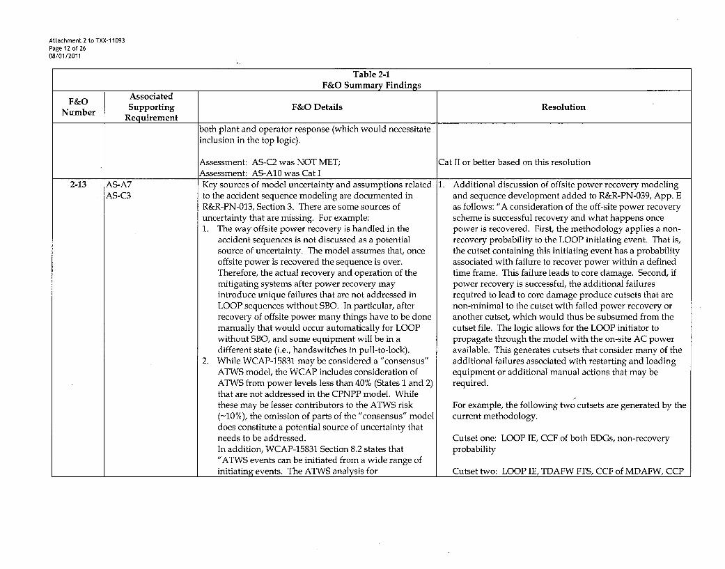
Key sources of model uncertainty and assumptions relatedto the accident sequence modeling are documented inR&R-PN-013, Section 3. There are some sources ofuncertainty that are missing. For example:1. The way offsite power recovery is handled in the
accident sequences is not discussed as a potentialsource of uncertainty. The model assumes that, onceoffsite power is recovered the sequence is over.Therefore, the actual recovery and operation of themitigating systems after power recovery mayintroduce unique failures that are not addressed inLOOP sequences without SBO. In particular, afterrecovery of offsite power many things have to be donemanually that would occur automatically for LOOPwithout SBO, and some equipment will be in adifferent state (i.e., handswitches in pull-to-lock).
2. While WCAP-15831 may be considered a "consensus"ATWS model, the WCAP includes consideration ofATWS from power levels less than 40% (States 1 and 2)that are not addressed in the CPNPP model. Whilethese may be lesser contributors to the ATWS risk(-10%), the omission of parts of the "consensus" modeldoes constitute a potential source of uncertainty thatneeds to be addressed.In addition, WCAP-15831 Section 8.2 states that"ATWS events can be initiated from a wide range ofinitiating events. The ATWS analysis for
1. Additional discussion of offsite power recovery modelingand sequence development added to R&R-PN-039, App. Eas follows: "A consideration of the off-site power recoveryscheme is successful recovery and what happens oncepower is recovered. First, the methodology applies a non-recovery probability to the LOOP initiating event. That is,the cutset containing this initiating event has a probabilityassociated with failure to recover power within a definedtime frame. This failure leads to core damage. Second, ifpower recovery is successful, the additional failuresrequired to lead to core damage produce cutsets that arenon-minimal to the cutset with failed power recovery oranother cutset, which would thus be subsumed from thecutset file. The logic allows for the LOOP initiator topropagate through the model with the on-site AC poweravailable. This generates cutsets that consider many of theadditional failures associated with restarting and loadingequipment or additional manual actions that may berequired.
For example, the following two cutsets are generated by thecurrent methodology.
Cutset one: LOOP IE, CCF of both EDGs, non-recoveryprobability
Cutset two: LOOP IE, TDAFW FTS, CCF of MDAFW, CCP

Attachment 2 to TXX-11093Page 13 of 2608/01/2011
Table 2-1F&O Summary Findings
F&O Associated
Number Supporting F&O Details ResolutionRequirement
Westinghouse PWRs (Reference 6) established that thelimiting events, with regard to RCS peak pressure, arethe loss of load with subsequent loss of all MFW andcomplete loss of normal feedwater. These limitingevents are both assumed to be initiated from normaloperation at full power." It is further stated in Section8.2.1 that "The model presented in this section assumesMFW is lost for all anticipated transient events. IfMFW continues to operate, then the event does notneed to address the pressure relief response, includingAFW and AMSAC, but only requires long-termshutdown. A split that accounts for MFW continuingto operate may be added to plant specific ATWSmodels if desired." it is not clear that the modeling forthe LOMFW top event captures all potential losses ofMFW following the initiating event. For example,flood events INIT-FO-AUXSWA and INIT-FO-AUXSWB, as analyzed, would trip the CW pumps dueto actuation of the flood sensing switches in thecondenser pits resulting in a loss of condensercoincident with the reactor trip. However, these aretreated as transients with MFW available in the ATWSanalysis. In addition, random failure of MFWfollowing reactor trip is not addressed in the fault treelogic for top event LOMFW (this was included in theBraidwood model described in Section 9.1 of theWCAP).Therefore, it is not clear that the CPNPP modeling isentirely consistent with the "consensus" model and thepotential uncertainty introduced by the deviations isnot discussed.
A FTS, PORV B FTO
With no AFW and 1 PORV failed to open, success criteriawill require 2 CCPs.If off-site power was successfully recovered in cutsetnumber one and the scenario continued, the cutset wouldlook like:
Cutset three: LOOP IE, CCF of both EDGs, powerrecovered, TDAFW FTS, CCF of MDAFW, CCP A FTS,PORV B FTO
The quantification software would look at cutset three andcutset two and identify that cutset three was non-minimal tocutset two and remove it before the results would be writtento the cutset file.
Thirdly, if the model logic was modified to account for thesuccessful restoration of off-site power, cutsets may begenerated that contain unique failures after recovery thatdoes not apply before recovery. That is, that after recoveryof offsite power many actions may have to be donemanually that would occur automatically for LOOP withoutSBO, and some equipment will be in a different state. Forexample, 1) Loop IE, CCF of Both EDGs, Operator fails toestablish FW after recovery of power, 2) Loop IE, CCF ofBoth EDGs, CCF of normal power tie breakers to safetybusses to close or 3) Loop IE, CCF of Both EDGs, Operatorfails to properly sequence loading of busses.
For these remaining cases, the impact on CDF would beinsignificant. This can be seen by looking at the overall

Attachment 2 to TXX-11093Page 14 of 2608/01/2011
Table 2-1F&O Summary Findings
F&O Associated INumber Supporting F&O Details Resolution
Requirementmake-up of these non-generated cutsets. For CPNPP theLOOP initiating event frequency is approximately E-2, theCCF of the EDGs is approximately E-4, providing an E-6starting point probability. A best estimate of successfulLOOP recovery prior to core damage would lower thesecutsets by at least an order of magnitude, resulting in an E-7cutset probability. For non-operator failure based scenarios,because of redundancy and/or diversity ofequipment/success paths, at least two additional failureswould have to occur in order to cause core damage. Thiswould provide at least an E-4 failure probability. Foroperator failure based scenarios, given that once off-sitepower is restored, the focus of the staff would be on re-energizing the safety busses, followed by restoration ofmitigating equipment and systems.
Therefore a failure probability of E-3 would be anappropriate value based on current similar HRA analyses.This would put the non-generated cutsets in the E-10 to E-11range (or lower) for a given core damage scenario. Giventhe current model CDF value (-3E-06) and the contributionof LOOP (- 10 to 15 percent) to CDF, these scenarios wouldnot significantly contribute to overall CDF." The aboveinformation has been added to the Quantification SupportFile Notebook, R&R-PN-039.
2. The ATWS event tree has been revised to pass allanticipated transient events discussed in the WCAP (i.e. no.loop, no ISI) through the LOMFW logic. The splitaccounting for MFW continuing to operate has beenremoved.
Concerning LOOP, the WCAP further states (§5.4): "Since

Attachment 2 to TXX-11093Page 15 of 2608/01/2011
Table 2-1F&O Summary Findings
F&O AssociatedNumber Supporting F&O Details ResolutionRequirement
the impacts on CDF and RCS integrity from LOSP/AWTSevents are very small, this event will not be important to theplant risk profile or to risk-informed decision process forassessing changes to a plant." Regarding states 1 and 5 (lowpower), WCAP §5.4 also states: "Since the CDF and theimpact on CDF are dominated by ATWS state 3 / 4 thisstate is the most important one to consider in plant specificPRA models. The other modes of operation are smallcontributors to plant risk and will not be important to theplant specific risk profile or to the risk-informed decisionprocess for assessing changes to a plant." The results of theWCAP show that states 1 and 5 contribute less than 2.5% toATWS risk. Since ATWS risk at CPNPP is a 0.1%contributor, the potential contribution to overall CDF riskfrom ATWS states 1 and 5 is on the order of 0.0025%. Theuncertainty due to exclusion of ATWS states 1 and 5 istherefore confirmed to be insignificant to plant specific riskprofile or to the risk-informed decision process for assessingchanges to the plant. The above information has beenadded to the Accident Sequence notebook, R&R-PN-013.
Assessment: AS-A7 was NOT MET Cat II or better based on this resolution2-16 HR-C2 R&R-PN-020 Section 4.1.2 states that "In general, caution All HFEs have been re-analyzed to include appropriate Errors
HR-D2 was exercised when considering both an error of omission of Commission.HR-E2 (EOM) and an error of commission (EOC) for the sameHR-F2 activity. For most component manipulations, theseHR-G2 activities were judged to be mutually exclusive. For
example in the case of a repositioning a valve following atest, an error of omission skips the reposition. This wouldbe a reasonable error. An error or commission, howeverwould be to reposition the valve, i.e. the desired outcome,and is not considered." This is insufficient basis for

Attachment 2 to TXX-11093Page 16 of 2608/01/2011
Table 2-1F&O Summary Findings
F&O Associated
Number Supporting F&O Details ResolutionRequirement
excluding EOC. EOC could include (for this example)"repositioning" the wrong valve (correct intent, wrongaction). This same thought process was applied to the EOCfor post-initiator actions and was also not adequatelyjustified.
Assessment: HR-C2 was NOT MET Cat II or better based on this resolution.2-18 HR-H3 The process followed for dependency analysis utilizes the The cut set used in the re-analysis of dependency was generated
QU-C1 HRA Calculator® to identify the combinations of HFEs that by setting all HEPs to 1E-01 and re-quantifying at 1E-12, (whichappear in cutsets. The process used a quantification run meets the ASME PRA Standard for setting a truncation value).with a truncation level of 1E-14 to identify the HFE Additional combinations were obtained and appropriatelycombinations to assessed, but used nominal HEP values so analyzed for dependency. 1E-01 is generally at least two ordersit cannot be assured that all important combinations were of magnitude higher than the HEP values and is sufficientlyidentified. elevated to identify important combinations.
Assessment: QU-C1 was NOT MET Cat II or better based on this resolution3-1 IE-C5 From a methodology point of view, and per report R&R- LOOP IE frequencies were adjusted to a reactor year basis and
IE-D2 PN-008A, Rev 4, with the exception of the LOOP initiators, all other IE frequencies were re-verified to be calculated on aa reactor year basis and an appropriate availability factor reactor year basis and documented in R&R-PN-008A.was used. So, it is deemed that the analysis meets the CC-I/II as a whole. However, because LOOP, as stated insection 4.7 of R&R-PN-008A, Rev 4, uses a calendar yearbasis instead of a reactor year, an F&O was generated todocument the need to convert the LOOP initiating events toreactor year based frequencies.
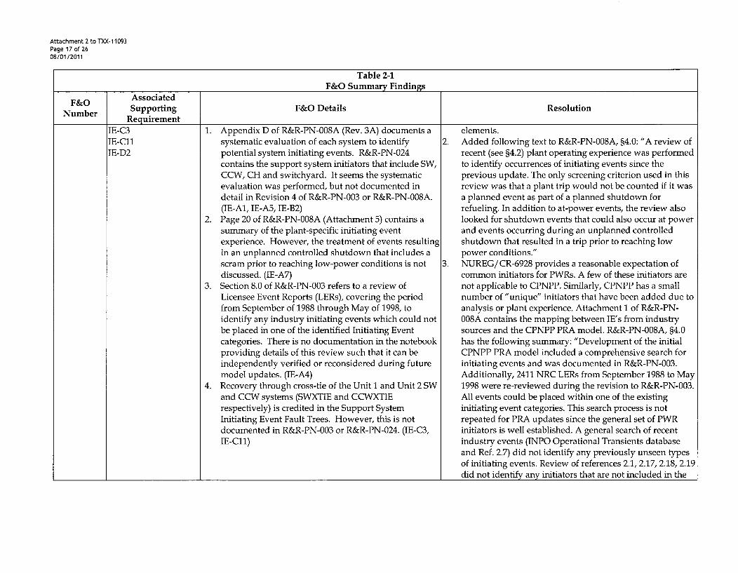
Assessment: IE-C5 was CAT I/II Cat II or better based on this resolution4-1 IE-Al In general, the initiating event analysis seems to have 1. The Initiating Event Analysis (PN-003) was revised to
IE-A4 identified a representative set of initiating events, document the system-by-system initiating event reviewIE-A5 However, the following areas were identified where the used to identify potential system initiating events. InIE-A7 documentation was missing or deficient in the current addition, R&R-PN-003 was also upgraded to incorporateIE-B2 revision: the documentation of the IE-D2 supporting requirement
Attachment 2 to TXX-11093Page 17 of 2608/01/2011
Table 2-1F&O Summary Findings
F&O Associated
Number Supporting F&O Details ResolutionRequirement
IE-C3IE-Cl1IE-D2
1. Appendix D of R&R-PN-008A (Rev. 3A) documents asystematic evaluation of each system to identifypotential system initiating events. R&R-PN-024contains the support system initiators that include SW,CCW, CH and switchyard. It seems the systematicevaluation was performed, but not documented indetail in Revision 4 of R&R-PN-003 or R&R-PN-008A.(IE-Al, IE-A5, IE-B2)
2. Page 20 of R&R-PN-008A (Attachment 5) contains asummary of the plant-specific initiating eventexperience. However, the treatment of events resultingin an unplanned controlled shutdown that includes ascram prior to reaching low-power conditions is notdiscussed. (IE-A7)
3. Section 8.0 of R&R-PN-003 refers to a review ofLicensee Event Reports (LERs), covering the periodfrom September of 1988 through May of 1998, toidentify any industry initiating events which could notbe placed in one of the identified Initiating Eventcategories. There is no documentation in the notebookproviding details of this review such that it can beindependently verified or reconsidered during futuremodel updates. (IE-A4)
4. Recovery through cross-tie of the Unit 1 and Unit 2 SWand CCW systems (SWXTIE and CCWXTIErespectively) is credited in the Support SystemInitiating Event Fault Trees. However, this is notdocumented in R&R-PN-003 or R&R-PN-024. (IE-C3,IE-C11)
elements.2. Added following text to R&R-PN-008A, §4.0: "A review of
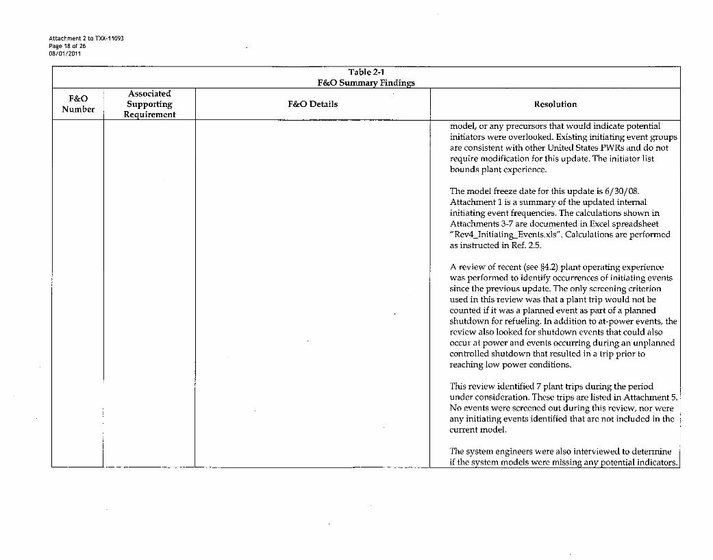
recent (see §4.2) plant operating experience was performedto identify occurrences of initiating events since theprevious update. The only screening criterion used in thisreview was that a plant trip would not be counted if it wasa planned event as part of a planned shutdown forrefueling. In addition to at-power events, the review alsolooked for shutdown events that could also occur at powerand events occurring during an unplanned controlledshutdown that resulted in a trip prior to reaching lowpower conditions."
3. NUREG/CR-6928 provides a reasonable expectation ofcommon initiators for PWRs. A few of these initiators arenot applicable to CPNPP. Similarly, CPNPP has a smallnumber of "unique" initiators that have been added due toanalysis or plant experience. Attachment 1 of R&R-PN-008A contains the mapping between IE's from industrysources and the CPNPP PRA model. R&R-PN-008A, §4.0has the following summary: "Development of the initialCPNPP PRA model included a comprehensive search forinitiating events and was documented in R&R-PN-003.Additionally, 2411 NRC LERs from September 1988 to May1998 were re-reviewed during the revision to R&R-PN-003.All events could be placed within one of the existinginitiating event categories. This search process is notrepeated for PRA updates since the general set of PWRinitiators is well established. A general search of recentindustry events (INPO Operational Transients databaseand Ref. 2.7) did not identify any previously unseen typesof initiating events. Review of references 2.1, 2.17, 2.18, 2.19did not identify any initiators that are not included in the
Attachment 2 to TXX-11093Page 18 of 2608/01/2011
Table 2-1F&O Summary Findings
F&O Associated
Number Supporting F&O Details ResolutionRequirement
model, or any precursors that would indicate potentialinitiators were overlooked. Existing initiating event groupsare consistent with other United States PWRs and do notrequire modification for this update. The initiator listbounds plant experience.
The model freeze date for this update is 6/30/08.Attachment 1 is a summary of the updated internalinitiating event frequencies. The calculations shown inAttachments 3-7 are documented in Excel spreadsheet"Rev4_InitiatingEvents.xls". Calculations are performedas instructed in Ref. 2.5.
A review of recent (see §4.2) plant operating experiencewas performed to identify occurrences of initiating eventssince the previous update. The only screening criterionused in this review was that a plant trip would not becounted if it was a planned event as part of a plannedshutdown for refueling. In addition to at-power events, thereview also looked for shutdown events that could alsooccur at power and events occurring during an unplannedcontrolled shutdown that resulted in a trip prior toreaching low power conditions.
This review identified 7 plant trips during the periodunder consideration. These trips are listed in Attachment 5.No events were screened out during this review, nor wereany initiating events identified that are not included in thecurrent model.
The system engineers were also interviewed to determineif the system models were missing any potential indicators.
Attachment 2 to TXX-1 1093Page 19 of 2608/01/2011
Table 2-1F&O Summary Findings
F&O Associated
Number Supporting F&O Details ResolutionRequirement
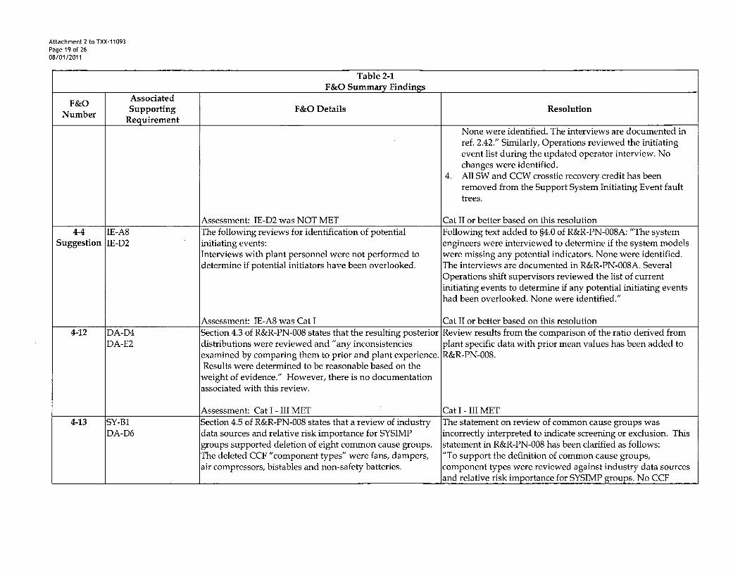
None were identified. The interviews are documented inref. 2.42." Similarly, Operations reviewed the initiatingevent list during the updated operator interview. Nochanges were identified.
4. All SW and CCW crosstie recovery credit has beenremoved from the Support System Initiating Event faulttrees.
Assessment: IE-D2 was NOT MET Cat II or better based on this resolution
4-4 IE-A8 The following reviews for identification of potential Following text added to §4.0 of R&R-PN-008A: "The systemSuggestion IE-D2 initiating events: engineers were interviewed to determine if the system models
Interviews with plant personnel were not performed to were missing any potential indicators. None were identified.
determine if potential initiators have been overlooked. The interviews are documented in R&R-PN-008A. SeveralOperations shift supervisors reviewed the list of currentinitiating events to determine if any potential initiating eventshad been overlooked. None were identified."
Assessment: IE-A8 was Cat I Cat II or better based on this resolution4-12 DA-D4 Section 4.3 of R&R-PN-008 states that the resulting posterior Review results from the comparison of the ratio derived from
DA-E2 distributions were reviewed and "any inconsistencies plant specific data with prior mean values has been added toexamined by comparing them to prior and plant experience. R&R-PN-008.Results were determined to be reasonable based on theweight of evidence." However, there is no documentation
associated with this review.
Assessment: Cat I - III MET Cat I - III MET4-13 SY-B1 Section 4.5 of R&R-PN-008 states that a review of industry The statement on review of common cause groups was
DA-D6 data sources and relative risk importance for SYSIMP incorrectly interpreted to indicate screening or exclusion. Thisgroups supported deletion of eight common cause groups. statement in R&R-PN-008 has been clarified as follows:The deleted CCF "component types" were fans, dampers, "To support the definition of common cause groups,air compressors, bistables and non-safety batteries, component types were reviewed against industry data sources
and relative risk importance for SYSIMP groups. No CCF

Attachment 2 to TXX-11093Page 20 of 2608/01/2011
Table 2-1F&O Summary Findings
F&O Associated
Number Supporting F&O Details ResolutionRequirement
events associated with significant basic events were excluded inthe definition of common cause groups."
Assessment: Cat II or better MET Cat II or better MET4-14 DA-D3 The CPNPP PRA includes mean values and statistical The Multiple Greek Letter method for estimating CCF mean
DA-E2 representations of the uncertainty intervals for the values is a method adopted from NUREG 5485 which is cited asparameter estimates. However, the uncertainty parameters a source in the ASME standard. Though this method does notfor the CCF events are not included, readily support statistical representation of uncertainty
intervals, other sources of uncertainty have been considered.As noted in Appendix D.5 of NUREG 5485, "the uncertaintiesdue to judgment required in interpretation and classification offailure events and the assessment of impact vectors are the mostsignificant of all sources of uncertainty."This discussion of uncertainty for CCF parameter estimationhas been added to R&R-PN-008. The data notebook includes anexplicit reference to R&R-PN-041, Uncertainty Analysis, whichaddresses EPRI recommendations for treatment of uncertainty.
Assessment: Cat III MET Cat III MET4-15 DA-C4 The CPNPP PRA includes many SSCs with plant-specific A systematic review of plant specific data identified those
DA-D1 parameter estimates (see Attachment 3 of R&R-PN-008). components with sufficient, relevant plant data. AllHowever, there is no documented systematic process or components with sufficient data were updated to generate plantcriteria to determine which SSCs should be evaluated for specific parameter estimates. Data sources reviewed for changesthe plant-specific estimates, including the potentially in failures or failure modes included Maintenance Rule,significant basic events. Mitigation System Performance Indicator (MSPI), EPIX and
consultations with System and Component Engineers.This discussion of the update process and criteria was added toR&R-PN-008.
Assessment: Cat II or better MET Cat II or better MET4-24 IE-B5 Sections 5.2.1, 5.2.2, 5.2.3, 5.2.4 of R&R-PN-022 discuss the 1. The treatment of room cooling was reviewed and
IE-C3 cutset reviews performed for CPNPP PRA. Issues were determined to be correctly applied, i.e. individual room

Attachment 2 to TXX-11093Page 21 of 2608/01/2011
Table 2-1F&O Summary Findings
F&O Associated
Number Supporting F&O Details ResolutionRequirement
IE-C11 identified with two specific cutsets that require additional heat loads are different, thus different probabilities areQU-D1 discussion and/or justification: reasonable. However, due to the uncertainty regarding
1. Cutset #9 in the CDF results contains two events potential dependency, cutsets containing failures of both(RHACHCOOL & RHBCHCOOL) which represent the trains are treated as completely dependent. A replacementconditional probability a RH train will fail upon loss of event equal to the highest probability of the pair isthe essential chilled water that provide the room substituted in place of the independent events. A sensitivitycooling. Each event has the conditional probability of case [R&R-PN-041] has been performed to address the0.688 based on the RXE-SY-CP1/1-028 (1992). It is not uncertainty of this assumption. Further discussion of thisclear whether this conditional probability is justifiable. topic is addressed in App. D of R&R-PN-039.In addition, it seems the RHACHCOOL & 2. All SW and CCW crosstie recovery credit has been removedRHBCHCOOL events should be based on a joint from the Support System Initiating Event fault trees. R&R-probability when these two events show together in a PN-024 discusses credit for cross-ties to mitigate corecutset. (QU-D1) damage but not in determining the SSIE frequencies. This
2. Cutset #10 contains SWXTIE that credits Unit 2 SW crosstie function is credited as a recovery only with bothsystem upon Loss of SW system in Unit 1 followed by trains in the other unit available. As modeled, one trainan induced RCP Seal LOCA which would result in a from the other unit cannot be used to supply both units.start signal for the EDGs. It is not clear whether the Use of the crosstie does not prevent inducing an RCP Sealoperators have enough time to make the crosstie in LOCA; nor does it prevent operators from taking requiredtime to provide the cooling to EDGs on Unit 1 before actions (e.g. stopping the EDGs on a loss of SW) prior tothe diesels fail. (IE-B5, IE-C3, IE-C11, QU-D1) alignment of the crosstie.
Assessment: QU-D1 was NOT MET Cat II or better based on this resolution4-29 QU-A2 Section 6.0 of R&R-PN-022 provides the discussions of the Discussion of significant sequences has been added to R&R-PN-
Suggestion QU-D6 significant contributors to CDF, the initiator contributions, 022.QU-F3 and top event contributors for each event tree. Section 7.0
of R&R-PN-022 provides significant contributors from CCFevents, operator actions and independent events.However, the sequence level contributors are notindentified in the notebook.Assessment: QU-F3 was Cat I
Cat II based on this resolution4-31 QU-E4 R&R-PN-041 provides the results of uncertainty and R&R-PN-041 Section 5.1 describes the application of the EPRI

Attachment 2 to TXX-1 1093Page 22 of 2608/01/2011
Table 2-1F&O Summary Findings
F&O Associated
Number Supporting F&O Details ResolutionRequirement
QU-F4 sensitivity results, and other PRA notebooks identify the approach to CPNPP.potential sources of model uncertainty. However, it is notclear how these sources of uncertainty affect the PRAmodel.
Assessment: QU-F4 was NOT MET Cat II based on this resolution4-34 QU-F6 No documentation was found in R&R-PN-022, 39 and 41 The quantitative definition for significant basic event,
providing a quantitative definition of significant basic significant cutset, and significant accident sequence is asevent, cutset, and accident sequence. described in ASME/ANS PRA Standard, part 2. This definition
has been explicitly added to R&R-PN-022, 039, and 041.
Assessment: QU-F6 was NOT MET Cat II based on this resolution4-35 IE-C8 The CCW, SW, and CH initiating event fault trees use a The data used to calculate the MTTR value were screened to
IE-C10 MTTR factor, which is calculated based on the data from the identify unavailability events not associated with planned testDA-C16 Maintenance Rule database. It is not clear whether the data and maintenance. Detailed data includes dates, durations and
screening was appropriately handled for the initiating event the reason for unavailability. A table detailing screen resultscriteria, was added to R&R PN-008.
In addition, the MTTR factor is applied using rules based MTTR events are explicitly included in SSIE models. Therecovery rather than being explicitly modeled in the SSIE following is included in R&R-PN-024, §4.1: "Each SSIE tree hasfault trees as required by this SR. been developed such that every train is modeled with the
operating equipment relying on an annualized exposure time.At an appropriate location, where the trains meet in the logic,an event representing the mean time to repair of the redundanttrain was placed. This event effectively replaces the annualizedvalue of the redundant equipment with the MTTR exposuretime. In this way, the logic will always result in a yearlyfrequency at the top while any of the operating trains mayrepresent the initial annualized failure. An example of thisapproach is shown below, and each MTTR event used in themodel is subsequently discussed.
Attachment 2 to TXX-1 1093Page 23 of 2608/01/2011
Table 2-1F&O Summary Findings
F&O Associated
Number Supporting F&O Details ResolutionRequirement
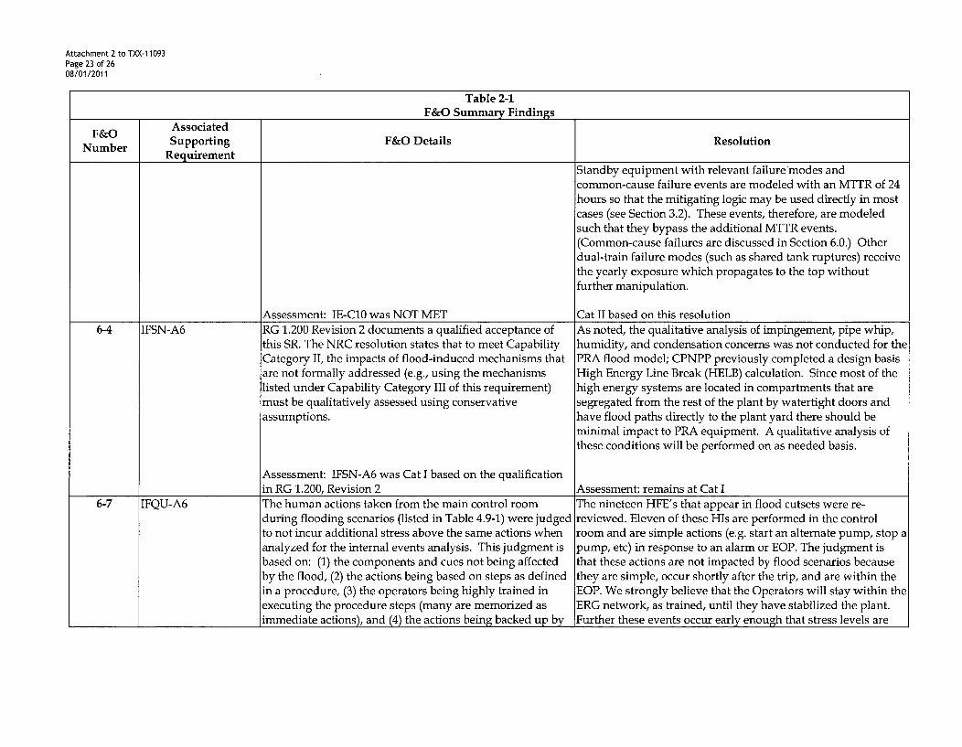
Standby equipment with relevant failure modes andcommon-cause failure events are modeled with an MTTR of 24
hours so that the mitigating logic may be used directly in mostcases (see Section 3.2). These events, therefore, are modeledsuch that they bypass the additional MTTR events.
(Common-cause failures are discussed in Section 6.0.) Otherdual-train failure modes (such as shared tank ruptures) receivethe yearly exposure which propagates to the top withoutfurther manipulation.
Assessment: IE-C10 was NOT MET Cat II based on this resolution6-4 IFSN-A6 RG 1.200 Revision 2 documents a qualified acceptance of As noted, the qualitative analysis of impingement, pipe whip,
this SR. The NRC resolution states that to meet Capability humidity, and condensation concerns was not conducted for theCategory II, the impacts of flood-induced mechanisms that PRA flood model; CPNPP previously completed a design basisare not formally addressed (e.g., using the mechanisms High Energy Line Break (HELB) calculation. Since most of thelisted under Capability Category III of this requirement) high energy systems are located in compartments that aremust be qualitatively assessed using conservative segregated from the rest of the plant by watertight doors andassumptions. have flood paths directly to the plant yard there should be
minimal impact to PRA equipment. A qualitative analysis ofthese conditions will be performed on as needed basis.
Assessment: IFSN-A6 was Cat I based on the qualificationin RG 1.200, Revision 2 Assessment: remains at Cat I
6-7 IFQU-A6 The human actions taken from the main control room The nineteen HFE's that appear in flood cutsets were re-during flooding scenarios (listed in Table 4.9-1) were judged reviewed. Eleven of these His are performed in the controlto not incur additional stress above the same actions when room and are simple actions (e.g. start an alternate pump, stop aanalyzed for the internal events analysis. This judgment is pump, etc) in response to an alarm or EOP. The judgment isbased on: (1) the components and cues not being affected that these actions are not impacted by flood scenarios becauseby the flood, (2) the actions being based on steps as defined they are simple, occur shortly after the trip, and are within thein a procedure, (3) the operators being highly trained in EOP. We strongly believe that the Operators will stay within theexecuting the procedure steps (many are memorized as ERG network, as trained, until they have stabilized the plant.immediate actions), and (4) the actions being backed up by Further these events occur early enough that stress levels are

Attachment 2 to TXX-11093Page 24 of 2608/01/2011
Table 2-1F&O Summary Findings
F&O AssociatedNumber Supporting F&O Details ResolutionRequirement
supervision in the control room during the floodingscenario. Additionally, most of the actions are assumed tobe taken early in a sequence before the determination that aflood is occurring (an average time frame of 10 minutes isassumed). Thus, few of the actions are expected to be takenin the long term as a scenario progresses.
Certainly, the components in the control room (thosephysically manipulated by the operators) should not beaffected by the flood scenarios. The lack of impact on cuesis not certain. All the actions appear to be based onprocedural guidance for which the operators are trained.Control room supervision is expected.
However, the assumption regarding the actions being takenearly within a scenario does not apply to several of the maincontrol room actions that are listed in Table 4.9-1. At leastnine actions from Table 4.9-1 were identified which couldreasonably be expected to be performed in a time framebeyond the assumed, average 10 minutes. Among theseactions were:
- The failure to establish feed-and-bleed within 25 (or 30)minutes
- The failure to align for low pressure recirculation (up to41.8 minutes)
- The failure to align for hot leg recirculation (up to 270minutes)
- The failure to start a standby SW pump (up to 37minutes)
- The failure to depressurize and begin RHR SDC (up to1433 minutes)
judged to be unchanged from the level originally assessed forthe event. WOG ERGs are symptom based. That is, theoperators respond to plant indications rather than performingdiagnosis of the event. No specific time limit is applied to thisreview.
One HFE concerns equipment failed due to flooding. The HFEis therefore N/A. The remaining 7 actions have some portion ofthe response performed remotely (i.e. in the field). The generalprocess was to increase transit time where the flood could causethe PEO to stop and have additional discussion with the controlroom and/or re-route to the destination. In lieu of more specificinformation, the transit time was doubled. Changing timing inthe HRA methodology may change the dependency of recoveryactions, with potential subsequent increase in the Human ErrorProbability (HEP). This approach was judged reasonable sincethe actions that were modified already include the effects ofhigh stress in the base analysis.
Three of the seven are not impacted by flood scenarios.TLXHICSTFILY and AFXHICSTFILY are "refill the CST"actions and do not occur for at least 5.5 hours after plant trip. Inthis case the flood impacts are assumed to be terminated.EPXHICHASWY does not occur in a flood area.
Four of the seven remote actions were judged to be potentiallyimpacted by the flood. The potential impact was judged tolikely be an increase in transit time due to additionalcommunication with the control room or the need to take analternate path. For these cases, transit time was doubled. Whereappropriate, dependency levels were changed as a result ofincreased timing. In two of the four events the dependency

Attachment 2 to TXX-1 1093Page 25 of 2608/01/2011
Table 2-1F&O Summary Findings
F&O AssociatedNumber Supporting F&O Details Resolution
Requirement
level did not change, thus the HEP did not change. In theremaining two events, the dependency level increased, thusincreasing the associated HEP.
Assessment: Cat I - III MET Cat I - III METNo F&O IFEV-A6 R&R-PN-021 Section 4.7 indicates that the flood initiating During the internal flooding (IF) analysis a search for previousincluded event frequencies were based on the EPRI 1021086 failure IF events at CPNPP was performed and none were found. A
data combined with plant-specific piping lengths. No Bayesian update with no specific plant events would incur aBayesian updating with plant-specific operating experience non-conservative result; therefore no Bayesian update wasor adjustment based on engineering judgment was performed as there is no impact to application evaluations.performed.
Assessment: Cat I is MET Assessment: remains at Cat INo F&O LE-C11 No credit was taken for continued operation of equipment Since no credit has been taken for continued operation afterincluded after containment failure. RXE-LA-CPX/0-105 Table 6-1 containment failure, justification cannot be provided. Impact
specifically notes that "No credit is taken for operation of on specific applications will be evaluated as needed.the ECCS/CS system after containment failure or foroperator actions or other equipment that could be impactedby containment failure because there are none that aresignificant." It is not clear that this is equivalent tojustifying "any credit given" as required for CC 11/111.
Assessment: Cat I is MET Assessment: remains at Cat I2-7 SC-A6 The MAAP calculations (RXE-LA-CPX/0-103 and RXE-LA- To address the conservatism, Hot Leg Recirculation
(Suggestion CPX/0-104) are generally consistent with features and requirements were removed for Small and Very Small LOCAF&O) procedures. However, the requirement for switchover to based on Westinghouse ERG documents and comparison with
hot leg recirculation is conservative, and may impact the other plants.CDF results and, thus, the insights on dominantcontributors.

Attachment 2 to TXX-11093Page 26 of 2608/01/2011
Table 2-2SRs Assessed as Not Met or Category I for the CPNPP PRA
Technical Element Not Met SRs Cat I SRsInitiating Event (IE) IE-ClO IE-A8
IE-D2Accident Sequence Analysis (AS) AS-A7 AS-AlO
AS-C2Success Criteria (SC) None NoneSystems Analysis (SY) None NoneHuman Reliability (HR) HR-C2 None
HR-G7Data Analysis (DA) None NoneInternal Flooding (IF) None IFSN-A6*
IFSN-A14IFSN-A 16IFEV-A6
Quantification (QU) QU-CI QU-F3QU-D1QU-F4QU-F6
Large Early Release Frequency (LE) LE-F2 LE-C 11Maintenance &Update/Configuration Control (MU) None None

Attachment 3 to TXX-11093Page 1 of 10508/01/2011
ATTACHMENT 3 to TXX-11093
PROPOSED TECHNICAL SPECIFICATION CHANGES (MARK-UP)
Pages TSINSERTS 3.3-27 3.4-30 3.7-15 3.8-14
3.1-1 3.3-36 3.4-33 3.7-16 3.8-15
3.1-3 3.3-39 3.4-34 3.7-18 3.8-16
3.1-5 3.3-44 3.4-38 3.7-21 3.8-22
3.1-9 3.3-48 3.4-40 3.7-22 3.8-24
3.1-11 3.349 3.4-41 3.7-25 3.8-25
3.1-13 3.3-53 3.5-2 3.7-28 3.8-31
3.1-18 3.4-2 3.5-4 3.7-30 3.8-32
3.2-4 3.4-3 3.5-5 3.7-33 3.8-34
3.2-6 3.4-5 3.5-9 3.7-34 3.8-36
3.2-9 3.4-6 3.5-10 3.7-41 3.8-38
3.2-10 3.4-8 3.6-6 3.7-43 3.8-40
3.2-13 3.4-9 3.6-12 3.7-46 3.9-1
3.3-8 3.4-11 3.6-13 3.8-6 3.9-3
3.3-9 3.4-13 3.6-14 3.8-7 3.9-5
3.3-10 3.4-15 3.6-15 3.8-8 3.9-7
3.3-11 3.4-17 3.6-16 3.8-9 3.9-9
3.3-12 3.4-22 3.6-17 3.8-10 3.9-11
3.3-13 3.4-23 3.7-7 3.8-11 3.9-12
3.3-25 3.4-27 3.7-9 3.8-12 5-5-16
3.3-26 3.4-28 3.7-14 3.8-13
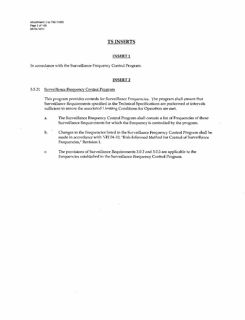
Attachment 3 to TXX-11093Page 2 of 10508/01/2011
TS INSERTS
INSERT 1
In accordance with the Surveillance Frequency Control Program.
INSERT 2
5.5.21 Surveillance Frequency Control Program
This program provides controls for Surveillance Frequencies. The program shall ensure thatSurveillance Requirements specified in the Technical Specifications are performed at intervalssufficient to assure the associated Limiting Conditions for Operation are met.
a. The Surveillance Frequency Control Program shall contain a list of Frequencies of thoseSurveillance Requirements for which the Frequency is controlled by the program.
b. Changes to the Frequencies listed in the Surveillance Frequency Control Program shall bemade in accordance with NEI 04-10, "Risk-Informed Method for Control of SurveillanceFrequencies," Revision 1.
c. The provisions of Surveillance Requirements 3.0.2 and 3.0.3 are applicable to theFrequencies established in the Surveillance Frequency Control Program.

SDM3.1.1
3.1 REACTIVITY CONTROL SYSTEMS
3.1.1 SHUTDOWN MARGIN (SDM)
LCO 3.1.1 SDM shall be within the limits provided in the COLR.
APPLICABILITY: MODE 2 with keff < 1.0,MODES 3, 4, and 5
-------------------------------- NOTE -----------------------------------------------While this LCO is not met, entry into MODE 5 from MODE 6 is not permitted.
ACTIONS
CONDITION REQUIRED ACTION COMPLETION TIME
A. SDM not within limit. A.1 Initiate boration to restore SDM to 15 minuteswithin limit.
SURVEILLANCE REQUIREMENTS
SURVEILLANCE FREQUENCY
SR 3.1.1.1 Verify SDM to be within limits. 24-her-s
INSERT 1
COMANCHE PEAK - UNITS 1 AND 2 3.1-1 Amendment No. 15ff

Core Reactivity3.1.2
SURVEILLANCE REQUIREMENTS
SURVEILLANCE FREQUENCY
i
SR 3.1.2.1 -------------------NOTE ------------------The predicted reactivity values may be adjusted(normalized) to correspond to the measured core reactivityprior to exceeding a fuel burnup of 60 effective full powerdays (EFPD) after each fuel loading.
Verify measured core reactivity is within ± 1% Ak/k ofpredicted values.
Once prior toentering MODE 1after each refueling
AND
---------- NOTE ---------Only required after60 EFPD
31 EF-PE I ei eafte,
L-INSERT 1
COMANCHE PEAK - UNITS 1 AND 2 3.1-3 Amendment No. 0

MTC3.1.3
SURVEILLANCE REQUIREMENTS
SURVEILLANCE FREQUENCY
SR 3.1.3.1 Verify MTC is within upper limit. Once prior toentering MODE 1after each refueling
SR 3.1.3.2 ---------------------- NOTES -----------------1. Not required to be performed'until 7 effective full power
days (EFPD) after reaching the equivalent of anequilibrium RTP all rods out (ARO) boron concentrationof 300 ppm.
2. If the MTC is more negative than the 300 ppmSurveillance limit (not LCO limit) specified in the COLR,SR 3.1.3.2 shall be repeated once per 14 EFPD duringthe remainder of the fuel cycle.
3. SR 3.1.3.2 need not be repeated if the MTC measuredat the equivalent of equilibrium RTP-ARO boronconcentration of _< 60 ppm is less negative than the60 ppm Surveillance limit specified in the COLR.
Verify MTC is within lower limit. Once eac-eyelce
ISERT1
COMANCHE PEAK- UNITS 1 AND 2 3.1-5 Amendment No. W
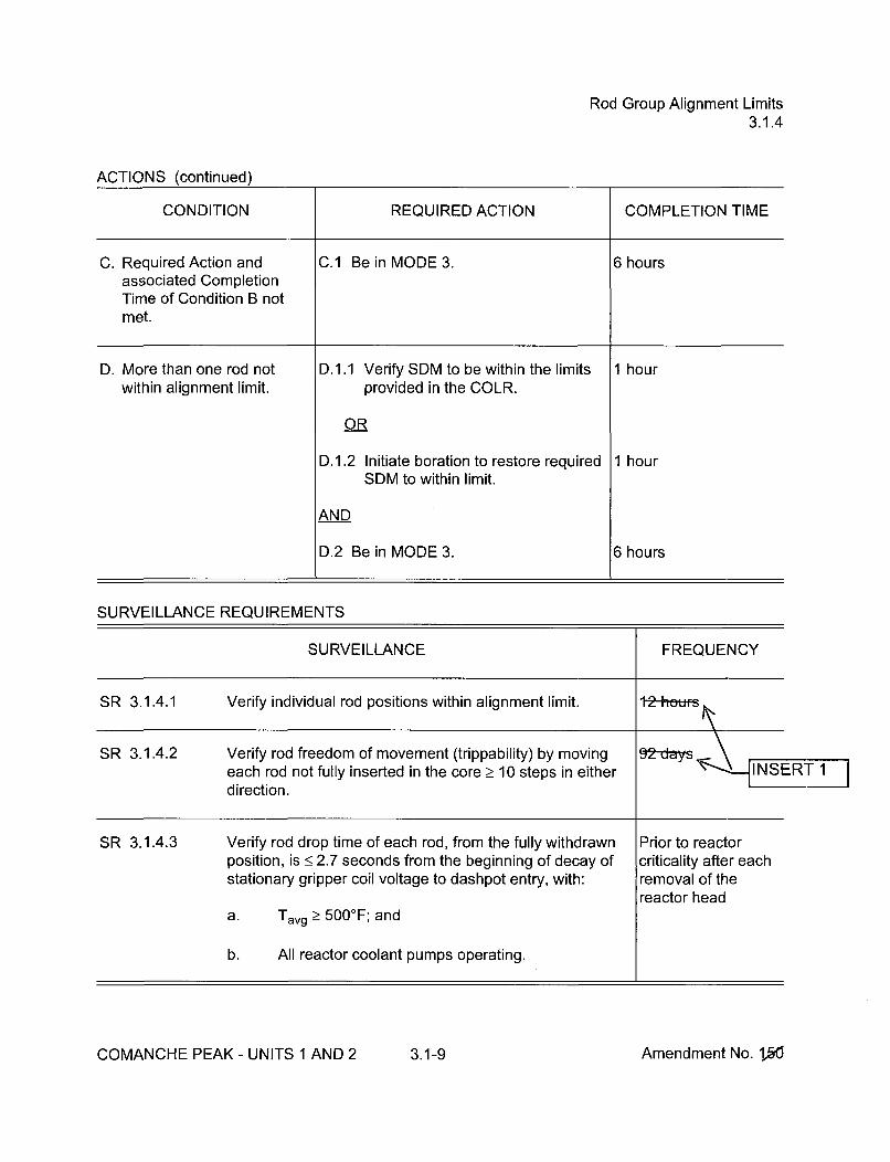
Rod Group Alignment Limits3.1.4
ACTIONS (continued)
CONDITION REQUIRED ACTION COMPLETION TIME
C. Required Action and C.1 Be in MODE 3. 6 hoursassociated CompletionTime of Condition B notmet.
D. More than one rod not D.1.1 Verify SDM to be within the limits 1 hour
within alignment limit, provided in the COLR.
OR
D.1.2 Initiate boration to restore required 1 hourSDM to within limit.
AND
D.2 Be in MODE 3. 6 hours
SURVEILLANCE REQUIREMENTS
SURVEILLANCE FREQUENCY
SR 3.1.4.1 Verify individual rod positions within alignment limit. 1-2-hemfs
SR 3.1.4.2 Verify rod freedom of movement (trippability) by movingeach rod not fully inserted in the core _> 10 steps in eitherdirection.
INSERTI11
SR 3.1.4.3 Verify rod drop time of each rod, from the fully withdrawn Prior to reactorposition, is < 2.7 seconds from the beginning of decay of criticality after eachstationary gripper coil voltage to dashpot entry, with: removal of the
reactor heada. Tavg > 5000F; and
b. All reactor coolant pumps operating.
COMANCHE PEAK - UNITS 1 AND 2 3.1-9 Amendment No. 10
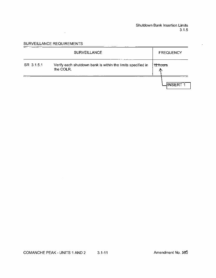
Shutdown Bank Insertion Limits3.1.5
SURVEILLANCE REQUIREMENTS
SURVEILLANCE FREQUENCY
SR 3.1.5.1 Verify each shutdown bank is within the limits specified in 12 huosthe COLR.
INSERT I
COMANCHE PEAK- UNITS 1 AND 2 3.1-11 Amendment No. 1-36

Control Bank Insertion Limits3.1.6
ACTIONS (continued)
CONDITION REQUIRED ACTION COMPLETION TIME
B. Control bank sequence or B.1.1 Verify SDM to be within the limits 1 houroverlap limits not met. provided in the COLR.
OR
B.1.2 Initiate boration to restore SDM to 1 hourwithin limit.
AND
B.2 Restore control bank sequence and 2 hoursoverlap to within limits.
C. Required Action and C.1 Be in MODE 3. 6 hoursassociated CompletionTime not met.
SURVEILLANCE REQUIREMENTS
SURVEILLANCE FREQUENCY
SR 3.1.6.1 Verify estimated critical control bank position is within the Within 4 hours priorlimits specified in the COLR. to achieving
criticality
SR 3.1.6.2 Verify each control bank insertion is within the limitsspecified in the COLR.
SR 3.1.6.3 Verify sequence and overlap limits specified in the COLRare met for control banks not fully withdrawn from the core.
I
COMANCHE PEAK - UNITS 1 AND 2 3.1-13 Amendment No. 15&

PHYSICS TESTS Exceptions - MODE 23.1.8
ACTIONS (continued)
CONDITION REQUIRED ACTION COMPLETION TIME
C. RCS lowest operating loop C.1 Restore RCS lowest operating loop 15 minutesaverage temperature not average temperature to within limit.within limit.
D. Required Action and D.1 Be in MODE 3. 15 minutesassociated CompletionTime of Condition C notmet.
SURVEILLANCE REQUIREMENTS
SURVEILLANCE FREQUENCY
SR 3.1.8.1 Perform a CHANNEL OPERATIONAL TEST on powerrange and intermediate range channels per SR 3.3.1.7,SR 3.3.1.8, and Table 3.3.1-1.
Prior to initiation ofPHYSICS TESTS
COMANCHE PEAK - UNITS 1 AND 2 3.1-18 Amendment No. 1.5ff
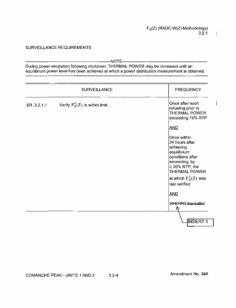
FQ(Z) (RAOC-W(Z) Methodology)3.2.1
SURVEILLANCE REQUIREMENTS
During power escalation following shutdown, THERMAL POWER may be increased until anequilibrium power level has been achieved at which a power distribution measurement is obtained.
SURVEILLANCE FREQUENCY
SR 3.2.1.1 Verify FC(Z) is within limit. Once after eachrefueling prior toTHERMAL POWERexceeding 75% RTP
AND
Once within24 hours afterachievingequilibriumconditions afterexceeding, byŽ 20% RTP, theTHERMAL POWER
at which FC(Z) waslast verified
AND
31 EFPD thereafter
\--[INSERT 1
COMANCHE PEAK - UNITS 1 AND 2 3.2-4 Amendment No. 15&

FQ(Z) (RAOC-W(Z) Methodology)3.2.1
SURVEILLANCE REQUIREMENTS
SURVEILLANCE FREQUENCY
SR 3.2.1.2 (continued) Once within24 hours afterachievingequilibriumconditions afterexceeding, byŽ 20% RTP, theTHERMAL POWER
at which FC(Z) waslast verified
AND
31 IzFPD tl heeaf't
-INSERT
COMANCHE PEAK - UNITS 1 AND 2 3.2-6 Amendment No. 1.5ff

NFAH
3.2.2
SURVEILLANCE REQUIREMENTS
------------------------ NOTE-----------------------------------During power escalation following shutdown, THERMAL POWER may be increased until anequilibrium power level has been achieved at which a power distribution measurement is obtained.
SURVEILLANCE FREQUENCY
SR 3.2.2.1 Verify FAH is within limits specified in the COLR. Once after eachrefueling prior to
THERMAL POWERexceeding 75% RTP
AND
31 EFPD ther.afto"
V INSERT 1
COMANCHE PEAK - UNITS 1 AND 2 3.2-9 Amendment No. 1,00

AFD (RAOC Methodology)3.2.3
3.2 POWER DISTRIBUTION LIMITS
3.2.3 AXIAL FLUX DIFFERENCE (AFD) (Relaxed Axial Offset Control (RAOC) Methodology)
LCO 3.2.3 The AFD in % flux difference units shall be maintained within the limitsspecified in the COLR.
--------------------------------- NOTE --------------------------The AFD shall be considered outside limits when two or more OPERABLEexcore channels indicate AFD to be outside limits.
APPLICABILITY:
ACTIONS
MODE 1 with THERMAL POWER > 50% RTP
CONDITION REQUIRED ACTION COMPLETION TIME
A. AFD not within limits. A.1 Restore THERMAL POWER to 30 minutes< 50% RTP.
SURVEILLANCE REQUIREMENTS
SURVEILLANCE FREQUENCY
SR 3.2.3.1 Verify AFD is within limits for each OPERABLE excore 7-dayschannel.
INSERT1
COMANCHE PEAK - UNITS 1 AND 2 3.2-10 Amendment No. 150

QPTR3.2.4
SURVEILLANCE REQUIREMENTS
SURVEILLANCE FREQUENCY
SR 3.2.4.1 ------------------------- NOTES -------------------1. With input from one Power Range Neutron Flux
channel inoperable and THERMAL POWER _< 75%RTP, the remaining three power range channels can beused for calculating QPTR.
2. SR 3.2.4.2 may be performed in lieu of thisSurveillance.
Verify QPTR is within limit by calculation. t-days
SR 3.2.4.2 -- -------------------- NOTE ------------------Not required to be performed until 12 hours after input fromone or more Power Range Neutron Flux channels are INSERTinoperable with THERMAL POWER > 75% RTP.
Verify QPTR is within limit using the core power distribution 424-e&~u-.measurement information.
COMANCHE PEAK - UNITS 1 AND 2 3.2-13 Amendment No. 15ff

RTS Instrumentation3.3.1
ACTIONS (continued)
CONDITION REQUIRED ACTION COMPLETION TIME
T. One or more required T.1 Verify interlock is in required state for 1 hour
channel(s) inoperable, existing unit conditions.
OR
T.2 Be in MODE 2. 7 hours
U. One trip mechanism U.1 Restore inoperable trip mechanism to 48 hours
inoperable for one RTB. OPERABLE status.
OR
U.2 Be in MODE 3. 54 hours
V. Not used.
SURVEILLANCE REQUIREMENTS
------------------------------------ NOTE ----------------------------------Refer to Table 3.3.1-1 to determine which SRs apply for each RTS Function.
SURVEILLANCE FREQUENCY
SR 3.3.1.1 Perform CHANNEL CHECK. t2-heu%-
AINSERT
COMANCHE PEAK - UNITS 1 AND 2 3.3-8 Amendment No. JZ9-

RTS Instrumentation3.3.1
SURVEILLANCE REQUIREMENTS (continued)
SURVEILLANCE FREQUENCY
SR 3.3.1.2 IM[J I--- -- - - -- - - -- - - -- - - --1 I-------------------------------------
Not required to be performed until 24 hours afterTHERMAL POWER is > 15% RTP.
Compare results of calorimetric heat balance calculation toNIS Power Range channel and N-16 Power Monitorchannel outputs. Adjust NIS Power Range channel outputsif calorimetric heat balance calculation exceeds NIS PowerRange channel outputs by more than +2% RTP. AdjustN-1 6 Power Monitor channel outputs if calorimetric heatbalance calculation exceeds N-16 Power Monitor channeloutputs by more than +2% RTP.
UrI~S
SR 3.3.1.3Not required to be performed until 24 hours afterTHERMAL POWER is > 50% RTP.-------------------------------------------------------------------------------
Compare results of the core power distribution 31-effptive fullmeasurements to Nuclear Instrumentation System (NIS) power daj-(Ef-P-)AFD. Adjust NIS channel if absolute difference is > 3%.
SR 3.3.1.4 -- -------------------- NOTE ------------------This Surveillance must be performed on the reactor tripbypass breaker for the local manual shunt trip only prior toplacing the bypass breaker in service.
Perform TADOT. 6&-da -STACC•ERE T-•ET
INSERT 1
COMANCHE PEAK- UNITS 1 AND 2 3.3-9 Amendment No. V,4ý-

RTS Instrumentation3.3.1
SURVEILLANCE REQUIREMENTS (continued)
SURVEILLANCE FREQUENCY
SR 3.3.1.5 Perform ACTUATION LOGIC TEST. 92-d7y9muSTACCGE RE TE-BT
SR 3.3.1.6 ----------------------- NOTE ------------------Not required to be performed until 72 hours after achievingequilibrium conditions with THERMAL POWER >_ 75%RTP.
Calibrate excore channels to agree with core powerdistribution measurements.
SR 3.3.1.7 -------------------- NOTES -----------------1. Not required to be performed for source range
instrumentation prior to entering MODE 3 from MODE 2until 4 hours after entry into MODE 3.
2. Source range instrumentation shall include verificationthat interlocks P-6 and P-10 are in their required state forexisting unit conditions. I
Perform COT.
COMANCHE PEAK - UNITS 1 AND 2 3.3-10 Amendment No. +5,&

RTS Instrumentation3.3.1
SURVEILLANCE REQUIREMENTS (continued)
SURVEILLANCE FREQUENCY
SR 3.3.1.8 -NOTE -----------------------------------This Surveillance shall include verification that interlocksP-6 and P-10 are in their required state for existing unitconditions.
Perform COT.
the previousFrequencyspecified in theSFCP
---- -NOTE ----------On required whenno erformed withinpro--- uc- 18- da ....
Prior to reactor
startup
AND
12 hours afterreducing powerbelow P-10 forpower andintermediateinstrumentation
AND
Four hours afterreducing powerbelow P-6 for sourcerangeinstrumentation
AND
Eve~y 1-84 daysthe reafter/P
IISETl1
COMANCHE PEAK - UNITS 1 AND 2 3.3-11 Amendment No. 4,50-

RTS Instrumentation3.3.1
SURVEILLANCE REQUIREMENTS (continued)
SURVEILLANCE FREQUENCY
SR 3.3.1.9 ----------------------- NOTE ------------------Verification of setpoint is not required.
Perform TADOT. 92-days4\
SR 3.3.1.10 -------------------- NOTES1. N-16 detectors are excluded from CHANNEL
CALIBRATION.
2. This Surveillance shall include verification that the timeconstants are adjusted to the prescribed values.
3. Prior to entry into MODES 2 or 1, N-16 detector plateauverification is not required to be performed until 72 hoursafter achieving equilibrium conditions with THERMALPOWER > 90% RTP.
Perform CHANNEL CALIBRATION.
SR 3.3.1.11 -------------------- NOTES -----------------1. Neutron detectors are excluded from CHANNEL
CALIBRATION.
2. This Surveillance shall include verification that the timeconstants are adjusted to the prescribed values.
3. Prior to entry into MODES 2 or 1, power andintermediate range detector plateau verification is notrequired to be performed until 72 hours after achievingequilibrium conditions with THERMAL POWER > 90%RTP. I
t6-n~en4h~Perform CHANNEL CALIBRATION.
COMANCHE PEAK - UNITS 1 AND 2 3.3-12 Amendment No. 1-5&

RTS Instrumentation3.3.1
SURVEILLANCE REQUIREMENTS (continued)
SURVEILLANCE FREQUENCY
SR 3.3.1.12 Not used.
SR 3.3.1.13 Perform COT. Ynths
SR 3.3.1.14 ----------------------------------- It uir'- -- - - - - - - - - - - - - - - - -
Verification of setpoint is not required.
Perform TADOT.
i
SR 3.3.1.15 --------------------- NOTE-Verification of setpoint is not required.
Perform TADOT.
the previousFrequencyspecified in theSFCP
Prior to exceedingthe P-9 interlockwhenever the unithas been inMODE 3, if not
... yi.u" 31 days
SR 3.3.1.16 ---------------------- NOTE ------------------Neutron and N-16 detectors are excluded from responsetime testing.
Verify RTS RESPONSE TIMES are within limits. 18-rn t,9-efn-aS TAC C-,- r, R D TESTB*S1&
•-INSERT 1
COMANCHE PEAK - UNITS 1 AND 2 3.3-13 Amendment No. +50

ESFAS Instrumentation3.3.2
ACTIONS (continued)
CONDITION REQUIRED ACTION COMPLETION TIME
L. One or more required L.1 Verify interlock is in required state for 1 hour
channel(s) inoperable, existing unit condition.
OR
L.2.1 Be in MODE 3. 7 hours
AND
L.2.2 Be in MODE 4. 13 hours
SURVEILLANCE REQUIREMENTS
------------------------------ NOTE ------------------------- ---------Refer to Table 3.3.2-1 to determine which SRs apply for each ESFAS Function.
COMANCHE PEAK - UNITS 1 AND 2 3.3-25 Amendment No. 158

ESFAS Instrumentation3.3.2
SURVEILLANCE REQUIREMENTS (continued)
SURVEILLANCE FREQUENCY
SR 3.3,2.5
SR 3.3.2.6
Perform COT.
Perform SLAVE RELAY TEST.
SR 3.3.2.7 ----------------------NOTES -----------------1. Verification of relay setpoints not required.
2. Actuation of final devices not included.
Perform TADOT.
SR 3.3.2.8 ----------------------- NOTE ------------------Verification of setpoint not required for manual initiationfunctions.
Perform TADOT.
SR 3.3.2.9 -----------------NOTE ------------------This Surveillance shall include verification that the timeconstants are adjusted to the prescribed values.------------------------------------------------------------------------------
Perform CHANNEL CALIBRATION. 1-8-meh
COMANCHE PEAK - UNITS 1 AND 2 3.3-26 Amendment No. 4-5ý

ESFAS Instrumentation3.3.2
SURVEILLANCE REQUIREMENTS (continued)
SURVEILLANCE FREQUENCY
SR 3.3.2.10 ------------------------ NOTE -------------------Not required to be performed for the turbine driven AFWpump until 24 hours after SG pressure is > 532 psig.
Verify ESF RESPONSE TIMES are within limits. is- mn1tlon-aZTACG•rEIDTEST
BA'S1\
SR 3.3.2.11 --- ------------------------------------ r -- -- - - - - - - - -- - - - - - - -
Verification of setpoint not required.INSERT 1
Perform TADOT.
COMANCHE PEAK - UNITS 1 AND 2 3.3-27 Amendment No. +5G

PAM Instrumentation3.3.3
SURVEILLANCE REQUIREMENTS
------------------------------------------ 11 r --------------------------------------------------------------
SR 3.3.3.1 and SR 3.3.3.3 apply to each PAM instrumentation Function in Table 3.3.3-1.
SURVEILLANCE FREQUENCY
SR 3.3.3.1 Perform CHANNEL CHECK for each required 31 daysinstrumentation channel that is normally energized.
SR 3.3.3.2 Deleted,• -INSERT 1 1
SR 3.3.3.3 Perform CHANNEL CALIBRATION. t8-nronths.
COMANCHE PEAK- UNITS 1 AND 2 3.3-36 Amendment No. +5fý-
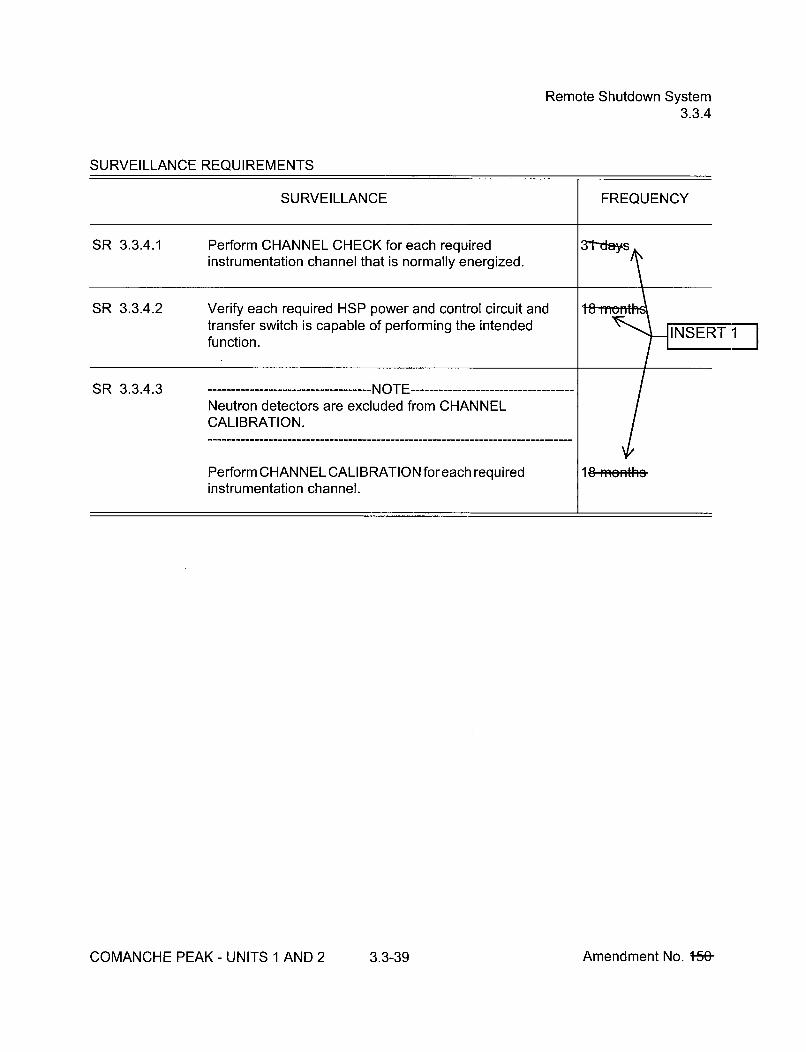
Remote Shutdown System3.3.4
SURVEILLANCE REQUIREMENTS
SURVEILLANCE FREQUENCY
i
SR 3.3.4.1 Perform CHANNEL CHECK for each requiredinstrumentation channel that is normally energized.
SR 3.3.4.2 Verify each required HSP power and control circuit andtransfer switch is capable of performing the intendedfunction.
SR 3.3.4.3 . Irvr --- -- - -- - -- - -- - -- - -- - I -----------------------------------Neutron detectors are excluded from CHANNELCALIBRATION.
Perform CHANNEL CALIBRATION foreach requiredinstrumentation channel.
18 ffieiRh
COMANCHE PEAK - UNITS 1 AND 2 3.3-39 Amendment No. +5&

LOP DG Start Instrumentation3.3.5
SURVEILLANCE REQUIREMENTS
SURVEILLANCE
SR 3.3.5.1 Perform ACTUATION LOGIC TEST. Prior to enteringMODE 4 when inMODE 5 forŽ 72 hours and if notperformed in •-
SR 3.3.5.2Setpoint verification is not applicable.
Perform TADOT.
SR 3.3.5.3 Perform CHANNEL CALIBRATION.
limits.BASIS
COMANCHE PEAK - UNITS 1 AND 2 3.3-44 Amendment No. t5,O--

Containment Ventilation Isolation Instrumentation3.3.6
ACTIONS (continued)
CONDITION REQUIRED ACTION COMPLETION TIME
C. -------- NOTE -------------------- NOTE ------------Only applicable during The containment pressure relief valvesCORE ALTERATIONS or may be opened in compliance with themovement of irradiated fuel gaseous effluent monitoringassemblies within instrumentation requirements in Part I ofcontainment, the ODCM.
Required Action and C.1 Place and maintain containment Immediatelyassociated Completion ventilation valves in closed position.Time for Condition A notmet. OR
C.2 Enter applicable Conditions and ImmediatelyRequired Actions of LCO 3.9.4,"Containment Penetrations," forcontainment ventilation isolationvalves made inoperable by isolationinstrumentation.
SURVEILLANCE REQUIREMENTS
------- - ----------------------- NOTE--------------------------------Refer to Table 3.3.6-1 to determine which SRs apply for each Containment Ventilation IsolationFunction.
SURVEILLANCE FREQUENCY
SR 3.3.6.1 Perform CHANNEL CHECK. 1-2-heu*s
INSERT 1
COMANCHE PEAK - UNITS 1 AND 2 3.3-48 Amendment No. -159-
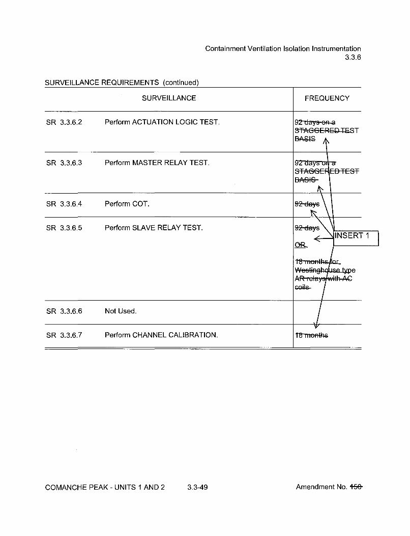
Containment Ventilation Isolation Instrumentation3.3.6
Perform SLAVE RELAY TEST.
COMANCHE PEAK - UNITS 1 AND 2 3.3-49 Amendment No. +5&

CREFS Actuation Instrumentation3.3.7
SURVEILLANCE REQUIREMENTS
------------------------------------ NOTE ----------------------------------Refer to Table 3.3.7-1 to determine which SRs apply for each CREFS Actuation Function.
COMANCHE PEAK - UNITS 1 AND 2 3.3-53 Amendment No. +56-
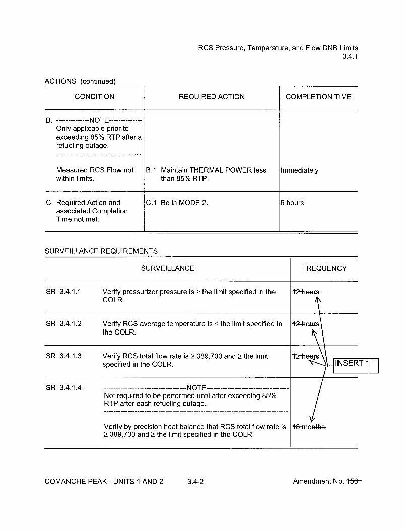
RCS Pressure, Temperature, and Flow DNB Limits3.4.1
ACTIONS (continued)
CONDITION REQUIRED ACTION COMPLETION TIME
B. -------- NOTE --------------Only applicable prior toexceeding 85% RTP after arefueling outage.
Measured RCS Flow not B.1 Maintain THERMAL POWER less Immediatelywithin limits, than 85% RTP.
C. Required Action and C.1 Be in MODE 2. 6 hoursassociated CompletionTime not met.
SURVEILLANCE REQUIREMENTS
SURVEILLANCE FREQUENCY
SR 3.4.1.1 Verify pressurizer pressure is > the limit slCOLR.
t2-heu~s
SR 3.4.1.2 Verify RCS average temperature is < the limit specified inthe COLR.
SR 3.4.1.3 Verify RCS total flow rate is >_ 389,700 and _> the limitspecified in the COLR.
SR 3.4.1.4 --------------------- NOTENot required to be performed until after exceeding 85%RTP after each refueling outage.
V/+8-Hi~epith&Verify by precision heat balance that RCS total flow rate is
_> 389,700 and > the limit specified in the COLR.
COMANCHE PEAK- UNITS 1 AND 2 3.4-2 Amendment No.-+5()-

RCS Minimum Temperature for Criticality3.4.2
3.4 REACTOR COOLANT SYSTEM (RCS)
3.4.2 RCS Minimum Temperature for Criticality
LCO 3.4.2 Each operating RCS loop average temperature (Tavg) shall be >_ 551'F.
APPLICABILITY: MODE 1,MODE 2 with keff > 1.0
ACTIONS
CONDITION REQUIRED ACTION COMPLETION TIME
A. Tavg in one or more A.1 Be in MODE 2 with keff < 1.0. 30 minutes
operating RCS loops notwithin limit.
SURVEILLANCE REQUIREMENTS
SURVEILLANCE FREQUENCY
SR 3.4.2.1 Verify RCS Tavg in each operating loop _> 551'F. l2-hewr-
iINSERT 1
COMANCHE PEAK - UNITS 1 AND 2 3.4-3 Amendment No. 4-5ý

RCS P/T Limits3.4.3
ACTIONS (continued)
CONDITION REQUIRED ACTION COMPLETION TIME
C. -------- NOTE-------Required Action C.2 shallbe completed wheneverthis Condition is entered.
Requirements of LCO not C.1 Initiate action to restore parameter(s) Immediatelymet any time in other than to within limits.MODE 1, 2, 3, or 4.
AND
C.2 Determine RCS is acceptable for Prior to enteringcontinued operation. MODE 4
SURVEILLANCE REQUIREMENTS
SURVEILLANCE FREQUENCY
SR 3.4.3.1 -NOTE-Only required to be performed during RCS heatup andcooldown operations and RCS inservice leak andhydrostatic testing.
Verify RCS pressure, RCS temperature, and RCS heatupand cooldown rates are within the limits specified in thePTLR.
I•_INSERT 1
COMANCHE PEAK - UNITS 1 AND 2 3.4-5 Amendment No. 1-5-&

RCS Loops -- MODES 1 and 23.4.4
3.4 REACTOR COOLANT SYSTEM (RCS)
3.4.4 RCS Loops -- MODES 1 and 2
LCO 3.4.4 Four RCS loops shall be OPERABLE and in operation.
APPLICABILITY:
ACTIONS
MODES 1 and 2
CONDITION REQUIRED ACTION COMPLETION TIME
A. Requirements of LCO not A.1 Be in MODE 3. 6 hoursmet.
SURVEILLANCE REQUIREMENTS
SURVEILLANCE FREQUENCY
SR 3.4.4.1 Verify each RCS loop is in operation. 12-hatws
I-N-SERT 1
COMANCHE PEAK - UNITS 1 AND 2 3.4-6 Amendment No. 15&-

RCS Loops - MODE 33.4.5
ACTIONS (continued)
CONDITION REQUIRED ACTION COMPLETION TIME
C. One required RCS loop not C.1 Restore required RCS loop to 1 hourin operation, with Rod operation.Control System capable ofrod withdrawal. OR
C.2 Place the Rod Control System in a 1 hourcondition incapable of rodwithdrawal.
D. Four RCS loops inoperable. D.1 Place the Rod Control System in a Immediatelycondition incapable of rod
OR withdrawal.
No RCS loop in operation. AND
D.2 Suspend operations that would Immediatelycause introduction of coolant into theRCS with boron concentration lessthan required to meet SDM ofLCO 3.1.1.
AND
D.3 Initiate action to restore one RCS Immediatelyloop to OPERABLE status andoperation.
SURVEILLANCE REQUIREMENTS
COMANCHE PEAK - UNITS 1 AND 2 3.4-8 Amendment No. +ý

RCS Loops - MODE 33.4.5
SURVEILLANCE REQUIREMENTS (continued)
SURVEILLANCE FREQUENCY
SR 3.4.5.2 Verify steam generator secondary side water levels are2! 38% (Unit 1) and _ 10% (Unit 2) for required RCS loops.
12-hew-6
SR 3.4.5.3 Verify correct breaker alignment and indicated power areavailable to the required pump that is not in operation.
COMANCHE PEAK - UNITS 1 AND 2 3.4-9 Amendment No. 449-

RCS Loops -- MODE 43.4.6
ACTIONS (continued)
CONDITION REQUIRED ACTION COMPLETION TIME
B. Two required loops B.1 Suspend operations that would Immediatelyinoperable, cause introduction of coolant into the
RCS with boron concentration lessOR than required to meet SDM of
LCO 3.1.1.No RCS or RHR loop inoperation. AND
B.2 Initiate action to restore one loop to ImmediatelyOPERABLE status and operation.
SURVEILLANCE REQUIREMENTS
SURVEILLANCE FREQUENCY
SR 3.4.6.1 Verify one RHR or RCS loop is in operation.
SR 3.4.6.2 Verify SG secondary side water levels are _38% (Unit 1)and Ž10% (Unit 2) for required RCS loops.
SR 3.4.6.3 Verify correct breaker alignment and indicated power areavailable to the required pump that is not in operation.
COMANCHE PEAK - UNITS 1 AND 2 3.4-11 Amendment No. 4-Fý

RCS Loops -- MODE 5, Loops Filled3.4.7
ACTIONS
CONDITION REQUIRED ACTION COMPLETION TIME
A. One RHR loop inoperable. A.1 Initiate action to restore a second ImmediatelyRHR loop to OPERABLE status.
ANDOR
Required SGs secondaryside water levels not within A.2 Initiate action to restore required SG Immediatelylimits, secondary side water levels to within
limits.
B. Required RHR loops B.1 Suspend operations that would Immediatelyinoperable, cause introduction of coolant into the
RCS with boron concentration lessOR than required to meet SDM of
LCO 3.1.1.No RHR loop in operation.
AND
B.2 Initiate action to restore one RHR Immediatelyloop to OPERABLE status andoperation.
SURVEILLANCE REQUIREMENTS
SURVEILLANCE FREQUENCY
SR 3.4.7.1 Verify one RHR loop is in operation. 9-4t.ufs.
SR 3.4.7.2 Verify SG secondary side water level is Ž38% (Unit 1) and2!10% (Unit 2) in required SGs.
SR 3.4.7.3 Verify correct breaker alignment and indicated power areavailable to the required RHR pump that is not in operation.
COMANCHE PEAK - UNITS 1 AND 2 3.4-13 Amendment No. 4-54

RCS Loops -- MODE 5, Loops Not Filled3.4.8
ACTIONS
CONDITION REQUIRED ACTION COMPLETION TIME
A. One RHR loop inoperable. A.1 Initiate action to restore RHR loop to ImmediatelyOPERABLE status.
B. Required RHR loops B.1 Suspend operations that would Immediatelyinoperable, cause introduction of coolant into the
RCS with boron concentration lessOR than required to meet SDM of
LCO 3.1.1.No RHR loop in operation.
AND
B.2 Initiate action to restore one RHR Immediatelyloop to OPERABLE status andoperation.
SURVEILLANCE REQUIREMENTS
SURVEILLANCE FREQUENCY
SR 3.4.8.1 Verify one RHR loop is in operation. 12 hours
SR 3.4.8.2 Verify correct breaker alignment and indicated power areavailable to the required RHR pump that is not in operation.
7--a•s -<INSERT 1
COMANCHE PEAK - UNITS 1 AND 2 3.4-15 Amendment No. 4,r'ý

Pressurizer3.4.9
ACTIONS (continued)
CONDITION REQUIRED ACTION COMPLETION TIME
C. Required Action and C.1 Be in MODE 3. 6 hoursassociated CompletionTime of Condition B not ANDmet.
C.2 Be in MODE 4. 12 hours
SURVEILLANCE REQUIREMENTS
SURVEILLANCE FREQUENCY
SR 3.4.9.1 Verify pressurizer water level is < 92%.
SR 3.4.9.2 Verify capacity of each required group of pressurizerheaters is _> 150 kW.
COMANCHE PEAK - UNITS 1 AND 2 3.4-17 Amendment No. 4-5ý
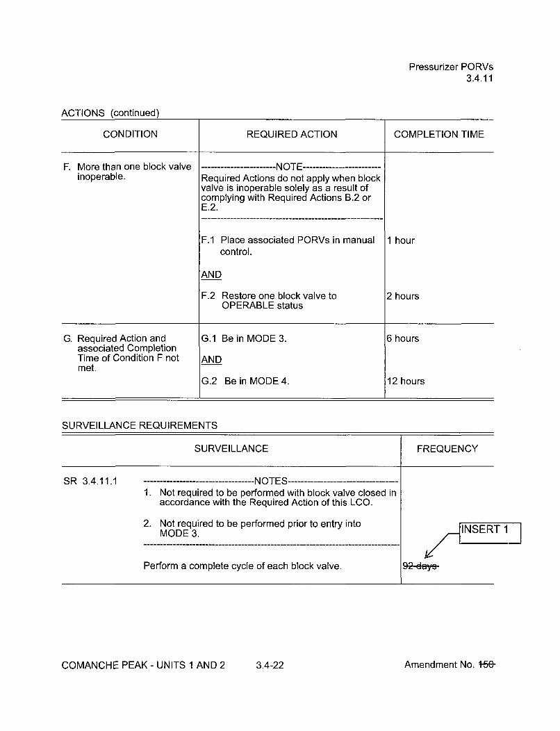
Pressurizer PORVs3.4.11
ACTIONS (continued)
CONDITION REQUIRED ACTION COMPLETION TIME
F. More than one block valve ------- NOTE ------------------------inoperable. Required Actions do not apply when block
valve is inoperable solely as a result ofcomplying with Required Actions B.2 orE.2.
F.1 Place associated PORVs in manual 1 hour
control.
AND
F.2 Restore one block valve to 2 hoursOPERABLE status
G. Required Action and G.1 Be in MODE 3. 6 hoursassociated CompletionTime of Condition F not ANDmet.
G.2 Be in MODE 4. 12 hours
SURVEILLANCE REQUIREMENTS
SURVEILLANCE FREQUENCY
SR 3.4.11.1 -NOTES.1. Not required to be performed with block valve closed in
accordance with the Required Action of this LCO.
2. Not required to be performed prior to entry intoMODE 3.
/I INSERT 192 ay
Perform a complete cycle of each block valve.
COMANCHE PEAK- UNITS 1 AND 2 3.4-22 Amendment No. 1-5&

Pressurizer PORVs3.4.11
SURVEILLANCE REQUIREMENTS (continued)
SURVEILLANCE FREQUENCY
SR 3.4.11.2 --------------------NOTE -------------------Not required to be performed prior to entry into MODE 3.
Perform a complete cycle of each PORV.
INSERT 1
COMANCHE PEAK - UNITS 1 AND 2 3.4-23 Amendment No. +SO--
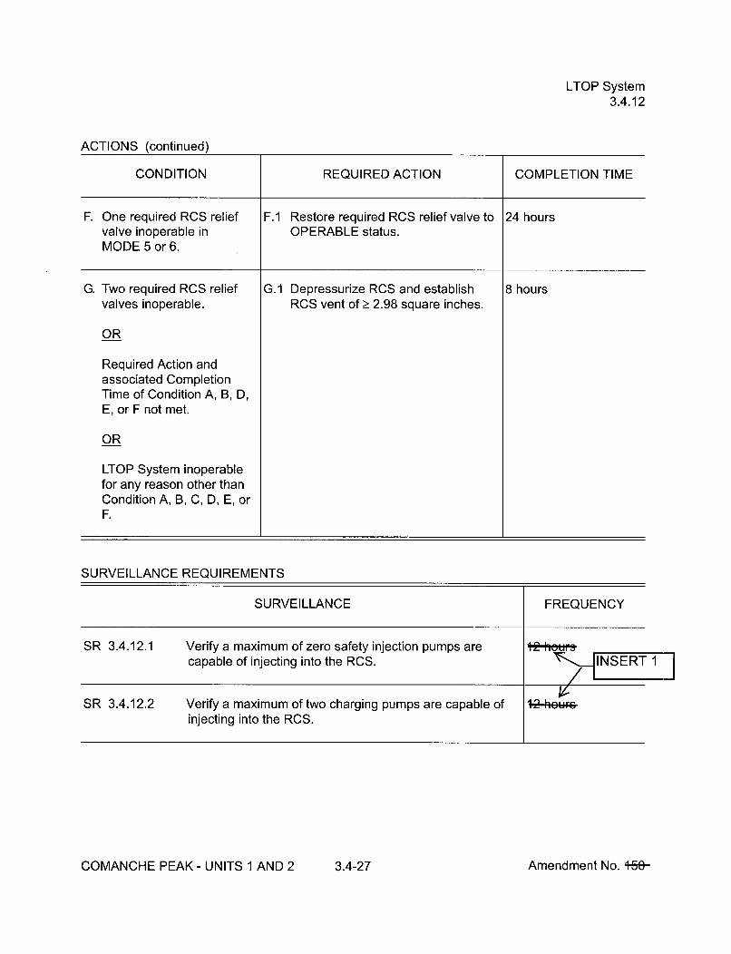
LTOP System3.4.12
ACTIONS (continued)
CONDITION REQUIRED ACTION COMPLETION TIME
F. One required RCS relief F.1 Restore required RCS relief valve to 24 hoursvalve inoperable in OPERABLE status.MODE 5 or 6.
G. Two required RCS relief G.1 Depressurize RCS and establish 8 hours
valves inoperable. RCS vent of _ 2.98 square inches.
OR
Required Action andassociated CompletionTime of Condition A, B, D,E, or F not met.
OR
LTOP System inoperablefor any reason other thanCondition A, B, C, D, E, orF.
SURVEILLANCE REQUIREMENTS
SURVEILLANCE FREQUENCY
SR 3.4.12.1 Verify a maximum of zero safety injection pumps arecapable of injecting into the RCS. 112jh t1f
SR 3.4.12.2 Verify a maximum of two charging pumps are capable of 1Q [email protected] into the RCS.
COMANCHE PEAK- UNITS 1 AND 2 3.4-27 Amendment No. +Se-

LTOP System3.4.12
SURVEILLANCE REQUIREMENTS (continued)
SURVEILLANCE FREQUENCY
SR 3.4.12.3 Verify each accumulator is isolated when accumulatorpressure is greater than or equal to the maximum RCSpressure for the existing RCS cold leg temperature allowedby the P/T limit curves provided in the PTLR.
12 hunisM -
SR 3.4.12.4 Verify RHR suction isolation valves are open for eachrequired RHR suction relief valve.
SR 3.4.12.5 Verify required RCS vent _> 2.98 square inches open.
SR 3.4.12.6 Verify PORV block valve is open for each required PORV.
SR 3.4.12.7 Not Used.
SR 3.4.12.8 - ------------------- NOTE -----------------Not required to be performed until 12 hours afterdecreasing any RCS cold leg temperature to < 350'F.
Perform a COT on each required PORV, excludingactuation.
SR 3.4.12.9 Perform CHANNEL CALIBRATION for each requiredPORV actuation channel.
COMANCHE PEAK - UNITS 1 AND 2 3.4-28 Amendment No. 169
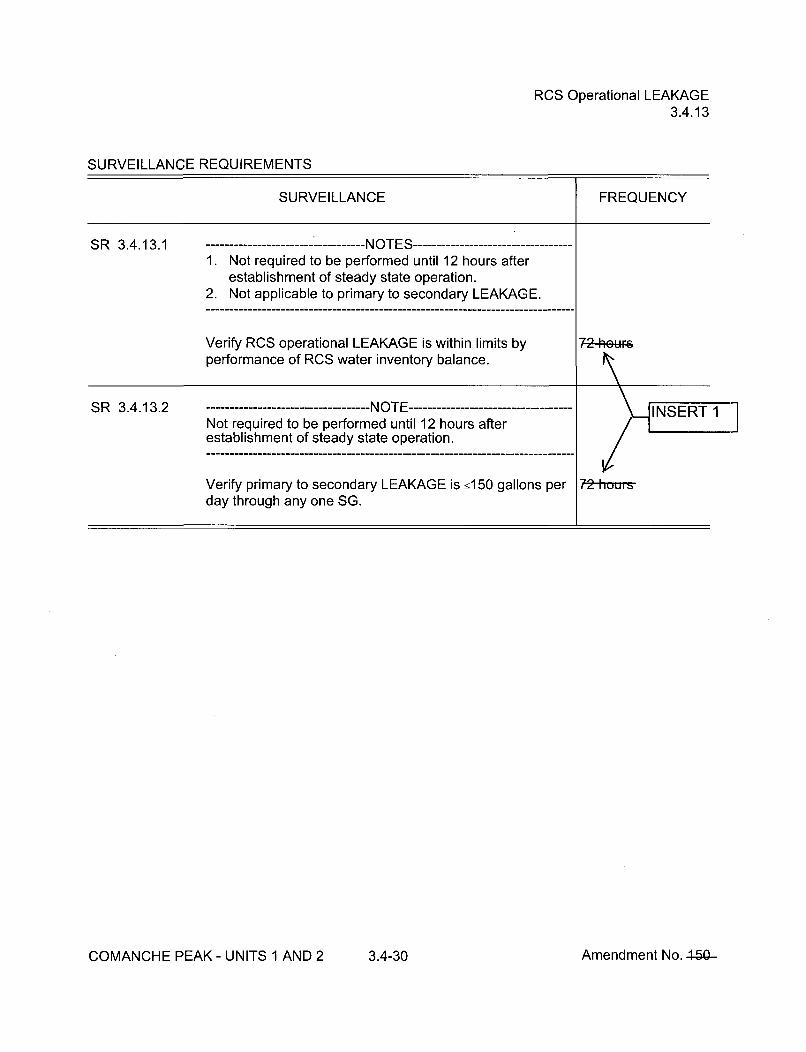
RCS Operational LEAKAGE3.4.13
SURVEILLANCE REQUIREMENTS
SURVEILLANCE FREQUENCY
SR 3.4.13.1 ------------ -------- NOTES -----------------1. Not required to be performed until 12 hours after
establishment of steady state operation.2. Not applicable to primary to secondary LEAKAGE.
Verify RCS operational LEAKAGE is within limits by 72-heu•performance of RCS water inventory balance.
SR 3.4.13.2 ---------------------- NOTE --------------------------- INSERTNot required to be performed until 12 hours afterestablishment of steady state operation.
Verify primary to secondary LEAKAGE is •150 gallons per 72 housday through any one SG.
COMANCHE PEAK - UNITS 1 AND 2 3.4-30 Amendment No. 150

RCS PIV Leakage3.4.14
SURVEILLANCE REQUIREMENTS
SURVEILLANCE FREQUENCY
SR 3.4.14.1 -------------- - NOTES -----------------1. Not required to be performed in MODES 3 and 4.
2. Not required to be performed on the RCS PIVs locatedin the RHR flow path when in the shutdown coolingmode of operation.
3. RCS PIVs actuated during the performance of thisSurveillance are not required to be tested more thanonce if a repetitive testing loop cannot be avoided.
Verify leakage from each RCS PIV is equivalent to< 0.5 gpm per nominal inch of valve size up to a maximumof 5 gpm at an RCS pressure > 2215 psig and < 2255 psig.
In accordance withthe InserviceTesting Program,and 18 -meioths
AND
Prior to enteringMODE 2 wheneverthe unit has been inMODE 5 for 7 daysor more, and ifleakage testing hasnot been performedin the previous9 months except forvalves 8701A,8701 B, 8702A and8702B
AND
Within 24 hoursfollowing checkvalve actuation dueto flow through thevalve
COMANCHE PEAK - UNITS 1 AND 2 3.4-33 Amendment No. 158

RCS PIV Leakage3.4.14
SURVEILLANCE REQUIREMENTS (continued)
SURVEILLANCE FREQUENCY
SR 3.4.14.2 Verify RHR System interlock prevents the valves from beingopened with a simulated or actual RCS pressure signal>_ 442 psig, except when the valves are open to satisfyLCO 3.4.12.
18 months
INSERT 1
COMANCHE PEAK - UNITS 1 AND 2 3.4-34 Amendment No. 4-[ý

RCS Leakage Detection Instrumentation3.4.15
SURVEILLANCE REQUIREMENTS
SURVEILLANCE FREQUENCY
i
S R 3.4.15.1 Perform CHANNEL CHECK of the required containmentatmosphere particulate and gaseous radioactivity monitors.
SR 3.4.15.2 Perform COT of the required containment atmosphereparticulate and gaseous radioactivity monitors.
SR 3.4.15.3 Perform CHANNEL CALIBRATION of the requiredContainment Sump Level and Flow Monitoring System.
SR 3.4.15.4 Perform CHANNEL CALIBRATION of the requiredcontainment atmosphere particulate and gaseousradioactivity monitors.
S R 3.4.15.5 Perform CHANNEL CALIBRATION of the requiredcontainment air cooler condensate flow rate monitor.
COMANCHE PEAK - UNITS 1 AND 2 3.4-38 Amendment No. 150
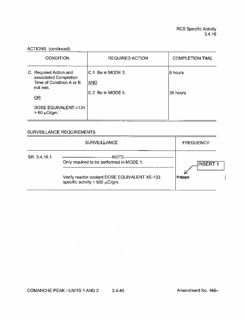
RCS Specific Activity3.4.16
ACTIONS (continued)
CONDITION REQUIRED ACTION COMPLETION TIME
C. Required Action and C.1 Be in MODE 3. 6 hoursassociated CompletionTime of Condition A or B ANDnot met.
C.2 Be in MODE 5. 36 hoursOR
DOSE EQUIVALENT 1-131> 60 pCi/gm.
SURVEILLANCE REQUIREMENTS
SURVEILLANCE FREQUENCY
SR 3.4.16.1 NOTE-Only required to be performed in MODE 1.
/d INSERT 1
:7 days-Verify reactor coolant DOSE EQUIVALENT XE-1 33specific activity < 500 pCi/gm.
COMANCHE PEAK - UNITS 1 AND 2 3.4-40 Amendment No. 4-60-

RCS Specific Activity3.4.16
SURVEILLANCE REQUIREMENTS (continued)
SURVEILLANCE FREQUENCY
SR 3.4.16.2 NOTE-Only required to be performed in MODE 1.
Verify reactor coolant DOSE EQUIVALENT 1-131 specificactivity < 0.45 pCi/gm.
/ I,.INSERT 1
"A-day&'
AND
Between 2 and6 hours after aTHERMAL POWERchange of Ž 15%RTP within a 1 hourperiod
SR 3.4.16.3 DELETED DELETED
COMANCHE PEAK- UNITS 1 AND 2 3.4-41 Amendment No. +5&

Accumulators3.5.1
SURVEILLANCE REQUIREMENTS
SURVEILLANCE FREQUENCY
SR 3.5.1.1 Verify each accumulator isolation valve is fully open. 424heurs-
SIR 3.5.1.2 Verify borated water volume in each accumulator is '2i-hus_ 6119 gallons and < 6597 gallons.
SR 3.5.1.3 Verify nitrogen cover pressure in each accumulator is t2-tTrs_ 623 psig and < 644 psig.
SR 3.5.1.4 Verify boron concentration in each accumulator is> 2300 ppm and < 2600 ppm. INSERT 1
AND
------NO E -----Only requir d to beperformed oraffectedaccumulat rs
Once wit in 6 hoursafter eac solutionvolume i crease of_ 101 ga Ions that isnot the r sult ofaddition rom therefuelin waterstorage tank
I
SR 3.5.1.5 Verify power is removed from each accumulator isolation 3 days-valve operator when RCS pressure is > 1000 psig.
COMANCHE PEAK- UNITS 1 AND 2 3.5-2 Amendment No. ý5ý

ECCS -- Operating3.5.2
ACTIONS (continued)
CONDITION REQUIRED ACTION COMPLETION TIME
B. One or more trains B.1 Restore train(s) to OPERABLE 72 hoursinoperable for reasons status.other than one inoperablecentrifugal charging pump.
AND
At least 100% of the ECCSflow equivalent to a singleOPERABLE ECCS trainavailable.
C. Required Action and C.1 Be in MODE 3. 6 hoursassociated CompletionTime not met. AND
C.2 Be in MODE 4. 12 hours
SURVEILLANCE REQUIREMENTS
SURVEILLANCE FREQUENCY
SR 3.5.2.1 Verify the following valves are in the listed position withpower to the valve operator removed.
124INSrTs
/__INSERT=Number8802 A&B8809 A&B8835884088068813
PositionClosedOpenOpenClosedOpenOpen
FunctionSI Pump to Hot LegsRHR to Cold LegsSI Pump to Cold LegsRHR to Hot LegsSI Pump Suction from RWSTSI Pump Miniflow Valve
COMANCHE PEAK- UNITS 1 AND 2 3.5-4 Amendment No. +5&-

ECCS -- Operating3.5.2
SURVEILLANCE REQUIREMENTS (continued)
SR 3.5,2.2 Verify each ECCS manual, power operated, and automaticvalve in the flow path, that is not locked, sealed, orotherwise secured in position, is in the correct position.
34-da
SR 3.5,2.3 Verify ECCS piping is full of water.
SR 3.5.2.4 Verify each ECCS pump's developed head at the test flowpoint is greater than or equal to the required developedhead.
SR 3.5,2.5 Verify each ECCS automatic valve in the flow path that isnot locked, sealed, or otherwise secured in position,actuates to the correct position on an actual or simulatedactuation signal.
SR 3.5.2.6 Verify each ECCS pump starts automatically on an actualor simulated actuation signal.
SR 3.5.2.7 Verify, for each ECCS throttle valve listed below, eachmechanical position stop is in the correct position.
Valve Number8810A 8816A 8822A8810B 8816B 8822B8810C 8816C 8822C8810D 8816D 8822D
Prior to ntry intoMODE
In accorthe InseTesting
ance withiceogram
t-
SR 3.5.2.8 Verify, by visual inspection, each ECCS train containmentsump suction inlet is not restricted by debris and the suctioninlet strainers show no evidence of structural distress orabnormal corrosion.
COMANCHE PEAK - UNITS 1 AND 2 3.5-5 Amendment No. +5&-

RWST3.5.4
SURVEILLANCE REQUIREMENTS
SURVEILLANCE FREQUENCY
SR 3.5,4.1 ------------------------- NOTE -------------------Only required to be performed when ambient airtemperature is < 40°F or > 1200 F.
Verify RWST borated water temperature is > 40°F and 2"4tttoufs< 1200 F.
SR 3.5,4.2 Verify RWST borated water volume is _> 473,731 gallons. tdavs=INSERT 1
SR 3.5,4.3 Verify RWST boron concentration is > 2400 ppm and 7-days< 2600 ppm.
COMANCHE PEAK - UNITS 1 AND 2 3.5-9 Amendment No. 450-

Seal Injection Flow3.5.5
3.5 EMERGENCY CORE COOLING SYSTEMS (ECCS)
3.5.5 Seal Injection Flow
LCO 3.5.5
APPLICABILITY:
Reactor coolant pump seal injection flow shall be:< 40 gpm with RCS pressureŽ> 2215 psig and _< 2255 psig and the charging flow control valve full open.
MODES 1, 2, and 3
ACTIONS
CONDITION REQUIRED ACTION COMPLETION TIME
A. Seal injection flow not A.1 Adjust manual seal injection throttle 4 hourswithin limit, valves to give a flow within limit with
RCS pressure > 2215 psig and< 2255 psig and the charging flowcontrol valve full open.
B. Required Action and B.1 Be in MODE 3. 6 hoursassociated CompletionTime not met. AND
B.2 Be in MODE 4. 12 hours
SURVEILLANCE REQUIREMENTS
SURVEILLANCE FREQUENCY
SR 3.5.5.1 --------------------- NOTE -----------------------------------Not required to be performed until 4 hours after the ReactorCoolant System pressure stabilizes at Ž_ 2215 psig and< 2255 psig.
Verify manual seal injection throttle valves are adjusted togive a flow within limit with RCS pressure > 2215 psig and< 2255 psig and the charging flow control valve full open.
/ INSERT 1
S ..days-
COMANCHE PEAK- UNITS 1 AND 2 3.5-10 Amendment No. +5+

Containment Air Locks3.6.2
SURVEILLANCE REQUIREMENTS
SURVEILLANCE FREQUENCY
SR 3.6.2.1 -------------------- NOTES ----------------1. An inoperable air lock door does not invalidate the
previous successful performance of the overall air lockleakage test.
2. Results shall be evaluated against acceptance criteriaapplicable to SR 3.6.1.1.
Perform required air lock leakage rate testing inaccordance with the Containment Leakage Rate TestingProgram.
In accordance withthe ContainmentLeakage RateTesting Program
SR 3.6.2.2 Verify only one door in the air lock can be opened at a time. 24-munths
\_INSERT1
COMANCHE PEAK - UNITS 1 AND 2 3.6-6 Amendment No. t5fJr

Containment Isolation Valves3.6.3
SURVEILLANCE REQUIREMENTS
SURVEILLANCE FREQUENCY
+
SR 3.6.3.1 Verify each 48 inch Containment Purge and 12 inchHydrogen Purge valve is sealed closed, except for onepurge valve in a penetration flow path while in Condition Dof this LCO.
SR 3.6.3.2 Not used.
SR 3.6.3.3 -------------------NOTES -----------------Valves and blind flanges in high radiation areas may beverified by use of administrative controls.
Verify each containment isolation manual valve and blindflange that is located outside containment and not locked,sealed, or otherwise secured and required to be closedduring accident conditions is closed, except forcontainment isolation valves that are open underadministrative controls.
31 days
SR 3.6.3.4 k i T'• -'- '-,-[-- - - -- - - - - - -- - - - - '~j " I•ltJ
I
r-."l ---------------------------------
1. Valves and blind flanges in high radiation areas may beverified by use of administrative means.
2. The blind flange on the fuel transfer canal need not beverified closed except after each drainage of the canal.
Verify each containment isolation manual valve and blindflange that is located inside containment and not locked,sealed, or otherwise secured and required to be closedduring accident conditions is closed, except forcontainment isolation valves that are open underadministrative controls.
Prior to enteringMODE 4 fromMODE 5 if notperformed within theprevious 92 days
COMANCHE PEAK - UNITS 1 AND 2 3.6-12 Amendment No. +5&
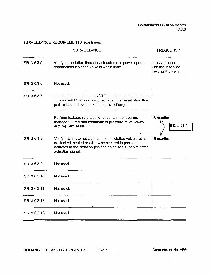
Containment Isolation Valves3.6.3
SURVEILLANCE REQUIREMENTS (continued)
SURVEILLANCE FREQUENCY
SR 3.6.3.5 Verify the isolation time of each automatic power operated In accordancecontainment isolation valve is within limits, with the Inservice
Testing Program
SR 3.6.3.6 Not used.
SR 3.6.3.7 -------------------- NOTE ------------------------------------This surveillance is not required when the penetration flowpath is isolated by a leak tested blank flange.
Perform leakage rate testing for containment purge,hydrogen purge and containment pressure relief valveswith resilient seals.
1-8-OlERTbsiNSERT 1
SR 3.6.3.8 Verify each automatic containment isolation valve that is 18 mu,,i'rsnot locked, sealed or otherwise secured in position,actuates to the isolation position on an actual or simulatedactuation signal.
SR 3.6.3.9 Not used.
SR 3.6.3.10 Not used.
SR 3.6.3.11 Not used.
SR 3.6.3.12 Not used.
SR 3.6.3.13 Not used.
COMANCHE PEAK- UNITS 1 AND 2 3.6-13 Amendment No. +50-
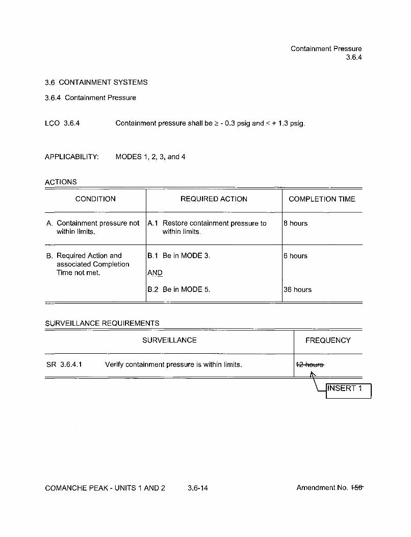
Containment Pressure3.6.4
3.6 CONTAINMENT SYSTEMS
3.6.4 Containment Pressure
LCO 3.6.4 Containment pressure shall be > - 0.3 psig and < + 1.3 psig.
APPLICABILITY:
ACTIONS
MODES 1, 2, 3, and 4
CONDITION REQUIRED ACTION COMPLETION TIME
A. Containment pressure not A.1 Restore containment pressure to 8 hourswithin limits, within limits.
B. Required Action and B.1 Be in MODE 3. 6 hoursassociated CompletionTime not met. AND
B.2 Be in MODE 5. 36 hours
SURVEILLANCE REQUIREMENTS
SURVEILLANCE FREQUENCY
SR 3.6.4.1 Verify containment pressure is within limits. 12 19'..'r,
COMANCHE PEAK - UNITS 1 AND 2 3.6-14 Amendment No. 4-5&

Containment Air Temperature3.6.5
3.6 CONTAINMENT SYSTEMS
3.6.5 Containment Air Temperature
LCO 3.6.5 Containment average air temperature shall be < 120'F.
APPLICABILITY:
ACTIONS
MODES 1, 2, 3, and 4
CONDITION REQUIRED ACTION COMPLETION TIME
A. Containment average air A.1 Restore containment average air 8 hourstemperature not within limit, temperature to within limit.
B. Required Action and B.1 Be in MODE 3. 6 hoursassociated CompletionTime not met. AND
B.2 Be in MODE 5. 36 hours
SURVEILLANCE REQUIREMENTS
SURVEILLANCE FREQUENCY
SR 3.6.5.1 Verify containment average air temperature is within limit. 24-hedF
INSERT I
COMANCHE PEAK - UNITS 1 AND 2 3.6-15 Amendment No. t5-Or-

Containment Spray System3.6.6
3.6 CONTAINMENT SYSTEMS
3.6.6 Containment Spray System
LCO 3.6.6 Two containment spray trains shall be OPERABLE.
APPLICABILITY: MODES 1, 2, 3, and 4
ACTIONS
CONDITION REQUIRED ACTION COMPLETION TIME
A. One containment spray A.1 Restore containment spray train to 72 hourstrain inoperable. OPERABLE status.
B. Required Action and B.1 Be in MODE 3. 6 hoursassociated CompletionTime of Condition A not ANDmet.
B.2 Be in MODE 5. 84 hours
C. Two containment spray C.1 Enter LCO 3.0.3. Immediatelytrains inoperable.
SURVEILLANCE REQUIREMENTS
SURVEILLANCE FREQUENCY
SR 3.6.6.1 Verify each containment spray manual, power operated,and automatic valve in the flow path that is not locked,sealed, or otherwise secured in position is in the correctposition.
INSERT 1
COMANCHE PEAK- UNITS 1 AND 2 3.6-16 Amendment No. 460-

Containment Spray System3.6.6
SURVEILLANCE REQUIREMENTS (continued)
SURVEILLANCE FREQUENCY
SR 3.6.6.2 Not used.
SR 3.6.6.3 Not used.
SR 3.6.6.4 Verify each containment spray pump's developed head at In accordance withthe flow test point is greater than or equal to the required the Inservicedeveloped head. Testing Program
SR 3.6.6.5 Verify each automatic containment spray valve in the flow 14-moatbspath that is not locked, sealed, or otherwise secured inposition, actuates to the correct position on an actual orsimulated actuation signal.
SR 3.6.6.6 Verify each containment spray pump starts automaticallyon an actual or simulated actuation signal.
SR 3.6.6.7 Not used.
SR 3.6.6.8 Verify each spray nozzle is unobstructed. Followingmaintenance whichcould result innozzle blockage
COMANCHE PEAK - UNITS 1 AND 2 3.6-17 Amendment No. 4-S&

MSIVs3.7.2
SURVEILLANCE REQUIREMENTS
SURVEILLANCE FREQUENCY
SR 3.7.2.1 ---------------------- NOTE ------------------Only required to be performed in MODES 1 and 2.
Verify the isolation time of each MSIV is < 5 seconds. In accordance withthe InserviceTesting Program
SR 3.7.2.2 ----------------------- NOTE -------------------Only required to be performed in MODES 1 and 2.
Verify each MSIV actuates to the isolation position on an 1It-nietactual or simulated actuation signal.
INSERT 1
COMANCHE PEAK- UNITS 1 AND 2 3.7-7 Amendment No. +%-

FIVs and FCVs and Associated Bypass Valves3.7.3
ACTIONS (continued)
CONDITION REQUIRED ACTION COMPLETION TIME
C. One or more FIV or FCV C.1 Close or isolate bypass valve. 72 hoursbypass valves inoperable.
AND
C.2 Verify bypass valve is closed or Once per 7 daysisolated.
D. Two valves in the same D.1 Isolate affected flow path. 8 hoursflowpath inoperable
E. Required Action and E.1 Be in MODE 3. 6 hoursassociated CompletionTime not met. AND
E.2 Be in MODE 4. 12 hours
SURVEILLANCE REQUIREMENTS
SURVEILLANCE FREQUENCY
SR 3.7.3.1 Verify the isolation time of each FIV, FCV, and associated In accordance withbypass valves is < 5 seconds. the Inservice
Testing Program
SR 3.7.3.2 Verify each FIV, FCV, and associated bypass valvesactuates to the isolation position on an actual or simulatedactuation signal.
1-8-memthINSERT 1
COMANCHE PEAK- UNITS 1 AND 2 3.7-9 Amendment No. +69-
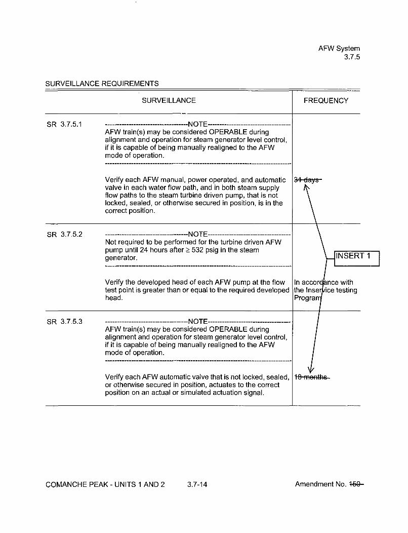
AFW System3.7.5
SURVEILLANCE REQUIREMENTS
SURVEILLANCE FREQUENCY
i
SR 3.7.5.1 --------------------- NOTE -------------------AFW train(s) may be considered OPERABLE duringalignment and operation for steam generator level control,if it is capable of being manually realigned to the AFWmode of operation.
Verify each AFW manual, power operated, and automaticvalve in each water flow path, and in both steam supplyflow paths to the steam turbine driven pump, that is notlocked, sealed, or otherwise secured in position, is in thecorrect position.
al-days-A\.
SR 3.7.5.2Not required to be performed for the turbine driven AFWpump until 24 hours after > 532 psig in the steamgenerator.
Verify the developed head of each AFW pump at the flow In accordpance withtest point is greater than or equal to the required developed the Inserpice testinghead. Progra
SR 3.7.5.3 ----------------------- NOTE ------------------AFW train(s) may be considered OPERABLE duringalignment and operation for steam generator level control,if it is capable of being manually realigned to the AFWmode of operation.
Verify each AFW automatic valve that is not locked, sealed, 1-8-fmfefft4h-or otherwise secured in position, actuates to the correctposition on an actual or simulated actuation signal.
COMANCHE PEAK- UNITS 1 AND 2 3.7-14 Amendment No. 4-ý

AFW System3.7.5
SURVEILLANCE REQUIREMENTS (continued)
SR 3.7.5.4 - ----------------------NOTES -----------------1. Not required to be performed for the turbine driven AFW
pump until 24 hours after > 532 psig in the steamgenerator.
2. AFW train(s) may be considered OPERABLE duringalignment and operation for steam generator levelcontrol, if it is capable of being manually realigned tothe AFW operation.
Verify each AFW pump starts automatically on an actual orsimulated actuation signal.
COMANCHE PEAK - UNITS 1 AND 2 3.7-15 Amendment No. 4-6ý

CST3.7.6
3.7 PLANT SYSTEMS
3.7.6 Condensate Storage Tank (CST)
LCO 3.7.6
APPLICABILITY:
The CST level shall be _> 53%.
MODES 1, 2, and 3
ACTIONS
CONDITION REQUIRED ACTION COMPLETION TIME
A. CST level not within limit. A.1 Verify by administrative means 4 hoursOPERABILITY of backup watersupply. AND
Once per 12 hoursthereafter
AND
A.2 Restore CST level to within limit. 7 days
B. Required Action and B.1 Be in MODE 3. 6 hoursassociated CompletionTime not met. AND
B.2 Be in MODE 4 12 hours
SURVEILLANCE REQUIREMENTS
SURVEILLANCE FREQUENCY
SR 3.7.6.1 Verify the CST level is > 53%. 2 hQ'-rs
INSERT1
COMANCHE PEAK - UNITS 1 AND 2 3.7-16 Amendment No. 4-Fý

CCW System3.7.7
SURVEILLANCE REQUIREMENTS
SURVEILLANCE FREQUENCY
i
SR 3.7.7.1 -NOTE -----------------------------------Isolation of CCW flow to individual components does notrender the CCW System inoperable.
Verify each CCW manual, power operated, and automaticvalve in the flow path servicing safety related equipment,that is not locked, sealed, or otherwise secured in position,is in the correct position.
SR 3.7.7.2 Verify each CCW automatic valve in the flow path that isnot locked, sealed, or otherwise secured in position,actuates to the correct position on an actual or simulatedactuation signal.
ý148
SR 3.7.7.3 Verify each CCW pump starts automatically on an actual orsimulated actuation signal.
+8-weffth6
COMANCHE PEAK - UNITS 1 AND 2 3.7-18 Amendment No. 4-6ý
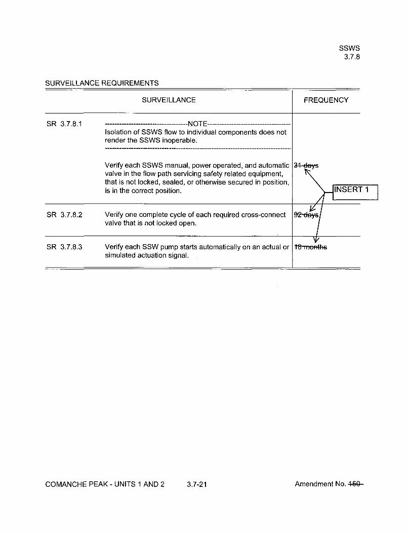
SSWS3.7.8
SURVEILLANCE REQUIREMENTS
SURVEILLANCE FREQUENCY
SR 3.7.8.1 -NO T E -----------------------------------Isolation of SSWS flow to individual components does notrender the SSWS inoperable.
Verify each SSWS manual, power operated, and automaticvalve in the flow path servicing safety related equipment,that is not locked, sealed, or otherwise secured in position,is in the correct position.
SR 3.7.8.2 Verify one complete cycle of each required cross-connectvalve that is not locked open.
\1/~hSR 3.7.8.3 Verify each SSW pump starts automatically on an actual orsimulated actuation signal.
COMANCHE PEAK- UNITS 1 AND 2 3.7-21 Amendment No. 469-

UHS3.7.9
3.7 PLANT SYSTEMS
3.7.9 Ultimate Heat Sink (UHS)
LCO 3.7.9
APPLICABILITY:
The Safe Shutdown Impoundment (SSI) shall be OPERABLE.
MODES 1, 2, 3, and 4
ACTIONS
CONDITION REQUIRED ACTION COMPLETION TIME
A. SSI level less than A.1 Restore SSI level to within limits. 7 daysrequired.
B. Required Action and B.1 Be in MODE 3. 6 hoursassociated CompletionTime of Condition A not ANDmet.
B.2 Be in MODE 5. 36 hoursOR
SSI inoperable for reasonsother than Condition A.
SURVEILLANCE REQUIREMENTS
COMANCHE PEAK - UNITS 1 AND 2 3.7-22 Amendment No. J-1%9-

CREFS3.7.10
SURVEILLANCE REQUIREMENTS
SURVEILLANCE FREQUENCY
SR 3.7.10.1 Operate each CREFS trains Emergency PressurizationUnit for _> 10 continuous hours with the heaters operatingand Emergency Filtration Unit >_ 15 minutes.
SR 3.7.10.2 Perform required CREFS testing in accordance with theVentilation Filter Testing Program (VFTP).
SR 3.7.10.3 Verifv each CREFS train actuates on an actual or simulatedactuation signal.
SR 3.7.10.4 Perform required CRE unfiltered air inleakage testing in In accordance withaccordance with the Control Room Envelope Habitability the Control RoomProgram. Envelope
Habitability Program
COMANCHE PEAK - UNITS 1 AND 2 3.7-25 Amendment No. 4,&&

CRACS3.7.11
SURVEILLANCE REQUIREMENTS
SURVEILLANCE FREQUENCY
SR 3.7.11.1 Verify each CRACS train has the capability to remove theassumed heat load.
18 ... antl is
COMANCHE PEAK - UNITS 1 AND 2 3.7-28 Amendment No. 1-%

PPVS - ESF Filtration Trains3.7.12
SURVEILLANCE REQUIREMENTS
SURVEILLANCE FREQUENCY
4-
SR 3.7.12.1 Operate each ESF Filtration train for Ž> 10 continuous hourswith the heaters operating.
SR 3.7.12.2 Perform required ESF Filtration Unit filter testing inaccordance with the Ventilation Filter Testing Program(VFTP).
SR 3.7.12.3 Verify each PPVS train actuates on an actual or simulatedactuation signal.
SR 3.7.12.4 Verify one PPVS train can maintain a pressure< -0.05 inches water gauge relative to atmosphericpressure during the post accident mode of operation.
SR 3.7.12.5 Not used.
ance with
SR 3.7.12.6 Verify each PPVS non-ESF fan stops on an actual orsimulated actuation signal.
I
COMANCHE PEAK - UNITS 1 AND 2 3.7-30 Amendment No. 175-0-

Fuel Storage Area Water Level3.7.15
3.7 PLANT SYSTEMS
3.7.15 Fuel Storage Area Water Level
LCO 3.7.15 The fuel storage area water level shall be _> 23 ft over the top of the storageracks
APPLICABILITY:
ACTIONS
During movement of irradiated fuel assemblies in a spent fuel storage area.
CONDITION REQUIRED ACTION COMPLETION TIME
A. Fuel storage area water A.1 ---------- NOTE ---------level not within limit. LCO 3.0.3 is not applicable.
Suspend movement of irradiated fuel Immediatelyassemblies in the fuel storage area.
SURVEILLANCE REQUIREMENTS
SURVEILLANCE FREQUENCY
SR 3.7.15.1 Verify the fuel storage area water level is _> 23 ft above thetop of the storage racks.
7-Tey
COMANCHE PEAK - UNITS 1 AND 2 3.7-33 Amendment No. t-lvft

Fuel Storage Pool Boron Concentration3.7.16
3.7 PLANT SYSTEMS
3.7.16 Fuel Storage Pool Boron Concentration
LCO 3.7.16
APPLICABILITY:
The fuel storage pool boron concentration shall be > 2000 ppm.
When fuel assemblies are stored in the fuel storage pool.
ACTIONS
CONDITION REQUIRED ACTION COMPLETION TIME
A. Fuel storage pool boron --------------- NOTE -----------concentration not within LCO 3.0.3 is not applicable.limit. -----------------
A.1 Suspend movement of fuel Immediatelyassemblies in the fuel storage pool
AND
A.2 Initiate action to restore fuel storage Immediatelypool boron concentration to withinlimit.
SURVEILLANCE REQUIREMENTS
SURVEILLANCE FREQUENCY
SR 3.7.16.1 Verify the fuel storage pool boron concentration is withinlimit. '-6rýNýSERT ý1
COMANCHE PEAK - UNITS 1 AND 2 3.7-34 Amendment No. 449-

Secondary Specific Activity3.7.18
3.7 PLANT SYSTEMS
3.7.18 Secondary Specific Activity
LCO 3.7.18
APPLICABILITY:
The specific activity of the secondary coolant shall be <! 0. 10 IJCi/gm DOSEEQUIVALENT 1-131
MODES 1, 2, 3, and 4
ACTIONS
CONDITION REQUIRED ACTION COMPLETION TIME
A. Specific activity not within A.1 Be in MODE 3. 6 hourslimit.
AND
A.2 Be in MODE 5. 36 hours
SURVEILLANCE REQUIREMENTS
SURVEILLANCE FREQUENCY
SR 3.7.18.1 Verify the specific activity of the secondary coolant is• 0.10 pCi/gm DOSE EQUIVALENT 1-131.
31 lays
COMANCHE PEAK - UNITS 1 AND 2 3.7-41 Amendment No. T5&

Safety Chilled Water3.7.19
SURVEILLANCE REQUIREMENTS
SURVEILLANCE FREQUENCY
SR 3.7.19.1 |
Isolation of safety chilled water flow to individualcomponents does not render the safety chilled watersystem inoperable.
Verify each safety chilled water manual, power operated,and automatic valve servicing safety related equipment,that is not locked, sealed, or otherwise secured in position,is in the correct position. INSERT I
SR 3.7.19.2 Verify each safety chilled water pump and chiller starts on 1ro&A#;gan actual or simulated actuation signal.
COMANCHE PEAK - UNITS 1 AND 2 3.7-43 Amendment No. VGG-

UPS HVAC System3.7.20
SURVEILLANCE REQUIREMENTS
SURVEILLANCE FREQUENCY
SR 3.7.20.1 Verify each required UPS & Distribution Room Fan CoilUnit operates _> 1 continuous hour.
SR 3.7.20.2 Verify each required UPS A/C train operates for _> 1continuous hour.
SR 3.7.20.3 Verify each required UPS A/C train actuates on an actual orsimulated actuation signal.
tB-monfth
COMANCHE PEAK - UNITS 1 AND 2 3.7-46 Amendment No. 160
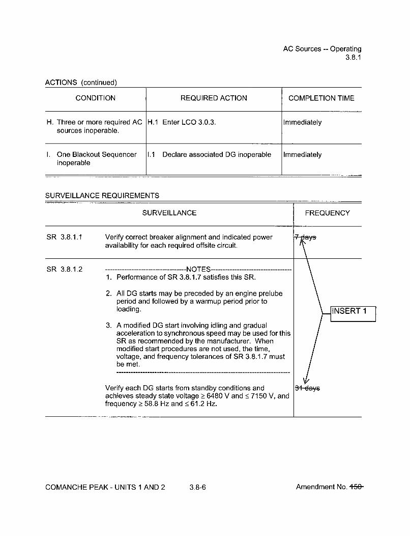
AC Sources -- Operating3.8.1
ACTIONS (continued)
CONDITION REQUIRED ACTION COMPLETION TIME
H. Three or more required AC H.1 Enter LCO 3.0.3. Immediatelysources inoperable.
I. One Blackout Sequencer 1.1 Declare associated DG inoperable Immediatelyinoperable
SURVEILLANCE REQUIREMENTS
SURVEILLANCE FREQUENCY
SR 3.8.1.1 Verify correct breaker alignment and indicated poweravailability for each required offsite circuit.
SR 3.8.1.2 -------------------- NOTES ---------1. Performance of SR 3.8.1.7 satisfies this SR.
2. All DG starts may be preceded by an engine prelubeperiod and followed by a warmup period prior toloading.
3. A modified DG start involving idling and gradualacceleration to synchronous speed may be used for thisSR as recommended by the manufacturer. Whenmodified start procedures are not used, the time,voltage, and frequency tolerances of SR 3.8.1.7 mustbe met.
Verify each DG starts from standby conditions andachieves steady state voltage Ž 6480 V and < 7150 V, andfrequency _> 58.8 Hz and < 61.2 Hz.
COMANCHE PEAK - UNITS 1 AND 2 3.8-6 Amendment No. +58-

AC Sources -- Operating3.8.1
SURVEILLANCE REQUIREMENTS (continued)
SURVEILLANCE FREQUENCY
SR 3.8.1.3 ------------------NOTES -----------------1. DG loadings may include gradual loading as
recommended by the manufacturer.
2. Momentary transients outside the load range do notinvalidate this test.
3. This Surveillance shall be conducted on only one DG ata time.
4. This SR shall be preceded by and immediately followwithout shutdown a successful performance ofSR 3.8.1.2 or SR 3.8.1.7.
-------------------------------------------------------------------------------
Verify each DG is synchronized and loaded and operatesfor _> 60 minutes at a load Ž_ 6300 kW and _< 7000 kW.
SR 3.8.1.4 Verify each day tank contains > 1440 gal of fuel oil.
SR 3.8.1.5 Check for and remove accumulated water from each daytank.
SR 3.8.1.6 Verify the fuel oil transfer system operates to automaticallytransfer fuel oil from storage tank to the day tank.
Jfr
COMANCHE PEAK - UNITS 1 AND 2 3.8-7 Amendment No. +56-

AC Sources -- Operating3.8.1
SURVEILLANCE REQUIREMENTS (continued)
SURVEILLANCE FREQUENCY
SR 3.8.1.7 --- •-------------------- IJ r ------------------------------------
All DG starts may be preceded by an engine prelubeperiod.
Verify each DG starts from standby condition and achieves:
a. in < 10 seconds, voltage _> 6480 V and frequency> 58.8 Hz; and
b. steady state, voltage _Ž 6480 V and < 7150 V, andfrequency >_ 58.8 Hz and < 61.2 Hz.
~eye
SR 3.8.1.8 --------------------- NOTE ------------------This Surveillance shall not normally be performed inMODE 1 or 2. However, this Surveillance may beperformed to reestablish OPERABILITY provided anassessment determines the safety of the plant ismaintained or enhanced.
Verify automatic and manual transfer of AC power sourcesfrom the normal offsite circuit to each alternate requiredoffsite circuit.
1.8-A40te-
COMANCHE PEAK - UNITS 1 AND 2 3.8-8 Amendment No. 16&
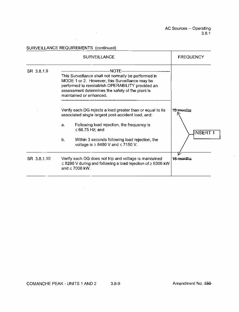
AC Sources -- Operating3.8.1
SURVEILLANCE REQUIREMENTS (continued)
SURVEILLANCE FREQUENCY
SR 3.8.1,9 -------------------NOTE ------------------This Surveillance shall not normally be performed inMODE 1 or 2. However, this Surveillance may beperformed to reestablish OPERABILITY provided anassessment determines the safety of the plant ismaintained or enhanced.
Verify each DG rejects a load greater than or equal to itsassociated single largest post-accident load, and:
a. Following load rejection, the frequency is< 66.75 Hz; and
b. Within 3 seconds following load rejection, thevoltage is > 6480 V and < 7150 V.
Aei~tb~
SR 3.8.1.10 Verify each DG does not trip and voltage is maintained< 8280 V during and following a load rejection ofŽ> 6300 kWand < 7000 kW.
COMANCHE PEAK - UNITS 1 AND 2 3.8-9 Amendment No. 4ý5&

AC Sources -- Operating3.8.1
SURVEILLANCE REQUIREMENTS (continued)
SURVEILLANCE FREQUENCY
SR 3.8.1.11 -----------------NOTES -----------------1. All DG starts may be preceded by an engine prelube
period.
2. This Surveillance shall not normally be performed inMODE 1 or 2. However, portions of the Surveillancemay be performed to reestablish OPERABILITYprovided an assessment determines the safety of theplant is maintained or enhanced.
Verify on an actual or simulated loss of offsite power signal:
a. De-energization of emergency buses;
b. Load shedding from emergency buses;
c. DG auto-starts from standby condition and:
1. energizes permanently connected loads in•!10 seconds,
2. energizes auto-connected shutdown loadsthrough automatic load sequencer,
3. maintains steady state voltage _Ž 6480 V and• 7150 V,
4. maintains steady state frequency > 58.8 Hzand < 61.2 Hz, and
5. supplies permanently connected andauto-connected shutdown loads for_> 5 minutes.
18-munths
% ýINSERT 1
COMANCHE PEAK - UNITS 1 AND 2 3.8-10 Amendment No. 460-

AC Sources -- Operating3.8.1
SURVEILLANCE REQUIREMENTS (continued)
SURVEILLANCE FREQUENCY
SR 3.8.1.12 ---------------------- NOTE ------------------All DG starts may be preceded by prelube period.
Verify on an actual or simulated Safety Injection (SI)actuation signal each DG auto-starts from standbycondition and;
a. in < 10 seconds after auto-start and during tests,achieves voltage >_ 6480 V and frequency>_ 58.8 Hz;
b. Achieves steady state voltage _> 6480 V and•7150 V and frequency > 58.8 Hz and •< 61.2 Hz; INSER
c. Operates for > 5 minutes.
SR 3.8.1.13 ---------------------- NOTE ------------------For Unit 2, testing need only be performed for LOOPconcurrent with SI until startup following 2RFO5.
Verify each DG's automatic trips are bypassed on actual orsimulated (i) loss of voltage signal on the emergency bus,and (ii) SI actuation signal, except:
a. Engine overspeed; and
b. Generator differential current.
COMANCHE PEAK - UNITS 1 AND 2 3.8-11 Amendment No. 44(ý-
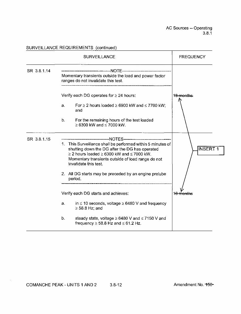
AC Sources -- Operating3.8.1
SURVEILLANCE REQUIREMENTS (continued)
SURVEILLANCE FREQUENCY
SR 3.8.1.14 -----------------NOTE ------------------Momentary transients outside the load and power factorranges do not invalidate this test.
Verify each DG operates for _ 24 hours:
a. For _> 2 hours loaded > 6900 kW and < 7700 kW;and
b. For the remaining hours of the test loaded_> 6300 kW and•< 7000 kW.
t8-meýA\.
SR 3.8.1.15 1.IfViT. r C--',--- - -- - - - -- - - - -- - - - !
t'- L'b
----------------------------------1. This Surveillance shall be performed within 5 minutes of
shutting down the DG after the DG has operated_> 2 hours loaded Ž_ 6300 kW and < 7000 kW.Momentary transients outside of load range do notinvalidate this test.
2. All DG starts may be preceded by an engine prelubeperiod.
Verify each DG starts and achieves:
a. in _< 10 seconds, voltage Ž> 6480 V and frequency_> 58.8 Hz; and
b. steady state, voltage Ž 6480 V and • 7150 V andfrequency > 58.8 Hz and < 61.2 Hz.
1~8-ffleI4he
COMANCHE PEAK - UNITS 1 AND 2 3.8-12 Amendment No. 15fý-

AC Sources -- Operating3.8.1
SURVEILLANCE REQUIREMENTS (continued)
SURVEILLANCE FREQUENCY
SR 3.8.1.16This Surveillance shall not normally be performed inMODE 1 or 2. However, this Surveillance may beperformed to reestablish OPERABILITY provided anassessment determines the safety of the plant ismaintained or enhanced.
Verify each DG:
a. Synchronizes with offsite power source whileloaded with emergency loads upon a simulatedrestoration of offsite power;
b. Transfers loads to offsite power source; and
c. Returns to ready-to-load operation.
IJ IIIJI ILI 1,ý
SR 3.8.1.17 --------------------- NOTE ------------------This Surveillance shall not normally be performed inMODE 1 or 2. However, portions of the Surveillance maybe performed to reestablish OPERABILITY provided anassessment determines the safety of the plant ismaintained or enhanced.------------------------------------------------------------------------------
Verify, with a DG operating in test mode and connected toits bus, an actual or simulated SI actuation signal overridesthe test mode by:
a. Returning DG to ready-to-load operation; and
b. Automatically energizing the emergency load fromoffsite power.
18 IflmhII
COMANCHE PEAK - UNITS 1 AND 2 3.8-13 Amendment No. 4-1ý

AC Sources -- Operating3.8.1
SURVEILLANCE REQUIREMENTS (continued)
SURVEILLANCE FREQUENCY
SR 3.8.1.18 --------------------- NOTE ------------------This Surveillance shall not normally be performed inMODE 1 or 2. However, this Surveillance may beperformed to reestablish OPERABILITY provided anassessment determines the safety of the plant ismaintained or enhanced.
Verify interval between each sequenced load block is within± 10% of design interval for each automatic loadsequencer.
t&rnunth~
COMANCHE PEAK - UNITS 1 AND 2 3.8-14 Amendment No. +S&
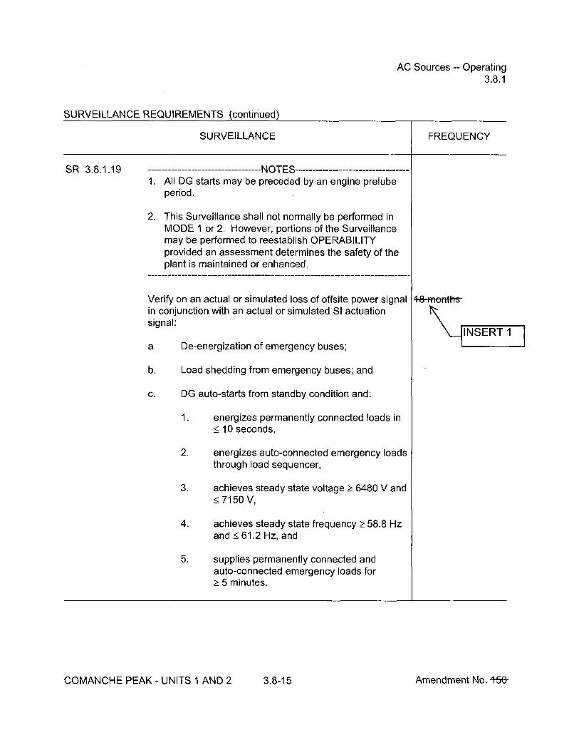
AC Sources -- Operating3.8.1
SURVEILLANCE REQUIREMENTS (continued)
SURVEILLANCE FREQUENCY
i
SR 3.8.1.19 --------------------NOTES -------------------1. All DG starts may be preceded by an engine prelube
period.
2. This Surveillance shall not normally be performed inMODE 1 or 2. However, portions of the Surveillancemay be performed to reestablish OPERABILITYprovided an assessment determines the safety of theplant is maintained or enhanced.
Verify on an actual or simulated loss of offsite power signalin conjunction with an actual or simulated SI actuationsignal:
a. De-energization of emergency buses;
b. Load shedding from emergency buses; and
c. DG auto-starts from standby condition and:
1. energizes permanently connected loads in< 10 seconds,
2. energizes auto-connected emergency loadsthrough load sequencer,
3. achieves steady state voltage _> 6480 V and< 7150 V,
4. achieves steady state frequency > 58.8 Hzand < 61.2 Hz, and
5. supplies permanently connected andauto-connected emergency loads for>_ 5 minutes.
"__INSERT 1
COMANCHE PEAK - UNITS 1 AND 2 3.8-15 Amendment No. +5&

AC Sources -- Operating3.8.1
SURVEILLANCE REQUIREMENTS (continued)
SURVEILLANCE FREQUENCY
SR 3.8.1.20 -NOTE.All DG starts may be preceded by an engine prelubeperiod.
Verify when started simultaneously from standby condition,each DG achieves:
a. in < 10 seconds, voltage > 6480 V and frequency_> 58.8 Hz, and
b. steady state, voltage > 6480 V, and •< 7150 V andfrequency 2! 58.8 Hz and < 61.2 Hz.
ag
Calibrate BO sequencers.SR 3.8.1.21
SR 3.8.1.22 ------------------NOTES -----------------1. Verification of setpoint is not required.
2. Actuation of final devices is not included.
Perform TADOT for SI and BO sequencers. attays-onaSTACCERED TEST
COMANCHE PEAK - UNITS 1 AND 2 3.8-16 Amendment No. t5t-

Diesel Fuel Oil, Lube Oil, and Starting Air3.8.3
SURVEILLANCE REQUIREMENTS
SURVEILLANCE FREQUENCY
SR 3.8.3.1 Verify each fuel oil storage tank contains _> a 7 day supply 31-dýof fuel.
SR 3.8.3.2 ----------------------- NOTE ------------------Not required to be performed until the engine has beenshutdown for > 10 hours.
Verify lubricating oil inventory is _> a 7 day supply a-ay
SR 3.8.3.3 Verify fuel oil properties of new and stored fuel oil are In ac r nce withtested in accordance with, and maintained within the limits the Di e Fuel Oilof, the Diesel Fuel Oil Testing Program. Testi•ngogram
SR 3.8.3.4 Verify each required DG air start receiver> 180 psig.
SR 3.8.3.5 Check for and remove accumulated water from each fuel oilstorage tank.
COMANCHE PEAK - UNITS 1 AND 2 3.8-22 Amendment No. 460-,45ý

DC Sources -- Operating3.8.4
ACTIONS (continued)
CONDITION REQUIRED ACTION COMPLETION TIME
D. Required Action and D.1 Be in MODE 3. 6 hoursAssociated CompletionTime not met. AND
D.2 Be in MODE 5. 36 hours
SURVEILLANCE REQUIREMENTS
SURVEILLANCE FREQUENCY
SR 3.8.4.1 Verify battery terminal voltage is greater than or equal tothe minimum established float voltage.
SR 3.8.4.2 Verify each battery charger supplies > 300 amps at greaterthan or equal to the minimum established charger testvoltage for _> 8 hours.
OR
Verify each battery charger can recharge the battery to thefully charged state within 24 hours while supplying thelargest combined demands of the various continuoussteady state loads, after a battery discharge to thebounding design basis event discharge state.
COMANCHE PEAK - UNITS 1 AND 2 3.8-24 Amendment No. 460-

DC Sources -- Operating3.8.4
SURVEILLANCE REQUIREMENTS (continued)
SURVEILLANCE FREQUENCY
i
SR 3.8.4.3 -------------------NOTES -----------------1. The modified performance discharge test in SR 3.8.6.6
may be performed in lieu of SR 3.8.4.3.
2. Verify requirement during MODES 3, 4, 5, 6 or with coreoff-loaded.
Verify battery capacity is adequate to supply, and maintainin OPERABLE status, the required emergency loads for thedesign duty cycle when subjected to a battery service test.
+8 months
INSERT 1I
COMANCHE PEAK - UNITS 1 AND 2 3.8-25 Amendment No. +-r,&

Battery Parameters3.8.6
SURVEILLANCE REQUIREMENTS (continued)
CONDITION REQUIRED ACTION COMPLETION TIME
F. Required Action and F.1 Declare associated battery(ies) Immediatelyassociated Completion inoperable.Time of Condition A, B, C,D, or E not met.
OR
One or two batteries on onetrain with one or morebattery cells float voltage< 2.07 V and float current> 2 amps.
SURVEILLANCE REQUIREMENTS
SURVEILLANCE FREQUENCY
SR 3.8.6.1 ----------------------- NOTE ------------------Not required to be met when battery terminal voltage is lessthan the minimum established float voltage of SR 3.8.4.1
Verify each battery float current is < 2 amps.
SR 3.8.6.2 Verify each battery pilot cell voltage is _> 2.07 V. 3+4aYrs IN 4R7T 1
SR 3.8.6.3 Verify each battery connected cell electrolyte level isgreater than or equal to minimum established design limits.
COMANCHE PEAK- UNITS 1 AND 2 3.8-31 Amendment No. +50-
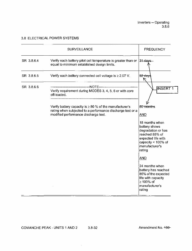
Inverters -- Operating3.8.6
3.8 ELECTRICAL POWER SYSTEMS
SURVEILLANCE FREQUENCY
SR 3.8.6.4 Verify each battery pilot cell temperature is greater than orequal to minimum established design limits.
SR 3.8.6.5 Verify each battery connected cell volta
SR 3.8.6.6 -NOTE -----------------------------------Verify requirement during MODES 3, 4, 5, 6 or with coreoff-loaded.-------------------------------------------------------------------------------
Verify battery capacity is > 80 % of the manufacturer'srating when subjected to a performance discharge test or amodified performance discharge test.
6f munt
AND
18 months whenbattery showsdegradation or hasreached 85% ofexpected life withcapacity < 100% ofmanufacturer'srating
AND
24 months whenbattery has reached85% of the expectedlife with capacityŽ 100% ofmanufacturer'srating
COMANCHE PEAK - UNITS 1 AND 2 3.8-32 Amendment No. +50-

Inverters -- Shutdown3.8.7
3.8 ELECTRICAL POWER SYSTEMS
CONDITION REQUIRED ACTION COMPLETION TIME
B. Required Action and B.1 Be in MODE 3. 6 hoursassociated CompletionTime not met. AND
B.2 Be in MODE 5. 36 hours
SURVEILLANCE REQUIREMENTS
SURVEILLANCE FREQUENCY
SR 3.8.7.1 Verify correct inverter voltage, and alignment to requiredAC vital buses.
COMANCHE PEAK - UNITS 1 AND 2 3.8-34 Amendment No. +50-

Distribution Systems -- Operating3.8.8
3.8 ELECTRICAL POWER SYSTEMS
SURVEILLANCE REQUIREMENTS
SURVEILLANCE FREQUENCY
L.
SR 3.8.8.1 Verify correct inverter voltage and alignments to requiredAC vital buses. INSERT 1__________________________________________________________ I _________________I
COMANCHE PEAK - UNITS 1 AND 2 3.8-36 Amendment No. +5&-
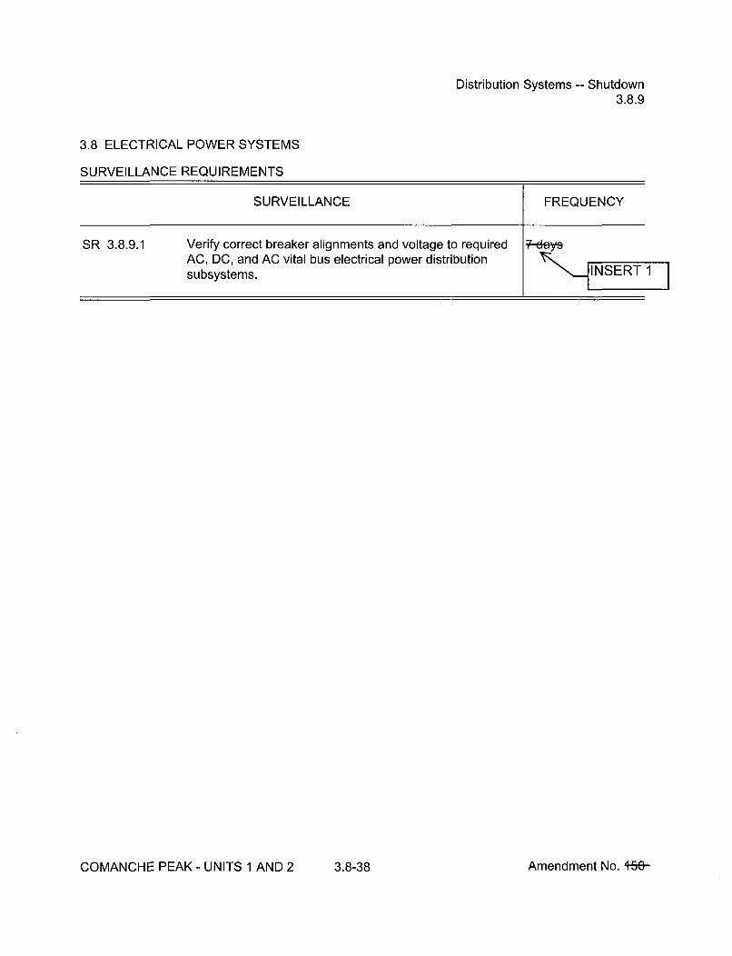
Distribution Systems -- Shutdown3.8.9
3.8 ELECTRICAL POWER SYSTEMS
SURVEILLANCE REQUIREMENTS
SURVEILLANCE FREQUENCY
SR 3.8.9.1 Verify correct breaker alignments and voltage to requiredAC, DC, and AC vital bus electrical power distributionsubsystems. INSERT 1
COMANCHE PEAK - UNITS 1 AND 2 3.8-38 Amendment No. +50-

Distribution Systems - Shutdown3.8.10
CONDITION REQUIRED ACTION COMPLETION TIME
A. (continued) A.2.4 Initiate actions to restore required ImmediatelyAC, DC, and AC vital bus electricalpower distribution subsystems toOPERABLE status.
AND
A.2.5 Declare associated required Immediatelyresidual heat removalsubsystem(s) inoperable and not inoperation.
SURVEILLANCE REQUIREMENTS
SURVEILLANCE FREQUENCY
SR 3.8.10.1 Verify correct breaker alignments and voltage to required 7-dys-AC, DC, and AC vital bus electrical power distribution =" 1subsystems. INSERT 1
COMANCHE PEAK - UNITS 1 AND 2 3.8-40 Amendment No. +5&
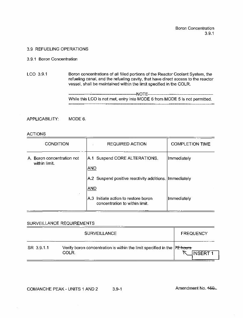
Boron Concentration3.9.1
3.9 REFUELING OPERATIONS
3.9.1 Boron Concentration
LCO 3.9.1 Boron concentrations of all filled portions of the Reactor Coolant System, therefueling canal, and the refueling cavity, that have direct access to the reactorvessel, shall be maintained within the limit specified in the COLR.
------------------------------ NOTE-----------------------While this LCO is not met, entry into MODE 6 from MODE 5 is not permitted.
APPLICABILITY: MODE 6.
ACTIONS
CONDITION REQUIRED ACTION COMPLETION TIME
A. Boron concentration not A.1 Suspend CORE ALTERATIONS. Immediatelywithin limit.
AND
A.2 Suspend positive reactivity additions. Immediately
AND
A.3 Initiate action to restore boron Immediatelyconcentration to within limit.
SURVEILLANCE REQUIREMENTS
SURVEILLANCE FREQUENCY
SR 3.9,1.1 Verify boron concentration is within the limit specified in the 72-hams-COLR. ,•I NSERT ý1
COMANCHE PEAK - UNITS 1 AND 2 3.9-1 Amendment No. 4-&ý

Unborated Water Source Isolation Valves3.9.2
SURVEILLANCE REQUIREMENTS
SURVEILLANCE FREQUENCY
SR 3.9.2.1 Verify each valve that isolates unborated water sources is 3t-days
secured in the closed position.
INSERT 1
COMANCHE PEAK - UNITS 1 AND 2 3.9-3 Amendment No. 440-

Nuclear Instrumentation3.9.3
SURVEILLANCE REQUIREMENTS
SURVEILLANCE FREQUENCY
SR 3.9.3.1 Perform CHANNEL CHECK. 12 hOwts
S R 3.9.3.2 -NO T E --------------------------------Neutron detectors are excluded from CHANNELCALIBRATION.
Perform CHANNEL CALIBRATION.
COMANCHE PEAK - UNITS 1 AND 2 3.9-5 Amendment No. +5Cý-

Containment Penetrations3.9.4
SURVEILLANCE REQUIREMENTS
SURVEILLANCE FREQUENCY
SR 3.9.4.1 Verify each required containment penetration is in the 7-days-required status.
SR 3.9.4.2 ---------------------- NOTE -----------------Only required for an open equipment hatch
7d~ys-Verify the capability to install the equipment hatch.
SR 3.9.4.3 Verify each required containment ventilation isolation t&-ntm'i-valve actuates to the isolation position on an actual orsimulated actuation signal.
COMANCHE PEAK - UNITS 1 AND 2 3.9-7 Amendment No. +ý
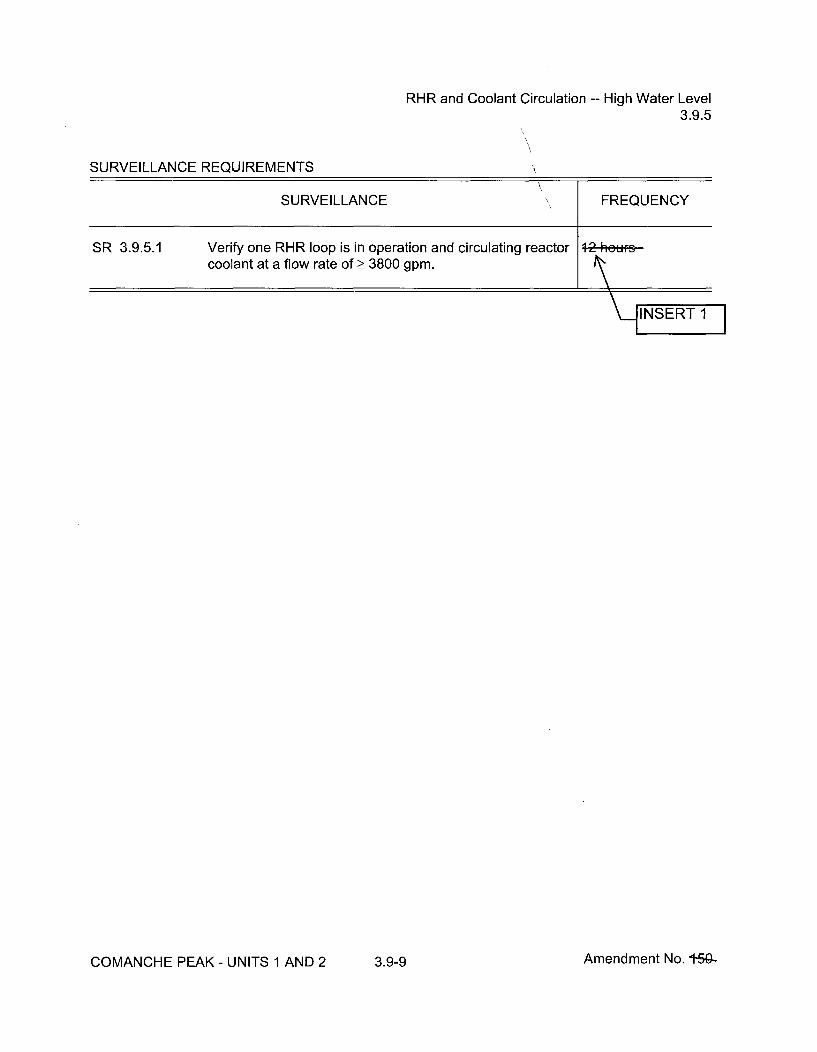
RHR and Coolant Circulation -- High Water Level3.9.5
SURVEILLANCE REQUIREMENTS
SURVEILLANCE FREQUENCY
SR 3.9.5.1 Verify one RHR loop is in operation and circulating reactor 12 houerscoolant at a flow rate of > 3800 gpm.
1ýINSERT11
COMANCHE PEAK - UNITS 1 AND 2 3.9-9 Amendment No. 1750-

RHR and Coolant Circulation -- Low Water Level3.9.6
ACTIONS (continued)
CONDITION REQUIRED ACTION COMPLETION TIME
B. No RHR loop in operation. B.1 Suspend operations that would Immediatelycause introduction of coolant into theRCS with boron concentration lessthan required to meet the boronconcentration of LCO 3.9.1.
AND
B.2 Initiate action to restore one RHR Immediatelyloop to operation.
AND
B.3 Close all containment penetrations 4 hoursproviding direct access fromcontainment atmosphere to outsideatmosphere.
SURVEILLANCE REQUIREMENTS
SURVEILLANCE FREQUENCY
SR 3.9.6.1 Verify one RHR loop is in operation and circulating reactorcoolant at a flow rate of > 1000 gpm. j- INSERT1
SR 3.9.6.2 Verify correct breaker alignment and indicated poweravailable to the required RHR pump that is not in operation.
f-d~ye-
COMANCHE PEAK - UNITS 1 AND 2 3.9-11 Amendment No. +SG-

Refueling Cavity Water Level3.9.7
3.9 REFUELING OPERATIONS
3.9.7 Refueling Cavity Water Level
LCO 3.9.7
APPLICABILITY:
Refueling cavity water level shall be maintained >! 23 ft above the top ofreactor vessel flange.
During movement of irradiated fuel assemblies within containment.
ACTIONS
CONDITION REQUIRED ACTION COMPLETION TIME
A. Refueling cavity water level A.1 Suspend movement of irradiated fuel Immediatelynot within limit, assemblies within containment.
SURVEILLANCE REQUIREMENTS
SURVEILLANCE FREQUENCY
SR 3.9.7.1 Verify refueling cavity water level is > 23 ft above the top of 24-hews-reactor vessel flange.
INERT I
COMANCHE PEAK- UNITS 1 AND 2 3.9-12 Amendment No. t56-

Programs and Manuals5.5
5.5 Programs and Manuals
5.5.20 Control Room Envelope Habitability Program (continued)
b. Requirements for maintaining the CRE boundary in its design conditionincluding configuration control and preventive maintenance.
c. Requirements for (i) determining the unfiltered air inleakage past the CREboundary into the CRE in accordance with the testing methods and at theFrequencies specified in Sections C.1 and C.2 of Regulatory Guide 1.197,"Demonstrating Control Room Envelope Integrity at Nuclear Power Reactors,"Revision 0, May 2003, and (ii) assessing CRE habitability at the Frequenciesspecified in Sections C.1 and C.2 of Regulatory Guide 1.197, Revision 0.
The following are exceptions to Sections C.1 and C.2 of RegulatoryGuide 1.197, Revision 0:
1. C. - Section 4.3.2 "Periodic CRH Assessment" from NEI 99-03Revision 1 will be used as input to a site specific Self Assessmentprocedure.
2. C.1.2 - No peer reviews are required to be performed.
d. Measurement, at designated locations, of the CRE pressure relative to allexternal areas adjacent to the CRE boundary during the pressurization modeof operation by one train of the CREFS, operating at the flow rate required bythe VFTP, at a Frequency of 18 months on a STAGGERED TEST BASIS.The results shall be trended and used as part of the 18 month assessment ofthe CRE boundary.
e. The quantitative limits on unfiltered air inleakage into the CRE. These limitsshall be stated in a manner to allow direct comparison to the unfiltered airinleakage measured by the testing described in paragraph c. The unfilteredair inleakage limit for radiological challenges is the inleakage flow rateassumed in the licensing basis analyses of DBA consequences. Unfiltered airinleakage limits for hazardous chemicals must ensure that exposure of CREoccupants to these hazards will be within the assumptions in the licensingbasis.
f. The provisions of SR 3.0.2 are applicable to the Frequencies for assessingCRE habitability, determining CRE unfiltered inleakage, and measuring CRE
JINSERT 2 Ipressure and assessing the CRE boundary as required by paragraphs c andd, respectively.
COMANCHE PEAK - UNITS 1 AND 2 5.5-16 Amendment No. 5

Attachment 4 to TXX-11093Page 1 of 13908/01/2011
ATTACHMENT 4 to TXX-11093
PROPOSED TECHNICAL SPECIFICATIONS BASES CHANGES(Mark-up For Information Only)
Pages BASES INSERT B 3.3-49 B 3.3-143 B 3.4-68 B 3.6-38 B 3.7-91 B 3.8-52
B 3.1-4 B 3.3-50 B 3.3-144 B 3.4-72 B 3.7-12 B 3.8-14 B 3.8-63
B 3.1-10 B 3.3-51 B 3.3-149 B 3.4-73 B 3.7-18 B 3.8-15 B 3.8-64
B 3.1-24 B 3.3-52 B 3.3-150 B 3.4-80 B 3.7-29 B 3.8-16 B 3.8-65
B 3.1-29 B 3.3-53 B 3.4-5 B 3.4-85 B 3.7-30 B 3.8-17 B 3.8-70
B 3.1-34 B 3.3-54 B 3.4-6 B 3.5-6 B 3.7-31 B 3.8-18 B 3.8-71
B 3.1-35 B 3.3-98 B 3.4-9 B 3.5-7 B 3.7-35 B 3.8-19 B 3.8-75
B 3.1-45 B 3.3-99 B 3.4-15 B 3.5-16 B 3.7-39 B 3.8-20 B 3.8-81
B 3.1-46 B 3.3-100 B 3.4-18 B 3.5-17 B 3.7-43 B 3.8-21 B 3.8-87
B 3.2-9 B 3.3-101 B 3.4-23 B 3.5-18 B 3.7-44 B 3.8-22 B 3.9-4
B 3.2-11 B 3.3-102 B 3.4-27 B 3.5-26 B 3.7-47 B 3.8-23 B 3.9-7
B 3.2-19 B 3.3-103 B 3.4-31 B 3.5-27 B 3.7-54 B 3.8-24 B 3.9-10
B 3.2-22 B 3.3-104 B 3.4-32 B 3.5-30 B 3.7-55 B 3.8-25 B 3.9-11
B 3.2-28 B 3.3-121 B 3.4-35 B 3.6-10 B 3.7-60 B 3.8-26 B 3.9-16
B 3.2-29 B 3.3-122 B 3.4-39 B 3.6-22 B 3.7-65 B 3.8-27 B 3.9-17
B 3.3-43 B 3.3-127 B 3.4-49 B 3.6-24 B 3.7-66 B 3.8-28 B 3.9-21
B 3.3-45 B 3.3-128 B 3.4-60 B 3.6-25 B 3.7-71 B 3.8-41 B 3.9-24
B 3.3-46 B 3.3-135 B 3.4-61 B 3.6-29 B 3.7-77 B 3.8-43 B 3.9-26
B 3.3-47 B 3.3-136 B 3.4-62 B 3.6-32 B 3.7-83 B 3.8-44
B 3.3-48 B 3.3-142 B 3.4-67 B 3.6-37 B 3.7-86 B 3.8-51
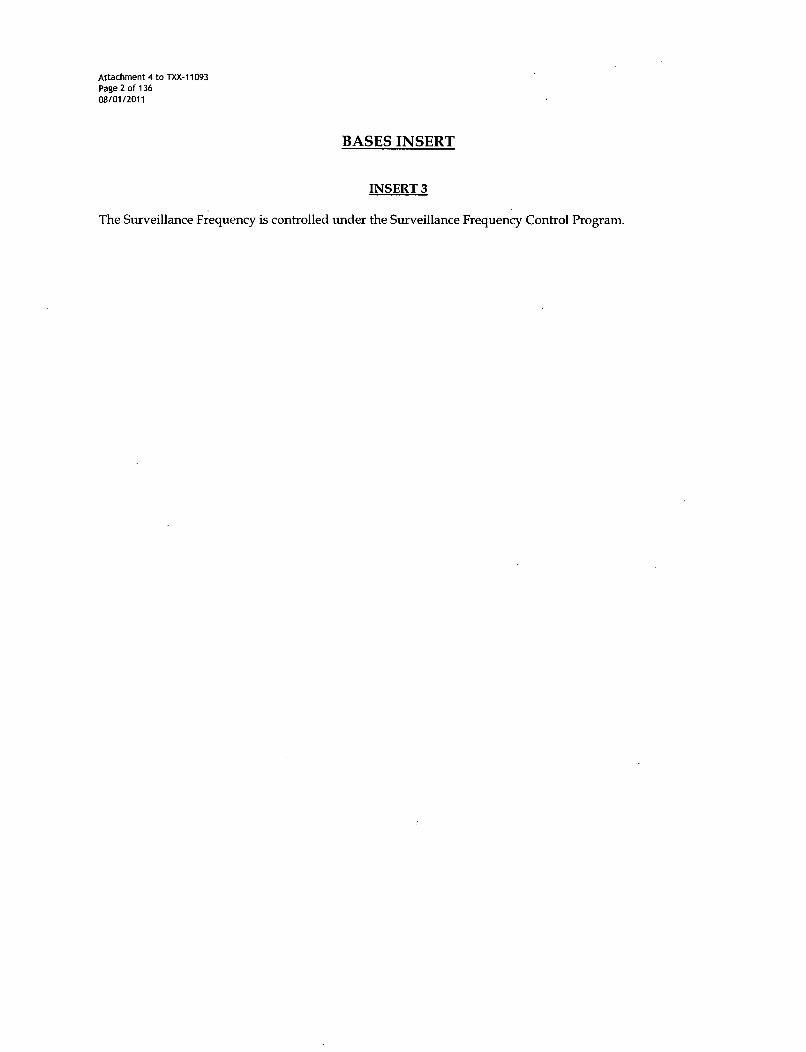
Attachment 4 to TXX-11093Page 2 of 13608/01/2011
BASES INSERT
INSERT 3
The Surveillance Frequency is controlled under the Surveillance Frequency Control Program.
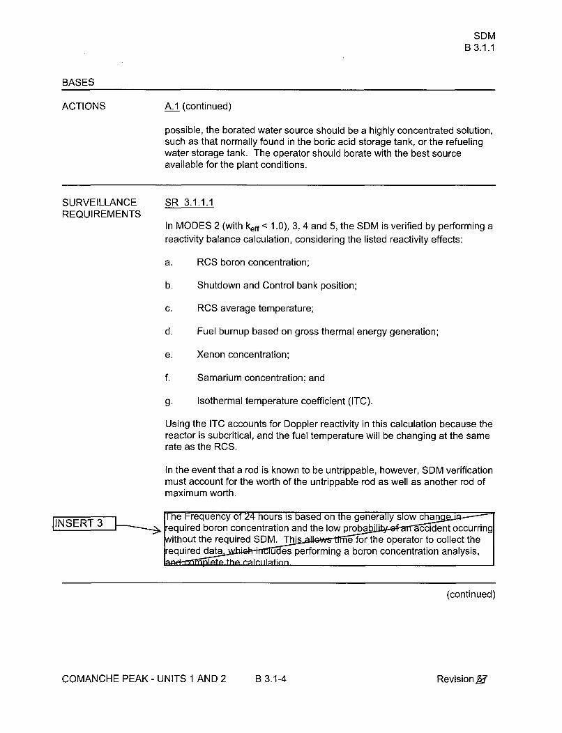
SDMB 3.1.1
BASES
ACTIONS A.1 (continued)
possible, the borated water source should be a highly concentrated solution,such as that normally found in the boric acid storage tank, or the refuelingwater storage tank. The operator should borate with the best sourceavailable for the plant conditions.
SURVEILLANCEREQUIREMENTS
SR 3.1.1.1
In MODES 2 (with keff < 1.0), 3, 4 and 5, the SDM is verified by performing a
reactivity balance calculation, considering the listed reactivity effects:
a. RCS boron concentration;
b. Shutdown and Control bank position;
c. RCS average temperature;
d. Fuel burnup based on gross thermal energy generation;
e. Xenon concentration;
f. Samarium concentration; and
g. Isothermal temperature coefficient (ITC).
Using the ITC accounts for Doppler reactivity in this calculation because thereactor is subcritical, and the fuel temperature will be changing at the samerate as the RCS.
In the event that a rod is known to be untrippable, however, SDM verificationmust account for the worth of the untrippable rod as well as another rod ofmaximum worth.
The Frequency of 24 hours is based on the generally slow chanrequired boron concentration and the low probab accident occurring
ithout the required SDM. Thi e for the operator to collect therequired data u es performing a boron concentration analysis,
JINSERT 3
(continued)
COMANCHE PEAK- UNITS 1 AND 2 B 3.1-4 Revision A
Core ReactivityB 3.1.2
BASES
ACTIONS B.1 (continued)
this status, the plant must be brought to at least MODE 3 within 6 hours. Ifthe SDM for MODE 3 is not met, then the boration required by LCO 3.1.1Required Action A.1 would occur. The allowed Completion Time isreasonable, based on operating experience, for reaching MODE 3 from fullpower conditions in an orderly manner and without challenging plantsystems.
SURVEILLANCE SR 3.1.2.1REQUIREMENTS
Core reactivity is verified by periodic comparisons of measured andpredicted RCS boron concentrations. The comparison is made, consideringthat other core conditions are fixed or stable, including control rod position,moderator temperature, fuel temperature, fuel depletion, xenonconcentration, and samarium concentration. The Surveillance is performedprior to entering MODE 1 as an initial check on core conditions and designcalculations at BOC. The SR is modified by a Note. The Note requires thatthe normalization of predicted core reactivity to the measured value musttake place within the first 60 effective full power days (EFPD) after each fuelloading. However, if the deviation between measured and predicted valuesis within the associated measurement and analytical uncertainties, it is notnecessary to normalize the predicted core reactivity. This allows sufficienttime for core conditions to reach steady state, but prevents operation for alarge fraction of the fuel cycle without establishing a benchmark for thedesign calculations. The required subsequent Frequency of,31 EFPP,following the initial 60 EFPD after entering MODE 1 IQ.......ble, based othe sl-w r819 Fate 8f GEo-c .hangeS ,duo t, fu 1; id t A RA"of otf.her
COMANCHE PEAK - UNITS 1 AND 2 B 3.1-10 Revision.,I

Rod Group Alignment LimitsB 3.1.4
BASES
ACTIONS (continued)
D.2
If more than one rod is found to be misaligned or becomes misalignedbecause of bank movement, the unit conditions fall outside of the accidentanalysis assumptions. Since automatic bank sequencing would continue tocause misalignment, the unit must be brought to a MODE or Condition inwhich the LCO requirements are not applicable. To achieve this status, theunit must be brought to at least MODE 3 within 6 hours.
The allowed Completion Time is reasonable, based on operatingexperience, for reaching MODE 3 from full power conditions in an orderlymanner and without challenging plant systems.
SURVEILLANCE SR 3.1.4.1REQUIREMENTS
Verification that individual rod positions are within alignment limits atFrequency of 12 hours provides a history that allows the o o detect arod that is beginning to deviate from its expected n. If the rod positiondeviation monitor is inoperable, the Fre is increased to 4 hours perTRM requirement TRS 13.1.37 ich accomplishes the same goal. Thespecified Frequency into account other rod position information that iscontinuousl able to the operator in the control room, so that duringac od motion, deviations can immediately be detected.
SR 3.1.4.2
Verifying each control rod is OPERABLE would require that each rod betripped. However, in MODES 1 and 2, tripping each control rod would result
JINSERT 3 in radial or axial power tilts, or oscillations. Exercising each individual controlrod evert492-4ays provides increased confidence that all rods continue to beO P BLE without exceeding the alignment limit, even if they are notregularly _ d. Moving each control rod by 10 steps will not cause radialor axial power tilts, scillations, to occur. The 9£-dQ*Frequency takesinto consideration other in ation available to the operator in the controlroom and SR 3.1.4.1, which is pe ed more frequently and adds to thedetermination of OPERABILITY of the ro Between or during requiredperformances of SR 3.1.4.2 (determination of control rod OPERABILITY bymovement), if a control rod(s) is discovered to be immovable, but remainstrippable, the control rod(s) is considered to be OPERABLE until thesurveillance interval expires. At any time, if a control rod(s) is immovable, adetermination of the trippability (OPERABILITY) of the control rod(s) must bemade, and appropriate action taken.
(continued)
COMANCHE PEAK - UNITS 1 AND 2 B 3.1-24 Revision X

Shutdown Bank Insertion LimitsB 3.1.5
BASES
ACTIONS A.1.1, A.1.2 and A.2 (continued)
The allowed Completion Time of 2 hours provides an acceptable time forevaluating and repairing minor problems without allowing the plant to remainin an unacceptable condition for an extended period of time.
B.1
If the shutdown banks cannot be restored to within their insertion limits within2 hours, the unit must be brought to MODE 3 where the LCO is notapplicable. The allowed Completion Time of 6 hours is reasonable, basedon operating experience, for reaching the required MODE from full powerconditions in an orderly manner and without challenging plant systems.
SURVEILLANCE SR 3.1.5.1REQUIREMENTS
Verification that the shutdown banks are within their insertion limits prior toan approach to criticality ensures that when the reactor is critical, or beingtaken critical, the shutdown banks will be available to shut down the reactor,and the required SDM will be maintained following a reactor trip. This SRand Frequency ensure that the shutdown banks are within limits during a unitstartup and subsequent operation.
Since the shutdown banks are positioned manually by the control•.TW1- , Ioperator, a verification of shutdown bank position a ency of 12 hours
NS is adequate to ensure that they are eir insertion limits. Also, the12 hour Frequenc account other information available in thecontr or the purpose of monitoring the status of shutdown rods.
REFERENCES 1. 10 CFR 50, Appendix A, GDC 10, GDC 26, and GDC 28.
2. 10 CFR 50.46.
3. FSAR, Chapter 15.
COMANCHE PEAK - UNITS 1 AND 2 B 3.1-29 Revision 517"

Control Bank Insertion LimitsB 3.1.6
BASES (continued)
SURVEILLANCE SR 3.1.6.1REQUIREMENTS
This Surveillance is required to ensure that the reactor does not achievecriticality with the control banks below their insertion limits.
The estimated critical condition (ECC) depends upon a number of factors,one of which is xenon concentration. If the ECC was calculated long beforecriticality, xenon concentration could change to make the ECC substantiallyin error. Conversely, determining the ECP immediately before criticalitycould be an unnecessary burden. There are a number of unit parametersrequiring operator attention at that point. Performing the ECC calculationwithin 4 hours prior to criticality avoids a large error from changes in xenonconcentration, but allows the operator some flexibility to schedule the ECCcalculation with other startup activities.
SR 3.1.6.2
Verification of the control bank insertion limits at a Frequency ofsufficient to ensure OPERABILITY and to de anks that may beapproaching the insertion normally, very little rod motion occursin12
ERT 3 SSR 3.1.6.3
There is a potential that, with only a limit on rod insertion, the RCCAs couldbe placed in a sequence or overlap position, perhaps during troubleshootingactivities or other abnormal plant conditions, that would violate core fluxpeaking factors while still satisfying the limits on rod insertion. This scenariois most likely to occur at reduced power following an automatic runback ordue to an administrative power reduction in response to some rod controlabnormality.
This surveillance ensures that the rod configuration across the core for anygiven operating condition will not result in unanalyzed peaking factors. Thesurveillance is not designed to test or verify the function of the Rod Controlsequence and overlap circuits. In practice, this surveillance will be satisfiedas long as the rod positions are in the positions specified in the COLR,regardless of the operability of the sequence and overlap circuits. The intentis to check the rod position to verify that the rods are in the expectedpositions as described in the COLR. If all rods are out of the core when thecheck is made, then rod sequence and overlap limits are satisfied for thepurpose of this surveillance. At all power levels, the rod positions shouldconform to the requirements of the COLR for rod sequence and overlap.Implicit within the LCO is the assumption that bank sequence and overlap
(continued)
COMANCHE PEAK - UNITS 1 AND 2 B 3.1-34 Revision,5r

Control Bank Insertion LimitsB 3.1.6
BASES
SURVEILLANCE SR 3.1.6.3 (continued)REQUIREMENTS
must be maintained during rod movement. When control banks aremaintained within their insertion limits as checked by SR 3.1.6.2 above, it isunlikely that their sequence and overlap will not be in accordance withrequirements provided in the COLR. -A o-.........f 12 - is Co.tewith the insertien limit check •b'-e c"R. 3 1 a ... 2.
REFERENCES 1 . 10 CFR 50, Appendix A, GD 10, GDC 26, GDC 28.
2. 10 CFR 50.46.3A CpNSERTA3p 1
3. FSAR, Chapter 15.
COMANCHE PEAK - UNITS 1 AND 2 B 3.1-35 Revision S-7"'

PHYSICS TESTS Exceptions - MODE 2B 3.1.8
BASES
ACTIONS (continued)
B.1
When THERMAL POWER is > 5% RTP, the only acceptable action is toopen the reactor trip breakers (RTBs) to prevent operation of the reactorbeyond its design limits. Immediately opening the RTBs will shut down thereactor and prevent operation of the reactor outside of its design limits.
C.1
When the RCS lowest operating loop Tavg is < 541'F, the appropriate actionis to restore Tavg to within its specified limit. The allowed Completion Time of15 minutes provides time for restoring Tavg to within limits without allowingthe plant to remain in an unacceptable condition for an extended period oftime. Operation with the reactor critical and with temperature below 541 OFcould violate the assumptions for accidents analyzed in the safety analyses.
D.1
If the Required Actions cannot be completed within the associatedCompletion Time, the plant must be brought to a MODE in which therequirement does not apply. To achieve this status, the plant must bebrought to at least MODE 3 within an additional 15 minutes. The CompletionTime of 15 additional minutes is reasonable, based on operating experience,for reaching MODE 3 in an orderly manner and without challenging plantsystems.
SURVEILLANCE SR 3.1.8.1REQUIREMENTS
The power range and intermediate range neutron detectors must be verifiedto be OPERABLE in MODE 2 by LCO 3.3.1, "Reactor Trip System (RTS)Instrumentation." A CHANNEL OPERATIONAL TEST is performed on eachpower range and intermediate range channel prior to initiation of thePHYSICS TESTS. This will ensure that the RTS is properly aligned toprovide the required degree of core protection during the performance of thePHYSICS TESTS.
SR 3.1.8.2
Verification that the RCS lowest operating loop Tavg is _> 541 OF will ensurethat the unit is not operating in a condition that could invalidate the safetyanalyses. Ve ftication of the R6- tempcratur at a Frcq.....; Of 30 mint
(continued)
COMANCHE PEAK - UNITS 1 AND 2 B 3.1-45 Revision V,7

PHYSICS TESTS Exceptions - MODE 2B 3.1.8
BASES
SURVEILLANCE SR 3.1.8.2 (continued)REQUIREMENTS
during the porformano of the PHYSICGSTESTS will ,nsur that the :conEI~tqens ef the safety analyses Wre met vielated.
SR 3.1.8.3
Verification that the THERMAL POWER is < 5% RTP will ensure that theplant is not operating in a condition that could invalidate the safety analyses.Verification of the THERMAL POWER at a Frequency of •1aeup 11eperformance of the PHYSICS TE e at the initial conditions ofthe safe no violated.
SR 3.1.8.4
Verification that the SDM is within limits specified in the COLR ensures that,for the specific RCCA and RCS temperature manipulations performed duringPHYSICS TESTS, the plant is not operating in a condition that couldinvalidate the safety analysis assumptions. The SDM verification can befacilitated through the use of tables prepared by the core designers in whichthe reactivity effects expected during the Physics Testing have beenpreviously considered.
The SDM is verified by performing a reactivity balance calculation,considering the following reactivity effects:
JINSERT 3 a. RCS boron concentration;
b. Shutdown and Control bank position;
c. RCS average temperature;
d. Fuel burnup based on gross thermal energy generation;
e. Xenon concentration;
f. Samarium concentration; and
g. Isothermal temperature coefficient (ITC).
Using the ITC accounts for Doppler reactivity in this calculation because thereactor is subcritical, and the fuel temperature will be changing at the samerate as the RCS.
The Frequency of 24 hours is based on the generallrequired boron concentratioprobabiity of an accident
ocuired SDM.
(continued)
COMANCHE PEAK - UNITS 1 AND 2 B 3.1-46 Revision 5-r"

FQ(Z) (RAOC-W(Z) Methodology)B 3.2.1
BASES
SURVEILLANCE SR 3.2.1.1 (continued)REQUIREMENTS
CThe limit with which FQ (Z) is compared varies inversely with power above50% RTP and directly with a function called K(Z) provided in the COLR.
Performing this Surveillance in MODE 1 prior to exceeding 75% RTP,Cprovides assurance that the FQ (Z) limit is met when RTP is achieved,
because peaking factors generally decrease as power level is increased.
If THERMAL POWER has been increased by 2! 20% RTP since the lastcdetermination of FQ (Z), another evaluation of this factor is required
24 hours after achieving equilibrium conditions at this higher power level (to
ensure that FQc(Z) values are being reduced sufficiently with power
increase to stay within the LCO limits).
The Frequency of 31 EFPD is adequate to monitor the c werINSERT 3 distribution with core burnup because s es are slow and well
controlled when the erated in accordance with the TechnicalS s 5).
SR 3.2.1.2
The nuclear design process includes calculations performed to determinethat the core can be operated within the FQ(Z) limits. Because powerdistribution measurements are taken at or near equilibrium conditions, thevariations in power distribution resulting from normal operational maneuversare not present in the core power distribution measurement data. Thesevariations are, however, conservatively calculated by considering a widerange of unit maneuvers in normal operation. The maximum peaking factorincrease over steady state values, calculated as a function of core elevation,
CZ, is called W(Z). Multiplying the measured total peaking factor, FQ (Z), byW(Z) gives the maximum FQ(Z) calculated to occur in normal
operation, F W(Z).
The limit with which F Q (Z) is compared varies inversely with power above
50% RTP and directly with the function K(Z) provided in the COLR.
(continued)
COMANCHE PEAK - UNITS 1 AND 2 B 3.2-9 RevisionV
FQ(Z) (RAOC-W(Z) Methodology)B 3.2.1
BASES
SURVEILLANCEREQUIREMENTS
JINSERT 3
SR 3.2.1.2 (continued)
The Surveillance Frequency of 31 EFPD is adequate to monitor thecof power distribution with core burnup. The Surveillance ma ýone morefrequently if required by the results of FQ(Z) eva u
The Frequency of 31 EFPD is ate to monitor the change of powerdistribution because a change is sufficiently slow, when the plant isoperated in ance with the TS, to preclude adverse peaking factorsbe 31 day surveillances.
REFERENCES 1.
2.
10 CFR 50.46,1974.
Regulatory Guide 1.77, Rev. 0, May 1974.
3. 10 CFR 50, Appendix A, GDC 26.
4. RXE-90-006-P-A, "Power Distribution Control Analysis andOvertemperature N-16 and Overpower N-16 Trip SetpointMethodology," TU Electric, June 1994.
5. WCAP-7308-L-P-A, "Evaluation of Nuclear Hot Channel FactorUncertainties," June 1988.
6. WCAP-1 0216-P-A, Rev. 1A, "Relaxation of Constant Axial OffsetControl (and) FQ Surveillance Technical Specification," February1994.
7. WCAP-12472-P-A, "BEACON Core Monitoring and OperationsSupport System," August 1994.
COMANCHE PEAK - UNITS 1 AND 2 B 3.2-11 Revision 6r2"'
NFAHB 3.2.2
BASES
SURVEILLANCE SR 3.2.2.1 (continued)REQUIREMENTS
LThe 31 EFPD Frequency is acceptable because the power distrchanges relatively slowly over this amount of fuel ccordingly, this
INSERT 3 Frequency is short limit cannot be exceeded for any
significa of operation.
REFERENCES 1. Regulatory Guide 1.77, Rev. 0, May 1974.
2. 10 CFR 50, Appendix A, GDC 26.
3. 10 CFR 50.46.
4. WCAP-12472-P-A, "BEACON Core Monitoring and Operations SupportSystem," August 1994.
COMANCHE PEAK - UNITS I AND 2 B 3.2-19 Revision 6"2f

AFD (RAOC Methodology)B 3.2.3
BASES
LCO (continued)
detector well. For convenience, this flux difference is converted to provideflux difference units expressed as a percentage and labeled as %A flux or%AI.
The AFD limits are provided in the COLR. The AFD limits for RAOC do notdepend on the target flux difference. However, the target flux difference maybe used to minimize changes in the axial power distribution.
Violating the LCO on the AFD could produce unacceptable consequences ifa Condition 2, 3, or 4 event occurs while the AFD is outside its limits.
APPLICABILITY The AFD requirements are applicable in MODE 1 greater than or equal to50% RTP, when the combination of THERMAL POWER and core peakingfactors are the core parameters of primary importance in safety analyses(Ref. 1).
For AFD limits developed using RAOC methodology, the value of the AFDdoes not affect the limiting accident consequences with THERMAL POWER< 50% RTP and for lower operating power MODES.
ACTIONS A.1
As an alternative to restoring the AFD to within its specified limits, RequiredAction A.1 requires a THERMAL POWER reduction to < 50% RTP. Thisplaces the core in a condition for which the value of the AFD is not importantin the applicable safety analyses. A Completion Time of 30 minutes isreasonable, based on operating experience, to reach 50% RTP withoutchallenging plant systems.
SURVEILLANCE SR 3.2.3.1 INSERT 3REQUIREMENTS This Surveillance verifies that the A as indicated by the NIS excore
channels is within its specified limits. T[e , urvellam, e Fr... uon, y of 7- daysi s adeqwate beca-use the -AF=D is; controlled by the operator and monitored. bythe PrcOees a crputitr. Furt~hecrmcrc, any deviatinam of the AFD froemrcqu..'irmcmnts that iS not alarmed shoul16d b@ readily noticed.
(continued)
COMANCHE PEAK - UNITS 1 AND 2 B 3.2-22 Revision 6.2"

QPTRB 3.2.4
BASES
ACTIONS A.6 (continued)
RTP within 24 hours but is increased slowly, then the peaking factorsurveillances must be performed within 48 hours after increasing THERMALPOWER above the limit of Required Action A.1. This Completion Time isintended to allow adequate time to increase THERMAL POWER to abovethe limits of Required Action A.1, while not permitting the core to remain withunconfirmed power distributions for extended periods of time.
Required Action A.6 is modified by a Note that states that the peaking factorsurveillances must be completed when the excore detectors have beennormalized to restore QPTR to within limit (i.e., Required Action A.5). Theintent of this Note is to have the peaking factor surveillances performed atoperating power levels, which can only be accomplished after the excoredetectors are normalized to restore QPTR to within limit.
B.1
If Required Actions A.1 through A.6 are not completed within theirassociated Completion Times, the unit must be brought to a MODE orcondition in which the requirements do not apply. To achieve this status,THERMAL POWER must be reduced to < 50% RTP within 4 hours. Theallowed Completion Time of 4 hours is reasonable, based on operatingexperience regarding the amount of time required to reach the reducedpower level without challenging plant systems.
SURVEILLANCE SR 3.2.4.1REQUIREMENTS
SR 3.2.4.1 is modified by two Notes. Note 1 allows QPTR to be calculatedwith three power range channels if THERMAL POWER is _< 75% RTP andthe input from one Power Range Neutron Flux channel is inoperable. Note 2allows performance of SR 3.2.4.2 in lieu of SR 3.2.4.1
INSERT 3This Surveillance verifies that the QPTR, as indicated by the Nucl rInstrumentation System (NIS) excore channels, is within its limits.,ý-Fre-u.n. y of. 7 .Eay takes into ,ccount other infmtin alarmavailable to the Opo•rif,. in the ,intrl room.
For those causes of QPT that occur quickly (e.g., a dropped rod), theretypically are other indications of abnormality that prompt a verification of corepower tilt.
(continued)
COMANCHE PEAK - UNITS 1 AND 2 B 3.2-28 Revision
QPTRB 3.2.4
BASES
SURVEILLANCE REQUIREMENTS (continued)
SR 3.2.4.2
This Surveillance is modified by a Note, which states that it is not requireduntil 12 hours after the inputs from one or more Power Range Neutron Fluxchannels are inoperable and the THERMAL POWER is > 75% RTP.
With an NIS power range channel inoperable, tilt monitoring for a portion ofthe reactor core becomes degraded. Large tilts are likely detected with theremaining channels, but the capability for detection of small power tilts insome quadrants is decreased. rr, s .. u ... 2 at a P Of
........ within its limit. . [INSERT 3 1
For purposes of monitoring the QPTR when one power range channel isinoperable, the moveable incore detectors or an OPERABLE PDMS may beused to confirm that the normalized symmetric power distribution isconsistent with the indicated QPTR and any previous data indicating a tilt.When using the moveable incore detector system, the incore detectormonitoring is performed with a full incore flux map or two sets of four thimblelocations with quarter core symmetry. The two sets of four symmetricthimbles is a set of eight unique detector locations. These locations are C-8,E-5, E-11, H-3, H-13, L-5, L-11, and N-8.
The symmetric thimble flux map can be used to generate symmetric thimble"tilt." This can be compared to a reference symmetric thimble tilt, from themost recent full core flux map, to generate an incore QPTR. Therefore,incore monitoring of QPTR can be used to confirm that QPTR is within limits.
With one NIS channel inoperable, the indicated tilt may be changed from thevalue indicated with all four channels OPERABLE. To confirm that nochange in tilt has actually occurred, which might cause the QPTR limit to beexceeded, the incore result may be compared against previous core powerdistribution measurements using an OPERABLE PDMS and the symmetricthimbles as described above or a complete flux map.. Nominally, quadrant tiltfrom the Surveillance should be within 2% of the tilt shown by the mostrecent flux map data.
REFERENCES 1. 10 CFR 50.46.
2. Regulatory Guide 1.77, Rev 0, May 1974.
3. 10 CFR 50, Appendix A, GDC 26.
COMANCHE PEAK - UNITS 1 AND 2 B 3.2-29 Revision 6-2"

RTS InstrumentationB 3.3.1
BASES (continued)
SURVEILLANCE The SRs for each RTS Function are identified by the SRs column ofREQUIREMENTS Table 3.3.1-1 for that Function.
A Note has been added to the SR Table stating that Table 3.3.1-1determines which SRs apply to which RTS Functions.
Note that each channel of process protection supplies both trains of the RTS.When testing Channel I, Train A and Train B must be examined. Similarly,Train A and Train B must be examined when testing Channel II, Channel III,and Channel IV (if applicable). The CHANNEL CALIBRATION and COTsare performed in a manner that is consistent with the assumptions used inanalytically calculating the required channel accuracies.
SR 3.3.1.1
Performance of the CHANNEL CHECK cnoc cvery 12 hours ensures thatgross failure of instrumentation has not occurred. A CHANNEL CHECK isnormally a comparison of the parameter indicated on one channel to asimilar parameter on other channels. It is based on the assumption thatinstrument channels monitoring the same parameter should readapproximately the same value. Significant deviations between the twoinstrument channels could be an indication of excessive instrument drift inone of the channels or of something even more serious. A CHANNELCHECK will detect gross channel failure; thus, it is key to verifying that theinstrumentation continues to operate properly between each CHANNELCALIBRATION.
Agreement criteria are determined by the unit staff based on a combinationof the channel instrument uncertainties, including indication and readability.If a channel is outside the criteria, it may be an indication that the sensor orthe signal processing equipment has drifted outside its limit.
IThe Frequency is based on operating experience thatdeo nl:failure is rare. The CHANNEL CHECK su es formal, but more
IN RT3 "frequent, hcso hag omloeainal use of the displays
|associ " e LCO required channels.
SR 3.3.1.2
SR 3.3.1.2 compares the calorimetric heat balance calculation to the NISand N-16 power indications every-24 hours. If the calorimetric exceeds theNIS or N-16 power indications by more than +2% RTP, the affected NIS andN-16 functions are not declared inoperable, but the channel gains must beadjusted consistent with the calorimetric power. If the NIS or N-16 channeloutputs cannot be properly adjusted, the channel is declared inoperable.
(continued)
COMANCHE PEAK - UNITS 1 AND 2 B 3.3-43 Revision .6W

RTS InstrumentationB 3.3.1
BASES
SURVEILLANCE SR 3.3.1.2 (continued)REQUIREMENTS
feedwater venturi. While the measurement uncertainty remains constant inAP as power decreases, when translated into flow, the uncertainty increasesas a square term. Thus, a 1% flow error at 100% power can approach a10% flow error at 30% RTP event though the AP error has not changed.
An evaluation of extended operations at reduced power conditions wouldlikely conclude that it is prudent to administratively adjust the setpoint of thePower Range Neutron Flux - High bistables to < 90% RTP when: 1) thePower Range channel output is adjusted in the decreasing power directiondue to a reduced power venturi-based calorimetric below 55% RTP; or 2) fora post refueling startup (consistent with the Bases for SR 3.4.1.4). Theevaluation of extended operation at reduced power conditions would alsolikely conclude that the potential need to adjust the indication of the PowerRange Neutron Flux in the decreasing power direction is quite small,primarily to address operation in the intermediate range about P-1 0(nominally 10% RTP) to allow enabling of the Power Range Neutron Flux -Low setpoint and the Intermediate Range Neutron Flux reactor trips. Beforethe Power Range Neutron Flux - High bistables are reset to their nominalvalue high setpoint, the NIS or N-16 power indication adjustment must beconfirmed based on LEFM-based calorimetric or on a venturi-basedcalorimetric performed at > 55% RTP.
The Note clarifies that this Surveillance is required only if reactor power is_> 15% RTP and that 24 hours are allowed for performing the firstSurveillance after reaching 15% RTP. A power level of 15% RTP is chosenbased on plant stability; i.e., the turbine generator is synchronized to the gridand rod control is in the automatic mode. The 24-hour allowance afterincreasing THERMAL POWER above 15% RTP provides a reasonable timeto attain a scheduled power plateau, establish the requisite conditions,perform the required calorimetric measurement and make any requiredadjustments in a controlled, orderly manner and without introducing thepotential for extended operation at high power levels with instrumentationthat has not been verified to be acceptable for subsequent use.
Tne Frequency oT every 24 hours is adequate. it is based on unit o pja.rrigexperience, considering instrument reliability and operating data forinstrument drift. Together these factors demonstrat a difference ofmore than +2% RTP between the calorimet at balance calculation andNIS Power Range channel output - Power Monitor output is not
NSRexpected in any24 hour
In additi trol room operators periodically monitor redundant indicationsarms to detect deviations in channel outputs.
(continued)
COMANCHE PEAK - UNITS 1 AND 2 B 3.3-45 Revisionfaf2"

RTS InstrumentationB 3.3.1
BASES
SURVEILLANCE REQUIREMENTS (continued)
SR 3.3.1.3
SR 3.3.1.3 compares the incore system to the NIS channel output eye5--E-FPI;D If the absolute difference is Ž! 3%, the NIS channel is stillOPERABLE, but must be readjusted. The excore NIS channel shall beadjusted if the absolute difference between the incore and excore AFD is >3%.
If the NIS channel cannot be properly readjusted, the channel is declaredinoperable. This Surveillance is performed to verify the f(Aq) input to theovertemperature N-16 Function.
A Note clarifies that the Surveillance is required only if reactor power is> 50% RTP and that 24 hours is allowed for performing the first Surveillanceafter reaching 50% RTP. The Note allows power ascensions and associatedtesting to be conducted in a controlled and orderly manner, at conditions thatprovide acceptable results and without introducing the potential for extendedoperation at high power levels with instrumentation that has not been verifiedto be OPERABLE. Due to such effects as shadowing from the relativelydeep control rod insertion and, to a lesser extent, the dependency of theaxially-dependent radial leakage on the power level, the relationshipbetween the incore and excore indications of axial flux difference (AFD) atlower power levels is variable. Thus, it is acceptable to defer the calibrationof the excore AFD against the incore AFD until more stable conditions areattained (i.e, withdrawn control rods and a higher power level). The AFD isused as an input to the Overtemperature N-16 reactor trip function and forassessing compliance with LCO 3.2.3, "Axial Flux Difference." Due to theDNB benefits gained by administratively restricting the power level to 50%RTP, no limits on AFD are imposed below 50% RTP by LCO 3.2.3; thus, theproposed change is consistent with the LCO 3.2.3 requirements below 50%RTP. Similarly, sufficient DNB margins are realized through operation below50% RTP that the intended function of the Overtemperature N-1 6 reactor tripfunction is maintained, even though the excore AFD indication may notexactly match the incore AFD indication. Based on plant operatingexperience, 24 hours is a reasonable time frame to limit operation above50% RTP while completing the procedural steps associated with thesurveillance in an orderly manner.
The Frequency of every 31 EFPD is adequate. It is based o erating
JINSexperience, considering instrument reliabir erating history data forinstrument drift. Also, the nges in neutron flux during the fuel cyclecan be uring this interval.
(continued)
COMANCHE PEAK - UNITS 1 AND 2 B 3.3-46 Revision £&T

RTS InstrumentationB 3.3.1
BASES
SURVEILLANCE REQUIREMENTS (continued)
SR 3.3.1.4
SR 3.3.1.4 is the performance of a TADOT 9;. , 62 am ... vn aSTAGCERED TEST BASIS. This test shall verify OPERABILITY byactuation of the end devices. The RTB test shall include separateverification of the undervoltage and shunt trip mechanisms. Independentverification of RTB undervoltage and shunt trip Function is not required forthe bypass breakers. No capability is provided for performing such a test atpower. The independent test for bypass breakers is included in SR 3.3.1.14.The bypass breaker test shall include a local manual shunt trip. A Note hasbeen added to indicate that this test must be performed on the bypassbreaker prior to placing it in service.
Theu Fiequ,,uy uf eveiy 62 days . on a STACC•E"• D--- TEST BASIS .1j,,tifiodR m Refercnee 12.
SR 3.3.1.5
i___,/3SR 3.3.1.5 is the performance of an ACTUATION LOGIC TEST. The SSPSis tested .v..; 92 days .. a STAGGERED TEST BASIS, using thesemiautomatic tester. The train being tested is placed in the bypasscondition, thus preventing inadvertent actuation. Through the semiautomatictester, all possible logic combinations, with and without applicablepermissives, are tested for each protection function. Tm ri~uu 1.cy of eVery
"• ~92 days eRq a, STACCERED TEST BASIS is justifie•d im Refermene q2.
SR 3.3.1.6
SR 3.3.1.6 is a calibration of the excore channels to the core powerdistribution measurement. If the measurements do not agree, the excorechannels are not declared inoperable but must be calibrated to agree withthe core power distribution measurements. If the excore channels cannot beadjusted, the channels are declared inoperable. This Surveillance isperformed to verify the f(Aq) input to the overtemperature N-16 Function.
A Note modifies SR 3.3.1.6. The Note states that this Surveillance isrequired only if reactor power is > 75% RTP and that 72 hours is allowed forperforming the first surveillance after reaching equilibrium conditions at aTHERMAL POWER > 75% RTP. The SR is deferred until a scheduledtesting plateau above 75% is attained during the post-outage powerascension. During a typical post-refueling power ascension, it is usuallynecessary to control the axial flux difference at lower power levels throughcontrol rod insertion. Due to rod shadowing effects and, to a lesser degree,
(continued)
COMANCHE PEAK - UNITS I AND 2 B 3.3-47 Revision ý

RTS InstrumentationB 3.3.1
BASES
SURVEILLANCE SR 3.3.1.6 (continued)REQUIREMENTS
the dependency of the axially-dependent radial leakage on the power level,the incore-excore AFD relationship well below 75% RTP may differexcessively from the incore-excore axial flux difference relationship at fullpower. Excore calibration adjustments should be based on the incore-excore multipoint relationship established above 75% RTP by use of thedeveloped calibration standard equations or by initiating an AFW swing andperforming a direct multipoint measurement. After equilibrium conditions areachieved at the specified power plateau, a full core flux map must be taken,and the required data collected. The data is typically analyzed and theappropriate excore calibrations are completed within 48 hours afterachieving equilibrium conditions. An additional time allowance of 24 hours isprovided during which the effects of equipment failures may be remediedand any required re-testing may be performed.
The allowance of 72 hours after equilibrium conditions are attained at thetesting plateau provides sufficient time to allow power ascensions andassociated testing to be conducted in a controlled and orderly manner, atconditions that provide acceptable results and without introducing thepotential for extended operation at high power levels with instrumentationthat has not been verified to be acceptable for subsequent use. The benefitgained by operating at reduced power levels is sufficient to offset potentialdifferences between the incore and excore indications of Aq prior tocompletion of this surveillance.
[The Frequency of 92 EFPD is adequat~e. It is base naig! experience, osdrn ntu, i a prting history data forI[INSERT 3 i• instrurnea
SR 3.3.1.7
SR 3.3.1.7 is the performance of a COT e.e,'y4.84-day%. A COT isperformed on each required channel to ensure the channel will perform theintended Function.
Setpoints must be within the Allowable Values specified in Table 3.3.1-1.
SR 3.3.1.7 is modified by two Notes. Note 1 provides a 4 hour delay in therequirement to perform this Surveillance for source range instrumentationwhen entering MODE 3 from MODE 2. This Note allows a normal shutdownto proceed without a delay for testing in MODE 2 and for a short time inMODE 3 until the RTBs are open and SR 3.3.1.7 is no longer required to beperformed. If the unit is to be in MODE 3 with the RTBs closed for > 4 hoursthis Surveillance must be performed prior to 4 hours after entry into MODE 3.Note 2 requires that the quarterly COT for the source range instrumentationinclude verification by observation of the associated permissive annunciator
(continued)
COMANCHE PEAK- UNITS 1 AND 2 B 3.3-48 Revision J2
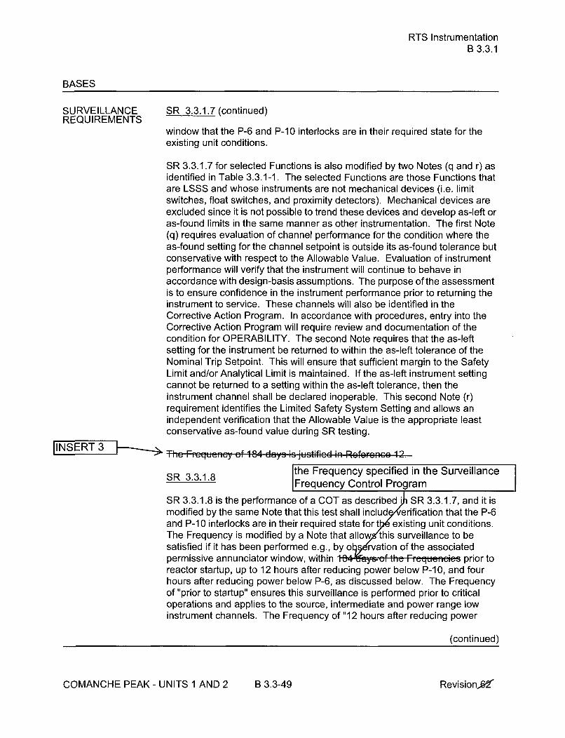
RTS InstrumentationB 3.3.1
BASES
SURVEILLANCE SR 3.3.1.7 (continued)REQUIREMENTS
window that the P-6 and P-1 0 interlocks are in their required state for theexisting unit conditions.
SR 3.3.1.7 for selected Functions is also modified by two Notes (q and r) asidentified in Table 3.3.1-1. The selected Functions are those Functions thatare LSSS and whose instruments are not mechanical devices (i.e. limitswitches, float switches, and proximity detectors). Mechanical devices areexcluded since it is not possible to trend these devices and develop as-left oras-found limits in the same manner as other instrumentation. The first Note(q) requires evaluation of channel performance for the condition where theas-found setting for the channel setpoint is outside its as-found tolerance butconservative with respect to the Allowable Value. Evaluation of instrumentperformance will verify that the instrument will continue to behave inaccordance with design-basis assumptions. The purpose of the assessmentis to ensure confidence in the instrument performance prior to returning theinstrument to service. These channels will also be identified in theCorrective Action Program. In accordance with procedures, entry into theCorrective Action Program will require review and documentation of thecondition for OPERABILITY. The second Note requires that the as-leftsetting for the instrument be returned to within the as-left tolerance of theNominal Trip Setpoint. This will ensure that sufficient margin to the SafetyLimit and/or Analytical Limit is maintained. If the as-left instrument settingcannot be returned to a setting within the as-left tolerance, then theinstrument channel shall be declared inoperable. This second Note (r)requirement identifies the Limited Safety System Setting and allows anindependent verification that the Allowable Value is the appropriate leastconservative as-found value during SR testing.
IINSERT 3 T-h Frequency of 184 days is justificd in Rofo•ron. 12.
the Frequency specified in the SurveillanceSR 3.3.1.8 Frequency Control Program
SR 3.3.1.8 is the performance of a COT as described i SR 3.3.1.7, and it ismodified by the same Note that this test shall includ erification that the P-6and P-1 0 interlocks are in their required state for t existing unit conditions.The Frequency is modified by a Note that allow this surveillance to besatisfied if it has been performed e.g., by o l:rvation of the associatedpermissive annunciator window, within 1 th-6e Frequen-es prior toreactor startup, up to 12 hours after reducing power below P-10, and fourhours after reducing power below P-6, as discussed below. The Frequencyof "prior to startup" ensures this surveillance is performed prior to criticaloperations and applies to the source, intermediate and power range lowinstrument channels. The Frequency of "12 hours after reducing power
(continued)
COMANCHE PEAK - UNITS 1 AND 2 B 3.3-49 Revision,£&2"

RTS InstrumentationB 3.3.1
BASES
SURVEILLANCE SR 3.3.1.8 (continued)REQUIREMENTS
below P-10" (applicable to intermediate and power range low channels) and"4 hours after reducing power below P-6" (applicable to source rangechannels) allows a normal shutdown to be completed and the unit removedfrom the MODE of Applicability for this surveillance without a delay toperform the testing required by this surveillance. The Frequency efc-vry-484-days thereafter applies if the plant remains in the MODE of Applicabilityafter the initial performances of prior to reactor startup, 12 hours afterreducing power below P-10, and four hours after reducing power below P-6.The MODE of Applicability for this surveillance is < P-1 0 for the power rangelow and intermediate range channels and < P-6 for the source rangechannels. Once the unit is in MODE 3, this surveillance is no longerrequired. If power is to be maintained < P-10 for more than 12 hours or < P-6 for more than 4 hours, then the testing required by this surveillance mustbe performed prior to the expiration of the 12 hour or 4 hour limit, asapplicable. These time limits are reasonable, based on operatingexperience, to complete the required testing or place the unit in a MODEwhere this surveillance is no longer required. This test ensures that the NISsource, intermediate, and power range low channels are OPERABLE prior totaking the reactor critical and after reducing power into the applicable MODE(< P-10 or < P-6) for the periods discussed above. The Frequency of 184days is justified in Rflcfercnc 12.
INSERT 3SR 3.3.1.9
SR 3.3.1.9 is the performance of a TADOT and is per.form.d ov.ry 92 days,as justified in Roforonepae 5.
This SR is modified by a Note that excludes verification of setpoints from theTADOT. Since this SR applies to RCP undervoltage and underfrequencyrelays, setpoint verification requires elaborate bench calibration and isaccomplished during the CHANNEL CALIBRATION.
SR 3.3.1.10
Ae-l I ANNE l AIlBr-ATIO)N 95 Peif...ed . V.. y 18 mc -•rt-, OF,,PPr0.i..tel. at eVerY r.fu.li.g. CHANNEL CALIBRATION is a complete
check of the instrument loop, including the sensor. The test verifies that thechannel responds to a measured parameter within the necessary range andaccuracy.
This SR is modified by Note 1 stating that N-16 detectors are excluded fromthe CHANNEL CALIBRATION because the unit must be in at least MODE 1to obtain N-16 indications. However, after achieving equilibrium conditions
(continued)
COMANCHE PEAK - UNITS 1 AND 2 B 3.3-50 Revision 0

RTS InstrumentationB 3.3.1
BASES
SURVEILLANCE SR 3.3.1.10 (continued)REQUIREMENTS
in MODE 1, detector plateau curves should be obtained, evaluated andcompared to manufacturer's data.
CHANNEL CALIBRATIONS must be performed consistent with theassumptions of the setpoint methodology.
]The Frequency of 18 months is based on the assurm 6,1:1111 a11:11 ntJINSERT 3 -- -. callibration interval in h eem 1:iatm..antd of equip~ment drift ]in
I th~e setpoint
SR 3.3.1.10 is modified by Note 2 stating that this test shall includeverification that the time constants are adjusted to the prescribed valueswhere applicable. This surveillance does not include verification of timedelay relays. These relays are verified via response time testing perSR 3.3.1.16. Whenever an RTD is replaced in Functions 6 or 7, the nextrequired CHANNEL CALIBRATION of the RTDs is accomplished by aninplace cross calibration that compares other sensing elements with therecently installed element.
The SR is modified by Note 3 stating that, prior to entry into MODES 2 or 1,power and intermediate range detector plateau verification is not required tobe performed until 72 hours after achieving equilibrium conditions withTHERMAL POWER Ž 90% RTP.
SR 3.3.1.10 for selected Functions is also modified by two Notes (q and r) asidentified in Table 3.3.1-1. The selected Functions are those Functions thatare LSSS and whose instruments are not mechanical devices (i.e. limitswitches, float switches, and proximity detectors). Mechanical devices areexcluded since it is not possible to trend these devices and develop as-left oras-found limits in the same manner as other instrumentation. The first Note(q) requires evaluation of channel performance for the condition where theas-found setting for the channel setpoint is outside its as-found tolerance butconservative with respect to the Allowable Value. Evaluation of instrumentperformance will verify that the instrument will continue to behave inaccordance with design-basis assumptions. The purpose of the assessmentis to ensure confidence in the instrument performance prior to returning theinstrument to service. These channels will also be identified in theCorrective Action Program. In accordance with procedures, entry into theCorrective Action Program will require review and documentation of thecondition for OPERABILITY. The second Note (r) requires that the as-leftsetting for the instrument be returned to within the as-left tolerance of theNominal Trip Setpoint. This will ensure that sufficient margin to the SafetyLimit and/or Analytical Limit is maintained. If the as-left instrument setting
(continued)
COMANCHE PEAK- UNITS 1 AND 2 B 3.3-51 Revision e2

RTS InstrumentationB 3.3.1
BASES
SURVEILLANCEREQUIREMENTS
SR 3.3.1.10 (continued)
cannot be returned to a setting within the as-left tolerance, then theinstrument channel shall be declared inoperable. This second Note (r)requirement identifies the Limited Safety System Setting and allows anindependent verification that the Allowable Value is the appropriate leastconservative as-found value during SR testing.
SR 3.3.1.11
SR 3.3.1.11 is the performance of a CHANNEL CALIBRATION, asdescribed in SR 3.3.1.10, ;v'ry 18 .mrnth.s This SR is modified by a Notestating that neutron detectors are excluded from the CHANNELCALIBRATION. For the intermediate and power range channels, detectorplateau curves are obtained, evaluated and compared to manufacturer'sdata. For the source range neutron detectors, performance data is obtainedand evaluated. Note 3 states that, prior to entry into MODES 2 or 1, thepower and intermediate range detector plateau voltage verification is notrequired to be current until 72 hours after achieving equilibrium conditionswith THERMAL POWER > 90% RTP. Equilibrium conditions are achievedwhen the core is sufficiently stable at intended operating conditions toperform a meaningful detector plateau voltage verification. The allowance of72 hours after equilibrium conditions are attained at the testing plateauprovides sufficient time to allow power ascension testing to be conducted ina controlled and orderly manner at conditions that provide acceptable resultsand without introducing the potential for extended operation at high powerlevels with instrumentation that has not been verified to be OPERABLE forsubsequent use. EO,,ri,,, experience has shown these " mp.....t.cusually pass the S2,r'eillance when performed an thb 1A mnnth Frpi jinr.n[INSERT 3'
SR 3.3.1.11 is modified by Note 2 stating that this test shall includeverification that the time constants are adjusted to the prescribed valueswhere applicable. This surveillance does not include verification of timedelay relays. These relays are verified via response time testing perSR 3.3.1.16.
SR 3.3.1.12
Not Used.
SR 3.3.1.13
SR 3.3.1.13 is the performance of a COT of RTS interlocks every 18 mneh&.
(continued)
COMANCHE PEAK - UNITS 1 AND 2 B 3.3-52 Revision .6-2

RTS InstrumentationB 3.3.1
BASES
SURVEILLANCEREQUIREMENTS
SR 3.3.1.13 (continued)
JThe Frequency is based on the known reliabilit ft:multichannel redundancy av" * ,I seen shown to be acceptablethro experience.
S R 3.3.1.14
SR 3.3.1.14 is the performance of a TADOT of the Manual Reactor Trip, andthe SI Input from ESFAS, and the Reactor Trip Bypass Breaker undervoltage
JINSERT 3 trip mechanisms. This TADOT is performed ever; 18 months.
The Manual Reactor Trip TADOT shall independently verify theOPERABILITY of the handswitch undervoltage and shunt trip contacts forboth the Reactor Trip Breakers and Reactor Trip Bypass Breakers. TheReactor Trip Bypass Breaker test shall include testing of the automaticundervoltage trip mechanism.
The Frequency is based on the known reliability of the emultichannel redundancy avail een shown to be acceptablethrou h erience.
The SR is modified by a Note that excludes verification of setpoints from theTADOT. The Functions affected have no setpoints associated with them.
SR 3.3.1.15
SR 3.3.1.15 is the performance of a TADOT of Turbine Trip Functions. ThisTADOT is as described in SR 3.3.1.4, except that this test is performed prior
frequency specified in to exceeding the P-9 interlock whenever the unit has been in MODE 3. Thisthe SFCP Surveillance is not required if it has been performed within the previous
. Verification of the Trip Setpoint does not have to be performed forthis Surveillance. Performance of this test will ensure that the turbine tripFunction is OPERABLE prior to exceeding the P-9 interlock.
SR 3.3.1.16
SR 3.3.1.16 verifies that the individual channel/train actuation responsetimes are less than or equal to the maximum values assumed in the accidentanalysis. The required trip initiation signals and acceptance criteria forresponse time testing are included in Technical Requirements Manual,(Ref. 6). No credit was taken in the safety analyses for those channels withresponse time listed as N.A. No response time testing requirements applywhere N.A. is listed in the TRM. Individual component response times arenot modeled in the analyses. The analyses model the overall or total
(continued)
COMANCHE PEAK - UNITS 1 AND 2 B 3.3-53 Revision fd

RTS InstrumentationB 3.3.1
BASES
SURVEILLANCE SR 3.3.1.16 (continued)REQUIREMENTS
elapsed time, from the point at which the parameter exceeds the trip setpointvalue at the sensor until loss of stationary gripper coil voltage.
For channels that include dynamic transfer Functions (e.g., lag, lead/lag,rate/lag, etc.), the response time test may be performed with the transferFunction time constants set at their nominal values.
Response time may be verified by actual response time tests in any series ofsequential, overlapping or total channel measurements, or by the summationof allocated sensor, signal processing and actuation logic response timeswith actual response time tests on the remainder of the channel. Allocationsfor sensor response times may be used for selected components providedthat the components and methodology for verification have been previouslyNRC approved.
As appropriate, each channel's response time must be verified eve18 months on a STAGGERED TEST BASIS. Each verificati all includeat least one logic train such that both logic trains are ied at least once
IINSERT3 per 36 months. Testing of the final actuatio ices is included in the' testing. Some portions of the res ime testing cannot be performed
during unit operation beca quipment operation is required to measureresponse times. rence has shown that these components usually passthis surve' e when performed at the 18 month Frequency. Therefore, theF ency was concluded to be acceptable from a reliability standpoint.Response time verification in lieu of actual testing may be performed on RTScomponents in accordance with reference 10.
SR 3.3.1.16 is modified by a Note stating that neutron and N-16 gammadetectors are excluded from RTS RESPONSE TIME testing. This Note isnecessary because of the difficulty in generating an appropriate detectorinput signal. Excluding the detectors is acceptable because the principles ofdetector operation ensure a virtually instantaneous response. Responsetime of the neutron flux or N-16 signal portion of the channel shall bemeasured from detector output or input to the first electronic component inthe channel. SR 3.3.1.16 is applied to Power Neutron Flux Rate - HighPositive Rate based on NSAL 09-01 [Ref. 14] in accordance withAdministrative Letter 98-10.
REFERENCES 1. FSAR, Chapter 7.
2. FSAR, Chapter 15.
(continued)
COMANCHE PEAK - UNITS 1 AND 2 B 3.3-54 RevisionW
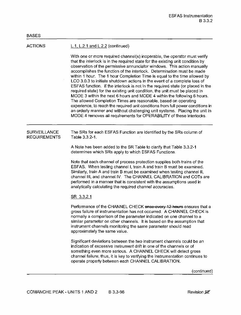
ESFAS InstrumentationB 3.3.2
BASES
ACTIONS L.1, L.2.1 and L.2.2 (continued)
With one or more required channel(s) inoperable, the operator must verifythat the interlock is in the required state for the existing unit condition byobservation of the permissive annunciator windows. This action manuallyaccomplishes the function of the interlock. Determination must be madewithin 1 hour. The 1 hour Completion Time is equal to the time allowed byLCO 3.0.3 to initiate shutdown actions in the event of a complete loss ofESFAS function. If the interlock is not in the required state (or placed in therequired state) for the existing unit condition, the unit must be placed inMODE 3 within the next 6 hours and MODE 4 within the following 6 hours.The allowed Completion Times are reasonable, based on operatingexperience, to reach the required unit conditions from full power conditions inan orderly manner and without challenging unit systems. Placing the unit inMODE 4 removes all requirements for OPERABILITY of these interlocks.
SURVEILLANCE The SRs for each ESFAS Function are identified by the SRs column ofREQUIREMENTS Table 3.3.2-1.
A Note has been added to the SR Table to clarify that Table 3.3.2-1determines which SRs apply to which ESFAS Functions.
Note that each channel of process protection supplies both trains of theESFAS. When testing channel I, train A and train B must be examined.Similarly, train A and train B must be examined when testing channel II,channel III, and channel IV. The CHANNEL CALIBRATION and COTs areperformed in a manner that is consistent with the assumptions used inanalytically calculating the required channel accuracies.
SR 3.3.2.1
Performance of the CHANNEL CHECK ncqc cvcry 12 hour;s ensures that agross failure of instrumentation has not occurred. A CHANNEL CHECK isnormally a comparison of the parameter indicated on one channel to asimilar parameter on other channels. It is based on the assumption thatinstrument channels monitoring the same parameter should readapproximately the same value.
Significant deviations between the two instrument channels could be anindication of excessive instrument drift in one of the channels or ofsomething even more serious. A CHANNEL CHECK will detect grosschannel failure; thus, it is key to verifying the instrumentation continues tooperate properly between each CHANNEL CALIBRATION.
(continued)
COMANCHE PEAK- UNITS 1 AND 2 B 3.3-98 Revision k6Z

ESFAS InstrumentationB 3.3.2
BASES
SURVEILLANCE SR 3.3.2.1 (continued)REQUIREMENTS
Agreement criteria are determined by the unit staff, based on a combinationof the channel instrument uncertainties, including indication and reliability. Ifa channel is outside the criteria, it may be an indication that the sensor or thesignal processing equipment has drifted outside its limit.
The Frequency is based on operating experience that demo annelfailure is rare. The CHANNEL CHECK su ess formal, but morefrequent, checks of chan g normal operational use of the displaysassocia e CO required channels.
SR 3.3.2.2
SR 3.3.2.2 is the performance of an ACTUATION LOGIC TEST.-The- S•SPi-. tetod .v..; 92 days .. n a-STACERED TEST BASIS, using thesemiautomatic tester. The train being tested is placed in the bypasscondition, thus preventing inadvertent actuation. Through the semiautomatictester, all possible logic combinations, with and without applicablepermissives, are tested for each protection function. In addition, the masterrelay coil is pulse tested for continuity. This verifies that the logic modulesare OPERABLE and that there is an intact voltage signal path to the master
[INSERT 3 relay coils. The Frequency of evey 92 days on a STAGGERED TES10 JaIstIfed iili Refie ile, e 13.
S R 3.3.2.3
Not used.
SR 3.3.2.4
SR 3.3.2.4 is the performance of a MASTER RELAY TEST. The MASTERRELAY TEST is the energizing of the master relay, verifying contactoperation and a low voltage continuity check of the slave relay coil. Uponmaster relay contact operation, a low voltage is injected to the slave relaycoil. This voltage is insufficient to pick up the slave relay, but large enoughto demonstrate signal path continuity. Ti is test ,s pef, , ied every 92 daysu, d, STAGGERED TEST BASIS. The time allowed for the testing (4 hours)"s justified in Reference 6. The Freque1 f 92 dy• u, d STAGGERED
SR 3.3.2.5
SR 3.3.2.5 is the performance of a COT.
(continued)
COMANCHE PEAK - UNITS 1 AND 2 B 3.3-99 Revision 52

ESFAS InstrumentationB 3.3.2
BASES
SURVEILLANCE SR 3.3.2.5 (continued)REQUIREMENTS
A COT is performed on each required channel to ensure the entire channelwill perform the intended Function. Setpoints must be found within theAllowable Values specified in Table 3.3.2-1.
The difference between the current "as found" values and the previous test"as left" values must be consistent with the drift allowance used in thesetpoint calculation. The setpoint shall be left set consistent with theassumptions of the current unit specific setpoint calculation.
SR 3.3.2.5 for selected Functions is also modified by two Notes (q and r) asidentified in Table 3.3.2-1. The selected Functions are those Functions thatare LSSS and whose instruments are not mechanical devices (i.e. limitswitches, float switches, and proximity detectors). Mechanical devices areexcluded since it is not possible to trend these devices and develop as-left oras-found limits in the same manner as other instrumentation. The first Note(q) requires evaluation of channel performance for the condition where theas-found setting for the channel setpoint is outside its as-found tolerance butconservative with respect to the Allowable Value. Evaluation of instrumentperformance will verify that the instrument will continue to behave inaccordance with design-basis assumptions. The purpose of the assessmentis to ensure confidence in the instrument performance prior to returning theinstrument to service. These channels will also be identified in theCorrective Action Program. In accordance with procedures, entry into theCorrective Action Program will require review and documentation of thecondition for OPERABILITY. The second Note requires that the as-leftsetting for the instrument be returned to within the as-left tolerance of theNominal Trip Setpoint. This will ensure that sufficient margin to the SafetyLimit and/or Analytical Limit is maintained. If the as-left instrument settingcannot be returned to a setting within the as-left tolerance, then theinstrument channel shall be declared inoperable. This second Note (r)requirement identifies the Limited Safety System Setting and allows anindependent verification that the Allowable Value is the appropriate leastconservative as-found value during SR testing.
3IS R T , i F ie q je i -,c y o f ,8 4 d ay s is ju s tifie d, in . . . . . . . .. . .
SR 3.3.2.6
SR 3.3.2.6 is the performance of a SLAVE RELAY TEST. The SLAVERELAY TEST is the energizing of the slave relays. Contact operation isverified in one of two ways. Actuation equipment that may be operated in thedesign mitigation mode is either allowed to function, or is placed in a
(continued)
COMANCHE PEAK - UNITS 1 AND 2 B 3.3-100 Revision £S2"

ESFAS InstrumentationB 3.3.2
BASES
SURVEILLANCEREQUIREMENTS
SR 3.3.2.6 (continued)
condition where the relay contact operation can be verified without operationof the equipment. Actuation equipment that may not be operated in thedesign mitigation mode is prevented from operation by the SLAVE RELAYTEST circuit. For this latter case, contact operation is verified by a continuitycheck of the circuit containing contacts operated by the slave relay. T-fie4esa peirformd eycr; 92 days. Tho Freuec Ie adequate, based on indiis4~
.... iG G@ G-t1.6i Ixe: P.sr_.rent reliability aprnd onpprEfinq hi-qtnry
For ESFAS slave relays and auxiliary relays which are Westinghouse typeAR relays, the SLAVE ,RELAY TEST 0s perfamrnd ev,-y 18 months. TheFrgquency is based oft the slave relay reliability assessment presented inReference 10. This rcliability arsessment is relay specific and applies onlyto Westinghouse type AR relays with AC coils. Note that, for normallyenergized applications, the relays may require periodic replacement inaccordance with the guidance given in Reference 10.
SR 3.3.2.7
SR 3.3.2.7 is the performance of a TADOT everiy 31 days-. This test is acheck of the Loss of Offsite Power Function.
INSERT 3 The SR is modified by a Note that excludes verification of setDoints for
relays. Relay setpoints require elaborate bench calibration and are verifiedduring CHANNEL CALIBRATION. The SR is modified by a second note thatexcludes the actuation of final devices from the surveillance testing. Thestart of the auxiliary feedwater pumps during this SR is unnecessary as
curthese numps are adequately tested by the SRs for LCO 3.7.5. tT\ ::•requsiencyo Is deq atei[ity baRE upl, in 19isuey data. epeen
SR 3.3.2.8
SR 3.3.2.8 is the performance of a TADOT. This test is a check of theManual Actuation Functions and AFW pump start on trip of all MFW pumps.The Safety Injection TADOT shall independently verify the OPERABILITY ofthe handswitch undervoltage and shunt trip contacts for both the ReactorTrip Breakers and Reactor Trip Bypass Breakers as well as the contacts forsafety injection actuation. It is peiformod eveFy 18 ,moths. As a minimum,each Manual Actuation Function is tested up to, but not including, the masterrelay coils. This test overlaps with the master relay coil testing performed in
ccordance with SR 3.3.2.4. T:he Froguncqy is adcquatc, based on in1dustr(operat, ig expesrience and is cosistent with the typical refueling cycle. The
(continued)
COMANCHE PEAK - UNITS 1 AND 2 B 3.3-101 Revisionx,

ESFAS InstrumentationB 3.3.2
BASES
SURVEILLANCE SR 3.3.2.8 (continued)REQUIREMENTS
SR is modified by a Note that excludes verification of setpoints during theTADOT for manual initiation Functions. The manual initiation Functionshave no associated setpoints.
SR 3.3.2.9
SR 3.3.2.9 is the performance of a CHANNEL CALIBRATION.
A CHANNEL CeAL',DRATION as per.oF.m.d evr;' 18 m,,,ths, e.ppr..xi.m'tly at cvc,; r"fuoling CHANNEL CALIBRATION is a completecheck of the instrument loop, including the sensor. The test verifies that thechannel responds to measured parameter within the necessary range andaccuracy.
CHANNEL CALIBRATIONS must be performed consistent with theassumptions of the unit specific setpoint methodology.
[•NSERT 3 The Frequency of 18 months is based on the assum 1moncalibration interval in the deter e magnitude of equipment drift inthe set o ogy.
This SR is modified by a Note stating that this test should include verificationthat the time constants are adjusted to the prescribed values whereapplicable.
SR 3.3.2.9 for selected Functions is also modified by two Notes (q and r) asidentified in Table 3.3.2-1. The selected Functions are those Functions thatare LSSS and whose instruments are not mechanical devices (i.e. limitswitches, float switches, and proximity detectors). Mechanical devices areexcluded since it is not possible to trend these devices and develop as-left oras-found limits in the same manner as other instrumentation. The first Note(q) requires evaluation of channel performance for the condition where theas-found setting for the channel setpoint is outside its as-found tolerance butconservative with respect to the Allowable Value. Evaluation of instrumentperformance will verify that the instrument will continue to behave inaccordance with design-basis assumptions. The purpose of the assessmentis to ensure confidence in the instrument performance prior to returning theinstrument to service. These channels will also be identified in theCorrective Action Program. In accordance with procedures, entry into theCorrective Action Program will require review and documentation of thecondition for OPERABILITY. The second Note (r) requires that the as-leftsetting for the instrument be returned to within the as-left tolerance of theNominal Trip Setpoint. This will ensure that sufficient margin to the Safety
(continued)
COMANCHE PEAK - UNITS 1 AND 2 B 3.3-102 Revision,

ESFAS InstrumentationB 3.3.2
BASES
SURVEILLANCE SR 3.3.2.9 (continued)REQUIREMENTS
Limit and/or Analytical Limit is maintained. If the as-left instrument settingcannot be returned to a setting within the as-left tolerance, then theinstrument channel shall be declared inoperable. This second Note (r)requirement identifies the Limited Safety System Setting and allows anindependent verification that the Allowable Value is the appropriate leastconservative as-found value during SR testing.
SR 3.3.2.10
This SR ensures the individual channel ESF RESPONSE TIMES are lessthan or equal to the maximum values assumed in the accident analysis.Response Time testing, required channels, and acceptance criteria areincluded in the Technical Requirements Manual (Ref. 7). For eachFunctional Unit to which this SR applies, at least one ESF function has arequired response time but not necessarily all associated ESF functions. Nocredit was taken in the safety analyses for those channels with responsetime listed as N.A. When the response time for a function in the TRM is NA,no specific testing need be performed to comply with this SR. Individualcomponent response times are not modeled in the analyses. The analysesmodel the overall or total elapsed time, from the point at which the parameterexceeds the Trip Setpoint value at the sensor, to the point at which theequipment in both trains reaches the required functional state (e.g., pumpsat rated discharge pressure, valves in full open or closed position).
For channels that include dynamic transfer functions (e.g., lag, lead/lag, rate/lag, etc.), the response time testing may be performed with the transferfunctions set at their nominal values. The response time may be measuredby a series of overlapping tests such that the entire response time ismeasured.
Response time may be verified by actual response time tests in any series ofsequential, overlapping or total channel measurements, or by the summationof allocated sensor, signal processing and actuation logic response timeswith actual response time tests on the remainder of the channel. Allocationsfor sensor response times may be used for selected components providedthat the components and methodology for, verification have been previouslyNRC approved.
ESF RESPONSE TIME tests are performed on an 18 month ST
TEST BASIS. The testing shall include at least such that bothtrains are tested at least once s. Testing of the final actuationdevices, which mak e ulk of the response time, is included in thetes cchannel. The final actuation device in one train is tested with,
(continued)
COMANCHE PEAK - UNITS 1 AND 2 B 3.3-103 Revision f6e

ESFAS InstrumentationB 3.3.2
BASES
SURVEILLANCE SR 3.3.2.10 (continued)REQUIREMENTS
each channel. I herefore, staggered testing results in response t'verification of these devices every 18 months., T Frequency isconsistent with the typical refueli n is based on unit operatingexperience, whic at random failures of instrumentation
c s causin serious response time degradation, but not channelfihr j r ¢,- n re ,,et ocCu ce esponse time verification in lieu ofactual testing may be perf on ESFAS components in accordance withreference1
Th ' is modified by a Note that clarifies that the turbine driven AFW pump
_is tested within 24 hours after reaching 532 psig in the SGs.JINSERT 3 X
SR 3.3.2.11
SR 3.3.2.11 is the performance of a TADOT as described in SR 3.3.2.8,xcept that it is performed for the P-4 Reactor Trip Interlock. Th-iFequefeýL
is b08-01am~ on peffting
The SR is modified by a Note that excludes verification of setpoints duringthe TADOT. The Function tested has no associated setpoint.
REFERENCES 1. FSAR, Chapter 6.
2. FSAR, Chapter 7.
3. FSAR, Chapter 15.
4. IEEE-279-1971.
5. 10 CFR 50.49.
6. WCAP-10271-P-A, Supplement 2, Rev. 1, June 1990.
7. Technical Requirements Manual.
8. WCAP-10271-P-A, Supplement 3, September 1990.
9. "Westinghouse Setpoint Methodology for Protection SystemsComanche Peak Unit 1, Revision 1," WCAP-12123, Revision 2,April, 1989.
10. WCAP-13877-P-A, Revision 2, August 2000.
(continued)
COMANCHE PEAK - UNITS 1 AND 2 B 3.3-104 Revision W

PAM InstrumentationB 3.3.3
BASES
ACTIONS (continued)
E.1 and E.2
If the Required Action and associated Completion Time of Condition C is notmet and Table 3.3.3-1 directs entry into Condition E, the unit must bebrought to a MODE where the requirements of this LCO do not apply. Toachieve this status, the unit must be brought to at least MODE 3 within 6hours and MODE 4 within 12 hours.
The allowed Completion Times are reasonable, based on operatingexperience, to reach the required unit conditions from full power conditions inan orderly manner and without challenging unit systems.
F. 1
Alternate means of monitoring Reactor Vessel Water Level and ContainmentArea Radiation have been developed. These alternate means may betemporarily used if the normal PAM channel cannot be restored toOPERABLE status within the allotted time. If these alternate means areused, the Required Action is not to shut down the unit but rather to follow thedirections of Specification 5.6.8, in the Administrative Controls section of theTS. The report provided to the NRC should discuss the alternate meansused, describe the degree to which the alternate means are equivalent to theinstalled PAM channels, justify the areas in which they are not equivalent,and provide a schedule for restoring the normal PAM channels.
SURVEILLANCE A Note has been added to the SR Table to clarify that SR 3.3.3.1 and
REQUIREMENTS SR 3.3.3.3 apply to each PAM instrumentation Function in Table 3.3.3-1.
SR 3.3.3.1
Performance of the CHANNEL CHECK ance- tery 31 days ensures that agross instrumentation failure has not occurred. A CHANNEL CHECK isnormally a comparison of the parameter indicated on one channel to asimilar parameter on other channels. It is based on the assumption thatinstrument channels monitoring the same parameter should readapproximately the same value. Significant deviations between the twoinstrument channels could be an indication of excessive instrument drift inone of the channels or of something even more serious. A CHANNELCHECK will detect gross channel failure; thus, it is key to verifying theinstrumentation continues to operate properly between each CHANNELCALIBRATION.
(continued)
COMANCHE PEAK - UNITS 1 AND 2 B 3.3-121 Revision Blf

PAM InstrumentationB 3.3.3
BASES
SURVEILLANCE SR 3.3.3.1 (continued)REQUIREMENTS
Agreement criteria are determined by the unit staff, based on a combinationof the channel instrument uncertainties, including isolation, indication, andreadability. If a channel is outside the criteria, it may be an indication that thesensor or the signal processing equipment has drifted outside its limit. If thechannels are within the criteria, it is an indication that the channels areOPERABLE.
As specified in the SR, a CHANNEL CHECK is only required for thosechannels that are normally energized. All of the instruments listed inTable 3.3.3-1 are normally energized.
The Frequency of 31 days is based on operating experiendemonstrates that channel failure is rare. T EL CHECKsupplements less formal, bu quent, checks of channels duringnormal operatio o the displays associated with the LCO required
S R 3.3.3.2
Deleted
S R 3.3.3.3
A GCHAN CALIBRATION is p aormod ovor,'c 1 roqnths, o;approximately at ever; rofuoling. CHANNEL CALIBRATION is a complete
INSERTcheck of the instrument loop, including the sensor. The test verifies that thechannel responds to measured parameter with the necessary range andaccuracy. The calibration method for neutron detectors is specified in theBases of LCO 3.3.1, "Reactor Trip System (RTS) Instrumentation."Whenever an RTD is replaced in Function 3 or 4, the next requiredCHANNEL CALIBRATION of the RTDs is accomplished by an inplace crossalibration that compares other sensing elements with the recently installed
e ment. Whenever a core exit thermocouple replaced in Functions 15 thru
18, he next required CHANNEL CALIBRATION of the core exitther couples is accomplished by an in-place cross calibration thatclompa the other sensing elements with the recently installed sensingele men-. I Io 'Frouenoy is based em operating experionee and eamsisteneym i- thotypica~l iHEd~tr,' rofuGoRin cYcle. Containment Radiation Level (HighRange) CHANNEL CALIBRATION may consist of an electronic calibration ofthe channel, not including the detector, for range decades above IOR/hr anda one point calibration check of the detector below 1 OR/hr with an installed orportable gamma source.
(continued)
COMANCHE PEAK - UNITS I AND 2 B 3.3-122 Revisionx

Remote Shutdown SystemB 3.3.4
BASES
ACTIONS A.1 (continued)
The Required Action is to restore the required Function and required HSPcontrols to OPERABLE status within 30 days. The Completion Time isbased on operating experience and the low probability of an event that wouldrequire evacuation of the control room.
B.1 and B.2
If the Required Action and associated Completion Time of Condition A is notmet, the unit must be brought to a MODE in which the LCO does not apply.To achieve this status, the unit must be brought to at least MODE 3 within6 hours and to MODE 4 within 12 hours. The allowed Completion Times arereasonable, based on operating experience, to reach the required unitconditions from full power conditions in an orderly manner and withoutchallenging unit systems.
SURVEILLANCE SR 3.3.4.1REQUIREMENTS
Performance of the CHANNEL CHECK uice every, 31 days ensures that agross failure of instrumentation has not occurred. A CHANNEL CHECK isnormally a comparison of the parameter indicated on one channel to asimilar parameter on other channels. It is based on the assumption thatinstrument channels monitoring the same parameter should readapproximately the same value. Significant deviations between the twoinstrument channels could be an indication of excessive instrument drift inone of the channels or of something even more serious. CHANNEL CHECKwill detect gross channel failure; thus, it is key to verifying that theinstrumentation continues to operate properly between each CHANNELCALIBRATION.
Agreement criteria are determined by the unit staff, based on a combinationof the channel instrument uncertainties, including indication and readability.If the channels are within the criteria, it is an indication that the channels areOPERABLE. If a channel is outside the criteria, it may be an indication thatthe sensor or the signal processing equipment has drifted outside its limit.
As specified in the Surveillance, a CHANNEL CHECK is only required forthose channels which are normally energized. With the exception of thecharging pump to CVCS and RCP seals flow indication, all instruments listedin Table 3.3.4-1 are normally energized. The channels (recorders) for theRCS Hot Leg Temperature and RCS Cold Leg Temperature functions maybe de-energized during non-use with capability to be energized to obtain thenecessary reading. The F•re..u....y of 31 days is based uon peai
whieh deannatrtes that channel failure i(S Weiu
(continued)
COMANCHE PEAK - UNITS I AND 2 B 3.3-127 Revisionfie

Remote Shutdown SystemB 3.3.4
BASES
SURVEILLANCE SR 3.3.4.1 (continued)REQUIREMENTS
[Te CHANNEL CHECK supplements less formabtenes uing normal o e-o edisplays associated with
::il1fannels.
S R 3.3.4.2
SR 3.3.4.2 verifies each required Remote Shutdown System HSP power andcontrol circuit and transfer switch performs the intended function. Thisverification is performed from the Hot Shutdown Panel and locally, asappropriate. Operation of the equipment from the remote shutdown panel is
INSERT 3 -- not necessary. The Surveillance can be satisfied by performance of acontinuity check. This will ensure that if the control room becomesinaccessible, the unit can be placed and maintained in MODE 3 from theremote ghutdown panel and the local control statfions- T. 1e Rmieth-
Frequency is based on the need to perform this Surveillance un econditions that apply during a plant outage and the po or anunplanned transient if the Surveillance were rmed with the reactor atpower. (However, this Surveillan ot required to be performed onlyduring a unit outage.) ing experience demonstrates that remoteshutdown co annels usually pass the Surveillance test whenpe at the 18 month Frequency.
S R 3.3.4.3
CHANNEL CALIBRATION is a complete check of the instrument loop andthe sensor. The test verifies that the channel responds to a measuredparameter within the necessary range and accuracy. Whenever a sensingelement is replaced, the next required CHANNEL CALIBRATION of theresistance temperature detectors (RTD) sensors is accomplished by an in-place cross calibration that compares the other sensing elements with therecently installed sensing element. The Fr1equeniCy of 18 11iuiiuis IS babeuepcen operatingtle sxpoione and cn sinste ncy w fith the typical insi bserefeg-qGyGle-
REFERENCES 1. 10 CFR 50, Appendix A, GDC 3 and 19.
2. FSAR Section 7.4
COMANCHE PEAK - UNITS 1 AND 2 B 3.3-128 Revisionx<

LOP DG Start InstrumentationB 3.3.5
BASES
ACTIONS (continued)
F. 1
Condition F applies when one or more trains of Automatic Actuation Logicand Actuation Relay function are inoperable.
Required Action F.1 requires restoring the inoperable train(s) to OPERABLEstatus. The 1 hour completion Time allows time to repair failures and takesinto account the low probability of an event requiring LOP DG start occurringduring this interval.
G.1
Condition G applies to each of the LOP DG start Functions when theRequired Action and associated Completion Time for Conditions A through Fare not met.
In these circumstances the Conditions specified in LCO 3.8.1, "AC Sources -Operating," for the DG made inoperable by failure of the LOP DG startinstrumentation are required to be entered immediately. The actions ofthose LCOs provide for adequate compensatory actions to assure unitsafety.
SURVEILLANCE SR 3.3.5.1REQUIREMENTS
SR 3.3.5.1 is the performance of an ACTUATION LOGIC TEST. The LOPDG Start Automatic Actuation Logic and Actuation Relays are tested prior toentering MODE 4 when in MODE 5 for greater than or equal to 72 hours andif not performed in the previous 9-.2day. The Function is tested prior toentering MODE 4 to assu t the associated diesel generator is notunnecessarily starte the testing. Such unnecessary starts could beadverse to the ability of the diesel generator. The testing verifies that thelogic is 0 BLE. The Frequency of the testing is adequate. The
Frequency 372 rs assures that there is sufficient time during the shutdown to performspecified in e testing. TIti 92 days is basd an idustry oper.tig exper'enco,Ithe SFCP asdin 99ifnt eablt ide8aR0ht
r rISR 3•.5.2 is the performance of a TADOT. This test is performed prior toentry ih~& MODE 4 when in MODE 5 for >__ 72 hours and if no performed inprevious 99-2t-y. The test checks trip devices that provid ctuation signals
directly, bypassing the analog process control equipment. he Frequen
(continued)
COMANCHE PEAK - UNITS 1 AND 2 B 3.3-135 Revision X
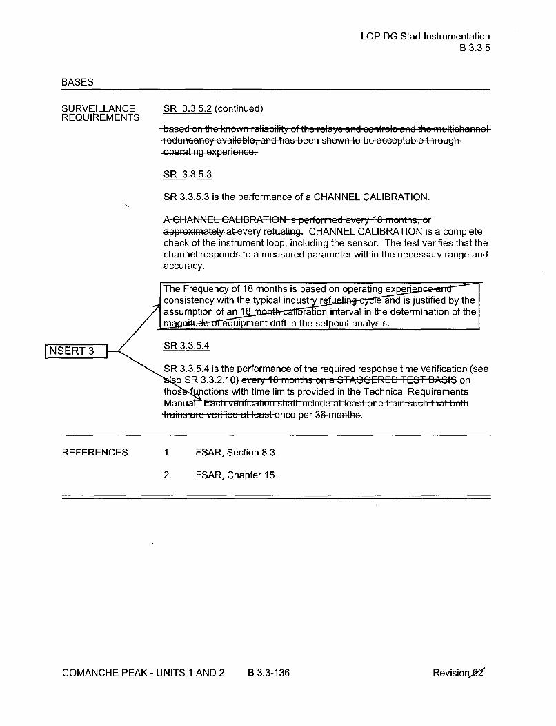
LOP DG Start InstrumentationB 3.3.5
BASES
SURVEILLANCE SR 3.3.5.2 (continued)REQUIREMENTS
based on the know reliability of the relaY- 8nd entr-• - 'S 8,n th98 ,ultiehannlrodlundancy ayailablc, and has been shown tc be acccptablc thrcgW@h
pra..ting 0 p..i nc o.
SR 3.3.5.3
SR 3.3.5.3 is the performance of a CHANNEL CALIBRATION.
A Cl IANNEL: CALi:BR~ATION is perfo.rmd evr 18 months, aapproximately at ever refeling CHANNEL CALIBRATION is a completecheck of the instrument loop, including the sensor. The test verifies that thechannel responds to a measured parameter within the necessary range andaccuracy.
The Frequency of 18 months is based on operating expejrconsistency with the typical industry ref e and is justified by theassumption of a18 ration interval in the determination of them ýequipment drift in the setpoint analysis.
[INSERT 3 SR 3.3.5.4
SSR 3.3.5.4 is the performance of the required response time verification (see
REFERENCES 1. FSAR, Section 8.3.
2. FSAR, Chapter 15.
COMANCHE PEAK - UNITS 1 AND 2 B 3.3-136 RevisionX

Containment Ventilation Isolation InstrumentationB 3.3.6
BASES
ACTIONS B.1 (continued)(continued)
If a train is inoperable, or the Required Action and associated CompletionTime of Condition A are not met, operation may continue as long as theRequired Action for the applicable Conditions of LCO 3.6.3 is met for eachvalve made inoperable by failure of isolation instrumentation.
A Note is added to allow the containment pressure relief valves to be openedin compliance with the gaseous effluent monitoring instrumentationrequirements in Part I of the ODCM, for Required Action and associatedCompletion Time of Condition A not met.
A Note is added stating that Condition B is only applicable in MODE 1, 2, 3,or4.
C.1 and C.2
Condition C applies to the inability to restore the radiation monitoringchannel to OPERABLE status in the time allowed for Required Action A.1. Ifthe Required Action and associated Completion Time of Condition A are notmet, operation may continue as long as the Required Action to place andmaintain containment ventilation isolation valves in their closed position ismet or the applicable Conditions of LCO 3.9.4, "Containment Penetrations,"are met for each valve made inoperable by failure of isolationinstrumentation. A note allows the containment pressure relief valves to beopened in compliance with gaseous effluent monitoring instrumentationrequirements in Part I of the ODCM. The Completion Time for theseRequired Actions is Immediately.
A Note states that Condition C is applicable during CORE ALTERATIONSand during movement of irradiated fuel assemblies within containment.
SURVEILLANCE A Note has been added to the SR Table to clarify that Table 3.3.6-1REQUIREMENTS determines which SRs apply to which Containment Ventilation Isolation
Functions.
SR 3.3.6.1
Performance of the CHANNEL CHECK uic evei-Y 12 hours ensures that agross failure of instrumentation has not occurred. A CHANNEL CHECK willdetect gross channel failure; thus, it is key to verifying the instrumentationcontinues to operate properly between each CHANNEL CALIBRATION.
(continued)
COMANCHE PEAK - UNITS 1 AND 2 B 3.3-142 Revision 0
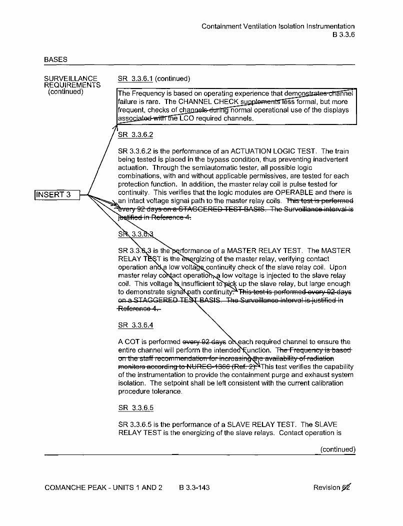
Containment Ventilation Isolation InstrumentationB 3.3.6
BASES
SURVEILLANCEREQUIREMENTS
(continued)
SR 3.3.6.1 (continued)
The Frequency is based on operating experience that dm nefailure is rare. The CHANNEL CHECK su ess formal, but morefrequent, checks of cha g normal operational use of the displayslasso " e LCO required channels.
'ISR 3.3.6.2
SR 3.3.6.2 is the performance of an ACTUATION LOGIC TEST. The trainbeing tested is placed in the bypass condition, thus preventing inadvertentactuation. Through the semiautomatic tester, all possible logiccombinations, with and without applicable permissives, are tested for eachprotection function. In addition, the master relay coil is pulse tested forcontinuity. This verifies that the logic modules are OPERABLE and there isan intact voltage signal path to the master relay coils. Ttst is pcrfc..cd
Q r~-fr-Q -M rrQ-- DA 1Q -,k C I1 ; • + I ;|ia%•
[INSERT 3 1
y ur 'Jyc IJ a V" C1
Pam i ZRefeene 4.
SR 3.3.S3 is the rformance of a MASTER RELAY TEST. The MASTERRELAY T T is the rgizing of the master relay, verifying contactoperation an a low volta.. continuity check of the slave relay coil. Uponmaster relay co act operatio , low voltage is injected to the slave relaycoil. This voltage insufficient to ck up the slave relay, but large enough
to demonstrate signa ath continuit .y- .-.gthis tcst is pcformcd cvej 92 d-ys
S R 3.3.6.4
A COT is performed ei8- 92-cays o each required channel to ensure theentire channel will perform the intendedF unction. The F1 ual is bs0. i , t i staff,, eco ni-n n daei-,, o,,, for ,,,F s~u--L _ _ _.•• •4 t ava ,ab o,,ty of Ffad *s l~
, ,monOFSEtedg to ,N"UEG-',,'-C-I 3, (Ref. y."This test verifies the capabilityof the instrumentation to provide the containment purge and exhaust systemisolation. The setpoint shall be left consistent with the current calibrationprocedure tolerance.
SR 3.3.6.5
SR 3.3.6.5 is the performance of a SLAVE RELAY TEST. The SLAVERELAY TEST is the energizing of the slave relays. Contact operation is
(continued)
COMANCHE PEAK - UNITS 1 AND 2 B 3.3-143 Revision 0

Containment Ventilation Isolation InstrumentationB 3.3.6
BASES
SURVEILLANCEREQUIREMENTS(continued)
SR 3.3.6.5 (continued)
verified in one of two ways. Actuation equipment that may be operated in thedesign mitigation mode is either allowed to function or is placed in acondition where the relay contact operation can be verified without operationof the equipment. Actuation equipment that may not be operated in thedesign mitigation mode is prevented from operation by the SLAVE RELAYTEST circuit. For this latter case, contact operation is verified by a continuitycheck of the circuit containing contacts operated by the slave relay. Ttlts'tesiz~pt-i UI1i itu 1-Vely 3' aUys. The I- ,eeptab"-
-OE14 MIR-'an 1. Liafml-iIIL* LA IRAJ hI nL IL l.LELtNIjL~JI L 'J
e;L riseL;; 1e.I
u I lO jl I l [,, IL I . yl.,l.ll. J ~ !I%,L4.L •/~[,lr,! I •: .• •1%• I•.. F •..,
For ESFAS slave relays and auxiliary relays which are Westinghouse typeAR relays, the SLAVE RELAY TEST is peformed every 1, months. The.-Fe - based on the slave relay reliability assessment presented in
JINSERT 3 • Reference 3. This reliability assessment is relay specific and applies only toWestinghouse type AR relays with AC coils. Note that, for normallyenergized applications, the relays may require periodic replacement inaccordance with the guidance given in Reference 3.
SR 3.3.6.6
Not Used.
SR 3.3.6.7
A CI IANNEL CALI2,,RATION is pfcfOrncd evc,; 18 ,mcnths, er8ppr.Ximlatly at eVe.y refeling CHANNEL CALIBRATION is a completecheck of the instrument loop, including the sensor. The test verifies that thechannel responds to a measured parameter within the necessary range andaccuracy.
The Frequenucy is based un upeiatingy jxp riuiiu dnd is uiisisiteiit witll 1u1-typical industry rofbeing c.yc..
)
REFERENCES 1. 10 CFR 100.11.
2. NUREG-1366, July 22, 1993.
3. WCAP-1 3877-P-A, Revision 2, August 2000.
4. WCAP-15376-P-A, Revision 2, "Risk-Informed Assessment of theRTS and ESFAS Surveillance Test Intervals and Reactor TripBreaker Test and Completion Times," March 2003.
COMANCHE PEAK - UNITS 1 AND 2 B 3.3-144 Revision 0

CREFS Actuation InstrumentationB 3.3.7
BASES
ACTIONS (continued)
D.1 and D.2
Condition D applies when the Required Action and associated CompletionTime for Condition A or B have not been met during MODE 5 or 6 or whenirradiated fuel assemblies are being moved. Movement of irradiated fuelassemblies and CORE ALTERATIONS must be suspended immediately toreduce the risk of accidents that would require CREFS actuation
SURVEILLANCE A Note has been added to the SR Table to clarify that Table 3.3.7-1
REQUIREMENTS determines which SRs apply to which CREFS Actuation Functions.
SR 3.3.7.1
Performance of the CHANNEL CHECK once every, 12 h, ,irs ensures that agross failure of instrumentation has not occurred. A CHANNEL CHECK isnormally a comparison of the parameter indicated on one channel to asimilar parameter on other channels. It is based on the assumption thatinstrument channels monitoring the same parameter should readapproximately the same value. Significant deviations between the twoinstrument channels could be an indication of excessive instrument drift inone of the channels or of something even more serious. A CHANNELCHECK will detect gross channel failure; thus, it is key to verifying theinstrumentation continues to operate properly between each CHANNELCALIBRATION.
Agreement criteria are determined by the unit staff, based on a combinationof the channel instrument uncertainties, including indication and readability.If a channel is outside the criteria, it may be an indication that the sensor orthe signal processing equipment has drifted outside its limit.
SThe Frequency is based on operating experience that chann nethfailure is rare. The CHANNEL CHECK si fs formal, but more
c frequenty ohec In torprov e nal use of the displays
setpoint hall be left consistent with the unit specific calibration proceduretolerance. i the FquLiucy rs baeid h tae knownel s. ib,,ity of th, m-nitoring
efAOT ispmerformnd has been sho dayn tob eacchbo troqugchanoroensure(cntnud
COMANCHE PEAK - UNITS 1 AND 2 B 3.3-149 Revisionx

CREFS Actuation InstrumentationB 3.3.7
BASES
SURVEILLANCEREQUIREMENTS
SR 3.3.7.2 (continued)
-expecieve. The COT surveillance of the control room air intake monitorsverifies the contacts and circuitry between the monitors and the CREFSactuation circuits, and thereby satisfies the COT for Automatic ActuationLogic and Actuation Relays.
SR 3.3.7.3
Not Used.
SR 3.3.7.4
Not Used.
SR 3.3.7.5
Not Used.
SR 3.3.7.6
SR 3.3.7.6 is the performance of a TADOT. This test is a check of theManual Actuation Functions and ic p8•rf...md .V.ry 11a months. EachManual Actuation Function is tested up to, and including, the master relaycoils. In some instances, the test includes actuation of the end device.
The test also includes trip devices that provide actuation signals directly tothe Solid State Protection System, bypassing the analog process controlequipment. The Frequenciy is ba.sed on .thet know.. e.abiity of the Fu,- tion
R •d the rFd,-6dR.'aRcy a':aiabig, and ha•s been shoAw tO he acceptabln
JINSERT 3 I'thcigh operatlng cxpcronco- . The SR is modified by a Note that excludesverification of setpoints during the TADOT. The Functions tested have no
~setpoints; associated with them.
~SR 3.3.7.7
A CHANNEL CAWlBRATIGN is p•rfirmId c•vyl 1Ig months, aIapproximately at ... ;y rcfucling. CHANNEL CALIBRATION is a completecheck of the instrument loop, including the sensor. The test verifies that thechannel responds to a measured parameter within the necessary range andaccuracy.
lie Fi, e ueIImy is UbizttU 0ii u eid ldLII ig 1iisLe dui l il •t iti' 1 w it:typial inductry rafueling lyde
(continued)
Revisiono6COMANCHE PEAK - UNITS I AND 2 B 3.3-150

RCS Pressure, Temperature, and Flow DNB LimitsB 3.4.1
BASES (continued)
SURVEILLANCE SR 3.4.1.1REQUIREMENTS
Since Required Action A.1 allows a Completion Time of 2 hours to reparameters that are not within limits, the 12 hour Surv~eiýlequency forpressurizer pressure is sufficient to ensure the n re can be restored to anormal operation, steady state cond' " owing load changes and otherexpected transient opera he 12 hour interval has been shown byoperating prac e sufficient to regularly assess for potentialde on and to verify operation is within safety analysis assumptions.
SR 3.4.1.2
Since Required Action A.1 allows a Completion Time of 2 hours tparameters that are not within limits, the 12 hour Surveill requency forRCS average temperature is sufficient to ens emperature can berestored to a normal operation, ste e condition following load changesand other expected tran perations. The 12 hour interval has beenshown by o practice to be sufficient to regularly assess for potentiald ion and to verify operation is within safety analysis assumptions.
SR 3.4.1.3
The 12 i1uu0 SurvIvildiu Fluqueliuy fu [he inudicLed ReS total flow i-aleINSERT 3 performed us;ing the installed f i The 12 1 im iiterydI I
be610n- Ghown41 by operating practice to be su fficient to regu larly assesspotential degradation ad• to verif'y,' opFrion Within safety r al, nliassumpttanse. The indication for this parameter indicates in percent (%). Thevalue in % that will assure compliance with the minimum total flow limit in theSR is determined based on the measured RCS total flow from SR 3.4.1.4.
- oaior to the completion of SR 3.4.1.4,th %alue in % used to assure compliance with the minimum RCS total flow isbase upon the measured RCS total flow (SR 3.4.1.4) from the previousoperati ycle or an alternate measurement and assessment of actual RCStotal flow.
SR 3.4.1.4
Measurement of RCS total flow rate by performance of a precisioncalorimetric heat balance ancc evcry 18 ,,,•mothS (,ft•r eah ,Fre'fWuo allowsthe installed RCS flow instrumentation to be normalized and verifies theactual RCS flow rate is greater than or equal to the minimum required RCSflow rate.
(continued)
COMANCHE PEAK - UNITS 1 AND 2 B 3.4-5 Revision 0

RCS Pressure, Temperature, and Flow DNB LimitsB 3.4.1
BASES
SURVEILLANCEREQUIREMENTS
SR 3.4.1.4 (continued)
The Frequency of 18 months reflects the importance of v ee erarefueling outage when the core e ý,which may have caused an
alte esis ance.
IINSERT 3 This SR is modified by a Note that allows entry into MODE 1, without havingperformed the SR, and placement of the unit in the best condition forperforming the SR. The Note states that the SR is not required to beperformed until after exceeding 85% RTP after each refueling outage.Using precision instrumentation with multiple indications, the stated RCSflow accuracy may be attained at power levels significantly below 85% RTP,as described in the uncertainty analyses. Requiring the precision flowmeasurement to be performed prior to 85% RTP allows for a single testingplateau to be used to perform the RCS flow measurement and various othertests described in Section 3.2. Procedures require that the THERMALPOWER, available instrumentation, and calibration intervals be sufficient toensure that the stated RCS flow accuracy is attained. For feedwaterpressure and temperature, the main steam pressure, and feedwater flowdifferential pressure instruments are calibrated within 90 days of performingthe calorimetric flow measurement.
REFERENCES 1. FSAR, Section 15.
COMANCHE PEAK - UNITS 1 AND 2 B 3.4-6 Revision X

RCS Minimum Temperature for CriticalityB 3.4.2
BASES (continued)
SURVEILLANCEREQUIREMENTS
SR 3.4.2.1
RCS loop average temperature is required to be verified at or above 551 OFevey q2hous.
The SR to verify operating RCS loop average temperatures every rstakes into account indications and alarms that are conti available tothe operator in the control room and is consi i other routineSurveillances which are typically ed once per shift. In addition,operators are trained t nsitive to RCS temperature during approach tocriticality an nsure that the minimum temperature for criticality is met"cality is approached.
REFERENCES 1. FSAR, Chapter 15.
COMANCHE PEAK - UNITS 1 AND 2 B 3.4-9 RevisionW

RCS P/T LimitsB 3.4.3
BASES
ACTIONS C.1 and C.2 (continued)
ASME Code, Section XI, Appendix E (Ref. 7), may be used to support theevaluation. However, its use is restricted to evaluation of the vessel beltline.
Condition C is modified by a Note requiring Required Action C.2 to becompleted whenever the Condition is entered. The Note emphasizes theneed to perform the evaluation of the effects of the excursion outside theallowable limits. Restoration alone per Required Action C.1 is insufficientbecause higher than analyzed stresses may have occurred and may haveaffected the RCPB integrity.
SURVEILLANCE SR 3.4.3.1REQU IREMENTS
Verification that operation is within the PTLR limits is required e'eFY30 rn-ite when RCS pressure and temperature conditions are undergoingplanned change Tits Frequncy ib -uiniidfeid i''asuidble ih, view of .. it.
' ,ftICICILU lIU IC:iltk U I UL4IClllU IIII•€:lrn ts : dr te ~ll; s e ified in Iu Uly IlIcIe .nItIsII, 9 U
minutes permits aseossmont and c.r...tion fer minor dc..i.tiai.. within a
Surveillance for heatup, cooldown, or ISLH testing may be discontinuedwhen the definition given in the relevant plant procedure for ending theactivity is satisfied.
This SR is modified by a Note that only requires this SR to be performedduring system heatup, cooldown, and ISLH testing. No SR is given forcriticality operations because LCO 3.4.2 contains a more restrictiverequirement.
REFERENCES 1. Not used.
2. 10 CFR 50, Appendix G.
3. ASME, Boiler and Pressure Vessel Code, Section III, Appendix G.
4. ASTM E 185-82, July 1982.
5. 10 CFR 50, Appendix H.
6. Regulatory Guide 1.99, Revision 2, May 1988.
7. ASME, Boiler and Pressure Vessel Code, Section XI, Appendix E.
COMANCHE PEAK - UNITS 1 AND 2 B 3.4-15 RevisionjW

RCS Loops - MODES 1 and 2B 3.4.4
BASES
APPLICABILITY (continued)
The decay heat production rate is much lower than the full power heat rate.As such, the forced circulation flow and heat sink requirements are reducedfor lower, noncritical MODES as indicated by the LCOs for MODES 3, 4, and5.
Operation in other MODES is covered by:
LCO 3.4.5, "RCS Loops - MODE 3";LCO 3.4.6, "RCS Loops - MODE 4";
LCO 3.4.7, "RCS Loops - MODE 5, Loops Filled";
LCO 3.4.8, "RCS Loops - MODE 5, Loops Not Filled";
LCO 3.9.5, "Residual Heat Removal (RHR) and CoolantCirculation - High Water Level" (MODE 6); and
LCO 3.9.6, "Residual Heat Removal (RHR) and CoolantCirculation - Low Water Level" (MODE 6).
ACTIONS A.1
If the requirements of the LCO are not met, the Required Action is to reducepower and bring the plant to MODE 3. This lowers power level and thusreduces the core heat removal needs and minimizes the possibility ofviolating DNB limits.
The Completion Time of 6 hours is reasonable, based on operatingexperience, to reach MODE 3 from full power conditions in an orderlymanner and without challenging safety systems.
SURVEILLANCE SR 3.4.4.1REQUIREMENTS
This SR requires verification eery 12-f• w that each RCS loop is inoperation. Verification may include flow rate, temperature, or pump statusmonitoring, which help ensure that forced flow is providing heat removal
JINSERT 3 while maintaining the margin to DNB. The . .. "".
in th• o ,cntonl rEom tG m•onitor RCS loop pn4o8frmn'ce.
REFERENCES 1. FSAR, Section 15.
COMANCHE PEAK - UNITS 1 AND 2 B 3.4-18 RevisionaiT

RCS Loops - MODE 3B 3.4.5
BASES
ACTIONS D.1, D.2, and D.3 (continued)
coolant added with boron concentration meeting the minimum SDMmaintains acceptable margin to subcritical operations. The immediateCompletion Time reflects the importance of maintaining operation for heatremoval. The action to restore must be continued until one loop is restoredto OPERABLE status and operation.
SURVEILLANCE SR 3.4.5.1REQUIREMENTS
This SR requires verification every 12 hew'& that the required loops are inoperation. Verification may include flow rate, temperature, or pump statusmonitoring, which help ensure that forced flow is providing heat removal.The Frequency of 12 hours is sufficient considerin ot nalarms available to the o ro room to monitor RCS loop
SR 3.4.5.2
SR 3.4.5.2 requires verification of SG OPERABILITY. SG OPERABILITY isINSERT 3 verified by ensuring that the secondary side narrow range water level is
>38% (Unit 1) and >10% (Unit 2) for required RCS loops. If the SGsecondary side narrow range water level is <38% (Unit 1) and <10% (Unit 2),
\the tubes may become uncovered and the associated loop may not be•capable of providing the heat sink for removal of the decay heat. "The -1-
-1iuu• FI eque, icy is con~sd d ade ua e W ,n e;Of OthF ",ndieetie~is available
in the control room to aWert the operator to a loss of _qS level'
SR 3.4.5.3 INSERT3 3
Verification that the required RCPs are OPERABLE ensures that s fetyanalyses limits are met. The requirement also ensures that an ad itionalRCP can be placed in operation, if needed, to maintain decay he t removaland reactor coolant circulation. Verification is performed by verj ing properbreaker alignment and power availability to the required RCPs.
REFERENCES None.
COMANCHE PEAK - UNITS 1 AND 2 B 3.4-23 Revision JC

RCS Loops - MODE 4B 3.4.6
BASES
ACTIONS B.1 and B.2 (continued)
criticality must not be reduced in this type of operation. Suspending theintroduction of coolant into the RCS with boron concentration less thanrequired to meet the minimum SDM of LCO 3.1.1 is required to assurecontinued safe operation. With coolant added without forced circulation,unmixed coolant could be introduced to the core, however coolant addedwith boron concentration meeting the minimum SDM maintains acceptablemargin to subcritical operations. The immediate Completion Times reflectthe importance of maintaining operation for decay heat removal. The actionto restore must be continued until one loop is restored to OPERABLE statusand operation.
SURVEILLANCE SR 3.4.6.1REQUIREMENTS
This SR requires verification eve 2 h44 s-that one RCS or RHR loop is inoperation. Verification may include flow rate, temperature, or pump statusmonitoring, which help ensure that forced flow is providing heat removal.TIh Frequency of 12 h,' r- is . uffiei:. t c: .. .,,ir-g other indic-tions 2ndalarms a-ailablc te the Opefrtor in the control ream- to ,-oi to, ReS cid RHR
SR 3.4.6.2
SR 3.4.6.2 requires verification of SG OPERABILITY. SG OPERABILITY isverified by ensuring that the secondary side narrow range water level is>38% (Unit 1) and >10% (Unit 2). If the SG secondary side narrow range
LISET water level is <38% (Unit 1) and <10% (Unit 2), the tubes may become
uncovered and the associated loop may not be capable of providing the heat\ •~sink necessary for removal of decay heat. The i2-huur F, qum,,cy-is\ -;.4ns-d redadequate in viewýA~ of other ind!c-;atiens- availalble in the control
r.eva *,.,. k p,- .-q• ,we the ,p~G ... th eso SG leve...
S R 3.4.6.3
Verification that the required pump is OPERABLE ensures that an additionalRCS or RHR pump can be placed in operation, if needed, to maintain decayheat removal and reactor coolant circulation. Verification is performed byverifying proper breaker alignment and power available to the required
ump. R eI e icy o f 7 days s considerd reascwmable iMVieW Of Othcr
-EeratCng Nxpernenc.
REFERENCES None.
COMANCHE PEAK - UNITS 1 AND 2 B 3.4-27 Revision 0

RCS Loops - MODE 5, Loops FilledB 3.4.7
BASES
ACTIONS A.1 and A.2 (continued)
OPERABLE status or to restore the required SG secondary side waterlevels. Either Required Action A.1 or Required Action A.2 will restoreredundant heat removal paths. The immediate Completion Time reflects theimportance of maintaining the availability of two paths for heat removal.
B.1 and B.2
If no RHR loop is in operation, except during conditions permitted by Notes 1and 4, or if no loop is OPERABLE, all operations involving introduction ofcoolant, into the RCS, with boron concentration less than required to meetthe minimum SDM of LCO 3.1.1 must be suspended and action to restoreone RHR loop to OPERABLE status and operation must be initiated. Toprevent inadvertent criticality during a boron dilution, forced circulation fromat least one RCP is required to provide proper mixing and preserve themargin to criticality in this type of operation. Suspending the introduction ofcoolant, into the RCS, with boron concentration less than required to meetthe minimum SDM of LCO 3.1.1 is required to assure continued safeoperation. With coolant added without forced circulation, unmixed coolantcould be introduced to the core, however coolant added with boronconcentration meeting the minimum SDM maintains acceptable margin tosubcritical operations. The immediate Completion Times reflect theimportance of maintaining operation for heat removal.
SURVEILLANCE SR 3.4.7.1REQUIREMENTS
This SR requires verification r that the required loop is inoperation. Verification may include flow rate, temperature, or pump statusmonitoring, which help ensure that forced flow is providing heat removal.The Frequenicy of 12 liuub is sufic ,, i co ide•, •,, - -",,., otalfM'S available tO the operator in the control rco,,m t Fmonlitor RHR loop
SIR 3.4.7.2
JINSERT 3 Verifying that at. least two SGs are OPERABLE by ensuring their secondaryside narrow range water levels are >38% (Unit 1) and >10% (Unit 2) ensures
<an alternate decay heat removal method via natural circulation in the eventtthat the second RHR loop is not OPERABLE. If both RHR loops areCOPERABLE, this Surveillance is not needed. Thle i2 nowu Fequency-ic
"•-GAOnsIdered adequate Vn v&ew Of other@dca- n Piabe! the centre
room to alert the operator to the LoeIs of SG le..l.
(continued)
COMANCHE PEAK- UNITS 1 AND 2 B 3.4-31 Revision 60

RCS Loops - MODE 5, Loops FilledB 3.4.7
BASES
SURVEILLANCE REQUIREMENTS (continued)
SR 3.4.7.3
Verification that a second RHR pump is OPERABLE ensures that anadditional pump can be placed in operation, if needed, to maintain decayheat removal and reactor coolant circulation. Verification is performed byverifying proper breaker alignment and power available to the RHR pump. Ifsecondary side water level is >38% (Unit1) and >10% (Unit 2) in at least twoSGs, this Surveillance is not needed. The Fr-. n - f 7 days is
JINSERT 3 ' .15du e •a o a l in... . vie • o..f •k .•','''~ rf, ' nfn• ~ lq l n
Ilasb n s nIIUVVI to be a• ceptble, by U ati n ll
REFERENCES 1. NRC Information Notice 95-35, "Degraded Ability of SteamGenerators to Remove Decay Heat by Natural Circulation."
COMANCHE PEAK - UNITS I AND 2 B 3.4-32 Revision 6-6

RCS Loops - MODE 5, Loops Not FilledB 3.4.8
BASES
ACTIONS (continued)
B.1 and B.2
If no required RHR loops are OPERABLE or in operation, except duringconditions permitted by Note 1, all operations involving introduction ofcoolant into the RCS with boron concentration less than required to meet theminimum SDM of LCO 3.1.1 must be suspended and action must be initiatedimmediately to restore an RHR loop to OPERABLE status and operation.Boron dilution requires forced circulation for uniform dilution, and the marginto criticality must not be reduced in this type of operation. Suspending theintroduction of coolant, into the RCS, with boron concentration less thanrequired to meet the minimum SDM of LCO 3.1.1 is required to assurecontinued safe operation. With coolant added without forced circulation,unmixed coolant could be introduced to the core, however coolant addedwith boron concentration meeting the minimum SDM maintains acceptablemargin to subcritical operations. The immediate Completion Time reflectsthe importance of maintaining operation for heat removal. The action torestore must continue until one loop is restored to OPERABLE status andoperation.
SURVEILLANCE SR 3.4.8.1REQUIREMENTS
This SR requires verification eveiy 12 hauw& that one loop is in operation.Verification may include flow rate, temperature, or pump status monitoring,which help ensure that forced flow is providing heat removal. Thle-Preqtteteyof 12 heburs *6ufficiont conc~idoring othor indic-ationes and- al-arms availa-ble tothe operator im the control room to monitor RHR loop porFormaco.
S R 3.4.8.2INSERT 3 S/
Verification that the required number of pumps are OPERABLE ensures thatadditional pumps can be placed in operation, if needed, to maintain decayheat removal and reactor coolant circulation. Verification is performed byverifying proper breaker alignment and power available to the required
umps. TI, Fequiuy u7 Jdcaysm s tuiidied i-eaisouable l-i weý oftihREFERinitrEtive aR-trcl3 OvailbOI1 Ond has boon shewn ebeN e ptable bycperotimg expe~~c~.
REFERENCES None.
COMANCHE PEAK - UNITS 1 AND 2 B 3.4-35 Revisionfa6•

PressurizerB 3.4.9
BASES
ACTIONS C.1 and C.2 (continued)
based on operating experience, to reach the required plant conditions fromfull power conditions in an orderly manner and without challenging plantsystems.
SURVEILLANCEREQUIREMENTS
SR 3.4.9.1
This SR requires that during steady state operation, pressurizer level ismaintained below the nominal upper limit to provide a minimum space for asteam bubble. The Surveillance is performed by observing the indicatedclchvl. TheFrequ 1cy of ........ hours.eab ..n . ton veiy. ing thrtie.toe.evelsfff. The n 12 98 mlau s beenUlU shaw "b y "' Ope ,k!M lr., ti,,, o be
SH E; Offt it 19 FRERA Eir Y city SR-6-6- . -. r A- AV - 0AHM-WAR 2- A V a 9 A at ajew, rQ
is CODS-1-SMIX WILU LUP SWWW anAIýISP-S -W;-S1 IMPLIOUS CIL PUS' 10W LuaL a -SM2
bubble Axi6ts in the pressurizer. Alarms a1So0 aVa ilab;le fo erlYt dl totion
C34. @WQGrM21 level indir-al on-q
SIR 3.4.9.2
The pressurizer heaters used to satisfy the pressure control function arecomprised of one proportional control group and three backup groups. Theheater groups are normally connected to the emergency power supplies (twoto each Class 1 E train of emergency power) and normally operate. The SRis satisfied when the power supplies are demonstrated to be capable ofproducing the minimum power and the associated pressurizer heaters areverified to be at their design rating. This may be done by testing the powersupply output and by performing an electrical check on heater elementcontinuity and resistance. This may also be done by energizing the heatersand measuring circuit current. Tlie FI equi, icy of 18 ,-,-,oths is scosideredadequ late to de•te t t heater degradation and has been shown hby peratirg.. ........ t. beo ecaptable. The heate. vo Ieg ca1 d aperatiuli i~ uiscisisteit
-wMth the basis for an 18 month surye"Ilaee deseribed in Section 6.6 Of Ret.-_.,-2_.: ,-'
REFERENCES 1. FSAR, Section 15.
2. NUREG-0737, November 1980.
3. NUREG-1 366, Improvements to Technical Specification SurveillanceRequirements.
COMANCHE PEAK - UNITS 1 AND 2 B 3.4-39 RevisionW~

Pressurizer PORVsB 3.4.11
BASES
ACTIONS (continued)
G.1 and G.2
If the Required Actions of Condition F are not met, then the plant must bebrought to a MODE in which the LCO does not apply. To achieve this status,the plant must be brought to at least MODE 3 within 6 hours and to MODE 4within 12 hours. The allowed Completion Times are reasonable, based onoperating experience, to reach the required plant conditions from full powerconditions in an orderly manner and without challenging plant systems. InMODES 4 5 and 6 (with the reactor vessel head on), automatic PORVOPERABILITY may be required. See LCO 3.4.12.
SURVEILLANCE SR 3.4.11.1 NSTI3REQUIREMENTS -
Block valve cycling verifies that the valve(s) can be opened and closed.bais Im 1: ,e F, equeitcy of 92 days is the,, ASE . ._de (Rlef. 3).
This SR is modified by two Notes. Note 1 modifies this SR by stating that itis not required to be performed with the block valve closed, in accordancewith the Required Actions of this LCO. Opening the block valve in thiscondition increases the risk of an unisolable leak from the RCS since thePORV is already inoperable. Note 2 modifies this SR to allow entry into andoperation in MODE 3 prior to performing the SR. This allows thesurveillance to be performed in MODE 3 under operating temperature andpressure conditions, prior to entering MODE 1 or 2. In accordance withReferences 4, 5 and 6, administrative controls require this test be performedin MODES 3, 4 or 5 to adequately simulate operating temperature andpressure effects on PORV operation.
SR 3.4.11.2 INSERT 3
SR 3.4.11.2 requires a complete cycl of each PORV. Operating a PORVthrough one complete cycle ensure hat the PORV can be manuallyactuated for mitigation of an SGTR. i r que,, I U -. 1- r, .....Uon a typcual ,eft•.ing cyclc r.d inductry .ccopt .. practi.e The Notemodifies this SR to allow entry into and operation in MODE 3 prior toperforming the SR. This allows the surveillance to be performed in MODE 3under operating temperature and pressure conditions, prior to enteringMODE 1 or 2. In accordance with References 4, 5 and 6, administrativecontrols require this test be performed in MODES 3, 4 or 5 to adequatelysimulate operating temperature and pressure effects on PORV operation.
(continued)
COMANCHE PEAK - UNITS 1 AND 2 B 3.4-49 Revision 56d
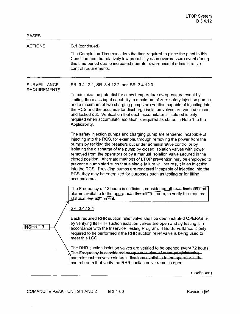
LTOP SystemB 3.4.12
BASES
ACTIONS G.1 (continued)
The Completion Time considers the time required to place the plant in thisCondition and the relatively low probability of an overpressure event duringthis time period due to increased operator awareness of administrativecontrol requirements.
SURVEILLANCE SR 3.4.12.1, SR 3.4.12.2, and SR 3.4.12.3REQUIREMENTS
To minimize the potential for a low temperature overpressure event bylimiting the mass input capability, a maximum of zero safety injection pumpsand a maximum of two charging pumps are verified capable of injecting intothe RCS and the accumulator discharge isolation valves are verified closedand locked out. Verification that each accumulator is isolated is onlyrequired when accumulator isolation is required as stated in Note 1 to theApplicability.
The safety injection pumps and charging pump are rendered incapable ofinjecting into the RCS, for example, through removing the power from thepumps by racking the breakers out under administrative control or byisolating the discharge of the pump by closed isolation valves with powerremoved from the operators or by a manual isolation valve secured in theclosed position. Alternate methods of LTOP prevention may be employed toprevent a pump start such that a single failure will not result in an injectioninto the RCS. Providing pumps are rendered incapable of injecting into theRCS, they may be energized for purposes such as testing or for fillingaccumulators.
The Frequency of 12 hours is sufficient, considerin s andalarms available to theý oe ro room, to verify the requiredsat e ipme nt.
SR 3.4.12.4
EEach required RHR suction relief valve shall be demonstrated OPERABLEbby verifying its RHR suction isolation valves are open and by testing it in
JINSERT 3 accordance with the Inservice Testing Program. This Surveillance is onlyrequired to be performed if the RHR suction relief valve is being used tomeet this LCO.
The RHR suction isolation valves are verified to be opened evei~y4:-f tWS..i he Froglucney is considorod adequate i view of other administrative
ntr',a auc~h as valve status i, advatonz a-'ilablo to the oporeter thc' r . . . th a t ... .fy ' h" R• H ,R ... t. n l.. ... r... . . . .inu e o p en
(continued)
COMANCHE PEAK - UNITS 1 AND 2 B 3.4-60 Revision WpS

LTOP SystemB 3.4.12
BASES
SURVEILLANCEREQUIREMENTS
SR 3.4.12.4 (continued)
The ASME Code (Ref. 8), test per Inservice Testing Program verifiesOPERABILITY by proving proper relief valve mechanical motion and bymeasuring and, if required, adjusting the lift setpoint.
Insert a period S SR 3.4.12.5 IINSERT 3
The ent of >_ 2.98 sqe inches is proven OPERABLE by verifying itsopen conditi eithe 'V-
a. Once every 12 hours for a valve that is not locked, sealed, ootherwise secured in the open position.
b. Once every 31 days for ent paths (e.g., a valve that is locked,sealed or o e secured in position). A removed pressurizer
valve or open manway also fits this category.
Any passive vent path arrangement must only be open when required to beOPERABLE. This Surveillance is required if the vent is being used to satisfythe pressure relief requirements of the LCO 3.4.12.
SR 3.4.12.6
The PORV block valve must be verified open h to provide theflow path for each required PORV to perform its function when actuated.The valve must be remotely verified open in the main control room. ThisSurveillance is performed if the PORV satisfies the LCO.
The block valve is a remotely controlled, motor operated valve. The powerto the valve operator is not required removed, and the manual operator is notrequired locked in the inactive position. Thus, the block valve can be closedin the event the PORV develops excessive leakage or does not close (sticksopen) after relieving an overpressure situation.
JINSERT 3:1
7The 72 hour Frequency is considered adequate in view ofadministrative controls available in e control room, such asvalve on, that verify that the PORV block valve remains open.
SR 3.4.12.7
Not Used
(continued)
COMANCHE PEAK - UNITS 1 AND 2 B 3.4-61 Revision W

LTOP SystemB 3.4.12
BASES
SURVEILLANCE REQUIREMENTS (continued)
SR 3.4.12.8
Performance of a COT is required within 12 hours after decreasing RCStemperature to < 350'F and every 31 day, on each required PORV to verifyand, as necessary, adjust its lift setpoint. The COT will verify the setpoint iswithin pre-established calibration tolerances of the nominal PORV setpointspresented in the PTLR. PORV actuation could depressurize the RCS and isnot required.
The 12 hour allowance considers the unlikelihood of a low temperatureoverpressure event during this time.
A Note has been added indicating that this SR is required to be performed 12hours after decreasing RCS cold leg temperature to < 350'F. The test mustbe performed within 12 hours after entering the LTOP MODES.
SR 3.4.12.9
NSERT3 < • Performance of a CHANNEL CALIBRATION on each required PORV
actuation channel is required ev'e -,Y moths to adjust the whole channelso that it responds and the valve opens within the required range andaccuracy to known input.
REFERENCES 1. 10 CFR 50, Appendix G.
2. Generic Letter 88-11.
3. ASME, Boiler and Pressure Vessel Code, Section III.
4. FSAR, Chapter 15.
5. 10 CFR 50, Section 50.46.
6. 10 CFR 50, Appendix K.
7. Generic Letter 90-06.
8. ASME Code for Operation and Maintenance of Nuclear PowerPlants.
9. FSAR, Chapter 5.
COMANCHE PEAK - UNITS 1 AND 2 B 3.4-62 Revision .64

RCS Operational LEAKAGEB 3.4.13
BASES
SURVEILLANCE SR 3.4.13.1 (continued)REQUIREMENTS
the RCPB is maintained. Pressure boundary LEAKAGE would at firstappear as unidentified LEAKAGE and can only be positively identified byinspection. It should be noted that LEAKAGE past seals and gaskets is notpressure boundary LEAKAGE. Unidentified LEAKAGE and identifiedLEAKAGE are determined by performance of an RCS water inventorybalance.
The RCS water inventory balance must be met with the reactor at steadystate operating conditions (stable temperature, power level, pressurizer andmakeup tank levels, makeup and letdown, and RCP seal injection and returnflows). This surveillance is modified by two Notes. Note 1 states that thisSR is not required to be performed until 12 hours after establishing steadystate operation near operating pressure. The 12 hour allowance providessufficient time to collect and process necessary data after stable plantconditions are established.
Steady state operation is required to perform a proper inventory balancesince calculations during maneuvering are not useful. For RCS operationalLEAKAGE determination by water inventory balance, steady state is definedas stable RCS pressure, temperature, power level, pressurizer and makeuptank levels, makeup and letdown, and RCP seal injection and return flows.An early warning of pressure boundary LEAKAGE or unidentified LEAKAGEis provided by the automatic systems that monitor the containmentatmosphere radioactivity and the containment sump level. It should be notedthat LEAKAGE past seals and gaskets is not pressure boundary LEAKAGE.These leakage detection systems are specified in LCO 3.4.15, "RCSLeakage Detection Instrumentation."
Note 2 states that this SR is not applicable to primary to secondaryLEAKAGE because LEAKAGE of 150 gallons per day cannot be measuredaccurately by an RCS water inventory balance. -INSERT 3
Thu 72 h... F.equencY iS o roasonablo ntrvmal to ted I EAKA
recognizes the importance of early leakage detection in the prevention ofaccidents. When non steady state operation precludes surveillanceperformance, the surveillance should be performed in a reasonable timeperiod commensurate with the surveillance performance length, once steadystate operation has been achieved, pr..id:cd grt•r.. the^ n :72 h,•u, havoelapsed sinee the l89t PcrfFm(onine.
(continued)
COMANCHE PEAK - UNITS 1 AND 2 B 3.4-67 RevisionMe

RCS Operational LEAKAGEB 3.4.13
BASES
SURVEILLANCE REQUIREMENTS (continued)
SR 3.4.13.2
This SR verifies that primary to secondary LEAKAGE is less than orequal to150 gallons per day through any one SG. Satisfying the primary tosecondary LEAKAGE limit ensures that the operational LEAKAGEperformance criterion in the Steam Generator Program is met. If this SR isnot met, the performance criterion is not met and LCO 3.4.17, "SteamGenerator Tube Integrity," should be entered. The 150 gallons per day limitis measured at room temperature as described in Reference 8. Theoperational LEAKAGE rate limit applies to LEAKAGE through any one SG. Ifit is not practical to assign the LEAKAGE to an individual SG, all the primaryto secondary LEAKAGE should be conservatively assumed to be from oneSG.
The Surveillance is modified by a Note which states that the Surveillance isnot required to be performed until 12 hours after establishment of steadystate operation. For RCS primary to secondary LEAKAGE determination,steady state is defined as stable RCS pressure, temperature, power level,pressurizer and makeup tank levels, makeup and letdown, and RCP sealinjection and return flows. INSERT 3
Tne Surveillance Ftequ•iUy M 7 .j ur. .. o ................... to trendprim.r..t .......... LA.... •_d recognizes the importance of earlyleakage detection in the prevention of accidents. The primary to secondaryLEAKAGE is determined using continuous process radiation monitors orradiochemical grab sampling in accordance with the EPRI guidelines (Ref.8).
SURVEILLANCE 1. 10 CFR 50, Appendix A, GDC 4 and 30.REQUIREMENTS
2. Regulatory Guide 1.45, May 1973.
3. FSAR, Section 15.
4. FSAR, Section 3.6B.
5. NUREG-1061, Volume 3, November 1984.
6. 10 CFR 100.
7. NEI 97-06, "Steam Generator Program Guidelines".
8. EPRI, "Pressurized Water Reactor Primary-to-Secondary LeakGuidelines".
COMANCHE PEAK - UNITS 1 AND 2 B 3.4-68 Revisionx,
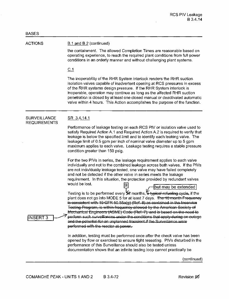
RCS PIV LeakageB 3.4.14
BASES
ACTIONS B.1 and B.2 (continued)
the containment. The allowed Completion Times are reasonable based onoperating experience, to reach the required plant conditions from full powerconditions in an orderly manner and without challenging plant systems.
C.1
The inoperability of the RHR System interlock renders the RHR suctionisolation valves capable of inadvertent opening at RCS pressures in excessof the RHR systems design pressure. If the RHR System interlock isinoperable, operation may continue as long as the affected RHR suctionpenetration is closed by at least one closed manual or deactivated automaticvalve within 4 hours. This Action accomplishes the purpose of the function.
SURVEILLANCE SR 3.4.14.1REQUIREMENTS
Performance of leakage testing on each RCS PIV or isolation valve used tosatisfy Required Action A.1 and Required Action A.2 is required to verify thatleakage is below the specified limit and to identify each leaking valve. Theleakage limit of 0.5 gpm per inch of nominal valve diameter up to 5 gpmmaximum applies to each valve. Leakage testing requires a stable pressurecondition greater than 150 psig.
For the two PIVs in series, the leakage requirement applies to each valveindividually and not to the combined leakage across both valves. If the PIVsare not individually leakage tested, one valve may have failed completelyand not be detected if the other valve in series meets the leakagerequirement. In this situation, the protection provided by redundant valveswould be lost. but ma be extended]
Testing is to be performed every, months,ypicaling c if theplant does not go into MODE 5 for at least 7 days. The 10 nionth FrequcncyW s consistent with 10 CFR 60.65a(g) (Ref. 9) as containoid in the IneorvicoI octing Programf, is Within frcquency allewcd by the Arnericon Scaicty ef
_ iaV•iUcalII Eiieei, s (ASME) cude (.•ef. 7), and is based e,, the in, d to
IINSERT 3 •1 pedorm euch -re nce uAder the zonditionns that apply during an. outagoand the potential for an unplanned transient ifthe S,.r'-eila.nce wereperformed with the react.or at powe..
In addition, testing must be performed once after the check valve has beenopened by flow or exercised to ensure tight reseating. PIVs disturbed in theperformance of this Surveillance should also be tested unlessdocumentation shows that an infinite testing loop cannot practically be
(continued)
COMANCHE PEAK- UNITS 1 AND 2 B 3.4-72 Revision 0"

RCS PIV LeakageB 3.4.14
BASES
SURVEILLANCE SR 3.4.14.1 (continued)REQUIREMENTS
avoided. Testing must be performed within 24 hours after the check valvehas been reseated (except as provided by Note 1). Within 24 hours is areasonable and practical time limit for performing this test after opening orreseating a check valve.
The leakage limit is to be met at the RCS pressure associated withMODES 1 and 2. This permits leakage testing at high differential pressureswith stable conditions not possible in the MODES with lower pressures.
Entry into MODES 3 and 4 is allowed to establish the necessary differentialpressures and stable conditions to allow for performance of this Surveillance.The Note that allows this provision is complementary to the Frequency ofprior to entry into MODE 2 whenever the unit has been in MODE 5 for 7 daysor more, if leakage testing has not been performed in the previous 9 monthsexcept for RHR isolation valves 8701A, 8701B, 8702A and 8702B. Thisexception is allowed since these RHR valves have control room positionindication, inadvertent opening interlocks and a system high pressure alarm.In addition, this Surveillance is not required to be performed on the RHRSystem when the RHR System is aligned to the RCS in the shutdowncooling mode of operation. PIVs contained in the RHR shutdown coolingflow path must be leakage rate tested after RHR is secured and stable unitconditions and the necessary differential pressures are established.
Testing is not required for the RHR suction isolation valves 'nythan 18 months as these valves are moto - wi control roomposition indication, madee4 ning interlocks and system high pressurealar
SR 3.4.14.2
Verifying that the RHR System interlocks are OPERABLE ensures that RCSpressure will not overpressurize the RHR system. The interlock setpoint thatprevents the valves from being opened is set so the actual RCS pressuremust be < 442 psig to open the valves. This setpoint ensures the RHRdesign pressure will not be exceeded and the RHR relief valves will not lift.
, I he 18 month t- requency is based on the need to perfomtheJINSERT i nder conditions that apply during a pan month Frequency
s loacetbeb eainoftedsgn reliability (andI " erating experience) of the equipment.
This SR is not applicable when using the RHR System suction relief valvesfor cold overpressure protection in accordance with SR 3.4.12.7.
(continued)
COMANCHE PEAK - UNITS 1 AND 2 B 3.4-73 Revision 66"

RCS Leakage Detection InstrumentationB 3.4.15
BASES
SURVEILLANCEREQUIREMENTS
SR 3.4.15.1 (continued)
Frequency of 12 hours is based on instrument tyai" s~ 'ona le
for detect iin 'oýns. -SR 3.4.15.2
SR 3.4.15.2 requires the performance of a COT on the required containmena~tmosphere radioactivity monitor. The test ensures that the monitor can
It
perform its function in the desired manner. The test verifies the alarmsetpoint and relative accuracy of the instrument string. Tii FiuqutJLJy uf 92
F40 0~~ ~ ~ I-o~n aplI- LAe9r a&. S ft i= 1 0=.f -MJ~ ItC M nt tJJ.,In -MMl I 'r t- .,fil .*e rl 7 I
that it is proper fer detecting defradlAtion.
SR 3.4.15.3, SR 3.4.15.4, and SR 3.4.15.5
These SRs require the performance of a CHANNEL CALIBRATION for eachof the RCS leakage detection instrumentation channels. The calibrationverifies the accuracy of the instrument string, including the instrumentslocated inside containment. The FregueiLy uf 18 1 -,-,ot, s , typicalieult~iUlll uyul• adl• I..*UI er l cSJ l - elnrlllol rolioblJitIy. Agai,li p rv i ngv...
expe, ie, me i as n, t jvt7-.I-. ti at mis i , equeney is aeeel9tai5lew..r ............ r ............. "1 ..... J ...... Iv ......
REFERENCES 1. 10 CFR 50, Appendix A, Section IV, GDC 30.
2. Regulatory Guide 1.45.
3. FSAR, Section 5.2.
4. NUREG-609, "Asymmetric Blowdown Loads on PWR PrimarySystems," 1981.
5. Generic Letter 84-04, "Safety Evaluation of Westinghouse TopicalReports Dealing with Elimination of Postulated Pipe Breaks in PWRPrimary Main Loops."
6. FSAR, Section 3.6B.
COMANCHE PEAK - UNITS 1 AND 2 B 3.4-80 Revision,£&e"

RCS Specific ActivityB 3.4.16
BASES (continued)
SURVEILLANCE SR 3.4.16.1REQUIREMENTS
SR 3.4.16.1 requires performing a gamma isotopic analysis as a measure ofthe noble gas specific activity of the reactor coolant at least enca eve7-•deys. While basically a quantitative measure of radionuclides with halflives longer than 10 minutes, excluding iodines, this measurement is thesum of the degassed gamma activities and the gaseous gamma activities inthe sample taken. This Surveillance provides an indication of any increasein noble gas specific activity.
Trending the results of this Surveillance allows proper remedial action to betaken before reaching the LCO limit under normal operating conditions. T-he7 d~y F,- u ,- oi- Id s the ',ikclihecd of a grcss fuel failure during thc
INSERT 3 If a specific noble gas nuclide listed in the definition of DOSE EQUIVALENTXE-1 33 in Specification 1.1, "Definitions," is not detected, it should bea ed to be present at the minimum detectable activity.
The NOTE m 'ies this SR to allow entry into and operation in MODE 4,MODE 3, and MO rior to performing the SR. This allows theSurveillance to be perfor in those MODES, prior to entering MODE 1.
S R 3.4.16.2
This Surveillance is performed in MODE 1 only to sure iodine specificactivity remains within the LCO limit during normal ope in and followingfast power changes when iodine spiking is more apt to occurF requency is adequate [u tiu lI ytyb ei thid uu idaytevityi e.11,considering noble gas actiVity i6 monitord`4 cvory 7 day&. The Frequency,between 2 and 6 hours after a power change _> 15% RTP within a 1 hourperiod, is established because the iodine levels peak during this timefollowing iodine spike initiation; samples at other times would provideinaccurate results.
The NOTE modifies this SR to allow entry into and operation in MODE 4,MODE 3, and MODE 2 prior to performing the SR. This allows theSurveillance to be performed in those MODES, prior to entering MODE 1.
SR 3.4.16.3
DELETED
(continued)
COMANCHE PEAK - UNITS 1 AND 2 B 3.4-85 RevisionX

AccumulatorsB 3.5.1
BASES
ACTIONS (continued)
C.1 and C.2
If the accumulator cannot be returned to OPERABLE status within theassociated Completion Time, the plant must be brought to a MODE in whichthe LCO does not apply. To achieve this status, the plant must be brought toMODE 3 within 6 hours and RCS pressure reduced to •1000 psig within 12hours. The allowed Completion Times are reasonable, based on operatingexperience, to reach the required plant conditions from full power conditionsin an orderly manner and without challenging plant systems.
D.1
If more than one accumulator is inoperable, the plant is in a condition outsidethe accident analyses; therefore, LCO 3.0.3 must be entered immediately.
SURVEILLANCE SR 3.5.1.1REQUIREMENTS
Each accumulator valve should be verified to be fully open evey 12 hq'rei.This verification ensures that the accumulators are available for injection andensures timely discovery if a valve should be less than fully open. If anisolation valve is not fully open, the rate of injection to the RCS would bereduced. Although a motor operated valve position should not change withpower removed, a closed valve could result in not meeting accident analysesassumption i I Thi Fie ic is considered i easemable in view of ather
]INSERT 3 SR 3512adSR 3.5.1.3
Ev • 1 to.-Prated water volume and nitrogen cover pressure are
verified for each accumulator. TIius Fbeque,,cy 5 su~ff, went to ensureadequate injection during a LOCA. Because of the static desi noLaccumulator, a 12 hour Frequency usually allow rator to identifychanges before limits are reache a ing experience has shown thisFrequency to be a e f•orearly detection and correction of off normal~r.
Each accumulator is equipped with two level and two pressure channels.One channel of each is designated the primary channel and used for thissurveillance except when declared inoperable. The second channel is usedto perform channel checks and as backup to the primary channel.Surveillances are routinely performed on both channels.
(continued)
COMANCHE PEAK - UNITS 1 AND 2 B 3.5-6 Revision.0
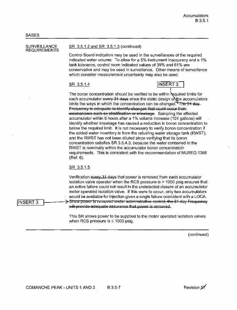
AccumulatorsB 3.5.1
BASES
SURVEILLANCE SR 3.5.1.2 and SR 3.5.1.3 (continued)REQUIREMENTS
Control Board indication may be used in the surveillances of the requiredindicated water volume. To allow for a 5% instrument inaccuracy and a 1%tank tolerance, control room indicated values of 39% and 61% areconservative and may be used in surveillance. Other means of surveillancewhich consider measurement uncertainty may also be used.
SR 3.5.1.4 iINSERT 3
The boron concentration should be verified to be within quired limits foreach accumulator e;'ery 31 days since the static design o e accumulatorslimits the ways in which the concentration can be changed. Tht--3+-dey-FFroguoncy is adequate to identify changoc that could- occur frome.hna....... u.h as stratifiatin Or . i.l.akage. Sampling the affectedaccumulator within 6 hours after a 1% volume increase (101 gallons) willidentify whether inleakage has caused a reduction in boron concentration tobelow the required limit. It is not necessary to verify boron concentration ifthe added water inventory is from the refueling water storage tank (RWST),and the RWST has not been diluted since verifying that its boronconcentration satisfies SR 3.5.4.3, because the water contained in theRWST is nominally within the accumulator boron concentrationrequirements. This is consistent with the recommendation of NUREG-1366(Ref. 6).
SR 3.5.1.5
Verification every 31 days that power is removed from each accumulatorisolation valve operator when the RCS pressure is > 1000 psig ensures thatan active failure could not result in the undetected closure of an accumulatormotor operated isolation valve. If this were to occur, only two accumulatorswould be available for injection given a single failure coincident with a LOCA.
pINSERT 3 ,oe,,is uniuved u1 "nd,,r adne on.t..l, the 31 day FrcquoncyWill provido adeGluato aswurae that PGe- is r....e.
This SR allows power to be supplied to the motor operated isolation valveswhen RCS pressure is < 1000 psig.
(continued)
COMANCHE PEAK - UNITS I AND 2 B 3.5-7 RevisionX

ECCS - OperatingB 3.5.2
BASES (continued)
SURVEILLANCE SR 3.5.2.1REQUIREMENTS
Verification of proper valve position ensures that the flow path from theECCS pumps to the RCS is maintained. Misalignment of these valves couldrender both ECCS trains inoperable. Securing these valves in position byremoval of power by a control board switch in the correct position ensuresthat they cannot change position as a result of an active failure or beinadvertently misaligned. These valves are of the type, described inReferences 6 and 7, that can disable the function of both ECCS trains andinvalidate the accident analyse A 1-2 ,,r,• ..... •..u.n.y' i..ide
As noted in LCO Note 1, both Safety
Injection pump flo aths may each be isolated for two hours in MODE 3 byclosure of on r more of these valves to perform pressure isolation valvetesting.
[INSERT 3 Verifying the correct alignment for manual, power operated, and automaticvalves in the ECCS flow paths provides assurance that the proper flow pathswi ist for ECCS operation. This SR does not apply to valves that arelocked, led, or otherwise secured in position, since these were verified tobe in the cor position prior to locking, sealing, or securing. A valve thatreceives an actua •.signal is allowed to be in a non-accident positionprovided the valve will amatically reposition within the proper stroke time.This Surveillance does not r ire any testing or valve manipulation.Rather, it involves verification tha se valves capable of beingmispositioned are in the correct positio Thc 31 day Frcqucncy isappropriate becau",se the valves are operated under administrative contnrl,and an improper valve pQsitiMn o,,Ild onl affect ..singla train. ThisFrequen.y has been shovwn to be acrcrrptable through operating experience
SR 3.5.2.3
Venting of the ECCS pump casing and accessible discharge piping highpoints prior to entering MODE 3 and following any maintenance oroperations activity which drains portions of the system, ensures the systemis full of water and will perform properly (i.e., allows injecting the full ECCScapacity into the RCS on demand).
The CCP design and attached piping configuration allow the CCP to vent theaccumulated gases via the attached suction and discharge piping.Continuous venting of the suction piping to the Volume Control tank (VCT)and manual venting of the discharge piping high points satisfies the pumpcasing venting requirements for the CCPs.
(continued)
COMANCHE PEAK - UNITS 1 AND 2 B 3.5-16 Revision 5

ECCS - OperatingB 3.5.2
BASES
SURVEILLANCE REQUIREMENTS (continued)
SR 3.5.2.4
Periodic surveillance testing of ECCS pumps to detect gross degradationcaused by impeller structural damage or other hydraulic componentproblems is required by the ASME Code. This type of testing may beaccomplished by measuring the pump developed head at only one point ofthe pump characteristic curve. The following ECCS pumps are required todevelop the indicated differential pressure on recirculation flow:
1) Centrifugal charging pump Ž2370 psid,2) Safety injection pump > 1440 psid, and3) RHR pump > 170 psid.
This verifies both that the measured performance is within an acceptabletolerance of the original pump baseline performance and that theperformance at the test flow is greater than or equal to the performanceassumed in the plant safety analysis. SRs are specified in theInservice Testing Program of the ASME Code. The ASME Code and theTechnical Requirements Manual provides the activities and Frequenciesnecessary to satisfy the requirements.
SR 3.5.2.5 and SR 3.5.2.6 INSERT 3
These Surveillances demonstrate that each automatic ECCS va e actuatesto the required position on an actual or simulated SI signal and hat eachECCS pump starts on receipt of an actual or simulated SI sign i. ThisSurveillance is not required for valves that are locked, sealed r otherwisesecured in the required position under administrative controls.Frequency is based on the need to perform these Surveillances undconditions that apply during a plant outage and the potenti nplannedplant transients if the Surveillances were perfomthe reactor atpower. The 18 month Frequency is als eptable based on considerationof the design reliability (and c inrg operating experience) of theequipment. Theac logic is tested as part of ESF Actuation Systemtesting, an ipment performance is monitored as part of the Inservice
" 'q Pro qram.
SR 3.5.2.7
The correct alignment of throttle valves in the ECCS flow path on an SIsignal is necessary for proper ECCS performance. Valves 881 OA, B, C, D
(continued)
COMANCHE PEAK - UNITS 1 AND 2 B 3.5-17 Revision X

ECCS - OperatingB 3.5.2
BASES
SURVEILLANCE SR 3.5.2.7 (continued)REQUIREMENTS
are provided in the charging pump to cold leg injection lines. Valves 8822A,B, C, D are provided in the SI pump to cold leg injection lines. These manualthrottle valves are positioned following flow balancing and have mechanicallocks to ensure that the proper positioning for restricted flow to a rupturedcold leg is maintained and that the other cold legs receive at least therequired minimum flow. Valves 8816A, B, C, D are provided in the SI pumpto hot leg recirculation lines. These manual throttle valves are positionedfollowing flow balancing and have mechanical locks to ensure flow balancingand to limit SI pump runo Th-,-11Ko 11801 . ...th .FFrogueney is based on the •ame
N T Periodic inspections of the containment sump suction inlet ensure that it isunrestricted and stays in proper operating condition. The 18 -memr4h-Frequency is based on the need to perform this Surveillance un7dconditions that apply during a plant outage, on the nee ave access tothe location, and because of the potenti unplanned transient if theSurveillance were performe e reactor at power. This Frequency hasbeen found to dent to detect abnormal degradation and is confirmedb ing experience.
REFERENCES 1. 10 CFR 50, Appendix A, GDC 35.
2. 10 CFR 50.46.
3. FSAR, Sections 6.3 and 7.6.
4. FSAR, Chapter 15, "Accident Analysis."
5. NRC Memorandum to V. Stello, Jr., from R.L. Baer, "RecommendedInterim Revisions to LCOs for ECCS Components," December 1,1975.
6. IE Information Notice No. 87-01.
7. BTP EICSB-1 8, Application of the Single Failure Criteria to Manually-Controlled Electrically-Operated Valves.
COMANCHE PEAK - UNITS 1 AND 2 B 3.5-18 RevisionArd

RWSTB 3.5.4
BASES
ACTIONS (continued)
B.1
With the RWST inoperable for reasons other than Condition A (e.g., watervolume), it must be restored to OPERABLE status within 1 hour.
In this Condition, neither the ECCS nor the Containment Spray System canperform its design function. Therefore, prompt action must be taken torestore the tank to OPERABLE status or to place the plant in a MODE inwhich the RWST is not required. The short time limit of 1 hour to restore theRWST to OPERABLE status is based on this condition simultaneouslyaffecting redundant trains.
C.1 and C.2
If the RWST cannot be returned to OPERABLE status within the associatedCompletion Time, the plant must be brought to a MODE in which the LCOdoes not apply. To achieve this status, the plant must be brought to at leastMODE 3 within 6 hours and to MODE 5 within 36 hours. The allowedCompletion Times are reasonable, based on operating experience, to reachthe required plant conditions from full power conditions in an orderly mannerand without challenging plant systems.
SURVEILLANCE SR 3.5.4.1REQUIREMENTS
The RWST borated water temperature should be verified eve•y-24 hei tobe within the limits assumed in the accident analyses band. is-Frehqtiemand been shown to b....... oeetal through •pfl.: -eln
The SR is modified by a Note that eliminates the requiremen to perform thisSurveillance when ambient air temperatures are within the op rating limits ofthe RWST. With ambient air temperatures within the band, t e RWSTtemperature should not exceed the limits.
SR 3.5.4.2 INSER
The RWST water volume should be verified -7 A to be above therequired minimum level in order to ensure that a ufficient initial supply isavailable for injection and to support continued CS and ContainmentSpray System pump operation on recirculation. Since the RWST v;'umRc i3norFMolly StOble and the eeintakind velumc roguid i ýprtcctd by on alarmA,a :7 day Froquoncy ic aFpprpiato and h4A- boon8- ~ho4nA to4 boA -Accoptablothrouh p......ting -xp in......
(continued)
COMANCHE PEAK - UNITS 1 AND 2 B 3.5-26 Revision V

RWSTB 3.5.4
BASES
SURVEILLANCE SR 3.5.4.2 (continued)REQUIREMENTS
Control Board indication may be used in the surveillances of the requiredindicated RWST water volume. The indicated level of 95%, which includes5% measurement uncertainty, is a conservative verification of containedvolume. Other means of surveillance which consider measurementuncertainty may also be used.
SR 3.5.4.3
The boron concentration of the RWST should be verified eveiy 7- day to bewithin the required limits. This SR ensures that the reactor will remainsubcritical following a LOCA. Further, it assures that the resulting sump pHwill be maintained in an acceptable range so that boron precipitation in thecore will not occur and the effect of chloride and caustic stress corrosion onmechanical systems and components will be minimized. e the RWST-
gperating oxpeFreino.
REFERENCES 1. FSAR, Chapter 6 and Chapter 15. FINSERT 3
COMANCHE PEAK - UNITS 1 AND 2 B 3.5-27 Revision,57

Seal Injection FlowB 3.5.5
BASES
ACTIONS (continued)
B.1 and B.2
When the Required Actions cannot be completed within the requiredCompletion Time, a controlled shutdown must be initiated. The CompletionTime of 6 hours for reaching MODE 3 from MODE 1 is a reasonable time fora controlled shutdown, based on operating experience and normal cooldownrates, and does not challenge plant safety systems or operators. Continuingthe plant shutdown begun in Required Action B.1, an additional 6 hours is areasonable time, based on operating experience and normal cooldown rates,to reach MODE 4, where this LCO is no longer applicable.
SURVEILLANCE SR 3.5.5.1REQUIREMENTS
The surveillance ensures the seal injection flow is less than 40 gpm withcharging header pressure greater than or equal to 145 psig (130 psig +15 psig for instrument uncertainty) above RCS pressure.
Verification -very 31 deys that the manual seal injection throttle valves areadjusted to give a flow within the limit ensures that proper manual sealinjection throttle valve position, and hence, proper seal injection flow, ismaintaine The Frcequcncy of 31 doays is based on cngiccrig judgmecnt
• C,•,C,,h:: r•GV'GR ÷tO be ...... fle th...rouh oner~teng e•pn~ripnr
JINSERT 3As noted, the Surveillance is not required to be performed until 4 hours afterthe RCS pressure has stabilized within a ± 20 psig range of normal operatingpressure. The RCS pressure requirement is specified since thisconfiguration will produce the required pressure conditions necessary toassure that the manual valves are set correctly. The exception is limited to 4hours to ensure that the Surveillance is timely.
REFERENCES 1. FSAR, Chapter 6 and Chapter 15.
2. 10 CFR 50.46.
COMANCHE PEAK - UNITS 1 AND 2 B 3-5-30 Revision ýý

Containment Air LocksB 3.6.2
BASES (continued)
SURVEILLANCE SR 3.6.2.1REQU IREMENTS
Maintaining containment air locks OPERABLE requires compliance with theleakage rate test requirements of the Containment Leakage Rate TestingProgram. This SR reflects the leakage rate testing requirements with regardto air lock leakage (Type B leakage tests). The acceptance criteria wereestablished during initial air lock and containment OPERABILITY testing.The periodic testing requirements verify that the air lock leakage does notexceed the allowed fraction of the overall containment leakage rate. TheFrequency is required by the Containment Leakage Rate Testing Program.
The SR has been modified by two Notes. Note I states that an inoperableair lock door does not invalidate the previous successful performance of theoverall air lock leakage test. This is considered reasonable since either airlock door is capable of providing a fission product barrier in the event of aDBA. Note 2 has been added to this SR requiring the results to be evaluatedagainst the acceptance criteria which is applicable to SR 3.6.1.1. Thisensures that air lock leakage is properly accounted for in determining thecombined Type B and C containment leakage rate.
SR 3.6.2.2
The air lock interlock is designed to prevent simultaneous opening of bothdoors in a single air lock. Since both the inner and outer doors of an air lockare designed to withstand the maximum expected post accident containmentpressure, closure of either door will support containment OPERABILITY.Thus, the door interlock feature supports containment OPERABILITY whilethe air lock is being used for personnel transit in and out of the containment.Periodic testing of this interlock demonstrates that the interlock will function
INSERT 3 si ned and that simultaneous opening of the inner and outer doors willnot inadverten mt ue to the Iel3,-e nature f-tLhU -terl-- and giventhat the interlock mechanism is not normally challenged when thecontainment air lock door is used for entry and exit (procedures r e strictadherence to single door opening), this test is only require e performedevery 24 months.
The 24 month Frequency is based on t eed to perform this surveillanceunder the conditions that apply d i a plant outage and the potential forloss of containment OPER ITY if the Surveillance were performed withthe reactor at power e 24 month Frequency for the interlock is justifiedbased on gen i operating experience. The Frequency is based onengine judgement and is considered adequate given that the interlock isn allenged during use of the airlock.
(continued)
COMANCHE PEAK - UNITS 1 AND 2 B 3.6-10 Revision-Wej
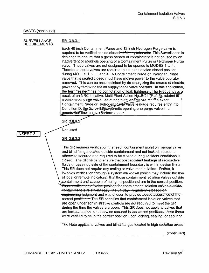
Containment Isolation ValvesB 3.6.3
BASES (continued)
SURVEILLANCE SR 3.6.3.1REQUIREMENTS
Each 48 inch Containment Purge and 12 inch Hydrogen Purge valve isrequired to be verified sealed closed at 31 day ,t,- val'. This Surveillance isdesigned to ensure that a gross breach of containment is not caused by aninadvertent or spurious opening of a Containment Purge or Hydrogen Purgevalve. These valves are not designed to be opened in MODES 1 to 4.Therefore, these valves are required to be in the sealed closed positionduring MODES 1, 2, 3, and 4. A Containment Purge or Hydrogen Purgevalve that is sealed closed must have motive power to the valve operatorremoved. This can be accomplished by de-energizing the source of electricpower or by removing the air supply to the valve operator. In this application,the term "sealed" has no connotation of leak tightness IT I -Freresult of an NRC initiative, Multi-Plant Action No - 4"(Ref. 5 0containment purge valve use during plan er . e eventContainment Purge or Hydro e a ve leakage requires entry intoCondition D, the n ermits opening one purge valve in a
Lnlow pat perform repairs.SR 3.6 '/
No sed
IINSET 3 \SR 3.6.3.3
This SR requires verification that each containment isolation manual valveand blind flange located outside containment and not locked, sealed, orotherwise secured and required to be closed during accident conditions isclosed. The SR helps to ensure that post accident leakage of radioactivefluids or gases outside of the containment boundary is within design limits.This SR does not require any testing or valve manipulation. Rather, itinvolves verification through a system walkdown (which may include the useof local or remote indicators), that those containment isolation valves outsidecontainment and capable of being mispositioned are in the correct position.continement io r vativel.,y .o... the 31 en, Frcqucncy is b'tsi on
uiii~i l'll' juudgmnn n duu € vali V C 1; tus, I ,;t:l E0U I1UVIUU d:UUUU a• ur dn](e On l 1UI
-eefet pasiticfa. The SR specifies that containment isolation valves thatare open under administrative controls are not required to meet the SRduring the time the valves are open. This SR does not apply to valves thatare locked, sealed, or otherwise secured in the closed positions, since thesewere verified to be in the correct position upon locking, sealing, or securing.
The Note applies to valves and blind flanges located in high radiation areas
(continued)
COMANCHE PEAK - UNITS 1 AND 2 B 3.6-22 Revision ýd

Containment Isolation ValvesB 3.6.3
BASES
SURVEILLANCE REQUIREMENTS (continued)
SR 3.6.3.5
Verifying that the isolation time of each automatic power operatedcontainment isolation valve is within limits is required to demonstrateOPERABILITY. An automatic power operated containment isolation valve isa containment isolation valve which is required to be closed by an automatic(i.e., other than operator manual) actuation signal and is powered by otherthan manual actuation (e.g., by an air or motor operator). The isolation timetest ensures the valve will isolate in a time period less than or equal to thatassumed in the FSAR [Ref. 2]. The isolation time and Frequency of this SRare in accordance with the Technical Requirements Manual and theInservice Testing Program.
SR 3.6.3.6
Not used.
SR 3.6.3.7
The Containment Purge, Hydrogen Purge, and Containment Pressure Reliefvalves with resilient seals, are leakage rate tested per the requirements of 10CFR 50, Apppendix J, Option B to ensure OPERABILITY.
The containment purge, hydrogen purge, and containment pressure reliefvalves are tested in accordance with the Containment Leakage Rate TestingProgram. Leakage rate acceptance criteria applies as follows:
a. The inboard and outboard isolation valves with resilient materialseals in each locked closed 48 inch containment purge and 12 inchhydrogen purge supply and exhaust penetration measured leakagerate is < 0.05 La when pressurized to Pa.
b. Each 18 inch containment pressure relief discharge isolation valvewith resilient material seals measured leakage rate is < 0.06 La whenpressurized to Pa-
The Note is a clarification that leakage rate testing is not required forJINSERT 3 containment purge valves with resilient seals when their penetration flow
path is isolated by a leak tested blank flange.
(continued)
COMANCHE PEAK - UNITS 1 AND 2 B 3.6-24 Revision.""

Containment Isolation ValvesB 3.6.3
BASES
SURVEILLANCE REQUIREMENTS (continued)
SR 3.6.3.8
Automatic containment isolation valves close on a containment isolationsignal to prevent leakage of radioactive material from containment followinga DBA. This SR ensures that each Phase "A" automatic containmentisolation valve will actuate to its isolation position on a Phase "A" Isolationsignal, each Phase "B" automatic containment isolation valve will actuate toits isolation position on a containment Phase "B" Isolation signal, and eachpressure relief discharge valve actuates to its isolation position on aContainment Ventilation Isolation signal. This surveillance is not required forvalves that are locked, sealed, or otherwise secured in the required positionunder administrative controls, npepati•• a xprio•,R. har, G.hwn that these. ..... ~~S: / v .v, .,, . .• . . . . . . .,• : "•. . .Kiii lcltz i-0ii 4oaaau-7 tr-urcin c wn1-n -.-. ,mc Ii inc m-- m-n
-. -
t- I u I I V. I I 1 I I I , trc- I I~ NVUcncýYV~a cconludced to be acco~ptabko ronma ieliability standpoint.
SR 3.6.3.9
Not used
SR 3.6.3.10[INSERT 3
Not used.
SR 3.6.3.11
Not used.
SR 3.6.3.12
Not used.
SR 3.6.3.13
Not used.
REFERENCES 1. FSAR, Section 15.
2. FSAR, Section 6.2.
3. Standard Review Plan 6.2.4.
(continued)
COMANCHE PEAK - UNITS 1 AND 2 B 3.6-25 Revision ýW-

Containment PressureB 3.6.4
BASES
ACTIONS B.1 and B.2 (continued)
MODE 3 within 6 hours and to MODE 5 within 36 hours. The allowedCompletion Times are reasonable, based on operating experience, to reachthe required plant conditions from full power conditions in an orderly mannerand without challenging plant systems.
SURVEILLANCEREQUIREMENTS
SR 3.6.4.1
Verifying that containment pressure is within limits ensures that unitoperation remains within the limits assumed in the containment analysis.The 12 hour Frequency of this SR was developed based on operatiexperience related to trending of containment press ions during theapplicable MODES. Furthermore, t r requency is consideredadequate in view of o cations available in the control room, includingalarm e operator to an abnormal containment pressure condition.
REFERENCES 1. FSAR, Section 6.2.
2. 10 CFR 50, Appendix K.
COMANCHE PEAK - UNITS 1 AND 2 B 3.6-29 Revision 5ýr

Containment Air TemperatureB 3.6.5
BASES
ACTIONS (continued)
B.1 and B.2
If the containment average air temperature cannot be restored to within itslimit within the required Completion Time, the plant must be brought to aMODE in which the LCO does not apply. To achieve this status, the plantmust be brought to at least MODE 3 within 6 hours and to MODE 5 within 36hours. The allowed Completion Times are reasonable, based on operatingexperience, to reach the required plant conditions from full power conditionsin an orderly manner and without challenging plant systems.
SURVEILLANCE SR 3.6.5.1REQUIREMENTS
Verifying that containment average air temperature is within the LCO limitensures that containment operation remains within the limit assumed for thecontainment analyses. In order to determine the containment average airtemperature, an adjusted average is calculated using two temperaturemeasurements, on fixed or portable instruments. The temperaturemeasurements are taken at the following locations: a) the containmentdome, at or above Elevation 1000'-6"; b) the containment floor, at or aboveElevation 860'-0". At least one of the temperatures must be taken at orabove Elevation 1000'-6". The locations within the containment were
[INSERT 3 - lected to provide a representative sample of the overall containmentatmosp The 24 h-.. Fr•gu.n.y .f this SR is con;.id.r. d aI,,,G@cceptabloSbased on observed slow rates of temperature increase within conta.sa result of environmental heat sources (due to h e ofcontainment). Furthermore, h ' qec s considered adequatein Lview of other niaial i h ontrol room, ipncluding alarms, toalert _aor to an abnormal containment temperature condition.
REFERENCES 1. FSAR, Section 6.2.
2. 10 CFR 50.49.
COMANCHE PEAK - UNITS 1 AND 2 B 3.6-32 Revisionx

Containment Spray SystemB 3.6.6
BASES (continued)
SURVEILLANCE SR 3.6.6.1REQUIREMENTS
Verifying the correct alignment for manual, power operated, and automaticvalves in the containment spray flow path provides assurance that the properflow paths will exist for Containment Spray System operation. This SR doesnot apply to valves that are locked, sealed, or otherwise secured in position,since these were verified to be in the correct position prior to locking, sealing,or securing. This SR does not require any testing or valve manipulation.Rather, it involves verification through a system walkdown (which mayinclude the use of local or remote indicators), that those valves outsidecontainment (only check valves are inside containment) and capable of
JINSERT3 -potentially being mispositioned are in the correct position.
SR 3.6.6.2
Not Used
SR 3.6.6.3
Not Used
SR 3.6.6.4
Verifying each containment spray pump's developed head at the flow testpoint is greater than or equal to the required developed head (specified inthe Technical Requirements Manual) ensures that spray pump performancehas not degraded during the cycle. Flow and differential pressure are normaltests of centrifugal pump performance required by the ASME Code (Ref. 5).Since the containment spray pumps cannot be tested with flow through thespray headers, they are tested on recirculation flow via a test header. Thistest confirms one point on the pump design curve and is indicative of overallperformance. Such inservice tests confirm component OPERABILITY, trendperformance, and detect incipient failures by abnormal performance. TheFrequency of the SR is in accordance with the Inservice Testing Program.
SR 3.6.6.5 and SR 3.6.6.6
These SRs require verification that each automatic containment spray valveactuates to its correct position on an actual or simulated actuation of acontainment "P" (High-3) signal and that each containment spray pumpstarts upon receipt of an actual or simulated actuation of a containment "S"(High-I) and "P" (High-3) pressure signals. This Surveillance is not requiredfor valves that are locked, sealed, or otherwise secured in the required
(continued)
COMANCHE PEAK - UNITS 1 AND 2 B 3.6-37 Revision 14

Containment Spray SystemB 3.6.6
BASES
SURVEILLANCE SR 3.6.6.5 and SR 3.6.6.6 (continued) INSEREQU IREMENTS
position under administrative controls. 138rating oXporiGnce has shown thatLhebe CuuIpu ,l ...u....lly pass I..le St ...... .. hen pe, rokrmed at the 18.
111nth Frequency. Thercferc, the FroequoncY Was onlu to be0aeeeptable from a reliabilty stai idaint.
SR 3.6.6.7
Not Used
SR 3.6.6.8
With the containment spray inlet valves closed and the spray header drainedof any solution, low pressure air or smoke can be blown through testconnections. This SR ensures that each spray nozzle is unobstructed andprovides assurance that spray coverage of the containment during anaccident is not degraded. Due to the passive design of the nozzle,confirmation of operability following maintenance activities that can result inobstruction of spray nozzle flow is considered adequate to detect obstructionof the nozzles. Confirmation that the spray nozzles are unobstructed may beobtained by utilizing foreign materials exclusion (FME) controls duringmaintenance, a visual inspection of the affected portions of the system, or byan air or smoke flow test following maintenance involving opening portions ofthe system downstream of the containment isolation valves or draining of thefilled portions of the system inside containment. Maintenance that couldresult in nozzle blockage is generally a result of a loss of foreign materialcontrol or a flow of borated water through a nozzle. Should either of theseevents occur, a supervisory evaluation will be required to determine whethernozzle blockage is a possible result of the event. For the loss of FME event,an inspection or flush of the affected portions of the system should beadequate to confirm that the spray nozzles are unobstructed since water flowwould be required to transport any debris to the spray nozzles. An air flow orsmoke test may not be appropriate for a loss of FME event but may beappropriate for the case where borated water inadvertently flows through thenozzles.
REFERENCES 1. 10 CFR 50, Appendix A, GDC 38, GDC 39, GDC 40, GDC 41, GDC
42, and GDC 43.
2. 10 CFR 50, Appendix K.
3. FSAR, Section 6.2.1.
(continued)
COMANCHE PEAK- UNITS 1 AND 2 B 3.6-38 RevisionW

MSIVsB 3.7.2
BASES (continued)
SURVEILLANCEREQUIREMENTS
SR 3.7.2.1
This SR verifies that MSIV closure time is < 5 seconds. The hand switchmay be used as the actuation signal to perform this surveillance. The MSIVisolation time is assumed in the accident and containment analyses. ThisSurveillance is normally performed upon returning the unit to operationfollowing a refueling outage.
The Frequency is in accordance with the Inservice Testing (IST) Program.This test is allowed to be conducted in MODE 3 with the unit at operatingtemperature and pressure. This SR is modified by a Note that allows entryinto and operation in MODE 3 prior to performing the SR. This allows adelay of testing until MODE 3, to establish conditions consistent with thoseunder which the acceptance criterion was generated.
SR 3.7.2.2
This SR verifies that each MSIV can close on an actual or simulated mainsteam line isolation actuation signal. This Surveillance is normallyperformed upon returning the unit to operation following a refueling outage.The frequency of MSIV testing is every 18 months. The 18 mont.0.Frequency for testing is based on the refuelin crting experien~cehas shown that these componntpss the Surveillance whenperformed at the requency. Therefore, this Frequency isacý rom a reliability standpoint.
This test is allowed to be conducted in MODE 3 with the unit at operatingtemperature and pressure. This SR is modified by a Note that allows entryinto and operation in MODE 3 prior to performing the SR. This allows adelay of testing until MODE 3, to establish conditions consistent with thoseunder which the acceptance criterion was generated.
I N S E RT 3
REFERENCES 1. FSAR, Section 10.3.
2. FSAR, Section 6.2.
3. FSAR, Chapter 15.
4. 10 CFR 100.11.
COMANCHE PEAK - UNITS 1 AND 2 B 3.7-12 Revision '-x

FIVs and FCVs and Associated Bypass ValvesB 3.7.3
BASES
ACTIONSE.1 and E.2 (continued)
Completion Time, the unit must be placed in a MODE in which the LCO doesnot apply. To achieve this status, the unit must be placed in at least MODE 3within 6 hours, and in MODE 4 within 12 hours. The allowed CompletionTimes are reasonable, based on operating experience, to reach the requiredunit conditions from full power conditions in an orderly manner and withoutchallenging unit systems.
SURVEILLANCEREQUIREMENTS
SR 3.7.3.1
This SR verifies that the closure time of each FIV, FCV, and associatedbypass valves is < 5 seconds. The FIV and FCV isolation times areassumed in the accident and containment analyses. This Surveillance isnormally performed upon returning the unit to operation following a refuelingoutage. This is consistent with RG 1.22 (Ref. 4).
The Frequency for this SR is in accordance with the Inservice TestingProgram. Per Ref. 5, if it is necessary to adjust stem packing to stop packingleakage and if a required stroke test is not practical in the current plantmode, it should be shown by analysis that the packing adjustment is withintorque limits specified by the manufacturer for the existing configuration ofpacking, and that the performance parameters of the valve are not adverselyaffected. A confirmatory test must be performed at the first availableopportunity when plant conditions allow testing. Packing adjustmentsbeyond the manufacturer's limits may not be performed without (1) anengineering analysis and (2) input from the manufacturer, unless tests canbe performed after adjustments.
SR 3.7.3.2
This SR verifies that each FIV and associated bypass valve can close on anactual or simulated actuation signal. This Surveillance is normally performedupon returning the unit to operation following a refueling outage.
The frequency of this surveillance is every 18 months. TheFrequency for testing is based on the refueli perating experiencehas shown that these compon a y pass the Surveillance when
performed at the Frequency. Therefore, this Frequency isa e rom a reliability standpoint.
(continued)
COMANCHE PEAK - UNITS 1 AND 2 B 3.7-18 Revision 5e

AFW SystemB 3.7.5
BASES (continued)
SURVEILLANCE SR 3.7.5.1REQUIREMENTS
Verifying the correct alignment for manual, power operated, and automaticvalves in the AFW System water and steam supply flow paths providesassurance that the proper flow paths will exist for AFW operation. This SRdoes not apply to valves that are locked, sealed, or otherwise secured inposition, since they are verified to be in the correct position prior to locking,sealing, or securing. This SR also does not apply to valves that cannot beinadvertently misaligned, such as check valves. This Surveillance does notrequire any testing or valve manipulation; rather, it involves verification thatthose valves capable of being mispositioned are in the correct position.The 31 day Frequency is based on engineering j d ent with
JINSERT 3TU 1 1111the procedural controls gover era ion, and ensures correct valve
This SR is modified by a note stating that one or more AFW trains may beconsidered OPERABLE during alignment and operation for steam generatorwater level control, if it is capable of being manually realigned to the AFWmode of operation and provided it is not otherwise inoperable. Thisexception allows the system to be out of its normal standby alignment andtemporarily incapable of automatic initiation without declaring the train(s)inoperable and applies only when the unit is below 10% RATED THERMALPOWER. Since AFW may be used during startup, shutdown, hot standbyoperations, and hot shutdown operations for steam generator level control,and these manual operations are an accepted function of the AFW system,OPERABILITY is maintained. The ability to realign the affected AFW train(s)to a standby condition or to an in-service condition supplying feedwater tothe steam generator(s) assures the intended safety function is available.Realignment of the AFW train(s)is normally performed from the ControlRoom. However, when explicitly allowed by Operations' procedure, thisprovision may also be applied to local manual operation of AFW valves.
SR 3.7.5.2
Verifying that each AFW pump's developed head at the flow test point isgreater than or equal to the required developed head ensures that AFWpump performance has not degraded during the cycle. Flow and differentialhead are normal tests of centrifugal pump performance required by theASME Code (Ref. 2). The motor driven pumps should develop a differentialpressure of _> 1380 psid at a flow of > 430 gpm. The turbine driven pumpshould develop a differential pressure of _> 1438 psid at a flow of _> 860 gpm.Because it is undesirable to introduce cold AFW into the steam generatorswhile they are operating, this testing is performed on recirculation flowthrough a test line. This test confirms one point on the pump design curve
(continued)
COMANCHE PEAK - UNITS 1 AND 2 B 3.7-29 Revision X

AFW SystemB 3.7.5
BASES
SURVEILLANCE SR 3.7.5.2 (continued)REQUIREMENTS
and is indicative of overall performance. Instrument uncertainty is notincluded in the above flow and differential pressure values but is addressedin the surveillance testing procedure. Such inservice tests confirmcomponent OPERABILITY, trend performance, and detect incipient failuresby indicating abnormal performance. Performance of inservice testingdiscussed in the ASME Code (Ref. 2) (only required at 3 month intervals)satisfies this requirement.
This SR is modified by a Note indicating that the SR should be deferred untilsuitable test conditions are established. This deferral is required becausethere is insufficient steam pressure to perform the test.
SR 3.7.5.3
This SR verifies that AFW can be delivered to the appropriate steamgenerator in the event of any accident or transient that generates an ESFAS,by demonstrating that each automatic valve in the flow path actuates to itscorrect position on an actual or simulated actuation generated by an auxiliaryfeedwater actuation signal. The Steam Generator Blowdown, SteamGenerator Blowdown Sample, and Unit 2 Feedwater Split Flow Bypassvalves close on an auxiliary feedwater actuation to ensure auxiliaryfeedwater is delivered to the steam generator upper nozzles and is retainedin the steam generator for decay heat removal. The AFW flow control valvestrip to auto (open) on an auxiliary feedwater actuation to ensure full flow is'delivered to each steam generator flow path. The steam admission valvesopen to supply the turbine driven auxiliary feedwater pump. ThisSurveillance is not required for valves that are locked, sealed, or otherwisesecured in the required position under administrative controls. Thc 18 mnthFrequency is based on the need to perform this Surveillance un..dpta-''
conditions that apply during a unit outage and the or an unplannedJIN.SERT 3 to , i Sttransient if the Surveillance were jwith the reactor at power. The
18month. rqeetbebsdo prtng experience and thede a " ity of the equipment.
This SR is modified by a note stating that one or more AFW trains may beconsidered OPERABLE during alignment and operation for steam generatorwater level control, if it is capable of being manually realigned to the AFWmode of operation and provided it is not otherwise inoperable. Thisexception allows the system to be out of its normal standby alignment andtemporarily incapable of automatic initiation without declaring the train(s)inoperable and applies only when the unit is below 10% RATED THERMALPOWER. Since AFW may be used during startup, shutdown, hot standbyoperations, and hot shutdown operations for steam generator level control,
(continued)
COMANCHE PEAK - UNITS 1 AND 2 B 3.7-30 Revision 15e

AFW SystemB 3.7.5
BASES
SURVEILLANCE SR 3.7.5.3 (continued)REQUIREMENTS
and these manual operations are an accepted function of the AFW system,OPERABILITY is maintained. The ability to realign the affected AFW train(s)to a standby condition or to an in-service condition supplying feedwater tothe steam generator(s) assures the intended safety function is available.Realignment of the AFW train(s) is normally performed from the ControlRoom. However, when explicitly allowed by Operations' procedure, thisprovision may also be applied to local manual operation of AFW valves.
SR 3.7.5.4
This SR verifies that the AFW pumps will start in the event of any accident ortransient that generates an ESFAS by demonstrating that each AFW pumpstarts automatically on an actual or simulated actuation generated by anauxiliary feedwater actuation signal in MODES 1, 2, and 3. In MODE 4, therequired pump is already operating and the autostart function is not required.The 18 month Frequency is based on the need to perform ance
. under the conditions that apply dunn e and the potential for anEunplanned transie e ance were performed with the reactor at
This SR is modified by two notes. Note 1 indicates that the SR be deferreduntil suitable test conditions are established. This deferral is requiredbecause there is insufficient steam pressure to perform the test. Note 2states that one or more AFW trains may be considered OPERABLE duringalignment and operation for steam generator water level control, if it iscapable of being manually realigned to the AFW mode of operation andprovided it is not otherwise inoperable. This exception allows the system tobe out of its normal standby alignment and temporarily incapable ofautomatic initiation without declaring the train(s) inoperable and applies onlywhen the unit is below 10% RATED THERMAL POWER. Since AFW maybe used during startup, shutdown, hot standby operations, and hot shutdownoperations for steam generator level control, and these manual operationsare an accepted function of the AFW system, OPERABILITY is maintained.The ability to realign the affected AFW train(s) to a standby condition or to anin-service condition supplying feedwater to the steam generator(s) assuresthe intended safety function is available. Realignment of the AFW train(s) isnormally performed from the Control Room. However, when explicitlyallowed by Operations' procedure, this provision may also be applied to localmanual operation of AFW valves.
(continued)
COMANCHE PEAK - UNITS 1 AND 2 B 3.7-31 Revision>s"
CSTB 3.7.6
BASES
ACTIONS B.1 and B.2 (continued)
within 6 hours, and in MODE 4, within 12 hours. The allowed CompletionTimes are reasonable, based on operating experience, to reach the requiredunit conditions from full power conditions in an orderly manner and withoutchallenging unit systems.
SURVEILLANCE SR 3.7.6.1REQUIREMENTS
This SR verifies that the CST contains the required volume of cooling water.O'he required CST volume surveillance of 53% level is based on the use ofcontrol board indications which include a 3.5% measurement uncertainty.IThe 12 hour Frequency is based on operating experience adto
S Joperator awareness of unit evolutions that ma .. ST inventoryIINSERT 3 Iý Ibetween checks. lo h 1 unyi osdered adequate in
Lve fohe ni hencontrol room inclluding alarms, to alert theI
REFERENCES 1. FSAR, Sections 3.9B, 7.3, and 9.2.6.
2. FSAR, Chapter 6.
3. FSAR, Chapter 15.
4. BTP RSB 5-1, Design Requirements of the Residual Heat RemovalSystem.
5. FSAR Appendix 5A.
COMANCHE PEAK- UNITS 1 AND 2 B 3.7-35 Revision X

CCW SystemB 3.7.7
BASES
SURVEILLANCEREQUIREMENTS
SR 3.7.7.1 (continued)
in the correct position prior to locking, sealing, or securing. This SR alsodoes not apply to valves that cannot be inadvertently misaligned, such ascheck valves. This Surveillance does not require any testing or valvemanipulation; rather, it involves verification that those valves capable ofbeing mispositioned are in the correct position.
The 31 day Frequency is based on engineering judqme• withe procedural controls gover a ion, and ensures correct valveI Os
fSIR 3.7.7.2
This SR verifies proper automatic operation of each automatic CCW valveon its associated actual or simulated ESF actuation signal. The CCWSystem is a normally operating system that cannot be fully actuated as partof routine testing during normal operation. This Surveillance is not requiredfor valves that are locked, sealed, or otherwise secured in the requiredposition under administrative controls. Tihe 18 Inunth Fiqueiiuy iS, bai---,r
IINSERT~ 3
the need to perform this Surveillance under the conditions that apply aunit outage and the potential for an unplanned transie urveillancewere performed with the reactor at powe a ing experience has shownthat these components usu s the Surveillance when performed at the18 month Fre . herefore, the Frequency is acceptable from a. . . standpoint.
SIR 3.7.7.3
This SR verifies proper automatic operation of the CCW pumps on an actualor simulated Safety Injection actuation signal. The CCW System is anormally operating system that cannot be fully actuated as part of routine
Itesting during normal operation. ThI e 18 , , -,nt F-EitueMy iS ,ased uo, tii ,need to perform this Surveillance under the conditions that apply duunit outage and the potential for an unplanned transie.rveillancewere performed with the reactor at poe a n xperience has shown
that these components users the Surveillance when performed at the
18 month Fr The eforet e Fr quecy is acceptable from a
S y standpoint.
REFERENCES 1. FSAR, Sections 3.9B, 7.3, and 9.2.2.
2. FSAR, Section 6.2.
COMANCHE PEAK - UNITS 1 AND 2 R 3.7-39 Revision.15e

SSWSB 3.7.8
BASES
ACTIONS B.1 (continued)
generator. The second Note indicates that the applicable Conditions andRequired Actions of LCO 3.4.6, "RCS Loops - MODE 4," should be entered ifan inoperable SSWS train results in an inoperable decay heat removal train.This is an exception to LCO 3.0.6 and ensures the proper actions are takenfor these components. The 72 hour Completion Time is based on theredundant capabilities afforded by the OPERABLE train, and the lowprobability of a DBA occurring during this time period.
C.1 and C.2
If the SSWS train or an SSW Pump on the opposite unit and its associatedcross-connects cannot be restored to OPERABLE status within theassociated Completion Time, the unit must be placed in a MODE in whichthe LCO does not apply. To achieve this status, the unit must be placed in atleast MODE 3 within 6 hours and in MODE 5 within 36 hours.
The allowed Completion Times are reasonable, based on operatingexperience, to reach the required unit conditions from full power conditions inan orderly manner and without challenging unit systems.
SURVEILLANCE SR 3.7.8.1REQUIREMENTS
This SR is modified by a Note indicating that the isolation of the SSWScomponents or systems may render those components inoperable, but doesnot affect the OPERABILITY of the SSWS.
Verifying the correct alignment for manual, power operated, and automaticvalves in the SSWS flow path provides assurance that the proper flow pathsexist for SSWS operation. This SR does not apply to valves that are locked,sealed, or otherwise secured in position, since they are verified to be in thecorrect position prior to being locked, sealed, or secured. This SR does notrequire any testing or valve manipulation; rather, it involves verification thatthose valves capable of being mispositioned are in the correct position. ThisSR does not apply to valves that cannot be inadvertently misaligned, such ascheck valves.
JINSE. 3 The 31 day Frequency is based on engineering . d it1hII SE T3 the procedural controls gover " _*aio~n, aqn-d ensures correct valve
(continued)
COMANCHE PEAK - UNITS 1 AND 2 B 3.7-43 RevisionX

SSWSB 3.7.8
BASES
SURVEILLANCE REQUIREMENTS (continued)
SR 3.7.8.2
This SR verifies proper position or manual operation of the cross-connectvalves between units. TheI 92 udy ,equeicy is based on the fr..u.... in
1F.ASM XI, (,qef. 7) ,for testin'g of CategO,- A 811-d B" valves alI~d CIs [,oi-SsteI-t
SR 3.7.8.3
JINSERT 3 This SR verifies proper automatic operation of the SSWS pumps on an
< actual or simulated Safety Injection actuation signal. The SSWS is anormally operating system that cannot be fully actuated as part of normaltesting during normal operation. The 18 month FrFequeny is based oa th,,~cneed to perform this Surveillance under the conditions that apply dur•unit outage and the potential for an unplanned transin rveillancewere performed with the reactor at power.. ing experience has shownthat these components usuall. e Surveillance when performed at the18 month Fre u eeoeteFrqecy is acceptable from areli '" andpoint.
REFERENCES 1. FSAR, Section 9.2.1.
2. FSAR, Section 6.2.
3. FSAR, Section 5.4.7.
4. Generic Letter 91-13, "Request for Information related to theResolution of Generic Issue 130, Essential Service Water SystemFailures at Multi-unit Sites, Pursuant to 10 CFR 50.54(f)."
5. General Design Criteria 5 and 44.
6. TXX-92410, "License Amendment Request 92-002, Combined Unit 1and 2 Technical Specifications" dated August 31, 1992.
7. ASME XI.
COMANCHE PEAK - UNITS 1 AND 2 B 3.7-44 Revision X

UHSB 3.7.9
BASES
ACTIONS (continued)
B.1 and B.2
If the level cannot be restored to OPERABLE status within the associatedCompletion Time, or if the SSI is inoperable for reasons other than ConditionA, the unit must be placed in a MODE in which the LCO does not apply. Toachieve this status, the unit must be placed in at least MODE 3 within 6hours and in MODE 5 within 36 hours.
The allowed Completion Times are reasonable, based on operatingexperience, to reach the required unit conditions from full power conditions inan orderly manner and without challenging unit systems.
SURVEILLANCE SR 3.7.9.1REQUIREMENTS
This SR verifies that adequate long term (30 day) cooling can be maintained.The specified level also ensures that sufficient NPSH is available to operatethe SSWS pumps. The 24 hur F.r...u.n.y is based . n .p..atinglexperience related to trending of the parameter al!aplcal MODES. ThsSle 'vel is >_ 770 ftI
TsRINSERT 3erfiestha the SSWS is available to cool the CCW System to ateast its maximum design temperature with the maximum accident or normaldesign heat loads fr30dys following a Design Basis Accident. Thw-24
hour Frequency is based on operating experience related toparameter variations dunn the This SIR verifies that the
mtaie-týýe o e Station Service Water System intake is:!• 1021F.
REFERENCES 1. FSAR, Sections 2.3, 2.4 and 9.2.5.
2. Regulatory Guide 1.27.
COMANCHE PEAK - UNITS 1 AND 2 B 3.7-47 Revisionx

CREFSB 3.7.10
BASES
ACTIONS D.1, D.2.1, and D.2.2 (continued)
CRE. This places the unit in a condition that minimizes the accident risk.This does not preclude the movement of fuel to a safe position.
E.1 and E.2
In MODE 5 or 6, or during movement of irradiated fuel assemblies, with twoCREFS trains inoperable or with one or more CREFS trains inoperable dueto an inoperable CRE boundary, action must be taken immediately tosuspend activities that could result in a release of radioactivity that mightrequire isolation of the CRE. This places the unit in a condition thatminimizes the accident risk. This does not preclude the movement of fuel toa safe position.
F.1
If both CREFS trains are inoperable in MODE 1, 2, 3, or 4, for reasons otherthan an inoperable CRE boundary (i.e., Condition B), the CREFS may not becapable of performing the intended function and the unit is in a conditionoutside the accident analyses. Therefore, LCO 3.0.3 must be enteredimmediately.
SURVEILLANCE SR 3.7.10.1REQUIREMENTS
Standby systems should be checked periodically to ensure that they functionproperly. As the environment and normal operating conditions on thissystem are not too severe, each train once every month provides anadequate check of this system. Monthly heater operations dry out anymoisture accumulated in the charcoal from humidity in the ambient air.Filtration units with heaters must be operated for > 10 continuous hours withthe heaters energized. Filtration units without heaters need only beoperated for > 15 minutes to demonstrate the function of the system. The-9-
• Ii LL.-. - I _:d18Y Frequeney ia based an the roliability of the equipmecnt ad th L- LV tr3in
SR 3.7.10.2 IINSERT3 j
This SR verifies that the required CREFS testing is performed in accordancewith the Ventilation Filter Testing Program (VFTP). The CREFS filter testsare in accordance with Regulatory Guide 1.52 (Ref. 3). The VFTP includestesting the performance of the HEPA filter, charcoal adsorber efficiency,
(continued)
COMANCHE PEAK - UNITS 1 AND 2 B 3.7-54 Revision 51!

CREFSB 3.7.10
BASES
SURVEILLANCE SR 3.7.10.2 (continued)REQUIREMENTS
minimum flow rate, and the physical properties of the activated charcoal.Specific test Frequencies and additional information are discussed in detailin the VFTP.
The VFTP filtration testing requirements of Sections 5.5.1 Ia, b, and c are notrequired for an Emergency Pressurization Unit when being testing (1) duringa periodic test (e.g., 18 months or after 720 hours of operation), (2) after anystructural maintenance on the HEPA filter or charcoal adsorber housings, or(3) following painting, fire, or chemical release for the corresponding CREFStrain to be OPERABLE.
SR 3.7.10.3
This SR verifies that each CREFS train starts and operates on an actual orsimulated Safety Injection, Loss-of-Offsite Power, or Intake Vent-HighRadiation actuation signal. The Fiecueicy of 10 i•-tnth s based6 RG'61t#y Operating eXPer.e'-cGO- anAd iS cOnsi[_tenAt wi9th the typic! ef-eln
-eyele- Each actuation signal must be verified (overlapping testing isacceptable).|
SIR 3.7.10.4 ISR3
This SR verifies the OPERABILITY of the CRE boundary by testing forunfiltered air inleakage past the CRE boundary and into the CRE. Thedetails of the testing are specified in the Control Room Envelope HabitabilityProgram.
The CRE is considered habitable when the radiological dose to CREoccupants calculated in the licensing basis analyses of DBA consequencesis no more than 5 rem whole body or its equivalent to any part of the bodyand the CRE occupants are protected from hazardous chemicals andsmoke. For Comanche Peak there is no CREFS actuation for hazardouschemical releases or smoke and there are no Surveillance Requirementsthat verify operability for hazardous chemicals or smoke. This SR verifiesthat the unfiltered air inleakage into the CRE is no greater than the flow rateassumed in the licensing basis analyses of DBA consequences. Whenunfiltered air inleakage is greater than the assumed flow rate, Condition Bmust be entered. Required Action B.3 allows time to restore the CREboundary to OPERABLE status provided mitigating actions can ensure thatthe CRE remains within the licensing basis habitability limits for theoccupants following an accident. Compensatory measures are discussed inRegulatory Guide 1.196, Section C.2.7.3, (Ref. 4) which endorses, with
(continued)
COMANCHE PEAK - UNITS 1 AND 2 B 3.7-55 Revision'515'

CRACSB 3.7.11
BASES
ACTIONS (continued)
E.1 and E.2
If both CRACS trains are inoperable in MODE 1, 2, 3, or 4, with at least100% of the required heat removal capability equivalent to a singleOPERABLE train available, action must be taken to restore OPERABLEstatus in 30 days. In this condition, the remaining OPERABLE airconditioning units in both trains are adequate to maintain the control roomtemperature within limits. However, the overall reliability is reduced becausea single failure in the OPERABLE CRACS air conditioning units could resultin loss of CRACS function. The 30 day Completion Time is based on the lowprobability of an event challenging the remaining units and the considerationthat the remaining train can provide the required protection.
If both CRACS trains are inoperable in MODE 1, 2, 3, or 4, the control roomCRACS may not be capable of performing its intended function. Therefore,as an alternative to Required Action E.1, LCO 3.0.3 may be enteredimmediately.
SURVEILLANCE SR 3.7.11.1 JINSERT 3
REQUIREMENTSThis SR verifies that the heat removal capability of the systeI is sufficient toremove the heat load assumed in the safety analyses in the .ontrol room.This SR consists of a combination of testing and calculations.N he10Riequeuiicy is appJIi-opdi-e siIIce sigi i•iFmudIt UyldUdegull U of te ••AS is sluowand i9 not ,XpEGctd ovor this tome prio. The CRACS heating coils are notrequired to be included in this SR.
REFERENCES 1. FSAR, Section 6.4.
2. FSAR, Section 9.4.1.
COMANCHE PEAK - UNITS 1 AND 2 B 3.7-60 RevisionX

PPVSB 3.7.12
BASES
ACTIONS C.1 (continued)
The 7 day Completion Time is appropriate because the risk contribution isless than that for the ECCS (72 hour Completion Time), and this system isnot a direct support system for the ECCS. The 7 day Completion Time isbased on the low probability of a DBA occurring during this time period, andability of the remaining train to provide the required capability.
Concurrent failure of two PPVS trains would result in the loss of functionalcapability; therefore, LCO 3.0.3 must be entered immediately.
D.1 and D.2
If the PPVS train or negative pressure envelope cannot be restored toOPERABLE status within the associated Completion Time, the unit must beplaced in a MODE in which the LCO does not apply. To achieve this status,the unit must be placed in at least MODE 3 within 6 hours, and in MODE 5within 36 hours. The allowed Completion Times are reasonable, based onoperating experience, to reach the required unit conditions from full powerconditions in an orderly manner and without challenging unit systems.
SURVEILLANCE SR 3.7.12.1REQU IREMENTS
Standby systems should be checked periodically to ensure that they functionproperly. As the environment and normal operating conditions on thissystem are not severe, testing each train once a month provides anadequate check on this system. Monthly heater operations dry out anymoisture that may have accumulated in the charcoal from humidity in theambient air. Systems with heaters must be operated _> 10 continuous hourswith the heaters energized with flow through the HEPA filters and charcoaladsorbers. Operation is to be initiated from the Control Room. i, 31 dayF uq e is based v, tihe kinowi reliabilty Of eqU It;II M li elU L• b two 1Id: liedundacy availabUle. I
SR 3.7.12.2 FNSERT3
This SR verifies that the required PPVS testing is performed in accordancewith the Ventilation Filter Testing Program (VFTP). The ECCS PREACSfilter tests are in accordance with Reference 4. The VFTP includes testingHEPA filter performance, charcoal adsorbers efficiency, minimum systemflow rate, and the physical properties of the activated charcoal (general useand following specific operations). Specific test Frequencies and additionalinformation are discussed in detail in the VFTP.
(continued)
COMANCHE PEAK - UNITS 1 AND 2 B 3.7-65 Revision 0"1ý0

PPVSB 3.7.12
BASES
SURVEILLANCE REQUIREMENTS (continued)
SR 3.7.12.3
This SR verifies that each PPVS train starts and operates on an actual orsimulated Safety Injection actuation signa The 10 month Frfequeney i
SR 3.7.12.4
This SR verifies the intege iof the negative pressure envelope. The abilityof the Auxiliary and S guards buildings to maintain a negative pressure,with respect to pot ially uncontaminated adjacent areas, is periodicallytested to verify oper functioning of the PPVS. During the post accidentmode of op tion, the PPVS is designed to maintain a slight negativepressure* the Auxiliary, Fuel and Safeguards buildings, with respect toadja t areas, to prevent unfiltered LEAKAGE. The acceptance criteria of< .05 inches water gauge relative to atmospheric pressure was selectedas a reasonable measure of the integrity of the negative pressure boundary.The Frequency of 18 months is consistent with the guidance prov
NUREG-0800, Section 6.5.1 (Ref. 6).
INSERT 3 This test is conducted wit s for filter penetration; thus, an 18 monthFrequency o •.- GERED TEST BASIS is consistent with that specified
"x•Fence 4.
Not used.
SR 3.7.12.6
This SR is required to veri he shutdown of the non-ESF fans to preventbypass of the ESF Filtration un . The plant design does not include bypassdampers, however, bypass of the r units will occur if the non-ESF fansare still running when the ESF fans sta Therefore, to prevent bypass, thenon-ESF fans must be stopped. The SR onstrates that the non-ESFfans stop on an actual or simulated ESF actua i n signal (safety injectionsignal). Verification of the tripping of each non-E an on an SI signal isnecessary to ensure that the system functions properl . A i'requenuy uif 18,months is ccnsistcnt with SR 3.7.12.3.
(continued)
COMANCHE PEAK - UNITS 1 AND 2 B 3.7-66 RevisionW

Fuel Storage Area Water LevelB 3.7.15
BASES
APPLICABLE SAFETY ANALYSES (continued)
assumes that all fuel rods fail, although analysis shows that only the first fewrows fail from a hypothetical maximum drop. The fuel storage pool waterlevel satisfies Criteria 2 and 3 of 1OCFR50.36(c)(2)(ii).
LCO The fuel storage area water level is required to be > 23 ft over the top of thestorage racks. The specified water level preserves the assumptions of thefuel handling accident analysis (Ref. 3). As such, it is the minimum requiredfor fuel storage and movement within the spent fuel storage areas.
APPLICABILITY This LCO applies during movement of irradiated fuel assemblies in the spentfuel storage areas, since the potential for a release of fission products exists.
ACTIONS A.1
Required Action A.1 is modified by a Note indicating that LCO 3.0.3 does notapply.
When the initial conditions for prevention of an accident cannot be met, stepsshould be taken to preclude the accident from occurring. When the spentfuel storage areas water level is lower than the required level, the movementof irradiated fuel assemblies in the spent fuel storage areas is immediatelysuspended to a safe position. This action effectively precludes theoccurrence of a fuel handling accident. This does not preclude movement ofa fuel assembly to a safe position.
If moving irradiated fuel assemblies while in MODE 5 or 6, LCO 3.0.3 wouldnot specify any action. If moving irradiated fuel assemblies while in MODES1, 2, 3, and 4, the fuel movement is independent of reactor operations.Therefore, inability to suspend movement of irradiated fuel assemblies is notsufficient reason to require a reactor shutdown.
SURVEILLANCE SR 3.7.15.1 JINSERT 3 1REQUIREMENTS
This SR verifies suffi ent fuel storage pool water is available in the event ofa fuel handling accidE nt. The water level in the fuel storage pool must bechecked periodically. h .7 dlay Frqu.n.. . ,I a. ........ b.ase the-vlu... in thc p-l ip normlly .,.. WI .later level c-hanges ar rontwrlled byplant procoduroc and arc acoptable based en eperating expo(ontiued.
(continued)
COMANCHE PEAK - UNITS 1 AND 2 B 3.7-71 C/Revision '90

Fuel Storage Pool Boron ConcentrationB 3.7.16
BASES (continued)
ACTIONS A.1 and A.2
When the concentration of boron in the fuel storage pool is less thanrequired, immediate action must be taken to preclude the occurrence of anaccident or to mitigate the consequences of an accident in progress. Thisaction is most efficiently achieved by immediately suspending the movementof fuel assemblies. The concentration of boron is restored simultaneouslywith suspending movement of fuel assemblies. Prior to resuming movementof fuel assemblies, the concentration of boron must be restored. Thisrequirement does not preclude movement of a fuel assembly to a safeposition.
The Required Actions are modified by a Note indicating that LCO 3.0.3 doesnot apply. If the LCO is not met while moving irradiated fuel assemblies inMODE 5 or 6, LCO 3.0.3 would not be applicable. If moving irradiated fuelassemblies while in MODE 1, 2, 3, or 4, the fuel movement is independent ofreactor operation. Therefore, inability to suspend movement of fuelassemblies is not sufficient reason to require a reactor shutdown.
SURVEILLANCE SR 3.7.16.1 JINSERT 3REQUIREMENTS
This SR verifies that he concentration of boron in the fuel storage pool iswithin the required 1I it. As long as this SR is met, the analyzed accidentsare fully addressed. ppFOPrlate bcea-se Re maiorroplenishment of pool Watcr is cxpoctcd to take placs oVer such B Short-Pe~ied Of iffl~e
REFERENCES 1. FSAR, Section 9.1.
2. License Amendment Requests 94-22, 98-08, and 00-05, Spent FuelStorage Capacity Increase, Docket NOS 50-445 and 50-446,CPSES.
3. Comanche Peak High Density Spent Fuel Rack Criticality Analysisusing Soluble Boron Credit and No Outer Wrapper Plate, datedJuly, 2001 (Enclosure 2 to TXX-01118).
4. WCAP-14416 NP-A, Rev. 1, "Westinghouse Spent Fuel Rack Critical-ity Analysis Methodology," November 1996.
5. FSAR, Section 15.7.4.
6. American Nuclear Society, "American National Standard for NuclearCriticality Safety in Operations with Fissionable Materials OutsideReactors," ANSI/ANS-8.1-1983, October 7, 1983.
COMANCHE PEAK - UNITS 1 AND 2 B 3.7-77 Revisionl5e
Secondary Specific ActivityB 3.7.18
BASES
SURVEILLANCE SR 3.7.18.1 (continued)REQUIREMENTS)
releases. It also serves to identify and trend any unusual isotopicconcentrations that might indicate changes in reactor coolant activity orLEAKAGE. The 31 day F...uny is based n tho detoction of increasnJINSERT 3_j U ýi oe ids- the ...... ... of "ES ........ : ' .. .3q, 8 " .....S fa ......... "-^
-aetion to be takcn te maintain levels below the LCO( limit.
REFERENCES 1. 10 CFR 100.11.
2. FSAR, Chapter 15.
COMANCHE PEAK - UNITS I AND 2 B 3.7-83 Revisionx

Safety Chilled Water SystemB 3.7.19
BASES
ACTIONS A. 1 (continued)
OPERABLE Safety Chilled Water System train could result in loss of theSafety Chilled Water System function. The 72 hour Completion Time isbased on the redundant capabilities afforded by the OPERABLE train, andthe low probability of a DBA occurring during this time.
B.1 and B.2
If the Safety Chilled Water System train cannot be restored to OPERABLEstatus within the associated Completion Time, the unit must be placed in aMODE in which the LCO does not apply. To achieve this status, the unitmust be placed in at least MODE 3 within 6 hours and MODE 5 within36 hours. The allowed Completion Times are reasonable, based onoperating experience, to reach the required unit conditions from full powerconditions in an orderly manner and without challenging unit systems.
SURVEILLANCE SR 3.7.19.1REQUIREMENTS
This SR is modified by a Note indicating that the isolation of safety chilledwater flow to individual components may render these componentsinoperable but does not affect the OPERABILITY of safety chilled watersystem.
Verifying the correct alignment for manual valves servicing safety-relatedequipment provides assurance that the proper flow paths exist for SafetyChilled Water System operation. This SR does not apply to valves that arelocked, sealed, or otherwise secured in position, since they are verified to bein the correct position prior to being locked, sealed, or secured. This SRdoes not require any testing or valve manipulation; rather, it involvesverification that those valves capable of being mispositioned are in thecorrect position. This SR does not apply to valves that cannot beinadvertently misaligned, such as check valves.
The 31 day Frequency is based on engineering Judge s ent withthe procedural controls gove eration, and ensures correct valveposi
SR 3.7.19.23This SR verifies proper operation of the Safety Chilled Water System fans
and pumps on an actual or simulated Safety Injection actuation signal.Operating experience has shown that these components esurveillance when performred requency. Therefore, the18 y is acceptable from a reliability standpoint.
(continued)
COMANCHE PEAK- UNITS 1 AND 2 B 3.7-86 Revisionx

UPS HVACB 3.7.20
BASES (continued)
SURVEILLANCE SR 3.7.20.1REQUIREMENTS
Verifying each require EFCU operates for > 1 continuous hour ensures thatthey are OPERABLE
S R 3.7. .2r
erifying each UPS A/C train operates for > 1 hour ensures that they are
IINSERT 3 -- OPERABLE and that all associated controls are functioning properly.
SR 3.7.20.3 INSERT 3
This SR verifies that the e ch UPS A/C train starts and operates on an actualor simulated Safety Injecti n actuation signal and on an actual or simulatedBlackout actuation signal. The 18 mo-th f-equegiLcy is co., isist,,t witl 1:ie,typicai refueiing cycle. Operating experience has snown tat mecomponents usually pass the Surveillaýnce e at the 18 monthFrequency. Therefore ncy is acceptable from a reliability
REFERENCES 1. FSAR, Section 9.4C.8.
COMANCHE PEAK - UNITS 1 AND 2 B 3.7-91 Revision ca/'PO

AC Sources - OperatingB 3.8.1
BASES (continued)
SURVEILLANCEREQUIREMENTS
The AC sources are designed to permit inspection and testing of allimportant areas and features, especially those that have a standby function,in accordance with 10 CFR 50, Appendix A, GDC 18 (Ref. 8). Periodiccomponent tests are supplemented by extensive functional tests duringrefueling outages (under simulated accident conditions). The SR fordemonstrating the OPERABILITY of the DGs are consistent with therecommendations of Regulatory Guide 1.9 (Ref. 3), and RegulatoryGuide 1.137 (Ref. 10).
Where the SR discussed herein specify voltage and frequency tolerances,the following is applicable.
The minimum steady state output voltage of 6480 V allows for voltage dropsto motors and other equipment down to the 120 V level to ensure that theloads will not experience voltage less than the minimum rated voltage. Themaximum steady state output voltage of 7150 V ensures that, under lightlyloaded conditions, motors and other equipment down to the 120 V level willnot experience voltages more than the maximum rated voltage. Thespecified minimum and maximum frequencies of the DG are 58.8 Hz and61.2 Hz, respectively. These values are equal to ± 2% of the 60 Hz nominalfrequency and are derived from the recommendations given in RegulatoryGuide 1.9 (Ref. 3).
SR 3.8.1.1 INSERT 31
This SR ensures prop r circuit continuity for the offsite AC electrical posupply to the onsite di tribution network and availability of offsite ACelectrical power. The breaker alignment verifies that each breaker is incorrect position to ens re that distribution buses and loads are connecttheir preferred power ;urce, and that appropriate independence of offi,circuits is maintained. I he " -" 1. I M'-^^'-^-
wer
itsed tosite
-J
P.ISl.UI IS I 1UL IiII\el Lu C! alu I VVI W UiUll L IU J upei LUI a .taayi ben ca LOr pi , iO
becau-se its st~at-s is dis;QLaed in the control room.
SR 3.8.1.2 and SR 3.8.1.7
These SR help to ensure the availability of the standby electrical powersupply to mitigate DBAs and transients and to maintain the unit in a safeshutdown condition.
To minimize the wear on moving parts that do not get lubricated when theengine is not running, these SR are modified by a Note (Note 2 for
(continued)
COMANCHE PEAK - UNITS I AND 2 B 3.8-14 RevisionX

AC Sources - OperatingB 3.8.1
BASES
SURVEILLANCE SR 3.8.1.2 and SR 3.8.1.7 (continued)REQUIREMENTS
SR 3.8.1.2) to indicate that all DG starts for these Surveillances may bepreceded by an engine prelube period. In addition, for SR 3.8.1.2, followingprelube, a warmup period is allowed prior to loading.
For the purposes of SR 3.8.1.2 and SR 3.8.1.7 testing, the DGs are startedfrom standby conditions. Standby conditions for a DG mean that the dieselis shutdown but is ready for either a manual or automatic start signal and isready to pickup the required safety related loads. For SR 3.8.1.2 andSR 3.8.1.7 testing, the diesel should be started from ambient conditionswhich means the diesel engine is cold or at a temperature consistent withmanufacturer's recommendations.
The DG shall start using one of the following signals: 1) Manual,2) Simulated or actual safeguards bus undervoltage, 3) Safety Injectionsimulated or actual signal in conjunction with a simulated or actual loss ofoffsite power signal, or 4) a Safety Injection simulated or actual signal byitself.
For SR 3.8.1.2, in order to reduce stress and wear on diesel engines, themanufacturer recommends a modified start in which the starting speed ofDGs is limited, warmup is limited to this lower speed, and the DGs aregradually accelerated to synchronous speed prior to loading. These startprocedures are the intent of Note 3.
SR 3.8.1.7 requires that, at a 184 day ,roguoncy, the DG starts fromstandby conditions, accelerates to 441 RPM, and achieves required voltageand frequency within 10 seconds. The 10 second start requirement supportsthe assumptions of the design basis LOCA analysis in the FSAR, Chapter 15(Ref. 5).
The 10 second start requirement is not applicable to SR 3.8.1.2 (see Note 3)when a modified start procedure as described above is used. If a modifiedstart is not used, the 10 second start requirement of SR 3.8.1.7 applies.
Since SR 3.8.1.7 requires a 10 second start, it is more restrictive thanSR 3.8.1.2, and it may be performed in lieu of SR 3.8.1.2. This is the intentof Note 1 of SR 3.8.1.2.
In addition to the SR requirements, the time for the DG to reach steady stateoperation, unless the modified DG start is employed, is periodicallymonitored and the trend evaluated to identify degradation of governor andvoltage regulator performance.
(continued)
COMANCHE PEAK - UNITS 1 AND 2 B 3.8-15 Revisionp<

AC Sources - OperatingB 3.8.1
BASES
SURVEILLANCEREQUIREMENTS
JINSERT 3
tSR 3.8.1.2 and SR 3.8.1.7 (continued)
The31dayFrqunc foR3.8.12, is cossent wih Re a1.9 (Ref. 3) and Generic Letter 94-01 (Ref. 14) Ta Frequency forT e33 d y F e u n yfrSR 3.8.1.2, is
consitios'tent with G ene icL et teo 4 1(Ref.~~~~ 7)dqut asrn e n oorD
OP ý , wil m nimzing dgradtion resu ting from tsig
SIR 3.8.1.3
This Surveillance verifies that the DGs are capable of synchronizing with theoffsite electrical system and accepting loads greater than or equal to theequivalent of the maximum expected accident loads. A minimum run time of60 minutes is required to stabilize engine temperatures, while minimizing thetime that the DG is connected to the offsite source.
Although no power factor requirements are established by this SR, the DG isnormally operated at a power factor between 0.8 lagging and 1.0. The 0.8value is the design rating of the machine, while the 1.0 is an operationallimitation to ensure circulating currents are minimized. The load band isprovided to avoid routine overloading of the DG. Routine overloading mayresult in more frequent teardown inspections in accordance with vendorrecommendations in order to maintain DG OPERABILITY.
The 31 day Frequency for this Surveillanc I egulatoryGuide 1.9 Ref. ter 94-01 (Ref. 14).
This SR is modified by four Notes. Note 1 indicates that diesel engine runsfor this Surveillance may include gradual loading, as recommended by themanufacturer, so that mechanical stress and wear on the diesel engine areminimized. Note 2 states that momentary transients, because of changingbus loads, do not invalidate this test. Note 3 indicates that this Surveillanceshould be conducted on only one DG at a time in order to avoid commoncause failures that might result from offsite circuit or grid perturbations. Note4 stipulates a prerequisite requirement for performance of this SR. Asuccessful DG start must precede this test to credit satisfactoryperformance.
SR 3.8.1.4
This SR provides verification that the level of fuel oil in the day tank is at orabove the required level. The level is expressed as an equivalent volume ingallons, and is selected to ensure adequate fuel oil for a minimum of 1 hourof DG operation at full load plus 10% (562 gallons) plus 878 gallons which iscredited in TS 3.8.3 in meeting the 7 day fuel oil storage requirement.
(continued)
COMANCHE PEAK - UNITS 1 AND 2 B 3.8-16 RevisionW

AC Sources - OperatingB 3.8.1
BASES
SURVEILLANCEREQUIREMENTS
SR 3.8.1.4 (continued)
The 31 day Frequency is adequate to assure that a su o ueloil is and acility operatorsoil is available, since low levelovi edu nd fi o'wouldlIJ1 1,1:1iian y arge uses of fuel oil during this period.
i,,l•
JINSERT 3
SR 3.8.1.5
Microbiological fouling is a major cause of fuel oil degradation. There arenumerous bacteria that can grow in fuel oil and cause fouling, but all musthave a water environment in order to survive. Removal of water from thefuel oil day tanks onco eve.'o' 31 day' eliminates the necessary environmentfor bacterial survival. This is the most effective means of controllingmicrobiological fouling. In addition, it eliminates the potential for waterentrainment in the fuel oil during DG operation. Water may come from any ofseveral sources, including condensation, ground water, rain water,contaminated fuel oil, and breakdown of the fuel oil by bacteria. Frequentchecking for and removal of accumulated water minimizes fouling andprovides data regarding the watertight integrity of the fuel oil system. The-Surveillance Fregqueuli(JUS dia eaublisIi, d by Reguldatui-y Gide .137(Ref. 116). This SR 09 f:r pFr-ntatfivc matponan•m The presence of waterdoes not necessarily represent failure of this SR, provided the accumulatedwater is removed during the performance of this Surveillance.
SR 3.8.1.6
This Surveillance demonstrates that each required fuel oil transfer pumpoperates and transfers fuel oil from its associated storage tank to itsassociated day tank. This is required to support continuous operation ofstandby power sources. This Surveillance provides assurance that the fueloil transfer pump is OPERABLE, the fuel oil piping system is intact, the fueldelivery piping is not obstructed, and the controls and control systems forautomatic fuel transfer systems are OPERABLE.
The frequency of 92 days is adequate to verify proper autom on ofthe fuel transfer pumps to maintain the re me of fuel oil in the daytanks. This frequency cs& o the testing requirements for pumps ascont ' SME Code (Ref. 11).
SR 3.8.1.7
See SR 3.8.1.2.
(continued)
COMANCHE PEAK - UNITS 1 AND 2 B 3.8-17 RevisionPd

AC Sources - OperatingB 3.8.1
BASES
SURVEILLANCE REQUIREMENTS (continued)SR 3.8.1.8 IINSERT 3
Transfer of each 6.9 kV ESF bus power supply from the normal offs e circuitto the alternate offsite circuit demonstrates the OPERABILITY of talternate circuit distribution network to power the shutdown loads.`18 month IFrequeney I f th•o• SurillancI is basod olgn 9n judgment•takting inte eonsidefratien the unfit Gonditiono roguired to efr hSuryeillagco, and e s irteredod to be eonsigtent with " xpeeted fuel eye eiengths. Gpefrating expcricnco hac chown.4 thaPt those componentS "S' ally-pass th• SR "when pe...r..ed at the 18 ....nth Fr...u...y. The.rofor, th.F-eunuMy Was c,,c.uded to be ae ptable fom a reliability tandpoint.
This SR is modified by a Note. The reason for the Note is that, duringoperation with the reactor critical, performance of this SR could causeperturbations to the electrical distribution systems that could challengecontinued steady state operation and, as a result, unit safety systems. Thisrestriction from normally performing the Surveillance in MODE 1 or 2 isfurther amplified to allow the Surveillance to be performed for the purpose ofreestablishing OPERABILITY (e.g. post work testing following correctivemaintenance, corrective modification, deficient or incomplete surveillancetesting, and other unanticipated OPERABILITY concerns) provided anassessment determines plant safety is maintained or enhanced. Thisassessment shall, as a minimum, consider the potential outcomes andtransients associated with a failed Surveillance, a successful Surveillance,and a perturbation of the offsite or onsite system when they are tied togetheror operated independently for the Surveillance; as well as the operatorprocedures available to cope with these outcomes. These shall bemeasured against the avoided risk of a plant shutdown and startup todetermine that plant safety is maintained or enhanced when the Surveillanceis performed in MODE 1 or 2. Risk insights or deterministic methods may beused for this assessment.
SR 3.8.1.9
Each DG is provided with an engine overspeed trip to prevent damage to theengine. Recovery from the transient caused by the loss of a large load couldcause diesel engine overspeed, which, if excessive, might result in a trip ofthe engine. This Surveillance demonstrates the DG load responsecharacteristics and capability to reject the largest single load withoutexceeding predetermined voltage and frequency and while maintaining aspecified margin to the overspeed trip. The single largest motor load on thebus at any given time is the Component Cooling Water pump load which hasa name plate rating of 783 KW. This Surveillance may be accomplished by:
(continued)
COMANCHE PEAK - UNITS 1 AND 2 B 3.8-18 Revisionpo'

AC Sources - OperatingB 3.8.1
BASES
SURVEILLANCE SR 3.8.1.9 (continued)REQUIREMENTS
a. Tripping the DG output breaker with the DG carrying greater than orequal to its associated single largest post-accident load whileparalleled to offsite power, or while solely supplying the bus; or
b. Tripping its associated single largest post-accident load with the DGsolely supplying the bus.
As required by IEEE-308 (Ref. 12), the load rejection test is acceptable if theincrease in diesel speed does not exceed 75% of the difference betweensynchronous speed and the overspeed trip setpoint, or 15% abovesynchronous speed, whichever is lower.
The time, voltage, and frequency tolerances specified in this SR are derivedfrom Regulatory Guide 1.9 (Ref. 3) recommendations for response duringload sequence intervals. The 3 seconds specified is equal to 60% of atypical 5 second load sequence interval associated with sequencing of thelargest load. The voltage and frequency specified are consistent with thedesign range of the equipment powered by the DG. SR 3.8.1.9.a
[INSERT 3 corresponds to the maximum frequency excursion, while SR 3.8.1.9.b is a-steady state voltage value to which the system must recover following loadrejectio?0. The 10 ,,uth Frequency is consistemt with the recmm,,ndeatinuf Rt•udIy Guide 1.1E., (Ref. 9).
This SR is modified by a Note. The reason for the Note is that, duringoperation with the reactor critical, performance of this SR could causeperturbations to the electrical distribution systems that could challengecontinued steady state operation and, as a result, unit safety systems. Thisrestriction from normally performing the Surveillance in MODE 1 or 2 isfurther amplified to allow the Surveillance to be performed for the purpose ofreestablishing OPERABILITY (e.g. post work testing following correctivemaintenance, corrective modification, deficient or incomplete surveillancetesting, and other unanticipated OPERABIITY concerns) provided anassessment determines plant safety is maintained or enhanced. Thisassessment shall, as a minimum, consider the potential outcomes andtransients associated with a failed Surveillance, a successful Surveillanceand a perturbation of the offsite or onsite system when they are tied togetheror operated independently for the Surveillance; as well as the operatorprocedures available to cope with these outcomes. These shall bemeasured against the avoided risk of a plant shutdown and startup todetermine that plant safety is maintained or enhanced when the Surveillanceis performed in MODE 1 or 2. Risk insights or deterministic methods may beused for this assessment.
(continued)
COMANCHE PEAK - UNITS 1 AND 2 B 3.8-19 Revision f"Y-1'90

AC Sources - OperatingB 3.8.1
BASES
SURVEILLANCE REQUIREMENTS (continued)
SR 3.8.1.10
This Surveillance demonstrates the DG capability to reject a full load withoutoverspeed tripping or exceeding the predetermined voltage limits. The DGfull load rejection may occur because of a system fault or inadvertent breakertripping. This Surveillance ensures proper engine generator load responseunder the simulated test conditions. This test simulates the loss of the totalconnected load that the DG experiences following a full load rejection andverifies that the DG does not trip upon loss of the load. These acceptancecriteria provide for DG damage protection. While the DG is not expected toexperience this transient during an event and continues to be available, thisresponse ensures that the DG is not degraded for future application,including reconnection to the bus if the trip initiator can be corrected orisolated.
The 18 month Frequency is consistent with the recoi[INSERT 3 Regulatory Guide 1.9 (Refl. o be consistent with expected
fuel c
SR 3.8.1.11
As required by Regulatory Guide 1.9 (Ref.3), this Surveillance demonstratesthe as designed operation of the standby power sources during loss of theoffsite source. This test verifies all safety functions encountered from theloss of offsite power, including shedding of the nonessential loads,energization of the emergency buses in < 10 seconds after auto-start signal,and energization of the respective loads from the DG. It furtherdemonstrates the capability of the DG to automatically maintain the requiredsteady state voltage and frequency.
The DG autostart time of 10 seconds is derived from requirements of theaccident analysis to respond to a design basis large break LOCA. TheSurveillance should be continued for a minimum of 5 minutes in order todemonstrate that all starting transients have decayed and stability isachieved.
The requirement to verify the connection and power supply of permanentand autoconnected loads is intended to satisfactorily show the relationship ofthese loads to the DG loading logic. In certain circumstances, many of theseloads cannot actually be connected or loaded without undue hardship orpotential for undesired operation. For instance, Emergency Core CoolingSystems (ECCS) injection valves are not desired to be stroked open, or highpressure injection systems are not capable of being operated at full flow, or
(continued)
COMANCHE PEAK - UNITS 1 AND 2 B 3.8-20 RevisionW

AC Sources - OperatingB 3.8.1
BASES
SURVEILLANCE SR 3.8.1.11 (continued)REQUIREMENTS
residual heat removal (RHR) systems performing a decay heat removalfunction are not desired to be realigned to the ECCS mode of operation. Inlieu of actual demonstration of connection and loading of loads, testing thatadequately shows the capability of the DG systems to perform thesefunctions is acceptable. This testing may include any series of sequential,overlapping, or total steps so that the entire connection and loadingsequence is verified.
The Frequency of 18 months is consistent with the recoin oJSERT 3 Regulatory Guide 1.9 (Ref.3), takes into ion unit conditions
:required to perform th nce, and is intended to be consistent withex cycle lengths.
This SR is modified by two Notes. The reason for Note 1 is to minimize wearand tear on the DGs during testing. For the purpose of this testing, the DGsmust be started from standby conditions. Standby conditions for a DG meanthat the diesel is shutdown but is ready for either a manual or automatic startsignal and is ready to pickup the required safety related loads. To minimizedegradation resulting from testing, Diesel Generators may have the enginecoolant and oil continuously circulated and temperature maintainedconsistent with manufacturer recommendations prior to DG start. Thereason for Note 2 is that performing the Surveillance would remove arequired offsite circuit from service, perturb the electrical distribution system,and challenge safety systems. This restriction from normally performing theSurveillance in MODE 1 or 2 is further amplified to allow portions of theSurveillance to be performed for the purpose of reestablishingOPERABILITY (e.g. post work testing following corrective maintenance,corrective modification, deficient or incomplete surveillance testing, andother unanticipated OPERABILITY concerns) provided an assessmentdetermines plant safety is maintained or enhanced. This assessment shall,as a minimum, consider the potential outcomes and transients associatedwith a failed partial Surveillance, a successful partial Surveillance, and aperturbation of the offsite or onsite system when they are tied together oroperated independently for the partial Surveillance; as well as the operatorprocedures available to cope with these outcomes. These shall be measuredagainst the avoided risk of a plant shutdown and startup to determine thatplant safety is maintained or enhanced when portions of the Surveillance areperformed in MODE 1 or 2. Risk insights or deterministic methods may beused for the assessment.
(continued)
COMANCHE PEAK - UNITS 1 AND 2 B 3.8-21 Revisiong

AC Sources - OperatingB 3.8.1
BASES
SURVEILLANCE REQUIREMENTS (continued)
SR 3.8.1.12
This Surveillance demonstrates that the DG automatically starts, achievesand maintains the required voltage and frequency within the specified time(10 seconds) from the safety injection signal and operates for _> 5 minutes.The 5 minute period provides sufficient time to demonstrate stability.
The Frequency of 18 months takes into consideration unit conditionsrequired to perform the Surveillance and is intended to b s ent with theexpected fuel cycle lengths. Operating ex e as shown that thesecomponents usually pass the en performed at the 18 month
ýFrequency. Theu e Frequency was concluded to be acceptable froma re "s andpoint.
JINSERT 3
This SR is modified by a Note. The reason for Note 1 is to minimize wearand tear on the DGs during testing. For the purpose of this testing, the DGsmust be started from standby conditions. Standby conditions for a DG meanthat the diesel is shutdown but is ready for either a manual or automatic startsignal and is ready to pickup the required safety related loads. To minimizedegradation resulting from testing, Diesel Generators may have the enginecoolant and oil continuously circulated and temperature maintainedconsistent with manufacturer recommendations prior to DG start.
SR 3.8.1.13
This Surveillance demonstrates that DG noncritical protective functions (e.g.,high jacket water temperature) are bypassed on a DG emergency startwhich occurs from either a loss of voltage or an SI actuation test signal. Thenoncritical trips are bypassed during DBAs and provide an alarm on anabnormal engine condition. This alarm provides the operator with sufficienttime to react appropriately. The DG availability to mitigate the DBA is morecritical than protecting the engine against minor problems that are notimmediately detrimental to emergency operation of the DG.
The 18 month Frequency is based on engineering judgment, ta oconsideration unit conditions required to perform the . ance, and isintended to be consistent with expected c e lengths. Operatingexperience has shown that t omponents usually pass the SR whenperformed at the Frequency. Therefore, the Frequency wasconcl e acceptable from a reliability standpoint.
(continued)
COMANCHE PEAK - UNITS 1 AND 2 B 3.8-22 Revisionfi-3ý

AC Sources - OperatingB 3.8.1
BASES
SURVEILLANCE REQUIREMENTS (continued)
SR 3.8.1.14
Regulatory Guide 1.9 (Ref.3), requires demonstration once per 18 monthsthat the DGs can start and run continuously at full load capability for aninterval of not less than 24 hours, > 2 hours of which is at a load equivalent toapproximately 110% of the continuous duty rating and the remainder of thetime at a load equivalent to 90% to 100% of the continuous duty rating of theDG. For the purposes of the 2 hour run, the minimum load is approximately110% of the 6300 kW maximum design load in lieu of the 7000 kWcontinuous rating. The DG start for this Surveillance can be performed eitherfrom ambient or hot conditions. The provisions for prelubricating andwarmup, discussed in SR 3.8.1.2, and for gradual loading, discussed in SR3.8.1.3, are applicable to this SR.
The load band is provided to avoid routine overloading of the DG. Routineoverloading may result in more frequent teardown inspections in accordancewith vendor recommendations in order to maintain DG OPERABILITY.
The 18 month Frequency is consistent with the recommenRegulatory Guide 1.9 (Ref.3), takes into ion unit conditionsrequired to perform eance and is intended to be consistent withe e cycle lengths.
This Surveillance is modified by a Note 1 which states that momentary
transients due to changing bus loads do not invalidate this test.
JINSERT 3 S R 3.8.1.15
This Surveillance demonstrates that the diesel engine can restart from a hotCcondition, such as subsequent to shutdown from normal Surveillances, andachieve the required voltage and frequency within 10 seconds. The10 second time is derived from the requirements of the accident analysis toespond to a design basis large break LOCA. Thc 18 month F8c_,bcncy iSenfis~toflt with the Feccrnrmemdatioms of Rulatry Cu ~de 1.9 (Rf.3).
The generator voltage shall be between 6480 V and 7150 V and frequencyshall be 60± 1.2 Hz within 10 seconds after the start signal; the steady stategenerator voltage and frequency shall be maintained within these limitsduring this test.
(continued)
COMANCHE PEAK - UNITS 1 AND 2 B 3.8-23 Revisione

AC Sources - OperatingB 3.8.1
BASES
SURVEILLANCE SR 3.8.1.15 (continued)REQUIREMENTS
This SR is modified by two Notes. Note 1 ensures that the test is performedwith the diesel sufficiently hot. The load band is provided to avoid routineoverloading of the DG. Routine overloads may result in more frequentteardown inspections in accordance with vendor recommendations in orderto maintain DG OPERABILITY. The requirement that the diesel hasoperated for at least 2 hours at full load conditions prior to performance ofthis Surveillance is based on manufacturer recommendations for achievinghot conditions. Momentary transients due to changing bus loads do notinvalidate this test. Note 2 allows all DG starts to be preceded by an engineprelube period to minimize wear and tear on the diesel during testing.
SR 3.8.1.16
As required by Regulatory Guide 1.9 (Ref. 3) this Surveillance ensures thatthe manual synchronization and automatic load transfer from the DG to theoffsite source can be made and the DG can be returned to ready to loadstatus when offsite power is restored. It also ensures that the autostart logicis reset to allow the DG to reload if a subsequent loss of offsite poweroccurs. The DG is considered to be in ready to load status when the DG isat rated speed and voltage, the output breaker is open and can receive anautoclose signal on bus undervoltage, and the load sequence timers arereset.
The Frequency of 18 months is consistent i tJINSERT 3 Regulatory Guide 1.108 R ap 2.a.(6), and takes into
consi ' ' conditions required to perform the Surveillance.
This SR is modified by a Note. The reason for the Note is that performingthe Surveillance would remove a required offsite circuit from service, perturbthe electrical distribution system, and challenge safety systems. Thisrestriction from normally performing the Surveillance in MODE 1 or 2 isfurther amplified to allow the Surveillance to be performed for the purpose ofreestablishing OPERABILITY (e.g. post work testing following correctivemaintenance, corrective modification, deficient or incomplete surveillancetesting, and other unanticipated OPERABILITY concerns) provided anassessment determines plant safety is maintained or enhanced. Thisassessment shall, as a minimum, consider the potential outcomes andtransients associated with a failed Surveillance, a successful Surveillance,and a perturbation of the offsite or onsite system when they are tied togetheror operated independently for the Surveillance; as well as the operatorprocedures available to cope with these outcomes. These shall be measured
(continued)
COMANCHE PEAK - UNITS 1 AND 2 B 3.8-24 Revision,81

AC Sources - OperatingB 3.8.1
BASES
SURVEILLANCE SR 3.8.1.16 (continued)REQUIREMENTS
against the avoided risk of a plant shutdown and startup to determine thatplant safety is maintained or enhanced when the Surveillance is performedin MODE 1 or 2. Risk insights or deterministic methods may be used for thisassessment.
SR 3.8.1.17
Demonstration of the test mode override ensures that the DG availabilityunder accident conditions will not be compromised as the result of testingand the DG will automatically reset to ready to load operation if a LOCAactuation signal is received during operation in the test mode. Ready to loadoperation is defined as the DG running at rated speed and voltage with theDG output breaker open. These provisions for automatic switchover areconsistent with IEEE-308 (Ref. 13).
The intent of the requirement to automatically energize the emergency loadswith offsite power is to show that the emergency loading was not affected bythe DG operation in test mode. In lieu of actual demonstration of connectionand loading of loads, testing that adequately shows the capability of theemergency loads to perform these functions is acceptable.
This testing may include any series of sequential, overlapping, or total stepsso that the entire connection and loading sequence is verified.
|The 18 month Frequency is consistent with the recommeJINSRT 3Regulatory Guide 1.9 (Ref.3,tksit o unit conditionsINET3 /require opefr he._, nd s ntede to be consistent with
|ex pe yce lengths.
This SR is modified by a Note. The reason for the Note is that performingthe Surveillance would remove a required offsite circuit from service, perturbthe electrical distribution system, and challenge safety systems. Thisrestriction from normally performing the Surveillance in MODE 1 or 2 isfurther amplified to allow portions of the Surveillance to be performed for thepurpose of reestablishing OPERABILITY (e.g. post work testing followingcorrective maintenance, corrective modification, deficient or incompletesurveillance testing, and other unanticipated OPERABILITY concerns)provided an assessment determines plant safety is maintained or enhanced.This assessment shall, as a minimum, consider the potential outcomes andtransients associated with a failed partial Surveillance, a successful partialSurveillance, and a perturbation of the offsite or onsite system when they aretied together or operated independently for the partial Surveillance; as well
(continued)
COMANCHE PEAK - UNITS 1 AND 2 B 3.8-25 Revision £0J

AC Sources - OperatingB 3.8.1
BASES
SURVEILLANCE SR 3.8.1.17 (continued)
REQUIREMENTS
as the operator procedures available to cope with these outcomes. Theseshall be measured against the avoided risk of a plant shutdown and startupto determine that plant safety is maintained or enhanced when portions ofthe Surveillance are performed in MODE 1 or 2. Risk insights or deterministicmethods may be used for the assessment.
SR 3.8.1.18
Under accident and loss of offsite power conditions loads are sequentiallyconnected to the bus by the automatic load sequencer. The sequencinglogic controls the permissive and starting signals to motor breakers toprevent overloading of the DGs due to high motor starting currents. The10% load sequence time interval tolerance ensures that sufficient time existsfor the DG to restore frequency and voltage prior to applying the next loadand that safety analysis assumptions regarding ESF equipment time delaysare not violated. Reference 2 provides a summary of the automatic loadingof ESF buses.
LThe Frequency of 18 months is consistent with the recommeRegulatory Guide 1.108 (Ref. 9), paragra ,a es into consideration
F unit conditions requ ired e Surveillance, and is intended to becons expected fuel cycle lengths.
This SR is modified by a Note. The reason for the Note is that performingthe Surveillance would remove a required offsite circuit from service, perturbthe electrical distribution system, and challenge safety systems. Thisrestriction from normally performing the Surveillance in MODE 1 or 2 isfurther amplified to allow portions of the Surveillance to be performed for thepurpose of reestablishing OPERABILITY (e.g. post work testing followingcorrective maintenance, corrective modification, deficient or incompletesurveillance testing, and other unanticipated OPERABILITY concerns)provided an assessment determines plant safety is maintained or enhanced.This assessment shall, as a minimum, consider the potential outcomes andtransients associated with a failed partial Surveillance, a successful partialSurveillance, and a perturbation of the offsite or onsite system when they aretied together or operated independently for the partial Surveillance; as wellas the operator procedures available to cope with these outcomes. Theseshall be measured against the avoided risk of a plant shutdown and startupto determine that plant safety is maintained or enhanced when portions ofthe Surveillance are performed in MODE 1 or 2. Risk insights or deterministicmethods may be used for the assessment.
(continued)
COMANCHE PEAK - UNITS 1 AND 2 B 3.8-26 Revision.&<
AC Sources - OperatingB 3.8.1
BASES
SURVEILLANCE REQUIREMENTS (continued)
SR 3.8.1.19
In the event of a DBA coincident with a loss of offsite power, the DGs arerequired to supply the necessary power to ESF systems so that the fuel,RCS, and containment design limits are not exceeded.
This Surveillance demonstrates the DG operation, as discussed in the Basesfor SR 3.8.1.11, during a loss of offsite power actuation test signal inconjunction with an SI actuation signal. In lieu of actual demonstration ofconnection and loading of loads, testing that adequately shows the capabilityof the DG system to perform these functions is acceptable. This testing mayinclude any series of sequential, overlapping, or total steps so that the entireconnection and loading sequence is verified.
The Frequency of 18 months takes into consideration uniJINSERT 3 required to perform the Surveill n ed to be consistent with an
ex ec i 1.6eng of 18 months.
This SR is modified by two Notes. The reason for Note 1 is to minimize wearand tear on the DGs during testing. For the purpose of this testing, the DGsmust be started from standby conditions. Standby conditions for a DG meanthat the diesel is shutdown but is ready for either a manual or automatic startsignal and is ready to pickup the required safety related loads. To minimizedegradation resulting from testing, Diesel Generators may have the enginecoolant and oil continuously circulated and temperature maintainedconsistent with manufacturer recommendations prior to DG start. Thereason for Note 2 is that the performance of the Surveillance would remove arequired offsite circuit from service, perturb the electrical distribution system,and challenge safety systems. This restriction from normally performing theSurveillance in MODE 1 or 2 is further amplified to allow portions of theSurveillance to be performed for the purpose of reestablishingOPERABILITY (e.g. post work testing following corrective maintenance,corrective modification, deficient or incomplete surveillance testing, andother unanticipated OPERABILITY concerns) provided an assessmentdetermines plant safety is maintained or enhanced. This assessment shall,as a minimum, consider the potential outcomes and transients associatedwith a failed partial Surveillance, a successful partial Surveillance, and aperturbation of the offsite or onsite system when they are tied together oroperated independently for the partial Surveillance; as well as the operatorprocedures available to cope with these outcomes. These shall be measuredagainst the avoided risk of a plant shutdown and startup to determine thatplant safety is maintained or enhanced when portions of the Surveillance areperformed in MODE 1 or 2. Risk insights or deterministic methods may beused for the assessment.
(continued)
COMANCHE PEAK - UNITS 1 AND 2 B 3.8-27 Revision,6e

AC Sources - OperatingB 3.8.1
BASES
SURVEILLANCE REQUIREMENTS (continued)
SR 3.8.1.20
This Surveillance demonstrates that the DG starting independence has notbeen compromised. Also, this Surveillance demonstrates that each enginecan achieve proper speed (441 rpm) within the specified time when the DGsare started simultaneously.
The 10 year Frequency is conitent ' en ations ofRegulato e . 9).
This SR is modified by a Note. The reason for the Note is to minimize wearon the DG during testing. For the purpose of this testing, the DGs must bestarted from standby conditions. Standby conditions for a DG mean that thediesel is shutdown but is ready for either a manual or automatic start signaland is ready to pickup the required safety related loads. To minimizedegradation resulting from testing, Diesel Generators may have the enginecoolant and oil continuously circulated and temperature maintainedconsistent with manufacturer recommendations prior to DG start.
SR 3.8.1.21 and SR 3.8.1.22
,INSERT 3 ,These SRs ensure the proper functioning of the safety injection and blackoutsequencers.
SR . .1.21 applies to the blackout sequencer input undervoltage relays.I~ ~ ~ ~ ~ ~ ~~e event ll l LillU [U VUy 18 1 iont'i]is.
SR 3.8.1.22 appli to the Solid State Safeguards Sequencers (both theSafety Injection Sequ er and the Blackout Sequencer) and is theperformance of a TADOT. This su,'cillncc, is pcf9or.mod eve.i' 31 days
This SR is modified by two Notes. The first Note excludes verification ofsetpoints from the TADOT. The trip setpoints are verified by as part of theESF Instrumentation. The second Note excludes actuation of final devices.Operation of the sequencer during power operations could disrupt normaloperation and induce a plant transient.
(continued)
COMANCHE PEAK - UNITS 1 AND 2 B 3.8-28 Revision'@ý

Diesel Fuel Oil, Lube Oil, and Starting AirB 3.8.3
BASES
SURVEILLANCE SR 3.8.3.1 (continued)REQUIREMENTS
fuel be tested to verify that the absolute specific gravity or API gravity iswithin the range assumed in the diesel fuel oil consumption calculations.The 7 day period is sufficient time to place the unit in a safe shutdowncondition and to bring in replenishment fuel from an offsite location.
The 31 day Frequency is adequate to ensure that a suffic ueoil is available, since low level i e and unit operators wouldbe a ge uses of fuel oil during this period.
SR 3.8.3.2
The Surveillance contains a note that states that it is required only when theengine has been in shutdown for > 10 hours. This allowance is requiredbecause the lube oil level drops when the engine is running and does notimmediately return to static conditions.
This Surveillance ensures that sufficient lube oil inventory is available tosupport at least 7 days of full load operation for each DG based on an enginelube oil consumption rate of 1.5 gallon per hour. The lube oil inventoryequivalent to a 7 day supply is 1.75" below the low static level requirement
JINSERT 3 Iand is based on conservative DG consumption values. Implicit in this SR isthe requirement to verify adequate inventory for 7 days of full load operationwithout the level reaching the manufacturer recommended minimum level.
31A day Frequency is adequate to ensure thao supply3 1 i s s u p p l is
onsite, since DG e are closely monitored by the unit staff.
SR 3.8.3.3
The tests listed below are a means of determining whether new fuel oil is ofthe appropriate grade and has not been contaminated with substances thatwould have an immediate, detrimental impact on diesel engine combustion,and when added to the tank existing volume will maintain the tank volumeabsolute specific gravity range of > 0.8348 and < 0.8927 at 60/60°F or anAPI gravity range of > 27' and < 380 at 601F. If results from these tests arewithin acceptable limits, the fuel oil may be added to the storage tankswithout concern for contaminating the entire volume of fuel oil in the storagetanks. Tests a through d are to be conducted prior to adding the new fuel tothe storage tank(s), but in no case is the time between receipt of new fueland conducting the tests a through d to exceed 31 days. The tests, limits,and applicable ASTM Standards are as follows:
(continued)
COMANCHE PEAK - UNITS 1 AND 2 B 3.8-41 RevisionO3

Diesel Fuel Oil, Lube Oil, and Starting AirB 3.8.3
BASES
SURVEILLANCE REQUIREMENTS
SR 3.8. (continued)
can cause fouling of filters and fuel oil injection equipment, however, whichcan cause engine failure.
Particulate concentrations should be determined in accordance withASTM D2276-1978, Method A, or D5452-2000 (Ref. 6). This methodinvolves a gravimetric determination of total particulate concentration in thefuel oil and has a limit of 10 mg/I. It is acceptable to obtain a field sample forsubsequent laboratory testing in lieu of field testing. For those designs inwhich the total stored fuel oil volume is contained in two or moreinterconnected tanks, each tank must be considered and tested separately.
The Frequency of this test takes into consideration fuel oil degradationtrends that indicate that particulate concentration is unlikely to change
SR 3.8.3.4 significantly between Frequency intervals.
This Surveillance ensures that, without the aid of the refill compressor,sufficient air start capacity for each DG is available. The receiver designrequirements provide for a minimum of five engine start cycles withoutrecharging. A start cycle is defined by the DG vendor, but usually ismeasured in terms of time (seconds of cranking) or engine cranking speed.The pressure specified in this SR is intended to reflect the lowest value atwhich one start can be accomplished.
The 31 day Frequency takes into account the capacity, caredundancy, and diversity of the AC sou er indications available
JINSERT 3 • 1in the control room, i rms, to alert the operator to below normal airst e.
SR 3.8.3.5
Microbiological fouling is a major cause of fuel oil degradation. There arenumerous bacteria that can grow in fuel oil and cause fouling, but all musthave a water environment in order to survive. Removal of water from thefuel storage tanks onee every 31 days eliminates the necessary environmentfor bacterial survival. This is the most effective means of controllingmicrobiological fouling. In addition, it eliminates the potential for waterentrainment in the fuel oil during DG operation. Water may come from any ofseveral sources, including condensation, ground water, rain water, andcontaminated fuel oil, and from breakdown of the fuel oil by bacteria.Frequent checking for and removal of accumulated water minimizes foulingand provides data regarding the watertight integrity of the fuel oil system.
(continued)
COMANCHE PEAK - UNITS 1 AND 2 B 3.8-43 Revisionfid

Diesel Fuel Oil, Lube Oil, and Starting AirB 3.8.3
BASES
SURVEILLANCE REQUIREMENTS
SR 3.8.3.5 (continued)
The Surveillance Frequencies dwe esablished by Reyulatuay Guade 1.137[INSERT 3 JThis SR is for preventive maintenance. The presence of water
does not necessarily represent failure of this SR, provided the accumulatedwater is removed during performance of the Surveillance.
REFERENCES 1. FSAR, Section 9.5.4.1.
2. Regulatory Guide 1.137.
3. ANSI N195-1976.
4. FSAR, Chapter 6.
5. FSAR, Chapter 15.
6. ASTM Standards: D4057-1981; D975-1981; D1298-1980;D4176-1982; D1796-1968; D1552-1979; D2622-1982; D4294-2003;D2276-1978, Method A, D5452-2000.
7. ASTM Standards, D975-1981, Table 1.
COMANCHE PEAK - UNITS 1 AND 2 B 3.8-44 Revision,90 -I

DC Sources - OperatingB 3.8.4
BASES
ACTIONS (continued)
D.1 and D.2
If the inoperable DC electrical power subsystem cannot be restored toOPERABLE status within the required Completion Time, the unit must bebrought to a MODE in which the LCO does not apply. To achieve this status,the unit must be brought to at least MODE 3 within 6 hours and to MODE 5within 36 hours. The allowed Completion Times are reasonable, based onoperating experience, to reach the required unit conditions from full powerconditions in an orderly manner and without challenging plant systems. TheCompletion Time to bring the unit to MODE 5 is consistent with the timerequired in Regulatory Guide 1.93 (Ref. 7).
SURVEILLANCE SR 3.8.4.1REQUIREMENTS
Verifying battery terminal voltage while on float charge helps to ensure theeffectiveness of the battery chargers, which support the ability of thebatteries to perform their intended function. Float charge is the condition inwhich the charger supplies a continuous charge required to overcome theinternal losses of a battery and maintain the battery in a fully charged statewhile supplying the continuous steady state loads of the associated DCsubsystem. On float charge, battery cells will receive adequate current tooptimally charge the battery. The voltage requirements are based on thenominal design voltage of the battery and are consistent with the minimumfloat voltage established by the battery manufacturer. The minimumestablished float voltage is 2.13 Vpc or 128 V at the battery terminals. Thisvoltage maintains the battery plates in a condition that supports maintainingthe grid life (expected to be approximately 20 years ,i-t7y qn'C.Tu, Si(-I wll . Ith I u11 1I ,ul l ar " d EE-4 G (Ne-f. t).
SR 3.8.4.2 INSERT 3 1
This SR verifies the design capacity of the battery chargers. According toRegulatory Guide 1.32 (Ref. 9), the battery charger supply is recommendedto be based on the largest combined demands of the various steady stateloads and the charging capacity to restore the battery from the designminimum charge state to the fully charged state, irrespective of the status ofthe unit during these demand occurrences. The minimum required amperesand duration ensures that these requirements can be satisfied.
This SR provides two options. One option requires that each battery chargerbe capable of supplying 300 amps at the minimum established charger testvoltage of 130 volts or greater for 8 hours. The ampere requirements are
(continued)
COMANCHE PEAK - UNITS 1 AND 2 B 3.8-51 Revision P6

DC Sources - OperatingB 3.8.4
BASES
SURVEILLANCE SR 3.8.4.2 (continued)REQUIREMENTS
based on the output rating of the chargers. The voltage requirements arebased on the charger voltage level after a response to a loss of AC power.The time period is sufficient for the charger temperature to have stabilizedand to have been maintained for at least 2 hours.
The other option requires that each battery charger be capable of rechargingthe battery after a service test coincident with supplying the largestcombined demands of the various continuous steady state loads(irrespective of the status of the plant during which these demands occur).This level of loading may not normally be available following the batteryservice test and will need to be supplemented with additional loads. Theduration for this test may be longer than the charger sizing criteria since thebattery recharge is affected by float voltage, temperature, and theexponential decay in charging current. The battery is recharged when themeasured charging current is < 2 amps.
The Surveillance Frequency is acceptable, given the unit equiredJINSERT 3 to perform the test and the other admi, n rols existing to ensure
adequate charger e uring these 18 month intervals. In addition,th" cy is intended to be consistent with expected fuel cycle lengths.
SR 3.8.4.3
A battery service test is a special test of battery capability, as found, tosatisfy the design requirements (battery duty cycle) of the DC electricalpower system. The discharge rate and test length should correspond to thedesign duty cycle requirements as specified in FSAR Chapter 8 (Ref. 4).
SThe Surveillance Frequency of'18 months is consistent with thee...-,•recommendations of Regulatory Guide 1.32 (Reegulatory
JINSERT 3 Guide 1.129 (Ref. 10), which stat e attery service test should beSperfore ui perations or at sorne other outage, with "intervalsb e ss, not to exceed 18 months.
This SR is modified by two Notes. Note 1 allows the performance of amodified performance discharge test in lieu of a service test.
Note 2 says to verify the requirement during MODES 3, 4, 5, 6 or with thecore off-loaded. This note does not prohibit the application of LCO 3.0.5 orthe performance of this SR to restore equipment operability. Note 2 neitherapproves nor prohibits testing in MODES 1 and 2; however, for testing that isperformed in MODES I and 2 (e.g., for post work testing) the testing may not
(continued)
COMANCHE PEAK - UNITS 1 AND 2 B 3.8-52 Revision 0
Battery ParametersB 3.8.6
BASES
ACTIONS E.1 (continued)
specified for battery parameters on non-redundant batteries not within limitsare therefore not appropriate, and the parameters must be restored to withinlimits on at least one train within 2 hours.
F. 1
With one or more batteries with any battery parameter, outside theallowances of the Required Actions for Condition A, B, C, D, or E sufficientcapacity to supply the maximum expected load requirement is not assuredand the corresponding DC battery must be declared inoperable.Additionally, discovering one or more batteries in one train with one or morebattery cells float voltage less than 2.07 V and float current greater than2 amps indicates that the battery capacity may not be sufficient to performthe intended functions. The battery must therefore be declared inoperableimmediately.
SURVEILLANCE SR 3.8.6.1REQUIREMENTS
Verifying battery float current while on float charge is used to determine thestate of charge of the battery. Float charge is the condition in which thecharger is supplying continuous charge required to overcome the internallosses of a battery and maintain the battery in a charged state. The floatcurrent requirements are based on the float current indicative of a chargedbattery. Use of float current to determine the state of charge of the battery isconsistent with IEEE-450 (Ref. 4). 1 he 7 day Fr.que...y is .e ,,itent withIEEE 4, 0 (Rff. 4).
JINSERT
This SR is modified by a Note that states the float current requirement is notrequired to be met when battery terminal voltage is less than the minimumestablished float voltage of SR 3.8.4.1. When this float voltage is notmaintained the Required Actions of LCO 3.8.4 ACTION A are being taken,which provide the necessary and appropriate verifications of the batterycondition. Furthermore, the float current limit of 2 amps is established basedon the nominal float voltage value and is not directly applicable when thisvoltage is not maintained.
SR 3.8.6.2 and SR 3.8.6.5
Optimal long term battery performance is obtained by maintaining a floatvoltage greater than or equal to the minimum established design limitsprovided by the battery manufacturer, which corresponds to 132 V for 60cells at the battery terminals, or 2.20 Vpc. This provides adequate over-
(continued)
COMANCHE PEAK - UNITS 1 AND 2 B 3.8-63 Revisionyd

Battery ParametersB 3.8.6
BASES
SURVEILLANCE SR 3.8.6.2 and SR 3.8.6.5 (continued)REQUIREMENTS
potential, which limits the formation of lead sulfate and self discharge, whichcould eventually render the battery inoperable. The minimum float voltagerequired by the battery manufacturer is 2.13 Vpc which corresponds to 128 Vfor 60 cells at the battery terminals. Float voltages in the range of less than2.13 Vpc, but greater than 2.07 Vpc, are addressed in Specification 5.5.19.SRs 3.8.6.2 and 3.8.6.5 require verification that the cell float voltages areequal to or greater than the short term absolute minimum voltage of 2.07 V.I ne Frequency for ceil voltage verification every 3 i days for piiot cell and 92days re ea nh ncected ell e s comsistent vo, th. •_E-- , E 5 (•,•,. 4).
SR 3.8.6.3
The limit specified for electrolyte level ensures that e plates suffer nophysical damage and maintains adequate electron tr nsfer capability. T-heFiequencLy is uucistent wvit• IEEE-450 (Ref. 4).
SR 3.8.6.4
This Surveillance verifies that the pilot cell temperature i greater than orequal to the minimum established design limit (i.e., 701F . Pilot cellelectrolyte temperature is maintained above this tempe ature to assure thebattery can provide the required current and voltage t meet the designrequirements. Temperatures lower than assumed in attery sizingcalculations act to inhibit or reduce battery capacity. Fre-.e,eami•.tI• t with IEEE 450 (Rf1f. 4).
SR 3.8.6.6
A battery performance discharge test is a test of constant current capacity ofa battery, normally done in the as found condition, after having been inservice, to detect any change in the capacity determined by the acceptancetest. The test is intended to determine overall battery degradation due toage and usage.
Either the battery performance discharge test or the modified performancedischarge test is acceptable for satisfying SR 3.8.6.6; however, only themodified performance discharge test may be used to satisfy the batteryservice test requirements of SR 3.8.4.3.
A modified performance discharge test is a test of the battery capacity andits ability to provide a high rate, short duration load. This will confirm thebattery's ability to meet the critical period of the load duty cycle, in addition to
(continued)
COMANCHE PEAK - UNITS 1 AND 2 B 3.8-64 Revisionfa-!r

Battery ParametersB 3.8.6
BASES
SURVEILLANCEREQUIREMENTS
SR 3.8.6.6 (continued)
determining its percentage of rated capacity. Initial conditions for themodified performance discharge test will be identical to those specified for aservice test and the test discharge rate will envelope the duty cycle of theservice test if the modified performance discharge test is performed in lieu ofa service test.
It may consist of just two rates; for instance the one minute rate published forthe battery or the largest current load of the duty cycle, followed by the testrate employed for the performance test, both of which envelope the dutycycle of the service test. Since the ampere-hours removed by a rated oneminute discharge represents a very small portion of the battery capacity, thetest rate can be changed to that for the performance test withoutcompromising the results of the performance discharge test. The batteryterminal voltage for the modified performance discharge test must remainabove the minimum battery terminal voltage specified in the battery servicetest for the duration of time equal to that of the service test.
The acceptance criteria for this Surveillance are consistent with IEEE-450(Ref. 4) and IEEE-485 (Ref. 5). These references recommend that thebattery be replaced if its capacity is below 80% of the manufacturer's rating.A capacity of 80% shows that the battery rate of deterioration is increasing,even if there is ample capacity to meet the load requirements. Furthermore,the battery is sized to meet the assumed duty cycle loads when the batterydesign capacity reaches this 80% limit.
The ,ure,,ane, Frequeny for th. s teSt is ormally 68 months. If the batteryshows degradation, or if the battery has reached 85% of its expected life andcapacity is < 100% of the manufacturer's rating, the Surveillance Frequencyis reduced to 18 months. However, if the battery shows no degradation buthas reached 85% of its expected life, the Surveillance Frequency is onlyreduced to 24 months for batteries that retain capacity > 100% of themanufacturer's rating. Degradation is indicated, according to IEEE-450 (Ref.4), when the battery capacity drops by more than 10% from its capacity ofthe previous performance test, or is below 90% of the manufacturer's rating.This frequency is consistent with the recommendations in IEEE-450 (Ref. 4).
This SR is modified by a Note. This Note says to verify the requirementduring MODES 3, 4, 5, 6 or with the core off-loaded. This note does notprohibit the application of LCO 3.0.5 or the performance of this SR to restoreequipment operability. The Note neither approves nor prohibits testing inMODES 1 and 2; however, for testing that is performed in MODES 1 and 2(e.g., for post work testing) the testing may not be credited to satisfy the SR.
(continued)
JINSERT 3
COMANCHE PEAK - UNITS 1 AND 2 B 3.8-65 Revision A,

Inverters - OperatingB 3.8.7
BASES (continued)
ACTIONS A.1
With a required inverter inoperable, its associated AC vital bus becomesinoperable until it is re-energized by an operable inverter or the alternatebypass power supply from the Class 1 E transformers.
For this reason a Note has been included in Condition A requiring the entryinto the Conditions and Required Actions of LCO 3.8.9, "DistributionSystems - Operating." This ensures that the vital bus is re-energized within2 hours.
Required Action A.1 allows 24 hours to fix the inoperable inverter and returnit to service. The 24 hour limit is based upon engineering judgment, takinginto consideration the time required to repair an inverter and the additionalrisk to which the unit is exposed because of the inverter inoperability. Thishas to be balanced against the risk of an immediate shutdown, along withthe potential challenges to safety systems such a shutdown might entail.When the AC vital bus is powered from its Class 1 E transformer, it is relyingupon non-regulating interruptible AC electrical power sources (offsite andonsite). Because of the potential impact of interrupted power on theEmergency Diesel Generator and the Solid State Safeguards BlackoutSequencer during a postulated Loss of Offsite Power event, thesecomponents are considered inoperable when operating on inverter bypasspower, and evaluated under the SFDP of Specification 5.5.15. Theuninterruptible inverter source to the AC vital buses is the preferred sourcefor powering instrumentation trip setpoint devices.
B.1 and B.2
If the inoperable devices or components cannot be restored to OPERABLEstatus within the required Completion Time, the unit must be brought to aMODE in which the LCO does not apply. To achieve this status, the unitmust be brought to at least MODE 3 within 6 hours and to MODE 5 within 36hours. The allowed Completion Times are reasonable, based on operatingexperience, to reach the required unit conditions from full power conditions inan orderly manner and without challenging plant systems.
SURVEILLANCE SR 3.8.7.1REQUIREMENTS
This Surveillance verifies that the inverters are functioning properly with allrequired circuit breakers closed and AC vital buses energized from theinverter. The verification of proper voltage output ensures that the requiredpower is available for the instrumentation of the RPS and ESFAS connectedto the AC vital buses. The 7 day Frequency t•kcs intO accou-nt the
(continued)
COMANCHE PEAK - UNITS 1 AND 2 B 3.8-70 Revision 64

Inverters - OperatingB 3.8.7
BASES
SURVEILLANCE SR 3.8.7.1 (continued)REQU IREMENTS
redundant capability of ii~ mev t, suad . th. -'d : ..atiGms availabe ion thecontrol9 rooem that alcrt the eperoter te inverter maelfurtiotns.
REFERENCES 1. FSAR, Chapter 8.
2. FSAR, Chapter 6.
3. FSAR, Chapter 15.
COMANCHE PEAK - UNITS 1 AND 2 B 3.8-71 Revision 0p

Inverters - ShutdownB 3.8.8
BASES
ACTIONS A.1, A.2.1, A.2.2, A.2.3, and A.2.4 (continued)
immediately initiate action to restore the required inverters and to continuethis action until restoration is accomplished in order to provide the necessaryinverter power to the unit safety systems.
The Completion Time of immediately is consistent with the required times foractions requiring prompt attention. The restoration of the required invertersshould be completed as quickly as possible in order to minimize the time theunit safety systems may be without power or powered from a constantvoltage source transformer.
SURVEILLANCEREQUIREMENTS
SR 3.8.8.1
This Surveillance verifies that the inverters are functioning properly with allrequired circuit breakers closed and AC vital buses energized from theinverter. The verification of proper voltage output ensures that the requiredpower is available for the instrumentation connected to the AC vital buses.
he 7 day Frequency takes into account the redundaJINSERT 3 >inverter n te nicto = e~ntrol ro~om that alert theI
opgeatuj-ý er malifunctions.
REFERENCES 1. FSAR, Chapter 6.
2. FSAR, Chapter 15.
COMANCHE PEAK - UNITS 1 AND 2 B 3.8-75 Revision 0
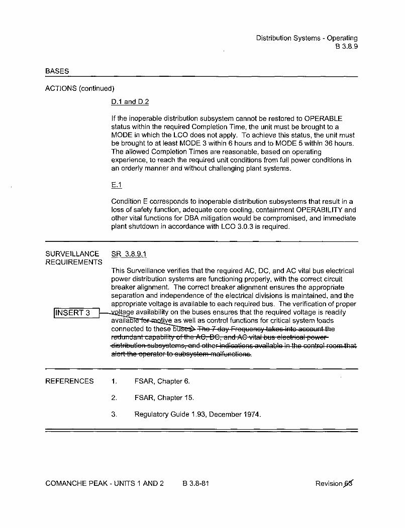
Distribution Systems - OperatingB 3.8.9
BASES
ACTIONS (continued)
D.1 and D.2
If the inoperable distribution subsystem cannot be restored to OPERABLEstatus within the required Completion Time, the unit must be brought to aMODE in which the LCO does not apply. To achieve this status, the unit mustbe brought to at least MODE 3 within 6 hours and to MODE 5 within 36 hours.The allowed Completion Times are reasonable, based on operatingexperience, to reach the required unit conditions from full power conditions inan orderly manner and without challenging plant systems.
E.1
Condition E corresponds to inoperable distribution subsystems that result in aloss of safety function, adequate core cooling, containment OPERABILITY andother vital functions for DBA mitigation would be compromised, and immediateplant shutdown in accordance with LCO 3.0.3 is required.
SURVEILLANCE SR 3.8.9.1REQUIREMENTS
This Surveillance verifies that the required AC, DC, and AC vital bus electricalpower distribution systems are functioning properly, with the correct circuitbreaker alignment. The correct breaker alignment ensures the appropriateseparation and independence of the electrical divisions is maintained, and theappropriate voltage is available to each required bus. The verification of proper
INSERT 3 Itage availability on the buses ensures that the required voltage is readily•availa tive as well as control functions for critical system loads
conn~ectevd to thies~eu The :7 day FrceqUoncY takes- into con theIeUlIUdi dpblly UdI IC, DCp, and b- nfh AC vital bus5 ele•t•i•,• POWOIEi0StribuktiEan SE1G~eG andI othcr indications available in the con--trol room tha,l.-t the ap...t.. t- subsyste.. m malfunctions
REFERENCES 1. FSAR, Chapter 6.
2. FSAR, Chapter 15.
3. Regulatory Guide 1.93, December 1974.
COMANCHE PEAK - UNITS 1 AND 2 B 3.8-81 Revisiong

Distribution Systems - ShutdownB 3.8.10
BASES
INSERT 3SURVEILLANCE SR 3.8.10.1 (continued)REQUIREMENTS Fh
control functions for critical system loads connected to these buses. e7 day FM quuiiuy akes iitou acunt fi. capability of the eletrie." pcwcrd stributiam subsystems, and Ither indiectic3 available in th• •cntrol F8r-
that slert the epefrator to SUbcycto e ofuntoe
REFERENCES 1. FSAR, Chapter 6.
2. FSAR, Chapter 15.
COMANCHE PEAK- UNITS 1 AND 2 B 3.8-87 Revisiong
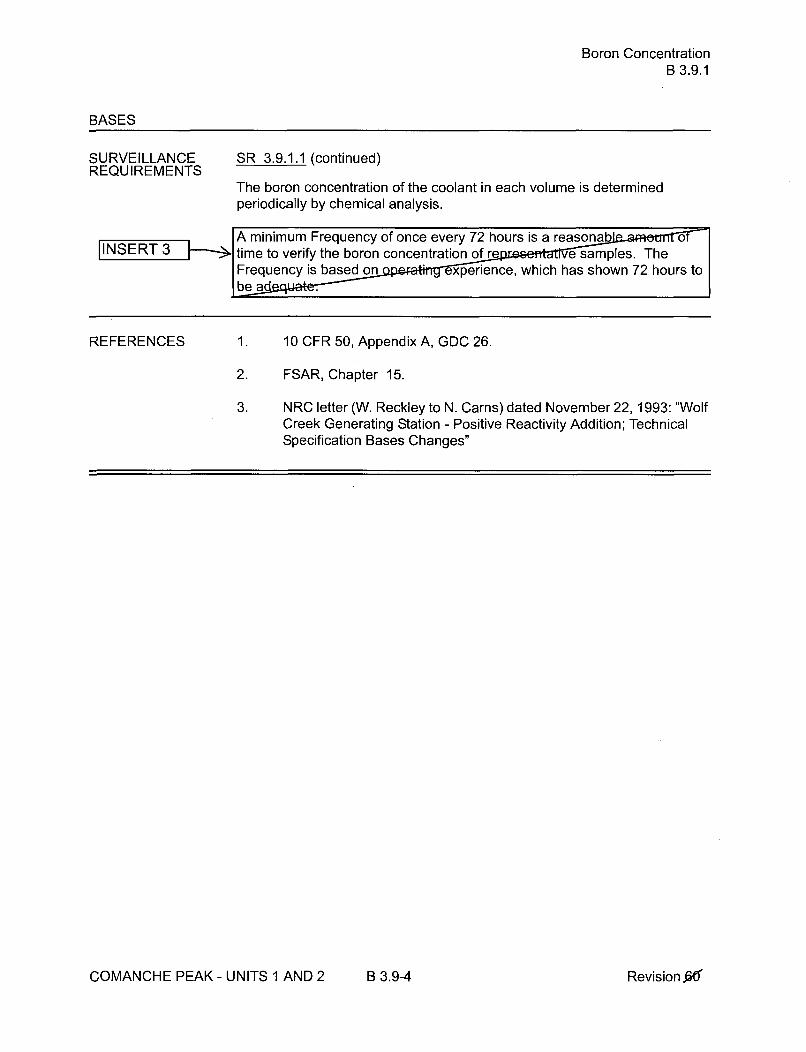
Boron ConcentrationB 3.9.1
BASES
SURVEILLANCEREQUIREMENTS
SR 3.9.1.1 (continued)
The boron concentration of the coolant in each volume is determinedperiodically by chemical analysis.
A minimum Frequency of once every 72 hours is a reasonab otime to verify the boron concentration of re e samples. TheFrequency is based on experience, which has shown 72 hours tobe a
REFERENCES 1. 10 CFR 50, Appendix A, GDC 26.
2. FSAR, Chapter 15.
3. NRC letter (W. Reckley to N. Carns) dated November 22, 1993: "WolfCreek Generating Station - Positive Reactivity Addition; TechnicalSpecification Bases Changes"
COMANCHE PEAK - UNITS 1 AND 2 B 3.9-4 Revision.&

Unborated WAer Source Isolation ValvesB 3.9.2
BASES
SURVEILLANCEREQUIREMENTS
SR 3.9.2.1 (continued)
that all unborated water sources are isolated, precluding a dilution. Theboron concentration is checked every 72 hours during MODE 6 under
[INSERT 3 SR 3.9.1.1. This Surveillance demonstrates that the valves are closedi h- a system walkdown (which may include the use of local or remote
inr~lr•,al.•~dLq• -'l.. ")4 •1•, I- • .... .. : k ~ l•,• • e j.r . .1 r. r *L ... J.
CL.U nibIut ud I t~dbU Mdulez hi vlI of~V uI IEel ad linisi ~iplve eenral tha~IOLilt wYill
REFERENCES 1. FSAR, Section 15.
2. NUREG-0800, Section 15.4.6.
COMANCHE PEAK- UNITS 1 AND 2 B 3.9-7 Revision X

Nuclear InstrumentationB 3.9.3
BASES
ACTIONS (continued)
B.1
With no required source range neutron flux monitor OPERABLE, action torestore a monitor to OPERABLE status shall be initiated immediately. Onceinitiated, action shall be continued until a source range neutron flux monitoris restored to OPERABLE status.
B.2
With no required source range neutron flux monitor OPERABLE, there areno direct means of detecting changes in core reactivity. However, sinceCORE ALTERATIONS and boron concentration changes inconsistent withRequired Action A.2 are not to be made, the core reactivity condition isstabilized until the source range neutron flux monitors are OPERABLE. Thisstabilized condition is determined by performing SR 3.9.1.1 to ensure thatthe required boron concentration exists.
The Completion Time of once per 12 hours is sufficient to obtain andanalyze a reactor coolant sample for boron concentration and ensures thatunplanned changes in boron concentration would be identified. The 12 hourFrequency is reasonable, considering the low probability of a change in corereactivity during this time period.
SURVEILLANCE SR 3.9.3.1REQUIREMENTS
SR 3.9.3.1 is the performance of a CHANNEL CHECK, which is acomparison of the parameter indicated on one channel to a similarparameter on other channels. It is based on the assumption that the twoindication channels should be consistent with core conditions. Changes infuel loading and core geometry can result in significant differences betweensource range channels, but each channel should be consistent with its localconditions.
The Frequency of 12 hour: iscosi "CHECK
Fre " mi arly for the same instruments in LCO 3.3.1.
SIR 3.9.3.2 INSERT 3
SR 3.9.3.2 is the performance of a CHANNEL CALIBRATIONm,±ths. This SR is modified by a Note stating that neutron tectors areexcluded from the CHANNEL CALIBRATION. For the so e range neutrondetectors, performance data is obtained and evaluated. I
(continued)
COMANCHE PEAK - UNITS 1 AND 2 B 3.9-10 Revision raiý

Nuclear InstrumentationB 3.9.3
BASES
SURVEILLANCE SR 3.9.3.2 (continued)REQUIREMENTS
Frequency is based on the need to perform this Surveillanceconditions that apply during a plant outage. experience hasshown these components ss the Surveillance when performed atthe 18 uency.
REFERENCES 1. 10 CFR 50, Appendix A, GDC 13, GDC 26, GDC 28, and GDC 29.
2. FSAR, Section [15.2.41.
3. NRC letter (W. Reckley to N. Carns) dated November 22, 1993 "WolfCreek Generating Station - Positive Reactivity Addition; TechnicalSpecification Bases Changes".
COMANCHE PEAK - UNITS 1 AND 2 B 3.9-11 Revisionx

Containment PenetrationsB 3.9.4
BASES (continued)
SURVEILLANCE SR 3.9.4.1REQUIREMENTS
This Surveillance demonstrates that each of the containment penetrationsrequired to be in its closed position is in that position. The Surveillance onthe open isolation valves will demonstrate that the required valves are notblocked from closing. Also the Surveillance will demonstrate that each valveoperator has motive power, which will ensure that each required valve iscapable of being closed by an OPERABLE automatic containmentventilation isolation signal.
The Surveillance is performed every 7 days during CORE ALTERATION rmovement of irradiated fuel assemblies within containment. TSurveillance interval is selected to be commensurate ' e normalduration of time to complete fuel handling op ns. A surveillance beforethe start of refueling operations will e two or three surveillanceverifications during the appli period for this LCO. As such, thisSurveillance nue apsuae fuel handling accident that releasesfissio rd iatvty within the conanetwl not result in a releaseof fi ' product radioactivity to the environment.
SR 3.4.9.2 /
This Surveillance demonstrates that the necessary hardware, tools, andequipment are available to install the equipment hatch. The equipmenthatch is provided with a set of hardware, tools, and equipment for moving thehatch from its storage location and installing it in the opening. The requiredset of hardware, tools, and equipment shall be inspected to ensure that theycan perform the required functions. IINSERT 3
The Surveillance is performed every 7 days during CORE ALTERATIONS ormovement of irradiated fuel assemblies within the containment. Tfhe-Su[ Vu •llaI me ii iklivl is, s lected to be oUliIIe,-tv ate with the Ii'lal
duratui• of time to cp'lete the fuel had',ing p•ratiram. The Surv 7 anceis modified by a Note which only requires that the Surveillance b et for anopen equipment hatch. If the equipment hatch is installed in i opening, theavailability of the means to install the hatch is not required.r-regU.. . y *. ade•U-t.. . .. aidcri-g that the he .dWa. ., tOOlS, a11 etuipmentalre 1dedica;te-d- to the oquipmcnt hateh anel not used for any other funtotn.
SR 3.9.4.3
This Surveillance demonstrates that each required containment ventilationvalve actuates to its isolation position on manual initiation or on an actual orsimulated high radiation signal from a containment atmosphere gaseous
(continued)
COMANCHE PEAK - UNITS 1 AND 2 B 3.9-16 Revisionx

Containment PenetrationsB 3.9.4
BASES
SURVEILLANCEREQUIREMENTS
IINSERT 3SR 3.9.4.3 (continued) I
monitorinq instrumentation channel. i Fu i F qu,, i-,-,fhtaintconsistency with other similar instrumentation and valve testingrequirements. In LCO 3.3.6, the Containment Ventilation I *oninstrumentation requires a CHANNEL CHECK ev hours and a COTevery 92 days to ensure the channel 0 ILITY during refuelingoperations. Every 18 months NNEL CALIBRATION is performed.These Surveillances rmed during MODE 6 will ensure that the valvesare capab osing after a postulated fuel handling accident to limit ar e of fission product radioactivity from the containment.
REFERENCES 1. FSAR, Section 15.7.4.
2. NUREG-0800, Section 15.7.4, Rev. 1, July 1981.
3. NUREG-0797, Section 15.4.8, Supplement 22, January 1990.
4. Technical Requirements Manual
COMANCHE PEAK - UNITS 1 AND 2 B 3.9-17 Revision X

RHR and Coolant Circulation - High Water LevelB 3.9.5
BASES
ACTIONS A.3 (continued)
6 and the refueling water level _> 23 ft above the top of the reactor vesselflange, corrective actions shall be initiated immediately.
A.4
If RHR loop requirements are not met, all containment penetrations providingdirect access from the containment atmosphere to the outside atmospheremust be closed within 4 hours. With the RHR loop requirements not met, thepotential exists for the coolant to boil and release radioactive gas to thecontainment atmosphere. Closing containment penetrations that are open tothe outside atmosphere ensures dose limits are not exceeded.
The Completion Time of 4 hours is reasonable, based on the low probabilityof the coolant boiling in that time.
SURVEILLANCE SR 3.9.5.1 INSERT3REQUIREMENTS
This Surveillance demonstrates that the HR loop is in operation andcirculating reactor coolant. The flow rate determined by the flow ratenecessary to provide sufficient decay heat moval capability and to preventthermal and boron stratification in the core. The Froguency of 12 hours;.sufficient, considering the [low, tellped.tu,, pun1p CuOMM,, and alarm0 dcaim av~ailable to the epefroter in the control F-1roo for1 mon-itoring theRNR Systerm,
REFERENCES 1. FSAR, Section 5.4.7.
COMANCHE PEAK - UNITS 1 AND 2 B 3.9-21 Revision W
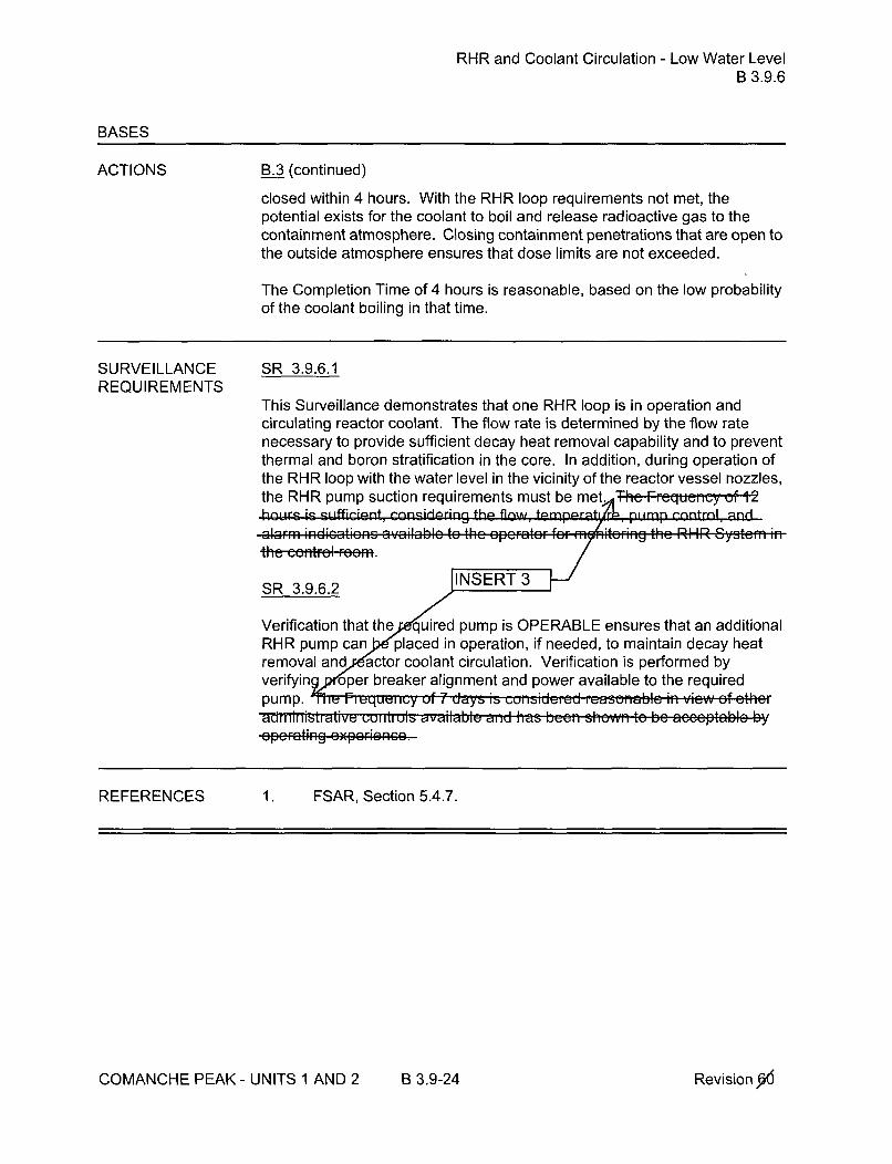
RHR and Coolant Circulation - Low Water LevelB 3.9.6
BASES
ACTIONS B.3 (continued)
closed within 4 hours. With the RHR loop requirements not met, thepotential exists for the coolant to boil and release radioactive gas to thecontainment atmosphere. Closing containment penetrations that are open tothe outside atmosphere ensures that dose limits are not exceeded.
The Completion Time of 4 hours is reasonable, based on the low probabilityof the coolant boiling in that time.
SURVEILLANCE SR 3.9.6.1REQUIREMENTS
This Surveillance demonstrates that one RHR loop is in operation andcirculating reactor coolant. The flow rate is determined by the flow ratenecessary to provide sufficient decay heat removal capability and to preventthermal and boron stratification in the core. In addition, during operation ofthe RHR loop with the water level in the vicinity of the reactor vessel nozzles,the RHR pump suction requirements must be met. he FrequIency cf 12hoilrs is s-14fticient, Gpsnneilring the flaxwu fmnrt/bnimn Lnntrnl and
t h e c o n mt r o l r e em . J N E TS R 3.9.6_. ... 2
Verification that the quired pump is OPERABLE ensures that an additionalRHR pump can placed in operation, if needed, to maintain decay heatremoval and actor coolant circulation. Verification is performed byverifyin oper breaker alignment and power available to the requiredpump. m ,, rluei my of , days is considered, ease, view of etadministrative uuii,,uls avaduilabl aben aonwd to be .... ptabl• bRpFrEting . FR Son5.4
REFERENCES 1 . FSAR, Section 5.4.7.
COMANCHE PEAK - UNITS 1 AND 2 B 3.9-24 Revision "KYU
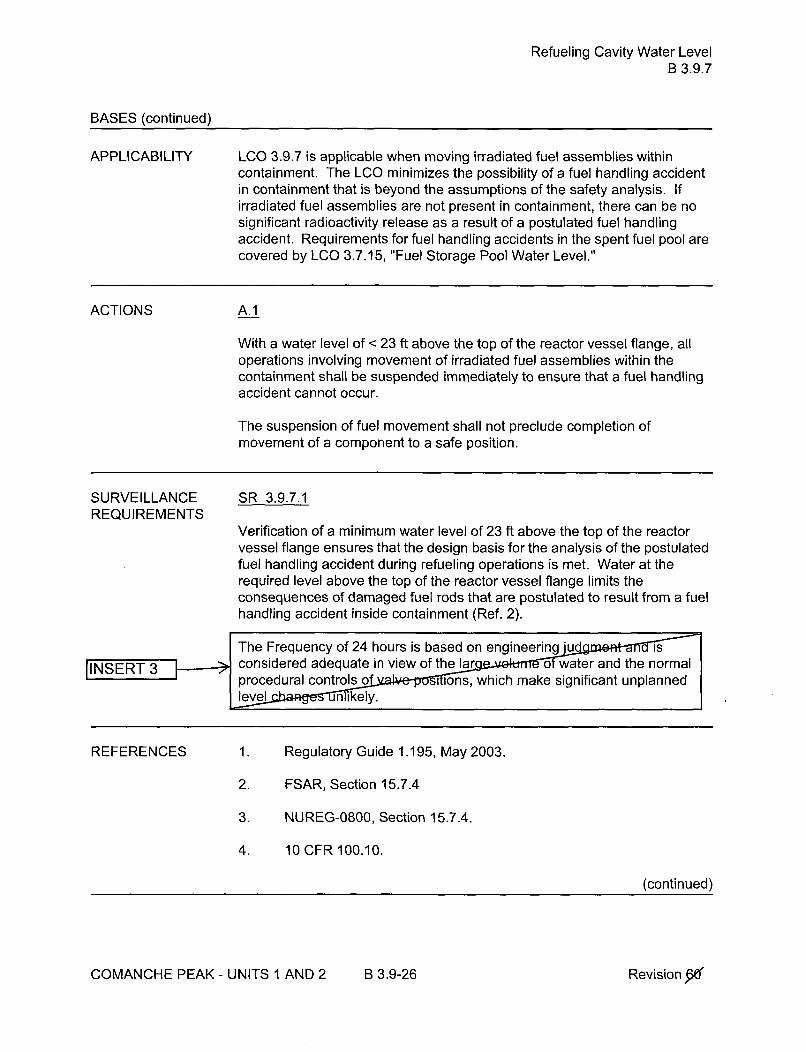
Refueling Cavity Water LevelB 3.9.7
BASES (continued)
APPLICABILITY LCO 3.9.7 is applicable when moving irradiated fuel assemblies withincontainment. The LCO minimizes the possibility of a fuel handling accidentin containment that is beyond the assumptions of the safety analysis. Ifirradiated fuel assemblies are not present in containment, there can be nosignificant radioactivity release as a result of a postulated fuel handlingaccident. Requirements for fuel handling accidents in the spent fuel pool arecovered by LCO 3.7.15, "Fuel Storage Pool Water Level."
ACTIONS A.1
With a water level of < 23 ft above the top of the reactor vessel flange, alloperations involving movement of irradiated fuel assemblies within thecontainment shall be suspended immediately to ensure that a fuel handlingaccident cannot occur.
The suspension of fuel movement shall not preclude completion ofmovement of a component to a safe position.
SURVEILLANCE SR 3.9.7.1REQUIREMENTS
Verification of a minimum water level of 23 ft above the top of the reactorvessel flange ensures that the design basis for the analysis of the postulatedfuel handling accident during refueling operations is met. Water at therequired level above the top of the reactor vessel flange limits theconsequences of damaged fuel rods that are postulated to result from a fuelhandling accident inside containment (Ref. 2).
The Frequency of 24 hours is based on engineeringjud sconsidered adequate in view of the la rg - ok • ater and tenraINET3, procedural controls of llllllwhchmak sgnificant unplanned
level nikely.
REFERENCES 1. Regulatory Guide 1.195, May 2003.
2. FSAR, Section 15.7.4
3. NUREG-0800, Section 15.7.4.
4. 10 CFR 100.10.
(continued)
COMANCHE PEAK - UNITS 1 AND 2 B 3.9-26 Revision X

Attachment 5 to TXX-11093Page 1 of 19508/01/2011
ATTACHMENT 5 to TXX-11093
RETYPED TECHNICAL SPECIFICATION PAGES
Pages 3.1-1 3.3-22 3.3-55 3.4-34 3.7-16 3.8-63.1-3 3.3-23 3.4-2 3.4-35 3.7-17 3.8-7
3.1-5 3.3-24 3.4-3 3.4-36 3.7-18 3.8-8
3.1-9 3.3-25 3.4-4 3.4-37 3.7-19 3.8-93.1-10 3.3-26 3.4-5 3.4-38 3.7-20 3.8-10
3.1-11 3.3-27 3.4-6 3.4-39 3.7-21 3.8-11
3.1-12 3.3-28 3.4-7 3.4-40 3.7-22 3.8-12
3.1-13 3.3-29 3.4-8 3.4-41 3.7-23 3.8-13
3.1-14 3.3-30 3.4-9 3.4-42 3.7-24 3.8-14
3.1-15 3.3-31 3.4-10 3.4-43 3.7-25 3.8-15
3.1-16 3.3-32 3.4-11 3.4-44 3.7-26 3.8-16
3.1-17 3.3-33 3.4-12 3.4-45 3.7-27 3.8-22
3.1-18 3.3-34 3.4-13 3.5-2 3.7-28 3.8-24
3.1-19 3.3-35 3.4-14 3.5-3 3.7-29 3.8-25
3.24 3.3-36 3.4-15 3.5-4 3.7-30 3.8-30
3.2-6 3.3-37 3.4-16 3.5-5 3.7-31 3.8-31
3.2-9 3.3-38 3.4-17 3.5-6 3.7-32 3.8-32
3.2-10 3.3-39 3.4-18 3.5-7 3.7-33 3.8-34
3.2-13 3.3-40 3.4-19 3.5-8 3.7-34 3.8-36
3.3-8 3.3-41 3.4-20 3.5-9 3.7-35 3.8-38
3.3-9 3.3-42 3.4-21 3.5-10 3.7-36 3.8-40
3.3-10 3.3-43 3.4-22 3.5-11 3.7-37 3.9-1
3.3-11 3.3-44 3.4-23 3.6-6 3.7-38 3.9-3
3.3-12 3.3-45 3.4-24 3.6-12 3.7-39 3.9-5
3.3-13 3.3-46 3.4-25 3.6-13 3.740 3.9-7
3.3-14 3.3-47 3.4-26 3.6-14 3.7-41 3.9-9
3.3-15 3.3-48 3.4-27 3.6-15 3.742 3.9-11
3.3-16 3.3-49 3.4-28 3.6-16 3.7-43 3.9-12
3.3-17 3.3-50 3.4-29 3.6-17 3.7-44 5-5-173.3-18 3.3-51 3.4-30 3.7-7 3.7-453.3-19 3.3-52 3.4-31 3.7-9 3.7-46
3.3-20 3.3-53 3.4-32 3.7-14 3.7-47
3.3-21 3.3-54 3.4-33 3.7-15 3.7-48
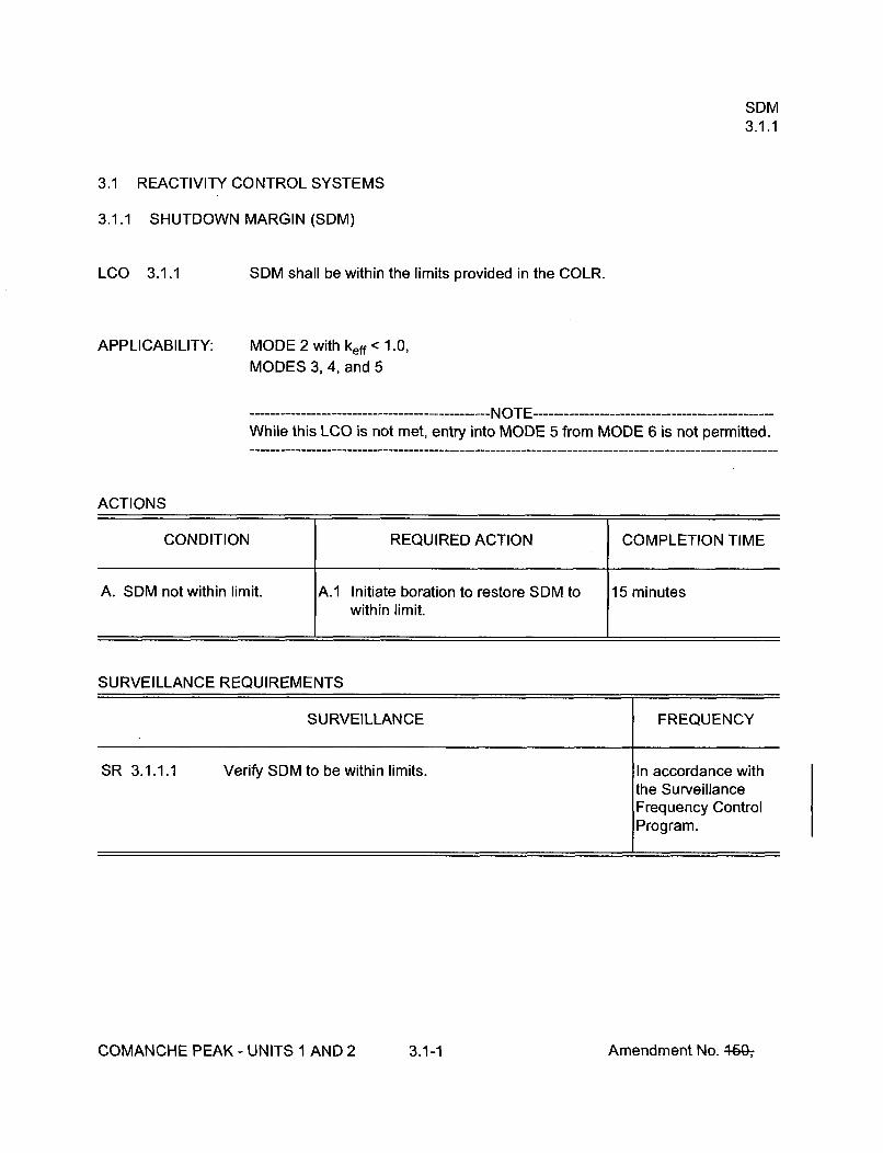
SDM3.1.1
3.1 REACTIVITY CONTROL SYSTEMS
3.1.1 SHUTDOWN MARGIN (SDM)
LCO 3.1.1 SDM shall be within the limits provided in the COLR.
APPLICABILITY: MODE 2 with keff < 1.0,MODES 3, 4, and 5
-------------------------------- NOTE -----------------------------------------------While this LCO is not met, entry into MODE 5 from MODE 6 is not permitted.
ACTIONS
CONDITION REQUIRED ACTION COMPLETION TIME
A. SDM not within limit. A.1 Initiate boration to restore SDM to 15 minuteswithin limit.
SURVEILLANCE REQUIREMENTS
SURVEILLANCE FREQUENCY
SR 3.1.1.1 Verify SDM to be within limits. In accordance withthe SurveillanceFrequency Control
Program.
COMANCHE PEAK - UNITS 1 AND 2 3.1-1 Amendment No. 469-,

Core Reactivity3.1.2
SURVEILLANCE REQUIREMENTS
SURVEILLANCE FREQUENCY
SR 3.1.2.1 -NOTE -----------------------------------The predicted reactivity values may be adjusted(normalized) to correspond to the measured core reactivityprior to exceeding a fuel burnup of 60 effective full powerdays (EFPD) after each fuel loading.
Verify measured core reactivity is within ± 1 % Ak/k ofpredicted values.
Once prior toentering MODE 1after each refueling
AND
---------- NOTE ---------Only required after60 EFPD
In accordance withthe SurveillanceFrequency ControlProgram.
COMANCHE PEAK - UNITS 1 AND 2 3.1-3 Amendment No. 44(ý,

MTC3.1.3
SURVEILLANCE REQUIREMENTS
SURVEILLANCE FREQUENCY
SR 3.1.3.1 Verify MTC is within upper limit. Once prior toentering MODE 1after each refueling
SR 3.1.3.2 ---------------------- NOTES -----------------1. Not required to be performed until 7 effective full power
days (EFPD) after reaching the equivalent of anequilibrium RTP all rods out (ARO) boron concentrationof 300 ppm.
2. If the MTC is more negative than the 300 ppmSurveillance limit (not LCO limit) specified in the COLR,SR 3.1.3.2 shall be repeated once per 14 EFPD duringthe remainder of the fuel cycle.
3. SR 3.1.3.2 need not be repeated if the MTC measuredat the equivalent of equilibrium RTP-ARO boronconcentration of < 60 ppm is less negative than the60 ppm Surveillance limit specified in the COLR.
Verify MTC is within lower limit. In accordance withthe SurveillanceFrequency ControlProgram.
COMANCHE PEAK - UNITS 1 AND 2 3.1-5 Amendment No. 4-6G-,

Rod Group Alignment Limits3.1.4
ACTIONS (continued)
CONDITION REQUIRED ACTION COMPLETION TIME
C. Required Action and C.1 Be in MODE 3. 6 hoursassociated CompletionTime of Condition B notmet.
D. More than one rod not D.1.1 Verify SDM to be within the limits 1 hour
within alignment limit, provided in the COLR.
OR
D.1.2 Initiate boration to restore required 1 hourSDM to within limit.
AND
D.2 Be in MODE 3. 6 hours
SURVEILLANCE REQUIREMENTS
SURVEILLANCE FREQUENCY
SR 3.1.4.1 Verify individual rod positions within alignment limit. In accordance withthe SurveillanceFrequency ControlProgram.
SR 3.1.4.2 Verify rod freedom of movement (trippability) by moving In accordance witheach rod not fully inserted in the core > 10 steps in either the Surveillancedirection. Frequency Control
Program.
COMANCHE PEAK - UNITS 1 AND 2 3.1-9 Amendment No. 46G-,

Rod Group Alignment Limits3.1.4
SURVEILLANCE REQUIREMENTS (continued)
SURVEILLANCE FREQUENCY
SR 3.1.4.3 Verify rod drop time of each rod, from the fully withdrawn Prior to reactorposition, is < 2.7 seconds from the beginning of decay of criticality after eachstationary gripper coil voltage to dashpot entry, with: removal of the
reactor heada. Tavg > 500°F; and
b. All reactor coolant pumps operating.
COMANCHE PEAK - UNITS 1 AND 2 3.1-10 Amendment No. 46&,

Shutdown Bank Insertion Limits3.1.5
3.1 REACTIVITY CONTROL SYSTEMS
3.1.5 Shutdown Bank Insertion Limits
LCO 3.1.5
APPLICABILITY:
Each shutdown bank shall be within insertion limits specified in the COLR.
MODE 1,MODE 2 with any control bank not fully inserted.
- ------------------------------- NOTE ----------This LCO is not applicable while performing SR 3.1.4.2.
ACTIONS
CONDITION REQUIRED ACTION COMPLETION TIME
A. One or more shutdown A.1.1 Verify SDM to be within the limits 1 hour
banks not within limits, provided in the COLR.
OR
A.1.2 Initiate boration to restore SDM to 1 hourwithin limit.
AND
A.2 Restore shutdown banks to within 2 hourslimits.
B. Required Action and B.1 Be in MODE 3. 6 hoursassociated CompletionTime not met.
COMANCHE PEAK - UNITS 1 AND 2 3.1-11 Amendment No. 4-6G-,

Shutdown Bank Insertion Limits3.1.5
SURVEILLANCE REQUIREMENTS
SURVEILLANCE FREQUENCY
SR 3.1.5.1 Verify each shutdown bank is within the limits specified in In accordance withthe COLR. the Surveillance
Frequency ControlProgram.
COMANCHE PEAK - UNITS 1 AND 2 3.1-12 Amendment No. 440-,

Control Bank Insertion Limits3.1.6
3.1 REACTIVITY CONTROL SYSTEMS
3.1.6 Control Bank Insertion Limits
LCO 3.1.6
APPLICABILITY:
Control banks shall be within the insertion, sequence, and overlap limitsspecified in the COLR.
MODE 1,MODE 2 with keff > 1.0.
-NOTE.....................--------------------------This LCO is not applicable while performing SR 3.1.4.2.
ACTIONS
CONDITION REQUIRED ACTION COMPLETION TIME
A. Control bank insertion limits A.1.1 Verify SDM to be within the limits 1 hour
not met. provided in the COLR.
OR
A.1.2 Initiate boration to restore SDM to 1 hourwithin limit.
AND
A.2 Restore control bank(s) to within 2 hourslimits.
COMANCHE PEAK - UNITS 1 AND 2 3.1-13 Amendment No. 4-6&,

Control Bank Insertion Limits3.1.6
ACTIONS (continued)
CONDITION REQUIRED ACTION COMPLETION TIME
B. Control bank sequence or B.1.1 Verify SDM to be within the limits 1 hour
overlap limits not met. provided in the COLR.
OR
B.1.2 Initiate boration to restore SDM to 1 hourwithin limit.
AND
B.2 Restore control bank sequence and 2 hoursoverlap to within limits.
C. Required Action and C.1 Be in MODE 3. 6 hoursassociated CompletionTime not met.
SURVEILLANCE REQUIREMENTS
SURVEILLANCE FREQUENCY
SR 3.1.6.1 Verify estimated critical control bank position is within the Within 4 hours priorlimits specified in the COLR. to achieving
criticality
SR 3.1.6.2 Verify each control bank insertion is within the limits In accordance withspecified in the COLR. the Surveillance
Frequency ControlProgram.
SR 3.1.6.3 Verify sequence and overlap limits specified in the COLR In accordance withare met for control banks not fully withdrawn from the core. the Surveillance
Frequency ControlProgram.
COMANCHE PEAK - UNITS 1 AND 2 3.1-14 Amendment No. 469-,
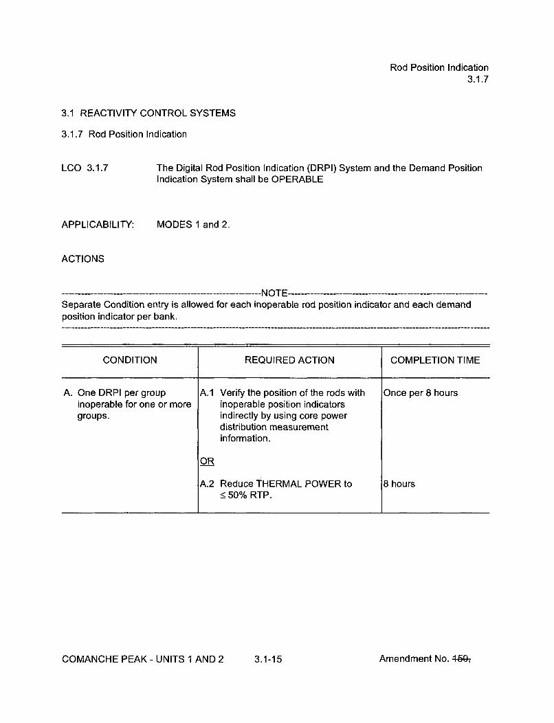
Rod Position Indication3.1.7
3.1 REACTIVITY CONTROL SYSTEMS
3.1.7 Rod Position Indication
LCO 3.1.7
APPLICABILITY:
The Digital Rod Position Indication (DRPI) System and the Demand PositionIndication System shall be OPERABLE
MODES 1 and 2.
ACTIONS
Separate Condition entry is allowed for each inoperable rod position indicator and each demandposition indicator per bank.
CONDITION REQUIRED ACTION COMPLETION TIME
A. One DRPI per group A.1 Verify the position of the rods with Once per 8 hoursinoperable for one or more inoperable position indicatorsgroups. indirectly by using core power
distribution measurementinformation.
OR
A.2 Reduce THERMAL POWER to 8 hours•50% RTP.
COMANCHE PEAK - UNITS 1 AND 2 3.1-15 Amendment No. 46G-,

Rod Position Indication3.1.7
ACTIONS (continued)
CONDITION REQUIRED ACTION COMPLETION TIME
B. More than one DRPI per B.1 Place the control rods under manual Immediately
group inoperable, control.
AND
B.2 Monitor and record RCS Tavg. Once per 1 hour
AND
B.3 Verify the position of the rods with Once per 8 hoursinoperable position indicatorsindirectly by using core powerdistribution measurementinformation.
AND
B.4 Restore inoperable position 24 hoursindicators to OPERABLE status suchthat a maximum of one DRPI pergroup is inoperable.
C. One or more rods with C.1 Verify the position of the rods with 4 hoursinoperable DRPIs have inoperable position indicatorsbeen moved in excess of indirectly by using core power24 steps in one direction distribution measurementsince the last determination information.of the rod's position.
OR
C.2 Reduce THERMAL POWER to 8 hours•50% RTP.
COMANCHE PEAK - UNITS 1 AND 2 3.1-16 Amendment No. 46&,

Rod Position Indication3.1.7
ACTIONS (continued)
CONDITION REQUIRED ACTION COMPLETION TIME
D. One demand position D.1.1 Verify by administrative means all Once per 8 hoursindicator per bank DRPIs for the affected banks areinoperable for one or more OPERABLE.banks.
AND
D.1.2 Verify the most withdrawn rod and Once per 8 hoursthe least withdrawn rod of theaffected banks are < 12 stepsapart.
OR
D.2 Reduce THERMAL POWER to 8 hours• 50% RTP.
E. Required Action and E.1 Be in MODE 3. 6 hoursassociated CompletionTime not met.
SURVEILLANCE REQUIREMENTS
SURVEILLANCE FREQUENCY
SR 3.1.7.1 Verify each DRPI agrees within 12 steps of the group Once prior todemand position for the full indicated range of rod travel. criticality after each
removal of thereactor vessel head.
COMANCHE PEAK - UNITS 1 AND 2 3.1-17 Amendment No. 449ý

PHYSICS TESTS Exceptions - MODE 23.1.8
3.1 REACTIVITY CONTROL SYSTEMS
3.1.8 PHYSICS TESTS Exceptions - MODE 2
LCO 3.1.8 During the performance of PHYSICS TESTS, the requirements of
LCO 3.1.3, "Moderator Temperature Coefficient (MTC)";LCO 3.1.4, "Rod Group Alignment Limits";LCO 3.1.5, "Shutdown Bank Insertion Limits";LCO 3.1.6, "Control Bank Insertion Limits"; andLCO 3.4.2, "RCS Minimum Temperature for Criticality"
may be suspended, provided:
a. RCS lowest operating loop average temperature is > 541 OF; and
b. SDM is within the limits provided in the COLR; and
c. THERMAL POWER is < 5% RTP
APPLICABILITY: MODE 2 during PHYSICS TESTS.
ACTIONS
CONDITION REQUIRED ACTION COMPLETION TIME
A. SDM not within limit. A.1 Initiate boration to restore SDM to 15 minutes
within limit.
AND
A.2 Suspend PHYSICS TESTS 1 hourexceptions.
B. THERMAL POWER not B.1 Open reactor trip breakers. Immediatelywithin limit.
COMANCHE PEAK - UNITS 1 AND 2 3.1-18 Amendment No. 4-59-,

PHYSICS TESTS Exceptions - MODE 23.1.8
ACTIONS (continued)
CONDITION REQUIRED ACTION COMPLETION TIME
C. RCS lowest operating loop C.1 Restore RCS lowest operating loop 15 minutesaverage temperature not average temperature to within limit.within limit.
D. Required Action and D.1 Be in MODE 3. 15 minutesassociated CompletionTime of Condition C notmet.
SURVEILLANCE REQUIREMENTS
SURVEILLANCE FREQUENCY
SR 3.1.8.1 Perform a CHANNEL OPERATIONAL TEST on power Prior to initiation ofrange and intermediate range channels per SR 3.3.1.7, PHYSICS TESTSSR 3.3.1.8, and Table 3.3.1-1.
SR 3.1.8.2 Verify the RCS lowest operating loop average temperature In accordance withis > 5410 F. the Surveillance
Frequency ControlProgram.
SR 3.1.8.3 Verify THERMAL POWER is < 5% RTP. In accordance withthe SurveillanceFrequency ControlProgram.
SR 3.1.8.4 Verify SDM is within the limits provided in the COLR. In accordance withthe SurveillanceFrequency ControlProgram.
COMANCHE PEAK - UNITS 1 AND 2 3.1-19 Amendment No. 4fQ-, 4&2-,
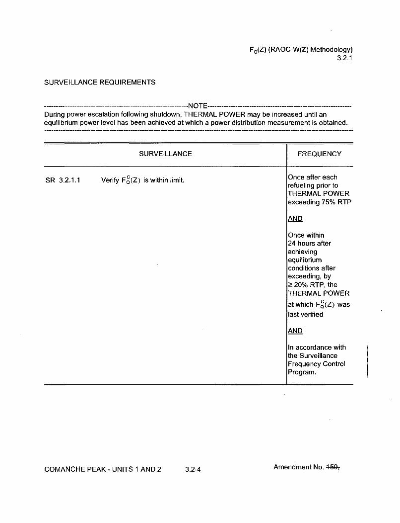
FQ(Z) (RAOC-W(Z) Methodology)3.2.1
SURVEILLANCE REQUIREMENTS
-------------------------------- NOTE-----------------------------During power escalation following shutdown, THERMAL POWER may be increased until anequilibrium power level has been achieved at which a power distribution measurement is obtained.
SURVEILLANCE FREQUENCY
-4
SR 3.2.1.1 Verify FG(Z) is within limit. Once after eachrefueling prior toTHERMAL POWERexceeding 75% RTP
AND
Once within24 hours afterachievingequilibriumconditions afterexceeding, byŽ 20% RTP, theTHERMAL POWER
at which F c(Z) was
last verified
AND
In accordance withthe SurveillanceFrequency ControlProgram.
COMANCHE PEAK - UNITS 1 AND 2 3.2-4 Amendment No. 46Q,

FQ(Z) (RAOC-W(Z) Methodology)3.2.1
SURVEILLANCE REQUIREMENTS
SURVEILLANCE FREQUENCY
SR 3.2.1.2 (continued) Once within24 hours afterachievingequilibriumconditions afterexceeding, byŽ> 20% RTP, theTHERMAL POWER
at which FC(Z) waslast verified
AND
In accordance withthe SurveillanceFrequency ControlProgram.
COMANCHE PEAK - UNITS 1 AND 2 3.2-6 Amendment No. 46G-i

NFAH3.2.2
SURVEILLANCE REQUIREMENTS
------------------------------ NOTE--------------------------------During power escalation following shutdown, THERMAL POWER may be increased until anequilibrium power level has been achieved at which a power distribution measurement is obtained.
SURVEILLANCE FREQUENCY
SR 3.2.2.1 NVerify FAH is within limits specified in the COLR. Once after eachrefueling prior toTHERMAL POWERexceeding 75% RTP
AND
In accordance withthe SurveillanceFrequency ControlProgram.
COMANCHE PEAK - UNITS 1 AND 2 3.2-9 Amendment No. 46&,

AFD (RAOC Methodology)3.2.3
3.2 POWER DISTRIBUTION LIMITS
3.2.3 AXIAL FLUX DIFFERENCE (AFD) (Relaxed Axial Offset Control (RAOC) Methodology)
LCO 3.2.3 The AFD in % flux difference units shall be maintained within the limitsspecified in'the COLR.
--- ------------------------------ NOTE -------------------------The AFD shall be considered outside limits when two or more OPERABLEexcore channels indicate AFD to be outside limits.
APPLICABILITY:
ACTIONS
MODE 1 with THERMAL POWER > 50% RTP
CONDITION REQUIRED ACTION COMPLETION TIME
A. AFD not within limits. A.1 Restore THERMAL POWER to 30 minutes< 50% RTP.
SURVEILLANCE REQUIREMENTS
SURVEILLANCE FREQUENCY
SR 3.2.3.1 Verify AFD is within limits for each OPERABLE excore In accordance withchannel. the Surveillance
Frequency ControlProgram.
COMANCHE PEAK - UNITS 1 AND 2 3.2-10 Amendment No. 4-GG-,
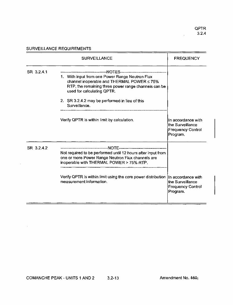
QPTR3.2.4
SURVEILLANCE REQUIREMENTS
SURVEILLANCE FREQUENCY
+
SR 3.2.4.1 ----------------NOTES-------- --------1. With input from one Power Range Neutron Flux
channel inoperable and THERMAL POWER < 75%RTP, the remaining three power range channels can beused for calculating QPTR.
2. SR 3.2.4.2 may be performed in lieu of thisSurveillance.
Verify QPTR is within limit by calculation. In accordance withthe SurveillanceFrequency ControlProgram.
SR 3.2.4.2Not required to be performed until 12 hours after input fromone or more Power Range Neutron Flux channels areinoperable with THERMAL POWER > 75% RTP.
Verify QPTR is within limit using the core power distributionmeasurement information.
In accordance withthe SurveillanceFrequency ControlProgram.
COMANCHE PEAK - UNITS 1 AND 2 3.2-13 Amendment No. 460-,

RTS Instrumentation3.3.1
ACTIONS (continued)
CONDITION REQUIRED ACTION COMPLETION TIME
T. One or more required T.1 Verify interlock is in required state for 1 hour
channel(s) inoperable, existing unit conditions.
OR
T.2 Be in MODE 2. 7 hours
U. One trip mechanism U.1 Restore inoperable trip mechanism to 48 hours
inoperable for one RTB. OPERABLE status.
OR
U.2 Be in MODE 3. 54 hours
V. Not used.
SURVEILLANCE REQUIREMENTS
----------------------- NOTE -------------------------------------------------------------Refer to Table 3.3.1-1 to determine which SRs apply for each RTS Function.
SURVEILLANCE FREQUENCY
SR 3.3.1.1 Perform CHANNEL CHECK. In accordance withthe SurveillanceFrequency ControlProgram.
COMANCHE PEAK - UNITS 1 AND 2 3.3-8 Amendment No. 4-60-,

RTS Instrumentation3.3.1
SURVEILLANCE REQUIREMENTS (continued)
SURVEILLANCE FREQUENCY
SR 3.3.1.2 -NOTE-Not required to be performed until 24 hours afterTHERMAL POWER is Ž 15% RTP.
Compare results of calorimetric heat balance calculation toNIS Power Range channel and N-16 Power Monitorchannel outputs. Adjust NIS Power Range channel outputsif calorimetric heat balance calculation exceeds NIS PowerRange channel outputs by more than +2% RTP. AdjustN-16 Power Monitor channel outputs if calorimetric heatbalance calculation exceeds N-16 Power Monitor channeloutputs by more than +2% RTP.
In accordance withthe SurveillanceFrequency ControlProgram.
SR 3.3.1.3 ----------------------- NOTE --------------------Not required to be performed until 24 hours afterTHERMAL POWER is Ž 50% RTP.
Compare results of the core power distribution In accordance withmeasurements to Nuclear Instrumentation System (NIS) the SurveillanceAFD. Adjust NIS channel if absolute difference is > 3%. Frequency Control
Program.
SR 3.3.1.4 ----------------------- NOTE ------------------This Surveillance must be performed on the reactor tripbypass breaker for the local manual shunt trip only prior toplacing the bypass breaker in service.
Perform TADOT. In accordance withthe SurveillanceFrequency ControlProgram.
COMANCHE PEAK - UNITS 1 AND 2 3.3-9 Amendment No. 46Gý

RTS Instrumentation3.3.1
SURVEILLANCE REQUIREMENTS (continued)
SURVEILLANCE FREQUENCY
SR 3.3.1.5 Perform ACTUATION LOGIC TEST. In accordance withthe SurveillanceFrequency ControlProgram.
SR 3.3.1.6 ----------------------- NOTE ------------------Not required to be performed until 72 hours after achievingequilibrium conditions with THERMAL POWER > 75%RTP.
Calibrate excore channels to agree with core power In accordance withdistribution measurements. the Surveillance
Frequency ControlProgram.
SR 3.3.1.7 ---------------------- NOTES -----------------1. Not required to be performed for source range
instrumentation prior to entering MODE 3 from MODE 2until 4 hours after entry into MODE 3.
2. Source range instrumentation shall include verificationthat interlocks P-6 and P-1 0 are in their required state forexisting unit conditions.
Perform COT. In accordance withthe SurveillanceFrequency ControlProgram.
COMANCHE PEAK - UNITS 1 AND 2 3.3-10 Amendment No. 4-60-,

RTS Instrumentation3.3.1
SURVEILLANCE REQUIREMENTS (continued)
SURVEILLANCE FREQUENCY
-f
SR 3.3.1.8 --------------------- NOTE -----------------------------------This Surveillance shall include verification that interlocksP-6 and P-1 0 are in their required state for existing unitconditions.
Perform COT. --------- NOTE -- -----..Only required whennot performed withinthe previousFrequency specifiedin the SFCP.
Prior to reactor
startup
AND
12 hours afterreducing powerbelow P-10 forpower andintermediateinstrumentation
AND
Four hours afterreducing powerbelow P-6 for sourcerangeinstrumentation
AND
In accordance withthe SurveillanceFrequency ControlProgram thereafter
COMANCHE PEAK - UNITS 1 AND 2 3.3-11 Amendment No. 4,50ý

RTS Instrumentation3.3.1
SURVEILLANCE REQUIREMENTS (continued)
SURVEILLANCE FREQUENCY
SR 3.3.1.9 ----------------------- NOTE ------------------Verification of setpoint is not required.
Perform TADOT. In accordance withthe SurveillanceFrequency ControlProgram.
SR 3.3.1.10 -- .....--------- ------------ NOTES ------------------1. N-16 detectors are excluded from CHANNEL
CALIBRATION.
2. This Surveillance shall include verification that the timeconstants are adjusted to the prescribed values.
3. Prior to entry into MODES 2 or 1, N-1 6 detector plateauverification is not required to be performed until 72 hoursafter achieving equilibrium conditions with THERMALPOWER _> 90% RTP.
Perform CHANNEL CALIBRATION. In accordance withthe SurveillanceFrequency ControlProgram.
COMANCHE PEAK - UNITS 1 AND 2 3.3-12 Amendment No. 440-,
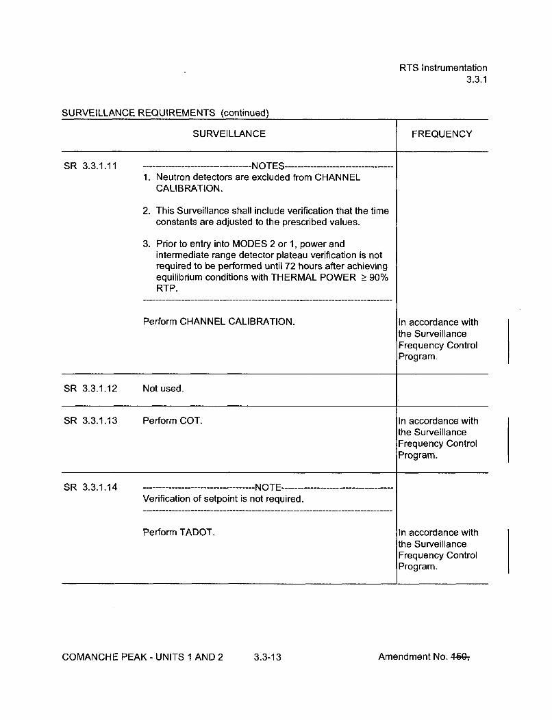
RTS Instrumentation3.3.1
SURVEILLANCE REQUIREMENTS (continued)
SURVEILLANCE FREQUENCY
SR 3.3.1.11 -NOTES-1. Neutron detectors are excluded from CHANNEL
CALIBRATION.
2. This Surveillance shall include verification that the timeconstants are adjusted to the prescribed values.
3. Prior to entry into MODES 2 or 1, power andintermediate range detector plateau verification is notrequired to be performed until 72 hours after achievingequilibrium conditions with THERMAL POWER > 90%RTP.
Perform CHANNEL CALIBRATION. In accordance withthe SurveillanceFrequency ControlProgram.
SR 3.3.1.12 Not used.
SR 3.3.1.13 Perform COT. In accordance withthe SurveillanceFrequency ControlProgram.
SR 3.3.1.14 ---------------------- NOTE ------------------Verification of setpoint is not required.
Perform TADOT. In accordance withthe SurveillanceFrequency ControlProgram.
COMANCHE PEAK - UNITS 1 AND 2 3.3-13 Amendment No. 460-,

RTS Instrumentation3.3.1
SURVEILLANCE REQUIREMENTS (continued)
SURVEILLANCE FREQUENCY
SR 3.3.1.15 ----------------------------------- I i L j S--, - - - - - - - -- - - - - - - -
Verification of setpoint is not required.
Perform TADOT. Prior to exceedingthe P-9 interlockwhenever the unithas been inMODE 3, if notperformed in theprevious Frequencyspecified in theSFCP
S R 3.3.1.16 ------------------------NOTE -------------------Neutron and N-16 detectors are excluded from responsetime testing.
Verify RTS RESPONSE TIMES are within limits. In accordance withthe SurveillanceFrequency ControlProgram.
COMANCHE PEAK - UNITS 1 AND 2 3.3-14 Amendment No. 4-60-,

RTS Instrumentation3.3.1
Table 3.3.1-1 (page 1 of 6)Reactor Trip System Instrumentation
APPLICABLEMODES OR OTHER
SPECIFIED REQUIRED SURVEILLANCE ALLOWABLEFUNCTION CONDITIONS CHANNELS CONDITIONS REQUIREMENTS VALUE(a)
1. Manual Reactor Trip 1,2 2 B SR 3.3.1.14 NA
3 (b), 4 (b), 5 (b) 2 C SR 3.3.1.14 NA
2. Power Range NeutronFlux
a. " High 1,2 4 D SR 3.3.1.1 5 109.6% RTp(q)(r)SR 3.3.1.2SR 3.3.1.7SR 3.3.1.11SR 3.3.1.16
b. Low 1 (), 2 4 E SR 3.3.1.1 < 25.6% RTP(q)(r)SR 3.3.1.8SR 3.3.1.11SR 3.3.1.16
3. Power Range Neutron 1,2 4 E SR 3.3.1.7 5 6.3% RTPFlux Rate High SR 3.3.1.11 with time constantPositive Rate SR 3.3.1.16 2> 2 sec
4. Intermediate Range 1 (c), 2 (d) 2 F,G SR 3.3.1.1 !5 31.5% RTPNeutron Flux SR 3.3.1.8
SR 3.3.1.11
(a) The Allowable Value defines the limiting safety system setting except for Trip Functions 2a, 2b, 6, 7, and 14 (the Nominal TripSetpoint defines the limiting safety system setting for these Trip Functions). See the Bases for the Nominal Trip Setpoints.
(b) With Rod Control System capable of rod withdrawal or one or more rods not fully inserted.(c) Below the P-1 0 (Power Range Neutron Flux) interlock.(d) Above the P-6 (Intermediate Range Neutron Flux) interlock.(q) If the as-found channel setpoint is conservative with respect to the Allowable Value but outside its predefined as-found acceptance
criteria band, then the channel shall be evaluated to verify that it is functioning as required before returning the channel to service.(r) The instrument channel setpoint shall be reset to a value that is within the as-left tolerance of the Nominal Trip Setpoint or a value that
is more conservative than the Trip Setpoint; otherwise, the channel shall be declared inoperable. The Nominal Trip Setpaint, themethodology used to determine the as-found tolerance and the methodology used to determine the as-left tolerance shall bespecified in the Technical Specification Bases.
COMANCHE PEAK - UNITS 1 AND 2 3.3-15 Amendment No. 4ýW4&ý-,
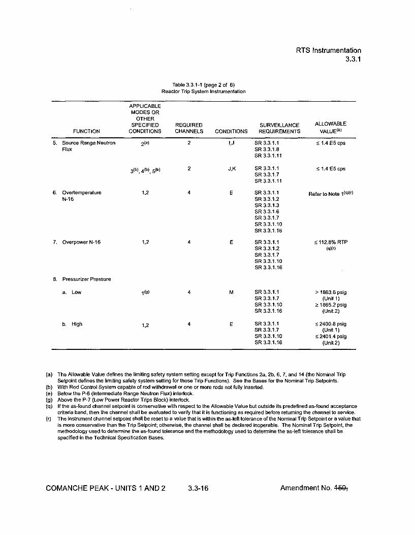
RTS Instrumentation3.3.1
Table 3.3.1-1 (page 2 of 6)Reactor Trip System Instrumentation
APPLICABLEMODES OR
OTHERSPECIFIED REQUIRED SURVEILLANCE ALLOWABLE
FUNCTION CONDITIONS CHANNELS CONDITIONS REQUIREMENTS VALUE(a)
5. Source Range Neutron 2(e) 2 I,J SR 3.3.1.1 • 1.4 E5 cpsFlux SR 3.3.1.8
SR 3.3.1.11
3 (b), 4 (b), 5 (b) 2 J,K SR 3.3.1.1 <1.4 E5 cpsSR 3.3.1.7SR 3.3.1.11
6. Overtemperature 1,2 4 E SR 3.3.1.1 Refer to Note 1 (q)(r)N-16 SR 3.3.1.2
SR 3.3.1.3SR 3.3.1.6SR 3.3.1.7SR 3.3.1.10SR 3.3.1.16
7. OverpowerN-16 1,2 4 E SR 3.3.1.1 < 112.8% RTPSR 3.3.1.2 (qXr)
SR 3.3.1.7SR 3.3.1.10SR 3.3.1.16
8. Pressurizer Pressure
a. Low (g) 4 M SR 3.3.1.1 1863.6 psigSR 3.3.1.7 (Unit 1)SR 3.3.1.10 >1865.2 psigSR 3.3.1.16 (Unit2)
b. High 1,2 E SR 3.3.1.1 <2400.8 psigSR 3.3.1.7 (Unit 1)SR 3.3.1.10 •2401.4 psigSR 3.3.1.16 (Unit 2)
(a)
(b)(e)(g)(q)
(r)
The Allowable Value defines the limiting safety system setting except for Trip Functions 2a, 2b, 6, 7, and 14 (the Nominal TripSetpoint defines the limiting safety system setting for these Trip Functions). See the Bases for the Nominal Trip Setpoints.With Rod Control System capable of rod withdrawal or one or more rods not fully inserted.Below the P-6 (Intermediate Range Neutron Flux) interlock.Above the P-7 (Low Power Reactor Trips Block) interlock.If the as-found channel setpoint is conservative with respect to the Allowable Value but outside its predefined as-found acceptancecriteria band, then the channel shall be evaluated to verify that it is functioning as required before returning the channel to service.The instrument channel setpoint shall be reset to a value that is within the as-left tolerance of the Nominal Trip Setpoint or a value thatis more conservative than the Trip Setpoint; otherwise, the channel shall be declared inoperable. The Nominal Trip Setpoint, themethodology used to determine the as-found tolerance and the methodology used to determine the as-left tolerance shall bespecified in the Technical Specification Bases.
COMANCHE PEAK- UNITS 1 AND 2 3.3-16 Amendment No. 4f)@-,

RTS Instrumentation3.3.1
Table 3.3.1-1 (page 3 of 6)Reactor Trip System Instrumentation
APPLICABLEMODES OR
OTHERSPECIFIED REQUIRED SURVEILLANCE ALLOWABLE
FUNCTION CONDITIONS CHANNELS CONDITIONS REQUIREMENTS VALUE(a)
9. PressurizerWaterLevel- 1(g) 3 M SR 3.3.1.1 •93.9% ofHigh SR 3.3.1.7 instrument span
SR 3.3.1.10
10. Reactor Coolant Flow - I(g) 3 per loop M SR 3.3.1.1 Ž88.6% of indicatedLow SR 3.3.1.7 loop flow (Unit 1)
SR 3.3.1.10 _88.8% of indicatedSR 3.3.1.16 loop flow (Unit 2)
11. Not Used
12. Undervoltage 1(g) 1 per bus M SR 3.3.1.9 > 4753 VRCPs SR 3.3.1.10
SR 3.3.1.16
13. Underfrequency 1(g) 1 per bus M SR 3.3.1.9 Ž 57.06 HzRCPs SR 3.3.1.10
SR 3.3.1.16
14. Steam Generator (SG) 1,2 4 per SG E SR 3.3.1.1 Ž37.5% of narrow
Water Level Low-Low (I) SR 3.3.1.7 range instrumentSR 3.3.1.10 spanSR 3.3.1.16 (Unit 1) (q)(r)
2! 34.9% of narrowrange instrument
span
(Unit 2 )(q)(r)
15. Not Used.
(a)
(g)(I)(q)
(r)
The Allowable Value defines the limiting safety system setting except for Trip Functions 2a, 2b, 6, 7, and 14 (the Nominal TripSetpoint defines the limiting safety system setting for these Trip Functions). See the Bases for the Nominal Trip Setpoints.Above the P-7 (Low Power Reactor Trips Block) interlock.The applicable MODES for these channels in Table 3.3.2-1 are more restrictive.If the as-found channel setpoint is conservative with respect to the Allowable Value but outside its predefined as-found acceptancecriteria band, then the channel shall be evaluated to verify that it is functioning as required before returning the channel to service.The instrument channel setpoint shall be reset to a value that is within the as-left tolerance of the Nominal Trip Setpoint, or a valuethat is more conservative than the Trip Setpoint; otherwise, the channel shall be declared inoperable. The Nominal Trip Setpoint, themethodology used to determine the as-found tolerance and the methodology used to determine the as-left tolerance shall bespecified in the Technical Specification Bases.
COMANCHE PEAK - UNITS 1 AND 2 3.3-17 Amendment No. 4640ý

RTS Instrumentation3.3.1
Table 3.3.1-1 (page 4 of 6)Reactor Trip System Instrumentation
APPLICABLEMODES OR
OTHERSPECIFIED REQUIRED SURVEILLANCE ALLOWABLE
FUNCTION CONDITIONS CHANNELS CONDITIONS REQUIREMENTS VALUE(a)
16. Turbine Trip
a. Low Fluid OilPressure
b. Turbine Stop ValveClosure
17. Safety Injection (SI) Inputfrom Engineered SafetyFeature ActuationSystem (ESFAS)
18. ReactorTripSystem Interlocks
a. Intermediate RangeNeutron Flux, P-6
b. Low Power ReactorTrips Block, P-7
c. Power RangeNeutron Flux, P-8
d. Power RangeNeutron Flux, P-9
e. Power RangeNeutron Flux, P-10
f, Turbine First StagePressure, P-13
19. Reactor Trip
Breakers(RTBs)(k)
3
4
2 trains
0 SR 3.3.1.10SR 3.3.1.15
P SR 3.3.1.10SR 3.3.1.15
Q SR 3.3.1.14
_> 46.6 psig
2! 1% open
NA1,2
2(e) 2
1 per train
4
4
S SR 3.3.1.11SR 3.3.1.13
T SR 3.3.1.5
T SR 3.3.1.11SR 3.3.1.13
T SR 3.3.1.11SR 3.3.1.13
S SR 3.3.1.11SR 3.3.1.13
T SR 3.3.1.10SR 3.3.1.13
R SR 3.3.1.4
C SR 3.3.1.4
> 6E-11 amp
NA
< 50.7% RTP
i5 52.7% RTP
Ž7.3% RTP and• 12.7% RTP
< 12.7% turbinepower
NA
1,2 4
1 2
1,2 2 trains
2 trains3 (b), 4 (b), 5 (b) NA
(a) The Allowable Value defines the limiting safety system setting except for Trip Functions 2a, 2b, 6, 7, and 14 (the Nominal TripSetpoint defines the limiting safety system setting for these Trip Functions). See the Bases for the Nominal Trip Setpoints.
(b) With Rod Contol System capable of rod withdrawal or one or more rods not fully inserted.(e) Below the P-6 (Intermediate Range Neutron Flux) interlock.(j) Above the P-9 (Power Range Neutron Flux) interlock.(k) Including any reactor trip bypass breakers that are racked in and closed for bypassing an RTB.
COMANCHE PEAK - UNITS 1 AND 2 3.3-18 Amendment No. 46Gý
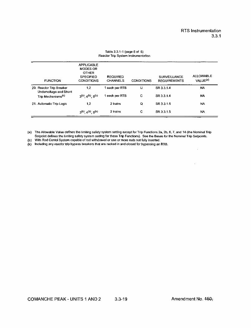
RTS Instrumentation3.3.1
Table 3.3.1-1 (page 5 of 6)Reactor Trip System Instrumentation
APPLICABLEMODES OR
OTHERSPECIFIED REQUIRED SURVEILLANCE ALLOWABLE
FUNCTION CONDITIONS CHANNELS CONDITIONS REQUIREMENTS VALUE(a)
20. Reactor Trip Breaker 1,2 1 each per RTB U SR 3.3.1.4 NAUndervoltage and Shunt
Trip Mechanisms(k) 3 (b) 4 (b), 5 (b) 1 each per RTB C SR 3.3.1.4 NA
21. Automatic Trip Logic 1,2 2 trains Q SR 3.3.1.5 NA
3 (b) 4 (b), 5 (b) 2 trains C SR 3.3.1.5 NA
(a) The Allowable Value defines the limiting safety system setting except for Trip Functions 2a, 2b, 6, 7, and 14 (the Nominal TripSetpoint defines the limiting safety system setting for these Trip Functions). See the Bases for the Nominal Trip Setpoints.
(b) With Rod Contol System capable of rod withdrawal or one or more rods not fully inserted.(k) Including any reactor trip bypass breakers that are racked in and closed for bypassing an RTB.
COMANCHE PEAK - UNITS 1 AND 2 3.3-19 Amendment No. 4-510ý

RTS Instrumentation3.3.1
Table 3.3.1-1 (page 6 of 6)Reactor Trip System Instrumentation
Note 1: Overtemperature N-16
The Overtemperature N-16 Function Allowable Values shall not exceed the following setpoint by more than 0.5% N-16span for N-16 input, 0.5% Tcold span for Tcold input, 0.5% pressure span for pressure input, and 0.5% Aq span for Aq input.
r(1 +t•1 s)
Qsetpoint = K1 - K2[l + T1STc -T] +K 3 (P-P1)-f,(Aq)
Where:
Qsetpoint = Overtemperature N-16 trip setpoint
K1
K2 = rF
K3 = */psig
Tc = Measured cold leg temperature, °F
Tcc = Indicated reference Tc at RATED THERMAL POWER, **F
P = Measured pressurizer pressure, psig
p 1 * psig (Nominal RCS operating pressure)
s = the Laplace transform operator, sec1 .
' =1,T2 Time constants utilized in lead-lag controller for Tc, T , sec, and T2 < * sec
fl(Aq) = *{(qt - qb) +
0%
*{(qt- qb) -
when (qt - qb) - *% RTP
when *% RTP < (qt - qb) < *% RTP
when (qt - qb) >- *% RTP
* as specified in the COLR
COMANCHE PEAK - UNITS 1 AND 2 3.3-20 Amendment No. 4-60-,
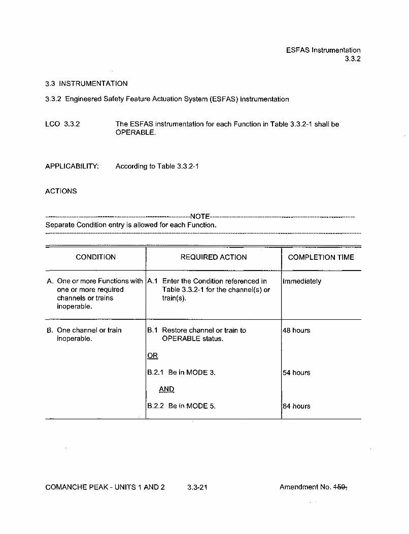
ESFAS Instrumentation3.3.2
3.3 INSTRUMENTATION
3.3.2 Engineered Safety Feature Actuation System (ESFAS) Instrumentation
LCO 3.3.2
APPLICABILITY:
The ESFAS instrumentation for each Function in Table 3.3.2-1 shall beOPERABLE.
According to Table 3.3.2-1
ACTIONS
Separate Condition entry is allowed for each Function.
CONDITION REQUIRED ACTION COMPLETION TIME
A. One or more Functions with A.1 Enter the Condition referenced in Immediatelyone or more required Table 3.3.2-1 for the channel(s) orchannels or trains train(s).inoperable.
B. One channel or train B.1 Restore channel or train to 48 hours
inoperable. OPERABLE status.
OR
B.2.1 Be in MODE 3. 54 hours
AND
B.2.2 Be in MODE 5. 84 hours
COMANCHE PEAK - UNITS 1 AND 2 3.3-21 Amendment No. 4.60-,

ESFAS Instrumentation3.3.2
ACTIONS (continued)
CONDITION REQUIRED ACTION COMPLETION TIME
C. One train inoperable. ----------------- NOTE ------------One train may be bypassed for up to4 hours for surveillance testing providedthe other train is OPERABLE.
C.1 Restore train to OPERABLE status. 24 hours
OR
C.2.1 Be in MODE 3. 30 hours
AND
C.2.2 Be in MODE 5. 60 hours
D. One channel inoperable. --------------- NOTE --------One channel may be bypassed for up to12 hours for surveillance testing.
D.1 Place channel in trip. 72 hours
OR
D.2.1 Be in MODE 3. 78 hours
AND
D.2.2 Be in MODE 4. 84 hours
COMANCHE PEAK- UNITS 1 AND 2 3.3-22 Amendment No. 460-,

ESFAS Instrumentation3.3.2
ACTIONS (continued)
CONDITION REQUIRED ACTION COMPLETION TIME
E. One Containment Pressure ------- NOTE ------------------------channel inoperable. One channel may be bypassed for up to
12 hours for surveillance testing.
E.1 Place channel in bypass. 72 hours
OR
E.2.1 Be in MODE 3. 78 hours
AND
E.2.2 Be in MODE 4. 84 hours
F. One channel or train F.1 Restore channel or train to 48 hours
inoperable. OPERABLE status.
OR
F.2.1 Be in MODE 3. 54 hours
AND
F.2.2 Be in MODE 4. 60 hours
COMANCHE PEAK - UNITS 1 AND 2 3.3-23 Amendment No. 46G-,
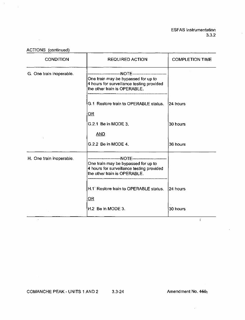
ESFAS Instrumentation3.3.2
ACTIONS (continued)
CONDITION REQUIRED ACTION COMPLETION TIME
G. One train inoperable. ------- NOTE ------------------------One train may be bypassed for up to4 hours for surveillance testing providedthe other train is OPERABLE.
G.1 Restore train to OPERABLE status. 24 hours
OR
G.2.1 Be in MODE 3. 30 hours
AND
G.2.2 Be in MODE 4. 36 hours
H. One train inoperable. ----------------- NOTE ------------One train may be bypassed for up to4 hours for surveillance testing providedthe other train is OPERABLE.
H.1' Restore train to OPERABLE status. 24 hours
OR
H.2 Be in MODE 3. 30 hours
COMANCHE PEAK - UNITS 1 AND 2 3.3-24 Amendment No. 460-,

ESFAS Instrumentation3.3.2
ACTIONS (continued)
CONDITION REQUIRED ACTION COMPLETION TIME
I. One channel inoperable. -------------- NOTE ------------One channel may be bypassed for up to12 hours for surveillance testing.
1.1 Place channel in trip. 72 hours
OR
1.2 Be in MODE 3. 78 hours
J. One Main Feedwater Pump J.1 Place channel in trip. 6 hourstrip channel inoperable.
OR
J.2 Be in MODE 3. 12 hours
K. One channel inoperable. -------------- NOTE ------------One channel may be bypassed for up to12 hours for surveillance testing.
K.1 Place channel in bypass. 72 hours
OR
K.2.1 Be in MODE 3. 78 hours
AND
K.2.2 Be in MODE 5. 108 hours
COMANCHE PEAK - UNITS 1 AND 2 3.3-25 Amendment No. 46Gý

ESFAS Instrumentation3.3.2
ACTIONS (continued)
CONDITION REQUIRED ACTION COMPLETION TIME
L. One or more required L.1 Verify interlock is in required state for 1 hour
channel(s) inoperable, existing unit condition.
OR
L.2.1 Be in MODE 3. 7 hours
AND
L.2.2 Be in MODE 4. 13 hours
SURVEILLANCE REQUIREMENTS
------------------------------ NOTE ----------------------------------Refer to Table 3.3.2-1 to determine which SRs apply for each ESFAS Function.
SURVEILLANCE FREQUENCY
SR 3.3.2.1 Perform CHANNEL CHECK. In accordance withthe SurveillanceFrequency ControlProgram.
SR 3.3.2.2 Perform ACTUATION LOGIC TEST. In accordance withthe SurveillanceFrequency ControlProgram.
SR 3.3.2.3 Not Used.
COMANCHE PEAK - UNITS 1 AND 2 3.3-26 Amendment No. 4-60-,

ESFAS Instrumentation3.3.2
SURVEILLANCE REQUIREMENTS (continued)
SURVEILLANCE FREQUENCY
SR 3.3.2A4 Perform MASTER RELAY TEST. In accordance withthe SurveillanceFrequency ControlProgram.
SR 3.3.2.5 Perform COT. In accordance withthe SurveillanceFrequency ControlProgram.
S R 3.3.2,6 Perform SLAVE RELAY TEST. In accordance withthe SurveillanceFrequency ControlProgram.
SR 3.3.2.7 ---------------------- NOTES -------------------1. Verification of relay setpoints not required.
2. Actuation of final devices not included.
Perform TADOT. In accordance withthe SurveillanceFrequency ControlProgram.
S R 3.3.2,8 -- -------------------- NOTE ------------------Verification of setpoint not required for manual initiationfunctions.
Perform TADOT. In accordance withthe SurveillanceFrequency ControlProgram.
COMANCHE PEAK - UNITS 1 AND 2 3.3-27 Amendment No. 460-,

ESFAS Instrumentation3.3.2
SURVEILLANCE REQUIREMENTS (continued)
SURVEILLANCE FREQUENCY
SR 3.3.2.9 ----------------------- NOTE ------------------This Surveillance shall include verification that the timeconstants are adjusted to the prescribed values.
Perform CHANNEL CALIBRATION. In accordance withthe SurveillanceFrequency ControlProgram.
SR 3.3.2.10 ---------------------- NOTE ------------------Not required to be performed for the turbine driven AFWpump until 24 hours after SG pressure is >_ 532 psig.
Verify ESF RESPONSE TIMES are within limits. In accordance withthe SurveillanceFrequency ControlProgram.
SR 3.3.2.11 ---------------------- NOTE ------------------Verification of setpoint not required.
Perform TADOT. In accordance withthe SurveillanceFrequency ControlProgram.
COMANCHE PEAK - UNITS 1 AND 2 3.3-28 Amendment No. 46&,

ESFAS Instrumentation3.3.2
Table 3.3.2-1 (page 1 of 6)Engineered Safety Feature Actuation System Instrumentation
APPLICABLEMODES OR
OTHERSPECIFIED REQUIRED SURVEILLANCE ALLOWABLE
FUNCTION CONDITIONS CHANNELS CONDITIONS REQUIREMENTS VALUE(a)
1. Safety Injection
a. Manual Initiation 1, 2, 3,4 2 B SR 3.3.2.8 NA
b. Automatic Actuation 1, 2, 3, 4 2 trains C SR 3.3.2.2 NALogic and Actuation SR 3.3.2.4Relays SR 3.3.2.6
c. Containment 1, 2, 3 3 D SR 3.3.2.1 < 3.8 psigPressure -- High 1 SR 3.3.2.5
SR 3.3.2.9SR 3.3.2.10
d. Pressurizer Pressure 1, 2, 3 (b) 4 D SR 3.3.2.1 _ 1803.6 psig- Low SR 3.3.2.5
SR 3.3.2.9SR 3.3.2.10
e. Steam Line Pressure 1, 2, 3 (b) 3 per steam line D SR 3.3.2.1 _> 594.0 psig(c)Low SR 3.3.2.5 (Unit 1)
SR 3.3.2.9 > 578.4 psig(c)SR 3.3.2.10 (Unit2)
2. Containment Spray
a. Manual Initiation 1, 2, 3, 4 2 per train, B SR 3.3.2.8 NA2 trains
b. Automatic Actuation 1,2,3,4 2 trains C SR 3.3.2.2 NALogic and Actuation SR 3.3.2.4Relays SR 3.3.2.6
c. Containment 1, 2, 3 4 E SR 3.3.2.1 •18.8 psigPressure SR 3.3.2.5High - 3 SR 3.3.2.9
SR 3.3.2.10
(a) The Allowable Value defines the limiting safety system except for functions 5b and 6c (the Nominal Trip Setpoint defines the limitingsafety system setting for these Trip Functions). See the Bases for the Nominal Trip Setpoints.
(b) Above the P-11 (Pressurizer Pressure) interlock and below P-11, unless the Function is blocked.(c) Time constants used in the lead/lag controller are T1 > 10 seconds and T2 <5 seconds.
COMANCHE PEAK - UNITS I AND 2 3.3-29 Amendment No. 464;

ESFAS Instrumentation3.3.2
Table 3.3.2-1 (page 2 of 6)Engineered Safety Feature Actuation System Instrumentation
APPLICABLEMODES OR
OTHERSPECIFIED REQUIRED SURVEILLANCE ALLOWABLE
FUNCTION CONDITIONS CHANNELS CONDITIONS REQUIREMENTS VALUE(a)
3. Containment Isolation
a. Phase A Isolation
(1) Manual Initiation 1, 2,3,4 2 B SR 3.3.2.8 NA
(2) Automatic 1,2,3,4 2 trains C SR 3.3.2.2 NAActuation Logic SR 3.3.2.4and Actuation SR 3.3.2.6Relays
(3) Safety Injection Refer to Function 1 (Safety Injection) for all initiation functions and requirements.
b. Phase B Isolation
(1) Manual Initiation 1, 2, 3,4 2 per train, B SR 3.3.2.8 NA2 trains
(2) Automatic 1,2,3,4 2 trains C SR 3.3.2.2 NAActuation Logic SR 3.3.2.4and Actuation SR 3.3.2.6Relays
(3) Containment 1,2, 3 4 E SR 3.3.2.1 !5 18.8 psigPressure SR 3.3.2.5High - 3 SR 3.3.2.9
(a) The Allowable Value defines the limiting safety system except for functions 5b and 6c (the Nominal Trip Setpoint defines the limitingsafety system setting for these Trip Functions). See the Bases for the Nominal Trip Setpoints.
COMANCHE PEAK - UNITS 1 AND 2 3.3-30 Amendment No.+50,

ESFAS Instrumentation3.3.2
Table 3.3.2-1 (page 3 of 6)Engineered Safety Feature Actuation System Instrumentation
APPLICABLEMODES OR
OTHERSPECIFIED REQUIRED SURVEILLANCE ALLOWABLE
FUNCTION CONDITIONS CHANNELS CONDITIONS REQUIREMENTS VALUE(a)
4. Steam Line Isolation
a. Manual Initiation 1, 20), 30) 2 F SR 3.3.2.8 NA
b. Automatic Actuation 1, 2 0i), 3(i) 2 trains G SR 3.3.2.2 NALogic and Actuation SR 3.3.2.4Relays SR 3.3.2.6
c. Containment 1, 2,) 3 i) 3 D SR 3.3.2.1 <6.8 psigPressure - High 2 SR 3.3.2.5
SR 3.3.2.9SR 3.3.2.10
d. Steam Line Pressure
(1) Low 1, 20), 3 (bXi) 3 per steam line D SR 3.3.2.1 > 594.0 psig(c)SR 3.3.2.5 (Unit 1)SR 3.3.2.9 >578.4 psig(c)SR 3.3.2.10 (Unit 2)
(2) Negative Rate -- 3 (g)i) 3 per steam line D SR 3.3.2.1 < 178.7 psi(h)High SR 3.3.2.5
SR 3.3.2.9SR 3.3.2.10
(a) The Allowable Value defines the limiting safety system except for functions 5b and 6c (the Nominal Trip Setpoint defines the limitingsafety system setting for these Trip Functions). See the Bases for the Nominal Trip Setpoints.
(b) Above the P-11 (Pressurizer Pressure) Interlock and below P-11, unless the Function is blocked.(c) Time constants used in the lead/lag controller are T1 > 10 seconds and T2 •< 5 seconds.(g) Below the P-11 (Pressurizer Pressure) Interlock; however, may be blocked below P-11 when safety injection on steam line pressure-
low is not blocked.(h) Time constant utilized in the rate/lag controller is Ž 50 seconds.(i) Except when all MSIVs and their associated upstream drip pot isolation valves are closed and deactivated.
COMANCHE PEAK - UNITS 1 AND 2 3.3-31 Amendment No. I-K

ESFAS Instrumentation3.3.2
Table 3.3.2-1 (page 4 of 6)Engineered Safety Feature Actuation System Instrumentation
APPLICABLEMODES OR
OTHERSPECIFIED REQUIRED SURVEILLANCE ALLOWABLE
FUNCTION CONDITIONS CHANNELS CONDITIONS REQUIREMENTS VALUE(a)
5. Turbine Trip andFeedwater Isolation
a. Automatic Actuation 1,20) 2 trains H SR 3.3.2.2 NALogic and Actuation SR 3.3.2.4Relays SR 3.3.2.6
b. SG Water Level -- 1,20) 3 per SG(p) I SR 3.3.2.1 584.5% of narrowHigh High (P-14) SR 3.3.2.5 range span
SR 3.3.2.9 (Unit 1) (q)(r)
SR 3.3.2.10 -<82.0% of narrowrange span
(Unit 2) (q)(r)
c. Safety Injection Refer to Function 1 (Safety Injection) for all initiation functions and requirements.
(a)
0)(p)(q)
(r)
The Allowable Value defines the limiting safety system except for functions 5b and 6c (the Nominal Trip Setpoint defines the limitingsafety system setting for these Trip Functions). See the Bases for the Nominal Trip Setpoints.Except when all MFIVs and associated bypass valves are closed and de-activated or isolated by a closed manual valve.A channel selected for use as an input to the SG water level controller must be declared inoperable.If the as-found channel setpoint is conservative with respect to the Allowable Value but outside its predefined as-found acceptancecriteria band, then the channel shall be evaluated to verify that it is functioning as required before returning the channel to service.The instrument channel setpoint shall be reset to a value that is within the as-left tolerance of the Nominal Trip Setpoint, or a valuethat is more conservative than the Trip Setpoint; otherwise, the channel shall be declared inoperable. The Nominal Trip Setpoint, themethodology used to determine the as-found tolerance and the methodology used to determine the as-left tolerance shall bespecified in the Technical Specification Bases.
COMANCHE PEAK - UNITS 1 AND 2 3.3-32 Amendment No. 4-60-,
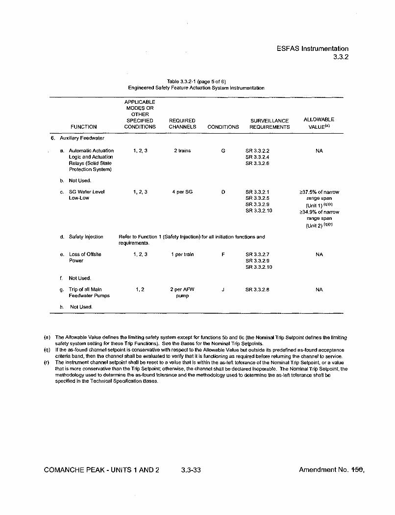
ESFAS Instrumentation3.3.2
Table 3.3.2-1 (page 5 of 6)Engineered Safety Feature Actuation System Instrumentation
APPLICABLEMODES OR
OTHERSPECIFIED REQUIRED SURVEILLANCE ALLOWABLE
FUNCTION CONDITIONS CHANNELS CONDITIONS REQUIREMENTS VALUE(a)
6. Auxiliary Feedwater
a. Automatic Actuation 1,2, 3 2 trains G SR 3.3.2.2 NALogic and Actuation SR 3.3.2.4Relays (Solid State SR 3.3.2.6Protection System)
b. Not Used.
c. SG Water Level 1,2, 3 4 per SG D SR 3.3.2.1 _>37.5% of narrowLow-Low SR 3.3.2.5 range span
SR 3.3.2.9 (Unit 1) (q)(r)SR 3.3.2.10 >-34.9% of narrow
range span
(Unit 2) (q)(r)
d. Safety Injection Refer to Function 1 (Safety Injection) for all initiation functions andrequirements.
e. Loss of Offsite 1, 2, 3 1 per train F SR 3.3.2.7 NAPower SR 3.3.2.9
SR 3.3.2.10
f. Not Used.
g. Trip of all Main 1,2 2 per AFW J SR 3.3.2.8 NAFeedwater Pumps pump
h. Not Used.
(a) The Allowable Value defines the limiting safety system except for functions 5b and 6c (the Nominal Trip Setpoint defines the limitingsafety system setting for these Trip Functions). See the Bases for the Nominal Trip Setpoints.
(q) If the as-found channel setpoint is conservative with respect to the Allowable Value but outside its predefined as-found acceptancecriteria band, then the channel shall be evaluated to verify that it is functioning as required before returning the channel to service.
(r) The instrument channel setpoint shall be reset to a value that is within the as-left tolerance of the Nominal Trip Setpoint, or a valuethat is more conservative than the Trip Setpoint; otherwise, the channel shall be declared inoperable. The Nominal Trip Setpoint, themethodology used to determine the as-found tolerance and the methodology used to determine the as-left tolerance shall bespecified in the Technical Specification Bases.
COMANCHE PEAK - UNITS 1 AND 2 3.3-33 Amendment No. 1-50,
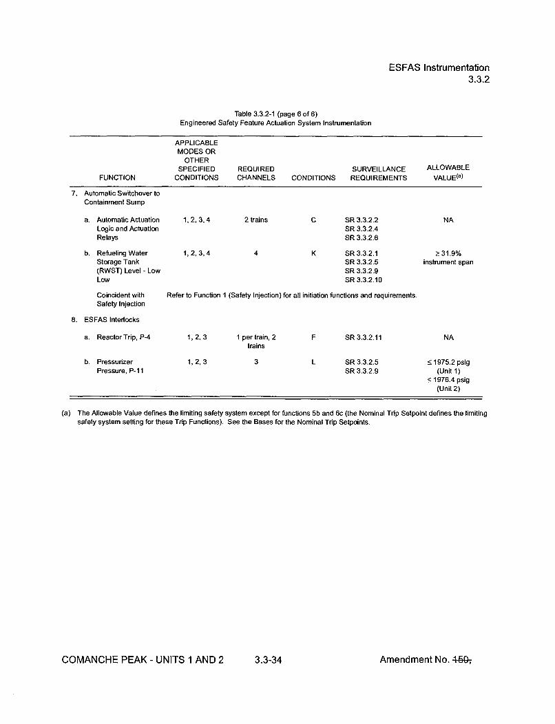
ESFAS Instrumentation3.3.2
Table 3.3.2-1 (page 6 of 6)Engineered Safety Feature Actuation System Instrumentation
APPLICABLEMODES OR
OTHERSPECIFIED REQUIRED SURVEILLANCE ALLOWABLE
FUNCTION CONDITIONS CHANNELS CONDITIONS REQUIREMENTS VALUE(a)
7. Automatic Switchover toContainment Sump
a. Automatic Actuation 1, 2,3,4 2 trains C SR 3.3.2.2 NALogic and Actuation SR 3.3.2.4Relays SR 3.3.2.6
b. Refueling Water 1, 2, 3,4 4 K SR 3.3.2.1 2> 31.9%Storage Tank SR 3.3.2.5 instrument span(RWST) Level - Low SR 3.3.2.9Low SR 3.3.2.10
Coincident with Refer to Function 1 (Safety Injection) for all initiation functions and requirements.Safety Injection
8. ESFAS Interlocks
a. Reactor Trip, P-4 1,2,3 1 per train, 2 F SR 3.3.2.11 NAtrains
b. Pressurizer 1, 2, 3 3 L SR 3.3.2.5 5 1975.2 psigPressure, P-11 SR 3.3.2.9 (Unit 1)
< 1976.4 psig(Unit 2)
(a) The Allowable Value defines the limiting safety system except for functions 5b and 6c (the Nominal Trip Setpoint defines the limitingsafety system setting for these Trip Functions). See the Bases for the Nominal Trip Setpoints.
COMANCHE PEAK - UNITS 1 AND 2 3.3-34 Amendment No. 460-,
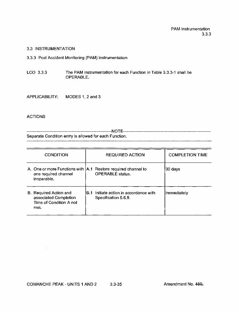
PAM Instrumentation3.3.3
3.3 INSTRUMENTATION
3.3.3 Post Accident Monitoring (PAM) Instrumentation
LCO 3.3.3
APPLICABILITY:
The PAM instrumentation for each Function in Table 3.3.3-1 shall beOPERABLE.
MODES 1, 2 and 3
ACTIONS
---------------------- NOTE---Separate Condition entry is allowed for each Function.
CONDITION REQUIRED ACTION COMPLETION TIME
A. One or more Functions with A.1 Restore required channel to 30 daysone required channel OPERABLE status.inoperable.
B. Required Action and B.1 Initiate action in accordance with Immediatelyassociated Completion Specification 5.6.8.Time of Condition A notmet.
COMANCHE PEAK - UNITS 1 AND 2 3.3-35 Amendment No. 4fQ-,

PAM Instrumentation3.3.3
ACTIONS (continued)
CONDITION REQUIRED ACTION COMPLETION TIME
C. One or more Functions C.1 Restore one channel to OPERABLE 7 dayswith two required status.channels inoperable.
OR
One required Thot channel
and one required CoreExit Temperature channelinoperable.
OR
One required Tcold
channel and one requiredSteam Line Pressurechannel for the associatedloop inoperable.
D. Required Action and D.1 Enter the Condition referenced in Immediatelyassociated Completion Table 3.3.3-1 for the channel.Time of Condition C notmet.
E. As required by Required E.1 Be in MODE 3. 6 hoursAction D.1 and referencedin Table 3.3.3-1. AND
E.2 Be in MODE 4. 12 hours
F. As required by Required F.1 Initiate action in accordance with ImmediatelyAction D.1 and referenced Specification 5.6.8.in Table 3.3.3-1.
COMANCHE PEAK - UNITS 1 AND 2 3.3-36 Amendment No. 460-,
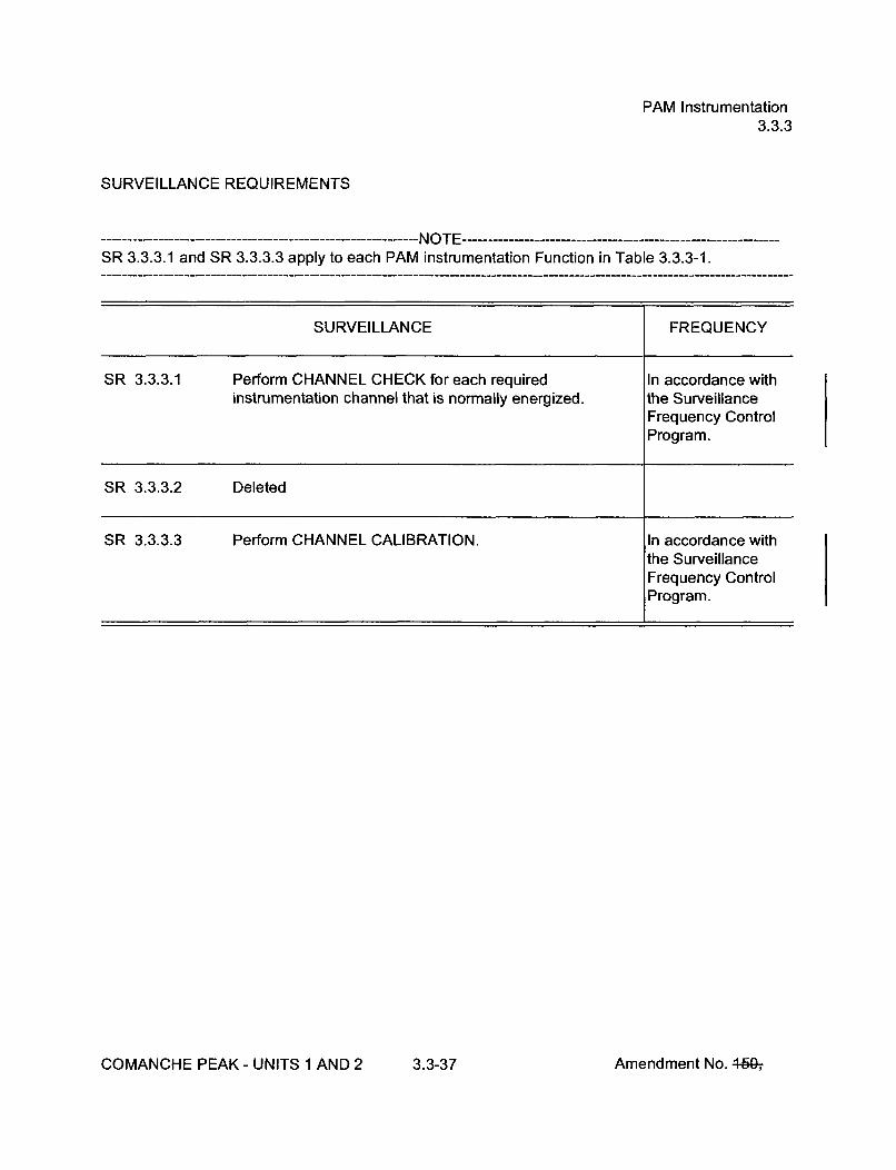
PAM Instrumentation
3.3.3
SURVEILLANCE REQUIREMENTS
----------------------------------- NOTE ----------------------------------SR 3.3.3.1 and SR 3.3.3.3 apply to each PAM instrumentation Function in Table 3.3.3-1.
SURVEILLANCE FREQUENCY
SR 3.3.3.1 Perform CHANNEL CHECK for each required In accordance withinstrumentation channel that is normally energized. the Surveillance
Frequency ControlProgram.
SR 3.3.3.2 Deleted
SR 3.3.3.3 Perform CHANNEL CALIBRATION. In accordance withthe SurveillanceFrequency ControlProgram.
COMANCHE PEAK - UNITS 1 AND 2 3.3-37 Amendment No. 46Gý

PAM Instrumentation3.3.3
Table 3.3.3-1 (page 1 of 1)Post Accident Monitoring Instrumentation
FUNCTION
1. Refueling Water Storage Tank Level
2. Subcooling Monitors
3. Reactor Coolant System (RCS) Hot LegTemperature (Wide Range) (Thot)
4. RCS Cold Leg Temperature (Wide Range)(Tcold)
5. RCS Pressure (Wide Range)
6. Reactor Vessel Water Level
7. Containment Sump Water Level (Wide Range)
8. Containment Pressure (Intermediate Range)
9. Steam Line Pressure
10. Containment Area Radiation (High Range)
11. Deleted
Table 3.3.3-1
(page 1 of 1)
Post Accident Monitoring
InstrumentationREQUIRED CHANNELS
2
2
1 per loop
1 per loop
2
2 (a)
2
2
2 per steam line
2
CONDITION REFERENCED FROMREQUIRED ACTION E.1
E
E
E
E
E
F
E
E
E
F
12. Pressurizer Water Level 2
13. Steam Generator Water Level (Narrow Range) 2 per steam generator
14. Condensate Storage Tank Level 2
15. Core Exit Temperature - Quadrant 1 2 (c)
16. Core Exit Temperature - Quadrant 2 2 (c)
17. Core Exit Temperature - Quadrant 3 2 (c)
E
E
E
E
E
E
E
E
E
18. Core Exit Temperature - Quadrant 4
19. Auxiliary Feedwater Flow
2(c)
a. AFW Flow 2 per steam generator
OR
b. AFW Flow and Steam Generator WaterLevel (Wide Range)
1 each per steamgenerator
(a) A channel is eight sensors in a probe. A channel is OPERABLE if four or more sensors, one or more in the uppersection and three or more in the lower section, are OPERABLE.
(b) Deleted(c) A channel consists of two core exit thermocouples (CETs).
COMANCHE PEAK - UNITS 1 AND 2 3.3-38 Amendment No. 4-50-,

Remote Shutdown System3.3.4
3.3 INSTRUMENTATION
3.3.4 Remote Shutdown System
LCO 3.3.4 The Remote Shutdown System Functions in Table 3.3.4-1 and the required hotshutdown panel (HSP) controls shall be OPERABLE.
APPLICABILITY: MODES 1, 2, and 3
ACTIONS
Separate Condition entry is allowed for each Function and required HSP control.
CONDITION REQUIRED ACTION COMPLETION TIME
A. One or more required A.1 Restore required Function and 30 daysFunctions inoperable, required HSP controls to OPERABLE
status.OR
One or more required HSPcontrols inoperable.
B. Required Action and B.1 Be in MODE 3. 6 hoursassociated CompletionTime not met. AND
B.2 Be in MODE 4. 12 hours
COMANCHE PEAK - UNITS 1 AND 2 3.3-39 Amendment No. 4W

Remote Shutdown System3.3.4
SURVEILLANCE REQUIREMENTS
SURVEILLANCE FREQUENCY
SR 3.3.4.1 Perform CHANNEL CHECK for each required In accordance withinstrumentation channel that is normally energized. the Surveillance
Frequency ControlProgram.
SR 3.3.4.2 Verify each required HSP power and control circuit and In accordance withtransfer switch is capable of performing the intended the Surveillancefunction. Frequency Control
Program.
SR 3.3.4.3 ------------ ------ NOTE --------------------Neutron detectors are excluded from CHANNELCALIBRATION.
Perform CHANNEL CALIBRATION for each required In accordance withinstrumentation channel. the Surveillance
Frequency ControlProgram.
COMANCHE PEAK - UNITS 1 AND 2 3.3-40 Amendment No. 460-,

Remote Shutdown System3.3.4
Table 3.3.4-1 (page 1 of 1)Remote Shutdown System Functions
FUNCTION REQUIRED CHANNELS
1. Neutron Flux Monitors 1
2. Pressurizer Pressure 1
3. RCS Hot Leg Temperature 1 per loop
4. RCS Cold Leg Temperature 1 per loop
5. Condensate Storage Tank Level 1
6. SG Pressure 1 per SG
7. SG Level 1 per SG
8. AFW Flow 1 per SG
9. Pressurizer Level 1
1 O.Charging Pump to CVCS Charging and RCP 1Seals Flow Indication
COMANCHE PEAK - UNITS 1 AND 2 3.3-41 Amendment No. 440-,

LOP DG Start Instrumentation3.3.5
3.3 INSTRUMENTATION
3.3.5 Loss of Power (LOP) Diesel Generator (DG) Start Instrumentation
LCO 3.3.5
APPLICABILITY:
The Loss of Power Diesel Generator Start Instrumentation for each Function inTable 3.3.5-1 shall be OPERABLE.
MODES 1, 2, 3, and 4
IMtJI- ---------------------------------- IV I',r -------------------------------------------------
Not applicable for 6.9 kV Preferred Offsite Source Undervoltage function whenassociated source breaker is open.
ACTIONS
------------------------- NOTE--Separate Condition entry is allowed for each Function.
CONDITION REQUIRED ACTION COMPLETION TIME
A. -------- NOTE------Not applicable to AutomaticActuation Logic andActuation Relays Function
One or more Functions with A.1 Place channel in trip. 6 hoursone channel per businoperable.
COMANCHE PEAK - UNITS 1 AND 2 3.3-42 Amendment No. 46Q,

LOP DG Start Instrumentation3.3.5
ACTIONS (continued)
CONDITION REQUIRED ACTION COMPLETION TIME
B. Two channels per bus for B.1 Restore one channel per bus to 1 hourthe Preferred offsite source OPERABLE status.bus undervoltage functioninoperable. OR
B.2.1 Declare the Preferred offsite source 1 hourinoperable.
AND
B.2.2 Open associated Preferred offsite 6 hourssource bus breaker.
C. Two channels per bus for C.1 Restore one channel per bus to 1 hourthe Alternate offsite source OPERABLE status.bus undervoltage functioninoperable. OR
C.2.1 Declare the Alternate offsite source 1 hourinoperable.
AND
C.2.2 Open associated Alternate offsite 6 hourssource bus breaker.
D. Two channels per bus for D.1 Restore one channel per bus to 1 hourthe 6.9 kV bus loss of OPERABLE status.voltage function inoperable.
OR
D.2 Declare the affected A.C. emergency 1 hourbuses inoperable.
COMANCHE PEAK - UNITS 1 AND 2 3.3-43 Amendment No. 440-,

LOP DG Start Instrumentation3.3.5
ACTIONS (continued)
CONDITION REQUIRED ACTION COMPLETION TIME
E. Two channels per bus for E.1 Restore one channel per bus to 1 hourone or more degraded OPERABLE status.voltage or low gridundervoltage function ORinoperable
E.2.1 Declare both offsite power source 1 hourbuses inoperable.
AND
E.2.2 Open offsite power source 6 hoursbreakers to the associated buses.
F. One or more Automatic F.1 Restore train(s) to OPERABLE 1 hourActuation Logic and status.Actuation Relays trainsinoperable.
G. Required Action and G.1 Enter applicable Condition(s) and Immediatelyassociated Completion Required Action(s) for the associatedTime not met. DG made inoperable by LOP DG
start instrumentation.
COMANCHE PEAK - UNITS 1 AND 2 3.3-44 Amendment No. 460-,

LOP DG Start Instrumentation3.3.5
SURVEILLANCE REQUIREMENTS
SURVEILLANCE FREQUENCY
SR 3.3.5.1 Perform ACTUATION LOGIC TEST. Prior to enteringMODE 4 when inMODE 5 forŽ 72 hours and if notperformed in theprevious Frequencyspecified in theSFCP
SR 3.3.5.2 ------------------------- NOTE -------------------Setpoint verification is not applicable.
Perform TADOT. Prior to enteringMODE 4 when inMODE 5 for> 72 hours and if notperformed in theprevious Frequencyspecified in theSFCP
SR 3.3.5.3 Perform CHANNEL CALIBRATION. In accordance withthe SurveillanceFrequency ControlProgram.
SR 3.3.5.4 Verify LOP DG start ESF RESPONSE TIMES are within In accordance withlimits. the Surveillance
Frequency ControlProgram.
COMANCHE PEAK - UNITS 1 AND 2 3.3-45 Amendment No. 4-W,
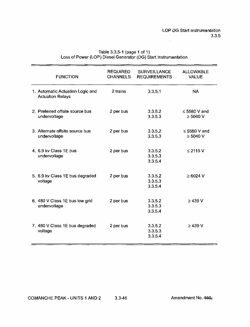
LOP DG Start Instrumentation3.3.5
Table 3.3.5-1 (page 1 of 1)Loss of Power (LOP) Diesel Generator (DG) Start Instrumentation
REQUIRED SURVEILLANCE ALLOWABLEFUNCTION CHANNELS REQUIREMENTS VALUE
1. Automatic Actuation Logic andActuation Relays
2. Preferred offsite source busundervoltage
3. Alternate offsite source busundervoltage
4. 6.9 kv Class 1E busundervoltage
5. 6.9 kv Class 1 E bus degradedvoltage
6. 480 V Class 1 E bus low gridundervoltage
7. 480 V Class 1E bus degradedvoltage
2 trains 3.3.5.1 NA
2 per bus
2 per bus
2 per bus
2 per bus
2 per bus
2 per bus
3.3.5.23.3.5.3
3.3.5.23.3.5.3
3.3.5.23.3.5.33.3.5.4
3.3.5.23.3.5.33.3.5.4
3.3.5.23.3.5.33.3.5.4
3.3.5.23.3.5.33.3.5.4
< 5580 V and> 5040 V
< 5580 V andŽ5040 V
•2115 V
Ž6024 V
> 439 V
> 439 V
COMANCHE PEAK - UNITS 1 AND 2 3.3-46 Amendment No. 4-60-,
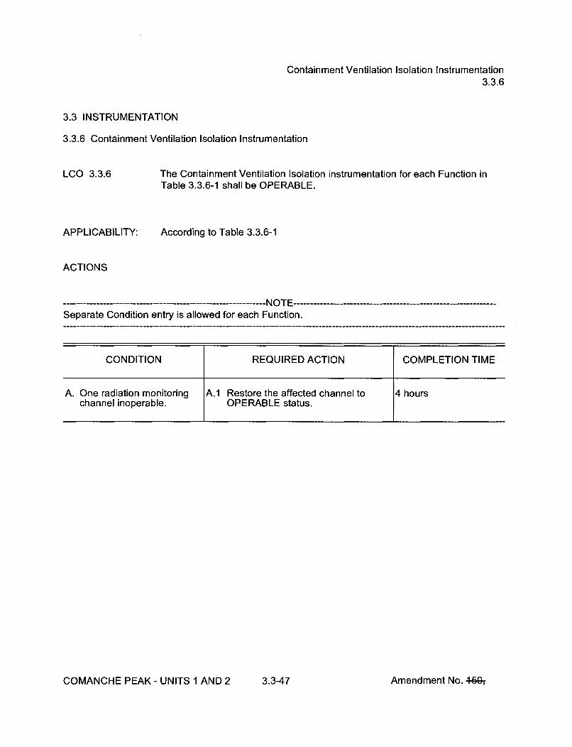
Containment Ventilation Isolation Instrumentation3.3.6
3.3 INSTRUMENTATION
3.3.6 Containment Ventilation Isolation Instrumentation
LCO 3.3.6
APPLICABILITY:
The Containment Ventilation Isolation instrumentation for each Function inTable 3.3.6-1 shall be OPERABLE.
According to Table 3.3.6-1
ACTIONS
----------------- NOTE---.Separate Condition entry is allowed for each Function.
CONDITION REQUIRED ACTION COMPLETION TIME
A. One radiation monitoring A.1 Restore the affected channel to 4 hourschannel inoperable. OPERABLE status.
COMANCHE PEAK - UNITS 1 AND 2 3.3-47 Amendment No. 44G-,
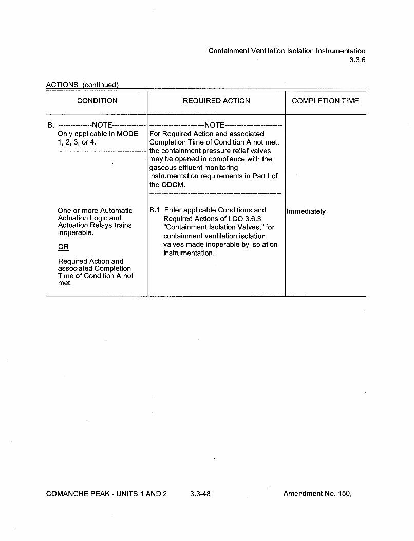
Containment Ventilation Isolation Instrumentation3.3.6
ACTIONS (continued)
CONDITION REQUIRED ACTION COMPLETION TIME
B. -------- NOTE --------------....-------------------- NOTE ------------Only applicable in MODE For Required Action and associated1, 2, 3, or 4. Completion Time of Condition A not met,
------------ the containment pressure relief valvesmay be opened in compliance with thegaseous effluent monitoringinstrumentation requirements in Part I ofthe ODCM.
One or more Automatic B.1 Enter applicable Conditions and ImmediatelyActuation Logic and Required Actions of LCO 3.6.3,Actuation Relays trains "Containment Isolation Valves," forinoperable, containment ventilation isolation
OR valves made inoperable by isolationinstrumentation.
Required Action andassociated CompletionTime of Condition A notmet.
COMANCHE PEAK - UNITS 1 AND 2 3.3-48 Amendment No. 460-,

Containment Ventilation Isolation Instrumentation3.3.6
ACTIONS (continued)
CONDITION REQUIRED ACTION COMPLETION TIME
C. -------- NOTE -------------------- NOTE ------------------------Only applicable during The containment pressure relief valvesCORE ALTERATIONS or may be opened in compliance with themovement of irradiated fuel gaseous effluent monitoringassemblies within instrumentation requirements in Part I ofcontainment, the ODCM.
Required Action and C.1 Place and maintain containment Immediatelyassociated Completion ventilation valves in closed position.Time for Condition A notmet. OR
C.2 Enter applicable Conditions and ImmediatelyRequired Actions of LCO 3.9.4,"Containment Penetrations," forcontainment ventilation isolationvalves made inoperable by isolationinstrumentation.
SURVEILLANCE REQUIREMENTS
------------------------------- NOTE------------------------------Refer to Table 3.3.6-1 to determine which SRs apply for each Containment Ventilation IsolationFunction.
SURVEILLANCE FREQUENCY
SR 3.3.6.1 Perform CHANNEL CHECK. In accordance withthe SurveillanceFrequency ControlProgram.
COMANCHE PEAK - UNITS 1 AND 2 3.3-49 Amendment No. 444;

Containment Ventilation Isolation Instrumentation3.3.6
SURVEILLANCE REQUIREMENTS (continued)
SURVEILLANCE FREQUENCY
SR 3.3.6.2 Perform ACTUATION LOGIC TEST. In accordance withthe SurveillanceFrequency ControlProgram.
SR 3.3.6.3 Perform MASTER RELAY TEST. In accordance withthe SurveillanceFrequency ControlProgram.
SR 3.3.6.4 Perform COT. In accordance withthe SurveillanceFrequency ControlProgram.
SR 3.3.6.5 Perform SLAVE RELAY TEST. In accordance withthe SurveillanceFrequency ControlProgram.
SR 3.3.6.6 Not Used.
SR 3.3.6.7 Perform CHANNEL CALIBRATION. In accordance withthe SurveillanceFrequency ControlProgram.
COMANCHE PEAK - UNITS 1 AND 2 3.3-50 Amendment No. 460-,

Containment Ventilation Isolation Instrumentation3.3.6
Table 3.3.6-1 (page 1 of 1)Containment Ventilation Isolation Instrumentation
APPLICABLEMODES OR
OTHERSPECIFIED REQUIRED SURVEILLANCE TRIPFUNCTION CONDITIONS CHANNELS REQUIREMENTS SETPOINT
1. Manual Initiation
2. Automatic ActuationLogic and ActuationRelays
3. Containment Radiation
1,2,3,4
1,2,3,4
Refer to LCO 3.3.2 "ESFAS Instrumentation,"Functions 2.a and 3.a.1, respectively for allinitiation functions and requirements.
2 trains SR 3.3.6.2SR 3.3.6.3S R 3.3.6.5
NA
a. Gaseous 1, 2, 3, 4, (b), (c) 1 SR 3.3.6.1SR 3.3.6.4SR 3.3.6.7
(a)
4. Containment Isolation - Refer to LCO 3.3.2, "ESFAS Instrumentation," Function 3.a, for allPhase A initiation functions and requirements.
(a)(b)(c)
Must satisfy Gaseous Effluent Dose Rate Requirements in Part I of the ODCM.During CORE ALTERATIONS.During movement of irradiated fuel assemblies within containment.
COMANCHE PEAK - UNITS 1 AND 2 3.3-51 Amendment No. 460-,

CREFS Actuation Instrumentation3.3.7
3.3 INSTRUMENTATION
3.3.7 Control Room Emergency Filtration System (CREFS) Actuation Instrumentation
LCO 3.3.7
APPLICABILITY:
The CREFS actuation instrumentation for each Function in Table 3.3.7-1 shallbe OPERABLE.
According to Table 3.3.7-1
ACTIONS
Separate Condition entry is allowed for each Function.
CONDITION REQUIRED ACTION COMPLETION TIME
A. One or more Functions with A.1 Place the affected CREFS train(s) in 7 daysone channel or train emergency recirculation mode.inoperable.
OR
A.2 ----------- NOTE ---------------------Applicable only to Functions 3a and3b.
Secure the Control Room makeup air 7 dayssupply fan from the affected airintake.
COMANCHE PEAK - UNITS I AND 2 3.3-52 Amendment No. 464;

CREFS Actuation Instrumentation3.3.7
ACTIONS (continued)
CONDITION REQUIRED ACTION COMPLETION TIME
B. One or more Functions with B.1.1 Place one CREFS train in Immediatelytwo channels or two trains emergency recirculation mode.inoperable.
AND
B.1.2 Enter applicable Conditions and ImmediatelyRequired Actions for one CREFStrain made inoperable byinoperable CREFS actuationinstrumentation
OR
B.2 --------- NOTE ---------Applicable only to Functions 3a and3b.
Secure the Control Room makeup air Immediatelysupply fan from the affected airintake.
C. Required Action and C.1 Be in MODE 3. 6 hoursassociated CompletionTime for Condition A or B ANDnot met in MODE 1, 2, 3,or 4. C.2 Be in MODE 5. 36 hours
D. Required Action and D.1 Suspend CORE ALTERATIONS. Immediatelyassociated CompletionTime for Condition A or B ANDnot met in MODE 5 or 6, orduring movement of D.2 Suspend movement of irradiated fuel Immediatelyirradiated fuel assemblies, assemblies.
COMANCHE PEAK - UNITS 1 AND 2 3.3-53 Amendment No. 46Gý

CREFS Actuation Instrumentation3.3.7
SURVEILLANCE REQUIREMENTS
------------------------------ NOTE -------------------------Refer to Table 3.3.7-1 to determine which SRs apply for each CREFS Actuation Function.
SURVEILLANCE FREQUENCY
SR 3.3.7.1 Perform CHANNEL CHECK. In accordance withthe SurveillanceFrequency ControlProgram.
SR 3.3.7.2 Perform COT. In accordance withthe SurveillanceFrequency ControlProgram.
SR 3.3.7.3 Not Used.
SR 3.3.7.4 Not Used.
SR 3.3.7.5 Not Used.
SR 3.3.7.6 -- -------------------- NOTE ------------------Verification of setpoint is not required.
Perform TADOT. In accordance withthe SurveillanceFrequency ControlProgram.
SR 3.3.7.7 Perform CHANNEL CALIBRATION. In accordance withthe SurveillanceFrequency ControlProgram.
COMANCHE PEAK - UNITS 1 AND 2 3.3-54 Amendment No. 469-,
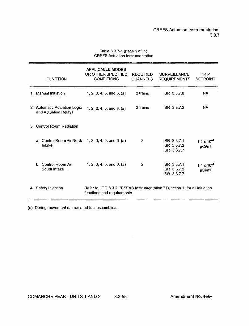
CREFS Actuation Instrumentation3.3.7
Table 3.3.7-1 (page 1 of 1)CREFS Actuation Instrumentation
APPLICABLE MODESOR OTHER SPECIFIED REQUIRED SURVEILLANCE TRIP
FUNCTION CONDITIONS CHANNELS REQUIREMENTS SETPOINT
1. Manual Initiation 1, 2, 3, 4, 5, and 6, (a) 2 trains SR 3.3.7.6 NA
2. Automatic Actuation Logic 1, 2, 3, 4, 5, and 6, (a) 2 trains SR 3.3.7.2 NAand Actuation Relays
3. Control Room Radiation
a. Control Room Air North 1,2,3,4,5, and6,(a) 2 SR 3.3.7.1 1.4x10⁻⁴Intake SR 3.3.7.2 gCi/ml
SR 3.3.7.7
b. Control Room Air 1, 2, 3, 4, 5, and 6, (a) 2 SR 3.3.7.1 1.4 x 10⁻⁴South Intake SR 3.3.7.2 4Ci/ml
SR 3.3.7.7
4. Safety Injection Refer to LCO 3.3.2, "ESFAS Instrumentation," Function 1, for all initiationfunctions and requirements.
(a) During movement of irradiated fuel assemblies.
COMANCHE PEAK - UNITS 1 AND 2 3.3-55 Amendment No. 4-60-,

RCS Pressure, Temperature, and Flow DNB Limits3.4.1
ACTIONS (continued)
CONDITION REQUIRED ACTION COMPLETION TIME
B. -------- NOTE --------------Only applicable prior toexceeding 85% RTP after arefueling outage.
Measured RCS Flow not B.1 Maintain THERMAL POWER less Immediatelywithin limits, than 85% RTP.
C. Required Action and C.1 Be in MODE 2. 6 hoursassociated CompletionTime not met.
SURVEILLANCE REQUIREMENTS
SURVEILLANCE FREQUENCY
SR 3.4.1.1 Verify pressurizer pressure is > the limit specified in the In accordance withCOLR. the Surveillance
Frequency ControlProgram.
SR 3.4.1.2 Verify RCS average temperature is < the limit specified in In accordance withthe COLR. the Surveillance
Frequency ControlProgram.
SR 3.4.1.3 Verify RCS total flow rate is > 389,700 and > the limit In accordance withspecified in the COLR. the Surveillance
Frequency ControlProgram.
COMANCHE PEAK - UNITS 1 AND 2 3.4-2 Amendment No. 460-,

RCS Pressure, Temperature, and Flow DNB Limits3.4.1
SURVEILLANCE REQUIREMENTS (continued)
SR 3.4.1.4 ----------------------- NOTE ------------------Not required to be performed until after exceeding 85%RTP after each refueling outage.
Verify by precision heat balance that RCS total flow rate is In accordance with> 389,700 and > the limit specified in the COLR. the Surveillance
Frequency ControlProgram.
COMANCHE PEAK - UNITS 1 AND 2 3.4-3 Amendment No. 46Gý

RCS Minimum Temperature for Criticality3.4.2
3.4 REACTOR COOLANT SYSTEM (RCS)
3.4.2 RCS Minimum Temperature for Criticality
LCO 3.4.2 Each operating RCS loop average temperature (Tavg) shall be __ 551'F.
APPLICABILITY: MODE 1,MODE 2 with keff _> 1.0
ACTIONS
CONDITION REQUIRED ACTION COMPLETION TIME
A. Tavg in one or more A.1 Be in MODE 2 with keff < 1.0. 30 minutesoperating RCS loops notwithin limit.
SURVEILLANCE REQUIREMENTS
SURVEILLANCE FREQUENCY
SR 3.4.2.1 Verify RCS Tavg in each operating loop > 551OF. In accordance withthe SurveillanceFrequency ControlProgram.
COMANCHE PEAK- UNITS 1 AND 2 3.4-4 Amendment No. 46G,

RCS P/T Limits3.4.3
3.4 REACTOR COOLANT SYSTEM (RCS)
3.4.3 RCS Pressure and Temperature (P/T) Limits
LCO 3.4.3 RCS pressure, RCS temperature, and RCS heatup and cooldown rates shallbe maintained within the limits specified in the PTLR.
APPLICABILITY: At all times
ACTIONS
CONDITION REQUIRED ACTION COMPLETION TIME
A. -------- NOTE-------Required Action A.2 shallbe completed wheneverthis Condition is entered.
Requirements of LCO not A.1 Restore parameter(s) to within limits. 30 minutesmet in MODE 1, 2, 3, or 4.
AND
A.2 Determine RCS is acceptable for 72 hourscontinued operation.
B. Required Action and B.1 Be in MODE 3. 6 hoursassociated CompletionTime of Condition A not ANDmet.
B.2 Be in MODE 5 with RCS pressure 36 hours< 500 psig.
COMANCHE PEAK - UNITS 1 AND 2 3.4-5 Amendment No. 449ý

RCS P/T Limits3.4.3
ACTIONS (continued)
CONDITION REQUIRED ACTION COMPLETION TIME
C. -------- NOTE --------------Required Action C.2 shallbe completed wheneverthis Condition is entered.
Requirements of LCO not C.1 Initiate action to restore parameter(s) Immediatelymet any time in other than to within limits.MODE 1, 2, 3, or 4.
AND
C.2 Determine RCS is acceptable for Prior to enteringcontinued operation. MODE 4
SURVEILLANCE REQUIREMENTS
SURVEILLANCE FREQUENCY
SR 3.4.3.1 ----------------------- NOTE ----------Only required to be performed during RCS heatup andcooldown operations and RCS inservice leak andhydrostatic testing.
Verify RCS pressure, RCS temperature, and RCS heatup In accordance withand cooldown rates are within the limits specified in the the SurveillancePTLR. Frequency Control
Program.
COMANCHE PEAK - UNITS 1 AND 2 3.4-6 Amendment No. 46&,

RCS Loops -- MODES 1 and 23.4.4
3.4 REACTOR COOLANT SYSTEM (RCS)
3.4.4 RCS Loops -- MODES 1 and 2
LCO 3.4.4 Four RCS loops shall be OPERABLE and in operation.
APPLICABILITY:
ACTIONS
MODES 1 and 2
CONDITION REQUIRED ACTION COMPLETION TIME
A. Requirements of LCO not A.1 Be in MODE 3. 6 hoursmet.
SURVEILLANCE REQUIREMENTS
SURVEILLANCE FREQUENCY
S R 3.4.4.1 Verify each RCS loop is in operation. In accordance withthe SurveillanceFrequency ControlProgram.
COMANCHE PEAK - UNITS 1 AND 2 3.4-7 Amendment No. 46G-,

RCS Loops -- MODE 33.4.5
3.4 REACTOR COOLANT SYSTEM (RCS)
3.4.5 RCS Loops -- MODE 3
LCO 3.4.5 Two RCS loops shall be OPERABLE, and either:
a. Two RCS loops shall be in operation when the Rod Control System iscapable of rod withdrawal; or
b. One RCS loop shall be in operation when the Rod Control System isnot capable of rod withdrawal.
------- ------------------- NOTE ------------------------All reactor coolant pumps may be removed from operation for < 1 hour per8 hour period provided:
a. No operations are permitted that would cause introduction of coolantinto the RCS with boron concentration less than required to meet theSDM of LCO 3.1.1; and
b. Core outlet temperature is maintained at least 1 0°F below saturationtemperature.
APPLICABILITY: MODE 3
ACTIONS
CONDITION REQUIRED ACTION COMPLETION TIME
A. One required RCS loop A.1 Restore required RCS loop to 72 hoursinoperable. OPERABLE status.
B. Required Action and B.1 Be in MODE 4. 12 hoursassociated CompletionTime of Condition A notmet.
COMANCHE PEAK - UNITS 1 AND 2 3.4-8 Amendment No. 460-,

RCS Loops -- MODE 33.4.5
ACTIONS (continued)
CONDITION REQUIRED ACTION COMPLETION TIME
C. One required RCS loop not C.1 Restore required RCS loop to 1 hourin operation, with Rod operation.Control System capable ofrod withdrawal. OR
C.2 Place the Rod Control System in a 1 hourcondition incapable of rodwithdrawal.
D. Four RCS loops inoperable. D.1 Place the Rod Control System in a Immediatelycondition incapable of rod
OR withdrawal.
No RCS loop in operation. AND
D.2 Suspend operations that would Immediatelycause introduction of coolant into theRCS with boron concentration lessthan required to meet SDM ofLCO 3.1.1.
AND
D.3 Initiate action to restore one RCS Immediatelyloop to OPERABLE status andoperation.
SURVEILLANCE REQUIREMENTS
SURVEILLANCE FREQUENCY
SR 3.4.5.1 Verify required RCS loops are in operation. In accordance withthe SurveillanceFrequency ControlProgram.
COMANCHE PEAK - UNITS 1 AND 2 3.4-9 Amendment No. 46&,

RCS Loops -- MODE 33.4.5
SURVEILLANCE REQUIREMENTS (continued)
SURVEILLANCE FREQUENCY
SR 3.4.5.2 Verify steam generator secondary side water levels are In accordance withŽ38% (Unit 1) and Ž_ 10% (Unit 2) for required RCS loops. the Surveillance
Frequency ControlProgram.
SR 3.4.5.3 Verify correct breaker alignment and indicated power are In accordance withavailable to the required pump that is not in operation. the Surveillance
Frequency ControlProgram.
COMANCHE PEAK - UNITS 1 AND 2 3.4-10 Amendment No. 440-,

RCS Loops -- MODE 43.4.6
3.4 REACTOR COOLANT SYSTEM (RCS)
3.4.6 RCS Loops -- MODE 4
LCO 3.4.6 Two loops consisting of any combination of RCS loops and residual heatremoval (RHR) loops shall be OPERABLE, and one loop shall be in operation.
LI r.rr r'--- ---------------------------- J ! ----------------------------------------------1. All reactor coolant pumps (RCPs) and RHR pumps may be removed from
operation for < 1 hour per 8 hour period provided:
a. No operations are permitted that would cause introduction of coolantinto the RCS with boron concentration less than required to meet theSDM of LCO 3.1.1; and
b. Core outlet temperature is maintained at least 1 0°F below saturationtemperature.
2. No RCP shall be started with any RCS cold leg temperature < 350°Funless the secondary side water temperature of each steam generator(SG) is < 50°F above each of the RCS cold leg temperatures.
APPLICABILITY: MODE 4
ACTIONS
CONDITION REQUIRED ACTION COMPLETION TIME
A. One required loop A.1 Initiate action to restore a second Immediately
inoperable, loop to OPERABLE status.
AND
A.2 ---------- NOTE -----------------------Only required if one RHR loop isOPERABLE
Be in MODE 5. 24 hours
COMANCHE PEAK - UNITS 1 AND 2 3.4-11 Amendment No. 464DT

RCS Loops -- MODE 43.4.6
ACTIONS (continued)
CONDITION REQUIRED ACTION COMPLETION TIME
B. Two required loops B.1 Suspend operations that would Immediatelyinoperable, cause introduction of coolant into the
RCS with boron concentration lessOR than required to meet SDM of
LCO 3.1.1.No RCS or RHR loop inoperation. AND
B.2 Initiate action to restore one loop to ImmediatelyOPERABLE status and operation.
SURVEILLANCE REQUIREMENTS
SURVEILLANCE FREQUENCY
SR 3.4.6.1 Verify one RHR or RCS loop is in operation. In accordance withthe SurveillanceFrequency ControlProgram.
SR 3.4.6.2 Verify SG secondary side water levels are _38% (Unit 1) In accordance withand Ž10% (Unit 2) for required RCS loops, the Surveillance
Frequency ControlProgram.
SR 3.4.6.3 Verify correct breaker alignment and indicated power are In accordance withavailable to the required pump that is not in operation. the Surveillance
Frequency ControlProgram.
COMANCHE PEAK - UNITS 1 AND 2 3.4-12 Amendment No. 46&,-

RCS Loops -- MODE 5, Loops Filled3.4.7
3.4 REACTOR COOLANT SYSTEM (RCS)
3.4.7 RCS Loops -- MODE 5, Loops Filled
LCO 3.4.7 One residual heat removal (RHR) loop shall be OPERABLE and in operation,
and either:
a. One additional RHR loop shall be OPERABLE; or
b. The secondary side water level of at least two steam generators (SGs)shall be >38% (Unit 1) and >10% (Unit 2).
----------------------------- NOTES -----------------------1. The RHR pump of the loop in operation may be removed from operation
for < 1 hour per 8 hour period provided:
a. No operations are permitted that would cause introduction of coolantinto the RCS with boron concentration less than required to meet theSDM of LCO 3.1.1; and
b. Core outlet temperature is maintained at least 10°F below saturationtemperature.
2. One required RHR loop may be inoperable for up to 2 hours forsurveillance testing provided that the other RHR loop is OPERABLE and inoperation.
3. No reactor coolant pump shall be started with any RCS cold legtemperature < 350°F unless the secondary side water temperature of eachSG is < 50°F above each of the RCS cold leg temperatures.
4. All RHR loops may be removed from operation during planned heatup toMODE 4 when at least one RCS loop is in operation.
APPLICABILITY:......................MODE........5....with........RC........loops.........filled........
APPLICABILITY: MODE 5 with RCS loops filled
COMANCHE PEAK - UNITS 1 AND 2 3.4-13 Amendment No. 4-60-,

RCS Loops -- MODE 5, Loops Filled3.4.7
ACTIONS
CONDITION REQUIRED ACTION COMPLETION TIME
A. One RHR loop inoperable. A.1 Initiate action to restore a second ImmediatelyRHR loop to OPERABLE status.
ANDOR
Required SGs secondaryside water levels not within A.2 Initiate action to restore required SG Immediatelylimits, secondary side water levels to within
limits.
B. Required RHR loops B.1 Suspend operations that would Immediatelyinoperable, cause introduction of coolant into the
RCS with boron concentration lessOR than required to meet SDM of
LCO 3.1.1.No RHR loop in operation.
AND
B.2 Initiate action to restore one RHR Immediatelyloop to OPERABLE status andoperation.
SURVEILLANCE REQUIREMENTS
SURVEILLANCE FREQUENCY
SR 3.4,7.1 Verify one RHR loop is in operation. In accordance withthe SurveillanceFrequency ControlProgram.
SR 3.47.2 Verify SG secondary side water level is Ž38% (Unit 1) and In accordance withA10% (Unit 2) in required SGs. the Surveillance
Frequency ControlProgram.
COMANCHE PEAK - UNITS 1 AND 2 3.4-14 Amendment No. 4649ý

RCS Loops -- MODE 5, Loops Filled3.4.7
SURVEILLANCE REQUIREMENTS (continued)
S R 3.4.7.3 Verify correct breaker alignment and indicated power are In accordance withavailable to the required RHR pump that is not in operation. the Surveillance
Frequency ControlProgram.
COMANCHE PEAK - UNITS 1 AND 2 3.4-15 Amendment No. 4ýW

RCS Loops -- MODE 5, Loops Not Filled3.4.8
3.4 REACTOR COOLANT SYSTEM (RCS)
3.4.8 RCS Loops -- MODE 5, Loops Not Filled
LCO 3.4.8 Two residual heat removal (RHR) loops shall be OPERABLE and one RHRloop shall be in operation.
------------------------------- NOTES -----------------------1. All RHR pumps may be removed from operation for < 1 hour provided:
a. The core outlet temperature is maintained at least 10°F belowsaturation temperature.
b. No operations are permitted that would cause introduction of coolantinto the RCS with boron concentration less than required to meet theSDM of LCO 3.1.1; and
c. No draining operations to further reduce the RCS water volume arepermitted.
2. One RHR loop may be inoperable for < 2 hours for surveillance testingprovided that the other RHR loop is OPERABLE and in operation.
APPLICABILITY: MODE 5 with RCS loops not filled
------------ NOTEWhile this LCO is not met, entry into MODE 5, Loops Not Filled from MODE 5,Loops filled is not permitted.
COMANCHE PEAK - UNITS I AND 2 3.4-16 Amendment No. 4-60-,

RCS Loops -- MODE 5, Loops Not Filled3.4.8
ACTIONS
CONDITION REQUIRED ACTION COMPLETION TIME
A. One RHR loop inoperable. A.1 Initiate action to restore RHR loop to ImmediatelyOPERABLE status.
B. Required RHR loops B.1 Suspend operations that would Immediatelyinoperable, cause introduction of coolant into the
RCS with boron concentration lessOR than required to meet SDM of
LCO 3.1.1.No RHR loop in operation.
AND
B.2 Initiate action to restore one RHR Immediatelyloop to OPERABLE status andoperation.
SURVEILLANCE REQUIREMENTS
SURVEILLANCE FREQUENCY
SR 3.4.8.1 Verify one RHR loop is in operation. In accordance withthe SurveillanceFrequency ControlProgram.
SR 3.4.8.2 Verify correct breaker alignment and indicated power are In accordance withavailable to the required RHR pump that is not in operation. the Surveillance
Frequency ControlProgram.
COMANCHE PEAK - UNITS 1 AND 2 3.4-17 Amendment No. 460-,
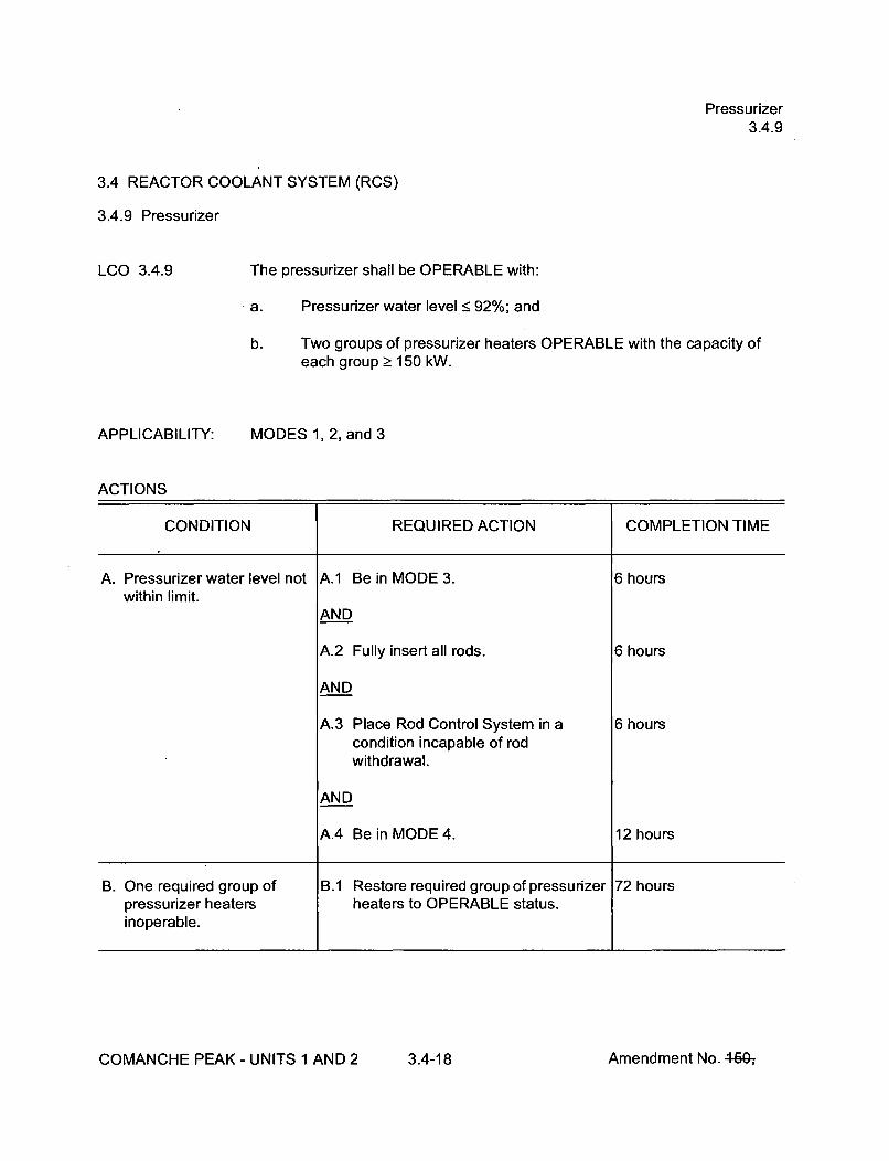
Pressurizer3.4.9
3.4 REACTOR COOLANT SYSTEM (RCS)
3.4.9 Pressurizer
LCO 3.4.9 The pressurizer shall be OPERABLE with:
a. Pressurizer water level < 92%; and
b. Two groups of pressurizer heaters OPERABLE with the capacity ofeach group Ž 150 kW.
APPLICABILITY: MODES 1, 2, and 3
ACTIONS
CONDITION REQUIRED ACTION COMPLETION TIME
A. Pressurizer water level not A.1 Be in MODE 3. 6 hourswithin limit.
AND
A.2 Fully insert all rods. 6 hours
AND
A.3 Place Rod Control System in a 6 hourscondition incapable of rodwithdrawal.
AND
A.4 Be in MODE 4. 12 hours
B. One required group of B.1 Restore required group of pressurizer 72 hourspressurizer heaters heaters to OPERABLE status.inoperable.
COMANCHE PEAK - UNITS 1 AND 2 3.4-18 Amendment No. 4649ý

Pressurizer3.4.9
ACTIONS (continued)
CONDITION REQUIRED ACTION COMPLETION TIME
C. Required Action and C.1 Be in MODE 3. 6 hoursassociated CompletionTime of Condition B not ANDmet.
C.2 Be in MODE 4. 12 hours
SURVEILLANCE REQUIREMENTS
SURVEILLANCE FREQUENCY
SR 3.4.9.1 Verify pressurizer water level is < 92%. In accordance withthe SurveillanceFrequency ControlProgram.
SR 3.4.9.2 Verify capacity of each required group of pressurizer In accordance withheaters is > 150 kW. the Surveillance
Frequency ControlProgram.
COMANCHE PEAK - UNITS 1 AND 2 3.4-19 Amendment No. 460-,

Pressurizer Safety Valves3.4.10
3.4 REACTOR COOLANT SYSTEM (RCS)
3.4.10 Pressurizer Safety Valves
LCO 3.4.10
APPLICABILITY:
Three pressurizer safety valves shall be OPERABLE with lift settings> 2410 psig and • 2485 psig.
MODES 1, 2, and 3,MODE 4 with all RCS cold leg temperatures > 320'F
---- ------------------------------------------------ \1 I Ir -- - - - -- - - - -- - - - -- - - - -- - - - -
The lift settings are not required to be within the LCO limits during MODES 3and 4 for the purpose of setting the pressurizer safety valves under ambient(hot) conditions. This exception is allowed for 54 hours following entry intoMODE 3 provided a preliminary cold setting was made prior to heatup.
ACTIONS
CONDITION REQUIRED ACTION COMPLETION TIME
A. One pressurizer safety A.1 Restore valve to OPERABLE status. 15 minutesvalve inoperable.
B. Required Action and B.1 Be in MODE 3. 6 hoursassociated CompletionTime not met. AND
OR B.2 Be in MODE 4 with any RCS cold leg 12 hourstemperatures < 3200F.
Two or more pressurizersafety valves inoperable.
COMANCHE PEAK - UNITS 1 AND 2 3.4-20 Amendment No. 460-,

Pressurizer Safety Valves3.4.10
SURVEILLANCE REQUIREMENTS
SURVEILLANCE FREQUENCY
SR 3.4.10.1 Verify each pressurizer safety valve is OPERABLE in In accordance withaccordance with the Inservice Testing Program. Following the Inservicetesting, lift settings shall be within ± 1%. Testing Program
COMANCHE PEAK - UNITS 1 AND 2 3.4-21 Amendment No.!' r-Q-,.

Pressurizer PORVs3.4.11
3.4 REACTOR COOLANT SYSTEM (RCS)
3.4.11 Pressurizer Power Operated Relief Valves (PORVs)
LCO 3.4.11
APPLICABILITY:
Each PORV and associated block valve shall be OPERABLE.
MODES 1, 2, and 3
ACTIONS
---------------------------------------------------- IIL It-r ---------------------------------------------------------------
Separate Condition entry is allowed for each PORV.
CONDITION REQUIRED ACTION COMPLETION TIME
A. One or more PORVs A.1 Close and maintain power to 1 hourinoperable and capable of associated block valve.being manually cycled.
B. One PORV inoperable and B.1 Close associated block valve. 1 hournot capable of beingmanually cycled. AND
B.2 Remove power from associated 1 hourblock valve.
AND
B.3 Restore PORV to OPERABLE status. 72 hours
COMANCHE PEAK - UNITS 1 AND 2 3.4-22 Amendment No. 460-,

Pressurizer PORVs3.4.11
ACTIONS (continued)
CONDITION REQUIRED ACTION COMPLETION TIME
C. One block valve inoperable. ------------ NOTE----------Required Actions do not apply when blockvalve is inoperable solely as a result ofcomplying with Required Actions B.2 orE.2.
C.1 Place associated PORV in manual 1 hour
control.
AND
C.2 Restore block valve to OPERABLE 72 hoursstatus.
D. Required Action and D.1 Be in MODE 3. 6 hoursassociated CompletionTime of Condition A, B, or C ANDnot met.
D.2 Be in MODE 4 12 hours
E. Two PORVs inoperable and E.1 Close associated block valves. 1 hournot capable of beingmanually cycled. AND
E.2 Remove power from associated 1 hourblock valves.
AND
E.3 Be in MODE 3 6 hours
AND
E.4 Be in MODE 4 12 hours
COMANCHE PEAK - UNITS 1 AND 2 3.4-23 Amendment No. 449-,

Pressurizer PORVs3.4.11
ACTIONS (continued)
CONDITION REQUIRED ACTION COMPLETION TIME
F. More than one block valve ------------- NOTE ------------inoperable. Required Actions do not apply when block
valve is inoperable solely as a result ofcomplying with Required Actions B.2 orE.2.
F.1 Place associated PORVs in manual 1 hour
control.
AND
F.2 Restore one block valve to 2 hoursOPERABLE status
G. Required Action and G.1 Be in MODE 3. 6 hoursassociated CompletionTime of Condition F not ANDmet.
G.2 Be in MODE 4. 12 hours
SURVEILLANCE REQUIREMENTS
SURVEILLANCE FREQUENCY
SR 3.4.11.1 ---------------------- NOTES -----------------1. Not required to be performed with block valve closed in
accordance with the Required Action of this LCO.
2. Not required to be performed prior to entry intoMODE 3.
Perform a complete cycle of each block valve. In accordance withthe SurveillanceFrequency ControlProgram.
COMANCHE PEAK - UNITS 1 AND 2 3.4-24 Amendment No. 460-,

Pressurizer PORVs3.4.11
SURVEILLANCE REQUIREMENTS (continued)
SURVEILLANCE FREQUENCY
SR 3.4.11.2 ---------------------- NOTE ------------------Not required to be performed prior to entry into MODE 3.
Perform a complete cycle of each PORV. In accordance withthe SurveillanceFrequency ControlProgram.
COMANCHE PEAK - UNITS 1 AND 2 3.4-25 Amendment No. 445Gý

LTOP System3.4.12
3.4 REACTOR COOLANT SYSTEM (RCS)
3.4.12 Low Temperature Overpressure Protection (LTOP) System
LCO 3.4.12 An LTOP System shall be OPERABLE with a maximum of zero safetyinjection pumps and two charging pumps capable of injecting into the RCSand the accumulators isolated and one of the following pressure reliefcapabilities:
a. Two power operated relief valves (PORVs) with lift settings within thelimits specified in the PTLR, or
b. Two residual heat removal (RHR) suction relief valves with setpoints> 436.5 psig and < 463.5 psig, or
c. One PORV with a lift setting within the limits specified in the PTLR andone RHR suction relief valve with a setpoint > 436.5 psig and• 463.5 psig, or
d. The RCS depressurized and an RCS vent of > 2.98 square inches.
-NOTE .....................-------------------------Accumulator may be unisolated when accumulator pressure is less than themaximum RCS pressure for the existing RCS cold leg temperature allowed bythe P/T limit curves provided in the PTLR.
APPLICABILITY: MODE 4, MODE 5,MODE 6 when the reactor vessel head is on
-- --------------------------- NOTE -----------------------------------------------The LCO is not applicable when all RCS cold leg temperatures are > 320°Fand the following conditions are met:
a. At least one reactor coolant pump is in operation, and
b. Pressurizer level is < 92%, and
c. The plant heatup rate is limited to 60°F in any one hour period.
COMANCHE PEAK - UNITS 1 AND 2 3.4-26 Amendment No. 4607

LTOP System3.4.12
ACTIONS
---------------------- NOTLCO 3.0.4.b is not applicable when entering MODE
I--------------------------------------------------------------
CONDITION REQUIRED ACTION COMPLETION TIME
A. One or more safety A.1 Initiate action to verify a maximum of Immediatelyinjection pumps capable of zero safety injection pumps areinjecting into the RCS. capable of injecting into the RCS.
B. Three charging pumps B.1 Initiate action to verify a maximum of Immediatelycapable of injecting into the two charging pumps are capable ofRCS. injecting into the RCS.
C. An accumulator not isolated C.1 Isolate affected accumulator. 1 hourwhen the accumulatorpressure is greater than orequal to the maximum RCSpressure for existing coldleg temperature allowed inthe PTLR.
COMANCHE PEAK - UNITS 1 AND 2 3.4-27 Amendment No. 460-,

LTOP System3.4.12
ACTIONS (continued)
CONDITION REQUIRED ACTION COMPLETION TIME
D. Required Action andassociated CompletionTime of Condition C notmet.
D.1 Increase RCS cold leg temperatureto > 3200F.
AND
Verify at least one reactor coolantpump is in operation.
AND
Pressurizer level is < 92%.
AND
The plant heatup rate is limited to60°F in any one hour period.
OR
D.2 Increase RCS average temperatureto > 3500 F.
OR
D.3 Depressurize affected accumulator toless than the maximum RCSpressure for existing cold legtemperature allowed in the PTLR.
12 hours
12 hours
12 hours
E. One required RCS relief E.1 Restore required RCS relief valve to 7 daysvalve inoperable in OPERABLE status.MODE 4.
COMANCHE PEAK - UNITS 1 AND 2 3.4-28 Amendment No. 460-,

LTOP System3.4.12
ACTIONS (continued)
CONDITION REQUIRED ACTION COMPLETION TIME
F. One required RCS relief F.1 Restore required RCS relief valve to 24 hoursvalve inoperable in OPERABLE status.MODE 5 or 6.
G. Two required RCS relief G.1 Depressurize RCS and establish 8 hours
valves inoperable. RCS vent of _ 2.98 square inches.
OR
Required Action andassociated CompletionTime of Condition A, B, D,E, or F not met.
OR
LTOP System inoperablefor any reason other thanCondition A, B, C, D, E, orF.
SURVEILLANCE REQUIREMENTS
SURVEILLANCE FREQUENCY
SR 3.4.12.1 Verify a maximum of zero safety injection pumps are In accordance withcapable of injecting into the RCS. the Surveillance
Frequency ControlProgram.
SR 3.4.12.2 Verify a maximum of two charging pumps are capable of In accordance withinjecting into the RCS. the Surveillance
Frequency ControlProgram.
COMANCHE PEAK - UNITS 1 AND 2 3.4-29 Amendment No. 4640ý

LTOP System3.4.12
SURVEILLANCE REQUIREMENTS (continued)
SURVEILLANCE FREQUENCY
SR 3.4.12.3 Verify each accumulator is isolated when accumulator In accordance withpressure is greater than or equal to the maximum RCS the Surveillancepressure for the existing RCS cold leg temperature allowed Frequency Controlby the P/T limit curves provided in the PTLR. Program.
SR 3.4.12.4 Verify RHR suction isolation valves are open for each In accordance withrequired RHR suction relief valve, the Surveillance
Frequency ControlProgram.
SR 3.4.12.5 Verify required RCS vent > 2.98 square inches open. In accordance withthe SurveillanceFrequency ControlProgram.
SR 3.4.12.6 Verify PORV block valve is open for each required PORV. In accordance withthe SurveillanceFrequency ControlProgram.
SR 3.4.12.7 Not Used.
SR 3.4.12.8 ------------------ NOTE------------------Not required to be performed until 12 hours afterdecreasing any RCS cold leg temperature to < 350°F.
Perform a COT on each required PORV, excluding In accordance withactuation. the Surveillance
Frequency ControlProgram.
SR 3.4.12.9 Perform CHANNEL CALIBRATION for each required In accordance withPORV actuation channel. the Surveillance
Frequency ControlProgram.
COMANCHE PEAK - UNITS 1 AND 2 3.4-30 Amendment No. 46G,-

RCS Operational LEAKAGE3.4.13
3.4 REACTOR COOLANT SYSTEM (RCS)
3.4.13 RCS Operational LEAKAGE
LCO 3.4.13 RCS operational LEAKAGE shall be limited to:
a. No pressure boundary LEAKAGE;
b. 1 gpm unidentified LEAKAGE;
c. 10 gpm identified LEAKAGE; and
d. 150 gallons per day primary to secondary LEAKAGE through any onesteam generator (SG).
APPLICABILITY: MODES 1, 2, 3, and 4
ACTIONS
CONDITION REQUIRED ACTION COMPLETION TIME
A. RCS operational LEAKAGE A.1 Reduce LEAKAGE to within limits. 4 hoursnot within limits for reasonsother than pressureboundary LEAKAGE orprimary to secondaryLEAKAGE.
B. Required Action and B.1 Be in MODE 3. 6 hoursassociated CompletionTime of Condition A not ANDmet.
B.2 Be in MODE 5. 36 hoursOR
Pressure boundaryLEAKAGE exists.
OR
Primary to secondaryLEAKAGE not within limits
COMANCHE PEAK - UNITS 1 AND 2 3.4-31 Amendment No. 460-,

RCS Operational LEAKAGE3.4.13
SURVEILLANCE REQUIREMENTS
SURVEILLANCE FREQUENCY
SR 3.4.13.1 ---------------------- NOTES -----------------1. Not required to be performed until 12 hours after
establishment of steady state operation.2. Not applicable to primary to secondary LEAKAGE.
Verify RCS operational LEAKAGE is within limits by In accordance withperformance of RCS water inventory balance. the Surveillance
Frequency ControlProgram.
SR 3.4.13.2 - -------------------- NOTE ---------------Not required to be performed until 12 hours afterestablishment of steady state operation.
Verify primary to secondary LEAKAGE is _150 gallons per In accordance withday through any one SG. the Surveillance
Frequency ControlProgram.
COMANCHE PEAK - UNITS 1 AND 2 3.4-32 Amendment No. 46&,

RCS PIV Leakage3.4.14
3.4 REACTOR COOLANT SYSTEM. (RCS)
3.4.14 RCS Pressure Isolation Valve (PIV) Leakage
LCO 3.4.14
APPLICABILITY:
Leakage from each RCS PIV shall be within limit.
MODES 1, 2, and 3,MODE 4, except valves in the residual heat removal (RHR) flow path when in,
or during the transition to or from, the RHR mode of operation
ACTIONS
K I f"•'l"P {'•-------- -------------------------------- I' " i
I'-."•,
I-1 ---------------------------------------
1. Separate Condition entry is allowed for each flow path.
2. Enter applicable Conditions and Required Actions for systems made inoperable by an inoperablePIV.
COMANCHE PEAK - UNITS 1 AND 2 3.4-33 Amendment No. 4-W,
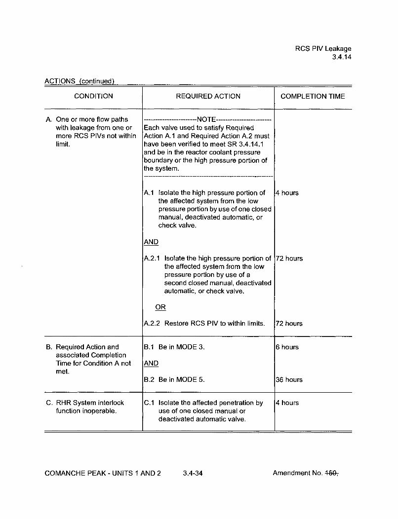
RCS PIV Leakage3.4.14
ACTIONS (continued)
CONDITION REQUIRED ACTION COMPLETION TIME
A. One or more flow paths --------------- NOTE ------------with leakage from one or Each valve used to satisfy Requiredmore RCS PIVs not within Action A.1 and Required Action A.2 mustlimit, have been verified to meet SR 3.4.14.1
and be in the reactor coolant pressureboundary or the high pressure portion ofthe system.
A.1 Isolate the high pressure portion of 4 hoursthe affected system from the lowpressure portion by use of one closedmanual, deactivated automatic, orcheck valve.
AND
A.2.1 Isolate the high pressure portion of 72 hoursthe affected system from the lowpressure portion by use of asecond closed manual, deactivatedautomatic, or check valve.
OR
A.2.2 Restore RCS PIV to within limits. 72 hours
B. Required Action and B.1 Be in MODE 3. 6 hoursassociated CompletionTime for Condition A not ANDmet.
B.2 Be in MODE 5. 36 hours
C. RHR System interlock C.1 Isolate the affected penetration by 4 hoursfunction inoperable, use of one closed manual or
deactivated automatic valve.
COMANCHE PEAK - UNITS 1 AND 2 3.4-34 Amendment No. 460-,

RCS PIV Leakage3.4.14
SURVEILLANCE REQUIREMENTS
SURVEILLANCE FREQUENCY
SR 3.4.14.1 ---------------------------- NO TES-1. Not required to be performed in MODES 3 and 4.
2. Not required to be performed on the RCS PIVs locatedin the RHR flow path when in the shutdown coolingmode of operation.
3. RCS PIVs actuated during the performance of thisSurveillance are not required to be tested more thanonce if a repetitive testing loop cannot be avoided.
Verify leakage from each RCS PIV is equivalent to< 0.5 gpm per nominal inch of valve size up to a maximumof 5 gpm at an RCS pressure > 2215 psig and < 2255 psig.
In accordance withthe InserviceTesting Program,and in accordancewith the SurveillanceFrequency ControlProgram.
AND
Prior to enteringMODE 2 wheneverthe unit has been inMODE 5 for 7 daysor more, and ifleakage testing hasnot been performedin the previous9 months except forvalves 8701A,8701 B, 8702A and8702B
AND
Within 24 hoursfollowing checkvalve actuation dueto flow through thevalve
COMANCHE PEAK - UNITS 1 AND 2 3.4-35 Amendment No. 4647

RCS PIV Leakage3.4.14
SURVEILLANCE REQUIREMENTS (continued)
SURVEILLANCE FREQUENCY
SR 3.4.14.2 Verify RHR System interlock prevents the valves from being In accordance withopened with a simulated or actual RCS pressure signal the Surveillance> 442 psig, except when the valves are open to satisfy Frequency ControlLCO 3.4.12. Program.
COMANCHE PEAK - UNITS 1 AND 2 3.4-36 Amendment No. 460-,

RCS Leakage Detection Instrumentation3.4.15
3.4 REACTOR COOLANT SYSTEM (RCS)
3.4.15 RCS Leakage Detection Instrumentation
LCO 3.4.15 The following RCS leakage detection instrumentation shall be OPERABLE:
a. One Containment Sump Level and Flow Monitoring System;
b. One containment atmosphere particulate radioactivity monitor; and
c. One containment air cooler condensate flow rate monitor or onecontainment atmosphere radioactivity monitor (gaseous).
APPLICABILITY: MODES 1, 2, 3, and 4
ACTIONS
CONDITION REQUIRED ACTION COMPLETION TIME
A. Required Containment A.1 ----------- NOTE ---------Sump Level and Flow Not required until 12 hours afterMonitoring System establishment of steady stateinoperable, operation.
Perform SR 3.4.13.1. Once per 24 hours
AND
A.2 Restore Containment Sump Level 30 daysand Flow Monitoring System toOPERABLE status.
COMANCHE PEAK - UNITS 1 AND 2 3.4-37 Amendment No. 46Gý

RCS Leakage Detection Instrumentation3.4.15
ACTIONS (continued)
CONDITION REQUIRED ACTION COMPLETION TIME
B. Required containment B.1.1 Analyze grab samples of the Once per 24 hoursatmosphere particulate containment atmosphere.radioactivity monitorinoperable. OR
B.1.2 ------- NOTE ---------Not required until 12 hours afterestablishment of steady stateoperation.
Perform SR 3.4.13.1. Once per 24 hours
AND
B.2 Restore required containment 30 daysatmosphere particulate radioactivitymonitor to OPERABLE status.
COMANCHE PEAK - UNITS 1 AND 2 3.4-38 Amendment No. 460-,
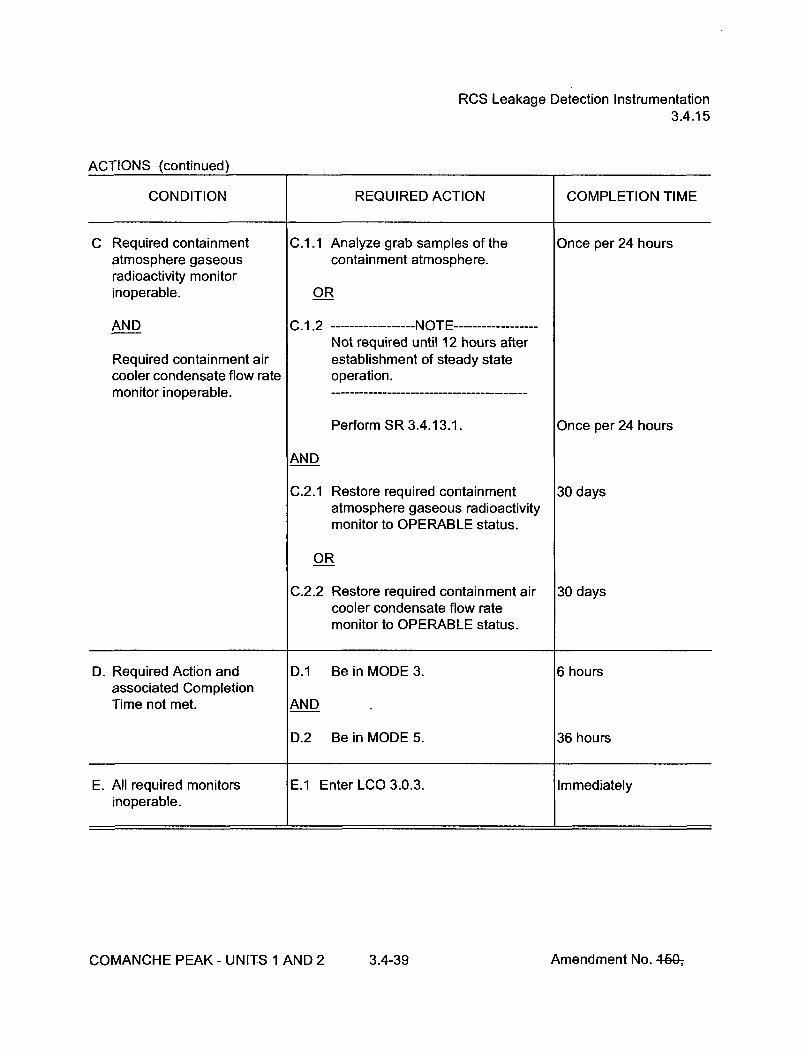
RCS Leakage Detection Instrumentation3.4.15
ACTIONS (continued)
CONDITION REQUIRED ACTION COMPLETION TIME
C Required containment C.1.1 Analyze grab samples of the Once per 24 hoursatmosphere gaseous containment atmosphere.radioactivity monitorinoperable. OR
AND C.1.2 ---------- NOTE ---------Not required until 12 hours after
Required containment air establishment of steady statecooler condensate flow rate operation.monitor inoperable.
Perform SR 3.4.13.1. Once per 24 hours
AND
C.2.1 Restore required containment 30 daysatmosphere gaseous radioactivitymonitor to OPERABLE status.
OR
C.2.2 Restore required containment air 30 dayscooler condensate flow ratemonitor to OPERABLE status.
D. Required Action and D.1 Be in MODE 3. 6 hoursassociated CompletionTime not met. AND
D.2 Be in MODE 5. 36 hours
E. All required monitors E.1 Enter LCO 3.0.3. Immediatelyinoperable.
COMANCHE PEAK - UNITS 1 AND 2 3.4-39 Amendment No. 46G-,

RCS Leakage Detection Instrumentation3.4.15
SURVEILLANCE REQUIREMENTS
SURVEILLANCE FREQUENCY
SR 3.4.15.1 Perform CHANNEL CHECK of the required containment In accordance withatmosphere particulate and gaseous radioactivity monitors. the Surveillance
Frequency ControlProgram.
SR 3.4.15.2 Perform COT of the required containment atmosphere In accordance withparticulate and gaseous radioactivity monitors. the Surveillance
Frequency ControlProgram.
SR 3.4.15.3 Perform CHANNEL CALIBRATION of the required In accordance withContainment Sump Level and Flow Monitoring System. the Surveillance
Frequency ControlProgram.
SR 3.4.15.4 Perform CHANNEL CALIBRATION of the required In accordance withcontainment atmosphere particulate and gaseous the Surveillanceradioactivity monitors. Frequency Control
Program.
SR 3.4.15.5 Perform CHANNEL CALIBRATION of the required In accordance withcontainment air cooler condensate flow rate monitor. the Surveillance
Frequency ControlProgram.
COMANCHE PEAK - UNITS 1 AND 2 3.4-40 Amendment No. 4fQ-,
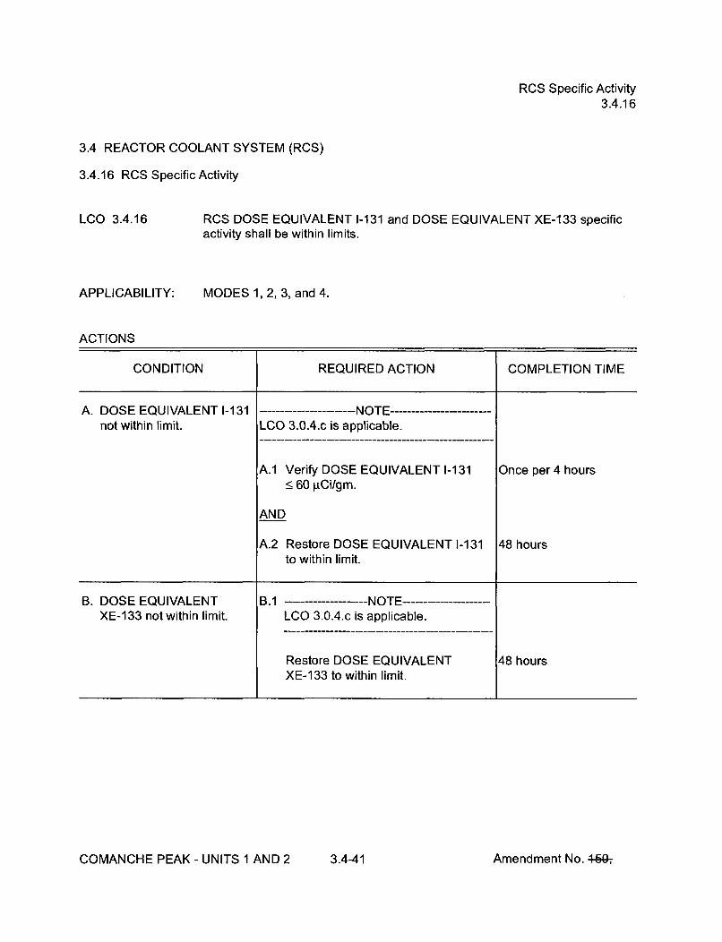
RCS Specific Activity3.4.16
3.4 REACTOR COOLANT SYSTEM (RCS)
3.4.16 RCS Specific Activity
LCO 3.4.16
APPLICABILITY:
RCS DOSE EQUIVALENT 1-131 and DOSE EQUIVALENT XE-133 specificactivity shall be within limits.
MODES 1, 2, 3, and 4.
ACTIONS
CONDITION REQUIRED ACTION COMPLETION TIME
A. DOSE EQUIVALENT 1-131 ------- NOTE ------------------------not within limit. LCO 3.0.4.c is applicable.
A.1 Verify DOSE EQUIVALENT 1-131 Once per4 hours•__ 60 gCi/gm.
AND
A.2 Restore DOSE EQUIVALENT 1-131 48 hoursto within limit.
B. DOSE EQUIVALENT B.1 ------------- NOTE -----------XE-133 not within limit. LCO 3.0.4.c is applicable.
Restore DOSE EQUIVALENT 48 hoursXE-133 to within limit.
COMANCHE PEAK - UNITS 1 AND 2 3.4-41 Amendment No. 460-,

RCS Specific Activity3.4.16
ACTIONS (continued)
CONDITION REQUIRED ACTION COMPLETION TIME
C. Required Action and C.1 Be in MODE 3. 6 hoursassociated CompletionTime of Condition A or B ANDnot met.
C.2 Be in MODE 5. 36 hoursOR
DOSE EQUIVALENT 1-131> 60 gCi/gm.
SURVEILLANCE REQUIREMENTS
SURVEILLANCE FREQUENCY
SR 3.4.16.1 - ---------------------- NOTE -Only required to be performed in MODE 1.
Verify reactor coolant DOSE EQUIVALENT XE-1 33 In accordance withspecific activity < 500 jiCi/gm. the Surveillance
Frequency ControlProgram.
COMANCHE PEAK - UNITS 1 AND 2 3.4-42 Amendment No. 46&,

RCS Specific Activity3.4.16
SURVEILLANCE REQUIREMENTS (continued)
SURVEILLANCE FREQUENCY
SR 3.4.16.2 ----------------------- NOTE ------ .....--------------------Only required to be performed in MODE 1.
Verify reactor coolant DOSE EQUIVALENT 1-131 specificactivity < 0.45 pCi/gm.
In accordance withthe SurveillanceFrequency ControlProgram.
AND
Between 2 and6 hours after aTHERMAL POWERchange of _> 15%RTP within a 1 hourperiod
SR 3.4.16.3 DELETED DELETED
COMANCHE PEAK - UNITS 1 AND 2 3.4-43 Amendment No. 460-,

SG Tube Integrity3.4.17
3.4 REACTOR COOLANT SYSTEM (RCS)
3.4.17 Steam Generator (SG) Tube Integrity
LCO 3.4.17 SG tube integrity shall be maintained.
AND
All SG tubes satisfying the tube repair criteria shall be plugged or repaired inaccordance with the Steam Generator Program.
APPLICABILITY: MODES 1, 2, 3, and 4
ACTIONS
------------------------------ --------------------- NOTES ----------------Separate Condition entry is allowed for each SG tube.
CONDITION REQUIRED ACTION COMPLETION TIME
A. One or more SG tubes A.1 Verify tube integrity of the affected 7 dayssatisfying the tube repair tube(s) is maintained until the nextcriteria and not plugged or refueling outage or SG tuberepaired in accordance with inspection.the Steam GeneratorProgram. AND
A.2 Plug or repair the affected tube(s) in Prior to enteringaccordance with the Steam MODE 4 following theGenerator Program. next refueling outage or
SG tube inspection
COMANCHE PEAK - UNITS 1 AND 2 3.4-44 Amendment No. 46&,

SG Tube Integrity3.4.17
ACTIONS (continued)
CONDITION REQUIRED ACTION COMPLETION TIME
B. Required Action and B.1 Be in MODE 3. 6 hoursassociated CompletionTime of Condition A not ANDmet.
B.2 Be in MODE 5. 36 hoursOR
SG tube integrity notmaintained.
SURVEILLANCE REQUIREMENTS
SURVEILLANCE FREQUENCY
SR 3,4.17.1 Verify SG tube integrity in accordance with the Steam In accordance withGenerator Program. the Steam
Generator Program
SR 3,4.17.2 Verify that each inspected SG tube that satisfies the tube Prior to enteringrepair criteria is plugged or repaired in accordance with the MODE 4 following aSteam Generator Program. SG tube inspection
COMANCHE PEAK - UNITS 1 AND 2 3.4-45 Amendment No. 460-,

Accumulators3.5.1
SURVEILLANCE REQUIREMENTS
SURVEILLANCE FREQUENCY
SR 3.5.1.1 Verify each accumulator isolation valve is fully open. In accordance withthe SurveillanceFrequency ControlProgram.
SR 3.5.1.2 Verify borated water volume in each accumulator is In accordance with> 6119 gallons and < 6597 gallons. the Surveillance
Frequency ControlProgram.
SR 3.5.1.3 Verify nitrogen cover pressure in each accumulator is In accordance with> 623 psig and < 644 psig. the Surveillance
Frequency ControlProgram.
SR 3.5.1.4 Verify boron concentration in each accumulator is In accordance with> 2300 ppm and < 2600 ppm. the Surveillance
Frequency ControlProgram.
AND
.--------- NOTE ---------Only required to beperformed foraffectedaccumulators
Once within 6 hoursafter each solutionvolume increase of> 101 gallons that isnot the result ofaddition from therefueling waterstorage tank
COMANCHE PEAK - UNITS 1 AND 2 3.5-2 Amendment No. 44&,
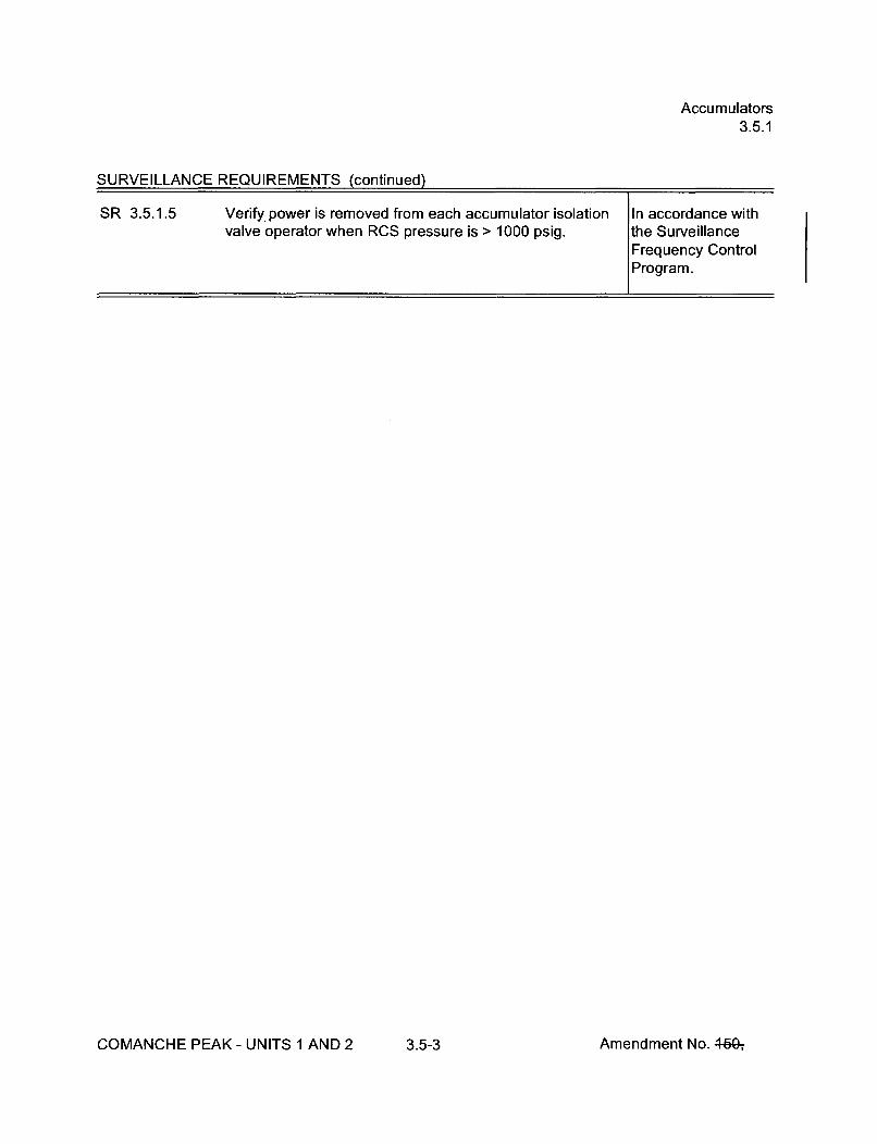
Accumulators3.5.1
SURVEILLANCE REQUIREMENTS (continued)
SR 3.5.1.5 Verify. power is removed from each accumulator isolation In accordance withvalve operator when RCS pressure is > 1000 psig. the Surveillance
Frequency ControlProgram.
COMANCHE PEAK - UNITS 1 AND 2 3.5-3 Amendment No. 4-60-,

ECCS -- Operating3.5.2
3.5 EMERGENCY CORE COOLING SYSTEMS (ECCS)
3.5.2 ECCS -- Operating
LCO 3.5.2 Two ECCS trains shall be OPERABLE.
--------------------------------------- It I ----------------------------------------------1. In MODE 3, both safety injection (SI) pump flow paths may be isolated by
closing the isolation valves for up to 2 hours to perform pressure isolationvalve testing per SR 3.4.14.1.
2. Operation in MODE 3 with ECCS pumps made incapable of injecting,pursuant to LCO 3.4.12, "Low Temperature Overpressure Protection(LTOP) System," is allowed for up to 4 hours or until the temperature of allRCS cold legs exceeds 375°F, whichever comes first.
APPLICABILITY: MODES 1, 2, and 3
ACTIONS
CONDITION REQUIRED ACTION COMPLETION TIME
A. One train inoperable A.1 Restore pump to OPERABLE status. 7 daysbecause of the inoperabilityof a centrifugal chargingpump.
COMANCHE PEAK - UNITS 1 AND 2 3.5-4 Amendment No. 449ý
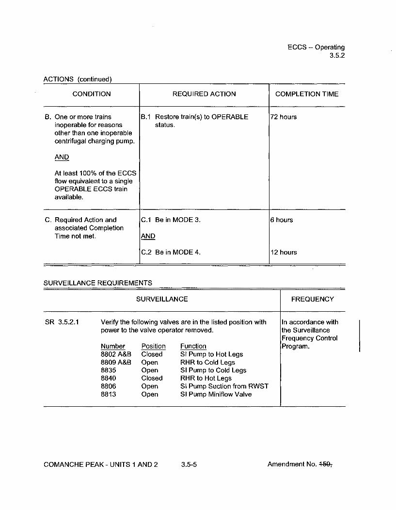
ECCS -- Operating3.5.2
ACTIONS (continued)
CONDITION REQUIRED ACTION COMPLETION TIME
B. One or more trains B.1 Restore train(s) to OPERABLE 72 hoursinoperable for reasons status.other than one inoperablecentrifugal charging pump.
AND
At least 100% of the ECCSflow equivalent to a singleOPERABLE ECCS trainavailable.
C. Required Action and C.1 Be in MODE 3. 6 hoursassociated CompletionTime not met. AND
C.2 Be in MODE 4. 12 hours
SURVEILLANCE REQUIREMENTS
SURVEILLANCE FREQUENCY
SR 3.5.2.1 Verify the following valves are in the listed position with In accordance withpower to the valve operator removed, the Surveillance
Frequency ControlNumber Position Function Program.8802 A&B Closed SI Pump to Hot Legs8809 A&B Open RHR to Cold Legs8835 Open SI Pump to Cold Legs8840 Closed RHR to Hot Legs8806 Open SI Pump Suction from RWST8813 Open SI Pump Miniflow Valve
COMANCHE PEAK - UNITS 1 AND 2 3.5-5 Amendment No. 460-,

ECCS -- Operating3.5.2
SURVEILLANCE REQUIREMENTS (continued)
SR 3.5.2.2 Verify each ECCS manual, power operated, and automatic In accordance withvalve in the flow path, that is not locked, sealed, or the Surveillanceotherwise secured in position, is in the correct position. Frequency Control
Program.
SR 3.5.2.3 Verify ECCS piping is full of water. Prior to entry intoMODE 3
SR 3.5.2.4 Verify each ECCS pump's developed head at the test flow In accordance withpoint is greater than or equal to the required developed the Inservicehead. Testing Program
SR 3.5.2.5 Verify each ECCS automatic valve in the flow path that is In accordance withnot locked, sealed, or otherwise secured in position, the Surveillanceactuates to the correct position on an actual or simulated Frequency Controlactuation signal. Program.
SR 3.5.2.6 Verify each ECCS pump starts automatically on an actual In accordance withor simulated actuation signal. the Surveillance
Frequency ControlProgram.
SR 3.5.2.7 Verify, for each ECCS throttle valve listed below, each In accordance withmechanical position stop is in the correct position. the Surveillance
Frequency ControlValve Number Program.8810A 8816A 8822A8810B 8816B 8822B8810C 8816C 8822C8810D 8816D 8822D
SR 3.5.2.8 Verify, by visual inspection, each ECCS train containment In accordance withsump suction inlet is not restricted by debris and the suction the Surveillanceinlet strainers show no evidence of structural distress or Frequency Controlabnormal corrosion. Program.
COMANCHE PEAK - UNITS 1 AND 2 3.5-6 Amendment No. 4-G&,

ECCS -- Shutdown3.5.3
3.5 EMERGENCY CORE COOLING SYSTEMS (ECCS)
3.5.3 ECCS -- Shutdown
LCO 3.5.3 One ECCS train shall be OPERABLE.
-------------------------------- NOTE--- -----------------------An RHR train may be considered OPERABLE during alignment and operationfor decay heat removal, if capable of being manually realigned to the ECCSmode of operation.
APPLICABILITY: MODE 4
ACTIONS
-------------- NOTELCO 3.0.4.b is not applicable to ECCS Centrifugal Pump subsystem.
CONDITION REQUIRED ACTION COMPLETION TIME
A. Required ECCS residual A.1 Initiate action to restore required Immediatelyheat removal (RHR) ECCS RHR subsystem tosubsystem inoperable. OPERABLE status.
B. Required ECCS Centrifugal B.1 Restore required ECCS Centrifugal 1 hourCharging Pump subsystem Charging Pump subsystem toinoperable. OPERABLE status.
C. Required Action and C.1 Be in MODE 5. 24 hoursassociated CompletionTime of Condition B notmet.
COMANCHE PEAK - UNITS 1 AND 2 3.5-7 Amendment No. 469-,

ECCS -- Shutdown3.5.3
SURVEILLANCE REQUIREMENTS
SURVEILLANCE FREQUENCY
SR 3.5.3.1 The following SRs are applicable for all equipment required In accordance withto be OPERABLE: applicable SRs
SR 3.5.2.1SR 3.5.2.4SR 3.5.2.7SR 3.5.2.8
COMANCHE PEAK - UNITS 1 AND 2 3.5-8 Amendment No. 4607

RWST3.5.4
3.5 EMERGENCY CORE COOLING SYSTEMS (ECCS)
3.5.4 Refueling Water Storage Tank (RWST)
LCO 3.5.4 The RWST shall be OPERABLE.
APPLICABILITY: MODES 1, 2,3, and 4
ACTIONS
CONDITION REQUIRED ACTION COMPLETION TIME
A. RWST boron concentration A.1 Restore RWST to OPERABLE 8 hours
not within limits, status.
OR
RWST borated watertemperature not withinlimits.
B. RWST inoperable for B.1 Restore RWST to OPERABLE 1 hourreasons other than status.Condition A.
C. Required Action and C.1 Be in MODE 3. 6 hoursassociated CompletionTime not met. AND
C.2 Be in MODE 5. 36 hours
COMANCHE PEAK - UNITS 1 AND 2 3.5-9 Amendment No. 440ý

RWST3.5.4
SURVEILLANCE REQUIREMENTS
SURVEILLANCE FREQUENCY
SR 3.5.4.1 ----------------------- NOTE -------------------Only required to be performed when ambient airtemperature is < 40°F or > 1200F.
Verify RWST borated water temperature is > 40°F and<_ 1200 F.
In accordance withthe SurveillanceFrequency ControlProgram.
SR 3.5.4.2 Verify RWST borated water volume is > 473,731 gallons. In accordance withthe SurveillanceFrequency ControlProgram.
SR 3.5.4.3 Verify RWST boron concentration is _ 2400 ppm and In accordance with< 2600 ppm. the Surveillance
Frequency Control
Program.
COMANCHE PEAK - UNITS 1 AND 2 3.5-10 Amendment No. 46&,

Seal Injection Flow3.5.5
3.5 EMERGENCY CORE COOLING SYSTEMS (ECCS)
3.5.5 Seal Injection Flow
LCO 3.5.5
APPLICABILITY:
Reactor coolant pump seal injection flow shall be!!< 40 gpm with RCS pressure_ 2215 psig and < 2255 psig and the charging flow control valve full open.
MODES 1, 2, and 3
ACTIONS
CONDITION REQUIRED ACTION COMPLETION TIME
A. Seal injection flow not A.1 Adjust manual seal injection throttle 4 hourswithin limit, valves to give a flow within limit with
RCS pressure _> 2215 psig and<_ 2255 psig and the charging flowcontrol valve full open.
B. Required Action and B.1 Be in MODE 3. 6 hoursassociated CompletionTime not met. AND
B.2 Be in MODE 4. 12 hours
SURVEILLANCE REQUIREMENTS
SURVEILLANCE FREQUENCY
SR 3.5.5.1 -- -------------------- NOTE ------------------Not required to be performed until 4 hours after the ReactorCoolant System pressure stabilizes at > 2215 psig and< 2255 psig.
Verify manual seal injection throttle valves are adjusted to In accordance withgive a flow within limit with RCS pressure >_ 2215 psig and the Surveillance< 2255 psig and the charging flow control valve full open. Frequency Control
Program.
COMANCHE PEAK - UNITS 1 AND 2 3.5-11 Amendment No. 460-,

Containment Air Locks3.6.2
SURVEILLANCE REQUIREMENTS
SURVEILLANCE FREQUENCY
SR 3.6.2.1 ---------------------- NOTES ----------------1. An inoperable air lock door does not invalidate the
previous successful performance of the overall air lockleakage test.
2. Results shall be evaluated against acceptance criteriaapplicable to SR 3.6.1.1.
Perform required air lock leakage rate testing in In accordance withaccordance with the Containment Leakage Rate Testing the ContainmentProgram. Leakage Rate
Testing Program
SR 3.6.2.2 Verify only one door in the air lock can be opened at a time. In accordance withthe SurveillanceFrequency ControlProgram.
COMANCHE PEAK - UNITS 1 AND 2 3.6-6 Amendment No. 4f)&,

Containment Isolation Valves3.6.3
SURVEILLANCE REQUIREMENTS
SURVEILLANCE FREQUENCY
SR 3.6.3.1 Verify each 48 inch Containment Purge and 12 inch In accordance withHydrogen Purge valve is sealed closed, except for one the Surveillancepurge valve in a penetration flow path while in Condition D Frequency Controlof this LCO. Program.
SR 3.6.3.2 Not used.
SR 3.6.3.3 ---------------------- NOTES -----------------Valves and blind flanges in high radiation areas may beverified by use of administrative controls.
Verify each containment isolation manual valve and blind In accordance withflange that is located outside containment and not locked, the Surveillancesealed, or otherwise secured and required to be closed Frequency Controlduring accident conditions is closed, except for Program.containment isolation valves that are open underadministrative controls.
SR 3.6.3.4 ----------------------- NOTES -----------------1. Valves and blind flanges in high radiation areas may be
verified by use of administrative means.
2. The blind flange on the fuel transfer canal need not beverified closed except after each drainage of the canal.
Verify each containment isolation manual valve and blind Prior to enteringflange that is located inside containment and not locked, MODE 4 fromsealed, or otherwise secured and required to be closed MODE 5 if notduring accident conditions is closed, except for performed within the
containment isolation valves that are open under previous 92 days
administrative controls.
COMANCHE PEAK - UNITS 1 AND 2 3.6-12 Amendment No. 460-,

Containment Isolation Valves3.6.3
SURVEILLANCE REQUIREMENTS (continued)
SURVEILLANCE FREQUENCY
SR 3.6.3.5 Verify the isolation time of each automatic power operated In accordancecontainment isolation valve is within limits, with the Inservice
Testing Program
SR 3.6.3.6 Not used.
SR 3.6.3.7 ---------------------- NOTE-------------------This surveillance is not required when the penetration flowpath is isolated by a leak tested blank flange.
Perform leakage rate testing for containment purge, In accordance withhydrogen purge and containment pressure relief valves the Surveillancewith resilient seals. Frequency Control
Program.
SR 3.6.3.8 Verify each automatic containment isolation valve that is In accordance withnot locked, sealed or otherwise secured in position, the Surveillanceactuates to the isolation position on an actual or simulated Frequency Controlactuation signal. Program.
SR 3.6.3.9 Not used.
SR 3.6.3.10 Not used.
SR 3.6.3.11 Not used.
SR 3.6.3.12 Not used.
SR 3.6.3.13 Not used.
COMANCHE PEAK - UNITS 1 AND 2 3.6-13 Amendment No. 4-60-,

Containment Pressure3.6.4
3.6 CONTAINMENT SYSTEMS
3.6.4 Containment Pressure
LCO 3.6.4 Containment pressure shall be _ - 0.3 psig and < + 1.3 psig.
APPLICABILITY:
ACTIONS
MODES 1, 2, 3, and 4
CONDITION REQUIRED ACTION COMPLETION TIME
A. Containment pressure not A.1 Restore containment pressure to 8 hourswithin limits, within limits.
B. Required Action and B.1 Be in MODE 3. 6 hoursassociated CompletionTime not met. AND
B.2 Be in MODE 5. 36 hours
SURVEILLANCE REQUIREMENTS
SURVEILLANCE FREQUENCY
SR 3.6.4.1 Verify containment pressure is within limits. In accordance withthe SurveillanceFrequency ControlProgram.
COMANCHE PEAK - UNITS 1 AND 2 3.6-14 Amendment No. 44Gý

Containment Air Temperature3.6.5
3.6 CONTAINMENT SYSTEMS
3.6.5 Containment Air Temperature
LCO 3.6.5 Containment average air temperature shall be < 1200 F.
APPLICABILITY: MODES 1, 2, 3, and 4
ACTIONS
CONDITION REQUIRED ACTION COMPLETION TIME
A. Containment average air A.1 Restore containment average air 8 hourstemperature not within limit, temperature to within limit.
B. Required Action and B.1 Be in MODE 3. 6 hoursassociated CompletionTime not met. AND
B.2 Be in MODE 5. 36 hours
SURVEILLANCE REQUIREMENTS
SURVEILLANCE FREQUENCY
SR 3.6.5.1 Verify containment average air temperature is within limit. In accordance withthe SurveillanceFrequency ControlProgram.
COMANCHE PEAK- UNITS I AND 2 3.6-15 Amendment No. 460-,

Containment Spray System3.6.6
3.6 CONTAINMENT SYSTEMS
3.6.6 Containment Spray System
LCO 3.6.6
APPLICABILITY:
Two containment spray trains shall be OPERABLE.
MODES 1, 2, 3, and 4
ACTIONS
CONDITION REQUIRED ACTION COMPLETION TIME
A. One containment spray A.1 Restore containment spray train to 72 hourstrain inoperable. OPERABLE status.
B. Required Action and B.1 Be in MODE 3. 6 hoursassociated CompletionTime of Condition A not ANDmet.
B.2 Be in MODE 5. 84 hours
C. Two containment spray C.1 Enter LCO 3.0.3. Immediatelytrains inoperable.
SURVEILLANCE REQUIREMENTS
SURVEILLANCE FREQUENCY
SR 3.6.6.1 Verify each containment spray manual, power operated, In accordance withand automatic valve in the flow path that is not locked, the Surveillancesealed, or otherwise secured in position is in the correct Frequency Controlposition. Program.
COMANCHE PEAK - UNITS 1 AND 2 3.6-16 Amendment No. 440-,
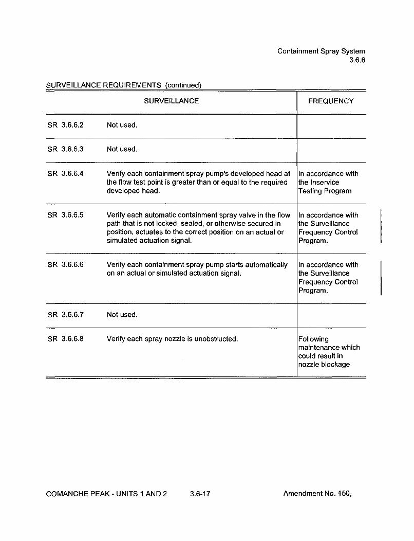
Containment Spray System3.6.6
SURVEILLANCE REQUIREMENTS (continued)
SURVEILLANCE FREQUENCY
SR 3.6.6.2 Not used.
SR 3.6.6.3 Not used.
SR 3.6.6.4 Verify each containment spray pump's developed head at In accordance withthe flow test point is greater than or equal to the required the Inservicedeveloped head. Testing Program
SR 3.6.6.5 Verify each automatic containment spray valve in the flow In accordance withpath that is not locked, sealed, or otherwise secured in the Surveillanceposition, actuates to the correct position on an actual or Frequency Controlsimulated actuation signal. Program.
SR 3.6.6.6 Verify each containment spray pump starts automatically In accordance withon an actual or simulated actuation signal. the Surveillance
Frequency ControlProgram.
SR 3.6.6.7 Not used.
SR 3.6.6.8 Verify each spray nozzle is unobstructed. Followingmaintenance whichcould result innozzle blockage
COMANCHE PEAK - UNITS 1 AND 2 3.6-17 Amendment No. 4-50-,

MSIVs3.7.2
SURVEILLANCE REQUIREMENTS
SURVEILLANCE FREQUENCY
SR 3.7.2.1 - -------------------- NOTE ------------------Only required to be performed in MODES 1 and 2.
Verify the isolation time of each MSIV is < 5 seconds. In accordance withthe InserviceTesting Program
SR 3.7.2.2 ----------------------- NOTE ------------------Only required to be performed in MODES 1 and 2.
Verify each MSIV actuates to the isolation position on an In accordance withactual or simulated actuation signal. the Surveillance
Frequency ControlProgram.
COMANCHE PEAK - UNITS 1 AND 2 3.7-7 Amendment No. 4-50-,

FIVs and FCVs and Associated Bypass Valves3.7.3
ACTIONS (continued)
CONDITION REQUIRED ACTION COMPLETION TIME
C. One or more FIV or FCV C.1 Close or isolate bypass valve. 72 hoursbypass valves inoperable.
AND
C.2 Verify bypass valve is closed or Once per 7 daysisolated.
D. Two valves in the same D.1 Isolate affected flow path. 8 hoursflowpath inoperable
E. Required Action and E.1 Be in MODE 3. 6 hoursassociated CompletionTime not met. AND
E.2 Be in MODE 4. 12 hours
SURVEILLANCE REQUIREMENTS
SURVEILLANCE FREQUENCY
SR 3.7.3.1 Verify the isolation time of each FIV, FCV, and associated In accordance withbypass valves is < 5 seconds. the Inservice
Testing Program
SR 3.7.3.2 Verify each FIV, FCV, and associated bypass valves In accordance withactuates to the isolation position on an actual or simulated the Surveillanceactuation signal. Frequency Control
Program.
COMANCHE PEAK - UNITS 1 AND 2 3.7-9 Amendment No. 46G-,

AFW System3.7.5
SURVEILLANCE REQUIREMENTS
SURVEILLANCE FREQUENCY
SR 3.7.5.1 --------------------- NOTE ------------------AFW train(s) may be considered OPERABLE duringalignment and operation for steam generator level control,if it is capable of being manually realigned to the AFWmode of operation.
Verify each AFW manual, power operated, and automaticvalve in each water flow path, and in both steam supplyflow paths to the steam turbine driven pump, that is notlocked, sealed, or otherwise secured in position, is in thecorrect position.
In accordance withthe SurveillanceFrequency ControlProgram.
SR 3.7.5.2 ----------------------- NOTE -------------------Not required to be performed for the turbine driven AFWpump until 24 hours after > 532 psig in the steamgenerator.
Verify the developed head of each AFW pump at the flow In accordance withtest point is greater than or equal to the required developed the Inservice testinghead. Program
SR 3.7.5.3 ----------------------- NOTE ---------------AFW train(s) may be considered OPERABLE duringalignment and operation for steam generator level control,if it is capable of being manually realigned to the AFWmode of operation.
Verify each AFW automatic valve that is not locked, sealed, In accordance withor otherwise secured in position, actuates to the correct the Surveillanceposition on an actual or simulated actuation signal. Frequency Control
Program
COMANCHE PEAK - UNITS 1 AND 2 3.7-14 Amendment No. 46&,

AFW System3.7.5
SURVEILLANCE REQUIREMENTS (continued)
SR 3.7.5.4 --------------------- NOTES -----------------1. Not required to be performed for the turbine driven AFW
pump until 24 hours after _> 532 psig in the steamgenerator.
2. AFW train(s) may be considered OPERABLE duringalignment and operation for steam generator levelcontrol, if it is capable of being manually realigned tothe AFW operation.
Verify each AFW pump starts automatically on an actual orsimulated actuation signal.
In accordance withthe SurveillanceFrequency ControlProgram.
COMANCHE PEAK - UNITS 1 AND 2 3.7-15 Amendment No. 46Gý
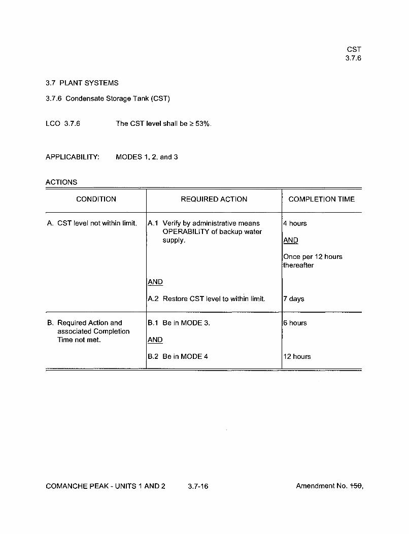
CST3.7.6
3.7 PLANT SYSTEMS
3.7.6 Condensate Storage Tank (CST)
LCO 3.7.6 The CST level shall be > 53%.
APPLICABILITY:
ACTIONS
MODES 1, 2, and 3
CONDITION REQUIRED ACTION COMPLETION TIME
A. CST level not within limit. A.1 Verify by administrative means 4 hoursOPERABILITY of backup watersupply. AND
Once per 12 hoursthereafter
AND
A.2 Restore CST level to within limit. 7 days
B. Required Action and B.1 Be in MODE 3. 6 hoursassociated CompletionTime not met. AND
B.2 Be in MODE 4 12 hours
COMANCHE PEAK - UNITS 1 AND 2 3.7-16 Amendment No. +50,

CST3.7.6
SURVEILLANCE REQUIREMENTS
SURVEILLANCE FREQUENCY
SR 3.7.6.1 Verify the CST level is > 53%. In accordance withthe SurveillanceFrequency ControlProgram.
COMANCHE PEAK - UNITS 1 AND 2 3.7-17 Amendment No. 44&,

CCW System3.7.7
3.7 PLANT SYSTEMS
3.7.7 Component Cooling Water (CCW) System
LCO 3.7.7
APPLICABILITY:
Two CCW trains shall be OPERABLE.
MODES 1, 2, 3, and 4
ACTIONS
CONDITION REQUIRED ACTION COMPLETION TIME
A. One CCW train inoperable. -------------- NOTE -------------Enter applicable Conditions and RequiredActions of LCO 3.4.6, "RCS Loops -MODE 4," for residual heat removal loopsmade inoperable by CCW.
A.1 Restore CCW train to OPERABLE 72 hoursstatus.
B. Required Action and B.1 Be in MODE 3. 6 hoursassociated CompletionTime of Condition A not ANDmet.
B.2 Be in MODE 5. 36 hours
COMANCHE PEAK - UNITS 1 AND 2 3.7-18 Amendment No. 46&,

CCW System3.7.7
SURVEILLANCE REQUIREMENTS
SURVEILLANCE FREQUENCY
SR 3.7.7.1 ----------------------- NOTE ------------------Isolation of CCW flow to individual components does notrender the CCW System inoperable.
Verify each CCW manual, power operated, and automatic In accordance withvalve in the flow path servicing safety related equipment, the Surveillancethat is not locked, sealed, or otherwise secured in position, Frequency Controlis in the correct position. Program.
SR 3.7.7.2 Verify each CCW automatic valve in the flow path that is In accordance withnot locked, sealed, or otherwise secured in position, the Surveillanceactuates to the correct position on an actual or simulated Frequency Controlactuation signal. Program.
SR 3.7.7.3 Verify each CCW pump starts automatically on an actual or In accordance withsimulated actuation signal. the Surveillance
Frequency ControlProgram.
COMANCHE PEAK - UNITS 1 AND 2 3.7-19 Amendment No. 46Gý

SSWS3.7.8
3.7 PLANT SYSTEMS
3.7.8 Station Service Water System (SSWS)
LCO 3.7.8
APPLICABILITY:
Two SSWS trains and a SSW Pump on the opposite unit with its associatedcross-connects shall be OPERABLE.
MODES 1, 2, 3, and 4
ACTIONS
CONDITION REQUIRED ACTION COMPLETION TIME
A. Required SSW Pump on A.1 Restore a SSW Pump on the 7 daysthe opposite unit or its opposite unit to OPERABLE status.associated cross-connectsinoperable. AND
A.2 Restore associated cross-connects 7 daysto OPERABLE status.
COMANCHE PEAK - UNITS 1 AND 2 3.7-20 Amendment No. 460-,
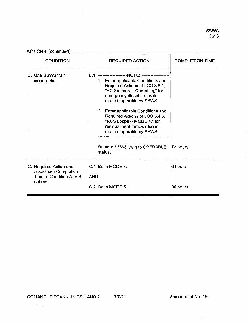
SSWS3.7.8
ACTIONS (continued)
CONDITION REQUIRED ACTION COMPLETION TIME
B. One SSWS train B.1 ------------ NOTES ----------inoperable. 1. Enter applicable Conditions and
Required Actions of LCO 3.8.1,"AC Sources -- Operating," foremergency diesel generatormade inoperable by SSWS.
2. Enter applicable Conditions andRequired Actions of LCO 3.4.6,"RCS Loops -- MODE 4," forresidual heat removal loopsmade inoperable by SSWS.
Restore SSWS train to OPERABLE 72 hoursstatus.
C. Required Action and C.1 Be in MODE 3. 6 hoursassociated CompletionTime of Condition A or B ANDnot met.
C.2 Be in MODE 5. 36 hours
COMANCHE PEAK - UNITS I AND 2 3.7-21 Amendment No. 4640ý

SSWS3.7.8
SURVEILLANCE REQUIREMENTS
SURVEILLANCE FREQUENCY
SR 3.7.8.1 -- -------------------- NOTE ------------------Isolation of SSWS flow to individual components does notrender the SSWS inoperable.
Verify each SSWS manual, power operated, and automatic In accordance withvalve in the flow path servicing safety related equipment, the Surveillancethat is not locked, sealed, or otherwise secured in position, Frequency Controlis in the correct position. Program.
SR 3.7.8.2 Verify one complete cycle of each required cross-connect In accordance withvalve that is not locked open. the Surveillance
Frequency ControlProgram.
SR 3.7.8.3 Verify each SSW pump starts automatically on an actual or In accordance withsimulated actuation signal. the Surveillance
Frequency ControlProgram.
COMANCHE PEAK - UNITS 1 AND 2 3.7-22 Amendment No. 460-,

UHS3.7.9
3.7 PLANT SYSTEMS
3.7.9 Ultimate Heat Sink (UHS)
LCO 3.7.9 The Safe Shutdown Impoundment (SSI) shall be OPERABLE.
APPLICABILITY:
ACTIONS
MODES 1, 2, 3, and 4
CONDITION REQUIRED ACTION COMPLETION TIME
A. SSI level less than A.1 Restore SSI level to within limits. 7 daysrequired.
B. Required Action and B.1 Be in MODE 3. 6 hoursassociated CompletionTime of Condition A not ANDmet.
B.2 Be in MODE 5. 36 hoursOR
SSI inoperable for reasonsother than Condition A.
SURVEILLANCE REQUIREMENTS
SURVEILLANCE FREQUENCY
SR 3.7.9.1 Verify water level of SSI is > 770 ft mean sea level. In accordance withthe SurveillanceFrequency ControlProgram.
COMANCHE PEAK - UNITS 1 AND 2 3.7-23 Amendment No. 460-,
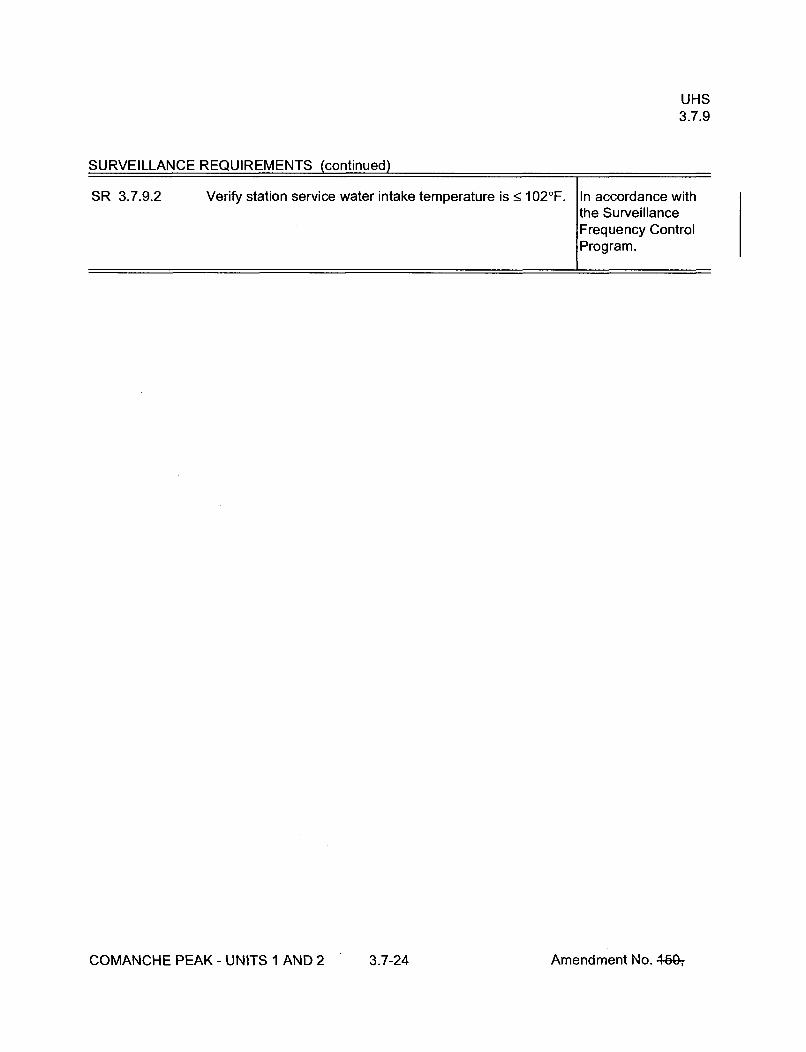
UHS3.7.9
SURVEILLANCE REQUIREMENTS (continued)
SR 3.7.9.2 Verify station service water intake temperature is < 102'F. In accordance withthe SurveillanceFrequency ControlProgram.
COMANCHE PEAK - UNITS 1 AND 2 3.7-24 Amendment No. 4459ý

CREFS3.7.10
3.7 PLANT SYSTEMS
3.7.10 Control Room Emergency Filtration/Pressurization System (CREFS)
LCO 3.7.10 Two CREFS trains shall be OPERABLE
------------------------------- NOTE -------------------- ---
The Control Room envelope (CRE) boundary may be opened intermittentlyunder administrative controls.
APPLICABILITY: MODES 1, 2, 3, 4, 5, and 6,During movement of irradiated fuel assemblies.
ACTIONS
CONDITION REQUIRED ACTION COMPLETION TIME
A. One CREFS train A.1 Restore CREFS train to OPERABLE 7 daysinoperable for reasons status.other than Condition B.
B. One or more CREFS Trains B.1 Initiate action to implement mitigating Immediatelyinoperable due to actions.inoperable CRE boundaryin MODES 1, 2, 3, and 4. AND
B.2 Verify mitigating actions to ensure 24 hoursCRE occupant exposures toradiological, chemical, and smokehazards will not exceed limits.
AND
B.3 Restore CRE boundary to 90 daysOPERABLE status.
COMANCHE PEAK - UNITS 1 AND 2 3.7-25 Amendment No. 449-,

CREFS3.7.10
ACTIONS (continued)
CONDITION REQUIRED ACTION COMPLETION TIME
C. Required Action and C.1 Be in MODE 3. 6 hoursassociated CompletionTime of Condition A or B ANDnot met in MODE 1, 2, 3,or 4. C.2 Be in MODE 5. 36 hours
D. Required Action and D.1 Place OPERABLE CREFS train in Immediatelyassociated Completion emergency recirculation mode.Time of Condition A not metin MODE 5 or 6, or during ORmovement of irradiated fuelassemblies. D.2.1 Suspend CORE ALTERATIONS. Immediately
AND
D.2.2 Suspend movement of irradiated Immediatelyfuel assemblies.
E. Two CREFS trains E.1 Suspend CORE ALTERATIONS. Immediatelyinoperable in MODE 5 or 6,or during movement of ANDirradiated fuel assemblies.
E.2 Suspend movement of irradiated fuel ImmediatelyOR assemblies.
One or more CREFS trainsinoperable due to aninoperable CRE boundaryin MODE 5 or 6, or duringmovement of irradiated fuelassemblies.
F. Two CREFS trains F.1 Enter LCO 3.0.3. Immediatelyinoperable in MODE 1, 2, 3,or 4 for reasons other thanCondition B.
COMANCHE PEAK - UNITS 1 AND 2 3.7-26 Amendment No. 4fgý,

CREFS3.7.10
SURVEILLANCE REQUIREMENTS
SURVEILLANCE FREQUENCY
S R 3.7.10.1 Operate each CREFS trains Emergency Pressurization In accordance withUnit for > 10 continuous hours with the heaters operating the Surveillanceand Emergency Filtration Unit > 15 minutes. Frequency Control
Program.
SR 3.7.10.2 Perform required CREFS testing in accordance with the In accordance withVentilation Filter Testing Program (VFTP). the VFTP
SR 3.7.10.3 Verify each CREFS train actuates on an actual or simulated In accordance withactuation signal. the Surveillance
Frequency ControlProgram.
SR 3.7.10.4 Perform required CRE unfiltered air inleakage testing in In accordance withaccordance with the Control Room Envelope Habitability the Control RoomProgram. Envelope
Habitability Program
COMANCHE PEAK - UNITS 1 AND 2 3.7-27 Amendment No. 469-,

CRACS3.7.11
3.7 PLANT SYSTEMS
3.7.11 Control Room Air Conditioning System (CRACS)
LCO 3.7.11
APPLICABILITY:
Two CRACS trains shall be OPERABLE.
MODES 1, 2, 3, 4, 5, and 6,During movement of irradiated fuel assemblies.
ACTIONS
CONDITION REQUIRED ACTION COMPLETION TIME
A. One CRACS train A.1 Restore CRACS train to OPERABLE 30 daysinoperable, status.
B. Required Action and B.1 Be in MODE 3. 6 hoursassociated CompletionTime of Condition A not met ANDin MODE 1, 2, 3, or 4.
B.2 Be in MODE 5. 36 hours
C. Required Action and C.1 Place OPERABLE CRACS train in Immediatelyassociated Completion operation.Time of Condition A not metin MODE 5, or 6, or during ORmovement of irradiated fuelassemblies. C.2.1 Suspend CORE ALTERATIONS. Immediately
AND
C.2.2 Suspend movement of irradiated Immediatelyfuel assemblies.
COMANCHE PEAK - UNITS 1 AND 2 3.7-28 Amendment No. 4f&,

CRACS3.7.11
ACTIONS (continued)
CONDITION REQUIRED ACTION COMPLETION TIME
D. Two CRACS trains D.1.1 Verify at least 100% of the required Immediatelyinoperable in MODE 5 or 6, heat removal capability equivalentor during movement of to a single OPERABLE trainirradiated fuel assemblies, available.
AND
D.1.2 Restore the CRACS trains to 30 daysOPERABLE status.
OR
D.2.1 Suspend CORE ALTERATIONS. Immediately
AND
D.2.2 Suspend movement of irradiated Immediatelyfuel assemblies.
E. Two CRACS trains E.1.1 Verify at least 100% of the required Immediatelyinoperable in MODE 1,2, 3, heat removal capability equivalentor 4. to a single OPERABLE train
available.
AND
E.1.2 Restore one CRACS train to 30 daysOPERABLE status.
OR
E.2 Enter LCO 3.0.3. Immediately
COMANCHE PEAK - UNITS 1 AND 2 3.7-29 Amendment No. 4-59-,

CRACS3.7.11
SURVEILLANCE REQUIREMENTS
SURVEILLANCE FREQUENCY
SR 3.7.11.1 Verify each CRACS train has the capability to remove the In accordance withassumed heat load. the Surveillance
Frequency ControlProgram.
COMANCHE PEAK - UNITS 1 AND 2 3.7-30 Amendment No. 4649-,

PPVS - ESF Filtration Trains3.7.12
3.7 PLANT SYSTEMS
3.7.12 Primary Plant Ventilation System (PPVS) - ESF Filtration Trains
LCO 3.7.12
APPLICABILITY:
Two PPVS trains shall be OPERABLE
MODES 1, 2, 3, and 4.
ACTIONS
CONDITION REQUIRED ACTION COMPLETION TIME
A. With one or more PPVS A.1 Restore PPVS trains to OPERABLE 30 daystrains unable to maintain a status.negative pressure envelopein the Auxiliary,Safeguards, and FuelBuildings _> 0.05 inch watergauge.
B. With one or more PPVS B.1 Restore ability of PPVS trains to 7 daystrains unable to maintain a maintain a negative pressurenegative pressure envelope envelope of _> 0.01 inch water gaugein the Auxiliary, pressure.Safeguards, and FuelBuildings > 0.01 inch watergauge.
C. One PPVS train inoperable C.1 Restore PPVS train to OPERABLE 7 daysfor any reason except status.Conditions A or B.
D. Required Actions and D.1 Be in MODE 3. 6 hoursassociated CompletionTimes not met. AND
D.2 Be in MODE 5. 36 hours
COMANCHE PEAK - UNITS 1 AND 2 3.7-31 Amendment No. 460-,

PPVS - ESF Filtration Trains3.7.12
SURVEILLANCE REQUIREMENTS
SURVEILLANCE FREQUENCY
SR 3.7.12.1 Operate each ESF Filtration train forŽ_ 10 continuous hours In accordance withwith the heaters operating. the Surveillance
Frequency ControlProgram.
SR 3.7.12.2 Perform required ESF Filtration Unit filter testing in In accordance withaccordance with the Ventilation Filter Testing Program the VFTP(VFTP).
SR 3.7.12.3 Verify each PPVS train actuates on an actual or simulated In accordance withactuation signal. the Surveillance
Frequency ControlProgram.
SR 3.7.12.4 Verify one PPVS train can maintain a pressure In accordance with< -0.05 inches water gauge relative to atmospheric the Surveillancepressure during the post accident mode of operation. Frequency Control
Program.
SR 3.7.12.5 Not used.
SR 3.7.12.6 Verify each PPVS non-ESF fan stops on an actual or In accordance withsimulated actuation signal. the Surveillance
Frequency ControlProgram.
COMANCHE PEAK - UNITS 1 AND 2 3.7-32 Amendment No. 460-,

FBACS3.7.13
3.7 PLANT SYSTEMS
3.7.13 Fuel Building Air Cleanup System (FBACS)
NOT USED
COMANCHE PEAK - UNITS 1 AND 2 3.7-33 Amendment No. 4940ý

PREACS3.7.14
3.7 PLANT SYSTEMS
3.7.14 Penetration Room Exhaust Air Cleanup System (PREACS)
NOT USED
COMANCHE PEAK - UNITS 1 AND 2 3.7-34 Amendment No. 46&,

Fuel Storage Area Water Level3.7.15
3.7 PLANT SYSTEMS
3.7.15 Fuel Storage Area Water Level
LCO 3.7.15
APPLICABILITY:
The fuel storage area water level shall be >_ 23 ft over the top of the storageracks
During movement of irradiated fuel assemblies in a spent fuel storage area.
ACTIONS
CONDITION REQUIRED ACTION COMPLETION TIME
A. Fuel storage area water A.1 ---------- NOTE ---------level not within limit. LCO 3.0.3 is not applicable.
Suspend movement of irradiated fuel Immediatelyassemblies in the fuel storage area.
SURVEILLANCE REQUIREMENTS
SURVEILLANCE FREQUENCY
SR 3.7.15.1 Verify the fuel storage area water level is Ž 23 ft above the In accordance withtop of the storage racks. the Surveillance
Frequency ControlProgram.
COMANCHE PEAK - UNITS 1 AND 2 3.7-35 Amendment No. 46Gý

Fuel Storage Pool Boron Concentration3.7.16
3.7 PLANT SYSTEMS
3.7.16 Fuel Storage Pool Boron Concentration
LCO 3.7.16
APPLICABILITY:
The fuel storage pool boron concentration shall be > 2000 ppm.
When fuel assemblies are stored in the fuel storage pool.
ACTIONS
CONDITION REQUIRED ACTION COMPLETION TIME
A. Fuel storage pool boron ------- NOTE---------concentration not within LCO 3.0.3 is not applicable.limit.
A.1 Suspend movement of fuel Immediatelyassemblies in the fuel storage pool
AND
A.2 Initiate action to restore fuel storage Immediatelypool boron concentration to withinlimit.
SURVEILLANCE REQUIREMENTS
SURVEILLANCE FREQUENCY
SR 3.7.16.1 Verify the fuel storage pool boron concentration is within In accordance withlimit. the Surveillance
Frequency ControlProgram.
COMANCHE PEAK - UNITS 1 AND 2 3.7-36 Amendment No. 44&,

Spent Fuel Assembly Storage3.7.17
3.7 PLANT SYSTEMS
3.7.17 Spent Fuel Assembly Storage
LCO 3.7.17
APPLICABILITY:
The combination of initial enrichment, burnup and decay time of each spentfuel assembly stored in Region II racks shall be within either (1) the"acceptable" domain of Figure 3.7.17-1 in a 4 out of 4 configuration, (2) the"acceptable" domain of Figure 3.7.17-2 in a 3 out of 4 configuration, (3) the"acceptable" domain of Figure 3.7.17-3 in a 2 out of 4 configuration, or(4) shall be stored in a 1 out of 4 configuration. The acceptable storageconfigurations are shown in Figure 3.7.17-4.
Whenever any fuel assembly is stored in Region II racks of the spent fuelstorage pool.
ACTIONS
CONDITION REQUIRED ACTION COMPLETION TIME
A. Requirements of the LCO A.1 ---------- NOTE-------not met. LCO 3.0.3 is not applicable.
Initiate action to move the Immediatelynoncomplying fuel assembly to anacceptable storage location.
COMANCHE PEAK - UNITS 1 AND 2 3.7-37 Amendment No. 4f&,
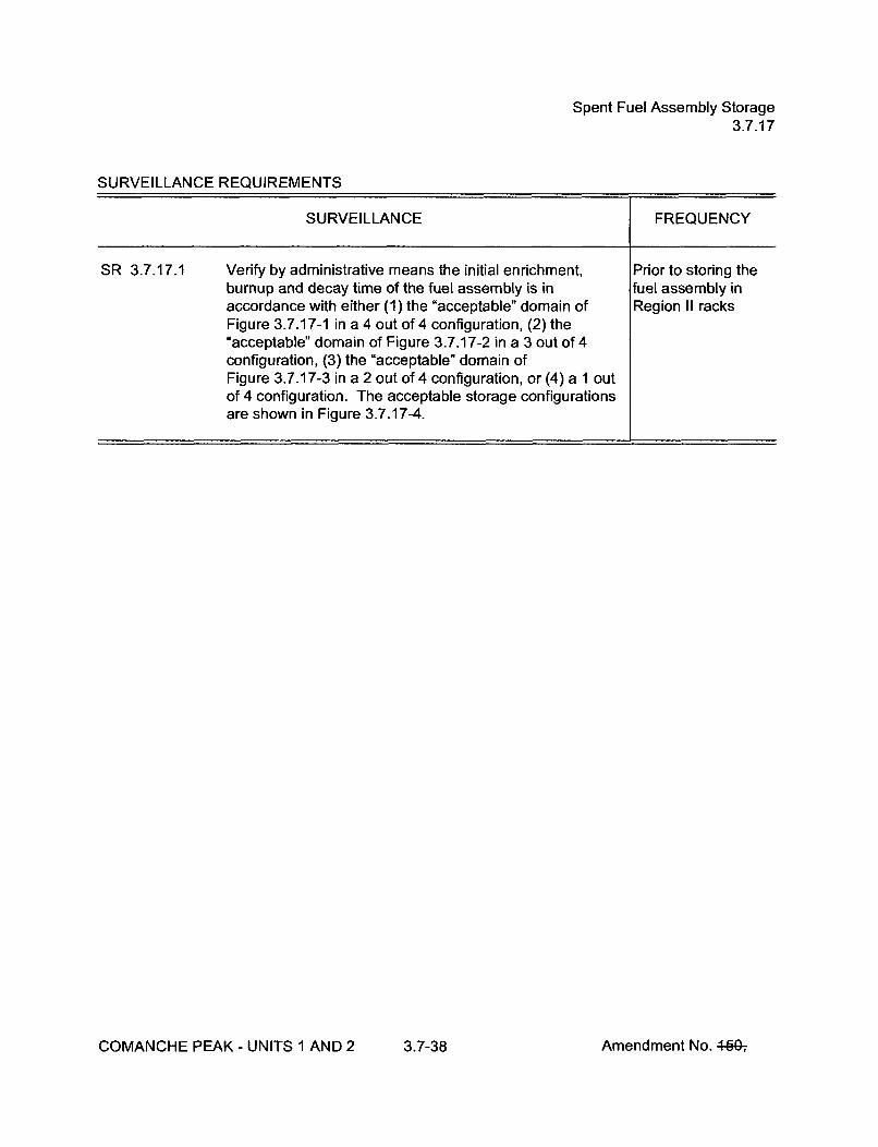
Spent Fuel Assembly Storage3.7.17
SURVEILLANCE REQUIREMENTS
SURVEILLANCE FREQUENCY
SR 3.7.17.1 Verify by administrative means the initial enrichment, Prior to storing theburnup and decay time of the fuel assembly is in fuel assembly inaccordance with either (1) the "acceptable" domain of Region II racksFigure 3.7.17-1 in a 4 out of 4 configuration, (2) the"acceptable" domain of Figure 3.7.17-2 in a 3 out of 4configuration, (3) the "acceptable" domain ofFigure 3.7.17-3 in a 2 out of 4 configuration, or (4) a 1 outof 4 configuration. The acceptable storage configurationsare shown in Figure 3.7.17-4.
COMANCHE PEAK - UNITS 1 AND 2 3.7-38 Amendment No. 44Gý
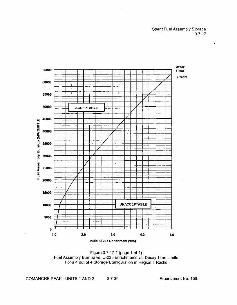
Spent Fuel Assembly Storage3.7.17
65000
60000
55000
Decay
Time:
0 Years=]--F izrI I I I I1 17 r7
50000 -I-T ACETABLE
- 45000
C 40000
0.= 35000C
-> 30000E
25000
20000
15000
10000
5000
0
/
UNCEP~tAB¶E
IF bEiIf4EI I
1.0 2.0 3.0 4.0 5.0
Initial U-235 Enrichment (w/o)
Figure 3.7.17-1 (page 1 of 1)Fuel Assembly Burnup vs. U-235 Enrichments vs. Decay Time Limits
For a 4 out of 4 Storage Configuration in Region II Racks
COMANCHE PEAK - UNITS 1 AND 2 3.7-39 Amendment No. 46G-,

Spent Fuel Assembly Storage3.7.17
45000
40000
35000
30000
25000C
m
20000E
= 15000L-
r ACUNACCEPTABLE
i /
DecayTime:
0 Years
10000
LZ5000
0
1.0 2.0 3.0 4.0 5.0
Initial U-235 Enrichment (w/o)
Figure 3.7.17-2 (page 1 of 1)Minimum Burnup vs. Initial U-235 Enrichment vs. Decay Time
For a 3 out of 4 Storage Configuration in Region II Racks
COMANCHE PEAK - UNITS 1 AND 2 3.7-40 Amendment No. 46G-,

Spent Fuel Assembly Storage3.7.17
20000
15000
i1111 iAmI~ _ 1 3ii I4
I-
CL
£100002,
EU)
...-i
I ACCEPTABLEi i i i ! i i i I I i i I i : 1 1 1 1 V ..'.I.I.I.I I I I II
0"1. ..... ..5000
i i i i i i i i i i i i i i i F i i i i i i i i i i i i i i E 1 1 1 1 E 1.UNACCEPTABLE
02.8 3.0 3.2 3.4 3.6 3.8 4.0 4.2 4.4 4.6 4.8 5.0
Initial U-235 Enrichment (w/o)
Figure 3.7.17-3 (page 1 of 1)Minimum Burnup vs. Initial U-235 Enrichment
For a 2 out of 4 Storage Configuration in Region II Racks
COMANCHE PEAK - UNITS 1 AND 2 3.7-41 Amendment No. 44Gý
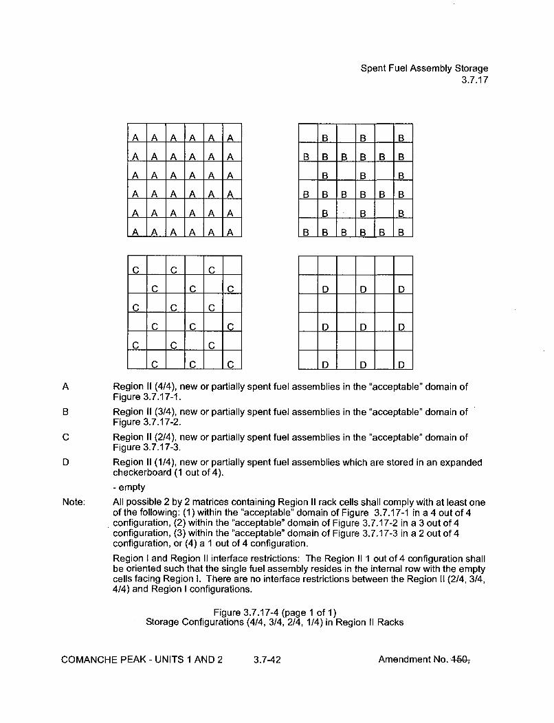
Spent Fuel Assembly Storage3.7.17
A A A A A A
A A A A A A
A IA IA A IA IA
A A A A A A
A A A A A A
IA IA IA IA IA IA
C C C
C C C
C I C CI
C C C
C C C
.C 1C I C
B B B
B B B B B B
B B B
B B B B B B
B B B
B1B B B B B
D D D
D D D
D D I D
A
B
C
D
Note:
Region 11 (4/4), new or partially spent fuel assemblies in the "acceptable" domain ofFigure 3.7.17-1.
Region 11 (3/4), new or partially spent fuel assemblies in the "acceptable" domain ofFigure 3.7.17-2.
Region 11 (2/4), new or partially spent fuel assemblies in the "acceptable" domain ofFigure 3.7.17-3.
Region 11 (1/4), new or partially spent fuel assemblies which are stored in an expandedcheckerboard (1 out of 4).
- empty
All possible 2 by 2 matrices containing Region II rack cells shall comply with at least oneof the following: (1) within the "acceptable" domain of Figure 3.7.17-1 in a 4 out of 4configuration, (2) within the "acceptable" domain of Figure 3.7.17-2 in a 3 out of 4configuration, (3) within the "acceptable" domain of Figure 3.7.17-3 in a 2 out of 4configuration, or (4) a 1 out of 4 configuration.
Region I and Region II interface restrictions: The Region I1 out of 4 configuration shallbe oriented such that the single fuel assembly resides in the internal row with the emptycells facing Region I. There are no interface restrictions between the Region 11 (2/4, 3/4,4/4) and Region I configurations.
Figure 3.7.17-4 (page 1 of 1)Storage Configurations (4/4, 3/4, 2/4, 1/4) in Region II Racks
COMANCHE PEAK - UNITS 1 AND 2 3.7-42 Amendment No. 46&,

Secondary Specific Activity3.7.18
3.7 PLANT SYSTEMS
3.7.18 Secondary Specific Activity
LCO 3.7.18
APPLICABILITY:
The specific activity of the secondary coolant shall be <ý 0.10 IJCi/gm DOSEEQUIVALENT 1-131
MODES 1, 2, 3, and 4
ACTIONS
CONDITION REQUIRED ACTION COMPLETION TIME
A. Specific activity not within A.1 Be in MODE 3. 6 hourslimit.
AND
A.2 Be in MODE 5. 36 hours
SURVEILLANCE REQUIREMENTS
SURVEILLANCE FREQUENCY
SR 3.7.18.1 Verify the specific activity of the secondary coolant is In accordance with•0.10 pCi/gm DOSE EQUIVALENT 1-131. the Surveillance
Frequency ControlProgram.
COMANCHE PEAK - UNITS 1 AND 2 3.7-43 Amendment No. 460-,

Safety Chilled Water3.7.19
3.7 PLANT SYSTEMS
3.7.19 Safety Chilled Water
LCO 3.7.19 Two safety chilled water trains shall be OPERABLE
APPLICABILITY:
ACTIONS
MODES 1, 2, 3, and 4.
CONDITION REQUIRED ACTION COMPLETION TIME
A. One safety chilled water A.1 Restore safety chilled water train to 72 hourstrain inoperable. OPERABLE status.
B. Required Action and B.1 Be in MODE 3. 6 hoursassociated CompletionTime of Condition A not ANDmet.
B.2 Be in MODE 5. 36 hours
COMANCHE PEAK - UNITS 1 AND 2 3.7-44 Amendment No. 4640ý

Safety Chilled Water3.7.19
SURVEILLANCE REQUIREMENTS
SURVEILLANCE FREQUENCY
+
SR 3.7.19.1 -NOTE-Isolation of safety chilled water flow to individualcomponents does not render the safety chilled watersystem inoperable.
Verify each safety chilled water manual, power operated,and automatic valve servicing safety related equipment,that is not locked, sealed, or otherwise secured in position,is in the correct position.
In accordance withthe SurveillanceFrequency ControlProgram.
SR 3.7.19.2 Verify each safety chilled water pump and chiller starts on In accordance withan actual or simulated actuation signal. the Surveillance
Frequency Control,Program.
COMANCHE PEAK - UNITS 1 AND 2 3.7-45 Amendment No. 440-,

UPS HVAC System3.7.20
3.7 PLANT SYSTEMS
3.7.20 UPS HVAC System
LCO 3.7.20
APPLICABILITY:
Two UPS HVAC System Trains shall be OPERABLE
MODES 1, 2, 3, and 4
ACTIONS
CONDITION REQUIRED ACTION COMPLETION TIME
A. One UPS HVAC System A.1 Verify the affected UPS & Distribution Immediatelytrain inoperable. Room is supported by an
OPERABLE UPS A/C Train.
AND
A.2 Restore the inoperable UPS HVAC 30 daystrain to OPERABLE status.
B. Two UPS HVAC System B.1 Verify air circulation is maintained by Immediately
trains inoperable, at least one UPS A/C Train.
OR AND
Required Action A.1 and B.2 Verify the air temperature in the 12 hoursassociated Completion affected UPS & Distribution Room(s)Time not met. does not exceed the maximum AND
temperature limit for the room(s).Once per 12 hoursthereafter
AND
B.3 Restore UPS HVAC System train to 72 hoursOPERABLE status.
COMANCHE PEAK- UNITS 1 AND 2 3.7-46 Amendment No. 46Q,

UPS HVAC System3.7.20
ACTIONS (continued)
CONDITION REQUIRED ACTION COMPLETION TIME
C. Required Action B.1 and C.1 Restore the required support. 1 hourassociated CompletionTime not met.
D. Required Action and D.1 Be in MODE 3. 6 hoursassociated CompletionTime of Required ANDAction A.2, B.2, B.3 or C.1not met. D.2 Be in MODE 5. 36 hours
COMANCHE PEAK - UNITS 1 AND 2 3.7-47 Amendment No. 460-,

UPS HVAC System3.7.20
SURVEILLANCE REQUIREMENTS
SURVEILLANCE FREQUENCY
SR 3.7.20.1 Verify each required UPS & Distribution Room Fan Coil In accordance withUnit operates > 1 continuous hour. the Surveillance
Frequency ControlProgram.
SR 3.7.20.2 Verify each required UPS A/C train operates for > 1 In accordance withcontinuous hour. the Surveillance
Frequency ControlProgram.
SR 3.7.20.3 Verify each required UPS A/C train actuates on an actual or In accordance withsimulated actuation signal. the Surveillance
Frequency ControlProgram.
COMANCHE PEAK - UNITS 1 AND 2 3.7-48 Amendment No. 44G-,

AC Sources -- Operating3.8.1
ACTIONS (continued)
CONDITION REQUIRED ACTION COMPLETION TIME
H. Three or more required AC H.1 Enter LCO 3.0.3. Immediatelysources inoperable.
I. One Blackout Sequencer 1.1 Declare associated DG inoperable Immediatelyinoperable
SURVEILLANCE REQUIREMENTS
SURVEILLANCE FREQUENCY
SR 3.8.1.1 Verify correct breaker alignment and indicated power In accordance withavailability for each required offsite circuit. the Surveillance
Frequency ControlProgram.
SR 3.8.1.2 ---------------------- NOTES -----------------1. Performance of SR 3.8.1.7 satisfies this SR.
2. All DG starts may be preceded by an engine prelubeperiod and followed by a warmup period prior toloading.
3. A modified DG start involving idling and gradualacceleration to synchronous speed may be used for thisSR as recommended by the manufacturer. Whenmodified start procedures are not used, the time,voltage, and frequency tolerances of SR 3.8.1.7 mustbe met.
Verify each DG starts from standby conditions and In accordance withachieves steady state voltage > 6480 V and • 7150 V, and the Surveillancefrequency > 58.8 Hz and < 61.2 Hz. Frequency Control
Program.
COMANCHE PEAK - UNITS 1 AND 2 3.8-6 Amendment No. 440-,

AC Sources -- Operating3.8.1
SURVEILLANCE REQUIREMENTS (continued)
SURVEILLANCE FREQUENCY
SR 3.8.1.3 ---------------------- NOTES---------------1. DG loadings may include gradual loading as
recommended by the manufacturer.
2. Momentary transients outside the load range do notinvalidate this test.
3. This Surveillance shall be conducted on only one DG ata time.
4. This SR shall be preceded by and immediately followwithout shutdown a successful performance ofSR 3.8.1.2 or SR 3.8.1.7.
Verify each DG is synchronized and loaded and operates In accordance withfor > 60 minutes at a load _ 6300 kW and < 7000 kW. the Surveillance
Frequency ControlProgram.
SR 3.8.1.4 Verify each day tank contains _> 1440 gal of fuel oil. In accordance withthe SurveillanceFrequency ControlProgram.
SR 3.8.1.5 Check for and remove accumulated water from each day In accordance withtank. the Surveillance
Frequency ControlProgram.
SR 3.8.1.6 Verify the fuel oil transfer system operates to automatically In accordance withtransfer fuel oil from storage tank to the day tank. the Surveillance
Frequency ControlProgram.
COMANCHE PEAK - UNITS 1 AND 2 3.8-7 Amendment No. 4640ý
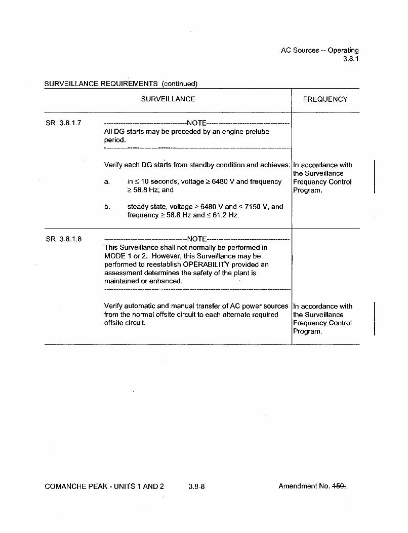
AC Sources -- Operating3.8.1
SURVEILLANCE REQUIREMENTS (continued)
SURVEILLANCE FREQUENCY
SR 3.8.1.7 - - ----- - - N O TE---All DG starts may be preceded by an engine prelubeperiod.
Verify each DG starts from standby condition and achieves:
a. in < 10 seconds, voltage _> 6480 V and frequency> 58.8 Hz; and
b. steady state, voltage _> 6480 V and < 7150 V, andfrequency > 58.8 Hz and < 61.2 Hz.
In accordance withthe SurveillanceFrequency ControlProgram.
SR 3.8.1.8 ---IIt J
This Surveillance shall not normally be performed inMODE 1 or 2. However, this Surveillance may beperformed to reestablish OPERABILITY provided anassessment determines the safety of the plant ismaintained or enhanced.
Verify automatic and manual transfer of AC power sourcesfrom the normal offsite circuit to each alternate requiredoffsite circuit.
In accordance withthe SurveillanceFrequency ControlProgram.
COMANCHE PEAK - UNITS 1 AND 2 3.8-8 Amendment No. 440-,

AC Sources -- Operating3.8.1
SURVEILLANCE REQUIREMENTS (continued)
SURVEILLANCE FREQUENCY
SR 3.8.1.9 --------------------- NOTE -----------------------------------This Surveillance shall not normally be performed inMODE 1 or 2. However, this Surveillance may beperformed to reestablish OPERABILITY provided anassessment determines the safety of the plant ismaintained or enhanced.
Verify each DG rejects a load greater than or equal to itsassociated single largest post-accident load, and:
a. Following load rejection, the frequency is• 66.75 Hz; and
b. Within 3 seconds following load rejection, thevoltage is >_ 6480 V and < 7150 V.
In accordance withthe SurveillanceFrequency ControlProgram.
SR 3.8.1.10 Verify each DG does not trip and voltage is maintained In accordance with< 8280 V during and following a load rejection ofŽ 6300 kW the Surveillanceand < 7000 kW. Frequency Control
Program.
COMANCHE PEAK - UNITS 1 AND 2 3.8-9 Amendment No. 46Gý

AC Sources -- Operating3.8.1
SURVEILLANCE REQUIREMENTS (continued)
SURVEILLANCE FREQUENCY
SR 3.8.1.11 ---------------------- NOTES -----------------1. All DG starts may be preceded by an engine prelube
period.
2. This Surveillance shall not normally be performed inMODE 1 or 2. However, portions of the Surveillancemay be performed to reestablish OPERABILITYprovided an assessment determines the safety of theplant is maintained or enhanced.
Verify on an actual or simulated loss of offsite power signal: In accordance withthe Surveillance
a. De-energization of emergency buses; Frequency ControlProgram.
b. Load shedding from emergency buses;
c. DG auto-starts from standby condition and:
1. energizes permanently connected loads in•10 seconds,
2. energizes auto-connected shutdown loadsthrough automatic load sequencer,
3. maintains steady state voltage Ž_ 6480 V and<7150 V,
4. maintains steady state frequency > 58.8 Hzand •61.2 Hz, and
5. supplies permanently connected andauto-connected shutdown loads for> 5 minutes.
COMANCHE PEAK - UNITS 1 AND 2 3.8-10 Amendment No. 44Gý
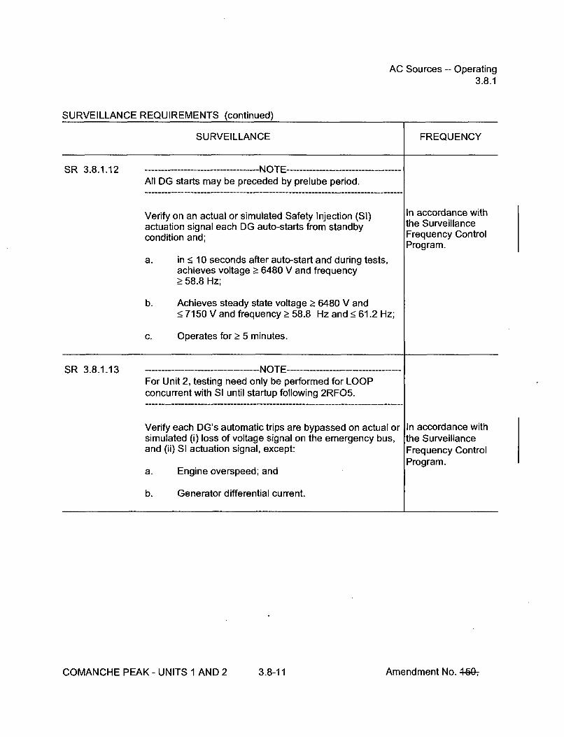
AC Sources -- Operating3.8.1
SURVEILLANCE REQUIREMENTS (continued)
SURVEILLANCE FREQUENCY
SR 3.8.1.12 --I'-- J
All DG starts may be preceded by prelube period.
Verify on an actual or simulated Safety Injection (SI)actuation signal each DG auto-starts from standbycondition and;
a. in < 10 seconds after auto-start and during tests,achieves voltage > 6480 V and frequency> 58.8 Hz;
b. Achieves steady state voltage > 6480 V and• 7150 V and frequency > 58.8 Hz and • 61.2 Hz;
c. Operates for > 5 minutes.
In accordance withthe SurveillanceFrequency ControlProgram.
SR 3.8.1.13 I.lt I -- I--- - - - - - - -- - - - - - - - -I'J." I ------------------------------------.
For Unit 2, testing need only be performed for LOOPconcurrent with SI until startup following 2RFO5.
Verify each DG's automatic trips are bypassed on actual orsimulated (i) loss of voltage signal on the emergency bus,and (ii) SI actuation signal, except:
a. Engine overspeed; and
b. Generator differential current.
In accordance withthe SurveillanceFrequency ControlProgram.
COMANCHE PEAK - UNITS 1 AND 2 3.8-11 Amendment No. 4497

AC Sources -- Operating3.8.1
SURVEILLANCE REQUIREMENTS (continued)
SURVEILLANCE FREQUENCY
4
SR 3.8.1.14 -----------------NOTE ------------------Momentary transients outside the load and power factorranges do not invalidate this test.
Verify each DG operates for _> 24 hours:
a. For > 2 hours loaded _ 6900 kW and < 7700 kW;and
b. For the remaining hours of the test loaded__ 6300 kW and • 7000 kW.
In accordance withthe SurveillanceFrequency ControlProgram.
SR 3.8.1.15 -NOTES1. This Surveillance shall be performed within 5 minutes of
shutting down the DG after the DG has operated> 2 hours loaded > 6300 kW and < 7000 kW.Momentary transients outside of load range do notinvalidate this test.
2. All DG starts may be preceded by an engine prelubeperiod.
Verify each DG starts and achieves:
a. in < 10 seconds, voltage > 6480 V and frequency> 58.8 Hz; and
b. steady state, voltage _> 6480 V and < 7150 V andfrequency > 58.8 Hz and < 61.2 Hz.
In accordance withthe SurveillanceFrequency ControlProgram.
COMANCHE PEAK - UNITS 1 AND 2 3.8-12 Amendment No. 440-,

AC Sources -- Operating3.8.1
SURVEILLANCE REQUIREMENTS (continued)
SURVEILLANCE FREQUENCY
SR 3.8.1.16 ---- ---- ---- ---- ---- ---- ---- M .U r, -----------------------------------
This Surveillance shall not normally be performed inMODE 1 or 2. However, this Surveillance may beperformed to reestablish OPERABILITY provided anassessment determines the safety of the plant ismaintained or enhanced.
Verify each DG:
a. Synchronizes with offsite power source whileloaded with emergency loads upon a simulatedrestoration of offsite power;
b. Transfers loads to offsite power source; and
c. Returns to ready-to-load operation.
In accordance withthe SurveillanceFrequency ControlProgram.
SIR 3.8.1.17 ---------------------------------- -NOTE-This Surveillance shall not normally be performed inMODE 1 or 2. However, portions of the Surveillance maybe performed to reestablish OPERABILITY provided anassessment determines the safety of the plant ismaintained or enhanced.
Verify, with a DG operating in test mode and connected toits bus, an actual or simulated SI actuation signal overridesthe test mode by:
a. Returning DG to ready-to-load operation; and
b. Automatically energizing the emergency load fromoffsite power.
In accordance withthe SurveillanceFrequency ControlProgram.
COMANCHE PEAK - UNITS 1 AND 2 3.8-13 Amendment No. 460-,
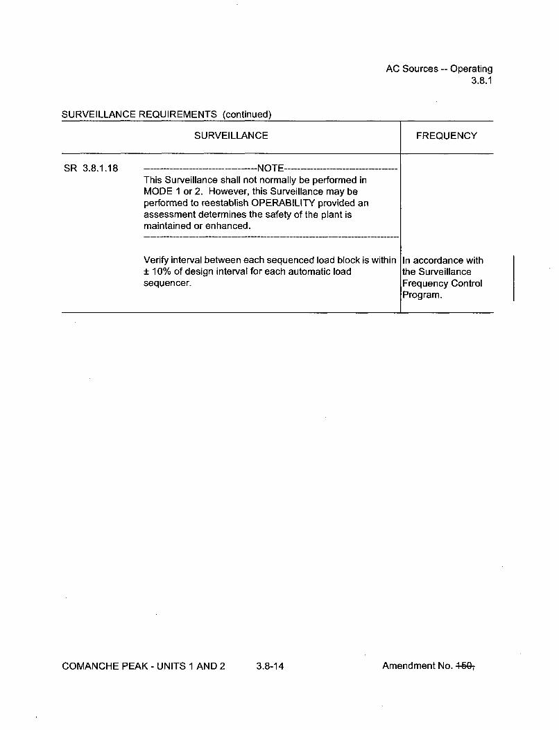
AC Sources -- Operating3.8.1
SURVEILLANCE REQUIREMENTS (continued)
SURVEILLANCE FREQUENCY
SR 3.8.1.18 -- -------------------- NOTE ------------------This Surveillance shall not normally be performed inMODE 1 or 2. However, this Surveillance may beperformed to reestablish OPERABILITY provided anassessment determines the safety of the plant ismaintained or enhanced.
Verify interval between each sequenced load block is within In accordance with± 10% of design interval for each automatic load the Surveillancesequencer. Frequency Control
Program.
COMANCHE PEAK - UNITS 1 AND 2 3.8-14 Amendment No. 469-,

AC Sources -- Operating3.8.1
SURVEILLANCE REQUIREMENTS (continued)
SURVEILLANCE FREQUENCY
SR 3.8.1.19 --------------------- NOTES -----------------1. All DG starts may be preceded by an engine prelube
period.
2. This Surveillance shall not normally be performed inMODE 1 or 2. However, portions of the Surveillancemay be performed to reestablish OPERABILITYprovided an assessment determines the safety of theplant is maintained or enhanced.
Verify on an actual or simulated loss of offsite power signal In accordance within conjunction with an actual or simulated SI actuation the Surveillancesignal: Frequency Control
Program.a. De-energization of emergency buses;
b. Load shedding from emergency buses; and
c. DG auto-starts from standby condition and:
1. energizes permanently connected loads in< 10 seconds,
2. energizes auto-connected emergency loadsthrough load sequencer,
3. achieves steady state voltage > 6480 V and< 7150 V,
4. achieves steady state frequency > 58.8 Hzand < 61.2 Hz, and
5. supplies permanently connected andauto-connected emergency loads for> 5 minutes.
COMANCHE PEAK - UNITS 1 AND 2 3.8-15 Amendment No. 4607

AC Sources -- Operating3.8.1
SURVEILLANCE REQUIREMENTS (continued)
SURVEILLANCE FREQUENCY
SR 3.8.1.20All DG starts may be preceded by an engine prelubeperiod.
Verify when started simultaneously from standby condition,each DG achieves:
a. in __ 10 seconds, voltage > 6480 V and frequency> 58.8 Hz, and
b. steady state, voltage > 6480 V, and • 7150 V andfrequency _> 58.8 Hz and < 61.2 Hz.
In accordance withthe SurveillanceFrequency ControlProgram.
SR 3.8.1.21 Calibrate BO sequencers. In accordance withthe SurveillanceFrequency ControlProgram.
SR 3.8.1.22 ----------------------- NOTES -------------------1. Verification of setpoint is not required.
2. Actuation of final devices is not included.
Perform TADOT for SI and BO sequencers. In accordance withthe SurveillanceFrequency ControlProgram.
COMANCHE PEAK - UNITS 1 AND 2 3.8-16 Amendment No. 4-50-,

Diesel Fuel Oil, Lube Oil, and Starting Air3.8.3
SURVEILLANCE REQUIREMENTS
SURVEILLANCE FREQUENCY
SR 3.8.3.1 Verify each fuel oil storage tank contains > a 7 day supply In accordance withof fuel. the Surveillance
Frequency ControlProgram.
SR 3.8.3.2 ----------------------- NOTE ------------------Not required to be performed until the engine has beenshutdown for > 10 hours.
Verify lubricating oil inventory is > a 7 day supply In accordance withthe SurveillanceFrequency ControlProgram.
SR 3.8.3.3 Verify fuel oil properties of new and stored fuel oil are In accordance withtested in accordance with, and maintained within the limits the Diesel Fuel Oilof, the Diesel Fuel Oil Testing Program. Testing Program
SR 3.8.3.4 Verify each required DG air start receiver pressure is In accordance withŽ180 psig. the Surveillance
Frequency ControlProgram.
SR 3.8.3.5 Check for and remove accumulated water from each fuel oil In accordance withstorage tank. the Surveillance
Frequency ControlProgram.
COMANCHE PEAK - UNITS 1 AND 2 3.8-22 Amendment No. 4f)g-, 464ý-,
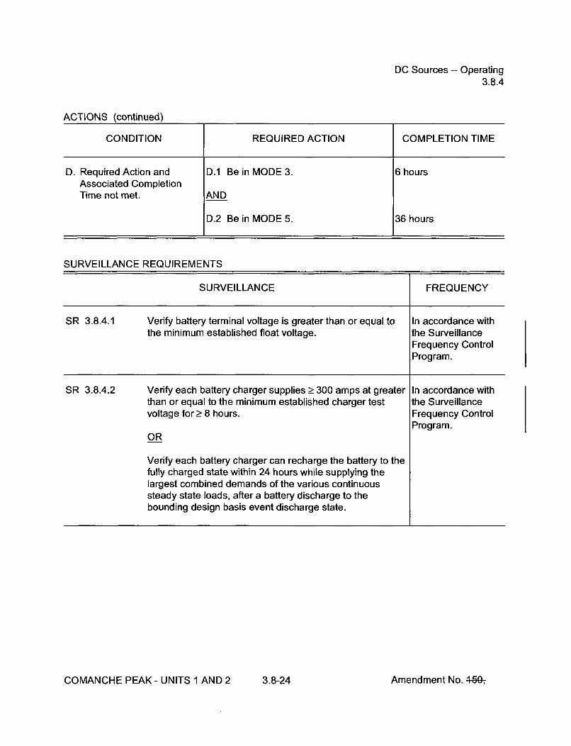
DC Sources -- Operating3.8.4
ACTIONS (continued)
CONDITION REQUIRED ACTION COMPLETION TIME
D. Required Action and D.1 Be in MODE 3. 6 hoursAssociated CompletionTime not met. AND
D.2 Be in MODE 5. 36 hours
SURVEILLANCE REQUIREMENTS
SURVEILLANCE FREQUENCY
SR 3.8.4.1 Verify battery terminal voltage is greater than or equal to In accordance withthe minimum established float voltage, the Surveillance
Frequency ControlProgram.
SR 3.8.4.2 Verify each battery charger supplies _ 300 amps at greater In accordance withthan or equal to the minimum established charger test the Surveillancevoltage for Ž 8 hours. Frequency Control
Program.OR
Verify each battery charger can recharge the battery to thefully charged state within 24 hours while supplying thelargest combined demands of the various continuoussteady state loads, after a battery discharge to thebounding design basis event discharge state.
COMANCHE PEAK - UNITS 1 AND 2 3.8-24 Amendment No. 4640ý
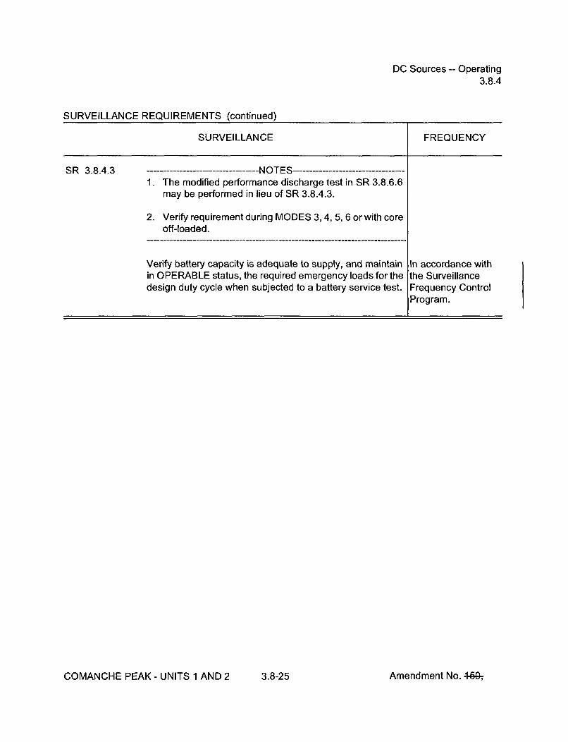
DC Sources -- Operating3.8.4
SURVEILLANCE REQUIREMENTS (continued)
SURVEILLANCE FREQUENCY
SR 3.8.4.3 --- -------------------- IJJ r-."% ----------------------------------
1. The modified performance discharge test in SR 3.8.6.6may be performed in lieu of SR 3.8.4.3.
2. Verify requirement during MODES 3, 4, 5, 6 or with coreoff-loaded.
Verify battery capacity is adequate to supply, and maintainin OPERABLE status, the required emergency loads for thedesign duty cycle when subjected to a battery service test.
In accordance withthe SurveillanceFrequency ControlProgram.
COMANCHE PEAK - UNITS 1 AND 2 3.8-25 Amendment No. 4-15Gý

Battery Parameters3.8.6
ACTIONS (continued)
CONDITION REQUIRED ACTION COMPLETION TIME
F. Required Action and F.1 Declare associated battery(ies) Immediatelyassociated Completion inoperable.Time of Condition A, B, C,D, or E not met.
OR
One or two batteries on onetrain with one or morebattery cells float voltage< 2.07 V and float current> 2 amps.
SURVEILLANCE REQUIREMENTS
SURVEILLANCE FREQUENCY
SR 3.8.6.1 -------------------- NOTE -------------------Not required to be met when battery terminal voltage is lessthan the minimum established float voltage of SR 3.8.4.1
Verify each battery float current is < 2 amps. In accordance with
the SurveillanceFrequency ControlProgram.
SR 3.8.6.2 Verify each battery pilot cell voltage is _> 2.07 V. In accordance withthe SurveillanceFrequency ControlProgram.
COMANCHE PEAK - UNITS 1 AND 2 3.8-30 Amendment No. 464;

Battery Parameters3.8.6
SURVEILLANCE REQUIREMENTS (continued)
SR 3.8.6.3 Verify each battery connected cell electrolyte level is In accordance withgreater than or equal to minimum established design limits, the Surveillance
Frequency ControlProgram.
SR 3.8.6.4 Verify each battery pilot cell temperature is greater than or In accordance withequal to minimum established design limits, the Surveillance
Frequency ControlProgram.
SR 3.8.6.5 Verify each battery connected cell voltage is Ž> 2.07 V. In accordance withthe SurveillanceFrequency ControlProgram.
COMANCHE PEAK - UNITS 1 AND 2 3.8-31 Amendment No. 4-W

Battery Parameters3.8.6
SURVEILLANCE REQUIREMENTS (continued)
SURVEILLANCE FREQUENCY
SR 3.8.6.6 --------------------- NOTE -----------------------------------Verify requirement during MODES 3, 4, 5, 6 or with coreoff-loaded.
Verify battery capacity is___ 80 % of the manufacturer'srating when subjected to a performance discharge test or amodified performance discharge test.
In accordance withthe SurveillanceFrequency ControlProgram.
AND
18 months whenbattery showsdegradation or hasreached 85% ofexpected life withcapacity < 100% ofmanufacturer'srating
AND
24 months whenbattery has reached85% of the expectedlife with capacityŽ_ 100% ofmanufacturer'srating
COMANCHE PEAK - UNITS 1 AND 2 3.8-32 Amendment No. 460-,

Inverters -- Operating3.8.7
ACTIONS (continued)
CONDITION REQUIRED ACTION COMPLETION TIME
B. Required Action and B.1 Be in MODE 3. 6 hoursassociated CompletionTime not met. AND
B.2 Be in MODE 5. 36 hours
SURVEILLANCE REQUIREMENTS
SURVEILLANCE FREQUENCY
SR 3.8.7.1 Verify correct inverter voltage, and alignment to required In accordance withAC vital buses. the Surveillance
Frequency ControlProgram.
COMANCHE PEAK - UNITS 1 AND 2 3.8-34 Amendment No. 44Gý

Inverters -- Shutdown3.8.8
SURVEILLANCE REQUIREMENTS
SURVEILLANCE FREQUENCY
SR 3.8.8.1 Verify correct inverter voltage and alignments to required In accordance withAC vital buses. the Surveillance
Frequency ControlProgram.
COMANCHE PEAK - UNITS 1 AND 2 3.8-36 Amendment No. 449-,

Distribution Systems -- Operating3.8.9
SURVEILLANCE REQUIREMENTS
SURVEILLANCE FREQUENCY
SR 3.8.9.1 Verify correct breaker alignments and voltage to required In accordance withAC, DC, and AC vital bus electrical power distribution the Surveillancesubsystems. Frequency Control
Program.
COMANCHE PEAK - UNITS 1 AND 2 3.8-38 Amendment No. 44&,

Distribution Systems -- Shutdown3.8.10
CONDITION REQUIRED ACTION COMPLETION TIME
A. (continued) A.2.4 Initiate actions to restore required ImmediatelyAC, DC, and AC vital bus electricalpower distribution subsystems toOPERABLE status.
AND
A.2.5 Declare associated required Immediatelyresidual heat removalsubsystem(s) inoperable and not inoperation.
SURVEILLANCE REQUIREMENTS
SURVEILLANCE FREQUENCY
SR 3.8.10.1 Verify correct breaker alignments and voltage to required In accordance withAC, DC, and AC vital bus electrical power distribution the Surveillancesubsystems. Frequency Control
Program.
COMANCHE PEAK - UNITS 1 AND 2 3.8-40 Amendment No. 46&,

Boron Concentration3.9.1
3.9 REFUELING OPERATIONS
3.9.1 Boron Concentration
LCO 3.9.1 Boron concentrations of all filled portions of the Reactor Coolant System, therefueling canal, and the refueling cavity, that have direct access to the reactorvessel, shall be maintained within the limit specified in the COLR.
-NOTE-While this LCO is not met, entry into MODE 6 from MODE 5 is not permitted.
APPLICABILITY: MODE 6.
ACTIONS
CONDITION REQUIRED ACTION COMPLETION TIME
A. Boron concentration not A.1 Suspend CORE ALTERATIONS. Immediatelywithin limit.
AND
A.2 Suspend positive reactivity additions. Immediately
AND
A.3 Initiate action to restore boron Immediatelyconcentration to within limit.
SURVEILLANCE REQUIREMENTS
SURVEILLANCE FREQUENCY
SR 3.9.1.1 Verify boron concentration is within the limit specified in the In accordance withCOLR. the Surveillance
Frequency ControlProgram.
COMANCHE PEAK - UNITS 1 AND 2 3.9-1 Amendment No. 460-,
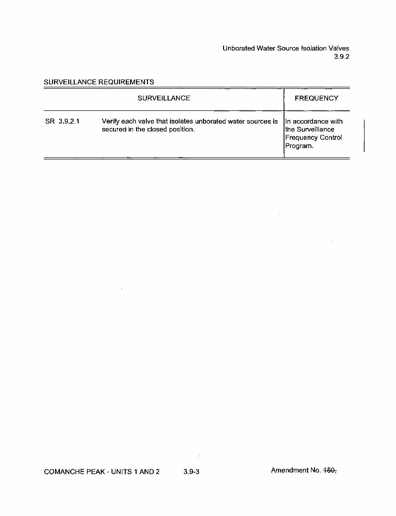
Unborated Water Source Isolation Valves3.9.2
SURVEILLANCE REQUIREMENTS
SURVEILLANCE FREQUENCY
SR 3.9.2.1 Verify each valve that isolates unborated water sources is In accordance withsecured in the closed position. the Surveillance
Frequency ControlProgram.
COMANCHE PEAK - UNITS 1 AND 2 3.9-3 Amendment No. 46&,

Nuclear Instrumentation3.9.3
SURVEILLANCE REQUIREMENTS
SURVEILLANCE FREQUENCY
SR 3.9.3.1 Perform CHANNEL CHECK. In accordance withthe SurveillanceFrequency ControlProgram.
SR 3.9.3.2 ----------- NOTE ------------------Neutron detectors are excluded from CHANNELCALIBRATION.
Perform CHANNEL CALIBRATION. In accordance withthe SurveillanceFrequency ControlProgram.
COMANCHE PEAK - UNITS 1 AND 2 3.9-5 Amendment No. 4-60-,

Containment Penetrations3.9.4
SURVEILLANCE REQUIREMENTS
SR 3.9.4.1 Verify each required containment penetration is in the In accordance withrequired status. the Surveillance
Frequency ControlProgram.
SR 3.9.4.2 - - --------------------NOTE -----------------Only required for an open equipment hatch
Verify the capability to install the equipment hatch. In accordance withthe SurveillanceFrequency ControlProgram.
SR 3.9.4.3 Verify each required containment ventilation isolation In accordance withvalve actuates to the isolation position on an actual or the Surveillancesimulated actuation signal. Frequency Control
Program.
COMANCHE PEAK- UNITS 1 AND 2 3.9-7 Amendment No. 46&,
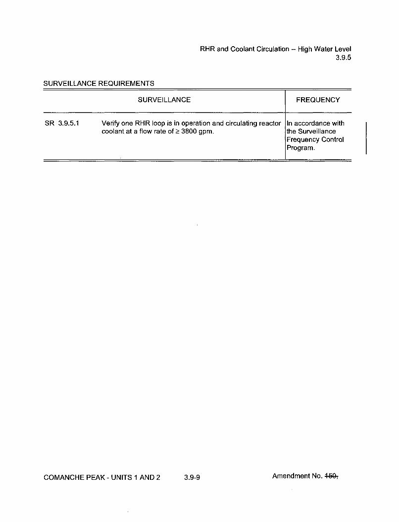
RHR and Coolant Circulation -- High Water Level3.9.5
SURVEILLANCE REQUIREMENTS
SURVEILLANCE FREQUENCY
SR 3.9.5.1 Verify one RHR loop is in operation and circulating reactor In accordance withcoolant at a flow rate of _> 3800 gpm. the Surveillance
Frequency ControlProgram.
COMANCHE PEAK - UNITS 1 AND 2 3.9-9 Amendment No. 440-,

RHR and Coolant Circulation -- Low Water Level3.9.6
ACTIONS (continued)
CONDITION REQUIRED ACTION COMPLETION TIME
B. No RHR loop in operation. B.1 Suspend operations that would Immediatelycause introduction of coolant into theRCS with boron concentration lessthan required to meet the boronconcentration of LCO 3.9.1.
AND
B.2 Initiate action to restore one RHR Immediatelyloop to operation.
AND
B.3 Close all containment penetrations 4 hoursproviding direct access fromcontainment atmosphere to outsideatmosphere.
SURVEILLANCE REQUIREMENTS
SURVEILLANCE FREQUENCY
SR 3.9.6.1 Verify one RHR loop is in operation and circulating reactor In accordance withcoolant at a flow rate of _> 1000 gpm. the Surveillance
Frequency ControlProgram.
SR 3.9.6.2 Verify correct breaker alignment and indicated power In accordance withavailable to the required RHR pump that is not in operation. the Surveillance
Frequency ControlProgram.
COMANCHE PEAK - UNITS 1 AND 2 3.9-1 1 Amendment No. 44Gý

Refueling Cavity Water Level3.9.7
3.9 REFUELING OPERATIONS
3.9.7 Refueling Cavity Water Level
LCO 3.9.7 Refueling cavity water level shall be maintained >_ 23 ft above the top ofreactor vessel flange.
APPLICABILITY: During movement of irradiated fuel assemblies within containment.
ACTIONS
CONDITION REQUIRED ACTION COMPLETION TIME
A. Refueling cavity water level A.1 Suspend movement of irradiated fuel Immediatelynot within limit, assemblies within containment.
SURVEILLANCE REQUIREMENTS
SURVEILLANCE FREQUENCY
SR 3.9.7.1 Verify refueling cavity water level is _ 23 ft above the top of In accordance withreactor vessel flange. the Surveillance
Frequency ControlProgram.
COMANCHE PEAK - UNITS 1 AND 2 3.9-12 Amendment No. 449-,

Programs and Manuals5.5
5.5 Programs and Manuals
5.5.21 Surveillance Frequency Control Program
This program provides controls for Surveillance Frequencies. The program shallensure that Surveillance Requirements specified in the Technical Specifications areperformed at intervals sufficient to assure the associated Limiting Conditions forOperation are met.
a. The Surveillance Frequency Control Program shall contain a list ofFrequencies of those Surveillance Requirements for which the Frequency iscontrolled by the program.
b. Changes to the Frequencies listed in the Surveillance Frequency ControlProgram shall be made in accordance with NEI-04-10, "Risk-Informed Methodfor Control of Surveillance Frequencies," Revision 1.
c. The provisions of Surveillance Requirements 3.02 and 3.03 are applicable tothe Frequencies established in the Surveillance Frequency Control Program.
COMANCHE PEAK - UNITS 1 AND 2 5.5-17Amendment No. 4"W,

Attachment 6 to TXX-11093Page 1 of 13008/01/2011
ATTACHMENT 6 to TXX-11093
RETYPED TECHNICAL SPECIFICATION BASES PAGES(For Information Only)
Pages B 3.1-4 B 3.3-100 B 3.4-60 B 3.7-18 B 3.8-22
B 3.1-10 B 3.3-101 B 3.4-61 B 3.7-29 B 3.8-23
B 3.1-24 B 3.3-102 B 3.4-62 B 3.7-30 B 3.8-24
B 3.1-29 B 3.3-103 B 3.4-67 B 3.7-31 B 3.8-25
B 3.1-34 B 3.3-120 B 3.4-68 B 3.7-34 B 3.8-26
B 3.1-35 B 3.3-121 B 3.4-72 B 3.7-38 B 3.8-27
B 3.1-45 B 3.3-126 B 3.4-73 B 3.7-42 B 3.8-40
B 3.1-46 B 3.3-127 B 3.4-80 B 3.7-43 B 3.8-42
B 3.2-9 B 3.3-134 B 3.4-85 B 3.7-46 B 3.8-43
B 3.2-11 B 3.3-135 B 3.5-6 B 3.7-53 B 3.8-50
B 3.2-19 B 3.3-141 B 3.5-7 B 3.7-54 B 3.8-51
B 3.2-22 B 3.3-142 B 3.5-16 B 3.7-59 B 3.8-62
B 3.2-28 B 3.3-143 B 3.5-17 B 3.7-64 B 3.8-63
B 3.2-29 B 3.3-148 B 3.5-18 B 3.7-65 B 3.8-64
B 3.3-43 B 3.3-149 B 3.5-26 B 3.7-70 B 3.8-68
B 3.3-45 B 3.4-5 B 3.5-27 B 3.7-76 B 3.8-74
B 3.3-46 B 3.4-9 B 3.5-30 B 3.7-82 B 3.8-80
B 3.3-47 B 3.4-15 B 3.6-10 B 3.7-85 B 3.8-86
B 3.3-48 B 3.4-18 B 3.6-21 B 3.7-90 B 3.9-4
B 3.3-49 B 3.4-23 B 3.6-23 B 3.8-14 B 3.9-7
B 3.3-50 B 3.4-27 B 3.6-24 B 3.8-15 B 3.9-10
B 3.3-51 B 3.4-31 B 3.6-28 B 3.8-16 B 3.9-16
B 3.3-52 B 3.4-32 B 3.6-31 B 3.8-17 B 3.9-20
B 3.3-53 B 3.4-35 B 3.6-36 B 3.8-19 B 3.9-23
B 3.3-98 B 3.4-39 B 3.6-37 B 3.8-20 B 3.9-25
B 3.3-99 B 3.4-49 B 3.7-12 B 3.8-21

SDMB 3.1.1
BASES
ACTIONS A.1 (continued)
possible, the borated water source should be a highly concentrated solution,such as that normally found in the boric acid storage tank, or the refuelingwater storage tank. The operator should borate with the best sourceavailable for the plant conditions.
SURVEILLANCEREQUIREMENTS
SR 3.1.1.1
In MODES 2 (with keff < 1.0), 3, 4 and 5, the SDM is verified by performing a
reactivity balance calculation, considering the listed reactivity effects:
a. RCS boron concentration;
b. Shutdown and Control bank position;
c. RCS average temperature;
d. Fuel burnup based on gross thermal energy generation;
e. Xenon concentration;
f. Samarium concentration; and
g. Isothermal temperature coefficient (ITC).
Using the ITC accounts for Doppler reactivity in this calculation because thereactor is subcritical, and the fuel temperature will be changing at the samerate as the RCS.
In the event that a rod is known to be untrippable, however, SDM verificationmust account for the worth of the untrippable rod as well as another rod ofmaximum worth.
The Surveillance Frequency is controlled under the Surveillance FrequencyControl Program.
(ont~Inud
(continued)
COMANCHE PEAK - UNITS 1 AND 2 B 3.1-4 Revision

Core ReactivityB 3.1.2
BASES
ACTIONS B.1 (continued)
this status, the plant must be brought to at least MODE 3 within 6 hours. Ifthe SDM for MODE 3 is not met, then the boration required by LCO 3.1.1Required Action A.1 would occur. The allowed Completion Time isreasonable, based on operating experience, for reaching MODE 3 from fullpower conditions in an orderly manner and without challenging plantsystems.
SURVEILLANCE SR 3.1.2.1REQU IREMENTS
Core reactivity is verified by periodic comparisons of measured andpredicted RCS boron concentrations. The comparison is made, consideringthat other core conditions are fixed or stable, including control rod position,moderator temperature, fuel temperature, fuel depletion, xenonconcentration, and samarium concentration. The Surveillance is performedprior to entering MODE 1 as an initial check on core conditions and designcalculations at BOC. The SR is modified by a Note. The Note requires thatthe normalization of predicted core reactivity to the measured value musttake place within the first 60 effective full power days (EFPD) after each fuelloading. However, if the deviation between measured and predicted valuesis within the associated measurement and analytical uncertainties, it is notnecessary to normalize the predicted core reactivity. This allows sufficienttime for core conditions to reach steady state, but prevents operation for alarge fraction of the fuel cycle without establishing a benchmark for thedesign calculations. The required subsequent Frequency, following theinitial 60 EFPD after entering MODE 1, is controlled under thethe Surveillance Frequency Control Program.
REFERENCES 1. 10 CFR 50, Appendix A, GDC 26, GDC 28, and GDC 29.
2. FSAR, Chapter 15.
COMANCHE PEAK - UNITS 1 AND 2 B 3.1-10 Revision

Rod Group Alignment LimitsB 3.1.4
BASES
ACTIONS (continued) j
D.2
If more than one rod is found to be misaligned or becomes misalignedbecause of bank movement, the unit conditions fall outside of the accidentanalysis assumptions. Since automatic bank sequencing would continue tocause misalignment, the unit must be brought to a MODE or Condition inwhich the LCO requirements are not applicable. To achieve this status, theunit must be brought to at least MODE 3 within 6 hours.
The allowed Completion Time is reasonable, based on operatingexperience, for reaching MODE 3 from full power conditions in an orderlymanner and without challenging plant systems.
SURVEILLANCE SR 3.1.4.1REQUIREMENTS
The Surveillance Frequency is controlled under the Surveillance FrequencyControl Program.
SR 3.1.4.2
Verifying each control rod is OPERABLE would require that each rod betripped. However, in MODES 1 and 2, tripping each control rod would resultin radial or axial power tilts, or oscillations. Exercising each individual controlrod provides increased confidence that all rods continue to be OPERABLEwithout exceeding the alignment limit, even if they are not regularlytripped. Moving each control rod by 10 steps will not cause radial oraxial power tilts, or oscillations, to occur. The Frequency takes intoconsideration other information available to the operator in the control roomand SR 3.1.4.1, which is performed more frequently and adds to thedetermination of OPERABILITY of the rods. The Surveillance Frequency iscontrolled under the Surveillance Frequency Control Program. Between orduring required performances of SR 3.1.4.2 (determination of control rodOPERABILITY by movement), if a control rod(s) is discovered to beimmovable, but remains trippable, the control rod(s) is considered to beOPERABLE until the surveillance interval expires. At any time, if a controlrod(s) is immovable, a determination of the trippability (OPERABILITY) of thecontrol rod(s) must be made, and appropriate action taken.
(continued)
COMANCHE PEAK - UNITS 1 AND 2 B 3.1-24 Revision

Shutdown Bank Insertion LimitsB 3.1.5
BASES
ACTIONS A.1.1, A.1.2 and A.2 (continued)
The allowed Completion Time of 2 hours provides an acceptable time forevaluating and repairing minor problems without allowing the plant to remainin an unacceptable condition for an extended period of time.
B.1
If the shutdown banks cannot be restored to within their insertion limits within2 hours, the unit must be brought to MODE 3 where the LCO is notapplicable. The allowed Completion Time of 6 hours is reasonable, basedon operating experience, for reaching the required MODE from full powerconditions in an orderly manner and without challenging plant systems.
SURVEILLANCEREQUIREMENTS
SR 3.1.5.1
Verification that the shutdown banks are within their insertion limits prior toan approach to criticality ensures that when the reactor is critical, or beingtaken critical, the shutdown banks will be available to shut down the reactor,and the required SDM will be maintained following a reactor trip. This SRand Frequency ensure that the shutdown banks are within limits during a unitstartup and subsequent operation.
The Surveillance Frequency is controlled under the Surveillance FrequencyControl Program. I
REFERENCES 1. 10 CFR 50, Appendix A, GDC 10, GDC 26, and GDC 28.
2. 10 CFR 50.46.
3. FSAR, Chapter 15.
COMANCHE PEAK - UNITS 1 AND 2 B 3.1-29 Revision

Control Bank Insertion LimitsB 3.1.6
BASES (continued)
SURVEILLANCE SR 3.1.6.1REQUIREMENTS
This Surveillance is required to ensure that the reactor does not achievecriticality with the control banks below their insertion limits.
The estimated critical condition (ECC) depends upon a number of factors,one of which is xenon concentration. If the ECC was calculated long beforecriticality, xenon concentration could change to make the ECC substantiallyin error. Conversely, determining the ECP immediately before criticalitycould be an unnecessary burden. There are a number of unit parametersrequiring operator attention at that point. Performing the ECC calculationwithin 4 hours prior to criticality avoids a large error from changes in xenonconcentration, but allows the operator some flexibility to schedule the ECCcalculation with other startup activities.
SR 3.1.6.2
The Surveillance Frequency is controlled under the Surveillance FrequencyControl Program.
SR 3.1.6.3
There is a potential that, with only a limit on rod insertion, the RCCAs couldbe placed in a sequence or overlap position, perhaps during troubleshootingactivities or other abnormal plant conditions, that would violate core fluxpeaking factors while still satisfying the limits on rod insertion. This scenariois most likely to occur at reduced power following an automatic runback ordue to an administrative power reduction in response to some rod controlabnormality.
This surveillance ensures that the rod configuration across the core for anygiven operating condition will not result in unanalyzed peaking factors. Thesurveillance is not designed to test or Verify the function of the Rod Controlsequence and overlap circuits. In practice, this surveillance will be satisfiedas long as the rod positions are in the positions specified in the COLR,regardless of the operability of the sequence and overlap circuits. The intentis to check the rod position to verify that the rods are in the expectedpositions as described in the COLR. If all rods are out of the core when thecheck is made, then rod sequence and overlap limits are satisfied for thepurpose of this surveillance. At all power levels, the rod positions shouldconform to the requirements of the COLR for rod sequence and overlap.Implicit within the LCO is the assumption that bank sequence and overlapmust be maintained during rod movement. When control banks aremaintained within their insertion limits as checked by SR 3.1.6.2 above, it isunlikely that their sequence and overlap will not be in accordance with
(continued)
COMANCHE PEAK - UNITS 1 AND 2 B 3.1-34 Revision

Control Bank Insertion LimitsB 3.1.6
BASES
SURVEILLANCE SR 3.1.6.3 (continued)REQUIREMENTS
requirements provided in the COLR. The Surveillance Frequency iscontrolled under the Surveillance Frequency Control Program.
REFERENCES 1. 10 CFR 50, Appendix A, GDC 10, GDC 26, GDC 28.
2. 10 CFR 50.46.
3. FSAR, Chapter 15.
COMANCHE PEAK - UNITS 1 AND 2 B 3.1-35 Revision

PHYSICS TESTS Exceptions - MODE 2B 3.1.8
BASES
ACTIONS (continued)
B.1
When THERMAL POWER is > 5% RTP, the only acceptable action is toopen the reactor trip breakers (RTBs) to prevent operation of the reactorbeyond its design limits. Immediately opening the RTBs will shut down thereactor and prevent operation of the reactor outside of its design limits.
C.1
When the RCS lowest operating loop Tavg is < 541'F, the appropriate actionis to restore Tavg to within its specified limit. The allowed Completion Time of15 minutes provides time for restoring Tavg to within limits without allowingthe plant to remain in an unacceptable condition for an extended period oftime. Operation with the reactor critical and with temperature below 541°Fcould violate the assumptions for accidents analyzed in the safety analyses.
D.1
If the Required Actions cannot be completed within the associatedCompletion Time, the plant must be brought to a MODE in which therequirement does not apply. To achieve this status, the plant must bebrought to at least MODE 3 within an additional 15 minutes. The CompletionTime of 15 additional minutes is reasonable, based on operating experience,for reaching MODE 3 in an orderly manner and without challenging plantsystems.
SURVEILLANCE SR 3.1.8.1REQUIREMENTS
The power range and intermediate range neutron detectors must be verifiedto be OPERABLE in MODE 2 by LCO 3.3.1, "Reactor Trip System (RTS)Instrumentation." A CHANNEL OPERATIONAL TEST is performed on eachpower range and intermediate range channel prior to initiation of thePHYSICS TESTS. This will ensure that the RTS is properly aligned toprovide the required degree of core protection during the performance of thePHYSICS TESTS.
SR 3.1.8.2
Verification that the RCS lowest operating loop Tavg is _Ž 541 °F will ensurethat the unit is not operating in a condition that could invalidate the safetyanalyses. The Surveillance Frequency is controlled under the SurveillanceFrequency Control Program.
(continued)
COMANCHE PEAK - UNITS 1 AND 2 B 3.1-45 Revision

PHYSICS TESTS Exceptions - MODE 2B 3.1.8
BASES
SURVEILLANCE REQUIREMENTS (continued)
SR 3.1.8.3
Verification that the THERMAL POWER is < 5% RTP will ensure that theplant is not operating in a condition that could invalidate the safety analyses.The Surveillance Frequency is controlled under the Surveillance FrequencyControl Program.
SR 3.1.8.4
Verification that the SDM is within limits specified in the COLR ensures that,for the specific RCCA and RCS temperature manipulations performed duringPHYSICS TESTS, the plant is not operating in a condition that couldinvalidate the safety analysis assumptions. The SDM verification can befacilitated through the use of tables prepared by the core designers in whichthe reactivity effects expected during the Physics Testing have beenpreviously considered.
The SDM is verified by performing a reactivity balance calculation,considering the following reactivity effects:
a. RCS boron concentration;
b. Shutdown and Control bank position;
c. RCS average temperature;
d. Fuel burnup based on gross thermal energy generation;
e. Xenon concentration;
f. Samarium concentration; and
g. Isothermal temperature coefficient (ITC).
Using the ITC accounts for Doppler reactivity in this calculation because thereactor is subcritical, and the fuel temperature will be changing at the samerate as the RCS.
The Surveillance Frequency is controlled under the Surveillance FrequencyControl Program.
(continued)
COMANCHE PEAK - UNITS 1 AND 2 B 3.1-46 Revision

FQ(Z) (RAOC-W(Z) Methodology)B 3.2.1
BASES
SURVEILLANCE SR 3.2.1.1 (continued)REQUIREMENTS
CThe limit with which FQ (Z) is compared varies inversely with power above
50% RTP and directly with a function called K(Z) provided in the COLR.
Performing this Surveillance in MODE 1 prior to exceeding 75% RTP,
provides assurance that the FQc(Z) limit is met when RTP is achieved,
because peaking factors generally decrease as power level is increased.
If THERMAL POWER has been increased by _> 20% RTP since the lastC
determination of FC (Z), another evaluation of this factor is required
24 hours after achieving equilibrium conditions at this higher power level (toC
ensure that FQ (Z) values are being reduced sufficiently with power
increase to stay within the LCOjlimits).
The Surveillance Frequency is controlled under the Surveillance FrequencyControl Program.
SR 3.2.1.2
The nuclear design process includes calculations performed to determinethat the core can be operated within the FQ(Z) limits. Because powerdistribution measurements are taken at or near equilibrium conditions, thevariations in power distribution resulting from normal operational maneuversare not present in the core power distribution measurement data. Thesevariations are, however, conservatively calculated by considering a widerange of unit maneuvers in normal operation. The maximum peaking factorincrease over steady state values, calculated as a function of core elevation,
Z, is called W(Z). Multiplying the measured total peaking factor, F c(Z), by
W(Z) gives the maximum FQ(Z) calculated to occur in normalw
operation,FQ (Z).
wThe limit with which F QW(Z) is compared varies inversely with power above
50% RTP and directly with the function K(Z) provided in the COLR.
(continued)
COMANCHE PEAK - UNITS 1 AND 2 B 3.2-9 Revision

FQ(Z) (RAOC-W(Z) Methodology)B 3.2.1
BASES
SURVEILLANCE SR 3.2.1.2 (continued)REQUIREMENTS
The Surveillance Frequency is controlled under the Surveillance FrequencyControl Program.
REFERENCES 1. 10 CFR 50.46, 1974.
2. Regulatory Guide 1.77, Rev. 0, May 1974.
3. 10 CFR 50, Appendix A, GDC 26.
4. RXE-90-006-P-A, "Power Distribution Control Analysis andOvertemperature N-16 and Overpower N-16 Trip SetpointMethodology," TU Electric, June 1994.
5. WCAP-7308-L-P-A, "Evaluation of Nuclear Hot Channel FactorUncertainties," June 1988.
6. WCAP-1 0216-P-A, Rev. IA, "Relaxation of Constant Axial OffsetControl (and) FQ Surveillance Technical Specification," February1994.
7. WCAP-12472-P-A, "BEACON Core Monitoring and OperationsSupport System," August 1994.
I
COMANCHE PEAK - UNITS 1 AND 2 B 3.2-11 Revision

NFAH
B 3.2.2
BAS ES
SURVEILLANCEREQUIREMENTS
SR 3.2.2.1 (continued)
The Surveillance Frequency is controlled under the Surveillance FrequencyControl Program. I
REFERENCES 1. Regulatory Guide 1.77, Rev. 0, May 1974.
2. 10 CFR 50, Appendix A, GDC 26.
3. 10 CFR 50.46.
4. WCAP-12472-P-A, "BEACON Core Monitoring and Operations SupportSystem," August 1994.
COMANCHE PEAK - UNITS 1 AND 2 B 3-2-19 Revision

AFD (RAOC Methodology)B 3.2.3
BAS ES
LCO (continued)
detector well. For convenience, this flux difference is converted to provideflux difference units expressed as a percentage and labeled as %A flux or%AI.
The AFD limits are provided in the COLR. The AFD limits for RAOC do notdepend on the target flux difference. However, the target flux difference maybe used to minimize changes in the axial power distribution.
Violating the LCO on the AFD could produce unacceptable consequences ifa Condition 2, 3, or 4 event occurs while the AFD is outside its limits.
APPLICABILITY The AFD requirements are applicable in MODE 1 greater than or equal to50% RTP, when the combination of THERMAL POWER and core peakingfactors are the core parameters of primary importance in safety analyses(Ref. 1).
For AFD limits developed using RAOC methodology, the value of the AFDdoes not affect the limiting accident consequences with THERMAL POWER< 50% RTP and for lower operating power MODES.
ACTIONS A.1
As an alternative to restoring the AFD to within its specified limits, RequiredAction A.1 requires a THERMAL POWER reduction to < 50% RTP. Thisplaces the core in a condition for which the value of the AFD is not importantin the applicable safety analyses. A Completion Time of 30 minutes isreasonable, based on operating experience, to reach 50% RTP withoutchallenging plant systems.
SURVEILLANCE SR 3.2.3.1REQU IREMENTS
This Surveillance verifies that the AFD as indicated by the NIS excorechannels is within its specified limits. The Surveillance Frequency iscontrolled under the Surveillance Frequency Control Program.
(continued)
I
COMANCHE PEAK - UNITS 1 AND 2 B 3.2-22 Revision

QPTRB 3.2.4
BASES
ACTIONS A.6 (continued)
RTP within 24 hours but is increased slowly, then the peaking factorsurveillances must be performed within 48 hours after increasing THERMALPOWER above the limit of Required Action A.1. This Completion Time isintended to allow adequate time to increase THERMAL POWER to abovethe limits of Required Action A.1, while not permitting the core to remain withunconfirmed power distributions for extended periods of time.
Required Action A.6 is modified by a Note that states that the peaking factorsurveillances must be completed when the excore detectors have beennormalized to restore QPTR to within limit (i.e., Required Action A.5). Theintent of this Note is to have the peaking factor surveillances performed atoperating power levels, which can only be accomplished after the excoredetectors are normalized to restore QPTR to within limit.
B.1
If Required Actions A.1 through A.6 are not completed within theirassociated Completion Times, the unit must be brought to a MODE orcondition in which the requirements do not apply. To achieve this status,THERMAL POWER must be reduced to < 50% RTP within 4 hours. Theallowed Completion Time of 4 hours is reasonable, based on operatingexperience regarding the amount of time required to reach the reducedpower level without challenging plant systems.
SURVEILLANCE SR 3.2.4.1REQU IREMENTS
SR 3.2.4.1 is modified by two Notes. Note 1 allows QPTR to be calculatedwith three power range channels if THERMAL POWER is • 75% RTP andthe input from one Power Range Neutron Flux channel is inoperable. Note 2allows performance of SR 3.2.4.2 in lieu of SR 3.2.4.1
This Surveillance verifies that the QPTR, as indicated by the NuclearInstrumentation System (NIS) excore channels, is within its limits. TheSurveillance Frequency is controlled under the Surveillance FrequencyControl Program.
For those causes of QPT that occur quickly (e.g., a dropped rod), theretypically are other indications of abnormality that prompt a verification of corepower tilt.
(continued)
COMANCHE PEAK - UNITS 1 AND 2 B 3.2-28 Revision

QPTRB 3.2.4
BASES
SURVEILLANCE REQUIREMENTS (continued)
SR 3.2.4.2
This Surveillance is modified by a Note, which states that it is not requireduntil 12 hours after the inputs from one or more Power Range Neutron Fluxchannels are inoperable and the THERMAL POWER is > 75% RTP.
With an NIS power range channel inoperable, tilt monitoring for a portion ofthe reactor core becomes degraded. Large tilts are likely detected with theremaining channels, but the capability for detection of small power tilts insome quadrants is decreased. The Surveillance Frequency is controlledunder the Surveillance Frequency Control Program.
For purposes of monitoring the QPTR when one power range channel isinoperable, the moveable incore detectors or an OPERABLE PDMS may beused to confirm that the normalized symmetric power distribution isconsistent with the indicated QPTR and any previous data indicating a tilt.When using the moveable incore detector system, the incore detectormonitoring is performed with a full incore flux map or two sets of four thimblelocations with quarter core symmetry. The two sets of four symmetricthimbles is a set of eight unique detector locations. These locations are C-8,E-5, E-11, H-3, H-13, L-5, L-11, and N-8.
The symmetric thimble flux map can be used to generate symmetric thimble"tilt." This can be compared to a reference symmetric thimble tilt, from themost recent full core flux map, to generate an incore QPTR. Therefore,incore monitoring of QPTR can be used to confirm that QPTR is within limits.
With one NIS channel inoperable, the indicated tilt may be changed from thevalue indicated with all four channels OPERABLE. To confirm that nochange in tilt has actually occurred, which might cause the QPTR limit to beexceeded, the incore result may be compared against previous core powerdistribution measurements using an OPERABLE PDMS and the symmetricthimbles as described above or a complete flux map. Nominally, quadrant tiltfrom the Surveillance should be within 2% of the tilt shown by the mostrecent flux map data.
REFERENCES 1. 10 CFR 50.46.
2. Regulatory Guide 1.77, Rev 0, May 1974.
3. 10 CFR 50, Appendix A, GDC 26.
COMANCHE PEAK - UNITS 1 AND 2 B 3.2-29 Revision
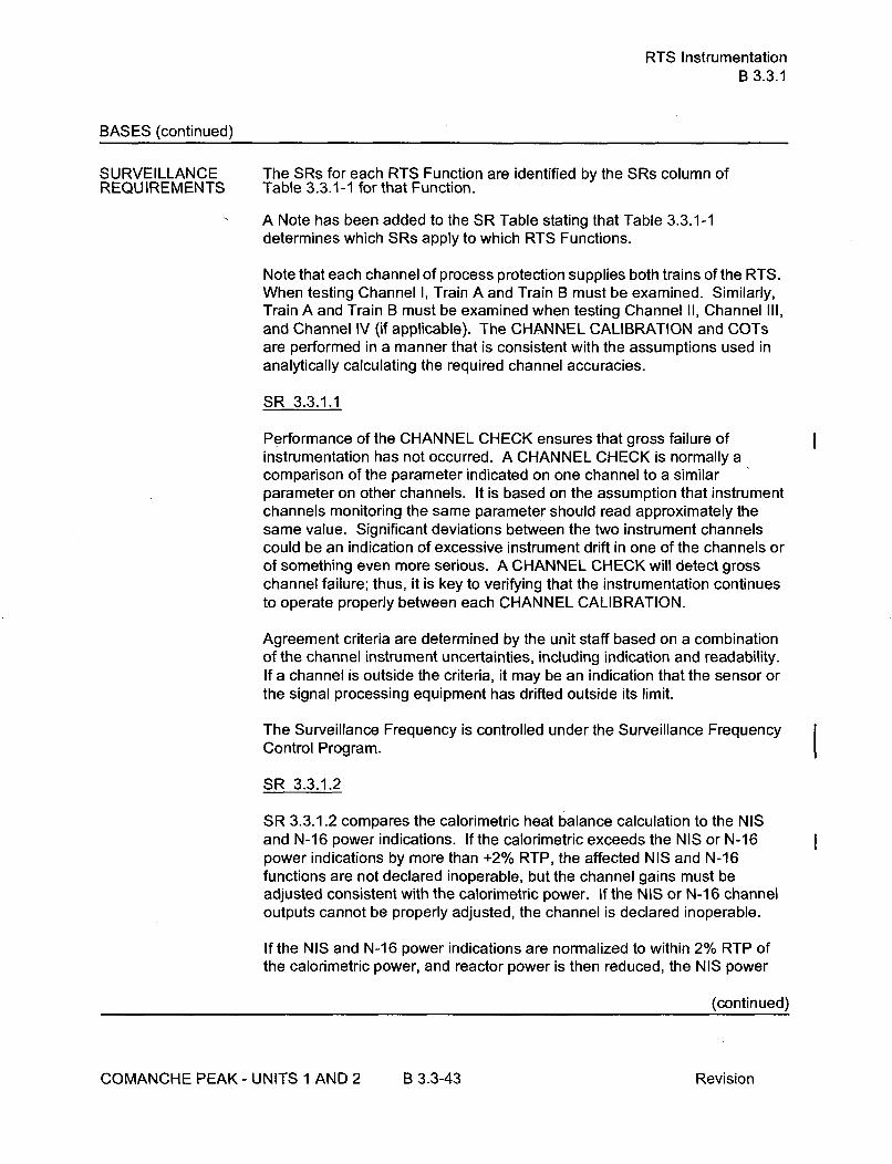
RTS InstrumentationB 3.3.1
BASES (continued)
SURVEILLANCE The SRs for each RTS Function are identified by the SRs column ofREQUIREMENTS Table 3.3.1-1 for that Function.
A Note has been added to the SR Table stating that Table 3.3.1-1determines which SRs apply to which RTS Functions.
Note that each channel of process protection supplies both trains of the RTS.When testing Channel I, Train A and Train B must be examined. Similarly,Train A and Train B must be examined when testing Channel II, Channel Ill,and Channel IV (if applicable). The CHANNEL CALIBRATION and COTsare performed in a manner that is consistent with the assumptions used inanalytically calculating the required channel accuracies.
SR 3.3.1.1
Performance of the CHANNEL CHECK ensures that gross failure ofinstrumentation has not occurred. A CHANNEL CHECK is normally acomparison of the parameter indicated on one channel to a similarparameter on other channels. It is based on the assumption that instrumentchannels monitoring the same parameter should read approximately thesame value. Significant deviations between the two instrument channelscould be an indication of excessive instrument drift in one of the channels orof something even more serious. A CHANNEL CHECK will detect grosschannel failure; thus, it is key to verifying that the instrumentation continuesto operate properly between each CHANNEL CALIBRATION.
Agreement criteria are determined by the unit staff based on a combinationof the channel instrument uncertainties, including indication and readability.If a channel is outside the criteria, it may be an indication that the sensor orthe signal processing equipment has drifted outside its limit.
The Surveillance Frequency is controlled under the Surveillance FrequencyControl Program.
SR 3.3.1.2
SR 3.3.1.2 compares the calorimetric heat balance calculation to the NISand N-16 power indications. If the calorimetric exceeds the NIS or N-16power indications by more than +2% RTP, the affected NIS and N-16functions are not declared inoperable, but the channel gains must beadjusted consistent with the calorimetric power. If the NIS or N-16 channeloutputs cannot be properly adjusted, the channel is declared inoperable.
If the NIS and N-16 power indications are normalized to within 2% RTP of
the calorimetric power, and reactor power is then reduced, the NIS power
(continued)
COMANCHE PEAK - UNITS 1 AND 2 B 3.3-43 Revision

RTS InstrumentationB 3.3.1
BASES
SURVEILLANCE SR 3.3.1.2 (continued)REQUIREMENTS
feedwater venturi. While the measurement uncertainty remains constant inAP as power decreases, when translated into flow, the uncertainty increasesas a square term. Thus, a 1% flow error at 100% power can approach a10% flow error at 30% RTP event though the AP error has not changed.
An evaluation of extended operations at reduced power conditions wouldlikely conclude that it is prudent to administratively adjust the setpoint of thePower Range Neutron Flux - High bistables to < 90% RTP when: 1) thePower Range channel output is adjusted in the decreasing power directiondue to a reduced power venturi-based calorimetric below 55% RTP; or 2) fora post refueling startup (consistent with the Bases for SR 3.4.1.4). Theevaluation of extended operation at reduced power conditions would alsolikely conclude that the potential need to adjust the indication of the PowerRange Neutron Flux in the decreasing power direction is quite small,primarily to address operation in the intermediate range about P-1 0(nominally 10% RTP) to allow enabling of the Power Range Neutron Flux -Low setpoint and the Intermediate Range Neutron Flux reactor trips. Beforethe Power Range Neutron Flux - High bistables are reset to their nominalvalue high setpoint, the NIS or N-16 power indication adjustment must beconfirmed based on LEFM-based calorimetric or on a venturi-basedcalorimetric performed at > 55% RTP.
The Note clarifies that this Surveillance is required only if reactor power is> 15% RTP and that 24 hours are allowed for performing the firstSurveillance after reaching 15% RTP. A power level of 15% RTP is chosenbased on plant stability; i.e., the turbine generator is synchronized to the gridand rod control is in the automatic mode. The 24-hour allowance afterincreasing THERMAL POWER above 15% RTP provides a reasonable timeto attain a scheduled power plateau, establish the requisite conditions,perform the required calorimetric measurement and make any requiredadjustments in a controlled, orderly manner and without introducing thepotential for extended operation at high power levels with instrumentationthat has not been verified to be acceptable for subsequent use.
The Surveillance Frequency is controlled under the Surveillance FrequencyControl Program.
S R 3.3.1.3
SR 3.3.1.3 compares the incore system to the NIS channel output. If theabsolute difference is _> 3%, the NIS channel is still OPERABLE, but must bereadjusted. The excore NIS channel shall be adjusted if the absolutedifference between the incore and excore AFD is > 3%.
(continued)
COMANCHE PEAK - UNITS I AND 2 B 3.3-45 Revision

RTS InstrumentationB 3.3.1
BASES
SURVEILLANCE SR 3.3.1.3 (continued)REQUIREMENTS
If the NIS channel cannot be properly readjusted, the channel is declaredinoperable. This Surveillance is performed to verify the f(Aq) input to theovertemperature N-16 Function.
A Note clarifies that the Surveillance is required only if reactor power is> 50% RTP and that 24 hours is allowed for performing the first Surveillanceafter reaching 50% RTP. The Note allows power ascensions and associatedtesting to be conducted in a controlled and orderly manner, at conditions thatprovide acceptable results and without introducing the potential for extendedoperation at high power levels with instrumentation that has not been verifiedto be OPERABLE. Due to such effects as shadowing from the relativelydeep control rod insertion and, to a lesser extent, the dependency of theaxially-dependent radial leakage on the power level, the relationshipbetween the incore and excore indications of axial flux difference (AFD) atlower power levels is variable. Thus, it is acceptable to defer the calibrationof the excore AFD against the incore AFD until more stable conditions areattained (i.e, withdrawn control rods and a higher power level). The AFD isused as an input to the Overtemperature N-16 reactor trip function and forassessing compliance with LCO 3.2.3, "Axial Flux Difference." Due to theDNB benefits gained by administratively restricting the power level to 50%RTP, no limits on AFD are imposed below 50% RTP by LCO 3.2.3; thus, theproposed change is consistent with the LCO 3.2.3 requirements below 50%RTP. Similarly, sufficient DNB margins are realized through operation below50% RTP that the intended function of the Overtemperature N-1 6 reactor tripfunction is maintained, even though the excore AFD indication may notexactly match the incore AFD indication. Based on plant operatingexperience, 24 hours is a reasonable time frame to limit operation above50% RTP while completing the procedural steps associated with thesurveillance in an orderly manner.
The Surveillance Frequency is controlled under the Surveillance FrequencyControl Program.
SR 3.3.1.4
SR 3.3.1.4 is the performance of a TADOT. This test shall verifyOPERABILITY by actuation of the end devices. The RTB test shall includeseparate verification of the undervoltage and shunt trip mechanisms.Independent verification of RTB undervoltage and shunt trip Function is notrequired for the bypass breakers. No capability is provided for performingsuch a test at power. The independent test for bypass breakers is includedin SR 3.3.1.14. The bypass breaker test shall include a local manual shunttrip. A Note has been added to indicate that this test must be performed onthe bypass breaker prior to placing it in service.
(continued)
COMANCHE PEAK - UNITS I AND 2 B 3.3-46 Revision

RTS InstrumentationB 3.3.1
BASES
SURVEILLANCE SR 3.3.1.4 (continued)REQUIREMENTS
The Surveillance Frequency is controlled under the Surveillance FrequencyControl Program.
S R 3.3.1.5
SR 3.3.1.5 is the performance of an ACTUATION LOGIC TEST. The SSPSis tested using the semiautomatic tester. The train being tested is placed inthe bypass condition, thus preventing inadvertent actuation. Through thesemiautomatic tester, all possible logic combinations, with and withoutapplicable permissives, are tested for each protection function. TheSurveillance Frequency is controlled under the Surveillance FrequencyControl Program.
S R 3.3.1.6
SR 3.3.1.6 is a calibration of the excore channels to the core powerdistribution measurement. If the measurements do not agree, the excorechannels are not declared inoperable but must be calibrated to agree withthe core power distribution measurements. If the excore channels cannot beadjusted, the channels are declared inoperable. This Surveillance isperformed to verify the f(Aq) input to the overtemperature N-1 6 Function.
A Note modifies SR 3.3.1.6. The Note states that this Surveillance isrequired only if reactor power is _> 75% RTP and that 72 hours is allowed forperforming the first surveillance after reaching equilibrium conditions at aTHERMAL POWER _> 75% RTP. The SR is deferred until a scheduledtesting plateau above 75% is attained during the post-outage powerascension. During a typical post-refueling power ascension, it is usuallynecessary to control the axial flux difference at lower power levels throughcontrol rod insertion. Due to rod shadowing effects and, to a lesser degree,the dependency of the axially-dependent radial leakage on the power level,the incore-excore AFD relationship well below 75% RTP may differexcessively from the incore-excore axial flux difference relationship at fullpower. Excore calibration adjustments should be based on the incore-excore multipoint relationship established above 75% RTP by use of thedeveloped calibration standard equations or by initiating an AFW swing andperforming a direct multipoint measurement. After equilibrium conditions areachieved at the specified power plateau, a full core flux map must be taken,and the required data collected. The data is typically analyzed and theappropriate excore calibrations are completed within 48 hours afterachieving equilibrium conditions. An additional time allowance of 24 hours isprovided during which the effects of equipment failures may be remediedand any required re-testing may be performed.
(continued)
COMANCHE PEAK - UNITS 1 AND 2 B 3.3-47 Revision

RTS InstrumentationB 3.3.1
BASES
SURVEILLANCE SR 3.3.1.6 (continued)REQUIREMENTS
The allowance of 72 hours after equilibrium conditions are attained at thetesting plateau provides sufficient time to allow power ascensions andassociated testing to be conducted in a controlled and orderly manner, atconditions that provide acceptable results and without introducing thepotential for extended operation at high power levels with instrumentationthat has not been verified to be acceptable for subsequent use. The benefitgained by operating at reduced power levels is sufficient to offset potentialdifferences between the incore and excore indications of Aq prior tocompletion of this surveillance.
The Surveillance Frequency is controlled under the Surveillance FrequencyControl Program.
SR 3.3.1.7
SR 3.3.1.7 is the performance of a COT. A COT is performed on eachrequired channel to ensure the channel will perform the intended Function.
Setpoints must be within the Allowable Values specified in Table 3.3.1-1.
SR 3.3.1.7 is modified by two Notes. Note 1 provides a 4 hour delay in therequirement to perform this Surveillance for source range instrumentationwhen entering MODE 3 from MODE 2. This Note allows a normal shutdownto proceed without a delay for testing in MODE 2 and for a short time inMODE 3 until the RTBs are open and SR 3.3.1.7 is no longer required to beperformed. If the unit is to be in MODE 3 with the RTBs closed for > 4 hoursthis Surveillance must be performed prior to 4 hours after entry into MODE 3.Note 2 requires that the quarterly COT for the source range instrumentationinclude verification by observation of the associated permissive annunciatorwindow that the P-6 and P-10 interlocks are in their required state for theexisting unit conditions.
SR 3.3.1.7 for selected Functions is also modified by two Notes (q and r) asidentified in Table 3.3.1-1. The selected Functions are those Functions thatare LSSS and whose instruments are not mechanical devices (i.e. limitswitches, float switches, and proximity detectors). Mechanical devices areexcluded since it is not possible to trend these devices and develop as-left oras-found limits in the same manner as other instrumentation. The first Note(q) requires evaluation of channel performance for the condition where theas-found setting for the channel setpoint is outside its as-found tolerance butconservative with respect to the Allowable Value. Evaluation of instrumentperformance will verify that the instrument will continue to behave inaccordance with design-basis assumptions. The purpose of the assessment
(continued)
COMANCHE PEAK - UNITS 1 AND 2 B 3.3-48 Revision

RTS InstrumentationB 3.3.1
BASES
SURVEILLANCE SR 3.3.1.7 (continued)REQUIREMENTS
is to ensure confidence in the instrument performance prior to returning theinstrument to service. These channels will also be identified in theCorrective Action Program. In accordance with procedures, entry into theCorrective Action Program will require review and documentation of thecondition for OPERABILITY. The second Note requires that the as-leftsetting for the instrument be returned to within the as-left tolerance of theNominal Trip Setpoint. This will ensure that sufficient margin to the SafetyLimit and/or Analytical Limit is maintained. If the as-left instrument settingcannot be returned to a setting within the as-left tolerance, then theinstrument channel shall be declared inoperable. This second Note (r)requirement identifies the Limited Safety System Setting and allows anindependent verification that the Allowable Value is the appropriate leastconservative as-found value during SR testing.
The Surveillance Frequency is controlled under the Surveillance FrequencyControl Program.
SR 3.3.1.8
SR 3.3.1.8 is the performance of a COT as described in SR 3.3.1.7, and it ismodified by the same Note that this test shall include verification that the P-6and P-10 interlocks are in their required state for the existing unit conditions.The Frequency is modified by a Note that allows this surveillance to besatisfied if it has been performed e.g., by observation of the associatedpermissive annunciator window, within the Frequency specified in theSurveillance Frequency Control Program prior to reactor startup, up to 12hours after reducing power below P-10, and four hours after reducingpower below P-6, as discussed below. The Frequency of "prior tostartup" ensures this surveillance is performed prior to critical operations andapplies to the source, intermediate and power range low instrumentchannels. The Frequency of "12 hours after reducing power below P-10"(applicable to intermediate and power range low channels) and "4 hoursafter reducing power below P-6" (applicable to source range channels)allows a normal shutdown to be completed and the unit removed from theMODE of Applicability for this surveillance without a delay to perform thetesting required by this surveillance. The Frequency thereafter applies if theplant remains in the MODE of Applicability after the initial performances ofprior to reactor startup, 12 hours after reducing power below P-10, and fourhours after reducing power below P-6. The MODE of Applicability for thissurveillance is < P-10 for the power range low and intermediate rangechannels and < P-6 for the source range channels. Once the unit is inMODE 3, this surveillance is no longer required. If power is to be maintained< P-10 for more than 12 hours or < P-6 for more than 4 hours,
(continued)
COMANCHE PEAK - UNITS 1 AND 2 B 3.3-49 Revision

RTS InstrumentationB 3.3.1
BASES
SURVEILLANCE SR 3.3.1.8 (continued)REQUIREMENTS
then the testing required by this surveillance must be performed prior to theexpiration of the 12 hour or 4 hour limit, as applicable. These time limits arereasonable, based on operating experience, to complete the required testingor place the unit in a MODE where this surveillance is no longer required.This test ensures that the NIS source, intermediate, and power range lowchannels are OPERABLE prior to taking the reactor critical and afterreducing power into the applicable MODE (< P-1 0 or < P-6) for the periodsdiscussed above. The Surveillance Frequency is controlled under theSurveillance Frequency Control Program.
SR 3.3.1.9
SR 3.3.1.9 is the performance of a TADOT. The Surveillance Frequency iscontrolled under the Surveillance Frequency Control Program.
This SR is modified by a Note that excludes verification of setpoints from theTADOT. Since this SR applies to RCP undervoltage and underfrequencyrelays, setpoint verification requires elaborate bench calibration and isaccomplished during the CHANNEL CALIBRATION.
SR 3.3.1.10
CHANNEL CALIBRATION is a complete check of the instrument loop,including the sensor. The test verifies that the channel responds to ameasured parameter within the necessary range and accuracy.
This SR is modified by Note 1 stating that N-16 detectors are excluded fromthe CHANNEL CALIBRATION because the unit must be in at least MODE 1to obtain N-16 indications. However, after achieving equilibrium conditionsin MODE 1, detector plateau curves should be obtained, evaluated andcompared to manufacturer's data.
CHANNEL CALIBRATIONS must be performed consistent with theassumptions of the setpoint methodology.
The Surveillance Frequency is controlled under the Surveillance FrequencyControl Program.
SR 3.3.1.10 is modified by Note 2 stating that this test shall includeverification that the time constants are adjusted to the prescribed valueswhere applicable. This surveillance does not include verification of timedelay relays. These relays are verified via response time testing perSR 3.3.1.16. Whenever an RTD is replaced in Functions 6 or 7, the next
(continued)
COMANCHE PEAK - UNITS 1 AND 2 B 3.3-50 Revision
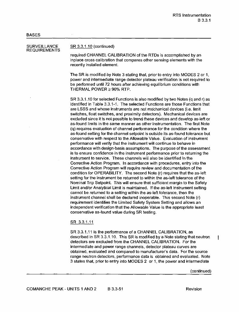
RTS InstrumentationB 3.3.1
BASES
SURVEILLANCE SR 3.3.1.10 (continued)REQUIREMENTS
required CHANNEL CALIBRATION of the RTDs is accomplished by aninplace cross calibration that compares other sensing elements with therecently installed element.
The SR is modified by Note 3 stating that, prior to entry into MODES 2 or 1,power and intermediate range detector plateau verification is not required tobe performed until 72 hours after achieving equilibrium conditions withTHERMAL POWER > 90% RTP.
SR 3.3.1.10 for selected Functions is also modified by two Notes (q and r) asidentified in Table 3.3.1-1. The selected Functions are those Functions thatare LSSS and whose instruments are not mechanical devices (i.e. limitswitches, float switches, and proximity detectors). Mechanical devices areexcluded since it is not possible to trend these devices and develop as-left oras-found limits in the same manner as other instrumentation. The first Note(q) requires evaluation of channel performance for the condition where theas-found setting for the channel setpoint is outside its as-found tolerance butconservative with respect to the Allowable Value. Evaluation of instrumentperformance will verify that the instrument will continue to behave inaccordance with design-basis assumptions. The purpose of the assessmentis to ensure confidence in the instrument performance prior to returning theinstrument to service. These channels will also be identified in theCorrective Action Program. In accordance with procedures, entry into theCorrective Action Program will require review and documentation of thecondition for OPERABILITY. The second Note (r) requires that the as-leftsetting for the instrument be returned to within the as-left tolerance of theNominal Trip Setpoint. This will ensure that sufficient margin to the SafetyLimit and/or Analytical Limit is maintained. If the as-left instrument settingcannot be returned to a setting within the as-left tolerance, then theinstrument channel shall be declared inoperable. This second Note (r)requirement identifies the Limited Safety System Setting and allows anindependent verification that the Allowable Value is the appropriate leastconservative as-found value during SR testing.
SR 3.3.1.11
SR 3.3.1.11 is the performance of a CHANNEL CALIBRATION, asdescribed in SR 3.3.1.10. This SR is modified by a Note stating that neutrondetectors are excluded from the CHANNEL CALIBRATION. For theintermediate and power range channels, detector plateau curves areobtained, evaluated and compared to manufacturer's data. For the sourcerange neutron detectors, performance data is obtained and evaluated. Note3 states that, prior to entry into MODES 2 or 1, the power and intermediate
(continued)
COMANCHE PEAK - UNITS 1 AND 2 B 3.3-51 Revision

RTS InstrumentationB 3.3.1
BASES
SURVEILLANCE SR 3.3.1.11 (continued)REQUIREMENTS
range detector plateau voltage verification is not required to be current until72 hours after achieving equilibrium conditions with THERMAL POWER> 90% RTP. Equilibrium conditions are achieved when the core issufficiently stable at intended operating conditions to perform a meaningfuldetector plateau voltage verification. The allowance of 72 hours afterequilibrium conditions are attained at the testing plateau provides sufficienttime to allow power ascension testing to be conducted in a controlled andorderly manner at conditions that provide acceptable results and withoutintroducing the potential for extended operation at high power levels withinstrumentation that has not been verified to be OPERABLE for subsequentuse. The Surveillance Frequency is controlled under the SurveillanceFrequency Control Program.
SR 3.3.1.11 is modified by Note 2 stating that this test shall includeverification that the time constants are adjusted to the prescribed valueswhere applicable. This surveillance does not include verification of timedelay relays. These relays are verified via response time testing perSR 3.3.1.16.
SR 3.3.1.12
Not Used.
SR 3.3.1.13
SR 3.3.1.13 is the performance of a COT of RTS interlocks.
The Surveillance Frequency is controlled under the Surveillance FrequencyControl Program.
SR 3.3.1.14
SR 3.3.1.14 is the performance of a TADOT of the Manual Reactor Trip, andthe SI Input from ESFAS, and the Reactor Trip Bypass Breaker undervoltagetrip mechanisms.
The Manual Reactor Trip TADOT shall independently verify theOPERABILITY of the handswitch undervoltage and shunt trip contacts forboth the Reactor Trip Breakers and Reactor Trip Bypass Breakers. TheReactor Trip Bypass Breaker test shall include testing of the automaticundervoltage trip mechanism.
The Surveillance Frequency is controlled under the Surveillance FrequencyControl Program.
(continued)
COMANCHE PEAK - UNITS 1 AND 2 B 3-3-52 Revision

RTS InstrumentationB 3.3.1
BASES
SURVEILLANCE SR 3.3.1.14 (continued)REQUIREMENTS
The SR is modified by a Note that excludes verification of setpoints from theTADOT. The Functions affected have no setpoints associated with them.
SR 3.3.1.15
SR 3.3.1.15 is the performance of a TADOT of Turbine Trip Functions. ThisTADOT is as described in SR 3.3.1.4, except that this test is performed priorto exceeding the P-9 interlock whenever the unit has been in MODE 3. TheSurveillance Frequency is controlled under the Surveillance Frequency ControlProgram. Verification of the Trip Setpoint does not have to be performed forthis Surveillance. Performance of this test will ensure that the turbine tripFunction is OPERABLE prior to exceeding the P-9 interlock.
SR 3.3.1.16
SR 3.3.1.16 verifies that the individual channel/train actuation responsetimes are less than or equal to the maximum values assumed in the accidentanalysis. The required trip initiation signals and acceptance criteria forresponse time testing are included in Technical Requirements Manual,(Ref. 6). No credit was taken in the safety analyses for those channels withresponse time listed as N.A. No response time testing requirements applywhere N.A. is listed in the TRM. Individual component response times arenot modeled in the analyses. The analyses model the overall or totalelapsed time, from the point at which the parameter exceeds the trip setpointvalue at the sensor until loss of stationary gripper coil voltage.
For channels that include dynamic transfer Functions (e.g., lag, lead/lag,rate/lag, etc.), the response time test may be performed with the transferFunction time constants set at their nominal values.
Response time may be verified by actual response time tests in any series ofsequential, overlapping or total channel measurements, or by the summationof allocated sensor, signal processing and actuation logic response timeswith actual response time tests on the remainder of the channel. Allocationsfor sensor response times may be used for selected components providedthat the components and methodology for verification have been previouslyNRC approved.
The Surveillance Frequency is controlled under the Surveillance FrequencyControl Program. Response time verification in lieu of actual testing may beperformed on RTS components in accordance with reference 10.
SR 3.3.1.16 is modified by a Note stating that neutron and N-16 gamma
(continued)
COMANCHE PEAK - UNITS 1 AND 2 B 3.3-53 Revision

ESFAS InstrumentationB 3.3.2
BASES
ACTIONS L.1, L.2.1 and L.2.2 (continued)
With one or more required channel(s) inoperable, the operator must verifythat the interlock is in the required state for the existing unit condition byobservation of the permissive annunciator windows. This action manuallyaccomplishes the function of the interlock. Determination must be madewithin 1 hour. The 1 hour Completion Time is equal to the time allowed byLCO 3.0.3 to initiate shutdown actions in the event of a complete loss ofESFAS function. If the interlock is not in the required state (or placed in therequired state) for the existing unit condition, the unit must be placed inMODE 3 within the next 6 hours and MODE 4 within the following 6 hours.The allowed Completion Times are reasonable, based on operatingexperience, to reach the required unit conditions from full power conditions inan orderly manner and without challenging unit systems. Placing the unit inMODE 4 removes all requirements for OPERABILITY of these interlocks.
SURVEILLANCE The SRs for each ESFAS Function are identified by the SRs column ofREQUIREMENTS Table 3.3.2-1.
A Note has been added to the SR Table to clarify that Table 3.3.2-1determines which SRs apply to which ESFAS Functions.
Note that each channel of process protection supplies both trains of theESFAS. When testing channel I, train A and train B must be examined.Similarly, train A and train B must be examined when testing channel II,channel III, and channel IV. The CHANNEL CALIBRATION and COTs areperformed in a manner that is consistent with the assumptions used inanalytically calculating the required channel accuracies.
SR 3.3.2.1
Performance of the CHANNEL CHECK ensures that a gross failure ofinstrumentation has not occurred. A CHANNEL CHECK is normally acomparison of the parameter indicated on one channel to a similarparameter on other channels. It is based on the assumption that instrumentchannels monitoring the same parameter should read approximately thesame value.
Significant deviations between the two instrument channels could be anindication of excessive instrument drift in one of the channels or ofsomething even more serious. A CHANNEL CHECK will detect grosschannel failure; thus, it is key to verifying the instrumentation continues tooperate properly between each CHANNEL CALIBRATION.
(continued)
COMANCHE PEAK - UNITS 1 AND 2 B 3.3-98 Revision

ESFAS InstrumentationB 3.3.2
BASES
SURVEILLANCE SR 3.3.2.1 (continued)REQUIREMENTS
Agreement criteria are determined by the unit staff, based on a combinationof the channel instrument uncertainties, including indication and reliability. Ifa channel is outside the criteria, it may be an indication that the sensor or thesignal processing equipment has drifted outside its limit.
The Surveillance Frequency is controlled under the Surveillance FrequencyControl Program.
SR 3.3.2.2
SR 3.3.2.2 is the performance of an ACTUATION LOGIC TEST using thesemiautomatic tester. The train being tested is placed in the bypasscondition, thus preventing inadvertent actuation. Through the semiautomatictester, all possible logic combinations, with and without applicablepermissives, are tested for each protection function. In addition, the masterrelay coil is pulse tested for continuity. This verifies that the logic modulesare OPERABLE and that there is an intact voltage signal path to the masterrelay coils. The Surveillance Frequency is controlled under the SurveillanceFrequency Control Program.
SIR 3.3.2.3
Not used.
S R 3.3.2.4
SR 3.3.2.4 is the performance of a MASTER RELAY TEST. The MASTERRELAY TEST is the energizing of the master relay, verifying contactoperation and a low voltage continuity check of the slave relay coil. Uponmaster relay contact operation, a low voltage is injected to the slave relaycoil. This voltage is insufficient to pick up the slave relay, but large enoughto demonstrate signal path continuity. The time allowed for the testing(4 hours) is justified in Reference 6. The Surveillance Frequency iscontrolled under the Surveillance Frequency Control Program.
S R 3.3.2.5
SR 3.3.2.5 is the performance of a COT.
A COT is performed on each required channel to ensure the entire channelwill perform the intended Function. Setpoints must be found within theAllowable Values specified in Table 3.3.2-1.
(continued)
COMANCHE PEAK - UNITS I AND 2 B 3.3-99 Revision

ESFAS InstrumentationB 3.3.2
BASES
SURVEILLANCE SR 3.3.2.5 (continued)REQUIREMENTS
The difference between the current "as found" values and the previous test"as left" values must be consistent with the drift allowance used in thesetpoint calculation. The setpoint shall be left set consistent with theassumptions of the current unit specific setpoint calculation.
SR 3.3.2.5 for selected Functions is also modified by two Notes (q and r) asidentified in Table 3.3.2-1. The selected Functions are those Functions thatare LSSS and whose instruments are not mechanical devices (i.e. limitswitches, float switches, and proximity detectors). Mechanical devices areexcluded since it is not possible to trend these devices and develop as-left oras-found limits in the same manner as other instrumentation. The first Note(q) requires evaluation of channel performance for the condition where theas-found setting for the channel setpoint is outside its as-found tolerance butconservative with respect to the Allowable Value. Evaluation of instrumentperformance will verify that the instrument will continue to behave inaccordance with design-basis assumptions. The purpose of the assessmentis to ensure confidence in the instrument performance prior to returning theinstrument to service. These channels will also be identified in theCorrective Action Program. In accordance with procedures, entry into theCorrective Action Program will require review and documentation of thecondition for OPERABILITY. The second Note requires that the as-leftsetting for the instrument be returned to within the as-left tolerance of theNominal Trip Setpoint. This will ensure that sufficient margin to the SafetyLimit and/or Analytical Limit is maintained. If the as-left instrument settingcannot be returned to a setting within the as-left tolerance, then theinstrument channel shall be declared inoperable. This second Note (r)requirement identifies the Limited Safety System Setting and allows anindependent verification that the Allowable Value is the appropriate leastconservative as-found value during SR testing.
The Surveillance Frequency is controlled under the Surveillance Frequency
Control Program.
SR 3.3.2.6
SR 3.3.2.6 is the performance of a SLAVE RELAY TEST. The SLAVERELAY TEST is the energizing of the slave relays. Contact operation isverified in one of two ways. Actuation equipment that may be operated in thedesign mitigation mode is either allowed to function, or is placed in acondition where the relay contact operation can be verified without operationof the equipment. Actuation equipment that may not be operated in thedesign mitigation mode is prevented from operation by the SLAVE RELAYTEST circuit. For this latter case, contact operation is verified by a continuity
(continued)
COMANCHE PEAK - UNITS I AND 2 B 3.3-100 Revision

ESFAS InstrumentationB 3.3.2
BASES
SURVEILLANCE SR 3.3.2.6 (continued)REQU IREMENTS
check of the circuit containing contacts operated by the slave relay. TheSurveillance Frequency is controlled under the Surveillance FrequencyControl Program.
For ESFAS slave relays and auxiliary relays which are Westinghouse typeAR relays, the slave relay reliability assessment presented in Reference 10is relay specific and applies only to Westinghouse type AR relays with ACcoils. Note that, for normally energized applications, the relays may requireperiodic replacement in accordance with the guidance given in Reference10.
SR 3.3.2.7
SR 3.3.2.7 is the performance of a TADOT. This test is a check of the Lossof Offsite Power Function.
The SR is modified by a Note that excludes verification of setpoints forrelays. Relay setpoints require elaborate bench calibration and are verifiedduring CHANNEL CALIBRATION. The SR is modified by a second note thatexcludes the actuation of final devices from the surveillance testing. Thestart of the auxiliary feedwater pumps during this SR is unnecessary asthese pumps are adequately tested by the SRs for LCO 3.7.5. TheSurveillance Frequency is controlled under the Surveillance FrequencyControl Program.
SR 3.3.2.8
SR 3.3.2.8 is the performance of a TADOT. This test is a check of theManual Actuation Functions and AFW pump start on trip of all MFW pumps.The Safety Injection TADOT shall independently verify the OPERABILITY ofthe handswitch undervoltage and shunt trip contacts for both the ReactorTrip Breakers and Reactor Trip Bypass Breakers as well as the contacts forsafety injection actuation. As a minimum, each Manual Actuation Function istested up to, but not including, the master relay coils. This test overlaps withthe master relay coil testing performed in accordance with SR 3.3.2.4. TheSurveillance Frequency is controlled under the Surveillance FrequencyControl Program. The SR is modified by a Note that excludes verification ofsetpoints during the TADOT for manual initiation Functions. The manualinitiation Functions have no associated setpoints.
SR 3.3.2.9
SR 3.3.2.9 is the performance of a CHANNEL CALIBRATION.
(continued)
COMANCHE PEAK - UNITS 1 AND 2 B 3.3-101 Revision

ESFAS InstrumentationB 3.3.2
BASES
SURVEILLANCE SR 3.3.2.9 (continued)REQUIREMENTS
A CHANNEL CALIBRATION is a complete check of the instrument loop,including the sensor. The test verifies that the channel responds tomeasured parameter within the necessary range and accuracy.
CHANNEL CALIBRATIONS must be performed consistent with theassumptions of the unit specific setpoint methodology.
The Surveillance Frequency is controlled under the Surveillance FrequencyControl Program.
This SR is modified by a Note stating that this test should include verificationthat the time constants are adjusted to the prescribed values whereapplicable.
SR 3.3.2.9 for selected Functions is also modified by two Notes (q and r) asidentified in Table 3.3.2-1. The selected Functions are those Functions thatare LSSS and whose instruments are not mechanical devices (i.e. limitswitches, float switches, and proximity detectors). Mechanical devices areexcluded since it is not possible to trend these devices and develop as-left oras-found limits in the same manner as other instrumentation. The first Note(q) requires evaluation of channel performance for the condition where theas-found setting for the channel setpoint is outside its as-found tolerance butconservative with respect to the Allowable Value. Evaluation of instrumentperformance will verify that the instrument will continue to behave inaccordance with design-basis assumptions. The purpose of the assessmentis to ensure confidence in the instrument performance prior to returning theinstrument to service. These channels will also be identified in theCorrective Action Program. In accordance with procedures, entry into theCorrective Action Program will require review and documentation of thecondition for OPERABILITY. The second Note (r) requires that the as-leftsetting for the instrument be returned to within the as-left tolerance of theNominal Trip Setpoint. This will ensure that sufficient margin to the SafetyLimit and/or Analytical Limit is maintained. If the as-left instrument settingcannot be returned to a setting within the as-left tolerance, then theinstrument channel shall be declared inoperable. This second Note (r)requirement identifies the Limited Safety System Setting and allows anindependent verification that the Allowable Value is the appropriate leastconservative as-found value during SR testing.
SR 3.3.2.10
This SR ensures the individual channel ESF RESPONSE TIMES are lessthan or equal to the maximum values assumed in the accident analysis.
(continued)
COMANCHE PEAK - UNITS 1 AND 2 B 3-3-102 Revision

ESFAS InstrumentationB 3.3.2
BASES
SURVEILLANCE SR 3.3.2.10 (continued)REQUIREMENTS
Response Time testing, required channels, and acceptance criteria areincluded in the Technical Requirements Manual (Ref. 7). For eachFunctional Unit to which this SR applies, at least one ESF function has arequired response time but not necessarily all associated ESF functions. Nocredit was taken in the safety analyses for those channels with responsetime listed as N.A. When the response time for a function in the TRM is NA,no specific testing need be performed to comply with this SR. Individualcomponent response times are not modeled in the analyses. The analysesmodel the overall or total elapsed time, from the point at which the parameterexceeds the Trip Setpoint value at the sensor, to the point at which theequipment in both trains reaches the required functional state (e.g., pumpsat rated discharge pressure, valves in full open or closed position).
For channels that include dynamic transfer functions (e.g., lag, lead/lag, rate/lag, etc.), the response time testing may be performed with the transferfunctions set at their nominal values. The response time may be measuredby a series of overlapping tests such that the entire response time ismeasured.
Response time may be verified by actual response time tests in any series ofsequential, overlapping or total channel measurements, or by the summationof allocated sensor, signal processing and actuation logic response timeswith actual response time tests on the remainder of the channel. Allocationsfor sensor response times may be used for selected components providedthat the components and methodology for verification have been previouslyNRC approved.
The Surveillance Frequency is controlled under the Surveillance FrequencyControl Program. Response time verification in lieu of actual testing may beperformed on ESFAS components in accordance with reference 11.
This SR is modified by a Note that clarifies that the turbine driven AFW pumpis tested within 24 hours after reaching 532 psig in the SGs.
SR 3.3.2.11
SR 3.3.2.11 is the performance of a TADOT as described in SR 3.3.2.8,except that it is performed for the P-4 Reactor Trip Interlock. TheSurveillance Frequency is controlled under the Surveillance FrequencyControl Program.
The SR is modified by a Note that excludes verification of setpoints duringthe TADOT. The Function tested has no associated setpoint.
(continued)
COMANCHE PEAK - UNITS 1 AND 2 B 3.3-103 Revision

PAM InstrumentationB 3.3.3
BASES
ACTIONS (continued)
E.1 and E.2
If the Required Action and associated Completion Time of Condition C is notmet and Table 3.3.3-1 directs entry into Condition E, the unit must bebrought to a MODE where the requirements of this LCO do not apply. Toachieve this status, the unit must be brought to at least MODE 3 within 6hours and MODE 4 within 12 hours.
The allowed Completion Times are reasonable, based on operatingexperience, to reach the required unit conditions from full power conditions inan orderly manner and without challenging unit systems.
F.1
Alternate means of monitoring Reactor Vessel Water Level and ContainmentArea Radiation have been developed. These alternate means may betemporarily used if the normal PAM channel cannot be restored toOPERABLE status within the allotted time. If these alternate means areused, the Required Action is not to shut down the unit but rather to follow thedirections of Specification 5.6.8, in the Administrative Controls section of theTS. The report provided to the NRC should discuss the alternate meansused, describe the degree to which the alternate means are equivalent to theinstalled PAM channels, justify the areas in which they are not equivalent,and provide a schedule for restoring the normal PAM channels.
SURVEILLANCE A Note has been added to the SR Table to clarify that SR 3.3.3.1 and
REQUIREMENTS SR 3.3.3.3 apply to each PAM instrumentation Function in Table 3.3.3-1.
SR 3.3.3.1
Performance of the CHANNEL CHECK ensures that a gross instrumentationfailure has not occurred. A CHANNEL CHECK is normally a comparison ofthe parameter indicated on one channel to a similar parameter on otherchannels. It is based on the assumption that instrument channels monitoringthe same parameter should read approximately the same value. Significantdeviations between the two instrument channels could be an indication ofexcessive instrument drift in one of the channels or of something even moreserious. A CHANNEL CHECK will detect gross channel failure; thus, it is keyto verifying the instrumentation continues to operate properly between eachCHANNEL CALIBRATION.
(continued)
COMANCHE PEAK - UNITS I AND 2 B 3.3-120 Revision

PAM InstrumentationB 3.3.3
BASES
SURVEILLANCE SR 3.3.3.1 (continued)REQUIREMENTS
Agreement criteria are determined by the unit staff, based on a combinationof the channel instrument uncertainties, including isolation, indication, andreadability. If a channel is outside the criteria, it may be an indication that thesensor or the signal processing equipment has drifted outside its limit. If thechannels are within the criteria, it is an indication that the channels areOPERABLE.
As specified in the SR, a CHANNEL CHECK is only required for thosechannels that are normally energized. All of the instruments listed inTable 3.3.3-1 are normally energized.
The Surveillance Frequency is controlled under the Surveillance FrequencyControl Program.
SR 3.3.3.2
Deleted
SR 3.3.3.3
CHANNEL CALIBRATION is a complete check of the instrument loop,including the sensor. The test verifies that the channel responds tomeasured parameter with the necessary range and accuracy. Thecalibration method for neutron detectors is specified in the Bases ofLCO 3.3.1, "Reactor Trip System (RTS) Instrumentation." Whenever anRTD is replaced in Function 3 or 4, the next required CHANNELCALIBRATION of the RTDs is accomplished by an inplace cross calibrationthat compares other sensing elements with the recently installed element.Whenever a core exit thermocouple replaced in Functions 15 thru 18, thenext required CHANNEL CALIBRATION of the core exit thermocouples isaccomplished by an in-place cross calibration that compares the othersensing elements with the recently installed sensing element. TheSurveillance Frequency is controlled under the Surveillance FrequencyControl Program. Containment Radiation Level (High Range) CHANNELCALIBRATION may consist of an electronic calibration of the channel, notincluding the detector, for range decades above 1OR/hr and a one pointcalibration check of the detector below 1OR/hr with an installed or portablegamma source.
(continued)
COMANCHE PEAK - UNITS 1 AND 2 B 3.3-121 Revision
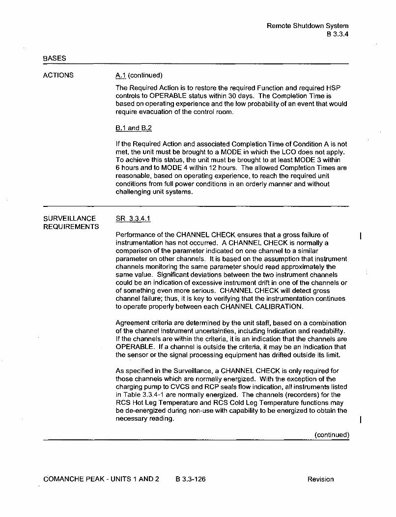
Remote Shutdown SystemB 3.3.4
BASES
ACTIONS A.1 (continued)
The Required Action is to restore the required Function and required HSPcontrols to OPERABLE status within 30 days. The Completion Time isbased on operating experience and the low probability of an event that wouldrequire evacuation of the control room.
B.1 and B.2
If the Required Action and associated Completion Time of Condition A is notmet, the unit must be brought to a MODE in which the LCO does not apply.To achieve this status, the unit must be brought to at least MODE 3 within6 hours and to MODE 4 within 12 hours. The allowed Completion Times arereasonable, based on operating experience, to reach the required unitconditions from full power conditions in an orderly manner and withoutchallenging unit systems.
SURVEILLANCE SR 3.3.4.1REQUIREMENTS
Performance of the CHANNEL CHECK ensures that a gross failure ofinstrumentation has not occurred. A CHANNEL CHECK is normally acomparison of the parameter indicated on one channel to a similarparameter on other channels. It is based on the assumption that instrumentchannels monitoring the same parameter should read approximately thesame value. Significant deviations between the two instrument channelscould be an indication of excessive instrument drift in one of the channels orof something even more serious. CHANNEL CHECK will detect grosschannel failure; thus, it is key to verifying that the instrumentation continuesto operate properly between each CHANNEL CALIBRATION.
Agreement criteria are determined by the unit staff, based on a combinationof the channel instrument uncertainties, including indication and readability.If the channels are within the criteria, it is an indication that the channels areOPERABLE. If a channel is outside the criteria, it may be an indication thatthe sensor or the signal processing equipment has drifted outside its limit.
As specified in the Surveillance, a CHANNEL CHECK is only required forthose channels which are normally energized. With the exception of thecharging pump to CVCS and RCP seals flow indication, all instruments listedin Table 3.3.4-1 are normally energized. The channels (recorders) for theRCS Hot Leg Temperature and RCS Cold Leg Temperature functions maybe de-energized during non-use with capability to be energized to obtain thenecessary reading.
(continued)
COMANCHE PEAK - UNITS 1 AND 2 B 3.3-126 Revision

Remote Shutdown SystemB 3.3.4
BASES
SURVEILLANCE SR 3.3.4.1 (continued)REQU IREMENTS
The Surveillance Frequency is controlled under the Surveillance FrequencyControl Program.
SR 3.3.4.2
SR 3.3.4.2 verifies each required Remote Shutdown System HSP power andcontrol circuit and transfer switch performs the intended function. Thisverification is performed from the Hot Shutdown Panel and locally, asappropriate. Operation of the equipment from the remote shutdown panel isnot necessary. The Surveillance can be satisfied by performance of acontinuity check. This will ensure that if the control room becomesinaccessible, the unit can be placed and maintained in MODE 3 from theremote shutdown panel and the local control stations. The SurveillanceFrequency is controlled under the Surveillance Frequency Control Program.
SR 3.3.4.3
CHANNEL CALIBRATION is a complete check of the instrument loop andthe sensor. The test verifies that the channel responds to a measuredparameter within the necessary range and accuracy. Whenever a sensingelement is replaced, the next required CHANNEL CALIBRATION of theresistance temperature detectors (RTD) sensors is accomplished by an in-place cross calibration that compares the other sensing elements with therecently installed sensing element. The Surveillance Frequency is controlledunder the Surveillance Frequency Control Program.
REFERENCES 1. 10 CFR 50, Appendix A, GDC 3 and 19.
2. FSAR Section 7.4
COMANCHE PEAK - UNITS 1 AND 2 B 3.3-127 Revision

LOP DG Start InstrumentationB 3.3.5
BASES
ACTIONS (continued)
F. 1
Condition F applies when one or more trains of Automatic Actuation Logicand Actuation Relay function are inoperable.
Required Action F.1 requires restoring the inoperable train(s) to OPERABLEstatus. The 1 hour completion Time allows time to repair failures and takesinto account the low probability of an event requiring LOP DG start occurringduring this interval.
G.1
Condition G applies to each of the LOP DG start Functions when theRequired Action and associated Completion Time for Conditions A through Fare not met.
In these circumstances the Conditions specified in LCO 3.8.1, "AC Sources -Operating," for the DG made inoperable by failure of the LOP DG startinstrumentation are required to be entered immediately. The actions ofthose LCOs provide for adequate compensatory actions to assure unitsafety.
SURVEILLANCE SR 3.3.5.1REQUIREMENTS
SR 3.3.5.1 is the performance of an ACTUATION LOGIC TEST. The LOPDG Start Automatic Actuation Logic and Actuation Relays are tested prior toentering MODE 4 when in MODE 5 for greater than or equal to 72 hours andif not performed in the previous 92 days. The Function is tested prior toentering MODE 4 to assure that the associated diesel generator is notunnecessarily started by the testing. Such unnecessary starts could beadverse to the reliability of the diesel generator. The testing verifies that thelogic is OPERABLE. The Frequency of the testing is adequate. The72 hours assures that there is sufficient time during the shutdown to performthe testing. The 92 days is based on industry operating experience,considering instrument reliability and operating history data.
SR 3.3.5.2
SR 3.3.5.2 is the performance of a TADOT. This test is performed prior toentry into MODE 4 when in MODE 5 for > 72 hours and if not performed inprevious 92 days. The test checks trip devices that provide actuation signalsdirectly, bypassing the analog process control equipment.
(continued)
COMANCHE PEAK - UNITS 1 AND 2 B 3.3-134 Revision

LOP DG Start InstrumentationB 3.3.5
BASES
SURVEILLANCE REQUIREMENTS (continued)
SR 3.3.5.3
SR 3.3.5.3 is the performance of a CHANNEL CALIBRATION.
CHANNEL CALIBRATION is a complete check of the instrument loop,including the sensor. The test verifies that the channel responds to ameasured parameter within the necessary range and accuracy.
The Surveillance Frequency is controlled under the Surveillance FrequencyControl Program.
SR 3.3.5.4
SR 3.3.5.4 is the performance of the required response time verification (seealso SR 3.3.2.10) on those functions with time limits provided in theTechnical Requirements Manual. The Surveillance Frequency is controlledunder the Surveillance Frequency Control Program.
REFERENCES 1. FSAR, Section 8.3.
2. FSAR, Chapter 15.
COMANCHE PEAK - UNITS 1 AND 2 B 3.3-135 Revision

Containment Ventilation Isolation InstrumentationB 3.3.6
BASES
ACTIONS B.1 (continued)(continued)
If a train is inoperable, or the Required Action and associated CompletionTime of Condition A are not met, operation may continue as long as theRequired Action for the applicable Conditions of LCO 3.6.3 is met for eachvalve made inoperable by failure of isolation instrumentation.
A Note is added to allow the containment pressure relief valves to be openedin compliance with the gaseous effluent monitoring instrumentationrequirements in Part I of the ODCM, for Required Action and associatedCompletion Time of Condition A not met.
A Note is added stating that Condition B is only applicable in MODE 1, 2, 3,
or4.
C.1 and C.2
Condition C applies to the inability to restore the radiation monitoringchannel to OPERABLE status in the time allowed for Required Action A.1. Ifthe Required Action and associated Completion Time of Condition A are notmet, operation may continue as long as the Required Action to place andmaintain containment ventilation isolation valves in their closed position ismet or the applicable Conditions of LCO 3.9.4, "Containment Penetrations,"are met for each valve made inoperable by failure of isolationinstrumentation. A note allows the containment pressure relief valves to beopened in compliance with gaseous effluent monitoring instrumentationrequirements in Part I of the ODCM. The Completion Time for theseRequired Actions is Immediately.
A Note states that Condition C is applicable during CORE ALTERATIONSand during movement of irradiated fuel assemblies within containment.
SURVEILLANCE A Note has been added to the SR Table to clarify that Table 3.3.6-1REQUIREMENTS determines which SRs apply to which Containment Ventilation Isolation
Functions.
SR 3.3.6.1
Performance of the CHANNEL CHECK ensures that a gross failure ofinstrumentation has not occurred. A CHANNEL CHECK will detect grosschannel failure; thus, it is key to verifying the instrumentation continues tooperate properly between each CHANNEL CALIBRATION.
(continued)
COMANCHE PEAK - UNITS 1 AND 2 B 3.3-141 Revision

Containment Ventilation Isolation InstrumentationB 3.3.6
BASES
SURVEILLANCE SR 3.3.6.1 (continued)REQUIREMENTS
(continued) The Surveillance Frequency is controlled under the Surveillance FrequencyControl Program.
SR 3.3.6.2
SR 3.3.6.2 is the performance of an ACTUATION LOGIC TEST. The trainbeing tested is placed in the bypass condition, thus preventing inadvertentactuation. Through the semiautomatic tester, all possible logiccombinations, with and without applicable permissives, are tested for eachprotection function. In addition, the master relay coil is pulse tested forcontinuity. This verifies that the logic modules are OPERABLE and there isan intact voltage signal path to the master relay coils. The SurveillanceFrequency is controlled under the Surveillance Frequency Control Program.
SR 3.3.6.3
SR 3.3.6.3 is the performance of a MASTER RELAY TEST. The MASTERRELAY TEST is the energizing of the master relay, verifying contactoperation and a low voltage continuity check of the slave relay coil. Uponmaster relay contact operation, a low voltage is injected to the slave relaycoil. This voltage is insufficient to pick up the slave relay, but large enoughto demonstrate signal path continuity. The Surveillance Frequency iscontrolled under the Surveillance Frequency Control Program.
SR 3.3.6.4
A COT is performed on each required channel to ensure the entire channelwill perform the intended Function. The Surveillance Frequency is controlledunder the Surveillance Frequency Control Program. This test verifies thecapability of the instrumentation to provide the containment purge andexhaust system isolation. The setpoint shall be left consistent with thecurrent calibration procedure tolerance.
SR 3.3.6.5
SR 3.3.6.5 is the performance of a SLAVE RELAY TEST. The SLAVERELAY TEST is the energizing of the slave relays. Contact operation isverified in one of two ways. Actuation equipment that may be operated in thedesign mitigation mode is either allowed to function or is placed in acondition where the relay contact operation can be verified without operationof the equipment. Actuation equipment that may not be operated in thedesign mitigation mode is prevented from operation by the SLAVE RELAYTEST circuit. For this latter case, contact operation is verified by a continuity
(continued)
COMANCHE PEAK - UNITS 1 AND 2 B 3.3-142 Revision

Containment Ventilation Isolation InstrumentationB 3.3.6
BAS ES
SURVEILLANCEREQUIREMENTS(continued)
SR 3.3.6.5 (continued)
check of the circuit containing contacts operated by the slave relay. TheSurveillance Frequency is controlled under the Surveillance FrequencyControl Program.
For ESFAS slave relays and auxiliary relays which are Westinghouse typeAR relays, the SLAVE RELAY TEST based on the slave relay reliabilityassessment presented in Reference 3. This reliability assessment is relayspecific and applies only to Westinghouse type AR relays with AC coils.Note that, for normally energized applications, the relays may requireperiodic replacement in accordance with the guidance given in Reference 3.
SR 3.3.6.6
Not Used.
SR 3.3.6.7
CHANNEL CALIBRATION is a complete check of the instrument loop,including the sensor. The test verifies that the channel responds to ameasured parameter within the necessary range and accuracy.
The Surveillance Frequency is controlled under the Surveillance FrequencyControl Program.
I
I
IREFERENCES 1. 10 CFR 100.11.
2. NUREG-1366, July 22, 1993.
3. WCAP-13877-P-A, Revision 2, August 2000.
4. WCAP-15376-P-A, Revision 2, "Risk-Informed Assessment of theRTS and ESFAS Surveillance Test Intervals and Reactor TripBreaker Test and Completion Times," March 2003.
COMANCHE PEAK - UNITS 1 AND 2 B 3.3-143 Revision
CREFS Actuation InstrumentationB 3.3.7
BASES
ACTIONS (continued)
D.1 and D.2
Condition D applies when the Required Action and associated CompletionTime for Condition A or B have not been met during MODE 5 or 6 or whenirradiated fuel assemblies are being moved. Movement of irradiated fuelassemblies and CORE ALTERATIONS must be suspended immediately toreduce the risk of accidents that would require CREFS actuation
SURVEILLANCE A Note has been added to the SR Table to clarify that Table 3.3.7-1
REQUIREMENTS determines which SRs apply to which CREFS Actuation Functions.
SR 3.3.7.1
Performance of the CHANNEL CHECK ensures that a gross failure ofinstrumentation has not occurred. A CHANNEL CHECK is normally acomparison of the parameter indicated on one channel to a similarparameter on other channels. It is based on the assumption that instrumentchannels monitoring the same parameter should read approximately thesame value. Significant deviations between the two instrument channelscould be an indication of excessive instrument drift in one of the channels orof something even more serious. A CHANNEL CHECK will detect grosschannel failure; thus, it is key to verifying the instrumentation continues tooperate properly between each CHANNEL CALIBRATION.
Agreement criteria are determined by the unit staff, based on a combinationof the channel instrument uncertainties, including indication and readability.If a channel is outside the criteria, it may be an indication that the sensor orthe signal processing equipment has drifted outside its limit.
The Surveillance Frequency is controlled under the Surveillance FrequencyControl Program.
SR 3.3.7.2
A COT is performed on each required channel to ensure the entire channelwill perform the intended function. This test verifies the capability of theinstrumentation to provide the CREFS actuation. The setpoints shall be leftconsistent with the unit specific calibration procedure tolerance. TheSurveillance Frequency is controlled under the Surveillance FrequencyControl Program. The COT surveillance of the control room air intakemonitors verifies the contacts and circuitry between the monitors and theCREFs actuation circuits, and thereby satisfies the COT for AutomaticActuation Logic and Actuation Relays.
(continued)
COMANCHE PEAK- UNITS 1 AND2 B 3.3-148 Revision

CREFS Actuation InstrumentationB 3.3.7
BAS ES
SURVEILLANCE REQUIREMENTS (continued)
SR 3.3.7.3
Not Used.
SR 3.3.7.4
Not Used.
SR 3.3.7.5
Not Used.
SR 3.3.7.6
SR 3.3.7.6 is the performance of a TADOT. This test is a check of theManual Actuation Functions. Each Manual Actuation Function is tested upto, and including, the master relay coils. In some instances, the test includesactuation of the end device.
The test also includes trip devices that provide actuation signals directly tothe Solid State Protection System, bypassing the analog process controlequipment. The Surveillance Frequency is controlled under the SurveillanceFrequency Control Program. The SR is modified by a Note that excludesverification of setpoints during the TADOT. The Functions tested have nosetpoints associated with them.
SR 3.3.7.7
CHANNEL CALIBRATION is a complete check of the instrument loop,including the sensor. The test verifies that the channel responds to ameasured parameter within the necessary range and accuracy.
The Surveillance Frequency is controlled under the Surveillance FrequencyControl Program.
I
IREFERENCES
1. FSAR Section 6.4.
COMANCHE PEAK - UNITS 1 AND 2 B 3.3-149 Revision

RCS Pressure, Temperature, and Flow DNB LimitsB 3.4.1
BASES (continued)
SURVEILLANCE SR 3.4.1.1REQU IREMENTS
The Surveillance Frequency is controlled under the Surveillance FrequencyControl Program.
SR 3.4.1.2
The Surveillance Frequency is controlled under the Surveillance FrequencyControl Program.
SR 3.4.1.3
The indication for this parameter indicates in percent (%). The value in %that will assure compliance with the minimum total flow limit in the SR isdetermined based on the measured RCS total flow from SR 3.4.1.4. Prior tothe completion of SR 3.4.1.4, the value in % used to assure compliance withthe minimum RCS total flow is based upon the measured RCS total flow (SR3.4.1.4) from the previous operating cycle or an alternate measurement andassessment of actual RCS total flow. The Surveillance Frequency iscontrolled under the Surveillance Frequency Control Program.
SR 3.4.1.4
Measurement of RCS total flow rate by performance of a precisioncalorimetric heat balance allows the installed RCS flow instrumentation to benormalized and verifies the actual RCS flow rate is greater than or equal tothe minimum required RCS flow rate.
The Surveillance Frequency is controlled under the Surveillance FrequencyControl Program.
This SR is modified by a Note that allows entry into MODE 1, without havingperformed the SR, and placement of the unit in the best condition forperforming the SR. The Note states that the SR is not required to beperformed until after exceeding 85% RTP after each refueling outage.Using precision instrumentation with multiple indications, the stated RCSflow accuracy may be attained at power levels significantly below 85% RTP,as described in the uncertainty analyses. Requiring the precision flowmeasurement to be performed prior to 85% RTP allows for a single testingplateau to be used to perform the RCS flow measurement and various othertests described in Section 3.2. Procedures require that the THERMALPOWER, available instrumentation, and calibration intervals be sufficient toensure that the stated RCS flow accuracy is attained. For feedwaterpressure and temperature, the main steam pressure, and feedwater flow
(continued)
COMANCHE PEAK - UNITS 1 AND 2 B 3.4-5 Revision

RCS Minimum Temperature for CriticalityB 3.4.2
BASES (continued)
SURVEILLANCEREQUIREMENTS
SR 3.4.2.1
RCS loop average temperature is required to be verified at or above 551 OF.
The Surveillance Frequency is controlled under the Surveillance FrequencyControl Program.
REFERENCES 1. FSAR, Chapter 15.
COMANCHE PEAK - UNITS 1 AND 2 B 3.4-9 Revision

RCS P/T LimitsB 3.4.3
BASES
ACTIONS C.1 and C.2 (continued)
ASME Code, Section XI, Appendix E (Ref. 7), may be used to support theevaluation. However, its use is restricted to evaluation of the vessel beltline.
Condition C is modified by a Note requiring Required Action C.2 to becompleted whenever the Condition is entered. The Note emphasizes theneed to perform the evaluation of the effects of the excursion outside theallowable limits. Restoration alone per Required Action C.1 is insufficientbecause higher than analyzed stresses may have occurred and may haveaffected the RCPB integrity.
SURVEILLANCE SR 3.4.3.1REQUIREMENTS
Verification that operation is within the PTLR limits is required when RCSpressure and temperature conditions are undergoing planned changes. TheSurveillance Frequency is controlled under the Surveillance FrequencyControl Program.
Surveillance for heatup, cooldown, or ISLH testing may be discontinuedwhen the definition given in the relevant plant procedure for ending theactivity is satisfied.
This SR is modified by a Note that only requires this SR to be performedduring system heatup, cooldown, and ISLH testing. No SR is given forcriticality operations because LCO 3.4.2 contains a more restrictiverequirement.
REFERENCES 1. Not used.
2. 10 CFR 50, Appendix G.
3. ASME, Boiler and Pressure Vessel Code, Section I11, Appendix G.
4. ASTM E 185-82, July 1982.
5. 10 CFR 50, Appendix H.
6. Regulatory Guide 1.99, Revision 2, May 1988.
7. ASME, Boiler and Pressure Vessel Code, Section Xl, Appendix E.
COMANCHE PEAK - UNITS 1 AND 2 B 3.4-15 Revision

RCS Loops - MODES 1 and 2B 3.4.4
BASES
APPLICABILITY (continued)
The decay heat production rate is much lower than the full power heat rate.As such, the forced circulation flow and heat sink requirements are reducedfor lower, noncritical MODES as indicated by the LCOs for MODES 3, 4, and5.
Operation in other MODES is covered by:
LCO 3.4.5, "RCS Loops - MODE 3";
LCO 3.4.6, "RCS Loops - MODE 4";LCO 3.4.7, "RCS Loops - MODE 5, Loops Filled";
LCO 3.4.8, "RCS Loops - MODE 5, Loops Not Filled";LCO 3.9.5, "Residual Heat Removal (RHR) and Coolant
Circulation - High Water Level" (MODE 6); and
LCO 3.9.6, "Residual Heat Removal (RHR) and CoolantCirculation - Low Water Level" (MODE 6).
ACTIONS A.1
If the requirements of the LCO are not met, the Required Action is to reducepower and bring the plant to MODE 3. This lowers power level and thusreduces the core heat removal needs and minimizes the possibility ofviolating DNB limits.
The Completion Time of 6 hours is reasonable, based on operatingexperience, to reach MODE 3 from full power conditions in an orderlymanner and without challenging safety systems.
SURVEILLANCE SR 3.4.4.1REQUIREMENTS
This SR requires verification that each RCS loop is in operation. Verificationmay include flow rate, temperature, or pump status monitoring, which helpensure that forced flow is providing heat removal while maintaining themargin to DNB. The Surveillance Frequency is controlled under theSurveillance Frequency Control Program.
REFERENCES 1. FSAR, Section 15.
I
COMANCHE PEAK - UNITS 1 AND 2 B 3.4-18 Revision

RCS Loops - MODE 3B 3.4.5
BASES
ACTIONS D.1, D.2, and D.3 (continued)
coolant added with boron concentration meeting the minimum SDMmaintains acceptable margin to subcritical operations. The immediateCompletion Time reflects the importance of maintaining operation for heatremoval. The action to restore must be continued until one loop is restoredto OPERABLE status and operation.
SURVEILLANCE SR 3.4.5.1REQU IREMENTS
This SR requires verification that the required loops are in operation.Verification may include flow rate, temperature, or pump status monitoring,which help ensure that forced flow is providing heat removal. TheSurveillance Frequency is controlled under the Surveillance FrequencyControl Program.
SR 3.4.5.2
SR 3.4.5.2 requires verification of SG OPERABILITY. SG OPERABILITY isverified by ensuring that the secondary side narrow range water level is>38% (Unit 1) and >10% (Unit 2) for required RCS loops. If the SGsecondary side narrow range water level is <38% (Unit 1) and <10% (Unit 2),the tubes may become uncovered and the associated loop may not becapable of providing the heat sink for removal of the decay heat. TheSurveillance Frequency is controlled under the Surveillance FrequencyControl Program.
SR 3.4.5.3
Verification that the required RCPs are OPERABLE ensures that safetyanalyses limits are met. The requirement also ensures that an additionalRCP can be placed in operation, if needed, to maintain decay heat removaland reactor coolant circulation. Verification is performed by verifying properbreaker alignment and power availability to the required RCPs. TheSurveillance Frequency is controlled under the Surveillance FrequencyControl Program.
REFERENCES None.
COMANCHE PEAK - UNITS 1 AND 2 B 3.4-23 Revision

RCS Loops - MODE 4B 3.4.6
BASES
ACTIONS B.1 and B.2 (continued)
criticality must not be reduced in this type of operation. Suspending theintroduction of coolant into the RCS with boron concentration less thanrequired to meet the minimum SDM of LCO 3.1.1 is required to assurecontinued safe operation. With coolant added without forced circulation,unmixed coolant could be introduced to the core, however coolant addedwith boron concentration meeting the minimum SDM maintains acceptablemargin to subcritical operations. The immediate Completion Times reflectthe importance of maintaining operation for decay heat removal. The actionto restore must be continued until one loop is restored to OPERABLE statusand operation.
SURVEILLANCE SR 3.4.6.1REQUIREMENTS
This SR requires verification that one RCS or RHR loop is in operation.Verification may include flow rate, temperature, or pump status monitoring,which help ensure that forced flow is providing heat removal. TheSurveillance Frequency is controlled under the Surveillance FrequencyControl Program.
SR 3.4.6.2
SR 3.4.6.2 requires verification of SG OPERABILITY. SG OPERABILITY isverified by ensuring that the secondary side narrow range water level is>_38% (Unit 1) and >10% (Unit 2). If the SG secondary side narrow rangewater level is <38% (Unit 1) and <10% (Unit 2), the tubes may becomeuncovered and the associated loop may not be capable of providing the heatsink necessary for removal of decay heat. The Surveillance Frequency iscontrolled under the Surveillance Frequency Control Program.
SR 3.4.6.3
Verification that the required pump is OPERABLE ensures that an additionalRCS or RHR pump can be placed in operation, if needed, to maintain decayheat removal and reactor coolant circulation. Verification is performed byverifying proper breaker alignment and power available to the requiredpump. The Surveillance Frequency is controlled under the SurveillanceFrequency Control Program.
REFERENCES None.
COMANCHE PEAK - UNITS 1 AND 2 B 3.4-27 Revision
RCS Loops - MODE 5, Loops FilledB 3.4.7
BASES
ACTIONS A.1 and A.2 (continued)
OPERABLE status or to restore the required SG secondary side waterlevels. Either Required Action A.1 or Required Action A.2 will restoreredundant heat removal paths. The immediate Completion Time reflects theimportance of maintaining the availability of two paths for heat removal.
B.1 and B.2
If no RHR loop is in operation, except during conditions permitted by Notes 1and 4, or if no loop is OPERABLE, all operations involving introduction ofcoolant, into the RCS, with boron concentration less than required to meetthe minimum SDM of LCO 3.1.1 must be suspended and action to restoreone RHR loop to OPERABLE status and operation must be initiated. Toprevent inadvertent criticality during a boron dilution, forced circulation fromat least one RCP is required to provide proper mixing and preserve themargin to criticality in this type of operation. Suspending the introduction ofcoolant, into the RCS, with boron concentration less than required to meetthe minimum SDM of LCO 3.1.1 is required to assure continued safeoperation. With coolant added without forced circulation, unmixed coolantcould be introduced to the core, however coolant added with boronconcentration meeting the minimum SDM maintains acceptable margin tosubcritical operations. The immediate Completion Times reflect theimportance of maintaining operation for heat removal.
SURVEILLANCE SR 3.4.7.1REQU IREMENTS
This SR requires verification that the required loop is in operation.Verification may include flow rate, temperature, or pump status monitoring,which help ensure that forced flow is providing heat removal. TheSurveillance Frequency is controlled under the Surveillance FrequencyControl Program.
SR 3.4.7.2
Verifying that at least two SGs are OPERABLE by ensuring their secondaryside narrow range water levels are >38% (Unit 1) and >10% (Unit 2) ensuresan alternate decay heat removal method via natural circulation in the eventthat the second RHR loop is not OPERABLE. If both RHR loops areOPERABLE, this Surveillance is not needed. The Surveillance Frequency iscontrolled under the Surveillance Frequency Control Program.
(continued)
COMANCHE PEAK - UNITS 1 AND 2 B 3.4-31 Revision

RCS Loops - MODE 5, Loops FilledB 3.4.7
BASES
SURVEILLANCE REQUIREMENTS (continued)
SR 3.4.7.3
Verification that a second RHR pump is OPERABLE ensures that anadditional pump can be placed in operation, if needed, to maintain decayheat removal and reactor coolant circulation. Verification is performed byverifying proper breaker alignment and power available to the RHR pump. Ifsecondary side water level is >38% (Unit1) and >10% (Unit 2) in at least twoSGs, this Surveillance is not needed. The Surveillance Frequency iscontrolled under the Surveillance Frequency Control Program. I
REFERENCES 1. NRC Information Notice 95-35, "Degraded Ability of SteamGenerators to Remove Decay Heat by Natural Circulation."
COMANCHE PEAK - UNITS 1 AND 2 B 3.4-32 Revision
RCS Loops - MODE 5, Loops Not FilledB 3.4.8
BASES
ACTIONS (continued)
B.1 and B.2
If no required RHR loops are OPERABLE or in operation, except duringconditions permitted by Note 1, all operations involving introduction ofcoolant into the RCS with boron concentration less than required to meet theminimum SDM of LCO 3.1.1 must be suspended and action must be initiatedimmediately to restore an RHR loop to OPERABLE status and operation.Boron dilution requires forced circulation for uniform dilution, and the marginto criticality must not be reduced in this type of operation. Suspending theintroduction of coolant, into the RCS, with boron concentration less thanrequired to meet the minimum SDM of LCO 3.1.1 is required to assurecontinued safe operation. With coolant added without forced circulation,unmixed coolant could be introduced to the core, however coolant addedwith boron concentration meeting the minimum SDM maintains acceptablemargin to subcritical operations. The immediate Completion Time reflectsthe importance of maintaining operation for heat removal. The action torestore must continue until one loop is restored to OPERABLE status andoperation.
SURVEILLANCE SR 3.4.8.1REQUIREMENTS
This SR requires verification that one loop is in operation. Verification mayinclude flow rate, temperature, or pump status monitoring, which help ensurethat forced flow is providing heat removal. The Surveillance Frequency iscontrolled under the Surveillance Frequency Control Program.
SR 3.4.8.2
Verification that the required number of pumps are OPERABLE ensures thatadditional pumps can be placed in operation, if needed, to maintain decayheat removal and reactor coolant circulation. Verification is performed byverifying proper breaker alignment and power available to the requiredpumps. The Surveillance Frequency is controlled under the SurveillanceFrequency Control Program.
REFERENCES None.
COMANCHE PEAK - UNITS 1 AND 2 B 3.4-35 Revision

PressurizerB 3.4.9
BASES
ACTIONS C.1 and C.2 (continued)
based on operating experience, to reach the required plant conditions fromfull power conditions in an orderly manner and without challenging plantsystems.
SURVEILLANCE SR 3.4.9.1REQUIREMENTS
This SR requires that during steady state operation, pressurizer level ismaintained below the nominal upper limit to provide a minimum space for asteam bubble. The Surveillance is performed by observing the indicatedlevel. The Surveillance Frequency is controlled under the SurveillanceFrequency Control Program.
SR 3.4.9.2
The pressurizer heaters used to satisfy the pressure control function arecomprised of one proportional control group and three backup groups. Theheater groups are normally connected to the emergency power supplies (twoto each Class 1 E train of emergency power) and normally operate. The SRis satisfied when the power supplies are demonstrated to be capable ofproducing the minimum power and the associated pressurizer heaters areverified to be at their design rating. This may be done by testing the powersupply output and by performing an electrical check on heater elementcontinuity and resistance. This may also be done by energizing the heatersand measuring circuit current. The Surveillance Frequency is controlledunder the Surveillance Frequency Control Program.
REFERENCES 1. FSAR, Section 15.
2. NUREG-0737, November 1980.
3. NUREG-1366, Improvements to Technical Specification SurveillanceRequirements.
COMANCHE PEAK - UNITS 1 AND 2 B 3.4-39 Revision

Pressurizer PORVsB 3.4.11
BASES
ACTIONS (continued)
G.1 and G.2
If the Required Actions of Condition F are not met, then the plant must bebrought to a MODE in which the LCO does not apply. To achieve this status,the plant must be brought to at least MODE 3 within 6 hours and to MODE 4within 12 hours. The allowed Completion Times are reasonable, based onoperating experience, to reach the required plant conditions from full powerconditions in an orderly manner and without challenging plant systems. InMODES 4 5 and 6 (with the reactor vessel head on), automatic PORVOPERABILITY may be required. See LCO 3.4.12.
SURVEILLANCE SR 3.4.11.1REQUIREMENTS
Block valve cycling verifies that the valve(s) can be opened and closed. TheSurveillance Frequency is controlled under the Surveillance FrequencyControl Program.
This SR is modified by two Notes. Note 1 modifies this SR by stating that itis not required to be performed with the block valve closed, in accordancewith the Required Actions of this LCO. Opening the block valve in thiscondition increases the risk of an unisolable leak from the RCS since thePORV is already inoperable. Note 2 modifies this SR to allow entry into andoperation in MODE 3 prior to performing the SR. This allows thesurveillance to be performed in MODE 3 under operating temperature andpressure conditions, prior to entering MODE 1 or 2. In accordance withReferences 4, 5 and 6, administrative controls require this test be performedin MODES 3, 4 or 5 to adequately simulate operating temperature andpressure effects on PORV operation.
SR 3.4.11.2
SR 3.4.11.2 requires a complete cycle of each PORV. Operating a PORVthrough one complete cycle ensures that the PORV can be manuallyactuated for mitigation of an SGTR. The Surveillance Frequency iscontrolled under the Surveillance Frequency Control Program. The Notemodifies this SR to allow entry into and operation in MODE 3 prior toperforming the SR. This allows the surveillance to be performed in MODE 3under operating temperature and pressure conditions, prior to enteringMODE 1 or 2. In accordance with References 4, 5 and 6, administrativecontrols require this test be performed in MODES 3, 4 or 5 to adequatelysimulate operating temperature and pressure effects on PORV operation.
(continued)
COMANCHE PEAK - UNITS I AND 2 B 3.4-49 Revision
LTOP SystemB 3.4.12
BASES
ACTIONS G.1 (continued)
The Completion Time considers the time required to place the plant in thisCondition and the relatively low probability of an overpressure event duringthis time period due to increased operator awareness of administrativecontrol requirements.
SURVEILLANCE SR 3.4.12.1, SR 3.4.12.2, and SR 3.4.12.3REQUIREMENTS
To minimize the potential for a low temperature overpressure event bylimiting the mass input capability, a maximum of zero safety injection pumpsand a maximum of two charging pumps are verified capable of injecting intothe RCS and the accumulator discharge isolation valves are verified closedand locked out. Verification that each accumulator is isolated is onlyrequired when accumulator isolation is required as stated in Note 1 to theApplicability.
The safety injection pumps and charging pump are rendered incapable ofinjecting into the RCS, for example, through removing the power from thepumps by racking the breakers out under administrative control or byisolating the discharge of the pump by closed isolation valves with powerremoved from the operators or by a manual isolation valve secured in theclosed position. Alternate methods of LTOP prevention may be employed toprevent a pump start such that a single failure will not result in an injectioninto the RCS. Providing pumps are rendered incapable of injecting into theRCS, they may be energized for purposes such as testing or for fillingaccumulators.
The Surveillance Frequency is controlled under the Surveillance FrequencyControl Program.
SR 3.4.12.4
Each required RHR suction relief valve shall be demonstrated OPERABLEby verifying its RHR suction isolation valves are open and by testing it inaccordance with the Inservice Testing Program. This Surveillance is onlyrequired to be performed if the RHR suction relief valve is being used tomeet this LCO.
The RHR suction isolation valves are verified to be opened. TheSurveillance Frequency is controlled under the Surveillance FrequencyControl Program.
(continued)
COMANCHE PEAK - UNITS 1 AND 2 B 3.4-60 Revision

LTOP SystemB 3.4.12
BASES
SURVEILLANCE SR 3.4.12.4 (continued)REQUIREMENTS
The ASME Code (Ref. 8), test per Inservice Testing Program verifiesOPERABILITY by proving proper relief valve mechanical motion and bymeasuring and, if required, adjusting the lift setpoint.
SR 3.4.12.5
The RCS vent ofŽ 2.98 square inches is proven OPERABLE by verifying itsopen condition. The Surveillance Frequency is controlled under theSurveillance Frequency Control Program.
Any passive vent path arrangement must only be open when required to beOPERABLE. This Surveillance is required if the vent is being used to satisfythe pressure relief requirements of the LCO 3.4.12.
SR 3.4.12.6
The PORV block valve must be verified open to provide the flow path foreach required PORV to perform its function when actuated. The valve mustbe remotely verified open in the main control room. This Surveillance isperformed if the PORV satisfies the LCO.
The block valve is a remotely controlled, motor operated valve. The powerto the valve operator is not required removed, and the manual operator is notrequired locked in the inactive position. Thus, the block valve can be closedin the event the PORV develops excessive leakage or does not close (sticksopen) after relieving an overpressure situation.
The Surveillance Frequency is controlled under the Surveillance Frequency
Control Program.
SR 3.4.12.7
Not Used
SR 3.4.12.8
Performance of a COT is required within 12 hours after decreasing RCStemperature to < 350'F on each required PORV to verify and, as necessary,adjust its lift setpoint. The COT will verify the setpoint is within the PTLRallowed maximum limits in the PTLR. PORV actuation could depressurizethe RCS and is not required.
(continued)
COMANCHE PEAK - UNITS 1 AND 2 B 3.4-61 Revision

LTOP SystemB 3.4.12
BASES
SURVEILLANCEREQUIREMENTS
SR 3.4.12.8 (continued)
The 12 hour allowance considers the unlikelihood of a low temperatureoverpressure event during this time.
A Note has been added indicating that this SR is required to be performed 12hours after decreasing RCS cold leg temperature to < 3500F. The test mustbe performed within 12 hours after entering the LTOP MODES.
The Surveillance Frequency is controlled under the Surveillance Frequency
Control Program.
SR 3.4.12.9
Performance of a CHANNEL CALIBRATION on each required PORVactuation channel is required to adjust the whole channel so that it respondsand the valve opens within the required range and accuracy to known input.
The Surveillance Frequency is controlled under the Surveillance FrequencyControl Program.
I
I
REFERENCES 1. 10 CFR 50, Appendix G.
2. Generic Letter 88-11.
3. ASME, Boiler and Pressure Vessel Code, Section III.
4. FSAR, Chapter 15.
5. 10 CFR 50, Section 50.46.
6. 10 CFR 50, Appendix K.
7. Generic Letter 90-06.
8. ASME Code for Operation and Maintenance of Nuclear PowerPlants.
9. FSAR, Chapter 5.
COMANCHE PEAK- UNITS 1 AND 2 B 3.4-62 Revision

RCS Operational LEAKAGEB 3.4.13
BASES
SURVEILLANCE SR 3.4.13.1 (continued)REQUIREMENTS
the RCPB is maintained. Pressure boundary LEAKAGE would at firstappear as unidentified LEAKAGE and can only be positively identified byinspection. It should be noted that LEAKAGE past seals and gaskets is notpressure boundary LEAKAGE. Unidentified LEAKAGE and identifiedLEAKAGE are determined by performance of an RCS water inventorybalance.
The RCS water inventory balance must be met with the reactor at steadystate operating conditions (stable temperature, power level, pressurizer andmakeup tank levels, makeup and letdown, and RCP seal injection and returnflows). This surveillance is modified by two Notes. Note 1 states that thisSR is not required to be performed until 12 hours after establishing steadystate operation near operating pressure. The 12 hour allowance providessufficient time to collect and process necessary data after stable plantconditions are established.
Steady state operation is required to perform a proper inventory balancesince calculations during maneuvering are not useful. For RCS operationalLEAKAGE determination by water inventory balance, steady state is definedas stable RCS pressure, temperature, power level, pressurizer and makeuptank levels, makeup and letdown, and RCP seal injection and return flows.An early warning of pressure boundary LEAKAGE or unidentified LEAKAGEis provided by the automatic systems that monitor the containmentatmosphere radioactivity and the containment sump level. It should be notedthat LEAKAGE past seals and gaskets is not pressure boundary LEAKAGE.These leakage detection systems are specified in LCO 3.4.15, "RCSLeakage Detection Instrumentation."
Note 2 states that this SR is not applicable to primary to secondaryLEAKAGE because LEAKAGE of 150 gallons per day cannot be measuredaccurately by an RCS water inventory balance.
The Surveillance Frequency is controlled under the Surveillance FrequencyControl Program and recognizes the importance of early leakage detection inthe prevention of accidents. When non steady state operation precludessurveillance performance, the surveillance should be performed in areasonable time period commensurate with the surveillance performancelength, once steady state operation has been achieved.
(continued)
COMANCHE PEAK - UNITS 1 AND 2 B 3.4-67 Revision

RCS Operational LEAKAGEB 3.4.13
BASES
SURVEILLANCE REQUIREMENTS (continued)
SR 3.4.13.2
This SR verifies that primary to secondary LEAKAGE is less than orequal to150 gallons per day through any one SG. Satisfying the primary tosecondary LEAKAGE limit ensures that the operational LEAKAGEperformance criterion in the Steam Generator Program is met. If this SR isnot met, the performance criterion is not met and LCO 3.4.17, "SteamGenerator Tube Integrity," should be entered. The 150 gallons per day limitis measured at room temperature as described in Reference 8. Theoperational LEAKAGE rate limit applies to LEAKAGE through any one SG. Ifit is not practical to assign the LEAKAGE to an individual SG, all the primaryto secondary LEAKAGE should be conservatively assumed to be from oneSG.
The Surveillance is modified by a Note which states that the Surveillance isnot required to be performed until 12 hours after establishment of steadystate operation. For RCS primary to secondary LEAKAGE determination,steady state is defined as stable RCS pressure, temperature, power level,pressurizer and makeup tank levels, makeup and letdown, and RCP sealinjection and return flows.
The Surveillance Frequency is controlled under the Surveillance FrequencyControl Program and recognizes the importance of early leakage detection inthe prevention of accidents. The primary to secondary LEAKAGE isdetermined using continuous process radiation monitors or radiochemicalgrab sampling in accordance with the EPRI guidelines (Ref. 8).
SURVEILLANCE 1. 10 CFR 50, Appendix A, GDC 4 and 30.REQUIREMENTS
2. Regulatory Guide 1.45, May 1973.
3. FSAR, Section 15.
4. FSAR, Section 3.6B.
5. NUREG-1061, Volume 3, November 1984.
6. 10 CFR 100.
7. NEI 97-06, "Steam Generator Program Guidelines".
8. EPRI, "Pressurized Water Reactor Primary-to-Secondary LeakGuidelines".
COMANCHE PEAK - UNITS 1 AND 2 B 3.4-68 Revision
,RCS PIV LeakageB 3.4.14
BASES
ACTIONS B.1 and B.2 (continued)
the containment. The allowed Completion Times are reasonable based onoperating experience, to reach the required plant conditions from full powerconditions in an orderly manner and without challenging plant systems.
C.1
The inoperability of the RHR System interlock renders the RHR suctionisolation valves capable of inadvertent opening at RCS pressures in excessof the RHR systems design pressure. If the RHR System interlock isinoperable, operation may continue as long as the affected RHR suctionpenetration is closed by at least one closed manual or deactivated automaticvalve within 4 hours. This Action accomplishes the purpose of the function.
SURVEILLANCE SR 3.4.14.1REQUIREMENTS
Performance of leakage testing on each RCS PIV or isolation valve used tosatisfy Required Action A.1 and Required Action A.2 is required to verify thatleakage is below the specified limit and to identify each leaking valve. Theleakage limit of 0.5 gpm per inch of nominal valve diameter up to 5 gpmmaximum applies to each valve. Leakage testing requires a stable pressurecondition greater than 150 psig.
For the two PIVs in series, the leakage requirement applies to each valveindividually and not to the combined leakage across both valves. If the PIVsare not individually leakage tested, one valve may have failed completelyand not be detected if the other valve in series meets the leakagerequirement. In this situation, the protection provided by redundant valveswould be lost.
Testing is to be performed every 9 months, but may be extended if the plantdoes not go into Mode 5 for at least 7 days. The Surveillance Frequency iscontrolled under the Surveillance Frequency Control Program.
In addition, testing must be performed once after the check valve has beenopened by flow or exercised to ensure tight reseating. PIVs disturbed in theperformance of this Surveillance should also be tested unlessdocumentation shows that an infinite testing loop cannot practically beavoided. Testing must be performed within 24 hours after the check valvehas been reseated (except as provided by Note 1). Within 24 hours is a
(continued)
COMANCHE PEAK - UNITS 1 AND 2 B 3.4-72 Revision

RCS PIV LeakageB 3.4.14
BASES
SURVEILLANCE SR 3.4.14.1 (continued)REQUIREMENTS
reasonable and practical time limit for performing this test after opening orreseating a check valve.
The leakage limit is to be met at the RCS pressure associated withMODES 1 and 2. This permits leakage testing at high differential pressureswith stable conditions not possible in the MODES with lower pressures.
Entry into MODES 3 and 4 is allowed to establish the necessary differentialpressures and stable conditions to allow for performance of this Surveillance.The Note that allows this provision is complementary to the Frequency ofprior to entry into MODE 2 whenever the unit has been in MODE 5 for 7 daysor more, if leakage testing has not been performed in the previous 9 monthsexcept for RHR isolation valves 8701A, 8701 B, 8702A and 8702B. Thisexception is allowed since these RHR valves have control room positionindication, inadvertent opening interlocks and a system high pressure alarm.In addition, this Surveillance is not required to be performed on the RHRSystem when the RHR System is aligned to the RCS in the shutdowncooling mode of operation. PIVs contained in the RHR shutdown coolingflow path must be leakage rate tested after RHR is secured and stable unitconditions and the necessary differential pressures are established.
SR 3.4.14.2
Verifying that the RHR System interlocks are OPERABLE ensures that RCSpressure will not overpressurize the RHR system. The interlock setpoint thatprevents the valves from being opened is set so the actual RCS pressuremust be < 442 psig to open the valves. This setpoint ensures the RHRdesign pressure will not be exceeded and the RHR relief valves will not lift.The Surveillance Frequency is controlled under the Surveillance FrequencyControl Program.
This SR is not applicable when using the RHR System suction relief valvesfor cold overpressure protection in accordance with SR 3.4.12.7.
(continued)
COMANCHE PEAK - UNITS 1 AND 2 B 3.4-73 Revision

RCS Leakage Detection InstrumentationB 3.4.15
BASES
SURVEILLANCE SR 3.4.15.1 (continued)REQUIREMENTS
The Surveillance Frequency is controlled under the Surveillance FrequencyControl Program.
SR 3.4.15.2
SR 3.4.15.2 requires the performance of a COT on the required containmentatmosphere radioactivity monitor. The test ensures that the monitor canperform its function in the desired manner. The test verifies the alarmsetpoint and relative accuracy of the instrument string. The SurveillanceFrequency is controlled under the Surveillance Frequency Control Program.
SR 3.4.15.3, SR 3.4.15.4, and SR 3.4.15.5
These SRs require the performance of a CHANNEL CALIBRATION for eachof the RCS leakage detection instrumentation channels. The calibrationverifies the accuracy of the instrument string, including the instrumentslocated inside containment. The Surveillance Frequency is controlled underthe Surveillance Frequency Control Program.
REFERENCES 1. 10 CFR 50, Appendix A, Section IV, GDC 30.
2. Regulatory Guide 1.45.
3. FSAR, Section 5.2.
4. NUREG-609, "Asymmetric Blowdown Loads on PWR PrimarySystems," 1981.
5. Generic Letter 84-04, "Safety Evaluation of Westinghouse TopicalReports Dealing with Elimination of Postulated Pipe Breaks in PWRPrimary Main Loops."
6. FSAR, Section 3.6B.
COMANCHE PEAK - UNITS I AND 2 B 3.4-80 Revision

RCS Specific ActivityB 3.4.16
BASES (continued)
SURVEILLANCE SR 3.4.16.1REQU IREMENTS
SR 3.4.16.1 requires performing a gamma isotopic analysis as a measure ofthe noble gas specific activity of the reactor coolant. While basically aquantitative measure of radionuclides with half lives longer than 10 minutes,excluding iodines, this measurement is the sum of the degassed gammaactivities and the gaseous gamma activities in the sample taken. ThisSurveillance provides an indication of any increase in noble gas specificactivity.
Trending the results of this Surveillance allows proper remedial action to betaken before reaching the LCO limit under normal operating conditions. TheSurveillance Frequency is controlled under the Surveillance FrequencyControl Program.
If a specific noble gas nuclide listed in the definition of DOSE EQUIVALENTXE-133 in Specification 1.1, "Definitions," is not detected, it should beassumed to be present at the minimum detectable activity.
The NOTE modifies this SR to allow entry into and operation in MODE 4,MODE 3, and MODE 2 prior to performing the SR. This allows theSurveillance to be performed in those MODES, prior to entering MODE 1.
SR 3.4.16.2
This Surveillance is performed in MODE 1 only to ensure iodine specificactivity remains within the LCO limit during normal operation and followingfast power changes when iodine spiking is more apt to occur. TheSurveillance Frequency is controlled under the Surveillance FrequencyControl Program. The Frequency, between 2 and 6 hours after a powerchange __ 15% RTP within a 1 hour period, is established because the iodinelevels peak during this time following iodine spike initiation; samples at othertimes would provide inaccurate results.
The NOTE modifies this SR to allow entry into and operation in MODE 4,MODE 3, and MODE 2 prior to performing the SR. This allows theSurveillance to be performed in those MODES, prior to entering MODE 1.
SR 3A.16.3
DELETED
(continued)
COMANCHE PEAK - UNITS 1 AND 2 B 3.4-85 Revision
AccumulatorsB 3.5.1
BASES
ACTIONS (continued)
C.1 and C.2
If the accumulator cannot be returned to OPERABLE status within theassociated Completion Time, the plant must be brought to a MODE in whichthe LCO does not apply. To achieve this status, the plant must be brought toMODE 3 within 6 hours and RCS pressure reduced to •1000 psig within 12hours. The allowed Completion Times are reasonable, based on operatingexperience, to reach the required plant conditions from full power conditionsin an orderly manner and without challenging plant systems.
D.1
If more than one accumulator is inoperable, the plant is in a condition outsidethe accident analyses; therefore, LCO 3.0.3 must be entered immediately.
SURVEILLANCE SR 3.5.1.1REQUIREMENTS
Each accumulator valve should be verified to be fully open every 12 hours.This verification ensures that the accumulators are available for injection andensures timely discovery if a valve should be less than fully open. If anisolation valve is not fully open, the rate of injection to the RCS would bereduced. Although a motor operated valve position should not change withpower removed, a closed valve could result in not meeting accident analysesassumptions. The Surveillance Frequency is controlled under theSurveillance Frequency Control Program.
SR 3.5.1.2 and SR 3.5.1.3
Borated water volume and nitrogen cover pressure are verified for eachaccumulator. The Surveillance Frequency is controlled under theSurveillance Frequency Control Program.
Each accumulator is equipped with two level and two pressure channels.One channel of each is designated the primary channel and used for thissurveillance except when declared inoperable. The second channel is usedto perform channel checks and as backup to the primary channel.Surveillances are routinely performed on both channels.
Control Board indication may be used in the surveillances of the requiredindicated water volume. To allow for a 5% instrument inaccuracy and a 1%tank tolerance, control room indicated values of 39% and 61 % are
(continued)
COMANCHE PEAK - UNITS 1 AND 2 B 3.5-6 Revision

AccumulatorsB 3.5.1
BASES
SURVEILLANCE SR 3.5.1.2 and SR 3.5.1.3 (continued)REQUIREMENTS
conservative and may be used in surveillance. Other means of surveillancewhich consider measurement uncertainty may also be used.
SR 3.5.1.4
The boron concentration should be verified to be within required limits foreach accumulator since the static design of the accumulators limits the waysin which the concentration can be changed. The Surveillance Frequency iscontrolled under the Surveillance Frequency Control Program. Sampling theaffected accumulator within 6 hours after a 1% volume increase (101gallons) will identify whether inleakage has caused a reduction in boronconcentration to below the required limit. It is not necessary to verify boronconcentration if the added water inventory is from the refueling water storagetank (RWST), and the RWST has not been diluted since verifying that itsboron concentration satisfies SR 3.5.4.3, because the water contained in theRWST is nominally within the accumulator boron concentrationrequirements. This is consistent with the recommendation of NUREG-1366(Ref. 6).
SR 3.5.1.5
Verification that power is removed from each accumulator isolation valveoperator when the RCS pressure is > 1000 psig ensures that an activefailure could not result in the undetected closure of an accumulator motoroperated isolation valve. If this were to occur, only two accumulators wouldbe available for injection given a single failure coincident with a LOCA. TheSurveillance Frequency is controlled under the Surveillance FrequencyControl Program.
This SR allows power to be supplied to the motor operated isolation valveswhen RCS pressure is < 1000 psig.
(continued)
COMANCHE PEAK - UNITS 1 AND 2 B 3.5-7 Revision

ECCS - OperatingB 3.5.2
BASES (continued)
SURVEILLANCE SR 3.5.2.1REQUIREMENTS
Verification of proper valve position ensures that the flow path from theECCS pumps to the RCS is maintained. Misalignment of these valves couldrender both ECCS trains inoperable. Securing these valves in position byremoval of power by a control board switch in the correct position ensuresthat they cannot change position as a result of an active failure or beinadvertently misaligned. These valves are of the type, described inReferences 6 and 7, that can disable the function of both ECCS trains andinvalidate the accident analyses. The Surveillance Frequency is controlledunder the Surveillance Frequency Control Program. As noted in LCO Note1, both Safety Injection pump flow paths may each be isolated for two hoursin MODE 3 by closure of one or more of these valves to perform pressureisolation valve testing.
SR 3.5.2.2
Verifying the correct alignment for manual, power operated, and automaticvalves in the ECCS flow paths provides assurance that the proper flow pathswill exist for ECCS operation. This SR does not apply to valves that arelocked, sealed, or otherwise secured in position, since these were verified tobe in the correct position prior to locking, sealing, or securing. A valve thatreceives an actuation signal is allowed to be in a non-accident positionprovided the valve will automatically reposition within the proper stroke time.This Surveillance does not require any testing or valve manipulation.Rather, it involves verification that those valves capable of beingmispositioned are in the correct position. The Surveillance Frequency iscontrolled under the Surveillance Frequency Control Program.
SR 3.5.2.3
Venting of the ECCS pump casing and accessible discharge piping highpoints prior to entering MODE 3 and following any maintenance oroperations activity which drains portions of the system, ensures the systemis full of water and will perform properly (i.e., allows injecting the full ECCScapacity into the RCS on demand).
The CCP design and attached piping configuration allow the CCP to vent theaccumulated gases via the attached suction and discharge piping.Continuous venting of the suction piping to the Volume Control tank (VCT)and manual venting of the discharge piping high points satisfies the pumpcasing venting requirements for the CCPs.
(continued)
COMANCHE PEAK - UNITS 1 AND 2 B 3.5-16 Revision

ECCS - OperatingB 3.5.2
BASES
SURVEILLANCE REQUIREMENTS (continued)
SR 3.5.2.4
Periodic surveillance testing of ECCS pumps to detect gross degradationcaused by impeller structural damage or other hydraulic componentproblems is required by the ASME Code. This type of testing may beaccomplished by measuring the pump developed head at only one point ofthe pump characteristic curve. The following ECCS pumps are required todevelop the indicated differential pressure on recirculation flow:
1) Centrifugal charging pump Ž2370 psid,2) Safety injection pump > 1440 psid, and3) RHR pump > 170 psid.
This verifies both that the measured performance is within an acceptabletolerance of the original pump baseline performance and that theperformance at the test flow is greater than or equal to the performanceassumed in the plant safety analysis. SRs are specified in theInservice Testing Program of the ASME Code. The ASME Code and theTechnical Requirements Manual provides the activities and Frequenciesnecessary to satisfy the requirements.
SR 3.5.2.5 and SR 3.5.2.6
These Surveillances demonstrate that each automatic ECCS valve actuatesto the required position on an actual or simulated SI signal and that eachECCS pump starts on receipt of an actual or simulated SI signal. ThisSurveillance is not required for valves that are locked, sealed, or otherwisesecured in the required position under administrative controls. TheSurveillance Frequency is controlled under the Surveillance FrequencyControl Program.
SR 3.5.2.7
The correct alignment of throttle valves in the ECCS flow path on an SIsignal is necessary for proper ECCS performance. Valves 8810A, B, C, Dare provided in the charging pump to cold leg injection lines. Valves 8822A,B, C, D are provided in the SI pump to cold leg injection lines. These manualthrottle valves are positioned following flow balancing and have mechanicallocks to ensure that the proper positioning for restricted flow to a rupturedcold leg is maintained and that the other cold legs receive at least therequired minimum flow. Valves 8816A, B, C, D are provided in the SI pumpto hot leg recirculation lines. These manual throttle valves are positioned
(continued)
COMANCHE PEAK- UNITS 1 AND 2 B 3.5-17 Revision

ECCS - OperatingB 3.5.2
BASES
SURVEILLANCEREQUIREMENTS
SR 3.5.2.7 (continued)
following flow balancing and have mechanical locks to ensure flow balancingand to limit SI pump runout. The Surveillance Frequency is controlled underthe Surveillance Frequency Control Program.
SR 3.5.2.8
Periodic inspections of the containment sump suction inlet ensure that it isunrestricted and stays in proper operating condition. The SurveillanceFrequency is controlled under the Surveillance Frequency Control Program. I
REFERENCES 1. 10 CFR 50, Appendix A, GDC 35.
2. 10 CFR 50.46.
3. FSAR, Sections 6.3 and 7.6.
4. FSAR, Chapter 15, "Accident Analysis."
5. NRC Memorandum to V. Stello, Jr., from R.L. Baer, "RecommendedInterim Revisions to LCOs for ECCS Components," December 1,1975.
6. IE Information Notice No. 87-01.
7. BTP EICSB-18, Application of the Single Failure Criteria to Manually-Controlled Electrically-Operated Valves.
COMANCHE PEAK - UNITS 1 AND 2 B 3.5-18 Revision

RWSTB 3.5.4
BASES
ACTIONS (continued)
B.1
With the RWST inoperable for reasons other than Condition A (e.g., watervolume), it must be restored to OPERABLE status within 1 hour.
In this Condition, neither the ECCS nor the Containment Spray System canperform its design function. Therefore, prompt action must be taken torestore the tank to OPERABLE status or to place the plant in a MODE inwhich the RWST is not required. The short time limit of 1 hour to restore theRWST to OPERABLE status is based on this condition simultaneouslyaffecting redundant trains.
C.1 and C.2
If the RWST cannot be returned to OPERABLE status within the associatedCompletion Time, the plant must be brought to a MODE in which the LCOdoes not apply. To achieve this status, the plant must be brought to at leastMODE 3 within 6 hours and to MODE 5 within 36 hours. The allowedCompletion Times are reasonable, based on operating experience, to reachthe required plant conditions from full power conditions in an orderly mannerand without challenging plant systems.
SURVEILLANCE SR 3.5.4.1REQUIREMENTS
The RWST borated water temperature should be verified to be within thelimits assumed in the accident analyses band. The Surveillance Frequencyis controlled under the Surveillance Frequency Control Program.
The SR is modified by a Note that eliminates the requirement to perform thisSurveillance when ambient air temperatures are within the operating limits ofthe RWST. With ambient air temperatures within the band, the RWSTtemperature should not exceed the limits.
SR 3.5.4.2
The RWST water volume should be verified to be above the requiredminimum level in order to ensure that a sufficient initial supply is available forinjection and to support continued ECCS and Containment Spray Systempump operation on recirculation. The Surveillance Frequency is controlledunder the Surveillance Frequency Control Program.
Control Board indication may be used in the surveillances of the requiredindicated RWST water volume. The indicated level of 95%, which includes
(continued)
COMANCHE PEAK - UNITS I AND 2 B 3.5-26 Revision

RWSTB 3.5.4
BASES
SURVEILLANCE SR 3.5.4.2 (continued)REQUIREMENTS
5% measurement uncertainty, is a conservative verification of containedvolume. Other means of surveillance which consider measurementuncertainty may also be used.
SR 3.5.4.3
The boron concentration of the RWST should be verified to be within therequired limits. This SR ensures that the reactor will remain subcriticalfollowing a LOCA. Further, it assures that the resulting sump pH will bemaintained in an acceptable range so that boron precipitation in the core willnot occur and the effect of chloride and caustic stress corrosion onmechanical systems and components will be minimized. The SurveillanceFrequency is controlled under the Surveillance Frequency Control Program.
REFERENCES 1. FSAR, Chapter 6 and Chapter 15.
COMANCHE PEAK - UNITS 1 AND 2 B 3.5-27 Revision

Seal Injection FlowB 3.5.5
BASES
ACTIONS (continued)
B.1 and B.2
When the Required Actions cannot be completed within the requiredCompletion Time, a controlled shutdown must be initiated. The CompletionTime of 6 hours for reaching MODE 3 from MODE 1 is a reasonable time fora controlled shutdown, based on operating experience and normal cooldownrates, and does not challenge plant safety systems or operators. Continuingthe plant shutdown begun in Required Action B.1, an additional 6 hours is areasonable time, based on operating experience and normal cooldown rates,to reach MODE 4, where this LCO is no longer applicable.
SURVEILLANCE SR 3.5.5.1REQUIREMENTS
The surveillance ensures the seal injection flow is less than 40 gpm withcharging header pressure greater than or equal to 145 psig (130 psig +15 psig for instrument uncertainty) above RCS pressure.
Verification the manual seal injection throttle valves are adjusted to give aflow within the limit ensures that proper manual seal injection throttle valveposition, and hence, proper seal injection flow, is maintained. TheSurveillance Frequency is controlled under the Surveillance FrequencyControl Program.
As noted, the Surveillance is not required to be performed until 4 hours afterthe RCS pressure has stabilized within a ± 20 psig range of normal operatingpressure. The RCS pressure requirement is specified since thisconfiguration will produce the required pressure conditions necessary toassure that the manual valves are set correctly. The exception is limited to 4hours to ensure that the Surveillance is timely.
REFERENCES 1. FSAR, Chapter 6 and Chapter 15.
2. 10 CFR 50.46.
COMANCHE PEAK - UNITS 1 AND 2 B 3.5-30 Revision

Containment Air LocksB 3.6.2
BASES (continued)
SURVEILLANCE SR 3.6.2.1REQUIREMENTS
Maintaining containment air locks OPERABLE requires compliance with theleakage rate test requirements of the Containment Leakage Rate TestingProgram. This SR reflects the leakage rate testing requirements with regardto air lock leakage (Type B leakage tests). The acceptance criteria wereestablished during initial air lock and containment OPERABILITY testing.The periodic testing requirements verify that the air lock leakage does notexceed the allowed fraction of the overall containment leakage rate. TheFrequency is required by the Containment Leakage Rate Testing Program.
The SR has been modified by two Notes. Note 1 states that an inoperableair lock door does not invalidate the previous successful performance of theoverall air lock leakage test. This is considered reasonable since either airlock door is capable of providing a fission product barrier in the event of aDBA. Note 2 has been added to this SR requiring the results to be evaluatedagainst the acceptance criteria which is applicable to SR 3.6.1.1. Thisensures that air lock leakage is properly accounted for in determining thecombined Type B and C containment leakage rate.
SR 3.6.2.2
The air lock interlock is designed to prevent simultaneous opening of bothdoors in a single air lock. Since both the inner and outer doors of an air lockare designed to withstand the maximum expected post accident containmentpressure, closure of either door will support containment OPERABILITY.Thus, the door interlock feature supports containment OPERABILITY whilethe air lock is being used for personnel transit in and out of the containment.Periodic testing of this interlock demonstrates that the interlock will functionas designed and that simultaneous opening of the inner and outer doors willnot inadvertently occur. The Surveillance Frequency is controlled under theSurveillance Frequency Control Program.
REFERENCES 1. 10 CFR 50, Appendix J, Option B.
2. FSAR, Section 6.2
3. FSAR, Section 15
4. FSAR, Section 3.8
COMANCHE PEAK - UNITS 1 AND 2 B 3.6-10 Revision

Containment Isolation ValvesB 3.6.3
BASES
SURVEILLANCE SR 3.6.3.1REQUIREMENTS
Each 48 inch Containment Purge and 12 inch Hydrogen Purge valve isrequired to be verified sealed closed. This Surveillance is designed toensure that a gross breach of containment is not caused by an inadvertent orspurious opening of a Containment Purge or Hydrogen Purge valve. Thesevalves are not designed to be opened in MODES 1 to 4. Therefore, thesevalves are required to be in the sealed closed position during MODES 1, 2,3, and 4. A Containment Purge or Hydrogen Purge valve that is sealedclosed must have motive power to the valve operator removed. This can beaccomplished by de-energizing the source of electric power or by removingthe air supply to the valve operator. In this application, the term "sealed" hasno connotation of leak tightness. The Surveillance Frequency is controlledunder the Surveillance Frequency Control Program.
SR 3.6.3.2
Not Used
SR 3.6.3.3
This SR requires verification that each containment isolation manual valveand blind flange located outside containment and not locked, sealed, orotherwise secured and required to be closed during accident conditions isclosed. The SR helps to ensure that post accident leakage of radioactivefluids or gases outside of the containment boundary is within design limits.This SR does not require any testing or valve manipulation. Rather, itinvolves verification through a system walkdown (which may include the useof local or remote indicators), that those containment isolation valves outsidecontainment and capable of being mispositioned are in the correct position.The Surveillance Frequency is controlled under the Surveillance FrequencyControl Program. The SR specifies that containment isolation valves thatare open under administrative controls are not required to meet the SRduring the time the valves are open. This SR does not apply to valves thatare locked, sealed, or otherwise secured in the closed positions, since thesewere verified to be in the correct position upon locking, sealing, or securing.
The Note applies to valves and blind flanges located in high radiation areasand allows these devices to be verified closed by use of administrativemeans. Allowing verification by administrative means is consideredacceptable, since access to these areas is typically restricted during MODES1, 2, 3 and 4 for ALARA reasons. Therefore, the probability of misalignmentof these containment isolation valves, once they have been verified to be inthe proper position, is small.
(continued)
COMANCHE PEAK - UNITS 1 AND 2 B 3.6-21 Revision

Containment Isolation ValvesB 3.6.3
BASES
SURVEILLANCE SR 3.6.3.5 (continued)REQUIREMENTS
assumed in the FSAR [Ref. 2]. The isolation time and Frequency of this SRare in accordance with the Technical Requirements Manual and theInservice Testing Program.
SR 3.6.3.6
Not used.
SR 3.6.3.7
The Containment Purge, Hydrogen Purge, and Containment Pressure Reliefvalves with resilient seals, are leakage rate tested per the requirements of 10CFR 50, Apppendix J, Option B to ensure OPERABILITY.
The containment purge, hydrogen purge, and containment pressure reliefvalves are tested in accordance with the Containment Leakage Rate TestingProgram. Leakage rate acceptance criteria applies as follows:
a. The inboard and outboard isolation valves with resilient materialseals in each locked closed 48 inch containment purge and 12 inchhydrogen purge supply and exhaust penetration measured leakagerate is < 0.05 La when pressurized to Pa,
b. Each 18 inch containment pressure relief discharge isolation valvewith resilient material seals measured leakage rate is < 0.06 La whenpressurized to Pa.
The Note is a clarification that leakage rate testing is not required forcontainment purge valves with resilient seals when their penetration flowpath is isolated by a leak tested blank flange. The Surveillance Frequency iscontrolled under the Surveillance Frequency Control Program.
SR 3.6.3.8
Automatic containment isolation valves close on a containment isolationsignal to prevent leakage of radioactive material from containment followinga DBA. This SR ensures that each Phase "A" automatic containmentisolation valve will actuate to its isolation position on a Phase "A" Isolationsignal, each Phase "B" automatic containment isolation valve will actuate toits isolation position on a containment Phase "B" Isolation signal, and eachpressure relief discharge valve actuates to its isolation position on aContainment Ventilation Isolation signal. This surveillance is not required for
(continued)
COMANCHE PEAK - UNITS 1 AND 2 B 3.6-23 Revision

Containment Isolation ValvesB 3.6.3
BASES
SURVEILLANCEREQUIREMENTS
SR 3.6.3.8 (continued)
valves that are locked, sealed, or otherwise secured in the required positionunder administrative controls. The Surveillance Frequency is controlledunder the Surveillance Frequency Control Program.
SR 3.6.3.9
Not used
SR 3.6.3.10
Not used.
SR 3.6.3.11
Not used.
SR 3.6.3.12
Not used.
SR 3.6.3.13
Not used.
REFERENCES 1. FSAR, Section 15.
2. FSAR, Section 6.2.
3. Standard Review Plan 6.2.4.
4. Not used
5. Multi-Plant Action MPA-B024, "Venting and Purging ContainmentsWhile at Full Power and Effect of LOCA."
6. Technical Requirements Manual.
7. NUREG-0737, IL.E.4.
8. BTP CSB 6-4.
(continued)
COMANCHE PEAK - UNITS 1 AND 2 B 3.6-24 Revision
Containment PressureB 3.6.4
BASES
ACTIONS B.1 and B.2 (continued)
MODE 3 within 6 hours and to MODE 5 within 36 hours. The allowedCompletion Times are reasonable, based on operating experience, to reachthe required plant conditions from full power conditions in an orderly mannerand without challenging plant systems.
SURVEILLANCE SR 3.6.4.1REQU IREMENTS
Verifying that containment pressure is within limits ensures that unitoperation remains within the limits assumed in the containment analysis.The Surveillance Frequency is controlled under the Surveillance FrequencyControl Program.
REFERENCES 1. FSAR, Section 6.2.
2. 10 CFR 50, Appendix K.
I
COMANCHE PEAK - UNITS 1 AND 2 B 3.6-28 Revision

Containment Air TemperatureB 3.6.5
BASES
ACTIONS (continued)
B.1 and B.2
If the containment average air temperature cannot be restored to within itslimit within the required Completion Time, the plant must be brought to aMODE in which the LCO does not apply. To achieve this status, the plantmust be brought to at least MODE 3 within 6 hours and to MODE 5 within 36hours. The allowed Completion Times are reasonable, based on operatingexperience, to reach the required plant conditions from full power conditionsin an orderly manner and without challenging plant systems.
SURVEILLANCE SR 3.6.5.1REQUIREMENTS
Verifying that containment average air temperature is within the LCO limitensures that containment operation remains within the limit assumed for thecontainment analyses. In order to determine the containment average airtemperature, an adjusted average is calculated using two temperaturemeasurements, on fixed or portable instruments. The temperaturemeasurements are taken at the following locations: a) the containmentdome, at or above Elevation 1000'-6"; b) the containment floor, at or aboveElevation 860'-0". At least one of the temperatures must be taken at orabove Elevation 1000'-6". The locations within the containment wereselected to provide a representative sample of the overall containmentatmosphere. The Surveillance Frequency is controlled under theSurveillance Frequency Control Program.
REFERENCES 1. FSAR, Section 6.2.
2. 10 CFR 50.49.
COMANCHE PEAK - UNITS 1 AND 2 B 3.6-31 Revision

Containment Spray SystemB 3.6.6
BASES (continued)
SURVEILLANCE S R 3.6.6.1REQU IREMENTS
Verifying the correct alignment for manual, power operated, and automaticvalves in the containment spray flow path provides assurance that the properflow paths will exist for Containment Spray System operation. This SR doesnot apply to valves that are locked, sealed, or otherwise secured in position,since these were verified to be in the correct position prior to locking, sealing,or securing. This SR does not require any testing or valve manipulation.Rather, it involves verification through a system walkdown (which mayinclude the use of local or remote indicators), that those valves outsidecontainment (only check valves are inside containment) and capable ofpotentially being mispositioned are in the correct position.
The Surveillance Frequency is controlled under the Surveillance Frequency
Control Program.
SIR 3.6.6.2
Not Used
SIR 3.6.6.3
Not Used
SR 3.6.6.4
Verifying each containment spray pump's developed head at the flow testpoint is greater than or equal to the required developed head (specified inthe Technical Requirements Manual) ensures that spray pump performancehas not degraded during the cycle. Flow and differential pressure are normaltests of centrifugal pump performance required by the ASME Code (Ref. 5).Since the containment spray pumps cannot be tested with flow through thespray headers, they are tested on recirculation flow via a test header. Thistest confirms one point on the pump design curve and is indicative of overallperformance. Such inservice tests confirm component OPERABILITY, trendperformance, and detect incipient failures by abnormal performance. TheFrequency of the SR is in accordance with the Inservice Testing Program.
SR 3.6.6.5 and SR 3.6.6.6
These SRs require verification that each automatic containment spray valveactuates to its correct position on an actual or simulated actuation of acontainment "P" (High-3) signal and that each containment spray pumpstarts upon receipt of an actual or simulated actuation of a containment "S"(High-i) and "P" (High-3) pressure signals. This Surveillance is not required
(continued)
COMANCHE PEAK - UNITS 1 AND 2 B 3.6-36 Revision
Containment Spray SystemB 3.6.6
BASES
SURVEILLANCE SR 3.6.6.5 and SR 3.6.6.6 (continued)REQUIREMENTS
for valves that are locked, sealed, or otherwise secured in the requiredposition under administrative controls. The Surveillance Frequency iscontrolled under the Surveillance Frequency Control Program.
SR 3.6.6.7
Not Used
SR 3.6.6.8
With the containment spray inlet valves closed and the spray header drainedof any solution, low pressure air or smoke can be blown through testconnections. This SR ensures that each spray nozzle is unobstructed andprovides assurance that spray coverage of the containment during anaccident is not degraded. Due to the passive design of the nozzle,confirmation of operability following maintenance activities that can result inobstruction of spray nozzle flow is considered adequate to detect obstructionof the nozzles. Confirmation that the spray nozzles are unobstructed may beobtained by utilizing foreign materials exclusion (FME) controls duringmaintenance, a visual inspection of the affected portions of the system, or byan air or smoke flow test following maintenance involving opening portions ofthe system downstream of the containment isolation valves or draining of thefilled portions of the system inside containment. Maintenance that couldresult in nozzle blockage is generally a result of a loss of foreign materialcontrol or a flow of borated water through a nozzle. Should either of theseevents occur, a supervisory evaluation will be required to determine whethernozzle blockage is a possible result of the event. For the loss of FME event,an inspection or flush of the affected portions of the system should beadequate to confirm that the spray nozzles are unobstructed since water flowwould be required to transport any debris to the spray nozzles. An air flow orsmoke test may not be appropriate for a loss of FME event but may beappropriate for the case where borated water inadvertently flows through thenozzles.
REFERENCES 1. 10 CFR 50, Appendix A, GDC 38, GDC 39, GDC 40, GDC 41, GDC
42, and GDC 43.
2. 10 CFR 50, Appendix K.
3. FSAR, Section 6.2.1.
(continued)
COMANCHE PEAK - UNITS 1 AND 2 B 3.6-37 Revision

MSIVsB 3.7.2
BASES (continued)
SURVEILLANCE SR 3.7.2.1REQUIREMENTS
This SR verifies that MSIV closure time is < 5 seconds. The hand switchmay be used as the actuation signal to perform this surveillance. The MSIVisolation time is assumed in the accident and containment analyses. ThisSurveillance is normally performed upon returning the unit to operationfollowing a refueling outage.
The Frequency is in accordance with the Inservice Testing (IST) Program.This test is allowed to be conducted in MODE 3 with the unit at operatingtemperature and pressure. This SR is modified by a Note that allows entryinto and operation in MODE 3 prior to performing the SR. This allows adelay of testing until MODE 3, to establish conditions consistent with thoseunder which the acceptance criterion was generated.
SR 3.7.2.2
This SR verifies that each MSIV can close on an actual or simulated mainsteam line isolation actuation signal. This Surveillance is normallyperformed upon returning the unit to operation following a refueling outage.The Surveillance Frequency is controlled under the Surveillance FrequencyControl Program.
This test is allowed to be conducted in MODE 3 with the unit at operatingtemperature and pressure. This SR is modified by a Note that allows entryinto and operation in MODE 3 prior to performing the SR. This allows adelay of testing until MODE 3, to establish conditions consistent with thoseunder which the acceptance criterion was generated.
REFERENCES 1. FSAR, Section 10.3.
2. FSAR, Section 6.2.
3. FSAR, Chapter 15.
4. 10 CFR 100.11.
COMANCHE PEAK - UNITS 1 AND 2 B 3.7-12 Revision

FIVs and FCVs and Associated Bypass ValvesB 3.7.3
BASES
ACTIONSE.1 and E.2 (continued)
Completion Time, the unit must be placed in a MODE in which the LCO doesnot apply. To achieve this status, the unit must be placed in at least MODE 3within 6 hours, and in MODE 4 within 12 hours. The allowed CompletionTimes are reasonable, based on operating experience, to reach the requiredunit conditions from full power conditions in an orderly manner and withoutchallenging unit systems.
SURVEILLANCE SR 3.7.3.1REQUIREMENTS
This SR verifies that the closure time of each FIV, FCV, and associatedbypass valves is < 5 seconds. The FIV and FCV isolation times areassumed in the accident and containment analyses. This Surveillance isnormally performed upon returning the unit to operation following a refuelingoutage. This is consistent with RG 1.22 (Ref. 4).
The Frequency for this SR is in accordance with the Inservice TestingProgram. Per Ref. 5, if it is necessary to adjust stem packing to stop packingleakage and if a required stroke test is not practical in the current plantmode, it should be shown by analysis that the packing adjustment is withintorque limits specified by the manufacturer for the existing configuration ofpacking, and that the performance parameters of the valve are not adverselyaffected. A confirmatory test must be performed at the first availableopportunity when plant conditions allow testing. Packing adjustmentsbeyond the manufacturer's limits may not be performed without (1) anengineering analysis and (2) input from the manufacturer, unless tests canbe performed after adjustments.
SR 3.7.3.2
This SR verifies that each FIV and associated bypass valve can close on anactual or simulated actuation signal. This Surveillance is normally performedupon returning the unit to operation following a refueling outage.
The Surveillance Frequency is controlled under the Surveillance FrequencyControl Program.
(continued)
COMANCHE PEAK - UNITS 1 AND 2 B 3.7-18 Revision

AFW SystemB 3.7.5
BASES (continued)
SURVEILLANCE SR 3.7.5.1REQUIREMENTS
Verifying the correct alignment for manual, power operated, and automaticvalves in the AFW System water and steam supply flow paths providesassurance that the proper flow paths will exist for AFW operation. This SRdoes not apply to valves that are locked, sealed, or otherwise secured inposition, since they are verified to be in the correct position prior to locking,sealing, or securing. This SR also does not apply to valves that cannot beinadvertently misaligned, such as check valves. This Surveillance does notrequire any testing or valve manipulation; rather, it involves verification thatthose valves capable of being mispositioned are in the correct position.
The Surveillance Frequency is controlled under the Surveillance FrequencyControl Program.
This SR is modified by a note stating that one or more AFW trains may beconsidered OPERABLE during alignment and operation for steam generatorwater level control, if it is capable of being manually realigned to the AFWmode of operation and provided it is not otherwise inoperable. Thisexception allows the system to be out of its normal standby alignment andtemporarily incapable of automatic initiation without declaring the train(s)inoperable and applies only when the unit is below 10% RATED THERMALPOWER. Since AFW may be used during startup, shutdown, hot standbyoperations, and hot shutdown operations for steam generator level control,and these manual operations are an accepted function of the AFW system,OPERABILITY is maintained. The ability to realign the affected AFW train(s)to a standby condition or to an in-service condition supplying feedwater tothe steam generator(s) assures the intended safety function is available.Realignment of the AFW train(s)is normally performed from the ControlRoom. However, when explicitly allowed by Operations' procedure, thisprovision may also be applied to local manual operation of AFW valves.
SR 3.7.5.2
Verifying that each AFW pump's developed head at the flow test point isgreater than or equal to the required developed head ensures that AFWpump performance has not degraded during the cycle. Flow and differentialhead are normal tests of centrifugal pump performance required by theASME Code (Ref. 2). The motor driven pumps should develop a differentialpressure of > 1380 psid at a flow of > 430 gpm. The turbine driven pumpshould develop a differential pressure of > 1438 psid at a flow of_> 860 gpm.Because it is undesirable to introduce cold AFW into the steam generatorswhile they are operating, this testing is performed on recirculation flowthrough a test line. This test confirms one point on the pump design curve
(continued)
COMANCHE PEAK - UNITS 1 AND 2 B 3.7-29 Revision

AFW SystemB 3.7.5
BASES
SURVEILLANCE SR 3.7.5.2 (continued)REQUIREMENTS
and is indicative of overall performance. Instrument uncertainty is notincluded in the above flow and differential pressure values but is addressedin the surveillance testing procedure. Such inservice tests confirmcomponent OPERABILITY, trend performance, and detect incipient failuresby indicating abnormal performance. Performance of inservice testingdiscussed in the ASME Code (Ref. 2) (only required at 3 month intervals)satisfies this requirement.
This SR is modified by a Note indicating that the SR should be deferred untilsuitable test conditions are established. This deferral is required becausethere is insufficient steam pressure to perform the test.
SR 3.7.5.3
This SR verifies that AFW can be delivered to the appropriate steamgenerator in the event of any accident or transient that generates an ESFAS,by demonstrating that each automatic valve in the flow path actuates to itscorrect position on an actual or simulated actuation generated by an auxiliaryfeedwater actuation signal. The Steam Generator Blowdown, SteamGenerator Blowdown Sample, and Unit 2 Feedwater Split Flow Bypassvalves close on an auxiliary feedwater actuation to ensure auxiliaryfeedwater is delivered to the steam generator upper nozzles and is retainedin the steam generator for decay heat removal. The AFW flow control valvestrip to auto (open) on an auxiliary feedwater actuation to ensure full flow isdelivered to each steam generator flow path. The steam admission valvesopen to supply the turbine driven auxiliary feedwater pump. ThisSurveillance is not required for valves that are locked, sealed, or otherwisesecured in the required position under administrative controls. TheSurveillance Frequency is controlled under the Surveillance FrequencyControl Program.
This SR is modified by a note stating that one or more AFW trains may beconsidered OPERABLE during alignment and operation for steam generatorwater level control, if it is capable of being manually realigned to the AFWmode of operation and provided it is not otherwise inoperable. Thisexception allows the system to be out of its normal standby alignment andtemporarily incapable of automatic initiation without declaring the train(s)inoperable and applies only when the unit is below 10% RATED THERMALPOWER. Since AFW may be used during startup, shutdown, hot standbyoperations, and hot shutdown operations for steam generator level control,and these manual operations are an accepted function of the AFW system,OPERABILITY is maintained. The ability to realign the affected AFW train(s)
(continued)
COMANCHE PEAK - UNITS 1 AND 2 B 3.7-30 Revision

AFW SystemB 3.7.5
BASES
SURVEILLANCE SR 3.7.5.3 (continued)REQUIREMENTS
to a standby condition or to an in-service condition supplying feedwater tothe steam generator(s) assures the intended safety function is available.Realignment of the AFW train(s) is normally performed from the ControlRoom. However, when explicitly allowed by Operations' procedure, thisprovision may also be applied to local manual operation of AFW valves.
SR 3.7.5.4
This SR verifies that the AFW pumps will start in the event of any accident ortransient that generates an ESFAS by demonstrating that each AFW pumpstarts automatically on an actual or simulated actuation generated by anauxiliary feedwater actuation signal in MODES 1, 2, and 3. In MODE 4, therequired pump is already operating and the autostart function is not required.The Surveillance Frequency is controlled under the Surveillance FrequencyControl Program.
This SR is modified by two notes. Note 1 indicates that the SR be deferreduntil suitable test conditions are established. This deferral is requiredbecause there is insufficient steam pressure to perform the test. Note 2states that one or more AFW trains may be considered OPERABLE duringalignment and operation for steam generator water level control, if it iscapable of being manually realigned to the AFW mode of operation andprovided it is not otherwise inoperable. This exception allows the system tobe out of its normal standby alignment and temporarily incapable ofautomatic initiation without declaring the train(s) inoperable and applies onlywhen the unit is below 10% RATED THERMAL POWER. Since AFW maybe used during startup, shutdown, hot standby operations, and hot shutdownoperations for steam generator level control, and these manual operationsare an accepted function of the AFW system, OPERABILITY is maintained.The ability to realign the affected AFW train(s) to a standby condition or to anin-service condition supplying feedwater to the steam generator(s) assuresthe intended safety function is available. Realignment of the AFW train(s) isnormally performed from the Control Room. However, when explicitlyallowed by Operations' procedure, this provision may also be applied to localmanual operation of AFW valves.
REFERENCES 1. FSAR, Sections 7.3 and 10.4.9.
2. ASME Code for Operation and Maintenance of Nuclear PowerPlants.
COMANCHE PEAK - UNITS 1 AND 2 B 3.7-31 Revision

CSTB 3.7.6
BASES
ACTIONS B.1 and B.2 (continued)
within 6 hours, and in MODE 4, within 12 hours. The allowed CompletionTimes are reasonable, based on operating experience, to reach the requiredunit conditions from full power conditions in an orderly manner and withoutchallenging unit systems.
SURVEILLANCE SR 3.7.6.1REQUIREMENTS
This SR verifies that the CST contains the required volume of cooling water.The required CST volume surveillance of 53% level is based on the use ofcontrol board indications which include a 3.5% measurement uncertainty.The Surveillance Frequency is controlled under the Surveillance FrequencyControl Program.
REFERENCES 1. FSAR, Sections 3.9B, 7.3, and 9.2.6.
2. FSAR, Chapter 6.
3. FSAR, Chapter 15.
4. BTP RSB 5-1, Design Requirements of the Residual Heat RemovalSystem.
5. FSAR Appendix 5A.
I
COMANCHE PEAK - UNITS 1 AND 2 B 3.7-34 Revision

CCW SystemB 3.7.7
BASES
SURVEILLANCE SR 3.7.7.1 (continued)REQU IREMENTS
in the correct position prior to locking, sealing, or securing. This SR alsodoes not apply to valves that cannot be inadvertently misaligned, such ascheck valves. This Surveillance does not require any testing or valvemanipulation; rather, it involves verification that those valves capable ofbeing mispositioned are in the correct position.
The Surveillance Frequency is controlled under the Surveillance FrequencyControl Program.
SR 3.7.7.2
This SR verifies proper automatic operation of each automatic CCW valveon its associated actual or simulated ESF actuation signal. The CCWSystem is a normally operating system that cannot be fully actuated as partof routine testing during normal operation. This Surveillance is not requiredfor valves that are locked, sealed, or otherwise secured in the requiredposition under administrative controls. The Surveillance Frequency iscontrolled under the Surveillance Frequency Control Program.
SR 3.7.7.3
This SR verifies proper automatic operation of the CCW pumps on an actualor simulated Safety Injection actuation signal. The CCW System is anormally operating system that cannot be fully actuated as part of routinetesting during normal operation. The Surveillance Frequency is controlledunder the Surveillance Frequency Control Program.
REFERENCES 1. FSAR, Sections 3.9B, 7.3, and 9.2.2.
2. FSAR, Section 6.2.
COMANCHE PEAK - UNITS 1 AND 2 B 3.7-38 Revision
SSWSB 3.7.8
BASES
ACTIONS B.1 (continued)
generator. The second Note indicates that the applicable Conditions andRequired Actions of LCO 3.4.6, "RCS Loops - MODE 4," should be entered ifan inoperable SSWS train results in an inoperable decay heat removal train.This is an exception to LCO 3.0.6 and ensures the proper actions are takenfor these components. The 72 hour Completion Time is based on theredundant capabilities afforded by the OPERABLE train, and the lowprobability of a DBA occurring during this time period.
C.1 and C.2
If the SSWS train or an SSW Pump on the opposite unit and its associatedcross-connects cannot be restored to OPERABLE status within theassociated Completion Time, the unit must be placed in a MODE in whichthe LCO does not apply. To achieve this status, the unit must be placed in atleast MODE 3 within 6 hours and in MODE 5 within 36 hours.
The allowed Completion Times are reasonable, based on operatingexperience, to reach the required unit conditions from full power conditions inan orderly manner and without challenging unit systems.
SURVEILLANCE SR 3.7.8.1REQUIREMENTS
This SR is modified by a Note indicating that the isolation of the SSWScomponents or systems may render those components inoperable, but doesnot affect the OPERABILITY of the SSWS.
Verifying the correct alignment for manual, power operated, and automaticvalves in the SSWS flow path provides assurance that the proper flow pathsexist for SSWS operation. This SR does not apply to valves that are locked,sealed, or otherwise secured in position, since they are verified to be in thecorrect position prior to being locked, sealed, or secured. This SR does notrequire any testing or valve manipulation; rather, it involves verification thatthose valves capable of being mispositioned are in the correct position. ThisSR does not apply to valves that cannot be inadvertently misaligned, such ascheck valves.
The Surveillance Frequency is controlled under the Surveillance FrequencyControl Program.
(continued)
COMANCHE PEAK - UNITS 1 AND 2 B 3.7-42 Revision

SSWSB 3.7.8
BASES
SURVEILLANCE REQUIREMENTS (continued)
SR 3.7.8.2
This SR verifies proper position or manual operation of the cross-connectvalves between units. The Surveillance Frequency is controlled under theSurveillance Frequency Control Program.
SR 3.7.8.3
This SR verifies proper automatic operation of the SSWS pumps on anactual or simulated Safety Injection actuation signal. The SSWS is anormally operating system that cannot be fully actuated as part of normaltesting during normal operation. The Surveillance Frequency is controlledunder the Surveillance Frequency Control Program.
REFERENCES 1. FSAR, Section 9.2.1.
2. FSAR, Section 6.2.
3. FSAR, Section 5.4.7.
4. Generic Letter 91-13, "Request for Information related to theResolution of Generic Issue 130, Essential Service Water SystemFailures at Multi-unit Sites, Pursuant to 10 CFR 50.54(f)."
5. General Design Criteria 5 and 44.
6. TXX-92410, "License Amendment Request 92-002, Combined Unit 1and 2 Technical Specifications" dated August 31, 1992.
7. ASME Xl.
COMANCHE PEAK - UNITS 1 AND 2 B 3.7-43 Revision

UHSB 3.7.9
BASES
ACTIONS (continued)
B.1 and B.2
If the level cannot be restored to OPERABLE status within the associatedCompletion Time, or if the SSI is inoperable for reasons other than ConditionA, the unit must be placed in a MODE in which the LCO does not apply. Toachieve this status, the unit must be placed in at least MODE 3 within 6hours and in MODE 5 within 36 hours.
The allowed Completion Times are reasonable, based on operatingexperience, to reach the required unit conditions from full power conditions inan orderly manner and without challenging unit systems.
SURVEILLANCE SR 3.7.9.1REQUIREMENTS
This SR verifies that adequate long term (30 day) cooling can be maintained.The specified level also ensures that sufficient NPSH is available to operatethe SSWS pumps. The Surveillance Frequency is controlled under theSurveillance Frequency Control Program.
SR 3.7.9.2
This SR verifies that the SSWS is available to cool the CCW System to atleast its maximum design temperature with the maximum accident or normaldesign heat loads for 30 days following a Design Basis Accident. TheSurveillance Frequency is controlled under the Surveillance FrequencyControl Program.
REFERENCES 1. FSAR, Sections 2.3, 2.4 and 9.2.5.
2. Regulatory Guide 1.27.
COMANCHE PEAK - UNITS 1 AND 2 B 3.7-46 Revision

CREFSB 3.7.10
BASES
ACTIONS D.1; D.2.1, and D.2.2 (continued)
CRE. This places the unit in a condition that minimizes the accident risk.This does not preclude the movement of fuel to a safe position.
E.1 and E.2
In MODE 5 or 6, or during movement of irradiated fuel assemblies, with twoCREFS trains inoperable or with one or more CREFS trains inoperable dueto an inoperable CRE boundary, action must be taken immediately tosuspend activities that could result in a release of radioactivity that mightrequire isolation of the CRE. This places the unit in a condition thatminimizes the accident risk. This does not preclude the movement of fuel toa safe position.
F.1
If both CREFS trains are inoperable in MODE 1, 2, 3, or 4, for reasons otherthan an inoperable CRE boundary (i.e., Condition B), the CREFS may not becapable of performing the intended function and the unit is in a conditionoutside the accident analyses. Therefore, LCO 3.0.3 must be enteredimmediately.
SURVEILLANCE SR 3.7.10.1REQUIREMENTS
Standby systems should be checked periodically to ensure that they functionproperly. As the environment and normal operating conditions on thissystem are not too severe, each train once every month provides anadequate check of this system. Monthly heater operations dry out anymoisture accumulated in the charcoal from humidity in the ambient air.Filtration units with heaters must be operated for > 10 continuous hours withthe heaters energized. Filtration units without heaters need only beoperated for > 15 minutes to demonstrate the function of the system. TheSurveillance Frequency is controlled under the Surveillance FrequencyControl Program.
SR 3.7.10.2
This SR verifies that the required CREFS testing is performed in accordancewith the Ventilation Filter Testing Program (VFTP). The CREFS filter testsare in accordance with Regulatory Guide 1.52 (Ref. 3). The VFTP includestesting the performance of the HEPA filter, charcoal adsorber efficiency,
(continued)
COMANCHE PEAK - UNITS 1 AND 2 B 3.7-53 Revision

CREFSB 3.7.10
BASES
SURVEILLANCE SR 3.7.10.2 (continued)REQUIREMENTS
minimum flow rate, and the physical properties of the activated charcoal.Specific test Frequencies and additional information are discussed in detailin the VFTP.
The VFTP filtration testing requirements of Sections 5.5.1 Ia, b, and c are notrequired for an Emergency Pressurization Unit when being testing (1) duringa periodic test (e.g., 18 months or after 720 hours of operation), (2) after anystructural maintenance on the HEPA filter or charcoal adsorber housings, or(3) following painting, fire, or chemical release for the corresponding CREFStrain to be OPERABLE.
SR 3.7.10.3
This SR verifies that each CREFS train starts and operates on an actual orsimulated Safety Injection, Loss-of-Offsite Power, or Intake Vent-HighRadiation actuation signal. The Surveillance Frequency is controlled underthe Surveillance Frequency Control Program. Each actuation signal must beverified (overlapping testing is acceptable).
SR 3.7.10.4
This SR verifies the OPERABILITY of the CRE boundary by testing forunfiltered air inleakage past the CRE boundary and into the CRE. Thedetails of the testing are specified in the Control Room Envelope HabitabilityProgram.
The CRE is considered habitable when the radiological dose to CREoccupants calculated in the licensing basis analyses of DBA consequencesis no more than 5 rem whole body or its equivalent to any part of the bodyand the CRE occupants are protected from hazardous chemicals andsmoke. For Comanche Peak there is no CREFS actuation for hazardouschemical releases or smoke and there are no Surveillance Requirementsthat verify operability for hazardous chemicals or smoke. This SR verifiesthat the unfiltered air inleakage into the CRE is no greater than the flow rateassumed in the licensing basis analyses of DBA consequences. Whenunfiltered air inleakage is greater than the assumed flow rate, Condition Bmust be entered. Required Action B.3 allows time to restore the CREboundary to OPERABLE status provided mitigating actions can ensure thatthe CRE remains within the licensing basis habitability limits for theoccupants following an accident. Compensatory measures are discussed inRegulatory Guide 1.196, Section C.2.7.3, (Ref. 4) which endorses, with
(continued)
COMANCHE PEAK - UNITS 1 AND 2 B 3.7-54 Revision

CRACSB 3.7.11
BASES
ACTIONS (continued)
E.1 and E.2
If both CRACS trains are inoperable in MODE 1, 2, 3, or 4, with at least100% of the required heat removal capability equivalent to a singleOPERABLE train available, action must be taken to restore OPERABLEstatus in 30 days. In this condition, the remaining OPERABLE airconditioning units in both trains are adequate to maintain the control roomtemperature within limits. However, the overall reliability is reduced becausea single failure in the OPERABLE CRACS air conditioning units could resultin loss of CRACS function. The 30 day Completion Time is based on the lowprobability of an event challenging the remaining units and the considerationthat the remaining train can provide the required protection.
If both CRACS trains are inoperable in MODE 1, 2, 3, or 4, the control roomCRACS may not be capable of performing its intended function. Therefore,as an alternative to Required Action E.1, LCO 3.0.3 may be enteredimmediately.
SURVEILLANCE SR 3.7.11.1REQUIREMENTS
This SR verifies that the heat removal capability of the system is sufficient toremove the heat load assumed in the safety analyses in the control room.This SR consists of a combination of testing and calculations. TheSurveillance Frequency is controlled under the Surveillance FrequencyControl Program. The CRACS heating coils are not required to be includedin this SR.
REFERENCES 1. FSAR, Section 6.4.
2. FSAR, Section 9.4.1.
COMANCHE PEAK - UNITS 1 AND 2 B 3.7-59 Revision

PPVSB 3.7.12
BASES
ACTIONS C.1 (continued)
The 7 day Completion Time is appropriate because the risk contribution isless than that for the ECCS (72 hour Completion Time), and this system isnot a direct support system for the ECCS. The 7 day Completion Time isbased on the low probability of a DBA occurring during this time period, andability of the remaining train to provide the required capability.
Concurrent failure of two PPVS trains would result in the loss of functional
capability; therefore, LCO 3.0.3 must be entered immediately.
D.1 and D.2
If the PPVS train or negative pressure envelope cannot be restored toOPERABLE status within the associated Completion Time, the unit must beplaced in a MODE in which the LCO does not apply. To achieve this status,the unit must be placed in at least MODE 3 within 6 hours, and in MODE 5within 36 hours. The allowed Completion Times are reasonable, based onoperating experience, to reach the required unit conditions from full powerconditions in an orderly manner and without challenging unit systems.
SURVEILLANCE SR 3.7.12.1REQUIREMENTS
Standby systems should be checked periodically to ensure that they functionproperly. As the environment and normal operating conditions on thissystem are not severe, testing each train once a month provides anadequate check on this system. Monthly heater operations dry out anymoisture that may have accumulated in the charcoal from humidity in theambient air. Systems with heaters must be operated > 10 continuous hourswith the heaters energized with flow through the HEPA filters and charcoaladsorbers. Operation is to be initiated from the Control Room. TheSurveillance Frequency is controlled under the Surveillance FrequencyControl Program.
SR 3.7.12.2
This SR verifies that the required PPVS testing is performed in accordancewith the Ventilation Filter Testing Program (VFTP). The ECCS PREACSfilter tests are in accordance with Reference 4. The VFTP includes testingHEPA filter performance, charcoal adsorbers efficiency, minimum systemflow rate, and the physical properties of the activated charcoal (general useand following specific operations). Specific test Frequencies and additionalinformation are discussed in detail in the VFTP.
(continued)
COMANCHE PEAK - UNITS 1 AND 2 B 3.7-64 Revision

PPVSB 3.7.12
BASES
SURVEILLANCE REQUIREMENTS (continued)
SR 3.7.12.3
This SR verifies that each PPVS train starts and operates on an actual orsimulated Safety Injection actuation signal. The Surveillance Frequency iscontrolled under the Surveillance Frequency Control Program.
SR 3.7.12.4
This SR verifies the integrity of the negative pressure envelope. The abilityof the Auxiliary and Safeguards buildings to maintain a negative pressure,with respect to potentially uncontaminated adjacent areas, is periodicallytested to verify proper functioning of the PPVS. During the post accidentmode of operation, the PPVS is designed to maintain a slight negativepressure in the Auxiliary, Fuel and Safeguards buildings, with respect toadjacent areas, to prevent unfiltered LEAKAGE. The acceptance criteria of< -0.05 inches water gauge relative to atmospheric pressure was selectedas a reasonable measure of the integrity of the negative pressure boundary.The Surveillance Frequency is controlled under the Surveillance FrequencyControl Program.
SR 3.7.12.5
Not used.
SIR 3.7.12.6
This SR is required to verify the shutdown of the non-ESF fans to preventbypass of the ESF Filtration units. The plant design does not include bypassdampers, however, bypass of the filter units will occur if the non-ESF fansare still running when the ESF fans start. Therefore, to prevent bypass, thenon-ESF fans must be stopped. The SR demonstrates that the non-ESFfans stop on an actual or simulated ESF actuation signal (safety injectionsignal). Verification of the tripping of each non-ESF fan on an SI signal isnecessary to ensure that the system functions properly. The SurveillanceFrequency is controlled under the Surveillance Frequency Control Program.
(continued)
COMANCHE PEAK - UNITS 1 AND 2 B 3.7-65 Revision

Fuel Storage Area Water LevelB 3.7.15
BASES
APPLICABLE SAFETY ANALYSES (continued)
assumes that all fuel rods fail, although analysis shows that only the first fewrows fail from a hypothetical maximum drop. The fuel storage pool waterlevel satisfies Criteria 2 and 3 of 10CFR50.36(c)(2)(ii).
LCO The fuel storage area water level is required to be _> 23 ft over the top of thestorage racks. The specified water level preserves the assumptions of thefuel handling accident analysis (Ref. 3). As such, it is the minimum requiredfor fuel storage and movement within the spent fuel storage areas.
APPLICABILITY This LCO applies during movement of irradiated fuel assemblies in the spentfuel storage areas, since the potential for a release of fission products exists.
ACTIONS A.1
Required Action A.1 is modified by a Note indicating that LCO 3.0.3 does notapply.
When the initial conditions for prevention of an accident cannot be met, stepsshould be taken to preclude the accident from occurring. When the spentfuel storage areas water level is lower than the required level, the movementof irradiated fuel assemblies in the spent fuel storage areas is immediatelysuspended to a safe position. This action effectively precludes theoccurrence of a fuel handling accident. This does not preclude movement ofa fuel assembly to a safe position.
If moving irradiated fuel assemblies while in MODE 5 or 6, LCO 3.0.3 wouldnot specify any action. If moving irradiated fuel assemblies while in MODES1, 2, 3, and 4, the fuel movement is independent of reactor operations.Therefore, inability to suspend movement of irradiated fuel assemblies is notsufficient reason to require a reactor shutdown.
SURVEILLANCE SR 3.7.15.1REQUIREMENTS
This SR verifies sufficient fuel storage pool water is available in the event ofa fuel handling accident. The water level in the fuel storage pool must bechecked periodically. The Surveillance Frequency is controlled under theSurveillance Frequency Control Program.
(continued)
COMANCHE PEAK - UNITS 1 AND 2 B 3.7-70 Revision

Fuel Storage Pool Boron ConcentrationB 3.7.16
BASES (continued)
ACTIONS A.1 and A.2
When the concentration of boron in the fuel storage pool is less thanrequired, immediate action must be taken to preclude the occurrence of anaccident or to mitigate the consequences of an accident in progress. Thisaction is most efficiently achieved by immediately suspending the movementof fuel assemblies. The concentration of boron is restored simultaneouslywith suspending movement of fuel assemblies. Prior to resuming movementof fuel assemblies, the concentration of boron must be restored. Thisrequirement does not preclude movement of a fuel assembly to a safeposition.
The Required Actions are modified by a Note indicating that LCO 3.0.3 doesnot apply. If the LCO is not met while moving irradiated fuel assemblies inMODE 5 or 6, LCO 3.0.3 would not be applicable. If moving irradiated fuelassemblies while in MODE 1, 2, 3, or 4, the fuel movement is independent ofreactor operation. Therefore, inability to suspend movement of fuelassemblies is not sufficient reason to require a reactor shutdown.
SURVEILLANCE SR 3.7.16.1REQUIREMENTS
This SR verifies that the concentration of boron in the fuel storage pool iswithin the required limit. As long as this SR is met, the analyzed accidentsare fully addressed. The Surveillance Frequency is controlled under theSurveillance Frequency Control Program.
REFERENCES 1. FSAR, Section 9.1.
2. License Amendment Requests 94-22, 98-08, and 00-05, Spent FuelStorage Capacity Increase, Docket NOS 50-445 and 50-446,CPSES.
3. Comanche Peak High Density Spent Fuel Rack Criticality Analysisusing Soluble Boron Credit and No Outer Wrapper Plate, datedJuly, 2001 (Enclosure 2 to TXX-01118).
4. WCAP-14416 NP-A, Rev. 1, "Westinghouse Spent Fuel Rack Critical-
ity Analysis Methodology," November 1996.
5. FSAR, Section 15.7.4.
6. American Nuclear Society, "American National Standard for NuclearCriticality Safety in Operations with Fissionable Materials OutsideReactors," ANSI/ANS-8.1-1983, October 7, 1983.
I
COMANCHE PEAK - UNITS 1 AND 2 B 3.7-76 Revision

Secondary Specific ActivityB 3.7.18
BAS ES
SURVEILLANCEREQUIREMENTS)
SR 3.7.18.1 (continued)
releases. It also serves to identify and trend any unusual isotopicconcentrations that might indicate changes in reactor coolant activity orLEAKAGE. The Surveillance Frequency is controlled under the Surveillance IFrequency Control Program. I
REFERENCES 1. 10 CFR 100.11.
2. FSAR, Chapter 15.
COMANCHE PEAK - UNITS 1 AND 2 B 3.7-82 Revision

Safety Chilled Water SystemB 3.7.19
BASES
ACTIONS A. 1 (continued)
OPERABLE Safety Chilled Water System train could result in loss of theSafety Chilled Water System function. The 72 hour Completion Time isbased on the redundant capabilities afforded by the OPERABLE train, andthe low probability of a DBA occurring during this time.
B.1 and B.2
If the Safety Chilled Water System train cannot be restored to OPERABLEstatus within the associated Completion Time, the unit must be placed in aMODE in which the LCO does not apply. To achieve this status, the unitmust be placed in at least MODE 3 within 6 hours and MODE 5 within36 hours. The allowed Completion Times are reasonable, based onoperating experience, to reach the required unit conditions from full powerconditions in an orderly manner and without challenging unit systems.
SURVEILLANCE SR 3.7.19.1REQUIREMENTS
This SR is modified by a Note indicating that the isolation of safety chilledwater flow to individual components may render these componentsinoperable but does not affect the OPERABILITY of safety chilled watersystem.
Verifying the correct alignment for manual valves servicing safety-relatedequipment provides assurance that the proper flow paths exist for SafetyChilled Water System operation. This SR does not apply to valves that arelocked, sealed, or otherwise secured in position, since they are verified to bein the correct position prior to being locked, sealed, or secured. This SRdoes not require any testing or valve manipulation; rather, it involvesverification that those valves capable of being mispositioned are in thecorrect position. This SR does not apply to valves that cannot beinadvertently misaligned, such as check valves.
The Surveillance Frequency is controlled under the Surveillance FrequencyControl Program.
SR 3.7.19.2
This SR verifies proper operation of the Safety Chilled Water System fansand pumps on an actual or simulated Safety Injection actuation signal. TheSurveillance Frequency is controlled under the Surveillance FrequencyControl Program.
(continued)
COMANCHE PEAK - UNITS 1 AND 2 B 3.7-85 Revision

UPS HVACB 3.7.20
BASES (continued)
SURVEILLANCE SR 3.7.20.1REQUIREMENTS
Verifying each require EFCU operates for _> 1 continuous hour ensures thatthey are OPERABLE. The Surveillance Frequency is controlled under theSurveillance Frequency Control Program.
SR 3.7.20.2
Verifying each UPS A/C train operates for > 1 hour ensures that they areOPERABLE and that all associated controls are functioning properly. TheSurveillance Frequency is controlled under the Surveillance FrequencyControl Program.
SR 3.7.20.3
This SR verifies that the each UPS A/C train starts and operates on an actualor simulated Safety Injection actuation signal and on an actual or simulatedBlackout actuation signal. The Surveillance Frequency is controlled underthe Surveillance Frequency Control Program.
REFERENCES 1. FSAR, Section 9.4C.8.
COMANCHE PEAK - UNITS 1 AND 2 B 3.7-90 Revision
AC Sources - OperatingB 3.8.1
BASES (continued)
SURVEILLANCE The AC sources are designed to permit inspection and testing of allREQUIREMENTS important areas and features, especially those that have a standby function,
in accordance with 10 CFR 50, Appendix A, GDC 18 (Ref. 8). Periodiccomponent tests are supplemented by extensive functional tests duringrefueling outages (under simulated accident conditions). The SR fordemonstrating the OPERABILITY of the DGs are consistent with therecommendations of Regulatory Guide 1.9 (Ref. 3), and RegulatoryGuide 1.137 (Ref. 10).
Where the SR discussed herein specify voltage and frequency tolerances,the following is applicable.
The minimum steady state output voltage of 6480 V allows for voltage dropsto motors and other equipment down to the 120 V level to ensure that theloads will not experience voltage less than the minimum rated voltage. Themaximum steady state output voltage of 7150 V ensures that, under lightlyloaded conditions, motors and other equipment down to the 120 V level willnot experience voltages more than the maximum rated voltage. Thespecified minimum and maximum frequencies of the DG are 58.8 Hz and61.2 Hz, respectively. These values are equal to ± 2% of the 60 Hz nominalfrequency and are derived from the recommendations given in RegulatoryGuide 1.9 (Ref. 3).
SR 3.8.1.1
This SR ensures proper circuit continuity for the offsite AC electrical powersupply to the onsite distribution network and availability of offsite ACelectrical power. The breaker alignment verifies that each breaker is in itscorrect position to ensure that distribution buses and loads are connected totheir preferred power source, and that appropriate independence of offsitecircuits is maintained. The Surveillance Frequency is controlled under theSurveillance Frequency Control Program.
SR 3.8.1.2 and SR 3.8.1.7
These SR help to ensure the availability of the standby electrical powersupply to mitigate DBAs and transients and to maintain the unit in a safeshutdown condition.
To minimize the wear on moving parts that do not get lubricated when theengine is not running, these SR are modified by a Note (Note 2 forSR 3.8.1.2) to indicate that all DG starts for these Surveillances may bepreceded by an engine prelube period. In addition, for SR 3.8.1.2, followingprelube, a warmup period is allowed prior to loading.
(continued)
COMANCHE PEAK - UNITS 1 AND 2 B 3.8-14 Revision

AC Sources - OperatingB 3.8.1
BASES
SURVEILLANCE SR 3.8.1.2 and SR 3.8.1.7 (continued)REQUIREMENTS
For the purposes of SR 3.8.1.2 and SR 3.8.1.7 testing, the DGs are startedfrom standby conditions. Standby conditions for a DG mean that the dieselis shutdown but is ready for either a manual or automatic start signal and isready to pickup the required safety related loads. For SR 3.8.1.2 andSR 3.8.1.7 testing, the diesel should be started from ambient conditionswhich means the diesel engine is cold or at a temperature consistent withmanufacturer's recommendations.
The DG shall start using one of the following signals: 1) Manual,2) Simulated or actual safeguards bus undervoltage, 3) Safety Injectionsimulated or actual signal in conjunction with a simulated or actual loss ofoffsite power signal, or 4) a Safety Injection simulated or actual signal byitself.
For SR 3.8.1.2, in order to reduce stress and wear on diesel engines, themanufacturer recommends a modified start in which the starting speed ofDGs is limited, warmup is limited to this lower speed, and the DGs aregradually accelerated to synchronous speed prior to loading. These startprocedures are the intent of Note 3.
SR 3.8.1.7 requires that the DG starts from standby conditions, acceleratesto 441 RPM, and achieves required voltage and frequency within 10seconds. The 10 second start requirement supports the assumptions of thedesign basis LOCA analysis in the FSAR, Chapter 15 (Ref. 5).
The 10 second start requirement is not applicable to SR 3.8.1.2 (see Note 3)when a modified start procedure as described above is used. If a modifiedstart is not used, the 10 second start requirement of SR 3.8.1.7 applies.
Since SR 3.8.1.7 requires a 10 second start, it is more restrictive thanSR 3.8.1.2, and it may be performed in lieu of SR 3.8.1.2. This is the intentof Note 1 of SR 3.8.1.2.
In addition to the SR requirements, the time for the DG to reach steady stateoperation, unless the modified DG start is employed, is periodicallymonitored and the trend evaluated to identify degradation of governor andvoltage regulator performance.
The Surveillance Frequency is controlled under the Surveillance FrequencyControl Program.
(continued)
COMANCHE PEAK - UNITS 1 AND 2 B 3.8-15 Revision

AC Sources - OperatingB 3.8.1
BASES
SURVEILLANCE REQUIREMENTS (continued)
SR 3.8.1.3
This Surveillance verifies that the DGs are capable of synchronizing with theoffsite electrical system and accepting loads greater than or equal to theequivalent of the maximum expected accident loads. A minimum run time of60 minutes is required to stabilize engine temperatures, while minimizing thetime that the DG is connected to the offsite source.
Although no power factor requirements are established by this SR, the DG isnormally operated at a power factor between 0.8 lagging and 1.0. The 0.8value is the design rating of the machine, while the 1.0 is an operationallimitation to ensure circulating currents are minimized. The load band isprovided to avoid routine overloading of the DG. Routine overloading mayresult in more frequent teardown inspections in accordance with vendorrecommendations in order to maintain DG OPERABILITY.
The Surveillance Frequency is controlled under the Surveillance FrequencyControl Program.
This SR is modified by four Notes. Note 1 indicates that diesel engine runsfor this Surveillance may include gradual loading, as recommended by themanufacturer, so that mechanical stress and wear on the diesel engine areminimized. Note 2 states that momentary transients, because of changingbus loads, do not invalidate this test. Note 3 indicates that this Surveillanceshould be conducted on only one DG at a time in order to avoid commoncause failures that might result from offsite circuit or grid perturbations. Note4 stipulates a prerequisite requirement for performance of this SR. Asuccessful DG start must precede this test to credit satisfactoryperformance.
SR 3.8.1.4
This SR provides verification that the level of fuel oil in the day tank is at orabove the required level. The level is expressed as an equivalent volume ingallons, and is selected to ensure adequate fuel oil for a minimum of 1 hourof DG operation at full load plus 10% (562 gallons) plus 878 gallons which iscredited in TS 3.8.3 in meeting the 7 day fuel oil storage requirement.
The Surveillance Frequency is controlled under the Surveillance FrequencyControl Program.
(continued)
COMANCHE PEAK - UNITS 1 AND 2 B 3.8-16 Revision

AC Sources - OperatingB 3.8.1
BASES
SURVEILLANCE REQUIREMENTS (continued)
SR 3.8.1.5
Microbiological fouling is a major cause of fuel oil degradation. There arenumerous bacteria that can grow in fuel oil and cause fouling, but all musthave a water environment in order to survive. Removal of water from thefuel oil day tanks eliminates the necessary environment for bacterial survival.This is the most effective means of controlling microbiological fouling. Inaddition, it eliminates the potential for water entrainment in the fuel oil duringDG operation. Water may come from any of several sources, includingcondensation, ground water, rain water, contaminated fuel oil, andbreakdown of the fuel oil by bacteria. Frequent checking for and removal ofaccumulated water minimizes fouling and provides data regarding thewatertight integrity of the fuel oil system. The Surveillance Frequency iscontrolled under the Surveillance Frequency Control Program. The presenceof water does not necessarily represent failure of this SR, provided theaccumulated water is removed during the performance of this Surveillance.
SR 3.8.1.6
This Surveillance demonstrates that each required fuel oil transfer pumpoperates and transfers fuel oil from its associated storage tank to itsassociated day tank. This is required to support continuous operation ofstandby power sources. This Surveillance provides assurance that the fueloil transfer pump is OPERABLE, the fuel oil piping system is intact, the fueldelivery piping is not obstructed, and the controls and control systems forautomatic fuel transfer systems are OPERABLE.
The Surveillance Frequency is controlled under the Surveillance Frequency
Control Program.
SR 3.8.1.7
See SR 3.8.1.2.
SR 3.8.1.8
Transfer of each 6.9 kV ESF bus power supply from the normal offsite circuitto the alternate offsite circuit demonstrates the OPERABILITY of thealternate circuit distribution network to power the shutdown loads. TheSurveillance Frequency is controlled under the Surveillance FrequencyControl Program.
(continued)
COMANCHE PEAK - UNITS 1 AND 2 B 3.8-17 Revision
AC Sources - OperatingB 3.8.1
BASES
SURVEILLANCE SR 3.8.1.9 (continued)REQUIREMENTS
The time, voltage, and frequency tolerances specified in this SR are derivedfrom Regulatory Guide 1.9 (Ref. 3) recommendations for response duringload sequence intervals. The 3 seconds specified is equal to 60% of atypical 5 second load sequence interval associated with sequencing of thelargest load. The voltage and frequency specified are consistent with thedesign range of the equipment powered by the DG. SR 3.8.1.9.acorresponds to the maximum frequency excursion, while SR 3.8.1.9.b is asteady state voltage value to which the system must recover following loadrejection. The Surveillance Frequency is controlled under the SurveillanceFrequency Control Program.
This SR is modified by a Note. The reason for the Note is that, duringoperation with the reactor critical, performance of this SR could causeperturbations to the electrical distribution systems that could challengecontinued steady state operation and, as a result, unit safety systems. Thisrestriction from normally performing the Surveillance in MODE 1 or 2 isfurther amplified to allow the Surveillance to be performed for the purpose ofreestablishing OPERABILITY (e.g. post work testing following correctivemaintenance, corrective modification, deficient or incomplete surveillancetesting, and other unanticipated OPERABIITY concerns) provided anassessment determines plant safety is maintained or enhanced. Thisassessment shall, as a minimum, consider the potential outcomes andtransients associated with a failed Surveillance, a successful Surveillanceand a perturbation of the offsite or onsite system when they are tied togetheror operated independently for the Surveillance; as well as the operatorprocedures available to cope with these outcomes. These shall bemeasured against the avoided risk of a plant shutdown and startup todetermine that plant safety is maintained or enhanced when the Surveillanceis performed in MODE 1 or 2. Risk insights or deterministic methods may beused for this assessment.
SR 3.8.1.10
This Surveillance demonstrates the DG capability to reject a full load withoutoverspeed tripping or exceeding the predetermined voltage limits. The DGfull load rejection may occur because of a system fault or inadvertent breakertripping. This Surveillance ensures proper engine generator load responseunder the simulated test conditions. This test simulates the loss of the totalconnected load that the DG experiences following a full load rejection andverifies that the DG does not trip upon loss of the load. These acceptancecriteria provide for DG damage protection. While the DG is not expected toexperience this transient during an event and continues to be available, this
(continued)
COMANCHE PEAK - UNITS 1 AND 2 B 3.8-19 Revision
AC Sources - OperatingB 3.8.1
BASES
SURVEILLANCE SR 3.8.1.10 (continued)REQUIREMENTS
response ensures that the DG is not degraded for future application,including reconnection to the bus if the trip initiator can be corrected orisolated.
The Surveillance Frequency is controlled under the Surveillance FrequencyControl Program.
SR 3.8.1.11
As required by Regulatory Guide 1.9 (Ref.3), this Surveillance demonstratesthe as designed operation of the standby power sources during loss of theoffsite source. This test verifies all safety functions encountered from theloss of offsite power, including shedding of the nonessential loads,energization of the emergency buses in < 10 seconds after auto-start signal,and energization of the respective loads from the DG. It furtherdemonstrates the capability of the DG to automatically maintain the requiredsteady state voltage and frequency.
The DG autostart time of 10 seconds is derived from requirements of theaccident analysis to respond to a design basis large break LOCA. TheSurveillance should be continued for a minimum of 5 minutes in order todemonstrate that all starting transients have decayed and stability isachieved.
The requirement to verify the connection and power supply of permanentand autoconnected loads is intended to satisfactorily show the relationship ofthese loads to the DG loading logic. In certain circumstances, many of theseloads cannot actually be connected or loaded without undue hardship orpotential for undesired operation. For instance, Emergency Core CoolingSystems (ECCS) injection valves are not desired to be stroked open, or highpressure injection systems are not capable of being operated at full flow, orresidual heat removal (RHR) systems performing a decay heat removalfunction are not desired to be realigned to the ECCS mode of operation. Inlieu of actual demonstration of connection and loading of loads, testing thatadequately shows the capability of the DG systems to perform thesefunctions is acceptable. This testing may include any series of sequential,overlapping, or total steps so that the entire connection and loadingsequence is verified.
The Surveillance Frequency is controlled under the Surveillance FrequencyControl Program.
(continued)
COMANCHE PEAK - UNITS 1 AND 2 B 3.8-20 Revision

AC Sources - OperatingB 3.8.1
BASES
SURVEILLANCE SR 3.8.1.11 (continued)REQUIREMENTS
This SR is modified by two Notes. The reason for Note 1 is to minimize wearand tear on the DGs during testing. For the purpose of this testing, the DGsmust be started from standby conditions. Standby conditions for a DG meanthat the diesel is shutdown but is ready for either a manual or automatic startsignal and is ready to pickup the required safety related loads. To minimizedegradation resulting from testing, Diesel Generators may have the enginecoolant and oil continuously circulated and temperature maintainedconsistent with manufacturer recommendations prior to DG start. Thereason for Note 2 is that performing the Surveillance would remove arequired offsite circuit from service, perturb the electrical distribution system,and challenge safety systems. This restriction from normally performing theSurveillance in MODE 1 or 2 is further amplified to allow portions of theSurveillance to be performed for the purpose of reestablishingOPERABILITY (e.g. post work testing following corrective maintenance,corrective modification, deficient or incomplete surveillance testing, andother unanticipated OPERABILITY concerns) provided an assessmentdetermines plant safety is maintained or enhanced. This assessment shall,as a minimum, consider the potential outcomes and transients associatedwith a failed partial Surveillance, a successful partial Surveillance, and aperturbation of the offsite or onsite system when they are tied together oroperated independently for the partial Surveillance; as well as the operatorprocedures available to cope with these outcomes. These shall be measuredagainst the avoided risk of a plant shutdown and startup to determine thatplant safety is maintained or enhanced when portions of the Surveillance areperformed in MODE 1 or 2. Risk insights or deterministic methods may beused for the assessment.
SR 3.8.1.12
This Surveillance demonstrates that the DG automatically starts, achievesand maintains the required voltage and frequency within the specified time(10 seconds) from the safety injection signal and operates for _> 5 minutes.The 5 minute period provides sufficient time to demonstrate stability.
The Surveillance Frequency is controlled under the Surveillance FrequencyControl Program.
This SR is modified by a Note. The reason for Note 1 is to minimize wearand tear on the DGs during testing. For the purpose of this testing, the DGsmust be started from standby conditions. Standby conditions for a DG meanthat the diesel is shutdown but is ready for either a manual or automatic startsignal and is ready to pickup the required safety related loads. To minimize
(continued)
COMANCHE PEAK - UNITS 1 AND 2 B 3.8-21 Revision

AC Sources - OperatingB 3.8.1
BASES
SURVEILLANCE SR 3.8.1.12 (continued)REQUIREMENTS
degradation resulting from testing, Diesel Generators may have the enginecoolant and oil continuously circulated and temperature maintainedconsistent with manufacturer recommendations prior to DG start.
SR 3.8.1.13
This Surveillance demonstrates that DG noncritical protective functions (e.g.,high jacket water temperature) are bypassed on a DG emergency startwhich occurs from either a loss of voltage or an SI actuation test signal. Thenoncritical trips are bypassed during DBAs and provide an alarm on anabnormal engine condition. This alarm provides the operator with sufficienttime to react appropriately. The DG availability to mitigate the DBA is morecritical than protecting the engine against minor problems that are notimmediately detrimental to emergency operation of the DG.
The Surveillance Frequency is controlled under the Surveillance FrequencyControl Program.
SR 3.8.1.14
Regulatory Guide 1.9 (Ref.3), requires demonstration that the DGs canstart and run continuously at full load capability for an interval of not lessthan 24 hours, >_ 2 hours of which is at a load equivalent to approximately110% of the continuous duty rating and the remainder of the time at a loadequivalent to 90% to 100% of the continuous duty rating of the DG. For thepurposes of the 2 hour run, the minimum load is approximately 110% ofthe 6300 kW maximum design load in lieu of the 7000 kW continuousrating. The DG start for this Surveillance can be performed either fromambient or hot conditions. The provisions for prelubricating and warmup,discussed in SR 3.8.1.2, and for gradual loading, discussed in SR 3.8.1.3,are applicable to this SR.
The load band is provided to avoid routine overloading of the DG. Routineoverloading may result in more frequent teardown inspections in accordancewith vendor recommendations in order to maintain DG OPERABILITY.
The Surveillance Frequency is controlled under the Surveillance FrequencyControl Program.
This Surveillance is modified by a Note 1 which states that momentarytransients due to changing bus loads do not invalidate this test.
(continued)
COMANCHE PEAK - UNITS 1 AND 2 B 3.8-22 Revision

AC Sources - OperatingB 3.8.1
BASES
SURVEILLANCE REQUIREMENTS (continued)
SR 3.8.1.15
This Surveillance demonstrates that the diesel engine can restart from a hotcondition, such as subsequent to shutdown from normal Surveillances, andachieve the required voltage and frequency within 10 seconds. The10 second time is derived from the requirements of the accident analysis torespond to a design basis large break LOCA. The Surveillance Frequency iscontrolled under the Surveillance Frequency Control Program.
The generator voltage shall be between 6480 V and 7150 V and frequencyshall be 60± 1.2 Hz within 10 seconds after the start signal; the steady stategenerator voltage and frequency shall be maintained within these limitsduring this test.
This SR is modified by two Notes. Note 1 ensures that the test is performedwith the diesel sufficiently hot. The load band is provided to avoid routineoverloading of the DG. Routine overloads may result in more frequentteardown inspections in accordance with vendor recommendations in orderto maintain DG OPERABILITY. The requirement that the diesel hasoperated for at least 2 hours at full load conditions prior to performance ofthis Surveillance is based on manufacturer recommendations for achievinghot conditions. Momentary transients due to changing bus loads do notinvalidate this test. Note 2 allows all DG starts to be preceded by an engineprelube period to minimize wear and tear on the diesel during testing.
SR 3.8.1.16
As required by Regulatory Guide 1.9 (Ref. 3) this Surveillance ensures thatthe manual synchronization and automatic load transfer from the DG to theoffsite source can be made and the DG can be returned to ready to loadstatus when offsite power is restored. It also ensures that the autostart logicis reset to allow the DG to reload if a subsequent loss of offsite poweroccurs. The DG is considered to be in ready to load status when the DG isat rated speed and voltage, the output breaker is open and can receive anautoclose signal on bus undervoltage, and the load sequence timers arereset.
The Surveillance Frequency is controlled under the Surveillance FrequencyControl Program.
This SR is modified by a Note. The reason for the Note is that performingthe Surveillance would remove a required offsite circuit from service, perturb
(continued)
COMANCHE PEAK - UNITS 1 AND 2 B 3.8-23 Revision

AC Sources - OperatingB 3.8.1
BASES
SURVEILLANCE SR 3.8.1.16 (continued)REQU IREMENTS
the electrical distribution system, and challenge safety systems. Thisrestriction from normally performing the Surveillance in MODE I or 2 isfurther amplified to allow the Surveillance to be performed for the purpose ofreestablishing OPERABILITY (e.g. post work testing following correctivemaintenance, corrective modification, deficient or incomplete surveillancetesting, and other unanticipated OPERABILITY concerns) provided anassessment determines plant safety is maintained or enhanced. Thisassessment shall, as a minimum, consider the potential outcomes andtransients associated with a failed Surveillance, a successful Surveillance,and a perturbation of the offsite or onsite system when they are tied togetheror operated independently for the Surveillance; as well as the operatorprocedures available to cope with these outcomes. These shall be measuredagainst the avoided risk of a plant shutdown and startup to determine thatplant safety is maintained or enhanced when the Surveillance is performedin MODE 1 or 2. Risk insights or deterministic methods may be used for thisassessment.
SR 3.8.1.17
Demonstration of the test mode override ensures that the DG availabilityunder accident conditions will not be compromised as the result of testingand the DG will automatically reset to ready to load operation if a LOCAactuation signal is received during operation in the test mode. Ready to loadoperation is defined as the DG running at rated speed and voltage with theDG output breaker open. These provisions for automatic switchover areconsistent with IEEE-308 (Ref. 13).
The intent of the requirement to automatically energize the emergency loadswith offsite power is to show that the emergency loading was not affected bythe DG operation in test mode. In lieu of actual demonstration of connectionand loading of loads, testing that adequately shows the capability of theemergency loads to perform these functions is acceptable.
This testing may include any series of sequential, overlapping, or total stepsso that the entire connection and loading sequence is verified.
The Surveillance Frequency is controlled under the Surveillance FrequencyControl Program.
This SR is modified by a Note. The reason for the Note is that performingthe Surveillance would remove a required offsite circuit from service, perturbthe electrical distribution system, and challenge safety systems. Thisrestriction from normally performing the Surveillance in MODE 1 or 2 is
(continued)
COMANCHE PEAK - UNITS 1 AND 2 B 3.8-24 Revision

AC Sources - OperatingB 3.8.1
BASES
SURVEILLANCE SR 3.8.1.17 (continued)REQUIREMENTS
further amplified to allow portions of the Surveillance to be performed for thepurpose of reestablishing OPERABILITY (e.g. post work testing followingcorrective maintenance, corrective modification, deficient or incompletesurveillance testing, and other unanticipated OPERABILITY concerns)provided an assessment determines plant safety is maintained or enhanced.This assessment shall, as a minimum, consider the potential outcomes andtransients associated with a failed partial Surveillance, a successful partialSurveillance, and a perturbation of the offsite or onsite system when they aretied together or operated independently for the partial Surveillance; as wellas the operator procedures available to cope with these outcomes. Theseshall be measured against the avoided risk of a plant shutdown and startupto determine that plant safety is maintained or enhanced when portions ofthe Surveillance are performed in MODE 1 or 2. Risk insights or deterministicmethods may be used for the assessment.
SR 3.8.1.18
Under accident and loss of offsite power conditions loads are sequentiallyconnected to the bus by the automatic load sequencer. The sequencinglogic controls the permissive and starting signals to motor breakers toprevent overloading of the DGs due to high motor starting currents. The10% load sequence time interval tolerance ensures that sufficient time existsfor the DG to restore frequency and voltage prior to applying the next loadand that safety analysis assumptions regarding ESF equipment time delaysare not violated. Reference 2 provides a summary of the automatic loadingof ESF buses.
The Surveillance Frequency is controlled under the Surveillance FrequencyControl Program.
This SR is modified by a Note. The reason for the Note is that performingthe Surveillance would remove a required offsite circuit from service, perturbthe electrical distribution system, and challenge safety systems. Thisrestriction from normally performing the Surveillance in MODE 1 or 2 isfurther amplified to allow portions of the Surveillance to be performed for thepurpose of reestablishing OPERABILITY (e.g. post work testing followingcorrective maintenance, corrective modification, deficient or incompletesurveillance testing, and other unanticipated OPERABILITY concerns)provided an assessment determines plant safety is maintained or enhanced.This assessment shall, as a minimum, consider the potential outcomes andtransients associated with a failed partial Surveillance, a successful partialSurveillance, and a perturbation of the offsite or onsite system when they are
(continued)
COMANCHE PEAK - UNITS 1 AND 2 B 3.8-25 Revision
AC Sources - OperatingB 3.8.1
BASES
SURVEILLANCE SR 3.8.1.18 (continued)REQU IREMENTS
tied together or operated independently for the partial Surveillance; as wellas the operator procedures available to cope with these outcomes. Theseshall be measured against the avoided risk of a plant shutdown and startupto determine that plant safety is maintained or enhanced when portions ofthe Surveillance are performed in MODE 1 or 2. Risk insights or deterministicmethods may be used for the assessment.
SR 3.8.1.19
In the event of a DBA coincident with a loss of offsite power, the DGs arerequired to supply the necessary power to ESF systems so that the fuel,RCS, and containment design limits are not exceeded.
This Surveillance demonstrates the DG operation, as discussed in the Basesfor SR 3.8.1.11, during a loss of offsite power actuation test signal inconjunction with an SI actuation signal. In lieu of actual demonstration ofconnection and loading of loads, testing that adequately shows the capabilityof the DG system to perform these functions is acceptable. This testing mayinclude any series of sequential, overlapping, or total steps so that the entireconnection and loading sequence is verified.
The Surveillance Frequency is controlled under the Surveillance FrequencyControl Program.
This SR is modified by two Notes. The reason for Note 1 is to minimize wearand tear on the DGs during testing. For the purpose of this testing, the DGsmust be started from standby conditions. Standby conditions for a DG meanthat the diesel is shutdown but is ready for either a manual or automatic startsignal and is ready to pickup the required safety related loads. To minimizedegradation resulting from testing, Diesel Generators may have the enginecoolant and oil continuously circulated and temperature maintainedconsistent with manufacturer recommendations prior to DG start. Thereason for Note 2 is that the performance of the Surveillance would remove arequired offsite circuit from service, perturb the electrical distribution system,and challenge safety systems. This restriction from normally performing theSurveillance in MODE 1 or 2 is further amplified to allow portions of theSurveillance to be performed for the purpose of reestablishingOPERABILITY (e.g. post work testing following corrective maintenance,corrective modification, deficient or incomplete surveillance testing, andother unanticipated OPERABILITY concerns) provided an assessmentdetermines plant safety is maintained or enhanced. This assessment shall,as a minimum, consider the potential outcomes and transients associated
(continued)
COMANCHE PEAK - UNITS 1 AND 2 B 3.8-26 Revision

AC Sources - OperatingB 3.8.1
BASES
SURVEILLANCE SR 3.8.1.19 (continued)REQUIREMENTS
with a failed partial Surveillance, a successful partial Surveillance, and aperturbation of the offsite or onsite system when they are tied together oroperated independently for the partial Surveillance; as well as the operatorprocedures available to cope with these outcomes. These shall be measuredagainst the avoided risk of a plant shutdown and startup to determine thatplant safety is maintained or enhanced when portions of the Surveillance areperformed in MODE 1 or 2. Risk insights or deterministic methods may beused for the assessment.
SR 3.8.1.20
This Surveillance demonstrates that the DG starting independence has notbeen compromised. Also, this Surveillance demonstrates that each enginecan achieve proper speed (441 rpm) within the specified time when the DGsare started simultaneously.
The Surveillance Frequency is controlled under the Surveillance FrequencyControl Program.
This SR is modified by a Note. The reason for the Note is to minimize wearon the DG during testing. For the purpose of this testing, the DGs must bestarted from standby conditions. Standby conditions for a DG mean that thediesel is shutdown but is ready for either a manual or automatic start signaland is ready to pickup the required safety related loads. To minimizedegradation resulting from testing, Diesel Generators may have the enginecoolant and oil continuously circulated and temperature maintainedconsistent with manufacturer recommendations prior to DG start.
SR 3.8.1.21 and SR 3.8.1.22
These SRs ensure the proper functioning of the safety injection and blackoutsequencers.
SR 3.8.1.21 applies to the blackout sequencer input undervoltage relays.The Surveillance Frequency is controlled under the Surveillance FrequencyControl Program.
SR 3.8.1.22 applies to the Solid State Safeguards Sequencers (both theSafety Injection Sequencer and the Blackout Sequencer) and is theperformance of a TADOT. The Surveillance Frequency is controlled underthe Surveillance Frequency Control Program.
(continued)
COMANCHE PEAK - UNITS 1 AND 2 B 3.8-27 Revision

Diesel Fuel Oil, Lube Oil, and Starting AirB 3.8.3
BASES
SURVEILLANCE SR 3.8.3.1 (continued)REQU IREMENTS
fuel be tested to verify that the absolute specific gravity or API gravity iswithin the range assumed in the diesel fuel oil consumption calculations.The 7 day period is sufficient time to place the unit in a safe shutdowncondition and to bring in replenishment fuel from an offsite location.
The Surveillance Frequency is controlled under the Surveillance FrequencyControl Program.
SR 3.8.3.2
The Surveillance contains a note that states that it is required only when theengine has been in shutdown for > 10 hours. This allowance is requiredbecause the lube oil level drops when the engine is running and does notimmediately return to static conditions.
This Surveillance ensures that sufficient lube oil inventory is available tosupport at least 7 days of full load operation for each DG based on an enginelube oil consumption rate of 1.5 gallon per hour. The lube oil inventoryequivalent to a 7 day supply is 1.75" below the low static level requirementand is based on conservative DG consumption values. Implicit in this SR isthe requirement to verify adequate inventory for 7 days of full load operationwithout the level reaching the manufacturer recommended minimum level.
The Surveillance Frequency is controlled under the Surveillance FrequencyControl Program.
SR 3.8.3.3
The tests listed below are a means of determining whether new fuel oil is ofthe appropriate grade and has not been contaminated with substances thatwould have an immediate, detrimental impact on diesel engine combustion,and when added to the tank existing volume will maintain the tank volumeabsolute specific gravity range of > 0.8348 and < 0.8927 at 60/60°F or anAPI gravity range of_> 270 and < 380 at 600 F. If results from these tests arewithin acceptable limits, the fuel oil may be added to the storage tankswithout concern for contaminating the entire volume of fuel oil in the storagetanks. Tests a through d are to be conducted prior to adding the new fuel tothe storage tank(s), but in no case is the time between receipt of new fueland conducting the tests a through d to exceed 31 days. The tests, limits,and applicable ASTM Standards are as follows:
(continued)
COMANCHE PEAK - UNITS 1 AND 2 B 3.8-40 Revision

Diesel Fuel Oil, Lube Oil, and Starting AirB 3.8.3
BASES
SURVEILLANCE REQUIREMENTS
SR 3.8.3.3 (continued)
can cause fouling of filters and fuel oil injection equipment, however, whichcan cause engine failure.
Particulate concentrations should be determined in accordance withASTM D2276-1978, Method A, or D5452-2000 (Ref. 6). This methodinvolves a gravimetric determination of total particulate concentration in thefuel oil and has a limit of 10 mg/I. It is acceptable to obtain a field sample forsubsequent laboratory testing in lieu of field testing. For those designs inwhich the total stored fuel oil volume is contained in two or moreinterconnected tanks, each tank must be considered and tested separately.
The Frequency of this test takes into consideration fuel oil degradationtrends that indicate that particulate concentration is unlikely to changesignificantly between Frequency intervals.
SR 3.8.3.4
This Surveillance ensures that, without the aid of the refill compressor,sufficient air start capacity for each DG is available. The receiver designrequirements provide for a minimum of five engine start cycles withoutrecharging. A start cycle is defined by the DG vendor, but usually ismeasured in terms of time (seconds of cranking) or engine cranking speed.The pressure specified in this SR is intended to reflect the lowest value atwhich one start can be accomplished.
The Surveillance Frequency is controlled under the Surveillance FrequencyControl Program.
S R 3.8.3.5
Microbiological fouling is a major cause of fuel oil degradation. There arenumerous bacteria that can grow in fuel oil and cause fouling, but all musthave a water environment in order to survive. Removal of water from thefuel storage tanks eliminates the necessary environment for bacterialsurvival. This is the most effective means of controlling microbiologicalfouling. In addition, it eliminates the potential for water entrainment in thefuel oil during DG operation. Water may come from any of several sources,including condensation, ground water, rain water, and contaminated fuel oil,and from breakdown of the fuel oil by bacteria. Frequent checking for andremoval of accumulated water minimizes fouling and provides dataregarding the watertight integrity of the fuel oil system.
(continued)
COMANCHE PEAK - UNITS 1 AND 2 B 3.8-42 Revision

Diesel Fuel Oil, Lube Oil, and Starting AirB 3.8.3
BASES
SURVEILLANCE REQUIREMENTS
SR 3.8.3.5 (continued)
The Surveillance Frequency is controlled under the Surveillance FrequencyControl Program. This SR is for preventive maintenance. The presence ofwater does not necessarily represent failure of this SR, provided theaccumulated water is removed during performance of the Surveillance.
REFERENCES 1. FSAR, Section 9.5.4.1.
2. Regulatory Guide 1.137.
3. ANSI N195-1976.
4. FSAR, Chapter 6.
5. FSAR, Chapter 15.
6. ASTM Standards: D4057-1981; D975-1981; D1298-1980;D4176-1982; D1796-1968; D1552-1979; D2622-1982; D4294-2003;D2276-1978, Method A, D5452-2000.
7. ASTM Standards, D975-1981, Table 1.
COMANCHE PEAK - UNITS 1 AND 2 B 3.8-43 Revision

DC Sources - OperatingB 3.8.4
BASES
ACTIONS (continued)
D.A and D.2
If the inoperable DC electrical power subsystem cannot be restored toOPERABLE status within the required Completion Time, the unit must bebrought to a MODE in which the LCO does not apply. To achieve this status,the unit must be brought to at least MODE 3 within 6 hours and to MODE 5within 36 hours. The allowed Completion Times are reasonable, based onoperating experience, to reach the required unit conditions from full powerconditions in an orderly manner and without challenging plant systems. TheCompletion Time to bring the unit to MODE 5 is consistent with the timerequired in Regulatory Guide 1.93 (Ref. 7).
SURVEILLANCE SR 3.8.4.1REQUIREMENTS
Verifying battery terminal voltage while on float charge helps to ensure theeffectiveness of the battery chargers, which support the ability of thebatteries to perform their intended function. Float charge is the condition inwhich the charger supplies a continuous charge required to overcome theinternal losses of a battery and maintain the battery in a fully charged statewhile supplying the continuous steady state loads of the associated DCsubsystem. On float charge, battery cells will receive adequate current tooptimally charge the battery. The voltage requirements are based on thenominal design voltage of the battery and are consistent with the minimumfloat voltage established by the battery manufacturer. The minimumestablished float voltage is 2.13 Vpc or 128 V at the battery terminals. Thisvoltage maintains the battery plates in a condition that supports maintainingthe grid life (expected to be approximately 20 years). The SurveillanceFrequency is controlled under the Surveillance Frequency Control Program.
SR 3.8.4.2
This SR verifies the design capacity of the battery chargers. According toRegulatory Guide 1.32 (Ref. 9), the battery charger supply is recommendedto be based on the largest combined demands of the various steady stateloads and the charging capacity to restore the battery from the designminimum charge state to the fully charged state, irrespective of the status ofthe unit during these demand occurrences. The minimum required amperesand duration ensures that these requirements can be satisfied.
This SR provides two options. One option requires that each battery chargerbe capable of supplying 300 amps at the minimum established charger testvoltage of 130 volts or greater for 8 hours. The ampere requirements are
(continued)
COMANCHE PEAK - UNITS 1 AND 2 B 3.8-50 Revision

DC Sources - OperatingB 3.8.4
BASES
SURVEILLANCE SR 3.8.4.2 (continued)REQUIREMENTS
based on the output rating of the chargers. The voltage requirements arebased on the charger voltage level after a response to a loss of AC power.The time period is sufficient for the charger temperature to have stabilizedand to have been maintained for at least 2 hours.
The other option requires that each battery charger be capable of rechargingthe battery after a service test coincident with supplying the largestcombined demands of the various continuous steady state loads(irrespective of the status of the plant during which these demands occur).This level of loading may not normally be available following the batteryservice test and will need to be supplemented with additional loads. Theduration for this test may be longer than the charger sizing criteria since thebattery recharge is affected by float voltage, temperature, and theexponential decay in charging current. The battery is recharged when themeasured charging current is < 2 amps.
The Surveillance Frequency is controlled under the Surveillance FrequencyControl Program.
SR 3.8.4.3
A battery service test is a special test of battery capability, as found, tosatisfy the design requirements (battery duty cycle) of the DC electricalpower system. The discharge rate and test length should correspond to thedesign duty cycle requirements as specified in FSAR Chapter 8 (Ref. 4).
The Surveillance Frequency is controlled under the Surveillance FrequencyControl Program.
This SR is modified by two Notes. Note 1 allows the performance of amodified performance discharge test in lieu of a service test.
Note 2 says to verify the requirement during MODES 3, 4, 5, 6 or with thecore off-loaded. This note does not prohibit the application of LCO 3.0.5 orthe performance of this SR to restore equipment operability. Note 2 neitherapproves nor prohibits testing in MODES 1 and 2; however, for testing that isperformed in MODES 1 and 2 (e.g., for post work testing) the testing may notbe credited to satisfy the SR. Only the testing performed in MODES 3, 4, 5,6 or with core off-loaded can be credited to satisfy the SR.
(continued)
SR 3.8.4.3 (continued)
COMANCHE PEAK - UNITS 1 AND 2 B 3.8-51 Revision

Battery ParametersB 3.8.6
BASES
ACTIONS E.1 (continued)
specified for battery parameters on non-redundant batteries not within limitsare therefore not appropriate, and the parameters must be restored to withinlimits on at least one train within 2 hours.
F. 1
With one or more batteries with any battery parameter, outside theallowances of the Required Actions for Condition A, B, C, D, or E sufficientcapacity to supply the maximum expected load requirement is not assuredand the corresponding DC battery must be declared inoperable.Additionally, discovering one or more batteries in one train with one or morebattery cells float voltage less than 2.07 V and float current greater than2 amps indicates that the battery capacity may not be sufficient to performthe intended functions. The battery must therefore be declared inoperableimmediately.
SURVEILLANCE SR 3.8.6.1REQUIREMENTS
Verifying battery float current while on float charge is used to determine thestate of charge of the battery. Float charge is the condition in which thecharger is supplying continuous charge required to overcome the internallosses of a battery and maintain the battery in a charged state. The floatcurrent requirements are based on the float current indicative of a chargedbattery. Use of float current to determine the state of charge of the battery isconsistent with IEEE-450 (Ref. 4). The Surveillance Frequency is controlledunder the Surveillance Frequency Control Program.
This SR is modified by a Note that states the float current requirement is notrequired to be met when battery terminal voltage is less than the minimumestablished float voltage of SR 3.8.4.1. When this float voltage is notmaintained the Required Actions of LCO 3.8.4 ACTION A are being taken,which provide the necessary and appropriate verifications of the batterycondition. Furthermore, the float current limit of 2 amps is established basedon the nominal float voltage value and is not directly applicable when thisvoltage is not maintained.
SR 3.8.6.2 and SR 3.8.6.5
Optimal long term battery performance is obtained by maintaining a floatvoltage greater than or equal to the minimum established design limitsprovided by the battery manufacturer, which corresponds to 132 V for 60cells at the battery terminals, or 2.20 Vpc. This provides adequate over-
(continued)
COMANCHE PEAK - UNITS 1 AND 2 B 3.8-62 Revision
Battery ParametersB 3.8.6
BASES
SURVEILLANCE SR 3.8.6.2 and SR 3.8.6.5 (continued)REQUIREMENTS
potential, which limits the formation of lead sulfate and self discharge, whichcould eventually render the battery inoperable. The minimum float voltagerequired by the battery manufacturer is 2.13 Vpc which corresponds to 128 Vfor 60 cells at the battery terminals. Float voltages in the range of less than2.13 Vpc, but greater than 2.07 Vpc, are addressed in Specification 5.5.19.SRs 3.8.6.2 and 3.8.6.5 require verification that the cell float voltages areequal to or greater than the short term absolute minimum voltage of 2.07 V.The Surveillance Frequency is controlled under the Surveillance FrequencyControl Program.
SR 3.8.6.3
The limit specified for electrolyte level ensures that the plates suffer nophysical damage and maintains adequate electron transfer capability. TheSurveillance Frequency is controlled under the Surveillance FrequencyControl Program.
SR 3.8.6.4
This Surveillance verifies that the pilot cell temperature is greater than orequal to the minimum established design limit (i.e., 700F). Pilot cellelectrolyte temperature is maintained above this temperature to assure thebattery can provide the required current and voltage to meet the designrequirements. Temperatures lower than assumed in battery sizingcalculations act to inhibit or reduce battery capacity. The SurveillanceFrequency is controlled under the Surveillance Frequency Control Program.
SR 3.8.6.6
A battery performance discharge test is a test of constant current capacity ofa battery, normally done in the as found condition, after having been inservice, to detect any change in the capacity determined by the acceptancetest. The test is intended to determine overall battery degradation due toage and usage.
Either the battery performance discharge test or the modified performancedischarge test is acceptable for satisfying SR 3.8.6.6; however, only themodified performance discharge test may be used to satisfy the batteryservice test requirements of SR 3.8.4.3.
A modified performance discharge test is a test of the battery capacity andits ability to provide a high rate, short duration load. This will confirm thebattery's ability to meet the critical period of the load duty cycle, in addition to
(continued)
COMANCHE PEAK - UNITS 1 AND 2 B 3.8-63 Revision

Battery ParametersB 3.8.6
BASES
SURVEILLANCE SR 3.8.6.6 (continued)REQUIREMENTS
determining its percentage of rated capacity. Initial conditions for themodified performance discharge test will be identical to those specified for aservice test and the test discharge rate will envelope the duty cycle of theservice test if the modified performance discharge test is performed in lieu ofa service test.
It may consist of just two rates; for instance the one minute rate published forthe battery or the largest current load of the duty cycle, followed by the testrate employed for the performance test, both of which envelope the dutycycle of the service test. Since the ampere-hours removed by a rated oneminute discharge represents a very small portion of the battery capacity, thetest rate can be changed to that for the performance test withoutcompromising the results of the performance discharge test. The batteryterminal voltage for the modified performance discharge test must remainabove the minimum battery terminal voltage specified in the battery servicetest for the duration of time equal to that of the service test.
The acceptance criteria for this Surveillance are consistent with IEEE-450(Ref. 4) and IEEE-485 (Ref. 5). These references recommend that thebattery be replaced if its capacity is below 80% of the manufacturer's rating.A capacity of 80% shows that the battery rate of deterioration is increasing,even if there is ample capacity to meet the load requirements. Furthermore,the battery is sized to meet the assumed duty cycle loads when the batterydesign capacity reaches this 80% limit.
The Surveillance Frequency is controlled under the Surveillance FrequencyControl Program. If the battery shows degradation, or if the battery hasreached 85% of its expected life and capacity is < 100% of themanufacturer's rating, the Surveillance Frequency is reduced to 18 months.However, if the battery shows no degradation but has reached 85% of itsexpected life, the Surveillance Frequency is only reduced to 24 months forbatteries that retain capacity > 100% of the manufacturer's rating.Degradation is indicated, according to IEEE-450 (Ref. 4), when the batterycapacity drops by more than 10% from its capacity of the previousperformance test, or is below 90% of the manufacturer's rating. Thisfrequency is consistent with the recommendations in IEEE-450 (Ref. 4).
This SR is modified by a Note. This Note says to verify the requirementduring MODES 3, 4, 5, 6 or with the core off-loaded. This note does notprohibit the application of LCO 3.0.5 or the performance of this SR to restoreequipment operability. The Note neither approves nor prohibits testing inMODES 1 and 2; however, for testing that is performed in MODES 1 and 2(e.g., for post work testing) the testing may not be credited to satisfy the SR.
(continued)
COMANCHE PEAK - UNITS 1 AND 2 B 3.8-64 Revision

Inverters - OperatingB 3.8.7
BASES (continued)
ACTIONS A.1
With a required inverter inoperable, its associated AC vital bus becomesinoperable until it is re-energized by an operable inverter or the alternatebypass power supply from the Class 1 E transformers.
For this reason a Note has been included in Condition A requiring the entryinto the Conditions and Required Actions of LCO 3.8.9, "DistributionSystems - Operating." This ensures that the vital bus is re-energized within2 hours.
Required Action A.1 allows 24 hours to fix the inoperable inverter and returnit to service. The 24 hour limit is based upon engineering judgment, takinginto consideration the time required to repair an inverter and the additionalrisk to which the unit is exposed because of the inverter inoperability. Thishas to be balanced against the risk of an immediate shutdown, along withthe potential challenges to safety systems such a shutdown might entail.When the AC vital bus is powered from its Class 1 E transformer, it is relyingupon non-regulating interruptible AC electrical power sources (offsite andonsite). Because of the potential impact of interrupted power on theEmergency Diesel Generator and the Solid State Safeguards BlackoutSequencer during a postulated Loss of Offsite Power event, thesecomponents are considered inoperable when operating on inverter bypasspower, and evaluated under the SFDP of Specification 5.5.15. Theuninterruptible inverter source to the AC vital buses is the preferred sourcefor powering instrumentation trip setpoint devices.
B.1 and B.2
If the inoperable devices or components cannot be restored to OPERABLEstatus within the required Completion Time, the unit must be brought to aMODE in which the LCO does not apply. To achieve this status, the unitmust be brought to at least MODE 3 within 6 hours and to MODE 5 within 36hours. The allowed Completion Times are reasonable, based on operatingexperience, to reach the required unit conditions from full power conditions inan orderly manner and without challenging plant systems.
SURVEILLANCE SR 3.8.7.1REQUIREMENTS
This Surveillance verifies that the inverters are functioning properly with allrequired circuit breakers closed and AC vital buses energized from theinverter. The verification of proper voltage output ensures that the requiredpower is available for the instrumentation of the RPS and ESFAS connectedto the AC vital buses. The Surveillance Frequency is controlled under theSurveillance Frequency Control Program.
(continued)
I
COMANCHE PEAK - UNITS 1 AND 2 B 3.8-68 Revision
Inverters - ShutdownB 3.8.8
BAS ES
ACTIONS A.1, A.2.1, A.2.2, A.2.3, and A.2.4 (continued)
immediately initiate action to restore the required inverters and to continuethis action until restoration is accomplished in order to provide the-necessaryinverter power to the unit safety systems.
The Completion Time of immediately is consistent with the required times foractions requiring prompt attention. The restoration of the required invertersshould be completed as quickly as possible in order to minimize the time theunit safety systems may be without power or powered from a constantvoltage source transformer.
SURVEILLANCE SR 3.8.8.1REQU IREMENTS
This Surveillance verifies that the inverters are functioning properly with allrequired circuit breakers closed and AC vital buses energized from theinverter. The verification of proper voltage output ensures that the requiredpower is available for the instrumentation connected to the AC vital buses.The Surveillance Frequency is controlled under the Surveillance FrequencyControl Program.
REFERENCES 1. FSAR, Chapter 6.
2. FSAR, Chapter 15.
COMANCHE PEAK - UNITS 1 AND 2 B 3.8-74 Revision

Distribution Systems - OperatingB 3.8.9
BASES
ACTIONS (continued)
D.1 and D.2
If the inoperable distribution subsystem cannot be restored to OPERABLEstatus within the required Completion Time, the unit must be brought to aMODE in which the LCO does not apply. To achieve this status, the unitmust be brought to at least MODE 3 within 6 hours and to MODE 5 within 36hours. The allowed Completion Times are reasonable, based on operatingexperience, to reach the required unit conditions from full power conditions inan orderly manner and without challenging plant systems.
E.1
Condition E corresponds to inoperable distribution subsystems that result ina loss of safety function, adequate core cooling, containment OPERABILITYand other vital functions for DBA mitigation would be compromised, andimmediate plant shutdown in accordance with LCO 3.0.3 is required.
SURVEILLANCE SR 3.8.9.1REQUIREMENTS
This Surveillance verifies that the required AC, DC, and AC vital buselectrical power distribution systems are functioning properly, with thecorrect circuit breaker alignment. The correct breaker alignment ensures theappropriate separation and independence of the electrical divisions ismaintained, and the appropriate voltage is available to each required bus.The verification of proper voltage availability on the buses ensures that therequired voltage is readily available for motive as well as control functions forcritical system loads connected to these buses. The Surveillance Frequencyis controlled under the Surveillance Frequency Control Program.
REFERENCES 1. FSAR, Chapter 6.
2. FSAR, Chapter 15.
3. Regulatory Guide 1.93, December 1974.
COMANCHE PEAK - UNITS 1 AND 2 B 3.8-80 Revision

Distribution Systems - ShutdownB 3.8.10
BASES
SURVEILLANCE SR 3.8.10.1 (continued)REQUIREMENTS
control functions for critical system loads connected to these buses. TheSurveillance Frequency is controlled under the Surveillance FrequencyControl Program.
REFERENCES 1. FSAR, Chapter 6.
2. FSAR, Chapter 15.
COMANCHE PEAK - UNITS 1 AND 2 B 3.8-86 Revision

Boron ConcentrationB 3.9.1
BASES
SURVEILLANCE SR 3.9.1.1 (continued)REQUIREMENTS
The boron concentration of the coolant in each volume is determinedperiodically by chemical analysis.
The Surveillance Frequency is controlled under the Surveillance FrequencyControl Program.
REFERENCES 1. 10 CFR 50, Appendix A, GDC 26.
2. FSAR, Chapter 15.
3. NRC letter (W. Reckley to N. Cams) dated November 22, 1993: "WolfCreek Generating Station - Positive Reactivity Addition; TechnicalSpecification Bases Changes"
COMANCHE PEAK - UNITS 1 AND 2 B 3.9-4 Revision

Unborated WAer Source Isolation ValvesB 3.9.2
BASES
SURVEILLANCE SR 3.9.2.1 (continued)REQUIREMENTS
that all unborated water sources are isolated, precluding a dilution. Theboron concentration is checked every 72 hours during MODE 6 underSR 3.9.1.1. This Surveillance demonstrates that the valves are closedthrough a system walkdown (which may include the use of local or remoteindicators). The Surveillance Frequency is controlled under the SurveillanceFrequency Control Program.
REFERENCES 1. FSAR, Section 15.
2. NUREG-0800, Section 15.4.6.
I
COMANCHE PEAK - UNITS 1 AND 2 B 3.9-7 Revision

Nuclear InstrumentationB 3.9.3
BASES
ACTIONS (continued)
B.1
With no required source range neutron flux monitor OPERABLE, action torestore a monitor to OPERABLE status shall be initiated immediately. Onceinitiated, action shall be continued until a source range neutron flux monitoris restored to OPERABLE status.
B.2
With no required source range neutron flux monitor OPERABLE, there areno direct means of detecting changes in core reactivity. However, sinceCORE ALTERATIONS and boron concentration changes inconsistent withRequired Action A.2 are not to be made, the core reactivity condition isstabilized until the source range neutron flux monitors are OPERABLE. Thisstabilized condition is determined by performing SR 3.9.1.1 to ensure thatthe required boron concentration exists.
The Completion Time of once per 12 hours is sufficient to obtain andanalyze a reactor coolant sample for boron concentration and ensures thatunplanned changes in boron concentration would be identified. The 12 hourFrequency is reasonable, considering the low probability of a change in corereactivity during this time period.
SURVEILLANCE SR 3.9.3.1REQUIREMENTS
SR 3.9.3.1 is the performance of a CHANNEL CHECK, which is acomparison of the parameter indicated on one channel to a similarparameter on other channels. It is based on the assumption that the twoindication channels should be consistent with core conditions. Changes infuel loading and core geometry can result in significant differences betweensource range channels, but each channel should be consistent with its localconditions.
The Surveillance Frequency is controlled under the Surveillance FrequencyControl Program.
SR 3.9.3.2
SR 3.9.3.2 is the performance of a CHANNEL CALIBRATION. This SR ismodified by a Note stating that neutron detectors are excluded from theCHANNEL CALIBRATION. For the source range neutron detectors,performance data is obtained and evaluated. The Surveillance Frequency iscontrolled under the Surveillance Frequency Control Program.
(continued)
COMANCHE PEAK - UNITS 1 AND 2 B 3.9-10 Revision

Containment PenetrationsB 3.9.4
BASES (continued)
SURVEILLANCE SR 3.9.4.1REQUIREMENTS
This Surveillance demonstrates that each of the containment penetrationsrequired to be in its closed position is in that position. The Surveillance onthe open isolation valves will demonstrate that the required valves are notblocked from closing. Also the Surveillance will demonstrate that each valveoperator has motive power, which will ensure that each required valve iscapable of being closed by an OPERABLE automatic containmentventilation isolation signal.
The Surveillance Frequency is controlled under the Surveillance FrequencyControl Program.
SR 3.4.9.2
This Surveillance demonstrates that the necessary hardware, tools, andequipment are available to install the equipment hatch. The equipmenthatch is provided with a set of hardware, tools, and equipment for moving thehatch from its storage location and installing it in the opening. The requiredset of hardware, tools, and equipment shall be inspected to ensure that theycan perform the required functions.
The Surveillance is performed during CORE ALTERATIONS or movement ofirradiated fuel assemblies within the containment. The Surveillance ismodified by a Note which only requires that the Surveillance be met for anopen equipment hatch. If the equipment hatch is installed in its opening, theavailability of the means to install the hatch is not required. The SurveillanceFrequency is controlled under the Surveillance Frequency Control Program.
SR 3.9.4.3
This Surveillance demonstrates that each required containment ventilationvalve actuates to its isolation position on manual initiation or on an actual orsimulated high radiation signal from a containment atmosphere gaseousmonitoring instrumentation channel. The Surveillance Frequency iscontrolled under the Surveillance Frequency Control Program.
REFERENCES 1. FSAR, Section 15.7.4.
2. NUREG-0800, Section 15.7.4, Rev. 1, July 1981.
3. NUREG-0797, Section 15.4.8, Supplement 22, January 1990.
4. Technical Requirements Manual
COMANCHE PEAK - UNITS 1 AND 2 B 3.9-16 Revision

RHR and Coolant Circulation - High Water LevelB 3.9.5
BASES
ACTIONS A.3 (continued)
6 and the refueling water level > 23 ft above the top of the reactor vesselflange, corrective actions shall be initiated immediately.
A.4
If RHR loop requirements are not met, all containment penetrations providingdirect access from the containment atmosphere to the outside atmospheremust be closed within 4 hours. With the RHR loop requirements not met, thepotential exists for the coolant to boil and release radioactive gas to thecontainment atmosphere. Closing containment penetrations that are open tothe outside atmosphere ensures dose limits are not exceeded.
The Completion Time of 4 hours is reasonable, based on the low probabilityof the coolant boiling in that time.
SURVEILLANCE SR 3.9.5.1REQUIREMENTS
This Surveillance demonstrates that the RHR loop is in operation andcirculating reactor coolant. The flow rate is determined by the flow ratenecessary to provide sufficient decay heat removal capability and to preventthermal and boron stratification in the core. The Surveillance Frequency iscontrolled under the Surveillance Frequency Control Program.
REFERENCES 1. FSAR, Section 5.4.7.
COMANCHE PEAK - UNITS 1 AND 2 B 3.9-20 Revision

RHR and Coolant Circulation - Low Water LevelB 3.9.6
BASES
ACTIONS B.3 (continued)
closed within 4 hours. With the RHR loop requirements not met, thepotential exists for the coolant to boil and release radioactive gas to thecontainment atmosphere. Closing containment penetrations that are open tothe outside atmosphere ensures that dose limits are not exceeded.
The Completion Time of 4 hours is reasonable, based on the low probabilityof the coolant boiling in that time.
SURVEILLANCE SR 3.9.6.1REQUIREMENTS
This Surveillance demonstrates that one RHR loop is in operation andcirculating reactor coolant. The flow rate is determined by the flow ratenecessary to provide sufficient decay heat removal capability and to preventthermal and boron stratification in the core. In addition, during operation ofthe RHR loop with the water level in the vicinity of the reactor vessel nozzles,the RHR pump suction requirements must be met. The SurveillanceFrequency is controlled under the Surveillance Frequency Control Program.
SR 3.9.6.2
Verification that the required pump is OPERABLE ensures that an additionalRHR pump can be placed in operation, if needed, to maintain decay heatremoval and reactor coolant circulation. Verification is performed byverifying proper breaker alignment and power available to the requiredpump. The Surveillance Frequency is controlled under the SurveillanceFrequency Control Program.
REFERENCES 1. FSAR, Section 5.4.7.
H
COMANCHE PEAK - UNITS 1 AND 2 B 3.9-23 Revision

Refueling Cavity Water LevelB 3.9.7
BASES (continued)
APPLICABILITY LCO 3.9.7 is applicable when moving irradiated fuel assemblies withincontainment. The LCO minimizes the possibility of a fuel handling accidentin containment that is beyond the assumptions of the safety analysis. Ifirradiated fuel assemblies are not present in containment, there can be nosignificant radioactivity release as a result of a postulated fuel handlingaccident. Requirements for fuel handling accidents in the spent fuel pool arecovered by LCO 3.7.15, "Fuel Storage Pool Water Level."
ACTIONS A.1
With a water level of < 23 ft above the top of the reactor vessel flange, alloperations involving movement of irradiated fuel assemblies within thecontainment shall be suspended immediately to ensure that a fuel handlingaccident cannot occur.
The suspension of fuel movement shall not preclude completion ofmovement of a component to a safe position.
SURVEILLANCE SR 3.9.7.1REQUIREMENTS
Verification of a minimum water level of 23 ft above the top of the reactorvessel flange ensures that the design basis for the analysis of the postulatedfuel handling accident during refueling operations is met. Water at therequired level above the top of the reactor vessel flange limits theconsequences of damaged fuel rods that are postulated to result from a fuelhandling accident inside containment (Ref. 2).
The Surveillance Frequency is controlled under the Surveillance FrequencyControl Program.
REFERENCES 1. Regulatory Guide 1.195, May 2003.
2. FSAR, Section 15.7.4
3. NUREG-0800, Section 15.7.4.
4. 10 CFR 100.10.
5. Malinowski, D. D., Bell, M. J., Duhn, E., and Locante, J., WCAP-828,Radiological Consequences of a Fuel Handling Accident, December1971.
(continued)
I
COMANCHE PEAK - UNITS 1 AND 2 B 3.9-25 Revision

Attachment 7 to TXX-11093Page 1 of 308/01/2011
ATTACHMENT 7 to TXX-11093
PROPOSED NO SIGNIFICANT HAZARDS CONSIDERATION

Attachment 7 to TXX-11093Page 2 of 308/01/2011
1.0 DESCRIPTION OF AMENDMENT REQUEST
The proposed change requests the adoption of an approved change to the Standard TechnicalSpecifications (STS) for Westinghouse Plants (NUREG-1431), to allow relocation of specifictechnical specification surveillance frequencies to a licensee-controlled program. The proposedchange is described in and consistent with the NRC approved Technical Specification Task Force(TSTF) Traveler 425-A, Revision 3, "Relocate Surveillance Frequencies to Licensee Control - RiskInformed Technical Specifications Task Force (RI-TSTF) Initiative 5b," (ADAMS Accession No.ML090850642) related to the Relocation of Surveillance Frequencies to Licensee Control and wasdescribed in the Notice of Availability published in the Federal Register on July 6, 2009 (74 FR31996). The proposed change relocates surveillance frequencies to a licensee-controlled program,the Surveillance Frequency Control Program (SFCP). This change is applicable to licensees usingprobabilistic risk guidelines contained in NRC-approved NEI 04-10, "Risk-Informed TechnicalSpecifications Initiative 5b, Risk-Informed Method for Control of Surveillance Frequencies,"(ADAMS Accession No. 071360456).
2.0 BASIS FOR PROPOSED NO SIGNIFICANT HAZARDS CONSIDERATION
As required by 10 CFR 50.91 (a), the Luminant Power analysis of the issue of no significanthazards consideration is presented below:
1. Does the proposed change involve a significant increase in the probability orconsequences of any accident previously evaluated?
Response: No
The proposed change relocates the specified frequencies for periodic surveillancerequirements to licensee control under a new Surveillance Frequency Control Program.Surveillance frequencies are not an initiator to any accident previously evaluated. As aresult, the probability of any accident previously evaluated is not significantly increased.The systems and components required by the technical specifications for which thesurveillance frequencies are relocated are still required to be operable, meet theacceptance criteria for the surveillance requirements, and be capable of performing anymitigation function assumed in the accident analysis. As a result, the consequences ofany accident previously evaluated are not significantly increased. Therefore, theproposed change does not involve a significant increase in the probability orconsequences of an accident previously evaluated.
2. Does the proposed change create the possibility of a new or different kind of accidentfrom any previously evaluated?
Response: No
No new or different accidents result from utilizing the proposed change. The changes donot involve a physical alteration of the plant (i.e., no new or different type of equipmentwill be installed) or a change in the methods governing normal plant operation. Inaddition, the changes do not impose any new or different requirements. The changes donot alter assumptions made in the safety analysis. The proposed changes are consistentwith the safety analysis assumptions and current plant operating practice. Therefore, theproposed changes do not create the possibility of a new or different kind of accident fromany accident previously evaluated.

Attachment 7 to TXX-11093Page 3 of 308/01/2011
3. Does the proposed change involve a significant reduction in the margin of safety?
Response: No
The design, operation, testing methods, and acceptance criteria for systems, structures,and components (SSCs), specified in applicable codes and standards (or alternativesapproved for use by the NRC) will continue to be met as described in the plant licensingbasis (including the Final Safety Analysis Report and Bases to TS), since these are notaffected by changes to the surveillance frequencies. Similarly, there is no impact to safetyanalysis acceptance criteria as described in the plant licensing basis. To evaluate a changein the relocated surveillance frequency, Luminant Power will perform a probabilistic riskevaluation using the guidance contained in NRC approved NEI 04-10, Rev. 1 inaccordance with the TS SFCP. NEI 04-10, Rev. 1, methodology provides reasonableacceptance guidelines and methods for evaluating the risk increase of proposed changesto surveillance frequencies consistent with Regulatory Guide 1.177. Therefore, theproposed changes do not involve a significant reduction in a margin of safety.
Based upon the reasoning presented above, Luminant Power concludes that the requested changedoes not involve a significant hazards consideration as set forth in 10 CFR 50.92(c), Issuance ofAmendment.

Attachment 8 to TXX-1 1093Page 1 of 1908/01/2011
ATTACHMENT 8 to TXX-11093
TSTF425 (NUREG-1431) vs. CPNPP TS Cross Reference

Attachment 8 to TXX-11093Page 2_of 1908/01/2011
TSTF-425 c . z
(NUREG-1431) • Corresponding CPNPP TS Surveillance Requirement (SR)4
SR Number' H .
3.1.1 Shutdown Margin (SDM) - Reactor Trip Breakers Open
3.1.1.1 1 3.1.1.1 Verify SDM. 1
3.1.2 Core Reactivity
3.1.2.1 1 3.1.2.1 Verify measured core reactivity. 1
3.1.3 Moderator Temperature Coefficient (MTC)
Not in TSTF N/A 3.1.3.1 Verify MTC within upper limit. N/A
Not in TSTF N/A 3.1.3.2 Verify MTC within lower limit. 1 X
3.1.4 Rod Group Alignment Limits
3.1.4.1 1 3.1.4.1 Verify individual rod positions. 1
3.1.4.2 1 3.1.4.2 Verify rod freedom of movement. 1
Not in TSTF N/A 3.1.4.3 Verify rod drop time. N/A
3.1.5 Shutdown Bank Alignment Limits
3.1.5.1 1 3.1.5.1 Verify shutdown bank within limits. 1i[
3.1.6 Control Bank Insertion Limits
Not in TSTF N/A 3.1.6.1 Verify estimated critical control bank position within limits. N/A
3.1.6.2 1 3.1.6.2 Verify control bank position within limits. 1
3.1.6.3 1 3.1.6.3 Verify control bank sequence and overlap. 1
3.1.7 Rod Position Indication
Not in TSTF [N/AA 1 [ 3.1.7.1 Verify each rod position indicates within 12 steps of bank demand. IN/A3.1.8 PHYSICS TESTS Exceptions - Mode 2
Not in TSTF N/A 3.1.8.1 Perform COT. N/A
3.1.8.2 1 3.1.8.2 Verify RCS loop temperatures. 1
3.1.8.3 1 3.1.8.3 Verify THERMAL POWER. 1

Attachment 8 to TXX-11093Page 3 of 1908/01/2011
TSTF425 Z
(NUREG-1431) • Corresponding CPNPP TS Surveillance Requirement (SR)4
UUSR Number' - . Z
3.1.8.4 1 3.1.8.4 Verify SDM.
3.2.1 FQ(Z) (RAOC-W(Z) Methodology)
3.2.1.1 1 3.2.1.1 Verify FcQ(Z) is within limit.
3.2.1.2 1 3.2.1.2 Verify FwQ(Z) is within limit.
3.2.2. Nuclear Enthalpy Rise Hot Channel Factor (FNAH)
3.2.2.1 1 3.2.2.1 Verify FNAH within limits.
3.2.3 AXIAL FLUX DIFFERENCE (AFD) (Relaxed Axial Offset Control (RAOC) Methodology)
3.2.3.1 1 3.2.3.1 Verify AFD is within limits.
3.2.4 QUADRANT POWER TILT RATIO (QPTR)
3.2.4.1 1 3.2.4.1 Verify QPTR by calculation.
3.2.4.2 1 3.2.4.2 Verify QPTR by measurement.
3.3.1 Reactor Trip System (RTS) Instrumentation
3.3.1.1 1 3.3.1.1 Perform CHANNEL CHECK.
3.3.1.2 1 3.3.1.2 Calorimetric heat balance calculation.
3.3.1.3 1 3.3.1.3 Core power distribution measurement.
3.3.1.4 1 3.3.1.4 Perform TADOT.
3.3.1.5 1 3.3.1.5 Perform ACTUATION LOGIC TEST.
3.3.1.6 1 3.3.1.6 Calibrate excore channels.
3.3.1.7 1 3.3.1.7 Perform COT.
3.3.1.8 1 3.3.1.8 Perform COT.
3.3.1.9 1 3.3.1.9 Perform TADOT.
3.3.1.10 1 3.3.1.10 Perform CHANNEL CALIBRATION.
3.3.1.11 1 3.3.1.11 Perform CHANNEL CALIBRATION.

Attachment 8 to TXX-1 1093Page 4 of 1908/01/2011
TSTF-425 z ~(NUREG-1431) 0,1 Corresponding CPNPP TS Surveillance Requirement (SR)4
SR Number1 P14
3.3.1.12 1 X 3.3.1.12 Not used. N/A
3.3.1.13 1 3.3.1.13 Perform COT. 1
3.3.1.14 1 3.3.1.14 Perform TADOT. 1
Not in TSTF N/A 3.3.1.15 Perform TADOT. 1 X
3.3.1.16 1 3.3.1.16 Verify RTS RESPONSE TIMES. 1
3.3.2 Engineered Safety Features Actuation System (ESFAS) Instrumentation
3.3.2.1 1 3.3.2.1 Perform CHANNEL CHECK 1
3.3.2.2 1 3.3.2.2 Perform ACTUATION LOGIC TEST. 1
3.3.2.3 1 X 3.3.2.3 Not used. N/A
3.3.2.4 1 3.3.2.4 Perform MASTER RELAY TEST. 1
3.3.2.5 1 3.3.2.5 Perform COT. 1
3.3.2.6 1 3.3.2.6 Perform SLAVE RELAY TEST. 1
3.3.2.7 1 3.3.2.7 Perform TADOT. 1
3.3.2.8 1 3.3.2.8 Perform TADOT. 1
3.3.2.9 1 3.3.2.9 Perform CHANNEL CALIBRATION. 1
3.3.2.10 1 3.3.2.10 Verify ESF RESPONSE TIMES. 1
Not in TSTF N/A 3.3.2.11 Perform TADOT. 1 X
3.3.3 Post Accident Monitoring (PAM) Instrumentation
3.3.3.1 1 3.3.3.1 Perform CHANNEL CHECK. 1
3.3.3.2 1 X 3.3.3.2 Deleted. N/A
Not in TSTF N/A 3.3.3.3 Perform CHANNEL CALIBRATION. 1 X
3.3.4 Remote Shutdown System
3.3.4.1 1 3.3.4.1 Perform CHANNEL CHECK. 1

Attachment 8 to TXX-11093Page 5 of 1908/01/2011
TSTF-425 z . Z(NUREG-1431) a,' Corresponding CPNPP TS Surveillance Requirement (SR)4
USR Number', r-,
U
3.3.4.2 1 3.3.4.2 Verify each required HSP power and control circuit and transfer switches. 1
3.3.4.3 1 3.3.4.3 Perform CHANNEL CALIBRATION. 1
3.3.4.4 1 X Perform TADOT of the reactor trip breaker open/closed indication.
3.3.5 Loss of Power (LOP) Diesel Generator (DG) Start Instrumentation
3.3.5.1 1 X Perform CHANNEL CHECK
Not in TSTF N/A 3.3.5.1 Perform ACTUATION LOGIC TEST. 1 X
3.3.5.2 1 3.3.5.2 Perform TADOT. 1
3.3.5.3 1 3.3.5.3 Perform CHANNEL CALIBRATION. 1
Not in TSTF N/A 3.3.5.4 Verify LOP DG start ESF RESPONSE TIMES. 1 X
3.3.6 Containment Ventilation Isolation Instrumentation
3.3.6.1 1 3.3.6.1 Perform CHANNEL CHECK. 1
3.3.6.2 1 3.3.6.2 Perform ACTUATION LOGIC TEST. 1
3.3.6.3 1 3.3.6.3 Perform MASTER RELAY TEST. 1
3.3.6.4 1 X Perform ACTUATION LOGIC TEST.
3.3.6.5 1 X Perform MASTER RELAY TEST.
3.3.6.6 1 3.3.6.4 Perform COT. 1
3.3.6.7 1 3.3.6.5 Perform SLAVE RELAY TEST. 1
3.3.6.8 1 X Perform TADOT
Not in TSTF N/A 3.3.6.6 Not used. N/A
3.3.6.9 1 3.3.6.7 Perform CHANNEL CALIBRATION. 1
3.3.7 Control Room Emergency Filtration System (CREFS) Actuation Instrumentation
3.3.7.1 1 3.3.7.1 Perform CHANNEL CHECK.
3.3.7.2 1 3.3.7.2 Perform COT.

Attachment 8 to TXX-11093Page 6 of 1908/01/2011
TSTF-425 z 06b
(NUREG-1431) U Corresponding CPNPP TS Surveillance Requirement (SR)4
SR Number' rI. H0
Not in TSTF N/A 1 3.3.7.3 Not used. N/A
Not in TSTF N/A 3.3.7.4 Not used. N/A
Not in TSTF N/A 3.3.7.5 Not used. N/A
3.3.7.3 1 X Perform ACTUATION LOGIC TEST.
3.3.7.4 1 X Perform MASTER RELAY TEST.
3.3.7.5 1 X Perform ACTUATION LOGIC TEST.
3.3.7.6 1 X Perform MASTER RELAY TEST.
3.3.7.7 1 X Perform SLAVE RELAY TEST.
3.3.7.8 1 3.3.7.6 Perform TADOT. 1
3.3.7.9 1 3.3.7.7 Perform CHANNEL CALIBRATION. 1
X 3.3.8 Fuel Building Air Cleanup (FBACS) Actuation Instrumentation
X 3.3.9 Boron Dilution Protection System (BDPS)
3.4.1. RCS Pressure, Temperature, Flow Departure from Nucleate Boiling (DNB) Limits
3.3.4.1 1 3.4.1.1 Verify pressurizer pressure within limit. 1
3.3.4.2 1 3.4.1.2 Verify RCS average temperature within limit. 1
3.3.4.3 1 3.4.1.3 Verify RCS total flow rate within limit. 1
3.3.4.4 1 3.4.1.4 Verify RCS total flow rate by precision heat balance within limit. 1
3.4.2 RCS Minimum Temperature for Criticality
3.4.2.1 1 3.4.2.1 Verify RCS Tavg in each operating loop. 1
3.4.3 RCS Pressure and Temperature (P/T) Limits
3.4.3.1 1 3.4.3.1 Verify RCS pressure, temperature, and heatup and cooldown rates within limits. i1
3.4.4. RCS Loops - MODE 1 and 2
3.4.4.1 1 3.4.4.1 Verify each RCS loop is in operation. 1

Attachment 8 to TXX-11093Page 7 of 1908/01/2011
en U0
TSTF-425(NRG-41 t Z 0(NUREG-1431) - Corresponding CPNPP TS Surveillance Requirement (SR)4
USR Number1 ý - P F-
U
3.4.5 RCS Loops - MODE 3
3.4.5.1 1 3.4.5.1 Verify required RCS loops are in operation. 1
3.4.5.2 1 3.4.5.2 Verify steam generator secondary side water levels. 1
3.4.5.3 1 3.4.5.3 Verify breaker alignment/indicated power for required pump not in operation. 1
3.4.6 RCS Loops - MODE 4
3.4.6.1 1 3.4.6.1 Verify one RHR or RCS loop is in operation. 1
3.4.6.2 1 3.4.6.2 Verify SG secondary side water levels. 1
3.4.6.3 1 3.4.6.3 Verify breaker alignment/indicated power for required pump not in operation. 1
3.4.7 RCS Loops - MODE 5, Loops Filled
3.4.7.1 1 3.4.7.1 Verify one RHR loop is in operation. 1
3.4.7.2 1 3.4.7.2 Verify SG secondary side water level 1
3.4.7.3 1 3.4.7.3 Verify breaker alignment/indicated power for required pump not in operation. 1
3.4.8 RCS Loops - MODE 5, Loops Not Filled
3.4.8.1 [1i 3.4.8.1 Verify one RHR loop is in operation. 1
3.4.8.2 1 3.4.8.2 Verify breaker alignment/indicated power for required pump not in operation. 1
3.4.9 Pressurizer
3.4.9.1 1 3.4.9.1 Verify pressurizer water level. 1
3.4.9.2 1 3.4.9.2 Verify pressurizer heaters capacity. 1
3.4.9.3 1 X Verify capability of emergency power for pressurizer heaters.
3.4.10 Pressurizer Safety Valves
Not in TSTF N/A 1 3.4.10.1 Verify safety valves OPERABLE. N/A
3.4.11 Pressurizer Power Operated Relief Valves (PORVs)
3.4.11.1 1 1 3.4.11.1 Cycle each block valve. 1

Attachment 8 to TXX-1 1093Page 8 of 1908/01/2011
LO
TSTF-425 Z(NUREG-1431) - Corresponding CPNPP TS Surveillance Requirement (SR)4
SR Number1 :-
3.4.11.2 1 3.4.11.2 Cycle each PORV. 1
3.4.11.3 1 X Cycle air accumulator valves in PORV control circuits.
3.4.11.4 1 X Verify capability of emergency power for pressurizer heaters.
3.4.12 Low Temperature Overpressure Protection (LTOP) System
3.4.12.1 1 3.4.12.1 Verify no safety injection pumps capable of injecting. 1
3.4.12.2 1 3.4.12.2 Verify maximum of two charging pumps capable of injecting. 1
3.4.12.3 1 3.4.12.3 Verify accumulators isolated. 1
3.4.12.4 1 3.4.12.4 Verify RHR suction isolation valves are open. 1
3.4.12.5 1 3.4.12.5 Verify required RCS vent. 1
3.4.12.6 1 3.4.12.6 Verify PORV block valve open. 1
3.4.12.7 1 X Verify power removed from associated RHR suction isolation valves.
Not in TSTF N/A 3.4.12.7 Not used. N/A
3.4.12.8 1 3.4.12.8 Perform a COT. 1
3.4.12.9 1 3.4.12.9 Perform CHANNEL CALIBRATION. 1
3.4.13 RCS Operational Leakage
3.4.13.1 1 3.4.13.1 RCS water inventory balance. 13.4.13.2 1 3.4.13.2 Verify SG LEAKAGE within limit. 1
3.4.14 RCS Pressure Isolation Valve (PIV) Leakage
3.4.14.1 1 3.4.14.1 Verify leakage from PIV. 1
3.4.14.2 1 3.4.14.2 Verify RHR System interlock prevents valve opening. 1
3.4.14.3 1 X Verify RHR System interlock causes valve closure.
3.4.15 RCS Leakage Detection System Instrumentation
3.4.15.1 1 1 1 3.4.15.1 Perform CHANNEL CHECK. 1
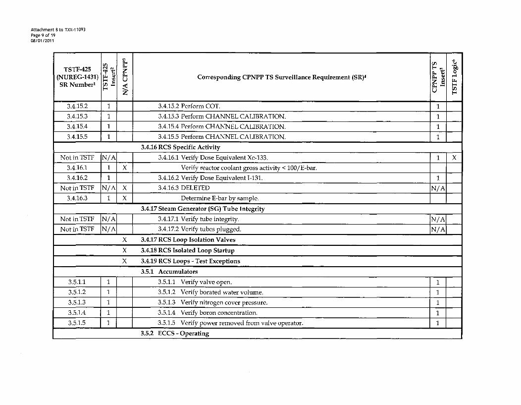
Attachment 8 to TXX-1 1093Page 9 of 1908/01/2011
LO~
TSTF-425 T -, Z(NUREG-1431) • _ Corresponding CPNPP TS Surveillance Requirement (SR)4
SR Number1 r-4
3.4.15.2 1 3.4.15.2 Perform COT. 1
3.4.15.3 1 3.4.15.3 Perform CHANNEL CALIBRATION. 1
3.4.15.4 1 3.4.15.4 Perform CHANNEL CALIBRATION. 1
3.4,15.5 1 3.4.15.5 Perform CHANNEL CALIBRATION. 1
3.4.16 RCS Specific Activity
Not in TSTF N/A 3.4.16.1 Verify Dose Equivalent Xe-133. 1 X
3.4,16.1 1 X Verify reactor coolant gross activity < 100/E-bar.
3.4,16.2 1 3.4.16.2 Verify Dose Equivalent 1-131. 1
NotinTSTF N/A X 3.4.16.3 DELETED N/A
3.4,16.3 1 X Determine E-bar by sample.
3.4.17 Steam Generator (SG) Tube Integrity
Not in TSTF N/A[ 1 3.4.17.1 Verify tube integrity. N/A
Not in TSTF N/A 3.4.17.2 Verify tubes plugged. N/A
X 3.4.17 RCS Loop Isolation Valves
X 3.4.18 RCS Isolated Loop Startup
X 3.4.19 RCS Loops - Test Exceptions
3.5.1 Accumulators
3.5.1.1 1 3.5.1.1 Verify valve open. 1
3.5.1.2 1 3.5.1.2 Verify borated water volume. 1
3.5.1.3 1 3.5.1.3 Verify nitrogen cover pressure. 1
3.5.1.4 1 3.5.1.4 Verify boron concentration. 1
3.5.1.5 1 3.5.1.5 Verify power removed from valve operator. 1
3.5.2 ECCS - Operating

Attachment 8 to TXX-11093Page 10 of 1908/01/2011
TSTF-425 "(NUREG-1431) Wo Corresponding CPNPP TS Surveillance Requirement (SR)4
SRNumber' P,U
3.5.2.1 1 3.5.2.1 Verify valve position. 1
3.5.2.2 1 3.5.2.2 Verify valve position. 1
3.5.2.3 1 3.5.2.3 Verify piping full. N/A X
Not in TSTF N/A 3.5.2.4 Verify pump differential pressure. N/A
3.5.2.5 1 3.5.2.5 Verify valve actuation. 1
3.5.2.6 1 3.5.2.6 Verify pump starts. 1
3.5.2.7 1 3.5.2.7 Verify throttle valve position. 1
3.5.2.8 1 3.5.2.8 Verify flow path not obstructed. 1
3.5.3 ECCS - Shutdown
Not in TSTF IN/Al 3.5.3.1 Surveillance Requirements are applicable. [N/A3.5.4 Refueling Water Storage Tank (RWST)
3.5.4.1 1 3.5.4.1 Verify water temperature. 1
3.5.4.2 1 3.5.4.2 Verify borated water volume. 1
3.5.4.3 1 3.5.4.3 Verify boron concentration. 1
3.5.5 Seal Injection Flow
3.5.5.1 1 3.5.5.1 Verify seal injection throttle valve position. I
X 3.5.6 Boron Injection Tank (BIT)
3.6.1 Containment
Not in TSTF N/A[ 1 3.6.1.1 Perform leakage rate testing. N/A
Not in TSTF N/A X Verify containment structural integrity. ---
3.6.2 Containment Air Locks
Not in TSTF N/A 3.6.2.1 Perform leakage rate testing. N/A
3.6.2.2 111 3.6.2.2 Verify door operation. 1
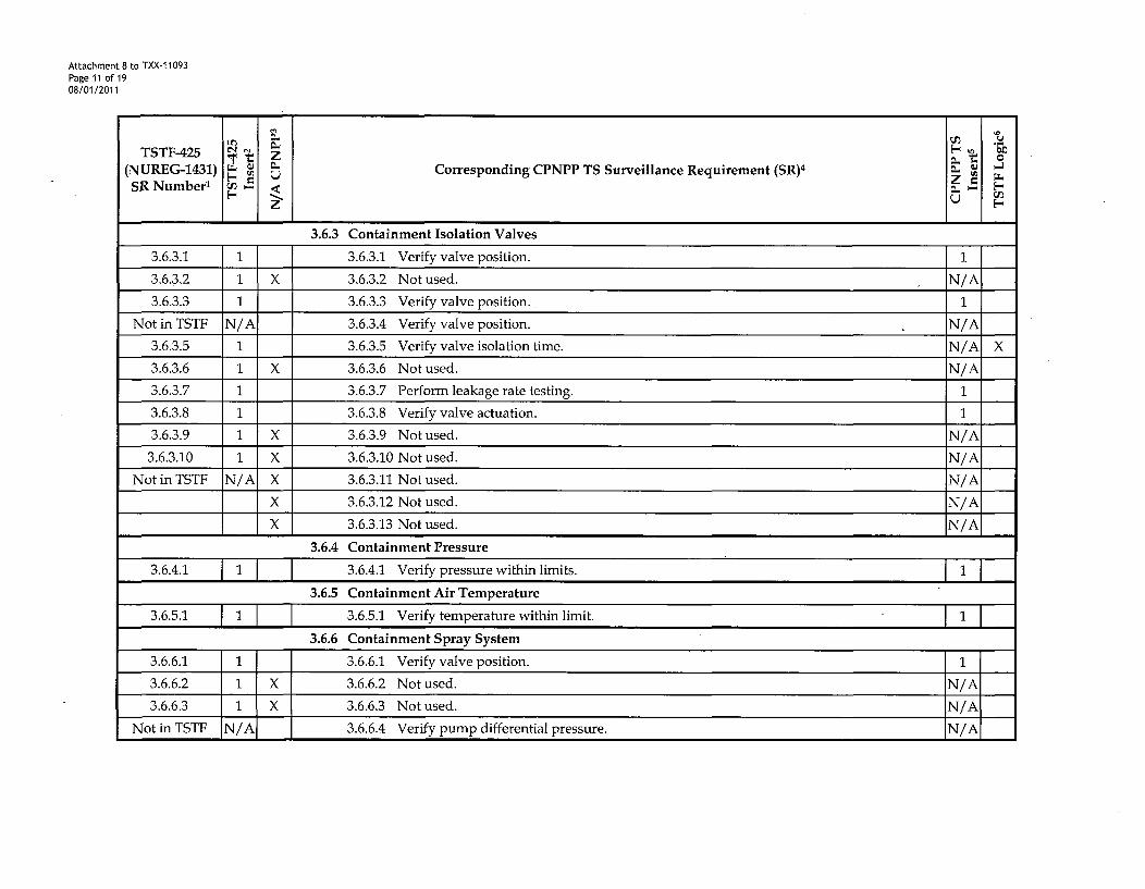
Attachment 8 to TXX-11093Page 11 of 1908/01/2011
TSTF-425 z Z(NUREG-1431) Ql Corresponding CPNPP TS Surveillance Requirement (SR)4 04
SR Number' n z.
3.6.3 Containment Isolation Valves
3.6.3.1 1 3.6.3.1 Verify valve position. 1
3.6.3.2 1 X 3.6.3.2 Not used. N/A
3.6.3.3 1 3.6.3.3 Verify valve position. 1
Not in TSTF N/A 3.6.3.4 Verify valve position. N/A
3.6.3.5 1 3.6.3.5 Verify valve isolation time. N/A X
3.6.3.6 1 X 3.6.3.6 Not used. N/A
3.6.3.7 1 3.6.3.7 Perform leakage rate testing. 1
3.6.3.8 1 3.6.3.8 Verify valve actuation. 1
3.6.3.9 1 X 3.6.3.9 Not used. N/A
3.6.3.10 1 X 3.6.3.10 Not used. N/A
Not in TSTF N/A X 3.6.3.11 Not used. N/A
X 3.6.3.12 Not used. N/A
X 3.6.3.13 Not used. N/A
3.6.4 Containment Pressure
3.6.4.1 1 1 3.6.4.1 Verify pressure within limits. 1
3.6.5 Containment Air Temperature
3.6.5.1 1 3.6.5.1 Verify temperature within limit. 1 1
3.6.6 Containment Spray System
3.6.6.1 1 3.6.6.1 Verify valve position. 1
3.6.6.2 1 X 3.6.6.2 Not used. N/A
3.6.6.3 1 X 3.6.6.3 Not used. N/A
Not in TSTF N/A 3.6.6.4 Verify pump differential pressure. N/A

Attachment 8 to TXX-11093Page 12 of 1908/01/2011
TSTF-425
(NUREG-1431) • Corresponding CPNPP TS Surveillance Requirement (SR)4
E- USR Number' (n P4
3.6.6.5 1 3.6.6.5 Verify valve actuation. 1
3.6.6.6 1 3.6.6.6 Verify pump starts. 1
3.6.6.7 1 X 3.6.6.7 Not used. N/A
3.6.6.8 1 3.6.6.8 Verify spray nozzles unobstructed. N/A
3.6.7 Spray Additive System
Not in TSTF N/A 3.6.7.1 Verify system ensures sump pH within limit. N/A X
3.6.7.1 1 X Verify valve positions.
3.6.7.2 1 X Verify spray additive tank volume.
3.6.7.3 1 X Verify spray additive tank concentration.
3.6.7.4 1 X Verify valve actuation.
3.6.7.5 1 X Verify flowpaths.
X 3.6.8 Shield Building (Dual and Ice Condenser)
X 3.6.9 Hydrogen Mixing System (HMS) (Atmospheric, Ice Condenser, and Dual)
X 3.6.10 Hydrogen Ignition System (HIS) (Ice Condenser)
X 3.6.11 Iodine Cleanup System (ICS) (Atmospheric and Subatmospheric)
X 3.6.12 Vacuum Relief Valves (Atmospheric and Ice Condenser)
X 3.6.13 Shield Building Air Cleanup System (SBACS) (Dual and Ice Condenser)
X 3.6.14 Air Return System (ARS) (Ice Condenser)
X 3.6.15 Ice Bed (Ice Condenser)
X 3.6.16 Ice Condenser Doors (Ice Condenser)
X 3.6.17 Divider Barrier Integrity (Ice Condenser)
X 3.6.18 Containment Recirculation Drains (Ice Condenser)

Attachment 8 to TXX-11093Page 13 of 1908/01/2011
TSTF-425 z
(NUREG-1431) • Corresponding CPNPP TS Surveillance Requirement (SR)4
SR Numbere Q-j
3.7.1 Main Steam Safety Valves (MSSVs)
Not in TSTF JN/A 3.7.1.1 Verify lift setpoint. N/A[
3.7.2 Main Steam Isolation Valves (MSIVs)
Not in TSTF N/A 3.7.2.1 Verify valve isolation time. N/A
3.7.2.2 1 3.7.2.2 Verify valve actuation. 1
3.7.3 Feedwater Isolation Valves (FIVs, Feedwater Control Valves (FCVs), and Associated BypassValves
Not in TSTF N/A 3.7.3.1 Verify valve isolation time. N/A
3.7.3.2 1 3.7.3.2 Verify valve actuation. 1
3.7.4 Steam Generator Atmospheric Relief Valves (ARVs)
3.7.4.1 1 3.7.4.1 Cycle valves. N/A X
3.7.4.2 1 3.7.4.2 Cycle block valves. N/A X
3.7.5 Auxiliary Feedwater (AFW) System
3.7.5.1 1 3.7.5.1 Verify valve position. 1
Not in TSTF N/A 3.7.5.2 Verify pump differential pressure. N/A
3.7.5.3 1 3.7.5.3 Verify valve actuation. 1
3.7.5.4 1 3.7.5.4 Verify pump starts. 1
Not in TSTF N/A X Verify flowpaths.
3.7.6 Condensate Storage Tank (CST)
3.7.6.1 [ 3.7.6.1 Verify level. 1
3.7.7 Component Cooling Water (CCW) System
3.7.7.1 1 3.7.7.1 Verify valve position.
3.7.7.2 1 3.7.7.2 Verify valve actuation.

Attachment 8 to TXX-11093Page 14 of 1908/01/2011
TSTF-425 z(NUREG-1431) P- Corresponding CPNPP TS Surveillance Requirement (SR)4 W
UMSR Number' V)z
3.7.7.3 1 3.7.7.3 Verify pump starts.
3.7.8 Station Service Water (SSW) System
3.7.8.1 1 3.7.8.1 Verify valve position. 1
3.7.8.2 1 3.7.8.2 Cycle cross-connect valves. 13.7.8.3 1 3.7.8.3 Verify pump starts.1
3.7.9 Ultimate Heat Sink (UHS)
3.7.9.1 1 3.7.9.1 Verify water depth.
3.7.9.2 1 3.7.9.2 Verify intake temperature.
3.7.9.3 1 X Operate each cooling tower fan ---
3.7.9.4 1 X Verify cooling tower fan actuation.
3.7.10 Control Room Emergency Filtration/Pressurization System (CREFS)
3.7.10.1 1 3.7.10.1 Operate each train. 1
Not in TSTF N/A 3.7.10.2 Perform filter testing. N/A X
3.7.10.3 1 3.7.10.3 Verify train actuation. 1
3.7.10.4 1 3.7.10.4 Perform air inleakage testing. N/A X
3.7.11 Control Room Air Conditioning System (CRACS)
3.7.11.1 1 3.7.11.1 Verify train capability. I13.7.12 Primary Plant Ventilation System (PPVS) - ESF Filtration Trains
3.7.12.1 1 3.7.12.1 Operate each train. 1
3.7.12.2 1 3.7.12.2 Perform filter testing. N/A
3.7.12.3 1 3.7.12.3 Verify train actuation. 1
Not in TSTF N/A 3.7.12.4 Verify train capability. 1
NotinTSTF N/A 3.7.12.5 Not used. N/A
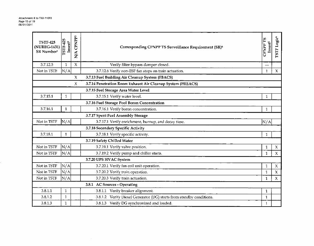
Attachment 8 to TXX-1 1093Page 15 of 1908/01/2011
TSTF-425 Z(NUREG-1431) m Corresponding CPNPP TS Surveillance Requirement (SR)4
SR Number' 0'3
3.7.12.5 1 X Verify filter bypass damper closed. ---
Not in TSTF N/A 3.7.12.6 Verify non-ESF fan stops on train actuation. 1 X
X 3.7.13 Fuel Building Air Cleanup System (FBACS)
X 3.7.14 Penetration Room Exhaust Air Cleanup System (PREACS)
3.7.15 Fuel Storage Area Water Level
3.7.15.1 1 3.7.15.1 Verify water level. 1
3.7.16 Fuel Storage Pool Boron Concentration
3.7.16.1 1 3.7.16.1 Verify boron concentration. 1
3.7.17 Spent Fuel Assembly Storage
Not in TSTF N/A 1 3.7.17.1 Verify enrichment, burnup, and decay time. N/A
3.7.18 Secondary Specific Activity
3.7.18.1 1 3.7.18.1 Verify specific activity. 1 I
3.7.19 Safety Chilled Water
Not in TSTF N/A 3.7.19.1 Verify valve position. 1 X
Not in TSTF jN/AJ 1 3.7.19.2 Verify pump and chiller starts. 1 X
3.7.20 UPS HVAC System
Not in TSTF N/A 3.7.20.1 Verify fan coil unit operation. 1 X
Not in TSTF N/A 3.7.20.2 Verify train operation. 1 X
Not in TSTF N/A 3.7.20.3 Verify train actuation. 1 X
3.8.1 AC Sources - Operating
3.8.1.1 1 3.8.1.1 Verify breaker alignment. 1
3.8.1.2 1 3.8.1.2 Verify Diesel Generator (DG) starts from standby conditions. 1
3.8.1.3 1 3.8.1.3 Verify DG synchronized and loaded. 1

Attachment 8 to TXX-11093Page 16 of 1908/01/2011
TSTF-425 Z
(NUREG-1431) • Corresponding CPNPP TS Surveillance Requirement (SR)4 WU
SRNumber' r-4
3.8.1.4 1 3.8.1.4 Verify day tank level. 1
3.8.1.5 1 3.8.1.5 Remove accumulated water from day tank. 1
3.8.1.6 1 3.8.1.6 Verify fuel oil transfer system operation. 1
3.8.1.7 1 3.8.1.7 Verify DG starts from standby conditions. 1
3.8.1.8 1 3.8.1.8 Verify transfer of power from normal offsite circuit to alternate offsite circuit. 1
3.8.1.9 1 3.8.1.9 Verify DG load rejection. 1
3.8.1.10 1 3.8.1.10 Verify DG maintains load following load reject. 1
3.8.1.11 1 3.8.1.11 Verify equipment operation on loss of offsite power. 1
3.8.1.12 1 3.8.1.12 Verify equipment operation on Safety Injection (SI) signal. 1
3.8.1.13 1 3.8.1.13 Verify automatic trips bypassed on SI signal. 1
3.8.1.14 1 3.8.1.14 Verify DG operates for LE 24 hours. 1
3.8.1.15 1 3.8.1.15 Verify DG starts and operates. 1
3.8.1.16 1 3.8.1.16 Verify DG synchronizes with offsite power. 1
3.8.1.17 1 3.8.1.17 Verify SI signal overrides test mode. 1
3.8.1.18 1 3.8.1.18 Verify interval between each sequenced load block. 1
3.8.1.19 1 3.8.1.19 Verify equipment operation on loss of offsite power in conjunction with SI signal. 1
3.8.1.20 1 3.8.1.20 Verify simultaneous DG starts and operates. 1
Not in TSTF N/A 3.8.1.21 Calibrate BO sequencers. 1 X
Not in TSTF N/A 3.8.1.22 Perform TADOT for SI and BO sequencers. 1 X
3.8.2 AC Sources - Shutdown
Not in TSTF N/A 1 3.8.2.1 Surveillance Requirements are applicable. N/A
3.8.3 Diesel Fuel oil, Lube Oil, and Starting Air
3.8.3.1 1 1 1 3.8.3.1 Verify tank level. 1

Attachment 8 to TXX-11093Page 17 of 1908/01/2011
TSTF-425 " z z 0
(NUREG-1431) Corresponding CPNPP TS Surveillance Requirement (SR)4
SR Number' cAP- zU3.8.3.2 1 3.8.3.2 Verify lubricating oil inventory. 1
Not in TSTF N/A 3.8.3.3 Verify fuel oil properties. N/A
3.8.3.4 1 3.8.3.4 Verify starting air receiver pressure. 1
3.8.3.5 1 3.8.3.5 Remove accumulated water from storage tank. 1
3.8.4 DC Sources - Operating
3.8.4.1 1 3.8.4.1 Verify battery terminal voltage. 1
3.8.4.2 1 3.8.4.2 Verify battery chargers supply amperage. 1
3.8.4.3 1 3.8.4.3 Verify battery capacity (service test). 1
3.8.5 DC Sources - Shutdown
Not in TSTF N/A 3.8.5.1 Surveillance Requirements are applicable. N/A
3.8.6 Battery Parameters
3.8.6.1 1 3.8.6.1 Verify battery float current. 1
3.8.6.2 1 3.8.6.2 Verify battery pilot cell voltage. 1
3.8.6.3 1 3.8.6.3 Verify battery connected cell electrolyte level. 1
3.8.6.4 1 3.8.6.4 Verify battery pilot cell temperature. 1
3.8.6.5 1 3.8.6.5 Verify battery connected cell voltage. 1
3.8.6.6 1 3.8.6.6 Verify battery capacity (discharge test). 1
3.8.7 Inverters - Operating
3.8.7.1 1 3.8.7.1 Verify inverter voltage and alignment. 1
3.8.8 Inverters - Shutdown
3.8.8.1 1 3.8.8.1 Verify inverter voltage and alignment. 1
3.8.9 Distribution Systems - Operating
3.8.9.1 1 3.8.9.1 Verify breaker alignment and voltage to distribution subsystems. 1

Attachment 8 to TXX-1 1093Page 18 of 1908/01/2011
TSTF-425 • Z(NUREG-1431) • Corresponding CPNPP TS Surveillance Requirement (SR)4
SR Number' P .-
3.8.10 Distribution Systems - Shutdown
3.8.10.1 1 3.8.10.1 Verify breaker alignment and voltage to distribution subsystems. 1
3.9.1 Boron Concentration
3.9.1.1 1 3.9.1.1 Verify boron concentration. 1
3.9.2 Unborated Water Source Isolation Valves
3.9.2.1 1 3.9.2.1 Verify isolation valves closed. 1
3.9.3 Nuclear Instrumentation
3.9.3.1 1 3.9.3.1 Perform CHANNEL CHECK.
3.9.3.2 1 3.9.3.2 Perform CHANNEL CALIBRATION.3.9.4 Containment Penetrations
3.9.4.1 1 3.9.4.1 Verify containment penetration in required status.
Not in TSTF N/A 3.9.4.2 Verify capability to install equipment hatch. 1 X
3.9.4.2 1 3.9.4.3 Verify valve actuation. 1
3.9.5 Residual Heat Removal (RHR) and Coolant Circulation - High Water Level
3.9.5.1 J 3.9.5.1 Verify RHR loop circulating reactor coolant. i3.9.6 Residual Heat Removal (RHR) and Coolant Circulation - Low Water Level
3.9.6.1 1 3.9.6.1 Verify RHR loop circulating reactor coolant. 1
3.9.6.2 1 3.9.6.2 Verify breaker alignment/indicated power for required pump not in operation.
3.9.7 Refueling Cavity Water Level
3.9.7.1 1 3.9.7.1 Verify water level 1

Attachment 8 to TXX-11093Page 19 of 1908/01/2011
Notes:
1. TSTF 425 SR Number - A list of the surveillance requirements from NUREG-1431 provided in the TSTF for change.
2. TSTF-425 Insert - "1" is provided in this column where standard insert wording is being used for the surveillance requirement being relocated,"--" is provided where the surveillance requirement does not exist, and "N/A" is provided where no change is proposed because the surveillancerequirement is event driven, conditional, or controlled by another approved program and therefore not a candidate for relocation.
3. N/A CPNPP - An "X" in this column means CPNPP does not have the surveillance requirement referenced in the TSTF.
4. Similar Corresponding CPNPP TS Surveillance Requirements (SR) - A list of the similar surveillance requirements that are included in theCPNPP Technical Specifications.
5. CPNPP TS Insert - "1" is provided in this column where standard insert wording is being used for the surveillance requirement being relocated,"-" is provided where the surveillance requirement does not exist, and "N/A" is provided where no change is proposed because the surveillancerequirement is event driven, conditional, or controlled by another approved program and therefore not a candidate for relocation.
6. TSTF Logic - An "X" in this column identifies where logic from the TSTF was used to justify changes to CPNPP surveillance requirements.