ML17334B615.pdf - Nuclear Regulatory Commission
850
CATEGORY 1 REGULAT INFORMATION DISTRIBUTION STEM (RIDS) ACCESSION NBR:9703170230 DOC.DATE: 97/03/10 NOTARIZED: YES DOCKET FACIL:.50-315 Donald C. Cook Nuclear Power Plant, Unit 1, Indiana M 05000315 50-316 Donald C. Cook Nuclear Power Plant, Unit 2, Indiana M 05000316 AUTH. NAME AUTHOR AFFILIATION FITZPATRICK,E. Indiana Michigan Power Co. (formerly Indiana 6 Michigan Ele RECIP.NAME RECIPIENT AFFILIATION Document Control Branch (Document Control Desk) SUBJECT: Forwards response to RAI re GL 87-02,including responses to nine items from NRC staff ! seismic evaluation work sheets. C DISTRIBUTION CODE: A025D COPIES RECEIVED:LTR ENCL SIZE: TITLE: Seismic Qualification of Equipment in Operating Plants — A-46 — GL-87 T NOTES: RECIPIENT ID CODE/NAME OGC/HDS2 HICKMAN,J COPIES LTTR ENCL 1 1 1 1 RECIPIENT ID CODE/NAME PD3-3 PD COPIES LTTR ENCL 1 1 E 0 INTERN : FILE CE DE/ECGB NRR/DRCH/HHFB NRR/DRPE/PD1-3 EXTERNAL: NRC PDR 1 1 1 1 1 1 1 1 1 1 NRR/DE NRR/DE/EMEB NRR/DRCH/HICB NRR/DSSA/SRXB 1 1 2 2 1 1 1 1 D U NOTE TO ALL "RIDS" RECIPIENTS: PLEASE HELP US TO REDUCE WASTE! CONTACT THE DOCUMENT CONTROL DESK, ROOM OWFN 5D-5(EXT. 415-2083) TO ELIMINATE YOUR NAME FROM DISTRIBUTION LISTS FOR DOCUMENTS YOU DON'T NEED! TOTAL NUMBER OF COPIES REQUIRED: LTTR 13 ENCL 13
-
Upload
khangminh22 -
Category
Documents
-
view
0 -
download
0
Transcript of ML17334B615.pdf - Nuclear Regulatory Commission

CATEGORY 1REGULAT INFORMATION DISTRIBUTION STEM (RIDS)
ACCESSION NBR:9703170230 DOC.DATE: 97/03/10 NOTARIZED: YES DOCKETFACIL:.50-315 Donald C. Cook Nuclear Power Plant, Unit 1, Indiana M 05000315
50-316 Donald C. Cook Nuclear Power Plant, Unit 2, Indiana M 05000316AUTH.NAME AUTHOR AFFILIATION
FITZPATRICK,E. Indiana Michigan Power Co. (formerly Indiana 6 Michigan EleRECIP.NAME RECIPIENT AFFILIATION
Document Control Branch (Document Control Desk)
SUBJECT: Forwards response to RAI re GL 87-02,including responses tonine items from NRC staff ! seismic evaluation work sheets. C
DISTRIBUTION CODE: A025D COPIES RECEIVED:LTR ENCL SIZE:TITLE: Seismic Qualification of Equipment in Operating Plants — A-46 — GL-87
TNOTES:
RECIPIENTID CODE/NAME
OGC/HDS2HICKMAN,J
COPIESLTTR ENCL
1 11 1
RECIPIENTID CODE/NAME
PD3-3 PD
COPIESLTTR ENCL
1 1
E
0
INTERN : FILE CEDE/ECGB
NRR/DRCH/HHFBNRR/DRPE/PD1-3
EXTERNAL: NRC PDR
1 11 11 11 1
1 1
NRR/DENRR/DE/EMEBNRR/DRCH/HICBNRR/DSSA/SRXB
1 12 21 11 1
D
U
NOTE TO ALL "RIDS" RECIPIENTS:PLEASE HELP US TO REDUCE WASTE! CONTACT THE DOCUMENT CONTROL DESK,ROOM OWFN 5D-5(EXT. 415-2083) TO ELIMINATE YOUR NAME FROMDISTRIBUTION LISTS FOR DOCUMENTS YOU DON'T NEED!
TOTAL NUMBER OF COPIES REQUIRED: LTTR 13 ENCL 13

Indgana Mich!gan ~Power Company500 CircIe OriveBuchanan, MI 491071395
INOlANSlMlCMGANPQWM
March 10, 1997
Docket Nos.: 50-31550-316
U.S. Nuclear Regulatory CommissionAttn: Document Control DeskWashington, D.C. 20555
Gentlemen:
AEP: NRC: 1040E
Donald C. Cook Nuclear Plant, Units 1 and 2RESPONSE TO NRC LETTER REQUEST FOR ADDITIONAL
INFORMATION RELATED TO COOK NUCLEAR PLANT'S RESPONSETO GENERIC LETTER 87-02 (TAC NO. M69437)
By letter dated October 21, 1996, the NRC requested additionalinformation regarding our January 30, 1996, response to genericletter 87-02. The following attachments contain the requestedinformation.
Attachment No. 1 contains the responses to the nine items fromthe NRC staff
Attachment No. 2
Attachment No. 3
Attachment No. 4
Attachment No. 5
Attachment No. 6
contains the sample seismic evaluation worksheets (SEWS) and anchorage calculations asrequested in item 2
contains the sample SEWS and anchoragecalculations for tanks and heat exchangers asrequested in item 5
contains the seismic adequacy calculations fortanks 1-TK-33 and 2-TK-32 as requested in item6
contains the SEWS and anchorage calculationsfor horizontal tanks and heat exchangers asrequested in item 7
contains the calculations for limitedanalytical reviews (LARs) of the cable andconduit raceways as requested in item 8
PP~j~Vice President
vlbAttachments
'P703i70230 9703i0PDR ADOCK 05000315P PDR
r UUrg.g
SWORN TO AND SUBSCRIBED BEFORE ME
THIS IO ~ DAY OF
Qdt 199,7
JAMNNSOWNOTARYPUBUC,BERRIEN COUNY, MlMYCOMMISSIONEXPIRES FEB. 10,1999
rrrrrrrrInrrrrrrgmrrI[ItrllrgrrgIrgfr
D~g /
Notary PublicJI
My Commission Expires

IlilIll ll»
lI~
~ p~I II
I
\
JI
'

U.S. Nuclear Regulatory CommissionPage 2
AEP: NRC: 1040E
CC A. A. BlindA. B. BeachMDEQ - DW 6c RPDNRC Resident InspectorJ. R. Padgett

ATTACHMENT 1 TO AEP:NRC:1040E
RESPONSES TO NRC REQUEST FORADDITIONALINI"ORMATION(RAI)
RELATED TO COOK NUCLEAR PLANT'S RESPONSETO GENERIC LETTER 87-02 (TAC NO M69437)
>)ozgops

" ll
r /
I r. J
l'PaO. i
tf9,"

RESPONSE TO THE USNRC REQUEST FOR ADDITIONALINFORMATIONUNRESOLVED SAFETY ISSUE USI A-46 REVIEW FOR
DONALDC. COOK NUCLEARPLANT, UNITS 1 &2
%ith rcspcct to Section 2.2, page 2-2, discuss the engineering basis for using the In-Structure Response Spectra (ISRS) developed for the Diesel Generator Building todetermine loads in the AuxiliaryBuilding at Elevation 609 fcct, and provide the DieselGenerator Building and AuxiliaryBuilding ISRS.
The basis for using the ISRS developed for the. diesel generator building to determine loads inthe auxiliary building at elevation 609 feet is provided in the third fullparagraph ofpage 2-2 ofthe final Seismic Evaluation and Walkdown Summary Report submittal. This paragraph states:"The ISRS are not available at some of the floor elevations where safe shutdown equipment is
located. When this is the case, either the ISRS for a higher elevation or the ISRS developed bya linear interpolation between existing ISRS may be used in the evaluation. In the case of theauxiliary building elevation 609 feet, since the interpolated ISRS are very close to the
corresponding ISRS for the diesel generator building, the ISRS for the diesel generatorbuilding were used."
To further illustrate this basis, figure 1 shows a plot of four ISRS (SSE, 5% equipmentdamping) for the elevations in question. These spectra include the auxiliary building 587'nd633'levations which are the elevations where developed spectra exist directly 'above andbelow the 609'levation, and the spectra at 609'n the diesel generator building. In addition tothese spectra, a 609'uxiliary building spectra is provided that was generated by interpolatingthe spectral acceleration values at 587'nd 609'. The auxiliary building and diesel generatorbuilding share a common foundation mat. As shown in figure 1, there is essentially nodifference between the diesel generator spectra at 609'nd the interpolated auxiliary buildingspectra at 609', and, therefore, there is no.engineering significance with regard to the loaddetermination ifeither ofthese are used.
With regard to the diesel generator building and auxiliary building ISRS, the ISRS for allelevations of all buildings at Cook Nuclear Plant included in the USI A-46 evaluation for 2%and 5% equipment damping have been provided in appendix 8 of the final Seismic Evaluationand Walkdown Summary Report submittal.

1.50
Donald C. Cook Nuclear PlantComparison of Selected Auxiliary Building FRS and 1.5xBS
to Diesel Generator Building FRS at Elevation 609 feet- 5% Damping
Ql
O
QQOO
C
O
CLG9
1.00
0.50
0.00
0.1 10 50
Frequency (Hz)
Oteeel609'ux 609'nterpohted 1.5xBS
Figure l ISRS for D.G. Building El 609'ompared to ISRS for AuxiliaryBuilding El. 587', 609' 633' 5% Damping

Discuss key examples of designated "rigorously analyzed anchorages," (page 4-6) usinghand calculations and ANCHOR4 sofhvarc package and provide copies of theirengineering calculations. Also discuss a few cases ofanchorage verification based on thcresults of tug tests conducted and provide a description of the tests and applicableengineering justification for such an approach.
Table I provides a list of key examples ofequipment items with varying levels of anchorageevaluations. These examples include "rigorously analyzed anchorages," comparisons toanalyzed equipment items and judgments based on the anchorage inspection and in some
cases judgments supplemented by tug tests. Copies of the completed seismic evaluation worksheets (SEWS), the analysis (ifapplicable) and the corresponding anchorage inspection sheets
are included in attachment 2 of this response to the RAI for those items marked with a * intable l. When comparison or judgment was used to satisfy the GIP anchorage criteria an
appropriate description of the evaluation is documented in the notes of the SEWS. Theanchorage inspections and installation testing performed for the Cook Nuclear Plant USI A-46 evaluations, discussed in greater detail in the response to RAI question 4, greatly exceedthe requirements of the GIP. This provides greater confidence in the judgments made by theseismic review team (SRT) that capacity greatly exceeded demand when a formal anchoragecalculation was not made.
A review of notes within the data base for each equipment item in the Cook Nuclear PlantUSI A-46 effort was conducted in order to respond to this request'for additional information(RAI). Anchorage evaluations performed can be categorized as follows: a) a detailedANCHOR4 evaluation was performed; b) a detailed hand calculation was performed; c) theanchorage was screened based on an anchorage evaluation on an identical item of equipmentand anchorage or a worst case evaluation of a similar equipment item; or d) the SRT judged,based on the weight and anchorage of the equipment, that the anchorage obviously met theGIP screening criteria.
In some cases when method (d) was used, a tug test was performed. This was performed byan SRT member that would tug on the assembly in the weakest direction to a level of abouttwo times the estimated weight of the item. The tug test from a practical standpoint wasunnecessary due to the relative light weight and robust'anchorage of the equipment. Eachanchorage evaluation whether detailed or by judgment was based on a detailed anchorageinspection and the SRT inspection. Items tug tested were in general light weight components.
Samples ofdetailed analysis performed by ANCHOR4 and by hand calculations are includedwith the sample SEWS in attachment 2. When judgment was used the basis for the judgmentis included in the notes section of the SEWS. The detailed anchor inspection documentationis also included with each SEWS provided.
The engineering justification for the approach used for performing the anchorage evaluationsis described in section 4.4, page 4-26 second paragraph of the Rev. 2 GIP. This paragraphstates: "There are various combinations of inspections, analyses, and engineering judgmentwhich can be used to verify the adequacy of equipment anchorage. The Seismic CapabilityEngineers should select the appropriate combination of elements for each anchorage

installation based on the information available. For example, a simple hand calculation maybe sufficient for a pump which has only a few, very rugged, anchor bolts in a symmetricalpattern. On the other hand, at times it may be advisable to use one of the computer codes to
determine the loads applied to a multi-cabinet motor control center if its anchorage is notsymmetrically located." The anchorage evaluations used the appropriate combinations ofelements necessary to determine that any screened equipment met the GIP criteria.
Table 1 provides a brief description of the anchorage evaluation performed. There is a goodcross section of examples that include all equipment classes on the Cook Nuclear Plant safe
shutdown equipment list (SSEL) (1 to 20) and categories ofanchorage evaluations performed.Examples of class 0 and 21 anchorage evaluations are provided in response to RAI questions5 and 7.
Table 1
Examples of Anchorage Evaluations
Class Equipment ID1-AB-N
1-ABD-A*
2-ABV-A
2-AM-D
2-EZC-D
1-11A
1-52-RTB
2-21B
2-T21B
1-T11A
1-CRID-III-CVT
I-TR11B
2-CRID-I-CVT*
Anchorage Evaluation PerformedThree section MCC. Detailed ANCHOR4 evaluationperformed.Six section MCC. Detailed ANCHOR4 evaluationperformed.Six section MCC. Detailed ANCHOR4 evaluationperformed.Eight section MCC. Detailed ANCHOR4 evaluationperformed.Eleven section MCC (including attached EZC-BS).Detailed ANCHOR4 evaluation performed.Large Multisection 600V Switchgear. DetailedANCHOR4 evaluation performed.Reactor Trip Breaker Units composed of 4 breakervertical sections. Detailed ANCHOR4 evaluationperformed.Large 'ultisection 600V Switchgear. DetailedANCHOR4 evaluation performed.Large Multisection 4KV Switchgear... DetailedANCHOR4 evaluation performed.Large Multisection 4KV Switchgear. DetailedANCHOR4 evaluation performed.Small Transformer 4'-6" x 2'-6" x 2'-4". Weightestimated at 1180 lbs. Detailed ANCHOR4 evaluationperformed.Large supply transformer. Detailed ANCHOR4evaluation performed.Small Transformer 4'-6" x 2'-6" x 2'-4". Weightestimated at 1180 lbs. Detailed ANCHOR4 evaluationperformed.

Table I (Continued)Examples ofAnchorage Evaluations
Class Equipment ID2-TR-ELSC
1-PP-10W*
1-PP-4
1-PP-50W
1-QT-111-AB
12-PP-31S
2-PP-26N
2-PP-3E
2-PP-46-4*
2-PP-82S
2-QT-106-CD1
1-PP-7W
2-PP-9W
1-HV-AFP-8RE-2
Anchorage Evaluation PcrformcdSmall Transformer 20" D x 30" W x 36" H. DetailedANCHOR4 evaluation performed..900 GPM pump. 'etailed ANCHOR4 evaluationperformed including nozzle loadings on the suction and
discharge piping.440 GPM pump. Detailed ANCHOR4 evaluationperformed including nozzle loadings on the suction and
discharge piping.Large Pacific Pump with a weight of20,000 lbs. Detailed
, ANCHOR4 evaluation performed.Small 90 GPM Pump - weight about 800 lbs. DetailedANCHOR4 evaluation performed.100 GPM pump - 2076 lbs. Detailed ANCHOR4evaluation performed.. Item was designated an outlieruntil nozzle loads are defined.Pacific Pump - total weight 5500 lbs. DetailedANCHOR4 evaluation performed including nozzleloadings on the suction and discharge piping.Large Ingersoll Rand Pump - 7935 lbs. DetailedANCHOR4 evaluation performed.Small Goulds Pump - 511 lbs. Nozzle loads judged to be
small by SRT. Anchorage screened by judgment afterreview of the anchorage inspection documentation (four5l8" anchors) and the walkdown.Small Goulds Pump - 214 lbs. Nozzle loads judged to be
small by. SRT. Anchorage screened by judgment afterreview of the anchorage inspection documentation (four5/8" anchors) and the walkdown.Small Worthington Pump - 135 lbs. Detailed ANCHOR4evaluation performed induding nozzle loadings on thesuction arid discharge piping.Large vertical pump with a 45'ong vertical casing.Screening of anchorage based on a review of existingqualification that included an anchorage evaluation.Vertical pump. Detailed ANCHOR4 evaluationperformed'including nozzle loadings on the suction anddischarge piping.Small light weight fan - 154 lbs. Anchorage accepted byjudgment aAer a review of the anchorage drawings.


Table 1 (Continued)'xamplesof Anchorage Evaluations
Class
9
10
10
14
14
14
14
Kquipmcnt ID1-HV-AFP-M1*
1-HV-AFP-Xl
I-HV-CEQ-I
12-HV-ES W-7*
12-HU-ESW-1
2-HU-AFP-BRE-1
2-HV-DGS-1
2-HV-DGX-1
1-HV-ACRA-1
1-HV-AES-1 (FLT)
1-AFW*
1-BCTC-AB
1-CRCD
1-ELSC
1-ELSCX
Anchorage Evaluation PerformedMedium size fan - 500 lbs, mounted with 16 1/2" steelto steel bolts. Anchorage accepted by judgment after a
review of the anchorage drawings.Small light weight fan - 287 lbs, mounted with 12 3/8"steel to steel bolts. Anchorage accepted by judgmentafter a review of the anchorage drawings.Large fan unit. Detailed ANCHOR4 evaluationperformed.Large fan unit. Detailed ANCHOR4 evaluationperformed.Large fan unit similar to 12-HV-ESW-7. Anchoragescreened based on comparison to ANCHOR4 evaluationfor 12-HV-ESW-7.Small light weight fan - 154 lbs. Anchorage accepted byjudgment after a review of the anchorage drawings.Large fan - 1531 lbs. Detailed ANCHOR4 evaluationperformed.Large fan - 1100 lbs. Detailed ANCHOR4 evaluationperformed.Cooler unit with a weight estimate of 3000 lbs. DetailedANCHOR4 evaluation performed.Large filter unit - 24,000 lbs. Detailed ANCHOR4evaluation performed.Small wall mounted panel (36" H x 20" W x 6" D).Panel estimated to weigh 50 lbs. Anchorage screened byjudgment after a review of the anchorage description anda 100 lb. tug test.
Panel 38" W x 60" H x 9" D. Weight estimated at 300lbs. Detailed ANCHOR4 evaluation performed.Rack 38" W x 84" H x 9" D - Weight estimated at 400lbs. Detailed ANCHOR4 evaluation performed.Small wall mounted panel (36" H x 20" W x 6" D).Panel estimated to weight 50 lbs. Anchorage screened
by judgment after a review of the anchorage descriptionand a 100 lb. tug test.
Small distribution panel 57" H x 22" W x 6" D.Weight estimated at 370 lbs. Detailed ANCHOR4evaluation performed.

Table 1 (Continued)Examples of Anchorage Evaluations
Class14
14.
14
14
14
14
14
15
16
16
16
16
Equipment ID1-MDAB
1-TDAB
1-VDCD-1 8. 2
2-AFWX
2-BATT-N-SH
2-DCN
2-VDAB-1 &2
2-BATT-AB*
1-BC-AB1
1-CIUD-I-INV
2-BC-A
2-DGAB-INV
1-OME-150-AB*
Anchorage Evaluation PerformedWall mounted switchboard 38" W x 84" H x 9" D.Anchorage accepted by comparison to the ANCHOR4evaluation performed for 1-MCAB.Wall mounted switchboard 38" W x 84" H x 9" D.Anchorage accepted by comparison to the ANCHOR4evaluation performed for 1-MCAB.Pair of 22" W x 38" H x 7" D distribution panels.Anchorage accepted by comparison to the ANCHOR4evaluation performed for 1-VDAB-1 (IdenticalConstruction).Wall mounted panel - 57" H x 22" W x 6" D. Weightestimated at 100 to 150 lbs. Anchorage screened byjudgment after a review of the anchorage description anda tug test.Wall mounted Battery Shunt. Weight estimated at 100lbs. Anchorage screened by judgment after a review ofthe anchorage description, the ANCHOR4 evaluationperformed for 1-BATT-N-SH and a tug test.
Switchboard bolted to a steel rack. Anchorage screenedbased on comparison to the ANCHOR4 analysis forsimilar panel 1-DCN.Pair of 22" W x 38" H x 7" D distribution panels.Anchorage screened based on comparison to the detailedANCHOR4 evaluation performed for similar panel 1-
VDAB-1.Substantial 2 - step battery rack. Anchorage evaluationbased on a review of existing anchorage and recentmodifications made to the racks.
Battery Charger 3025 lbs. Detailed ANCHOR4evaluation performed.Inverter 2'-5" x 3' 6'-3" - 2100 lbs. DetailedANCHOR4 evaluation performed.Battery Charger 32" L x 24" W x 46" H. DetailedANCHOR4 evaluation performed.Inverter 28" x 28" x 57". Detailed ANCHOR4evaluation performed.Large Diesel Generator. Anchorage capacity for 2-OME-150-CD indicated an additional margin of 36.Anchorage screened based on comparison to thatevaluation.

Table 1 (Continued)Examples of Anchorage Evaluations
Class18
18
1&
18
18
1&
18
18
18
18
18
Equipment ID1-CLI-113
1-CPS-317
1-CPS-410
1-MPP-232
1-NPP-151
2-8LI-110
2-CLI-113
2-CPS-410
2-FFI-210
2-IFI-311
2-IFI-51
Anchorage Evaluation PerformedSmall transmitter - 27 lbs. Anchorage screened byjudgment after review of the anchorage inspectiondocumentation and the walkdown.Small 9" x 9" panel. Anchorage screened by judgmentafter review of the anchorage inspection documentationand the walkdown.Rack supported device. One detailed ANCHOR4analysis was performed to encompass 1-CPS-410, 8c
420 and 2-CPS-410 Ec, 420.Small pressure transmitter - 35 lbs. Anchorage screened
by judgment after review of the anchorage inspectiondocumentation and the walkdown.Small pressure transmitter - 24 lbs. including bracket.Anchorage screened by judgment aAer review of theanchorage inspection documentation and the walkdown.Instrument on small, stiff bracket. Assembly weighsless than 100 lbs. Anchorage screened by judgment afterreview of the anchorage inspection documentation and,the walkdown.Transmitter bolted to support composed of a smalldiameter pipe. Anchorage screened by judgment afterreview of the anchorage inspection documentation andthe walkdown.Small device on a rack. Detailed ANCHOR4 evaluationperformed.Transmitter bolted to support composed of a smalldiameter pipe. Anchorage screened by judgment afterreview of the anchorage inspection documentation andthe walkdown.Transmitter bolted to support composed of a smalldiameter pipe. Anchorage screened by judgment afterreview of the anchorage inspection documentation andthe walkdown.Transmitter bolted to support composed of a smalldiameter pipe. Anchorage screened by judgment afterreview of the anchorage inspection documentation andthe walkdown.
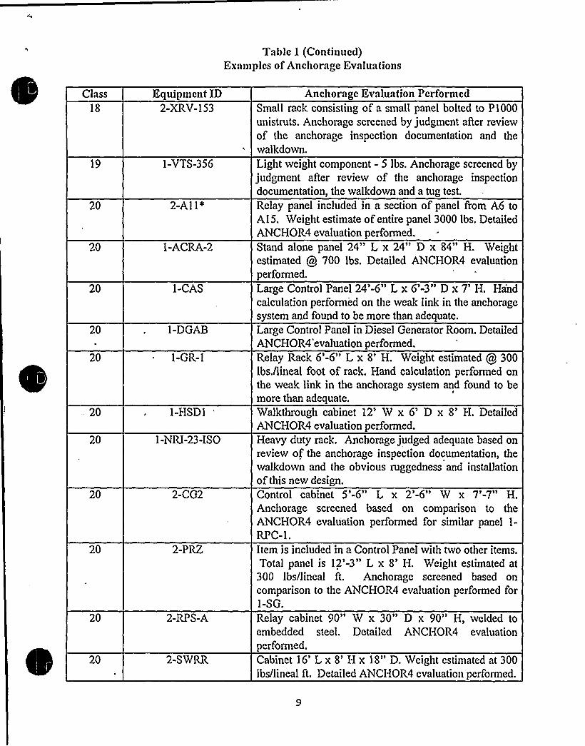
Table 1 (Continued)Examples ofAnchorage Evaluations
Class
18
19
20
20
20
20
20
20
20
20
20
20
20
Equipmcnt ID2-XRY-153
1-VTS-356
2-Al 1*
1-ACRA-2
1-CAS
1-DGAB
1-GR-1
1-HSD1
1-NRI-23-ISO
2-CG2
2-PRZ
2-RPS-A
2-SWRR
Anchorage Evaluation PerformedSmall rack consisting of a small panel bolted to P1000unistruts. Anchorage screened by judgment after reviewof the anchorage inspection documentation and thewalkdown.Light weight component - 5 lbs. Anchorage screened byjudgment after review of the anchorage inspectiondocumentation, the walkdown and a tug test.
Relay panel included in a section of panel from A6 toA15. Weight estimate ofentire panel 3000 lbs. DetailedANCHOR4 evaluation performed.Stand alone panel 24" L x 24" D x 84" H. Weightestimated @ 700 lbs. Detailed ANCHOR4 evaluationperformed.Large Control Panel 24'-6" L x 6'-3" D x 7'. Handcalculation performed on the weak link in the anchoragesystem and found to be more than adequate.
Large Control Panel in Diesel Generator Room. DetailedANCHOR4'evaluation performed.Relay Rack 6'-6" L x 8'. Weight estimated 300lbs./lineal foot of rack. Hand calculation performed onthe weak link in the anchorage system and found to bemore than adequate.
Walkthrough cabinet 12' x 6' x 8'. DetailedANCHOR4 evaluation performed.Heavy duty rack. Anchorage judged adequate based onreview of the anchorage inspection documentation, thewalkdown and the obvious ruggedness and installationof this new design.Control cabinet 5'-6" L x 2'-6" W x 7'-7" H.Anchorage screened based on comparison to theANCHOR4 evaluation performed for similar panel 1-
RPC-1.Item is included in a Control Panel with two other items.Total panel is 12'-3" L x 8'. Weight estimated at300 Ibs/lineal ft. Anchorage screened based oncomparison to the ANCHOR4 evaluation performed for1-SG,
Relay cabinet 90" W x 30" D x 90" H, welded toembedded steel. Detailed ANCHOR4 evaluationperformed.Cabinet 16' x 8' x 18" D. Weight estimated at 300lbs/lineal ft. Detailed ANCHOR4 evaluation performed.


3) Table 4.5 shows that the 1.5 x Bounding Spectrum and the, GERS with an amplificationfactor of 7 do not cnvclopc thc floor response spectra. Provide copies of thc seismicdemand versus capacity spectral comparison.
The location of the devices that are documented as outliers in table 4.5 are at elevation 687'nthe containment building. Figure 2 shows a comparison of the ISRS at elevation 687'n thecontainment building to 1.5 times the bounding spectrum. The GERS must be compared to1.5 times the demand spectra for median centered spectra because Cook Nuclear Plantresponse spectra was designated as median centered spectra by the NRC. An amplificationfactor through the piping and support of the piping system must also be considered whencomparing GERS to the demand spectra. The GIP defines the upper bound amplificationfactor as 7. Therefore, the total ISRS was multiplied by 1.5 x 7 (10.5) to define the demandthat is compared to the GERS. Figure 3 shows a comparison of the GERS for air operatedvalves (AOVs) to 10.5 x the ISRS at containment building elevation 687'. Figure 4 shows acomparison of the GERS for solenoid operated valves (SOUs) to 10.5 x the ISRS atcontainment building elevation 687'. Figure 5 shows a comparison of the GERS for motoroperators to 10.5 x the ISRS at containment building elevation 687'. As shown in figures 2,3, 4, and 5, the demand exceeds the capacity.
The outlier resolution for these items is to review the existing piping analyses and comparethe demand acceleration from the analysis to the capacity acceleration. It is believed that theactual amplification factor is less than 7 and the capacity willbe shown to be greater than thedemand once the outlier resolution has been completed.
10


2,00
Donald C. Cook Nuclear PlantCont. Bldg. Elev. 687.5 feet vs 1.5xBS
5% Damping
1,50C0GJS
Q)
u 1,000
0
0.50
P
~ ~ ~ ~ ~ ~ 0 ~ ~
~ ~ I r
: ~ ~ i ~ .: ~: ~ X I ~ ~
I I ~ I ~ 'I
~ 5 ~ ~ ~ ~ \~ r,, ~ J' ~ ~ ~ ~ '1 ~ ~ I
0 ~ 000.1 10
Frequency (Hz)
1.5xBS EL667.5
Figure 2 ISRS for Containment El. 6".7.5'. Vs. 1.5 x Bounding Spectrum - 5% Damping
11


20
Donald C. Cook Nuclear PlantAmplified Containment Building El. 687.5 feet vs AOV GERS
5o/o Damping
15C06$l0)
10
(5
DSa. 5(0
'I r ~ r r ~ ~
' ~ h ~
~ ~ ~ r ~ ~ ~ ~ ~ ~ ~ ~
~ r/:.'/'.
: r~..~ ~ ~ ~ ~ ~ ~ ~ -:.r ~ ~ ~ -'.. ~ ~ ': ~ ~: ~ ': ~:.
~ ~ r
0
0.1
~ \4 ~
10
Frequency (Hz)
1 O.Gx
EL687AOVGERS
Figure 3 Amplified ISRS for Containment El. 687.5's. AOVGERS -5% Damping
Donald C. Cook Nuclear PlantAmplified Containment Building El. 687.5 feet vs Solenoid Valve GERS
- 5/o Damping20
~ r
I I I I
1 h ~
\ I
15O
CIu 10O
CS
0Q)a. 5
CO
~ \ h ~
I' I' I
~ r e ~
I ~
I \ ~ h h I
~ ~ ~ h ~ ~ h
j I ~ I' ~ P
0 ~ h ~ ~
'I ~ ~
/~ g ~ ~ ~ ~ ~ ~ I ~ ~ ~ ~ ~
/~ ~ ~ ~ h ~ ~ ~ ~ ~ \ ~ ~
0.1 10 50
. Frequency (Hz)
1 0.5xEL687
SolenoidGERS
F<igure 4 Amplified ISRS for Containment El. 687.5's. Solenoid Valve GERS - 5% Damping
13

25
Donald C. Cook Nuclear PlantAmplified Containment Building El. 687.5 feet vs MOV GERS
5% Damping~ ~ 'r ~ ~ ~ ~ r ~ '
~ r
20
C0C6
OO
10
0CL(0 -5
~ 4 % ~
~ e ~ e e ~
~ ~
' r ~ o' ~
r ~ ~ ~
~ ~ ~ ~ ~ ~ t I. r ~ ~ ~
~ ~;:.I-. I...... '
~ 0 ~ ~ ~
~ ~ J' ~ ~ ~ I ~ ~ ~ I
'I. ~ s... ~ .s.) ~ ~ .... ~
~:- ~ ~ ~ -': I ~:. ~-
~ ~ ./ ~
t r ~ ~ ~ 5
0
0.1
~ 5 0 0 4 1 ~ 8 ~ I
10 50
Frequency (Hz)
3 0.5x MOVEL687 GERS
Figure 5 Amplified ISRS for Containment El. 687.5's. Motor Operator GERS - 5% Damping
l4

Regarding thc tightncss check of expansion anchors performed on a representative number ofmechanical and electrical components, state whether the representative number meets thcsample size for expansion anchor tightness check as listed on table C.2-4 of the GIP.
The number ofexpansion bolts tightness tested for the Cook Nuclear Plant VSI A-46 effort exceeded
the sample size for expansion anchor tightness check as listed on table C.2-4 of the GIP. Bolttightness checks were conducted on every accessible expansion bolt in the scope of USI A-46equipment on the SSEL. In addition all accessible steel to steel and cast-in-place bolts/nuts werevisually inspected and loose nuts were tightened as needed. This was done to ensure that the boltswere snug and therefore active in the event of vertical reaction loadings on the anchorage during anearthquake. Other tests using ultrasonic techniques to determine embedment length and weld qualitywere also performed as an enhancement to the program. Anchorage inspection documentation isincluded with the SEWS in attachment 2 of this RAI.
When the type of expansion anchor used could not be positively determined, a 0.6 reduction factorfor unknown expansion bolts was used in the anchorage evaluations performed in accordance withthe GIP.
Inaccessible anchor bolts were not tightness tested. The GIP excludes inaccessible anchors from thesample and states in the second paragraph of section 4 4.1 that "all accessible anchorages should bevisually inspected. Allpracticable'means should be tried to inspect inaccessible anchorages or thoseobstructed from view ifthey are needed for strength to secure the item ofequipment or ifthey secure
'quipmenthousing essential relays (to avoid impact or excessive cabinet motion). For exam'pie, it isnot considered practicable to resort to equipment disassembly, removal, etc., to inspect inaccessibleanchorages. The basis for the engineering judgment for not performing these inspections should bedocumented." The majority of anchorages for SSEL equipment were accessible. These anchorageswere tightness tested, had their embedment length verified and were visually inspected by theanchorage inspection team and were again visually inspected by the SRT.
There were some fans that had inaccessible anchorages that would have required removal of fireprotection material to inspect and disposal of material that could possibly be contaminated. Thiswould not have been consistent with the ALARAgoals at the site (dust and exposure). These fanshad calculated or judgmental anchorage margins of 10 or greater and therefore were not inspected.Anchorages for these were primarily cast in place or steel to steel bolts and the tightness check wasnot required to be performed. The regenerative heat exchanger anchorages were also not visuallyinspected due to the time required to remove insulation and to perform the anchorage inspection in a
high radiation area. There werc also a number ofwall mounted panels (class 14 and 20) that were nottightness checked. Tightness checking of these bolts would have required complete equipmentdisassembly and removal of the equipment. This activity would be contrary to section 4.4.1 of theGIP. These panels also had very high margins even when considering a 0.6 reduction factor forunknown expansion anchors. In the cases mentioned above, the engineering judgment for notperforming the inspections were documented on the SEWS for the equipment item. There were alsosome cases when isolated bolts were not tested on a given assembly because they could not be
reached without disassembly. These cases are documented in the anchorage inspectiondocumentation.

5) Table 5.1 shows only four (4) vertical tanks for GIP review. Provide the engineering criteriafor sclccting only four vertical tanks and thc justification of the structural integrity of the othersmaller vertical tanks for Safe Shutdown E<arthquakc (SSK). Indicate the number of verticaltanks supported on skirts and structural legs at Cook Nuclear Plant, Units 1 8r, 2.
Table 5.1 of the final Seismic Evaluation and Walkdown Summary Report submittal includes onlythe flat bottom vertical tanks that may be evaluated using the GIP methodology in section 7 of the
GIP. These tanks are described in the first paragraph of section 7.3.1 of the GIP which states: "Thetype of vertical tanks covered by the screening guidelines are large, cylindrical tanks whose axis ofsymmetry is vertical and are supported, on their flat bottoms, directly on a concrete pad or a floor."
The evaluation of the remaining tanks are documented in table 4-7 of the final Seismic Evaluationand Walkdown Summary Report submittal. Items 1 and 2 of table 4-7 "Commentary on EquipmentItems Meeting the Intent of the GIP Caveats" discuss this evaluation. Item 1 includes class 0
equipment items and states "There are 50 and 51 equipment items identified as class 0 in unit 1 andunit 2 respectively. These items were primarily passive and were similar to items considered as
components of the class 21 equipment. For these equipment items the SRT assessed the potential forseismic damage and made the necessary evaluations. All these items were at locations in the plantwhere 1.5 times the bounding spectrum is greater than the floor response spectra where they arelocated. Anchorage was evaluated using the GIP criteria." Item 2 includes class 21 tanks and heatexchangers not covered by the GIP criteria (section 7 of the GIP). This item states:. "There are 63
and 58 equipment items identified as class 21 in unit 1 and unit 2 respectively. Of these tanks andheat exchangers, there were only 20 where the GIP criteria was applicable. The remaining 98 wereevaluated by meeting the intent of the GIP criteria. Anchorage was evaluated using the GIP criteria."
The class 0 and 21 equipment items on the SSEL that may be categorized as tanks and heat
exchangers for unit 1 and 2 are listed in tables 2 &, 3, respectively. The table includes a description ofthe tank or heat exchangers configuration and anchorage evaluation. Included in that list are all tankssupported on skirts and structural legs that are on the Cook Nuclear Plant SSEL. Tanks on legsinclude 1,2-QT-113-AB1, AB2, CD1, CD2 (eight diesel oil filters); 1,2-QT-144-AB, CD (four dieseloil filters}; 1,2-TK-10 (two reactor coolant letdown volume control tanks); 1,2-TK-11 (two boroninjection tanks); 1-TK-12-N, 12-TK-12-M and 2-TK-12S (three boric acid storage tanks}. Tanks onskirts include 1,2-TK-37 (two component cooling water surge tanks); and 1,2-QT-141, AB1, AB2,CD1, CD2 (eight diesel starting air receivers).
Sample SEWS (including the calculations and anchorage inspection documentation) are provided inattachment 3 for the tanks that have an * aAer the equipment ID in tables 2 and 3.

Table 2Description of Configuration and Anchorage Evaluation for Tanks and Heat Exchangers (Unit 1)
Class IDI-QT-112-AB &,
CD (2 filters)
DescriptionAB &CD EMERGDIESEL FULLFLOW LUBE OILFILTERS
Building El.AUXILIARY 579
Description of Configuration and Anchorage EvaluationSmall tank-like component containing oil, with a height ofabout 5', and a
diameter of3'. Weight full= 2707 lbs. Anchored by three 3/8" diameter J-
bolts and three 5/8" wedge anchors at 60 degree intervals (i.e., evenlyspaced).
I-QT-I 13-AB I *,113-AB2, 113-
CD I, 113-CD2
(4 strainers)
I-QT-116-AB &CD (2 heatertanks)
I-QT-118-AB &CD (2 filters)
AB &, CD EMERGDIESEL FULLFLOW LUBE OILSTRAINERS
AB &, CD EMERGDIESEL LUBE OILHEATER(TANK)
AB EMERG DIESELBYPASS LUBE OILFILTER
AUXILIARY 579
AUXILIARY 579
AUXILIARY 579
The anchorage was screened based on a review ofan existing vendorcalculation that indicated a high anchorage margin.Strainer supported on 4 angle legs. Each leg is anchored by one 1/2" J-boltanchor. The total weight is 1730 lbs. The ANCHOR4 analysis performedfor 1-QT-113-AB1 and 1-QT-113-AB2 together, since they are connected
by a relatively rigid piping segment, indicated that the anchorage was
adequate..Heaters anchored by three 3/8" J-bolts at 120 degrees apart, on a 5" highconcrete pad. The weight of the tank is approximately 152.5 lbs.
Anchorage screened by an ANCHOR4 evaluation.Filter anchored by three 3/8" J-bolts with a minimum embedment of10.25", at 120 degrees.
The approximate weight of the tank is estimated to be the same as 1-QT-112-CD (Wt =2707 lbs.), because the tanks are of the same manufacturer,and size, and both hold oil.
Anchorage screened by an ANCHOR4 evaluation.


Table 2 (Continued)Description of Configuration and Anchorage Evaluation for Tanks and Heat Exchangers (Unit 1)
Class ID Description Building El. Description of Configuration and Anchorage EvaluationI-QT-143-ABI, AB EMERGAB2, CD I & DIESEL CONTROLCD2 (4 dryers) AIR DRYER I
AUXILIARY Airdryer mounted on 2-1/2" x 2-1/2" x 1/4" angle steel frame with otherair dryer tanks. Angle frame on 1-3/4" Grout Pad. Frame anchored byeight 1/2" non-shell type expansion anchors, four per base plate. Tankshold air and are the size of fire extinguishers.
I-QT-144-AB AB EMERG&CD (2 filters) DIESEL FUEL OIL
TRANSFERFILTERS
AUXILIARY 58
7
Anchorage judged adequate based on the walkdown and review of the
anchorage inspection documentation.Small filter 10" in diameter, 44" high, mounted on three angle legsanchored by three 5/8" Phillips Red Head Wedge/coupling anchors
Anchorage screened based on an ANCHOR4 evaluation for 1-QT-144-AB.
I -TK-253-1, 2,3 &4 (4 tanks)
PRESSURIZER TR"B" PRESSURERELIEF VALVENRV-152 RESERVECONTROL AIRTANKS
CONTAINMENT 61
2This horizontal tank contains air and is supported by other than standardsaddles:
Tank is well welded to building steel, and judged adequate by the SRT.
12-TK-207 REACTOR PLANTNITROGEN BULKSTORAGE TANKS¹3,4,5,6,7,8
GROUNDS 609
Similar to a horizontal heat exchanger; each tank is approximately 2'ndiameter and 20'ong (about 15'etween supports). Tank weight is about4800 lbs. Anchorage consists of four cast-in-place (in buried concrete
pedestals) 3/4" diameter J-Bolts.
Anchorage screened based on an ANCHOR4 evaluation.
18

Table 2 (Continued)Description of Configuration and Anchorage Evaluation for Tanks and Heat Exchangers (Unit 1)
Class21
21
IDI-HE-11
I-HE-13*
DescriptionREACTORCOOLANTPUMPSEAL WATERHEATEXCHANGEREXCESS LETDOWN HEATEXCHANGER
BuildingAUXILIARY
CONTAINMENT
El.609
612
Description of Configuration and Anchorage EvaluationVertical Heat Exchanger is identical to 2-HE-11. The anchorage wasscreened by comparison to the calculation for 2-HE-11.
Relatively small exchanger (1600 lbs) on two saddles in extremely high radarea.
Anchorage includes four 3/4" diameter J-bolts, embedded at least 2 feet intopiers. Could not inspect the anchorage due to ALARAconsiderations.
21 I-HE-14 LETDOWN HEATEXCHANGER
AUXILIARY 633
Due to large anchorage (four 3/4" bolts) and small exchanger, the anchoragewas judged adequate by the SRT.Exchanger anchored with two 7/8" diameter J-bolts on 11-3/8" spacing.Vertical distance from the base ofexchanger to the C.G. of exchanger is 13".
Vertical distance from the base of the exchanger to the top nozzle is 29".
Anchorage adequacy was accepted based on a short hand calculation..21 I-HE-15E 8c EAST AND WEST
W (2 CCW HEATexchangers) EXCHANGERS
AUXILIARY 609 Component Cooling Water Heat Exchanger on two reinforced saddles.
Anchorage is two 7/8" diameter J bolts. There are four 1" wedge expansionanchors in one pedestal in the horizontal direction.
C.G. ofexchanger from the top of the saddle pedestal about 3'.
A hand calculation was performed for the heat exchanger and the resultsshow that the anchor bolts and saddles are adequate.
19

Table 2 (Continued)Description of Configuration and Anchorage Evaluation for Tanks and Heat Exchangers (Unit 1)
Class ID Description Building El. Description of Configuration and Anchorage Evaluation21
21
I-HE-I7E & W (2exchangers)
I-HE-18E' W (2exchangers)
EAST & WESTRHR HEATEXCH ANGERS
EAST & WESTCONTAINMENTSPRAY HEATEXCHANGERS
AUXILIARY 6P9
AUXILIARY 6P9
Anchorage more than adequate based on previous analysis of exchangerwithout top braces. Braces had since been installed.
Very well engineered support structure.
There is a ring support at top of the exchanger bracketed to the mall ineach ofthe four quadrants. This takes the overturning loads on the
exchanger.
Bottom support (at about the 1/4 point of the exchanger, with theremainder of the exchanger hanging below) is a heavy duty ring withgussets at the bolt locations. These are bolted to a steel support structurethat is obviously well engineered.
21 I-HE-32E &32W(2 exchangers)
EAST RHR PUMPPP-35EMECHANICALSEAL HEATEXCHANGERS
AUXILIARY 573
Qualification data indicates an analysis to the design basis. Based on the
review of this analysis and anchorage inspection documentation the Heat
Exchanger is adequate.8" diameter by 2" wide exchanger, attached to East Residual HeatRemoval Pump with two 1/2" bolts. Could have been considered withthe pump'using the rule of the box, however the exchanger was listedseparately on the SSEL.
Anchorage to the pumps was judged adequate by the SRT.
20

~ >
Table 2 (Continued)Description of Configuration and Anchorage Evaluation for Tanks and Heat Exchangers (Unit I)
Class21
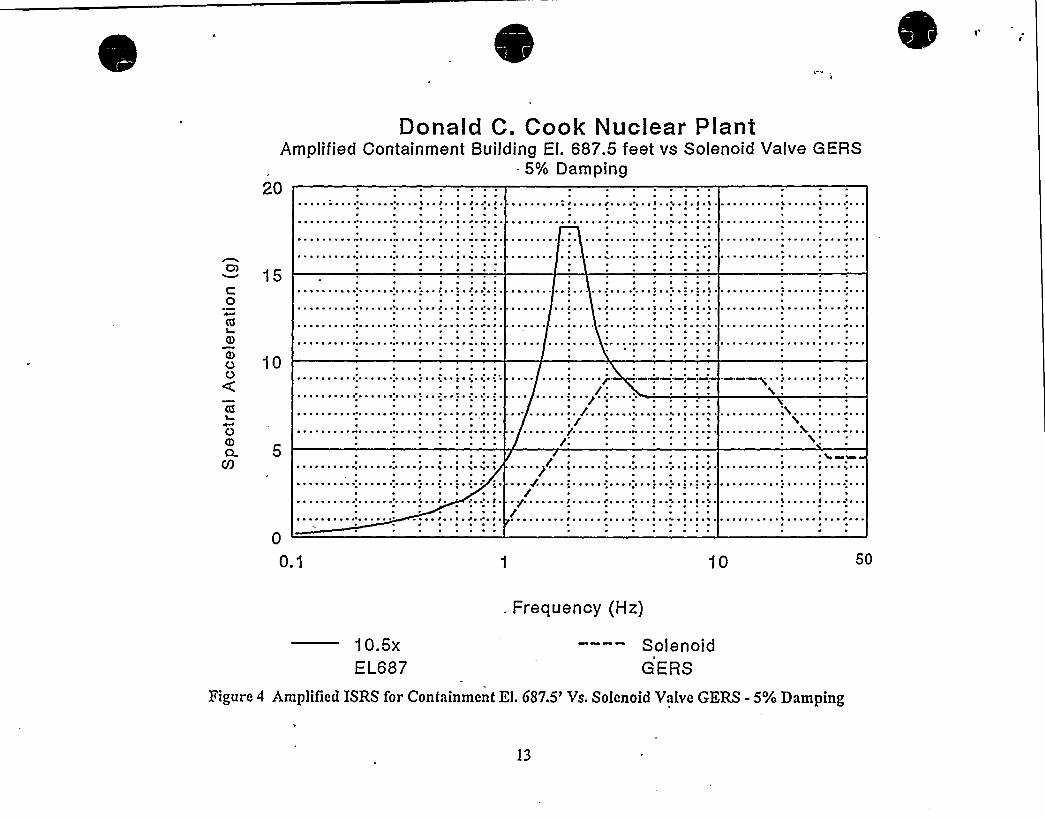
IDI-HE-33E & W(2exchangers)
DescriptionEAST AND WESTCONTAINMENTSPRAY PUMP PP-9EMECHANICALSEAL HEATEXCHANGER
Building El.AUXILIARY 573
Description of Configuration and Anchorage Evaluation6" diameter by 8-3/4" high exchanger, attached to East Containment
Spray Pump with two 1/2" bolts. Could have screened with the pumpusing the rule of the box, however the exchanger was listed separatelyon the SSEL.
Anchorage to the pumps was judged adequate by the SRT.
21 I-HE-34-NE*, 34-
NW, 34-SE, &34-SW (4 exchangers)
NORTH SAFETYINJECTION PUMPPP-26N INBOARD *
MECHANICALSEAL HEATEXCHANGERS
AUXILIARY 587 6" diameter by 8-3/4" high exchanger, attached to North Safety InjectionPump with two 1/2" bolts. Could have screened with the pump usingthe rule of the box, however the exchanger was listed separately on the
SSEL.
Anchorage to the pumps was judged adequate by the SRT.
21 I-HE-35N, 35S (2coolers)
NORTH SAFETYINJECTION PUMPPP-26N LUBE OILCOOLERS
AUXILIARY 587 Small exchangers 1'-5" long and 4" in diameter attached to North SafetyInjection Pump with four 1/4" bolts. Could have screened with the
pump using the rule of the box, however the exchanger was listedseparately on the SSEL.
Anchorage to the pumps was judged adequate by the SRT.
21

I

Table 2 (Continued)Description of Configuration and Anchorage Evaluation for Tanks and Heat Exchangers (Unit 1)
Class ID Description Building El. Description ofConfiguration and Anchorage Evaluation21 I-HE-36-EN, 36-ES,
36-WN, 36-WS(4 exchangers)
EAST & WESTCENTRIFUGALCHARGING PUMP PP-50EINBOARDMECHANICALSEAL HEATEXCHANGERS
AUXILIARY 587 6" in diameter 8-3/4" high heat exchanger, attached to East
Centrifugal Charging Pump with two 1/2" bolts. Could havescreened with the pump using the rule of the box, however theexchanger was listed separately on the SSEL.
Anchorage to the-pumps was judged adequate by the SRT.
21 I-HE-37E, 37W (2coolers)
EAST&, WESTCENTRIFUGALCHARGING PUMP PP-
50E, &50WGEAROILCOOLERS
AUXILIARY 537 Small exchanger 1'-6" long and 5" in diameter attached toreinforced plate support with four 1/2" bolts. Plate support boltedto East Centrifugal Charging Pump with three 1/2" bolts. Couldhave screened with the pump using the rule of the box, howeverthe exchanger was listed separately on the SSEL.
21 I-HE-38E &38W (2coolers)
EAST & WESTCENTRIFUGALCHARGING PUMPBEARING LUBE OILCOOLERS
AUXILIARY 5g7Anchorage to the pumps was judged adequate by the SRT.Small exchangers 1'-6" long and 5" in diameter bolted to two
1'ong
channel columns that are welded to the skid of the EastCentrifugal Charging Pump. Could have screened with the pumpusing the rule of the box, however the exchanger was listedseparately on the SSEL.
Anchorage to the pumps was judged adequate by the SRT.
22

Table 2 (Continued)Description of Configuration and Anchorage Evaluation for Tanks and Heat Exchangers (Unit 1)
Class
21
ID- I-HE-47-ABN&47-ABS, 47-CDN &47-CDS (4 aItercoolers)
I-QP-21
DescriptionAB &CD EMERGDIESEL NORTHCOMBUSTIONAIRAFTERCOOLERS
NORTH BORICACID BLENDER(MIXINGTEE)
BuildingAUXILIARY
AUXILIARY
El.587
587
Description of Configuration and Anchorage EvaluationAftercooler on Diesel Generator skid transfers its lateral load to theinlet manifolds. Gravity loads are carried by a post on a spring hangerbase, so the post is incapable ofcarrying lateral or longitudinal load.
The Diesel Generator Turbochargers in Unit 1 were replaced in a recent
outage. As part of the modification, an analysis was perforined for theassociated piping and the aftercoolers. Allsupports met D.C. Cookacceptance criteria.Boric Acid Blender supported by piping. It is in-line with the pipebetween two pipe supports offthe floor. Blender very small (6" indiameter and 11" long).
21 I-QT-107- AB &CD(2 tanks)
CD EMERGDIESEL FUEL OILDAYTANKS
AUXILIARY 587
Screened based on drawings (insulation precluded inspection of the
blender connection to the piping system) and inspection for interactions.
Horizontal tanks which sits on two saddles. Each saddle has two, 1/4"
thick plates, forming a "U", with no gussets. There are two 5/8" anchors
per saddle.
21 I-QT-110-AB &CD(2 Coolers)
AB &CD EMERGDIESEL LUBE OILCOOLERS
AUXILIARY 587
A Horizontal Tank Analysis was performed to show that the tankanchorage is adequate.
Lube Oil Coolers mounted to wall with fourteen 3/4" wedge typeexpansion anchors.
External Anchor Analysis was performed on the Unit 2 Jacket WaterHeater 2-QT-131-CD which has the same configuration as 1-QT-110-AB. Based on this. analysis, both supports are adequate.
23

Table 2 (Continued)Description of Configuration and Anchorage Evaluation for Tanks and Heat Exchangers (Unit 1)
Class21
IDI-QT-131-AB &,
CD (2 Coolers)
DescriptionAB 64 CD EMERGDIESEL JACKETWATERCOOLERS
BuildingAUXILIARY
El.587
Description of Configuration and Anchorage EvaluationJacket Water Cooler mounted to wall by fourteen 3/4" wedge typeexpansion anchors. External Anchor Analysis was performed on the Unit2 Jacket Water Heater 2-QT-131-CD..
Based on this analysis both supports are adequate.
I-QT-133-AB &CD (2 Tanks)
AB 8c CD EMERGDIESEL JACKETWATER SURGETANKS
AUXILIARY 587 100 Gal. Tanks, 2'-6" D x 3'.
Notes and the ANCHOR4 analysis for 1-QT-133-CD also apply to 1-QT-133-AB since they are essentially identical.
The surge tanks are supported (bolted) to a shelf. The shelf is bolted to
the wall by four J-bolts. In addition, two 3/4" wedge anchors attach the
top channel to the wall. The wedge anchors were conservatively left outof the ANCHOR4 analysis.
21 I-QT-134-AB &134-CD (2 Tanks)
AB &CD EMERGDIESEL AUXJACKET WATERHEATERS(TANKS}
AUXILIARY 587
The anchorage was screened based on an ANCHOR4 analysis for the
anchorage to the shelf.The AB tank is the same as the CD tank except that 3/8" bolts weremeasured in the field instead of the 1/4" bolts on the drawings for AB.
The ANCHOR4 analysis for 1-QT-134-CD (using 1/4" diameter PhillipsRedhead Wedge Anchors) demonstrated adequacy. The base plates werealso shown to be adequate.
24


Table 2 (Continued)Description of Configuration and Anchorage Evaluation for Tanks and Heat Exchangers (Unit I)
Class ID Description Building'l. Description of Configuration and Anchorage Evaluation21
21
21
I -QT-141-AB I,141-AB2, 141-CD I,141-CD2 (4 airreceivers)
I-TK-10
I-TK-11*
AB &CD EMERGDIESEL STARTINGAIR RECEIVERS I
&2
REACTORCOOLANTLETDOWNVOLUMECONTROL TANK
BORON INJECTIONTANK
AUXILIARY
AUXILIARY
AUXILIARY
5S7 Airtanks anchored by four 5/S" J-bolts (Ref. 1, 4). Total weight foreach tank is 6000 lb.
Tank anchorage was verified by an ANCHOR4 analysis. Nozzle loadswere included.
609 Tank on 4 wide flange legs, 90 inches in diameter and 120 inches inheight.
Tank 1-TK-10 is similar to the 2-TK-10. Tank anchorage and wide.flange legs were evaluated in a hand calculation for 2-TK-10 and foundto be adequate.
612 Tank is 5'iameter by 10'n height supported by 4 Wide Flange Legsupports (10" WF w/5/S" flange) 4'-4" in height..
.Each leg is bolted to the pedestal w/ two embedded 1 3/4" bolts.
21 I-TK-200 MAINSTEAMLEADSCONDENSATIONDRAINTANK(POT)
The Seismic Evaluation of the Boric Acid Tank (2-TK-12S) isseismically adequate. The Boron Injection Tank (1-TK-11) is muchsmaller but has about the same support. Therefore, Tank 1-TK-11 isjudged adequate based on comparison.
621 Small tank supported from floor.
Anchorage judged acceptable based on the walkdown and theanchorage inspection documentation.
25


Table 2 (Continued)Description of Configuration and Anchorage Evaluation for Tanks and Heat Exchangers (Unit 1)
Class
21
IDI-TK-32
DescriptionCONDENSATESTORAGE TANK
Building El.GROUNDS 609
Description of Configuration and Anchorage EvaluationLarge flat bottom tank 52'-0" inside diameter 34'-5 1/2" height (31'-7"
liquid tank). 500,000 gallons and weighs 128,700 lbs. Anchored withthirty 3/8" th x 5" w x 4'-4" long strap that is embedded in the concreteat a 2'epth with a 2" radius hook at the end.
The strap detail is identical to the strap for the Unit 1 and 2 RefuelingWater Storage Tanks (RWST) 1-TK-33 and 2-TK-33. The calculation forthe RWST resulted in the conclusion that the meld to the tank and
embedment in the concrete was sufficient to develop the fullyieldstrength of the strap.
The RWST has a very similar configuration as this CST. The calculationfor the RWST using the GIP methodology indicated an overall safetyfactor of2.57 for overturning and 1.72 for shear.
21 I-TK-33 REFUELINGWATERSTORAGE TANK
G ROUN DS 609
The CST was screened based on a comparison of the significant attributesto the RWST.Large flat bottom tank 48'-0" inside diameter 32'-3" height (31'iquidtank). 420,000 gallons, weight 94,000 lbs. The tank is founded on a
concrete pad and anchored with twenty-five 3/8" th x 5" W x 4' 4" Lstrap, embedded in concrete a 2'epth with a 2" radius hook at the end.
A detailed calculation was performed to the SQUG GIP criteria. Thecalculation resulted in the conclusion that the weld to the tank and
embedment in the concrete was sufficient to develop the full yieldstrength of the strap. The calculation for the RWST using GIPmethodology indicated an overall safety factor of2.57 for overturningand 1.72 for shear.
26


Table.2 (Continued)Description of Configuration and Anchorage Evaluation for Tanks and Heat Exchangers (Unit I)
Class ID Description Building El. Description of Configuration and Anchorage Evaluation21 I-TK-37* COMPONENT
COOLINGNATER SURGETANK
AUXILIARY 650 Skirted tank 11'-10 1/4" diameter and 17'n height. Skirt is 4'-6" high from the topof the pad to skirt connection to tank. Skirt has I/2" thickness. There are 8 boltsevenly spaced around tank, with a solid steel washer 3-3/4" high x 4" length x 2"
width. Bolts suppoited from 3" x 3 x I/2" angle.
21
21
I -TK-76N, 76S
I-TK12-N
CONTROLROOM A/CNORTH ANDSOUTH CHILLV/ATEREXPANSIONTANKSNORTH BORICACIDSTORAGETANK
AUXILIARY 650
AUXILIARY 537
The anchorage was screened based on a hand calculation performed for the boltstresses.
Small tank 2'n length x 9" in diameter on a I" diameter piping system. Tank in-linewith pipe, supported by a U-bolt on a cantilevered angle (2 I/2" x 2 I/2" x 3/8")about I'6" long. Angle welded to a plate that is bolted to the wall with 2 I/2"expansion anchors.
Anchorage and support for these small tanks were accepted by SRT judgment after the
walkdown and a review of the anchora e ins ection documentation.
Boric Acid Tank on 4 Wide Flange Beam Legs.
This Tank is identical to tank 2-TK-12S which was evaluated-by means
ofa calculation. The calculation indicated that the legs and anchorageare adequate.
21 I 2-HE- I 6N NORTH SPENTFUEL PIT HEATEXCHANGER
AUXILIARY 609 3' 2" diameter horizontal heat exchanger about 22'ong on two saddles supported bypiers, Total weight full given as 26,200 lbs. Exchanger bolted into pier with four7/8" diameter bolts per saddle. Piers are doweled into floor. The results of tankanal sis show that the tank anchora e and saddles are ade uate.

Table 2 (Continued)Description of Configuration and Anchorage Evaluation for Tanks and Heat Kxchangers (Unit 1)
Class
21
ID12-OME-44N-2 &44S-2
Descri tionNORTH &SOUTHRADIOACTIVEWASTE GASCOMPRESSOROME-44N-2 SEALWATER HEATEXCHANGERS
EI.BuildinAUXILIARY 609
Descri tion of Confi uration and Anchora e EvaluationSmall Heat Exchanger 3'-2" long by 10" in diameter attached to South
Radioactive Waste Gas Compressor OME-44S-1 with 4 - 1/2" bolts.
Compressor anchored to ground with 4 3/4" bolts. The SRT reviewedthe anchorage drawings for the compressor and judged the anchorageto be adequate (4 J-bolts). The compressor is not on the SSEL and
only anchorage adequacy is required.
21 12-TK-47-AB*&47-CD
AB &CD EMERGDIESEL FUEL OILSTORAGE TANKS
GROUNDS
The anchorage of the compressor was judged acceptable after a reviewof the anchorage during the walkdown.
609 Underground tanks. SRT evaluated this tank based on the availabledocumentation in the equipment package.
A tank calculation was performed by hand. The tank was modeled as a
beam on elastic foundation. The overall tank stresses were very low (onthe order of3.6 ksi).
21 12-TK12-M MIDDLEBORICACID STORAGETANK
AUXILIARY 587 Boric Acid Tank on 4 Wide Flange Beam Legs. Alldimensions for the
tank, legs, connections and anchorage given in the anchorage packagefor the tank.
This Tank is identical to tank 2-TK-12S which was evaluated by means
ofa hand calculation. The calculation indicated that the legs and
anchorage are adequate. This tank was screened based on comparisonto the Unit 2 calculation.
28

'k

Table 3Description of Anchorage Evaluation for Tanks and Heat E<xchangers (Unit 2)
Class ID12-HE-25A
Description15GPMRADIOACTIVEWASTEEVAPORATORHE-25CONDENSER
BuildingAUXILIARY
El.600
Description of Configuration and Anchorage EvaluationComponent is supported offshell ofmuch larger (about 4.0') diametertank 12-TK-148 which is not on the SSEL. This component is
designated an outlier due to concerns related to the anchorage for 12-TK-148 and nozzle loads.
12-HE-25B & C (2Coolers)
2-QT-112-AB &CD (2 filters)
15 GPMRADIOACTIVEWASTEEVAPORATORHE-25DISTILLATECOOLERS
AB&CDEMERGENCYDIESEL FULLFLOW LUBE OILFILTER
AUXILIARY
AUXILIARY
587
579
The Heat Exchanger is about 14" in diameter and 10 feet long,supported by stiffened saddles with two 3/4" diameter anchor bolts ineach saddle, supported offofa steel platform. Weight ofHX < 2000 lbs.
Capacity exceeds demand for saddles, support frame and platform byinspection.Small tank, with a ht ofabout 5'nd a diameter of3', anchored by six1/2" expansion anchors at 60 degree intervals. Tank contains oil, totalmaximum approximate weight = 2707 lbs.
ANCHOR analysis shows high margins and includes inlet and outletnozzle loads.
29

Table 3 (Continued)Description ofAnchorage Evaluation for Tanks and Heat Exchangers (Unit 2)
Class Descri tion Buildin El. Descri tion of Confi uration and Anchora e Evaluation2-QT-113-ABI,AB2,CDI &CD2 (4Strainers)
AB EMERGENCYDIESEL FULLFLOW LUBE OILSTRAINER 5 I
AUXILIARY 579 Supported on four angle legs. Each leg is anchored by one I/2" J-bolt anchor.
Weight = 17304, c.g. at approx. mid-height = 33".
The ANCHOR analysis performed for CDI & CD2 including nozzle loads showed
a high margin. The inlet and outlet nozzle loads were assumed equally distributedbetween the two strainers. Anchorage for ABI and AB2 was acceptable bycorn arison.
2-QT-116-AB&CD
AB&CDEMERGENCYDIESEL LUBE OILHEATER TANK
AUXILIARY 579 Small heater 9.5" Dia. x 3'-9.5" Ht.
Anchorage screened based on the ANCHOR4 analysis for 116-CD.II
2-QT-118-A B&CD
AB EMERGENCYDIESEL BYPASSLUBE OIL FILTER
AUXILIARY 579 Filter anchored by nine anchors in three groups of three, so each group is 120 degrees
for the next (i.e., evenly space).
The approx. syeight of the tank is estimated to be the same as that of2-QT-I l2-CD(Wt =2707//), because the tanks are of the same manufacturer, size, and both hold oil.
2-QT-143-ABI,AB2 andCD I, CD2 (4dryers)
AB EMERGENCYDIESELCONTROL AIRDRYER/II
AUXILIARY 587
Anchorage screened based on an ANCHOR4 evaluation.
Small tank mounted together on steel frame with the other air dryer tank (ABI withAB2 and CDI with CD2). Frame anchored by eight 3/8" non-shell type expansionanchors, four per base plate. Tanks hold air and are the size of fire extinguishers,
(approx. 8.9 lbs. filled weight each). The nozzle loads are not a concern.
Anchorage screened based on judgment aAer walkdown and review ofanchorageinspection documentation.
30
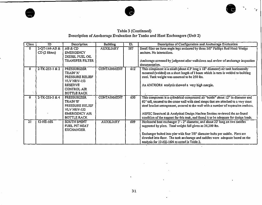
Table 3 (Continued)Description ofAnchorage Evaluation for Tanks and Heat Exchangers (Unit 2)
Class ID2-QT-l44-AB &CD (2 filters)
DescriptionAB&CDEMERGENCYDIESEL FUEL OILTRANSFER FILTER
BuildingAUXILIARY
El.587
Description of Configuration and Anchorage EvaluationSmall filteron three angle legs anchored by three 5/8" Phillips Red Head Wedgeanchors. No interactions.
Anchorage screened by judgment after walkdown and review ofanchorage inspectiondocumentation.
0 2-TK-253-1 &2
0 2-TK-253-3 &4
PRESSURIZERTRAIN
'A'RESSURE RELIEFVLVNRV-153RESERVECONTROL AIRBOTTLE RACKPRESSURIZERTRAIN
'B'RESSURE RELIEFVLVNRV-152EMERGENCY AIRBOTTLE RACK
CONTAINMENT 612
CONTAINMENT 650
This component is a small (about 4.5'ong x 16" diameter) air tank horizontallymounted (welded) on a short length of I beam which in turn is welded to buildingsteel. Tank weight was assumed to be 250 lbs.
An ANCHOR4 analysis showed a very high margin.
This component is a cylindrical compressed air "bottle" about 12" in diameter and60" tall, secured to the crane wall with steel straps that are attached to a very stoutsteel bracket arrangement, secured to the wall with a number ofexpansion anchors.
AEPSC Structural &Analytical Design Nuclear Section reviewed the as-foundcondition of the support for this tank, and found it to be adequate for design loads.
21 12-HE-16S SOUTH SPENTFUEL PIT HEATEXCHANGER
AUXILIARY 609 Horizontal heat exchanger 3' 2" diameter, and about 22'ong on two saddles
supported by piers. Total weight full given as 26,200 lbs.
Exchanger bolted into pier with four 718" diameter bolts per saddle. Piers are
doweled into floor. The tank anchorage and saddles were adequate based on the
analysis for 12-HE-16N as noted in Table 2.


Table 3 (Continued)Description ofAnchorage Evaluation for Tanks and Heat Exchangers (Unit 2)
Class
21
ID2-HE-I I »
DescriptionREACTORCOOLANTPUMPSEAL WATERHEATEXCHANGER
BuildingAUXILIARY
El.
609Description of Configuration and Anchorage Evaluation
Vertical Heat Exchanger on a Gusseted steel pedestal. Each Pedestal
is anchored to the floor with eight 3/4" J-Bolts embedded 20" intofloor. Exchanger is 16" in diameter and 14'n height.
Exchanger is bolted to the steel pedestal with two 1" diameter steel
bolts on 6" centers in weak direction and 2'-8" in strong direction.This connection is more limiting than the anchorage to the floor.
21 2-HE-13 EXCESS LETDOWN CONTAINMENT 612HEATEXCHANGER
A hand calculation was performed to demonstrate the adequacy ofthese four bolts.Heat exchanger (1600 Ibs) on two saddles in extremely high rad area.
Anchorage includes four 3/4" diameter J-bolts, embedded at least 2
feet into piers. Due to large anchorage (four 3/4" bolts) and smallexchanger, the anchorage is acceptable by SRT judgment.
21
21
2-HE-14
2-HE-15E &15W (2exchangers)
LETDOWN HEATEXCHANGER
EAST k WESTCOMPONENTCOOLING WATERHEATEXCHANGER
AUXILIARY
AUXILIARY
633
609
Exchanger anchored with two 7/8" diameter J-bolts on 11-3/8"
spacing. Vertical distance from the base ofexchanger to the C.G. ofexchanger is 13". Vertical distance from the base of the exchanger to
the top nozzle is 29". Anchorage adequacy was accepted based on a
short hand calculation.Component Cooling Water Heat Exchanger on two reinforcedsaddles. Anchorage is two 7/8" diameter J bolts. There are four 1"
wedge expansion anchors in one pedestal in the horizontal direction.
C.G. ofexchanger from the top of the saddle pedestal about 3'.
Anchorage screened based on a hand calculation for 1-HE-15E.
32

Table 3 (Continued)Description ofAnchorage Evaluation for Tanks and Heat Exchangers (Unit 2)
Class
21 2-HE-17E & 17WDescri tion
EAST &WESTRESIDUAL HEATREMOVALHEATEXCHANGER
BuildinAUXILIARY
El.609
Descri tion of Confi oration and Anchora e EvaluationVery well engineered support structure. There is a ring support at top of the
exchanger bracketed to the wall in each of the four quadrants. This takes the
overturning loads on the exchanger. Bottom support is a heavy duty steel gussetstructure supported by two peers. There are two bolts in each peer. The supportstructure for the exchanger is obviously well engineered.
21 2-HE-18E & 18 W EAST& WESTCONTAINMENTSPRAY HEATEXCHANGER
AUXILIARY 609
Qualification data indicates an analysis to the design basis. Based on the inspectionand anchorage data collected, the Heat Exchangers are adequate.
Very well engineered support structure. There is a ring support at top of theexchanger bracketed to the wall in each of the four quadrants. This takes theoverturning loads on the exchanger. Bottom support (at about the quarter point of the
exchanger, with the remainder of the exchanger hanging below) is a heavy duty ringwith gussets at the bolt locations. These are bolted to a steel support structure that is
obviously well engineered.
21 2-HE-32E &32W EAST & WESTRESIDUAL HEATREMOVALPUMPPP-35EMECHANICALSEAL HEATEXCHANGERS
AUXILIARY 573
Qualification data indicates an analysis to the design basis. Based on the inspectionand anchorage data collected the Heat Exchanger is adequate.8" in diameter by 2" long exchanger, attached to East Residual Heat Removal Pumpwith two 5/8" bolts. Could have screened with the pump using the rule of the box,however the exchanger was listed separately on the SSEL.
Anchorage to the pumps was judged adequate by SRT judgment.
33

Table 3 (Continued)Description of Anchorage Evaluation for Tanks and Heat Exchangers (Unit 2)
Class
21
ID2-HE-33E &33W (2exchangers)
DescriptionEAST & WESTCONTAINMENTSPRAY PUMP PP-
9E MECHANICALSEAL HEATEXCHANGERS
BuildingAUXILIARY
El.573
Description of Configuration and Anchorage Evaluation6" diameter by 8-3/4" high exchanger, is not attached to the East
Containment Spray Pump as shown on the anchorage sketch, however
piping can support the small exchanger. Could have screened with the
pump using the rule of the box, however the exchanger was listed
separately oh the SSEL.
21 2-HE-34-NE,34-NW, 34-SE,&34-SW (4exchangers)
NORTH &SOUTHSAFETYINJECTION PUMPPP-26N
OUTBOARDMECHANICALSEAL HEATEXCHANGERS
AUXILIARY 587
Anchorage to the pumps was judged adequate by the SRT.6" diameter by 8-3/4" high exchanger, attached to North SafetyInjection Pump with two 1/2" bolts. Could have screened with the
pump using the rule of the box, however the exchanger was listedseparately on the SSEL.
Anchorage to the pumps was judged adequate by the SRT.
2-HE-35N & NORTH &SOUTH35S (2 Coolers) SAFETY
INJECTION PUMPPP-26N LUBE OILCOOLERS
AUXILIARY 587 Small exchanger 1'-5" long by 4" in diameter by 8-3/4", attached toNorth Safety Injection Pump with four 1/4" bolts. Could have screened
with the pump using the rule of the box, however the exchanger waslisted separately on the SSEL.
Anchorage to the pumps was judged adequate by the SRT.

Table 3 (Continued)Description ofAnchorage Evaluation for Tanks and Heat Exchangers (Unit 2)
Class ID Description Building El. Description of Configuration and Anchorage Evaluation21 2-HE-36-EN,
36-ES, 36-WN,36-WS (4exchangers)
EAST & WESTCENTRIFUGALCHARGING PUMP PP-
50E INBOARDMECHANICALSEALHEAT EXCHANGERS
AUXILIARY 587 6" in diameter 8-3/4" high heat exchanger, attached to East Centrifugal ChargingPump with two I/2" bolts. Could have screened with the pump using the rule ofthe box, however the exchanger was listed separately on the SSEL.
Anchorage to the pumps was judged adequate by the SRT.
21
21
2-HE-37E,37W
~ 2-HE-38E* &38W
EAST & WESTCENTRIFUGALCHARGING PUMP PP-
50E GEAR OILCOOLER
EAST &WESTCENTRIFUGALCHARGING PUMP PP-
50E LUBE OIL COOLER
AUXILIARY 587
AUXILIARY 587
Exchanger I'-6" long and 5" in diameter attached to reinforced plate support withfour I/2" bolts. Plate support bolted to East Centrifugal Charging Pump withthree I/2" bolts. Could have screened using the rule of the box, however the
exchanger has a separate SSEL listing.
Anchorage to the pumps was judged adequate by the SRT.
Small exchanger I'-6" long and 5" in diameter bolted to 2 1'ong channelcolumns that are welded to the skid of the East Centrifugal Charging Pump.Could have screened with the pump using the rule of the box, however theexchanger was listed separately on the SSEL.
21 2-HE-47-ABN&, 47-ABS, 47-CDN &47-CDS (4aAercoolers)
AB &CD EMERGENCYDIESEL NORTHCOMBUSTION AIRAFTER-COOLERS
AUXILIARY 587Anchorage to the pumps was judged adequate by the SRT.Aftercooler transfers its lateral load to the inlet manifolds. Gravity loads are
carried by a post on a spring hanger base, so the post is incapable ofcarryinlateral or longitudinal load.
The Diesel Generator Turbochargers in Unit 2 were replaced in a recent outa< e.
As part of the modil ication an analysis was perlonned for thc associated pipingand the aAercoolers. Allsupports met the D.C. Cook acceptance criteria.
35
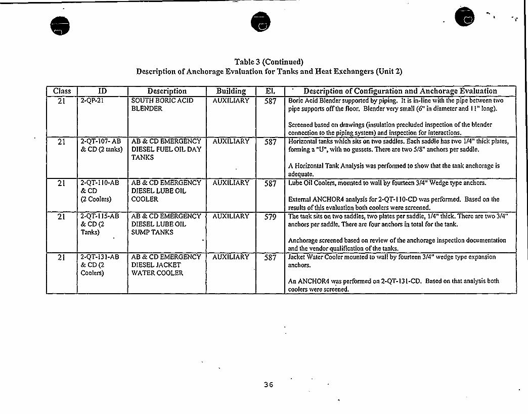
Table 3 (Continued)Description of Anchorage Evaluation for Tanks and Heat Exchangers (Unit 2)
Class ID Description Building El. Description of Configuration and Anchorage Evaluation21 2-QP-21 SOUTH BORIC ACID
BLENDERAUXILIARY 587 Boric Acid Blender supported by piping. It is in-line with the pipe between two
pipe supports offthe floor. Blender very small (6" in diameter and I I" long).
21
21
21
21
2-QT-107- AB&CD (2 tanks)
2-QT-110-AB&CD(2 Coolers)
2-QT-115-AB& CD(2Tanks)
2-QT-131-AB& CD(2Coolers)
AB & CD EMERGENCYDIESEL FUEL OIL DAYTANKS
AB &CD EMERGENCYDIESEL LUBE OILCOOLER
AB &CD EMERGENCYDIESEL LUBE OILSUMP TANKS
AB &CD EMERGENCYDIESEL JACKETWATER COOLER
AUXILIARY 587
AUXILIARY 5/7
AUXILIARY 579
AUXILIARY 587
Screened based on drawings (insulation precluded inspection of the blenderconnection to the piping system) and inspection for interactions.Horizontal tanks which sits on two saddles. Each saddle has two I/4" thick plates,forming a "U",with no gussets. There are two 5/8" anchors per saddle.
A Horizontal Tank Analysis was performed to show that the tank anchorage is
adequate.
Lube Oil Coolers, mounted to wall by fourteen 3/4" Wedge type anchors.
External ANCHOR4 analysis for 2-QT-110-CD was performed. Based on the
results of this evaluation both coolers were screened.
The tank sits on two saddles, two plates per saddle, I/O" thick. There are two 3/4"
anchors per saddle. There are four anchors in total for the tank.
Anchorage screened based on review of the anchorage inspection documentationand the vendor qualification of the tanks.
Jacket Water Cooler mounted to wall by fourteen 3/4" wedge type expansionanchors.
An ANCHOR4 was performed on 2-QT-131-CD. Based on that analysis bothcoolers were screened.
36


Table 3 (Continued)Description ofAnchorage Evaluation for Tanks and Heat Exchangers (Unit 2)
Class ID Description Building El. Description of Configuration and Anchorage Evaluation21 2-QT-133-A B
&CD (2 tanks)AB&CDEMERGENCYDIESEL JACKETWATER SURGETANK
AUXILIARY 587 100 GAL. TANK,2'-6" D x 3'.The surge tanks are supported (bolted) to a shelf. The shelf is boltedto the wall by four 7/8" anchors.
21 2-QT- l34-AB&CD4 (2tanks)
AB &CDEMERGENCYDIESEL AUXILIARYJACKET WATERHEATER (TANK)
AUXILIARY 587
An ANCHOR4 was performed on 2-QT-133-CD. Based on thatanalysis both coolers were screened.
Heater tanks separately mounted by three 1/2" coupling rods and
Phillips Redhead wedge type anchors.
An ANCHOR4 was performed on 2-QT-134-CD. Based on that
analysis both coolers were screened.
21 2-QT-14 I-ABI,AB2,CDI, &CD2(4AirReceivers)
AB EMERGENCYDIESEL STARTINGAIR RECEIVER III
AUXILIARY 587 Airtanks anchored by four 5/8" J-bolts. Total weight for the tank is
6000 lbs.
The tank anchorage was verified by an ANCHOR4 analysis. Nozzleloads were included.
21 2-TK-10 REACTOR COOLANTLETDOWN VOLUMECONTROL TANK
AUXILIARY 609 Tank on four wide flange legs, 90 inches in diameter and 120 inchesin height.
The tank leg support and anchorage was screened based on a handcalculation.
37

Table 3 (Continued)Description ofAnchorage Evaluation for Tanks and Heat Exchangers (Unit 2)
Class21
ID2-TK- I I
DescriptionBORON INJECTIONTANK
BuildingAUXILIARY
El.612
Description of Configuration and Anchorage EvaluationTank is about 5'n diameter by 10'n height supported by 4 WideFlange Leg supports (10" WF w/5/8" flange) 4'-4" in height..
Each leg is bolted to the pedestal w/ two embedded 1 3/4" bolts.
Weld of leg to tank about 14" in length and 1/4" thickness on each sideof the wide flange and 10" at the top of the wide flange.
21
21
2-TK-12S
2-TK-150
SOUTH BORIC ACIDSTORAGE TANK
MAINSTEAM LEADSCONDENSATE DRAINTANK
AUXILIARY
AUXILIARY
587
600
The seismic evaluation of the Boric Acid Tank (2-TK-12S) indicatesthat it is seismically adequate. The Boron Injection Tank is muchsmaller but has about the same support. Therefore, Tank 2-TK-11 is
judged adequate based on comparisonBoric Acid Tank on four Wide Flange Beam Legs.
Tank anchorage and wide flange legs were evaluated using a handcalculation. The calculation indicated that the legs and anchorage are
adequate.
Small horizontal tank bolted to wall in-line with the piping system.
Anchorage was judged acceptable based on the walkdown and a
review of the anchorage inspection documentation.
38
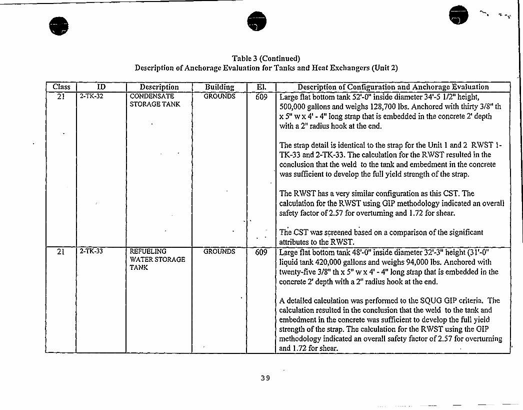
Table 3 (Continued)Description ofAnchorage Evaluation for Tanks and Heat Exchangers (Unit 2)
Class21
ID2-TK-32
DescriptionCONDENSATESTORAGE TANK
BuildingGROUNDS 609
Description of Configuration and Anchorage EvaluationLarge flat bottom tank 52'-0" inside diameter 34'-5 1/2" height,500,000 gallons and weighs 128,700 lbs. Anchored with thirty 3/8" th
x 5" w x 4' 4" long strap that is embedded in the concrete 2'epthwith a 2" radius hook at the end.
The strap detail is identical to the strap for the Unit 1 and 2 RWST 1-
TK-33 and 2-TK-33. The calculation for the RWST resulted in theconclusion that the weld to the tank and embedment in the concretewas sufficient to develop the full yield strength of the strap.
The RWST has a very similar configuration as this CST. Thecalculation for the RWST using GIP methodology indicated an overallsafety factor of2.57 for overturning and 1.72 for shear.
21 2-TK-33 REFUELINGWATER STORAGETANK
GROUNDS 609
The CST was screened based on a comparison of the significantattributes to the RWST.
Large flat bottom tank 48'-0" inside diameter 32'-3" height (31'-0"
liquid tank 420,000 gallons and weighs 94,000 lbs. Anchored withtwenty-five 3/8" th x 5" w x 4' 4" long strap that is embedded in theconcrete 2'epth with a 2" radius hook at the end.
A detailed calculation was performed to the SQUG G1P criteria. Thecalculation resulted in the conclusion that the weld to the tank and
embedment in the concrete was sufficient to develop the fullyieldstrength of the strap. The calculation for the RWST using the GIPmethodology indicated an overall safety factor of2.57 for overturningand 1.72 for shear.
39

Table 3 (Continued)Description ofAnchorage Evaluation for Tanks and Heat Exchangers (Unit 2)
Class ID Description Building El. Description of Configuration and Anchorage Evaluation21 2-TK-37 COMPONENT
COOLING WATERSURGE TANK
AUXILIARY 650 Skirted tank 11'-10 1/4" diameter and 17'n height. Skirt is 4'-6" highfrom the top of the pad to skirt connection to tank. Skirt has 1/2"
thickness.. There are eight bolts evenly spaced around tank, with a
solid steel washer 3-3/4" high x 4" length x 2" width. Bolts supportedfrom 3" x 3" x 1/2" angle.
21 2-TK-76N*,76S
CONTROL ROOM AIRCONDITIONINGNORTH AND SOUTHCHILLWATEREXPANSION TANKS
AUXILIARY 650
2-TK-37 is similar to 1-TK-37. The support for 2-TK-37 wasscreened based on the hand calculation for 1-TK-37.Small tank 2'n length x 9 " in diameter on a 1" diameter pipingsystem. Tank in-line with pipe, supported by a U-bolt on a
cantilevered angle (2 1/2" x 2 1/2" x 3/8") about 1'-6" long. Anglewelded to a plate that is bolted to the reinforced block wall with three5/8" diameter through bolts (other side ofwall inspected and boltscame through).
Anchorage and support for these small tanks were accepted by SRTjudgment after the walkdown and a review of the anchorageinspection documentation.
40

r

Section 5.1.2 states that all four tanks reviewed met the intent of the GIP. Indicate that thcGIP-2 guidclincs and methodology are fully.mct or identify any deviations from thcguidelines and thc methodology. Provide calculations for determining thc seismic adequacyof the tanks (ID 1-TK-33 and 2-TK-32) using thc methodology dcscribcd in section 7 of thcGIP-2. The evaluation of thc anchors which restrain the tank movement should also beprovided.
The flat bottom tanks were screened based on calculations performed on August 25, 1989, prior tothe publication of the rev. 2 GIP. The evaluation performed followed the procedure available atthe time in the rev. 1 GIP. There are only minor differences between the two revisions that do notaffect the results due to the resulting high margins.
There are two differences in the configuration of the RWST (1-TK-33) that are not in conformancewith the GIP procedure: a) the tJR = .0007351 which is less than the limits of the GIP screeningtable of .001; and b) the tank was not anchored with bolts but rather with twenty-five 3/8" x 5" x 4'
4" long straps that are embedded in the concrete at a two foot depth with a two inch radius hookat the end.
The tJR issue was accounted for by making an appropriate adjustment in the calculated naturalfrequency for the tank. The anchorage was considered by replacing the strap in the calculationwith bolts ofequivalent area and strength. Both of these modifications meet the intent of the GIPguidelines. The calculation resulted in the conclusion that the weld to the tank and embedment inthe concrete was sufficient to develop the full yield strength of the strap. The calculation for theRWST using the Rev. 1 GIP methodology indicated an overall safety factor of 2.57 foroverturning and 1.72 for shear. In order to obtain further assurance that the RWST is seismicallyadequate a calculation that conformed to'ASCE Standard 4-86 was performed and'yielded similarresults.
The strap detail for the CST (2-TK-32) is identical to the strap for the RWST (1-TK-33). Thecalculation for the RWST resulted in the conclusion that the weld to the tank and embedment inthe concrete was sufficient to develop the full yield strength of the strap. The CST also has a verysimilar configuration as this RWST. The CST was therefore screened based on a comparison ofthe significant attributes to the RWST.
The SEWS for 1-TK-33 and 2-TK-32 including the calculations are included as attachment 4.

7i Section 5.1.5 states that horizontal tanks and heat cxchangers rcviewcd mct thc intent of thcGIP. Indicate that the GIP-2 guidelines and methodology are fully met or identify anydeviations from them. Provide calculations using the methodology described in section 7 ofthe GIP-2 for the following tanks and cxchangers: 1-HE-14, 2-HK-15K, 12-HE-16N, 1-QT-107-AB and 2-QT-115-CD. The evaluation of the anchors which restrain thc tankmovement should also be provided.
As previously discussed in response to questions 2 and 5, anchorage and support evaluations tookseveral different forms consistent with the GIP. These forms included for tanks and heatexchangers: a) detailed evaluations using the step by step procedure in section 7.4 of the GIP; b)detailed hand calculations; c) screening based on an anchorage evaluation for an identical item ofequipment and anchorage or a worst case evaluation ofa similar item; or d) the SRT judged, based
on the weight and anchorage of the equipment, that the anchorage obviously met the GIPscreening criteria. The GIP-2 guidelines for adequate strength of the tanks or exchangers, saddlesand anchorage are met for all horizontal tanks and heat exchangers that were identified in the finalreport as screened. The step by step procedure in section 7.4 was not used for supports that wereobviously rugged based on the inspection. Exchangers that did not meet 'the applicable ranges ofparameters and assumptions contained in table 7-6 of the GIP could not be evaluated with thesection 7.4 procedure. These tanks were evaluated as, described in tables 2 and 3 of this responseto item 5 of the RAI.
SEWS that include the calculations and the anchorage inspection documentation for 1-HE-14, 2-HE-15E, 12-HE-16N, 1-QT-107-AB and 2-QT-115-CD are contained in attachment 5 of thissubmittal. The evaluations for 1-HE-15E and 1-QT-107-CD are also provided since the screeningfor 2-HE-15E and 1-QT-107-AB are based on these evaluations, respectively. These SEWS andcalculations provide a good cross section of the evaluations performed. The calculation for 1-HE-14 was a short hand calculation that indicated the anchorage had a safety margin of eight. A handcalculation was performed for 1-HE-15E that was also used to screen 2-HE-15E. These had acalculated safety margin of four. Heat exchanger 12-HE-16N and tanks 1-QT-107-CD and 2-QT-115-CD included a calculation using the step by step methodology in section 7.4 of the GIP.

S) Tables 6-1 and 6-2 provide a summary of the limited analytical reviews (LARS) for thcsclcctcd cable and conduit raceways. Provide copies of the calculations of the analyses forresolution of thc outlicrs listed as LARNumbers 005, 011, 022 and 023. Also provide typicalsample calculations for thc raceways that arc not selected as outliers (i.e., LAR Numbers001, 010, 027 and 030).
The requested information is contained in attachment 6 to this RAI.

A'
y 9) Discuss thc issue described in thc Information Notice 95-49 regarding Thermo-Lag panels,in particular, thc issue regarding seismic resistance capability of the cable tray and its
support when appropriate weight and modulus of the Thermo-Lag are included in thcanalysis.
The fire-wrapped raceways were walked-down as part of the USI A-46 raceway evaluations, alongwith all of the other raceways in the plant. The weight of the Thermo-Lag material was considered
in choosing LARS for the USI A-46 effort. None of the hangers supporting fire-wrappedraceways were selected for LARbecause: (1) the SRT did not find them to be an enveloping case,
i.e., other hangers of similar construction were more heavily loaded; and (2) the SRT was awarethat the hangers supporting the fire-wrapped raceways had been evaluated and, unlike most otherrod hangers in the plant, had been laterally braced.
In addition, in response to NRC bulletin 92-01 and generic letter 92-08, we performed a walkdown ofall Thermo-Lag installations in the plant to determine whether seismically induced failureof the Thermo-Lag could result in the Thermo-Lag falling and damaging nearby equipment. Thiswalk down covered all Thermo-Lag installations, including conduits and cable trays, wallpilasters, and electrical equipment. The walkdown team concluded that the Thermo-Lag was wellsecured, so that large sections could not fall, but smaller pieces (golfball size and smaller) couldfall if local sections of the Thermo-Lag fractured. As a result of the walkdown Thermo-Lagmaterial was removed from some of the conduits to address the safety interface condition.
In the mid 1980s, a minimum number (<10 %) of the cable tray and conduit raceways were fire-wrapped with Thermo-Lag material as part of our 10 CFR 50 Appendix R efforts. Some of theThermo-Lag material in the plant is being removed and will be replaced with DARMATTmaterial. In some instances, the Thermo-Lag was removed and was not replaced by any other typeofmaterial...
44

ATTACHMENT2 TO AEP:NRC:1040E
SAMPLE SEWS, ANCHORAGE CALCULATIONS,ANDANCHORAGE INSPECTION DOCUMENTATION
FOR CLASS 1 THROUGH 20 EQUIPMENTRAI ITEM 2

This attachment includes sample SEWS, anchorage calculations and anchorage inspectiondocumentation for a cross section of class 1 through 20 equipment items. The samples selectedare designated with an * in Table 1 of this RAI. The following examples are included:
lass
1-ABD-A2-CRID-1-CVT1-1'P-10W
14
17
1-HV-AFP-Mk12-HV-E W-71-A W-A -A
1- Mk:-15 -AB 2- Mk:-150-2-A11

Ol/16/92PG. HO.I )
SAfE SNUIOOuN EoulpHENT LIST (SSELup)
fUHCI ION: 600 VAC STSTEH
Equipment Io ~ 1-ABD-A
Equi pment Class: Train: I
Drawing Number: 1-12001 1-12010
Systemt ELECTRICAL OlSTRIBUTIOH 600VAC
Equip Description: 600VAC NCC ABD-A
Bul lding: AUXILIART Roomt AB EHERG OIESEL GENERATOR ROON Etevationt 587
Normal state: Desired st'ate: Power Required: Sort: U,
Supporting System Drawing Munbert
Required Interconnections and Suppo t Cupport ing Components:
Safety Related Status: NUCLEAR SR flin/Optt HIM
Alias Hubert
AOOITIOHAL IMFORNATIOM
Power Train: B
Component Scrvedt 600Y KCC ABD-A
Manufacturer: CUTLER-HAMMER Model:
Panel:
Elem Drawing: uiring Drawingt 1-9QOS I-9C206
Power Source: 1-llAS
ualkdownt F Relay Only: H
Component Type: HCC
ISO Drawings:
Detailed Location: IN tHE MU RE'GIOM OF tHE ROONROON, NEAR THE NORTH MALL

D.C. COOK Unit 1
SCREENING EVALUATIONWORK SHEET (SEWS)GIP Rev 2, Corrected, 2/14/92Status: YesSheet 1 of 12
ID: 1-ABD-A( Rev. 0)Description: 600VAC MCC ABD-A
Class: 1. Motor Control Centers
Building: AUXILIARY Floor El.: 587.00 Room, Row/Col: AB EDG RM, INTHE NWREGN OF THE RM, NEARTHE N WALL
Manufacturer, Model, Etc.: CUTLER-HAMMER
SEISMIC CAPACITYVS DEMAND
Elevation where equipment receives seismic inputElevation of seismic input below about 40'rom grade (grade = 608.00)Equipment has fundamental frequency above about 8 Hz (est. frequency = )Capacity based on: 1.50 Bounding SpectrumDemandbasedon: 1.00 RealisticMedian-CenteredFloorResponseSpectra
587.00N/AN/A
'I.200
LOG
0.0000.50
1
'
II \
/
I
/
/
LOG Hz
Capacity ..... Demand
50.00
CapacitDemand 1
Demand 2
FileCAGIPtGIPtspectra.desC:tGIP'PROJ0035tspectra.desC.'tGIPIPROJ0035'Lspectra.dos
Label Boundin S ctrumBUILDINGAuxilia ELEVATION587 BROADEN NBUILDINGAuxilia ELEVATION587 BROADEN N
Does capacity exceed demand'
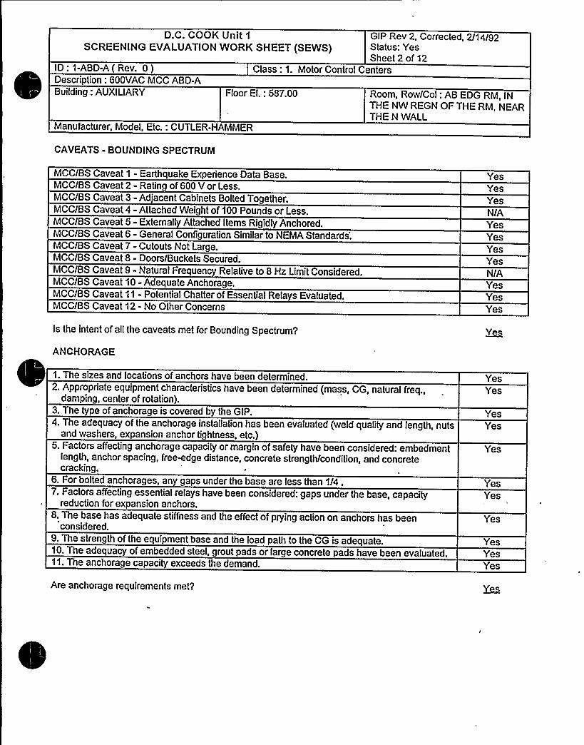
D.C. COOK Unit 1
SCREENING EVALUATIONWORK SHEET (SEWS)GIP Rev 2, Corrected, 2/14/92Status: YesSheet 2 of 12
ID: 1-ABD-A(Rev. 0) Class: 1. Motor Control CentersDescription: 600VAC MCC ABD-ABuilding: AUXILIARY Floor El.: 587.00 Room, Row/Col: AB EDG RM, IN
THE NW REGN OF THE RM, NEARTHE N WALL
Manufacturer, Model, Etc.: CUTLER-HAMMER
CAVEATS - BOUNDING SPECTRUM
MCC/BS Caveat 1 - Earthquake Experience Data BaseMCC/BS Caveat 2 - Rating of 600 V or Less.MCC/BS Caveat 3 - Adjacent Cabinets Bolted TogetherMCC/BS Caveat 4 - Attached Weight of 100 Pounds or Less.MCC/BS Caveat 5 - Externaliy Attached Items Rigidly Anchored.MCC/BS Caveat 6 - General Configuration Similar to NEMAStandards.MCC/BS Caveat 7- Cutouts Not LargeMCC/BS Caveat 8- Doors/Buckets Secured.MCC/BS Caveat 9 - Natural Frequency Relative to 8 Hz LimitConsidered.MCC/BS Caveat 10 - Adequate Anchorage.MCC/BS Caveat 11 - Potential Chatter of Essential Relays Evaluated.MCC/BS Caveat 12 - No Other Concerns
Is the intent of all the caveats met for Bounding Spectrum/
ANCHORAGE
YesYesYesN/AYesYesYesYesN/AYesYesYes
1. The sizes and locations of anchors have been determined2. Appropriate equipment characteristics have been determined (mass, CG, natural freq.,
damping, center of rotation).3. The type of anchorage is covered by the GIP4. The adequacy of the anchorage installation has been evaluated (weld quality and length, nuts
and washers, expansion anchor tightness, etc.)5. Factors affecting anchorage capacity or margin of safety have been considered: embedment
length, anchor spacing, freewdge distance, concrete strength/condition, and concretecracking.
6. For bolted anchorages, any gaps under the base are less than 1/4 .7. Factors affecting essential relays have been considered: gaps under the base, capacity
reduction for expansion anchors.8. The base has adequate stiffness and the effect of prying action on anchors has been
considered.9. The strength of the equipment base and the load path to the CG is adequate10. The adequacy of embedded steel, grout pads or large concrete pads have been evaluated.11. The anchorage capacity exceeds the demand.
Are anchorage requirements met'?
YesYes
YesYes
Yes
YesYes
Yes
YesYesYes

D.C..COOK Unit 1
SCREENING EVALUATIONWORK SHEET (SEWS)GIP Rev 2, Corrected, 2/14/92Status: YesSheet 3 of 12
ID: 1-ABD-A(Rev. 0)Description: 600VAC MCC ABD-ABuilding: AUXILIARY
Class: 1. Motor Control Centers
Floor El.: 587.00 Room, Row/Col: AB EDG RM, INTHE NW REGN OF THE RM, NEARTHE N WALL
Manufacturer, Model, Etc.: CUTLER-HAMMER
INTERACTION EFFECTS
1. Soft targets are free from impact by nearby equipment or structures2. If the equipment contains sensitive relays, it is free from all impact by nearby equipment or
structures.3. Attached lines have adequate flexibility.4. Overhead equipment or distribution systems are not likely to collapse.5. No other adverse concerns were found.
Is equipment free of interaction effects?
YesYes
YesYesYes
CO+IME~N
1-ABD-A& 1-ABD-B in the same box.
5 vertical panels on 4" concrete pad.
Anchorage by bolts in front 4 1/2" J-bolts and 2 1/2" expansion anchors. Anchorage by welds in back 6 2" long3/16" fillet.
Anchor Pattern:
f x ][ x][x ][ x][x x]
Weight of MCC is a maximum of 800 Ibs/cabinet x 5 = 4000 Ibs, which was used in the anchor analysis.
The AEPSC Rev. 0 report" Fundamental Resonant Frequencies of Cook Nuclear Plant Cabinets, Panels, andRacks in Auxiliary Building Complex ( Determined By In-Situ Modal Testing; Year 1985 and 1986)" dated August10, 1994 documents the testing of four MCC assemblies. The minimum fundamental frequancy from these testswas 9.6 Hz for MCC assembly 2-ABD-B/ABD-A.The SRT based on this report judged that the frequancy for MCCassembly 1-ABD-A/ABD-B was above 8 Hz. However, for conservatism credit for MCC Assembly 1-ABD-A/ABD-Bbeing above 8 Hz. was not taken, and therefore the caveats on this SEWs related to the 8 Hz issue were answeredN/A. This enabled the conservative use of the 1.5 x Bounding Spectrum vs. floor spectrum comparison for capacityvs. demand and the use of the peak of the 5% damped floor spectrum for the anchorage calculations.
No interaction concern.
Zap 345 MCC ABD-ABBZap,346 Typ. Opening @ bottom.
Anchor Evaluation Performed by Bahaa Mahmoud - S8AChecked by George Gary Thomas.

D.C. COOK Unit 1
SCREENING EVALUATIONWORK SHEET (SEWS)GIP Rev 2, Corrected, 2/14/92Status: YesSheet 4 of 12
ID: 1-ABD-A(Rev. 0) Class: 1. Motor Control CentersDescription: 600VAC MCC ABD-ABuilding: AUXILIARY Floor El.: 587.00 Room, Row/Col: AB EDG RM, IN
THE NW REGN OF THE RM, NEARTHE N WALL
Manufacturer, Model, Etc.: CUTLER-HAMMER
Anchor calculation additional margin = 1.634
Evaluated by Gary Thomas and Satyan Sharma on 7/17/92.
Evaluated by: Date:

D.C. COOK Unit 1
SCREENING EVALUATIONWORK SHEET (SEWS)GIP Rev 2, Corrected, 2/14/92Status: YesSheet 5 of 12
ID: 1-ABD-A(Rev. 0)Description: 600VAC MCC ABD-ABuilding: AUXILIARY
Class: 1. Motor Control Centers
Floor El.: 587.00 Room, Row/Col: AB EDG RM, INTHE NW REGN OF THE RM, NEARTHE N WALL
Manufacturer, Model, Etc.: CUTLER-HAMMER
MCC ABD-AM TYP. OPENING AT BOTTOM.

D.C. COOK Unit 1
SCREENING EVALUATIONWORK SHEET (SEWS)GIP Rev 2, Corrected, 2/14/92Status: YesSheet 6 of 12
ID: 1-ABD-A(Rev. 0)Description: 600VAC MCC ABD-A
Class: 1. Motor Control Centers
Building: AUXILIARY Floor El.: 587.00 Room, Row/Col: AB EDG RM, INTHE NW REGN OF THE RM, NEARTHE N WALL
Manufacturer, Model, Etc.: CUTLER-HAMMER
ANCHOR Report
Eargm~Z
'esponseSpectrum: Instructure Realistic
Frequency: GIP - Flexible
Percent Damping: GIP - 5.00
Spectral Values:
DirectionNorth - SouthEast - WestVertical
Acceleration (g's)1.041.040.17
Angle (N-S Direction makes with the X Axis): 0.00
Combination Criteria: SRSS
~We ggs
Number ofWeights: 1
No Weight1 4000.00 50.000 10.000 45.000
Fgrrgg
Number of External Forces: 0
Eunmh'umberof External Moments: 0
fgc~LIRJRR
Number of Anchor types: 2
Tension ShearUltimate Ultimate Inter Inter Saf

D.C. COOK Unit 1
SCREENING EVALUATIONWORK SHEET (SEWS)GIP Rev 2, Corrected, 2/14/92Status: YesSheet 7 of 12
ID: 1-ABD-A( Rev. 0) Class: 1. Motor Control CentersDescription: 600VAC MCC ABD-ABuilding: AUXILIARY Floor El.: 587.00 Room, Row/Col: AB EOG RM, IN
THE NW REGN OF THE RM, NEARTHE N WALL
Manufacturer, Model, Etc.: CUTLER-HAMMER
No. Dia Manufact Product Tension Shear Coeff Coeff Fact1 1/2
2 1/2
Other
Other
J-Bolt (90deg)
UnknownExpansion
Anchor
6660.00 3330.00
2290.00 2380.00
1.00
1.00
0.30
0.30
1.00
1.00
Czmrch.
Ultimate Stress: 3500.00 psi.
Reduction Factor: 0.85
W~Allowable Stress: 30600 psi.
Surry~c
Number of Surfaces: 1
Surface Orientation
No
DirectionComp
0.000
DirectionComp
Ny0.000
DirectionComp
1.000
Anchor Pattern for Surface ¹ 1

D.C. COOK Unit 1
SCREENING EVALUATIONWORK SHEET (SEWS)GIP Rev 2, Corrected, 2/14/92Status: YesSheet 8 of 12
ID: 1-ABD.-A(Rev. 0)Description: 600VAC MCC ABD-A
Class: 1. Motor Control Centers
Building: AUXILIARY Floor EI.: 587.00 Room, Row/Col: AB EDG RM, INTHE NW REGN OF THE RM, NEARTHE N WALL
Manufacturer, Model, Etc.: CUTLER-HAMMER
4x
Legend for Anchor Patterns
Anchor Bolts:
Concrete Uncs:
Concrete Potnts: ~IIIINeid Uncs:
knobs"
Number of Anchors: 6
AnchNo. Id
1 1
2 1
3 1
4 25 26 1
Coord3.750
36.50043.80076.60083.90096.300
Coord1.5001.5001.5001.5001.5001.500
Coord0.0000.0000.0000.0000.0000 000
SurfId
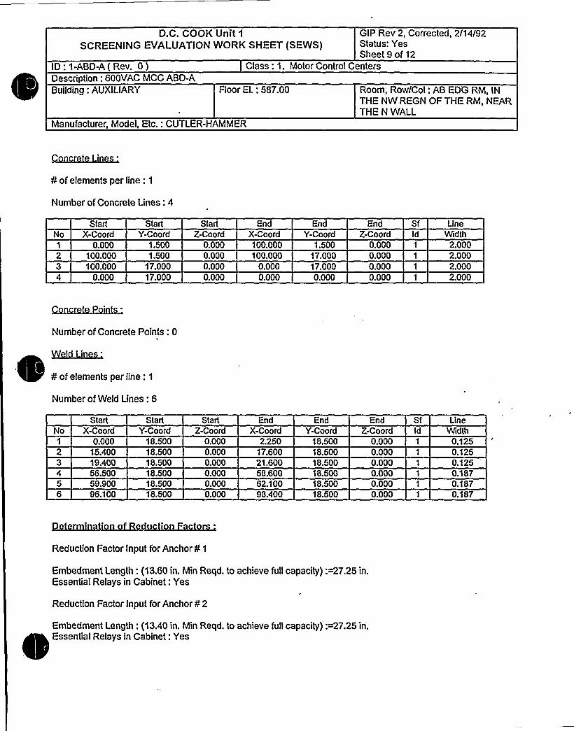
D.C. COOK Unit 1
SCREENING EVALUATIONWORK SHEET (SEWS)GIP Rev 2, Corrected, 2l14I92Status: YesSheet 9 of 12
ID: 1-ABD-A(Rev. 0)Description: 600YAC MCC ABD-A
Class: 1. Motor Control Centers
Building: AUXILIARY Floor El.: 587.00 Room, Rovi/Col: AB EDG RM, INTHE NW REGN OF THE RM, NEARTHE N WALL
Manufacturer, Model, Etc.: CUTLER-HAMMER
¹ of elements per line: 1
Number of Concrete Lines: 4
NoStart
X-Coord0.000
100.00Q100.000
0.000
StartY-Coord
1.5001.500
17.00017.000
StartZ-Coo rd
0.0000.0000.0000.000
EndX-Coord100.000100.000
0.0000.000
EndY-Coord
1.50017.00017.0000.000
EndZ-Coord
0.0000.0000.0000.000
SfId
LineWidth
2.0002.0002.QQQ
2.000
Number of Concrete Points: 0
¹ of elements per line: 1
Number of Weld Lines: 6
StartNo X-Coord
StartY-Coord
StartZ-Coord
EndX-Coord
EndY-Coord
EndZ-Coo rd ld
LineWidth
0.00015.400
3 — 19.40056.50059.90096.100
18.50018.50018.50018.50018.50018.500
0.0000.0000.0000.0000.0000.000
2.25017.60021.60058.60062.10098.400
18.50018.50018.50018.50018.50018.500
0.000 1
0.000 1
0.000 1
0.000 1
0.0000.000 1
0.1250.1250.1250.1870.1870.187
Reduction Factor Input for Anchor ¹ 1
Embedment Length: (1 3.60 in. Min Reqd. to achieve full capacity):=27.25 in.Essential Relays in Cabinet: Yes
Reduction Factor Input for Anchor ¹ 2
Embedment Length: (13 40 in. Min Reqd. to achieve full capacity):=27.25 in.Essential Relays in Cabinet: Yes

D.C. COOK Unit 1
SCREENING EVALUATIONWORK SHEET (SEWS)GIP Rev 2, Corrected, 2/14/92Status: YesSheet 10 of 12
ID:1-ABD-A(Rev. 0) Class: 1. Motor Control CentersDescription: 600VAC MCC ABD-ABuilding: AUXILIARY Floor El.: 58?.00 Room, Row/Col: AB EDG RM, IN
THE NW REGN OF THE RM, NEARTHE N WALL
Manufacturer, Model, Etc.: CUTLER-HAMMER
Reduction Factor Input for Anchor ¹ 3
Embedment Length: (13.60 in. Min Reqd. to achieve full capacity):=27.25 in.Essential Relays in Cabinet: Yes
Reduction Factor Input for Anchor ¹ 4
Essential Relays in Cabinet: Yes
Reduction Factor Input for Anchor ¹ 5
Essential Relays in Cabinet: Yes
Reduction Factor Input for Anchor ¹ 6
Embedment Length: (13.50 in. Min Reqd. to achieve full capacity}:=27.25 in.Essential Relays in Cabinet: Yes
Reduction Factors Data Current: Yes
AncNo Id
1 1
2 1
3 1
4 2
5 2
6 1
PaIVVali
3750.913330.003708.293330.003750.913330.001717.501785.001717.501785.003729.603330.00
Pallr/VallrN/A
N/ANIAN/AN/ANIAN/AN/AN/A
N/A
RT RN RLX 0.56X 1.00X 0.56X 1.00X 0.56X 1.00X XX XX XX XX 0.56X 1.00
RG RS REX XX X,X XX XX XX XX XX XX XX XX XX X
RF RCX XX XX X
X XX XX XX XX XX XX XX X
RR RP RB1.00 X X1.00 X X1.00 X X1.00 X X1.00 X X1.00 X X0.75 X X0.75 X X0.75 X X0.75 X X1.00 X X1.00 X X
RM
N/A = Not ApplicablePall = Allowable Pull without Reduced InspectionVali = Allowable Shear without Reduced InspectionPallr = Allowable Pull with Reduced InspectionVallr = Allowable Shear with Reduced Inspection
= Outlier= Reduction Factor Not Used
RT = Reduction Factor for Type of AnchorageRN = Reduction Factor for Installation Adequacy

D.C. COOK Unit 1
SCREENING EVALUATIONWORK SHEET (SEWS)GIP Rev 2, Corrected, 2/14/92Status: YesSheet 11 of 12
ID: 1-ABD-A(Rev. 0)Description: 600VAC MCC ABD-A
Class: 1. Motor Control Centers
Building: AUXILIARY Floor El.: 687.00 Room, Row/Col: AB EDG RM, INTHE NW REGN OF THE RM, NEARTHE N WALL
Manufacturer, Model, Etc.: CUTLER-HAMMER
RL = Reduction Factor for EmbedmentRG = Reduction Factor for Gap at AnchorsRS = Reduction Factor for SpacingRE = Reduction Factor for Edge DistanceRF = Reduction Factor for Concrete StrengthRC = Reduction Factor for Concrete CracksRR = Reduction Factor for Essential RelaysRP = Reduction Factor for Base Stiffness and Prying ActionRB = Reduction Factor for Base Strength and Load PathRM = Reduction Factor for Embed. Steel and Pads
e
Analysis Performed: Yes
Type ofAnalysis: Regular
Spectral Accelerations (G's)
10
121314
1617
1920
22
N-S
1.038-1.038-1.0381.0381.038
-1.0381.038
-1.0380.415
-0.4150.415
-0.415-0.4150.4150.415
-0.4150.415
-0.4150.415
-0.415-0.4150.4150.416
0.415-0.4150.415
-0.415-0.4150.4150.415
-0.4151.038
-1.038-1.0381.0381.038
-1.0381.038
-1.0380.415
-0.4150.415
-0.4150.415
-0.415-0.415
Vertical0.067
-0.0670.067
-0.0670.067
-0.067-0.0670.0670.067
-0.0670.067
-0.0670.067
-0.067-0.0670.0670.167
-0.167-0.1670.1670.167
-0.1670.167
Safety Factor3.6537.0483.5267.0856.8633.6523.7876.8191.6343.9903.9761.6761.6434.0551.6663.9123.8169.4874.3028.4943.8389 6738.579

D.C. COOK Unit 1
SCREENING EVALUATIONWORK SHEET (SEWS)GIP Rev 2, Corrected, 2/14/92Status: YesSheet 12 of 12
ID: 1-ABD-A(Rev. 0) Class: 1. Motor Control CentersDescription: 600VAC MCC ABD-ABuilding: AUXILIARY Floor EI.: 587.00 Room, Row/Col: AB EDG RM, IN
THE NW REGN OF THE RM, NEARTHE N WALL
Manufacturer, Model, Etc.: CUTLER-HAMMER
24 Z.415 0.415 -0.167 4.333
Minimum Safety Factor: 1.634.
The Anchorage Capacity is 1.634 times greater than the Demand
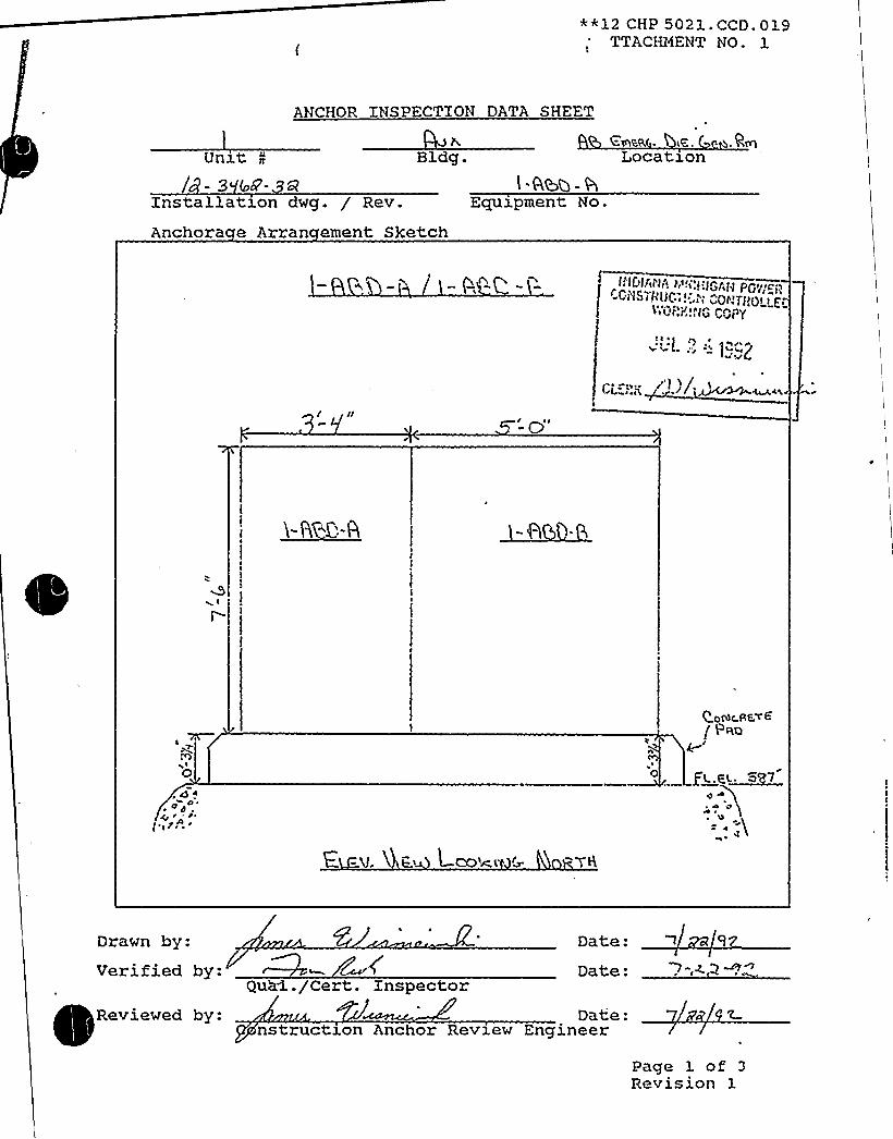
**12 CHP 5021. CCD. 019TTACHHENT NO. 1
ANCHOR INSPECTION DATA SHEET
Bldg. Location
Installation dwg. / Rev.
Anchora e Arran ement SketchEquipment No.
/ II
VIE
L ~
Q 4pOg
( 7
E, -v. K E.i Lco'm< G.
0
QOCOC.RETG
( P~o4
Drawn by:Verified by:
QuM./Cert. Inspector
Date:Date:
l
~q~n
Reviewed by: Date:nstructz.on Anchor Review Engineer
Page 1 of 3
Revision 1

**12 CHP 5021. CCD. 019TTACHMENT NO. 1
ANCHOR INSPECTION DATA SHEET
Ab F~ c,. i-.. Ce~ Q.~Unzt I Bldg. Locate.on
Installation dwg. / Rev.
Anchora e Arran ement Sketch
Equipment No.
I0 ~ 0
~ ~ r ~ 1 I
CLEi'-; 8) ) / ~r>Z~r-~
I rr
0
ELCJ. /AC+ Lop>W)|'h Z
Drawn by:Verified by:
Qua1. /Cert. Inspector
Date:Date.
Reviewed by: Date: 7 2»~nstructzon Anchor Review Engineer
Page 1 of 3Revision 1

* ' CHP 5021. CCD. 019.TTACHMENT NO. 1
ANCHOR INSPECTION DATA SHEET
4'b C ~ c,. ~.egg P~Un3.t g
- 3"/&-Bldg. Locate.on
Installation dwg. / Rev.
Anchora e Arran ement SketchEquipment No.
3-'I 6'-0t< cpa pygmy 4p& %%cd
P'g) g Q c~ll
LJL~>
A~5 An~So~
( ~!
2-'FV»
0
1~/A, l 3'/g
l'/i Typ
0VL fg
Drawn by:Verified by:
Qual./Cert. Inspector
Date:Date: >-r~
Reviewed by: Date:onstructzon Anchor Reve.ew Engineer
Page 1 of 3Revision 1


!
D ~ ~ II
0
~ ~
~ ~
C ~
I I ~ ~
I ~ ~
~ l~4
~ ~
~ ~ ~
~ ~
~ ~
o ~
~ ~
~ II II
~ - r.
Q
P 0
R%Ã~%~%~%%%~~~jIIIIHRIIIIIIIIWHIIINIIIRIIIRRLLI551IIWIIILLeimmmimemrr
RRIml%NIRSIj!mLLWRSHHR%WSLL~~5%~Wiiiimeemrr0' I$~%k%$%R%5%$%WW
~ ~l.~ l
I '
alMKWF
sC

**12 CHP 5021. CCD. 03.9ATTACHMENT NO. 1
ANCHOR INSPECTION DATA SHEET
Equipment No.: l- SO-
Embedded Steel Dwg. No.: ! - G3-
PHYSICAL CHARACTERISTICS
Dwg No.: 2"3
Weld IDT e
SizeLen thCracks Yes
0Yes Yes
3 II
Yesde
C
3 III
Yes Yes<HZ'esNoYesNo
Weld T e Codes1 = Fillet2 = Plug/Slot3 = Groove
Lack ofPenetrationPorosity
Yes YesCZb
Yes Yes Yes
Yes Yes
YesNo
YesNo
YesNo
YesNo
0 (=
SC(-Qs 4 Wrv ~ a.r <4'. W ~4(nc+ +0 aO KWUQS~Q gh'4e.
ULLQ DCTRIL
Equipment base flexible: 0 Yes 8 No
Reviewed by:ons ruc ron re Date: 7 z fe
Date:
Verified by:ua . era. npsec or 0,„:;I",: t !.<(.'i:I..".I "l!i!!Ao(.LLiP
i>IJ( 'I ':.:
4-'uc
ron nc or eve.ew ngzneerf6~~( r ;,i>(;!(I;.(r "..I('('((lhI; LI,:V/E!) Date:
QQIIIJ( ~ ~,. „'age 3 of 3
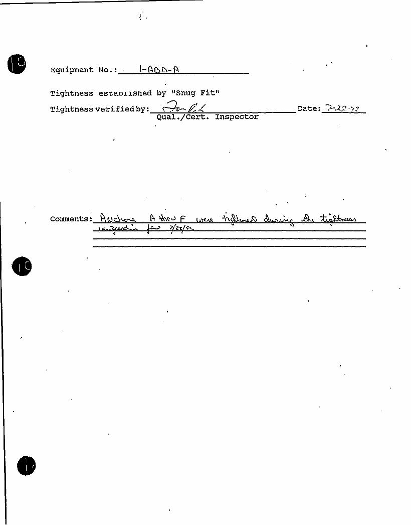
Equipment No.:
Tightness esvaoxzsned by "Snug Fit"Tightness verified by: ~- ',(
Qual. /Cert. Inspector
Comments: 4 Mc~ 9 4c >) z s

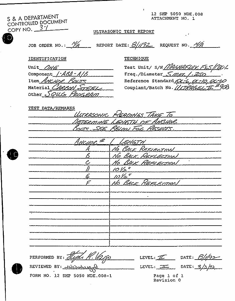
S 5 A DEPARTl4ENTCONTROLLED DOCUMENT
COPY NO.
JOB ORDER NO.:
12 SHP 5050 NDE.008ATTACHMENT NO. 1
Uf TRASONXC TEST REPORT
REPORT DATE: 8 ~ REQUEST NO.
IDENTIFICATION
UnitComponent:
ItemMaterialOther
Test Unit/ S/NWFrea./DiameterReference StandardCouplant/Batch No.
TEST DATA REMARKS
Ic' '
c
8'ERFORMED
BY:
REVIEWED BY: WD
FORM NO. 12 SHP 5050 NDE.008-1
f EVEf:~ DATE:
'VEE: ~ DATE:
Page 1 OERevision 0
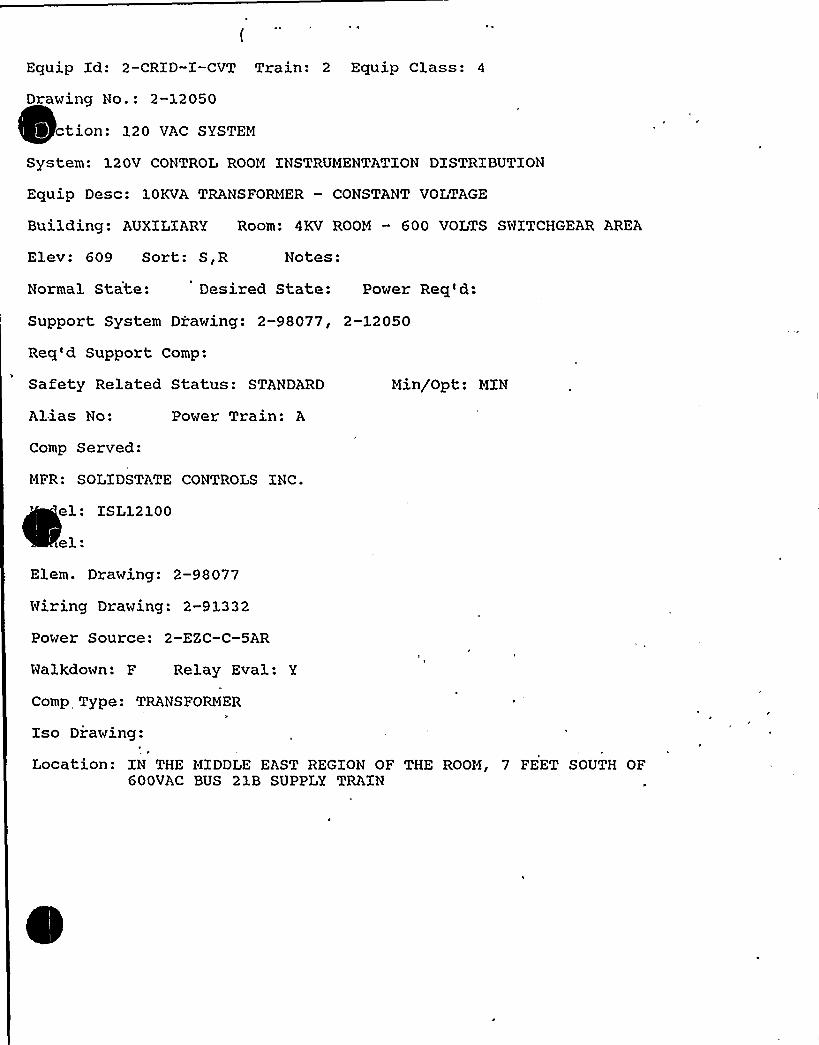
Equip Xd: 2-CRID-I-CVT Train: 2 Equip Class: 4
Drawing No.: 2-12050
ction: 120 VAC SYSTEM
System: 120V CONTROL ROOM XNSTRUMENTATXON DXSTRIBUTXON
Equip Desc: 10KVA TRANSFORMER — CONSTANT VOLTAGE
Building: AUXILIARY Room: 4KV ROOM — 600 VOLTS SWITCHGEAR AREA
Elev: 609 Sort: S,R Notes:
Normal State: Desired State: Power Req'd:
Support System Drawing: 2-98077, 2-12050
Req'd Support Comp:
Safety Related Status: STANDARD Min/Opt: MXN
Alias No:
Comp Served:
Power Train: A
MFR: SOLIDSTATE CONTROLS INC.
el: XSL12100
el:Elem. Drawing: 2-98077
Wiring Drawing: 2-91332
Power Source: 2-EZC-C-5AR
Walkdown: F Relay Eval: Y
Comp Type: TRANSFORMERk
Xso Diawing:
Location: XN THE MIDDLE EAST REGXON OF THE ROOM, 7 FEET SOUTH OF600VAC BUS 21B SUPPLY TRAIN

DC Cook Unit 2SCREENING EVALUATIONWORK SHEET (SEWS)
GIP Rev 2, Corrected, 2/14/92Status: YesSheet 1 of 11
ID: 2-GRID-I-CVT ( Rev. 0 ) Class: 4. TransformersDescription: 10KVATRANSFORMER - CONSTANT VOLTAGEBuilding: AUXILIARY Floor El.: 609.00 Room, Row/Col: 4KV RM - 600V
SWGR AREA - IN THE MIDDLEEAST REGION OF THE ROOM, 7FEET SOUTH OF 600VAC BUS21B SUPPLY TRAIN
Manufacturer, Model, Etc.: SOLIDSTATE CONTROLS INC. ISL12100
SEISMIC CAPACITYVS DEMAND
Elevation where equipment receives seismic inputElevation of seismic input below about 40'rom grade (grade = 608.00Equipment has fundamental frequency above about 8 Hz (est. frequency = 8.00)Capacity based on: 1.50 * Bounding SpectrumDemand based on: 1.00 * Realistic Mean-Centered Floor Response Spectra
633.00N/AN/A
1.200
LOG
0.085
\
/\
r/I
//
//r
0.S0 LOG HzCapacity ..... Demand
S0.00
CapacityDemand 1
Demand 2
C:tGIPLGIPtspectra.desC."tGIP'PROJ0032tspectra.desC:tGIPLPROJ0032tspectra.des
RecordLabellBounding SpectrumBUILDINGAuxilia ELEVATION633 BROADEN NBUILDINGAuxilia ELEVATIONI633IBROADENN
Does capacity exceed demand'

DC Cook Unit 2SCREENING EVALUATIONWORK SHEET (SEWS)
GIP Rev 2, Corrected, 2/1 4/92Status: YesSheet 2 of 11
ID: 2-CRID-I-CVT( Rev. 0) Class .'. TransformersDescription: 10KVATRANSFORMER - CONSTANT VOLTAGEBuilding: AUXILIARY Floor El.: 609.00 Room, Row/Col: 4KV RM - 600V
SWGR AREA - IN THE MIDDLEEAST REGION OF THE ROOM, 7FEET SOUTH OF 600VAC BUS21B SUPPLY TRAIN
Manufacturer, Model, Etc.: SOLIDSTATE CONTROLS INC. ISL12100
CAVEATS - BOUNDING SPECTRUM
TRN/BS Caveat 1 - Earthquake Experience Equipment ClassTRN/BS Caveat 2 - Rating of 4.16 KVor Less.
'RN/BSCaveat 3- Transformer Coils Postively Restrained Within CabinetTRN/BS Caveat 4- Coils Top Braced or Anal zed for Large Transformers.TRN/BS Caveat 5- Clearance Between Energized Component and Cabinet.TRN/BS Caveat 6- Adequate Slack in High Voltage Leads.TRN/BS Caveat 7- Wall-Mounted Units Anchored Close to Enclosure Structure.TRN/BS Caveat 8 - Weak-Way Bending of Thin Webs Evaluated.TRN/BS Caveat 9 - Adjacent Cabinets Bolted Together.TRN/BS Caveat 10 - Doors Secured.TRN/BS Caveat 11 - Adequate AnchorageTRN/BS Caveat 12- Potential Chatter of Essential Relays Evaluated.TRN/BS Caveat 13 - No Other Concerns.
YesYesYesN/AYesYesN/AYesN/AYesYesN/AYes
Is the intent of all the caveats met for Bounding Spectrum?
ANCHORAGE
1. The sizes and locations of anchors have been determined2. Appropriate equipment characteristics have been determined (mass, CG, natural freq.,
damping, center of rotation).3. The type of anchorage is covered by the GIP4. The adequacy of the anchorage installation has been evaluated (weld quality and length, nuts
and washers, expansion anchor tightness,'etc.)5. Factors affecting anchorage capacity or margin of safety have been considered: embedment~ length, anchor spacing, free-edge distance, concrete strength/condition, and concrete-
cracking.6. For bolted anchorages, any gaps under the base are less than 1/47. Factors affecting essential relays have been considered: gaps under the base, capacity
reduction for expansion anchors.8. The base has adequate stiffness and the effect of prying action on anchors has been
considered.9. The strength of the equipment base and the load path to the CG is adequate.10. The adequacy of embedded steel, grout pads or large concrete pads have been evaluated.11. The anchorage capacity exceeds the demand.
YesYes
YesYes
Yes
YesN/A
Yes
YesYesYes
Are anchorage requirements met?

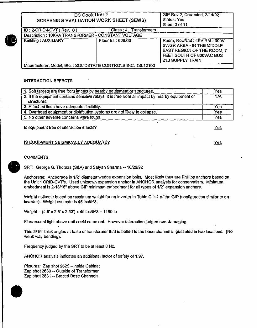
DC Cook Unit 2
SCREENING EVALUATIONWORK SHEET (SEWS)GIP Rev 2, Corrected, 2/14/92Status: YesSheet 3 of 11
ID: 2-GRID-I-CVT'( Rev. 0 ) Class: 4. TransformersDescription: 10KVATRANSFORMER - CONSTANT VOLTAGEBuilding: AUXILIARY Floor El.: 609.00 Room, Row/Col: 4KV RM - 600V
SWGR AREA - IN THE MIDDLEEAST REGION OF THE ROOM, 7FEET SOUTH OF 600VAC BUS21B SUPPLY TRAIN
Manufacturer, Model, Etc.: SOLIDSTATE CONTROLS INC. ISL12100
INTERACTION EFFECTS
1. Soft targets are free from impact by nearby equipment or structures2. Ifthe equipment contains sensitive relays, it is free from all impact by nearby equipment or
structures.3. Attached lines have adequate flexibility.4. Overhead equipment or distribution systems are not likely to collapse.5. No other adverse concerns were found.
YesN/A
YesYesYes
Is equipment free of interaction effects'P
C L D
~CON IE~S
SRT: George G. Thomas (S8A) and Satyan Sharma -10/29/92
Anchorage: Anchorage is 1/2" diameter wedge expansion bolts. Most likely they are Phillips anchors based onthe Unit 1 GRID-CVT's. Used unknown expansion anchor in ANCHOR analysis for conservatism. Minimumembedment is 2-13/16" above GIP minimum embedment for all types of 1/2" expansion anchors.
Weight estimate based on maximum weight for an inverter in Table C.1-1 of the GIP (configuration similar to aninverter). Weight estimate is 45 Ibs/ft"3.
Weight = (4.5' 2.5' 2.33') x 45 Ibs/ft"3 = 1180 Ib
Fluorescent light above unit could come out. However interaction judged non4amaging
Thin 3/16" thick angles at base of transformer that is bolted to the base channel is gusseted in two locations. (Noweak way bending).
Frequency judged by the SRT to be at least 8 Hz.
ANCHOR analysis indicates an additional factor of safety of 1.97.
Pictures: Zap shot 2629 -Inside CabinetZap shot 2630 —Outside of TransformerZap shot 2631 —Braced Base Channels

DC Cook Unit 2SCREENING EVALUATIONWORK SHEET (SEWS)
GIP Rev 2, Corrected, 2/14/92Status: YesSheet 4 of 11
ID: 2-GRID-I-CVT ( Rev. 0) Class: 4. TransformersDescription: 10KVATRANSFORMER - CONSTANT VOLTAGEBuilding: AUXILIARY Floor El.: 609.00 Room, Row/Col: 4KV RM -600V
SWGR AREA - IN THE MIDDLEEAST REGION OF THE ROOM, 7FEET SOUTH OF 600VAC BUS21B SUPPLY TRAIN
Manufacturer, Model, Etc.: SOLIDSTATE CONTROLS INC. ISL12100
Evaluated by: Date:
// «gzAttachment: PicturesAttachment: ANCHOR Report


DC Cook Unit 2SCREENING EVALUATIONWORK SHEET (SEWS)
GIP Rev 2, Corrected, 2/14/92Status: YesSheet 5 of 11
ID: 2-GRID-I-CVT( Rev. 0 ) Class: 4. TransformersDescription: 10KVATRANSFORMER - CONSTANT VOLTAGEBuilding: AUXILIARY Floor El.: 609.00 Room, Row/Col: 4KV RM - 600V
SWGR AREA - IN THE MIDDLEEAST REGION OF THE ROOM, 7FEET SOUTH OF 600VAC BUS21B SUPPLY TRAIN
Manufacturer, Model, Etc.: SOLIDSTATE CONTROLS INC. ISL12100
P IC~UIRg$
C
t
Braced Base Channels Inside Cabinet
'
Outside of Transformer

DC Cook Unit 2SCREENING EVALUATIONWORK SHEET (SEWS)
GIP Rev 2, Corrected, 2/14/92Status: YesSheet 6 of 11
ID: 2-GRID-I-CVT( Rev. 0) Class: 4. TransformersDescription: 10KVATRANSFORMER - CONSTANT VOLTAGE8uilding: AUXILIARY Floor El.: 609.00
Manufacturer, Model, Etc.: SOLIDSTATE CONTROLS INC. ISL12100
Room, Row/Col: 4KV RM - 600VSWGR AREA - IN THE MIDDLEEAST REGION OF THE ROOM, 7FEET SOUTH OF 600VAC 8US218 SUPPLY TRAIN
ANCHOR Report
~~~use'esponseSpectrum:!nstructure Realistic
Frequency: User - 8.00Percent Damping: User - 5.00
Spectral Values:DirectionNorth - SouthEast - WestVertical
Acceleration (g's)0.360.360.18
Angle (N-S Direction makes with the X Axis): 0.00Combination Criteria: SRSS
W~~s'umber of Weights: 1
No Weight1 1180.00 14.000 14.250 35.375
Porcine
Number of External Forces: 0
gl~oe~sNumber of External Moments: 0
~llowat~s.~n~Number of Anchor types: 1
Ultimate UltimateTension
InterShearInter Saf
No Dia Manufact Product Tension Shear 'oeff Coeff Fact1/2 Other Unknown
ExpansionAnchor
2290.00 2380.00 1.00 0.30 1.00
~rgbUltimate Stress: 3500.00 psi.


DC Cook Unit 2
SCREENING EVALUATIONWORK SHEET (SEWS)GIP Rev 2, Corrected, 2/14/92Status: YesSheet 7 of 11
ID: 2-GRID-I-CVT(Rev. 0) Class: 4. TransformersDescription: 10KVATRANSFORMER - CONSTANT VOLTAGEBuilding: AUXILIARY Floor El.: 609.00
Manufacturer, Model, Etc.: SOLIDSTATE CONTROLS INC. ISL12100
Reduction Factor: 0.85
Room, Row/Col: 4KV RM - 600VSWGR AREA - IN THE MIDDLEEAST REGION OF THE ROOM, 7FEET SOUTH OF 600VAC BUS218 SUPPLY TRAIN
~W
Allowable Stress: 0 psi.
~uNumber of Surfaces: 1
Surface OrientationDirection
Comp
0.000
DirectionComp
0.000
DirectionComp
1.000
Anchor Pattern for Surface 0 1
Legend for Anchor Patterns

DC Cook Unit 2SCREENING EVALUATIONWORK SHEET (SEWS)
GIP Rev 2, Corrected, 2/14/92Status: YesSheet 8 of 11
ID: 2-GRID-I-CVT( Rev. 0) Class: 4. TransformersDescription: 10KVATRANSFORMER - CONSTANT VOLTAGEBuilding: AUXILIARY Floor El.: 609.00 Room, Row/Col: 4KV RM - 600V
SWGR AREA - IN THE MIDDLEEAST REGION OF THE ROOM, 7FEET SOUTH OF 600VAC BUS21B SUPPLY TRAIN
Manufacturer, Model, Etc.: SOLIDSTATE CONTROLS INC. ISL12100
Anchor Bolts:
Concrete Lines: ~ItinConcrete Points: ~mtmW'eld Lines '.
~Ge retryAn(QIL'Number of Anchors: 4
NoAnch
Id Coord1.500
26.4381.750
26.875
Coord0.7500.750
27.75027.750
Coord0.0000.0000.0000.000
SurfId
ft of elements per line: 1
Number of Concrete Lines: 2
NoStart
X-Coord0.0000.000
StartY-Coord
0.89127.609
Sta~Z-Coord
0.0000.000
EndX-Coord
28.06328.000
EndY-Coord
0.89127.609
EndZ-Coord
0.0000.000
SfId
LineWidth
1.7811.781
Number of Concrete Points: 0
KeldJ.um4 of elements per line: 5Number of Weld Lines: 0
er i in u i a oReduction Factor Input for Anchor 0 1


OC Cook Unit 2SCREENING EVALUATIONWORK SHEET (SEWS)
GIP Rev 2, Corrected, 2/14/92Status: YesSheet 9 of 11
ID: 2-GRID-I-CVT(Rev. 0) Class: 4. TransformersDescription: 10KVATRANSFORMER - CONSTANT VOLTAGEBuilding: AUXILIARY Floor El.: 609.00 Room, Row/Col: 4KV RM - 600V
SWGR AREA - IN THE MIDDLEEAST REGION OF THE ROOM, 7FEET SOUTH OF 600VAC BUS21B SUPPLY TRAIN
Manufacturer, Model, Etc.: SOLIDSTATE CONTROLS INC. ISL12100
Adequately Installed: YesGap at Threaded Anchor: 0.00 in.Edge Distance - Edge 1: 5.00 in.Crack Size: 0.000 in. - Cracks Affect <= 50% BoltsEssential Relays in Cabinet: NoAdequate Equipment Base Strength and Structural Load Path: YesEmbedment Steel and Pads Adequately Installed: Yes
Reduction Factor Input for Anchor ¹ 2
Adequately Installed: YesGap at Threaded Anchor: 0.00 in.Edge Distance - Edge 1: 5.00 in.Crack Size: 0.000 in. - Cracks Affect <= 50% BoltsEssential Relays in Cabinet: NoAdequate Equipment Base Strength and Structural Load Path: YesEmbedment Steel and Pads Adequately Installed: Yes
Reduction Factor Input for Anchor ¹ 3
Adequately Installed: YesGap at Threaded Anchor: 0.00 in.Edge Distance - Edge 1: 5.00 in.Crack Size: 0.000 in. - Cracks Affect <= 50% BoltsEssential Relays in Cabinet: NoAdequate Equipment Base Strength and Structural Load Path: YesEmbedment Steel and Pads Adequately Installed: Yes
Reduction Factor Input for Anchor ¹ 4
Adequately Installed: YesGap at Threaded Anchor: 0.00 in.Edge Distance - Edge 1: 5.00 in.Crack Size: 0.000 in. - Cracks Affect <= 50% BoltsEssential Relays in Cabinet: NoAdequate Equipment Base Strength and Structural Load Path: YesEmbedment Steel and Pads Adequately Installed: Yes
Reduction Factors Data Current: Yes
AncNo Id
PaIVVali
Pallr/Vallr RT RN RL RG RS RE RF RC RR RP RB RM
1' 1202.25 N/A 0.60 1.00 X 1.00 1.00 1.00 0.88 1.00 1.00 1.00 1.00 1.00
1428.001202.25
N/AN/A
0.60 1.000.60 1.00
X 1.00 1.00X 1.00 1.00
1.00 1.00 1.00 1.001.00 0.88 1.00 1.00
1.001.00
1.00 1.001.00 1.00


DC Cook Unit 2SCREENING EVALUATIONWORK SHEET (SEWS)
GIP Rev 2, Corrected, 2/14/92Status: YesSheet 10 of 11
ID: 2-GRID-I-CVT( Rev. 0) Class: 4. TransformersDescription: 10KVATRANSFORMER - CONSTANT VOLTAGEBuilding: AUXILIARY Floor El.: 609.00 Room, Row/Col: 4KV RM - 600V
SWGR AREA - IN THE MIDDLEEAST REGION OF THE ROOM, 7FEET SOUTH OF 600VAC BUS21B SUPPLY TRAIN
Manufacturer, Model, Etc.: SOLIDSTATE CONTROLS INC. ISL1 2100
1428.00 NIA 0.60 1.00 X 1.00 1.00 1.00 1.00 1.00 1.00 1.00 1.00 1.003 1 1202.25 NIA
1428.00 NIANIA1202.25
1428.00 NIA
0.60 1.00 X0.60 1.00 X0.60 1.00 X0.60 1.00 X
1.00 1.001.00 1.001.00 1.001.00 1.00
1.00 0.88 1.001.00 1.00 1.001.OO O.88 1.OO
1.00 1.00 1.00
1.00 1.00 1.001.00 1.00 1.001.00 1.00 1.001.00 1.00 1.00
1.001.001.001.00
N/AI aliVanPallrVallr
RT
RLRGRS
RCRRRP
= Not Applicable= Allowable Pull without Reduced inspection= Allowable Shear without Reduced Inspection= Allowable Puli with Reduced Inspection= Allowable Shear with Reduced Inspection= Outlier= Reduction Factor Not Used= Reduction Factor for Type of Anchorage= Reduction Factor for Installation Adequacy= Reduction Factor for Embedment= Reduction Factor for Gap at Anchors= Reduction Factor for Spacing= Reduction Factor for Edge Distance= Reduction Factor for Concrete Strength= Reduction Factor for Concrete Cracks= Reduction Factor for Essential Relays= Reduction Factor for Base Stiffness and Prying Action= Reduction Factor for Base Strength and Load Path= Reduction Factor for Embed. Steel and Pads
Analysis Performed: Yes
Type of Analysis: RegularSpectral Accelerations (G's)
N-S0.362
-0.362-0.3620.3620.362
-0.3620.362
-0.3620.145
E-W0.145
-0.1450.145
-0.145-0.1450.1450.145
-0.1450.362
Vertical0.073
-0.0730.073
-0.0730.073
-0.073-0.0730.0730.073
Safety Factor1.9692.0062.0091.9711.9712.0081.9692.0073.820

DC Cook Unit 2
SCREENING EVALUATIONWORK SHEET (SEWS)GIP Rev 2, Corrected, 2/14/92Status: YesSheet 11 of 11
ID: 2-GRID-I-CVT(Rev. 0) Class: 4. TransformersDescription: 10KVATRANSFORMER - CONSTANT VOLTAGEBuilding: AUXILIARY Floor El.: 609.00
Manufacturer, Model, Etc.: SOLIDSTATE CONTROLS INC. ISL12100
Room, Row/Col: 4KV RM - 600VSWGR AREA - IN THE MIDDLFEAST REGION OF THE ROOM, 7FEET SOUTH OF 600VAC BUS21B SUPPLY TRAIN
10
1213141516171819
2021222324
-0.1450.145
-0.145-0.1450.1450.145
-0.1450.145
-0.1450.145
-0.145-0.1450.1450.145
-0.145
- -0.362-0.3620.3620.362
-0.3620.362
-0.3620.145
-0.1450.145
-0.1450.145
-0.145-0.1450.145
-0.0730.073
-0.0730.073
-0.073-0.0730.0730.183
-0.183-0.1830.1830.183
-0.1830.183
-0.183
4.1963.8114.1983.86T4.1444.1463.8694.9175.0104.9225.0165.0274.9344.9285.022
Minimum Safety Factor: 1.969
The Anchorage Capacity is 1.969 times greater than the Demand

Coo
Component Ão.2 ( ~~~ "T C4T Claca ~
Any particular area tha Sei.smic Review Team should pay extra attention totYes W Ho (Xf yes, check items that, apply.)
Anchor TypeAnchor DiameterAnchor SpacingAnchor NumberAnchor EmbedmentvAnchor Edge DistanceAnchor GapAnchor Thread EngagementAnchor GripAnchor AngularityConcrete Crack
Others (describe briefly)
If there is concern for Design Basis Di.screpancy, circle the «pplicableitem and explain.
Harcfvare Haintenance Type DiscrepancyDrawing Update Type Di.screpancyS igni.ffcant Operability/Design Basi.s DiscrepancyOthers
Condition:
Actions Taken:
Prepared Sy Dsta ~R-<< 3

**12 CHP 5021. CCD. 019ATTACHMENT NO. 1
Un1typt4 tR T3/2- W <~-n-9>
Installation dwg. / Rev.
Anchora e Arran ement Sketch
ANCHOR jNSPECTION DATA SHEET
AuK VAv ~0'7-'ldg.Location
4 Q.Pro-+-C.v wEquipment No.
2 -CFiQ- 7=C.VT
I ~ II
"'iiÃ7
OS> leaf. OV»
3II
il9 clonic)
ELp V. V low Looki'n
gtl
'Pao ~iNoR~h
Drawn by:Verified by. Q~(
Date: ri zv e»
Qual. /Cert. InspectorReviewed by: T Date: ~ ~ (l- 'l~
Construction Anc or Review Engineer
Page 1 of 3Revision 1


**12 CHP 5021.CCD.019ATTACHMENT NO. 1
ANCHOR INSPECTION DATA SHEET
Un1t Bldg.T3'~-II-9W
Location
Installation dwg. / Rev.
Anchora e Arran ement SketchEquipment No.
+ /a. BoLT
GYP
EI-BQ- glE,A Lope.<toG- ER
Drawn by:Verified by:
Date:
Date:, I~.7- lZ.Qual. /Cert. Inspector
Reviewed by: T " 4>'~4~~. Date:Construction An hor Review Engineer
Page 1 of 3Revision 1

I

++12 CHP 5021-CCD.Q19ATTACHMENT NO. 1
ANCHOR INSPECTION DATA SHEET
VAv ~~ 0 .'g'z5Un>.t 5 Bldg. Locationi>- Sq.7&- t
7 ~> <I 'I> C.~SO 2- QvfInstallation dwg. / Rev. Equipment No.
Anchora e Arran ement Sketch
~ls ~i)
d O'A
~ ~
IPIt e ~
~"~i"i> ~ ( Cur Y
t~".;ll >O )f95
Date: /l 2'. 7Drawn by:Verified by: 8 8(f. Date: IZ=l- I Z.
Qual. /Cert. InspectorReviewed by: T. +~'-<k. Date:
Construe won An hor Review Engineer
Page 1 of 3Revision 1

**12 CHP 502 1 . CCD. 0 1.9
( ATTACHMENT NO. 1
ANCHOR XNSPECTXON DATA SHEET
g /CA+ ~g v'P~ Dg- g" Fc
Unxt 5 Bldg. Location) ~ - 3 q)'o -('))
/ ) %-)l-I)> g Q I O-Z-C.vgInstallation dwg. / Rev. Equipment No.
Anchora e Arran ement Sketch
e
el0
'"4')
I:Ii~ Il ~
~ I
I II -3 II3II ~ rIrJ~)
D
3 - D'li~II- 9'/i).
l e n ~ + </) p'II'IA::«U lQ90
R'h l= )
Lc'qy, $
Drawn by: Date:Date: /2 7- "~.Verified b (
Qual. /Cert. XnspectorReviewed by: I')&<L~I Date:
Construction Anchor Review Engineer
Page 1 of 3Revision 1

lSSRSSLLLLRSLLL5WWHRESHWl5WRHSRI - - WLHLL~RHSSWS~~~~55%5%5%RHWS.5%RSWMMMWRI~~~~~~~M


4*12 CHP 5021.CCD.019ATTACHMENT NO. 1
ANCHOR XNSPECTXON DATA SHEET
Equipment No.: ~. C~ 0- -VT'mbeddedSteel Dwg. No.:
PHYSXCAL CHARACTERXSTXCS
Dwg No..: ~V~<7i <-3 q7b-te
T~i~-n- 'I
Weld XD
T e
SizeLen th
O'I 4/~ Weld T e Codes1 = Fillet2 = Plug/Slot3 = Groove
Cracks
Lack ofPenetrationPorosity
Yes
YesN
s0
0
Y s0
Yes
YesNo
YesNo
YesNo
YesNo
YesNo
YesNo
YesNo
YesNo
YesNo
YesNo
YesNo
YesNo
Vt."~B )0 18'~
Equipment base
Reviewed'y:
Verified by:
flexible: 0 Yes I No T'> u ~~4~~~ons r c ron e
ons r son nc o evxew ngxneernua . er . npsec or
Date:
Date: I l.- il-
Date: IZ. 7-~ L
Page 3 of 3
Revision 1


S 8 A DEPARTMENTCONTROL.FO OOCUMENT
COPY NO.
12 SHP SOSO NDE.008ATTACHMENT NO. 1
ULTRASONIC TEST REPORT
ZOB ORDER NO.: REPORT DATE: //3:~ ~ REQUEST NO.
IDENTIFICATION
Unit /~ComponentItem r " JMaterial >5Other
Test Unit/ S/NFreq./DiameterReference StandardCouplant/Batch No.
c - '() ~
TEST DATA REMARKS
/, g
PERFORMED BY:
REVIEWED BY:
FORM NO. 12 SHP S050 NDE.008-1
LEVEL:~ DATE: /LEVEL: ~ DATE: ll
Page 'f 1Revision 0

Equipment No.: - CQX'Q-X-C.'d
Tightness established by "Snug Fit"Tightness verified by: & (."z <PL
'ual./Cert. Inspector
Comments:

01/16/92>G. MG. 72
sAFE'KvtoouN EGUIpHENT LisT (ssELMp)
FUMCTIOM: CCM
Equipment Class: 5 train: 1
Equipment IO: I-PP.IOM Orauing H +bert 1.5135A
SyStem: CCM
Equip Description: LIESt CCM PVHP
Building: AUXILIARY Room: 609 KALLMAY Elevation: 609
Normal state: R/NR Oesired state: R Pouer Required: Y Sort: M,R
Suceorting System Orauing Herbert 1-12001 1-12060 1-98/05
Required Interconnections and Supporting Coeponentst 'I-T11A7 I.HCAB-3
fetv Related Status: NUCLEAR SR( Hin/Opt: HIN
AOOITIONAL IHFORHATION
IAl ias Hubert Pouer Train: 8
C~nt Served: VEST CCM PVHP
Hanufacturer: IHGERSOI.L-RANO CO Hodel: 9000CPH
Panel: I-CCM I-HSOI
E I cm Orauing: 1-98405 Miring Orauing: 1-93011
Pover Source: 1-1'I IA7, 1-HCAB-3
ual tdount F Relay Only: Y
C~nent Type: PVHP
ISO Orauings:
Oetai led Location:

D.C. COOK Unit 1
SCREENING EVALUATIONWORK SHEET (SEWS)GIP Rev 2, Corrected, 2/14/92Status: YesSheet 1 of 11
ID: 1-PP-10W( Rev. 0)Description: WEST CCW PUMP
Class: 5. Horizontal Pumps
Building: AUXILIARY Floor El.: 609.00 Room, Row/Col: HALL AY,Manufacturer, Model; Etc.: INGERSOLL-RANDCO 9000GPM
SEISMIC CAPACITYYS DEMAND
1. Elevation where equipment receives seismic inputElevation of seismic input below about 40'rom grade (grade = 608.00)
3. Equipment has fundamental frequency above about 8 Hz (est. frequency = 20.00)Capacity based on: 1.00 * Bounding SpectrumDemand based on: 1.00 Design Basis Ground Response Spectrum
609.00YesYes
0.800
c'OCi
0.090
/rr/
/
//r/
0.50 LOG HzCapacity ..... Demand
33.00
CapacityDemand 1
Demand 2
C:tGIPtGIPtspectra.desC:tGIPLPROJ0035tspectra.desCAGIPIPROJ0035tspectra.des
RecordLabel Bounding SpectrumBUILDINGGround(ELEVATIONI608 BROADEN NBUILDINGGround ELEVATION608 BROADEN N
Does capacity exceed demand?


D.C. COOK Unit 1
SCREENING EVALUATIONWORK SHEET (SEWS)GIP Rev 2, Corrected, 2/14/92Status: YesSheet 2 of 11
ID:1-PP-10W(Rev. 0)Description: WEST CCW PUMP
Class: 5. Horizontal Pumps
Building: AUXILIARY Floor El.: 609.00 Room, Row/Col: HALLWAY,Manufacturer, Model, Etc.: INGERSOLL-RAND CO 9000GPM
CAVEATS - BOUNDING SPECTRUM
HP/BS Caveat 1 - Earthquake Experience Equipment ClassHP/BS Caveat 2- Driver and Pump on Rigid SkidHP/BS Caveat 3 - Thrust Bearings in Both Axial DirectionsHP/BS Caveat 4 - Check of Long Unsupported PipingHP/BS Caveat 5 - Base Vibration Isolation System Checked.HP/BS Caveat 6 - Sufficient Slack and Flexibilityof Attached Lines.HP/BS Caveat 7 - Adequate Anchorage.HP/BS Caveat 8 - Potential Chatter of Essential Relays Evaluated.HP/BS Caveat 9- No Other Concerns.
Is the intent of all the caveats met for Bounding Spectrum?
ANCHORAGE
YesYesYesYesYesYesYesN/AYes
1. The sizes and locations of anchors have been determined2. Appropriate equipment characteristics have been determined (mass, CG, natural freq.,
damping, center of rotation).3. The type of anchorage is covered by the GIP4. The adequacy of the anchorage installation has been evaluated (weld quality and length, nuts
and washers, expansion anchor tightness, etc.)5. Factors affecting anchorage capacity or margin of safety have been considered: embedment
length, anchor spacing, free-edge distance, concrete strength/condition, and concretecracking.
6. For bolted anchorages, any gaps under the base are less than 1/47. Factors affecting essential relays have been considered: gaps under the base, capacity
reduction for expansion anchors.8. The base has adequate stiffness and the effect of prying action on anchors has been
considered.9. The strength of the equipment base and the load path to the CG is adequate10. The adequacy of embedded steel, grout pads or large concrete pads have been evaluated.11. The anchorage capacity exceeds the demand.
Are anchorage requirements met?
INTERACTION EFFECTS
YesYes
YesYes
Yes
YesN/A
Yes
YesYesYes*
1. Soft targets are free from impact by nearby equipment or structures2. If the equipment contains sensitive relays, it is free from all impact by nearby equipment or
structures.3. Attached lines have adequate flexibility4. Overhead equipment or distribution systems are not likely to collapse.5. No other adverse concerns were found.
YesN/A
YesYesYes
Is equipment free of interaction effects?

D.C. COOK Unit 1
SCREENING EVALUATIONWORK SHEET (SEWS)GIP Rev 2, Corrected, 2/14/92Status: YesSheet 3 of 11
ID: 1-PP-10W(Rev. 0 }Description: WEST CCW PUMP
Class: 5. Horizontal Pumps
Building: AUXILIARY Floor EI.: 609.00 Room, Row/Col: HALLWAY,Manufacturer, Model, Etc.: INGERSOLL-RAND CO 9000GPM
IS E UIPME T SEISMIC LLY DE UATE> ~es
CO MEN S
SRT: John D. Stevenson, Paul Wilson, Rick Leonard, and Kaifash Mahajan on 10/5/93.
MFG: INGERSOLL-RAND PUMP, 9000 G.P.M.
Anchorage: 6-3/4" J-Bolts.Total WT=9580 lbs. C.G.=35" above base.
'Minor cracks in non-Struct. pad judged insignificant.
Nozzle loads were applied in the ANCHOR analysis. Nozzle loads were obtained from AEP "SUMMARYOFLOAD ON EQUIPMENT" 11/2/71, Summary of Loads on Pumps for CCW Ã1W PUMP, (microfilm page00100020022) and included deadweight, thermal, thermal anchor movements, and seismic loads.
Ref. Drwgs.: Ingersoll-Rand C-14ALV86X51, W-16ALV500X17, AEPSC 12-3286-9, 12-3073B-2, 12-3073A-3, 12-
~ ~
~
3285-23, Livsey 8 Co. 1-CCW-37, Rev. 5, Sh. 2 of 2.
Picture f/12, Wk1, Tmi, Disk2
Evaluated by:c- /
Date:
Ot
8- ZS- qS
tta nt'i u esachm ' e 0


D.C. COOK Unit 1
SCREENING EVALUATIONWORK SHEET (SEWS)GIP Rev 2, Corrected, 2/14/92Status: YesSheet 4 of 11
ID: 1-PP-10W( Rev. 0) Class: 5. Horizontal PumpsDescription: WEST CCW PUMPBuilding: AUXILIARY Floor El.: 609.00 Room, Row/Col: HALLWAY,Manufacturer, Model ~ Etc.: INGERSOLL-RAND CO 9000GPM
CTUR S
4 ~
L j
41-PP-10W West CCW Pump-Anchorage

D.C. COOK Unit 1
SCREENING EVALUATIONWORK SHEET (SEWS)GIP Rev 2, Corrected, 2/14/92Status: YesSheet 5 of 11
ID: 1-PP-10W( Rev. 0) Class: 5. Horizontal PumpsDescription: WEST CCW PUMPBuilding: AUXILIARY Floor El.: 609.00 Room, Row/Col: HALLWAY,Manufacturer, Model, Etc.: INGERSOLL-RANDCO 9000GPM
ANCHOR Report
~Ea h ua e:
Response Spectrum: SSE
Frequency: GIP - Rigid
Percent Damping: GIP - 5.00
Spectral Values:
DirectionNorth - SouthEast - WestVertical
Acceleration (g's)0.380.380.25
Angle (N-S Direction makes with the X Axis): 0.00
Combination Criteria: SRSS
~We'gag
'umberof Weights: 1
No Weight1 9580.00 105.400 20.750 35.000
o ces
Number of External Forces: 2
No Fx Fy Fz1 2.86E+003 1.24E+003 -3.24E+0032 -2.36E+003 2.24E+003 -4.85E+003
26.87026.870
-5.25047.750
17.00019.000
/~mme
Number of External Moments: 2
No Mx My1 4.88E+004 1.68E+0052 6.32E+004 8.76E+004
3.34E+004-1.60E+004


D.C. COOK Unit 1
SCREENING EVALUATIONWORK SHEET (SEWS)GIP Rev 2, Corrected, 2/14/92Status: YesSheet 6 of 11
ID: 1-PP-10W ( Rev. 0 )Description: WEST CCW PUMP
Class: 5. Honzontal Pumps
Building: AUXILIARY Floor El.: 609.00 Room, Row/Col: HALLWAY,Manufacturer, Model
~ Etc.: INGERSOLL-RAND CO 9000GPM
~llowal>les:
~nor'umber
of Anchor types: 1
Ultimate UltimateTension
InterShearInter Saf
Dia Manufact Product Tension Shear Coeff Coeff Fact3/4 Other J-Bolt (90
deg) 15030.007510.00 1.00 0.30 1.00
Gmseng
Ultimate Stress: 3500.00 psi.
Reduction Factor: 0.85
Allowable Stress: 30600 psi.
S~ua c~Number of Surfaces: 1
Surface Orientation
No
DirectionComp
Nx0.000
DirectionComp
Ny0.000
DirectionComp
Nz1.000
Anchor Pattern for Surface ¹ 1

t '

D.C. COOK Unit 1
SCREENING EVALUATIONWORK SHEET (SEWS)GIP Rev 2, Corrected, 2/14/92Status: YesSheet 7 of 11
ID:1-PP-10W(Rev. 0)Description: WEST CCW PUMP
Class: 5. Honzontal Pumps
Building: AUXILIARY Floor El.: 609.00 Room, Row/Col: HALLWAY,Manufacturer, Model, Etc.: INGERSOLL-RAND CO 9000GPM
Legend for Anchor Patterns
Anchor Bolts: ~IIIK'~Concrete Lines: ~[~<nggg
Concrete Points:
Weld Lines
.'~e
Number of Anchors: 6
AnchId
1 1
2 1
3 1
4 1
5 1
6 1
Coord10.00059.750
109.50010.00059.750
109.500
Coord4.2504.2504.250
37.25037.25037.250
Coord0.0000.0000.0000.0000.0000.000
SurfId
r in

D.C. COOK Unit 1
SCREENING EVALUATIONWORK SHEET (SEWS)GIP Rev 2, Corrected, 2/14/92Status: YesSheet 8 of 11
ID: 1-PP-1 OW ( Rev. 0 )Description: WEST CCW PUMP
Class: 5. Horizontal Pumps
Building: AUXILIARY Floor El.: 609.00 Room, Row/Col: HALLWAY,Manufacturer, Model, Etc.: INGERSOLL-RAND CO 9000GPM
¹ of elements per line: 1
Number of Concrete Lines: 4
NoStart
X-Coord8.2508.2508.250
129.000
StartY-Coord
2.6252.625
37.2502.625
StartZ-Coord
0.0000.0000.0000.000
EndX-Coord129.000
8.250129.000129.000
EndY-Coord
2.62537.25037.25037.250
EndZ-Coord
0.0000.0000.0000.000
Sf LineWidth
1.0001.0001.0001.000
r Pin
Number of Concrete Points: 0
¹ of elements per line: 5
Number of Weld Lines: 0
D ter inati du on a
Reduction Factor Input for Anchor ¹ 1
Adequately Installed: YesEmbedment Length: (19.50 in. Min Reqd. to achieve full capacity):=40.88 in.Gap at Threaded Anchor: 0.00 in.Edge Distance - Edge 1: 4.00 in.Crack Size: 0.016 in. - Cracks traverses thru InstallationEssential Relays in Cabinet: NoAdequate Equipment Base Strength and Structural Load Path: YesEmbedment Steel and Pads Adequately Installed: Yes
Reduction Factor Input for Anchor ¹ 2
Adequately Installed: YesEmbedment Length: (19.50 in. Min Reqd. to achieve full capacity):=40.88 in.Gap at Threaded Anchor: 0.00 in.Edge Distance - Edge 1: 4.63 in.Crack Size: 0.016 in. - Cracks traverses thru InstallationEssential Relays in Cabinet: NoAdequate Equipment Base Strength and Structural Load Path: YesEmbedment Steel and Pads Adequately Installed: Yes
Reduction Factor Input for Anchor ¹ 3

I

D.C. COOK Unit 1
SCREENING EVALUATIONWORK SHEET (SEWS)GIP Rev 2, Corrected 2/14/92Status: YesSheet 9 of 11
Oa
ID: 1-PP-10W ( Rev. 0 )Description: WEST CCW PUMP
Class: 5. Horizontal Pumps
Room, Row/Col: HALLWAY,Floor El.: 609.00Building: AUXILIARYManufacturer, Model, Etc.: INGERSOLL-RAND CO 9000GPM
Adequately Installed: YesEmbedment Length: (19.50 in. Min Reqd. to achieve full capacity):=40.88 in.Gap at Threaded Anchor: 0.00 in.Edge Distance - Edge 1: 4.00 in.Crack Size: 0.016 in. - Cracks traverses thru InstallationEssential Relays in Cabinet: NoAdequate Equipment Base Strength and Structural Load Path: YesEmbedment Steel and Pads Adequately Installed: Yes
Reduction Factor Input for Anchor f/4
Adequately Installed: YesEmbedment Length: (20.06 in. Min Reqd. to achieve full capacity):=40.88 in.Gap at Threaded Anchor: 0.00 in.Edge Distance - Edge 1: 4.50 in.Crack Size: 0.016 in. - Cracks traverses thru InstallationEssential Relays in Cabinet: NoAdequate Equipment Base Strength and Structural Load Path: YesEmbedment Steel and Pads Adequately Installed: Yes
Reduction Factor Input for Anchor 0 5
I Adequately Installed: YesEmbedment Length: (20.00 in. Min Reqd. to achieve full capacity):=40.88 in.Gap at Threaded Anchor: 0.00 in.Edge Distance - Edge 1: 4.63 in.Crack Size: 0.016 in. - Cracks traverses thru InstallationEssential Relays in Cabinet: NoAdequate Equipment Base Strength and Structural Load Path: YesEmbedment Steel and Pads Adequately Installed: Yes
Reduction Factor Input for Anchor f/6
Adequately Installed: YesEmbedment Length: (19.25 in. Min Reqd. to achieve full capacity):=40.88 in.Gap at Threaded Anchor: 0.00 in.Edge Distance - Edge 1: 4.38 in.Crack Size: 0.016 in. - Cracks traverses thru InstallationEssential Relays in Cabinet: NoAdequate Equipment Base Strength and Structural Load Path: YesEmbedment Steel and Pads Adequately Installed: Yes
Reduction Factors Data Current: Yes
AncNo Id
Pall/Vali
5342.332798.39
Pallr/VallrN/AN/A
RT RN1.00 1.001.00 1.00
RL RG0.54 1.001.00 1.00
RS RE1.00 0.651.00 0.37
RF RC1.00 1.001.00 1.00
RR1.001.00
RP RB RM1.00 1.00 1.001.00 1.00 1.00

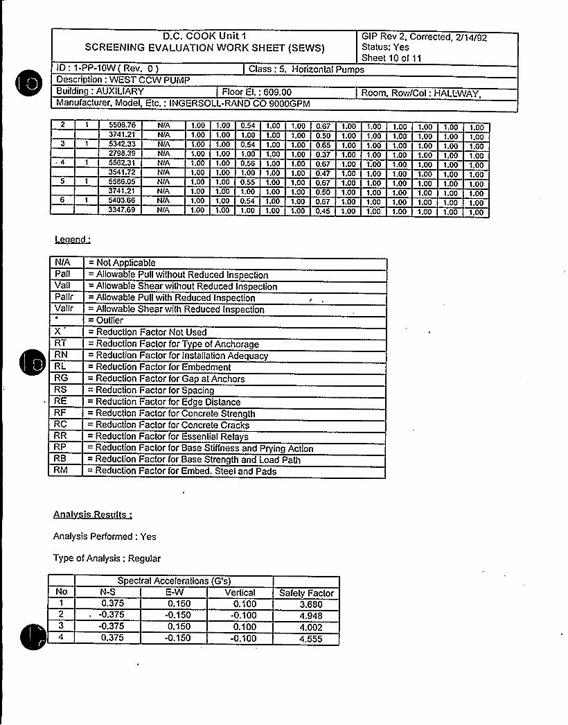
D.C. COOK Unit 1
SCREENING EVALUATIONWORK SHEET (SEWS)GIP Rev 2, Corrected, 2/14/92Status: YesSheet 10 of 11
ID: 1-PP-10W(Rev. 0)Description: WEST CCW PUMP
Class: 5. Horizontal Pumps
Building: AUXILIARY Floor El.: 609.00 Room, Row/Col: HALLWAY,Manufacturer, Model, Etc.: INGERSOLL-RAND CO 9000GPM
5508,76 N/A 1.00 1.00 0.54 1.00 1.00 0.67 1.00 1.00 1.00 1.00 1.00 1.003741.21 NIA 1.00 1.00 1.00 1.00 1.00 0.50 1.00 1.00 1.00 1.00 1.00 1.005342.33 N/A 1.00 1.00 0.54 1.00 1.00 0.65 1.00 1.00 1.00 1.00 1.00 1.002798.395562.313541.72
NIA 1.00N/A 1.00N/A 1.00
1.001.001.00
1.00 1.000.56 1.001.00 1.00
1.001.001.00
0.37 1.00 1.000.67 1.00 1.000.47 1.00 1.00
1.00 1.00 1.001.00 1.00 1.001.00 1.00 1.00
1.001.001.00
5586.05 N/A 1.00 1.00 0.55 1.00 1.00 0.67 1.00 1.00 1.00 1.00 1.00 1.003741.21
1 5403.66N/A 1.00NIA 1.00
1.001.00
1.00 1.000.54 1.00
1.001.00
0.50 1.00 1.000.67 1.00 1.00
1.00 1.00 1.001.00 1.00 1.00
1.001.00
3347.69 N/A 1.00 1.00 1.00 1,00 1.00 0.45 1.00 1.00 1.00 1.00 1.00 1.00
N/A = Not ApplicablePall = Allowable Pull without Reduced InspectionVali = Allowable Shear without Reduced InspectionPallr = Allowable Pull with Reduced InspectionVallr = Allowable Shear with Reduced Inspection
= OutlierX = Reduction Factor Not UsedRT = Reduction Factor for Type of AnchorageRN = Reduction Factor for Installation AdequacyRL = Reduction Factor for EmbedmentRG = Reduction Factor for Gap at AnchorsRS = Reduction Factor for SpacingRE = Reduction Factor for Edge DistanceRF = Reduction Factor for Concrete StrengthRC = Reduction Factor for Concrete CracksRR = Reduction Factor for Essential RelaysRP = Reduction Factor for Base Stiffness and Prying ActionRB = Reduction Factor for Base Strength and Load PathRM = Reduction Factor for Embed. Steel and Pads
al is Re
Is'nalysis
Performed: Yes
Type of Analysis: Regular
Spectral Accelerations (G's)No'-S 0.375
-0.375-0.3750.375
E-W0.150
-0.1500.150
-0.150
Vertical0.100
-0.1000.100
-0.100
Safety Factor3.6804.9484.0024.555

D.C. COOK Unit 1
SCREENING EVALUATIONWORK SHEET (SEWS)GIP Rev 2, Corrected, 2/14/92Status: YesSheet 11 of 11
ID: 1-PP-10W( Rev. 0) Class: 5. Horizontal PumpsDescription: WEST CCW PUMPBuilding: AUXILIARY Floor El.: 609.00 Room, Row/Col: HALLWAY,Manufacturer, Model, Etc.: INGERSOLL-RAND CO 9000GPM
10
121314
15
18192021
222324
0.375-0.3750.375
-0.3750.150
-0.1500.'I50
-0.150-0.1500.1500.150
-0.1500.150
-0.1500.150
-0.150-0.1500.1500.150
-0.150
-0.1500.1500.150
-0.1500.375
-0.375-0.3750.3750.375
-0.3750.375
-0.3750.150
-0.1500.150
-0.1500.150
-0.150-0.1500.150
0.100-0.100-0.1000.1000.100
-0.1000.100
-0.1000.100
-0.100-0.1000.1000.250
-0.250-0.2500.2500.250
-0.2500.250
-0.250
4 4284.1813.7414.6412.3763.6013.4032.5032.4793.4482.4003.4184.9077.9505.4506.2604.9097.6066.4175.768
Minimum Safety Factor: 2.376
The Anchorage Capacity is 2.376 times greater than the Demand

**12 CHP 5021.CCD.019ATTACHNENT NO . 1
ANCHOR NSPECTXON DATA SHE
.. Unxt Bldg. ZocatzonI- t -
iow'nstalat>.on dwg. / Rev.
Anchora e Arran ement Sketch
X- PP-(ox
Equipment No.
'IO <'- z'l~ "l-3 l~
—0 0 $ ~/~"
~$cP
I
cJ
I
IN
+0I
A0 pk
8
"I-3.VI
INOIANA MICHIGASITE OESIGN CON
WORKING C
jUL 201
RC'Efi
LERKT
Drawn by:Verified by:
Date: t"- /ZV/ ~Z.
Date:Qual. /Cert. Inspector
Reviewed by. Date:.Construction Anc or Review Engineer
Page 1 of 3
Revision 3

~~ Jd ('HJ 502 J ~ CCD. QlgATTACHMENT NO. l
Unit
CHOR NSP CT ON DATA SHE
Bldg.CG RAh
Locat1'on
Installation dwg. / Rev.
Anchora e Arran ement Sketch
X- PP-lnvlEqu1pment No.
INOIANA IIICIIIGANP0%'RSITE DESIGN CONTROLLcO
WORKING COPY
JUL 201995
LERK +
Drawn by:Verified by:
Reviewed by:
Date: / zlDate:
Qual. /Cert. Xnspectorr- Date: 1 l I <2
Construct1on chor Rev1ew Engineer
Page 1 of 3Revision

ATTACHMENT NO.
ANCHOR ZNSPECTXON DATA S
O I AUnxt-5 8t'o-'t
Bldg. Locationg- I P- IQWf
Znstallatz.on dwg. / Rev.
Anchora e Arran ement SketchEquipment No.
Q l)~z-
FLE,U. Ux.ew uonxx.ea ~urn+
INOIANA IAICHIGAN POVIERSITE DESIGN CONTROLLED
WORKING COPY
)Ut. 20 $ 9SK
LERK T
Drawn by: Date:Date: +-lF-
Qua ./Cert:. Xn pectorReviewed by: Dat
Construction nchor Review Engineer
Verified by:
1-('i-9 x
Page 1 of 3Revision

0

J4 QJ4L Vv4 4 ~ QPP gd y.TTACHMZNT Np.
Equipment No.: - PP- 'IO~Anchor type: ~ oi - ~YPE. Z, Dia:Tightness established by: 0 "Snug Fit"Torque Wrench No.:Tightness verified? 0 Yes
Dwg No .:Dwg No.: l2: 3A3g
0 TorqueCal, Due Date:
0 No Nk'ns ruc Date: — — 2ion
Date:ruc 1 n AREEquipment base flexible? 0 Yes g, No
ons
Bolt IDGaps
Comments
Anchorlen th
Protruding <glen th .~
Embedment
fI v'1" Il fq-
3 ~
Bolt- Pr1
Concretecondition
Edgedistance
- 'In<i" ~ ~
4,~r~'a KDc.E, oeQo<- ~TK'XC.T.
Pac g'lq'A~
Anchors acinAnchor
an laritThread
engagement
~ ~ I
Z-5q 2:5~( Z.-'3 2- Sg
Q~ Q< Oa OK Q< OgQa g. Qa Q< O< OK
Comments:C s ~ o - S~aucv. P
DR.x,
Verified by:Q a ./Cert. Inspector
Revieved by:Construct1on
IHOIAHA MIC4IGAW POWER
WORKlt(G COPY
JUL 20 1993
Date:
ago 2 of 3e r ion 3


S & A DEPARTMENTCONTROLLED DOCUMENTCopY NO.~ SHP 5050 NDE pp8
ATTACHNEHT NO.
ULTRASONIC TEST REPORT
JOB ORDER NO.: REPORT DATE: u-aO~i9 REQUEST NO.
IDENTIFICATION
Unit On cComponent J - 7'P- )0 0ItemMaterial
Test Unit/ S/N 4Frey./Diameter Jjz.Reference Standard 4 -8Couplant/Batch No. 4 <./
TEST DATA REMARKS
4
wA-'~
PERFORMED BY:
REVIEWED BY;
I.EVEE'~IEVEI:~
DATE:
DATE:
FORM NO. 12 SHP 5050 NDE.008-1 Page 1 of 1Revision 0

Equip Xd: 2-PP-46-4 Train: 1 Equip Class: 5
Drawing No.: 12-5131 12-5131A
tion: RI
Syst: em: BORON MAKEUP (CVCS)
Equip Desc: BORIC ACXD STORAGE TANKS TRANSFER PUMP g4
Building: AUXILXARY Room: BORXC ACID STORAGE TANK AREA
Elev: 587 Sort: S,R Notes:
Normal State: NR Desired State: R Power Req'd: Y
Support System Drawing: 2-12010 2-98272
Req'd Support Comp: 2-AB-A-1D
Safety Related Status: NUCLEAR SR Min/Opt: MIN
Alias No: Power Train: B
,Comp Served: BAST
MFR: GOULDS PUMPS XNC.
Mo el: 3196
1: 2-BA 2-HSD2
Elem. Drawing: 2-98272
Wiring Drawing: 2-94217
Power Source: 2-AB-A-1D
Walkdown: F Relay Eval: Y
Comp Type: PUMP
Iso Drawing: 0-DR-724
'ocation: XN THE MXDDLE EAST REGION OF THE ROOM, 15 FEET'OUTHEASTOF MXDDLE BORIC ACXD STORAGE TANK
512-TK-12M, NEAR THE FLOOR

D.C. COOK Unit 2SCREENING EVALUATIONWORK SHEET (SEWS)
GIP Rev 2, Corrected, 2/14/92Status: YesSheet 1 of4
ID: 2-PP-46-4 ( Rev. 0 ) Class: 5. Horizontal Pumps
Building: AUXILIARY Floor El.: 587.00
Manufacturer, Model, Etc.: GOULDS PUMPS INC. 3196
SEISMIC CAPACITYVS DEMAND
1. Elevation where equipment receives seismic input
Description: BORIC ACID STORAGE TANKS TRANSFER PUMP f/4Room, Row/Col: BORIC ACIDSTOR TANKAREA - IN THEMIDDLEEAST REGION OF THEROOM, 15 FEET SOUTHEAST OFMIDDLEBORIC ACID STORAGETANKIt/12-TK-12M, NEAR THEFLOOR
587.00Elevation of seismic input below about 40'rom grade (grade = 608.00)
3. Equipment has fundamental frequency above about 8 Hz (est. frequency = 20.00)Capacity based on: 1.50 " Bounding Spectrum
5. Demand based on: 1.00 Realistic Median-Centered Floor Response Spectra
N/AN/A
1.200
LOG
: 0.080
lI
\I\
III
I
II
j/I
r~
0.50 LOG HzCapacity ..... Demand
50.00
CapacitDemand 1
Demand 2
FileC:tGIP>GIP'Lspectra.desC:tGIPIPROJ0034tspectra.desC:tGIPIPROJ0034'Lspectra.des
RecordLabel(Bounding SpectrumBUILDINGAuxilia IELEVATION587IBROADEN(NBUILDINGAuxilia ELEVATION587 BROADENIN
Does capacity exceed demand?


D.C. COOK Unit 2SCREENING EVALUATIONWORK SHEET (SEWS)
GIP Rev 2, Corrected, 2/14/92Status: YesSheet 2 of 4
ID: 2-PP-46-4 ( Rev. 0 ) Class: 5. Horizontal Pumps
Building: AUXILIARY Floor El.: 587.00
Manufacturer, Model, Etc.: GOULDS PUMPS INC. 3196
Description: BORIC ACID STORAGE TANKS TRANSFER PUMP &Room, Row/Col: BORIC ACIDSTOR TANKAREA - IN THEMIDDLEEAST REGION OF THEROOM, 15 FEET SOUTHEAST OFMIDDLEBORIC ACID STORAGETANK012-TK-12M, NEAR THEFLOOR
CAVEATS - BOUNDING SPECTRUM
HP/BS Caveat 1 - Earthquake Experience Equipment ClassHP/BS Caveat 2- Driver and Pump on Rigid Skid.HP/BS Caveat 3 - Thrust Bearings in Both Axial DirectionsHP/BS Caveat 4 - Check of Long Unsupported Piping.HP/BS Caveat 5 - Base Vibration Isolation System CheckedHP/BS Caveat 6 - Sufficient Slack and Flexibilityof Attached Lines.HP/BS Caveat 7 - Adequate Anchorage.HP/BS Caveat 8 - Potential Chatter of Essential Relays Evaluated.HP/BS Caveat 9 - No Other Concerns.
YesYesYesYesYesYesYesN/AYes
Is the intent of all the caveats met for Bounding Spectrum7
ANCHORAGE
1. The sizes and locations of anchors have been determined2. Appropriate equipment characteristics have been determined (mass, CG, natural freq.,
damping, center of rotation).3. The type of anchorage is covered by the GIP4. The adequacy of the anchorage installation has been evaluated (weld quality and length, nuts
and washers, expansion anchor tightness, etc.)5. Factors affecting anchorage capacity or margin of safety have been considered: embedment
length, anchor spacing, free-edge distance, concrete strength/condition, and concretecracking.
6. For bolted anchorages, any gaps under the base are less than 1/47. Factors affecting essential relays have been considered: gaps under the base, capacity
reduction for expansion anchors.8. The base has adequate stiffness and the effect of prying action on anchors has been
considered.9. The strength of the equipment base and the load path to the CG is adequate10. The adequacy of embedded steel ~ grout pads or large concrete pads have been evaluated.11. The anchorage capacity exceeds the demand.
Are anchorage requirements met?
YesYes
YesYes
Yes.
YesN/A
Yes
YesYesYes

D.C. COOK Unit 2SCREENING EVALUATIONWORK SHEET (SEWS)
GIP Rev 2, Corrected, 2/14/92Status: YesSheet 3 of 4
ID: 2-PP-46-4 ( Rev. 0 ) Class: 5. Horizontal Pumps
Building: AUXILIARY Floor El.: 587.00
Manufacturer, Model, Etc.: GOULDS PUMPS INC. 3196
Description: BORIC ACID STORAGE TANKS TRANSFER PUMP I/4Room, Row/Col: BORIC ACIDSTOR TANKAREA - IN THEMIDDLEEAST REGION OF THEROOM, 15 FEET SOUTHEAST OFMIDDLEBORIC ACID STORAGETANK012-TK-12M, NEAR THEFLOOR
INTERACTION EFFECTS
1. Soft targ'ets are free from impact by nearby equipment or structures2. If the equipment contains sensitive relays, it is free from all impact by nearby equipment or
structures.3. Attached lines have adequate flexibility.4. Overhead equipment or distribution systems are not likely to collapse.5. No other adverse concerns were found.
YesNIA
YesYesYes
ls equipment free of interaction effects?
IS E U P ENTSEISIVIICA Y D U T ~Ys
COMMEN S
SRT: John D. Stevenson, Paul Wilson, Rick Leonard, and kailash Mahajan on 10/05/93.
GOULDS PUMP.Anchorage Four 5/8" diameter Ram anchor expansion bolts.Pump WT 511lbs, C.G=12 3/8" above base.
The 5/8" diameter expansion anchors have 4" embedment into the base concrete below the 8" pad, per theanchorage inspection.This judged adequate by the SRT for the light (511 (bs) pump.Attached piping is 2" or less. Nozzle toads judged not to be a problem by the SRT.
Picture 0 49, Wk1, Tm1, Disk1.
Evaluated by: Date:
achm t: Pictures


D.C. COOK Unit 2SCREENING EVALUATIONWORK SHEET (SEWS)
GIP Rev 2, Corrected, 2/14/92Status: YesSheet 4 of 4
ID: 2-PP-46-4 ( Rev. 0 ) Class: 5. Horizontal PumpsDescription: BORIC ACID STORAGE TANKS TRANSFER PUMP N4
Building: AUXILIARY Floor El.: 587.00 Room, Row/Col: BORIC ACIDSTOR TANKAREA - IN THFMIDDLEEAST REGION OF THEROOM, 15 FEET SOUTHEAST OFMIDDLEBORIC ACID STORAGETANKf/12-TK-12M, NEAR THEFLOOR
Manufacturer, Model, Etc.: GOULDS PUMPS INC. 3196
ICTUR S
Boric Acid Storage Tank Transfer Pump 2-PP-46A-~ Anchors

Coo
Component No. Claaa
Any payticular prea the Seismic Review Team should pay extra attention totYam ~ No W (If yea, check items that apply. )
Anchor TypeAnchor DiameterAnchor SpacingAnchor NumberAnchor EmbedmentAnchor Edge DistanceAnchor GapAnchor Thread~EngagementAnchor Grip
v'nchorAngularityConcrete Crack
Others (describe briefly}
If there is concern for Design Basis Discrepancy, circle the applicableitem and explain.
1.2.3.
Hardvare Maintenance Type DiscrepancyDrawing Up&,te Type DiscrepancySignificant Operability/Doaign Basis DiscrepancyOthers
Condition:l4- 33-
Actions Taken:
PreI ared By T Data

*(* '. CHP 5021.CCD.019ZTACHMENT NO. 1
Unxt
NCHOR NS ECTION DATA SH E
Bl g.l TO A I= %ASK A,Re.I'-.Location
Installation dwg. / Rev.
Anchora e Arran ement SketchEquipment No.
M5QLATiCIA
OlI l
( AP)Chorq CcO!l
(ARE Z~«~fyZ V)IR:P.
II
I1
I l
gI
lOl
',O'- ',OI
All /IJ/C.IIORq+g Pf
/»'o"
/-'8Ã"
PL%,M VIKVf
r ~I J
PLA-rE >g pPz x pP~ ~~
INQIANA hIICHIGhN POwFRSITE DESIGN CONTRQI.LEO
WORKING COPY
JUL t Z t995
I.ERK T
Drawn by:Verified by:
Date:Date:
Qua ./Cert. Inspector~ ~
Reviewed by: 7'ate:Construction An hor Revs,ew Engineer
Page 1 of 3Revision 1

~ ~ l
~ ~
~ ~ ~
~ ~
r~ %~1
~ II o
s ~
~ ~
R%WWK~%WW&&C4541%1LHLLKlSSWL1%%L~LISWLRSL5%5%WKRILSLmmWSLLXLL~HRRKR'%%saaslmMMM&i&
5%L%SKRRLRI r 4 a r i k
JSC~r
i ~


-pp
'> T]ig,lgl (
("~ i'!":iROLl.E%DOCui4&4T
2 SHP 50SO NDE.008ATTACHMENT NO. 1
UK TRASON IC TEST REPORT
JOB ORDER NO.: REQUEST NO. /A
IDENTIFICATION
UnitComponent
ItemMaterialOther 5
P.sTest, Unit/ S/NFreq./DiameterReference StandardCouplant/Batch No.g l4
DS /
TEST DATA REMARKS
nc r
PERFORMED BX:
REUIEMED BY:
FORM NO. 12 SHP SOSO NDE.008-1 Page 1 ofRevision 0
:~Z- '3

Database: K:SSEL1B.DBF
Equip XD: 1-HV-AFP-M1 Train: 2 Equip Class:9
ing No.: 12-5148B
ction: HVAC
System: TURBXNE BUXLDXNG VENTXLATION
Equip Desc:. EAST MOTOR DRXV AUX FEEDWATER PUMP ROOM EXHAUST FAN
Building: TURBXNE Room: EAST MOTOR DRIV. AUX FEEDWATER PUMP ROOM
Elev: 591 Sort: S,R Notes:
Normal State: Desired State: Power Req'd: Y
Support System Drawing: 1-12030 1-98214
Req'd Support Comp: 1-AB-D-R2D
Safety Related Status: NUCLEAR SR Min/Opt:MIN'lias
No: Power Train: A
Comp Served: EAST MOTOR DRXV AUX FEED PUMP
MFR:
1: 10000 FT 3/MIN
Panel:
Elem. Drawing: 1-98214
Wiring Drawing: 1-94228
Power Source: 1-AB-D-R2D
Walkdown: F Relay Eval
Comp Type: VENT FAN
Y
Xso Drawing:
Location: XN THE SW CORNER OF THE ROOM, 10'W OF EAST MDAFWP, ONTHE WEST WALL, 12'BOVE THE FLOOR.

D.C. COOK Unit 1
SCREENING EVALUATIONWORK SHEET (SEWS)GIP Rev 2, Corrected, 2/14/92Status: YesSheet1 of3
ID: 1-HV-AFP-M1 ( Rev. 0 ) Class: 9. FansDescription: EAST MOTOR DRIVAUXFEEDWATER PUMP ROOM EXHAUST FANBuilding: TURBINE Floor El.: 591.00 Room, Row/Col: E MOTOR DRIV
AUXFDWTR PUMP RM, IN THESW CORNER OF THE RM, 10'WOF E MDAFWP, ON THE W WALL,12'BOVE THE FLR.
Manufacturer, Model, Etc.: JOY MANUFACTURINGCO. ~ 10000 FT"3/MIN
SEISMIC CAPACITYVS DEMAND
Elevation where equipment receives seismic input2. Elevation of seismic input below about 40'rom grade (grade = 608.00)
Equipment has fundamental frequency above about 8 Hz (est. frequency = 10.00)4. Capacity based on: 1.00 Bounding Spectrum5. Demand based on: 1.00 " Design Basis Ground Response Spectrum
591.00YesYes
0.000
LOG
0.090
/r
rr
0.50 LOG Hz
Capacity ..... Demand33.00,
CapacitDemand 1
Demand 2
FileC:tGIPtGIPtspectra.desC:LGIPLPROJ0035tspectra.desCAGIPLPROJ0035tspectra.des
RecordLabel Bounding SpectrumBUILDINGGround ELEVATION608 BROADEN NBUILDINGGround ELEVATIONI608BROADEN N
Does capacity exceed demand'

D.C. COOK Unit 1
SCREENING EVALUATIONWORK SHEET (SEWS)GIP Rev 2, Corrected, 2/14/92Status: YesSheet 2 of 3
ID: 1-HV-AFP-M1 ( Rev. 0 ) Class: 9. FansDescription: EAST MOTOR DRIVAUX FEEDWATER PUMP ROOM EXHAUST FANBuilding: TURBINE Floor El.: 591.00 Room, Row/Col: E MOTOR DRIV
AUXFDWTR PUMP RM, IN THESW CORNER OF THE RM, 10'WOF E MDAFWP, ON THE W WALL,12'BOVE THE FLR.
Manufacturer, Model, Etc.: JOY MANUFACTURINGCO., 10000 FT"3/MIN
CAVEATS - BOUNDING SPECTRUM
FAN/BS Caveat 1 - Earthquake Experience Equipment ClassFAN/BS Caveat 2 - Drive Motor and Fan Mounted on Common Base.FAN/BS Caveat 3 - Long Shafts Supported at Fan and at Motor.FAN/BS Caveat 4 - No Possibility of Excessive Duct Distortion Causing Binding or Misalignment
of Fan.FAN/BS Caveat 5 - Base Vibration Isolation System CheckedFAN/BS Caveat 6 - Sufficient Slack and Flexibilityof Attached Lines.FAN/BS Caveat 7 - Adequate Anchorage.FAN/BS Caveat 8 - No Other Concerns
Is the intent of all the caveats met for Bounding Spectrum7
ANCHORAGE
YesYesYesYes
N/AYesYesYes
1. The sizes and locations of anchors have been determined2. Appropriate equipment characteristics have been determined (mass, CG, natural freq.,
damping, center of rotation).3. The type of anchorage is covered by the GIP4. The adequacy of the anchorage installation has been evaluated (weld quality and length, nuts
and washers, expansion anchor tightness, etc.)5. Factors affecting anchorage capacity or margin of safety have been considered: embedment
length, anchor spacing, free-edge distance, concrete strength/condition, and concretecracking.
6. For bolted anchorages, any gaps under the. base are less than 1/47. Factors affecting essential relays have been considered: gaps under the base, capacity
reduction for expansion anchors.8. The base has adequate stiffness and the effect of prying action on anchors has been
considered.9. The strength of the equipment base and the load path to the CG is adequate.10. The adequacy of embedded steel, grout pads or large concrete pads have been evaluated.11. The anchorage capacity exceeds the demand.
Are anchorage requirements met?
YesYes
YesYes
Yes
YesN/A
Yes
YesYesYes

D.C. COOK Unit 1
SCREENING EVALUATIONWORK SHEET (SEWS)GIP Rev 2, Corrected, 2/14/92Status: YesSheet 3 of 3
ID: 1-HV-AFP-M1 ( Rev. 0 ) Class: 9. FansDescription: EAST MOTOR DRIVAUXFEEDWATER PUMP ROOM EXHAUST FANBuilding: TURBINE Floor El.: 591.00 Room, Row/Col: E MOTOR DRIV
AUXFDWTR PUMP RM, IN THESW CORNER OF THE RM, 10'WOF E MDAFWP, ON THE W WALL,12'BOVE THE FLR.
Manufacturer, Model, Etc.: JOY MANUFACTURINGCO., 10000 FT"3/MIN
INTERACTION EFFECTS
1. Soft targets are free from impact by nearby equipment or structures2. Ifthe equipment contains sensitive relays, it is free from all impact by nearby equipment or
structures.3. Attached lines have adequate flexibility4. Overhead equipment or distribution systems are not likely to collapse.5. No other adverse concerns were found.
Is equipment free of interaction effects'P
YesNIA
YesYesYes
S U
~CIELIRXR
SRT: Gary Thomas, Gunnar Harstead and Harry Young on 10/20/93.
Anchorage: .
Fan mounted to embedded plate structure with at least 16 steel to steel bolts at least 1/2" in diameter.
Weight of fan 500 lbs.
No anchorage calculation required for a fan of this size with this robust anchorage. Therefore anchorage is OKbased on SRT judgement and inspection.
Interaction:Insulated pipe running outside the room the fan services could impact the outside screen of the fan. Pipe wellinsulated and willcushion the impact, therefore the SRT judged this as non4amaging.
Photo: Fan mounted outside the room with the damper on the inside, therefore could not get a good picture of fan.
Evaluated by: Date:

0

2 CHP 5021.CCD.019ATTACHMENT NO
Unct Ii 2.-5(:8
Xnstallatxon dwg. / Rev.
Anchora e Arran ement Sketch
ANCHOR XNSPECTXON DATA SHEETTuRsit4P. OI4VW /gal Pq<~'T ~~a,l 2 h&ogC R.oatFCMg v)ATCR. Paine poenh SauTuMCsT c~IM
Bldg. Locationi- t<-V- hFP-Mi
Equipment No.
Dla4~ON'5'p
( g FP-Old7 QSuP PO T~.
Drawn by: Date: ~'- 8-~1~
Verified by:
Reviewed by
Hh Date:Qual. /Cert. Xnspector
Anal~ Date:Construction Anchor Review Engineer).- <) -~( 3
Page 1 of 3Revision 1


Database: K:SSEL1B.DBF
Eguip ID: 12-HV-ESW-7 Train: 2 Equip Class:9
wing No.: 12-5148B
ction: HVAC
System: SCREENHOUSE VENTXLATXON
Equip Desc: UNIT Q1 EAST ESW PUMP ROOM SUPPLY VENTXLATION FAN
Building: SCREENHOUSE Room: EAST ESW PUMP ROOM
Elev: 591 Sort: S,R Notes:
Normal State: Desired State: Power Req'd: Y
Support System Drawing: 1-12033 1-98415
Req'd Support Comp: 1-PS-D-2B
Safety Related Status: NUCLEAR SR Min/Opt: MXN
Alias No: Power Train: A
Comp Served: EAST ESW PUMP
MFR: BUFFALO FORGE CO
l: 5000 FT"3/MIN
Panel:
Elem. Drawing: 1-98415 1-98721
Wiring Drawing: 1-95103
Power Source: 1-PS-D-2B
Walkdown: F Relay Eval : Y
Comp Type: VENT FAN
Xso Drawing:
Location: IN THE SW CORNER OF THE ROOM, 15'E OF EAST ESW PP,13'BOVETHE FLOOR.

l~I

D.C. COOK Unit 1
SCREENING EVALUATIONWORK SHEET (SEWS)'IP Rev 2, Corrected, 2/14/92
Status: YesSheet1 of11
ID: 12-HV-ESW-7 Rev. 0 Class: 9. FansDescri tion: UNIT41 EAST ESW PUMP ROOM SUPPLY VENTILATIONFANBuilding: SCREENHOUSE Floor El.: 591.00 Room, Row/Col: E ESW PUMP
RM, IN THE SW CORNER OF THERM, 15'SE OF E ESWPP,
13'BOVETHE FLR.Manufacturer, Model, Etc.: BUFFALO FORGE CO., 5000 FT"3/MIN
SEISMIC CAPACITYVS DEMAND
1. Elevation where e ui ment receives seismic in utElevation of seismic in ut below about 40'rom rade rade = 608.00
3. E ui menthasfundamentalfre uenc aboveabout8Hz est.fre uenc =10.00Ca acit based on: 1.50'Boundin S ectrumDemand based on: 1.00 * Realistic Median-Centered Floor Res onse S ectra
587.00N/AN/A
1.200
LOG
0.0800.50
l'
\\\
I
\I
I
rjr
LOG Hz
Capacity ..... Demand
50.00
Ca aciDemand 1
Demand 2
FileC:tGIP<GIPIs ra.desC:(GIPIPROJ0035ls .desC:(GIPPROJ003Qs lra.des
RecordLabel Boundin S trumBUILDINGAuxilia ELEVATION587 BROADEN NBUILDINGAuxilia ELEVATION587 BROADEN N
Does capacity exceed demand? Yes


D.C. COOK Unit 1
SCREENING EVALUATIONWORK SHEET (SEWS)GIP Rev 2, Corrected, 2/14/92Status: YesSheet 2 of 11
ID: 12-HV-ESW-7 Rev. 0 Class: 9. FansDescri tion: UNITN EAST ESW PUMP ROOM SUPPLY VENTILATIONFANBuilding: SCREENHOUSE Floor El.: 591.00 Room, Row/Col: E ESW PUMP
RM, IN THE SW CORNER OF THERM, 15'SEOF E ESWPP,
13'BOVETHE FLR.Manufacturer, Model, Etc.: BUFFALO FORGE CO., 5000 FT"3/MIN
CAVEATS - BOUNDING SPECTRUM
FAN/BS Caveat 1- Earth uake Ex erience E ui ment ClassFAN/BS Caveat 2- Drive Motor and Fan Mounted on Common Base.FAN/BS Caveat 3- Lon Shafts Su orted at Fan and at Motor.FAN/BS Caveat 4- No Possibility of Excessive Duct Distortion Causing Binding or
Misali nment of Fan.FAN/BS Caveat 5- Base Vibration Isolation S stem CheckedFAN/BS Caveat 6- Sufficient Slack and Flexibilit of Attached Lines.FAN/BS Caveat 7 - Ade uate Anchora e.FAN/BS Caveat 8- No Other Concerns
YesYesYesYes
N/AYesYesYes
ts the intent of all the caveats met for Bounding Spectrum'
ANCHORAGE
1. The sizes and locations of anchors have been determined2. Appropriate equipment characteristics have been determined (mass, CG, natural freq.,
dam in, center of rotation .
3. The t e of anchora e is covered b the GIP.4. The adequacy of the anchorage installation has been evaluated (weld quality and length,
nuts and washers, ex ansion anchor ti htness, etc.5. Factors affecting anchorage capacity or margin of safety have been considered:
embedment length, anchor spacing, free-edge distance, concrete strength/condition, andconcrete crackin .
6. For bolted anchora es, an a s under the base are less than 1/47. Factors affecting essential relays have been considered: gaps under the base, capacity
reduction for ex ansion anchors.8. The base has adequate stiffness and the effect of prying action on anchors has been
considered.9. Thestren th of thee ui mentbaseand the load athto the CG isade uate.10. The ade uac of embedded steel, rout ads or la e concrete ads have been evaluated.11. The anchora e ca acit exceeds the demand.
Are anchorage requirements met7
INTERACTION EFFECTS
Yes
YesYes
YesYes
Yes
YesN/A
Yes
YesYesYes
Yes
1. Soft tar ets are free from im act b nearb e ui mentorstructures.2. If the equipment contains sensitive relays, it is free from all impact by nearby equipment or
structures.3. Attached lines have ade uate flexibilit .
4. Overhead e ui ment or distribution s stems are not likel to colla se.5. No other adverse concerns were found.
YesN/A
YesYesYes
ls equipment free of interaction effects? Yes

D.C. COOK Unit 1
SCREENING EVALLIATIONWORK SHEET (SEWS)GIP Rev 2, Corrected, 2/14/92Status: YesSheet 3 of 11
ID: 12-HV-ESW-7 Rev. 0 Class: 9. FansDescri tion: UNIT¹1 EAST ESW PUMP ROOM SUPPLY VENTILATIONFANBuilding: SCREENHOUSE Floor El.: 591.00 Room, Row/Col: E ESW PUMP
RM, IN THE SW CORNER OF THERM, 15'E OF E ESW PP,
13'BOVETHE FLR.Manufacturer, Model, Etc.: BUFFALO FORGE CO., 5000 FT"3/MIN
IS EQUIPMENT SEISMICALLYADEQUATE'P Yes
COMMENTS
SRT: Gary Thomas, Gunnar Harstead and Harry Young on 10/19/93.
Capacity vs Demand:Component is in Screenhouse building using Auxiliary building Response Spectra for calculation
Anchorage:Fan sits on steel platform, bolted to the wall on two sides with 2- 3/4" through bolts on each side, and hung atopposite corner by a 4x4x3/8" angle.
Calculation should be rerun. This fan is the limiting analysis fo 12-HV-ESW-1,2,3,4,5,6,7,&8
Anchorage is adequate. The calculated anchorage safety factor is 32.8.
~ ~Photo: Wk. 2, Tm. 2, Disk 1, Picture 29 Fan; 30 Underside of frame showing two bolts to wall; 31 Top of anglehanger support for platform.
Evaluated by: Date:
Attachment: PicturesAttachment: ANCHOR Re ort

0

D.C. COOK Unit 1
SCREENING EVAI UATIONWORK SHEET (SEWS)GIP Rev 2, Corrected, 2/1 4/92Status: YesSheet 4 of 11
ID: 12-HV-ESW-7 Rev. 0 Class: 9. FansDescri tion: UNITP1 EAST ESW PUMP ROOM SUPPLY VENTILATIONFAN
1 Building: SCREENHOUSE Floor El.: 591.00 Room, Row/Col: E ESW PUMPRM, IN THE SW CORNER OF THERM, 15'E OF E ESW PP,
13'BOVETHE FLR.Manufacturer, Model, Etc.: BUFFALO FORGE CO., 5000 FT"3/MIN
PICTURES
Figure 1: Fan 12-HV-ESW-7 Figure 2: Underside of frame showing two bolts towall
Figure 3: Top of angle hanger support for platform

D.C. COOK Unit 1
SCREENING EVALUATIONWORK SHEET (SEWS)GIP Rev 2, Corrected, 2/14/92Status: YesSheet 5 of 11
ID: 12-HV-ESW-7 Rev. 0 Class: 9. Fans
Room, Row/Col: E ESW PUMPRM, IN THE SW CORNER OF THERM, 15'SEOF E ESWPP,
13'BOVETHE FLR.
F,loor El.: 591.00Building: SCREENHOUSE
Manufacturer, Model, Etc.: BUFFALO FORGE CO., 5000 FT"3/MIN
ANCHOR Report
Descri tion: UNIT ¹1 EAST ESW PUMP ROOM SUPPLY VENTILATIONFAN
Response Spectrum: SSE
Frequency: GIP - Flexible
Percent Damping: GIP - 5.00
Spectral Values:
DirectionNorth - SouthEast - WestVertical
Acceleration 's
0.600.600.25
Angle (N-S Direction makes with the X Axis): 0.00
Combination Criteria: SRSS
~Wei htn:
Number of Weights: 1
No Wei ht1 500.00 35.000 23.000 18.000
Forces:
Number of External Forces: 0
Moments:
Number of External Moments: 0
Allowables:
Anchor:
Number of Anchor types: 1
Tension Shear
Coeff FactShearProductDiaUltimate Ultimate Inter Inter Saf
No. Manufact Tension Coeff

D.C. COOK Unit 1
SCREENING EVALUATIONWORK SHEET (SEWS)GIP Rev 2, Corrected, 2/14/92Status: YesSheet 6 of 11
ID: 12-HV-ESW-7 Rev. 0 Class: 9. FansDescri tion: UNIT ¹1 EAST ESW PUMP ROOM SUPPLY VENTILATIONFANBuilding: SCREENHOUSE Floor El.: 591.00 Room, Row/Col: E ESW PUMP
RM, IN THE SW CORNER OF THERM, 15'EOF E ESW PP,
13'BOVETHE FLR.Manufacturer, Model, Etc.: BUFFALO FORGE CO., 5000 FT"3/MIN
1 3/4 Other Grouted In 1500.00 7510.00 1.00Place
0.30 1.00
Concrete:
Ultimate Stress: 3500.00 psi.
Reduction Factor: 0.85
Weld:
Allowable Stress: 31200 psi.
Surfaces:
Number of Surfaces: 2Surface Orientation
DirectionCom
No0.0001.000
DirectionCom
N1.0000.'000
DirectionCom
Nz0.0000.000
Anchor Pattern for Surface ¹ 1
Anchor Pattern for Surface //2


D.C. COOK Unit 1
SCREENING EVALUATIONWORK SHEET (SEWS)GIP Rev 2, Corrected, 2/14/92Status: YesSheet 7 of 11
ID: 12-HV-ESW-7 Rev. 0 Class: 9. FansDescri tion: UNIT¹1 EAST ESW PUMP ROOM SUPPLY VENTILATIONFANBuilding: SCREENHOUSE Floor El.: 591.00 Room, Row/Col: E ESW PUMP
RM, IN THE SW CORNER OF THERM, 15'E OF E ESW PP,
13'BOVETHE FLR.Manufacturer, Model, Etc.: BUFFALO FORGE CO., 5000 FT"3/MIN
Legend for Anchor Patterns
Anchor Bolts:
Concrete Uncs: ~mmConcrete Points:
Weld Uncs:
Geometrei:
Anchor:
Number of Anchors: 4
Anch SurfNo. Id
1
2 1
34 1
Coord16.10052.60070.00070.000
Coord46.00046.00041.3004.800
Coord4.0004.0004.0004.000
Id
Concrete Lines:


D.C. COOK Unit 1
SCREENING EVALUATIONWORK SHEET (SEWS)GIP Rev 2, Corrected, 2/14/92Status: YesSheet 8 of 11
ID: 12-HV-ESW-7 Rev. 0 Class: 9. FansDescri tion: UNIT ¹1 EAST ESW PUMP ROOM SUPPLY VENTILATIONFANBuilding: SCREENHOUSE Floor El.: 591:00 Room, Row/Col: E ESW PUMP
RM, IN THE SW CORNER OF THERM, 15'EOF E ESW PP,
13'BOVETHE FLR.Manufacturer, Model, Etc.: BUFFALO FORGE CO., 5000 FT"3/MIN
¹ of elements per line: 1
Number of Concrete Lines: 2
Nostart
X-Coo rd0.000
70.000
startY-Coord
46.0000.000
startZ-Coo rd
4.0004.000
EndX-Coord
70.00070.000
EndY-Coord
46.00046.000
EndZ-Coord Id
4.000 1
4.000 2
LineWidth
3.0003.000
Concrete Points:
Number of Concrete Points: 0
Weld Lines:
¹ of elements per line: 5
Number of Weld Lines: 0
Determination of Reduction Factors:
Reduction Factor Input for Anchor ¹1
Adequately Installed: YesEmbedment Length: ( 7.50 in. Min Reqd. to achieve full capacity):= 7.50 in.Gap at Threaded Anchor: 0.00 in.Edge Distance - Edge 1: 6.63 in.Crack Size: 0.000 in.Essential Relays in Cabinet: NoAdequate Equipment Base Strength and Structural Load Path: YesEmbedment Steel and Pads Adequately Installed: Yes
Reduction Factor Input for Anchor ¹ 2
Adequately Installed: YesEmbedment Length: ( 7.50 in. Min Reqd. to achieve full capacity):= 7.50 in.Gap at Threaded Anchor: 0.06 in.Edge Distance - Edge 1: 6.63 in.Crack Size: 0.000 in.Essential Relays in Cabinet: NoAdequate Equipment Base Strength and Structural Load Path: YesEmbedment Steel and Pads Adequately Installed: Yes
Reduction Factor Input for Anchor ¹ 3
Adequately Installed: Yes


D.C. COOK Unit 1
SCREENING EVALUATIONWORK SHEET (SEWS)
GIP Rev 2, Corrected, 2/14/92Status: YesSheet 9 of 11
ID: 12-HV-ESW-7 Rev. 0 Class: 9. FansDescri tion: UNIT f/1 EAST ESW PUMP ROOM SUPPLY VENTILATIONFANBuilding: SCREENHOUSE Floor El.: 591.00 Room, Row/Col: E ESW PUMP
RM, IN THE SW CORNER OF THERM, 15'E OF E ESW PP,
13'BOVETHE FLR.Manufacturer, Model, Etc.: BUFFALO FORGE CO., 5000 FT"3/MIN
Embedment Length: ( 7.50 in. Min Reqd. to achieve full capacity):= 7.50 in.Gap at Threaded Anchor: 0.13 in.Edge Distance - Edge 1: 6.63 in.Crack Size: 0.000 in.Essential Relays in Cabinet: NoAdequate Equipment Base Strength and Structural Load Path: YesEmbedment Steel and Pads Adequately Installed: Yes
Reduction Factor input for Anchor 0 4
Adequately Installed: YesEmbedment I.ength: (7.50 in. Min Reqd. to achieve full capacity):= 7.50 in.Gap at Threaded Anchor: 0.13 in.Edge Distance - Edge 1: 6.63 in.Crack Size: 0.000 in.Essential Relays in Cabinet: NoAdequate Equipment Base Strength and Structural Load Path: YesEmbedment Steel and Pads Adequately Installed: Yes
Reduction Factors Data Current: Yes
NoAnc Pall/
Vali1500.007510.001500.007510.001500.007510.00
Pallr/Vallr RT RN
NIAN/A
1.00 1.001.00 1.00
NIA 1.00 1.00N/A 1.00 1.00
N/A 1.00 1.00N/A 'l.oo 1.00
RL RG1.00 1.001.00 1.001.00 1.001.00 1.001.00 1.001.00 1.00
RS RE1.00 1.001.00 1.001.00 1.001.00 1.001.00 1.001.00 1.00
RF RC1.00 1.00
1.00 1.001.00 1.001.00 1.00
RR RP RB1.00 1.00 1.001.00 1.00 1.001.00 1.00 1.001.00 1.00 1.001.00 1.00 1.001.00 1.00 1.00
RM
1 1500.00?510.00
NIA 1.00 1.00NIA 1.00 1.00
1.00 1.001.00 1.00
1.00 1.001.00 1.00
1.00 1.001.00 1.00
1.00 1.00 1.001.00 1.00 1,00
~Le eed:
N/A = Not A licablePall = Allowable Pull without Reduced Ins ectionVail = Allowable Shear without Reduced Ins ectionPallr = Allowable Pull with Reduced Ins ectionVallr = Allowable Shear with Reduced Ins ection
= Outlier= Reduction Factor Not Used
RT = Reduction Factor for T e of Anchora eRN = Reduction Factor for Installation Ade uacRL = Reduction Factor for Embedment
= Reduction Factor for S acinRSRG = Reduction Factor for Ga at Anchors

D.C. COOK Unit 1
SCREENING EVALUATIONWORK SHEET (SEWS)GIP Rev 2, Corrected, 2/14/92Status: YesSheet 10 of 11
ID: 12-HV-ESW-7 Rev. 0 Class: 9. FansDescri tion: UNITN EAST ESW PUMP ROOM SUPPLY VENTILATIONFANBuilding: SCREENHOUSE Floor El.: 591.00 Room, Row/Col: E ESW PUMP
RM, IN THE SW CORNER OF THERM, 15'SEOF E ESWPP,
13'BOVETHE FLR.Manufacturer, Model, Etc.: BUFFALO FORGE CO., 5000 FT"3/MIN
RFRCRRRPRB
= Reduction Factor for Ed e Distance= Reduction Factor for Concrete Stren th= Reduction Factor for Concrete Cracks= Reduction Factor for Essential Reta s= Reduction Factor for Base Stiffness and P in Action= Reduction Factor for Base Stren th and Load Path= Reduction Factor for Embed. Steel and Pads
Anal sis Results:
Analysis Performed: Yes
Type of Analysis: Regular
S ectral Accelerations G's
No
10
1213141516
18't92021
N-S0.600
-0.600-0.6000.6000.600
-0.6000.600
-0.6000.240
-0.2400.240
-0.240-0.2400.2400.240
-0.2400.240
-0.2400.240
-0.240-0.240
E-W0.240
-0.2400.240
-0.240-0.2400.2400.240
-0.2400.600
-0.600-0.6000.6000.600
-0.6000.600
-0.6000.240
-0.2400.240
-0.2400.240
Vertical0.100
-0.1000.100
-0.1000.100
-0.100-0.1000.1000.100
-0.'I 000.100
-0.1000.100
-0.100-0.'I000.1000.250
-0.250-0.2500.2500.250
Safet Factor44.55359.94877.05450.89748.71659.56549.641
106.18431.79653.06891.15132.44433.58556.10333.32187.64856.45359.642/6.162
205.01567.138
22 ~ 0.2400.240
-0.240-0.240
-0.2500.250
67.33376.365
24 -0.240 0.240 -0.250 59.986
Minimum Safety Factor: 31.796

D.C. COOK Unit 1
SCREENING EVALUATIONWORK SHEET (SEWS)GIP Rev 2, Corrected, 2/14/92Status: YesSheet 11 of 11
ID: 12-HV-ESW-7 Rev. 0 Class: 9. FansDescri tion: UNIT ¹1 EAST ESW PUMP ROOM SUPPLY VENTILATIONFANBuilding: SCREENHOUSE Floor El.: 591.00 Room, Row/Col: E ESW PUMP
RM, IN THE SW CORNER OF THERM, 15'SEOF E ESW PP,
13'BOVETHE FLR.Manufacturer, Model, Etc.: BUFFALO FORGE CO., 5000 FT"3/MIN
The Anchorage Capacity is 31.796 times greater than the Demand

Coo
Component No. I'Z"& G~+- 1 Cla»a
Any particular prea the Seismic Review Team»hould pay extra attontion to7Yes No v'Lfye», check item» that apply.)
Anchor TypeAnchor DiameterAnchor SpacingAnchor NumberAnchor EmbedmentAnchor Edge DistanceAnchor CapAnchor Thread EngagementAnchor CripAnchor AngularityConcrete Crack
Other» (describe brief].y)
If thereitem and
l.2.3.
i» concern. for Desi.gn Basis Discrepancy, circle tho applicableexplain.
Hardvare Maintenance Type DiscrepancyDrawing Update Type DiscrepancySignificant Operability/Do»ign Basis DiscrepancyOthers
Condi tion:
Actions Taken:
Prepared By ~'aca ~5>'" 3


*c' CHP @021. CCD. 019. ZTACHNENT NO. 1
O(vUnxt
Xnstallatxon dwg. / Rev.
Anchora e Arran ement Sketch
NCHOR XNSPECTION DATA SHEE
E. M ea 4o~Bldg. Location
iZ- 9-ES -7Equipment No.
rAu &r I (OIAi~A MlCHIQAy POWERSITE i)ES I'H CO ITROLLEO
WORKIIIQ COPY
JUL >S tsSS
«RZ l.
DETAIL A DETAIL(I
0(0
CoHPon(EQ r I 8 I'-ITTAC'AGOT(o /V Cu~l QZ'Q 'P IATE
a~ (~) zz"p5
~-as'~+~1rI
cj(((I((VB AprlrI,E
I
IIF-(I(Il~
3-P
8 eche ~4AL~/A" B.<T't~f(pf,Q oP Top
/)~i(Joo o
Drawn by:Verified b Date:
Qual. /Cert. XnspectorReviewed by: pate. F-RI- t 3
Construction An hor Review Engineer
Page 1 of 3Revision 1

**l2CHP 5021.CCD.019I 'TACHMENT NO. 1
Unzt
Xnstallatz.on dwg. / Rev.
Anchora e Arran ement Sketch
NCHOR INSPECTXON DATA SHEET
c.Yc.t Quod 0 ~ E U 7 oow~ Bldg. Location
IZ,- Av- F>g-7Equipment No.
\
Ow
~I
II
I
I
I'I
I-~+/6 f 'THRV Cbo'ErbI. 7YP. Z
lo Yig
EL'E.V lEw'w Meir
I IOIANA h'ICHIGAIJ POP,'/IISl fF. OCSIGH CONTROLLED
YIORKIIIG COPY
JUL tg19SS
. LCRK~
Drawn by:Verified b
Date: Y /2 q
Date: 'PDQual. /Cert. Inspector
~
~~
~ ~
Reviewed by: T Date: ~ <'-'I~Construct>on A chor Review Engineer
Page 1 of 3Revision 1
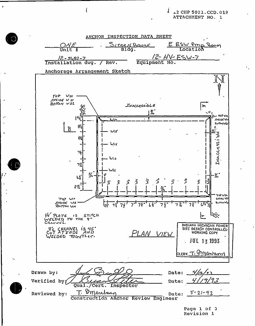
i~2 CHP 5021 - CCD. 019ATTACHMENT NO. 1
Unct
bNcHQR
Bldg.
NSPECTION DATA SHEET
E Few Q~Locatzo
Installation dwg. / Rev.
Anchora e Arran ement Sketch
Equipment No.
Top Wgosps ipcPbi77u~ IV'2Z
I 'I~
I—4/iS'I
I
)—4/iy
I
I~ 4'ibI
WwACcc:ssibt 8
Pi@ ~ TOP Mc)xwsoC vc
Q II1vg
0 M
Vd
Z"
5/
POp Wc v
~S<QQ MibBO77~ +i@
I/u" PLtI Y-e i S S Ti Y'CSWE't DED YO
Tnt')'Lr
rv >c L.
Sc CHANNEL IS bta'vT87'FNos AnlQ
HEEDED VOLrt-TI cr»
fi 7I 7 7<. L»" 7c"
TOP Qi~ZJlMg VVlb''vt48~
IttDIANA MICiIIGQN PPWt RSITC PESld't( CONTROLLt.J
WORKING COPY
f UL 1g tSSS
~ pRg T~E'WPD
n'rawn
by: Date:
~
~
~ ~
Verified byQual. /Cert. Inspector
Reviewed by: T, Date:Construct>.on A chor Review Engineer
') "2.I- Qg
Page 1 of 3
Revision 1

*" 2 CHP 5021- CCD ~ 019ATTACHMENT NO. 1
.Unxt
NC OR INSPECTIO D TA S E
C/8 N uSEBldg.
F.. FSM R> iP oeLocation
4 -7Installation dwg. / Rev.
Anchora e Arran ement SketchEquipment No.
C.0
gA" /Z. /Q" /g "
O>Oy ECT VIe& AA
0'5'~ '~ '+,>,~C, o tQg+>',:< -',~l8"+: ~ W.A ~ %~XI'>"5'I (rd S '4~ ~ )'>-4 <J~ -56
AntCho<s A, d,c,iOAPF. Y~"P mJ
HAVE &ashore.
I8 Q,. 0
IZ'2" l2 Fi(." II Pa
cT is& P
INOIRIIAVICMIGA>I POWERSITE OESlut< CONTfiOLLEO
WORKING COPY
lUL 1519S5
LCRK
Drawn by: Date:
Qual. /Cert. InspectorReviewed by: Date:
Construction An hor Review Engineer
Page 1 of 3Revision 1


~ ~ ~
e ~ ~ a
- ~ ~ ~ ~
~ 9 ~
~ ~ e s ~
~ ~ ~
o 14
V
t
5%RRSRSHKLPMWWMMM&WR%1%RRRRSLMMWMMMW&RSRSSWRHLL555%655%%LLR5%%%5%%88~~~~5555WRIHHSE54WWHRRSRI
%8%Ã%R4%~~M5%K'WWMMMWW
Pt 4 P C.
44
c

'12 CHP 5021. CCD. 03.9ATTACHMENT NO. 1
ANCHOR INSPECTION DATA SHEET
Equipment No.: IZ- AV'-
Embedded Steel Dwg. No.:PHYSICAL CHARACTERISTICS
Dwg No.': Iz.-$4 82-7
Weld IDT e
SizeLen thCracks
/ 3/
Yes57@
YesdRP
Yes Yes
~i M~ w'~ w/ /
YescHZP
YesQRD
~/i<"
/ '/y"
Y s
Weld T e Codes1 = Fillet2 = Plug/Slot3 = Groove
Lack ofPenetration
Ye's Yes Yes Yes@HE
Yesc85 +Ys Yes
429Yes
CPS
Porosity Yes Yes Yes Yes Yes YescHZP . 895
Yes<HE
lhQIAt(A te1ICH~GA I POII~RSlTE OrS|GH CONTROLLED
WORKING COPY
JUL t~199~
LrPg T ~ CA
Equipment base flexible: G Yes 8 No
Reviewed by:ons ruc on re
ns ruc 1on c or ev1ew ng1neer~
~ ~
verified by:ua . er . npsec or
Date:
Date:
g-Ah- 93
Page 3 of 3Revision 1

(12 CHP 5021. CCD. 019ATTACHMENT NO. 1
ANCHOR TNSPECTXON DATA SHEET
quipment No.: l~-/-rV'- E'SVEmbedded Steel Dwg. No.: h
PHYSICAL CHARACTERISTICS
Dwg No.: t+-W 4BZ.-7
Weld XD
T e
SizeLen thCracks
Lack ofPenetrationPorosity
'lie.
Yes
Yes
Yes
w'io
Yes
Yes
Yes
Yes
Yes
Yes
Yes Yes
Yes Yes
Yes4lZP
Yes'RAN
Qes
YesCfB
YesCh
YesKDYes
Weld T e Codes
1 = Fillet2 = Plug/Slot3 = Groove
liVOIANA h".CH IGnN PO)".ERSITE OFSICH
COlITROaa.EL'CRNlIt(C
CCRC'UI.
>g]995
-tres T ~~Equipment base flexible: 0 Yes 5 No T
Reviewed by:ons ruc 1o re Date: 0- >>- 'l'3
Date: b-2,(- f2
Verified by:~ ~
ons ruc 1on nc or ev1ew ng1neer
ua . er . npsec or Date:
Page 3 of 3Revision 1

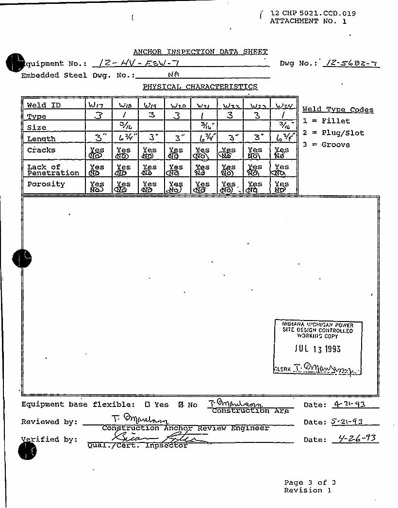
C'2 CHP 5021. CCD. 019ATTACHMENT NO- 1
ANCHOR INSPECTION DATA SHEET
quipment No.: / Z —
A'mbeddedSteel Dwg. No.: ghPHYSlCAL CHARACTERISTICS
Dwg No..'Z-WC SZ-~
Weld XD
T e
SizeLen thCracks
Lack ofPenetrationPorosity
Yes
Yes
Yes
ges
3"
Yes
@Ys
YesCb
3/
s0
Yes s
Yes
s0
3/
Yes0
s Yes
Weld T e Codes1 = Fillet2 = Plug/Slot3 = Groove
INDI/(JA >.',~Q<ICAN PP;ygIISITC O~SlCN CONT(IDLI.ED
YYDIIKIIICCQP'f
lUL ~q 199"
Equipment base flexible: 0 Yes 5 Noon ruc x n re Date '2I
Reviewed by:
V rified by:on ruc >on nc o
ua . er . npsec or
evxew ngxneerDate:
Page 3 of 3Revision 1


12 CHP 5021. CCD. 019ATTACHMENT NO. 1
ANCHOR XNSPECTXON DATA SHEET
quipment No.: 2- — Sld- 7
Embedded Steel Dwg. No.: g-3L8~PHYSXCAL CHARACTERXSTXCS
Dwg No.: Z-W Z-7
Held XD
T e
4JZ IJ~L 4AV Weld T e Codes1 = Fillet
SizeLen thCracks
Lack ofPenetrationPorosity
Yes
YeskS'es855
Yes
YesB5
Yes
YesQRI
Yesc55'es
Yes
Yescd&
7'Fq
YescRED
Yesdrab
YesCKb
Yes
es
Yes
Yes Yesmz . Hh
YesNo
YesNo
YesNo
2 = Plug/Slot3 = Groove
QEhlOTES An/ XII $ 4O~AJW uJEL A.
INOIANA tIICHIGAN POWERSITE DESIGN CONTROLLED
WORKING COPY
JUL >~ 1995
.LEAK 7
Eguipment base flexible: 0 Yes 8-No
Reviewed by:ons uc zo re
Date:ons ruc son or evzew ngxneer
Verified by:ua . er . npsec or Date: Y-<-9'3
Page 3 of 3Revision 1

II
1
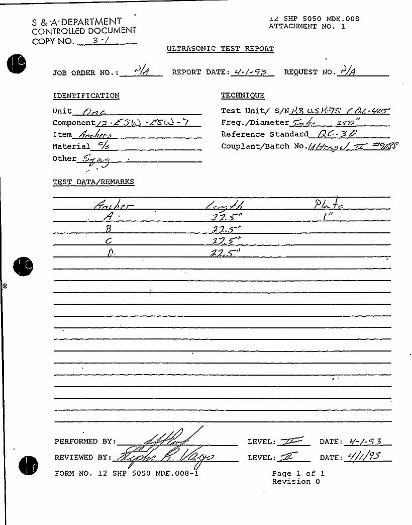
S 8 .A.DEPARTMENTCONTPOLLED DOCUtvlciNTCOPY NO. 3 -l
SHP 5050 NDE.008ATTACHMENT NO. 1
ULTRASONIC TEST REPORT
JOB ORDER NO.: /8 REPORT DATE: 4-/- '73 REQUEST NO.
IDENTIFICATION
UnitComponentItem n /iMaterial /<Other 5
-FS i~~ "Test Unit/ S/N > (wS'r.'- 5'2F- P~
Freq./Diameter 7 zsZ~
Reference Standard C- ~ PCouplant/Batch No. '=. c/ ~7aZ
TEST DATA REMARKS
PERFORMED BY:
REVIEWED BY:
FORM NO. 12 SHP 5050 NDE.008-1
: ~3LEVEL:~ DATE: ~ ///+
Page 1 of 1Revision 0

Equip XD: 1-AFW Train: 2 Equip Class: 14
Drawing No.: 1-12035
sction: 120 VAC SYSTEM
stem: 120/208V MISC. SAFTEY RELATED POWER DXSTRIBUTXONJ
Equip Desc: POWER PANEL
Building: AUXILIARY Room: CD EMERGENCY DXESEL GENERATOR ROOM
Elev: 587 Sort: S, Notes:
,Normal State: Desired State: Power Req'd:
Support System Drawing:
Req'd Support Comp:
Safety Related Status: NUCLEAR SR
Alias No: Power Train: A
Comp Served:
Mfr: POWER ELECTRIC INC.
Model:
Min/Opt: MIN
E em. Drawing: 1-98215
Wiring Drawing: 1-95022
Power Source: 1-ABD-C-2A
Walkdown: F Relay Eval : N
Comp Type: DISTRIBUTXON PANEL
XSO Drawing:
Location: 10 FEET NW OF CD EMERGENCY DIESEL GENERATORgl-OME-150-CD( ON THE NORTH WALL

DC Cook Unit1SCREENING EVALUATIONWORK SHEET (SEWS)
GIP Rev 2, Corrected, 2/1 4/92Status: YesSheet 1 of 3
ID: 1-AFW ( Rev. 0 )Description: POWER PANELBuilding: AUXILIARY
Class: 14. Distribution Panels
F(oor El.: 587.00 Room, Row/Col: CD EDG RM, 10FEET NW OF CD EMERGENCYDIESEL GENERATOR C1-OME-150-CD, ON THE N WALL
Manufacturer, Model, Etc.: POWELL ELECTRIC INC.
SEISMIC CAPACITYVS DEMAND
Elevation where equipment receives seismic inputFlevation of seismic input below about 40'rom grade (grade = 608.00)Equipment has fundamental frequency above about 8 Hz (est. frequency = )
Capacity based on: 1.00 'ounding SpectrumDemand based on: 1.00 * Design Basis Ground Response Spectrum
587.00YesSRT
0.000
LOG
r
/////
/
//
0 0900.50 LOG Hz
Capacity ..... Demand
33.00
CapacityDemand 1
Demand 2
FileC:tGIPtGIPtspectra.desC:LGIPIPROJ0031tspectra.desC:tGIPtPROJ0031tspectra.des
RecordLabel Bounding SpectrumBUILDINGGroundlELEVATION 608 BROADEN NBUILDINGGround(ELEVATION 608 BROADEN N
Does capacity exceed demand?

DC Cook Unit 1
SCREENING EVALUATIONWORK SHEET (SEWS)GIP Rev 2, Corrected, 2/14/92Status: YesSheet 2 of 3
ID: 1-AFW ( Rev. 0 )
Description: POWER PANELBuilding: AUXILIARY
Class: 14. Distribution Panels
Floor El.: 587.00 Room, Row/Col: CD EDG RM, 10FEET NW OF CD EMERGENCYDIESEL GENERATOR f/1-OME-150-CD, ON THE N WALL
Manufacturer, Model, Etc.: POWELL ELECTRIC INC.
CAVEATS - BOUNDING SPECTRUM
DP/BS Caveat I - Earthquake Experience Equipment ClassDP/BS Caveat 2 - Contains only Circuit Breakers and SwitchesDP/BS Caveat 3 - Doors Secured.DP/BS Caveat 4 - Adjacent Cabinets Bolted Together.DP/BS Caveat 5 - General Configuration Similar to NEMAStandards.DP/BS Caveat 6 - Adequate AnchorageDP/BS Caveat 7 - Potential Chatter of Essential Rela s Evaluated.DP/BS Caveat 8 - No Other Concerns.
Is the intent of all the caveats met for Bounding Spectrum'7
YesYesYesN/AYesYesN/AYes
ANCHORAGE
1. The sizes and locations of anchors have been determined2. Appropriate equipment characteristics have been determined (mass, CG, natural freq.,
damping, center of rotation).3. The type of anchorage is covered by the GIP4. The adequacy of the anchorage installation has been evaluated (weld quality and length, nuts
and washers, expansion anchor tightness, etc.)5. Factors affecting anchorage capacity or margin of safety have been considered: embedment
length, anchor spacing, free-edge distance, concrete strength/condition, and concretecracking.
6. For bolted anchorages, any gaps under the base are less than 1/4 .
7. Factors affecting essential relays have been'considered: gaps under the base, capacityreduction for expansion anchors.
8. The base has adequate stiffness and the effect of prying action on anchors has beenconsidered.
9. The strength of the equipment base and the load path to the CG is adequate.10. The adequacy of embedded steel, grout pads or large concrete pads have been evaluated.11. The anchorage capacity exceeds the demand.
YesYes
YesYes
Yes
YesN/A
Yes
YesN/AYes
Are anchorage requirements met?

DC Cook Unit 1
SCREENING EVALUATIONWORK SHEET (SEWS)GIP Rev 2, Corrected, 2/14/92Status: YesSheet 3 of 3
ID: 1-AFW( Rev. 0)Description: POWER PANEL
Class: 14. Distribution Panels
Building: AUXILIARY Floor El.: 587.00 Room, Row/Col: CD EDG RM, 10FEET NW OF CD EMERGENCYDIESEL GENERATOR 81-OME-150-CD, ON THE N WALL
Manufacturer, Model, Etc.: POWELL ELECTRIC INC.
INTERACTION EFFECTS
1. Soft targets are free from impact by nearby equipment or structures2. If the equipment contains sensitive relays, it is free from all impact by nearby equipment or
structures.3. Attached lines have adequate flexibility4. Overhead equipment or distribution systems are not likely to collapse.5. No other adverse concerns were found.
Is equipment free of interaction effects?
YesN/A
YesYesYes
S'E I NT ES C L Y DE U E
SRT: George Gary Thomas (S&A) and Tom Huang (AEP) on 10/7/1993
Ref. 1: Anchor Inspection Data Sheet: Anchorage Arrangement Sheet, 1/21/93.Ref. 2: Dwg 0 1-12035-12 (internal components dwg).
Capacity:BSCav.2: Verified by walkdown and Ref. 2.
Anchorage:Wall mounted panel with dimensions: 36"Hx20''Wx6"Deep. Anchorage was not accessible.
Panel estimated to weigh less than 50 lbs. Tug tested by G. Thomas to at least 100 Ibs, OK; therefore, no explicitanchorage evaluation necessary.
Evaluated by: Date:
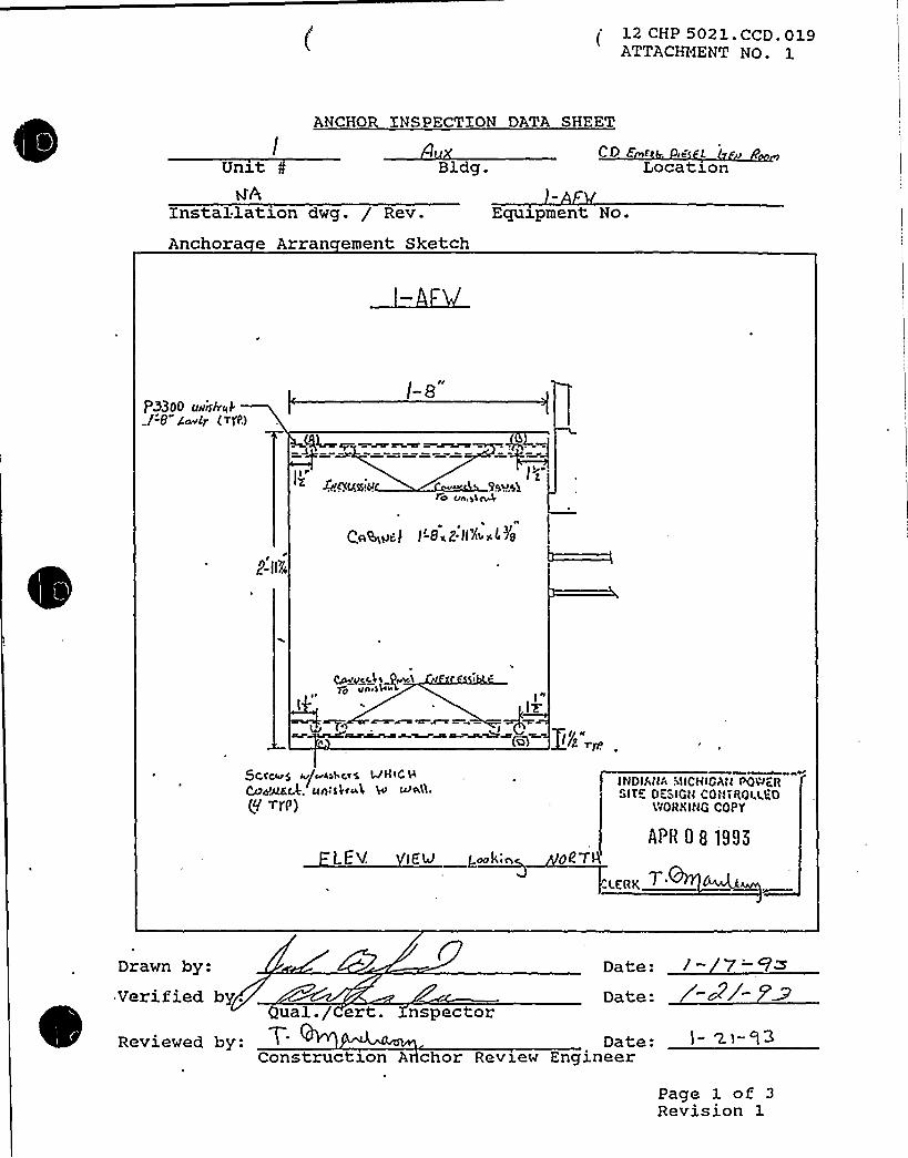
(12 CHP 5021. CCD. 019ATTACENENT NO. 1
ANCHOR INSPECTION DATA SHEET
COE E gg I,
Un>.t Bldg. Location
Installation dwg. / Rev.
Anchora e Arran ement SketchEquipment No.
PHOO uuislr«k1-'8" C~lr ( YI'I'.)
t-a"
r&AQUI!M )qua%
lo un,pl~
CASa)~) I'-8wZ-II8! «5 /8
~ ~
lI
8
lvI
(~)
5Ctcwg ~/~ssl cps LJII tC H
Cd/AEc.f. un:sic«I, H ufo'A.
(9'rP)II'IDIMIt,'!CHICA,I~W~IIGITE DESIGII COIITIIOU.'60
VFORXING COPY
APH 0 8 tS93
..I.EAK
Drawn by:verified by-
Reviewed b
7-Date:
1- ~I-'l3ual./ ert. nspector
Date:Construction A chor Review Engineer
Page 1 of 3Revision 1

g
~-
eemseaarxRRRRRSRSHHELRSRSRRRRMML&WRRRSHHHRLQSSISLRLSHRRRRRRLLLLMWWWWW&WRWRlWRHSLW558WRLELMWWWWMW&
I
k i
0 f
~J4>
~ ~

Database: K:SSEL2C.DBF
Equip ID: 2-BATT-AB Train: 1 Equip Class:15
ywing No.: 2-12003
nction: 250 VDC SYSTEM
System: 250VDC DISTRXBUTXON
Equip Desc: PLANT BATTERY AB
Building: AUXILIARY Room: AB BATTERY EQUIPMENT AREA
Elev: 609 Sort: S,R Notes:
Normal State: Desired State: Power Req'd:
Support System Drawing: 2-98055, 2-12003
Req'd Support Comp:
Safety Related Status: NUCLEAR SR Min/Opt: MIN
Alias No: Power Train: B
Comp Served:
MFR: C 6 D BATTERIES
l: LC-25
Panel: 2-BC-AB
Elem. Drawing: 2-98055
Wiring Drawing: 2-91012, 2-91301
Power Source: 2-TDAB-5
Walkdown: C Relay Eval : Y
Comp Type: BATTERY, *RHR WALKDOWN COMPONENT
Iso. Drawing:
Location: IN THE CENTER OF THE ROOM, 3 FEET NORTH OF THE ENTRANCEDOOR

D. C. Cook Unit 2Screening Evaluation Worksheet (SEWS)
GIP Rev 2, Corrected, 2114/92Status: NoSheet 1 of 6
ID: 2-BATT-AB ( Rev. 0) Class: 15. Batteries on RacksDescription: PLANT BATTERYABBuilding: AUXILIARY Floor El.: 609.00 Room, Row/Col: AS BATTERY
EQUIP AREA - IN THE CENTEROF THE ROOM, 3 FEET NORTHOF THE ENTRANCE DOOR
Manufacturer, Model, Etc.: CBD Power Systems LC-25 Cells
SEISMIC CAPACITYVS DEMAND
1. Elevation where equipment receives seismic inputElevation of seismic input below about 40'rom grade (grade = 608.00)
3. Equipment has fundamental frequency above about 8 Hz (est. frequency = 8.00)Capacity based on: 1.00 Bounding Spectrum
5. Demand based on: 1.00 " Design Basis Ground Response Spectrum
609.00YesSRT
0.850
LIN Irr ~ 1
rr
er
~ t
0.0001.00 LOG Hz
Capacity ~.... Demand
33.00
CapacttDemand 1
Demand 2
HAGIPtGIPtspectra.desH:tGIPtPROJOOSStspectra.desH:tGIPV'ROJ0058tspectra.des
RecordLabel Bounding SpectrumBUILDINGGround Spectrum ELEVATION BROADENBUILDINGGround Spectrum ELEVATION BROADEN
Does capacity exceed demand'


D. C. Cook Unit 2Screening Evaluation Worksheet (SEWS)
GIP Rev 2, Corrected, 2/14/92Status: NoSheet 2 of 6
ID: 2-BATT-AB ( Rev. 0)Description: PLANT BATTERYABBuilding: AUXILIARY
Class: 15. Batteries on Racks
Floor El.: 609.00 Room, Row/Col: AG BATTERYEQUIP AREA - IN THE CENTEROF THE ROOM, 3 FEET NORTHOF THE ENTRANCE DOOR
Manufacturer, Model, Etc.: CSD Power Systems LC-25 Cells
CAVEATS - BOUNDING SPECTRUM
BAT/BS Caveat I - Earthquake Experience Equipment ClassBAT/BS Caveat 2 - Battery Cell Plates are Lead-Calcium Flat-Plate, Plante, or Manchex
Design.BAT/BS Caveat 3- Each Individual Battery Weighs Less Than 450 Pounds.BAT/BS Caveat 4- Close-Fitting Spacers between Cells..BAT/BS Caveat 5- Batteries Restrained by Side and End RailsBAT/BS Caveat 6 - Battery Racks Have Longitudinal Cross Bracing.BAT/BS Caveat 7- Racks Constructed of Wood Evaluated.BAT/BS Caveat 8 - Batteries Greater Than 10 Years Old Evaluated.BAT/BS Caveat 9 - Adequate AnchorageBAT/BS Caveat 10 - No Other Concerns.
Is the intent of all the caveats met for Bounding Spectrum?
YesYes
YesYesYesYesN/A
YesYes
ANCHORAGE
1. The sizes and locations of anchors have been determined2. Appropriate equipment characteristics have been determined (mass, CG, natural freq.,
damping, center of rotation).3. The type of anchorage is covered by the GIP4. The adequacy of the anchorage installation has been evaluated (weld quality and length, nuts
and washers, expansion anchor tightness, etc.)5. Factors affecting anchorage capacity or margin of safety have been considered: embedment
length, anchor spacing, free-edge distance, concrete strength/condition, and concretecracking.
6. For bolted anchorages, any gaps under the base are less than 1/47. Factors affecting essential relays have been considered: gaps under the base, capacity
reduction for expansion anchors.8. The base has adequate stiffness and the effect of prying action on anchors has been
considered.9. The strength of the equipment base and the load path to the CG is adequate10. The adequacy of embedded steel, grout pads or large concrete pads have been evaluated.11. The anchorage capacity exceeds the demand.
Are anchorage requirements met?
YesYes
YesYes
Yes
YesN/A
Yes
YesN/AYes

D. C. Cook Unit 2Screening Evaluation Worksheet (SEWS)
GIP Rev 2, Corrected, 2/14/92Status: NoSheet 3 of 6
ID: 2-BATT-AB( Rev. 0)Description: PLANT BATTERYAB
Class: 15. Batteries on Racks
Building: AUXILIARY Floor EI.: 609.00 Room, Row/Col: AB BATIERYEQUIP AREA - IN THE CENTEROF THE ROOM, 3 FEET NORTHOF THE ENTRANCE DOOR
Manufacturer, Model, Etc.: C&D Power Systems LC-25 Cells
INTERACTION EFFECTS
1. Soft targets are free from impact by nearby equipment or structures2. If the equipment contains sensitive relays, it is free from all impact by nearby equipment or
structures.3. Attached lines have adequate flexibility4. Overhead equipment or distribution systems are not likely to collapse.5. No other adverse concerns were found.
Is equipment free of interaction effects?
YesN/A
YesYesYes
S IC LLY D U
~CON I~EN
Date: 10/18/93
SRT: Tom Huang (AEP), Steve Anagnostis (S&A), Paul Krugh (AEP), Randy Steele (AEP)
References:1. Cook Dwgs 12-3476-18, 12-3073A-3, 12-3073D2. C&D Power Systems Inc Dwgs K-5629-3, M-8654-C, M-8655-C, M-8665-D3. Anchorage Package
Four substantial welded steel 2-step battery racks well braced in both directions. Two racks house 28 cells each,and two racks house 30 cells each. Each cell is a C&D Power Systems LC-25. The cells are well secured. Eachrack is anchored with twelve (12) 3/8" anchors.- see references for details.
Frequency > 8 Hz by inspection.
BS Caveat 2: Batteries are C&D lead calcium flat plate (per label on battery).BS Caveat 3: Each cell weighs 325 Ibs (Reference 2)BS Caveat 8: Batteries were installed in 1985. SQUG Action Item 002 was written to address the aging issue.
ANCH Caveat 1: The anchorage package specifies the anchors as unknown 3/8" non-shell type expansionanchors. The original plant drawings (Ref 1) specify 3/8" J-bolts (90 degrees, 9", embedment), but when the currentbattery rack was replaced in 1985, a note was added to the plant drawing that, where necessary due to bolt holemisalignment in the rack, the original J bolts were to be cut off and replaced with 3/8" Kwikbolts. The current boltsare exactly where the original plant drawings locate the J bolts, and they look like J-bolts (cut-off threaded end).
ANCH Caveat 2: Per Ref 2, the 28 cell racks weigh 10231 Ibs and the 30 cell racks weigh 10920 lbs. The cellsare about 90% of the weight and the rack is about 10% of the weight. The attached "Battery Rack WeightDistribution" shows the geometry.
ANCH Caveat 4, 6: Installation checked per Ref 3.

D. C. Cook Unit 2Screening Evaluation Worksheet (SEWS)
GIP Rev 2, Corrected, 2/14/92Status: NoSheet 4 of 6
ID: 2-BATT-AB ( Rev. 0 )Description: PLANT BATTERYABBuilding: AUXILIARY
Class: 15. Batteries on Racks
Floor EI.: 609.00 Room, Row/Col: AB BATTERYEQUIP AREA - IN THE CENTEROF THE ROOM, 3 FEET NORTHOF THE ENTRANCE DOOR
Manufacturer, Model, Etc.: C8D Power Systems LC-25 Cells
ANCH Caveat 5: In the SRT's judgement, the anchors are the original J bolts. Per GIP Table C.4-1, these havenominal capacities of 3.74k pullout and and 1.87 kip shear. The pullout capacity is reduced by 0.51 to 1.91 kipsdue to the 9" embedment length. No other reductions are required.
Note that ifthe anchors were 3/8" Kwikbolts (the replacements specified in Ref 1), the nominal capacities wouldbe 1 46 k pullout and 1.42 kip shear. The pullout capacity would be reduced by 0.88 to 1.28 kips due to 3.5 ksiconcrete. No other reductions would be required."
ANCH Caveat 8: The racks are anchored through a pair of 3/4" thick plates that run along the front and back ofthe racks (see references and photos). This configuration may produce some prying on the anchors; although theplate may be stiffenough relative to the anchors to keep this to a minimum. Per the discussion for ANCH Caveat11, the pullout load would have to increase by a factor of 6.2 for J-bolts (3.6 for Kwik,bolts) to reach the allowablelimits.
ANCH Caveat 11: The attached "Battery Rack Weight Distribution" shows that the front-to-back overturningmoment for one rack is 55648 in-lbs. That moment is resisted by six anchors with a moment arm of 30", whichproduces a per bolt pullout load of 55648/6/30 = 309 lbs. The side-to-side seismic loads willnot produce anysignificant pullout loads. The shear load is 4586 Ibs for one horizontal direction of input. SRSS'ing the twohorizontal directions and dividing by the number of bolts produces a per bolt shear load of 1.41 x 4586/12 = 539lbs.
Using the bi-linear shear-tension interaction in GIP Figure C.3-2, the interaction for a J bolt anchor is 309/1910 =0.16 (Note that the shear is less than 0.3 of the shear allowable). Ifa 3/8" Kwikbolt were assumed, the interactionwould be 0.7 x (309/1280) + (539/1420) = 0.55.
Photos: W2T1.11, 12
Evaluated by: Date: /c'o ~S
Attachment: PicturesAttachment: Battery Rack Weight Distribution


D. C. Cook Unit 2Screening Evaluation Worksheet (SEWS)
GIP Rev 2, Corrected, 2/14/92Status: NoSheet 5 of 6
ID: 2-BATT-AB ( Rev. 0 )Description: PLANT BALIERY AB
Class: 15. Batteries on Racks
Building: AUXILIARY Floor El.: 609.00 Room, Row/Col: A8 BATTERYEQUIP AREA - IN THE CENTEROF THE ROOM, 3 FEET NORTHOF THE ENTRANCE DOOR
Manufacturer, Model, Etc.: C8D Power Systems LC-25 Cells
JPPGTUR s
0.12

L
0

D. C. Cook Unit 2Screening Evaluation Worksheet (SEWS)
GIP Rev 2, Corrected, 2/14/92Status: NoSheet 6 of 6
ID: 2-BATI-AB( Rev. 0 )Description: PLANT BATTERYAB
Class: 15. Batteries on Racks
Building: AUXILIARY Floor El.: 609.00 Room, Row/Col: AB BATTERYEQUIP AREA - IN THE CENTEROF THE ROOM, 3 FEET NORTHOF THE ENTRANCE DOOR
Manufacturer, Model, Etc.: C8D Power Systems LC-25 Cells
ac W s ib
P—11
CC of upper tie
W x Sah = 2295 Ib
W x (1 — 0.4 Sov) ~ 4958 Ib
CG of lower tier
W x Sah ~ 2293 fb
W = 1/2 rack weight = 5460 Ibs
Soh = 1.5 x 57. FRS O 8 Hz = 0.42gSav = 2/3 x 1.5 x 5K FIIS I 20 Hz =
0.23g'ateral
Load = 2 x 2293 Ib = 4586
W x (1 - 0.4 Sov) = 4958 Ib
Overturning Momen't (sum moments about 8) „~ (2293 x 26) + (2293 x 48) - (4958 x 23)= 55648 in fbs
Base Channet
Bolt lines

D. C. Cook Unit 2Outlier Seismic Verification Sheet (OSVS)
GIP Rev 2, Corrected 2/14/92Sheet 1 of 4
ID: 2-BATT-AB (Rev. 0)Description: PLANT BATTERY ABBuilding: AUXILIARY
Class: 15. Batteries on Racks
Floor EI.: 609.00 Room, Row/Col: AB BATTERYEQUIP AREA - IN THE CENTER OFTHE ROOM, 3 FEET NORTH OFTHE ENTRANCE DOOR
.OU L I SU DE I I ION- ec calan Eeet ical E u'
a. Identify all the screening guidelines which are not met. (Check more than one ifseveral guidelines couldnot be satisfied.)
Capacity vs. DemandCaveatsAnchorageSeismic InteractionOther
b. Describe all the reasons for the outlier (i.e., ifall the listed outlier issues were resolved, then the signatorieswould consider this item of equipment to be verified for seismic adequacy).
The battery rack is an outlier due to BAT/BS Caveat 8 - Batteries Greater Than 10 Years Old.
2 P D DO U E 0 U N ~ono,
a. Defined proposed method(s) for resolving outlier.
The attached "Position Paper on the Replacement of the Safety Related Batteries at the Donald C.Cook Nuclear Plant" (R. J. Roman May 10, 1993) states that AEPSC has committed to adoptingthe replacement criteria stated in ANSI/IEEE Std 450-1987. AEPSC's position is that thiscommitment resolves the outlier.
b. Provide information needed to implement proposed method(s) for resolving outlier (e.g., estimate offundamental frequency).
3 C
4CE C 0
The information on this OSVS is, to the best of our knowledge and belief, correct and accurate, and resolution ofthe outlier issues listed on the previous page willsatisfy the requirements for this item of equipment to be verifiedfor seismic adequacy:
F
Approved by: Date:
Attachment: Position Paper on the Replacement of Saf Related Batteries

~ QI
I ~ ~ ~
~ ~ I II ' It
~ I ~ I ~
~ Ml ~
~ ' ~, I ~ ~ t ~ I S I V ~ ~ I
~ ~ I ~ ~
I
I s
~ C '»I ~ s
I I
I I ~
I~ ~ »» I ~ ~
~ ~ ~ I ~ ~ II I ~ ~ ~ ~ I».
~ . ~ I I I II ~ I ~ I ~ ~ I
~ ~ II ~ I I I
I ~ II I
l I
II. S ~
I ~ . ~ ~ I 'Jl ~ »I ~
~ ~ ~ ~ ~ ~ »' ~ I
~ ~ ~ ~ ~ ~ ~ ~ ~
~ I ~ ~ ~ ~I ~ ~
~ I~ I ~ ~ I II I ~ ~
I~ ~ I Ii. ~ ~ I ~'
~ ~
»O ~ I ~
~ ~ »I ~
~ ~ I ~ ~ I ~ ~
~ I »\ ~
V ~ I I~ ~ ~ I » ~ I ~
~ ~
~ ~ ~ ~
C ~ ~ ~
~ ~ ~ ~ '
~ ~ ~ ~
~ ~ ~ ~ ~ ~
~ I
' I ~ I»J ~
1J ~ I ~ I ~ 4
I
lL.
~I ~ »

CHARTER POWER ersAfMS, INC, Plyrrmuth Meeting, Pennsyh an(a
DATE:
TO:
FROM'6
February 1984
Ron RomanAmerican Electric Power Service Corp.
Graham WalkerCM Charter Power Systems, inc.
SUBJECT: O.C, Cook Nuclear PlantTmfn N, 250 VoftSafety Refatad BatterySeismic and Ufe Qualification
I
In response to your1B Feb 94 memo, our mes indicate the following;'I
1. The Train N batteries were originally purchased ln May 1979 under,P.O. No. 0887M21-8, as the Train C AuxiliaryFeedwater System dattarfea.
2. The original Technical Specification, DCCEE-183&CN, Rev. 2, 1 May 1878,requfmd only seismic qualification,
3, The C&Q Seismic QuafNcatfon Report submfttid for these batteries and racksfs No. VL7S10-02, ReV. 2, dated 16 July 1878:. AlldoCumentatfcn at that timewas submitted tha AEPSC offices In New Yofft',City.
II
4. The 3DCU-g has a 20 qualified life at a 77F arinual average operating ,ltomporature. Qualification is by equivalence af conffguratfon, desfgn andmaterials to previously tested 3DCU-5, 3DCU-7 and OCU-17 models whichwere 20 years artNcfaffy aged in acconfance with fEEE<36 prfor to seismictestfng. The fEEE-344 seismfc qualNcation testing these caffe experiencedenvelopes the D.C. Cook fioor responsa spectrum. The reports for these !
qualification tests are located at C&D Headquirters fn Plymouth Meeting, PA,.and are avaffabfa for review.
II
lfyou have any questions, pfease call me.I
I
Sincerely,
Graham WafkorManage; Applications Engineering
TOTAL P.03
volt-u- »ax Note 7671
~ ~S~SCo JOopn
Pnono N
vsFrom
. Co.
Phono s
Fat 0
~ 4»'» ~ V t
Date May 10, 1993
nnnpeot Position Paper on the RepIacemeat of the Safety Related Batteriea at theDonald C. Cook Nuclear Plant
tronP~~Ro Je Roman/D ~ Re Smith
%pie
1) J.A ra l+)
s)
+ ~ ~vA~ ~~l+CA« ~I"i><
+~r/qg
Based on a review of the surveillance raporto, history, and maintenancerecords/trend charta for the 2AB battery, tho decision hae been made toreplace this battery during thc 1994 Unit 2 refueling outage. Theresults of similar raviaws for the five other safety-related batterieohas led to the decision to not replace any of these batteries during thoupcoming xafueling outages. Tha following discussion addreaaas thedotails of the reviews that, led to this decision.
AEPSC'a plan had boon to replace the oafoty-related batteriea at theDonald C. cook Nuclaax Plant ovary- 10 years even though they arepurchased aa 20 year batteriea. a nav lated
to ton nt, was developed aaod on prev oua prematurep a er eo and high temperatures oxperiencod in the
battory rooms. Beforo the decision was made to adopt this plan, astudy waa conducted by HVAC showing that it would ba lees expansive toraplaco the battaries avory tan years than to air condition the batteryrooms. Baood on this plan alone, tha lAB battaxy should ba replaced in1995 (since it wao manufactured in 1985), tha 1CD battery in 1995, the1N battery in 1999, tha 2AB battory in 1994, the 2CD battery in 1996,and the 2N in 1998.
During the EDSFI, the 10 year x'eplacemont pl,an came into qucation duringa review of the original battary sizing calculationo. After lengthydiscussions between the inspector and Mr. Roman< AEPSC ccaxnittad toadopting the replacement criteria stated in ANSI/IEEE Std 450"1987r IEEERocoaaended Practice for Maintenance, Testing, and Replacement of LargeLead Storago Batteries fox'enerating Stations and Substations.Specifically, IEEE 450 recommends replacing a battery when its capacity,aa determined by the 60 month performance tost, ia bolow 80t of thamanufacturer's rating. Under ideal conditions, a battery would roach
'L
A rule of thumb regarding high temperature is that, for ovary 15'Fabove a 77'F average temperature, a battery' lifo io shortened by 50% ~ Theaverage temperatures in the battery roomo at the DCCNP are leoo than 92'F(77'F + 15'F) however other factors, ao discussed in the body of this report,lead to accelerated aging and/ox aarly roplacament of large lead-acid storagebat'terios.
77 F average temperature, thorough maintenance throughout batterylifo, etc.
intra-System

r v ~ raa»»»u ~ VC
Poaition Paper on the R«pl«cement of the Safoty @el«ted Batteries «t tb+Donald C. Cook Nuclear PlantMay 10, 1993Page 2
thi.o point somewhere around 20 years. Under current DccNp conditions,battery could reach this point sooner (due to the high battery roomtcmpcraturee mentioned previously). Ao implied in the previous twostatements however, factors other than age affect the viability of thebattery. Physical characteristics, such as plate condition togetherwith agc, are often determinants for complete battery replacement.Failure to hold a charge, as shown by cell voltage and specific gravityreadi.ngo, io a good indicator for further investigation into the needfox replacement. lt io a combination of those factors, and not simplythe age or capacity alone, that haa led to the decision to replace the2AB battery during the 1994 Unit 2 refueling outage. Neither thesefactors, nor the age or capacity alone, indicate the need to replace anyof tho other safety"related batteries at this time.
Xn support of the decision to not xaplace any of the other safety"related batteries during 1994 r~fucling outagco, the followinginformation i.a provided.
QQCA Voc ~g~
2)
3)
4)
March/April voltage trends of these batteries i.ndicatc that all ofthc calls have voltagoa in the normal range of 2.20 - 2.24 volts(on a float charge). For comparison purpooao, thirteen (13) ofthe 2AB cell voltages ware leos than (or equal to) 2.20 volts.A cursory review of the past tcn year's worth of these safety-reLated battery files reveals few occurrences, i.f any, involvingcell low voltages, electrolytelspecific gravity concerns, andoverall less than dcaircable physical conditions. Ao a contrast,there wexe many instances of these same concerns regarding the 2ABbattery.The files do not indicate that an issue waa made xagaxding thetemperatures of the 1AB< 1CD, 1N, 2CD, & 2N battery xooms. Thcfi.lco do show, however, that, upon procuxement & i.notallation ofthe 2AB battery, the manufacture'o xapxeaentativc atatod that thebattery life would be shortened due to the high ambienttemperatures in the battery room. While this is a recognizedattribute for all of thc batteries/roomo, it appeared to be morcsevere at the time fox tha 2AB battery room.Routine preventive and corrective maintenance ie a part of anybattery's life. This maintenance should be fairly consistent fromono safety-xelated battery to another, ao they are all large,lead-acid stationary batteriee. For the most part, thi.omaintenance hae been consistent for the majority of the Class 1Ebatteries. As expected then, these Class 1E battcrico arcexperiencing a normal, predictaEXe decrease in their ecrvico li.fc.The 2AB battery, howavex, hae demanded considerable additionalmaintenance and engineering time i.n the past couple of years
n Nine (9) cells had voltages leoa than 2.20 vDc and four (4) cellshad voltagco equal to 2.20 VDC.
4The aforcmcntioned study comparing the coot of more fx'cqucnt battory
replacement versus ai.r conditioning the battery rooms supporto this otatament.The atnbiont temperatures axe generally higher i.n the AB battery rooms, whencompaxed to the cD and N Txain rooms, due to their physical location in theplant and their ventilation systems.

Position Paper on the Replacement of the Safety Related Batteriea at theDonald C. Cook ?tucloar PlantMay 10, 1993Page 3
resolving issues concerning low voltages, specific gravities. etc.Ae the additional time spent maintaining this battery issignificant, it is believed that this is signaling tho end of thisbattery's useful life and that it will most probably not staywithin the Tech Spec range for individual coll voltages beyond thoupcoming refueling outage.
Toad acid storage batterieo are dynamic electrochemical devices. Asouch, the ability to predict their future performance and/or capacityrepresents a near formidable Cask. The decision to not replace any oftho other safety-related batterios outside of 2KB dura,ng the upcomingrefueling outages was arrived at after careful consideration of all thefactors involved- Tho information available simply does not supporttheir replacement at this time. Therefore, it is recommended that thosebattories continue to be maintained and tasted in accordance with thoIREE standards and the recommendation to replace them corno when thomaintenance/testing data supports it.
Preparod By/Date: os'/o 9 g
Concurrence 8y/Date: n~ ~AC~~pS'07'.
Concurranco Statement:
ass m
~~ ~~ ~c: 0+Co Joffxoy/4+Rr tdlderoon/Reit+ RomanR.I. GhoborgJ.A. KobyraD.R. Smith/J. Murtha - BridgmanT.A. Kratt - BridgmanAEPSC/NEEP Gafoty Related Battery File
(c:ir$rXbatteryioefmemo.wp)
TOTAL P.G3


0 ~ ~ I ~
~ ~ ~ L ~ ~ 0 0 ~
~ ~ ~ ~
mr rr
~ ~ I
e
~ - h 0
Q ~ ~
0 .104
~-
0 ~
0 ~
0 ~
RSRKRIRWRSRIISII:-RSMIIIII55IIImmlsIIRIISIIB55IIRSIIIIRIRSIRIIIRIRRIIII
y 4 e o o
IIHRIIRW~RwmIIERMWWWWMWWJ 0 0 H j
0 e r~ + ~ t 0 0 ~MWWMMWWW
~ ~ Cr0h
~ 'tta;EERIER0L ~

**12 CHP 5021 ~ CCD. 019".TACHMENT NO. 1
NCHOR INS ECTION DATA SHEETW KV A6 CIAT7Egg ROOD
Unz.t Bldg. Locationz.-34~ — 8 t z.-3z z -serT-
Installatxon dwg. / Rev. Ecpxxpment No.
Anchora e Arran ement Sketch
Rr T-aQ
('T~r II
INDIANAMICHIGAN POKIERSITE OESIGt< COtITIIOLLEO
WOfiKIIIGCOPY
OCT 0 5 3995
I.ER'K T@I Q(~QJ.<l>.1rI |
1
I
3-8/q.
+~I)I'<
(.Typ)
)I -3$ <.>)c)
/ i
7 C/fhhlhgBL TYP,
Eca.M Ni~Q
400k
i'd&
N
<RAN
9.
Drawn by:Verified by:
Reviewed by:~
~
Date: 2 3Date: I->6"4>
I r -r-'2Qual. /Cert. Inspector
w %n Date:Constructs.on Anchor Review Engineer
Page 1 of 3Revision 1

( >*12 CHP 5021. CCD. 0].9ATTACHMENT NQ. 1
i i/vOUnct
NS CT 0 T
Avx (D C'FBldg.
ASE P V I P I'I!=U ~
Location/2 " 3 ~ = 'i'- 7
Installation dwg. / Rev.
Anchora e Arran ement Sketch
2.->i i | - A'E|Equipment No.
INDIANAMICHIGAtt POVlCRSITC DESIGN CONTROLLCO
lVORKING COPY
OCV 05 >99S
GAY TBRYl0 Yz. A I 4 ~ 20 /q
(spp- Sut'PoRrDI=TAIL)
VJ Q L H f4'1 E ." J:
Q X3 4 4 i ORi <~DAhrGCC FRANC
~<AT TBR'
lO ~L pc I e "X ZO'i+"
(SPE ZLI! PORlQFTWI I
S7g
4.g'$
2
p II2C-8
~ II
cRov t P&e
T C.I4ANV I= I- GAS
Ecv>o A
Drawn by:Verified by:
Date:Date:ual./Cert. inspector
Reviewed by: T '4~4 Date:Construction Anc or Review Engineer
t o.-5-'I3
Page 1 of 3
Revision . 3


**12 CHP 5021.CCD.019ATTACHMENT NO. 1
UnLt
Ig - 3P ZP-y
P CT 0 T
ucq'ldg.
~ & QA~raRg~JUL f'ME.~T. Boo H
Location
Installation dwg. / Rev.
Anchora e Arran ement Sketch
/ /2, BARaOi T.aC
Equipment No.
iiii)ll'lA:<iCi'IC "SIIE 0"SiGi'l CO" ~
'ii'OR!.IhC (.Oi'
OCT 05 1995
>'+z Q 1I
WI
'hI'~ 4
Date: 2
Date:
Drawn by:
l g.-z -c.'~
Verified by:Qual./Cert. Inspector
Reviewed by: T'i' v~v~~=~.; Date:Construct'>on Anchor Reve.ew Engineer
Page 1 of 3
Revision .3

rh

( >*12 CHP 5021. CCP. 019ATTACHMENT NO.
TkvoUnzt
N ECT 0 T
.- ux gotBldg.
A, 5 .BA>~E.RYEC V'~ > %COO;-q
Location
Installation dwg. / Rev.
Anchora e Arran ement SketchEquipment No.
IIDIP . ~ Q. BOP
EVERY 2.Wu OR ERD
CATTP R'f FOR C-I MG-
UMISTRVTS T'IG-HTA~INS, r WTTI=RY
INDIANA MICHIGAN PO'V(fRSITE DESIGN CONTROLLED
WORKING COPY
OCT 0 5 1995
UNl STRv 7(hR>C.gI-= Twa+,-2o58
IIYz Tt+K. E'c.OF RiGIDIh/SV LOFTI ONSOAR loQR~~WGATTBRI&5
QP,~<Pg'I'VAPOR i DP.l Al L
Drawn by:Verified by:
,Date:
Date:Qual. /Cert. Inspector
Reviewed by: I '~F'I'5'h~-~(bQn Date:Construct>on Anchor Review Engineer
Page 1 of 3Revision . 3
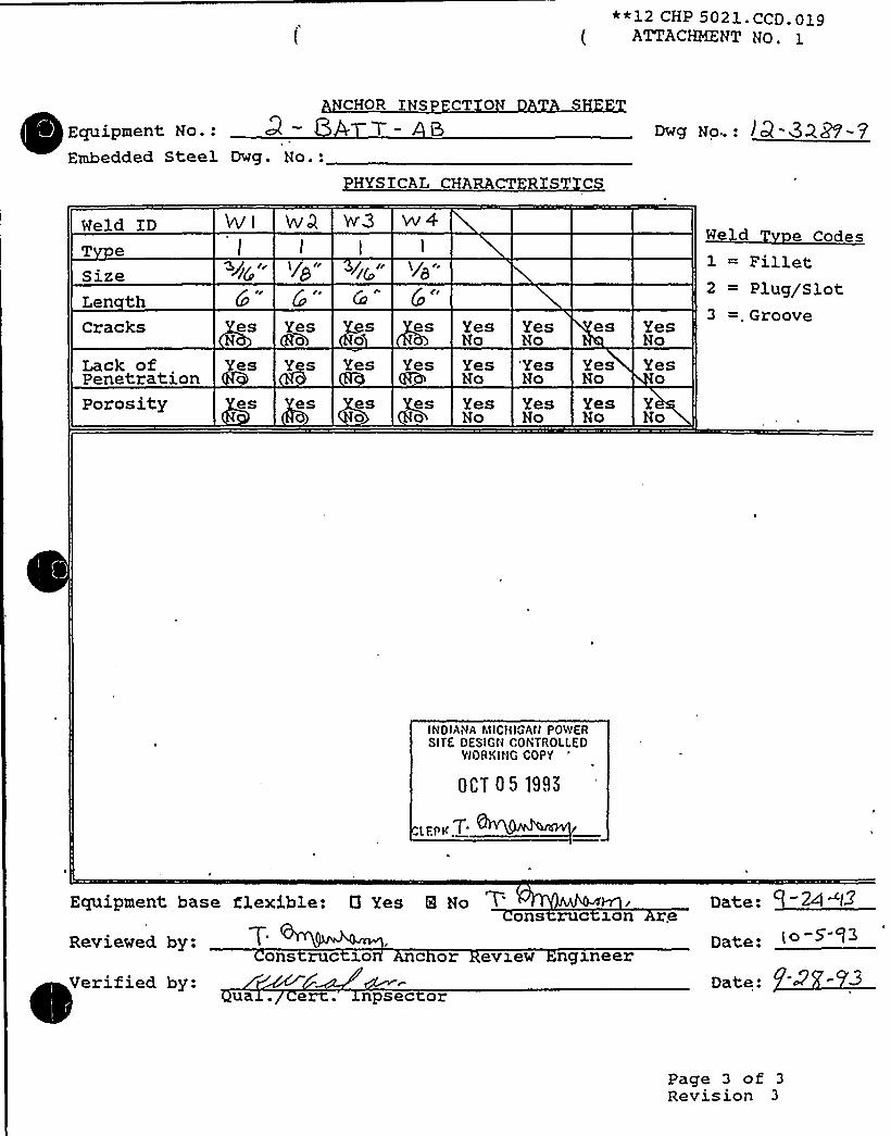
**12 CHP 5021. CCD. 019( ATTACHMENT No.
Equipment No.:Embedded Steel Dwg. No.:
CHOR XNS CT 0
HYS ICAL CHARACT RIST C
Dwg No..: j Q -QQp- p
Weld IDT e
SizeLen thCracks
Lack ofPenetration
Wi
Q/~@CC
esN
Yes
I/ cr
Yes0
Y s
Ct
s es
Yes Yes
W3 w4
YesNo
YesNo
YesNo'YesNo
es
YesNo
YesNo
Yes0
We d e Codes1 = Fillet2 = Plug/Slot3 =.Groove
Porosity es es eso
es0
YesNo
YesNo
YesNo
YNo
INDIANA41ICHIGAII POPOVER
SITE OESIGII CONTROLLEDWORKING COPY
0CT 05 19,I5
I.EP'K
T'quipment
base flexible: 0 Yes 8 Noons ruc ron re Date: -24
Reviewed by:
Verified by:ons ruc z.o c or evxew ngzneer
ua . e . npsec or
Date:
Date:
(o-5'- f3
Page 3 of 3
Revision 3

I ~
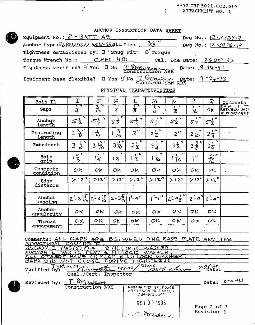
~ ~ )0 $t'R
~ ~
~ ~ ~ ~ ~
~ ~
~ ~ ~
s ~
e ~
RRRSRRRRRSRWRSI5--.IMIIIIIR8imimmmSRIMIIMIIIKRIIRRIIIIIIIRSRIIIHRRIERRImilliAIR%%LRRHLL
/S ~

0

0 ~ ~ ~
~ ~ t
E
0~ te a ~
E o ~
0 0
~ a ~
r
~ - l- ~
Q
t l~ l'4
~-
)
f
s 4
~ ~
o ~
0 ~
IBK~EP~0
~~RK~~~~RR -,-RRRRRSRSRSRSRSRR~ .
MRRRSMR58%55WRSMRIRSIH555$ 55RHRRSSRRRRRRRSRRRSESRRRHMRRWWRSRRRRRSRRRSRRS~RWRHHEQHKRH5%6%
IHMWRRRSRHRIRHr e
a e r rMMWMMMWWa ~a -.. EL. a
ka ~ r g ~ r g e~W~J'He~~:aneesmw
8Ke
Ak'
I ~
s


~ y ~ I ~
~ ~ ~ 4 lj ~ ~ e ~ ~
e ~
~ ~ ~
~ ~
~ - ~
~ .~ %4
~ - 0 ~ ~ .e
e ~
~ ~
e ~
~ ~
~ '
RRRRRRRRRRRRRImi:;:mmmmilmMIIIRRRSElKRMIIIIHIRRIIIMlmlmIIISmimimlRIy y r e
~IIIIIREQR!SRwRSIIMWWMWMWWr e 1 e r y
r p i P t eMW&MMMW&Ca ~C a
'YSMe!ERP%%9&UIKQWJC
'h ~
P ~MWaMNaLMC)HNk&&%4%
~ a
~ ~

~ ~ I~
f ~ ~
~ ~
~ ~ ~ ~ ~ 4 ~
Q 0 ~
- ~ ~ ~
5 - 8
o 1~4
o ~
RRNNRNR%5%5%555%- -.
IKmmmmmmmm- mmlESRNmmmmm
RES1mmmKlmmRSMEWRSmMMIR
y e o r e r o
~mmmmhhRRWHRmmmm
mmmmmmm55mr
~ y ~MWWMMM&Waj ~
0 C.' ~ ~
4 ~0 HFJBESISSI%leaSKHKaeRKSSP~ i . K~%K8'

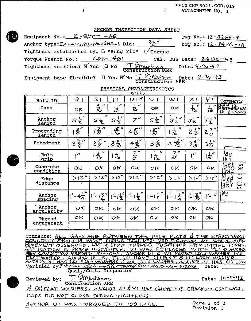
~ ~
I ~
~ ~ ~
~ ~,.
~ ~ ~ s ~
I ~ ~
~ ~
~ ~
~ - ~
~ .s is)
~ - C ~
s ~
~ ~
s ~
t
KRERHHRWHMSRRSIIIII .
RRRSNIRSRRR%mm5I=-IIIMIIIII55IIISRIEIIIIIIIIRRRRSRI5%MIEIIRSRSRSIIIS
0 ~ ~
~IIIIRWRESHESIIIIIIEIIIIIIIIIIRHIRl
0 I'
0 yMWWMMMW&~ ~4 4 ~ s a 8 a R E M
a%4%%~<' a.. a i o ~ la a ~
sssIsss ''~'%81sssssssssi%1E 's~s.ssvissw . ssaake~sssIMII 25a4KM<ÃtRQRUPk%0r
~ ~ rr ~
O ~l~e
APL ~ ~
~ 1

S 8 A DEPART)so=ATCONTROl.LED DOCUMENTCOPY NO.
i12 SHP 5050 NDL- 008ATTACPNENT HO.
UITRASONIC TEST REPORT
JOB ORDER NO.: REPORT DATE: REQUEST NO.
IDENTIFICATION
Unit ~QComponent — - AItem - ~ rSMaterial ~ S
Other
Test Unit/ S/N (Freq./Diameter 5 m4zReference StandardCouplant/Batch No.
i<.TS c c-9
TEST DATA REMARKS
AM ru. s'/z
k.L
PERFORMED BY:C
REVIEWED BY: '" M~. Pc&
FORM NO. 12 SHP 5050 NDE.008-1
I EVEE,:.~~IEVEI'age
1 ofRevision 0
DATE: C /.- 5 y3

oly16192PG. N0.425
SAFE'HUTDOWN EOUIPNEHT LIST (SSELUP)
FUNCT IOH: 01ESEL GENERAT IOM
Equipment Class: 17 Train: 1
Equipment ID: I-DHE-150-AB DraMing Number: 1.12001 1-5151A 1-51510
System: DIESEL GEHERATOR COM1'ROL AHD IHSTRlNENTATION
Equip Description: AB EKERG DIESEL GEHERATOR
Bui lding: AUXILIARY Roan: AB EHERG DIESEL GEHERAI'OE ROOM Elevation:'87
Normal state: Desired state: Pouer Required: Sort: lI,R
Si~rting System Orauing Number:
Recnsired Interconnections and Supporting Conponentsl
ty Related Status:
E.
NUCLEAR SR Min/Dpt: KIM
ADDITIOMAL INFORHATIOH
alias Number: Prier I'rain: B
Conponent Served: AB EKERG DIESEL GEHERATOR
Nanufacturerl GENERAL ELECIRIC CO Model:
'Pnneil 1-OGAB 1-OGABX
Elcm Orauing: 1-98032 1-98051 1-98052 Uiring Drawing: 1-95301
Paver Source: 1-T11A11 1-T1164 1-TOAD-2
un I Ldoun: F Relay Only: Y
Component 'Type: ENG. GEN 3500XU,4KV
ISO Drauingsl
Detailed Location: IN tHE CENTER OF THE ROON


DC Cook Unit 1
SCREENING EVALUATIONWORK SHEET (SEWS)GIP Rev 2, Corrected, 2/14/92Status: YesSheet1 of4
ID: 1-OME-150-AB ( Rev. 0) Class: 17. Engine-GeneratorsDescription: AB EMERG DIESEL GENERATORBuilding: AUXILIARY Floor El.: 687.00 Room, Row/Col: AB EDG RM, IN
THE CENTER OF THE RMManufacturer, Model, Etc.: GENERAL ELECTRIC CO
SEISMIC CAPACITYVS DEMAND
1. Elevation where equipment receives seismic inputElevation of seismic input below about 40'rom grade (grade = 608.00)
3. Equipment has fundamental frequency above about 8 Hz (est. frequency = 20.00)4. Capacity based on: 1.00 Bounding Spectrum
Demand based on: 1.00 " Design Basis Ground Response Spectrum
687.00YesYes
0.800
G
LOG
0.0900.50 LOG Hz
Capacity ..... Demand
33.00
Ca aciDemand 1
Demand 2
C:IGIPtGIPLspectra.desC:tGIPLPROJ0031 tspectra.desC:LGIPIPROJ0031tspoctra.des
RecordLabel Boundin SpectrumBUILDINGGround EI.EVATION608 BROADEN NBUILDINGGround ELEVATION608 BROADEN N
Does capacity exceed demand'
CAVEATS - BOUNDING SPECTRUM
'G/BSCaveat 1 - Earthquake Experience Equipment ClassEG/BS Caveat 2- Driver and Driven Component on Rigid Skid.EG/BS Caveat 3- Base Vibration Isolation System Checked.EG/BS Caveat 4 - Sufficient Slack and Flexibilityof Attached Lines.EG/BS Caveat 5 - Adequate AnchorageEG/BS Caveat 6 - Potential Chatter of Essential Relays Evaluated.EG/BS Caveat 7 - No Other Concerns.
YesYesN/AYesYesN/AYes
Is the intent of all the caveats met for Bounding Spectrum'

DC Cook Unit 1
SCREENING EVALUATIONWORK SHEET (SEWS)Glp Rev 2, Corrected, 2/14/92Status: YesSheet2of4
ID: 1-OME-.150-AB ( Rev. 0 ) Class: 17. Engine-GeneratorsDescription: AB EMERG DIESEL GENERATORBuilding: AUXILIARY Floor El.: 587.00 Room, Row/Col: AB EDG RM, IN
THE CENTER OF THE RMManufacturer, Model, Etc.: GENERAL ELECTRIC CO
ANCHORAGE
1. The sizes and locations of anchors have been determined2. Appropriate equipment characteristics have been determined (mass, CG, natural freq.,
damping, center of rotation).3. The type of anchorage is covered by the GIP4. The adequacy of the anchorage installation has been evaluated (weld quality and length, nuts
and washers, expansion anchor tightness, etc.)5. Factors affecting anchorage capacity or margin of safety have been considered: embedment
length, anchor spacing, free-edge distance, concrete strength/condition, and concretecracking.
6. For bolted anchorages, any gaps under the base are less than 1/47. Factors affecting essential relays have been considered: gaps under the base, capacity
reduction for expansion anchors.8. The base has adequate stiffness and the effect of prying action on anchors has been
considered.9. The strength of the equipment base and the load path to the CG is adequate.10. The adequacy of embedded steel, grout pads or large concrete pads have been evaluated.11. The anchorage capacity exceeds the demand.
YesYes
YesYes
Yes
YesN/A
Yes
YesYesYes
Are anchorage requirements met'P
INTERACTION EFFECTS
1. Soft targets are free from impact b nearby equipment or structures2. If the equipment contains sensitive relays, it is free from all impact by nearby equipment or
structures.3. Attached lines have adequate flexibility4. Overhead equipment or distribution systems are not likely to collapse.5. No other adverse concerns were found.
Is equipment free of interaction effects'
YesN/A
YesYesYes
C L D
~Clggg~g
SRT: George Gary Thomas (S&A) and Tom Huang (AEP) on 10/16/93.
Diesel Generator and driver not on same skid, however large contrete foundations originate from common floor,differential motion not a concern.

DC Cook Unit 1
SCREENING EVALUATIONWORK SHEET (SEWS)GIP Rev 2, Corrected, 2/14/92Status: YesSheet 3 of 4
ID: 1-OME-150-AB ( Rev. 0 ) Class: 17. Engine-GeneratorsDescription: AB EMERG DIESEL GENERATORBuilding: AUXILIARY Floor El.: 587.00 Room, Row/Col: AB EDG RM, IN
THE CENTER OF THE RMManufacturer, Model, Etc.: GENERAL ELECTRIC CO
No interations. See AEP anchorage data for seismic qualification. Engine anchored by fourteen 2" or largeranchors. Generatoranchoredbyeight1" anchors. Generatorshaftendanchoredbyfour1.75" anchors. theANCHOR analysis gives a large safety margin (36) as shown by that done for 2-OME-150-CD.
Concern noted with regard to support of air manafold that supports aftercooler. Aftercooler supported by springmounted column. This concern was tracked and reconciled with items 1-HE47-ABS 8 ABN.
Zap shot Wk. 2, Team 2, Disk 2, Picture 20 8 21.
Evaluated by: Date:
i(-~—Attachment: Pictures

DC Cook Unit 1
SCREENING EVALUATIONWORK SHEET (SEWS)GIP Rev 2, Corrected, 2/14/92Status: YesSheet 4 of 4
ID: 1-OME-1 50-AB ( Rev. 0 ) Class: 17. Engine-GeneratorsDescription: AB EMERG DIESEL GENERATORBuilding: AUXILIARY Floor El.: 587.00
Manufacturer, Model, Etc.: GENERAL ELECTRIC CO
Room, Row/Col: AB EDG RM, INTHE CENTER OF THE RM
AB Emerg Diesel Generator 1-AB-150-AB
AB Emerg Diesel Generator, 1-OME-150-AB
AB Emerg. Diesel Generator 1-OME-150-AB
AB Emerg. Diesel Generator, 1-OME-150-AB

~ >12 CHP 5021 ~ CCD 019ATTACHMENT NO. 1
CT
UnztIZ.-3458- 3
Bldg.
Instailat on dwg. / Rev.
Anchora e Arran ement Sketch
~T'Pc''F DI~BLEV&INE GeS~ROT OR ROOnA
Locationr.' &ME. —/50-3 6
Equipment No.
/rl~z
~ g ~
~ g0,
INDIANAMICHIG PSITE DESIGN NT L
WORKING C Y
SEP 2 7 $ 995
EIID
LERK / ~
gap— dv ~Ion Vlpw Lmwivs BAs~
Drawn by:( Verified by:
Q a C rt. Xnspector
Date:Date: ~-8 'Y- ~.8
Reviewed by: Date:Construction chor Review Engineer
Page 1 of 3Revision 3


*12 CHP 5021.CCD.019ATTACiQ&NT NO ~ 1
PME'n tl2.-3468 - l3
Installat on dwg. / Rev.
Eh/Q OP C(E.SE.I-G;euERATaR Roof.
Bldg- Locatzony. —awe, -l4o-AE
Equipment No.
Anchora e Arran ement Sketch
COgr't
+Cp
/3y
9$
9tl
Oo Oos "q F
Sf'I'/~g"
5fv'
Q5q
~O
Qo o
PENT
MACHlh/E BASF ftmsanom~ H.
GRou T PawINOIANA MICHIGAN POIVCIISITE DESIGN CONTROLLEO
WORKING COPY
SEP 27 1995
I
Ol
G H
Qo Qo
qual
QMCHa R- MUV'"Ra.~SSaa lZ2. +4"g x )5>< "DE, (gEeC'BORE, TyP. (g) PL@ 5,
KT I,J.Z.L A..-< sr<"Loll,-A45%ÃS-kE-ABC+r//To EueZODEO mfa.
Drawn by:Verified by.
q . ert.Reviewed by:
Construe on
Date:Date: r -2~ - F~
Cn'age
1 of 3Revision .3
VvuInspector
('2
chor Review Engineer


**12 CHP 5021.CCD.019ATTACHKENT NO. 1
I Equipment No.-Anchor type: re ~c rTightness established by:Torque Mrench No.:Tightness verified? 0 Yes
Equipment base flexible?
0 "Snug Fit" Q
8 Noons ruc
0 Yes N Noons
DWg NOe
'orque
Cal. Due Date:Date:
1on
ruc 1on ARE
Bolt ZD
Caps "I/I/ CCATS I El 6
D W W & O'ommentsAIU'T <Ec SEE roc're "
Anchorlen th
protrudinglen th
Embedment
3~" 37>" rk
Bolt;riConcretecondition
Edgedistance
ACC
ogeh'K1 b LEgq q gg C9,~'II Q~Rt'
Xu rr46800 T &%DAN> EE~ T
~ <i~" 3" v"
Anchor +y~ y.Anchor
an larit O 0
Thread Feesengagement ~, I~
-y„'I
Q'' Q O
76cE556p ccs58 cc d8 cfcEIch emcee
~z
Comments:
c~
tAVerified by:., Cert:. Inspector
I
Reviewed by:Construct1on I MICHIGAN POWER
SITE DESIGN CONTROLLEDWORKING COPY
SEP 2 7 1995
( tat I ~+'AA~vl
Date:
Date:
Paga 2 ofRevision 3

S 8 A DEPARTMENTCONTROLLED DOCUMENTCOPY NO. 3
JOB ORDER NO.:
SHP 5050 NDE.008ATTACHMENT NO. 1
ULTRASONIC TEST REPORT
REPORT DATE: / d" 3 REQUEST NO.
IDENTIFICATION
UnitComponent -OWN-/ &Item AC+o SMaterial .S.Other
TEST DATA REMARKS
Test Unit/ S/NFreq./DiameterReference StandardCouplant/Batch No.
Vs"
Vs"
PERFORMED BY:
REVIEWED BY:
FORM NO. 12 SHP 5050 NDE.008-1
I.EVEI:M DATE: / P
I EVE I: ~ DATE:
Page 1 of 1Revision 0

Equip Id: 2-OME-150-CD Train: 2 Equip Class: 17
D~<wing No ~ : 2-12002,,2-5151C, 2-5151D
tion: DIESEL GENERATION
System: DXESEL GENERATION, CONTROL & INSTRUMENTATXON
Equip Desc: CD EMERGENCY DIESEL GENERATOR
Building: AUXILXARY Room: CD EMERGENCY DIESEL GENERATOR ROOM
Elev: 587 'ort: S,R Notes:
Normal State: Desired State: 'ower Req'd:
Support System Drawing: 2-98033, 2-98051, 2-98052, 2-12002
Req'd Support Comp:
Safety Related Status: NUCLEAR SR Min/Opt: MXN
Alias No: Power Train: A
Comp Served: CD EMERGENCY DXESEL GENERATOR
MFR: GENERAL ELECTRXC CO.
2 SAs 2 DGCD 2 DGCDX
Elem. Drawing: 2-98033, 2-98051, 2-98052
Hiring Drawing: 2-953027
Power Source: 2-T21C3, 2-T21D8, 2-TDCD-2
Halkdown: F Relay Eval: Y
Comp Type: ENG. GEN-3500KW, 4KV
Iso Drawing:
Location: XN THE CENTER OF THE ROOM, 10 FEET NORTH OP THE MAXNENTRANCE DOOR

D.C. COOK Unit 2SCREENING EVALUATIONWORK SHEET (SEWS)
GIP Rev 2, Corrected, 2/14/92Status: YesSheet1 of14
ID: 2-OME-150-CD ( Rev. 0 ) Class: 17. Engine-GeneratorsDescription: CD EMERGENCY DIESEL GENERATORBuilding: AUXILIARY
Manufacturer, Model, Etc.:
Floor El.: 587.00 Room, Row/Col: CD EMER DSLGEN RM - IN THE CENTER OFTHE ROOM, 10 FEET NORTH OFTHE MAINENTRANCE DOOR
SEISMIC CAPACITYVS DEMAND
1. Elevation where equipment receives seismic inputElevation of seismic input below about 40'rom grade (grade = 608.00)
3. Equipment has fundamental frequency above about 8 Hz (est. frequency = )Capacity based on: 1.00 Bounding SpectrumDemand based on: 1.00 * Design Basis Ground Response Spectrum
587.00YesSRT
0.800
LOG //
//
r/
r~/r
0.0900.50 LOG Hz
Capacity ..... Demand
33.00
'apacit
Demand 1
Demand 2
FileC:LGIPtGIPLs ectra.desC:tGIPIPROJ0034ts ectra.desC:tGIPtPROJ0034tspectra.des
RecordLabel Boundin SpectrumBUILDINGGround ELEVATION608 BROADEN NBUILDINGGround ELEVATION608 BROADEN N
Does capacity exceed demand?

0
0
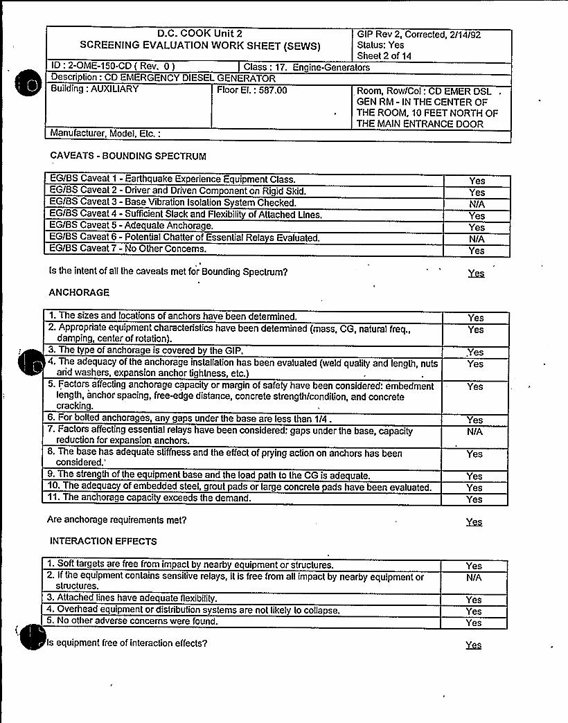
D.C. COOK Unit 2SCREENING EVALUATIONWORK SHEET (SEWS)
GIP Rev 2, Corrected, 2/14/92Status: YesSheet 2 of 14
ID: 2-OME-150-CD ( Rev. 0) Class: 17. Engine-GeneratorsDescription: CD EMERGENCY DIESEL GENERATORBuilding: AUXILIARY
Manufacturer, Model, Etc.:
Floor El.: 587.00 Room, Row/Col: CD EMER DSL .
GEN RM - IN THE CENTER OFTHE ROOM, 10 FEET NORTH OFTHE MAINENTRANCE DOOR
CAVEATS - BOUNDING SPECTRUM
EG/BS Caveat 1 - Earthquake Experience Equipment ClassEG/BS Caveat 2 - Driver and Driven Component on Rigid SkidEG/BS Caveat 3 - Base Vibration Isolation System CheckedEG/BS Caveat 4 - Sufficient Slack and Flexibili of Attached LinesEG/BS Caveat 5 - Adequate Anchorage.EG/BS Caveat 6 - Potential Chatter of Essential Relays Evaluated.EG/BS Caveat 7- No Other Concerns.
YesYesN/AYesYesNIAYes
Is the intent of all the caveats met for Bounding Spectrum'
ANCHORAGE
1. The sizes and locations of anchors have been determined2. Appropriate equipment characteristics have been determined (mass, CG, natural freq.,
damping, center of rotation).3. The type of anchorage is covered by the GIP4. The adequacy of the anchorage installation has been evaluated (weld quality and length, nuts
arid washers, expansion anchor tightness, etc.)5. Factors affecting anchorage capacity or margin of safety have been considered: embedment
length, anchor spacing, freewdge distance, concrete strength/condition, and concretecracking.
6. For bolted anchorages, any gaps under the base are less than 1/47. Factors affecting essential relays have been considered: gaps under the base, capacity
reduction for expansion anchors.8. The base has adequate stiffness and the effect of prying action on anchors has been
considered.'.
The strength of the equipment base and the load path to the CG is adequate10. The adequa of embedded steel, grout pads or large concrete pads have been evaluated.11. The anchorage capacity exceeds the demand.
Are anchorage requirements met?
INTERACTION EFFECTS
YesYes
YesYes
Yes
YesN/A
Yes
YesYesYes
1. Soft targets are free from impact by nearby equipment or structures.2. If the equipment contains sensitive relays, it is free from all impact by nearby equipment or
structures.3. Attached lines have adequate flexibility4. Overhead equipment or distribution systems are not likely to collapse.5. No other adverse concerns were found.
Is equipment free of interaction effects?
YesNIA
YesYes

D.C. COOK Unit 2SCREENING EVALUATIONWORK SHEET (SEWS)
GIP Rev 2, Corrected, 2/14/92Status: YesSheet 3 of 14
ID: 2-OME-150-CD ( Rev. 0 ) Class: 17. Engine-GeneratorsDescription: CD EMERGENCY DIESEL GENERATORBuilding: AUXILIARY
Manufacturer, Model~ Etc.:
Floor EI.: 587.00 Room, Row/Col: CD EMER DSLGEN RM - IN THE CENTER OFTHE ROOM, 10 FEET NORTH OFTHE MAINENTRANCE DOOR
S U SESMC LL D
~cbmgp~
SRTs are TR Satyan-Sharma, W. Djordjevic, J. Nieto, and R. Steele. -. 10/5/93
REF: 1. Anchorage Inspection Data Sheet, Anchorage Arrangement Sketches of generator anchorage, 9/8/93.2. Report on Seismic Analysis of Equipment Supplied by Worthington Compressors Inc. for the D. C. Cook NuclearPlant, Report EG-37017, 9/20/74- Engine on Foundation calculation.3.. Dwgs 12-3241-12, 12-3468-13.4. Anchor Bolt Schedule, Dwg 12-3073A-3.5. General Arrangement Dwg W501812AT.
Anchorage:See Reference 0 2 for seismic qualification of Engine. Engine is anchored by 14 - 2" anchors.
Generator anchored by 8-1" CIP anchors. An edge distance reduction factor is taken for the 4 inside anchors (theyare located approx. 3.7" from the pit's edge). Generator shaft end anchored by 4-1.75" CIP anchors ( modeled as1.375" anchors ANCHOR because this is the largest size anchor covered in the GIP). See ANCHOR analysis.
Photo: DG21-34&35, 36 and 37 (-34 of bolt, -35 from SW corner, -36 from NW corner, and -37 from NE corner).
Evaluated by: Date:
9

GIP Rev 2, Corrected, 2/14/92Status: YesSheet 4 of 14
Class: 17. Engine-GeneratorsID: 2-OME-150-CD ( Rev. 0 )Description: CD EMERGENCY DIESEL GENERATORBuilding: AUXILIARY
Manufacturer, Model, Etc.:
Floor El.: 587.00 Room, Rov//Col: CD EMER DSLGEN RM - IN THE CENTER OFTHE ROOM, 10 FEET NORTH OFTHE MAINENTRANCE DOOR
D.C. COOK Unit 2SCREENING EVALUATIONWORK SHEET (SEWS)
PJCT~UQS
Figure 2: 2-OME-150-CD (Photo DG21.35)Figure 3: 2-OME-150-CD (Photo DG21.36)
Figure 4: 2-OME-150-CD (Photo DG21.37)Figure1: 2-OME-150-CD (Photo DG21.34)

D.C. COOK Unit 2SCREENING EVALUATIONWORK SHEET (SEWS)
GIP Rev 2, Corrected, 2/14/92Status: YesSheet 5 of 14
ID: 2-OME-150-CD ( Rev. 0 ) Class: 17. Engine-GeneratorsDescription: CD EMERGENCY DIESEL GENERATORBuilding: AUXILIARY
Manufacturer, Model, Etc.:
ANCHOR Report
~Ea t~eResponse Spectrum: SSE
Frequency: GIP - Rigid
Percent Damping: GIP - 5.00
Spectral Values:
Floor El.: 587.00 Room, Row/Col: CD EMER DSLGEN RM - IN THE CENTER OFTHE ROOM, 10 FEET NORTH OFTHE MAINENTRANCE DOOR
Direction.North - SouthEast - WestVertical
Acceleration (g's)0.380.380.25
Angle (N-S Direction makes with the X Axis): 0.00
Combination Criteria: SRSS
Wejg+g
'umberof Weights: 1
No Weight1 10000.00 50.500 85.400 51.250
aleeNumber of External Forces: 0
Number of External Moments: 0
~li wattg~
hach@.'umber
of Anchor types: 2
Tension Shear

D.C. COOK Unit 2SCREENING EVALUATIONWORK SHEET (SEWS)
GIP Rev 2, Corrected, 2/14/92Status: YesSheet 6 of 14
ID: 2-OME-150-CD ( Rev. 0) Class: 17. Engine-GeneratorsDescription: CD EMERGENCY DIESEL GENERATORBuilding: AUXILIARY
Manufacturer, Model, Etc.:
Floor El.: 587.00 Room, Row/Col: CD EMER DSLGEN RM - IN THE CENTER OFTHE ROOM, 10 FEET NORTH OFTHE MAINENTRANCE DOOR
Ultimate Ultimate Inter Inter SafDia Manufact Product Tension Shear Coeff Coeff Fact
1-3/8
Other
Other
Cast InPlace (A-
307)Cast In
Place (A-307)
26690.00 13350.00
50400.00 25250.00
1.00
1.00
0.30
0.30
1.00
1.00
Ultimate Stress: 3500.00 psi.
Reduction Factor: 0.85
~WI
Allowable Stress: 30600 psi.
~ance
Number of Surfaces: 2Surface Orientation
No
DirectionComp
0.0000.000
DirectionComp
0.0000.000
DirectionComp
Nz1.0001.000
Anchor Pattern for Surface ff. 1


D.C. COOK Unit 2SCREENING EVALUATIONWORK SHEET (SEWS)
GIP Rev 2, Corrected, 2/14/92Status: YesSheet 7 of 14
ID: 2-OME-150-CD ( Rev. 0) Class: 17. Engine-GeneratorsDescription: CD EMERGENCY DIESEL GENERATORBuilding: AUXILIARY
Manufacturer, Model, Etc.:
Floor EI.: 587.00 Room, Row/Col: CD EMER DSLGEN RM - IN THE CENTER OFTHE ROOM, 10 FEET NORTH OFTHE MAINENTRANCE DOOR
Anchor Pattern for Surface //2
Legend for Anchor Patterns

D.C. COOK Unit 2SCREENING EVALUATIONWORK SHEET (SEWS)
GIP Rev 2, Corrected, 2/14/92Status: YesSheet 8 of 14
ID: 2-OME-150-CD ( Rev. 0) Class: 17. Engine-GeneratorsDescription: CD EMERGENCY DIESEL GENERATORBuilding: AUXILIARY
Manufacturer, Model, Etc.:
Floor El.: 587.00 Room, Row/Col: CD EMER DSLGEN RM - IN THE CENTER OFTHE ROOM, 10 FEET NORTH OFTHE MAINENTRANCE DOOR
Anchor Bolts
.'oncreteLines '.
Concrete Points .
Weld Lines .
mmmm
geoJHefXK
'umber
of Anchors: 12
10
12
AnchId Coord
98.70093.20093.200 ~
98.7002.3008.0608.0602.300
30.75030.75070.25070.250
Coord76.75076.750
129.250129.250129.250129.25076.75076.75010.00022.00010.00022.000
Coord0.0000.0000.0000.0000.0000.0000.0000.0008.5008.5008.5008.500
SurfId
ttt of elements per line: 5
Number of Concrete Lines: 4
sta~ stan s~art End End End sf LineX-Coord
5.00096.00035.500
Y-Coord39.36039.3600.000
Z-Coord0.0000.0008 500
X-Coo rd5.000
96.00035 500
Y-Coo rd131.360131.36032.000
Z-Coord id0.000 1
0.000 1
8.500 2
Width10.00010.00030.000

D.C. COOK Unit 2SCREENING EVALUATIONWORK SHEET (SEWS)
GIP Rev 2, Corrected, 2/14/92Status: YesSheet 9 of 14
ID: 2-OME-150-CD ( Rev. 0 ) Class: 17. Engine-GeneratorsDescription: CD EMERGENCY DIESEL GENERATORBuilding: AUXILIARY
Manufacturer, Model, Etc.:
Floor El.: 587.00 Room, Row/Col: CD EMER DSLGEN RM - IN THE CENTER OFTHE ROOM, 10 FEET NORTH OFTHE MAINENTRANCE DOOR
4 65.500 0.000 8.500 65.500 32.000 8.500 2 30.000
Number of Concrete Points: 0
¹ of elements per line: 5
Number of Weld Lines: 0
Dete a' educti F
Reduction Factor Input for Anchor ¹ 1
Adequately Installed: YesEmbedment Length: (61.38 in. Min Reqd. to achieve full capacity):=10.00 in.Gap at Threaded Anchor: 0.00 in.Edge Distance - Edge 1: 8.75 in.Crack Size: 0.000 in.Essential Relays in Cabinet: NoAdequate Equipment Base Strength and Structural Load Path: YesEmbedment Steel and Pads Adequately Installed: Yes
Reduction Factor Input for Anchor ¹ 2
Adequately Installed: YesEmbedment Length: (61.38 in. Min Reqd. to achieve full capacity):=10.00 in.Gap at Threaded Anchor: 0.00 in.Edge Distance - Edge 1: 3.70 in.Crack Size: 0.000 in.Essential Relays in Cabinet: NoAdequate Equipment Base Strength and Structural Load Path: YesEmbedment Steel and Pads Adequately Installed: Yes
Reduction Factor Input for Anchor ¹ 3
Adequately Installed: YesEmbedment Length: (61.38 in. Min Reqd. to achieve full capacity):=10.00 in.Gap at Threaded Anchor: 0.00 in.Edge Distance - Edge 1: 3.70 in.Crack Size: 0.000 in.
ssential Relays in Cabinet: No

D.C. COOK Unit 2SCREENING EVALUATIONWORK SHEET (SEWS)
GIP Rev 2, Corrected, 2/14/92Status: YesSheet 10 of 14
ID; 2-OME-1 50-CD ( Rev. 0 ) Class: 17. Engine-GeneratorsDescription: CD EMERGENCY DIESEL GENERATORBuilding: AUXILIARY
Manufacturer, Model, Etc.:
Floor El.: 587.00 Room, Row/Col: CD EMER DSLGEN RM - IN THE CENTER OFTHE ROOM, 10 FEET NORTH OFTHE MAINENTRANCE DOOR
Adequate Equipment Base Strength and Structural Load Path: YesEmbedment Steel and Pads Adequately Installed: Yes
Reduction Factor Input for Anchor ¹ 4
Adequately Installed: YesEmbedment Length: (61.38 in. Min Reqd. to achieve full capacity):=10.00 in.Gap at Threaded Anchor: 0.00 in.Edge Distance-Edge1: 8.75in.Crack Size: 0.000 in.Essential Relays in Cabinet: NoAdequate Equipment Base Strength and Structural Load Path: YesEmbedment Steel and Pads Adequately Installed: Yes
Reduction Factor Input for Anchor ¹ 5
Adequately Installed: YesEmbedment Length: (61.38 in. Min Reqd. to achieve full capacity):=10.00 in.Gap at Threaded Anchor: 0.00 in.Edge Distance - Edge 1: 8.75 in.Crack Size: 0.000 in.Essential Relays in Cabinet: NoAdequate Equipment Base Strength and Structural Load Path: Yes.Embedment Steel and Pads Adequately Installed: Yes
Reduction Factor Input for Anchor ¹ 6
Adequately Installed: YesEmbedment Length: (61.38 in. Min Reqd. to achieve full capacity):=10.00 in.Gap at Threaded Anchor: 0.00 in.Edge Distance - Edge 1: 3.70 in.Crack Size: 0.000 in.Essential Relays in Cabinet: NoAdequate Equipment Base Strength and Structural Load Path: YesEmbedment Steel and Pads Adequately Installed: Yes
Reduction Factor Input for Anchor ¹ 7
Adequately Installed: YesEmbedment Length: (61.38 in. Min Reqd. to achieve full capacity):=10.00 in.Gap at Threaded Anchor: 0.00 in.Edge Distance - Edge 1: 3.70 in.Crack Size: 0.000 in.Essential Relays in Cabinet: No
dequate Equipment Base Strength and Structural Load Path: Yes


D.C. COOK Unit 2SCREENING EVALUATIONWORK SHEET (SEWS)
GIP Rev 2, Corrected, 2/14/92Status: YesSheet 11 of 14
ID: 2-OME-1 50-CD ( Rev. 0 ) Class: 17. Engine-GeneratorsDescription: CD EMERGENCY DIESEL GENERATORBuilding: AUXILIARY
Manufacturer, Model, Etc.'.
Floor El.: 687.00 Room, Row/Col: CD EMER DSLGEN RM - IN THE CENTER OFTHE ROOM, 10 FEET NORTH OFTHE MAINENTRANCE DOOR
Embedment Steel and Pads Adequately Installed: Yes
Reduction Factor Input for Anchor ¹ 8
Adequately Installed: YesEmbedment Length: (61.38 in. Min Reqd. to achieve full capacity):=10.00 in.Gap at Threaded Anchor: 0.00 in.Edge Distance - Edge 1: 8.75 in.Crack Size: 0.000 in.Essential Relays in Cabinet: NoAdequate Equipment Base Strength and Structural Load Path: YesEmbedment Steel and Pads Adequately Installed: Yes
Reduction Factor Input for Anchor ¹ 9
Adequately Installed: YesEmbedment Length: (54.50 in. Min Reqd. to achieve full capacity):=13.75 in.Gap at Threaded Anchor: 0.00 in.
( Edge Distance - Edge 1: 8.75 in.Crack Size: 0.000 in.Essential Relays in Cabinet: NoAdequate Equipment Base Strength and Structural Load Path: YesEmbedment Steel and Pads Adequately Installed: Yes
Reduction Factor Input for Anchor ¹ 10
Adequately Installed: YesEmbedment Length: (54.50 in. Min Reqd. to achieve full capacity):=13.75 in.Gap at Threaded Anchor: 0.00 in.Edge Distance - Edge 1: 8.76 in.Crack Size: 0.000 in.Essential Relays in Cabinet: NoAdequate Equipment Base Strength and Structural Load Path: YesEmbedment Steel and Pads Adequately Installed: Yes
Reduction Factor Input for Anchor ¹ 11
Adequately Installed: YesEmbedment Length: (64.50 in. Min Reqd. to achieve full capacity):=13.75 in.Gap at Threaded Anchor: 0.00 in.Edge Distance - Edge 1: 8.75 in.Crack Size: 0.000 in.Essential Relays in Cabinet: NoAdequate Equipment Base Strength and Structural Load Path: Yes=mbedment Steel and Pads Adequately Installed: Yes
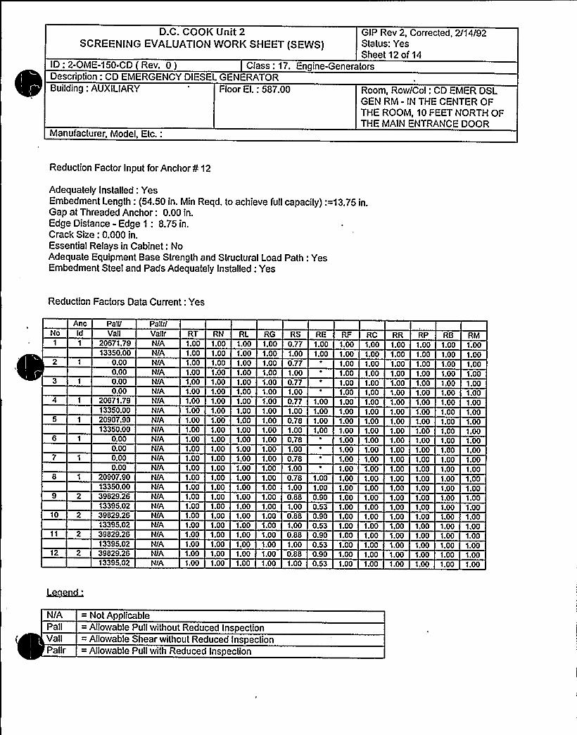
D.C. COOK Unit 2SCREENING EVALUATIONWORK SHEET (SEWS)
GIP Rev 2, Corrected, 2/14/92Status: YesSheet 12 of 14
ID: 2-OME-1 50-CD ( Rev. 0 ) Class: 17. Engine-GeneratorsDescription: CD EMERGENCY DIESEL GENERATORBuilding: AUXILIARY
Manufacturer, Model, Etc.:
Floor EI.: 587.00 Room, Row/Col: CD EMER DSLGEN RM - IN THE CENTER OFTHE ROOM, 10 FEET NORTH OFTHE MAINENTRANCE DOOR
Reduction Factor Input for Anchor ¹ 12
Adequately Installed: YesEmbedment Length: (54.50 in. Min Reqd. to achieve full capacity):=13.75 in.Gap at Threaded Anchor: 0.00 in.Edge Distance - Edge 1: 8.75 in.Crack Size: 0.000 in.Essential Relays in Cabinet: NoAdequate Equipment Base Strength and Structural Load Path: YesEmbedment Steel and Pads Adequately Installed: Yes
Reduction Factors Data Current: Yes
NoAnc Paii/
VailPaltr/Vallr RT RN RL RG RS RE RF RC RR RP RB RM
7
1 20671.7913350.00
0.000.000.000.00
1 20671.7913350.00
1 20907.9013350.00
0.000.000.000.00
1 20907.90
N/A 1.00 1.00N/A 1.00 1.00N/A 1.00 1.00NIA 1.00 1.00N/AN/AN/A
1.00 1.001.00 1.001.00 1.00
N/A 1.00 1.001.00 1.00N/A
N/A 1.00 1.00
N/A 1.00 1.00N/A 1.00 1.00N/A 1.00 1.00NIA 1.00 1.00N/A 1.00 1.00
1.00 1.001.00 1.001.00 1.001.00 1.001.00 1.001.00 1.001.00 1.001.00 1.001.00 1.001.00 1.001.00 1.001.00 1.001.00 1.001.00 1.001.00 1.00
0.77 1.001.00 1.000.771.000.771.000.77 1.001.00 1.000.78 1.001.00 1.000.781.000.781.000.78 1.00
1.00 1.001.00 1.001.00 1.001.00 1.001.00 1.001.00 1.001.00 1.001.00 1.001.00 1.001.00 1.001.00 1.001.00 1.001.00 1.001.00 1.M1.00 1.00
1.00 1.001.00 1.001.00 1.001.00 1.001.00 1.001.00 1.001.M 1.001.00 1.001.00 1.001.00 1.001.00 1.001.00 1.001.00 1.001.00 1.001.00 1.00
1.001.001.001.001.001.001.001.001.001.001.001.001.001.001.00
1.001.001.001.00
1.001.001.001.001.00
1.001.001.001.00
13350.002 39829.26
N/AN/A
1.00 1.001.00 1.00
1.00 1.001.00 1.00
1.00 1.000.88 0.90
1.00 1.001.00 1.00
1.00 1.001.M 1.00
1.001.00
1.001.00
10
12
13395.022 39829.26
13395.022 39829.26
13395.022 39829.26
13395.02
NIA 1.00 1.00N/A 1.00 1.00N/A 1.00 1.00
NIA 1.00 1.00NIA 1.00 1.00NIA 1.00 1.00N/A 1.00 1.00
1.00 1.001.00 1.001.00 1.001.00 1.001.00 1.001.00 1.001.00 1.00
1.00 0.530.88 0.901.00 0.530.88 0.901.00 0.530.88 0.901.00 0.53
1.M 1.001.00 1.001.00 1.001.00 1.001.00 1.001.00 1.001.00 1.00
1.00 1.001.00 1.001.00 1.001.00 1.001.00 1.001.00 1.001.00 1.00
1.00'i.oo
1.001.001.001.00
1.001.00
1.001.001.001.00
N/A = Not ApplicablePall = Allowable Pull without Reduced InspectionValiPallr
= Allowable Shear without Reduced Inspection= Allowable Pull with Reduced Inspection

0

D.C. COOK Unit 2
SCREENING EVALUATIONWORK SHEET (SEWS)GIP Rev 2, Corrected, 2/14/92Status: YesSheet 13 of 14
ID: 2-OME-1 50-CD ( Rev. 0 ) Class: 17. Engine-GeneratorsDescription: CD EMERGENCY DIESEL GENERATORBuilding: AUXILIARY
Manufacturer, Model, Etc.:
Floor El.: 587.00 Room, Row/Col: CD EMER DSIGEN RM - IN THE CENTER OFTHE ROOM, 10 FEET NORTH OFTHE MAINENTRANCE DOOR
Vallr = Allowable Shear with Reduced Inspection= Outlier= Reduction Factor Not Used
RT = Reduction Factor for Type of AnchorageRN = Reduction Factor for Installation AdequacyRL = Reduction Factor for EmbedmentRG = Reduction Factor for Gap at AnchorsRS = Reduction Factor for SpacingRE = Reduction Factor for Edge Distance
= Reduction Factor for Concrete StrengthRC = Reduction Factor for Concrete CracksRR = Reduction Factor for Essential RelaysRP = Reduction Factor for Base Stiffness and Prying ActionRB = Reduction Factor for Base Strength and Load PathRM = Reduction Factor for Embed. Steel and Pads
SI u
Analysis Performed: Yes
Type of Analysis: Regular
Spectral Accelerations (G's)No
10
12131415
17
N-S0.375
-0.375-0.3750.3750.375
-0.3750.375
-0.3750.150
-0.1500.150
-0.150-0.1600.1500.150
-0.1500.150
E-W0.150
-0.1500.150
-0.150-0.1500.1500.160
-0.1500.375
-0.375-0.3750.3750.375
-0.3750.375
-0.3750.150
Vertical0.100
-0.1000.100
-0.1000.100
-0.100-0.1000.1000.100
-0.1000.100
-0.1000.100
-0.100-0.1000.1000.250
Safety Factor49.38766 43749.19666.70036.84879.87280.17436.70384.08984.91941.166
124.22384.08285.264
124.22341 14257.447


D.C. COOK Unit 2
SCREENING EVALUATIONWORK SHEET (SEWS)GIP Rev 2, Corrected, 2/14/92Status: YesSheet 14 of 14
ID: 2-OME-1 50-CD ( Rev. 0 ) Class: 17. Engine-GeneratorsDescription: CD EMERGENCY DIESEL GENERATORBuilding: AUXILIARY
Manufacturer, Model, Etc.:
Floor El.: 587.00 Room, Row/Col: CD EMER DSLGEN RM - IN THE CENTER OFTHE ROOM, 10 FEET NORTH OFTHE MAINENTRANCE DOOR
181920
222324
-0.1500.150
-0.150-0.1500.1500.150
-0.150
-0.1500.150
-0.1500.150
-0.150-0.1500.150
-0.250-0.2500.2500.250
-0.2500.250
-0.250
2091.746735.38537.89257.220
2091.80438.041
735.242
Minimum Safety Factor: 36.703
The Anchorage Capacity is 36.703 times greater than the Demand

REPORT ON SEISMIC ANALYSIS
OF EQUIPMENT SUPPLIFD BY
WORTffINGTON CohfPRFSSORS INC.
FOR
TllE D. C. COOK NUCLEAR PLANT
or
AMERICAN ELECTRIC POWER
SERVICF. CORPORATION
REPORT HG-37017, Ldition C
September 20, 1974

CC 05A
SUMKCT
RL
oooo
Sheet ofSee.'
Comment No. DES CRXPTXOH
Engine SepecMications
Foundation Bolt Specifications
@@gine Flange Specifications
Poundation BoltsOperating,
— Tension - Rocking,Tightening, Seismic~
Stresses 8c F.S.
lA,3
Foundation Bolts - Bending
Foundation Bolts - Shear S Combined
Stresses K F.S.
15 P1ange - Bending - Rocking, Torque,
Stress &; P. S.
Conclusions


su~acr E~~i«P~ ~~rzowTYPF ~RG No W-$0/B/Zg a~ ~ ~J2sr .
xa
0
xO
Qzx
0 g =44
\
~ p'iv&dpggeV Soar S CZPr)(z ~g. r.s~)
Ill/SO (ke 44~m. sK- w~ssa)b) C'. k -4s Swuc w ('r~~ A~w Jaia)c) Ovr~pci c&nv. - /r J>ocul
J) po~g~w~<g = gfdP ('y~~ 5>~ca.)
eg pe. = 5z~ Cr~+ >~w Js- t1>sA)
~) louadareu AzT 5rsds( rkE8 = +CA kA X~srcw)wr

'(- goaooaHWodour'~ ''
She«t of~ Shts./ 7
a/s ~+
WCL.5D3
Li = 8.)l,g.L, = 6. O iH.
L~ = 6~.0 iN.
F<vgb/lTioH UogTS
b,: 'l,8I5'4D.- S.~ Pjog.
~25 iH ~
. 35'Z. X io '"/L/~
EioNP/ToH Lbc- .
. lo8 s io 'H/Lb+
(~ 4is7 N.)(So o'PSib
.Ol & y. io '"/gb+(Io 6o> lN )(Polio PSi)
42,0 IN
('3.sb7& iu )( s y>oo'si)
4,,„- 4, +6, tK,-golsti|<R. Rargr<oH gpouT Poise
.06%iiio "
7
A////4'o//L As%/pccu~n r .'
oh'/o
(o /g ]<I ~
7 go.v s (g. /Cr/t Io//.'/.by,
7 g/o

<. ~'
~ S
CAL 8Y
E>4 <>> ~l< FPu<DATiwAf
~g No 4'CIL/ZA~
+ aucu.I
oaovp
Sheet Mof~Shte.
0C5
zI
a
F l - (I ~ 4) SK 5'u) c $5 .5 < 8+ - W
CdiV'f/~ = =,o = D 7P/0l.
8g 'Wi> Ssdrss gp~~ PF~ouwmw~+irg: 7( ':/gyp'~<')
~j~>eA iud +u+swrs >/gvw.worww / 4'~size~~~ /oAyzcwy~c
@/<~ dN>~c 7o P~~c" Pw dwy~w gi pg,4'e Fp)
= WP~)
H
~~ = Pc/'file 5jeers J~~ goer =~.- ~~ ggjjgY,Pve rp kc~rwq i/~

Jil g
su~m +86/PE ON +@nba/7/PWMRG. No. -E(O 5 A
~gp. C- J: i"Qwet of~~%4.
x0
II <fg~
x0IC9
zI
0
3bh C4-Z3(4' 7S)
/2
~« ~zz ~4.io c~os~
.zs 3 y ro '"Z~eJL
DS.S zo /JY- Z Q~io = Z/p, 37 xl0 /gaag . ZD3'0
5 pic'+c Cc h's7 lh'FRzzs uir4 a~~v-y:
A'p I~P goLTS
5.@gal x /0
/ /2l9,37>./0 5.p x ro
Cd~~
A-A
s5sw r~"gZSg /o

~ ) ~
~„~ Fk'/r/Pr A fuuPddziu//
~RG No W g OY64 ~CAL BY
oaoue
Sheet ~ of~ Shte.
/E4. 4z.~
. Odd&
O
xO
zK
0
4ryz~c A +u~a///ruN;use Lk r HrrupE -Wc~ —/ou//ORnu// ur.rz Ckr XA'c:
Jig~ ~ /~~sruti.
8) F<ung gwsAwsw S/uWc'HW +i'm/ .'zEu = QS7As, g~s/s azw/rr pu~er
/ =.04dN 'XwC. Pju, g) ~ s/o 4>~uurbco g. gag, g gpss+= 8/parr/rN = . 2~
75oi. ru~/ C+aoe S3
~~~zCz.~),= id<-le ~'< .~crs
5) Cl &'rPilA'$ 5jgp(g — /ZcRc err Po giv4rrru 4/puu
cbA/ 5/p
''Yw B$ "
J'
zi
/I,gag
/f/P/O'' D',p
(Sl QGES oH SAhl.LEs 7 CR~AS <Cc.7>apJ OFCOM HD2 (T u FOUN DA'TI0H 60(1)


++4/A8' wFp~A////J/4//'YPF
~Rg. N<> k-S/0'/A /0CAL BY
GROUP
XO
"X0fee
CO
X
0
e)/w/r~>r /cA~/m tw Aces Pic'o //y//jew///t':us~~< 4 /+ed~ 4zwx~~z~~ c~ c = 4 z.
(/Arm gzEuc n//(gc'y /eupcuys — ////////<~
Cf~srr~~~r X~/x A.~)2= Aw,A~~ Pr~ = Z/~/ - /Ai////a /o+gw - @os des -Fj . PAP'w. XAc)7~ <8+
z~~ e, A ((zP@)c8 (y. z.)(Z. xx/)
gP~ 00< Q

0I

TYPF
CAL SY
QiVr,rate- giY tl&h/87iVpl
RG N~ +- /096 / /GROUP '" ~Sheet of~ Shte.
!
/od 0, 3 Esp
5 9$ r 3 f'sl
3z 6/,9 aa
~s/
7 = r ~o/7 r
fzAnt Ezj'PcPsr SPE<148 ZnP/E +4 6.<
+- g~yt/iFzM =
9 = /''/l A~/> ) -iHC~'>~8
(pg) =~ P/g/fg ~) = /o 776 6
= ~/p) /o7766'(, 2)
> 6,Zog.
<j F><iN ~rMS = ( rcw&oa Cw gers)P~~l~r~( SEJM /L = /8 5 / I /'s/
4'4arw'Cr Sw/oss'z
pdwl~lc" Sea'sue+
5) scrag PF 5$ FE/Y,+E y/B'av AFF+~<+y- ~+J<it'Ides /8'gvos/Ed
~uAP~rnw Mrs, h PA&i<rivx~c. +aserrv~swiAg/lg gg Jgr PP gjP gcs8d.cQ
P(rrre~r ~/aa~iWe,<'gzyp~+r (S~ss. fr~ri~s:
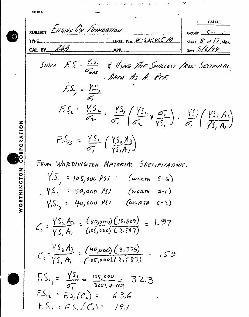
sUMKT +$gp~ + oPA84Xi4~
TYPE ......~RG. No. ~ ~CAL BY
oaove
Sheet ~ of~~ Shta.
z0
z0QzK
0
Fi~v~ lAloklHirlklopl P4Tc~lAL 5/diiFic~7r~h'f.

CAL BY
E8/cpwE'iY fpuHorg/'roAI
gg N 5 00009k~GROUP
Sheet of~ Shh.
hde
z0I
z0QzI
0
W /%dr dF rsrugg- swdN4 -/Sw&'riuw gers losjg Pip/Pop'<gr„$d/J'WIC 5W
~, = 8+/rw 8 = ~6,+/rrr.
8, =<LOr+8 4 =,oe9'8 =.ot"/(I8IS) = 4' ZZ./+
o< P~ >) = 9! oo+ err
o ~ji+ -~~p(~ ~~)+- / 256 rrr

TYPF
CAL BY
Ew&Ne gw Wiu&4PJ~~G. No.
CALCU.
oaom
Sheet of~ Shts.lo
z0
X00x
0
/J Y Scdstrtutlug (g /rrro Qi 'oiN4 y Sug&8rrn/4 JlrlOLmcuW4,'
'"fur~ ag-.
pq cx437

GRoUp r z.C 't
Sheet ofJ.. Shts,gJ
Inrccc//ri//r, g~.co:
/
/
1
P Pc/(x M) $//(w-oL)jp// (x-$)g + C3
X0I
Q~ y/
E"/ g
p~(gg e ~ ~] I
+
'3
/ (X ~L) Pc( Cy cL)-
X00X
0
8cZcc<rrc/o/,'
SPA///'G Lo//cm'//r lu Lciroiuyg
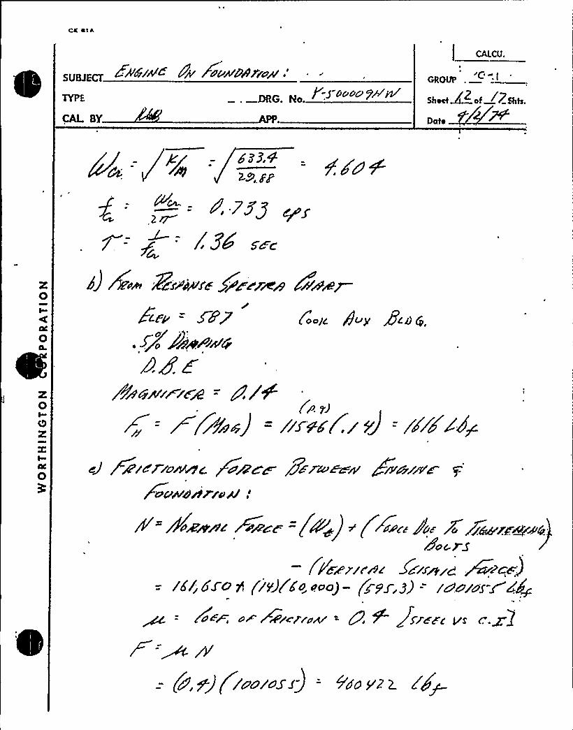
gUgpg ZiVW/A+ Pp 845PPA /fdic
MG. Ro. ~
Ioooo
Sheet~ of 7$hh.
Date
/Z4 s~c
8) /E.~ i8i~A4f~gg~r J~i5 CPA~~
g ~~zcrrum~c ~a~wc g7wru ~w +wuzmwWoaWaaWru~ .
P" X~ew ~ r ~~~a = (P~) ~ ( +~~c~ Pu~ Sr7~e+w .
/or gS
/ Pd&E/c'>c'clxwzg ~c'cw)= ld/6' (i vJc'Eo. ~oog- prpr,z3 = zunis-wd@
e~ WwlcleeAr ~ Q 5 +$ /zc c vf


cuuiw~ ck X~w8/jailSUEJECT
CAL BY
f"Shoo'Pi/M
caecU.
eaoUp
Sheet ~ of Shit.
~oo~zi > rgro~//c1roj/1 '» Saf/
rs/o'vd
/+pe//48'//n// 4/047. F~B/A~z Nc c Ac uA/pe /o ///F ////oF/ower. Pnwr:i +6"/s//~@
//82'0/?/PcvYE/Pcg~r/~ +cP/7sis /8'o/- /so /ipAe //f P/r/// .
/u Xrt~ /auwda/~w Aces go~ Wo
5M>M/e 4nwds'.


~ ~
>~E~ EIIIrIIIIC.P'OWIII47IoIIf'- 5-~Do o&PJWRG. No.
oaout
Sheet of~ Shto./ / ~l~
III Moof OF FAllVFE SHcno- ill FouuoArloH Boa rS bul:To Sogt>o/7'Ai s6IRWIC- I.oh,JIHAD,
F„=(FI ~> t.urh CW'h~ tg(ZS'O) =
FRom P
P"
I OO 'flLF'g, I c T to H
FgloT ) ~pl ~ 'Io 9ol'L).LE 'tI l 9
7Pd
W8'/citaly
QEscu E:tnt i'd r orred/7i'c h' +YE~A IH 6 88$ E rj cf uM Po SHCJ+ For2i 85 TcF4+WSW j7TE8 EO 7M Fpc aOarroN got.rS.
3E f oubNA <ro N goer w iriHl. revctoo ) jt'. F tom l I9u
Wogttt < )Le- -o Rove CTtH II.'3IR 6 I —)gQ GEE.T'CS l
ToQ.QVG = l %CO -~s<0 Fr- impFtt+M bCt the OC +AC NNC
LINEA
CH15 4 i) l r'Iti'C, (
5QP C.=,~ b .-
(r>-cc)(.tugcb 7p Ooo L6~hQ VIlIl&k.C Mttad; ~Q. A~ "- LSg tel
SHAR< p< = 2, 6 ie7- =-„= t<9IY.i
—.',G~f>9 III IN
4$ 40~%%. 5ccito 4 npig Ag ~ 3.16 rt.(
5pg~g g:, ),Q 76 ( ll
iver/„~ r . 9V75 " tg. 76 /H
cg F.~., (ualaa') .. ical„o ~ g p 5 -. (6)(lo(o~o)4 li''rl.9 —I r ivv«l l
b~F~. (~.~ay)-]999> v1'3


CAL SY
EWp/A/E t/+ ~~~~gQ Sly~
6 No - 0 Yd<Waaovv .... <
Sheet ~ ofMZ,Shts.
o
xOI
0
XO
X
a
/ ~d~ ~F Hh~uP< ocul% '/ ~N E H~~4'J>4
fane i6'. 4: 7 =.pion~~~FZow ~sP~us~ fjwcXm& Cw>wg .
grf4A'ril~—HgZ
sic 5')
Ck. w)(P~~~ w)
/Fire = gd.7
8Arifpl/i4M~ 8~x 4cdg,
c>) f'~~ IZocA/A di, (p ~)
(pic,~iz~~+g = rs<F~p/
w= wg) =(q,>~a):~~) = see.~V ~>;»/J/< (lib>/)6 l9 ) pg~~ L/If

iYPE
CAL SY
&CIIIO@~yAIDHTi~II
~RG. No.> ~~~ "~< ~
L CALCU.
c-.j. ~
GROUP "
Shoot of~ Shta.
X0
C 4r~/>Cu44r)//oc44$ ///op/ P~A/Pp//r//c 6/fislci) ~upas gC~qL/W
///~ ju/a/8'/- QcM +i+//'rc-///II@ Zu~~5'Ad/+~ILo+Flg/~E +8 g+4P c4'4~~>/II'I/ 'C8 0'/IWCy
JFx2c sr Pew/'//Ir//II<~o+rI lp
FaW ><I/yp 6 P>C///4c FCr~r~rS r-put-g.
(gl/IS IJ PVEPII'dII'SFNVllIILI'P DOC ~r//E rp/~ocrIn/'E coI/I/II''J
4) 'gdcrs g~ I /I/'I/g$ E:(ddiuoI4$)O ~ a
ef~<rrwq
Z, 3+jZIO ~ 4DZ PZ/ .7a
e) 5plcrf /8cpo/2,~3o
Z4 7Z
yy = 7<, uc //. 'L /0 WPI, J'>OC
C ~/
'

SUBJ~ ENGINE ON FOUNDATION-
TYPF
CAL BY
G. No.
GROUPI
Sheet ~> of~> She.
z0
CONCLUSIONS<
POUNDATXON BOLT F S ~ 2 4' P >4 ) j F
THXS SAFETY FACTOR IS DUE TO THE PREIOAD ON
THE FOUNDATION BOLT AND OCCURS ON THE LOWER PART
OF THE 3-PIECE BOLT, FRXCTXON BETWEEN THE ENGINE
AND FOUNDATION ALIDW NO SHEAR OR BENDING IN THE
BOLTSE SO THE PRETENSIONS BEING CONSIDERABLY
GREATER THAN TZNSIXZ IOADS CAUSED BX ENGINE ROCKING,
IS THE GOVERNING FACTOR.
0v XI ENGINE MOUNTING FLANOES: R.S. - «.23 (P.Z6)
FREQUENCIES:k
A) ENGZNE ROCKZNG: F 3 9:('PS ((')THXB IS VERY CONSERVATIVE BECAUSE XT IS
BASED ON FOUNDATXON BOLT EIDNGATION AND THE
PKDENSION SHOULD ALMW NONE ~
B) VERTLCAL -' . ~ 44 CPScr'p v3
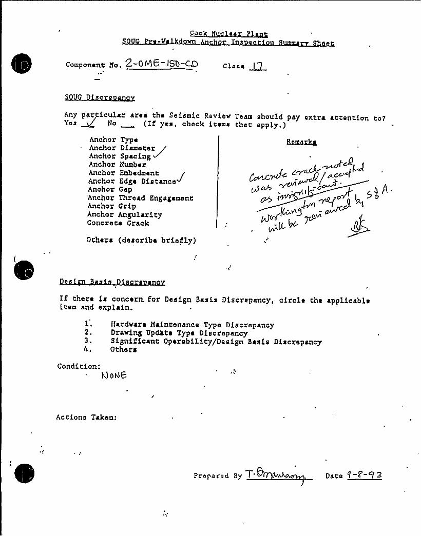
Coo
Componene Po. 2-086- ISO-~ Claia ~l
Any pazpicular area che Seismic Roviev Team should pay extra actontion cotYes ~ No (If yea, check icema that apply. )
Anchor TypeAnchor Diameter /Anchor Spacing ~Anchor NumberAnchor EmbedmentAnchor Edge Distance~Anchor Gap'Anchor Thread EngagementAnchor GripAnchor AngularityConcrete Crack
/wG~A
Others (describe briefly)
IE chere ia concern. for Design Basis Discrepancy, circle the applicableitom and explain.
l.2.3.
Hardvare maintenance Type DiscrepancyDrawing UpWt~ Type DiscrepancySignificant Operability/Dosign Basis DiscrepancyOthers
Condition:k) ORB
Actions Taken:
Proparad By T. Dato 1-~-'V ~

~ K
A
~ ~ r s
s ~ ~ ~ ~
y~ 0 ~ I
P
~ ~ ~ o ~
~ r
NI
'P
e
MPWi.I
I
'
L PV~
~o s s
0
/~ y~ // ~r
~ 0/
~ i
~ ~ 4
~ ~

~ a ~ ~ ~ I
P
~ ~ ~ ~ P ~
~ 8~ ~ ~
~ e ~ o ~
P
. Ie y I ~ a
O~ O~ O~ 0»
P
~ I ~
I ' I~ '
go I I
~ P
~I i /ifr. / r
~ ~
~ ~

«1Z CHP >Ox l. CCD. O 1 gATTACHMZHT No.
~g No.: /2-Z4C8 — l3Dwg No.: /Z-30T5A, —g
0 TorqueCal. Due Date:
Date:ons r c zo
Equipment No.:Anchor type: UD A CHEART PF—~~ Dia:Tightness established by: 0 "Snug FitTorque Wrench No.: QA
Tightness verified? 0 Yes 8, No
Equipment base flexible? 0 Yes 8- No 7ons uc
P YSICAL CHARACT RUSTIC
Date:ARE
Bolt ZD
Gaps
Anchorlen th
/Arpa7 eRMJ
5
-Cu'AGL-. - bV
S -5" S-4
CE.SS B
s-("
H'ommentspv A c oPQ
„Pc. R. 'Dw&.~ ~ + ~ -"/z-Zo~:A,
Protrudinglen th
Embedment/I
5 - I/gII
5 -I—/Cn
3/l g IIS-Ig 6 -ling g-2.
13 ll
/II I ~l I 3ll
S- I~( 5-l~ S-lg,
BoltriConcretecondition
Edgedistance
llZ zg
V '~e"
I'llZ~/b5"/&
I/2 /)(
ly/I
I(. 2/&
gk CK
Anchors acin
~ Il5 cg
p /I5 ~ IIS-B /3"Z'~ /3 II gll
S ~~ S~
Anchoran larit
Threadengagement
Ol( old oh OK
0"0''V
oK.
Comments: W A C. AC.Q H F:C.OOR C AT'I&6- WA
A,. H RS PRF-SP.=& ~,
Verified by:Qual. /Cert. Xnspector
I
Reviewed by: TConstruction
INDIANAESIGN CONTROLLCD
WORKING COPY
SEP 08 1998
Date:
Date: I->- J~
I.CRK ~ '~~ age 2 of 3gvi<IoA

~ /
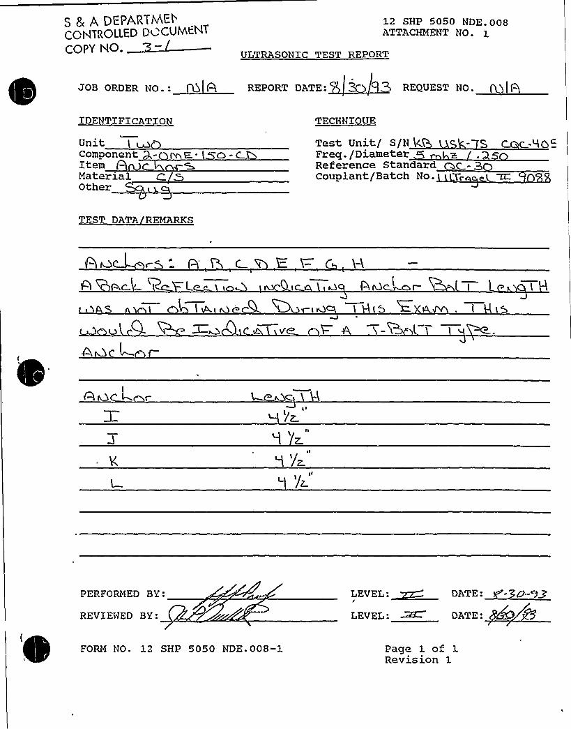
S 8 ADEt'ARTMEt'GHTROLLED Du CUt4tNT
COPY NO.
12 SHP 5050 NDE-008ATTACHMENT NO- 1
ULTRASONIC TEST REPORT
JOB ORDER NO ~ : REPORT DATE: REQUEST NO. (Q ) Q
IDENTIFICATION
UnitComponent - pr E,. 0 -CItemMaterial C. &Other
TECHNI UE
Test Unit/ S/N k.Freq./DiameterReference StandardCouplant/Batch No.
SS
TEST DATA REMARKS
c-S-
Qvc ~I
'/z
PERFORMED BY:
REVIEWED BY:
(
FORM NO. 12 SHP 5050 NDE. 008-1
LEVEL: ~ DATE:
Page 1 of 1Revision 1

Uatabase: K:SSEL2C. DBF
Equip Xd: 2-All Train: NA Equip Class: 20
Drawing No.: NONE
~
~~
nction:
System: EQUIPMENT CONTROL AND XNDXCATXON STATXONS
Equip Desc: AUXXLIARYRELAY PANEL AllBuilding: AUXXLIARY Room: CONTROL ROOM
Elev: 633 Sort: S, Notes:
Normal State: Desired State: Power Req'd:
Support System Drawing:
Req'd Support Comp:
Safety Related Status: NUCLEAR SR Min/Opt: MIN
Alias No:
Comp Served:
MFR
Power Train:
Model:
Elem. Drawing:
Wiring Drawing: 2-92071
Power Source:
Walkdown: F Relay,Eval: N
Comp Type: INSTRUMENT/RELAY RACK
Xso Drawing:
Location: XN THE NORTHEAST CORNER OF THE ROOM

0
T

D. C. Cook Unit 2Screening Evaluation Worksheet (SEWS)
GIP Rev 2, Corrected, 2/14/92Status: Yes'Sheet 1 of 8
ID: 2-A11 Rev. 0Descri tion: AUXILIARYRELAYPANEL A11
Class: 20. Instrumentation and Control Panels and Cabinets
Building: AUXILIARY
Manufacturer, Model, Etc.:
Floor El.: 633.00 Room, Row/Col:.CONTROLROOM - IN THE NORTHEASTCORNER OF THE ROOM
SEISMIC CAPACITYVS DEMAND
Elevation where e ui ment receives seismic in utElevation of seismic in ut below about 40'rom rade rade = 608.00E ui menthasfundamental fre uenc above about8Hz est.fre uenc =11.00Ca acit based on: 1.00'Boundin S eclrumDemand based on: 1.00 * Desi n Basis Ground Res onse S ectrum
633.00YesYes
0.850
LIN
0.0001.00 LOG Hz
Capacity ..... Demand
33.00
Caac'emand
1
Demand 2
FileH:tGIPLGIPts ectra.desH:$GIPIPROJ0059ts tra.desH:LGIPIPROJ0059ts tra.des
RecordLabel Boundin S trumBUILDINGGrounds ectrum ELEVATION BROADENBUILDINGGround S ectrum ELEVATION BROADEN
Does capacity exceed demand? Yes


D. G. Gook Unit 2Screening Evaluation Worksheet (SEWS)
GIP Rev 2, Corrected, 2/14/92Status: YesSheet 2 of 8
ID: 2-A11 Rev. 0Descri tion: AUXILIARYRELAYPANEL A11
Class: 20. Instrumentation and Control Panels and Cabinets
Building: AUXILIARY
Manufacturer, Model, Etc.:
Floor El.: 633.00 Room, Row/Col: CONTROLROOM - IN THE NORTHEASTCORNER OF THE ROOM
CAVEATS - BOUNDING SPECTRUM
l&C/BS Caveat 1 - Earth uake Ex erience E ui ment Classl&C/BS Caveat 2- Com uters and Pro rammable Controllers Evaluated Se aratell&C/BS Caveat 3 - Stri Chart Recorders Evaluated.l8 C/BS Caveat 4 - Structural Ade uate.l&C/BS Caveat 5 - Ad acent Cabinets or Panels Bolted To etherI8,C/BS Caveat 6 - Drawers or E ui ment on Slides Restrained18C/BS Caveat 7- Doors Secured.l&C/BS Caveat 8 - Sufficient Slack and Flexibilit of Attached Lines.l8 C/BS Caveat 9 - Ade uate Anchora e.l8C/BS Caveat 10 - Potential Chatter of Essential Rela s Evaluated.I&C/BS Caveat 11 - No Other Concerns.
Is the intent of all the caveats met for Bounding Spectrum'
YesN/AN/AYesYesN/AYesYesYesYesYes
Yes
ANCHORAGE
1. The sizes and locations of anchors have been determined2. Appropriate equipment characteristics have been determined (mass, CG, natural freq.,
dam in ~ center of rotation .
3. The t e of anchora e is covered b the GIP4. The adequacy of the anchorage installation has been evaluated (weld quality and length,
nuts and washers, ex ansion anchor ti htness, etc.5. Factors affecting anchorage capacity or margin of safety have been considered:
embedment length, anchor spacing, free-edge distance, concrete strength/condition,-andconcrete crackin .
6. For bolted anchora es, an a s under the base are less than 1/47. Factors affecting essential relays have been considered: gaps under the base, capacity
reduction for ex ansion anchors.8. The base has adequate stiffness and the effect of prying action on anchors has been
considered.9. Thestren thofthee ui mentbaseandtheload athtotheCGisade uate.10. The ade uac of embedded steel, rout ads or lar e concrete ads have been evaluated.11. The anchora e ca acit exceeds the demand.
YesYes
YesYes
Yes
N/AYes
Yes
YesYesYes
Are anchorage requirements met?
INTERACTION EFFECTS
1. Soft ta etsare free fromim act b nearb e ui mentorstructures2. If the equipment contains sensitive relays, it is free from all impact by nearby equipment or
structures.3. Attached lines have ade uate flexibilit4. Overhead e ui ment or distribution s stems are not likel to colla se.5. No other adverse concerns were found.
ls equipment free of interaction effects?
Yes
YesYes
YesYesYes
Yes

D. C. Cook Unit 2Screening Evaluation Worksheet (SEWS)
GIP Rev 2, Corrected, 2/14/92Status: YesSheet 3 of 8
ID: 2-A11 Rev. 0Descri tion: AUXILIARYRELAYPANEL A11
Class: 20. Instrumentation and Control Panels and Cabinets
Building: AUXILIARY
Manufacturer, Model, Etc.:
Floor El.: 633.00 Room, Row/Col: CONTROLROOM - IN THE NORTHEASTCORNER OF THE ROOM
IS EQUIPMENT SEISMICALLYADEQUATE? Yes
COMMENTS
Date: 11/1/93SRT: Satyan Sharma (AEP), Paul Krugh (AEP), Steve Anagnostis (S&A), Randy Steele (AEP - Relay Engineer)
References:1. Anchorage Package2. AEPSC USI A-46 Project Report No MT2, Rev 0, "Summary Report of Fundamental Frequencies Determinedby ln-Situ Transfer Function Modal Testing at Cook Nuclear Plant", Aug 1994.3. Drawing No 12-3388-3
A11 -15 form an 10"-2" long x 8'all x 2'eep control panel. The panel is constructed of welded steel plate,angles, and channels. The panel is welded along the front to embedded steel at 4 points, and along the back attwo points. A11 and A13 contain essential relays.
Based on modal test data of similar panels in the control room (Ref 2) ~ the SRT estimates the lower boundfundamental frequency at 11 Hz.
The overhead control room ceiling and raceways have been evaluated as part of the raceway walkdown andjudged acceptable - see the control room PASS form for details.
There is a door at the far end of the A6-A15 bank that is commonly left open. The door could, strike the panel,but the SRT judges the impact is far enough away from the essential relays not to be significant.
There is a ladder secured against the wall in front of the panel - it is secured so it will not strike the panel - judgedacceptable.
There is a fire extinguisher hung on the end of A6 that wilt bang against the cabinet. The SRT judges that it willnot affect the essential relays in A11 and A13.
Anchorage:
1. The anchorage package shows details for 1 of the four front edge weldments - the others are similar.2. The back edge weldments were not detailed - the SRT added these details to the anchorage package.3. The SRT conservatively estimates the weight at 300 Ibs/ lineal foot.4. The strength of the weldments is equivalent to at least a 1.5" x 1/8" fillet weld (4 kips per GIP Table C.6-1).The embedded steel is a 5/16" steel plate anchored with a 1/2" x 4" Nelson stud every 12" (4.4 kips per GIPTable C.3-1 including a .65 knockdown for embedment length). The weldment controls. The attached ANCHORanalysis shows a margin of 3.3.

D. C. Cook Unit 2Screening Evaluation Worksheet (SEWS)
GIP Rev 2, Corrected, 2/14/92Status: YesSheet 4 of 8
ID: 2-A11 Rev. 0Descri tion: AUXILIARYRELAYPANEL A11
Room, Row/Col: CONTROLROOM - IN THE NORTHEASTCORNER OF THE ROOM
Floor El.: 633.00Building: AUXILIARY
Manufacturer, Model, Etc.:
Class: 20. Instrumentation and Control Panels and Cabinets
Evaluated by: Date:
Attachment: ANCHOR Report


D. C. Cook Unit 2Screening Evaluation Worksheet (SEWS)
GIP Rev 2, Corrected, 2/14/92Status: YesSheet 5 of 8
ID: 2-A11 Rev. 0Descri tion: AUXILIARYRELAYPANEL A11
Class: 20. Instrumentation and Control Panels and Cabinets
Building: AUXILIARY
Manufacturer, Model, Etc
ANCHOR Report
Floor El.: 633.00 Room, Row/Col: CONTROLROOM - IN THE NORTHEASTCORNER OF THE ROOM
Response Spectrum: Instructure RealisticFrequency: User - 11.00Percent Damping: User- 5.00
S ectral Values:Direction Acceleration 's
North - South 0.314East - WestVertical
0.3140.183
Angle (N-S Direction makes with the X Axis): 0.00Combination Criteria: SRSS
~eicehts:Number of Weights: 1
No Wei ht1 3000.00 60.000 0.000 50.000
Forces:Number of External Forces: 0
Moments:Number of External Moments: 0
Allowables:Anchor:Number of Anchor types: 1
Tension Shear
Dia Manufact ProductUltimateTension
UltimateShear
InterCoeff
Inter SafCoeff Fact
3/8 Hilti Kwik-BoltN
1460.00 1420.00 1.00 0.30 1.00
Concrete:Ultimate Stress: 3500.00 psi.Reduction Factor: 0.85
Weld:Allowable Stress: 30600 psi.

D. C. Cook Unit 2Screening Evaluation Worksheet (SEWS)
GIP Rev 2, Corrected, 2/14/92Status: YesSheet 6 of 8
ID:2-A11 Rev. 0Descri tion: AUXILIARYRELAYPANEL A11
Class: 20. Instrumentation and Control Panels and Cabinets
Building: AUXILIARY
Manufacturer, Model, Etc.:
Floor El.: 633.00 Room, Row/Col: CONTROLROOM - IN THE NORTHEASTCORNER OF THE ROOM
Surfaces:Number of Surfaces: 1
Surface OrientationDirection
ComNo
0.000
DirectionCom
0.000
DirectionCom
1.000
Anchor Pattern for Surface ¹1
gY
Legend for Anchor Patterns
Anchor Bolts:
Concrete Vines: ~Ppgy(Peg!P
Concrete Points: ~5m+Weio uncs: ~5~5
~GeomerAnchor:Number of Anchors: 0
Concrete Lines:¹ of elements per line: 1


D. C. Cook Unit 2Screening Evaluation Worksheet (SEWS)
GIP Rev 2, Corrected, 2/14/92Status: YesSheet 7 of 8
ID: 2-A11 Rev. 0Descri lion: AUXILIARYRELAYPANEL A11
Class: 20. Instrumentation and Control Panels and Cabinets
Building: AUXILIARY
Manufacturer, Model, Etc.:
Floor El.: 633.00 Room, Row/Col: CONTROLROOM - IN THE NORTHEASTCORNER OF THE ROOM
Number of Concrete Lines: 0
Concrete Points:Number of Concrete Points: 6
No Coord19.00047.00075.000
103.0002.000
118.000
YCoord
2.0002.0002.0002.00Q
22.00022.000
Coord0.0000.0000.0000.0000.0000.000
SurfId
Conc-PtArea9.0009.0009.0009.0009.0009.000
Weld Lines:¹ of elements per line: 1
Number of Weld Lines: 6
NoStart
X-Coo rd19.00047.00075.000
103.0002.000
118.000
StartY-Coord
2.0002.0002.0002.000
22.00022.000
StaaZ-Coord
0.0000.0000.0000.0000.0000.000
X-Coord20.50048.50076.500
104.5003.500
119.500
EndY-Coord
2.0002.0002.0002.000
22.00022.000
Z-Coo rd0.0000.0000.0000.0000.0000.000
StId
LineWidth
0.1250.1250.1250.1250.1250.125
Determination of Reduction Factors:
Reduction Factors Data Current: Yes
Anal sis Results:Analysis Performed: Yes
T eofAnal sis:Re ularS ectral Accelerations G's
No N-S0.314
-0.314-Q.3140.3140.314
-0.314
E-W0.125
-0.1250.125
-0.125-0.1250.125
Vertical0.073
-0.0730.073
-0.0730.073
-0.073
Safet Factor13.9738.111
13.9738.1118.500
18.535
-0.314 -0.125 0.073 '8.5007 0.314 0.125 -0.073 18.535

0

D. C. Cook Unit 2
Screening Evaluation Worksheet (SEWS)GIP Rev 2, Corrected, 2/14/92Status: YesSheet 8 of 8
IO: 2-A11 Rev. 0Descri tion: AUXILIARYRELAYPANEL A11
Class: 20. Instrumentation and Control Panels and Cabinets
Building: AUXILIARY
Manufacturer, Model, Etc.:
Floor EI.: 633.00 Room, Row/Col: CONTROLROOM - IN THE NORTHEASTCORNER OF THE ROOM
10
12131415161718192021
222324
0.125-0.1250.125
-0.125-0.1250.1250.125
-0.1250.125
-0.1250.125
-0.125-0.1250.1250.125
-0.125
0.314-0.314-0.3140.3140.314
-0.3140.314
-0.3140.125
-0.1250.125
-0.1250.125
-0.125-0.1250.125
0.073-0.0730.073
-0.0730.073
-0.073-0.0730.0730.183
-0.183-0.1830.1830.183
-0.1830.183
-0.183
7.5053.2903.3528.9217.5053.2908.9213.352
12.6267.842
37.0288.816
12.6267.8428.816
36.553
Minimum Safety Factor: 3.290
The anchorage can withstand 3.290 times greater seismic demand

I**12 CHP 502 1. CCD. 019
ATTACHMENT NO. 1
Unztz-maw'- o
CT 0
Bldg-
Mop < H E+SI- coR+FR,O(= l HE'ROOM
Location
Installation dwg. / Rev.
Anchora e Arran ement SketchEquipment No.
AVx, Pa.LA,Y PAMC-LS A-II T'HRL( A-ISI'BR DMS I, 2,-Zg'I'F-lo 2-SS'<0-0
? -C4 4<A- I g~ 2."ZZ'46- I
~lg
/o-? p
A-IS
Q-0
IHOIAHA t(IICHICAH POW-ASITE OESIGH COHTAOLLEO
WOAKIHG COPV
SEP 21 1995
SEC DE,r4.I L I
'(z, g I '!'a x S 4 SH(n
ELev. VIEw LYG-,EAST'LEAK
+
Drawn by:Verified by:
Date: /Date: ga. g9
Qual ./Cert. inspectorReviewed by: F Date:
Construction Anch r Review Engineer-2-I- t3
page 1 of 3Revision .3

~ fq
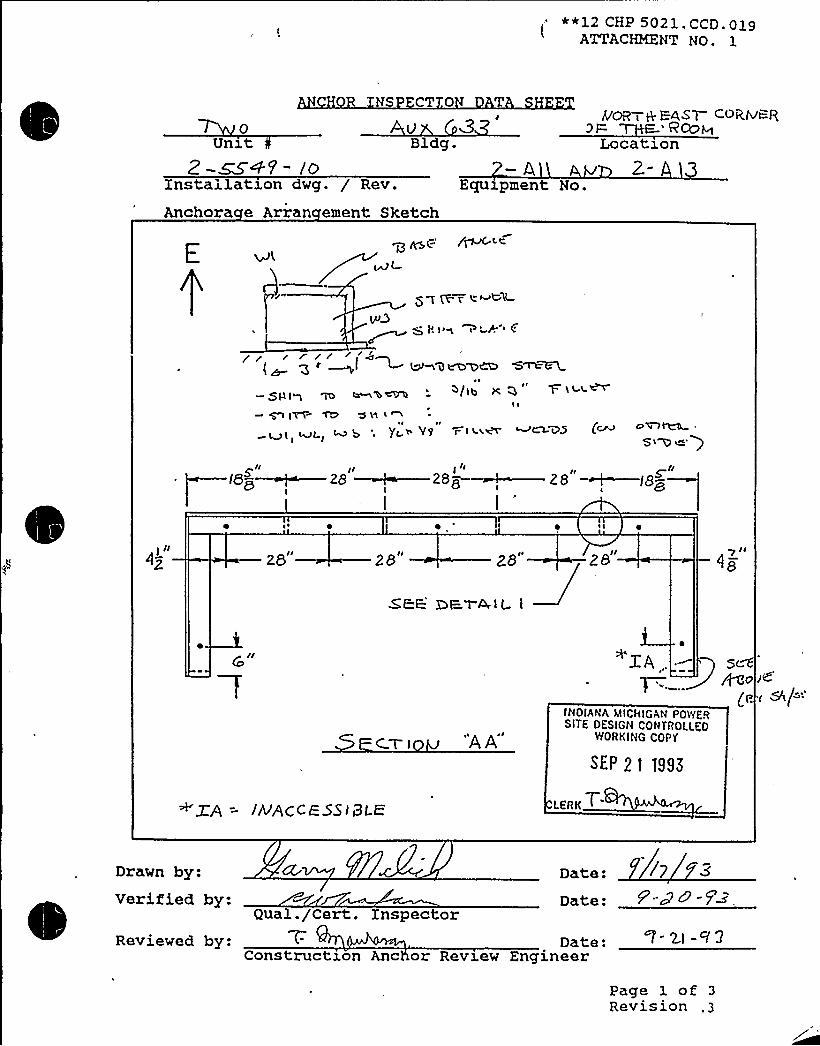
**12 CHP 5021 CCD p19ATTACHMENT NO.
NS CT 0 T
VBldg.
yCR + E4gl COB.IVI=-R3F T F.~WH
Location
Installation dwg. / Rev.
Anchora e Arran ement SketchEcgxzpment No.
E
~ A ) ~~ ~i t.A '( g ~ ~I ~ ~'9v D~CD "S~~
~ ~
V~/tb1 ~
gltVC ~ 'SK4 <~I ~ ~
V9 r I 'Lk~ ~~VSI
os~ ~
S> D e')~/I II I lg ~II
(6~ ~ 28 ~28'Z8 ~IB~QI I
~ I
28 2B ZB ZB 'Ie
ZE:E: DF-1 AIL I
CTI "A
A'A..'NOIAtIA
MICklGAt( POWERSITE OESIGN Cott TAOLLEO
WORKING COP'f
SEP 2i >99<
5t~o
(I.
~~A = jhrPCCF S5]BLK LEAKT
Drawn by:Verified by-
Date:
Date:
/y 3
Qual. /Cert. InspectorReviewed by: Date:
Construction Anc or Review Engineer
Page 1 of 3Revision


""~4 <Ha'021.CCD oa9ATTACHMENT NO. a
Equipment No.:Embedded Steel Dwg. No.:
CHOR INS CTIO
H S ICAL CHARACTERIS C
.: 2~22 eV—
Weld IDT e
SizeLen thCracks
WJ WZI I
y// g I/
0
W3 W< WSI TAcK. I/II'
3/'l
W7'z"
YNo
Weld e Codes1 = Fillet2 = Plug/Slot3 Groove
Lack ofPenetrationPorosity
o o o 0
YeNo
YesNo
W I IS WELD Pb oN 1=OUR S(DE.S,W Q Y8" L/hrQE.R CV1W 3 +8 ClhJC)BQCL/ 7W 4. /4 LrNDCR Cu T
'/4. UIVO E:P, CU t.
4v Cg /4 UMDL=RCVT'8
/4 UADER cvTII
3Ia 8
I2
Q HOLW WIt-H WASHSR5
RMBE.@DE 0~ C
I
4l X 3 X~ PING LI:-
3 HAGI,
0
a WI
SEc.TIo~ e E'aYAIL-I S E.c-~101 C C.
Equipment base flexible: Cl Yes E Noons ruc son re
Reviewed by:
Verified by:ua . er . npsec or Irrl)IANAFiIICHIGAN PO'V/FTI
SITE OCSIOrr Cotr TIIOLLt.oV/OII~Ir G COI V
SEP 2 l 1993
ons ruc son c or evzew ngzneerDate:
Date: 5 +
page 3 ofRevision


ATTACHMENT3 TO AEP:NRC:1040E
SAMPLE SEWS, ANCHORAGE CALCULATIONS,ANDANCHORAGE INSPECTION DOCUMENTATION
FOR TANKS Ec HEAT EXCHANGERS EVALUATEDFOR USI A-46 THAT ARE NOT COVERED BY THE
PROCEDURES IN SECTION 7 OF THE GIPRAI ITEM 5

This attachment includes sample SEWS, anchorage calculations and anchorage inspectiondocumentation for a cross section of class 0 and 21 tanks and heat exchangers that are notcovered by the procedures in Section 7 of the GIP. The samples selected are designated with an* in Table 2 and 3 of this RAI. The following examples are included:
lass
21
1- T-113-AB11-HE-13
21
21
21
1- -34-1-'I'K-111-'1 K-37
21
21
21
2- -112- -32- -134- D

Equip ID: 1-QT-113.-AB1
" wing No.: 1-5151A
tion: EMERG DXESEL
Train: 1 Equip Class:0
System: DIESEL LUBE OXL
Equip Desc: AB EMERG DIESEL PULL PLOW LUBE OIL STRAINER 1
Building: AUXILIARY Room: AB EMERG DXESEL LUBE OXL PXT
Elev: 579 Sort: S, Notes:
Normal State: Desired State: Power Req'd: N
Support System Drawing:
Req'd Support Comp:
Safety Related Status: NUCLEAR SR Min/Opt: MIN
Alias No: Power Train: NA
Comp Served: LUBE OXL STRAXNER 1
MPR: NUGENT
1' 1554-4L3B
P lElem. Drawing: N/A
Wiring Drawing: N/A
Power Source: N/A
Walkdown: A Relay Eval
; Comp Type: STRAINER
Xso Drawing:
Location:

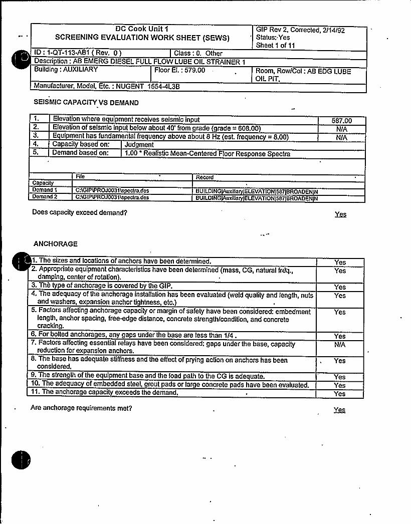
DC Cook Unit 1
SCREENING EVALUATIONWORK SHEET (SEWS)GIP Rev 2, Corrected, 2/14/92Status: YesSheet1 of11
ID;,1-QT-113-AB1 ( Rev. 0 ) Class: 0. OtherDescnption: AB EMERG DIESEL FULL FLOW LUBE OIL STRAINER 1
Building: AUXILIARY Floor El.: 579.00 Room, Row/Col: AB EDG LUBEOIL PIT,
Manufacturer, Model, Etc.: NUGENT 1554PL3B
SEISMIC CAPACITYVS DEMAND
1. Elevation where equipment receives seismic inputElevation of seismic input below about 40'rom grade (grade = 608.00)Equipment has fundamental frequency above about 8 Hz (est. frequency = 8.00)Capacity based on: Judgment
5. Demand based on: 1.00 'ealistic Mean-Centered Floor Response Spectra
587.00N/AN/A
Ca acitDemand 1
Demand 2
File
C:LGIPtPROJ0031tspectra.desC:<GIPIPROJ0031'Lspectra.des
Record
BUILDING uxilia ELEVATION587 BROADEN NBUILDING uxilia ELEVATION5S7 BROADEN N
Does capacity exceed demand'
ANCHORAGE
2. Appropriate equipment characteristics have been determined (mass, CG, natural fretful.,damping, center of rotation).
3. Thh pe of anchorage is coveredb the GIP.4. The adequacy of the anchorage installation has been evaluated (weld quality and length, nuts
and washers, expansion anchor tightness, etc.)5. Factors affecting anchorage capacity or margin of safety have been considered: embedment
length, anchor spacing, free-edge distance, concrete strength/condition, and concretecracking.
6. For bolted anchorages, any gaps under the base are less than 1/4.7. Factors affecting essential relays have been considered: gaps under the base, capacity
reduction for expansion anchors.8. The base has adequate stiffness and the effect of prying action on anchors has been
considered.9. The strength of the equipment base and the load path to the CG is adequate.10. The adequac of embedded steel, grout pads or large concrete pads have been evaluated.11. The anchorage capacity exceeds the demand.
Yes
YesYes
Yes
YesN/A
Yes
YesYesYes
Are anchorage requirements met?

DC Cook Unit1SCREENING EVALUATIONWORK SHEET (SEWS) ~
GIP Rev 2, Corrected, 2/14/92Status: YesSheet 2 of 11
ID: 1-QT-113-AB1 ( Rev. 0 ) Class: 0. OtherDescription: AB EMERG DIESEL FULL FLOW LUBE OIL STRAINER 1
Building: AUXILIARY Floor El.: 579.00 Room, Row/Col: AB EDG LUBEOIL PIT.
Manufacturer, Model, Etc.: NUGENT 1554PL3B
INTERACTION EFFECTS
1. Soft targets are free from impact by nearby equipment or structures2. If the equipment contains sensitive relays, it is free from all impact by nearby equipment or
structures.3. Attached lines have adequate flexibili .
4. Overhead equipment or distribution systems are not likely to collapse.5. No other adverse conce'ms were found.
YesN/A
YesYesYes
Is equipment free of interaction effects'
SRT: Tom Huang (AEP) and George Gary Thomas (S&A) on 10/6/93
REF: 1. Anchor Inspection Data Sheets: Anchorage Arrangement Sketches and Physical Characteristics DataSheet, Certified 6//6/92 for both 1-QT-113-AB1 and 1-QT-113-AB2.2. Dwg 0 10-0893. Worthington Co. Full Flow Oil Lube Strainer Calculation, 8/26/74.
MFG: NUGENT, WM W8Co -1554M-L3B-DN-100
Seismic Capacity vs Demand: The Bounding Spectrum does not apply for Class 0 items. This component isseismically rugged based on SRTIudgement and inspection, and anchor analysis.
Anchorage:Supported on 4 angle legs. Each leg is anchored by one 1/2" J bolt anchor. The ANCHOR analysis wasperformed for 1-QT-113-AB1 and 1-QT-113-AB2 together, since they are connected by a relatively rigid pipingsegment.
Frequency was judged to be greater than 8 Hz.
The total weight is 17305, with the CG located at an approx. mid-height = 33" (Ref. 2).
The minimum embedment of the 1/2" J-bolts for 1-QT-113-AB1 and'1-QT-113-AB2 is 9.125" and was used for theembedment reduction factor for the J-bo! ts.
The SRT also judged the bolts may be subject to prying. therefore a very conservative.5 reduction factor wasapplied for prying.
ANCHOR analysis includes nozzle loads as specified in Ref. 3, Sheet 15. Conservatively assume that the inlet andoutlet nozzle loads are distributed between the two strainers, 1-QT-113-AB1 and AB2, because of the way theyare joined (see Ref. 2). Therefore the nozzle loads modeled in the ANCHOR analysis are the absolute values of

DC Cook Unit 1
SCREENING EVALUA'TIONWORK SHEET (SEWS)GIP Rev 2, Corrected, 2/14/92Status: YesSheet 3 of 11
ID: 1-QT-113-AB1 ( Rev. 0 ) Class: 0. OtherDescription: AB EMERG DIESEL FULL FLOW LUBE OIL STRAINER 1
Building: AUXILIARY Floor El.: 579.00 Room, Row/Col: AB EDG LUBEOIL PIT,
Manufacturer, Model, Etc.: NUGENT 1554AL3B
the larger of the two loads specified in Ref. 3, Sheet 15. The way the loads are defined in Ref. 3," they correspondto the x,y,z coordinate system as follows: c=x, a=y, and b=z.
The ANCHOR analysis even with the highest nozzle loads and anchorage reduction factors, shows a high marginof safety (2.5).
Zap Shot, Wk1, Tm 2, Disk 1, Picture 45
Evaluated by: Date:
Attachment: PicturesAttachment: ANCHOR Report

0

DC Cook Unit 1
SCREENING EVALUATIONWORK SHEET (SEWS)GIP Rev 2, Corrected, 2/14/92Status: YesSheet 4 of 11
ID: 1-QT-113-AB1 ( Rev. 0 ) Class: 0. OtherDescription: AB EMERG DIESEL FULL FLOW LUBE OIL STRAINER 1
Building: AUXILIARY Floor El.: 579.00 Room, Row/Col: AB EOG LUBEOIL PIT,
Manufacturer, Model, Etc.: NUGENT 1554<L3B
P~CI BKR
AB Emerg Diesel Full Flow Lube Oll Strainer 1, 1-QT-113-ABI

DC Cook Unit 1
SCREENING EVALUATIONWORK SHEET (SEWS)GIP Rev 2, Corrected, 2/14/92Status: YesSheet 5 of 11
ID: 1-QT-113-AB1 ( Rev. 0 ) Class: 0. OtherDescription: AB EMERG DIESEL FULL FLOW LUBE OIL STRAINER 1
Building: AUXILIARY Floor El.: 579.00 Room, Row/Col: AB EDG LUBEOIL PIT,
Manufacturer, Model, Etc.: NUGENT 1554-4L3B
ANCHOR Report
gy~gi~g'esponseSpectrum: Instructure Realistic
Frequency: User - 8.00Percent Damping: User - 5.00
Spectral Values:DirectionNorth - SouthEast - WestVertical
Acceleration (g's)0.320.320.17
Angle (N-S Direction makes with the X Axis): 0.00Combination Criteria: SRSS
NciahtmNumber of Weights: 2
No Weight1730.001730.00
22.875-22.875
0.0001.000
33.00033.000
EQKQRNumber of External Forces: 2
No Fx Fy Fz1.23E+0023.31E+002
1.23E+002 7.03E+0024.02E+002 6.24E+002
0.0000.000
12.000-12.000
24.00024.000
%@arnis'umberof External Moments: 2
Mx1 8.64E+003 -1.86E+0042 3.98E+003 -8.52E+002
6.86E+0032.54E+003
hlhMrat~haabuc'umber
of Anchor types: 1
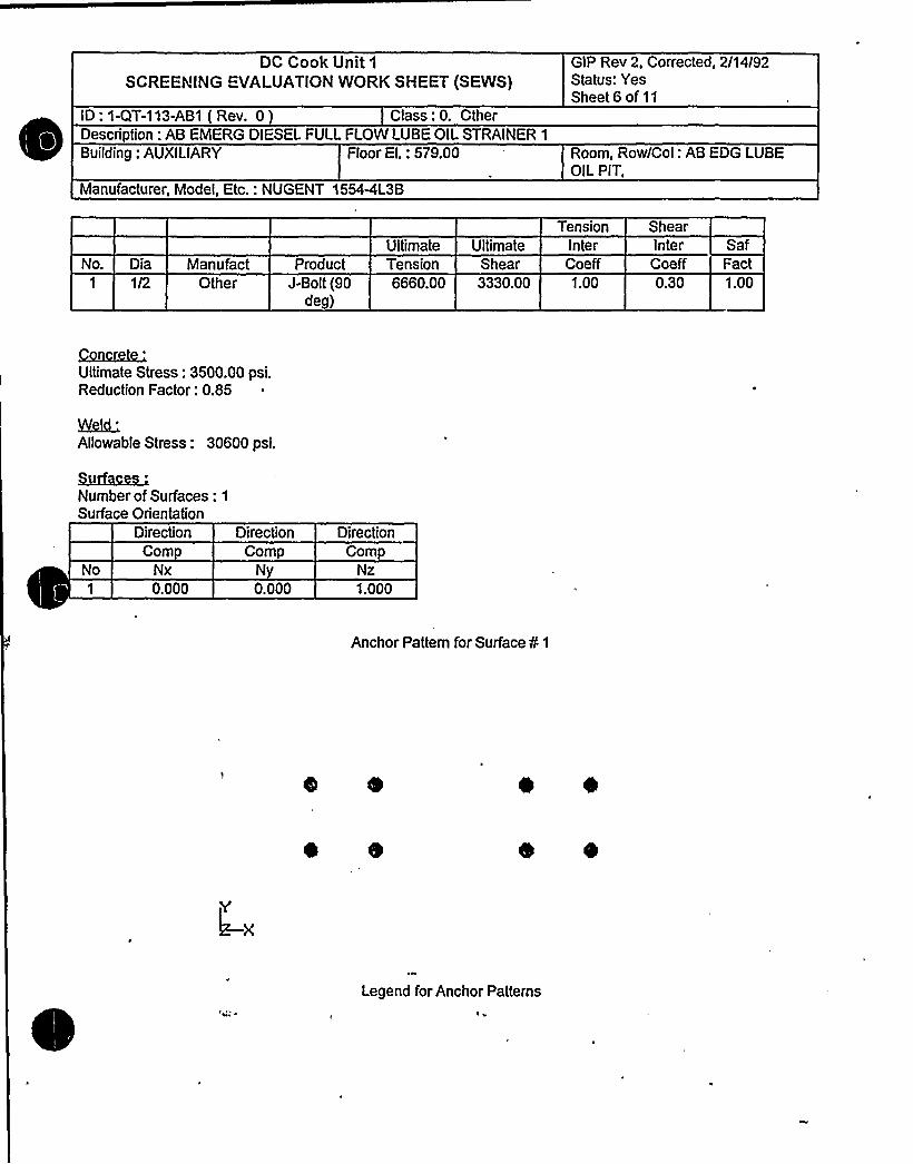
DC Cook Unit 1
SCREENING EYALUATIONWORK SHEET (SEWS)GlP Rev 2, Corrected, 2/14/92Status: YesSheet 6 of 11
ID: 1-QT-113-AB1 ( Rev, 0) Class: 0. OtherDescription: AB EMERG DIESEL FULL FLONlLUBE OIL STRAINER 1
Building: AUXILIARY Floor El.: 579.00 Room, Row/Col: AB EDG LUBEOIL PIT,
Manufacturer, Model, Etc.: NUGENT 1554<L3B
Ultimate UltimateTension
InterShearInter Saf
No. Dia1 1/2
ManufactOther
ProductJ-Bolt (90
deg)
CoeffShearTension6660.00 3330.00 1.00
Coeff Fact0.30 1.00
Qaac&c'ltimateStress: 3500.00 psi.
Reduction Factor: 0.85
~iAllowable Stress: 30600 psi.
Qi~g~Number of Surfaces: 1
Surface OrientationDirection
CompNx0.000
DirectionComp
Ny0.000
DirectionComp
1.000
Anchor Pattern for Surface ¹ 1
Legend for Anchor Patterns

DC Cook Unit 1
SCREENING EVALUATIONWORK SHEET (SEWS)GIP Rev 2, Corrected, 2/14/92Status: YesSheet 7 of 11
ID: 1-QT-113-AB1 ( Rev. 0 ) Class: 0. OtherDescription: AB EMERG DIESEL FULL FLOW LUBE OIL STRAINER 1
Building: AUXILIARY Floor El.: 579.00 Room, Row/Col: AB EDG LUBEOiL PIT,
Manufacturer, Model, Etc.: NUGENT 1554-4L3B
Anchor Bolts: mmmmConcrete Lines: ~mt//+Concrete Points
.'eld
Lines
.'ux;
hrzhac.'umberof Anchors: 8
NoAnch
Id Coord-30.719-16.531-30.719-16.53130.71916.53130.71916.531
Coord-7.260-7.2507.2507.250
-7.250-7.2507.2507.250
Coord0.0000.0000.0000.0000.0000.0000.0000.000
SurfId
0 of elements per line: 4Number of Concrete Lines: 0
Number of Concrete Points: 8
No Coord-30.719-16.531-30.719-16.53130.71916.53130.71916.531
Coord-7.250-7.2507.2507.250
-7.250-7.2507.2507.260
Coord0.0000.0000.0000.0000.0000.0000.0000.000
SurfId
Conc-PtArea4.0004.0004.0004.0004.0004.0004.0004.000

DC Cook Unit 1
SCREENING EVALUATIONWORK SHEET (SEvVS)GIP Rev 2, Corrected, 2/14/92Status: YesSheet 8 of 11
ID: 1-QT-113-AB1 ( Rev. 0 ) Class: 0. OtherDescription: AB EMERG DIESEL FULL FLOW LUBE OIL STRAINER 1
Building: AUXILIARY Floor El.: 579.00 Room, Row/Col: AB EDG LUBEOIL PIT,
Manufacturer, Model, Etc.: NUGENT 1554AL3B
EcldJ.iaaf '
of elements per line: 4Number ofWeld Lines: 0
Reduction Factor Input for Anchor 0 1
Adequately Installed: YesEmbedment Length: (27.25 in. Min Reqd. to achieve full capacity):= 9.13 in.Gap at Threaded Anchor: 0.00 in.Edge Distance - Edge 1: 4.38 in.Crack Size: 0.000 in. - Cracks traverses thru InstallationEssential Relays in Cabinet: NoAdequate Equipment Base Strength and Structural Load Path: YesEmbedment Steel and Pads Adequately Installed: Yes
Reduction Factor Input for Anchor 0 2
Adequately Installed: YesEmbedment I.ength: (27.25 in. Min Reqd. to achieve full capacity):= 9.13 in.Gap at Three'ded Anchor: 0.00 in.:Edge Distance - Edge 1: 4.38 in.Crack Size: 0.000 in. - Cracks traverses thru InstallationEssential Relays in Cabinet: NoAdequate Equipment Base Strength and Structural Load Path: YesEmbedment Steel and Pads Adequately Installed: Yes
Reduction Factor Input for ..ichor 0 3
Adequately In"tailed: YesEmbedment Length: (27.25 in. Min Reqd. to achieve full capacity):= 9.13 in.Gap at Threaded Anchor: 0.00 in.Edge Distance - Edge 1: 4.38 in.Crack Size: 0.000 in. - Cracks traverses thru InstallationEssential Relays in Cabinet: NoAdequate Equipment Base Strength and Structural Load Path: YesEmbedment Steel and Pads Adequately Installed: Yes
Reduction Factor Input for Anchor 0 4
Adequately Installed: YesEmbedment Length: (27.25 in. Min Reqd. to achieve full capacity):= 9.13 in.Gap at Threaded Anchor: 0.00 in.Edge Distance - Edge 1: 4.38 in.Crack Size: 0.000 in. - Cracks traverses thru InstallationEssential Relays in Cabinet: No

DC Cook Unit1SCREENING EVALUATIONWORK SHEET (SEWS)
GIP Rev 2, Corrected, 2/14/92Status: YesSheet 9 of 11
ID: 1-QT-113-AB1 ( Rev. 0 ) Class: 0. OtherDescription: AB EMERG DIESEL FULL FLOW LUBE OIL STRAINER 1
Building: AUXILIARY Floor EI.: 579.00 Room, Row/Col: AB EDG LUBEOIL PIT,
Manufacturer, Model, Etc.: NUGENT 15544L3B
Adequate Equipment Base Strength and Structural Load Path: YesEmbedment Steel and Pads Adequately Installed: Yes
Reduction Factor Input for Anchor ¹ 5
Adequately Installed: YesEmbedment Length: (27.25 in. Min Reqd. to achieve full capacity):= 9.13 in.Gap at Threaded Anchor: 0.00 in.Edge Distance - Edge 1: 4.38 in.Crack Size: 0.000 in. - Cracks traverses thru InstallationEssential Relays in Cabinet: NoAdequate Equipment Base Strength and Structural Load Path: YesEmbedment Steel and Pads Adequately Installed: Yes
Reduction Factor Input for Anchor ¹ 6
Adequately Installed: Yes'mbedment Length: (27.25 in. Min Reqd. to achieve full capacity):= 9.13 in.
Gap at Threaded Anchor: 0.00 in.Edge Distance - Edge 1: 4.38 in.Crack Size: 0.000 in. - Cracks traverses thru InstallationEssential Relays in Cabinet: NoAdequate Equipment Base Strength and Structural Load Path: YesEmbedment Steel and Pads Adequately Installed: Yes
Reduction Factor Input for Anchor ¹ 7
Adequately Installed: YesEmbedment Length: (27.25 in. Min Reqd. to achieve full capacity):= 9.13 in.Gap at Threaded Anchor: 0.00 in.Edge Distance - Edge 1: 4.38 in.Crack Size: 0.000 in. - Cracks traverses thru InstallationEssential Relays in Cabinet: NoAdequate Equipment Base Strength and Structural Load Path: YesEmbedment Steel and Pads Adequately Installed: Yes
Reduction Factor Input for Anchor ¹ 8
Adequately Installed: YesEmbedment Length: (27.25 in. Min Reqd. to achieve full capacity):= 9.13 in.Gap at Threaded Anchor: 0.00 in.Edge Distance - Edge 1: 4.38 in.Crack Size: 0.000 in. - Cracks traverses thru InstallationEssential Relays in Cabinet: NoAdequate Equipment Base Strength and Structural Load Path: YesEmbedment Steel and Pads Adequately Installed: Yes

DC Cook Unit 1
SCREENING EVALUATIONWORK SHEET (SEWS)GIP Rev 2, Corrected, 2/14/92Status: YesSheet 10 of 11
ID: 1-QT-113-AB1 ( Rev. 0 ) Class: 0. OtherDescription: AB EMERG DIESEL FULL FLOW LUBE OIL STRAINEP. 1
Building: AUXILIARY Floor El.: 579.00 Room, Row/Col: AB EDG LUBEOIL PIT,
Manufacturer, Model, Etc.: NUGENT 1554-4L3B
Reduction Factors Data Current: Yes
AncNo ld
1 1
2 1
Pall/VaIl
1398.603330.001398.603330.00
Pallr/VallrN/AN/AN/AN/A
RT1.001.001.00
RN RL1.00 0.421.00 1.001.00 0.421.00 1.00
RG RS1.00 1.001.00 1.001.00 1.001.00 1.00
RE RF RC1.00 1.00 1.001.00 1.00 1.001.00 1.00 1.001.00 1.00 1.00
RR RP RB1.00 0.50 1.001.00 1.00 1.001.00 0.50 1.001.00 1.00 1.00
RM1.001.001.001.00
3 1
4 1
1398.60 N/A3330.00 N/A1398.60 N/A
1.001.001.00
1.00 0.421.00 1.001.00 0.42
1.00 1.001.00 1.001.00 1.00
1.00 1.00 1.001.00 1.00 1.001.00 1.00 1.M
1.00 0.50 1.001.00 1.00 1.001.00 0.50 1.00
1.001.00
3330.00 NIA 1.00 1.00 1.00 1.00 1.00 1.00 1.00 1.00 1.00 1.00 1.005 1
6 1
1398.60 N/A3330.00 N/A1398.60 N/A
1.001.001.00
1.00 0.421.00 1.001.00 0.42
1.00 1.001.00 1.001.00 1.00
1.00 1.00 1.001.00 1.00 1.001.00 1.00 1.00
1.00 0.50 1.001.0Q 1.0Q 1.001.00 0.50 1.00
1.001.QO
1.003330.00 N/A 1.QO 1.00 1.00 1.QO 1.00 1.QO 1.QO 1.00 1.00 1.00 1.00 1.00
7 1
8 1
3330.001398.60
N/AN/A
1398.60 N/A 1.001.QO
1.00
1.00 0.42"s.00 1.001.00 0.42
1.00 1.001.00 1.001.00 1.00
1.00 1.00 1.GO
1.00 1.00 1.001.00 1.00 1.00
1.00 0.50 1.001.00 1.00 1.001.M 0.50 1.'00
1.001.00
3330.00 NIA 1.00 1.00 1.00 1.M 1.00 1.00 1.00 1.00 1.00 1.00 1.00
N/Aall
= Not Applicable—Allowabi Pull without Reduced Inspection
Vail = Allowable Shear without Reduced InspectionPallr = Allowable Pull with Reduced InspectionVallr = Allowable Shear with Reduced Inspection
= Outlier= Reduction Factor Not Used
RT = Reduction Factor for Type of AnchorageRN = Reduction Factor for In tallation AdequacyRL = Reduction Factor for EmbedmentRG = Reduction Factor for Gap at AnchorsRS = Reduction Factor for SpacingRE = Reduction Factor for Edge DistanceRF = Reduction Factor for Concrete StrengthRC = Reduction Factor for Concrete CracksRR = Reduction Factor for Essential RelaysRP = Reduction Factor for Base Stiffness and Prying ActionRB = Reduction Factor for Base Strength and Load PathRM = Reduction Factor for Embed. Steel and Pads
Analysis Performed: Yes
ype of Analysis: RegularI A elerations (G's)


DC Cook Unit 1
SCREENING EVALUAlION WORK SHEET (SEWS)GIP Rev 2, Corrected, 2/14/92Status: YesSheet11 of11
ID: 1-QT-113-AB1 ( Rev. 0 ) Class: 0. OtherDescription: AB EMERG DIESEL FULL FLOW LUBE OIL STRAINER 1
Building: AUXILIARY Floor El.: 579.00 Room, Row/Col: AB EDG I.UBEOIL PIT,
Manufacturer, Model, Etc.: NUGENT 1554-4L3B
No1
234567891011
12131415161718
20212223
N-S0.325
-0.325-0.3250.3250.325
-0.3250.325
-0.3250.130
-0.1300.130
-0.130-0.1300.1300.130
-0,1300.130
-0.130.130
-0.130-0.1300.1300.130
-0.130
E-W0.130
-0.1300.130
-0.130-0.1300.1300.130
-0.1300.325
-0.325-0.3250.3250.325
-0.3250.325
-0.3250.130
-0.1300.130
-0.1300.130
-0.130-0.1300.130
Vertical0.067
-0.0670.067
-0.0670.067
-0.067-0.0670.0670.067
-0.0670.067
-0.0670.067
-0.067-0.0670.0670.167
-0.167-0.1670.1670.167
-0.1670.167
-0.167
Safety Factor5.8437.4565.8437.4565.8537.2137.2135.8532.4782.7562.5032.6952.4782.7562.6952.5035.1149 3858.7525.0405.1149.3855.0408.752
Minimum Safety Factor: 2 I78
The Anchorage Capacity is 2.478 times greater than the Demand


SUBJECT F F nM
CAL BY
S AIN R
G. No.ak
GROUP
~~of Sos.
PAGE DESCREPTIOH
z0
O
XQ
X
I
0
2-S
7-9
10-11
12
13
14
15
29
30
Fig. 1
Frequency of System
Seismic leg forces
Nozzle loads
Leg forces due to nozzle loads
Leg stresses
Base Plate
Flolding down boltMeld of leg to tank
Local Shell Stresses
Recommendation sketch (SK-7940)
Summary


CalculationsSUBJECT: WC/ -/Ci iC ~ ( Q..(
JOB NUMBER / 8/'/'ILE
NUMBER "(0SHEET / OF
SY A Y /'A/OATE~FAPP CATE

CalculationsSUBJECT:
JOB NUMBER
FILE NUMBER
SHEET ZBY ~~1APP
Z5-r dC-<0
OF
DA~DATE
l27'r
ps S
fif
FA'r
/~f0'

CalculationsSU6JECT: SHEET Z OF
BY A TH/ DATE~'PP DATE
+Cj 2 t/Ol\g+Q 4 «4«L / gS«t~
AC AZgA'474 Sds
gC7
/0 >
Q/
4t
g«
Z//2 B
CF
N7/S
IdZ4
/2 ~S"r —.
Se~p~
'i0'5''/
.rg . /r= ' +44
C
rim«/P4 f
g'(
/z w"FAC( t'
/Sgs
Q~Z' c~ ~
F
r JCar: ~C g
/F
Ã
~ Q4 «
~ ~

0

Calculations ~"
EU@EDT: fjordJIVE reQ/g. ~ 1 ~/AJ/E+
t~,I
SHEET
BY
OF
DA
IJOB NUMBER 26 I TdJ
FILE NUMBER
APP DATE
~ WcrvOM F~eArW')P
7u~)( r- ~o>'-.+ 6v S'.~
r~/ ) l-a'gw
E
C«34>EE MOTIF5
+

/UA7 V
CalculationsSUBJECT: LJog~)ply ~ypl
8 654 Or l. ~A/&k4
Fzr uw<c o<
FILE NUMBER
SHEET OF
BV I ~
DATIVE
APP DATE
7)rr ZZC7 )od
~p g ( —F. " FEZ 5 F. gg~ px~ ~z)
r~rJ)C
x (IS &4S ZC~)AJ C
x ~AFEFxxlz 'x,assed+ sZ
Q~)my
Is?+PD4 T 9?e t 24/ 7P
~7~ /2d 0
cgaZ rr 29/
2llrS99~6 l z
~l.6?~l2
87 + 3,{?r,
ll)&I QZ,M
x
7,(2. ]
Ax/g/
WA5% CfpfC./)r-))
~~< "i/8&
Formals-iA Fizgcy ~ &~g~Ay/~ — l P ~
't6xsnc 8esEr p sr +~ srs ~ az F) ~l x?zoP +sos g F~ v
azszj'El
CC ~K l2)'4( FEE@ w EP~~>1 ~~ 5
lO Z+O
4> g4 rg>EE(O I
/224 4

Cak:ulations.SUBJECT:
FILE NUMBER C I 0SHEET~ OF
APP DATE

CalculationsSUSJECTI
„,~PFILE NUMBER + l 0
SKEET~ OF
eV A L H DATE29
APP DATE
x DSC~
X
ZzC 25
p4 /7a >
gi 2.¹/


CalculationsSUBJECT:
~PFILE NUMBER
SHEET~ OF
BY +CW DATE
APP DATE
3l
I
/F/
K
OzXO

Cele UiationsSUBJECT:
FILE NUMBER Q~ lSHEET~ OF
APP DATE
z

0

' ~ E
~ CalculationsSUBJECT:, IJy~rHWC7 oA/
rl/o
J-~)f8 A7 G4 SIT PP'EtZW
FILE NUMBER
SHEET OF
BYE r OA~~/gDATE
prACr]a+i P Pierr|CrlOV ~ Srg<CrxOal
D an dr /~ca r
/2.6 mid -W.i
- HrZ W.j -a,d
Wc 7
-4dr3
g,5 -asA i e-ig,/ -Wee irk
iS,S -/4P u.i
-I/AZ-39rd-
77,'5'82li
-87)]~0//QrS
NEO
/D7.0 A7
Co<By/Al /045
-/ IB-5 —+S'Z
->Br7-/&Br'B.7
)- a7Z-l~~)
O
CC
O
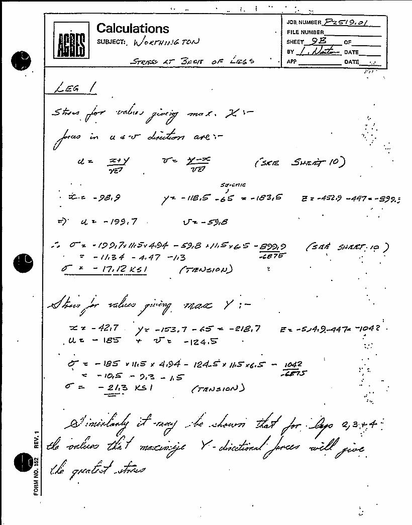
CalcuiationssuwscTI QocruFFT'o&
5reru A. Zs-~fr OP I-r~C ~
JOB NUMBER
FILE NUMBER
SHEET
BY
APP
619,o
OF
DATE
DATE
~Eh /A
F OL(F 4 OFF g ATF
<GO ~ ~ cg CJ
g ~PC ( gA~ ~FFFDOF'F" /0)
c -Pg,PSq'cnxc
y - «B,G ~ ~ - iS'S,G' g 482F) +$7+
- /99r 7
"/9917'/r>e'er&+ 5+rB >l/i~w~b -S'~/g-//,34 - w,47 -/.5 «48 7&
- /7,/2 Ws/
(sFrd sziFrrr Fo )
/'r ~44?M P r™
g/'
( V<M~ld+3
aqua ++
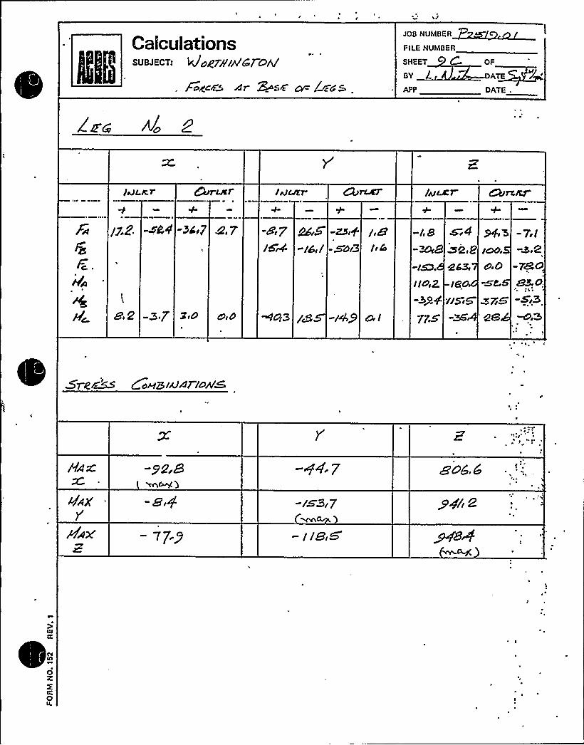
Calculationssu+EcT: 4~grA w'c7ohl
/age& dr Sos'p &cd'5
JOB NUMBER
FILE NUMBER
SHEET CBV lAPP
OF
ATE
OA7E .
/a)LÃT /vmr
/jiZ 4,7 -8r 7-/6il
a,2 -Br graf3//5i5
-St
are''

CalculationssUBJEGT: ~4R7 //IA<re
fuge& g/ 9QsF np Z4'
F I LE NUMBE R
SHEET
BY
APP
OF
DA~TE
DATE
JOB NUMBER N/ rO
/&mr JWLEP
F~
Wc
/7 2
8'E2
-5ZA
-37
-Bdr7 8(7 -28$ C3rgFdic
-/B A,9 -e/
~5',P.ER
/DOr
2', Or0-le-II& ~7z& -as4
'7r,l
?Br2.
~ I
4d
. 4r3
muvt7Zo+S
's
Q,B -aZ.1 /7Pr 9
-XZ.4
—77- 2
—/LSM(~ .r~ 5
r 69,8,
~ Xj/r7-'
+7'T iE
'0z
0

Calculations'UBJECT:
PoA?c~ g7 9AM~ 'c5
JOB NUMBER
FILE NUMBER
SHEET KBY
APP
/,oOF
'ATE /DATE
IHuZ7 C~l IecEp Aur
/3F6 HC'i/ 8F5 HE 7IWi4
-m,5-/6i/
ZSA-Wr3
BS(dsc}E3
-/o70 -4i7-3g2 -JCO
-BF g ~D F7 40F3 -/8S j4P 77iS
//5i-zs>
i $)C /
~ 5"I
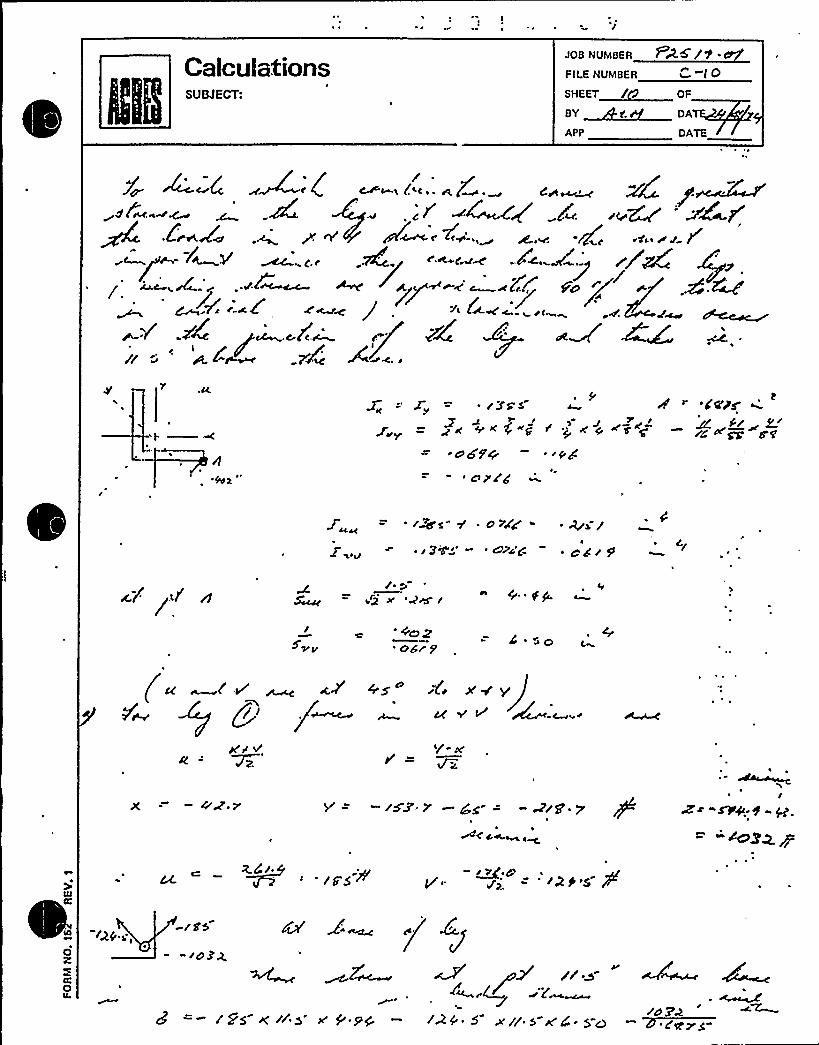
CalculationsSUBJECT:
„~fFILE NUMBER s t 0SHEET~/ OF
APP OATS
.u~ r
3's'K
SF K
o 6'P+~ OPIA
s+g E 'j, K
Ce'zs. ~SSS'4 gg
WFSl
i~s" Y ~ oh''~ ) 3C~ - ' >C:C-'
4's /~ QgSF P
FQ~ I
fez'6/ gl ~ so
4s" 4i x+ v~-c ~~+
X = -4'dv —/XX F S'g = - A/SF ~ yF
~ ~
I
QS ~j = ~2k'5
-res- -rOZZ
rr>-"=- res Krrs < & 9g r24" s ~rr' w4 ~ s-<
ro Pw7 ''O''


CalculationsSUBJECT:
JOB NUMBER
FILE NUMBER 6 I 0SHEET~ OF
APP OATS
— r~ S ~ — g~~ — /5 ~
y~ +(g gr. -g'.g y = - ) s's .y - 4 s = -ag. p'
~ rti.~ «»..~ PEP" t r 4'/CP J
V 7
(/4/ K 6 sC 'I /O'P s''//) //. SI
~d5S W rSC rr ~ + AO>P'4'po w '~y.0 ~ MA" Ping
'SFFS
- 5'C r-Ss c
r7pa H fr ~ 4
K~ - S'Z .7 rO + ~ S'4's' = 145 3'
Ir'C ~ <<'~ rg V=,~s> ~
..znC ~we c.~
ASIA
+Qp ( r/j .. ~C'~w~ i Aging o
zVA
~ES~ FS E'Fg
~p pro
/rr g'/ p /r 0
gag / f SE'.~E 8 gus'K ~ Z r~1ne /. r
S r
= rrv'

CalculationsSUBJECT:
JOB NUMBFR
FILE NUMBER
SHEET
BY
/ O
DATE
DATE
/~p/Ag
;~ ~'f~ «vj M~ @r"(/&W + l~ &) «A ( IC'rE!+
y C2 ai 2
lo2P
Ip g e ~ rEEE rr't/r.
gr'(.jr' «<7l rx«AE .w)mArD
E y,lrcP.'jvr~~W E'~
/(4 o'MW~/ i>p+ /4

h ~

CalculationsSUBJECT:
FILE NUM8ER
SHEET
ev
APP
Q.- (c
OF
OA~kDATE
A. JE (( :Z~r /de oCI'+0
/4 to
+ (~~~-D) J '.DgP~ %
~1 &o( ~ ogp
/ C
7c a~&
r- y. Z,y C
C
FKP
~" M.( r.
~ ~
2IJJ 7- g. ~ yr FS
Arf><j~~~rSy g ~~ A
/
0CC
0z

CalculationsSUMECT:
„„,~F' F.FILE NUMBER
SHEET~ OF
APP OATS
E" y"
~Ca AVE g > E5'7
I~ JA.
z ~ y'&Ma4'm
JP4&~iT'C
r s4~I~~'j ~ ZPE'ii)
IggZ Ted
>K
s
C
t ~ gfs APtg SggP ~ ~gg - ~c J d
~St 8'c tS

0
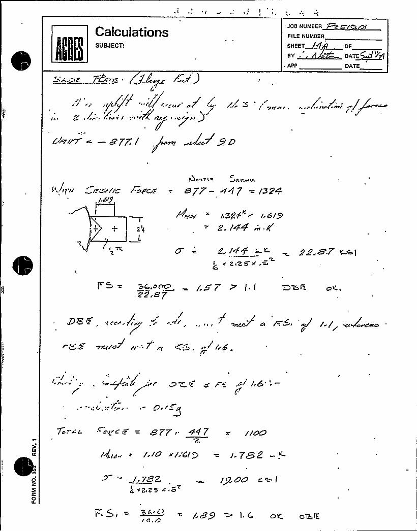
CalculationsSUBJECT:
JOB NUMBER
FILE NUMBER
SHEET
BY r
~ APP
OF
DATE
0 ATE
~ ~rr rr rr,/rr M / r~p~ r r r/rf p /(Z,(e~/ rr /(A ~
C4F/~ ~ —Q7P lj
Qow7LR C>0, lr HLC
r afUrr apF- ~47 raw.
T2<L
t./ i92. /44 ~ lC
~ zcZ5 X .~dZ.~T ~~I
o<.
98~,


~ 8" ~ 2
,'„~~ Euic Fiow L~ac. Gt~ 'STRAINER
TYP RG. No. /0-O89
CAL BY
C -I0GROUP
Sheet of
a/z ~/~~
z0
u
Local S Hc~~ - Tz.css as '
go~'hem LoAbs ~ (As pEi
sn/~r.''i
VZZS C.Q -/29 Lb~
F8 + +/0 /6/ - 7o3 Lb~
fc ~ /zZ /bg,- sr~ >gj4 t5'L>(A) w-Q I- IA7cl) w-/bg
A + s~zbz) w zb<,-z-i;z&4i~-+Ac t y4j(il) iN Lbg - 7z-ci&z) ur
, C
c+ciaI.C.f
6/zA 7+3
OLl7LET;+ +0l lb( ~ /$+ O Lby, -Ca+
48<, - ~ L.b~
k p>oft) ~ -lQ ~- lf]2) /n'-LLg
2/2 ((Z) lpl-lip 2 C(E) ll45'/o(>R)w ~by - 3ER.C/~) w-4@
~Y+
0LJ7+ @
l5.Gr2.5

TYP
CAL BY
RS. No. ~~
SU~EOT FULL FL>'W LU E OiL STRA IN ER. eaour
Sheet of Shta,
XL T'RANKKtL OF LoAbh FR< M IDYLL'T g OUT LCT'HOKKLEhTo TAvK sH<it Ho~zizs.: (sxgrcH P.ts )
ASSo&E eHvg oHE Ho4ht t Peg TAHE 5t cs NCLeA1% PRO& ~C (HECT g OVT<6 r )JG4%LE'Sf
"~ Fr.~ Fa.:
FR. I f Fig I~~+i3y= ~ =as/klNo KRC.E S
4)A ":~i
g]ace ~= w (m<hSK I
v»= w.~~~~. (;~+„~Fj...)(z)bv.6LR8
= (i»+i»(')( s.|.~) 85 3/ Pg gp(
L5g'l
Fa. Faleg our'a
/VORRLEg 2
Alp - (~<jpg ~F1,„p)(l)(li b l3) .(>'Zq ~VOL)(~)(gJ,Q)P
e 82 07/~ 7 /jll LSy
a)Fiz.~ F6:iZ F6„/s,;
Fb,„~ t6,"., ~" ~ zo ~ L4-/ ~ppp aceg
<) p'= (Fb;„~ F'<;,')(x)(igloo)) Ce" ~~)(t)(cpu)8
= go/.5
jL ('Fb„'- /b..,),g(qi0~)„j —= zqgc) zH. 6 g
~p'0 Qp c.Cg

TYP
CAL BY
RG. No. lO-DBS
pt ULL FLoW LLJE,F OIL ~i TRAtHEk, eaom
Shoat of Sh?s.
8/26/>+
$ >f5,6-- (Fs,„- F h,„, ( ) ( .z - v)( )
4 go4%v6g
ag Fh,„F'k,„~:(F8 -Pk ) ~ ~ 'oy
~ ~Pc RRc.FS
Y=
Py - zg ')(/i,sc>) («y wry) (i)-(n.<cry
8w -44'
p/~+'Fb,„„> Fb +„) (is) (6iv vi|o)(iz)X pro Z4l 55 Z
Fb,.„";
= (F8,z ~b +,) ('i)(ir6~r) (7~> -~) (z) (vc6is33
s 82. 7f4 i / lu - L 4+
= (r-b,,„~ t h,+,)(i~) (go~+.) (i~))QRR Lc. 5 L
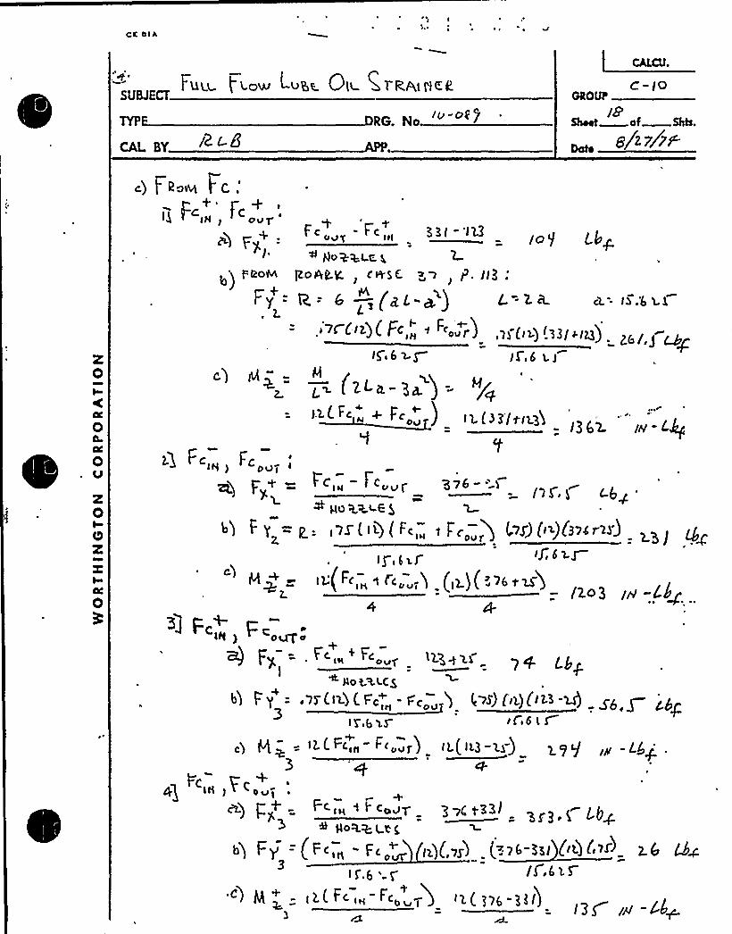
mL sV
FUI-l- t l.ow vila Ole Cl RAIIIER
RG N
C - IOOROLP
i8Sheet a f Shh.
8/2 ~/w-
c) [rooc FC.- Fc+'c+
F „-F „, KE I-l23
hlo+KLC. L
<)poor goALy, cesE. o>, p. II3:
Fy = p. = 6 —(+L-*) L=2iL a.-+ .
cC i)(F „" "«cJ6~5 IL,6 aj
c (2LIc- p~ ) = ~/~Fc ) I 2 ( I 3 it<i3'$
i3 6>
zs s,g
IN - LQ
c)
L
I. c,„- f c„„~+ go <a<6 $
>gr 6iS
ig(Fc,cr ~ I'c„„.,j
~76-" > I'IS ~ l ~6g '
(,vS) (ii)(3occ'3')IJ, 6ig
'>e ~u(2cr 3
~ oo~~icS
)g 6 yg I f o6 L S
= l2< ~~in ~'oor) l"(IC3 '4) 29'J3
«)~Coojh) I
+ F'cia "" adT ~~70 t~~~/OR+ (t 5
Fy CFc,„- F I )(>r'I (-'ll-3zl (i\(>I) 2Q3
IC 6 ' /0,6>5'c) Q z - i (F2c Itl co lb»( j~e 3II)-
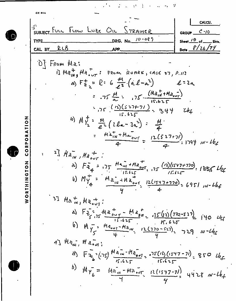
l$gU~E~ FULL I ~4& L~4'C QlL R t k.Av<C
TYP RG. No.
GAL BY
mOuI C JO
z0I
I
z0Oz
I
0
+b) I'ly
+

C
gU~~ FUI.U FLDw LDEE OIL ~TRAI<KN
TYP RG. No.
CAL BY
CAMl.
c-P
Sheet of Shts.ZO
<2 Fa+ I4: rsvp///ulcc'b 5 0 .'
/'46„~ /6...:
Fi8a& //>'/98K' CPS'8 '3 7 P//g.''y
=R = 6' (gL -~) L= 23.('~)
( $ 7?.W 1I Q PI@
~) fiam /des', dgM:v, /.//>:
Ega.- gq.g =
pl< &»''&l 3!"Lcg
) p:5
+bw +~~aug Zfia L ~7g (..IH, »pJ .7g (iL 5 1l-l<)
3 Q.,(n/7,'6 Z p / 6' t )
- ~be-r «(s ~i-]i): NFa i~ LQ-

gU@ECT FvW. MW Lv K6 ~tL. Sl l~hlA~K.
Re. No.
CAL BY
L~GROlP
Shoot af Shta.>/
F] Fl~!!!!! N C, pgAHE!.A'TC to 0,
@5 p+ !!e,„+Hc,„(<Q(~el+«<3avf szS. 7
b) A y = (gFp ( is (!.t') xt i~<!'(!river!).3 —I'l7/,$ /8-C4~
8
Pp c. g c y (Q(yq) ply)+ plo~kt,c. 5
M~,„+AC,„ t>(al.o eP~X)
g (<~q l C (x)
\. I K. (l5.6>J5 p (! iL )(>ggi~)7.o 5 g, 7 aJ - l.4+
8
~c - Hc l.(l
Ac '„+
~>!! Rc „~ ii(<!!l-'B<) <ql. C <1 ) y ( I h)
/!! y = (i!(F~)(<!~ 6U~ (L) (!'l,!) (u'6'L!).8 8
) pg H,z + c~„< zt(991 3!31$= Ob>E'-~4'

Qe
FLow 4'u KE. Qlc Cli2AIHKR.
RG No
uu sv
C-I<
Sheet of Sos.22
Si23jXy
X0
8c,„, Wc„+
22) 'F+=8
c) p)(
: ~t,~) a (.1~)
2. (. F~ ) C~r.ecr) cg3.si )(iroc3')
grVc +COol- i3.(X3OF 3CO)
¹ Plo+ W (C$'= Jggp
X0Oz
0
6J CoNPCLAT<oN OF I RAHC feR'Peg /Mal.e LCO*bC'q
Fv.')Fy = Fg> + Fx< = ~F3.3+2.nx = 6Y$ 5 Lbg
~) Fy - Fy + p> = ~~ ~~py = all Lbg
zq Fy,'+ '+
I '5) < I ~ ~ F Yy - 2(LAPGJ f'4'fl > 4 - 0 "rc|
Fyi + Fy< "FYoi = &33 + 2.el+ i~i 8"- 'is 6:S
~F-= . '.f ~ "t F~ + F+>- fogy 3'/pv 3K',g "- By/,g Q~
6) F4 = FZ + I'+++ FK> = '663,3 0 /332 3P 5 %.=2'52VJ+.'I
~'l x:«q Ax = P1x„+ Nx~ = 62ov e sszcx = @733'j w-t5<6)8x: iitp + <x< = l2is+v63's. -" 8866
Q jiff;@ Ay= py> + p7y2 +/ye = l6ol p+il9yvi27ls=seUio.c6>s) Ny = Ny, + Ny~~ayz = no~.6+Shl~zosv',7 =/wf).3
63 ~~:a) 0+ = Pa, ~ I'1a 2 <isa~ - col.2 +iso3 t s22. = 23 e 6 3 m 26g-
iilfh + /fan t g< = aoxV,2% /363 + S'3S2'78/;2 IO 26S-/

CK ~ IAl
~ ~
FULL FLoW LU5E QlL S1RANEE'.
TYP RG. Na
gy RL5
OkOVF
Sheet Mof Shh,
8 gt/7P
Hj Dlo<'o&ENTAYloN OP TRANLF'EgpED goK+lc LaAgg '
gi-(
Fy, = +6%5, g Lb<, - Kll LI+
FY= +»&.S L4q, - «-~.e+Fh=+ 8'll.S L4~ '~- lying,g LIl
iH) 4 Ll)Bi/ IH c'4g ) 8 BC6 w-LL< . p
H Y + %(41 I tH LQ j IYl893nr 5,'~ X~AK + 2s sag'3 lN L4y~ "s 78/,Q N.t.g~ I
o
I

II *

-',"U„~ I.ui- r" Luis; Q)~ =pi(p,i~i<<
RG. No
CAL BY
oooo C
Sheet Mof Shts.
82m O
TAHV. 5 H C I < I H ) Q 6 iE < 1 Y
J I >RikaH TAa aEl<KlC. Bt HbiNQ ~pi2C(t
c7 = I-o~4r n orNHC 5T'rc c'A d~d r~ Pc /r pc/~IWc.t 5 C/J ~/p g.Np+g, ( Rcvhirlgg
AT
l3 -2 P ]C -rl.dLJ 3= 3A',+ iu0 zz.
( P,Sg(~.<)
"/p)(l'L) g( I>S QJ(~)(gg-y/,p)
g~~ (>(, g)=+is4.
I'"'/ >

il",„~~ I uii )ioW LueE Qi STggiHZP
RG No Io -O 0S
CAL BY LSheet of Shta.
a ~s/~
3K GlcMH Fi'6< Q QH blH ro CpiEr i ic 6 t) v r 7~ Jl/o y~( g gQA ii6
'lT t~ f ~v 8 LQ SAT QE FcLLumtHQ l oAb~ Cog't~< lg vgaMWY LANK c4~5 R VATtV C $ 6 HQlfFQ Lgg Qg po ~g
++gal.,''SIi.e
l-CH P.>3 )
Rg H> = l>,6'(FV) i My= la,g ('l i Hi6$ + +Si 6 .- ~i +88, 6 iH -L)g
P$ py = i;r(ry) (~)('Fp)+ H)= n.S(~ii') «(e)(2~-LS.S') + iqiZS,>) — »oiler,iH--le
I/l. i'
9 Al Lloà 6 + 87ol.l.,I '26op7
bt MPob 4uo~.7cr - —= -+'ll7o. 5 64/ <+ g Pg H. //H
V~o>(o Rc Sri>ess ~LuE To gogz<v Leppy
I) a = ~g YX~'f 7 g,~/uAREA /<(g, gg, L yg-
F~
- (io'- iS.Pl-)F}
CooihiHeh 6tH eH EiL STso sr@ 6 !
+ + l 0 +O = ~+~ +-cr +os'+cI
dye ~tie.i+f8,6+ u>5, 3 S <i~v, C+ 7S,q = ~S eo,~ jw.~s
l ~ P 5a +~~ ~+~1( l, I + Fc,~+ li'70,5 + w1 (
- —J1oG ~ l
+ HL46,7 /iH~Thai Q

, CAL BY
t us.s- fMsss Luge Ola STRA(HC 6
RG. N
NSIH Q WRC QOl L.6 T'Ihl I>1, 7HC I-DC 6E PRI AHP l 5'l PE'Sr ~STHE ~A~~ SHEI.~, OVC F ~ VERY CoI4EERVd
>IVY'R.AI4SFKRL64H~'%+I-6 ~DO f oN P.2.3 *g.E SHOm 8 OAQht'h 'SHEE, T, P.L'7> F POD PQIHT Oug,P, X5,
SIHCE:Pt< 5 H6AR IH'r6HSI t'r i f <ma((, [email protected] 2. F'ak7He CoebIH6 „l-R.e~S IOTGH(Irr uH beer-8 S~F7, P. ~7,LVI<i 'QE ll5 6 0,
z0I
-u n.8
~), = Sy($)+a~ 78<9./
m.= 5
"%IS~ 3
?.i7l(I'Nsgi
-~01,/
iIX84.7
t'ss7,2.
/ohio 9
.il KP9',7
ltz80,p n7't,7
t'337,l. -3i7/.I
los 0, Q -9o) t| /
p2I4' lo897,
-3»i I 7s-34,i
->oJ O',I 2 ~ ~1 4
loZ37,I >f96,X
Dc.
&29,7
'7$ 36,2
R 2.'19~ 7
0I0z
0
~IJ H 5AFET'r F8ct"u r2
$ (7oOD
il2t Y, 7~e
f. S.-" 9oaov P5/ <ftA 8 "4'2
A~- ~
Z,64

i LILI 7'I asm LaaP„(. UII b 7 fdlSIIILfc
L= 2 )77.S C"Tg.- )(x&t'o, I) (P.
te AS ~ li04 I ooo ~
Radial loof,Circ, Itaieant ~
Loilp Honiont a ~
'T ~ talon Houont,Shoot Load,Sheer Loode
1».C 1;~ lb.IIL I.".lan~ ~ lbsi e st/+lan Ib»
Vc ~lbVL T~VIb
2. Geoee ~Iris Poionerera
(0.4)$)—~ 0 e3Rin
'cL/2
OuOLAu
-XTabto 5-Computation Shoat for Local Strossos in Cylindrical Shellsc.b)
H2ga a~by
Cb Q g - //e,tro
P SQ c = /s.cisot) w = g.f'g
Mr
ROUNDATTACHMENT
Bu
2I Oueu Hrr
Vessel Ihicl I~ aa,
Atteclvaent rudiva,Yo ~ aot Iediv ~ ~
I IS)1r
5II~ I ~ ConceniI ~ Iion due I~I/~ ) Ieenbiano Ised, Kn
b) bondtnp leod, Kb ~r. 0
'HOT EI Ent ~ I oil 4tco valves in
~ ccoidence arith ~ ipn convention
uCL X/
CYLINDRICAL SHELL
,o L5
F~Flp
Sc
IC
Rood cvrvsalor
Hisd/Rie
Course ~ ebsolvt ~ valves ~ f~ II~I~ ~ Iid enter I~ @ii)I ~
Kb ~
Av AL Bu BL Cu CL Dv
7 89 '/ In'/I
STRE$ 5ES if lead a ~ OSSOIII ~ thor shove, teeerse ~ ipns shove
OL
y Fa
.I)/ g
Ag
, CIOBQ
2A
2 ~
14 ~ r'I ~ I
Hc/ Rut/i~IIS
sar/ RuffHIS
~HL/ N~>/7
Hier
HL/a ll
77 77SS7)S'7
0 /7$ C) /'7it 0 /7f0
3.'t cCH ~
lr I I'
Add ~Itehiotseur 4I aueueonoo~ IIS ~Ilsaaes, ~Ics P 4 I 5> X>+Tfa
/69I'0/69
sq 1 2.'l+'s
/oS
,Ol 2C
dA
2A
da
2O orI
Hs IrNe
Itc/RutllHs
Hc/Rural
Na
HL/RntPHa
IaL/ Reel)
He \ HL
HV~tg/ R I/)T
+
5
HtIIS ~ r ~ Si 2d It T0
Sheer stress duote lee ~Iuu Ils
Add ~ Iceluoiaollr 4I ouu vien~I K ateeaaia,na ~ (i = <>is')+L 6fs 6fs3 1.7S L7r 7 S'l» S6
+
5heor arrest 40I~ leod. Yc
5heor steer ~ duoto leod, VL
r aaSV
VLY
Add Altearolcatlr fer eurenenen~I sacer ~ iieaaea, r
COII~ IHED 5TRE55 IHTEHSITTI $
I) when ny ~, tr
hero lthe sitest I a it ~ lna'I IIOFI Cr
0 0 o 0 0 0 0
2l trhear 'O
Sl Wh d~anhoes uafko Htaa
5 4iseei ol $ $ ~ Ie ert IISI ~
)
5 t I'isis es)' ~ rrI ~I
~,
~ I
l0 ,Iifrrapra irt >bohr IIR

Qd~
~(
?
JDC, I
?~ 1 f\
~ / ~ eV p
p( ~
P Jorp('
F:;C,F
IUnF. F. L. 0.
strainer'C,ODf!,!i.!,
KD14 ~ p 3 ~ 42r(p G ~ G J/ 1 ~ (( 1 ~
("(L',:(T, V'", 'lL.: *
4>o 5/ 27uu ~ '2g $41v3 o >y 1 17
I ~ (/r' 025 g lo 3((', ~ ~ O.C4'p >2 o 35.// p F 'k A/ F 2 r'1 p i~ 4 D p F 2 ('/
3 ~ 3< ~ Ql, "~ 2; '025 g 1 ~ 35/
3'i, !7S(
.014
~ Vg
I
g
',(, '" ~
(.'.
~ (
I ~
Jo ~
~ .. 'iCn'I
o ~
~ r~:." ~ rF P=
l.r
r
537 " LAX=""':.:.
i7SO .'C.",= ("
"17 lu D":!= ~; ..7755 -.r.P v
'130F~X=
16981102SG543.51 q4if55
11630
( ~ ~
~I~ ~
I
~~4 '('d j'.
gczupg 8/'
gg//m Ni~Y'i~i ~/('((//(gzz>: rP4z vu~p~;< -.-..;
./Wy +~jvzcj~j'.,P/"-:".
'I
~ O,', '.Pq ~ 'I ~ ~
"~ I

Ot 4> ~AAT N(L VAICAW tATT. NO
iy, d/A'A'///.4 g5A'$
Pfd'dPAcwb
«~/St.'. "45~ah//
COP< WliVFg
z.y c xc DiZ3A/
~ t
lthe/aiA
~ ~
SO 5 4/A'C,'.:
VP/Z5
jg/$j/h/&/.F8-
/5'/5g.x5 4
ppPig
TlII ~
ms /coypu..
Ep/$j/h+800
j'/arV8-8s~ir-:r~~
~ "alp'vP s4L d~ $gAAi+HA'gdPM~ /0~~~+f /HA-XZg-Pdldd SuZ/i'd& ~.a <Crx~ag SPW/h/+g/-M IWEPg. 486 /O.P8$~ W==.k~/. F4uiAffbkj'~g fgKFEF7kfJ$7 8f- A@/ddt >'c.v'= 6I
jH''g
oF Pp'z$fwd- LEE'S 7d/CCoyyaORPa g~Z MzrV,"'7/4FFS j 8'/jl~g R/7ERlh'CT. SQAÃlhFRPafs j/d/
i~ ti~u;i5 dddE.; A$///E--SECfoal
~„&A/$g/4& i~<'/35Cg/h/6- Oh/
M)ygz>C ACE t'A'Cc&
VNIXSS DIN(ANISE SttC.DNICNSIONS ~NNAI\I
ID(CA, CEO«CIA(0 STVSOES1 VSAII TI~ I IIEA~ IlAihlll
S INAICNI1 C $ SCI AOVNotI($$II tAAAllllllVtf1 t(NOICVEAA
ANCLIAAITTAoh( VTIAOC tollIIONDON((NI1IclffSTVNII1I
I IlACC DCC (Calt tlACC DCC IS>SfS t(ACC DCC D(attlANCECSTIISCADLVN IAI~
alata(or $(C
tllltftaSA le AAA~ ACAA CONN(AS at ~ Er IIAC.1ENOYt SVAASSsipgic Sf"Pf
~ I tOIIION~
II INC(ON (ANION«Ohltlal IOCO«ONII
~ Ihlln I ~ IAII ~
NOAINVCION Ol «CAVO
slvNAN Ioo«n.vah tCS(ttfl
NOA MNO Oh ~ ~ AA\«Ohl INOI(h 1 ~
Sf//>JMEA /OVili& pOOIF: pWO ~ TIIISC501 Cotto ~ ATIOII
CCVtttftnt ~ CACIAC DIT. SVff1(0, A. 5,Ohh g g( CW~L Attn, g l$
'N "-"-"-VMJ cy ~ I >I I I

CalculationsSUBJECT-'/ 04KB/h(<-'C"c/4
2 u8< C~u ~rp~wEp~o'MMAK
Y'OBNUMBER
FILE NUMBER
SHEET 0BY
APP
C -/0OF
DA~DATE
Cr F F5 / 8) P //
FE /- Z Pid
('wC
F
(4 .TK4' ~l
A,<~ .OEEE WS/ rn
F
wein . r c'(4 T'c '4 F Acct Fc.FAF+cccccf
r Ei; cr cc I 6 Cd~~y FA +c,cAA~ 1o
l<.r&PPd~ CHAFE PF 5K PLATO. SWI r /
,'7c cr.'-~EEOC Fr>
r< /~7'~ ~E/ ~ 4&l
~~gf4(r r/8/EE g,g4
g IM
3 rrt Cr
(FA dcS
Qr
Oz

**12 CHP 5021. CCD. 019ATTACHMENT NO. 1
Unxt N
/8- J9
ANCHOR INSPECTION DATA SHEET
Bldg.CION'RO. Qiagai L~OL: Qc, Pi-,
Location
Installation dwg.. / Rev.
Anchora e Arran ement SketchEquipment No.
0-6" ~ g~
g~ g
g ~~ I
~ I~ ~
~ ~~ ~I ~~ ~
iV~'(%e)
~ g
5 g Type >Qol %5 Cfyp)
) I
sc& L
(',i''L
Drawn by:Verified by:
Reviewed 'by:
Date:Date: '2--') -/2
Qual. /Cert.
onstructz.on
Page 1 of 3h~
InspectorDate: l
Anchor Review Engineer


**12 CHP 5021-CCD-019ATTACHMENT NO. 1
C OR INSPECTION DATA SHEET
Give LMM'ic /i iUnzt
/2- 3zae
Bldg. Location- Ql -/13-A82
Installation dwg. / Rev.
Anchora e Arran ement SketchEquipment No.
- Q/z
Drawn by:Verified by:
Reviewed by:Qu ./Ce t. Inspector
nstructxon Anchor Review
Date:
Date:
Date:Engineer
5
r3 ~A+ Q~"p )
G lc 5'<
Page 1 of 3Revision 1

~ ~ ~
0~ ~ II
~ ~ a i e
~ ~
~ ~ ~ ~r
o ~
0 ~
s ~
RSR%RRKi%WW&W .
a a o o
mRSRIN WALLSwwweaarrm55555LSRLRSmmmRHE%RRHHRRHHELmRSmmELSLlIRSHRRELLLMW&M MWW
~ II II
0
'rr ~
s ~1
~JUL i
I ~~hl
sir ~ ~

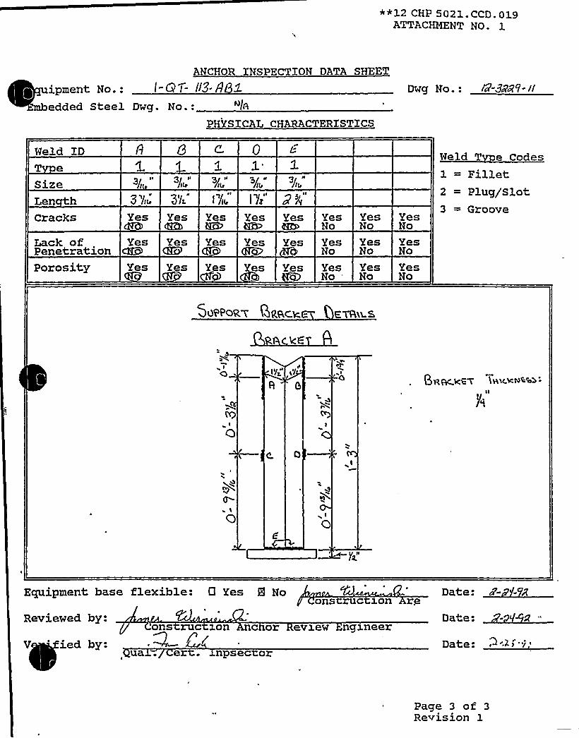
*+12 CHP 5021.CCD.019ATTACHMENT NO. 1
ANCHOR INSPECTION DATA SHEET
ipment No.: l-6 t- II3-8edded Steel Dwg. No.: ~lb
PHYSICAL CHARACTERISTICS
Dwg No.: l&3cÃV-//
Held IDT eSizeLen hCracks
Lack ofPenetrationPorosity
Yes
Yesc3g9
Yes
3'lL
YesCRh
YesQtV
Yes
Yes Yes
YesHZP
Yes
es
Yes
Yes
Yes
YesNo
YesNo
YesNo
'esNo
YesNo
YesNo
YesNo
YesNo
YesNo
Held T e Codes
1 = Fillet2 = Plug/Slot3 = Groove
5~7'PGR< QQac.~ - evhu s
Qg~ggg (gal.kl0%bb
0
0
Ecpxipment hase flexible: Cl Yes 8 Noons ruc won e
Date: cP-
Reviewed by:
V 'ed by:ons ruc ron c or evzew ngxneer
~/'a
. er . npsec or
Date:
Date: ~'~ ~ 'i
Page 3 of 3Revision 1
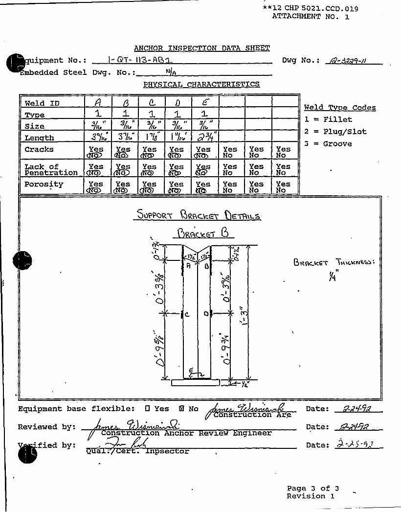
**12 CHP 5021 CCD 019ATTACHMENT NO ~ 1
ANCHOR INSPECTION DATA SHEET
ipment No.: - GT- i(3- 6
mbedded Steel Dwg. No.:PHYSICAL CHARACTERISTICS
Weld IDT eSizeLenCracks
Lack ofPenetration
Yes ~Ys
Yes0
Yes
Yes0
Yes Yes
Yes @Ys
YesNo
YesNo
YesNo
YesNo
YesNo
YesNo
Weld T e Codes
1 = Fillet2 = Plug/Slot3 = Groove
Porosity Yes0
Yes es Yes Yes65
YesNo
YesNo
YesNo
SQPPoR 7 QRhc.k. - E'YFh~s
Qg~ggg $ g>c.atoll ~
fP)~ I
a
0'
O
Ecpxipment base flexible: 0 Yes 8 Noons ruc son re Date:
Reviewed by:
V 'fied by:ons ruc son c or evxew ngxneer
ua ; er . npsec or
Date:
Date: 0 35 9"
Page 3 of 3Revision 1

**12 CHP 502 1 . CCD. 0 19ATTACHMENT NO. 1
ANCHOR INSPECTION DATA SHEET
quipment No.: /- - - Q3.
Embedded Steel Dwg. No.: A
PHYSICAL CHARACTERXSTXCS
Dwg No.: IB-8"zV-il
Weld IDT e
SizeLen hCracks
Lack ofPenetration
Yes
Yes
Yes Yes Yes Yes
Yes Yes Yes Yes
YesNo
YesNo
Yes'Lto
YesNo
YesNo
YesNo
Weld T e Codes
1 = Fillet2 = Plug/Slot:3 = Groove
Porosity Yes Y s Yes Yes Yes YesNo
YesNo
YesNo
50PPoR 7 QPhck c- EYRi~s
+KCT
Qg~gg+ (<xc,Kf4%'bb
Ecpxiyment hase flexible: CI Yes 8 Noons ruc won re
Reviewed by:
ified by:ons ruc ron c or evxew ngzneer
ua —. e . npsec or
Date:
Date: ~ r 5
y.'age
3 of 3Revision 1

'I 4
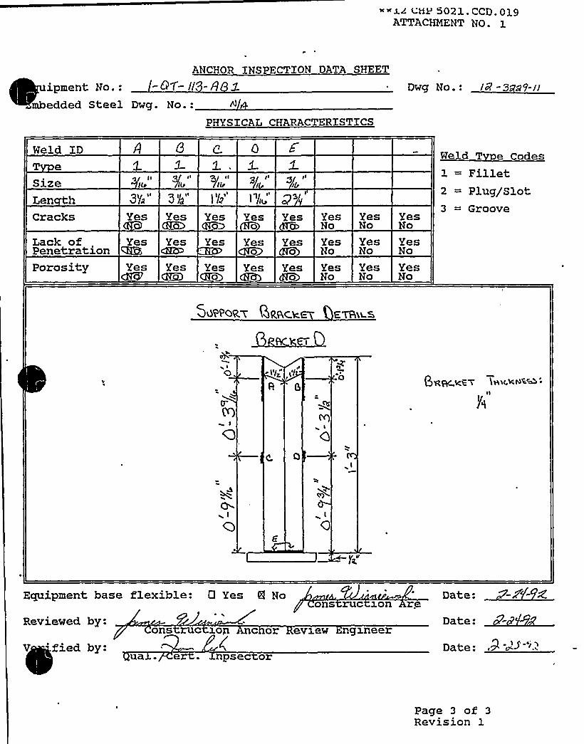
~~j.~ ( riP 4021 CCD 019ATTACHMENT NO- 1
ANCHOR INSPECTION DATA SHEET
ipment No.: -97- I/ g
mbedded Steel Dwg. No.:PHYSICAL CHARACTERISTICS
g .: ~gWeld IDT e
SizeLen hCracks
Lack ofPenetrationPorosity
Yes
Yes
Yes
YesQRD
YescKRP
YesCgg)
Yes
Yes
Yes0
Yes0
Yes0
Yes
Yes
Yes0
Yeso
YesNo
YesNo
YesNo
YesNo
YesNo
YesNo
YesNo
YesNo
YesNo
Weld T e Codes
1 = Fillet2 = Plug/Slot3 = Groove
507'PoQ~ QQ&ck - EYRg 5,
~ I
OBS.RC.kC 7 (Hi(.k8%&:
Equipment base flexible: 0 Yes 8 No Date:ons ruc 1on re
Reviewed by:
V 'fied by:ons ruc 1on c or ev1ew nglneer
ua . e . npsec or
Date:
Date:
Page 3 of 3Revision 1
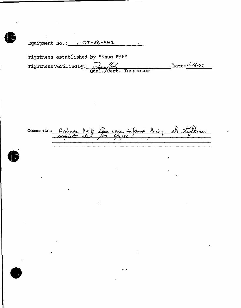
Equipment No.: ( - G~-<6 - RSX~
~ ~
Tightness established by "Snug Fit"Tight:ness verified by:
Qual. /Cert. Xnspector
Comments: )pP

Equip ID: 1-HE-,13 Train: 12
Drawing No.: 1-5129A 1-5135
.ction: RI~
~
Equip Class: 21
Sys tern: CVCS
Equip Desc: EXCESS LETDOWN HEAT EXCHANGER
Building: CONTAINMENT Room: REGENERATIVE HEAT EXCHANGER ROOM, AZ 295
Elev: 612 Sort: S, Notes:
Normal State: Desired State: Power.Req'd: N
Support System Drawing:
Req'd Support Comp:
Safety Related Status: NUCLEAR SR Min/Opt: MIN
Alias No: Power Train: NA
Comp Served: EXCESS LETDOWN HEAT EXCHANGER
Mfr: ATLAS INDUSTRIAL MANUFACTURING CO
Model:
Elem. Drawing:
Wiring Drawing:
Power Source:
Walkdown: F G Relay Eval : N
Comp Type: HEAT EXCHANGER
XSO Drawing:
Location: ON THE CONTAXNMENT WALL SIDE OF THE RM

DC Cook Unit 1
SCREENING EVALUATIONWORK SHEET (SEWS) Status: YesSheet 1 of 1
ID: 1-HE-13 (Rev. 0) Class: 21 - Tanks and Heat ExchangersDescription: EXCESS LETDOWN HEAT EXCHANGERBuilding: CONTAINMENT Floor El.: 612.00 Room, Row/Col: REGENERATIVE
HEAT EXCHANGER RM, ON THECONT WALLSIDE OF THE RM
Manufacturer, Model, Etc.: ATLAS It!DUSTRIALMANUFACTURINGCO
BASIS: External analysis
1. The buckling capacity of the shell of a large, flat-bottom, vertical tank is equal to or greaterthan the demand.
2. The capacity of the anchor bolts and their embedments is equal to or greater than thedemand.
3. The capacity of connections between the anchor bolts and the tank shell is equal to orgreater than the demand.
4. Attached piping has adequate fiexibilityto accommodate the motion of a large, fiat-bottom,, vertical tank.
5. A ring-type foundation is not used to support a large, flat-bottom, vertical tank.
N/A
Yes
Yes
Yes
C~MMEE.'Q
SRT: George G. Thomas (SS A) and Tom Huang (AEP), April 13, 1995.l
Ref: Unit'1 and 2 Anchor Bolt Schedule (Drwg. ¹ 3073A-3 and 3073D), and Unit 1 8 2 Containment BuildingConcrete Floor (Drwg. ¹ 1-2-3207-23)
Relatively small exchanger (1600 Ibs) on two saddles in extremely high rad area.
Could not inspect anchorage due to it being hidden from view with insulation. Removal of insulation was notperformed because of ALARAconsiderations.
Anchorage includes four 3/4" diameter J-bolts, embedded at least 2 feet into piers. Due to large anchorage (four3/4" bolts) and small exchanger, the anchorage is acceptable by SRT judgment,
Evaluated by: Date:
iz /~ /~s

01/16/92PG. NO.539
SAFE SHUTDOuN EOUIPHENT LIST (SSELMP)
FUHCTIOH: ESN
Equipment Class: 2'I Train: 2
Eeiirment IO: 1-HE- IBE Drawing Nunbert 1-5113 I-51C4
Svstem: COHTAINHENT SPRAY
Enufo Description: EAST CONTAINHENI'PRAY HEAT EXCHANGER
Rui lriing: AUXI L IARY Room: E CONTAINHENI'PRAY HEAT EXCKAHGER ROOII Elevation: 609
wnr~l state: Desired state: Power Required: N Sort: u,
Siaoorting System Drawing Number:
Required Interconnections and Supporting Components:
fetv Related Status: NUCLEAR SR Hin/Opt: HIN
ADDITIONAL INFORMATION
4l ias Number: Power Train: NA
Cnmcx nent Served: EAST COHTAINMENT SPRAY HEAT EXCHANGER
wsnufacturer: YUSA Node l:
oanel:
EIem Drawing: H/A wiring Drawing: N/A
cower Source: N/A
ualtdown: F Relay Only: NO
Comoonent Type: HE
ISO Drawings:
Detailed Locatian:

.DC COOK Unit 1
SCREENING EVALUATIONWORK SHEET (SEWS)GIP Rev 2, Corrected, 2/14/92Status: YesSheet 1 of 2
ID: 1-HE-18E (Rev. 0) Class: 21 - Tanks and Heat ExchangersDescription: EAST CONTAINMENTSPRAY HEAT EXCHANGERBuilding: AUXILIARY Floor El.: 609.00 Room, Row/Col: E CONT SPRAY
HEAT EXCHANGER RM,Manufacturer, Model, Etc.: YUBA(VERTICAL)
BASIS: External analysis
1. The buckling capacity of the shell of a large, flat-bottom, vertical tank is equal to or greaterthan the demand.
2. The capacity of the anchor bolts and their embedments is equal to or greater than thedemand.
3. The capacity of connections between the anchor bolts and the tank shell is equal to orgreater than the demand.
4. Attached piping has adequate flexibilityto accommodate the motion of a large, fiat-bottom,vertical tank.
5. A ring- pe foundation is not used to support a large, flat-bottom, vertical tank.
N/A
Yes
Yes
Yes
N/A
C LL 0 T?
~C)JJV~N$
SRT: Gary Thomas, Tom Huang and Kailash Mahajan on 11/3/93.
ery well engineered support structure.
There is a ring support at top of the exchanger bracketed to the wall in each of the 4 quadrants. This takes theoverturning loads on the exchanger.
Bottom support (at about the 1/4 point of the exchanger, with the remainder of the exchanger hanging below) is aheavy duty ring with gussets at the bolt locations. These are bolted to a steel support structure that is obviouslywell engineered.
Qualification data (Yuba Heat Transfer Division Calculation 69-G-226) indicates an analysis to the design basis.Based on the inspection and anchorage data collected the Heat Exchanger is adequate.
Evaluated by:
cQDate:
> /I g
/8- ~ - fiAttachment: Pictures

DC COOK Unit 1
SCREENING EVALUATIONWORK SHEET (SEWS)GIP Rev 2, Corrected, 2/14/92Status: YesSheet 2 of 2
ID: 1-HE-18E (Rev. 0) Class: 21 - Tanks and Heat ExchangersDescription: EAST CONTAINMENTSPRAY HEAT EXCHANGERBuilding: AUXILIARY Floor El.: 609.00 Room, Row/Col: E CONT SPRAY
HEAT EXCHANGER RM,Manufacturer, Model, Etc.: YUBA(VERTICAl)
ELC3XKE>
BASE GUSSETED SUPPORT TOP SUPPORT


P. O. BOX 3158 ~ TULSA, OKLAHOMA74101 o (918) 939.2201
December 7, l971YUSA ItlOUSTA!SS, lNC.
American Electric PowerTwo BroadwayNew York, New York 10004
Attention: Mr. R. A. KadlecMechanical Engineering Division
Subject: Indiana & Michigan Electric CompanyDonald CD Cook Nuclear PlantContract 1241Containment Spray Heat ExchangersYuba Job Number 69-G-226
,C~~~ F'LA~>ORD - grD f,gpss
~rCTIDNE~~GtNV;.qDATE
~LEANT LIPEy~MEDATE TO PLANT0 NOH pERHAHENr
HlNQfUMg~~N~
Gentlemen:
(6) 'four Seismic Stress Analysis for the subject gob.Qe are enclosing six (6) copies o our
b"" 9 1971. written by your Mr. A. Sherman, request'ingji refer to a letter of Novem Qr~ ~~ ~ ~
a' suit we have completely rewritten this a y *additional clarification. As a resu
as Rev. 2.
nts at our earliestPlease return one ( ) copy in i(1) d'cating your approval and/or commentconvenience.
Uery truly yours,
YUBA HEAT TRANSFER CORPORATION
B. F. FormanDes ign Engineer
BFF:dccc: Mr. A. Sherman
Main FileEng. File
/U JI
1

Y\/."!< .!!::/s7 1 8 N"SF 0!'lV I S I Ql~>U3/s l(vov ~>ales, Inc,
Seismic S trc. s Anal vsisIndiana & Michigan Electric Company
Donald C. Cook tiuc lea r PlantContract 1241
Containment Spray Heat ExchangersYuba Reference 69-G-226
Page 1 op
Rev. 2
S tresses in the support ring structure resulting from the operating load on supports, thc
forces due to seismic acceleration and operating pressure will be investigated using the refer-
ences listed below.
The support structur'e consists of two 4" x 2" rings encircling the exchanger together
with a 1" thick wear plate and q" shell plate. Refer to Page 5 for vertical support details.
The following stresses will be calculated:
1. Longitudinal bending stress due to shell acting as a cantilever beam and
loaded with horizontal seismic force.
2. Bending stress in ring structure loaded with operating wt. and vertical
seismic and horizontal seismic force acting at center of gravity of
exchanger.
3. Circumferential and longitudinal stress in shell due to pressure in shell.
The period of vibration'is determined using References 1 and 2 below:
l. "Introduction to Matrix Method of Structural Analysis", by Harold C.
Martin, McGraw-Hill Book Company, 1966.
2. Yuba Computer Program to determine loads and reactions in structures by
the direct stiffness method per reference 1 above. The program also/
Icalculates the natural frequencies of structures. See discussion on
Pages 10 and 11.

"LIU/iI SCAT TRANSF!. R 0!Vl"IQl':.'OA
IYOUSTalas, INC.
(' .. 'u <g u / l~ U 4 Page 2 ciRcv.
k
~
~W = 94.4 Total Operating Wt.
<Vertical,Acceleration Av = .17
*Horizontal Acceleration AH = .3
A = 10/12 Ft-
B = 18/12 Ft.
C = 9.42 Ft.
D = 3.46 Ft.
E = 6.92. Ft.
(See Fig. 2 Page 5)
6 = 45'k
HF = W x AH = 94.4 x .3 = 28.3
VF = W x (1 $ A ) = 94.4 x 1.17 = 110.4
2 PE Sin 8 = VF D Sin 6+CHF
. 2 P x 6.92 x .707 = 110.4" x 3.46' .707 ]9.42' 28.3
P = 54.9 k (Vertical reaction at one support)
'Zhe following forces are horizontal components acting normal to the rings. Tvo
forces act at each support - See Fig. 2 Page 5.
A x P '/12' 54.9kRl 2/3B x 2 2/3 (]8/] 2 ) 2
22 . 8 k (Force due to moment caused by ver tica 1
reac Lion)
HF/2 Sin 01= 4x2
HF Sin 6hg = 4x2 = 2.5 (Force due to moment cuased by horizontalk
reaction)
28.3 /2 x .707 I= 1.25 (Horizontal shehr in each ring)
28.3 x .707k
4x2

".,I-:l7 Tf? ANSF ER DIVISIONYVOfi'IIIDVSTAICS,II6c.
U i' (.' iPago 3 o
~
Rev. 2
h ~ hR= l~, 1 I 2 -"228'k ~125k>25kI
= 26.55 k, 24.05 k (Total horizontal force acting normal to the ringSee Fig. 2 Page 4)
Using'' 2" Rings and the loading "R" shown in Figure 2, calculations were
made to determine stresses.
For stress in rings see Page 6.
Stress in Shell(Due to HF Acting at CG)
kM = 'F x C = 28.3 x 9.42' 12 = 3200 in k (Moment in Shell)
Section Modulus Where d = outside diameter of shell, in.
(d4~~= .049087
R
d 4) di = inside diameter of shell, in.
30 3= 1426 ill43300
M 3 200.000 in lbStress =
S=
. 1426 2245 psi Shell Stress
The above calculations were'' based on the horizontal & vertical acceleration
given in your specification 42373-NK.I
The accelerations used to obtain stresses correspond closely to those obtained
by calculating the natural frequency of the exchanger see Page 9 for values plotted
on the response spectra curve it Floor EL.633.I
The natural period of the exchanger as obtained from our computer program and
based on loadings shown on Figure 1. Page 4 is 1.275 Second (maximum).
~('

f

~ ~
v' y V) jI (. I, ~,.r.. Q," i ~
k~~ 'I
C
Hr- Wrr7r&C. C
0l(.C..
C
Og
t Qa'
0
(I)4
('Xl+
7~-'ll rt~/rr 'g" t:f
c 5i
Hcg
++OOO
c'as".
I
I
S+7W 7
SS r/7u4< Sr' . ,r
/r
Or~ („K,:7~/ -~o'
l(Q
Phoo6+~7'nA
.~zSWa I: ~WC>QOyZ'7.
l
II'LVO
I.iV6i};:,.A VS!M7 '1 I..'.~ I."i:.."i'-FL Ci~e~f'O'LCAVlIf.u;.-'iI~
< 11'L"kic=zG ir7S~
~ rm
s. cvvvIIIIrIIvoI Y~i:A COI:."r~iIufTZC> l!:Dl1~Tl'.lI.".. ll!C. (
3515 Ol 'V .ON lmAO. 1'Ut 'a. 0! LAf<Q1.1AI IAVI:4 1%.".t 0 0 0~ ~ ill h ~tr 'I'A ltWLV
0Vo'C.
ez-g- ~=a -/

'
'l
l ~
~ L
r, ~
~ J 0 '4 ~ ~ v 4 4 dA~r I V J A U
%Iran'
llha ~ ~ ~ J ~ ~ ~
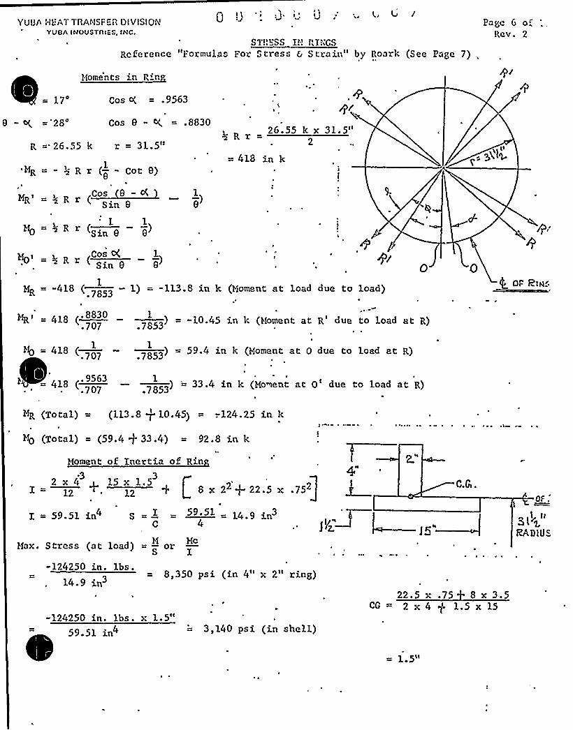
QI\ '':j. I'. !J:;. 4, 4 aI
YUUh HLAI1'AANSF 613 Ol VISIONYVOA IMDVSTAIFS, INC.
STRRSS I!; Rl;;CSReference "Formulas For Stress 6 Strain" by Roark (See Page 7)
Miome'nts in Rin
Pa e Go.."Rev. 2
= 17'
- ~ =28'os ()k = .9563
Cos e - ~ = .8830
R ='26.55 k r = 31.5"26.55 k x 31.5"
2
'MR = - ~3- R
MR' 5 R r
r (-- Cote)1
e
( si e1-)e
=418 in k
M'0 = 4 R r ( . — -)1 1
sin e e
R(Cos o( 1)
Sin e e
MR = -418 (—1
.7853
= 418 ('8830.707
1) = -113.8 in k (Moment at load due to load)
1) = -10.4S in Ic (Moment at R'ue to load at R).7853
Q Oc. plH5
418 (—— ) = 59.4 in k (Moment at 0 due to load zt R)1 1
.707 .7853
418 ( — } = 33.4 in k (Moment at 0'ue to load at R). 9563 1
.707 .7853
I = 59.51 in4 S59. 51 = 14.9 in3
MR (Total) = (113.8 + 10.45) = -.124.25 in k
M0 (Total) = (59.4 p 33.4) = 92.8 in k
Moment of Inertia of Rin.3 3
1= 12 + 12 q L 8x 22+22 5m2 x 4 15 x 1.5
1
T
.752]QF.
~ll~ ti
RADlVSMax. Stress (at load)
-124250 in. lbs.14-9 in3
Mcor I
-124250 in. lbs. x 1.5"
8,350 psi (in 4" x 2" ring)a
22.5 x .75 8 x 3.5CG = 2 x 4 $ 1.5 x 15
59.51 in 3,140 psi (in shell)
5II

Y'J13fs r'L;ATTftAl"SFCR DIVISrQNYVOA INOUSTAISS, INC.
isa.„re: o',
Copy Taken From
"Formulas For Stress and Strain" by Roark
Tauu: VIII.—Fonstur~s ron Clncof,*n Braes win Ancnns
Bf'n 2'n Vn Bf, T, and V arc positive xvhcn as shosvn, negative ivhcn reversed. Allapplied forces and couplesarc positive svhcn as sirocco, negative svhcn reversed. The follosving notation is ctnploycd: g w niodufug~ ofelasticity (lb. ppr sq. in.); f ~ moment of incrl,ia bf ring cross section (in.'); 1V or F as shovrn ~ applied load or
I y/~ reaction (lb.); w ~ applied load (lb. pcr lin. in.); l: ~ freight of contain'd liquid (lb. pcr cu. in.) ~ ~ si« ~~i
' ~ cosa;s ~ sin 0,c ~ cos0;n ~ sinO, c ~ cos O; p sruti,q ~ cosp. Allanglcs~uradians,distanccsinNI ' 2 inches, forces in pounds, moments in inch-pounds. +D, or +D„rncans incrcasc, -D, or -D„means decrease
in diamctcrs. +drR means increase, -aR means dccrcasc, in upper half of vertical diameter. C
TI trtn VIII.—FolMULAs l'OR ClncvLAR Itngcs A'Ho Ar'cncs.—(Confinucd)
fzalin ruppxe andcow numM
Formulas for tending moment II,eireumfere rfsl 4ensfon 2', rsdtst shear V at a u!ar dieesneo r from toirnm o ting and for Vi.shan't in Lairosut drnmeeer,and D,. change in versiesi dismerer
f fdK under sny numbx of equal radialforem cqusay spsadI Il/
IO'~./,0' I ' JlrZ(b.-. 0
Ilr
(a ~ eton ~ I) It'-frI!(---):hfag+If~ rfP/ xat o,h,dd,l „ /u l /l
c)" 4s e)r ~ - 'Ir eot C at toads.
l
ludisl disrtseement ef each load foist ~ -@L (y+,e2n.L, (2 2 )lrlfs/2 1 'X .
ftsdisi dupfae me t se r 0, 2I, In, ere.' C- fnsrsrdgal (C ~ ss)
htss —hf ~ --frP(- —eor I}sr each loadl /l
(o

. VU/i II::Al 'I IIAisSICI:IIOIVISIQNYVOA ftaovSTRIES. tNc.
SUlMARY OF STRESSES
Combined Lon itudinal Stress
s r xLongitudinal stress due to pressure = 2t - .2 p
ghere r = inside radius of shell, t = shell thickness & p = design pressure
2x 5" .2 x 150 psi = 4,470 psi
Combines stress = pressure stress + bending stress (Page 3)
= 4,470 + 2,245 = 6,715 psi h
Combined Circumferential Stress
r xCircumferential stress due to pressure = - .6 pt ~
Combined stress = pressure stress $ bending s tress (Page 6)
= 8,910 +3,140 = 12,050 psi
Shear S tress
s
'Xhe shear stress in the shell can be ignored since the ring structure takes the load
in bending.

ggllalii5alll
gmgg~~gg
gggg~g55I~SR
~ g
) ~
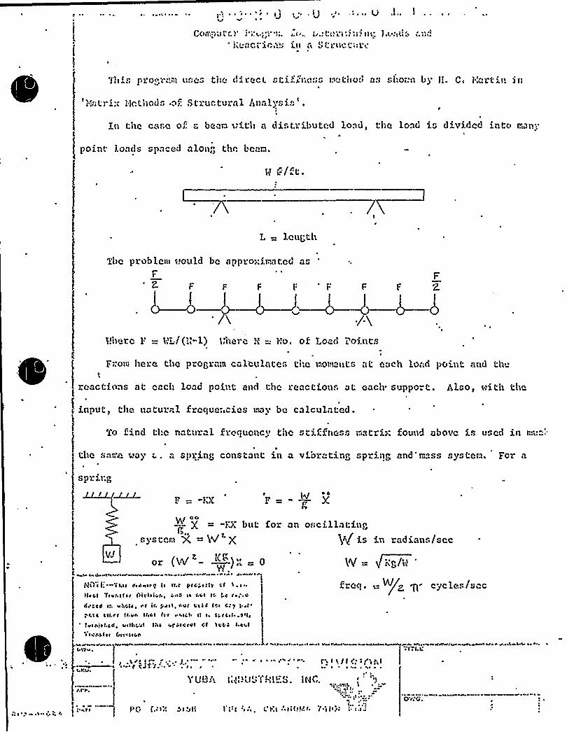
'«i'..cc'ice!i
'j'his procvc(ct7 uses the direcL sti.'.i'(.ss Ur Lilod as si:o-:n b> Ii. C« I.'artif! jn
s';AL') i;( f'jnL'hlods ol. Stl.uctul:al tlnal)'8).s ~
l
Xn the case or: "- been a:ith a distributed load, the load is d'vide(. into f an...
pOint lOadS SpaCed alOng thf: Laealf}.
g i:/f't.
L = len('th
The problenl (!ould be appzo>:ifvated asF
F F F t:'
p I'I~I/('«1) )<he) e H = 'fao ~ pk Load l pints
Fro}fr here t >e program calculates ti:e nov>'«ts at each loari point and th
reactions at each load point and the reactions at each support. Also, (:ith the
input:, the natural fzcque;.cies may be calculated.
'Co find tl.e natural fze(Iucncv tnc stiifness:".atri>: Sound above is used in r.:;:"'.
the sa.,~a @ay ..". spring constant in a vibrating spriqg and'rf".ss systera. For a
spring
F = "IZ hlF=- —. X
I oo= -g: buL for
4„8)'S teal rrC4 — }IV
or (W' —);;-0Z [CDEY.
v l ~ «I I aa «a ~~w vhv J~ N ta p J AIf~
an of;cillilting$}}c/ is in radians/sec
'iV = g/~phd'
fa}O i ('l«l «I««I««Illa lc II I pre ~ cly cflllcl Yrvracflr I)!ci~ ivr., '«ld I~ rc I lc. Lc r ~ >'.d
da'd I ~ 4 IClc ~~ I \I l J ~ l, I «Ir I IC«C l ~ Cr 4 l val ~
f,l ca Crr.rr fr.V« ll«C l f« r V«.lcf Il I~ CCCC«l ~ .C«l,
(V~ ra} ~ t C«f ~ VII(«CCC I'I~ 4f CICrJl Cl ll 0 l C« lI IvrCf ~ I («IVIIICA
Ercq ..- ~/Z g rye le«/ccc
~«««4«rv vva~ v v J cv IAa v~ C«C.C:
aa«va««v~««a ~l avv4 «wav ~k a«t J 1 ~ I J«ae ~ ~ ve«A4U
1
Ca'vr v
Ca<T I
YUB.'. i,'.'}':YRI=.S. lNC.
I'(:f '>:.. (:l:.l '.ll!!I!r 'I:I(«.::}I(;« f.f I'«l "l<I!

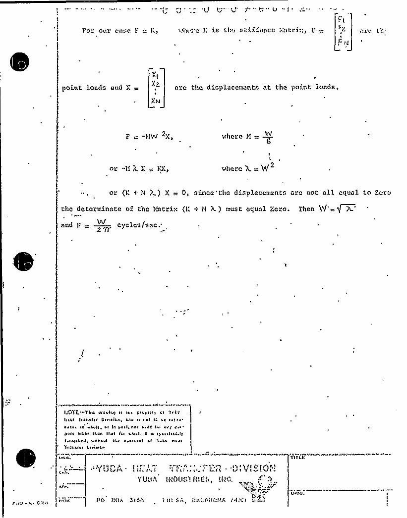
Fo our case F =: 1', aa! Ia "r'e 1 1S 'Lh<.: S t itllfeS fr i'eai tr ) .". I
"1 1
r-;
F f.t
point loGds O'Ad are the displace.~. nt.. at the point loads.
p wt+ 2)e vllere H =- hV
or "11 )i X —. KZ, where X.. 2
or (1' H tf ) X = 0, since'tlie displecer.ents "re not nll equal to Zero
the deterninate of. thc 1!atria (1; + H X.) aust equal Ze.o. ThenW'=~7'nd
P -„—..cycles/sec..W2 A
4ev e vPLRv ~ vev v '
lie.alt -%Let 4tnvle.g> 11 11 a fena till CI
Ievbt ftnhatae fteaetfCte ~ ~ hV e ~ I Vl IC 1 V 1 ~ eV
Ovnta IC ~ 't vlf~ tet Iti pCII~ hOf I ~ Cr I . ~ ge'r pre ~
ehntt Othtt It.nn Il.nt fn ~ a haah il ea tr'l~ 'IeCCelf
f at hlahnef ~ vllhnvl It.et C v 0 ~ 4 tvl Cf IvLC tta 41
Tent.liat fraeetecee
~ ' ve vvvearteaa et,
C cate.
.at r.
k4it4A a ~ ra acr A'L~ v re A ~ e pv JNrv vh eva e~> dva vlNkbr
' '' '' " ~
''/I4+ je 1 ~ I' . a '~ I' ~,aa ~ '$ I I ~ (I pt(Z ~ ~
fJLeefw a ~ e s'a i ~ ~ af e ~ aa ~ I Ij 'at J lw ~ Vl ~
Y U'5r 1r"i~hIS'1 f1'L: lflC
t (: tr'Or'a wl aell I lf. 'era i.'I' etc!II ala I'I'I. I L'h.:.4 i
e'a' rreaeaealwre ~vie 'AAwAA,ave ee r ~
TITI.Ir
0'cela".

XNSTRUC LIONS
FOR
XNSTALLATXON, OPERATXON AM) MAXIQENANCE
or
SHELL AM) TUBE IIEAT EXCHAlxGERS
FOR
AZRXCAIT ELECTRIC POHEP, P'HVXCE CORPORATXOH
XIIDXAIIA8: 11XCHXOAD ELECTRXC CO&ZiQK
DONALD C. COOK IICL"P3PL~I'HXT
1 A|lD 2
GUSTO."KR' PURCHASE ORDER IMBIBER
Contract 1243.
YUBA HEAT TRANSFER DIVISION JOB NUIIBER
69-G-226
DESIGNED AM) BUILT
BY
YUBA HEAT TRANSFER DXVXSXON
TULSA, OKLAHOa~M,

VV'I: D HHQ,'I7 ll i;ZQ,I.JGL-;.2 L'3i"'7J"I'~"'~I.GP. O. OOX 3158 ~ TULSA, OKLAIIOMA 24101 ~ 19161 939 2201
EXCHANGER SPECIFICATION SHEET
;,Qg
,/69-G-226
YVGA INOUSTAIES. INC,
CUSTOI 1E R American Electric Power Corn. OATF.
CVST. NO.
9-18-7042373-P(IY
PROPOSAL NO. OG-898-64PLANT LocATIQN Donald C ~ Cook tguclear Plant
SIZE 60-355 TYPE CFU POSITIONVertxca'ontainment
S ra Cooler EA"1ITEMi NO
200 sHELLs PF FourNO. OF UNITS One SHELL ARRANGEMENT PARALLEL ENGRS. TEB
PERFORMANCE OF ONE UNIT
10
VAPOR
LIQVIO/HR.
v.- /KA.
FLVIO CIRCVLATEOB TOTAL FLVIO ENTERING lHR.
SH'ELL SIDE
Lake Hichigan Ilater1 650,000 - 3300 GPI~I
1 650 000
TVOE SIDE
Boraced NaOH I ater1,600,000 - 3200 GPif
1 600 000STEAM /HR.
'NON CONOENSAGLES /HR.13 FI.VIO VAPORI?ED OR CONOENSEO /HA.14 STEAM Coia/OENSEO
15 GRAVITY.I,IQUIO16 VISCOSITY-I.IQVIO
MOLcCULAR.V(EIGHT VAPORS
=/HR.oAP I
CP.
16 SP. HEAT-GTV/=(aFFNTHAL.PY-GTV/='G
TEMPERATURE IN20 TEMPEAATVRE OVT
oF 76141. 5
167.5100
21 OPERATING PRESSVRE P.S.I.A. P.S.I.G.
IMPER OF P S tWO
24LOCITY
pRcssuRc ORopF ov'LING REslsTANcE
F TJSEC.PD. t
.001 .0005
3.710 at.LowEo l,4 c" t.c. 10 aLLowEo 4. 0 cat.c.
26 HEAT EXCHANGco-G.T.UJHR.22'RANSFER RATE SERVICE
107, 850, 000375
M.T.O. ~+~V-~OF. 25 ~ 6
29 OESIGN PRESSVAE
CON STR UCTION-EACH SHEL L
150 300GO TEST PRESSURE
DESIGN TEMPERATURE
A249 TP316
Steel
I a.t. 225oF 200
No- 1150 U
450200
0 0 5/8 IN 20 GwG.AvG.gt+;vaLLLENGTH 29 7 PITCH 'l3/l 6« ~ > 7LYA((
INOM. I. O. 60«o. o.'QS SKELI. COVER IINTEGRAL Qp<~~~QItS+26 CKANNEL. 304 S ta in less Steelo? TUBE sHEETs sTATIONARY Steel 6 Overlav
F LTG. KO. COVERCHANiiIEL COV E R 304 S.Steel ClaFLOATING
GB BAFFI.Es sEGME'(TAL Steel P ITCH lt CUT F I.OW
QG BAFFLE-LONG Steel IMP'T. Stainless Steel40 TYPC JQINTs sHELL . Bo1 ted TUBES Bolted41 GAsKETs-sHELL S.Steel Clad4? CONNECTIONS-SHEI.L-IN 18
CHANNEL- IN44 CORROSION ALLQIVANCE SKELL SIOB l./8
FLTG. HO cHaNNEL S.Steel CladOUT 18 SEAIES
oUT t,2« SERIES VETUBE SIOE
FULI- OF lvATEA 94,4004 HTS EacH sHELI ANO GUNQI E 60 000 GVNOLE ONLY
EMARKs:— Edd current cesc tubes.Seal weld tuoes.Full suo ort olace a U bends.
E"REQUIREMENTS-as«E 1968 Sect.I IC Tube Sec= 8 STA'.I~IYEst 6~Y TEMAcLAss

JUL 11M~4'i(/7I'~C-
7//f
YQBA HEAT TRANSFER CRPORATIONP. O. BOX 3158 ~ TULSA, OKLAHOMA74101 ~ (9181 939-2201
July 9, 1.975
American Electric Power Service CorporationTwo BroadwayNew York, New York 10004
Attention: Mr. Cherry
Subject: Indiana & Michigan Electric Co.Donald C. Cook Nuclear PlantContract 1241Containment Spray Heat ExchangerYuba Job Number 69"G-226
Reference: Seismic Report for American Electric Power
Gentlemen:
Confirming our recent telephone conversations regarding,our SeismicAnalysis, our 69-G-226 vertical containment spray'heat exchanger for t'e-Donald C. Cook Nuclear Power Plant, the natural period of vibration is.108 sec. rather than .787 sec. as stated in the report.
Please note that the .108 sec. perio'd will result in lower accelerationsand stresses than those in the Seismic Report.
If we may be of further assistance, please contact us.
Very truly yours,
YUBA HEAT TRANSFER CORPORAT N
WCN/etcc:. Mr. R. H. Shaw
Mr. T. R. HarringtonMr. Bill NewlandMain FileEngineering File
WiXliam C. Newland, Jr.Design Engineer
,ALL AGREEMENTS CONTINGENT UPON STRIKES, ACCIOENTS ANO OTHER CONOITIONS BEYONO OUR CON
o'LLC NO TRACTS ARE SVLIECT TO APPROVAL SY AN OFFICER OF THE COMPANY. QUOTA'TIONS SUMECT TO CHANGE YYITHOUTNOTICE,

712
"VI
U-TUBE EXCHANGER
REMOVABLE CHAN."$=L AND COVER
TOO PASS SHELLEVEN PASS TU" E SIDE
TEMA CLASS 'R'ONSTRUCTION
VUGG V~CaV Vna,usvt-:v. D<vrorotaYVOA INOVSTAI4S'NC ir~ ~~
TYPICAL CONSTR U CTIONFEATURES OF YUBA TYPECFU EXCHANGER


0
e'%f'
l~~l
IT
~>V"
g(y( /

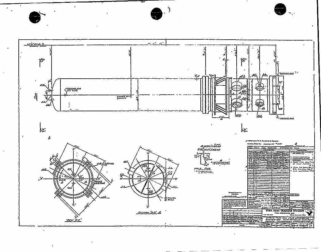
rr:o /re% ror«o ~
,t/ %'
,0
gg~~t
a~/ SOAP
got 4 ~
Ctootorr ooogoo«/7
Lf.ooo
trI
w ooo«« to lo tv«or ItCoo«rtt /~tr raW/
rtoooota
o ~
I /k
C.(iPICC tS /«/«JtrfCC
~ ao «orto«/tt .4 tp«r~.o J ot Ct o /%it
ct. ~. toI ooh>
to/I/~A'too J
.Sc r r/root BP gCooo toIltoo.
YVSA lQAT TRAPGFA NYIQIOIITIBIAWKANlWoo,poC,«o, ~
oC
rttr~ oo too r« /~ ro fr&rot.rtrrtce ar o«rrro o/II«o to«tD«4ro«oorrI rw to«««r ~r// r/~rtl'; ~ '. It 4'oI
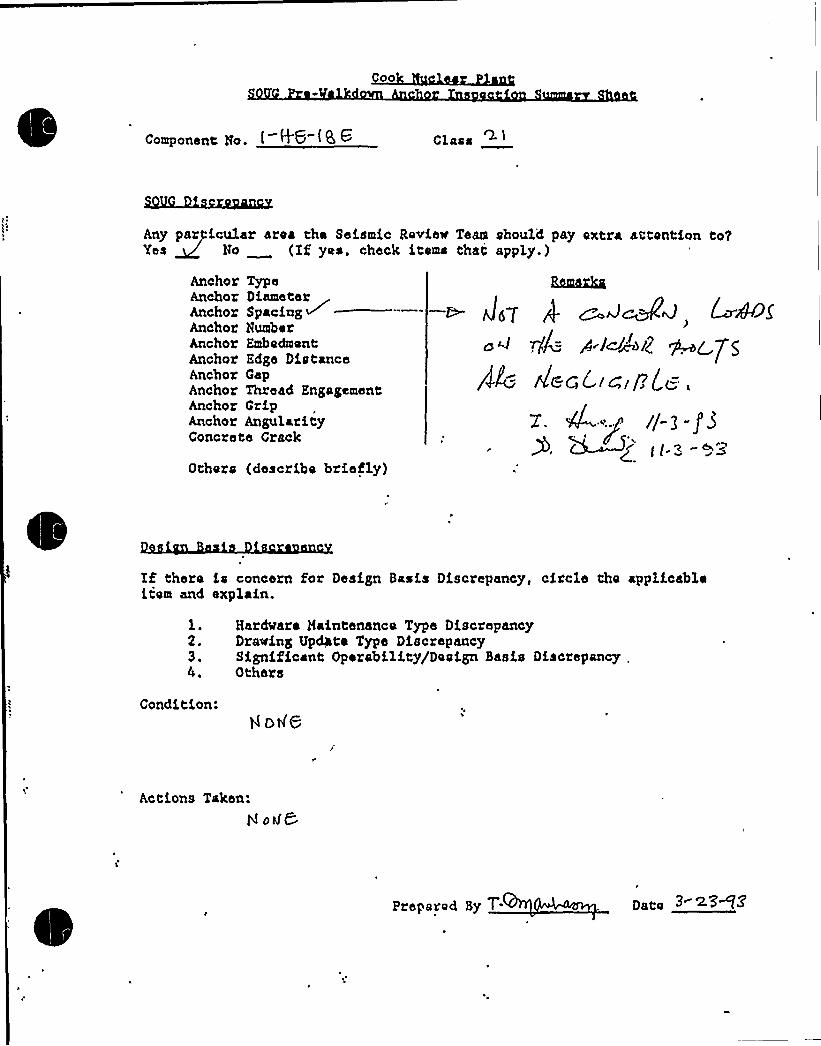
Co
Component Zo. t H 6-(8 6 Class
Any particular area the Seismic Review Team should pay extra attontion to?Yes No (If yes, check items that apply.)
Anchor TypeAnchor Diameterhnchor Spac:fag ~Anchor NumberAnchor EmbedmentAnchor Edge DistanceAnchor GapAnchor Thread EngagementAnchor GripAnchor AngularityConcrete Crack
Others (describe briefly)
If there is concern for Design Basis Discrepancy, circle the applicableitem and explain.
l.2.3,
Hardvare Maintenance Type DiscrepancyDrying Up&,te Type DiscrepancySignificant Operability/Design Basis Discrepancy .
Others
Condition:
Actions Taken:
t4 odC
Prepared By T. naos > <3 7Z
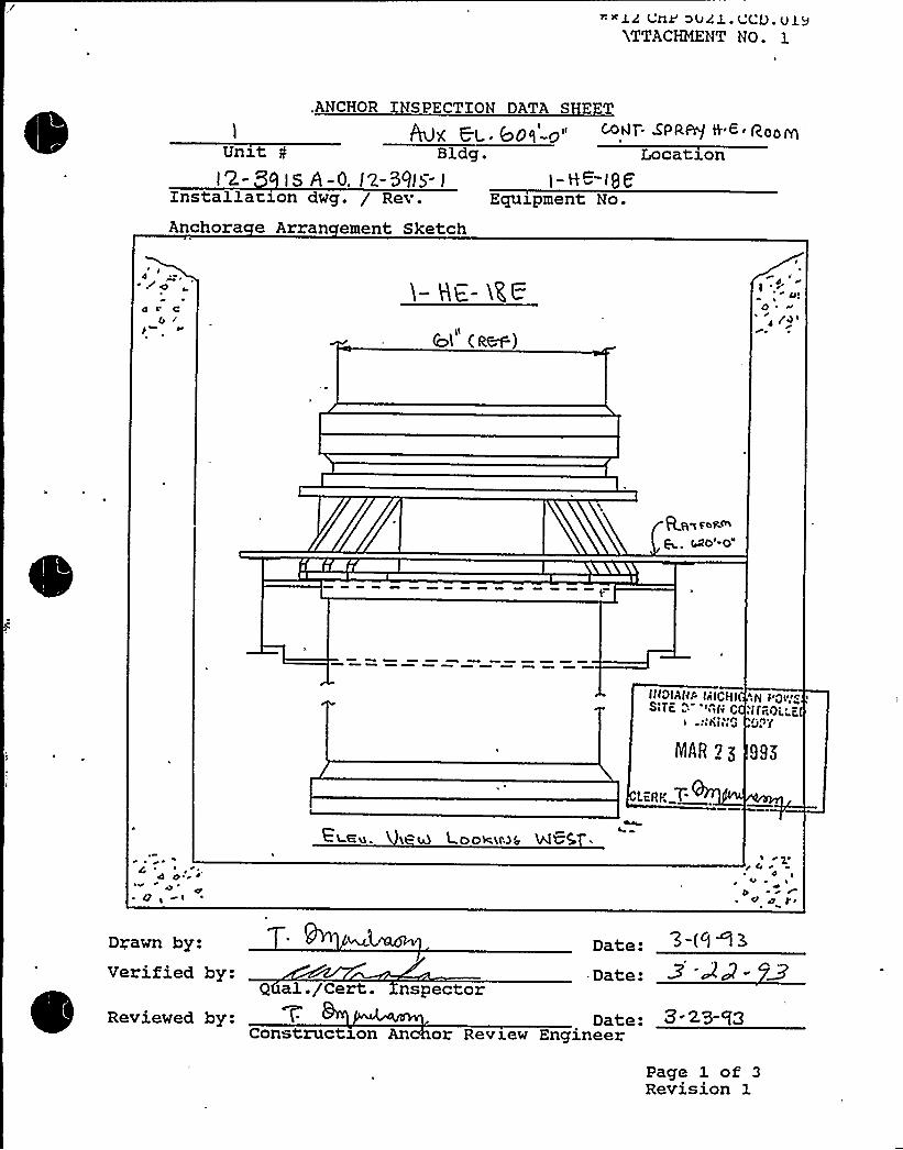
~~l4 Vrxr'441.V O.ulrATTACHMENT NO- 1
Equipment No.
Anchora e Arran ement Sketch
.ANCHOR INSPECTION DATA SHEET
Avx E.c. bog'-g uUnxt 0 Bldg. Location
t 'Z-) 5 A -0, I 2-39I >- J 1- H ~8f
Installation dwg. / Rev.
1 (a~)
~ ~zVI
0 ~
r
(AO'-0"
It(OlAl(P 4ICHI(
tahiseg
MAR 2g
A g flQ)l~ 4,
i'lfPOi.'rdnY
LORY. T
~ ~
4 or>'0 '
gp ) ( ~
ELGu. i"4 Loose)6 NGSg 4
4 ~V ~
r
Drawn by: Date:Date:Verified by:
~
~ ~Q al./Cert. nspectorReviewed by: Date: 8 <>83
Construction An or Review Engineer
Page 1 of 3Revision 1

**12 CHP 5021 CCD01'TTACHMENTNO.
CHOR INSPECTION DATA S EE, ~ ~<T.5'PR~ %.6- R~g0
0'ldg. Location
Installation dwg. / Rev.
Anchora e Arran ement SketchEquxpm'ent No.
kg+ p oiT, 4lh5~,HMT(STCAM)
Sl'„. „"„=~ ~ ~~ J ~', ik I ~ g Q
2S 1995
'ngr
lp~ 4'Fg
I8 W$g
ig
4'rawn
by: T'~ Lmt-mm,a Date:Verified by:~~ ~~
Date:Q al./Cert. Inspector
Reviewed by: Date:Construction An hor Review Engineer
Page 1 of 3Revision 1

**12 CHP 5021.CCD.019ATTACHMENT NO. 1
Unxti<- '39IS S I-HG- I55
Ecpxxpment No.Installation dwg. / Rev.
Anchora e Arran ement Sketch
NCHOR INSPECTION D TA SHEE, ~ WvT SPRR'/ ~ 6- RooI4A '~. Ct. Voq-o"
Bldg. Location
IIIIIIIIII
I'
g~
fpllc CE 'cIVV 'i.< ~ ii
MAR 2g the~
IIII
IIIIIIII~l PLP,g Ul~ .
(B e.Oe t mme.886<I)
7.W ..U Date: 3- I'i<~
Date:Drawn by:Verified by:
qual./Cert. InspectorReviewed by: Date: 3-aS-'f>
Construction An hor Review Engineer
Page 1 of 3Revision 1

**12 CHP 5021. CCD. 019ATTACHMENT NO. 1
Unxt12-39 lb A
Installatl.on dwg. / Rev.
Anchora e Arran ement Sketch
ANCHOR INSPECTION DATA SHEE~! . pg q
~ 40NT 5 PRA'/ H Q- Pop~Bldg. Location
A 1- ~ - (QE.Equipment No.
6I &s~/sP!
9 24,+jg~p4.
>40 50!.T,! o~< —~Wh5~, NOT(~r. 5)
SE. CT. 'A,-A S'ECT. 5-8
2/g+'/g ~pg)
!3
~h.~4gw)
3'/2 xg x>/yx 8'jf(p~) 4
c 4-
IO
ACCT,'c-c
I t<0!*!!A V.!,"'l!"t::
WOc",Kl!":" C~
MAR 7 Z l~~'BCT0-D
Date: ~-~~-'~Z
Date:
&~L4nln.Drawn by:Verified by:
Qual. /Cert. InspectorReviewed by: T- Date:
Constru son An hor Pevxew Engineer
Page 1 of 3Revision 1

*+12 CHP 5021.CCD.019ATTACHMENT NO. 1
Un t> AInstallat on dwg. / Rev.
Anchora e Arran ement Sketch
ANCHOR INSPECTION DATA S EEw~t- zpn.~ w c - a<p~
Bldg. Location0 I- l-h=- —ISI:
Equipment No.
p l/+ +p~i ~ ~ll5/ cp 54l T w 1TH lo4. MHh&%9RHOT
IB «/zX g"
I~ I/a x Wy (STI~a Wmeg+~ I/2 R)
StHM K OH CIT~ Se6 Or RR HEe I~ VO7 S~WH
SECT. F-E
(RW)0~ g
p lI
0 I
~:>l ~ !i>i'cV. CQpy
MAR 2Z 1S95
-LCRK,T
5CcT. F-F
T AuL4esp Date: ~-' -'(~
Date:
Drawn by:
Date:hor Review Engineer
Page 1 of 3Revision 1
Verified by:ua ./Cert. Tnspector
Reviewed by:Constru son

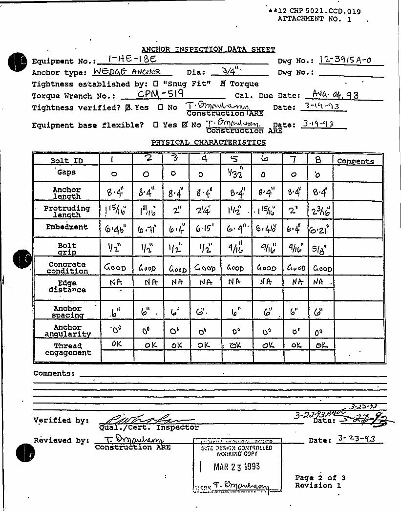
~ ~
~ ~ II
~ ~
~ ~i
~ +
~ ~
s ~
~ s ~
~ - ~
' L I W 1
KR~~~RRKR~ + ~ ~
~ ~ ~ v l ~ j
- mmwmmlHmmm mml@mmR1mmRI
e ~
mRSWRIRRNSNKlMWWWWW&W5%mmRMSRRmmRQmmmRRRRR%l%
~ 0 I 0 Cs 4 ~MW&MMWW&
~ r~gs r
W

0
tW - ~ ~

**12 CHP 5021. CCD. 019ATTACHMENT NO. 1
Dwg No.: )~- S ))SA- 0
Dwg No.:Equipment No.:Anchor type NR)GC t.lfeR. Dia: >/
Tightness established by: 0 "Snug Fit" 5 TorqueTorque Nrench No.: ~~+ ~) ) Cal. Due Date: C 04 3
Tightness verified? 5.Yes 0 No 7- '~'~'<~'i Date: "-< )-')3ons ruc ron
Equipment base flexible? 0 Yes 8 No ''.""""<»"l: Date: 3 '- l3
Bolt IDCaps
Anchorlen th
l 0 tL lK )'5
84 sq s4"
l S' lo CommentsGETw&&nJCoNC:Q L
Protrudinglen th
Embedment
Boltri /S S/j'/II"tp g"
'"/sl)
( 3y 653
~4. ~/g
Concretecondition Cj OQQ 0 00$ G,OOg g o 0g (WOOLD 40OP'oop Coop
Edgedistance
Anchors acinAnchor
an laritThread
engagement
+(l ~rr gl l
/eI m&S OK olc. oL
g 9/)@ 4Il
Q II
OE Og. hJUT tsSl~"T&lclL.
Comments:
Verified by:q a ./Cert. Inspector
Date: +Reviewed by: T-
Const ct ogI II)IrNh tfil~rIGr'll I <Wr;
'rYODK)AG COPY
y;qB 23 1993
Pago 2 of 31-Revision
Date: 3- a3- qg

gu4 J. ~ <i', gggATTACHMENT NO.
ANCHOR INSPECT ON D T S~
~
~ ~
Equipment No.: I—1+6-< SG
Embedded Steel Dwg. No.:HYSICAL C CT RIST C
D g No.: I- Bhi5A-a
Weld IDT e
SizeLen hCracks
Lack ofPenetration
3|ltp
Yes Yes0
YesNo
YesNo
YesNo
YesNo
YesNo
YesNo
YesNo
YesNo
YesNo
YesNo
YesNo
YesNo
Weld e Codes1 = Fillet2 = Plug/Slot3 = Groove
Porosity Yes YesNo
YesNo
Yes'o YesNo
Yes YesNo No
R&.os 8 TYpLce io<+71()N< AAB g~6 pg, sTR084 R ~~T-' -re-'tz
INGIABO '<tSITe 0=<"
VIP
LEACH + r
Equipment base flexible:Reviewed by:
Qns rucOps'QyVerified by: ua. e
Q Yes Q. No 7 43 Lw~<w-uons c 1on re
xon c or evzew ngxneerov hy'.
npsec or
Date: 3- <"
Date:
Date:
Page 3 of 3Revision 1


S 8 A CEPARTMENTCONTROL.LEO DOCUMc8'l
COPY NO.
12 SHP 5050 NDE.008ATTACHMENT NO. 1
Ul',TRASONIC TEST REPORT
JOB ORDER NO.: > If( REPORT DATE: > '+ lZ REQUEST NO. l IA.
IDENTIFICATION
Unit C hlEComponent l AC.l FItemMaterialOther
TECHNI UE
Test Unit/ S/NFreq./Diameter 6Reference Standard C. KeCouplant/Batch No. i~ cMA6t= o".
'3e
TEST DATA REMARKS
PERFORMED BY:
REVIEWED BY:
FORM NO. 12 SHP 5050 NDE.008-1
IEVEI: ~ DATE:
E.EVEL:~ DATE: 5
Page 1 of 1Revision 0

0

01/16/92PG. MO.SC5
SAFE SHUTOOMM EOUIPHENT LIST (SSELMP)
FUNCTION:
Equipment Class: 21 I'rain: 2
Equipment IO: 1-HE-3C-HE Drawing Number: 1-5135A
Svstem: CCM
Equip Description: NORTH SAFETY INJECTION PUMP PP.26N OUTBOARD MECHANICAL SEAL HEAT EXCHANGER
Building: AUXILIARY Room: NORTH SAFETY INJEC'IIOH PUMP ROOII Elevation: 587
Normal State: Desired state: iPower Required: M Sort: lf,
Suoonrting System Drawing Humber:
omvired Interconnections and Supporting Components:
fety Related Status: NUCLEAR SR Min/Opt: MIN
ADDITIONAL INFORMATION
AIIas Number:
Cnmonnent Served: NORTH SAFETY INJECTION PUMP PP 26N
Power Train: MA
wanufacturert BORG. MARNER Kodeit NX 0500-FM
Panel
EC~ Drawing: H/A Miring Drawing: N/A
Pnwer Source: N/A
Mal%down: F Relay Only: M
Comoonent I'ype:ISO Drawings:
HE ~
Detailed Location:

DC COOK Unit 1
SCREENING EVALUATIONWORK SHEET (SEWS)GIP Rev 2, Corrected, 2/14/92Status: YesSheet 1 of 2
ID: 1-HE-34-NE (Rev. 0) Class: 21 - Tanks and Heat ExchangersDescription: NORTH SAFETY INJECTION PUMP PP-26N INBOARD MECHANICALSEAL HEATEXCHANGERBuilding: AUXILIARY Floor El.: 587.00 Room, Row/Col: N SAFETY
INJECTION PUMP RM,Manufacturer, Model, Etc.: BORG-WARNER, NX-0500-FW
BASIS: External analysis
1. The buckling capacity of the shell of a large, flat-bottom, vertical tank is equal to or greaterthan the demand.
2. The capacity of the anchor bolts and their embedments is equal to or greater than thedemand.
3. The capacity of connections between the. anchor bolts and the tank shell is equal to orgreater than the demand.
4. Attached piping has adequate flexibilityto accommodate the motion of a large, flat-bottom,vertical tank.
5. A ring-type foundation is not used to support a large, flat-bottom, vertical tank.
N/A
Yes
Yes
Yes
N/A
S S C
~co vinsSRT: Gary Thomas, Tom Huang and Kailash Mahajan on 11/1/93.
ANCHORAGE ACCEPTABLE BY ENGINEERING JUDGMENT OF THE SRT.
6" diameter by 8-3/4" high exchanger, attached to North Safety Injection Pump with 2 1/2" bolts. Could havescreened with the pump using the rule of the box, however the exchanger was listed seperately on the SSEL.
Crane above in a parked and locked position.
Evaluated by: Date:
Attachment: Pictures
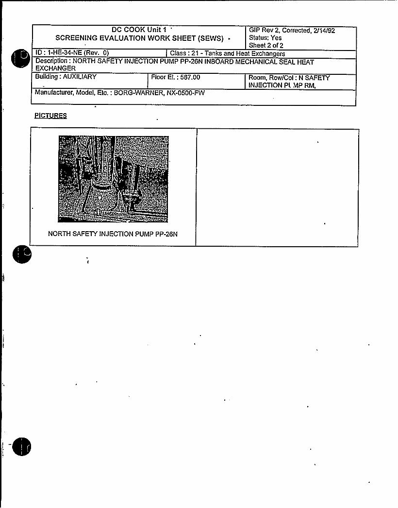
DC COOK Unit 1
SCREENING EVALUATIONWORK SHEET (SEWS) ~
GIP Rev 2, Corrected, 2/14/92Status: YesSheet 2 of 2
ID: 1-HE-34-NE (Rev. 0) Class: 21 - Tanks and Heat ExchangersDescription: NORTH SAFETY INJECTION PUMP PP-26N INBOARD MECHANICALSEAL HEATEXCHANGERBuilding: AUXILIARY Floor El.: 587.00 Room, Row/Col: N SAFETY
INJECTION Pt MP RM,Manufacturer, Model, Etc.: BORG-WARNER, NX-0500-FW
NORTH SAFETY INJECTION PUMP PP-26N

~~xc vnr ~vs~ iiu. viaATTACHMENT NO. 1
ANCHOR INSPECTION DATA SHEET
Un1t g Bldg.A. 5a4z h~ e~ ', 9„ Rn
Locat1onC
Installat1on dwg. / Rev.
Anchora e Arran ement, SketchEqu1pment No.
F46'v. J>I=4 45DksQl c
yj'4 Ooi~Yyp
Vlc o.O.
INDiAHA." llCHIGA"IPOY(ERCONSTRLICT!Oib CGLTROLLEO
EYORKING COPY
S~P g g tqap
Oo
I~l
FLo 'E4.'-0
~ T,
4 Gra q
' i
CLERK
k7
,:IDrawn by:Verified by:
Reviewed by:
Date: /8-/-Date: L-Z.- 'P <
Qual. /Cert. InspectorDate:
nstruct1on Anchor Rev1ew Engineer
Page 1 of 3Revision 1

Equipment No.:
Tightness Verified by:
Tightness established by "Snug Fit"Tightness veri'ed by: 'C.
goal./Cert. Inspector
onstruction ARE
Comments:
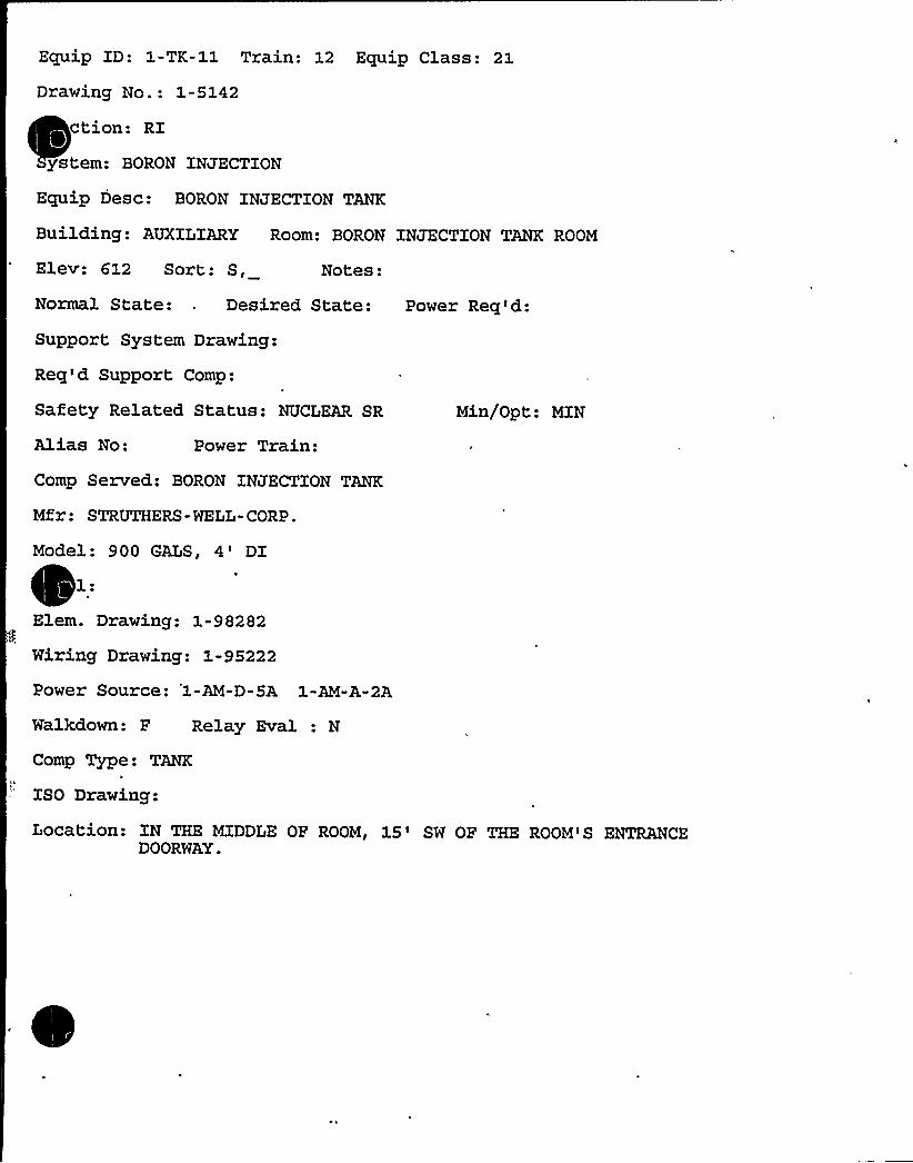
Equip ID: 1-TK-11 Train: 12 Equip Class: 21
Drawing No.: 1-5142
ction: RI
ys tern: BORON INJECTION
Equip Desc: BORON INJECTION TANK
Building: AUXILXARY Room: BORON INJECTION TANK ROOM
Elev: 612 Sort: S, Notes:
Normal State: Desired State: Power Req'd:
Support System Drawing:
Req'd Support Comp:
Safety Related Status: NUCLEAR SR
Alias No: Power Train:
Comp Served: BORON INJECTION TANK
Mfr: STRUTHERS-WELL-CORP.
Model: 900 GALS, O'I'.Elem. Drawing: 1-98282
Wiring Drawing: 1-95222
Power Source: '1-AM-D-5A 1-AM-A-2A
Walkdown: F Relay Eval : N
Comp Type: TANKa
ISO Drawing:
Min/Opt: MIN
Location: XN THE MIDDLE OF ROOM, 15'W OF THE ROOM'S ENTiVQICEDOORWAY.

DC COOK Unit 1
SCREENING EVALUATIONWORK SHEET (SEWS)GIP Rev 2, Corrected, 2/14/92Status: YesSheet 1 of 3
ID: 1-TK-11 (Rev. 0)Description: BORON INJECTION TANK
Class: 21 - Tanks and Heat Exchangers
Building: AUXILIARY Floor El.: 612.00 Room, Row/Col: BORONINJECTION TANKRM, IN THEMIDDLEOF RM, 15'WOF THERM'S ENTRANCE DOORWAY.
Manufacturer, Model, Etc.: STRUTHERS-WELL-CORP. 900 GALS, 4'lBASIS: External analysis
1. The buckling capacity of the shell of a large, flat-bottom, vertical tank is equal to or greaterthan the demand.
2. The capacity of the anchor bolts and their embedments is equal to or greater than thedemand.
3. The capacity of connections between the anchor bolts and the tank shell is equal to orgreater than the demand.
4. Attached piping has adequate flexibilityto accommodate the motion of a large, flat-bottom,vertical tank.
5. A ring-type foundation is not used to support a large, flat-bottom, vertical tank.
N/A
Yes
Yes
Yes
N/A
SMC
~CO ~~SSRT: Gary Thomas, Tom Huang and Kailash Mahajan on 11/3/93.
ADEQUACYOF ANCHORAGE AND TANKTO SUPPORT CONNECTION BASED ON JUDGMENT BY THE SRTAND COMPARISON TO THE BORIC ACID TANKEVALUATION.
Tank is 5'iameter by 10'n height supported by 4 Wide Flange Leg supports (10" WF w/5/8" flange) 4'R" inheight..
Each leg is bolted to the pedestal w/ two embedded 1 3/4" bolts with 2'-11" embedment
Weld of leg to tank about 14" in length and 1/4" thickness on each side of the wide flange and 10" at the top of thewide flange.
Adjacent Block wall reinforced with column supports and it is not an interaction concern.
The Seismic Evaluation of the Boric Acid Tank (2-TK-12S) is seismically adequate. The Boron Injection Tank (1-TK-11) is much smaller but has about th. same support. Therefore, Tank 1-TK-11 is judged adequate.

DC COOK Unit 1
SCREENING EVALUATIONWORK SHEET (SEWS)GIP Rev 2, Corrected, 2/14/92Status: YesSheet 2 of 3
ID: 1-TK-11 (Rev. 0)Description: BORON INJECTION TANK
Class: 21 - Tanks and Heat Exchangers
Building: AUXILIARY Floor El.: 612.00 Room, Row/Col: BORONINJECTION TANKRM, IN THEMIDDLEOF RM, 15'WOF THERM'S ENTRANCE DOORWAY.
Manufacturer, Model, Etc.: STRUTHERS-WELL-CORP. 900 GALS. 4'lEvaluated by: Date:
- fs.
Attachment: Pictures


DC COOK Unit 1
SCREENING EVALUATIONWORK SHEET (SEWS)GIP Rev 2, Corrected, 2/14/92Status: YesSheet 3 of 3
ID: 1-TK-11 (Rev. 0)Description: BORON INJECTION TANK
Class: 21 - Tanks and Heat Exchangers
Building: AUXILIARY Floor El.: 612.00 Room, Row/Col: BORONINJECTION TANKRM, IN THEMIDDLEOF RM, 15'W OF THERM'S ENTRANCE DOORWAY.
Manufacturer, Model, Etc.: STRUTHERS-WELL-CORP. 900 GALS, 4'lELILlEH
BASE ANCHORAGE PEDESTAL SUPPORT COLUMN TO TANKCONNECTION


Coo
Component No. ~ TK. <laic Ql
Any payticulir area the Seismic Revue~ Teaa should pay extra attention to?Yes ~ No (If yea, check items that apply.)
Anchor TypeAnchor DiameterAnchor SpacingAnchor NumberAnchor Embedment <Anchor Edge DistanceAnchor CapAnchor Thread EngagementAnchor CripAnchor AngularityConcrete Crack
Others (describe briefly)
If there ts concern for Design Basis Discrepancy, circle the applicableitem and explain.
l.2.3.4(,.
Hardvare Maintenance Type DiscrepancyDrawing Up&,te „Type DiscrepancySignificant Operability/Design Basis DiscrepancyOthers
Condition:
Actions Taken:
Prepared By D444

0
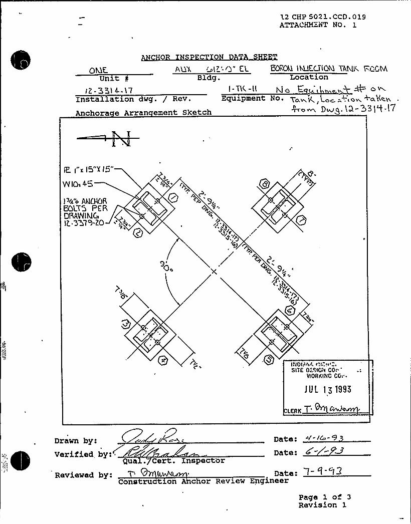
L2 CHP 5021.CCD.019ATTACHM.NT NO. 1
AQ'L ~~I'-0" ClBldg.
I - T>C. -IlEquipment
Un tI2- 3514.-17
Installation dwg. / Rev.
Anchora e Arran ement Sketch
BORON'MKCTIOM tAMI( t=.I GMLocation
O
NO. Ycxwk, Loc. =+i@~ +aK<IrPro~ Dwg. (0-33] "t-l7
E I"x I5"X l5"
W IO» 4.5
I ~1~'+ AMOSHQLY'5 PEPDRAINlklC) Q.357')-20
o
O.
6J
Qc
40Qg INOI.-'sic. r'.I.,r< ~ „".
SITE 0::SIGN COrWORKING CGc ~
JUL lg tSS5
LERK
Drawn by:Verified, by: ~
Qua . Cert. InspectorDate:
Reviewed by: = 4,Construct on
Date:c or Review Engineer
Page 1 of 3Revision 1

.2 CHP 5021. CCD. 019ATTACHMENT NO. 1
Un t AUX. (oQ'-0" EL.Bldg.
BQROQ M,K,CT'lQKL TAMK PQQMLocation
Installation dwg. / Rev.
Anchora e Arran ement Sketch
I-TK-)iEquxpment No.
)8
ELK.V. LKC. UHH
INOIANA MICKIGAN POWERSITE DESIGN CONTROLLEO
WORKING COPY
lUt. 1)1995
LERK~
Drawn by:Verified by:
Reviewed by:
Date:Date:
Construction AnDate:
or Review Engineer
Qua . Cert. Xnspector3
Page 1 of 3Revision 1


~ ~ ~ 4 4 vo 4 ~ gag t/i y)
ATTACHMENT No.
quipment No, I- Vl(-iL ~ No i ~pe. c i-.Yaw< ~g No.:Anchor type: >~+ ~"P~ ~ I~~ Dia: I ++ Dwg No.:Tightnass cata isnas hy: FJ "snug Fit" 0 Torque
g Torque Wrench No.: hlh Cal. Due Date:
+Q- Tightness verified'? 0 Yes 0 No Date:
ons ruc ronq Equipment base flexible7 D Yes I No ' <">l Date:
ons ruc xo ARE
/o Pj ~J I ~
)Q %~7+
Bolt ID'/tie" A '13K A
COIIIments I
Anchorlen h
s //' w'//'j1eb' v 4
Z'-II" @ 0 ~ '-I I
" ~ g 2'-IFE.CE~ RGCLGSE.OProtruding p~~T~o
< ~/ ., ~a galen th
P.ECESXQ <ITT I HICK Ill4 p/+» )/In ~ > + @
Ih I ICD
Embedment~v
2-6'/s" 2'-5'e
Boltri Z."~<~" 2 '~o" 6 '4" 2'/e" E>4"V<t." GPGUY
condition'""'te CO~Cea iS CeC~ IL BELD-LCa
PER CPAV{LLLCs
Edge 4/A N/A M /'A IM/4, 4/A 4/0, hL/0, g/A &z)g<distance TIS IQ Q.m
Anchors acinAnchor
an larit
6'/z" 8'/z" 8" B " 8" 5" 8"Atu QIOR
4/4 4/A kVA UJA kl /A IJ/A U/4 4/A &Hi u~TW (N >/S ' I+" ~/~- our mi~~a-.
Thread " ~ecE~ t-I< RE~a RccEss 0 i4 P,G Ess DK. H ICengagement
Comments, + UA'TA, 'QoT QwtlkiEQ DUE 'To 7 AYLQM.INA
UUOKTALNA LIE TCi T P,
Verified by-gua ,//Cert inspector
Ravieved by:Construct on ARE
INDIANALIIGHT'..:SITE OESIGN CONTRC~ 0
WORKING COPY
Date: -> 3
Pago 2 of 3Revision 1
LERK 9 '~ I

S '8 'A DEPAR'FMENTCONTROLLED DOCUMENTCOPY NO. 'P -l
2 SHP 5050 NDE.008ATTACP2KNT NO. 1
ULTRASONiC TEST REPORT
C
A'/Tg
gy
REQUEST NO. JA
IDENTIFICATION
Unit + eComponent: - 7 f -//Item n/ A/'/--Naterial ~/
Other C)
TECHNI UE-'tl
Test Unit/ S/NL(.i -'/'S
Freq./DiameterReference StandardCouplant/Batch No.
Cz c "RQS
TEST DATA RENARKS
A /T c'L C
PERFORMED BY:
REVIEWED BY:"
FORM NO. 12 SHP 5050 NDE.008-1
LEVEL~ DATE: 3 23 ~13
LEVEL:~ DATE: Y ZS
Page 1 of 1Revision 0
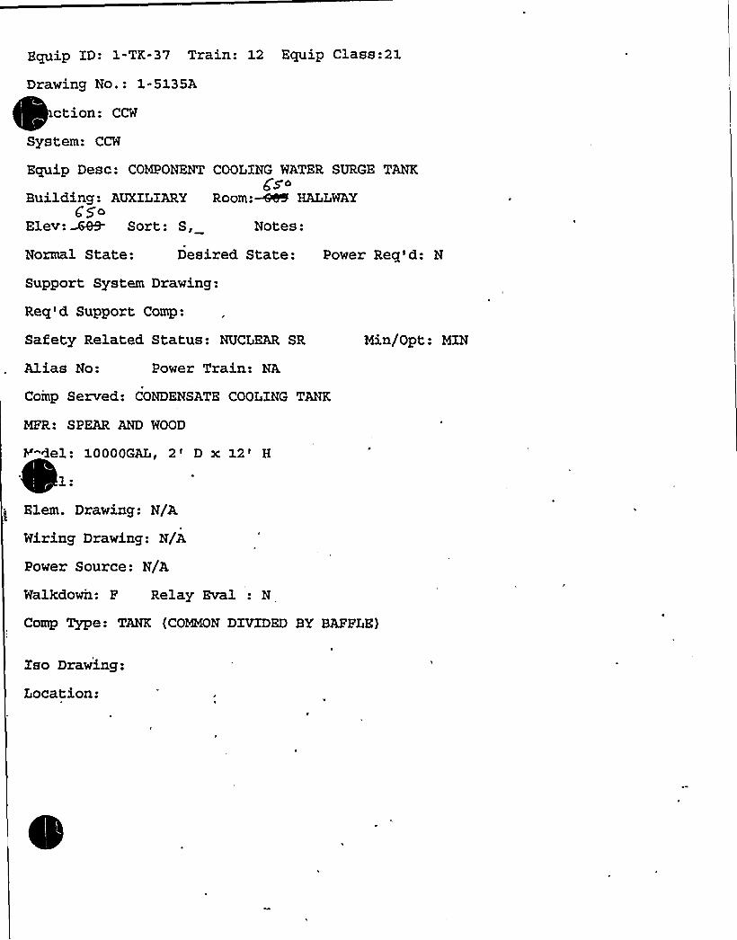
Equip ID: 1-TK-37 Train: 12 Equip Class:21
Drawing No.: 1-S13SA
ction: CCW~
~
System: CCW
Equip Desc: COMPONENT COOIING WATER SURGE TANKggc
Building: AUXILIARY Room:~ HALLWAY$ 5o
Elev: %69- Sort: S, Notes:
Normal State: Desired State: Power Req'd: N
Support System Drawing:
Req'd Support Comp:
Safety Related Status: NUCLEAR SR Min/Opt: MIN
Alias No: Power Train: NA
Comp Served: CONDENSATE COOLING TANK
MFR: SPEAR AND WOOD
Y"Gel: 10000GAL, 2' x 12'
'lem. Drawing: N/A
Wiring Drawing: N/A
Power Source: N/A
Walkdown: F Relay Eval : N
Comp Type: TANK (COMMON DIVIDED BY BAFFLE}
Iso Drawing:
Location:

DC Cook Unit 1
SCREENING EVALUATIONWORK SHEET (SEWS)GIP Rev 2, Corrected, 2/14/92Status: YesSheet1 of5
ID: 1-TK-37 (Rev. 0) Class: 21 - Tanks and Heat ExchangersDescription: COMPONENT COOLING WATER SURGE TANKBuilding: AUXILIARY Floor El.: 650.00 Room, Row/Col: HALLWAY,Manufacturer, Model, Etc.: SPEAR AND WOOD, 10000GAL, 2' x 12'
BASIS: External analysis
1. The buckling capacity of the shell of a large, flat-bottom, vertical tank is equal to or greaterthan the demand.
2. The capacity of the anchor bolts and their embedments is equal to or greater than thedemand.
3. The capacity of connections between the anchor bolts and the tank shell is equal to orgreater than the demand.
4. Attached piping has adequate flexibilityto accommodate the motion of a large, flat-bottom,vertical tank.
5. A ring- pe foundation is not used to support a large, flat-bottom, vertical tank.
N/A
Yes
Yes
Yes
N/A
SRT: Gary Thomas and Tom Huang on 11/3/93.
Skirted tank 11'-10 1/4" diameter and 17'n height. Skirt is 4'4" high from the top of the pad to skirt connection totank. Skirt has 1/2" thickness. There are 8 bolts evenly spaced around tank, with a solid steel washer 3-3/4" highx 4" length x 2" width.
Bolts supported from 3" x 3" x 1/2" angle.
Crane above tank has been evaluated by AEPSC for seismic loads.
The results gave a safety factor of 1.06 for the anchor bolts using the GIP penalty for J-bolt embedment.
A hand calculation that included in the package was performed for the bolt stresses.
Evaluated by: Date:
Attachment: PicturesAttachment: External Anchorage Analysis for 1-rK-37

DC Cook Unit 1
SCREENING EVALUATIONWORK SHEET (SEWS)GIP Rev 2, Corrected, 2/14/92Status: YesSheet2of5
ID: 1-TK-37 (Rev. 0) Class: 21 - Tanks and Heat ExchangersDescription: COMPONENT COOLING WATER SURGE TANKBuilding: AUXILIARY Floor El.: 650.00 Room, Row/Col: HALLWAY,Manufacturer, Model, Etc.: SPEAR AND WOOD, 10000GAL, 2' x 12'
BOLT TO TANKDETAIL
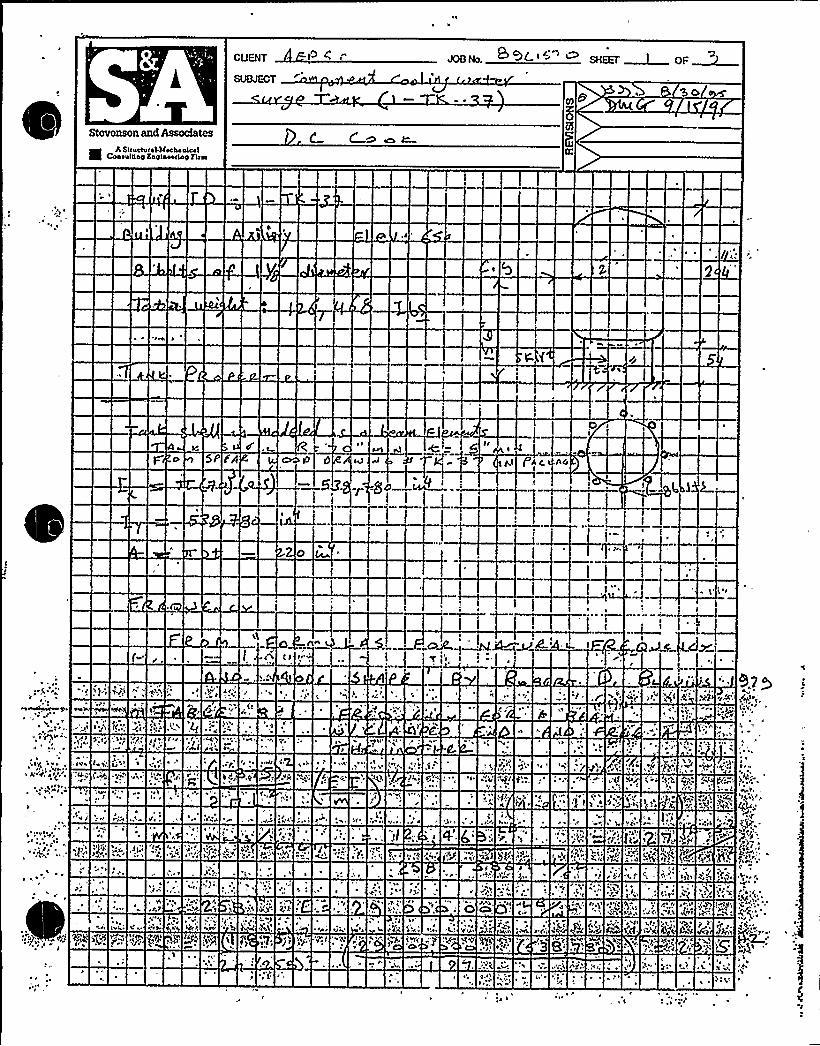
CUENT <<Iota S'+t-I "" attar ~ or~
Stevenson and Assodates
8 A Structural Meelto atcolCoo<atria<5 Eat<to«a<toy Fr<ra
D5
~ ~
5P fA
~ ~
6Cl
»
th
~ .\
<It» tu l.'.
-<o» ( «o
45 i
~ 'I
'L~ I
I, A,S»hf
tht I
hr
h»ft
gl Pg ti
<; » I '«rtrl tth.
I~ I
I (~f ~ ~
«'l'
\I ~ I
*
I»5 p. «,
I ~ '<
~ „.,~ .If
yh(l
~5
\ ~
of
(tl '551<»»
~ r
» Cf Pl»h I ftjj
II«L
pt 'p tr
5
» I
tt ''I11 lh l O
.Il
trrlh
I
u (
5
»rl»g
r ~ ttro
~ t
55>'5 t,:.It}
I~

CIJENT 4(S Sl. 8 "" L I ., '7 M stru. ~ I
SUBJECT ~ ~s'1 P w w Cg«I Ccs ~.~ uI <, I(J>1.c 7E
A Ic- [ « ~g ~ 5 7
Stevenson and AssodatesAS(ruccurc!.MccIsr aces l
Coarul((s(r Ea(r(act((ay E(rsi
is»I 4.," . ~,
gc '?N.
4 E~E. I«II)I IEII,(
u ~ 1' ilr 7 r(c
'I„~ ~
8'ci
1 *
5 ~ 11.'cc
„~II
'I ~ 4
r?
~ » 1~
h.
Il .CI VI Qlr ~
1 I41\5,
* 4 ~4
)i% tl7 (l»P
re» ~ t (1; I.Ilrr, '114 "C
?u
qg.c i r PL ?cl
»»
I» cl
'4'i. ''7(
~ C
7( '5„
. Itrr
~ I
~C E
~ '
~ lC'I
cgt
114 QI
CI
fine
»4 1
~
l,''FV
I\ ~
~ir
p7
~ t I
rli
~roc 2?P
O'«'»I'
rI
-,c; r(lr»;~
irc»I x
5
7
4 44
kt'''I
lr»E
1 I»7
S"Cj 4'PW
I'ic~ CI
C("'"' I t«lv, «(7s,c ~
'r«r,. Ttt(I
I 5»r
:Lt ~I".1 ()r
E~ 4
r'

4
CuEHT Y) 9 ~' " SHEET OF
g@~ C ~~~ F ~~ a V ~ c.ter„- 4-IJt r.Z»
7 ht tc, ( h'rSteve@son and Assodatcs
0 *Stractara)-Mac)raalcalCoarldttay Ka2ltaccrlatr Ftral
44
(2
2 7.
'24"4'fcr.gf
,44rr ~
44144
2
IFJt ll ~ I
r-'29'vYt ~
".4.' 'r Jtt
'24" V
i g 2 'tFI't 4)
'II~ \
Fr
YYt
g 'I
~ '
~
' 1' . ~ > ''r.Vrx 2FI' - 41. 241
~4
h ~
41 ~
Pl2
~ 44,
'YrY
I;"2 ~Ih
222~
' '1
fIrl\IF
) 4Y.C 44
Y'4
22Y2", I.f ~ .g;\s Yl
*)f.
h'F.y I

**12 CHP 5021. CCD. 019ATTACHMENT NO. 1
ANCHOR INSPECTION DATA SHEET
Unxt "
/2-3 Z7Bldg.
Y(-Location
Installation dwg. / Rev.
Anchora e Arran ement SketchEquipment No.
'w MG ORNA
INDIANACONST RU
w
a 3 ~992
MICHIGAN POWER
TION CONTROLLEO
RKIHG COPY
« ~L 4''-o
Drawn by.Verified by
Date:Date:
Reviewed by:Q al./Cert. Inspector
Date: Snstructzon Anchor Review Engineer
Page 1 of 3Revision 1

**12 CHP 5021 CCD O19ATTACHMENT NO. 1
ANCHOR INSPECT10N DATA SHEET
Unxt g
Q-3Bldg. Locate.on
Installation dwg. / Rev.
Anchora e Arran ement SketchEcpxzpment No.
INDIANAMICHIGAN POWER
CONSTRUCTION CONTROLLEDWORKING COPY
AUG 1 > 1992
CLERK .> +~~
8/y
.:c "aq'.e
Drawn by:Verified by:
Reviewed by:QG ./Cert.
nstructxon
Date:
Date:Inspector
P
Date:Anchor Review Engineer
-I- l
Page 1 of 3Revision 1

0

**12 CHP 5021. CCD. 019ATTACHMENT NO. 1
r
ANCHOR INSPECTION DATA SHEET
Unxt g Bldg. Location
Installatz.on dwg. / Rev.
Anchora e Arran ement SketchEquipment No.
1- -3
(gp($ +4 <4(QH>GAB POWERQON$ TQQCv n~ GONTSOLLEO
wOR ~. 'Ci CC('Y
azw
p~l ~b c<~ (omnlsonS Votv SrC r~a~ +i~>
Leo +
H» +
Fl 6
oP)s
4r 3+c//< Ãs B% 3'ls
Drawn by:Verified by:
Reviewed by:
Date:
Date:Q l./Cert. Inspector
Date:onstructxon Anchor Review Engineer
Page 1 of 3Revision 1

l s
fi ~
~ ~
I ~ ~
,;~/~ N
~ ~ ~
~ ~ ~
s ~
~W~sRM~RHR%a ~ ~ aMMIIIIIIIII585mmlmmmRSIIIRIMIIIII
RSIIISIIIRSRRIIII55. Iles% .. l%I%
IIIIIISIIIHIIa
Rse&R4%Ã%RM~RJ%8%5%MWWMWMW&I
~ La Sl ~ ~i
~~K9MEX >
LL ~ L ~ (
~~asia~ ~
~ I ~
~ ~ ~
~~ ~ i f ~
~ ~

Equipment No.: I .! -
~'ightnessestablished by "Snug Fit"Tightness veri fied by:
Qual. /Cert. Xnspector
Comments:
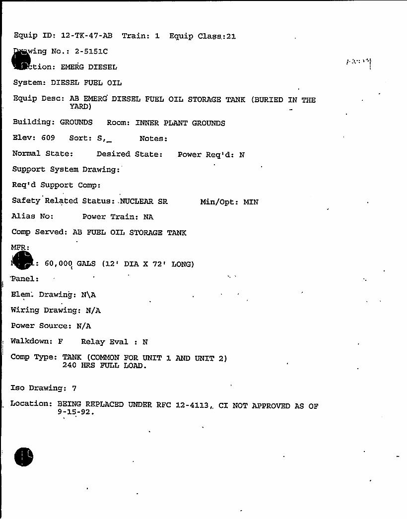
Equip XD: 12-TK-47-AB Train: 1 Equip Clays,:21
wing No.: 2-5151C
tion: EMERG DIESEL
System: DIESEL FUEL OXL
Equip Desc: AB EMERG DIESEL FUEL OIL STORAGE TANK (BURIED IN THEYARD)
Building: GROUNDS Room: INNER PLANT GROUNDS
Elev: 609 Sort: S, Notes:
Normal State: Desired State: Power Req'd: N
Support System Drawing:
Req'd Support Comp:
Safety Related Status:.NUCLEAR SR
Alias No: Power Train: NA
Comp Served: AB FUEL OXL STORAGE TANK
MFR:
60,000 GALS (12'IA X 72'ONG)'Panel:
Elem'. Drawing: NgA
Hiring Drawing: N/A
Min/Opt: MIN
Power Source: N/A
Walkdown: F Relay Eval : N
Comp Type: TANK (COMMON FOR UNIT 1 AND UNIT 2)240 HRS FULL LOAD.
Xso Drawing: 7
Location: BEXNG REPLACED UNDER RFC 12-4113,, CI NOT APPROVED AS OF9-15-92.


DC Cook Unit 1
SCREENING EVALUATIONWORK SHEET (SEWS)GIP Rev 2, Corrected, 2/14/92Status: YesSheet 1 of 11
ID: 12-TK47-AB (Rev. 0) Class: 21 - Tanks and Heat ExchangersDescription: AB EMERG DIESEL FUEL OIL STORAGE TANKBuilding: GROUNDS Floor El.: 609.00 Room, Row/Col: INNER PLANT
GROUNDS UNIT0 2 BURIEDSOUTH OF TURBINE BUILDING
Manufacturer, Model, Etc.: 12'IAX 69'-10"LONG, 60000 GALS
BASIS: External analysis
1. The buckling capacity of the shell of a large, flat-bottom, vertical tank is equal to or greaterthan the demand.
-2. The capacity of the anchor bolts and their embedments is equal to or greater than thedemand.
3. The capacity of connections between the anchor bolts and the tank shell is equal to orgreater than the demand.
4. Attached piping has adequate flexibilityto accommodate the motion of a large, flat-bottom,vertical tank..
5. A ring-type foundation is not used to support a large, flat-bottom, vertical tank.
N/A
Yes
Yes
N/A
N/A
mQKS
SRT: George G. Thomas (SBA) and Tom Huang (AEP)'C
Underground tank. SRT evaiuated this tank based on the ave~~able documentation in the equipment package.
A tank calculation was performed (included in the tank package) based on the reference drawings The tank wasmodeled as a beam on elastic foundation. The overall tank stresses were very low (on the order of 3.6 ksi).
Evaluated by:
~gi-) Date:
il /Z ~low"
Attachment: EVALUATIONOF STRESSES IN THE TANK

CUENT
g - a4CttO5~
Stcvcnson and Assodatcs
EIAStructural Maclen aleut
Conautttatr Kntrtncartng Ftrra > cn tn-
OSC

CLlEHT
SUMECT
Stevenson and Associates
ElA scuctvcal Mechanical
coasulctsy Elplaoocno f4'

CUENT
Stcvcnson and Associates
k A Stsucturel-M eAe nleslCoaoultlaa Koalnooriay Fina . C. ~ Ca~ 4


CUENT
Stevenson and Assodates
R A StnsctvcehMocha alcalCoaaoltlay Eagtoeeaay Fina De +e C-WO W

CUENT
Stevenson and Assodates
h st(udvrasMecha aleafCoawltlay Knylnoodng fire


g CUENT
Stevenson and Assodates
Il A Structursl-Mschs nicslConsulting Engtn«ring Sirrn
z08Pu
5 ~ 4, No~ o
—1 '3 lOc 3%
c

4CUENT
Stevenson end Assodatcs
l5 A Srrucrural.McchaalcalCaarulung Kaalaccriny flrra Pr Cr 8 WOCr

CUENT
Stevenson and Associates
II h StructurohM echo uk olCuaoulttau Kactaoortatr fto ra
I 2.
S (

0

CUENT
Stevenson and Assodates
8 A SICIICIVC1I.MWL4OIC4ICoaoul5sy Kaylneorlng Feaa D.
a ggg

V
i'

CUENT
SVMEGT
Stcvcnson and hssodatcs
8 ASvuctural.MechanicalCoaaultiog K~laoeclny Eitoa
Y-t
A.

Equip ID: 2-HE-11 Train: 12 Equip Class: 21
Drawing No.: 2-5129A 2-5135~
~
~ction: RI
System: REACTOR COOLANT PUMP SEAL WATER INZ/LEAKOFF
Equip Desc: REACTOR COOLANT PUMP SEAL WATER HEATEXCHANGER
Building: AUXILIARY Room: SEAL WATER HEAT EXCHANGER ROOM
Elev: 609 Sort: S, Notes:
Normal State: Desired State: Power Req'd: N
Support System Drawing:
Req'd Support Comp:
Safety Related Status: NUCLEAR SR
Alias No: Power Train: NA
Comp Served: REACTOR COOLANT PUMP
Mfr: ATLAS INDUSTRIAL MANUFACTURING CO.
Blem. Drawing: N/A
Wiring Drawing: N/A
Power Source:
Walkdown: F Relay Bval : N
Min/Opt: MIN
Comp Type: HEAT EXCHANGER
ISO Drawing: 2-CS-91 2-CS-100
Location: IN WEST AREA OF ROOM

DC COOK Unit 1
SCREENING EVALUATIONWORK SHEET (SEWS)GIP Rev 2, Corrected, 2/14/92Status: YesSheet 1 of 7
ID: 2-HE-11 (Rev. 0) Class: 21 - Tanks and Heat ExchangersDescription: REACTOR COOLANT PUMP SEAL WATER HEAT EXCHANGERBuilding: AUXILIARY Floor El.: 609.00 Room, Row/Col: SEAL WTR HEAT
XCHGR RM - IN WEST AREA OFROOM
Manufacturer, Model, Etc.: ATLAS INDUSTRIALMANUFACTURINGCO.
BASIS: External analysis
1. The buckling capacity of the shell of a large, flat-bottom, vertical tank is equal to or greaterthan the demand.
2. The capacity of the anchor bolts and their embedments is equal to or greater than thedemand.
3. The capacity of connections between the anchor bolts and the tank shell is equal to orgreater than the demand.
4. Attached piping has adequate flexibilityto accommodate the motion of a large, flat-bottom,vertical tank.
5. A ring-type foundation is not used to support a large, flat-bottom, vertical tank.
N/A
Yes
Yes
Yes
N/A
S U
~CVIF~S
SRT: Gary Thomas and Tom Huang on 11/3/93.
Vertical Heat Exchanger on a Gusseted steel pedestal. Each Pedestal is anchored to the floor with 8- 3/4" J-Boltsembedded 20" into floor.
Exchanger is 16" in diameter and 14'n height.
Exchanger is bolted to the steel pedestal with,2 1" diameter steel bolts on 6" centers in weak direction and 2'-8" instrong direction. This connection is more limiting than the anchorage to the floor.
Attached calculation was to judge adequacy of these for bolts.
The exchanger has a frequency of 10.6 Hz and the bolts had a safety factor in tension of 3.54.
Evaluated by: Date:
IC) /4
~g~ CZ
Attachment: Picturesttachment: Verification of Bolt Connection


DC COOK Unit 1
SCREENING EVALUATIONWORK SHEET (SEWS)GIP Rev 2, Corrected, 2/14/92Status: YesSheet 2 of 7
ID: 2-HE-11 (Rev. 0) Class: 21 - Tanks and Heat ExchangersDescription: REACTOR COOLANT PUMP SEAL WATER HEAT EXCHANGERBuilding: AUXILIARY Floor El.: 609.00 Room, Row/Col: SEAL WTR HEAT
XCHGR RM - IN WEST AREA OFROOM
Manufacturer, Model, Etc.: ATLAS INDUSTRIALMANUFACTURINGCO.
ECUlKR
SUPPORT PEDESTAL TOP OF THE EXCHANGER

CUENT
SUBJECT
t'()Ne.Q CaO<~
Stevenson and Assodates
S ASllvclvlal-MCCIIIalcolCoalvlgag Saglaotllag Fitch
Ahchol' ~ Acca oaohC Slcatch
2-HHIIoalcro Vatlaco tacofaSllC DYSICN CDNYIDSIIO
clalclha cotY
Sfp lS 1SSS
I~ I(
I ~
h'YI'nt>
NYCTlS fC(WF)
~,Clyl
, ~')
eIC.S ~
qvr)"..'LEV
l K(o C)SST
~ ~ ~ ~ r ~ ~ ~ . ~ ~ . ~ I ~ ~ I ~ I ~ - ~ ~ ~ ~ ~ ~ ~ r er'
~ ~ ~ ' ~ ~ h ' ~ ~
rt'acatl4c
". )pP
;I@aha'
li cac
~ \hr 5't,o IODIINC IVQOCAN YOOC~ cl 5 Dcslca cahl caslto
voc claa can
SSP lS lSSS
SIC
IYCSO IAIL~FA) AD
CIYcltaJ
IICCDI13(YYY )
«CIO II3(rlrg.-,'t
IYCSO'Wt(tel Y3)
~ ICSDWIlg
~ I~ '
I. "~
T eotTtrit)
tr(»
3ECY.'t\3 ccc(cccl c-c N occuv)
r~
C
A Bl I 'oh0 0p 0
0 0c e
o. ~
0 0II IC
0 0F >3 e(FID)
0 0IC
0 0C I\
L
C,caclr
~E
sell:'rc I
0 0T.
rL ~
,Ql01hhc I cocah cocca«lc Dlgas cac IDLsco
aacclha catt
SfP'S SSSS
acscT
r0 ~aa Iaa
S.
g.)i
~ r
g+Ps
Yah CI'I
c I,
tC
'Ã)' ~
'S
C

CUEHF
QJBJECT
Stevenson and Assodatcs
8 A Structural-MectfaalcalCoaru! o oft Eatftocurtafr Fifa<
P P.
~ i'I, h ,f ~
P.'
~cK
«<<I
j.fipv»<YA ~iverfl"gv vruhu '. 'P<% .fc\u <K
h.. 'g"I
~ )
I t» f«~lg 'tfr lg«»u'P vh tlap
P..
~, '«
rr'pi
t,'hr >
f. ~ I ~
p
pfr
»~
» I
~ «
~ u / Pf»
P
h
P..
htrfu P
~h«
IP
gh'
I
l'I
r<
up
I'P H
f '«
'
~ru ~
I
~ I
qtr ~ »Irph
r'tfu Ip.
hFrutarp
toKj .ifu* ~
h

r,

CUENT JOB No.
SUBJECT ~@AweEW
Stevenson and Assoctntes
IR.ASt( ucfuf al.Macha afccl
CuafulffaffRaffface(Lay Sic(a
4~
1 ~
+1
~ I
Jul gl»
~'gIu4
«P
Irp ( ~
/««
«ls 1,14 'la»n. ~
\'..IP 'f
»J
Sir! I
'I .4
.'"4,')!e/Off P CP
'"'5 III,I(lr«"«»l
«'+rrf„»VtfPP
PrirI~ 1
~ I ru
I'« "f~ 'I
~pI'-
l -'5 4
crap l»Q,:If
(~"r, ~ 44
I(l«»I'l('
lI ~
uf'I
14.C'«PPP
~ 1,1P
~ «1«
''1 1(Q/
'1 »t
%14 r IIIu
~rpl
rpI
0(fg ff

CUENT JOB No. ~ 'HEET OF
Stevenson and Assodatcs
5 AStructural.l4ucha attutCoaruttiag Kagtauurtag Firar
L.
~ r~ r,

Coo
Componone yo, 2 Class l
Any paxpicular area the Seismic Review Teaa should pay extra attention totYes < No (Xf yea, check items that apply.)
Anchor TypoAnchor DiameterAnchor SpacingAnchor NumberAnchor Embodmont<Anchor Edge DistanceAnchor CapAnchor Thread EngagementAnchor CripAnchor AngularityConcrete Crack
~qs ~ ~~T
gjO I/ E; Q Pl I IJ (. ) <Al(= (gE'L
Other'a (describe bri.oily)
TE there is concern for Design Basis Discrepancy, cir'clo the applicableitem and explain.
1.2.3.
Hardware Maintenance Type Discrepancyl'raving Upd?te Typo DiscrepancySigni|.'icant Operability/Design Basis DiscrepancyOthers
Condition:
Actions Taken:
Prepared By
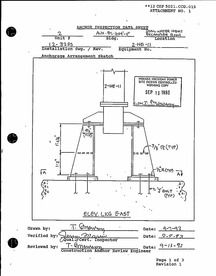
**12 CHP 5021.CCD. 019ATTACHMENT NO. 1
ANCHOR INSPECTION DATA SHEESBfn DATER I+&ATAX . M @Oq -01'AC,HAhl4BR g.oug
Bldg. Location
Installation dwg. / Rev.
Anchora e Arran ement Sketch
2..~-I tEctuzpment No.
2-HG "I I
INDIANA I IICMIGAN POWCRSITE DESIGN CONTROLLEO
WORKING COPY
SEP t)1995
g(
~ I
|<YPg
~i1 R(7<~)
I/Z,R.(~p) ~Ag
~b<~ 0 \
~ h~
<~b
PLED. gK.G C A&T
Date:
Date:
Drawn by:
Date:Engineer
.Verified by:~ ual./Cer . Inspector
Reviewed by: TConstrue won An hor Review
Page 1 of 3Revision 1

**12 CHP 5021. CCD. 019ATTACHMENT NO. 1
ANCHOR INSPECT ON DATA SH E
Unxtl2- 3z
Xnstallatxon dwg. / Rev.
Anchora e Arran ement SketchEquipment No.
(>yp) IVB &(T9P)
I
,'A 0 0P
0 0I
~4
I
0 0
0 0>/g Z(~p)
0 08
C AFOOTPee .
0 0
I-O'RP
I IOIAPIA iVICHIGAN POPOVER
SITE OESIGN CONTROlLEDYPORKIHG COPY
SEP t~1995
.LFRKT
Drawn by: Date:Verified by: Date:
al. Cert. XnspectorReviewed by: Date:
Construction Anch r Review Engineer
Page 1 of 3Revision 1

*12 CHP 5021. CCD. 019ATTACHMENT NO. 1
CHOR INSPECTION DAT S
A"SX ~ gPa'-O" S~ %PITCH &BR'TBXCHfHIGBR. RooH
Unitl 2- 525s
Bldg.
Installation dwg. / Rev.
Anchora e Arran ement Sketch
H~ -1(Equipment No.
Location
INDIANAI.IICHIGAN PO'ilE'RSITE DLSIGN COMTROLLiD
WORKING COPY
SF.P 13 ISSUE
LERK
W~Hb('TYPE) 3/( y
WMAj ~/II(~P'L) /Ig
HMH$~P2.) ~I(
w~ wB
wm wl
.bi,'ob'4'ga
J BoiT(~P)
e'$~ ~
5CCT, Z -8 (scca c;c ~«~+~~)
Drawn by: Date: ~ 1
Verified by:~ ~
ual Cert. InspectorReviewed by: T
Construe won chor Review
Date:
Date:Engineer
-F-F
Page 1 of 3Revision 1

ATTACHMENT NO ~ 1
ANC OR SP
EquipmentNo.-'mbeddedSteel Dwg. No.:
YSICA CHARA IS C
Dwg No.:
Weld IDT e
SizeLen thCracks
2I/Yes Yes Yes Yes s
'/ ~II I >/II 3li t
l II/ %4" <4'8I/Yes
oYesNo
YesNo
Weld e Codes
1 = Fillet2 = Plug/Slot3 = Groove
Lack of ~ePenetrationes Yes es QeQs Yes
No NoYesNo
Porosity Yes Yes Yes Yes Yes'es YesNo
YesNo
INDIANAMICHIGAN POWERSITE DESIGN CONTROLLED
WORKING COPY
SEP tg t995
LERK
Equipment base flexible: 0 Yes 5-Noons ruc z n e
Date:
Reviewed'y:
Verified by:ons ruc won c or evzev ngxneerV
a .. e . npsec or
Date: t l2 3
Date:
Page 3 of 3Revision

*~12 CHP 5021 ~ CCD. 019ATTACHMENT NO. 1
Equipment No.:Anchor type: GODET
Tightness established by: 0Torque Wrench No.:Tightness verified? 0 Yes
Equipment base flexible? 0
Dia:"Snug Fit"
Dwg No.: l2-32pwg No ~: I 2 - '32 8$
0 TorqueCal. Due Date:
No Date: 1ons c 10Yes C(No ~. Date: 0 1-13
ons uc 1 n ARE
C C
Bolt IDGaps
Anchorlen th
A 5 C O e. F cl aeT I/S~"em Yg>'STc $$ $Hpv gpss
\ It I " 'I V< ii i il c « I II2.- 0 2,- 0 Z-o 2.- o 2- o g-0 2o
0
2-0
Comments
f~ IYI QCfCjI 2.-3vlgG
Protruding p I5/l~ g" p'I ~ '>/~ ~"/g Z~Jy
edment )I )I//)~i iI qu 1< qu lI-1" li q'i~I 1 qy8 ) q
BoltriConcretecondition
Edgedistance
g ( 2. /IX P I 2." > I W ) I> W t 2. 0 I 2. 7i2-
Anchors acinAnchor
an laritThread
engagement
@II @tl @'II @II ( 4 u
~4 Oo i~o 00 g0 OO O4 ()
0
oy 0 y ng oK. ot. ck ok o((
Comments:
Verified by:r9 a ., ert. Inspector
Revieved by:Construct on ARE SITE DESIGN CONTROLLED
WOIIKING COPY
SEP l~ 1995
LEIIK
Date:
Date:
ago2of 3ovision -3

r4

~ I e
~ ~ k
~ ~ '
~ ~
~ ~ e
~ ~ e
~ ~ I- ~ ~ 4' ~ / I
e 14elec
~ ~ II I - d e
W '
.R Lk
ommmmiimmmi.
- IIIIIIIIHImmmIIRlmmmmRRIIIRI mm58~ ~ ~ o p o
~ - = ISRIIRHIIIIIIR5lRRREMIIMMIT&
~ i g $ J I' ]'0 ) J WW%%
~ .
0

S 8 A DEPARTMENTCONTROLLEO DOCUMENTCOPY NO.
12 SHP 5050 NDE.008ATTACHMENT NO. 1
ULTRASONIC TEST REPORT
JOB ORDER NO.: CQ 4, REPORT DATE: REQUEST NO. M A,
IDENTIFICATION
Unit 'l ~CDComponent 2 — - l l
ItemMaterial + SOther
TECHNI UE
Test Unit/ S/Frey./DiameterReference StandardCouplant/Batch No. C <
TEST DATA REMARKS
PERFORMED BY:
REUIEWED BY:
FORM NO. 12 SHP 5050 NDE.008-1
LEVEL: M~ DATE: / 5Page 1 of 1Revision 0

Emlip ID: 2-HE-38E Train: 2 Equip Class:21J
wing No.: 2-5135A
ction: CCW
System: MISCELLANEOUS SEALING AND COOLXNG
Equip Ddsc: EAST CENTRIFUGAL CHARGING PUMP PP-50E LUBE OIL COOLER
Building: AUXILIARY Room: EAST CENTRIFUGAL CHARGING PUMP ROOM
Elev: 587 Sort: S, Notes:
Normal State: Desired State:
Support System Drawing:
Req'd Support Comp:
Safety Related Status: NUCLEAR SR
Power Req'd: N
Min/Opt: MIN
Alias No: Power Train: NA
Comp Served: EAST CENTRXFUGAL CHARGING PUMP
MFR: AMERXCAN PRECISION INDUSTRIES (BASCO)
M
Pa lElem. Drawing: N/A
Wiring Drawing: N/A
Power Source: N/A
Walkdown: F Relay Eval : N
Comp Type: HE
Iso Drawing: 2-CCÃ-515, 2-CCW-508
Location: XN THE NORTHEAST PART OF THE ROOM, 2 FEET NORTHEAST OFEAST CENTRXFUGAL CHARGING PUMP g2-PP-50E
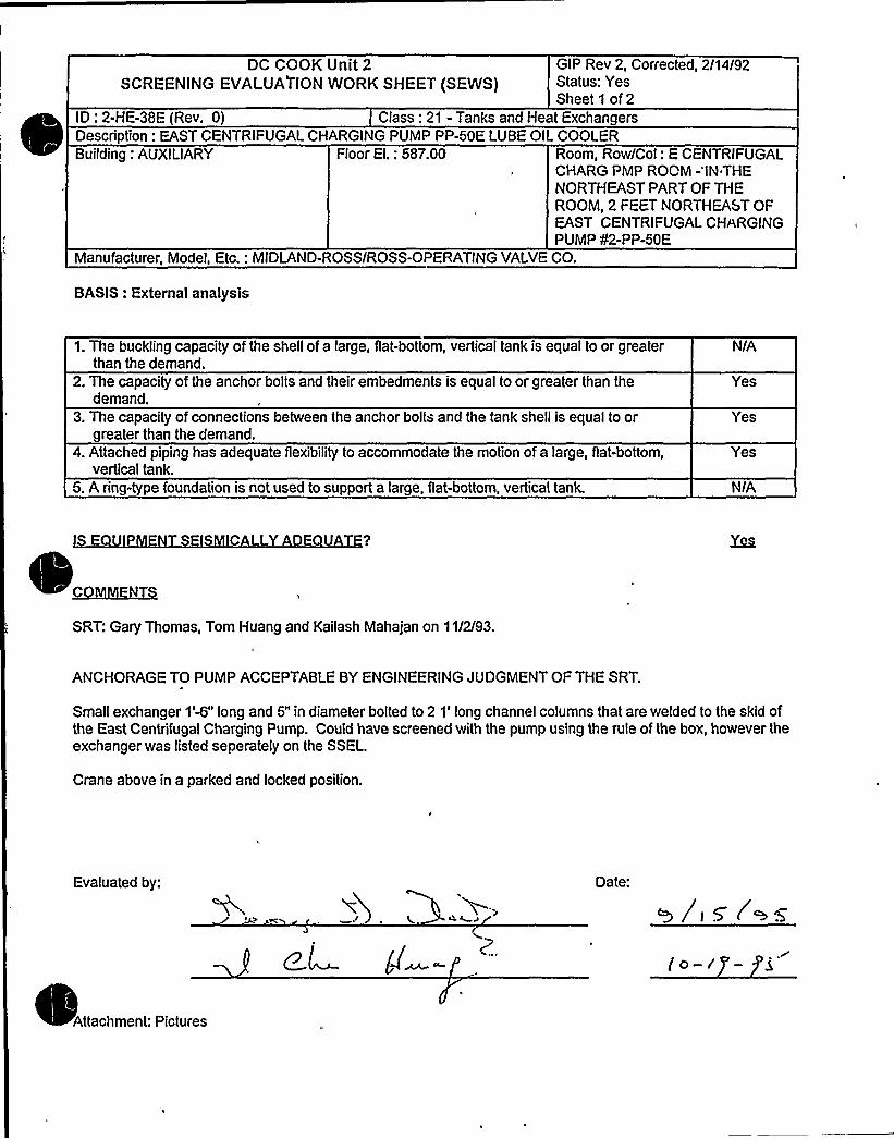
DC COOK Unit 2SCREENING EVALUAPION WORK SHEET (SEWS)
GIP Rev 2, Corrected, 2/14/92Status: YesSheet 1 of 2
ID: 2-HE-38E (Rev. 0) Class: 21 - Tanks and Heat Exchangers
Building: AUXILIARY Floor El.: 587.00 Room, Row/Col: E CENTRIFUGALCHARG PMP ROOM -'IN THENORTHEAST PART OF THEROOM, 2 FEET NORTHEAST OFEAST CENTRIFUGAL CHARGINGPUMP ¹2-PP-50E
Manufacturer, Model, Etc.: MIDLAND-ROSS/ROSS-OPERATING VALVECO.
BASIS: External analysis
Description: EAST CENTRIFUGAL CHARGING PUMP PP-50E LUBE OIL COOLER
1. The buckling capacity of the shell of a large, flat-bottom, vertical tank is equal to or greaterthan the demand.
2. The capacity of the anchor bolts and their embedments is equal to or greater than thedemand.
3. The capacity of connections between the anchor bolts and the tank shell is equal to orgreater than the demand.
4. Attached piping has adequate flexibilityto accommodate the motion of a large, flat-bottom,vertical tank.
5. A ring-type foundation is not used to support a large, flat-bottom, vertical tank.
N/A
Yes
Yes
Yes
N/A
C Y D
SRT: Gary Thomas, Tom Huang and Kailash Mahajan on 11/2/93.
ANCHORAGE TO PUMP ACCEPTABLE BY ENGINEERING JUDGMENT OF THE SRT
Small exchanger 1'W" long and 5" in diameter bolted to 2 1'ong channel columns that are welded to the skid ofthe East Centrifugal Charging Pump. Could have screened with the pump using the rule of the box, however theexchanger was listed seperately on the SSEL.
Crane above in a parked and locked position.
Evaluated by: Date:
Attachment: Pictures

DG COOK Unit 2SCREENING EVALUATIONWORK SHEET (SEWS)
GIP Rev 2, Corrected, 2/14/92Status: YesSheet2of2
ID: 2-HE-38E (Rev. 0) Class: 21 - Tanks and Heat ExchangersDescription: EAST CENTRIFUGAL CHARGING PUMP PP-50E LUBE OIL COOLERBuilding: AUXILIARY Floor El.: 587.00 Room, Row/Col: E CENTRIFUGAL
CHARG PMP ROOM - IN THENORTHEAST PART OF THEROOM, 2 FEET NORTHEAST OFEAST CENTRIFUGAL CHARGINGPUMP ¹2-PP-50E
Manufacturer, Model, Etc.: MIDLAND-ROSS/ROSS-OPERATING VALVECO.
EAST CENTRIFUGAL CHARGING PUMP PP-50ELUBE OIL COOLER

**12 CHP 5021 ~ CCD. 019ATTACHMENT NO. 1
Un1tNA
Installation dwg. / Rev.
Anchora e Arran ement Sketch
ANCHOR INSPECTION DATA SHEET
hu -&. gz'-o'ldg. Location
'2-H-E-5 6Ecgxzpment No.
INDIANA MICHIGAN PPW'FgSITE DESIGN CONTROLLED
WORKING COPY
AUG 25 t985
LEgK T'(eek>~
O'- III"
~~~ 7O QCIC E,
g,g<, wssT
Date:6 a-pa
Drawn by-Verified by:
goal.] ert. InspectorReviewed by: Dt:
Constructxon nchor Review Engineer
Page 1 of 3Revision 1

**12 CHP 5021 ~ CCD. 019ATTACHMENT NO. 1
Unct g
MhInstallation dwg. / Rev.
Anchora e Arran ement Sketch
ANCHOR INSPECTION DATA SHEET~gT c.CHTRi~h~ C.~)gg~X-BL 5'5 t-0 Puca A.o~e
Bldg. Locationa-~-BEE
Equipment No.
INOIAtEA PiCHIGAW "OWERSITE OESICh CON~RGu.EO
AORKltIQ COPT
AUG 25 1885
I.ERi< 7
y+'~ PPI T, CJ~~~qq~si~ e u) ~T~P)
~l
I
ookiQt ORTH
Drawn by-Verified by'-
~/~la,~D tDate:
ual./Cert. InspectorReviewed by: T Date:
Construct@on An hor Review Engineer
Page 1 of 3Revision 1

Equip ID: 2-QT-134-CD Train: 2 Equip Class:21
D awing No.: 2-5151D
tion: EDG
System: DIESEL JACKET WATER
Equip Desc: CD EMERGENCY DIESEL AUXILIARYJACKET WATER HEATER(TANK)
Building: AUXILIARY Room: CD EMERGENCY DIESEL GENERATOR ROOM
Elev: 587 Sort: S, Notes: B
Normal State: Desired State: Power Req'd: Y
Support System Drawing: 2-12030 2-98014
Req'd Support Comp: 2-ABD-C-1D
Safety Related Status: STANDARD Min/Opt: MIN
Alias No: Power Train: A
Comp Served: CD AUXILIARYJACKET WATER HEATER
MFR: INDEECO
75KW HEATER
Panel: 2-DGCD
Elem. Drawing: 2-98014
Wiring Drawing: 2-95302
Power Source: 2-ABD-C-1D
Walkdown: F Relay Eval : N
Comp Type: TANK
Iso Drawing:
Location: IN THE NORTHEAST PART OF THE ROOM, 5 FEET NORTH OF CDEMERGENCY DIESEL JACKET WATER PUMP g2-QT-130-CD2,

DC Cook Unit 2SCREENING EVALUATIONWORK SHEET (SEWS)
GIP Rev 2, Corrected, 2/14/92Status: YesSheet 1 of 14
ID: 2-QT-134-CD (Rev. 0) Class: 21 - Tanks and Heat ExchangersDescription: CD EMERGENCY DIESEL AUXILIARYJACKET WATER HEATER (TANK)Building: AUXILIARY Floor El.: 587.00 Room, Row/Col: CD EMER DSL
GEN RM - IN THE NORTHEASTPART OF THE ROOM, 5 FEETNORTH OF CD EMERGENCYDIESEL JACKET WATER PUMP82-QT-130-CD2,
Manufacturer, Model, Etc.: 75KW HEATER
BASIS: External analysis
1. The buckling capacity of the shell of a large, flat-bottom, vertical tank is equal to or greaterthan the demand.
2. The capacity of the anchor bolts and their embedments is equal to or greater than thedemand.
3. The capacity of connections between the anchor bolts and the tank shell is equal to orgreater than the demand.
4. Attached piping has adequate flexibilityto accommodate the motion of a large, flat-bottom,vertical tank.
5. A ring- pe foundation is not used to support a large, fiat-bottom, vertical tank.
N/A
Yes
Yes
Yes
N/A
DE
SRT: W. Djordjevic and TR Satyan Sharma. 10/6/93.
REF: 1. Anchor Inspection Data Sheets: Anchorage Arrangement Sketches and Physical Characteristics DataSheet, Certified 8/31/93.2. Dwg 0 12-3468-13.3. Worthington Corp. Dwg. SK7938, 8-23-74
Anchorage: 2-QT-134-CD is the J.W. Heater, separately mounted by three1/2" coupling configuration of rod andPhillips Redhead wedge type anchors. Tightness was verified by torque, 6/28/93.
For anchorage evaluation, see External ANCHOR analysis, File: 2QT134CD.ANC. Weight of fullwater tank isestimated as 550 Ib (assumed with 12.75" OD, .375" Wall thickness, flat.375" thick end plates, 64" height, and4.18 cu. ft volume ofwater). Considered as a cantilever with distributed load, the fundamental frequency isestimated to be 82.5 Hz. Actual response is governed by fixityof the base; anchorage system consists of three5/16" x 2" x 6.25" plates welded to the bottom of the tank at 120 degree intervals. Considering the base flexibilityand configuration, the frequency was estimated to be 8.96 Hz. as indicated on the attached calculation. TheANCHOR analysis intlicates a factor of safety of 3.74, however, the capacity of the anchorage is controlled by thebase plates with a factor of safety of 1.84 as shown in the attached calculation.
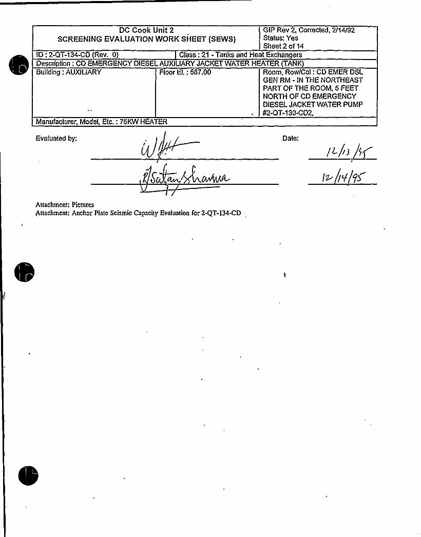
DC Cook Unit 2SCREENING EVALUATIONWORK SHEET (SEWS}
GIP Rev 2, Corrected, 2114I92Status: YesSheet 2 of 14
ID: 2-QT-134-CD (Rev. 0) Class: 21 - Tanks and Heat ExchangersDescription: CD EMERGENCY DIESEL AUXILIARYJACKET WATER HEATER (TANK)Building: AUXILIARY Floor El.: 587.00 Room, Row/Col: CD EMER DSL
GEN RM - IN THE NORTHEASTPART OF THE ROOM, 5 FEETNORTH OF CD EMERGENCYDIESEL JACKET WATER PUMP42-QT-130-CD2,
Manufacturer, Model, Etc.: 75KW HEATER
Evaluated by: Date'.
/ L/i3 ~/~g
Attachment: PicturesAttachment: Anchor Plate Seismic Capacity Evaluation for 2-QT-l34-CD

DC Cook Unit 2SCREENING EVALUATIONWORK SHEET (SEWS'j
GIP Rev 2, Corrected, 2/14/92Status: YesSheet 3 of 14
ID: 2-QT-134-CD (Rev. 0) Class: 21 - Tanks and Heat ExchangersDescription: CD EMERGENCY DIESEL AUX!LIARYJACKET WATER HEATER (TANK)Building: AUXILIARY Floor El.: 587.00 Room, Row/Col: CD EMER DSL
GEN RM - IN THE NORTHEASTPART OF THE ROOM, 5 FEETNORTH OF CD EMERGENCYDIESEL JACKET WATER PUMP¹2-QT-130-CD2,
Manufacturer, Model, Etc.: 75KW HEATER
2-QT-134-CD

CUFNT
SUBJECT
Stovenson and Assodatcs
8 A S!rucru ral.Mocha a!colCoaoulaa4 KOO!aoorlaO Flrra
tttch
»I~
II
cA
~ gcggg~ E//z$guG- 8g+s~t,+~447rdP'p4/g, 0~~/GALS. (7-". zw.l~S)
IOO 'P~p//8 &gdVf8&.ChF gh'E-
.~CU~ge~ ~Eg ti/VSr d~Q-//di~ gg 444'/0 ~igh~ APOXg'rdn44 Q FC707 5
'?h"4'.e i'~Sfl
I.'r)I
i 8I
$0'
5
zo'', III~ ~
~ ~
~ I
O ~ .
iI» ICg+
rt )%hi
kj.
It'!ho'r
I
* I ~
h
roll 04f8 Igd 095
t.tt
).AMERlCANELECTRiC POWER
.,'@RVICE CORPORATiON
)gf'APPtHOVEO (N GENERAL"8-~IOVEDEXCEPT AS NOTED
'U:.NOT APPROVED
0:~ MFEREN E ONLY
DzR!.I l5 Zrv/.
/j
I ~
or»or Ioor
IOIICuott Iorouorltc
OOI C
.p4
c. ubr
I IIIIO ' c ~ ' 'LI ' I ' ' ~ L t.tent L 4 Ii':. ''~":5'l'Li
Y'),, I
~ I


CUEN~ P
Stevenson and Assochtes
8 ASttuctu tat.McchaatcalCoatutttay Eaglacortay Fttta
z
t ~
4',r.)}
c
%)
~~ ~ ul I
,1
%St . ~
~ i
ag
~i/pcs
c
rt
ft u Mc

0

CUENT
R~ IZI qs.8
Stevenson and Assodatcs
5 A Sciacra ral44>eba alaalCaaralaay Karrlaeerlarr furr
1'1~r
~ h
LA ~
'I'v»r»4+
~»I I
LhUIC
~'IAh
~ I ~
A
LV
AIIl
Al
.LC
hl
1VC
h. ~
gQ re<A g~'(
if'J 5~> li~~;
S»1 ~
ra
av ~ b
ALII U ~ IP
I~
, rv
~ 1I
r»»'.IVIS
~ QI
h »Il
iri A IL,ag
~ I
ol I~ Lr
lh
I Lhr .'I'Ij $>
»C'I (
'IVI
I a.l ~'"iv4
'C S
11>I:m al >.
i ~ » I .I).hI ~ A' Il'
~ I A I
'

CUENT
SVBJECT
SHEET OF
Stevenson and Associates
A SvvctuwhMeehs nleelCoaeu!tlag Kagiaoeriaq face
\2/0 9s


CLiFNT
Stevenson and Assodatcs
8 A Strttctttral Meeit4444ealCOatultttty sag(4444tlttti fltat
4+0'-
~P
4 ~ 4, 4~
'S
at"I
* .g! tQ;,<JS * SS4 i
+~I
4 StS p
~ S
rs p4
44


DC Cook Unit 2SCREENING EVALUATIONWORK SHEET (SEWS)
GIP Rev 2, Corrected, 2/14/92Status: YesSheet 9 of 14
ID: 2-QT-134-CD (Rev. 0) Class: 21 - Tanks and Heat Exchangers
Room, Row/Col: CD EMER DSLGEN RM - IN THE NORTHEASTPART OF THE ROOM, 5 FEETNORTH OF CD EMERGENCYDIESEL JACKET WATER PUMP¹2-QT-130-CD2,
Floor El.: 587.00Building: AUXILIARY
Manufacturer, Model, Etc.: 75KW HEATER
Description: CD EMERGENCY DIESEL AUXILIARYJACKET WATER HEATER (TANK)
K Ij:tbaualx'esponseSpectrum: User
Frequency: User - 8.96Percent Damping: User - 0.0G
Spectral Values:DirectionNorth - SouthEast - WestVertical
Acceleration (g's)0.380.380.23
Angle (N-S Direction makes with the XAxis): 0.00Combination Criteria: SRSS
~Wightumber of Weights: 1
No Weight1 550.00 6.875 0.000 32.000
Number of External Forces: 0
XmasNumber of External Moments: 0
gggygiJPp~hacharNumber of Anchor types: 1
Ultimate UltimateTension
InterShearInter Saf
No Dia Manufact Product Tension Shear Coeff Coeff Fact1/2 Phillips Wedge (N) 2290.00 2380.00 1.00 0.30 1.00
Qmmta'ltimateStress: 3500.00 psi..
eduction Factor: 0.8 .

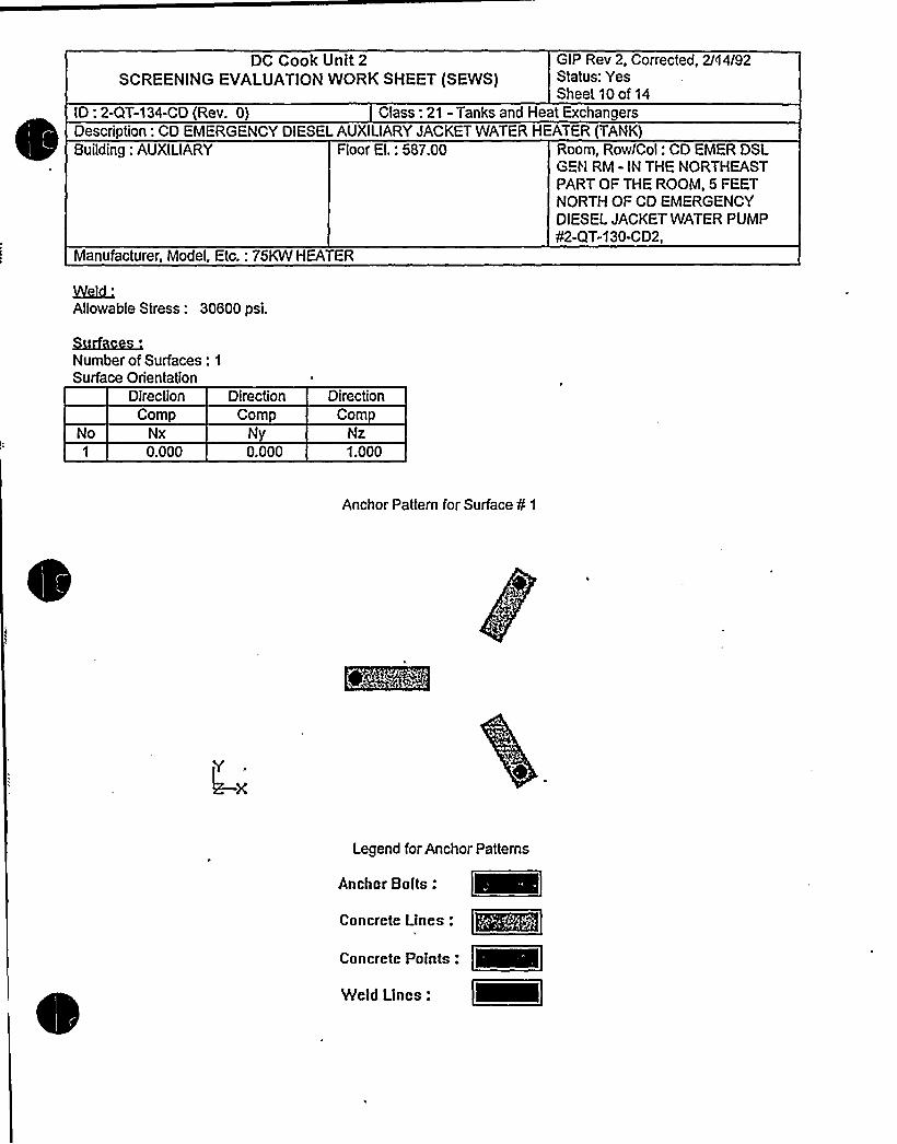
DC Cook Unit 2SCREENING EVALUATIONWORK SHEET (SEWS)
GIP Rev 2, Corrected, 2/ti4/92Status: YesSheet 10 of 14
ID: 2-QT-134-CD (Rev. 0) Class: 21 - Tanks and Heat ExchangersDescription: CD EMERGENCY DIESEL AUXILIARYJACKET WATER HEATER (TANK)Building: AUXILIARY Floor El.: 587.00 Room, Row/Col: CD EMER DSL
GEI'I RM - IN THE NORTHEASTPART OF THE ROOM, 5 FEETNORTH OF CD EMERGENCYDIESEL JACKET WATER PUMP¹2-QT-130-CD2,
Manufacturer, Model, Etc.: 75KW HEATER
Kaid'llowable Stress: 30600 psi.
Rzfvm'umberof Surfaces: 1
Surface Orientation
No
DirectionComp
Nx0.000
DirectionComp
0.000
DirectionComp
Nz1.000
Anchor Pattern for Surface ¹ 1
Legend for Anchor Patterns
Anchor Bolts .
Concrete Linen: ~mmConcrete Points .
Vleld Lines:


DC Cook Unit 2SCREENING EVALUATIONWORK SHEET (SEWS)
GIP Rev 2, Corrected,2/14/92'tatus:
YesSheet 11 of 14
ID: 2-QT-134-CD (Rev. 0) Class: 21 - Tanks and Heat ExchangersDescription: CD EMERGENCY DIESEL AUXILIARYJACKET WATER HEATER (TANK)Building: AUXILIARY Floor EI.: 587.00 Room, Row/Col: CD EMER DSL
GEN RM - IN THE NORTHEASTPART OF THE ROOM, 5 FEETNORTH OF CO EMERGENCYDIESEL JACKET WATER PUMP¹2-QT-130-C02,
Manufacturer, Model, Etc.: 75KW HEATER
Qmmdnhrzhar.Number ofAnchors: 3
NoAnch
Id Coord0.000
14.06314.063
Coord0.000
-8.1198.119
ZCoord
0.0000.0000.000
SurfId
¹ of elements per line: 1
Number of Concrete Lines: 3
Start Start End End End Sf LineNo X-Coord Y-Coord Z-Coord X-Coord Y-Coord Z-Coo rd Id Width
-1.00011.43811.438
0.000-3.5723.572
0.0000.0000.000
6.25014.56314.563
0.000-8.9858.985
, 0.000 1
0.000 1
0.000 1
2.0002.0002.000
Number of Concrete Points: 0
EcldJ.bm '
of elements per line: 4Number of Weld Lines: 0
Reduction Factor input for Anchor ¹ 1
Adequately Installed: YesEmbedment Length: ( 2.13 in. Min Reqd. to achieve full capacity):= 2.13 in.Gap at Threaded Anchor: 0.00 in.Edge Distance- Edge 1: 5.00in.Crack Size: 0.000 in. - Cracks Affect <= 50% BoltsEssential Relays in Cabinet: NoAdequate Equipment Base Strength and Structural Load Path: Yes
mbedment Steel and Pads Adequately Installed: Yes

OC Cook Unit 2SCREENING EVALUATIONWORK SHEET (SEWS)
GIP Rev 2, Corrected, 2/14/92Status: YesSheet 12 of 14
ID: 2-QT-134-CD (Rev. 0) Class: 21 - Tanks and Heat ExchangersDescription: CD EMERGENCY DIESEL AUXILIARYJACKET WATER HEATER (TANK)Building: AUXILIARY Floor El.: 587.00 Room, Row/Col: CD EMER DSL
GEN RM - IN THE NORTHEASTPART OF THE ROOM, 5 FEETNORTH OF CD EMERGENCYDIESEL JACKET WATER PUMP¹2-QT-130-CD2,
Manufacturer, Model, Etc.: 75KW HEATER
Reduction Factor Input for Anchor ¹ 2
Adequately Installed: YesEmbedment Length: ( 2.13 in. Min Reqd. to achieve full capacity):= 2.13 in.Gap at Threaded Anchor: 0.00 in.Edge Distance - Edge 1: 5.00 in.Crack Size: 0.000 in. - Cracks Affect <= 50% BoltsEssential Relays in Cabinet: NoAdequate Equipment Base Strength and Structural Load Path: YesEmbedment Steel and Pads Adequately Installed: Yes
Reduction Factor Input for Anchor ¹ 3
Adequately Installed: YesEmbedment Length: (2.13 in. Min Reqd. to achieve full capacity):= 2.13 in.Gap at Threaded Anchor: 0.00 in.Edge Distance - Edge 1: 5.00 in.Crack Size: 0.000 in. - Cracks Affect <= 50% BoltsEssential Relays in Cabinet: NoAdequate Equipment Base Strength and Structural Load Path: YesEmbedment Steel and Pads Adequately Installed: Yes
Reduction Factors Data Current: Yes
AncNo Id
1 1
2 1
3 1
PaIVVali
2003.752380.002003.752380.002003.752380.00
PallrlVallr RT RN
1.00 1.001.00 1.001.00 1.001.00 1.M1.00 1.001.00 1.00
RL RG RS1.00 1.00 1.001.00 1.00 1.001.00 1.00 1.M1.00 1.00 1.001.00 1.00 1.001.00 1.00 1.00
RE RF Rc RR1.00 0.88 1.00 1.001.00 1.00 1.00 1.001.M 0.88 1.00 1.001.00 1.00 1.00 1.001.00 0.88 1.M 1.001.00 1.00 1.00 1.00
RP RB RM1.00 1.00 1.001.00 1.00 1.001.00 1.00 1.001.00 1.00 1.001.M 1.M 1.001.00 1.00 1.00
N/A = Not ApplicablePall = Allowable Pull without Reduced InspectionVali = Allowable Shear without Reduced InspectionPallr = Allowable Pull with Reduced InspectionVailr = Allowable Shear with Reduced Inspection
= Outlier= Reduction Factor Not Used
RT
RL
= Reduction Factor for Type of Anchorage= Reduction Factor for Installation Adequa= Reduction Factor for Embedment

0

DC Cook Unit2,~'CREENINGEVALUATIONWORK SHEET (SEWS)
GIP Rev 2, Corrected, 2/14/92Status: YesSheet 13 of 14
ID: 2-QT-134-CD (Rev. G) Class: 21 - Tanks and Heat ExchangersDescription: CD EMERGENCY DIESEL AUXILIARYJACKET WATER HEATER (TANK)Building: AUXILIARY Floor El.: 587.00 Room, Row/Col: CD EMER DSL
GEN RM - IN THE NORTHEASTPART OF THE ROOM, 5 FEETNORTH OF CD EMERGENCYDIESEL JACKET WATER PLIMP¹2-QT-130-CD2,
Manufacturer, Model, Etc.: 75KW HEATER
RGRS
RFRCRRRPRB
= Reduction Factor for Gap at Anchors= Reduction Factor for Spacing= Reduction Factor for Edge Distance= Reduction Factor foi Concrete Strength= Reduction Factor for Concrete Cracks= Reduction Factor for Essential Relays= Reduction Factor for Base Stiffness and Prying Action= Reduction Factor for Base Strength and Load Path= Reduction Factor for Embed. Steel and Pads
Analysis Performed: Yes
Type of Analysis: RegularSpectral Accelerations (G's)
No N-S E-W Vertical Safety Factor
10
121314
1617181920
222324
0.380-0.380-0.3800.3800.380
-0.3800.380
-0.3800.152
-0.1520.152
-0.152-0.1520.1520.152
-0.1520.152
-0.1520.152
-0.152-0.1520.1520.152
-0.152
0.152-0.1520.152
-0.152-0.1520.1520.152
-0.1520.380
-0.380-0.3800.3800.380
-0.3800.380
-0.3800.152
-0.1520.152
-0.1520.152
-0.152-0.1520.152
0.092-0.0920.092
-0.0920.092
-0.092-0.0920.0920.092
-0.0920.092
-0.0920.092
-0.092-0.0920.0920.230
-0.230-0.2300.2300.230
-0.2300.230
-0.230
4.2044.7044.5144.6124.2044.7044.6124.5145.6983.0395.6983.8593.7406.0646.0643.7408.2577.950
15.0066.8306.830
15.0068.2577.950


DC Cook Unit 2SCREENING EVALUATIONWORK SHEET (SEWS)
GIP Rev 2, Corrected, 2/14/92Status: YesSheet14 of14
ID: 2-QT-134-CD (Rev. 0) Class: 21 - Tanks and Meat ExchangersDescription: CD EMERGENCY DIESEL AUXILIARYJACKET WATER HEATER (TANK)Building: AUXILIARY Floor El.: 587.00 Room, Row/Col: CD EMER DSL
GEN RM - IN THE NORTHEASTPART OF THE ROOM, 5 FEETNORTH OF CD EMERGENCYDIESEL JACKET WATER PUMP¹2-QT-130-CD2,
Manufacturer, Model, Etc.: 75KW HEATER
Minimum Safety Factor: 3.740
The Anchorage Capacity is 3.740 times greater than the Demand

Coo
ComponenC Po. '2" KT ) ~4'laia
Any payticu1.ar area the Seismic Review Team should pay extra attention totYes V No (If yea, check itima that apply.)
Anchor TypeAnchor DiameterAnchor SpacingAnchor NumberAnchor Embedmen
'nchorEdge DistanceAnchor GapAnchor Thread Engagements~Anchor GripAnchor AngularityConcrete Crack&
khumrJsa
eA-
Others (describe bri.eely)
IE there is concern for Design Basis Discrepancy, circle th» applicablei.tom and explain.
1.2.3.
Hardvc,re Maintenance Type DiscrepancyDrawing Update Type DiscrepancySignificant Operability/Design Basis DiscrepancyOthers
Condition: a)c,(,~ <)~ P vV(c.8-o K
b> p, >F. +g0+R j~) g->$ 4
Actions Taken:
prepared By T. Dat. 0 » /~

'.2 CHP 5021 ~ CCD.019~TTACEQKNT NO. 1
TWQUn
(Z-34K- l3Znsta at on dwg. / Rev.
Anchora e Arran ement Sketch
~P,qHEA,gg F OR'f)OQ OFROC'OOM.Sa7-0" L
Bldg- Locat on2,-GT-isa- CD
Equipment No.
IIZ'a l30LT VllTH QVERSlZEDWASHY.R 4 NUT )hl >s"38(CK, K, NG'9 54QTTEQ HQLE,
L'-0'ia"
MO WAG%.R
+A QA
INDIANAMICHIGAN POWERSITE DESIGN CONTROLLED
WORKING COPY
AUG 51 1S95
LERK ~ ~
Drawn by: Date: c
Date: - 0
Date:or Review Engineer
Verified by:Qu ./Cert. Xnspector
Reviewed by:Construe on
Page 1 of 3Revision 1

~ ~
s ~ ~
0 ~ ~ ~ ~ II
~ ~ ~ I
~ I~
'
~ 4 ~w~ ~
~ ~
~ ~

i I ~
r~ ~ II
4~ ~ ~
e 'L ~ + ~ i ~ ~ 'l~ ~ ~
~ ~ ~
~ ~
~ -. Ci ~ I
l-s. L ~
o li)
I
I~ ~ ~ II
r ~
II
I~ 0
RHMeWsaMMMWWHHHL%%%EE.SL~LE55- ewmaaara858QERLl LEWlRISR%i EL
.- l%RiR~HRLWLLMWWWWW~W&mmRIHRHLIL5%l%SRHRRli%&WWWWK%RRiRgRkigi%~~~~~~
~ S ~
~ g'
I ~ ~
IE
> ~ l ~,
~ '~ '

5 <".~ A DEPT.Ri('v'.'='',".CONTROLLED DOCUMENTCOPY NO.
'2 SHP 5050 mE 008ATTACPNENT NO. 3
ULTRASONIC TEST REPORT
JOB ORDER NO.: /A Q ~)IDENTIFICATION
UnitComponent
Material V~Other 5- .
TECHNI UE
Test Unit/ S/N y'S -'l~ CA.c'. -'sFreq. /DiameterReference StandardCouplant/Batch No.
TEST DATA REMARKS
~ wl+%CC'.CS«LcC+
PERFORMED BX:
REVIEWED BY:
FORM NO. 12 SHP 5050 NDE.008-1
LEVEL:~ DATE:
LEVEL~- DATE.
Page 1 of 1Revision 0

Equip XD: 2-TK-76N Train: 2 Equip Class:21
P~awing No.: 2-5149
~
~
~
~ ~
ction: HVAC
System: CONTROL ROOM AIR CONDXTXONING CHILL WATER
Equip Desc: CONTROL ROOM AIR CONDITIONING NORTH CHXLL WATEREXPANSION TANK
Building: AUXILIARY Room: CONTROL ROOM AXR CONDITIONER ROOM
Elev: 650 Sort: S, Notes:
Normal State: Desired State: Power Req'd: N
Support System Drawing:
Req'd Support Comp:
Safety Related Status: STANDARD Min/Opt: MXN
Alias No:
Comp Served:
MFR:
Power Train:
Panel:
Elem. Drawing: NOT APPL
Wiring Drawing: NOT APPL
Power Source:
Walkdown: F Relay Eval : N
Comp Type: TANK.
Iso Drawing: 2-VW-529
Location: 4 FEET EAST OF THE ROOM'S ENTRANCE GATE, AT THE NORTHWALL, 7 FEET ABOVE THE FLOOR

DC COOK Unit 2SCREENING EVALUATIONWORK SHEET (SEWS)
GIP Rev 2, Corrected, 2/14/92Status: YesSheet1 of2
ID: 2-TK-76N (Rev. 0) Class: 21 - Tanks and Heat ExchangersDescription: CONTROL ROOM AIR CONDITIONINGNORTH CHILLWATER EXPANSION TANKBuilding: AUXILIARY
Manufacturer, Model, Etc.:
BASIS: External analysis
Floor El.: 650.00 Room, Row/Col: CTRL RM AIRCONDIT RM - 4 FEET EAST OFTHE ROOM'S ENTRANCE GATE,AT THE NORTH WALL, 7 FEETABOVE THE FLOOR
1. The buckling capacity of the shell of a large, flat-bottom, vertical tank is equal to or greaterthan the demand.
2. The capacity of the anchor bolts and their embedments is equal to or greater than thedemand.
3. The capacity of connections between the anchor bolts and the tank shell is equal to orgreater than the demand.
4. Attached piping'has adequate flexibilityto accommodate the motion of a large, flat-bottonvertical tank.
5. A ring-type foundation is not used to support a large, flat-bottom, vertical tank.
N/A
Yes
Yes
Yes
N/A
S C L DE
~C
SRT: Gary Thomas, Tom Huang and Kailash Mahajan on 11/3/93.
ANCHORAGE AND SUPPORT OF TANKACCEPTABLE BY JUDGMENT BY THE SRT FOR THIS SMALLTANK.
Small tank 2'n length x 9 " in diameter on a 1" diameter piping system. Tank in-line with pipe, supported by a U-bolt on a cantelevered angle (2 1/2" x 2 1/2" x 3/8") about 1' 6" long. Angle welded to a plate that is bolted to thereinforced block wall with 3 5/8" diameter through bolts (other side of wall Inspecied and bolts came through).
Glass site tube judged acceptable (no interactions).
Evaluated by: Date:
Attachment: Pictures

DC COOK Unit 2SCREENING EVALUATIONWORK SHEET (SEWS)
GIP Rev 2, Corrected, 2/14/92Status: YesSheet 2 of 2
ID: 2-TK-76N (Rev. 0) Class: 21 - Tanks and Heat ExchangersDescription: CONTROL ROOM AIR CONDITIONINGNORTH CHILLWATER EXPANSION TANKBuilding: AUXILIARY
Manufacturer, Model, Etc.:
QJCT~I=S
Floor El.: 650.00 Room, Row/Col: CTRL RM AIRCONDIT RM -4 FEET EAST OFTHE ROOM'S ENTRANCE GATE,ATTHE NORTH WALL, 7 FEETABOVE THE FLOOR
CONTROL ROOM AIR CONDITIONINGNORTHCHILLWATER EXPANSION TANK

Coo
Component go, 2 TK 7~ ~ Class 2~
Any payticular area the Seismic Review Team should pay axtra attention to?Yes < No (If'es, check items that apply.)
Anchor TypeAnchor DiameterAnchor SpacingAnchor ÃumberAnchor EmbedmentAnchor Edge DistanceAnchor CapAnchor Thread EngagementAnchor CripAnchor Angulari~Concrete Crack<
Others (describe brieily)
If there is concern for Design Basi.s Discrepancy, circle the applicableitem and explain.
l.3.
Fardvare Naintenanc'a Type Discrepancyruling Update Type Discrepancy
Significant Operability/Dosi~ Basis DiscrepancyOthers
Condition:WoH6
Actions Taken:
Prepared B nasa

12 CHP 5021. CCD. 019ATTACHMENT NO. 1
Unit
0 - NSP CT 0 D T
AU'L ( 50'- Q" .
Bldg.%ÃTHWE,ST CORKP OF CbNTRQl. RIM AlR (.:I„'"„lT>gq s
ROOM IC WAL 1"0" AEOVF FLQClrLocation
Installation dwg. / Rev.
Anchora e Arran ement Sketch
Z.- Tl(- IC 0Equipment No.
R > g" x 4 "x I'-4"
ZI r~r'.IO~g e R{'.D 'ltllTll-{.UE<C
VUH'P.i
Wl
83+/ $
g4.'t&L~QOCK %I&44SEC TlQM "4-k"
I7A
Z >"x3"x~ra"—J Q LQ'iX 5'"+
Z'6 I'r"I
Z" Z."
CO
o~C.O>.-rL n-et; ~ PpUO
O C9
O 2.'Y.
~ ~O4/l
ZO&~usQy
n
t.4LI
+ amQ<S CRACWCD VC CBLIMG,ALSQ. MQPTAR BEl'WCCkl t"LQCI(5C RACKE.Q
~/s"4 5%6-ROD
0)-'EB5llED
%A'5'.5
SEC Y."2-K'ECT. 'Y -C"
Drawn by:Verified by:
~
~ ~ual./ ert.Reviewed by:
Construction
Date: C.-/
Date:Inspector
Date:Anc or Review Engineer
Page 1 of 3Revision 1
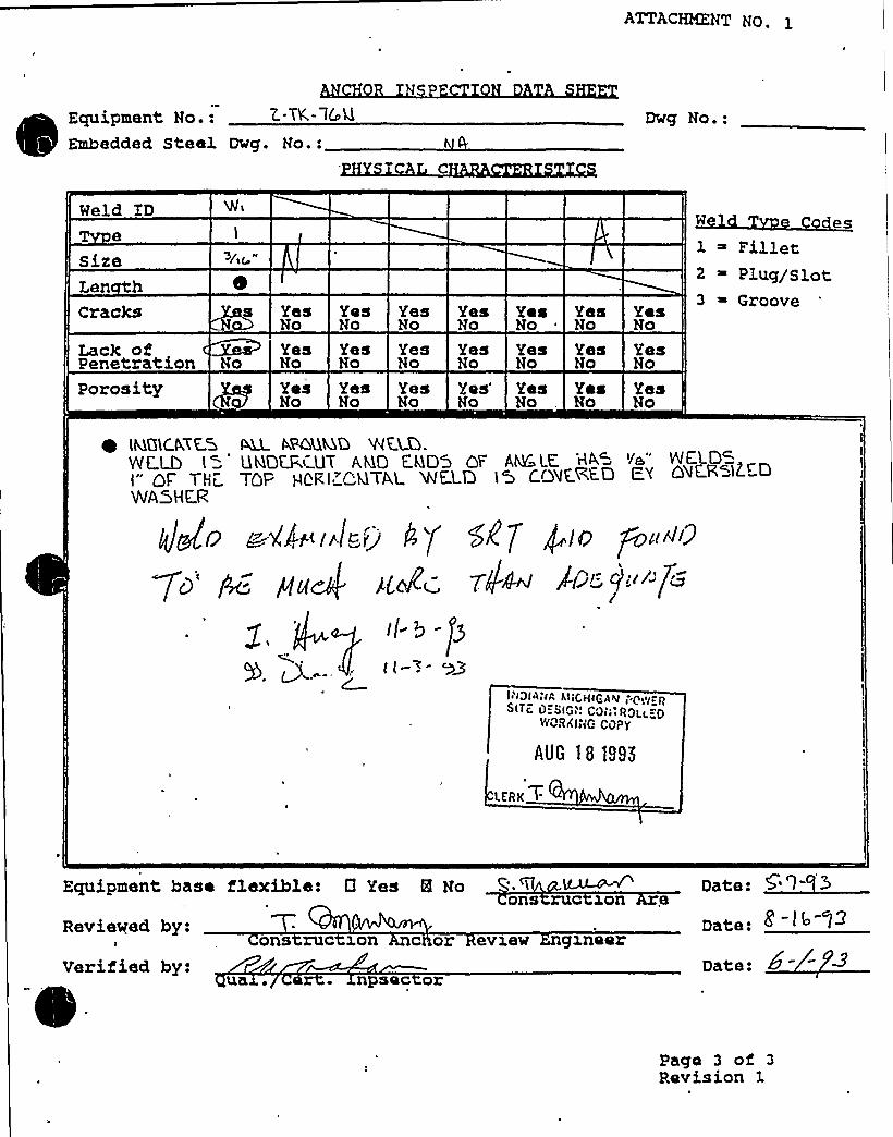
ATTACHMENT Np.
Equipment No.:Embedded Steel Dwg. No.:
Dwg No.:
Weld ID
sizeLen hcracks
Lack ofPenetrationPorosity
No
Yes Yes Yes Yes Yes YesNo No Ho No No No
Yes Yes Yes Yes Yes YesNo No No No No No
Yes Yes Yes Yes'es YesNo No No No No , No
des1 ~ Fillet2 ~ Plug/s3.ot3 ~ Groove
YesNo
YesNo
YesNo
(MGLC.N'ES ~ kFQQMQ 'REM.YVC.LD I ~ UMQCR<U'T AND FMDS OF AMC LE. H< '~e"I" QF 7Hz TOP HQR I "'TAL WELD I 5 CQ~~<~>WASHER
lh3IA;IA h'ijcH(QQNT~o ~i~ c
woaxi-G carr
AUG 181995
LKRKT
I
Equipment base flexible: 0 Yes 8 Noons ruc I.on e
Date:
Reviewed by:I
Verified by:ua
ons ruc won c or evxew gxneer
npsec orDate:
Pago 3 of 3Revision 1

ATTACHMENT4 TO AEP:NRC:1040E
SAMPLE SEWS, ANCHORAGE CALCULATIONS,ANDANCHORAGE INSPECTION DOCUMENTATION
FOR LARGE FLAT BOTTOM TANKSRAI ITEM 6

This attachment includes sample SEWS, anchorage calculations and anchorage inspectiondocumentation for the large fiat bottom tank evaluations requested in RAI Question 6. Includedin this attachment are the evaluations for 1-TK-33 (RWST) and 2-TK-32 (CST).

wquip ID: 1-TK-33 Txain: 12 Equip Class: 21
Drawing No.: 1-5144~
~
~ ~
.'ction: DRI
System: REFUELING WATER STORAGE TANK SUPPLY
Equip Desc: REFUELING WATER STORAGE TANK
Building: GROUNDS Room: RWST ARBA
Elev: 609 Sort: S, Notes:
Normal State: Desixed State: Powex Req'd:
Support System Drawing:
Req'd Support Comp:
Safety Related Status: NUCLBAR SR Min/Opt: MIN
Alias No: Power Train:
Comp Served: RWST
Mfr: GRAVER TANK AND MAMJPACTURING CO
Model: 420,000 GALS
"Elem. Drawing:
Wiring Drawing:
Power Source:
Walkdown: F Relay Bval : N
Comp Type: TANK
ISO Drawing:
Location: 25'ORTH OF UNIT 1 CONTAINMENT BUILDING.

>12 CHP 5021- CCD. 019ATTACHE'.NT NO. l
Un ti- 2- 3049
GA, ufo+Bl g.
25 HEPTA OI- Awrearr&T.Local on
lc- 33Insta at on wg. / Rev.
Anchora e Arran ement SketchEquipment No.
RW.S T
7~k. DiN&NCioM '.$ DIRx 5'2'- '5 ttlAH
2'5 ~C.&R STR~ Q &@A~( SB& hJRcy pa.g9 poP, aT~ ncvWg<g
gHC CT'%Re (S SW1 PraOuHO ~ e. ~~w~ c~~ p,~<< /$4 ove 'e (e% ro4
TH@ SoTTOM oF Ttl@
~t46- GF ~ >(g CIaeug~ WCP TeS V~ T'tb array'OOR.IS TA.imM) fH ~~~ I ~ NX,l- Pagan .
AROOHO SNaoTH MO They ~~q Faorn
~ll4) TO YQ ( F R12T QF T~ '2 Gtl>S ~ <0 FtC.SCL)SV:—To
'4~&/ $6 ~$ 6 0 F r~ nC'e'7~& <~aiI mZ ~Su~>oa),
INDIANAI/ICHIGAN POWERSITE DESIGN CONTROLLED
WORKING COPY
OCT kB tSSZ
LERKT
Date: IQ-1 t2D te:
Drawn by:Verifiod by:
gga . Ce . ZnspectorReviewed by: 2
Cons ruct on Anc or Review Engineer
Page 1 oi'Revision .3

'(
I
0

> 12 CHP 502 1 ~ CCD ~ 019ATTACHMENT NO. 1
B g.
Insta at on dwg. / Rev.
Anchora e Arran ement Sketch
'2S NOR t H OF NOTWWYYI~.TLocat on
'l-TK.-33Equipment No.
r=C+3uau
>/II"<is'w IP I e < O u>q
OMrI'S 'NIIYI~hS Ceo~Q
OI 3/br'" norns
TRt4K.
a4., 4
,44 s
4~ 4 ~
a
INDIANAMICHIGAN POWERSITE DESIGN CONTROLLEIi
WORKING COPY
Ot;T 15 1995
LERK +
SECT.'A A
8 ~04T 66 tYRACVAW~Q.AT~ S~gg 4p M~All(.+K STRFtP (DCThiL
c.av~a b be. measu.va a.c.cu.va4)T hue Q~ iv su.tokoav 'F 'adi~ S
Date: 1G 1Drawn by:Uerified by: Date: /<'-
Qua . Cert. InspectorReviewed by: Date. l 0-13- '9'X
Cons ruct on Anc or Rev ew Engineer
Page 1 of 3Revision .3

DC Cook Unit 1
SCREENING EVALUATIONWORK SHEET (SEWS)GIP Rev 2, Corrected, 2/14/92Status: YesSheet1 of26
ID: 1-TK-33 (Rev. 0) Class: 21 - Tanks and Heat ExchangersDescription: REFUELING WATER STORAGE TANKBuilding: GROUNDS Floor El.: 609.00 Room, Row/Col: RWST AREA, 25'
OF UNIT 1 CONT BUILDING.Manufacturer, Model, Etc.: GRAVER TANKAND MANUFACTURINGCO. 420,000 GALS
BASIS: External analysis
1. The buckling capacity of the shell of a large, flat-bottom, vertical tank is equal to or greaterthan the demand.
2. The capacity of the anchor bolts and their embedments is equal to or greater than thedemand.
3. The capacity of connections between the anchor bolts and the tank shell is equal to orgreater than the demand..
4. Attached piping has adequate flexibilityto accommodate the motion of a large, flat-bottom,vertical tank.
5. A ring-type foundation is not used to support a large, flat-bottom, vertical tank.
Yes
Yes
Yes
Yes
Yes
COJg NINES
~
~
SRT: George G. Thomas and Tom Huang on 10/5/930Large flat bottom tank 48'-0" inside diameter 32'-3" height (31'-0" liquid tank). Tank manufactured by Graver Tank,made of ASTM A240 Type 304 Steel, 420,000 gallons and weighs 94,000 lbs. Anchored with 25 3/8" th x 5" w x
4'4"
long strap that is embedded in the concrete 2'epth with a 2" radius hook at the end.
A detailed calculation was performed to the SQUG GIP criteria as part of the Stevenson 8 Associates report"Earthquake Analysis of D.C. Cook NPP Refueling Water Storage Tank Subjected to Nozzle Loadings to Originaland Current Design Criteria", September 12, 1989.
The calculation for the RWST resulted in the conclusion that the weld to the tank and embedment in the concretewas sufficient to develop the full yield strength of the strap.
The calculation for the RWST using GIP methodology indicated an overall safety factor of 2.57 for overturning and1.72 for shear. The calculation is included as a document of this SEWS.
The tank is founded on a concrete pad per drawing 0 1-2-3048.g4
Although anchora the straps were not rusted to the degree that the SRT judged the;e should be reduction incapacity. A flin ing of the walkdown was that these straps should be cleaned and painted to maintain their integrity.
Picture 2, Wk. 1, Tm 2, Disk 1- Pipe at the Bottom of the RWSTPicture 1, Wk. 1, Tm 2, Disk 1 - Typical Rusted StrapPicture 3, Wk. 1, Tm 2, Disk 1 - Buckled out Anchor Strap

DC Cook Unit 1
SCREENING EVALUATIONWORK SHEET (SEWS)GIP Rev 2, Corrected, 2/14/92Status: YesSheet 2 of 26
ID: 1-TK-33 (Rev. 0) Class: 21 - Tanks and Heat ExchangersDescription: REFUELING WATER STORAGE TANKBuilding: GROUNDS Floor El.: 609.00 Room, Row/Col: RWST AREA, 25'
OF UNIT 1 CONT BUILDING.Manufacturer, Model, Etc.: GRAVER TANKAND MANUFACTURINGCO. 420,000 GALS
Evaluated by: Date:
/~ -zg-
Attachment: PicturesAttachment: Seismic Evaluation of The RWST

& 5

OC Cook Unit1SCREENING EVALUATIONWORK SHEET (SEWS)
GIP Rev 2, Corrected, 2/14/92Status: YesSheet 3 of 26
ID: 1-TK-33 (Rev. 0) Class: 21 - Tanks and Meat ExchangersDescription: REFUELING WATER STORAGE TANKBuilding: GROUNDS Floor El.: 609.00 Room, Row/Col: RWST AREA, 25'
OF UNIT 1 CONT BUILDING.Manufacturer, Model, Etc.: GRAVER TANKAND MANUFACTURINGCO. 420,000 GALS
5 «I
!g5(Sl'') )I
Buckled out Anchor Strap
Pipe at the Bottom of the RWST
)
c
„"5'
5
'I Eyj
Rusted Anchor Strap

4l
'h p
P
1

+ pshsg
"'„"',ggr~ t
STEVENSONR ASSOCIATES
a IlruclaiknoCnanlcalccinclnng englnnnrlng flan CC,( WCC! 4 Ev AL Q AT (a4
0
a,~ (a5 v8
I3I-, I
(J s
IL :O'
+np. n.C. ERIC
I/7
g~r~i ~ !~!'y
pIIL.~~8~~ / rs( PJ7 I
r-i -rl
~ ~
I I jd7
+ t
.I.h.k.+As.g„( !
e..IH ~LC SgWI I I
I
Ii
I I
gLCJ f!~ I
I
~ I 'I
$!
f 6 cnI„. Q,uy ~i>~~<.I.
I I
i rr 7
I 'I
Ir
I I ! )
! i I I I I
Id,i
Il
I I ~ s ~
.Li 1~2.C (I.Ms ' i
Is ~ ~
I I 1
.CD&.iiI 7
7 I
I I IP 'H ~ .: —-'25 ~
I+
Li l
i II
o~ qi gA~—r- j
I I 1j
+I rV'-~—! (',C I(~ ..mI I " I
I i ! I 7
' I
7
Mod .'C gI i I
Icn e)
!I- .i. I I ~ ~ t ~
C' Ial ~ O'. - PPl /~C~ .OJ L klI ~
II
Qgl
I
rh I I ~ ~
~I i~
I ~~
~ 77
I Acct(a 'r< I 8 a~II I
II j
(D'MC.I(.C'B~AuD
2$
pig II'7 Is
I
I ~
~ ~ r
I j
j


SUBJECT
nt 4 I
SHEET OF'BO Z-
NM > zan0RcJ
STEVENSON5 ASSOCIATES
0 Ifn»clUTCHnechonlcotcon»vtttng engtneeltng ttt»n
NS - ~. C e PP
L.t~
I I II I 'I
.«
I! i ~l IRQ.C.—I a. <
)p~ pI I I
w~J. E,DclsPLLt c eL. Pp~i,~I,'pm, sb~~.FI,EE .
I .'!»
i i
~M.4 P~(A.'IFtIP/
tti i l t
MBLc~Ik
t
!r,aT ~~i
I~ et- c.~'a~A
~j: . SWJI
Q,»ti m PgI ~
':)3~'.ca:~: l g cc.Ec.~ ~
Cw:.~)—' —C- ~- -'. -' -::-Ce)-- -'.--'C~-">-'-.----' C~>--'--:I ' I
I . =.Ii '] I i I Tl I
I. C.'Z CC.
j . z 6 ...,..''..5;. t .: '.,:2 ~ .'. ]!
~ T ! ~ I »
~ I
~..l l %. O i
W,O iI
I i II .,o.5:G. ~,
~
i09''.Z-»
I . tAEFA=. n . t.
IIt~
»I~~I1i
I I
+I I 4
~ II i I
! I ~, I I
i ''I 7 8,
I i'e:~I
~ I
i 'II~ .PM~K
7 + Z,- o|r,b,
I 'I
I I i .,2AT j
l
~I
I
Ii
1 ! i~ ~ e*., i., I. ~ ~ t
!.i.C,tq-.J Z.dD .. VZ0Q.Q,~IS.g»-! M~ I
fl>gs q
P,s to»I s .in F. .,'E.F», a!FFE.c.'rP-'. FE,
i P
I
g,r s~o a.etcE» ~-4-CM~-E M~ —4/t.l ~ TEI m.
.cc'AGAN n.A '~a 6 c~,~~a.@~'~w~.s..y c.'F-M.c..ks.
jpJ t
i!
i )
rex tpU ws.( ~-~, p- ..Ei'.A.,c:)ir..'< h,»~<. J»FAG,P.h EA.kaI„P'nk ..i.m~46+S.IV S ~P-,A..
n.p. !
WHX., H,z.& .
t.D~I I
IC C IFFY
I2 E
i
I I ~
lI i
» I I I ~ I ~ ~ ~ ~rr—f ~ ~ ~ I ~ II
P~ H~C ~C. k..I

Response SpectraEOASP 1.0
08-03-1989
g V ~ ~
FREO
1. 0. 102. 0.133. 0.164. 0.205. 0.256. 0.327. 0.40a. O.5O9. i 0.63
10. 0.7911. 1.0012. 1.2613. 1.5814. 2.0015. 2.51
DAMP.050
9.872E-031.790E-022.700E-023.660E-024.832E-026.133E-b27.518E-029.276E.021.219E-011.434E-011.702E-012.040E-012.357E-012.604E-012.834E-01
DAMP.040
1.008E-021.846E-022.794E-023.798E-025~043E-026.432E-027.920E-029.817E-021.306E.011 '40E-011.838E-012.217E-012.572E. 012.849E-013.108E-01
1/3
FREQ
16. 3.1617. 3.9818. 5.0119. 6.3120. 7.9421. 10.0022. 12.5923. 15.8524. 19.9525. 25.1226. 31.6227. 39.8128. 50.1229. 63.1030. 79.43
DAMP DAMP.050 .040
2.288E-01~92~+ 2G'$~
~05&91~~1Qv3BH. Ql~~1
0&612A78E 01
3.066E-01 3.371E-013.290E-01 3.629E-013.292E-01 3.630E-012.937E-O'1 3.208E-01 fo
+'.591E-012.809E-012.337E-01 2.514E-012.20?E-01 2.367E-01
t'.Zc 2. 292E-012%38~1
2/3

5 2 - ~6'5cf- P-EF
SHEETM~Ol42.~
g~ S-S
*
\'I
'STEVENSONR ASSOCIATES
a Ittuatu)CHnechanlcafconsul)lng cnglnccnng nrrn
2)2,.e
C+ ,4 23( I
. I 8 aS
~'o ms 4wi ! I
L j
(I I l IO'Oi I I I
~.s g 0 C., 3-8J~ C.H&l?=~ I I I w4w~w..PaEWEf=mA I
I I f I'~-V'nil p~ '.T F~
l I f I I j I' I j ""'
.G.~~r~.b.of e.&v . 'C,fw.C.A IA, . C~~~~.~) <.~'
~ I T!. „. c.„.) i . A &,c .y'.g f g, LV J.f,a „4 ~oi,7 I,rl &.6)„kd.MQAG.=Ex P' wv.'
JI ! I: I I
I
I j > ~ I ~ I~ I
I .io'z <~~I
! ' l I L'' '-I wi.i
,b..~.f,a C .y... 8. V..... VZa .,O L ..fd .. CV.Cv'6S..~
l ~
I Il ~ f" i, * ', I I I I I I
l
~pi 4
I II
: c.~~S~4./i'T
ri-i'5
jI
I I ~
/05 5"73
( I ( I
5l
Ii 3 M 'Ao
I ( I i ! ( II! I
'
I l1
~ ~ I
I i I ~lII
I I f II
~
g '" 3cO+J ji
j=.o, a Ol ....Ua CD
;.3'~lI
l
I

STEVENSON'ASSOCIATES
a IinrcturojtnochonlcotccnsuNIAII oncinooring Ilrm
SUBJECT~&~IC P6 JOB No.'e" ''' 'J 'u'..C 'C' *Q,P.P
s(ig CPS'Q e-s.-eOCII
III
c o
~ <C
! T li
Tn I+I+L! II ~ J M!5~
~c~ (~~.E~E. k'~~a I oj~ N'"=RE..~
„C '4:.'...orrT=.. I.~!O 'O.j I l.
g. opj
I
Assio «([a
II , nM.Ir
II
T'
I ~ I II~ ~
<6,P. "..==.I.-I I
J+ 'L . Q~'~p.'i:MC'tj C.C K I
i~ }
I
!: I (
I I I I I
! o8~ I, ~
I I I ' I i
~'
I 4
.:,4 c.cI I I
I
I i r«T $'-'a'
'Z.Z .I"~l I
tI I '
~ Qoi i 34~I oI da
, (''6
II ~
I
T ~
r

I i
SUBJECT sosi(0. ++<'1<~7'HssTMa oFEPM
,;-.'STEVENSON8c ASSOClATES
a ttructutoHnechantcotCohuttt«JQ cttglttcctut(I tttttt
5 (
KO «C
j I H l -X,.9
.~. ~J3.6~ j
j L l j
j jt
I~
tI
I ((
tI 1
t I I, (I
«J
I (
j
«MC P '- B ~ 0 4<WGR 'lJJ!~««««I. P Q P mJII
J Q g S Q~ P'4 e l W jy~C't i j
I
il I.!2QI ~
$ 4«
L Ia4-I
j ~~+~ I I-
Ii «j i
I~ I !
t « ~ I '«j3
~ i I ~ I!
'. I I . (
~ « ~ I ~ ~~ I ~ t I
~ 4 S.E GAA.P H.D~ I ~ ~-~L~ a.t/,~ 6='. I I
~ « ~
',.'; . Sj ..'S~P..J @ .—.....,: G'.c~.—.gg;,~.~ i~a I .'t-.'. o....PP-.E'.'.s:~a.+:~ L~a g.;pl@&'C(A D — 6 H.tat I Q ' p, g~( g i.Jci ~ ((«-tc'; T (7): ~ I
I~, Il
I
t
„„.«0 (~ ~
I *',~ ~
plHr~ ..I
j lQ,'./g....j:,...Z 0 ...I.:~, =i j.'.. +
..)=. J <' >~ p»
~ « I '«-c--II . !
P.

Pp
STEVENSONh ASSOCIATES
a IttuotWOHneChcnlCOICchfttltlttg OttghtOOttttg tttttl
I=IDXOttt)ItlIK
t-trg.
I ~ t I~ ~ I I
' „/ 9?~
( .'I ! ( ' t I
' 'Ig TLIg~iQ~
l ((
j~(
K<M .c aA PA44
t t I .'j
~ I
L.. t,bI
t r I
t~ I
/ trr 4
r'
r* I I
) 1
3 ' ~
I ~
I IA/I
It. E8'.I WN
D~.. DE'te."I I
y
~ ~ ~
lt
x.EI..~ ~
H.rw4R:.:,LoAD „cd'ir I
I ~
I
I r I

SUBJECT JOB Ng ~ r! s Ils—S/'s.s
O'ZcJ V-S-S
~/rI
'TEVENSON8c ASSOCIATESccnrvttlng ongrnooltng trim
~-Dc. .RP;~
LL Qs„+ 3„ O
LID
5 PEP
> 8 e, aaL,7J
KJI
r4>. w
I t~S..H.- fc i~
I
iI I
s
I r ~
s I
I
'..w c a~@'„!I . „> I I ',;
I', IIJ ~>cp.p~Liri'Tlc>,nJ—r-- ~'- — "-- —" ~ - ~ = ~
II II ~ ~
.5 WE,P I /.Q..... g.j..~C+ 5~CT*e icI:7- +);:
I
I
i
l q) S zap (...ID,....-... 2.>I
r I " r '
iL.J
.'A.R.E....!.. W nH:C.c ~I
DQ I 4I ~.tt
4 9~g~cA.&Qr
~ ~
I~ ' i ' lt I
O..~ + H. Q I pQ p ~i~ f jig nI Lp~p.+ ~g~ I I
i ~ I
.. A-.M....,.. -'S ~L?'FPI'l'-I Cia I 7.O „:...Eg.5g.g/i;.. 'Z:B.Ai..+8;CQ~
'~
~ I Ir
~ l t.'L.<mrt,a ww<. CA~+.c,.( mv'.I.Ij ~ ~ I
c . 6 6; J..I.S&~3
I'
4? I r.'C) I&.&I C p4( I, I ], I
I II
~ ~ r «'t ~
! I'.C n.y~: I
(..I (.
I ! ~ s ~ I ~
.FI I I
' ' I . ( ''I ~ I
i'R2's/I('
IL. Li
-,.V~ ~,
r r
>0-r—~".I
I IN
\
I t
I '-I 1
r'r'V '. I,.Ll, I
I'
M rI
I I I II> ~
's
I vrl st I:lsr «rr rT'.rs,! s,
'i'
I~ !
'I j
J
II/I rl ~3. I— s-... I
I I j
~ ~
I jI *q ~ r
t '!
I
II
: L,=..2+% ~;L.. ICE, I/. '
I!——
Il l I
I
~ .,r
s i" R'„ I ~ II t
~ II I ~
tI
r. $ sL ~ II I i
r ~ !

SUBJECT i'A,VV.v.
STEVENSON8c ASSOClATES
O ItnIClwalmechoNcolconsaNng cnginoc!Ing II!m
P ~cv C
Q.A/A~ g vll.X
A
l
AA~c- !i .TT''i,y~.+ 'ip
i
L
L tk~~. 3.l.8,i ~ I
wP.EC
Lam~
8 'e 'A'.Pm Je'~.c.d'i
i I i
I
P.I-.A.-I6 8 B,Nm4~ ~ v p
cI'I ='.!ri, g./JAN 'J,: 4 i'j ps';pv~i lDa lij~~ns A
-
I ' ~
c5 = . Q''(y.e+$ 5c +=',,Lel... C? 'ps i !os.d 2%co'p~
S,UR E vvj E .~ c.c A, FIc c- 'l.=,$ 5. ~i >/z'..".)..!2 =,«!>."~7,.%„,~J
C
I v
:„, .. t=wLQ f g.'wg.nL.v'... „~P g~~ P '. P C..~'a I,.PC&,..~~..,...C!g.a ~i,a P..'.,:
l I ! 'i~ \ I
! i ~
'I~A Bee. '!N;v.D.i'~. G' .HK'.~rL DA &~'~
L
~ ~I I i ~ ~
L t.:,'=.: >' rZ.: CZI .) .=..2S;,3;:W ..2.>..~
H ~ r~.~ ~ A c T'~ '~i T A,c.v.e~.'~+!AacMk ~i+.vv< ~i . ~, I !
> J,5 i i PA (rTVV ' ~ T V~/aREFnR .Py~g.I I -, I l v I < I ' ! ! I I t; I ~
'
.i~ ''a mZ!~ vi vL.. '.C'e SvILA~Kv iv'Ev'.'I I;!: I l: l I'.! I!
L
: R.I,S~...:.H-C'.,CW . ~o.GS .APE ~4.9.:4: ..~B 'EF~Q.460
I I ' I I I P I „< „, i ~ I
.* . I ) - . 0 ~ .T
L
!
—-I—- —.—,-,—.---,—!—.;——,—,,————,'PC I, 'ai-I PL a '~ '. I '&I
f"Il r. T-' ' '! '
'. J, j: ..'.LL~S v.D'~ &rH.! = I2'C~7S)+!O'LZ,.5D=.I ?:'i i ! ! I ! ! .:.;: ! i Y"'.vvc iv'v. 'w' f7
E'...,.....,,......v....,. „..... g,v . /.. T,...!i .....,J.L.:....'.. I.: I ;', . ME~OI...CAP,...= I Z,5. (,. VCIP) ....; '8;, C7~..: ".3.;. l..7. 67,>C~.=. ~
~ w v I ~ ~ 'A» vd ~ v v ~ JA « ~v v 4 v ' ~ v 4 4 V4 lv

~s ~„2."s
SUBJECT S I ~ I+ ~ JOB NI4.+
vl I id
STEVENSON80 ASSOCIATES
a IIIIIChslCIIIIOChcnleolconiutiinIIengineering turn
0, . C.o
MKOIo
IIIK
f~ZZ
37" 7"~ I QI,'iT I I I I s
I
e~L'~C ~I
* '1!, 1 5 so..='e..~
I iL
r ~i$ qf-rPAL
I
'. ~ERE( F,'M.Lm. < wWCR &i~~
lM .
oCT
I,s
'9fz „'l~r
~g C I .~.$ .I.m„<.,5,I
1 M Pr4Di.PR=~,LED ag.c.". '
I
rI ~ l ~
dOSi I.Py~&$ a my'~I
II II I
II ~ ~ I I ~ r ',''.I I I l lglr
I'4 $ P.~c.c-.a
~
'..,H
ctv E „~m ..8.<„
.]c
.O.u R.. I&..er
.II- . ~,.CT.I.t .a
I
I'M.C}=i+D e MA 4 C..lc 'i
I. e,~c.r .nsr..~ J '.
I
l 'A.hDI
ta,~i@ES.'t W.~..~ ....(.~l! L I ' I i
.Q» ~..C .... C.C a.I~ ''.ua iI j.W C. !,n.Wr~g-".„.,Sq-..'ygPZ~I
L'e~ k~~.', a.~. .'.. '.:~..~ .. ~~.g i...S 'n U.C-. '.U. S,Z.:. —:..+.6; '. ! '. I..,II
Prs co+.sP=L.na sruti .or.'-.'-.rs 6 I CiZ ..I ,'I III.f
S M rE- .~'~ ——r II ! i
I
II ~ * r I
~ s I
I—I ', rs
I
j
I ', II 'II
~ I - ~
I
I r
Ir ~
Ir,I
s
't t r ~
~ ~ I
ss I ~
~ ~ ~ \ ~
I r I ~ I
I II r w
r rI~ r
rr s
~ r I
I II I
II I
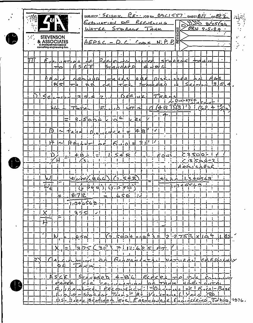
\
t~ 4
SUBJECT C ISnn I
* oa er- PJOB No. ~~+~ +~~ SHEETglll Ol4~
STEYENSON5 ASSOCIATEScenteIIInii englnoednII nrm
OIi)
illCC
iI
4.
+~i i;I
J ~„L
I L
II
~ll~ i i
I I I
~ iI I
i3 I
I i! ii ~iI
8 Ec5!~ ., l''
. i i
Ip
i I Q„l
I I I
L,
8!7 i
I. 5
I ' I
I If
I
I
IIt~
I II
i I :.2MLI
'.3
I7 C;3LiI i,:I l I I
I .F~.a ]i
I II~ ~
I
":!I
I
I
)II'
g'< ii IgA
IP'I
.l.+J IO'.II.SV..S =J.)IL>~~
i A
I I, II ~
,hlA~u P.B )
i ~
i
~O.g~v fo'~ II i
)=N 4-.c-cn&lrACsd~'lI I t-.)C +i.X4D 8
i i

t
W,
l
!

SHEET~~~ '~~STEVENSON
5 ASSOCIATESconwNng onglnoorlng Irrm
O
~/5I
I
21E
2 h'
I l
!-'
e
!8 ~I F ~'u.l2.4'I
v
J hAAv=~ ~~1
g+s
. ss ..DI
l'
I e Ie
PC <5'IW'V: a f-
e~! l l lI I '
I
1
l
.h~ ~
Ie
1k
! I: 1 ~ r I l
H.K L(xP2. '~~I I 1
I
l~QtJ I
Ttt& kr
I I e I
! I !
I I I I
l..i
I iI
e I
Lr g e& ~e 32 ~ 2
I I I I~
1~
i 1 I1—'-i
I i i l J'E
I
Dj i 1-8-:5
--f1
J
e e e ~
e
e e
l M1 '.. 3.6I:..Ft'.E.'.MM.A. HE. H .' 4 Z6«<4
e
e
I
4
e
l,j I
J I I
II
l. ~ lI
l
I
i l
I I ' i 'I . II ~
~ v r i~»~ e»e»e'~EE~

STEVENSON5 ASSOCIATES
O Itiuolvrolctt4Chorticolcoriirrtttrco 44QIA44rtog Itrrri
SUBJECT JOB No. (-I+
I «J.
SHEETBL+ 'OfJQ- 2-
RM'F-S-'' CCCC:
rir «~ "I
, P 8+~ ~ C
2K. 2hz I
-i~t 5—t
zfz 8Se'~. 3M'e6 ~~a ".
, JC,(M gi ~7
L3~:
~+If~
fg 5
I ri(
I
r
II I
r 1~( y.g I~i! I'l(
I(
~ ~ i -~~
I'
. rI I
J~C I
C'
~C \ r ~ ~
. ~ ., ~ ~,.r,,„.. r i+-,
i
nrr~l4 ~1
(!, I Ir ~ - '
II " . *"
II
5
o« «.«",f=rr r . I.="pa cr o-c,«..r,r rrr«rcrff;ao aa.6$ *««r.«f r rrw
I J~ ~ ~ ~ ~ r ~ *I ~ I
I I
!. '.f, u P T- )
Mphil
Ql 8 A 0 ES P 5„h CP X„7- I('gP%gW jFi-,F X'u''R~ 8
C 1
7. I{I=..„.,S~! 5 ! ! (
~J,DMH Atua . HANS
L
Ecvz.a~ 0I
FRE.uEZ,C.r. C.r=., OV..A.I .I i~.6..RI'Xi'Oa .OF .4''
r H EROS JJIM O
4 ( LJC C~.HI ~+~ 8++r ',, '
.re.J..g:S.. AS ..A„:.CS H ~f f e~VSC-~,H.'rI i I
!~ ~ ~ ~ ~ ~r '
=. ~ C ~ ~ ~
r
A5s~ v K ggQ ~JP- 8' ! l~
I"
I
pl+( I~l
I
I
(>rI
!(-~4—
( I r ' I ! IIrW 4,! ...,. 3,'5.'L4r? .EIIr... MMs
U 5.(.g,Q, > ~ ~~ i." QP'
I( A. I
~'.~l,'~w~ ~F.v. s. PPP.&x f M.A.+ f ~M««c ~H prrA rrc rL.....CCI g Sg hl,~q.u
j I ' i l l I; I 5
8 g(g.~C~I f!,'~c
(I
i, t 4» wt
IC
'r ~ « - r
r r~,; i ! ! ~ I l jr... ~ '.. ~ ~ ', ~' a« ~ !

'"k»'» r~ Irk
I»
~ rI8 ~
:-. STEVENSON'.-.; „'. at, ASSOCIATES.';".' a It»I»CttltattnootlantCOI» ~
' Ctcttttlg 0tlgtt»00tttlg tits
» ~
kk
SUBJECT I ' JOB No. Ik
I» A~VA i t~ W ~ leP. ~t f O
Ill.k=!»»F-'»'—'b
5~trYI ~ '
I'C
n"' f
I »»
~ I I} ((J
LIJ TI~ t
jt
gjI
',li& Br~~
i ij I .'J- i+
-5I '
l CI-
~ Z
~ I I I ~
5
l.Z,. P (c 2SI
o+z)
o2> cQoQ
(2e+

4/g 4
~ '

STEVENSON',.', & ASSOC3ATES~ o structrrroHnechohtcotCOIN(tthg Oh(t(hchfthg (If!ill
CVP u Arc~ n(-
0!ft
(t
KcJ -S-8'
J> VV>VI>M> IJ
}
II
t
~','
3 i
3
t~ t
3
}!
!i }
~ t }
f; i
I = I
3
i~
> ~
I1
3
IJ
II
]~!3 I ~
1 4 ' }(
4I I
I t
}+I
J '
(4 P y.fj, t 4
I}
v
4D A i >}r. I(—I(
+-
II
I1 I
I I I
L
3
! i~ ~
I t t~
3~ ~
3 k- ~
4
3
I
I4 I
I~ I ~ ~
I ' '» ~ 'IL

SUBJECT
C
STEVENSON8('ASSOCIATES ' 6@ G c
o )ftucfut~cf)otucoftuA)uN(thg OtlglhOOflog fltm
~
'OB No. +++ j +~~
zO
~ IIH(IT~OIII
N 9 cP'-5-8).'C. '-,y>,'pt1 ', lh
't'C ~
C s R
. Si C»
I,'i
~~
I
I I
a Ii g'W7 P~„~!
I X~ESS~ C.6.„I i ~ ~
t
~.i.S'~At.8'VT'I.O.+
~ I
~ ~
I )
R!"I~, i
IL.
~ I ~
~ '
I
iI l
I Ie I I I
i!
) j, I
t~I
Il I
&i% .
j ! !EQ R.~I
!
I
tI I I I~ c Dr~t-.
~ ~I l ~:, I i
' i(
&r. O..~.&.W.R.Q.;.):6,C EO Sm )4I':~ ~OK.
D'~ ~ s 4.~,'<w~nP,~c.~~ urn+
~ I i I i ! tt
II I
l C.35o+-I
( D/p—
~ ~ i IE:j M I ~ i 'C ~tV'„C fi..4!.D '.E't ~..~~: '
)I ~
I
~ ' I I
.I ..Pg, . S.O~(=ty 't=)j. „Crt,igPP C.A.C
I~~ . ~ . t
~ I ~ -I a ., ~, ) ~,, 'I ~,, ~ ~, ~ ~ t '1 ~ ~ ~ ~ ~ ~ ., ~ ~ . ~ ~, ~ . ~ ~ ~ ~
~ I

g
:0
'0

STEVENSON'I
ASSOCIATESa Itn(cturotrnochontcol
coewWng eng(noortng firm
h
E
E
(~smr
E
I ~ S
9$ c(=
Ir
E
2
)I
I I
+ ~,.~rs 5'o I I
Q ~I
I)
LGJI
I
II
, S I
I ( rr ~ ~
+&,l
ln,sac 8&
Vt5>QW
I I -" /
'i (s3! ~( I (
JVl
( J.2 o5.k
'Q Lo521 I
:Cpp
(
I I
8&m
4) I ( II I
"i
i ) l i
I ~
i~~7 IE
L.'I X- CE L
I (a gi
)
.j LI
. L

tt d
II
0

STEVENSON8; ASSOC1ATEScont)itttng entttneerlntt tltm
i UP7 tmA C F- ej &5 m r I
-P. c
)
SHEET '4~~0
Ctt -s-z0Itt
Ut
~ L~~l~f !
7(o 'iI (,I t .'o.+77gg
cate jM~~ ! i '
S.~~a.oJjR,O . I P.~~~V"4" .!jct B
I 'R-O t'<5~Lt'QF 5 t:.SIC'R b
j~jt
I )
l t l
I1 ~
! i I
I 3; 4't) ~~,if
'OS)),
J+i I ~ j.„„D C„I 7 ~ .~R C ~„....~i +, Q pent')'
i <~ ~- .,r' " SVZ
-,'ace.II"lo) ','.c)n7 '.""co s t)'i(3-'j,s',—'
~ I
'I
~ ~ ~
P „ i 3 35 5~
~ I I ~ ~ ~ * - I J
i ~ '5'
~ ~j ~ ~ I I i i I I l~I ~) L
I l It
.'...5 Q ~pj, ij... h/+~ +i
i'P
jc~ ''l
~&.2itt t
pea (
2-.2 ..p,e I..... y .J3.3.4%9;.K 5;....'P ~ t.','...., y.:.= H CC3.C
.'+ 5.O ..t) S'.i. ',Ir.i=.:.37 'rr
t.(n.,o po F
.J'4-n p~g
l
t ~ it, tt)
III ~ ~ I ~
f'"
It
~I~.....'3.,5.Q .p.s,.l,, =„...
tlj'' I ) I JI I
.= 'J&.2.: ..! ' I ~ II I ~ I
++ tt ~.3.l.f P s.i =.='.=.(
''t
f ~~i( * \ ~ ~
4 . A ~ « IA 4 ) I~ A'y
I 5 i I joi \ i I . I ~ I t ti J I ! I I I I i i I ~

r„'ai<Q,
r'rotrr, s
,„;.; ";.'TEVENSON'"'- Ik ASSOCIATESo slructuroirnochonlcol
consurrrng ongrneerlng tlrrn
SUBJECT (C 'OB No. ~DC l~u'i(~c
'' AP.R
V)zOrrt
cc
ss ssr@~orrt< ~.~l~sls
4/ ~5 ~g
s n-s ~ fs"s s~0
s rats c."J
~ri;, ~ .
r'M
t J'.K L'u .P,.i
l~r.....s .. l ic k,.to y. I'P.~i
gH~ Im~r
( (~g ~.~™)M<.csO.A .a.,&,5
, i C.s „..MH ./i AsJ,rtc s.~~~ ~>
Q 2
IO+'(-
=,3 2 co .'c' rc....'-ps)r r ~
F R I=-~ w.(.a.k'. ~'..:.7~L ~ L~I A.w~ ~..$ , p'.ig.'<i,.4 t.C .Pg;:C.~ 5 sJ r(c:C ~
FF~ 8 D.A.n'< E.,rt r. h:e r~ ! . t p'I.Q 6, .J., Cl t g r. o 4
rI r r I ~ „( (
EL
,'„3 4 5+ ~ ..I n. J .
if~I
7 Q I, r, I
8S x lc ~HZ -(. 2 359t i ~
IL
l ~
I I
I
«',H..p h'.. J ' WnJ'g,g ~< ~ '.s-r,~ ~ „.Ent.C .t W.'.~r,,<~~t„l CI
I = 2-;
I I i3/a(e da ~ I
r it i
e 4.+z '~I
I
I r II
~ -. '
I
~ 1 '
iLsd i .8-Q
rns~MML
r'L~ ~- 1
I

~ 4 CC,
)C
f
~','TEVENSON .
.- 8CASSOClATESO Ithfotchc<<hOChoh<CO<
cohfcfltlhp cop<hoof<tip hfhl
SUBJECT
Ar )'
G.O'S < —.'G:c. c.~! A PP . ':~
'OROV)
U<
SHEETS~™PF gP ~ '
~.<r
r'O
<5j $ < &S
++!iI
'C I~OI I
I !'
,'5o.8I
I ~
Jt0~$ I xI +-l-
3I
)~!iI I
I T9-W!~UL3.ed1
~C iI .~
I1, '
~ ~ ~
~ I ~ I ~ I
~ ', j
W'7 ff' 1 i c I ~
I I r, I I~ 1 1 r
1" I
I I
II
I I II
II
I I II
I C
SIO I~~ I5 + x In.~B' ~~v5'3'f ~ ~~ R <j~.. I 8
f
l I i
.,.7.e.Z), W, L- Z d,27 ~,g 4~E!,Q~ ~) I +-I I ~ ~ I
<.. ~ .I I i
~! I M ~'Z. IV
~ ~I <
~
~ ~ 1
I II I ~ ', ~ . I !
i I '' ~ ~
(J g.a I S.,i,)(,~.4 ...,E,0<~I.Oa. C.C-„ =A<„< S .FuP-rt.v<..<S„.. i og-I !
I
rI 1 I I r r I I
~ ~
I I: . ~ . ~ ~'. I; I ~ c
I~ ~I+,+<<., ~
1 I ... ~ *r . ~~,. 1 .C...I .c ~ ..Ar
~'r c rcr, ~ a. e~c '
'.....I-rhrrrf....;,.IKSS:S.... e&l ~:. S 'E +,:='.+. (C26 CClCS..)i..


4 J
SUBJEGT ~ c. ri, jOBMJ:-J33C f55 9..'.'SHEET/2 I B~2Z::+Ac Y <g.. f-
d Wc'-5-STEVENSON
8c ASSOC}ATESO ItnjclllloH54Chonlcol
conIIJINny englneerlny ntm
0EO
~ 'I~"
IJS ~ J S k
I7 axe
~ I
cn+
} I I;" }
~ ~
I
,po
I II
1~ .
7p~ I I
i r~) I
I ~J
i
1 R !8 ~ C-~iP'IO~IE.<~L E ~
'I
}I
i
C
}
A P'+ ! )'pl '. Qg t4'5(o 4 ~
4 R. EI
». 1.F.U<~<6.%3:[ a~I?=Aj C
L ..
S~IE- JJ JI
I ~ I) I
I ~ ~
1
,.Z. B&'~ I I
SZ,I2 O
IAI

i g
01l
R
h
>'I
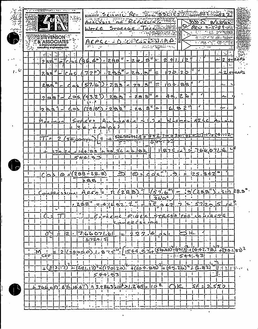
'1 1 1terrrr 14 r rA ~ 1 rt
SUBJECT '~ Wr ~--t;tt r~g
~ V.tri
':4"""~~"STEVENSON""''.-';;:
"..'-".: 8t ASSOCIATES" '-'„,
conrurrrnp enprnaorlng nrrn
Ok &/ . "T et e:i ii'~ >."""'11 +'" X0ro
UIcr. .".ggq Jt..r" rut-r ..rt)tpf.
pPi
3 ~ I ~
~Res 4~I
ct W~ 8.~
604 SW.'t52,4 ++
~ ~
~i ' '~l i~
I I
g
'7+-8+1-.(-1I t
ZSB- Z S.'8 '
~
I
.I e ~
I I I I I I
4 ~
~iP-..C
~ ~ ~
QQ)8' 'I
I2S.SII I I2.B,B:, . 5 IA
I I! .f.'g tI
,w C.1 !Let.
1 r
<J g ~~i~s4!f. k. '- (.8j 5. pc Wff..rf'~ J1 ~ ~ I
It I
, ('7 4rtt Ct~
I.'real
I' g,
rr
r
--~lr
(g~,gg) i
I I I
II
t I
'CAP II I
1
I
t. t 2) + (7O,>u)(J
(to 4. Q
I+
~ g'++; ~ 'h3' i
'I l
1 I ~ 1
~t
I
Ki~S < J)
~ I ~ ~
V

Equip Id: 2-TK-32 Train: 12 Equip Class: 21
'ng No.: 2-5106A
Function: D
System: CONDENSATE STORAGE TANK SUPPLY
Equip Desc: CONDENSATE STORAGE TANK
Building: GROUNDS Room: INNER PLANT GROUNDS
Elev: 609 Sort: Sg Notes:
Normal State: Desired State: Power Req'd: N
Support System Drawing:
Req'd Support Comp:
Safety Related Status: STANDARD Min/Opt: MIN
Alias No: Power Train: NA
Comp Served: CONDENSATE STORAGE TANK
MFR: GRAVER TANK & MFG. CO., INC.
l: 500,000 GALS.
Panel:
Elem. Drawing: NOT APPL
Wiring Drawing: NOT APPL
Power Source:
Walkdown: F Relay Eval: N
;i'omp Type: TANK
Iso Drawing:
Location: 50 FEET SOUTH OF THE UNIT 2 CONTAINMENT DOME

DC Cook Unit 2SCREENING EVALUATIONWORK SHEET (SEWS)
GIP Rev 2, Corrected, 2/14/92Status: YesSheet 1 of 3
ID: 2-TK-32 (Rev. 0)Description: CONDENSATE STORAGE TANK
Class: 21 - Tanks and Heat Exchangers
Building: GROUNDS Floor El.: 609.00 Room, Row/Col: INNER PLANTGROUNDS - 50 FEET SOUTH OFTHE UNIT2 CONTAINMENTDOME
Manufacturer, Model, Etc.: GRAVER TANK& MFG. CO., INC. 500,000 GALS.
BASIS: External analysis
1. The buckling capacity of the shell of a large, flat-bottom, vertical tank is equal to or greaterthan the demand.
2. The capacity of the anchor bolts and their embedments'is equal to or greater than thedemand.
3. The capacity of connections between the anchor bolts and the tank shell is equal to orgreater than the demand.
4. Attached piping has adequate flexibilityto accommodate the motion of a large, flat-bottom,vertical tank.
5. A ring-type foundation is not used to support a large, flat-bottom, vertical tank.
Yes
Yes
Yes
Yes
Yes
E P El IC
COJHI)LES
SRT: George G. Thomas and Tom Huang on 10/5/93
Large flat bottom tank 52'-0" inside diameter 34'-5 1/2" height. Tank manufactured by Graver Tank, made ofASTM A240 Type 304 Steel, 500,000 gallons and weighs 128,700 lbs. Anchored with 30 3/8" th x 5" w x 4'4"long strap that is embedded in the concrete 2'epth with a 2" radius hook at the end.
The strap detail is identical to the strap for the Unit 1 and 2 refueling Water Storage Tanks (RWST) 1-TK-33 and2-TK-33. The calculation for the RWST.resulted in the conclusion that the weld to the tank and embedment in theconcrete was sufficient to develop the full yield strength of the strap.
The RWST has a very similar configuration as this CST. The calculation for the RWST using GIP methodologyindicated an overall safety factor of 2.57 for overturning and 1.72 for shear. Calculation is attached to the SEWS of1-TK-33.
Comparison of significant attributes of the tanks is shown below:
RWST CST
48'iameter31'iquid Height25'trap Anchors
52'iameter31'-7" Liquid Height30'trap Anchors
For shear the tanks are essentially identical since the demand and capacity are both proportional to the area underthe base.

4%,h
II
's'.il r

DC Cook Unit 2SCREENING EVALUATIONWORK SHEET (SEWS)
GIP Rev 2, Corrected, 2/14/92Status: YesSheet 3 of 3
ID: 2-TK-32 (Rev. 0)Description: CONDENSATE STORAGE TANK
Class: 21 - Tanks and Meat Exchangers
Building: GROUNDS Floor El.: 609.00 Room, Row/Col: INNER PLANTGROUNDS - 50 FEET SOUTH OFTHE UNIT2 CONTAINMENTDOME
Manufacturer, Model, Etc.: GRAVER TANK8 MFG. CO., INC. 500,000 GALS.
ELXUHIR
,, jest
7T
y4)4X, h P
~ o'p ht ~
g t h
2'uckled
Out Anchor Strap
Pipes at the Bottom of the RWST

+*12 CHP 5021.CCD.O].9ATTACHMENT NO.
I- K-30B g.
'2 Tg-'7'4Location
Insta at on wg. / Rev.
Anchora e Arran ement SketchEcgxxpment No.
~gDGg<RTE KToRRG6 fdicIi
DIN&4«od.->< DIp g s4.-S/< %AH
McA)R +'TRRPs ~ ( bbJQ QT'p.~ fQ )NQ~gQQ,~)
>+B GF TM H~~ U~y pp~~~~ s~~<'T y+" p~T4 FK.LES,Q)Gu6
~«~TIos1
QF T W ~TO ~g ~U RAT-
INDIANAMICHIGAN POWE~R
SITE DESIGN CONTROLLEDWORKING COPY
OCT $ 5 tBS5
Drawn by:Verified by:
Qua . Ce Inspector
Date:Date:
Reviewed by: Date:Cons ruct on Anc or Review Engineer
t o-l>
page 1 of 3Revision .3

0

**12 CHP 5021.CCD ~ 019ATTACHKENT NO. 1
Un tI—'l-'90 4 9
B g.CQ N p
Eblis
~C S I 0 C,Mc
2. T(c- '3QInsta~ at on dwg. / Rev.
Anchora e Arran ament SketchEquipment No.
~/g wl L Q~RAe&- O~g,
0I
N 3/yx5" <Toms
b INDIANAhflOg, AN POLI cSITE OKSIGN C "ITROLL
WORKING OPY
OCT '[5 1995
8("KY' r < Q~
rb
LERK T
++ 4~ '5 A'~'amS OIIYl~I4N~ ts,
8Q'ECT.'AA
+ ~847 rn&AS'uk'a~~~ e,~so'F
%6$ 4~TIW- 8 '3 C7~ ~SWIICy)X 4~Re'>~T«
Date: I o -1-'l2
D te:Drawn by:Verified by:
Qua ./Ce . InspectorReviewed by: Date: I o-<3-'7>
Cons ruct on Anc r Rev ew Engineer
Page 1 o|.'Revision

ATTACHMENT5 TO AEP:NRC:1040E
SAMPLE SEWS, ANCHORAGE CALCULATIONS,ANDANCHORAGE INSPECTION DOCUMENTATION
FOR HORIZONTALTANKS AND HEAT EXCHANGERSRAI ITEM 7

This attachment includes sample SEWS, anchorage calculations and anchorage inspectiondocumentation for the horizontal tank and heat exchanger evaluations requested in RAI Question7. Included in this attachment are the evaluations for 1-HE-14, 2-HE-15E, 12-HE-16N, 1-QT-107-AB, 2-QT-1 1$ -CD, 1-HE-.15E and 1-QT-107-CD.

01/16/92PG. N0.53'AFE
SHUTDOWN EQUIPMEHT I.IST (SSELWP)
FUNCTION: CC'W
Equipment Class: 21 Train: 12
Equipment ID: 1-NE-1C Drawing Number: 1-5135
System: CVCS
Equip Description: LETDOWN HEAT EXCHANGER
Ruilding: AUXILIARY Room: LETDOWN HEAT EXCHANGER ROOM Elevation: 633
Normal state: Desired state: Power Required: H Sort:
Suooorting System Drawing Number:
acquired Interconnections and Supporting Components:
fety Related Status: NUCLEAR SR Min/Opt: MIN
ADDITIONAL INFORMATIOQ
Al ias Number: Power Train: NA
Comnonent Served: LETDOWN HEAT EXCHAHGFR
Manufacturer: AILAS INDUSTRAIAL MANUFACTURING CO Model: 1000 GPM
Panel:
Elem Drawing: H/A Wiring Drawing: N/A
Power Source: N/A
Walkdownt F Relay Only: N
Comoonent Type: HE (ONE PER UHIT)ISO Drawings:
Detailed Location:

DC Cook Unit 1
SCREENING EVALUATIONWORK SHEET (SEWS)GIP Rev 2, Corrected, 2/14/92Status: YesSheet1 of3
ID: 1-HE-14 (Rev. 0)Description: LETDOWN HEAT EXCHANGER
Class: 21 - Tanks and Heat Exchangers
Building: AUXILIARY Floor El.: 633.00 Room, Row/Col: LETDOWN HEATEXCHANG,
Manufacturer, Model, Etc.: ATLAS INDUSTRAIALMANUFACTURINGCO, 1000 GPM
BASIS: External analysis
1. The buckling capacity of the shell of a targe, flat-bottom, vertical tank is equal to or greaterthan the demand.
2. The capacity of the anchor bolts and their embedments is equal to or greater than thedemand.
3. The capacity of connections between the anchor bolts and the tank shell is equal to orgreater than the demand.
4. Attached piping has adequate flexibilityto accommodate the motion of a large, flat-bottom,vertical tank.
-5. A ring-type foundation is not used to support a large, fIat-bottom, vertical tank.
N/A
Yes
Yes
Yes
N/A
SRT: Gary Thomas, and Tom Huang on 11/3/93.
ANCHORAGE ADEQUACYACCEPTABLE TO SRT BASED ON BACKOF ENVELOPE CALCULATIONSHOWNBELOW.
Nozzle loads on heat exchanger are small (on the order of 600 lbs. and 600 ft.-lbs.).
Anchored with 2 - 7/8" diameter J-bolts on 11-3/8" spacing. Vertical distance from the base of exchanger to theC.G. of exchanger is 13". Vertical d'stance from the base of the exchanger to the top nozzle is 29".
Supports for saddle dowled into base concrete. Saddle supports are adequately reinforced to transfer loads tobolts.
SRT judged that the Heat Exchanger is rigid.
Back of the envelope calculation:
0.24g (DBE ZPA at floor) x 1.25 (for realistic spectra) x 3320 lbs. (wt. of HX) x 13" (to C.G.) / [2 (bolts) x (11.375")]+ 700 Ibs x 29" (Nozzle loads)/(2 x 11.375" ]+ 700 (ft. -Ibs) x12 in/ft/(2 x11.375") = 1830 lbs. tension/bolt-3320 (.76g )/4 (dead wt. - vertical earthquake) ) = 1199 lbs. tension/bolt
.24 x 1.25 x 3320/4 (bolts) + 700/4 = 424 lbs. shear/bolt
Embedment for the 7/8" diameter J-bolts is 19.5" or 19.5/.875 = 22.3 bolt diameters into concrete. RLp forembedment (90 degree hook) = ]19.5+8(7/8)]/(62.5 x.875)=0.49. Allowable for tension = 20.44 x 0.49 = 9.8 k >1.2 k. For shear = 10.22 k > 0.424 k. OK.


DC COOK Unit 1
SCREENING EVALUATIONWORK SHEET (SEWS)GIP Rev 2, Corrected, 2/14/92Status: YesSheet 2 of 3
ID: 1-HE-14 (Rev. 0)Description: LETDOWN HEAT EXCHANGER
Class: 21 - Tanks and Heat Exchangers
Building: AUXILIARY Floor El.: 633.00 Room, Row/Col: LETDOWN HEATEXCHANG,
Manufacturer, Model, Etc.: ATLAS INDUSTRAIALMANUFACTURINGCO, 1000 GPM
Evaluated by: Date:
8/f5 (~>w
(p (p-
Attachment: Pictures
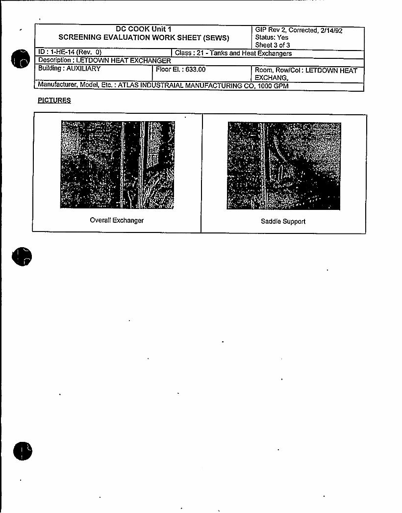
DC COOK Unit 1
SCREENING EVALUATIONWORK SHEET (SEWS}GIP Rev 2 Corrected 2/14/92Status: YesSheet 3 of 3
ID: 1-HE-14 (Rev. 0)Description: LETDOWN HEAT EXCHANGER
Class: 21 - Tanks and Heat Exchangers
Building: AUXILIARY Floor El.: 633.00 Room, Row/Col: LETDOWN HEATEXCHANG,
Manufacturer, Model, Etc.: ATLAS INDUSTRAIALMANUFACTURINGCO, 1000 GPM
Overall Exchanger Saddle Support

Coo
ComponenC No. Class
Any parget:icular area the Seismic Roviev Teaa should pay oxtra attontion to?Yes < No (If yea, check items that apply.)
5
Anchor TypeAnchor DiameterAnchor SpacingAnchor NumberAnchor Embedment~Anchor Edge distanceAnchor
Cepv'nchorThread EngagementAnchor GripAnchor AngularityConcrete Crack
khamxha
lhd 4= kt('.~<fn r( 'I '< ~ ~ P~
lg" ~4/) J (T(p C04~AJ
Others (((sstribs brisrly) " ~ N IIk~~NO bl AS~5. )~ 5<,&~ f
(
IE there ia concern, for Design Basis Discrepancy, circle the applicableitem and explain.
1.2.3.
Hardvare Maintenance Type DiscrepancyDra~ing Up&,te Type DiscrepancySignificant Operabili.ty/Design Basis DiscrepancyOthers
Condition:
Actions Taken:lJDIJB (AG.H P PrO(AT(O(~
Prepared By T Data ('s >l P--


'HP 5021 CCD.019..i'TACHMENT NO 1
lt 5bPI-ZZlZ,- 332.5 - '9
ALlX I 33'-O" EL. LETDOWN BEAT EXCHANC ER RQQMBl g. Location
I - HE.- I4-
Insta at on wg. / Rev.
Anchora e Arran ement SketchEquipment No.
OI
4
CC'V
DUE, TQ HIC H RADIA'TIOM AREACSO v.~b HALT LOCKTIQMS WE.PE.NQT QBTALME.D QM THC KkG1PE.D'E5'TAL C)GI VlERE, DEXERMME.Q5(M(LAR TQ THE. WEST PE.QEGTAL.
Wr
II/ N 5'~z-'a I'iz," 5'e"
0>
5E.C T/QM "4-A"
PLA,M I
Drawn by:Verified by:
Reviewed by:
Date: 4!-Z>-'BDate:
ua ./Cert. Xnspector7 Date:
Construction An hor Review Engineer
Page 1 of 3Revision 1


++12 CHP 5021 ~ CCD. 019ATTACHMENT NO.
pgg No.: IZ-3)ZI-U. II IZ-3.)ZE ~
gag No.; IZ-50 t ) -ZO
Tightness verified? 0 Yes 0 No Date:ons ruc on
Equipment base flexible? 0 Yes I No Date:ons ruc o ARE
~
~ ~quipment No.: I-HE-I4.
Anchor type: ~ >~<~ ~~PE Z Dia:Tightness established by: 0 "Snug Fit" 0 TorqueTorque Wrench No.: Cal. Due Date:
Bolt ID I ~ 3 4
GaPs BFlwk5l BEfivEEIUI
Comments
Anchorlen th 2 '-
I '~z" Z'- I'li''- I ~i" 7'- I'jz"41'~z" ~ 41'l4" 4lg " 41 "L
Protruding ~sic ~ -~su --~6~.len th
BoltriConcretecondition
Edg»distance,
)I'-7 lc I'-7~i~" I.'- /'rz" I'-7Yz->8'/4" >8" W Rli "dh a7Vr.
"~V~ ~'/2>/4 " 2'1(" L>~
C.SACK IhlCGMCRETT:
~1( UOTII SIDE5
4'/q 4 '/4
Anchors acinAnchor
an laritThread
engagement
I I ~/s" II~~a"
4 IO' lQ (50'LQCD I( OIC OK &IC
Comments 4 QtlE TD Hlf' RADIKfloLI AREA Iso Ar'I MLT Loc.ATI wERc hloT QKTAll.lTHC EAST P WERE DE:TER~I IMILAR, TO THE UV'C5i'T PE'0 'TAI Ih
A I hlSPEC T'L(5hl.15 I
R \hH R
R llICo
Varified by:Qua ./Cert. Inspector
Revieved by!T'ons ruct on
Date:
Date!
Page 2 of 3Revision l
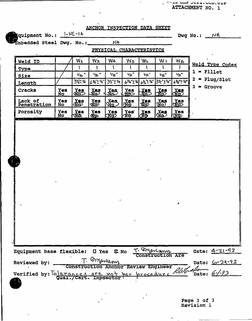
siss've w i vvui verATTAVBKNTNO. l
l-HE,- l 4-
edded Steel Dwg. No.:Dug No.: re&
Weld ID
Size
Cracks
Lack ofPenetration
3(/v ( (/~ ~y &» (/4IP 3(/ gr I, (/
Yes YesNo QKOYes s YesNo
/~/4"(('//, /y "» '//,''lg"»'l4"
Yes
W~ WS Vl4 WS 'IMr- W V
l l
I/~ I/~ I/S
des
Yes
Wa,l
1 ~ Fillet~((~I/ » 2 ~ Plllg/slot
3 ~ Groove
Porosity Yes Yes Yes YesNo
Yes's Yes
Equipment base flexible: 0 Yes 8- Noons ruc x
Reviewed by:ons ruc son c or evxev ngxneer
Uerified by: To <~+wc. s «~ oua . e . npsec or Date:
Page 3 of 3Revision 1


ssaC aVC J ~ 4 SU ~ V J VATTACHMENT NO. 1
~ipment No . 1- HE, - l4
added Steel Dwg. No.:Dwg No.: WR
Meld ID
Size
Cracksg >/g'~~lg "
Yes Yes Yes Yes Yes Yes YQSNo No No No No No No
l ~ Filletes'
Plug/Slot3 ~ Groove
Lack of . ~ Yes Yes .YesPenetration KaJ No No NoYes Yes Yes YesNo No No No
Porosity Y Yes Yes Yes Yes'es Yes Yeso No No No No No No No
Equipment hase flexible: 0 Yas E Noon ruc z n a
Reviewed by:
Veri.fied by: 7c l eons ruc son c or avxew gxnaer
e . np ec r Date:
Page 3 of 3
Revision 1
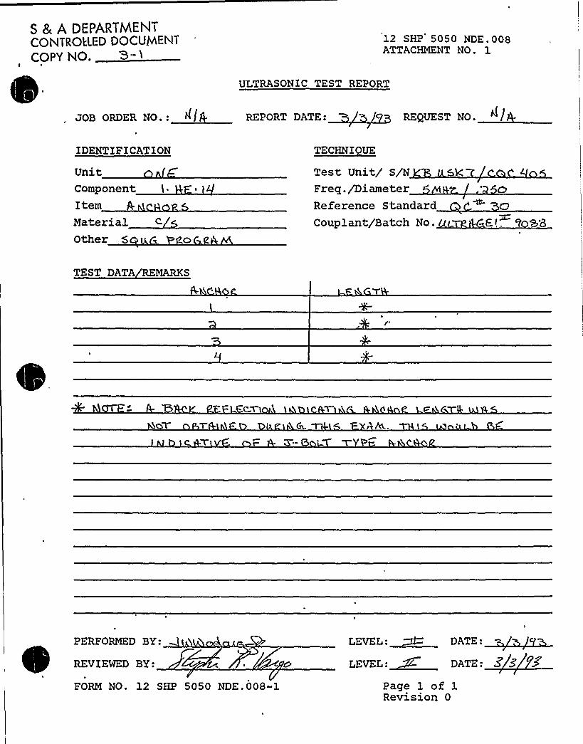
S 8 A DEPARTMENTCONTROLLED DOCUMENTCOPY NO. 3- ~
12 SHP 5050 NDE pp8ATTACHMENT NO. 1
ULTRASONIC TEST REPORT
JOB ORDER NO.: ~l REPORT DATE: REgUEST NO.
IDENTIFICATION
UnitComponentItemMaterialOther 5
TECHNI UE
Test Unit/ S/N 5kFreq./DiameterReference StandardCouplant/Batch No. '7 SB
TEST DATA REMARKS
PERFORMED BY:
REVIEWED BY:
FORM NO. 12 SHP 5050 NDE.008-1
LEVEL ~ DATE
LEVEL:~'- DATE: Z 5
Page 1 of 1Revision 0

Equip ID: 2-HE-15E Train: 2 Equip Class:21
wing No.: 2-5135A 2-5113
tion: CCW
System: COMPONENT COOLING WATER
Equip Desc: EAST COMPONENT COOLING WATER HEAT EXCHANGER
Building: AUXILIARY Room: 609 HALLWAY
Elev: 609 Sort: S, Notes:
Normal State:4
Desired State: Power Req'd: N
Support System Drawing:
Req'd Support Comp:
Safety Related Status: NUCLEAR SR Min/Opt: MIN
Alias No: Power Train: NA
Comp Served: EAST COMPONENT COOLING WATER HEAT EXCHANGER
MPR: M.L.W. INDUSTRIES
Pa el:Elem. Drawing: NOT APPL
Wiring Drawing: NOT APPL
Power Source: NOT APPL
Walkdown: F Relay Eval : N
Comp Type: HE
Iso Drawing: 2-CCW-41, 2-CCW-42
Location: 30 FEET EAST OP THE N2 MONITOR TANK


DC COOK Unit 2SCREENING EVALUATIONWORK SHEET (SEWS)
GIP Rev 2, Corrected, 2/14/92Status: YesSheet1 of2
ID: 2-HE-15E (Rev. 0) Class: 21 - Tanks and Heat ExchangersDescription: EAST COMPONENT COOLING WATER HEAT EXCHANGERBuilding: AUXILIARY Floor El.: 609.00 Room, Row/Col: 609 HALLWAY-
30 FEET EAST OF THE ¹2MONITOR TANK
Manufacturer, Model, Etc.: M.L.W. INDUSTRIES (HORIZONTAL)
BASIS: External analysis
1. The buckling capacity of the shell of a large, flat-bottom, vertical tank is equal to or greaterthan the demand.
2. The capacity of the anchor bolts and their embedments is equal to or greater than thedemand.
3. The capacity of connections between the anchor bolts and the tank shell is equal to orgreater than the demand.
4. Attached piping has adequate flexibilityto accommodate the motion of a large, flat-bottom,vertical tank.
5. A ring-type foundation is not used to support a large, flat-bottom, vertical tank.
N/A
Yes
Yes
Yes
N/A
C LL 0
~CO I~SSRT: Gary Thomas, Tom Huang, and Kailash Mahajan on 11/2/93.
Component Cooling Water Heat Exchanger on two reinforced saddles. Anchorage is two 7/8" diameter J bolts.There are 4 1" wedge expansion anchors in one pedestal in the horizontal direction.
C.G. of exchanger from the top of the saddle pedestal about 3'.
Pedestal concrete is cracked. AEPSC tracking the problem through a condition report. SRT has reviewed theresolution of this problem and determined that it is resolved.
This unit is the same as 1-HE-15E except there are no horizontal anchors on 1-HE-15E. The anchorage for thisexchanger is more robust. The calculations of 1-HE-15E show that the anchors are adequate and the saddles aresafe.
Evaluated by:
, sb.~ Date:
ttachment: Pictures

DC COOK Unit 2SCREENING EVALUATIONWORK SHEET (SEWS)
GIP Rev 2, Corrected, 2/14/92Status: YesSheet 2 of 2
ID: 2-HE-15E (Rev. 0) Class: 21 - Tanks and Heat ExchangersDescription: EAST COMPONENT COOLING WATER HEAT EXCHANGERBuilding: AUXILIARY Floor El.: 609.00 Room, Row/Col: 609 HALLWAY-
30 FEET EAST OF THE ¹2MONITOR TANK
Manufacturer, Model, Etc:: M.L.W. INDUSTRIES (HORIZONTAL)
BLCLI le
ONE SADDLE WITH 4 HORIZONTALBOLTS OTHER SADDLE SUPPORT

Coo
Component No. '2- —I S E Cloaa
Any pazpicular area tho Seismic Review Teaa should pay extra attontion to?Yea < No (If yea, check Stoma that apply.)
Anchor TypoAnchor DiameterAnchor SpacingAnchor lumbarAnchor Embodmont+Anchor Edge DistanceAnchor Gap MAnchor Thread EngagementAnchor GripAnchor AngularityConcrete
Cracks'thers
(describe briefly)
If there ia concern for Design Basis Discrepancy, circle tho applicableatom and explain.
1.2.3.
Hardvare Maintenanco Type DiscrepancyDra~ing Update Typo DiscrepancySignificant Operability/Design Basis DiscrepancyOthers
Condition:HotJ8
Actions Taken:9 SING
Preparod By Dasa

**12 CHP 5021 CCD. 019ATTACHMENT NO. 1
Equipment No.
Anchora e Arran ement Sketch
ANCHOR INSPECTION DATA SHEET
2 6)x B..goy'-0" worry sourH ~w~qUnzt 0 Bldg. Locationi2.- B~Qg- 2s,iz-3zb- z-R6-l56
Installation dwg. / Rev.
74'-'/a
~tt Ypg
l~0—
C,RPICe IIJ4ROVl .
I
J
C+ACK II I
6 CCouT
INDIANA MICHIGAN POVIERSITE DESIGN CONTROLLED
Y(OR KING COPY
AUG 24 1S95
LERK
/~g CRAuC T'O FLIIIIR
0'- l'/a +'/5 (gyp)
Drawn by: Date:Date: &~~ ~~
~~ ~
Verified by:Qual. /Cert. Inspector
Reviewed by: 7 Date: 8 ~ t~Construction Anc or Review Engineer
Page 1 of 3Revision 1

**12 CHP 5021. CCD. 019ATTACHMENT NO. 1
2.Unxt
l 2.-3285-23 f2-'328
ANCHOR INSPECTION DATA SHEET
he~ M bO I'-O" NORTH ~GATV ~W~qBldg. Location
Installation dwg. / Rev.
Anchora e Arran ement SketchEquipment No.
INOIANA MICHIGAN POvggRSITE DESIGN CONTROLI.EP
'tYORKING COPY
AUG 24 tSIIS
I.ERK
Y9P cR.Ac.z g~ XoIVV e6T.08.00T 4 CoLlC,
ROOT@ TOP
t BOGCf FB. WlPB)K'TEIDE 't'L
0IJ 0
ly+7z 'y 7-E <S~
<>xP)
El Ev. ~<ca UooicuQG
Drawn by: Date:
Dat:e:Verified by:gua ./Cert. Inspector
Reviewed by: T Date:Construct on An hor Review Engineer
Page 1 of 3Revision 1

0
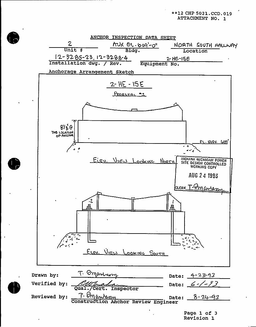
**12 CHP 5021.CCD.019ATTACHMENT NO. 1
2Unxt 0
l2.- N. SS-25, is-32eg-Installatz.on dwg. / Rev.
Anchora e Arran ement Sketch
ANCHOR INSPECTION DATA SHEET
Bl..IOOq'-g~I hJQATA COOT/ HAU u~Bldg. Location
z- HB-t58Equipment No.
z- Bg - i'd%
Ql/g 9~ lOC4TlOA0$ ~(,N0R.
d
ItIDIANAMICMIGAW POWERSITE DESIGN CONTROLLED
WORKING COPY
AUG 24 1998
LERK T-
4
gv iEL.CV. U'I - UO k IQ OuY
C <~ c
0
Date:Date:
Drawn by:
gual./Cert:. InspectorReviewed by: Dat
Constru tron chor Review Engineer
Verified by:~~ ~~
e:
Page 1 of 3Revision 1

0

**12 CHP 5021. CCD. 019ATTACHMENT NO. 1
2Unzt 0
12.-8296- S t2.-3xg-Installation dwg. / Rev.
Anchora e Arran ement SketchEquipment No.
ANCHOR INSPECTION DATA SHEET
PrOX &1 - boq'-o" NORTH SbQTH RPn~+Bldg. Location
I /bklg (7Yp()7 6
O~
QOGIFI@) AT4X+
CRRcX
)'p j94C80 8,uJP 5AER
0V
INOIANA MICHIGAN PO)VERSITE DESIGN CONTROLLED
YYOR KING COPY
AUG 24 1895
LERK +
~ ~ pa
CId
CPP ~ Q f~ Volh)7gC,TWd&hl 4,RouT~ MQC.
EI Eu . J)EM tppkxÃI 0 IA
Drawn by:Verified by:
Date:
Date:Q a ./Cert. InsPector
Reviewed by: 7 Date:Construction An hor Review Engineer
Page 1 of 3Revision 1

**12 CHP 502 1. CCD. 0 19ATTACHMENT No.
Equipment No.: '- H C IGCAnchor type: Z BGU Dia:Tightness established by: 0 "Snug Fit" 0Torque Wrench No.: rJATightness verified? 0 Yes 5 No HR
ons rucEquipment base flexible7 0 Yes S. No T'ns
Dwg No.: IR-3298"fDvg No.:
TorqueCal. Due Date:
c o ARE
Bolt ED
Gaps
t 2, 3 +o
Comments
Anchor +I p]~ +I g/~'i I3q''.~3(~"len thProtruding q3/~ )IS(I
>'enhQ ~ r I
Embedment Z~ ~~~ ZI ~I~/', 2'4'/<
37/
~tv QW4> a-3o13 8-Z<o~mCC~>/8'. 5'ee eEL v
Boltri ~ /8 E"/IIo 2'IX. < "/II .
To~mc6+>/gSbg LjoTE GEL4w.
Concrete CRAB CRACK. GRfKK GRhWconditionEdge &''" (oo
distance
CEGTcH
To~&+~/~'nchor
s acinAnchor
an laritThread
engagement
Tp L,~W<6I/q"
Comments. X /Ig'g~ &67~ QLITJtHASSSR, Yiq 4'GTW6&J Wm~oI PII R
0 'I4hCRIT ~ P 0 Serai To
OI 'T RIP ~HOT M u RR ~ C'T
verified by:Qua ./Cert. nspector
Revieved by:Construct on
SITE. DESIGN CONTROLLEDYIOIIKINGCOPY
'UG 2419SK
Date:
D te: 8-»
"I'ERKT
PaRe
e2of 3ision 1

**12 CHP 5021.CCD.P19ATTACHMENT No,
~
~ ~Equipment No.:Anchor type: < ~t. PrH(&OP.
Tightness established by: 0Torque Wrench No.: P
Tightness verified? I Yes
Equipment base flexible? 0
kg No.: '+ >>S8-Dia: I'wgNo.: ~> 8>"ZA
"Snug Fit" E Torque l?-- BoardI
Cal. Due Date:0 No S %a~~ Date: 4.<> 95
ons ruc ionYes 8 No ~~ Date: 0 +> 13
ons ruc on ARE
Bolt IDGaps
Comments
Anchorlen
Protrudinglen h
7~/y'ual CtII
Embedment 5l(q."
BoltriC n ete C,~< MPCQ CRPcv CppcE.condition
Edgedistance
Anchors acinAnchor
an laritThread
engagement
/I (p $~/l(p 4 4 "
(3/$V )3tqlI gyl /II5" I g'3/8" 5', C ~(<I,"
0 0 0Og. ot'K,
Vo TOP OFC SHIIT
Ta ToPoF AN<
Comments:
Y~ gh ac.ssC'erifiedby:
Qua ./ ert. Inspectorevieved by:
Const ct on ARE
A~MJ I
INDIANAMICHIGAN POWERSITE DESIGN CONTROLLED
WORKING COPY
AUG 24 19S5
ReLERK
Date:
Date:
o2of 3ision 1

**12 CHP 5021. CCD. 019ATTACHMENT NO. 1
Equipment No.:Embedded Steel Dwg. No.:
OR S CT 0
CAL
Dwg No.: I 2-8>98-
Weld XD
T eSizeLen hCracks
~li Io ~hb
Yes Yes YesNo
QL gZ W3
g] ~
Yes YesNo
YesNo
YesNo
YesNo
We e Codes1 = Fillet2 = Plug/Slot3 = Groove
Lack of . LesPenetration QRYes Yes
Noes Yes
NoYesNo
YesNo
YesNo
Porosity Yes Yes YesNo
YesNo
Yes YesNo . No
YesNo
&GQ hi<
'R. ~/~3RYgxqx. q"
IA
'4.4
~ J)44
+4 ~
4 o
.0,~ 4.
INDIANA MICHIGAN PO'LYERSITE DESIGN CONTRCI.LEO
IVORKING COPY
AUG 24 1895
~ ~qyeHh RCCBpT 7~ ~O~"
Equipment base flexible: 0 Yes g No 1 Date: <-2'~ons ruc z n e
Reviewed by:
ified by:ons ruc ron c or evxew ngxneer
ua . e . npsec or
: ~S. -3Date:
Page 3 of 3Revision 1

S 8 A DEPARTMENTCONTROLlED DOCUMENTCOPY NO. ~/
12 SHP 5050 NDE.008ATTACHMENT NO. 1
UfTRASONIC TEST REPORT
JOB ORDER NO«: :~/.». ~ * . /A
IDENTIFICATION
Unit WaaComponentItem A~a.MaterialOther 5
Test Unit/ S/NflVSR- CNC-9'KFreq./Diameter .asDReference Standard &C'-8Couplant/Batch No. ~ ~/~ lP88
TEST DATA REMARKS
P. EPV C.
EE
EI
„
J ~
PERFORMED BY:
REVIEWED BY:
FORM NO. 12 SHP 5050 NDE.008-1
LEVEL:~~ DATE: IY'-/3~z3
LEVEL:~ DATE:
Page 1 of 1Revision 0

~Yi atabase: K:SSEL1B.DBF
Equip ID: 12-HE-16N Train: 12 Equip Class:21~
~
~ing No.: 12-5136, 1-5135
Function: SFP COOLING AND CCW
System: SPENT FUEL PIT COOLING & CCW
Equip Desc: NORTH SPENT FUEL PIT HEAT EXCHANGER
Building: U-1 AUXILIARY Room: SPENT FUEL PIT HE ROOM
Elev: 609 Sort: S, Notes:
Normal State: Desired State: Power Req'd: N
Support System Drawing:
Req'd Support Comp:
Safety Related Status: STANDARD
Alias No: Power Train: NA
~ Comp Served: OAT, JOSEPH, CORP
MFR:
5:Panel:
Elem. Drawing:
Wiring Drawing:
Power Source:
Walkdown: F Relay Eval : N
Comp Type: HE
Min/Opt: MIN
Iso Drawing: 12-SF-5, 7, 1-CCW-l, 7
Location: NW AREA OF RM

DC COOK Unit 1
SCREENING EVALUATIONWORK SHEET (SEWS)GIP Rev 2, Corrected, 2/14/92Status: YesSheet 1 of 9
ID: 12-HE-16N (Rev. 0) Class: 21 - Tanks and Heat ExchangersDescription: NORTH SPENT FUEL PIT HEAT EXCHANGERBuilding: AUXILIARY Floor El.: 609.00 Room, Row/Col: SPENT FUEL PIT
HEATXCHGR RM, NWAREAOFRM
Manufacturer, Model, Etc.: OAT, JOSEPH, CORP.
BASIS: Horizontal TANKanalysis
1. The buckling capacity of the shell of a large, flat-bottom, vertical tank is equal to or greaterthan the demand.
2. The capacity of the anchor bolts and their embedments is equal to or greater than thedemand.
3. The capacity of connections between the anchor bolts and the tank shell is equal to orgreater than the demand.
4. Attached piping has adequate flexibilityto accommodate the motion of a large, flat-bottom,vertical tank.
5. A ring-type foundation is not used to support a large, flat-bottom, vertical tank.
N/A
Yes
Yes
Yes
N/A
C
~CM@NN Q
RT: Gary Thomas, Tom Huang and Kailash Mahajan on 11/3/93.
3' 2" diameter horizontal heat exchanger about 22'ong on two saddles supported by piers. Total weight full givenas 26,200 lbs.
Exchanger bolted into pier with 4 7/8" diameter bolts per saddle. Piers are dowled into floor.
The results of tank analysis show that the tank anchorage is adequate and also the saddles are safe.
Evaluated by: Date:
Attachment: PicturesAttachment: TANKAnalysis ResultsAttachment: Check of Stresses in Saddles

DC COOK Unit 1
SCREENING EVALUATIONWORK SHEET (SEWS)GIP Rev 2, Corrected, 2/14/92Status: YesSheet2of9
ID: 12-HE-16N (Rev. 0) Class: 21 - Tanks and Heat ExchangersDescription: NORTH SPENT FUEL PIT HEAT EXCHANGERBuilding: AUXILIARY Floor El.: 609.00 Room, Row/Col: SPENT FUEL PIT
HEAT XCHGR RIVI, NW AREA OFRM
Manufacturer, Model, Etc.: OAT, JOSEPH, CORP.
NORTH SPENT FUEL PIT HEAT EXCHANGER


DG COCK Unit 1
SCREENING EVALUATIONWORK SHEET (SEWS)GIP Rev 2, Corrected, 2/14/92Status: YesSheet 3 of 9
ID: 12-HE-16N (Rev. 0) Class: 21 - Tanks and Heat ExchangersDescription: NORTH SPENT FUEL PIT HEAT EXCHANGERBuilding: AUXILIARY Floor El.: 609.00 Room, Row/Col: SPENT FUEL PIT
HEAT XCHGR RM, NWAREA OFRM
Manufacturer, Model, Etc.: OAT, JOSEPH, CORP.
TANKAnalysis Results
Step 1 —Input Dataa) Assumptions1. Tank is cylindrical, horizontally oriented and supported on saddles.2. Tank and saddles are made of carbon steel3. Saddles are uniformly spaced.4. Saddles overhang is less than spacing /25. Base plates have slotted anchor bolt holes for thermal growth except for the base plate under
the fixed saddle.6. Imposed nozzle loads are not significant.7. The tank foundation is adequate.8. Anchor bolts are cast in place or expansion type.
YesYesYesYesYes
YesYesYes
b) MaterialsWeight of Tank+ FluidWeight Density of Tank+ FluidSaddle Elastic ModulusSaddle Shear ModulusBase Plate Yield StrengthAnchor Type
c) DimensionsTank Diameter, DTank Length, LTank Thickness, tHeight of Tank+ Fluid C.G., HcgNumber of SaddlesSaddle Spacing, SSaddle Height, hSaddle Shear cross-sectional areaSaddle Weak Axis Moment of InteriaNumber of Bolt Locations / SaddleNumber of Bolts / Bolting LocationExtreme Bolt Spacing,
D'nchorBolt Eccentricity, eWeld ThicknessBase Plate Thickness
26.2 kips151 Ibs/ftn330000.0 ksi1". 500.0 ksi30000.0 ksi
7/8 in 90 deg. J-Bolts
3.17 ft22.0 ft0.44 in2.16 ft
13.0 ft4.9 in
23 63 inn224.36 in"4
1.83 ft3.0 in
0.188 in0.5 in


DC COOK Unit 1
SCREENING EVALUATIONWORK SHEET (SEWS)GIP Rev 2, Corrected, 2/14/92Status: YesSheet4of9
ID: 12-HE-16N (Rev. 0) Class: 21 - Tanks and Heat ExchangersDescription: NORTH SPENT FUEL PIT HEAT EXCHANGERBuilding: AUXILIARY Floor El.: 609.00 Room, Row/Col: SPENT FUEL PIT
HEAT XCHGR RM, NWAREA OFRM
Manufacturer, Model, Etc.: OAT, JOSEPH, CORP.
d) Anchor Bolts
Type = 90 Deg J-BoltManufacturer =
Diameter = 7/8 inProduct Name =
Nominal CapacityPullout
20.44 kipsShear
10.22 kips
Concrete Compression Strength, fc' 3500.0 psi
Reduction ParametersCapacity Reduction Factor
Label Check Condition Pullout Shear1. Type of Anchorage2. Installation Adequacy
YesYes Installation is adequate
1.01.0
1.01.0
3. Embedment Length Yes Embedment Length = 18.75in
0.47 1.0
4. Gap at Threaded Anchors5. Spacing between Anchorages
Yes Gap size = 0.0 inYes
1.01.0
1.01.0
7. Concrete Strength and Condition8. Concrete Crack Location and Size9. Essential Relays in Cabinets10. Base Stiffness and Prying Action11. Equipment Base Strength and
Structural Load Path12. Embedment Steel and Pads
Yes Base strength and load pathare O.K.
Yes Installation is O.K.
YesYes Crack Size = 0.0 inNo
Yes
1.01.0
'1.0
1.0
1.0
1.01.0
1.01.0
1.0
Does the tank satisfy all the assumptions and is within the applicable range of parameters?
Step 2- The allowable bolt loads
Allowable Tension Load,Pu'llowableShear Load,Vu'.211 kips
7.967 kips
Step 3 —Determine base plate bending strength reduction factor
RB 346.7068

DC COOK Unit 1
SCREENING EVALUATIONWORK SHEET (SEWS)GIP Rev 2, Corrected, 2/14/92Status: Yes
'heet5 of 9ID: 12-HE-16N (Rev. 0) Class: 21 - Tanks and Heat ExchangersDescription: NORTH SPENT FUEL PIT HEAT EXCHANGERBuilding: AUXILIARY Floor El.: 609.00 Room, Row/Col: SPENT FUEL PIT
HEATXCHGR RM, NWAREAOFRM
Manufacturer, Model, Etc.: OAT, JOSEPH, CORP.
Step 4 —Determine base plate weld strength reduction factor
RW 3.3848
Step 5 —Determine the anchorage tension and shear allowable loads
Allowable Anchorage Tension Load, PuAllowable Anchorage Shear Load, Vu
7.211 kips7.967 kips
Step 6 —Calculate the ratios and values
alpha (Pu/Vu)
Vu /WbHcg /
D'cg/SF1
F2
0.913.28 kips/bolt
2.431.18
0.1662.2362.475
Step 7- Determine the acceleration capacity of the tank anchorage
lambda 1
lambda uAnchor Acceleration capacity, lambda
1.088 G0.772 G0.772 G
Step 8 —Determine the maximum saddle spacing for transverse and vertical rigid frequency response
Maximum Saddle Spacing, Sc 13.45 ft
Step 9 —Compute the resonant frequency of the tank in the longitudinal direction
Saddle Stiffness, KsR nant Frequency of Tank in Longitudinal Direction
13948.206 kipsfin72.15 Hz
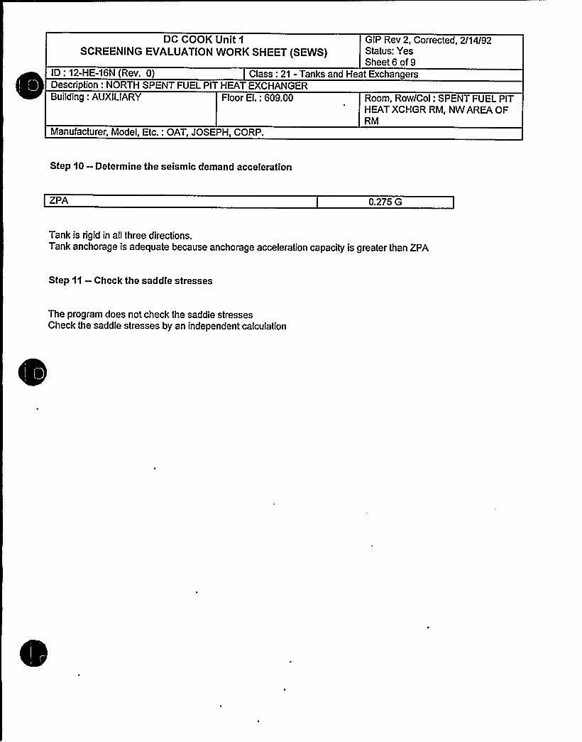
DC COOK Unit 1
SCREENING EVALUATIONWORK SHEET (SEWS)GIP Rev 2, Corrected, 2/14/92Status: YesSheet 6 of9
ID: 12-HE-16N (Rev. 0) Class: 21 - Tanks and Heat ExchangersDescription: NORTH SPENT FUEL PIT HEAT EXCHANGERBuilding: AUXILIARY Floor El.: 609.00 Room, Row/Col: SPENT FUEL PIT
HEAT XCHGR RM, NWAREA OFRM
Manufacturer, Model, Etc.: OAT, JOSEPH, CORP.
Step 10 —Determine the seismic demand acceleration
ZPA 0.275 G
Tank is rigid in all three directions.Tank anchorage is adequate because anchorage acceleration capacity is greater than ZPA
Step 11 —Check the saddle stresses
The program does not check the saddle stressesCheck the saddle stresses by an independent calculation

CUENT
Cr~ H~hmou
Stevenson and Associates
A Struoiurnl Mnohnaionlconrulbag Engiauutiny Firm
''/gag: .4~ J,l~ s4 ke:ss e.s .i
P
II
III I
1 I
i3«) VI S
/r24'z '""
'j8'* '
irin<yjt.p /g.u.IIII .«.g '(., J = ...3 .I PSI
-'A--n.o-L Aro-'n".CIopn.oI ig g'= r Ir0 J.
--Z'.pa--—— .'pg j.E
(I:rru CI'FiOar)
I " ~ ~ I ~ -« ~
I 'I
~ Qf'W r«II
I l II
I
'I 1
u 2.l~ I gg L Lire,
r
—ZBIrls..u ru.S
j
I
~ II'
I i I~ I
~ ~ i
i I I
~4I i2!
j i j
I I
I
i l,I I

CUENT
SUBJECT
W)JOB No. SHEET OF
Stevenson and Associates
5 A Srrucrurnl McchnnrcnlConrulnnrr Enprnncnnrr fum
Z085
o
~ ~ ~ ~ ~

o ~ ~
~ ~ ~ ~ II
e e ~ 0 II
I I II
~ ~ '
~ ~
~ ~
I'

eo r vms ~ we'll ~ Q J,gATTACHMENT HO. l
~g No.: IL 5L97A-I4Dwg No.: IL M135 2
Equipaent No.: 'li- HE-(4 0Anchor types'
'. VDCY Dia: ie"+
Tightness established by: 0 "Snug Fit" 0 TorqueTorque Wrench No.: Cal. Due Date:Tightness verified? 0 Yes EI No Date: ((-(o- 2
ons c nEquipment hase flexible? 0 Yes K No Date: -(0- l2
ons ruc on ARE
Bolt XD
CapsComments
Anchor ', „„, ~m ox~len I
'- l l" l'-ll" I'-II" I'-ll" I'- l l" I'- l I"
I'-
I I" I'-(I" 1%" 30'73-g
Pro~ding ~i',- ~" ~p "8," 4iia 'i
len
Edgedistance
gIz" C 'i'."
„0 ~2,' 2,'+"
Concretecondition 0(( Ql< QK QK OK OK OK
4
. Anchor' acinAnchor
an laritThread
engagement
Q 7 IEI," 3 1/i >~tg" > 'iZ" 4 4 4
0 0 Zo po 4 4 4 4OlC. OIC. QK Ok; .. Ol( 'l( Qk GK
Comments: 4 5QRr'Yean.m.
IM T PER RA&I I Z, ~
CKo~W A~a,
Verified by:Qua . Cert. nspect r
Reviewed byeConstruct on INDIA IA MICHIGAN POVIER
SITE DESIGN CONTROLLEDVlORKING COPY
. Date:
5-2.z-)z
AUG 2 4.1995
LEAK
Page 2 of 3Revision l

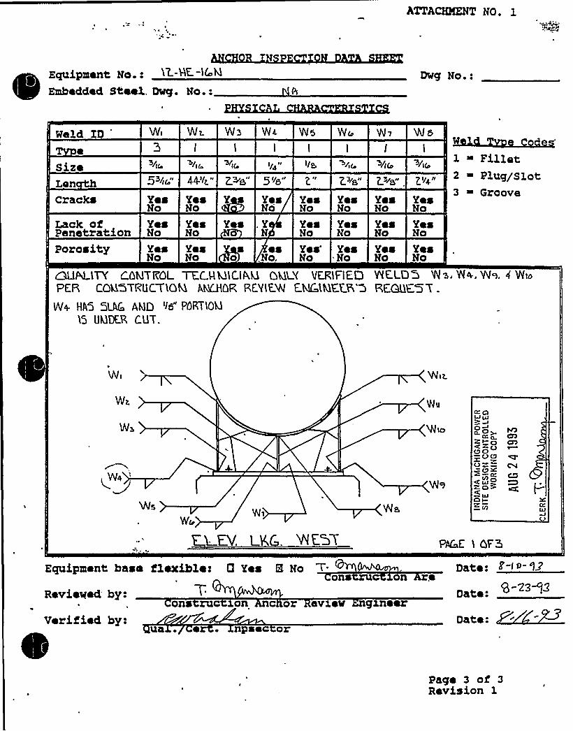
ATTAU96ÃZ NO. 1
Equipment No.: )Z.-HC -IGM
Embedded Steel. Dry. No.:Dug No.:
I l I I I t I
>li ~/ic.1 ~ Fillet2 ~ Plug/slot3 ~ Groove
/~r ~i<. ~i( If~" IS ~i iSize5~~ic" 44.'i'z" Z.>a" 5 '~s" 2." Z ~a" L~~s"
.E.'~4"Lan
Cracks Yea Yea Y s Yea Yes YeaNo No No No No
Yea YeaNo No
Yea YesNo No
Yea YeaNo No
'AE.LDQ 'INS. Vl4, WS. 4 NIoRE.QDE.'5 T
Lack of Yea Yes Yes . YPenetration No No N
Yea YeaNo No
Porosity Yea Yes s es Yea'esNo No o No. No No
CXlALLTY CQMTRQL TEC W MlC.IAU QLll Y VERIFIE,DPER COGGTRUCTLOM, AbKHQR REVlEVl E.MCLMEER,'5
W+ HA'5 5LAC AND its" POPlTLOM
15 UklKR CUT.
geld y 'Ihfi Wz. Wa W< VVs Wr W~ W s
Wi
Wz
Wa
WII
BIOLJ ~? ~6~O >.Cg~NO<i-oQO~OQOX-~@X
co oZO?O i-'l
L UFV. LK . V/E.GY PAC E l QFK
Equipment base flexihles 0 Yea 8 Noons
Revieyed byn e
Date:
Dateons ruc on c or ev ev g eer
Verified by:ua ~ ~ npsec or Date:
Page 3 of 3Revision 1

ATTAauKNT No. l
Equipment No.: IZ HC IGM
Embedded Steel Dry. No.:%g No.:
Weld ID
SizeLan
Ws VYIo W ii 'llizI 1
~l(c. ~/I( Wi(
5 A Z ~s 4.4'i~ 5'4
Cracks
Lack ofPenetration oPorosity Y
s Yeso No
Yes Yes YesNo No No
Yes .Yes Yes Yeso No No No No
Y Yes Yes Yes'eso No No No No
l ~ Fillet2 ~ Plug/Slot3 ~ Grooves Yes
N No
Yes YesNo oYes YNo No
We '~s" PQRTIOkl CF VlE.EO )6 UQQE.RC O'T.
INDIANAMICHIGAN PO(VERSITE DESIGN CONTROLLED
'IVORKING COPY
AUG 24 1995
"LERK TPACE Z.OF5
Equipment base flexible: 0 Yes H. No T'on e
Date:
Reviewed by:
Verified by:ons ru o
a . e . npsec or
c r evlev g eer
Pago 3 of 3Revision 3.

ATTACEBKNT No.
Equipment No.: 'lh HC )AUEmbedded Steel Dwg. No.:
Dwg No.:
Weld ID
size
V/)s W i~ W is W ic W..)~ W)eI
~/)C +Iso
I I I I
)/s, ~ha- Pi~ )IS
44'Iz" Z.'ls" Z'~z" L"e," Z."e" Z.'Iz" Z.'~e"
WmW
1 ~ Fillet~~Is.
2 ~ Plug/Slot3 ~ GrooveCracks
Lack ofPenetrationPorosity
Yea YesNo No
Yea YesNo No
Yea YesNo No
Yes Yes Yes YeaNo No No No
Yea ,Yes Yea YeaNo No No No
Yes Yea Yes'esNo No No No
YeaNo
YeaNo
YesNo
YesNo
YeaNo
YesNo
WELD'QM 'THI5 PAC E. WC.KE. MOT 'tE.RAFIEO aV a .C.. T~~<~D~-
W)+
INDIANAMICHIGAN POWERSITE DESIGN CONTROLLED
WORKING COPY
~UG 24 tSSS
W)sW) LERK T
Equipment base flexible: 0 Yes EL Noona 0 e
Date:
Reviewed by:
Verified by:ona ruc
ua . o . npsec or
on c o evxew gxneerDate: ~-~-~~
Date:
Page 3 of 3Revision 1

S Px A DEPARTMENTCONTROLLED DOCUMENT
COPY NO.
SHP 5050 NDE.008ATTACHMENT NO. 1
UITRASONIC TEST REPORT
JOB ORDER NO.: ~ A REPORT DATE: 9 REQUEST NO. hl
IDENTIFICATION
Unit aComponentItemMaterialOther
TECHNI UE
Test Unit/ S/NFreq./Diameter RaReference StandardCouplant/Batch No. 'g L S
TEST DATA REMARKS
r 4
Y T A LE SA'F'T'
t A.
F wio
PERFORMED BY: W
REVIEWED BY:
FORM NO. 12 SHP 5050 NDE.008-1
DATE:
Page 1 of 1Revision 0
IEVER:I
I EVE?: ~ DATE:

Equip ID: 1-QT-107-AB Train: 1 Equip Class:21
Drawing No.: 1-5151A~
~
~
~
~ ~
tion: EMERQ DIESEL
System: DIESEL FUEL OIL
Equip Desc: AB EMERG DXESEL FUEL OIL DAY TANK
Building: AUXILIARY Room: AB EMERG DIESEL GENERATOR ROOM
Elev: 587 Sort: S, Notes:
Normal State: Desired State: Power Req'd: N
Support System Drawing:
Req'd Support Comp:
Safety Related Status: NUCLEAR SR
Alias No: Power Train: NA
Comp Served: AB FUEL OXL DAY TANK
MFR:
el: 36" D x 108" L, 465 GAL.
el:Elem. Drawing: N/A
Wiring Drawing: N/A
Power Source: N/A
Walkdown: F Relay Eval : N
Min/Opt: MIN
Comp Type: TANK (CAPACITY- 2HRS FULL LOADOPERATION)
Iso Drawing:
Location: XN THE SW REGION OF THE ROOM INSIDE THE AB EMERGENCYDIESEL FUEL OIL DAY TANK ENCLOSURE,, AT 599 EL.
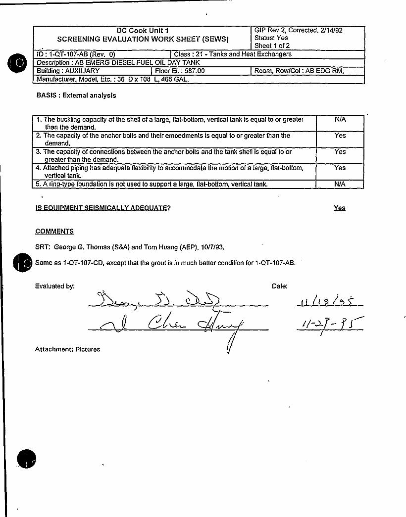
DC Cook Unit 1
SCREENING EVALUATIONWORK SHEET (SEWS)GIP Rev 2, Corrected, 2/14/92Status: YesSheet 1 of 2
ID: 1-QT-107-AB (Rev. 0) Class: 21 - Tanks and Heat ExchangersDescription: AB EMERG DIESEL FUEL OIL DAYTANKBuilding: AUXILIARY Floor El.: 587.00 Room, Row/Col: AB EDG RM,Manufacturer, Model, Etc.: 36 D x 108 L,465 GAL.
BASIS: External analysis
1. The buckling capacity of the shell of a large, flat-bottom, vertical tank is equal to or greaterthan the demand.
2. The capacity of the anchor bolts and their embedments is equal to or greater than thedemand.
3. The capacity of connections between the anchor bolts and the tank shell is equal to orgreater than the demand.
4. Attached piping has adequate flexibilityto accommodate the motion of a large, flat-bottom,vertical tank.
5. A ring-type foundation is not used to support a large, fiat-bottom, vertical tank.
N/A
Yes
Yes
Yes
N/A
COh0iggNT!j
SRT: George G. Thomas (SM) and Tom Huang (AEP), 10/7/93.
~
~
Same as 1-QT-107-CD, except that the grout is in much better condition for 1-QT-107-AB.
Evaluated by:
Attachment: Pictures
ed=/
I
Date:
/I 9 ~85el

DC Cook Unit 1
SCREENING EVALUATIONWORK SHEET (SEWS)GIP Rev 2, Corrected, 2/14/92Status: YesSheet 2 of 2
ID: 1-QT-107-AB (Rev. 0) Class: 21 - Tanks and Heat ExchangersDescription: AB EMERG DIESEL FUEL OIL DAYTANKBuilding: AUXILIARY Floor El.: 587.00 Room, Row/Col: AB EDG RM,Manufacturer, Model ~ Etc.: 36 D x 108 L, 465 GAL.
~PC~FQ
AB Emerg. Diesel Fuel Oil Day Tank 1-QT-1 07-AB
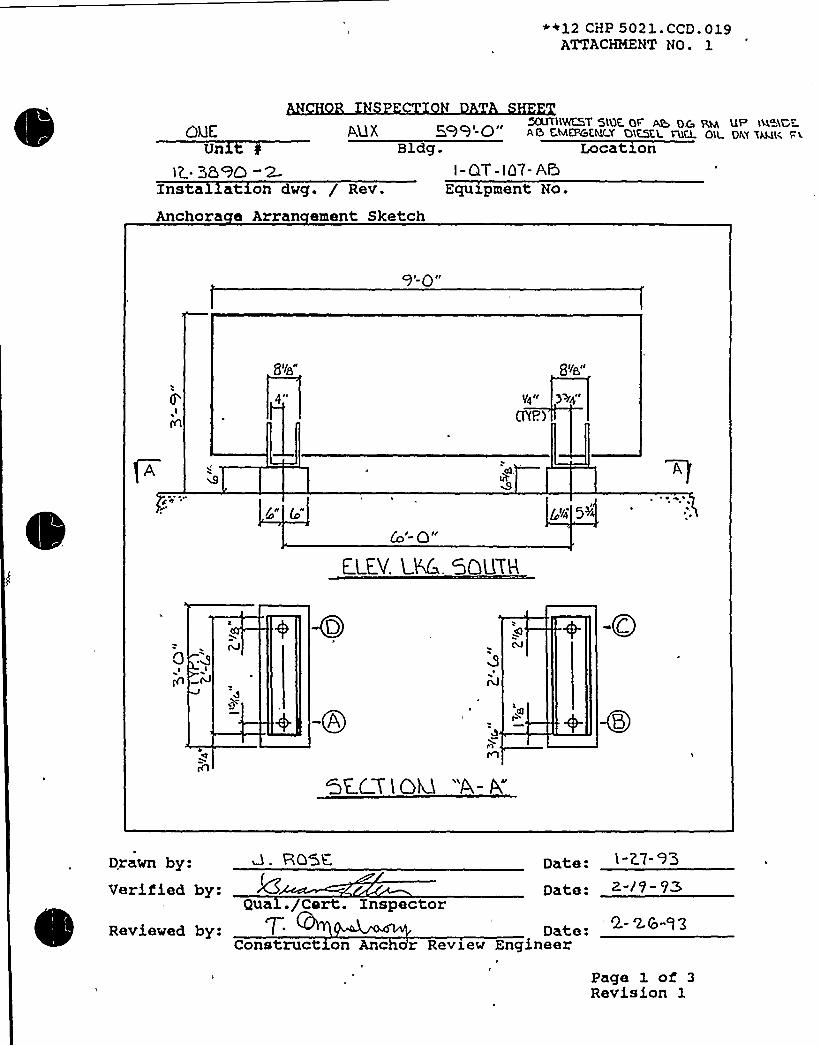
++12 CHP 5021 ~ CCD ~ 019ATTACHMENT NO. 1
AUXUn
iQ- 369Q -2- i-QT- ia7- A5Equipment No.Insta at. on dwg. / Rev.
Anchora e Arran ement Sketch
50UTH%E57 5'le QF'@ o,g pM UP w~iCr) -O AG EMCPGt:M(Y QKSEL T11Q Oll OlE't XLktl( b'i
Bldg. Location
gl Qil
4e p4II
FfP.)
+I Qll
E l E.V. LM. 5QUTH
5y'E.CY1
QD 'A- A"
D,rawn by: Q. ROTC,
Verified by:Qua ./Cart.
Reviewed by:Construct on
Inspector
Date:Date:
Date:Anc r Review Engineer
f
2.- 'LS-g g
Page 1 of 3Revision 1


~ ~ l
- ~ ~ ~ ~
~ i
S ~ ~
0 - ~
s '%~4
l kt.S
&5%~~%aaaISWISRRRHLLmmeeasmmmmRRE555RRRLLWWWRHaLaii) aa) kalggggggggggg~~~~
gggg@gg++QQ%555%WLLLL~ 4 k k 4MWWMWWWW
Pg

I

S (% A DEPAiRTMFNTCONTROLLED DOCUMENTCOPY NO.
SHP 5050 NDE.QQ8ATTACHMENT NO. 1
ULTRASONIC TEST REPORT
JOB ORDER NO.: REPORT DATE: gr 1 REQUEST NO.
IDENTIFICATION
UnitComponentItemMaterialOther
TECHNI UE
Test Unit/ S/NFrey./Diameter ~ ABC)Reference StandardCouplant/Batch No.L&p
TEST DATA REMARKS
W6/7~"
7c'
PERFORMED BY: LEVEL:~& DATE: /REVIEMED BY: LEVEL: DATE:
FORM NO. 12 SHP 5050 NDE.008-1. Page 1 of 1Revision 0

Page No. 77010/19/94
SYSTEMDESCRIPTDRAWINGNOBUILDXNGNORMSTATEDESXRSTATEPOWERREQDALIASNOPOWERTRAXNCOMPSERVEDMANUFACTURMODELPANELELEMDWGWIRXNGDWGPWRSOURCEQUALXFWALKDOWNPFDOPTSUPPSYSDWGREQSUPPEVAL TYPENOTESFUNCTXON.E'VATION
KTXON. YP TYPE
ISO DWGSDETAIL LOCFLOORFLOW PATHREVREV LOCKLOCK DATESHOW INDEXTAGS IGNATURESREV NOTES
221
2-QT-115-CDDIESEL LUBE OILCD EMERGENCY DIESEL LUBE OXL SUMP TANK2-5151CAUXILIARY
NACD LUBE OIL SUMP TANK
775GALS
NOT APPLNOT APPLNOT APPLNUCLEAR SRFMIN
Seismic Only
EDG579.00
CD EMER DSL LUBE OIL PITNTANK
XN THE WEST PART OF THE PXT, NEAR THE WEST WALL, 3 FEET ABOVE THE
S0
N/ /
YN

Donald C. Cook Niiclear Plant, Unit 2 GIP Rev 2, Corrected, 2/14/92
SCREENING EyALUATIONWORK SHEET (SEWS) Status: YesSheet1 of7
ID: 2-QT-115-CD Rev. 0 Class: 21 - Tanks and Heat Exchan ersDescn tion: CD EMERGENCY DIESEL LUBE OIL SUMP TANKBuilding: AUXILIARY
Manufacturer, Model, Etc.: 775GALS
BASIS: Horizontal TANKanalysis
Floor El.: 579.00 Room, Row/Col: CD EMER DSLLUBE OIL PIT - IN THE WESTPART OF THE PIT, NEAR THEWEST WALL,3 FEET ABOVE THEFLOOR
1. The buckling capacity of the shell of a large, fiat-bottom, vertical tank is equal to or greaterthan the demand.
2. The capacity of the anchor bolts and their embedments is equal to or greater than thedemand.
3. The capacity of connections between the anchor bolts and the tank shell is equal to orreater than the demand.
4. Attached piping has adequate flexibilityto accommodate the motion of a large, flat-bottom,vertical tank.
5. A rin -t e foundation is not used to su ort a la e, flat-bottom, vertical tank.
N/A
Yes
Yes
N/A
N/A
IS E UIPMENT SEISMICALLYADE UATE? Yes
COMMENTS
SRT: W. Djordjevic and TR Satyan Sharma. 10/6/93.
REF: 1. Anchor inspection Data Sheets: Anchorage Arrangement Sketches and Physical Characteristics DataSheet, Certi".:ed 10/1/93.2. Worthington Dwg ¹ 700003BY.3. Worthington Co.Lube Oil Sump Tank Calculation, 8/22/74.
Anchorage:The tank sits on 3 saddles, 2 plates per saddle, 1/4" thick. There are two 3/4" anchors per saddle. There are 4anchors in total for the tank because the middle saddle has no anchorage on it.
Horizontal Tank Analysis:Saddle Weak Axis Moment of Inertia = 2I + 2(ad "2) = 2((36"x0.25in"3)/1 2) + 2(1 8in"2 x (5"2)in"2") = 900in "4.
Saddle stresses analyzed in Ref. 3.
Nozzle loads judged not significant by SRT.
Evaluated by: Date:
U
go

0

Donald C. Cook Nuclear Plant, Uni~ 2SCREENING EVALUATIONWORK SHEET (SEWS)
GIP Rev 2, Corrected, 2/14/92Status: YesSheet 2 of 7
ID: 2-QT-115-CD Rev. 0 Class: 21 - Tanks and Heat Exchan ersDescri tion: CD EMERGENCY DIESEL LUBE OIL SUMP TANKBuilding: AUXILIARY
Manufacturer, Model, Etc.: 775GALS
Attachment: PicturesAttachment: TANKAnalysis Results
Floor El.: 579.00 Room, Row/Col: CD EMER DSLLUBE OIL PIT - IN THE WESTPART OF THE PIT, NEAR THEWEST WALL,3 FEET ABOVE THEFLOOR

Donald C. Cook Nuclear Plant, Unit 2 GIP Rev 2, Corrected, 2/14/92SCREENING EVALUATIONWORK SHEET (SEWS)
Sheet 3 of 7ID: 2-QT-115-CD Rev. 0 Class: 21 - Tanks and Heat Exchan ersDescri tion: CD EMERGENCY DIESEL LUBE OIL SUMP TANKBuilding: AUXILIARY
Manufacturer, Model, Etc.: 775GALS
PICTURES
Floor El.: 579.00 Room, Row/Col: CD EMER DSLLUBE OIL PIT - IN THE WESTPART OF THE PIT, NEAR THEWEST WALL,3 FEET ABOVE THEFLOOR
2-QT-115-CD

Donald C. Cook Nuclear Plant, Unit 2
SCREENING EVALUATIONWORK SHEET (SEWS)
GIP Rev 2, Corrected, 2/14/92Status: YesSheet 4 of 7
ID: 2-QT-115-CD Rev. 0 Class: 21 - Tanks and Heat Exchan ersDescri tion: CD EMERGENCY DIESEL LUBE OIL SUMP TANKBuilding: AUXILIARY Floor El.: 579.00 Room, Row/Col: CD EMER DSL
LUBE OIL PIT - IN THE WESTPART OF THE PIT, NEAR THEWEST WALL,3 FEET ABOVE THEFLOOR
Manufacturer, Model, Etc.: 775GALS
TANKAnalysis Results
Step 1 —Input Data
a Assum tions1. Tank is c lindrical, horizontall oriented and su orted on saddles.2. Tank and saddles are made of carbon steel3. Saddles are uniforml s aced.4. Saddles overhan is less than s acin /25. Base plates have slotted anchor bolt holes for thermal growth except for the base plate
under the fixed saddle.6. Im osed nozzle loads are not si nificant7. The tank foundation is ade uate
YesYesYesYesYes
YesYes
8. Anchorbolts are cast in lace or ex ansion t e.
b MaterialsWei ht of Tank+ FluidWei ht Densit of Tank+ FluidSaddle Elastic ModulusSaddle Shear ModulusBase Plate Yield Stren thAnchor T e
6.83 ki s60 Ibs/ft*3
29000.0 ksi1150.0 ksi36.0 ksi
3/4 in 90 de . J-Bolts
Yes
c DimensionsTank Diameter, DTankLen th, LTank Thickness, tHei ht of Tank+ Fluid C.G., HNumber of SaddlesSaddle S acin, SSaddle Hei ht, hSaddle Shear cross-sectional areaSaddle Weak Axis Moment of InteriaNumber of Bolt Locations / SaddleNumber of Bolts / Boltin LocationExtreme Bolt S acin,
D'nchorBolt Eccentricit, eWeld ThicknessBase Plate Thickness
3.8 ft10.0 ft0.19 in2.08 ft
7.67 ft2.0 in
18.0 in"2900.0 in"4
2.67 ft0.02 in0.19 in0.25 in

0

Donald C. Cook Nuclear Plant, Unit 2SCREENING EVALUATIONWORK SHEET (SEWS)
GIP Rev 2, Corrected, 2/14/92Status: YesSheet 5 of 7
ID: 2-QT-115-CD Rev. 0 Class: 21 - Tanks and Heat Exchan ersDescri tion: CD EMERGENCY DIESEL LUBE OIL SUMP Ti NKBuilding: AUXILIARY
Manufacturer, Model, Etc.: 775GALS
d Anchor Bolts
Floor El.: 579.00 Room, Row/Col: CD EMER DSLLUBE OIL Pl, - IN THE WESTPART OF THE PIT, NEAR THEWEST WALL,3 FEET ABOVE THEFLOOR
T e = 90 De J-BoltManufacturer =
Diameter= 3/4 inProduct Name =
Nominal Ca acitPullout
15.03ki sShear
7.51 ki s
Concrete Com ression Stren th, fc'= 4000.0 si
Reduction ParametersCa acit Reduction Factor
Label1. T e of Anchora e
CheckYes
Condition Pullout1.0
Shear1.0
2. Installation Ade uac3. Embedment Length
4. Ga at Threaded Anchors5. S acin betweenAnchora es
Yes Embedment Length = 27.0in
Yes Ga size = 0.0 inYes
Yes installation is ade uate 1.00.7
1.01.0
1.01.0
1.01.0
6. Edge Distance Yes Edge Distance = 6.0 inAnother Edge Distance = 4
in
0.41 0.31
7. Concrete Stren th and Condition8. Concrete Crack Location and Size
YesYes Crack Size = 0.0 in
1.01.0
1.01.0
9. Essential Relays in Cabinets Yes Essential relays are notresent
1.0 1.0
10. Base Stiffness and P in Action11. Equipment Base Strength and
Structural Load Path12. Embedment Steel and Pads
YesYes
Yes Installation is O.K.
Base strength and load pathare O.K.
1.01.0
1.0
1.01.0
Does the tank satisfy all the assumptions and is within the applicable range of parameters? Yes
Step 2 —The allowable bolt loads
Allowable Tension Load,Pu'llowableShear Load,Vu'.344 ki s
2.346 ki s
Step 3 —Determine base plate bending strength reduction factor
0.1726

Donald C. Cook Nuclear Plant, Un«2SCREENING EVALUATIONWORK SHEET (SEWS)
GIP Rev 2, Corrected, 2/14/92Status: YesSheet 6 of 7
ID: 2-QT-115-CD Rev. 0 Class: 21 - Tanks and Heat Exchan ersDescri lion: CD EMERGENCY DIESEL LUBE OIL SUMP TANKBuilding: AUXILIARY
Manufacturer, Model, Etc.: 775GALS
Floor El.: 579.00 Room, Row/Col: CD EMER DSL'UBEOIL PIT - IN THE WEST
PART OF THE PIT, NEAR THEWEST WALL,3 FEET ABOVE THEFLOOR
Step 4- Determine base plate weld strength reduction factor
RW 0.0379
Step 5 —Determine the anchorage tension and shear allowable loads
Allowable Anchora e Tension Load, PuAllowable Anchora e Shear Load, Vu
0."i64ki s2.346 ki s
Step 6 —Calculate the ratios and values
al ha Pu/VuWbVu/WbH /0'
/S
F2
0.071.71 ki s/bolt
1.370.7790.2712.2361.779
Step 7 —Determine the acceleration capacity of the tank anchorage
lambda 1
lambda uAnchor Acceleration ca acit, lambda
0.614 G0.568 G0.568 G
Step 8- Determine the maximum saddle spacing for transverse and vertical rigid frequency response
Maximum Saddle S acin, Sc 14.2 ft
Step 9 —Compute the resonant frequency of the tank in the longitudinal direction

0

Donald C. Cook Nuclear Plant, Unit 2SCREENING EVALUATIONWORK SHEET (SEWS)
GIP Rev 2, Corrected, 2/14/92Status: YesSheet 7 of 7
ID: 2-QT-115-CD Rev. 0 Class: 21 - Tanks and Heat Exchan ersDescri tion: CD EMERGENCY DIESEL LUBE OIL SUMP TANKBuilding: AUXILIARY
Manufacturer Model, Etc.: 775GALS
Floor El.: 579.00 Room, Row/Col: CD EMER DSLLUBE OIL PIT - IN THE WESTPART OF THE PIT, NEAR THEWEST WALL,3 FEET ABOVE THEFLOOR
Saddle Stiffness, KsResonant Fre uenc of Tank in Lon itudinal Direction
10339.067 ki s/in121.66 Hz
Step 10 —Determine the seismic demand acceleration
ZPA 0.25 G
Tank is rigid in all three directions.Tank anchorage is adequate because anchorage acceleration capacity is greater than ZPA
Step 11 —Check the saddle stresses
The program does not check the saddle stressesCheck the saddle stresses by an independent calculation
~Summa
IS E UIPMENT SEISMICALLYADE UATE'?
The tank anchorage is adequate.


*12 CHP 5021. CCD. 019ATTACHMENT NO. 1
ANCHOR INSPECTION DATA SHEET
Unztl 2.- 5'2
~<' ~ 6. CDBldg.
Iz
I
Location2. -QT-) I
- CCInstallation dwg. / Rev.
Anchora e Arran ement SketchEquipment No.
I/O".
Qp, UYe)
bb'b
P,~/X,ID a5-2" 7 DIMLZ.324112-
8 G RouT PC%
4, O'4 na
I'-Z"(~p
0/4Q 3 604$ ('7$P)I/j. R AbSHCR
INOIANA MICHIGANPOWE'ITE
OKSIGN GONTPQLI.Q)OWOIIKINQ CQPY 0
AUG 271995
LKRK T
D.te.Date:
Drawn by:Verified by:
ua ./Cert. InspectorReviewed by: Date: 8 -+~ +~
Constructs.on An hor Review Engineer
Page 1 of 3Revision 1


*~L2 CHP 0023.. CCD. ()] gATTACHMENT NO l
ANCHOR INSPECTION DATA SHE
&x,g c.D PITLocate.on
2.- a.y -( t g - C D
Unit g
l~- 9 I
ldg.
Equipment No.Installation dwg. / Rev.
Anchora e Arran ement Sketch
06
CQ
p
CL
I
-- -0
(o" INOIANA MICHIGAN POWERSITE OESIGN CONTROLLEO
WORKING COPY
AUG 2't 3995
LERK +
Drawn by:Verified by:
Date:
Date:
Q-t 0-gg
ual.fCert. InspectorReviewed by: 7'ate:
Construction A char Review Engineer-27-'t ~
Page 1 of 3
Revision 1

**12 CHP 5021. CCD. 0 lgATTACHMENT N(3.
Dwg No.: I 2-3Z~t-1
Dwg No.: l 2-3qpZg
PHYSICAL CHARACTERISTICS
Equipment No.: + @T I< 5 | D~
~
~
~Anchor type: BOL ~BlTightness established by: 0 "Snug Fit" 0 TorqueTorque Vrrench No.: QA Cal, Due Date:Tightness verified? Cl Yes Cl No NPI 7 ': ll—""*
ons ru t,z.on
Equipment base flexible? 0 Yes 8 No Date: ~ ~D I~onstruc x n ARE
Bolt IDGaps
Comments
Anchorlen th
Protrudinglen th
Embedment
il2-8 '2- 8I I'
l2-3/Ib
l2- Bolas
5 ~~ ~HOT
BoltriConcretecondition
Edgedistance
Anchors acinAnchor
an laritThread
engagement
fIb~iY<
9~ht"@I|<il
0
C,RhC I( IN
QA.OVTCR~Itl QROV T
2.- oI
7((g+l'I~ SC~
<v(c.',AHhl0<
M~SR~ GP-OUT T~~~~< ~
JS Il P JOT'P DOING (SoKaTH H~C C)Sl C?1 &AC 9 ADDING I / TM ~IL FR.OM, OP OF C ROOT. % ACC.~ 55IGL6 gl 4D
I "Y&nl 5 >3" >I P 0 AC WP(5l R.CSPGC.TIV Y.
Verified by:~ ~Qual. /Cert.
Reviewed by: TConstruction
nspectorINOIANA kt ICHIGAN POWERSITE DESIGN CONTROLLED
AUG 27 tS8~
Date:
Date: 8'1 I ~
LERK + Page 2 of 3Revis ion 3

'8 A DEPARTMENT
CONTROLLEO DOCUMENTCOPY NO. 2 I
' SHP 5050 NDE. 008ATTACFNEVZ NO .
LTRASONIC TEST REPORT
JOB ORDER NO.: i 6 REPORT DATE-' ~ Q REQUEST NO.
IDENTIFICATION
Unit l ~<3Component - 7- l - t 4ItemMaterial C. S,Other
Test Unit/ S/NFreer./Diameter hReference StandardCouplant/Batch No.
TEST DATA REMARKS
1&(l~ L w l
PERFORMED BY:
REVIEWED BY:
FORM NO. 12 SHP 5050 NDE.008-1
EZVEI ~ DATE: ~ /7Page 1 ofRevision 0

01/16/92PG. N0.535
SAFE SHUTDOWN EOUIPHENI'IST (SSELWP)
FUNCTION: CCM
Equipment Class: 21 Train: 2
Cauiamcnt IO: 1.HE.15E Orawing Nurbert \-5135A 1-5113
Svstcm: CCM
Cauip Oescription: CAST CCM HEAT EXCHAHGER
Building: AUXILIARY Room: 609 HALLMAY Elevation: 609
wnrmaI state- Oesired state: Po~er Required: M„ Sort: M,
Sunnorting System Drawing Number:
oeauired Interconnections and Supporting Components:
fety Related Status: NUCLEAR SR Nin/Opt 4 HIN
ADDITIONAL INFORMATION
Al ias Number: Power Train: NA
C~nent Served: EAST CCW HEAT EXCHANGER
Hanufacturcr: NL'M INOUSTRIES Model t
Pahei 4
Elem Orawing: M/A Miring Orawing: N/A
Po~er Source: N/A
uaILdown: F Relay Only: N
Comoonent Type: HE
ISO Orawings:
Octallcd Location:

DC COOK Unit 1
SCREENING EVALUATIONWORK SHEET (SEWS)GIP Rev 2, Corrected, 2/14/92Status: YesSheet 1 of 6
ID: 1-HE-15E (Rev. 0)Description: EAST CCW HEAT EXCHANGER
Class: 21 - Tanks and Heat Exchangers
Building: AUXILIARY Floor El.: 609.00 Room, Row/Col: HALLWAY,Manufacturer, Model, Etc.: MLWINDUSTRIES (HORIZONTAL)
BASIS: External analysis
1. The buckling capacity of the shell of a large, flat-bottom, vertical tank is equal to or greaterthan the demand.
2. The capacity of the anchor bolts and their embedments is equal to or greater than thedemand.
3. The capacity of connections between the anchor bolts and the tank shell is equal to orgreater than the demand.
4. Attached piping has adequate flexibilityto accommodate the motion of a large, flat-bottom,vertical tank.
5. A ring-type foundation is not used to support a large, flat-bottom, vertical tank.
N/A
Yes
Yes
Yes
N/A
IS E UP EN SEIS C L 0 U E? ~Ye
C~I~IVIEN S
SRT: Gary Thomas, Tom Huang, and Kailash Mahajan on 11/2/93'.
Component Cooling Water Heat Exchanger on two reinforced saddles. Anchorage is two 7/8" diameter J bolts.There are 4 1" wedge expansion anchors in one pedestal in the horizontal direction.
C.G. of exchanger from the top of the saddle pedestal about 3'.
Pedestal concrete in good condition, but can see the grout to concrete interface.Hand calculation was performed for the heat exchanger and the results show that the anchor bolts are adequateand the saddles are safe.
Evaluated by: Date:
LAttachment: PicturesAttachment: ANCHORAGE ANALYSISFOR THE TANK

DC COOK Unit 1
SCREENING EVALUATIONWORK SHEET (SEWS)GIP Rev 2, Corrected, 2/14/92Status: YesSheet 2 of 6
ID: 1-HE-15E (Rev. 0)Description: EAST CCW HEAT EXCHANGER
Class: 21 - Tanks and Heat Exchangers
Building: AUXILIARY Floor EI.: 609.00 Room, Row/Col: HALLWAY,Manufacturer, Model, Etc.: MLWINDUSTRIES (HORIZONTAL)
CTU ES
kgb
I
ONE SADDLE WITH 4 HORIZONTALBOLTS OTHER SADDLE SUPPORT

CUENT
SUBJECT
SHEEf OF
Stevenson and Associates
II h Svurtvsal Macha nialConaulnnp Cnpmawlnp f neo
08lUK
Itgfl(
~~o
I2o- 0
3
(gy) x58
g 6~a&
<<Ig P(3g'0
P'I ..7ke t./a.

CUENT
SUOJECT
JOO No. SHEET Ft OF
~ Ah~rto>
Stevenson and Associates
5l A Sicuniucni llsolsnnionlConculnnSI EnqsnsucsnFI Fsc su
i-H —tea
II
i . i S. E.gojs, 'TbM. X<'fnlg] .. o. (.QM ..~6OI'; kx) it:.:I
I ' I
c
~, . „~s I ~ '
* ~, s s Ci,I
I ~ '
~
Ip ..-Q„n I
is
IF
~ ~
~.l cn51cuC40'f
>el t„y . Z-s~r
w.o~ ~p.b'.=, A>(.oo gg
s
T.WS ..SS.:=.~ . = ISI TS/'S I, . 1.3.'gi
~ ~ s ~ ~
~.g>~~A.. |'i«/g.n~g~~ ~ ~ l'~2.
M xS~ y3z zgh) .„„,
z 5'.~(+ i.l~s)
ly I~ Vn'. Ess'J
4.)oscs O.Ic}-.
~ I
iI"7."2.>;"F"",Z, S/< 356 'I;~ I~:
s
I ~
K7$ (f7qOD'), gQ ~ .87ESC +'7. O .O) cital 2~$ ,27S) +qboIS
~
~
I
V ~ J... 3~ ~ FE~ 4 n 2 '6 sun
* I '
4. ~ « I ~ ~
i I ',.'c,lJl 2CIC?.l, '., = '8 8 VS — ii,7 c D .'.,6): WSITSI II.I, . ~ ']9, 8 O'CW
I~ F I
s
I ~ I
I s
s
i II ~
~ I II I
J) I
-s ~
~ 'I
I * ~

CLIENT SHEET OF
~ f~ > " 'KO cr pg
Stevenson and Associates
S A Srrncrvrnl hlcchcnrcclConsnlrlnp Enprnccrrnp Flrrn
A,QIOg~io(r.'TET'yY' $ K$ .tv'4 40(.$ $
l0( gxd
~ E.-.4CQ <4C >~4J(LE:k. "'-
o5
' ( «j3xAo f ~,q p
~ ...'.,o-ro ~.yy-y.+ t- lg
. lg =.+.oc ...:.3'.+6 .=.Io8
3 2-~ 5 X 37 3' E. g g ( l 5) — 'ZT
I P TS

CLIENT sHEET ~ o
Stcvcnson and Associates
0 A Srrucrurel hlechenreelCnnsulrrng Engrneenng Frrnr
Io,g75g
VP //ader'< = = 2Zjyoo glOE.i 7y344
2
Jr
zI ~ 2 75 )t', gg y~ g . ( g 1I ) — Z 3 Z. 6 5.J
f. nl ~~H~ ~ Hg
Z7 SoS .+/ Z~~ E 6)" 'tSZ.lS 7.S)j'
o8 .SIPED
.I (C «)'~ (ISS)'f, Se
7 77- ( rlr I "g)I'-S r'e o.y
3 Z..$7 7Z
Ts '27SX 2f go c ~ 1 Z~z
III ~ 3 Z(
V'~ S.fT.. -.


**12 CHP 5021 ~ CCD. 019ATTACHMENT NO. 1
ANCHOR INSPECTION DATA SHEET
Unzt g Bldg.@AU MA
Location1- H~ -isG
Installation dwg. / Rev.
Anchora e Arran ement SketchEquipment No.
I- RE- 'I5F
PcQRGWA,c PZDE5t&a
li"ICO
40
0
Ihtlh MiCHIGAN POWERSTRUC IO."I COI': ROLLEO
~'r'ORKIAG COPY
f'UG1 ( ]quip
T>~ a"jg
" Z-'vcr(vxP)
a~ 4
cl
0'rawn
by:Verified by:
Reviewed by:
Date: /D- 7-
Date:Q~ l-/Cert. Xnspector
Date: X/7 z.structxon Anchor Review Engineer
Page 1 of 3Revision 1


"*12 CHP 5021.CCD.019ATTACHMENT NO. 1
ANCHOR INSPECTION DATA SHEET
Un1t 0 Bldg.F- >
Location
Installation dwg. / Rev.
Anchora e Arran ement SketchEquipment No.
I <I
3 II
il~ )5-a /i~
- I'/g 'xINDIA%'iI8!CtOGAI'I POlVEIOiISTBlICTIO".ICO.'ITROLL
'ViOlIKii'IGCOPY
P,UG l 7 19gr
CL RK
Drawn by:Uerified by:
Reviewed by:Qu ./Cert. Inspector
Date:onstructxon Anchor Review Engineer
Page 1 of 3Revision 1

~ '

+*12 CHP 5021. CCD. 019ATTACHMENT NO. 1
ANCHOR INSPECTION DATA SHEET
Unxt 0 Bldg.-I L"
Location
Installation dwg. / Rev.
Anchora e Arran ement SketchEquipment No.
0-'9ll
O-S1i
o 4'Nr:4'<Il,!CHIGA!<
P0'ON'rr;;C.!!r~ .0!nnP"i'0".K.'."<G CGPY
C A4
r~ ~II
LCicv. Ui- VoGK lQ 00 Y'
rawn by:Verified by: Date:
Q l./Cert. InspectorReviewed by: Date:
onstructzon Anchor Review Engineer
4>- )2
Page 1 of 3Revision 1

0

'+12 CHP 5021.CCD.019ATTACHMENT NO. 1
ANCHOR INSPECTION DATA SHEET
Unxt 4
ZlBldg.
Installatz.on dwg. / Rev.
Anchora e Arran ement Sketch
— E- eEEquipment No.
Location
-HE-i
~F
or'r + O
r
Ei . Uicu
goal
4oLH Imhusg
V~e)
0
0 ~ y
ll'(~'lb''i/. V.i(::-'IGA'iPO'QCQNGTR~.'"."IG:< C.l":.i:RG .LED
AUG j. 7 8,"'>
0oCL'n~(
Q- Pt<0-9
ELEv. 48.& UookiAe 0 H
O~0
V +< D
Drawn by:Verified by:
Reviewed by:
Date: to-7- l
Date: P -~/u >
Q al./Cert. InspectorDate:
onstructxon Anchor Review Engineer
Page 1 of 3Revision 1

~ ~
~ e ~ t
~ ~ ti''~ )a
) ~ ~
~ ~ ~
~ ~
~ - )
~ '1~4
gQ+Q~gig~~~~kRWWWKHELmmmmmHHLLRSRSmmRRSLIR555m55LLLSRSWRIRHRRLSRSW ~ HLLLLK%%5 .. RRWWWWMWWREWW&W%%55WRIHRRSRRRSRRLLR%8%8%RRMMW&MWWWWMWW
sl ~ !~ „ I~ C Iu
»Bl kl» ~
~ a
al z&its
~ ~

H
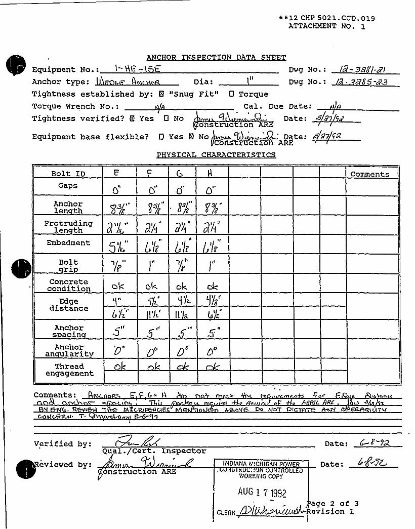
) ~ r
iaL a ~ s.
~ ~ t ' ~ ~ s ~
~ ~ ~
~ ~ ~
~ ~ ~
Ir ~ r
~-
>LkL ' err
- ~ 0 ~ e ~ ~ ..t ia..'. ~r'( ~ ~ 1 4
~ r~ ~
t~ ~ ~
0
555%5%%%%LLRSR55%mHHLS55Ã%8NNLLLLWISNRRRKLLRWWSWLLLLRIRSSRRLELERRRWRWWRSWRWELLLRSWWQLEELR%R%RSRWMMWWMW&WWW&&~ ~ a. 0 ~ l 1 A 1 a a
~ ~gh A.. s OJ r ~ IL5 ~ ~ saaJ
I/5Ji4 4A L I~ ~ f
~ i

Equipment No.:
Tightness established by "Snug Pit"7Tightness verified by: -c
Qual. /Cert. Inspector
Comments:

/w uEPARTPAENICONTROLLED OOCUMEHT
coPYI'-. 9 I
12 SHP 5050 NCE.OOGATTACHMENT NO. 1
ULTRASONIC TEST REPORT
JOB ORDER NO ~ : ~$ REPORT DATE: 2 REQUEST NO.
IDENTIFICATION
UnitComponentItemMaterial C.SOther
Test Unit/ S/N ifjFreq./DiameterReference StandardCocuplant/Batch No.
TEST DATA REMARKS
ll~V
II r/"II /I A
PERFORMED BY:
REVIEWED BY:
FORM NO. 12 SHP 5050 NDE.008-1
LEVEL:~ DAT<:
I'EVEL:~- DATE:
Page 1 of 1Revision 0

Equip ID: 1-QT-107-CD . Train: 2 Equip Class:21
Drawing No.: 1-5151C~
~
~ ~
nction: EMERG DIESBL
System: DXESEL FUEL OXL
Equip Desc: CD EMERG DIESEL FUEL OXL DAY TANK
Building: AUXILXARY Room: CD EMERG DIESEL GENERATOR ROOM
Elev: 587 Sort: S, Notes:
Normal State: Desired State: Power Req'd: N
Support System Drawing:
Req'd Support Comp:
Safety Related Status: NUCLEAR SR Min/Opt: MXN
Alias No: Power Train: NA
Comp Served: CD FUBL OXL DAY TANK
MPR:
Model: 36" D x 108" L, 465 GAL.
":Elem. Drawing: N/A
Wiring Drawing: N/A
Power Source: N/A
Walkdown: P Relay Eval : N
Comp Type: TANK (CAPACITY - 2 HRS PULL LOADOPERATION)
Xso Drawing:
Location: XN THE NW REGXON OP THE ROOM, 10 FEET NW OP THE GEN ENDOP DGCD INSIDE THE FUEL OXL DAY TANK ENCLOSURE, AT THB599 EL.

DC Cook Unit1SCREENING EVALUATIONWORK SHEET (SEWS)
GIP Rev 2, Corrected, 2/14/92Status: YesSheet1 of6
ID: 1-QT-107-CD (Rev. 0) Class: 21 - Tanks and Heat ExchangersDescription: CD EMERG DIESEL FUEL OIL DAYTANKBuilding: AUXILIARY Floor El.: 587.00 Room, Row/Col: CD EDG RM,Manufacturer, Model, Etc.: 36 D x108 L,465 GAL.
BASIS: Horizontal TANKanalysis
1. The buckling capacity of the shell of a large, fiat-bottom, vertical tank is equal to or greaterthan the demand.
2. The capacity of the anchor bolts and their embedments is equal to or greater than thedemand.
3. The capacity of connections between the anchor bolts and the tank shell is equal to orgreater than the demand.
4. Attached piping has adequate flexibilityto accommodate the motion of a large, fiat-bottom,vertical tank.
5. A ring-type foundation is not used to support a targe, flat-bottom, vertical tank.
N/A
Yes
Yes
Yes
N/A
D T 7
SRT: George G. Thomas (SB A) and Tom Huang (AEP) —10/7/93.
REF: 1. Anchor Inspection Data Sheets: Anchorage Arrangement Sketches and Physical Characteristics DataSheet, Certified 4/5/93.2. Worthington Dwg it/ 700006BU3. Worthington Co. Fuel Oil Day Tank Calculation, 8/1 //74.
Anchorage: 1-QT-107-CD is a horizontal tank which sits on 2 saddles. Each saddle has 2, 1/4" thick plates,forming a "U", with no gussets. There are 2 - 5/8" anchors per saddle.
Cracks in the leveling grout on the concrete pad were identified. The SRT judged this acceptable since thestructural concrete pads are intact.
Horizontal Tank Analysis:Saddle Weak Axis Moment of Inertia = 2I + 2(ad*2) = 2((30"x0.25in"3)/1 2) + 2(15in"2 x (4"2)in"2") = 480in"4.
Results of Horizontal Tank Analysis show tank anchorage is adequate (conservatively using expansion bolts forthe 5/8" diameter Nelson Stud anchors), and Ref. 3 calculation contains saddle stresses check.
Interactions: Block wall has been confirmed by AESPC to have been evaluated in the IE 80-11 program.
Evaluated by: Date:
I l /Z ~! eW

DC Cook Unit 1
SCREENING EVALUATIONWORK SHEET (SEWS)GIP Rev 2, Corrected, 2/14/92Status: YesSheet 2 of 6
ID: 1-QT-107-CD (Rev. 0) Class: 21 - Tanks and Heat ExchangersDescription: CD EMERG DIESEL FUEL OIL DAYTANKBuilding: AUXILIARY Floor El.: 587.00 Room, Row/Col: CD EDG RM,Manufacturer, Model, Etc.: 36 D x 108 L,465 GAL.
Attachment: TANK Analysis Results

DC Coo4; Unit 1
SCREENING EVALUATIONWORK SHEET (SEWS)GIP Rev 2, Corrected, 2/14/92Status: YesSheet 3of6
ID: 1-QT-107-CD (Rev. 0) Class: 21 - Tanks and Heat ExchangersDescription: CD EMERG DIESEL FUEL OIL DAYTANKBuilding: AUXILIARY Floor El.: 587.00 Room, Row/Col: CD EDG RM,Manufacturer, Model, Etc.: 36 Dx108 L,465GAL.
TANK Analysis Results
Step 1 —Input Data
a) Assumptions1. Tank is cylindrical, horizontally oriented and supported on saddles.2. Tank and saddles are made of carbon steel3. Saddles are uniformly spaced.4. Saddles overhang is less than spacing /2.5. Base plates have slotted anchor bolt holes for thermal growth except for the base plate under
the fixed saddle.6. Imposed nozzle loads are not significant.7. The tank foundation is adequate.8. Anchor bolts are cast in place or expansion type.
b) Materials
YesYesYesYesYes
YesYesYes
Weight of Tank + FluidWeight Density of Tank+ FluidSaddle Elastic ModulusSaddle Shear ModulusBase Plate Yield StrengthAnchor Type
c) DimensionsTank Diamete; DTank Length, LTank Thickness, tHeight of Tank+ Fluid C.G., HcgNumber of SaddlesSaddle Spacing, SSaddle Height, hSaddle Shear cross-sectional areaSaddle Weak Axis Moment of InteriaNumber of Bolt Locations / SaddleNumber of Bolts / Bolting LocationExtreme Bolt Spacing,
D'nchorBolt Eccentricity, eWeld ThicknessBase Plate Thickness
4.5 kips70.7 Ibs/ft"329000.0 ksi1150.0 ksi36.0 ksi
5/8 in Expansion Bolts
3.03 ft9.0 ft
0.19 in1.71 ft
6.0 ft2.38 in
15.0 in"2480.0 in"4
2.1? ft6.0 in0.19 in0.19 in

DC Cook Unit1SCREENING EVALUATIONWORK SHEET (SEWS)
GIP Rev 2, Corrected, 2/14/92Status: YesSheet 4 of 6
ID: 1-QT-107-CD (Rev. 0) Class: 21 - Tanks and Heat ExchangersDescription: CD EMERG DIESEL FUEL OIL DAYTANKBuilding: AUXILIARY Floor El.: 587.00 Room, Row/Col: CD EDG RM,Manufacturer, Model, Etc.: 36 D x108 L,465 GAL.
d) Anchor BoltsType = Expansion AnchorManufacturer = Phillips Stud (S)
Diameter = 5/8 inProduct Name =
Nominal CapacityPullout
3.17 kipsShear
3.79 kips
Concrete Compression Strength, fc' 3500.0 psi
Reduction ParametersCapacity Reduction Factor
Label1. Type of Anchorage
CheckYes
Condition Pullout1.0
Shear1.0
2. Installation Adequacy3. Embedment Length
4. Gap at Threaded Anchors5. Spacing between Anchorages6. Edge Distance7. Concrete Strength and Condition8. Concrete Crack Location and Size
Yes Installation is adequateYes Embedment Length = 2.38
inYes Gap size = 0.0 in
YesYes Edge Distance = 6.25 inYesYes Crack Size = 0.0 in
1.01.0
1.01.01.0
0.881.0
1.01.0
1.01.01.01.01.0
9. Essential Relays in Cabinets
10. Base Stiffness and Prying Action11. Equipment Base Strength and
Structural Load Path
Yes
YesYes
Essential relays are notpresent
Base strength and load pathare O.K.
1.0
1.0'<.0
1.0
1.01.0
12. Embedment Steel and Pads Yes Installation is O.K. 1.0 1.0
Does the tank satisfy all the assumptions and is within the applicable range of parameters?
Step 2 —The allowable bolt loads
Allowable Tension Load,Pu'llowableShear Load,Vu'.774 kips
3.79 kips
Step 3 —Determine base plate bending strength reduction factor
RB 0.1562
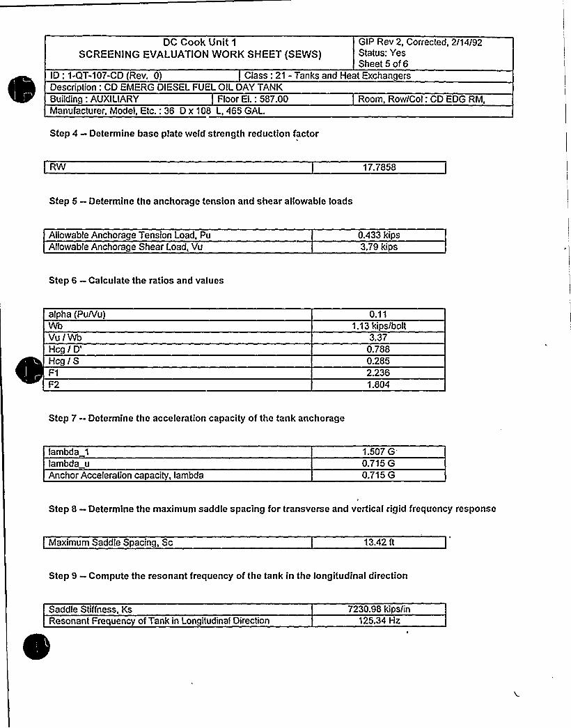
DC Cook Unit 1
SCREENING EVALUATIONWORK SHEET (SEWS}GIP Rev 2, Corrected, 2/14/92Status: YesSheet5of6
ID: 1-QT-107-CD (Rev. 0) Class: 21 - Tanks and Heat ExchangersDescription: CD EMERG DIESEL FUEL OIL DAYTANKBuilding: AUXILIARY Floor El.: 587.00 Room, Row/Col: CD EDG RM,Manufacturer, Model, Etc.: 36 D x 108 L, 465 GAL.
Step 4 —Determine base plate weld strength reduction factor
RW 17.7858
Step 5 —Determine the anchorage tension and shear allowable loads
Allowable Anchorage Tension Load, PuAllowable Anchorage Shear Load, Vu
0.433 kips3.79 kips
Step 6 —Calculate the ratios and values
alpha (Pu/Vu}
Vu /WbHcg /
D'cg/S
F2
0.111.13 kips/bolt
3.370.7880.2852.2361.804
Step 7- Determine the acceleration capacity of the tank anchorage
lambda 1
lambda uAnchor Acceleration capacity, lambda
1.507G'.715G
0.715 G
Step 8 - Determine the maximum saddle spacing for transverse and vertical rigid frequency response
Maximum Saddle Spacing, Sc 13.42 ft
Step 9 —Compute the resonant frequency of the tank in the longitudinal direction
Saddle Stiffness, KsResonant Frequency of Tank in Longitudinal Direction
7230.98 kips/in125.34 Hz

DC Cook Unit 1
SCREENING EVALUATIONWORK SHEET (SEWS)GIP Rev 2, Corrected, 2/14/92Status: YesSheet 6 of6
ID: 1-QT-107-CD (Rev. 0) Class: 21 - Tanks and Heat ExchangersDescription: CD EMERG DIESEL FUEL OIL DAYTANKBuilding: AUXILIARY Floor El.: 587.00 Room, Row/Col: CD EDG RM,Manufacturer, Model, Etc.: 36 D x 108 L, 465 GAL.
4
Step 10 —Determine the seismic demand acceleration
ZPA 0.25 G
Tank is rigid in all three directions.Tank anchorage is adequate because anchorage acceleration capacity is greater than ZPA
Step 11 —Check the saddle stresses
The program does not check the saddle stressesCheck the saddle stresses by an independent calculation
5mamaw
IC
The tank anchorage is adequate.

Coo
Component No. i QT- l 0"( -( i) Claaa
IIEIUll
Any pazticularprea the Seismic Review Teaa should pay axtra attention to1Yes No ~ (Xf yea, check items that apply.)
Anchor TypeAnchor DiameterAnchor SpacingAnchor NumberAnchor EmbedmentAnchor Edge DistanceAnchor GapAnchor Thread EngagementAnchor GripAnchor AngularityConcrete Crack
Others (describe bri.efly)
If there ia concern for Design Basis Discrepancy, circle the applicableitem and explain.
l.2.3.4.
Hardvaro Maintenance Type Discrepancy.rawing Update Type DiscrepancySignificant Operability/Design Basis DiscrepancyOthers
Condition:! 'oo!6
Actions Taken:
Jog~
peaparad ByT'~~co Dace 4'+ ~ ~

"*12 CHP 5021.'CCD. 019ATTACHMENT NO. 1
IZ..» 890Bldg.
TVE. Moli>tH 5F'~. QP "C D" D~~.CCi-'P
IMSLQE IHE. TUEL OlL W.Y fh'tW-
Locatxon
Insta at on dwg. / Rev.
Anchora e Arran ement SketchEquipment No.
j'j4 5~a
Ql Q/I
EEEV. 4K&. MQR'TH APR D 5 19S
LEIIK~Q
FACE'~ WC,Rg8 (TVF
Drawn by:Verified by:
d. RQ~IL Date:Date:
Reviewed by:Qua ./Cert. InspectorT o.~l~ Date:
Construction chor Review Engineer
Page 1 of 3Revision 1

0

~ g
~ f
'i
y ~ i
~ ~ t
+Jl ~ > e e ~
~ ~ ~
~ ~ ~
~ - liI.
e 'l~l
~ - s.~ r
t L.S
e ~
~ ~
e ~
~ ~
R%K~SWKiRWWWW .
1 0 0 0
RRRSRSRSWWHHHHQL88558LL55WII~WHL 5HHI%55%L 8RESRE5555RWW&&55RRRRHRilN5%5%i% - %SIN6%5%5%RSMMRaIRMWWMWWWW
h 0
I
J l'la1
~ ~ ~ ~

SHP 5050 NDE-008ATTACHMENT NO. 1
UI.TRASONIC TEST REPORT
JOB ORDER NO.: REPORT DATE: g7 5 REQUEST NO. A
IDENTIFICATION
UnitComponentItemMaterialOther
Test Unit/ S/NFreq./Diameter ~Reference StandardCouplant/Batch No.
TEST DATA REMARKS
~ 7D
. 7$"
PERFORMED BY:
REVIEWED BY:
FORM NO. 12 SHP 5050 NDE.008-1
LEVEL:W DATE: /I EVEE' DATE:
Page 1 of 1Revision 0

ATTACHMENT6 TO AEP:NRC:1040E
SAMPLE LARS CALCULATIONS001, 005, 010, 011, 022, 023, 027 AND 030
RAI ITEM 8

This attachment contains thc following:
1. A 16 page document containing thc proccdurcs, input data, and rcfcrcnccs used in the Limited AnalyticalReviews.
2. The rcqucsted Limited Analytical Rcvicws: LAR IIs 001,005,010,011,022,023,027 and 030.3. Thc calculation used to resolve the outlicr gcncratcd by LAR022.4. The proccdurc used to address the outlier gcneratcd by LAR005.

k
'I

PROCEDURES, INPUT DATA,AND REFERENCESUSED IN THI:I,IMnZDANAI,VSISazmm S

3. LIMITEDANALYTICALREVIEWS
3.1 Problem Statement
This Limited Analytical Review (LAR), performed within the scope of Unresolved Safety issue (USI) A46,evaluates the structural integrity of cable tray and conduit supports which have been chosen asrepresentative, worst case examples of the major different types of raceway support configurations withinD.C.Cook Nuclear Power Plants 1 and 2. Twenty nine sample supports have been chosen from the plantraceway support systems for evaluation.
3.2 Summary of Results
The critical interaction value and related comments for each of the raceway support evaluations in thisLAR are summarized in Table 3.1 below. Refer to the Attachments to this section for details of each of theevaluations.
D. C. Cook A46 Cable Tray and Conduit Raceway ReviewOctober 1995
page 3-1
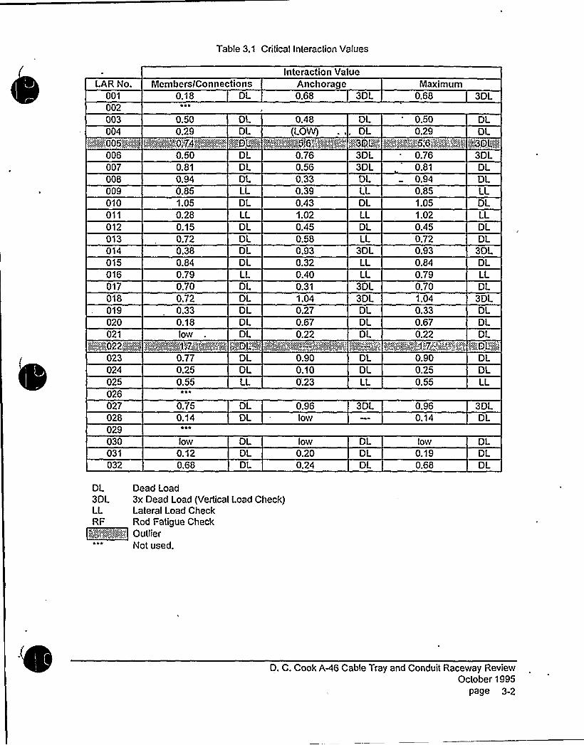
Table 3.1 Critical Interaction Values
Interaction ValueLAR No.
001002
Members/Connections0.18 DL
~ ee
Anchorage0.68 3DL
Maximum0.68 3DL
003 0.50 OL 0.48 DL 0.50 DL004
K":005."j!:.:::::-„'i~
0.29 DL<@FOP'<g~
(LOW) ... OLe~~c'~p; 'e""w,'5'~< ~,'„e<'ew ''e< gxQD<p,%:e
0.29 DLItgQLKI
006007008009010011012013014015016017018019020021
023024025026027028029030031032
0.500.810.940.851.050.280.150.720.380.840.790.700.720.330.18low
0.770.250.55
*1~
0.750.14
~ e*
low0.120.68
DLDLDLLLDLLLDLOIDLDLLLDLDL
DLDL
DLDLLL
DLDL
DLDLDL
0.760.560.33
0.431.020.450.580.930.320.400.311.04
0.670.22
0.900.100;23
0.96low
low0.200.24
3DL3DLDLLLDLLLDLLL
30LLLLL
30L3DLDLDLDL
DLOLLL
30L
DLDLDL
0.760.810.940.851.051.020.450.720.930.840.790.701.040.330.670.22
0.900.250.55
0.960.14
low0.190.68
30LDLDLLLOLLLDLDL
30LOLLLDL
30LDLDLDL
O'D,L"':k
DLOLLL
30LDL
DLDLDL
DL Dead Load30L 3x Dead Load (Vertical Load Check)LL Lateral Load CheckRF Rod Fatigue Check
~f'i~/'::„':: Qellier*** Not used.
D. C. Cook A-46 Cable Tray and Conduit Raceway ReviewOctober 1995
Page 3-2

i i m f a Tr v I i
Logic diagrams indicating the evaluation path taken to demonstrate the acceptance of each of theraceway supports are shown below. Note that the particular evaluation path taken for the support inquestion is defined in heavy outline.
LAR Nos. 003, 004, 008, 010, 012, 019, 020, 021, 023, 024, 030, 031, 032
START
8.3.1
Does the Support HaveVertical Dead Load CapacityWith Eccentricities ~ t.0 x OL?
Yes
Yes8.3.1
Directly mounted to or rigidlycantilevered from an adjacentstructural wall or ceiling?
+No8.3.7
Floor mounted?
; Ho
Yes
8.3.2
Does the Support HaveVertical Capacity ~ 3.0 x OL?
Yes
8.3.3
Does the Supped Have DuctileResponse to Lateral Loading?
Yes
8.3.4
Does the Support Have AdequateLateral Load Strength '?
Yes
No
l
8.3.5
Is the Support a Fixed- EndRod Hanger?
Yes8.3.5
Does the Support Pass theFatigue Evaluation?~ Yes
tfo
Pass AnalyticalReview
Outlier
(Rigid Mount)
D. C. Cook AA6 Cable Tray and Conduit Raceway ReviewOctober 1995
page 3-3

LAR Nos. 005, 022
START
8.3.1
Does the Support HaveVertical Dead Load CapacilyWith Eccentricities ) 1.0 x OL?
No
Yes8.3.1
Directly mounted to or rigidlycantilevered from an adjacentstructural wall or ceiling7
8.3,7
Floor mounted?
No
Yes
8.3.2
Does the Support HaveVertical Capacity -,. 3.0 x DL?
Yes
8.3.3
Does the Support Havo DuctileResponse lo Lateral Loading?
Yes
INo
I
8.3.4
Does the Support Have AdequateLateral Load Strength 7
Yes
8.3.5
Is the Support a Fixed - EndRod Hanger 7
No
.V...1
Pass AnalyticalReview
Yes8.3.5
Does the Supporl Pass thoFatigue Evaluation 7
Yes
Outlier
(Any support failing OL)
D. C. Cook A-46 Cable Tray and Conduit Raceway ReviewOctober 1995
page 3A

LAR Nos. 009, 011, 016, 025
START
8.3.1
Does the Support HaveVertical Dead Load CapacityW~th Eccentricities ~ 1.0 x Dt.?
Yes
Yes8.3.1
Directly mounted to or rigidlycantilevered from an adjacentstructural wall or ceiling?
No
8,3.?
Floor mounted?
l NoI
8.3.2
Does the Support HaveVeicaIG pocky 30xDL2
l Yes
Yes
8.3.3
Does the Support Have OuctgeResponse to Lateral Loading '7
Yes
8,3.4
Does the Support Have AdequateLateral Load Strength?
Yes
8.3.5
Is Ihe Supporl a Fixed - EndRod Hanger?
Yes8.3.5
Does the Support Pass theFatigue Evaluation '?
Yes
Pass AnalyticalReview
Outlier
(Floor Mounted Support)
jD. C. Cook AAG Cable Tray and Conduit Raceway Review
October 1995page 3-5

LAR Nos. 014, 028
START
8.3.1
Does thc Support HavoVertical Dead Load CapacityWith Ecccntricities ~ 1.0 x DL '?
Yes
No
Ycs8.3.1
Directly mounted to or rigidlycantilevered from an adjacentstructural wall or ceiting?
No
8.3.7
Floor rnounted2
No
Yes
8.3.2
Does the Support HaveVertical Capacity ~ 3.0 x OL 2
Ycs
8.3.3
Does the Support Have DuctileResponse to Lateral Loading 7
Yes
8.3.4
Does thc Support Have AdequateLateral Load Strenglh 7
Ycs
No
8.3.5
Is lhe Support a Fixed ~ EndRod Hanger '?
Yes8.3,5
Does the Support Pass thcFatigue Evaluation?
Yes
Pass AnalyticalReview
Outlier
(Trapeze Frames)
D. C. Cook AA6 Cable Tray and Conduit Raceway ReviewOctober 1995
page 3-6

LAR Nos. 001, 006, 007, 017, 018, 027
START
8.3.1
Does the Support HaveVertical Dead Load CapacityWith Eccentricities ) 1.0 x DL '?
Yes
No
Yes8.3.1
Directly mounted Io or rigidlycantilevered from an adjacentstructural wall or ceiling?
8.3.7
Floor mounted?
Does the Support KavoVertical Capacity ~ 3 o x OL?
Yes
8.3.3
Does tho Support Have DuctileResponse to Lateral Loading '?
Yes
8.3.4
Does the Support Havo AdequateLateral Load Strength 7
Yes
8.3.5
Is the Support a Fixed - EndRod Hanger?
NoI
Yes8.3.5
Does tho Support Pass thoFatigue Evaluation?
Yes
Pass AnalyticalReview
Outger
(Rod Hanger Trapezes)
D. C. Cook A46 Cable Tray and Conduit Raceway ReviewOctober 1995
page 3-7

LAR Nos. 013, 015
START
8.3,1
Does the Support HaveVertical Dead Load CapacityWith Eccentricities ~ I.O x DL 7
Yes
Yes8.3.1
Directly mounted to or rigidlycantilevered from an adjacentstructural wall or ceiting?
8.3.?
Floor mounted?Yes
8.3.2
Does the Support HaveVertical Capacity 3.0 x OL '?
Yes
8.3.3
Does the Support Have OuctigeResponse to Lateral Loading 7
Yes
No 8.3.4
Does the Support Have Adequate'ateralLoad Strength 2
Yes
8.3.5
Is the Support a Fixed - EndRod Hanger 7
No
Yes8.3.5
Does the Support Pass theFaligue Evaluabon?
Yes
Pass Analytical/Review
Outlier
(Floor to Ceiling Supports)
D. C. Cook AA6 Cable Tray and Conduit Raceway ReviewOctober 1995
page 3-8

3.3 Method of Solution
Hand calculations are performed employing the methodology outlined in Section 8 of Reference 3.6.4,"Generic Implementation Procedure (GIP) for Seismic Verification of Nuclear Plant Equipment.",Supportstructures are broken down, where applicable, into subsections which lend themselves to common, closedform solutions for structures subjected to static loading.
3.4 Allowables and Assumptions
The following is a compilation of allowable stress and load criteria used throughout the raceway supportevaluations.
strength of 36 ksi. AISC Specification allowables for Allowable Stress Design (Ref. 3.6.1) are used for thedead load analysis. For other analyses, the allowable stress is increased to 0.9 Fy = 32.4 ksi.
J2.5 of Ref. 3.6.1, is 0.3 x 60 = 18 ksi for dead load analysis. For all other analyses, 1.7 x 0.3 x 60 =
30.6 ksi is used.
i: Dimensions, properties, and allowables use'd to analyze variousUnistrut support system components are based on the Manufacturer's Catalog Data provided in Refs.3.6.2 and 3.6.3. These values are used for the dead load analysis and all other analyses. Values forUnistrut components commonly used at D.C.Cook are summarized below:
Unistrut bending moment: Ref. 3.6.3, p.23
P1000: 5080 in-Ib (allowable bending stress of 25 ksi)
Channel nuts/bolts Ref. 3.6.3, p.69
5/8": pullout in P1000 or P3000: 2500 Ib5/8": slip in P1000 or P3000: 1500 Ib1/2": pullout in P1000 or P3000: 2000 Ib1/2": slip in P1000 or P3000: 1500 Ib3/8": pullout in P1000 or P3000: 1000 Ib3/8": slip in P1000 or P3000: 800 IbBolts are assumed tightened to manufacturer's recommended values
r I: D.C. Cook embedded channels are Unistrut P1000 (or equivalent), galvanized, 12 ga. channels with a material yield strength = 33 ksi, modilied by the addition of 3/8 $ x 4"L
Nelson Studs at 12" o.c. Results of tests of modified channels (Ref 3.6.20) indicate a minimum pulloutcapacity of 6400 lb/ft. The mode of failure was ripping of strut material around the stud; stud remaining inconcrete. Using the AISC Allowable Stress Design allowable shear stress of 0.4 x Fy = 13.2 ksi on a
45'one
shaped slip surface results in an allowable pulloutof 13.2 ksi x n x (D + t) x t = 13.2 x 3.14 x (0.375 + 0.105) x 0.105" = 2090 Ib, therefore use the standardcatalog value of 2000 Ib, but not more than the allowable value for pullout of Unistrut channel nuts/bolts aslisted above. For all other load cases, use an allowable stress of 1.7 x 0.4 x Fy resulting in an allowablepullout of 3550 Ib, but not more than the catalog allowable value for the pullout of Unistrut channelnuts/bolts as listed above.
D. C. Cook A-46 Cable Tray and Conduit Raceway ReviewOctober 1995
page 3-9

To summarize:
Pullout of embedded strut:(dead load analysis)
2000 Ib
2000 Ib1000 Ib
5/8" channel nuVbolt1/2" channel nut/bolt3/8" channel nut/bolt
Pullout of embedded strut:(all other analyses)
2500 Ib2000 Ib1000 Ib
5/8" channel nut/bolt1/2" channel nut/bolt3/8" channel nut/bolt
Concentrated loads may not be spaced closer than 12" apart unless the sum total ofconcentrated loads on any 12" of Unistrut length does not exceed the single loadallowable.
Reference 3.6.14, willbe used unless noted otherwise within the individual LAR's.
1/2"3/4"1
II
1-1/2"2 II
3 II
4ll
1.1 Ib/ft1.3 Ib/ft2.0 Ib/ft3.5 Ib/ft4.9 Ib/ft
11.1 Ib/ft16.6 Ib/ft
wide by 6" high) is 25 pounds per linear foot, unless noted otherwise within the individual LAR's.
h I: Concrete anchor bolt allowables used in alf analyses are based on Tables C.2-1and C.2-2 of the GIP, Ref. 3.6.4. The anchor bolt type must be known to use the maximum values.
Ifanchor bolts are'identified as "non-shell" type anchors on the PASS, then, per Ref. 3.6.12, the anchorsare either 5/8" Hilti"Kwik-Bolts"or 5/8" Phillips wedge-type anchors. Allother anchors must be identifiedon the PASS or they willbe considered "unknown." Unknown anchors require a reduction factor of 0.6 onthe allowable toads provided in Ref. 3.6.4, Tables C.2-1 and C.2-2.
Allconcrete anchors, known or unknown, shell or non-shell type, which are not loaded in tension by deadweight, require an additional reduction factor of 0.75 for the "Reduced Inspection Alternative", and,because one third of the anchor bolts (there must be a minimum of six) must be assumed to be "notavailable", another reduction factor of 0.67 must be taken.
The design concrete strength at D. C. Cook is 3500 psi. This requires a reduction factor of 0.875 to beapplied to the pullout capacity of all anchors. No reduction is required for the shear capacity.
Ifa tightness check has been performed, it will be so stated on the PASS and the "Reduced InspectionAlternative" reduction factors may be waived.
'D. C. Cook A<6 Cable Tray and Conduit Raceway Review
October 1995Page 3-10

r n or I
To summarize:
"Known" concrete anchors such as 5/8" Hilti "Kwik-Bolts", 5/8" PhillipsWedge-type, or 5/8" Phillips Red Head "self drills":
Pall = 3.17 kips x 0.8T5 x 0.75 x 0.67= 1.39 kipsVali = 3.79 kips x 0.75 x 0.67= 1.90 kips
Pall = 3.17 kips x 0.875 = 2.77 kipsVali = 3.79 kips
Allother 5/8" concrete anchors:
(not in tension by deadweight)
(in tension by deadweight)I
Pall = 3.17 kips x 0.875 x 0.6 x 0.75 x 0.67 = 0.83 kips (not in tension by deadweight)Vali = 3.T9 kips x 0.6 x 0.75 x 0.67= 1.14 kips
Pall = 3.17 kips x 0.875 x 0.6 = 1.66 kipsVali = 3.79 kips x 06 = 228 kips
All3/4" concrete anchors:
(in tension by deadweight)
Pall = 4.69 x 0.875. x 0.6 x 0.75 x 0.67 = 1.23 kipsVali = 5.48 x 0.6 x 0.75 x 0.67 = 1.65 kips
Pall = 4.69 x 0.&'F5 x 0.6 = 2.46 kipsVali = 5.48 x 0.6 = 3.29 kips
All 1/2" concrete anchors:
(not in tension by deadweight)
(in tension by deadweight)
Pall = 2.29 x 0.875 x 0.6 x 0.75 x 0.67 = 0.60 kipsVail = 2.38 x 0.6 x 0.75 x 0.67 = 0.72 kips
Pall = 2.29 x 0.875 x 0.6 = 1.20 kipsVali = 2.38 x 0.6 = 1.43 kips
All 3/8" concrete anchors:
.(not in tension by deadweight)
(in tension by deadweight)
Pall = 1.46 x 0.875 x 0.6 x 0.75 x 0.67 = 0.39 kipsVali = 1.42 x 0.6 x 0.75 x 0.67 = 0.43 kips
Pall = 1.46 x 0.875 x 0.6 = 0.77 kipsVall=142x06=085kips
(not in tension by deadweight)
(in tension by deadweight)
Shear-tension interaction limitations per the GIP, Ref. 3.6.4, Section C.2.11 willbe used to evaluate theeffect of combined anchor bolt loading.
D. C. Cook A-46 Cable Tray and Conduit Raceway ReviewOctober 1995
Page 3-11

3.5 input Data
The hangers evaluated in this calculation were selected by the Seismic Review Team (SRT) thatperformed the raceway walkdown. The selections are documented in the Plant Area Summary Sheets(PASS), which are part of the project documentation.Pl ei i
Horizontal seismic accelerations are required for the Lateral Load Evaluation and the Rod Hanger FatigueEvaluations as defined in the GIP, Ref. 3.6.4.
Three options are presented in the GIP, Ref. 3.6.4, Section 8.3.4 for determining the horizontal seismicacceleration to be used in lateral load evaluations. Acceleration values for D.C.Cook corresponding toeach of the options are summarized below.
Elevation ZPA Building Option 1 Option 2 Option 3587633650609598612625651699
0.200.220.220.220.320.370.420.520.80
AuxAuxAuxDGBContContContContCont
1.211.211.211.211.211.211.211.211.21
0.630.690.690.691.001.161.311.632.50
0.940.940.940.940.940.940.940.942.50
Option 1: 2g scaled by the maximum of SSE/Bounding Spectrum (ZPA value controls)Option 2: 2.5*1.25'Floor ZPA (1.25 is for 'realistic'loor spectra)Option 3: 2.5'1.25 1.5'SSE ZPA (within 40'f grade)
Conclusion: Option 2 for Aux and DGB, Option 3 for Containment
D. C. Cook A-46 Cable Tray and Conduit Raceway ReviewOctober 1995
page 3-12

0
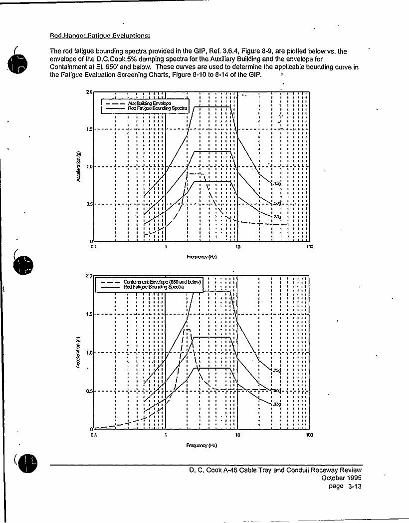
The rod fatigue bounding spectra provided in the GIP, Ref. 3.6.4, Figure 8-9, are plotted below vs. theenvelope of the D.C.Cook 5% damping spectra for the Auxiliary Building and the envelope forContainment at El. 650'nd below. These curves are used to determine the applicable bounding curve inthe Fatigue Evaluation Screening Charts, Figure 8-10 to 8-14 of the GIP.
20
1.5
g 1.0
0.5
00.1
IIIIIIIII1
I II II II II II II II III II II II II I11I III II 1
I II'I II II11I I
r
I I I II I I II I I II'I'rI I I II I I II I I II I I II I I II I I II I I II I I II I I II I I II I I II I II I II I I
111I I I II I II I Ir rr
I I II I II I
I I II I I III~ I II I I I
II,
Iis/ I
/
I s
I I II I I
1
I II I II I II II I ~INI II I II I II 11I I I
I 11I 11I I ~
I I ~
I II I I
I I yl1 I
I II I s
I I II I ~
I I ~
I II II I I
~ ssI I I II I I I
II I II I I II I I III~ III I I'I1111I I I II I I II I I I~ I I I
I II I I II I Issls I I ~
I I I II I I I
II I I II I II I I I~ I I I
I I I-rrrrgl I
~ II~ 111~ I I I
I ~ II I I
10
I I II I II 11I I II I II I II sl II I I
1 NI I I II I I II I I II I I II I I II I I II I I II I I II I I II 111
I I II I I II I I I
I I I II I I I
I I II I I IfI I I I
I I II ~ II I I I
I 11I I I II I I II I I I
I I II I II I II I II I IIII I II I I
I I II I II I II I I111I I II I II I I
I I II I II I II I II I II I II I I111I I I-I rrrI I II I II I II I II I II I I~ ~ II I I
F~(Hz)
20
1.5
I 1.0
0.5
I-00.1
I II II II II I
H II II II II II II II II II I1 II II II II II II I~ II II I~ II II Is I~ II I~ II
I I I I II 1111I I I I II I I I II I I I I
I I SS'I I I I
I I I I II I I I II I I I II I I I II I I I II I I I II I I I II I I I IrrrrI I I I II I>I II I I II I I I II I III I I II I I I I~ I I II ~ ~ II I III I I I
I I II I IIs s~s
I I I I II I I I I
I I II ~
6508AdbctoA) I s s
I I ~ I I II
I II II II ~
I III II s
~ II II I
I II II III I
HII
I ~
I
I) I
I II I
I
I II I I I~ I I I~ ~II
II I I
I I I I~ I I I
I I I~ I I I
I~ I I I~ ~ II I I-rrrsJ I I I~ 111
I I I
IIII
I II II II 'II I11I I
II
I/ I
II ~ ' ls
I I I ~ II~I I III~ I
I s
I III II ~
I II s
I ~
~ ~
s I II I I~ ~ II I I~ III I I~ IIII~ ~ I
10
s
I II II II II II II II II II II II II II II II II II II I
1 II II II I
II I
~339I II II I~ ~
~ ~
II II II II II II II II II II II ~
I II II II II II II ~
I I II I II I II I II I II I II I II I II I ISSII I II I II I II I II ssI I II I II I II I IrrrI I II I IIII I II I II I II I I111I I II I II I II I I~ ~ I11 ~
I I I~ I ~
I I I~ ~ I
Frequency (H )
(D. C. Cook A-46 Cable Tray and Conduit Raceway Review
October 1995page 3-13

i vl in r nn Po r
All threaded rods used in raceway supports at O.C.Cook are manufactured all-thread rods.Some rods, however, are anchored using the welded rod coupler detail shown to the right.The SRT was concerned that the coupler material is not as ductile as the rod material,particularly after being welded. 2.
Fatigue tests were performed on O.C.Cook threaded rods with the welded rod couplerdetail (Ref.3.6.23). These tests show that for the same ductilitydernand, the number ofcycles to failure using the welded coupler detail is approximately half the number of cyclesto failure using typical "nutted" rod connection details at O.C. Cook (Ref. 3.6.6, Table 8-2).
I
The test data points for the welded coupler detail are plotted below on Figure 8=5 from Reference 3.6.6(this figure was used to develop the fatigue evaluation screening charts in the GIP). Each test data pointrepresents 3 tests (6 tests total) on 5/8" rods with an applied axial tensile preload (ITT) of 2.2 ksi (500 lb.)The test data points lie above the "2/3 Strain Acceptance l.ine", which represents the ductility demand vs.cycles to failure acceptance criteria for field-threaded rods. Therefore, in these LAR's, in order to coverrod-hung raceway supports that have not been selected as LAR candidates because of lower weight orlonger length, but which may have welded coupler anchorage details, Rod Hanger Fatigue Evaluations willconservatively include the procedures specified in the G1P for field-threaded rods.
3.20
FATIGUE DATAFOR THREADED RODS
COMPEER. ~INST. CVRV8 W/ flGD THRIVED
2.80
2.60
3 2a0
P 2.20
a1.60
1.40
ACCEPTANCE LINE
aa06 ltae~~~«Ildt40W4c AQ(.
1.20 0
1.001.008+00
NOt5lAUZED OVOllUIYDo&NO
O. C. Cook AA6 Cable Tray and Conduit Raceway ReviewOctober 1995
page 3-14

3.6 References
3.6.1 "Manual of Steel Construction, Allowable Stress Design", 9th Edition, American Institute of SteelConstruction, lnc. Chicago, IL, 1989.
3.6.2 "General Engineering Catalog", No. 10, Unistrut Building Systems, GTE Products Corporation,Wayne, Ml, 1983.
3.6.3
3.6 4
"General Engineering Catalog", No. 12, North American Edition, Unistrut Corporation, Wayne, Ml,1992.
I
"Generic Implementation Procedure (GIP), for Seismic Verification of Nuclear Plant Equipment",Revision 2A, March, 1993, Seismic Qualification UtilityGroup.
3.6.5 "Design of Welded Structures", Orner W. Blodgett, James F. Lincoln Arc Welding Foundation, July1976.
3.6.6 "Seismic Evaluation of Rod Hanger Supports for Electrical Raceway Systems", EPRI NP-7152-D,March, 1991.
3.6.7 "Cable Tray and Conduit System Seismic Evaluation Guidelines", EPRI NP-7151-D, March, 1991.
3.6.8 "The Performance of Raceway Systems in Strong-Motion Earthquakes", EPRI NP-7150-D,March, 1991.
3.6.9 "Seismic Verification of Nuclear Plant Equipment Anchorage" EPRI NP 5228-SL, Revision1,Volume 1, June, 1991.
3.6.10 AEP Guideline No. 18.3, Rev. 4, 4/9/86: "Guide for Cable Tray Loading"
3.6.11 Test Report 91C1681-02, Testing of D.C.Cook typical Unistrut attachment brackets for rod hungcable trays.
3.6.12 AEP Drawing No. 1-2-EDS433-14, Sheet 1 of 2, 5/31/91.
3.6.13 "Longitudinal Load Resistance in Seismic Experience Database Raceway Systems", EPRI NP-7153-D, March 1991.
3.6.14 AEP Document No. 02-0120-1097, Revision 0, Page 3 (Rigid Conduit Weights)
3.6.15 Letter from I.C.Huang of AEP Service Corporation to Steve Anagnostis of Stevenson andAssociates, 1/10/94, re: as-installed conduit weights for raceway supports LAR011 and LAR017.
3.6.16 "Rigid Frame Formulas", A. Kleintogei, Frederick Ungar Publishing Co., New York, 1952.
/.D. C. Cook A-46 Cable Tray and Conduit Raceway Review
October 1995page 3-15
3.6.17 Donald C. Cook Nuclear Plant Drawings:
1-1594-41-1460-751-1528-511-1525-571-1464-83
3.6.18 AEP Guideline No. 18.2A, Rev. 0, 6/27/86: "Guide for Cable Tray System Design".
3.6.19 Telecopy dated 4/29/94 from I. Huang of AEP to Steve Anagnostis of Stevenson and Associatesregarding as-installed cable tray and conduit weights for LAR's 1,3,5,9",10,16,18, and 22.
3.6.20 Letter from I.C.Huang/AEP to Steve Anagnostis/Stevenson and Associates, April 7, 1994-resultsof testing of D C Cook modified embedded Unistrut,
3.6.21 Stevenson 8 Associates Design Report, AEP Raceways 82C200-02, Cable Tray Testing-Analysis and Report, 9/30/83.
3.6.22 Telecopy from I.C.Huang/AEP to Steve Anagnostis/Stevenson and Associates, May 6, 1994-Field information concerning LAR011 (bolt spacing and conduit spans).
3.6.23 "Low Cycle Fatigue Tests on 5/8 inch Threaded Road" by Dario A. Gasparini, P.E.IPh.D., Dept. ofCivil Engineering, Case Western Reserve University for Stevenson 8 Associates, March 25, 1992.
D. C. Cook A<6 Cable Tray and Conduit Raceway ReviewOctober 1995
page 3-16

REQUESTED SAMPLE LARCALCULATIONS001,005,010,011,022,023,027,030

I

CUENT
Fb ~KMJOB No. IS' SHEET OF
Stl.'VenSOn and ASSOdateS
HlA 5rruc rural Maclra alca I
Coarultrag Eagiaaerrag Frrra
./9

CUENT
%6DC 4 ZAZ-ooi
Stevenson end Associates
Il A SrrnclnrohMochoalcolCoaoolliag Englnoorlng flrra
O5' C7
~cr /(

CUENT
SUOJEGT
gd g~g< Zs4- oo/
Stevenson and Assodatcs
5IA Sauctural.Mechoolrsl
coasu!5og Knylnoaanq Few
~. aoP
c
Or8 ~Adds

CUENT
smu acr
ce ~ ~M-oatStevenson and Associates
R h Souelvwl.MechanicalCoasulaao Kayiaoorlaa Flies
sa / Il

'Os6fyLZXt$g C
OMIQN-
~Fthm<
EHVDpQ..'sr.r,', . ss IIIII~1WT~ 7 I' ~ ~ '4I g. > . ~ 'I>y~
$I,V-RLl
s
S
yV
0'cow vtYC'IsgL
I
slI
Isl Ifs
s P",s
Is
I II
II
'ag)~gL @0
~rSI6,CWiW. 80K4 Q'IIILT4)~
IL 4"
yss
t,Mss 's& s'
ss
~ +Jlgt s' I LLI~ t 1, tN.IHP B.
631'- 0"
.=r arS Wt+~~I.SI~gq~
g'laos'r. IL~"e~
$ 3ss
I'3s„'s3y ~ II CIJLMIS (TC0
$ $ I
Skt"~h"s CI MGib
gs IIlg ss
gs, gII
~~IoO ao IIEr~rrIar
WI5 ~Et OVK IIEET WO
GLKVhToR..
~PPoRY ¹ 2ACeVa rL. LL cO1Lo"

wY'g4iW.
Qf&Ar
II5I~P
~ (tPIlfyl.
+PC~~'
1 cAOAling,,
II
I II III
» Y,'
I
~l
n,>/sr>'4.
Z4L+ g» ml»)>VS
~:
fdJla»» t i» t» %A» ~ »»A»» e P»»»J,
Al-'PfdPP tL
Na>22,15t 5 lts5IFT
glc%$Ppi'>'h~
x wan ar» a tat u»»Ie»'sr&.s.»»~~ ag
12.444 LSSlI=T
II»C I5
~ l
I2,55t' $5/FT
1S;hLS>iFT
6,tA C
GIAN 693
10.4$ L$5lFT zCnmD
OmN
'z4. 5(o4 $5rFt'y»
v:c&tsN)~~
AlRm+ C1 6-4
sk@i 6~'4
1Q.625 LBSf FT
YAM-FS
2 .c,t23
l»r
. 1LQI
g» )II
hllKHHVf
cd&'4'IGLOO
g»» I»ll
4'T%lC SVRh4 C46. I»QY WO
5 LCVh'To@»
SUPPLY ¹ <—R.» %L C»5»I»r 0 ~
At'TUEL VVEJC WT5 FOR LAR4'
COH001T lOEHTlFI CATION UNKNOWN
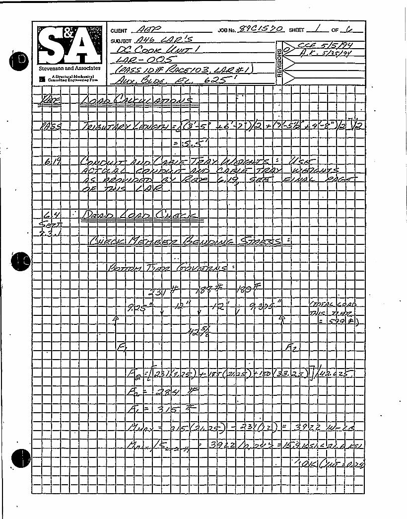
0L
CUENT
r
Stevenson and Assodates
II A s<ruclural MoehaalcalConeulling Enylnooeny l'leaa
<85$ 'D9 l'ScM/oZ

. ~

CUENT
ggu~ + '4@8 S
Stevenson and Assodates
II A svuciurel.Mechanicalcon oui liay fagiaoorlny Fa w
SS JQx C.»
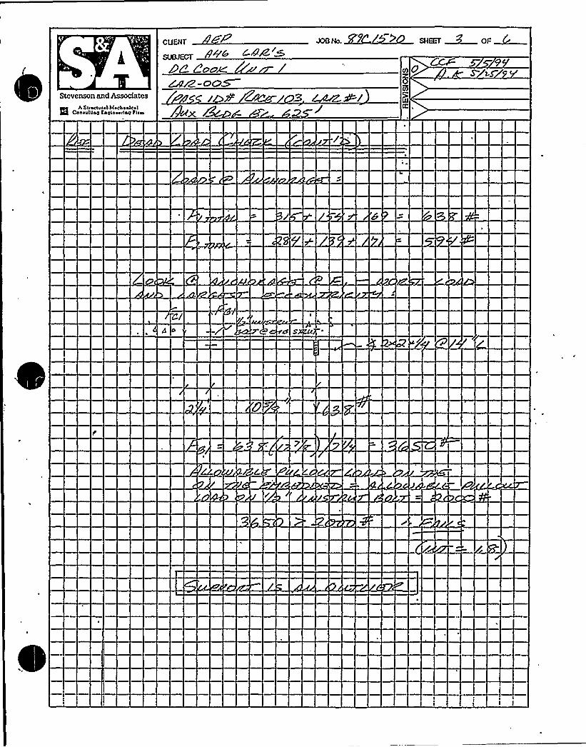
(
Stcvcnson and Assodatcs
Q A Suwtvral MoehoaleolCosevl8og Eaylaoorlay Fires
CUENT
sum ccr ~+'>DQ 2ccm
4 S
CP

CUENT
Smuem
P~rrStevenson and Associates
Q A SnueNral MechanicalcohsulUay laglaoo<lnp n<m 4'4rx Lad- Wc ID'

CUENT
SUOJ~ 4 b 4AZMSC'IC /HPO auaac 6 oa c
Rcvcnson and Assodates
H A SteuccusahkechaalcalCoa>ulpop Kaplaeeclop
Fitch's~-cv5
AY~re M ~roB ~>PzAce ~ W~. ma.
~ ~

Stevenson and Associates
Il A Svuctuwl Moeho nlcslCoaeu!5'nginooenp Fans
Z4Z-oosS zs 9

p'g. A~
1%AC~ear>
~ ~
We.ckc@D gooYo RaD Cc&PL/JJhTo L 'j$',Q RgoUklPWSLD (mK)&EE VETAlL"C-C"
~ ~ ~OQ ~
~/~ TAI
2'-to
U-eu MPspp >Q
I11
2/g IAMC8 I AN P3
U - t'LAMPSQvQ
f "1/g'
'- 4/g"5~~ 6"
l AM-XIO I AMP
&EEPETA'lL
Ie,"(n@l AN-CGQ
)1 p gI
f A,N< CG [ l AM-C82
g1/ Il

2'D
I
l
/g. UN&BRUT ~
BoLl(~) i
I
lqx2x2 x)0 L
I
I
I
llI
I
I
8 MC5>t=-0
) I
I )0+g"
DEgRv'T
PETAlL "c.-c'PXT <wI'poRT
TNP-~ vPFg~
')>r5A
HOTeAGHL=E

'34 l8:46 FROn AEPSC NUCLEAR DES
LEFT'O RIGHTIA."-2840(o-I, 2.98 LBS / FTI'I~"- 50IIZR-I, 3.2.2 LK5/FT<r~-- SOIOSV-I, S.ZZLS>r Vr
I - 9957R-I, I.73 LBS/FT
'q ~ I"-205I3-I, I.BI( 6 LHS/FT~ ~
~ j,Pp~ o gg~
PAGE.OQ4
ACTUALNElGWT5 FOR LAR ~5
2 3O
'R&KPPeon
U-cLkNPs
a'< ~~z
We.Eke@& BOD~o Hot Cc vPLQK~-XC L 3/4. nu >aV4C>wctu> I'~eg&EE OFTA1L "c-c"
l0. 95 LB5/FT'29.Hr 5 L65IFT
3~C8 3AM PZ
t-PIUM@EL. 633'~f
g 'pg&hDP
U-CVd4P5C~Q
yl1
w.~ra".
3
1t
3g Q~)
LEFT TO RKHT0"-9Z.G2PS-I) IO;75 L55/FT4'-'MBPS-I fO.GHL65/FTlANxto )ANTE .
t-3 g
LEFT TO RIGHT
I4. 291'o LD5/FT
25 'H54L65/'I-T
3 AN-'C80 I~~CG t I AM-C82
l 25cg'xP "SF~ (TYP)
I.FI-T TO RISIIT
+I.95 LSD/FT34.Z7 LB5/ FT>2,77 I.Pv/ FT


Stevenson and Assodates
R A svuctu( ~ I Mn«hnnlcnlCnnlulgng Knglnuuslng
Elf'UENT
D2 o
4AM-use
Joulk>. +~~+~ sHEEf~ oFM~
III O8
LJ.
OW

CUENT
~guECT D O
Stovenson and Assodates
II AStrwte re lkoAonlcs1cosoullsy Ksylaoooay Fleas
o

ECUENT
muccr > C
XeN. ~<~<~~ SHEET 3 OF~~
Stevenson and Associates
II AS(naciecabHocbaelealCoasulliny Enolsoerlsa I«w
id' ~Z

0

CUENT
~c
Stevenson and Assoc|ates
imA slnscturel Mechanical
Coastal'5aO Kngtnoedsg Fhm

CUENT
l
Stcvcnson and Assodatcs
ERA structural Hocbaaiea'I
coneulsny Englnoodna Fcce

V
h
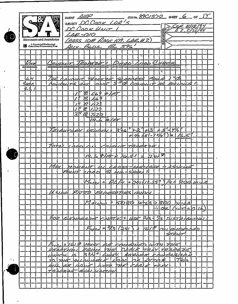
CUENT
Stevenson and Associates
H A SlluclulnlJlochn nlcnlCon<utgng Cnglnuurlng finn
7d
~ C

CUENT
mum
Stevenson end Assodetes
Wh Srrac<arsl Mschsslcsl
Cssralriarr taylssarlsy Firrs
xg


Rcvcnson and Associates
RIIL Suuctu<al Mochaalcal
Con o villa@ Esglaeorlay E'l(a

CUENT JOG No.
Stcvcnson and Associates
NmA ScwNral htoehonlcal
CoaevlCng Caglaoeslsy Fwa
o5'

CUENT
Stevenson and Assodatcs
S A Stiactvial MechanicalCoaouluny Eaoisoeclsy flea

CUENT
SUBJECT
Stevenson and Associates
RlA Sltvc(v ral MoAoalcsl
Conoul5sa Kaylnoorlao Faa
l/
~ ~

CUENT
Stevenson and Associates
Il A S<oadvrol.Woc4alcslCoaoultley Eaglnoo(lay Foes
O

ECUENT
Stevenson and Assodatcs
E5A sv~ousal Mechaaical
Coa>vlsay Ksglaoerlay Fns


LCUENT
Stevenson and Associates
l5 A Snvctssal l4ochaaks1coao~hay Esyisoonay nba
d

CUENT
Stevenson and Associates
El A Suvelurst.MechanicalConsolan'aylneorlng fl<w
24&a 0
CD'c

CUENT JOO Na MS O SliEEE ~& OF ~F
Stcvcnson and Associates
l5 h strvciscn MechanicalconovlUne ssolssorlnp fires
/z

CUE~r
SUOJECr
Stevenson and Associates
II A suuelucol MechanicalConouluna Esglaoorlsp Fifa
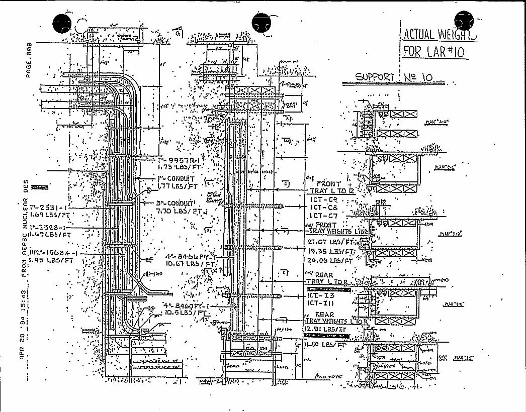
.<'( (
(S ag ~ I W4 ~ ~ I (p'rf +
att/+ ae a ~~ ~, ACTUAI WEIG
! FOV LAR~IOQJIrJaQ.
I, ~,~ ~
ei tV
~ ~ r,'JI g"
Jttr .
~ ~ 'I+a ~~ e~ r ~ ~ ~
t
Sr
3c',J IS
~ ~ ~
I ~ ~J
~ f
r(fvyt tva~ ~ ~ r
th)~ I
. a(htJ (JC.S'.
I
I
&PPoRT ¹ )0~ ~ ~
t at
te~ I'
I ~ t ~ *rat
~ ~~t
~
~~
~
~)'jest I
~'J ge
(JJ
CI
R
~ I"-'253I- I
~~ I b'I LBS/Pg ' '.')Dz I"-2528-I~(IS(ng LES// I-T ~
N0.
a I(IQ. - 'I 0 f(S 0 4. - I
z I,(I5 LB5/I=T I ~ '.,~'C
~ I
r ~
ml~la ~*
IA I
I
~Jm!I ~
(JJ: I ~
(SJ '
/IQ..a, ~ I
S
II
et~ te)
~ fI
~ ~
~ r
~ I
rrt ~~ ~ t
t ~ra I~,
I~
J J'I ~ ~ ~ e
~ 'I
~i
I ~
~ ~~ ~ ~
4-'+bI(JPY-f,IOIIl.LR5/ FT
~ ~
r~ $ rat ~
1i,.(p rI''I
~ \~ ~
~+'|- 8(l&qFf-I~ IOI6 LSD/~: "$l:
I ~ ~
I~
I 'a ~
~ ~
t t ~,C ~ 'I ~
1 ~ g)y; Nr. I kgu(r
~ ~ ~ I \\
~ g ~ I ~
I
I"- 9957R-I ~ 'I ~
'i75'LB>/I:T ~ . I'
I"-coNOUjT'.77 LM/i-"7 '~
COiOuITJ .
'7s70 Leih/ F.'.T i~ I ~ ~
~ Qg, ~I
er rt
~ ~ ~ '
~ +A ~
:j„t
'JI
lt.
lai
JCJ!4 ICJ'CJ r
I I;i ~
gt t ~ I rINa~ Ia
~q
~ rTlt
~ ~C
~ a IM N
~ ~
\ ~'V
(ea I'IH
I~ ~
r) ~ ~~ ~ >V,.:
QI(J 'J
r~ ~
r'. J~ ~
l CT C7Ji.tt FROHT ~ ~ ~ ~
TRAY MIGII76 L
2;l,07 M5/k7 C
I9, M, .LE'J/ PTJ: ~
20.08 LP&/FT '
REAR
IGT.- I5I CT- X I I
~ al
Jg REAlZ
~ r
( ~ I
n > ca'I
~C ~
(
n..a!LRS/Xr~ J
I'"''I
80 LB5lPT'l't..
CI
tl. Ii tait)VL"~ . ~ /
~ ..
j; ~
TRAY L, TQ fZ '-':., ~
ICT- C(l ~: -; .(ri .,aI CT- Ce „ t,s,".'> ~ ~
a]))Sg J( 'a
I ~
~ I ~ r>

a4"
~ r r g4"recco~ 1 ~, Korrl
~ ~
~ I ~'I~
F- bC ~ 4
~Ite)o Sel I~ ~
4 Ieh
~r Oe~r4e r
~ vrouw
SUPPoRT. ¹ >0
~g
I I ~
so ~
aClvej
IS
spl I h~ o
r'
~ r ~ I
rI
~ \sg
I
~DeOeS ISr\,
I
'
"rll,'r
r
, ~
~ ~
11'J „i ~~
~\I 'I
IIII
I
~ @
~ ~~I's ~ L ~
ff K
IsosrtI
CutltfP
If>c
'f
K ~ L.-e ~
'' e'rie
J" ~rKr /I~" ~ \
'PI
r 'o
Qfttr
J,I1 Is..IJIC I
IJ ~
I 'I I ..'~ ~
I. I IIkl+'Cr~ ~
s 'I'',I s'I'lrs«I S
S I'I II JI
I:II sI I . I
f:4~3 .I ~ II I)'Ios II I ~I.'ll II' ~ ~I II II .Il II II ~I,II
@Ager
I II ~
~
IlI ~ I
slrl ~
I I~'
I IIII~
I I ~
I ~ e
~ ~ o~ I
~Ce6'I\$ rr ~
e. IlI II ~ ~~ ~ I ~s ) ~ I
i ~I
I I~ IS ~~ e',I ~~ I ~
.IL.'
Ie
ICI Cl
etel ~ ~ore e%%
~ ~ re tA~ o e'I ~ ~ ~
~ rrr' ' 'I~ rsrr
~ ~ slee o~ ~ leer
,r)I ~ ( ~ ~
ro .'goJ'sA tpAtr I II(
'I
~ ~ O. „. Jgpq ~q I
<tr "~
ef}e I~IAII A I
~ t.'~\
ISnrICIrs
AALU
II ~
'le ~
AA
'
~ I ~
Its!I'e.t'
I: -rr ~ A.04
~ St.s'r 1 J')'
I~ ~
I
Ie CIIJ)
I'
)!I"r.. ~
IIA
~ ~
J'" ~ r .
I
rs I I InI''A"~ ~ 'rt IeorSIII
Ilsr't tt"
'g Ietll 'r t

0 CCW 5'S
Stevenson and Associates
@IA Structural Mechoslcil
Cosovlllay Eaylaooclny Fam 6

0

SUOJFCT
4 d 844&DC Coen
STEVENSON& ASSOClATES
a slntctwo4nochonlcotconwtttng onglncottng tlrm
H8'SS rD> rica"ro/ M~A/

STEYENSON5, ASSOCIATES
0 lttvclw04MchonlcolconwNny enqlnoodnp Arm
SUOJEGT AgA z449
OCO
tU
S
JOB No. ++ ~~~ ~ SHEET~~ OF~~

SUBJECT JOB No. ~~~++~ SKEET'=OF~~/
STEVENSON5 ASSOCIATES
a sliucturo4neehonlecAconwWAg ong'Inoohng Nm
DOC~ b~r~ JDu-o'er'

0

SUBJECT JOB No. o 5SHEEf OF/~
STEVENSON84 ASSOCIATES
a aovchroHnochoNcdCOhWNAQ Ohglhlhrlhg Sftl
D2 Caom ~imS4M-w/'r'ASE
rap Wca-
S Xd'

SUBJECT SHEET 0F
STEVENSONK ASSOCIATES
0 IIWCfutCHAOChQhICCICOAWIIIAPCAQfhtOAlg fllfh
844-Oi/HA2~ JDW P ag /0/ ~Nl
0I/I5UJ
~ 0


CLIENT
amECT
Qa Stevenson and Associates
A suvctvtal Mochoslcolconeulusq ssolhttclly Flra

0

g ~ ~ S
STEVENSON5 ASSOCIATES
a slrvcluroHn+chantcolconwmng nnglnonnng Arm
xo/ ~ j6

CUGNT
Stevenson and Associates
8 A stnaclvwl Hechaslcalcosevhisy tsglooonng fna


SUZeRT.-To—= jPSRS~„"~~-~SUPPORT ...mHF NSro85-V"~) .. 'd'
8'k3'~ i~"L'2
24 27/ ii&
2Q.:ply Il
22 pal'2I ~u.
20~ r-
FL. EL. SSS'-o
«~~l.~8>, 8 QQp
19lB i>
- e rt)ylo
]~. r> 'lb
isio
Sf 3~X/qL---=~V---'-'A=---A'~.)5UI'f'opT AHCRog. PiN,
PLBX i SL.P. C.OTtx 0)q>
bc. PI > ~) @8' 4 ~l@
>0
x)qola
M'M.H'.—..s ...(TYI',)
~ms'eor.,Y=—ASQQo.R..piM~ioMG(T~P)
25 . 7/')>8
sJ@
~hebc
:. 1ND<kNP N~CWC kg po%ERDoNKLD c.. cooK NuciEp,p PLAN~
. DP-. B<. N. MAa~R ...DATE: E4. BB&'-.o."........BUILp'1N&,"AUX.: LoC.P,YiOH RvJGw, can.;.:.PiPE .-YUQHEL JN/7 @ 4
SR GHEE RH ant~ AGEE LAP go pg

. ATTACHMENT NQ.3
ypP
'~Yt<lC ) )J~
~>~vcr~'ue>oW'ery+~
g ~un~ sun~
LoQ Bod 5o ]JF YT SvPPi&TMlS SuFPoR~ Ch)F iu Rv)<V'@Pc 'Yu~)UF L Gun-<
Phoo
g/Wq//~
lIII
I
tl
5I
7r
5
pig Acx EoLTI+'ovC~I)
)l0
lo
+% "zg~g',dy~ 4v t
}/ ga
/4Apg'3 glO

ATTACHMENT NO. 1COOK NUCLEAR PLANT
A-46 RACEWAY EVALUATIONSLARoll
CONDUiTNO.
(SEEATTACH.3)
10
CONDUXT SIZEAND TYPE
3/4" EMT
1" EMT
1" EMT
1 1/2" RIGIDSTEEL
RIGIDSTEEL
1 1/2" RIGIDSTEEL
2" RXGXDSTEEL
2" RIGIDSTEEL
3" RIGIDSTEEL
3" RIGIDSTEEL
2" RIGIDSTEEL
2 i'IGIDSTEEL
3" RXGXDSTEEL
CABLE TYPEAND SIZE
XN CONDUIT
1-12/C f12 XLA
2-2T/C f161-STP g16
1-4/C g7/3.8
1-4/C g7/18
1-4/C g7/18
1-3TC g41-1/C g4
1-4/C gl2
1-3TC g2/01-1/C g2
1-3TC g2/01-1/C g"2
1-3TC g21-1/C g4
1-4/C /12
1-3TC g4/01-1/C g2/0
POUNDS PER FOOTOF CONDUIT AND
CABLE
0.97
0.73
0 '92.87
2.87
2.87
3.81
3 '27 '17 '13 '23 '28 '9
BASIS FOR WEIGHT.CALCULATION
(SEE LXSTED ATTACH. NOS.)
5 & 7C
5 & 8B
5 & 13B
6 & 7C
6 & 7C
6 & 7C
6i 9i & 10
6 & 7C
6, 9, & 10
6, 9, & 10
6, 9, & 10
6 & 7C
6c 9,.& 10

f
)p)
i ~ '
~giant~ II%IS
n)a~a<~) gg O
l8)
la)
hl
4l
0
88rn
'rMKAF.
'i%%f QSÃl.
I%f4Nr>
%% .Pi~
I%$4~C ~
5 ~
~ )+
~eatI
~03
<iS
ClOtl~0z,.'
lRE
J /J ~
'P
A ~

CUENT
C.AQ 5
Stcvcnson and Associates
Il llstevcwcal HochanlcalCDlllll4lligKllglhoollhO Fcm
GNAT iDP ~ - os ~ezra ~.


CLIENT
SmuECT 4+6
Stevenson and Associates
Q A Sttuatutal Nathan(calCaaeulUntt Eaelnaatlng fltta
SX i&~Zo r
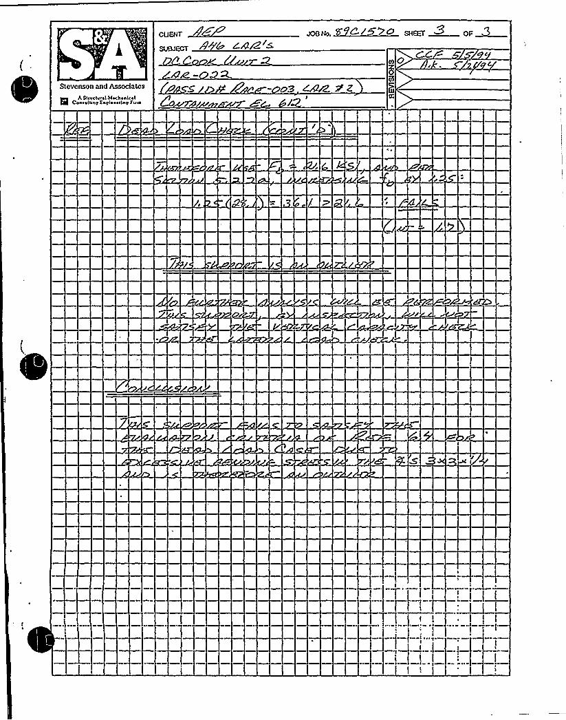
GUENON
sujet~ 8' CA/Z ~
Stevenson and Associates
Q A Snueivr ~ I.MecLanicalConevlsny Kayisoocag Firm
SZ

< s''
~ s
~nno5r
~I
GSZC-P2.
~~
CADirt hsf'Lo
~ l
l gQQQ+ C5»
I>sGSZC-CS18. 5'2 I.B5/ I=T
tt t'Sll'~ ~o
~ mrs" ZOO~JA 0
3 - M.'T8"Z.9.'ISLETS/ T
PIOOO
Op L
GUPPY%
nAS:Slf
+/DAN
LI'»A'bSECT 'AA''07 d'iJ gp~~~'- IZ+KC-Z. <A4 ~~I 65(PT
I5i01
ItIIgPy,I» gO~ ~
1'COT
scrrrrH m v sum's Au
~ ~
~ t, ~, ~
~ ~
Z.'» 7SGM 2.4.A 4 I.65/ PX
O
DI
0DClm
Ci7
C)
ACTUAL VJElC HT5 FOR 4/AR:~ZZ
IQCMTIPICATIOH QF It <, Il/2." g C,D'5UNKHOWH

g~o7 Tg
1I'
JCC.N> 2
L~t%555o Lk(Tft3
ii~ IIIililI
I'O'I~
I'it+It &to
ue Octal. A
LI'-44'4
SECT
'A'A'g'll
co-.%'tt cor ~ ~
l'a
I&i('ii~ I 4 CoiIOIItt
BOVTEM MhY SVPT'5 PEAN VlEW~ ~
t
Pg M, fOX
CII. I.HM4IIIII%CWTX II'IC~ 'll.

Egad o SHEEf OF
CCW 5 dPd
c
STEVENSON5. ASSOCIATES
a Itntcfvtctmocttantcolconutttlnp onplnoottntt Ilrm
0s5 zD8 Pea 659 &~<9
gyy 4 @f82/8 ~4..
OCO
tUK

SUBJECT
4+5 848~JOB No. SHEET~UQF
STEVENSON5, ASSOCIATES
a Auelvcahnoe~cantina ongfnoodng nrm b
0

SUMFGT
STEVENSONK ASSOCIATES
o ttructurotrnnchontcolconautNng nnptneertnq nrm

P
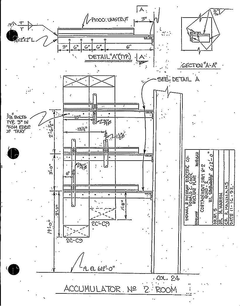
0 0 0 0
g1l @l <
pl l Qll
I
'4 ~, ~ ~
:cga-TKg A-g
SEE-.: DETAK. A
4 ~ Ill
e I
fL.Gl 6l2-0"

0

SUNEGT
STEVENSON5. ASSOCIATES
0 ltmchnol4lochohlcolconeNnp onplnoonnp turn
A5s ro+&W 9 uzi
5r

sussex
STEVENSON8( ASSOCIATES

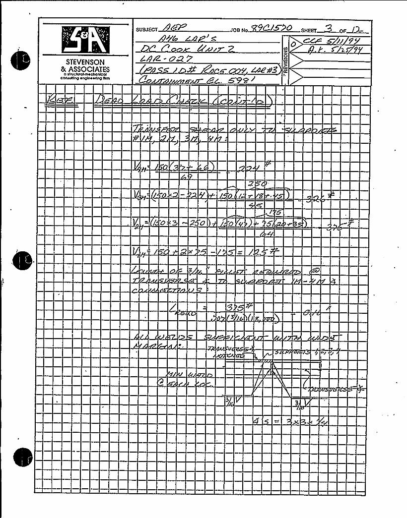
SUBJECT JOB Ho. +~~~ SHEET &OF~~
STEVENSON8. ASSOCIATES
a sovclvrounochoMolCchNNho Ohglhccdho Alhl
844- oP 2PAz7
ESP

SUBJECT
STEVENSON8c ASSOCIATESCOhSVINhg OhQIA40tlhg flllA
Goo~ errS/D C
0
Or'/
O
S


SUBJECT JOB No
STEVENSON8( ASSOCIATESconwmng onpHoorlng am

0

STEVENSON5 ASSOCIATESconweng onplnoonnp Arm
Mrz P3
~w//7M 5 z,S0
g 1/

0
!

SUBJECT lPIIHF.STD/K 0 SHEET F OF
STEVENSON8( ASSOCIATES
o Etructrrrolrnochonlcotconsrrtttng ongtnoortng arm 0
su~Oa7 ~ F
O


6w/i 2STEVENSON
8t. ASSOCIATESQ ltntchl<OHTi4ctMtnlcnl
cntuttlnp ongtnoorlnp tttm

STEVENSON8c ASSOCIATES
o structurotrnoctronlcclconruttlng onglnoorlng llrm
S
Ore
ltttt
CCC 5 /-/C. 7

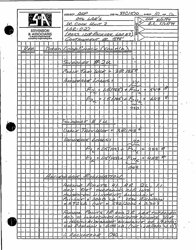
STEVENSON8c ASSOCIATES
o rrruclrrrcHnochanrcclconrrrrtlng onprnoodnp tlrm

SUBJECT JOB Ho.
STEVENSON8( ASSOCIATES
a ttructvrctrnochcnlcnlccnwtttnp onglnoortnp hrm


SUBJECT
+6 84r8 sZ
JOB No.
STEVENSON8 ASSOCIATESeonsuenp onplntorlng tern 7 %imam WC,

fooll((fIo%~
(((oA~S))1)OI SAC'lh.
r el(«UNh
\'o Oe(ll 'IAI(
~
1( ) ( r 4 9( (4
Alta Ci>fV14)
f(IOA IIII'1o
,h4<)('() telo IOtfftfgWOV(f
~ ~ If~rSOT'TEN lRAYS—
NC&c~~iCI,All
II f(IIIKO ho CIAan t1'I'11~'Wb
o [lo ~ I'~ 0 ~
~ ~
I(( ~ ( loC(OKAY C COSMIC
lLCLIAt IAAI(f
COnll((((n(% (Oftf IIO t~(fAS 0
~L. 01'4CC IIO- 1
~ I,WI((AS'5
t. ((A(I4LI('IOATC I(.1( '%1.
COL 17
~ I(fII)i/~AIII1AII A(I
K> I(IOI
Cr Aflgis'It"I'Ia.
a)It)fAt4 1S
rCCTIC((I A A '
~
~ ~
~)J
LC1~'(f V
tC C44
2c C~SI ~ 1
2C'CW i 1(J(
~A -zc
~ I
I ~
II~ I
IIII. l
gpP T'IIAY5-~ww

SUBJECT ...SZC/5 9o
STEVENSON8( ASSOCIATES
o ssrvctwosrnochonrcolconsurrlnSS onynoorhq rrrrn
o >~iZAg- o So
2oarÃrww)ewe 8c„bp3 -ro
0rrs
ro
Og
QC

SUBJECT
ZAN>r
STEVENSON& ASSOCIATES
0 IoMclvfokhochnnkclConukonp onplnoohng ilrm


9'TEVENSON
8( ASSOCIATES0 SlcUClvt04IhlChohtCN
COAWNA9 OA9414OEIA9 llCN

SUBJECT JOG No. 6/ SHEET~ OF
STEVENSON8. ASSOCIATES
0 oltMcIvcoMlochofllcolconsvNng onglnoodng tlcm "r'O
0C/l
UJCC

2"
5/8 ROD BENT AROUNDPIPE AND BOLTED INSIDE
P1000 ANGLE
I
~ ~
II
5/8 "EXPANSION ANCHORS
EMBEDDED STRUT 2'-0"
2'-6"31 ~
10" PIPE
1'-0"
CRANE WALL
VIEW A-A
o ALL ANGLES ARE 3X3X1/4
o PIPE PENETRATES CRANE WALL AT EL. 603' 10AND RUNS UP INSIDE CRANE WALL TO A JUNCTIONBOX AT EL. 625'-6". THERE IS A LATERAL SUPPORT ATEL. 610'. NO OTHER SUPPORTS EXCEPT PENETRATIONAND JUNCTION BOX.
o PIPE LAYOUT SHOWN IN DRAWING 1 —1460 (SEESECTION 1X-1X AND DRAWING 1-1525).
UNIT 1, LOWER CONTAINMENTCONDUIT 1A1: 10" PIPE
D. C. COOKA-46 RACEWAY WALKDOWNPASS ID//: RACE-1>1, LAR //2

CALCULATIONUSED TO RESOLVETHE OUTLIER GENERATED BY
LAR8022
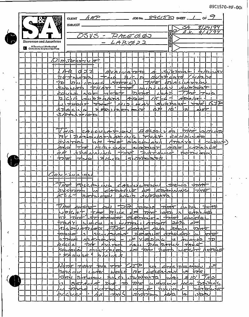
89C1570-HF-OOI
QUENT C/ cuccc ~ a"~—
Stevenson and Assodatcs
mmA Sauctuccl Mochoalccl
Coaoulu ap Kaplaocrlup Puca
cc


CUENT nrem ran
Stcvcnson and Assodatcs
Q A Stractaral.MochankalConrrrttintt Enpinoortnrt Firm


CUENT
SUOJECT
Stevenson and AssociatesI A Sgupturnl MnpbnnlpnlCpneuliing Englnnoeng Fgw

1

CUENT
SUBJECT
5 SHEET ~ OF ~~
. CF
Stevenson and Associates
R A STTHSTE T~ I MSOiTSEICSICOOSE'lung EnglnESTing FTTES
OF'I

CUENT smM DF
Stevenson and Associates
R5A Sfrucluf41 Muchnnicnl
Cnnrulrinp Knpinnnrinp firm
6 4
3(

0

LCUENT C S ~ SHEEi. ~pP~
Stevenson and Associates
Q A st<ucNs ~ I Mechanicalconevaino Ksqineoano arm

CUENT
Stevenson and Associates
H h Suuct~ral Mechanicalcossunisy Esglaoeany fnm
S 8 C- OGQ


CUENT JOE HF C SHEET $ OF~Stevenson and Associates
l3 ii, SIT S IiurshMSSha OiC*lConSVIITOTI KngiOSSriOTI fTTTTI
43
IF
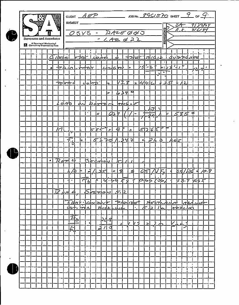
cuEwr
SUBJECT
Stevenson and Associates
/
55A Suuc<u< ~ I Mechonlgal
conovning engineering l'atm
PS
g l
k

PROCEDURE USED TO ADDRESSTHE OUTLIER GENERATED BY
LAR8005


1. Introduction and Summary
The prying-action detail documented in Plant Area Summary Sheet RACE103 and analyzed in LimitedAnalytical Review LAR005 resulted in an outlier. Per the Outlier Seismic Verification Sheet, therecommended resolution to this outlier is to walk-down the plant and document.all occurrences of thisdetail, screen the specific configuration of each detail using an acceptance criteria based on the LARrequirements, and modify those occurrences that do not meet the criteria. This document addresses thefirst part of this resolution - the walkdown and screening. The screening criteria is described in Section 2,the screening walkdown documentation is contained in Section 3.
This walkdown was performed by the Seismic Review Team members that did the bulk of the originalraceway walkdown: I. C. Huang (AEPSC) and Stephen Anagnostis (SEA). The walkdown included all theareas of the plant covered in the raceway walkdown except for the Unit 1 containment above El 650 andinside the crane wall below El 650, as the unit was operating (the Unit 1 containment annulus wasincluded). Based on the original raceway walkdown and that this walkdown of the Unit 2 containment didnot find any significant occurrences of the prying-action detail, the SRT concluded that the Unit 1
containment does not contain any significant occurrences of the prying-action detail.
The results of this walkdown is summarized in Table 1. The first column contains the walkdownworksheet number (the worksheets are in Section 3), the second column describes the location of thehangers with the prying-action detail, and the third column states whether the hangers passed or failed thescreening criteria. About 50 hangers with the prying-action detail were found (note. that some worksheetscover more than one hanger). Twelve of those hangers failed the screening criteria. Allof the hangersthat failed are located in one area of the plant - the Unit 1 Vestibule and the adjacent section of the Unit 1
Reactor Cable Tunnel.
Table 1. Summary of the Prying Action Detail screening walkdown.
Worksheet ff1-092694-1
1-092694-2
1-092694-3
1-092694K
1-092694-5
1-092694-6
1-092694-7
1-092694-8
2-092794-1
2-092794-2
Hanger LocationAux1, El 596, RCT Quad 3 NorthHangers 9, 10, 11 along the right wall counting from door 1-DR-AUX323.Aux1, El 596, RCT Quad 4Hangers 5, 6, 7, 8, 9 on the left wall counting from door 1-DR-AUX329.Aux1, El 596, RCT Quad 4Directly across the hall from penetration 1-CEP-4P5Aux1, El 596, RCT Quad 4Adjacent to penetration 1-CEP-4P5Aux1, El 596, RCT Quad 1
Two hangers across the hallway from penetration 1-CEP-1PGOne hanger near MCC 1-CT-BNAux1, El 596, RCT Quad 1
Upper platform, 1st hanger on right facing door 1-DR-AUX467Aux1, El 596, RCT Quad 1
Upper platform, first 3 hangers on left facing door 1-DR-AUX467Aux1, El 596, RCT Quad 1
Upper platform, first hanger on right off the edge of the platform.Aux2, El 596, RCT Quad 3 SouthNear 2-VRS-2200 (Upper Cntmt RMS "B" Data Acq Module)Aux2, El 596, RCT Quad 1
Upper platform, two hangers about 3 hangers away from Door 2-OR-AUX468.
Pass/Fail,Pass
Pass
Fail (1J
P3ass
Pass
Pass (2)
Pass [3]
Fail
Pass
Pass
Attachment to the OSVS for RACE103Prying-Action Detail Screening Criteria and Walkdown
page 1

1-092794-3
1-092794-4
1-092794-5
2-092894-1
2-092894-2
1-092894-3
2-092894-4
2-092894-5
1-0928944
1-092894-?
1-092894-8
1-092894-9
1-092894-1 0
1-092894-11
2-092894-12
2-092894-13
2-092994-1
Aux1, El 609, 4kV AreaAbove 600V Bus IIAAux1, El 609, Transformer RoomOne hanger above 1-DGTAB and one hanger at the right side of theentrance.Aux1, AuxiliaryCable Vault15'outh of the hatchAux2, EI 5736'outh of gate 2-GT-AUX1013 (U2 Rx Coolant Drain Pump Room)Aux2, El 573South end of the hallway common to both unitsAux1, El 609, elevated area adjacent to the control room cable vaultAbove 12HV-ACA-FLT-3Aux2, El 609Near Miscellaneous Rack 2-H-HAux2, El 609Above cabinet 2-BITH2Aux1, El 612, Vestibule, upper platform leading to RCTNext to 1-DR-AUX467
'ux1,El 612, Vestibule, upper platform leading to RCT3rd hanger on left from the edge of the platformAux1, El 612, Vestibule, upper platform leading to RCT4th hanger on left from the edge of the platformAux1, El 612, Vestibule, upper platform leading to RCT2nd hanger on right from the edge of the platformAux1
~El 612, Vestibule
4 hangers along the containment wall just before the upper platformleading to the RCT.Aux1, El 612, VestibuleThe hanger above the west end of 1-HE-22 and the next hanger west.The two or three hangers south of these running along the block wall.Aux2, El 612, Vestibule, upper platform leading to RCT4th hanger on right from the edge of the platformAux2, El 633Hangers between the Containment Auxiliaries Panel and 2-MSI-1.Cont2, El 598, AnnulusSeveral hangers near Column 1, Az 63, Quad 1
Pass
Pass
Pass [4]
Pass
Pass
Pass
Pass
Pass
Pass [5]
Pass
Pass
Fail [6]
Fail
Fait [73
Pass
Pass
Pass
[1] The angle is "clipped" to the embedded channel with the edge of a washer bolted into the embeddedchannel. Repair by drilling a hole through the angle and rebolting.
[2] This case doesn't meet the screening criteria, but was judged acceptable as the span between the tw'o
adjacent supports is <= 10', so GIP requirements would be met even if this support was removed. Notethat the adjacent hanger would then have a tributary length of 8'5'n one side and 3'n the other) and aload per rod of 640ft.. This load satisfies the allowables of 20000 for DL and 2500Ã for 3DL as specified inthe LAR calculation.
[3] This case doesn't meet the screening criteria for 3DL, but was judged acceptable as the r/c wall on oneside and a large pipe, and platform steel and handrail on the other side will prevent any significant lateralmotion.
'Attachment to the OSVS for RACE103
Prying-Action Detail Screening Criteria and Walkdownpage 2

[4] This case doesn't meet the screening criteria, but was judged acceptable as the span between the twoadjacent supports is <= 10', so GIP requirements would be met even if this support was removed. Notethat the adjacent hanger would then have a tributary length of 7'4.5'n one side and 3.5'n the other)and a load per rod of 440% This load satisfies the allowables of 2000@ for DL and 2500@ for 3DL asspecified in the LAR calculation.
[5] This case doesn't meet the screening criteria, but was judged acceptable as the span between the twoadjacent supports is 9'<= 10'), so GIP requirements would be met even if this. support was removed.Note that the adjacent hanger would then have a tributary length of 7.5'4.5'n. one side and 3'n theother) and a load per rod of 600iti. This toad satisfies the allowables of 2000'or DL and 2500ft for 3DL asspecified in the LAR calculation. I
[6] Both rods on this hanger do not meet the screening criteria (this hanger was the subject of LAR iIi'5,
which initiated this effort).
[7}The two hangers above 1-HE-22 probably need both rod anchorages to be modilied - these twohangers are on either side of a removable concrete hatch. The rods furthest from the corners of the hatchwere clearly visible (and do not meet the criteria), the rods nearest the corner were not easily visible butlook like they willalso require modification.
I
The rods immediately adjacent to the block wall of two or three hangers running along the block wall werenot clearly visible, but do not look like they will meet the screening criteria.
iAttachment to the OSVS for RACE103
Prying-Action Detail Screening Criteria and Walkdownpage 3

2. Screening Criteria
2.1 Criteria DevelopmentThis criteria is for evaluating the D. C. Cook cable tray hanger anchorage detail shown belowfor seismic adequacy in accordance with GIP procedures (Ref. 1).
Lg
v vpv'vP
V
I/2 OR 5/8UNISTRUT NUT AND BOLTIN EMBEDDED UNISTRUT
L2x2x1/4 or L3x3xl/4
'c
= Bearing force on concreteFR = Te'nsile load in threaded rodFa = Tensile load on Unistrut bolt
Force in Unistrut bolt: Fa = FR(1 + Lg/Lq) => FR = Fa/(1+ Lg/L1)
Maximum moment in angle: MMAx= FRL2 FR™MAx/L2
In this detail, bending stresses in the angle and pullout force on the Unistrut bolt will each limitthe capacity of the anchorage. The equations above show that the bending moment in theangle is related to L2, while the force in the Unistrut bolt is related to the ratio of L2 to L<. As theratio L2/L< increases, the lever action on the Unistrut bolt increases for a given rod load FR.
r li 'I
The anchorage detail above is used on rod-hung trapeze hangers. For trapeze-type supports,which may swing laterally during an earthquake, the GIP requires both a Dead Load Check anda Vertical Capacity Check (3 x DL) of the anchorage. The vertical capacity check ensures thatthere is extra design margin in the anchorage to account for additional loads due to supportdisplacement.
This detail is also used on wall-mounted brackets to provide vertical support at the cantileveredend. These supports are directly attached to building structure and are not free to move duringan earthquake. Per GIP procedures, only a Dead Load Check is necessary for these supports.
Attachment to the OSVS for RACE103Prying-Action Detail Screening Criteria and Walkdown
page 4

Allowa I n b ndi s ess
Bending stresses in angles are calculated in accordance with the AISC specification for single-angle members, Ref. 2. Per Section 5.2.1b of the specification, the calculated bending stress,fa, is:
fa= 1.25M/S = 1.25FnLz/S
where S is the geometric section modulus of the angle section.
For the Dead Load Check, the working stress allowables given in Ref. 2 are used. Per Sections5.1 and 5.2 of Ref. 2, the allowable bending stress is 0.66 Fq for 2x2x1/4 L's, and 0.6 Fq for3x3x1/4 L's. For the 3 x DL Check, an allowable bending stress of 0.9FY is used for both anglesections. The bending stress, fa, and the stress limits are summarized as follows:
1.25FnLz/(0.247)1.25FqLz/(0.577)1.25FnLz/(0.247)1.25FnLz/(0.577)
5 0.66Fy5 0.60Fy5 0.90Fy6 0.90Fy
for L2x2x1/4, DL Casefor L3x3x1/4, DL Casefor L2x2x1/4, 3DL Casefor L3x3x1/4, 3DL Case
liow le nis b llo I d
Allowable pullout loads for the Unistrut bolt are summarized below (see Ref 3 for discussion):
1/2" bolt5/8" bolt1/2" bolt5/8" bolt
2000 Ib,2000 Ib,2000 Ib,2500 Ib,
DL CaseDL Case
.3DL Case3DL Case
Limits for Lz and Lz/L< for a given Fz are listed below for all combinations of angle size, Unistrutbolt size, and load case.
DL case, bending in L2x2x1/4:1 25F+Lz/S 6 0 66Fy Lz 5 0 66 (36 000)(0 247)/(1 25Fn) > Lz 5 4690/Fn
DL case, bending in L3x3x1/4:1.25FnLz/S S 0.60Fy => Lz 6 0.60 (36,000)(0.577)/(1.25Fn) => Lz 6 9970/Fn
3DL case, bending in L2x2x1/4:3x1.25FpLz/S s 0.9Fy = Lz s 0.90 (36,000)(0.247)/(1.25x3Fn) => Lz s 2130/Fn
3DL case, bending in L3x3x1/4:3x1.25F„L,/S 6 0.9Fy
4990/FnLz 5 0.90 (36,000)(0.577)/(1.25x3Fq) => Lz s
Attachment to the OSVS for RACE103Prying-Action Detail Screening Criteria and Watkdown
page 5

DL case, pullout of 1/2" Unistrut bolt:FR(1+LE/Lq) 5 2000 Ib => L2/Lq 5 (2000/FR)-1
DL case, pullout of 5/8" Unistrut bolt:FR(1+L2/Lq) 52000 Ib => L2/Lq 5(2000/FR)-1
3DL case, pullout of 1/2" Unistrut bolt:3FR(1+LE/Lq) 52000 Ib => LP/Lq 5(667/FR)-1
3DL case, pullout of 5/8" Unistrut bolt:3FR(1+L2/Lg) 52500 Ib => LP/Lq 6(833/FR)-1
The equations above are summarized in table form below.
(LB)
ANGLESIZE
UNISTRUTBOLT SIZE
LOAD CASEDL 3DL
L2 (IN., MAX) L2/Lg(MAX) L2 (IN., MAX) Lp(L/(MAX)
2x2x1/4
3x3x1/4
1/2"
5/8"
1/2"
5/8"
4690/ FR
4690/ FR
9970/ FR
9970/ FR
(2000/FR) 1
I (2000/FR) 1
lI (2000/FR)-1
'(2000/FR)-'I
2130/ FR
2130/ FR
4990/ FR
4990/ FR
( (667/FR)-1
I (833/FR) 1
l, (667/FR)-1
'833/FR)-1
2.2 References
1. Generic Implementation Plan Procedure (GIP), for Seismic Verification of Nuclear PlantEquipment", Revision 2A, March, 1993, Seismic Qualification UtilityGroup.
2. "Specification for Allowable Stress Design of Single-Angle Members," from Section 5 ofthe AISC Manual of Steel Construction, Allowable Stress Design, Ninth Edition, AmericanInstitute of Steel Construction, Inc. Chicago, IL, 1989.
3. LAR criteria document
Attachment to the OSVS for RACE103Prying-Action Detail Screening Criteria and Walkdown
page 6

2.3 Screening Charts
Screening charts for F„ in increments of 25 lb up to 800 lb. appear on the following pages.
SCREENlNG CHART FOR FR < '|00 LB
LOAD CASE
Fn
(LB)
ANGLESIZE
UNISTRUTBOLT SIZE
DL
L2/L)(MAX)L2 (IN., MAX)
3DL
L2 (IN., MAX) L2/L)(MAX)
100
2x2x1/4
3x3x1/4
2x2x1/4
3x3x1/4
'2x2x1/4
3x3x1/4
2x2x1/4
3x3x1/4
1/2"
6/8"
1/2"
5/8"
1/2"
5/8"
1/2"
5/8"
1/2"
5/8"
1/Z'/8"
1/2"
5/8"
1 /2 II
5/8"
188
188
399
399
93.8
93.8
199
199
62.5
62.5
133
133
46.9
46.9
, 99.799.7
79.0
79.0
79.0
79.0
39.0
39.0
39.0
39.0
25.7
25.7
25.7
25.7
19.0
19.0
19.0
19.0
I85.2'25.785.2 I 32.3
II
I
200 I 25.7
200 I 32.3II
I42.6'12.3426 I 157
II
I
998 I 123998
I16,7
II
I
28,4 I 7,9
28.4 I 10.1III
66.5I 7.9
665 I 101II
I
21.3 I 5.7
213 t 73II
I
499I
5749.9 I 7.3
II
Attachment to the OSVS for RACE103Prying-Action Detail Screening Criteria and Walkdown
page 7

SCREENING CHART FOR FR < 200 LB
LOAD CASE
Fr(
(LB)
ANGLESIZE
UNISTRUTBOLT SIZE
DL ~ ~
Lg/Li(MAxlL2 (IN., MAX)
3DL
L2(L)(MAXIL2 (IN., MAXI
125
2x2x1/4
3x3x1/4
1/2"
5/8"
1/2"
5/8"
37.5
37.5
79.8
79.8
15.0
15.0
15.0
15.0
17.0
17.0
39.9
39.9
4.3
5.7
4.35.7
150
2x2x1/4
3x3x1/4
1/2"
5/8"
1/2"
5/8"
'1.331.3
66.5
66.5
12.3
12.3
12.3
12.3
14.2
14.2
33.3
33.3
344.6
344.6
175
2x2x1/4
3x3x1/4
1/2"'/8"
1/2"
5I8"
26.826.8
57.0
57.0
10410.4
10.4
10.4
12.2
12.2
28.5
28.5
2.8
3.8
2.8
3.8
200
2x2x1/4
3x3x1/4
1/2"
5/8"
1/2"
5/8"
23.5
23.5
49.949.9
9.0
9.0
9.0
9.0
10.7
10.7
25.025.0
2.3
3.2
2.3
3.2
Attachment to the OSVS for RACE103Prying-Action Detail Screening Criteria and Walkdown
page 8

SCREENING CHART FOR FR < 300 LB
LOAD CASE
Fn
(LB)
ANGLESIZE
UNISTRUTBOLT SIZE
DL
L2/LIlMAX)L2 tlN., MAX)
3DL
L2/LIlMAX)L2 lIN.. MAX)
225
2x2x1/4
3x3x1/4
1/2"
5/8"
1/2"
5/8"
20.8
20.8
44.344.3
7.9
7.9
7.9
7.9
9.5
9.5
22.2
22.2
2.0
2.7
2.0
2.7
250
2x2x1/4
3x3x1/4
1/2"
5/8"
1/2"
5/8"
18.8
18.8
39.9
39.9
7.0
7.0
7.07.0
8.5
8.5
20.0
20.0
1.7
2.3
1.7
2.3
2x2x1/4
3x3x1/4
1/2"
5/8
1/2"
5/8"
17.1 II
17.1I
II
36.3
36.3II
6.36.3
6.3
6.3
?.7
7.7
18.1
18.1
1.4
2.0
1.4
2.0
300
2x2x1/4
3x3x1/4
1/2"
5/8"
1/2"
5/8"
15.6
15.6
33.2
33.2
I
5.7
5.7II,I
5.7
5.7II
7.1
7.1
16.6
16.6
1.2
1.8
1.2
1.8
Attachment to the OSVS for RACE103Prying-Action Detail Screening Criteria and Walkdown
page 9

SCREENlNG CHART FOR FR < 400 LB
LOAD CASE
Fr(
(LBj
ANGLE UNISTRUTSIZE BOLT SIZE
DL ~ ~
L2/Lt(MAX}Lp (IN., MAX}
3DL
L2/L)(MAX)Lp (IN., MAXl
325
2x2x1/4
3x3x1/4
1/2"
5/8"
1/2"
5/8"
14.4
14.4
30.7
30.7
5.2
5.2
5.2
, 5.2
6.6-6.6
15.4
15.4
1.1
1.6
1.1
1.6
350
2x2x1/4
3x3x1/4
1/2"
5/8"
1/2"
5/8"
13.4
13A
28.5
28.5
IIIIIIIIIII
III
4.74.7
4.74.7
6.1
6.1
14.3
14.3
0.9
1.4
0.9
1.4
375
2x2x1/4
3x3x1/4
1/2"
5/8"
1/2"
5/8"
12.5
12.5
26.626.6
4.3
4.3
4.34.3
5.7
5.7
13.3
13.3
0.8
1.2
0.81.2
400
2x2x1/4
3x3x1/4
1/2"
5/8"
1/2"
5/8"
11.7
11.7
24.9
24.9
4.0
4.0
4.04.0
5.3
5.3
12.5
12.5
0.7
1.1
0.7
1.1
Attachment to the OSVS for RACE103Prying-Action Detail Screening Criteria and Wa}kdown
page 10

SCREENING CHART FOR FR < 500 LB
LOAD CASE
Fn
(LBI
ANGLESIZE
UNISTRUTBOLT SIZE
DL
L2/L>(MAxlL2 (IN., MAXl
3DLL,iL,(MAxlL2 (IN., MAX)
425
2x2x1/4
3x3x1/4
1/2"
5/8"
1/2"
5/8"
11.0
11.0
23.5
23.5
3.7
3.7
3.7
3.7
5.0
5.0
11.7
11.7
0.6
0.6
1.0
450
2x2x1/4
3x3x1/4
1/2"
5/8"
1/2"
5/8"
10.4- 10.4,
22.222.2
3434
343.4
4.74.7
11.1
11.1
0.5
0.9
0.5
0.9
2x2x1/4
3x3x1/4
1/2"
5/8"
1/2"
5/8"
9.9
9.9
21.021.0
3.2
3.2
3.2
3.2
4.5
4.5
10.5
10.5
0.4
0.8
0.4
0.8
500
2x2x1/4
3x3x1/4
1/2"
5/8"
1/2"
5/8"
9.4
9.4
19.9
19.9
3.0
3.0
3.0
3.0
4.3
4.3
10.0
10.0
0.3
0.7
0.3
0.7
I Attachment to the OSVS for RACE103Prying-Action Detail Screening Criteria and Walkdown
page 11

0

SCREENlNG CHART FOR FR < 600 LB
LOAD CASE
Fn
(LB)
ANGLESIZE
UNISTRUTBOLT SIZE
DL
L2/L)lMAX)L2 llN., MAX)
3DL
L2/L1 lMAX)L2 llN., MAX)
2x2x1/4
3x3x1/4
1/2"
5/8"
1/2"
5/8"
8.9
8.9
19.0
19.0
2.8
2.8
2.8
2.8
4.1
4.1
9.5
9.5
0.3
0.6
0.3
0.6
550
2x2x1/4
3x3x1/4
1/2"
5/8"
1/2"
5/8"
8.5
8.5
18.1
18.1
2.6
2.6
2.6
2.6
3.93.9
9.1
9.1
0.2
0.5
0.2
0.5
575
2x2x1/4
3x3x1/4
1/2"
5/8"
1/2"
5/8"
8.2
8.2
17.3
17.3
2.5
2.5
2.5
2.5
3.7
3.7
8.7
8.7
0.2
0.4
0.2
0.4
600
2x2x1/4
3x3x1/4
1/2"
5/8"
1/2"
5/8"
7.8
7.8
16.6
16.6
2.3
2.3
2.3
2.3
3.6
3.6
8.3
8.3
0.1
0.4
0.1
0.4
Attachment to the OSVS for RACE103Prying-Action Detail Screening Criteria and Wa)kdown
page 12
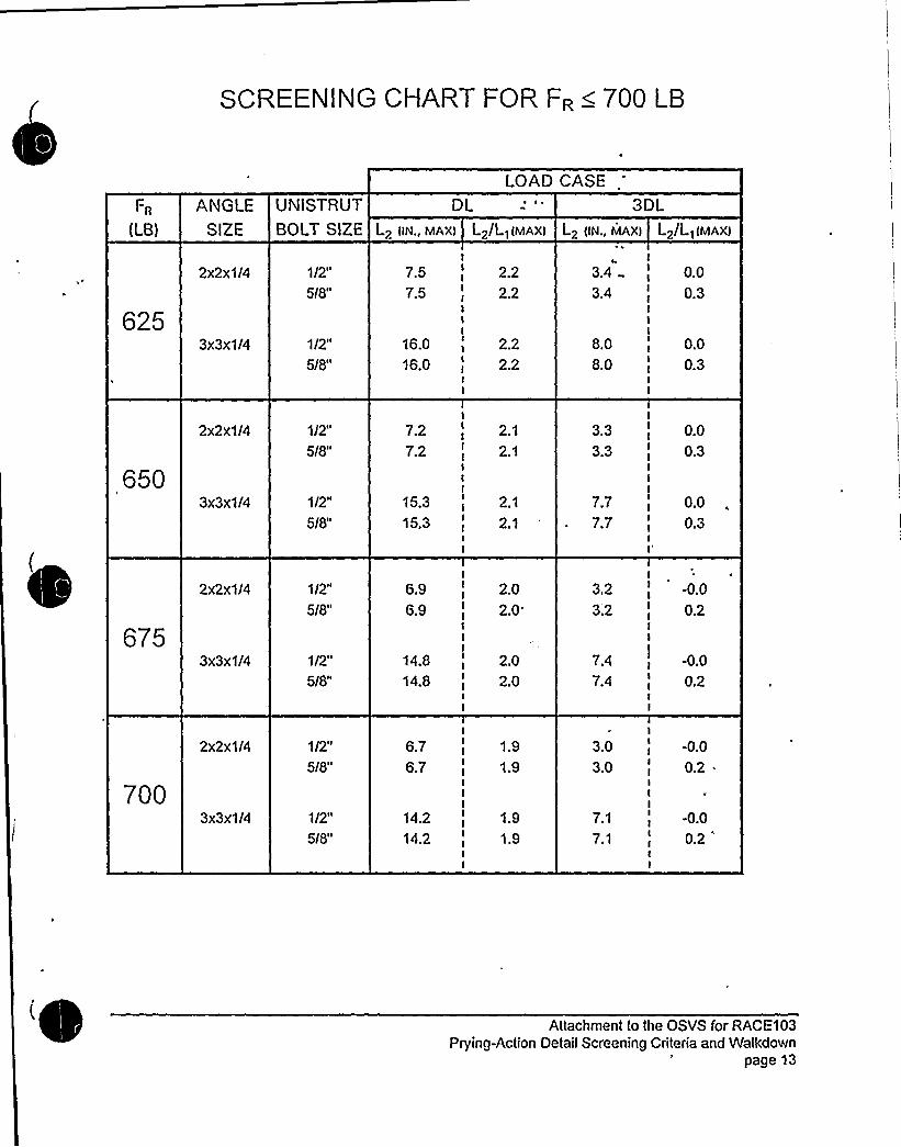
$ CREENING CHART FOR FR < 700 LB
LOAD CASE
Fn
(LB)
ANGLESIZE
UNISTRUTBOLT SIZE
DL
I 2/L) lMAX)L2 IIN., MAX)
3DL
L2/L)lMAX)L2 (IN., MAX)
2x2x1/4
3x3x1/4
1/2"
5/8"
1/2"
5/8"
7.5
7.5
16.0
16.0
2.2
2.2
2.2
2.2
3.4
3.4
8.0
8.0
0.0
0.3
0.0
0.3
650
2x2x1/4
3x3x1/4
1/2"
5/8"
1/2"
5/8"
7.2
7.2
15.3
15.3
2.1
2.1
2.1
2.1
3.3
3.3
7.7
7.7
0.0
0.3
0.0
0.3
675
2x2x1/4
3x3x1/4
1/2"
5I8"
1/2"
5/8"
6.9
6.9
14.8
14.8
2.0
2.0
2.0
2.0
3.2
3;2
7.4
7.4
-0.0
0.2
-0.0
0.2
700
2x2x1/4
3x3x1/4
1/2"
5/8"
1/2"
5/8"
6.7
6.7
14.2
14.2
1.9
1.9
1.9
1.9
3.0
3.0
7.1
7.1
-0.0
0.2 .
-0.0
0.2
Attachment to the OSVS for RACE103Prying-Action Detail Screening Criteria and Watkdown
page 13

SCREENING CHART FOR FR < 800 LB
LOAD CASE
Fn
LB)
ANGLE UNISTRUTSIZE BOLT SIZE
DL ~ ~
Lp(L){MAX)Lp {IN., MAX)
30LL2 {IN., MAXI L2/L]{MAX)
3x3x1/4
5/8"
1/2"
5/8"
6.5
13.8
13.8
1.8
1.8
1.8
2.9
6.96.9
0.1
N/A
0.1
750
2x2x1/4
3x3x1/4
1/2"
5/8"
1/2"
5/8"
6.36.3
13.3
13.3
1.7
1.7
't.7
1.7
2.8
2.8
6.76.7
N/A
0.1
N/A0.1
2x2x1/4
3x3x1/4
1/2"
5/8"
1/2"
5/8"
6.1
6.1
12.912.9
1.6
1.6
1.6
1.6
2.7
2.7
6.46.4
N/A
0.0
N/A
0.0
800
2x2x1/4
3x3x1/4
1/2"
5/8"
1/2"
5/8"
5.9
5.9
12.5
12.5
1.5
1.5
1.5
1.5
2.?
2.7
6.26.2
N/A
0.0
N/A
0.0
Attachment to the OSVS for RACE103Prying-Action Detail Screening Criteria and Walkdown
page 14


2.4 Anchora e Evaluation Works eet
r,vVV VVV
Vt
Fo
LI
VVVVV~ ~
Hanger Identification and Location:
I/2 DR 5/dVRIvvIRVI IIVI AND DDL'IVI CIIOCDDLD VIIISIRVl
L2v2vl/I VI L2I2II/O
Span: Estimated load on threaded rod, FR.
FSTIMATED CABLE TRAYAND CONDUITWEIGHTS, PLF
Calculations:
ITEM PLFCABLE TRAYS 251/2 CONDUIT 1.1
3/4 CONDUIT 1.31" CONDUIT 2.01.5" CONDUIT 3.52 CONDUIT 4.93 CONDUIT 11.1
4 CONDUIT 16.6
FIELD DATA:
Angle size:
Lengths: L1
Unistrut Bolt Size:
L2/L1
LIMITINGVALUES FROM SCREENING CHART FOR FR= LB:
DL CASE 3 X DL CASE (IF APPLICABLE)*
Max L
Actual L
Max L2/L1
Actual L>/L1
Max L
Actual L
Max L>/L1
Actual L>/L1
PASS:YES NO
PASS:YES NO
PASS:YES NO
PASS:YES NO
*3xDLcase N/A for wall mounted brackets.
Attachment to the OSVS for RACE103
Prying-Action Detail Screening Criteria and Walkdown1 page 15

I 3. Screening Walkdown Worksheets
Hanger LocationWorksheot ¹1-092694-1
1-092694-2
1-092694-3
1-0926944
1-092694-5
1-092694-6
1-092694-7
1-092694-8
2492794-1
2492794-2
1-092794-3
1-092794<
1-092794-5
2-092894-1
2-092894-2
1-092894-3
24)92894M
2-092894-5
1-0928944
1-092894-7
1%92894%
1492894-9
1-092894-10
1-092894-11
2-092894-12
2-092894-13
2-092994-1
Aux1, El 596, RCT Quad 3 NorthHangers 9, 10, 11 along the right wall counting from door 1-OR-AUX323.Aux1 ~ EI 596, RCT Quad 4Hangers 5. 6, 7, 8, 9 on the left wall counting from 'd'oor 1-DR-AUX329.Aux1 ~ El 596. RCT Quad 4Directly across the hall from penetration 1-CEPAP5Aux1 ~ El 596, RCT Quad 4Adjacent to penetration 1-CEP-4P5.Aux1, El 596, RCT Quad 1
Two hangers across the hallway from penetration 1-CEP-1P5One hanger near MCC 1-CT-BNAux1 ~ El 596. RCT Quad IUpper platform, 1st hanger on right facing door 1-OR-AUX467Aux1 ~ El 596, RCT Quad IUpper platform, first 3 hangers on loft facing door 1-OR-AUX467Aux1 ~ EI 596, RCT Quad 1
Upper platform, first hanger on right off the edge of the platform.Aux2, El 596, RCT Quad 3 SouthNear 2-VRS-2200 tUpper Cntmt RMS "B" Data Acq Module)Aux2, EI 596, RCTQuad 1
Upper platform, two hangers about 3 hangers away from Door 2-DR-AUX468.Aux1, El 609, 4kV AreaAbove 600V Bus IIAAux1 ~ El 609, Transformer RoomOne hanger above 1-DGTAB and one hanger at the right side of the entrance.Aux1 ~ Auxiliary Cable Vault15'outh of the hatchAux2, EI 5736'outh of gate 2-GT-AUX1013 (U2 Rx Coolant Drain Pump Room)Aux2. EI 573South end of the hallway common to both units.Aux1, El 609, elevated area adjacent to the control room cable vaultAbove 12HV-ACA.FLT-3Aux2, El 609Near Miscellaneous Rack 2-H.HAux2, EI.609Above cabinet 2-BITH2Aux1, El 612, Vestibule, upper platform loading to RCTNext to 1-DR-AUX467Aux1. EI 612, Vestibule. upper platform leading to RCT3rd hanger on left from the edge of the platformAux1 ~ El 612, Vestibule, upper platform leading to RCT4th hanger on left from the edge of the platformAux1 ~ El 612, Vestibule, upper platform leading to RCT2nd hanger on right from the edge of the platformAux1. EI 612, Vestibule4 hangers along the containment wall just before the upper platform leading tothe RCT.Aux1 ~ El 612, VestibuleThe hanger above the west end of 1-HE-22 and the next hanger west.The two or three hangers south of these running along the block wall.Aux2, EI 612, Vestibule. upper plalform leading to RCT4th hanger on right from the edge of the platformAux2, EI 633Hangers between the Containment Auxiliaries Panel and 2-MSI-1.Cont2, El 598, AnnulusSeveral hangers near Column 1. Az 63, Quad 1
Attachment to the OSVS for RACE103Prying-Action Detail Screening Criteria and Walkdown
page 16

Ip