ENERGY. - adams - Nuclear Regulatory Commission
27
Steven D. Capps Vice President DUKE McGuire Nuclear Station ENERGY. Duke Energy MG01VP 112700 Hagers Ferry Road Huntersville, NC 27078 o: 980.875.4805 f:: 980.875.4809 [email protected] Serial: MNS-14-090 November 12, 2014 10 CFR 50.90 ATTN: Document Control Desk U.S. Nuclear Regulatory Commission Washington, DC 20555 Duke Energy Carolinas, LLC (Duke Energy) McGuire Nuclear Station (MNS), Units 1 and 2 Docket Numbers 50-369, 50-370 Renewed License Numbers NPF-9 and NPF-17 Subject: Response to August 28, 2014 NRC Request for Additional Information Regarding License Amendment Request To Implement A Risk-Informed Performance-Based Fire Protection Program (TAC NOs. MF2934 and MF2935). References: 1. MNS Letter, License Amendment Request (LAR) to Adopt National Fire Protection Association (NFPA) 805 Performance-Based Standard for Fire Protection for Light- Water Reactor Generating Plants, dated September 26, 2013, Agencywide Document and Management System (ADAMS) Accession Number ML1 3276A1 26. 2. NRC E-Mail, McGuire 1 and 2 NFPA 805 License Amendment Request - Unacceptable With The Opportunity To Supplement, dated December 18, 2013, ADAMS Accession Number ML13352A514. 3. MNS Letter, Supplemental Information For License Amendment Request (LAR) to Adopt National Fire Protection Association (NFPA) 805 Performance-Based Standard for Fire Protection for Light-Water Reactor Generating Plants, dated January 8, 2014, ADAMS Accession Number ML14016A097. 4. NRC Letter, McGuire Nuclear Station, Units 1 and 2 - Acceptance of Requested Licensing Action RE: License Amendment Request to Adopt National Fire Protection Association (NFPA) 805 Performance-Based Standard for Fire Protection for Light- Water Reactor Generating Plants (TAC NOs. MF2934 and MF2935), dated January 15, 2014, ADAMS Accession Number ML14014A279). 5. NRC Letter, Request for Information Regarding License Amendment Request To Implement A Risk-Informed Performance-Based Fire Protection Program (TAC NOs. MF2934 and MF2935), dated August 28, 2014, ADAMS Accession Number ML14233A366).
-
Upload
khangminh22 -
Category
Documents
-
view
3 -
download
0
Transcript of ENERGY. - adams - Nuclear Regulatory Commission

Steven D. CappsVice PresidentDUKE McGuire Nuclear Station
ENERGY. Duke Energy
MG01VP 112700 Hagers Ferry RoadHuntersville, NC 27078
o: 980.875.4805f:: 980.875.4809
Serial: MNS-14-090
November 12, 2014 10 CFR 50.90
ATTN: Document Control DeskU.S. Nuclear Regulatory CommissionWashington, DC 20555
Duke Energy Carolinas, LLC (Duke Energy)McGuire Nuclear Station (MNS), Units 1 and 2Docket Numbers 50-369, 50-370Renewed License Numbers NPF-9 and NPF-17
Subject: Response to August 28, 2014 NRC Request for Additional Information RegardingLicense Amendment Request To Implement A Risk-Informed Performance-BasedFire Protection Program (TAC NOs. MF2934 and MF2935).
References:
1. MNS Letter, License Amendment Request (LAR) to Adopt National Fire ProtectionAssociation (NFPA) 805 Performance-Based Standard for Fire Protection for Light-Water Reactor Generating Plants, dated September 26, 2013, Agencywide Documentand Management System (ADAMS) Accession Number ML1 3276A1 26.
2. NRC E-Mail, McGuire 1 and 2 NFPA 805 License Amendment Request - UnacceptableWith The Opportunity To Supplement, dated December 18, 2013, ADAMS AccessionNumber ML13352A514.
3. MNS Letter, Supplemental Information For License Amendment Request (LAR) to AdoptNational Fire Protection Association (NFPA) 805 Performance-Based Standard for FireProtection for Light-Water Reactor Generating Plants, dated January 8, 2014, ADAMSAccession Number ML14016A097.
4. NRC Letter, McGuire Nuclear Station, Units 1 and 2 - Acceptance of RequestedLicensing Action RE: License Amendment Request to Adopt National Fire ProtectionAssociation (NFPA) 805 Performance-Based Standard for Fire Protection for Light-Water Reactor Generating Plants (TAC NOs. MF2934 and MF2935), dated January 15,2014, ADAMS Accession Number ML14014A279).
5. NRC Letter, Request for Information Regarding License Amendment Request ToImplement A Risk-Informed Performance-Based Fire Protection Program (TAC NOs.MF2934 and MF2935), dated August 28, 2014, ADAMS Accession NumberML14233A366).

United States Nuclear Regulatory CommissionNovember 12, 2014Page 2
6. MNS Letter, Response to August 28, 2014 NRC Request for Additional InformationRegarding License Amendment Request To Implement A Risk-Informed Performance-Based Fire Protection Program, dated October 13, 2014, No ADAMS Number.
By letter dated September 26, 2013 (Reference 1), Duke Energy submitted a licenseamendment request (LAR) to adopt a new, risk-informed, performance-based (RI-PB) fireprotection licensing basis for the MNS Unit Nos. 1 and 2.
On December 18, 2013 (Reference 2), the NRC requested supplemental information in order tomake the September 26, 2013, LAR complete and acceptable for review by the NRC. By letterdated January 8, 2014 (Reference 3), Duke Energy provided the requested supplementalinformation to the NRC. By letter dated January 15, 2014 (Reference 4), the NRC accepted theSeptember 26, 2013, LAR for review.
By letter dated August 28, 2014 (Reference 5), the NRC requested additional information (RAI)in order to complete their review of the September 26, 2013, LAR. That letter grouped the RAIsinto 60-day, 90-day, and 120-day response times. Duke Energy provided the 60-day RAIresponses by letter dated October 13, 2014 (Reference 6). Duke Energy's responses to the 90-day RAls are provided in Enclosure 1. As a result of some of the responses to the 90-day RAls,it will be necessary to perform some heat release rate reanalysis and to revise some pages ofthe LAR. Those LAR revisions and analyses, which are described in the applicable responses,have been entered into the MNS Corrective Action Program. The LAR revisions will be includedin the submittal providing the responses to the 120-day RAls. Responses for the 120-day RAlswill be provided by December 12, 2014.
The conclusions reached in the original determination that the September 26, 2013, LARcontains No Significant Hazards Considerations and the categorical exclusion from performingan Environmental/Impact Statement have not changed as a result of the August 28, 2014, RAlsand the RAI responses in Enclosure 1.
This submittal does not contain any new or revised regulatory commitments.
Please direct any questions on this matter to Jeffrey N. Robertson at 980-875-4499.
I declare under penalty of perjury that the foregoing is true and correct. Executed on November12, 2014.
Sincerely,
Steven D. Capps
Enclosure 1

United States Nuclear Regulatory CommissionNovember 12, 2014Page 3
xc:
V.M. McCree, Region II AdministratorU.S. Nuclear Regulatory CommissionMarquis One Tower245 Peachtree Center Avenue NE, Suite 1200Atlanta, Georgia 30303-1257
G. E. Miller, Project Manager (MNS and CNS)U.S. Nuclear Regulatory Commission11555 Rockville PikeMail Stop 0-8 G9ARockville, MD 20852-2738
J. ZeilerNRC Senior Resident InspectorMcGuire Nuclear Station
W. L. Cox III, Section ChiefNorth Carolina Department of Health and Human ServicesDivision of Health Service RegulationRadiation Protection Section1645 Mail Service CenterRaleigh, NC 27699-1645

ENCLOSURE I
Duke Energy Responses To The August 28, 2014 90-Day RAIs RelatedTo The MNS NFPA 805 LAR

Enclosure 1Page 1 of 23
REQUEST FOR ADDITIONAL INFORMATION
LICENSE AMENDMENT REQUEST TO ADOPT
NATIONAL FIRE PROTECTION ASSOCIATION STANDARD 805
PERFORMANCE BASED STANDARD FOR FIRE PROTECTION
FOR LIGHT WATER REACTOR GENERATING PLANTS
DUKE ENERGY CAROLINAS, LLC
MCGUIRE NUCLEAR STATION UNITS 1 AND 2
DOCKET NOS. 50-369. 50-370
By letter dated September 26, 2013, (Agencywide Documents Access and ManagementSystem (ADAMS) Accession No. ML13276A126), Duke Energy Carolinas (Duke) submitted alicense amendment request to change its fire protection program to one based on the NationalFire Protection Association (NFPA) Standard-805, "Performance-Based Standard for FireProtection for Light Water Reactor Electric Generating Plants," 2001 Edition, as incorporatedinto Title 10 of the Code of Federal Regulations (10 CFR), Part 50, Section 50.48(c). In orderfor the U. S. Nuclear Regulatory Commission (NRC) staff to complete its review of the licenseamendment request (LAR), the following additional information is requested:

Enclosure 1Page 2 of 23
Fire Protection Engineering (FPE) Request for Additional Information (RAI) - 90-DayResponses
FPE RAI 03
LAR Attachment I, Table 1-1 "Definition of Power Block" states that structures required to meetthe radioactive release criteria described in Section 1.5 of NFPA-805 but not required to meetthe nuclear safety criteria are not defined within the power block. Currently, the endorsedguidance of Nuclear Energy Institute (NEI) 04-02, "Guidance for Implementing a Risk-Informed,Performance-Based Program Under 10 CFR 50.48(c)," states that, where used in Chapter 3,"power block" and "plant" refers to structures that have equipment required for nuclear plantoperations, such as containment, auxiliary building, service building, control building, fuelbuilding, radiological waste, water treatment, turbine building, and intake structure, or structuresthat are identified in the facility's current license basis. As currently described in the LARAttachment E, the Rad Waste Facility is a standalone building within the Yard Fire Area.Additionally, the Contaminated Material Handling and Waste Handling areas are described aspart of the Auxiliary Building. Included in this compartment are Building 1202 and the WasteSolidification Building.
Provide clarification that those structures listed within the guidance are accounted for as eitherwithin or not within the power block.
Duke Energy Response:
The McGuire Nuclear Station (MNS) definition of power block was developed based on theguidance provided in FAQ 06-0019 Revision 4 (ML073060545) and the NRC closure memo toFAQ 06-0019 (ML080510224). The MNS definition of power block was developed with respect tothose structures required to meet the NFPA 805 nuclear safety performance criteria. This includesstructures with the potential to affect power plant operations, the potential to affect equipmentimportant to nuclear safety, and the potential to affect the ability to safely shutdown the plant in theevent of a fire.
The NRC closure memo includes a chronological history of the development of FAQ 06-0019 thatsupports this definition. The NRC Staff comments on FAQ 06-0019, Revision 3 states:
"The letter and the intent of the NFPA 805 definition for "power block" and "plant" ("Structuresthat have equipment required for nuclear plant operations') includes all equipment needed togenerate electricity (main turbine, feedwater, circulating water, service water, main steam, etc.)as well as that equipment needed to mitigate accidents required by the TechnicalSpecifications (safety injection, emergency diesel generators, containment spray, emergencyservice water, etc.)."
The MNS definition of Power Block as found in LAR Attachment I, Table I-1 is consistent with theNRC Staff Comments on the definition of power block.
Referring to the structures listed in the guidance (FAQ 06-0019), the MNS power block includesContainment (Reactor Buildings), Auxiliary Building (where Nuclear Safety CapabilitiesAssessment [NSCA] equipment is located), Service Building, Fuel Building, Turbine Building,intake (and discharge) structures, in addition to structures specific to MNS - the Doghouses,

Enclosure 1Page 3 of 23
Standby Shutdown Facility (SSF), and yard areas where equipment required to meet the nuclear
safety performance criteria goals is located.
MNS does not have a defined Control Building. The Control Room and supporting rooms thatmay be typically found in a Control Building are located in the Auxiliary Building. The WaterTreatment Facility and Switchyard are not included in the power block definition. The WaterTreatment Facility is not required to meet the nuclear safety performance criteria, and theSwitchyard is not included as the NFPA 805 analysis boundary begins at the Main and AuxiliaryTransformers.
Radiological waste areas are not included in the MNS power block definition. There is a series ofstructures identified in LAR Attachment E, Radioactive Release Transition, which are notidentified in the MNS power block. The MNS radiological release areas are not included based onthe guidance in the NRC closure memo in that the areas are not needed to generate electricity orneeded to mitigate accidents as required by the Technical Specifications. These specific MNSareas include:
" The Rad Waste Facility (located in the Yard)* The Contaminated Material and Waste Handling areas (Building 1202 and the Waste
Solidification Building) which are considered part of the Auxiliary Building* The Equipment Staging Building (located in the Yard adjacent to the Unit 2 Reactor
Building)" The Compacted & Central Waste Facilities (located in the Yard)* The Radiography Facility (located in the Yard)* Warehouse 7 (located outside of the protected area and within the owner controlled area)
FPE RAI 09
In LAR Attachment A, Table B-i, Section 3.3.5.3., the LAR indicates that electrical cables complywith IEEE-383 flame propagation testing (Institute of Electrical and Electronics EngineersStandard 383 "IEEE Standard for Type Test of Class 1 E Electric Cables, Field Splices, andConnections for Nuclear Power Generating Stations"). The staff noted that the LAR onlydescribes armored cables in conjunction with a discussion of an outer jacket, but the licensee'sanalysis includes unjacketed armored cables and the staff notes that rapid and significant flamespread is associated with unjacketed armored cables.
a. Describe whether unjacketed armored cable is installed, and if it is, describe the extentand installed locations.
b. Describe the qualification of unjacketed cables and, if this configuration is unqualified,describe how the lack of qualification has been addressed, including in the performance-based analyses.
c. If the unjacketed cables are unqualified, describe the impact on the Fire ProbabilisticRisk Assessment (PRA) analysis.
Duke Energy Response:
a. Unjacketed armored cable is installed at MNS, primarily in Containment. A review of thecable database shows that approximately 90 percent of unjacketed armored cable is foundin the Unit 1 and Unit 2 Reactor Buildings. The remainder of the armored unjacketedcables is distributed throughout MNS in the following locations: Auxiliary Building (CableRooms, Battery Room, ETA and ETB Switchgear and Penetration rooms, etc.), Unit 1 and2 Turbine Buildings, and Service Building.

Enclosure 1Page 4 of 23
b. Procurement of armored cable for use in Duke Energy nuclear power generating stationshas always been performed using criteria from cable specifications to ensure a certainlevel of cable performance and quality.
The term "qualified" is interpreted to mean "cable that meets or exceeds the performancerequirements specified in IEEE 383-1974." Because a portion of the cables installed atMNS pre-dates IEEE 383, not all cable was procured to this standard. Power, controlsand instrumentation cables purchased today (and since 1981) are required to meet IEEE383. As stated in the Fire Protection Design Basis Document (MCS-1465.00-00-0008):
Cable used at McGuire, classified as either power, control or instrumentation,passes the IEEE No. 383-1975 [1974] Flame Test.
The staff has noted "rapid and significant flame spread is associated with unjacketedarmored cables," reflecting unanticipated observations made during a series of cabletests performed in 2006, at the Intertek Testing Services Inc. facility in Elmendorf, Texas(formerly Omega Point Laboratories, Inc.). It is important to note that this series of testswas conducted to evaluate fire-induced circuit failure, not flame propagation. Therefore,these tests were performed under conditions that were significantly more severe thantesting required to meet IEEE 383 [IEEE Standard for Qualifying Class 1 E Electric Cablesand Field Splices for Nuclear Power Generating Stations] and IEEE 1202 [IEEE Standardfor Flame-Propagation Testing of Wire and Cable].
Calculation DPC-1435.00-00-0009, "Performance Characteristics of Duke Armored CablesUnder Fire Exposure", is the AREVA Engineering Information Record document EIR 51-9160514-000, an analysis of the same name. As stated in this calculation:
In the fall of 2007, Duke requested that General Cable Corporation (GCC), themanufacturer of the Duke-specific armored cable that was used in the DukeArmored Cable Control Circuit Tests conducted in 2006, provide IEEE- 1202 testresults for both jacketed and unjacketed versions of the same armored cable typeused in some of the Duke Armored Cable Control Circuit Tests.
...These standardized test results indicate that both jacketed and unjacketedversion of the armored 8-conductor #1 2AWG cable passed the IEEE-1 202 cableflame propagation test... [bounding the requirements of the IEEE-383 flame test.]
...The test results also indicate that there is essentially no difference in the flamepropagation performance of jacketed and unjacketed applications of this armoredcable type when tested in accordance with the IEEE 1202 standard.
Additionally, the IEEE 1202 test report for the jacketed version of cable type testedon 09/17/2007 (Duke GSI Armored 8-conductor #12 1 KV-FR- XLPE ) noted thatflame did in fact "shoot" out the bottom of the sample during the second half of the20-minute flame exposure test. This indicates a similar phenomenon to whatoccurred in a few of the Duke Armored Cable Control Circuit Tests conducted atIntertek Laboratories in 2006...
This calculation concludes:
... the "shooting flame" condition is not a result of flame propagation internal to thearmored cable. Fire testing shows that when flames have occurred at the ends ofarmored cables, the mechanism that causes flame to occur at this location is

Enclosure 1Page 5 of 23
attributed to a series of events and conditions that lead to hot gases and vaporstraveling inside the armored shielding from the vicinity of the fire exposure to theopen ends of the cable where these gases ignite when mixed with available air...
... Therefore, no additional guidance or conservatism needs to be added to theFPRA based on the use of armored cable and the potential for the "shooting flame"condition to occur.
.. In summary, the "shooting flame" phenomenon is not new to armored cables.Fire testing as far back as 1978 suggests that this condition has occurred undercertain test parameters. Evidence of this phenomenon has also occurred at timesduring standardized tests for determining the flame propagation characteristics ofarmored cables. In no instance has a testing authority ever deemed the results ofa standardized flame propagation test for armored cables unacceptable due to thisphenomenon.
... Many of the armored cable types use[d] at Duke nuclear power generatingstations have undergone standardized testing to determine their flame spreadpropagation characteristics. These tests were typically performed in accordancewith the IEEE 383 and/or IEEE 1202 test standards. The results of this testingconfirmed that the armored cable types tested are IEEE 383 and/or IEEE 1202"qualified".
... There are standardized test methods for measuring and determining a cable'sflame propagation qualities. IEEE 383 and IEEE 1202 are two such standards thathave been deemed acceptable to the NRC. The armored cable types used atDuke nuclear power generating stations have either been qualified to one of thesestandards or are considered equivalent by comparison.
c. The unjacketed armored cables used at MNS have either been purchased to meet thesestandards, have been shown to meet the requirements of IEEE 383 or IEEE 1202 throughtesting, or are considered equivalent to IEEE 383 or IEEE 1202 qualified cables bycomparison. Therefore, there is no impact on the Fire PRA analysis.
A revision to LAR Attachment A, Section 3.3.5.3 is planned to be submitted with the 120 day RAIresponses to clarify MNS cable is IEEE 383 or equivalent in accordance with flame propagationtests as outlined in FAQ 06-0022.

Enclosure 1Page 6 of 23
Safe Shutdown Analysis (SSA) RAIs - 90-Day Responses
SSA RAI 01
LAR Attachment B, Table B-2, identifies certain attributes of NEI 00-01, "Guidance for Post-FireSafe Shutdown Circuit Analysis" Revision 1, as "Aligns with Intent." For the following attributes,the alignment basis does not fully explain why there are deviations from the recommendations ofthe attribute.
For each attribute listed below, provide a detailed justification as to what specifically does notalign.
a. 3.1C Spurious Operation
b. 3.1.1.7 Offsite power
c. 3.1.1.11 Multiple units
d. 3.2.1.6 Spurious components
e. 3.3.1.3 Isolation Devices
f. 3.3.1.6 Auto Initiation Logic
g. 3.3.1.7 Circuit Coordination
h. 3.5.1.3 Duration of Circuit Failures
i. 3.5.2.1 Circuit Failures Due to an Open Circuit
j. 3.4.1.4 Manual Actions
Duke Energy Response:
a. MNS aligns with the guidance of considering spurious operations, but aligns with theintent for high/low pressure interfaces. High/low pressure interfaces are limited tomeeting the latest guidance in NEI 00-01, Revision 2. NEI 00-01 Revision 1 states thathigh/low pressure interfaces result in a Loss of Coolant Accident (LOCA). RG 1.189Revision 2 Section 5.3.2.c endorses NEI 00-01 Revision 2, which expands the high/lowpressure interface definition to a LOCA outside containment. MNS analyzed high/lowpressure interfaces resulting in a LOCA outside containment.
b. MNS does not credit offsite power in the deterministic analysis and does notdemonstrate it to be free of fire damage. However, MNS analyzed safe shutdownsuccess paths as shown on the functional logic diagrams with and without offsite powerfor normal and alternate shutdown components. For example, for normal shutdown,pressurizer heaters powered from offsite power need to be off, but spurious operationcould turn them on with offsite power available and operator action to trip the supplybreakers is required. Without offsite power this is not an issue. Similarly, foralternative shutdown areas, MNS specifically assumes it is available where availabilitycould adversely affect alternative safe shutdown, otherwise, alternative shutdown isshown without offsite power. Thus MNS aligns with the intent of considering offsitepower during the analysis but does not credit it.
c. MNS has some common Fire Areas (FA) (e.g., FA-4, 13, and 14), and both units wereanalyzed for effects of fires in these areas. In unit specific FAs (e.g., FA-2, 5, 19, and 20),there is potential for an opposite unit impact (e.g. in FA-2- Unit 1 Motor Driven AuxiliaryFeedwater Pump Room, FA-5- U1 A Train Emergency Diesel Generator, FA-19- Unit 1

Enclosure 1Page 7 of 23
Cable Room, and FA-20- Unit 2 Cable Room) that could possibly affect the opposite unit.Unit specific fire areas were mostly found to not have any potential for an opposite unitimpact through analysis of fire impacts by equipment and cable location. However, anexample of an opposite unit affect concerns the Unit 1, A Train battery charger, whichis normally aligned to Unit 1. If a fire occurred in a fire area during those cases thataffected the battery charger power supply, operators can promptly realign the batterycharger to Unit 2. Since multiple unit effects of fires were analyzed, MNS aligns withthe guidance.
d. MNS aligns since equipment was identified for NSCA that could spuriously operate or mal-operate, which meets the NEI 00-01 guidance.
e. Isolation devices were analyzed for the credited train in a given FA; therefore, MNS alignswith the guidance.
f. In addition to the guidance, the analysis was not limited to "...the fire-induced failure ofautomatic logic circuits.." The automatic interlock signals were analyzed and assumed tooccur / not occur in the worst case situation unless specifically analyzed not to do so. Thisapproach exceeds the guidance. Thus, MNS aligns with the guidance.
g. Fault coordination impacts were analyzed for the credited trains/busses. Thus, MNSaligns with the guidance in that a breaker coordination analysis was performed.
h. MNS did not take credit to clear (i.e. the duration of the hot short was not limited) spuriousoperations in the deterministic analysis. Thus, MNS aligns with this guidance.
i. MNS analyzed open circuits per the NEI 00-01 guidance, including potential high voltagecurrent transformer (CT) secondary damage as itemized. Thus, MNS aligns with theguidance.
j. Variations From Deterministic Requirements (VFDRs) resolutions included in theperformance based Fire Risk Evaluations (FREs) included recovery actions as potentialmitigating actions to maintain a safe and stable condition for the operational effects of firedamage. Recovery actions are demonstrated to be feasible in accordance with NRCrequirements as documented in calculation MCC-1435.00-00-0045. Thus, MNS Alignswith the guidance.
SSA RAI 03.a
LAR Attachment F, "Fire-Induced Multiple Spurious Operations Resolution," provides adescription of the process for evaluating potential multiple spurious operations (MSOs). In orderto clarify the methodology, provide the following:
a. In describing the documents used for guidance by the expert panel, LAR Attachment Fstated that some of these documents (NEI 00-01, NEI 04-06, Fire PRA Task Instruction,and pressurized-water reactor owners group (PWROG) MSO list) were identified as"draft." Describe what reconciliation was done to ensure completeness of the analysiswith the final documents.
Duke Energy Response:
a. The documents referenced were used as guidance at the time of convening the expertpanel.
The MSO evaluation in MCC-1435.00-00-0023, Rev. 1, "NFPA 805 Transition ExpertPanel Report for Addressing Potential McGuire Multiple Spurious Operations (MSO)",
Enclosure 1Page 8 of 23
was done against the PWROG draft MSO list. A reconciliation review to NEI-00-01,Revision 3, was completed as part of responding to this RAI. The review looked at thechanges from the PWROG MSO list to the MSO list in NEI 00-01, Revision 3, andconcluded that all changes are covered in existing MSOs in the MSO calculation. TheMSO calculation has been revised to add an attachment that provides a comparisonbetween the new MSO list in NEI 00-01, Revision 3, and the PWROG MSO list that wasin the MSO calculation when the LAR was written. The attachment includes a summaryof the reconciliation of differences.
The MSO process for the expert panel used the guidance in the Fire PRA TaskInstruction (Draft C) and NEI 04-06 (Draft L). The expert panel was completed usingthese documents as guidance. NEI 04-06 has not been officially issued, and the Draft Lhas not been changed. NEI 04-06 Draft L was a guide for conducting a self-assessmentand that process was considered similar to doing the MSO Expert Panel. Since NEI 00-01 now incorporates the process for the MSO expert panel, the NEI 04-06 process ismoot. The MSO process that was in the Fire PRA Task Instruction is also nowincorporated into NEI 00-01, Revision 3. A review indicates that the procedure for theMSO expert panel did not change sufficiently to require a change to the expert panelresults.
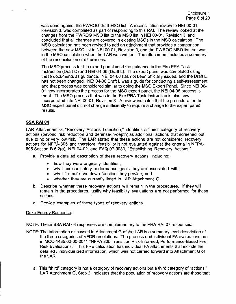
SSA RAI 04
LAR Attachment G, "Recovery Actions Transition," identifies a "third" category of recoveryactions (beyond risk reduction and defense-in-depth) as additional actions that screened outdue to no or very low risk. The LAR stated that these actions are not considered recoveryactions for NFPA-805 and therefore, feasibility is not evaluated against the criteria in NFPA-805 Section B.5.2(e), NEI 04-02, and FAQ 07-0030, "Establishing Recovery Actions."
a. Provide a detailed description of these 'recovery actions, including:
* how they were originally identified;* what nuclear safety performance goals they are associated with;* what fire safe shutdown function they provide; and* whether they are currently listed in LAR Attachment G.
b. Describe whether these recovery actions will remain in the procedures. If they willremain in the procedures, justify why feasibility evaluations are not performed for theseactions. 1
c. Provide examples of these types of recovery actions.
Duke Energy Response:
NOTE: These SSA RAI 04 responses are complementary to the PRA RAI 07 responses.
NOTE: The information discussed in Attachment G of the LAR is a summary level description ofthe three categories of VFDR resolutions. The process and individual FA evaluations arein MCC-1435.00-00-0041 "NFPA 805 Transition Risk-Informed, Performance-Based FireRisk Evaluations." This FRE calculation has individual FA attachments that include thedetailed / individualized information, which was not carried forward into Attachment G ofthe LAR.
a. This "third" category is not a category of recovery actions but a third category of "actions."LAR Attachment G, Step 2, indicates that the population of recovery actions are those that

Enclosure 1Page 9 of 23
are required to resolve VFDRs. The population of VFDRs is from the deterministicanalysis for each fire area. No VFDRs were written against pre-existing operator manualactions (OMAs) by themselves; there had to be a fire effect on the component. Somecomponent fire impacts that resulted in a VFDR were found to have pre-existing OMAsthat could be used to address the VFDR resolution. Each VFDR (See LAR Attachment C)was then evaluated using the performance-based approach, and required recovery actionswere identified where necessary to satisfy risk or defense-in-depth (DID). The FREprocess, using the Fire PRA, determined that some of these had no or very lowcontribution to risk and were not required to be carried forward as recovery actions for riskor DID. If VFDRs in Attachment C contained recommended operator actions for thedeterministic analysis, but did not result in required recovery actions, then therecommended action was not required to be implemented and not reflected inAttachment G.
Some recommended actions are designated as Primary Control Station (PCS) actions,which are not Recovery Actions. PCS actions are required to be performed but do notrequire the feasibility assessment that Recovery Actions do. Attachment G lists all thePCS actions and Recovery Actions (either for Risk or DID).
LAR Attachment C has a discussion for each VFDR including performance goal andfunction. The VFDRs of this "third" category are identified with a disposition of "SatisfiesRisk, DID, and Safety Margin Criteria Without Further Action."
b. These non-required actions are strong candidates for deletion from fire responseprocedures. They may be desired to be retained by OPS as potential margin items orotherwise. If maintained, see PRA RAI 07d.
c. Examples of these "third" category actions where VFDRs did not result in requiredrecovery actions but are presently in fire protection procedures are:
* VFDR-13-035 - 1NC VA0031B (Pressurizer PORV Isolation Valve), AP-45,Plant Fire, closes this valve.
• VFDR-04-106 - 1 NC VA0033A (Pressurizer PORV Isolation Valve), AP-45,Plant Fire, closes valve
* VFDR-13-005 - 1CA VA0002 (Unit 1 Auxiliary Feedwater Pumps Suction fromAuxiliary Feedwater Storage Tank Isolation Valve), AP-24, Loss of PlantControl Due to Fire or Sabotage, manually closes this valve when condensatestorage tank level is low.
SSA RAI 05
LAR Section 4.2.1.1, "Comparison to NEI 00-01 Revision 2," states that post fire manualoperation of rising stem valves in the fire area of concern, noted as an additional NEI 00-01Revision 2 element, will be evaluated as part of the feasibility evaluation conducted asdocumented in "NFPA-805 Recovery Action Feasibility Review". LAR Attachment B, Table B-2,Section 3.2.1.2, identifies MCC-1 435.00-00-0045 Rev. 0 - "NFPA 805 Transition Recovery ActionFeasibility Review," as the referenced documentation. However, there is no identification of thiselement in the recovery action feasibility review. It appears that neither the assumptions nor thecriteria in the recovery action feasibility review address this element.
Provide more detail with regard to which recovery actions require operation of rising stemvalves in the fire area of concern. Identify where the criterion used in the evaluation isspecifically identified, and how the criterion is evaluated.

Enclosure 1Page 10 of 23
Duke Energqy Response:
MCC-1435.00-00-0045, Rev. 0, "NFPA 805 Transition Recovery Action Feasibility Review," didnot identify valve operability issues of this kind since there were no rising stem valves identified atthe time. However, Motor Operated Valves (MOVs) 1/2CA161C and 1/2CA1 62C, alternateAuxiliary Feedwater suction source, have subsequently been identified as rising stem valves.These valves would require opening prior to 18 hours after the initiating fire to provide an alternatesuction water source for the Turbine Driven Auxiliary Feedwater (TDAFW) pump during StandbyShutdown System (SSS) operation.
The potential reliance on local operation of these valves following potential fire damage is beingremoved by plant modification. Engineering Changes (ECs) will be performed to install manualbypass butterfly valves around the valves of concern, which will eliminate the rising stem valveissue with 1/2CA161C and 1/2CA162C. MNS will revise the NFPA 805 LAR Attachment S, TableS-2, to commit to EC 109071 (Unit 1) and EC 109072 (Unit 2 - 2CA161C and 2CA162C only).
To ensure no future omission of justifying operation of rising stem valves, MCC-1435.00-00-0045has been revised to include a requirement for an engineering evaluation for any rising stem valvesadded to the program that require a recovery action in the FA of concern.

Enclosure 1Page 11 of 23
Fire Modeling (FM) RAIs - 90-Day Responses
FM RAI 01.k
NFPA 805-Section 2.4.3.3 states that the PRA approach, methods, and data shall be acceptableto the NRC. The NRC staff noted that the fire modeling analysis comprised the following:
- The Generic Fire Modeling Treatments (GFMTs) approach was used to determine the Zoneof Influence (ZOI) for ignition sources and the time to Hot Gas Layer (HGL) conditions in allfire areas throughout MNS, Unit 1 and 2.
- The Consolidated Fire Growth and Smoke Transport (CFAST) model was used to assessthe main control room (MCR) abandonment time calculations.
LAR Section 4.5.1.2, "Fire PRA," states that fire modeling was performed as part of the fire PRA(FPRA) development (NFPA :805 Section 4.2.4.2). Reference is made to Attachment J, "FireModeling Verification and Validation," for a discussion of the acceptability of the fire models thatwere used to develop the FPRA.
Specifically regarding the acceptability of the PRA approach, methods, and data:
k. Regarding the fires in the proximity of a wall or a corner, explain how the GFMTsapproach was applied for a fire against a wall or in a corner. Explain how wall andcorner effects in the ZOI and HGL timing calculations were accounted for, or providea technical justification if these effects were not considered.
Duke Energy Response:
k. The following methodology was used for wall and corner effects in the Zone of Influence(ZOI) evaluation:
Regarding separation distances, Calculation DPC-1 535.00-00-0024, Rev. 0, "Generic FireModeling Treatments (GFMT)", Section 3.3.7 [Guidance for Fuel Packages Positioned in aCorner and Wall] states:
1. If the fuel package is within 0.6 m (2 ft.) of a wall, then double the heat release rateand assume that the fire is centered at the fuel package edge adjacent to the wall.
2. If the fuel package is within 0.6 m (2 ft.) of a corner, then quadruple the heatrelease rate and assume that the fire is centered at the fuel package cornernearest the wall corner.
This GFMT is reflected in the MNS Fire Scenario Report, MCC-1535.00-00-0104, Rev. 3,Section 9.3 [Location Factor]. This section states:
The location of an ignition source relative to a wall or a corner may impact the zoneof influence [ZOI]. While an ignition source walk down did not identify any fixedignition sources as being located in a corner, ... Inverters... in the Battery Room wereconfirmed to be located against a wall. The inverters, which stand nearly 8 feet tall,were located against individual battery room walls that are approximately 8 feet highwith significant free space between the top of the cabinet and the adjacent roomand the overall battery room ceiling; therefore, the location of these cabinets againstthe wall has minimal impact on the heat release rate. The impact of the location onthe zone of influence for these fixed ignition sources (all of which were equippedwith a top mounted deflector shield) has been addressed in the scope of assumedtarget damage. Similarly for transients, if the postulated transient location .... wasalong a wall or in a corner, the zone of influence was adjusted accordingly.

Enclosure 1Page 12 of 23
Wall and corner effects were not applied to the HGL screening analysis. HGL effects werecalculated for situations with and without the presence of localized fire exposures. Incases with localized fire exposures, where HGL formation was sufficient to impact the ZOIof the localized fire, a reduced critical heat flux value was used to determine whether ornot a target would be damaged. The method used is described in the Generic FireModeling Treatments calculation, Section 6.1.2 [Combined Hot Gas Layer- Localized FireExposure Effects].
Because the overall heat input to the room is not increased by placement near a wall orcorner, in order to address the initial change in rate, the room volumes (and ventilationparameters) would also be doubled and quadrupled, accordingly. The net impact on theroom burnout calculation is, therefore, considered negligible.
FM RAI 02.e
American Society of Mechanical Engineers/American Nuclear Society (ASME/ANS) Standard RA-Sa-2009, "Standard for Level 1/Large Early Release Frequency Probabilistic Risk Assessmentsfor Nuclear Power Plant Applications," Part 4, requires damage thresholds be established tosupport the FPRA. The standard further states that thermal impact(s) must be considered indetermining the potential for thermal damage of systems, structures, and components (SSCs) andappropriate temperature and critical heat flux criteria must be used in the analysis.
Provide the following information:
e. Explain how the damage thresholds for non-cable components (i.e., pumps, valves,electrical cabinets, etc.) were determined. Identify any non-cable components thatwere assigned damage thresholds different from those for thermoset and thermoplasticcables, and provide a technical justification for these damage thresholds.
Duke Energy Response:
e. In accordance with Appendix H.2 of NUREG/CR-6850, for major components such asmotors, valves, etc., the fire vulnerability was assumed to be limited by the vulnerability ofthe power, control, and/or instrument cables supporting the component. As stated in thescenario development calculation, "In some fire scenarios, the target set may includeanother cabinet in which case application of the cable damage threshold would tend to beconservative since no credit would be taken for the protective nature of the enclosure." Inother words, electrical cabinets are subject to the same damage thresholds as the cablesin the analysis. No other non-cable components were assigned a damage thresholddifferent from that which was used for cables.

Enclosure 1Page 13 of 23
FM RAI 02.f
American Society of Mechanical Engineers/American Nuclear Society (ASME/ANS) Standard RA-Sa-2009, "Standard for Level 1/Large Early Release Frequency Probabilistic Risk Assessmentsfor Nuclear Power Plant Applications," Part 4, requires damage thresholds be established tosupport the FPRA. The standard further states that thermal impact(s) must be considered indetermining the potential for thermal damage of systems, structures, and components (SSCs) andappropriate temperature and critical heat flux criteria must be used in the analysis.
Provide the following information:
f. Describe the damage criteria that were used for exposed temperature-sensitiveelectronic equipment. Explain how temperature-sensitive equipment inside an enclosurewas treated, and provide a technical justification for these damage criteria.
Duke Energy Response:
f. The sensitive electronics treatment at MNS is consistent with many aspects of the FirePRA FAQ 13-0004. For example, the damage criteria used for temperature-sensitiveelectronic equipment inside of electrical cabinets was the same as that for thermosetcables. However, MNS has yet to officially incorporate FAQ 13-0004 since it was notapproved when the Fire PRA was developed. The current sensitive electronics treatmentin the MNS Fire PRA does not fully address the caveats in Fire PRA FAQ 13-0004regarding sensitive electronics mounted on the surface of cabinets and the presence oflouvers or vents. These caveats will be addressed in further detail in the response to MNSPRA RAI 16 (120 day response).

Enclosure 1Page 14 of 23
Probabilistic Risk Assessment (PRA) RAIs - 90-Day Responses
PRA RAI 01.d
Section 2.4.3.3 of NFPA 805 states that the probabilistic safety assessment (PSA) (PSA is alsoreferred to as PRA) approach, methods, and data shall be acceptable to the authority havingjurisdiction (AHJ), which is the NRC. Regulatory Guide (RG) 1.205 identifies NUREG/CR-6850 asdocumenting a methodology for conducting a FPRA and endorses, with exceptions andclarifications, Nuclear Energy Institute (NEI) 04-02, Revision 2, as providing methods acceptableto the NRC staff for adopting a fire protection program consistent with NFPA-805. RG 1.200describes a peer review process utilizing an associated ASME/ANS standard (currentlyASME/ANS-RA-Sa-2009) as one acceptable approach for determining the technical adequacy ofthe PRA once acceptable consensus approaches or models have been established forevaluations that could influence the regulatory decision. The primary result of a peer review arethe facts and observations (F&Os) recorded by the peer review and the subsequent resolution ofthese F&Os.
Clarify the following dispositions to fire F&Os and Supporting Requirement (SR) assessmentidentified in LAR Attachment V that have the potential to impact the FPRA results and do notappear to be fully resolved:
d) FSS-07: The disposition to the peer review assessment for FSS-07 (LAR Table V-2)does not specifically address how automatic suppression was credited other than inthe MCA. Section 10.3 of the Fire Scenario Report identifies that the Halonsuppression system was credited in the evaluation of turbine-driven auxiliaryfeedwater pump fire scenarios and that the generic unavailability for Halon systemsfrom NUREG/CR-6850 was used in the evaluation of these scenarios. According tothe PRA standard, the intent for CC-Il is to "require a review of plant records todetermine if the generic unavailability credit is consistent with actual systemunavailability." Provide justification that the generic estimates for credited automaticsuppression systems bound actual system unavailability based on an evaluation ofplant records and that outlier behavior has not been experienced at MNS. Ifnecessary, provide updated risk results as part of the aggregate change-in-riskanalysis requested in PRA RAI 03 that appropriately accounts for actual automaticsuppression system reliability/availability experience at MNS.
Duke Energy Response:
d) Fire PRA credit for automatic suppression is limited to the Halon systems in the Unit 1 and2 Turbine Driven Auxiliary Feedwater Pump rooms. Credit was taken by applying aNUREG/CR-6850 generic unreliability factor of 0.05, which is reasonable given the systemredundancy. Per the design basis specification for the Fire Protection systems, "There isone Auxiliary Feedwater Pump turbine Halon 1301 fire suppression system per unitincorporating one main Halon cylinder and one reserve Halon cylinder."
A review of the MNS Fire Impairment Log records from February 2012 to September 2014showed that for both Unit 1 and 2 Auxiliary Feedwater Pump turbine Halon 1301 firesuppression systems, unavailability was less than 0.05. Therefore, the non-suppressionprobability of 0.05 used in the MNS Fire PRA is appropriate for the limited number ofscenarios which credit the Halon system, and updated risk results in the response to PRARAI 03 are not necessary.

Enclosure 1Page 15 of 23
PRA RAI 12
Section 2.4.3.3 of NFPA-805 states that the PRA approach, methods, and data shall beacceptable to the NRC. Section 2.4.4.1 of NFPA-805 further states that the change in publichealth risk arising from transition from the current fire protection program to an NFPA-805 basedprogram, and all future plant changes to the program, shall be acceptable to the NRC.RG 1.174provides quantitative guidelines on CDF, LERF, and identifies acceptable changes to thesefrequencies that result from proposed changes to the plant's licensing basis and describes ageneral framework to determine the acceptability of risk-informed changes. The NRC staff reviewof the information in the LAR has identified the following information that is required to fullycharacterize the risk estimates.
LAR Section V.2.7 describes two MCR abandonment on loss-of-habitability scenarios, W1 andW2, where, in both cases, "failures were assumed which virtually eliminated all success pathsother than the Standby Makeup Pump and the TDCA [turbine-driven auxiliary feedwater] pumpfrom the SSF [Safe Shutdown Facility]." It is further explained that the conditional core damageprobability (CCDP) for these scenarios is based on the highest CCDP for main control board(MCB) and non-MCB fires with additional failures as necessary to ensure no credit for functionsthat require continued presence in the MCR. Regarding this analysis, provide the following:
a) Summarize what "failures were assumed" and why they were assumed. Specifically,are they assumed because of general issues (e.g., unknown cable routing for functionsalways assumed failed) or are the assumptions only used for MCR abandonmentscenarios?
b) An explanation of how the CCDPs account for the range of probabilities for properlyshutting down the plant, and discussion of how they were applied in the scenarioanalysis. In doing so, provide examples over the full range of values utilized, acharacterization of the scenarios to which these values are applied, and a summary ofhow each value is developed.
This information should include explanations of how the following scenarios areaddressed:
i. Scenarios where the fire fails few functions aside from MCR habitability andsuccessful shutdown is straightforward.
ii. Scenarios where the fire could cause some recoverable functional failures orspurious operations that complicate the shutdown but successful shutdown islikely.
iii. Scenarios where the fire induced failures cause great difficulty for shutdown byfailing multiple functions and/or causing complex spurious operations that makesuccessful shutdown unlikely.
c) Explanation of the timing considerations (i.e., total time available, time until cues arereached, manipulation time, and time for decision making) made to characterizescenarios in Part (b). Include in the explanation the basis for any assumptions madeabout timing.
d) Discussion of how the probability associated with failure to transfer control to the SSFis taken into account in Part (b).
e) Description of how the feasibility of the operator actions supporting the alternateshutdown pathway was considered by the scenario characterization performed inPart (b).

Enclosure 1Page 16 of 23
Duke Energy Response:
a. The MNS Fire PRA has the SSF and associated operator action to transfer control to theSSF fully incorporated into the PRA model. For control room abandonment, the SSF isthe only success path credited in the Fire PRA. The primary functions of the SSF arereactor coolant pump seal cooling via the standby reactor coolant makeup pump andsecondary side heat removal via the TDCA pump. To ensure that only SSF functions arecredited as success paths for the Fire PRA control room abandonment scenarios, SSCsnot failed by the control room fire were assumed to be failed or unavailable in the FirePRA. Consequently, the failures that were referred to as "assumed" were not associatedwith assumed cable routing. These "assumed" failures were added as necessary to theabandonment scenarios to ensure no credit for functions that require continued presencein the MCR.
Main Feedwater is an example of a failure added to the abandonment scenarios. Controlof Main Feedwater is not available from the SSF. If the fire event requiring the SSF hasnot defeated Main Feedwater, transfer of control to the SSF will defeat Main Feedwater.To ensure sole reliance on the SSF, available credit for Main Feedwater recovery wasremoved. This removal was the nature of the "assumed" failures discussed in LAR sectionV.2.7.
b. As alluded to in the PRA RAI 12b question, the risk for the MCR abandonment scenariosshould account for the impact of fire induced failures on the ability to shut down from analternate location (SSF). The Fire PRA analysis was developed in a manner thataddresses these impacts.
Each MCR abandonment scenario encompasses the range of results from few functionalfailures to multiple functional failures, each condition (b.i, b.ii, & b.iii) leading to the mostsevere end state where the SSF is the sole remaining success path after abandonment.In the MNS Fire PRA, for the abandonment scenarios, the number of fire induced failuresand spurious operations is based on the panel of origin that produces the highestconditional core damage probability (CCDP). Therefore, the abandonment scenariosaccount for the worst case impacts on the SSF regardless of a potentially more favorableoutcome.
The underlining assumption is that in the abandonment scenarios, any of the MCR firescould lead to conditions that require abandonment.
c. The scenarios addressed in part "b" of this RAI are modeled such that sequences rely onthe SSF as the sole success path. Timing considerations for the PRA basic event thatrepresents this success path are discussed below:
Although the modeled abandonment scenarios are applicable to habitability, thehuman reliability analysis (HRA) timing takes into consideration that the operators willgo to the SSF either for loss of habitability or for loss of function. Loss of function isthe more limiting time available and therefore was the value that was used in the HRA.The analysis assumes that a loss of alternating current (AC) power which results in aloss of reactor coolant pump seal cooling occurs at the time the function is lost. Thisprovides the smallest available timing used for the HRA probability.
The timing values are based on the more limiting time available associated with a lossof function. The total time available from the loss of seal cooling to when a seal LOCAmight result is estimated to be 13 minutes [Ref WCAP-1 5603, Rev.1] with a time of 7.5minutes for cognition and recovery. The analysis assumes that the cue occurs at thebeginning of the accident scenario (time 0). The timing does not explicitly address theAuxiliary Feedwater function since the seal cooling timing is the most limiting and there

Enclosure 1Page 17 of 23
is steam generator level instrumentation available upon transfer to the SSF that willauto-start the Turbine Driven Auxiliary Feedwater pump if necessary.
The discussion on timing, above, is applicable to the quantification results for the SSFhuman failure event, prepared for a future PRA update. The failure probability used inthe MNS LAR submittal is considerably higher and therefore bounds the timingconsiderations provided above.
d. As discussed above, the SSF and the SSF human failure event are directly modeled in theFire PRA; therefore, the "probability associated with failure to transfer control to the SSF"and the other random SSF equipment failures are directly quantified for each applicablescenario using the worst case HRA timing as discussed in "c" above.
e. Feasibility was considered in the development of the SSF human failure event failureprobability. Time available for cognition and implementation of the actions are all takeninto account for feasibility. This event is part of the Time Critical Operator action programand is trained upon with a completion time requirement of 10 minutes, which is shorterthan the total time available (see "c"). Successful drills records indicate that the action issufficiently feasible from a timing standpoint. The HRA analysis also considers the impactof lighting, environment, accessibility, and other performance shaping factors onfeasibility. Regarding accessibility and environment, fires impacting the SSF fire area donot credit the SSF for recovery. Additionally, to address fires not impacting the SSF firearea, the SSF is located in the yard, and there are multiple pathways available for theoperators to reach the SSF and avoid any fire effects.
PRA RAI 17
Section 2.4.3.3 of NFPA-805 states that the PRA approach, methods, and data shall beacceptable to the NRC. RG 1.205 identifies NUREG/CR-6850 as documenting a methodologyfor conducting a FPRA and endorses, with exceptions and clarifications, NEI 04-02, Revision2, as providing methods acceptable to the staff for adopting a fire protection programconsistent with NFPA-805. Methods that have not been determined to be acceptable by theNRC staff or acceptable methods that appear to have been applied differently than describedrequire additional justification to allow the NRC staff to complete its review of the proposedmethod.
The licensee's analysis indicates that the ZOI associated with a 142 kilo-watt (kW) heat releaserate (HRR) (75th percentile) transient fire was used in almost all fires areas. Discuss the keyfactors used to justify the reduced rate below 317 kW per the guidance provided in the June21,2012, memo from Joseph Giitter to Biff Bradley ("Recent Fire PRA Methods review PanelDecisions and EPRI 1022993, 'Evaluation of Peak Heat Release Rates in Electrical CabinetsFires'," ADAMS Accession No. ML121171A583). Include in this discussion:
a) Identification of all fire compartments/areas where a ZOI for a reduced HRR of 142 kW(75th percentile) was used. The guidance in the referenced June 21, 2012,. memoindicates that a reduced HRR would be an exception supported by rigorous controlsand restrictions. Please discuss how using a reduced HRR for almost all fire areas, ifcorrect, is consistent with the guidance.
b) For each location (or group of similar locations) where a reduced HRR is credited, adescription of the administrative controls that justify the reduced HRR including howlocation-specific attributes and considerations are addressed.
c) The results of a review of records related to violations of the transient combustible andhot work controls.

Enclosure 1Page 18 of 23
d) Confirm that 142 kW and 317 kW HRRs were the only transient fire sizes used inthe FPRA.
Duke Energy Response:
a. A 142 kW fire size for general transient fires was applied in 18 out of the 40 firecompartments at MNS. These 18 compartments are part of the Auxiliary Building and arelisted in the table below. The remaining majority of the site's fire compartments werelocations where at least a 317 kW fire was assumed for general transient scenariodevelopment or the scenario development for the entire compartment was not refinedbeyond full room burnout.
FIRE COMPARTMENT FIRE COMPARTMENT DESCRIPTION1 Auxiliary Building Common EL 695' & Pipe Chase2 Unit 1 Motor Auxiliary Feedwater (CA) Pump Room2A Unit 1 Turbine Driven CA Pump Room
3 Unit 2 Motor CA Pump Room3A Unit 2 Turbine Driven CA Pump Room
4 Auxiliary Building Common El 716'
13 Battery Rooms Common14 Auxiliary Building Common El 733'
17A Unit 1 Train A Switchgear HVAC Room
18A Unit 2 Train A Switchgear HVAC Room
19 Unit 1 Cable Room20 Unit 2 Cable Room
21 Auxiliary Building Common El 750'25 Auxiliary Building Common El 767'
9-11 Unit 1 Train B Switchgear/Pen Room10-12 Unit 2 Train B Switchgear/Pen Room
15-17 Unit 1 Train A Switchgear/Pen Room16-18 Unit 2 Train A Switchgear/Pen Room
The June 21, 2012, memo mentioned in the RAI references the September 27, 2011,letter from Nuclear Energy Institute (NEI) to NRC (Subject: Recent Fire PRA MethodsReview Panel Decisions: Clarification for Transient Fires and Alignment Factor for PumpOil Fires ), which includes an NRC accepted clarification of the guidance in NUREG/CR-6850 for selecting HRRs to be assumed for transient fires. The clarification acknowledgesthe HRR of 317 kW is a screening value that can be used throughout the analysis for agiven plant unless there is reason to believe larger transient fires can be reasonablyexpected for a specific plant location based on the typical activities that occur. Theclarification further states a lower screening HRR can be used for individual plant specificlocations if the 317 kW value is judged to be unrealistic given the specific attributes andconsiderations applicable to that location. Locations within the plant under more rigorouscontrols or that have greater restrictions with respect to the introduction, handling, andplacement of combustibles and/or the performance of hot work would be expected to havea lower HRR applied as compared to locations that have less rigorous controls and/or

Enclosure 1Page 19 of 23
restrictions. Further justification for how the guidance outlined in the September 27, 2011,letter is addressed in responses to parts "b" and "c" of this RAI.
b. The memo from Joseph Giitter to Biff Bradley ("Recent Fire PRA Methods review PanelDecisions and EPRI TR-1022993, 'Evaluation of Peak Heat Release Rates in ElectricalCabinets Fires', "ADAMS Accession No. ML 12171A583) endorses methods from theSeptember 27, 2011, NEI submitted letter on "Recent Fire PRA Methods Review PanelDecision: Clarification for Transient Fires and Alignment Factor for Pump Oil Fires" withminor clarifications. Within this document, the following statements support the use of thelower heat release rate (HRR) of 142 kW:
"A screening HRR of 317 kW can be used throughout the analysis for a given plantunless there is reason to believe that larger transient fires can be reasonablyexpected for a specific plant location based on the typical activities that occur.Conversely, a lower screening HRR can be used for individual plant specificlocations if the 317 kW value is judged to be unrealistic given the specific attributesand considerations applicable to that location."
* "Locations within the plant that are under more rigorous controls or that havegreater restrictions with respect to the introduction, handling, and placement ofcombustibles and/or the performance of hot work would be expected to have alower HRR applied as compared to locations that have less rigorous controlsand/or restrictions."
The following table provides dispositions relative to the recommendations bulleted abovefor each of the compartments listed in Part A of the RAI response where the 142 kW HRRfire size is credited.
FIRE FIRE COMPARTMENT DESCRIPTION NoteCOMPARTMENT1 Auxiliary Building Common EL 695' & Pipe 1
Chase2 Unit 1 Motor CA Pump Room 2
2A Unit 1 Turbine Driven CA Pump Room 23 Unit 2 Motor CA Pump Room 2
3A Unit 2 Turbine Driven CA Pump Room 24 Auxiliary Building Common El 716' 313 Battery Rooms Common 4, 6
14 Auxiliary Building Common El 733' 317A Unit 1 Train A Switchgear HVAC Room 518A Unit 2 Train A Switchgear HVAC Room 5
19 Unit 1 Cable Room 2,620 Unit 2 Cable Room 2,6
21 Auxiliary Building Common El 750' 3
25 Auxiliary Building Common El 767' 39-11 Unit 1 Train B Switchgear/Pen Room 3, 610-12 Unit 2 Train B Switchgear/Pen Room 3, 6
15-17 Unit 1 Train A Switchgear/Pen Room 3, 6
16-18 Unit 2 Train A Switchgear/Pen Room 3, 6

Enclosure 1Page 20 of 23
Notes:
1. This compartment will be re-analyzed assuming the larger HRR of 317 kW and will nolonger credit the 142 kW HRR.
2. The lower HRR of 142 kW is justified because the transient combustible controlprogram has designated this compartment as needing additional controls beyond thebasic requirements of the procedure (to be implemented during transition to NFPA805). Per the procedure, administrative controls will be applied with regards toamount, duration and monitoring of combustible materials brought into thesecompartments based on a tiered approach which meet Chapter 3 requirements ofNFPA 805 while at the same time incorporating the risk insights used in the PRA.There are limitations on materials being left unattended during work activities in thesecompartments which could require additional compensatory measures.
3. This compartment will be re-analyzed assuming the larger HRR of 317 kW in order todetermine specific sections within these locations that require additional restrictionsand support of the 142 kW HRR. MNS will update the transient combustible controlsprocedure to ensure that the sections identified require additional controls. A newimplementation item will be created and submitted with the updated LAR to capture theareas that fall under this note.
4. Room 701 in Fire Compartment 13 is designated as a room with additional controlsbeyond the basic requirements of the procedure. Administrative controls are appliedwith regard to amount, duration and monitoring of combustible materials brought intothese compartments based on a tiered approach which meet Chapter 3 requirementsof NFPA 805 while at the same time incorporating the risk insights used in the PRA.This Fire Compartment also includes rooms 706 through 711 which were treated in amanner similar to full room burnout therefore the requirement for restrictions necessaryfor the assumption of the lower 142 kW fire size is not necessary. Also included in thisFire Compartment is room 648 which is the cable shaft. This location is not likely toaccumulate combustible material due to its size.
5. This compartment is not designated as having additional controls beyond the basicrequirements of the transient control procedure. However, the size and geometry ofthese rooms effectively restricts the size of the fuel package that can be practicablystored such that the 142 kW HRR is applicable.
6. This compartment predominantly contains electrical equipment and thereforesignificant combustibles normally associated with mechanical maintenance activitiesare not likely to accumulate in this area.
For the compartments listed above, introduction of transient fire loads is permitted only ifconditions (i.e., separation distances and load limits) comply with the Transient CombustibleProcedure (to be implemented during transition to NFPA 805).
Transient Combustible Procedure controls combustibles by the following methods:
" A tiered approach to required compensatory measures is established such that morestringent compensatory measures are required if transient combustible material is notseparated from other transient combustible material to minimize quantity in onelocation.
* A tiered approach to required compensatory measures is established such that morestringent compensatory measures are required if transient combustible material is notseparated from plant equipment susceptible to fire damage.
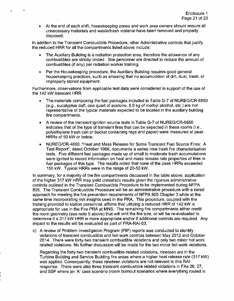
Enclosure 1Page 21 of 23
* At the end of each shift, housekeeping zones and work area owners should ensure allunnecessary materials and waste/trash material have been removed and properlydisposed.
In addition to the Transient Combustible Procedure, other Administrative controls that justifythe reduced HRR for all the compartments listed above include:
* The Auxiliary Building is a radiation protection area, therefore the allowance of anycombustibles are strictly limited. Site personnel are directed to reduce the amount ofcombustibles (if any) per radiation worker training.
" Per the Housekeeping procedure, the Auxiliary Building requires good generalhousekeeping practices, such as ensuring that no accumulation of dirt, dust, trash, orimproperly stored equipment.
Furthermore, observations from applicable test data were considered in support of the use ofthe 142 kW transient HRR.
" The materials composing the fuel packages included in Table G-7 of NUREG/CR-6850(e.g., eucalyptus duff, one quart of acetone, 5.9 kg of methyl alcohol, etc.) are notrepresentative of the typical materials expected to be located in the auxiliary buildingfire compartments.
* A review of the transient ignition source tests in Table G-7 of NUREG/CR-6850indicates that of the type of transient fires that can be expected in these rooms (i.e.,polyethylene trash can or bucket containing rags and paper) were measured at peakHRRs of 50 kW or below.
* NUREG/CR-4680, "Heat and Mass Release for Some Transient Fuel Source Fires: ATest Report", dated October 1986, documents a series nine trash fire characterizationtests. Five different fuel packages made up of small to moderate trash accumulationswere ignited to record information on heat and mass release rate properties of fires infuel packages of this type. The results noted that none of the peak HRRs exceeded150 kW. Typical HRRs were in the range of 20-50 kW.
In summary, for a majority of the fire compartments discussed in the table above, applicationof the higher 317 kW HRR may yield unrealistic results given the rigorous administrativecontrols outlined in the Transient Combustible Procedure to be implemented during NFPA805. The Transient Combustible Procedure will be an administrative procedure with a tieredapproach for meeting the fire prevention requirements of NFPA 805 Chapter 3 while at thesame time incorporating risk insights used in the PRA. This procedure, coupled with thetraining provided to station personnel, affirms that utilizing a reduced HRR of 142 kW isappropriate for use in the Fire PRA at MNS. The remaining fire compartments either creditthe room geometry (see note 5 above) that will limit the fire size, or will be re-evaluated todetermine if a 317 kW HRR is more appropriate and/or if additional controls are required. Anyimpact to the results will be evaluated as part of PRA-RAI-03.
c) A review of Problem Investigation Program (PIP) reports was conducted to identifyviolations of transient combustible and hot work controls between May 2012 and October2014. There were forty-two transient combustible violations and only two minor hot workrelated violations. No further discussion will be made for the two minor hot work violations.
Regarding the forty-two transient combustible related violations, nineteen are in theTurbine Building and Service Building fire areas where a higher heat release rate (317 kW)was applied. Consequently, these nineteen violations are not relevant to this RAIresponse. There were also three transient combustible related violations in FAs 26, 27,and SSF where an 'A' case scenario (room burnout scenarios where everything routed in

Enclosure 1Page 22 of 23
the room is assumed to be fire damaged) was utilized. These three are also excludedfrom further evaluation since fire size is not relevant for these room burnout cases. Oneviolation did not take place in a designated fire area so it was excluded from furtherconsideration.
The remaining nineteen transient combustible related violations identified in areasassociated with a reduced HRR of 142 kW were identified in FAs 2, 3, 3A, 14, 19, 20, 21,and 25. The violations were primarily administrative in nature, such as missingdocumentation needed to exceed the limit for combustible material in the fire area.
The site is currently under a Transient Combustible Improvement Action plan, which hasyielded a proactive fire program and heightened sense of awareness over time as moreviolations were identified during the transition from Appendix R to NFPA 805. This isevident in the increase of violations that took place in March 2014. A second increase ofviolations appeared in September 2014. However, this can be attributed to the Unit 1outage (outage start date was September 13, 2014). Although four violations took place inFA 14 during this month, this is not an adverse trend considering how large FA 14 is andthe fact the violations were not severe. One violation was for a slightly overfilled 55 gallondrum and the other three were administrative in nature (missing documentation for aNuclear Site Directive [NSD] 313-1 form which documents the evaluation done by the siteFire Protection Engineer). The four violations identified in October 2014 (2 in FA 14 and 2in FA 25) were also administrative violations as they were missing documentation for anNSD 313-1 evaluation. Additionally, the violations identified during the outage do notapply to an at-power Fire PRA.
The goal of the Transient Combustible Improvement Action plan is to increase stationawareness concerning transient combustibles. Consequently, these violations areexpected to diminish. As the sensitivity for transient combustibles is increased, a positivechange in fire safety culture at the station has taken place. Accordingly, the MNS FirePRA reflects the plant as designed and operated with respect to the TransientCombustible program.
Transient Combustible Violations (all Fire Areas)
18
16
14 _
12 _
10 _
8 i-ransient Combustible Violations
6 - (all Fire Areas)4
2 I
(N 1N M' m ' ýn n mn mý mr 1
V) Z -,- 2-U

Enclosure 1Page 23 of 23
Transient Combustible Violations (Fire Areas withreduced HRR)
5,
4
3
2 - Transient Combustible Violations(Fire Areas with reduced HRR)
1 . . . . . . . . .I I I I .
0. > a .0
(n z - 2 i Lnz - 22 0
d) Only the 142 kW and 317 kW HRRs were used in the Fire PRA. In some cases (e.g. roomburnout), the transient HRR was immaterial to the quantification.