
Power - Nuclear Regulatory Commission
418
consumers Power PDWERIN6 MICHl6AN'S PRDliRESS General Offices: 1945 West Parnall Road, Jackson, Ml 49201 • (517) 788-0453 December 13, 1993 Nuclear Regulatory Commission Document Control Desk Washington, DC 20555. DOCKET 50-255 - LICENSE DPR-20 - PALISADES PLANT - David P Hoffman Vice President Nuclear Operations I Environmental & Technical Services REVISION 16 TO THE FINAL SAFETY ANALYSIS REPORT (FSAR) UPDATE In accordance with 10 CFR 50.4, one original and 10 copies of the Palisades Plant FSAR Update, Revision 16 are enclosed. This revision is submitted on a replacement page basis and includes a vertical line in the right margin and "Rev 16" in the lower right-hand corner. Word processor problems that resulted in adding vertical lines only in the margin have been resolved and revision markers will be restored to the tfght hand .. _.margins as the' FSAR is revised. Additionally, some of the submitteg>' 'pages wilT encompass entire sections of chapters to maintain format throughout the section. In accordance with 10 CFR 50.71, an identification of FSAR changes made under the provisions of 10 CFR 50.59, but not previously submitted to the NRC, are identified by the attached "FSAR Change Request Log." There were no changes made that were not made under the provisions of 10 CFR 50.59 or SERs received from the Nuclear Regulatory Commission. To the best of my knowledge, this revision accurately incorporates all changes made to the Palisades Plant or to the Palisades Plant procedures described in the FSAR, and all other applicable information contained in licensing submittals within six months prior to the date of this submittal. David P f n Vice President Nuclear Operations cc Administrator, Region III, USNRC NRC Resident Inspector - Palisades Plant 9312220057 RDR ADOCK PDR A CMS' ENER<:iY COMPANY )'\: '\ BIG ROCH POlnT nuclczar Plant
-
Upload
khangminh22 -
Category
Documents
-
view
5 -
download
0
Transcript of Power - Nuclear Regulatory Commission

consumers Power
PDWERIN6 MICHl6AN'S PRDliRESS General Offices: 1945 West Parnall Road, Jackson, Ml 49201 • (517) 788-0453
December 13, 1993
Nuclear Regulatory Commission Document Control Desk Washington, DC 20555.
DOCKET 50-255 - LICENSE DPR-20 - PALISADES PLANT -
David P Hoffman Vice President Nuclear Operations I Environmental & Technical Services
REVISION 16 TO THE FINAL SAFETY ANALYSIS REPORT (FSAR) UPDATE
In accordance with 10 CFR 50.4, one original and 10 copies of the Palisades Plant FSAR Update, Revision 16 are enclosed. This revision is submitted on a replacement page basis and includes a vertical line in the right margin and "Rev 16" in the lower right-hand corner. Word processor problems that resulted in adding vertical lines only in the le~ft margin have been resolved and revision markers will be restored to the tfght hand .. _.margins as the' FSAR is revised. Additionally, some of the submitteg>' 'pages wilT encompass entire sections of chapters to maintain format throughout the section.
In accordance with 10 CFR 50.71, an identification of FSAR changes made under the provisions of 10 CFR 50.59, but not previously submitted to the NRC, are identified by the attached "FSAR Change Request Log."
There were no changes made that were not made under the provisions of 10 CFR 50.59 or SERs received from the Nuclear Regulatory Commission.
To the best of my knowledge, this revision accurately incorporates all changes made to the Palisades Plant or to the Palisades Plant procedures described in the FSAR, and all other applicable information contained in licensing submittals within six months prior to the date of this submittal.
David P f n Vice President Nuclear Operations
cc Administrator, Region III, USNRC NRC Resident Inspector - Palisades Plant
9312220057 5~6~5~55 RDR ADOCK PDR
A CMS' ENER<:iY COMPANY
~u6' )'\: \~ '\ ~
BIG ROCH POlnT nuclczar Plant

• i ii iii iv
Sections
1.1-1 1.1-2
1.2-1 1.2-2 1.2-3 1.2-4 1.2-5 1. 2-6 1. 2-7 1.2-8 1.2-9
1.3-1
1.4-1 1.4-2 1.4-3 1.4-4 1.4-5 '-· 1.5-1 1.5-2 1.5-3
1.6-1
1. 7-1 1.7-2
1.8-1 1.8-2 1.8-3 1.8-4 1.8-5
Tables
1-1 Sh 1 1-1 Sh 2
1-2 Sh 1 1-2 Sh 2 1:.2 Sh 3 1-2 Sh 4 1-2 Sh 5 1-2 Sh 6 1-2 Sh 7 1-2 Sh 8 1-2 Sh 9 1-2 Sh 10 1-2 Sh 11
• l
PALISADES -Pj.;ANT FINAL SAFETY ANALYSIS REP.ORT (FSAR) UPDATE
LIST OF EffECTIVE PAGES
ChaR~er .. ·~
Revision Number
14 14 14 14
12 12
12 14 12 12 12 15 12 14 12 .
12 12 12 13 14
13 12
14 15 14 14 14 14 14 15 a 0 0
----"'---
\1 ~ ~ ~ ~l '-..._
~ '-.....
"1J '-0 t '
w 1 \i 'W
~ ~ Q ' CJ.
l.'\\ t ~ ............
°"' ~ -q ~
~
April 1993

Page 2 of 42 Chapter 1
Revision Page Number Number
• 1-3 Sh 1 13 1-3 Sh 2 13 1-3 Sh 3 14 1-3 Sh 4 13 1-3 Sh 5 13. 1-3 Sh 6 13 1-3 Sh 7 13 1-3 Sh 8 13 1-3 Sh 9 13
1-4 Sh 1 3 1-4 Sh 2 3 1-4 Sh 3 14 1-4 Sh 4 11 l-4 Sh 5 3 1-4 Sh 6 11 1-4 Sh 7 3 1-4 Sh 8 3
l-5 12
Figures
1-1 Sh 1 ·14 1-1 Sh 2 15 1-2 15 1-3 15 1-4 12 1-5. 12 1:.5 14 1-7 11
• 1-8 13 1-9 . 13 1-10 11 1-11 0 1-12 Sh 1 ·15 1-12 Sh 2 - 14 1-13 15 1-14 15 1-15 0 1-16 15
. 1-17 (DELETED) 12 1-18 0. 1-19 (DELETED) 12 1-20 (DELETED) 13 1-21 . (DELETED) · . 13 1-22 2 1-23 9
... 1-24 (DELETED) 12 1-25 12 1-\26 12 1-27 ",·_. 12 1-28 13 1-29 0
• April 1993

Page 3 of 42 ~haoter 2
Revision Page Number Number
• Table of Contents
i 14 ii 14
- iii 14 iv 14
Sections
2.1-1 a 2.1-2 a 2.1-3 a 2.1-4 a 2.1-5 a 2.1-6 a
2.2-1 a 2.2-2 a 2.2-3 a 2.2-4 a 2.2-5 a
2 .3-1. a 2.3-2 a 2.3-3 a 2.3-4 a 2.3-5 a
2.4-1 a 2.4-2 a 2.4-3 a
• 2.5-1 12 2.5-2 _ 12 2.5-3 12 2.5-4 12 2.5-5 12 2.5-6 12 2~5-7 12 2.5-8 12 2.5-9 12
2.6-1 14 2.6-2 15 2.6-3 14 2.6-4 14 2.6-5 14
References
2-1 12 2-2 12
Tables
• 2-1 a 2-2 Sh 1 a 2-2 Sh 2 a 2-2 Sh 3 a 2-3 a 2-4 a 2-5 a 2-6 a
• 2-7 a 2-8 a 2-9 a 2-10 a -2-11 a 2-12 a
April 1993

••
•
•
2-13 2-14 2-15 2-16 2-17 2-18
Page Number
2-19 Sh 1 2-19 Sh 2 2-20 2-21 2-22 Sh 1 2-22 Sh 2 2-22 Sh 3 2-22 Sh 4
Figures
2-1 2-2 2-3 2-4 2-5 2-6 2-7 2-8 2-9 2-10 2-11 2-12 2-13 2-14 2-15 2-16 2-17 2-18 2-19 2-20 2-21 2-22 2-23 2-24 2-25 2-26 2-27 2-28 2-29
2A (DELETED) ·fr
Revision Number
0 0 0 0 0 0 0 0
10 14 14 14 10 14
0 15 0 0 0 0 0 0 0 0 0 0 0 0 0 0
15 14 15 12 12 12 12 12 12 12 12 12 12
12
Page 4 of 42
April 1993

Page 5 of 42 Chapter 3
Revision Page Number Number
• Table of Contents
14 ii 14 iii 14
Sections
3.1-1 8
3.2-1 12 3.2-2 12 3.2-3 12 3.2-4 14 3.2-5 12 3.2-6 12
3.3-1 14 3.3-2 12 3.3-3 12 3.3-4 12 3.3-5 12 3.3-6 12 3.3-7 12 3.3-8 14 3.3-9 14 3.3-10 12 3.3-11 12 3.3-12 12 3.3-13 12 3.3-14 12
• 3.3-15 12 3.3-16 12 3.3-17 12 3.3-18 14 3.3-19 12 3.3-20 12 3.3-21 12 3.3-22 12 3.3-23 12 3.3-24 12 3.3-25 12 3.3-26 14 3.3-27 14 3.3-28 14 3.3-29 14 3.3-30 14 3.3-31 14
References
3-1 8 3-2 14 3-3 ·~ ·. 14
~
Tu!ili.§.
3-1 0 3-2 (DELETED) 8 3-3 (DELETED) 8 3-4 (DELETED) 8 3-5 0 3-6 0 3-7 0 • 3-8 0 3-9 (DELETED) 8 3-10 (DELETED) 8
Apri 1 1993

--- -----
Page 6 of 42 Chapter 3
Revision Page Number Number
• 3-11 Sh 1 14 3-11 Sh 2 14 3-11 Sh 3 14 3-11 Sh 4 14 3-12 14
Figures
3-1 0 3-2 0 3-3 0 3-4 (DELETED) 12 3-5 (DELETED) 12 3-6 . (DELETED) 12 3-7 0 3-8 0 3-9 (DELETED) 12 3-10 (DELETED) 12 3-11 (DELETED) 12 3-12 0 3-13 0 3-14 0 3-15 0 3-16 0 3-17 0 3-18 0 3-19 0 3-20 0 3-21 0 3-22 12 3-23 12 3-24 12 • 3-25 (DELETED) 14 3-26 0
• April 1993

Page 7 of 42 · Chapter 4
Revision Page Number Number
• Table of Contents
i 14 ii 14 iii 14 e· iv 14
Sections
4.1-1 0
4.2'.'1 12 4.2-2 12 4.2-3 12 4.2.4 12
4.3-1 12 4.3-2 12 4.3-3 12 4.3-4 12 4;3-5 12 4.3-6 12 4.3-7 12 4.3-8. 13 4.3-9 12 4.3-10 12 4.3-11 12 4.3-12 12 4.3-13 12 4.3-14 12 4.3-15 12 4.3-16 14 • 4.3-17 12
. 4.3-18 13
4.4-1 10 4.4-2 0 4.4-3 11
4.5-1 12 4.5-2 12 4.5-3 12 4.5-4 14 4.5-5 14 4.5-6 14 4.5-7 12 4.5-8 12 4.5-9 12 4.5-10 12 4.5-11 12 4.5-12 12
4.6-1 3
4,7-1 15 4'. 7-2 15
4.8-1 0 4.8-2 0
References
4-1 . 12 4-2 12
• . 4-3 14
Apr i l .1993 .

Chapter 4 Page 8 of 42
Revision Page Number Number • Tables
4-1 12 . 4-2 0 4-3 0 4-4 Sh 1 14 4-4 Sh 2 14 4-5 7 4-6 Sh 1 0 . ···~ "'·:··,
4-6 .Sh 2 0 4-7 0 4-8 0 4-9 Sh 1 12 4-9 Sh 2 12 4-10 0 4-11 13 4-12 0 4-13 0 4-14 11 4-15 0 4-16 14 4-17 1 4-18 11 4-19 0 4-20 0 4-21 Sh 1 0 4-21 Sh 2 12 4-21 Sh 3 0 4-22 0 4-23 14
• Figures
4-1 Sh 1 15 4-1 Sh 2 15 4-1 Sh 3 (DELETED) 8 4-2 0 4-3 15 4-4 0 4-5 0 4-6 0 4-7 0 4-8 0 4-9 7 4-10 12 4-11 0 4-12 0 4-13 0 4-14 0 • 4-15 (DELETED) 14 4-16 Sh 1 (DELETED). 3 4-16 Sh 2 (DELETED} 3 4-16 Sh 3 (DELET~~l_ 3 4-17 11
• ••• April 1993

Page 9 of 42 Chapter 5
Revision Page Number Number • Table of Contents
15 ii 15 iii 15 iv 15 v 15 .. vi · 15 vii 15 viii 15 ix 15 x 15 xi. 15 xii 15 xiii 15 xiv 15 xv 15
.·sections
5.1-1 12 5.1,..2 12 5.1-3 13 5.1-4 13 -;:---:·-·
5.1-5 12 5.1-6 12 5.1-7 15 5.1-8 12 5.1-9 12 5.1-10 12 5.1-11 12
• 5.1-12 12 5.1-13 12 5.1-14 12 5.1-15 14 5.1-16 12 5.1-17 12 5.1-18 15 5.1-19 12 5.1-20 12 5.1-21 12 5.1-22 12 5.1-23 12 5.1-24 12 5.1-25 12 5.1.26 12 5.1.27 12 5.1.28 12 5.1.29 12 5.1.30 12 5.1.31 12 5.1.32 12 5.1.33 14 5.1.34 14
. 5,.1.35 12 5.1.36 14
. 5.2-1 12 5.2-2 12 5.2-3 12 . 5.2-4 13 5.2-5 14
References . -. 5.2-6 0
. Apri 1-1993

Page 10 of 42 Chapter 5
Revision Page Number Number
• 5.3-1 0 5.3-2 0 5.3-3 0
References 5.3-4 0
5.4-1 0 5.4-2 14
References 5.4-3 0
5.5-1 0 5.5-2 0 5.5-3 0 5.5-4 0 5.5-5 0 5.5.6 0 5.5-7 5 5.5-8 0 5.5-9 0 5.5-10 0
References 5.5-11 5
5.6-1 12 5.6-2 12 5.6-3 12 5.6-4 12 5.6-5 12 5.6-6 12 5.6-7 12 5.6-8 12
• 5.6-9 12 5.6-10 12 5.6-11 12 5.6-12 12 5.6-13 15 5.6-14 15 5.6-15 12
References 5.6-16 12
5.7-1 12 5.7-2 13 5.7-3 15 5.7-4 15 5.7-5 15 5.7-6 15 5.7-7 15 5.7-8 15 5.7-9 15 5.7-10 15 5.7-11 15 5.7-12 ··, .. ..--- 15 5, 7-13 15 5·.1-14 15 5.7-15 15 5.7-16 15 5.7-17 15 5.7-18 15 5.7-19 15 5.7-20 15 5.7-21 15 5.7-22 15
• Reference 5.7-23 15 5.7-24 15
April 1993

Chapter 5 Page 11 of 42
Revision Page Number ·Number
• 5.8-1 12 5.8-2 12 5.8-3 12 5.8-4 12 5.8-5 12 5.8-6 12 5.8-7 12 5.8-8 12 5.8-9 12 5.8-10 12 5.8-11 12 5.8-12 12 5.8-13 12 5.8-14 12 5.8-15 12 5.8-16 12 5.8-17 12 5.8-18 12 5.8-19 12 5.8-20 12 5.8-21 12 5.8-22 12 5.8-23 12 5.8-24 12 5.8-25 12 5.8-26 12 5.8-27 12 5.8-28 12 5.8-29 12 5.8-30 12 5.8-31 12 5.8-32 12 • 5.8-33 12 5.8-34 12 5.8-35 12 5.8-36 12 5.8-37 12 5.8-38 12 5.8-39 12 5.8-40 12 5.8-41 12 5.8-42 12 5.8-43 12 5.8-44 12 5.8-45 12 5.8-46 12 5.8-47 12 5.8-48 12 5.8-49 12 5.8-50 12 5.8-51 12 5.8-52 12 5.8-53 12 5.8-54 12 5 .. 8-55 12 5-.8-56 12 5.8-57 12 5.8-58 12 5.8-59 12 5.8-60 15 5.8-61 13 5.8-62 15 5.8-63 13 5.8-64 14
• 5.8-65 13 5.8-66 13 5.8-67 13 5.8-68 13 5.8-69 13
April 1993

----- -- ---
Chapter 5 Page 12 of 42
Revision Page Number Number
• 5.8-70 12 5.8-71 12 5.8-72 12 5.8-73 14 5.8-74 14 5.8-75 14 5.8-76 14 5.8-77 14 5.8-78 14 ·. -~'.~:.:~ ... _; . .···'-'·· ·:·)
5.8-79 14 5.8-80 14 5.8-81 14 5.8-82 14 5.8-83 14 5.8-84 14 5.8-85 14 5.8-86 14 5.8-87 14 5.8-88 14 5.8-89 14 5.8-90 14 5.8-91 14 5.8-92 14 5.8-93 14
References· 5.8-94 14 5,8-95 14 5.8-96 14
5.9-1 15 5.9-2 15 5.9-3 15 • 5.9-4 15 5.9-5 15 5.9-6 15 5.9-7 15 5.9-8 15 5.9-9 15 5.9-10 15 5.9-11 15 5.9-12 15 5.9-:13 15 5.9-14 15 5.9-15 15 5.9-16 15
Reference§ . 5.9-17 15
5.10-1. 15 5.10-2 15 5.10-3 15 5.10-4 ' . 15 - . ·-. 5.10-5 "'15 :,-··. 5.10-6 1~ 5 10-7 15
. s:10-8· 15 5.10-9 15 . 5.10-10 15 5.10-11 15 5.10-12 15 5.10-13 15 5.10-14 15 5.10-15 15
References
• 5.10-16 15 5.10-17 15
Apri 1 1993

Chapter 5 Page 13 of 42
Revision Page Number Number • Tables
5.2-1 0 5.2-2 Sh 1 12 5.2-2 Sh 2 12 5.2-2 Sh 3 12 5.2-2 Sh 4 12 5.2-3 Sh 1 0 5.2-3 Sh 2 0 5.2-3 Sh 3 0 5.2-3 Sh 4 14 5.2-3 Sh 5 0 5.2-3 Sh 6 0 5.2-3 Sh 7 0 5.2:..3 Sh 8 12 5.2-3 Sh 9 12 5.2-3 Sh 10 12 5.2-3 Sh 11 12 5.2-3 Sh 12 12 5.2-3 Sh 13 15 5.2-4 Sh 1 . 13 5.2-4 Sh 2 11 5.2-4 Sh 3 13 5.2-4 Sh 4 12 5.2-5 Sh 1 0 5.2-5 Sh 2 11 5.2-5 Sh 3 7 5.2-5 Sh 4 13 5.2-5 Sh 5 13 5.2-5 Sh 6 12 5.3-1 0
• 5.4-1 0 5.5-1 0 5.5-2 0 5.5-3 0 5.5-4 0 5.5-5 0 5.5-6 0 5.5-7 0 5.5-8 0 5.5-9 0 5.6-1 Sh l 0 5.6-1 Sh 2 0 5.6-2 Sh 1 0 5.6-2 Sh 2 0 5.6-2 Sh 3 0 5.6-3 0 5.6-4 12 5.7-1 0 5.7-2 3 5.7-3 0 5.7-4 0 5.7-5 0 5.7-6 Sh 1 -.---..:~·,,..--- 0 5,. 7-6 Sh 2 0 5.7-7 Sh 1 0 5.7-7 Sh 2 Ci 5.7-B Sh 1 0 5.7-8 Sh 2 1 5.7-9 0 5.7-10 Sh 1 4 5.7-10 Sh 2 7 5.7-11 14
• 5.8-1 Sh 1 0 5.8-1 Sh 2 0 5.B-1 Sh 3 0 5.8-1 Sh 4 0 5.8-1 Sh 5 0 5.8-1 Sh 6 0
April 1993

Page 14 of 42 Chapter 5
Revision
• Page Number Number
.\ 5.8-2 Sh 1 0 5.8-2 Sh 2 0 5.8-3 0 5.8-4 Sh 1 14 5.8-4 Sh 2 14 5.8-4 Sh 3 14 5.8-4 Sh 4 14 5.8-4 Sh 5 14 5.8-4 Sh 6 14 5.8-4 Sh 7 14 5.8-4 Sh 8 14 5.8-4 Sh 9 14 5.8-4 Sh 10 14 5.8-4 Sh 11 14
·5.8-4 Sh 12 14 5.9-1 0 5.10-1 0 5.10-2 Sh 1 0 5.10-2 Sh 2 0
Figures
5.5-1 0 5.5-2 0 5.7-1 0 5.7-2 0 5.7-3 0 5.7-4 0 5.7-5 (DELETED) 13 -5.7-6 0
• 5.7-7 (DELETED) 13 5.7-8 (DELETED) 13 5.7-9 (DELETED) 13 5.7-10 (DELETED) 13 5.7-11 0 5.7-12 0 5.7-13 (DELETED) 13 5.7-14 (DELETED) 13 5.7-15 (DELETED) 13 5.7-16 (DELETED) 13 5.7-17 0 5.7-18 0 5.7-19 0 5.7-20 0 5.7-21 0 5.7-22 0 5.7-23 0 5.7-24 0 5.7-25 .o 5.7-26 Sh 1 (DELETED) 13 5.7-26 Sh 2 (DELETED) 13 . 5.7-27 · (DELETED) i · 14 5.7-28 (DELETED}.: __ 13 5.7-29 (DELETEor~3- :~ 13 s.. 7-30 (DELETED). 13 5.7-31 (DELETED) 13 5.7-32 (DELETED) 13 . 5.7-33 (DELETED) 13 5.7-34 (DELETED) 13 5.7-35 (DELETED) 13 5.7-36 (DELETED) 13 5.7-37 (DELETED) 13 5.7-38 (DELETED) 13
• 5.7-39 (DELETED) 13 - 5.8-1 Sh 1 0
5.8-1 Sh 2 0 5.8-2 0 5.8-3 0 5.8-4 0
April 1993

Chapter 5 Page 15 of 42
Revision Page Number Number
• 5.B-5 Sh 1 0 5.B-5 Sh 2 0 5.8-5 Sh 3 0 5.8-5 Sh 4 0 5.8-6 0 5.8-7 0 5.8-8 0 5.8-9 0 5.8-10 0 5.8-11 Sh 1 0 5.8-11 Sh 2 0 5.8-11 Sh 3 0 5.8-11 Sh 4 0 5.8-12 Sh 1 . 0 5.8-12 Sh 2 0 5.8-12 Sh 3 0 5.8-12 Sh 4 0 5.8-13 Sh 1 0 5.B-13 Sh 2 0 5.8-13 Sh 3 0 5~8-13 Sh 4 0 5.8-14 0 5.B-15 Sh 1 0 5. 8-.15 Sh 2 0 5.8-16 Sh 1 0 5.8-16 Sh 2 0 5.8-17 0 5.8:.19 0 5.8-19 0 5.8-20 0
.5.8-21 0
• 5.8-22 Sh 1 0 5.8-22 Sh 2 0 5.8-23 Sh 1 0 5.8-23 Sh 2 0 5.8-23 Sh 3 0 5.8-24 0 5.8-25 Sh 1 0 5.8-25. Sh 2 0 5.8-26 0 5.8-27 Sh 1 0 5.8-27 Sh 2 0 5.8-28 0 5.8-29 14 5.8-30 14 5.9:..l 0
Appendices
5A.1 (DELETED) 13
5A.2 (DELETED) _::,. 13 "'-;:-:~ ..:::~
!)A.3 (DELETED) 13
• April 1993

Page 16 of 42 Chapter 6
Revision Page Number Number
• ----· Table of Contents
14 ii 14 iii 14 iv 14
Sections
6.1-1 12 6.1-2 12 6.1-3 15 6.1-4 12 6.1-5 12 6.1-6 14 6.1-7 12 6.1-8 12 6.1-9 14 6.1-10 12 6.1-11 15 6.1-12 14 6.1-13 14 6.1-14 12 6.1-15 15 6.1-16 15 6.1-17 12
6.2-1 12 6.2-2 14
. 6.2-3 14 6.2-4 14
• 6.3:..1 14 6.3-2 14 6.3-3 14 6.3-4 14 6.3-5 14
6.4-1 14 6.4-2 13 6.4-3 13 6.4-4 13
6.5-1 0
6.6-1 0 6.6-2 0
6.7-1 0 6.7-2 0 6.7-3 3 6.7-4 3 6.7-5 3
.. ·-- .
6,_.8-1 0
6.9-1 15 6.9-2 14 e
6.10-1 15 6.10-2 15
6.11-1 (DELETED) 12
• References
6-1 15
Apri 1 1993

Page 17 of 42 Chapter 6
Revision Page Number Number
• Tables
6-1 14 6-2 13 6-3 0 6-4 Sh 1 0 6-4 Sh 2 0 6-5 0 6-6 (DELETED) 11 6-7 Sh 1 0 6-7 Sh 2 0 6-7 Sh 3 10 6-8 Sh 1 12 6-8 Sh 2 0 6-9 13 6-10 13 6-11 Sh 1 0 6-11 Sh 2 12 6-12 0 6-13 Sh 1 15 6-13 Sh 2 7 6-13 Sh 3 7 6-14 7 6-15 Sh 1 0 6-15 Sh 2 0
. 6-16 (DELETED) 12 6-17 (DELETED) 12
Figures
6-1 Sh 1 14
• 6-1 Sh 2 15 6-2 Sh 1 15 6-2 Sh. lA 15 6-2 Sh lB 15 6-3 (DELETED) 11 6-4 3 6-5 0 6-6 Sh 1 15 6-6 Sh 2 15 6-6 Sh 3 14 6-7 0 6-8 10
,-_-- : ..
• April 1993
-- -~
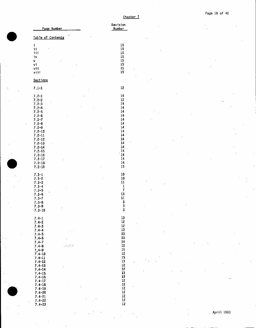
Page 18 of 42 Chaoter 7
Revision Page Number Number
• Table of Contents
i 15 ii 15 iii 15 iv 15 v 15 vi 15 vii 15 viii 15
Sections
7.1-1 12
7.2-1 14 7.2-2 12 7.2-3 14 7.2-4 14 7.2-5 14 7.2-6 14 7.2-7 14 7.2-8 14 7.2-9 14 7.2-10 14 7 .2-11 14 7.2-12 14 7.2-13 14 7.2-14 14 7.2-15 14 7.2-16 14
• 7.2-17 14 7.2-18 14 7.2-19 13
7.3-1 10 7.3-2 10 7.3-3 11 7.3-4 1 7.3-5 7 7.3-6 13 7.3-7 11 7.3-8 3 7 -~-9 3 7.3-10 0
7.4-1 13 7.4-2 12 7.4-3 12 7.4-4 13 7.4-5 13 7.4-6 13 7.4-7 14 7.4-8 -: ·--o_· ~ -- 12 7,4-9 15 7'.4-10 12 7 .4-11 15 7.4-12 13 7.4-13 12 7.4-14 12 7.4-15 13 7.4-16 12 7.4-17 12 7.4-18 12
• 7.4-19 12 7.4-20 12 7.4-21 12 7.4-22 12 7.4-23 12
April 1993

•
•
•
Page Number
7.4-24 7.4-25 7.4-26 7.4-27 7.4-28 7.4-29 7.4-30 7.4-31 7.4-32 7.4-33
7.5-1 7.5-2 7.5-3 7.5-4 7.5-5 7.5-6 7.5-7 7.5-8 7.5-9 7.5-10 7. 5-11 7.5-12 7.5-13 7.5-14 7.5-15 7.5-16
7.6-1. 7.6-2 7.6-3 7.6-4 7.6-5 7.6-6 7.6-7 7.6-8 7.6-9 7.6-10 7. 6-11 7.6-12 7.6-13
.7.6-14 7.6-15 7.6-16 7.6-17 7.6-18 7.6-19
7.7-1 7.7-2 7.7-3 7.7-4 7.7-5 7.7-6 7.7-7 }~7-8
7.8-1 7.8-2 7.8-3 7.8-4 7.8-5
References
7-1 7-2
Chapter 7
Revision Number
12 12 12 12 12 14 12 12 12 14
12 12 14 14 14 14 14 15 14 14 14 14 14 14 14 14
12 12 12 14 12 12 12 12 12 12 12 12 12 12 14 14 14 14 14
0 14 0 2 2 2 0 0
0 0 0 0 0
14 14
Page 19 of 42
' \
e
April 1993

\
Chapter 7 Page 20 of 42
Revision Page Number Number •• Tables
7-1 2 7-2 Sh 1 11 7-2 Sh 2 12 7-2 Sh 3 12 7.,.3 12 7-4 12 7-5 8 7-6 o Figures
7-1 15 7-t 10 7-3 8 7-4 9 7-5 (DELETED) 8 7-6 15 7-7 12 7-8 15 7-9 9 7-10 o 7-11 o 7-12 o 7-13 9 7-14 Sh 1 13 7-14 Sh 2 15 7-14 Sh 3 11 7-14 Sh 4 11 7-14 Sh 5 15
• 7-14 Sh 6 15 . 7-14 Sh 7 15
7-14 Sh 8 11 7-14 Sh 9 9 7-14 Sh 10 11 7-14 Sh 11 13 7-14 Sh 12 11 7-14 Sh 13 11 7-15 15 7-16 15 7-17 15 7-18 15 7-19 9 7-20 15 7-21 15 7-22 15 7-23 12 7-24 15 7-25 (DELETED) 1 7-26 .. 15 7'-27 15. 7-28 - - 15 7-29 ·---. :: -·-"- 15 7:-29A Sh 1 15 7-29A Sh 2 15 7-30 12 7-31 15 7-32 10 7-33 o 7-34 o 7-35 o 7-36 o 7-37 11 • 7-38 15 7-39 15 7-40 Sh 1 15 7-40 Sh 2 15 7-41 o
April 1993

Page 21 of 42 Chapter 7
Revision Page Number Number
• 7-42 11 7-43 9 7-44 9 7-45 10 7-46 3 7-47 9 7-48 (DELETED) 11 7-49 11 7-50 11 7-51 11 7-52 11 7-53 11 7-54 12 7-55 12 e 7-56 12 7-57 0 7-58 12 7-59 (DELETED) 15 7-60 12 7-61 0 7-62 10 7-63 (DELETED) 8 7-64 0 7-65 12
·Appendices
7A Engineered Safeguards Testing Sh 1 15 Sh 2 12 Sh 3 12
• Sh 4 15 Sh 5 15 Sh 6 12 Sh 7 12 Sh 8 12
78 (DELETED) 13
7C Reg Guide 1.97, Instrumentation Pg 1 14 e Pg 2 14 Pg 3 14 Pg 4 14 Pg 5 14 Pg 6 14 Pg 7 14 Pg 8 14 Pg 9 14 Pg 10 14 Pg 11 14 Pg 12 14 Pg 13 14 Pg 14 -----,~:.-:__- 14 Pg 15 14 Pg 16 14 Pg 17 14 Pg 18 14 Pg 19 14 Pg 20 14 Pg 21 14 Pg 22 14 Pg 23 14 Pg 24 14 • Pg 25 14 Pg 26 14 Pg 27 15 Pg 28 15 Pg 29 14
April 1993

•
•
•
Page Number
Pg 30 Pg 31 Pg 32
Chapter 7
Revision Number
14 15 14
Page 22 of 42
April 1993

Page 23 of 42 Chapter 8
Revision Page Number Number
• Table of Contents
15 ii. 15 iii 15 iv 15 v 15
Sections
8.1-1 12 8.1-2 13 e 8.1-3 12 8.1-4 12 8.1-5 12 8.1-6 14
8.2-1 15 8.2-2 11 8.2-3 11 8.2-4 11
8.3-1 14 8.3-2 10 8.3-3 11 8.3-4 11 8.3-5 14 8.3-6 10 8.3-7 11 8.3-8 11 8.3-9 14
• 8.3-10 10 8.3-11 15· 8.3-12 15 8.3-13 15 8.3-14 15 8.3-15 15 8.3-16 15 8.3-17 15
8.4-J 12 8.4-2 12 8.4-3 15 8.4-4 13 8.4-5 13 8.4-6 13 8.4-7 13 8.4-8 15 8.4-9 15
8.5-1 12 8.5-2 14 8.5-3 14 8.5-4
.. .. 14 . . .
a,. 5-5 0 8.5-6 11 8.5-7 0 8.5-8 0 8.5-9 0 8.5-10 0
8.6-1 10 8.6-2 11 8.6-3 11 • 8.6-4 14 8.6-5 14 .
April 1993

Page 24 of 42 Chapter 8
Revision
• Page Number Number
8.7-1 13 8.7-2 14 8.7-3 13 8.7-4 13 8.7-5 14 8.7-6 15 8.7-7 13
8.8-1 12
8.9-1 12
8.10-1 12
References
8-1 12
Tables
8-1 0 8-2 11 8-3 11 8-4 Sh 1 0 8-4 Sh 2 0 8-4 Sh 3 0 8-5 0 8-6 12 8-7 12 8-8, 15
• Figures
8-1 Sh 1 14 8-1 Sh 2 15 8-1 Sh 3 10 8-2 Sh 1 12 8-2 Sh lA 14 8-2 Sh 2 . 14 8-3 12 8-4 12 8-5 14 8-6 14 8-7 12 8-8 14 8-9 Sh 1 15 8-9 . Sh 2 14. 8-9 Sh 3 13 8-10 14 8-11 Sh 1 10 8-11 Sh 2 3 8-12 Sh 1 15 8-12 Sh 2 15 8-13 0 8.-14 15 8-15 15 8-16 15
.8-17 . (DELETED) 11 8-18 11 8-19 11 · 8-20 11 8-21 11 8-22 15
• 8-23 15 8-24 15 8-25 11 8-26 11 8-27 11 8-28 13
April 1993

Page 25 of 42 Chapter 9
Revision Page Number Number
• Table of Contents
15 ii 15 ii 1 15 iv 15 v 15 vi 15 vii 15
Sections
9.1-1 12 9 .1-2 14 9 .1-3 15 9.1-4 14 9.1-5 15
9.2-1 14 9.2-2 14 9.2-3 14
9.3-1 12 9.3-2 15 9.3-3 15 9.3-4 14 9.3-5 15 9.3-6 15
9.4-1 14
• 9.4-2 14 9.4-3 13 9.4-4 13
9.5-1 14 9.5-2 15 9.5-3 14 9.5-4 12 9.5-5 12 9.5-6 12
9.6-1 13 9.6-2 14 9.6-3 15 9.6-4 15 9.6-5 15 9.6-6 15 9.6-7 15 9.6-8 15 9.6-9 15 9.6-10 15 9 .6-11 15 9.6-12 15 9,_ 6-13 15 9.6-14 15 9.6-15 15 9.6-16 15 9.6-17 15 9.6-18 15 5.6-19 15 5.6-20 15
• 9.7-1 12 9.7-2 14 9.7-3 14 9.7-4 14 9.7-5 14
April 1993

Page 26 of 42 Chapter 9
Revision Page Number Number
• 9.8-1 13 9.8-2 13 9.8-3 15 9.8-4 13 9.8-5 13 9.8-6 13 9.8-7 15 9.8-8 15 9.8-9 15 9.8-10 13 9.8-11 13 9.8-12 13 9.8-13 13 9.8-14 15 9.8-15 13 9.8-16 13 9.8-17 13 9.8-18 15 9.8-19 13 9-8-20 13 . 9.8-21 15 9.8-22 13
9.9-1 5 9.9-2 14
.9.10-1 13 9.10-2 15 9.10-3 13 9.10-4 13 9.10-5 13
• 9 .10-6 15 9 .10-7 15 9.10-8 15 9 .10-9 15 9.10-10 15 9 .10-11 15
9.11-1 14 9.11-2 13 9.11-3 14 9.11-4 14 9.11-5 14 9.11-6 15 9.11-7 15 9 .11-8 14 9 .11-9 15 9.11-10 12 9.11-11 12 9.11-12 12 9.11-13 12 9.11-14 12 9.11-15 12 9.11-16 12 g:.·.11-17 12 9.11-18 12
References
9-1 15
• April 1993

Chapter 9 Page 27 of 42
Revision Page Number Number
• Tables
9-1 13 9-2 Sh 1 14 9-2 Sh 2 o 9-3 (DELETED) 15 9-4 Sh 1 14 9-4 Sh 2 14 9-4 Sh 3 o 9-4 Sh 4 o 9-5 15 9-6 Sh 1 14 9-6 Sh 2 15 9-6 Sh 3 o 9-6 Sh 4 1 9-7 15 9-8 Sh 1 14 9-8 Sh 2 o 9-8 Sh 3 o 9-8 Sh 4 o 9-9 Sh 1 14 9-9 Sh 2 15 9-9 Sh 3 o 9-9 Sh 4 14 9-10 Sh 1 15 9-10 Sh 2 5 9-10 Sh 3 7 9-10 Sh 4 o 9-10 Sh 5 15 9-11 Sh 1 13 9-11 Sh 2 13
• 9-11 Sh 3 13 9-12 Sh 1 14 9-12 Sh 2 o 9-12 Sti 3 o 9-13 Sh 1 14 9-13 Sh 2 15 9-13 Sh 3 15 9-14 (DELETED) 2 9-15 13 9-16 Sh 1 o 9-16 Sh 2 15 9-16 Sh 3 15 9-17 Sh 1 10 9-17 Sh 2 10 9-17 Sh 3 10
.9-17 Sh 4 10 9-17 Sh 5 10 ' 9-17 ·sh 6 10 9-18 0 9-19 Sh 1 14 9-19 Sh 2 5 9-20 Sh 1 12 9-20 Sh 2 12 9-:-20 Sh 3 12 9.:20 Sh 4 15 9-20 Sh 5 15 9-20 Sh 6 15 9-20 Sh 7 15 9-20 Sh 8 15 9-20 Sh 9 15 9-20 Sh 10 15 9-20 Sh 11 15 9-20 Sh 12 15
• 9-21 (DELETED) 15 9-22 o 9-23 6 9-24 Sh 1 o 9-24 Sh 2 o
April 1993

Chapter 9 Page 28 of 42
Revision Page Number Number
• Figures
9-1 Sh 1 15 9-1 Sh lA 15 9-1 Sh lB 14 9-1 Sh 2 15 9-2 15 9-3 o 9-4 o 9-5 o 9-6 o 9-7 Sh 1 15 9-7 Sh 2 15 9-7 Sh 3 15 9-8 15 9-9 Sh 1 14 9-9 Sh 2 15 9-10 Sh 1 14 9-10 Sh 2 14 9-11 13 9-12 Sh 1 15 9-13 15 9-14 15 9-15 15 9-16 (DELETED) 2 9-17 Sh 1 15 9-17 Sh 2 15 9-17 Sh 3 6 9-17 Sh 4 11 9-17 Sh 5 15 9-17 Sh 6 15
• 9-17 Sh SA 15 9-17 Sh 7 15 9-18 2 9-19 11 9-20 Sh 1 o 9-20 Sh 2 o 9-21 Sh 1 15 9-21 Sh lA 6 9-21 Sh lB 15
.9-21 Sh lC 15 9-21 Sh lD 15 9-21 Sh lE 15 9-21 Sh lF 15 9-21 Sh 2 15 9-22 Sh 1 11 9-22 Sh 2 14 9-23 15 9-24 o 9-25 Sh 1 14 9-25 Sh lA 14 9-25 Sh lB 14 9-26 (DELETED) 15 ..
9-27 ·- o 9-;28 6 9-29 o 9-30 15
• April 1993

Page 29 of 42 Chapter 10·
Revision·
• Page Number Number
Table of Contents
13 ii 13 iii 13
Sections
10.1-1 0
10.2-1 12 10.2-2 13 10.2-3 12 10.2-4 12 10.2-5 ~ 12 10.2-6 12 10.2-7 12 10.2-8 13 10.2-9 15 10.2-10 . 13
. 10.2-11 13 10.2-12 13
'.;;.~ :~ ' ' ·~.-·:: ..
10.3-1 0
10.4-1 11
Tables
10-1 0
• 10-2 0 10-3 0 10-4 13 10-5 0 10-6 0 10-7 0 10-8 0 10-9 0
Figures
10-1 Sh 1 15 10-1 Sh lA 14 10-1 Sh lB 15 10-1 Sh 2 15 10-1 Sh 2A 15 10-2 Sh 1 15
·10-2 Sh lA 15 10-2 Sh lB 13 10-2 Sh lC 14 10-3 Sh 1 14 10-3 Sh lA 14 10-4 Sh 1 .. 15 10-4 Sh lA
--•_..; .. 15 10-4 Sh lB 15 10-4 Sh lC 15 10-5 Sh 1 12 10-5 Sh 2 2 10-6 Sh 1 15 10-6 Sh 2 10 10-6 Sh 3 15 10-7 o 10-8 14
• Apri 1 1993


Page 31 of 42 Chapter 11
Revision Page Number Number
• Tables
11-1 Sh 1 0 11-1 Sh 2 0 11-1 Sh 3 0 11-2 -Sh 1 0 11-2 Sh 2 0 11-3 Sh 1 0
-:. 1i·-3 Sh 2 0 11-3 Sh 3 0 11-3 Sh 4 0 11-3 Sh 5 0 11-3 Sh ·5 0 11-3 Sh 7 0 11-3 Sh 8 0 11-3 Sh 9 0 11-4 Sh 1 0 11-4 Sh 2 12 11-4 Sh 3 11 11-4 Sh 4 0 11-4 Sh 5 0
.11-4 Sh 6 0 11-4 Sh 7 · 0 11-5 0 11-6 0 11-7 0 11-8 0 lr-9 0 11-10 15 11-11 0 11-12 0
• 11-13 15 11-14 Sh 1 0 11-14 Sh 2 0 11-14 Sh 3 0 11-14 Sh 4 13 11-14 Sh 5 0 11-15 Sh 1 10 11-15 Sh 2 0 11-15 Sh 3 1 11-16 15
Figures
11-1 Sh 1 13 11-1 Sh lA 15 11-1 Sh lB 11 11-1 Sh lC 15 U-1 · Sh 2 15 11-1 Sh 3 9 lt-2 Sh 1 12 11-2 Sh 2. 11 11-2 Sh 2A 12 11-2 Sh 28 11 11-3 Sh 1 15 11-3 Sh 2 12 11-4 Sh 1 13 li-4 Sh 2 15 11-4 . Sh 3 15 11-4 . Sh 4 11 . 11-4. Sh 5 15 11-5 Sh 1 9 11-5 Sh lA 12 11-5 Sh lB 11 • 11-5 Sh 2 11 11-6 11 11-7 0 11-8 3 11-9 0
April 1993

Page Number
• llA Appendix I, Submitt June 4 • 1976 al
•
•
Chapter 11
Revision Number
0
Page 32 of 42
April 1993

Chapter 12 Page 33 of 42
Revision Page Number Number • Table of Contents
15 ii 15 iii 15 iv 15
Sections
12.1-1 15 12.1-2 15 12.1-3 15 12.1-4 15 12.1-5 15 12.1-6 15 12.1-7 15 12.1-8 15 12.1-9 15 12.1-10 15 12.1-11 15
12.2-1 15 12 .2:-2 15 12.2-3 15 12.2-4 15
12.3-1 15 12.3•2 15
12.4-1 15 12.4-2 15
• . 12.4-3 15
12.5-1 1
12.6-1
Figures
12-1 13 12-2 13 12-3 15 12-4 13 12-5 13
• ·April 1993

Page 34 of 42 Chapter 13
Revision Page Number Number • Table of Contents
0
Sections
13.1-1 0 13.1-2 0 13.1-3 0
13.2-1 0 13.2-2 0
13.3-1 0 13.3-2 0
13.4-1 0
•
• April 1993

Page 35 of 42 Chapter 14
Revision Page Number Number
• Table of Contents
14 ii 14 iii 14 iv 14 v 14 vi 14 vii 14 viii 14 ix 14 x 14 xi 14 xii 14 xiii 14
Sections
14.1-1 15 14.1-2 14 14 .1-3 14
. 14.1-4 14 ' References
14.1-1 15
14.2-1 12 14.2-2 12 14.2-3 12 14.2-4 14 14.2-5 14 14.2-6 14
• 14.2-7 14 References 14.2-1 15
14.3:..l 12 14.3-2 14 14.3-3 12 14.3-4 12 14.3-5 12 14.3-6 12
References 14.3-1 14
14.4-1 .12 14.4-2 14 14.4-3 14
References 14.4-1 14
14.5-1 12 References 14.5-1 12
14.6-1 15 14.6-2 15 14.6-3 12
References 14.6-1 15
14.7-1. 14 14.7-2 14 14.7-3 12
• 14·.7-4 14 References 14.7-1 14
April 1993
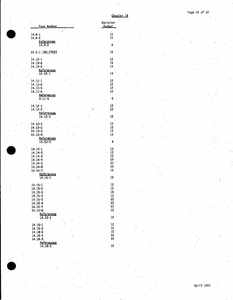
Page 36 of 42 Chapter 14
Revision Page Number Number
• 14.8-1 12 14.8-2 12
References 14.8-3 8
14.9-1 {DELETED) 15
14.10-1 12 14.10:-2 15 14.10-3 14
References 14.10-1 14
14.11-1 12 14 .11-2 12 14.11-3 12 14.11-4 12
References 4.11-5 0
14.12-1 12 14 .12-2 12
References 14.12-1 12
14.13-1 12 14 .13-2 12 14.13-3 12 14.13-4 12
References 14.13-5 8
• 14.14-1 12 14.14-2 12 14.14-3 15 14.14-4 15 14.14-5 15 14.14-6 15 14.14-7 15
References 14.14-1 15
14.15-1 12 14 .15-2 12 14.15-3 15 14.15-4 12 14.15-5 12 14.15-6 12 14.15-7 12 14.15-8 12
References 14.15-1 12
14.lli-l 12 l~.16-2 12 14.16-3 12 14.16-4 12 14.16-5 12
References 14.16-1 12
• April 1993

Page. 37 of 42 Chapter 14
Revision Page Number Number
• 14.17-1 14 14.17-2 14 14.17-3 14 14.17-4 14 14.17-5 12 14.17-6 12 14.17-7 12 14.17-8 12 14.17-9 12 14.17-10 12 14.17-11 12
References 14.17-1 14 14.17-2 14
14.18-1 12 14.18-2 12 14.18-3 12 14.18.:.4 12 14.18-5 15 14.18-6 14 14.18-7 14 14.18-8 14 14.18-9 14 14.18-10 12 14.18-11 12 14.18-12 12
References 14.18-1 15
14.19-1 12
• 14.19-2 15 . 14.19-3 15
14 .19-4 12 References 14 .19-5 11
14.20-1 12 14.20-2 12
14.21-1 12 14.21-2 12 14.21-3 12
14.22-1 12 14.22-2 12 14.22-3 14 14.22-4 14 14.22-5 15 14.22-6 14
References 14.22-1 14
14.23-1 12 l~.23-2 12
References 14.23-1 12
14.24-1 15 14.24-2 15
References 14.24-1 12
• April 1993

l
Chapter 14 Page 38 of 42
Revision Page Number Number
• ..Tables
14.1-1 (DELETED) 12 14.1-2 12 14.1-3 12 14.1-4 8 14.1-5 14 14.1-6 Sh 1 14 14.1-6 Sh 2 14 14.1-6 Sh 3 14 14.1-6 Sh 4 14 14.1-6 Sh 5 14 14.1-6 Sh 6 14 14.1-6 Sh 7 14 14.1-7 Sh 1 14 14.1-7 Sh 2 14 14.2.1-1 12 14.2.2-1 14 14.2.3-1 14 14 .. 2-3.2 14 14.3-1 12 14.4-1 14 14.5-1 (DELETED) 12 14.6-1 ·(DELETED) 12 14.6.2-1 12 14.1..:1 14 14.7-2 14 14.10-1 14 14.11-1 0 14.11-2 0 14.11-3 0
• 14.12-1 12 14.13-1 12 14.13-2 (DELETED) 12
- 14.14-1 Sh 1 12 14.14-1 Sh 2 12 14.14-2 12 14.14-3 Sh 1 12 14.14-3 Sh 2 12 14.14-4 12 14.14-5 12 14.14-6 12 14.15-1 12 14.15-2 12 14.15-3 Sh 1 12 14.15-3 Sh 2 12 14.15-4 12 14.15-5 12 14.15-6 12
.14.16-1 12 14.16-2 12 14 .16-3 12 14.17.1-1 Sh 1 14 14.17.1-1 Sh 2 ... ~- - 14 l!t.17.1-2 Sh 1 12 14.17.1-2 Sh 2 12 14.17.1-2 Sh 3 12 14.17.1-3 14 14.17.1-4 14 14.17.2-1 Sh 1 12 14.17.2-1 Sh 2 12 14.lZ.2-2 12 14.17.2-3 12
• 14.17.3-1 Sh 1 12 14.17.3-1 Sh 2 12 14.18.1-1 Sh 1 12 14.18.1-1 Sh 2 12 14.18.1-2 12 14.18.1-3 12
April 1993

Chapter 14 Page 39 of 42
Revision Page Number Number
• 14.18.1-4 12 14.18.1-5 13 14.18.2-1 14 14.18.2-2 14 14.18.2-3 14 14.18.2-4 (DELETED) 14 14.18.3-1 14 14.18.3-2 14 14.18.3-3 14 14.19-1 0 14.19-2 15 14.22-1 Sh 1 8 14.22-1 Sh 2 8 14.22-2 Sh 1 8 14.22-2 Sh 2 8 14.22-3 8 14.22-4 Sh 1 12 14.22-4 Sh 2 12 14.22-4 Sh 3 14 14.22-4 Sh 4 14 14.22-5 (DELETED) 12 14.22-6 (DELETED) 12 14.22-7 (DELETED) 12 14.23-1 12 14.23-2 12 14.24-1 15 14.24-2 12
Figures
14.1-1 0
• 14.1-2 12 14 .1-3 12 14.1-4 8 14.2.1-1 12 14.2.1-2 12 14.2.1-3 12 14.2.1-4 12 14.2.1-5 12 14.2.1-6 12 14.2.1-7 12 14.2.1-8 12 14.2.1-9 12 14.2.2-1 (DELETED) 14 14.2.2-2 14 14.2.2-3 14 14.2.2-4 14 14.2.2-5 14 14.2.2-6 14 14.2.2-7 14 14.2.2-8 14 14.2.2-9 14 14.2.2-10 14 14.3-1 0 1~.4-1 12 14.4-2 12 14.4-3 12 14.4-4 12 14.4-5 12 14.4-6 (DELETED) 12 e 14.5-1 (DELETED) 12
• April 1993

Chapter 14 Page 40 of 42
Revision Page Number Number
• 14.7-1 13 14.7-2 12 14.7-3 12 14.7-4 12 14.7-5 12 14.7-6 12 14.7-7 12 14.7-8 12 14.7-9 12 14.7-10 12 14.10-1 12 14.10-2 12 14.10-3 12 14 .10-4 12 14.10-5 12 14.10-6 (DELETED) 12 14.11-1 12 14.11-2 12 14.12-1 12 14.12-2 12 14.12-3 12 14.12-4 12 14 .12-5 12 14.13-1 8 14 .13-2 8 14.14-1 12 14.14-2 12 14.14-3 12 14.14-4 12 14.14-5 12 14.14-6 12
• 14.14-7 12 14.14-8 12 14.14-9 12 14.14-10 12 14.14-11 12 14.14-12 12 14.14-13 (DELETED) 12 14.14-14 (DELETED) 12 14.14-15 (DELETED) 12 14.14-16 (DELETED) 12 14.14-17 (DELETED) 12 14.14-18 (DELETED) 12 14.14-19 (DELETED) 12 14.14-20 (DELETED) 12 . 14.14-21 (DELETED) 12 14.14-22 (DELETED) 12 14.14-23 (DELETED) 12 14.15-1 12 14.15-2 12 14.15-3 12 14.15-4 12 14.15-5 12 14.15-6 - . --· 12 1§.15-7 12 14.15-8 12 14.15-9 12 14.15-10 12 14.15-11 12 14.15-12 12 14.15-13 12 14.15-14 12
. 14.15-15 12
• 14.15-16 12 14.15-17 12 14.15-18 12 14.15-19 12 14.15-20 12 14.15-21 12
April 1993

•
•
•
-Page Number
14.15-22 14.15-23 14 .15-24 14.15-25 14.16-1 14.16-2 14 .16:-3 14.16-4 14;16-5 14.17.1-1 14.17.1-2 14.17.2-1 14.17.2-2 14.17.2-3 14.17.2-4 14.17.2-s 14.17.2-6 14.18.1-1 14.18.1-2 14.18.2-1 14.18.2-2 14.22-1 14.22-2
Chapter 14
Revision Number
12 12 12 12 12 12 12 12 12 12 12 12 12 12 12 12 12 12 12 14
. 14 14 14
Page 41 of 42
April 1993

•
•
•
Page Number
Table of C . ontents
i ii
Sections
15.1-1
15.2-1 15.2-2 15.2-3 15.2-4 15.2-5 15.2-6 15.2-7
Figures
15-1 15-2
Chapter 15
Revisi~n Number
0 0
0
0 0 0 0 0 0 0
0 0
Page 42 of 42
April 1993

GENERAL INDEX
• Section Title Page
CHAPTER 1 INTRODUCTION AND GENERAL DESCRIPTION OF PLANT
1.1 INTRODUCTION 1.1-1 1.1.1 GENERAL 1.1-1 1.1.2 LICENSING HISTORY 1.1-1
1.2 GENERAL PLANT DESCRIPTION 1. 2-1 1. 2 .1 PLANT SITE 1. 2-1 1. 2.2 PLANT ARRANGEMENT 1. 2-1 1.2.3 CONTAINMENT 1. 2-2 1.2.4 NUCLEAR STEAM SUPPLY SYSTEM (NSSS} 1. 2-3 1. 2. 5 TURBINE GENERATOR 1.2-9
1.3 IDENTIFICATION OF CONTRACTORS 1.3-1
1.4 PRINCIPAL DESIGN CRITERIA 1.4-1 1.4.1 STATION DESIGN 1.4-1 1.4.2 REACTOR 1.4-1 1.4.3 PRIMARY COOLANT AND AUXILIARY SYSTEMS 1.4-2 1.4.4 CONTAINMENT SYSTEM 1.4-3
• 1.4.5 ENGINEERED SAFEGUARDS 1.4-3 1.4.6 INSTRUMENTATION AND CONTROL 1.4-3 1.4. 7 ELECTRICAL SYSTEMS 1.4-4 1.4.8 RADIOACTIVE WASTES AND RADIATION PROTECTION 1.4-4 1.4.9 FUEL HANDLING AND STORAGE 1.4-4 1. 4 .10 FIRE PROTECTION 1.4-4 1.4.11 CIRCULATING WATER SYSTEM 1.4-4 1.4.12 SECURITY 1.4-4 1. 4 .13 EMERGENCY PLANNING 1.4-5 1.4.14 PLANT OPERATION 1.4-5 1.4.15 STRUCTURES 1.4-5
1.5 MAJOR PLANT MODIFICATIONS (DESIGN/CONSTRUCTION) 1. 5-1
1.6 INSERVICE INSPECTION 1.6-1 1.6 .1 HISTORICAL BACKGROUND 1.6-1 1.6.2 GENERAL 1.6-1
-
1,, 7 RESEARCH~AND DEVELOPMENT REQUIREMENTS 1. 7-1 1. 7 .1 FLOW MIXING AND FLOW DISTRIBUTION 1. 7-1 1. 7 .2 CONTROL ROD TESTS 1.7-1 1. 7 .3 CONTROL ROD DRIVE MECHANISMS 1. 7-1 1. 7 .4 FUEL BUNDLE DESIGN 1. 7-1 1. 7 .5 REACTOR VESSEL FLOW TESTS 1. 7-2
• 1 Rev 15

GENERAL INDEX
• Section Title Page
1.8 SPECIAL MAJOR PROGRAMS 1.8-1 1.8.1 SYSTEMATIC EVALUATION PROGRAM 1.8-1 1.8.1.1 Integrated Assessment (NUREG-0820} 1.8-1 1.8. 2 TMI ACTION ITEMS (NUREG-0737) 1.8-2 1.8.3 PIPE SUPPORT BASEPLATE DESIGNS USING CONCRETE
EXPANSION ANCHOR BOLTS (IE BULLETIN 79-02) 1.8-2 1.8.4 SEISMIC ANALYSIS FOR AS-BUILT SAFETY-RELATED PIPING
SYSTEMS (IE BULLETIN 79-14) 1.8-3 1.8. 5 UNRESOLVED SAFETY ISSUES (NUREG-0410) 1.8-3 1.8.6 ENVIRONMENTAL QUALIFICATION OF "SAFETY-RELATED"
ELECTRICAL EQUIPMENT (EEQ) (NUREG-0588) (USI A-24) 1.8-4 1.8. 7 CONTROL ROOM HABITABILITY (NUREG-0696) 1.8-4 1.8.8 EFFECTS OF PIPE RUPTURE (SEP TOPICS III.5.A AND B) 1.8-4 1.8.9 STATION BLACKOUT (10 CFR 50.63) (USI A-24) 1. 8-4
. CHAPTER 2· SITE AND ENVIRONMENT
2 .1 LOCATION 2.1-1 2 .1.1 TOPOGRAPHY AND LAND USAGE 2.1-2
• 2.1.2 POPU~ATION 2.1-2 2.1.3 NEARBY INDUSTRIAL, TRANSPORTATION AND MILITARY
FACILITIES . 2 .J-4
2.2 HYDROLOGY 2.2-1 2.2.1 GROUNDWATER 2.2-1 2.2.2 GENERAL LAKE HYDROLOGY 2.2-3
2.3 GEOLOGY 2.3-1 2.3.1 PREGLACIAL GEOLOGY 2.3-1 2.3.2 GLACIAL GEOLOGY 2.3-1 2.3.3 FAULTS 2.3-2 2.3.4 ENGINEERING GEOLOGY 2.3-3 2.3.5 CONCLUSIONS 2.3-5
2.4 SEISMICITY 2.4-1 2.4.1 SITE GEOLOGY 2.4-1 2.4.2 SEISMIC HISTORY 2.4-2 Z.4.3 DISCUSSION 2.4-2 2.4.4 CONCLUSIONS 2.4-3
2.5 METEOROLOGY 2.5-1 2.5.1 GENERAL CLIMATOLOGY OF PALISADES PLANT AREA 2.5-1 2.5.2 METEOROLOGICAL PROGRAM HISTORY 2.5-3 2.5.2.1 Preoperational Program 2.5-3 2.5.2.2 Interim Program 2.5-3 • . 2.5.2.3 Present Program • 2.5-4
2 Rev 15

GENERAL INDEX
• Section Title Page
2.5.3 DISCUSSION OF EXISTING 1977/1978 DATA 2.5-4 2.5.3.l ~ind Fregyency Distribytjons 2.5-4 2.5.3.2 Stability Wind Roses 2.5-5 2.5.3.3 Persistence 2.5-5 2.5.3.4 Hourly Data 2.5-6 2.5.3.5 Data Recovery 2.5-6 2.5.4 DIFFUSION CLIMATOLOGY 2.5-6 2.5.4.1 Turbulence and Diffysion Regimes 2.5-7 2.5.4.2 Shoreline Influences 2.5-7 2.5.5 SHORT-TERM DISPERSION PARAMETERS 2.5-8 2.5.6 LONG-TERM DISPERSION PARAMETERS 2.5-9
2.6 ENVIRONMENTAL SURVEILLANCE 2.6-1 2.6.1 SAMPLE SENSITIVITY 2.6-2 2.6.2 SAMPLE TYPE AND FREQUENCY 2.6-2 2.6.3 SAMPLING STATIONS 2.6-2 2.6.4 SAMPLE TYPES 2.6-3 2.6.5 SUMMARY OF PREOPERATIONAL RESULTS 2.6-3 2.6.6 ADJUSTMENTS TO THE ENVIRONMENTAL SURVEY 2.6-5
REFERENCES 2-1
• CHAPTER 3 REACTOR
3.1 INTRODUCTION 3.1-1
3.2 DESIGN BASES 3.2-1 3.2.1 PERFORMANCE OBJECTIVES 3.2-1 3.2.2 DESIGN OBJECTIVES 3.2-1 3.2.3 DESIGN LIMITS 3.2-2
3.3 REACTOR DESIGN 3.3-1 3.3.1 GENERAL SUMMARY 3.3-1 3.3.2 NUCLEAR DESIGN AND EVALUATION 3.3-2 3.3.2.1 Re§ctjvity and Control Reguirements 3.3-2 3.3.2.2 Reactivity Coefficients 3.3-4 3.3.2.3 Control Blade Worths 3.3-6 l..3.2.4 Reactivity Insertion Rates 3.3-6 3.3.2.5 Power Distribution 3.3-7 3.3.2.6 Neutron Flyence on Pressure Vessel 3.3-8 3.3.2.7 Nuclear Evaluation 3.3-9 3.3.2.8 Reactor Stability 3.3-12 3.3.3 THERMAL-HYDRAULIC DESIGN AND EVALUATION 3.3-16 3.3.3.l Thermal-Hydraulic Design Criteria 3.3-16 3.3.3.2 Plant Parameter Variations 3.3-16 •• 3.3.3.3 Core Flow Distribution 3.3-16 3.3.3.4 Trip Set Points 3.3-17
3 Rev 15

GENERAL INDEX
• Section Title Page
3.3.4 MECHANICAL DESIGN AND EVALUATION 3.3-18 3.3.4.1 Reactor Internals 3.3-18 3.3.4.2 Control Rod Drive Mechanism 3.3-22 3.3.4.3 Core Mechanical Design 3.3-26
REFERENCES 3-1
CHAPTER 4 PRIMARY COOLANT SYSTEM
4.1 INTRODUCTION 4.1-1
4.2 DESIGN BASIS 4.2-1 4.2.1 PERFORMANCE OBJECTIVES AND PARAMETERS FOR NORMAL
CONDITIONS 4.2-1 4.2.2 DESIGN CYCLIC LOADS 4.2-1 4.2~3 DESIGN SERVICE LIFE CONSIDERATIONS 4.2-2 4.2.4 CODES ADHERED TO AND COMPONENT CLASSIFICATION 4.2-2 4.2.5 SAFETY CONSIDERATIONS OF DESIGN PARAMETERS 4.2-3 4.2.6 PRIMARY COOLANT SYSTEM ASYMMETRIC LOADS 4.2.3
I • 4.3 SYSTEM DESIGN AND OPERATION 4.3-1 4.3.1. GENERAL DESCRIPTION 4.3-1 4.3.2 INTERFACES WITH OTHER SYSTEMS 4.3-2 4.3.3 REACTOR VESSEL 4.3-3 4.3.4 STEAM GENERATOR 4.3-5 4.3.4.1 Steam Generator Tube Degradation 4.3-7 4.3.4.2 Steam Generator Replacement 4.3-7 4.3.5 PRIMARY COOLANT PUMPS 4.3-8 4.3.6 PRIMARY COOLANT PIPING 4.3-9 4.3.7 PRESSURIZER 4.3-10 4.3.8 QUENCH TANK . 4.3-14 4.3.9 VALVES 4.3-15 4.3.9.1 General Criteria 4.3-15 4.3.9.2 Pressurizer Throttling {SRra~} Control Valves 4.3-16 4.3.9.3 Power-Oper~ted Relief Valves {PORV} ~nd Block Valves 4.3-16 4.3.9.4 Spring-Actyated Primar~ Safet~ V~lves 4.3-17 4.3.10 ENVIRONMENTAL PROTECTION 4.3-17 &\. 3 .11. MATERIALS EXPOSED TO COOLANT 4.3-18 4.3.12 INSULATION 4.3-18 4.3.13 SYSTEM CHEMICAL TREATMENT 4.3-18
4.4 SYSTEM DESIGN EVALUATION 4.4-1 4.4.1 DESIGN MARGIN 4.4-1 4.4.2 PREVENTION OF BRITTLE FRACTURE 4.4-1
• 4 Rev 15

GENERAL INDEX
• Section Title Page
4.5 TESTS AND INSPECTIONS 4.5-1 4.5.1 GENERAL 4.5-1 4.5.2 NIL DUCTILITY TRANSITION TEMPERATURE DETERMINATION 4.5-1 4.5.3 SURVEILLANCE PROGRAM 4.5-2 4.5.4 NONDESTRUCTIVE TESTS 4.5-6 4.5.5 ADDITIONAL TESTS . 4.5-7 4.5.6 INSERVICE INSPECTION 4.5-9 4.5.7 NOTT OF OTHER PRIMARY SYSTEM COMPONENTS . 4. 5-11 4.5.8 NONDESTRUCTIVE TESTS OF OTHER PRIMARY SYSTEM COMPONENTS 4.5-12
4.6 OPERATING LIMITATIONS 4.6-1
4.7 PRIMARY COOLANT PRESSURE BOUNDARY LEAKAGE DETECTION 4.7-1 4.7.1 LEAK DETECTION 4.7-1 4.7.2 OPERATOR ACTION FOLLOWING LEAK DETECTION 4 ._7-2
4.8 PRIMARY COOLANT GAS VENT SYSTEM 4.8-1
REFERENCES 4~1
• CHAPTER 5 DESIGN OF STRUCTURES. SYSTEMS AND COMPONENTS
5 .1 . GENERAL DESIGN CRITERIA 5.1-1 5.1.1 INTRODUCTION 5.1-1 5.1.2 GROUP I: OVERALL REQUIREMENTS (CRITERIA 1-5) 5.1-2 5.1.2.1 Criterion 1 - gyalit~ Standgrds and Records 5.1-2 5.1.2.2 Criterion 2 - Design Bases for Protection Against
Natyr9l Phenomen9 5.1-3 5.1.2.3 Criterion 3 - Fire Protection 5.1-3 5.1.2.4 Criterion 4 - Environmental and Missile Design Bases 5.1-4
. 5.1.2.5 Criterjon 5 - Sharing of Structyres! S~stems and Comoorients 5.1-5
5.1.2.6 Conclusions 5.1-5 5.1.3 GROUP II: PROTECTION BY MULTIPLE FISSION PRODUCT
BARRIERS (CRITERIA 10-19) 5.1-5 5.1.3.l Criterion 10 - Reactor Design 5.1-5 5.1.3~2 · Criterion 11 - Reactor Inherent Protection 5.1-5 &.1.3 .3 Criterion 12 - Suggression of Reactor Power
Oscillations 5.1-6 5.1.3.4. · Criterion 13· - Instrumentation and Control 5.1-6 5.1.3.5 Criterion 14 - Primar~ Coolant Pressure Boundar~ 5.1-7 5.1.3.6 Criterion 15 - Reactor Coolant S~stem Design 5.1-8 5.1.3.7 Criterion 16 - Containment Design 5.1-8 5.1.3.8 Criterion 17 - Electrical Power S~stems 5.1-9 5.1.3.9 . Criterion 18 - Insgection gnd Testing of Electrical • Power S~stems 5.1-10 5.1.3.10 Criterion 19 - Control Room 5.1-11 5.1.3.11 Conclusions 5.1-12
5 . Rev 15

•
•
•
Section
5.1.4
5.1.4.1 5.1.4.2
5.1.4.3 5.1.4.4 5.1.4.5
5.1.4.6
5.1.4.7
5.1.4.8
5.1.4.9 5.1.4.10
5.1.4.11 5.1. 5 5.1.5.1
5.1.5.2
5.1.5.3
5.1.5.4 5.1.5.5 5.1.5.6 5.1.5.7
5.1.5.8
5.1.5.9 5.1.5.10
5.1.5.11
5.1.5.12 &. I. 5 .13
5.1.5.14
5.1.5.15 5.1.5.16
5.1.5.15
GENERAL INDEX
Title
GROUP III: PROTECTION AND REACTIVITY CONTROL SYSTEMS (CRITERIA 20-29}
Criterion 20 - Protection System Functions Criterion 21 - Protection System Reliability and
Testability Criterion 22 - Protection System Independence Criterion 23 - Protection System Failure Modes Criterion 24 - Separation of Protection and Control
Systems Criterion 25 - Protection System Requirements for
Reactivity Control Malfunctions Criterion 26 - Reactivity Control System Redundancy
and Capability Criterion 27 - Combined Reactivity Control Systems
Capability Criterion 28 - Reactivity Limits Criterion 29 - Protection Against Anticipated
Operational Occurrences Conclusions GROUP IV: · FLUID SYSTEMS (CRITERIA 30-46} Criterion 30 - Quality of Reactor Coolant Pressure
Boundary Criterion 31 - Fracture Prevention of Reactor Coolant
Pressure Boundary Criterion 32 - Inspection of Reactor Coolant Pressure
Boundary Criterion 33 - Reactor Coolant Makeup Criterion 34 - Residual Heat Removal Criterion 35 - Emergency Core Cooling Criterion 36 - Inspection of Emergency Core Cooling
System Criterion 37 - Testing of Emergency Core Cooling
System Criterion 38 - Containment Heat Removal Criterion 39 - Inspection of Containment Heat Removal
System Criterion 40 - Testing of Containment Heat Removal
System ·criterion 41 - Containment Atmosphere Cleanup Criterion 42 - Inspection of Containment Atmosphere
Cleanup Systems Criterion 43 - Testing of Containment Atmosphere
Cleanup Systems Criterion 44 - Cooling Water Criterion 45 - Inspection of Cooling Water System and
Criterion 46 - Testing of Cooling Water System Conclusions
6
Page
5.1-12 5.1-12
5.1-13 5.1-14 5.1-14
5.1-15
5.1-15
5.1-16
5.1-16 5.1-17
5.1-17 5.1-18 5.1-18
5.1-18
5.1-19
5.1-20 5.1-20 5.1-20 5.1-21
5.1-22
5.1-22 5.1-22
5.1-23
5.1-23 5.1-24
5.1-25
5.1-25 5.1-25
5.1-26 5.1-27
Rev 15

•
•
••
Section
5.1.6 5.1.6.1 5.1.6.2
5.1.6.3
5.1.6.4
5.1.6.5 5.1.6.6
5.1.6.7 5.1.6.8 5.1.6.9 5.1. 7
5.1.7.1
5.1.7.2
5.1.7.3
5.1.7.4 5.1.7.5 5.1.7.6 5.1.8
5.2 5.2.1 5.2.1.l 5.2.1.2 5.2.2 5.2.2.1 5.2.2.2 5.2.2.3 5.2.2.4 5.2.2.5 5.2.2.6 5.2.2.7
5.2.2.8
5.3 5.3.1 5.3.1.1 5.3.1.2
GENERAL INDEX
Title
GROUP V: REACTOR CONTAINMENT (CRITERIA 50-57) Criterion 50 - Containment Design Basis Criterion 51 - Fracture Prevention of Containment
Pressure Boundary Criterion 52 - Capability for Containment Leakage Rate
Testing Criterion 53 - Provisions for Containment Testing and
Inspection Criterion 54 - Piping Systems Penetrating Containment Criterion 55 - Primary Coolant Pressure Boundary
Penetrating Containment Criterion 56 - Primary Containment Isolation Criterion 57 - Closed System Isolation Valves Conclusions · · GROUP VI: FUEL AND RADIOACTIVITY CONTROL
(CRITERIA 60-64) Criterion 60 - Control of Releases of Radioactive
Materials to the Environment Criterion 61 - Fuel Storage and Handling and
Radioactivity Control Criterion 62 - Prevention of Criticality in Fuel
Storage and Handling Criterion 63 - Monitoring Fuel and Waste Storage ·criterion 64 - Monitoring Radioactivity Releases Conclusions OVERALL CONCLUSION
CLASSIFICATION OF STRUCTURES, SYSTEMS AND COMPONENTS BACKGROUND INFORMATION Classification Overvie~ Original Palisades Design Review CP CO DESIGN CLASSIFICATIONS Design - Class 1 Design - Class 2 Design - Class 3 Desjgn - Palisades Modification Inservice Inspection Service Oyality Grouo Classification Service - Electrical and Instrumentation and Controls
Egyipment Classification Safety-Related Classification
REFERENCES
WIND AND TORNADO LOADINGS WIND Design Parameters Forces on Structures
7
Page
5.1-27 5.1-27
5.1-28
5.1-28
5.1-28 5.1-29
5.1-29 5.1-30 5.1-32 5.1-32
5.1-33
5.1-33
5.1-34
5.1-35 5.1-35 5.1-35 5.1-36 5.1-36
5.2-1 5.2-1 5.2-1 5.2-2 5.2-2 5.2-2 5.2-3 5.2-3 5.2-3 5.2-4 5.2-4
5.2-5 5.2-5
5.2-6
5.3-1 5.3-1 5.3-1 5.3-1
Rev 15

•
•
•
Section
5.3.2 5.3.2.1 5.3.2.2 5.3.3
5.4 5.4.1 5.4.1.1 5.4.1.2
5.4.2
5.5 5.5.1 5.5.1.1 5.5.1.1.1
5.5.1.1.2 5.5.1.1.3 5.5.1.1.4 5.5.1.2 5.5.1.3 5.5.1.3.1 5.5.1.3.2 5.5.2 5.5.2.1 5.5.2.2 5.5.2.3 5.5.2.4 5.5.2.4.1 5.5.2.4.2 5.5.3 5.5.3.1 5.5.3.2 5.5.4
5.6 5.6.1 5.6.2 5.6.2.1 5.6.2.2
. 5.6.2.3 5.6.2.4
GENERAL INDEX
TORNADO Design Parameters Forces on Structures PLANT REEVALUATION
REFERENCES
WATER LEVEL DESIGN
Title
FLOODING FROM NATURAL SOURCES Description of Events Effects on CP Cd Design Class 1 Structures and Safety-
Related Equipment FLOODING AND WETTING FROM PLANT SOURCES
REFERENCES
MISSILE PROTECTION TORNADO MISSILES Design Parameters Containment Structure, Auxiliary Building, Turbine
Building Intake Structure Auxiliary Building Radwaste Addition Auxiliary Building TSC/EER/HVAC Addition Structural Considerations Plant Reevaluation Review Parameters Sunvnary TURBINE MISSILES Background High-Pressure Turbine Missiles Low-Pressure Turbine Missiles Inspection Programs Low-Pressure Turbine Discs Turbine Overspeed Protection System INTERNALLY GENERATED MISSILES Containment Missiles Plant Reevaluation
· SITE PROXIMITY MISSILES
REFERENCES
DYNAMIC EFFECTS OF PIPE RUPTURE DEFINITIONS DESIGN BASES S~stems in Which Design Basis Failures Occur I entification of Essential Systems and Components Lim tin Conditions · Sa t va uation
8
Page
5.3:.1 5.3-1 5.3-2 5.3-2
5.3-4
5.4-1 5.4-1 5.4-1
5.4-1 5.4-2
5.4-3
5.5-1 5.5-1 5.5-1
5.5-1 5.5-1
-5.5-2 5.5-2 5.5-2 5.5-3 5.5-3 5.5-3 5.5-4 5.5-4 5.5-4 5.5-5 5.5-6 5.5-6 5.5-7 5.5-·7 5.5-7 5.5-8 . 5.5-9
5. 5-11
5.6-1 5.6-1 5.6-2 5.6-2 5.6-2 5.6-3 5.6-3
Rev 15

GENERAL INDEX
• Section Title Page
5.6.3 CRITERIA USED TO DEFINE BREAKS 5.6-4 5.6.3.l ASME Section 111 2 Class 1 Piging 5.6-4 5.6.3.2 ASME Section III Class 2 and 3 Pi in other than
etween containment iso ation va ves 5.6-5 5.6.3.3 Nonnuc ear C ass Pigint 5.6-6 5.6.3.4 Pi8in~ Penetratinr con-ainment 5.6-7 5.6.4 PR TE TIVE MEASUR S 5.6-7 5.6.5 JET IMPINGEMENT 5.6-9 5.6.6 PLANT MODIFICATION LINE-BREAK ANALYSIS 5.6-9 5.6.6.1 Plant Modifications Involving High -or Moderate-
EnerR:l Pi12int 5.6-9 5.6.6.2 Plant -odirica-ions Involving Essential S:istems
and Com~onents 5.6-9 5.6.7 HISTORY 0 PALISADES HIGH-ENERGY LINE-BREAK ANALYSIS 5.6-10 5.6.7.1 High-Energ:l line Breaks Outside Containment 5.6-10 5.6.7.2 Hi9h-Enerr:l Line Breaks Inside Containment 5.6-13 5.6.7.3 Mo-erate--nerg:l S:istem Pige-Break Evaluation 5.6-14
REFERENCES 5.6-16
5.7 SEISMIC DESIGN 5.7-1 5.7.1 SEISMIC INPUT 5.7-1 5.7.1.1 Design Bases 5.7-1
• 5.7.1.2 Ground Design Resgonse Sgectra 5.7-1 5.7.1.3 Floor Design Resgonse Sgectra 5.7-2 5.7.1.4 Dgmging Values 5.7-3 5.7.1.5 Temgorar:l Structures and Temgorar:l loading on
Plant Structures 2 Piging or Eguigment 5.7-3 5.7.2 SEISMIC ANALYSIS OF MAJOR CP CO DESIGN CLASS 1
STRUCTURES 5.7-4 5.7.2.1 Containment Building 5.7-5 5.i.2.2 Auxiliar~ Building 5.7-6 5.7.3 SEISMIC ANALYSIS OF OTHER CP CO DESIGN CLASS 1
STRUCTURES 5.7-6 5.7.3.1 Turbine Building 5.7-6 5.7.3.1.1 CP Co Design Class 1 Portion 5.7-7 5.7.3.1.2 CP Co Design Class 3 Portion 5.7-7 5.7.3.2 Intake Structyre 5.7-8 5.7.3.3 Auxili§r:l Byilding Radwaste Addition 5.7-9 5.7.3.4 Ayxjligr:l Building TSCLEER Addition {Portion
• iFoynded on WGDIR} 5.7-9 5·.7.3.5 Otber Ayxiliar:l Building Additions 5.7-11 5.7.3.6 CP Co Design Class 1 Tank Foundations 5.7-11 5.7.3.7 Miscellaneous Frames and Trusses 5.7-11 5.7.4 SEISMIC ANALYSIS OF CP CO DESIGN CLASS 1 PIPING 5.7-11 5.7.5 SEISMIC ANALYSIS OF MAJOR CP CO DESIGN CLASS 1 SYSTEM
AND COMPONENTS 5.7-14
• 9 Rev 15
GENERAL INDEX
• Section Title Page
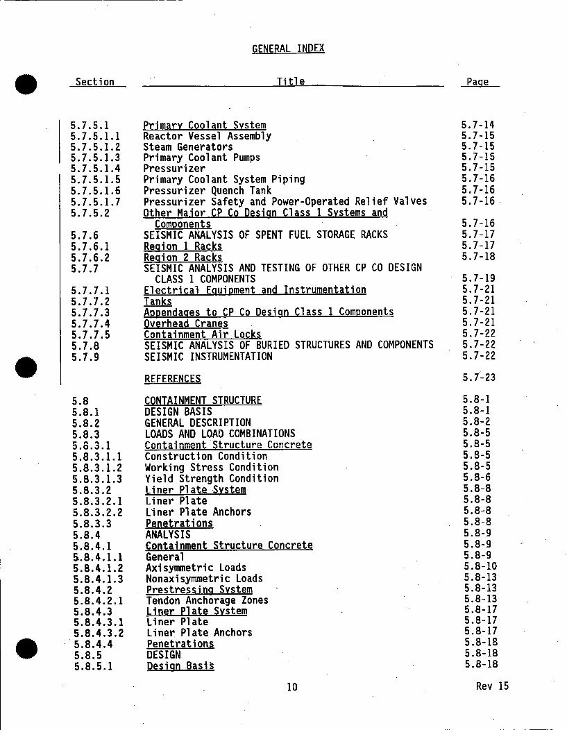
5.7.5.1 Primar~ Coolant S~stem 5.7-14 5.7.5.1.l Reactor Vessel Assembly 5.7-15 5.7.5.1.2 Steam Generators 5.7-15 5.7.5.1.3 Primary Coolant Pumps 5.7-15 5.7.5.1.4 Pressurizer 5.7-15 5.7.5.1.5 Primary Coolant System Piping 5.7-16 5.7.5.1.6 Pressurizer Quench Tank 5.7-16 5.7.5.1.7 Pressurizer Safety and Power-Operated Relief Valves 5.7-16 5.7.5.2 Other Major CP Co Design Class 1 S~stems and
Components 5.7-16 5.7.6 SEISMIC ANALYSIS OF SPENT FUEL STORAGE RACKS 5.7-17 5.7.6.l Region 1 Racks 5.7-17 5.7.6.2 Region 2 Racks 5.7-18 5.7.7 SEISMIC ANALYSIS AND TESTING OF OTHER CP CO DESIGN
CLASS 1 COMPONENTS 5.7-19 5.7.7.1 Electrical Eguipment and Instrumentation 5.7-21 5.7.7.2 Tanks 5.7-21 5.7.7.3 Appendages to CP Co Design Class 1 Components 5.7-21 5.7.7.4 Overhead Crgnes 5.7-21 5.7.7.5 Contginment Air Locks 5.7-22 5.7.8 SEISMIC ANALYSIS OF BURIED STRUCTURES AND COMPONENTS 5.7-22
• 5.7.9 SEISMIC INSTRUMENTATION 5.7-22_
REFERENCES 5. i-23
5.8 CONTAINMENT STRUCTURE 5.8-1 5.8.1 DESIGN BASIS 5.8-1 5.8.2 GENERAL DESCRIPTION 5.8-2 5.8.3 LOADS AND LOAD COMBINATIONS 5.8-5 5.8.3.1 Containment Structure Concrete 5.8-5 5.8.3.1.1 Construction Condition 5.8-5 5.8.3.1.2 Working Stress Condition 5.8-5 5.8.3.1.3 Yield Strength Condition 5.8-6 5.8.3.2 Ljn~r elgte S~stem 5.8-8 5.8.3.2.1 Liner Plate 5.8-8 5.8.3.2.2 Liner Plate Anchors 5.8-8 5.8.3.3 Penetrations 5.8-8 5.8.4 ANALYSIS 5.8-9 5.8.4.1 Cootginment Structure Concrete 5.8-9 &.8. 4 .1.1 General 5.8-9 5.8.4.1.2 Axisy1T111etric Loads 5.8-10 5.8.4.1.3 Nonaxisynunetric Loads 5.8-13 5.8.4.2 Prestressing S~stem 5.8-13 5.8.4.2.1 Tendon Anchorage Zones 5.8-13 5.8.4.3 Liner Platg S~stem 5.8-17 5.8.4.3.1 Liner Plate 5 .8-17 5.8.4.3.2 Liner Plate Anchors 5.8-17
• 5.8.4.4 Penetrations 5.8-18 5.8.5 DESIGN 5.8-18 5.8.5.l Design Basis 5.8-18
10 Rev 15

GENERAL INDEX
• Section Title Page
5.8.5.2 Containment Structure Concrete 5.0-20_ 5 .8. 5 .. 2 .1 General Criteria 5.8-20 5.8.5.2.2 Construction Condition 5.8-21 5.8.5.2.3 Working Stress Condition 5.8-23 5.8.5.2.4 Yield Strength Condition 5.8-24 5.8.5.2.5 Results 5.8-28 5.8.5.3 Prestressing System 5.8-28 5.8.5.3.1 Tendons 5.8-28 5.8.5.3.2 Tendon Anchorage Zones 5.8-30 5.8.5.4 Liner Plate System 5.8-31 5.8.5.4.1 General 5.8-31 5.8.5.4.2 Liner Pl ate 5.8-31. 5.8.5.4.3 Liner Plate Anchors 5.8-33 5.8.5.4.4 Brackets 5.8-34 5.8.5.5 Penetrations 5.8-35 5.8.6 PENETRATIONS 5.8-35 5.8.6.l Design Basis 5.8-35 5.8.6.2 General Descrirition 5.8-35 5.8.6.2.1 Personnel and Equipment Openings 5.8-36 5.8.6.2.2 Other Openings 5.8-37 5.8.6.3 Design Criteria 5.8-37
• 5.8.6.3.1 Concrete Openings 5.8~37 -5.8.6.3.2 Steel Penetrations 5.8-38 5.8.6.4 Analysis and Design . 5.8-40 5.8.6.4.1 Small Penetrations 5.8-41 5.8.6.4.2 Large Penetrations 5.8-42 5.8.6.4.3 · Other Design Details 5.8-45 5.8.7 CONSTRUCTION 5.8-46 5.8.7.1 Materials 5.8-46 s.a.1.1~1 Concrete 5.8-46 5.8.7.1.2 Reinforcing Steel 5.8-47 5.8.7.1.3 Prestressing Tendons and Hardware 5.8-47 5.8.7.1.4 Liner Plate 5.8-48 5.8.7.1.5 Steel Penetrations 5.8-48 5.8.7.1.6 Sheathing Filler 5.8-48 5.8.7.2 Oyality Control 5.8-49 5.8.7.2.1 Concrete Mix Design 5.8-49 5.8.7.2.2' Concrete Materials 5.8-50 5.8.7.2.3 .. Concrete 5.8-50 ~.8.7.2.4 Reinforcing Steel and CADWELD Splices 5.8-51 5.8.7.2.5 Prestressing· Tendons and Hardware 5.8-51 5.8.7.2.6 Liner Plate 5.8-52 5.8.7.2.7 Steel Penetrations 5.8-53 5.8.7.2.8 Sheathing Filler 5.8-53 5.8.7.3 Construction Methods 5.8-54 5.8.7.3.1 Governing Code~ 5.8-54 5.8.7.3.2 Concrete 5.8-54 • 5.8.7.3.3 Reinforcing Steel and CADWELD Splices 5.8-55 5.8.7.3.4 Prestressing System 5.8-55 5.8.7.3.5 Liner Pl ate· 5.8-56
11 Rev 15

•
•
•
Section
5.8.7.4 5.8.7.4.1 5.8.7.5
5.8.8 5.8.8.1 5.8.8.1.1 5.8.8.1.2 5.8.8.1.3 5.8.8.1.4 5.8.8.J .5 5.8.8.1.6 5.8.8.2 5.8.8.2.1 5.8.8.2.2 5.8.8.2.3 5.8.8.2.4 5.8.8.2.5 5.8.8.3 5.8.8.3.1 5.8.8.3.2 5.8.8.3.3 5.8.8.3.4 5.8.8.3.5 5.8.8.4 5.8.8.4.1 5.8.8.4.2 5.8.8.4.3 5.8.8.4.4 5.8.8.4.5 5.8.8.5 5.8.8.5.1 5.8.8.5.2 5.8.8.5.3 5.8.8.5.4 5.8.8.6 5.8.8.6.1 5.8.8.6.2 5.8.8.6.3 5..8.8.6.4 5.8.8.6.5 5.8.9 5.8.9.l 5.8.9.2 5.8.8.3 5.8.9.3.1 5.8.9.3.2 5.8.9.3.3 5.8.9.3.4 5.8.9.3.5
GENERAL INDEX
Title
Construction Problems Cracking at Welds in Containme~i Liner Plate Containment Integrity and the Steam Generator
Replacement Project CONTAINMENT STRUCTURE TESTING Integrated Leak Rate Testing Basis for Program Test Guidelilies Test Frequency Preoperational Test Objectives Acceptance Criteria Historical Summary Local Leak Detection Tests Basis for Program Test Guidelines Test Frequency Acceptance Criteria Historical Summary Prestressing System Surveillance Basis for Program Surveillance Period Surveillance Guidelines Acceptance Criteria .
·Historical Summary · Structural Integrity Test Basis for Test Test Guidelines Objectives Test Data and Results Summary Liner Plate and Penetration Surveillance Program Basis for Program -Surveillance Period Details of Program Summary End Anchorage Concrete Surveillance Basis for Program Surveillance Period Surveillance Locations Details and Results Summary STEAM GENERATOR REPLACEMENT CONSTRUCTION OPENING General Description Containment Reevaluation Materials Concrete Reinforcing Steel Prestressing Tendons and Hardware Liner Plate and Hardware Sheathing Filler
12
Page
5.8-57 5.8-57
5.8-60 5.8-60 5.8-60 5.8-60 5.8-60 5.8-61 5.8-62 5.8-62 5.8-62 5.8-63 5.8-63 5.8-64 5.8-64 5.8-65 5.8-66 5.8-66 5.8-66 5.8-67 5.8-67 5.8-70 5.8-70 5.8-73 5.8-73 5.8-74 5.8-74 5.8-75 5.8-76 5.8-77 5.8-77 5.8-78
- 5,8-78 5.8-79
. 5.8-79 5.8-79 5.8-79 5.8-80 5.8-80 5.8-81 5.8-81 5.8-81 5.8-82 5.8-84 5.8-84 5.8-86 . 5.8-86 5.8-86 5.8-86
Rev 15

GENERAL INDEX
• Section Title Page
5.8.9.4 gyglit~ Control 5.8-87 5.8.9.4.1 Concrete Mix Design 5.8-87 5.8.9.4.2 Concrete Materials 5.8-88 5.8.9.4.3 Concrete 5.8-88 5.8.9.4.4 Reinforcing Steel and CADWELD Splices 5.8-88 5.8.9.4.5 Prestressing Tendons 5.8-89 5.8.9.4.6 Liner Plate 5.8-90 5.8.9.4.7 Sheathing Filler 5.8-90 5.8.9.5 Construction Methods 5.8-90 5.8.9.5.1 Governing Codes 5.8-90 5.8.9.5.2 Concrete 5.8-91 5.8.9.5.3 Reinforcing Steel and CADWELD Splices -5. 8-91 5.8.9.5.4 Prestressing System 5.8-91 5.8.9.6 Contginment Testjng 5.8-91 5.8.9.6.1 Integrated Leak Rate Testing 5.8-91 5.8.9.6.2 Structural Integrity Test 5.8-91
REFERENCES 5.8-93
5.9 OTHER STRUCTURES 5.9-1 5.9.1 DESIGN CRITERIA 5.9-1
• 5.9.1.1 CP Co Design Class 1 Structures 5.9-1 5.9.1.1.1 Design Methods 5.9-1 5.9.1.1.2 Loads and Load Combinations · 5.9-2 5.9.1.2 CP Co Design Class 2 Structures 5.9-4 5.9.1.3 CP Co Design ClgSS 3 Structures 5.9-4 5.9.1.4 Logds Common to All Stryctyres 5.9-4
5.9.2 CONTAINMENT INTERIOR STRUCTURES 5.9-5 5.9.2.l General Description° 5.9-5 5.9.2.2 Loads 5.9-6 5.9.2.3 Anglvsis and Design- 5.9-7 5.9.2.4 Materigls of Constryction 5.9-8 5.9.3 AUXILIARY BUILDING 5.9-9 5.9.3.1 Generil DescrigtiQD 5.9-9 5.9.3.2 Loads 5.9-10 5.9.3.3 Anil~sis gnd Design 5.9-10 5.9.3.4 Materials of Construction 5. 9-11 5.9.4 TURBINE BUILDING AND INTAKE STRUCTURE 5.9-12 &. 9. 4 .1 Genergl 5.9-12 5.9~5 AUXILIARY BUILDING RADWASTE ADDITION 5.9-12 5.9.5.1 General Description 5.9-12 5.9.5.2 Anal~sis and Design 5.9-12 5.9.5.3 Materigls of Construction 5.9-13 5.9.6 AUXILIARY BUILDING TSC/EER/HVAC ADDITION 5.9-13 5.9.6.1 Genergl Description 5.9-13
• 5.9.6.2 Logds and Load Combingtions 5.9-13 5.9.6.2.1 Loads 5.9-13 5.9.6.2.2 Load Combinations 5.9-14
_13 Rev 15

GENERAL INDEX
• Section Title Page
5.9.6.3 Analvsis and Design 5.9-15 5.9.6.4 Materials of Construction 5.9-16
REFERENCES 5.9-17
5.10 SYSTEMS AND COMPONENTS 5.10-1 5.10.l DESIGN CRITERIA FOR CP CO DESIGN CLASS 1 SYSTEMS
AND COMPONENTS 5.10-1 5.10.1.l CP Co Desiga ClgSS 1 Piping 5.10-1 5.10.1.2 CP Co Design Class 1 Pipe Supports 5.10-2 5.10.1.3 Otber CP CQ Design Clgs~ l Systems gDd Components 5.10-5 5.10.1.4 Temporgry Loads 5.10-5 5.10.1.5 Interim Operability Criterig 5.10-6 5.10.2 DESIGN CRITERIA FOR CP CO DESIGN CLASS 2 AND CLASS 3
SYSTEMS AND COMPONENTS 5.10-6 5.10.2.1 CP Co Design ClgSS 2 5.10-6 5.10.2.2 CP Co Design Class 3 5.10-6 5.10.3 ANCHORAGE MODIFICATIONS FOR SAFETY-RELATED SYSTEMS
AND COMPONENTS. 5.10-6 5.10.3.l Pioing Systems 5.10-6
. 5.10.3.1.1 1974 Review 5.10-6
• 5.10.3 .1.2 1979 Reanalysis 5.10-7 5.10.3.1.3 Revision of Seismic Piping Criteria - ASHE
Section Ill, Code Case N-411 5.10-7 5.10.3.1.4 Inspection and Enforcement Bulletins 5 .10-8 5.10.3.2 Masonry Walls 5.10-10 5.10.3.2.1 History 5.10-10 5.10.3.2.2 Identification 5.10-10 5.10.3.2.3 Reevaluation 5.10-10 5.10.3.2.4 Modifications 5.10-10
1. 5.10.3.3 Electrical Eqyipment 5.10-11 5.10.3.3.1 History 5.10-11 5.10.3.3.2 Identification 5.10-11 5.10.3.3.3 Evaluation and Modifications 5.10-11 5.10.4 QUALITY CONTROL 5.10-12 5.10.4.1 Shop Welding 5.10-12 5.10.4.2 Field Welding 5.10-12 5.10.4.3 Inspection of Piping 5.10-13 5.10.4.4 Fteld Inspection of Mechanical Components~ Electrical
Components gnd Instrumentation 5.10-14
REFERENCES 5.10-16
APPENDIX
5A. l DELETED
• 5A.2 DELETED
5A.3 DELETED.
14 Rev 15

GENERAL INDEX
• Section Title Page
CHAPTER 6 ENGINEERED SAFEGUARDS SYSTEMS
6.1 SAFETY INJECTION SYSTEM 6.1-1 6 .1.1 DESIGN BASES 6.1-1 6.1.2 SYSTEM DESCRIPTION AND OPERATION 6.1-4 6.1.2.1 General Descrigtion 6.1-4 6.1.2.2 Comgonent Design 6.1-6 6.1.2.3 Ogeration 6.1-12 6.1.3 TESTING 6.1-15 6.1.3.1 Ogeration~l Testing 6.1-15 6.1.3.2 Environmental Testing 6.1-16 6.1.4 DESIGN ANALYSIS 6.1-16
6.2 CONTAINMENT SPRAY SYSTEM 6.2-1 6.2.1 DESIGN BASIS 6.2-1 6.2.2 SYSTEM DESCRIPTION AND OPERATION 6.2-1 6.2.2.1 · Gener~l Descrigtion 6.2-1 6.2.2.2 Comgonent Descrigtion 6.2-2 6.2.2.3 S~stem Ogeration 6.2-2 6.2.3 DESIGN ANALYSIS 6.2-3
• 6.2.3.1 Margins of Safet~ 6.2-3 6.2.3.2 Margins of Cagacit~ 6.2-3 6.2.3.3 Testing 6.2-3
6.3 CONTAINMENT AIR COOLERS 6.3-1 6.3.1 DESIGN BASES 6.3-1 6.3.2 SYSTEM DESCRIPTION AND OPERATION 6.3-1 6.3.2.1 General Descrigtion 6.3-1 6.3.2.2 S~stem Ogeration 6.3-2 6.3.3 DESIGN ANALYSIS 6.3-3 6.3.4 COMPONENT TESTING 6.3-4 6.3.4.1 Coils 6.3-4 6.3.4.2 Fans 6.3-5 6.3.4.3 Testing 6.3-5
6.4 IODINE REMOVAL SYSTEM 6.4-1 6.4.1 DESIGN BASIS 6.4-1 6.4.2 SYSTEM DESCRIPTION AND OPERATION 6.4-1 &.4. 2 .1 Gener~l Descrigtion 6.4-1 6.4.2.2 Ogeration 6.4-2 6.4.2.3 Materials 6.4-3 6.4.2.4 Paint 6.4-3
6.5 CONTAINMENT VENTING CHARCOAL FILTER 6.5-1 6.5.1 GENERAL 6.5-1
• 15 Rev 15

GENERAL INDEX
• Section Title Page
6.6 ELECTRIC HYDROGEN RECOMBINER SYSTEM 6.6-1 6.6.l DESIGN BASIS 6.6:-1 6.6.2 SYSTEM DESCRIPTION AND OPERATION 6.6-1 6.6.2.l General Description 6.6-1 6.6.2.2 Ooeration 6.6-1
6.7 CONTAINMENT ISOLATION SYSTEM 6.7-1 6.7.1 DESIGN BASIS 6.7-1 6.7.2 SYSTEM DESCRIPTION AND OPERATION 6.7-1 6.7.2.1 Svstem Description . 6. 7-1 6.7.2.2 Component Description 6.7-3 6.7.2.3 System Operation 6.7-3 6.7.3 DESIGN ANALYSIS 6.7-5 6.7.3.l System Reliability - Margins of Safety 6.7-5 6.7.3.2 Provisions for Testing and Inspection 6.7-5
6.8 REACTOR CAVITY FLOODING SYSTEM 6.8-1 6.8.1 SYSTEM OPERATION 6.8-1
6.9 INSERVICE INSPECTION OF ASME CLASSES 12 2 AND 3 SYSTEMS AND COMPONENTS 6.9-1
• 6.9.l STRUCTURAL INTEGRITY EXAMINATION 6.9-1 6.9.2 PUMP AND VALVE TESTING PROGRAM 6.9-2 6.9.2.1 Pump Testing Program 6.9-2 6.9.2.2 Valve Testing Program 6.9-2
6.10 CONTROL ROOM HABITABILITY 6.10-1 6.10.l DESIGN BASIS 6.10-1 6.10.2 SYSTEM DESIGN 6.10-1 6.10.3 DESIGN ANALYSIS 6, 10-2
. -· -·· .
6.11 DELETED
REFERENCES 6-1
CHAPTER 7 INSTRUMENTATION AND CONTROLS
- ·.---
7:.1 INTRODUCTION 7.1-1
7.2 REACTOR PROTECTIVE SYSTEM 7.2-1 7.2.1 GENERAL 7.2-1 7.2.2 DESIGN BASES 7.2-2 7.2.3 REACTOR PROTECTIVE SYSTEM ACTIONS 7.2-3 7.2.3.1 High Rate-of-Change of Power 7.2-3 7.2.3.2 Variable High Power 7 .2.:.4
• 7.2.3.3 Low Prim~ry Cool~nt Flow 7.2-5 7.2.3.4 High Pressyrizer Pressure 7.2-6 7.2.3.5 Thermal Margin/Low Pressure -7.2-7
16 Rev 15
----- - -----

GENERAL INDEX
• Section Title Page
7.2.3.6 Loss of Load 7.2-8 7.2.3.7 Low Steam Generator Water Level 7.2-8 7.2.3.8 Low Steam Generator Pressure 7.2-8 7.2.3.9 Containment High Pressure 7.2-9 7.2.3.10 ManuAl Trip 7.2-9 7.2.4 SIGNAL GENERATION 7.2-9 7.2.5 LOGIC OPERATION 7.2-10 7.2.5.1 Trip Logic 7.2-10 7.2.5.2 Trip Bvoass Logic 7.2-11 7.2.5.3 CROM Clutch Power Circuitry 7.2-12 7.2.6 TESTING 7.2-13 7.2.7 EFFECTS OF FAILURES . 7.2-14 7.2.8 POWER SOURCES 7.2-16 7.2.9 PHYSICAL SEPARATION AND ELECTRICAL ISOLATION 7.2-16 7.2.9.1 Physical Separatjon 7.2-16 7.2.9.2 El ectricAl Isolation 7.2-17 7.2.10 REACTOR TRIP AND PRETRIP SET POINTS 7.2.18
7.3 ENGINEERED SAFEGUARDS CONTROLS 7.3-1 7.3.1 INTRODUCTION 7.3-1 7.3.2 SAFETY INJECTION SYSTEM CONTROL CIRCUITS AND EQUIPMENT
• INITIATION 7.3-2 7.3.2.1 ·Design Basis 7.3-2 7.3.2.2 Description and Operation 7.3-2 7.3.2.3 Design Analysis 7.3-4 7.3.3 CONTAINMENT HIGH PRESSURE AND HIGH RADIATION . 7.3-4 7.3.3.l ·Design Basis 7.3-4 7.3.3.2 Description and Operation 7.3-4 7.3.3.3 Design Analysis 7.3-6 7.3.4 SAFETY INJECTION AND REFUELING WATER TANK LOW LEVEL 7.3-8 7.3.4.1 Design Basis 7.3-8 7.3.4.2 Description and Orieration 7.3-8
7.3.4.3 Design Analysis 7.3-9 7.3.5 ENGINEERED SAFEGUARDS TESTING 7.3-9 7.3.5.1 Design Bases 7.3-9 7.3.5.2 Testing Description 7.3-10
. 7 .4 OTHER SAFEIY-RELATED PROTECTION:i CONTROL AND DISPLAY SYSTEMS 7.4-1
7.4.1 REACTOR SHUTDOWN CONTROLS 7.4-1 7.4.1.1 Sife Shytdown Offsite and Onsite Power 7.4-1 7.4.1.2 Reactivity Control and Maintenance of Primary
Coolant Inventory 7.4-2 7.4.1.3 Primary Co2lan~ System Pressyre Control 7.4-4 7.4.1.4 Rea~tor DeCAY Heat Removal - Hot Sbytdown 7.4-5
• 7.4.1.5 Pres§yr~ Redyction and Cooldown 7.4-7 7.4.1.6 React~r Decay Heat Removal - Cold Shutdown 7.4-8 7.4.1.7 Support Functions 7.4-9 7.4.1.8 Shutdown Pr~cess Monitoring 7.4-10
17 Rev 15

GENERAL INDEX
• Section Title Page
7.4.1.9 Auxjliary Shutdown Control Panel Area Protection 7.4-14 7.4.1.10 Physical Segaration and Electricgl Isolation 7.4-14 7.4.2 PRIMARY COOLANT BOUNDARIES PROTECTION - 7.4-15 7.4.2.1 Primgry Coolant Overgressyre Protection System 7.4-15 7.4.2.2 Other Primary Coolant Boundaries Protection 7.4-18 7.4.3 AUXILIARY FEEDWATER CONTROLS 7.4-18 7.4.3.l Auxiliary Feedwater Initiation 7.4-19 7.4.3.2 Auxili9ry Feedwgter Flow Controls and Isolation 7.4-24 7.4.4 CONTAINMENT HYDROGEN CONTROLS 7.4-27 7.4.4.1 Design Basis 7.4-27 7.4.4.2 Descrigtion gnd Ogergtioa 7.4-27 7.4.5 VENTILATION AND EFFLUENT RELEASES CONTROLS 7.4-27 7.4.5.1 Control Room 7.4-28 7.4.5.2 Engineered Safeguards Pumg Rooms 7.4-28 7.4.5.3 Radwaste Area 7.4-28 7.4.5.4 Fuel Handling Areas 7.4-28 7.4.5.5 Waste Gas Decay Tank 7.4-28 7.4.6 OTHER SAFETY-RELATED DISPLAY SYSTEMS 7.4-28 7.4.6.l Subcooled Margin Monitor 7.4-29 7.4.6.2 Wide-Range Contajnment Pressure 1 Temgergture and
Water Level 7.4-30
• 7.4.6.3 Reactor Vessel Level Monitoring System 7.4-31
7.5 NONSAFETY-RELATED REGULATING CONTROLS 7.5-1 7.5.l DESIGN BASES 7.5-1 7.5.1.1 Re9ctor Regulating 7.5-1 7.5.1.2 Primary Pressure Regulating 7.5-2 7.5.1.3 Feedw9ter Regulating 7.5-2 7.5.1.4 Pressurizer Level Regulating 7.5-3 7.5.1.5 Steam Dymg and Byuass 7.5-3 7.5.1.6 Turbine Runbgck 7.5-4 7.5.1.7 Turbine Gener9tor Controls 7.5-4
7.5.2 SYSTEM DESIGN 7.5-4 7.5.2.1 Primgry Loog Temgerature Instrumentation 7.5-4 7.5.2.2 Prjmary Pressyre Regulating 7.5-7 7.5.~.3 Feedw9ter Regylgting 7.5-7 7.5.2.4' Prg~syrizgr Level Regylating 7.5-8 7~. 5. 2. 5 Steam Dymg gng Byggs~ 7.5-9 7.5.2.6. Turbine Generator Controls 7.5-10 7.5.3 SYSTEM EVALUATION 7. 5-11 7.5.3.l Rod Drive Control System 7.5-11 7.5.3.2 Primary Pressure Regulating 7.5-13 7.5.3.3 Feedwater Regu]gting 7.5-13 7.5.3.4 Pressurizer Level Regulating 7.5-14 7.5.3.5 Steam Dumg gnd Bygass 7.5-15 • 7.5.3.6 Turbine Generator Controls 7.5-16
18 Rev 15

GENERAL INDEX
• Section Title Page
7.6 NUCLEAR STEAM SUPPLY SYSTEM INSTRUMENTATION 7.6-1 7.6.1 DESIGN BASES 7.6-1 7.6.l.l Process Instrumentation 7.6-1 7.6.1.2 Nuclear Instrumentation 7.6-1 7.6.1.3 Control Rod Position Instrumentation and Plant
Information Processor 7.6-2 7.6.1.4 Incore Instrumentation 7.6-2 7.6.1.5 Plant Data Logger 7.6-3 7.6.1.6 Critical Functions Monitor 7.6-4 7.6.2 SYSTEM DESCRIPTION 7.6-4 7.6.2.1 Process Instrumentation 7.6-4 7.6.2.2 Nuclear Instrumentation 7.6-9 7.6.2.3 Control Rod Position Instrumentation and Plant
Information Processor 7.6-13 7.6.2.4 Incore Instrumentation 7.6-15 7.6.2.5 Plant Data Logger 7 .6-17 7.6.2.6 Critical Functions Monitor 7.6-18
7.7 OPERATING CONTROL STATIONS 7.7-1 7.7.1 GENERAL LAYOUT 7.7-1 7.7.2 CONTROL ROOM 7.7-1
• 7.7.3 ENGINEERED SAFEGUARDS AUXILIARY PANEL {C-33) 7.7-4 7.7.4 AUXILIARY HOT SHUTDOWN CONTROL PANELS {C-150/C-lSOA) 7.7-4 7.7.5 RADWASTE SYSTEM LOCAL CONTROL PANEL 7.7-6 7.7.6 MISCELLANEOUS LOCAL CONTROL STATIONS 7.7-6 7.7.7 FEATURES WHICH ENHANCE SAFE OPERATION 7.7-6 7.7.8 IN-PLANT COMMUNICATION SYSTEM 7.7-7 7.7.9 OUT-OF-PLANT COMMUNICATION SYSTEM 7.7-8
7 Q QUALITY CONTROL 7 g_ 1 I •.., , .w .&.
7.8.1 SPECIFICATIONS 7.8-1 7.8.2 SUPPLIER'S QUALITY CONTROL 7.8-1 7.8.3 REACTOR PROTECTIVE SYSTEM SHOP TEST 7.8-2 7.8.4 SHIPPING AND STORAGE 7.8-3 7.8.5 RELIABILITY 7.8-3
7.8.6 RECORDS AND CERTIFICATION 7.8-3 7.8.7 FIELD QUALITY CONTROL 7.8-4
. ---_ ..
REFERENCES 7-1 7-2
APPENDICES:
7A ENGINEERED SAFEGUARDS TESTING
78 DELETED • 7C REGULATORY GUIDE 1.97 INSTRUMENTATION
19 Rev 15

GENERAL INDEX
• Section Title Page
CHAPTER 8 ELECTRICAL SYSTEMS
8.1 INTRODUCTION · 8.1-1 8.1.1 DESIGN BASIS 8.1-1 8.1.2 DESCRIPTION AND OPERATION 8.1-2 8.1.3 ENVIRONMENTAL QUALIFICATION OF ELECTRICAL EQUIPMENT 8.1-4 8.1.4 SEISMIC QUALIFICATION OF ELECTRICAL EQUIPMENT 8.1-6 8.1.5 STATION BLACKOUT 8.1-6
8.2 NETWORK INTERCONNECTION 8.2-1 8.2.1 DESIGN BASIS 8.2-1 8.2.2 DESCRIPTION AND OPERATION 8.2-1 8.2.3 DESIGN ANALYSIS 8.2-3
8.3 STATION DISTRIBUTION 8.3-1 . 8.3.1 4,160 VOLT SYSTEM 8.3-1 8.3.1.1 Design Basis 8.3-1 8.3.1.2 Description and Operation 8.3-1 8.3.1.3 Design Analysis 8.3-3 8.3.2 2,400 VOLT SYSTEM 8.3-3
• 8.3.2.1 Design B~sis 8.3-3 8.3.2.2 Description and Operation 8.3-3 8.3.2.3 Design Analysis 8.3-7 8.3.3 480 VOLT SYSTEM 8.3-7 8.3.3.1 De~ign Basis 8.3-7 8.3.3.2 Description and Operation 8.3-7 8.3.3.3 Design Analysis 8.3-10 8.3.4 CONTROL ROD DRIVE POWER 8.3-10 8.3.4.1 Design Basis 8.3-10 8.3.4.2 Description and Operation 8.3-10 8.3 .. 4.3 De~ign Analysis 8.3-11 8.3.5 DC AND PREFERRED AC SYSTEMS 8.3-11 8.3.5.1 Design Bs~is 8.3-11 8.3.5.2 Description and Operation 8.3-11 8.3.5.3 Desiga Analysis 8.3-16 8.3.6 INSTRUMENT AC SYSTEM . 8.3-16 8.3.6.l De~ign Basis 8.3-16 8.3.6.2 Description and Ooeration 8.3-16 &.3.6.3 Design Analysis 8.3-17
8.4 · EMERGENCY POWER SOURCES 8.4-1 8.4.1 EMERGENCY GENERATORS . 8.4-1 8.4.1.1 Design Basis 8.4-1 8.4.1.2 Description and Operation 8.4-1 8.4.1.3 Design Analysis 8.4-3 8.4.2 STATION BATTERIES 8.4-6
• 8.4.2.1 Design Bssi~ 8.4-6 8.4.2.2 Description and Operation 8.4-6 8.4.2.3 Design Analysis 8.4-7
20 Rev 15

GENERAL INDEX
• Section Title Page
8.4.3 TURBINE GENERATOR COASTDOWN 8.4-8 8.4.3.1 Design Basis 8.4-8 8.4.3.2 Description and Operation 8.4-8 8.4.4 EMERGENCY POWER SUPPLY FOR PRESSURIZER HEATERS 8.4-9 8.4.4.1 Design Basis 8.4-9 8.4.4.2 Description and Operation 8.4-9
8.5 RACEWAY AND CABLING SYSTEM 8.5-1 . 8. 5.1 DESIGN BASIS 8.5-1 8.5.1.1 Fire Protection Features . 8. 5-1 8.5.1.2 Electricil Penetritions of Reactor Contiinment 8.5-1 8.5.2 DESIGN DESCRIPTION 8.5-1 8.5.3 DESIGN EVALUATION 8.5-2 8.5.3.1 Compliance With Regulatory Guide 1.75 8.5-3 8.5.3.2 RaceWiY ind Cabling Separation Criteria 8.5-3 8.5.3.3 Riceway and Cabling Eire Barriers 8.5-6 8.5.3.4 Cable Spreading Room Protection Design 8.5-6 8.5.3.5 Cabl~ Penetration Rooms erotection Design 8.5-7 8.5.3.6 Raceway Runs Protection Design 8.5-8 8.5.3.7 ~afety-Related Cabling Routing Vii Nonsafety-Related
Areas 8.5-8
• 8.5.3.8 Containment Building Routing Protection 8.5-9 8.5.3.9 Other Areas Routing Protection 8.5-9
8.6 AUTOMATIC TRANSFER 1 VOLTAGE PROTECTION AND LOAD SHEDDING CONTROLS 8.6-1
8.6.l DESIGN BASIS 8.6-1 8.6.2 DESCRIPTION AND OPERATION . 8.6-1 8.6.3 DESIGN ANALYSIS 8.6-4 8.6.3.l Automatic Transfer System 8.6-4 8.6.3.2 Voltage Protection and Load Shedding Systems 8.6-5
8.7 PHYSICAL SEPARATION 1 ELECTRICAL ISOLATION AND SUPPORT SYSTEMS 8.7-1
8.7.l ELECTRICAL ISOLATION 8.7-1 8.7.2 PHYSICAL SEPARATION 8.7-2 8.7.2.l .·General 8.7-2 8.7. 2. 2 Transformers 8.7-2 8.7.2.3 Prgte~tion Agiinst Water Damage 8.7-3 &.7.2.4 Smoke Control 8.7-3 8.7.2.5 Switchgear Rooms Protection 8.7,-4 8. 7. 2 .• 6 Em~rgeacv Generitors Rooms erotection 8.7-4 8.7.2.7 Battery Rooms Protection 8.7-5 8.7.3 SUPPORT SYSTEMS 8.7-6 8.7.3.l .Ventilation 8.7-6
. 8.7.3.2 Other Support Systems · 8.7-7 8.8 MOTOR OPERATED VALVES 8.8-1 • 8.9 LIGHTING SY~TEMS 8.9-1
21 . Rev 15

GENERAL INDEX
• Section Title Page
- - ----- --- ----------------

•
•
•
GENERAL INDEX
Section Title
9.5 9.5.1 9.5.2 9.5.2.1 9.5.2.2 9.5.2.3 9.5.3 9.5.3.1 9.5.3.2 9.5.3.3
COMPRESSED AIR AND HIGH-PRESSURE AIR SYSTEM DESIGN BASIS SYSTEM DESCRIPTION AND OPERATION System Descriotion Component Description System Operation DESIGN ANALYSIS Margins of Safety · Provisions for Testing Failure of Instrument Air
9.6 FIRE PROTECTION 9.6.1 INTRODUCTION 9.6.1.1 Other FSAR Sections Related to Fire Protection 9.6.1.2 Fire Protection Program Report 9.6.1.3 Changes to the Fire Protection Program 9.6.2 DESIGN BASIS 9.6.3 SYSTEM DESCRIPTION AND OPERATION 9.6.3.l System Description 9.6.3.2 Component Description 9.6.3.3 System Operation 9.6.4 TESTS AND INSPECTION 9.6.5 SAFETY EVALUATION 9.6.5.1 Fire Protection Program Report (FPPR) 9.6.6 PERSONNEL QUALIFICATIONS AND TRAINING 9.6.7 ·GENERIC LETTER 88-12 9.6.7.1 Requirements for Operation 9.6.7.1.1 Fire Detection Instrumentation 9.6.7.1.2 Fire Suppression Water System 9~6.7.1.3 Fire Sprinkler System 9.6.7.1.4 Fire Hose Stations 9.6. 7 .1.5 Fire Rated ·And Fire Protection Assemblies 9.6.7.2 Testing Requirements 9.6.7.2.1 Fire Detection Instrumentation 9.6.7.2~2 Fire Suppression Water System 9.6.7.2.2.1 Fire Pump,Valve, Hydrant Testing 9.6.7.2.2.2 · Fire Pump Diesel Engine and Battery Testing 9.6.7.2.3 Fire Sprinkler Systems 9.6.7.2.4 ·Fire Hose Stations ~.6.7.2.4.1 Fire Hose Station Inspections During Plant
9.6.7.2.4.2
9.6.7.2.5 9.6.7.2.5.1 9.6.7.2.5.2 9.6.7.2.6 9.6.7.3 9.6.7.4
Power Operations Fire Hose Station Inspection During Refueling
O_utages · Fire Rated And Fire Protection Assemblies Fire Rated and Fire Protection Assembly Inspection Fire Door Inspections Emergency Lighting Fire Brigade Training
23
Page
9.5-1 9.5-1 9.5-1 9.5-1 9.5-3 9.5-3 9.5-4 9.5-4 9.5-5 9.5-5
9.6-1 9.6-1 9.6-2 9.6-2 9.6-3 9.6-4 9.6-5 9.6-5 9.6-7 9.6-7 9.6-7 9.6-8 9.6-8 9.6-9 9.6-10 9.6-10 9.6-10 9.6-11 9.6-13 9.6-14 9.6-15 9.6-16 9.6-16 9.6-16 9.6-16 9.6-17 9.6-17 9.6-18
9.6-18
9.6-18 9.6-19 9.6-19 9.6-19 9.6-19 9.6-20 9.6-20
Rev 15

GENERAL INDEX
• Section Title Page
9.7 AUXILIARY FEEDWATER SYSTEM 9.7-1 9.7.1 DESIGN BASIS 9.7-1 9.7.2 SYSTEM DESCRIPTION AND OPERATION 9.7-1 9.7.2.1 S~stem Descrigtion 9.7-1 9.7.2.2 Comgon~nt Descrigtion 9.7-2 9.7.2.3 S~stem Ogeration 9.7-2 9.7.3 DESIGN ANALYSIS . 9.7-3 9.7.4 SYSTEM RELIABILITY 9.7-4 9.7.5 TESTS AND INSPECTION 9.7-4
9.8 HEATING 2 VENTILATION AND AIR-CONQITIONING SYSTEM 9.8-1 9.8.l DESIGN BASIS 9.8-1 9.8.2 SYSTEM DESCRIPTION AND OPERATION 9.8-2 9.8.2.1 S~stem Descrigtion 9.8-2 9.8.2.2 Comgonent Descrigtion 9.8-3 9.8.2.3 Codes 9.8-4 9.8.2.4 Ogeration 9.8-5 9.8.3 TESTS AND INSPECTIONS 9.8-16 9.8.4 LOSS OF INSTRUMENT AIR TO VENTILATION DAMP.ERS 9.8-16 9.8.5 SAFETY EVALUATION 9.8-17 9.8.5.1 Introduction 9.8-17
• 9.8.5.2 Evaluation 9.8-18
9.9 SAMPLING SYSTEM 9.9-1 9.9.l DESIGN BASIS 9.9-1 9.9.2 SYSTEM DESCRIPTION AND OPERATION 9.9-1 9.9.3 SYSTEM EVALUATION 9.9-2
9.10 CHEMICAL AND VOLUME CONTROL SYSTEM 9.10-1 9.10.1 . DESIGN BASIS 9.10-1 9.10.2 SYSTEM DESCRIPTION AND OPERATION 9.10-1 9.10.2.1 General 9.10-1 9.10.2.2 Volyme Control 9.10-2 9.10.2.3 Chemic~l Control 9.10-3 9.10.2.4 Re~ctjvit~ Contra] 9.10-3 9.10.2.5 Pressyre-Leakage Test S~stem 9 .10-4 9.10.2.6 Comgonent EYn~tiQn~] Descrigtion 9 .10-4 9.10.3 OPERATIONS 9.10-7 9.10.3.l Start-Ug 9.10-7 9'.10.3.2 Norm~l Ogerations 9.10-7 9.10.3.3 Shytdown 9.10-8 9.10.3.4 Emergenc~ Oger~tions 9 .10-9 9.10.4 DESIGN ANALYSIS 9.10-9 9.10.5 TESTING AND INSPECTION 9.10-10 9.10.6 REGENERATIVE HEAT.EXCHANGER 9.10-10
• 24 Rev 15

GENERAL INDEX
• Section Title Page
9.11 FUEL HANDLING AND STORAGE SYSTEMS 9.11-1 9.11.1 INTRODUCTION 9.11-1 9.11.2 NEW FUEL STORAGE 9.11-1 9.11.3 SPENT FUEL STORAGE 9.11-1 9.11.3.1 Original Design 9.11-1 9.11.3.2 Modified Sgent Fyel Storage 9.11-2 9.11.3.3 Structur9l Anal~sis 9 .11-4 9.11.3.4 Prevention of Criticalit~ During Transfer and
Storage 9.11-5 9.11.3.5 R9diological Considerations 9.11-5 9.11.3.5.1 Radiation Shielding 9.11-5 9.11.3.5.2 Pool Surface Dose 9 .11-6 9.11.3.5.3 Airborne Doses 9 .11-6 9.11.3.5.4 General Area Doses 9.11-7 9.11.3.5.5 Protection Against Radioactivity Release 9.11-7 9.11.4 FUEL HANDLING SYSTEM 9 .11-8 9.11.4.1 General 9.11-8 9.11.4.2 Fuel Handling Structures 9 .11-9 9.11.4.3 Major Fuel Handling Eguigment 9.11-9 9.11.4.4 S~stem Evaluation 9.11-17 9.11.4.5 Test Program 9.11-18
• REFERENCES 9-1
CHAPTER 10 STEAM AND POWER CONVERSION SYSTEM
10.1 DESIGN BASIS 10.1-1
10.2 SYSTEM DESCRIPTION AND OPERATION 10.2-1 10.2.1 SYSTEM GENERAL DESCRIPTION 10.2-1 10.2.2 STEAM TURBINE · '.· - 10.2-4 10.2.2.1 High-Pressure Turbine 10.2-4 10.2.2.2 Low-Pressure Turbine 10.2-5 10.2.2.3 Ele~tric9l Generator 10.2-6 10.2.2.4 Exciter 10.2-7 10.2.3 CONDENSATE AND FEEDWATER 10.2-7 10.2.3.1 Cond~nset~ S~stem 10.2-7 10.2.3.2 Condens9te Deminer9lizer S~stem 10.2-9 10.2.3.3 Feed~ater Regyl9ting S~stem 10.2-9 10.2.4 CIRCULATING WATER SYSTEM 10.2-11 10.2.4.1 Cooljng Iowers 10.2-11 10.2.4.2 Makeug end Blowdown 10.2-12 10.2.4.3 Dilution 10.2-12 10.2.5 CODES AND STANDARDS 10.2-12
10.3 SYSTEM ANALYSIS 10.3-1
• 10.3.1 REACTOR AND/OR TURBINE TRIP 10.3-1
25 Rev 15

GENERAL INDEX
• Section Title Page
I0.4 TESTS AND INSPECTIONS I0.4-I I0.4.I PIPE WALL THINNING INSPECTION PROGRAM I0.4-I
CHAPTER II RADIOACTIVE WASTE MANAGEMENT AND RADIATION PROTECTION
II. I SOURCE TERMS II.I-I
Il.2 LIQUID RADIOACTIVE WASTE SYSTEM Il.2-I Il.2.I DESIGN BASES Il.2-I Il.2.1.1 Design Objective 11.2-1 Il.2.1.2 Design Criteria 11.2-1 Il.2.1.3 Codes Il.2-1 Il.2.2 SYSTEM DESCRIPTION Il.2-2 11.2.2.I Clean W9stg Section Il.2-2 Il.2.2.2 Dirt~ Waste Section Il.2-4 11.2.2.3 Laundr~ Waste Section 11.2-4 11.2.3 RADIOACTIVE RELEASES 11.2-5 Il.2.3.1 Clean Waste Section Il.2-5 11.2.3.2 Dirt~ Waste Section 11.2-7
• 11.2.3.3 Laundr~ Waste Section 11. 2-8 11.2.4 BALANCE OF PLANT (BOP) INTERFACE 11.2-8 11.2.4.1 Clean Waste Section 11.2-8 11.2.4.2 Dirt~ Waste Section 11.2-8 11.2.4.3 Layndr~ Waste Section 11.2-8 11.2.5 SYSTEM EVALUATION 11.2-9
11.3 GASEOUS RADIOACTIVE WASTE SYSTEM 11.3-1 11.3.1 DESIGN BASIS 11.3-1 11.3.2 SYSTEM DESCRIPTION 11.3-1 11.3.2.1 G9s Collection Header 11.3-1 11.3.2.2 Waste Gas Processing S~stem 11.3-1 11.3.3 RADIOACTIVE RELEASES 11.3-2 11.3.4 . BOP INTERFACE 11.3-2 11.3.5 SYSTEM EVALUATION 11.3-3
11.4 SOLID WASTE MAHAGEMENT SYSTEM 11. 4-1 11.4.1 - DESIGN BASIS 11. 4-1 H.4.2 SYSTEM DESCRIPTION 11.4-2 11.4.2.l Original S~stem 11.4-2 11.4.2.2 1972-19Z3 Modific9tion 11.4-2 11.4.2.3 Interim Solid Waste S~stem 11. 4-3 11.4.2.4 Volume Redyction and Solidification S~stem 11.4-3 11.4.2.5 Radioactive Waste Storage Facilities 11.4-6 11.4.3 RADIOACTIVE RELEASES 11.4-9 11.4.4 BOP INTERFACE 11.4-10 • 11.4.5 SYSTEM EVALUATION 11.4-10 11.4.6 REQUEST TO RETAIN SOIL IN ACCORDANCE WITH 11.4-10
10 CFR 20.302
26 Rev 15

GENERAL INDEX
• Section Title Page
11.5 PROCESS AND EFFLUENT RADIOLOGICAL MONITORING AND SAMPLING SYSTEM 11.5-1
11.5.1 DESIGN BASIS 11.5-1 11.5.2 SYSTEM DESCRIPTION 11. 5-1 11.5.3 EFFLUENT MONITORING AND SAMPLING 11.5-2 11.5.3.1 Orjgin9] Stgck Monitoring System 11.5-2 11.5.3.2 R9dioactive Gaseous Effluent Monitoring System
CRGEMSl 11.5-3 11.5.4 SYSTEM EVALUATION 11. 5-4
11.6 RADIATION PROTECTION 11.6-1 11.6.1 GENERAL 11.6-1 ll.6.1.1 Radiation Exposure of Personnel 11.6-1 11.6.1.2 Radiation Exposyre of Materigls and Components 11. 6-1 11.6.2 RADIATION ZONING AND ACCESS CONTROL 11. 6-2 11.6.3 GENERAL DESIGN CONSIDERATIONS 11.6-3 11.6.3.1 Specific Design Values 11. 6-3 11.6.3.2 Reactor Core Datg 11.6-3 11.6.4 SHIELDING DESIGN 11.6-3 11.6.4.1 Containment Building Shell 11.6-3 11.6.4.2 Containment Building Interior 11.6-4
• 11.6.4.3 . Auxiliary Byilding (lnclyding Rgdw9ste B~ilding Addition} 11.6-5
11.6.4.4. Turbine Building 11.6-6 11.6.4.5 General Plant Ygrd Areas 11.6-6 11.6.4.6 Other Buildings 11. 6-6 11.6.5 AREA RADIATION MONITORING SYSTEMS 11. 6-7 11.6.5.1 Design Basis 11.6-7 11.6.5.2 System Description 11.6-7 11.6.5.3 Testing and Maintenance 11. 6-8 11.6.6 HEALTH PHYSICS 11.6-8 11.6.6.1 Facilities 11.6-8 11.6.6.2 ToQl gnd Eguipment Decontamingtion facility 11. 6-9 11.6.6.3 C9libration Facility 11.6-9 11.6.6.4 Radiation Contra] 11.6-9 11.6.6.5 Shielding 11.6-10 11.6.6.6 Access Control 11.6-10 11.6.6. 7 Fi~]]ity Contamingtion Control 11.6-11 11.6.6.8 Personnel Contamination Control 11.6-11 H.6.6.9 Airbgrne Contamination Control 11.6-12 11.6.6.9.l Respiratory Protection Program 11.6-13 11.6.6.10 E~tern9l Radi9tion Dose Determination 11.6-14 11.6.6.11 Interngl Radi9tion Dose Determingtion 11.6-15
. 11.6.7 RADIATION PROTECTION INSTRUMENTATION 11.6-15 11.6.7.l Coynting Room Instrumentation 11.6-15 11.6.7.2 Portable Radigtion Detecting Instrumentgtion 11.6-15
• 11.6.7.3 Air Sampling Instrymentation 11.6-15 11.6.7.4 Person9l Monitoring Instrumentation 11.6-16 11.6.7.5 Emergency lnstrymentation 11.6-16
27 Rev 15

•
•
•
Section
11.6.8 11.6.8.1 11.6.8.2 11.6.8.3 11.6.8.4 11.6.9
GENERAL INDEX
TESTS AND INSPECTIONS Shielding
Title
Area and Process Radiation Monitors Continuous Air Monitors Radiation Protection Instrumentation CONTROL OF BYPRODUCT, SOURCE OR SPECIAL NUCLEAR MATERIAL (SNM) SOURCES
REFERENCES
Appendix llA APPENDIX I Submittal, June 4, 1976
12.1 12.1.1
12.1.1.1 12.1.1.1.1 12.1.1.1.2 12.1.1.1.3 12.1.1.1.4 12.1.1.1.5 12.1.1.2 12.1.1.2.1 12.1.1.2.2 12 .1. 2
12.1.2.1 12.1.2.2 12.1.2.3 12.1.2.4 12.1.2.5 12.1.2.6 12.1.3 12.1.3.1
12.1.3.1.1 12.1.3.1.2 12.1.3.1.3 12.1.3.1.4 12.1.3.1.5 12.1.3.1.6 12.1.3.1.7
12.1.3.1.8 12.1.3.l.9
CHAPTER 12 CONDUCT OF OPERATIONS
ORGANIZATION AND RESPONSIBILITY GENERAL OFFICE ADMINISTRATIVE AND SUPPORT
ORGANIZATIONS Nuclear Ooerations Department Nuclear Performance Assessment Department Nuclear Engineering and Construction Organization Nuclear Training Department Palisades Training Administrator Nuclear Services Department Energy Supply Services Department Environmental and Technical Services Department Field Maintenance Services Department QUALIFICATION REQUIREMENTS OF KEY STAFF POSITIONS ,
IN THE GENERAL OFFICE ADMINISTRATIVE AND SUPPORT ORGANIZATIONS
Director. Nuclear Performance Assessment Nuclear Performance Specialists Manager. Nuclear Engineering and Construction Direct. Nuclear Training Palisades Training Administrator Director Nuclear Services PLANT ORGANIZATION Responsibilities and Authority of Key Plant
Positions Plant General Manager Director, Plant Safety and Licensing Plant Operations and Outage Planning Manager Operations Superintendent Plant Chemistry Superintendent Maintenance Manager Mechanical, Electrical/Instrument and Control
Maintenance Superintendents Radiological Services Manager Radiation S~fety Manager
28
Page
- 11.6-16 11.6-16 11.6-17 11.6-17 11.6-17
11.6-17
11-1
12.1-1
12.1-1 12.1-1 12.1-1 12.1-2 12.1-2 12.1-2 12.1-2 12.1-2 12.1-2 12.1-3-·
12.1-3 12.1-3 12.1-3 12.1-3 12.1-3 12.1-4 12.1-4 12.1-4
12.1-4 12.1-4 12.1-4 12.1-5 12.1-5 12.1-5 12.1-5
12.1-5 . 12.1-5 12.1-6
Rev 15

•
•
•
Section
12.1.3.1.10 12.1.3.1.11 12.1.3.1.12 12.1.3.1.13 12.1.3.1.14 12.1.3.1.15 12.1.3.1.16 12.1.3.1.17 12.1.3.2 12.1.3.3
12.1.3.4
12.1.3.4.1 12.1.3.4.2 12.1.3.4.3 12.1.3.4.4 12.1.3.4.5 12.1.3.4.6 12.1.3.4.7
12.1.3.4.8 12.1.3.4.9 12.1.3.4.10 12.1.3.4.11 12.1.3.4.12 12.1.3.4.r3 12.1.3.4.14
- 12.1.3.4.15 12.1.3.4.16 12.1.3.4.17
12.2 12.2.1 12.2.1.1 12.2.1.2 12.2.1.3 12.2.1.4
1'2.2.1.5
12.2.1.6
12.2.1.7
12.2.1.8 12.2.1.9
12.2.1.10
GENERAL INDEX
Title
Radiological Services Superintendent Plant Administrative Manager System Engineering Manager Shift Supervisor/Operations Shift Engineer/Shift Technical Advisor Control Operator 1 Control Operator 2 Auxiliary Operators Operating Shift Crew Composition General Qualification Reguirements for Plant
Personnel Specific Qualification Reguirements for Plant
Personnel in Key Positions Plant General Manager Director, Plant Safety and Licensing Plant Operations and Outage Planning Manager Operations Superintendent Plant Chemistry Superintendent Maintenance Manager Mechanical Maintenance and Electrical/
I&C Maintenance Superintendents Radiological Services Manager Radiation Safety Manager Radiological Services Superintendent Plant Administrative Manager System Engineering Manager Shift Supervisor/Operations Shift Engineer Control Operator 1 Control Operator 2 Auxiliary Operator
TRAINING PLANT STAFF TRAINING PROGRAM General Employee Training Basic Radiation Worker Training Operator Training Program Instrumentation and Controls Technician Training - .. Program Instrumentation and Controls Maintenance Personnel
Continuing Training Instrumentation and Controls Maintenance Personnel
On-the-Job Training COJTl Mechanical and Electrical Maintenance Personnel
Training Program -Radiological Safety and Chemistry Training Program Radiological Safety and Chemistry Continuing
Training Radiological Safety and Chemistry On-the-Job
Training (OJT)
29
Page
12.1.6 12.1-6 12.1-6 12.1-6 12.1-6 12.1-7 12.1-7 12.1-7 12.1-7
12.1-7
12.1-8 12.1-8 12.1-8 12.1-8 12.1-9 12.1-9 12.1-9
12.1-9 12.1-9 12.1-10 12.1-10 12.1-10 12.1-10 12.1-11 12.1-11 12.1-11 12.1-11 12.1-11
12.2-1 12.2-1 12.2-1 12.2-1 12.2-2
12.2-2
12.2-2
12.2-3
12.2-3 12.2-3
12.2-3
12.2-3
Rev 15

GENERAL INDEX
• Section Title Page
12.2.1.11 Technic9] Deg9rtment Tr9injnq 12.2-4 12.2.1.12 Fire Protection Training 12.2-4 12.2.2 TRAINING EFFECTIVENESS EVALUATION 12.2-4
12.3 PLANT PROCEDURES 12.3-1 12.3.1 TECHNICAL SPECIFICATIONS REQUIREMENTS 12.3-1 12.3.2 UPGRADE AND MAINTENANCE OF EMERGENCY OPERATING
PROCEDURES 12. 3-·2
12.4 REVIEW AND AUDII 12.4-1 12.4.1 PLANT REVIEW COMMITTEE 12.4-1 12.4.2 NUCLEAR PERFORMANCE ASSESSMENT DEPARTMENT (NPAD} 12.4-2 12.4.2.1 Resgonsibilities 12.4-2 12.4.2.2 Comgosition 12.4-2 12.4.2.3 Interdisciglinary Reviews 12.4-2
12.5 EMERGENCY PLANNING 12.5-1
12.6 INDUSTRIAL SECURITY 12.6-1·
• CHAPTER 13 INITIAL TESTS AND OPERATION
I
13.1 TESTS PRIOR TO REACTOR FUELING 13.1-1
13.2 REACIOB FUELING AND PHYSICS TESIS 13.2-1 13.2.1 CORE LOADING 13.2-1 13.2.2 POST-LOADING TESTS 13.2-1 13.2.3 INITIAL CRITICALITY 13.2-2
13.3 POST-CRIIICALITY AND POWER ESCALATION 13.3-1 . 13.3.1 ZERO POWER TESTING 13.3-1
13.3.2 POWER ESCALATION 13.3-1 13.3.3 ESCALATION TO 2,650 MWt 13.3-2
13.4 OPERATION RESTRICTIONS 13.4-1 13.4.1 SAFETY PRECAUTIONS 13.4-1 13.4.2' SUMMARY 13.4-1
CHAPTER 14 SAFETY ANALYSIS
14.1 I NIRODUCTI Otj 14.1-1 14.1.1 BACKGROUND 14.1-1 14.1.2 ANALY.SES AT NOMINAL POWER LEVEL OF 2,650 MWt 14.1-2 :·• 14.l .3 ANALYSES PERFORMED Al 2,530 MWt 14.1-2
REFERENCES . 14.1-1
30 Rev 15

GENERAL INDEX
• Section Title Page
14.2 UNCONTROLLED CONTROL ROD WITHDRAWAL 14.2-1 14.2.1 UNCONTROLLED CONTROL ROD BANK WITHDRAWAL FROM A
SUBCRITICAL OR LOW POWER START-UP CONDITION 14.2-1 14.2.1.1 Event Descrigtion 14.2-1 14.2.1.2 Thermal-H~draylic Anal~sis 14.2-2 14.2.1.2.1 Analysis Method 14.2-2 14.2.1.2.2 Bounding Event Input 14.2-2 14.2.1.2.3 Analysis of Results 14.2-2 14.2.1.3 Radiological Conseguences 14.2-2 14.2.1.4 Conclusion 14. 2-2-14.2.2 UNCONTROLLED CONTROL ROD BANK WITHDRAWAL AT POWER 14.2-3 14.2.2.1 Event Descrigtion 14.2-3 14.2.2.2 - Thermal-H~draulic Anal~sis 14.2-3 14.2.2.2.1 Analysis Method 14.2-3 14.2.2.2.2 Bounding Event Input 14.2-4 14.2.2.2.3 Analysis of Results 14.2-5 14.2.2.3 Rgdiologicgl Conseguences 14.2-5 14.2.2.4 Conclusion 14.2-5 14.2.3 SINGLE CONTROL ROD WITHDRAWAL 14.2-5 14.2.3.1 Event Descrigtion 14.2-5 14.2.3.2 Thermal-H~draulic Anal~sis 14.2-6
• 14.2.3.2.1 Analysis Method 14.2-6 14.2.3.2.2 Bounding Event Input 14.2-6 14.2.3.2.3 -Analysis of Results 14.2-6 14.2.3.3 Radiological Conseguences 14.2-7 14.2.3.4 Conclusions 14.2-7
REFERENCES 14.2-1
14.3 BORON DILUTION _ 14.3-1 14.3.1 DILUTION DURING REFUELING 14.3-1 14.3.1.1 Event Descrigtion 14.3-1 14.3.1.2 Thermgl-H~draylic Anal~sis 14.3-2 14.3.1.2.1 Analysis Method 14.3-2 14.3.1.2.2 Bounding Event Input 14.3-2 14.3.1.2.3 Analysis of Results 14.3-2 14.3.1.3 Rgdiologicgl Conseguences 14.3-3 14.3.2 DILUTION DURING START-UP 14.3-3 14.3.2.1 Event De~crjgtion (See Section 14.3.1.1) 14.3-3 14.3.2.2 Tbermg]-H~d[gyli~ Angl~sis 14;3_3 14.3.2.2.1 Analysis Methods 14.3-3 14.3.2.2.2 Bounding Event Input 14.3-3 14.3.2.2.3 Analysis of Results 14.3-3 14.3.2.3 Radiologicgl Conseguences 14.3-3 14.3.3 HOT STANDBY OR REACTOR CRITICAL 14.3-3 14.3.3.1 Event Descriotion (See Section 14~3.l.1) 14.3-3 14.3.3.2 Thermal-H~draulic Anal~sis 14.3-3 • 14.3.3.2.1 Analysis Method (See Section 14.3.1.2.1) 14.3-3 14.3.3.2.2 Bounding Event Input 14.3-4 14.3.3.2.3 Analysis of Results 14.3-4
31 Rev 15

GENERAL INDEX
• Section Title Page
14.3.4 DILUTION DURING POWER OPERATION 14.3-4 14.3.4.1 Event Description (See Section 14.3.1.1) 14.3-4 14.3.4.2 Thermal-H~drgulic Angl~sis 14.3-4 14.3.4.2.l Analysis Method 14.3-4 14.3.4.2.2 Bounding Event Input 14.3-5 14.3.4.2.3 Analysis of Results 14.3-5 14.3.4.3 Radiological Conseguences 14.3-5 14.3.5 FAILURE TO ADD BORON TO COMPENSATE FOR REACTIVITY
CHANGES AFTER SHUTDOWN 14.3-5 14.3.5.1 Event Description (See Section 14.3.1.1) 14.3-5 14.3.5.2 Thermal-H~draulic Anal~sis 14.3-5 14.3.5.2.l Analysis Methods 14.3-5 14.3.5.2.2 Bounding Event Input 14.3-5 14.3.5.2.3 Analysis of Results 14.3-6 14.3.5.3 Radiological Conseguences 14.3-6 14.3.6 CONCLUSIONS 14.3-6
REFERENCES 14.3-1
14.4 CONTROL ROD DROP 14.4-1 14~4.1 DROPPED ROD EVENT 14.4-1
• 14.4.1.1 Event Description 14.4-1 14.4.1.2 Thermal-H~draulic Anal~sis 14 .1.1 14.4.1.2.1 Analysis Method 14.4-1 14.4.1.2.2 Bounding Event Input 14.4-2 14.4.1.2.3 Analysis of Results 14.4-2 14. 4 .1.·3 Radiological Conseguences 14.4-2 14.4.2 ROD BANK DROP EVENT 14.4-2 14.4.2.1 Event Description 14.4-2 14.4.2.2 Thermgl-H~draulic Anal~sis 14.4-3 14.4.2.2.1 Analysis Methods 14.4-3 14.4.2.2.2 Bounding Event Input 14.4-3 14.4.2.2.3 Analysis of Results 14 .. 4-3 14.4.2.3 Radiological Conseguences 14.4-3 14.4.3 CONCLUSIONS 14.4-3
REFERENCES 14.4-1
14.5 CORE BARREL FAILURE 14.5-1 1,4. 5 .1 EVENT DESCRIPTION 14.5-1 14.5.2 THERMAL-HYDRAULIC ANALYSIS 14.5-1 14.5.3 RADIOLOGICAL CONSEQUENCES 14.5-1 14.5.5 CONCLUSIONS 14.5-1
REFERENCES 14.5-1
14.6 CONTROL ROD MISOPERATION 14.6-1 • 32 Rev 15

GENERAL INDEX
• Section Title Page
14.6.1 MALPOSITION OF THE PART-LENGTH CONTROL ROD GROUP 14.6-1 14.6.1.1 Event Description 14.6-1 14.6.1.2 Thermal-Hydraulic Analysis 14.6-1 14.6.1.3 Radiological Consequences 14.6-1 14.6.1.4 Conclusions 14.6-1 14.6.2 STATICALLY MISALIGNED CONTROL RQD/BANK 14.6-1 14.6.2.1 Event Description 14.6-1 14.6.2.2 Thermal-Hydraulics Analysis 14.6-2 14.6.2.2.1 Analysis Method 14.6-2 14.6.2.2.2 Bounding Event Input 14.6-2 14.6.2.2.3 Analysis of Results 14.6-2 14.6.2.3 Radiological Consequences 14.6-2 14.6.2.4 Conclusions 14.6-3
REFERENCES 14.6-1
14.7 DECREASED REACTOR COOLANT FLOW 14.7-1 14.7.1 LOSS OF FORCED REACTOR COOLANT FLOW 14.7-1 14.7.1.1 Event Description 14.7-1 14.7.1.2 Thermal-Hydraulic Analysis 14.7-2 14.7.1.2.1 Analysis Method 14.7-2
• 14.7.1.2.2 Bounding Event Input 14.7-2 14.7.1.2.3 Analysis of Results 14.7-2 14.7.1.3 Radiological Consequences 14.7-3 14.7.1.4 Conclusions 14.7-3 14.7.2 REACTOR COOLANT PUMP ROTOR SEIZURE 14.7-3
.14.7.2.1 Event Description 14.7-3 14.7.2.2 Thermal-Hydraulic Analysis 14.7-3 14.7.2.2.1 Analysis Method 14.7-3 14.7.2.3 Boundina Event Inout 14.7-3 . "
14.7.2.4 Analysis of Results 14.7-4 14.7.2.5 Radiological Consequences 14.7-4 14.7.2.6 Conclusions 14.7-4
REFERENCES 14.7-1
14 .8 . START-UP OF AN INACTIVE LOOP 14.8-1 14.8.l EVENT DESCRIPTION 14.8-1 14.8.2 THERMAL-HYDRAULIC ANALYSIS 14.8-1 14.8.2.1 Analysis Method 14.8-1 14.8.2.2 Bounding Event Input 14.8-1 14.8.2.3 Analysis Of Results 14.8-1 14.8.3 RADIOLOGICAL CONSEQUENCES 14.8-2 14.8.4 CONCLUSIONS 14.8-2
REFERENCES 14.8-3
• 14.9 EXCESSIVE FEEDWATER INCIDENT - DELETED 14.9-1
33 Rev 15

GENERAL INDEX
• Section Title Page
14.10 INCREASE IN STEAM FLOW {EXCESS LOAD} 14.10-1 14.10.1 EVENT DESCRIPTION 14.10-1 14.10.2 THERMAL-HYDRAULIC ANALYSIS 14.10-1 14.10.2.1 Analysis Method 14.10-1 14.10.2.2 Bounding Event Inoyt 14.10-1 14.10.2.3 Analysis of Results 14.10-2 14.10.3 RADIOLOGICAL CONSEQUENCES 14.10-2 14.10.4 CONCLUSIONS 14.10-3
REFERENCES 14.10-1
14.11 POSTULATED CASK DROP ACCIDENTS 14.11-1 14.11.1 EVENT DESCRIPTION 14.11-1 14.11.2 STRUCTURAL ANALYSIS 14.11-1 14.11.2.1 Analysis Method 14.11-1 14.11.2.2 Bounding Event Input 14.11-1 14.11.2.3 Analysis of Results 14.11-1 14.11.3 RADIOLOGICAL CONSEQUENCES 14.11-2 14.11.3.1 Analysis Method 14.11-2 14.11.3.2 Bounding Event Input 14.11-3 14.11.3.3 Analysis of Results 14.11-3
• 14.11.4 CONCLUSIONS 14.11-4
REFERENCES 14.11-5
14.12 LOSS OF EXTERNAL LOAD 14.12-1 14.12.1 EVENT DESCRIPTION 14.12-1 14.12.1 THERMAL-HYDRAULIC ANALYSIS 14.12-1 14.12.2.1 Analysis Method 14.12-1 14.12.2.2 Bounding Event Inout 14.12-1 14.12.2.3 Analysis of Results 14.12-2 14.12.3 RADIOLOGICAL CONSEQUENCES 14.12-2 14.12.4 CONCLUSIONS 14.12-2
REFERENCES 14.12-1
14.13 LOSS OF NORMAL FEEDWATER 14.13-1 14.13.1 EVENT DESCRIPTION 14.13-1 14.13.2 THERMAL-HYDRAULIC ANALYSIS 14.13-2 14.13.2.1 Analysis Method 14.13-2 14.13.2.2 Bounding Event Input 14.13-3 14.13.2.3 Analysis of Results 14.13-3 14.13.3 RADIOLOGICAL CONSEQUENCES 14.13-4 14.13.4 CONCLUSIONS 14 .13-4
REFERENCES 14.13-5
• 34 Rev 15

•
•
•
GENERAL INDEX
Section Title
14.14 14.14.1 14.14.2 14.14.2.1 14.14.2.2 14.14.2.3 14.14.3 14.14.3.1 14.14.3.2 14.14.3.3 14.14.4
STEAM LINE RUPTURE INCIDENT EVENT DESCRIPTION THERMAL-HYDRAULIC ANALYSIS Analysis Method Bounding Event Input Analysis of Results RADIOLOGICAL CONSEQUENCES Analysis Method Bounding Event Input Analysis of Results
- CONCLUSIONS
REFERENCES
14.15
14.15.1 14.15.2 14.15.2.1 14.15.2.2 14.15.2.3 14.15.3 14.15.3.1 14.15.3.2 14.15.3.3 14.15.4
STEAM GENERATOR TUBE RUPTURE WITH A LOSS OF OFFSITE POWER
EVENT DESCRIPTION THERMAL-HYDRAULIC ANALYSIS Analysis Method Bounding Event Input Analysis of Results RADIOLOGICAL ANALYSIS Analysis Method Bounding Event Input Analysis of Results CONCLUSIONS
REFERENCES
14.16 CONTROL ROD EJECTION 14.16.1 EVENT DESCRIPTION 14.16.2 THERMAL-HYDRAULIC ANALYSIS 14.16.2.1 Analysis Method 14.16.2.2 Bounding Event Inout 14.16.2.3 Analysis of Results 14.16.3 RADIOLOGICAL CONSEQUENCES 14.16.3.1 Induced LOCA 14.16.3.1.1 Analysis Method 14.16.3.1.2 Bounding Event Input 14.16.3.1.3 Analysis of Results 14.16.3.2 Steam Generator Release 14.16.3.2.1 Analysis Method 14.16.3.2.2 Bounding Event Input 14.16.3.2.3 Analysis of Results 14.16.4 , CONCLUSION
REFERENCES
35
Page
14.14-1 14.14-1 14.14-1 14.14-1 14.14-2 14.14-3 14 .14-5 J4 .14-5 14.14-5 14.14-6 14.14-7
14.14-1
14.15-1 14.15-1 14.15-1 14.15-1 14.15-2 14.15-3 14.15-6 14.15-6 14.15-6 14.16-7 14.15-8
14.15-1
14.16-1 14.16-1 14.16-1 14.16-1 14.16-2 14.16-3 14 .16-3 14.16-3 14 .16-3 14.16-4 14.16-4 14.16-4 14.16-4 14.16-5 14.16-5 14.16-5
14.16_-l
Rev 15

•
•
•
Section
14.17 14.17.1 14.17.1.1 14.17.1.2 14.17.L2.l-14.17.1.2.2 14.17.1.2.3 14.17.1.3 14.17.1.4 14.17.2 14.17.2.1 14.17.2.2 14.17.2.2.1 14.17.2.2.2 14.17.2.2.3 14.17.2.3 14.17.2.4 14.17.3
14.17.3.1 14.17.3.2 14.17.3.2.1 14.17-3.2.2 14.17.3.2.3 14.17.3.3 14.17.3.4
GENERAL INDEX
LOSS OF COOLANT ACCIDENT LARGE BREAK LOCA
Title
Event Description Thermal-Hydraulic Analysis Analysis Method Bounding Event Input Analysis of Results Radiologic Consequences Conclusions SMALL BREAK LOCA Event Description Thermal-Hydraulic Analysis Analysis Method Bounding Event Input Analysis of Results Radiologic Consequences Conclusion REACTOR INTERNALS STRUCTURAL BEHAVIOR
FOLLOWING A LOCA Event Description Thermal-Hydraulic Analysis Analysis Method Bounding Event Input Analysis of Results Radiological Consequences Conclusions ·
REFERENCES
14.18 CONTAINMENT PRESSURE AND TEMPERATURE ANALYSIS 14.18.1 LOCA ANALYSIS 14.18.1.1 Event Description 14.18.1.2 Thermal-Hydraulic Analysis 14.18.1.2.1 Analysis Method--:-:•· 14.18.1.2.2 Bounding Event Input 14.18.1.2.3 Analysis of Results 14.18.1.3 Radiological Consequences 14.18.1.4 Conclusion 14.18.2 MSLB INSIDE CONTAINMENT. 14.18.2.1 Event Descriotiori 14.18.2.2 Thermal-Hydraulic Analysis 14.18.2.2.1 Analysis Method 14.18.2.2.2- Bounding Event Input 14.18.2.2.3 Analysis of Results 14.18.2.3 Radiological Consequences 14.18.2.4 Conclusion
36
' : • • ~ • • 1 ; : " .;
Page
. .
14.17-1 14.17-1 14.17-1
- 14.17-2 14 . .17-2 14.17-3 14.17-3. 14.17-4_ 14.17-4 14.17-5 14.17-5 14.17-5 14.17-5 14.17-6 14.17-8 14.17-10 14.17-10
14.17-10 14.17-10 14.17-11 14.17-11 14.17-11 14.17-11 14.17-11 14.17-lL
14.17-1
·14.18-1 14.18-1 14.18-1 14.18-1 14.18-1 14.18-3 14.18-4 14 .18-4 14.18-4 14.18-5 14.18-5 14.18-5 14.18-5 14.18-7 14.18-9 14.18-9 14.18-9
Rev 15

GENERAL INDEX
• Section Title Page
37 Rev 15

GENERAL INDEX
• Section Title Page
14.22 MAXIMUM HYPOTHETICAL ACCIDENT 14.22-1 14.22.1 EVENT DESCRIPTION 14.22-1 14.22.2 THERMAL-HYDRAULIC ANALYSIS 14.22-1 14.22.2.1 Analysis Method 14.22-1 14.22.2.2 Bounding Event Input 14.22-3 14.22.2.3 Analysis of Results 14.22-4 14.22-3 RADIOLOGICAL CONSEQUENCES 14.22-5 14.22.3.1 Analysis Method 14.22-5 14.22.3.2 Bounding Event Input 14.22-5 14.22.3.3 Analysis of Results 14.22-5 14.22.4 CONCLUSION 14.22-6
REFERENCES 14.22-1
14.23 RADIOLOGICAL CONSEQUENCES OF FAILURE OF SMALL LINES CARRYING PRIMARY COOLANT OUTSIDE CONTAINMENT 14.23-1
14.23.1 EVENT DESCRIPTION 14.23-1 14.23.2 THERMAL-HYDRAULIC ANALYSIS 14.23-1 14.23.3 RADIOLOGICAL CONSEQUENCES 14.23-1 14.23.3.1 Analysis Method 14.23-1 14.23.3.2 Bounding Event Inpyt 14.23-1 • 14.23.3.3 Analysis of Results 14.23-2 14.23.4 CONCLUSIONS 14.23-2
REFERENCES 14.23-1
14.24 CONTROL ROOM RADIOLOGICAL HABITABILITY 14.24-1 14.24.1 EVENT DESCRIPTION 14.24-1 14.24.2 THERMAL-HYDRAULIC ANALYSIS 14.24-1 14.24.3 RADIOLOGICAL CONSEQUENCES 14.24-1 14.24.3.1 Analysis Method 14.24-1 14.24.3.2 Bounding Event Input 14.24-2 14.24.3.3 Analysis of Resylts 14.24-2 14.24.4 CONCLUSION 14.24-2
REFERENCES 14.24-1
----::_.·;, - CHAPTER 15 QUALITY ASSURANCE PROGRAM
15.1 QUALITY ASSURANCE DURING THE OPERATIONAL PHASE 15.1-1
15.2 QUALITY ASSURANCE DURING ORIGINAL PLANT DESIGN AND CONSTRUCTION 15.2-1
15.2.l BECHTEL CORPORATION 15.2-1
• 15.2.1.1 General 15.2-1 15.2.1.2 Organization 15.2-1
38 Rev 15

•
•
•
Section
15.2.2 15.2.2.1 15.2.2.2 15.2.2.3 15.2.3 15.2.3.1 15.2.3.2 15.2.3.3 15.2.3.4
GENERAL INDEX
Title
COMBUSTION ENGINEERING, INC General Organization Responsibilities CONSUMERS POWER COMPANY General Vendor Shops Nuc 1 ear Fue 1 Construction Activities
..· .::..-;:-·
39
Page
15.2-2 15.2-2 15.2-2 15.2-3 15.2-4 15.2-4 15.2-5 15.2-6 15.2-7
Rev 15

•
•
•
8. Chemical Treatment
Primary system makeup water is taken from the demineralized water storage system and from the concentrated boric acid tanks. The makeup water is pumped through the regenerative heat exchanger into the primary loop by the charging pumps.
Bleed from the primary system during a boron concentration reduction is routed to the radwaste liquid receiver tanks for processing through the Radwaste System before reuse in the Plant or disposal to the lake.
Chemical injection equipment is provided for the addition of corrosion control chemicals to the primary loop water. Hydrogen is added to primary coolant for oxygen scavenging through the volume control tank.
9. Nuclear Control and Instrumentation
a.
b.
Nuclear Plant Control
The reactor control system provides for start-up and shutdown of the reactor and for adjustment of the reactor power in response to turbine load demand. The NSSS is capable of following a ramp change from 15% to 100% power at a rate of 5% per minute and at greater rates over smaller load change increments up to a step change of 10%. This control is normally accomplished by manual rod motion. A temperature computing station calculates the reactor average temperature and a reference temperature value corresponding to turbine power. The reactor average coolant temperature and the reference temperature values are displayed to operators who manually adjust coolant temperature by moving control rods. Regulation of the primary temperature in accordance with this program maintains the secondary steam pressure and matches reactor power to load demand.
Reactor Neutron Monitoring
The nuclear instrumentation consists of out-of-core and incore flux monitoring chambers. Ten channels of out-of-core instrumentation monitor the neutron flux and six of the ten channels provide reactor protection signals during start-up and power operation. Two of the channels follow the neutron flux through the start-up range and eight channels follow the neutron flux from within the start-up range through the full-power range.
The incore monitors consist of rhodium neutron detectors and a thermocouple. This system provides information on neutron flux and temperatures in the core .
1.2-6 Rev 12

•
•
•
The condensate and makeup demineralizer building (feedwater purity building) was constructed during the feedwater purity modification. It houses the raw water filtration system, the reverse osmosis pretreatment system, the makeup demineralizer system, various components of the condensate demineralizer system, regeneration chemicals handling system, feedwater purity service and instrument air, chemical storage and a boiler room. Because of continuing concern with resin leakage and sodium release, the condensate demineralizer system has been rendered inoperable and retired in place.
The intake structure houses the service water pump and the fire protection pumps. Prior to converting the Plant from once-through cooling to closed-cycle cooling, this building contained the circulating water pumps.
The cooling tower pump house contains two vertical pumps with sufficient head capacity to circulate the tube side condenser cooling water up to the cooling tower inlet near the tower top. The cooling tower basins are elevated some 20 feet above the Plant.
The circulating water cooling towers are cross-flow mechanical draft, located approximately 500 and 1,000 feet from the Plant. Each tower contains 18 cells and is designed for a 30°F range.
1.2.3 CONTAINMENT
The containment building uses a prestressed concrete design. The building is a vertical right cylindrical structure with a dome and a flat base. The building interior is lined with carbon steel plate for leak tightness. Inside the structure, the reactor and other NSSS components are shielded with concrete. An unlined steel ventilation stack is attached to the outside of the containment building and extends to an elevation equal to the top of the containment dome. Access to portions of the containment building during power operation is permissible.
The containment building, in conjunction with engineered safeguards, is designed to withstand the internal pressure and coincident temperature resulting from the energy released in the event of a OBA. The original structure design conditions are an internal pressure of 55 psig, a coincident temperature of 283°F and a leak rate of 0.1% per day by weight at design temperature and pressure. Actual containment conditions calculated to occur following accidents are discussed in Chapter 14.
The containment is equipped with two independent, full-capacity systems for cooling by air recirculation or building sprays after the postulated OBA. The recirculation system is designed to provide maximum containment atmosphere mixing. The cooling coils and fans are sized to provide adequate containment cooling following a OBA with three of the four units in service on emergency power. The building sprays supply borated water with trace levels of hydrazine to cool and simultaneously remove some of the released fission products from the containment atmosphere. The spray system is sized to provide adequate cooling with two of the three containment spray pumps in service and the tw~ shutdown heat exchangers in operation. Actual system capabilities and operating requirements for fans, coolers and sprays are discussed in Chapters 6 and 14.
1.2-2 Rev 14

•
•
•
2.
3.
4.
A three-to-four batch, mixed central zone fuel management plan is employed and a further reduction in nuclear peaking is obtained by local enrichment zoning within the bundles. Boric acid dissolved in the coolant is used as the neutron absorber to provide long-term reactivity control. In order to reduce the boric acid concentration required at the beginning of the fuel cycle, and thus to make the moderator coefficient of reactivity more negative, mechanically fixed, burnable poison rods are utilized.
Steam Generators
The two steam generators are vertical shell and "U" tube units, each producing approximately 5.5 x 10⁶ lb/h of steam at a normal operating pressure of 750 psia based on approximately 7907 active tubes in each steam generator.
The steam generated in the shell side of the steam generator flows upward through moisture separators which reduce its moisture content to less than 0.2%. All surfaces in contact with the primary coolant are either stainless steel or Inconel in order to maintain primary coolant purity.
Primary Coolant Pumps
The coolant in the primary loop is circulated by four primary coolant pumps of the single suction centrifugal type. The pump shafts are sealed by mechanical seals. The seal performance is monitored by pressure and temperature sensing devices in the seal water circulation system.
Primary System Piping
Each of the two loops which make up the Primary Coolant System consists of one 42-inch ID pipe and two 30-inch ID pipes. The larger pipe carries the water from the reactor to the steam generator. The flow from the steam generators is pumped to the reactor through the 30-inch ID pipes.
5. Pressure Control System
The pressure in the Primary Coolant System is controlled by regulating the temperature of the coolant in the pressurizer, where steam and water are held in thermal equilibrium. Steam is formed by the pressurizer heaters or condensed by the pressurizer spray to reduce pressure variations caused by expansion and contraction of the primary coolant due to primary system temperature changes.
Overpressure protection is provided by spring-loaded safety valves connected to the pressurizer. The discharge from the pressurizer safety valves is released under water in the pressurizer quench tank, where it is condensed and cooled. In the event that the discharged volume of steam exceeds the capacity of the quench tank, the tank relieves via a rupture disc to containment .
1. 2-4 Rev 12

•
•
•
7. Power excursions which could result from any credible reactivity addition accident must not cause damage, either by motion or rupture, to the pressure vessel or impair operation of required safeguards.
8. Neutron absorption for reactivity control isprovided by control rods and by dissolved boric acid in the coolant. The boron chemical shim system is completely independent of the control rod system.
9. For all operating conditions, the control rods are capable of providing an adequate shutdown margin at hot, zero power conditions following a trip, even with the most reactive rod stuck in the fully withdrawn position.
10. The boron chemical shim system is capable of adding boric acid to the primary coolant at a rate sufficient to maintain an adequate shutdown margin during primary system cooldown at the maximum design rate following a reactor trip.
11. The combined response of the fuel temperature coefficient, the moderator temperature coefficient, the moderator void coefficient and the moderator pressure coefficient to an increase in reactor thermal power is a decrease in reactivity. In addition, the reactor power transient remains bounded and damped in response to any expected changes in any operating variable.
12. The Primary Coolant Gas Vent System is designed to relieve steam or gas bubbles in the reactor vessel head and pressurizer areas of the Primary Coolant System. The system consists of a flow-limiting orifice on both the reactor vessel vent and pressurizer vent lines, solenoid valves, a pressure transmitter for pressure indication and alarm, and connecting piping. The primary vent path is directed into the open area of containment where adequate mixing with the containment atmosphere is assured.
Automatic and redundant reactor trips are provided to prevent anticipated plant transients from producing fuel or clad damage.
1.4.3 ' PRIMARY COOLANT AND AUXILIARY SYSTEMS
Heat removal systems are provided which can safely accommodate core heat output under all credible circumstances. Each of these heat removal systems has sufficient redundancy to provide reliable operation under all credible circumstances.. ·
1.4-2 Rev 13
-------

•
•
•
AUXILIARY BUILDING TSC/EER/HVAC ADDITION - BECHTEL/BECHTEL
During 1983 an addition was added to the north side of the auxiliary building to house a technical support center (TSC), an electrical equipment room (EER) and a heating, ventilating and air conditioning (HVAC) area. The TSC was required to fulfill the guidelines of NUREG-0696, the HVAC area as a result of the control room habitability requirements of NUREG-0737, and the EER area as a result of loads placed on the electrical system by the addition of the TSC and HVAC areas. See Section 9.8 for discussion of the HVAC system, Chapter 8 for discussion of the electrical equipment and the Site Emergency Plan for the functional discussion of the TSC.
INTERIM OLD STEAM GENERATOR STORAGE FACILITY - BECHTEL/BECHTEL
In 1990, a reinforced concrete building was constructed for interim storage of two old steam generators. This facility is located in the controlled area of the site approximately 2,200 feet northeast of the containment building. The storage facility design provides sufficient radiation shielding such that the onsite and offsite dose rate will not exceed the limits defined in 10 CFR 20 and 40 CFR 190, respectively. The facility is designated as a secondary restricted area. The old steam generators will remain in this facility until an ultimate disposition method is selected .
1.5-3 Rev 15

•
•
•
1.6 INSERVICE INSPECTION
1.6.1 HISTORICAL BACKGROUND
The Palisades Nuclear Power Plant was built in the late 1960s and was placed in commercial service on December 31, 1971. During the first 40-month life of the Plant, in order to comply with Paragraphs 4.3 and 4.12 of the Technical Specifications (dated September 1, 1972) of the Provisional Operating License DPR-20 for the Palisades Nuclear Plant, which discusses !SI requirements of ASME Class 1 components and systems, the nondestructive examinations were performed to satisfy the requirements of the ASME Boiler and Pressure Vessel Code~ Section XI, 1971 Edition, including the Winter 1972 Addenda (ASME B&PV Code, Section XI, 71W72a). In February 1976, the NRC amended Paragraph 55a (g) of 10 CFR 50 to require nuclear plants to upgrade their Technical Specifications in the areas of the IS! requirements and the functional testing of pumps and valves. By amending Paragraph 55a (g) and by invoking Regulatory Guide 1.26, the NRC required· nuclear plants to upgrade their !SI program to include not only ASME Class 1 systems, but also ASME Class 2 and ASME Class 3 systems.
1.6.2 GENERAL
The Inservice Inspection Plan for the four 10-year inservice intervals was developed by Southwest Research Institute and Consumers Power Company and reviewed and approved by Consumers Power Company for use at Consumers Power Company's Palisades Nuclear Power Plant Unit 1. Subsequent updating to remain responsive to industry requirements is anticipated.
The start of the first 10-year interval coincides with the date of first commercial operation, December 31, 1971. The length of the first 3-1/3-year period was extended to October 30, 1976 by adding 18 months cumulative shutdown time between August 1973 and April 1975 in accordance with ASME B&PV Code, Section XI, IS-241, 71W72a.
The second perio~ of the first 10-year interval was scheduled to end on February 28, 1980. The beginning of the.third period was delayed until June 1, 1980 due to the 1979/1980 extended refueling outage. The Palisades Plant was out of service from September 1979 through May 1980. The interval has been extended to September 30, 1983 per ASME B&PV Code, Section XI, IWA-2400(c), 77S78a.
See Section 6.9 for details of the Inservice Inspection Program .
fs1281-1290a-09-72 1.6-1 Rev 0

•
•
•
Number of Pumps
Type
Design Flow/Pump
Design Head
Total Heat Output
Heat Generated in Fuel
Design Thermal Overpower
TABLE 1-2 (Sheet 2 of 11}
DNB Ratio at Nominal Conditions
Minimum DNBR for Design Transients (XNB Correlation} (ANFP Correlation}
Core Power Density
Number of Fuel Bundles
Number of Fuel Rods/Bundle Initial Core Loading (A, B, Cl+ Typical Reload Fuel)
Number of Fuel Rods/Bundle, Cycle 10
Fuel Rod Pitch
Fuel Clad Material
, Fuel Clad Thickness
Number of Full-Length Control Rods
Number of Part-Length Control Rods
Control Rod Pitch
Absorber Material
Control Rod Drive Type
4
Vertical, Centrifugal, Mechanical Seals
83,000 gpm
260'
2530 Mwt
97.5%
15%
2.00
1.17 1.154
69.3 kW/Liter original 79.8 kW/Liter presently
204
212
216 typical
0.550"
Zircaloy-4
0.0275" minimum
41
4
16.97"
Silver-Indium-Cadmium
Rack and Pinion
Rev 15

•
•
•
Equivalent Core Diameter
Total Uranium as U02
Enrichment (Wt % U-235)
Batch A
Batch N (Average)
Reactor Vessel
Inside Diameter
Overall Length
Wall Thickness Without Clad
Wa 11 Materi a 1
Cladding Thickness
Cladding Material
Design Temperature
Design Pressure
NOT Temperature (Initial)
Total Weight
Steam Generators
Number of Units
Type
Outside Diameter
Length
Number of Tubes
Tube OD
TABLE 1-2 (Sheet 3 of 11)
136.7"
80 metric tons
1.65
3.36
172"
40'-3/4"
8-1/2"
SA-302
3/16"
SS-304
650°F
2,500 psia
40°F
426 Tons
2
Vertical "U" Tube
20'-10"
59'-2"
8,519 Initial
3/4"
Rev 14

•
•
•
Tube Material
Shell Material
Primary Side
TABLE 1-2 (Sheet 4 of 11)
Tube Side Design Pressure
Tube Side Design Temperature
Tube Side Operating Pressure
Coolant Inlet Temperature
Coolant Outlet Temperature
Bottom Head Clad Material
Secondary Side
Shell Side Design Pressure
Shell Side Design Temperature
Operating Pressure (Steam Generator Outlet at Plant Rating of 2,530 MWt Core)
Operating Temperature
Quality
Feedwater Inlet Temperature
Steam Flow/Steam Generator (10 lb/h)
Turbine Cycle
Turbine Design
Exhaust Pressure
Makeup
Steam Atmospheric Dump (Rated Steam Flow)
Inconel
SA-302B and SA-516, Gr 70
2,500 psi a
650°F
2,060 psi a
583°F
536°F
SS-304
1,000 psia
550°F
750-760 psia presently
512°F
99.8%
435°F
5.485
Tandem-Compound, 1 HP, 2 LP Turbines
1.8 inHg
0.25%
35%
Steam Bypass to Condenser (Rated Steam Flow) 5%
Rev 14

• Feedwater Heater Stages
Condensate Pumps - Number
Design Flow
Design Head
Feedwater Pumps - Number
Design Flow
Design Head
TABLE 1-2 (Sheet 5 of 11)
Condenser Circulating Pumps - Number
Design Flow
Design Head
• Generator
•
Design Rating
Power Factor
Terminal Voltage
NSSS Auxiliary Systems
1. Chemical and Volume Control System
Normal Letdown Flow Rate
Maximum Letdown Flow Rate
Charging Pumps - Number
Design Flow
Design Head
Metering Pumps - Number
Design Flow
Design Head
6
2 - Half Capacity
9,250 gpm
1,000'
2 - Half Capacity
13,500 gpm
1,920'
2 - Half Capacity
205,000 gpm/Pump
90'
955 MVA
0.85
22,000
40 gpm
133 gpm
2 - Fixed Capacity 1 - Variable Capacity
40 gpm
6,375'
1
40 gph
230'
Rev 14

• TABLE 1-2 (Sheet 9 of 11)
Pumps - Number 2 - Half Capacity
Rating, Each 1,700 gpm
Head 64'
Heat Exchanger - Number 2
Rating 23 x 106 Btu/h
Filter - Number 1
Type Cartridge
Rating 150 gpm
Size 25 Microns
.Demineralizer - Number 1
• Resin Type H-OH
Bed Size 68 f t 3
Nominal Flow 150 gpm
10. Shield Cooling System
Pumps - Number 2 - Full Capacity
Rating, Each 125 gpm
Head 38'
Heat Exchanger - Number 1 - Full Capacity
Rating 2 x 1Q5 Btu/h
Sets of Cooling Coils - Number 2 - Full Capacity
Conventional Plant Auxiliary Systems
1. Service Water System
Serv1ce Water Pumps - Number 3 - Half Capacity
• Rating 8,ooo gpm
FS0686-0361B-TM13 Rev 0

•
•
•
Head
2. Compressed
Compressors
Rating
Discharge
Air System
- Number
Pressure
TABLE 1-2 (Sheet 10 of 11)
3. High-Pressure Air Systems
Compressors - Number
Rating, Each
Discharge Pressure
Containment
Type
Diameter
Height
Liner - Material
Thickness
Design Pressure
Design Temperature
Free Volume
Leak Rate
Electrical Equipment
Main Transformer - Rating
Voltage
Diesel Generators - Number
FS0686-0361B-TM13
140'
3
200 scfm
100 psig
3
22.3 scfm
325 psig
Reinforced Concrete, Prestressed, PostTensioned
116 '-011 ID (Inside)
190'-6" (Inside)
A442 Plate
1/4"
55 psig
283°F
1. 64 x 106 ft3
0.2%/Day
875 MVA
345 kV
2 - Full Capacity
Rev 0

J • f I'!!!!!!!!! H l,t I.( I.( I,! ll I! I,( I! 1! 1 l l!I! I! I l I !I! 111 ! I
~1-w
• H
G
F
IT E
11] Ill
• I:!
~ ~ <> :i:
D
tQ.
r-CFH~
l>fOOULAR
au1LOINS
c i ~
5".,,ot m• LOlUr. 'J•Hl<o•
B ~ ~ ~
• A
8 7
f 'l'I 11 I 111 11 I I I I I I I 11II11 I 4 1 'r • "n n tt 14 11111 t7 11 t9 • n tt
FOli:. AIJ>CILJ~R'f t co .. nt !HM.E.IJT P:-'J\Lr.:W:i "l'EE' :W6 M~4-
TU£tt1A1(f .SV""Y. I
IN~(Jel/M~NTJllTION CAawEr
~ ~ ~
6
H.£ I
~
r I I I J I f I ! .! ! .! l I· I I l !:r•1••1111u1
< I I I
1•
____ l~C.~UTA~. -----. ----- --+--+--- _ -------
ROOF-
1'2------i-----·---
I
~--1 I I
~ @ ~
5 4
. ... ~.~ ..
[l"IEll"tNCY PtRSOt.lNtL AC.Ct SS
~
1
® ~
~
:es o s 1aoo68 -Q(o 3 .~ ..
. ~'l SIZE.E
1>-
.Qt M·IS
'·
HCHTH COMPANY
PALISADES PLANT CONSUMERS POWER COMPANY
EQUIPMENT LOCATION -~Uf<P.>INE BU!LDlt~G
PLAl'J OF- EL <OZS'-0"
~ 5935 M-13
..
H
G,
F
E
D
c
A
/.I'
SI APERTURE
k,. CARD f!P.
Also Available On Aperture Card
Figure No 1-14 FSAR Rev 1 5.1 :~,..
... .,.

•
•
•
Tables 2-S through 2-8 show the distribution of various transient population groups which includes motels, campsites, educational facilities and major employers (see Reference 2). Table 2-9 shows the maximum probable population that may be present by combining the values from Tables 2-4 through 2-8.
To estimate the summer cottage residents, an arbitrary figure of five persons per summer cottage was used. Summer residents were assumed to live in the area three months out of the year and are counted as 1/4 residents. Van Buren State Park is located immediately north-northeast of the site and has a maximum population of 2,943 persons including campers and day visitors.
Covert Park is located at a distance of approximately 1-1/2 miles southsouthwest. The estimated maximum summer population is 600 persons consisting of 200 walk-ins and 400 campers.
The 1980 census data show a reduced rate of growth and, when compared to the Stanford projections, indicate the end-of-plant-life population may be considerably less than originally estimated. Growth in the 9 southwestern Michigan counties was 16.3% between 1960 and 1970 and estimated to increase from 1970 to 1980 by 26.7%. The census data indicate the actual growth was 10%. Growth in the 3 northern Indiana counties was estimated to be 30% between 1970 and 1980; however, the census data indicated only a 1.2% increase in population over the 10-year period .
Population distribution near the Plant (0- to 10-mile radius) requires consideration of several factors: (1) permanent residences, (2) summer cottages, (3) summer transients to area motels and campsites, (4) facilities employing ten or more people and (S) educational facilities.
Permanent resident population data were developed using a residence count from the Emergency Plan (see Reference 2) and 1980 census statistics (see Reference 1). These data are shown on Table 2-3 and Figure 2-7. tributions to the population distribution from the remaining four factors are described in Tables 2-S through 2-8. Table 2-9 summarizes the probable maximum population within 10 miles of the Plant from all categories, distributed by sector.
Figure 2-8 shows permanent population (1970 data) distribution from 10 to SO miles from the Plant; this includes all cities and towns shown as population centers on Figure 2-6. This distribution was made by obtaining city, township and county populations and then distributing them in their proper sectors. To estimate the total population during the summer months for Figure 2-8, within a 10- to SO-mile radius of the Plant, a multiplying factor of 1.S was used on the permanent figures. This factor is based on a comparison between sales tax returns on food for June, July and August 196S and those for February, March and April 196S for Van Buren, Allegan and Berrien Counties. These three counties are within 30 miles of the Plant and are adjacent to Lake Michigan .
fs1281-1291a-09-72 2.1-3 Rev 0

• ·"'
•
•
Historical and present population data for nine Michigan counties and three Indiana counties are shown in Table 2-10. The three Indiana counties and some of the Michigan counties are only partially within a 50-mile radius of Palisades; therefore, the total population within this radius is less than the numbers shown.
Also shown in Table 2-10 are the projected populations and respective population densities for the nine Michigan counties through the year 2000. No growth projections have been made for the early decades of the 21st century. Current projections show only one southwestern Michigan county (Kent) as having a population density in excess of 500 persons per square mile. The nearest boundary of the county is approximately 40 miles from the Plant.
2.1.3 NEARBY INDUSTRIAL, TRANSPORTATION AND MILITARY FACILITIES
There is little industrial activity in the vicinity of the Palisades Plant. The nearest concentration of industrial activity is located in the South Haven city area and consists primarily of light manufacturing facilities. Regional planning officials have stated that to their knowledge no industrial developments are planned for the vicinity of the nuclear Plant.
The nearest transportation routes to the Plant are US Route 33 and Interstate I-196 which pass about 3,600 feet and 4,200 feet, respectively, from the Plant at their closest point of approach. The highway separation distances at Palisades exceed the minimum distance criteria given in the Regulatory Guide 1.91, Revision 1, and, therefore, provide reasonable assurance that transportation accidents resulting in explosions of truck-size shipments of hazardous materials will not have an adverse effect on the safe operation of the Plant. The effect of hazardous chemical spills on Plant operations is discussed in Section 6.10, Control Room Habitability.
The nearest railroad other than the spur line serving the Plant is the Chesapeake and Ohio line about 2-1/4 miles to the east. At this distance, potential railroad accidents involving hazardous materials are not considered to be a credible risk to the safe operation of the Plant.
The nearest large pipelines to the Plant lie in a corridor about three miles southeast. These pipelines include a 30-inch diameter natural gas pipeline and a 10-inch diameter petroleum products pipeline. These pipelines are far enough removed to assure that pipeline accidents will not affect the safety of the nuclear Plant. There are no gas or oil production fields, underground storage facilities or refineries in the vicinity of the Plant.
There are no large commercial harbors along the eastern shore of Lake Michigan near the Plant. Some freight, including fuel oil, is shipped through St Joseph harbor about 17 miles to the south. Major shipping lanes in the lake are located well offshore, at least 10 miles or more from the Plant. Thus, lake shipping is not considered to be a hazard to the Plant.
The closest airport to the Plant is South Haven Municipal Airport, a general aviation facility located approximately three miles northeast. Ross
fs1281-1291a-09-72 2.1-4 Rev 0

•
•
•
Field in Benton Harbor, about 15 miles south of the Plant, is the nearest airport with scheduled commercial air service. Low altitude Federal Airways Vl93 and V55 pass about 4 miles northwest and 10 miles east of the Plant site, respectively. There are no military training routes within 30 miles of the site. Of the aviation facilities in the area, only South Haven Airport is of concern to the Plant.
South Haven Airport has one paved runway and three turf runways. The paved runway, designated 4-22 and orientated in a northeast-southwest direction, is 3,485 feet long and 50 feet wide. The airport is classified by the Federal Aviation Administration as a basic utility airport which indicates that it can accommodate about 95% of the general aviation propeller fleet under 12,500 pounds. The main runway is equipped with medium intensity runway lights. The airport has instrument approach capability consisting of a straight-in approach to Runway 22 from the Pullman VORTAC which is located six miles northeast of the field. There is no control tower at South Haven Municipal. The airport is used for general aviation activities such as business and pleasure flying and for agricultural spraying operations. There are currently about 20,000 operations per year at the facility and 12 to 16 based aircraft exclusive of aircraft used for crop dusting. An operation is either a takeoff or a landing. A touch-and-go is considered as two operations. The great majority of the aircraft are single-engine propeller airplanes which typically weigh on the order of 1,500 to 2,000 pounds .
The Plant's inherent design to withstand tornado missiles and other design loads also provides protection from the collision forces imposed by such light general aviation aircraft without adverse consequences (see Chapter 5). The present probability of a light aircraft striking safetyrelated equipment located outside a protective structure has also been evaluated and found to be extremely low and within acceptable risk guidelines.
South Haven Municipal Airport is included in the National Airport System Plan (NASP) which proposes that South Haven be upgraded from a basic utility to a general utility facility. A general utility airport can accommodate virtually all general aviation propeller aircraft under 12,500 pounds. The Michigan State Airport System Plan recommends that South Haven be upgraded first to a general utility and then to a basic transport facility by increasing the runway length and making other improvements. A basic transport airport can accommodate general aviation aircraft up to 60,000 pounds including business jets. In order to evaluate the general findings of the State plan, and to develop specific guidance for local authorities, an airport master plan was prepared in July 1978 by the City of South Haven. This plan, based on projected increases in aviation activities, recommends that South Haven Municipal Airport should be expanded to basic transport standards by making various improvements to the facility including the construction of a new runway, 5,000 feet long and 150 feet wide (designated 5-23).
The master plan contains 20-year forecasts for the based aircraft fleet and the number of operations expected at the airport. It is projected that by
fsl281-129la-09-72 2.1-5 Rev 0

•
•
•
1995 there will be 36 single-engine (other than aerial application aircraft), 10 to 20 aerial application, 10 multiengine (9 reciprocating and 1 turboprop), and 1 turbojet aircraft based at the field. The total number of operations forecast for 1995 is 53,350 of which 37,000 will be by general utility aircraft and 950 by basic transport aircraft. Basic transport aircraft weigh up to 60,000 pounds.
Actual increases in flight operations will be closely followed, so that action can be taken well in advance to maintain the present high margin of safety. Refer to Section 5.5 for further discussion of Plant missile protection .
fsl281-129la-09-72 2.1-6 Rev 0

•
•
•
REFERENCES
1. 1980 Census of Population and Housing, Preliminary Reports, US Department of Commerce, February 1981.
2. "Palisades Nuclear Power Station Evacuation Time Estimates," HMM Associates, Inc, June 1980.
3.
4.
s.
6.
7.
8.
9.
10.
11.
12.
"Geologic and Groundwater Investigations, Palisades Nuclear Power Plant," Bechtel Company, September 1966.
Water Resources of Van Buren County, Michigan, Water Investigation 3, Geological Survey Division, Michigan Department of Natural Resources, 1964.
Telephonic Communication with Phillip Gersten, Great Lakes Hydraulic Branch, US Army Corps of Engineers, Detroit District, January 1982.
Hough, J L, et al, "Lake Michigan Hydrology Near Palisades Park, Michigan."
Fenneman, N M, "Physiography of the Eastern United States," 1938.
Seismic Survey, South Haven, Michigan, Weston Geophysical Engineers, Inc, April 1966.
"Foundation Investigation for Palisades Nuclear Plant, South Haven, Michigan," Bechtel Corporation, 196S .
"Foundation Investigation for Design of Palisades Nuclear Plant, South Haven, Michigan," Bechtel Company, October 1966.
Cohee, G V, "Geologic History of the Michigan Basin," Washington Academy of Science Journal, Volume SS, Pp 211-223, 196S.
Harding, T P, "Petroleum Traps Associated with Wrench Faults," American Association of Petroleum Geologists Bulletin, Volume S8, No 7, Pp 1290-1304, 1974.
13. Denise, R, "Preliminary Safety Evaluation of Faulting in Lake Michigan," letter to B Grimes, Consumers Power Company, dated October 11, 1978.
14. Richter, C F, "Seismic Regional ization," Bulletin of the Seismological Society of America, Volume 49, No 2, 19S9.
lS. US Department of Commerce, Weather Bureau, Climatological Data, Michigan, Annual Summary 1960, Asheville, North Carolina.
16. The University of Chicago Miscellaneous Re12orts, No 4, Phil E Church, Chicago, Illinois.
17. The University of Chicago Mi see 11 aneous Re12orts, No 18, Phil E Church, Chicago, Illinois .
2-1 Rev 12

•
•
•
18. Letter from Norton D Strommen, State Climatologist, USWB, East Lansing, Michigan, to Gerald J Walke, Consumers Power Company, Jackson, Michigan, dated May 6, 1966.
19. Changnon, Stanley A, "Effect of Lake Michigan on Sevefe Weather," a paper presented at the Ninth Conference on Great Lakes Research, Chicago, Illinois, March 28-30, 1966.
20. Lyons, Walter A, "Some Effects of Lake Michigan Upon Squall Lines and Summertime Convection," a paper presented at the Ninth Conference on Great Lakes Research, Chicago, Illinois, March 28-30, 1966.
21. Palisades Meteorological Study, Volume 1, prepared by EG&G Environmental Consultants, September 1975.
22. Appendix I Analysis, Palisades Plant, NUS Corporation, May 1976.
23. Walke, Gerald J, "Topographic Influences on Diffusion Coefficients at a Shoreline Site," International Symposium on Fission Products Release and Transport Under Accident Conditions, Conference 650407, Oak Ridge,· Tennessee, April 5-7, 1965.
24. Slade, David H, "Meteorology and Atomic Energy," US Atomic Energy Commission, Washington, DC, 1968.
25. Letter from DPHoffman, CPCo to DLZiemann, NRC, dated April 6, 1979: "Palisades Plant- Meteorological Data Summary and Analysis for 1978."
2-2 Rev 12

• CHAPTER 3
REACTOR
TABLE OF CONTENTS
Section Title Page
3.1 INTRODUCTION 3.1-1
3.2 DESIGN BASES 3.2-1 3.2.1 PERFORMANCE OBJECTIVES 3.2-1 3.2.2 DESIGN OBJECTIVES 3.2-1 3.2.3 DESIGN LIMITS 3.2-2
3.3 REACTOR DESIGN 3.3-1 3.3.l GENERAL SUMMARY 3.3-1 3.3.2 NUCLEAR DESIGN AND EVALUATION 3.3-2 3.3.2.1 Reactivity and Control Reguirements 3.3-2 3.3.2.2 Reactivity Coefficients 3.3-4 3.3.2.3 Control Blade Worths 3.3-6 3.3.2.4 Reactivity Insertion Rates 3.3-6 3.3.2.5 Power Distribution 3.3-7
• 3.3.2.6 Neutron Fluence on Pressure Vessel 3.3-8 3.3.2.7 Nuclear Evaluation 3.3-9 3.3.2.8 Reactor Stability 3.3-12 3.3.3 THERMAL-HYDRAULIC DESIGN AND EVALUATION 3.3-16 3.3.3.1 Thermal-Hydraulic Design Criteria 3.3-16 3.3.3.2 Plant Parameter Variations 3.3-16 3.3.3.3 Core Flow Distribution 3.3-16 3.3.3.4 Trig Set Points 3.3-17 3.3.4 MECHANICAL DESIGN AND EVALUATION 3.3-18 3.3.4.1 Reactor Internals 3.3-18 3.3.4.2 Control Rod Drive Mechanism 3.3-22 3.3.4.3 Core Mechanical Design 3.3-26
REFERENCES 3-1
1• Rev 14

•
•
•
3-1
3-2 3-3 3-4 3-5 3-6 3-7 3-8
3-9 3-10 3-11 3-12
LIST OF TABLES
Title
Primary Stress Limits for Critical Reactor Vessel Internal Structures
Deleted Deleted Deleted k-effective as Calculated by XPOSE for 13 U02 SS Clad Criticals Summary of Key Critical Experiment Lattices Comparison of Measured and Calculated Multiplications Using XPOSE Description and Results of Predictive Calculations for Some
PRCF Critical Experiments Using XPOSE/PDQ7 Deleted Deleted Advanced Nuclear Fuels Fuel Bundle Component Description Power Distribution Measurement Uncertainties
i i Rev 14

• Figure
3-1 3-2
3-3 3-4 3-5 3-6 3-7
3-8
3-9 3-10 3-11 3-12
3-13 3-14
• 3-15
3-16 3-17 3-lS 3-19 3-20 3-21 3-22 3-23 3-24 3-25 3-26
•
LIST OF FIGURES -
Title
Reactor Arrangement Position of Fuel Assemblies and Control Rod Groups in the
Palisades Core Control Rod Insertion Limits Deleted Deleted Deleted Power Distribution Comparison PRCF Critical Loading No GP-L66
Ag-In-Cd Absorber Rod Critical Power Distribution Comparison Central 15 x 15 Design PRCF
Critical Loadirig No GP-LBS, Burnable Poison Critical - 5.3 w/o B202
Deleted Deleted Deleted Reactivity Difference Between Fundamental and Excfted States ·
of a Bare Cylindrical Reactor Thermal Neutron Flux at the Center of the Core vs Time Damping Coefficient vs Reactivity Difference Between
Fundamental and Excited State End of Life Axial Oscillations With Doppler Feedback, Full
Power (2-Hour Time Steps) Split Detector Response to Axial Power Profiles in the Core Reactor Core Cross Section Reactor Arrangement Upper Guide Structure -Assembly Hold Down Ring Control Rod Drive Mechanism Fuel Bundle Assembly - Typical For Batches H, I, J Exxon Nuclear Spacer Assembly - Typical For Batch E ~ L Exxon Nuclear Fuel Rod Assembly - Typical For Batches H, I, J Deleted Control Rod
i ii Rev 14

•
•
•
The fuel rod will operate without failure during normal operation and anticipated transients, meeting the following design criteria:
I. Internal hydriding is precluded.
2. Cladding creep collapse will not occur.
3. Adequate cooling exists to prevent overheating of the cladding.
4. Fuel melting will not occur during normal operation and anticipated operational occurrences (AOOs).
5. The transient circumferential strain is within the 1% design limit.
Control Rods
The control rods are designed to maintain their structural integrity under all steady-state and transient operating conditions, and under handling, shipping and refueling loads. Thermal distortion, mechanical tolerances, vibration and wear are all accounted for in the control rod design. Control rod clearances and corresponding fuel bundle alignment are established so that possible stack up of mechanical tolerances and thermal distortion will not result in frictional forces that prevent reliable operation of the control system. The structural criteria for control rods are based on limiting the maximum stress intensity to those values specified in Section III of the ASME Boiler and Pressure Vessel Code.
The control rod drive mechanism (CRDM) is capable of performing its actuating functions on the control rod under steady-state and transient operating conditions and during hypothetical seismic occurrences. For pipe rupture accident load£, the CRDM ts designed to support and maintain the position of the control rod in the core and to be capable-of-actuating the control rodwhen these loads have diminished.
The speed at which the control rod is inserted or withdrawn from the core is consistent with the reactivity change requirements during reactor operation. For conditions that require a rapid shutdown of the reactor, the CROM clutch releases to allow the control rod and the connecting CROM components to drop by gravity into the core. The reactivity is reduced during such a rod drop at a rate sufficient to prevent violation of fuel damage limits.
The pressure housing of the CROM is an extension of the reactor vessel, providing a part of the primary containment for the primary coolant, and is therefore designed-to meet the requirements of the ASME Boiler and Pressure Vessel Code, Section III, Nuclear Vessels. Pressure and thermal transients as well as steady-state loading were considered in this analysis .
3.2-6 Rev 12

•
•
•
3.3 REACTOR DESIGN
3.3.l GENERAL SUMMARY
A general perspective view of the reactor is shown in Figure 3-1. The reactor core is composed of 204 fuel bundles and 45 control rods.
The fuel is low enrichment U02 encapsulated in Zircaloy tubes which are welded into a hermetic enclosure. Local power flattening is achieved by enrichment zoning within the bundles, and the fuel is managed in a three-to-four-batch mixed central zone fuel management plan which provides overall power flattening.
In order to reduce the boric acid concentration required at beginning-of-life operating conditions, and thus to reduce the algebraic magnitude of the moderator temperature coefficient, mechanically fixed neutron absorber rods are provided in selected fuel bundles. These neutron absorber rods are-of two possible designs, either one or both of which may be used at the same time. The first design consists of boron carbide dispersed in alumina pellets that are clad in Zircaloy. Several of these rods are attached to a cluster that is inserted into a fuel bundle, the neutron absorber rods going into open-ended guide tubes that have the same outside diameter as, and take the place of, a fuel rod. The second design uses gadolinium as the neutron absorber. Gadolinium oxide (Gd203 ) is dispersed into a matrix of uranium dioxide and the composite material is fabricated into a fuel rod mechanically similar to a normal fuel rod. The design of choice is based on a trade-off of economics and core loading flexibility.
In order to reduce the incident reactor vessel wall flux, selected ·fuel assemblies have Hafnium poison rods inserted into the fuel bundles. These fuel bundles are then placed at-key- locations.- The Hafnium rods are arranged_ in a cluster formation similar to that used in the boron carbide burnable poison. The cluster is inserted into open-ended gu1de tubes in the host fuel bundle. The Hafnium poison is clad in Zircaloy, with a designed in core residence lifetime of ten years (Reference 35). Several fuel assemblies containing 56 stainless steel rods and 160 low enrichment Uranium rods are also used for vessel wall flux reduction. These assemblies are placed on the core periphery and were first used in cycle 10.
In all fuel bundles, the center fuel rod location is replaced by a captured Zircaloy instrumentation tube which provides an opening in the fuel lattice for the insertion of incore instrumentati6n or neutron sources. The bundle structure is a boxlike girder made up of Zircaloy guide bars, Inconel and/or Zircaloy spacer grids and stainless steel end fittings. This structure axially captures and laterally positions and supports the fuel rods and other bundle components. The outer surface of the guide bars also provides an envelope surrounding the control rod channels in the core .
3.3-1 Rev 14

•
•
•
The 45 control rods are made of rectangular stainless steel tubes containing a silver-indium-cadmium alloy that is hermetically sealed within the tube. The tubes are electron beam-welded into a cruciform structure with stainless steel end fittings. Four of the control blades have neutron absorber (silverindium-cadmium) only in their lower section. They were originally intended for axial power distribution control, particularly for axial xenon oscillations. However, experience at other CE plants indicates that power distribution peaking factors may be violated by using the part-length rods. If it ever becomes desirable to use the part-length control rods again, their use might be justified with further analysis.
3.3.2 NUCLEAR DESIGN AND EVALUATION
This section discusses the design parameters which are of significance to the performance of the core in normal transient and steady-state operational conditions. A discussion of the nuclear design methods employed and comparisons to experiment which support the use of these methods is included.
3.3.2.1 Reactivity and Control Requirements
The maximum excess reactivity is at beginning of life for the core at cold, clean, unborated conditions. The excess reactivity is reduced as the reactor is taken from cold to hot zero power and to hot full power. The major effect reducing reactivity is from the Doppler broadening of the fuel absorption cross section. There is also some effect from the moderator temperature increase, but that depends on the boron concentration in the moderator .
Control of the change in the reactivity of the reactor is accomplished both by control rods and by boric acid dissolved in the Primary Coolant System. The control rods provide rapid changes in reactivity such as reactor trip, compensation for moderator and fuel temperature changes, and void formation associated with -changes in-power level. There are-41- standard-control rods and 4 part-length control rods. The standard rods are used for two functions: shutdown and regulation. The shutdown rods are combined into two groups and the regulating rods are combined into four groups. During power operation, the shutdown groups are fully withdrawn while the position of the regulating groups is adjusted to meet reactivity and power distribution requirements. All control rods except the part-length rods drop to a fully inserted position upon reactor trip.
Adjustment of the boric acid concentration is used to control the relatively slow reactivity changes associated with Plant heatup and cooldown, fuel burnup and certain xenon variations. Also, additional boric acid is used to provide a large shutdown margin for refueling operations. The use of dissolved boric acid in the water makes it possible to maintain most of the control rods in a withdrawn position during full-power operation, thus minimizing the distortions in power distribution.
The boron concentration established for refueling is at least 1,720 ppm. This concentration is verified for each new cycle to be at least 5% subcritical with all control rods withdrawn. Administrative controls employed in the placement and movement of fuel within the reactor cavity ensure that the 5% ~P subcriticality margin is maintained during refueling operations. The
3.3-2 Rev 12

• refueling concentration is equivalent to 1 wt% boric acid (H~B03 } in the coolant which is approximately 10% of the solubility limit at refueling temperatures. After a normal shutdown or reactor trip, boric acid is injected into the primary system to compensate for reactivity increases due to normal cooldown and xenon decay. Although the boric acid system reduces reactivity relatively slowly, the rate of reduction is more than sufficient to maintain the shutdown margin against the effects of normal cooldown and xenon decay.
Sufficient worth is available in the regulating rods to compensate for the rapid changes in reactivity associated with power level changes. In addition, these rods may be used for partial control of xenon changes and minor variations in moderator temperature and boron concentration. The following control rod reactivity allowances are calculated for each reload cycle as part of the safety analysis for that cycle. The total worth of all control rods, including shutdown rods, covers these requirements and also provides adequate shutdown with the most reactive rod stuck in the fully withdrawn position.
Fuel Temperature Variation
The increase in reactivity occurring when the fuel temperature decreases from the full-power value to the zero-power value is due primarily to the Doppler effect in U-238. The total reactivity difference is compensated by control rod movement and soluble boron changes.
• Moderator Temperature Variation
•
The average coolant temperature in the reactor increases with increasing power level and the associated changes in reactivity are controlled by the control rods. The largest increase in reactivity from full power to zero power occurs
.at the end of the burnup cycle when the least amount of dissolved boron is -present. At beginning of life, when the moderator tempe-rature coefficient- is near zero, the change in reactivity with moderator temperature is also near zero.
Moderator Voids
A change in reactivity results from the formation of voids due to local boiling in going from zero to full power. The average void content in this core is very small and is estimated to be 1/4% at full power. As with the moderator temperature effect, the maximum increase in reactivity from full to zero power occurs at end of life when the dissolved boron is absent.
Control Rod Bite
The control rod bite is the minimum reactivity worth in control rods which can be in the core and still accomplish the reactivity tamp rates associated with load changes .
3.3-3 Rev 12

•
•
•
Maneuvering Band
An allowance is made in the reactivity worth of the control rods to compensate for variations in xenon, dissolved boron concentration and moderator temperature. When the control rods reach the limits imposed on control rod motion, additional reactivity changes will be made by changing the boron concentration.
Shutdown Margin
An allowance of 2% Ap has been made for the shutdown margin at hot, zero-power conditions with the most reactive rod stuck in the withdrawn position. Two percent shutdown margin is required by the Technical Specifications.
3.3.2.2 · Reactivity Coefficients
The factors which contribute to the reactivity of a reactor, such as the thermal utilization, resonance escape probability, and nonleakage probabilities, are dependent upon certain parameters, such as moderator pressure and temperature and fuel temperature. Reactivity coefficients, denoted by a, relate changes in the core reactivity with variations in these parameters. The utility of these coefficients lies in linking core reactivity to externally imposed conditions in the analysis concerned with determining the response of the reactor core to normal and abnormal Plant operations .
Lifetime effects will change the reactivity coefficients appreciably; therefore, the range of coefficients expected throughout the cycle must be determined to permit adequate control and protection systems to be designed.
The Plant transient analysis is summarized in Chapter 14. The assumed reactivity coeffiti ents are-listed -or referenced in the- appropii ate sect iOns.
Moderator Temperature Coefficient
The reactivity worths of control rods and boron vary with moderator temperature in opposite directions. The total worth of the control blades decreases with decreasing moderator temperature while the reactivity of a given amount of dissolved boron increases. The interaction of these temperature effects (along with the temperature coefficient of the unborated core) results in a net moderator temperature coefficient of reactivity at operating temperature which ranges from strongly negative to slightly positive, depending upon the moderator temperature, the soluble boron content, the degree of control rod insertion and the fuel burnup.
In a core partially controlled by chemical shim dissolved in the moderator, the moderator coefficient is more positive than that of a similar core controlled entirely by rods. There are two primary reasons for this. First, an increase in moderator temperature decreases neutron absorption in the boron because of both a decrease in density and a hardening of the thermal neutron spectrum. This results in a positive rise in reactivity with temperature . Secondly, the control rods represent a negative contribution to the coefficient, due to the fact that the rod worth increases as the moderator temperature increases, and since there are less rods in the chemically shimmed
3.3-4 Rev 12

•
•
•
core than in the unshimmed, rodded core, the chemically shimmed core has a more positive coefficient. If, in addition to the soluble shim, neutron absorber rods are employed to control excess reactivity, the moderator temperature coefficient will be made more negative again. This is because less soluble boron will be needed, and because the mechanically fixed neutron absorber rods have the same negative effect on the coefficient as do the control rods.
The allowed range of the moderator temperature coefficient is from +0.00005 Ap/°F to -0.00035 Ap/°F. The upper limit is a limit from the Technical Specifications (Section 3.12) and in the Plant transient analyses (see Reference 6). In general, the upper limit on the moderator temperature coefficient is used to limit power increases in transients where the primary system is heating up. The lower limit on the moderator temperature coefficient is only from the Plant transient analysis. It is used to limit the return to power after a severe Plant cooldown.
Moderator Pressure Coefficient
The moderator pressure coefficient is the change in reactivity per unit change in primary system pressure. Since an increase in pressure increases the water density, the pressure coefficient is opposite in sign to the temperature coefficient. The reactivity effect of increasing the pressure is reduced in the presence of dissolved boron because an increase in water density adds boron to the core.
Fuel Temperature Coefficient
The fuel temperature coefficient, af el (commonly called the Doppler coefficient), reflects the change o~core reactivity with fuel temperature. -The effect may be broken into two parts, namely, therma 1 and ep itherma 1 - --(Doppler) contributions. The thermal contribution is due to hardening of the spectrum as the temperature increases. The epithermal contribution is the temperature dependence of the resonance escape probability, which in turn is physically due to Doppler broadening of the resonances in U-238.
Power Defect
The power defect is the integrated reactivity difference between zero power and some higher power level. The reactivity difference is caused by both the moderator temperature effect and by the fuel temperature effect. The value is always negative; that is, reactivity must be added to the core to increase the power level. The curve generated for a Start-Up and Operations Report is computed with no control rods in the core.
The power defect curve used in the transient analysis for a steam line break (see Reference 5) is computed with a different set of assumptions. First, the highest worth stuck-out control rod must be determined. Then the calculation is performed with all other control rods fully inserted. Also, the moderator temperature is held constant in the calculation because moderator temperature is accounted for separately in the transient calculation.
3.3-5 Rev 12

• In order to check that the power defect for a particular cycle is bounded by the analysis of Reference 5, it is sufficient to check the fuel temperature coefficient and the stuck rod worth against those used in the analysis.
3.3.2.3 Control Blade Worths
Figure 3-2 identifies the core locations and the groupings of the control blades. The total worth available in the 41 full-length, scrammable control blades must be enough to shut the reactor down by at least 23 in reactivity. The shutdown margin is evaluated at BOC and EOC for HFP and HZP conditions and is defined as the difference between the total control rod worth, less the worth of the most reactive rod (N-1), and the total shutdown requirements.
The worth of all control rods is calculated at HZP, with full-power equilibrium xenon. These conditions are utilized as they are the starting point for the Plant transient analysis of the steam line break which sets the shutdown margin requirement. The N-1 worth is the worth of all banks minus the most reactive rod which is assumed to be stuck out of the core. To ensure that there is shutdown margin in the core, a 103 reduction is made in the prediction of the N-1 worth.
Shutdown requirements include allowances for power defect, flux redistribution, power dependent insertion limit (PDIL) Group 4 rod insertion and void effects. The power defect (moderator and Doppler) is separated from
• the flux redistribution effect by the method of performing the calculation. The flux redistribution and void effects are bounding values derived from a calculation performed for a typical PWR at EOC conditions for a severe xenon distribution (see Reference 12). The reactivity allowance for HZP and HFP Group 4 insertion is calculated as the worth of the bank inserted to its respective PDIL limtts. The PDIL is based both on shutdown margin
- - ---- - -- - requirements---and on- power--d-istr-ibut-ion-peak-ing-fac-tor--1-imi-t-s-. -- -- -- - --- --- --- --
•
Excess shutdown margin is defined as the shutdown margin minus the required shutdown margin. The required shutdown margin is equal to the reactivity insertion following a small steam line break accident. The value used for the required shutdown margin is 2.03 Ap at both the BOC and EOC. ,
3.3.2.4 Reactivity Insertion Rates
Reactivity insertion from control blade withdrawal, either a single blade or group of blades, has been analyzed (see Chapter 14) to show that there are no unsafe consequences resulting from the transient. For group rod withdrawal, the rea·ctivity insertion rates of 1 x 10- to 60 x 10- Ap/s for both mid- and full-power cases should bound any possible reactivity insert!on rate. For single rod withdrawals, reactivity insertion rates of 1 x 10 to 4.5 x 10- Ap/s were analyzed .
3.3-6 Rev 12

•
•
•
The maximum rate of reactivity insertion due to boron removal by operation of the Chemical and Volume Control System is about 1/17 of the rate available in rods. Adequate time is available to take corrective measures as described in the analysis of the boron dilution incident {Section 14.3). Section 14.3 also shows that the reactor operator has sufficient time to recognize and to take corrective action to compensate for the maximum reactivity addition due to xenon decay and cooldown.
3.3.2.5 Power Distribution
The power distribution in the core, especially the peak power density, is of major importance in determining core thermal margin. Enrichment zoning within fuel bundles is used to reduce local power peaking.
Since dissolved boron is used to control long-term reactivity changes such as burnup, the control blades do not need to be used to a great extent. Typically, at hot full power, only Group 4 blades are in the reactor about 10% or less. This is not enough to upset the global power distribution.
Several power distribution limits have been established to protect against fuel failures. A limit on the linear heat generation rate that is a function of the axial location of the peak power in the pin protects against departure from nucleate boiling and from overheating during an LOCA. The LHGR limits are given in Section 3.23.l, Linear Heat Rate, of the Technical Specifications.
There are additional limits on the axially averaged radial peaking factors that also protect against fuel failures. These limits ensure that the margin to DNB and the linear heat generation rates are not violated during normal or transient conditions and that the thermal margin/low-pressure trip and the high-power trip set points remain valid during normal operations. The peaking factors are given in Section 3.23.2, Radial Peaking Factors, of the Technical Specifications. The peaking factor definitions are:
Assembly Radial Peaking Factor - F~
The assembly radial peaking factor is the maximum ratio of individual fuel assembly power to core average assembly power integrated over the total core height, including tilt.
Total Radial Peaking Factor - F~T
The maximum product of the ratio of individual assembly power to core average assembly power times the highest local peaking factor integrated over the total core height including tilt. Local Peaking is defined as the maximum ratio of the power in an individual fuel rod to assembly average rod power .
3.3-7 Rev 12

•1
• i - -
•
The linear heat generation rate (LHGR) and Peaking Factor limits shown in Tables 3.23-1 and 3.23-2 of the Technical Specifications must be reduced by several factors before all necessary conservatisms are accounted for. To account for calculational uncertainties in the incore monitoring system (Reference 36), the limits are reduced by dividing them by the appropriate uncertainties in Table 3-13 (Reference 37). To account for the change of dimensions from densification (due to resintering) and thermal expansion, the LHGR limits are reduced by dividing them by 1.03. The Technical Specification Amendment, dated April 3, 1992, that approved these uncertainties lists the following CPCo commitments; 1) The derivation of the W-prime and pin-to-box factors and the generation of input to the PIDAL XTG nodal model is limited to the use of the current fuel vendor (SNP) NRC approved methods; 2) required CPCo to replace all 43 incore strings each operating cycle; 3) CPCo to review the uncertainty components monthly for the initial cycle after issuing the amendment; 4) when adding additional cycle data to the uncertainty data base, CPCo will verify the data using commonly accepted statistical methods. To account for uncertainty in the reactor thermal power, the LHGR limits are reduced by dividing them by 1.02.
3.3.2.6 Neutron Fluence on Pressure Vessel
At the end of Cycle 2, after 2.26 effective full-power years of operation, a capsule containing reactor vessel construction specimens was removed from the reactor vessel for evaluation (see Reference 17). The capsule was located at 240 degrees, just outside of the core barrel .
The neutron fluence of the specimens within the capsule was deduced from the neutron induced activity of several iron wires from the capsule. The neutron fluence for neutron energies greater than 1 MeV was determined to be 4. 4 x 10¹⁹ nvt. - - - --
The fluence at the capsule location is then adjusted by a lead factor, which is the ratio of the fast flux at the capsule location to the maximum fast flux at the vessel wall. The DOT-3 computer code (see Reference 19) was used to compute a value of 17.5 for this factor (see References 17 and 18). The corresponding peak vessel fluence was determined to be 2.5 x 10¹⁸ nvt.
A vessel wall capsule at 290 degrees location was pulled out at the end of Cycle 5 at 11.67 calendar years of operation. Measured fluence levels at the capsule were 1.1 x 10¹⁹ nvt corresponding to 5.20 effective full power years (see References 28 and 29). A lead factor of 1.22 (see Reference 29) was established to compute the peak vessel wall fluence of 9.0 x 10¹⁸ nvt.
Beginning with Cycle 8, a fluence reduction program was initiated. A low leakage fuel management scheme with partial stainless steel shielding assemblies near the critical axial weld locations was employed to reduce the vessel wall flux. Additional flux reduction was achieved for Cycle 9 using Hafnium poisoned assemblies in place of stainless steel. Cycle 10 was designed using specially fabricated shield assemblies in addition to the Hafnium poisoned assemblies. DOT calculations have been performed to compute the flux levels for Cycles 8 and 9 operation. Assuming a 75% capacity factor for the remainder of the plant's 40 year operational life and flux levels comparable with Cycle 9, the maximum fast fluence the vessel wall will receive
3.3-8 Rev 14

•
•
•
is 2.7 x 10¹⁹ nvt. The reactor vessel is projected to remain below the PTS screening criteria under these assumptions (Reference 29). While these results have been presented to the NRC, their review is not complete as of August 1, 1992. In their interim safety evaluation (Reference 30), the staff has imposed additional margin on the axial weld chemistry factor and has taken issue with the validity of the vessel fluence calculations. Despite this, the NRC has concluded that the Palisades reactor vessel will not exceed the screening criteria until well after 1995.
A supplemental dosimetry program has been established. Ex-vessel dosimetry has been used to monitor the fluence at various locations during Cycles 8 and 9. In-vessel dosimetry has also been employed to monitor Cycle 9 fluence at surveillance capsule location W-290. Irradiated dosimeters have been analyzed and measured flux values have been determined. These flux values have been used for benchmarking the vessel/fluence calculations.
3.3.2.7 Nuclear Evaluation
Nuclear Design Methods
The basic Exxon Nuclear PWR neutronic design tools used in the Palisades reload core analyses are the XPOSE (see Reference 7) code for generating the cross sections or the basic nuclear parameters for standard fuel, while XPIN (see Reference 8) is used for gadolinia bearing fuel, the PDQ7 (see Reference 9) code for computing reactivity and xy power distributions and the XTG (see Reference 10) code for two- or three-dimensional analysis. The PDQ7 code is a multigroup diffusion theory code and, combined with the HARMONY (see Reference 11) depletion routine, provides a powerful and flexible core depletion capability. XTG is a group-and-a-half diffusion theory code which uses coarse mesh spacing and a three-dimensional analysis which accounts for the important reactivity feedback mechanisms such __ as power dependent xenon, Doppler broadening and thermal hydraulics. The application of these models to cores containing standard and gadolinia bearing fuel has been verified by comparison with measured data from several operating pressurized water reactors (see Reference 12).
Nuclear Cross-Section Data
Measured neutron cross sections are the necessary starting point of all neutronic calculations. These are strong functions of neutron energy and exhibit very different values for the various isotopes present in PWR cores.
With a few exceptions, the cross-section data are from the national nuclear data file ENDF/B - Version I. The source of each isotope is given in Appendix A to Exxon Report XN-75-27, Supp l(A) (see Reference 12). The data itself is basically a d~scription of the neutron reaction cross section over the range from 10 MeV to .0001 eV incident neutron energy. Resonance reactions are described using single level Breit-Wigner resonance parameters. With this exception, the cross sections are taken to be constant over a small range in energy. The entire energy range from 10 MeV to .0001 eV is described by 345 of these "fine groups."
3.3-9 Rev 14

•
•
•
The Neutron Cross-Section Code (XPOSE) and Its Application
Neutron spectra are calculated using the XPOSE code which is an improved version of the LEOPARD code. XPOSE uses the basic nuclear data library to produce spectrum averaged broad group cross sections over the following energy ranges:
Group No
1
2
3
4
Energy Range
10 MeV - .821 MeV
.821 MeV - 5,530 eV
5,530 eV - 1.855 eV
1.855 eV - .0001 eV
The spectrum calculation for energies from .0001 eV to 1.855 eV is based upon the Wigner-Wilkins approximation as contained in the SOFOCATE (see Reference 13) code. Spatial thermal self-shielding factors are introduced by means of the Amouyal-Benoist (see Reference 14) methods where the factors are energy dependent and inherent in the spectral calculation; ie, they are determined at each energy level. In addition, provision is made to weight nonunit fuel cell regions such as water channels, control rod guide tubes and burnable poison rods by a factor to account for nonuniform thermal neutron flux distributions within the fuel assembly. Two-hundred-ninety-five (295) fine groups cover the energy range.
The epithermal slowing down spectrum calculation is performed with 50 MUFT (see Reference 15) fine energy groups from 10 MeV to 1.855 eV. The resonance cross sections are Doppler broadened using an input "effective resonance" temperature.
The U-238 resonance absorption is calculated by a technique which is based upon the experimental measurements of integral absorption by Hellstrand (see Reference 16).
The Pu-240 absorption at 1.056 eV is calculated in the thermal portion of XPOSE using a Doppler broadened single level Breit-Wigner representation.
Verification by Critical Experiment Comparisons
Verification of reactivity calculations based upon spectrum-averaged cross sections computed by XPOSE is partly accomplished by using three sets of critical experiments .
3.3-10 Rev 12

•
•
•
The first set of lattice experiments consists of 13 lattices of SS-clad fuel rod~ of 2.7% U-235 and 3.7% U-235 enrichment listed in Table 3-5. The pitch of the fuel rods was varied and a measured critical buckling was obtained for each pitch. Lattices 9 through 13 yielded the critical buckling with different amounts of dissolved boron. The last column in Table 3-5 exhibits the values of k-effective obtained from XPOSE with the measured critical buckling input. In general, the agreement is quite good with deviations ranging up to 0.5% in k-effective.
The second set contains a range of clad and fuel experiments. Both UO and UO-PuO rods are represented. The details of the critical lattices are contained in Table 3-6. Table 3-7 exhibits the comparisons of the measured and calculated multiplications using XPOSE for the 11 critical experiments. With the exception of Lattices 14, 17 and 18, the leakage was accounted for by using the "measured" buckling as input. In the case of Lattice 14, an X-Y PDQ7 was run to calculate the radial component of the total leakage. Using this buckling along with the measured axial buckling, XPOSE gave an eigenvalue of 1.0013. -
Exxon Nuclear, in cooperation with other organizations, participated in a critical experiments program conducted at the Plutonium Recycle Facility (PRCF) by Battelle Northwest. The objective of this program was to provide participating organizations with a bench-mark base of experimental data for assessing the accuracy of calculational techniques used in designing light water reactor cores containing both slightly enriched uranium as well as recycled plutonium. The experiments were designed to provide information about power distributions, control rod worths and burnable poison effects for lattices representative of RCC-type PWRs.
Table 3-8 gives a summary of the experiments for which predictive calculations have been performed. The first 7 loadings consist of 2.35 wt% enriched UO fuel while the last 3- consist of -a- central 15 x 15 array of 4.o--wt% -PuO --surrounded by a zone of 2.35 wt% enriched UO. Nine experimental positions are located in the plutonium island. The lattice is a square array with a fuel rod pitch of 0.75 inch. The height of the active core is three feet. The loadings were made critical by adjusting the soluble boron concentration in the water.
These experiments were modeled with PDQ7 with macroscopic cross sections computed by XPOSE. For the loadings that contained either control rods or burnable poison rods, absorber region cross sections were obtained from XPOSE via a special technique for treating heavy absorbers. Briefly, transport theory was used in the absorber region and diffusion theory in the surrounding medium. The neutron current-to-flux ratio, a, at the surface of the rod was computed as a function of energy in both the thermal and epithermal range and then averaged over the neutron spectrum as computed by XPOSE for a homogenized fuel assembly. The energy averaged a's were then converted into a consistent set of equivalent diffusion theory parameters for use in the X-Y Code PDQ7 .
3.3-11 Rev 12

•
•
•
The experimental loadings were described in the PDQ7 code using a 3 x 3 mesh for unit fuel cells and a 5 x 5 mesh for absorber rod cells. Specifically, the absorber rod cell consisted of a central absorber region with a 3 x 3 mesh surrounded by a homogenized region of water and clad. With the exception of the GP-L99 loading, the calculational results are within ± 0.5 Ap of the measured reactivities. The GP-L99 loading, which contained 9 borated water holes in a regular UO lattice, showed a calculated reactivity about 0.7% Ap high. The average deviation between measured and predicted eigenvalues was - 0.263.
Power distribution comparisons for two of the critical loadings, GP-L66 and GP-L85, are displayed in Figures 3-7 and 3-8, respectively. Shown is the central 15 x 15 zone which includes the experimental positions, normalized to the power in this zone. Figure 3-8, which displays the measured and calculated power for an Ag-In-Cd critical, shows the largest discrepancy to be about 3.3%, but located away from the absorber rod locations. Immediately adjacent to the absorber cells, the agreement is excellent. For critical loading GP-L85 containing burnable poison in the experimental locations, the agreement between measured and calculated power distributions is excellent.
Verification by Comparison With PWR Cores
Good agreement with room temperature critical experiments does not guarantee satisfactory reactivity calculations for an actual PWR core when under operating conditions. This is true even when core contents and geometry are the same as the critical experiment. The higher core operating temperatures are responsible for changes in material densities, neutron cross sections and in neutron scattering behavior which have significanf effects on the reactivity calculation. Hence, it is indispensable to verify neutronics design methods which have passed the room temperature test with comparisons to actual PWR core reactivities-. - --
In addition to the temperature effects which make core comparisons mandatory, there is also the change in reactivity due to the change in core composition induced by core burnup. Comparisons to exposed core data check the validity of the transmutation calculation.
Comparisons of calculated and measured reactivities, in terms of critical boron curves and power distributions, are presented in Reference 12.
3.3.2.8 Reactor Stability
Xenon stability analyses on the Palisades core indicate that any radial and azimuthal xenon oscillations induced in the core will be damped, and that the core could exhibit instabilities with respect to axial xenon oscillations during certain portions of the burnup cycle, in the absence of appropriate control action. Before discussing the methods of analysis employed to obtain these predictions, it is appropriate to reiterate several important aspects of the xenon oscillation problem .
1. The time scale on which the oscillations occur is long, and any induced oscillations typically exhibit a period of 30 to 50 hours.
3.3-12 Rev 12

• 2. Xenon oscillations are detectable as discussed below.
3. As long as the initial power peak associated with the perturbation initiating the oscillation is acceptable, the operator has time in the order of from hours to days to decide upon and to take appropriate remedial action prior to the time when allowable peaking factors would be exceeded.
Method of Analysis
The classic method for assessing spatial xenon oscillations is that developed by Randall and St John {see Reference 24), which consists of expanding small perturbations of the -flux and xenon concentrations about equilibrium values in eigenfunctions of the system with equilibrium xenon present. While the Randall-St John technique is correct only for a uniform unreflected system, its use of the separations between the eigenvalues of the various excited states of the system and the eigenvalue of the fundamental state is helpful in directing attention to which of the various excited states are the most likely to occur. As indicated in Figure 3-12, the first axial mode, which has the minimum eigenvalue separation from fundamental mode, is the most likely to occur, and the higher modes would have, on the basis of this simple theory, the indicated relative likelihoods of occurrence.
However, it is necessary to extend this simpler linear analysis to treat cores
• which are nonuniform because of fuel zoning, depletion and control rod patterns, for example. Such extensions have been worked out and are reported in References 25 and 26. In this extension, the eigenvalue separations between the excited state of interest and the fundamental are computed numerically for symmetrical flux shapes. For nonsymmetrical flux shapes, the eigenvalue separation can usually be obtained indirectly from the dominance
--- - --- ---- - -rat i o-->./.A,- -compute-d- -during- the -iteration- cycl e--of -the-machine spatial- - - - --- - - --
•
calculation.
In making the analysis, numerical space-time calculations are performed in the required number of spatial dimensions for the various modes as checkpoints for the predictions of the extended Randall-St John treatment described above.
Radial Mode Oscillations
From the remote position of the first radial excited eigenvalue in Figure 3-12 {over 4% in A), it is expected that such oscillations would be rapidly damped even in a core whose power was flattened by; eg, enrichment zoning. To confirm that this mode is extremely stable, a space-time calculation was run for a reflected, zoned core 11 feet in diameter without including the damping effects of the negative power coefficient. The initial perturbation was a poison worth 0.4% in reactivity placed in the central 20% of the core for one hour. Following removal of the perturbation, the resulting oscillation was followed in 4-hour time steps for a period of 80 hours. As shown in Figure 3-13, the resulting oscillation died out very rapidly with a damping factor of about -0.06 per hour. If this damping coefficient is corrected for a finite time mesh by the formula in Reference 27, it would become even more strongly convergent. On this basis, one is led to conclude that radial oscillations are highly unlikely.
3.3-13 Rev 12

•
•
•
This conclusion is of particular significance because it means that there is no type of oscillation where the inner portions of the core act independently of the peripheral portions of the core whose behavior is most closely followed by the out-of-core flux detectors. As will be noted later, primary reliance is placed on these for the detection of any xenon oscillations.
Azimuthal Mode Oscillations
Azimuthal oscillations in an unreflected uniform reactor are less likely than axial mode oscillations as had been indicated in Figure 3-12. The situation is quite different in a radially power flattened reflected core even at beginning of life, as shown in Figure 3-14. Here, the eigenvalue separations for the actual core are predicted by the modified Randall-St John treatment and include the effects of power flattening. On the basis of this information, it appears that the azimuthal mode is the most easily excited at beginning of life even though the axial mode becomes the most unstable later.
With reference to Figure 3-14, it is indicated that the eigenvalue separation between the first azimuthal harmonic and the fundamental is about 0.7% in A. Although the axial oscillations were found to be relatively insensitive to the moderator temperature feedback because of the constant power condition, the azimuthal modes should be stabilized appreciably by the negative moderator coefficient. Furthermore, the Doppler coefficient applicable to the Palisades reactor is calculated to be approximately -4.3 x 10- Ap/MWt, which is more than enough to ensure stability of all the azimuthal modes.
Axial Mode Oscillations
As checkpoints for the predictions of the modified Randall-St John approach, numerical spatial time calculations have been performed for the axial case at both-beginning- and end of cycle. The fuel and poison distributions were - --obtained by depletion with soluble boron control so that, although the power distribution was strongly flattened, it was still symmetric about the core midplane. Spatial Doppler feedback was included in these calculations. In Figure 3-15, the time variation of the thermal neutron flux is shown for two points along the core axis near end of life with Doppler feedback. The initial perturbation used to excite the oscillations was a 20% insertion into the top of the reactor of a 1.5% reactivity rod bank for one hour. As is indicated, the damping factor for this case was about +0.02 per hour. When corrected for finite time mesh by the methods of Reference 27, however, the damping factor became more like +0.05. When this damping factor is plotted on Figure 3-14 at the appropriate eigenvalue separation for this mode at end of cycle, it is apparent that good agreement is obtained with the modified Randall-St John prediction.
At beginning of cycle, the space-time calculations indicated a positive damping coefficient of about +0.04 per hour in the absence of spatial Doppler feedback, and a negative dampin~ coefficient of -0.05 per hour results with a power coefficient of -3.4 x 10- Ap/MWt. Again, these space-time results are in excellent agreement with the predictions of the modified Randall-St John technique.
3.3-14 Rev 12

-·
•
•
Calculations performed with both Doppler and moderator feedback have resulted in damping factors which were essentially the same as those obtained with Doppler feedback alone. This result suggests that the constant power condition which applies to the axial oscillations results in a very weak moderator feedback since the moderator density is fixed at the top and bottom of the core and only the density distribution in between can change. For the Doppler coefficient of -4.6 x 10"6 Ap/MWt estimated for Palisades, it can be seen from Figure 3-14 that the damping factor toward end of the burnup cycle is about zero; thus, within the uncertainties in predicting power coefficients and uncertainties in the analysis, there is a distinct possibility of unstable axial xenon oscillations.
Detection of Xenon Oscillations
Primary reliance for the detection of any xenon oscillations is placed on the out-of-core flux monitoring instrumentation, one channel of which per quadrant is an axially split ionization detector. As indicated earlier, oscillations in modes such as the radial, which would allow the center of the core to behave independently from the peripheral portions of the core, are highly unlikely and this lends support to reliance on the out-of-core detectors for this purpose. Furthermore, as an example of the ability of the axially split out-of-core detectors to respond to flux tilts in the core, we have included Figure 3-16, which indicates the ratio of the lower half of the axially split detector signal to the signal from the upper half for two different power distributions: one axially symmetric, the other containing a strong contribution from the first axial harmonic and having a peaking factor of about 1.8. In the latter case, the signal seen from the lower half of the detector was 50% higher than that seen from the upper half.
Keeping in mind that the primary response of these detectors will be to the power _shapes in __ _t_ne peripher~l fuel asse_mbl ies, but noting th_at :the lowe_r _ modes of any induced oscillations will affect the power shapes in these peripheral assemblies, we conclude that any flux tilts can be observed and identified by the use of out-of-core instrumentation to provide data upon which appropriate remedial action can be based.
In addition, the incore instrument detectors provide information which will be used in the early stages of operation to confirm predicted correlations between indications from the out-of-core detectors and the space-dependent flux distribution within the core. Later on, during normal operation, the incore detector system provides information which may be used to supplement that available from the out-of-core detectors.
Operating Experience
The conclusions of the above xenon stability analysis have been confirmed through power testing and many years of operating experience. The Palisades reactor is very stable in the radial and azimuthal directions, and the only significant oscillations observed were deliberately induced during tests. The reactor is less stable in the axial direction, as oscillations can be induced through normal control rod movements and power level changes. However, the axial power shape changes are monitored by the out-of-core detectors through the Thermal Margin Monitor, and are readily controlled by slight insertions of
3.3-15 Rev 12

•
•
•
the regulating rods at appropriate times in the oscillation. Even at the operating state of least stability (end of cycle, full power), the damping factor appears to be slightly negative and the power distribution remains stable unless perturbed.
3.3.3 THERMAL-HYDRAULIC DESIGN AND EVALUATION
The thermal-hydraulic design of the reactor has as its primary objective, the assurance that the core can meet normal steady-state and transient performance requirements without exceeding thermal-hydraulic design limits. This subsection, therefore, discusses the thermal-hydraulic characteristics that relate reactor performance to the margin to design limits.
3.3.3.1 Thermal-Hydraulic Design Criteria
The requirements of 10 CFR 50, Appendix A, Criteria 10, 20, 25 and 29 require that the design and operation of the Plant and the Reactor Protective System assure that the specified acceptable fuel design limits (SAFDLs) not be exceeded during anticipated operational occurrences (AOOs). As per the definition of AOO in 10 CFR 50, Appendix A, "Anticipated Operational Occurrences mean those conditions of normal operation which are expected to occur one or more times during the life of the Plant and include but are not limited to loss of power to all recirculation pumps, tripping of the turbine generator set, isolation of the main condenser, and loss of all offsite power." The specified acceptable fuel design limits (SAFDLs) are that: (1) the fuel shall not experience center line melt (21 kW/ft); and (2) the departure from nucleate boiling ratio (DNBR) shall have a minimum allowable limit such that there is a 95% probability with a 95% confidence interval that departure from nucleate boiling (DNB) has not occurred (XNB DNBR of 1.17). The XNB DNB correlation is demonstrated to be applicable to Palisades standard fuel design in Reference 23.
3.3.3.2 Plant Parameter Variations
Normal reactor operation includes both the nominal steady-state design conditions and variations from these conditions during expected operating transients. Instrument and control errors are taken into account in the analysis of transients by setting the initial conditions at the most adverse values within the steady-state operating envelope. Delays between parameter changes, trip signals and initiation of rod movement are made a part of the transient calculations. Values of Plant parameters are given in Section 14 for the nominal and steady-state design conditions.
3.3.3.3 Core Flow Distribution
The core flow distribution (CFO) analysis is performed to assess cross flow between assemblies in the core for use in subsequent minimum DNBR subchannel analyses. The core flow distribution analysis is particularly important for mixed fuel loadings where hydraulically different fuel types are coresident in the core. The result of the CFO analysis is a set of axially varying boundary conditions on heat, mass and momentum fluxes through the vertical boundaries of the assemblies of interest. These boundary conditions are employed in the subsequent 1/8 assembly simulations in which minimum DNBR is computed.
3.3-16 Rev 12

•
•
•
In the analysis, each fuel assembly in an octant of the Palisades core is modeled as a hydraulic channel. The calculations are performed with the XCOBRA-IIIC computer code (see Reference 20). Cross flow between adjacent assemblies in the open lattice core is directly modeled. The single-phase loss coefficients are used in the analyses to hydraulically characterize the assemblies in a mixed core.
The core flow and subchannel calculations are performed at conditions representative of the single rod withdrawal or dropped rod AOO. For the standard fuel assembly design the minimum DNBR under these conditions is calculated to be 1.22 for Cycle 8.
In the 1/8 assembly simulation, the XCOBRA-IIIC computer code is employed to evaluate the pertinent thermal hydraulic variables in the inter-rod flow channels of the fuel assembly of interest. Heat, mass and momentum fluxes between the inter-rod flow channels are explicitly calculated. Local values of mass velocity and enthalpy are determined, and used to calculate the DNBR via the XNB critical heat flux correlation (see References 22 and 23). Axially varying boundary conditions on the vertical boundaries of the assembly are obtained from the appropriate CFO calculation discussed above.
The calculations include factors to account for manufacturing tolerances and densification effects. Specifically, a 3% engineering factor is applied to the limiting rod power to account for fabrication tolerances on pellet diameter, density, enrichment and cladding diameter. These manufacturing tolerances potentially affect heat flux at the limiting DNBR location in the assembly.
3.3.3.4 Trip Set Points
A Tinte~ Leo and the~mal margin/low prei~~re (TM/LP) trip were developed for operation with the modified Reactor Protective System (RPS). Their development is presented in Reference 21. The T.nt t LCO provides protection against penetrating DNB during limiting anticipa~ed operational occurrence (AOO) transients. The Tinte; LCO is given in Section 3.1.1, Operable Components, of the Technica Specifications.
The most limiting AOO transient that does not produce a reactor trip is the inadvertent drop of a full-length control assembly. The T.nl t LCO must provide DNB protection for this transient assuming a retur~ B full power with enhanced peaking due to the anomalous control assembly insertion pattern.
The modified RPS includes the hardware for a new TM/LP trip which was installed at the Palisades Plant during the 1988 refueling outage. This new TM/LP is an improvement over the previous trip in that it allows monitoring of the core axial shape index .
3.3-17 Rev 12

•
•
•
The function of the TM/LP trip is to protect against slow heat-up and depressurization transient events. In order to perform this function, the TM/LP trip must initiate a scram signal prior to exceeding the specified acceptable fuel design limits {SAFDLs) on departure from nucleate boiling {DNB) or before the average core exit temperature exceeds the saturation temperature. The SAFDL ensures that there is no damage to the fuel rods and the limit on core exit saturation is imposed to assure meaningful thermal power measurements.
The TM/LP trip works in conjunction with the other trips and the limiting conditions of operation {LCO) on control rod group position, radial peaking, and reactor coolant flow. The variable high power {VHP) trip is factored into the TM/LP development by limiting the maximum possible power that can be achieved at a particular radial peaking to 15% {Reference 38) above the power corresponding to that radial peaking. The LCO on the control rod group position is included in the TM/LP through monitoring of the axial shapes, and the LCO on radial peaking is factored in by including its variation with power level in the TM/LP development. Finally, the LCO on reactor coolant flow is built into the TM/LP through the use of conservative flows throughout its development.
3.3.4 MECHANICAL DESIGN AND EVALUATION
The reactor core and internals are shown in perspective in Figure 3-1. A cross section of the reactor core and internals is shown in Figure 3-17. A vertical section of the core and internals is shown in Figure 3-18. Mechanical design features of the reactor internals, the control rod drive mechanisms and the reactor core are described below.
3.3.4.1 Reactor Internals -
The reactor internals are designed to support and orient the reactor core fuel bundles and control rods, absorb the control rod dynamic loads and transmit these and other loads to the reactor vessel flange, provide a passageway for the reactor coolant and support incore instrumentation.
The internals are designed to safely perform their functions during all steady-state conditions and during normal operating transients. The internals are designed to safely withstand the forces due to deadweight, handling, system pressure, flow impingement, temperature differential, shock and
·vibration. All reactor components are considered Class 1 for seismic design. The reactor internals' design limits deflection where required by function. The structural components satisfy stress values given in Section III of the ASME Boiler and Pressure Vessel Code. Certain components have been subjected to a fatigue analysis. Where appropriate, the effect of neutron irradiation on the materials concerned is included in the design evaluation.
The components of the reactor internals are divided into three major parts consisting of the core support barrel {including the lower core support structure and the core shroud), the upper guide structure {including the control rod shrouds and the incore instrumentation guide tubes) and the flow skirt. These components are shown in Figure 3-18.
3.3-18 Rev 14

•
•
•
Core Support Assembly
The major support member of the reactor internals is the core support assembly. This assembled structure consists of the core support barrel, the core support plate and support columns, the core shrouds, the core support barrel to pressure vessel snubbers and the core support barrel to upper guide structure guide pins. The major material for the assembly is Type 304 stainless steel.
The core support assembly is supported at its upper flange from a ledge in the reactor vessel flange. The lower end is restrained in its lateral movement by six core support barrel to pressure vessel snubbers. Within the core support barrel are axial shroud plates and former plates which are attached to the core support barrel wall and the core support plate and form the enclosure periphery of the assembled core. The core support plate is positioned within the barrel at the lower end and is supported both by a ledge in the core support barrel and by 52 columns. The core support plate provides support and orientation for the fuel bundles. Also within the core support barrel just below the nozzles are four guide pins which align and prevent excessive motion of the lower end of the guide structure relative to the core support barrel during operation.
Core Support Barrel
The core support barrel carries the entire weight of the core and other internals (about 485,000 pounds). It is a right circular cylinder with a nominal inside diameter of 149-3/4 inches and a minimum wall thickness in the weld prep area of 1 inch. It is suspended by a four-inch-thick flange from a ledge on the pressure vessel. The core support barrel in turn supports the core support plate upon which the fuel bundles rest. Press fitted into the flange of-the core support barrel are four 3.25-incn x 4-inch x 12-inch alignment keys located 90 degrees apart. The reactor vessel, closure head and upper guide structure assembly flanges are slotted in locations corresponding to the alignment key locations to provide proper alignment between these components in the vessel flange region.
Since the core support barrel is 27 feet long and is supported only at its upper end, it is possible that coolant flow could induce vibrations into the structure. Therefore, amplitude limiting devices, or snubbers, are installed near the bottom outside end of the core support barrel (CSB). The snubbers consist of six equally spaced double lugs around the circumference which are the grooves of the "tongue-and-groove" assembly in which the pressure vessel lugs are the tongues. Minimizing of the clearance between the two mating pieces prevents the barrel from undergoing vibrations of significant amplitude. At assembly, as the internals are lowered into the vessel, the pressure vessel tongues engage the core support grooves in an axial direction. With this design, the internals may be viewed as a beam with supports at the farthest extremities. Radial and axial expansions of the core support barrel are accommodated, but lateral movement of the core support barrel is restricted by this design. The pressure vessel tongues have bolted, lock-welded Inconel shims, and the core support barrel grooves are hard faced with stellite to minimize wear.
3.3-19 Rev 12

•
•
•
Core Support Plate and Support Columns
The core support plate, 1-1/2 inches thick, is a perforated member with flow distribution and pin locating holes for each fuel bundle. The plate is supported by a ledge and by columns. The ledge on the CSB supports the periphery of the plate, and the plate is pinned, bolted and lock welded to the ledge for maintaining accurate location of the plate. A series of columns are placed between the plate and the beams across the bottom of the core support barrel. The columns provide stiffness and transmit the core load to the bottom of the core support barrel.
Core Shroud Plates and Centering Plates
The core shroud follows the perimeter of the core and limits the amounts of coolant bypass flow. The shroud consists of rectangular plates 5/8 inch thick, 145 inches long and of varying widths. The bottom edges of these plates are fastened to the core support plate by use of anchor blocks.
The critical gap between the outside of the peripheral fuel bundles and the shroud plates is maintained by seven tiers of centering plates attached to the shroud plates and centered during initial assembly by adjusting bushings located in the core support barrel. The overall core shroud assembly, including the rectangular plates, the centering plates, and the anchor blocks, is a bolted and lock-welded assembly. In locations where mechanical connections are used, bolts and pins are designed with respect to shear, binding and bearing stresses. All bolts and pins are lock welded. In addition, all bolts (bodies and heads) are designed to be captured in the event of fracture. Holes are provided in the core support plate to allow some coolant to flow upward between the core shroud and the core support barrel, thereby minimizing thermal stresses in the shroud plates and eliminating stagnant- pockets. -
Flow Skirt
The Inconel flow skirt is a perforated (2-1/2 inch diameter holes) right circular cylinder, reinforced at the top and bottom with stiffening rings. The flow skirt is used to reduce inequalities in core inlet flow distributions and to prevent formation of large vortices in the lower plenum. The skirt provides a nearly equalized pressure distribution across the bottom of the core support barrel. The skirt is hung by welded attachments from the core stop lugs near the bottom of the pressure vessel and is not attached to the core support barrel. ·
Upper Guide Structure Assembly
This assembly (Figure 3-19) consists of a flanged grid structure, 45 control rod shrouds, a fuel bundle alignment plate and a ring shim. The upper guide structure aligns and supports the upper end of the fuel bundles, maintains the control rod channel spacing, prevents fuel bundles from being lifted out of position during a severe accident condition and protects the control rods from the effect of coolant cross flow in the upper plenum. It also supports the incore instrumentation guide tubing. The upper guide structure is handled as one unit during installation and refueling.
3.3-20 Rev 12

•
•
•
The upper end of the assembly is a flanged grid structure consisting of a grid array of 18-inch-deep long beams in one direction with 9-inch-deep short beams at 90 degrees to the deeper beams. The grid is encircled by an 18-inch-deep cylinder with a 3-inch-deep flange welded to the cylinder. The periphery of the flange contains four accurately machined and located alignment keyways, equally spaced at 90-degree intervals which engage the core barrel alignment keys. The reactor vessel closure head flange is slotted to engage the upper ends of the alignment keys in the core barrel. This system of keys and slots provides an accurate means of aligning the core with the closure head. The grid aligns and supports the upper end of the control rod shrouds.
The control rod shrouds are of cruciform configuration and extend from about 1 inch above the fuel bundles to about 2 inches above the top of the pressure vessel flange. They are 136 inches long and enclose the control rods in their fully withdrawn position above the core, thereby protecting them from adverse effects of flow forces. The shrouds consist of 4 formed plates, 0.187 inch thick by 138 inches long, which are welded to 4 end bars to form a cruciform-shaped structure. The shrouds are fitted with support pads at the upper end machined for a bolted and lock-welded attachment to the flanged grid structure. The lower ends of the shrouds are also fitted with support pads machined for a bolted and lock-welded attachment to the fuel bundle alignment plate. The cruciform design provides a stiff section, resulting in low stresses and deflections. In the area of maximum cross flow, the shroud is supported between the flanged grid structure and the fuel bundle alignment plate as a beam with fixed ends .
The fuel bundle alignment plate is designed to align the upper ends of the fuel bundles and to support and align the lower ends of the control rod shrouds. Precision machined and located pins attached to the fuel bundle alignment plate align the fuel bundles. The fuel bundle alignment plate also has four equally spaced slots on its outer edge ~hich-engage with stellite hard-faced pins protruding out from the core support barrel to prevent lateral motion of the upper guide structure assembly during operation. Since the weight of a fuel bundle under all normal operating conditions is greater than the flow lifting force, it is not necessary for the upper guide structure assembly to hold down the core. However, the assembly does capture the core and would limit upward movement in the event of an accident condition.
A hold-down device bears on the top of the flange of the upper guide structure to resist axial movement of internals assembly, compensate for axial differential thermal expansions and compensate for closure head rotation considerations during bolt-up and pressurization. The hold-down ring (see Figure 3-20) conta;-ns 308 plungers supported by 22 Belleville washers (each) which are contained within a 304 SS frame. The frame, or ring segments, are bolted to the upper guide structure to provide uniform rigidity within the segments. The design loading of the hold-down device will produce a .086-inch compression resulting in net hold-down force of nominally 700,000 pounds. In addition, a .290-inch shim is located between the upper guide structure and core support barrel flanges to accommodate fuel growth. ·
The upper guide structure assembly also supports the incore instrument guide tubes. The tubes are conduits which protect the incore instruments and guide them during removal and insertion operations while refueling.
3.3-21 Rev 12

•
•
•
3.3.4.2 Control Rod Drive Mechanism
The control rod drive mechanism (CROM) drives the control rod within the reactor core and indicates the position of the control rod with respect to the core. The speed at which the control rod is inserted or withdrawn from the core is consistent with the reactivity change requirements during reactor operation. For conditions that require a rapid shutdown of the reactor, the CROM drive rel eases to a 11 ow the cont ro 1 rod and the supporting CROM components to drop by gravity into the core. The reactivity is reduced during such a rod drop at a rate sufficient to control the core under any operating transient or accident condition.
The control rod is decelerated at the end of the rod drop insertion by the CROM which supports the control rod in the fully inserted position.
There are 45 CRDMs mounted on flanged nozzles on top of the reactor vessel closure head, located directly over the control rods in the reactor core. Each CROM is connected to a control rod by a locked coupling. The weight of the CRDMs is carried by the vessel head. In order to provide lateral stability, particularly in resisting horizontal earthquake forces, the CRDMs are supported in the horizontal direction by interconnection. The interconnecting structure permits limited vertical movement due to. thermal expansion, but restricts bending deflection so as to limit stresses to allowable values in the lower housing and nozzle areas .
The CROM is designed to handle a control rod weighing 215 pounds {dry). The total stroke of the drive is 132 inches. The speed of the drive is 46 inches per minute. For a reactor trip, the time from receiving a trip signal to 90% of the full-in position of the rod is less than 2-1/2 seconds. The rod is allowed to accelerate to about 11 ft/s and is decelerated to a stop at the end of the stroke. - -
The CROM is of the vertical rack-and-pinion type with the drive shaft running parallel to the rack and driving the pinion gear through a set of bevel gears. The design of the drive is shown in Figure 3-21. The rack is driven by an electric motor operating through a gear reducer and a magnetic clutch. By de-energizing the magnetic clutch, the control rod drops into the reactor under the influence of gravity. The drive assembly is equipped with a magnetic brake and an antireversing clutch which maintain the poiition of the rod with the drive in the holding condition and prevent upward movement of the rod when in the scrammed condition. For actuating partial length control rods which maintain their position during a reactor trip, the CROM is modified by replacing the magnetic clutch with a solid shaft assembly which eliminates the trip function. Otherwise, this CROM is the same as those attached to the full-length control rods. The drive shaft penetration through the pressure housing is closed by means of a face-type rotating seal. The rack is connected to the control rod blade by means of a tie bolt which extends through the rack to a connecting shaft engaged with the upper end of the control rod. The rack is connected to the control rod by means of a rack extension containing a bayonet-type coupling. The rack extension is connected to the rack through a tie rod by means of a nut and locking device at the upper end of the rack. The tie bolt is fixed to the rack by means of a nut and locking device at the upper end of the rack. A small diameter closure is
3.3-22 Rev 12

•
•
• I
I~
provided at the top of the pressure housing for access to this nut for releasing the control rod from the CROM. The rack is guided at its upper end by a section having an enlarged diameter which operates in a tube extending the full length of the rod travel. The final cushioning at the end of a rod drop is provided by the dashpot action of the guiding section of the rack entering a reduced diameter in the guide tube.
Pressure Housing
The pressure housing consists of a lower and an upper section joined near the top of the drive by means of a threaded autoclave-type closure. The pressure housing design and fabrication conform to the requirements of the ASME Pressure Vessel Code, Section III, for Class A vessels. The housing is designed for steady-state conditions, as well as all anticipated pressure and thermal transients.
The lower housing section is a stainless steel tubular section welded to an eccentric reducer and flange piece at the lower end. This flange fits the nozzle flange provided on the reactor vessel closure head and is seal welded to it by an omega-type seal. Once seal welded and bolted into place, the lower pressure housing need not be removed since all servicing of the drive is performed from the top of this housing. The upper part of the lower housing ts machined to form the closure and is provided with a recessed gasket surface for a spirally wound gasket .
The upper part of the pressure housing has a flange which mates with the lower housing closure, a cavity which contains the drive rotating seal, and a tubular housing extension with a small flange closure which provides access for attaching and detaching the control rod.
The shaft seals are hydraulically balanced face seals utflizing stationary 0-rings for the shaft and pressure housing seals. The rotating, axially movable member has a carbon-graphite seating surface which in the original design mated to a stationary member made of a carbide alloy. The carbide alloy was replaced with chromium oxide applied directly to the stainless steel body with no bond coat. The carbide alloy was found to present problems because a nickel binder was preferentially leaching out onto the seating surface.
The two parts of the seal are fitted with 0-rings to prevent leakage around the seal. The 0-rings are static seals. A cooling jacket surrounds the seal area to maintain the temperature of the seal and 0-rings below 250°F. This cooling water is from the Component Cooling System and is under low pressure and not connected to the primary water system. A seal leakage collection cup is provided with a thermocouple in the seal leak-off line to monitor for cooling water or seal failure. Seal leakage is drained to the containment sump .
3.3-23 Rev 12

•
•
•
Rack-and-Pinion Assembly
The rack-and-pinion assembly is an integrated unit which fits into the lower pressure housing and couples to the motor drive package through the upper pressure housing. This unit carries the bevel gears which transmit torque from the vertical drive shaft to the pinion gear. The vertical drive shaft has splined couplings at both ends and may be lifted out when the upper pressure housing is removed. Ball bearings are provided for supporting the bevel gears and the pinion gear. The rack engages the pinion, and is held in proper engagement with the pinion by the backup rollers which carry the load due to gear tooth reactions. The gear assembly is attached to a stainless steel tube supported by the upper part of the pressure housing. This tube also carries and positions the guide tube which surrounds the rack. The rack is a tube with gear teeth on one side of its outer surface and flats on the opposite side which form a contact surface for guide rollers. Flats are cut on two opposite· sides of the rack tube for forming the rack teeth and for a contact surface for the backup rollers. The upper end of the rack is fitted with an enlarged section which runs in the guide tube and provides lateral support for the upper end of the rack. It also acts as a piston in controlling water flow in the lower guide tube dashpot. The top section also carries a permanent magnet which is used to operate a rod position indicator outside the pressure housing. The load on the guide tube is transferred through a connection at its upper end to the support tube, then to the pressure housing. The support for the guide tube contains an energy absorber at the top end of the tube which deforms to limit the stresses on the tie rod, connector shaft and control rod in case the mechanism is scrammed without water in the dashpot. If such a "dry scram" should occur, the mechanism and control rod would not be damaged; however, it would be necessary to disassemble the drive and replace the guide energy absorber.
Motor Drive Packag~
Power to operate the drive is supplied by a synchronous, fractional horse-power, 120-volt, single-phase, 60-hertz motor. Since system frequency varies by less than 0.05%, the motor speed changes during operation are considered insignificant. The output is coupled to the vertical drive shaft through a magnetic clutch and an anti reverse clutch operating in parallel. When the magnetic clutch is energized, the drive motor is connected to the main shaft and can drive the rod either up or down. With the magnetic clutch de-energized, the rod will drop due to its own weight. The motor shaft is fitted with an electrically operated brake which is connected to release the brake when the motor is energized. When the motor is de-energized, the brake is set by means of ·springs. This brake prevents driving except by means of the motor and thus holds the drive and control rod in position. The magnetic clutch, when de-energized, separates the drive between the pinion gear and the brake, thus permitting the rod to drop. The antireverse clutch and the brake prevent rotation of the drive in the up direction, and hold the control rod in position against upward forces on the control rod. This action is completely mechanical and does not rely on any outside source of power. The motor, brake, clutches, position indicator and limit switches are all mounted on a common frame for maintaining position and alignment. This entire drive package is assembled and checked as a unit and can be removed and replaced without disturbing the other parts of the mechanism. The frame for the drive
3.3-24 Rev 12

•
•
•
package is provided with a flange which is bolted to a flange on the pressure housing for positioning the drive assembly. The electrical connections are located at the top of the drive package and are readily accessible.
The control rod drive mechanism clutch assemblies experienced many early operational problems due to excessive internal friction. A modification was necessary to reduce this friction and improve reliability. The lower jaw face of the clutch assemblies were chrome plated and the sliding spline replaced with a convoluted bellows.
Position Readout Equipment
Two independent position readout systems are provided for indicating the position of the control rod. One (primary system) is a synchrotransmitter geared to the main drive shaft with readout provided by synchroreceivers connected to the transmitter. The other (secondary system) position indicator consists of a series of accurately located reed switches built into a subassembly which is fastened to the outside of the CROM along the pressure housing. The permanent magnet built into the top of the rack actuates the reed switches one at a time as it passes by them. An appropriate resistor network and above-mentioned servo actuate the readouts to position indication. Limit switches located in the motor drive package are gear driven from the shaft and are used to provide indication of rod position at certain predetermined points. Two of these switches are used as limit switches on the drive system and indicate the fully withdrawn and inserted positions. Other switches are provided which may be adjusted to actuate at intermediate points in the travel. The functions of these switches are described in Chapter 7.
Control Rod Disconnect
The control rod is connected to the drive mechanism-by means of an- extension -shaft with a bayonet-type coupling at its lower end. A tie rod connects the extension shaft to the rack. In order to disengage the rod from the drive, it is necessary to remove the flange closure at the extreme upper end of the drive. A tool is then inserted through this opening and, with the drive in the full down position, the tool is used to release the nut locking device and to unscrew the nut from the tie rod. By turning another handle on the tool, the tie rod and bayonet coupling are rotated about a quarter turn to disengage the CROM extension from the control rod.
CROM Evaluation
The pressure contafning members of the CROM are considered to be extensions of the reactor vessel with the same operating and accident load capabilities. They are designed and fabricated in accordance with the ASME Pressure Vessel Code, Section III, Class A.
Additionally, each CROM pressure housing is hydrostatically tested in accordance with this code to verify its structural integrity .
3.3-25 Rev 12

•
•
•
Development models of internal and external drive components, subassemblies of the CROM, as well as a complete model CROM have undergone accelerated.life tests under reactor conditions and have demonstrated that the CROM fulfills all drive, trip and endurance requirements.
In addition to these development tests, a prototype CROM with a simulated reactor core module was accelerated life tested in an autoclave under reactor conditions to prove the overall adequacy of the CROM during its design life. Each CROM manufactured will be tested at design pressure to prove its functional adequacy.
3.3.4.3 Core Mechanical Design
The core approximates a right circular cylinder with an equivalent diameter of 136.7 inches and an active height of 132 inches. It is made up of 204 fuel bundles with each bundle typically carrying either 208 or 216 fuel rods, depending on the neutron absorber rod design used. The core contains approximately 80 metric tons of slightly enriched uranium in the form of sintered uranium dioxide pellets encapsulated in ·zircaloy fuel rods. The fuel is managed in a three- or four-batch mixed-zone refueling pattern with 52~ 76 fuel bundles in each new batch. A fuel loading pattern is chosen so as. to minimize the fast neutron flux on the reactor vessel beltline materials.
Short-term reactivity control is provided by 41 cruciform control rods, 1 for every 4 nonperipheral fuel bundles. Four of the control rods contain short-length poison modules on the lower end of the blade. The control rods, which have no followers, are guided within the core by a system of guide bars that are integral parts of the fuel bundles. Each fuel bundle has two guide bars along each side.
Fuel Bundle--
Figure 3-23 shows a typical ANF reload fuel bundle which consists of a square (15 by 15) array of 225 positions: 216 fuel rods, 8 Zircaloy-4 guide bars, and 1 Zircaloy-4 instrument tube. For a gadolinia assembly, typically 3 to 16 of the fuel rods would contain gadolinia mixed with the fuel. For a boron carbide or Hafnium poisoned assembly, a modification is made to the upper tie plate to allow the poison pin cluster to be inserted through the tie plate into guide tubes. A typical poison cluster has 8 poison pins, displacing as many fuel rods. If an assembly has poison pin guide tubes but does not have a poison cluster inserted, a plugging cluster is used instead to minimize flow bypass leakage. Multiple rows of fuel rods may be replaced with solid stainless steel rods to allow the bundle to serve a reactor vessel fast neutron shielding function when placed on the core periphery. This method was used in cycle 8. Hafnium poisoned fuel assemblies may also serve a fast neutron reduction function when placed on the core periphery. This method was used in cycle 9. Both methods are used in cycle 10 and beyond. Table 3-11 provides further fuel bundle component descriptions.
The guide bars are solid Zircaloy-4 rods with threaded ends. They are located on the perimeter of the fuel bundle and serve three main functions. First, they serve a structural function. The spacer grids are welded to the guide bars at equally spaced intervals and the end fittings are joined to the
3.3-26 Rev 14
I
--------1

•
•
•
threaded end of the guide bars with cap screws. Second, they provide a guiding surface for the control rods. The guide bars protrude beyond both the fuel rods and perimeter strip of the spacer grids so that a control rod contacts only the guide bars. Third, they provide guiding surfaces which facilitate refueling and protect fuel rods from damage.
The tie plates and guide bars are connected with Inconel cap screws. The cap screws are torqued during cage assembly. This results in an initial tensile stress that depends upon the initial torque value and coefficient of friction. The minimum value is above the maximum load which could be exerted on the joint due to differential thermal expansion between the fuel rods and guide bars.
The upper and lower tie plates position the fuel bundle between the core support plate and the upper alignment plate. Both tie plates are of cast 304L stainless steel and contain flow slots and the upper tie plate has holes for positioning poison rods and incore guide tubes. In addition, the upper tie plate serves as a lifting fixture. The lower tie plate contains two locating pins which fit into corresponding holes in the core plate. The upper end of the fuel bundle is aligned relative to the core plate by two pins in the upper alignment plate which engage corresponding precision bored holes in the upper tie plate. Positive positioning of the bundle in this manner prevents the bundle from twisting, thereby maintaining the control rod channel opening. It also maintains the proper positioning of the bundle under OBA loading. The outer edges of the lower tie plate serve as a guiding surface during installation or removal of a fuel bundle from the core. Beginning with Reload N and beyond, the lower tie plates have been reduced in height to incorporate debris resistant design features, yet keep the overall fuel assembly height unchanged.
The grid spacers (see Figure 3-23) maintain the fuel rod pitch over the full length of the bundle. The grids are fabricated in three different designs from Zircaloy-4 strips joined in an "eggcrate" fashlon and welded together. The fuel rods are supported at ten axial locations using either a spring-rigid dimple arrangement or arched flow channels. The springs provide the damping force which holds the rod against the rigid support point, thus keeping the rod relatively straight. With the arched flow channel design, four-channel sides with elongated contact areas provide symmetric lateral support to the fuel rod. The axial spacing at the grids prevents excessive lateral bowing of the rod span between grids. The springs and channels have been designed to be flexible enough to elastically accommodate manufacturing tolerances and imposed deflection during assembly and operation. The flow channel design grid provides additional strength and improves thermal performance. The original spring-rigid dimple design is being phased out of service .
3.3-27 Rev 14

•
•
•
The adequacy of the grid spacers has been established by an extensive test program. Fretting characteristics of fuel rods and spring-rigid dimple spacers were evaluated from a flow test made at maximum reactor flow conditions with no sign of any fretting corrosion. In addition, a production spacer was welded to eight fixed guide bars and prototypic cyclic and steady-state loads were applied to the grid cells through coil springs. The high thermal performance spacers have also undergone extensive flow testing, including levitation tests, a 500-hour fretting test, and pressure drop tests. These tests were conducted using a full-scale model of the fuel assembly in the hydraulic test facility of Advanced Nuclear Fuels. Tests indicate superior fretting resistance compared to the spring-rigid. dimple design.
Tests of the spacer side plate guide bar welds indicated ultimate strengths of the spacer side plate. This strength far exceeds the requirements of the spacer guide bar joint.
Fuel Rod
The fuel rods (see Figure 3-24} consist of a stack of approximately 470 U02 pellets with alumina disc(s} at each end and a compression spring .at the top end all clad within Zircaloy-4 tubing and sealed by welding end caps to each end (refer to Table 3-11 for dimensional characteristics}. The atmosphere within the rods is pressurized helium. This pressure will assure that the fuel rod cladding will be free-standing under all anticipated reactor operating conditions. A plenum is provided at the top of the fuel column to accommodate the gaseous products released from the fuel and to accommodate the axial expansion of the fuel column. The compression spring is located within the plenum to maintain a compact fuel column. The alumina disc at the bottom of the stack is used to ensure that the interface temperatures are well below
_ _:the UO~-Z_ircaloy-4 r~acti~n temperatures and that the .thermal stresses are not excessive. The alum-ma disc at-the top--of the stack- i-s used- to evenly distribute the plenum spring load to the fuel stack. Older rods have the alumina discs at both ends of the rod. More recent rods have the disc only at the bottom of the rod. This extra conservatism is being phased out primarily to create greater plenum space within the fuel rod. Beginning with series "N" assemblies, the fuel rods have been modified to accommodate debris resistant design features that included elimination of the bottom alumina disc and replacing it with a longer solid lower end cap. Stress analysis conducted on this configuration resulted in lower stresses than with the prior design (Reference 40). The solid end cap, combined with a lowered bottom spacer grid, is designed to trap debris at a location in the bottom of the assembly where fretting would not affect the fission product barrier integrity. Exterior dimensions and active fuel zones of the assemblies are not affected by the changes.
Boron Carbide Poison Rod
Each poison rod contains approximately 120 84C-Ala03 pellets with Al 203 discs at each end of the stack. A Zircaloy-4 disc and tube support the poison column and provide a plenum space at the lower end of the rod. An Inconel compression spring in the upper plenum bears on the upper Al~O~ disc. Zircaloy-4 end caps are seal welded to the cold-worked and lightly stress-relieved Zircaloy~4 cladding.
3.3-28 Rev 14 ·

•
•
Beginning with Batch G, guide tubes were incorporated to accommodate removable burnable poison clusters, and a burnable poison or plugging cluster assembly· of eight rods which inserts into the guide tubes through the fuel assembly upper tie plate. Instead of occupying a fuel rod position, the poison pellets and cladding have been reduced in size to be accommodated inside a guide tube which now occupies the fuel rod position. The smaller Reload G poison rod has proportional pellet diameter, pellet-clad gap and clad wall thickness to that of the previous Reload E poison rod.
Stainless Steel Shield Rod Equipped Assemblies
For Cycle 8 stainless steel shielding rods were incorporated into 16 fuel assemblies to reduce neutron fluence at critical locations of the pressure vessel beltline. The rods are constructed of solid Type 304 stainless steel. For Cycle 10 and beyond, eight shield assemblies have been fabricated for use in vessel fluence reduction. Each shield assembly consists of a normal cage assembly, and contains 160 fuel rods, 56 stainless steel shielding rods, and one instrument tube. The shielding rods are positioned in four rows, two rows on each of two opposing faces of the assembly (see Table 3-11 for SS rod dimensional characteristics).
Hafnium Poison Rod
The Hafnium poison rods consist of a stack of five solid hafnium round bar stock sections and a compression spring at the top all clad within Zircaloy-4 tubing and sealed by welding end caps to each end (refer to Table 3-11 for dimensional characteristics). The atmosphere within the rods is pressurized helium.
_________ As was done with the boron carbide poi son rods, the hafnium rods are arranged fn -a clu-ster of-Efighr--rods-which-are-then- inserted--i-ns--ide gu·ide -tubes.- -The---------guide tubes occupy fuel rod positions. When a bundle is due for removal, the
•
cluster can be removed and re-inserted into another (guide tube equipped) fuel bundle for re-use. The cluster has been designed for ten years of in reactor use (Reference 35).
Inert Rods
Inert rods consist of a stack of solid Zircaloy-2 or -4-round bar stock sections and a compression spring at the top, all clad with Zircaloy-4 tubing and sealed by welding end caps to each end (refer to Table 3-11 for dimensional characteristics). The atmosphere within the rods is pressurized Helium.
Inert rods are used to repair assemblies that contain failed rods in order to reduce reactor coolant activity levels in subsequent cycles. The criteria for inserting inert rods in burned fuel assemblies is that the inert rod not cause an increase in the assembly peaking factor. To accomplish this, several rod shuffles may be needed within the assembly, rather than a one-for-one exchange .
3.3-29 Rev 14

•
•
•
----- - ---
Control Rod Design
The control rod shown in Figure 3-26 consists of 32 stainless steel clad poison modules and a hanger section. The modules and hanger section are electron beam welded together to form a cruciform blade with a 12.250-inch span and a total length of 151 inches.
Each module contains a 131-inch length of absorber material of 80 wt% silver, 15 wt% indium, 5 wt% cadmium and is clad with 0.020-inch-thick 304 stainless steel. The module cross section is 6.750 inch wide by 0.180 inch thick. End caps are welded to the ends of each module and inspected to ensure integrity.
The hanger section provides a means for handling the blade and for coupling the blade to the CROM extension shaft. A hanger section is a welded assembly fabricated from a 0.180-inch-thick 304 stainless steel lower section and a 0.312-inch~thick 348 stainless steel upper section.
Four of the 45 control rods contain Ag-In-Cd modules reduced in length to 31 inches. The length of the lower hanger section has been increased proportionately so that the overall length is the same as the rods contaiDing full~length poison modules. Since the stainless steel in the lower hanger section will also act as a neutron absorber, its span is reduced from 12.25 inches to 5.8 inches so that the Ag-In-Cd section will have a higher worth relative to the lower hanger section. The lower hanger section extends beyond the first guide bar of each fuel bundle making up the control rod channel.
The control rod assembly can accept a 15,000 pound tensile load in the event it is subjected to a dry scram. Under normal operation, the control rod buffering device located in the CROM reduces the maximum load at the control
---rod -coupling--to--1-ess -than 4,000-pounds-for-a r-od,...scr-am cond-ition. _________________ _
Control Rod Evaluation
Physical tests have been performed on poison modules, poison modules to hanger sections, and the hanger section at room temperature and operating temperature. In all cases, the tensile test results show the actual components to have higher strength values than the calculated values. Waterlogging experiments on poison modules with simulated clad defects show that no clad swelling occurred under normal depressurization conditions. Under a rapid depressurization transient, only minor clad swelling occurred which would not influence scram times. The thermal distortion tests indicated the poison modules are dimensionally stable.
Further bending, torsion, compression, tension and thermal bowing tests were performed on a prototype control rod to verify the design calculations. A destructive pull test of the control rod coupling connection and a nonbuffered control rod drop was made.
The guidance system for a followerless control rod has been adequately demonstrated in a series of tests in which a control rod was dropped within a four fuel bundle arrangement under flow conditions. The tests were performed in a cold loop with various water velocities along the blade. The guidance
3.3-30 Rev 14

•
•
•
system was misaligned in excess of twice the permissible misalignment without impairing rod drop time. The control rod channel was reduced 0.025 inch below the nominal control rod blade thickness again without affecting rod drop time. This test clearly demonstrated the ability of the control rod to drop readily at any elevation even in a channel whose width is 0.147 inch less than the minimum permissible channel width. The fuel bundles used in this phase of the test program were about 1-1/8 inches less in width and about 2 feet shorter in length than a prototype fuel bundle. The test control rod was 0.020 inch thicker, 1-1/4 inches less in span and 2 feet shorter than the prototype control rod. The dimensional difference between the test components and reactor components results in a conservative test since the overall guidance system is less flexible. The above control rod drop tests were repeated at reactor operating conditions with prototype components and under adverse flow location, tolerance and thermal bowing conditions.
Source Design
Four neutron source assemblies are installed in the reactor and serve as sustainer sources for future start-up service. The sustainer source material is antimony-berylium. The source pins are loaded into the instrument guide tubes of the selected assemblies. The weight of the source pin is suffic1ent to hold it in place against the hydraulic lifting force.
The neutron source rods employ Type 304 stainless steel cladding material with a 0.34-inch OD and a 0.024-inch wall thickness. The sustainer sources contain 72 inches of Sb-Be pellets.
The cladding is of a freestanding design. The internal pressure is always less than reactor operating pressure. Internal gaps and clearances are provided to allow for differential expansion between the source material and cladding .
3.3-31 Rev 14

•
•
•
------~---
REFERENCES
1. Advanced Nuclear Fuels, "Mechanical Design Report for Palisades Fuel Assemblies - Reloads J, Kand L Fuel Types and High Thermal Performance Spacer Leads," ANF-88-087, September 1988.
2. Advanced Nuclear Fuels, "Palisades Large Break LOCA/ECCS Analysis With Increased Radial Peaking," ANF-88-107, August 1988.
3. CE Owner's Group Asymmetric Loads Program Report, "Reactor Coolant System Asymmetric Loads Evaluation Program Final Report," Volumes 1, 2 and 3, dated June 30, 1980.
4. Combustion Engineering Owner's Group, "Leak-Before-Break Evaluation of Primary Coolant Loop Piping in Combustion Engineering Designed Nuclear Steam Supply Systems," CEN-367, November 1987.
5. Exxon Nuclear Company, "Plant Transient Analysis of the Palisades Reactor for Operation at 2,530 MWt," XN-NF-77-18, July 1977.
6. Advanced Nuclear Fuels, "Palisades Cycle 8 Safety Analysis Report," ANF-88-109, August 1988 •
7. Exxon Nuclear Report, "XPOSE - The Exxon Nuclear Revised LEOPARD," XN-CC-26, Rev 2, April 1975.
8. Exxon Nuclear Report, "XPIN: The Exxon Nuclear HAMBUR," XN-CC-26, Rev 1, December 1965.
9. Westinghouse Electric Corp, "PDQ-7 Reference Manual," WAPD-TM-678, January 1967.
10. Exxon Nuclear Report, "XTG: A Two-Group Three-Dimensional Reactor Simulator Utilizing Coarse Mesh Spacing," XN-CC-28, Rev 5, July 31, 1979.
11. Westinghouse Electric Corp, "HARMONY: System for Nuclear Reactor Depletion Computation," WAPD-TM-478, January 1975.
12. Exxon Nuclear Report, "Exxon Nuclear Neutronics Design Methods for Pressurized Water Reactors," XN-75-27, June 1975; Supplement 1, April 1977; Supplement 2, December 1980; Supplement 3, September 1981; Supplement 4, 1985; and Supplement 5, 1987.
13. Amster, H, and Suarez, R, "The Calculation of Thermal Constants Averaged Over a Wigner-Wilkins Flux Spectrum: Description of the SOFOCATE ·code," WAPD-TM-39, January 1957 •
14. Amouyal, A, Benoist, P, and Horowitz, J, "New Method of Determining the Thermal Utilization Factor in a Unit Cell," J Nuclear Energy, Vol 6, 1957.
FS0686-0365D-TM13-TM11 3-1 Rev 8

•
•
•
15. Bohl, H, Belbard, E, and Ryan, G, "MUFT-4 - Fast Neutron Spectrum Code for the IBM-704," WAPD-TM-72, July 1957.
16. Hellstrand, E, Blomberg, P, and Horner, S, Nuclear Science and Engineering, 8, 497, 1960.
17. Battelle Columbus Laboratories Report, "Final Report on Palisades Nuclear Plant Reactor Pressure Vessel Surveillance Program: Capsule A-240," BCL-585-12, March 13, 1979.
18. Letter from Dr John Carew of Battelle Columbus Laboratories to Dr Rolfe B Jenkins of Consumers Power Company, dated October 5, 1979.
19. RSIC Computer Code Collection, DOT 3.5 - Two Dimensional Discrete Ordinates Radiation Transport Code, Radiation Shielding Information Center, Oak Ridge National Laboratory, Oak Ridge, Tennessee.
20. Exxon Nuclear Report, "XCOBRA-IIIC: A Computer Code To Determine the Distribution of Coolant During Steady-State and Transient Core Operation," XN~75-21, April 1975.
21. Advanced Nuclear Fuel, "Palisades Modified Reactor Protection System Report: Analysis of Chapter 15 Events," ANF-150(NP), Volume 2, June 1988 .
22. Exxon Nuclear Company, "Exxon Nuclear DNB Correlation for PWR Fuel Design," XN-NF-621(A), Rev 1, April 1982.
23. Exxon Nuclear Report, "Justification of XNB Correlation for Palisades, XN-NF-709," May 1983.
24. Randall, D, "Xenon Spatial Oscillations," Nucleonics 16, 3, Pp 82-86, 1958.
25. Daitch, P B, CEND-TP-26.
26. Stacey, W M, Jr, "Linear Analysis of Xenon Spatial Oscillations," Nuclear Science Engineering 30, Pp 453-455, 1967.
27. Poncelet, C G, "The Effect of a Finite Time Step Length on Calculated · Spatial Xenon Stability Characteristics in Large PWRs," Trans ANS, 10, 2, p 571, 1-967.
28. Analysis of Capsules T-330 and W-290 from the Consumers Power Company Palisades Reactor Vessel Radiation Surveillance Program, Westinghouse Report No WCAP-10637, September 1984.
29.
I 30.
Slade (CPCo) to NRC, June 5, 1992, "Docket 50-255 License DPR-20 -Palisades Plant - 10CFR50.61 Pressurized Thermal Shock - Revised Projected Values of RTPTs for Reactor Beltline Materials."
Holian (NRC) to Slade (CPCo), April 10, 1992, "Palisades Plant -Pressurized Thermal Shock Interim Safety Evaluation {TAC No. M59970)."
3-2 Rev 14

•
••
•
31. Deleted
32. DeAgazio, Albert, USNRC, "Safety Evaluation on Asymmetric LOCA Loads -MPA D-010 - Palisades Plant {Tac No M08621)" to KW Berry, October 27, 1989.
33. Advanced Nuclear Fuels, "Palisades Batch Kand L Evaluation For Increased Power Peaking For Cycles 9 and 10," ANF-88-087{P) Rev 1 Supplement 1, November 1990.
34. Advanced Nuclear Fuels, "Mechanical Licensing Report For Palisades High Thermal Performance Fuel Assemblies," ANF-90-079{P) Rev 1, September 1990.
35. Advanced Nuclear Fuels, "Mechanical Design Report for Palisades Hafnium Cluster Assemblies," ANF-90-063{P) Rev 1, July 1990.
36. "The CPCo Full Core PIDAL System Software Description," Revision 8, April 13, 1992, BRGardner BRG-92-01.
37 "The CPCo Full Core PIDAL System Uncertainty Analysis," Revision 2, August 15, 1990, GABaustion GAB-90-06.
38. Advanced Nuclear Fuels, "Review and Analysis of SRP Chapter 15 Events for Palisades With A 15% Variable High Power Trip Reset," ANF-90-181, November 1990.
39.
I 40.
Holian, Brian, USNRC, "Safety Evaluation on the Seismic Analysis of High Thermal Performance Fuel Design (TAC No M75590)" to G.B. Slade (CPCo), April 6, 1992.
Siemens Nuclear Power Corp., "Mechanical Design Report For Palisades N Debris-Resistant Design," EMF-91-164(P) Rev 0, November 1991. ·
3-3 Rev 14

•
•
•
TABLE 3-5
k-eff ec ti ve AS CALCULATED BY XPOSE FOR 13 U02
Lattice E(W/O)/CB No (PEm)(a) Material
1 2.7/0 SS
2 2.7/0 SS
3 2.7/0 SS
4 2.7/0 SS
5 2.7/0 SS
6 3.7/0 SS
7 3.7/0 SS
8 3.7/0 SS
9 3.7/456.1 SS
10 3.7/709.1 SS
11 3.7/1261.4 SS
12 3.7/1332.7 SS
13 3.7/1475.2 SS
(a)Boron concentration in ppm (b)Volume ratio
FS0686-0365F-TM13-TM11
SS CLAD CRITICALS
Pitch H20/ Measured in Fuel(b) s2
0.405 1.050 .4775-2
0.435 1.405 .5323-2
0.470 1.853 .6326-2
0.418 1.200 .4750-2
0.493 2.170 .6880-2
0.418 1.222 .6830-2
0.493 2.210 .9510-2
0.493 2.210 .9568-2
0.493 2.210 .7464-2
0.493 2.210 .6366-2
0.493 2.210 .4099-2
0.493 2.210 .3839-2
·0.493 2.210 .3338-2
k-effective
1. 0006
1.0052
1.0048
1.0004
.9996
1. 0006
1. 0030
1.0014
.9996
.9992
1.0003
1. 0001
.9993
Rev 0

• • • TABLE 3-6
SUMMARY OF KEY CRITICAL EXPERIMENT LATTICES
Uranium Lattice Enrichment Wt% Pu02 Fuel Clad Clad Pitch Ppm Measured Data
No Fuel Wt% % Pu-240 OD, 1n Matl Thickness 1n Boron Bz2, cm-2 BT2, cm-2 Reference
14 U02 2. 72 ' .400 Zr-2 .0315 .69 0 .0005475 WCAP-3726-1
15 U02 5.74 .357 SS-304 .015 .52 0 .000904 .01176 WCAP-3385-54
16 U02 2.459 .4054 6061-Al .032 .644 0 .00047 .00861 BAW-3647-03
17 U02 2.459 .4054 6061-Al .032 .644 864 - BAW-3647-03
18 U02 2.459 .4054 6061-Al .032 .644 1,536 BAW-3647-03
19 U02-Pu02 • 72 2.0/8 .505 Zr-2 .030 .69 0 .000856 .00696 WCAP-3726-1
20 U02-Pu02 • 72 2.0/8 .505 Zr-2 .030 .9758 0 .0009466 .010472 WCAP-3726-1
21 U02-Pu02 • 72 2.0/8 .505 Zr-2 .030 .69 526 .0008954 .00583 WCAP-3726-1
22 U02-Pu02 • 72 2.0/24 .505 Zr-2 .030 .9758 0 .0009436 .00795 WCAP-3726-1
23 U02-Pu02 • 72 6.6/8.57 .3374 Zr-4 .0233 .52 0 .001070 .01088 WCAP-3385-54
24 U02-Pu02 .22 1.5/7 .8 .373 Zr .021 .60 0 .006513 WCAP-6073
.... ~
FS0686-0365G-TM13-TM11 Rev 0

•
•
•
TABLE 3-7
COMPARISON OF MEASURED AND CALCULATED MULTIPLICATIONS USING XPOSE
Boron Total Lattice Fuel Enrichrrient Cone Buckling H20
No Type W/O _f£!!!._ cm-2 XPOSE Fuel(a)
14 U02 2.72 0 .Ol01045(b) 1.0013
15 U02 5.74 0 .011760 .00497
16 U02 2.459 0 .008610 .99697
17 U02 2.459 864 .003955(c) 1.01408
18 U02 2.459 1,536 .001464(c) 1.00836
19 Pu02-U02 2.0/8% Pu-240 0 .006915 .99470
20 Pu02-U02 2.0/8% Pu-240 0 .010472 1.0039
21 Pu02-uo2 2.0/8% Pu-240 526 .005830 .9999
22 Pu02-U02 2.0/24% 0 .007950 1.0006 Pu-240
23 Pu02-U02 6.6/8.57% 0 .010880 1.0028 Pu-240
24 Pu02-U02 1.5/7.83% 0 .006513 .9981 Pu-240
(a)Volume ratio. (b)Radial component of BT2 obtained by running an X-Y PDQ7;
only measured axial buckling reported • (c)Total buckling computed from dimensions and reflector savings
on similar experimental setups.
FS0686-0365H-TM13-TM11
2.418
1.502
1.843
1.843
1.843
1.099
3.448
1.099
3.448
1.682
1.549
Rev 0

•
•
•
Loading ID
GP-Ll05
GP-L59
GP-L66
GP-L70
GP-L76
GP-L85
GP-L99
GP-Ll49
GP-Ll32
GP-Ll86
TABLE 3-8
DESCRIPTION AND RESULTS OF PREDICTIVE CALCULATIONS FOR SOME PRCF CRITICAL EXPERIMENTS USING XPOSE/PDQ7
Description of Experimental Loading
1,201 U02 Rods, Reference
1,192 U02 Rods, 9 B4C Rods
1,192 U02 Rods, 9 Ag-In-Cd
1,192 U02 Rods, 9 Glass Rods, KG-33 (12.85 W/O B203)
1,192 U02 Rods, 9 Glass Rods, EN-1 (18.0 W/O B203)
. 1,192 U02 Rods, 9 Glass Rods, RP-3 (5.3 W/O B203)
1,192 U02 Rods, 9 Borated Water Holes
976 U02 Rods, 225 Pu02 Rods, Reference Core
976 U02 Rods, 216 Pu02 Rods, 9 Ag-In-Cd Rods
976 U02 Rods, 224 Pu02 Rods, 1 Ag-In-Cd Rod
Measured Boron, Ppm
579.2
397.3
416.5
459.1
479.0
510.5
552.2
906.7
686.9
872.5
FS0686-0365I-TM13-TM11
Calculated keff
1.0032
1. 0016
.9989
.9987
1.0048
1. 0051
1.0073
1.0036
1.0007
1. 0029
Rev 0

•
•
•
TABLE 3-11 (Sheet 1 of 4)
ADVANCED NUCLEAR FUELS FUEL BUNDLE COMPONENT DESCRIPTION
Material and 'Dimensional Component Fabrication Characteristic Other Details
Assembly 15 x 15. Length 149 inches, 216 fuel rods distance between tie (typical), plates 140.7 to 141.7 8 guide bars, inches, rod pitch 1 instrumenta-0.550 inch tion tube, as-
sembly pitch 8.355 to 8.615 inches, 10 grid spacers, 9 within active fuel zone
Grid spacers Zr-4 welded Outside dimension eggcrate with 8.195 inches square lnconel springs
Zr-4 welded eggcrate with lnconel spring strips. High strength design
Zr-4 welded eggcrate with Zircaloy inte-grated flow channels. High strength and high thermal performance design
Lower tie. Stainless steel Outside dimension plate casting 8.250 inches square,
2.4 to 3.4 inches high
Alignment pins Inconel Length 2.50 inches, projecting length
· 1.47 inches
Rev 14

• TABLE 3-11 (Sheet 2 of 4)
Material and Dimensional Comoonent Fabrication Characteristic Other Details
Upper tie Stainless steel Outside dimension plate casting 8.16 inches square,
3.29 inches high
Guide bars Zr-4 annealed Total length 140.7 to bar 141.7 inches, width
.398 inch, maximum depth .450 inch
Instrument Zr-4 tube, Length 141. 7 to tube assembly reduced and 142.7 inches,
stress relieved OD 0.417 inch, ID 0.358 inch
I Fuel rod Total length 139.4 Rods prepressur-
to 140.2 inches, ized to values
• active fuel length that prevent 131.80, plenum collapse length 6.4-6.7 inches
Fuel Sintered U02 Diameter 0.35 inch pellets
Poison rod B4C-Al 203 Total length Rods prepressur-( B4C-A 1203 ) 139.452 inches, ized to values
poison column length that prevent 120.00 inches, upper collapse plenum length 12.35 inches, lower plenum length 5.90 inches
Cladding for Zr-4, tube OD 0.415 inch to fuel, Inert - reduced and 0.417 inch, ID 0.358 Rods stress relieved inch, wall thickness
(minimum) 0.0275 inch
Poison Hot pressed Diameter 0.274 inch, B4C-Al 203 length 1.00 inch, pellets chamfer 0.030 inch
Poison Gadolinia None Mixed with U02 • Rev 14

• Component
Poison
Poison Rod
Clearance available for fuel axial
• growth
Cluster Locking mechanism
Cladding for B4C-Al 203 poison rod
Cluster frame
Guide tube
Shield Rod (Series N Shield Bundles)
Cladding for Hafnium poison rod
•
Material and Fabrication
Hafnium
Hafnium
4 Inconel studs with SS locking lugs
Zr-4, tube reduced and stress relieved
Stainless steel
Zr-4 annealed
Stainless steel Type 304
Zr-4, tube reduced and
TABLE 3-11 (Sheet 3 of 4)
Dimension al Characteristic
Diameter 0.276 inch Length 25.8 inches Chamfer 0.02 inch
Total Length 139.7 inches, Poison column 129.l inches, Upper plenum length 6.7 inches, No lower plenum
1.20-1.48 inches
OD 0.332 inch, ID 0.286 inch, wall thickness (nomi-nal) 0.0228 inch
Frame matches projected area of upper tie plate
OD 0.416 inch, ID 0.391 inch
OD 0.417 inch, total length 140.62 inches
OD 0.332 inch ID 0.286 inch
stress relieved Wall thickness 0.021 minimum
Other Details
Minimum 95% hafnium Purity
Rods pressurized to a value that prevent collapse
Consistent with projected batch burn up
Rev 14

----------------------------------- --- - --
•
•
•
Component
Inert Rod (for Fuel Repair)
Material and Fabrication
Zr-2, or Zr-4 may be used as rod fill er
TABLE 3-11 (Sheet 4 of 4)
Dimensional Characteristic
Total Length 139.6 inches, OD 0.417 inch Plennum Length 6.7 inches
Other Details
Rod Pressurrized to a value that prevents collapse
Rev 14

•
•
•
I I
I ----~ I. 19 I. 30
I. 19 I. 30
I. 19 I. 26
I. 19 I. 27
I. 30 I. 33 I. 30 1.37
I. 29 I. 32 I. 31 I. 32
I. 18 I. 25 I. 29
I. 20 1.25 I. 29
x I. 16
I. 16
I. 27
I. 26
I I
I I
I
LEGEND
ENRICHMENT-2.35 w/o u235 in uo2
BORON CONCENTRATION-4-i6.5 ppm
keff {calc.)=0.9989
1.18 I. 20
I. 23
I. 23
keff (,meas .. )=l.0003 (4-.12 ¢excess)
lX I. 17
I. 16
I. 27
1.27
1.27 1.24-
I. 15
I. I 4-
R I. 12
1.12
I. 16 -----I. 16
I/ INDICATES EXPERIMENTAL
l/ LOCATIONS _/'
lo'"
I. 12
I. 12
I. 18 -- XPOSE/PDQ. 7
I. 16 - MEASURED
CONSUMERS POWER COMPANY ·PALISADES PLANT
FSAR -UPDATE
POWER DISTRIBUTION COMPARISON
PRCF CRITICAL LOADING NO~ GP-L66
Ag-In-Cd ABSORBER ROD CRITICAL
FIGURE NO 3-7
REVISION NO O

•
••
•
~ I. 22 I. 21 1.la ix. I. 21 I. 19 I. 17
I. 22 I. 22
I. 21 I. 20
I. 21 1.20
I. 19 I. 22
I. 20 I. 18 - -I. 19 I. 17 -- -I. 18 I. 18 I. 16 I. I 4-
i. 17 I. 17 I. 15 I. I 4-
x I. 13
I • I 4-
I. 10
I. IO
I
LEGEND
ENRICHMENT-2.35 w/o u235 in U02
BORON CONCENTRATION-510.5 ppm
keff (calc.)=l.0051
keff (meas.)=l.0003 (4-.5 ¢excess)
I. 16 I. 15
I. 15
I. 14-
I • I 4-·
1.10
I. 12
I. II
x I. 06
1.07
I. 13
I • I 4-
_/
/ 1.03
I. 03
,_
v
--
INDICATES EXPERIMENTAL LOCATIONS
XPOSE/PDQ-7
MEASURED
CONSUMERS POWER COMPANY PALISADES PLANT
FSAR UPDATE
POWER DISTRIBUTION COMPARISON · CENTRAL 15- X 15- DES I GN
PRCF CRITICAL LOADING NO. GP-L85 BURNABLE POISON CRITICAL-5.3 w/o B203
FIGURE NO 3-8
REVISION NO 0

•
•
•
In the event of a loss of offsite power, one half of the heater capacity (750 kW nominally) is normally connected to the ID emergency bus and can be manually controlled via a hand switch in the control room. This would provide sufficient heater capacity to establish and maintain natural circulation in a hot standby condition. In addition, should the other half of the heater capacity be needed, methods and procedures have been established for manually connecting them to the IC emergency bus via a "jumper cable." The amount of time required to make this connection (less than five hours) has been evaluated to assure that a 20°F subcooling margin due to pressure decay is not exceeded (see Reference 7).
The pressurizer spray system consists of 3-inch lines running from the PCP discharges (P50B and P50C) to two 3-inch diaphragm-operated spray control valves, which then combine to a single 4-inch line connected to a single spray head inside the top of the pressurizer. The spray head is accessible through the pressurizer upper head manway. Manual isolator valves upstream and downstream of the spray valves afford isolation should it be necessary.
These components are sized to use the differential pressure between the pump discharge and the pressurizer to pass the amount of spray required to prevent the pressurizer steam pressure from opening the power-operated relief valves during normal load following transients. Use of lines from a cold leg in eacH of the heat transfer loops permits spray with less than four pumps operating. An auxiliary spray line is provided from the charging pumps to permit pressurizer spray during Plant heatup or cooling if the primary coolant pumps are shut down. A small continuous flow is maintained through the spray lines when Primary Coolant Pump P50B or P50C is operating to keep the spray lines and the surge line warm, reducing thermal shock during Plant transients. This continuous flow also aids in keeping the chemistry and boric acid concentration of the pressurizer water equal to that of the coolant in the heat transfer loops. In 1975, isolation valves were provided for the pressurizer spray valves to alleviate the necessity of draining the entire Primary Coolant System when performing maintenance on these valves.
NRC Bulletin 88-11, dated December 1988, was issued to address pressurizer surge line temperature stratification concerns. The effects of thermal stratification were evaluated by the Combustion Engineering Owners Group. The Combustion Engineering Owners Group Report (see Reference 29) concluded the structural integrity of the pressurizer surge line is acceptable for the forty-year life of the Plant.
Overpressure protection for the Primary Coolant System for abnormal pressure is provided by three ASME Code spring-loaded safety valves mounted or top of the pressurizer. These valves are piped to the quench tank. They are further described in Subsection 4.3.9.4 and Table 4-10. If an abnormal incident results in a pressure rise which exceeds the relieving capacity of the pressurizer spray, the pressurizer high pressure will trip the Reactor Protective System which will trip the reactor. The safety valves will open if the pressure continues to increase and exceeds the valve lift set point .
4.3-13 Rev 12

•
•
•
Ultrasonic inspection of components provides indications from discontinuities, impedance mismatches (such as a junction between Inconel weld metal and carbon steel) and from changes in component geometry. Baseline data to assist in interpretation of future inspection results will be acquired from a preservice inspection and pertinent shop data.
If indications of defect initiation or growth are noted, the program will be reviewed and sufficient inspections performed to determine that defects are not being initiated or propagated in other areas of the pressure vessel or components.
The bases for the above inspection points and the frequency of inspection are the result of a review of design drawings, the test results available from the PVRC vessel test program conducted at Southwest Research Institute, and the present knowledge available on the mechanics of failure of such systems. They are also based on the fact that the component fabricator for this Plant has a history of successful vessel fabrication in accordance with the practices of the ASME B&PV Code and more restrictive self-imposed specifications. Code manufacturing procedures and inspection techniques precluded the initial presence of large flaws in the vessel. Therefore, it is believed that the most likely location of a failure would be at a point of expected maximum stress concentration and not at some random location.
Thus, high stress locations are selected for monitoring of initiation of flaws. Furthermore, with baseline ultrasonic readings obtained on the pressure vessel and other inspection points in the reactor primary system, added assurance is attained that no significant flaws exist in the pressure boundary components of the Primary Coolant System.
Additional inservice inspection requirements have been established in Technical Specifications to address augmented steam generator tube inspection per Subsection 4.3.4.1.
4.5.7 NOTT OF OTHER PRIMARY SYSTEM COMPONENTS
The impact properties of all carbon steel and alloy steel materials which form a part of the pressure boundary of the Primary Coolant System were determined in accordance with the requirements of the ASME B&PV Code, Section III, Paragraph N-330, 1965, W65a. · The materials were required to pass the acceptance test noted in Paragraph N-330 at 40°F, although it was an objective. that the materials meet this requirement at l0°F. The operating stress limits for these materials in the Primary Coolant System other than the reactor vessel will be the·same as those for the reactor vessel. Shortly after Plant start-up, the integrated neutron flux will result in the reactor vessel being the controlling component .
4.5-11 Rev 12

•
•
•
4.8 PRIMARY COOLANT GAS VENT SYSTEM
The Primary Coolant Gas Vent System (PCGVS) is designed to relieve steam or gas bubbles in the reactor vessel head and pressurizer areas of the Primary Coolant System. This system was installed pursuant to NUREG-0737, Topic II.B.l.
The system, see Figure 4-1, consists of a flow-limiting orifice on both the reactor vessel vent and pressurizer vent lines, solenoid valves, a pressure transmitter for pressure indication and alarm; and connecting piping. Refer to Section 7.4 for description of valve control features.
The orifices are placed as close to the vessels as possible to limit the possibility of an uncontrolled Loss of Coolant Accident (LOCA). They are sized such that they would limit mass loss from a line break to less than the makeup capability of a single charging pump in order to maintain pressurizer level control.
The entire PCGVS is designed for Seismic Category I. The primary coolant pressure boundary within the PCGVS, up to and including the second solenoid valve, is Safety Class 2. The piping was designed, fabricated, installed, and tested to ASME B&PV Code, Section III, Subsection NC, 1974, S76a. Supports were designed, fabricated, installed and tested in accordance with Subsection NF, ASME B&PV Code, Section III, 1974, S76a .. The entire PCGVS was analyzed using the ALDPIPE Computer Code, Revision 3C. The PCGVS, up to and including the second normally closed solenoid valve, will be maintained as Quality Group A (Class 1) per Reg Guide I.26 and ASME B&PV Code, Section XI. ·
The PCGVS piping is AISI Type 304 stainless steel. The PCGVS solenoid valve bodies are AISI Type 316 stainless steel. The design pressure and temperature for the reactor vent line is 2,500 psia at 650°F. The balance of the PCGVS, up to and including the second solenoid valve, is designed to 2,500 psia at 700°F. The pressure/temperature values used for the PCGVS were chosen based on the design temperature and pressure for the reactor vessel, pressurizer and primary coolant loop.
The method for determination of the presence of voids and the actions to be taken for their venting, are described in Plant Emergency Operating Procedures (EOP) and Off Normal Procedures (ONP). Refer to Section 7.4 for a description of the subcooled margin monitor.
The primary vent path for large volumes of noncondensible gases is directed into the open area of containment where adequate mixing with the containment atmosphere is assured. The PCGVS exhausts the noncondensible gases through a 3-inch diameter, open-ended pipe. The discharge is directed straight up toward the containment dome. The action of discharged gases (at a high velocity), together with the containment ventilation fans, assures good mixing .
There are no safety grade components directly above the PCGVS in containment which could be adversely affected by the action of the PCGVS.
fs0981-0492a-09-72 4.8-1 Rev 0
l

•
•
•
I.
2.
3.
4.
5.
6.
7.
8.
9.
REFERENCES
Energy Inc, "Palisades Plant PCS Overpressurization Subsystem Description" Report, October 1977.
CEN-5, "Palisades Reactor Internal Wear Report," April 1974.
Combustion Engineering Report, "Analysis to Determine Allowable Tube Wall Degradation for Palisades Steam Generators," Revision 2, March 30, 1976.
Consumers Power Company Report, "Report of Eddy Current Testing, Data Evaluation and Tube Plugging," March 1976.
CEN-59 (P), "Palisades Steam Generator Tube Repair by Sleeving," August 26, 1977.
Bechtel Report, "Investigation of Submerged Electrical Equipment Inside Containment for Palisades Plant," March 23, 1977.
Combustion Engineering Report, "Input for Response to NRC Lessons Learned Requirements for Combustion Engineering Nuclear Steam Supply Systems," CEN-125, December 1979 .
CE-NPSD-154, "Natural Circulation Cooldown," October 1981.
Technical Paper - WAPD-BT18 Bettis Technical Review, Reactor Technology Section, "Application of Stress Concentration Factors" by B F Langer, April 1960.
10. US Nuclear Regulatory Commission, Regulatory Guide 1.99, "Effects of Residual Elements on Predicted Radiation Damage to Reactor Vessel Materials," Revision 2, May 1988.
11. US NRC Standard Review Plan, Directorate of Licensing, Section 5.3.2, "Pressure-Temperature Limits."
12. ASME B&PV Code, Section III, Appendix G, "Protection Against Non-Ductile Failure," 1974 Edition.
13. Engineering Analysis EA-PAL-89-098-01, Palisades Reactor Pressure Vessel Temperature Limits Determination, September 5, 1989.
14. 10 CFR 50, Appendix G, "Fracture Toughness Requirements," May 31, 1983 as Amended November 6, 1986.
15. Battelle Report, "Palisades Nuclear Plant Reactor Vessel Surveillance Program: Capsule A-240," March 13, 1979 .
16. Deletion.
4-1 Rev 12

•
•
•
17. Consumers Power Company Letter, From Brian D Johnson to Harold R Denton, US Nuclear Regulatory Commission, Dated October 31, 1984.
18. Kunka, M K and Cheney, C A, "Analysis of Capsules T-330 and W-290 From the Consumers Power Company Palisades Reactor Vessel Radiation -Surveillance Program," WCAP-10637, September 1984.
19. Paulson, Walter A, Project Manager, Operating Reactors Branch 5, Division of Licensing, NRC, to David J VandeWalle, Nuclear Licensing Administrator, CP Co, "Reactor Vessel Surveillance Capsule Program," February 28, 1984.
20. VandeWalle, David J, Director Nuclear Licensing, to Dennis M Crutchfield, Chief Operating Reactors Branch 5, "1983/84 Steam Generator Evaluation and Repair Report," April 19, 1984.
21.
22.
23.
24 .
25.
26.
27.
SOER 82-7, "Reactor Vessel Pressurized Thermal Shock."
CEN-152, "Combustion Engineering Emergency Procedure Guideline," Dated May 8, 1984.
Palisades Technical Specifications, Chapter 3, Section 3.1.2.
Palisades Systems Operation Procedure SOP-1, "Primary Coolant System."
EPRI Report NP5558, "Boric Acid Application Guidelines for Intergranular Corrosion Inhibition."
Consumers Power Company Letter, From Kenneth W Berry to Nuclear Regulatory Commission, Document Control Desk, Dated January 19, 1988.
Wambach, Thomas V, Project Manager, NRC, to Kenneth W Berry, Director of Nuclear Licensing, "Palisades Plant - Issuance of Amendment No 110 to DPR-20, Change to Technical Specifications for Secondary Water Chemistry."
28. EPRI PWR Secondary Water Chemistry Guidelines.
29. CEN-387-P (Also Numbered CE NPSD-546-P}, "Pressurizer Surge Line Flow Stratification Evaluation," July 1988.
30. Engineering Analysis EA-FC-809-13.
31. Engineering Analysis EA-PTS-87010, DOT Benchmarking Model.
32. Holian, Brian, NRC Project Manager, to Gerald B. Slade, Palisades Plant General Manger, "Amendment No. 135 to Provisional Operating License No. DPR-20," February 11, 1991.
33. CE Owner's Group Asymmetric Loads Program Report, "Reactor Coolant System Asymmetric Loads Evaluation Program Final Report," Volumes 1, 2 and 3, dated June 30, 1980.
4-2 Rev 12

•
•
•
34. Combustion Engineering Report, "Response to Questions on the Reactor Coolant System Asymmetric Loads Evaluation Program Final Report," Submitted to the NRC on July 31, 1981.
35. Combustion Engineering Owner's Group, "Leak-Before-Break Evaluation of Primary Coolant Loop Piping in Combustion Engineering Designed Nuclear Steam Supply Systems," CEN-367, November 1987.
36. DeAgazio, Albert, USNRC, "Safety Evaluation on Asymmetric LOCA Loads -MPA D-010 - Palisades Plant (Tac No M08621)" to KW Berry, October 27, 1989.
37. Slade (CPCo) to NRC, June 5, 1992, "Docket 50-255 License DPR-20 -Palisades Plant - 10CFR50.61 Pressurized Thermal Shock - Revised Projected Values of RT~5 for Reactor Beltline Materials".
38. Holian (NRC) to Slade (CPCo), April 10, 1992, "Palisades Plant -Pressuized Thermal Shock Interim Safety Evaluation (TAC No. M59970)" .
4-3 Rev 14

•
•
•
Number
TABLE 4-4 (Sheet 1 OF 2)
STEAM GENERATOR PARAMETERS
2
Type Vertical U-Tube
Number of Active Tubes
Original Design SG A SG B
Tube Outside Diameter
Nozzles and Manways
Primary Inlet Nozzle ·Primary Outlet Nozzle Steam Nozzle Feedwater Nozzle Instrument Taps Primary Manways Secondary Manways Secondary Handhole Secondary Drain and Slowdown Recirculation Inlet Auxiliary Feedwater Inspection Ports
Primary Side Initial Design/ Present Operation
Design Pressure Design Temperature Design Thermal Power Operating Thermal Power (NSSS) Cold Leg Temperature Hot Leg Temperature Coolant Flow Rate (Each) Normal Operating Pressure
Quantity
1 2 1 1 9 2 2 4 1 1 1 2
8215 7907 7907
0.750"
Initial
2,500 psia 6so·r 2,650 MWt 2,212 MWt 545°F 591·r 62. 5 x 10⁶ l b/h 2,100 psia
Size
42" ID 30" ID 34" ID 18" Nominal l" Nominal 18" ID 18" ID 6" ID 6" Nominal 6" Nominal 4" Nominal 2" Nominal
Present
2,500 psia 55o·r 2,545 MWt 535.6°F 581.0°F 71.55 x 10⁶ lb/h 2,060 psia
Rev 14

• H
G
F
E
• D
c
8
• A OPCT
·210 SH. 2 !G-71
8
SHUTDOVN COOLING
-204 SH I CH·ll
8
7
PR I MARY CODI ANT PUMP P-500 IP- 28!
IRE FER ALSO TO H- 20q &. H-214 FOR COOLING !.. SEALSI
7
6
eJa•
PRIMARY COOLANT PUMP P- 50C !P-2Al
!REFER ALSO TO H· 20q &. H-214 FOR COOLING &. SEALS!
6
LOOP 2A
5
~ LHT N~C<OQ
~ ~ I C C N
x I I
INNER
RO
"""
I -NI 10HJ-PC 10q5A
CC-5·2'
5
REACTOR Yf..S.SEL•
CHARGJNQ INLET H-202 SH 18
<f-51
u u
OUTER
4
~ N
u
4
3
• TIA -~-
i~ ~
0.\ 'eY
~8 ~~
;~- :t: ~
~=>N ~x-::.~ .
u u
~ ·~ ~
·rrk, --~
1E-61 --i
' I I
PY-01028 IE-71 -,
I I I
~-~ ~--t
@ PR I MARY COO! AN_I_ PUMP P-508 !P-18!
IREFER ALSO TO H-20q & H-21" FOR COOLING & SEALS!
~ I
2
H
G
F
E
'D g
c
I -PC 1020A
8
t{;~·C~' SI APERTURE
~, CARD
Also Available On · Aperture Card
CONSUMERS POWER COMPANY A I ) PAtlSllOCS N.ICl(l'A ..,, .. ~, 9 s o s i s o 6 a· ~"---·-__;'='"'"·"=""'"'__:::==-t . 0 .· . . -
PIPING & INSTRUMENT DIAGRAM -f'RIMARY COOLANT SYSTEM
M201 55
___ _=.2 ___ _,___ ___ figure No 4-1 Sh 1 FSAR Rev 15 "
3

• H
G
F
E
• D
c
B
• A
8
"'lflWIY SYSllM lllM(· ... WAl[fll t·•
M-5" 11·11
NIHOOlN M•JJ2 SM.
ID·ll
A
7
GU. ~-
~-,.
'\_~r-
PIP•-.-------1 I
199'1·11141 : ( M·Zll SH.I '.11(---J&l ___ I
•·JI LD MO·•IS lNHN.Cl:I'
(M·Hi SH.I (-----------------IG·JI
~ I
.. ~ ·l ~tc
MACIOll HEllO .... ICl·4·1"
M•allSH.1 .....
7
6 5
Siii IOOWN cm ..... · Rll l(r
) H ;-Mi O;ii i > , ... lA , • . " 5.1. IN«S ~lllN
RE Liff
l[ IOOWN l IM Allllf ~~~
11,C·l!ll h
~ y
4
.1-
3
!!0111. I. HV PC 1548 a HV PC IG,9 AR( PAA" OJ ,V(JfA"UN
INSlfllJ'4fHI HNilfCXD INSUtllD I)~ l 1·•1_,, '
2
CR (Nllfrw)O
,, •• 1120
PIPING & INSTRUMENT DIAGRAM PRIMARY COOLANT SYSTEM
@ . ;~~;. -;.2.,~:.2--· .... 2'1
H
G
F
E
0
c
B
A
1 -~igure N? 4-1 Sh ~ FSAR Rev 1 5
9305130068 - /2.,

•
•
•
identified systems was evaluated. Based upon these evaluations, the NRC .concluded that the 27 systems were adequately protected from missiles such that any damage they might incur would not affect the Plant's overall ability to perform safety functions or would not release a significant amount of radioactivity.
5.5.4 SITE PROXIMITY MISSILES
The capability of Palisades' safety-related structures, systems and components to resist the effects of site proximity missiles was evaluated in Topic III-4.D of the Nuclear Regulatory Commission's (NRC) Systematic Evaluation Program (SEP).
The potential for hazardous activities in the vicinity of the Palisades Plant has been addressed in Subsection 2.1.3, Nearby Industrial, Transportation and Military Facilities. As indicated therein, little industrial activity is located near the Plant. Transportation facilities, including highways, railroads, pipelines and lake shipping lanes, are sufficiently far away so as not to present a credible missile hazard. No military facilities or military activities that c'ould create a missile hazard exist near the Plant.
Aircraft operation is the only activity in the vicinity of the Palisades Plant that presents a potential missile hazard. South Haven Municipal Airport is a general aviation facility located about three miles from the Plant. Other airports in the area will not have a significant effect on the safety of the Plant due to the nature of their operations and their distance from the Plant.
South Haven Municipal Airport is used primarily by light single engine aircraft engaged in general aviation activities such as business and pleasure flying, and agricultural spraying operations. The facility includes one paved runway and turf runway.. The paved 'runway, designated 4-22 and oriented in a northeast-southwest direction, is 3,485 feet long and 50 feet wide.·
The airport currently experiences 20,000 operations per year, with 12 to 15 aircraft based at the field exclusive of aircraft used for crop dusting. The airport master plan forecasts increases in annual number of operations, number of based aircraft and size of aircraft using the facility (see Subsection 2.1.3). However, these projected increases were based on the assumption of runway expansion. To date, expansion has not taken place and, according to airport management (see Reference 7), is not contemplated in the foreseeable future. For this reason, the hazard probabilities mentioned below are based on the present level and type of aircraft operations.
Airport activities will be monitored to determine if substantial increases in the annual number of operations or substantial use by heavier aircraft
·is imminent, since such changes will require a reassessment of the risk of an aircraft accident at the Plant and the damage it could inflict •
FS0686-0369E-TM13 5.5-9 Rev 0

•
•
•
~uclear power plant structures that are designed to withstand tornado missile loads simultaneously with other design loads can withstan'd collision forces imposed by light general aviation aircraft without adverse consequences. However, safety-related equipment located outside such protective structures is vulnerable to a light airplane crash. The overall probability of a light aircraft striking such equipment at the Palisades Plant is about 1.55 x 10⁻⁷ per year, based on calculations employing the analytical model given in NRC Standard Review Plan (SRP) 3.5.1.6, "Aircraft Hazards" (see Reference 8). This probability level is within the acceptance criteria of SRP 2.2.3, "Evaluation of Potential Accidents" (see Reference 9). Conservative assumptions used in the calculation include the foliowing:
1. All operations at the South Haven Airport, an operation being either a takeoff or landing, involve aircraft which pass over the Plant area.
2. All relevant Plant targets are considered vulnerable to aircraft crashes from any direction, even when these targets are shadowed by other Plant buildings.
Five pieces of safety-related equipment at ally vulnerable to light aircraft impacts. available or are not required to achieve a operations. The affected equipment is:
the Palisades Plant are potenti- · All fiv~ either have a backup
safe shutdown under normal Plant
1. Atmospheric dump valves (via incapacitation of roof vents)
2. Condensate storage tank
3. Diesel generators (via incapacitation of intake and exhaust vents)
4. Safety injection and refueling water (SIRW) tank
5. Station transformers
The combined probability of an aircraft disabling one of these pieces of equipment and the simultaneous loss of normal Plant operations leading to a demand for that equipment is well within the acceptance criter~a of SRP 2.2.3.
The spent fuel pool is also vulnerable. It is covered by a structural steel framework finished with thin metal panels. Assuming that this cover is not present, the pr·obability of a light aircraft striking the pool is about 2.5 x lo-a per year. However, the structural steel framework will provide substantial resistance to aircraft impacts. Therefore, the probability of an aircraft entering the spent fuel pool and damaging a sufficient number of fuel assemblies such that 10 CFR Part 100 dose guidelines would be exceeded is very low, well within the acceptance criteria of SRP 2.2.3 •
FS0686-0369E-TM13 5.5-10 Rev 0

•
•
•
1.
2.
3.
4.
5.
6.
REFERENCES
"Design of Protective Structures," A Amirikian, NAVDOCKS P-51, Bureau of Yards and Docks, Department of the Navy, 1950.
Design of Structures for Tornado Missile Impact, Bechtel Topical Report BC-TOP-9-A, Revision 2.
"Evaluation of Tornado Missile Impact Effects on Structures," J V Rotz; presented at the Tornado Symposium entitled "Assessment of Knowledge and Implications for Man," June 1976.
NRC Systematic Evaluation Program, Topic III-4.A, "Tornado Missiles," letter from TV Wambach (NRC) to DP Hoffman (CP Co), PW820202B.
NRC Standard Review Plan, NUREG-0800, Section 3.3.2, "Tornado Loadings," Revision 2, July 1981.
NRC Systematic Evaluation Program, Topic III-4.C, "Internally Generated Missiles," letter from D M Crutchfield (NRC) to DP Hoffman (CP Co), PW810921C.
7. Oral communication between F Kantor, NRC and Robert Mueller, South Haven Municipal Airport Manager, September 20, 1979 •
8. NRC Standard Review Plan, NUREG-0800, Section 3.5.1.6, "Aircraft Hazards," Revision 1, July 1981.
9. NRC Standard Review Plan, NUREG-0800, Section 2.2.3, "Evaluation of Potential Accidents," Revision 2, July 1981.
10. NRC Safety Evaluation Report, attachment to letter from C E Rossi (NRC) to J A Martin (Westinghouse).
11. "Probilistic Evaluation of Reduction in Turbine Valve Test Frequency" Westinghouse document WCAP-11525.
12. Action Item Record A-PAL-87-074 •
FS0686-0369E-TM13-ll 5 .5-11 Rev 5

•
·•
•
1.
2.
3.
4.
5.
6.
REFERENCES
"Design of Protective Structures," A Amirikian, NAVDOCKS P-51, Bureau of Yards and Docks, Department of the Navy, 1950.
Design of Structures for Tornado Missile Impact, Bechtel Topical Report BC-TOP-9-A, Revision 2.
"Evaluation of Tornado Missile Impact Effects on Structures," JV Rotz; presented at the Tornado Symposium entitled "Assessment of Knowledge and Implications for Man," June 1976.
NRC Systematic Evaluatipn Program, Topic III-4.A, "Tornado Missiles," letter from TV Wambach (NRC) to DP Hoffman (CP Co), PW820202B.
NRC Standard Review Plan, NUREG-0800, Section 3.3.2, "Tornado Loadings," Revision 2, July 1981.
NRC Systematic Evaluation Program, Topic III-4.C, "Internally Generated Missiles," letter from D M Crutchfield·(NRC) to DP Hoffman (CP Co), PW810921C.
7. Oral communication between F Kantor, NRC and Robert Mueller, South Haven Municipal Airport Manager, September 20, 1979.
8. NRC Standard Review Plan, NUREG-0800, Section 3.5 .. 1.6, "Aircraft Hazards," Revision 1, July 1981.
9. NRC Standard Review Plan, NUREG-0800, Section 2.2.3, "Evaluation of Potential Accidents," Revision 2, July 1981 .
fs0284-0465f-09-158 5 .5-11 Rev 0

• System/Component
MAIN STEAM SYSTEM
Interconnecting Piping and Valves Comprising Main Steam Lines Extending From the Secondary Side of the Steam Generators up to and Including the Outermost Containment Isolation Valve in Each Main Steam Line and Connected Piping up to and Including the First Valve That Is Normally Closed or Capable of Automatic Closure During All Modes of Normal Reactor Operation
Main Steam Piping Outside Containment Between the Main Steam Isolation Valves and the Steam Takeoff Block Valves
Remainder of System
Atmospheric Dump
Air Supply to Dumps
Safety Valves
Steam Generator Slowdown and Recirculation Lines, Extending from the Secondary Side of the SG through the Containment Penetration (For Piping from Outermost Containment Isolation Valve, Refer to "Feedwater System")
Seismic Class per RG 1. 29
Interpretation(a)
Category I
Category I
Noncategory
Category
Category
Category I
Category I
• TABLE 5.2-3
(Sheet 8 of 13)
CP Co Design Class(b)
Class 1
Class 2
Class 3
Class 1
Class 1
Class 1
Class 1
Class per RG 1. 26
Interpretation(c)
Nonclass
ASHE I II Class 2
ASHE I II Class 3
ASHE III Class 2
ASHE III Class C
ASME III Class 2
ASHE I II Class 2
• Standards Used in Plant Design
ASA 631.1 (1955) ASA 616.5 (1961) Code Cases N-1 Through N-13
ASA 631.l (1955) ASA 616.5 (1961) Code Cases N-1 Through N-13
ASA 631.1 (1955) ASA 616.5 (1961)
ASA 631.l (1955) ASA 616.5 (1961) Code Cases N-1 Through N-13 to ASME
ANSI 631.l - 1973 Design ASHE III - 1986 Shop Fabrication and Materials Penetration USAS B 31.1 - 1967 Installation
(a) Seismic category as identified in the Franklin Research Center Technical Evaluation Report TERC5257428 Pursuant to SEP Topic !Ill and other related materials.
(b) Equipment classification as identified in the Palisades 1980 FSAR, APPENDIX A, and TERC5257428. (c) Class pursuant to the ASME B&PV Code, Section III, Division 1, Subsection NB, 1977 edition, 1978 addenda, as determined by TERC5257428, pursuant to SEP
Topic III! and modified by CP Co. Rev 12

• • TABLE S.2-5
(Sheet 1 of 6)
INSTRUMENTATION AND CONTROL/COMPONENT CLASSIFICATION(a)
1. Reactor Protective System Channels Inputs
Nuclear Instrumentation Power Range Safety Primary Coolant Flow Pressurizer Pressure Primary Coolant Temperatures Steam Generator Level Steam Generator Pressure
2. Reactor Protective System Control Devices (Including CROM Clutches and Manual Activation)
3. Engineered Safeguards Controls Channels Inputs
Pressurizer Pressure Containment Pressure Containment Radiation Refueling Radiation SIRW Tank Level
4. Engineered Safeguards Control Devices (for Activation of)
HPSI Pumps LPSI Pumps Containment Spray Pumps NaOH Injection Charging Pumps Letdown Control Valves Valve Between Auxiliary Spray Line and Charging Valve Between the Charging Pumps and the HPSI System
FS0686-03690-TM13-TM11
•
Safety Class lE(b)
Yes Yes Yes Yes Yes Yes
Yes
Yes Yes Yes Yes Yes
Yes Yes Yes Yes Yes Yes Yes Yes
Rev 0

•
•
•
S~stem
Spent Fuel Pool
TABLE 5.7-7 (Sheet 2 of 2)
Com:eonent
Fuel Pool Demineralizer (Mixed Bed)
Fuel Pool Filter
Fuel Pool Cooling Heat Exchangers
Specification Values
OBE SSE Direction
0.121 g 0.230 g Horizontal 0.067 g 0 .133 g Vertical
0.121 g 0.230 g Horizontal 0.067 g 0.133 g Vertical
0.121 g 0.23 g Horizontal 0.067 g 0 .14 g Vertical
NOTE: This is a partial list of Major CP Co Design Class 1 components and is intended. to provide a general indication of the seismic parameters listed from' an overall standpoint .
fs0583-1430n-09-35 Rev 0
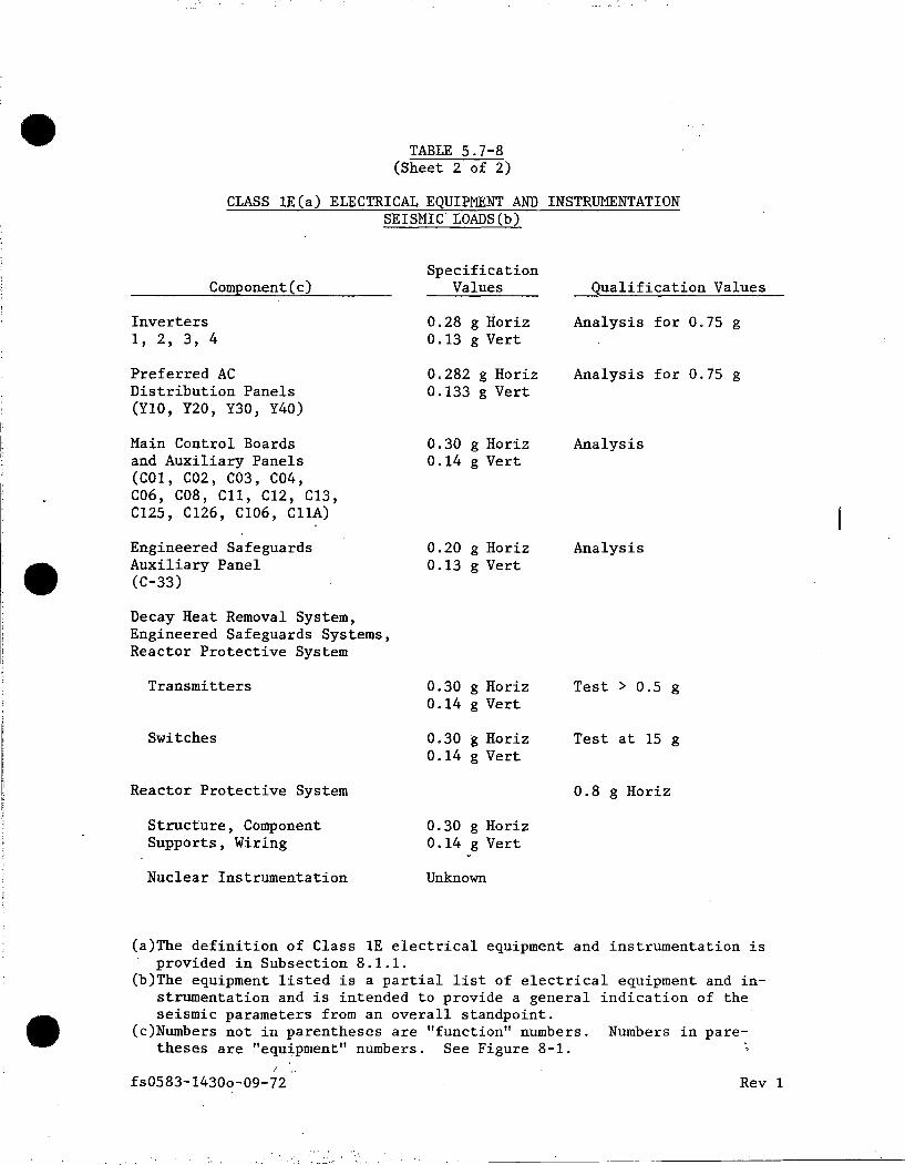
•
•
•
TABLE 5. 7-8 (Sheet 2 of 2)
CLASS lE(a) ELECTRICAL EQUIPMENT AND INSTRUMENTATION SEISMIC LOADS(b)
Component(c) Specification
Values Qualification Values
Inverters 1, 2, 3, 4
Preferred AC Distribution Panels (YlO, Y20, Y30, Y40)
Main Control Boards and Auxiliary Panels (COI, C02, C03, C04, C06, COB, Cll, C12, C13, C125, C126, CI06, CllA)
Engineered Safeguards Auxiliary Panel (C-33)
Decay Heat Removal System, Engineered Safeguards Systems, Reactor Protective System
Transmitters
Switches
Reactor Protective System
Structure, Component Supports, Wiring
Nuclear Instrumentation
0.28 g Iioriz 0.13 g Vert
0.282 g Horiz 0.133 g Vert
0.30 g Horiz 0.14 g Vert
0.20 g Horiz 0.13 g Vert
0.30 g Horiz 0.14 g Vert
0.30 g Horiz 0.14 g Vert
0.30 g Horiz 0.14 g Vert
Unknown
Analysis for 0.75 g
Analysis for 0.75 g
Analysis
Analysis
Test > 0.5 g
Test at 15 g
0.8 g Horiz
(a)The definition of Class-IE electrical equipment and instrumentation is provided in Subsection 8.1.1.
(b)The equipment listed is a partial list of electrical equipment and instrumentation and is intended to provide a general indication of the seismic parameters from an overall standpoint .
(c)Numbers not in parentheses are "function" numbers. Numbers in paretheses are "equ:j.pment" numbers. See Figure 8-1.
fs0583-1430o-09-72. Rev 1

•
••
•
Tank ·
Concentrated Boric Acid (T-53A, T-53B)
Condensate: Storage (T-2)
Iodine Removal Hydrazine (T-102) and Iodine Removal Makeup Sodium Hydroxide (T-103)
Miscellaneous Drain (T-60, T-70, T-74, T-76, T-80)
Miscellaneous Shop Fabricated (T-4A, T-4B, T-5, T-28 T-29, T-63, T-66A, T-66B, T-67, T-68A, T-68B, T-68C, T-69)
Volume Control (T-54)
fs0583-1430p-09-35
TABLE 5.7-9
CLASS 1 TANKS SEISMIC LOADS (g)
Specification Values Horizontal Vertical
0.35 g 0.50 g
0.10 g 0.20 g
0.176 g 0.352 g
0.228 g 0.418 g
0.16 g 0.30 g
0.35 g 0.50 g
0.24 g 0.33 g
0.07 g 0.133 g
0.076 g 0.152 g
0.067 g 0 .133 g
0.07 g 0.14 g
0.24 g 0.33 g
Earthquake
OBE SSE
OBE SSE
OBE SSE
OBE SSE
OBE SSE
OBE SSE
Rev 0

•
•
•
This long-term cooling modification uses portions of the HPSI and the PCS. The hot-leg injection piping connects the HPSI Train 1 header and the HPSI Train 2 header to the PCS hot-leg drain line. All components of the long-term cooling modifications located inside the containment are Seismic Category I and are designed in compliance with the requirements of ANSI/ASME B31.l-1980 and ANSI Nl8.2-1973. These components are capable of withstanding a 40-year integrated dose, plus a design basis accident dose of 0.2 x 10⁸ rads for gamma radiation and 1.8 x 10⁸ rads for beta radiation.
6.1.2 SYSTEM DESCRIPTION AND OPERATION
6.1.2.1 General Description
1. Emergency Core Cooling
Borated water is injected into the Primary Coolant System by the safety injection tanks and the high- and low-pressure safety injection pumps. The components and the flow paths are shown on Figures 6-1 and 6-2.
The borated water in the elevated safety injection tanks is at safety injection and refueling water (SIRW) tank concentration range of 1,720 to 2,000 ppm boron; the tanks are pressurized with nitrogen to greater than 200 psig. They are connected to the Primary Coolant System cold legs through isolation valves which are normally open and have had the electrical power removed from the valves' electrical system in order to meet the ECCS single failure criteria.
Two check valves prevent primary coolant from entering the tanks. Injection will occur whenever the primary system pressure falls below the combined pressure of the static waterhead plus the tank gas pressure.
Following injection of water from the Safety Injection Tanks, core cooling is provided by the safety injection pumps. The safety injection pumps are started automatically by a safety injection signal {SIS) which is supplied by the engineered safeguards control system (see Section 7.3). Flow from the low pressure safety injection pumps is ensured since the shutdown cooling heat exchanger bypass valve is normally locked open and has had the air supply removed in order to meet the ECCS single failure criteria.
The safety injection signal also opens certain valves, as shown on Figures 6-1, Sheet 2. Borated water at a minimum concentration of 1,720 ppm boron is initially pumped from the SIRW tank to the Primary Coolant System. In 1979, a system valve modification was made to eliminate a potential deficiency that could, with the failure of one of the emergency diesel-generators, limit available high-pressure injection to two of eight paths. The modification involved switching the electrical power sources between the isolation valves on the high-pressure and redundant high-pressure injection lines going to Primary Coolant Loops 2A and 2B. In addition, two upstream valves had their normal positions changed to provide train separation .
6.1-4 Rev 12

•
•
•
d. Flow
Shutdown cooling and total low-pressure injection flow rates are measured by an orifice meter installed in the low-pressure injection header. Flow rate is indicated in the main control room. The flow element also transmits a signal to a controller which will provide automatic flow control during shutdown cooling operation. Each of the four cold leg low-pressure injection branch lines and each of the four cold leg high-pressure branch lines is equipped with flowmeters which can be used to balance injection flow rates. The hot leg injection lines also have flow indication.
A flowmeter installed in the safety injection test and leakage return line is used during operation tests of the Safety Injection System.
6.1.2.3 Operation
The Safety Injection System is used during various Plant operating modes as follows:
1.
2.
Normal Operation
During normal Plant operation, there are no components of the system in operation. All components are on standby for possible emergency operation.
Start-Up and Shutdown
The shutdown cooling fu~ction may be used during the early stages of Plant start-up to control the primary coolant temperature. As the primary coolant temperature approaches 300°F and the primary coolant pressure approaches 270 psia, this function is discontinued, and the system aligned for emergency operation.
The shutdown cooling function of the system is brought into use when the primary coolant temperature falls below 300°F and the primary coolant pressure falls below 270 psia. At this time, the system must be realigned for shutdown cooling. In 1982, per NUREG-0737, Item 11.B.2,
. Valves MV-3189, MV-3190, MV-3198 and MV-3199 were given motor operators to provide for remote realignment for shutdown cooling due to potential high radiation in the area. Subsequent to installation of motor operators, designation of valves was changed to M0-3189, M0-3190, M0-3198 and M0-3199 .. Realignment consists of unlocking and opening four valves on the low-pressure pump suction, closing the valves in the low-pressure pump suction line from the SIRW tank, unlocking and opening the two crossover valves from the low-pressure pumps to the shutdown cooling heat exchangers and locking the manual valves in the spray header lines closed. Prior to placing the system in operation, the boron concentration is verified at various points in the system. During the early stages of shutdown cooling, the cooldown rate is controlled by limiting the flow through the tube side of the heat exchanger. In order
6.1-12 Rev 14

• 3.
to use this valve, it must be unlocked, its air supply returned to service and its flow controller placed in automatic operation.
Shutdown After Fire
10 CFR 50 Appendix R requires the ability to safely attain hot shutdown after a fire in the 590-foot corridor of the auxiliary building. In order to do this under the criteria of Appendix R, the output of Containment Spray Pump P548 must be connected to the inlet of HPSI Pump P-668. (The higher pressure then delivered by the HPSI Pump ensures adequate subcooling and allows PZR level to remain within indication.) CV-3070 controls the flow between P548 and P-668 and is air-to-open. Normally, an air supply and the operability of SV-3070 to control that air supply are required to open CV-3070. Under worst case postfire conditions following a 590-foot level corridor fire, normal air supply may not be available and SV~3070 may not be operable; therefore, an alternate air supply which can be manually controlled is required. A nitrogen backup station equipped with minimum 2,000 psig nitrogen bottles, located in the turbine building, provides 90 psig N~ backup to the air supply to CV-3070. A manual bypass valve, normally ~losed, provides a means to open CV-3070 in the event that SV-3070 becomes inoperable due to a fire in the 590-foot corridor.
4. Emergency Operation
• a. Safety Injection
•
Safety injection is automatically initiated upon receipt of a safety injection signal (SIS). The SIS starts the high- and low-pressure injection pumps, opens the safety injection valves and closes the primary system check valve leakage paths. The rest of the system is always aligned for safety injection during power operation. The safety injection tanks will discharge into the primary system when the pressure drops to approximately 240 psig.
Motor-operated valve and system piping design are such that safety injection flow will be distributed approximately equally between the four PCS cold legs. No throttling of motor-operated valves or other operator action is required to distribute flow.
b. Recirculation
When the water in the SIRW tank reaches a predetermined low level, the recirculation actuation signal (RAS) is initiated on coincident 1 out of 2 (taken twice) low-level switch actuation. The RAS opens the containment sump valves, closes the SIRW tank valves, stops the low-pressure pumps and provides a permissive to manually close the valves in the pump minimum flow lines. The minimum flow-line valves have also been provided with an isolation contact and redundant position indication in the control room to meet single failure criterion. The stroke time on the supply valves is set up to ensure an adequate overlapping stroke in order to provide a continuous supply
6.1-13 Rev 14

•
•
•
6.3 CONTAINMENT AIR COOLERS
6.3.1 DESIGN BASES
The function of the containment air recirculation and cooling system (see Figure 9-17) is to remove heat and vapor from the containment atmosphere during normal Plant operation and, in the event of a DBA, to limit the containment building pressure rise and reduce the leakage of airborne radioactivity by providing a means of cooling the containment atmosphere.
The containment air recirculation and cooling system is independent of the Safety Injection and Containment Spray Systems, and is completely redundant to the Containment Spray System. It is sized such that three of the four units will limit containment pressure to less than design pressure following a DBA LOCA as discussed in Section 14.18.1. For purpose of design diversification for greater reliability, electrically, three fan units are aligned with one containment spray pump, while the fourth fan unit is aligned with the remaining two containment spray pumps.
All system components are de~igned to withstand CP Co Design Class 1 loadings as described in Section 5.2.
6.3.2 SYSTEM DESCRIPTION AND OPERATION
6.3.2.1.General Description
The containment air recirculation and cooling system includes four air handling and cooling units located entirely within the containment building. Plant service water from the critical service water header is circulated through the air cooling coils.
Each cooler consists of eight coils piped to manifolds for supply and return connections to the Service Water System.
The service water supply line for each cooler has an air-operated stop valve which is normally open and de-energized. The return line for each cooler has an air-operated discharge valve which is normally held closed and a modulating temperature control valve in a bypass line around the closed discharge valve. The discharge and supply valves may be manually operated from the main control room and the engineered safeguards local panel. The control valve is operated by a pneumatic signal from a temperature controller in the cooler discharge. The temperature control valve for VHX-4 is failed closed. Air is drawn through the coils by two matched vaneaxial fans with direct connected motors. One fan motor is rated for normal operating conditions and the second is rated for post-OBA conditions. The fan motors rated for the post-DBA condition are fed.from the emergency power buses. All fans may be manually started or stopped from the main control room or at the individual breakers.
Replaceable air filters are located in eath cooler ahead of the coil bank to maintain coil surface cleanliness .
6.3-1 Rev 14
•
•
•
Gravity-operated dampers are installed in each fan discharge to assure that the airflow will not short circuit back to the fan inlet plenum when only one fan is operating.·
Each cooler has a sump with a drain, a liquid level switch and an overflow valve. Normally, very little water will be condensed from the air and the small amount will easily flow out through the drain. If a cooling coil leak or steam leak occurs to cause a flow through the drain greater than 20 gpm, the level in the sump will rise to the liquid level switch and initiate an alarm in the control room. A sketch of this arrangement appears in Figure 6-4. During post-DBA operation, water flows of over 150 gpm will flow through the overflow valve.
The NRC granted Palisades relief from Section XI of the ASME Code for making non-code repairs to three containment air coolers until the coolers are replaced by the end of the 1996 refueling outage {Reference 13). Non-code repair was also approved for the fourth cooler, which previously had been replaced. The non-code repair, designed to meet mandated zero leakage after hydrotest, installs a clamp with an epoxy sealant on leaking joints upon discovery of leakage, regardless of the operational mode of the cooler. The clamps may be added up to the weight permitted by seismic calculation. Code repair of the coolers is impractical because rebrazing leaking connections fn 'the coils has resulted in adjacent tube-to-manifold connections becoming heat affected, creating additional leaks in previously non-leaking connections .
Ratings and materials of construction are shown in Table 6-8. Service water flow is shown in Figure 9-1.
6.3.2.2 System Operation
1. Normal Operation
Four units are normally in operation with two fans in each unit operating. Each unit cools with service water controlled by a temperature control valve and/or high-capacity valve on the discharge piping. Containment temperature is maintained through combined operation of containment air cooler fans and the positioning of the service water valves. During normal operation, the service water flow is modulated by temperature control valves, and if necessary, the high capacity discharge valves .. FC-713 failed VHX-4's temperature control valve closed; however, VHX-4 can still be used for normal cooling by opening its high-capacity discharge valve. Refer to Table 6-9 for containment air cooler performance data during normal operation.
2. Plant Shutdown Operation·
During Plant shutdown, all cooling units continue to operate as in normal operation .
6.3-2 Rev 14

•
•
•
6.4 IODINE REMOVAL SYSTEM
6.4.1 DESIGN BASIS
The iodine removal system acts in conjunction with the Containment Spray System to reduce the post-accident level of fission products in the con tainment atmosphere. The initial system provided for the addition of sodium hydroxide {NaOH) to the water from the SIRW tank after an LOCA to provide for both iodine retention and neutral pH control. Pursuant to commitments made in Amendment 31 to the Operating License DPR-20 and described further in Amendment 40 to the operating license, the iodine removal system was modified to provide for automatic addition of hydrazine rather than NaOH_for purposes of iodine retention. The sodium hydroxide feed was retained, however, for long-term control of pH in the spray water; initiation is manual.
6.4.2 SYSTEM DESCRIPTION AND OPERATION
6.4.2.1 General Descriotion
The chemical injection system for iodine removal is shown in Figure 6-2. _An iodine removal hydrazine tank and an iodine removal makeup sodium hydroxide tank are provided with redundant tank heating and temperature controls. Redundant indicator alarm devices for level ~nd temperature are provided as well as pressure indicator alarms. The tanks are located adjacent to the SIRW tank on the roof of the auxiliary building. Hydrazine and sodium hydroxide solutions are fed through two sets of parallel headers to the suction headers of the low-pressure and high-pressure safety injection pumps and containment spray pumps. Each header for the iodine removal hydrazine tank is provided with two locked open gate valves, a normally closed power-operated valve and one check valve. Each header for the iodine removal makeup sodium hydroxide tank is provided with one locked closed gate valve, one locked open gate valve, one normally closed power-operated valve and one check valve.
The piping for the chemical injection system is arranged to maintain required separation to the safety injection and containment spray pumps by location of the pumps in separate rooms. The control systems for the power-operated valves feeding the pumps in each engineered safeguards room are independent. The tanks, piping and valves are fabricated of stainless steel and carbon steel. The piping exposed to the environs is redundantly heat traced.
The iodine removal hydrazine tank contains 270 ± 17 gallons of 15.5 ± 0.5% by weight of hydrazine solution with a nitrogen cover gas pressure of 11.2 ± 2 psig .
6.4-1 Rev 14

• 6.4.2.3 Materials
•
•
The materiaJs of the equipment and components of the Emergency Core Cooling . Systems have been examined for compatibility with the sodium hydroxide and
hydrazine solution and are adequate for extended operation in contact with this solution. The components and materials are listed in Table 6-11.
Service Water Valves
Body - Carbon Steel ASTM A 216 WCB
Operator Enclosure - Cast Iron
Containment Air Cooler Fan Blades
The fan blades are aluminum and would be affected by this solution if exposure were credible. Exposure is not considered possible since the fans draw suction from the steam generator compartments which are covered and, therefore, not exposed to the spray water. Any droplets carried into these compartments will first pass through an inlet filter and then are passed over the coils. The filter will remove most of these droplets and the coils will remove the balance. Any droplets passing through the filter will be intercepted by the coils and diluted by the condensate on the coils. Any droplets which might escape the coils will be considerably diluted; further, the low velocity in the fan inlet plenum will allow any droplets which escape the coils to fall into the condensate collection chamber and the physical location of the fans in a vertical duct approximately six feet above the outlet of the coolers precludes the transport of droplets to the fan blades.
6.4.2.4 Paint
The paint systems used on the large surface area equipment inside containment were selected on the basis of withstanding the post-MHA environmental condition of 283°F, 55 psig, 100% relative humidity, borated water, an integrated dose of 2 x 10⁷ rads, and suitable heat transfer to the heat sinks.
To meet these requirements, the primary paint system selected was a Carboline Co inorganic zinc system, Carbo Zinc 11 primer and inorganic zinc finish No 3912. Inorg~nic zinc paint systems have been tested as follows:
I. Irradiated at 2.6 x 10⁶ R/h to a cumulative dose up to 1 x 10¹⁰ R as covered by ORNL Report No 3916 and ORNL Report No 3589 (see References 3 and 4). ~Th~ conclusions based on the results of the irradiation tests are that the inorganic zinc paint systems.will withstand the post-MHA radiation.
2. Subjected to 44 hours' test with samples submerged in a solution at 212°F, 1.33 HBO and 9.5 pH. Conclusions derived from the ORNL test data are that the inorganic zinc systems will withstand the post-MHA condition with negligible hydrogen production .
6.4-3 Rev 13

•
•
•
Repairs and replacements of ASME Classes 1, 2 and 3 components will be in accordance with the 1983 edition, Summer 1983 addenda of Section XI with the exception of repair of the containment air coolers (see Section 6.3.2.1).
System leakage tests, system functional tests, system inservice tests and system hydrostatic tests are performed in accordance with the 1983 edition, Summer 1983 addenda of Section XI.
6.9.2 PUMP AND VALVE TESTING PROGRAM
Inservice testing of ASME Classes 1, 2 and 3 pum~s and valves is done in accordance with ASME B&PV Code, Section XI, 1983, S83 as required by 10 CFR 50.55a{g), except where specific relief has been granted by the NRC. This testing provides assurance that these components will function if required.
6.9.2.1 Pump Testing Program
The inservice pump test program is summarized in Table 6-14. The pumps are generally tested per ASME B&PV Code, Section XI, Subsection IWP, except where acceptable alternative testing in accordance with 10 CFR 50.55a is allowed by the NRC. Complete details are contained in Palisades Plant Engineering Manual, Procedure EM-09-04, "Inservice Testing of Selected Safety Related Pumps."
6.9.2.2 Valve Testing Program
Valves are generally tested per ASME B&PV Code, Section XI, Subsection IWV, except where acceptable alternative testing, in accordance with 10 CFR 50.SSa, is allowed by the NRC. Complete details are contained in Palisades Plant Engineering Manual, Procedure EM-09-02, "Inservice Testing of Plant Valves."
6.9-2 Rev 14 e

·-
•
•
1.
2.
3.
4.
5.
6.
7.
REFERENCES
Combustion ~ngineering Report, "Palisades Long-Term Cooling Performance Evaluation," P-CE-5627, May 8, 1980.
Code of Federal Regulations - 10 CFR-50.46 and Appendix K.
Oak Ridge National Lab Report, "Unit Operation Section Orderly Progress Report," ORNL-3916, July-September 1965.
Oak Ridge National Lab Report, "Gamma Radiation Damage and Decontamination Evaluation of Protective Coatings and Other Materials for Hot Laboratory and Fuel Processing Facilities," ORNL-3589, February 1965.
Deleted
Deleted
Letter from Brian Holiari (NRC) to GBSlade (CPCo), "Safety Evaluation of the Second Ten-Year Interval Inservice Inspection Program Plan and Associated Requests for Relief for Palisades Nuclear Plant~" dated September 3, 1991 .
8. Combustion Engineering Inc, Cale No P-PEC-170, Dated January 16, 1979, "Head Losses and Flow Requirements for Hot Le~ Injection Line for Palisades."
9. Deleted
10. Letter from Kenneth W. Berry (CPCo) to NRC, "Response to Generic Letter 88-17, Loss of Decay Heat Removal (60 day Response)", January 4, 1989.
11 Letter from Kenneth W. Berry (CPCo) to NRC, "Response to Generic Letter 88-17, Loss of Decay Heat Removal (90 day Response)", January 31, 1989.
12 Letter from NRC to RCYoungdahl (CPCo) concerning boron precipitation post-LOCA, March 14, 1975.
13. Letter from NRC to GBSlade (CPCo), "Request for Relief from Specific ASME Code Requirements - Containment Air Cooler Repair", March 31, 1992.
6-1 Rev 15
(

•
•
•
TABLE 6-14
INSERVICE PUMP TEST PROGRAM SUMMARY
ASME Safety Test
Pum Class P&ID Procedures
P-7A, B and C - Service Water 3 M-213 Q0-14
P-8A - Aux Feed (Constant Speed) 3 M-207 M0-38 P-8B - Aux Feed (Variable Speed) Q0-21 P-8C - Aux Feed (Constant Speed)
P-56A and B - Boric Acid 2 M-202 Q0-18
P-SSA - Charging (Variable Speed) 2 M-202 Q0-17 P-SSB. and C - Charging (Constant Speed)
P-52A, B and c - Component Cooling 3 M-209 Q0-15
P-54A, B and c - Containment Spray 2 M-204 Q0-16/Q0-10
P-67A and B - LPSI and Shutdown Cooling 2 M-204 qo...:20
P-66A and B - HPSI 2 M-204 Q0-19
NOTE: See Engineering Manual Procedure EM-09-04, "Inservice Testing of Selected Safety-Related Pumps," for more detail on the pump test program •
FS0686-0564Q-TM13-TM11 Rev 7

" .. ..
• H
G
F
E
• D
c
• A
8 7
I' ·NlqHJ-3236
SAf"ETY INJECT ION TANl(S
I0-11 8 TRAIN H- 21113 Sii. 2
CONTAINH[NJ SPRAY RECIRCULATION
A TRAIN H-203 SH. 2 tC-11
CONTAINMENT SPRAY
H-203 SH. 2
CONTAINMENT SPRAY
(H-203 SH.2 ( a:-11
LP SAFETY INJECl ION
H·203 Sil. 2 ID··O
SHUTOO'lr'N COOL ING CROSSOVER
TO SHUTDOWN COOL ING LINE
THIS 0110 0::-11
~z-~I LC
2' - N 19HJ- 3234 Ii l C
LC (I' -NIJ0MJ-33'4B T
tD "--QillD CiC-10· I'
GC-10-1'
61 ·N26H3DA· 3225
A GC·l·B'
CONNECT ION TO SPENT
FUEL POOL
\ GC-1·8'
6 ' HC·23·61
I' ·N130H3·3378 COMPONENT
COOL ING WATER r-<H-20'1 SH.2(
llt-'~'-111------;'-... <H-61
E-60A 'i'
L!J '( I' ·Nl30HJ·J3B0 ) · VEST SAFEGUARDS
AOOH SLl4P H-211 SH. I
;;, -J :.. __!II\ ~ 'eJ'
ELD
ELD
(Tl\_ ~
cv?l'-Nl30HJ-ES 3382) r.i COMPONENT
COOLING WATER
r-<H-2B't SH.2(
E-608 t ) cu-6>
I' ·NI qHJ- 3394
WEST SAFEOUAROS ROOH SUHP
H-211 SH. I
5
@SHUTDOWN .l:illlU!'l.Q_
HEAT EXCHANGERS
GC-4-4'
reS ____ ~2-111 ~ Vo2-2e6
~ Vc
r
4
HP SAFETY ]NJECTION PUMP 0
E:Ji.68.
GC-10·3'
CONTAINMENT "SPRAY POMPS
I I I I
3
I '4' • N2'1H20R- 3206
GC-8· 14' ,
LO
~ I I I I I I I I I I I I
~~ I I
I I OR I j L--..-•-' ·---------· I I LC
2' -Nl30H3-3222
HC-l-14'
I I
2 SPRAY REC IRC TO S IRlll'
)M-204 SH. IB) CH-61
RECIRC TD SIRV H-204 SH. 18
CD·BJ
SIRV H-204 SH. 18
IE-71
C33
.. g
P668 SUBCOOL ING H-204 SH. 19
2~·
@'II'
uc-e-e· LC
CD-71
TEMPORARY CONNECT lON FOR SPENT FUEL POOL
COOL ING H- 221 lA-51
L __ {ij
<I ~ ~ ~ -
SIRW (M-2B4 SH. IB(
lA-7>
I t---, ik I Wc ~ C33t
~~ ~ 9~
i~ I' ·3163 ~~
GC-1-1• en
LC
---®--TR-0351 ~CC-BJ
CJJ
a; s
-{HV-ES-523) i:.I~ e !rz4 ~~:~ l ~ ~ l z Pl
l--'---{0J1q L•~jr:ii - ~ 0 ~ 9305"130068
• ~ ~~ pc ~
-------·-·-·-·-·-·---·-·-·!:;:/~".~·-·t·-·-·-·-·-·-·-·-·---·-·- ~5-6~.!-.,.~1 ----------------~-,..,--.--,,--! .. REMOVEO VL V. 605 PER OCR 'U 012 11 l ~~ ., ,,.,. NOTES1 ,
I. REFER TO 0110 H- 2B'J FOR SAFEGUARDS PUHPS COOLINO RCV OAT DESCRIPTION
2. REFER TO 0110 H- 211 FOR SAFEGUARDS ROOHS SUH PS CONSUMrns POWER COMPANY
f-:
li
F
L
D
c
3. REFER TO OllG N555-6q6- I fCE DWG 2'166·0- 32041 FOR L. P. SAFETY INJECTION PUMPS VENT ANO DRAIN PIPING.
4. REFER TO OWG N555-6'15- I ICE OllG 2'166-0-50821 FOR H.P. PALl~~'~i~T~~~~~~l\:LANT M~~4·1.0GN (: SAFETY INJECTION PUMPS VENT ANO DRAIN PIPING.
5. RfFER TO Pll DIAGRAM H-225 FOR CONTROL AIR SYSTEM DETAILS. 6. HCC-101·2' l HCC· 102-2' SHALL Bf TIED INTO EXISTING
PIPING AT EL 63'1' -0' LOCATE ROOT VALVES ADJACENT TO TIE IN FOR •WET TAP' IF REOU IRED.
i. ALL VALVE SUFFIXES ARE 'E51 ANO TAGGED AS BUil T l.lil...ESS OTHERWISE NOTED.
SI APERTURE
CARD
Aiso Available On Aperture Card
1'1
FSAR Rev 15
~ ·- ..

• H
G
F
E
• D
c
• A
CHARGING PUHPS
}H-202 SH. 18) CB-4)
cc-1-2•
/
~~ , _______ _
CC-6-6'
6
GC-10-J'
ENG. SFO.
( H-2~~H:H. I f-HC'-"-·,_1-_,_I'_,-=-,, lli-81
OC-1-'4'
GC-'4-4'
5
3' -NIJBMJOR-3203
LO
@HP SAFETY INJECT ION PUMP
f'..::..6.6fl.
4
ELD
--{ 61 • N234HJR-3183 )
~ H
-T- o e 'c
~ Cll
. ,., ~
3 2
CONTAINMENT SUMP
~ ------------- --~ - fi!J ~ ·- . - --~ ®@ @--~
CJJ
~ EVENT •---RECORDER I lQPENl
I H :~ _,_ • c •1 1. Ir> IN 1-I,', IX I
~L1_1 -:;
~ 4
L----"1.-+ ........ ------'----___,E+-+( E-Hc:-:;:;4.--DIRTY WASTE
DRAIN HEADER
NOTES1 I.REFER TO mm H-21a'l fOR SAFEGUl:\ROS PUMPS COOLING. 2. REFER TO OWG H-211 FDA SAFEGU~OS ROOMS SUMPS. J. REFER TO mm NSSS-6'16-1 ICE owo 2qs6-0·32BCl FOR l. P.
SAFETY INJECTION PUKPS VENT ANO ORAIN PIPING. 4. REFER TO mm NSSS-6'15-1 <CE OWJ 2"166-0-50821 FOR H.P.
SAFETY INJECTION PUHPS VENT ANO DRAIN PIPING.
H-211 SH. I
5, REFER TO P&I DIAGRAM H-225 Fffi CCJHROL AIR SYSTEM DETAILS. 6. HCC- IBl-2' 6 HCC-102-2' SHALL BE TIED INTO EXISTING
PIPING AT EL. 63'1' ·0' LOCATE RJOT VALVES ADJACENT TO TIE IN FOR 1 VET TAP' IF REQUIRED.
7.ALL VALVE PREFIXES ARE 'ES' Ai'41 TAGGED AS BUILT UNLESS OTHER WISE NOTED.
9sos1 a oo ss -/S PIPING & INSTRUMENT DIAGRAM
SAFC:TY INJECTION CONTAINMENT SPRAY ANO SHUTDOWN COOLING SYSTEM
I.
('
F
c
B
SI APERTURE l CARD fl;,>' A!so Available On
Aperture Card
-======---=or.!~~~---=-==---r~Ah1:f r-r L_ ___ s-----,-------=7----,--------=-s---.------;5;:::-----.-----4=-. -----,-'----;::;-3-----r-----:2;::;-.·.---'---r----. -. -Figure No 6-2 Sh 1 A FSAR Rev 1 !?

• 0
b
•• 0
0
PCP£JR.tl10N NQ & P&ID
(A-11
M·218
(C-1l
2
M-20~ M-207
IC-11
3 ..
M-20~ M-207
4
CC-21
5
M-207 M-220
6
M-207 M·220
7
M-207
B
M·207
9
M·207
(A·ll
10
M·212
SYS ICM
MAltt SlEAM L .. (
CSG.l-~J
-[AS1 -
MAIN 'Sl£AM Lit€
CSGE-~
-WEST-
SfEAM GENCAAtOA
([-50A) 8l0W00WN
STEAM GENERA10R
IE-5081 BLOW~WN
FEEDWATER TO
STEAM GENERATOR
IC-50AI
FEEDWATER 10
Sl[AM GEl€RATOR
IE-5081
AUX FEED .10
·STEAM---· GENERATOR 1£-~Al
SEAvicE AIR
ASSOCIATED COUIPMENT
OUJSIOE CONT.
CON"'fGUstATtON
ll.1111\IN[
1UA8tf£
ll .. IKlt.ICoi "-""' ""' 1
.
rLA.91 TANI< ll-291~ Bl.OWOOWN TANK . CY. 07 71 ll-29At STEAM NO GEt£RA10R Bl.OW- T &\ OOWN PUMPS (P- ..__,,---.:c.,r'CV-0767
:i::::!.c°~ LC 2° 1£-Jll Bl.OWDOWN DE.Mitt. lt\NK 11-1041. MAIN CONDENSER
!LASH WIK ll-291. • R El.Oit'OOWN lANK f to' Cl-2981 STEAM .---f'l C•·0'70 ClE1€AATOR Bl.OW- - "A> ~ . OOWN P.....,. IP- ..._T CY-0768 911AOBI l!l.OWOOWN HEAT EJ<CHA'IGER CC -lll Bl.OWOOWN DEMIH 1ANKIT-t04t MAIN CONl>I N"..f R
LC
\.r-~AM• I )
. c .. P
INSIDE CONT.
4.
t--f-... ·-r EB·9·Uf 7 18'-211111-01~02 t< 10
LC • "-f..746FW
CAP
MA1N rullf'\M's t;----f-.. 9 C8·9-iil" e 10· .
IP·IA&81 . 1
18'·N216A·07'@;1', IC 'Y•t LC
. -f~1rw
ASSOCIAUD (QUll'ME'Nl
S.lfAM Gf.HCRl\IOM
IE-50AI
SUl\M GEN(AAIOA
([·!>OBI
S1£AM Gr.Nl.RATOA IC·~Al
SIEAM GEN£11ATOA
IE-!>OBl
SIEAM GENERATOR
(C·!>OAl
STEAM
Gf.NEAATOR (£-!>OBI
[B8·6·1· AU• ~~'l".~'J • .-•C.P\0729 FWS (P·SAC Ba> 6·01i .. 0104 r~
au• rcEDF'L1'11' 1 / · 12· STE AM __ :: 9 GENCRATOA
IP·llc.l /' \ • 088+4· IE·~AI 'cee·1·&" LC E llO I 4
.. ·*~ t;55C'A AIR COMPRESSORS
IC-2A.l\&CJ, z'".~4~ ":'~~ AIR RECEIVERS ...- ...,. ..
(T-llA,B.&CI
\,;.4·-uv-120 rw5
SERVICE AIR
IN CONTAINMENT
CONTAINMENT PENETRATIONS
f1. .. 1AAllOt
NO & 1'&10
(C-2)
11
M-211
CONO£NsA.1r TO C.llllllC"CK'lllll(°,
5.1.JNfol 1'\tU(
t-----+·-------
12
M·20B
(ll
13
M-208
IC ·?I
14
M 109
---·-((. 21
15
M·209
SFRVI(( WAl[A
Sllf'l'I Y
SFRVI([ WA1fR
AE IU~IN
co.....-.c .. m Coot..ING wAtrA
IN
C.OMl'UJl NI COOllNG WAllA
OUI
.... ~OCIMFO (OUll'MfNI
CC>r\IOENSA.Tr 1RA...,.~£R
l'UMP (P U)
SrAv1cr WA1£A
f'UMf'S
II' 7fl.U.llCI
OUl!JtOf COOi CClfirK...1UAA.ll(lt.
~ \~i-'11 40I \. (~·0919
~ IK\26 \.~~-~
~ I
~ .
1' 11'i
'-l°·~?f><TS
"'" I"· ~J6A CO!o 1
ASSOCIAffO ((lUll'M(NI
!iHIEl COOL ING SUIC.C JAN<
ll·621
CONTAINM£NT
AIR COOlERS CVllX l,l'.1,1\ .. J
~-I·~~. ~ t;i.
l(),.:·1;~~ 10 g 2]R·411"1~ ........ ......,
v. I J-1-1.•~J ~ 1'.:,12sws-.......... uc. 1;t vi~. . ...
•IA••cr WAHR~ :...,, A./l 1Q' ~:·10864
(P·~~~~:CI C•·00,.,2•~~·h~. ~218·408 ~ Ii 614 •WS· -- 6~ 10·• 1_~-,'.""; •. ~ 611 •w• --- ·- ~ ""1° 6llA SWS·--- 12 '\:"'V·0861
\.-; 61•A •ws ...--.; I ~) R 218 •107 :~.-
~ -ltt 8'·216·409_./ · C•·087J
CONTAINMC NT
AIR COOl.£RS
CVliX· 1,2,1,&4,
C0Mf'ON(H1 con- -,,.-,-,[-l_D_C_OOl __ ING-i
IP'(; Wr\llA tt[AJ \_MJ .. 1J1 09IOCC tlCA1 FJICl&AtCi(R
l1'0tM¥.'-{R'S.1£·54A. \ t.Z\N') • 1[·64), LE11JOWN Bl COMroNCNT COOl· ·~ -T t-'i:t- HCAT UCtlA"Gf:A ltJGPl.MPSlP·fl2 --. i _._-... 10 \:~--IE·!liOl PRIMARY A,E\,C' C()t.;F()tEN1 LC cv.mi CC\OlANI Pl.MP
coo~ ING suqc.r - f &t7f:C Sf Al Ir !.OA,R.C,Ol TANK IJ·ll ,-.. -.~-~-tff-~N~l~CCQL.,,.,-~.------~~~---
11 .. , Wl\llW Ill Al
I .11.(111\HU 11',.ll-~41\0 l~ CCMUf.NI COOi.· ltlG PUMPS (P.!Ji2
A.B.C I. C[Mflf)N[NI coan.:; SURGE
!J1r1 o ron.tNC~
II Al I ICUll'INl;f U If N() 1£i IC·-!14l lf. llX)WN
LC COOl ANf PUMP
1----+-------+TAUK 11-ll
"-.11----.....---f·"'-r-'i~ •l"AT EXCHANGER cv.0940· ~ CV·OIZ;ll \:~ • CE-!Jiei PRIMARY
~ (. !tQecc SE Al CP 50A.B,Cpl
flA'iH JANK lf·19l EROWOCJNN TANK I 1-29Bt 'iTEAM C£tLAA10R Bl.CM'· OOWN PUMPS CP-98A&Bl BLOWOC'MN H( At [X· CllANC".(R lf·l1J, 8l0W· DOWN DlMIN (1·t04J,& MAIN CONOf.NSl A
CC·ll
16
M·207 M·226
(ll
17
18
Ste llM «.t¥ f.'ATOR
CE·!>OAJ R((IRCULATINC:.
CONTAl!-0-..t[NT
PAES~uRE (.,•T•o.J ....... 'r,..11>.1
FUEL TRANSFER
TUliC
.. ~...... rJ}-... -•t>c .... 41-----(~_.
SHAM GfNlRAtM
ll ~CIA)
P(N[ 1AA110t ASSOCl,,HD OIJ1'510£. • ~10[ ASSOCIA1[0 NO & P&IO SYSlEM [OUIP ..... Et-11 COHI CONr IGUAATI~ c0tn COUIPM£NT
t--:-:-,--t-Pf-A_"'_N~t«-l-+:-::...-,--•• -~-; ·;:~~ ~~: ~1 ,--=-r.C ·, · t 1r·f· :::· ;,~~. LOCK/ ~.~l~~·,. ~ ... I 1' - .
~~) ©l ML--il -·---' - --~ --,-1
20
21A
21
,.,
22
M·20J M·204
(ll
23
M·ZOJ M·204
24
IC·2l
25 M·210
(C·21
26
M·222
27
JJl lUt
(A·21
.28
29
·Sl'A.ffl · •
CPEOUND\N?) ti P SAFE1Y INJFCtlbN
t1.P. s•rcn INJlCl·ON
-SPARE-
Cl[ AN VJAS IE ACC.El~[.A
IANK-YfNI 105-1'.U'
Nl1ROGEN TO QUENCH t•NK
ILR1 rill LINE
CONIAIN1AE .. I AIR SAt.-,IPLE
-SPAf!E-
-""""'
mcv9
1RA N' £LO HIGtf pc;,cssUR£
SAF'f:TY l._.JfC llON
PUMP tP-6&a.A&CI
MAHI E XHAUSI FAN'i • 'J-8A&01
.•. ~~
-SPARE-
CLEAN WASIE REC( IV[ A I ANKS
l1·0•A.R.r.&n1
OU£NCH TANll IT·7JI SAFETY INJ£C TION TA ...
IT-112A,B,Cjl[f PRIMARY SYS1EM DRAIN TANKIT-741
CON SUM EAS POWER CO. CONTAINMENT PENETRATIONS SHEET 1 OF 3
9305130068 -17 "
.·.-

:a.· ... ~
•
•
•
PENETRATIOO NO & P&ID
(X)
30
M-203
(X)
31
M-203
(Xl
32
M-203 M-204
(C-3)
33
M-204
34
(B-2).
35
M-204
(B-1)
36
M-202
(C-2)
37
M-210
CC-2)
38·
M-21~
(C-3)
39
M-215
41)
40B "IJA
SYSTEM
CONTAINMENT SPRAY PUMPS
DISCHARGE·
CONTAINMENT SPRAY PUMPS
DISCHARGE
IDW PRESSURE SAFETY
INJECTION
SAFETY INJECTION
TANK CRAIN
-SPARE-
SHUTDOWN COOLING RETURN
LETDOWN TO PURIFICATION
ION EXCHANGER
ASSOCIATED EQUIPMENT
CONTAINMENT SPRAY PUMPS ( P- 54 AJJ.&Cl
CONTAINMENT SPRAY PUMPS (P-54A,E\&C)
OUTSIDE
CONT CONFIGURATION
INSIDE CONT
LC /TO PENE. N0.33
3f211:s ,..
,!..O..., ~--~~NC 12•
3258 1 Cv-3001
30 B"
~ 3226
LC f-3344ES
LC_ TO PENE NO. 33
3216
M0-3008 M: 3103ES
NO NO i--CONTAINMENT 3197 3196 ~0-30l0 SPRAY PUMPS SX·3336·t ~ IC 3118ES
(P-54A.E\&CI ./f'_EID T 16" M0-3012
~E~~ESSURE ;V-:x>06 l I - 32 12" NC 3133ES
INJECTION 10:) i--PUMPS (P-67A&Bl /!ll' CV ~0-3014~
ELC~ 3025 NC314&S
I) LC T-3163ES
TO PENE. NO. 35
SAFETY "-2--NLCl9M3-3234 /MV-~~A INJECTION ~ A.c r.=c AND REFUELING -- ..- ..,. ..- , 'C7 z· TANK (T-58) U:
MV·3J48A
&/ -SPARE-
LON PRESSURE. 8'-320~s,sxcE2044ftRV-3164 SAFETY -- ~ 3204 ELC LC INJECTION PUMPS 14"·3190~ ES
4.12• n ,..YI
CP-67A&0). & . 35
~12"~ SHUTDOWN 14" -M:lv~·MOV COOLING. HEAT LC f 3016E X>15ES EXCHANGERS ~ 34 (E-60A&B) 14"-3199ESS
FROM PENE. NO 32 RV-0401
ASSOCIATED EQUIPMENT
CONTAINMENT SPRAY
HEADER
CONTAINMENT SPRAY
HEADER
PRIMARY COOLANT SYSTEM
SAFETY INJECTION
TANKS ( T • 82 A.B.C;ull
PRIMARY COOLANT SYSTEM
PURIFICATION ION EXCHANGERS (T-'51A&Bl, DEBORATlNG ION EXCHANGER (T-52\ VOLUME CONTROL TANK (T-54} ·
PRIMARY COOLANT SYSTEM, REGEUERAT lVE HEAT EXCHANGER (E-56), & LETDO\oVN HEAT EXCHANGER (E·5B)
PRIMARY SYSTEM PRIMARY SY9TEM 403CWN N~. 12·
37 11:!· PRIMARY SYSTEM
DRAIN TANK CT-74l
DRAIN PUMP DRAIN TANK RECIRC PUMPS (P-71 A&Bl
CONDENSATE• RETURN FRoM
STEAM HEATING UNITS
CONDENSATE RECEIVER
(T-20)
CONTAINMENT HEAJING 9J1LER HEATING SYSTEM M- 8
FU """ ..... '°""'M lfltlP;O&[N
l">O"'ITI>9..I~
SEE SHEET 3 OF 3
l cv-1001
LC,_1"-503CRW
!©
NC:i!f\ ~"'P. r 12· ..--c~~~~150._:2-~-c~~~150l4-1..L..(:3 e
LC f·502VA
N NC."'P_ r --lf···l .~ BLIND FLANGE:' CV·1~3 ~~ii;Jij·E~WR LC 1:.503VA
OPERATION
2·
t 39 4'
REACTOR BLDG UNIT HEATERS (VUH-19,20.21,22,
23.& 24)
REACTOR BLDG UNIT HEATERS (VUH-19 ?O 21 22
23 & 24)
PENETRATION
NQ & P&ID
(C-2)
41
M-210
(C-2)
42
M-201
43•
CB-1)
44
M-202
(B-1)
45
M-202
(C-2)
46
M-211
(C-2)
47
M-210
IXl
48
M-210
(C-2)
49
M-210
CXl
50
(X)
51
(A-1l
52 52A 528
M-211
CONTAINMENT PENETR,tt.TIONS
SYSTEM
DEGASSIFIER PUMP
DISCHARGE
DEMINERALIZED WATER TO
QUENCH TANK
-SPARE-
CONTROLLED BLEED OFF FROM RCP'S
CHARGING PUMP
DISCHARGE
CONTAINMENT VENT HEADER
ASSOCIATED EQUIPMENT
OUTSIDE CONT.
CONFrGURATION INSIDE CONT
DEGASSIFIER PUMPS (P-6BA&.8) 3-N23BM2R llO ..... £ 'r
VACUUM i---f-.....t--,.---{::a_t--<;41 DEGO.SSIFIER 407CRW :V-1004
3·
(T-57) LC f-5(16CRW
T
ASSOCIATED EQUIPMENT
CLEAN WASTE RECEIVER TANKS
(T-64A,B,C,&D)
PRIMARY SYSTEM 2-V01558 i-¥:~2· MAKE-UP WATER r--f-....~ 42 • QUENCH TANK PUMPS (P·OOA&B) :V-01 5 2 (T -73)
. LC f-1126PC
T
12·
@ SPARE
~.<If'_ IKJ~2· \OLUME CONTRa. .... -i-{)'.x:J---,i:-- 44
TANK ( T- 54) c11·Zifi7 LC CV-2083 3/4"
LC ::~~g~~
PRIMARY COOLANT PUMP SEALS (P·50A,B,C,8.D)
CHARGING PUMPS r-of!::J 12• REGENERATIVE (P-55A,B,&C) ~-f--..._~ HEAT EXCHANGER
VO~~~E (~~~~T)RCJL CV-2111 2"-2110 . 2· lE-56), & REACTOR
WASTE GAS SURGE TANK
CT-67)
PRIMARY SYSTEM PRIMARY SYSTEM ~- l.O~ _....12· PRIMARY SYSTEM DRAIN TANK DRAIN TANK f-{:O:J----r-~ DRAIN TANK
PUMP SUCTION PUMPS (P-71A&B) CV-1007 C:V-1002 4 IT-74)
CONTAINMENT ISOLATION
AND SAFETY INJECTION
SIGNAL
CLEAN WASTE RECEIVER TANK
CIRC. PUMP SUCTION
EMERGENCY ACCESS
EQUIPMENT DOOR
CONTAINMENT SUMP DRAIN
TO SUMP TANK
[--_... V·l6oS.C. V·1•1!1t.
(Tt.ST C.Oo.ot.ILCTtOU
RECEIVER TANK CIRC. PUMP
(P-70
LC r:.5Cl2CRW
N~ I~ _t:Z'
Cv-1036 ~ LC LC 1:.513CRW
'i' f·514CRW~
CLEAN WASTE RECEIVER T At-4KS (T-64A,B,C,&D)
~2= --! 5·-lO" DIA. CAM OPERATED PRESSURE
Pl·:3404 \.:._J.fi ,.....,.:,_,;-;' =..!f.r EQUALIZING VALVE OPEN
t;,· f. l-j ~· WHEN HANDWHEEL IS IN ~-CAP~ 50 OPEN POSITION CLOSED
~·- :rLC WHEN HANDWHEEL iS IN ._. POVA -
14.cLOSED POSITION
FOR DETAIL OF PENS. 52, 52A, ~.CB & 56 SfE ONG. M-2.32 SH. 2A
(X)
53
M-204
(X)
54
M-204
CC-1)
55
M-207 M-226
56 M-211 SH. I
57
58
59
60
I
SYSTEM ASSOCIATED EQUIPMENT
OUTSIDE CONT CONFIGURATION
INSIDE CONT
CONTAINMENT SPRAY PUMP
SUCTION
CONTAINMENT SPRAY PUMP
SUCTION
STEAM GENERATOR
(E-508)
FLASH TANK (T -29) BIDWDO\oVN TANK (T·29Bl STEAM NC~ J GENERATOR BLOW- -~-----.< CV DOWN PUMPS (P-98 "i · 0738 AO.Bl BIDWDOWN -/
RECIRCULA~ION HEAT EXCHANGER IE-31) BLOWDOWN DEMIN TANK (T-104)
MAIN CONDENSER
12·
55 4•
CONTAINMENT SUMP LL!JEL
INSTRUM(N TATKlN
SEE PEN. 52 FOR SCHEM. ON .PEN. 56
SPARE <i!/ SPARE
SPARE @/ SPARE
SPARE
12·
@ SPARE
SPARE
12·
@ SPARE
ASSOCIATED EQUIPMENT
CONTAINMENT SUMP
CONTAINMENT Su MP
STEAM GENERATOR
CE-500)
1----_.;'_.;-----+-------------------~-------1. ~ I. ··~
61 I SPARE
12·
® I '
SPARE
62 SPARE ti.!/" r SPARE
,__ __ l ___ --+----------------f
63
(A·2)
64
M-221
SPARE
I
I REACTCR CAVITY I FILL & RECIRC.
12·
@ SPARE
FUEL POOL COOLING PUMP (P-51A&B) LC lt LC SPENT FUEL POOL~~. REACTOR CAVITY HEAT EXCHANGERS 120SFP 6 121SFP (E-53A&.0) LC f-514SFP
c!>
SI APERTURE ~.CARD Anso Available On
Aperture Card
-/8 Figure No 6-6 Sh 2 FSAR Rev 1..§,

•
•
•
7.4 OTHER SAFETY RELATED PROTECTION, CONTROL AND DISPLAY SYSTEMS
While the R,actor Protective System protects against reactor core damage and the engineered safeguards controls protect against a loss of coolant incident, other safety related (Class lE service) control and instrumentation systems ensure a safe shutdown of the Plant, protection of primary coolant fluid boundaries, mitigation of anticipated events such as loss of feedwater and uncontrolled release of radioactive effluents. In addition, Plant parameters critical to safety are monitored with Class IE instruments to ensure the operator can act in a timely fashion during abnormal conditions.
7.4.1 REACTOR SHUTDOWN CONTROLS
This subsection describes how the instrumentation and control features provided in the design, allow safe reactor shutdown in compliance with 10 CFR 50, Appendix A, General Design Criteria 19 and 21 and the Standard Review Plan (NUREG-75/087).
This subsection demonstrates compliance with Appendix R to 10 CFR 50 and 10 CFR 50.48 which became effective February 17, 1981, and which requires reactor shutdown capability independent of the damage (hot shorts and grounds) caused by a fire in critical areas. Refer·also to Section IV of the Fire Protection Program Report (FPPR), Safe Shutdown Analysis.
Critical areas, referred to as "postulated areas" i~ the following analysis, are defined as: the control room, cable spreading room, engineered safeguards panel room with adjacent stairwell, 10 switchgear room, and the corridor between the charging pump room and switchgear room 1-C.
The performance goals for achieving safe shutdown (to cold shutdown) in the event of a fire in postulated areas are met using CP Co Design Class 1 {and Class IE as applicable) systems and equipment described in Subsections 7.4.1.1 through 7.4.1.8. A fire in the southwest electrical penetration room containing the Auxiliary Hot Shutdown Control Panels C-150/C-lSOA has been analyzed as described in Subsection 7.4.1.9. Section 5.4 provides the analysis of flooding versus safe shutdown operation.
The Auxiliary Hot Shutdown Control Panels C-150/C-150A mentioned in the Section 7.4 analysis is described in Subsection 7.7.4. This panel is comprised of two enclosures: the main enclosure C-150 and an auxiliary one called C-150A. The safe shutdown analysis that follows combines these two enclosures into one entity called "Panel C-150."
7.4.1.1 Safe Shutdown Offsite and Onsite Power
Offsite and onsite power systems features corresponding to reactor shutdown are discussed in Chapter 8 .
7.4-1 Rev 13

•
•
•
------- -------1
needed. The charging pump will use either the safety injection and refueling water tank or the boric acid tank as the source of borated water to be injected into the reactor vessel. The charging pump will also inject water into the reactor vessel as necessary to maintain the proper water level in the vessel. The charging pump selected for use may be started at its circuit breaker and all valves in the system may be positioned manually.
The three charging pumps provide flow to the Primary Coolant System through: (I) the normal charging line, (2) the pressurizer auxiliary spray valve or (3) the alternate high-pressure safety injection (HPSI) line. A failure of Nonclass I control and instrument air disables flow paths to the pressurizer auxiliary spray valve. However, the other charging paths remain available and the boric acid pumps may be bypassed.
The Charging Pumps A and B are powered from Class IE 480 volt Bus I2, while Pump C is supplied with power from Class IE 480 volt Bus II. Power for charging Pump B can also be transferred to the power supply for Pump C due to a change made in October I989. The capacity of one charging pump is sufficient to compensate for coolant contraction during normal cooldown.
All electrically controlled valves are powered from Class IE buses. In addition, the motor-operated valves have manual overrides which permit local control if necessary.
The boric acid heat tracing and boric acid concentrated tank heaters are supplied from Nonclass IE power sources (480 volt Motor Control Centers 7 and 8) with backup from Class IE buses. The temperature of the boric acid in the flow lines is monitored by three redundant sensors, two indicators at local panels with alarms in the control room and the other indicator in the control room itself. Failure of the boric acid heat tracing system is covered by the alternate use of the SIRW tank.
I. Control Room Fire
Damage - Loss of offsite power, charging pump motor starting control circuitry, control circuitry to valves in a flow path from the concentrated boric acid or SIRW tank to the Primary Coolant System via a charging line.
Operation - Start the selected charging pump, at its circuit breaker if necessary, and open a flow path by positioning the necessary valves manually if necessary. All valves in the flow path can be positioned manually or fail-open on loss of air.
2. Cable Spreading Room Fire
Damage - Same as for a control room fire plus the loss of I25 volt de operating and control power to the 480 volt Class IE load centers and damage to the load centers .
7.4-3 Rev I2
I

•
•
•
In the event the fire causes the loss of normal control air, standby 2,000 psig nitrogen bottle systems with manifold and pressure reducers located in the turbine building 590' level and in the component cooling room will supply the steam valves, steam pressure regulating valve and AFW flow control valves for I2 hours. See Figure 7-54 for a typical interface of the normal air source and the I2-hour standby. The high-pressure air compressors onsite power source can be restored within I2 hours. The only electrical power required for control from the auxiliary shutdown control panel is I25 volt de. The source for this power and circuit routing to the panel lies away from the postulated fire areas.
Steam for operation of the turbine-driven auxiliary feedwater pump will be available from the steam generators if there is decay heat to remove. The code safety valves release the decay heat and are neither located in the postulated fire areas nor need power for their operation.
2. Cable Soreading Room Fire
3.
Damage - Same as that of the control room except that all the Class IE 480 volt power sources, the Class IE and Nonclass IE instrument power sources, the I25 volt de power sources (except the I25 volt de power and control source to the emergency generators, the Class IE 2,400 volt buses, the auxiliary shutdown control panel and Nonclass IE 480 volt Bus I3) are subject to partial or total damage .
Operation - The Auxiliary Feedwater System will be used as described for the control room fire.
Engineered Safeguards Auxiliary Panel Room or Corridor Between I-C Switchgear and Charging Pump Rooms Fire
Damage - Control circuitry to auxiliary feedwater valves and the turbine bypass and atmospheric dump valves. ·
Damage to the auxiliary f eedwater v a 1 ves wi 11 be very 1 i mi ted s i nee the control circuitry of the auxiliary feedwater valves, auxiliary feedwater turbine steam supply valve and the circuitry of auxiliary feedwater flow instruments are not routed via the postulated fire areas.
Operation - The Auxiliary Feedwater System will be used as discussed for the control room fire.
7.4.I.5 Pressure Reduction and Cooldown
In the transition from hot shutdown to cold shutdown, the decay heat is removed by feeding either steam generator via the Auxiliary Feedwater System with water from the condensate storage tank or fire mains using the steam-driven AFW pump as for hot shutdown. The steam produced is released to the atmosphere by means of a steam jet air ejector instead of being released by means of the code safety valves on the secondary system. Use of the steam jet air ejector is sufficient for timely transition from hot shutdown to conditions at which cold shutdown may be initiated. The air ejector is not located in the postulated fire areas.
7.4-7 Rev 14

• 7.4.1.6 Reactor Decay Heat Removal - Cold Shutdown
•
•
When the Primary Coolant System pressure has been reduced to below 250 psig, one of the two low-pressure safety injection pumps is started (if not already operating) in recirculation mode to provide shutdown cooling. The decay heat from the Primary Coolant System is transferred to the Component Cooling System via a shutdown cooling heat exchanger; in turn, the decay heat is transferred to the Service Water System via a component cooling water heat exchanger. It is expected that the cold shutdown condition can be achieved within 72 hours.
The systems and equipment that are used to take the reactor from the hot shutdown condition to cold shutdown are one low-pressure safety injection pump with motor and solenoid operated valves, one shutdown heat exchanger, one component cooling water heat exchanger, one component cooling water pump and one service water pump. Instrumentation is provided to indicate shutdown cooling return flow, service water pump flow, component cooling pump flow and component cooling surge tank level.
Analysis of fire damage in any of the areas containing portions of systems required for the shutdown cooling operation shows there will always be an undamaged power supply to one or the other of the shutdown cooling pumps (low-pressure safety injection pumps). The electrical operators and power supplies for powered valves may be damaged; however, valve alignment can be achieved manually. Availability of service water and component cooling water systems is described in Subsection 7.4.1.7 .
The performance goals are met for fires in the postulated fire areas in the same manner as for hot shutdown except as follows:
1. Control Room Fire
Operation - Manually position valves as required to line up the shutdown cooling flow path. Start selected low-pressure safety injection pump manualJy at its circuit breaker.
2. Cable Spreading Room Fire
Same as Control Room Fire.
3. Engineered Safeguards Auxiliary Panel Room or Corridor Between 1-C Switchgear and Charging Pump Rooms Fire
Damage - Control circuitry of certain control valves for shutdown cooling.
Operation - Valves that cannot be operated electrically can be positioned manually. The selected low-pressure safety injection pump to be used for shutdown cooling can be started in the manual fashion .
7.4-8 Rev 12

•
•
•
2. Design Description
Four Class lE AFW flow control channels are provided, fed from separate preferred ac sources, two for each steam generator {Figures 7-43 and 7-44). Two flow control channels relate to motor-driven AFW Pump A and turbine-driven Pump 8, while the other channels relate to motor-driven Pump C. In each flow control channel, a flow indicating controller maintains constant flow rates to the applicable steam generator and provides flow indication in the main control room. The four channels are physically and electrically isolated including fire barriers according to IEEE 384-1977. The channels' components are qualified to IEEE 323-1974 and IEEE 344-1975.
The AFW flow control valves activated by these channels are CP Co Design Class 1. The flow control valves corresponding to operation with the turbine-driven AFW pump have a 12-hour motive nitrogen supply (see Subsection 7.4.1.4).
For FIC-0727 and FIC-0749, the flow controllers keep the control valves shut until one of the AFW pumps is started (Figures 7-46 and 7-47). This is accomplished using two flow set points on the controllers, one for shutdown (valve closed) and one for operation (valve opened for predetermined flow). Set point switching is provided by the motor-driven pumps' circuit breaker auxiliary contacts and the turbine-driven pump steam admission valve controls auxiliary contacts on an OR logic basis. This design allows timely and smooth opening of the AFW flow control valves without operator intervention .
For FIC-0736A and FIC-0737A, the flow controllers keep the control valves shut until an AFAS signal is received. This is accomplished by the program in the controller. The program looks for a pump start signal and an AFAS signal before automatically opening the valves. This design allows timely and smooth opening of the AFW flow control valves without operator intervention.
A separate Class lE AFW flow indication channel for each AFW flow path (Figure 7-45) and a wide-range steam generator level indication channel for each steam generator are also provided allowing indication of flow independent from the control channel and monitoring of steam generator water level to cover all anticipated transients. These indication channels are qualified in the same way as the control channels and are also fed from preferred ac sources.
A "feed-only-good-generator" (FOGG) logic circuit {Figure 7-49) monitors the pressure differential between the steam generators using four independent and redundant Class lE pressure sensors on each steam generator. These pressure sensors are also used by the Reactor Protective System and main steam isolation circuits (refer to Subsection 7.2.3.8). Concurrent excessive differential pressure between steam generators and low level in the depressurized steam generator initiates isolation of the depressurized steam generator by closing corresponding motor-operated isolation valves in the AFW supply lines (Figures 7-50 and 7-51). Two-out-of-four (2/4) differential pressure logic is used in
7.4-25 Rev 12

•
•
•
coincidence with the output of the steam generator low-level logic described in Subsection 7.4.3.1. The isolation signal is generated through electronic bistable modules. Due to nuclear safety considerations, the automatic isolation feature of the FOGG system has been disabled and the operator is instructed by Plant Emergency Operating Procedures to manually isolate the affected steam generator (see Reference 5).
The motor-operated automatic isolation valves are supplied from Class IE 480 volt motor control centers. One isolation valve from each of the four discharge headers to the steam generators is supplied from the left channel of power and the other from the right channel to meet the single failure criterion.
Operation - Auxiliary feedwater flow indication, controls and isolation are normally from the main control room. In the event the control room must be evacuated, indication and controls can be taken over from either the Engineered Safeguards Auxiliary Panel C-33 or from the Auxiliary Hot Shutdown Control Panel C-I50, depending on the nature of the emergency (see Subsections 7.4.I, 7.7.3 and 7.7.4). The controls at the alternate locations are manual. The motor-operated isolation valves can be controlled locally at the valve by the operator.
If the pressure differential between the steam generators reaches the set point for actuation of FOGG circuit and the water level is low in one of the steam generators, the redundant FOGG signals close the motor-operated isolation valves to the depressurized steam generator. Due to nuclear safety considerations, the automatic isolation feature of the FOGG system has been disabled and the operator is instructed by Plant Emergency Operating Procedures to manually isolate the affected steam generator (see Reference 5). Isolation valve status is monitored in the control room. The FOGG circuit status is annunciated on the main control board (Figures 7-52 and 7-53}.
Testing - Testing of the flow control instrumentation is provided by actual system functional testing since the Auxiliary Feedwater System is used during normal Plant evolutions.
The FOGG logic circuit including bistable isolation modules is provided with test push buttons for test of the coincidence logic and isolation modules for on-line testing.
3. Design Evaluation
The performance of the AFW system can be assessed by the AFW flow indicators, two for each steam generator located in the control room and alternate stations outside the control room and a wide-range water level indicator for each steam generator. All components of the indication system are Class IE, seismically and environmentally qualified, and as such exceed the requirements of NUREG-0578/0737 .
7.4-26 Rev I2

•
•
•
7.5 NONSAFETY-RELATED REGULATING CONTROLS
7.5.1 DESIGN BASES
7.5.1.1 Reactor Regulating
Reactivity is controlled by a combination of chemical shim and CROM motion. Variation of the chemical shim (boric acid} concentration provides long-term regulation and control. The Chemical and Volume Control System is used to increase or decrease boron concentration with concentration being measured by chemical analysis and by information from a boronometer (see Subsection 9.10.2.6.12).
Control rod motion is used for short-term regulation. Sequential insertion or withdrawal of the control rods in the regulating groups is used for normal power regulation. During Plant start-up and shutdown and all cases where power is below 15%, manual control of the control rods is used.
Either of two independent channels may be selected to provide reactor average coolant temperature and a reference temperature value corresponding to turbine power. The reactor average coolant temperature and reference temperature values are displayed to operators who manually adjust primary coolant temperatures by moving the control rods.
The primary coolant average temperature is adjusted according to a preselected program. This program provides an average temperature which is linearly increasing with power.
Inputs to the temperature computing stations are primary coolant cold leg temperature, primary coolant hot leg temperature, and turbine first stage pressure. The temperature computing stations are two separate stations with each having separate inputs as listed above. Rod position instrumentation is covered later in this section and details of the CROM are covered in Chapter 3.
Control rods are grouped into shutdown, regulating and part-length groups. The shutdown groups are the first to be withdrawn on start-up and they remain withdrawn throughout power operation to provide a definite shutdown margin at all times. The regulating groups are manually positioned. The part-length control rods are manually positioned individually or by group and cannot be tripped. Alarms exist in the control rod position instrumentation to · annunciate deviation of control rods within any group except the part-length group. Any individual control rod may be positioned manually if required.
The part-length control rods are completely withdrawn from the core during power operation except for control rod exercises and physics tests. The insertion of part-length rods into the core, except for rod exercises or physics tests, is not permitted since it has been demonstrated on other CE plants that design power distribution envelopes can, under some circumstances, be violated by using part-length rods .
The regulating and shutdown control rods are inserted by gravity action (backed up by control rod rundown) on the receipt of a reactor trip signal.
7.5-1 Rev 12

•
•
•
The circuitry used for sequential control rod group movement is shown on the Rod Drive Control System Schematic Diagram, Figure 7-56. The insertion of the shutdown rods before the regulating rods is prevented by the contacts from the shutdown rod insertion permissive relays R/RSl through R/RS4 or the exercise band limit switches and contacts from the shutdown group relay R/ADl. A single failure could cause the shutdown rods to be inserted beyond the exercise limit prior to the insertion of the regulating rods, only in conjunction with the operator selecting the shutdown group for insertion. Simultaneous insertion of the regulating and shutdown rods could occur only by energizing the rod run-down relay. Failure of a single CROM clutch power supply "K" relay (Subsection 7.2.5.3) will not cause rod rundown. De-energization of either the shutdown (scram) or rod control bus will run down all control rods.
The simultaneous withdrawal of more than two groups of control rods could occur upon certain single failures in the control system. This could occur during the overlap period when two groups of rods are being withdrawn, so that the failure of the sequential permissive contact in the sequence relay circuit of a third group would permit three groups to be moving at once. Indication of the group(s) selected for rod motion and indication of the direction of rod motion for the group(s) selected is provided at the main control room console to alert the operator of a sequ~ncing malfunction (refer to Figure 7-56). An out-of-sequence alarm initiated from the primary rod position is provided to alert the operator of an out-of-sequence condition. The secondary position system also alerts the operator of an out-of-sequence condition, thus providing an independent alarm system. The failure of the sequential permissive contact in the sequence relay circuit is an independent failure relative to the reactor regulating system; and, therefore, a nonsequential withdrawal incident is not a continuous withdrawal. Thus, average primary coolant temperature and core power are limited to demand values during the incident.
Should more than two banks be withdrawn simultaneously, there are two aspects to consider: (1) reactivity addition rate and (2) effect on power distribution and, therefore, the DNB ratio. The reactivity addition rate will be increased but not exceed the maximum values shown in Figures 14.2-6 and 14.2-17. As shown in these figures, as reactivity addition rate is increased, the minimum allowable DNB ratio increases. An adverse effect must then come from a change in power shape relative to the shape applicable to the planned sequential withdrawal. Starting from full-power conditions, maximum bite, only two banks are inserted (Figure 3-3); and thus the three-group withdrawal incident cannot occur. Starting from lower power conditions, for example at 50% of full power, there are three groups inserted under maximum bite conditions; and at hot standby there are four groups inserted. Withdrawing various combinations of three banks during the overlap period, starting from these initial conditions, results in minimum DNB ratios greater than 1.3 .
7.5-12 Rev 14

•
•
•
It is possible for a rod group to be withdrawn out of proper sequence if certain single failures occur in coincidence with specific operational situations. This could occur during the overlap period when two groups of rods are being withdrawn so that any failure, such as the de-energization of the group relay which stops the movement of the leading group, will interrupt the planned sequence. The out-of-sequence alarm will be actuated in such an event. Again, the nonsequential withdrawal is not a continuous withdrawal.
The major difference between a sequential and a nonsequential withdrawal is their respective power distribution during the withdrawal. Therefore, in order to examine the potential consequences of a nonsequential withdrawal, cases were studied for initial conditions of maximum bite {Figure 3-3) for full power, 50% of full power and hot standby. For these initial conditions, the most unfavorable of nonsequential withdrawals were studied. The maximum total peaking factors are equal to or less than those assumed for the accident {sequential withdrawal) analysis of Chapter 14, except for the hot standby condition. For hot standby, the maximum total peaking factor may be several percent greater than for the nonsequential case. In all cases, the axial power peak is lower in the core {and therefore more favorable from a DNB ratio standpoint) for the nonsequential cases relative to the associated sequential power distributions. For all cases analyzed, the DNB ratio is greater than 1.3.
7.5.3.2 Primary Pressure Regulating
Two independent channels are available for automatically regulating the pressurizer heaters and spray valves. Either channel may be used to control the pressure in the system, and the output from both channels is recorded in the control room. Independent high and low alarms are provided.
7.5.3.3 Feedwater Regulating
For power above 25% full power, conventional three-element, feedwater control is used with fail-as-is, feedwater control valves. Manual override of the automatic control is always available. Manual bypass valves and feedwater stop valves provide backup for feedwater valve failure. For power below 25% full power, and to facilitate start-ups, a single-element feedwater bypass valve controller is used. Manual override of this automatic control is also available.
Feedwater pump speed control is by automatic or manual means.
The analysis of the main steam line break in the accident analysis of Chapter 14 assumes a feedwater flow reduction to< 5% of full power over 60 seconds after reactor trip. The feedwater regulating system will automatically ramp down the feedwater pump turbine drivers on turbine trip or reactor trip. Feedwater flow from the condensate pumps will be shut off via closure of the feedwater regulating and bypass valves on low steam generator pressure {< 500 psia). 500. psia is above the maximum condensate pump delivery head such that the maximum of feedwater delivered to the steam generator will be no greater than that assumed in the safety analysis.
7.5-13 Rev 14

•
•
•
Accurate measurements of reactor power output use the feedwater flow instruments as a base for calorimetric calculations (see Subsection 7.2.3.2 for reactor power level measurement versus reactor trip function). These flow instruments' calibration is thus regulated by the Technical Specifications.
7.5.3.4 Pressurizer Level Regulating
Two separate level control channels are provided with redundant level transmitters and controllers. Only one channel is used during operation. The controllers are located in the control room. Control can be accomplished by either automatic or manual operation. Three charging pumps and three letdown orifice valves provide redundant means of increasing or decreasing primary coolant water inventory. The variable pressurizer level control program maintains primary coolant discharge and addition required during Plant load changes.
The pressurizer level control system is sufficient to protect the Primary Coolant System fluid boundaries without a reactor trip on high pressurizer level to protect against a water solid condition. If a malfunction is suspected in the operating channel, operation can be switched to the other channel. If a failure of the controller output is postulated, a large "program minus actual level" difference will result. This will cause two orifice stop valves to close and will start all three charging pumps. When the pressurizer level increases 4.63 above the programmed level, two charging pumps will be secured and the two orifices' stop valves reopened. This failure will not result in a filled pressurizer.
If a failure in the level transmitter is postulated, a low-low level signal is initiated causing all orifice stop valves to close and all three charging pumps to operate. In order to fill the pressurizer, this condition would have to exist unchecked by operation action for a period of about 30 minutes (time required to fill the 700-ft3 steam space in the pressurizer). During this period, an alarm would sound alerting the operator to the mismatch between charging and letdown flow. Also, a low-level alarm from the volume control tank would sound. (There are about 3,600 gallons stored in the volume control tank, and over 5,000 gallons are required to fill the 700-ft3 steam space.) Continuous operation of the charging pumps is indicated by lights in the control room. The operator can switch to pressurizer level control Channel B (assuming Channel A is in service at the time) to determine if the reason for the extended charging operation is caused by a malfunction of the level transmitter. The operator can manually secure the charging pumps when the problem has been diagnosed, or allow the backup channel to assume control.
Assuming that no operator action was taken, and the pressurizer continued filling with water, and pressure continued to rise, the pressurizer pressure control system will maintain pressure at about 2,180 psia. At 1,700 seconds after the transient is initiated, the spray nozzle, which extends about 2 feet from the top of the pressurizer, becomes submerged by the rising water and is no longer effective (the effectiveness of the spray is reduced even before submergence of the spray nozzle, owing to the shape of the spr}Y extending from the nozzle). At the level of nozzle submergence, a 40-ft steam space remains at the top of the pressurizer. A simplifying and conservative assumption invoked for this analysis is that pressurizer pressure is
7.5-14 Rev 14

•
•
•
maintained at 2,180 psia until it is completely filled, thereby neglecting the mitigating effect of the 40-ft3 steam space in minimizing pressure during the incident.
After the pressurizer fills, it is assumed that all three charging pumps continue to deliver water into the Primary Coolant System at the maximum rate of 120 gpm and that all letdown orifices remain closed. The time required to increase system pressure from 2,180 psia to reactor trip pressure of 2,255 psia is approximately 2 minutes (owing to the compressibility of one-half million pounds of water at 578°F, more than 1,000 pounds of additional water is required to raise system pressure 220 psi).
Following the high pressurizer pressure reactor trip signal, the control rods are inserted 90% of travel within 2.7 seconds. The turbine admission valves are closed at 0.3 second, and all rods are fully inserted. Although the steam dump and bypass valves will open following turbine trip (and thereby reduce the pressure increase in the steam generator and subsequently reduce the increase in primary system temperature), credit is not taken for such action in this analysis. The maximum increase in the average temperature of the primary system following trip of the reactor and turbine is less than 0.5°F. This energy increase in the Primary Coolant System results in a Primary Coolant System pressure transient as shown on Figure 7-61. The maximum pressure increase is 26 psi and occurs approximately 4 seconds following trip. Since reactor outlet temperature is decreasing during the entire transient following trip, the primary system temperature increase is due entirely to the increase in steam generator pressure, causing an increase in primary coolant temperature exiting from the steam generators.
At four seconds following reactor trip, core heat flux is decreasing at a faster rate than primary coolant temperature exiting from the steam generators is increasing; and therefore, the Primary Coolant System pressure begins decreasing as shown in Figure 7-61.
If it is postulated that the pressurizer fills solid with water, owing to a malfunction in the pressurizer level control system concurrent with the assumption of no operator response to the various alarms and indications available, the maximum Primary Coolant System pressure during the transient is well below the hydrostatic test pressure of 3,125 psia. Because of the rapid response of the reactor protection system in causing a reactor trip at 2,255 psia, and becau~e of the large hea~ sink supplied by the 241,000 pounds of liquid stored in the steam generators, the maximum pressure during the transient is 2,426 psia; and operation of the pressurizer safety valves is not required.
7.5.3.5 Steam Dump and Bvpass
The steam dump valves can be operated from either the control room or from the engineered safeguards local panel. Automatic or manual control is provided at the control room station .
7.5-15 Rev 14

•
•
•
Inadvertent opening of the atmospheric dump valves is prevented by requiring that the turbine stop valves be closed before the dump valves. can be opened. Excessive primary system cooldown by the dump valves when in automatic control is prevented by a narrow-range Tavg temperature signal which has a minimum output corresponding to 515°F.
Turbine bypass is available whether the turbine valves are open or closed and will limit the maximum steam pressure to 900 psia during hot standby.
7.5.3.6 Turbine Generator Controls
The electrohydraulic control used, is a conventional control system with many unit-years of operating experience. This type control has been refined and has proved to be very reliable and superior to earlier controls.
With the redundancy and safety features designed into the turbine control and protection system as described below, the probability of turbine overspeed occurring is very remote.
The steam required to produce turbine overspeed has to come from either the main steam system or flashing from feedwater heaters and moisture separators after a turbine trip. All feedwater heaters with sufficient energy to overspeed the turbine have extraction nonreturn valves and the moisture separator outlets have intercept valves to limit steam flow following a turbine trip. To have an uncontrolled source of steam from the main steam line, all of the following turbine control devices would have to fail:
1. Main governor and governing valves.
2. Overspeed protection controller. This is an acceleration response device which closes the turbine main governing valves and moisture seperator intercept valves.
I 3. Mechanical overspeed trip. This is a centrifugally actuated device which trips the turbine main stop, control, reheat stop and intercept valves (16 valves total).
The main governor and overspeed protection controller both control highpressure fluid system which provides the motive force to operate the turbine steam valves. The high-pressure fluid system consists of duplicate oil pumps, filters and heat exchangers. The fluid reservoir is stainless steel to minimize the possibility of contamination.
The mechanical overspeed trip actuates the auto stop oil system which uses turbine oil as the control medium and is separate from the high-pressure fluid control system used for the main and auxiliary governing systems.
The turbine main stop and governing valves, and moisture separator intercept and reheat stop valves are all spring-loaded to fail closed.
The turbine overspeed event has been analyzed in Section 5.5 .
7.5-16 Rev 14

•
•
•
I.
2.
3.
4.
5.
REFERENCES
Consumers Power Company, "Palisades Plant Reactor Protection System Common Mode Failure Analysis," Docket 50-255, License DPR-20, March 1975.
Consumers Power Company, Response to NUREG-0737, December 19, 1980 (Item II.E.4.2 - Special Test of April 15, 1980).
Gwinn, D V, and Trenholme, WM, "A Log-N Period Amplifier Utilizing Statical Fluctuation Signals From a Neutron Detector," IEEE Trans Nucl Science, NS-10(2), 1-9, April 1963.
Failure Mode and Effect Analysis: Auxiliary Feedwater System, Bechtel Job 12447-039, dated January 14, 1980, Letter 80-12447/039-10, File 0275, dated March 25, 1980 to Consumers Power Company's B Harshe (Consumers Power Company FC 468-3 File).
VandeWalle, David J, Director, Nuclear Licensing, CP Co, to Director, Nuclear Reactor Regulation, USNRC, "Proposed Technical Specification. Change Request - Auxiliary Feedwater System," September 17, 1984.
6. Zwolinski, John A, Chief, Operating Reactors Branch 5, USNRC~ to David J VandeWalle, Director, Nuclear Licensing, CP Co, "Amendment No 91 -Deletion of Technical Specification 4.13, Reactor Internals Vibration Monitoring," September 5, 1985.
7. Johnson, B D, Consumers Power Company, to Director Nuclear Reactor Regulation, Attention Mr Dennis M Crutchfield, "Seismic Qualification of Auxiliary Feedwater System," August 19, 1981.
8. VandeWalle, David J, Director, Nuclear Licensing, CP Co, to Director, NucJear Reactor Regulation, USNRC, "Supplement 1 to NUREG-0737, Safety Parameter Display System, Revised Preliminary Safety Analysis Report," August 21, 1985.
9. Berry, Kenneth W, Director, Nuclear Licensing, CP Co, to Director, Nuclear Reactor Regulation, USNRC, "Response to Request for Additional Information, Safety Parameter Display System," May 19, 1986. ·
10. Kuemin, James L, Staff Licensing Engineer, CP Co, to Director, Nuclear Reactor Regulation, USNRC, "Generic Letter 83-28, Salem ATWS Event, Item 1.2, Control Rod Position," May 5, 1986.
11. Thadani, Ashok C, Director, Nuclear Regulatory Commission, to Kenneth W Berry, Director, Nuclear Licensing, CP Co, "NUREG-0737, Item II.F.2, Inadequate Core Cooling Instrumentation," January 12, 1987.
12. DeAgazio, Albert W, Project Manager, Project Directorate III-I, USNRC, to Kenneth W Berry, Nuclear Licensing, CP Co, "Safety Evaluation for Generic Letter 83-28, Items 4.5.2 and 4.5.3, Reactor Trip Reliability, On-Line Testing (TAC No 54009), January 12, 1990.
7-1 Rev 14

•
• l I
I I
!
• \
---·----
STA PWR LOAD SHED W/STARTUP
START ENG.SAFEGUAEDS EQUIP.W/O STDBY PWR. PWR AVAIL DIESEL GENER.BKR.CLOSE ALARMS IREF. DWG. E·2<J31. TART DBA SEQUENCE START .NSD SEQUENCE
INPUT INPUT TEST VOLT.&
SIS .HO SIS LOAD SHED
rui. x1e.il s2At: ~55
~
- 7 2
11 ~1 ~ ··r·~., ~~~; ... TX-L TS-L 8 ,,. f ~'I,,, .. ,, ~ ea eu .· ......__ 12 I 1270-12 I
)C 'I )( 8 Ill
i ti.A. 'I t.l.1. 7 Tl27D-ll XI& W d 18 - ~ 2
> P~2 c t.l.1. ~ x D illli I a: SIS-3 lCI& eu IL
0 TEST 21 II ~ CONN LOAD E'ifDl 1'14-188 ;: Ct£ I( 22 12 z
fil D u
13 13 P3 I HC-34L182 HC-34Ll82 ~ ~ ~7
2 14 1860-1
LY LY SAFETY INJECTION l SEOUENCE LOADING CIRCUIT NO. I .!!..../~--------'
SCt£HE NO. S4I 12!1¥ DC BKR 72 J36''11--II'H ONE CF TWO IDENTICAL CIRCUI rs PNL D!l-2 11 Cl~ Tuz1541:.~
ADAPTER TABLE
DIESEL DIESEL GEN.BKR. S.l.PB 5Ct£HE PAEF SEO. ENGINE DESCRIPTION NO. LOCATION A.C. Q.OSE ·. u.v. RELAY twf. INIT. RESET BLOO<
S.I. l SEO. LOADING CICT. NO. I S41 . Au I CllQ. IC84L tc11tc22 Y3B 34-1,3,!I 1270-1 1860-1 PSI-I PB2-I P93-I
S.J. & SEO. LOAOING CICT. NO. 2 S42 Al2 I C86R I C04R I Cl3R I C26 Y28 34-2,4,6 1270-2 1860-2 PBl-2 PB2-2 PB3-2
• ADAPTER TABLE
SEAL-IN
1~ SEQUENCER
COHROL RESET
!BG0-1 14 ·~1860-1
1'11860-I
l;·;--a-
BUS
SIS ALARMS SIS BLOCK SAF.ETY INJECTION SPARE
INniATION CICTS. U.V.
1! · lb :t-.·:t'8·<t'8-L .&!.- l- f Ml •.t •.t - .t• .
TXB-L ·-T~
61 !II XB-L
18
'I l XB-R
;rXB-L 12f
11!
41 5 I SIS-I
l SIS-6 --- 18 . 2 f2
~,------,.____
XB-R
12l INTE:RLOCICS
1~ . "I ! s1s-x1 ! 385L
TU=~~ T Pl,Pl2
----..-.----SEE owe;,, SEE DWG. SEE DWG. ~~8'1 N0.~~8<J NO. E-121
C!3R ISCHEME S421
NORM
1 1 ~ ~ON
3 I ALARMS IE-2'12 SH. 21 -.i ~SEO. TEST
TSIS-XB 'll 1860-1 • OFF + . I i..:y
seRV. wtR. DIESEL ~i:1111115 MC-16 h~- ~r-i 31.961H_ 1 I:! I 1 ~0
. PP. P7C GEN. BKR.. 34R1117~34L1117 ---,a:-r_J ~ --'-SEE DVG. SEE DWG. 4 4 2 2 -..-u
t«l.E-154 SH.2 E-13<J IC• ·· NORM. SHYTDN. SEO.TEST
34RUl7 15 L85°':.'ri~~y CONT~~~~IZED . SW. TS-L & TS-R
Sf.QUENCER TROUBLE G.E. TYPE CR-2'141 SPRING RETURN TO OFF POSITION-LOC. C!3
SEQUENCER
SWITCH ICS-34L & ICS-34R
SEQUENCER CONTROL RESET OFF RESET
LOAD SEQUENCER NORM. SHUT- CHP RELAY lHJERVOLTAGE CONTROL DC DC SHED CONTROL ON SEO TEST CONTACTS
RELAY LOCATION RELAY RELAY
127-i-X2,162-153-XI J'l488 ICJ4-IB8 1860-1/Xl
127-2-)(2,162-1!14-Xl J<J4BI 1'14-211 1860.-2/Xl
•
RESET ICEYSWITCH PUSHBUTTON
ICS34L
kS34R
TS-L '5P-3/2, 5P-.Bll
TS-R ~-412, 5P-<J/I
• SEE E-20'1, SH. 2A FOR .. · RELAY TABLES.
PNL
Dll-2
021-2
BICR
172-13f I o o 2 --'-
MIRCO SW TYPE PTF SPRING RETURN TO CFF POSITION
JU.A. 2 72-236
LOC.Cl3 STATION POWER LOAD Q£0 0.G. LOADING SEOL£NCER
W/STARTUP POWER AVAILABLE OBA/NSO NDTE1 POWER PROVIDED TO DRIVE ClJTPUT ""'°',... __ ANO __ s_1_s_1_N_Tl_A_Tl_ON.----+--PROCE __ s_SOA __ IEA __ 1_N'_u_T_NS0 __ 1NPU __ T-+-----1 ~~~~T~~T~TL~~s L~iHON. 24 J~,:1 ~~~E~c~is~1 ~s:~e~ei~~~. WIRING MJG RIS JCiD APP. C.J. ~~~!LD 412218
R: J. L. STERRETT Cl<. T.D. VOGT 4122/83
._l<J_4_-4_1;...' q.;..· 4_-_41..;., _s1_s_x-_7-+J_S_4_3-+-'MC~-.;;.34....;L;.;;.18.;;..;l'--+HC~-..;.34..;;;L;...U!..;;.2/l~-MC;;..-.;;.34L.=.;112;.=/2'+-'-F.;;.UZ;;../S4.;;;..;.;l....;-2~· ,~::UJ. "~NA rli~T c~~JJf ow~ ~"i 1-.:25~~~j~_a_v~~g~gE~~~~~~:!!~E~D!.:.~R!!_O.~\~t~~g~0~~E~rJ~· s~~D-A-PT_E_R_~J:...:FM+J::GD:.i:D::.:M:.B ,_P_P_._P_.-'DL~~ - 4122183 ICJ4-42, CJ4-42. SISX-8 J!l42 MC-34RUll HC-34Rl82/I HC-34Rl8212 FUZ/542-2 OfF Wt£N OUTPUT IS OPEN. REV AT DESCRIPTION BY Cl< Af'P PP. D.C. TARSI 4/22183
· CONSUMERS POWER CO. PALISADES PLANT
E,20"1-2.DGN
SCHEMATIC DIAGRAM SAFETY INJECTION & SEOUENC
LOADING CIRCUITS NO. E-20"1 SHEET 2
REV.25
~-!~~. '::
SI APERTURE ~CARD f)r~:Y;,
AlsoAvailable On Aperture Card
Figure No 7-18 FSAR Rev 15
.93051S00.68 - 2 9

I.
-·
·I
..
-.oa. ______ _
pf u ... CE
N • ~ GI
>= _, .... z ci: IL
u . CE ,;_ .... a: IL
~ ~
3JA
CFH CPCO IN'UT •TAG •
uq SP-3
120 5P-6
121 SR-3
122 5R-6
W1.. x
14 J.fil
ENERGIZED ON 214 CONTAINMENT HIGH PnESSURE ENEnGIZED ON 2/4 CONTAINMENT HIGH RAC·IAl ION
OR REFUELING ACCIDENT HIGH RADIATION
!5
Cl3L CIJR
5 5
I~ ~ ~
ml
Cl3L... ClJL.. I
2
"ll~ f ruz
I Cl3L.
10
WL.._r,_~_" __ C ..... '3B~r_w ___ ra_s_' __ !5 _rtH __ 2 ___ fiW_:, J ~ OJI._ C1L
:>P-1
I {}' SE{_2W-
TEST L LIGHT
C1JL..
~
5P-I
J450 TBB-1
IG20 IJ4511 CIG211 CTB5-U
TO 13TV4-81 FOR CONT. SEE
E-297 SH.I ISCHEHE IG20 ONL YI
I ill1 J877
·J~ ·J~ 14
C1JL..
5P-3
BK
WH
1
5P-5
28 121
5P-7
' IJTvq-102 Cl3TVl5-q71
•JI CJ SC HE HE IG2" •U20KSCHEHE IG211
INFO. RELATED TO INPUTS •120 & •121 rs IN PARENTHESISll.
2 9t.2
wm 11715 5P-3 118>6 ~-61
13-TVl0-88 3·TVl0-J00 113-TVIS-CJJI 5R-3 5117> 13·TVl!5-102
15R-6> 61!81 /
!5iH
TO l3TV<0-81 FOR CONT. !>EE OWG.. .._ ___ ___,E-297 SH.I
ISCHEHE IG28 Ohl.. YI
SCHEME S83 IOl:E OF TWO IDENTICAL CIRCUl!§l
!5R-3
SCHEMES IG20 l iGZI APPLY TO C:FH CIRCUIT OHL Y
!5R-5
TO LSX8327
FOR CONT. SEE DWG. E-287 SH.I lSCHEHE IG28 ON..YI
5R-7
J45el TBS-I
CJ4!511 ITB5-1:·
21 131
•121 SCHEME IG21J •1122XSCHEI<: IG21>
,.
WH
22 (41
ALARM CONTAINMENT l!:OL, NOTES•
-----------· - --
I SIGNAL CICTS •. rJ~V .. I!
REF. DWG. E-2'1!· L PS/1802A & PS/1804A ARE CONTAINMENT
PRESSURE SWITCH CONTACTS
EONIECTED DIRECTLY IN CIRCUISUT "I ONTACTS CLOSE ON HIGH PRES RE.
R
1 74 1 74 Tc1s-1 T 1:1s-2
SPARES
f ~ CONTACTS 2.3 .. 4
Xl.Xll.tJI
2. PS/1801A & PS/J803A ARE CONTAINMENT HIGH PRESS~E SWITCH CONTACTS
· CONIECTED DIRECTLY IN CIRCUIT •2. CONTACTS CLOSE ON HIGH PRESSURE.
3. PS/I~~ PSi802, PS/1803 & PS/1804 ARE ~2 W TH AUX. RE~AYS, T~SE ~ PRESS ~ ~E~il'k~~>
4. ~TAINEHT ISOLATION RELAYS ~~~D~H~gjT~~rl~IGH
!5. • OPEN CONTACT W>EN RELAY JS DEENERGIZEO. IAEF. THIS DWG. SH. 21
6. FOR !5P I. 5R RELAY TABLE, SEE SH. 2 7. TEST LIGHT WILL ft~ EhiERUIZEO ON
PRESSlff: SWITCH 'fi:sT.
ruUr~ ruUrF~ OUT@ IN
BE.-1 I. BE=2. .a.LA 'OOT' POSITION ON.. YI I § OCEY REHOVABLE IN
-w -sw· 2 • • AOHINISTRATIVE CONTROL REFUELING
ACCIOENT HIGH RAOIATION SWITCH
G.E. TYPE Cfl2<M0 KEY OPERATED WITH MAINTAINED CONTACTS.
8. "R" LIGHT IS ON WHEN REFUELING HIGH RADIATION CIRCUIT IS IN SERVICE.
'L * lllCllCATES Jl.H'EREO BROKEN LINC ~i'.....,..
·if' / SJ APERTURE
P,. CARD
AJso Avaifable On
Figure No 7-28 FSAR Rev 15
9305130068 -3<0
-.
i .... i
- ..
.. "
.... i
u a
• •
'

(--
• +
•
+
•• 12447·123
·-~ . ....
PROCESS ARE/\ SWITCHGEAR ROOM ID CABINE1 J-1051
CONTROL ROOM (-33 PANEL. PANEL C-01
.------1.µ ;·: 1TO CFl'ff FROM C-150
SI APERTURE
CARD
Also Avaiiable On .An1>rhiro1> r~ord
PROCESS AREA
A/5 25PSI
....... ·~I
I ~ I I (ISOLATION PA~L r4-ZOmA
-24 VDC n ~ : : JCABl!iET TCb-J I/P-07Z7
n-o7?7 I TB FM ... o7:>7 - ~ ,_----;:. 4-zomA . . .-. 4-zomAffi~
~L~ 4-ZDmA I f!Soli - , - L - ~O : i : : : : ·
1---------1--'-....,...' --+---f~ ~~ I .....___ - I I I • ' 1--, """'"", ___ __,
: : . ~ I I 'V A-5 voe l..c-~H-T_ L u 1-------1
3-15 PSI
1--------+---'-, ...:...~-'~'--I~ I I ([> tMA-0 72 7 .,... I I r - ITT CDNOf:'LUW : r ""' R,_O ....... SE-_M_O_U_..NT ~ 1- ~ 42spIL BAILEY y· n l>< TB Hl(-0717 NOTE I< 2 MODEL GT1SCAIB2~ kJi:r'
TRANSMITTER ~ . -.....=_\ P/N750010AAAN2 ~~ I 11• .,... ,,------.., A/5 60P51 J ; •. r~.,v ~
-=- BAILEY r __ ...:_:E ~ 1 1 ~ -....._----·----.-~ ••. .__,. .. _.
SEE rr=I ~ P/N7bblOOIOOBAAN2 I - - - '""' I ~I 8'1'PASSAROUNDCV73"/\"f c. V717A - - - - -- - l ~ I I 1 '7"' ~ ~ ~ SCHEMES IM lb t.TMD'\ ONL.'i' ~ I
JLG-14/o(Ql ?""; I . A/S 60 PSI ~ /tilt\ FS-0727 ~ ~ I : ; ~ 1 · /'. . " . -?J- . I
~~A~~~DGIC)--+---il,-J(~H LOGIC ~ / f-- 11 : I I I ~ I II ~E~lRE.Nct;:- -.- - --. --,I ~ I JLG- 14><Q> .l I : H ~;;·ci f-- / L I I, 11 1 r;,.. : ~ i ~ 1. P no' M- 201cQis~. z Of 2 L bl,3~ I
I
I ~ L -I T _I BAILE'r' f5"(')Ll J ~ ~ ~ ~ I. I I 2. ELEORICAL SCf.IEME : E- 79 . _- - ~
I ~ ____:_, P/N745210AAAN2 .JC... L ~ c ~ I I I ~ I ~ I 3. FOR DETAIL CABINET WIRING If\JrORMATION SEE
f:'S I ___c:- 301:."' I I ~ I VENDOR PRINT WHICl-l IS IDENTIFIED ~ ~s=8j~~~ § -:- s ... i 24 v1 ~ / ~ ~ ~ ,
1 ~ I IN THE ADAPTER TABLE ON SHEET 2 .
I FP. JLP ~2(Ql ~ ~r=-. -·- .,. -I '- -1..r: llKl1 ~ ....., . I 4. INTEKFl\CE LOOP DIAGRf\M FLOW/PRESSURE JLP-b2(Ql - .. - .-- -1 I I v- _11_ - - - ~ ~ T ~ 1 _- _, ~ - - - - - - II. ~ - i I I I
,----;!7·w~'W"~="~~·1-,.,,&.:;1~~,,,&.;:1*r:>4i'l~r 1-~~·- :.. r -1-_+. -AFA5 SIGf\Jhl ! ..... . . l TB K )( l' Jk' 1"1C ..l JK. JK JK JK JK. l 1( ~< ~ JI l ~L--.DliF1c.~1~ ·F;c o73iJ;1 BAILEY I ~ I "-'N=O_;_;TE=·s'-:
RENCE 3 I I I J I I I I I I 11 ,--,.. I FIC!013711 1 I. TRANSFER RELAY PROVIDED BY CPCO FOR --- --:::-::::- -= ~ ~ --=-~r [tr i - 1~ - - ~-: - ::;::l : - ~N~( ; YtJ 71 IOIOAAAN I ! I 5l~~b~R~TJt!~~~ SYSTEM -LOCATED IN
'- - -- - - - - - -· - - - - - - ?""' i- I ·- - -- - -AS25P's1 I z. rnAN~Fm RELAY NOT REqu1Rrn rnR I/P-0730A . ~ !-+ I IIP- 073fo. l I AND l/P-07 37A.
~i- hJ 3. SEE Sl-IEET 2. r:DR ADAPTER TA5LE.
'---------~::[~ ,' =~ 3~ '~.. ,1
~ SCAUniv IDUIONmA WISSMAN lllAWN U.1A/r1r10<;
'-------------+--4' Ji- .I TT f'DNDfLOW
'--------------+--ll~\--!Oo I MODEL E-T l.5 Ui/f'.2fD I ~---------------4--H~ i- I 4 -2.0 ""' ~I
?"" EI 073!, ,
~i-- • L ~l:rt-. r~ . ~~ >~, " ;jl ~~~ ,_ ~.....!: .• , " I ~ ,: . - . .~ '-------------------+- ...:. - - ---
~ I ~ tl"5V[)( ~,
PALISADES PLANT CONSUMERS POWER COMPANY
INTE.RFACE LOOP DIAGRAM FLOW CONTROL
,,_..-......._.+!:~~~~,j[~ J I +I- I I ' FOk FIC 07c:7 7 I ---"" 8/\ILF.Y L-, I I -{:: . I ID JOI.... DRAWING ....
ro 72~ ONLY ·-r----- IP1N10113?.AAAl\11 I 21 v oc. : ' sE'.~ 12447-osq JLP-lol(Q> SH. 1
HY.
5 MOORF" . ' ) FOR FILU73~A.-,,I AiiY[W SLPC-171-1
..... 'on 7A QNI_ '( (_ ~ E /liPfU IJPE ,!,(T /I ·SV/o'l .~OMl\I ,:-.wo.:.isr~ AUXILIARY FEEDWATER MODIFICATIONS, PHASE. li
Figure No. 7-43 FSAR Rev. 9
8910040143-'{$'

1
• •• •• •
+
'~ (.) ,--------®---r-- fFRl* -*- tJOTES 1~2 rROM = ~
iRAN'.1rEK - - [-150 ::- f<E.LAV ·i'! ~ I . 0121 I I~~ ,,072 I ~
I ,-FS-07~ I ' , I
~ TO rLOGlC,11" l="S * Ill FMA\ ~ I
rr + PUMP--t . I- - . I 01a TO !IM I/P ** , .. I 07l7 START . I I 0~ Z I 0?2 111 ~SOLAT/ON 0127 .,
~~ LOGIC L TWICE .J . 11
\ CABINET
~o -c--FROMl'S-0727A)I c ®..:.. ~ ~ .-: f}c !..::: ~ ~s-074q, 111 CV ~ ~:{: I~ ~~ ' . I I 07l7 j - ·-...... c: ,~ . I IL . -h· --- ~ V""" i 1 I - - - - -·--, r -,- - -1 -, SS~. 1--!1/ ' ' '@ jl · L,.: __ _, c.v I 1~ ~!I! DEic.-2.:.4 11 EII 013 t"'°'"'"' ~., , .. I Q Q! ...... u Df':JC - I - 4 11
(V-:>7.!l ~ -·- - _L - ~ I/P I - f- - me- 4- b" ~~ :s: me- 3- 011 ~Pl!'tf:~~·~~--=.-- 013i;, I
LJ R-12447/osq- -= J iS ::? ! *"* SUPPLIED BY COPES-VULCAN L - ---: _ J ·. -- -- -..
~ . t.: I M/R-12447/osq-J-43b(Q) '-~ . · 'Z
I + SUPPLIED BY ROSEMOUtJT
•• M/R-12447/05Cl-J-448(Q) :;_, - 0 SUPPLIED BY ~lOW TECH If
• ~ . M/R-1244 7/05q-J-451
• . ADAPTER TABLE
-" -SQUARE TO f:"LOW HAND FIRE PROTECTION I/P PUMP HI C t10DE
~ f:"LOW PANEL PANEL VENDOR POWER INSTR. CONTROL TRANSMITTER ROOT F'L\MP INDICATING
LOCATION INDICATING POWER PANEL DRAWING LOGIC NOTES ~IONITOK l
l:i: EXT. SWITCH LOGIC CONT ROLLE Fi CO~TRDLLER LOCATION PRINT CHAN~EL PANEL HI( CHANNEL LOCATION REI=". CONVERTER VALVE INTERFACE .SW'I rc.1~
+
~ FT-0727 FMV-07(.7 F"S-0727 P-BC nC-07C7 C-01 HIC-07Z7 (-33 J-441AlQH8flq LEFT J-1051 f.a.fc,11 RIGHT C-150 .ln.:t~-v I/P-0727 CV-0727 JLG-14-3(Q) FMA-0727 -FT-074'1 J:"Mv-074q J:'S-074q P-8( HC-074CJ [-01 HIC-074q (-33 J-44 IACQJ-ZO~c?I Lt FT . J-1051 _f.a;G:,1,' RIGHT C-150 ~ l/P-074q cv-014q r"'1A·O 71.19 ~
II. FT-073bA ~Mv·073bAJ FS-073bA P-55 rIC-07%A (-01 IHC~073bA (·33 iJ-441AlQ>- 9~ 10 RIGHT J-1052 - - - - l/P-073~ CV-0731DA !="MA·073bA
-~ JLG-144(Q) 2 n-0737A f:"MY-Q737AA :rs-o737A P-55 FIC-0737A (-01 HIC-0737A C-33 J-4 41ACQ>-11qz RIGHT J-IOSC. - - - - I./P-0737A CV-0737A F"'1A-0737A !
I~~ ~---- ' - I- -- -- -------------~ ..... -··
<t ::.'!:: a CONTHOL I /P SIGNAL SCALI /JI!..• IDlllGNID·A WISSMAN 1 MAWM u. woou~ ~~ i
~ VALVE CONVERTER CONV£RTER tr ~~ ~?
Ch'ITIGAL FUNL ll!;N f BYPASS l SI ~!~!fJ~~L3 MllNITOR SYSTEM
~
l- P.L\NEL !;!; 1 I l...()CA Tl O"l APERTURE PALISADES PLANT ' '-L
~ >=> J456 CARD CONSUMERS POWEil COMPANY ~~ ~ I --··---------
H J~50 f->--r- - t
INTERJ:"ACE LOOP DIAGRAM ~ lf]ID I ,.J451 Cl/073<0 I/P013{, EII D73rD Also AvaHabie On ~-----·· !="LOW CONTROL ,J451 - C..V0737 I IP0731 Ei' I 0731 Apertmre Care r-.. _____ ·--- ... _ --. 8
IOI Ne., HAWING Ne. llV.
... ·- - ~ - - s 12447-059 JLP-IDICQ> SH. 2 oY Z 5 ·-----·----··-+
AUXILIARY ~EEDWATER MODIFICATION~>, PHASE II.
•• .. Figure No, 7-44 FSAR Rev. 9-
12447·123
8 9 1 0 u 4 0 ]. 4 3-if (e,
. •.

-: . '
• +
•
+
• --- ' .. -..
-- --t--
~ ~I
o/. Ill Q.
Q
a u, .: 1-G Ill a llJ > ~ '(
J l.'l
ii~ o,~µ_,
'
PROCESS AREA SWITCHGEAR ROOM ID CABINET J'IOS 2.
CONTROL ROOM + SUPPLIED eiY ROSEMOUNT TO [-l50 WR-IZ447/0Sq-J-448(QJf\rJD + ~~TAENS~~~:i ~ __[}[]b.
<- SUPPLIED BV BAILEV '<7. ~ R "y ·1- --~ "f' -~
. FIIDlA ,-----R-EFERENC_E_3 _____ : ~::~::::0
:::-::::(.Q) p::~-i ~· ~1M om l_ ;j; c-150 PANEL ' _ 24 vDc I ,- M/R-12447/osq-J-451 .: I 0750
m'CFM '~~~~~~N 0121
!="T-07Z7A tE'~ I IB 1--1 f'Mv-0727A "'fB I ~ 1-SVD~ TB FI-07Z7A '6SUPPLIED 8YVER5,6;illE f TO PUMP r -'-, I __ _ 4 _
1 FI-~12.1A,F1-tD14'1A, 1 STARTLOGIC-- -, LOGIC J CI I ,-, 7"" ~ I ;;>""'; I I I ,-, ?"" ~m ,__ 120VAC . rr- ~737, FI-~73'. i I Ot 2
E : \:) j ~ : 1511o;~Oll -V _F ;--r-;-!lT~!-----t-:,...., .,...: -11=-++.-[I) + - · ~ SUPPLllEP BY SIG.MA
1 ·r-y .f--1 il"yn\ O S ~TWICE J 4-ZOmA) I '¥- ~ I BAILEY ~ L ~ ~ - """]__ . ~{_~~~~ 7/~S4-J·43'T~a) .l \J!!!!) l ~ l
ROSEMOUNT NOTE 3'
4 1 rO _fp1N150020AAAN2 - I i VERSATILE - · ~ ~ vi
TRANSMITTER I~~LCXfioNf" '1 ; : ;:; - '-.!..'...'..........__ FS--0727A ( INDIC/UOR hl ____ _,,. REFERENCES: ~ S cb l- I I >-- !;')AILE'<.:::::::,,. - I . <JUH-~&·D ·VB. 13N . I. p ~ID: M - 20-l(Q) SH. 2 ~ ~ ~
CABINET I '-' ~ 1 P'N7bbl005AANZ /c _]TO I · -=- 1 . JLP-folCQ> ----·- .x_
3• .... Z. ELECTRICAL SCHEMATIC: E-81 J E-76
I . L >- I w .3. FOR DETAILED CABINET WIRING INFORMATION
BAILEY f SEE VENDOR PRINT WHICH IS !DEN-I P/N745210AAAN2 I TIFIED IN THE ADAPTER TABLE BELOW.
I -Z4 VDC
IB TB I NOTES:
,- l I I [± -f:;;._:--':-+----'<!A"'-:-..;...:-+:---11~~n: TB :..1-SVDCJ TB PI-07S~ ; ~·. ~~::~:~:~ ~~:~~:;:: ~~: ~~~~~~T~~~ E '{_ ~ _J' }'T' I ~ I j2501l I ?"" I , I ,-, """ ,-, ffi 4 l . PRESSURE'
~ 4 20 A ~L ~ 1---l...,.1_,1-----e-'-+---,-1-« '1""1 -5 = 120VAC 3. A TRl\NSFER RELAY IS NOT RElilUIRED rDR FT-073? ~-----' - m I ~ - ~ I I : I ~ _LJ...._ 2 AND n-073b LOOPS . ROSEMOUNT I .r""" -:- £""""' I 'r' •.,..· ~ _J _7--, TRAN5MIT1ER TO CFM I I "'"' ;---; . L- ?"' _L 4. TRANS!="ER RELA'i' PROVIDED AND INSTALLED IW
ISOLATION [ I : : ~ ~ ~f~~1YblOOBAANl :.... I ~ ~-----' - cPco rnR !='IRE PROTECTION SYSTEM INTERrAcE CABINET 1 1
-1 ~l 7 1 SIGMA -LOCATEDINJL-2<o3ANDJL-2<o4.
- INDICATOR L ___ -__________ __J: qz"3ic.-oo-n-vB-13N
PT-0750
1CAU /'Jt. .I I DUICIMID A WI S'5M'"' 1 IUWll I.A. 11/,.,,.,...., ~l!.~'•J) ""o=> ~· ~~ ADAPTER TABLE : c!IJP~I~b 0w~·0.~1t-~~~--,r-~~~-.-~~~~~~~~~=-~~i::_LO~W~IN_D_1c_AT~IO~N~-=----~~....-~~~~~~~~..,.-~~~--,.,....,,..,,.-xr--;::::-:-,-~=r.....,_~--1 ...., ~ PALISADES PLANT ~ ~~ TRANSMIHER CABINET INDICATOR NOTES ... ___ c_o_N_s_uM_ER_s_P_o_w_E_1t_c_o_M_P_AN_Y ___ ... ~ NUME'>ER LOCATION NUME'>ER LDClnlON ,
POWER ASSOCIATED VENDOR I CRITl,\1,\~gH~CTlC.JN
CHANNEL PUMP PRINT NUUBER LOCATION ~ ~~ ~ FT -07Z7 A [ -11 J INTERrnCE LOOP DIAGRAM
rT-074qA [-II 1
I FLUWCPRESSURE INDICATION LEFT P-8A OR P-8B J-441A(Ql-2Z J45D LEFT P-BA OR P-BB J- 441A<Q> -23 J450.
J-1051 5WGR RM W i='I-07Z7A J-1051 SWGR RM ID H-074qA J-1052 SWGR RM ID n-0737 RIGHT P-8( J-1052 5WGR RM ID n-0D1o RIGHl P-8(
PRESSURE INDICATION PT-0750 J-1052 SWGR RM ID PI-0750 C-01 RIGHl P-8(
12447·123
J-441A(Ql-14 J451 J-441ACQl-13 J451
J- 441A(Q)-'l J.:152
SI APERTURE
CARD
tt'C,~so Available On A pr:r'tuTe Card
DIAWING Ne. llV.
JLP- Co2CQ) 3
'2 AU.X.ILIAR'< FEEDWATER MODIFICATIONS PHASE II
Figure No. 7-45 FSAR Rev. 10
q0050800 40 - l(o
.. ·1 . _,
.:: ...

•• •
OWl'Wlll __ _
wi: , OWi-----
..... U-IT-11'
a/I
STEAM SUPPLY TO AUllLIAIY flllWATll TlllllE
IHI c
• CUI
a11 - 11-11 •1 en- 1
, ..... TIPICM. '1f All -.r R:
CW.ZJl.SYIUJI & -K 00111 I 11, 0111 CWOJ•t & 11, e1et l'C~U & l'Cllll
,._...__ ..
STAte IT ctWTIOL All! surrLt
• --IUCllltCM.' --"· ... •ILIAM' ..... -.-.-c111
•• ~ 191'1t1CI
\..,/a11 I
L-..._~~-t-~~.~
I I I
AlllLIAIY f(OWATEI CllTIOL L-~"--~~~~~~~ .... ~_;.;'";.;_~''-'-"-'--.. ~~~~~----1--~-I-
... ,.. "., ..
PltS~IZEI AllO STEAM llUEIATOI LEYH lllSTlllM:llTS
l•I •Yll-IYU arv ,.,, C Ml fWlllol - H"l• &fll PllOIP I II 0.l If II II LGGI C-Sll fllllll( ,_..
I I I I ...__ ___ ___. __ ,, I I I
.......
ca•
-U-• Lf ., ...
w PALlaADEa PLANT
FaAR UPDATE
IEACTCMI SIMITDM COITIOU
ftEVISIOll llO IZ

•
•
•
APPENDIX 7A (Sheet 4 of 8)
Procedure Q0-8B is used during cold shutdown to full flow test the LPSI check valves, to part stroke the HPSI/RHPSI check valves, and to stroke the hot leg injection check valve. The safety injection flow indication and safety injection tank leakoff control system are used to verify flow and monitor the test pressures between the valves. Primary system drain tank level instrumentation is used to verify flow through the hot leg injection valve.
7A.l.2 TEST METHODS
Since the engineered safeguards equipment being initiated varies according to whether power is available from the offsite source or the diesel generator, mode selector switches are provided so that either the normal shutdown or the design basis accident (DBA) portions of the circuit can be tested separately. Individual momentary-type push buttons are provided to simulate the SIS in each of the redundant control circuits. The test is in progress only as long as the push button is depressed. Releasing this push button during a test will automatically reset the SIS or OBA sequence relays.
Two mode selector switches are provided in the SIS and OBA test circuitry. The first switch allows the operator to simulate an SI with or without offsite power available. The second switch allows the operator to simulate a loss-of-offsite power with or without SI. Procedure Q0-1 calls for the use of the first switch, and as previously described, Procedure R0-13 calls for the use of the second switch.
A momentary-type push button is provided to simulate the SIS in each of the redundant control channels. Procedure Q0-1 calls for the use of this SIS test push button as a means of system i~itiation. Q0-1 utilizes the left push button for left channel testing and the right push button for right channel testing. As described in Q0-1, the test is terminated upon releasing the push button.
After a test, the SIS or OBA sequencer relays and all of the solenoid valves (with the exception of the containment sump drain valves) will reset automatically. Other initiated equipment such as motor-operated valves and pump motors will not automatically reset.
Testing in the "without offsite power" mode does not initiate load shedding, since load shedding is purely a function of actual voltage on the emergency buses. Each component that features load shed input circuitry, utilizes a load shed "a" contact in its trip circuits. This "a" contact closes to provide component trip whenever the emergency bus de-energizes.
Procedure Q0-1 simulates the SIS by requiring that the momentary test push buttons be depressed. Upon depressing the button, the test requires that the operation verifies. proper load response. An alternate method of initiating the SIS is by tripping two-out-of-four pressurizer low-low pressure instruments in the SIS initiating circuit matrix. Procedures RT-8C+O actually call for this method of SIS initiation.
Rev 15

•
•
•
----------------------
APPENDIX 7A (Sheet 5 of 8)
Procedure Q0-1 simulates the loss of offsite power and sequences the loads. Procedures RT-SC+D verify-bus shedding and actual sequence loading of components by causing an actual loss of power to each of the Class lE buses.
7A.1~3 ACCEPTANCE CRITERIA
As preyiously described, the procedures used t~ test the Safety Injection System are Q0-1 and RT-SC+D. The acceptance criteria for each of these ~rocedures as stated in the procedures are given below: ·
a. "The equipment which is designated in the tables has actuated.to the condition shown in the Test Operation column ... "
b. "The equipment which is designated in the tables has be~n actuated by the sequencers."
RT-SC+D
a. "The test will be considered satisfactory if it is verified that both diesels start, load sheds and the OBA sequencers start and load all the required Engineered Safeguards Equipment."
b. "OBA sequencer timing is considered satisfactory if set point tolerances listed in Attachment 2 are satisfied."
c. "Operation of Engineered Safeguards Equipment is considered satisfactory if all equipment performs its required action as specified in Attachment 1."
d. "Manual SIS initiation is considered satisfactory if the alarms required in Sections 5.13 and 5.16 are verified."
Acceptance criteria for pump shutoff head at minimum recirculation flow and pump operability is included in the quarterly inservice inspection pump tests as given earlier .
Rev 15

• CONSUMERS POWER COMPANY PALISADES PLANT
llADTAllF
ITEM TAG NO DESCRIPTION TYPE
COl 16 Core Core Exit c Exit Temperature Thermo-couples
LTRIOlOlA LTRIOlOlB
C02 None Radioactivity c Concentration or Radiation Level in Circulating Primary Coolant
C03 None Analysis of c Primary Cool-ant (Gamma Spectrum)
C04 PCS Pressure c (Pressurizer Pressure)
cos Containment c Pressure
TN<:rnllMl'I T RAN(.;F
CATE-GORY EXISTING REQUIRED
1 O"F to 200"F to 2300"F 23DD"F
1 - ~ Tech Spec Limit to 100 times Tech Spec Limit
3 - lOµCi/ml to lOCi/ml or Tl014844 source term in coolant volume
1 - 0-4000 PSIG
1 - -5 PSIG to design pressure
• REGULATORY GUIDE 1.97 REV 3
PARAMETER SUMMARY TABLE TYPE C VARIABLES
QA REQUIRE- ENVIRONMENTAL SEISMIC
MENT QUALIFICATION QUALIFICATION
Comply Comply Comply
POWER REDUNDANCE SUPPLY
2 Channels Pref erred (8 Thermo- lE couples per Channel)
• Page 10 of 32
nT<:D AV I nrA.TTnN
CR TSC EDF COMMENTS
CllA CFMS CFMS See Note 15
Online Analysis capability iso-lated during accident. Grab sample to be used to evaluate variable
No on line system for analysis available. Grab sample to be used to evaluate variable.
Covered by Item A02
Covered by Item Cl2
Rev 14

• CONSUMERS POWER COMPANY PALISADES PLANT
VAR T Al .IF
ITEM TAG NO DESCRIPTION TYPE
C06 Containment c , Sump Water
Level (Narrow Range)
C07 Containment c Water Level (Wide Range)
COB Containment c Area Radiation
C09 RE0631 Effluent c RIA0631 Radioactivity
Noble Gas Effluent from Condenser air Removal System Exhaust
ClO PCS Pressure c (Pressurizer Pressure)
Cll Containment c Hydrogen Concentration
TN<;TRllMFH DANf.;F
CATE-GORY EXISTING REQUIRED
2 - Narrow Range (Sump)
1 - Wide Range (Plant Specific)
3 - 1 R/HR to 104 R/HR
3 10° to 10.6µc/cc 106 CPM to (Equiva- l0"2µc/cc lent to lx10·5 to 2x10·2
µci/cc
1 - 0-4000 PSIG
1 0-10 Vol-% (Capable of Operat-ing from -5 PSIG to maximum design pressure)
• REGULATORY GUIDE 1.97 REV 3
PARAMETER SUMMARY TABLE TYPE C VARIABLES
QA REQUIRE- ENVIRONMENTAL SEISMIC
MENT QUALIFICATION QUALi FI CA TI ON
N/A N/A N/A
POWER REDUNDANCE SUPPLY
N/A Pref erred lE
• Page 11 of 32
OTSP AV I nrl\TTON
CR TSC EDF COMMENTS
Covered by Item Bl2
Covered by Item Bl3
Covered by Item EOl
Cl3 CFMS CFMS
Covered By Item A02
Covered By Item A06
Rev 14

• CONSUMERS POWER COMPANY PALISADES PLANT
VART411F
ITEM TAG NO DE SCR I PTI ON TYPE
Cl2 PT1Bl2A Containment c P/Sl812A Pressure LPIR0383
PT1B05A P/Sl805A LPIR0382
Cl3 Containment c Effluent Radioactivity Noble Gases from Identi-fied Release Points
Cl4 Effluent c Radioactivity Noble Gases (from bu i ld-ings or areas where pene-trations and hatches are located)
TNSTRllMl'llT D4'Jf.:I'
CATE-GORY EXISTING REQUIRED
1 -14.7 to -5 PSIG 185.3 PSIG to 3 times
Design Pressure for Concrete
2 - 10"6µCi/cc to 10·2µCi/cc
2 - 10"6µC i/cc to 103µCi/cc
• REGULATORY GUIDE 1.97 REV 3
PARAMETER SUMMARY TABLE TYPE C VARIABLES
QA REQUIRE- ENVIRONMENTAL SEISMIC
MENT QUALIFICATION QUALIFICATION
Comply Comply Comply
POWER REDUNDANCE SUPPLY
2 Channels Preferred lE
• Page 12 of 32
nTSD l\Y I nrATTnN
CR TSC EOF COMMENTS
Cl3 CFMS CFMS Design Pressure 55 PSIG
Covered by Item E03
Covered by Item E03
Rev 14

• CHAPTER 8
ELECTRICAL SYSTEMS
TABLE OF CONTENTS
Section Title Page
8.1 INTRODUCTION 8.1-1 8.1.1 DESIGN BASIS 8.1-1 8.1.2 DESCRIPTION AND OPERATION 8.1-2 8.1.3 ENVIRONMENTAL QUALIFICATION OF ELECTRICAL EQUIPMENT 8~1-4 8.1.4 SEISMIC QUALIFICATION ,OF ELECTRICAL EQUIPMENT 8.1-6 8.1.5 STATION BLACKOUT 8.1-6
8.2 NETWORK INTERCONNECTION 8.2-1 8.2.1 DESIGN BASIS 8.2-1 8.2.2 DESCRIPTION AND OPERATION 8.2-1 8.2.3 DESIGN ANALYSIS 8.2-3
8.3 STATION DISTRIBUTION 8.3-1 8.3.l 4,160 VOLT SYSTEM 8.3-1 8.3.1.l Design Basis 8.3-1
• 8.3.1.2 Descrigtion and Ogeration 8.3-1 8.3.1.3 Design Analysis 8.3-3 8.3.2 2,400 VOLT SYSTEM 8.3-3 8.3.2.1 Design Basis 8.3-3 8.3.2.2 Descrigtion and Ogeration 8.3-3 8.3.2.3 Design Analysis 8.3-7 8.3.3 480 VOLT SYSTEM 8.3-7 8.3.3.l Design Basis . 8.3-7 8.3.3.2 Descrigtion and Ogeration 8.3-7 8.3.3.3 Design Analysis 8.3-10 8.3.4 CONTROL ROD DRIVE POWER 8.3-10 8.3.4.l Design Basis 8.3-10 8.3.4.2 Descrigtion and Oger~tion 8.3-10 8.3.4.3 De~ign Analysis . 8.3-11 8.3.5 DC AND PREFERRED AC SYSTEMS 8.3-11 8.3.5.1 Design Basis 8.3-11 8.3.5.2 Descrigtion and Ogeration 8.3-11 8.3.5.3 Des·ign Anal ~sis 8.3-16 8.3.6 INSTRUMENT AC SYSTEM 8.3-16 8.3.6.l Design B!isis 8.3-16 8.3.6.2 Descrigtion and Ogeration 8.3-16 8.3.6.3 Design Analysis 8.3-17
8.4 EMERGENCY POWER SOURCES 8.4-1 8.4.1 EMERGENCY GENERATORS 8.4-1 8.4.1.1 Design Basis 8.4-1 • 8.4.1.2 Descrigtion and Ogeration 8.4-1 8.4.1.3 Design Analysis 8.4-3
i - Rev 15


,. Section - Title Page
8.8 MOTOR OPERATED VALVES 8.8-1
8.9 LIGHTING SYSTEMS 8.9-1
8.10 QUALITY CONTROL 8.10-1
REFERENCES 8-1
•
•-; ; ; Rev 15

•
•
••
8-1 8-2 8-3 8-4 8-5
8-6 8-7 8-8
LIST OF TABLES
Title
Switchyard System, Rating~ and Construction of Components 4,160 Volt System, Ratings and Construction of Components 2,400 Volt System, Ratings and Construction of Components 480 Volt System, Ratings and Construction of Components DC and Preferred AC Systems, Ratings and Construction of
Components Diesel No 1-1 Sequence Start Diesel No 1-2 Sequence Start Station Batteries, Ratings and Construction
iv Rev 15

•
•
Figure
8-1 Sh I 8-1 Sh 2 8-1 Sh 3 8-2 Sh I 8-2 Sh IA 8-2 Sh 2 8-3 8-4 8-5 8-6 8-7 8-8 8-9 Sh l
8-9 . Sh 2
8-9 Sh 3
8-10 8-11 Sh I 8-11 Sh 2 8-12 Sh I
8-12 Sh 2
8-13 8-14 8-15 8-16 8-17 8-18 8-19 8-20 8-21 8-22
8-23
8-24
8-25
8-26
8-27
8-28
LIST OF FIGURES
Plant Single Line Diagram Plant Single Line Diagram Plant Sing]e Line Diagram Substation Substation Substation
Title
Ffgure was renumbered as 8-2, Sheet 2 Substation 120/240 V AC & 125 V DC Power Distribution Single Line Meter & Relay Diagram, Generator & 4,160 V System Single Line Meter & Relay Diagram, 2,400 Volt System Single Line Meter & Relay Diagram, 480 Volt Load Centers Single Line Meter & Relay Diagram, 480 Volt Load Centers Single Line Meter & Relay Diagram, 480 Volt Motor Control
Centers Single Line Meter & Relay Diagram, 480 Volt Motor Control
Centers Single Line Meter & Relay Diagram, 480 Volt Motor Control
Centers Single Line Meter & Relay Diagram, Radwaste System Single Line Meter & Relay Diagram, Cooling Tower Systems Single Line Meter & Relay Diagram, Cooling Tower Systems Single Line Meter & Relay Diagram, 125 V DC, 120 V Instrument &
Pref erred AC System Single Line Meter & Relay Diagram, 125 V DC, 120 V Instrument &
Preferred AC System 125 V DC System, Auxiliary Shutdown Layout Schematic Diagram, Diesel G~nerator Bkr's Schematic Diagram, Diesel Generator Bkr's Logic Diagram, Contents and Legend Deleted Voltage Protection Sensors Location Schematic Diagram, 2,400 V & 4,160 V Bus Transfer Schematic Diagram, 2,400 V & 4,160 V Bus Transfer Schematic Diagram, 2,400 V & 4,160 V Bus Transfer Schematic Diagram, 2,400 V & 4~160 V Bus Undervoltage & Load
Shedding Schematic Diagram, 2,400 V & 4,160 V Bus Undervoltage & Load
Shedding Schematic Diagram, 2,400 V & 4,160 V Bus Undervoltage & Load
Shedding ·Schematic Diagram, 2,400 V & 4,160 V Bus Undervoltage & Load
Shedding Schematic Diagram, 2,400 V & 4,160 V Bus Undervoltage & Load
Shedding Schematic Diagram, 2,400 V & 4,160 V Bus Undervoltage & Load
Shedding Schematic Diagram, Turbine Generator Protectton - Coastdown
v Rev 15

•
•
•
8.1.4 SEISMIC QUALIFICATION OF ELECTRICAL EQUIPMENT
The seismic design criteria for safety-related electrical equipment, instrumentation and raceways are provided in Section 5.7. Seismic Category I (Regulatory Guide 1.29) and Class IE electrical equipment and raceway are listed in Table 5.2-4. Electrical equipment anchorage and raceway supports for the components listed in that table have been redesigned in the period 1979 to 1981 as Seismic Category I as defined in Regulatory Guide 1.29. Reanalysis of selected safety-related electrical components to verify their operability under Seismic Category I accelerations is under way as of December 31, 1983. Refer to Section 5.7 for details.
8.1.5 STATION BLACKOUT
In 10 CFR 50.63 the NRC defined the loss of all onsite and offsite ac power sources (station blackout) as an event with which all plants are required to cope. Such factors as redundancy of offsite power sources, severe ,weather potential of the site and diesel generator reliability were evaluated in accordance with NUMARC 87-00 guidance to define minimum battery capacity and instrumentation requirements. On May 20, 1991 the NRC found that Palisades plant conformed with the SBO (Station Blackout) rule, Regulatory Guide 1.155, NUMARC 87-00, and NUMARC 87-00 Supplemental Questions/Answers and Major Assumptions.
Per NRC recommendations, load stripping of the station batteries is not initiated until 30 minutes after SBO. Actions necessary to isolate containment were identified, and an EOG reliability program (RG 1.155 Section 1.2) was developed. Evaluations ~nd committments to evaluate HVAC and heat tracing were approved by the NRC per the G.8.Slade, CPCo, letter of August 1, 1991. The addition of backup air to the atmospheric dump valves (scheduled May 1993) provides a minimum coping duration of four hours for SBO. These actions resolved recommendations made in the May 20, 1991 SER. This resolution was documented in a SER of June 25, 1992 .
8.1-6 Rev 14

•
•
8.4 EMERGENCY POWER SOURCES
The emergency power sources are-designed to furnish onsite power to reliably shut down the Plant and maintain it in a safe shutdown condition under all conditions, including OBA, upon loss of normal and standby power. The emergency power sources are part of the engineered safeguards electrical system and are identified as Class IE systems. Reliability is assured by the two-channel concept wherein independent electrical controls and sources supply redundant ac and de engineered safeguards loads.
8.4.1 EMERGENCY GENERATORS
8.4.1.1 Design Basis
The emergency generators are designed to provide a dependable onsite power source capable of starting and supplying the essential loads to safely shut down the Plant and maintain it in a safe shutdown condition under all conditions. The reliability of this onsite power is provided by its duplication wherein each emergency generator supplies redundant loads and each is capable of providing power to the minimum necessary safeguards.
8.4.1.2 Description and Operation
Description - There are two emergency diesel engine-driven generators of equal size. The generators have static-type excitation and are provided with field flashing for quick voltage buildup. Each generator is connected via a generator breaker to a separate 2,400 volt bus. The generator breaker control is shown on Schematic Diagram Figures 8-14 and 8-15. Synchronizing equipment is provided to permit connecting the generator to the 2,400 volt bus for parallel operation with the onsite or offsite power sources during testing of the emergency generators. The synchronizing equipment is automatically bypassed by breaker position interlocks to permit manual and automatic closing of the emergency generator breaker on a dead bus. The four 2,400 volt bus safeguard/station power and start-up transformer incoming breakers are interlocked to prevent automatic closing when the associated emergency generator breaker is closed. The incoming breakers can be closed manually· only by using synchronizing equipment when the associated emergency generator breaker is closed.
The diesel engines are designed for air start and a separate compressor and receiver are provided for each engine. There are two receivers and two air-start motors per engine. A separate fuel oil day tank is also provided for each engine. Each engine has two ind~pendent starting control circuits, one for each air motor, each initiated from a separate signal and energized from separate battery sources. The diesel engines, fuel oil systems and air start systems are equipped with instrumentation to monitor all important parameters and annunciate abnormal conditions. Water and oil heaters are provided to maintain the engines in "start"'readiness .
8.4-1 Rev 12

•
•
•
The emergency generators are equipped with the mechanical and electrical . safeguards ne~~~sary to assure personnel protection and to prevent or limit equipment damage during operation or fault and overload conditions. The generators and their 2,400 volt breakers have overcurrent and differential protection. All wiring will pass the vertical flame resistance test in
·accordance with IPCEA S-28-357, Paragraph 3.4. New installations will meet an equivalent flame test (eg, IEEE 383-1974, Section 2.5, ICEA S-19-81, Section 6.19.6, etc).
The emergency diesel generators and their auxiliaries are designed to withstand CP Co Design Class 1 seismic acceleration forces per Section 5.7 without malfunction. The emergency diesel generator systems and components are installed in a CP Co Design Class 1 portion of the auxiliary building and the units are separated by a wall.
Each emergency generator supplies a separate 2,400 volt bus and a redundant group of engineered safeguards consistent with the two-channel power concept.
Diesel generator reliability is targeted at 0.95. This level is to be maintained by a Diesel Generator Reliability Program in response to commitments.made by CP Co March 27, 1990 in regard to Station Blackout Rule 10 CFR 50.63 (Reference 11).
Diesel Generator Control Circuits - Physical separation and electrical isolation are maintained between the two diesel generator control circuits . The automatic start initiation circuits are a part of the safety injection control circuits and are redundant and physically isolated. The control circuits, in addition to the "automatic" functions, are arranged for manual start-stop at the diesel and in the control room. The controls for the governor, voltage regulator, synchronizing and for the generator breaker are located in the control room.
Normal Operation - As shown on Figures 8-17, 8-19, 8-20 and 8-21, both diesel generators are automatically started if undervoltage is sensed on either 2,400 volt Bus lC or lD. Section 8.6 provides additional details on undervoltage starting ..
When the Plant is operating normally, the diesels may be started, synchronized with the 2,400 volt buses and loaded.
The status of the emergency generators is monitored in the control room. Important functions such as failure to start, generator circuit breaker trip, diesel generator low oil pressure, high cooling water temperature, undervoltage, low starting air pressure and low day tank level are annunciated in the control room.
The diesel generators may be shut down locally or from the control room.
Shutdown Operation - During a normal shutdown operation, the emergency diesel generators will supply power only if the offsite power source fails. At this time, the automatic features will govern and normal shutdown.sequencers will sequentially load the generators.
8.4-2 Rev 12

•
•
•
If the emergency generators fail to start, the Plant auxiliaries can be fed via the main transformer in a backfeed mode. Refer to Subsection 8.6.2 for the details of controls switching required.
Ooeration After Loss of Coolant Accident - The emergency generators are required to supply power only if the offsite power source fails. At this· time, the automatic features will govern and OBA sequencers will sequentially load the diesels.
Operations During or After Fire Accident - The 1-1 emergency diesel generator has three remote/local isolation switches (one for output breaker and two for diesel/generator) to allow control in the event of fire in the control room, cable spreading room, auxiliary building corridor 590' level, or engineering safeguards panel room. These switches are intended to ensure operability of safe shutdown equipment per 10 CFR 50.48 and 10 CFR 50, Appendix R. Operabil.ity of 1-2 emergency diesel generator after a fire could b~ restored by operation of slide links in control circuitry. Operation of these slide links is not required, however, by the Appendix R, S'afe Shutdown Analysis.
I Operation of the switches/slide 1 inks is governed by Off Norma 1 Procedures. Reference FSAR Section 7.4 for critical fire areas.
Testing - Automatic start and load sequencing of the emergency generators are tested as part of the safety injection testing. For details see Subsection 7.3.5. The emergency generators' start-up may be manually tested at any time to verify required voltage and frequency are obtained within acceptable limits and time. To verify load acceptance by the generator, the emergency generator breaker i~ closed manually and the engine loaded onto the' 2,400 volt bus for parallel operation with the onsite or offsite power source. Refer to Technical Specifications for further details.
8.4.1.3 Design Analysis
The emergency generators have been selected to have sufficient capacity to supply the minimum necessary engineered safeguards loads with only one generator operating. In addition, each generator has enough reserve capacity to start and carry the largest single engineered safeguards device that may be loaded on the bus by a confrol circuit malfunction.
The emergency generators are designed to· reach rated speed and voltage and to be ready for loading within 10 seconds after the receipt of a start signal and be capabl,e of loading and carrying required safety-related loads within the times established for sequential loading (see Tables 8-6 and 8-7) ~ ·
To assure reliability, each emergency generator has two start circuits on separate de sources and two separate air starting motors. Although both will start the diesel, only the "B" starting circuit has field flashing to ensure that the generator can be loaded. The start signal is initiated by two separate sources. Physical separation is maintained betwe_en the two emergency generator units and their associated controls •
8.4-3 Rev 15

J q J
Each emergency generator and diesel engine is provided with several alarms, interlocks and trips. Each engine may be started and placed in service locally or from the control room. The generators may be synchronized from the control room so that they can be paralleled with the system for loading tests. Each diesel is located in a separate room as is shown on Figure 1-3. Each room has separate access doors.
Local alarms (engine trouble) at each diesel are:
Prelube Oil Pump Failure Low Lube Oil Pressure Trip Lube Oil Temperature High Lube Oil Temperature Low Lube Oil Filter Differential Pressure High Jacket Water Temperature High Jacket Water Expansion Tank Low Level Service Water Low Pressure Overspeed/Underspeed Trip Low Starting Air Pressure Engine Overcrank Trip
Remote alarms at the control room for engine trouble are segregated between disabling and nondisabling conditions as follows:
Troubling/nondisabling:
Local engine trouble (see above)
- Start signal blocked:
Loss of de control Engine overcrank trip Overspeed/underspeed trip Low lube oil pressure trip
In addition, a trip of the diesel generator breakers by anything other than a manual trip is annunciated separately in the control room as is low level in the main fuel oil storage tank, day tank hi-lo level, and generator overload. The diesel generator breakers will be opened should there be an overload, or generator differential relay operation, or should the diesel shut down. Additionally, a short duration trip signal is provided to the diesel generator breakers whenever a signal is initiated to automatically fast transfer the normal source of power to the start-up transformer. This trip signal places a diesel generator paralleled with the onsite or offsite source in a standby condition ready to energize the bus and sequence loads in the event the fast transfer to the alternate source is unsuccessful.
8.4-4 Rev 13

•
•
•
The diesel will be automatically tripped on generator differential or overcurrent relay action, engine overspeed/underspeed, overcrank or low lube oil pressur~, low jacket water pressure and can be manually tripped at any time from the local station or from the control room.
There are no trips on either the generator or the engine which are bypassed while engineered safeguards systems are functioning. Since there are two emergency diesels provided, each with full capacity rating, the single failure criterion is met regardless of which diesel auxiliary component is assumed to fail. Even more pertinent is the fact that the trips are minimum in number but important in function for equipment protection. Emergency power availability is thereby enhanced by tripping the unit off for these faults which enables repair and return to service rather than burning out the generator or engine. ·
The diesel generator is designed to start and be ready for loading in ten seconds. The worst case loading sequence for each diesel is shown in Tables 8-6 and 8-7 with zero second being diesel start time.
The engines are rated at 3,500 brake horsepower {bhp), with a predicted overload capacity of 3,840 bhp for two hours.
The generator is rated at 2,500 kW at 0.8 power factor with a two-hour overload rating of 2,750 kW, a one-half hour overload rating of 3,125 kW and a one-minute overload rating of 3,750 kW. The recovery time for voltage to return to 90% of rated voltage after application of each load step is less than three seconds.
At rated engine load, fuel consumption is 182 gallons per hour; at 3/4 load it is 134 gallons per hour; and at 1/2 load, it is 92 gallons per hour. Assuming that only No 1-2 diesel is running and that it takes 60 minutes to empty the SIRW tank, the 2,714 hp load would use 139 gallons in the first hour. When low level in the SIRW tank is obtained, the LP safety injection pump is automatically tripped off, thus reducing the load to 2,314 hp which results in a fuel consumption.rate of 119 gallons/hour. Each diesel has a bedplate fuel oil day tank and an auxiliary day tank in each diesel room, which feeds its respective bedplate day tank by gravity feed through the bedplate day tank's level actuated solenoid valve. A minimum fuel oil availability of 2,500 gallons is required in each diesel's day tanks. The No 1-2 diesel can therefore run for a total of 20.8 hours under the above assumed conditions. These assume~ conditions cause a higher fuel consumption than if No 1-1 diesel were also runnfng, for two reasons: The LP safety injection pump on No 1-2 runs longer since it takes longer to empty the SIRW tank and the two service water pumps, and three containment air cooling fans on No 1-2 remain in service due to nonavailability of the building sprays from the No 1-1 diesel .
8.4-5 Rev 13

•
•
•
IEEE 308-1978 requires sufficient fuel be onsite for the operation of one diesel for seven days assuming accident loads. Plant operating procedures alert operatlons personnel to evaluate the fuel on hand, the probability of restoring offsite power, and the probability of getting additional fuel. Fuel conservation practices will be implemented if it is likely that seven days will elapse before offsite power is restored and additional fuel is received. Adequate fuel is stored onsite for seven days of operation assuming accident loads with fuel conservation practices are implemented.
Either of two 20 gpm fuel oil transfer pumps are used for transferring fuel oil from the storage tank to the day tanks should additional fuel oil be required. In addition, a connection is available outside the diesel rooms to pump oil directly into the day tanks from an oil tanker truck.
Each diesel engine has its own self-contained jacket cooling and heating system. A jacket water pump is engine driven with a temperature controlled three-way valve which diverts part of the water through a jacket water heat exchanger which is cooled by the plant service water system. As is shown on Figure 9-1, each heat exchanger is fed from a separate critical service water header. The diesels can be started from a "just shutdown from full load condition" and run for 1.32 minutes at 2,500 kW without service water before reaching a temperature of 200°F on the jacket from an initial temperature of 170°F. If it is assumed that the engine is at 120°F and then started, it can be run for 3.4 minutes at 2,500 kW without exceeding 200°F. The jacket water pump on each diesel is connected to a surge line running to a 40 gallon expansion and makeup tank located eight feet above the crankshaft. Makeup water from the condensate storage tank is supplied through an automatic fill valve. When the engines are not running, the jacket water is heated by two thermostatically controlled heating elements mounted in the engine jackets.
8.4.2 STATION BATTERIES
8.4.2.1 Design Basis
The batteries are designed to furnish continuous power to certain normal Plant control and instrumentation circuits, and to control and instrumentation circuits associated with the engineered safeguards systems. They are also used to supply emergency Plant lighting. Two identical batteries feeding separate de control centers are provided to assure reliability.
8.4.2.2 Descriotion and Operation
Description - The batteries are of the lead calcium type; the most reliable type presently known. Special reinforced seismically qualified battery racks with high impact cell spacers are provided to meet the seismic criteria of CP Co Design Class 1 and to prevent damage from shifting of the battery cells. See Table 8-8 for ratings and construction of the station b~tteries.
Each battery is housed in its own ventilated room in the CP Co Design Class 1 portion of the auxiliary building. A sail switch is mounted in the ventilation duct to warn the operator in the control room of a loss of battery room ventilation which could lead to accumulation of hydrogen.
8.4-6 Rev 13

•
•
•
Normal Operation - The batteries are kept fully charged at approximately 130 volts by the battery chargers. Periodically, the voltage is raised to approximate.ly 138 volts for equalization of the charge on the individual battery cells. Since the batteries are normally c.onnected to the de switchgear, they will automatically absorb any sudden load changes that may occur on the system.
Emergency Operation - On loss of normal and standby ac power, the batteries will supply power to all preferred ac and de loads, until one of the diesel generators has started and can supply power for the chargers.
Svstem Monitoring - In order to ensure the availability of the batteries, . several annunciations are provided in the control room to warn the operator of
battery conditions (see Subsection 8.3.5.2). In addition, a de power system data collection program provides a daily check on the operability condition of the batteries. This data collection program requires that battery pilot cell parameters and battery float voltage and current be logged daily. In addition to logging these parameters, an operator is dispatched to the. battery chargers and metering panels on a shift basis for a general inspection of the de power system status. Proper trickle charging of the batteries by the chargers is monitored by the de bus undervoltage alarm in the control room and by verification of circuit breakers position.
Testing - The batteries are tested in accordance with IEEE 450-1975, IEEE 308-1974, NRC BTP EICSB 6 and the "Standard Technical Specifications for Combustion Engineering Pressurized Water Reactors" (NUREG-0212). The tests are as follows:
1. At least once per 18 months, during shutdown, a battery service test is performed to verify that the battery capacity is adequate to supply and maintain in operable status all of the actual emergency loads (Loss of Coolant Accident loads) for two hours.
2. At least once every 60 months, during shutdown, a battery performance test is performed to verify that the battery capacity is at least 80% of the manufacturer's rating.
Technical Specifications describe additional surveillance requirements for monthly and ·quarterly testing.
8.4.2.3 Design Analysis
The batteries~ive ample capacity to supply all de loads and the preferred ac loads during a complete loss of ac power for at least two hours, assuming neither diesel emergency generator is available. The two-hour time period can be further extended if nonessential loads are shed. The batteries are designed to furnish their maximum load down to an operating temperature of 70°F without dropping below 105 volts, and the equipment supplied by the batteries is capable of operating satisfactorily at this voltage rating. The sediment space in the individual battery cells is sized such that the battery cannot develop an internal short circuit during its normal life .
8.4-7 Rev 13

•
•
•
The worst battery loading case shown in Table 8-8 assumes that neither of the two battery chargers, which are available for each battery, is operating. This loading is based upon the required opening and closing sequences of the 4,160, 2,400 and 480 volt circuit breakers, and upon solenoid, inverter, emergency lighting, annunciator and de motor operations.
The two-hour minimum used in the battery sizing design is conservative and allows ample time to place either of two chargers in service before adversely affecting the battery performance.
Battery calculations in accordance with the guidelines provided in NUMARC 87-00 verified that the C.lass IE batteries have capacity to meet station blackout {SBO) loads for four hours. This assumes that loads not needed to cope with the station blackout are stripped. The loads and the stripping procedure are identified in Procedure EOP-3. EOP-3 requires monitoring and stripping loads prior to 30 minutes of SBO. The battery analysis shows manual load shedding at 30 minutes and plant procedures are consistent with this. NRC final approval was received in a SER {June 25, 1992).
In the event of a Loss of Coolant Accident and coincident loss of offsite power with emergency generators available, one charger for each battery will be energized automatically from its respective emergency generator in 10 seconds to supply de loads. Hence, the station battery will carry full load for approximately 10 seconds during a OBA and then will be supported by the battery charger. The battery can be completely unloaded by manually energizing the second charger.
8.4.3 TURBINE GENERATOR COASTDOWN
8.4.3.1 Design Basis
The coastdown circuits are designed to utilize the kinetic energy of the turbine generator to maintain primary coolant flow for approximately 10 seconds after a turbine generator trip when the trip occurs simultaneously with a power system grid failure.
8.4.3.2 Descriotion and Ooeration
Description - The turbine generator voltage regulator temporarily maintains excitation during coastdown. A 362CD time delay relay that has been set at 10 ± 1 second is initiated by the 386C turbine coastdown relay. The coastdown control circuits, as shown on Figures 8-16, 8-19, 8-21 and 8-28, consist of the necessary relays and components to maintain generator excitation and delay the tripping of Station Power Transformer 1-1 4,160 volt incoming breakers for the first 10 seconds of coastdown .
8.4-8 Rev 15

·-
•
•
Operation - The coastdown circuits operate only when the tuibine generator trips and there is no start-up transformer power. These circuit components act to delay tripping the 4,I60 volt station power incoming breakers until after a IO second time delay. The circuit components also act to remove the voltage regulator and exciter from service when the 4,I60 volt station power breakers are tripped. Utilization of the turbine generator inertia is blocked whenever a fault occurs within the electrical system of the main generator.
8.4.4 EMERGENCY POWER SUPPLY FOR PRESSURIZER HEATERS
8.4.4.I Design Basis
The pressurizer heater's power supply is designed to supply one half of the heaters from an offsite power source and the other half from an emergency power source. - The heaters connected to the offsite power source may be manually switched to an emergency power source to provide redundant emergency power to the heaters as required by NUREG-0737 and as described in the safe shutdown analysis of Subsection 7.4.I.
8.4.4.2 Description and Operation
Description - The pressurizer heater 2,400 volt power connections are shown on Figures 8-6 and 8-7. The pressurizer heater power supply is such that one half of the heater capacity {750 kW nominally) can be supplied from an offsite p·ower source {via 2,400 volt Bus IE); the other half of the press_urizer heaters can be supplied from the emergency power source {via 2,400 volt
_Bus ID).
During I980, modifications were made to the Pressurizer Heater Transformer I5 feeder breaker on 2,400 volt Bus IE and the Dilution Water Pump A feeder breaker on 2,400 volt Bus IC. This modification allows Pressurizer Heater Transformer I5 feeder to be manually switched from Bus IE to Bus IC, providing flexibility to operate half the heater banks from Bus IC or ID. ·
Operation - Switching the heaters from Bus IE to Bus IC requires that the Dilution Water Pump A breaker on Bus IC be opened, the dilution water pump leads removed from the load side of the breaker and the "jumper cable" connected to the Pressurizer Heater Transformer IS. The operator then goes to the Pressurizer Heater Transformer I5 breaker on Bus IE and racks out the breaker. The control room then closes the Dilution Water Pump A breaker on Bus IC and the pressurizer heaters can then be ~nergized.
S~e Subsection 4.3.7 for additional operating details for the pressurizer heaters •
8.4-9 Rev I5

•
•
•
the engineered safeguards. When offsite power returns, the start-up or safeguard/station power transformer incoming breakers may be closed manually through the synchronizing circuit.
8.6.3.2 Voltage Protection and Load Shedding Systems
The vdltage protection and load shedding systems meet the criteria outlined in Subsection 8.6.l as evaluated below:
The voltage trip set point has been set low enough such that spurious trips of the offsite source due to operation of the undervoltage relays are not expected for any combination of unit loads and normal grid voltages.
This set point at the 2,400 volt bus and reflected down to the 480 volt buses has been verified through an analysis to be greater than the minimum allowable motor voltage (90% of nominal voltage). Motors are the most limiting equipment in the system. MCC contactor pickup and drop-out voltage is also adequate at the set-point values. The analysis ensured that the distribution system is capable of starting and operating all safety-related equipment within the equipment voltage rating at the allowed source voltages. The power distribution system model used in the analysis has been verified by actual testing.
The time delays involved will not cause any thermal damage as the set points are within voltage ranges recommended by ANSI C8.4.l-1971 for sustained operation. They are long enough to preclude trip of the offsite source caused by the starting of large motors and yet do not exceed the time limits of safeguards actuation assumed in Chapter 14.
Once the emergency generator is connected to its bus, the load shed is blocked by interlocks and auxiliary relays and load shedding is reinstated upon a trip of the emergency generator.
Load shedding of 2,400 volt Bus IE and other nonessential loads provide a more than adequate margin on Start-Up Transformer 1-2, Station Power Transformer 1-2, and Safeguard Transformer 1-1 to ensure reliable power is available for all engineered safeguards loads.
Load shedding on offsite power trip and load sequencing once the diesel generator is supplying the safety buses are tested periodically. A simulated loss of the diesel generator and subsequent load shedding and load sequencing, once the diesel generator is back on line, are also tested. The time durations of the tests verify that the time delay of the undervoltage relays is sufficient to avoid spurious trips and that the load shed bypass circuit is functioning properly .
8.6-5 Rev 14

•
•
•
Smoke detectiori is provided for these rooms; Fire extinguishment is provided by water hose stations located_in adjacent areas and by portable extinguishers.
Considering the limited quantity of combustibles, manual fire protection is adequate to extinguish fires in th~se rooms.
8.7.3 SUPPORT SYSTEMS
8.7.3.1 Ventilation
Severe weather phenomena do not present a significant hazard to Plant electrical equipment (designed for I0° to 40°C) while the Plant is operating because simple air exchange will maintain adequate temperature control. It may be necessary to operate the diesel generators during the winter if the normal Plant heating systems fail.
Ventilation for each diesel generator room is supplied by two fans. The two fans are safety related and receive power from associated safety-reiated distribution systems. ·
Ventilation for the remaining electrical distribution system rooms - the cable spreading room, the two 2,400 volt bus (switchgear) IC and ID rooms and the two battery rooms - is supplied from a single duct system. The duct system has one supply fan, one exha~st fan and one recirculation fan. The one recirculation fan is redundant to the supply and exhaust fans.
The cab~e sp~eading room can withsta~d a loss of ventilation for up to six hours before exceeding the upper design temperature limit. High temperature in the room is annunciated in the control room. One of the redundant fans can be connected to emergency power sources.
The IC and ID switchgear rooms are not affected by a loss of ventilation since no appreciable heat sources are contained in these rooms. The battery room redundant fans are powered from separate channels of safety-related sources and therefore are not vulnerable to a loss of offsite power.
Tests have demonstrated that the equipment serviced in these rooms would not be adversely affected by lack of ventilation during loss of offsite power and/or a safe shutdown earthquake as defined in Section 5.7.
These ventilation tests show that inverter and charger cabinets as well as auxiliary feedwater cabinets in the cable spreading room require forced-air cooling in order not to depend on the normal ventilation system. Fans for this cooling are provided and powered by an uninterruptible source .
8.7-6 Rev 15

•
•
•
• ~)TO S'Allf UJ' anu~ I l
I • I
TO SllfEGUARQ 1rK1 •1·1 15[[ V0\421 SU.]11
<l
SvlJCHTA/10 STA. PWA. lfHR •1 CR[f, OW'G. WO 1421 SH. Ill
2"00V 1'50 HYAI BUS No. ID 111121
···•·Viii
;JLJ!'.SM[lr 1nJ Pu;.i' F6U1 • 0v1 f S£AYICE VA 1 ER P'1'1P '1• •419 f SERVICE V•l[A 'lf1P PJC •4/I Ii H..P, SAFf. IT INJ ,,_.... P66• •4/I 0 •u•.fEEOW•J[R Pl.MP rac •419 f COMPONENT COOlllllG P'11P ~29 •4/I II CONTAIHMCNI SPRAY P''4' P54A •411
·-·•4/0_ .... --------------+---·~·~1·~-------+--------------------------------+-------1-----------------1------1----it-~I TOSTo110NPlilR.•rHR.No.18 •4/111- Stftl~e~~~-~ ~r----------------+------~~----------------f------t----it--~J~lllSTAll~P~.~HR.~.17
.. 5~~1!~! PwR llfMR •2e11 <J :ilOllllrt f'lfB...!l.fMfL~.'11 ~( l~i:':.·;~i~~0I' teeV.lfiH <J .Jt~flON.fQw[R_ar~R No.12 r----~- -ui=-.. ---. ----.---.---------------~-- 1~~----------------------1 <J II~+ J.~~~ 15'11ewn;A,Ud11~.n.,v ~~:~":~ )f'H 15ai .,,.A.HA.2•00-•eev I .s1Ar10"' ~~R ~rMH No.IJ _ .5'~'ION f'wR 1J11R ~0 1,. I u~~lL!!~~.IL ~lt.rc~xJc0 c~:CN~ ~a..r'i::"''nr1!1 Ms81~,~P1 lPH,SeHZ.Z• 5 .
75:: g0 Hi • T 0 3PH.60il.Z•7.26:t I T 7501CVA,NA,l400 480V T l50U•HA2400 48BY I 7'01CYllll.NA.2•03·4110Y ltEWlfl[() FDA A MSICN BASIS ACCIOENT • r'1). .(~ 1 ,,. 75z .(' t" ,
1 JPH.&et1z.z,1.iaz .(' 3PH.&eHz.i, 7•2 E.7. ,
1 T 3PH.6BHZ,Z•7.l"1.:
0 1'3 (IJ" HAii~ CAPC.CllT X X II 112 II' HAii.._.., CAPA(ll1 ~ 1: ~ ~ I .J_ ~ 1:: I ..... .f 2/J ,lf" HA•IP1UH CAPACIT1 2 ~62~~001 1~~~"1--------- 1 1~~~02-------- 1 J:i~}.z--· ______________ J ___ : ;:;r~ .. ---------.-------- -------~~r~~, i ~ '6""A : ~~= ·~ ::1~ ~z;~::~
I:~;\ .. zeo '"'""' •••• eus No.••'"'"' I ""' ous ••-" "'" I Ul6&• •••• eus No.ll '"'" I ;~:•:•eus No.IJ '""' ~~ ""' eus ... _,. '""' I ! l,,----1-~:"~:sgO-:· ~a~I 1~,:-----------·-------I~ ~ti~i,el H.C.C.HO."l'i H.C. .No.'iZ I H.C.C.No ... 4 I OCHARCING PUMP P5 '5 60011 I VARH WA1£R· N.O. DIST.t:TR. (L[CIRIC K.C.C.No ... Jl."11 I H.C.C.No.'15 I 0 CllARGlf.!(; PUMP ,5'5: '51·121Z11 I MCIRC.,U"P,, 160li'IA .. C0•1Sl.PWA.rDA. ~~,'l\~:C"'(A H-'lsJ EU:; ~t:: ~~j:: ~ I :i~·ccp':fs:~cqeJA ~ I ~ 0 INsrn , 1R tPRsR c2e ~ 1-: 1 M.c.c.No., ~ 52·rn0 ... c.c.Nv.• 1: ~ ~ [Ofif'HlSSOR H-~I CONSIAUCllON NO~!,"~, lllR (PRSR.C._,JO N.0.)--- )~~":201 MAIN (IOIAUSJ FAN ¥£.A ) NO. }--1 rj~ft"~ ,'loll N.O.) 22~ =t~:~::~.. NO ~61!!0A : )E.OOA ) 61!!0A ~:~~l&j}J:' FA8 SHOP FOR ";i,;:52·'1007 :J; ~ . ~ ~ M.C.C.No.] ~ 52•1381 5CRl£4 Wn')H PUHP P'4 , .• :J;!ii"-iiii ~'52·1101 ~ 52·110]
CONSIRUCll~ HYAC rUA !l~~~i'a1 ~~g:;::: ~~rn =~~:~ ~= :~~ frcl'i! ~~~~;., ~1:rtf'1:~R T fMM[~R:J(0fCY 6~~~:.~~~R R[CIRC fAH • 311 HCC ·z '_°"" __ "_'°"_"'_HC_c_··-------------+-------+--«> JO Sf•TIO .. PWR BUS CB2'BI
l!llR 52·100&
SPLICE Ill SllPPMl BLOG. l,RANSFORH(A M..C.C. No.l!I 18081
BORIC liCID JANC 1'lA H[llTER l!IORIC llCIO P'IP( TRACIP<i CONTRCl. 1'00f1 CCNJ. CPRSR. VC·IB TllNC 1102 JHH[RSIOfof H[Al[R HTR04J70 Tilllta: llEIJ IHMCRSUJJil H£.til(R HTR04JllB
STORAGE fACll llY IFP41S •.. "~~;:_~,.,~---- .. ,. Qv[All[AQ LINE
8
t l ~00 HI tHf'll W1l~W'1(.H ,,.UI.
lfl'IP.OIST PM.~~-
«
i-- -- ' llN< ~--T
7
OC DISJ. PN.. No.2
6
H.P:IN l.l'. IN BORIC CHG. P.I'. BORIC N:IO StCI. WlV. H02160 l!IORIC KID Pt..M'EO fUD VAL.¥[ M0214fit CHG. ,,P. SIRlil IAMIC suer. Yl.V .... OJ072 COHIROl 11100 DRIVE 1RANSFORHER No.I SOOIUH HTOROllOf H[AI TRACING tnonor.t N RECOH(UNFH ... fi'lA P'[N.• flW ROt~S [llWJ'il UNll fAN Vl<J•
) .. 8TPA55 REGLl.ATOA
5 t
152·146
!IORIC llCIO JN«: T538 HlAUR BORIC M:IO PIP[ !RACING CONIROI. ROOH COND. CPRSR. VC·l.ti J.O.Nlt: 111112 IH"ERSIOH H(Alf:R HTR04J7• TlllNIC 110] IHHERSIO"I H[Al[R HTR04J8.ti
lfl"I Nftlfl'i. BnlHRt
No.I IOeu
9 2 1 0 2 0 0 l 3 3 -/ f
:':, P.G.OflOWN 1·26-BJ --------·-----------APP E.R.LONGMl\N 1-26-BJ
APP P.LOLICH
APP O.L Tl\nSI
4
1-26-BJ
1·26-BJ
CONSUMERS POWER CO .
JACXSOH, MICHICAN
CORR[(f(O JO 6 16-92
3 2
.a::IOOlll ..... l•l'.lllM>SO"VC.·•·,, 'U·l•c.cOI
"'1ClllO lllU ~ U•Ult wtl• ..... "Ill V•HI C-.. t--~-----~~-----~~
S AREA SW REGION
WO 950
T SOUTH HAVEN. 6MI. S.W.
Stl([I
H
G
F
E
D
c
B
SI APERTURE
CARD
AAJsoAvaP~-
Apert·
Figure No 8-1 Sh 1 FSAR Rev 14
,,,,

•
•
• "-·-
TO STARr-uP XFHR.1-1 (B)---t-------------------~ X-WINDING
Yl~ll
l.60HHS~ J500A XIXIJ Zill! ITYPI 11.25 ft
"'",.,,, '
25 HVA HVA
TO STA. PWA. Xf'HR • l<J
TO 2400V BUS IE I
C)--t--------------------+-------------------,
2-750HCH/PH -750HCH/PH
I 4- 750MCH/PH 4-750MCH/PH -750HCH/PH
• I
1) 2000A ~ 2000A
) 2BOOA 1~~~:01 ,.!; 252-302 ) 252-301 ,.!; 252-<02 ,.!; ,.!;
4160V 1350HVAl BUS IF IA231 '4160V 1350HVAJ BUS IG IA241
1-120'3A BKR. 1-1200A BKR. COOLING TOWER PUMP 31JA COOLING TOWER PUHl' PJIJB I
1) 1200A
f ~f~~ HIAttl
STATION PWA XFHR No~ 1500 kVA,0A,4160-480V 3PH,60HZ,Z=S.00Z
. 'IBBV BUS 71 18711
COOLING TOWER FANS VCT 30A-I THROUGH 6 COOLING TOWER BYPASS VALVE H0-5340 COOLING TOWER BYPASS VALVE H0-5341 LIGHTING PANEL Lil
1) 1200A
• a • .f ~: .. •u,, 1500 KVA,0A,4160-480V 3PH,60HZ.Z=6.'13%
'180V BUS 73 19731
.COOLING TOWER FANS YCT JBA-7 THROUGH 12 SANO REMOVAL Pl T PUMP P4SA GEAR BOX LUBE OIL PUHP P203A
~, 1200A
l~~:,~~ . •u6Hl ..5!a!JON PWR. XFMR~ 1500 KVA,OA,4160-480Y 3PH,60HZ,Z=6.01%
) 1200A
.i"'~E~~ ~ ..... u
FI~~,~-·
'160Y BUS 75 f8751 '180Y BUS 7.,._6 .-IB;;,;7"61 ___ _
COOLING TOWER FANS YCT 30A-13 THROUGH 18 COOLING TOWER FANS ICT 308-13 THROUGH 18 LIGHT ING PANEL LIJ LIGHTING PANEL L1"
1) 1200A
"'l~~.,:·~ HIAHJ .STATION PWR XFMR Ng 7'1
1500 KVA,0A,'1160-480V 3PH,60HZ,Z=S.qn:
1<" J-"
480V BUS 74 18741
COOLING TOWER FANS VCT 308-7 THROUGH 12 SAND REMOVAL PIT PUMP P48B GEAR BOX LUBEOIL PUHP P2038
COOLING TOWER SYSTEM_ t~~~~~~~~~~~~~~~~~~
l I
EVAP. CONDENSATE RETURN PUMP EVAP. CO NOENS ATE RETURN PUMP EvAP, AECIRC. PUMP EVAP. RECIRC. PUMP [YAP. DISTILLATE PUMP EVAP. DISTILLATE PUMP [VAP. CONCENTRATE PUMP EVAP. CONCENTRATE PUMP EYAP. VACUUM PUMP EVAP. VACUUM PUMP MISC. WASTE OISTILl AT( PUMI' PR!. SYS. MAKEUP WAHR PUHP Ulll. WATER lAAN~Ffn PUMP
-~~f'".::. ~ ... ~ -~~i· :.:~ -~ ... ,. T
~~~~·"~~z~:.~~-.••o• "x.,"T ~~.sKe~~~z~~-~~~- .. 80V
}_(,' J_""
}~~~1.1-------------------------------------------------:-------] ~g~~BOI I I
-----tt---,:~~~".'~0.~·u~~~:~7_..IB~77-•----------tt------------«~~~--.... --.--~.0~0~:~:~~;1.~BU~S'-"7B'-"CB~78~1-------r .. ----------~ AIR HANDLING UNIT HEATER VHX-"15 5~~~6:4 AIR HANDLl<lG UNIT HEATER VHX-'16
~, 600A ~, 600A ~, 600A ~, 600A
P4JA P4JC
P85A P85C PB6A P86C P67A P87C P8BA PBBC PB9A f'90A MIA
,.!; 52-7702 ,.!; 52-7705 ,.!; 52-7BOS ,.!; 52-7802
I HCC 7' 101q1 I HCC 01 1881> I HCC 02 t.1021 I MISC. WASTE TRANSFER PUMP P92A EYAP. CONC. TRANSFER PUMP pq5A RECYCLED BORIC ACID PUMP P96 CLEAN WASTE DISTILLATE PUHP PC)7A AUX. BLOG. SUMP PUHP pq9A RAOWASTE CAUSTIC INJ. EOUIP. M66 AGITATOR EVAP. FEED TANK IMHERS. HTR. BORIC ACID HEAT TRACING PNL. CllJ LIGHTING PANEL L06 EVAP. HEAT TRACING PNL. CllJ RAOWASTE 120'1 A-C CONTROL POWER PAI. SYS. & UTIL. WATER PUMP ROOM AIR COOLING UNIT ¥75 tt(AT EXCHAllGER CONDENSATE PUMPS P200A&B LIGILllNG PAN[L L9015 lJGtll ING PANEL L cm16
RADWASTE AREA SUPPLY FAN Y67 RADWASTE AREA EXHAUST FAN VSBA FUEL HANDLING AREA EXH. FAN Y70A
RAOWASTE ADDITION YENTILATIONHONI TOR SAMPLER
RADWASTE AREA SUPPLY FAN Y6BB FUEL HANDLING AREA SUPPLY FAN V69 FUEL HA.NOL ING AREA EIUf. FAN V70B LIGHTING PANEL L-76 SPENT RESIN XFR. PU~1!' P106 FUEL HANDLING VENT. ''10NITOR SAMPLEft H&V COOLE BORIC ACI 011 BRIDGE CRANE L:l5 BORIC ACID GE ROOM· SPACE HEA & 32 RAOWASTE FILL JIB CRANE L37 WELDING OUTL TS . W·825 THAU 827 RAOWASTE PA AGING AREA HATCH COVER 18 CRA\IE LJ6
HCC 80 IB801
EVAP. CONDENSATE RETURN PUHP EYAP. CONDENSATE RE TURN PUMP EVAP. RECIRC. PUMP [VAP. RECIRC. PL.1-tP EVAP. DISTILLATE PUMP [YAP. DISTILLATE PUMP [YAP. CONCENTRATE PUMP [YAP. CONCENTRATE PUMP E\IAP. VACUUM PUMP [YAP. VACUUM PUHP MISC. WASTE DISTILLATE PUMP PR!. SYS. HAl<EUP WATER PUMP UTIL. WATER TRANSFER PUMP
P<JO P<JO P65B P850 PB61! PB60 P87B PB70
P660 P8'1A pqee P'llB
1) 1200A
,.,}~-~~ mAHl STATION PWR XfHR Ng 72
1500 KVA,0A,4160·480V 3PH,60HZ,Z=6.002
4e0v eUs 12 m121 •
COOLING TOWER FANS VCT 308-1 THRCUCiH 6 C00LING TOWER BYPASS VALVE H0-53t2 COOLING TOWER BYPASS VALVE H0-5343 LIGHTING PANEL ll2
NOTEi
l."'TH1s OWG. SUPERCEOES OWG. E-701
2. CABLES· LOCATED IN REAR OF CUBICLE 252-394 ANO ARE NOT NORMALLY CONNECTED.
93 0513 00 68 -t/-.S-Pl\2B pq, P't5B P97B pqq9
ANTI-FOAM EQUIP. M·67 AGITATOR TANK IMMERS. HEATER HEAT TRACING PNl.. Cll2
PLANT SINGLE LINE DIAGRAM t-54 L-30 @ EOH-1
VEH-37B YH-12
950 E-1 SHEET 2
PLANT HVAC EQUIP. ROOM HEATER VEH-37A HUMIDIFIER YH-13
RE P.G.BROWN 4-27-83 CONSLMERS POWER co. PALISADES OR
T HAVEN, 6 Ml. S.W.
PURGE FAN Y-'14 APP E.R.LONGMAN 4-27-83 t:LCCTFllC TRNMl~SIC"M [i,.;tHURllCi MC> a..51fU:11t»ol [l[P'AlllHf:MI s AREA APP P.LOLICll 4-27-83 ,JACKSON, MICHIGAN
SW REGION SOUTH WD-2.DGH REV
SHEfT 2 ------·--- WO 950 4-27-83 CORRECTED TO 1-6-93 22
H
G
F
E
D
c
B
A
SI APERTURE
~'- CARD ~··
Also Available On Aperture Card
Figure N~ 8-1 Sh 2 FSAR Rev 15 - ;-8
APP O.C.TAHSI
t 4 3 2 I 7 6 5

8
• H
G
F
E
• D
c
B
A
• 8 PB3012684
I • I
I
7 6
I DJSC LU«
""" t™··--~·. , Xll .J2 T :~-':::v:~:7.AA~FG-.L1vi 6ilHZ, Z• 5. 75" -:-X3
~)16""A ~52-2""2
48BV BUS 20 IB2BI
2-606!A, 5-~
T ~)~ ~)~ I ~~-I ~~~
r--;-~i--;-~~~~~~~~~~~~~~-t-~~~~~~~·__}'
;:: §
~I •• ~I ~ ~ ... "' i
I • I
7 6
5
5
4
ti: LI*
Ht.a' ~ STATION POy&B xftffi Np 19 H3 75e/IB0" KVA, AA/FA
XI .,.,><2 T N••-•••<1277. 3 rt .£1.,t'l 60HZ, Z:r~. 75% ":'X3
~)16eeA ~ 52-1902
4BeY BUS 1q IBlql
·-- 5-225A
NCC Na. 2S C8251
AIR FIL TEA UNIT VF2&A INLET DAMPER 07 AIR FILTER UNIT FAN V2&A HOO. DAMPER D2B AJA HANDLING UNIT FAN yq5 AIR FILTER UNIT FAN V26A AIR FJLTEA UNIT VF26A HEATER AIR HANOUNO UNIT-CONDENSER vc-1 t
DR P. G. BROWN
APP E.R. LONGMAN
APP P. LOUCH
APP o.c_ TARSI
4
~)6110A ~52-l'lS6
I- 18-84
I- 18-84
I- 18-84
I- 18-84
3
CONSUMERS POWER CO. IL!C111t?C ~ PGINIDIJIG #Cl CDlll'fU:TD DlH"'1ICWT
JAcJcscw. MICHIGAN I [4e,tnJlfm<ea.~\ REV
CORRECTED TD cr!-tt«I I
3
2
2
SI APERTURE
CARD
Also Avaflab]e On Aperture Cnrd
90050800 40 - ~~ .... ~ Ctll'R£CTtO P'fllO( c:oi.€CTOll$ ~ l"'[ll~ll"ll'M W'QI
PLQHT SUG .. E LINE DIAORAH
SJT£lD.
g50 E- 1 CO> SH. 3
PALISADES PLANT
H
G
F
E
D
c
B
S. AREA SW- REGION
T A SO. ·HAVEN, 6 MI. SW
WO g5eJ SHEET 2A
Figure No. 8-1 sh 3 FSAR Rev. 10

•
•
• ''
3-"""'2001-.. -31F3
CRTA STAR ....... """"'"''' ·~ 31H5 /_
[ELJA STAR -· """'"""'
47'VMNL ~II! S£CS. 47<1S·STN 0£CX
TALLMADGE-PALISADES LINE TALLMADGE
345 KV (•6)
lll:Cf~ x Ptl 151.'IJfl 2N!A
""
345 KV BUS F
PALISADES-VERGENNES VERGENNES
345 KV
LINE PALISADES-ARGENTA N0.1 LINE ARGENTA
ElfCTllOl'EDI
!671CKZ
sa_m STATE
""'"
(•5) AL·CH UJM-1-3-45 !52B n.IPH. PRE•INSERTTCN RES. 2BOOA 362KV 25006' HVA
29~ ITE 'TTT' /_
:zmilA.3450
3-2800~
tElTASTM 1'M-48A'
"""'"""' I llELTASTM
'PH-4PA'
""""'"""
345 KV (•4)
~ xAz
345 KV SYSTEM
345 KV BUS F
10 271A CP 467-r.tn:RD
Wl.421 SHJ
:i Ul
~ D
"' z D
D w :J
"' ~ z 0 u
~~~~~~~~~~~~~~~~~~~~~~~~-t--~---,,,,--,k---,,-,,,,.-~~~~~~~+-~~~~~~~~-,-if-i?~--t-~~~~~~~~~--;~~~~~~~~~--~~~~~~~~~~~~~~~~~BPR~
l·JEFFu.JXPT XPH rY°'y~ ~\15-IJSV
910·730 0 2 31R2 tELTASTM l ,,:;::,;.,, 345 KV BUS R 345 KV BUS R
~ .... ~~--....;.~....;..;.;..~~~~~~~-+-+~-+-~-1-~~~~~~~~~~---4 .... ~~~~~~~~~~~~~--1..P..~~--..;...~~~~~~~
REV R • 3.z7.qia OR. GEO/COR APP. JAP GWO 5CJ44 REVISED CURR PCl... CONN AT 2CW7·"467GB RELAY.
RE OR J.L. STERRETT
APP E.R. LONGMAN
APP P. LOUCH
APP D.C. TARSI
6/7/83
6/7 /83
6/7 /83
6/7/83
"'
CONSUMERS POWER CO. ELECTRIC TRANSMISSION ENGINEERING ANO CONSTRUCTION OEPARTl-ENT
JACKSON. MICHIGAN REV
CORRECTED TO 3-27-'l0 R
FORMER DWG. NO. E501
PALISADES SUBSTATION
T S REGION SO. HAVEN SM!. SW.
WO 1421 SHEET 2 Figure No. 8-3 FSAR Rev 12
SI APERTVRf:
L CARD II>·

) . ..:. ~ ,
• ..
•
' ;,
.,.
. - ---- -·-·--···-·-······- .
11111.111.----------386P Iii 3868 386C
rn CONTACTS POSITION DWG. DWG. i ALARMS , CHAND LE CONWCT FUNCTION NO. CONTACT FUNCTION NO. END> RESET TRIP
• !iEE DWO. E-288> l ......i 42 x TRIPS GEi~. BKR. 25F7 E-116 TRIPS GEN.BKR.25F7 E-116
3., ...... 4 x TRIPS GEN. BKR. 25HC) E-116 TRIPS GEN. BKR. 25HC) E-116
CONTROL CKT. UNDERVOLT
LOW POWER · GEN. NEGATIVE
~ERM._.r SEQUENCE GEN. REVERSE TRIP +. POWER +UNIT SYNC:,.
GENERATOR DISTANCE BACK-UP
2BA
-r-<~~~------3-111-4-~-~X-1 "1 1-·~-.-3--~-; T-(+p-, s----1-l-41-_.___
3_ ~I -~(-~-PS--4 .. 136111
... 151 u a. ,.., ... "i' N. ,.., IC :ii!: Ill ... a .J w z ([ D..
u c > 151 ~
w
CONTROL CKT. UNDERVOLT •
l374C 6
.,
q l 2 I..,_.;__ 346 332 A 2 • ._ _, ) (+)
CB4 18 0 346 .. 1111 O 332 5 I I 30 .a!- TPS
Pl ..>ICS >ICS : ~5L - - ,. '"' 321 611 2i.-
C11161 211111 1 5 - AW1111 5 1, 0
T83-5 1.- 1.- · :.:311J5RTICS Z<JPH> ~~ Z<3PH>
2 K22 : =sao = ~RN-1 6 I I ' > I t--f :t-------
I CH. A ~I ~ JCS - -zcPH- ~!;:ZIPH-
6 AWlB --ics . 91cs 1e 11 11 1• T PH> 4
PHI
BW1111 TB3-6 .LI 412111 1 t----1 lB 11
TBJ-5 -- ~ •1cs
6 BW1111 .. .... - , 21 c~~~ ~~~ t;-
TB3-6 1 ' I . 1111 1 0 . 1T1cs I 1-i 321-2 RANGE - .5-38' SEC
Cl1IS 5 4......_;.... 5 I.____ l --•-
2 == ~i; : = ~i;: ce
4 ~ 4 o s'.o 4 11 6 o
.) ..) (-) (-)
;1.-------+-r,=-~2 -D15 _J2Bl11 _C1114 ~
. D!Sio-PHl
F15 38")
-
51-::
4. ~;
6 11
0 (-)
- SET AT 3111 SEC>
~~-t~--~ ~ ~ 2 I TIMING I
~~r-~
F16Io-PH2 21 _____ __,
711 H15 :!.r --
H16 ' J2BB CllJ4 -~ 374C T 0::~3 386C I -3· 1 7J -L...-{~~~8 _______ ,~S~FF~:F:·-1:s:~1:::::::::~:-~'.:'_:2_1-::;1 :~_-_-_:_23_3.,_!_3_8.';x __ -_c .... 2
________ __,
T.G.PROTECTION-COASTDOWN & POWER AVAILABLE SCHEME Gl1l3
CFV>
CONTACT
a~i---.4
5~1---e6
5e-I r-e 6 x BACK UP TRANSFER TRIP E-116 BACK UP TRANSFER TRIP E-116
7 e-lf--e 8 x ENERGIZES 383-UA E-136 ENERGIZES 383-llA E-136
q e-lf--e1111 x ENERGIZE!; 383-11 E-136 ENERGIZES 383-11 E-136 11.., ...... 12 x ENERGIZES 383-12.383-23 E-136 ENERGIZES 383-12,383-23 E-136
13~ f--914 x ENERGIZE!> 383-21 E-136 ENERGIZES 383-21 E-136
15., f--916 x ENERGIZES 383-22 E-136 ENERGIZES 383-22 E-136
17 = =is x TURBINE ·:RIP SOLENOID E-121 TURBINE TRIP SOLENOID E-121
1qe-I "--92e x ENERGIZE!; 383-12A
386X-P CAVR> 386X-B IAYRI 386X-C CAVR>
FUNCTION
SPARE
OATALOGGER INP. I-11156
REF FUNCTION REF FUNCTJCJN
- SPARE - SPARE
E-53, DATALOGGER E-53, DATALOGGER SH 4 INP. 1-1111:)6 SH 7 INP. J-171.
. ·.;
APJbt~:ll · CARD '
Also Available Oft\ Aperture Card · ··
REF
-E-53, SH 13
E-136 ENERGIZES 383-12A E-136
GENERATOR LOCKOUT RELAYS TYPE 'WL'MANUALLY RESET
NOTES: l TEST SWITCH CONTACTS SHOWN IN
TEST POSTJON.
2 K22 CONTACTS CLOSE AT MORE THAN 157. POWER.
17·18 IREPLM:ED Cllll PEGllTIYE SEllENCE RW\V 11 'II rww42sr,Jl:r"' G03 PER sc--.. •
-1-1 -_. NONE 1- I,_ .I.I.. STERRETT
PALISADES PLANT CONSUMERS POWER COMPANY
SCHEMATIC DIAGRAM TURBINE GENERATOR
PROTECTION-COAST DOWN ....... _..,, -E-120 16
11l95111E1211l.11111l1
"" .J
-.,
.. ""
"' ...
u a
« m
Figure No 8-28 FSAR Rev 13
9203060.141 -~ ~- I _,,; ' ...

• CHAPTER 9
AUXILIARY SYSTEMS
TABLE OF CONTENTS
Section Title Page
9.1 SERVICE WATER SYSTEM '9 .1-1 9.1.1 DESIGN BASIS 9."1-1 9.1.2 SYSTEM DESCRIPTION AND OPERATION 9.1-1 9.1.2.1 System Descriotion 9.1-1 9.1.2.2 Component Descriotion - 9.1-2 9.1.2.3 System Operation 9.1-2 9.1.3 DESIGN ANALYSIS 9.1-4
. 9 .. 1.3.1 Margins of Safety 9.1-4 9.1.3.2 Provisions for Testing and Inspection 9.1-4 9.1.3.3 Discharge Line Rupture Analysis 9.1-4
9.2 REACTOR PRIMARY SHIELD COOLING SYSTEM 9.2-1 9.2.1 DESIGN BASIS 9.2-1 9.2.2 SYSTEM DESCRIPTION AND OPERATION 9.2-1 9.2.2.1 System Description 9.2-1 9.2.2.2 Component Description 9.2-1
• 9.2.2.3 System Operation 9.2-2 9.2.3 DESIGN ANALYSIS 9.2-3 9.2.3.1 Margins of Safety 9.2'-3
9.3 COMPONENT COOLING SYSTEM 9.3-1 9.3.1 DESIGN BASIS 9.3-1 9.3.2 SYSTEM DESCRIPTION.AND OPERATION 9.3-1 9.3.2.1 System Description 9.3-1 9.3.2.2 . Component Description 9.3-2 9.3.2.3 System Operition 9.3-2 9.3.3 DESIGN ANALYSIS 9.3-5 9.3.3.1 Margins of Safetv 9.3-5. 9.3.3.2 Provision§ for Testing and Inspection 9.3-6
9.4 SPEtH FUEL POOL COOLING SYSTEM 9.4-1 9.4.1 , DESIGN BASIS 9.4-1 9.4.2 -'.SYSTEM DESCRIPTION AND OPERATION 9.4-1 9.4.2.1 System Description 9.4-1 9,. 4. 2. 2 Component Description 9.4-1 9.4.2.3 System Oper1tion 9.4-2 9.4.3 DESIGN ANALYSIS 9.4-3 9.4.3.1 M1rqins of S1fety 9.4-3
. 9.4.3.2 Provisions for Testing 9.4-4
9.5 COMPRESSED AIR AND HIGH-PRESSURE AIR SYSTEM 9.5-1 9.5.1 DESIGN BASIS . 9.5-1
• 9.5.2 SYSTEM DESCRIPTION AND OPERATION 9 •. 5-1 . 9.5.2.1 System Description 9.5-1 9.5.2.2 -Component Description 9.5-3
i Rev 15

-·
•
•
Section Title
System Operation OESIGN ANALYSIS
9.5.2.3 9.5.3 9.5.3.1 9.5.3.2 9.5.3.3
Margins of Safety Provisions for Testing Failure of Instrument Air
9.6 FIRE PROTECTION 9. 6 .1 INJRODUCTION 9.6.1.1 Other FSAR Sections Related to Fire Protection 9.6.1.2 Fire Protection Program Report 9.6.1.3 Changes to the Fire Protection Program 9.6.2 DESIGN BASIS 9.6.3 SYSTEM DESCRIPTION AND OPERATION 9.6.3.1 System Description 9.6.3.2 Component Description 9.6.3.3 System Operation 9.6.4 TESTS AND INSPECTION 9.6.5 SAFETY EVALUATION 9.6.5.1 Fire Protection Program Report CFPPRl 9.6.6 PERSONNEL QUALIFICATIONS AND TRAINING 9.6.7 GENERIC LETTER 88-12 9.6.7.1 Requirements for Operation 9.6.7.1.1 Fire Detection Instrumentation 9.6.7.1.2 Fire Suppression Water System 9.6.7.1.3 Fire Sprinkler System 9.6.7.1.4 Fire Hose Stations 9.6.7.1.5 Fire Rated And Fire Protection Assemblies 9.6.7.2 Testing Requirements 9.6.7.2.1 Fire Detection Instrumentation 9.6.7.2.2 Fire Suppression Water System 9.6.7.2.2.1 Fire Pump,Valve, Hydrant Testing 9.6.7.2.2.2 Fire Pump Diesel Engine and Battery Testing 9.6.7.2.3 Fire Sprinkler Systems 9.6.7.2.4 Fire Hose Stations 9.6.7.2.4.1 Fire Hose Station Inspections During Plant
Power Operations 9.6.7.2.4.2 Fire Hose Station Inspection During Refueling
,_ Outages 9.6.7.2.5 -'':Ffre Rated And Fire Protection Assemblies 9'.6.7.2.5.l Fire Rated and Fire Protection Assembly Inspection 9.6.7.2.5.2 Fire Door Inspections 9.6.7.2.6 Emergency Lighting 9.6.7.3 Fire Brigade 9.6.7.4 Training
ii
Page
9.5-3 9.5-4 9.5-4 9.5-5 9.5-5
9.6-1 9.6-1 9.6-2 9.6-2 9.6-3 9.6-4 9.6-5 9.6-5 9.6-7 9.6-7 9.6-7 9.6-8 9.6-8 9.6-9 9.6-10 9.6-10 9.6-10 9. 6-11 9.6-13 9.6-14 9.6-15 9.6-16 9.6-16 9.6-16 9.6-16
. 9.6-17 9.6-17 9.6-18
9.6-18
9.6-18 9.6-19 9.6-19 9.6-19 9.6-19 9.6-20 9.6-20
Rev 15

• Section Title Page
9.7 AUXILIARY FEEDWATER SYSTEM 9.7-1 9.7.1 DESIGN BASIS 9.7-1 9.7.2 SYSTEM DESCRIPTION AND OPERATION 9.7-1 9.7.2.1 System Description 9.7-1 9.7.2.2 Component Description 9.7-2 9.7.2.3 System Operation 9.7-2 9.7.3 DESIGN ANALYSIS ' 9. 7-3 9.7.4 SYSTEM RELIABILITY 9.7-4 9.7.5 TESTS AND INSPECTION 9.7-4
9.8 HEATING 2 VENTILATION AND AIR-CONDITIONING SYSTEM 9.8-1 9.8.1 DESIGN BASIS 9.8-1 9.8~2 SYSTEM DESCRIPTION AND OPERATION 9.8-2 9.8.2.1 System Description 9.8-2 9.8.2.2 Component Description 9.8-3 9.8.2.3 Codes 9.8-4 9.8.2.4 Operation 9.8-5 9.8.3 TESTS AND INSPECTIONS 9.8-16 9.8.4 LOSS OF INSTRUMENT AIR TO VENTILATION DAMPERS 9.8-16 9.8.5 SAFETY EVALUATION 9.8-17 9.8.5.1 Introduction 9.8-17
• 9.8.5.2 Evaluation . 9.8-18
9.9 SAMPLING SYSTEM 9.9-1 9.9.l DESIGN BASIS 9 .. 9-1 9.9.2 SYSTEM DESCRIPTION AND OPERATION 9.9-1 9.9.3 SYSTEM EVALUATION 9.9-2
9.10 CHEMICAL AND VOLUME CONTROL SYSTEM 9.10-1 9.10.l DESIGN BASIS 9.10-1 9.10.2 SYSTEM DESCRIPTION AND OPERATION 9.10-1 9.10.2.1 General 9.10-1 9.10.2.2 Volume Control 9 .10-2 9.10.2.3 Chemical Control 9.10-3 9.10.2.4 Reactivity Control 9.10-3 9.10.2.5 Pressure-Leakage Test System 9 .10-4 9.10.2.6 Componen~ Fynctional Description 9.10-4 9.10.3 OPERATIONS 9.10-7 9.10.3.1 .. ···~start-Up 9 .10-7 9,,. 10. 3. 2 Normal Operations 9.10-7 9.10.3.3 Shytdown 9.10-8 9.10.3.4 Emergencv Operations 9.10-9 9.10.4 DESIGN ANALYSIS 9 .10-9 9.10.5 TESTING AND INSPECTION 9.10-10 9.10.6 REGENERATIVE HEAT EXCHANGER 9.10-10
• iii Rev 15

•
•
•
Section
9.11 9.11.l 9.11.2 9.11.3 9.11.3.l 9.11.3.2 9.11.3.3 9.11.3.4
9.11.3.5 9.11.3.5.1 9.11.3.5.2 9.11.3.5.3 9.11.3.5.4 9.11.3.5.5 9.11.4 9.11.4.1 9.11.4.2 9.11.4.3 9.11.4.4 9.11.4.5
Title
FUEL HANDLING AND STORAGE SYSTEMS INTRODUCTION NEW FUEL STORAGE SPENT FUEL STORAGE Original Design Modified Soent Fuel Storage Structural Analysis Prevention of Criticality During Transfer and
Storage Radiological Considerations Radiation Shielding Pool Surface Dose Airborne Doses General Area Doses Protection Against Radioactivity Release FUEL HANDLING SYSTEM General Fuel Handling Structures Major Fuel Handling Equipment System Evaluation Test Program
REFERENCES
· iv
Page
9.11-1 9.11-1 9 .1 r-1 9.11-1 9.11-1 9.11-2 9.11-4
9 .11-5 9.11-5 9.11-5 9 .11-6 9.11-6 9.11-7 9.11-7 9.11-8 9 .11-8 9.11-9 9.11-9 9.11-17 9.11-18
9-1
Rev 15

• Table
9-1 9-2 9-3 9-4
9-5 9-6
9-7 9-8
9-9. 9-10 9-11 9-12 9-13
9-14 9-15
• 9-16 9-17
9-18 9-19 9-20 9-21 9-22 9-23 9.-24
•
LIST OF TABLES
Title
Service Water System Flow Requirements (GPM)c3> Service Water System Design Ratings and Construction of Components Deleted . · Reactor Primary Shield Cooling System Design Ratings and
Construction of Components Component Cooling System Heat Loads Component Cooling Water System Design Ratings and Construction of
Components Component Cooling System Required Flow Rates (Gpm) Spent Fuel Pool Cooling System Design Ratings and Construction of
Components Instrument Air System Design Ratings and Construction of Components Effect of Loss of Air to Air-Operated Valves · Fire Detection Instrumentat1on Fire Protection System Design Ratings and Construction of Components Auxiliary Feedwater System Design Ratings and Construction of
Components (Deleted) Design Basis Ambient Conditions Control Room HVAC·System Major Component Design Data Ventilation Dampers: Functions and Positions for Various Modes
of Plant Operation Sampling Stations Sample Point Su1M1ary Chemical and Volume Control System Design Parameters Deleted Typ.ical Primary Makeup Water Chemistry Fuel Handling Data Fuel Building Crane
v Rev 15

•
•
•
Figure
9-1 Sh 1 9-1 Sh IA 9-1 Sh lB 9-1 Sh 2 9-2 9-3
9-4
9-5
9-6
9-7 Sh 1 9-7 Sh 2 9-7 Sh 3 9-8 9-9 Sh 1 -9-9 - Sh 2 9-10 - Sh 1 9-10 Sh 2 9-11 9-12 Sh 1 9~13 9-14 9-15 9-16 9-17 Sh 1
9-17 Sh 2
9-17 Sh 3
9-17 Sh 4 9-17 Sh 5
9-17 Sh 6 9-17 Sh 6a 9-17 Sh 7
9-18 9-19
9-20 Sh 1 9-20 Sh 2
LIST OF FIGURES
Title
P&ID, Non-Critical Service Water System P&ID, Service Water System P&ID, Service Water System P&ID, Service Water Screen Structure, and Chlorinator P&ID, Shield Cooling System _ Radial Temperature Distribution in Concrete (Equal Angular
Distance From Two Coils), Insulation on Concrete Radial Temperature Distribution in Concrete (Equal Angular
Distance From Two Coils) Insulation on Reactor Vessel Radial Temperature Distribution in Concrete (Zero Angular
Distance From Two Coils) Insulation on Reactor Vessel Radial Temperature Distribution in Concrete {Tangential to
Cooling Coil) on Reactor Vessel P&ID, Component Cooling System P&ID, Component Cooling System
- P&ID, Component Cooling System P&ID, Spent Fuel Pool Cooling System P&ID, Service and Instrument Air Systems P&ID, Miscellaneous Gas Supply Systems P&ID, High Pressure Air Operated Valves P&ID, High Pressure Air Operated Valves
· P&ID, Service and Instrument Air P&ID, Fire Protection System P&ID, Fire Protection System P&ID, Fire Protection System P&ID, Auxiliary Feedwater System (Deleted) P&ID, Heating~ Ventilation and Air Conditioning, Switchgear and
Cable Spreading Rooms P&ID, Heating, Ventilation and Air Conditioning, Containment
Building - P&ID, Heating, Ventilation and Air Conditioning, (Auxiliary
Building Offices) _ P&ID, Heating, Ventilation and Air Conditioning, Radwaste Area
-:~P&ID, Heating, Ventilation and Air Conditioning, Miscellaneous Buildings
P&ID, Heating, Ventilation and Air Conditioning, Control Room P&ID, Heating, Ventilation and Air Conditioning, Control Room P&ID, Heating, Ventilation and Air Conditioning {Control
Room) Heating and Ventilation Air Flow Diagram P&ID, Heating, Ventilating and Cooling Auxiliary Building,
Addition P&ID, HVAC System Condensate and Makeup Demineralizer Building P&ID, HVAC System Condensate and Makeup Demineralizer Building
vi Rev 15
____ _J

•
•
•
Figure
9-21 Sh 1 9-21 Sh IA 9-21 Sh lb 9-21 Sh le 9-21 Sh ld 9-21 Sh le 9-21 Sh IF 9-21 Sh 2 9-22 Sh 1 9-22 Sh 2 9-23 9-24
9-25 Sh 1 9-25 Sh IA 9-25 Sh 18 9-26 9-27 9-28 9-29 9-30
LIST OF FIGURES
Title
P&ID, Process Sampling System Notes and Symbols P&ID, Process Sampling System P&ID, Process Sampling System P&ID, Process Sampling System P&ID, Process Sampling System P&ID, Process Sampling System P&ID, Process Sampling System P&ID Fluid System Diagram Post Accident Sample Monitor System P&ID, Gas Analyzing Systems P&ID, Gas Analyzing Systems (Containment Hydrogen) Monitoring and Sampling Systems (Radwaste Addition) Chemical and Volume Control System Flow Schematic {Normal
Operation) P&ID, Chemical and Volume Control System P&ID, Chemical and Volume Control System P&ID, Chemical and Volume Control System DELETED Boron Concentration vs Core Lifetime Palisades Plant Spent Fuel Storage Rack Arrangement Fuel Handling Equipment Arrangement DELETED
_;_·-:---:..-
vii Rev 15

•
•
•
3. Post-OBA Operation
Either one or two service water pumps are required to provide cooling in the event of a OBA, depending on the accident events. If Plant offsite power sources are lost, all pump motors are automatically supplied with power from the emergency diesel generators with one pump on Diesel 1-1 and two pumps on Diesel 1-2. Cooling water demands can be met with one pump if only Diesel 1-1 is operating provided service water to containment is isolated, ind with tw6 pumps if only Diesel 1~2 is operating.
Service water through the noncritical systems is terminated by automatic closure of the noncritical header shutoff valve on a Safety Injection Signal (SIS), thus ensuring that all available service water is routed to the critical systems. The automatic shutoff valve can also be actuated remotely from the main control room or by a local handwheel.
On loss of instrument air, main valves to the CCW heat exchangers fail open, while the bypass valves failed closed to conserve service water. Hard stops are placed on these valves to prevent them from going full open and starving other critical services. Service water is continued to all critical systems' heat exchangers. Engineered safeguards pumps seal cooling is normally provided from the Component Cooling System; however, if that system is not operable, service water can be selected from the main control room for seal cooling .
The Service Water System is tested periodically to determine the flows to equipment on the critical headers. The system is aligned as it would be following a OBA coincident with a loss of offsite power, loss of a diesel generator, and a loss of instrument air. ·
the maximum allowed service water temperature was determined by analysis to be 81.5 °F. The service water temperature has exceeded 81.5°F on one occasion since 1982 for a very short duration (less than 4 hours). The NRC issued an SER in 1987 (Ref. 8) that recognized the possibility of elevated SW temperatures, but concluded that the likelihood for the incident of concern occurring was negligibly low. That incident being a OBA LOCA, loss of offsite power, loss of a diesel generator, plant at
. power, and Service Water inlet temperature above S0°F. Now the maximum temperature is s1.s•f making it even less likely for the event to occur. The NRC also recognized that the time periods of elevated lake temperature~ are shorter than the time required to complete an action statement and therefore required no tech spec limit on ultimate heat sink temperature •
9.1-3 Rev 15
•
•
•
9.2.2.3 System Operation
1. Normal Operation
During normal operation, one shield cooling pump and one set of cooling coils are in continuous service. The idle pump is in standby. The normal flow through the shield cool~ng coils is 125 gpm. The shield cooling heat exchanger is in continGous service with the shield cooling water flowing through the tubes and component cooling water through the shell.
Both pumps can be started and stopped from the main control room. The standby pump starts automatically on low discharge header pressure.
The surge tank is installed at elevation 649 feet 0 inches in order to maintain an approximately constant suction head of 27 psig on the pumps. Makeup water to the tank is normally pumped from the primary system makeup storage tank through an on-off solenoid valve which is actuated by a level switch on the surge tank. The condensate storage tank can be used as an alternate makeup supply. High and low level in the tank is annunciated in the control room. The tank vents directly to the · containment atmosphere and this protects the tank from overpressurization.
The temperature of the shield cooling water is regulated by manual adjustment of the component cooling water outlet header butterfly valve.
Temperature indication, high temperature {120°F) and low flow annunciation from the discharge of each set of coils are located in the control room. If the cooling coil set in operation becomes inopera-tive, the standby set is brought into operation by opening the inlet header control valve manually from the control room. Both pumps can supply cooling water to either set of coils. ·
The steady-state temperature profiles used in the design of the primary shield during normal operating condition are shown fn Fig.ures 9-3 through 9-6.
2. Shutdown Operation
During hot reactor shutdown conditions, the operation of the system is the same as during normal operating conditions.
The temperature profiles in the primary shield are similar to those during normal operating conditions.
During cold shutdown of the reactor, one shield cooling pump will continue to operate during the initial hours. Subsequently, as the reactor temperature decreases to a point such that the resultant temperature to the shield concrete remains below approximately 165°F without cooling, the shield cooling pump can be stopped manually .
9.2-2 Rev 14

•
•
••
The N~ backup systems for the Auxiliary Feedwater System are required for the operat>il i ty of auxi 1 i ary feedwater va 1 ves. Any failures of the AFW N2 backup system will place the Plant in an LCO condition. .
Five other nitrogen backup stations equipped with minimum 2,000 psig nitrogen bottles, located in the auxiliary and turbine buildings, provide backup of the compressed air system for operation of certain safety-related valves. Each station is sized to provide sufficient pressure to cycle each valve once and maintain the valve during a postulated accident in a desired position for a certain period of time or for a period of at least 5 days when a valve is required to hold position indefinitely. One station supplies 150 psig nitrogen to the 2 safety injection pump mini-flow stop valves. The remaining 4 stations supply 90 psi nitrogen to 2 containment spray isolation valves, 2 hydrazine tank outlet valves, 2 HPSI pump cooled suction valves, 2 service water containment isolation valves and l instrument air supply to containment
·valve. Nitrogen backup to all the valves except CV-0824 (service water containment isolation outlet) and CV-3070 (HPSI pump cooling suction) a~e considered enhancements to normal air system and not necessary for the operability of that valve.
The N backup system is required to make CV-0824 and CV-3070 operable. If CV-08~4 becomes inoperable, then it places the Plant in an LCO per Technical Specification 3.4.4. CV-0824 is considered to be a valve directly associated with Service Water Pump P-78. CV-3070 is required to have an operable N2 backup system due to Appendix R fire concerns and is considered to be a valve directly associated with High Pressure Safety Injection Pump P~66B. Both CV-0824 and CV-3070 are supplied by the same N2 backup station.
The nitrogen backup stations are shown ori Figure 9-9, Sheet 2.
The high-pressure compressed air consists of three high-pressure, oil . lubricated air compressors, each with its own refrigeration-type dryer and air receiver. The high-pressure air compressors provide high-pressure control air for cylinder-operated vital valves located in each of two engineered safeguards rooms and the turbine. building. Though riormal ly separated, these thre• compressors can, in an emergency, be crossconnected. The air receivers are sized to allow each valve operator, normally supplied by air, to be. stroked twice with the compressor inoperable and the initial pressure (260 psi) far below the low-pressure alarm set point (300 psi). This assures operability of those cylinder-operated safeguards valves necessary for · accident conditions, so long as the minimum pressure (260 psi) is maintained. Moisture is removed from the high-pressure air by refrigeration units in series with the compressors air-cooled aftercooler. Any remaining moisture is removed by periodic blowdown of the air receivers.
The Condensate Demineralizer Building compressed air needs are supplied by either of two full sized air compressors, each with an integral intercooler and separate aftercooler and receiver. Service air is piped directly from the receivers, while instrument air is routed from the receivers to a dryer and then piped to the instruments •
9.5-2 Rev 15

•
•
•
9.5.2.2 Comoonent Description
Design ratings and construction of components are shown on Table 9-9.
9.5.2.3 System Operation
1. Compressed Air System
a. Normal Operation
A continuous supply of 80-100 psig instrument air is provided to hold power-operated valve actuators in the positions required for operating conditions and to provide air for modulating control valves. Two compressors (C-2A and C-2C) will operate at constant speed with interlocked controls such that both compressors will load and unload simultaneously in response to variations in the pressure in the common header. The third compressor (C-28) will be on automatic standby.
Another operating mode is with C-28 operating and C-2A and C-2C in standby.
Each of the air compressors can be started, set up on standby and tripped by a separate control switch in the main control room.
The instrument air header downstream of the filters has a pressure switch which initiates the closing of a shutoff valve on the service air header in the event the instrument ~ir pressure drops to 85 psig. In addition, low-pressure is alarmed in the control room.
b. Shutdown Operation
The system remains capable of supplying the necessary instrument air irrespective of whether offsite power is available or not. When offsite power is available, the system operation is similar to normal operation. In case of offsite power failure, the compresso~s can be restarted on emergency power from the diesels.
c. Post-OBA Operation
In the event of a DBA with loss of offsite power, the compressor motors are shed from the normal ac bus. Subsequently, the emergency diesel generators are started and the compressors can be manually started after all engineered safeguards equipment has started to provide the air supply. During the interim period, air stored in the three receivers is available to meet system requirements. If offsite power is available, the system operation is similar to normal operation .
. )
9.5-3 Rev 14

•
•
2. High-Pressure Air System
The high-pressure air system is shown on Figure 9-10.
a. Normal Operation
Each high-pressure air compressor operates automatically as necessary to maintain a pressure of about 325 psig in its individual receiver tank.
b. Shutdown Operation
The system remains capable of supplying the necessary air irrespective of whether offsite power is available or not. When offsite power is available, the system operation is similar to normal operation. In the case of offsite power failure, the compressors can be restarted on emergency power from the diesel.
3. The condensate demineralizer building compressed air system is shown in Figure 9-11.
4.
The condensate demineralizer building air compressors operate automatically as necessary to maintain a pressure of approximately 125 psi in the air receiver tanks .
Post-OBA Operation
In the event of a DBA with loss of offsite power, the compressor motors are shed from the normal ac bus. Assuming the air compressors are not manually restarted from the emergency diesel generators, enough air supply is available in the receiver tanks to provide system requirements. If offsite power is available or power from the emergency diesel generators is used, the system operation is similar to normal operation.
9.5.3 DESIGN ANALYSIS
9.5.3.1 Margins of Safety
Two of the three air compressors in the compressed air system are rated to deliver 200 scfm, while one supplies 320 scfm. The total requirement is 250 scfm. T1rerefore, during normal operating condition, approximately 200% margin of safety is incorporated into the system.
During the post-OBA condition, two compressors are in operation, which are adequate to supply all demands.
The high-pressure air system receiver tanks for the engineered safeguards rooms are sized such that after loss of an air compressor, all connected valves can be cycled in one direction with sufficient air capacity remaining to accomplish the valve operations necessary to shift the Safety Injection
• System to the recirculation mode of operation.
9.5-4 Rev 12

•
•
•
9.5.3.2 Provisions fo~ Testing
Each compressor can be tested to ensure operability with manual "on-off" switches located in the main control room (one switch for each compressor).
9.5.3.3 Failure of instrument Air
Instrument air is primarily used for motive power for valve actuation and is not used in any reactor indication, control or protective circuit. The design of the system and redundancy of equipment and power supplies ensure that total loss of instrument air is highly improbable; however, attention has been given to the overall Plant design to ensure valve failures upon loss of air are consistent with the capability to maintain the Plant in a safe condition and to mitigate the consequences of any simultaneous incident or accident.
During normal Plant operation or Plant shutdown, only diaphragm air-operated valves are required to function or to be maintained in position. The diaphragm-type operator will function at pressures down to 30 psig. Assuming a stored air capacity of approximately 200 cubic feet is available (the volume of the three air receivers and air piping) and the system design usage rate of 195 scfm, 2.6 minutes is available from stoppage of all three air compressors until the diaphragm air-operated valves no longer function or assume their failed position.
When the instrument air supply drops to below 60 psig, a check valve in the nitrogen supply from the high-pressure bottles opens and continues to feed auxiliary feedwater valves. The bottles are designed to supply the valves for a minimum of 12 hours.
During a Design Basis Accident or post-OBA condition, operation of piston-type, air-operated valves may be desired. The piston air operator requires a minimum of 70 psig to function and, considering the same capacity and usage rate assumed above, will become inoperable or will assume its failed position in 1.4 minutes.
As discussed below, no failure of valves due to loss of instrument air precludes maintaining the Plant in a safe condition.
The positions of significant air-operated valves during normal reactor operation, reactor shutdown and loss of motive air are listed in Table 9-10.
Loss of instrument air during normal Plant operation requires manual trip of the main turbine due to the loss of feedwater heaters. The turbine trip will induce the associated reactor trip. The Plant will then be maintained in a hot shutdown condition. Temperature of the primary system can be controlled through steam safety valve actuation while makeup water is added with the auxiliary feed pumps. In addition, the operation of the radioactive waste system is limited to accumulation of wastes in the drain tanks. Processing of waste or discharging of wastes is not possible upon loss of instrument air. Continued cooling of primary system components is possible in that the Component Cooling System and the Service Water System continue to function normally with the exception that the component cooling supply to the spent fuel pool cooling system is secured and maximum service water flow to th~
9.5-5 Rev 12

•
•
•
containment air coolers is initiated. The spent fuel pool -may be cooled, if required, through the temporary connection to the fire water system. No air-operated valve failure upon loss of instrument air precludes maintaining the Plant in a safe shutdown condition.
If the Plant is in the process of being cooled down using the Shutdown Cooling System or the primary system temperature is being maintained by the Shutdown Cooling System, loss of instrument air restricts continued cooling through failure of LPSI pump discharge crossover valve (CV-3055) and shutdown heat exchanger discharge valve (CV-3025). If there is significant decay heat, system temperature will increase until limited by the heat removal capability of the steam safety valves. In addition, the limitations discussed above under normal operation apply.
In the unlikely event of a Design Basis Accident occurs simultaneously with loss of instrument air, no valve failure will limit the ability of the engineered safeguard~ system to perform its function. Maximum cooling is initiated to the containment air coolers upon loss of air and the containment spray header isolation valves fail open. No other air-operated valve operation is required of valves supplied from the compressed air system. Assuming the high-pressure air compressors were also lost, sufficient stored air capacity is available in the accumulators to open the containment sump suction valves after an SIRW low level is reached. Subcooling of the HPSI pump suction is not required for the post-OBA condition .
9.5-6 Rev 12

•
•
•
9.7 AUXILIARY FEEDWATER SYSTEM
9.7.1 DESIGN BASIS
The Auxiliary Feedwater System is designed to provide a supply of feedwater to the steam generators during start-up operations and to remove primary system sensible and decay heat during initial stages of shutdown operations. Equipment in the system is designed to CP Co Design Class 1 requirements (see Reference 3). As a result of lessons learned at TM!, the Auxiliary Feedwater System has been upgraded to a safety-related system.
9.7.2 SYSTEM DESCRIPTION AND OPERATION
9.7.2.1 System Description
The Auxiliary Feedwater System (AFW) supplies water to the secondary side of the steam generators for reactor decay heat removal when normal feedwater sources are unavailable. The system originally consisted of one electric motor-driven pump and one turbine-driven pump with piping, valves and associated instrumentation and controls. In 1983, a third high-pressure safety injection pump was converted to AFW service as the second electric motor-driven pump in the AFW system. Piping, valves and controls were added to provide redundancy of supply up to the containment penetrations where the redundant systems merge to form just two AFW lines - one to each steam generator (Figure 9-15). Each of the four lines in the redundant portion of the system, feeding the steam generators, contain one normally-closed, pneumatically-operated flow control valve and two normally-opened, motor-operated isolation valves; any one of the three pumps can feed one or both steam generators.
In 1988, flow control bypass valves were added around the flow control valves from P-8C. They were designed to allow continuous auxiliary feedwater at low flow rates during start-up and hot shutdown conditions. They are administratively controlled to operate only when the steam generator is cold or the level in the steam generator is 60% or greater to prevent the potential for water hammer.
During the 1983-84 refueling outage, the AFW nozzle was modified by removing the sparger ring damaged by water hammer and/or stress fatigue, and installing an inverted J-tube at the nozzle discharge in each steam generator. A new thermal liner splash shield assembly was installed inside each steam generator. The nozzle area was reduced from 4 inches to 3 inches by installing a reducing elbow on each of the two 4-inch AFW system pipes. The new AFW discharge system design should reduce the range of potential thermal stresses and cyclic fatigue associated with the fluid induced loads below that which existed for the original sparger system.
All three AFW pumps normally take suction from the condensate storage tank. The minimum amount of water required in the condensate storage tank and primary coolant system makeup tanks combined (100,000 gallons) exceeds the amount needed for 8 hours of auxiliary feedwater pump operation for decay heat removal following a reactor trip. The condensate storage tank level is monitored in the control room. In addition, a low-level switch is provided to
9.7-1 Rev 12

••
•
•
alarm at low water level of 66,750 gallons. The primary system makeup tank provides an additional source of water to the AFW pump suction. A low-level switch is set to alarm at 65,600 gallons which assures a minimum combined inventory of 132,000 gallons. A crosstie from the fire system provides an additional backup water supply to the AFW pumps. The third pump (Pump C) may also be supplied with water from the Service Water System.
Minimum flow recirculation is provided through breakdown orifices which are designed to pass minimum pump design flow at maximum pressure.
The two original pumps are located in a tornado-proof CP Co Design Class 1 portion of the turbine building. Pump C is located in west engineered safeguards room in the auxiliary building. The supply header from the condensate storage tank and the tank are not protected from tornadoes, but the backup supplies from the diesel engine-driven fire pump and Service Water System are located in a protected area. The discharge header from the auxiliary feedwater pumps in the turbine building to the auxiliary building is buried underground.
9.7.2.2 Component Description
Design ratings and construction of components are shown in Table 9-13.
9.7.2.3 System Operation
During the initial phase of primary system cooldown, the Auxiliary Feedwater System supplies water to the steam generators to remove reactor sensible and decay heat. Core decay heat is transferred from the reactor to the steam generators by natural or forced circulation of the primary coolant. Steam from the steam generators is discharged through the bypass valve to the condenser. The steam can be discharged to the atmosphere in the event that the main condenser is not operable.
Either motor-driven auxiliary feedwater pump can be operated to provide auxiliary feedwater to the steam generators during start-up. However, the flow control valves from P-8C have bypass valves which can control flow at lower flow rates. The level in the steam generators is maintained from the control room by remotely adjusting the auxiliary feedwater control valves in each respective steam generator auxiliary feed header.
The added motor-driven pump (Pump C) or the turbine-driven pump (Pump B) could supply auxiliary feedwater to the steam generators if Auxiliary Feedwater Pump A would fail. In the event that a loss of offsite elec_tric power occurs, the turbine-driven pump is started from the control room and is used to supply feedwater to the steam generators. Upon a loss of DC power, the turbine driven pump will start automatically via the diverse start system added for ATWS during the 1990-91 refueling outage. The turbine-drjven auxiliary feed pump and auxiliary feedwater control valves can also be operated locally. Driving steam for the turbine is supplied from the main steam header and the turbine exhaust steam is discharged to the atmosphere. The turbine operates at constant speed with steam pressures down to 40 psig and is protected by a 10% overspeed trip. Steam traps were added in 1989 to resolve concerns
9.7-2 Rev 14

•
•
•
regarding the starting of the turbine without draining the steam supply piping and the turbine casing.
Auxiliary feedwater flow to the steam generators will be automatically initiated on a low-steam generator water level .. The normal valve positions on all valves of the suction side of the pumps, between the condensate storage tank and the pumps, are locked open and the steam admission valves to the turbine-driven pump are closed. The flow control valves fail open and the steam admission valves may be manually operated on the loss of air. The flow control bypass valves fail closed allowing control with the flow control valves. Safety grade flow rate indication for auxiliary feedwater flow to each steam generator is provided in the main control room. In the event of loss of offsite power, the motor-driven auxiliary feedwater pumps are sequentially loaded onto their respective diesel generator. Power supplies for. instrumentation and the motor-driven auxiliary feedwater pumps are discussed in Section 7.4 and Chapter 8, respectively.
In the event of loss or depletion of the water supply from the condensate storage tank, the backup water supplies from the fire system or Service Water System can be utilized by opening the hand valves in the crossties and, i~ the case of the fire systems, starting one of the fire pumps.
For any condition during which feedwater to the steam generators from the main feedwater pumps is interrupted and the reactor is tripped, sufficient feedwater flow is maintained by the motor-driven AFW pumps or the turbine-driven auxiliary feed pump to remov~ decay heat from the primary system and maintain the reactor in a safe condition.
In the event a steam line break occurs, the main feedwater pumps are inoperative. The turbine-driven auxiliary feed pump and the motor-driven auxiliary feed pumps are available to be used to maintain shutdown cooling flow to one steam generator. The Feed Only Good Generator (FOGG) actuation system monitors steam generator pressure. The steam line break will result in a lower pressure in the affected steam generator and the FOGG actuation system will terminate AFW flow to that steam generator. Due to nuclear safety considerations, the automatic isolation feature has been disabled although the operators may manually isolate the affected steam generator using the motor operated isolation valves when breaks are inside containment ·(see Reference 2). For breaks outside containment, isolation may require use of the control valves since the FOGG valves may be inaccessible.
9.7.3 DESIGN ANALYSIS
A loss of feedwater event is the bounding condition for the Auxiliary Feedwater System. For P-8A the required flow is 300 gpm (150 to each) at 985 psig to.both steam generators or 300 gpm at 985 psig to one steam generator. For P-88 the required flow is 310 gpm (155 to each) at 985 psig to both steam generators or 310 gpm at 985 psig to one steam generator. For Pump P-8C, the required flow for the loss of feedwater event is 300 gpm (150 to each) at 885 psig to both steam generators or 300 gpm at 885 psig to one steam generator. Operation of the turbine bypass system or atmospheric dump valves is required to depressurize to 885 psig. The preceding flowrates will remove decay heat and pump heat from four operating primary coolant pumps.
9.7-3 Rev 14

•
•
•
If offsite power is not available, the primary coolant pumps will trip, reducing the primary system heat load. The required P-8C flowrate at 985 psig is 240 gpm which is higher than the flowrate of 220 gpm needed to remove decay heat. When offsite power is available, the plant operators have sufficient time to manually start P-SA or P-88 for additional auxiliary feedwater flow or to trip all four primary coolant pumps.
9.7.4 SYSTEM RELIABILITY
System reliability is achieved by the following features:
1. Two motor-driven and one turbine-driven pumps are provided, any of which satisfy the requirements of primary system cooldown.
2. Pump motor power is supplied from offsite sources with backup supplied from the emergency diesel generators (see Subsection 8.4.1).
3. Steam can be supplied to the turbine-driven pump from either steam generator.
4. The condensate storage tank capacity is 125,000 gallons and is monitored to maintain a minimum ·storage of 66,750 gallons. A backup supply from the primary system makeup tank, fire and makeup systems, and Service Water System is provided to the auxiliary feed pump suction .
5. The condensate pumps may be used to pump water through the normal feedwater train to the steam generators in the event of a failure of the auxiliary feedwater piping system. The steam generator pressure may be relieved by the ste~m dump system to accommodate this mode of operation.
A reliability and operability review has been conducted by Consumers Power Company, the NRC and their consultants. The findings demonstrate that the AFW meets the NRC's long-term safety requirements.
9.7.5 TESTS AND INSPECTION
I. The auxiliary feedwater pumps are tested periodically during Plant operation by starting each pump and monitoring pump performance as flow is recirculated to the condensate storage tank.
2. Each nonautomatic valve in the flow path that is not locked, sealed or otherwise secured in position is periodically inspected to verify its correct position.
3. The diaphragm-operated flow control valves in the auxiliary feedwater pump discharge piping are exercised periodically during Plant operation to ensure proper functioning.
4. Flow to the steam generators is observed as part of auxiliary feedwater check valve testing .
9.7-4 Rev 14

•
•
•
5. The automatic initiation function of the Auxiliary Feedwater System is periodically tested by simulating a low-steam generator level and observation of pump start. Operability of the diaphragm-operated 4-inch flow control valves is verified by simulating an auxiliary feedwater pump start signal and loss of DC (for the ATWS auto start portion) and observing valve actuation to its correct position or by monitoring Auxiliary Feedwater System flow. Operability of the IY~inch bypass valves is verified by observing the valves closing when control is taken by the 4-inch flow control valves.
6. Pump and valve operability tests are conducted in accordance with Section XI of the ASME B&PV Code with applicable addenda as modified by relief requests.
7. All Auxiliary Feedwater System components outside containment are accessible for inspection during Plant operation.
8. A 48-hour endurance test has been performed on the auxiliary feedwater pumps. The results demonstrated that the pumps performed in an acceptable manner without exceeding design limits .
9.7-5 Rev 14

•
•
•
The spent fuel pool cooling system has a heat removal capability of 23 x 10 Btu/h. The spent fuel pool cooling system is conservatively designed to maintain a pool average temperature at less than ISO"F with 1/3 core of fully burned up ftiel in the pool, 7 days after reactor shutdown. A single failure of the cooling system would increase the pool temperature by only 3"F. The water in the spent fuel pool is borated to~ 1,720 ppm. The entire spent fuel pool cooling system is tornado protected and is located in a CP Co Design Class I structure.
Fuel pool makeup water is supplied from the Safety Injection and Refueling Water (SIRW} tank. A secondary backup supply of water is available from the fire system. This would be utilized to replenish the fuel pool water. inventory in the event of considerable loss of pool water.
Two fuel tilt pits are located in the fuel handling area adjacent to the spent fuel pool and connected to it by canals which are closed off by dam blocks. One tilt pit is used for normal fuel transfer activities. The second tilt pit originally was provided to accommodate an additional unit on the site.
9.11.3.2 Modified Spent Fuel Storage
In 1977, due to the lack of fuel reprocessing facilities, the spent fuel pool storage capacity was increased from a capacity of 272 assemblies to a capacity of 798 assemblies. This increase in capacity was achieved by removing the existing fuel and control rod racks and replacing them with new racks with smaller center-to-center spacing .
Each individual storage location consists of two concentric 1/8-inch austenitic Type 304 stainless steel square cans with the annular space occupied by B4C neutron absorber plates to ensure subcriticality.
A rack assembly consists of a rectangular array of storage cans with a minimum 10-1/4 inches center~to-center spacing of the fuel assemblies. The array size of each rack was chosen to optimize the use of the pool space as shown in Figure 9-28. The racks are Seismic Category I per NRC Regulatory Guide 1.29 and are restrained to the pool wall at the top and bottom of each rack to prevent excessive movement of the racks under postulated seismic accelerations. Provisions are made in the design to accommodate thermal expansion.
The cask laydown area may contain one 11 x 11 rack which may be used to store fuel during full core off-loads. This rack may be removed to allow placement of the spent f.uel shipping cask or to allow the use of fuel inspection and repair equipment.
The second tilt pit is used for spent fuel and control rod storage and as an alternate cask laydown area. Control rods and dimensionally abnormal fuel assemblies may be stored in one rack with slightly larger cans than those used in the other racks. To minimize heat generation in the tilt pit, normally only fuel decayed for at least one year will be stored there. When fuel with a shorter decay time is stored in the tilt pit, thermal conditions are monitored to ensure that the design criteria is not exceeded .
9.11-2 Rev 13

•
•
•
An analysis was performed to demonstrate that the Region 2 rack can withstand a maximum uplift load of 4,000 pounds. This load can be applied to a postulated stuck fuel assembly without violating the criticality acceptance criterion. Resulting stresses are within acceptable stress limits, and there are no changes in rack geometry of a magnitude which cause the criticality acceptance criterion to be violated.
In the unlikely event of dropping a fuel assembly, accidental deformation of the rack will not cause the criticality acceptance criterion to be violated. Criticality calculations show that keff less than 0.95 and the acceptance criterion is not violated.
Consistent with the criteria of the NRC "OT Position for Review and Acceptance of Spent Fuel Storage and Handling Applications," the racks were evaluated for overturning and sliding displacement due to earthquake conditions under the various conditions of full, partially filled, and empty fuel assembly loadings. The fuel rack nonlinear time history analysis shows that the fuel rack slides a minimal distance. This distance combined with the rack structural deflection and thermal growth is less than rack-to-rack or rack-to-rack clearances. Thus, impact between adjacent rack modules or between rack module and pool is prevented. The factor of safety against overturning is well within the values permitted by Section 3.8.5.II.5 of the Standard Review Plan.
9.11.3.4 Prevention of Criticality During Transfer and Storage
The Region 1 racks in the main pool are designed for a 10-1/4-inch center-to-center spacing with B4C plates around each assembly, while the. Region 2 racks are designed for 9.17-inch center-to-center spacing with· boraflex sheets as a neutron-absorbing material. Borated water surrounds the spent fuel storage racks in the same concentration and to a level common to the fueling cavity and pool. The center-to-center distance of the storage racks in both the main pool and the tilt pit is such that a keff of less than 0.95 is maintained even in the event that unborated water was used to fill the storage areas.
The results of the criti~ality analysis are for the worst case situations, considering maximum variations in the position of fuel assemblies within the storage rack, neutron absorber positioning, variations in can dimensions, the most reactive temperature, calculational uncertainties and worst case accidents result in a keff less than 0.95 with a confidence level of 95%.
9.11.3.5 Radiological Considerations
9:11.3.5.1 Radiation Shielding
Adequate shielding for radiation protection of refueling personnel is provided by the handling of irradiated fuel under 10 feet of water. Mechanical stops are provided on all handling equipment, which limit the height of withdrawal of the irradiated fuel, to maintain the low level of radiation required for unrestricted occupancy of the area by personnel. An annunciation of low water level is provided.
9.11-5 Rev 14

·-
•
•
9.11.3.5.2 Pool Surface Dose
The additional spent fuel assemblies in the pool will result in an increase in dose rates in the spent fuel pool area due to a buildup of radionuclides in the pool water. To determine the amount of increase, a calculational model was devised that considered the presence of activated corrosion products, leakage ~f the isotopes from the fuel to the pool, the decontamination f~ctor and flow rate of the pool purification system, the isotopic half-lives and the decay time of the fuel. Using this model, the pool's activity was predicted for the present pool capacity (272 assemblies) and for the-increased capacity (798 original rerack assemblies). On the refueling platform, 5 feet above the center of the pool, the dose rate increased from 2.17 mrem/h for 272 assemblies to 3.24 mrem/h for 798 assemblies. (At poolside, 1 foot from the pool wall and 5 feet above the surface, the dose rate increased from 1.58 mrem/h to 2.34 mrem/h.) The increase in the pool capacity has a negligible effect on personnel exposure. Assuming an occupancy time of 504 man-hours per year at the refueling platform and 1,134 man-year poolside for refueling operations, and an additional 52 man-hours per year poolside for routine operations, the total incremental dose due to the expansion of pool capacity from 272 to 798 assemblies is 1.43 manrem per year. ·
To monitor dose rates in the spent fuel pool area, Thermoluminescent Dosimeters (TLD) have been mounted on a wall adjacent to the spent fuel pool since the beginning of Plant operations. The dose rate directly above the spent fuel pool has been measured during routine area surveys on the service platform. Survey sheets were examined for the periods of time between 1975 and 1983 during which the Plant was operating. Thirteen surveys were found with a record of the dose rates on the service platform directly above the spent fuel pool. These measurements ranged from 0.2 to 3.5 millirem per hour. The average dose rate was 1.5 millirem per hour. As with the TLD results, there is no correlation between the dose rate and the number of fuel bundles in the spent fuel pool.
9.11.3.5.3 Airborne Doses
The water evaporation rate, and hence tritium release to the environment around the spent fuel pool, is expected to change as a result of the following factors:
1. Lower calculated water temperatures for the updated FSAR in the spent fuel pooJ than those evaluated previously in the 1980 FSAR.
;:·.:.::~-:k:.:...
2~ Higher water temperatures in the north tilt pit area relative to the main pool.
3. Increased wat~r surfac~ area due to utilization of the north tilt pit.
Calculations show that the overall evaporation rate will increase approximately 9% .
9 .11-6 Rev 15 I
I

•
•
Airborne samples of the gross beta-gamma activities from the spe·nt fuel pool were taken during normal operating periods from 1979 through 1983. As with other parameters examined, no correlation could be established between the gross airborne activities and the number of fuel bundles in the spent fuel pool.
9.11.3.5.4 General Area Doses
The adequacy of the spent fuel pool and tilt pit shielding was analyzed with the QAD and ANISN computer codes, to take into account storage of additional spent fuel.
Analyses have shown that the existing shielding is generally adequate to reduce effectively neutron and secondary gamma radiation in all expected areas of occupancy surrounding the pool. However, three areas in which fission · product gamma dose rates have exceeded the FSAR radiation zoning criteria (Section 11.6) have been identified. These are (1) outside the north wall of the north tilt pit, (2) outside the north wall of the existing spent fuel pool, and (3) in the space directly below the spent fuel pool cask loading area.
When the north tilt pit is used to store fuel which has decayed for at least one year, it has been calculated that the expected gamma dose rate on the north wall of the tilt pit, which is 2 feet thick, will be approximately 14 rem/h. Studies show that approximately 7 inches of lead equivalent will be required in addition to the 2-foot-thick concrete wall to achieve dose rates. consistent with the FSAR radiation zoning criteria. Assuming that the spent fuel pool will be used to store fuel which has decayed for at least 36 hours, it has been calculated that the expected gamma dose rate on the north wall of the pool will exceed 10 mrem/h. Assuming the cask loading area will be used to store·fuel which has decayed for at least 36 hours, it has.been calculated that the gamma dose rate under the pool floor adjacent to the cask loading . area will exceed 200 mrem/h.
9.11.3.5.5 Protection Against Radioactivity Release
Protection against accidental radiation release from irradiated fuel is provided by the containment ventilation system and isolation capability, if required, of the spent fuel pit and auxiliary building ventilation system. Because of the. submergence of the bundle in 10 feet of water, any released fission produ~~s will be diluted and partially retained by the pool water.
·-;· .. • :_-~·~o-
The ventilation air for both the containment and spent fuel pool atmosph~res flows through absolute particulate filters before discharging to the Plant stack. The containment is normally isolated with purge air only when access to the air room is desired. In the event that the stack discharge should indicate a release in excess of the limits in the Technical Specifications, an alarm is received in the control room and the ventilation flow path from containment is closed manually from the control room. The ventilation flow paths from the fuel handling area and radwaste area are also manually closed from the control room. In addition, the ventilation flow paths to-and from containment are closed automatically upon containment high pressure or containment high radiation (Section 7.3).
9.11-7 Rev 15

• During normal operation, the spent fuel pool area exhaust air is pulled through a prefilter and a high-efficiency filter with a particulate efficiency of 99.97% of 0.3 micron particles. The fuel building exhaust fans discharge to the main exhaust fan inlet plenum for ultimate discharge through the ventilation stack.
In the event of a fuel handling accident in the spent fuel pool, which would require containment of radioactivity within the fuel handling area, the exhaust airflow is reduced to one-half by tripping the supply fan and closing the inlet damper and tripping one of the 50% capacity exhaust fans. All of the exhaust airflow is remote manually diverted, by means of pneumatically operated dampers, to flow through a high-efficiency radiological filter which is bypassed during normal operation. All building leakage will be inward to match the reduced exhaust airflow.
The radiological filter is in a bypass a~ound the normal service filters and designed for a capacity of 10,000 ft3/min and will retain 1,200 grams of methyl iodiqe. Its particulate efficiency is 99.97% for particles of 0.3 micron in size, and the filter medium has a test-proven efficiency for removal of radioactive iodine and iodine compounds as follows:
Radioactive Iodine I2131
Radioactive Methyl Iodide CH3 I2131
99.5%
95.0%
• 9.11.4 FUEL HANDLING SYSTEM
•
9.11.4.1 General
Refueling is accomplished by handling fuel bundles underwater at all· times. The refueling cavity and spent fuel pool are filled with borated water to a common level during refueling. The use of borated water provides a transparent radiation shield, a cooling medium and a neutron absorber to prevent inadvertent criticality.
The Fuel Handling System transfers the fuel bundles between the refueling cavity and the fuel storage pool through a transfer tube. The refueling machine removes a spent fuel bundle from the core, transports it to the tilt machine and deposits it in the transfer carriage within the tilt machine. The carriage is then rotated from a vertical position to a horizontal position and moved through the transfer tube to the spent fuel storage area. The carriage is then rotated to a vertical position, the spent fuel removed and placed in a storage rack by the service platform. The service platform is also used to remove the fuel from the storage rack and deposit it in the shipping cask for shipment off the site. During all handling operations, a sufficient water shield is maintained over the top of the fuel bundle to restrict radiation exposure to operating personnel. The refueling water boron concentration is checked periodically to assure adequate shutdown margins.
New fuel bundles are stored dry in the new fuel storage area. This area is provided with vertical racks to hold 36 replacement bundles. New fuel bundles are transported from the storage rack to the new fuel elevator by means of the fuel building overhead crane. The new fuel elevator receives the fuel bundle
9 .11-8 Rev 14

•
•
•
·in its raised position and then travels to the bottom of the fuel pool. Then the fuel bundle will be picked up by the service platform for transportation to one of the designated storage spaces in the storage rack. During refueling the service platform transports the fuel bundle to the transfer carriage. A layout of the refueling system is shown in Figure 9-29.
The new fuel elevator contains an inspection position to allow examination of irradiated fuel. Fuel repairs can be conducted in the elevator. The elevator is also used to transfer neutron sources between fuel assemblies.
9.11.4.2 Fuel Handling Structures
The refueling cavity is a reinforced concrete structure lined with stainless steel that forms a pool above the reactor. During the refueling, the cavity is filled with borated water to a depth which limits the radiation at the surface of the water to 2.5 mrem/h.
To prevent leakage of refueling water from the cavity, the flange of the reactor vessel is temporarily sealed to the bottom of the refueling cavity. This seal is installed after reactor cooldown but prior to the removal of the reactor vessel head and the flooding of the reactor. cavity.
The reactor cavity also provides storage space for the upper guide structure, irradiated incore instrumentation, miscellaneous refueling tools and the core support barrel when its removal is required. The reactor vessel head and missile shield are stored.on the operating floor.
9.11.4.3 Major Fuel Handling Eguicment
1. Reactor Vessel Head Lifting Device
The head lifting device is composed of a removable spreader bar assembly and a three-part column assembly and the rigging necessary to lift and move the head to the storage area. The column assembly which remains attached to the head also provides a working platform for personnel during maintenance, and supports the three hoists which are provided for handling the hydraulic stud tensioners, the studs, washers and nuts.
2. Upper Guide Structyre Lifting Device
When installed~ this device allows the main crane to lift the upper guide structure-j0
' Three bolts are threaded into the flange of the upper guide structure using a manually operated tool. Bushings on the lifting device engage the guide studs installed on the reactor vessel flange to provide guidance during removal and insertion of the guide structure. Work platforms are provided for operating personnel and brackets are attached to the lifting device for the storage of withdrawn. incore instrumentation •
9 .11-9 Rev 15

•
•
•
3. Refueling Machine
The refueling machine is a traveling bridge and trolley which spans the refueling cavity and moves on rails located on the working floor of the containment area. The bridge and trolley motions allow coordinate location of the fuel handling hoist and guide assembly over the fuel in the core. The hoist assembly contains a coupling device which when rotated by the actuator mechanism engages the fuel bundle or control rod to be removed. The hoist assembly is moved in a vertical direction by a cable that is attached to the top of the hoist assembly and runs over a sheave on the hoist cable support to the drum of the hoist winch. After the fuel bundle is raised into the hoist and the hoist into the refueling machine mast, the refueling machine transports the fuel bundle to its new location. Horizontal seismic motion is restrained by the bridge and trolley flanged wheels. Vertical seismic upward motion is restrained by uplifters on both the bridge and trolley of both the containment and fuel pool cranes.
The controls for the refueling machine are mounted on a console which is located on the refueling machine trolley. Coordinate location of the bridge and trolley is indicated at the console by digital readout devices which are driven by encoders coupled to the guide rails through rack and pinion gears. A system of pointer and scales is provided as a backup for the remote positioning readout equipment, and manually operated handwheels are provided for bridge, trolley and winch motions in the event of a power loss.
During withdrawal or insertion of a fuel assembly, the load on the hoist cable is monitored at the control console to ensure that movement is not being restricted. Variations from normal loads in excess of 10% will stop the motion of the hoist winch mechanism. A zoned mechanical interlock is provided which prevents opening of the fuel grapple and protects against inadvertent dropping of the fuel. A spreader device is provided which spreads adjacent fuel bundles to provide unrestricted removal and insertion. This spreader is part of the mast assembly and is piston-operated after grappling of the fuel bundle. Safety features of the refueling machine are as follows:
a. An anticollision device on the refueling machine mast which will stop bridge and trolley motion. This device consists of a hoop and limit switches to protect the mast from hitting vessel studs, guide structures or walls of refueling cavity.
b. Interlocks which restrict simultaneous operation of either the bridge and trolley or the hoist winch drive mechanism.
c. An interlock which prevents bridge and trolley motion with spreader device actuated.
d. An override switch which must be actuated after fuel hoist operation to allow bridge or trolley motion.
e. Overload and underload switches which stop fuel hoist motion.
9.11-10 Rev 12

•
•
•
f. Bridge and trolley speed restriction zones over the reactor core.
g. Fuel hoist speed restriction while fuel bundle is within the core.
h. An interlock which prevents positioning of refueling machine over the tilting machine unless the tilting machine is in the vertical position.
4. Tilting Machines
5.
Two tilting machines are provided, one in the containment building and the other in the fuel building. The tilting machine installed in the containment building consists of a fabricated hollow rectangular structure, supported through a pivot to a triangular-shaped support base. This structure is closed at one end and open at the other, which allows the transfer carriage to move completely into the structure by riding on the rails attached to the inner sides. Hydraulic cylinders attached to both the box and the frame are provided to rotate the transfer carriage to a vertical position and then to a horizontal position, as required by the fuel bundle transfer procedure. Slots are cut in the top and bottom surfaces of the box to accommodate the transfer carriage drive cables during the tilting operation.
The tilting machine installed in the fuel storage area is essentially as described above except that the box structure is open at both ends to allow the insertion and transfer of the fuel assemblies. A track is, therefore, provided to mate with the end rollers of the transfer carriage to support the weight of the transfer carriage and the fuel assemblies during the tilting operations.
Interlocks are provided to ensure the safe operation of this equipment by (1) prohibiting the lowering of a fuel bundle unless the transfer carriage has been correctly positioned in the tilting machine, (2) preventing inadvertent rotation of the tilting mechanism while a fuel bundle is being lowered, and (3) deactivating the cable drive so that a premature attempt to move the transfer carriage through the refueling tube cannot be initiated.
Transfer Carriage
A transfer carriage is provided to transport the fuel bundles from the refueling cavity through the transfer tube to the spent fuel storage area. Two main structural members form the sides of the carrier from which are supported two fuel assembly cavities and the associated bracing. The carrier rolls on rails through the transfer tube. Stainless steel wire cables connect the carrier to a drive assembly which provides the motive force. The location of the cable connections is such that during the tilting operations, a minimum of cable slack will be encountered and this slack will be automatically taken up when the vertical or horizontal stop positions are reached. Rollers on one end transfer the load of the carrier and fuel assembly to the track of the tilting machine in the fuel storage area.
9.11-11 Rev 12

•
•
•
6.
7.
The carriage has been provided with two fuel bundle locations to min1m1ze the time required for one complete fuel transfer cycle. After the transfer carriage containing a new fuel bundle is moved into the containment area and is tilted to the vertical position, the refueling machine can deposit a spent fuel bundle into one location and remove the new bundle from the other, thus allowing parallel operation of each piece of equipment. The fuel positions in the transfer carriage are located to allow the refueling machine to move from one position to the other by utilizing only bridge motion.
Transfer Rails
This is an assembly which contains the rails on which the transfer carriage rides when moving between the reactor cavity and fuel storage area. The rail supports seat on and are welded to the ID of the 36-inch diameter transfer tube and a groove is provided to mate with the key affixed to the supports which keep the rails aligned. The rail assemblies are fabricated to a length which will allow them to be lowered for installation in the transfer tube. A gap is left in the track at the 36-inch diameter valve on the fuel storage side of the transfer tube to allow closing of the valve.
Communications
Direct audible communication between the control room and the refueling machine operator is available whenever changes in core geometry are taking place.
This provision allows the control room operator to inform the refueling machine operator of any impending unsafe condition detected from the main control board indicators during fuel movement.
8. Fuel Building Crane
The fuel building crane is a 100-ton indoor electric overhead traveling bridge, single trolley crane, with radio controlled operator unit. Table 9-24 describes specifics of the fuel building crane. The fuel building crane is used to handle the spent fuel cask. The spent fuel cask is described in Section 14.11.
Codes and Standards
The crane was designed, constructed and erected in accordance with the requirements of:
a. Electric Overhead Crane Institute Specification 61 - Class A
b. American Welding Society Standard Specifications
c. National Electric Manufacturers Association
d. American Standards Association
9.11-12 Rev 12

•
•
•
e. National Electrical Code
f. National Fire Protection Association
Factors of Safety
The following minimum factors of safety, under static full rated load stresses and based on ultimate strength of material were provided:
Material
Cast Iron
Cast Steel
Structural Steel
Forged Steel
Cables
Weld
Stainless Steel
Factor of Safety
12
8
5
5
5
5
(Based on ultimate strength of metal in weld)
5
. Explicitly, the factors of safety are:
a. Hooks, shear blocks, bridge and trolley drives, complete hoisting mechanism, trolley frames and structural steel parts, not including bridge girders - not less than a safety factor of 5
b. Bridge girders - not less than 5
c. Welds - not less than 5
d. Rope - not less than 5
Mechanical Stress Analysis
In addition to the usual design requirements given in the referenced codes, the equipment is designed to meet seismic requirements as stated below.
The stresses resulting from the following seismic loads combined with normal operating stresses in no case exceed the yield point of the component materials. The seismic load was calculated as 60% of the dead load applied in any horizontal direction and 15% of the dead load applied in either direction vertically. The criteria is only applied to the unloaded crane.
9.11-13 Rev 12

•
•
•
Positive means are provided to prevent the crane bridge, trolley or any other items normally held by gravity from becoming dislodged and falling on equipment or structures situated below the crane.
Brakes
The main hoist is equipped with one magnetic-operated two-shoe brake and one automatic load sensing eddy current brake. The two-shoe holding brake is a standard General Electric 13-inch IC 9528 spring-set power-released magnetic brake, used on the motor shaft and capable of exerting 380 ft-lb torque. The two-shoe brake is capable of holding one-and-one-half times full load motor torque when power to main .hoist motor is off. The automatic load sensing eddy current brake is a standard Eaton's Dynamic AB 706 brake capable of applying 388 ft-lb of torque. The eddy current brake serves to control speed when lowering to prevent undue acceleration. The eddy current brake holds the speed and load without friction, and at selected speeds, in correspondence with controller position. Eddy current braking stabilizes and loads the wound rotor motor to such an extent that smooth lowering and hoisting speeds can be maintained regardless of hook load.
The auxiliary hoist is equipped with one General Electric 13-inch IC 9528 magnetic-operated two-shoe brake identical to the main hoist holding brake discussed above except that the brake is adjusted to exert 285 ft-lb torque. The brake is capable of holding one-and-one-half times full load motor torque when power to auxiliary hoist motor is off.
The bridge is equipped with a General Electric 8-inch IC 9528 brake identical, except in size, to the magnetic-operated two-shoe main hoist holding brake discussed above. The brake is capable of exerting 75 ft-lb torque. The brake is rated at 100% of full load motor torque and will automatically set when power is not available to the bridge motor.
The trolley is equipped with a General Electric 8-inch IC 9528 brake identical, except in size, to the magnetic-operated two-shoe main hoist holding brake discussed above. The brake is capable of exerting 50 ft-lb torque. The brake is rated at 100% of full load motor torque when power to the trolley drive is off.
All brakes are equally effective in both directions.
Two Blockfnq
Two blocking occurs when block and tackle meet.
Two blocking of main hoist could result, with full-rated load on hook, if both upper limit switches fail while hoist control is in the hoist position. Failure of both upper limit switches is not considered to be credible .
9.11-14 Rev 12

•
•
•
The main hoist magnetic-operated two-shoe brake operates on the shaft of the motor. A de magnet on the brake overcomes spring pressure to release the brake when energized. The main hoist motor is rated at 40 hp, 900 r/min, with 5-step control in either direction. The rated load torque for this motor is approximately 250 ft-lb. The normal breakdown torque for a wound rotor motor is 225% to 275% of full load torque. This corresponds to a motor stall torque of 690 ft-lb, which exceeds the brake capacity of 380 ft-lb plus full load rating of 250 ft-lb. The main hoist holding brake will not prevent two blocking of the hoist under rated load conditions.
Two blocking of auxiliary hoist could result with full-rated load on hook, if upper limit switch fails while hoist control is in the hoist position.
The auxiliary hoist motor is rated at 40 hp, 1,200 r/min, with stepless control in either direction. The rated full load torque for this motor in on the order of 180 ft-lb. The corresponding motor stall torque is 495 ft-lb, which exceeds the brake capacity of 285 ft-lb plus full load rating of 180 ft-lb. The auxiliary hoist holding brake will not prevent two blocking of the hoist under rated load conditions.
Hoist Drive System
For the 100-ton hoist, the hoist drive is driven by a 250:1 ratio gearbox.
Hoisting machinery consists of an open, dripproof, wound rotor, ball bearing, 75°C rise continuous, Class B insulation, General Electric motor driving through necessary gear reductions to a winding drum. Gears in reduction units are mounted on short shafts and supported between bearings. The drum gear is pressed on and keyed to the hub of the winding drum. The hoist motor is flexibly coupled to the speed reducer.
The hoist drum is mounted on pedestal bearings supported on a trolley truck assembly.
The hoist drive motor and gearbox are attached to the trolley truck.
An essentially identical arrangement exists for the 15-ton auxiliary hoist d~ive system.
Limit Switches
The main hoist has control circuit screw-type upper and lower limit switches and a redundant block-operated, paddle-type upper limit switch. These limit switches serve to interrupt current to the motor when the hoist block reaches or exceeds a predetermined limit of travel, thus setting brakes. Limit switches are reset automatically by moving controller to opposite direction .
The auxiliary hoist has control circuit screw-type upper and lower limit switches capable of setting its brake.
9.11-15 Rev 12

•
•
•
Automatic reset-type limit switches of the forked lever type have been provided to limit travel of bridge on each end of the frame runway. The limit switch is reset by reversal of bridge direction of travel.
An equivalent arrangement to that discussed for the bridge has been provided to limit trolley travel at each end.
Finally, limit switches have been provided to prevent traversal of the fuel pool. Under fuel transfer cask handling operations, the limit switches may be bypassed by a key kept under strict administrative control to allow placing cask in loading area of pool.
Controls
Control of all crane functions is from a radio controlled station carried by the crane operator.
The radio controlled station weighs about 7 pounds and has a master key lock power (on-off) switch with additional key lock switches for fuel pool and cask laydown overrides.
The radio control station is housed in a NEMA I enclosure with four-dead man style, spring-return, detent rotary switches for speed control. The master main (on-off) switch is a heavy duty, toggle-type with a mechanical latch required for the on position .
The bridge and trolley drive controllers are three speed, full magnetic with protection, furnished with NEMA I steel enclosures, NEMA Class 162 unbreakable resistors, general duty master switches, and are mounted on the crane for ease of maintenance and convenience. They are standard GE Type IC 7427A reversing-plugging controllers. Movement of master switch to first point closes the correct directional contactor to place all starting resistance in the circuit. Accelerating points are controlled by automatic relays which cut out resistance until full speed is attained. Quick reversal of master switch results in immediate reversal of directional contactors but acceleration contactors are held open by plugging relay until motor has stopped and reversed. Some braking is accomplished by plugging motor; however, controlled stopping is accomplished through holding brakes.
The aux"iliary hoist is provided with a GE IC 7415 silicon controlled rectifier (SCR) controller, providing stepless speed control in both hoist and lower directions. It is characterized by accuracy of speed control and smoothness of stopping. Reversing is accomplished by hoist and lower contactors in the primary circuit of the motor. Speed control is accomplished by varying the firing angle of the SCRs to result in sufficient ac voltage at the motor terminals to produce the required torque and speed. The required firing angle to do this is automatically controlled by employing a transistorized regulator. Use of the regulator makes it possible to control speed with essentially flat speed torque characteristics. The auxiliary hoist is also provided with a tachometer overspeed switch set at approximately 120% for overspeed protection.
9.11-16 Rev 12

•
•
•
The main hoist drive controller is a five-speed GE IC 7422A eddy current brake controller supplied with NEMA Class 163 unbreakable resistors and furnished with NEMA I enclosure. After stopping the hook with any load, the controller is able to allow incremental raising or lowering without sudden dropping of the hook. It is adapted to applications requiring accurate speed control in both hoisting and lowering directions under all conditions of loading. Control system incorporates an automatically controlled eddy current brake which provides a load on the motor at all times, allowing utilization of the excellent speed regulating characteristics of the wound rotor motor. For light hook loads, eddy current brake provides additional motor load so that speeds on each point are fairly constant.
Electrical
The electrical systems furnished are 3 phase, 3 wire, 60 hertz, 480 volt, ac power. Power is provided through the main disconnect switch to all motors, drives and controls.
A protection panel is provided consisting of a steel cabinet, including the following equipment:
a. Main disconnect switch
b. Main line fuses
The switch is operated by an external operating handle mounted on the front door of the cabinet, and may be arranged for locking in either "on" or "off" position. A main line contactor is provided and is operated by stop and reset buttons located conveniently for the operator. A control circuit transformer with fuses provides 110 volt control power to all control panels on the crane. Low voltage protection is included. Overload protection for the motors is included on the individual motor control panels at 125% overcurrent.
The wire sizes are suitable for crane rated motors in accordance with the National Electrical Code. All insulation, conduit and fittings conform to the requirements of the National Electrical Code.
9. Spent F~el Cask Lifting Device
When the shipment of spent fuel is feasible, a special spent fuel cask lifting device shall be used. This device shall conform to the standards of ANSI Nl4.6-1978 and the recommendations of NUREG-0612.
9.11.4.4 System Evaluation
Underwater transfer of spent fuel provides ease and safety in handling operations. Water is an effective, economic and transparent radiation shield and a reliable cooling medium for removal of decay heat .
9.11-17 Rev 12

•
•
•
Basic provisions to ensure the safety of refueling operations are:
1. Gamma radiation levels in the containment and fuel storage areas are continuously monitored. These monitors provide an audible alarm at the initiating detector and in the control room indicating an unsafe condition. Continuous monitoring in the control room of reactor neutron flux provides immediate indication and alarm of an abnormal core flux 1eve1 .
2. Violation of containment integrity is not permitted when the reactor vessel head is removed unless an adequate shutdown margin is maintained.
3. The required refueling boron concentration in the reactor cavity is sufficient to maintain the reactor subcritical by 5% Ap with all control rods withdrawn. Administrative controls employed during the movement and placement of fuel within the reactor cavity ensure that the 5% Ap subcriticality margin is maintained during Refueling Operations.
9.11.4.5 Test Program
In addition to the inspections and testing which were performed on individual components as they were fabricated, the major refueling items were shipped to Windsor, Connecticut, where they were assembled at a facility which allowed acceptance and performance testing of the equipment as a complete system. The testing facility simulated the refueling conditions of the Palisades site to allow assembly of the complete refueling configuration. The reactor tilting machine was positioned adjacent to a core and pressure vessel mock-up which was assembled in a pit. Rails were installed between the spent fuel pool tilting machine and the reactor tilting machine. With the refueling machine mounted on rails over the core mock-up, simulated refueling operations were performed as follows:
1. Indexing the refueling machine to the fuel assembly in the core
2. Engaging and lifting the fuel assembly into the fuel hoist
3. Indexing the refueling machine to the tilting machine and lowering the fuel assembly into the carriage
4. Operation of the transfer system to tilt the carriage to the horizontal, transfer- it through the simulated refueling tube to the spent fuel pool tilting machine and to tilt the carriage back to the vertical
Heaters were installed in the bottom of the pit to simulate the turbulence caused by decay heat generation.
Subsequent to the completion of this test program at Windsor, the equfpment was disassembled and shipped to the site. It was reassembled and sufficient tests performed to demonstrate that it met system requirements. This was part of the preoperational test program performed before fuel loading •
9.11-18 Rev 12

••
•
•
REFERENCES
1. Letter from DA Bixel (CP Co) to A Schwencer (NRC), dated February 8, 1977, spent fuel pool modifications, response to Question S6.
2. VandeWalle, David J, Director, Nuclear Licensing, CP Co, to Director, Nuclear Reactor Regulation, USNRC, "Proposed Technical Specification Change Request - Auxiliary Feedwater System, ... September 17, 1984.
3~ Johnson, B D, CP Co, to Director, Nuclear Reactor Regulation, Attention Mr Dennis M Crutchfield, "Seismic Qualification of Auxiliary Feedwater System," August 19, 1981. ·
4. Mr Thomas V Wambach (NRC) to KW Berry (CP Co), letter dated. July 24, 1979. .
5. Facility change, FC-680, Spent Fuel Pool Rerack.
a. Safety Analysis Report, "Spent Fuel Storage Modification," October ·16, 1986, amended December 19, 1986.
b. Westinghouse, "Design Report of Region 2 Spent Fuel Storage Racks Palisades Plant," WNEP-8626, May I, 1987 .
6. Letter from K W Berry (CP Co) to NRC~ dated January 29, 1990, "Response to Generic Letter 89-13, Service Water System.Problems Affecting SafetyRelated Equipment." ·
7. Deviation Report Number D-PAL-89-061, "Post-Accident Operation of CCW System," initiated March 23, 1989.
8. Safety Evaluation By the.Office of Nuclear Reactor Regulation, Withdrawal . of Service Water Temperature Limit, Consumers Power Company, May 4, 1987.
9. Deleted.
IO. Action Item Record A-PAL-40-128, "Fuel Pool Cooling System Decay Heat Load," initiated October 15, 1990.
11. Safety Eva]uation by the Office of Nuclear Reactor Regulation, Amendment . No. 140 t1ffacility Operating License, January 23, 1992.
12. Engineering Analysis, EA-DBD-1.02-003, Rev I, "West ESG Room Flooding."
13. CPCo Internal Correspondence, DTPerry to GBSzczypka;"Heat Exchanger (CCW) Flow Limits_," dated November 2, 1988.
·1_ 14. EI Final Report, "Analysis of Palisades Component Cooling and Service Water Systems,"· Revision .1, dated October 25, 1988 (D045\1075) •
9-1 . Rev 15

• 1.
• 2.
•
TABLE 9-4 (Sheet 1 of 4)
REACTOR PRIMARY SHIELD COOLING SYSTEM DESIGN RATINGS AND CONSTRUCTION OF COMPONENTS
Shield Cooling Coils
Length (Each Coil)
Spacing of Coils
Number of Coil Sections
Coil Diameter
Material
Design Pressure
Design Temperature
Code
Shield Cooling
Type
Number
·capacity (Each)
TOH
Material
Case
Impeller
Shaft
Motor
Codes
Pumps
in Each Set
Approx 24 ft
9 in Center-to-Center
3
3/4 in
Seamless Carbon Steel
75 psig
220°F
ASA 831.1
Horizontal Centrifugal With Mechanical Seals
2
125 gpm
38 ft
Cast Iron
Bronze
Carbon Steel
3 hp, 3 Ph, 60 Hz, 460 V, 1,750 r/min
Standards of Hydraulic Institute, NEMA, ASA and ASTM
Rev 14

•
•
•
TABLE 9-9 (Sheet 1 of 4)
INSTRUMENT AIR SYSTEM DESIGN RATINGS AND CONSTRUCTION OF COMPONENTS
1. Compressed Air System
a. Air Compressors
Type
Number
Design Capacity (Each)
Design Pressure
Motor
Code
b. Aftercoolers
Type
Number
c. Air Receivers
Type
Number
Design Pressure
Capacity
Code
d. Air Dryer
Type
Number
Capacity
Vertical, Nonlubricated, Reciprocated, Reciprocating, Double Acting
3
200 scfm
100 psig
60 hp, 3 Ph, 60 Hz, 440 V
Motor, NEMA
Shell and Tube
3 (1 per Compressor)
Vertical
3
125 psig
57 ft3
ASME B&PV Code, Section VIII
Silica Gel Absorbent, Electric Heater Reactivated
1
205 scfm
Rev 14

•
2 .
•
~
•
Outlet Moisture Content With Saturated Air Inlet
Code
e. Piping and Valves
Upstream of Dryer
Downstream of Dryer
Code
High-Pressure Air S~stem
a. Air Compressors
Type
Number
Design Capacity (Each)
Design Pressure
.. Motor
Code
b. Air Dryer
Type-::-~;:i!"'C·
Number
Capacity (Each)
Code
TABLE 9-9 · (Sheet 2 of 4)
-40°F Dew Point at 100 psig
ASHE B&PV Code, Section VIII
Carbon Steel Piping and Cl, or Bronze Valves ·
Copper Piping and Bronze or Stainless Steel Valves Except at Containment Penetration and at Isolation Valves (Carbon Steel)
ASA 831.1
Single Acting, Air Cooled
3
22.3 scfm
325 psig
10 hp, 440 v, 3 Phase
Motor, NEMA
. Refrigeration
3 (1 per Compressor)
25.5 scfm
ASHE B&PV Code, Section VIII
Rev 15
. i

•
•
•
c. Air Receivers
Type
Number
Design Pressure
Capacity
Code
d. Aftercoolers
Number
Type
e. Piping
Material
Code
TABLE 9-9 (Sheet 3 of 4)
Horizontal
3 (1 per Compressor)
350 psig
57. 7 n 3
ASME B&PV Code, Section VIII
3 (1 per Compressor)
Air Cooled
Carbon Steel
ASA B31.1 (Seismic Class I Supported From Receivers to Operators on Engineered Safeguards Systems)
. 3. Condensate Demineralizer Building Air System
a. Air Compressors
Type
Number
Design Capacity
Design Pressure
Motor
b. Air Dryer
Type
Number
fs1081-0107i-09-35
(Each)
Two stage reciprocating, oil lubricated
2
927 scfm
125 psi
200 hp, 460 V, 3 Phase
Pressure Swing
2
Rev 0
I
________________________ J

•
•
•
c.
d.
Capacity (Each)
Pressure
Dew Point
Aftercooler
Number
Type
Receiver
Type
Number'
Design Pressure
Design Temp
Capacity
Code
4. Nitrogen Backup Stations
a. Nitrogen Bottles
Pressure
Number
TABLE 9-9 (Sheet 4 of 4)
120 scfm
150 psig
-40°F
2 ~
Water Cooled
Horizontal
2
150 psig
650°F
50 ft3
ASME B&PV Code, Section VIII
2400 psig
27
Rev 14

• TABLE 9-10 (Sheet 3 of 5)
Position Valve Normal Shutdown After Loss
No Valve DescriEtion Position Position of Air
0437A(b) Hydrazine Tank Discharge c c c 0437B(b) Hydrazine Tank Discharge c c c 0438A NAOH Tank Discharge c c c 0438B NAOH Tank Discharge c c c
Feed and Condensate System
0727(b) Auxiliary Feed Control c 0 0 0730A Feedwater System c 0736 Auxiliary Feed Control Bypass c c c 0736A(a) Auxiliary Feed Control c 0 0 0737 Auxiliary Feed Control Bypass c c c 0737A(a) Auxiliary Feed Control c 0 0 0749(b) Auxiliary Feed Control c 0 0 0779 Atmospheric Steam Dump c c c 0780 Atmospheric Steam Dump c c c 0781 Atmospheric Steam Dump c c c
•• 0782 Atmospheric Steam Dump c c c
Service Water System
0823 Component Cool HX Dischg 0 0 0 0824(b) Return From Containment Coolers 0 0 0 0825 Eng Safe Room Cooler Supply c c 0 0826 Component Cool HX Dischg 0 0 0 0835 Turbine LO Cooler Stop Bypass c c 0 0836 Turbine LO Cooler Stop Bypass c c 0 0838 Normal Cont Cooler Control 0 0 c 0839 Generator H2 Cooler Stop Bypass c c 0 0843 Normal Cont Cooler Control 0 0 c 0844 Critical Service WtrHeader Iso 0 0 0 0845 Critical Service Wtr Header Iso 0 0 0 0846 Critical Service Water Header
Cross-Connect 0 0 0 0847(b) Supply to Containment Coolers 0 0 0 0852 Generator Exciter Cooler Supply
Bypass c c 0 0857 Critical Service Water Header
Cross-Connect 0 0 0 0861 811 Return From Cont Coolers c c 0 0862 Containment Cooler Supply 0 0 0 0863 Normal Cont Cooler Control 0 0 c 0864 811 Return From Cont Coolers c c 0 0865 Containment .Cooler Supply 0 0 0
• FS0686-0570J-TM13-TM11 Rev 7
,.
•
•
TABLE 9-10 (SHEET 5 OF 5)
Valve No
Main Steam2 Systems
050l(c)
0510(c)
0511
0521 0521A(b)(d) 0522A 05228(b) 0525
Service and
Valve Description
Main and Auxiliary Turbine
Main Steam Isolation Valve
Main Steam Isolation Valve
Steam Bypass Valve
Steam to Aux Turbine Feed Pump Auxiliary Feed Steam Steam to Aux Turbine Feed Pump Auxiliary Feed Steam Aux Turbine Steam Piping Slowdown
Instrument Air Systems
Position Normal Shutdown After Loss
Position Position of Air
0 0 As Is (Ac-cumulator)
0 0 As Is (Ac-cumulator)
c Open for c Bleed
c 0 0 c 0 0 c 0 0 c 0 0 c 0 c
Valve 12ll(b), Instrument Air Supply to Containment, is open during reactor operation or reactor shutdown and fails open on loss of air. ·
Process Sampling System
Air-operated process sampling valves are normally closed unless sampling a specific point. All air-operated valves fail closed.
Radioactive Waste Treatment System
All air-operated valves in the radioactive waste treatment system, including liquid and gas discharge stop valves, fail closed upon loss of instrument air.
Heatinq 2 Ventilation and Air Conditioning
Reference Subsection 9.8.4.
Shield Coolinq'-·system
During normal reactor operation and reactor shutdown, one of two air-operated shield cooling supply valves is open. Upon loss of instrument air, both supply valves fail open.
(a)Air supplied by high-pressure air system. (b)Nitrogen bottle backup. (c)Air supplied from high-pressure air system with backup from instrument air . (d)Air supplied from turbine room high-pressure air system.
Rev 15

·-
•
•
TABLE 9-20 (Sheet 1 of 13)
CHEMICAL AND VOLUME CONTROL SYSTEM DESIGN PARAMETERS
1.1 General
Normal Letdown Flow
Normal Purification Flow Rate
Normal Charging Flow
Primary Coolant Pump Controlled Bleedoff (4 Pumps)
Normal Letdown Temperature at Loop
Normal Charging Temperature at Loop
Ion Exchanger Operating Temperature
1.2 Regenerative Heat Exchanger - E56
Quantity
Type
Normal Heat Transfer
Code
Shell Side (Charging)
Fluid
Design Pressure
Design Temperature
Material
30 gpm
30 gpm
34 gpm
4 gpm
547.8°F
425°F
120°F
1
Shell and Tube, Vertical
6.6 x 10⁶ Btu/h
ASME B&PV Code, Section III, Cl ass C, 1965
Primary Coolant, 6-1/4 Wt % Boric Acid, Maximum
2,735 psig
650°F
Stainless Steel
Rev 12

•
•
•
TABLE 9-20 (Sheet 2 of 13)
Tube Side (Letdown)
Fluid
Design Pressure
Design Temperature
Materi a 1
Operating Parameters
Normal
Tube Side {Letdown)
Flow - gpm 40
Inlet Temp - OF 547.8
Outlet Temp - °F 238
Shell Side {Charging)
Flow - gpm 44
Inlet Temp - OF 120
Outlet Temp - °F 425
Heat Transf~~ - Btu/h 6. 6 x 10⁶
1.3 Letdown Orifice - R02003 2
R02004 and R02005
Quantity
Capacity (Each)
Design Pressure
Design Temperature
Normal Temperature of Fluid
Primary Coolant, 1 Wt % Boric Acid, Maximum
2,485 psig
650°F
Stainless Steel
- Regenerative Heat Exchanger
Maximum Unbalanced Maximum
Charging With Maximum Unbalanced Heat Transfer Purification Letdown
40 120 120
547.8 547.8 547.8
176 361 450
133 124 33
120 120 120
240 325 516
7.81 x 10⁶ 12.41 x 10⁶ 6.73 x 10⁶
3
40 gpm
2,485 psig
550°F
238°F
Rev 12

•
•
•
TABLE 9-20 (Sheet 3 of 13)
Maximum Temperature of Fluid
Normal Downstream Pressure
Normal Upstream Pressure
Material
Fluid
1.4 Letdown Heat Exchanger - ESB
Quantity
Type
Design Heat Transfer
Code
Tube Side (Letdown)
Fluid
Design Pressure
Design Temperature
Material
Shell Side (Cooling Water)
FlufCf
Design Pressure
Design Temperature
Material
470°F
470 psig
1,525 psig
Stainless Steel
Primary Coolant, 1 Wt% Boric Acid, Maximum
1
Shell and Tube, Horizontal
19.l x 106 Btu/h
ASME B&PV Code, Section III, Class C
Primary Coolant, 1 Wt% Boric Acid, Maximum
600 psig
550°F
Stainless Steel
Component Cooling Water
150 psig
250°F
Carbon Steel
Rev 12
~
I

•
I 1.12
• I 1.13
•
Materials in Contact With Pumped Fluid
Fluid
TABLE 9-20 (Sheet 9 of 12)
Boric Acid Batching Tank - T77
Quantity
Internal Volume
Useful Volume
Design Pressure
Design Temperature
. Norm~l Operating Temperature.
Type Heater
Heater Capacity
Code
Fluid
Material
Borit Acid Strainer - FlO
Quantity_
Type
Desi gn·'·-Pressure
Design Temperature
Screen Size
Design Flow
Material
Fluid
Stainless Steel or Equivalent Corrosion Resistance
6-1/4 Wt % Boric Acid, Maximum
1
569 gal
470 gal
Atmospheric
200°F
150°F
Electric Immersion
31.5 kV Minimum
ASME B&PV Code, Section VIII
6-1/4 Wt % Boric Acid
Stainless Steel
1
Basket
125 psig
2so·F
60 US Mesh
50 gpm
Stainless Steel
6-1/4 Wt % Boric Acid
Rev 15

• Main Hoist
Auxiliary Hoist
Trolley
Bridge
Service Class
Lift Main Hoist
Lift Auxiliary Hoist
• Span
Bridge Travel
Lifting Tackle
Girders
Trolley Rail
Bridge Drive
Trolley Drive
Capacity in Net Tons
• fs0583-053le-09-72
TABLE 9-24 (Sheet 1 of 2)
FUEL BUILDING CRANE
5 ft/min at Full Load (5 Steps), 40 hp at 900 r/min
28 ft/min at Full Load (Stepless), 40 hp at 1,200 r/min
75 ft/min at Full Load (3 Steps), 10 hp at 1,200 r/min
100 ft/min at Full Load (3 Steps), 15 hp at 1,200 r/min
Class A, Electric Overhead Crane Institute Specification 61
54 ft 0 in
108 ft 5 in
44 ft 10 in Center-to-Center Rails
Approximately 100 ft
Main Hoist - Rope 16 Parts 1-Inch SS, Drum 44-Inch Pitch Diameter, Sheaves 24-Inch Pitch Diameter
Auxiliary Hoist - Rope 4 Parts 3/4-Inch SS, Drum 18-3/4-Inch Pitch Diameter, Sheaves 18-3/4-Inch Pitch Diameter
Welded Box Section
100 and ASCE
Direct Drive Arrangement With Oiltight Center Gear Case
Direct Drive Arrangement With Oiltight Center Gear Case
Bridge 100 Tons, Main Hoist 100 Tons, Auxiliary Hoist 15 Tons
Rev 0

H
• G
F
E
• D
c
• A
.Q.El:!~T~ OIL COOLE°foo~~ ~~lfB-
R
H2 DRYER TO MAii[J'WNE~A!OR
NOIE2:
J. ALL \/ALVES ON HHS SHEET tlAVE • sws• ISEAV ICE VAT ER SYSTEHJ SUFF lX, UNLESS
OTHERW JSE NOTED.
7
~-t <lDiliD·· ' JB· l-61
JB-1-6'
(FE\ ~
JB JBD
v -a:@
JB-1-6'
IVI
A
L
EXCITER AIR COOLERS
M
w,; ow ...... . ~; ~ '50
"'"' iJ;
1'·65 SW 223
A/S
FROH LUBE @i OIL OUTLET TIC POC ~ .... (Tif\____ 0835 ~-
3' - 150- 1955V
CV 0BJS
AUXILIARY BUil DING A.C. CONDENSING
UNIT VC-2
f-'
L
F
E
D
c
B
Figure No 9-1 Sh 1 OLT ITT J!)
PiPING & INSTRUMENT DIAGRAM NON-CRITICAL SERVICE
WATER SYSTEM
M208 49
-- ,/
SI APERTURE
CARD
Also Avaliable On1
Aperture Card
FSAR Rev 15
93'05130068- S--7-

H
• G
F
E
• D
c
B
• A
NON-CRITICAL ~ERYICE
WATER <H'J0B SH.I
IH-51
CIAC. WATER LINE HYP001LORITE
<jfi~~N SH~:FFUSER HB·l-3"
c -41
I
2·-1q-sw 220
------------------,
MB-1-3'
FILL <OUTSIDE> I~ I 'PVC PIPE
_!____'-CHM 747 )
LEVEL STRIP
8
LEVEL STRIP
_ _.-Cf%° -Cl":'_2~[) Qh° -CHM~-2' PvC. PIPE _J!ll
T-!BA & B HYPOCHLORITE STORAGE TANKS
'
CHLORINATOR CONTROL
PANEL C48
b
BIO BOX
--------!
CORROSION TEST
ASSEMBLY
L.C.
SCREEN WASl-l
/
',, ',, ,,," ,,,"'' SERVICE wA°TER PUMPS
'1 I
LOCAL I I I
( I I
LI I 301 :
I ,_, L __
SYSTEM
/'.!L::{'" ~ SUMP PIT
SCREEN WASH PUMP P-4
930513 O·O 68
...,._
H
G
E
c
B
FSAR Rev 1 p,_

')t. •• , •• •
• H
F
E
• 0
c
• A
H8·24· 121
SHUTDOWN COOLING HEAT EXCHANGERS
HB-24· 121
12' ·CC 103
12' -cc 11114
~-----1
EB----+--~-,_---__.--.k!----t~ • «
CJJ~-----;
llB·24--4'
8 7
N
"' . u u
. N
'l'
HB-24-18'
HB-24-1 1 '
1 •-CC 152
u
{G-81
6 5
PS2 SUCT H-zi;,q SH, J
~~ D~I
~: ~!
• A/S
: ~C33 ~---- . f~ B
ELO
4
HB-24·3'
C33
---------,
.
a • : ~ : . :
CJ~H O : I :
~--: _____ ---------- ·----~
' -·;,,· ., ~-- 6'' SI '.~·: . ..,.,, ..
APERTURE . CARD fr
Also Available r~n Aperture Ca
H
G
F
E
0
c
N
m
'
9305130068-(i,2 B
M-z0g SH. 2 15
M?0'1·2. OGN
3 2 Figure No 9-7 Sh 2 FSAR Rev 1~.

• H
F
E
• 0 <
c
• A
8 7 I
··~ 'I~ IO i: W
PS· llll I I
•·11> THIS D!'Q >------!2· I 1171CS
18·11 ) THIS OwQ >---SV• 1212
C-71 < IHIS owa <----,.. 1292
IC•71) IHI$ DWO ")...-----
52· 1217/CI C>·ll >THIS D'l'Q >----
r--;::::::::::::::::::::::::::::::::~ ,--------------
I I I I I
' I L_ __ _
I I
L-----------------------1
C·JO >THIS 0110
li·71
.:.~~----,
FILTER SILENCER
C-35 • <EiSDWo:S- - - - ...!
IG-11
8 7
COMPRESSOR CONTROLLER
15([ [· 1571
6
PS llll SflY 51111AT
-----------------< THIS ova < C-41
~---------------------------' PS· 1214 C } LCWJ/lH..OllD
------< THIS OVG ( IC-II
v 6
I I I I I I I I I I I I I I
5 4
5 4
3
""
3
CONTAINMENT BLOG
CA·ll5
2
NOTH1
I. ALL "'LV[ ,REF l•ES AR[ 'CN' LH..ESS DTH£RW I SE NOTED.
2, #ILL l"l..UQ v-..vCS AA( J/41
lH.[Sf OTMUWllE JrC)l[Q.
INSTLlhKNT Alll CCHJ(NS[JI twCE -LP IYrCJ MJ£Cf Vlll..YEI
M-212 SK. 2 t=-21
INSTftUHENT AIR Al'" ftDOM
H•222 SH. 2 ll·ll
IHSTRll"ENI "'" TLll!lllE 11..00. "-212 SH. l
~-31
PUMP HOUSE
CCNSUM .. ~~j_t.£~~~.JiOMPANY
P1PING ' INSTRUMENT DIAGRAM SER"ICE & INSlRUMENT AIR SYSTEM
~~-= .:_:.::.:...::.........:-.:..:.:::.... 111J.1ic!VW!·· - --- "lcl. ·s.1: M-212 I ~q
Figure No 9-9 Sh 1 FSAR Rev 14
SI APERTURE
CARD
Aiso Available On Aperture Card

•
•
• ... ' .... '-*
H
G
F
E
0
c
B
A
IH5lR\J4ENT •••
8
A
1K• -JD·2
~L.C.
I SPOOL PIECE
7
~ Cll
"''
7
6
l'·CA~2D
WEST ENGINEERED SAFEGUARDS ROOM
6
5
5
4
REF[fl P. •I. D. M-284 CA-JI -· FOR CONYltCl. SIGNN.. DETAILS. I
l.--------- ------------- -- --i~=:iii···
4
I I I I
3 2
EAST ENGINEERED SAFEGUARDS ROOH
~S1
I. Clll 2~ IS LOCATlD IN 612' PIPlWAY, NOT £50,
2. All AIR SYSTEM VALVES ON THIS PAINT U PREFIX 1.H.£55 OTHCRWISE NOTED.
9 2 I 0 2 0 0 I 3 3-1
SI APERTURE
CARD
Also Available On Aperture Card
H
G
E
D
c
B
3 Figure No 9-10 Sh 1 FSAR Rev 14

• H
G
F
E
• D
c
B
• A
7
tf' Alllll 10 MSIV' 1 M-20!1 SH. I .-...
6
Cll
5
REFER P, '1. 0. M-2i7 U:· 71 FOR CCHTRO.. SIONAL DETAILS.
TURBINE BUILDING
cv\ Ht)
4 3
i i i i i i i i
-. -. -· -·-·- ·- ·-· -· -. -· -. -· -·-· -·-· _! HP CONTROL
AIR COMP C-6C
ft1AIR STSTEH VALVES ON THIS PR INT CA PREF IX lH..ESS OTHERWISE NOTED.
SI APERTURE
CARD
Also Available On Aperture Card
15 Jq~S A00£0 PCV-228't P[R <t2 6'tl IHACI
PALISADES PLANT CONSUMERS POWER COMPANY
PIPING & INSTRUMENT DIAGRAM HIGH PRESSURE AIR
OPERATED VALVES
F
E
[
(
9 2 I 0 2 0 0 I 3 3-3 </ l--@=---.L-_0q5_0 ...___M-2_25_SH~-,:5--'-2.0G><--ll~ Figure N,o 9-10 Sh 2 FSAR Rev 14
... .r

H
• G
F
E
• D
c
B
• A
rl__~/___J_____Qb~~~8==1---:~~~J-~~~__L__= 6'-FP21' ~ ~~
<H~:~~i~~--------:~-----~--C>-~·-~_l!J !~~ H
~ .J ~ M----:;;;r-&-L :~
WF ~ --,
' :
rD ~72 •• r· -i .. ~:~:~.~~ r:· ··-··ill, ~ '• ~ ,, m r----.:J~ ~
SPRK-BLUE CONSTRUCTION WHSE.
-----·------------------------<fJ.-----· >-¥ ~ ''"'' " ,. ! -------------:~-~:}·:-_::::r __ J_ __ ~ ___ J:-_ --L---~C.;\.:!l!:.-~ . ("
r------------------ """"" o. . --------- -------- ' I --- -"·"----------- ~ " ... "' __ ,., -----------"""---t ----~;:_1_;--";-c::1_. :-:: •.. I '~ l E
I I I I I I I I I I I I I I ... ••
Uf ~.
~~ - I
1u ' : ~ ..
!!?~ '!! I CJIJ) : I ,~~--'~
I 1-=="-,___,......-1 I I I I I I
_I I "'I I
~ ±I :
!!!ffi - "': : i:::< '\' Q I ~> ~ I : I I
I I
Ml l~ I ~· ~~lrATI~ : ~: I IRRIGATION WATER I
t ________ L_~ j_:
~1 i 2··FP 531
KBF
-h---.1 ICCF :
"' .. .. .. \;'1
~I
..,~
~ffi r g~ !!3 u~
'
8
~L_J ! I I I I I I I I I
~ ).ICBF ~ : ~ I
I
7
2"-1"6
r--..11-o..s2s·
6 5 4 - T
9~05130068 27 2q~7 ADDEO CK VLY • FP-'461 PER OCR 'U-11!15
-P.C..llflOotN
CONSUMERS POWER COMPANY
CONS~~~~5sADPEOSW PLANT M2lo·2.ocN ER COMPANY
PIPING & INSTRUMENT DIAGRAM FIRE PROTECTION SYSTEM
G
F
D
c
B
SI APERTU~E
~'- CARD /!;?',. /.fl.r.· '"·
Aiso Available On Aperture Card
<;, 7
@1--=0-::-:95-0-'-f--M--2-1= 6S=H-.2 -1~·7 A
Figure No 9-13 FSAR Rev 15 , ... ~

8 7
"'
• H I· '.!'
F
E
• ·~ g~ ~" ... ~ ~ ~ ~.
;.,I ,.:_I
D ";-'I
~: I I I I I
\I
~ ,. c " t
>ji
~·
• A
8 7
6 I TuAB~ll'. [lll:~[A
ct;i,~;t-J !D·Bl
lllflB'M: Of.Will J B ;,. roo,rasOPEA•HD~ ;..
~tHll SUPPLT 9 ~ll OtC,U·20S ~
lBICJJ:4' __
Di!::] ! UC•• '.UCTl:iN !i<IP "' 00 !~£( NOH u
~ ~ • lUI CH. "' 101- v ~I !B'{J!t4'
-- IH'
P-BC PUMP COOLING
6
~ i
],, .. ~~~~OU/ll
314'
5
1ifl!~
5
LI~~~
~~1~1~~c~ {<I>--------to• r,oa L{l(.I( 10 ~1a11· MB 0 -~-~
(;\\ ~-
_J
4 3
-rl!B IBB-
4 3
2
rn -···---~[·!IOBl~OLAILD
~oe·
" -~~ .. £~081SCUllO "1·
Cl
-~[II' JNllSOLATOI ------ - 41 VAL'i£Clif.>EDDR
~~ cSGl'>OLA1£0 0: (~DA ISOLHLD H'l I
[)~ - " -- ;o.1. E·S0•1SQLAl£0
2
~CHIS
UOR lfV[l lllhSlilll(R Jl(l DIH!ll(~llil rRt ~S11R( lFIANSUllHll IHPUlS 10 fQ(.C!&fJS I,£[ p & () i.t·!OllOl ~ltlJ L
[roc;. A I ..1[.1.N<; SH au tlr.LR~IJll r ':>06 1~ 1~tHllO.
!rcr.c. e I \ICiN~ s1u11 CENLR&Tl)R L ~111 •s N1111to.
~.;i[UQV[ S 1 RU~.~ liH~NltS j1\;i:·~C i.,;.11t.1&l ,.1·1111;.,lN,
1.lli:UOV[ SU.f.h.P ~lRi•t.lh O\.IFl•N,: N.;ilVll 01'1~.l]l('lt •.
4 ... l[)OllOI 10 'if. tOt 0 illlr) UMflD \:ti :HS ~1111'(.: ll(ICUOlt<•'l~,q_ 11.')(l'(l!tO; o.PR!\Sl.fllNl(ll(11S
f"'OI~& Pl{llU P10fllq
b.t"1f(( Pl,&l(S IORflOI ilOliNIS fC DB6 uom 1(0121 f(Ol4,
c. ~tlvtS • l1'H•~ 280 llS 1111 115 mr•s mr1s mr1s 1%HS m11s
d. l(Hl{RATUII [l[tt:NI uow:
e.flOl(lll(MI
"'"" 1.PR£SSlR lll>WSHJlllRS Pl·07sq
~.Ill lUl\IAllT l(H:Ullll ~1~1(11 ',(.Nil~ 10 11( l111l(ll. f!J'(l~ W:JUIOO C(fWl,ll(lPl 11.0.~ll~l PQ')!OI, (ll'llttU!f Fll(ll II( B&Ul CIBHITS JIOSlll() J(l'i2. CON14UIUNSIRl.IHOE&l ll(Clli1Mlll(lNCAe!N(IS
··--,oe .• .,1.;.,...~I
SI . APERTURE
CARD _,\~'.
A'isO Available On Aperture Card
PALISADES PLANT CONSUMERS POWER COMPANY
PIPING /., INSTRUMENT DIAGRAM
AUXILlAFlY FEEOWATER SYSTEM
''HS0 M-207 SH 2
H
G
F
E
D
c
A
l'l
Figure No 9-1 5 FSAR Rev 1 5 • 4

u I b
H • OUTSIDE
AIR
G
F
E
• TRAIN 'B'
D
c
ClJTSIDE AIR
I
4y
• A
OHESTIC WATER
I I
I I ~--------------------·----·
r
' I :c-~86 L +- HT
- I I
I
~H CONTROi. ROOM
c-11.-i
l/P __r;:r:c]_ '~ SET AT Ill. I~' H-n 165 --~ ~ z-
1 L
~ SOUTH
r CDRAIOOO ( A/S I --------------..... I
~
------- _.._ ______________ _
H-218 SH. 6 fC-81
H-218 SH. IA-Bl
LECiENO
PRESSL'RE RAT ING 3· I- 12~• TO • 12~' I -ROt.Hl 4- 1•4' TO -6~' 1-RECTANGll.AR OR ROUND 5- l-J1t• TO •3~' I -RECTAAGJLAA 6- 1•4' TO +6~' I -RECTANGl.LAR
MATERIAL N-'GALVAiilZED CARBON STEEL
HVAC C'UCT STANDARDS
·r~•··~ PRESSURE/ t . '\oocr ~:..__ ~~
L-WELC£0 DUCT & NON-SEISMIC CAT. I CONSTRUCT I~ INCLUDING HANGERS l SUPPORTS. N-GALVANllED STEEL DUCT. P- 1 O' -OLCT ISHIC CAT, I CONSTRUCTION INCLUC•INO & SL.PPORTS OF VELDED DUCTWORK. ANO GASKETED JOINTS IN CO,..!TROL
B. HUC-1-1.JHIOITY CONTROLLER HUS -HIJHIOITY LIMIT SWITCH
IE~l¥J EXHAUST FANJ
H
G
F
E
D
B
FL~-,----:=:::-::=::-=~~~-'-1A @ CONSUMERS POWER COMPANY
l"llll.ISAOCS N..ClCAA l"l.AHI CO,lRl,i'!IC"IG#f
PIPING & INSTRUMENT DIAGRAM HEATING, VENTILATION & AIR CONO!TlONING CONTROL ROOM
========~M~2~1B~=====j"~6'9~'
SI APERTURE
~:. CARD
~
Also Available On .Aperture Card
FSAR Rev 15

H
F
E
• D
c
A
<H21ct SH. IE ( IG-31
TO Hl.L Tl-CHANNEL
ANALYZER IAIT-45201
BELOW
> H21CJ SH. IE) IF-JJ
ISOTHERMAL BATH TANK E)CCHANGER
E-33
I
_J BY CPCO
-~L"°IN"E ';;8--,j PANEL (C42·V95 ) N~~t3z
@C-i2·3
I
•
C.f2-3
-~@
'~] : (42-2 qz-S : i HLA.Ti.~HANNEL
C Wll : : ANALYZER 4 4 ---~---" : tAIT·45l'll
6
FLEXIBLE SPRAY
NOZZLE ('42-4
4 J
GC·13·3/8"
, '•,, ;::: BELOW
··1
T HEADER -===-----l------i-1-------======1-------,-·----1-----------------:>~:H:21~•:SH::··E~):~~t~~!~~==~::~:~~~~~~~;~===============;==~===J1-=====----J_-----:i------------~ I TO TuRBINE BLOG <·• ' "'" ~· ... 'I' y ' ::,; > .... • .... ·- -~ y - ""'~ ~· H21'i SH.IE
tC-11
C42·6
(42-J
C.C-13-310'
__J BY CPCO
--=~----~LJWNEf'iiq~-, ~~~
(42-3
45'5C!
@(42-3
I 4
NOTE 2
HS-4517 HS-4525 HS-4532 HS-45:i6 HS-45'·8 US-4505 HS-4510 HS-45156 HS-45:.'JB HS·4550 115-45""5 HS-450:.'i ti5·4515A
H
G
F
E
D
c
B
~· ...
Aiso Available On Aperture Card
> M21~ SH.IE >--tB-21
_____ . _____ !_·1-----------------------
""" 111· [if :l "'"""" ., .. , """"
-----------------------·-CDC SYSTEM CLPU·21
H-904 > IA-51
------------------------------------------------------~:·~ .. " ... •• -----~-------------------->
(,lJQV[
! ! ! "''.llll """"'.;*::·~:::::~~~~· >
~<@><®>~~ 8 -,
'
'•' ::: '•' TO AOO/TIONAL •• .! : :_ __ TO W·X
MICllOMAll EQUIPMENT
OISCRE TE INPUTS t SEE UQT[ ll
_9 3 0 5 1 3 0 0 ~ ~ ') .)
--1
8/ PALISADES PLANT
L--~C~D~N~SU~M~E~R~S~P:O~W~E~R~C~O~M~P~A~N~Y;;:;;:;----1 INSTRUMENT DIAGRAMS A PIPPIR~?d'ss SAMPLING SYSTEM
0'l50 M-2\'l SH. IF 5
figure No 9-21 Sh 1 F FSAR Rev 15 >.

• H
G
F
E
• 0
c
B
• A
0. ~0{>~ Q PA l TO
~ •• "" .. ~J~°'";.:: H
Cl---::~~----4---L~=-l--B--~ ~~ftl ~ : FAIL
U,P.1 • ••.•••••• __. ---·········---------
RAOWASl[IXCAYTAHICS
,.~slr~
R~M~.t~ 015h\\~ri~ 01s~l~~~::Jtws
r--1 I I I I I I I I I I I
CONTllOLLEO L.AB CCJ\f<IOOA
~--{i}--~ .. ,, .. •,i,., ., y C~·"• ___ L~~----4---LOC_IW:.,._ _ A
" 1
fAIL . _________ ..,.. _____________________ ,
RAOWASI[ PACMGING AREA [Ao;,T
G:J 7--~--~ .. ,,.,'.%,., .,
~y y ~'"''" ___ l~~----4---1,_rx;_"'I,__ RI"' -~ 5707
FlllL • _________ ..... ____________________ .!
'""~"·"-:.··~~"""' ~ A RA L TO AA-5700 -- 5718 •- -f'{llMl
Y .@.'"'' ---L~~----4---L_OC~- RIA -~H 5711!1
H FAIL
• _________ ..,.. ____________________ •!..-----~
SPENTRE51N 5T~5 TANI.
!B·71
VASTE GAS D((Al ,_,
CHECK 501.f!CE
. -~~ r·· H fAlL ~ "v(. I -----.TO H·f.58 I C0•41
I
RAOWA!iTE AOOITION VENTILATION HONITOA
• -~8 ~ "v.: r- H fjl[l
I -----..'~c.~f~ I
FUEL HANDLING AREA MOWASTE VENTILATION MONITOR
Vf-7]
'1·658
11-658
(.r.;) . l y
---------4-------~':: ~·~· .
.
1Wl'o111ST£ [VAP()IATcu:I
"·5~ DISTILLAT[
571]
1 FAIL
,_ - ------ _...._ ____________________ !
YRS WT t~V[JOR FILL Sllillll>I
5714 9. (286
(151 H
--------~--- ----~-~' , _________ ...._ ____________________ !
RAChlAST( (VAPl'.)RAT(ll
"·5'16
~o '-'·-----<.>------l.;>-----~-1-
SAHPLEStl« •co
1
HCo
"·219 ...... :;;;<;!~:!!'!:!:....J.f c K-211 ~r ~-~
9305130068 ·-------x--···
-83 ?
.,- SI APERTURE
h... CARD ~~~ Also Available On.
Aperture Card
PALISADES PLANT CONSUMERS POWER COMPANY
[-
F
E
D
c
E
RAOWASTE ADDITION RADIATION A MCNITORING & SAMPLING SYSTEMS
0950 M-654 II
Figure No 9-23 FSAR Rev 15p

.. H
•
F
E
• D
c
• A
U:TDOWN M-2112 SH. IB
F-11 LC
( 11 -Nll111Hl·2l2m )---- T
'-·
8 7 ________ L _________ 6
DPCf HC-21-1' M-211 SH 2
(F-81
N559 SAMPLE FLUSH
5 4
SI APER1'_!1RE
CARD
Also Available On Aperture Card
@ OEBDRAT I NG ION EXCHANGER
tiQ!§l I. N..ARH 176J CAE·ll2Gll 15 iiTPASSED PER 5C·81·l84•
WASTE GAS ~GE IN.: M·21 I SH. 2
IJ-41
te:-32-l" CLEAN RESIN
IRANSF'EA TANK Ot-21• SH 19(
m-u
SERVICE AIR
• ~ - I.I.ICC-
PIPING & INSTRUMENT DIAGRAM CHEMICAL & VOLUME
CONTROL SYSTEM
9 2 1 0 2 0 0 l 3 3-l.f. 'f L:@~J__e'l_5e___..L__M_-2_e2_s-:H~::::.,.:-::,.:;:;-1.5 ..,., I
t-:
(
F
E
[
(
3 figure l'lo 9-25 Sh 1 FSAR Rev 14
\ -~
".' '

·.-
• H
G
F
E
• D
c
B
• A
8 .... -..
7
7
HCO· IH·K• ~~= ·292 SH. ID
F-21
PUAIF. F LtEAt -112 SH. I
IP;\ ~ "'
6
JC- 1- •
iS•-11sY-21211)
D<OT
_g__ -
4 3
te:-7-1"
2" •HS 176R· 2 IJJ
__ J_ -·- .. 1 .. -. _J_. ____ _ l ______ L
2 ----l--'
IC-5-J'
2 I
SI APERTURE
CARD
Also Availabie On Aperture Card
H202 IA 17
1
E
[
(
f:ig~~~ -No 9-2 5 Sh 1A FSAR Rev 14
-"· ........ :~.

8
• ~I
G
F
E
• D
c
B
A • 8
[()f4P0N(NI COOl lt.G
WATER
7
<EffiE.H- -·-----1 ~ l(;·]I rt---m~·
(OHPl> .. (NI ~ l~' COOllt.O _'i'
E;:~~- --__ ,_-_-_-,Jr---IG- Jl
7
Df'CI
6
-------r------------' I I I I I
cc-r-z·
I I I I I I I I I I I I
5
5
4 3 2
f.
F
vcr
... [
~ DEOI
t.. il
SI APERTU~E
L.O. CARD
Also Available On c Aperture Card
0•-232~
E
"' ! ~
l'-N~10A-2111
L.O. [.
9 2 1 0 2 0 0 ] S 3-5/ [email protected]:e::...:.:::q50~_H_-20_2 s-;;;:H·~:;;:;,.,.:;;-i.~ 4 3 I 2 I
Figure No 9-25 Sh 1 B FSAR Rev 14

•
••
•
3.
ln 1983 a modification was made that installed a vent cha~ber over the bottom ~ix rows of the tubes in the upper half of the tube sheet. This modification forces the heating steam entering the inlet chamber to flow througn only the outer radius tubes. The condensate formed in these tubes drains from the lower section of the hemispherical head through the heating steam condensate outlet connection while the excess scavenging steam reverses direction and flows into the bottom leg of the tubes covered by the vent chamber. The condensate and remaining excess steam which exit from this third and fourth pass are collected by the vent chamber and exit the tube bundle hemispherical head through the scavenging steam vent condenser discharge connection. The lower chamber of the hemispherical head is not vented.
An elongated orifice device known as a "control section" was installed in the vent condenser discharge line to control the flow of condensate and excess steam to the feedwater heater/condenser. This control section is specially sized to pass the condensate accumulated in the third and fourth passes plus 2% of the heating steam.
Main Steam Dump and Bypass System {Figures 10-4 and 10-1. Respectively)
The main steam dump and bypass system consists of four automatically actuated atmospheric dump valves which exhaust to atmosphere and a turbine bypass valve which exhausts to the main condenser; the total capacities of the atmospheric steam dump and turbine bypass valves are 30% and 4%, respectively, of steam flow with reactor at full power. The capacity of the atmospheric steam dump valves is adequate to prevent lifting of the main steam safety valves following a turbine and reactor trip. The turbine bypass to the main condenser provides for removal of reactor decay heat following reactor shutdown. Although the steam dump system is arranged for automatic operation, the atmospheric dump valves may be manually controlled from either control room or engineered safeguards control panels.
The atmospheric steam dump valves will be provided with back up air supplies to allow steam generator pressure control during station blackout. This meets 10 CFR 50.63 requirements for coping without AC power._
4. Main Steam Line Isolation
One ma i'l1·'"'steam i so 1 at ion va 1 ve is provided on each main steam header. The main steam isolation valves are closed on either a low steam generator pressure signal or a containment high-pressure signal. Closure of these .valves will also result in a turbine-generator trip. Manual closure of one valve will cause automatic closure of the other valve. Each valve consists of a swing disc held open against flow by a pneumatic cylinder. The valves are provided to isolate the steam generators, in the unlikely event of a steam generator tube failure following a main steam line break accident, to prevent the uncontrolled release of radioactivity. Closure of these valves also prevents a rapid uncontrolled cooldown of the Primary Cool ant System. ·
10.2-2 Rev 13

••
I 5.
•
•
-- -· ---- -------
An auxiliary function of the main steam isolation valves is to prevent the release to the containment of the contents of the secondary sides of both steam generators in the event of the rupture of one main steamline inside containment. The valves are normally open, and close in five seconds upon receipt of a low steam generator pressure signal in a no-flow condition. When flow does exist, the valve will close in less than one second. An accumulator is provided to hold the valve open in case of a loss of air supply to the valve operator.
Four pressure transmitters on each steam generator actuate contacts in indicating meter relays which are connected in a two-out-of-four logic to close both main steam isolation valves. On low steam generator pressure only, automatic closing of the main steam isolation valves can be blocked by ·pushing both of two isolation block push buttons as the steam pressure is decreasing toward the isolation set point. The isolation block is automatically removed by a two-out-of-four logic when the steam generator pressure rises to 50 psi above the isolation set point pressure. Refer to Section 7.2 for further details on system controls.
Steam Generator Slowdown System (Figures 10-3 Shts 1-18 and 10-4 Sh ll
The steam generator blowdown system is designed to process steam generator blowdown water. A minimum continuous blowdown of 5,000 lb/h per steam generator is required for effective steam generator chemistry control. During periods of severe condenser leakage, it is necessary to increase the blowdown rate considerably. Accordingly, the steam generator blowdown system is designed for continuous operation at up to 3.0,000 lb/h blowdown per steam generator. Other functions of the system include the capability to clean up the condenser hotwell prior to start up by recirculating the water through the blowdown demineralizers, and the capability to recirculate steam generator secondary side water, for treatment purposes, during cold shutdown conditions.
The steam generator blowdown system consists of flash tank, blowdown tank, two blowdown pumps, blowdown heat exchanger, blowdown filter, three blowdown demineralizers, piping, valves and instrumentation. The system is continuously monitored by a process monitor which detects radioactivity which may have leaked into the steam generator from the primary system.
During normal operation, the flash tank, blowdown tank, blowdown ·demineralizers, blowdown heat exchanger, blowdown filter, and one of the blowdown pumps will be in service. Under this condition, one pump is in "standby" and the other is in continuous service. The standby pump starts automatically on high blowdown tank level; The flash tank and the blowdown tank are vented to the plant heating/evaporator steam system. Slowdown water is pumped through the blowdown heat exchanger and filter (filter is optional) to the blowdown demineralizers and into the condenser. Alternate modes of operation include:
1. The ability to direct the blowdown through the blowdown demineralizers to the condensate storage tank;
10.2-3 Rev 12

• Number of Pumps
Type
Design Flow, gpm
Design Head, ft
Design NPSH, ft
Pump Speed, r/min
Motor Type
Horsepower, hp
Voltage
•
fs1281-0670f-09-35
TABLE 10-9
COOLING TOWER PUMPS
2
Vertical, Wet Pit
·2os,ooo
106
29
257
Induction
7,000
4,160
Rev 0

• H
F
• 0
c
• A
S TEAH GEN E · 508 H-207 SH. I
H-4 r--------------: ~HYO I I I C I I CLOSE TO I I EVENT RC0.--1
~-j ___ • OLS I
I STEAM GEN E-50A
H-207 SH. I H·I
<H-226 SH. I*- --1----~ Ul-11
EB-6-8'
" ro
!o! i - ~ i iD
~"'' UI ~!:
8 7
H R
b STEAH GENERATOR E-50A OR E-508
---------1 : FROM HS- 0501 A - ---, fTHiSl_
I~---, I CLOSE TO : IE-Bl I .... -- EVENT ACO. I :
I & OLS : H·Z~.-;-1 __ 1 10·51 I
.q H-205 SH. I
IA-31 EB-3·81
N g
6
GOVERNOR VALVES
ro I
~~ Ul:i z tn N ~ :g ~ ON ux
®
5
sv * 0517
--~"'a 517 c
OPENS a 80 PS IG
6iA\ .&a• C23A~--w.LERT
~~ ~-y
GLAND SEAL COHO.
~ 0-5
@ ~
Cll-~ ~
4
®
~--@c23A ---------©-!·o-------
. @ • 'l'
·1 w -· -
~ ~; ~ ~ Ul i:!i sg
:i:
€~
4
NO DUICK OPENING SIGNAL;· FROM STEAM DUHP • CONTROLLER :
>H-207 SH. C>--------· CH-61 !
~a~
MAIN STEAM
LOSS OF COMO. VACUUH PS-0766
-<l4-2u SH. 1c< I0-41
K·7A & B HP SIDE
<6-205 SH. 2A (EB·S·S".
HSR E-'m -205 SH. 18
EB-6-12' EB-6·8' CH-31
EB-6-8'
GLAND SEAL STEAH SUPPLY ·205 SH. I
HSA E-qa M-21115 SH. I
Oi-51 GB-2-16'
.~~=~~ ~~ ~"'
~~ ~.:
((j~~~~E::)~~::I>:~ "'
HSR E·'lO ::-~M- 205 SH. IQ>
IG-51
LPA & B GLAND SEAL EXHAUST -205 SH. I
(f'-71
SI APERTURE
CARD
:auso Available On i · Aperture Card
. ~~'
9305130068
CONSUMERS POWER COMPANY PAlLS<IOfSNUCl(ARPl"'Nf
(l)Y/111,f"lllNlt.A"I
PIPING & INSTRUMENT DIAGRAM MAIN srn~~fJ'tl~YtTE~g"ILIARY
H
G
F
E
0
c
B
:: _-::-::===--=- -r111M1~0~t.~ - • .- f'i"°' f ~5 _________ ,,__ ___ ..._ __ ~.._ 2 Figure No 10-1 Sh 1 3 FSAR Rev 1-5

...
• H
F
E
• D
c
• A
----~8~----'--------
PS·0/4\A 8, 00, UJ LOW SUCTION PRESSURE TRIP H-207 SH. 2 lG- II
AUX. F. P. P-88
>H-207 SH 2) IH-61
AUX. F. P. P-BB
H-21117 SH 2
m ,
Art·IOSPHERE
__ _1_ ___ ~6~--=1----~5---~--~-4--. I
FV 147
AUX. FEEOWATER PUMP TURBINE DRIVER K-8
I' ·65-Fv 58'1
,------"'T'-1 I I I I I I I I I
I :
I
~ L __ _,__J __ :
I
I F. P.
TURBINE TRIP
THRUST
EB - IJ-4'
EB EBO =-r FW 834
IOI 60" ·S 4l8·FV 15'1
38
_]___, __ -- __ i __ _
~ I
L..---~A/S
L ____ ~
4"-14-FW 151
SPEED CONTRCA..LER HIC-05215
--------~[> 18·31
ll/P-05261 TURBINE DRIVER
IC·7A CONTROL
H8·4,M1 '
SPEED CONTROLLER HIC-0526
~---< H·2B7 SH.I< IA-2J
P· IA SEAL WATER
-207 SH IA IA-51
LS-0547
--------·--- -< H-205 SH. 2A > IC-JI
L__ __ ~B------,---~7,------r---(36 ___ -r-___ 55~---r--~-~4r---~---:3f.---, 2
EB-5-4' HAIN STEAM
H.P. SIDE ·205 SH. 2
FT-0527 -----.(H-205 SH. 2A<
tF-61
FOR l-IOTES SEE H- 205 SH. I
9 3 o s is o o as·
PAL JSAOES PLANT CONSUM!~RS POWER COMPANY
PIPING & INSTRUMENT DIAGRAM MAIN STEAM ANO AUXILIARY
TURB !NE SYSTEMS -~~-- ------~----- ·--
095~ M-205 SH.2 31
M.~0'} 2. O(jN
H
G
F
E
D
c
B
A
Sl APERTURE - . CARD
Figure No 10-1 Sh 2 FSAR Rev 1-e ...

• H
G
F
E
• 0
c
• A
--
CONDENSER @H- 206 SH. 18(
10-31
l<t'' EHERGENCYORAIN OULET CONN,
TO FLOOR DRAIN -----jl I' DRAIN
ORIFI~~ UNION J WITH IA· DIA HOLE
I
IVl 1'·
EVENT RECORDER
m
"
TURBINE DRAIN H-205 SH. I
IC-31
oa+ 1Y.z• HEATER
LO
6' -HEO 111
6
H·205 SH. I H p TURBINE H-21215 SH. I
(f-Jl IC-21
GB· J·B•
CONDENSER CONDENSER GB· 1·2' H-206 SH. 18 50 • H-206 SH. 18
GB· l-2'
I0-4J
A LY WARNING RELIEF
AU IV UAL
STEM TO ATHOSPHERE
c0-41
. : I
2' ·HEO 50111
r-------- -- ----- --- ---------------- ------------------J
I BRUSH =
-------- s c~:~N'EL ~~ Wwh5 PT-067" &c PT-06<t5
~o_src_IL_L_oo_R,AP~H_, IC-31
~-' I
I I I I I I I I I
I I I I I I I L ______________________ J
~---1-------r------------------------ .~~. I ~ I H l • TRIP PUHP P· 10A l
,· (M-207 SH. 1c(--4iJ-- --~ IE-31 Y
::l~' -u ~ '
~ 3i 7 ~~ !i
~x
{,(\ ~
4
MOISTURE SEPARATOR
DRAIN TANK T-5
HEATER DRAIN PUMPS
TURBINE DRAIN H-205 SH. I
10.E-JI
EVENT RECORDER
GB· 1·3"
6D e
CONDENSER
) H206 SH. IB~ 10-<tl
- CONDENSER
@~J0HE_o_5_,_•_l~~~~~~-~~~~~~ GB-2-3' ~~
~~
CONDENSER H-206 SH. 18 3<t
IF-71
I" DRAIN If---:~ TO FLOOR DRAIN
'[_ORIFICE UNION VITH !'4° DIA HOLE
r -.~~·
SI APERTURE
IA' CARD
AJSo Available 0Ji Aperture Cai·d
NOTES: I. WESTINGHOUSE CONN. NO'S
lFP 5"135-143-<C<t WEST. OWG. 69"4J1241 I = INJECTION POINT S : SAMPLE POINT
EACH PO I NI HAS AN I SOLA T I ON VAL VE
2. FOR FEEDW1\TER HEATERS LS' S, Lr· S & LG' S PIPING l VALVfNG SEE H-206 SH. 2.
PALISADES PLANT MZOG- ,, DGN
CONSUMERS POWER COMPANY
H
G
F
E
0
c
B
'-------;s:;--------.---==-7 --'---.----------;:;:6--~--.--------=5=-------,-----4----,-----------:3:::------.----2=---_L_---;--- Figure No 10-2 Sh 1 FSAR Rev 15

• H
F
E
•
c
• A
8
i
7
AUX F'll TURBINE K-8
< H-205 SH. 2 ( IG-61
TO S.G. TEST
COOLER
5
6
- . GEN. LEY. I F. 'II. FLOW' .~~2 -~ ~r-1--,------------------------
@ C LIC -··--f·--·····----, ~(';;\(! 0701 ..................... ..
~~~ .. : ! ; t j ! O:<I: • I I • I TO CFM ' ' ........ I I I o 1 •J4 1 o
will : : : -~' ' STH FLO~' ' ZM I 1 1 'i,151 '
;::c : : : FR Fl ~:f : : : 7 I 0701
1-L~ •• : l L ......................... . (5> L-----FLASH'Tm(''''''''''''''
T-2"1
H-226 SH. I tC-81
FLASH TANI( T-2"1
4
•
<H-226 SH. I·~ <F-81
EIP-0701 E/P-0703
{hE\ \'eY
5
<fi-207 SH. IA<E--, ,--)'H-207 SH. 1!9-
CD-BI ~ (f-31 HIC
0525
.. ___________________________ _
4 3
~~ ~~
TD S. 0. TEST
COOLER
HY· HS· Sii:Ui04
2
NOTES1
I. SHOWN FOR CV 07Bh CV 07800
CV enq • CV 0782 1\RE lDENT ICAL. 2. sx-enq THRU SX-B7ll2 ARE HYDROSTATIC
TEST TAPS
REV. DESIGNATOR NO. ON CONTAINMENT Pl:NETAATION OF STEAM GENERATOR E··50A FROM 6 TO 5 PER OCR ~n-e76
- J.t.SICRREIT
PALISADES PLANT CDl~SUMERS POWER COMPANY
PIPING & INSTRUMENT DIAGRAM FEEDWATER & CONDENSATE SYSTEM
----+---------0950 M-207 SH. I
H
G
F
E
D
c
B
A
67
SI APERTURE
CARD
Mso Availabie On Aperture <;ard
68 -70 Figure No 10-4 Sh 1 FSAR Rev 15 .
/

·-
• 1 .
F
E
• D
c
• A
.\ ...
•
C<2 < H219 SH. JO<
F-46
§i~ §~~ m 5~~ iil ~gill ~re .;i §re 11 ~ur N :i: :i:
I I I L---1.--.----.
• 1------,:1:,
R
E-69 RECIRC H-207 SH. IC
CA-41
l' ·SP19-1588
~--
~-----i ELD
I
~ w
7
POS li'142
I
rh-i ~
SEE NOTE I
H
11 -FW 723 I I -FW 240
I I -F'll 239
1~·. 1'
FV 244 :. ~ ~~-=""""''c~·-·-~·~·~1~3~1~>- ~ G
l' -F'll 724A FW 92<)
T-198 • C J---,---t>lQ-~~'-"'--'--~-<H-22~-;H. 2<
~-----4 IOI
!'! THIS owo. CA-61 HAIN
18' - 146V-FW 0708
~ ~
~QB" ~ cI. 0706 a. w w
THIS mm. tG-11
I -,-1 ~--
' I '"' !zlil
4"' -'w G.u
~ii!
i~ i~
oe-1-1•
OB· 1-1•
SEAL WATER TO DRAIN
TANI< T-26A
M-205 SH. 2 IB-2. J)
1 ~~ ~ :i iii z"'. 8~$ ~~ ~
'!! .!.
~
HB-40-1
SY 0744
A
IYI
20· -140-909) E6A AECIRC. H-207 SH. I
IA-41
s: i~: !~i , .. ~ ~ L ___ ~ __ .,. __ J
I e 0E.f:3>------::-,
I I I I I I I I I ---· I I I
CORROSION PRODUCT MON I TOA H- 97
.!!Qll.51_
FEEOWATER
LDC ~L IT- 26AI
GC- 13- ~·
WASTE TO T-26A
J"AEFER TO f'll IO H- 225 FOR CONTROL • AIR SYSTOI DETAILS.
l sv-011e 1 r-------------------------~-2~~-;,"· 1c> I : ~ -------J §.! 115:L
+-----@ I
CONDENSATE t1- 207 SH. I c<
IG- IJ
ESB (H-207 SH. 1c<
lH-61
E5A -207 SH. IC
IH-7. Bl
930513006
-- .;::..p:c;_-l)RO~lll
. ;;---PALISADES PLANT "·'"' 10· '"'"
CONSUMERS POWER COMPANY
PIPING & INSTRUMENT DIAGRAM FEEDWATER & CONDENSATE SYSTEM
28
F
E
c
'I I A
3 2 Figure No 10-4 Sh 1 A FSAR Rev 1 5
.;
,..:;;,

8
• H
G
F
E
• D
c
• A
8
~ P• 10A l 8 SEALS
H-207 SH. IC CO, E-2, JI
BYP TO ElA H-287 SH. IC
C0-61
WATER BOX WEST OUTLEf
CHEMICAL INJECTION HYDRAZINE
H-653 SH. I CB-7>
) M-220 SH. 2) CA·BI
P- IBA l 8 SUCTION
(H-207 SH. IC( e-21
7
IVI
GB-!5-1-41
~
7
6 5 4
~ ~
i '!' m x
-'!'
19" CD 724A
ae-s-1e•
18' CD 103
C-208 PANEL
1----..,...---------"~·~-~·-~·~·-----------rr:::--l><:J:::::;:==;~;:;:::::;-7 ~~~
6
l'-l't CD 15B C42
(H-21q SH. IFf-Cl-FJ
~W~N,_ iij ~,, ceo-q,n-24•
~:::: :i m lllG: Ill. Z« m
~Hs
5
CBO· qia 1- 24'
4
3
!;
• ~ .s z w e~ m~ > z ~
T-2 CONO. 5 TOR. Tl(,
H-220 18-51
3
co ... 2
HAIN STEAM H-205 SH. I
lA-81
CV 05228 STEAM TRAP
H-205 SH, (f'-61
PLANT HEAT INO STEAM TRAP
(H-206 SH. IA( 01-81
I
I IH I I
[
F
GB·•· II\'
ow-.- co 1<2Y
co ••D
EVENT - -..RECOJ~Of.R
• &DLS .
FAST HAK(·l.P FOR HA IN STH. 0UHP
NOTES1
I. RE.~E.R TO P&IO H-22!5 FOR CONTROL AIR SYSTEM DETAILS
@) ~~~~~s~:~-~=~? ~~N~,10~~l~~ 1 ~~j P. 5935-
2
IVI
8/P TO E-38
H-207 SH. IC IG-31
'@]ill
SI APERTURE
CARD
Also Available On Aperture Card
0
c
B
9305130068 ~
.-----·------- ·- ----. PALISADES PLANT 1 CONSUMERS POWER COMPANY
PIPING & lNSTRUMENT OlAGR~~ i-'i FEEDWATER & CONDENSATE SYSTEM
1-=:---~~----==----·---l
lr-_@~· ___ '1_~_~;_;_0 __ ; _-_-; ___ -2_·~-~-_.::-__;_: __ ~~~---~,- ~~--'
Figure No 10-4 Sh 1 B FSAR Rev 15

\ ..
• ...... M--2117 SH. 19
Cl- I
~
• ; ~
...... M-2B7 SH. JB GBD- qe7- 241
• JS3112283 8
llEOITEI. TO SAtft. INO
SYSTEM
CE-~8 C0-3' TO S~NG
04• -BF-1113#11>-- i
... ~ C0-3J a:-8113
..
,-----~ N ~-~--~---LT~K"c9~'al ~~iii - ~ ---...:.:v ~--1 : ~ FROl4 VESSELS
iE~~ . . e.c•o
·,:.: _" 'of---• ..... ,.:(~~i!;~j~!;!J~:~~--~---:"'-.. -~---t--VE_, __ i:>'._"'"'ICl __ l-_i ••••••••• r+ ~--·~ I'
,, .. ~-·· r·······-··-········· .---_--_-_--_-_--_-_--_-_--_-_--_~-:-: ---;---------11---,:;;=;::-;:;;;'.==-b
i POST VESSEL : RESIN STRAINER
~--~ ~ .:cj!;ffi
~~ im·~~ ~---' ~~~i
~ c•-1 u
--~~~
ce-1
~ :~ •• .J ••• 87~6 !I!
. . "'
lb 16' .. .. ..
OCO-CMll--4' M~~: FROM BODYFEED SYSTEM PW.SE SEPARATOR DECANT
7 6 5 4 3
NOTES I. M.L PIPING. YM.YES. Ni.a INSTRl.ltENTiftTION
ME VEJCIOR 51..ff\.JED LN..ESS 0Tt£RVISE NOTED.
2. SCLENOIO HNrll SWITCHES MrCI VM.VES POSITIClt 1NDJCAT1ND LJGHTS ARE MO.NTEO ON CONTRa. PANEL C- 211 LH..ESS DTt£RW ISE NOTED.
I-
F
E
D
c
91073ll02 79-t) B
CONSUMERS POWER COMPANY
PALISADES PLANT
PIPING & INSTRUMENTATION DIAGRAM A CONDENSATE DEMINERALIZER SYSTEM
SH. I
Figure No. 10-5 Sh1 FSAR Rev 12
~- ..
SI AP.ERTURf; . CARD

u
H
• G
F
E
• D
B
• A
8 ··-
~. ,,_, .;,1
l
ffil;;~, ~.= a5 r:::
~~ ~ $ ~~ i
I I I
~---------------
l)
:.·:
'i
IYI
COOLING TOWER PUMPS
Qr ____________ ..__ ___ -111]1---------1,"'"---..--..:.:..;r-l_
~. !.I ':'I DI
~· I I I I I I
: C~J~~G ei~rNER
-+----A/s-i I L---------'·--' : DISCH. STRUCTURE
I I I
(126 I I I
I I C126
B-i~:~ ~L P-:qA:
I I I I I I I
-I
I -12~61TI~ \ \ WARM WATER / / -
\ \'\\C~/O/N II I CW~03 I 1342 I
I
--------------~ JB0-1 112'
\ I lllil : 112"-CW635
------------------------------------',;:.'~~ '~-------------------------- _____ ! ~~ ,r;:r--1~31 >--¥-------~~=---------------+--+---------------------~ / ~I : : FE
ov~~~~ow !NORTH> ISOUTHI ov~~~~ow \ q,(ql,' ~ : : 5385 ~ BLOW DOWN
TANI< DISCH. ~-!:!B.:~.:.6_:_"\
IB-4l \ \ \
\;-+-~=~~ I
IRRIGATION /;
>~~~~~:2>-J~j:.Z:, IE-Bl '
I
7
a·
RADIATION MONITOR
SEE M-223
·' -STOP L0ns=-:7
6
1,
MIXING BASIN
SUBMERGED OPENINGS
\ •",' coll--J ji
~~I : I \ $1 I c I
------------\ _cS,1 • : j? r-11co --~S=TO=P;;!!L!!!:O~G~S~:;c::;;~c_-j_ _____________ \ 7' ~! i
8 NOS-12' NOZZLES UPWARO = \~I ~I • I
5
ITYP) __f_ I c;-i1 \ -------·-------.1( : ~: TE\_ _____________ 'r __ Q!J : ~I
532V- \ ~ I I
tit I I L---------, I I I I
: I
~: ~: NI NI
~: ~: I I
~ ~~ tNQRTHJ Y i ISOUTHI
RECIRCULATION TO INTAKE STRUCTURE
4
;;;~~~7 ~~~11~~~
3
CLOSE VALVE ON P-JlA TRIP
L
PRIMING PUMPS
M-653 SH.I IF-41
r ... -----·-----••••2M-653 ~ L CB-81
/ IOI @!ID
r:_••-••·-;ti» M·6'53 SH 2 ) ,,_ _____ ...,.L - IA-Bl
~· [ill
I
~ ~
"' "' w w ~ .. ~ .. ~7
~ ~7
~ w w "~ "~ Z4 z~
§>: clz: s
C126
---~" 531 c
CONSUMERS POWER COMPANY
PALISADES PLANT
'/:s- PIPING & INSTRUMENT DIAGRAM COOLING TOWER SYSTEM
IB
H
G
F
E
D
A
SI APERTURE
CARD
Also Available On Aperture Card
2 Figure No 10-6 Sh 3 FSAR Rev 1~ -~ t ..

• CHAPTER 11
RADIOACTIVE WASTE MANAGEMENT AND RADIATION PROTECTION
TABLE OF CONTENTS
Section Title Page
11.1 SOURCE TERMS 11.1-1
11. 2 LIQUID RADIOACTIVE WASTE SYSTEM ' 11.2-1 11.2.1 DESIGN BASES 11.2-1 11.2.1.1 Design Objective 11.2-1 11.2.1.2 Design Criteria 11.2-1 11.2.1.3 Codes 11.2-1 11.2.2 . SYSTEM DESCRIPTION 11.2-2 11.2.2.1 Clean Waste Section 11.2-2 11.2.2.2 Dirty Waste Section 11.2-4 11.2.2.3 Laundry Waste Section 11.2-4 11.2.3 RADIOACTIVE RELEASES 11.2-5 11.2.3.1 Clean Waste Section 11.2-5 11.2.3.2 Dirty Waste Section 11.2-7 11.2.3.3 Laundry Waste Section 11.2-8 ll.2.4 BALANCE OF PLANT (BOP) INTERFACE ll.2-8
• 11.2.4.1 Clean Wgste Section 11.2-8 11.2.4.2 Dirty Waste Section 11.2-8 11.2.4.3 Laundry Wgste Section 11.2-8 11.2.5 SYSTEM EVALUATION 11.2-9
11.3 GASEOUS RADIOACTIVE WASTE SYSTEM 11.3-1 11.3.1 DESIGN BASIS 11.3-'1 11.3.2 SYSTEM DESCRIPTION 11.3-1 11.3.2.1 Gas Collection Header 11.3-1 11.3.2.2 Waste Gas Processing System li'.3-1 11.3.3 RADIOACTIVE RELEASES . 11.3-2 11.3.4 BOP INTERFACE 11.3-2 11.3.5 SYSTEM EVALUATION 11.3-3
11.4 SOLID WASTE MANAGEMENT SYSTEM 11.4-1 11.4.1 DESIGN BASIS 11.4-1 11.4.2 SYSTEM DESCRIPTION 11.4-2 11.4.2.1 =original System 11.4-2 U.4.2.2 1972-1973 Modification 11.4-2 11.4.2.3 Interim Solid Waste System 11.4-3 11.4.2.4 Volume Reduction gnd Solidificgtjon System 11.4-3 11.4.2.5 Radiogctive Waste Storage Fgci]ities 11.4-6 11.4.3 RADIOACTIVE RELEASES 11.4-9 11.4.4 BOP INTERFACE 11.4-10 11.4.5 SYSTEM EVALUATION 11.4-10. 11.4.6 .REQUEST TO RETAIN SOIL IN ACCORDANCE WITH 11.4-10 • 10 CFR 20.302
Rev 15

• Section Title Page
11. 5 PROCESS AND EFFLUENT RADIOLOGICAL MONITORING AND SAMPLING SYSTEM 11.5-1
11.5.l DESIGN BASIS 11.5-1 11.5.2 SYSTEM DESCRIPTION 11. 5-1 11.5.3 EFFLUENT MONITORING AND SAMPLING 11.5-2 11.5.3.l Original Stack Monitoring System 11.5-2 11.5.3.2 Radioactive Gaseous Effluent Monitoring System
(RGEMSl 11. 5-3 11.5.4 SYSTEM EVALUATION 11. 5-4
11.6 RADIATION PROTECTION 11.6-1 11.6.l GENERAL 11. 6-1 11.6.1.l Radiation Exgosure of Personnel 11.6-1 11.6.1.2 Radiation Exgosure of Materials and Comgonents 11. 6-1 11.6.2 RADIATION ZONING AND ACCESS CONTROL 11.6-2 11.6.3 GENERAL DESIGN CONSIDERATIONS 11. 6-3 11.6.3.1 Sgecific Design Values 11. 6-3 11.6.3.2 Reactor Core Data 11.6-3 11.6.4 SHIELDING DESIGN 11.6-3 11.6.4.1 Containment Building Shell 11. 6-3 11.6.4.2 Containment Building Interior 11. 6-4
• 11.6.4.3 Auxiliary Building (Including Radwaste Building ·Addition)· 11.6-5
11.6.4.4 Turbine Building 11.6-6 11.6.4.5 General Plant Yard·Areas 11.6-6. 11.6.4.6 Other Buildings 11. 6-6 11.6.5 AREA RADIATION MONITORING SYSTEMS 11. 6-7 11.6.5.1 Design Basis 11.6-7 11.6.5.2 System Descrigtion 11.6-7 11.6.5.3 Testing and Maintenance 11. 6-8 11.6.6 HEALTH PHYSICS 11. 6-8 11.6.6.1 Facilities 11.6-8 11.6.6.2 Tool and Eguigment Decontamination Facility 11. 6-9 11.6.6.3 Calibration Facility 11. 6-9 11.6.6.4 Radiation Control 11.6-9 11.6.6.5 Shielding 11.6-10 11.6.6.6 Access Control 11.6-10 11.6.6. 7 Facility Contamination Control 11.6-11 11.6.6.8 -- -Personne 1 Contamination Contra 1 11.6-11 U.6.6.9 Airborne Contamination Control 11.6-12 11.6.6.9.l Respiratory Protection Program 11.6-13 11.6.6.10 External Radiation Dose Determination 11.6-14 11.6.6.11 Internal Radiation Dose Determination 11.6-15 11.6. 7 RADIATION PROTECTION INSTRUMENTATION 11.6-15 11.6.7.1 Counting Room Instrumentation 11.6-15 11.6.7.2 Portable Radiation Detecting Instrumentation 11.6-15 11.6.7.3 Air Samgling Instrumentation 11.6-15 • 11.6.7.4 Personal Monitoring Instrumentation 11.6-16 11.6.7.5 Emergency Instrumentation 11.6-16
i i Rev 15

•
•
•
Section
11.6.8 11.6.8.1 11.6.8.2 11.6.8.3 11.6.8.4 11.6.9
Title
TESTS AND INSPECTIONS Shielding Area and Process Radiation Monitors Continuous Air Monitors Radiation Protection Instrumentation CONTROL OF BYPRODUCT, SOURCE OR SPECIAL NUCLEAR MATERIAL (SNM) SOURCES
REFERENCES
Appendix llA APPENDIX I Submittal, June 4, 1976
iii
Page
11.6-16 11.6-16 11.6-17 11.6-17 11.6-17
11.6-17
11-1
Rev 15

• Table
11-1 11-2 11-3 11-4
11-5 11-6 11-7 11-8 11-9
11-10
11-11 11-12 11-13
ll-14
• 11-15 11-16
•
LIST OF TABLES
Title
Primary Coolant Fission and Corrosion Product Activities Radioactive Waste Quantities of Significant Activity Equipment Ratings and Construction Codes - Original Equipment Equipment Ratings and Construction Codes - Additional Equipment
Installed 1971-1973 · Primary System Drain Tank Equipment Drain Tank Dirty Waste Drain Tank Li quid Radwaste Maximum Calculated Tritium Release Due to Evaporation From
Refueling Cavity and Spent Fuel Pool LADTAP Input Data and Results Maximum Individual Dose
Calculations Activity in Coolant and Gaseous Waste Special Location GASPAR Input Data Dose Results for Special Locations, Maximum Individual Doses by
Age Group and Organ, mr/yr Equipment Ratings and Construction Codes Volume Reduction and
Solidification System Process Radiation Service and Equipment Area Radiation Detectors
iv Rev 15

•
•
•
Figure
11-1 Sh 1 11-1 Sh la 11-1 Sh lb 11-1 Sh le 11-1 Sh 2 11-1 Sh 3 11-2 Sh 1 11-2 Sh 2 11-2 Sh 2A 11-2 Sh 2b 11-3 Sh 1 11-3 Sh 2 11-4 Sh 1 11-4 Sh 2 11-4 Sh 3 11-4 Sh 4 11-4 Sh 4 11-5 Sh 1 11-5 Sh IA 11-5 Sh lb 11-5 Sh 2 11-6 11-7 11-8 11-9
LI ST OF FIGURES
Title
P&ID Radioactive Waste Treatment System Clean P&ID Radioactive Waste Treatment System Clean P&ID Radioactive Waste Treatment System Clean P&ID Radioactive Waste Treatment System Clean P&ID Radioactive Waste Treatment System Clean P&ID Radwaste Evaporator System Clean Wastes P&ID Dirty Waste & Gaseous Waste P&ID Radwaste Evaporator System Miscellaneous Waste P&ID Radwaste Evaporator System Miscellaneous Waste P&ID Radwaste Evaporator System Miscellaneous Waste P&ID Radioactive Waste Treatment System Gaseous Waste _ P&ID Radioactive Waste Treatment System Gaseous Waste Spent Resin Storage and Radwaste Packaging System P&ID - M~227 Sh 1 Solid Waste Volume Reduction and Packaging Station P&ID - M-229 Heating Steam System for Volume Reduction System P&ID Radiation Monitoring and Sampling Systems P&ID Radiation Monitoring and Sampling Systems P&ID Radiation Monitoring and Sampling Systems P&ID Radiation Monitoring and Sampling Systems Gaseous Effluent Monitoring System Access Control and Radiation Zoning (Plant in Operation) Access Control and Radiation Zoning (Plant in Operation) Access Control and Radiation Zoning (Plant in Operation)
v Rev 15

•
•
•
The aforementioned detection devices display their information in radiation monitoring equipment panels located inside the main control room. The panels provide mounting for indicators, recorders, power supplies and alarms for each of these radiation monitoring systems. Two of the panels are located beside the area radiation monitoring panel. The process liquids radiation monitoring panel and the gas radiation monitoring panel are fed by the instrument ac bus which, in the event of a loss of power, is fed by the diesel generators.
The type of detectors used and the information displayed are listed in Table 11-15. The sensitivity and alarm conditions for each instrument are also listed.
11.5.3 EFFLUENT MONITORING AND SAMPLING
Liquid effluents which are discharged from the Plant are monitored by a process sampling detector located in the circulating water discharge structure. The process sample is obtained from a continuously flowing {freeze protected) sample loop which is part of the monitoring system.
In 1983 a main steam relief monitoring system was installed to monitor accident releases in the event the atmospheric dump or safety valves lift. Two monitors, one viewing each main steam line, continuously monitor and record the activity present in the secondary steam. In the event of a steam release, an acoustic switch, triggered by the high noise level, automatically switches the recorder to a higher speed for greater resolution .
Gaseous effluents leaving the Plant via the stack discharge system are described by the stack monitoring system {Subsections 11.5.3.1and11.5.3.2). Abnormal gaseous releases detected by any of the process or area radiation monitors within the radiation controlled areas of the containment and auxiliary buildings are processed by engineered ventilation systems which ultimately discharge to the Plant's stack.
Also in 1983 the radioactive gaseous effluent monitoring system {RGEMS) was added in parallel to the original system. The RGEMS extends the monitored range of the stack effluent and provides capability for rapid filter change out.
11.5.3.1 Original Stack Monitoring System
Prior to 1983 the stack monitoring system consisted of an isokinetic nozzle, dual particulate samplers, flow control valve, pump, gas monitoring channel and a flow indicator/transmitter. This equipment is now used as a backup system to the RGEMS, (Section 11.5.3.2).
The dual particulate samplers are two 2-inch diameter by 1-inch cartridge filters impregnated with activated charcoal for collection of volatile halogens as well as particulates. The filters are located downstream of the isokinetic nozzle within two parallel vertical lengths of tubing equipped with solenoid-operated isolation valves and quick access fittings. One filter cartridge may be changed without isolating the redundant filter cartridge. The samplers are analyzed by a cryogenic spectrum analyzer to determine isotopic identity. ·
11.5-2 Rev 15

•
•
•
The flow rate through the particulate samplers is automatically controller to compensate for filter loading and stack flow. The stack flow transmitter and sample flow indicator/transmitter operate through a controller and current pneumatic converter to regulate the control valve at the pumping system inlet. A two-pen flow indicator/recorder with flow alarm outputs continuously monitors the stack and sample flow.
The linear rate meter, with analyzer, provides effluent monitoring and pulse height analysis. The unit is equipped with a range of 0 CPM to 10 CPM, has all solid-state circuits, adjustable power supply, time constant of 1 minute at 10 CPM and 1 second at 10 CPM, adjustable red high-radiation alarm, adjustable yellow alert alarm, green failure alarm and a single channel analyzer. The sensitivity of the gas monitoring channel is 1 x 10⁻⁵ µCi/cm3
for Xe-133. An encapsulated check source is also included in the gas monitoring unit. The source is placed into service by actuating normally closed electric-solenoid-type isolation valves for the duration of the test-calibration period. ·
11.5.3.2 Radioactive Gaseous Effluent Monitoring System (RGEMS)
The RGEMS, installed in 1983, consists of normal range particulate/radioiodine filters, NaI gamma detector, scintillation chamber beta detector, and an accident range filter and ion chamber (refer to Figure 11-6). Flow through the system is provided by two 100% capacity diaphragm vacuum pumps. The flow is .controlled by automatic flow control valves to maintain a constant flow rate of 2 scfm through the system.
During normal operation, 2 scfm of the stack effluent is routed through a particulate/radioiodine filter then through the beta detector. The filter is continuously monitored by the NaI detector to detect any buildup on the filter. The filter is changed and counted on a regular basis by Plant personnel.
On indication of abnormal stack effluent activity (alert level}, a 15-second grab sample is automatically trapped in a sample bottle and an annunciator in the control room indicated the off-normal condition.
Following a high level indication, the normal sample loop is bypassed and the sample flow is split with approximately 0.02 scfm directed through the high-range filter and the balance of the 2 scfm through.the ion chamber. To avert a too rapid buildup of activity on th~ filter, the capability exists to interrupt the sample flow through the filter periodically for periods ranging from 6 seconds to 54 seconds every minute. The continuous monitoring capability of the high-range noble gas monitor is not affected during filter flow interruption. A "high radiation" annunciatcir in the control room alerts the Plant operators to the condition .
11.5-3 Rev 12

•
•
•
---------------- -- --- --
Systems may be controlled either locally or remotely from the control room. Dual microprocessor controllers provide system control through the normal, alert and high operating modes. Normally the controller located in the control room provides full system control. In the event of failure the local controller takes control of the system functions.
Refer to Table 11-15 for details of the monitors.
11.5.4 SYSTEM EVALUATION
All process systems which contribute to Plant discharges are monitored prior to entering the various discharge systems. Each discharge system is also monitored, providing redundancy of radiation detection for Plant effluents. The radwaste area, containment air, waste gas, engineered safeguards pump room, and the off-gas radiation monitoring systems are backed up by the stack-gas monitoring system. The service water, radwaste liquids discharge, component cooling and the system generator blowdown radiation monitoring systems are backed up by the circulating water discharge monitor.
Testing and maintenance for all systems, circuit testing of readout equipment and power supplies can be performed from the panels located in the control room. The circuit being tested or repaired is inoperative during that time and acts as if it were a tripped channel. The containment high-radiation monitors are continuously monitored while in service for loss of power, loss of detector high voltage and for loss of detector signal. ·
ll. 5-4 Rev 12

•
•
•
In the NRC safety evaluation for Amendment 98, the Staff noted they had reviewed the Palisades' personnel qualifications, facilities, equipment and procedures for handling byproduct, source and special nuclear material and found them consistent with Regulatory Guide 1.70.3 and meeting the requirements of 10 CFR Parts 30, 40 and 70. The Staff further found on the basis of the Palisades' radiation safety program, previous reviews, and. information provided by NRC, Region III, that Palisades has an adequate Health Physics organization and radiation protection program, and that personnel are adequately trained to handle the sealed sources licensed for Palisades. The Staff ~oncluded that incorporation of flexible, yet controlled licensed provisions for the receipt possession, and use of byproduct, source and special nuclear material into the Palisades Operating License is acceptable.
Some examples of Palisades' sources are:
Isotope Quantity Form Use
Pu Be 5 Ci Sealed Source Instrument Calibration Pu Be 1 Ci Sealed Source Instrument Calibration Cs-137 10 Ci Sealed Source Instrument Calibration Cs-137 400 Ci Sealed Source Instrument Calibration Cs-137 120 mCi Sealed Source Instrument Calibration Cs-137 250 mCi Sealed Source Instrument Calibration
The primary storage location for sources is the.Calibration Facility (described in Subsection 11.6.6.3) but other controlled locations can be used as necessary for the operation of the facility.
11.6.10 RADIOACTIVE MATERIAL STORAGE FACILITIES
Storage for re~sable radioactive m~terials, besides the limited space provided within the plant radiologically controlled area, is provided by buildings within the owner controlled area. These buildings are engineered structures. The Mechanical Maintenance Department is responsible for maintaining inventory, housekeeping and accessibility of work groups into the storage buildings. The Radiological Services Department oversees the movement of radioactive material to and from these buildings along with performing periodic radiation survey requirements. These buildings are maintained locked and entrance is only allQwed with the approval of the Radiological Services Department •
11.6-19 Rev 15

• Process Radiation Monitoring Systems
Liquid Service Water
Steam Generator Blowdown
Radwaste Liquid Discharge
Component Cooling Water
Liquids Discharge
Stack-Gas
Off-Gas Monitoring
FS0686-0574C-TM13-TM11
Detection Equipment/ Sampling Equipment
Scintillation detector/ detector well in service water line to discharge structure.
Scintillation detector/ external to blowdown tank, drain to discharge structure.
Scintillation detector/ in well in radwaste liquid line to discharge structure
Scintillation detector/ piping, valves, sample pump and detector housing; storage tank discharge to waste gas surge tank.
Scintillation detector/ piping, valves, sample pump and detector housing; circulating after to discharge structure.
Scintillation detector/ piping, valves, filters, sample pump, detector housing and sample nozzle; discharge to atmosphere.
Scintillation detector/ piping, valves and detector housing; main condenser steam jet air ejector noncondensibles.
• TABLE 11-15
(Sheet 1 of 3)
PROCESS RADIATION SERVICE AND EQUIPMENT
Readout Equipment
Log C~unt rate meter 10-10 CPM, recorded.
Linea~ rate meter 10-10 CPM, recorded.
Log c~unt rate meter 10-10 CPM, recorded
Linegr rate meter 0-10 CPM, recorded.
Linegr rate meter 0-10 CPM, recorded.
Log c~unt rate meters 10-10 CPM, recorded; stack flow, recorded; sample flow, recorded.
Linear rate m~ter analyzer 0-10 CPM, recorded.
Sensitivity
5 x 10⁻⁶ µci/cm3 of cs-137 equivalent.
4 x 10⁻⁶ µci/cm3 of Cs-137 equivalent.
5 x 10⁻⁶ µci/cm3
of Cs-137 equivalent.
5 x 10⁻⁶ µci/cm3 of Cs-137 equivalent.
4 x lo-6 µci/cm3 of Cs-137 equivalent.
1 x 10⁻⁵ µci/cm3 of xe-133 equivalent.
1 x 10⁻⁵ µci/cm3 of Xe-133 equivalent.
Alarm and Control
Alarm on high radiation, circuit failure.
Alarm on high radiation signal; isolates blowdown tank.
Alarm on high radiation, circuit failure; high radiation prohibits radwaste discharge to lake.
Alarm on high radiation, circuit failure; isolates component cooling water surge tank.
Alarm on high radiation, circuit failure.
Alarm on high radiation and circuit failure.
Alarm on high radiation and circuit failure.
•
Rev 10

• Process Radiation Monitoring Systems
Radwaste Area Ventilation
Engineered Safeguards Pump Rooms Vent
Waste Gas Radiation
Containment Building Gas Monitoring System
Failed Fuel
Steam Generator Blowdown Vent
Turbine Sample
FS0686-0574C-TM13-TM11
Detection Equipment/ Sampling Equipment
Geiger-Mueller tube/ piping, valves, sample pump and detector housing; air monitoring prior to discharge through stack.
Geiger-Mueller tube/ piping, valves, sample pump and detector housing; to stack, 2 systems, east and west rooms.
Geiger-Mueller tube/ piping, valves and detector housing; from the waste gas surge tank and waste gas decay tanks to stack.
Geiger-Mueller tube/ piping, solenoid valves and detector housing; from 5 sample locations on (4) cooler fans discharges and (1) purge fan exhaust.
Scintillation detector/ in sample line boronometer.
Scintillation detector/ in well on blowdown vent line.
Scintillation detector/ piping, valves, sample pump, and detector housing, sump pump discharge to drain.
• TABLE 11-15
(Sheet 2 of 3)
Readout Equipment
Linegr rate meter 0-10 CPM, recorded.
Linegr rate meter 0-10 CPM, recorded.
Linegr rate meter 0-10 CPM, recorded.
Linegr rate meter 0-10 CPM, recorded.
Linegr rate meter, 0-10 CPM, local.
Log cgunt rate meter, 10-10 CPM, recorded.
Log cgunt rate meter, 10-10 CPM, recorded.
Sensitivity
l x 10-5 µci/cm3 of Xe-133 equivalent.
2 x 10⁻⁶ µci/cm3 of Xe-133 equivalent.
2 x 10⁻⁶ µci/cm3 of Xe-133 equivalent.
2 x 10⁻⁶ µci/cm3 of Xe-133 equivalent.
NA
5 x 10⁻⁶ µci/cm 3
of Xe-133 equivalent.
1 x 10⁻⁶ µci/cm3 of Cs-137 equivalent.
Alarm and Control
Alarm on high radiation and circuit failure; isolates radwaste vent system.
Alarm on high radiation and circuit failure; isolates pump room vent supply and exhausts.
Alarm on high radiation and circuit failure; isolates waste gas surve tank and decay tanks.
Alarm on high radiation and circuit failure.
Alarm on high radia-tion, circuit failure.
Alarm on high radia-tion, circuit failure.
Alarm on high radia-tion, circuit failure.
•
Rev 0

• Process Radiation Monitoring Systems
Radwaste Addition Vent
Fuel Building Addition Vent
Dirty Waste Sample
RGEMS
Main Steam
FS0686-0574C-TM13-TM37
Detection Equipment/ Sampling Equipment
Beta Scintillation/ moving paper, sample pump, motor, discharge at radwaste addition vent.
Beta Scintillation/ moving paper, sample pump, motor, discharge at fuel building addition vent.
Scintillation Detector/ piping, valves, detector housing, discharge at dirty waste sample.
Scintillation Detectors for beta, gamma, ionization chamber/ piping, valves, filters, sample collection bottle1 discharge to atmosphere.
Gelger-Mueller tube/ in lead collimator adjacent to main steam lines.
• TABLE 11-15
(Sheet 3 of 3)
Readout Equipment
Log cgunt rate meter, 10-10 CPM, recorded.
Log cgunt rate meter, 10-10 CPM, recorded.
Log count rate meter.
Log count rate meter, recorded; stack flow, recorded; samplg flow, recorded; 10-10 CPM gamma 10-107 CPM beta . 1-107 mr/h (ion ' chambe~~ and 4 l< 10 -4 x 10⁶ Ci/s
Log count rate meter, 10-l to 103 µci/cm 3 .
Sensitivity
l x lo-6 µci/cm3 of Cs-137 equivalent.
1 x 10⁻⁶ µci/cm3 of Cs-137 equivalent.
l x 10-6 µci/cm3 of Cs-137 equivalent.
1 x 10⁻⁶ µci/cm3 of Xe-133 equivalent.
Alarm and Control
Alarm on high radiation, circuit failure.
Alarm on high radiation circuit failure1 high radiation isolates fuel building vent.
Alarm on high radiation, circuit failure.
Alarm, set recorder speed, isolate sample on alert level. Alarm transfer flow to upper range on high radiation .
Alarm on high radiation.
•
Rev l

-·
• H
F
E
• D
c
• A
8
HC-1-J' L.:.J
2'
CONTROLLED BLEED OFF
L.:.J
I'
RELIEF HC-21-1' >-M~2-02_~
IG-61
G;l _______ ,. _______________ _ ~ :
~------_j
~-------r·-----------;;.-·
~-------j A/S
7
~ z a ~ z c
" -' ._ ,;, 0
:l
~
"' I'
a_ ___ :--f---i.:'.51
~ i !
CLEAN RAO. WAS TE F-57A,B&C
8
i i ON CLOSURE
TRIP P·71A & 8
7
'2
i iii a, b ._ D 9 0 J
;,,
"'
6 5
CT~ 1qs
N2
LM·222 SH.!_...- HB-45-1' !B-8> HB ~
~ ; ~
~ N
~~ ~~
z ' ~ ~~ 4
-a ~ iii '.:j~ ·:s ' ,;, z j; ~~ ~ o;i ._
~ N DD
J~ ow ' ' ~c JJ
t-C-1-3"
2' ~
C-48 l~ --------@
:1- T.-~-~ltf---1 A/S x . T~
~
y OAAIN TO :
CONT. SUHP !
i-------'
3' • CRW 100
L_!!!HC;:·.!.l •;13!:_' +-i><lt----t .. 'l.,
P-71A
l _________________ ~ C-40 ®S : 42 • ., :
4 \:
\I
6
NE AIS
P-50A 1'' H-209 SH. I
IE-71 P-508
1---1'='-<,.M-~ lG-71
P-50C
', C-40
\ __ ~ \ill)
M· 209 SH. I CA-71
P-500 M· 209 SH. I
tC-71
J'·(RW 104
PRIMARY SYSTEM DRAIN TANK PUMPS
5
NSSS SAHPL ING SYSTEM HC-2· I'
18- .. 1
RAOilASTE SAHPL ING
/M=21q~::J
SYST~---. HC-2· I' LO ~-2lq ~~-1_8.:.
lo:Ji ~· x !>' @D. .. ,
DIRTY WASTE DRAIN TANIC
H-211 SH. I
;:,
"' "'
lE·J)
I'
N
"'
4
i ---.--------------:
6'
I
i
3 LETOOilN FROH CHEH I CAL & VOLUME CONTROL SYSTEH
·202 SH Ii::'!. CH·BI
SEAL COOLANT
TANK T 107.
2
WASTE GAS SURGE TANI(
-;;.--M-:-211~2> "IE=-51
LOCAL
-----0~---~L
C-<~H 1 ~~e ----- 15~2 · ~~ ------------ ~~v-···r·------
------ c-"" v LL ,
-~~~------ ·---~:. ; M·20~
-----cE-""" .. 1
CCV --H~->
<E- .. 1
SEAL WATER
COOLER •• ··_) E-67
1"-CRW 225
!' -CRW 224
~·-c. o ~I
"'
:~ I i -' I -1 ... t/llt'I . c ' ! ~::I~ I N i l: I
! I
- . ---·----- --- - _ _, ~-----·-·- -----·-·-·-
fH·7l
2'
y vAC DEGAS VAC P:JHP
SklD DRAIN
H
I I-G
F
E
D
c
8
'" -p SI APERTURE
,. CARD
Also Available 01 A peJ;tur1! Cara
CT":"~·
DEGAS!F!ER PUMPS
NOTE ·mvAL VES ON TH I 5 PA I NT ~AE CAW PREF rx UNLESS OTHERWISE NOTED 93~5130068-'18
' ~,.\-~ REY. CV-1007 & CV·l002 10 BE NORMALL 'f oPEN PlA OCR q3.07 -· -- - -·· - '-~I ~ J. A(Y DAI[ CESlRJHION I ~· .
CONSUMERS P9~ER .C~MPANY A
Nsss VENT TO l:;;;;~~~~~~..t----;;;(;:;;P•~-_:1 ~~-~~~~~~T;:~•·J~.'; ~~~~~:~R"~:~TL·_'C· W~~-~~-P- 688 423 cRv var I\::!::::) l-----------------------'""'c"'c'--1'-'2"-e-_,1'-'-------<=i!~~.:::_-!';: '"""'" ,,,_ ""' PIP!"i~G INSTRUMENT DJA~,~~•T
••-s• RADio~cnvE \vASTE TREA'. •L". _,.;~=li~: SYSTEM CL~A~
.. - ----- --~ =-·~-- -;~~ "l,~ ·~:-.. ~=-·!'. - . ·-, •.•.
0950 i"12i"1 i 2 ;<ii
4 3 2 Figure No 11-1 Sh 2 FSAR Rev 1,?

.-.h'
• H
F
E
• D
c
•
8
CLEAN RW T AMC
QUENCH TANK VENT
M-201 SH 2 IH-61
VENT HEADER HBC-23-J' -21e SH IA
IE-21
H-283 SH I IH-81
l'·WG 724
8
LOCATE PILOT
IN AIR ROOH
7
~ ~·7:·~a:~.;:;..~-
HB·l-1"
7
RV-1111
L!!:fff_~
HCC-1·3/4' ·
OT-1113 THIS O\JG
IF-31
F-58 DRAIN > H-218 SH-2 IC·Bl
IF-41
6
r HCC ~
~ :~· l:
6
5
WASTE GAS SYSTEM
HB-1-1 112'
DIRTY WASTE DRAIN TANK RELIEF
VCT VENT M-202 SH IA
IG-81 .
HB-1-1 112'
HB-1-11/2'
5
4
4
tE-61
HB-20-2'
3
RE-1113 ANO STACK
~~~~~~--;~H~-~~~
J
9305130068 1. 3
THIS OWG 10-61
2
(ID
~
GASEOUS WAS TE SURGE TANK
L.~i--a-~><1;1__~~..:::::..::c...:.~~~--z~~N!~
~~~SUMERS POWER COMPANY
H
G
F
E
d.f"'.. SI
C·
B
APERTURE · CARD ,
Also Available On Aperture Card
PALISADES PLANT M211·2.DGN
L-~~P-IP_l_N~G~&::::_:~;~~§;~~~~UMT~~;~~~~T~~~lt~NG;f~AS~~tS~T-E-M~A RADIO-ACTIVEGASEOUS WASTE
-""'~--- ---0950 M-211 SH.2 10
2 FSAR Rev 15.

•
•
8
• A
B
c•~ Ill '
WASTE GAS ' SURGE TANK
M-211 SH Z IG-3J
WASTE GAS SURGE TANK M-2ll SH 2
IF-21
WASTE GAS COMP DISCHARGE
H-211 SH 2 !D-ll
B
WASTE GAS SYSTEM
C•• C ...
,----------c~~~ _-_@ '" ~------------------------------c--------------------------~------------------c------------------··-·----------------------------------------~
HCC-123-1'
DEDT M-211 SH 2
t RADl~TION HB-2•-·· MONITOR
H - - '
3/'4'-CR\11 77q
7
cc~ " ll:ZI
6 5
N ;;;
z ~
SEE M-223
C-5'4 RELIEF VALVES
M-211 SH.3 l7-Gl
4
HCC-123-1'
HCC-125-3/'4'
HCC-123-1'
WASTE GAS DECAY TANKS
3
HB-20-'4" STACK M- H
<0-BI
HB-20-2'
3
WASTE GAS SURGE TANK RELIEF M-211 SH 2
<D-Bl
HCC-125-31'4'
2
SI APERTURE
CARD .
Also Available On Aperture Card
INSIDE TANK SPACE
ITYPI OUTSIDE
TANK ROOM
C'40 C40 TSBIT-101 ~s ~' SELECTOR z-iaz -- z·1 ---------SWITCH a •
1 A/B/C
[ ~~Jff~OR
OPENtcl.osE CONT~OL FROM WG COMPRESSOR BREAKERS
NOTES1 ~101A,B &. C HAVE ALL
NOZZLES 2'-150•FF WITH COATING. 2-CONNECTIONS SHOWN ON T-10lC
ARE TYPICAL FOR T-llill A & 8.
910.730 0 2 79-L/
CONSUMERS POWER COMPANY
PALISADES PLANT
H
G
F
E
0
c
B
PIPING & INSTRUMENT DIAGRAM RADIO-ACTIVE G~~~~Qs T~~~~~ENT SYSTEM A
0950 M-211 SH 3 13
~211.003
Figure No. 11-3 Sh 2 FSAR Rev 12

• H
F
E
• D
c
• A
8 7
T•2'1 M-226 SH 1
(f-61
P-~B
M-226 SH 1 m-41
6
.. STM. GEN. SLOWDOWN
TANK T-29S
5 4
RR-23BI PT. I
!
3
EK 137
CKT.
r·------------------------------------------------------------------------~-------------~
~ ~
----~
! : !
:-------------@B;::::::::::J:::~-i~!~:~;?~~g~~~~~;-----------_. I • i B73CJ. B77B • l CHECK : RE j 0771 l l.Fl:C£ i 9707 '
i . RR-2301 j GJl !
PT.2 ;_--·-·-·-·-·-·-·-----------·-·-·-·-·-·-·-·-·-·-·-·-·-·-·---·-·-·-·-·-------·-·-·-·-·-·-·I + STEAM GENERATORS SLOWDOWN MONITOR : * !SEE H·226 F·5l
,------------------------- -------- ---------------------- -- ------ - --- ---- --------- -- ------ ------:·:-~~~-:-~·::·: ~-~~~-:·:-~~-:-~~-:- ---- -- - --------1:, I - -·-----·-·- -·-
RR-2301 PT. 3 I
·-------------~-----------;;;;-~~~~~~-L~-~~:~~;~------------~ ! ~l"l--------------3>H-20<1 SH 3>
t ~CCKE : RE IH·-41
I : B<115
: l lSEE M-208, F-1)
I
BLOWOOWN TANK VENT H-226 SH I
CH-61
HB- IB-12' j COMPONENT COOL t NG HB-:Z-4- I' j CIRC. PUMPS SUCTION
DISCHARGE STRUCTURE
M·653 SH 3
(8-71
co-s. 61
STACK
RE '
32:':;l'.""c·---· ~ ----~H SLOWDOWN TANK VENT MONITOR
---·-·-·-·---·-·-·-·-·---· r·-·-·- - - - - - -·-·-·-·-·-·--- - -
I
i
RR-2301 PT. 5
+ . ' I
1··-----------$-----------------------------+--------------------, f RE : !
! 1323 j CV> ,'//, •••• : ••••••• ~
HC·"43-i•
DISCHARGE STRUCTURE
M-653 SH 3 18-6)
HC-"43-11
8
I
I
i P-76A ;---
·-------·-------------·--------j
""
CIRCULATING WATER MONITOR
7 6
~~'--~~~~--!!~ I CC:-'4l i
I i IOI
i i <DI ! L.-----·-·-·-·-·---·-·-·-------·-·-----·-·-·---------------·--'
COMPONENT COOLING WATER MONITOR
r·-·-----·---·-----·---·-------·-----·-·-·-·-·-·-·-·-·: i ~~~l ! i + j : I
. i-------------~:~:::::::::::~~~~~~tn\~~r------------t I • CB-"4l
t sco~ic~ ! cRw sqa
: ! TREATED WASTE MONITOR PUMPS 1 RADb'ASTE
DISCHARGE j 21~E2~·~·J~!!J>sc>-.::::.~:::....L~~;1--~~.._~~
HC- 2 _3, j DISCHARGE HEADER 1--~~~~~-'-~i~
CB-61 J , CB-6l
5
i i i i ! L----------·-·-----------------·-·-----·-----------·-·J
RAOWASTE DISCHARGE MONITOR
4 3
2 1
SI APE.RTURE
CARD
,t90122 o 01 or-;zz., 7·13 RE'o'ISEO -.....IC:IATOl'I ~ENCLATURE FROM Iii
qo TOEKPEROCR'\50·'10·~C:C:PICtKI
-A. CHAVOUS
PALISADES PLANT CONSUMERS POWER COMPANY
PIPING & INSTRUMENT DIARGRAM RADIATION MONITORING AND
SAMPLING SYSTEMS
0950 M-223 SH. IS
eceeM223. 018
6
Figure No. 11-5 sh lb FSAR Rev. 11
.·
H
G
F
E
D
c
B
A

• CHAPTER 14
SAFETY ANALYSIS
TABLE OF CONTENTS
Section Title Page
14.1 INTRODUCTION 14.1-1 14 .1.1 BACKGROUND 14.1-1 14 .1. 2 ANALYSES AT NOMINAL POWER LEVEL OF 2,650 MWt 14.1-2 14.1.3 ANALYSES PERFORMED AT 2,530 MWt 14.1-2
REFERENCES 14.1-1
14.2 UNCONTROLLED CONTROL ROD WITHDRAWAL 14.2-1 14.2.1 UNCONTROLLED CONTROL ROD BANK WITHDRAWAL FROM A
SUBCRITICAL OR LOW POWER START-UP CONDITION 14.2-1 14.2.1.l Event Descriptirin 14.2-1 14.2.1.2 Thermal-Hydraulic Analysis 14~2-2 14.2.1.2.1 Analysis Method 14.2-2 14.2.1.2.2 Bounding Event Input 14.2-2 14.2.1.2.3 Analysis of Results 14.2-2
• 14.2.1.3 Radiological Consequences 14.2-2 14.2.1.4 Conclusion 14.2-2 14.2.2 UNCONTROLLED CONTROL ROD BANK WITHDRAWAL AT POWER 14.2-3 14.2.2.1 Event Description 14.2-3 14.2.2.2 Thermal-Hydraulic Analysis 14.2-3 14.2.2.2.1 Analysis Method 14.2-3 14.2.2.2.2 Bounding Event Input 14.2-4 14.2.2.2.3 Analysis of Results 14.2-5 14.2.2.3 Radiological Consequences 14.2-5 14.2.2.4 Conclusion 14.2-5 14.2.3 SINGLE CONTROL ROD WITHDRAWAL 14.2-5 14.2.3.l Event Description 14.2-5 14.2.3.2 Thermal-Hydraulic Analysis 14.2-6 14.2.3.2.1 Analysis Method 14.2-6 14.2.3.2.2 Bounding Event Input 14.2-6 14.2.3.2.3 Analysis of Results 14.2-6 14.2.3.3 Radiological Consequences 14.2-7 14.2.3.4 Conclusions 14.2-7
REFERENCES 14.2-1
14.3 BORON DILUTION 14.3-1 14.3.1 DILUTION DURING REFUELING 14.3-1 14.3.1.l Event Description 14.3-1 14.3.1.2 Thermal-Hydraulic Analysis 14.3-2 14.3.1.2.1 Analysis Method 14.3-2
• 14.3.1.2.2 Bounding Event Input 14.3-2 14.3.1.2.3 Analysis of Results 14.3-2 14.3.1.3 Radiological Consequences 14.3-3
Rev 14
- J

• Section Title Page
14.3.2 DILUTION DURING START-UP 14.3-3 14.3.2.1 Event Description (See Section 14.3.1.1) 14.3-3 14.3.2.2 Thermal-H~draulic Anal~sis 14.3-3 14.3.2.2.1 Analysis Methods 14.3-3 14.3.2.2.2 Bounding Event Input 14.3-3 14.3.2.2.3 Analysis of Results 14.3-3 14.3.2.3 Radiological Conseguences 14.3-3 14.3.3 HOT STANDBY OR REACTOR CRITICAL 14.3-3 14.3.3.1 Event Description (See Section 14.3.1.1) 14.3-3 14.3.3.2 Thermal-H~draulic Anal~sis 14.3-3 14.3.3.2.1 Analysis Method (See Section 14.3.1.2.1) 14.3-3 14.3.3.2.2 Bounding Event Input 14.3-4 14.3.3.2.3 Analysis of Results 14.3-4 14.3.4 OILUTION DURING POWER OPERATION 14.3-4 14.3.4.1 Event Description (See Section 14.3.1.1) 14.3-4 14.3.4.2 Thermal-H~draulic Anal~sis 14.3-4 14.3.4.2.1 Analysis Method 14.3-4 14.3.4.2.2 Bounding Event Input 14 .. 3-5 14.3.4.2.3 Analysis of Results 14.3-5 14.3.4.3 Radiological Conseguences 14.3-5 14.3.5 FAILURE TO ADD BORON TO COMPENSATE FOR REACTIVITY
• CHANGES AFTER SHUTDOWN 14.3-5 14.3.5.1 Event Description (See Section 14.3.1.1) 14.3-5 14.3.5.2 Thermal-H~draulic Anal~sis 14.3-5 14.3.5.2.1 Analysis Methods 14.3-5 14.3.5.2.2 Bounding Event Input 14.3-5 14.3.5.2.3 Analysis of Results 14.3-6 14.3.5.3 Radiological Conseguences 14.3-6 14.3.6 CONCLUSIONS 14.3-6
REFERENCES 14.3-1
14.4 CONTROL ROD DROP 14.4-1 14.4.1 DROPPED ROD EVENT 14.4-1 14.4.1.1 Event Description 14.4-1 14.4.1.2 Thermal-H~draulic Anal~sis 14.1.1 14.4.1.2.1 Analysis Method 14.4-1 14.4.1.2.2 . Bounding Event Input 14.4-2 14.4.1.2.3 Analysis of Results 14.4-2 14.4.1.3 Radiological Conseguences 14.4-2 14.4.2 ROD BANK DROP EVENT 14.4-2 14.4.2.1 Event Description 14.4-2 14.4.2.2 Thermal-H~draulic Anal~sis 14.4-3 14.4.2.2.1 Analysis Methods 14.4-3 14.4.2.2.2 Bounding Event Input 14.4-3 14.4.2.2.3 Analysis of Results 14.4-3 14.4.2.3 Radiological Conseguences 14.4-3 • 14.4.3 CONCLUSIONS 14.4-3
REFERENCES 14.4-1
i i Rev 14

• Section Title Page
14.5 CORE BARREL FAILURE 14.5-1 14.5.1 EVENT DESCRIPTION 14.5-1 14.5.2 THERMAL-HYDRAULIC ANALYSIS 14.5-1 14.5.3 RADIOLOGICAL CONSEQUENCES 14.5-1 14.5.5 CONCLUSIONS 14.5-1
REFERENCES 14.5-1
14.6 CONTROL ROD MISOPERATION 14.6-1 14.6.1 MALPOSITION OF THE PART-LENGTH CONTROL ROD GROUP 14.6-1 14.6.1.1 Event Description 14.6-1 14.6.1.2 Thermal-Hydraulic Analysis 14.6-1 14.6.1.3 Radiological Consequences 14.6-1 14.6.1.4 Conclusions 14.6-1 14.6.2 STATICALLY MISALIGNED CONTROL ROD/BANK 14.6-1 14.6.2.1 Event Description 14.6-1 14.6.2.2 Thermal-Hydraulics Analysis 14.6-2 14.6.2.2.1 Analysis Method 14.6-2 14.6.2.2.2 Bounding Event Input 14.6-2 14.6.2.2.3 Analysis of Results 14.6-2 14.6.2.3 Radiological Consequences 14.6-2
• 14.6.2.4 Conclusions 14.6-3
14.6-1 REFERENCES
14.7 DECREASED REACTOR COOLANT FLOW 14.7-1 14.7.1 LOSS OF FORCED REACTOR COOLANT FLOW 14.7-1 14.7.1.1 Event Description 14.7-1 14.7.1.2 Thermal-Hydraulic Analysis 14.7-2 14.7.1.2.1 Analysis Method 14.7-2 14.7.1.2.2 Bounding Event Input 14.7-2 14.7.1.2.3 Analysis of Results 14.7-2 14.7.1.3 Radiological Consequences 14.7-3 14.7.1.4 Conclusions 14.7-3 14.7.2 REACTOR COOLANT PUMP ROTOR SEIZURE 14.7-3 14.7.2.1 Event Description 14.7-3 14.7.2.2 Thermal-Hydraulic Analysis 14.7-3 14.7.2.2.1 Analysis Method 14.7-3 14.7.2.3 Bounding Event Input 14.7-3 14.7.2.4 Analysis of Results 14.7-4 14.7.2.5 Radiological Consequences 14.7-4 14.7.2.6 Conclusions 14.7-4
REFERENCES 14.7-1
• i i i Rev 14

• Section Title Page
14.8 START-UP OF AN INACTIVE LOOP 14.8-1 14.8.1 EVENT DESCRIPTION 14.8-1 14.8.2 THERMAL-HYDRAULIC ANALYSIS 14.8-1 14.8.2.1 Anal~sis Method 14.8-1 14.8.2.2 Bounding Event lngut 14.8-1 14.8.2.3 Anal~sis Of Results 14.8-1 14.8.3 RADIOLOGICAL CONSEQUENCES 14.8-2 14.8.4 CONCLUSIONS 14.8-2
REFERENCES 14.8-3
14.9 EXCESSIVE FEEDWATER INCIDENT - DELETED 14.9-1
14.10 INCREASE IN STEAM FLOW {EXCESS LOAD} 14.10-1 14.10.l EVENT DESCRIPTION 14.10-1 14.10.2 THERMAL-HYDRAULIC ANALYSIS 14.10-1 14.10.2.1 Anal~sis Method 14.10-1 14.10.2.2 Bounding Event Ingut 14.10-1 14.10.2.3 Anal~sis of Results 14.10-2 14.10.3 RADIOLOGICAL CONSEQUENCES 14.10-2 14.10.4 CONCLUSIONS 14.10-3
• REFERENCES 14.10-1
14.11 POSTULATED CASK DROP ACCIDENTS 14.11-1 14.11.1 EVENT DESCRIPTION 14.11-1 14.11.2 STRUCTURAL ANALYSIS 14.11-1 14.11.2.1 Anal~sis Method 14.11-1 14.11.2.2 Bounding Event Ingut 14.11-1 14.11.2.3 Anal~sis of Results 14.11-1 14.11.3 RADIOLOGICAL CONSEQUENCES 14.11-2 14.11.3.1 Anal~sis Method 14.11-2 14.11.3.2 Bounding Event Ingut 14.11-3 14.11.3.3 Anal~~is of Results 14.11-3 14.11.4 CONCLUSIONS 14.11-4
REFERENCES 14.11-5
14.12 LOSS OF EXTERNAL LOAD 14.12-1 14.12.1 EVENT DESCRIPTION 14.12-1 14.12.1 THERMAL-HYDRAULIC ANALYSIS 14.12-1 14.12.2.1 Anal~sis Method 14.12-1 14.12.2.2 Boundiflg Event Ingut 14.12-1 14.12.2.3 Anal~sis of Results 14.12-2 14.12.3 RADIOLOGICAL CONSEQUENCES 14.12-2 14.12.4 CONCLUSIONS 14.12-2
• REFERENCES 14.12-1
iv Rev 14

• Section Title Page
14.13 LOSS OF NORMAL FEEDWATER 14.13-1 14.13.1 EVENT DESCRIPTION 14.13-1 14.13.2 THERMAL-HYDRAULIC ANALYSIS 14.13-2 14.13.2.1 Anal:tsis Method 14 .13-2 14.13.2.2 Bounding Event lngut 14.13-3 14.13.2.3 Anal:tsis of Results 14.13-3 14.13.3 RADIOLOGICAL CONSEQUENCES 14.13-4 14.13.4 CONCLUSIONS 14 .13-4
REFERENCES 14.13-5
14.14 STEAM LINE RUPTURE INCIDENT 14.14-1 14.14.1 EVENT DESCRIPTION 14.14-1 14.14.2 THERMAL-HYDRAULIC ANALYSIS 14.14-1 14.14.2.1 Anal:tsis Method 14.14-1 14.14.2.2 Bounding Event Ingut 14.14-2 14.14.2.3 Anal:tsis of Results 14.14-3 14.14.3 RADIOLOGICAL CONSEQUENCES 14 .·14-5 14.14.3.1 Anal:tsis Method 14.14-5 14.14.3.2 Bounding Event Ingut 14.14-5 14.14.3.3 Anal~sis of Results 14 .14-6
• 14.14.4 CONCLUSIONS 14.14-7
REFERENCES 14.14-1
14 .15 STEAM GENERATOR TUBE RUPTURE WITH A LOSS OF OFFS ITE POWER 14.15-1
14.15.l EVENT DESCRIPTION 14.15-1 14.15.2 THERMAL-HYDRAULIC ANALYSIS 14.15-1 14.15.2.1 Anal~sis Method 14.15-1 14.15.2.2 Bounding Event Ingut 14.15-2 14.15.2.3 Anal~sis of Results 14.15-3 14.15.3 RADIOLOGICAL ANALYSIS 14.15-6 14.15.3.l Anal:tsis Method . 14.15-6 14.15.3.2 Bounding Event Ingut 14.15-6 14.15.3.3 Anal~sis of Results 14.16-7 14.15.4 CONCLUSIONS 14.15-8
REFERENCES 14.15-1
14.16 CONTROL ROD EJECTION 14.16-1 14.16.l EVENT DESCRIPTION 14.16-1 14.16.2 THERMAL-HYDRAULIC ANALYSIS 14.16-1 14.16.2.1 Anal~sis Method 14.16-1 14.16.2.2 Bounding Event Ingut 14.16-2 14.16.2.3 Anal:tsis of Results 14.16-3 14.16.3 RADIOLOGICAL CONSEQUENCES 14.16-3
• 14.16.3.l Induced LOCA 14.16-3 14.16.3.1.1 Analysis Method 14.16-3 14.16.3.1.2 Bounding Event Input 14.16-4
v Rev 14

• Section Title Page
14.16.3.1.3 Analysis of Results 14.16-4 14.16.3.2 Steam Generator Release 14.16-4 14.16.3.2.1 Analysis Method 14 .16-4 14.16.3.2.2 Bounding Event Input 14.16-5 14.16.3.2.3 Analysis of Results 14.16-5 14.16.4 CONCLUSION 14 .16-5
REFERENCES 14.16-1
14.17 LOSS OF COOLANT ACCIDENT 14.17-1 14.17.1 LARGE BREAK LOCA 14.17-1 14.17.1.1 Event Description 14.17-1 14.17.1.2 Thermal-H~draulic Anal~sis 14.17-2 14.17.1.2.1 Analysis Method 14.17-2 14.17.1.2.2 Bounding Event Input 14.17-3 14.17.1.2.3 Analysis of Results 14.17-3 14.17.1.3 Radiologic Consequences 14.17-4 14.17.1.4 Conclusions 14. ·17-4 14.17.2 SMALL BREAK LOCA 14.17-5 14.17.2.1 Event Description 14.17-5 14.17.2.2 Thermal-H~draulic Anal~sis 14.17-5
• 14.17.2.2.1 Analysis Method 14.17-5 14.17.2.2.2 Bounding Event Input 14.17-6 14.17.2.2.3 Analysis of Results 14.17-8 14.17.2.3 Radiologic Consequences 14.17-10 14.17.2.4 Conclusion 14.17-10 14.17.3 REACTOR INTERNALS STRUCTURAL BEHAVIOR
FOLLOWING A LOCA 14 .11·-10 14.17.3.1 Event Description 14.17-10 14.17.3.2 Thermal-H~draulic Anal~sis 14.17-11 14.17.3.2.1 Analysis Method 14.17-11 14.17-3.2.2 Bounding Event Input 14.17-11 14.17.3.2.3 Analysis of Results 14.17-11 14.17.3.3 Radiological Consequences 14.17-11 14.17.3.4 Conclusions 14.17-11
REFERENCES 14.17-1
14 .18 CONTAINMENT PRESSURE AND TEMPERATURE ANALYSIS 14.18-1 14.18.1 LOCA ANALYSIS 14.18-1 14.18.1.1 Event Description 14.18-1 14.18.1.2 Thermal-H~draulic Anal~sis 14.18-1 14.18.1.2.1 Analysis Method 14.18-1 14.18.1.2.2 Bounding Event Input 14.18-3 14.18.1.2.3 Analysis of Results 14.18-4 14.18.1.3 Radiological Consequences 14 .18-4
• 14.18.1.4 Conclusion 14.18-4
vi Rev 14

---------------------- ---- -
I !
• Section Title Page
14.18.2 MSLB INSIDE CONTAINMENT 14.18-5 14.18.2.1 Event Description 14.18-5 14.18.2.2 Thermal-Hydraulic Analysis 14.18-5 14.18.2.2.1 Analysis Method 14.18-5 14.18.2.2.2 Bounding Event Input 14.18-7 14.18.2.2.3 Analysis of Results 14.18-9 14.18.2.3 Radiological Conseguences 14.18-9 14.18.2.4 Conclusion 14 .18-9 14.18.3 CONTAINMENT INTERNAL STRUCTURE EVALUATION 14.18-9 14.18.3.1 Event Description 14 .18-9 14.18.3.2 Thermal-Hydraulic Analysis 14.18-10 14.18.3.2.1 Analysis Method 14.18-10 14.18.3.2.2 Bounding Event Input 14.18-10 14.18.3.2.3 Analysis of Results 14.18-12 14.18.3.3 Radiological Conseguences 14.18-12 14.18.3.4 Conclusion 14.18-12
REFERENCES 14 .. 18-1
14.19 FUEL HANDLING INCIDENT 14.19-1 14.19.1 EVENT DESCRIPTION 14.19-1
• 14.19.2 THERMAL-HYDRAULIC ANALYSIS 14.19-2 14.19.3 RADIOLOGICAL CONSEQUENCES 14.19-2 14.19.3.1 Analysis Method 14.19-2 14.19.3.2 Bounding Event Input 14.19-3 14.19.3.3 Analysis of Results 14.19-3 14.19.4 CONCLUSIONS 14.19-4
REFERENCES 14.19-5
14.20 LIQUID WASTE INCIDENT 14.20-1 14.20.l EVENT DESCRIPTION 14.20-1 14.20.2 THERMAL-HYDRAULIC ANALYSIS 14.20-1 14.20.3 RADIOLOGICAL CONSEQUENCES 14.20-1 14.20.3.1 Analysis Method 14.20-1 14.20.3.2 Bounding Event Input 14.20-1 14.20.3.3 Analysis of Results 14.20-2 14.20.4 CONCLUSIONS 14.20-2
14.21 WASTE GAS INCIDENT 14.21-1 14.21.1 GAS DECAY TANK RUPTURE 14.21-1 14.21.1.1 Event Description 14.21-1 14.21.1.2 Thermal-Hydraulic analysis 14.21-1 14.21.1.3 Radiological Conseguences 14.21-1 14.21.1.3.1 Analysis Method 14.21-1 14.21.1.3.2 Bounding Event Input 14.21-1 14.21.1.3.3 Analysis of Results 14.21-2
• vii Rev 14

• Section Title Page
14.21.2 VOLUME CONTROL TANK RUPTURE 14.21-2 14.21.2.1 Event Descrigtion 14.21-2 14.21.2.2 Thermal-Hydraulic analysis 14.21-2 14.21.2.3 Radiological Consequences 14.21-3 14.21.2.3.1 Analysis Method 14.21-3 14.21.2.3.2 Bounding Event Input 14.21-3 14.21.2.3.3 Analysis of Results 14.21-3 14.21.3 CONCLUSIONS 14.21-3
14.22 MAXIMUM HYPOTHETICAL ACCIDENT 14.22-1 14.22.1 EVENT DESCRIPTION 14.22-1 14.22.2 THERMAL-HYDRAULIC ANALYSIS 14.22-1 14.22.2.1 Analysis Method 14.22-1 14.22.2.2 Bounding Event Ingut 14.22-3 14.22.2.3 Analysis of Results 14.22-4 14.22-3 RADIOLOGICAL CONSEQUENCES 14.22-5 14.22.3.l Analysis Method 14r22-5 14.22.3.2 Bounding Event Ingut 14 .. 22-5 14.22.3.3 Analysis of Results 14.22-5 14.22.4 CONCLUSION 14.22-6
• REFERENCES 14.22-1
14.23 RADIOLOGICAL CONSEQUENCES OF FAILURE OF SMALL LINES CARRYING PRIMARY COOLANT OUTSIDE CONTAINMENT 14.23-1
14.23.1 EVENT DESCRIPTION 14.23-1 14.23.2 THERMAL-HYDRAULIC ANALYSIS 14.23-1 14.23.3 RADIOLOGICAL CONSEQUENCES 14.23-1 14.23.3.l Analysis Method 14.23-1 14.23.3.2 Bounding Event Ingut 14.23-1 14.23.3.3 Analysis of Results 14.23-2 14.23.4 CONCLUSIONS 14.23-2
REFERENCES 14.23-1
14.24 CONTROL ROOM RADIOLOGICAL HABITABILITY 14.24-1 14.24.1 EVENT DESCRIPTION 14.24-1 14.24.2 THERMAL-HYDRAULIC ANALYSIS 14.24-1 14.24.3 RADIOLOGICAL CONSEQUENCES 14.24-1 14.24.3.1 Analysis Method 14.24-1 14.24.3.2 Bounding Event Ingut 14.24-2 14.24.3.3 Analysis of Results 14.24-2 14.24.4 CONCLUSION 14.24-2
REFERENCES 14.24-1
! •• viii Rev 14

•
•
•
Table
14.1-1 14.1-2
14.1-3 14.1-4 14.1-5
14.1-6 14.1-7 14.2.1-1
14.2.2-1
14.2-3-1
14.2-3-2 14.3-1 14.4-1 14.5-1 14.6-1 14.6.2-1 14.7-1 14.7-2 14.10-1 14.11-1 14.11-2 14.11-3 14.12-1 14.13-1 14.13-2 14.14-1 14.14-2 14.14-3 14 .14-4 14.14-5
14.14-6 14.15-1
14.15-2
14.15-3
14.15-4
14.15-5
LIST OF TABLES
Title
DELETED Nominal Operating Parameters Used in Analysis of
Palisades at 2,530 MWt Palisades Fuel Design Parameters Advanced Nuclear Fuels Kinetics Parameters Trip Set Points for Operation of Palisades Reactor at
2,530 MWt Disposition of Events Summary for Palisades Cycle 10 Summary of Results for Anticipated Operational Occurrences Event Summary For The Uncontrolled Bank Withdrawal From
A Low Power Event Event Summary For The Uncontrolled Rpd Bank Withdrawal
Event From Power Conservative Assumptions Used in the Single Control Rod
Withdrawal Event Summary Of MDNBRs For Single Control Rod Withdrawal Event's Summary Of Results For The Boron Dilution Event Event Summary For The Control Rod Bank Drop DELETED DELETED Summary of MDNBRs for Statically Misaligned Control Rod Event Event Summary For The Loss of Forced Reactor Coolant Flow Event Summary For The Reactor Coolant Pump Rotor Seizure Event Summary For The Excess Load Spent Fuel Transfer Cask Design Parameters Spent Fuel Transport Cask Postulated Cask Drop Accidents Cask Drop Accident Doses, Palisades Event Summary For The Loss of Load Event Summary For Loss Of Normal Feedwater DELETED . Initial Conditions ANF-RELAP Nuclear Input and Assumptions Initial Condition Thermal-Hydraulic Input Steam Line Break Sequence of Events Parameters Used In The Evaluation Of The Radiological
Consequences Of The Steam Line Break Offsite Doses From A Steam Line Break Event Initial Conditions For The Steam Generator Tube Rupture
With A Loss Of Offsite Power Setpoints For The Steam Generator Tube Rupture
With A Loss Of Offsite Power Sequence Of Events For The Steam Generator Tube Rupture
With A Loss Of Offsite Power Integrated Parameters For The Steam Generator Tube Rupture
With A Loss Of Offsite Power Assumptions Used In The Evaluation Of Radiological
Consequences Of The SGTR With A Loss Of Offsite Power
ix Rev 14

•
•
Table
14.15-6
14.16-1 14.16-2
14.16-3 14.17.1-1 14.17.1-2 14.17.1-3 14.17.1-4 14.17.2-1 14.17.2-2 14.17.2-3 14.17.3-1
14.18.1-1 14.18.1-2 14.18.1-3 14.18.1-4 14.18.1-5 14.18.2-1
14.18.2-2
14.18.2-3 14.18.2-4 14.18.3-1 14.18.3-2 14.18.3-3 14.19-1 14.19-2 14.22-1 14.22-2
14.22-3 14.22-4
14.22-5 14.22-6 14.22-7 14.23-1
14.23-2
14.24-1
14.24-2
Title
Radiological Consequences Of The Steam Generator Tube Rupture With A Loss Of Offsite Power
Event Summary For The Control Rod Ejection Parameters Used in the Offsite Radiological Consequences
of a Control Rod Ejection Induced LOCA Offsite Doses From A Control Rod Ejection Event Palisades System Analysis Parameters Palisades Containment Data Calculated Event Times for 0.6 DECLG Break Summary of Results for 0.6 DECLG Limiting Break Size Characteristics of BG&E Calvert Cliffs Unit No 1 and Palisades ECCS Performance Summary (Time in Seconds} Fuel Rod Performance Summary Maximum Stresses, Pressures and Deflections in Critical
Reactor Internals Following a Major Loss of Coolant Accident MSLB and LOCA Containment Building Heat Sinks LOCA Analysis Engineered Safeguards Equipment Alignment . LOCA Initial Conditions Reactor Building Response to LOCA LOCA Analysis Parameter Assumptions Initial Conditions For The MSLB Containment Analysis
Parameters Common To All Cases Initial Conditions For The MSLB Containment Analysis
Power- and Case-Dependent Parameters MSLB Containment Analysis Results DELETED Reactor Cavity Geometric Factors Geometry and Peak Pressures In Steam Generator Compartments Differential Pressures At Various Locations Source Term at Two Days After Shutdown Fuel Handling Accident Worst Case Results - Radiological MHA Sequence of Events for the Dose Consequence Analysis Parameters Used in the Offsite Radiological Consequence
Analysis of the Palisades MHA Summary of Calculated Offsite Doses Due to the Palisades MHA Material Inside Containment Subject to Corrosion by NaOH and
Boric Acid Solution DELETED DELETED DELETED Assumptions Used in Radiological Consequence Analysis of the
Failures of Small Lines Carrying Primary Coolant Outside Containment
Failure of Small Lines Carrying Primary Coolant Outside Containment Site Boundary Doses
Assumptions and Parameters For Control Room Habitability Analyses Of The MHA ·
Summary Of Control Room Habitability Analysis For All Design Basis Incidents
x Rev 14
_J

•
•
•
Figure
14.1-1 14.1-2 14.1-3 14.1-4 14.2.1-1 14.2.1-2 14.2.1-3 14.2.1-4 14.2.1-5 14.2.1-6 14.2.1-7 14.2.1-8 14.2.1-9 14.2.2-1 14.2.2-2 14.2.2-3 14.2.2-4 14.2.2-5 14.2.2-6 14.2.2-7 14 .2 .. 2-8 14.2.2-9 14.2.2-10 14.3-1 14.4-1 14.4-2 14.4-3 14.4-4 14.4-5 14.4-6 14.5-1 14.7-1 14.7-2 14.7-3 14.7-4 14.7-5 14.7-6
14.7-7 14.7-8 14.7-9 14.7-10
14.10-1 14.10-2
14 .10-3 14.10-4
LIST OF FIGURES
Title
Block Diagram PTSPWR2 Model Axial Power Profile for 102% of Stretch Power Operation Palisades Scram Curve
Nuclear Power vs Time Heat Flux vs Time Pressurizer Pressure Reactivity
Palisades Scram Curve Control Rod Withdrawal Control Rod Withdrawal Control Rod Withdrawal Control Rod Withdrawal Control Rod Withdrawal Control Rod Withdrawal Control Rod Withdrawal Control Rod Withdrawal Control Rod Withdrawal DELETED
Incident, Incident, Incident, Incident, Incident, Incident, Incident, Incident, Incident,
Mass Flow Rate vs Time Pressurizer Level vs Time PC$ Temperatures vs Time S/G Pressures vs Time S/G Liquid Level vs Time
Reactor Power Level For Uncontrolled Bank Withdrawal At Power Core Average Heat Flux For Uncontrolled Bank Withdrawal At Power Pressurizer Pressure For Uncontrolled Bank Withdrawal At Power Pressurizer Liquid Level For Uncontrolled Bank Withdrawal At Power PCS Mass Flow Rate For Uncontrolled Bank Withdrawal At Power PCS Temperatures For Uncontrolled Bank Withdrawal At Power Reactivities For Uncontrolled Bbank Withdrawal At Power Secondary Pressure For Uncontrolled Bank Withdrawal At Power S/G Liquid Level For Uncontrolled Bank Withdrawal At Power Variation in Reactivity Rate With Initial Boron Concentration Reactor Power Level For Control Bank Drop Primary Coolant System Temperatures For Control Bank Drop Pressurizer Pressure For Control Ba-nk Drop Pressurizer Liquid Level For Control Rod Drop Reactivities For Control Bank Drop DELETED DELETED Primary Coolant System Mass Flow Rate For Loss Of Forced Flow Reactor Power Level, For Loss Of Forced Flow Core Average Heat Flux For Loss Of Forced Flow Pressurizer Pressure For Loss Of Forced Flow Primary Coolant System Temperatures For Loss Of Forced Flow Primary Coolant System Mass Flow Rate For Reactor Coolant Pump
Rotor Seizure Reactor Power Level For Reactor Coolant Pump Rotor Seizure Core Average Heat Flux For Reactor Coolant Pump Rotor Seizure Pressurizer Pressure For Reactor Coolant Pump Rotor Seizure Primary Coolant System Temperatures For Reactor Coolant Pump
Rotor Seizure · Reactor Power Level for Excess Load From Full Power Primary Coolant System Temperatures For Excess Load From Full
Full Power Pressurizer Pressure For Excess Load From Full Power Pressurizer Liquid Level For Excess Load From Full Power
xi Rev 14

•
•
•
14.10-5 14.10-6 14.11-1 14.11-2 14.12-1 14.12-2 14.12-3 14.12-4 14.12-5 14.13-1
14.13-2
14.14-1 14.14-2 14.14-3 14 .14-4 14.14-5 14.14-6 14.14-7 14.14-8 14.14-9 14.14-10 14.14-11 14.14-12 14.14-13 14.14-14 14.14-15 14.14-16 14.14-17 14.14-18 14.14-19 14.14-20 14.14-21 14.14-22 14.14-23 14.15-1 14.15-2 14.15-3 14.15-4 14.15-5 14.15-6 14.15-7 14.15-8
14.15-9
14.15-10 14.15-11 14.15-12 14.15-13 14.15-14 14.15-15
Reactivities For Excess Load From Full Power DELETED Partial Operating Floor Plant EL 649'-C" Cask Transport Truck Trailer Reactor Power Level For Loss Of External Load Pressurizer Pressure For Loss Of External Load Pressurizer Liquid Level For Loss Of External Load Primary Coolant System Temperatures For Loss Of External Load Secondary Pressure For Loss Of External Load Primary Loop Temperature Loss of Feedwater Flow - Case 3 From
2580.6 MWt Pressurizer Level Loss of Feedwater Flow - Case 3 From
2580.6 MWt S/G Break Flows For Main Steam Line Break S/G Pressures for Main Steam Line Break S/G Liquid Fractions For Main Steam Line Break S/G Auxiliary Feedwater Mass Flow Rate For Main Steam Line Break Core Inlet Temperatures For ~ain Steam Line Break Pressurizer Pressure For Main Steam Line Break Pressurizer Liquid Level For Main Steam Line Break Core Sector Mass Flow Rates For Main Steam Line Break PCS Mass Flow Rate For Main Steam Line Break Core Reactivities For Main Steam Line Break Average Core Power For Main Steam Line Break HPSI Mass Flow Rate For Main Steam Line Break DELETED DELETED DELETED DELETED DELETED DELETED DELETED DELETED DELETED DELETED DELETED SGTR With LOAC: Core Power vs Time SGTR With LOAC: Core Coolant Temperatures vs Time SGTR With LOAC: Primary Coolant System Pressure vs Time SGTR With LOAC: Steam Generator Pressure vs Time SGTR With LOAC: Tube Leak Flow Rate vs Time SGTR With LOAC: Integrated Tube Leak Flow vs Time SGTR With LOAC: Pressurizer Liquid Volume vs Time SGTR With LOAC: Affected Steam Generator Safety Valve (MMSV)
Flow Rate vs Time SGTR With LOAC: Affected Steam Generator Safety Valve (MSSV)
Integrated Flow vs Time SGTR With LOAC: Steam Generators Liquid Mass vs Time SGTR With LOAC: Core Power vs Time SGTR With LOAC: Core Coolant Temperatures vs Time SGTR With LOAC: Primary Coolant System Pressure vs Time SGTR With LOAC: Steam Generators Pressure vs Time SGTR With LOAC: ·Pressurizer Liquid Volume vs Time
xii . Rev 14
- j

•
•
•
14.15-16 14.15-17 14.15-18 14.15-19 14.15-20 14.15-21 14.15-22 14.15-23 14.15-24 14 .15-25 14.16-1 14.16-2 14.16-3 14.16-4 14.16-5 14.17-1 14.17.1-2
14.17.2-1 14.17.2-2
14.17.2-3 14.17.2-4
14.17.2-5
14.17.2-6
14.18.1-1 14.18.1-2 14.18.2-1 14.18.2-2 14.22-1 14.22-2
SGTR With LOAC: Tube Leak Flow Rate vs Time . Integrated Leak Flow vs Time ADV Flow Rate vs Time Integrated ADV Flow vs Time RCS Subcooling vs Time HPSI Flow Rate vs Time Primary Activity vs Time Affected Steam Generator Activity vs Time Dose Released At The Site Boundary vs Time Dose Release At The LPZ vs Time Reactor Power Level For Control Rod Ejection Core Average Heat Flux For Control Rod Ejection Primary Coolant System Temperatures For Control Rod Ejection Pressurizer Pressure For Control Rod Ejection Secondary Pressure For Control Rod Ejection Containment Pressure, 0.6 DECLG Break, X/L = 0.8 PCT NODE Cladding Temperature After EOBY, 0.6 DECLG Break,
X/L = 0.8 Maximum Allowed Axial Power Shape (Axial Shape Index = -.116) Maximum Hot Spot Clad Temperature vs Break Size for Small_
Breaks Primarl and Secondary Pressures for 0.1 Ft2 CLB 0.1 Ft Cold Leg Break at Pump Discharge Reactor Power (Small
Break Analysis) 0.1 Ft2 Cold Leg Break at Pump Discharge Two-Phase Mixture
Volume in Inner Vessel Region (Small Break Analysis) 0.1 Ft2 Cold Leg Break at Pump Discharge Hot Spot Clad
Surface Temperature {Small Break Analysis) Palisades Containment FSAR Analysis Pressure Transient Curves Palisades Containment FSAR Analysis Temperature Transient Curves Containment Pressure vs Time Coolant Temperature vs Time Hydrogen Accumulation After MHA Containment Temperature Profile
xiii Rev 14

•
••
14 . 1 . INTRODUCTION
CHAPTER 14
SAFETY ANALYSIS
This chapter presents the results and major assumptions of the safety analysis under which the Palisades Plant is currently licensed. Additional detail for each analyzed event can be found in the references given at the end of each section. Also included for completeness is a list of references for other analyses that were done for Palisades for reasons not directly affecting the licensing basis (eg, Owner's Group work and steam generator plugged tube studies). Where important to the understanding of Plant safety, a summary of these analyses is provided.
The current licensed core thermal power level of the Palisades Plant is 2,530 MWt, supported by the results of the analysis described in this chapter.
14.1.1 BACKGROUND
The original final safety analysis report (FSAR) for Palisades was submitted in November.1968. The Palisades Plant was first operated in 1971 at 203 of 2,200 MWt. Later amendments increased the allowable power level to 60%, then 100% of 2,200 MWt.
On December 15, 1973, a major revision of the FSAR was made for a power uprating from 2,200 to 2,650 MWt. Extensive reanalyses were performed in support of the power increase. Most transients were either reanalyzed, or a
·determination was made that they were bounded by other events.- The power increase was not approved by the NRC, but the analyses were bounding for the licensed power level (2,200 MWt), and were used as the reference analysis.
In 1976, the Palisades Plant was reloaded with Exxon fuel. The limiting transients were reanalyzed using Exxon computer codes. The remaining events were not reanalyzed since the FSAR reference cycle analysis was still applicable and enveloped the Exxon analysis.
In July 1977, a topical report on Plant transient analysis of the Palisades reactor at a power uprating of 2,530 MWt was prepared by Exxon (see Reference 1 )'.·>.The NRC approved the power ·increase to 2, 530 MWt by 1 icense amendment No 31.dated November 1, 1977. The core was comprised of both Exxon
I and CE fuel elements. '
14.1-1 Rev 15
- I

•
•
•
A major revision of the Palisades Technical Specifications was approved by the NRC as Amendment 118 dated November 15, 1988. Advanced Nuclear Fuels Corporation, formally Exxon Nuclear Company, performed analyses in support of Palisades operation with up to 29.3% steam generator tube plugging and a modified Reactor Protective System (see Reference 2). The modified Reactor Protective System included a variable high-power trip and an improved thermal margin/low pressure trip with axial shape monitoring. Additional analyses were performed in Reference 3 supporting higher assembly peaking factors required for a revised fuel management scheme to reduce reactor vessel neutron flux.
Advanced Nuclear Fuels Corporation performed analyses(Reference 11) in support of Palisades Cycle 9 Operation. The analyses take into account changes that were made upon completion of Cycle 8. These include replacement of the Steam Generators with lower tube plugging level (assumed to be 15%), addition of High Thermal Performance (HTP) fuel assemblies, an increase in radial power peaking (Fr) to accommodate a low radial leakage core, and minor changes in assumed equipment set points and analysis uncertainties.
In support of the Steam Generator Replacement Project, ABB-Combustion Engineering reanalyzed the Steam Generator Tube Rupture (SGTR) event and the Main Steam Line Break (MSLB) containment analysis. The reanalysis was performed because of .physical changes associated with the replacement Steam Generators, specifically the lower tube plugging levels, the thinner tube walls, and the steam outlet flow restrictor. For flexibility in performing future analysis, the MSLB containment analysis was subsequently reanalyzed using CPCo's in-house containment analysis code (see 14.18.2 for details).
Siemans Nuclear Power Corporation, formally Advanced Nuclear Fuels Corporation, performed a Disposition of Events (Reference 13) to support a change to the Variable High Power Trip (VHPT) reset margin from 10% to 15% relative to the licensing basis for Palisades Cycle 9. A Disposition of Events (References 14 & 15) was also performed in support of Cycle 10 operation, and takes into account changes that were made upon completion of Cycle 9. These changes include insertion of a second full reload of HTP fuel assemblies, an increase in radial power peaking (FrA), and inclusion of eight partial shielding assemblies (PSA) in low peripheral locations to reduce vessel flux.
14.1.2 ANALYSES AT NOMINAL POWER LEVEL OF 2,650 MWt
Because of the history of the Palisades Plant, the fuel handling accident analyses (Section 14.19) is based on a 2,650 MWt core while the others are based on a 2,530 MWt core.
14.1.3 ANALYSES PERFORMED AT 2,530 MWt
The transient analyses for the Palisades Plant were generally performed using the Plant Transient Simulation model for Pressurized Water Reactors (PTSPWR2) (see Reference 4). The PTSPWR2 code is a digital computer program developed to describe the behavior of pressurized water reactors subjected to abnormal operating conditions. The model is based on the solution of the basic transient conservation equations for the primary and secondary coolant system,
14.1-2 Rev 14

•
•
•
on the transient conduction equation for the fuel rods, and on the point kinetics equation for the core neutronics. The program calculates fluid conditions such as flow, pressure, mass inventory and quality, heat flux in the core, reactor power, and reactivity during the transient. Various control and safety system components are included as necessary to analyze desired transients. A hot channel model is used to evaluate the departure from nucleate boiling ratio (DNBR) during transients. The DNBR evaluation is based on the hot rod heat flux for the subchannel with the highest enthalpy rise. The XNB and ANFP DNB correlations (see References 5 and 12) or the modified Barnett critical heat flux (CHF) correlation (see Reference 6) are used to predict DNB or CHF depending on the system conditions. The models contained within PTSPWR2 code are described in detail in Reference 4. A block diagram of the PTSPWR2 model is depicted in Figure 14.1-1.
For these analyses, the core parameters calculated using the PTSPWR2 code were used as boundary conditions to a transient thermal hydraulic code (see Reference 8) for evaluation of the minimum DNBR or minimum CHFR. The XNB and ANFP correlations were used to compute DNB heat fluxes at primary system pressures above 1,000 psia and the modified Barnett CHF correlation was used for system pressure below 725 psia. Between 1,000 psia and 725 psia, the critical heat flux was determined by averaging the critical heat flux determined by both correlations.
The initial conditions for the transient analyses are based on steady-state operations at 2,530 MWt (excluding pumping power) with the following uncertainties applied to ensure a conservative analysis; ie, minimize DNBR or maximize system pressure:
Reactor Power ± 2%
Average Core Inlet Coolant Temperature ± 5°F
Primary Coolant System Pressure ± 50 psia
Primary Coolant Flow ± 3%
The steady-state operating conditions for the core and the hot assembly are summarized in Table 14.1-2. The fuel design parameters for the ANF fuel are given in Table 14.1-3. The kinetics parameters for beginning-of-cycle (BOC) and end-of-cycle (EOC) conditions are listed in Table 14.1-4. The BOC and EOC moderator coefficients represent bounding values to ensure conservative calculations for Cycle 9 as well as future reload cycles. The BOC and EOC Doppler coefficients were increased or decreased by 20%, such that the most conservative effect during a particular transient was evaluated. The set of kinetics parameters used for each transient case is described in the section dealing with the representative transient.
Figure 14.1-2 shows the limiting axial shape (ASI=-0.135) used for all 100% power transients. No part power cases were run since the 100% power cases were determined to be most limiting .
14.1-3 Rev 14

•
•
•
The trip set points and their associated delay times to scram are given in Table 14.1-5. The rod scram curve used in the PTSPWR2 analysis is shown in Figure 14.1-3. The time for control rod insertion was conservatively taken to be 3.0 seconds from the time of rod release. This is adequate to meet the technical specification requirement of a minimum of 90% of full insertion at 2.5 seconds. Parameters dependent on transient type are discussed in each transient description section.
A summary Disposition of Events for Palisades is given in Table 14.1-6. This table lists each SRP Chapter 15 event, indicates whether the event is analyzed and provides a reference to the bounding event for events not analyzed. The FSAR section containing a summary of the analyzed events is also given in the table. A description of bounded events and the basis for selecting the bounding event is given in Reference 14. Therefore, bounded events are not described in this document.
The calculated MDNBR and other critical parameters for each analyzed Anticipated Operational Occurrence are given in Table 14.1-7. The MDNBR for other events are given in the appropriate FSAR section .
14.1-4 Rev 14

•
•
1.
2.
3.
4.
_5.
6.
. 7.
8.
REFERENCES
"Plant Transient Analysis of the Palisades Reactor at 2,530 MWt," XN-NF-77-18, Exxon Nuclear Company, July 1977.
"Palisad~~ Modified Reactor Piotection System Report: Analysis of Chapter 15 Events,"ANF-87-150, Volume 2, Advanced Nuclear Fuels, Inc, June 1988.
"Palisades Cycle 8: Disposition and Analysis of Standard Review Plan Chapter 15 Events," ANF-88-108, Revision 1, Advanced Nuclear Fuels, Inc, September 1988.
"Description of the Exxon Nuclear Plant Transient Simulation Model for Pressurized Water Reactors (PTS-PWR)," XN-NF-74-5(A), Revision 2 and Supplements 3-6, Exxon Nucle~r Company,. October 1986.
"Exxon Nuclear DNB Correlation for PWR Fuel Design," XN-NF~62l(A), ~evision 1, Exxon Nuclear Company, April 1982.
"A Correlation of Rod Bundle Heat Flux for Water in the Pressure Range of 150 to 725 Psia," IN-1412, Idaho Nuclear Corporation, July 1970 .
"Palisades Modified Reactor Protection System Report - Disposition of Standard Review Plan Chapter 15 Events," ANF-87-150, Volume 1, Advanced Nuclear Fuels, Inc, June 1988.
"XCOBRA-IIIC:· A Computer Code to Determine the Distribution of Coolant During Steady-State and Transient Core Operation," XN-NF-75-2l(A),
. Revision 2, Exxon Nuclear Company, January 1986 •.
9. Deleted
10. Deleted
11. "Palisades Cycle 9: Analysis of Standard Review Plan Chapter 15 Events," ANF-90-078, Advanced Nuclear Fuels, Inc, September 1990.
12. "Justification of the ANFP DNB Correlation for High Thermal Performance Fuel in the Palisades Reactor," Advanced Nuclear Fuels, Inc, January 1990. - .
13. "Review and Analysis of SRP Chapter 15 Events for Palisades with 15% Variable High Power Trip Reset," November 1990
14. "Palisades Cycle 10: Disposition and Analysis of Standard Review Plan Chapter 15 Events," EMF-91-176, Siemens Nuclear Power Corporation~ October 1991.
• 15. EA-GCP-91-01, "Palisades Cycle 10 Disposition of Events," October 1991.
14.1-1 Rev 15

•
•
•
14.2 UNCONTROLLED CONTROL ROD WITHDRAWAL
14.2.1 UNCONTROLLED CONTROL ROD BANK WITHDRAWAL FROM A SUBCRITICAL OR LOW POWER START-UP CONDITION
14.2.1.1 Event Description
This event is initiated by the uncontrolled withdrawal of a control rod bank, which results in the insertion of positive reactivity and consequently a power excursion. It could be caused by a malfunction in the reactor control or rod control systems. The consequences of a single-bank withdrawal from reactor critical, hot standby and hot shutdown (subcritical) operating conditions are considered in this event category. The consequences at rated power and initial operating conditions are considered in Section 14.2.2.
The control rods are wired together into preselected bank configurations. These circuits prevent the control rods from being withdrawn in other than their respective banks. Power is supplied to the banks in such a way that no more than two banks can be withdrawn at the same time and in their proper withdrawal sequence.
The reactivity insertion rate is rapid enough that very high neutron powers are calculated, but of short enough duration that excessive energy deposition does not occur. Rod surface heat flux lags the neutron power but still approaches a significant fraction of full power. Because the event is very rapid, primary coolant temperature lags behind power. The reactivity insertion rate is initially countered by the fuel temperature reactivity (Doppler) coefficient followed by trip and rod insertion.
The power transient (as well as the control rod withdrawal) is eventually terminated by the reactor protection system on one of the following signals:
1. Nonsafety grade high rate of change of power trip, .0001% to 15% power (no credit taken);
2. Variable overpower trip;
3. Thermal margin/low pressure trip;
4. High pressurizer pressure trip; or
5. High rate of change of power alarms, which initiate Rod Withdrawal Prohibit Action (no credit taken).
Further protection is provided by the Doppler reactivity feedback in the fuel and by available DNBR margin between the initial operating condition and the DNB thermal limit .
14.2-1 Rev 12

•
•
•
14.2.1.2 Thermal-Hydraulic Analysis
14.2.1.2.1 Analysis Method
The analysis is performed using the PTSPWR2 (see Reference 1) and XCOBRA-IIIC (see Reference 2) codes. The PTSPWR2 code models the salient system components and calculates reactor power, fuel thermal response, surface heat transport and fluid conditions, including coolant flow rate, temperature and primary pressure. The core boundary conditions are then input into XCOBRA-IIIC to obtain the MDNBR.
14.2.1.2.2 Bounding Event Input
This event is analyzed with four primary coolant pumps operating. The case input and initial conditions bound reactor critical, hot standby and hot shutdown modes. The lowest initial power yields the maximum margin to trip, and hence maximum time for withdrawal to trip. This yields the largest prompt multiplication and maximizes overshoot past trip. The power used conservatively bounds the possible initial power in critical and hot shutdown operation. Maximum coolant temperature, maximum radial peaking and minimum core flow rate are chosen to minimize DNBR. The biases for core age and the pellet-to-cladding heat transfer coefficient are selected to minimize Doppler feedback. Consistent beginning of Cycle parameters are used in the analysis
The steam generator replacement, changes in the pressurizer safety valve setpoint, or PORV's will not significantly affect the plant system response to a transient event.
14.2.1.2.3 Analysis of Results
The event is initiated with control bank withdrawal. The peak nuclear power of 1230.5 MWt is reached at 59.1 seconds. The rapid power increase results in a fuel temperature increase and negative Doppler reactivity feedback which limits the peak power. The trip signal occurs at 58.91 seconds on a variable high power trip. A peak surface heat flux equivalent to about 30% of rated power occurs at 60.44 seconds.
The responses of key system parameters are plotted in Figures 14.2.1-1 through 14.2.1-9. The sequence of events is given in Table 14.2.1-1. The MDNBR is evaluated for conditions at the time of peak clad surface heat flux, and accounts for elevated zero power peaking. The MDNBR was calculated to be 5.368 using the XNB correlation. The peak LHR is calculated to be 7.84 kW/ft.
14.2.1.3 Radiological Consequences
A radiological consequences analysis is not applicable for this event.
14.2.1.4 Conclusions
The 95/95 DNB correlation safety limit is not penetrated by this event . Maximum peak pellet LHR for this event is below the incipient fuel centerline melt criterion of 21 kW/ft. Thus, all applicable acceptance criteria are met.
14.2-2 Rev 12

•
•
•
14.2.2 UNCONTROLLED CONTROL ROD BANK WITHDRAWAL AT POWER
14.2.2.1 Event Description
As with event 14.2.1, this event is initiated by an uncontrolled withdrawal of a control rod bank. This withdrawal adds positive reactivity to the core which leads to potential power and temperature excursions. This event considers the consequences of control bank withdrawals at rated and operating initial power levels
The reactor protection trip system is designed and set to preclude penetration of the Safety Analysis Fuel Design Limits(SAFDLs). Because of the design of this analysis, the thermal margin/low pressure and variable overpower trips are principally challenged.
The thermal margin/low pressure trip function is designed and set to protect against DNB. Principal DNB parameters such as power (the highest auctioned value of either calorimetric or neutronic power), core inlet temperature, and core power distribution are measured. This function is based on the core protection boundaries. Operation within these boundaries assures protection of the SAFDLs.
A broad range of reactivity insertion rates and initial operating conditions are possible. The range of reactivity insertion is from very slow, as would be associated with a gradual boron dilution, and bounded on the fast end of the range by bank withdrawal.
The objective of the analysis is to demonstrate the adequacy of the trip set points to assure meeting the acceptance criteria. To assure this objective, the analysis is performed for a spectrum of reactivity insertion rates and initial power levels. Since neutronic feedback as a function of cycle exposure and design also influences results, these effects are also included in the analysis.
14.2.2.2 Thermal-Hydraulic Analysis
14.2.2.2.1 Analysis Method
The analysis is performed using the PTSPWR2 (see Reference 1) and XCOBRA-IIIC (see Reference 2) codes. The PTSPWR2 code models the salient system components and calculates neutron power, fuel thermal response, and fluid conditions. The fluid conditions and rod surface heat transport at the time of MDNBR are input to the XCOBRA-IIIC code for calculation of the MDNBR. Systems which minimize DNBR are enabled in the analysis .
14.2-3 Rev 12

•
•
•
The sequence of events is generally the same throughout the event spectrum, differing only in which trip is challenged, ie,
1. Reactivity is inserted.
2. Nuclear power increases
3. Thermal power increases
4. Primary temperature increases
5. Reactor trips on thermal margin/low pressure or variable overpower. No engineered safeguard features are challenged.
14.2.2.2.2 Bounding Event Input
The uncontrolled rod withdrawal from rated power (Mode 1) is not effected with Variable High Power Trip (VHPT) reset margin of 15% because the maximum trip setpoint remains at 106.5% of rated power (Reference 8). Mode 2 operation (~2% power), however, is affected by the VHPT reset of 15% since increased part-power radial peaking must be considered. The allowable peaking factor as a function of power is specified by:
Fr• Fr rated* (1.0 + 0.3*(1-P))
where
Fr= Radial Peaking Limit
Fr rated = Rated Power Fr
P = Fraction of rated power
The most limiting part-power initial condition is that which maximizes the allowable Fr, while still allowing the maximum trip setpoint of 106.5%. With a VHPT reset of 15%, the initial power level of 91.5% of rated satisfies these conditions.
The analysis evaluates the consequences of uncontrolled control rod bank withdrawal from 91/5% of rated power. A spectrum of reactivity insertion rates were evaluated in order to bound events ranging from a slow dilution of the primary system boron concentration to the fastest allowed control bank withdrawals. Specifically, ihe analysis encompasses reactivity insertion rates from l.OEl0-6 to 5.0ElO- Ap/sec. Figure 14.2.2-1 shows MDNBR versus Reactivity Insertion Rate for this event initiated from rated power. MDNBR versus insertion rates are shown for both positive (BOC) and negative (EOC) feedback. MOC kinetics are bounded in the analysis by considering conservatively bounding BOC and EOC kinetics, along with comprehensive range of reactivity insertion rates. The range of insertion rates was conservatively calculated based on control rod worth and withdrawal speed .
14.2-4 Rev 14

•
•
•
14.2.2.2.3 Analysis of Results
The uncontrolled control bank withdrawal transient was analyzed for full power conditions (100% of rated). The limiting uncontrolled control rod bank withdrawal at 100% power and BOC kinetics occurred at an insertion rate of 2.25El0-5 ~p/sec. The reactor tripped on a TM/LP signal. Based on the higher peaking factors for Cycle 10, the bounding MDNBR· for this event is 1.640 using the ANFP correlation (Reference 9).
The maximum peak pellet LHR occurs in the case which uses BOC kinetics. The maximum peak pellet LHR is calculated to be 16.98 kW/ft. The sequence of events for the Uncontrolled Bank Withdrawal transient is given in Table 14.2.2-1. The transient response of key system variables are given in Figures 14.2.2-2 through 14.2.2-10.
14.2.2.3 Radiological Consequences
A radiological consequences analysis is not applicable for this event.
14.2.2.4 Conclusions
Reactivity insertion transient calculations demonstrate that the DNB correlation limit will not be penetrated during any credible reactivity insertion transient at full power. The maximum peak pellet linear heat generation rate for this event is less than the fuel center line melt criterion of 21 kW/ft. Applicable acceptance criteria are therefore met for Cycle 10, and the adequate functioning of the thermal margin/low pressure trip demonstrated.
14.2.3 SINGLE CONTROL ROD WITHDRAWAL
14.2.3.1 Event Description
The rod withdrawal event is initiated by an electrical or mechanical failure in the Rod Control System that causes the inadvertent withdrawal of a single control rod. A rod is withdrawn from the reactor core causing an insertion of positive reactivity which results in a power excursion transient. The movement of a single rod out of sequence from the rest of the bank results in a local increase iri the radial power-peaking factor.
The combination of these two factors results in a challenge to DNB margin. The system response is essentially the same as that occurring in the uncontrolled bank withdrawal event at power (Event 14.2.2).
Acceptable outcomes for this event rely only on the Reactor Protective System or on the technical specifications limiting the conditions of operation .
14.2-5 Rev 14

•
•
14.2.3.2 Thermal-Hydraulics Analysis
14.2.3.2.1 Analysis Method
In this event the radial redistribution of power in the core can result in radial peaking factors in excess of technical specification limits. The analyses are performed by coupling a conservative power peak to transient response and DNB calculations. The power peak associated with the event is characterized through an augmentation factor which relates the maximum power peak to the steady-state power peak. The steady-state power distributions and augmentation factors are calculated with the XTGPWR (see Reference 5) reactor simulator. The conservatively biased core boundary conditions are then combined in an XCOBRA-IIIC (see Reference 2) calculation with a radial augmentation peaking factor calculated to bound the possible single-rod withdrawal radial power redistribution. Conservative conditions are employed in the analysis.
14.2.3.2.2 Bounding Event Input
The increased radial peaking factors for Cycle 10 will impact DNBR for this event. Radial peaking augmentation factors for the single-control rod withdrawal events are calculated at full power for different exposure conditions. The core boundary conditions of average heat flux, temperature, pressure and flow are selected to conservatively bound the consequences of this event at 91.5% of rated power. The bank withdrawal analysis (14.2.2) considers reactivity insertion rates down to 1.0El0-6 Ap/s which is representative of a single rod. The boundary conditions used in the calculation of MDNBR are obtained from the limiting transient response from event 14.2.2. Those conservatively biased core boundary conditions are then combined in an XCOBRA-IIIC calculation with a radial augmentation peaking factor calculated to bound the possible single rod withdrawal radial power redistribution. A radial peaking augmentation peaking factor of l.08 is used. See Table 14.2.3-1 for input assumptions.
14.2.3.2.3 Analysis of Results
The bounding MDNBR for this event is 1.375 using the ANFP correlation (Reference 9}. The peak LHR for this event is 18.34 kw/ft.
14.2-6 Rev 14

•
•
•
The consequences of a single rod withdrawal for Modes 3, 4, and 5 are either bounded or the event does not challenge the acceptance criteria. Mode 3 operation (Reactor Critical) is defined as having power greater than 10-4 % and T~ve greater than 525.F. Since the peak power obtained during a low power reactivity insertion increases with increasing insertion rate, the results for a single rod withdrawal are bounded by the results for a bank withdrawal (Event 14.2.1 where insertion rate is much lar~er). Mode 4 operation (Hot Standby) applies when the power is between 10-'"% and 2% and any of the control rods withdrawn. The peak heat flux following a rod withdrawal decreases with increasing initial power level. Since Mode 3 includes 10-4% power, Mode 4 is bounded by the results of Mode 3. Mode 5 operation (Hot Shutdown) applies when the power is less than 10-4% and Tav~ is greater than 525°F. The most reactive rod worth is less than the required shutdown margin; therefore, the reactor could not become critical by the withdrawal of any single rod. Table 14.2.3-2 contains a summary of MDNBR's for Single Control Rod Withdrawal Events.
14.2.3.3 Radiological Consequences
A radiological consequences is not applicable for this event
14.2.3.4 Conclusions
The MDNBR for this event is greater than the 95/95 DNBR limit for the XNB correlation. The peak LHR is less than the 21 kW/ft limit for centerline melt. Thus, all applicable acceptance criteria for these events are met for this infrequent event .
14.2-7 Rev 14

•
•
•
1.
2.
3.
4.
5;
6.
7.
REFERENCES
"Description of the Exxon Nuclear Plant Transient Simulation Model for Pressurized Water Reactors (PTSPWR)," XN-NF-74-5(A), Revision 2 and Supplements 3-6, Exxon Nuclear Company, October 1986. ·
"XCOBRA-IllC: A Computer Code to Determine the Distribution of Coolant During Steady-State and Transient Core Operation," XN-NF-75-21(A), Revision 2, Exxon Nuclear Company, January 1986.
Deleted
Deleted
"XTG: A Two-Group, Three-Dimensional Reactor Simulation Utilization Coarse Mesh Spacing (PWR Version)," XN-CC-28(A), Revision 3, Exxon Nuclear Company, January 1975.
Deleted
Deleted
8. · "Review and Analysis of SRP Chapter 15 Events for Palisades with a 15% Variable High Power Trip Reset," November 1990
~. "Palisades Cycle 10: Disposition and Analysis of Standard Review Plan Chapter 15 Events," October 1991 .
14.2-1 Rev 15

•
•
•
14.3 BORON DILUTION
14.3.1 DILUTION DURING REFUELING
14.3.1.1 Event Description
The Chemical and Volume Control System regulates both the chemistry and the quantity of coolant in the Primary Coolant System. Changes in boron concentration in the Primary Coolant System are a part of normal Plant operation, compensating for long-term reactivity effects such as fuel burnup, xenon transients and Plant cooldown.
Boron dilution is a manual operation, conducted under strict administrative control and in accordance with detailed operating procedures which specify permissible limits on rate and magnitude of any increment of boron dilution. Because of the procedures involved and the alarms and indications provided, the probability of a sustained erroneous dilution is very small. Administrative procedures will protect against protracted operator neglect to add boron to compensate for reactivity change included by post-shutdown cooldown or xenon decay.
The operation of the primary makeup water transfer pumps provides the normal supply of makeup water to the Primary Coolant System via charging pumps. Inadvertent dilution can be readily terminated by isolating the unborated water source .
During normal operation, concentrated boric acid solution is blended with primary makeup water to the approximate concentration present in the reactor coolant and is introduced into the volume control tank discharge header. There is a manual and an automatic mode of operation for this process. A malfunction in this system (such as failure of the boric acid pumps to start or of the boric acid control valve to open) while the operator fails to observe the alarm resulting from incorrect flow, could initiate a boron dilution incident.
Boron concentration in the Primary Coolant System can be decreased by controlled feed and bleed operation or by using the deborating demineralizer. {The deborating demineralizer is used for removal of boron when the primary coolant boron concentration is below 50 ppm.)
To add primary makeup water for boron dilution, the makeup controller mode selector switch is set to DILUTE and the primary makeup water batch quantity selector is set to the desired quantity. The makeup stop valve is then opened to initiate flow. When the specified amount has been injected, the primary makeup water control valve is closed automatically. Failure of the valve to close could, on the occasion of very low pressurizer level, result in the introduction of unborated water at the maximum capacity of all three charging pumps (133 gpm), if three pumps are available.
To cover all phases of Plant operation, incidents involving inadvertent boron dilution during refueling, start-up and power operation, as well as failure to add boron after shutdown, have been analyzed.
14.3-1 Rev 12

•
•
•
In the event of a boron dilution transient in this mode of operation, the following indications and alarm functions are available to alert the operator:
1. Volume control tank level indication, and high and low alarms; 2. Letdown diverter valve indication; 3. Charging flow indication; 4. Wide range logarithmic nuclear instrumentation.
14.3.1.2 Thermal-Hydraulic Analysis
14.3.1.2.1 Analysis Method
Appendix A of Reference 1 presents the assumptions, derivation of equations and summary of the "wave front/slug" flow approach to the boron dilution event. The wave front/slug flow approach is supplementary to the normal uniform mixing mathematical approach. In general, the wave front/slug flow approach to the boron dilution event is only applicable if the main coolant pumps are not in operation.
14.3.1.2.2 Bounding Event Input
For dilution to occur during refueling by primary makeup water, it is necessary to have at least one makeup water transfer pump operating, one charging pump operating, and the makeup controller set for dilution. None of these conditions are required·for refueling and would be in violation of operating procedures. Nevertheless, such a dilution incident has been analyzed as follows:
1. One shutdown cooling pump is running to remove decay heat. This operation also ensures continuous mixing in the reactor vessel.
2. The boron concentration of the refueling water is at least 1,720 ppm, corresponding to a shutdown of at leas~ 5.0% Ap with all control rods withdrawn. Periodic sampling ensures that the concentr~tion is maint~ined above 1,720 ppm and the concentration corresponding to 5.0% Ap shutdown margin.
3. Minimum primary coolant volume for reactor vessel head removal during refueling is considered (3,300 ft 3
). This is the volume necessary to fill the reactor vessel above the nozzles to ensure cooling via the Shutdown Cooling System (Reference 4).
4. The dilution flow is assumed to be 53 gpm which is the maximum flow rate of the variable speed charging pump or the flow through three idle charging pumps.
14.3.1.2.3 ·Analysis of Results
The operator has adequate indication of any significant boron dilution from the nuclear instrumentation. Audible count rate is provided in the reactor containment and the main control room. The count rate is a measure of the effective multiplication factor.
14.3-2 Rev 14

•
•
•
With all rods out of the core, the boron concentration must be reduced from the refueling to the critical boron concentration before the reactor will become critical. This would take approximately 74 (Reference 3) minutes after arrival of the first wave front.
14.3.1.3 Radiological Consequences
Not required for this event.
14.3.2 DILUTION DURING START-UP
14.3.2.1
14.3.2.2
Event Description (See Section 14.3.1.1)
Thermal-Hydraulic Analysis
14.3.2.2.1 Analysis Methods
Normal uniform mixing mathematical approach.
14.3.2.2.2 Bounding Event Input
After refueling and prior to hot standby, the primary coolant system may contain water having the boron concentration corresponding to shutdown margin of 2% Ap. The maximum possible rate of introduction of unborated demineralized water is 133 gpm. The volume of reactor coolant is about 8,627 ft 3
, which is the total volume of the Primary Coolant System with 15% steam generator tube plugging, excluding the pressurizer. The primary coolant pumps are assumed to be running (ie, perfect mixing is assumed).
14.3.2.2.3 Analysis of Results
Under these conditions the minimum time required to reduce the reactor coolant boron concentration to the critical concentration is about 67 minutes (Reference 3). Boron dilution for start-up will be performed under strict procedures and administrative controls.
14.3.2.3 Radiological Consequences
Not required for this event.
14.3.3 HOT STANDBY OR REACTOR CRITICAL
14.3.3.1
14.3.3.2
Event Description (See Section 14.3.1.1)
Thermal-Hydraulic Analysis
14.3.3.2.1 Analysis Method (See Section 14.3.1.2.1)
14.3-3 Rev 12

•
•
•
14.3.3.2.2 Bounding Event Input
During dilution at hot standby or reactor critical, the operating staff will be monitoring the nuclear instrument readings. An abnormal change in the reading of these instruments will inform the operator that dilution is occurring. The operator will have further indication of the process from volume control tank level and from operation of the letdown diverter valve. Further, should the makeup controller fail to close the makeup stop valve, the operator has visual indication of makeup water flow and of makeup water transfer pump operation.
In any case, should continued dilution occur, the reactivity insertion rate would be less than that considered for uncontrolled rod/rod bank withdrawals. The reactor protection provided for the rod withdrawal incident will also provide protection for the boron dilution incident.
14.3.3.2.3 Analysis of Results
When the primary system boron concentration is being changed, at least one shutdown cooling pump or one primary coolant pump must be functioning to provide sufficient heat removal capacity. Under the condition of one operating shutdown cooling pump, imperfect mixing is conceivable. With imperfect mixing, a shutdown cooling pump flow greater than or equal to 1,900 gpm is required to ensure that the acceptance criteria for this event is not violated for 2% Ap. Alternatively, a minimum shutdown cooling flow of 1,200 gpm will not violate the event acceptance criteria for a shutdown margin of at least 3.5% Ap. These values were calculated by evaluating the minimum shutdown cooling pump flow rate necessary to bring the Plant to a critical state in at least 15 minutes (see Reference 3), assuming a maximum charging flow rate of 133 gpm and a reactor coolant volume of about 8,627 ft 3 • These results for Cycle 9 are bounded by those in Reference 2 for Cycle 8.
With one charging pump operable and 3.5% Ap shutdown margin, the minimum required recirculating primary system flow rate to avoid violation of the acceptance criteria for this event (see Reference 3) is 500 gpm. This result applies to conditions with a primary system coolant volume greater than or equal to 3,300 ft 3 • These results for Cycle 9 are bounded by those in Reference 2 for Cycle 8.
14.3.4 DILUTION DURING POWER OPERATION
14.3.4.1
14.3.4.2
Event Description (See Section 14.3.1.1)
Thermal-Hydraulic Analysis
14.3.4.2.1 Analysis Method
Normal uniform mixing mathematical approach .
14.3-4 Rev 12

•
•
•
14.3.4.2.2 Bounding Event Input
Inadvertent injection of primary makeup water into the Primary Coolant System while the reactor is at power would result in a reactivity addition initially causing a slow rise in power, temperature and possibly pressure. Assuming that unborated water is injected at the maximum possible rate of 133 gpm, the rate of reactivity addition would be about 5.3 x 10⁻⁶ Ap/s. This is much slower than the maximum rate possible with a rod withdrawal.
14.3.4.2.3 Analysis of Results
If the operator takes no corrective action, the power, temperature and pressure would rise. However, this transient would be terminated either by the thermal margin/low pressure trip or by the over-power trip. Following a reactor trip, assuming a reactivity addition rate of 10-5 Ap/s, which is higher than that expected for a boron dilution event, and minimum shutdown worth of -23 Ap, the operator would have approximately 33 minutes (Reference 3) to terminate the dilution prior to losing shutdown margin.
14.3.4.3 Radiological Consequences
Not required for this event.
14.3.5 FAILURE TO ADD BORON TO COMPENSATE FOR REACTIVITY CHANGES AFTER SHUTDOWN
14.3.5.1
14.3.5.2
Event Description (See Section 14.3.1.1)
Thermal-Hydraulic Analysis
14.3.5.2.1 Analysis Methods
Normal uniform mixing mathematical approach.
14.3.5.2.2 Bounding Event Input
Administrative procedures require that boron levels be set and checked by sampling before cooldown is initiated. The unlikely event of a failure to add boron before cooldown to compensate for reactivity increases due to cooldown or xenon concentration reduction would result in a loss of shutdown margin and a return to criticality. The normal cooldown rate is 75°F per hour. Assuming the end of cycle moderator temperature coefficient of reactivity at hot standby with all rods in, the maximum rate of reactivity addition during cooldown from hot standby would be 2.13 x 10⁻² Ap/h. The maximum rate of xenon concentration reduction occurs 10 hours after shutdown from full power operation and is approximately equivalent to the reactivity change of 0.2 x 10⁻² Ap/h .
14.3-5 Rev 12

•
•
•
14.3.5.2.3 Analysis of Results
The reactivity addition rate due to the reduction of xenon concentration would not normally coincide with cooldown. However, with the combined effect of temperature reduction and xenon reduction at the maximum rate, it would require more than 32 minutes (Reference 3) for the reactor to go critical, assuming a minimum 2% shutdown margin.
14.3.5.3 Radiological Consequences
Not required for this event
14.3.6 CONCLUSIONS
The results of the analysis for this event are summarized in Table 14.3-1. The results show that there is adequate time for the operator to manually terminate the source of dilution flow. The operator can then initiate reboration to recover the shutdown margin. Boron dilution during power operation is bounded by the analyses presented in Section 14.2. However, the results presented here demonstrate that there is adequate time for the operator to manually terminate the source of dilution flow following reactor trip .
14.3-6 Rev 12

• 1.
2.
3.
4 .
•
•
REFERENCES
"Palisades Modified Reactor Protection System Report: Analysis of Chapter 15 Events," ANF-87-150, Volume 2, Advanced Nuclear Fuels, Inc, June 1988.
"Palisades Cycle 8: Disposition and Analysis of Standard Review Plan Chapter 15 Events," ANF-88-108, Revision 1, Advanced Nuclear Fuels, Inc, September 1988.
"Palisades Cycle 9: Analysis of Standard Review Plan Chapter 15 Events," ANF-90-078, Advanced Nuclear Fuels, Inc, September 1990.
Palisades RETRAN Model, Notebook Volumes I-III.
14.3-1 Rev 14

•
•
•
14.4 CONTROL ROD DROP
14.4.1 DROPPED ROD EVENT
14.4.1.1 Event Description
The dropped rod and dropped bank events are initiated by a de-energized control rod drive mechanism or by a malfunction associated with a control rod bank. The dropped rod events are classified as moderate frequency events.
In the dropped rod or dropped bank events, the reactor power initially drops in response to the insertion of negative reactivity. This results in reduction of the moderator temperature due to a mismatch between core power being generated and secondary system load demand. The core power redistributes due to the local power effect of the dropped assembly or bank. If no RPS trip occurs, the reactor power will return to the initial level due to the combined effects of a negative moderator temperature coefficient and reduced moderator temperature. The moderator temperature will not decrease below the temperature necessary to return the core to initial power because at that temperature, the core power and secondary system load demand are equalized, removing the driving force for further moderator cooldown. The rod and bank drop events challenge the DNBR SAFDL becaus.e of the increased radial peaking and the potential return to initial power .
The original design of the Palisades Plant included a turbine runback upon detection of a dropped rod. Later analysis showed that at the beginning of the cycle, in manual mode, turbine runback could have unacceptable effects on reactor performance. Thus, the turbine runback feature has been disabled and is no longer used in response to a dropped rod (see Page 52 of Reference 1).
14.4.1.2 Thermal-Hydraulic Analysis
14.4.1.2.1 Analysis Methods
The analysis of rod drop events is performed using XTGPWR (see Reference 2), XCOBRA-IIIC (see Reference 4) and PTSPWR2 (see Reference 3). In this event the radial redistribution of power in the core can result in radial peaking factors in excess of technical specification limits. The analyses are performed by coupling a conservative power peak to transient response and DNB calculations. The power peak associated with the event is characterized through an augmentation factor which relates the maximum power peak to the steady-state power peak. The steady-state power distributions and augmentation factors are calculated with the XTGPWR reactor simulator. A power augmentation factor is included in the XCOBRA-IIIC MDNBR calculations to account for radial power redistribution effects typical of the event .
14.4-1 Rev 12

•
•
•
Simulation .of the system transient for rod drops is not performed. Because the secondary system load demand remains constant through the event, the moderator will continue to cool down until moderator feedback is sufficient to restore the initial power level. At that point, the moderator temperature stabilizes because no mismatch between core power production and secondary system load demand exists. The transient thus results in a new steady-state condition characterized by a power level equal to the initial power and a core coolant temperature substantially reduced from the initial condition value. The DNBR is conservatively evaluated with an XCOBRA-IIIC calculation using the initial condition power, coolant temperature and flow at a reduced pressure. The redistribution of the radial peaking factor is incorporated as noted above.
14.4.1.2.2 Bounding Event Input
Reference 5 is the bounding transient analysis, Reference 6 is the MDNBR analysis performed for Cycle 10.
A conservative radial peaking augmentation factor of 1.15 for Cycle 10 was applied for this event.
14.4.1.2.3 Analysis of Results
The Reload N fuel bounding MDNBR for this event is 1.400 using the ANFP correlation. The peak LHR is 16.29 kW/ft .
14.4.1.3 Radiological Consequences
Not required for this event.
14.4.2 ROD BANK-DROP EVENT
14A.2.1 Event Description
The dropped bank event is distinguished from the dropped rod event by the greater magnitude of augmentation factors. The power initially drops due to the insertion of negative reactivity from the dropped bank. This, in turn produces a power mismatch between the primary and secondary sides. In the presence of negative moderator feedback, the core power increases to match the steam generator load. For the limiting combination of bank worth and peaking augmentation used in this analysis, the reactor trips on a TM/LP signal at 29.28 seconds. The core power return to about 90% of rated at the time of trip. The core average heat flux at the time of trip is about 88% of rated. At the time of trip, the core average temperate and pressurizer pressure are 26°F and 284 psi less than their respective initial values .
14.4-2 Rev 14

• 14.4.2.2 Thermal-Hydraulic Analysis
14.4.2.2.1 Analysis Methods
The analysis of rod bank drop events is performed using XTGPWR (see Reference 2), XCOBRA-IIIC (see Reference 4) and PTSPWR2 (see Reference 3). In this event the radial redistribution of power in the core can result in radial peaking factors in excess of technical specification limits. The analyses are performed by coupling a conservative power peak to transient response and DNB calculations. The power peak associated with the event is characterized through an augmentation factor which relates the maximum power peak to the st~ady-state power peak. The steady-state power distributions and augmentation factors are calculated with the XTGPWR reactor simulator. A power augmentation factor is included in the XCOBRA-IIIC MDNBR calculations to account for radial power redistribution effects typical of the event.
14.4.2.2.2 Bounding Event Input
The PTSPWR2 transient analysis (Reference 5) was performed for the worst combination of bank worth and radial peaking augmeAtation factor. The most limiting condition for this event is for the dropped bank to be Bank A (1~00 pcm). A radial peaking augmentation factor of 1.30 was conservatively used for Cycle 10. The assumptions employed in the control rod drop analysis bounds the consequences of dropping lower worth banks.
• 14.4.2.2.3 Analysis of Results
•
The bounding MDNBR for this event is 1.553 for Reload N using the ANFP correlation. The transient response of key variables are given in Figures 14.4-1 through 14.4-5. Table 14.4-1 lists the sequence of events for this transient.
14.4.2.3 Radiological Consequences
Not required for this event.
14.4.3 CONCLUSIONS
These moderate frequency events result in MDNBRs greater than the XNB critical heat flux correlation safety limit. Thus, the DNBR SAFDL is not penetrated. The maximum peak linear heat rate for these events is 16.30 kW/ft which is below the fuel center line melt criterion of 21 kW/ft. Therefore, applicable acceptance criteria for these events are met .
14.4-3 Rev 14

•
•
•
1.
2.
3.
4.
5.
REFERENCES
"Palisades - SEP Topics - Design Basis Events," SEP Topic XV-8, Section 4.6.3, D M Crutchfield letter to D P Hoffman, dated November 3, 1981.
"XTG: A Two-Group Three-Dimensional Reactor Simulation Utilization Coarse Mesh Spacing (PWR Version)," XN-CC-28(A), Revision 3, Exxon Nuclear Company, January 1975.
"Description of the Exxon Nuclear Plant Transient Simulation Model for Pressurized Water Reactors (PTSPWR)," XN-NF-74-5(A), Revision 2 and Supplements 3-6, Exxon Nuclear Company, October 1986.
"XCOBRA-IIIC: A Computer Code to Determine the Distribution of Coolant During Steady-State and Transient Core Operation," XN-NF-75-2l(A), Revision 2, Exxon Nuclear Company, January 1986.
"Palisades Cycle 9: Analysis of Standard Review Plan Chapter 15 Events," ANF-90-078, Advanced Nuclear Fuels, Inc, September 1990.
6. "Palisades Cycle 10: Disposition and Analysis of Standard Review Plan Chapter 15 Events," October 1991 .
14.4-1 Rev 14

•
•
•
14.6 CONTROL ROD MISOPERATION
14.6.1 MALPOSITION OF THE PART-LENGTH CONTROL ROD GROUP
14.6.1.1 Event Description
The four part-length control rods contain neutron poison only over approximately 25% of their length. The original purpose of these rods was to control the axial power distribution as determined by the upper and lower sections of out-of-core ion chambers by manual alignment within the core.
The part-length control rods are not connected to any reactor trip circuit and will not drop into the core on a reactor trip or loss of power, but a mechanical failure in a rod mechanism could cause an individual rod to drop into the lower region of the core. If the drop is caused by a mechanical failure in the brake mechanism, the rod position lower limit switch will be actuated. The limit switch will supply a signal that actuates the rod drop protection circuit.
14.6.1.2 Thermal-Hydraulic Analysis
A thermal-hydraulic analysis is not applicable for this event (Reference 4).
14.6.1.3 Radiological Consequences
A radiological consequences analysis is not applicable for this event.
14.6.1.4 Conclusions
Current technical specifications do not allow the use of the part-length control rods for the above purpose. During power operation, the part-length control rod group is maintained in the fully withdrawn position and is not used and mispositioning of these rods is not a credible event.
14~6.2 . STATICALLY MISALIGNED CONTROL ROD/BANK
14.6.2.1 Event Description
The static misalignment events occur when a malfunction of the control rod drive mechanism causes a control rod to be out of alignment with its bank. Misalignment occurs when the rod is either higher or lower than any of the other control rods in the same bank or when a bank(s) is out of alignment with the Power Dependent Insertion Limit (PDIL). The reactor is at steady state, rated full-power or part-power conditions with enhanced power peaking. This event is classified as a moderate frequency occurrence.
In the static rod misalignment event, a control bank is inserted but one of the rods remains in a withdrawn state. This results in.a local increase of the radial power peaking factor and a corresponding reduction in the DNB margin. The most severe misalignment occurs at full-power operation, with one bank inserted beyond its control rod insertion limit and one of the bank control assemblies fully.withdrawn. The radial power redistribution consequences of a reverse misalignment, wherein one rod is inserted while the
14.6-1 Rev 15

•
•
•
bank remains withdrawn, are essentially the same as the dropped rod event. The bank misalignment event occurs when one bank is inserted or withdrawn beyond the PDIL. The situation of concern is the power interval between 35% to 65% where Control Rod Banks 3 and 4 are used.
14.6.2.2 Thermal-Hydraulics Analysis
14.6.2.2.1 Analysis Method
In this event, the radial redistribution of power in the core can result in radial peaking factors in excess of technical specification limits. The analyses are performed by coupling a conservative power peak to transient response and DNB calculations. The power peak associated with this event is characterized through an augmentation factor which relates the maximum power peak to the steady-state power peak. The steady-state power distributions and augmentation factors are calculated with the XTGPWR (see Reference 1) reactor simulator. DNB calculations are performed using the XCOBRA-IIIC code (see Reference 2).
This single rod misalignment event is analyzed at the rated power condition with conservative allowances applied in a direction to minimize DNBR. In the analysis of the statically misaligned rod, primary system pressure, core inlet temperature and coolant flow rate at the rated full-power operating point are input into the XCOBRA-IIIC code to calculate MDNBR. The rated full-power core average clad surface heat flux is input to the MDNBR calculation after being adjusted for a radial peaking augmentation factor that bounds the radial power redistribution of a misaligned rod. The radial-peaking augmentation factor of 1.05 represents, conservatively, the most limiting static misalignment; ie, Bank 4 fully inserted with one rod fully withdrawn (Bank 4 is 99 inches out of alignment with rated power PDIL). By determining the radial peaking augmentation factor in this manner, MDNBRs for this event are conservatively calculated.
14.6.2.2.2 Bounding Event Input
The radial-peaking augmentation factor of 1.05 represents, conservatively, the most limiting static misalignment; ie, Bank 4 fully inserted with one rod fully withdrawn (Bank 4 is 99 inches out of alignment with rated power PDIL). By determining the radial peaking augmentation factor in this manner, MDNBRs for this event are conservatively calculated. From Reference 3, the bank misalignment events initiated from 50% and 65% of rated power are bounded by the misalignment of a single control rod at full power. Conservative conditions were used in the analysis.
14.6.2.2.3 Analysis of Results
The bounding MDNBR for this event is 1.419 using the XNB correlation. The peak LHR for this event is 16.24 kW/ft. The calculated minimum DNBRs and peak pellet LHGRS are given in Table 14.6.2-1 (Reference 6) .
14.6.2.3 Radiological Consequences
A radiological consequences analysis is not applicable for this event.
14.6-2 Rev 15

•
•
•
14.6.2.4 Conclusion
The 95/95 DNB correlation safety limit is not penetrated by any of the static misalignment events. Maximum peak pellet LHR for his event is below the incipient fuel centerline melt criterion of 21 kW/ft. Thus, all applicable acceptance criteria are met for these moderate frequency events .
14.6-3 Rev 12

•
•
•
14.7 DECREASED REACTOR COOLANT FLOW
14.7.1 LOSS OF FORCED REACTOR COOLANT FLOW
14.7.1.1 Event Description
This event is characterized by a total loss of forced reactor coolant flow which is caused by the simultaneous loss of electric power to all of the reactor primary coolant pumps. Following the loss of electrical power, the reactor coolant pumps begin to coast down.
If the reactor is at power when the event oc~urs, the loss of forced coolant flow causes the reactor coolant temperatures to rise rapidly. This results in a rapid reduction in DNB margin, and could result in DNB if the reactor is not tripped promptly. Also, as the reactor coolant temperatures rise, the primary coolant expands, which causes an insurge into the pressurizer, a compression of the pressurizer steam space, and a rapid increase in reactor coolant system pressure. The primary system overpressurization will be mitigated by the action of the primary system safety valves and the reduction in core power following reactor trip. Reactor trip signals are provided from low primary coolant flow signal. ·
The minimum ONBR is controlled by the interaction of the primary coolant flow decay and the core power decrease following reactor trip. The power to flow ratio initially increased, peaks and then declines as the challenge to the SAFOL's is mitigated by the decline in core power due to the reactor trip. If a reactor trip can be obtained promptly, the power to flow ratio will first peak and then decrease during the transient such that the SAFOL's will be no longer challenged.
The pump coastdown characteristics and the timing of the low primary coolant flow reactor trip, trip delays and scram rod insertion characteristics are key parameters. Natural circulation flow is developed ·in the primary system and the steam generators are available to remove the decay power. Therefore, long-term cooling of the core can be achieved.
Plant operation with a reduced low flow reactor trip set point (60% of rated four PCS flow) for three PCS pump operations at reduced power (34% of rated) has been justified (see Reference 1). This operating state is allowed for a limited period of time for repair/pump start-up, to provide for an orderly shutdown, or to provide for the conduct of reactor internals noise monitoring test measurements.
The primary concern with this event is the challenge to the SAFDL's. The event is analyzed to verify that the reactor protection system can respond fast enough to prevent penetration of the DNB SAFDL (Reference 5) .
14.7-1 Rev 14

•
•
•
14.7.1.2 Thermal-HydrauJic Analysis
14.7.1.2.1 Analysis Method
The overall response of the primary and secondary systems in Reference 2 for this event is calculated by the PTSPWR2 computer code (see Reference 3). The MDNBR for the event is calculated using the thermal hydraulic conditions from the PTSPWR2 calculation as input to XCOBRA-IIIC (see Reference 4}.
The event is initiated by simultaneously tripping of all of the reactor coolant pumps. The pump coastdown is governed by a conservative estimate of the pump flywheel inertia, the homologous pump curves and the loop hydraulics. Reactor trip is delayed until the low reactor coolant loop flow signal is obtained. This trip set point is conservatively reduced to account for uncertainties in flow measurement.
14.7.1.2.2 Bounding Event Input
This event is analyzed from full power initial conditions with the reactor control rod system in manual. The core thermal margins are at a minimum at full power conditions. This is the bounding mode of operation for this event. One case is analyzed for this event to assess the challenge to the DNB SAFDL. The event analysis is biased to minimize DNBR. The steam line bypass and the atmospheric dump valves are both assumed not to operate, which provide the greatest challenge to the DNB SAFDL .
The conservative conditions which minimize DNB for this event are given in Table 14.7-1.
14.7.1.2.3 Analysis of Results
The transient is initiated by tripping all four primary coolant pumps. As the pumps coast-down, the core flow is reduced, causing a reactor scram on low flow with rod insertion beginning at 1.64 seconds. The core flow is reduced to about 63% of initial in 5 seconds.
As the flow coasts-down, primary temperatures increase. The average core temperature increases about 6.6°F before being turned around due to the power decrease following reactor scram. This increase in temperature causes a subsequent power rise due to moderator reactivity feedback. At 2.2 seconds, the power peaks to 2686.7 MWt.
The temperature increase also causes an insurge into the pressurizer and resultant pressurization of the reactor coolant system. The peak pressure was 2127.8 psi at 4.7 seconds. The primary challenge to DNB is from the decreasing flow rate and resulting increase in coolant temperatures.
The transient response is shown in Figures 14.7-1 through 14.7-5. For Reload N, the minimum DNBR for this case is 1.391 and the peak pellet LHGR is calculated to be 13.77 kW/ft. Table 14.7-1 lists the sequence of events for this transient .
14.7-2 Rev 14

•
•
•
14.7.1.3 Radiological Consequences
Not required for this event.
14.7.1.4 Conclusions
The 95/95 DNB correlation safety limit is not penetrated, so event results are acceptable with respect to the DNBR SAFDL. Maximum peak pellet LHGR for this event is well below the incipient fuel center line melt criterion of 21 kW/ft. Applicable acceptance criteria for the event are therefore met.
14.7.2 REACTOR COOLANT PUMP ROTOR SEIZURE
14.7.2.1 Event Description
The locked rotor event is caused by an instantaneous seizure of a primary reactor coolant pump rotor. Flow through the affected loop is rapidly reduced, causing a reactor trip due to a low primary loop flow signal.
Following the reactor trip, the heat stored in the fuel rods continues to be transferred to the reactor coolant. Because of the reduced core flow, the coolant temperatures will begin to rise, causing expansion of the primary coolant and consequent pressurizer insurge flow and RCS pressurization. As the pressure increases, pressurizer sprays and safety valves would act to mitigate the pressure transient .
The rapid reduction in core flow and the increase in coolant temperature may seriously challenge or penetrate the DNBR SAFDL. The event is thus evaluated to assess the DNBR challenge. The fuel center line melt SAFDL is not seriously challenged by the small power increase typical of this event. RCS pressurization criteria have not been approached in ANF analyses of this event. No case addressing pressurization is therefore performed.
The event as simulated is structured to provide a bounding determination of MDNBR for both the locked rotor and broken shaft (15.3.4) events.
14.7.2.2 Thermal-Hydraulic Analysis
14.7.2.2.1 Analysis Method
The transient response of the plant is calculated using PTSPWR2. The MDNBR is calculated using the XCOBRA-IIIC code.
14.7.2.3 Bounding Event Input
One case is analyzed for this event to maximize the challenge to the DNB limit. The bounding operating mode for this event is full power initial conditions. The analysis uses a low flow trip setpoint of 93% of four primary coolant pump flow .
14.7-3 Rev 12

•
•
•
14.7.2.4 Analysis of Results
This event is initiated by the seizure of a rotor in a primary coolant pump. This analysis assumes a locked pump loss coefficient consistent with the homologous pump curves at zero pump speed. As the core flow is reduced, a reactor scram on low flow occurs with rod insertion beginning a 1.13 seconds. The average core temperature increases about 6.8°F before being turned around due to the power decrease following reactor scram. This increase in temperature causes a subsequent power rise due to moderator reactivity feedback. The core power peaks at 1.68 seconds with a value of 2743.1 MWt. The temperature increase also causes an insurge into the pressurizer and resultant pressurization of the primary coolant system. The peak pressure was 2145.2 psia at 3.82 seconds. The primary challenge to DNB is from the decreasing flow rate and resulting increase in coolant temperature. The transient response is shown in Figures 14.7-6 through 14.7-10.
For Reload N fuel, the bounding MDNBR for this event is 1.341 using the ANFP correlation. Table 14.7-2 lists the sequence of events for this transient.
14.7.2.5 Radiological Consequences
No radiological consequences occur due to fuel failure that results from penetrating DNB limits. The peak LHR is less than the 21 kw/ft limit to centerline melt. Applicable acceptance criteria for the event are therefore met .
14.7.2.6 Conclusions
Since the MDNBR for Reload N is above the 95/95 limit for the ANFP, correlation, this infrequent event results in no fuel failure due to penetrating DNB limits. Thus all applicable acceptance criteria are met .
14.7-4 Rev 14

• 1.
2.
3.
4.
I 5.
•
•
. REFERENCES
"Low Flow Trip Setpoint and Thermal Margin Analysis for Three Primary Coolant Pump Operations of the Palisades Reactor," XN-NF-86-9l(A}, Exxon Nuclear Company, November 1986.
"Palisades Cycle 9: Analysis of Standard Review Plan Chapter 15 Events," ANF-90-078, Advanced Nuclear Fuels, Inc., September 1990.
"Description of the Exxon Nuclear Plant Transient Simulation Model for Pressurized Water Reactors (PTSPWR}," XN-NF-74-5(A}, Revision 2 and Supplements 3-6, Exxon Nuclear Company, October 1986.
"XCOBRA-IIIC: A Computer Code to Determine the Distribution of Coolant During Steady-State and Transient Core Operation," XN-NF-75-2l(A}, Revision 2, Exxon Nuclear Company, January 1986.
"Palisades Cycle 10: Disposition and Analysis of Standard Review Plan Chapter 15 Events," October 1991 .
14.7-1 Rev 14

•
•
•
In Reference 3, the end-of-cycle moderator and Doppler feedback coefficients were selected to maximize the challenge to the SAFDL's. The time in the cycle will determine the value of the moderator temperature coefficient (MTC). If the MTC is negative, there will be a positive reactivity insertion, the magnitude of which is dependent upon the moderator temperature coefficient. The MTC is positive, then negative reactivity will be inserted as the coolant temperature decreases, causing the power to decrease with less challenge. The reactor control rod system at Palisades is disabled so that the control rods will not withdraw automatically in response to the decrease in core average temperature. Therefore, the consequences of this event are bounded at end-ofcycle conditions when the moderator temperature coefficient is at its maximum negative value.
14.10.2.3 Analysis of Results
The event is initiated by a rapid opening of the turbine control valves, the atmospheric dump valves and/or the turbine bypass valves resulting in an increase in steam flow. The maximum increased steam flow rate at full power is 130% of rated, or 3,961.4 lbm/sec, assuming the simultaneous opening of each of the secondary-side valves. A bounding value for the negative moderator temperature coefficient (EOC conditions) is assumed.
To bound the potential consequences of an increase in steam flow event from full power initial conditions, several cases were examined in which the steam flow rate was varied between 108% and 130%. The minimum DNBR for this event occurred for a steam flow increase of about 109%. At this steam flow rate, the TM/LP and the variable high-power trips coincide p·roducing nearly simultaneous trip signals. The junction of these two trips represents the worst possible DNB conditions; that is, maximum core power is attained combined with a low pressurizer pressure. For steam flow rates less than 109%, the primary system heat generation is balanced by the heat extraction rate by the secondary side at less limiting steady-state conditions within the set points of both the variable high power and TM/LP trips. For steam flow rates greater than 109%, either the variable high power or the TM/LP trip will terminate the event with less limiting DNB conditions.
The above results for this event initiated from full power were obtained . assuming an initial pressurizer pressure bias of -50 psia. Since the minimum DNBR occurs at the junction of both the variable high power and TM/LP trips, the MDNBR result is independent of the value of the initial pressurizer pressure bias and the steam flow ramp rate. This is true because the core conditions at the point of MDNBR are determined by the set points at the intersection of the variable high power and TM/LP trips.
Reactor trip occurred on a TM/LP trip signal at 226 seconds. The minimum Cycle 10 DNBR computed for this case is 1.812. The peak LHGR is calculated to
I be 15.oo-kW/ft (Reference 4). Table 14.10-1 lists the sequence of events for this transient.
14.10.3 RADIOLOGICAL CONSEQUENCES
Not required for this event.
14.10-2 Rev 15
I I

• 1.
2.
3.
4.
•
•
REFERENCES
"Description of the Exxon Nuclear Plant Transient Simulation Model for Pressurized Water Reactors (PTSPWR)," XN-NF-74-5(A), Revision 2 and Supplements 3-6, Exxon Nuclear Company, October 1986.
"XCOBRA-IIIC: A Computer Code to Determine the Distribution of Coolant During Steady-State and Transient Core Operation," XN-NF-75-2l(A), Revision 2, Exxon Nuclear Company, January 1986.
"Palisades Cycle 9: Analysis of Standard Review Plan Chapter 15 Events," ANF-90-078, Advanced Nuclear Fuels, Inc., September 1990.
"Palisades Cycle 10: Disposition and Analysis of Standard Review Plan Chapter 15 Events," October 1991 .
14.10-1 Rev 14

•
•
•
14.11 POSTULATED CASK DROP ACCIDENTS
14.11.1 EVENT DESCRIPTION
This section contains the analyses and evaluation of the consequences of postulated spent fuel cask drop accidents in the fuel handling area of the Palisades Plant. The dropping of the cask is assumed to be the result of a hypothetical failure in the crane system or handling devices. Estimates of damage to structure and safety-related equipment and the effects on the environment are included. The cask is assumed to be dropped in the spent fuel pool cask loading area, decontamination area and various other locations in the building on routes along which the spent fuel cask is handled.
14.11.2 STRUCTURAL ANALYSIS
14.11.2.1 Analysis Method
The postulated cask drop accidents may occur in the event of failure of the crane rope or lifting beam at or near the cask trunnion. The probability of such a drop is very remote, as a result of supervision, electrical controls and inherent safety factors existing during the cask handling process. Figure 14.11-1 shows the locations of the postulated cask drops considered to evaluate the possible damage that could occur to Plant structures, systems and components important to safety .
In addition to postulated cask drop accident, the structural enclosure is examined to determine its ability to accommodate the cask and transport vehicle while handling the fuel. The cask will be transported to the Plant by truck. The truck and trailer used to transport the cask to the Plant are shown in Figure 14.11-2.
14.11.2.2 Bounding Event Input
For purposes of this analysis, the Nuclear Fuel Services NFS-4, 25-ton cask defined in Table 14.11-1 is considered. Steel, lead and water are used as the shielding materials.
The cask is a right circular cylinder with upper and lower steel encased impact limiters and is delivered to the Plant by a special legal weight tractor and trailer. Figure 14.11-2 provides a simplified drawing of the cask and transport vehicle. The important parameters for structural analysis are:
Weight of cask including yoke
Diameter of cask at impact section
Height of cask (nominal)
14.11.2.3 Analysis of Results
25 tons
50 inches
17 feet 0 inch
Table 14.11-2 summarizes the effect of cask drop analysis on structural elements. The methods and criteria described in Bechtel Topical Report BC-TOP-9 (see Reference 1) were used to predict structural response.
14.11-1 Rev 12

•
•
•
It should be noted that the drop of the cask will not damage the integrity of the spent fuel pool for a drop in the cask storage area or the cask decontamination pit.
The cask to be utilized at the Palisades Plant meets all the appropriate 10 CFR 71, Department of Transportation and applicable state regulations. Based upon our evaluation of the structure and transport vehicle, the present building layout and structure can adequately handle cask and transport vehicle.
The possible effects of a postulated cask drop on equipment have also been examined. Both safety-related and nonsafety-related equipment were evaluated for possible damage as a result of a cask drop.
1) Nonsafety-Related Equipment: As mentioned above, the 25-ton cask would not penetrate the operating deck area, cask loading area, decontamination area or rail bay along the path of cask transport to result in direct impact or consequent flooding of equipment located below these areas. On this basis, the only equipment which could conceivably become damaged would be located in the operating deck area. Equipment in the path of cask transport is limited to nonsafety-related services, supplied for cask decontamination, such as demineralized water. This equipment does not function to mitigate the consequences of postulated accidents or bring or maintain the reactor in a safe shutdown condition .
2) Safety-Related Equipment: Based on an argument equivalent to that discussed above, the only safety-related equipment which could conceivably become damaged as a result of postulated cask drop is:
a. Cooling water return lines from the spent fuel pool cooling system
b. Fuel racks and assemblies
This equipment could only become damaged as a result of cask tipping. Even in the event the cooling water return lines to the spent fuel pool were impacted, it is highly unlikely that the system performance would be degraded to the extent that pool boiling would occur. In any event, sufficient makeup would be available from the Safety Injection and Refueling Water Storage Tank and the Fire Protection System to preclude uncovering of the fuel.
14.11.3 RADIOLOGICAL CONSEQUENCES
14.11.3.1 Analysis Method
In the unlikely event of a cask drop into the cask loading area, it is considered extremely unlikely that any fuel assemblies could be damaged. This is based on the fact that cask movement is made in an east-west direction, between cask washdown pit and cask loading area. Consequently, cask tipping in the cask loading pit would be expected to affect only the portion of the pool west of the loading area as defined by Figure 14.11-1.
14.11-2 Rev 12

•
•
•
14.11.3.2 Bounding Event Input
The analysis was based on the following assumptions:
1) Cask drop occurs 48 hours after shutdown with some number of recently unloaded fuel assemblies resident in the pool.
2) Fuel handling area air filters are operative, with all airborne activity released to the atmosphere via charcoal filtration using Regulatory Guide 1.25 filter efficiencies for inorganic and organic iodine of 90% and 70%, respectively.
3) Total activity released from the fuel during the accident is assumed to be uniformly released from the building over a two-hour period without credit being taken for radioactive decay after release from the fuel.
4) The dose calculations were based on radioactive releases from the maximum irradiated fuel assembly. This damaged assembly is assumed to have been removed form the core 48 hours before the accident.
5) In accordance with the design basis peaking factor curve, the peaking factor for the maximum irradiated fuel assembly was taken as 2.0.
6) The decay schemes used are from "Table of Isotopes" Lederer, et al, and used in the Bechtel Computer Code NE602, SOURCE2, to obtain activities 48 hours after shutdown.
7) The semi-infinite cloud dose model was used for external doses.
8) Radioactivity is released at ground level.
9) x/Q values for 667 meters (2.56 x 10⁻⁴ s/m3) and 4,820 meters
(2.80 x 10⁻⁵ s/m3) were used for the site boundary and low population
zone boundary.
14.11.3.3 Analysis of Results
Only 1/3 of a core could have the exposure hypothesized in the analysis. The remaining bundles (if they are in the fuel pool) would contribute much less to the site boundary dose. Even in the event that the cask could tip in a southerly direction and impact the stored fuel assemblies, a total of 22 stored fuel assemblies could be damaged before current dose limitations (10 CFR 100) would be violated.
Table 14.11-3 provides an effective summary of the dose consequences .
14.11-3 Rev 12

•
•
•
It is important to note that the doses given in Table 14.11-3 are for one maximum irradiated fuel assembly. For other fuel assemblies of the same off load, postulated to be damaged under the same hypothetical accident conditions, the doses associated with their release may be conservatively found by multiplying the calculated results for the maximum irradiated assembly by the ratio of each specific assembly's peaking factor to the maximum peaking factor.
14.11.4 CONCLUSIONS
A drop of the cask will not damage the integrity of the spent fuel pool or cask decontamination pit. It also will not damage any equipment necessary to mitigate the consequences of postulated accidents or to bring the reactor in a safe shutdown condition.
For the offsite doses, 22 fuel assemblies would have to be crushed before offsite doses would approach 10 CFR 100 limits. Doses to control room personnel are discussed in section 14.24 .
14.11-4 Rev 12
___J

•
•
•
REFERENCES
1 .. BC-TOP-9 Bechtel Topical Report, Design of Structures for Missile Impact, Revision 1, July 1973 .
fsl081-1718a-09-72 14.11-5 Rev 0

•
•
•
14.12 LOSS OF EXTERNAL LOAD
14.12.1 EVENT DESCRIPTION
A Loss of External Load event is initiated by either a loss of external electrical load or a turbine trip. Upon either of these two conditions, the turbine stop valve is assumed to rapidly close (0.1 second). Normally, a reactor trip would occur on a turbine trip; however, to calculate a conservative system response, the reactor trip on turbine trip is disabled. The steam dump system (atmospheric dump valves - ADV's) is assumed to be unavailable. These assumptions allow the Loss of External Load event to bound the consequences of Event 15.2.2 (Turbine Trip - steam dump system unavailable) and Event 15.2.4 (Closure of both MSIV's - valve closure time is > 0.1 second}.
The Loss of External Load event primarily challenges the acceptance criteria for both primary and secondary system pressurization and DNBR. The event results in an increase in the primary system temperatures due to an increase in the secondary side temperature. As the primary system temperatures increase, the coolant expands into the pressurizer causing an increase in the pressurizer pressure. The primary system is protected against overpressurization by the pressurizer safety and relief valves. Pressure relief on the secondary side is afforded by the steam line safety/relief valves. Actuation of the primary and secondary system safety valves limits the magnitude of the primary system temperature and pressure increase.
With a positive BOC moderator temperature coefficient, increasing primary system temperatures result in an increase in core power. The increasing primary side temperatures and power reduces the margin to thermal limits (i.e., DNBR limits} and challenges the DNBR acceptance criteria.
14.12.2 THERMAL-HYDRAULIC ANALYSIS
14.12.2.1 Analysis Method
This event is analyzed with the PTSPWR2 computer program (see Reference 1}. The core thermal hydraulic boundary conditions from the PTSPWR2 calculation are used as input to the XCOBRA-IIIC methodology (see Reference 2} to predict the minimum DNBR for the event.
14.12.2.2 Bounding Event Input
The objectives in analyzing this event are to demonstrate that the primary pressure relief capacity is sufficient to limit the pressure to less than 110% (2750 psia) of the design pressure and the secondary side pressure relief capacity is capable of limiting the pressure to less than 110% (1100 psia) of design pressure. No credit is taken for direct reactor trip on turbine trip, the turbine bypass system or the steam dump system. Also, credit from the pressurizer PORV's is conservatively excluded from this analysis. In general, the parameters and equipment operational states are selected to maximize the system pressure.
14.12-1 Rev 12

•
•
•
A loss of load event also challenges thermal margin limits. However, Reference 3 disposed this subevent as being bounded by other more limiting AOO events. Thus, the DNBR for this event is not evaluated.
The Loss of External Load is credible only for rated power and power operation events because there is no load on the turbine at other reactor conditions. The rated power conditions bound the consequences for other reactor power operating conditions because of the increased stored energy. The higher the stored energy in the primary system, the more severe the consequences of this event.
14.12.2.3 Analysis of Results
The maximum pressurization case initiates with a ramp closure of the turbine control valve in 0.1 seconds. Steam line pressure increases until the relief valves open at 7.85 seconds. The maximum pressure in the steam dome of the steam senerators of 1,030.6 psi is achieved at 10.29 seconds. The maximum required steam line ielief valve flow capacity to control the secondary-side pressure is about 3.8 Mlbm/hr.
The pressurization of the secondary side results in decreased primary to secondary heat transfer, and a substantial rise in primary system temperature. A primary coolant temperature increase of about 12.8°F has occurred by 9.37 seconds. This results in a large insurge into the pressurizer, compressing the steam space and pressurizing the primary system. The reactor trips on high pressure with rods beginning to insert at 5.31 seconds, and the pressurizer safety valves open at 7.19 seconds. The capacity of two valves is enough to contain the pressure transient within the vessel pressure criterion of 2,750 psia. The increase in coolant temperature also causes the core power to rise to 2668.4 MWt due to positive moderator feedback. The transient is terminated shortly after reactor scram due to decreasing primary coolant temperature and pressure.
The capacity of two of the available three valves is enough to contain the pressurizer pressure to a maximum of 2625.36 psia. With this pressurizer pressure, the maximum PCS pressure is less than the 2750 psia limit. The responses of key system variables are given in Figures 14.12-1 to 14.12-5. Table 14.12-1 lists the sequence of events for this transient.
14.12.3 RADIOLOGICAL CONSEQUENCES
Not required for this event.
14.12.4 CONCLUSIONS
The MDNBR for the Loss of Load event is bounded by other more limiting events that have been shown to meet acceptance criteria. Thus, the DNB SAFDL is not penetrated for this event. The peak pellet LHGR is less than the limit of 21 kW/ft. The maximum pressure remains below 110% of design pressure. Applicable acceptance criteria for the event are therefore met .
14.12-2 Rev 12

• 1.
2.
I 3.
~-
REFERENCES
"Description of the Exxon Nuclear Plant Transient Simulation Model for Pressurized Water Reactors (PTSPWR)," XN-NF-74-S(A), Revision 2 and Supplements 3-6, Exxon Nuclear Company, October 1986.
"XCOBRA-IIIC: A Computer Code to Determine the Distribution of Coolant During Steady-State and Transient Core Operation," XN-NF-75-2l(A), Revision 2, Exxon Nuclear Company, January 1986.
"Palisades Cycle 9: Analysis of Standard Review Plan Chapter 15 Events," ANF-90-078, Advanced Nuclear Fuels, Inc, September 1990.
14.12-1 Rev 12

•
•
•
14.17 LOSS OF COOLANT ACCIDENT
14.17.1 LARGE BREAK LOCA
14.17.1.1 Event Description
A loss of coolant accident (LOCA) is defined as the rupture of the Reactor. Coolant System primary piping up to and including a double-ended guillotine break. The limiting break occurs on the pump discharge side of a cold leg pipe. The LOCA is assumed to be coincident with a loss of offsite power. Primary coolant pump coastdown occurs coincident with the loss of offsite power. Following the break, depressurization of the Reactor Coolant System, including the pressurizer, occurs. A reactor trip signal occurs when the pressurizer low pressure trip set point is reached. Reactor trip and scram are conservatively neglected in the LBLOCA analysis. Early in the blowdown, the reactor core experiences flow reversal and stagnation which causes the fuel rods to pass through Critical Heat Flux (CHF). Following CHF, the fuel rods dissipate heat through the transition and film boiling modes of heat transfer. Rewet is precluded during blowdown by Appendix K of 10 CFR 50.
A Safety Injection System (SIS) signal is actuated when the appropriate set point (high containment pressure) is reached. Due to loss of offsite power, a time delay for start up of diesel generators and SIS pumps is assumed. Once the time delay criteria is met and the system pressure falls below the shutoff head of the High Pressure Injection System (HPSI) and Low Pressure Injection System (LPSI) pumps, SIS flow is injected into the cold legs.
Single failure criteria is met by assuming that one LPSI pump is not available for operation. The configuration of a loss of a LPSI and HPSI was, however, analyzed in order to provide an analysis consistent with the conditions considered by the transient analyses for other events. The loss of a LPSI and HPSI is reflective of a loss of diesel generator .. Losing a diesel generator results in the availability of one LPSI pump (2 of 4 control valves) and one HPSI pump (4 control valves). However, the containment spray pumps and air coolers, which are also lost with the diesel generator, were conservatively assumed to be operational since lower containment pressures and higher peak clad temperatures result. When the system pressure falls below the accumulator pressure, flow from the accumulators is injected into the cold legs. Flow from the Emergency Core Cooling System (ECCS) is assumed to bypass the core and flow to the break until the end-of-bypass (EOBY) is predicted to occur (sustained down flow in the downcomer). Following EOBY, ECCS flow fills the downcomer and lower plenum until the liquid level reaches the bottom of the core (beginning-of-core recovery or BOCREC time). During the refill period, heat is transferred from the fuel rods by radiation heat transfer.
The reflood period begins at BOCREC time. ECCS fluid fills the downcomer and provides the driving head to move coolant through the core. As the mixture level moves up the core, steam is generated. Steam binding occurs as the steam flows through the intact and broken loop steam generators and pumps. The pumps are assumed to have a locked rotor (per Appendix K of 10 CFR 50) which tends to reduce the reflood rate. The fuel rods are eventually cooled and quenched by radiation and convective heat transfer as the quench front moves up the core. The ~eflood heat transfer rate is predicted through
14.17-1 Rev 14
--. . _J

--------------- -
•
•
•
experimentally determined heat transfer and carry-over rate fraction correlations.
The purpose of the LBLOCA analysis is to demonstrate that the criteria stated in 10 CFR 50.46(b) are met. The criteria are:
1. The calculated peak fuel element cladding temperature does not exceed the 2,2oo·F limit.
2. The amount of fuel element cladding which reacts chemically with water or steam does not exceed 1% of the total amount of Zircaloy in the core.
3. The cladding temperature transient is terminated at a time when the core geometry is still amenable to cooling. The hot fuel rod cladding oxidation limit of 17% is not exceeded during or after quenching.
4. The core temperature is reduced and decay heat is removed for an extended period of time, as required by the long-lived radioactivity remaining in the core. ·
14.17.1.2 Thermal Hydraulics Analysis
14.17.1.2.1 Analysis Method
The ANF EXEM/PWR evaluation model (see Reference 1) was used to perform the analysis. This evaluation model consists of the following computer codes:
1. RODEX2 for computation of initial fuel stored energy, fission gas release and gap conductance;
2. RELAP4-EM for the system and hot channel blowdown calculations;
3. CONTEMPT/LT-22 as modified in accordance with NRC Branch Technical Position CSB 6-1 for computation of containment back pressure;
4. REFLEX for computation of system reflood, and
5. TOODEE2 for the calculation of fuel rod heatup during the refill and reflood portions of the LOCA transient.
The quench time, quench velocity and carry-over rate fraction (CRF) correlations in REFLEX, and the heat transfer correlations in TOODEE2 are based on ANFs fuel cooling test facility (FCTF) data.
The governing conservation equations for mass, energy and momentum transfer are used along with appropriate correlations consistent with Appendix K of 10 CFR 50. The reactor core in RELAP4 is modeled with heat generation rates determined from reactor kinetics equations with reactivity feedback, and with actinide and decay heating as required by Appendix K. Appropriate conservatisms specified by Appendix K of 10 CFR 50 are incorporated in all of the EXEM/PWR models.
14.17-2 Rev 14

•
•
•
14.17.1.2.2 Bounding Event Input
The Palisades Plant is a Combustion Engineering (CE) designed pressurized water reactor which has two hot leg pipes, two LI-tube steam generators, and four cold leg pipes with one recirculation pump in each cold leg. The Plant utilizes a large dry containment. The Reactor Coolant System was nodalized into control volumes representing reasonably homogeneous regions, interconnected by flow paths or "junctions." The two cold legs connected to the intac~ loop steam generator were assumed to be symmetrical and were modeled as one intact cold leg with appropriately scaled input. The model considers four accumulators, a pressurizer, and two steam generators with both primary and secondary sides of the steam generators modeled. The high pressure safety injection (HPSI) and residual heat removal (LPSI) pumps were modeled as fill junctions at the accumulator lines, with conservative flow rates given as a function of sy~tem back pressure. The reactor core was modeled radially with an average core and a hot assembly as parallel flow channels, each with three axial nodes. A steam generator tube plugging level of 29.3% was assumed with an asymmetric steam generator tube plugging of 4.5%. Because tube plugging increases steam binding during reflood, use of 29.3% tube plugging in the original steam generators is conservative relative. to operation with the replacement steam generators. The break was conservatively assumed to have occurred in the most highly plugged loop since this results in more steam binding during reflood and a higher peak cladding temperature.
Values for system parameters used in the analysis are given in Ta~le 14.17.1-1. The parameters used for the containment back pressure are given in Table 14.17.1-2. The condensing heat transfer coefficients are modeled in accordance with NRC Branch Technical Position CSB 6-1, Minimum Containment Pressure Model for PWR ECCS Performance Evaluation.
14.17.1.2.3 Analysis of Results
A mini-break spectrum study was performed in Reference 2 to confirm the previously determined 0.6 DECLG break as the limiting break size since numerous changes have occurred in the ANF LOCA methodology since the previous licensing calculations were performed for the Palisades Plant. Calculations were performed for 0.4, 0.6 and 0.8 DECLG break sizes with an axial power shape peaked at a relative core height of 0.6. Also, ANF methodology previously and currently shows that split breaks are less limiting than guillotine breaks. Therefore, split break calculations were not included in this analysis. System blowdown calculations were first performed to the end-of-bypass (EOBY) to confirm the 0.6 DECLG as the limiting break size.
Fuel and cladding temperatures between the 0.4 and 0.6 DECLG break sizes were fairly close at the end-of-bypass such that it was not conclusive that the 0.6 DECLG break was the limiting break. Therefore, calculations were performed through the refill and reflood periods for these two break sizes. The 0.6 DECLG break size was confirmed as the limiting break. The peak cladding temperature {PCT) for the 0.6 DECLG break with an axial power shape peaked at a relative core height of 0.6 was calculated to be 1,914.F. Thus, a maximum LHR of 15.28 kW/ft is supported up to a relative core height of 0.6. Calculated event times for the 0.6 DECLG break are shown in Table 14.17.1-3.
14.17-3 Rev 14

•
•
•
An EOC (top-skewed) axial ·power shape was analyzed to define the axially dependent LHR limit curve shown in Technical Specification Figure 3.23-1. The axial power shape was peaked at a relative-core height of 0.8 with an LHR of 14.75 kW/ft. The axial shape was selected from those axial shapes allowed by T;nLet LCO barn in Technical Specification Figure 3.0. A BOC fuel stored energy was conservatively used in conjunction with this axial shape. The results for the EOC shape are shown in Table 14.17.1-4. The PCT was calculated to be 2110.6°F. The effect of reduced pellet-to-clad gap (reduced stored energy) beginning with Reload M, more than offsets the effects of radial peaking, reduced ECCS flow and minimum SIT level. Plots of parameters depicting calculations for the limiting 0.6 DECLG break and the EOC shape are shown in Figures 14.17.1-1 and 14.17.1-2.
The results of previous exposure analyses for the Palisades Plant required a reduction in the LHR limit at high exposures. This was a result of the use of the previous ANF fuel rod code, GAPEX. Exposure calculations have been ·performed with the current EXEM/PWR methodology using RODEX2 for two plants with a maximum bundle average exposure of 52,500 MWD/MTU. The current ANF methodology predicts maximum fuel storage energy to occur near BOC where maximum densification occurs. Closure of the fuel-cladding gap at higher· exposures significantly reduces the fuel stored energy. At high exposures, gap closure significantly outweighs the effect of higher concentrations of fission gases which tend to reduce the gap conductance and increase fuel-stored energy. Also, the reduced stored energy at high exposures outweighs any adverse effects of increased rod internal pressure at high exposures. Thus, the peak cladding temperature will be lower at high exposures than for the limiting case which assumes a BOC fuel stored energy. Since this phenomena is fuel related rather than system related, the exposure study results for other plants are applicable to the Palisades Plant. Thus, the LHR limit is independent of exposure up to a maximum bundle average exposure of 52,500 MWD/MTU.
14.17.1.3 Radiological Consequences
The radiological consequences from a loss of coolant accident are bounded by that for the maximum hypothetical accident (MHA), described in Section 14.22.
14.17.1.4 Conclusions
The analysis demonstrates that the 10 CFR·50.46(b) criteria are satisfied for the Palisades plant with the axially dependent power peaking limit curve shown in Technical Specification Figure 3.23-1. The analysis supports a maximum LHR of 15.28 kW/ft up to a relative core height of 0.6 and a LHR of 14.75 kW/ft at a relative core height of 0.8. A total radial peaking factor of 2.04 and a maximum average steam generator tube plugging level of 29.3% with up to 4.53 asymmetry are supported. Results of the analysis for both the BOC and EOC axial profiles at the limiting 0.6DEClg break size are shown in Table 14.17.1-4. The peak cladding temperature was calculated to be 1926.5°F for the BOC profile and 2110.6.F for the EOC profile. The analysis supports Cycle 10 operation and is intended to support operation for future cycles .
14.17-4 Rev 14

•
•
•
9. "Calculation Methods for the Combustion Engineering Large Break LOCA Evaluation Model," CENPD-132, Combustion Engineering Proprietary Report, August 1974.
10. Letter from BG&E to the NRC transmitting the results of the reanalysis of the 0.1 ft 2 break at 2,754 MWt, Arthur E Lundvall, Jr to Robert W Reid, dated February 16, 1979.
11. "Acceptance Criteria for Emergency Core Cooling Systems for Light Water-Cooled Nuclear Power Reactors," Federal Register, Volume 39, No 3 - Friday, January 4, 1974.
12. "Review of Small Break Transients in Combustion Engineering Nuclear Steam Supply Systems," CEN-114-P, Amendment 1-P, July 1979.
13. "Palisades Long-Term Cooling Performance Evaluation," P-CE-5627, May 8, 1981.
14. "Justification of Trip Two/Leave Two Reactor Coolant Pump Trip Strategy During Transients," CEN-268, Revision 1, Combustion Engineering, May~ 1987.
"Response to NRC Request for Additional Information on CEN-268," CEN-268, Revision 1, Supplement 1-NP, Combustion Engineering, May 1987 .
15. Letter, D M Crutchfield (NRC) to DJ VandeWalle {CPCo), NUREG-0737, Item II.K.2.13, "Thermal - Mechanical Report," June 13, 1984.
16. "Evaluation of Pressurized Thermal Shock Effects Due to Small Break LOCAs with Loss of Feedwater for the Combustion Engineering NSSS," CEN-189, December 1981.
17. Combustion Engineering Calculation 2966-LOCA-030, "Palisades Small Break Stretch Power ECCS Analysis," 28 February 1979.
18. "Palisades Cycle 10: Disposition and Analysis of Standard Review Plan Chapter 15 Events," EMF-91-176, Siemens Nuclear Power Corporation, October 91 .
14.17-2 Rev 14

•
•
•
14.19 FUEL HANDLING INCIDENT
14.19.1 EVENT DESCRIPTION
The possibility of an accident with significant consequences during refueling is remote due to the many physical limitations imposed upon refueling operations. Administrative restrictions on refueling procedures provide additional margin.
Before refueling operations start, the boron concentration of the primary coolant is increased to ~ 1,720 ppm and is verified by chemical analysis. With this boron concentration, the keff of a new core is maintained at 0.95 or less even with all control rods removed from the reactor. Prior to the removal of the reactor vessel head, verification of complete insertion of all control rods is obtained from a visual check of each control drive position indicator. Each control rod is then individually uncoupled from the control drive mechanism drive shaft. Positive indication of uncoupling is obtained by rotating the inner tool at least one full turn at completion of the uncoupling procedure. Rotation cannot occur if the control rod is connected. The control drive mechanism is then energized to withdraw. Once this procedure has been completed for each control rod and each drive mechanism is at its upper limit, the vessel head is removed. During control drive mechanism withdrawal and reactor vessel head removal, the count rate is monitored as additional assurance that control rods are not being inadvertently removed .
Fuel handling hoists and manipulators are designed so that it is not possible to raise fuel bundles above a position which provides the minimum water shield requirements. This constraint applies in fuel handling areas inside containment and in the spent fuel pool area. In addition to these safeguards, direct radiation monitors at fuel handling areas give operating personnel audible and visual warning of high radiation levels. Interlocks are also provided to prevent tilt machine rotation during insertion and removal of spent fuel bundles. Fuel storage pool integrity is assured by designing the pool and storage racks as Class 1 structures.
In the spent fuel storage area, the design of storage racks and handling facilities is such that fuel is always in a subcritical geometrical array based on zero boron concentration in the fuel storage pool water. In addition, during refueling operations, fuel pool water will contain a minimum of 1,720 ppm of boron. Adequate cooling of fuel during handling and storage is supplied by natural convection of the surrounding water. An adequate supply of cooled water is assured by the spent fuel pool cooling system. At no time during transfer from the reactor core to the storage location is the fuel removed from the water. The fuel handling equipment is described in detail in Section 9.11.
Fuel failure during refueling as a result of inadvertent criticality or overheating during transfer is highly improbable. Similarly, damage to a fuel bundle as a consequence of external forces is also improbable. Operating procedures prohibit the handling of heavy objects such as shipping casks above the fuel storage rack. Inadvertent disengagement of the fuel bundle from the fuel handling machine is prevented by interlocks; consequently, the probability of dropping and damaging a fuel bundle is low.
14.19-1 Rev 12

•
•
•
14.19.2 THERMAL-HYDRAULIC ANALYSIS
A thermal-hydraulic.analysis fs not applicable for this event.
14.19.3 RADIOLOGICAL CONSEQUENCES
14.19.3.1 Analysis Method
For the purpose of defining the upper limit of the consequences of a fuel handling accident, it is assumed that the fuel bundle is dropped during handling. Because of interlocks and procedural and administrative controls,. such an event is unlikely. However, if the bundle is damaged to the extent that a number of fuel rods fail, the accumulated fission gases and iodines in the fuel rod gap could be released into the surrounding water. Release of fission products which are not in the gap; ie, in the fuel matrix, is negligible because the low fuel temperature during refueling reduces diffusi~n through the fuel to an insignificant amount (Reference 1).
The fuel bundles are stored within the spent fuel rack which is an eggcrate structure at the bottom of the spent fuel pool. When the fuel bundles are resting in their normal position within the spent fuel rack, the top of the rack extends above the tops of the stored fuel bundles. Because of the configuration and construction of the rack, a dropped fuel bundle can strike no more than one fuel bundle in the storage rack. · Impact can occur only. between the ends of the involved fuel bundles (the bottom end fitting of the dropped fuel bundle striking the top end fitting of a stored fuel bundle). The results of analyses of the energy absorption capability of the fuel bundles indicate that a fuel bundle dropped in this manner is capable of absorbing the kinetic energy of the drop without causing any fuel· rod failures. The worst fuel handling accident that could occur in the spent fuel pool is when a fuel bundle is dropped onto the spent fuel pool floor. After striking the pool floor, the bundle would rotate from the vertical position into a horizontal attitude. During this rotation, it is postulated that the . bundle strikes a protruding structural member of the fuel storage rack or fuel shipping cask •. _ The fue.l storage rack is designed without such protruding structures and, hence, the shape and nature of the assumed member is indeterminate.
To estimate the number of fuel rod failures for this mode, the energy required to crush a fuel rod sufficiently to cause failure is determined (Reference 2). The additional energy required to bend the entire assembly is also determined. Using the computed energy to crush an individual fuel rod and the energy · absorbed by bending of the entire fuel assembly, the energy required to fail one complete row of fuel rods is determined. The point of impact is assumed to occur at the most effective location for fuel rod damage; ie, center of percussion, and the load is assumed to be a line load. Resistance to crushing by the fuel pellet is considered in the analysis. The crushing failure mode for the fuel tube is considered to require the least energy absorption; hence, the model results .in a con·servative upper limit for the number of fuel rod · failures. Further, resistance offered by the guide bars is neglected .
14.19-2 Rev 15

•
•
•
Failure by bending is not a credible mode of failure for the fuel rods. More bending energy is required to fail a fuel rod than is available. H~wever, to fail more than one layer of fuel rods requires that the layers subsequent to the outer row of fuel rods fail by bending rather than crushing since it is not possible to apply the line load to layers of fuel rods beyond the first row.
14.19.3.2 Bounding Event Input
Approximately 43,500 in-lb of kinetic energy from rotation must be absorbed. The energy required to bend the assembly and crush the outer row of fuel rods to failure is 15,500 in-lb. To fail the second row of fuel rods, more than 60,000 in-lb of energy is required, which is greater than the kinetic energy originally available. Hence, it may be concluded that as much as one complete outer row of fuel rods (13 fuel rods) may fail in the event of a fuel handling incident but that insufficient kinetic energy is available to cause further failures.
This same conclusion is obtained if a fuel bundle were to be inadvertently dropped above the reactor core during refueling.
The fission product activity in the fuel rod gap was determined for the average fuel rod having a residence time of three full power years at 2,650 MWt. The results were then multiplied by 1.65 to accommodate maximum potential radial peaking for the highest power fuel rods .
The fuel assembly was assum~d dropped at two days after reactor shutdown and all the gap activity was released to the water. A credit was taken for partial retention of the iodines in the water by the application of an effective decontamination factor of 100. The resultant source term for the important isotopes is presented in Table 14.19-1.
14.19.3.3 Analysis of Results
For the wor~t case analysis the entire source term~ as d~scribed on Table 14~19-1; is assumed-released via the Plant stack with no credit for plate-out or cleanup (Reference 3). Table 14.19-2 presents this worst case results. As can be seen, the worst case dose is within the guidelines set by
·10 CFR 100. In the case of the actual incident however, the dose rate is expected to be significantly less.
If the assembly'were dropped in the containment building, the release would trigger the area alarms resulting in an automatic isolation of the reactor building ventilation system, resulting in .near zero release to the environment if the equipment hatch is closed.
In the spent fuel area of the auxiliary building, the area is exhausted via a charcoal filter. With a decontamination factor of 10 (90% efficient), the thyroid dose would be reduced to 0.62 rem .
14.19-3 Rev 15

•
•
•
As part of References 4 and 5, the NRC performed an independent calculation and assessment for a fuel handling accident. Because of a concern for radiation embrittlement of fuel cladding material, the NRC analysis assumed all the fuel rods in the equivalent of an entire assembly failed (216 rods), as opposed to CP Co's assumption that a single outer row (13 rods) failed. The NRC also assumed a slightly higher X/Q (3.4 x 10·4 versus 2.6 x 10⁻⁴). The results of the NRC analysis are shown in Table 14.19-2. The NRC concluded that the consequences of a fuel handling accident in the spent fuel area are acceptable with or without the charcoal filters operating. In Reference 5, the NRC stated, "The dose with the filter system operating was calculated to be 9 rem to the thyroid. If the filtration was not operating, the dose would have been 91 rem which is still 'appropriately within the guidelines' of 10 CFR 100 (ie, < 100 rem thyroid)." If the fuel has decayed for 30 days or greater, the dose consequences from a fuel handling accident would be of the same magnitude without the filters operating as the dose would be with the filters operating and the fuel decayed for only two days.
14.19.4 CONCLUSIONS
The potential offsite doses resulting from~ credible fuel handling accident in the spent fuel pool area or containment building are less than the guidelines of 10 CFR 100. The doses to control room personnel are discussed in section 14.24 .
14.19-4 Rev 12
•
•
•
REFERENCES
1. 1980 Palisades FSAR, Chapter 14, Section 19.2.
2. Amendment 14 to Palisades FSAR, Pages 14.17-1 to 14.19-1.
3. Letter from David P Hoffman to Albert Schwencer (NRC), Subject: Fuel Handling Accident in Containment, dated April 6, 1977.
4. Letter, Dennis L Zieman (NRC) to David Bixel (CP Co), dated June 21, 1979, Subject: Safety Evaluation of a Fuel Handling Accident Inside Containment.
5. Letter, Walter Paulson (NRC) to David VandeWalle (CP Co), dated May 22, 1984, Subject: Technical Specification Amendment 81 •
FS0990-0014M-TM13 14.19-5 Rev 11

•
•
•
TABLE 14.1-2
NOMINAL OPERATING PARAMETERS USED IN ANALYSIS OF PALISADES AT 2,530 MWt
Core
Totai Core Heat Output
Heat Generated in Fuel
System Pressure
Total Coolant Flow Rate*
Effective Core Flow Rate**
Core Inlet Coolant Temperature
Average Core Coolant Temperature
Steam Generators
Total Steam Flow
Secondary Steam Pressure
Feedwater Temperature
Number of Active Steam Generator Tubes,
SG 1
SG 2
Large Break LOCA Analysis*** Transient Analysis* Main Steam Line Break
Large Break LOCA Analysis*** Transient Analysis* Main Steam Line Break
*Reflects 15% average steam generator tube plugging **Reflects a 3% bypass flow
***Reflects 29.3% average steam generator tube plugging
2,530 MWt
97 .4%
2,060 Psia
138.6 M/lbm/hr
134.4 Mlbm/hr
543.65°F
567.45°F
10.97 Mlb/h
722 Psia
435°F
5,641 6,986 7,907
6,405 6,986 7,907
Rev 12
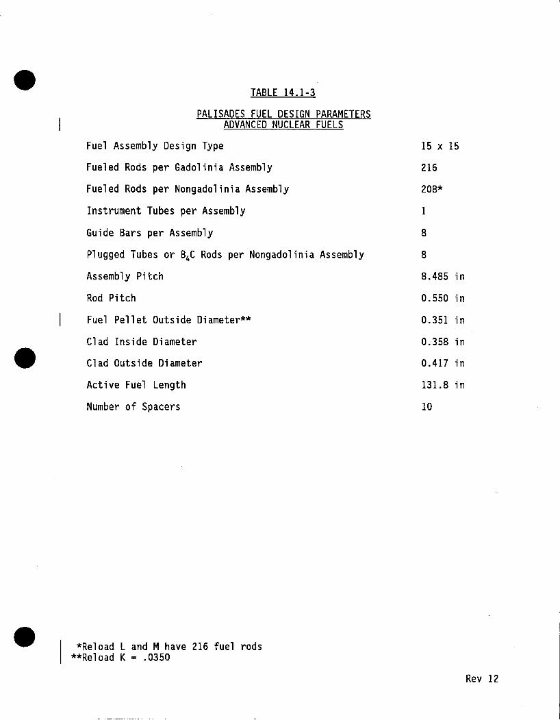
•
•
•
TABLE 14.1-3
PALISADES FUEL DESIGN PARAMETERS ADVANCED NUCLEAR FUELS
Fuel Assembly Design Type
Fueled Rods per Gadolinia Assembly
Fueled Rods per Nongadolinia Assembly
Instrument Tubes per Assembly
Guide Bars per Assembly
Plugged Tubes or B4C Rods per Nongadolinia Assembly
Assembly Pitch
Rod Pitch
Fuel Pellet Outside Diameter**
Clad Inside Diameter
Clad Outside Diameter
Active Fuel Length
Number of Spacers
*Reload L and M have 216 fuel rods **Reload K = .0350
15 x 15
216
208*
1
8
8
8.485 in
0.550 in
0.351 in
0.358 in
0.417 in
131.8 in
10
Rev 12

•
• I
•
TABLE 14.1-4
KINETICS PARAMETERS
Parameter
Moderator Coefficient (~p/°F) x 104
Doppler Coefficient (~p/°F) x ios
Pressure Coefficient (~p/Psia) x 106
Delayed Neutron Fraction, %
Net(a) Rod Worth (% ~p)(b)
Effective Neutron Lifetime, x io-s Seconds
u238 Atoms Consumed per Total Atoms Fissioned
Ejected Rod Worth (pcm)
(a)Total rod worth minus stuck rod worth (b)2.0% at hot standby
FS0489-0409F-TM13-TM11
Value Beginning End of of Cycle· Cycle
+0.50 -3.50
-1.09 -1. 76
-1.00 + 7. 00 '
.75 .45
-2.90 -2.90
41.9 19.9
0.54 0.10
172 229
Rev 8

• • TABLE I4. I-6
(Sheet I of 7)
DISPOSITION OF EVENTS SUMMARY FOR PALISADES CYCLE IO
SRP Event Bounding Designation Name Disposition Event
IS.I INCREASE IN HEAT REMOVAL BY THE SECONDARY SYSTEM
IS.I.I Decrease in Feedwater Temperature Bounded IS.I.3
IS.1.2 Increase in Feedwater Fl ow
I. Power Bounded IS.1.3. 2. Start-Up Bounded 15.1.3
IS.1.3 Increase in Steam Flow Anal yzed<a> Ref. ll <b> IS.1.4 Inadvertent Opening of a Steam
Generator Relief of Safety Valve
I. Power Bounded IS.1.3 2. Scram Shutdown Margin Bounded 15.1.3
IS.1.5 Steam System Piping Failures Inside and Outside of Containment Bounded Ref. 11
a) MDNBR analysis performed for Cycle IO.
b) PTSPWR2 analysis is given reference for this event.
•
Updated FSAR
Designation
I4.9.4
I4.9.6 14.9.5
I4.IO
I4. I4
Rev I4

• • • TABLE 14.1-6
(Sheet 2 of 7)
Updated SRP Event Bounding FSAR
Designation Name Disposition Event Designation
15.2 DECREASE IN HEAT REMOVAL BY THE SECONDARY SYSTEM
15.2.1 Loss of External Load Bounded Ref. 11 14.12
15.2.2 Turbine Trip Bounded 15.2.1
15.2.3 Loss of Condenser Vacuum Bounded 15.2.1
15.2.4 Closure of the Main Steam Isolation Valves (MSIVs) Bounded 15.2.1
15.2.5 Steam Pressure Regulator Failure Not Applicable; BWR Event
15.2.6 Loss of Nonemergency AC. Power to Short-term the Station Auxiliaries Bounded 15.3.1
Long-term Bounded 15.2.7
15.2.7 Loss of Normal Feedwater Flow 1) Maximum PCS Pressure Bounded Ref. 2 14.13 2) Maximum Primary-to-Secondary Bounded Ref. 2 14.13
pressure difference 3) Minimum steam generator inventory Bounded Ref. 2
15.2.8 Feedwater System Pipe Breaks Cool down 15 .1. 5 Inside and Outside Containment Bounded
Heatup Bounded 15.2.1
Rev 14

• • • TABLE 14.1-6
(Sheet 3 of 7)
Updated SRP Event Bounding FSAR
Designation Name Disposition Event Designation
15.3 DECREASE IN REACTOR COOLANT SYSTEM FLOW
15.3.1 Loss of Forced Reactor Coolant Ref. 11 <b> Flow Ana 1 yzed<a> 14.7
15.3.2 Flow Controller Malfunction Not Applicable
15.3.3 Reactor Coolant Pump Rotor Seizure Ana 1 yzed<a> Ref. 11 <b> 14.7
15.3.4 Reactor Coolant Pump Shaft Break Bounded 15.3.3
15.4 REACTIVITY AND POWER DISTRIBUTION ANOMALIES
15.4.1 Uncontrolled Control Rod Bank Withdrawal From a Subcritical or Low Power Condition Bounded Ref. 11 14.2.1
15.4.2 Uncontrolled Control Rod Bank Withdrawal at Power Operation
Ana 1 yzed<a> Ref. 13<b> Conditions 14.2.2
a) MDNBR analysis performed for Cycle 10.
b) PTSPWR2 analysis is given reference for this event. Rev 14

•
SRP Event Designation
15.4.3
15.4.4
15.4.5
• TABLE 14.1-6
(Sheet 4 of 7)
Name
Control Rod Misoperation
1. Dropped Control Bank/Rod 2. Dropped Part-Length Control
Rod 3. Malpositioning of the Part
Length Control Group 4. Statically Misaligned Control
Rod/Bank 5. Single Control Rod Withdrawal 6. Core Barrel Failure
Start-Up of an Inactive Loop
Flow Controller Malfunction
Disposition
Analyzed<a>
Bounded
Not Applicable
Bounded Anal yzed<a> Bounded
Bounded by rated power MDNBR
Not Applicable; No Flow Controller
a) MDNBR analysis performed for Cycle 10.
b} PTSPWR2 analysis is given reference for this event.
Bounding _Event
Ref. 13<b>
15.4.3.1
15.4.3.1 Ref. 15<b> 15.4.8
Updated FSAR
Designation
14.4
14.6
14.6 14.2.3 14.5
14.8
•
Rev 14

•
SRP Event Designation
15.4.6
15.4.7
15.4.8
15.4.9
• TABLE 14.1-6
(Sheet 5 of 7)
Name
CVCS Malfunction That Results in a Decrease in the Boron Concentration in the Reactor Coolant
1. Rated and Power Operation Conditions
2. Reactor Critical, Hot Standby.and Hot Shutdown
3. Refueling Shutdown Condition, Cold Shutdown Condition and Refueling Operation
Inadvertent Loading and Operation of a Fuel Assembly in an Improper Position
Spectrum of Control Rod Ejection Accidents
Spectrum of Rod Drop Accidents (BWR)
Disposition
Bounded
Bounded
Bounded
Administrative Procedures Preclude This Event
Bounded
Not Applicable; BWR Event
Bounding Event
Ref. 11
Ref. 11
Ref: 11
Ref. 11
Updated FSAR
Designation
14.3
14.3
14.3
14.16
•
Rev 14

• • • TABLE 14.1-6
(Sheet 6 of 7)
Updated SRP Event Bounding FSAR
Designation Name Disposition Event Designation
15.5 INCREASES IN REACTOR COOLANT INVENTORY
15.5.1 Inadvertent Operation of the ECCS Overpressure That Increases Reactor Coolant Bounded 15.2.1 Inventory Reactivity
Bounded 15.4.6
15.5.2 CVCS Malfunction That Increases Overpressure Reactor Coolant Inventory Bounded 15.2.1
Reactivity Bounded 15.4.6
15.6 DECREASES IN REACTOR COOLANT INVENTORY
15.6.l Inadvertent Opening of a PWR Pressurizer Pressure Relief Valve Analyzed<a> Ref. 3<b>
15.6.2 Radiological Consequences of the Failure of Small Lines Carrying Primary Coolant Outside of Containment Bounded 15.6.5 14.23
15.6.3 Radiological Consequences of Steam Generator Tube Failure Bounded FSAR 14.15
a) MDNBR analysis performed for Cycle 10.
b) PTSPWR2 analysis is given reference for this event. Rev 14

•
· SRP Event Designation
15.6.4
15.6.5
• TABLE 14.1-6
(Sheet 7 of 7)
Name Disposition
Radiological Consequences of a Not Applicable; Main Steam Line Failure Outside BWR Event Containment
Loss of Coolant Accidents Resulting Analyzed From a Spectrum of Postulated Piping Breaks Within the Reactor Coolant Pressure Boundary
15.7 RADIOACTIVE RELEASE FROM A SUBSYSTEM OR COMPONENT
15.7.l Waste Gas System Failure Deleted1'r
15.7.2 Radioactive Liquid Waste System Leak or Failure (Relea~e to Atmosphere) Deleted*-
15.7.3 Postulated Radioactive Releases Due to Liquid-Containing Tank Failures Bounded
15.7.4 Radiological Consequences of Fuel Handling Accidents Bounded
15.7.5 Spent Fuel Cask Drop Accidents Bounded
*This section of the Standard Review Plan has been deleted~
• Updated
Bounding FSAR Event Designation
14.17 14.18 14.22 14.24
14.21
FSAR 14.20
Ref. 15 14.19
Ref. 15 14.11
Rev 14

• • TABLE 14.1-7
(Sheet 1 of 2)
• SUMMARY OF RESULTS FOR ANTICIPATED OPERATIONAL OCCURRENCES
EVENT
.Increase in Steam Flow
Steam System Piping Failures Inside and Outside of Containment
Loss of External Load
Loss of Forced Reactor Coolant Flow
Reactor Coolant Pump Rotor Seizure
Uncontrolled Control Bank Withdrawal at Subcritical or Low Power
Uncontrolled Control Bank Withdrawal at Power
Control Rod Misoperation
• Dropped Rod or Bank
•Statically Misaligned Control Rod
• Single Rod Withdrawal
CVCS Malfunction that Results in a Decrease in the Boron in the Boron Concentration in the Reactor Coolant
MAXIMUM POWER LEVEL CMWTl
2735.4
318cNote 2)
2668.4
2686.7
2743.1
1230.5
2737.3
2580.6
2580.6
2737.3
MAXIMUM CORE AVERAGE HEAT FLUX
( Btu/hr-ft2)
175166
20272cNote 2)
165499
165473
165473
50171
173728
165473
165473
173728
MAXIMUM PRESSURIZER
PRESSURE (psia)
2033 .12
2060
2625.36
2127.78
2145 .19
2136.90
2097.90
2060
2060
2097.90
MONBR<liote 1 >
1.812
Note (3)
1.391
1.341
5.368
1.640
1.400
1.553
1.375
Adequacy of the shutdown margin is demonstrated
Rev 14

•
EVENT
Control Rod Ejection
Inadvertent Opening of a PWR Pressurizer Pressure Relief Valve
• TABLE 14.1-7
(Sheet 2 of 2)
MAXIMUM CORE MAXIMUM POWER AVERAGE HEAT FLUX
LEVEL CMWT) CBtu/hr-ft2)
3494.3
2690
173528
168558
MAXIMUM PRESSURIZER
PRESSURE (psia)
2115.00
2110.10
1 The MONBRs are based on the Cycle 10 radial peaking assumptions and the ANFP correlation
•
MONBR<Note 1 >
Note (4)
1. 741
(95/95 limit= 1.154). A 2% mixed core penalty was included in the MONBR analyses such that the effective ONB correlation limit is 1.174.
2 Maximum value after reactor trip. ·
3 Approximately 2% of the fuel fails as a result of penetrating DNB limits.
4 14.7% of the fuel rods in the core are calculated to fail as a result of penetrating ONB limits. The offsite doses that result from this event are 38 rem (thyroid) and 0.4 rem (whole body). These doses are within the acceptance criteria for this event (75 rem for thyroid and 6.25 rem for whole body).
Rev 14

•
•
•
TABLE 14.2.1-1
EVENT SUMMARY FOR THE UNCONTROLLED BANK WITHDRAWAL FROM A LOW POWER EVENT
Event Value
Bank Withdrawal Begins
Letdown Valve Open
Pressurizer Spray Activates
Reactor Scram (VHP Trip)
Peak Power Level 1230.5 MWt
Minimum DNBR 5.368
Peak Core Average Heat Flux 50, 171 Btu/hr-ft2
Peak Steam Dome Pressure 1017.85 psi a
Peak Pressurizer Pressure 2136.90 psi a
Peak Core Average Temperature 544.96°F
Time{sec)
0.00
0.00
0.01
58.91
59.51
60.39
60.44
67.11
67.61
71.93
Rev 12

•
•
•
TABLE 14.2.2-1
EVENT SUMMARY FOR THE UNCONTROLLED ROD BANK WITHDRAWAL EVENT FROM POWER
Event Value
Start Rod Withdrawal
Letdown Flow Valve Open
Minimum DNBR 1.640
Reactor Scram (TM/LP Trip)
Turbine Stop Valve Closed
Peak Power Level 2900.9 MWt
Peak Core Average Heat Flux 178,867 Btu/hr-ft2
Peak Core Average Temperature 576.53° F
Peak Pressurizer Pressure 2267.14 psia
Steam Line Safety Valves Open
Peak Steam Dome Pressure 1030.52
Time(secl
0.00
0.00
22.95
24.82
25.00
25.83
25.45 .
25. 77
27.00
29.50
31.69
Rev 14

•
•
•
TABLE 14.2.3-1
CONSERVATIVE ASSUMPTIONS USED IN THE SINGLE CONTROL ROD WITHDRAWAL EVENT
Single Control Rod Withdrawal (100% Power)
Power, MWt
Core Inlet Temperature, °F
Pressurizer Pressure, Psia
Vessel Flow Rate, lbm/hr
Maximum Augmentation Factor (XTGPWR}
Augmentation Factor Used in XCOBRA-IIIC
Hot Rod Radial Peaking Factor
2710 .1
550.42
2058.5
134.1 x 10⁶
1.045
1.080
2.03
Rev 14

• TABLE 14.2.3-2
SUMMARY OF MDNBRs FOR SINGLE CONTROL ROD WITHDRAWAL EVENTS
Maximum LHGR
Event (Power) Operating Mode MDNBR (kW/ft)
Rod Withdrawal (91. 53) Rated Power 1.375 18.34
Rod Withdrawal (503) Power Operation Bounded (Single Rod Withdrawal-1003)
Rod Withdrawal ( 10"43) Critical Bounded (Event 15.4.1)
Rod Withdrawa i (10-4%) Hot Standby Bounded (Event 15.4.1)
Rod Withdrawal (~ 10"43) Hot Shutdown Subcritical
•
• Rev 14

: ··~
•
•
•
TABLE 14.4-1
Event Summary for the Control Rod Bank Drop
Event
Bank Drops
Letdown flow valve opens
Reactor Scram (TM/LP Trip)
Turbine Stop Valve closed
Peak Power Level (after bank drop)
Value
2340.7 MWt
Time (Sec)
0.00
0.00
29.28
29.40
29.80
Peak Core Average Heat Flux (after bank drop) 146,400 btu/hr-ft2 29.90
Minimum DNBR 1.553 29.90
Peak Steam Dome Pressure 887.71 psia 39.28
Rev 14

•
•
•
TABLE 14.6.2-1
SUMMARY OF MDNBRs FOR STATICALLY MISALIGNED CONTROL ROD EVENT
Event (Power)
Statically Misaligned Control Rod (100%)
Statically Misaligned Bank (50%)
Statically Misaligned Bank (65%)
MDNBR
1.419
Maximum LHGR
(kW/ft)
16.24
Bounded(Statically Misaligned Control Rod - 100%)
Bounded{Statically Misaligned Control Rod - 100%)
Rev 12

• TABLE 14.7-1
Event Summary for the Loss of Forced Reactor Coolant Flow
Event Value Time (Sec}
Initiate Four-Pump Coastdown 0.0
Letdown Flow Valve Opens 0.00
Pressurizer Spray Actuates 0.60
Reactor Scram (Low Flow) 1.64
Turbine Stop Valve Closed 1.80
Peak Power Level 2686.7 MWt 2.20
Minimum DNBR 1.391 2.9i
Peak Core Average Temperature 579.01 OF 3.37
• Peak Pressurizer Pressure 2127.78 psia 4.70
Peak Steam Dome Pressure 963.39 psia 6.64
• Rev 14

• TABLE 14.7-2
Event Summary for the Reactor Coolant Pump Rotor Seizure
Event Value Time (Sec)
Primary Coolant Pump Rotor Seizes 0.0
Pressurizer Spray Actuates 0.20
Reactor Scram (Low Flow) 1.13
Turbine Stop Valve Closed 1.40
Peak Power Level 2743.1 MWt 1.68
Minimum DNBR 1.341 i. 76
Peak Core Average Temperature 579.3 OF 2.09
Peak Pressurizer Pressure 2145.19 psia 3.82
• Peak Steam Dome Pressure 986.34 psia 6.13
• Rev 14

•
•
•
TABLE 14.10-1
Event Summary for the Excess Load
Event
9% Step Increase in Steam Flow
Reactor Scram (TM/LP Trip)
Peak Power Level
Peak Core Average Heat Flux
Minimum DNBR
Turbine Stop Valve Closed
Peak Steam Dome Pressure
Value
2735.4 MWt
Time (Sec)
0.00
225.99
225.99
175,166 btu/hr-ft2
1.812
225.99
226.00
227.00
230.99 969.57 psi a,
Rev 14

•
•
•
TABLE 14.11-1
SPENT FUEL TRANSFER CASK DESIGN PARAMETERS
Method of Shipment
Vehicle Type
Gross Vehicle Weight
Cask Capacity in PWR Fuel Assemblies
Cask Weight Loaded
Cask Overall Dimensions for Loading
With Impact Limiter
W/O Impact Limiter and Head
Loading Height, Minimum
Yoke_Clearance Space
fs0582-1029s-09-72
Legal Weight Truck
Tractor and Trailer
70,000 lb
1
25 Tons
50" Diam, 214" Long
50" Diam, 200" Long
200 11
53" Maximum Diam
Rev 0

• TABLE 14.12-1
Event Summary for the Loss of Load
Event Value Time (Sec)
Turbine Trip 0.00
Pressurizer Heaters On 0.00
Peak Core Average Heat Flux 165,499 Btu/hr-ft2 0.74
Reactor Scram (High Pressure) 5.31
Peak Power Level 2668.4 MWt 5.87
Pressurizer Safety Valves Open 7.19
Peak Core Average Temperature 575.43 °F 7.34
Peak Pressurizer Pressure 2625.36 psia 7.74
• Steam Line Safety Valves Open 7.85
Peak Steam Dome Pressure 1030.60 psi a 10.29
• Rev 12

•
•
•
TABLE 14.11-3
CASK DROP ACCIDENT DOSES PALISADES
CLAD FAILURE AND GAP RELEASE WITH 23' WATER OVERCOVER AND FUEL HANDLING AREA RADIOLOGICAL FILTERS
WHOLE BODY
Site Boundary LPZ Boundary
SKIN
Site Boundary LPZ Boundary
THYROID
Site Boundary LPZ Boundary
ASSUMPTIONS
RP Factor
Partition Factor in Spent Fuel Pool
Iodine Noble Gases
Organic Iodine Inorganic Iodine in FHA Atmosphere
Fraction of Total Assembly Released From Full Assembly
I-XE-KR (Except KR85) KR85
rem
.396
.044
1. 75 .188
13.5 1.48
2
.01 1. 0
.25
.75
. 1
.3
NOTE: Results are for a single maximum irradiated fuel assembly damaged 48 hours after shutdown .
fs0582-1029u-09-72 Rev 0

•
•
•
TABLE 14.12-1
CONSERVATIVE ASSUMPTIONS USED IN THE LOSS OF EXTERNAL LOAD EVENT
Case
Rod Control
Power
Pressure
Core Inlet Temperature
Primary Flow Rate (Mlbm/hr)
Kinetics
Pressurizer Spray
Pressurizer Heaters
Pressurizer Safety Valve Set Point
Steam Dome Pressure (Psia)
Steam Bypass (and ADVs)
Secondary Relief Valves*
Scram On Turbine Trip
Low S/G Level Trip
CVCS (Maximum Makeup or Letdown Flow)
1
Maximum Primary Pressure
Manual
2,580.6
2,010
548.65
116. 7
BOC
Disabled
Full On
2,525
730
Disabled
1,030 Psia
Disabled
Disabled
Makeup
2
Minimum DNBR
Manual
2,580.6
2,010
548.65
116. 7
BOC
Full On
Disabled
2,475
730
Disabled
1,010 Psia
Disabled
Disabled
Letdown
*Supports a 3% tolerance on the secondary-side safety/relief valve set point.
FS0489-0410F~TM13-TM11 Rev 8

•
•
•
TABLE 14.17.1-4
SUMMARY OF RESULTS FOR 0.6 DECLG LIMITING BREAK SIZE
Peak LHR (kW/ft)
Hot Rod Burst
Time (Sec) Elevation (ft) Channel Blockage Fraction
Peak Cladding Temperature
Temperature (°F) Time (Sec) Elevation (ft)
Metal-Water Reaction
Local Maximum (%) Elevation of Local Maximum (ft) Hot Pin Total (%) Core Maximum (%)
*At 350 Seconds
BOC Stored Energy BOC Axial Shape
X/L = 0.6
15.28
46.00 7.45 0.30
1926.5 58.20 7.45
2.20 7.45 0.36
< 1.0*
BOC Stored Energy EOC Axial Shape
X/L = 0.8
14.75
47.20 8.95 0.32
2110.6 64.20 8.95
4.25 8.95 0.43
< 1.0*
Rev 14

• TABLE 14.19-1
SOURCE TERM AT TWO DAYS AFTER SHUTDOWN
Isotope Activity (Ci)
I-131 3.48 x 10
I-133 1.81 x 10
Xe-133 7 .13 x 103
Xe-133m 5.02 x 10³
Xe-135 2.46 x 10²
Kr-85 9.78 x 10²
•
• FS0990-0014N-TM13 Rev 0

•
•
•
TABLE 14.19-2
FUEL HANDLING ACCIDENT WORST CASE RESULTS - RADIOLOGICAL
CP Co Analysis Results
, Assumptions: 13 fuel rods failed 2 days after shutdown, no charcoal filter.
Isotooe
1-131
1-133
Xe-133
Xe-133m
Xe-135
Whole Body Dose (mrem)
0.86
0.59
13.90
9.80
4.00
29.15
NRC Analvsis Results
Thyroid Dose (rem)
4.7
1.5
6.2
NRC Assumptions: One fuel bundle failed two days after shutdown.
Exclusion Area Boundary 2-Hour Dose
Without Charcoal Filters ·
With Charcoal Filters
Whole Bodv
0.4
0.4
Dose(rem) Thyroid
91.
9.1
Rev 15

•
Ck:: w 3: 0 a.... _J a: ...... x a: D w N ...... _J a: :r: Ck:: 0 z
1.4
1.2
1.0
0.8
0.6
0.4
0.2
o.o .......... _._~.L..~__._---._. .......... _._-'"-.................... -'"-.................... -'"-......... _._.....L......__.__.__._~_._-L.... ...................... ......1.......~~_J 0.0 0.1 0.2 0.3 o. 4 o.s 0.8 0.7 0.8 o.s
FRACTIONAL ACTIVE fUEL t£IGHT
CONSUMERS POWER COMPANY PALISADES PLANT
FSAR UPDATE
1.0
AXIAL POWER PROFILE FOR 102% OF STRETCH POWER OPERATION
FIGURE NO 14.1-2 ._ ____________________________________ ... ______________________ _.
Revision No 12

• ~ ...... ·-> ·-...... 0 0 Cl)
~
E 0 L. 0 en
"'O Cl) N ·-0 E L. 0 z
•
•
to---------------------------------------------::=---,
o.~
0.0 o. 1. 2.
Time after Scram, seconds
CONSUMERS POWER COMPANY PALISADES PLANT
FSAR UPDATE
PALISADES SCRAM CURVE
FIGURE NO 14.1-4
3.
REVISION NO 8

••
0 z
-0 • ):a :::0 . -vc -t .-. >IC ):a '"llr-m r-
::n C> •-:x. re -0 ••• rri :m> c rri :::0 .. r- ):a O"D CD -t cmo m 1--4 .... .f'>. :z ;;m~ ::D ~ •D G">
I ' CD .... n "Tl >"D"' < .... ~ r-c;;· I C> ...,.. :D
s· .... C> m>n :::J :::0
.... -0 Zo r- -tK N ):> z ,,
> z -<
•
0
FUEL TILT {) MECH. PIT
1 2
D D
FUEL HANDLI llG MACHINE
~___,· ·+ ··F.----+---.. OOL CASK
STORAGE l 0 o:gp .,_,,__-1-coi' YMENT
jOi;::;::a.=:==:==:==:===:=:=:==:==f==:=O=P=E=R=AT=l=N=G==L=E;V;E=i'=E;L:.~6~4~9~~-0~D·R~OiCP 110.~;'!\.
I uw FUEL. STOIAGE: II
21 26
CAlfK WASH!)(>~_
PIT DROP NO
G)L-_-
HATCH 12-0· x 24- •
RAILROAD~ TRACK
•
D
N \»
I
°'
UI o_ I
0

::!! cc c .. CD .... ~ .... ....
I
N ::D CD S. en 0 :::> ...... N
•
(") ):loo (I) ~
-t ~ ):loo :z· (I) ..,, 0 ::ID -t -t ~ c: (") ~
-t ~ ):loo
r rn ~
n 0 z en
,.c "II>-= ~:D ,.. .. :D >,. ego ,.m. gen ,..,.m ,..:u -e,..n mzo
-IE ,, > z -<
0 'I
0 ...
I
REHOVABLE THERHAL SHEILD
11'-1o"MAX
• 16-8"
• iCASK
5)'-ll'' IHI M J
55'...6' (HAX I 2 ,000 LBS 32 ,000 LB~
LID IHPACT LIHITER TO REHAIN ON TRAILER
I 1/
lll-10 IHAXI
121-8
11 IHIN I .32'-6" (HIN I
7. 000 LBS 22,000 LBS
I 32,000 LBS
THROAT HEIGHT
TRUNION
CASK LID z IHPACT LIHITER X
REHOVED
.39,000 LBS
' z '° ...... :I: "'
'ao • =t ... 'I ~
· ...... I -...
•
511
BAR DI A
TRAILER ROOF
\ IOP<NI
ACCESS DOOR IOPEN)
0 ... 0 <C 0 _J z ::>

.. ~ 1500 0 Q..
UDJ
500
0 L--&.--....-.L--&.--~~~..6.-.1 ......... _.._.-...ll_.__.._~__._--.1-&.__._....-.~__._....-.-......~..-... ............. ~~ ......... 0 • I 10 l2
TIME, SEC ll II
CONSUMERS POWER COMPANY PALISADES PLANT
FSAR UPDATE
REACTOR POWER LEVEL FOR LOSS OF EXTERNAL LOAD
FIGURE NO 14.12-1
Revision No 12

a: ..... f
t I I 10 12 It 11 II Tit£, S£C
CONSUMERS POWER COMPANY PALISADES PLANT
FSAR UPDATE PRESSURIZER PRESSURE FOR
LOSS OF EXTERNAL LOAD
• FIGURE NO 14 .12-2
-------------------------------------Revision No 12

u
I UI la Tit£, SEC
It ·ll 11
CONSUMERS POWER COMPANY PALISADES PLANT
FSAR UPDATE PRESSURIZER LIQUID LEVEL FOR
LOSS OF EXTERNAL LOAD
FIGURE NO 14.12-3
Revision No 12

c... w
625.0
w 600.0 ~ C!) w Cl
... w ~ ::> 575.0 ..... cc ~ w a.. :z::: w .....
550.0
525.0
··············
· · · · · · · · · · · -· · PCS AVERAGE ---COLD LEG
>< HOT LEG ------- CORE INLET
................. ·········· ............................... . .... ······· .... -·········· ····················
····· ···········
------ -------- ------- ---- ----
500.0 ..._..__.__._ ........... __.__._~._....~ ....................... _.._....._ ............ _..__._ ............ __._........._..__._._~ .......... ._...._.._....._ ............ __.__._ ............ __.
0 2 6 8 10 1:i
TINE, SEC 16 18
CONSUMERS POWER COMPANY PALISADES PLANT
FSAR UPDATE
PRIMARY COOLANT SYSTEM TEMPERATURES FOR
LOSS OF EXTERNAL LOAD
• FIGURE NO 14.12-4 ______________________________________ _.
Revision No 12

• 1100
a: UXXl .... (/) 0...
700
S'fEAtl GDERflTOR • 1 STEAH Gf>l:RftT~ •2
600 ~_._....._._._._....._._._._......_...__.__._...._.~--....-_._--....._.._.._ ___ ~-----.......----~ ........... _._ ........... __. 0 8 8 10 1.a
TINE, SEC 18 11
CONSUMERS POWER COMPANY PALISADES PLANT
FSAR UPDATE
SECONDARY PRESSURE FOR LOSS OF EXTERNAL LOAD
FIGURE NO 14.12-5
Revision No 12
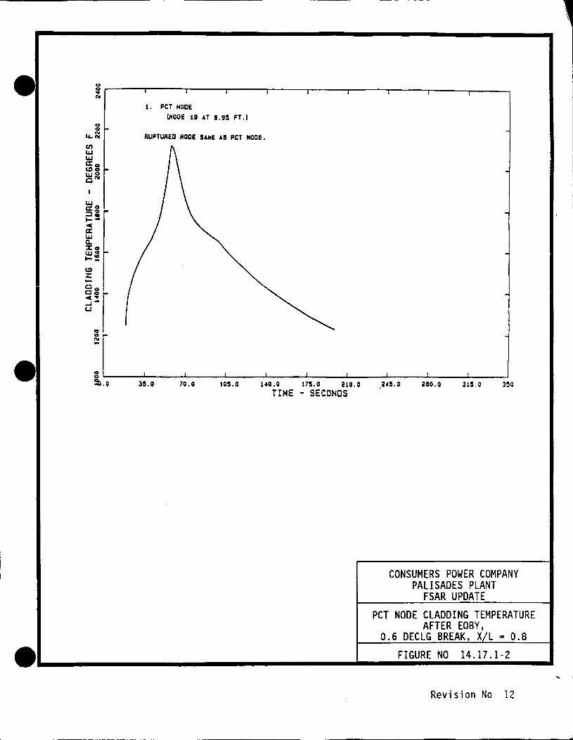
•
0 0
l. PCT NOOE
!NOOE 19 AT 11.95 FT .J
i.. l:: AUPT\Jl!ED HOOE SANE AS PCT NOOE.
c.n UJ UJ
ffig UJO CN
(:> % ..... Co Co -c .. ...Ju
0 0
"' -35.0 70.0 105.0 140.0 175.0 210.0
TIME - SECONDS 245.0 280.0 315.0 350
CONSUMERS POWER COMPANY PALISADES PLANT
FSAR UPDATE PCT NODE CLADDING TEMPERATURE
AFTER EOBY, 0.6 DECLG BREAK, X L = 0.8
• FIGURE NO 14.17.1-2
..._ ________________________________ .._.
Revision No 12