C Finite Element Analysis for Mechanical and Aerospace Design
Upload
khangminh22Category
view
2download
0
SCHOOL OF MECHANICAL AND INDUSTRIAL ENGINEERING
MASTERS OF MECHANICAL DESIGN ENGINEERING
MODELING, AND FEA OF MULTI-PLATE CLUTCHES
BY VARYING CLUTCH MATERIALS
FOR USE IN TCT SYSTEM OF GREEN, AND LIGHT VEHICLES
A THESIS SUBMITTED TO SCHOOL OF MECHANICAL AND INDUSTRIAL
ENGINEERING FOR PARCIAL FULFILMENT OF THE REQUIREMENT FOR THE
AWARD OF MASTERS OF SCIENCE IN MECHANICAL ENGINEERING
(Mechanical design stream)
By: SEYOUM KEBEDE
ID. GSR/1503/08
Advisor: Dr. DANIEL TILAHUN
Co. Advisor: Mr. NATHNAEL ABEBAW
June 2017, Addis Ababa

Addis Ababa University
Addis Ababa Institute of Technology
School of Mechanical and Industrial Engineering
This is to testify that the thesis prepared by Seyoum Kebede, entitled: Modeling, and FEA of
Multi-Plate Clutches By Varying Clutch Materials for use in TCT System of Green and Light
Vehicles submitted in partial fulfillment of the requirements for the degree of Master of
Sciences (Mechanical and Industrial Engineering) complies with the regulation of the
University and meets the accepted standards with to originality and quality.
Signed by the Examining Committee:
Internal Examiner ______________________Signature __________Date___________
External Examiner _____________________ Signature __________Date___________
Advisor Dr. Daniel Tilahun Signature________ Date__________
Co- Advisor Mr. Nathnael Abebaw Signature___________Date__________
____________________________
School or center Chair Person

ACKNOWLEDGMENT
First and foremost, I would like to thank to my advisor, Dr. Daniel Tilahun and Co. Advisor
Mr. Nathnael Abebaw for their valuable guidance and advice. They inspired me greatly to
work on this paper. Their willingness to motivate contributed tremendously to my thesis. I
also like to thank our chair Mr. Araya A. for his support; additionally I would like to show
my gratitude to all the department‟s staffs for their comments and suggestions.
I would also like to thank all my friends who contributed to my thesis work through giving
me supportive materials, data, information‟s and helpful ideas when I get confused and lost.
Finally I wish to express genuine gratefulness to my family for their great support and
understanding while working on this thesis and through all my graduate study.

ABSTRACT
Multi-plate Clutches (MPCs) are projected for transferring the greatest amount of torque with
less heat generation. The main objective of this thesis is modeling and FEA of multi-plate
clutches (MPCs) for selecting an optimum light weighted material for clutch plate for use in
twin clutch transmission (TCT) system of green, and Light Weight Vehicles using ANSYS
Work bench software. The candidate materials; Aluminum alloy 6061, E-Glass Epoxy UD,
and Gray Cast Iron are selected based on their weight and strength, and the mathematical
model has done for each materials using Euler Lagrange‟s Equation. The 3D solid model has
done using SOLID WORK 2016. The deformation and stress analyses were considered for
both static and dynamic analysis. The static analysis were developed using fixed support on
an inactive face of a clutch in static; and dynamic analysis is done applying displacement
boundary conditions on clutch plate, and 523 rpm rotational velocity on a plate rotating with
shafts. By default, since the objective is to increase the torque transfer capacity of a clutch,
the wear analysis were done by varying the coefficient of friction and intensity of pressure,
and thermal analysis were also done considering a heat flux of 0.54W/m2
at limiting
temperature of 150ºC for candidate materials. The total deformation, and maximum
equivalent stresses were evaluated by varying the compressive pressure acted upon the clutch
plate. Then comparison has been done in terms of total deformation and Equivalent stresses
of each material, and the composite E-Glass Epoxy is found to be a better Clutch material
with a lower deformation compared to the other selected materials for design of multi-plate
clutches in TCT system.
Keywords: Clutch materials, Multi-plate clutch, TCT, FEA, and Modeling.

Table of contents
Title Page
ACKNOWLEDGMENT........................................................................................................... ii
ABSTRACT ............................................................................................................................ iii
LIST OF FIGURE.................................................................................................................... vi
LIST OF TABLE...................................................................................................................
Viii
NOMENCLATURE .................................................................................................................xi
CHAPTER ONE: INTRODUCTION ...................................................................................... 1
1.1. Background ........................................................................................................... 1
1.2. Statement of the Problem ..................................................................................... 2
1.3. Objective of the Research...................................................................................... 3
1.3.1. General objective........................................................................................... 3
1.3.2. Specific objectives.......................................................................................... 3
1.4. Methodology of Research .................................................................................... 3
1.5. Significance of the Research ................................................................................ 4
1.6. Organization of the Paper ..................................................................................... 4
.CHAPTER TWO: LITERATURE REVIEW …......................................................................
5
2.1. Overview of Multi plate clutches in TCT system …............................................ 5
2.2. Papers Reviewed................................................................................................... 5
2.2.1 Common Clutch types ................................................................................... 7
2.2.2 Why multi plate clutch .................................................................................. 7
2.2.3 Characteristics of Wet clutches…................................................................ ..9
2.3. Materials ………….……………..…………….………………………………….9
2.4. Methods …………...………..………….……...………………….…………….10
2.4.1 Force, Pressure, and Torque Analysis …….……..………………………….10
2.4.2 Stress Analysis .......................................................................................…...10
2.5. Multi - plate clutches…………………………………….……………………….15
CHAPTER THREE: MODELING AND NUMERICAL ANALYSIS ................................ 18
3.1. Selection of clutch materials............................................................................... 18
3.1.1 General properties of clutch plate materials……….……………..…………24
3.2. Geometric Analysis............................................................................................. 24

3.2.1. Design considerations.......................................................................…........26
3.2.2. Design Statement…. ....................................................................................26
3.2.3. Methods of Analysis……….........................................................................27
3.2.4. Specifications of MPCs…….……………………….…..........…………….27
3.2.5. Analysis of loads and boundary conditions..............................................…29
3.2.6. Dynamic Analysis…….…………………………………..…………..…….31
3.2.7. Thermal analysis …………….…………………………..………..………..33
3.2.8. Model analysis……………………………………..…………..……………33
3.2.9. Stress analysis..........................................................................................….35
3.3. Three dimensional modeling of MPCs…………………….….….………………..41
3.3.1. Selection of softwares……………………………….……..……...………..41
3.4. FEA of clutch plate..........................................................................................…...43
3.4.1. Static analysis…………………….……………….………….....……….....43
CHAPTER FOUR: RESULT AND DISSCUSSION..............................................................51
4.1. Results ................................................................................................................. .51
4.2. Discussions….........................................................................................................52
CHAPTER FIVE: CONCLUSION, RECOMMENDATIONS AND FUTURE
WORK…….58
5.1. Conclusion .......................................................................................................... 58
5.2. Recommendation and Future Work..................................................................... 59
REFERENCES ...................................................................................................................... 60
APPENDIXES …………………………………….……………………………………...….62

LIST OF FIGURES
Page
Figure 1: Basic internal and external wet multi-plate clutch design ….…...……...……….....8
Figure 2: The Contact model for clutch
system...............................................................…...11
Figure 3: a Twin Clutch
Transmission…………………......………………………………...13
Figure 4: a Gear box Twin Clutch Transmission lining stricture…….……..………………..14
Figure 5: basic Twin Clutch Transmission arrangement………….….…..…………………..15
Figure 6: Basic multi-plate wet clutch
design………….……………………………………..16
Figure 7: Basic multi-plate wet clutch
design………….……………………………………..17
Figure 8: sectional view of set of MPCs (solid work model)…..….….....……….………….28
Figure 9: simple MPCs inertial system…………………………..……….…………………
31
Figure 10: Multi-plate clutch
facings………...………………………………...……..………35
Figure 11: sectional view and geometry of clutch
disc…………...…………………………..36
Figure 12: Multi-plate axial clutch…………………………………......…….………..….....37
Figure 13: 2D model of set of MPCs (solid work model)…………..…………………….....42
Figure 14: 3D model of set of MPCs (solid work model)...…….……………….…………...42
Figure15: a) external and, b) internal splines ...........................................................…..…….43
Figure16: Export and Meshed
model…………………………………………………….......44

Figure 17: a) load and boundary
conditions………………………………………................45
Figure 18: External splines MPC- static analysis result; a) applied maximum pressure
b) Total deformation c) stress d) strain for aluminum alloy………………….…..46
Figure 19: External splines MPC static analysis result; a) applied maximum pressure
b) Total deformation c) stress d) strain for Gray Cast Iron……………..………48
Figure 20: External splines MPC static analysis result; a) applied maximum pressure
b) Total deformation c) stress d) strain for E-Glass Epoxy……………………50
Figure 21: by varying the value of number of friction surfaces
(n)…………………………..55
Figure 22: By varying the value of coefficient of
friction……………………………………56
Figure 23: by varying the value of intensity of
pressure………...……………………………56
Figure 24: a) model export from solid work b) Meshed
model……………..……………....62
Figure25: load and boundary
conditions…………….…………………………………….......63
Figure 26: Internal splines MPC static analysis result; a) total deformation
b) Stress c) strain for Aluminum alloy ……………………………………….64
Figure 27: Internal splines MPC static analysis result; a) applied maximum pressure
b) Total deformation c) stress d) strain for cast iron……………………..……. 66
Figure 28: Internal splines MPC static analysis result; a) applied maximum pressure
b) Total deformation c) stress d) strain for E-Glass Epoxy………….…...……..68
Figure 29: loads and boundary
conditions…………….……...…………………….……........69
Figure 30: External splines MPC dynamic analysis result; a) total deformation
b) Stress c) strain for Aluminum Alloy…………………………….….…...….…71
Figure 31: External splines MPC dynamic analysis result; a) total deformation
b) Stress c) strain for Gray Cast Iron……………………........................………72

Figure 32: External splines MPC dynamic analysis result; a) total deformation
b) Stress c) strain for E-Glass Epoxy…………….......................…..…………..74
Figure33: load and boundary conditions…..………...…...………..………………….…..…..
75
Figure 34: Internal splines MPC dynamic analysis result; a) total deformation
b) Stress c) strain for Aluminum alloy……..……………………..………....….76
Figure 35: Internal splines MPC dynamic analysis result; a) total deformation
b) Stress c) strain for cast iron……….…………..……………...........…………78
Figure 36: Internal splines MPC dynamic analysis result; a) total deformation
b) Stress c) strain for E-Glass Epoxy…………………………................……….79

LIST OF TABLES’ PAGE
Table1: West European Light Vehicle Production by Transmission Type……….…......6
Table2: comparison of better materials based on strength specification……..…….…..22
Table 3: comparison of materials based on ability to resist corrosion…….…..……….23
Table 4: Comparison based on their cost per Kilogram…………….………….………23
Table 5: comparison based on availability, service life, and manufacturability…..…...24
Table 6: properties of candidate clutch lining materials…….………..……….…….…25
Table 7: common Properties of selected clutch plate materials………….….…...…....26
Table 8: commercial Lifan sedan clutch specifications…...……….….…….…....…...26
Table 9: newly modeled clutch specifications…………..…….…..……….….…........27
Table 10: External spline FEA /ANSYS result (static)..………...……..….….…….....51
Table 11: internal spline FEA/ANSYS result (static)..….……..…….…….….……....51
Table 12: internal spline FEA/ANSYS result (Dynamic)…….………….….….…......51
Table 13: External spline FEA/ANSYS result (Dynamic)…...…………..…….…......52
Table 14: Thermal FEA/ANSYS result …...……..……….….…………...……….......53
Table 15: Model FEA/ANSYS result ………….……….….………..…....……….......53
Table 16: By varying the value of number of friction surfaces (n)……..…....………..54
Table 17: By varying the value of coefficient of friction………….…….…….……….55
Table 18: By varying the value of intensity of pressure pa …….…...…..……………..55

NOMENCLATURE
A Area of a friction plate
AAiT Addis Ababa Institute of Technology
Al Aluminum
Al-Si Aluminum Silicon alloys
AMT automated- manual transmission
ANSYS system analysis software
APDL ANSYS Parametric Design Language
ASME American Society of Mechanical Engineers
AT automatic transmission
C Constant force of clutch plate
C1 clutch plate number one
C2 clutch plate number two
CVT controlled variable transmission
D Diameter clutch plate
DCT dual clutch transmission
Di = D1 Inner Diameter of clutch plate
Do = D2 Outer Diameter of clutch plate
E Elastic Modulus property of material
F Applied Force on Pin Holder Top Face
FE Finite Element
FEA Finite Element Analysis
FEM Finite Element Model/ Method
ff Frictional force
h Heat transfer coefficient of the material
H Hardness of Tasted Material
H Hardness Property of Material
I1 moment of inertia of clutch plate one
I2 moment of inertia of clutch plate two
k Thermal conductivity of the material
K Wear Coefficient
L Length
M Moment
Mc moment of a clutch plate

MPCs multi – plate clutches
MT manual transmission
n Number of friction surfaces
N Speed in RPM
n1 number of clutch plates on driven shaft
n2 number of clutch plates on driving shaft
NVH noise and vibration health
P Applied Pressure
Pmax engine maximum power
q Heat energy generated in watts
qf heat flux in
R Effective mean radius of a clutch
ri Inner Radius Of clutch plate
ro outer radius of clutch plate
RPM revolution per minutes
Si Silicon
SW16 Solid work 16
T Thickness
TCT twin clutch transmission
Te.max Engine Maximum Torque
ts Slip time in seconds
v Poison‟s Ratio
W Clamping force on clutch plate
Y Yield strength
Β Clutch safety factor
Ρ Density of pin materials
Ω Rotational Velocity
ω1 angular velocity of clutch plate one
ω2 angular velocity of clutch plate two
ωr Rotational speed
𝐹𝑒 Engine frequency
𝑁𝑒 Engine rpm range
𝑛 Order of frequency
µ Coefficient Of Friction

2D two dimensional models
3D three dimensional models

CHAPTER ONE
INTRODUCTION
1.1 Background
The important component of any automotive machine is the friction clutch. Clutch is a
mechanism for transmitting rotation which can be engaged and disengaged. It is a link
between engine and transmission system which conducts power in the form of torque from
engine to the gear assembly. Multi-plate Clutches (MPCs) are projected for transferring the
greatest amount of torque with less heat generation [3]. In today's world, with natural
resources such as oil and gas, petrol and diesel prices have been sky rocketing. Therefore, it
is becoming increasingly important for automobile manufacturers to make cars that deliver
good fuel economy. Powertrain engineering and in particular transmission systems and their
components, are facing very difficult and diverse challenges nowadays compared to the
decades before. These challenges are triggered mainly by international legislation, which is
tightening the regulations on emissions and fuel consumption all around the globe. In Europe
the carbon dioxide emissions have been reduced by 10% from 1995 to 2003 [10]. Those
effects can be reduced by improving the components in transmission system such as clutch.
Clutch is one part of the transmission system, and Twin clutch transmissions (TCT) have
emerged as a viable alternative to conventional planetary automatics and continuously
variable transmissions with the development of precise control strategies. TCT can be
considered as two lay shaft transmissions in one. Odd gears are connected to one shaft while
the even gears are connected to the other, and the developed multi plate clutches would be
used on those shafts as to transmit power.
Eventhough there are different components of transmission systems, a TCT system is the
most efficient and to be employed in vehicles to achieve better vehicle fuel economy and
comfort [5]. Normally, a manual clutch transmission system is not been the preferred choice;
due to recently developed Automatic TCT [1]. Evidences show that racing cars and most
electric vehicles, and Honda cars and motorcycles have been available with automatic
transmission systems [1].
Particularly, researchers shows that TCT which combines the advantages of manual
transmission and automatic transmission features the convenience and comfort of automatic
transmission and the fuel economy even better than manual transmission in any ordinary, and
electric vehicles. This also is influenced by types of clutches used single or multi-plate and/or

wet or dry. But, wet multi-plate clutches can improve torque transferring capacity and power
transfer efficiency even in their smaller size [5].
Our institution; Addis Ababa Institute of Technology (AAiT), School of Mechanical and
Industrial Engineering (SMIE) aim to develop a more robust light weight and Green Vehicle.
The Light Weight and Green Vehicle to be developed in our institution is claimed to be
excellent and competitive in every situation. So, different system designs are to be held on
each component parts.
Nowadays the diffusion of the TCT is limited to the high class vehicles because their costs
are higher with respect to the AMT or MT. On the other hand, market forecasts say that in the
next years the vehicles equipped with TCT will attain more than 10% of the market shares
[6]. So, developing MPCs from available and low cost materials would be essential.
Due to its advantages, MPCs has become a hotspot topic that attracts extensive development
interests in the automotive industry in recent years [5]. In this paper, mostly modeling and
FEA of MPCs has been held for a light weight and green vehicles. Special emphasis has been
laid on selection of better lining material and detailed model of MPCs.
1.2 Statement of the Problem
Addis Ababa Institute of Technology, School of Mechanical and Industrial Engineering is to
develop a light weight and Green vehicle which is robust, environmentally friendly, and
supporting the advancement of green area protocol.
The existing commercial clutch plate (Disc) material (i.e. Gray Cast Iron) weight which is
4.5-6 kg is a major issue in design of MPCs. But, the green vehicle to be developed would
have to have lighter weight and lighter component parts.
Therefore, to overcome those problems this paper was proposed and done to investigate a
better lining material and design of appropriate MPCs, for use in TCT system for a Green,
and light weight vehicles.
1.3 Objectives of the study
1.3.1 General Objective The main objective of this thesis is modeling and FEA for Total Deformation, von-misses
stress, Von-misses Strain, and wear of clutch disc materials (i.e. Aluminum Alloy, E-Glass
Epoxy UD, and Gray Cast Iron) for use in TCT system of Green and light vehicles, and
validate the results using FEM/ANSYS work bench.
1.3.2 Specific Objectives
The specific objectives of the study are to:

Identifying the better lining material, properties and their composition.
Select Modeling type, modeling, and analysis of MPCs.
Identifying the wear, stresses, and total deformation, of sample materials in their
maximum pressure conditions.
Comparing for basic similarity and difference of selected materials and state the cause
of difference.
Validating and Conclusion the results.
1.4 Methodology of Research
Some basic procedures that will be followed in order to fulfill the objectives of the thesis are
stated below:
Identifying the material types considering cost, availability, and their weight.
Calculation of stresses, and maximum pressures using Euler-Lagrange equations.
Developing 3D model of MPCs using Solid work 16 software.
Exporting the model of MPCs from solid work 16 to ANSYS 16 work bench for FEA.
Static and dynamic analysis of MPCs using ANSYS work bench at different operating
condition.
Determining the wear, maximum deformation and equivalent stresses for each
material using FEA
Showing the relation of deformation and resistance property of each material using
figures and tables.
Comparing and discussion of results for selection of better lining materials.
All the above procedures have been conducted with application of a specified conditions and
constraints that helps to get the suitable and reliable result.
1.5 Significance of the Research
This research paper outcome would have a great role for the further analysis and design for
manufacturing of MPCs. The advantage of this thesis mostly relay on the material analysis in
point of strength and identifying a better lining material for clutch plate. For newly
developing of Green, and light weight vehicles, this thesis provide new point of view and
knowledge in clutching system of green vehicles. In the future this paper adds more
knowledge on analysis of wear rate and deformation of friction plates using related software
in simplified and effective way. This paper indicates the easy way of analyzing MPCs
deformation using different operating conditions (i.e. pressures and loads).
1.6 Organization of the Paper
This paper is organized in to five main chapters. The first chapter discusses the introduction
of the MPCs and a TCT system and the study. On this chapter background, objectives,
statement of problem, limitations, and methodology is identified. On the second chapter two
is the review of literature that includes journals, articles and publications that related to the
thesis paper work. Additionally on this chapter some literature work is also seen that related
to field of study to strength the paper. On chapter Three the model and failure analysis for
selected materials is discussed. The requirement for analysis of structural mechanics or
deformation using related software also studied on chapter Three. On fourth chapter the final
result and discussion is performed. The result is obtained from the structural analysis using
related software. The software provides a basic solution that helps to determine the required
answers for the study based on the results the discussion follows. On the final chapter, Based
on the result of analysis conclusion, and recommendation is stated; additionally the possible
future work on the field of the study is included.
CHAPTER TWO
LITERATURE REVIEW
2.1 Overview of Multi-plate clutches in TCT system
Most people are aware that in today's time, motor vehicles come with two basic types of
clutches. These are namely; Wet and Dry types which carry out power transmission based on
vehicle speed. There is a new type of transmission system that has become increasingly
popular over the last decade, called the TCT and, semi-automatic transmission. The TCT falls
somewhere in between manuals and automatics, offering the best of both worlds. So,
different researchers have done analysis on this. To improve the TCT system they have done
analysis on those clutch types for better performance. They have used various approaches and
means to attain their main intention in designing MPCs.
A TCT system essentially comprises of two manual gearboxes operating independently
contained within housing. To be able to understand how it works, it would essential to first
review how a traditional manual gearbox works. Whilst driving a standard manual car, when

the driver wants to shift from one gear to the next, he or she first depresses the clutch pedal.
This operates a clutch, which disconnects the engine from the gearbox and interrupts power
flow to the transmission.
2.2 papers reviewed
In a vehicle with a 6-speed TCT, however, the clutches operate independently. One clutch
controls the odd gears (first, third, fifth and reverse), while the other controls the even gears
(second, fourth and sixth). Using this arrangement, gears can be changed at lightning fast
speeds, without interrupting the power delivery from the engine to the transmission [3].
In this paper literature has been critically involving various studies carried out by various
researchers related to the design, load, shifting and dynamic analysis of clutches as a
transmission system. The conventional existing types of transmission systems are
continuously being investigated by many researchers during the past year under different
condition in order to reduce the failure or increase their efficiency either by modifying the
power strain systems and component transmission geometry [4].
Automatic Transmissions aren't widely used, especially in the European market. But recent
automotive market forecasts predict that there will be a decline of the Manual Transmissions
(MTs) in favor of the AMTs and TCTs. TCTs will gain market share continuously over the
next few years although it depends on several circumstances based on the automakers' and
transmission manufacturers' strategies. As shown in table 1, at the moment, however, Europe
is the fastest growing market for TCTs. There is also significant interest at the moment in
North America. And we know that there are some programmes already released on (2009)
[6]. Since the recent market forecasts predict the growth both for the AMTs and TCTs, the
manufactures are investing huge resource to improve the performances of this kind of
transmissions and, at the same time, to reduce their cost. In this light, the work developed in
this thesis aims to give useful information both to the clutches designers and to the control
algorithms designer in order to improve the performances of clutches for use in the AMTs
and TCTs.
Table 1: West European Light Vehicle Production by Transmission Type.
Type Year
2002 2008 2014
AMT 1.0% 4.3% 5.5%
Automatic 13.5% 16.1% 13.5%
CVT 0.5% 1.8% 1.3%

TCT 0.0% 2.6% 11.4%
Manual 86.5% 75.2% 68.3%
Grand Total 100% 100% 100%
(Source: CSM Worldwide, retrived from C. Worldwide. (2009). Source for Automotive
Market Forecasting and Automotive Market Foresight, [Online]. Available:
www.csmauto.com) (visited on 01/08/2017).
Their paper gives an input for identifying types of clutches to be used and why wet MPCs in
TCT system is more preferable in this work. The main advantage of a TCT is that the shifts
can be achieved without sensible torque gap with the help of clutches. In fact, with this
system is possible to apply the engine torque to one clutch just as the engine torque is being
disconnected from the other clutch.
It is as smooth as the most sophisticated automatic, but more economical than a conventional
automatic; it is as easy to drive as a standard auto, faster and more responsive than manual
gearbox on high performance cars. Another important advantage of the TCT is the reduction
of fuel consumptions. In fact, by eliminating the torque gap the efficiency of the system is
improved.
2.2.1 Common Clutch types
The types of clutches can be classified depending on different methods of operation. So, this
design paper is done based on the methods stated: [7, 9]
The method of transmitting torque: automatic.
The method of control: automatic.
The method of creating force on pressure plate: Spring clutches.
The shape of friction surfaces: Disc.
The number of driven plate: Multi-plate clutch (mainly used in automatic
transmission)
2.2.2 Why multi-plate clutch
While designing MPCs for use in a system with combined AT and AMT which is TCT
system, consider the method of operation which depends on the number of driven plate. A
twin clutch transmission is quite similar to the conventional automatic, the main difference
being the double clutch structure compared to the single automatic clutch used in automatics.
Automatics make the use of a torque converter to transfer engine torque from the engine to
the transmission; TCTs on the other hand don't require torque converters. TCTs present in the
market today use single plate clutches to fulfill the same purpose. A "wet" clutch is a type of

clutch whose components are bathed in lubricating fluid, with the purpose of reducing
friction and limiting the production of heat energy.
Manual transmissions are generally equipped with dry clutches and some TCT manufacturers
are using these too, however, all production vehicles today which are equipped with TCTs
use the wet version. [11]
a) Active and rear faces of external spline multi-plate clutch
b) Active and rear faces for internal spline multi-plate clutch
Figure 1: 2D Basic multi-plate wet clutch design [solid work design]
Fundamentally, there are two types of clutching used in TCT depending on materials
properties, i.e. wet and dry clutch. Wet clutches require a large amount of lubricating oil to
operate, the oil needs to be evenly spread on the clutch plates to allow the energy generated
during shifting to be dissipated [8].
Wet clutches hold certain benefits over their dry counterparts, such as low wear and high
torque output. The wet MPCs used in the Bugatti Veyron's TCT, for instance, is designed to
cope with torques as high as 1,250 Nm, but at the cost of a lower efficiency.
A Wet type MPCs, is more preferable, and has been developed to meet the very high torque
capacity and to have more efficiency.

Compression of Wet, and Dry type clutches with their advantages and disadvantages has been
done [14]. So, this helps to analyze and identify which clutching type will be more preferable
for light duty vehicles.
2.2.3 Characteristics of Wet clutches
Good Characteristics of Clutches [9], [13] and [15]
High torque capacity
Low weight, easy packaging
No noise or vibrations (Good NVH characteristics)
Long life
High energy density
Low drag Torque to reduce fuel cost
From comparison a wet clutch is more preferable for this design, since they are more efficient
because of the reduced volume of oil being pumped though the transmission system. This is
because of the torque capacity of the green vehicle are designed to be higher.
2.3 Materials
The friction material is very similar to the material used in brake shoes and pads and
contained asbestos in the past. Also, clutches found in heavy duty applications such as trucks
and competition cars use ceramic clutches that have a greatly increased friction coefficient,
however these have a "grabby" action and are unsuitable for road cars [12].
Structural analysis for clutch plate has done using the properties of three materials which are
used for liner (i.e. carbon-carbon composites, Kevlar, Ceramic composites) [16]. In this cited
paper comparison is done for above materials to validate better lining material for clutch
plate, and also validates and made analysis on other materials used for clutching system. This
helps to identify appropriate materials to be used for clutch design.
2.4 Methods
2.4.1 Force, Pressure, and Torque Analysis
Researchers have done and wrote more on methods used for designing and modeling of twin
clutch. Most related papers are discussed below.
The design and modeling of twin clutch transmission system depends on the operating system
[13]. It is in principle impossible to skip a gear (e.g. a direct shift from 4th to 2nd gear)

without first disengaging the appropriate clutch. They give special emphasis on a detailed
model of the hydraulic actuation of clutches and synchronizers.
Moreover, the researchers have done analysis of synchronizers to balance the gear shifting
that takes place in the system. Gear shifting takes place in odd number gearbox transmission
systems. But, it is better if we use a 6-speed gearbox than 5-speed or 7-speed gearbox
systems [3].
There is a power loss to be considered while designing a clutches in manual transmission
system since there is a power loss due to torque convertor. A TCT due to its double clutch
structure, doesn't need a torque converter, the result is improved fuel efficiency (most
automatics lose their power and efficiency in the torque converter). For transmissions with
torque converters the torque ratio can be met with a mechanical ratio spread which is smaller,
because in the initial launch phase the torque converter provides additional torque
amplification [17]. Actually, this would give an input for design and dynamic analysis
especially on Torque transfer analysis.
2.4.2 Stress Analysis
Finite element analysis of grooved friction plate of Diaphragm spring Clutch can be used to
show the effects of material structure on stresses. This can be used to study of temperature
distribution and thermal stresses during single engagement [14]. The main objective of my
thesis is to obtain a minimum safe stress value and temperature distribution of friction plate
by using analytical and numerical calculation.
Finite elements analyses of the thermal and shear stresses in clutches can also be stated using
FEMs. The calculations were performed using the axisymmetric and fully three-dimensional
computational models [2].
The friction clutch design is strongly dependent upon the frictional heat generated between
contact surfaces during the slipping at beginning of engagement [15]. Because of that the
frictional heat generated firstly will reduce the performance of clutch system and then will
lead to premature failure in some cases. They had used Finite element method to investigate
an effect of thermal load type on the temperature field of the clutch system and Two-
dimensional axisymmetric model was used to study the temperature distribution for the clutch
system (pressure plate, clutch disc and flywheel) during heating phase (slipping period) and
in the cooling phase (full engagement period) as shown on figure 3. Depending on basic
friction clutch design they had applied two types of thermal loads; load type A (uniform
pressure) and load type B (uniform wear). Repeated engagements made at regular interval

were considered in this work. ANSYS13 has been used to perform the numerical calculation
in their paper.
(a) (b)
Figure 2: The Contact model for clutch system a) Uniform pressure/ load A. b) Uniform
wear/ load B.
In this paper the transient thermal analysis of a dry friction clutch system during 10 repeated
engagements based on the uniform pressure and uniform wear theories was performed. Two
dimensional axisymmetric models were built to obtain the numerical simulation for friction
clutch elements during the slipping. The temperature will increase rapidly when the number
of engagements increase and in some cases the temperature exceeds the maximum limit of
temperature, this situation lead to friction clutch failure before the expected lifetime,

therefore the study of the temperature field of contact surfaces during repeated engagements
operation is necessary to give an indication about the maximum temperature during the
engagements.
The Lagrangian, Galerkin‟s and Rayleigh-Ritz equation are preferable in mathematical
calculation and simulation analysis of TCT system. Mathematic calculation and simulation
have done in order to study the thermal behaviour of a two-speed dual clutch transmission. In
order to demonstrate the effectiveness of the model, they have done simulations based on the
presented theoretical analysis and developed powertrain model using different vehicle test
driving cycles.
Thermal behaviour study can contribute to the design of MPCs prototypes and calculating its
reliability avoiding unnecessary failures [15]. It could help accelerating products
development speed and save funds.
They also put a future work especially on investigation of the proposed model. This helps to
study and made analysis on clutching and other related component parts thermal behaviour in
transmission system.
The Model-Based Design with MATLAB/Simulink can be shown, and enable all automakers
and suppliers to achieve optimization results once reserved for a few large automakers with
the resources to develop large internal simulation models and optimization programs [19]. By
using a system model that incorporates the engine, transmission, axle ratio, driver, and
vehicle, engineers can precisely match powertrain components and optimize hardware
variables, such as transmission ratios, and calibration parameters, such as shift schedules,
simultaneously.

Figure.3: a Twin Clutch Transmission [3].
A dual clutch transmission is a new kind of semi-automatic transmission system which
utilizes a double clutch structure, comprising of two independent clutches, one each for the
odd and even gear sets. The dual clutch transmission is based largely on a conventional
manual gearbox, it can be described as two separate manual gearboxes sharing the same
housing, each consisting of a gear set (odd or even) and a respective clutch. However, unlike
the manual transmission; the two clutches in a DCT are linked to two input shafts, the shift
and clutch actuation is controlled by the transmission control module also known as the
mechatronics module, and there is no physical clutch pedal for a driver.
In most modern cars equipped with a DCT, the driver can initiate the gear change either
manually using a paddle shift or buttons, or by keeping the shift-stick in the fully automatic
'D' or 'S' modes. [8]
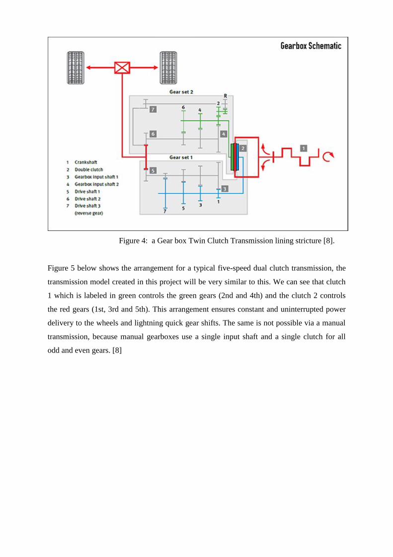
Figure 4: a Gear box Twin Clutch Transmission lining stricture [8].
Figure 5 below shows the arrangement for a typical five-speed dual clutch transmission, the
transmission model created in this project will be very similar to this. We can see that clutch
1 which is labeled in green controls the green gears (2nd and 4th) and the clutch 2 controls
the red gears (1st, 3rd and 5th). This arrangement ensures constant and uninterrupted power
delivery to the wheels and lightning quick gear shifts. The same is not possible via a manual
transmission, because manual gearboxes use a single input shaft and a single clutch for all
odd and even gears. [8]

Figure 5: basic Twin Clutch Transmission arrangement [8].
2.5 Multi-plate clutches
A dual clutch transmission is quite similar to the conventional automatic, the main difference
being the double clutch structure compared to the single automatic clutch used in automatics.
Automatics make the use of a torque converter to transfer engine torque from the engine to
the transmission; DCTs on the other hand don't require torque converters. DCTs present in
the market today use wet multi-plate clutches to fulfill the same purpose. A "wet" clutch is a
type of clutch whose components are bathed in lubricating fluid, with the purpose of reducing
friction and limiting the production of heat energy. Manual transmissions are generally
equipped with dry clutches and some DCT manufacturers are using these too, however, all
production vehicles today which are equipped with DCTs use the wet version. [8]

Figure 6: Basic multi-plate wet clutch design [8].
These wet multi-plate clutches are similar, in terms of principle of operation to torque
converters, in that they also use hydraulic pressure to drive the gears. As seen in Figure 6, the
lubricating fluid does it works inside the clutch piston. When the clutch is engaged, hydraulic
pressure inside the piston forces a set of coil springs apart, this in turn pushes a series of
stacked clutch plates and friction discs against a fixed pressure plate. The friction discs
shown in Figure 5 have got teeth on the inside; these teeth are shaped and sized in such a way
that they can mesh with splines on the clutch drum. This clutch drum is connected to the
gear-set which will receive the transfer force. The wet multi-plate clutches in Audi's DCTs
comprise of both a small coil spring and a large diaphragm spring. To disengage the clutch,
fluid pressure inside the piston is reduced. This allows the piston springs to relax, which
eases pressure on the clutch pack and pressure plate. These wet clutches engage and
disengage based purely on fluid pressure which is controlled by the transmission control
module (TCM) or the mechatronics module as VW like to call it. [8]
Figure 7 below shows the basic wet clutch design, when clutch 1 is engaged, clutch 2 is
disengaged:

Figure 7: Basic multi-plate wet clutch design [8]
The main advantage that wet multi-plate clutches hold over single-plate dry clutches is that
they can produce higher torque outputs and show a better resistance to wear. The bathing
fluid used such as the DSG oil used by VW helps to reduce friction, and in turn dissipates the
heat energy generated. The only real issue with wet multi-plate clutches is lower efficiency as
compared to their dry counterparts; there is on-going research and development with regards
to this. [9]
Generally all researchers have done their analysis on design for performance improvement of
transmission system for better use. They have contributed a lot for easy way of design and
applicability. But, they didn‟t have done more on modeling of clutches in transmission
system of electric vehicles, and ways of replacement of MPCs in TCT system for light duty
vehicles. This motivates to model MPCs for use in TCT system of green and light weight
vehicle in this thesis.

CHAPTER THREE
NUMERICAL ANALYSIS, AND MODELING OF MPCs
3.1 Clutch Material Selection Criteria
It is the friction pads or facings which actually transmit the power from the fly wheel to hub
in the clutching systems and from there to the output shaft. There are grooves in active sides
of the friction-disc facings. These grooves prevent the facings from sticking to the flywheel
face and pressure plate when the clutch is disengaged. The grooves break any vacuum that
might form and cause the facings to stick to the flywheel or pressure plate. The facings on
many friction discs are made of cotton and asbestos fibers woven or molded together and
impregnated with resins or other binding agents. In many friction discs, copper wires are
woven or pressed into the facings to give them added strength. However, asbestos is being
replaced with other materials in many clutches. Some friction discs have ceramic-metallic
facings.
After gear shift & during the clutch reengagement the clutch disc allows the transmission of
progressive torque through its Axial Stiffness. At that time wear or failure occurs in the
friction plate. The different materials have different properties to resist wear and failure in the
clutch plate. We use different materials but with suitable properties to obtain a better stress
and functions of pressure plate. The commercial clutch disc materials should be modified and
replaced by other materials which support the green area protocols. So, in this thesis materials
are optimized as to be used in green and light weight vehicles.
The present work investigates the response of clutch plates to an external load and pressure
and stresses. A Geometric model of clutch was designed in 3D by using solid work 2016
software and exported to Ansys16.0 work bench. The finite element program ANSYS is used
to compute the stresses and the strain.
Different machine design and manufacturing companies have stated a lot on material
properties used for clutches. The selection of correct clutch for the intended application is
critical to good operation, including the characteristics.
Identifying what clutch to get is dependent on the characteristics of the vehicles (i.e. how
much power does the vehicle make? how is it used? etc.) But, Materials using for MPCs for
use in TCT system of Green and light weight vehicles should have to have the following
common Properties;

Clutch Materials must have high coefficient of friction.
Materials must resist wear effects such as scoring, galling and ablation.
Materials should resistant to the environment (moisture and dust).
Material should possess good thermal properties, good thermal conductivity, high heat
capacity, and with stand high temperature.
Friction materials should have to be available locally and with lower cost.
Material should withstand high contact pressure and stresses.
Materials should be lighter in weight than the existing commercial clutch plate
materials.
Materials should have a long service life.
Depending on those properties stated above, some of the materials used for clutching are;
1 Aluminum Alloy (6061)
Aluminum-Silicon (Al-Si) alloys are most flexible materials, comprising 85% to 90% of the
total aluminum shed parts produced for the automotive industry [4]. Depending on the Si
focus in weight percent (wt. %), the Al-Si alloy systems drop into three major categories:
hypoeutectic (<12% Si), hypereutectic (14-25% Si) and eutectic (12-13% Si).
However, most Al-Si alloys are not suitable for lowering temperature applications because
tensile and fatigue strengths are not as high as preferred in the temperature range of 500 - 700
°F [7].
Advantages of Aluminum Matrix Composites Over iron, steel and other non-ferrous metals
are as follows [7]:
Higher elevated temperature strength
Improved wear resistance
Low density; high strength to weight ratio
Improve damping capabilities
Good corrosion resistance
2. Gray Cast Iron
Grey Cast Iron is made by re-melting pig iron. It is an alloy of Carbon and Iron. Small
amounts of Silicon, Phosphorus, Manganese and Sulfur are also present in it. The reasons
behind its popularity are: ability to make complex structures and low cost. In addition, the

excellent properties of Grey Cast Iron have made it one of the most widely used alloys in
vehicles braking and transmission system.
Properties of Gray Cast Iron are as follows [6]:
Has high compressive strength
Resistance to deformation and to oxidation
High thermal conductivity
High hardness
3. Composite materials
A Composite material (also called a composition material or shortened to composite, which is
the common name) a material made from two or more constituent materials with significantly
different physical or chemical properties that, when combined, produce a material with
characteristics different from the individual components. Many commercially produced
composites use a polymer matrix material often called a resin solution. There are many
different polymers available depending upon the starting raw ingredients.
4. E-Glass Epoxy material properties:
Providing a lightweight, and Corrosion-resistant alternative to steel
Higher Heat resistance strength, and Higher Impact strength
Higher Inter laminar shear strength and Tensile strength
5. Ceramics
Ceramics are very high temperature materials usually found on multi-puck disks. The
materials will accommodate 500hp+ with more abrupt engagement. The material will wear
the flywheel surface faster, especially in traffic situations. The material is suitable for
extreme clamping applications. The advantage of ceramics over aluminum alloy is that
ceramic materials are used for high power vehicles and drag racing cars. But, because of their
properties of wearing fly wheels the materials are not selected for design of MPCs for use in
green vehicles
6. Silicon carbide [SiC]
Silicon and carbon with chemical formula SiC. Silicon carbide powder has been mass-
produced since 1893 for use as a course. Grains of silicon carbide can be bonded together by
sintering to form very hard ceramics that are widely used in applications requiring high
staying power, such as car brakes, car clutches, grinding wheels, cutting tools and ceramic
dishes in bulletproof vests. Single crystals of silicon carbide can be grown by the Lely
method; they can be cut into trinkets known as artificial moissanite. Silicon carbide with high

surface area can be produced from SiO2 contained in plant material. SiC particulates can be
used as reinforcement, whiskers or fibers to improve the properties of the composite. When
surrounded in metal matrix a composite SiC certainly improves the overall strength of the
composite also it improves deterioration and wear resistance. Sic based composite has high
hardness; it can also use in number of applications such as in cutting tools, jeweler, structural
materials, electronic circuits, automobile parts, nuclear fuel particles, etc. [12]. Here, since
SiC is a tool material, the cost of those materials are very high than expected for design of
clutches. Due to this SiC is not selected for design of MPCs.
7. Kevlar 49
Kevlar is used in street-driven track cars up to 500hp. Due to the unforgiving nature of
Kevlar, it is not recommended for street cars, and especially those that see frequent stop-and-
go traffic which will cause surface glazing of the clutch.
Kevlar 49 materials properties
Uses in a high temperature range, but can be ruined from overheating.
Will not return to original characteristics if cooked.
The material has a break in period of 500-1000 miles during which slippage may
occur.
Eventhough Kevlar is a better friction materials, it is costly compared to the other. This
makes the material not to be selected for design of clutches in green vehicles.
8. Organic
Organics facings were originally made with asbestos, but as health issues arose concerning
the use of asbestos, it was phased out of industry. Facing were then made of fiber glass and
brass as its main ingredients.
As stated on material selection guide line, we need to choose a material that is stiff, light,
strong and cheap – we will therefore need to find information about the Young's modulus,
density, strength and cost for lots of different materials.
Since there are number of materials to be used for modeling and design of friction plates;
different criteria should be used for identifying best materials for clutching.
To specify and limit number of materials to be used for analysis; Material selection matrices
is used for expected clutch disc materials and materials mostly used by different researchers.
Table2: comparison of better materials based on strength specification
Material types Specific
Strength
Yield
Strength
(Mpa)
Elastic
Modulus(GPa)
Advantage
value
Grading

E-Glass Epoxy 28.4 1270 28 15 5
Aluminum Alloy 4.8 275 69.7 10 4
ceramics 6.7 457 33 12 4
Gray Cast Iron 19.1 720 24.1 10 4
Silicon Carbide 57 1710 63 15 5
Kevlar 49 23.8 370 72 11 4
organics 17 270 28 10 4
1 = poor, 2 = fair, 3 = good, 4 = very good, 5 = excellent
Table shows that E-Glass Epoxy, Silicon Carbide, and Alloy Materials are better in resisting
for yield while load is applying on them. But, it is clear that Silicon Carbide is a tool material
which is very costly. So, it is not recommended for use of clutching.
Table 3: comparison of materials based on ability to resist corrosion.
Materials Corrosion
Resistance
Weighted
value
Total Grading
Aluminum Alloy 9 1.5 13.5 3
ceramics 23 1.5 34.5 4
Gray Cast Iron 7.13 1.5 10.7 3
Silicon Carbide 29 1.5 43.5 5
E-Glass Epoxy 12 1.5 18 4
Kevlar 49 8 1.5 12 3
organics 7.3 1.5 10.95 3
1 = poor, 2 = fair, 3 = good, 4 = very good, 5 = excellent
So from this table it is shown that Ceramics, Silicon Carbide, and Epoxy materials are better
corrosion resistance materials than the other listed materials.
Table 4: Comparison based on their cost per Kilogram.
Materials Mass
(Kg)
Cost/Kg
($)
Grading
Aluminum Alloy 2.39 13.8 4
ceramics 2.88 38 2
Gray Cast Iron 3.4 40.7 2
Silicon Carbide 1.9 147.3 1
E-Glass Epoxy 1.8 29.2 3
Kevlar 49 2.92 56.7 2
organics 3.1 20.1 3
1 = very expensive, 2 = expensive, 3 = moderate price, 4 = inexpensive, 5 = very inexpensive
Table shows that Aluminum Alloy, E-Glass Epoxy and Organic materials have moderate
price.
Table 5: comparison based on availability, service life, and manufacturability.
Materials Local
Availability
Services
life
manufacturability No.
of +
No.
of -
Aluminum
Alloy
++ -+ ++ 5 1

ceramics -+ -+ -+ 3 3
Gray Cast Iron -+ -+ -+ 3 3
Silicon Carbide -- ++ -- 2 4
E-Glass Epoxy ++ ++ +- 5 1
Kevlar 49 -- -+ -+ 2 4
organics -+ -- +- 2 4
Table shows that using either of Aluminum Alloy, E-Glass Epoxy, Ceramics, and Gray Cast
Iron materials is better for clutching.
Generally depending on those decision matrixes and on behalf of the literatures used E-Glass
Epoxy, Aluminum Alloy, and Gray Cast Iron materials are selected for analysis of clutch
disc.
From the above listed materials Aluminum Alloy, Gray Cast Iron and E-Glass Epoxy are
better candidate materials for design of friction clutches. But, this is not the only way for
selection. Beside, FEA should be done using ANSYS Work Bench depending on the
properties of materials to identify which material is better.
The properties of the frictional lining are important factors in the design of the clutches. So,
typical characteristics of some widely used friction linings are given in table 6.
Table 6: properties of candidate clutch lining materials.
Materials combination Aluminum Alloy 6061 Gray Cast Iron E-Glass Epoxy
Dynamic
coefficient of
friction
Dry 0.25 – 0.45 0.15 – 0.25 0.25 – 0.45
Wet 0.06 – 0.09 0.03 – 0.06 0.06 – 0.09
Maximum pressure MPa 345 - 690 690 -720 345 -690
Maximum temperature 0C 2104 -260 260 204 - 206
To identify this comparison is done using Aluminum alloy (6061), and Gray Cast Iron, and
E-Glass Epoxy using ANSYS workbench and identify which one is better for use.
3.1.1 General properties of clutch Plate material
Table7: common Properties of selected clutch plate materials [18].
Materials combination Aluminum Alloy 6061 Gray Cast Iron E-Glass Epoxy
Young‟s Modulus (Mpa) 68900 120000 27600
Density(Kg/m3) 2700 7200 1900

Poisson‟s ratio 0.33 0.29 0.34
Friction coefficient 0.23 0.28 0.48
Tensile strength (Mpa) 276 220 124
3.2 Geometrical analysis
3.2.1 Design Considerations
A clutch of good design must have adequate torque capacity, ability to withstand and
dissipate heat and should have a long life. The clutch must have positive release, smooth
engagement, low operating force and ease of repair. To permit easy engagement and to
prevent excessive wear during the engagement period the facing should be flexible and the
largest possible area should be in contact during engagement.
Design is started considering: a 6-speed TCTs, two wet type MPCs; one on internal, and one
on external shaft, no gear shifting, and use of synchronizers, and use of lighter weight
materials than existing.
3.2.2 Design statement
As shown on figure 3 and figure 4 the friction plates are splined on their inner and outer
circumference and engage with corresponding splines on the flywheel or shafts. They are free
to slide axially. The friction material thus, rotates with the flywheel and the engine shaft. The
number of friction plates depends upon the torque to be transmitted. The driven shaft also
supports discs on the splines which rotate with the driven shaft and can slide axially. If the
actuating force on the pedal is removed, a spring presses the discs into contact with the
friction rings and the torque is transmitted between the engine shaft and the driven shaft.
3.2.3 Methods of analysis
The method of analysis of a clutch plate is either a uniform pressure or a uniform wear. The
torque that can be transmitted by a clutch is a function of its geometry and the magnitude of
the actuating force applied as well the condition of contact prevailing between the members.
The applied force can keep the members together with a uniform pressure all over its contact
area and the consequent analysis is based on uniform pressure condition. Condition may no
longer prevail. Hence the analysis here is based on uniform wear condition.
3.2.4 Specifications of multi-plate clutch
The composite clutch plate model is based on the clutches used in light duty and/or electric
vehicles. The clutch plate model is based on a single plate clutch used in Lifan 620

(LF48/Q3) developed using Gray Cast Iron material. It is defined that for 1000Kg car and
keeping everything else constant; on flat road at a speed of 25Km/hr requires 1.0KW power,
and on 50 gradients climbing at a speed of 25Km/hr requires 6.9KW power. General
specification of the vehicle is shown in table 8.
Table 8: Commercial Lifan sedan clutch specifications
Parameter Value Units
Geometry
Outline dimension L4550,W 1705,H 1495 mm
Max. power 85/115.6@5000rpm KW/Hp
Weight of vehicle 1150 Kg
Vehicle weight with load 1555 Kg
Torque 137 Nm
Torque delivery Speed 4500 Rpm
speed 170 Km/Hr
Gross weight of clutch 4 Kg
Axial intensity of pressure 160 KN/m2
Internal diameter of the
clutches
140 mm
Outer diameter of the clutches 210 mm
Clutch thickness 10 mm
Size 1.6 Liters
Brake model 6speed
Brake type 4wheel disk brake
Seating capacity 5 person
Transmission CVT
Effective torque radius 130 mm
Number of friction surfaces 5 pcs
Friction
Kinetic friction coefficient 0.3 -
Static friction coefficient 0.31 -

Clutch velocity tolerance 0.001 rad/s
Engagement threshold pressure 1 Pa
Source; instruction manual of Lifan Sedan (Lifan 620); Bushoftu Lifan vehicles assembling
company, Eastern Industrial Zone)
The vehicle parameters in this paper are based on the Lifan 620 (LF48/Q3) Automobile, and
the performance parameters are announced by Bushoftu Lifan Motors Assembling Company.
The total vehicle parameter is shown in Table 4 above. In a multi-plate clutch, the number of
frictional linings is increased which increases the capacity of the clutch to transmit torque.
A thesis design in this work is based and used the data tabulated below which have been
selected from the standard clutch specifications of Japan, Germany, and America clutch
manufacturing companies and some data‟s are taken from Bushoftu Automotive Industries
(directly taken from Germany designers), Lifan motor vehicles assembling company, and
Moenco car assembling company. Depending on those data the parameters of a clutch disk is
specified and a model is done.
Table 9: Newly modeled clutch specifications
Symbol Meaning Value
Te max Engine maximum torque 135 N m at 5000 rpm
Pmax. Max. power 5KW at 5000rpm
Clutch safety factor 1.2-1.6
µof E-Glass Epoxy Coefficient of friction 0.48
n Number of friction surfaces 1
ro Clutch friction plate outer dia. 200mm
ri Clutch friction plate inner dia. 150mm
t Thickness of clutch plates 8 mm
Figure 8: sectional view of set of multi-plate clutches (solid work model)

These are constructed with one plate attached to the inner shaft and the other plate to the
outer case. On figure 8 there is a surface in contact due to clutch plates C1 and C2, and this
allows a greater torque to be transmitted before slip occurs. Since there are two multi plate
clutches the number of friction surface is (n + n – 1) which is 1; then the maximum torque
increased n times. So, to deliver 5KW power, 135Nm torque, at a speed of 1000-5000rpm,
using E-glass Epoxy UD material, design calculations include,
In vehicles, the power delivery of engine and speed can vary from 3.5 – 85 KW and 4500-
5000 rpm respectively depending on engine transmission system. So, let‟s use the power
delivery of the vehicle as 5KW and at a specified initial speed of 5000rpm. But the torque
transferred by the clutch would be calculated for analysis of loads and maximum pressure
with new specifications.
The number of friction surfaces used in Lifan 620, for torque transfer of 138Nm are 9 with
number of friction surfaces on driving and driven shafts are 4 and 5 respectively, and have
maximum output torque of 137Nm. Lifan 620 is used as a reference because of its weight and
is being a light duty vehicle.
n = n1 + n2 – 1 (eq.1)
So, using twin multi-plate clutch is using the number of friction surfaces to be one.
Then, the total torque transfer would be;
60
2
Pt (eq.2)
Where Tt = a total torque transfer, P = a maximum power carried by a clutch, = speed in
rpm
Then using eq.2 above;
Tt =
= 10Nm
Then, using the number of friction surfaces n=1, for Two MPCs:
T = Tt/n = 10/1 = 10Nm
(eq.3)
Then using Clutch plate specifications for E-glass Epoxy UD material;
ri and ro are outer and inner radius of friction faces respectively
ri =150mm and ro = 200 mm,
n = no of pairs of contact surfaces.
Where n1 and n2 are number of disc on driving and driven shaft n1= 1 and n2= 1; n = 1 from
eq. 1
R = mean radius of friction surfaces. (ri + ro)/2 = 175mm
μ = coefficient of friction for E-glass Epoxy UD = 0.48

Max.power (P) = 5KW, thickness t = 8mm
Torque (T) = 10 Nm (result from eq. 2); at speed N = 5000 rpm (for a double clutch plate).
3.2.5 Formulation and analysis of Loads and boundary conditions
Static Analysis is used to determine deformation, stresses. under static loading conditions.
ANSYS can compute both linear and nonlinear static analyses. Nonlinearities can include
plasticity, stress stiffening, large deflection, large strain, hyper elasticity, contact surfaces,
and creep. And Dynamic Analysis - Used to determine the response of a structure to
arbitrarily time-varying loads.
All nonlinearities mentioned under Static Analysis above are allowed and enough for doing
this analysis. The clutches used here are a two wet type clutches, one on driving and the other
on driven the shearing effects between the plate faces are negligible. So, to simplify the
analysis and since the clutch plate face more effects of load than shearing, static modal
analysis would be done to identify which material is a better lining material. So, to find the
maximum pressure to be applied on clutch plate let‟s do the following.
Material used is Aluminum alloy with μ = 0.23, power (P) = 5KW, and torque capacity of 10
Nm at a speed of 5000rpm
D1 =150 mm and D2 = 200 mm; where D1 and D2 of friction faces
n = no of pairs of contact surfaces
Where n1 and n2 are no of disc on driving and driven shaft n1 = 1 and n2 = 1; n = 1
by considering uniform wear theory which states that, wear depends upon intensity of
pressure P and velocity of rubbing which further depend on R, thus for uniform rate of wear
PR = constant.
For uniform wear R = (D1+D2)/2
(eq.4)
Where R = mean diameter of friction material
R = (200+150)/2 = 175mm = 0.175m
Torque (T) = μ W R n (eq.5)
Where, μ = coefficient of friction and W = clamping force in N
10 = 0.23 *W * 0.175 * 1
W = 248 N
Now, from uniform wear theory,
W = 2 π (Pmaxx D1) x (D2 – D1) (eq.6)
Where, Pmax= maximum pressure between the contacting surfaces

248 = 2π (Pmax x 0.15) x (0.2 – 0.15)
Pmax= 0.0053MPa
And for E-Glass Epoxy material (μ=0.48), power of 5KW, and 10 Nm at 5000rpm.
Clamping force for E-Glass Epoxy material using eq. 5 above;
10 = 0.48 *W * 0.175 * 1
W = 119 N
Value of maximum pressure for E-Glass Epoxy material using eq.6
119 = 2π (Pmax x 0.15) x (0.2 – 0.15)
Pmax= 0.00037MPa
Similarly, for Material used is Gray Cast Iron with μ = 0.28, power (P) = 5KW, and torque
capacity of 10 Nm at a speed of 5000rpm
The clamping force for Cast Iron material using eq. 5
10 = 0.28 *W * 0.175 * 1
W = 204 N
Value of maximum pressure for Cast Iron Using eq. 6
204 = 2π (Pmax x 0.15) x (0.2 – 0.15)
Pmax= 0.0043Mpa
3.2.6 Dynamic Analysis
Figure 9: Dynamic Representation of Clutch or Brake
Consider a simple two- inertia system shown in Figure 9. Here, the coefficient of friction is
assumed to be a constant, independent of speed. It is also assumed also that no external
torques act on the system. The two clutches initially rotate at two different angular velocities
𝜔1 and 𝜔2.
Let the clutch be instantaneously applied at time t = 0 and the torque exerted by it on the two
flywheels Mc = constant. This torque will act on the system only as long as these exists a
difference in speeds between the two shafts Equations for speed, rate of heat dissipation etc.,
are therefore valid for time 0< t< t0, where t0 is the time required to couple the two shafts.

The equations of motion for the two sides of the clutch are
I1 (d𝜔1/dt) = -Mc (eq.7)
I2(𝜔2/dt) = Mc (eq.8)
Where 𝜔1, and 𝜔2 are angular velocities of C1 and C2 respectively as shown on figures 11 and
12. Integrating equations and applying the conditions.
For the considered system, after calculating the I- section inertia we have I1 = 0.2kg.m2; I2 =
0.149kg.m2; Mc = 50 Nm. 𝜔1 = 1500rpm = 157.075rad/sec. where I1 and I2 are inertia of
clutch plate 1 and 2 respectively.
Assuming clutch is applied at the output speed 𝜔2 = 1000rpm = 104.7rad/sec
The duration of engagement period or slip time of a clutch is,
sec21
2121
IIM
IIt
c
s
(eq.9)
)149.02.0(50
)7.104075.157(149.02.0
x = 0.06sec
1 General Nomenclature
ri – inner radius of clutch friction face
tc – thickness of clutch plate
tf – thickness of friction face
N – Speed of engine in rpm = 5000rpm
𝜔 – angular velocity red/sec
Pmax – maximum clamping pressure
2 Mathematical Calculations
The material considered for the friction pad is E-glass Epoxy UD. Uniform Wear Theory is
considered for calculations, and accordingly, the intensity of the pressure is inversely
proportional to the radius of friction plate.
𝑅=R𝑖+R𝑜/2=87.5m (eq.10)
In general, the frictional torque acting on the clutch plate is given by eq. 1 as 𝑃×𝑟=𝐶
(𝑐𝑜𝑛𝑠𝑡𝑎𝑛𝑡)
Since torque is 10Nm, Axial force on the clutch 114N,
𝑊=2𝜋×𝐶×(𝑅𝑜−𝑅𝑖) (eq.11)
𝐶 = 0.7𝑁𝑚

The maximum pressure occurs at the inner radius and the minimum pressure at the outer
radius.
𝑃𝑚𝑖𝑛 = 𝐶/𝑅𝑜= 0.007 𝑀𝑝𝑎 (eq.12)
𝑃𝑚𝑎𝑥 = 𝐶/𝑅𝑖= 0.0093 𝑀𝑝a (eq.13)
Here, we consider the maximum pressure value obtained in the Finite Element Analysis of
the clutch plate.
3.2.7 Thermal Analyses
1 Nomenclature
T – Temperature of the disc in Celsius
Tl – Limiting temperature of the material in Celsius = 150ºC
μ - Coefficient of friction of the material = 0.48
k – Thermal conductivity of the material in Watts per meter Kelvin
h – Heat transfer coefficient of the material.in Watts per sq. meters per Kelvin.
q – Heat energy generated in watts
qf – heat flux in W/m2
t – Slip time in seconds = 0.06sec
A – Area of a friction plate = 54950m2
2 Mathematical Calculations
𝜔𝑟=2×𝜋×𝑁/60 (eq.14)
= 2 x 𝜋 x 5000 /60 =523 𝑟𝑎𝑑/𝑠
𝑞= 𝜇×W×𝜔𝑟 (eq.15)
= 0.5 x 114 x 523 = 0.03M 𝑊
𝑞𝑓=𝑞/𝐴 (eq.16)
= 0.03/54950 = 0.54 𝑊/m2
3.2.8 Model Analysis
1 Nomenclature
𝐹𝑒 – Engine frequency
𝑛 – Order of frequency (1st order & 2nd order)
𝑁𝑒 – Engine rpm range (1500 rpm-5000 rpm)
2 Mathematical Calculations
𝐹𝑒=𝑁𝑒/60×𝑛 (eq.17)
= 1500/60 x 1 = 25Htz
3.2.9 Wear analysis A common and well known application for the clutch is in automotive vehicles where it is
used to connect the engine and the gearbox. Here the clutch enables to crank and start the
engine disengaging the transmission Disengage the transmission and change the gear to alter

the torque on the wheel. Due to friction between mating part some part of friction material
get wear out. So, let‟s discuss about the wear formation on selected candidate clutch
materials.
i. Friction Facings
It is the friction facings which actually transmit the power from the fly wheel to hub in the
clutch plate and from there to the output shaft. There are grooves in active sides of the
friction-disc facings. These grooves prevent the facings from sticking to the flywheel face
and pressure plate when the clutch is disengaged. The grooves break any vacuum that might
form and cause the facings to stick to the flywheel or pressure plate. However, asbestos is
being replaced with other materials in many clutches. Some friction discs have ceramic-
metallic facings. Such discs are widely used in multiple plate clutches The minimize the wear
problems, all the plates will be enclosed in a covered chamber and immersed in an oil
medium Such clutches are called wet clutches.
Figure 10: Multi-plate clutch facings
ii.Method of Analysis
There is number of method for analysis of wear and tear in clutch plate .The torque that can
be transmitted by a clutch is a function of its geometry and the magnitude of the actuating
force applied as well the condition of contact prevailing between the members. The applied
force can keep the members together with a uniform pressure all over its contact area and the
consequent analysis is based on uniform pressure condition. However as the time progresses
some wear takes place between the contacting members and this may alter or vary the contact

pressure appropriately and uniform pressure condition may no longer prevail. Hence the
analysis here is based on uniform wear condition.
In this paper we aimed to solve the optimized result for the multi plate friction clutch using
the uniform wear theory and obtained the optimum result of the inner radius and outer radius
of the multi disc friction clutch.
The maximum torque which can be transmitted by the friction clutch for uniform pressure
theory is given by
Tmax = n𝜋 par(R2 – r
2 ) (eq.18)
Where Ro and Ri are external and internal radius respectively.
The objective function, F1 can be defined as
22max
1
11
rRrnTF
a
(eq.19)
2
1
1
2
2
1
1
n
i
Rj
j
dR
FFF (eq.20)
If the constraint equation gj is satisfied with a probability pj if the normal variation for
probability pj is given then, the new constraint equation in deterministic form is given in
equation. And finally problem reduces to minimize the objective function given by equation
(18) satisfying constraint equation (19).
2
1
1
2
2
n
i
Rj
j
j
jjjR
gg (eq.21)
Now let‟s consider the following figures

Figure 11: sectional view and geometry of clutch disc
To design the multi plate friction clutch for maximum torque transmitting capacity, given:
[18]
µ= 0.48, n=1, 262 /10*35.0/35.0 mmNormmN
Solution:
On substituting the assumed data in equation 19;
F1 = )(*10*25.0**48.0*1
1226 rRr
= 7.8 * 10-7
/ (R2r –r
3)
If the design parameters D and d are taken as random variables following normal distribution
and the standard deviations are D = 0.01D and d = 0.01d respectively, then the new
objective function in deterministic form, from equation 20 is:
Fd = )(
10*8.732
7
rrR
+ )(
10*03.032
26
rrR
rR
+ 232
326
)(
(10*8.7
rrR
rrR
= )(
10*8.732
7
rrR
On substituting assumed data in equation 21:
gj =R
r73.1 (eq.22)
If the constraint equation is satisfied with a probability of 99.99%, then for Pj = 99.99% the
normal variants from table is 5. Using equation (19) the constraint equation in deterministic
form is:
gj d = 1.733 r/R – 0.087R 1
Hence the problem reduces to minimize objective function given by equation (21) satisfying
constraint equation (22). If the torsion is only considered as active constraint then the degree
of difficulty will be zero. Applying signomial geometric programming the normality and
orthogonally condition give.
3.2.10 Stress analysis
Assuming uniform pressure and considering an elemental area
dA = 2Π.r dr (eq.23)
The normal force on this elemental area is
dN =2. π.r.dr.p (eq.24)

The frictional force dF on this area is therefore
dF =f.2.π.r.dr.p (eq.25)
Figure 12: Multi-plate axial clutch
Now the torque that can be transmitted by this elemental are is equal to the frictional force
times the moment arm about 8.2*10-5/0.001275
The axis that is the radius „r‟ i.e.
T = dF. r = f.dN. r = f.p.A.r
= f.p.2.π.r. dr .r (eq.26)
The total torque that could be transmitted is obtained by integrating eq. 9 between the limits
of inner radius ri to the outer radius ro.
)3(3
22
332
rrr io
ro
ri
pfdrpf (eq.27)
Integrating the normal force form eq.6 between the same limits we get the actuating force that
need to be applied to transmit this torque.
prrprdrF io
r
r
a
o
i
)(2 22 (eq.28)
Equation 9 and 10 can be combined together to give equation for the torque,
)(
)(
3
222
33
io
ioa
rr
rrfF
(eq.29)
Here the maximum permissible stresses would be used for finding stresses. Where Pmax=
maximum permissible stress; inner radius of single plate clutch (Ri = 75mm); outer radius of
single plate clutch (Ro= 100mm) the effective area of the clutch is Area = r2 = 54950 mm
2.
Aluminum alloy 6061 with permissible stress of [Pmax. = 0.62 N/mm2];

Pressure (p) = (Pmaxx ri)/ro
o
i
o
i
r
r
io
r
ri
r
r
in drrPrdrrrPpdAF *22*)/)*(( .max.max
0
(eq.30)
= [2𝜋 (0.32 x 75) x ri (ro-ri)]/ro
= [2𝜋 (0.62 x 75) x 75 (100 - 75)]/100
= 2826 N= 5475.375
Stress=F/A
(eq.31)
= 5475.4/54950 = 0.1 N/mm2
For Gray Cast Iron with permissible stress of [Pmax. = 0.69 N/mm2]
Using eq. 6 for cast iron material
= [2𝜋 (0.69 x 75) x 75 (100 - 75)]/100
= 6093.6 N
And using eq. 26 the Stress value would be;
=0.11 N/mm2
E-Glass Epoxy Material with permissible stress of [Pmax. = 0.586N/mm2]
Similarly using eq. 6 the normal force for an E-Glass Epoxy material would be
= [2𝜋 (0.586 x 75) x 75 (100 - 75)]/100 = 5175 N
And the Stress value is;
=0.09 N/mm2
Generally we have seen that for a green, and light weight vehicle to be developed the clutch
material should be a materials with lower weight than existing light duty commercial clutch
plates and could resists the effects of stresses and loads. The existing clutch plates are those
developed from Gray Cast Iron and sometimes those from asbestos free materials. But as
shown in tables 2 above, E-Glass Epoxy material is more effective and efficient than Gray
Cast Iron. The model of the clutch in this thesis is developed using E-Glass Epoxy material
would have to resist the effects of force, torque and pressures as shown below.
Re arranging eq.3; the climbing force on a clutch would be:
w = 2T/n µR
(eq.32)
= 2(10Nm)/ (0.48) (1) (0.0875) = 457N
Torque capacity after initial wear,
T = 2/3μWDmn (eq.33)
= 2/3*0.5*457*0.0875 =13Nm
Safety factor when T=10;

= 10/10 = 1
Using result from eq. 16; Safety factor after initial wear;
= 13/10 = 1.3
Reduction in a clamping force so that slippage occurs;
As the friction material of the disc wears the surface shows a slight expansion, reducing their
clamping force.
New clamping force (W1) = W*μ*Tt/T
(eq.34)
=457*0.5*10/13 = 175.8N
Change in clamping force Wc would be (W - W1);
Wc = 457- 175.8 = 281.2N
Then, if we are calculating operating values for a number of pairs of contact surfaces:
Calculating operating force and operating average pressure by using uniform wear theory as
follows.
Average operating pressure:
Fo = (2*π*Po*r2)*(r2-r1)
(eq.35)
457= (1/2 x π×po×0.1) × (0.1-0.075)
Po = 0.1 MPa
Effective force acting at Rradius; will be,
Fe = µW = 0.5(457) = 228.5N
(eq.3)
It is imperative to understand the factors that influence friction force because this device
transmits torque via friction. Friction torque transmitted:
Tf = Fe R (eq.37)
= 228.5(0.0875) = 20Nm
Since no of friction surfaces n = 1; the torque transmitted by clutch is
Tc = nTf =1(20) = 20Nm (eq.38)
Then using eq. 13 the power transmitted by clutch is:
Pc = Tc*
= 20*
= 10KW
Since for a wet clutch allowable surface pressure varies from 0.05N/mm2 to 0.2N/mm
2 for
lining material; the normal force is (using the maximum of allowable surface pressure) [7]:
Using eq. 18 the normal force on a clutch is;
Fn = 2π*0.3*75*(100-75) = 3532.5N

Using eq. 11, the maximum input torque would be:
T = ½*0.5*457*0.0875 = 10Nm
Friction force: Ff = nµFn
(eq.39)
= (1*0.5*3532.5) = 1766.25N
The efficiency designed multi plate clutch for use in TCT would be;
imputpower
rOutputpoweefficency (eq.40)
Pi
Po = 0.3/12 = 99.8%
And in terms of torque transfer the efficiency would be:
eimputtorqu
ueOutputtorqefficency (eq.41)
Ti
To = 9.995/10 = 99.95%
Therefore, the newly modeled multi-plate clutch is 99.8% efficient and more acceptable than
existing commercial vehicle Gray Cast Iron single plate clutch which has 0.006% deviation
from the newly designed clutch.
3.3Three dimensional Modeling of MPCs
3.3.1 Selection of softwares A lot of research was carried out initially, to determine the choice of software to achieve the
desired results after the project theme had been selected. A combination of 3D modeling
software was considered and looked into, so was combinations of ANSYS/FEM and Solid
works were used. After deep conjecture, FEM along with additional software components
was selected as the choice of software beside analytical calculations, to try and achieve the
objectives of this Thesis.
Then using specifications from table 5; the 2D and 3D models for internal and external MPCs
are drawn.

a) 2D view of external splines MPCs
b) 2D view of internal splines MPCs
Figure 13: 2D model of internal and external multi-plate clutch

a) External splines b) internal splines
Figure14: 3D model of Multi-Plate clutch
3.4 Finite element Analysis of clutch plate
3.4.1 Static analysis
The multi plate clutch has modeled in Solid Work software and imported in ANSYS
Workbench 16. The static analysis has been carried out for Aluminum alloy, Gray Cast Iron
and E-Glass. Epoxy friction material clutch plate. The results of using both friction materials
have been compared based on the total deformation of the friction plate.
Frictions plates often have a groove pattern to help wipe fluid away, dissipate heat, eliminate
clutch noise, and change friction qualities during apply and release. A smooth plate is the
coolest and slowest to apply; the waffle plate will apply the fastest, but it will have less heat
removed by the oil.
(a) (b)
Figure15: a) external and, b) internal splines; 3D model of Multi-plate friction plate imported
from Solid-Work 2016
The maximum pressure obtained by calculations is applied on the friction plate and results
are obtained in Ansys and stress and deformation values are compared for both static and
dynamic analysis of internal and external MPC materials.

Figure 16: Export and Meshed model;

By considering Aluminum alloy as a friction material for external splines MPC
Boundary conditions

Figure17: load and boundary conditions
(a)

(b)
(c)
Figure 18: (a) Total deformation; (b) Equivalent Stress; (c) Equivalent strain
By considering Gray Cast Iron as friction material for external splines MPC

(a)
(b)
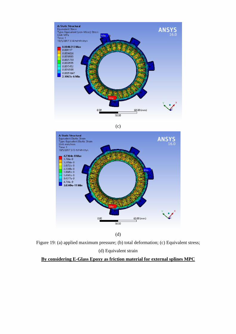
(c)
(d)
Figure 19: (a) applied maximum pressure; (b) total deformation; (c) Equivalent stress;
(d) Equivalent strain
By considering E-Glass Epoxy as friction material for external splines MPC

(a)
(b)

(c)
(d)
Figure 20: (a) applied maximum pressure; (b) total deformation; (c) Equivalent stress;
(d) Equivalent strain
The same case the dynamic analysis is done as shown on appendixes of page.
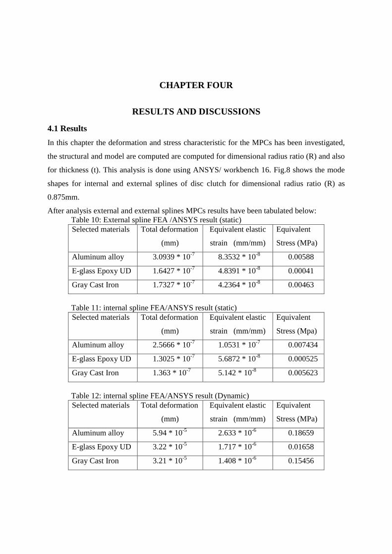
CHAPTER FOUR
RESULTS AND DISCUSSIONS
4.1 Results
In this chapter the deformation and stress characteristic for the MPCs has been investigated,
the structural and model are computed are computed for dimensional radius ratio (R) and also
for thickness (t). This analysis is done using ANSYS/ workbench 16. Fig.8 shows the mode
shapes for internal and external splines of disc clutch for dimensional radius ratio (R) as
0.875mm.
After analysis external and external splines MPCs results have been tabulated below:
Table 10: External spline FEA /ANSYS result (static)
Selected materials Total deformation
(mm)
Equivalent elastic
strain (mm/mm)
Equivalent
Stress (MPa)
Aluminum alloy 3.0939 * 10-7
8.3532 * 10-8
0.00588
E-glass Epoxy UD 1.6427 * 10-7
4.8391 * 10-8
0.00041
Gray Cast Iron 1.7327 * 10-7
4.2364 * 10-8
0.00463
Table 11: internal spline FEA/ANSYS result (static)
Selected materials Total deformation
(mm)
Equivalent elastic
strain (mm/mm)
Equivalent
Stress (Mpa)
Aluminum alloy 2.5666 * 10-7
1.0531 * 10-7
0.007434
E-glass Epoxy UD 1.3025 * 10-7
5.6872 * 10-8
0.000525
Gray Cast Iron 1.363 * 10-7
5.142 * 10-8
0.005623
Table 12: internal spline FEA/ANSYS result (Dynamic)
Selected materials Total deformation
(mm)
Equivalent elastic
strain (mm/mm)
Equivalent
Stress (MPa)
Aluminum alloy 5.94 * 10-5
2.633 * 10-6
0.18659
E-glass Epoxy UD 3.22 * 10-5
1.717 * 10-6
0.01658
Gray Cast Iron 3.21 * 10-5
1.408 * 10-6
0.15456

Table 13: External spline FEA/ANSYS result (Dynamic)
Selected materials Total deformation
(mm)
Equivalent elastic
strain (mm/mm)
Equivalent
Stress (MPa)
Aluminum alloy 3.0433 * 10-5
7.0744 * 10-7
0.0487
E-glass Epoxy UD 1.6118 * 10-5
4.9203 * 10-7
0.0049
Gray Cast Iron 1.6702 * 10-5
4.0124 * 10-7
0.0432
4.2 Discussions
4.2.1 Static, Dynamic and Thermal Analysis
As tabulated results shown in table 10,11 12,and 13 the Total deformation for Aluminum
Alloy external spline MPC is 3.0939e-7mm; that of E-glass Epoxy UD is 1.6427e-7mm and
that of Gray Cast Iron is 1.7327e-7mm. And from table 10, the Total deformation for
Aluminum Alloy internal spline MPC is 2.5666e-7mm; that of E-glass Epoxy UD is 1.3025e-
7mm and that of Gray Cast Iron is 1.363e-7mm through ANSYS Simulation Workbench 16.
Equivalent Strain for Aluminum alloy is 8.3532e-8mm/mm; that of epoxy is 4.8391e-8
mm/mm and that of Gray Cast Iron is 4.2364e-8mm/mm through ANSYS Simulation
Workbench 16.
Equivalent stress for Epoxy material is 0.00041MPa which is very less as compared to
Aluminum alloy of 0.00588MPa; and that of Gray Cast Iron is 0.00463MPa through ANSYS
Simulation Workbench 16, and the values obtained for the same through analytical
calculations are 0.1 N/mm2 for Aluminum alloy; 0.09 N/mm
2 for Epoxy, and 0.11 N/mm
2 for
Gray Cast Iron.
Also observed that; the total deformation, equivalent strain, equivalent stress for clutch plate
with E-Glass Epoxy as a friction material is less than that of Aluminum alloy and Gray Cast
Iron. For same input torque stress developed in clutch plate with friction material of E-Glass
Epoxy is less compared to Cast Iron and aluminum alloy. Hence it is concluded that the
clutch plate with friction material E-Glass Epoxy UD gives better performance than Gray
Cast Iron and Aluminum alloy.
In multi plate clutch, friction plate plays very important role in torque transmission from
engine to transmission system. So the friction material property is very important in clutch
design. From the above tables, it is clear that E-glass Epoxy UD material is a better friction
material than Gray Cast Iron and aluminum alloy. It is also observed that total deformation,
equivalent stress and equivalent strain of E-glass Epoxy UD material are in the permissible
range for the ideal friction material compared to the theoretical calculations.

E-glass Epoxy UD has the low total deformation when compared to the existing conventional
Gray Cast Iron friction material. Hence, it is concluded that E-glass Epoxy UD serves as a
better friction material than Gray Cast Iron, and aluminum alloy and gives better clutch
performance.
Another best performance of E-glass Epoxy UD friction material is its lower weight. The
objective of this thesis is using materials having lower weight and better in torque transfer.
As shown in table of properties of material, the density of E-glass Epoxy UD is lower than
that of Aluminum alloy, and Gray Cast Iron. Since the density is the ratio of mass to it
volume (ρ= m/v), and increase in mass is proportional to the density. So, Gray Cast Iron has
more weight than aluminum alloy, and E-Glass Epoxy with the lowest weight of materials.
This shows that E-glass Epoxy UD is the lowest in weight than that of existing commercial
clutch materials mostly Gray Cast Iron.
Table 14: Results from thermal analysis
Material Heat Flux (W/m2) Temperature distribution (
oc)
Aluminum Alloy 6061 0.769 247.03
Gray Cast Iron 0.82 250.05
E-Glass Epoxy UD 0.535 268.94
Table 15: Results from modal analysis
Material Frequency in (Hrtz)
Aluminum Alloy 6061 0.231
Gray Cast Iron 0.257
E-Glass Epoxy UD 0.251
As shown in tables 14 and 15 Thermal and Modal analysis is done on the wet friction plates
to verify the strength. Friction materials used are Aluminum Alloy 6061, E-Glass Epoxy, and
Gray Cast Iron. By observing the analysis results, design is safe. Total Deformation and
stress, Strain values are less for E-Glass Epoxy material. Cast Iron material is having
capability to with stand high frequency up to 0.257 Htz.
Temperature Distribution and Heat flux values which is moderate than Aluminum Alloy and
Epoxy Material. So, usage of Gray Cast Iron as surface lining is better than the other two
materials. Hence, if we conclude that for multi plate clutches using E-Glass Epoxy as friction
material Strength is Improved, Deformation is reduced and Material Life of the Clutch is

improved. To improve Performance of clutch Lubricant Oil is maintained and servicing of
Automobile is done in Perfect Time.
4.2.1 Wear Analysis Result
The different parameter can be selected to calculate objective functions as calculated under
the title of wear analysis.
1. First the numbers of friction surfaces are chosen for 1, 2, 3, 4 and 5 for the same value of
pressure intensity and coefficient of friction and generate the graph between the friction
surfaces and the objective function
2. Second generate the graph for different values of coefficient of friction and pressure
intensity and number of friction surfaces will remain same and calculate the objective
function.
3. Third generate the graph for different values of pressure intensity and number of friction
surfaces and the coefficient of friction will remain same and calculate the objective function.
Table 16: By varying the value of number of friction surfaces (n)
Friction surfaces (n) Torque
1 82.62
2 165.2
3 247.9
4 330.5
5 413.1
Table 17: By varying the value of coefficient of friction.
Coefficient of friction Torque
0.1 55.1
0.2 110.2
0.3 165.2
0.4 220.3

0.5 275.4
Table 18: By varying the value of intensity of pressure pa
intensity of pressure Torque
0.25 118.023
0.3 141.628
0.35 165.233
0.4 188.9
0.45 212.44
From tables 16, 17, and 18; we have seen that as the respective values of materials increases,
the torque transfer also increases. And show in charts below.
Figure 21: by varying the value of number of friction surfaces (n)
Figure 22: By varying the value of coefficient of friction

Figure 23: by varying the value of intensity of pressure
Figure 21, 22 and 23 shows that as the number of friction surfaces, intensity of pressure, and
coefficient of friction increases or in case of multi plate clutches as the number of active
friction faces increase the torque transfer capacity will also increases. The representative
charts are shown in figures (21, 22 and 23) the advantages of these charts are that one can
read the value of objective function for any specified coefficient of friction or number of
friction surfaces or intensity of the pressure.
Similar charts can be prepared using the variation of the other parameters. These charts can
be used for the design purpose so as to reduce the magnitude of the objective function by
applying external agencies and by this method obviously we can improve the quality and life
of the friction clutch disk for these above parameters. In the present work a numerical
example has been solved, but this method can also be applied to any practical clutch if the
information about the required data is available.
CHAPTER FIVE
CONCLUSION, RECOMMENDATIONS AND FUTURE WORK
5.1. Conclusion
There are External and Internal Multi-Plate Clutches for clutching mechanism. Both Internal
and External Multi-plate Clutches are successfully modeled and mechanical property
characterization is done on it using Ansys work bench. In this paper a three dimensional
model of multi-plate clutches are modeled and analyzed on Solid work and ANSYS
Workbench FEM softwares for analysis of lighter weight clutch materials. The plate is
subjected to a manually calculated maximum pressure for each selected materials. When the
maximum pressure is applied on the active faces the corresponding maximum equivalent
stresses, total deformation, and equivalent strains are induced. At the same time some
portion of internal face of the plate results the maximum value where some elements of the
plate deforms, and this property is shown on all three material used for analysis of
deformation.
From the ANSYS Workbench structural simulation and analysis in FEM is a key to facilitate
the assessment of structural analysis of clutch plate which provides relatively simple method
for analyzing of material strength. Besides, the analysis shows that increase in tensile yield
strength of material, the maximum equivalent stress decrease and similarly the deformation

rate decreases. The final result shows that E-Glass Epoxy materials have minimum
deformation in their applied load and pressure conditions than other materials used, it also
have high wear resistance property and lower weight than existing Gray Cast Iron, and
aluminum alloy materials. Besides these, the weight of E-Glass Epoxy material is 72% lower
than that of Gray Cast Iron and 26% lower than Aluminum Alloy Materials. So, this makes
Epoxy Materials to be better for clutching.
5.2. Recommendation for future work
Due to lack of laboratory testing equipment and shortage of time, I haven‟t done the wear and
Thermal analysis in detail on each clutch plates and TCT system simulations. But, for Green
and light weight vehicles reduction of weight of component parts is essential. So, I
recommend the next researchers to:
Analyze wear rate and deformation of clutch plates by considering heat generated
during contact and motion.
Analyze for effective use of MPCs in TCT systems using motion simulation
softwares.

REFERENCES
1. A. Senatore, Advances in the Automotive Systems: “An Overview of Dual-Clutch
Transmissions", Recent Patents on Mechanical Engineering, vol. 2, pp. 93{101, 2 2009,
issn: 2212-7976.).
2. Adam ADAMOWICZ, and Piotr GRZES, “FINITE ELEMENT ANALYSIS OF
THERMAL STRESSES IN A PAD-DISC BRAKE SYSTEM (A REVIEW)” acta
mechanica et automatica, vol.7 no.4 (2013), DOI 10.2478/ama-2013-0032.
3. Audi, S.-S.P. (2006) 6-speed twin-clutch gearbox 02E (S-Tronic) Self-Study
Programme386.Available,at:http://training.avme.net/admin/Upload/SSP/4800_386%206%
20speed%20twin%20clutch%20DSG%20s_tronic%20Audi.pdf.
4. Bony Chrisol Joseph1, M Vasundara, “Structural Analysis of Multi-plate Clutch using
ANSYS, international Journal of Software and Hardware Research in Engineering, ISSN
No: 2347-4890, Vol.2, Issue 5, and May2014. Tamilnadu, India.
5. Chang-Yeon Cho, Jeong-Heon Kam, Han-Ki Hong, and Dilp.-Ing. Carsten Lovenich,
“More Efficiency with the Dry Seven-speed Dual-clutch Transmission by Hyundai”,
Development transmissions and Clutches. ATZ 0612016, Vol. 118.p3-8.
6. Cooke, D.C, (2014) Automaker Rankings 2014. The Environmental Performance of Car,
Companies.Availableat:http://www.ucsusa.org/clean_vehicles/what_you_can_do/automak
er-rankings 2014.html#.VThXtSHBzGc.
7. Ganesh Raut, Anil Manjare, P Bhaskar, Analysis of Multidisc Clutch Using FEA,
International Journal of Engineering Trends and Technology (IJETT) – Volume 6 Number
1- Dec 2013, VIT University, TamilNadu-632001, India.
8. Harris, W.H. (2006) How Dual-clutch Transmissions Work. Available at:
http://auto.howstuffworks.com/dual-clutch-transmission.htm (Accessed: 15th February).

9. Mario Pisaturo, “Dry clutch for automated manual Transmissions” Structural analysis and
control strategies, Phd. Thesis in Mechanical Engineering, cycle XII(2011-2013)
10. M. Ehsani, Y. Gao, and A. Emadi, Modern Electric, Hybrid Electric, and Fuel Cell
Vehicles, Routledge: CRC Press Taylor & Francis Group, 2010.
11. M. Goetz, M.C. Levesley, D.A. Crolla “Dynamic Modeling of a Twin Clutch
Transmission for Controller Design”, Materials Science Forum Vols. 440-441 (2003) pp
253-260. (2003) Trans Tech Publications, Switzerland
doi:10.4028/www.scientific.net/MSF.440-441.253.
12. Mrs.Ch.Vasantha Lakshmi, and Sandhya Rani.V, “Design and Structural Analysis of
Composite Coated Clutch Plate by using Composite Materials”, international journal and
Magazine of Engineering, Technology, Management and Research, A peer Reviewed
Open Access International Journal. ISSN No: 2348-4845. P1-4.
13. N. Mutoh, R. Miyaji, and T. Yamaguchi, “Outstanding running performance of front-and-
rear-wheel-independent-drive-type electric vehicle (FRID EV) under various transient
running conditions,” 38th
Annual Conference of the IEEE Industrial Electronics Society,
IECON‟12. Montreal, October 2012.
14. O.I. Abdullah, and J. Schlattmann, “Finite Element Analysis of Temperature Field in
Automotive Dry Friction Clutch”, Tribology in Industry, System Technology and
Mechanical Design Methodology, Hamburg University of Technology, Germany,
www.tribology.fink.rs, Vol. 34, No. 4 (2012) 206-216,
15. O.I. Abdullah and M. Al-Shabibi and James R. Barber: Transient Solution of the
Unperturbed Thermoelastic Contact Problem, Journal of Thermal Stresses, Vol. 32, No. 3,
pp. 226-243, 2009.
16. P. Janssen, and K. Govindswamy, “Future Automatic Transmission Requirements”,
Submission_VDI_Transmission_IV_02.p5-8.
17. Suyog Vitnor1, and Mukund Kavade, “Finite Element Analysis of Friction Plate of
Diaphragm Spring Clutch for TD-3250 Vehicle” International Journal of Science and
Research (IJSR) ISSN (Online): 2319-7064 Index Copernicus Value (2013): 6.14 | Impact
Factor (2015): 6.391
18. Xingxing Zhou, Paul Walker, Nong Zhang, Bo Zhu, Jiageng Ruan, “Numerical and
experimental investigation of drag torque in a two-speed dual clutch transmission”,
Mechanism and Machine Theory 79 (2014) 46–63, journal homepage:

19. IEEE Terms and Conditions, AA/IADS, AMS, and ASTM/ASME standards Metals and
their Alloys, available online at “Engineering 360”; specifications of materials and their
alloys 2.
Appendix 1
FEA result
For internal splines MPCs the result would be;
Using aluminum alloy as a friction material for internal splines MPC;
Figure 24: a) imported from Solid Work b) meshed model

Figure25: load and boundary conditions
(a)

(b)
(c)
Figure26: (a) Total deformation; (b) Equivalent stress; (c) Equivalent strain
And for gray cast iron using internal splines MPC

(a)
(b)

(c)
(d)
Figure27: (a) applied maximum pressure; (b) total deformation; (c) Equivalent stress;
(d) Equivalent strain
Using E-Glass Epoxy as a friction material for internal spline
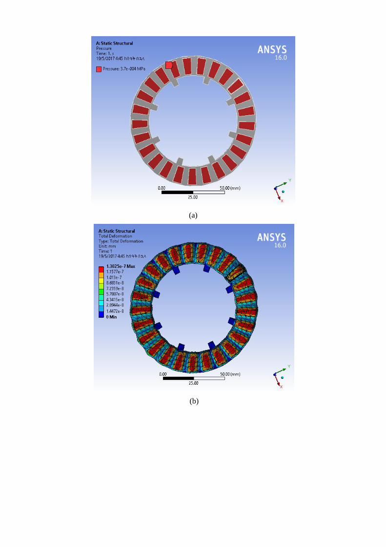
(a)
(b)
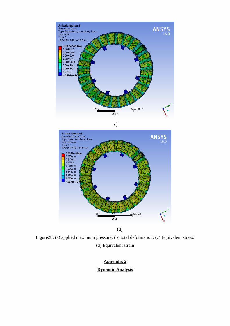
(c)
(d)
Figure28: (a) applied maximum pressure; (b) total deformation; (c) Equivalent stress;
(d) Equivalent strain
Appendix 2
Dynamic Analysis

Figure29: Loads and boundary conditions
By considering Aluminum alloy as a friction material for external splines MPC

(a)
(b)

(c)
Figure30: (a) total deformation; (b) Equivalent stress; (c) Equivalent strain
By considering Gray Cast Iron as friction material for external splines MPC
(a)

(b)
(c)
Figure 31: (a) total deformation; (b) Equivalent stress; (c) Equivalent strain
By considering E-Glass Epoxy as friction material for external splines MPC

(a)
(b)

(c)
Figure 32: (a) total deformation; (b) Equivalent stress; (c) Equivalent strain
Appendix 3
For internal splines the result would be;
Using aluminum alloy as a friction material for internal splines MPC;

Figure33: Boundary conditions
(a)

(b)
(c)
Figure34: (a) total deformation; (b) Equivalent stress; (c) Equivalent strain
And for gray cast iron using internal splines MPC

(a)
(b)
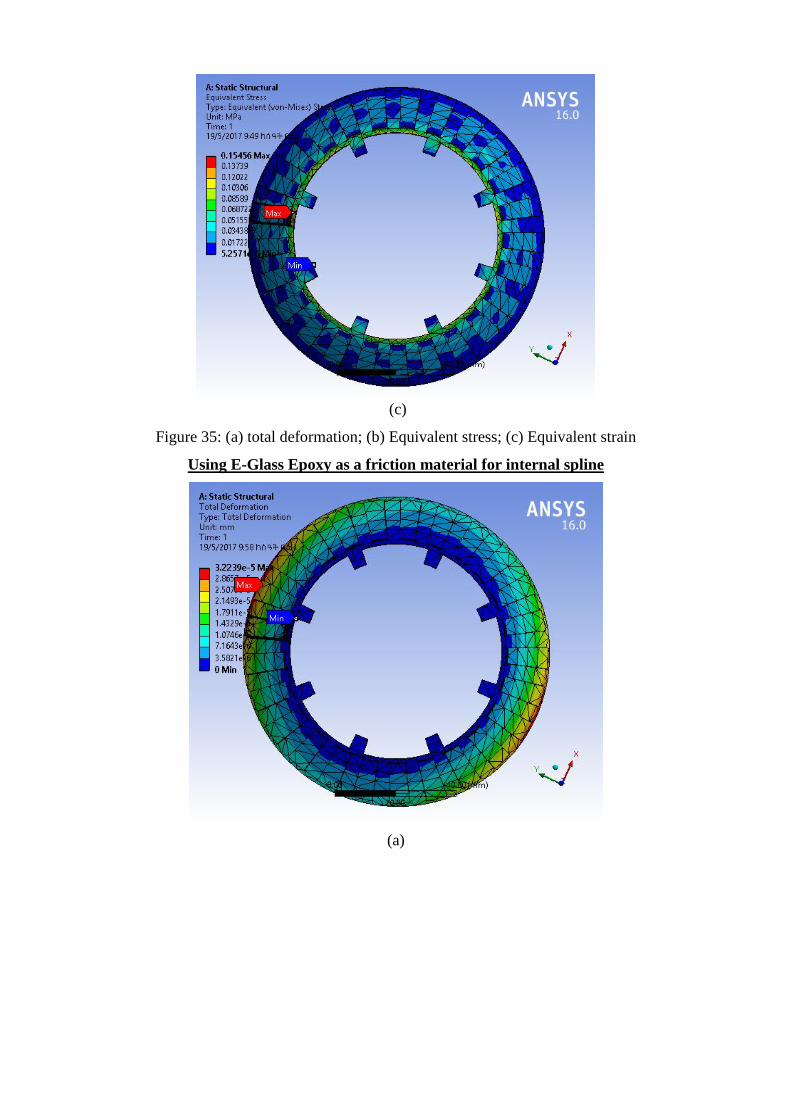
(c)
Figure 35: (a) total deformation; (b) Equivalent stress; (c) Equivalent strain
Using E-Glass Epoxy as a friction material for internal spline
(a)

(b)
(c)
Figure36: (a) total deformation; (b) Equivalent stress; (c) Equivalent strain
Copyright © 2022 FDOKUMEN