
A new species of Scytalopus tapaculo from the upper Magdalena Valley, Colombia
Upload
independentCategory
view
0download
0
Copyright 2012 Society of Photo-Optical Instrumentation Engineers. One print or electronic
copy may be made for personal use only. Systematic reproduction and distribution,
duplication of any material in this paper for a fee or for commercial purposes, or modification
of the content of the paper are prohibited.
Final mechanical and opto-mechanical design of the
Magdalena Ridge Observatory Interferometer
Fernando G. Santoroa - Andres M. Olivares
a - Chris D. Salcido
a - Stephen R.
Jimeneza - Colby A. Jurgenson
a - Xiaowei Sun
b - Christopher A. Haniff
b - David F.
Buscherb - Michelle J. Creech-Eakman
a - Robert J. Selina
a - Tyler McCracken
a -
John S Youngb - Martin Fisher
b - Dan Klinglesmith
a - Nicolas C. Torres
a - Chuck
Dahla - Alisa V. Shtromberg
a - Donald M.A. Wilson
b
aNMT/MRO, 101 East Rd, 87801 Socorro, NM - USA
bUniversity of Cambridge, Cavendish Laboratory, Cambridge - UK
ABSTRACT
Most subsystems of the Magdalena Ridge Observatory Interferometer (MROI) have progressed towards final mechanical design, construction and testing since the last SPIE meeting in San Di ego - CA. The first 1.4-meter telescope has successfully passed factory acceptance test, and construction of telescopes #2 and #3 has started. The beam relay system has been prototyped on site, and full construction is awaiting funding. A complete 100-meter length delay line system, which includes its laser metrology unit, has been installed and tested on site, and the first delay line trolley has successfully passed factory acceptance testing. A fully operational fringe tracker is integrated with a pro totyped version of the automated alignment system for a closed looping fringe tracking experiment. In this paper, we present details of the final mechanical and opto-mechanical design for these MROI subsystems and report their status on fabrication, assembly, integration and testing.
Keywords: Optical interferometer, delay line, beam combining, fringe tracking.
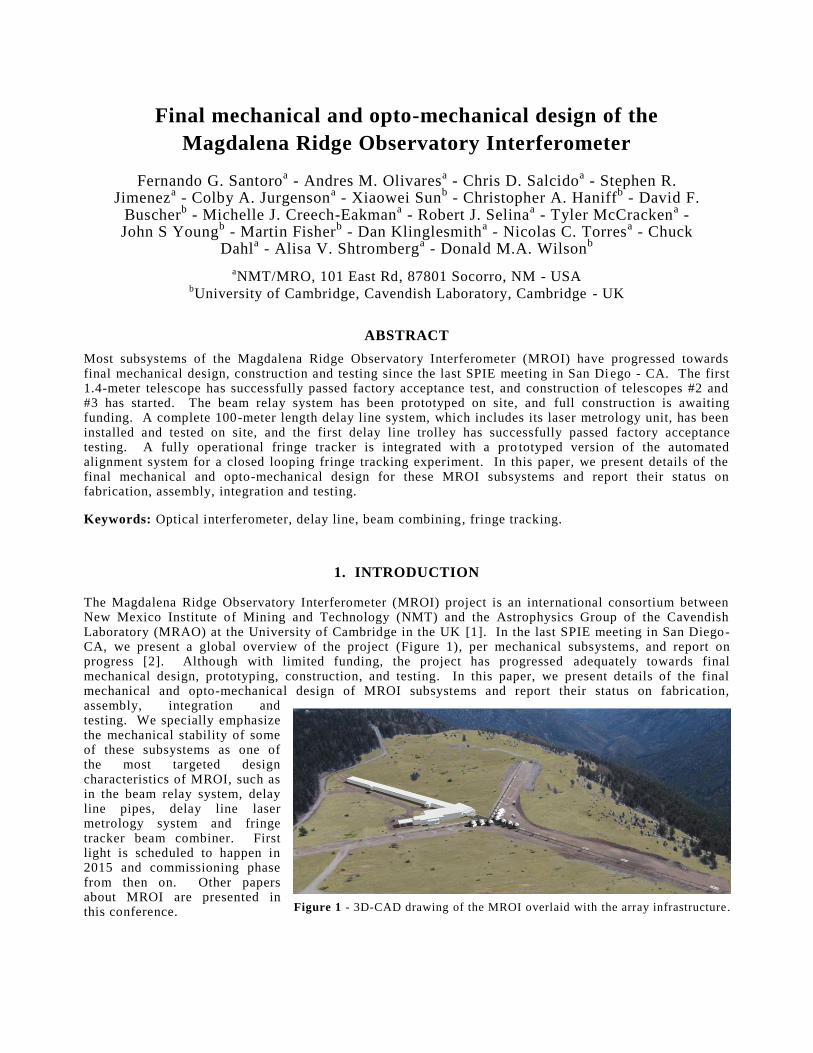
1. INTRODUCTION The Magdalena Ridge Observatory Interferometer (MROI) project is an international consortium between New Mexico Institute of Mining and Technology (NMT) and the Astrophysics Group of the Cavendish Laboratory (MRAO) at the University of Cambridge in the UK [1]. In the last SPIE meeting in San Diego-CA, we present a global overview of the project (Figure 1), per mechanical subsystems, and report on progress [2]. Although with limited funding, the project has progressed adequately towards final mechanical design, prototyping, construction, and testing. In this paper, we present details of the final mechanical and opto-mechanical design of MROI subsystems and report their status on fabrication, assembly, integration and testing. We specially emphasize the mechanical stability of some of these subsystems as one of the most targeted design characteristics of MROI, such as in the beam relay system, delay line pipes, delay line laser metrology system and fringe tracker beam combiner. First light is scheduled to happen in 2015 and commissioning phase from then on. Other papers about MROI are presented in this conference. Figure 1 - 3D-CAD drawing of the MROI overlaid with the array infrastructure.

2. MROI MECHANICAL SUBSYSTEMS A functional block diagram of the MROI is illustrated in [2]. As one can notice, the mechanical design portion was broken down into eight major mechanical subsystems. These mechanical subsystems have passed final design phase and some of them have matured to either construction or assembly, integration and verification (AIV) phases. Following the order that they appear to the incoming beam of light these subsystems are the Unit Telescope Mount/Optics (UTM/O), Fast Tip-Tilt System and Narrow-Field Acquisition System (FTTS/NAS), Beam Relay System (BRS), Delay Line System (DLS), Beam Compressing Telescope (BCR), Automated Alignment System (AAS), M10 and Infrared Coherencing Nearest Neighbor tracker (ICoNN). The Unit Telescope Enclosure (UTE) and Vacuum System (VS) are also added as major subsystems. Important issues investigated during final design phase were the feasibility of the mechanical design and the likelihood that it will allow the subsystems to meet top-level requirements defined for the project. The following sections describe these MROI mechanical subsystems and report the status of each of them. 2.1 Unit Telescope Mount The MROI unit telescope (UT) is a 1.4m Mersenne optics design assembled on an elevation over elevation gimbal configuration [2]. It takes an input beam of light from the night sky and delivers a collimated beam of 95mm in diameter. The optical train is composed of an f/2.25 concave parabolic primary mirror (M1) with 1.4m in diameter, a convex parabolic secondary mirror (M2) with 115 mm in diameter and a flat elliptical tertiary mirror (M3) that is articulated to allow light to be directed to a fixed horizontal position out of the telescope (nominally at 1.6m above the Beam Combining Facility (BCF) gr ade). The UTM is designed to provide high precision pointing and tracking during optimal observing environmental conditions (0.5arcsec rms on the sky after the application of a pointing model), and to hold small temporal variation of wavefront piston aberration due to vibration and changes in the pointing angle (Figure 2). The most challenging requirements placed on the UTM, also applicable to severe environmental conditions, are listed below:
Pupil stability: 0.5 mm over the entire field of regard;
Pointing error: lower than 20 arcsec over the full night;
Open loop tracking: better than 1 arcsec;
Closed loop tracking: 0.02 arcsec and 0.03 arcsec RMS respectively for the mount and the wind shake residual error. A 200 Hz bandwidth fast steering actuator is implemented at the level of the secondary mirror for tip-tilt correction;
Optical Path Length (OPL) Stability: 23 nm RMS for a 12 ms exposure time frame;
Overall image quality: 63 nm RMS; and
Optical obscuration: less than 5%.
Figure 2 - The MROI 1.4m UTM at AMOS facility during Factory Acceptance Test (Courtesy of AMOS).

These requirements have been demonstrated for the first UTM (hereafter called UTM#1) during Factory Acceptance Test (FAT) at AMOS facility in Belgium (http://www.amos.be/). UTM#1 has successfully passed FAT on May/2012, with testing activities performed over 2011-2012 and overseen by MRO personnel. UTM#1 is now packed and ready to be shipped to the MROI site on the Magdalena Ridge. As the first enclosure won’t be ready at the time that UTM#1 arrives on the MROI site, the MRO Project Office has decided to integrate it with the UTO and carry-on Site Acceptance Test (SAT) with AMOS on the integration facility on the Magdalena Ridge. This integration facility will have similar UTM interfaces (mating points) that will be presented at the 28 stations, but only 25% of the field of view of the telescope will be available with a removable roof. All utilities necessary to run the telescope such as: power, communication and cooling loop, will also be available at the integration facility. The MRO Project Office has scheduled to receive UTM#1 by Spring-2013. The manufacturing of larger parts of UTM#2 and UTM#3, such as: fork, gimbal and tube were completed on June/2011 by AMOS (Figure 3). UTM#2 is now under mechanical AIV phase, where the three major parts will be integrated, and the M1 mirror cell will be assembled in order to start measuring inner and outer axes alignment.
Figure 3 - Long lead items of UTM#2 and UTM#3 at AMOS facility (Courtesy of AMOS).
2.2 Unit Telescopes Optics As previously mentioned, the UTO consist of a f/2.25 concave parabolic M1 1.4m in diameter, a convex parabolic M2 115 mm in diameter and a flat elliptical M3. Combined wavefront aberrations from the three mirrors are specified to be no greater than 44nm rms, with tighter specifications for sub -apertures within the overall diameter (Table 1). Fabrication has started on the first six sets of UTO (Figure 4). All six secondary and tertiary mirrors are polished to specification and awaiting coating. RMS wavefront aberration for M2 ranges from 4.2nm to
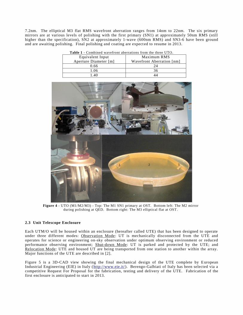
7.2nm. The elliptical M3 flat RMS wavefront aberration ranges from 14nm to 22nm. The six primary mirrors are at various levels of polishing with the first primary (SN1) at approximately 50nm RMS (still higher than the specification), SN2 at approximately 1-wave (600nm RMS) and SN3-6 have been ground and are awaiting polishing. Final polishing and coating are expect ed to resume in 2013.
Table 1 - Combined wavefront aberrations from the three UTO.
Equivalent Input Aperture Diameter [m]
Maximum RMS Wavefront Aberration [nm]
0.66 24
1.06 36
1.40 44
Figure 4 - UTO (M1/M2/M3) - Top: The M1 SN1 primary at OST. Bottom left: The M2 mirror
during polishing at QED. Bottom right: The M3 elliptical flat at OST. 2.3 Unit Telescope Enclosure Each UTM/O will be housed within an enclosure (hereafter called UTE) that has been designed to operate under three different modes: Observation Mode: UT is mechanically disconnected from the UTE and operates for science or engineering on-sky observation under optimum observing environment or reduced performance observing environment; Shut-down Mode: UT is parked and protected by the UTE; and Relocation Mode: UTE and housed UT are being transported from one station to another within the array. Major functions of the UTE are described in [2]. Figure 5 is a 3D-CAD view showing the final mechanical design of the UTE complete by E uropean Industrial Engineering (EIE) in Italy (http://www.eie.it/). Berengo-Galbiati of Italy has been selected via a competitive Request For Proposal for the fabrication, testing and delivery of the UTE. Fabrication of the first enclosure is anticipated to start in 2013.

Figure 5 - A 3D-CAD view of the MROI UTE (Courtesy of EIE).
2.4 Fast Tip-Tilt System and Narrow-Field Acquisition System The functions of the FTTS/NAS are twofold. One is to provide fast tip -tilt correction signals to the second stage hexapod actuators that allow fast tip -tilt motion of M2. The other is to operate under narrow acquisition mode which allows a telescope operator to find an object in the full field of view of the telescope. The design of the FTTS/NAS is being developed under contract with the University of Cambridge - UK. Construction, installation and on-site testing will also fall under responsibility of the University of Cambridge. MROI engineers will review designs and assist the Cambridge team with installation, integration and commissioning on the Magdalena Ridge. The University of Cambridge has successfully passed PDR in June/2011. The main scope of the review was to evaluate the likelihood of FTTS/NAS design to meet te chnical requirements. For this purpose, a complete prototype has been built to allow a fully integrated testing, which includes stability tests of complete opto-mechanical system. Stability tests of individual mounts are completed (see specific publication about the FTTS/NAS in this conference). 2.5 Beam Relay System The major function of the BRS is to transport light exiting M3 to the BCF in vacuum using two flat mirrors (referred as M4 and M5). When MROI is completed, a net of evacuated pipes wil l be available to feed all 28 stations and at any UT configuration in the "Y" array. A second function of the BRS is to allow tilt and shear errors between the UT and DLS axes to be minimized. The BRS is an in -house development. On each of the three arms of the array, there is up to three BRS pipes, each of which is placed parallel to the others in a horizontal plane. In addition to these nine pipes, there is a 10th that continues from a UT located at the geometric center of the array. From there to th e BCF, these ten pipes are laid out side by side with no additional optics. The minimum spacing of the beams is limited by the size and spacing of the DLs, as discussed in section 2.6, rather than the spacing of the UTs. This design calls for two different configurations of M4 and M5 depending on the array arm – if the West arm or North/South arms [2]. In the West arm, M4 is positioned on the UT Nasmyth table and M5 is positioned close to that UT. In the North/South arms, M4 is positioned close to the U T and M5 is positioned in the vertex of the array. M4 and M5 mirrors are 8" in diameter to guarantee a clear aperture greater than 130mm. The most challenging requirements placed on the BRS, also applicable to severe environmental conditions, are listed below:
Mirror tilt resolution: 0.8μrads; and
Mirror thermal stability: 0.75μrads (overnight temperature variation of 4ºC).

Unlike what was presented in the previous SPIE (San Diego -2010), the design of the cross-over cans and associate aluminum support has been changed. In the final design, the aluminum support that is made of six aluminum plates sits iso-statically on an alignment steel plate to compensate for mismatched material between them (Figure 6). The cross-over cans are responsible for protecting the mirror-mounts from environmental condition (wind buffeting and changes in temperature) and to keep the vacuum integrity a t a level of 0.5mbar (section 2.11). Appropriate seals and thermal isolation material have been added to the design in order to meet the stability requirements. As the mirror-mount needs to be moved with the telescope from station to station, during relocation, a quick access cover has been designed on top of the cans. The alignment steel plate will be consolidated with concrete after its alignments.
Figure 6 - Left: Cross-over can and aluminum support; Right: M4-M5 mirror mount.
Each BRS mirror is assembled in a commercial gimbal mount (Figure 6), appropriately modified for full automation and performance. The modifications in the mount include motorization through two high-resolution linear actuators, with a minimum incremental motion of 50nm. This allows a tip-tilt resolution of the mount of better than 0.8μrads. The actuators have their own rotary encoder with a design resolution of 35nm, but also have a backlash of only 2µm. To be able to measure the tip/tilt position, the design has included four pairs of capacitor sensors, which are also used as a fiducial. With the use of this device we will be able to measure the tilt of the mirror to ±0.58μrads over the range of more than 6arcmin. The mirror-mount will be sitting in a pre-alignment aluminum platform, which is kinematically attached to the main aluminum support. A mirror-mount has been tested in terms of resolution and thermal stability using the capacitor sensor (in only one axis). The results show that the thermal stability is close to 2μrads , so exceeds the requirements by factor of three and the tilt resolution have meet the specification. When measuring displacement on such a small range, the thermal expansion in the mirror-mount and the capacitor sensor play an important role. In order to characterize the mirror-mount and the capacitor sensor in an accurately way, it is necessary an optical system. The design is composed of a laser beam focused onto a CCD via mirror which has the capacitor sensor attached/glued to the mirror -mount. A second reference beam will allows measuring the displacement. The optical system will be enclosed on a thermal isolated box, to keep the opto-mechanical component stable in terms of temperature. The room where the test will be carried out has a thermal stability of 0.1°C/night, so it is expected to have a lower result inside of this insulated environment. The optical system is composed of a laser beam of 6mm diameter that is going through two folded mirror, beam expander (3x), beam splitter that split the beam to the mirror -mount and a retro-reflector, focusing lens, two folded mirror and the CCD (Figure 7). In order to characterize the mirror-mount, the mirror will be moved using the lineal actuator to measure the minimal incremental motion, in case of thermal stability the mirror -mount will remain in position.

Figure 7 - Optical system to measure the position of the mirror -mount in the laboratory.
A centroiding algorithm will be used to determine the position of the spot on the CCD, using a scheme adapted from [7], to estimate and correct error by modeling it as proportional to the displacement of the spot from the center of the image. After completion of the test in the laboratory, the next step will be on-site test (Figure 8). In order to measure stability due to temperature changes and wind loading, the first crossover-cans, aluminum support and mirror-mount will be installed on the dedicated pier on station W000 [2]. The optical system is similar to be used at the laboratory measurement, the beam will be sent from the Inner -BCA to station W000 (40m away in the West arm) through evacuated aluminum pipes.
Figure 8 - Set-up of on-site BRS test.
This type of test also allows a better understanding of the whole system (pier, aluminum frame, mirror-mount). It also helps to define a final alignment strategy and test of vacuum integrity of the system. In case tilt due to thermal condition is greater than the requirement, a closed loop will be used to keep the mirror stable as required. The capacitor sensor and the high-resolution linear actuator will be used for this purpose. Fabrication status of BRS hardware for testing of station W000 in the array is shown in (Figure 9): Mirror-mount modifications and capacitor plate for two axes is 90% completed; aluminum crossover cans and associate aluminum supports are 60% completed; pipes and support for station W000 are 95% completed; anchor support is completed; and vacuum pipes at the Outer -BCA is out for bid.

Figure 9 - Fabricated parts of the BRS and 80m of aluminum pipes .
2.6 Delay Line System The major function of the DLS is to control the position of each cat's eye along its correspond ing evacuated single path traverse DL pipe so as to match light paths from a star, via a pair of UTs, to within the coherence length of the light being measured. As already mentioned, the DLS is assembled inside the BCF, i.e. Delay Line Area (DLA) and Beam Combining Areas (Inner and Outer -BCA) [5]. When MROI is completed: - the DLA will be equipped with up to ten 190m DL pipes/supports and trolleys (cat's eyes assembled on wheeled carriages); - the Inner-BCA will be equipped with a laser metrology system with associated hardware and optics to feed up to ten DLs; and - the Outer-BCA will be equipped with associated electronics racks and computers. The first DL (with 100m length) was successfully installed and aligned in fall of 2010. The DL installed was DL[W2] which is connected to the west arm of the array and can be fed from any of the UTs on that arm, but the UT at station W000 [2]. The installation included aluminum pipes and steel flexure/anchor supports, one channel of the laser metrology system, and electronic hardware (Figure 10). Stability testing of this DL pipes/supports and its laser metrology system as well as testing vacuum integrity were also performed. The reasoning for installing a 100m DL is to be able run SAT of the first production trolley on a DL that is at least 5 times longer than the DL the trolley was tested in for FAT at the University of Cambridge in the UK. The first production trolley has already completed FAT and is ready to be shipped to MRO (Figure 11).
Figure 10 - First 100m DL installed, aligned and tested at the DLA of the MROI .

Figure 11 - Final preparation for FAT at the University of Cambridge in the UK.
Preparations have also been accomplished for SAT of the first production trolley. This includes installing an “Open Test Track”, which allows a trolley to be integrated and tested in the laboratory, and stability of alignment of the installed DL pipes/supports and laser stability testing of the metrology system. The tests have shown the DL to be very stable since installation. The pipes were installed at a nominal axis of 1517.50mm above grade and the deviation over one year afterward was less than 0.5mm through the whole 100m length. Measurements were done by installing a total station on a survey monument corresponding to the correct DL and setting it up so that it could project a virtual line along the nominal axis of the DL. A target was then placed on the DL pipe ends and at various places along the DL to check for deviations from the nominal axis. Initial stability tests of the metrology system have been good. The stability of the metrology laser was found to have a standard deviations of ±3.787µm in X and ±7.971µm in Y. X and Y represent horizontal and vertical axis respectively in the plane normal to the optical axis. The measurements were done using a SpotOn detector that was placed 3m away on the adjacent table (the metrology table is made of three 0.7m x 2.4m tables rigidly attached together), next to the metrology block. This implies tha t the laser position was stable to within 0.26 arcsec in X and 0.55 arcsec in Y. The measurement for X easily meets the requirement of 0.45 arcsec while Y is slightly out of spec. One source of the error in Y may be the metrology table bending due to temperature changes. Plans are being made to mitigate this problem. The detector was centered on the nominal position of the laser and measured the position of the beam once a minute. The measurements shown here were taken over the course of 6 days, though many measurements have been taken over the period since installation and show results consistent with what is shown here. Temperature was closely monitored during the testing with several temperature probes placed on and near the metrology table inside the Inner-BCA. Measurements show the temperature to be 15.64 ± 0.037
oC over
the test duration. Figure 12 shows the metrology system installed in the Inner -BCA. Figure 13 shows the results for the testing, the top graph shows the deviation in microns (X i s black and Y is red) over the 6 day testing period, the lower graph shows the temperature measurement over the same period. The spikes represent times when someone entered the inner -BCA to check the setup.
Figure 12 - Metrology system in the Inner-BCA.
Metrology block
Beamsplitter block
Agilent
laser

Figure 13 - Results from the metrology system laser stability test.
2.7 Beam Compressing Telescope Upon exiting the DLA, light from each UT enters the Inner -BCA, pass above the DL metrology table and reach the Beam Compressing Telescope (BCR) where will be optically compressed from 95mm to 18mm and directed to ICoNN. The BCR will be outsourced through a Request -For-Bid which considers design, fabrication, testing and delivery. Top-level requirements and SOW are completed for this process to s tart.
2.8 Automated Alignment System A beam of light from each UT will travel distances ranging from 460m to 660m (depending upon its location in the array) before reaching a beam combiner and spectrograph. Considering that MROI is comprised of three major optical axes, i.e. UT, DLS and beam combiner, a suitable method for co-aligning these axes automatically in a nightly basis is provided by the AAS. Fully automated alignment is performed via M4/M5 and switchyard, this being a key design characteristic of MROI (Figure 14). The AAS is an in-house development which design, prototyping and testing are underway [4].
Figure 14 - Diagram showing the three optical axes of the MROI.
2.9 M10 The M10 mirrors are responsible for converting the phase plane and beam pitch of ten beams of light exiting the BCR (609.6mm) to any switchyard (100mm) in the instrument area of the Inner -BCA. Each mirror can be adjusted in a nightly basis using a Newport Agilis mount and custom made support. 2.10 ICoNN The major role of ICoNN is to measure the group delay between all nearest neighbor UTs in the array and to send closed feedback signal to the corresponding DL trolleys for correction of atmospheric disturbances.

ICoNN is an in-house development in which the mechanical design is broken down into four smaller subsystems named as switchyard, beam combiner (BC), periscope optics (PO) and spectrograph. The switchyard is responsible for converting the phase plane and beam pitch from M10 to the BC and for co-aligning the DLS axes to the BC axes [3]. Fabrication is complete and alignment/stability testing has been successfully conducted since last SPIE [2] (Figure 15). The BC is responsible for making the pair -wise nearest combinations [3]. Two paired outputs of combined light are used to feed up to four spectrographs using two PO arrangements [2,3]. The BC design consists of 38 optical elements; 19 mirrors and 19 beamsplitters. A novel modular mechanical design philosophy was devised for the BC where optical elements that are in close proximity to one another were grouped together and installed in modules (Figure 15). They are all no-power optics and have similar optical functions in the BC and installing them in a single mount allows significant reduction of b uilt-up tolerances between them. In this scheme, only a few one-time adjustments are necessary to remove shear and tilt from each beam. Long term creeping is controlled by indexing each module on alignment templates made of same material as the optical table (mild steel). This means that after alignment is completed, the optical components of the BC should hold position and specially orientation between them in an over-night basis. Fabrication is complete and alignment/stability testing has been success fully conducted in conjunction with switchyard parts (Figure 15) [6]. Thermal tilt stability for the optical components meets the requirement of maximum ±25µrad for an over-night temperature variation of 0.1ºC inside the Inner-BCA. Long term thermal stability testing, in a full year time-scale, has been successfully conducted in the laboratory.
Figure 15 - BC under laboratory test using white light [6].
One PO assembly is placed at each output of the BC. They are both responsible to fold the linear output into arcs and to ensure that pair-wise nearest combinations arrive at the aperture stop in the spectrograph at the correct location and orientation [3]. One PO assembly takes up to nine beams and feed two spectrographs, one with five beams and the other with four. Currently, the PO assembly is designed to feed one spectrograph per BC output, which means six UTs in the array. The spectrograph is responsible for taking combined output beams exiting the PO, focusing them through aperture stops before re-collimation takes place, and making appropriate dispersion and focus onto the detector [3]. For the spectrograph to operate appropriately in the infrared, its optics and detector need to be enclosed inside a Dewar. A modular design approach and a built-to-print philosophy are applied in the opto-mechanical design of all subcomponents installed on the Cold Working Surface Plate (CWSP), which includes the detector (Figure 16). Following the order that each module appears to the incoming beams from the PO, they are: entrance windows, Eccentric Mersenne Gregorian OAPs 1, aperture stop, Eccentric

Mersenne Gregorian OAPs 2, Direct Vision Prism (DVP) flipper mechanism, focus-OAPs and detector. Appropriate indexing of each module on the CWSP, zero creeping between thermal cycles and an alignment procedure with minimum adjustments are also characteristic s of the ICoNN spectrograph design. For convenience, the aperture stop module is installed at the point of symmetry of the CWSP (physical point that is kept unchanged during cool-down and warm-up cycles) and has no adjustment.
Figure 16 - Cartoon of ICoNN CWSP and opto-mechanics.
The aperture stop and detector modules were fabricated and are now under cryogenic testing on the CWSP. All other modules are under fabrication at a specialized prototype machine shop in the Albuquerque-NM area. The OAPs (for EMGs and focus) were diamond turned and successfully clocked/integrated to their mounts. Special fixtures were designed in order to achieve the tight tolerances required in this process. The DVP flipper mechanism and focus-OAP mount are currently under fabrication. The DVP flipper mechanism allows selection of bandpass between H (1.5-1.8µm) and Ks (1.99-2.31µm). The flipper mechanism approach was chosen due to space limitation for a prism wheel inside the cryostat. In this design, H and Ks DVPs are grouped together in a V-shaped (90º angle) monolithic aluminum cell. The DVPs are assembled in an arc, following the input beam introduced int o the spectrograph. Each DVP is made of a pair of prisms with center separation of 1mm. All apex angles are different between DVPs. The first prism in the optical train is made of Infrasil 301 and the second is made of BaF 2. During assemble of the prisms in the mount, there is the need to control: - concentricity between pair of prisms; - relative center separation between pair of prism (longitudinal direction); - relative rotation between pair of prisms; - relative position between DVPs in the mount (arc); and relative rotation between DVPs in the mount (in order to correct the direction of dispersion (parallel and perpendicular )). The ideal mounting cell will be individual for each prism. It should guarantee the prisms to be optically concentric to w ithin tolerance at both ambient and cryogenic temperatures inside the spectrograph. It should also allow the correct center separation at cryogenic temperature. The mounting cell should also preserve critical alignment of all prisms even after a number of thermal cycles. Also important is that the cell should not allow thermally induced stress to build-in the prisms. These design drivers can be achieved using a spring finger cell design for each individual prism. The internal diameter of each cell is specified to lightly load the prism radially at room temperature and to have enough flexure to load the prism during cryogenic temperature without producing stress over the limit of material. Figure 17 is the DVP flipper mechanism and a typical pair of spring finger cells for DVP prisms.
Entrance windows
Eccentric Mersenne
Gregorian 1
Eccentric Mersenne
Gregorian 2
Focus-OAPs
DVPs flipper mechanism
Aperture stop
Detector
Thermal straps on
CWSP
CWSP

Figure 17 - Cartoon of the DVP flipper mechanism and a typical pair of spring cells .
Following the DVP flipper mechanism is the focus-OAP module, which is responsible for taking light from the DVPs and focuses them onto the detector. It is composed of five identical OAP aluminum segments, i.e. same off-axis-distance, diameter and center thickness. As with the EMGs and DVPs [2], these segments are arranged in an arc and are slightly displaced when assembled on the fro nt plane of the mount to separate their foci on the detector (Figure 18). Due to fabrication errors presented in the cell of each OAP segment and in the mount support for the cells, and also considering assembling errors involved in positioning and orienting the segments correctly, individual motorized adjustments in tip and tilt are required. These adjustments are also needed for fine tuning between pair of spectrographs when more than 6 UTs are operational in the array. Due to space limitation for implementing a tip/tilt mechanism for each of the five OAP segments, azimuth rotation is introduced around a pair of C-flex bearings using a Cedrat piezo-actuator (Figures 18 and 19). Rotation in elevation is possible through the use of a hinge flexure driven in a push-pull configuration by a pair of Cedrat piezo-actuators. A ±150µm of linear spot motion on the detector plane is required for both tip and tilt rotations in cryogenic temperature. A minimum of 12.5µrad of resolution is required for the fine tuning. The focus-OAP module has been prototyped successfully in the laboratory so as to characterize the hinge flexure and Cedrat actuators to the requirements (Figure 19).
Figure 18 - Cartoon of the focus-OAP module (back and front views).
Figure 19 - Cartoon of the focus-OAP tip-tilt cell and prototype under laboratory testing.
Cedrat piezo-actuator
C-flex
bearing
C-flex
bearing
Hinge flexure

Figure 20 is the Dewar spectrograph under assembly and testing in the laboratory. Full alignment in translation and orientation of the spectrograph on the ICoNN optical table is possible through appropriate adjustment blocks and bolts. The Dewar hold time exceeds 30 hours of steady temperature provided by LN2 (77K) without the need to re-fill the vessel. The spectrograph is now prepared for a closed loop experiment starting soon (see other publications in this conference).
Figure 20 - ICoNN spectrograph under assembly and testing.
2.11 Vacuum System The Vacuum System (VS) is an in-house development used to evacuate the BRS and DLS volumes. It is required to hold a vacuum level of 0.5mbar (3.75x10
-1 Torr) over the night and has to evacuate a volume of
approximately 320m3. Final design for the system has been completed. Testing of individual components
has begun.
3. CONCLUSION Final mechanical and opto-mechanical designs of major MROI subsystems are completed. Some prototyping is still underway, such as the BRS mirror mount, as well as fabrication and testing of subcomponents of major subsystems, such as ICoNN. Stability testing of key subcomponents has been successfully accessed, such as the ICoNN BC, DL pipes/supports and DL laser metrology system. The project is now working on get prepared for a closed loop fringe experiment, which includes most subcomponents installed inside the BCF (see paper in this conference). First light is scheduled for 2015.
ACKNOWLEDGEMENTS The Magdalena Ridge Observatory is funded by Agreement No.N00173-01-2-C902 with the Naval Research Laboratory (NRL). The MRO interferometer is hosted by the New Mexico Institute of Mining and Technology (NMIMT) in Socorro, NM, USA, in collaboration with the University of Cambridge - UK. Our collaborators at the University of Cambridge wish to also acknowledge their funding via STFC (formerly PPARC) in the UK. We would also like to express our deep acknowledgements to NMIMT for securing institutional revenue bond money to support MRO new instrumentation initiatives.

REFERENCES
[1] Creech-Eakman, M.J. et.al. - “Magdalena Ridge Observatory Interferometer: advancing to first light and new science”, SPIE 7734-5, San Diego - CA, USA (2010).
[2] Santoro, F.G., Olivares, A., Salcido, C., et.al. - “Mechanical design of the Magdalena Ridge Observatory Interferometer”, SPIE 7734-151, San Diego - CA, USA (2010).
[3] Jurgenson, C.A., Santoro, F.G., Baron, F., McCord, K.M., Block, E.K., Buscher, D.F., Haniff, C.A., Young, J.S., Coleman, T. and Creech-Eakman, M.J. - “Fringe tracking at the MROI”, SPIE 7013-046, Marseille - France (2008).
[4] Shtromberg, A.V., Jurgenson, C.A., McCord, K.M., Olivares, A.M., Bloemhard, H.N., Santoro, F.G., Buscher, D.F., Haniff, C.A., Young, J.S., Torres, N.C. and Farris, A.R. - “Magdalena Ridge Observatory Interferometer Automated Alignment System”, SPIE 7734-39, San Diego - CA, USA (2010).
[5] Fisher, M., Buscher, D.F., Haniff, C.A., Young, J.S., Wilson, D.M.A., Sun, X., Boysen, R.C. and Seneta, E.B. - “Design of the MROI delay line optical path compensator”, SPIE 7734-156, San Diego - CA, USA (2010).
[6] Jurgenson, C.A., Santoro, F.G., McCracken, T.M., McCord, K.M., Buscher, D.F., Haniff, C., Young, J. and Creech-Eakman M.J. - “The MROI fringe tracker: laboratory fringes and progress toward first light”, SPIE 7734-153, San Diego - CA, USA (2010).
[7] Yano, T.H. et.al. - “CCD centroiding experiment for the Japan astrometry satellite mission and in situ lunar orientation measurement”, Publications of the Astronomical Society of the Paci fic, 116:667-673 (2004).
Copyright © 2022 FDOKUMEN