FIRST YEAR MECHANICAL ENGINEERING (MECHANICAL (CAD ...
50
FIRST YEAR MECHANICAL ENGINEERING (MECHANICAL (CAD/CAM/CAE)) – CBCS PATTERN SEMESTER - I Sr. No Course (Subject Title) TEACHING SCHEME EXAMINATION SCHEME THEORY TUTORIAL PRACTICAL THEORY PRACTICAL TERM WORK Credits No. of Lecture Hours Credits No. of Lecture Hours Credits No. of Lecture Hours Hours Mode Marks Total Marks Min Hours Mode Marks Total Marks Min Hours Max Min 1 MECADME101 3 3 3 - - - - - - CIE 30 100 40 As per BOS Guidelines - - - - - ESE 70 2 MECADME 102 3 3 3 1 1 1 - - - CIE 30 100 40 - - 1 25 10 ESE 70 3 MECADME 103 3 3 3 - - - - - - CIE 30 100 40 - - - - - ESE 70 4 MECADME 104 (E-I) 3 3 3 - - - - - - CIE 30 100 40 - - - - - ESE 70 5 MECADME 105 (E-II) 3 3 3 - - - - - - CIE 30 100 40 - - - - - ESE 70 6 MECADME 106 - - - - - - 2 2 2 - - - - CIE 25 50 20 - - - - - ESE 25 7 MECADME 107 - - - - - - 1 2 2 - - - CIE 25 50 20 - - - - - ESE 25 8 MECADME 108 - - - - - 1 1 1 - - - - - - - - - 25 10 TOTAL 15 15 15 1 1 1 4 5 5 600 50 SEMESTER –II 1 MECADME 201 3 3 3 1 1 1 CIE 30 100 40 As per BOS Guidelines - - 1 25 10 ESE 70 2 MECADME 202 3 3 3 - - - CIE 30 100 40 - - ESE 70 3 MECADME 3 3 3 - - - CIE 30 100 40 - -
-
Upload
khangminh22 -
Category
Documents
-
view
4 -
download
0
Transcript of FIRST YEAR MECHANICAL ENGINEERING (MECHANICAL (CAD ...

FIRST YEAR MECHANICAL ENGINEERING (MECHANICAL (CAD/CAM/CAE)) – CBCS PATTERN
SEMESTER - I
Sr.
No
Co
urs
e (S
ub
ject
Tit
le)
TEACHING SCHEME EXAMINATION SCHEME
THEORY TUTORIAL PRACTICAL THEORY PRACTICAL TERM WORK
Cre
dit
s
No
. o
f
Lec
ture
Ho
urs
Cre
dit
s
No
. o
f
Lec
ture
Ho
urs
Cre
dit
s
No
. o
f
Lec
ture
Ho
urs
Ho
urs
M
od
e
Ma
rks
To
tal
Ma
rks
Min
Ho
urs
Mo
de
Ma
rks
T
ota
l M
ark
s
Min
Ho
urs
M
ax
Min
1 MECADME101 3 3 3
- - - - - - CIE 30
100 40
As
per
BO
S G
uid
elin
es
- - - - -
ESE 70
2 MECADME
102 3 3 3 1 1 1 - - -
CIE 30 100 40
- - 1 25 10 ESE 70
3 MECADME
103 3 3 3 - - - - - -
CIE 30 100 40
- - - - - ESE 70
4
MECADME
104
(E-I)
3
3
3
-
-
-
-
-
-
CIE 30 100
40
-
-
-
-
-
ESE 70
5
MECADME
105
(E-II)
3
3
3
-
-
-
-
-
-
CIE 30 100
40
-
-
-
-
-
ESE 70
6 MECADME
106 - - - - - - 2 2 2
- - - -
CIE 25 50 20 - - -
- - ESE 25
7 MECADME
107 - - - - - -
1 2 2
-
- - CIE 25
50 20 - - - - - ESE 25
8 MECADME
108 - - - - -
1 1 1
- - - -
-
- - - - 25 10
TOTAL 15 15 15 1 1 1 4 5 5 600 50
SEMESTER –II
1 MECADME
201 3 3 3
1 1 1
CIE 30 100 40
As
per
BO
S
Gu
idel
ines
- - 1 25 10
ESE 70
2 MECADME
202 3 3 3 - - -
CIE 30 100 40
- -
ESE 70
3 MECADME 3 3 3 - - - CIE 30 100 40 - -

203 ESE 70
4
MECADME
204
(E-III)
3
3
3
-
-
-
CIE 30 100
40
-
-
ESE 70
5
MECADME
205
(E-IV)
3
3
3
-
-
-
CIE 30 100
40
-
-
ESE 70
6 MECADME
206 - - - - - - 2 2 2
CIE 25 50 20
ESE 25
7 MECADME
207
-
-
-
-
-
-
1
2
2 CIE 25
50
20
ESE 25
8 MECADME
208 - - - - - - 1 1 1
1 25 10
TOTAL 15 15 15 1 4 5 5 600 50
TOTAL 30 30 30 2 - - 8 8 8 1200 -- 100
CIE- Continuous Internal Evaluation
ESE – End Semester Examination
Candidate contact hours per week : 30 Hours(Minimum) Total Marks for SEM I & SEM II:1300
Theory/Tutorial Duration : 60 Minutes and Practical Duration : 120 Minutes
Total Credits. For SEM I & SEM II:40
In theory examination there will be a passing based on separate head of passing for examination of CIE and ESE.
There shall be separate passing for theory and practical (term work)courses.

SECOND YEAR MECHANICAL ENGINEERING ( MECHANICAL (CAD/CAM/CAE))– CBCS PATTERN
SEMESTER –III
Sr.
No
Cou
rse
(Su
bje
ct
Tit
le)
TEACHING SCHEME EXAMINATION SCHEME
THEORY TUTORIAL PRACTICAL THEORY PRACTICAL TERM WORK
Cre
dit
s
No
. o
f
Lec
ture
Ho
urs
Cre
dit
s
No
. o
f
Lec
ture
Ho
urs
Cre
dit
s
No
. o
f
Lec
ture
Ho
urs
Ho
urs
Mo
de
Ma
rks
To
tal
Ma
rks
Min
Ho
urs
Mo
de
Ma
rks
To
tal
Ma
rks
Min
Ho
urs
Ma
x
Min
1 MECADME
E301 - - -
- - -
2 - -
- -
- - - 50 20
2 MECADME
302
-
-
-
-
-
-
2
5
5
CIE
-
-
-
50
20
3 MECADME
303
8 5 5 CIE 50 50
50
20
ESE 50 20
TOTAL - - - - - - 12 5 5 100 100
SEMESTER –IV
1 MECADME
401 - - -
- - -
8 5 5
CIE
50 20
50 20
2 MECADME
402
8 5 5
ESE
100 40
TOTAL - - - - - - 16 5 5 - 150 50
TOTAL - - - - - -
28 - -
CIE- Continuous InternalEvaluation
ESE–End Semester Examination
Total Marks for Sem III & IV:400
Total Credits for Sem III & IV :28
In theory examination there will be a passing based on separate head of passing for examination of CIE andESE.
There shall be separate passing for theory and practical (term work)courses.

Note:
*For seminar I and Seminar II, work load will be for two students
*** Open elective: - Students can take any subject from other PG discipline being conducted in the same Institute and with the consent of
their Guide/PG Faculty.
## For Dissertation Phase, Work load will be for 6 Students.

COURSE CODE AND DEFINITION
Semester I
Sr. No Code No. Subject Credits
1. MECADME101 Computer Aided Design 3
2. MECADME 102 Advanced Machine Design 4
3. MECADME 103 Advanced Finite Element Analysis 3
4. MECADME 104 Elective – I 3
5. MECADME 105 Elective – II 3
6. MECADME 106 CAD/CAM Laboratory I 2
7. MECADME 107 Design & Analysis Laboratory I 1
8 MECADME 108 *Seminar – I 1
TOTAL 20
Sr. No Elective-I Elective-II
1 Mechatronics System Design Design of Experiment and Research Methodology
2 Design & Development of
CAD/CAM/CAE Engineering
Automatic Control Engineering
3 Theory of Elasticity And
Plasticity
Optimization Techniques
4 Design of Hydraulic and
Pneumatic systems
Tribology & Surface Engineering

Semester II
Sr. No Code No. Subject Credits
1. MECADME 201 Manufacturing Systems Design 4
2. MECADME 202 Computer Aided Manufacturing 3
3. MECADME 203 Product Life Cycle management 3
4. MECADME 204
(E-I) Elective-III 3
5. MECADME 205
(E-II) Elective-IV 3
6. MECADME 206 Compressive Viva 2
7. MECADME 207 Design & Analysis Laboratory II 1
8. MEDE 208 *Seminar – II 1
TOTAL
20
Sr. No Elective-III Elective-IV 1 Nanotechnology Design For Manufacturing and
Assembly
2 Rapid Manufacturing Industrial Automation and Robotics
3 Computational Fluid
Dynamics.
CAD/CAM/CAE Practices in metal
forming
4 *** Open Elective Industrial Product Design

Semester III
Semester IV
Sr. No Code No. Subject Credits
1. MECADME 401 #Dissertation Phase-II 8
2. MECADME 402 #Dissertation Phase-III 8
TOTAL 16
\
Note :
*For seminar I and Seminar II, work load will be for two students.
#For Dissertation Phase I, Dissertation Phase II and Dissertation Phase III work load will be for 6 students.
Sr. No Code No. Subject Credits
1. MECADME 301 Industrial Training 2
2. MECADME 302 One Course from Moodle/Swayam 2
3. MECADME 303 #Dissertation Phase-I 8
TOTAL 12
SHIVAJI UNIVERSITY, KOLHAPUR
M.TECH MECHANICAL (CAD/CAM/CAE )
Programme Educational Objectives of M. Tech. in CAD-CAM-CAE:
1. To impart concepts of computer aided design and computer aided manufacturing engineering
through the use of analytical techniques, experiments, computer simulation methods, and other
modern engineering tools in the analysis and design of variety of mechanical engineering
systems and their industrial applicationseffectively.
2. Spreading the recent developments in CAD-CAM engineering field through educating the
students using new technologies, softwares and recent trends inCAD-CAM.
3. To develop habit of individual critical thinking in analyzing a complex problem in the
computer aided designing, manufacturing andoptimization.
4. Student‘s capacity building in up-coming areas of research in design and manufacturing
engineering.
Programme Outcomes of M. Tech. in CAD-CAM CAE:
a. Acquire knowledge of CAD-CAM engineering and be able to discriminate, evaluate, analyze
and integrate existing and new knowledge.
b. Be able to critically analyze and carry out independent research on complex problems of
CAD-CAM.
c. Be able to carry out systematic research, design appropriate experiments and tools, and
interpret experimental and analytical data for development of technological knowledge in CAD-
CAM engineering.
d. Be able to function productively with others as part of collaborative and multi-disciplinary
team.
e. Be able to communicate effectively with written, oral and visual means, the design and
research outcomes to the stakeholders.
f. Be able to recognize state-of-the-art need and will be able to engage in life-longlearning.
g. Be able to understand professional and ethical responsibility while carryout out research and
designactivities.
h. Be able to critically analyze, scrutinize and rectify one‘s decisions and actions and apply self
correctivemeasures.

SHIVAJI UNIVERSITY, KOLHAPUR
M.TECH MECHANICAL (CAD/CAM/CAE )
M.Tech. Mechanical (CAD/CAM/CAE) Part – I (Semester – I)
1. COMPUTER AIDED DESIGN Teaching Scheme: Examination Scheme:
Lectures: 3 Hours per week CIE: 30 Marks ESE: 70 Marks
Credit: 3
Course Objective:
(i) To understand the current available CAD hardware, software andfundamentals. (ii) To be understand finite element method for design optimization.
(iii) To learn new design optimization techniques and newer techniques inCAD.
Course Outcomes:
A Understand the engineering design process and its role in graphic communication process.
• Generate and interpret engineering technical drawings of parts and assemblies according to
engineering designstandards.
• Use CAD software to generate a computer model and technical drawing for a simple, well-
defined part orassembly.
• Fluent application of engineering techniques, tools andresources.
• Effective oral and written communication in professional and laydomains.
UNIT 1.Introduction: Definitions, Historical Development. Geometric Modeling, Nameable
and Unnamable shapes, Explicit and Implicit Equations, Intrinsic Equations, Parametric
Equations, Coordinate Systems. Design Of Curves: Algebraic and Geometric Forms, Parametric
space of a curve, Blending functions, Reparametrization, Truncating, Extending and subdividing,
Space curve, Four point form, Straight lines, Spline Curves, Bezier Curves, B-spline Curves,
Rational Polynomials, introduction to NURBS Design Of Surfaces: Algebraic and Geometric
form, Tangent and Twist Vectors, Normal, Parametric space of a surface, Blending Functions,
Reparametrization of a surface patch, subdividing, Sixteen Point form, Four Curve Form, Plane
surface, Cylindrical Surface, Ruled surface, Surface of Revolution. Bezier Surface, B-Spline
Surface.
UNIT 2.Solid Modeling Fundamentals: Topology of Closed Paths, Piecewise flat surfaces,
topology of closed curved surfaces, Generalized Concept of boundary, Set theory, Boolean
operators, Set-membership Classification, Euler operators, Formal Modeling Criteria.
UNIT3.Solid Model Construction: Graph Based methods, Boolean models, Instances and
Parameterized Shapes, Cell Decomposition and spatial-Occupancy Enumeration, Sweep
Representation, Constructive Solid Geometry, Boundary Representation
UNIT4.Transformations: Translation, Rotation, Scaling Symmetry and Reflection,
Homogeneous Transformations. Orthographic Projections, Axonometric Projections, Oblique
Projections, Perspective Transformation.
UNIT5.Introduction to Assembly-modeling, Analytical Properties, Relational Properties and
intersections, Data transfer formats.
UNIT6.Applications: Implementation of the algorithms on MATLAB, Construction of Solid
and Surface Models on any of the high end solid modelers (IDEAS / ProE and Image ware
Surfacer).
Books:
1.Geometric Modeling: Michael E. Mortension, John Wiley. 2. Mathematical Elements of Computer Graphics: Roger and Adams, McGrawHill.
3. CAD CAM Theory and Practice: I. Zeid, McGrawHill.
4. Computer Aided Engineering Design, Saxena and Sahay, Anamaya N.Delhi

SHIVAJI UNIVERSITY, KOLHAPUR
M.TECH MECHANICAL (CAD/CAM/CAE )
M.TECH (CAD/CAM/CAE) Semester:– I
2. ADVANCED MACHINE DESIGN
Teaching Scheme: Examination Scheme:
Lectures : 3 Hours per week CIE: 30 Marks ESE: 70 Marks
Tutorial : 1 Hour per week Term work: 25
Credit: 4
Course Objective:
1. To revise the fundamentals of stress analysis and vibrationanalysis.
2. To lay a strong foundation for designanalysis.
Course Outcomes: 1. Explain the concept of elasticity, and the difference between stress andstrain. 2. Explain the terms: isotropic, orthotropic and anisotropic, as applied to materials. 3. Explain the terms: plane stress and planestrain. 4. Use the concepts of principal stress and principalstrains.
5. Use the basic tensor notations, the stress, strain and inertia tensors, and their reductionto
principalaxes.
6. Apply the analytical procedures involved in strain gauge measurements, in particularthe
transformationequations.
7. Solve basic problems in two-dimensional elasticity using Airy's stress function.
UNIT1.Analysis of Stress: State of stress at a point, stress components on an arbitraryplane,
principal stresses, Mohr‘s circle, plane stress, differential equations of equilibrium, boundary
conditions.
UNIT2. Analysis of Strain: State of strain at a point, dilation, plane strain, compatibility
conditions.
UNIT3.Stress-Strain Relations: Generalizes Hooke‘s Law, relations between elasticconstants,
displacement equations ofequilibrium.
UNIT4.Theories of Failure: Theory of dislocations, Maximum principal stress theory,
maximum shear stress theory, maximum elastic strain theory, octahedral shearing stress theory,
distortion energy theory, Mohr‘s theory, significance of theory of failure, use of factor of safety
in design, selection of materials for engineering applications.
UNIT5. Energy Methods: Elastic strain energy, Maxwell-Betti-Rayleigh reciprocal theorem,
Castigliano‘s theorems, strain energy due to axial force, shear force, torsion, bending moment,
theory of virtual work. Axi-symmetric Problems: Thick-walled cylinders, shrink fits, rotating
discs.

SHIVAJI UNIVERSITY, KOLHAPUR
M.TECH MECHANICAL (CAD/CAM/CAE )
UNIT6. Fatigue Considerations in Design : Variable loads- basic concepts; Load and Stress
variations- different patterns; Cyclic stressing/straining- material response and the origin of
fatigue failure; S-N curve - fatigue strength and endurance limit; Factors influencing fatigue,
endurance strength modification factors; Fatigue stress concentration; Effect of mean stress-
Goodman and Soderberg relations; Design approach to fatigue- design for infinite and finite life;
Design of members under combined loading.
TERM WORK
Minimum six assignments based on the above topics including two exercises involving analysis
and design modification for critical components using reverse engineering approach. (e.g. need
to change material specifications of a connecting rod,etc.)
REFERENCE BOOKS
1. Advanced Solid Mechanics – L S Srinath, TataMcGraw-Hill
2. Theory of Elasticity (Third Edition) – S P Timoshenko, J N Goodier, McGraw- Hill
3. Computer Aided Mechanical Design and Analysis (Third Edition) – V Ramamurti,
TataMcGraw-Hill
4. Elements of Vibration Analysis – L Meirovitch,McGraw-Hill
5. Design of Machine Elements – M.F. Spotts& T.E. Shoup, PearsonEducation
6. Mechanical Engineering Design – Joseph E. Shigley&Chales R.Mischke, McGraw Hill
7. Engineering Design –George B. Dieter, McGrawHill
8. Machine Design, An Integrated Approach – Robert L. Norton, PearsonEducation
9. Mechanical Analysis & Design – Arhur H. Burr & John B.Chetham, Prentice
Hall India
10. Fundamentals of Machine Component Design – Robert C. Juvinall& Kurt M.
Marshel, John Wiley &Sons
11. Mechanical Vibrations (Fourth Edition) – S SRao, PearsonEducation
12. Fundamentals of Mechanical Vibrations – S Graham Kelly,McGraw-Hill
13. Mechanical Vibrations – G.K. Groover, Nemchand& Brothers,Roorkee.
14. Fundamentals of Machine Component Design – R. C.Juvinall

SHIVAJI UNIVERSITY, KOLHAPUR
M.TECH MECHANICAL (CAD/CAM/CAE )
M.TECH (CAD/CAM/CAE) Semester – I
3. ADVANCED FINITE ELEMENT ANALYSIS
Teaching Scheme: Examination Scheme:
Lectures: 3 Hours per week CIE: 30 Marks ESE: 70 Marks
Credit: 3
Pre-requisites:
• A basic understanding of vectors, matrices and partial differential equations for thermal and
mechanical problems.
Course Objectives:
• To provide the mathematical foundations of the finite element formulation forengineering
applications
• To expose students to some of the recent trends and research areas in finite elementanalysis.
Course Outcome:
1. The students will understand the Finite Element Formulation of Plate and Shell Elements and
itsapplication.
2. The students will be able to gain knowledge in material & geometric non-andplasticity.
3. The students will be able to solve problems under dynamic conditions by applying various
techniques.
4. The students can arrive at the solutions for fluid mechanics and heat transferproblems.
5. The students will acquire knowledge in error norms, convergence rates andrefinement.
6. The students will solve the real world engineering problems usingFEA.
UNIT1. Introduction to Finite Element Method: Basic Concept, Historical Background,
engineering applications, general Description, comparison with other methods. (3)
UNIT2. Integral Formulation and Variation Methods: Need for weighted-integral forms,
relevant mathematical concepts and formulate, weak formulation of boundary value problems,
variational methods, Rayleigh-Ritz method and weighted residual approach (5)
UNIT3. Finite Element Techniques: Module boundary value problem, finite element
decartelization, element shapes, sizes and node locations, interpolation functions, derivation
of element equations, connectivity, boundary conditions, FEM solutions, post processing,
Compatibility and completeness requirements, convergence criteria, higher order and
isoperimetric elements, natural coordinates, Lagrange and Hermit Polynomials (7)
UNIT4.Applications to Solid and Structural Mechanics Problems: External and internal
equilibrium equations, one-dimensional stress-strain relations, plane stress and strain problems,
axis symmetric and three dimensional stress strain problems, strain displacement relations,
boundary conditions compatibility equations, analysis of trusses, frames and solid of
revolution, computer programs. Applications to Heat Transfer Problems: Variational approach,
Galerikn approach one dimensional and two dimensional steady state problems for conduction,
convection and radiation, transient problems. (10)

SHIVAJI UNIVERSITY, KOLHAPUR
M.TECH MECHANICAL (CAD/CAM/CAE )
UNIT 5.Applications to Fluid Mechanics Problems: In viscid incompressible flow, potential
function and stream function formulation, incompressible viscous flow, stream function,
velocity-pressure and stream function voricity formulation, solution of incompressible and
compressible fluid film lubrication problems, Additional Applications: Steady state and transient
field problem.(8)
UNIT6.Parameters Affecting Accuracy of the FEA results: How to validate and check
accuracy of FEA results, Computational accuracy: strain energy norm, residuals, Reaction forces
and moments; convergence test, Average and un average stress difference. Correlation with
actual testing: strain gauging-stress comparison; natural frequency comparison; Dynamic
response comparison, temperature and pressure distribution comparison. (8)
Reference Books :
1. Finite Element Analysis – Theory & Practice by Fagan (Longman Scientific &Technical)
2. Fundamentals of Finite Element Analysis, David Hutton,TMH
3. Finite Element Method versus Classical Methods,- H.S. GovindaRao, New Age
International Publishers
4. An Introduction to Finite Element Analysis by J. N. Reddy, (Tata McGraw- Hill Pub.Co.)
5. The Finite Element Method: Linear Static and Dynamic Finite Element Analysis by
T. J. R. Huges, Dover Publications,2000
6. Finite Element Procedures by Bathe,Prentice-Hall.
7. Finite Element Analysis by P. Seshu(PHI)
8. Practical Finite Element Analysis - NitinGokhale (Finite To Infinite,Pune)
9. Introduction to Finite Elements in Engineering by Chandrupatala andBelegundu.
10. Concepts & Application of Finite Element Analysis by R. D. Cook, D. S. Malku, (John
Wiley& Sons)
11. The Finite Element Methods, 3/e –Sienkiewicz(Tata McGrawHill).

SHIVAJI UNIVERSITY, KOLHAPUR
M.TECH MECHANICAL (CAD/CAM/CAE )
M.TECH (CAD/CAM/CAE) Semester:– I
ELECTIVE I - 1. MECHATRONIC SYSTEM DESIGN
Teaching Scheme: Examination Scheme:
Lectures: 3 Hours per week CIE: 30 Marks ESE: 70 Marks
Credit: 3
Course Objective
To study components of mechatronic systems and their integration for various applications.
Course Outcome
1. Upon completion of this course, the Students can able to design mechatronics system withthe
help of Microprocessor, PLC and other electrical and Electronics Circuits.
2. Understand the fundamentals of mechatronic systems in a synergisticframework
3. Design and develop intelligent engineered products and processes to solve challenging
technological problems.
4. Design and simulate mechatronic systems using microcontrollers and programmable logic
controllers
5. Develop innovative approaches and an entrepreneurial mind set to problem solving
6. Can develop data handling and data acquisition system etc.
UNIT1. Introduction: Introduction to mechatronic system, evolution, scope and components of
mechatronic systems, mechatronics in product and measurement system, control system and
modes of control, traditional design and mechatronic design (4)
UNIT2. Actuators, Sensors and Transducers: Hydraulic, pneumatic and electrical actuators
and their system modeling, performance terminology, system modeling of sensors; displacement,
position and proximity sensors, velocity and acceleration sensors, flow sensors, force sensors,
temperature sensors, ultrasonic and fiber-optic sensors, selection of sensor, piezo-electric
sensors. (7)
UNIT3.Hardware Components: Number systems in Mechatronics, binary logic, Karnaugh map
minimization, transducer signal conditioning process, principals of analogue and digital signal
conditioning, protection, filtering, operational and instrumentation amplifiers and their gains,
analogue to digital and digital to analogue conversion, multiplexers, pulse modulation. (7)
UNIT4.Programmable Logic Controller: Review of logic gates, basic structure, features,
input/output processing, programming, functional block diagram (FBD), ladder diagram, logic
functions, latching, sequencing, jumps, internal relays, counters, shift registers, master and jump
control, data handling, data movement, data comparison, arithmetic operations, code conversion,
analog input and output, applications for automation, diagnostics and condition
monitoring.(7)

SHIVAJI UNIVERSITY, KOLHAPUR
M.TECH MECHANICAL (CAD/CAM/CAE )
UNIT5.Microcontroller: Comparison between microprocessor and microcontroller,
organization of microcontroller system, architectureofMCS51controller, pin diagram of 8051
addressing modes, programming of 8051, interfacing input and output devices, interfacing D/A
converters and A/D converters, Various applications for automation and control purpose.(6)
UNIT6. Real-Time Interfacing applications : Introduction, Elements of Data Acquisition and
Control System, Overview of I/O Process, Installation of the I/O Card and Software, Installation
of the application Software, Examples, Over framing. Advanced Applications in Mechatronics:
Mechatronic control in automated manufacturing, Artificial Intelligence in mechatronics, Fuzzy
Logic application in Mechatronics, Micro sensors in Mechatronics, Case studies of Mechatronic
systems. (9)
REFERENCE BOOKS
1) Mechatronics, 3/e --- W. Bolton (Pearson Education)
2) Mechatronics -Dan Necsulescu (PearsonEducation)
3) The 8051 Microcontroller: Architecture, Programming and Applications, 2/e—Kenneth J.
Ayala (Penram International)
4) Mechatronics: Principles, Concepts and Applications - N.P.Mahalik(TMH)
5) Introduction to Mechatronics & Measurement Systems – David G. Alciatore&Michael
B. Histand (TMH)
6) Process Control & Instrumentation Technology –Critis D. Johnson ( PearsonEducation)
7) Mechatronics System Design - DevdasShetty, Richard A. Kolk(Thomson)
8) Computer Control of Manufacturing Systems - YoramKoren (McGrawHill)
9) Automated Manufacturing Systems: Sensors, Actuators - S. Brain Morriss (McGrawHill)
10) Industrial Automation – David W. Pessen (John Wiley &Sons)
11) 99 Examples of Pneumatic Applications – FESTO Controls Pvt. Ltd.Bangalore.
12) Modular Pick and Place Device– FESTO Controls Pvt. Ltd.Bangalore.
13) Rationalization with Handling Technology– FESTO Controls Pvt. Ltd.Bangalore.
14) Rationalization with Small Workpiece Feeding- FESTO Controls Pvt. Ltd.Bangalore.
15) Sensors for Handling & Processing Pechnology- FESTO Controls Pvt. Ltd.Bangalore.
16) Sensors in Production Engg. - FESTO Controls Pvt. Ltd.Bangalore.
17) Handbook of Industrial Automation – Richard L. Shell & Ernest L. Hall (Marcel Decker
Inc.)
18) Programmable Logic Controllers‖ Programming Methods and Applications (with CD
Rom) – Jack R. Hackworth & Fredrick D. Hackworth,Jr.(Pearson Education).

SHIVAJI UNIVERSITY, KOLHAPUR
M.TECH MECHANICAL (CAD/CAM/CAE )
M.TECH (CAD/CAM/CAE) Semester:– I
Elective I - 2. DESIGN & DEVELOPMENT OF CAD/CAM/CAE ENGINEERING
Teaching Scheme: Examination Scheme:
Lectures: 3 Hours per week CIE: 30 Marks ESE: 70 Marks
Credit: 3
Course Objective:
To understand the methodologies for development of CAD/CAM/CAE Software and its
customization.
UNIT1.Introduction to Software Development: Customization, Application Programming
Interface (API), macros, scripts. (5)
UNIT2.Tools for Customization: Object Oriented Programming (OOP), OLE interfaces in
CAD/CAM software, Use of general programming interfaces like VB, VBS, VC++, JAVA,
OpenGL programming and System dependent programming interfaces like, Visual LISP
(AutoCAD), GRIP (Unigraphics), Pro-Programming (Pro-Engineer), CATIA, SOLID WORKS
etc.(6)
UNIT3.Computer-based System Engineering: System engineering process, Software
product development life cycle, software processes, software development project
management, software prototyping (8)
UNIT4.Rapid Development: Core issues in rapid development, rapid development
languages, life cycle planning and customer oriented development (6)
UNIT5.Solid Modeling Algorithms: Euler operations, basic solid modeling algorithms
Parametric Modeling: Computer Aided Process Planning, Parametric Modeling (7)
UNIT6.Automated Solid Modeling using Customization: Creating 2D, 3D and solid entities
through API, Editing 2D, 3D and solid entities through API, Design and development of user
interfaces- icons, menus, dialog boxes, integrating databases with CAD, creating bill of material
or parts list, automated assembly modeling through customization, automated drafting and
dimensioning using customization, creating automated animations using API and animation
software.(8)
Reference Books
1. Rapid Development,- Steve McConnel, MicrosoftPress
2. Software Engineering – Ian Sommerville, PearsonEducation
3. Computer Gtraphics – Foley, Van Dam, et al, PearsonEducation
4. Open GL Programming Guide – Mason Woo etal,
5. Advanced AutoCAD – GeorgeOmura
6. Customizing AutoCAD – ShyamTickoo, ThomsonLearning
7. CATIA - ShyamTickoo, ThomsonLearning

SHIVAJI UNIVERSITY, KOLHAPUR
M.TECH MECHANICAL (CAD/CAM/CAE )
8. Solid Modelling – MarttiMantilya, Computer SciencePress
9. Solid Works API Using VB and C++ - Custom Programming UnlimitedLLC
10. GRIP Programming Manuals for Unigraphics – Vol. I &II
11. User Function Programming Manuals for Unigraphics– Vol. I,II &III User Manuals
for CATIA
M.TECH (CAD/CAM/CAE) Semester:– I
Elective I- 3. THEORY OF ELASTICITY AND PLASTICITY
Teaching Scheme: Examination Scheme:
Lectures: 3 Hours per week CIE: 30 Marks ESE: 70 Marks
Credit: 3
Unit 1: Analysis of Stress Basic concepts: Body force, Surface Force, Stresses, Components of Stresses, State of stress at a point,
Stress components on an arbitrary plane, Principal stresses, Shear stresses, Stress transformation,
Mohr‘s circle in 3D, Plane stress, Differential equations of equilibrium, Boundary conditions, Stress
invariants, Octahedral stresses, Decomposition of a state of stress.
Unit 2: Analysis of Strain
Deformation, Strain displacement relations, Strain components, State of strain at a point,
Dilatation, Compatibility conditions, Plane strain.
Unit 3: Stress- Strain relations
Generalized Hookes Law in terms of elastic constants, Relations between elastic constants,
Displacement equations of equilibrium, Saint Venants principle
Unit 4(A):--Two dimensional problems in Cartesian co-ordinates
Airy‘s stress function, Biharmonic equilibrium equations, Investigation for simple beam
problems: (a) Bending of a cantilever beam with end load. (b) Simply supported beam with
uniform load.
Unit 4(B): Analysis of axi-symmetric problems and Torsion
Axi-symmetric problems: General equations in polar co-ordinates, Thick-walled cylinder subjected to
external and internal pressure, Rotating disc as a 2D problem, Shrink fits
Torsion:Torsion of prismatic (circular and elliptical cross-section) bars, Soap film analogy, Membrane
analogy
Unit 5 : Energy Methods
Concept of elastic strain energy, Strain energy due to axial force, shear force, torsion, bending
moment, Principle of superposition, Maxwell-Betti-Rayleigh reciprocal theorem, Castigliano‘s
theorems, Principle of virtual work.

SHIVAJI UNIVERSITY, KOLHAPUR
M.TECH MECHANICAL (CAD/CAM/CAE )
Unit 6: Plasticity Basic concepts and yield criteria ; Plastic stress-strain relations, Prandtl- Rouss Saint Venant,
Levy-Von Mises,Experimentalverification of the Prandtl- Rouss equation Upper and lower
bound theorems and corollaries, Application to problems: Uniaxial tension and compression,
Stages of plastic yielding, Elasto-plastic analysis of torsion and bending problems, torsion of a
bar of oval section (Sokoloskey's method), problems of spherical and axial symmetry, slip lines
and plastic flow, strainhardening.
Reference Books:
1. S. P. Timoshenko and J NGoodier,―TheoryofElasticity‖,McGrawHill Book Company.
2. L. S.Srinath,―Advanced Mechanics ofSolid‖
, Tata McGraw Hill Book Company .
3. RichardGBudynas,―AdvancedStrengthandAppliedStressAnalysis‖,McGrawHill,New Delhi,
Second Edition,2011.
4. Engineering Plasticity - Theory and Application to Metal Forming Process -R.A.C..Slater,
McMillan Press Ltd.,1977
5. Theory of Plasticity and Metal forming Process - Sadhu Singh, KhannaPublishers, Delhi,
1999.
Text Books:
1.Sadhusingh, ―TheoryofElasticity‖,KhannaPublishers, NewDelhi, Fourth Edition, 2012.2.
2. WangC. T. ,―AppliedElasticity‖, McGraw Hill, New Delhi, 1990.
3.L. D. Landau and E. M. Lifshitz, ―Theory of Elasticity‖, Vikas Publishing House Private. Ltd,
New Delhi.
4. T. G. Sitharam, ―Applied Elasticity‖, InterlinePublishing. 5. Phillips, Durelli and Tsao, ―Analysis of Stressand Strain‖McGraw Hill Book Company.
6. Introduction to the Theory of Plasticity for Engineers- Haffman and Sachs, LLC,2012. 7. Theory of plasticity - J Chakrabarty, Butterworth,2006. 8. Plasticity for Mechanical Engineers - Johnson and Mellor, Van Nostrand,1966

SHIVAJI UNIVERSITY, KOLHAPUR
M.TECH MECHANICAL (CAD/CAM/CAE )
M.TECH (CAD/CAM/CAE) Semester:– I
ELECTIVE I - 4. DESIGN OF HYDRAULIC AND PNEUMATIC SYSTEMS
Teaching Scheme: Examination Scheme:
Lectures: 3 Hours per week CIE: 30 Marks ESE: 70 Marks
Credit: 3
Course Objectives:
• To know the advantages and applications of Fluid Power Engineering and Power Transmission System.
• To learn the Applications of Fluid Power System in automation of Machine Tools and others Equipments.
Course Outcomes:
1: Identify hydraulic and pneumatic components.
2: Ability to design hydraulic and pneumatic circuits
3: Demonstrate good grounding in the subject area of fluid power
4: Appreciate the circuits and feel the advantages over the similar mechanical systems
5: Gain knowledge regarding the use of special control and regulation element.
UNIT1. Oil Hydraulic Systems: Hydraulic power generators, Selection and specification of
pumps, pump characteristics.(3)
UNIT 2. Hydraulic Actuators: Linear and Rotary Actuators - selection, specification and
characteristics.(3)
UNIT 3. Control and Regulation Elements: Pressure, Direction and flow control valves, Relief
valves, Non-return and safety valves, Actuation systems.(10)
UNIT 4. Hydraulic Circuits: Reciprocation, quick return, Sequencing, synchronizing circuits,
Accumulator circuits, Industrial circuits, Press circuits ,Hydraulic milling machine, Grinding,
planning, Copying, Forklift, Earth mover circuits, Design and selection of components,
Safety and emergency mandrels(6)
UNIT 5. Pneumatic Systems and Circuits: Pneumatic fundamentals, Control elements,
Position
and pressure sensing, Logic circuits, Switching circuits, Fringe conditions modules and these
integration, Sequential circuits, Cascade methods, Mapping methods, Step counter method,
Compound circuit design - combination circuit design.(10)
UNIT 6. Installation, Maintenance and Special Circuits: Pneumatic equipment‘s, Selection of
components, Design calculations, Application, Fault finding, Hydro pneumatic circuits, Use
of microprocessors for sequencing, PLC, Low cost automation, Robotic circuits.(07)
REFERENCES BOOKS:
1. Antony Espossito, " Fluid power with Applications ", Prentice Hall,1980.
2. Dudleyt, A.Pease and John J.Pippenger, " Basic Fluid Power ", Prentice Hall,1987.
3. Andrew Parr, " Hydraulic and Pneumatics ", (HB), Jaico Publishing House,1999.
4. Bolton. W. " Pneumatic and Hydraulic Systems ", Butterworth - Heineman,1997.
5. Web References:1. www.pneumatics.com2.www.fluidpower.com.tw

SHIVAJI UNIVERSITY, KOLHAPUR
M.TECH MECHANICAL (CAD/CAM/CAE )
M.TECH (CAD/CAM/CAE) Semester: – I
Elective II -1. DESIGN OF EXPERIMENTS & RESEARCH METHODOLOGY
Teaching Scheme: Examination Scheme:
Lectures: 3 Hours per week CIE: 30 Marks ESE: 70 Marks
Credit: 3
Course Objective: To prepare the orientation of the student towards research and to understand the techniques in design of
research and experimentation.
1. To provide a perspective on research to the scholars so as to broaden their conceptions of what
research involves
2. To impart knowledge on techniques related to research such as problem formulation, literature
survey, information retrieval, use of statistical techniques, writing of research reports andevaluation.
Course Outcome:
1. Student be motivated for research through the attainment of a perspective ofresearch
methodology
2. Analyze and evaluate research works and to formulate a research problem to pursueresearch;
3. Develop skills related to professional communication, technical report writing andpublishing
papers.
4. Classify the research problem and researchplan. 5. Analyze the research problem and researchmethodology. 6. Author the Research Paper, Dissertation Report on the basis of research carriedout
UNIT 1.Design of Experiments (DOE): Objectives, strategies, Factorial experimental design,
Designing engineering experiments, basic principles- replication, randomization, blocking, Guidelines for
design of experiments, process of DOE, Simple Comparative Experiments-Basic statistical concepts,
random variable, sample mean and variance, degrees of freedom, standard normal distribution, statistical
hypothesis, Two sample t-test, P-value, Confidence Intervals, Paired comparison.(7)
UNIT 2.Single Factor Experiment: Analysis of Variance (ANOVA) for fixed effect model; Total,
treatment and error sums of squares, Decomposition of total sum of squares, ANOVA for Randomized
complete block design to control effects of nuisance factors. Two factor Factorial Design: Basic
definitions and principles, main effect and interaction, response surface and contour plots, Blocking,
General arrangement for a two-factor factorial design; Models- Effects, mean sand regression. (8)
UNIT 3.Taguchi Techniques for Experimental Design: Taguchi loss function, Average loss, nominal-
the-best, smaller-the-best, larger-the-best, design process steps, selection of factors affecting- methods,
factor levels, Test strategies- Full factorial experiment, fractional factorial experiment, Orthogonal arrays
and their selection; Interaction effects, Parameter Design- Control and noise factors and parameter design,
signal to noise ratio, types, parameter design strategy, tolerance design, robust design (6)

SHIVAJI UNIVERSITY, KOLHAPUR
M.TECH MECHANICAL (CAD/CAM/CAE )
UNIT 4.Research: Definition of research, Applications of research and types, Research process and
steps in it, Deductive and inductive reasoning; Validity-conclusion, internal, construct and external;
Problem Solving – Types, Process and Approaches – Logical, Soft System and Creative; Creative
problem solving process, Development of Creativity, Group Problem Solving Techniques for Idea
Generation – Brain storming and Delphi Method. Research Modeling: Types of Models, Model building
and stages, Data consideration and testing, Heuristic and Simulation modeling, Data collection methods,
Surveys-types and method selection. (9)
UNIT 5. Literature review- Need, Procedure- Search for existing literature, Review the literature
selected, Develop a theoretical and conceptual framework, Writing up the review, Formulating a
research problem: Sources, Considerations, Steps in formulation of a problem, formulation of
objectives, Definition of variables – Concepts, indicators and variables, Types of variables, Types of
measurement scales, Constructing the Hypothesis-Null(Research) and alternative, one-tailed and two-
tailed hypotheses, Hypothesis testing, errors in testing.(5)
UNIT 6. .Research Proposal: Contents-Preamble, the problem, objectives, hypothesis to be tested,
study design, setup, measurement procedures, analysis of data, organization of report; Displaying data-
tables, graphs and charts, Writing a research report-Developing an outline, Key elements- Introduction,
Methods, Measurement section, Design & procedure section, Results, Conclusion section, Referencing of
books and research papers, Report Writing- Prewriting considerations, Thesis writing, Formats of
Report writing, Formats of publications in Research Journals.(5)
REFERENCEBOOKS:
1. Montgomery, Douglas C. (2007) – Design & Analysis of Experiments, 5/e. (New Delhi, Wiley Student
Edition, Wiley India Pvt. Ltd.) ISBN:978-81-265-1048-1
2. Montgomery, Douglas C. & Runger, George C. (2007) – Applied Statistics & Probability for
Engineers, 3/e, (New Delhi, Wiley Student Edition, Wiley India Pvt. Ltd.), ISBN:978-81-265-1424-3
3. Ranjit Kumar, (2006), Research Methodology- A Step-By-Step Guide for Beginners, (Pearson
Education, Delhi) ISBN: 81-317-0496-3
4. Trochim, William M.K., (2003), 2/e, Research Methods, (Biztantra, Dreamtech Press, New Delhi),
ISBN: 81-7722-372-0
5. Kothari, C.K., (2004), 2/e, Research Methodology- Methods and Techniques, (New Age International,
NewDelhi)
6. Ross, Philip J. (1996), 2/e, Taguchi Techniques for Quality Engineering, (McGraw Hill, NewYork)
7. Besterfield, Dale H. (2005), 3/e, Total Quality Management, (Pearson Education, NewDelhi)
8. Krishnaswamy, K. N., Sivakumar, AppaIyer and Mathirajan, M. (2006), Management Research
Methodology: Integration of Principles, Methods and Techniques (Pearson Education, NewDelhi)
9. Dean, Angela & Voss, Daniel, - Design & Analysis of Experiments, (1999), (Springer Verlag),ISBN:
0-387-98561-1
10. Panneerselvam – Research Methodology, (PHI), ISBN:81-203-2452-8
11. Hinkelmann&Kempthorne – Design & Analysis of Experiments, Vol. I- Introduction to
Experimental Design, (2005), (John Wiley &Sons)
12. Hinkelmann&Kempthorne – Design & Analysis of Experiments, Vol. II- Advanced
Experimental Design, (2005), (John Wiley &Sons)
13. Richard L. Shell & Ernest L. Hall - Handbook of Industrial Automation,– (Marcel Decker
Inc.)

SHIVAJI UNIVERSITY, KOLHAPUR
M.TECH MECHANICAL (CAD/CAM/CAE )
M.TECH (CAD/CAM/CAE) Semester– I
ELECTIVE II - 2. AUTOMATIC CONTROL ENGINEERING
Teaching Scheme: Examination Scheme:
Lectures: 3 Hours per week CIE: 30 Marks ESE: 70 Marks
Credit: 3
Course Objective To study the fundamentals of control engineering theory.
Course Outcome:
1) Analyze dynamics of a linear system by State Space Representation.
2) Determine the stability of a linear system using pole-placementtechnique.
3) Design stateobservers.
4) Analyze basics of Non-linear controlsystem.
5) Determine the stability of Non-linear systems
UNIT1.Introduction to Automatic Control Systems:-Basic definition, Structure of a feedback
systems, closed loop and open loop control systems. Laplace Transformation, Building blocks and
transfer functions of mechanical, electrical, thermal and hydraulic systems. Mathematical models of
physical systems, control systems components. Systems with dead time, control hardware and their
models, Electro-hydraulic valves, hydraulic servomotors, synchros, LVDT, electro-pneumatic valves,
pneumatic actuators.(8)
UNIT 2. Basic characteristic of feedback control systems:-Stability, steady state accuracy, transient
accuracy, disturbance rejection, insensitive and robustness, Basic models of feedback control systems:-
Proportional, integral, derivative and PID, feed forward and multi loop control configurations, stability,
concept of relative stability.(8)
UNIT 3. Root locus and frequency response methods, stability in frequency domain, frequency
domain methods of design, compensation and their realization in time and frequency domain, improving
system performance.(8)
UNIT 4. Design of Lead lag compensators, OpAmp based and digital implementation of compensators, Tuning of process controllers.(4)
UNIT 5. Introduction to design, sample data control systems, stable variable analysis and
design, optimal control systems.(4)
UNIT 6. Introduction to non linear control systems, discrete time systems and Z-Transformation
methods, Microprocessor based digital control, State space analysis, Optimal and adaptive control
systems. (5)
REFERENCE BOOKS:
1. F.H.Raven,‖Automatic Control Engineering‖, Third edition, McGraw Hill,1983. 2. K.Ogata,‖Modern Control Engineering‖, PHI, Estern Economy Edition,1982. 3. I.J.Nagrath, M.Gopal,‖Control SystemsEngineering‖. 4. B.C.Kuo, ―Automatic ControlSystems‖. 5. Schaum Series,‖ Theory and Problems of Feedback and Control Systems‖.(MGH) 6. Miller R.W.,‖Servo Mechanism Devices andFundamentals‖. 7. Dr.N.K.Jain,‖Automatic Control Systems Engineering‖, DhanpatRai PublishingCompany. 8. JackGolten,AndyVerwer,―ControlSystemDesignandSimulation‖,McGrawHill

SHIVAJI UNIVERSITY, KOLHAPUR
M.TECH MECHANICAL (CAD/CAM/CAE )
M.TECH (CAD/CAM/CAE) Semester– I
ELECTIVE II- 3. OPTIMIZATION TECHNIQUES
Teaching Scheme: Examination Scheme:
Lectures: 3 Hours per week CIE: 30 Marks ESE: 70 Marks
Credit: 3
Course Objective:
To impart knowledge on various categories of existing engineering problems and solutions to
such problems through different optimization techniques and approaches.
Course Outcomes:
It helps the students to get familiarized with the different approaches of optimizing (maximizing
or minimizing) an engineering problem or a function.
UNIT 1.Classical Optimization Techniques: Single-variable and Multi-variable Optimization, Hessian
Matrix, Saddle Point, Lagrange Multipliers Method, Kuhn-Tucker Conditions (3)
UNIT 2.Single-variable Optimization Techniques: Unrestricted Search, Exhaustive Search,
Dichotomous Search, Interval-halving Method, Fibonacci Method, Golden-section Method, Quadratic
Interpolation Method, Newton Method, Quasi-Newton Method, Secant Method (12)
UNIT 3.Multi-variable Optimization Techniques: Evolutionary Optimization Method, Simplex
Search Method, Pattern Search Method, Conjugate Direction Method, Steepest Descent Method,
Newton‘s Method, Conjugate Gradient Method, Davidon- Fletcher-Powell Method (12)
UNIT 4. Constrained Optimization Techniques: Interior Penalty Function Method, Exterior
Penalty function Method (5)
UNIT 5. Search Techniques: Genetic Algorithm, Simulated Annealing, Artificial Neural
Networks (4)
UNIT 6.Theory of Constraints: Introduction to TOC, Optimized Production Technology (OPT),Nine
principles of OPT, Five Focusing Steps (The 5FS) of TOC, Capacity Constrained Resources and theTime
Buffer, Modeling the Time Buffer, Modeling Return-On-Investment (ROI) in TOC, Comparison of TOC
and Local Optimization Approaches (4)
REFERENCE BOOKS:
1. Deb K (2004). Optimization for Engineering Design: Algorithms and Examples,Prentice
Hall of India.
2. Dennis J Jr, Schnabel R (1996). Numerical Methods for Unconstrained Optimization and
Nonlinear Equations, Society for Industrial and AppliedMathematics.
3. Rao S (1996). Engineering optimization, Theory and Practice, New AgeInternational
Publishers
4. Ravindran A, Ragsdell K and Reklaitis G (2006). Engineering Optimization:Methods
and Applications, 2nd edition, John Wiley and SonsInc.
5. Goldratt, E. M. and Cox, J. (2004). The Goal: A Process of Ongoing Improvement. 3rd
Edition, North River Press. ISBN-10: 0884271781, ISBN-13:978-0884271789
6. Dettmer, H. William (1997). Goldratt's Theory of Constraints: A Systems Approach to
Continuous Improvement, American Society for Quality. ISBN 0873893700,
9780873893701
SHIVAJI UNIVERSITY, KOLHAPUR
M.TECH MECHANICAL (CAD/CAM/CAE )
M.TECH (CAD/CAM/CAE) Semester– I
ELECTIVE II - 4. TRIBOLOGY & SURFACE ENGINEERING
Teaching Scheme: Examination Scheme:
Lectures: 3 Hours per week CIE: 30 Marks ESE: 70 Marks
Credit: 3
Course Objectives:
1. To understand basic lubrication mechanism and various lubrication systems.
2. To understand the friction and wearphenomenon
3. To understand the concept of nano tribology and green tribology and its application for
various mechanical systems orprocesses.
4.To educate students on the technologies of surface engineering for wear resistance by
introducing different methods for coatings and surfacetreatments.
5.To introduce the concepts of surface heat treatment, thermo chemical diffusiontreatment,
and mechanical treatmenttechniques.
6.To introduce the concepts of surface alloying and surface composites by laser melting and
solid state processingtechniques.
Course Outcomes: 1. By the end of the course, the students should be ableto:
2. Demonstrate an understanding and critical awareness of the concepts of surfaceengineering
3. Demonstrate a sound knowledge for the systematic application of alternative technologies
used to fabricate coatingsystems.
4. Recommend techniques used to characterize the surface and explain the principles behind
theiroperation.
5. Demonstrate knowledge of why the surface treatment affects the bulk properties of the
material.
6. Select the most suitable surface engineering techniques that would give the required
properties
SECTION I: TRIBOLOGY
UNIT1. Friction Wear and Corrosion: Theory of friction- sliding and rolling friction,
Tabor‘smodel of friction, Friction properties of metallic and non metallic materials, friction in
extreme conditions, Wear, types of wear, mechanisms of wear, wear resistant materials,
Mechanisms and types of corrosion, Measurement and testing of Friction, Wear and Corrosion,
Prevention of wear and Corrosion.(5)
UNIT2. Lubrication Theory: Lubricants and their physical properties, lubricants standards,
Lubrication regimes, Hydrodynamic lubrication, Reynolds equation, Thermal, inertia and
turbulent effects, Elasto, Plasto and magneto hydrodynamic lubrication, Hydrostatic, Gas
lubrication. Design of fluid film bearings, Design of air bearing and gas bearing.(9)

SHIVAJI UNIVERSITY, KOLHAPUR
M.TECH MECHANICAL (CAD/CAM/CAE )
UNIT3. Tribo Measurement and Instrumentation: Surface topography measurements, Electron
microscope, Laser method, Instrumentation, International Standards, Bearing performance measurements,
Bearing Vibration Measurement(4)
SECTION II: SURFACEENGINEERING
UNIT4. Introduction to Surface Engineering: Concept and Scope of Surface Engineering, Mathematical modeling and manufacturing of surface layers, The solid surface-geometrical , mechanical and physico
chemical concept, Three dimensional structure of surface, The superficial layer and its parameters.(4)
UNIT5.Surface Engineering for Wear and Corrosion Resistance: Diffusion Coatings, Electro and Electro
less plantings, Hot dip coating, Metal Spraying, Cladded coatings, Crystallizing coatings, Flame and arc
processes, Conversion coatings, selection of coatings for wear and corrosion resistance, Potential
properties and parameters of coatings.(8)
UNIT 6. Thin Layer Engineering Processes: Laser and electron beam hardening, its process parameters
and their effects, Physical vapour deposition, Thermal evaporation Arc vaporization, Sputtering,
Chemical vapour deposition, ion implantation technique, Coating of tools, TiC, TiN, Al2O3 and Diamond
coating properties, applications of thin Coatings.(8)
Reference Books:
1. Hulling J. ― Principles of Tribology‖ McMillan,1984
2. Williams J.A. ―Engineering Tribology‖ Oxford University press,1994. 3. DavisJ.―SurfaceEngineeringforcorrosionandWearResistance‖,WoodheadPublishing,
2001.
4. TadauszBurakowski,―SurfaceEngineeringofMetals:Principles,Equipments,
Tehnologies‖ Taylor andFrancis.
Web References:
1 http://www.csetr.org
2. http://www.bstsa.org
3. http://www.sea.org.

SHIVAJI UNIVERSITY, KOLHAPUR
M.TECH MECHANICAL (CAD/CAM/CAE )
M.TECH (CAD/CAM/CAE) Semester– I
CAD/CAM Laboratory-I
Teaching Scheme: Examination Scheme:
Practical: 2 Hours per week CIE: 25 Marks ESE: 25Marks
Credit: 2
Course Objectives:
(i) To learn graphicssoftware (ii) To perform various CAD operations usingsoftware (iii) To learn programming for analysis of mechanicalelements ‘ Course Outcomes:
Upon successful completion students will be able to:
(i) Operate graphics software for various Cad applications. (ii) Carry out programming for optimization ofdesign. (iii) Use customized software for real application ofCAD.
1. Introduction to Modeling software:
- 2D drawing and drafting using sketcher workbench – 2drawings
- 3D modeling and drafting using 3D features – 5models
- Assembling and drafting of 2 assemblies with interferencechecking.
- Surface modeling – 4exercises
2. Computer aided manufacturing:
- CNC Lathe – 4exercises
- CNC Machining Center – 4exercises
Generation of tool path, generation of NC code, Optimization of tool path
(to reduce machining time) using any CAM software.
3. Co-ordinate MeasuringMachine:
Case study: Inspection of a component using different probes, generation of
report and interface (for example – Gears, Housings, Flywheels, Walls of machine structure, etc.)

SHIVAJI UNIVERSITY, KOLHAPUR
M.TECH MECHANICAL (CAD/CAM/CAE )
M.TECH (CAD/CAM/CAE) Semester– I
Design and Analysis Laboratory – I
Teaching Scheme: Examination Scheme:
Practical: 2 Hours per week CIE: 25 Marks ESE: 25Marks
Credit: 1
Minimum eight assignments are to be completed on following area using appropriate software.
1. StructuralAnalysis
2. Thermal Analysis
3. Fluid FlowAnalysis
4. Coupled FieldAnalysis 5. Modal Analysis
• Minimum two problems shall be solved with handcalculations.
• In addition to above a visit to some facility where any of the above is actually used to prepare
report of the same.
M.TECH (CAD/CAM/CAE) Semester– I
8. Seminar – I
Teaching Scheme: Examination Scheme:
Practical: 1 Hours per week Termwork: 25marks
Credit: 1
Seminar - I should be based on the literature survey on any topic relevant to CAD/CAM/CAE. It may be
leading to selection of a suitable topic of dissertation.
Each student has to prepare a write-up of about 25 pages. The report typed on A4 sized sheets and bound
in the necessary format should be submitted after approved by the guide and endorsement of the Head of
Department.
The student has to deliver a seminar talk in front of the teachers of the department and his classmates. The
Guide based on the quality of work and preparation and understanding of the candidate shall do an
assessment of the seminar.

SHIVAJI UNIVERSITY, KOLHAPUR
M.TECH MECHANICAL (CAD/CAM/CAE )
M.TECH (CAD/CAM/CAE) Semester–II
1. MANUFACTURING SYSTEMS DESIGN
Teaching Scheme: Examination Scheme:
Lectures: 3 Hours per week CIE: 30 Marks ESE: 70 Marks
Tutorial: 1 Hour per week Term work: 25
Credit: 4
Course Objective:
Advanced course emphasizing the analysis and design of job requirements, workplace
arrangements, human-machine system design processes and principles which improve the human
workplace. Students will research and create a system design. Course Outcome: After completing this course; 1. The student will have an understanding of professional and ethicalresponsibility.
2. The student will be able to perform motion study, time study, work sampling, and
performance rating.
3. The student will have an understanding of manufacturing systems, its components, and the
impact of engineeringsolutions.
4. The student will have ability to design a system, component, or process to meet desiredneeds.
UNIT 1.Fundamentals: System concept, Hierarchical structure, System design, Decision making
procedure, System types in manufacturing environments;
Manufacturing Systems: Structural aspects, transformational aspects, procedural aspects, integrated
manufacturing systems; Modes of Production- Jobbing/Intermittent/ Continuous; Mass Production-
Economies of Scale, Optimum production scale, Mass Customization; Multi-Product Small Batch
Production- Economies of Scope with Diversification; Logistic Systems- Material flow: conversion /
transportation / storage. (8)
UNIT 2.Product / Process Planning and Design: Product Life Cycle, Planning of a new product,
Product Design Aspects, Design cost considerations, Concurrent Engineering; Process and Operation
Design- Computer Aided Process Planning, Optimum routing analysis using Dynamic Programming and
Network Techniques, Criteria for line balancing.(6)
UNIT 3.Manufacturing Optimization: Criteria for Evaluation, Optimization of single stage
manufacturing- Unit production time and cost; Optimization of multistage manufacturing system- Scope,
basic mathematical models; Cost Estimating- Classical metal cutting cost analysis, Industrial cost
estimation practices, Estimating material, setup and cycle times. (6)
UNIT 4.Information Systems in Manufacturing: Database structures, hierarchical, network,
Relational- concepts, keys, relational operations, query languages; Shop Floor Data Collection
Systems- Types of data, on-line and off-line data collection, Automatic data collection systems. (6)
UNIT 5.Computer Simulation in Manufacturing System Analysis: Characteristics,
Simulation Models, applications of probability and statistics. Design and evaluation
methodology of manufacturing systems, General design framework, Analysis of situation,
Setting objectives, Conceptual modeling, Detailed design, Evaluation and Decision.(7)
UNIT 6.Modern approaches in Manufacturing: Cellular Manufacturing- Group Technology,
Composite part, Rank Order Clustering Technique, Hollier method for GT cell layouts;
Flexible Manufacturing- Concept, components, architecture; Lean Production-concept, principles, Agile
Manufacturing- concept, principles and considerations for achieving agility.(7)
SHIVAJI UNIVERSITY, KOLHAPUR
M.TECH MECHANICAL (CAD/CAM/CAE )
Term Work:
Minimum Six exercises from the following:
1. Case Study of a manufacturing system in a small / mediumorganization.
2. Exercise on Concurrent Engg., Optimum routing analysis, LineBalancing
3. Exercise on Optimization of Single stage / Multi stage manufacturingsystem
4. Cost estimation of manufacturing a medium complex component of anassembly. 5. Creation of a relational database for a module of a manufacturing system, use of a suitable query
language and generation ofreports
6. Exercise on designing and analysis of GT Celllayouts
7. Simulation and performance testing of a manufacturingsystem
Reference Books:
1. Katsudo Hitomi, (1998), ―Manufacturing Systems Engineering ,Viva Low Priced Student
Edition, ISBN81-85617-88-0
2. B. Wu, ―ManufacturingSystems Design & Analysis: ContextandTechniques‖ (2/e), Chapman &
Hall, UK, ISBN041258140X
3. MikellP.Groover,(2002),―Automation,ProductionSystemsandComputerIntegrated Manufacturing‖, (2/e), Pearson Education, ISBN 81-7808-511-9
4. RadhakrishanP.,SubramaniyanS.andRajuV.,―CAD/CAM/CIM‖,(3/E),NewAge International Publication
5. Luca G. Sartori,(1998), ― Manufacturing Information Systems‖, Addison Wesley Publishing Co. 6. N.Viswanadhan&Y,Narhari,(1998),―PerformanceModelingofAutomatedManufacturing
Systems‖, Prentice Hall ofIndia
7. PhillipF.Ostwald,Jairo Munez,(2002),― Manufacturing Processes and Systems,JohnWiley&
Sons (Students‘ Edition), ISBN9971-512-34-3
8. Sanjay B. Joshi, Jeffrey S. Smith ,(1994), ―Computer Control of Flexible Manufacturing Systems: Research and Development‖,Springer, ISBN 0412562006, 9780412562006

SHIVAJI UNIVERSITY, KOLHAPUR
M.TECH MECHANICAL (CAD/CAM/CAE )
M.TECH (CAD/CAM/CAE) Semester–II
2. COMPUTER AIDED MANUFACTURING
Teaching Scheme: Examination Scheme:
Lectures: 3 Hours per week CIE: 30 Marks ESE: 70 Marks
Credit:3
Course Objectives:
1. To study advanced features of CAM so as to be capable of accepting professional
responsibilities.
2. To Understand Computer Aided Manufacturing Fundamentals andProcedure.
3. To understand the associativity between design andmanufacturing.
4. Develop an ability to prepare part programs.
Course Outcomes
At the end of this course, student will be able to
1. Use the techniques, skills, and computer aided tools necessary for advanceengineering
practice.
2. Students should able to understand the various Computer aided CNC partprogramming.
3. Able to understand the accurate and easier away of machiningprocess.
UNIT 1.Introduction to CAM: - CNC machine tools, Principle of operation of CNC, Construction features
including structure, drive system, tool-work movement actuation system, Work holding features, Tool holding
features, Feedback system, machine control system, 2D and 3D machining on CNC
UNIT 2. CNC Part Programming - Detailed Manual part programming on Lathe and Machining centers using
G & M codes, FAPT programming (FANUC) CNC Tooling:-Modern cutting tool materials and their
applications, ISO Nomenclature of tools and tool grades, Different types of tools and tool holders used on CNC
Machines, parameters for selection of configuration of cutting tools, Modular tools and fixtures, use of
pallets for work holding, palletizing of fixtures.
UNIT 3.Advanced CNC processes - EDM, Wire cut M, Abrasive water jet, LASERcutting, (Working principles, construction or set up of process, applications)
UNIT 4.Co-ordinate Measuring Machine – Working principle, Drives, Controls, Types and applications
of CMM software and utilities; CMM Inspection routines for measuring straightness, roundness,
concentricity, center distance and pitch circle diameters of holes, parallelism and per pendicularity of
surfaces and bore axes etc.
UNIT 5.Process planning using CNC machines: Differences with respect to conventional machines;
Design for manufacturing and assembly - Concept with case studies.
UNIT 6.Computer aided CNC part programming – Introduction to common CNC controllers like
FANUC, SIEMENS, MAZAK etc., Generation of tool path, generation of G & M codes, Optimization of
tool path (to reduce machining time), (Features available on a typical
CAM software).

SHIVAJI UNIVERSITY, KOLHAPUR
M.TECH MECHANICAL (CAD/CAM/CAE )
Reference Books:
1. JonStenersonandKellyCurran―ComputerNumericalControl‖, Prentice-HallofIndiaPvt.Ltd. New
Delhi,2008
2. Ibrahim Zeid ―CAD/CAM – Theory and Practice‖ Mc Hill, International edition,1998
3. P. N. Rao ―CAD/Camprinciplesand operations‖,TataMcGraw Hill
4. Reference Manuals of FANUC, Siemens, Mazak,etc. Thomas M. Crandell ―CNC Machining and Programming, Industrial PressISBN-0-8311-3118-7
5. Bedworth,WolfeandHenderson–―Computeraideddesignandmanufacturing‖-McGrawHill
6. A. Ghosh and Malik– ―Manufacturing Science Affiliated East West Press Pvt. Ltd.
7. Tilak Raj – ―CNC Technology and Programming‖, Dhanpat Rai Publication Company.
8. Robert Quesada, T.Jeyapoovan―Computer Numerical Control: Machiningand Turning Center, Pearson
Education.

SHIVAJI UNIVERSITY, KOLHAPUR
M.TECH MECHANICAL (CAD/CAM/CAE )
M.TECH (CAD/CAM/CAE) Semester– II
3. PRODUCT LIFE CYCLE MANAGEMENT
Teaching Scheme: Examination Scheme:
Lectures: 3 Hours per week CIE: 30 Marks ESE: 70 Marks
Credit:3
Course Objectives
1. To understand knowledge needed for effective management of the product during the
life cycle.
2. To understand the function of changeable requirements as a result of market situation,
production system in which the product ismanufactured.
3. To train and to explode the student for new productdevelopment.
Course Outcomes
At the end of this course, student will be able to
1. Acquired knowledge related to product structure and architecture of the product
families and similarproducts.
2. Integrate lifecycle management strategies and knowledge to develop new and/or
formulate appropriate engineering design solutions in engineeringenvironment.
3. Acquired engineering knowledge related to each phase of the life cycle through which
the product passes with the usage of integrated software for monitoring
andmanagement.
4. Incorporate preventive approaches concentrating on minimizing waste, hazard and
risk associated with product design, development andmanufacturing.
SHIVAJI UNIVERSITY, KOLHAPUR
M.TECH MECHANICAL (CAD/CAM/CAE )
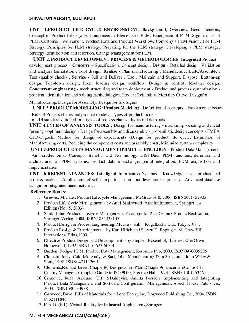
UNIT 1.PRODUCT LIFE CYCLE ENVIRONMENT: Background, Overview, Need, Benefits,
Concept of Product Life Cycle. Components / Elements of PLM, Emergence of PLM, Significance of
PLM, Customer Involvement. Product Data and Product Workflow, Company‘s PLM vision, The PLM
Strategy, Principles for PLM strategy, Preparing for the PLM strategy, Developing a PLM strategy,
Strategy identification and selection, Change Management for PLM.
UNIT 2. PRODUCT DEVELOPMENT PROCESS & METHODOLOGIES: Integrated Product
development process - Conceive – Specification, Concept design, Design - Detailed design, Validation
and analysis (simulation), Tool design, Realize - Plan manufacturing , Manufacture, Build/Assemble ,
Test (quality check) , Service - Sell and Deliver , Use , Maintain and Support, Dispose. Bottom-up
design, Top-down design, Front loading design workflow, Design in context, Modular design.
Concurrent engineering - work structuring and team deployment - Product and process systemization -
problem, identification and solving methodologies. Product Reliability, Mortality Curve. Designfor
Manufacturing, Design for Assembly. Design for Six Sigma.
UNIT 3.PRODUCT MODELLING: Product Modelling - Definition of concepts – Fundamental issues
- Role of Process chains and product models -Types of product models –
- model standardization efforts-types of process chains –Industrial demands.
UNIT 4.TYPES OF ANALYSIS TOOLS : Design for manufacturing - machining - casting and metal
forming - optimum design - Design for assembly and disassembly - probabilistic design concepts - FMEA
QFD-Taguchi Method for design of experiments -Design for product life cycle. Estimation of
Manufacturing costs, Reducing the component costs and assembly costs, Minimize system complexity
UNIT 5.PRODUCT DATA MANAGEMENT (PDM) TECHNOLOGY - Product Data Management
–An Introduction to Concepts, Benefits and Terminology, CIM Data. PDM functions, definition and
architectures of PDM systems, product data interchange, portal integration, PDM acquisition and
implementation.
UNIT 6.RECENT ADVANCES: Intelligent Information Systems - Knowledge based product and
process models - Applications of soft computing in product development process - Advanced database
design for integrated manufacturing.
Reference Books:
1. Grieves, Michael. Product Lifecycle Management, McGraw-Hill, 2006. ISBN0071452303
2. Product Life Cycle Management - by Antti Saaksvuori, AnselmiImmonen, Springer, 1st
Edition (Nov.5, 2003)
3. Stark, John. Product Lifecycle Management: Paradigm for 21st Century ProductRealisation,
Springer-Verlag, 2004. ISBN1852338105
4. Product Design & Process Engineering, McGraw Hill – Kogalkusha Ltd., Tokyo,1974.
5. Product Design & Development – by Kari Ulrich and Steven D. Eppinger, McGraw Hill
International Edns,1999.
6. Effective Product Design and Development – by Stephen Rosenthol, Business One Orwin,
Homewood, 1992 ISBN1-55623-603-4.
7. Burden, Rodger PDM: Product Data Management, Resource Pub, 2003. ISBN0970035225
8. Clement, Jerry; Coldrick, Andy; & Sari, John. Manufacturing Data Structures, John Wiley &
Sons, 1992. ISBN0471132691
9. Clements,RichardBarrett.Chapter8("DesignControl")andChapter9("DocumentControl")in
Quality Manager's Complete Guide to ISO 9000, Prentice Hall, 1993. ISBN 013017534X
10. Crnkovic, Ivica; Asklund, Ulf; &Dahlqvist, Annita Persson. Implementing and Integrating
Product Data Management and Software Configuration Management, Artech House Publishers,
2003. ISBN1580534988
11. Garwood, Dave. Bills of Materials for a Lean Enterprise, Dogwood Publishing Co., 2004. ISBN
0962111848
12. Fan, D. (Ed.), Virtual Reality for Industrial Applications,Springer

SHIVAJI UNIVERSITY, KOLHAPUR
M.TECH MECHANICAL (CAD/CAM/CAE )
M.TECH (CAD/CAM/CAE) Semester– II
ELECTIVE III – 4. NANOTECHNOLOGY
Teaching Scheme: Examination Scheme:
Lectures: 3 Hours per week CIE: 30 Marks ESE: 70 Marks
Credit:3
Course Objective:
To understand the concepts and context of MEMS and nanotechnology.
Course Outcome:
1. Recognize the history, background and the nature of the Nanoscience and technology.
2. State the different type of nanostructures and analyze the top down and bottom up approach for nano-
scale device preparation and differentiate the different properties ofnanomaterials.
3. Distinguish the functionality of nanostructures and their characteristic evaluation, self-assembly and its
application towards controlling thestructure.
4. Recognize the surface modification of nanoparticles by surface functionalization and theirapplication.
UNIT 1.Introduction: Micro-Electro-Mechanical Systems (MEMS), Microsystems and their products,
miniaturization, applications, mechanical MEMS, thermal MEMS, micro-opto electro-mechanical
systems, magnetic MEMS, radio frequency (RF) MEMS, micro fluidic systems, bio and chemo devices,
Nanotechnology – definition, nanoscale, consequences of the nanoscale for technology and society, need
and applications of nano electromechanical systems (NEMS)
UNIT2.Micro Fabrication Processes & Materials: Materials for MEMS – substrate and wafers, silicon
as a substrate material, crystal structure, single crystal and polycrystalline, mechanical properties, silicon
compounds, silicon piezo-resistors, gallium arsenide, quartz, piezo-electric crystals, polymers, packaging
materials; Fabrication Processes – Bulk micro-manufacturing, photolithography, photoresists, structural
and sacrificial materials, X-ray and electron beam lithography, Thin film deposition spin coating, thermal
oxidation, chemical vapour deposition (CVD), electron beam evaporation, sputtering; Doping diffusion,
ion implantation; Etching wet etching, dry etching; Surface micromachining, bulk vs. surface
micromachining; Wafer bonding glass-frit, anodic and fusion bonding;LIGA process and applications.
UNIT 3.Microsensors and actuators: Sensing and actuation, Chemical sensors, Optical sensors,
Pressure sensors, Thermal sensors – thermopiles, thermistors, micro machined thermocouple probes,
thermal flow sensors, MEMS magnetic sensor, Piezoelectric material as sensing and actuating elements –
capacitance, piezomechanics, Piezoactuators as grippers, micro grippers, micro motors, micro valves,
micro pumps, micro accelerometers, micro fluidics, shape memory alloy based optical switch, thermally
activated MEMS relay, micro spring thermal actuator, data storage cantilever.
UNIT 4.Microsystem Design: Design constraints and selection of materials, selection of manufacturing
process, selection of signal transduction technique, electromechanical system and packaging.
UNIT 5.Nanomaterials: Molecular building blocks to nanostructures – fullerenes, nanoscaled bimolecular,
chemical synthesis of artificial nanostructures, molecular switches and logic gates, nanocomposites; Carbon
nanotubes - structure, single walled, multi walled, properties of carbon nanostructures and their synthesis,
Potential applications of nano-structures. (8)

SHIVAJI UNIVERSITY, KOLHAPUR
M.TECH MECHANICAL (CAD/CAM/CAE )
UNIT 6.Nanofinishing Techniques: Abrasive flow machining, magnetic abrasive finishing, magneto
rheological finishing, elastic emission machining, ion beam machining, chemical mechanical polishing, Nan
manipulation, Nanolithography, Top-down versus bottom –up assembly, Visualization, manipulation and
characterization at the Nanoscale; Applications - in Energy, Tribology, Informatics, medicine, etc(8)
Reference Books:
1. Bharat Bhushan (Ed.), (2004), Handbook of Nanotechnology, Spinger-Verlag Berlin Heidelberg
New York, ISBN 3-540-01218-4
2. Hsu, Tai-Ran, (2003), MEMS & MICROSYSTEMS: Design & Manufacture, TMH, ISBN:0-07-
048709-X
3. Mahalik, N. P., (2007), MEMS, TMH, ISBN: 0-07-063445-9
4. Mahalik, N.P. (Ed.) (2006), Micromanufacturing& Nanotechnology, Springer India Pvt. Ltd., ISBN:
978-81-8128-505-8 (Distributed by New Age International, NewDelhi)
5. Nanosystems: Molecular Machinery, Manufacturing & Computation, K E Drexler,(Wiley),
(1992), ISBN0471575186
6. P.Rai- Choudhury, Handbook of Microlithography,Micromachining
&Microfabrication,SPIE,1997.
7. David Ferry, Transports in Nanostructures, Cambridge University Press,2000.
8. Poole, Charles & Owen, Frank J., - Introduction to Nanotechnology, Wiley (India) Pvt. Ltd.ISBN:
978-81-265-10993
9. Various Internet resources:www.nanotechweb.org,www.nano.gov,www.nanotec.org.uk

SHIVAJI UNIVERSITY, KOLHAPUR
M.TECH MECHANICAL (CAD/CAM/CAE )
M.TECH (CAD/CAM/CAE) Semester– II
Elective III- 2. RAPID MANUFACTURING
Teaching Scheme: Examination Scheme:
Lectures: 3 Hours per week CIE: 30 Marks ESE: 70 Marks
Credit:3
Course Objective: To educate students with fundamental and advanced knowledge in the field of Additive manufacturing
technology and the associated Aerospace, Architecture, Art, Medical and industrial applications.
Course Outcomes:
The students will be able to 1. Understand history, concepts and terminology of additivemanufacturing
2. Apply the reverse engineering concepts for designdevelopment
3. Understand the variety of additive manufacturingtechniques
4. Design and develop newer toolingmodels
5. Analyse the cases relevant to mass customization and some of the important research challenges
associated withAM.
UNIT 1.Design Potential of Rapid Manufacturing: Definition of rapid manufacturing (RM), rapid
prototyping (RP) and rapid manufacturing, areas of application. Conventional design for manufacturing
and assembly (DFM, DFMA), impact of RM on DFA and DFMA, Geometrical freedom, design
complexity/ optimization, parts consolidation, body fitting customization and multiple assemblies
manufactured as one, Customer input and customization, CAD environment For RM.(5)
UNIT 2.RM Processes: Liquid based processes, Powder based processes and Solid based processes;
RP Processes : Process overviews, STL file Generation, File Verification & Repair, Build File Creation,
Part Construction, Part Cleaning and finishing, Process Strength & limitations, Classes of RP systems:
3D Printers, Enterprise Prototyping centers, Direct digital tooling, Direct digital manufacturing, system
classification, Stereo lithography, SL with photo polymerization, SL with liquid thermal polymerization,
Selective Laser Sintering, Fused deposition modeling, Laminated object manufacturing, Laser powder
forming.(10)
UNIT 3.Materials in RM: Issues, viscous flow, photo-polymerization, sintering, infiltration, mechanical
properties, Materials for RM processes, Prototype properties: Material properties, color, dimensional
accuracy, stability, surface finish, machinability, environmental resistance, operational properties;
functionally graded materials (FGM composites), processing technologies for FGMs, laser sintering,
thermal and mechanical properties of FGM, Deposition systems and applications. (6)
UNIT 4..Applications of RP & RM: Design, Concept Models, Form and fit checking, Ergonomic
Studies, Functional testing, CAD data verification, Automotive applications- Parts of racing cars,
Applications in Aerospace industry, Construction industry, Retail industry, Archeology, Paleontology and
forensicscience,miniaturization.(5)
UNIT 5. Rapid Tooling: Mold making, Metal spraying, Rapid tooling for die, squeeze and permanent
mold casting, Rapid manufacturing of sheet metal forming tools, casting pattern plates by rapid tooling,
RP for series production investment casting.(8)

SHIVAJI UNIVERSITY, KOLHAPUR
M.TECH MECHANICAL (CAD/CAM/CAE )
UNIT 6.Management Issues of RM: Machine costs for RM, material cost, labour cost, comparison of
cost of RM with cost of injection molding; Cost of manufacturing by RM, overheads, stock and WIP,
location and distribution, supply chain management in RM (4)
References Books:
1. Rapid Manufacturing: An Industrial Revolution for the Digital Age – Editors N. Hopkinson, R.J.M.
Hague and P.M. Dickens, (2006) John Wiley & Sons, Ltd., ISBN-10 0-470-01613-2
2. Frank W. Liou, Rapid Prototyping & engineering applications, CRC Press, ISBN978-0-8493-3409-2
3. Rapid Prototyping theory & practice, Manufacturing System Engineering Series, Ali K.Kamarani,
SpringerVerlag
4. Rapid Prototyping- case book, J. A. McDonalds, C. J. Ryall, WileyEastern
5. Rapid & Virtual Prototyping & applications, C. E. Bocking, AEW Rennie, WileyEastern
6. Carmen Gabriela BĂCILĂ*, Zoltan-Gabor BAKI-HARI, “The Main Applications of Rapid Tooling,‖ RECENT, Vol. 8, nr. 3a(21a), November,2007
7. T. A. Grimm & Associates, Users Guide to Rapid Prototyping, Society of Manufacturing Engineers (
SME ) ISBN0872636976
8. ANNALS of the ORADEA UNIVERSITY. Fascicle of Management and TechnologicalEngineering,
Volume VI (XVI),2007
9. John F. Wallace, David Schwam,‖ Rapid manufacturing of sheet metal forming tools,‖ Case Western ReserveUniversity
10. A. Pereira, J.A. Pérez, J.L. Diéguez, G. Peláez and J.E. Ares, ―Design and manufacture of casting pattern plates‖, by rapid tooling, Archives of Materials Science, Vol. 29, No. 1-2, 2008 63
11. Using RP for Series Production Investment Castings, Tom Mueller, Express Pattern
12. Mechanical Vibrations (Fourth Edition) – S SRao, PearsonEducation 13. Fundamentals of Mechanical Vibrations – S Graham Kelly,McGraw-Hill
14. Mechanical Vibrations – G.K. Groover, Nemchand& Brothers,Roorkee.
15. Fundamentals of Machine Component Design – R. C. Juvinall
WEBSITES
1. http://www_rpl.stanford.edu
2. http:// home.utah.edu/
3. http:// www.me.psu.edu
4. http:// itri.loyola.edu/rp/02
5. http:// www.udri.udayton.edu/

SHIVAJI UNIVERSITY, KOLHAPUR
M.TECH MECHANICAL (CAD/CAM/CAE )
M.TECH (CAD/CAM/CAE) Semester– II
Elective III- 3.COMPUTATIONAL FLUID DYNAMICS
Teaching Scheme: Examination Scheme:
Lectures: 3 Hours per week CIE: 30 Marks ESE: 70 Marks
Credit:3
Course Objectives:
1. This course aims to introduce numerical modeling and its role in the field of heat, fluid flow
and combustion it will enable the students to understand the various discretisation methods and
solving methodologies and to create confidence to solve complex problems in the field of heat
transfer and fluid dynamics.
2. To develop finite volume discredited forms of the CFD equations.
3. To formulate explicit & implicit algorithms for solving the Euler Equations &Navies
Strokes Equations.
Course Outcome:
1. On successful completion of this course the student will be able to apply the concepts of CFD
to analyze the fluid flow and heat transfer in thermal systems.
Unit 1.Introduction: CFD as the third dimension of fluid mechanics. Numerical Discretization methods
such as Finite Difference, FEM and FVM. Why FVM as preferred method in CFD.(9)
Unit 2. Basic Equations of Fluid Dynamics: Potential flow, Nonlinear Potential flow, in viscid
flows and viscous flows. Navier Stokes equations. Primitive variable Vs. Conservation form.
Dimensional form Vs Non dimensional form. (6)
Unit 3. Numerical methods for convection- Diffusion equations: Up winding and
central difference schemes, Stability condition in terms of Courant number (9)
Unit4. Numerical methods for In viscid flow: Characteristic form of equations, flux
difference splitting. Application to 2-D flow such as flow through a nozzle (7)
Unit 5. Numerical methods for Incompressible flows: The continuity equation divergence
constraint, Poisson equation for pressure schemes such as SIMPLE due to Patankar and
Spalding.(6)
Reference Books:
1. Computational Fluid Dynamics – The Basics with Applications, John D. Anderson, Jr., McGraw
Hill International Editions,
2. Computational Fluid Dynamics - The Finite Volume Method, H. K. Versteeg and W.
Malalasekara, Longman Scientific &Technical
3. Computational Fluid Mechanics and Heat Transfer, John C. Tannehill, Dale A. Anderson and
Richard H. Pletcher, Taylor & Francis, Reprint2010.
4. Computational Methods for Fluid dynamics: Vol 1 and 2, C A J Fletcher, SpringerVerlag,
1987
5. Numerical Heat Transfer & Fluid Flow, Suhas V. Patankar, Taylor &Francis. 6. Computational Fluid Dynamics Vol 1 and 2, K. A. Hoffmann and S. T. Chiang,Engineering
Education System

SHIVAJI UNIVERSITY, KOLHAPUR
M.TECH MECHANICAL (CAD/CAM/CAE )
M.TECH (CAD/CAM/CAE) Semester– II
ELECTIVE III-4. OPEN ELECTIVE
Teaching Scheme: Examination Scheme:
Lectures: 3 Hours per week CIE: 30 Marks ESE: 70 Marks
Credit:3
Students can take any subject from other PG discipline being conducted in the same
Institute and with the consent of their Guide/PG Faculty.
M.TECH (CAD/CAM/CAE) Semester– II
ELECTIVE IV. 1. DESIGN FOR MANUFACTURING AND ASSEMBLY
Teaching Scheme: Examination Scheme:
Lectures: 3 Hours per week CIE: 30 Marks ESE: 70 Marks
Credit:3
Course Prerequisites: Machine design, Design and Analysis of Experiments.
Course Objective:
• The course is aimed at developing students to acquire skills to analyze product design and be
able to design products that are easier to manufacture, assemble, service and more friendlier to
environment, etc.
Expected outcome:
Upon completion of this course, the student shall be able to:
• Have customer-oriented, manufacturing and life-cycle sensitive approach to product design and
development, with product design principles and structured designmethodologies.
• Have Methods and approaches for developing, implementing, and nurturing an effective
DFM process within the firm.

SHIVAJI UNIVERSITY, KOLHAPUR
M.TECH MECHANICAL (CAD/CAM/CAE )
UNIT I
Introduction
General design principles for manufacturability – strength and mechanical factors, evaluation
method, Process capability - Feature tolerances- Geometric tolerances-Assembly limits- Datum
features- Tolerance stacks.
UNIT II
Factors influencing form Design
Working principle, Material, Manufacture, Design – Possible solutions – Materials choice –
Influence of materials on form design – form design of welded members, forgings and castings
UNIT III
Component Design – Machining Consideration
Design features to facilitate machining – drills - milling cutters – keyways – Doweling
procedures, counter sunk screws – Reduction of machined area – simplification by separation –
simplification by amalgamation– Design for Machinability –Design for accessibility – Design
for assembly.
UNIT IV
Robust Design and Taguchi Method
Robust design - Design of experiments – Robust design process- Orthogonal arrays: Two level
orthogonal arrays, Three level orthogonal arrays, Combined inner and outer arrays.
UNIT V
Redesign for Manufacture and case studies
Design for economy, Identification of uneconomical design – Modifying the design –Computer
Applications for DFMA – Case Studies.
Text Books
1. HarryPeck, ―Designfor Manufacture‖, Pittman Publication, 1983.
2. Karl T. Ulrich, Ateven D. Eppinger― Product Design and Development‖ Tata McGraw-
Hill, 2003.
References
1. James G. Bralla, ―Hand Book ofProduct Designfor Manufacturing‖, McGraw Hill co., 1986.
2. Swift K.G., ―Knowledgebased designformanufacture, Kogan PageLtd., 1987.
3. Boothroyd, G., (1994), Product Design for Manufacture and Assembly, MarcelDecker
Bralla, J.G., (1999), Design for Manufacturability Handbook,McGraw-Hill

SHIVAJI UNIVERSITY, KOLHAPUR
M.TECH MECHANICAL (CAD/CAM/CAE )
M.TECH (CAD/CAM/CAE) Semester– II
ELECTIVE-4 2.INDUSTRIAL AUTOMATION AND ROBOTICS
Teaching Scheme: Examination Scheme:
Lectures: 3 Hours per week CIE: 30 Marks ESE: 70 Marks
Credit: 3
Course Objectives: 1. To gain fundamental skills in industrial robotics and mobilerobotics 2. To obtain knowledge and understand basic concepts of industrial robotics, in
terms of classification, kinematics, in terms of classification, kinematics,
sensors and actuators, dynamics and motion planning for typicalapplication.
3. To attain the principles of machine vision including image processing and
itsapplication to robot control and motionplanning.
Course Outcomes:
On completion of the course students shall be able to: 1. derive the kinematics for robot manipulators including direct and inversekinematics 2. analyze robot dynamics for control of serial links for robotmanipulators 3. give an account of the basic theories of machine vision and imageprocessing
4. Apply robotics and visual sensing technologies to engineering applications.
UNIT 1.Introduction: Automated manufacturing systems, fixed /programmable /flexible
automation, need; Basic elements of automated systems- power, program and control; Advanced
automation functions, Levels of automation; Industrial control systems in Process and discrete
manufacturing industries, Continuous and discrete control;Low Cost automation, Economic and social
aspects of automation.(7)
UNIT 2.Transfer Lines: Fundamentals, Configurations, Transfer mechanisms, storage buffers,
control, applications; Analysis of transfer lines without and with storage buffers.(4)
UNIT 3.Assembly Automation: Types and configurations, Parts delivery at workstations-
Various vibratory and non-vibratory devices for feeding and orientation, Calculations of
feeding rates, Cycle time for single station assembly machines and partially automated
systems; Product design for automated assembly.(5)
UNIT 4.Fundamentals of Industrial Robots: Specifications and Characteristics, Basic
components, configurations, Criteria for selection, various industrial applications. Robotic Control
Systems: Drives, Robot Motions, Actuators, Power transmission systems; Robot controllers,
Dynamic properties of robots- stability, control resolution, spatial resolution, accuracy,
repeatability, compliance. (9)
UNIT5. Robotic End Effectors and Sensors: Transducers and sensors- sensors in robotics and
their classification, Touch (Tactile) sensors, proximity and range sensors, force and torque sensing,
End Effectors- Types, grippers, Various process tools as end effectors; Robot-End effect or
interface, Active and passive compliance, Gripper selection and design. (7)
UNIT6. Robot Programming: Lead through method, Robot program as a path in space,
Methods of defining positions in space, Motion interpolation, branching; Textual robot
Programming languages.(4)
Reference Books:
1. Groover,M.P.,(2004),―Automation,ProductionSystems&ComputerIntegrated Manufacturing‖ 2/e, (Pearson Edu.) ISBN:81-7808-511-9
2. Morris,S.Brian(1994),―AutomatedManufacturingSystems‖,(McGrawHill)ISBN:0-07- 113999-0
3. Pessen,DavidW.(1990),―IndustrialAutomation,CircuitDesign&Components‖,(JohnWiley& Sons, Singapore)
4. Groover,M.P.;Weiss,M.;Nagel,R.N.&Odrey,N.G.―IndustrialRobotics,Technology, Programming & Applications‖, (McGraw Hill Intl. Ed.) ISBN:0-07-024989-X
5. Fu,K.S.;Gonzalez,R.C.&Lee,C.S.G.―Robotics-Control,Sensing,VisionandIntelligence‖, (McGraw Hill Intl. Ed.) ISBN:0-07-100421-1

SHIVAJI UNIVERSITY, KOLHAPUR
M.TECH MECHANICAL (CAD/CAM/CAE )
6. Keramas,JamesG.(1998),―RobotTechnologyFundamentals‖,(CENGAGE)ISBN:981-240- 621-2
M.TECH (CAD/CAM/CAE) Semester– II
Elective IV- 3. CAD/CAM/CAE PRACTICES IN METAL FORMING
Teaching Scheme: Examination Scheme:
Lectures: 3 Hours per week CIE: 30 Marks ESE: 70 Marks
Credit:3
Course Objectives:
To study the use of computers in metal forming operations: planning and optimization.
Course Outcome:
1. Student should understand methods ofanalysis.
2. Student should understand application of CAD /CAM /CAE in metal forming processes
UNIT 1.Introduction:-Process Modeling, The finite element method, Solid formulation and hollow
formation, metal forming and FEM Metal forming Processes:-Introduction, Metal forming
operations as a system, Classification and Description of metal forming processes, Casting process
Analysis and Technology in Metal Forming:- Introduction, Flow stress of metals, Friction in metal
forming, Temperatures in metal forming, Impression and closed die forging, Hot extrusion of Rods
and Shapes, Cold forging and extrusion, Rolling of strip, plate and shapes, Drawing of Rod, wire,
shapes and Tubes, Sheet metal forming,fineblanking (9)
UNIT2.Plasticity and Visco-plasticity: Introduction, Stress, strain and strain rate, The yield criteria,
Equilibrium and Virtual work rate principle, Plastic potential and flow rate, Strain Hardening, Effective
stresses and Effective strain,Visco-plasticity.(4)
UNIT4.Method of Analysis: Introduction, Upper Bound method, Hills General Method, FEM
Analysis Technology in Metal Casting: Introduction, Cast ability of important Ferrous and Non- ferrous
metal, Shrinkage, Effect of Temperature, Effect of composition. Finite Element Method: Introduction,
Finite Element Procedures, Elements and shape function, Element strain rate matrix, Elemental stiffness
equation, Numerical integrations, Assemblage and Linear matrix solver, Boundary conditions, Direct /
Iteration method, Time investment and Geometry updating, Rezoning(9)
UNIT5.Plane – Strain Problems: Introduction, Finite Element formulation, Closed die forging with
flash, Sheet Rolling, Plate Bending, Side pressing. Axi-symmetric Isothermal Forging: Introduction,
Finite Element formation, Pre-form design method, Die design, Shell nosing at room temperature,
Plane strain rolling, Axially Symmetric forging.
UNIT6.Steady State Processes of Extrusion and Drawing: Introduction, Method of Analysis, Bar
Extrusion, Bar Drawing, Multi pass bar drawing and Extrusion, Applications to process.
design Sheet Metal Forming: Introduction, Plastic Anisotropy, In-plane deformation process,Axi-
symmetric but of plane deformation, Axi-symmetric Punch stretching and deep drawing process, Sheet
metal forming of General shapes, Square – cup drawing process.
Metal Casting: Introduction, Casting Design, FEA analysis, Die / pattern Design,
Casting Simulation – Gating Design, Die /Patternmanufacture (10)

SHIVAJI UNIVERSITY, KOLHAPUR
M.TECH MECHANICAL (CAD/CAM/CAE )
Reference Books
1. Mechanical Metallurgy (2/e)– by Dieter (McGrawHill)
2. Metal Casting – Dr. B. Ravi – (Prentice Hall of India)
3. Metal Forming & Finite Element Method – by Shiro Kobjashi Oxford University
4. Technology of Metal Forming Processes, -Surender Kumar(EEE)(PHI)
5. Theory of Plasticity- Amitav Chakraborty, McGrawHill.

SHIVAJI UNIVERSITY, KOLHAPUR
M.TECH MECHANICAL (CAD/CAM/CAE )
M.TECH (CAD/CAM/CAE) Semester– II
ELECTIVE-IV.4 INDUSTRIAL PRODUCT DESIGN
Teaching Scheme: Examination Scheme:
Lectures: 3 Hours per week CIE: 30 Marks ESE: 70 Marks
Credit:3
Course Objectives:
1. To understand the relationship of art and science todesign
2. To develop proficiency in design skills andmethodologies
3. To gain first-hand experience of the design process in the context of a ‗real‘, open-
ended multidisciplinary designproject
4. To work effectively and professionally in a team while executing a designproject
5. To apply engineering analysis tools in the designprocess
6. To understand the holistic context of design, including global, societal, ethical,
economic and environmentalconcerns
7. To improve proficiency in professional communicationskills
Course Outcomes: Upon completing this course,:
1. Students should be able to design a product using computer aideddesign.
2. Students should be able to carry out product development and planningprocess.
3. Students should be able to understand the concept ofprototyping.
UNIT1. Introduction: Challenges of product development; Successful product, development
Quality aspect of product design; Market Research; Survey. Identify customer needs and
Product Planning Processes. Product specifications: Process of setting specifications. Concept
generation– selection–testing. Product Architecture: Implication of architecture, establishing
the architecture, related system level design issue. Industrial design: Overview Design for
manufacturing and assembly-tolerance, design of gauges.
UNIT2. Design for environment; robust design. Prototyping; Engineering Materials.
Concurrent engg. Product costing, value engineering, Aesthetic concepts; visual effects of
form and colour. Product data management. Innovation and Creativity in Product Design. Case
Studies. Ergonomics and Industrial Safety (EIS)
UNIT 3. Introduction - General approach to the man-machine relationship-workstation design
working position and posture. An approach to industrial design - elements of design structure
for industrial design in engineering applications in manufacturing systems. Control and
Displays: configurations and sizes of various controls and displays;- design of controls in
automobiles, machine tools etc., - design of instruments and controls.
UNIT 4 .Ergonomics and Manufacturing: Ergonomics and product design; ergonomics in
automated Systems; Anthropomorphic data and its applications in ergonomic design;
limitations of anthropomorphic data - use of computerized database.
UNIT 5. Safety & Occupational Health and Environment: Application of Ergonomics in
industry for Safety, Health and Environment Control. Prevention and specific safety measures
for manufacturing and processing industry – safety in the use of machines, precaution for
certain chemical types of industry like foundry, process industry, and chemical industry.

SHIVAJI UNIVERSITY, KOLHAPUR
M.TECH MECHANICAL (CAD/CAM/CAE )
UNIT 6 .Environmental Safety and ISO 14000 Systems. Occupational Health – Health and
Safety consideration; Personal protective protective Equipment.
References Books :
1. Product Design and Development: Karl T. Ulrich, Steven G. Eppinger; Irwin McGrawHill
2. Product design and Manufacture: A.C. Chitale and R.C. Gupta;PHI
3. New Product Development: Tim Jones, Butterworth, Heinemann, Oxford,1997.
4. Product Design for Manufacture and Assembly: Geoffrey Boothroyd, Peter Dewhurst
and WinstonKnight.
5. Product Design : Otto and Wood; Pearson education.
6. Industrial Design for Engineers: Mayall W.H, London, Hiffee books Ltd,1988
7. Applied Ergonomics, Hand Book: Brian Shekel (Edited) Butterworth
Scientific,London 1988.
8. Introduction to ergonomics – R.C. Bridger, McGraw Hill Pub.
9. Human Factor Engineering – Sanders & McCormick, McGraw HillPublications.
10. Product Design – Kevin Otto, Kristin Wood Pierson
Education. 11.Noff, Shimon Y.―Handbook ofRobotics‖, (John Wiley&Sons)
11. Niku,SaeedB. (2002), ―Introduction to Robotics, Analysis, Systems&Applications‖, (Prentice
Hall ofIndia)
12. Koren,Yoram―Robotics for Engineers‖,(McGrawHill) Schilling, Robert J.(2004),
―Fundamentals of Robotics, Analysis & Control‖, (Prentice Hall of India), ISBN: 81-203-
1047-0.

SHIVAJI UNIVERSITY, KOLHAPUR
M.TECH MECHANICAL (CAD/CAM/CAE )
MTECH (CAD/CAM/CAE) Semester–II
1. Comprehensive viva
Teaching Scheme: Examination Scheme:
Practical: 2 Hours per week CIE: 25 Marks ESE: 25Marks
Credit: 2
The students have to do preparation on all the subjects which they have studied in Ist and IInd semesters.
The viva will be conducted by the external and internal examiners jointly and their appointments will be
made by university. The thorough knowledge, preparation and subjects ‘understanding will be assessed
by theExaminers.
M.TECH (CAD/CAM/CAE) Semester– II
Design & Analysis Laboratory - II
Teaching Scheme: Examination Scheme:
Practical: 2 Hours per week CIE: 25 Marks ESE: 25Marks
Credit: 1
Minimum eight exercises are to be completed on following topics using suitable software packages.
1. Transient ThermalAnalysis
2. DynamicAnalysis
3. Non-Linear Analysis
4. Design Optimization through FEA (TwoExercises)
5. Computational Fluid Dynamics (Optional)
6. A Composite project based on Exercises of Design & Analysis Laboratory I and II.

SHIVAJI UNIVERSITY, KOLHAPUR
M.TECH MECHANICAL (CAD/CAM/CAE )
M.TECH (CAD/CAM/CAE) Semester– II
8. SEMINAR – II
Teaching Scheme: Examination Scheme:
Practical: 1 Hours per week Term work: 25 Marks
Credit: 1
Seminar - II should be based on the literature survey on any topic relevant to CAD/CAM/CAE. It may be
leading to selection of a suitable topic of dissertation. The report shall contain some contribution by the
candidate in the form of experimental results, deductions, compilation and inferences etc.
Each student has to prepare a write-up of about 25 pages. The report typed on A4 sized sheets and bound
in the necessary format should be submitted after approved by the guide and endorsement of the Head of
Department.
The student has to deliver a seminar talk in front of the teachers of the department and his classmates. The
Guide based on the quality of work and preparation and understanding of the candidate shall do an
assessment of the seminar.
MTECH (CAD/CAM/CAE) Semester–III
1. Industrial Training
Examination Scheme:
Term work: 50 Marks
Credit: 2
The student has to prepare the report of training undergone in the industry during vacation after
semester II. It shall include the brief details of assignment completed by the candidate and
general observation and analysis. The identified areas for undertaking the dissertation work shall
form part of report. The term work marks should be based on report and departmental oral
exams. The training should be of minimum two weeks from reputed industries and certificate of
the same should be a part of the report.

SHIVAJI UNIVERSITY, KOLHAPUR
M.TECH MECHANICAL (CAD/CAM/CAE )
M.TECH (CAD/CAM/CAE) Semester– III
One Course from Moodle / Swayam Teaching Scheme: Examination Scheme:
Practical: 5 Hours per week Term work: 50 Marks
Credit: 2
Teaching scheme:
Course Objective – To teach use of Moodle/Swayam as a learning platform designed to provide
educators, administrators and learners with a single robust, secure and integrated system to create
personalized learning environment.
Course outcome – On successful completion of the course the student should be able to Students will be
able to choose course of their choice from Moodle/swayam and to be acquaintance with recent
developments in Mechanical Design Engineering beyond syllabus.
The term work under this submitted by the student shall include.
1) Work diary maintained by the student and countersigned by his guide.
2) The content of work diary shall reflect the efforts taken by candidates for (a) Searching the suitable
project work. (b) Visits to different factories or organizations. (c) The brief report of feasibility studies
carried to come to final conclusion. (d) Rough sketches (e) Design calculations etc. carried by the student.
3) The student has to make a presentation in front of panel of experts in addition to guide as decided by
department head
M.TECH (CAD/CAM/CAE) Semester– III
DISSERTATION PHASE-I
Teaching Scheme: Examination Scheme:
Practical: 5 Hours per week CIE: 50 Marks ESE: 50Marks
Credit:8
The dissertation work to be carried out individually commences in the Semester III and extends
through Semester IV. The topic of dissertation work related should be related to the areas of
CAD/CAM/CAE applications. Applications of computer as a tool for conceptualization, design,
analysis, optimization, manufacturing, manufacturing planning /management, quality
engineering, simulation of products / processes / mechanisms / systems, experimental study, etc.
are to be encouraged and preferred.
SYNOPSIS APPROVAL
The Head of the Department shall appoint a committee comprising of the Guide and two
expertsto review and approve the synopses before submitting them to the University for approval.
Thecandidates shall submit the synopsis to the University authorities for approval in the
prescribedformat before the due date.
It shall include the problem definition, literature survey, approaches for handling the problem, finalizing
the methodology for the dissertation work and design calculations / experimental design etc. A report of
the work shall be submitted at the end of SemesterIIIafter approval by the Guide and endorsement of the
Head of Department. It will be assessed for term work, by the evaluation committee (*) appointed by the
Head of the Department, for appropriateness, sufficiency of contents and offer suggestions if any.

SHIVAJI UNIVERSITY, KOLHAPUR
M.TECH MECHANICAL (CAD/CAM/CAE )
M.TECH (CAD/CAM/CAE) Semester– IV
DISSERTATION PHASE II Teaching Scheme: Examination Scheme:
Practical: 5 Hours per week Practical: 50Marks
Term work :50Marks
Credit:8
The candidate shall submit the detailed report as per the synopsis approved by the university, of the
dissertation work in the prescribed format after approval by the Guide and endorsement by the
Head of the Department. It will be assessed for term work by the evaluation committee (*)
appointed by the Head of the Department, for completion of the proposed work.
(*) Note: The evaluation committee shall consist of the Guide, one senior expert faculty member and
the Head of the Department or his/her representative.
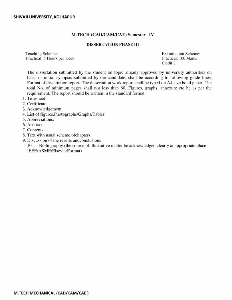
SHIVAJI UNIVERSITY, KOLHAPUR
M.TECH MECHANICAL (CAD/CAM/CAE )
M.TECH (CAD/CAM/CAE) Semester– IV
DISSERTATION PHASE III
Teaching Scheme: Examination Scheme:
Practical: 5 Hours per week Practical: 100 Marks
Credit:8
The dissertation submitted by the student on topic already approved by university authorities on
basis of initial synopsis submitted by the candidate, shall be according to following guide lines.
Format of dissertation report: The dissertation work report shall be typed on A4 size bond paper. The
total No. of minimum pages shall not less than 60. Figures, graphs, annexure etc be as per the
requirement. The report should be written in the standard format.
1. Titlesheet
2. Certificate
3. Acknowledgement
4. List of figures,Photographs/Graphs/Tables
5. Abbreviations.
6. Abstract
7. Contents.
8. Text with usual scheme ofchapters.
9. Discussion of the results andconclusions
10. Bibliography (the source of illustrative matter be acknowledged clearly at appropriate place
IEEE/ASME/ElsevierFormat)