Facilities Management CAD Standards January 2022
42
Facilities Management CAD Standards January 2022
-
Upload
khangminh22 -
Category
Documents
-
view
0 -
download
0
Transcript of Facilities Management CAD Standards January 2022

Facilities Management CAD Standards January 2022

Table of Contents Introduction Part 1
FM_TOC 1 Jan 1 2022
Part 5 CAD Deliverables
1 Introduction 1.0 1.2 Objectives 1.1 1.3 Authority 1.1 1.4 Software Upgrade Policies and Procedures 1.2 1.5 Comments & Feedback 1.3 1.6 How This Document is Organized 1.3
Part 2 Creating and Editing CAD Drawings 2 External References 2.1
2.1 Overview 2.1 2.2 General Rules of Thumb 2.1 2.3 Paper Space, Model Space and Viewports 2.2 2.4 Path Settings 2.2 2.5 Inserted Objects 2.2 26 File Linking (Attach vs. Overlay vs. Bind) 2.2 2.7 File Types 2.3 2.7.1 Sheet Files 2.3 2.7.1.1 Description 2.3 2.7.1.2 Sheet File Naming Convention 2.4 2.7.2 Model Files 2.5 2.7.2.1 Description 2.5 2.7.2.2 Model File Naming Convention 2.5 2.7.3 Sketch Files 2.10 2.7.3.1 Description 2.10 2.7.3.2 Sketch File Naming Convention 2.10 2.7.4 Detail Drawing Files 2.11 2.7.4.1 Description 2.11 2.7.4.2 Detail File Naming Convention 2.11 2.7.5 Hybrid Files 2.13 2.7.5.1 General Information 2.13 2.7.5.2 Hybrid File Naming Convention 2.13 2.7.5.3 Obsolete Image File Names 2.14
Part 3 Drafting Conventions 3 Drafting Conventions 3.1 3.1 Sheet Numbering Conventions for Construction Drawings 3.2 3.2 Sheet Numbering Conventions for Sketches 3.15
Part 4 Output and Quality Control
4 Quality Assurance 4.1 4.1 The Drawing Markup Process 4.1 4.2.1 General Instructions 4.1 4.2.2 Redline Files 4.1 4.2.3 File Naming Convention for Redline Files 4.1 4.2 Revising the Drawings (Issuing Addenda & Bulletins) 4.2
5 CAD Deliverables 5.1 5.1 General 5.1 5.2 Physical Submittals 5.1 5.3 Electronic Submittals 5.2 5.4 File Naming Convention for Compressed Electronic Submittals 5.2 5.5 Title Block standard 5.3
6 Communications 6.1 6.1 Communicating with FM 6.1
Part 6 Communications

FM_TOC 2 Jan 1 2022
Table of Contents Legal Issues Part 7
7 Intellectual Property 7.1 7.1 General Information 7.1 7.2 Copyrights 7.1 7.3 Trademarks 7.2 7.4 Special Characters 7.2 7.5 Attribution of Authorship 7.2
A File and Folder Naming Conventions (General Instruction) A.1
Appendices & References

UCI FM CAD Standards Introduction
CHPTR01 1.1 Jan 1 2022
1.0 Introduction
1.1 General
1. This document establishes standards that govern every phase of the CAD/Revit production process (i.e. project planning, electronic drafting, project oversight, delivery, review and revision). It establishes strict controls on the content, appearance, layout and organization of all CAD/Revit drawings prepared for or by the University of California, Irvine’s Facilities Management (FM). It also establishes guidelines that govern the physical form of the CAD/Revit deliverables submitted to FM.
2. These standards form the basis for review, critique and comment on all CAD/Revit drawings submitted
to FM. Closeout drawings submittal packages must comply with this standard.
3. These standards are also designed to improve coordination between FM and its consultants and insure closer coordination between all project team members. In short, these standards help to improve the quality of professional services obtained by FM from its in-house staff and its outside professional consultants.
4. Finally, these standards are designed to insure that drawings prepared by our consultants on CAD/Revit
systems that are different from FM' are compatible with the drawings we prepare.
1.2 Objectives
These standards are designed to do the following:
1. Reduce CAD/Revit production time and improve coordination among project team members.
2. Make project teams more nimble and responsive.
3. Help project teams produce drawings that are clear, concise and easy to understand.
4. Help project teams improve the quality and accuracy of our drawings.
5. Speed up the university’s and governmental review process by helping project teams produce drawings that demonstrate a clear understanding of, and compliance with relevant building codes, related governmental regulations and contract requirements.
6. Help project teams produce drawings that can be easily and accurately bid and constructed.
7. Insure that the drawings produced remain useful over long periods of time.
8. To reduce uncertainty as it relates to the contents and structure of the CAD files as they are handed off
from one team to another over the lifespan of a project.
1.3 Authority
1. This document supersedes all previous written and verbal instructions, procedures and standards governing the preparation of CAD/Revit drawings for or by FM.
2. These standards govern the creation of CAD/Revit drawings for traditional Design/Bid/Build projects as
well as Design/Build projects. They are to be used from the start of the design development phase onwards until a project is completed. Whenever possible, project team members are encouraged to

UCI FM CAD Standards Introduction
CHPTR01 1.2 Jan 1 2022
adhere to these standards in the schematic design phase in order to minimize the amount of rework that normally happens between phases.
3. In the course of everyday production, a condition may arise that is not covered by these standards. If confronted by such a situation, drafters are free to use whatever means are necessary to resolve the problem at hand. However, drafters are required to immediately notify the FM CAD Manager to explain the unique condition they encountered and seek approval for the solution they devised to deal with the situation.
4. Projects that are scheduled to last for 2 years or less will be governed by the standards in place at the
start of that project. Once such a project is underway, the standards associated with that project will not be altered for the duration of the project.
5. For longer duration projects (i.e. projects over 2 years in length), FM reserves the right to change it’s
CAD/Revit standards at it's discretion. However, in no instance will FM change the standards more frequently then once every 18 months.
6. Any changes that are made to CAD/Revit drawings as result of updated standards are seen as an ordinary
cost of doing business and will not be reimbursed by FM. All upgrade costs are to be born by the consultant organization. FM will not reimburse consultants for labor costs or any other associated expense.
1.4 Software Upgrade Policies and Procedures
1. Drawings for projects that are scheduled to be completed within 2 years shall be produced with the same version of AutoCAD or Revit software that was specified at the beginning of the project. Longer duration projects may, at the discretion of FM be completed with different versions of the software.
2. FM reserves the right to change the file format of all required CAD/Revit deliverables for long duration
project at any time. However, FM will give at least 12 months written notice to each consultant in advance of the required file format conversion date in recognition of the logistical efforts involved in any software upgrade.
3. In no instance will FM require software upgrades more frequently then once every 18 months.
4. Required software upgrades and associated file format conversions are seen as an ordinary cost of doing
business and will not be reimbursed by FM. All upgrade costs are to be born by the consultant organization. FM will not reimburse consultants for the cost of the software upgrade or any other associated expense.
5. In recognition that the successful deployment of upgraded software will require coordination among all
project team members, each consultant is required to create and submit an “Upgrade Impact Statement” to FM for review. The impact statement is due no later then two weeks (i.e. 10 working days) after receipt of written notification from FM that a software upgrade is required. The Upgrade Impact Statement shall contain a detailed schedule showing what steps the consultant will take to purchase, install, test and deploy the required upgrade and train it's staff to use the upgraded software.

UCI FM CAD Standards Introduction
CHPTR01 1.3 Jan 1 2022
1.5 Comments & Feedback
These standards are reviewed and revised on a regular basis. Readers are encouraged to study this document and suggest ways to improve its effectiveness or clarity. Our intent is to continuously improve the standards by incorporating your best ideas into each new edition. This document is distributed in both electronic form to FM’ entire staff and it’s consultants. If you require additional or updated copies of this document or any of the supporting materials, please contact the FM CAD Manager. The CAD Manager will be happy to send you a copy of the current edition and add your name to our distribution list for future updates. For those who wish to receive copies of the standards on magnetic media, please specify the type of system you use and type of media desired. Copies of the document can also be forwarded via electronic mail.
1.6 How This Document is Organized
1. For the convenience of the reader, this book is thematically grouped into 7 parts different. Part #1 contains introductory information. Part #2 explains how to create and edit CAD drawings. Part #3 contains information about plotting and quality control. Part #4 contains information that will help team members communicate with FM. Part #5 contains information about “Foreign” files. Part #6 deals with legal issues that that arise when using CAD technology. Part #7 contains all the appendices.
2. For ease of use, pages are numbered sequentially within each chapter. For example, pages in Chapter 1
are numbered 1.1, 1.2, 1.3, etc. and for Chapter 2, 2.1, 2.2, etc.
3. Figures are numbered sequentially within each chapter. For instance, Chapter 1 figures are listed as Figure 1.1, Figure 1.2, etc.
4. Appendices are listed in alphabetical order (i.e., A, B, C, etc.). Pages are numbered sequentially within
each appendix. For example, pages in Appendix A are numbered A.1, A.2, etc.

UCI FM CAD Standards External References
CHPTR02 2.1 Jan 1 2022
2.0 External References
2.1 Overview
FM & project teams shall makes extensive use of external referencing (a.k.a. Xref's). External referencing allows information found on one drawing to be shared with one or more other drawings. FM employs a very simple two tier external referencing scheme to link project drawings together (see illustration below). Under the FM scheme, sheet files contains all the links necessary to create a finished plotted sheet no matter how distant the referenced file is from that sheet file in the project directory tree. Nested Xref’s are not used or permitted.
Tier 1
Tier 2
A more detailed explanation of how each type of plotted drawing is assembled is contained on the following pages. These guides illustrate how a "typical" or "ideal" sheet should be assembled. Study the guides carefully. Any variation to these standards must be documented, submitted for review and approved by the FM CAD Manager prior to it's use.
2.2 General Rules of Thumb
1. All CAD drawings produced for or by FM shall conform to external referencing standards and conventions listed below.
2. FM uses six different types of reference files to produce it's CAD drawings. Each type of reference file has a
different naming convention. The first type of reference file is called a Sheet File. The second is called a Model File. The third is called a Component File (which includes Titleblocks). The forth is called a Sketch File. The fifth is called a Detail File. The sixth is called a Hybrid File. Name each type of file according to the conventions listed below.
3. All CAD files shall be named in accordance with the Microsoft Windows long file naming convention as
specified in Appendix “A” of this document. In conformance with the Microsoft Windows file naming conventions, all CAD file names shall include a File Prefix and a File Suffix.
4. Team members are not permitted to explode external references.
5. Team members are not permitted to edit or alter external references created by disciplines other then
their own.
6. The use of external referencing is unrestricted within the same project folder. However, drawings from one project may never be externally referenced to drawings from another project.
7. In the event that a project contains more than one building or phase, drawings for each building or phase
shall be given a unique identification number and segregated into separate project folders. Files that may be of use to multiple projects must be identified and duplicated. Copies of the "shared" files must be placed into each affected project folder.
Sheet File
Model Model Model Model Model Model Model Model File File File File File File File File

UCI FM CAD Standards External References
CHPTR02 2.2 Jan 1 2022
8. It’s common practice for drafters to temporarily link several drawings together to check alignments and spot interferences. Drafters are reminded to detach these “temporary” external references prior to ending each work session.
2.3 Paper Space, Model Space and Viewports
1. All work (with the exception of title blocks, legends and associated text or symbols) shall be drawn in
Model Space.
2. All viewports must be positioned within the borders of a title block.
3. Drafters are free to create as many viewports in a drawing as will comfortably fit within the borders of a title block.
4. Title blocks used in conjunction with externally referenced drawings shall be drawn in Paper Space. Title
blocks used in drawings without external references shall be drawn in Model Space. Refer to the External Reference Maps elsewhere in this chapter for more information about proper Paper Space / Model Space placement. Also refer to Chapter 5 for information about proper layer settings for Xref’s.
2.4 Path Settings
1. Team members are directed to use relative paths when creating external references (i.e. all external
references must use relative paths).
2. Maintaining path relationships between CAD drawings is essential to the success of every production effort. Drafters are not permitted to alter folder names or locations or to delete folders containing CAD files once they have been put in place. To minimize potential damage, drafters are required to use the “standard” FM folder structure.
3. Only one set of Architectural Model files (a.k.a. “backgrounds”) are permitted in a project folder.
Discipline Sheet files must reference the Architectural backgrounds using relative path settings. Discipline folders shall not contain Architectural “background” files.
2.5 Inserted Objects
1. OLE objects are not permitted in CAD files. Drafters are cautioned not to paste clipboard objects into an AutoCAD drawing from programs other then AutoCAD.
2. Blocks, Wblocks and CopyClipped AutoCAD objects are permitted in AutoCAD files.
3. Team members are instructed to insert Wblocks of individual details as they create Detail Sheets.
2.6 File Linking (Attach vs. Overlay vs. Bind)
1. Except as noted below, all external reference links shall be set to “overlay”. Use of the “overlay” option prevents circular references and keeps unwanted x-refs out of sheet files. It also keeps Xref chains as flat as possible.
2. Team members are only permitted to bind external references as they create Detail Sheets,
Sketches or Record Drawings. Bound Xref’s are not permitted on any other type of drawing. Team members are directed to use the “insert” option as they create bound Xref’s.

UCI FM CAD Standards External References
CHPTR02 2.3 Jan 1 2022
2.7 File Types
2.7.1 Sheet Files
2.7.1.1 Description
1. Sheet files are used to assemble several CAD drawings into a composite image for plotting
2. One Sheet file must be created for every plotted drawing in a set.
3. Sheet files are not externally referenced by any other file. They do however contain external references to other files. Sheet files typically contain references to the following types of files:
• Model Files (like plans, sections and elevations). • Titleblock Files • Component Files (like legends, diagrams and multi-page schedules). • Detail Files.
4. Information that will become obsolete once construction is complete (i.e. demolition work) should be
placed in a Sheet File.
5. An AutoCAD drawing shall be designated as a Sheet File if it meets any one of the following criteria: • It contains one or more viewports • It is used for plotting.
6. Sheet files contain the following drawing entities:
• Schedules. • Area of work indications (limit of work or limit of contract), phase lines, limits of work, contract
boundaries. • Dimensions. • Annotation, notes, keynotes, callouts and leader lines (including arrow heads), • Reference bubbles and section cut lines. • Drawing or view titles (except on details). • Scale indications (except on details) • North arrows. • Sheet grid numbers. • Title block text (i.e. sheet numbers, sheet title, team member names, revision history, etc.). • Tags (including wall type indicators, material or finish tags, equipment tags, etc.).
2.7.1.2 Sheet File Naming Convention
1. Sheet File prefixes contain two (2) different sections known respectively as the Project Identifier and the Sheet Number.
2. The Project Identifier contains the 7 (seven) digit FM's 5 million project number issued by FM Contracts
department.
3. Place a dash ( - ) after the Project Identifier.
4. Set the Sheet Number section of the file prefix to match the Sheet Number that’s contained in the file being named. For a detailed explanation of FM' sheet numbering convention, see Chapter 3.
5. Place a period ( . ) after the Sheet Number.
6. Set the Sheet File Suffix to .DWG per AutoCAD’s requirements.

UCI FM CAD Standards External References
CHPTR02 2.4 Jan 1 2022
1. Here's a closer look at the complete Sheet File naming convention. Note how the File Prefix and File Suffix combine to form the complete file name.
5xxxxxx-FP100.DWG
Suffix Sheet # FM's 5 million Project #
2.7.2 Model Files
2.7.2.1 Description
1. Model files are be used to create plans, sections, elevations and site plans.
2. An AutoCAD drawing shall be designated as a Model File if it meets any one of the following criteria: • Information within the drawing is used more than once within the same set of drawings. (The
drawing may be used in whole or in part.) • Information contained in the drawing is used more than once within the same discipline. • Information contained in the drawing is simultaneously used by more than one discipline within
the same set of drawings. • It coexists with a dissimilar type of drawing on the same plotted sheet (e.g. plans and sections or
plans and details, or plans and elevations etc.). • It contains Civil Site Plan information
3. Model files contain:
• Building geometry and / or site topography. • Door, window and room numbers. • Jurisdictional boundaries, property lines, easements or rights-of-way, fire lanes , etc. • Paths of egress or paths of travel. • Room numbers or area identification numbers and titles. • Match lines if more then one sheet is required to plot a drawing. • Contract limit lines. • Construction phase lines. • Hatch patterns to denote materials or construction patterning. • Work shared by more then one discipline. • Existing or proposed work as well as work to be demolished.
2.7.2.2 Model File Naming Convention
1. Model File prefixes contain five (5) different sections known respectively as the Model File Designator, the Project Identifier, the Discipline Designator, the Sheet Type, and the Location Code or the Sequence Number.
2. The Model File Designator shall be set to the letter "X". 3. The Project Identifier contains the 7 (seven) digit FM's 5 million project number issued by FM Contracts
department.
4. The Discipline Designator is up to three (3) characters in length. It designates the professional discipline who's work is shown on the drawing. The following table shows the appropriate letter designations to use for this section of the file name:

UCI FM CAD Standards External References
CHPTR02 2.5 Jan 1 2022
Civil C
Structural S
Architectural A
General G General Informational GI General Contractual GC General Resource GR Hazardous Materials H Asbestos HA Chemicals HC Lead HL PCB HP Refrigerants HR
Civil Demolition CD Civil Survey CS Civil Grading CG Civil Paving CP Civil Improvements CI Civil Transportation CT Civil Utilities CU
Landscaping L Landscaping Demolition LD Landscaping Irrigation LI Landscaping Planting LP
Structural Demolition SD Structural Substructure SS Structural Substructure SB Structural Framing SF
Architectural Site AS Architectural Demolition AD Architectural Elements AE Architectural Interiors AI Architectural Finishes AF Architectural Graphics AG Architectural Reflected Ceilings AR
Interiors I Interior Demolition ID Interior Design IN Interior Furnishings IF Interior Graphics IG
Equipment Q Athletic Equipment QA Bank Equipment QB Dry Cleaning Equipment QC Detention Equipment QD Educational Equipment QE Food Service Equipment QF Hospital Equipment QH Laboratory Equipment QL Maintenance Equipment QM
Discipline letter designation

UCI FM CAD Standards External References
CHPTR02 2.6 Jan 1 2022
Parking Lot Equipment QP Retail Equipment QR Site Equipment QS Theatrical Equipment QT Video/Photographic Equipment QV Security Equipment QY Other Unnamed Equipment Types Q# Designated By Sequence Number.
Fire Protection F Fire Detection and Alarm FA Fire Suppression FX
Plumbing P Plumbing Site PS Plumbing Demolition PD Plumbing Piping PP Plumbing Systems PQ Plumbing Electrical PE Plumbing Instrumentation PI Plumbing PL
Process Site DS Process Demolition DD Process Piping DP Process Systems DQ Process Electrical DE Process Instrumentation DI
Mechanical Site MS Mechanical Demolition MD Mechanical HVAC MH Mechanical Piping MP Mechanical Instrumentation MI
Electrical E Electrical Site ES Electrical Demolition ED Electrical Power EP Electrical Lighting EL Electrical Instrumentation EI Electrical Telecommunications ET Electrical Auxiliary Systems EY
Audio Visual TA Clock and Program TC Intercom TI Monitoring TM Data Networks TN Telephone TT Security TY
letter designation Discipline (continued)
Process D
Mechanical M
Telecommunications T

UCI FM CAD Standards External References
CHPTR02 2.7 Jan 1 2022
Operations O
Resource R Resource Civil RC Resource Structural RS Resource Architectural RA Resource Mechanical RM Resource Electrical RE
5. Single letter discipline codes are to be used on the majority of FM projects or jobs that do not require itemization of sub-disciplines.
6. All discipline designations shall be followed with a hyphen ( - ).
7. The forth section of the Model File name identifies the predominant type of drawing contained in the file.
Select the appropriate drawing type designation from the list shown below.
COL### Structural Grid (note: ### indicates scale factor) ELEV Elevation EQUIP Equipment Plan FLR Floor Plan KEY Drawing Key (for plans, sections or elevations) MAP Vicinity Map RCP Reflected Ceiling Plan ROOF Roof Plan SEC Section TTLB Title Block (see next page for more detailed naming instructions)
8. The fifth section of the Model file name is known as the Sheet Sequence Number. It is three characters in
length. It identifies drawings of the same discipline and type in numerical sequence. The numerical sequence starts at “001” and ends at “999”.
9. If the Drawing Type (see item #7 above) is a Building Plan (i.e. Floor, Roof, Demo, Existing, Equipment or
Enlarged, etc.) use the Location Code shown below in place of the Sheet Sequence Number. The Location Code is two or three characters in length. It identifies the basement, floor, mezzanine or roof contained in the file.
Sequence starts at 01 Floor or Roof numbers sequenced from bottom to top.
Sequence starts at B1 Basements numbers sequenced from top to bottom (e.g. level 1 being closest to the ground; level 2 being lower, etc.)
letter designation Discipline (continued)
Geotechnical B
Survey / Mapping V
designation description
code description
Mezzanine (## = Floor number. Each mezzanine is identified with the floor directly beneath it).
##M
"F" suffix on Structural plans indicates Foundation Plan. Use only if Foundation Plan is separate from Basement Plan.
S-2##F

UCI FM CAD Standards External References
CHPTR02 2.8 Jan 1 2022
A-2##F "F" suffix on Architectural plans indicates Furniture Plan.
10. The same Sequence Number or Location Code shall be used by all disciplines when the same drawing type and area of work are to be shown on a drawing. The FM Project Manager shall determine the Sequence Number for all other disciplines.
11. The Sequence Number or Location Code is followed by a period ( . )
12. Set the Sheet File Suffix to .DWG per AutoCAD’s requirements
13. Here's a closer look at the complete Model File naming convention. This illustration shows the maximum
number of characters in the Model File Name. Note how all the sections combine to form the complete file name.
X5xxxxxxAAA-XXX001.DWG
File Suffix Sequence Number or Location Code Drawing Type Discipline Designator Five million FM Project Number Model File Designator
.
2.7.3 Sketch Files
2.7.3.1 Description
1. Sketches are used to clarify portions of the contract documents after they are issued for bid or agency review.
2. Sketches never contain external references. They are stand alone files that are never linked to or by any
other file.
3. Sketch files are very similar to detail files (see detail file description for comparison).
4. Sketch files are snapshots in time. They will never change. Once issued, Sketches will never be modified, revised or updated. They have no revision history.
5. Sketch files contain:
• A sketch titleblock and sheet border. • Titleblock information in the form of an attributed block. • Notes, dimensions, tags, call-outs, reference bubbles, leaders and text. • Hatch patterns and material designations. • Building or site geometry.
6. To create a sketch, simply open a new drawing from the appropriate template, insert all pertinent
Wblocks (including a title block) and complete the drawing. See the illustration below for more information.
code Description (continued)
Sequence starts at P1 Parking level numbers sequenced from bottom to top.

UCI FM CAD Standards External References
CHPTR02 2.9 Jan 1 2022
2.7.3.2 Sketch File Naming Convention
1. All CAD sketches produced for or by FM shall be named in accordance with the file naming convention specified below.
2. CAD Sketches shall conform to the Microsoft Windows file naming convention as specified in Appendix A
of this document. In conformance with the Microsoft Windows file naming conventions, all CAD Sketch file names shall include a File Prefix and a File Suffix.
3. The Sketch File Prefix contains two sections. The first section is called the Drawing Type Designator. It
identifies a drawing as a Sketch and is three characters in length. The appropriate designation for sketches is “SK-“.
4. The second section of the Sketch File Prefix is called the Sheet Number. Sheet Numbers are three
characters in length. Sketches are numbered sequentially in the order they are issued. Sheet numbers start at "001" and end at "999".
5. The File Suffix for all CAD sketches shall be set to .DWG per AutoCAD’s standard practice.
6. Here's a closer look at the complete sketch file naming convention. Note how the file prefix and suffix
combine to form the complete file name:
SK-999.DWG
File Suffix File Prefix
2.7.4 Detail Drawing Files
2.7.4.1 Definition
1. Details contain magnified views of the work. They illustrate how components or materials are joined or positioned. They also show the relative position of components and materials when construction is complete. In addition, they also illustrate how the work complies with applicable codes and regulations.
2. Details never contain external links to other drawings.
3. Any drawing that will be plotted larger then one inch equals one foot is considered a detail.
4. Detail files contain:
• Building or site geometry. • Notes, leaders and call-outs (including keynote tags, CSI specification section numbers and UL
product testing labels). • Reference bubbles. • Material indications and hatch patterns. • Dimensions. • Alignment indicators, grid lines and grid identification bubbles. • Detail border, title block and detail title. • Scale indicator

UCI FM CAD Standards External References
CHPTR02 2.10 Jan 1 2022
2.7.4.2 Detail Drawing File Naming Convention
1. All detail drawing files created for or by FM shall be named in accordance with the following conventions:
2. FM’ Detail File Naming convention is derived from and is very similar to the detail file naming
convention found in the Uniform Drawing System and the National CAD Standard.
3. Detail File prefixes contain two (2) different sections known respectively as the Sheet Number and the Sequence Number.
4. Set the Sheet Number portion of the file prefix to match the sheet number where the detail will reside.
5. Sheet Numbers shall be followed with a hyphen ( - ). The hyphen acts as a placeholder to make the file
name is easier to understand.
6. The Sequence Number is two (2) characters in length. Project detail files are numbered in the sequence they are created or inserted into the detail sheet file.. The sequence starts at 01 and ends at 30 (i.e. the maximum number of details that can be placed on the standard 30” x 42” FM sheet. Note: details are placed on a sheet from bottom to top and from right to left – see figure #1 below).
30" x 42" (6w x 5h)
30 25 20 15 10 05
29 24 19 14 09 04
28 23 18 13 08 03
27 22 17 12 07 02
26 21 16 11 06 01
Figure #1
7. The File Suffix for all CAD details shall be set to .DWG per AutoCAD’s standard practice.
8. Here's a closer look at the complete project detail file naming convention. Note how all four components combine to form the complete file name:
(Sheet #)-01.DWG
File Suffix Sequence # Placeholder Sheet #
9. Detail files shall be placed into appropriate project folders. For guidance regarding FM’ project folder structure, see Chapter 2.

UCI FM CAD Standards External References
CHPTR02 2.11 Jan 1 2022
3.7.5 Hybrid Files
3.7.5.1 General Information
1. AutoCAD drawings that contain embedded or externally referenced raster (a.k.a. bitmapped) images are called Hybrid files.
2. Hybrid files created for or by FM shall be governed by the conventions specified below.
3. FM does not permit the use of raster images in CAD deliverables with only two exceptions. Raster
images may be externally referenced to a CAD drawing if the raster image is being used as an underlay in the CAD conversion process (i.e. the process of converting a paper drawing into a CAD drawing). Raster images may also be externally referenced to a CAD drawing if the raster image is a rendering or project illustration. No other uses are permitted ! Bitmapped logos, professional stamps, as well as scanned maps, details or schedules are not permitted.
4. Raster or bitmapped image files must be placed into the same folder as the CAD drawings they will be
attached to or pasted into. Refer to earlier sections in Chapter 3 for additional information about FM’ project directory structure.
5. Drafters are instructed not to save paths when attaching raster files.
6. Raster and bitmapped image files that are attached to or pasted into an AutoCAD drawing must be placed
onto an appropriate layer. Refer to Chapter 5 for information about FM’ layer conventions.
7. Drafters are free to set the display order of bitmapped and raster images and the InsUnits system variable as needed.
8. Drafters are free to use their discretion when selecting the insertion point, scale and rotation angle of
externally referenced raster files.
9. Raster files that are used for CAD conversion purposes shall be detached from the AutoCAD files they are linked to when the conversion process is complete.
3.7.5.2 Hybrid File Naming Convention
1. Raster or bitmapped image files shall conform to the Microsoft Windows file naming convention as
specified in Appendix A of this document. In conformance with the Microsoft Windows file naming conventions, all bitmapped or raster image file names shall include a File Prefix and a File Suffix.
2. The File Prefix is composed of three (3) different sections. The File Suffix has only one section.
3. The first section of the File Prefix identifies the sheet number that the raster image is (or will be)
attached to (i.e. the target). Refer to Chapter 2 for additional information about FM’ sheet numbering conventions
4. The second section of the File Prefix is a hyphen ( - ). The hyphen acts as a placeholder to make the
complete file name easy to understand.
5. The third section of the File Prefix describes the bitmap or raster image. Make the description unique so that it can be easily recognized in AutoCAD’s Image Manager.
6. The File Suffix is three characters in length. Set the File Suffix by selecting the appropriate designation
from the following list.

UCI FM CAD Standards External References
CHPTR02 2.12 Jan 1 2022
.GP4, .MIL, .RST, .CG4, .CAL Mil-R-Raster I Image
.BIL GeoSPOT Image (BIL files must be accompanied with HDR and PAL files with correlation data, in the same directory).
.IG4 Image Systems Group 4 Image
.IGS Image Systems Grayscale Image
.PCX PC Paintbrush Picture
.PNG Portable Network Graphic
.TGA True Vision Raster-Based Data Format (a.k.a. TARGA File).
7. Here's an example of a complete raster or bitmap file name. Note how the various sections combine to form the complete file name:
(Sheet #)-(Description).XXX
File Suffix Description Placeholder Sheet #
3.7.5.3 Obsolete Image File Names
1. To minimize any liability that may arise from incomplete record keeping, it is important to keep a copy of any revision made to a raster or bitmapped image over the course of a project. In order to maintain existing links between CAD and raster files, best practice dictates that revised files retain the same name of the files they replace. Accordingly, old or obsolete files will need to be renamed to prevent them from being overwritten and deleted. The following rules govern the renaming of obsolete raster or bitmapped files.
2. Renamed copies should be made of the soon-to-be obsolete file prior to start of any revisions.
3. The File Prefix for obsolete raster images is composed of 2 different sections. The first section of the new
file name contains the entire file prefix of the original file.
4. The second section of the File Prefix is used to track the revision history of a file. It contains a dash ( - ), the word “OLD” and a two digit numerical sequence that starts at 01 and ends at 99. Obsolete images are numbered in the sequence they were replaced (i.e. the most recent having the highest number).
Windows and OS/2 Bitmap Image .BMP, .DIB, .RLE Description File Suffix
.FLC, .FLI FLIC Autodesk Animator Animation
.JPG, .JPEG Joint Photographic Experts Group Image
.PCT Macintosh Picture
.RLC Run-Length Compressed File
.TIF, .TIFF Tagged Image File Format

UCI FM CAD Standards External References
CHPTR02 2.13 Jan 1 2022
5. The File Suffix for the renamed obsolete file remains unchanged. See the next page for an example of the complete file name for an obsolete raster or bitmapped file.
(Sheet #)-(Description)-OLD01.XXX
File Suffix Version
# Original File Prefix

UCI FM CAD Standards Drafting Conventions (CD Sheet Numbers)
CHPTR03 3.1 Jan 1 2022
3.0 Drafting Convention
3.1 Sheet Numbering Convention for Construction Drawings (Overview)
When there is sufficient information to “print” a sheet, it becomes necessary to create a “sheet” file. The “electronic sheet file” may be composed of a border, text, symbols, and views of files {x-refs of model files}, representing everything that appears on the final sheet.
The sheet identification format depicted here has three components:
• The discipline designator, consisting of 1 or 2 alphabetical characters (the one or two-character
discipline designator identifies the sheet as a member of a subset). Most FM projects shall use just 1 character with the second charactor usually a hyphen.
A A N N N
Discipline Designator
• The sheet type designator, consisting of 1 numerical character (a sheet type designator that identifies the type of information of the sheet)
A A N N N
Sheet Type Designator
• The sheet sequence number, consisting of 2 numerical characters (representing the sheet sequence
number). The middle numerical character shall be the floor level plan number for the 100 sheet type designator series. The left digit is the sheet number user sequence.
A A N N N
Sheet Sequence Number
Recognizing the wide variance in project complexity, The University allows two levels of sheet identification although most projects would not require the second alpha character. Level 1 offers the simplest identification format and would be suitable for all but the most complex University projects. Only for Fire Alarm (FA) and Fire Suppression (FS) sheets should level 2 be used and then without the hyphen.
Note that the hyphen in the Level 1 discipline designator is a required placeholder in the absence of the second character.
A - N N N
Level 1 Discipline Designator
A A N N N
Level 2 Discipline Designator

UCI FM CAD Standards Drafting Conventions (CD Sheet Numbers)
CHPTR03 3.2 Jan 1 2022
Discipline Designator
The first component of the sheet identification format, the discipline designator, is based on the traditional system of alphabetical discipline designators, using either a single alphabetical character with a hyphen (Level 1) or two alphabetical characters (Level 2).
The discipline character identifies the creator or discipline of the drawings on the sheet.
Discipline Character
LEVEL 1 DISCIPLINE DESIGNATORS COMMENTS
G General Used by Architect or lead consultant
C Civil
L Landscape
S Structural
A Architectural
I Interiors
Q Equipment
F Fire Protection
P Plumbing
M Mechanical HVAC & Process Cooling
E Electrical
T Telecommunications AV, complete Tele/data & Security
R Resource Existing building drawings, information drawings, or work not in contract
X Other Disciplines
Z Contractor/Shop Drawings Contractor Use
The modifier character is used to further subdivide the information for a specific use or purpose.
Modifier Character
The University has decided not to use the modified character except for Fire Alarm and Fire Suppression drawings. Before using modifier character for other disciplines, request approval from University’s Representative.
-
A A
A

UCI FM CAD Standards Drafting Conventions (CD Sheet Numbers)
CHPTR03 3.3 Jan 1 2022
Sheet Type Designator
The second component of the sheet identification format is the sheet type designator. The sheet type is identified by a single numerical character. All sheet types may apply to all discipline designators. It is not necessary to use all the sheet types for a project or within a discipline.
A A N N N
Sheet Type Designator
SHEET TYPE DESIGNATORS
0 General (symbols, legend, notes, fire life safety, codes, equipment schedules, details, diagrams)
1 Plans (horizontal views @ 1/16”, 1/8” or ¼” scale)
2 Elevations (vertical views)
3 Sections (sectional views, wall sections)
4 Large Scale Views (partial plans, elevations, or sections that are not details, stair sections)
5 Details (referenced & typical)
6 Schedules and Diagrams (door, window and finish schedules)
7 Control Diagrams
8 User Defined
9 3D Representations (isometrics, perspectives, photographs)
The use of sheet type designators does not preclude combining different types of drawings on the same sheet for simplicity and to eliminate more than half a sheet being empty. For instance, it is acceptable to:
Place schedules, details, diagrams, elevations & sections general or floor plan sheets. Place same scale sections on the same sheet as large scale plans of stairs or escalators. Place schedules on a plan sheet when the information is closely associated.
When the sheet type of drawings, other than General, on a sheet is mixed, clearly identify the type drawings contained on the sheet in the sheet title block.
Sheet Sequence Number
The third component of the sheet identification format, a two-digit sheet sequence number, identifies each sheet in a series of the same discipline and sheet type. The first sheet of each general series is numbered 01, followed by 02 through 99. The first sheet of other sheet types can be numbered 01, followed by 02 through 99. While many projects may not require more than a single digit, standardization of a two-digit sequence number is required for efficient electronic file sorting and facility management databases.
UCI FM CAD Standards Drafting Conventions (CD Sheet Numbers)
CHPTR03 3.4 Jan 1 2022
A A N N N
Sheet Sequence Number
On plan sheets, it is desirable to replicate the floor number within each discipline. Usually a project will require more than one sheet per floor plan. Using the middle number digit as the floor plan level number allows the right ten digits for user sequence. This will keep the same floor plans together and allow various disciplines to use the number for similar floor levels. Such as sheets A-121, M-121, and E-121 all being the same second floor plan. This system helps when mezzanines or split-level plans are involved. Site plan will always be numbered 100. Basement or lower levels would start with 101.
Additional drawings inserted in a set of drawings after a sheet identification organization has already been established shall only be identified with a suffix when approved by the University’s Representative. This suffix may be comprised of two user-defined designators. Do not use unless approved.
A A N N N U U
User Defined Designators
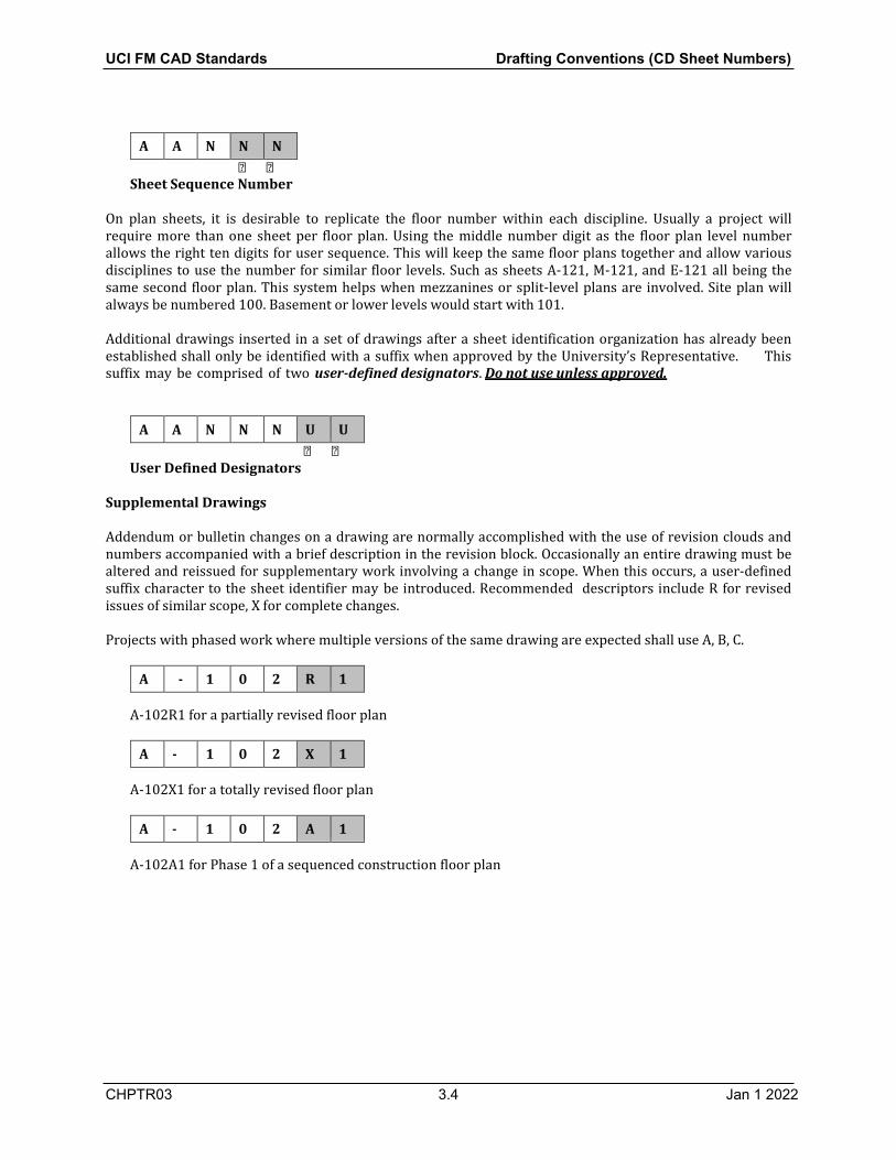
Supplemental Drawings
Addendum or bulletin changes on a drawing are normally accomplished with the use of revision clouds and numbers accompanied with a brief description in the revision block. Occasionally an entire drawing must be altered and reissued for supplementary work involving a change in scope. When this occurs, a user-defined suffix character to the sheet identifier may be introduced. Recommended descriptors include R for revised issues of similar scope, X for complete changes.
Projects with phased work where multiple versions of the same drawing are expected shall use A, B, C.
A - 1 0 2 R 1
A-102R1 for a partially revised floor plan
A - 1 0 2 X 1
A-102X1 for a totally revised floor plan
A - 1 0 2 A 1
A-102A1 for Phase 1 of a sequenced construction floor plan

UCI FM CAD Standards Drafting Conventions (CD Sheet Numbers)
CHPTR03 3.5 21 May 2020
Appendix A- Level 1 Discipline Designators
Designator (Level 1)
Description of Suggested Name Contents
G General All or any portion of subjects including: Drawing list, codes, Fire Marshal notes,
legend, campus map, Scope of Work Phasing, schedules, contractor staging areas,
fencing, haul routes, erosion control, temporary and special requirements
Photographs, soil borings
C Civil All or any portion of subject including Civil Demolition Structure removal and site clearing Civil Survey (site) Plats, topographic, dimension control Civil Grading Excavation, grading, drainage, retention ponds
Civil Paving Roads, bridges, drives and parking lots Civil Improvements Pavers, flagstone, exterior tile, furnishings,
retaining walls, and water features Civil Utilities Water, sanitary sewer, storm sewer, power,
and communications
L Landscape All or any portion of subjects including Landscape Demolition Protection and removal of existing
landscaping Landscape Irrigation
Landscape Planting
S Structural All or any portion of subjects including: Structural Demolition Protection and removal Structural Site
Structural Substructure Foundations, piers, slabs, and retaining walls
Structural Framing Floors and roofs
A Architectural All or any portion of subjects including: Architectural Site
Architectural Demolition Protection and removal Architectural Elements General Architectural Architectural Interiors
Architectural Finishes
Architectural Graphics

UCI FM CAD Standards Drafting Conventions (CD Sheet Numbers)
CHPTR03 3.6 Jan 1 2022
Designator (Level 1)
Description of Suggested Name Contents
I Interiors All or any portion of subjects including: Interior Design
Interior Furnishings
Q Equipment All or any portion of subjects including: Athletic Equipment Gymnasium, exercise, aquatic, and
recreational Educational Equipment Chalkboards, library Food Service Equipment Kitchen, bar, service, storage, and
processing Hospital Equipment Medical, exam, and treatment Laboratory Equipment Science labs, planetariums, observatories Maintenance Equipment Housekeeping, window washing, and
vehicle servicing Parking Lot Equipment Gates, ticket and card access Retail Equipment Display, vending, and cash register Site Equipment Bicycle racks, benches, playgrounds Theatrical Equipment State, movie, rigging systems Video/Photographic
Equipment Television, darkroom and studio
Security Equipment Access control and monitoring, surveillance
F Fire Protection All or any portion of subjects including: Fire Detection and Alarm
Fire Suppression Fire extinguishing systems and equipment
FA Fire Detection and Alarm
FS Fire Suppression Fire extinguishing systems and equipment
P Plumbing All or any portion of subjects including: Plumbing Site Extension and connections to Civil Utilities Process/Plumbing
Demolition Protection, termination, and removal
Process Systems Soft water, RO, & DI systems and equipment.
Plumbing Domestic water, sanitary and storm drainage, fixtures
M Mechanical All or any portion of subjects including: Mechanical Site Utility tunnels and piping between facilities

UCI FM CAD Standards Drafting Conventions (CD Sheet Numbers)
CHPTR03 3.7 Jan 1 2022
Designator (Level 1)
Description of Suggested Name Contents
Mechanical Demolition Protection, termination, and removal Mechanical HVAC Ductwork, air devices, and equipment Mechanical Piping Chilled and heating water, High Temp water
or steam
E Electrical All or any portion of subjects including: Electrical Site Utility tunnels, site lighting Electrical Demolition Protection, termination, and removal Electrical Power
Electrical Lighting
Electrical Instrumentation Controls, relays, instrumentation, and measurement Devices
Electrical Auxiliary Systems
Alarms, nurse call, security, CCTV, PA, music, clock, and program
T Telecommunications All or any portion of subjects including: Audio Visual Cable, music, and CCTV systems Clock and Program Time generators and bell program systems Intercom Intercom and public address systems Monitoring Monitoring and alarm systems Data Networks Network cabling and equipment Telephone Telephone systems, wiring, and equipment Security Access control and alarm systems
R Resource Data furnished without warrant as to accuracy
Resource Civil Surveyor’s information and existing civil drawings
Resource Structural Existing facility structural drawings Resource Architectural Existing facility architectural drawings Resource Mechanical Existing facility mechanical drawings Resource Electrical Existing facility electrical drawings

UCI FM CAD Standards Drafting Conventions (CD Sheet Numbers)
CHPTR03 3.8 Jan 1 2022
Appendix B- Sheet Identification Examples
The following table illustrates hypothetical indexes of drawings for typical University construction projects.
Designator Sheet Title (Level 1)
General Drawings
G-001 Cover Sheet (Title Sheet)
G-002 List of Sheet and Symbols
G-003 Location and Area Maps
G-004 Code Summary Fire Exiting and Separation
G-005 General Requirements Notes
G-100 Site Fire Access Plan
G-101 Site Utilization Plan
G-111 Fire Life Safety Plans
G-601 Phasing Diagrams
Civil Drawings
C-001 Grading and Excavation Notes
C-002 Paving Notes
C-003 Utilities Distribution Notes and Symbols
C-101 Site Demolition Plan
C-102 Utilities Demolition Plan
C-103 Dimension Control Plan
C-104 Excavation Plan
C-105 Grading Plan
C-106 Paving Plan
C-107 Site Utilities Plan
C-108 Domestic Water Distribution Plan and Profile
C-109 Fire Protection Water Distribution Plan and Profile
C-110 Sanitary Sewer Plan and Profile
C-201 Grading Profiles
C-301 Excavation Sections
C-302 Grading Sections
C-303 Paving Sections
C-501 Grading Details
C-502 Paving Details
C-503 Site Utilities Details

UCI FM CAD Standards Drafting Conventions (CD Sheet Numbers)
CHPTR03 3.9 Jan 1 2022
Designator (Level 1) Sheet Title
C-504 Domestic Water Distribution Details
C-505 Sanitary Sewer Details
Landscape Drawings
L-001 Irrigation Notes and Symbols
L-002 Planting Notes and Symbols
L-101 Irrigation Demolition Plan
L-102 Planting Removal Plan
L-103 Irrigation Plan
L-104 Plant Materials Plan
L-401 Large Scale Irrigation Plans
L-402 Large Scale Planting Plans
L-501 Irrigation Details
L-502 Landscape Details
L-601 Irrigation Schedules
L-602 Irrigation Diagrams
L-603 Plant Materials Schedules
L-604 Planting Diagrams
L-901 Landscape 3D Representations
Structural Drawings
S-001 Framing Notes
S-101 Lower Level or Foundation Plan
S-111 First Floor Plan
S-121 Second Floor Framing Plan
S-131 Third Floor Framing Plan
S-141 Fourth Floor Framing Plan
S-151 Roof Framing Plan
S-201 Foundation Wall Elevations
S-202 Framing Elevations
S-301 Foundation Sections
S-302 Framing Sections
S-303 Wall Sections
S-401 Large Scale Foundation Plans
S-402 Large Scale Plan at Physical Therapy
S-501 Foundation Details

UCI FM CAD Standards Drafting Conventions (CD Sheet Numbers)
CHPTR03 3.10 Jan 1 2022
Designator (Level 1) Sheet Title
S-502 Framing Details
S-503 Stair and Elevator Details
S-601 Foundation Schedules
S-602 Foundation Load Diagrams
S-603 Reinforcing Schedules
S-604 Column and Beam Schedules
S-605 Framing Schedules
S-606 Load Diagrams
S-901 Framing Isometrics
Architectural Drawings
A-001 Architectural Notes and Symbols
A-100 Architectural Site Plan
A-101 Lower Level Plan
A-111 First Floor Plan
A-112 First Floor Reflected Ceiling Plan
A-113 First Floor Finishes Plan
A-121 Second Floor Plan
A-122 Second Floor Reflected Ceiling Plan
A-123 Second Floor Finishes Plan
A-131 Third Floor Plan
A-132 Third Floor Reflected Ceiling Plan
A-133 Third Floor Finishes Plan
A-141 Fourth Floor Plan
A-142 Fourth Floor Reflected Ceiling Plan
A-143 Fourth Floor Finishes Plan
A-151 Roof Plan
A-201 Exterior Elevations
A-202 Interior Elevations
A-203 Signage Elevations
A-301 Building Sections
A-302 Wall Sections
A-303 Signage Sections
A-401 Large Scale Toilet Plans
A-402 Stair and Elevator Plans and Sections

UCI FM CAD Standards Drafting Conventions (CD Sheet Numbers)
CHPTR03 3.11 Jan 1 2022
Designator (Level 1) Sheet Title
A-403 Kitchen and Dining Room Plan
A-404 Large Scale Signage Drawings
A-501 Exterior Details
A-502 Interior Details
A-503 Signage Details
A-601 Door and Window Schedules
A-602 Diagrams
A-602 Room Finish Schedules
A-603 Signage Schedules
A-901 3D Representations and Isometrics
Equipment
Q-001 Notes and Symbols
Q-002 Equipment Schedules (or in 600 series)
Q-111 Equipment First Floor Plan
Q-501 Equipment Details
Plumbing & Fire Suppression Drawings
P-001 Notes & Symbols
P-002 Equipment and Fixture Schedules (or in 600 series)
P-100 Site Plan
P-111 First Floor Plan
P-112 Waste and Vent First Floor Plan – East
P-113 Waste and Vent First Floor Plan – West
P-121 Second Floor Plan
P-131 Third Floor Plan
P-141 Fourth Floor Plan
P-151 Roof Plan
P-301 Sections
P-401 Large Scale Plans
P-501 Details
P-601 Waste & Vent Riser Diagrams
P-602 Water Riser Diagrams
Mechanical Drawings
M-001 Notes, Symbols and Legend
M-002 Equipment Schedules (or in 600 series)

UCI FM CAD Standards Drafting Conventions (CD Sheet Numbers)
CHPTR03 3.12 Jan 1 2022
Designator (Level 1) Sheet Title
M-100 Site Plan
M-101 Basement Floor Plan
M-111 First Floor Plan
M-112 First Floor Piping Plan
M-121 Second Floor Plan
M-131 Third Floor Plan
M-141 Roof Plan
M-301 Section
M-401 Large Scale Plans
M-501 Details
M-601 Piping Diagrams
M-701 Control Sequence and Control Diagrams
Electrical Drawings
E-001 Notes, Symbols & Legend
E-002 Equipment Schedules (or in 600 series)
E-100 Site Plan
E-101 Basement Floor Plan
E-102 Basement Floor Plan – Lighting
E-103 Basement Floor Plan – Comm./Data & Fire Alarm
E-111 First Floor Plan – Power
E-112 First Floor Plan – Lighting
E-113 First Floor Plan – Comm./Data & Fire Alarm
E-121 Second Floor Plan – Power
E-122 Second Floor Plan – Lighting
E-123 Second Floor Plan – Comm./Data & Fire Alarm
E-131 Third Floor Plan – Power
E-132 Third Floor Plan – Lighting
E-133 Third Floor Plan – Comm./Data & Fire Alarm
E-141 Roof Plan - Power
E-142 Roof Power Plan – Lighting
E-143 Roof Plan – Comm./Data & Fire Alarm
E-301 Sections
E-401 Large Scale Plans
E-501 Details

UCI FM CAD Standards Drafting Conventions (CD Sheet Numbers)
CHPTR03 3.13 Jan 1 2022
Designator (Level 1) Sheet Title
E-601 Single Line Diagrams
E-602 Telephone, Fire Alarm and Security Riser Diagrams
E-701 Lighting Controls
UCI Sheet Numbering Standards
Use only single letter with a dash except for Fire Suppression and Fire Alarm. Do not use dash when using 2 letters. Digits 1 & 2 for a plan (i.e. north 2nd floor) are the same for each discipline. Keep floor plans together in 100 series except for enlarged rooms would be in
the 400 series.
Example: M-132 means HVAC plan of third floor and second user sequence sheet.
Discipline Designator digit 1 Sheet Type digit 2 Floor level digit 3
G - General 0 General (can be used
with each discipline) 0 Site/Basement/ lower
level 0
C - Civil 1 Plans 1 First 1 L - Landscape 2 Elevations 2 Second 2 S - Structural 3 Sections 3 Third 3 A - Architectural 4 Large plans 4 Fourth 4 Q - Equipment 5 Details 5 Roof (after final floor
plan) 5
P - Plumbing 6 Schedules/ Diagrams 6
M - HVAC 7 Controls 7 E - Electrical 8 user 8 F S Fire Suppression 9 3D 9 F A Fire Alarm
T - Telecommunication
The use of sheet type designators does not preclude combining different types of drawings on the same sheet for simplicity and to eliminate more than half a sheet being empty. For instance, it is acceptable to:
Place schedules, details, diagrams, elevations & sections general or floor plan sheets. Place same scale sections on the same sheet as large scale plans of stairs or escalators. Place schedules on a plan sheet when the information is closely associated.
When the type of drawings on a sheet is mixed, clearly identify all of the drawings contained on the sheet in the sheet title block.

UCI FM CAD Standards Drafting Conventions (CD Sheet Numbers)
CHPTR03 3.14 Jan 1 2022
3.2 Sheet Numbering Conventions for Sketches
1. For projects subject to DSA or OSHPD review, all sketches prepared for or by FM shall be numbered in
accordance with the conventions of the reviewing agency.
2. In the absence of DSA or OSHPD requirements, all sketches produced for or by FM shall be numbered in accordance with the sheet numbering convention specified below.
3. These instructions apply only to sketches prepared after a bid set has been issued.
4. Sketch Identification Numbers contain two sections. The first section is called the Drawing Type
Designator. It identifies a drawing as a Sketch and is three characters in length. The appropriate designation for sketches is “SK-“.
5. The second section of the Sketch Identification Number is called the Sheet Number. Sheet Numbers are
up to three characters in length. Sketches are numbered sequentially in the order they are issued. Sheet numbers start at "001" and end at "999".
6. Here's a closer look at the complete Sketch Identification Number. Note how the two sections combine to
form the complete number:
S K - N N N
Sheet Type Designator
S K - N N N
Sheet Number

UCI FM CAD Standards Quality Assurance
CHPTR04 4.1 Jan 1 2022
4.0 Quality Assurance
4.1 The Drawing Markup Process
4.1.1 General Instructions Drawings are continuously being modified throughout the life of a project. In recognition of this, GKK has devised the following set of rules to guide the drawing revision process. GKK uses a color-coded markup system derived from the “REDICHECK” system (see reference), to capture drawing review comments and insure that those comments are incorporated onto projects drawings in a timely and efficient manner. Team members are required to use the following colors to mark up CAD check plots or blue line prints:
1. Team members are instructed to use Red when making review comments that require changes to the
drawings.
2. Use Green to capture review comment responses.
3. Use a Yellow highlight or strikethrough to indicate that a drawing has been revised to reflect specific Red or Green comments (i.e. a comment has been "picked -up").
4. Use Blue for comments that require no action on the drawings. Blue comments are typically made for the
reviewer’s own use.
4.1.2 Redline Files
1. The creation and use of digital redline files shall be controlled by the conventions specified below.
2. FM employs two different methods to produce redline files. The first method uses scanners to capture redline comments after they have been manually placed onto paper documents. The second method uses software to place redline comments onto CAD drawings. This second method is known as digital redlining.
4.1.3 File Naming Convention for Redline Files
1. Redline drawing files shall conform to the Microsoft Windows file naming convention as specified in Appendix A of this document. In conformance with the Microsoft Windows file naming conventions, all redline drawing file names shall include a File Prefix and a File Suffix.
2. The File Prefix is composed of three (3) different sections. The File Suffix has only one section.
3. The first section of the redline File Prefix identifies the sheet number (for scanned images) or File Prefix
(for AutoCAD drawings) that the redlines relate to (i.e. the target). Refer to Chapter 2 for additional information about D&CS’s sheet numbering conventions
4. The second section of the File Prefix is eight (8) or nine (9) characters in length. It identifies the file as a
redline or marked up image file. Set this portion of the File Prefix to read “_REVIEW_” or “_MARKUP_” UCI reviewed dwgs.
5. The third section of the File Prefix contains the date that the redline file was created. It is six characters in length. Dates are specified by year, month and day (yymmdd). Years are designated with a 2 digit sequence that corresponds to the decade and the calendar year. Months are designated with a 2 digit sequence that starts at 01 (January) and ends at 12 (December). Dates are 2 digit sequences that correspond to the day of the month (01-31).

UCI FM CAD Standards Quality Assurance
CHPTR04 4.2 Jan 1 2022
6. The File Suffix is three characters in length. Set the File Suffix by selecting the appropriate designation from the following list. Note: the File Suffix for renamed scanned files should remain unchanged.
.RML Redline Markup Language file (colored image generated by Volo View and Volo View Express).
7. Here's an example of a review file name. Note how the various sections combine to form the complete file name:
A-201_REVIEW_190410.XXX
File Suffix Date YYMMDD Redline Designator Sheet #
Note 1 Most scanners automatically name image files as they are created. These files must be renamed to conform to the convention described above before they are issued for use.
Note 2 Digital redline files must be placed in the same folder as the drawings they comment on.
4.2 Revising the Drawings (Issuing Addenda & Bulletins)
1. Revisions can be made by deleting, striking out, changing or adding new information to a drawing.
2. Revisions can occur any time after a drawing has been issued to bidders. Addendums are issued during
the bidding period to clarify, revise or add new information to the contract documents. Bulletins are issued during the construction phase to revise or add to the scope of work.
3. Each revision shall be drawn in a way that graphically distinguishes it from surrounding areas or areas
unaffected by the revision. Areas affected by a revision shall be outlined in black (i.e. “clouded”) to make the revision more conspicuous. A revision symbol shall be placed on a drawing in the immediate proximity of the revised work. Drafters shall use the AutoCAD block that has been designated for this purpose (i.e. the revision delta symbol).
4. Revisions and their associated clouds, delta symbols and titleblock entries must be placed on the
appropriate layer, use the proper screen color and be located in either Paper Space or Model Space as appropriate. Drafters are directed to the Table of Contents or the Index of this document for locate additional information about each of these topics.
5. Drafters are advised to keep the number of clouds and symbols to a minimum. Whenever possible, use a
single revision cloud and symbol to identify several changes or revisions on the same drawing.
6. Each revision (i.e. clouds, revision symbols and associated text) must be isolated on it’s own layer. Obsolete revision layers must be turned off once they are superseded by a new revision. Drafters are instructed not to erase obsolete revision clouds and symbols.
Portable Document Format (black & white image from scanner) .PDF Description File Suffix
.TIF Tagged Image File Format (black & white image from scanner).

UCI FM CAD Standards Quality Assurance
CHPTR04 4.3 Jan 1 2022
7. Revision symbols contain a unique alphanumeric identifier. On drawings being “Issued For Construction” the revision identifier shall be set to zero (0). Subsequent revisions shall be consecutively numbered (e.g. 1, 2, 3, etc.).
8. Each revision shall be logged and noted in the area set aside to record such information in the title block.
9. Addenda or Bulletins may contain an unlimited number of sheets. Each bundle of sheets is tied to a
specific revision number. In other words, every sheet in a given bundle contains revision clouds with the same revision number. Revision numbers are not sheet specific.
10. Revision numbers do not necessarily correspond to the addenda or bulletin numbers under which they
are issued. For example, revision 3 may be issued as Addenda #5 or Bulletin #8.
11. The revision identifier for as-built drawings shall be set to the letter “A”. Subsequent revisions to as- built drawings shall be indicated with an alphabetical sequence (e.g. B, C, D etc.). To eliminate the possibility for misinterpretation, the letters I, O, Q and X shall not be used.
12. All revision symbols and clouds shall be removed on as-built (i.e. record drawing) submittals.
13. Revisions to as-built drawings shall be shown in black. Areas not affected by the revision shall be muted
using a gray screen.
14. Revision numbers are used to determine if the drawings being viewed are the most current available. A new number is issued each time revised drawings are released to the contractor. Each issuance may contain a single change or multiple changes to the drawings.
15. If a new sheet is added by addendum there is no need to cloud the drawing. However, the new sheet must
contain the appropriate revision information in it’s titleblock (i.e. the revision number and it’s date of issue).
16. Drafters are free to issue either “A” (8-1/2” x 11”), “B” (11” x 17”) or “F” (30” x 42”) size sheets for
addenda or bulletins. Drafters are encouraged to use small sized sheets if at all practical. Small sheets are easier to duplicate and are preferred if the revisions are localized to a small area in the drawing. Drafters are directed to use full size sheets if the revisions are extensive or occur in many different places on a drawing.
17. All sketches issued as part of an addenda or bulletin must be numbered in accordance with the
conventions listed in Chapter 2.2.4 of this document.

UCI FM CAD Standards CAD Deliverables
CHPTR0
5.1 21 May 2020
Capacity or Size Media Type
5.0 CAD Deliverables 5.1 General
1. Electronic files may be submitted to FM two different ways. Submittals may be (1) transmitted
electronically or (2) delivered on physical media. Instructions regarding physical submittals are listed in section 5.2 below. Instructions for electronic submissions are listed in section 5.3 below. Refer to the appropriate section for detailed submittal instructions.
2. All digital submissions must be delivered to FM free of physical defects, corruption or viruses.
3. Encrypted files will not be accepted.
4. All electronic files submitted to FM shall become the property of FM.
5. All consultants or contractors required to produce electronic documents for FM Corporation shall keep
at least one (1) copy of all such documents available at their place of business for reference purposes. Reference copies must be exact duplicates of the files submitted to FM and must be kept in good working order.
6. FM will not accept any electronic file whose usage or distribution is prohibited or restricted in whole or
in part by copyright or license; or require FM to incur any costs, fees or expenses.
7. Each submittal package must include a “Read.Me” text file that contains the same information that is required on labels (see labeling instructions in section 5.2, item #6 below). The “Read.Me” file must also contain any special instructions about the deliverables.
5.2 Physical Submittals
1. Electronic files may be delivered to FM in any of the following media formats:
CD-ROM, CD-R, CD-RW, DVD-ROM; DVD-R, DVD-RW, DVD+R, DVD+RW & DVD-RAM
Any capacity. Standard (120 mm / 12 cm) diameter only. FM will not accept Mini (80 mm / 8 cm) diameter discs.
2. All submittal media must be readable by computers running Microsoft Windows 7 operating systems.
3. Any brand disc is acceptable.
4. Each disc must be delivered to FM in a protective case.
5. All discs must be clearly labeled. Labels shall contain the following information:
Project Name & Location: FM Project Number: (if applicable or known) Submission Status: (i.e. weekly progress set, 50% or 90% CD submittal, As-built submittal, etc.) Consultant, Contractor or Vendor Contact Information: FM Contact: (i.e. Project Manager or Director, etc.) Submission Date: Disk Contents: (including file names and a short description of file contents) Disk Number: (if more then one in set; i.e. 1 of 5, 2 of 5 etc.) Compression Method: (if applicable)
6. Submitters shall take whatever steps are necessary to physically protect submissions during shipping.

UCI FM CAD Standards CAD Deliverables
CHPTR05
CHPTR05
5.2 Jan 1 2022
5.3 Electronic Submittals
1. Files may be electronically transmitted to FM via email or FTP.
2. Email messages with attachments may not exceed 5 MB.
3. FTP submissions must adhere to the conventions and procedures found in the “FTP Procedures, Instructions and Requirements “ section of this document.
4. Refer to Chapter 6 of this document for more information about FM email addresses and for
instructions regarding access to FM’ FTP project sites.
5.4 File Naming Convention for Compressed Electronic Submittals
1. CAD submittals may be compressed only if they are email attachments. File compression is not permitted on any FTP submittals.
2. Electronic files submitted to FM may be compressed using any compression software that produces
files that are 100% compatible with WinZip 7.0 software published by Nico Mak Computing, Inc. Note: “.ZIP” files are acceptable, “.EXE” (self extracting archive files) are not.
3. In no case may a compressed file exceed 5 MB.
4. Do not include compression software with the submittal package.
5. Compressed files shall be named in accordance with the file naming conventions listed below:
• All compressed files shall conform to the Microsoft Windows file naming convention as specified in
Appendix A of this document. In conformance with Windows file naming conventions, compressed electronic files shall contain a File Prefix and a File Suffix.
• The File Prefix has three different sections.
• The first section contains the name or abbreviation of the company creating the file. The name or
abbreviation is followed by an underscore ( _ ).
• The second section of the File Prefix contains the date that the file was created. It is six characters in length. Dates are specified by year, month and day (yymmdd). Years are designated with a 2 digit sequence that corresponds to the decade and the calendar year. Months are designated with a 2 digit sequence that starts at 01 (January) and ends at 12 (December). Dates are 2 digit sequences that correspond to the day of the month (01-31). The creation date is followed by an underscore ( _ ).
• The third section of the File Prefix is known as the Sequence Number. The Sequence Number is 2
characters in length. Compressed files are numbered sequentially as they are created. The sequence starts at 01 and ends at 99.
• Set the File Suffix to .ZIP

CHPTR0
6.1 Jan 1 2022
6
• A complete file name for a compressed file looks like this:
ABC_041225_01.ZIP
File Suffix
Sequence #
Creation Date
Company Name
In the example shown above, the file was created by ABC Corporation on Christmas Day 2004. It was the first .ZIP file of the day created for a specific project.
5.5 Title Block Standard
1. The standard FM title block should be used for all projects, this border has the Sate Fire Marshals
approval stamp located 3.5” from the top of the sheet.
2. If another border is used the same space for the stamp must be added, this is a OCFA requirement.

CHPTR0
6.1 Jan 1 2022
6
UCI FM CAD Standards Communications
6.0 Communications 6.1 Communicating with FM Inquiries, requests, suggestions and submittals can be directed to any member of the FM staff through any one of the following methods:
Electronic Mail: Messages may be sent to FM at any time (24 hours a day, 7 days a week). Expect responses during business hours only (Monday-Friday from 8:00am-5:00pm Pacific Time). Each message with attachments can not exceed 10 MB.
Contact information for any project team member is available from the FM CAD Manager upon request.
U.S. Mail or messenger service: Submittals must conform to the specifications found in Chapter 5 of this document. Chapter 5 contains information about acceptable media types and sizes, labeling requirements, and how best to insure the physical integrity of the submittal)
University of California, Irvine Facilities Management 19172 Jamboree Rd. Irvine, CA 92697-5444
Phone: Expect responses during business hours only (Monday-Friday from 8:00am-3:30pm Pacific Time).
(949) 824-2062
Project FTP Sites: Project team members can upload or download files from any location in the world using the FTP protocol. Available 24 hours a day, 7 days a week.
URL addresses, User Names and Passwords can be obtained from FM Project Manager.
Please include your name, your return address and a voice or FAX phone number with all communications.
Communications Method Address:

CHPTR07
7.1 Jan 1 2022
UCI FM CAD Standards Intellectual Property
7.0 Intellectual Property 7.1 General Information
Intellectual property rights must be respected. To that end all documents produced for or by FM shall adhere to the following Copyright and Trademark policies.
7.2 Copyrights
1. The copyrights to all publishable documents produced for or by FM are the properties of FM unless they are contractually assigned to another party.

CHPTR07
7.1 Jan 1 2022
UCI FM CAD Standards Appendix A
File and Folder Naming Conventions (General Instructions)
1. All electronic files and folders prepared for or by FM shall be named in accordance with the Microsoft Windows long file and folder naming conventions.
2. Microsoft Windows file names have two components. The first component is called the File Prefix. File
Prefixes are a maximum of two hundred and fifty two (252) characters in length. The second component in a file or folder name is called the File Type (also known as a File Suffix). File Type names are a maximum of three (3) characters in length (note: although two (2) character file suffixes are acceptable, they are very rarely used).
3. File Prefixes and File Types are separated by a period ( . ).
4. Only one period may be used in a file name. It must be located no more than four (4) characters from the
end of the name.
5. A period counts as one character.
6. Microsoft Windows folder names have only one component. Folder names may contain up to two hundred and fifty five (255) characters.
7. Periods are not permitted in a Folder or Directory name.
8. The following characters may not be used in any portion of a Microsoft Windows File or Folder name:
\ / : * ? " < > |
9. Although Windows permits spaces to be used in folder and file names, FM has elected to prohibit their use. In their place, users are instructed to use an underscore ( _ ) as a place holder.
10. Unless there is a compelling reason to do so, folder and file names shall not be changed. If a compelling
reason exists, folder and file names may be changed only if it can be determined that the file or folder is not electronically linked to any other file or folder.
11. Throughout this document, FM uses specific file prefix and suffix naming conventions. FM also uses
specific folder naming conventions. Refer to relevant sections of this document for specific instructions regarding file and folder names.