Arup Ratan Bandyopadhyay, M.Phil, PhD - University of Calcutta
Upload
khangminh22Category
view
1download
0
100
Arup Concept Narrative Structural Design, Mechanical and Sustainability Report
C:\CORMAC\3\CONCEPT REPORT.0003REPORT_DEC 2007.DOC Arup North America LtdDraft 3 November 30, 2007
Document VerificationPage 1 of 1
Job number Job title Seattle Civic Square
131851
File reference Document title Concept Narrative
Document ref
Revision Date Filename
Description First draft
Prepared by Checked by Approved by
Name CD, GA, PA, JO, JM, BG Brian Glover Cormac Deavy
Draft 1 11/30/07
Signature
Filename CONCEPT REPORT.0003Report_Nov 2007.doc
Description November 2007 issue
Prepared by Checked by Approved by
Name CD, GA, PA, JO, JM, BG Brian Glover Cormac Deavy
Draft 3 12/05/07
Signature
Filename
Description
Prepared by Checked by Approved by
Name
Signature
Filename
Description
Prepared by Checked by Approved by
Name
Signature
Issue Document Verification with Document �
Seattle Civic Square - DRAFT Concept Design Submission - December 10, 2007 101
Arup Concept Narrative Structural Design, Mechanical and Sustainability Report
Triad Seattle Civic SquareConcept Narrative
C:\CORMAC\3\CONCEPT REPORT.0003REPORT_DEC 2007.DOC Arup North America LtdDraft 3 November 30, 2007
ContentsPage Page
1 Introduction 1
2 The Site 1
2.1 The Site 1
2.2 Geology and Seismology 2
2.3 Adjacent Structures / Utilities 2
3 Project Design Precepts 3
3.1 Project Description 3
4 Structural Engineering 3
4.1 Ground Investigation and Site Geology 3
4.2 Substructure and Foundation Design 3
4.3 Superstructure 6
4.4 Typical Floor Structure 8
4.5 Material Specifications 9
4.6 Structure and Sustainability 9
5 Mechanical Engineering 10
5.1 Mechanical System: Infrastructure Approach 10
5.2 Mechanical System: Building Approach 12
6 Electrical Engineering 15
6.1 Design Loads 15
6.2 Power System 15
6.3 Grounding System 16
6.4 Lightning Protection 16
6.5 Fire Alarm System 16
6.6 Telecommunication and Security Systems 16
6.7 Generator 16
6.8 Utility Vaults and Service 17
6.9 Sketches 17
7 Plumbing / Water Engineering 17
7.1 Building Water Strategies 17
7.2 Sketches 18
8 Façade Engineering 18
9 Sustainability Consulting 18
9.1 Sustainability Metrics 18
9.2 Overall Sustainable Approach 18
9.3 Sustainable Design Concepts 19
9.4 Sustainable Design Responsibility Matrix 23
9.5 LEED® Core & Shell Summary 24
AppendicesAppendix A
Structural Engineering Sketches
Appendix B
Mechanical Engineering Sketches
Appendix C
Electrical Engineering Sketches
Appendix D
Plumbing / Water Engineering Sketches
Appendix E
Sustainability Appendix
Appendix F
Facade Engineering Sketches
Appendix G
Extracts from Shannon and Wilson Report
102
Arup Concept Narrative Structural Design, Mechanical and Sustainability Report
Triad Seattle Civic SquareConcept Narrative
UCC:\CORMAC\3\CONCEPT REPORT.0003REPORT_DEC 2007.DOC Page 1 Arup North America LtdDraft 3 November 30, 2007
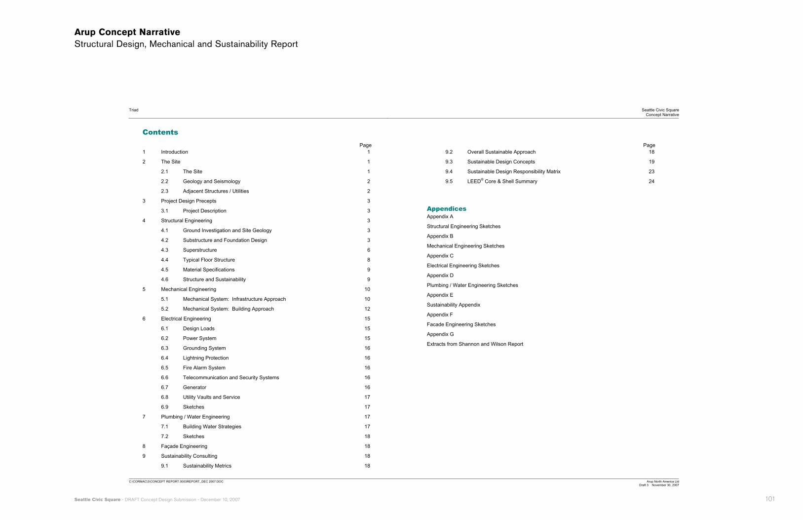
1 Introduction This report outlines the ideas considered during Concept Design for the Seattle Civic Square and the status of the design at the end of the Concept Design phase.
Figure 1 : Architectural Concept | Image Foster + Partners
2 The Site 2.1 The Site
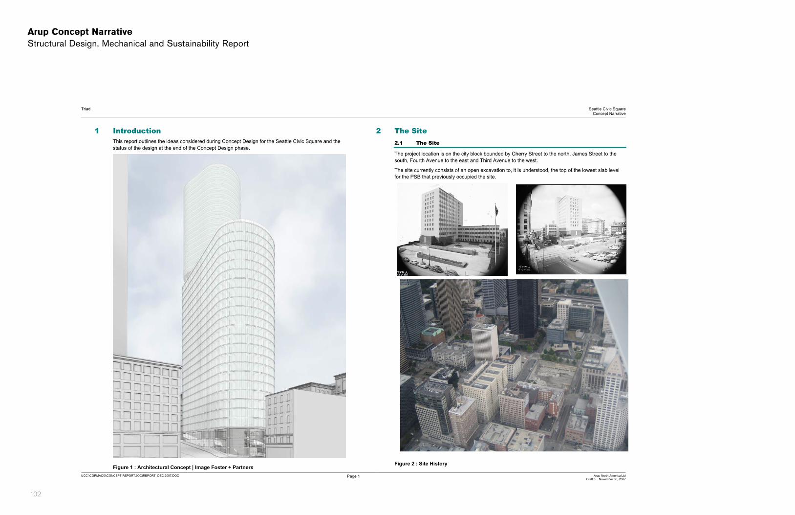
The project location is on the city block bounded by Cherry Street to the north, James Street to the south, Fourth Avenue to the east and Third Avenue to the west.
The site currently consists of an open excavation to, it is understood, the top of the lowest slab level for the PSB that previously occupied the site.
Figure 2 : Site History

Seattle Civic Square - DRAFT Concept Design Submission - December 10, 2007 103
Arup Concept Narrative Structural Design, Mechanical and Sustainability Report
Triad Seattle Civic SquareConcept Narrative
UCC:\CORMAC\3\CONCEPT REPORT.0003REPORT_DEC 2007.DOC Page 2 Arup North America LtdDraft 3 November 30, 2007
2.2 Geology and Seismology
2.2.1 Geological Strata Fill materials extend from the surface to depths ranging from approximately 2 to 20 feet below the ground surface. Under the fill and extending down to 45 feet below the surface in some locations are recent deposits consisting of silts and clays with organic matter and gravels with sand. Dense to very dense interglacial or glacial deposits are found under the recent deposits.
2.2.2 Seismology in Puget Sound Area Seattle is an active seismic area, and parameters for the design were also addressed in the soils report. Seattle has different types of seismic events, including 1) shallow crustal events, 2) deep inter-plate events, and 3) subduction zone events. All three different types of events were used to establish the region’s seismic design parameters, which correspond to provisions for a 50 year design life.
Deep inter-plate seismic events are familiar, having occurred in 1949, 1965, and 2001 in the region. They can be intense; their recurrence interval is quite frequent (30 years +/-). The length of time of ground shaking is not too long, and major aftershocks are not common. Advances in structural engineering in the region have typically addressed this type of seismic event, and more-recent designs suffered little during the 2001 event.
Shallow crustal events with a long recurrence interval (1000 years+/-) result from shallower faults in the region, including the Seattle fault zone. A structure in this event would experience very strong motions. Ground disturbances are common near a fault. Strong aftershocks may test the capacity of a structure to withstand repeated seismic activity within a short time.
The subduction zone seismic event also has a long recurrence interval (maybe 500 years+/-), and is caused by the North American Plate colliding and sliding over the Juan de Fuca Plate. This event releases huge amounts of energy. A structure shaken in this event would experience strong motions for a longer time period than the other types of events.
2.2.3 Seismic Design Parameters The code-specified seismic design parameters given for a 50 year design life are not unusual for the Seattle area; the design will use an Ss of 1.41, an S1 of 0.48, an Fa of 1.0, Fv of 1.32, and a soil profile type C.; this will need to be verified as part of the geotechnical investigations. There is little possibility of ground rupture or liquefaction at this site, according to the soils report.
2.2.4 Additional Geotechnical Information Further information is included in the Shannon and Wilson report dated 2004. A further detailed geotechnical investigation is required; an RFP has been prepared and forwarded to Triad.
2.3 Adjacent Structures / Utilities
2.3.1 PSB Building Foundations From the Shannon and Wilson report dated 2004 it is understood that the PSB building was supported on spread footings. Reportedly the footings bear at approximately 54ft in the southwest corner and 68ft in the northeast corner of the building. It is expected that these footings were not removed during the demolition. The foundation subgrade is about 20 to 45 ft below the street level, the deepest being in the northeast corner of the site. This should be confirmed through trial pitting during subsequent investigations.
2.3.2 Metro Tunnel The Downtown Seattle Transit Project (DSTP) bus tunnel [Metro] and Pioneer Station is under Third Avenue, adjacent to the site. The crown of the bus tunnel is between approximate elevations 36 ft at Cherry Street and 32 ft at James Street.
Due to the limited space between the existing walls and Pioneer Square Station tieback anchors are unlikely to be feasible for shoring this section of wall. Internal bracing could be used.
Figure 3 : Metro Tunnel

104
Arup Concept Narrative Structural Design, Mechanical and Sustainability Report
Triad Seattle Civic SquareConcept Narrative
UCC:\CORMAC\3\CONCEPT REPORT.0003REPORT_DEC 2007.DOC Page 3 Arup North America LtdDraft 3 November 30, 2007
Figure 4 : Metro Tunnel
2.3.3 BNSF Tunnel The Burlington Northern Santa Fe (BNSF) railroad tunnel is under Fourth Avenue and according to the Shannon and Wilson 2004 report is between approximate elevations 12 and 54 ft..
Figure 5 : BNSF Tunnel Alignment
2.3.4 Additional Survey Information Additional survey information will be required as the design progresses. This includes but is not limited to;
� BNSF horizontal and vertical alignment
� Utilities around the site perimeter
� Trial pitting to assist in identifying and locating the existing wall footings.
� Arup have met with and attended site with Bush, Roed & Hutchings (BRH) to help outline the preliminary requirements.
3 Project Design Precepts 3.1 Project Description
3.1.1 The Building The primary function of the building is commercial with all the associated features, such as entrance lobby and plant rooms. Towards the top of the building are residential apartments. The site footprint is approximately 240 ft x 240 ft on plan.
The tower occupies the northern end of the site and is approximately 520 ft at its highest. The 590,000 sq ft office component is approximately 340ft high; the residential component extends above that.. To the south and west of the site are lower height retail elements.
A 6 storey basement (car parking garage and loading dock) extends below the entire block.
The development is targeting a LEED® gold rating (see Section 9 below).
4 Structural Engineering 4.1 Ground Investigation and Site Geology
Geotechnical information is contained in the Shannon and Wilson report dated 2004. A further detailed geotechnical investigation is required for which Arup have issued an RFP.
Little detailed information is known at this stage on the tunnel. Detailed information and study is required to at the outset of Schematic Design (SD) to understand the movements and stresses induced in the tunnel due to the surcharge from the tower and Civic Square construction.
Refer to Figure 8 for section through the site and tunnel.
4.2 Substructure and Foundation Design
The tower and Civic Square area of the basement are going to experience differential vertical movements due to the large difference in applied load on the ground between these two areas. One way to mitigate this issue would be to introduce a movement joint throughout the basement along the interface between these areas, though a movement joint does pose a number of real and difficult design issues, in particular. It is not recommended to form a movement joint in the design for this basement, and the structural elements will therefore be designed to resist the forces induced by this.
The lateral loads from wind and seismic events must be transferred to/from the ground via a suitable structure at mat slab level. Resistance to the net loads from wind, earth, water and seismic forces on the building is provided by a combination of friction at the raft/ground interface and pile shear capacity and passive resistance of the basement perimeter walls.
The building is situated on a sloping site, with a difference of approximately 27ft over the width of the basement in the east-west direction. The lateral earth pressures are therefore out-of balance with
Seattle Civic Square - DRAFT Concept Design Submission - December 10, 2007 105
Arup Concept Narrative Structural Design, Mechanical and Sustainability Report
Triad Seattle Civic SquareConcept Narrative
UCC:\CORMAC\3\CONCEPT REPORT.0003REPORT_DEC 2007.DOC Page 4 Arup North America LtdDraft 3 November 30, 2007
each other. This difference is designed for by additional moments within the building’s stability system.
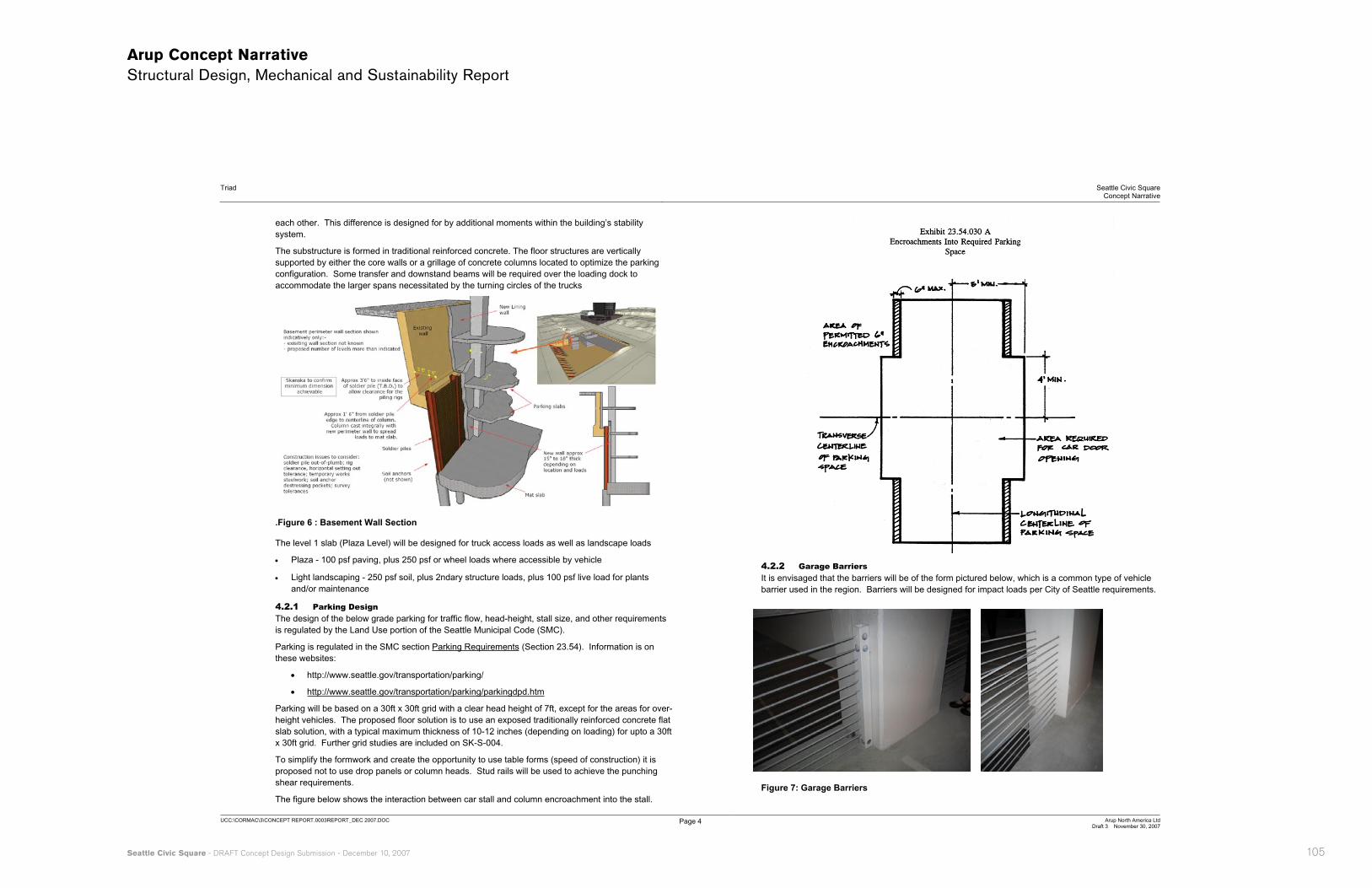
The substructure is formed in traditional reinforced concrete. The floor structures are vertically supported by either the core walls or a grillage of concrete columns located to optimize the parking configuration. Some transfer and downstand beams will be required over the loading dock to accommodate the larger spans necessitated by the turning circles of the trucks
.Figure 6 : Basement Wall Section
The level 1 slab (Plaza Level) will be designed for truck access loads as well as landscape loads
� Plaza - 100 psf paving, plus 250 psf or wheel loads where accessible by vehicle
� Light landscaping - 250 psf soil, plus 2ndary structure loads, plus 100 psf live load for plants and/or maintenance
4.2.1 Parking Design The design of the below grade parking for traffic flow, head-height, stall size, and other requirements is regulated by the Land Use portion of the Seattle Municipal Code (SMC).
Parking is regulated in the SMC section Parking Requirements (Section 23.54). Information is on these websites:
� http://www.seattle.gov/transportation/parking/
� http://www.seattle.gov/transportation/parking/parkingdpd.htm
Parking will be based on a 30ft x 30ft grid with a clear head height of 7ft, except for the areas for over-height vehicles. The proposed floor solution is to use an exposed traditionally reinforced concrete flat slab solution, with a typical maximum thickness of 10-12 inches (depending on loading) for upto a 30ft x 30ft grid. Further grid studies are included on SK-S-004.
To simplify the formwork and create the opportunity to use table forms (speed of construction) it is proposed not to use drop panels or column heads. Stud rails will be used to achieve the punching shear requirements.
The figure below shows the interaction between car stall and column encroachment into the stall.
4.2.2 Garage Barriers It is envisaged that the barriers will be of the form pictured below, which is a common type of vehicle barrier used in the region. Barriers will be designed for impact loads per City of Seattle requirements.
Figure 7: Garage Barriers

106
Arup Concept Narrative Structural Design, Mechanical and Sustainability Report
Triad Seattle Civic SquareConcept Narrative
UCC:\CORMAC\3\CONCEPT REPORT.0003REPORT_DEC 2007.DOC Page 5 Arup North America LtdDraft 3 November 30, 2007
Figure 8 : Section through site
Seattle Civic Square - DRAFT Concept Design Submission - December 10, 2007 107
Arup Concept Narrative Structural Design, Mechanical and Sustainability Report
Triad Seattle Civic SquareConcept Narrative
UCC:\CORMAC\3\CONCEPT REPORT.0003REPORT_DEC 2007.DOC Page 6 Arup North America LtdDraft 3 November 30, 2007
4.3 Superstructure
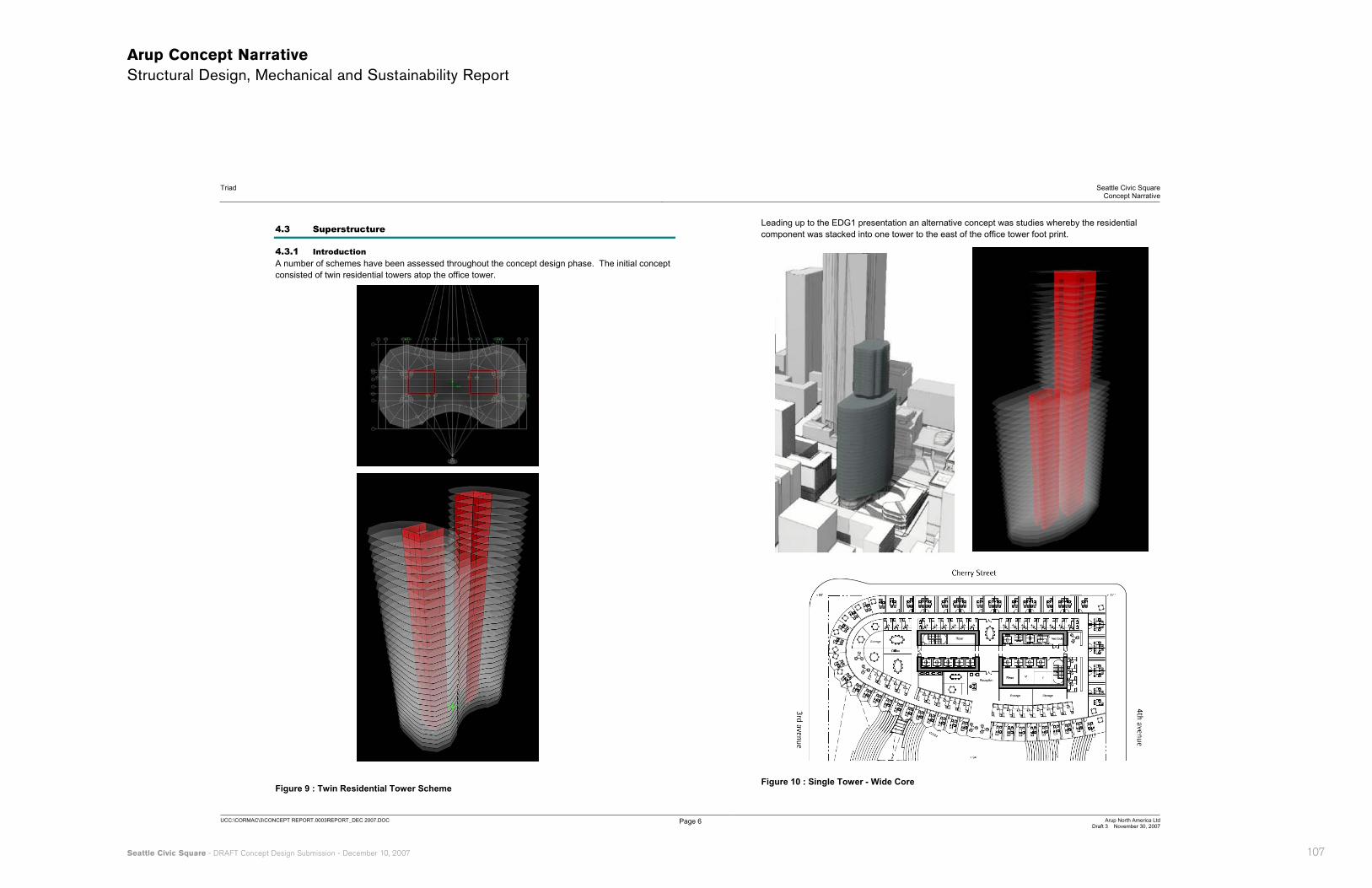
4.3.1 Introduction A number of schemes have been assessed throughout the concept design phase. The initial concept consisted of twin residential towers atop the office tower.
Figure 9 : Twin Residential Tower Scheme
Leading up to the EDG1 presentation an alternative concept was studies whereby the residential component was stacked into one tower to the east of the office tower foot print.
Figure 10 : Single Tower - Wide Core
108
Arup Concept Narrative Structural Design, Mechanical and Sustainability Report
Triad Seattle Civic SquareConcept Narrative
UCC:\CORMAC\3\CONCEPT REPORT.0003REPORT_DEC 2007.DOC Page 7 Arup North America LtdDraft 3 November 30, 2007
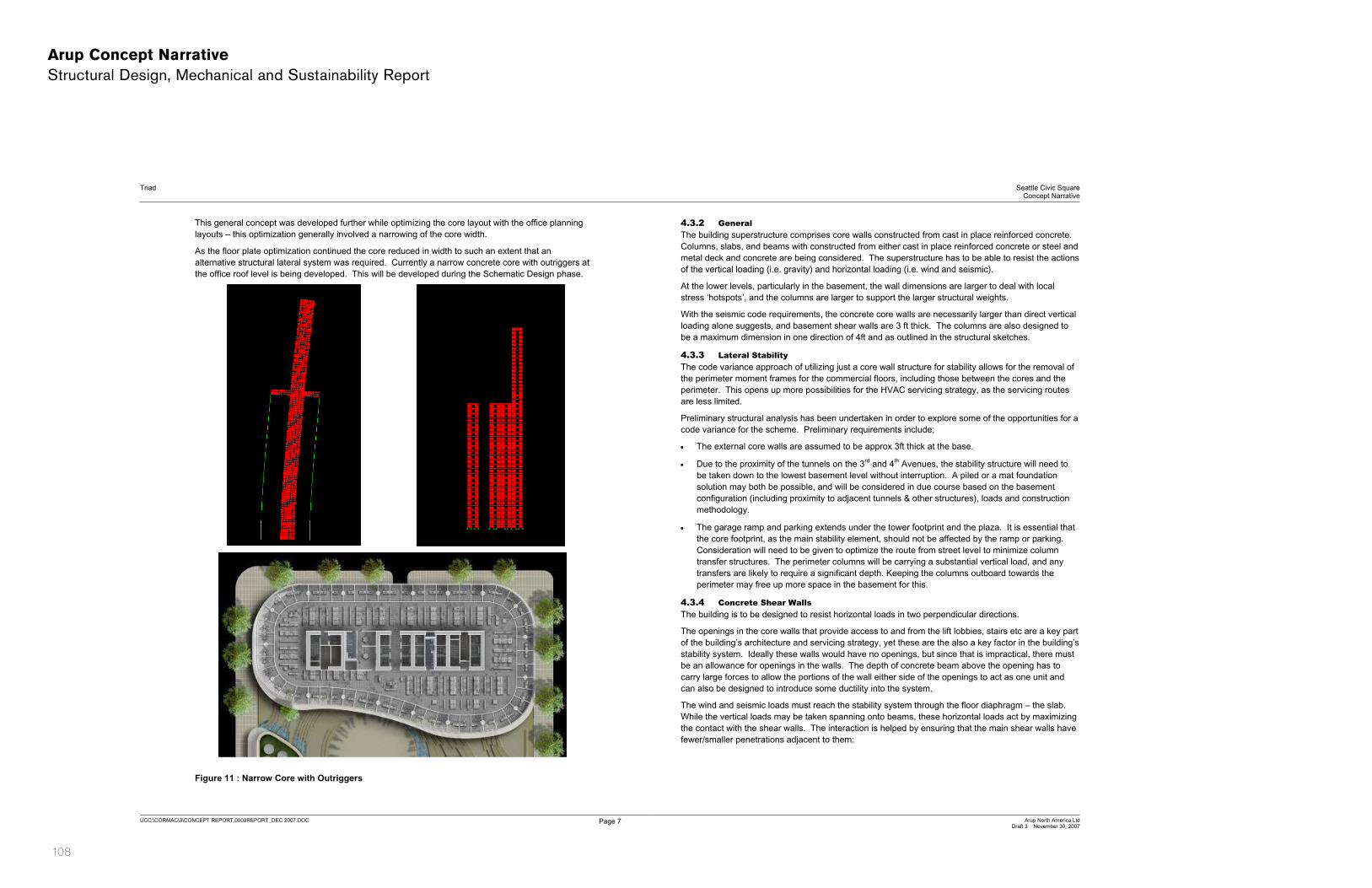
This general concept was developed further while optimizing the core layout with the office planning layouts – this optimization generally involved a narrowing of the core width.
As the floor plate optimization continued the core reduced in width to such an extent that an alternative structural lateral system was required. Currently a narrow concrete core with outriggers at the office roof level is being developed. This will be developed during the Schematic Design phase.
Figure 11 : Narrow Core with Outriggers
4.3.2 GeneralThe building superstructure comprises core walls constructed from cast in place reinforced concrete. Columns, slabs, and beams with constructed from either cast in place reinforced concrete or steel and metal deck and concrete are being considered. The superstructure has to be able to resist the actions of the vertical loading (i.e. gravity) and horizontal loading (i.e. wind and seismic).
At the lower levels, particularly in the basement, the wall dimensions are larger to deal with local stress ‘hotspots’, and the columns are larger to support the larger structural weights.
With the seismic code requirements, the concrete core walls are necessarily larger than direct vertical loading alone suggests, and basement shear walls are 3 ft thick. The columns are also designed to be a maximum dimension in one direction of 4ft and as outlined in the structural sketches.
4.3.3 Lateral Stability The code variance approach of utilizing just a core wall structure for stability allows for the removal of the perimeter moment frames for the commercial floors, including those between the cores and the perimeter. This opens up more possibilities for the HVAC servicing strategy, as the servicing routes are less limited.
Preliminary structural analysis has been undertaken in order to explore some of the opportunities for a code variance for the scheme. Preliminary requirements include;
� The external core walls are assumed to be approx 3ft thick at the base.
� Due to the proximity of the tunnels on the 3rd and 4th Avenues, the stability structure will need to be taken down to the lowest basement level without interruption. A piled or a mat foundation solution may both be possible, and will be considered in due course based on the basement configuration (including proximity to adjacent tunnels & other structures), loads and construction methodology.
� The garage ramp and parking extends under the tower footprint and the plaza. It is essential that the core footprint, as the main stability element, should not be affected by the ramp or parking. Consideration will need to be given to optimize the route from street level to minimize column transfer structures. The perimeter columns will be carrying a substantial vertical load, and any transfers are likely to require a significant depth. Keeping the columns outboard towards the perimeter may free up more space in the basement for this.
4.3.4 Concrete Shear Walls The building is to be designed to resist horizontal loads in two perpendicular directions.
The openings in the core walls that provide access to and from the lift lobbies, stairs etc are a key part of the building’s architecture and servicing strategy, yet these are the also a key factor in the building’s stability system. Ideally these walls would have no openings, but since that is impractical, there must be an allowance for openings in the walls. The depth of concrete beam above the opening has to carry large forces to allow the portions of the wall either side of the openings to act as one unit and can also be designed to introduce some ductility into the system.
The wind and seismic loads must reach the stability system through the floor diaphragm – the slab.While the vertical loads may be taken spanning onto beams, these horizontal loads act by maximizing the contact with the shear walls. The interaction is helped by ensuring that the main shear walls have fewer/smaller penetrations adjacent to them:
Seattle Civic Square - DRAFT Concept Design Submission - December 10, 2007 109
Arup Concept Narrative Structural Design, Mechanical and Sustainability Report
Triad Seattle Civic SquareConcept Narrative
UCC:\CORMAC\3\CONCEPT REPORT.0003REPORT_DEC 2007.DOC Page 8 Arup North America LtdDraft 3 November 30, 2007
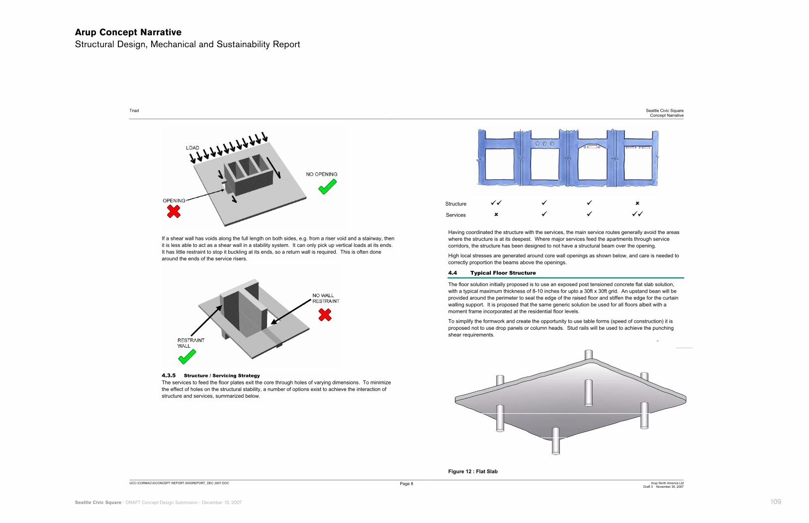
If a shear wall has voids along the full length on both sides, e.g. from a riser void and a stairway, then it is less able to act as a shear wall in a stability system. It can only pick up vertical loads at its ends. It has little restraint to stop it buckling at its ends, so a return wall is required. This is often done around the ends of the service risers.
4.3.5 Structure / Servicing Strategy The services to feed the floor plates exit the core through holes of varying dimensions. To minimize the effect of holes on the structural stability, a number of options exist to achieve the interaction of structure and services, summarized below.
Structure ��� �� �� ��
Services �� �� �� ���
Having coordinated the structure with the services, the main service routes generally avoid the areas where the structure is at its deepest. Where major services feed the apartments through service corridors, the structure has been designed to not have a structural beam over the opening.
High local stresses are generated around core wall openings as shown below, and care is needed to correctly proportion the beams above the openings.
4.4 Typical Floor Structure
The floor solution initially proposed is to use an exposed post tensioned concrete flat slab solution, with a typical maximum thickness of 8-10 inches for upto a 30ft x 30ft grid. An upstand bean will be provided around the perimeter to seal the edge of the raised floor and stiffen the edge for the curtain walling support. It is proposed that the same generic solution be used for all floors albeit with a moment frame incorporated at the residential floor levels.
To simplify the formwork and create the opportunity to use table forms (speed of construction) it is proposed not to use drop panels or column heads. Stud rails will be used to achieve the punching shear requirements.
Figure 12 : Flat Slab
110
Arup Concept Narrative Structural Design, Mechanical and Sustainability Report
Triad Seattle Civic SquareConcept Narrative
UCC:\CORMAC\3\CONCEPT REPORT.0003REPORT_DEC 2007.DOC Page 9 Arup North America LtdDraft 3 November 30, 2007
Figure 13 : Typical Stud Rail Details
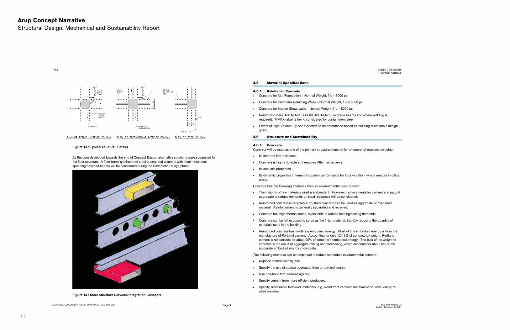
As the core developed towards the end of Concept Design alternative solutions were suggested for the floor structure. A floor framing scheme of steel beams and columns with steel metal deck spanning between beams will be considered during the Schematic Design phase.
Figure 14 : Steel Structure Services Integration Concepts
4.5 Material Specifications
4.5.1 Reinforced Concrete � Concrete for Mat Foundation – Normal Weight, f ’c = 6000 psi
� Concrete for Perimeter Retaining Walls – Normal Weight, f ’c = 5000 psi
� Concrete for Interior Shear walls – Normal Weight, f ’c = 8000 psi
� Reinforcing bars: ASTM A615 GR 60 (ASTM A706 in grade beams and where welding is required). MMFX rebar is being considered for containment steel.
� Extent of High Volume Fly Ash Concrete to be determined based on building sustainable design goals.
4.6 Structure and Sustainability
4.6.1 ConcreteConcrete will be used as one of the primary structural material for a number of reasons including:
� Its inherent fire resistance.
� Concrete is highly durable and requires little maintenance.
� Its acoustic properties.
� Its dynamic properties in terms of superior performance for floor vibration, where needed in office areas.
Concrete has the following attributes from an environmental point of view:
� The majority of raw materials used are abundant. However, replacements for cement and natural aggregate to reduce demands on local resources will be considered.
� Reinforced concrete is recyclable; crushed concrete can be used as aggregate or road base material. Reinforcement is generally separated and recycled.
� Concrete has high thermal mass, exploitable to reduce heating/cooling demands.
� Concrete can be left exposed to serve as the finish material, thereby reducing the quantity of materials used in the building.
� Reinforced concrete has moderate embodied energy. Most of this embodied energy is from the manufacture of Portland cement. Accounting for only 12-18% of concrete by weight, Portland cement is responsible for about 90% of concrete’s embodied energy. The bulk of the weight of concrete is the result of aggregate mining and processing, which accounts for about 5% of the moderate embodied energy in concrete.
The following methods can be employed to reduce concrete’s environmental demand:
� Replace cement with fly ash,
� Specify the use of coarse aggregate from a recycled source,
� Use non-toxic form release agents,
� Specify cement from more efficient producers,
� Specify sustainable formwork materials, e.g. wood from certified sustainable sources, easily re-used material.

Seattle Civic Square - DRAFT Concept Design Submission - December 10, 2007 111
Arup Concept Narrative Structural Design, Mechanical and Sustainability Report
Triad Seattle Civic SquareConcept Narrative
UCC:\CORMAC\3\CONCEPT REPORT.0003REPORT_DEC 2007.DOC Page 10 Arup North America LtdDraft 3 November 30, 2007
4.6.2 Structural Steelwork Steel is being considered for the above grade parts of the structure. Steel has the following attributes from an environmental point of view:
� The majority of raw materials are from recycled steel.
� Steel has the potential to be dismantled and re-used.
The following methods can be employed to reduce steel’s environmental demand;
� Optimize the weight of steel members,
� Use composite construction, where the concrete slabs become the top flanges of the members,
� Use members built from plates or castellated members, to further optimize the steel member weights,
� Specify sustainable materials, e.g. recycled steel,
� Specify steel products to be fabricated at plants close to the construction site, minimizing transport energy demands.
5 Mechanical Engineering 5.1 Mechanical System: Infrastructure Approach
The mechanical systems will be selected to achieve energy efficient operation while maintaining tenant equipment flexibility and reasonable cost. The mechanical system consists of a central system infrastructure with connections provided to tenant heating and cooling systems.
The team is investigating several approaches to servicing the cooling and heating loads for the retail, commercial and residential spaces. There are two basic infrastructure servicing strategies:
� Option #1: A water-source heat pump loop serving unitary compressors (heat pumps and DX systems) in each tenant space.
� Option #2: A central chiller/boiler plant with chilled water and hot water pumped to coils in each tenant space.
5.1.1 Infrastructure Option #1: Water Source Heat Pump Loop A water-source loop allows for site heat recovery from cooling-dominated retail and commercial spaces, with the heat used by the more heating-dominated residential units. Two uninsulated pipes run through the site (supply and return) carrying water between roughly 45F and 95F. Each tenant space includes a DX cooling unit of heat pump (air moving equipment with a refrigerant compressor) to provide local heating or cooling, with space heat either removed or rejected to the heat pump loop. While the heat pumps themselves are not as efficient as central chilled water and heating water equipment, the ability to move heat around the site can improve efficiency. Furthermore, the heat pumps are part of the tenant TI, so the owner is not burdened with the first cost and maintenance of a large central chilled water system.
As tenant equipment removes or rejects heat, the temperature of the loop changes. In the summer, as tenants cool their spaces by rejecting heat to the loop, the loop temp may increase to the point that the tenant equipment can no longer cool the space. To limit the maximum loop temperature, the loop includes a device for rejecting heat to the outside air (see discussion on heat rejection devices below). In the winter, tenant equipment can remove so much heat from the loop that the loop temperature will no longer support the tenant heating requirements. A supplementary loop heating source is therefore incorporated, either with a boiler plant or connection to Seattle Steam, a local private utility. See below for a discussion on the relative merits of each. Each heat pump will also include a water economizer coil so that when all zones are in heating, the loop temperature can be raised with loop water circulated through a heating coil in the air steam. This approach will reduce energy costs compared to running all heat pumps in electric heating mode simultaneously.
Locating compressors within each tenant space will require significant attention to acoustical issues. Overall maintenance increases due the greater number of compressors compared to central equipment.
5.1.2 Infrastructure Option #2: Central Chilled Water and Hot Water plants With central chilled and hot water, the building maintains two central plants – a chilled water plant and a heating water plant. The chilled water plant includes water cooled chillers connected by condenser piping to a heat rejection device (most likely cooling towers). The chillers are located in a dedicated room on the top level of the parking garage, in a double-height space of roughly 13 feet clear. Chilled water supply and return piping distributes cooling water throughout the site in insulated piping.
The heating water plant includes either boilers or a connection to Seattle Steam, a local private utility. See below for a discussion on the relative merits of each. Insulated heating water supply and return piping distributes water throughout the site.
Tenant equipment includes air handling units, fan coil units, chilled beams or a combination of these systems for space heating and cooling. These devices will include chilled water and heating water coils. Unlike the heat pump system, the tenant equipment does not include compressors, so maintenance is more centralized at the central plant, and tenant space noise is reduced. However, the first cost of the cooling and heating plants is borne by the building shell and core budget. A mechanism for metering usage must be developed to encourage efficient use of the systems and to back-charge maintenance and energy costs.
5.1.3 Heat Rejection from site infrastructure Either infrastructure cooling option can utilize several options for heat rejection:
Cooling towers:
Cooling towers evaporate water to reduce the temperature in the heat pump loop or the chiller condenser loop. Chilled water plants can use open towers which are more efficient but can introduce dirt into the system, increasing chiller maintenance. Heat pump loops require closed towers with evaporation on the outside of the sealed coil, reducing efficiency but also reducing maintenance costs.
112
Arup Concept Narrative Structural Design, Mechanical and Sustainability Report
Triad Seattle Civic SquareConcept Narrative
UCC:\CORMAC\3\CONCEPT REPORT.0003REPORT_DEC 2007.DOC Page 11 Arup North America LtdDraft 3 November 30, 2007
An advantage of the closed tower is that it can run dry (no evaporation) in the winter, reducing the cooling tower ’plume’ (mist) associated with tower operation in cold weather.
Tower location is an aesthetic challenge on most projects, including this one. They cannot be located on the residential roof due to vibration and maintenance concerns, as well as a project schedule which requires the towers to be operational prior to the completion of the residential roof - this will be further reviewed during the Schematic Design phase. Locations on the office roof are under investigation, but a minimum separation from the roof garden of 25 feet must be maintained, and the tower noise may impact the quality of the roof garden space. Locations on the edge of the office roof (separated from the garden by the residential tower) may be appropriate, but the acoustical impact on the residences must be studied. In all rooftop locations, large diameter piping runs through the building from the towers to the chiller plant in the basement, impacting cost.
Towers may be easier to locate on top of the low level retail. This reduces piping costs to the chiller plant, simplifies maintenance with the towers closer to street level, and reduces the acoustical impact on the building. The appearance and acoustics in relation to the plaza must be studied.
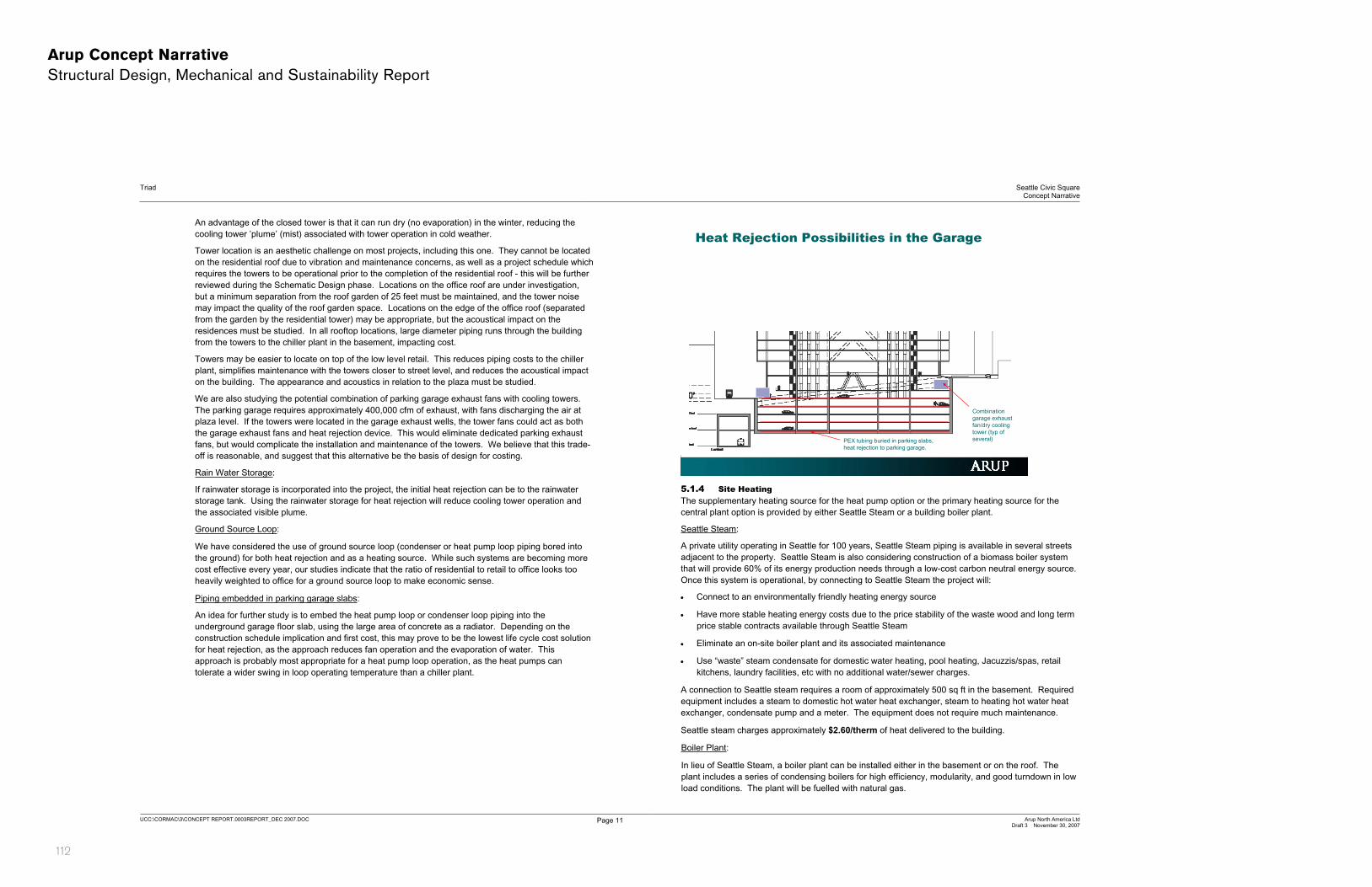
We are also studying the potential combination of parking garage exhaust fans with cooling towers. The parking garage requires approximately 400,000 cfm of exhaust, with fans discharging the air at plaza level. If the towers were located in the garage exhaust wells, the tower fans could act as both the garage exhaust fans and heat rejection device. This would eliminate dedicated parking exhaust fans, but would complicate the installation and maintenance of the towers. We believe that this trade-off is reasonable, and suggest that this alternative be the basis of design for costing.
Rain Water Storage:
If rainwater storage is incorporated into the project, the initial heat rejection can be to the rainwater storage tank. Using the rainwater storage for heat rejection will reduce cooling tower operation and the associated visible plume.
Ground Source Loop:
We have considered the use of ground source loop (condenser or heat pump loop piping bored into the ground) for both heat rejection and as a heating source. While such systems are becoming more cost effective every year, our studies indicate that the ratio of residential to retail to office looks too heavily weighted to office for a ground source loop to make economic sense.
Piping embedded in parking garage slabs:
An idea for further study is to embed the heat pump loop or condenser loop piping into the underground garage floor slab, using the large area of concrete as a radiator. Depending on the construction schedule implication and first cost, this may prove to be the lowest life cycle cost solution for heat rejection, as the approach reduces fan operation and the evaporation of water. This approach is probably most appropriate for a heat pump loop operation, as the heat pumps can tolerate a wider swing in loop operating temperature than a chiller plant.
Heat Rejection Possibilities in the Garage
PEX tubing buried in parking slabs, heat rejection to parking garage.
Combination garage exhaust fan/dry cooling tower (typ of several)
5.1.4 Site Heating The supplementary heating source for the heat pump option or the primary heating source for the central plant option is provided by either Seattle Steam or a building boiler plant.
Seattle Steam:
A private utility operating in Seattle for 100 years, Seattle Steam piping is available in several streets adjacent to the property. Seattle Steam is also considering construction of a biomass boiler system that will provide 60% of its energy production needs through a low-cost carbon neutral energy source. Once this system is operational, by connecting to Seattle Steam the project will:
� Connect to an environmentally friendly heating energy source
� Have more stable heating energy costs due to the price stability of the waste wood and long term price stable contracts available through Seattle Steam
� Eliminate an on-site boiler plant and its associated maintenance
� Use “waste” steam condensate for domestic water heating, pool heating, Jacuzzis/spas, retail kitchens, laundry facilities, etc with no additional water/sewer charges.
A connection to Seattle steam requires a room of approximately 500 sq ft in the basement. Required equipment includes a steam to domestic hot water heat exchanger, steam to heating hot water heat exchanger, condensate pump and a meter. The equipment does not require much maintenance.
Seattle steam charges approximately $2.60/therm of heat delivered to the building.
Boiler Plant:
In lieu of Seattle Steam, a boiler plant can be installed either in the basement or on the roof. The plant includes a series of condensing boilers for high efficiency, modularity, and good turndown in low load conditions. The plant will be fuelled with natural gas.

Seattle Civic Square - DRAFT Concept Design Submission - December 10, 2007 113
Arup Concept Narrative Structural Design, Mechanical and Sustainability Report
Triad Seattle Civic SquareConcept Narrative
UCC:\CORMAC\3\CONCEPT REPORT.0003REPORT_DEC 2007.DOC Page 12 Arup North America LtdDraft 3 November 30, 2007
If the plant is on the roof, boiler flues will be easier to route, but the gas piping must be extended through the building and boiler maintenance will be more difficult. We therefore recommend that the boilers be in the basement, with flues terminating above retail, screened to preserve views for the office and plaza.
The boiler room size is shown on the sketch. The boiler equipment requires more space than the Seattle Steam connection.
Natural gas is market rate, with a typical cost of $0.95/therm. With condensing boilers operating on average at 95% efficiency, the cost of heat produced is approximately $1.00/therm, significantly less than the cost for steam from Seattle Steam. However, this reduced fuel cost must be rationalized against the cost of money for the boiler plant construction cost, the maintenance of the plant, the value of the additional boiler plant space in the basement, and the cost of replacement boiler equipment after 15-20 years of operation.
5.2 Mechanical System: Building Approach
5.2.1 Commercial Offices There are two key decisions that must be made with regard to the commercial office servicing:
� Underfloor vs. overhead distribution of services.
� Floor by floor ventilation vs. central ventilation from the roof of the office tower.
We have considered a variety of building servicing strategies, with the basic system types described below. In genera for a building of this height, systems that align with 100% outside air economizers for cooling (UFAD and conventional VAV) will rely on floor by floor air handling units with outside air and exhaust air through the façade on each level. The use of 100% outside air economizers will not allow central rooftop ventilation systems due to the large volumes of air, and the attendant large shaft areas which reduce floor efficiency on the upper levels. These floor-by-floor units may include a DX compressor or heat pump (for the heat pump loop type central system) or an air handling unit with chilled water and heating water coils (central and heating water plant). Given the size and shape of the floor plate, even single tenant floors will likely require two air handling units.
In systems that do not rely on 100% outside air economizers (minimum ventilation systems), central ventilation air from roof level is possible due to the significantly reduced riser requirements. These systems eliminate the multiple louver penetrations through the façade, and in general reduce the space for distribution throughout the building.
5.2.2 Underfloor Option – 100% outside air economizer type system Underfloor air distribution (UFAD) is common throughout Europe and the United States. It is well suited to the Pacific Northwest, due to the mild climate. UFAD often provides a balance in efficiency, utility and first cost. While not yet as common as overhead systems, underfloor systems are now well established in the Seattle market, and contractors and suppliers are familiar with the system.
With UFAD, a raised floor is built approximately 18 inches over the top of the structural floor slab, supported by posts on 24 inch centers. The void between the structural slab and the raised floor acts as a path for cable distribution and air. The air required for heating, cooling and ventilation is supplied at low level through floor diffusers, which mix the air well at low level without creating drafts or cold spots. In a typical open plan office arrangement, one diffuser is often dedicated to each workstation providing a measure of local control not available with a traditional overhead system. Return air is from high level through a shallow ceiling plenum.
UFAD systems traditionally use 100% outside air economizer s, as one of the main advantages is reduced chiller plant size and hours of operation due to elevated supply air temperatures. The Seattle code encourages this economizer approach. This requirement guides the design towards a floor by floor AHU approach to serve the UFAD system.
The UFAD system has the following characteristics:
Flexibility:
Power and data cables can run anywhere within the floor plenum to serve any interior planning layout, with floor boxes located as required to serve the furniture layout without core drilling the structural slab. Floor diffusers can be re-arranged without system interruption to redistribute air within the space without ductwork, piping or controls changes. This flexibility allows the used of modular office partitioning that is not “hard wired” and is easy to relocate.
Reduced Ductwork and Controls Costs:
The UFAD system has less ductwork than the conventional overhead system. Most diffusers are not ducted, instead receiving their air from the underfloor supply plenum. While the raised floor itself adds cost, the number of zones, controls points and overall complexity is reduced. Where zone control is required for high load spaces, fan-powered boxes under the floor provide additional supply air to ducted diffusers. Examples include conference rooms and perimeter areas.
Reduced Chiller Plant Energy Use:
In Seattle, the cooling season is short, and humidity is generally low. This allows mechanical systems to use outside air for cooling whenever the outside air temperature is lower than the system supply air temperature. Traditional overhead VAV systems supply air at 55F while UFAD systems supply air at 65F. With UFAD, outside air can be used for cooling for a greater portion of the year, reducing the number of hours that the cooling plant runs. Furthermore, the large floor plenum allows for low air velocities and therefore low pressure drop, reducing fan power.
Improved Indoor Air Quality:
As ventilation air is delivered to the occupied zone, ventilation effectiveness is better than with overhead VAV systems, which deliver ventilation air at high level. With UFAD, contaminants and odor rise to high level where they are less likely to impact comfort in the occupied zone.
Aesthetics:
Without the complex duct distribution at high level, the ceiling is simplified and the opportunities for different ceiling types increases. There are no ceiling supply diffusers or large plenum to hide ductwork, and opportunities for indirect lighting are increased.

114
Arup Concept Narrative Structural Design, Mechanical and Sustainability Report
Triad Seattle Civic SquareConcept Narrative
UCC:\CORMAC\3\CONCEPT REPORT.0003REPORT_DEC 2007.DOC Page 13 Arup North America LtdDraft 3 November 30, 2007
5.2.3 Overhead VAV – 100% outside air economizer type system If this project does not identify a particular advantage for an underfloor cable distribution pathway, and the HVAC cost must bear the entire rationale for the raised floor, then a conventional overhead distribution system should be considered in lieu of a raised floor.
As with the underfloor system, the Seattle Energy code encourages a 100% outside air economizer type of system, with ventilation pathways sized so that outside air can provide full cooling when temperature conditions are appropriate. This requirement guides the design towards a floor by floor AHU approach to serve the overhead VAV system.
Flexibility:
The overhead ductwork is reasonably flexible especially in an open plan office where remodels do not affect the diffuser location. However, if the floor plan is primarily closed offices, and multiple relocations of these offices is likely, the overhead VAV will result in a higher churn cost over the life of the building compared to a raised floor. The main reduction in flexibility is not associated with the HVAC system, but with the increased cabling cost related to poke-through floor outlets, with core drilling required every time a floor box is relocated.
Ductwork and controls:
Overhead VAV uses more pounds of sheet metal per square foot than an underfloor system. Each zone is smaller and the number of control points is therefore greater.
Chiller Plant Energy Use:
The overhead VAV system supplies air at 55F, increasing both overall chiller load and hours of operation compared to underfloor. As the air is supplied at high level, there is no stratification of heat, and the entire space load is conditioned. The colder supply air does however result in an increased capability to condition dense cooling loads, like IT closets and electrical rooms.
Air Quality:
Ventilation effectiveness is generally worse than with an underfloor system, as the overhead supply pushes room contaminants back into the occupied zone.
5.2.4 Distributed Cooling and Heating – minimum ventilation air with water economizer Current Seattle codes encourage the use of 100% outside air economizers. This approach reflects the general belief that it must be more efficient to use ‘free’ outside air for cooling when outside temperature conditions are appropriate. However, the use of 100% economizers must be considered against the space required for the associated large ventilation pathways, the impact on the façade due to outside air louvers and exhaust louvers in tall buildings where the air cannot all be served from the roof, and the inherent inefficiency of fans compared to pumps for moving energy around a building.
If a minimum ventilation air system is incorporated, all ventilation air can be supplied from roof level, as the size of the ventilation shafts will not hurt floor plate efficiencies. Louvers will not be required in the façade, overall space for distribution is reduced, and with proper operational sequences, energy efficiency can be enhanced.
Flexibility:
Distributed ceiling mounted cooling units such as fan coils, heat pumps, chilled ceilings or chilled beams bring cooling and heating to each zone hydronically. This creates additional piping on each floor. Significant renovations are therefore more expensive than with air based systems, due to the higher cost of piping and insulation trades compared to sheet metal duct trades. The minimum ventilation air can be introduced through an underfloor plenum if a raised floor is provided for cable management, or through overhead ductwork is the building does not include a raised floor.
Equipment and Controls:
The hydronic systems that characterize the distributed cooling and heating systems typically have larger zones than conventional overhead VAV systems, so overall control point count is reduced.
Energy Use:
Due to the lack of an air economizer sized to serve the peak cooling load, these systems increase chiller plant energy use while decreasing fan energy due to the reduced airflow. The code requires a water economizer (cooling tower) sized to provide the same benefit as an air economizer on a conventional system. A chilled ceiling will likely provide the lowest energy usage of any system studied for this project.
Air Quality:
Seattle Civic Square - DRAFT Concept Design Submission - December 10, 2007 115
Arup Concept Narrative Structural Design, Mechanical and Sustainability Report
Triad Seattle Civic SquareConcept Narrative
UCC:\CORMAC\3\CONCEPT REPORT.0003REPORT_DEC 2007.DOC Page 14 Arup North America LtdDraft 3 November 30, 2007
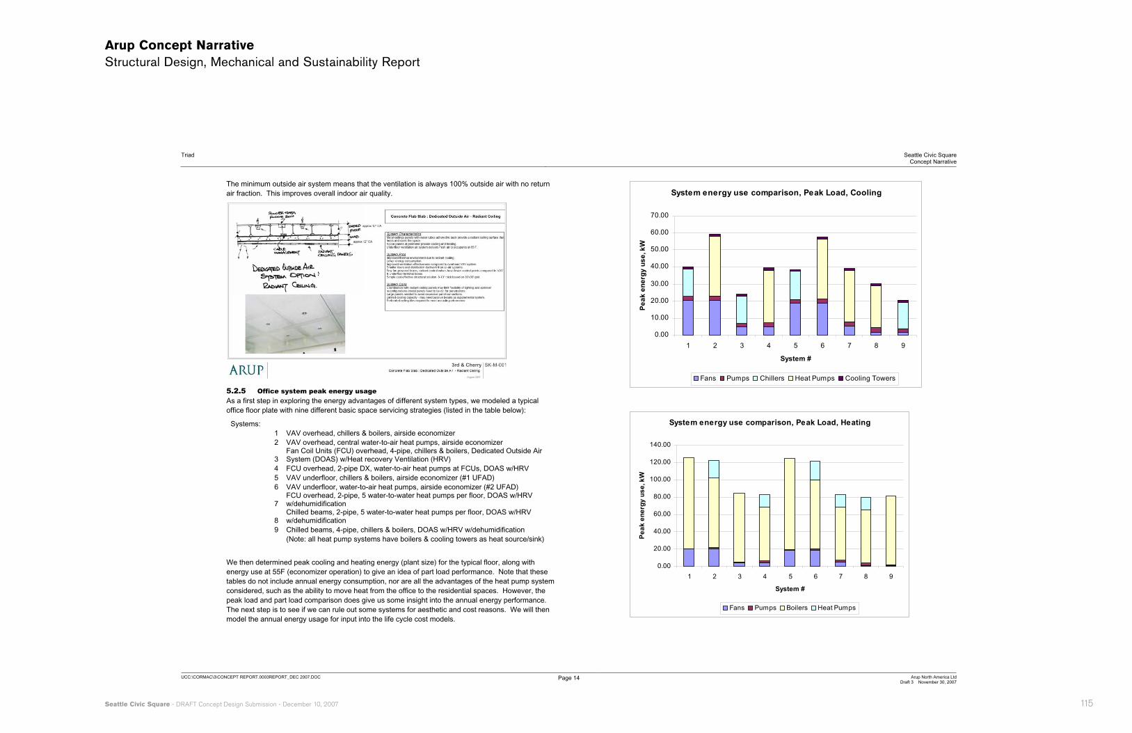
The minimum outside air system means that the ventilation is always 100% outside air with no return air fraction. This improves overall indoor air quality.
5.2.5 Office system peak energy usage As a first step in exploring the energy advantages of different system types, we modeled a typical office floor plate with nine different basic space servicing strategies (listed in the table below):
Systems: 1 VAV overhead, chillers & boilers, airside economizer 2 VAV overhead, central water-to-air heat pumps, airside economizer
3Fan Coil Units (FCU) overhead, 4-pipe, chillers & boilers, Dedicated Outside Air System (DOAS) w/Heat recovery Ventilation (HRV)
4 FCU overhead, 2-pipe DX, water-to-air heat pumps at FCUs, DOAS w/HRV 5 VAV underfloor, chillers & boilers, airside economizer (#1 UFAD) 6 VAV underfloor, water-to-air heat pumps, airside economizer (#2 UFAD)
7FCU overhead, 2-pipe, 5 water-to-water heat pumps per floor, DOAS w/HRV w/dehumidification
8Chilled beams, 2-pipe, 5 water-to-water heat pumps per floor, DOAS w/HRV w/dehumidification
9 Chilled beams, 4-pipe, chillers & boilers, DOAS w/HRV w/dehumidification (Note: all heat pump systems have boilers & cooling towers as heat source/sink)
We then determined peak cooling and heating energy (plant size) for the typical floor, along with energy use at 55F (economizer operation) to give an idea of part load performance. Note that these tables do not include annual energy consumption, nor are all the advantages of the heat pump system considered, such as the ability to move heat from the office to the residential spaces. However, the peak load and part load comparison does give us some insight into the annual energy performance. The next step is to see if we can rule out some systems for aesthetic and cost reasons. We will then model the annual energy usage for input into the life cycle cost models.
System energy use comparison, Peak Load, Cooling
0.00
10.00
20.00
30.00
40.00
50.00
60.00
70.00
1 2 3 4 5 6 7 8 9
System #
Pea
k en
ergy
use
, kW
Fans Pumps Chillers Heat Pumps Cooling Towers
System energy use comparison, Peak Load, Heating
0.00
20.00
40.00
60.00
80.00
100.00
120.00
140.00
1 2 3 4 5 6 7 8 9
System #
Pea
k en
ergy
use
, kW
Fans Pumps Boilers Heat Pumps
116
Arup Concept Narrative Structural Design, Mechanical and Sustainability Report
Triad Seattle Civic SquareConcept Narrative
UCC:\CORMAC\3\CONCEPT REPORT.0003REPORT_DEC 2007.DOC Page 15 Arup North America LtdDraft 3 November 30, 2007
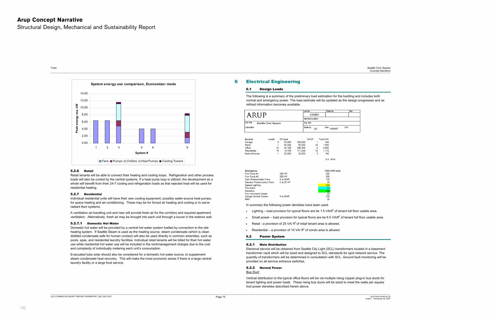
System energy use comparison, Economizer mode
0.00
2.00
4.00
6.00
8.00
10.00
12.00
14.00
1 2 3 5 6 9
System #
Pea
k en
ergy
use
, kW
Fans Pumps Chillers Heat Pumps Cooling Towers
5.2.6 RetailRetail tenants will be able to connect their heating and cooling loops. Refrigeration and other process loads will also be cooled by the central systems. If a heat pump loop is utilized, the development as a whole will benefit from their 24-7 cooling and refrigeration loads as that rejected heat will be used for residential heating.
5.2.7 Residential Individual residential units will have their own cooling equipment, possibly water-source heat pumps, for space heating and air-conditioning. These may be for forced air heating and cooling or to serve radiant floor systems.
A ventilation air-handling unit and riser will provide fresh air for the corridors and required apartment ventilation. Alternatively, fresh air may be brought into each unit through a louver in the exterior wall.
5.2.7.1 Domestic Hot Water Domestic hot water will be provided by a central hot water system fuelled by connection to the site heating system. If Seattle Steam is used as the heating source, steam condensate (which is clean distilled condensate safe for human contact) will also be used directly in common amenities, such as pools, spas, and residential laundry facilities. Individual retail tenants will be billed for their hot water use while residential hot water use will be included in the rent/management charges due to the cost and complexity of individually metering each unit’s consumption.
Evacuated tube solar should also be considered for a domestic hot water source, to supplement steam condensate heat recovery. This will make the most economic sense if there is a large central laundry facility or a large food service.
6 Electrical Engineering 6.1 Design Loads
The following is a summary of the preliminary load estimation for the building and includes both normal and emergency power. The load estimate will be updated as the design progresses and as refined information becomes available.
In summary the following power densities have been used:
� Lighting – load provision for typical floors are be 1.5 VA/ft2 of tenant full floor usable area.
� Small power – load provision for typical floors are be 6.5 VA/ft2 of tenant full floor usable area.
� Retail - a provision of 25 VA/ ft2 of retail tenant area is allowed.
� Residential – a provision of 10 VA/ ft2 of condo area is allowed
6.2 Power System
6.2.1 Main Distribution Electrical service will be obtained from Seattle City Light (SCL) transformers located in a basement transformer vault which will be sized and designed to SCL standards for spot network service. The quantity of transformers will be determined in consultation with SCL. Ground fault monitoring will be provided on all service entrance switches.
6.2.2 Normal Power Bus Duct
Vertical distribution to the typical office floors will be via multiple rising copper plug-in bus ducts for tenant lighting and power loads. These rising bus ducts will be sized to meet the watts per square foot power densities described herein above.

Seattle Civic Square - DRAFT Concept Design Submission - December 10, 2007 117
Arup Concept Narrative Structural Design, Mechanical and Sustainability Report
Triad Seattle Civic SquareConcept Narrative
UCC:\CORMAC\3\CONCEPT REPORT.0003REPORT_DEC 2007.DOC Page 16 Arup North America LtdDraft 3 November 30, 2007
6.2.3 Office Floor Electric Closet One electric closet located in the building core is provided on each office floor. Tenant power distribution will be from the bus duct riser to one (or more) 480/277V, 3 ph, and 4 wire panelboard(s) on each floor (number of panelboards is dependent on the number of tenants on a particular floor). The 480/277V panelboards will serve tenant lighting and will include space for tenant sub-metering.
The 480/277V panelboard(s) will also sub-feed one (or more) 208/120-volt tenant small power transformer(s), as applicable and dependent on the number of tenants on a particular floor, which in turn will supply tenant small power panelboards on each typical floor.
6.2.4 RetailEmpty conduits will be stubbed into each retail space for power. Retail spaces will be designed for direct local utility company metering via separate service entrance board.
6.2.5 LandlordTypical floor core ‘landlord’ lighting and small power will not be circuited to tenant lighting and small power panels. A landlord panel will be provided every 3 floors to serve the building core power and lighting loads.
6.2.6 Mechanical Loads Electrical service will be provided to all base building mechanical loads from dedicated mechanical distribution panels (and/or Motor Control Centers).
6.2.7 Emergency Power A diesel fired engine generator set will be provided to serve code required egress lighting, stairwell and elevator shaft pressurization fans, fire alarm system and fire fighter control equipment, one elevator within each elevator lift bank, elevator control system, life safety ventilation fans, tenant emergency egress lighting, and fire and jockey pumps.
A generator annunciator and status panel will be provided in the Fire Control Room.
At this stage of design it is assumed the generator set will be located within the garage.
Based on the preliminary load assessment the generator set will be approximately 1500kW in size.
Distribution
The emergency generator installation will comprise one main emergency distribution switchboard with an input feeder from the generator output section.
Three automatic transfer switches will be provided - one for “life safety” systems (code required systems), one for the elevators and the third for smoke control systems.
A 480/277-volt emergency power (and Landlord) panelboard will be provided every three floors to serve code required egress lighting and tenant egress lighting requirements. A power provision of 0.20 watts/sq. ft. of tenant usable area will be used to size panels.
6.3 Grounding System
A central grounding electrode system will be provided, consisting of ground rods, a concrete encased electrode and connections to the water piping system. Building steel and other piping systems will be bonded to the grounding electrode system. All grounded busses from switchboards, transformers, and the telecommunications system will be connected to this system at a central ground bus in the main Switchgear/meter room.
A copper bus will be provided in each electrical closet located on the tenant floors. A copper ground riser will be run through the electrical closets interconnecting the copper bus in each closet back to the central ground bus. All copper bus details will be connected to building steel.
A separate telecommunication-grounding riser will interconnect each telecom closet throughout the building.
6.4 Lightning Protection
An evaluation of the risk of lightning strikes will be conducted in accordance with the procedures in NFPA 780, and a recommendation will be made to the Owner on the basis of this evaluation. If the risk is considered to be sufficiently high, a lightning protection system will be installed to meet local and state code requirements.
6.5 Fire Alarm System
An addressable fire alarm system will be designed and installed to meet base building and future tenant requirements and will comprise (but not limited to) the following components and functions:
� Fire fighter control panel and fire alarm control panel in the Fire Control Room.
� Remote annunciator at a location as required by local fire marshal.
� Reporting to an off-site agency (or 24 hour central station).
� Smoke detectors in the elevator machine room and elevator lobbies for elevator recall.
� Duct mounted smoke detectors at air handling units for fan shutdown.
� Duct mounted smoke detectors near fire/smoke dampers for damper control.
� Speakers to provide voice evacuation alarms throughout the building.
� Strobes to provide visual alarms at locations of common use, such as corridors, open offices, meeting rooms, toilets and corridors.
� Fire fighter’s communication system in the stairwells and elevator lobbies.
� Manual pull stations at exits from each floor.
� Fire alarm panels at each tenant floor to cover building core fire alarm requirements and future tenant fire alarm system requirements. The number of signaling line and notification appliance circuits allocated for tenant fire alarm systems will be agreed with Owner prior to completion of design.
The fire fighter control panel will provide override functions of the HVAC systems including manual control of individual air handling units, each fire and smoke damper, individual smoke exhaust fans. The fire fighter control panel will provide real time status indication of all controlled equipment.
The fire alarm control system inclusive of the fire fighter control panel and fire alarm control panel will be backed up with UPS power and emergency generator power.
6.6 Telecommunication and Security Systems
General conduit and pathway requirements for the building telecoms will be installed to allow for adequate distribution of telecommunications system throughout the building. Routing, quantity and size of conduits to be determined in coordination with Architect, telecom service providers and Triad Development.
6.7 Generator
We have estimated the total load for the emergency power on the project and it appears a generator of roughly 1500kW will be needed. This will require a room approximately 40ft x 20ft that will incorporate generator, base tank, generator distribution panels and automatic transfer switches. This room will require a 2-hour rating and should be located below the retail building component to allow

118
Arup Concept Narrative Structural Design, Mechanical and Sustainability Report
Triad Seattle Civic SquareConcept Narrative
UCC:\CORMAC\3\CONCEPT REPORT.0003REPORT_DEC 2007.DOC Page 17 Arup North America LtdDraft 3 November 30, 2007
engine exhaust (tailpipe) to exit the building at the retail roof level, potentially combined in a common shaft with garage exhaust air and/or generator cooling exhaust air.
The estimates at this point have anticipated the following loads:
� (2) Fire Pumps
� Stair and Elevator Pressurization Fans
� Egress Lighting
� Fire Alarm System
� Elevators
� Fire Command Center
� Garage Smoke Control
� Building Management System
There is currently no allowance for the following potential loads:
� General Garage Exhaust / Fresh Air Systems
� Garage Sump/Ejector Pumps
� Atrium Smoke Control (no atrium in current design)
� Mechanical Cooling
� Freeze Protection
� Security Systems
� EM power as amenity for office tenants
� EM power as amenity for retail/restaurant tenants
� EM power as amenity for antenna tenants
� EM power as amenity for residential condos
6.8 Utility Vaults and Service
We are still working with Seattle City Light (SCL) to get their engineering feedback on required utility vault sizes, both in the basement and potentially the interstitial level of the building between office and residential.
It appears that the utility service would be at 13kV, and we have estimated the load for the building as 6-8 MVA.
SCL currently has requirements to physically group utility metering (if the utility metering path is chosen) to simplify reading of meters by their personnel. Their requirement is that meters be grouped so they occur no more often than every 3rd floor. This is a departure from the sketches shown so far with meters on every level (minimizing the maximum footprint in favor of a consistent approach to each floor). SCL is starting to implement metering technology that would eliminate this challenge by allowing the remote reading of meters. This will be discussed further with the appropriate engineering personnel from SCL.
6.9 Sketches
Refer to sketches in Appendix C of this report.
7 Plumbing / Water Engineering 7.1 Building Water Strategies
Outlined below are examples of building-level strategies that may be applied in order to meet the project’s water targets. These strategies are intended as a starting point and guide for future vertical development within the project. It is by no means an exhaustive or exclusive list, especially given the stage of design of those elements and considering that new products and systems are continually being developed.
Low Flow Fixtures
Toilets Low volume gravity tank toilets
Low volume pressurized toilets
Dual flush toilets
Waterless toilets
Offers significant water savings over traditional fixtures
Waterless toilets offer almost 100% savings
Urinals Low volume urinals
Waterless urinals
Offers significant water savings over traditional fixtures
Waterless urinals offer almost 100% savings
Showerheads Low volume showerheads Offers significant water savings over traditional fixtures
Energy savings can be realized by reduced hot water usage
Faucets Low volume kitchen and lavatory faucets, using aeration, flow control or devices
Sensor activated faucets
Automatic shut-off faucets
Offers significant water savings over traditional fixtures
Energy savings can be realized by reduced hot water usage
Clothes Washers High efficiency, front loading washers
Offers significant water savings over traditional fixtures
Energy savings can be realized by reduced operational costs and hot water usage
Improved performance over conventional models in terms of wear and tear on the clothes, shorter drying times due to improved moisture extraction and reduced detergent needs.
Dishwashers Water efficient dishwashers Offers significant water savings over traditional fixtures
Energy savings can be realized by reduced operational costs and hot water usage
Seattle Civic Square - DRAFT Concept Design Submission - December 10, 2007 119
Arup Concept Narrative Structural Design, Mechanical and Sustainability Report
Triad Seattle Civic SquareConcept Narrative
UCC:\CORMAC\3\CONCEPT REPORT.0003REPORT_DEC 2007.DOC Page 18 Arup North America LtdDraft 3 November 30, 2007
7.2 Sketches
Refer to sketches in Appendix D of this report.
8 Façade Engineering Refer to Appendix F of this report.
9 Sustainability Consulting 9.1 Sustainability Metrics
9.1.1 LEED Core & Shell v 2.0 The goal of the project is to be LEED® Core and Shell v 2.0 Gold certified. However, the project is aspiring to Platinum certification, if achievable within the project’s financial, schedule and programmatic constraints.
The project will aim to achieve Gold pre-certification before the start of construction in order to demonstrate its achievements to the client body as well as to aid in marketing of the project to potential tenants. Arup led the sustainability efforts for the first LEED® Shell & Core pre-certification project – Xihu Tiandi in China which was pre-certified Platinum – and will use the expertise and experience to ensure this project’s success. The project goal is to be pre-certified Gold at the completion of schematic design.
The entire project will be considered a single LEED® Core and Shell project, including the site development, interface with Metro, retail program, parking garage, commercial office space, and residential units.
9.1.2 Other Metrics In addition to LEED® Core & Shell, the project team will also be using several other sustainable design tools and metrics to either judge our success, guide the design, or set project goals. The two main metrics we will be using are ASHRAE Standard 189-P and the Architecture 2030 Challenge. Both of these metrics are actively supported by the City of Seattle – both by the mayor’s office as well as the Department of Planning and Development. The project is also investigating the applicability and market benefits of the ALA Health House program for application to the residential units.
ASHRAE Standard 189-P
ASHRAE Std. 189-P is current a draft standard being jointly developed by ASHRAE, the AIA, the USGBC, and IESNA. It is an attempt to provide standard-level language to ensure project sustainability – language that can be incorporated into local, state, or federal codes to enforce all aspects of a project’s sustainability. While it draws heavily from LEED®, it has important differences in that it removes some of the flexibility of LEED® to enforce a greater level of minimum performance standards in each main area of sustainability – site, water, energy, materials, and the indoor environment.
While still in the draft stage, the Standard is anticipated to be approved in 2008. The City of Seattle has indicated that it intends to bring the standard into its code language as quickly as possible within the code cycle. It is likely that the standard will be adopted into Seattle code before the completion of the Seattle Civic Square project, though likely after it has gone through the permitting process.
Due to the strong role Seattle DPD is playing in the development of the standard and its likelihood of quick adoption, this project will also track itself against the standard such that it can be deemed compliant with the standard. This will help the City demonstrate the viability of the standard through a benchmarked commercial development.
9.1.3 Architecture 2030 Challenge The Architecture 2030 Challenge deals entirely with the issue of carbon emissions and site energy consumption of buildings. The goal of the Challenge is to have all new buildings built by 2030 be carbon neutral. As such it has set intermediate benchmarks to guide the industry towards that ultimate goal. The Challenge’s goal for buildings built in 2010 is that they achieve a site energy consumption of 60% less than the average for its building type, as defined by the 2003 US EIA Commercial Building Energy Consumption Survey.
The Architecture 2030 Challenge has been endorsed and supported by ASHRAE, the AIA, and many local and state level organizations, including the City of Seattle. As such, another goal of this project is to achieve the 2010 energy savings of the Challenge.
The Architecture 2030 Challenge has several design and implementation challenges for the project:
� The energy savings goals include all end use energy of the building, including non-regulated energy consumption, such as tenant plug loads and residential energy consumption
� The baseline for the Challenge, the 2003 CBECS database, does not include any information on residential performance.
To demonstrate achievement prior to construction several assumptions will be made:
� office and retail energy consumption will be estimated based on typical data
� residential energy consumption will:
benchmark against average energy consumption for Seattle condominiums. The project team aims to work with Seattle City Light to get this data to set the benchmark.
include estimates of non-regulated energy consumption based on data from Seattle City Light as well as data from selected appliances, lighting, and other equipment that will be installed
9.1.4 American Lung Association’s Health House® Program While not specifically written to address a high rise condominium residential complex, the underlying principles are complementary to LEED® and help address additional concerns in residential construction that are not specifically addressed by LEED® Core & Shell.
The key areas of focus for this program are:
� moisture control
� air-sealing and insulation performance
� high performance facades
� sealed combustion appliances
� high levels of air filtration
� whole house ventilation control
� humidity control
� interior finishes
9.2 Overall Sustainable Approach
The overall approach towards sustainability on the project will be one of “each component stands on its own.” To be truly sustainable, all aspects of the project must be individually sustainable. To achieve a high level of sustainability, as indicated by a LEED® Gold or Platinum certification, the project cannot afford to have poorly performing aspects propped up by other aspects. This is most certainly true for
Copyright © 2022 FDOKUMEN