
Genetic model for conceptual design of mechanical products based on functional surface
11
ORIGINAL ARTICLE Genetic model for conceptual design of mechanical products based on functional surface Y. Shang & K. Z. Huang & Q. P. Zhang Received: 19 October 2007 / Accepted: 10 June 2008 / Published online: 11 July 2008 # Springer-Verlag London Limited 2008 Abstract Computer-aided conceptual design (CACD) aims to increase efficiency and quality of design work but with little essential progress due to the gap between abstract concept and detailed structure. In order to tackle the problem concerned with conceptual design process and automation, this paper introduces the concept of functional surface as the information carrier to link together product function and structure and describes a product genetic model to represent and organize product information. Functional surface is used to formalize the product gene, a varied-length coding scheme for functional surface and product gene is proposed, and the design process model for conceptual design is established based on product gene. Finally, a prototype system for CACD is introduced to demonstrate how a product can be designed based on the proposed model. Keywords Conceptual design . Functional surface . Product genetic model . Formalization . Process model 1 Introduction Conceptual design has significant influence on product functionality, performance, reliability, and customer satis- faction [1]. Creativity and high efficiency are still the essential requirements for conceptual design with wide concerns in current design research and engineering practice. There exist many kinds of complex heterogeneous design knowledge during conceptual design process, so it is recognized as the most difficult part in the whole product design cycle to represent and model. Conceptual design is one of the few areas of mechanical design where the computer has yet to make an impact. Computer-aided conceptual design (CACD) aims to increase efficiency and quality of design work but with little essential progress. In recent years, lots of research work had been done to tackle these problems. Conceptual design can be regarded as the early stage of the design process of a product where some synthesis work is performed and preliminary solu- tions are generated to the design problem. Functional representation modeling and functional reasoning techni- ques are the two major aspects concerned in conceptual design [2]. Formalizing the representation of functional design requirements is essential for computer-aided conceptual design. Approaches have been developed for representing functions such as verb–noun pairs [3], input–output trans- formations where inputs and outputs can be energy, materials or information [4], and verb-attribute pairs [5]. Two of the major advantages of verb–noun pair are that it allows designer to define a function at quite a high level of abstraction and that the designer is not biased towards developing a solution with a particular physical structure. Function–Means modeling [6] describes alternative ways of providing a top-level function through the use of known means of two types: principles and entities. Function– Behavior–State modeling [7] has been proposed as an approach to minimizing the subjectivity of function in design. Function–Behavior–Structure approach [8] uses the Int J Adv Manuf Technol (2009) 42:211–221 DOI 10.1007/s00170-008-1607-1 Y. Shang : K. Z. Huang (*) School of Mechanical Engineering, Shandong University, No. 73 Jingshi Road, Jinan 250061, People’ s Republic of China e-mail: [email protected] Q. P. Zhang Department of Mechanical Engineering, Jinan University, No. 106 Jiwei Road, Jinan 250022, People’ s Republic of China
-
Upload
independent -
Category
Documents
-
view
0 -
download
0
Transcript of Genetic model for conceptual design of mechanical products based on functional surface

ORIGINAL ARTICLE
Genetic model for conceptual design of mechanical productsbased on functional surface
Y. Shang & K. Z. Huang & Q. P. Zhang
Received: 19 October 2007 /Accepted: 10 June 2008 / Published online: 11 July 2008# Springer-Verlag London Limited 2008
Abstract Computer-aided conceptual design (CACD) aimsto increase efficiency and quality of design work but withlittle essential progress due to the gap between abstractconcept and detailed structure. In order to tackle theproblem concerned with conceptual design process andautomation, this paper introduces the concept of functionalsurface as the information carrier to link together productfunction and structure and describes a product geneticmodel to represent and organize product information.Functional surface is used to formalize the product gene,a varied-length coding scheme for functional surface andproduct gene is proposed, and the design process model forconceptual design is established based on product gene.Finally, a prototype system for CACD is introduced todemonstrate how a product can be designed based on theproposed model.
Keywords Conceptual design . Functional surface . Productgenetic model . Formalization . Process model
1 Introduction
Conceptual design has significant influence on productfunctionality, performance, reliability, and customer satis-
faction [1]. Creativity and high efficiency are still theessential requirements for conceptual design with wideconcerns in current design research and engineeringpractice. There exist many kinds of complex heterogeneousdesign knowledge during conceptual design process, so it isrecognized as the most difficult part in the whole productdesign cycle to represent and model. Conceptual design isone of the few areas of mechanical design where thecomputer has yet to make an impact. Computer-aidedconceptual design (CACD) aims to increase efficiency andquality of design work but with little essential progress.
In recent years, lots of research work had been done totackle these problems. Conceptual design can be regardedas the early stage of the design process of a product wheresome synthesis work is performed and preliminary solu-tions are generated to the design problem. Functionalrepresentation modeling and functional reasoning techni-ques are the two major aspects concerned in conceptualdesign [2].
Formalizing the representation of functional designrequirements is essential for computer-aided conceptualdesign. Approaches have been developed for representingfunctions such as verb–noun pairs [3], input–output trans-formations where inputs and outputs can be energy,materials or information [4], and verb-attribute pairs [5].Two of the major advantages of verb–noun pair are that itallows designer to define a function at quite a high level ofabstraction and that the designer is not biased towardsdeveloping a solution with a particular physical structure.Function–Means modeling [6] describes alternative ways ofproviding a top-level function through the use of knownmeans of two types: principles and entities. Function–Behavior–State modeling [7] has been proposed as anapproach to minimizing the subjectivity of function indesign. Function–Behavior–Structure approach [8] uses the
Int J Adv Manuf Technol (2009) 42:211–221DOI 10.1007/s00170-008-1607-1
Y. Shang :K. Z. Huang (*)School of Mechanical Engineering, Shandong University,No. 73 Jingshi Road,Jinan 250061, People’s Republic of Chinae-mail: [email protected]
Q. P. ZhangDepartment of Mechanical Engineering, Jinan University,No. 106 Jiwei Road,Jinan 250022, People’s Republic of China
relationships between the physical structure, behavior, andfunctionality of existing designs to provide a basis for newproduct development using analogical reasoning.
Efforts in developing design languages has madeobvious improvements, such as shape grammar [9–12];however, further research for product design at assemblylevel is still needed. Instead of developing ad-hoc designlanguages, many researchers have directed their efforts atdeveloping common design ontology [1, 13]
Most modern CAD systems are geometry-based. How-ever, during conceptual design, the various alternativescreated and compared by a designer are generally createdfrom a non-spatial perspective and lack of detailedgeometric structure [14]. In order to evaluate concepts, itis important to consider all critical geometric and spatialrelationships that are relevant. The “minimum commitmentprinciple” is well known [15–17] and is used as anapproach to creating geometric models of design solutionsin conceptual design with only the most critical details ofthe product. Feature modeling for conceptual design in bothtwo and three dimensions has been reported [18]. Someresearchers have combined parametric geometry, features,and variation modeling into integrated design representa-tion schemes for conceptual design [19].
During conceptual design, a designer exploits a consid-erable variety of knowledge to effectively generate a set ofgood design concepts. To represent and reason based on theknowledge, flexible modeling paradigms and reasoningtechniques are required, such as experience-derived heu-ristics [20] and case-based reasoning [21].
Among design reasoning techniques, adaptive search hasattracted a lot of attention which relates to search tech-niques, such as genetic algorithms, evolutionary search,simulated annealing, and hill-climbing, for automateddesign applications through the optimization of variables[22]. These methods are restricted in its application toroutine or parametric designing and the processes of searchmap well onto those of optimization [23]. Some extensionshave been made to them drawn from analogies with themore recently developed areas of genetic engineering anddevelopmental biology [24].
There is an increasing interest in developing computa-tional models based on nonhuman process. Using bioge-netics as a blueprint, some genetic models have beenproposed. Holland proposed a genetic model to describedesign activities compared with evolutionary biology [25];Richard and Edwin proposed an empirical genetic model tosolve problems in product external form design [26]; Gu etal. proposed the concept of product gene for inheritance andtransferring of product knowledge [27]. Product gene wasalso employed to index principle solutions in order tobridge the gap between relation change-based functions and
their corresponding principle solutions [5]. Virtual geneswere proposed, and methods were developed for reformingvirtual genes for product innovation using genetic engi-neering techniques [28].
In recent years, researchers have begun using evolution-ary method to automate early stages of a design process[29]. Pham and Yang proposed a genetic algorithm forconceptual design system [30]. Rosenman et al. did lots ofresearch works in developing evolutionary models fornonroutine design, creating growth model for form gener-ation and generating form [31–33]. These research worksgave a good start for evolutionary design. Gero et al.applied a genetic engineering-based extension to geneticalgorithms for the layout planning problem [34–35].Computational models and preliminary framework forevolutionary design were described to implement theprocess of architectural space layout design.
Although a great deal of efforts has been made so far,little essential progress is made due to the gap betweenabstract concept and detailed structure and the lack ofinsight into their relationship. It is not difficult to notice thatthere are two obvious trends in those research effortssurveyed above: adding more and more visual informationto abstract function model and including more and morefunctional information to geometric model. Integration offunctional and structural information becomes the ideal wayto smooth and seamless connection between conceptualdesign stage and downstream activities.
To improve design modeling, the combination offunction and structure has been investigated a lot in ourprevious work. The granularity of structure has beenconsidered in detail and surface selected as the appropriatelevel [36]. Integration of function with surface leads to theconcept functional surface. The design process model basedon functional surface introduces the important structuralelements—Functional Surface—from the very beginning ofthe design process and keeps them all through to thedetailed design and downstream activities. This establisheda solid foundation for smooth and seamless transitionduring the whole lifecycle of a product with followingadvantages: (1) visually operable during conceptual designstage, which is a very important feature for mechanicaldesign where imaginary thinking prevails; (2) genericfeature can still be maintained by keeping multiplealternatives in hierarchical product data structure, whichcan be utilized more easily by design automation systemcompared with abstract symbolic feature that depends onhuman beings’ mind or experience for its true meaning; (3)early evaluation of product scheme made possible atconceptual design stage, such as tolerancing [37]; (4) eachcomponent in the product is generated step by stepcontrolled by growth design process and so computer
212 Int J Adv Manuf Technol (2009) 42:211–221
system can show more intelligence in doing creativedesigns; (5) conceptual design is smoothly and seamlesslyconnected with downstream design activities.
Based on functional surface, growth design modeling[38] and product lifecycle genetic model [38] have beensuccessively established.
In this paper, the functional surface concept is firstlyintroduced as a basis, then a product genetic model basedon functional surface is described and a conceptual designprocess model is proposed to help develop correspondingCACD systems for further design automation.
2 Functional surface
Geometrically, a point is the smallest entity, followed byline, surface, feature, part, and component. In the mechan-ical structure, points and lines are ambiguous and inconve-nient to express function. Compared with solid parts andcomponents, surfaces are the most suitable geometricalgranularity to express function and structure and havewidest influence on the components of a product through-out its lifecycle. In the manufacturing and assemblyprocess, part surfaces are the critical factors for selectingthe process and equipment and also influence the productperformance and costs. In computer graphics, a surface isthe basic three-dimensional geometrical element of theexterior of a part. The common types of surfaces includeplane, cylindrical surface, conical surface, spherical surface,involute surface, helix surface, etc.
2.1 Concept of functional surface
In fact, the concept of functional surface is not new toengineering design field. With unambiguous functionalconcept and geometrical properties, it acts as the mediumto express part concept in the design process [40]. It is theimportant factor to determine the mechanical function, andits design is an important task in mechanical design [41].
In this paper, from the perspective that a product isdesigned as a whole instead of a set of isolated components,a Functional Surface (FS) is defined as the basic informa-tion unit for representation of a product. It is physically theinterface between two components that contact with eachother to perform certain functions, and at the same time, itis conceptually the function information carrier thatrepresents designer’s intentions.
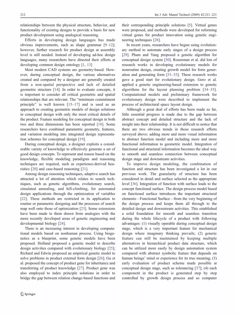
A fixture for machining piston is shown in Fig. 1a. All thefunctional surfaces for its components have been extracted asshown in Fig. 1b.
It is well known that all manmade products are goal-oriented and have definite purposes. The fixture in Fig. 1 is
for locating and clamping the piston to be machined furtherand will be operated by human hands that provide thepower source for clamping. According to this analysis,functional surfaces on each component are classified intotwo major categories: (1) generalized-locating-surface(GLS) that is used for location of the component itself, e.g., all the functional surfaces from the piston (GLS inFig.1b); and (2) making-location-surface (MLS) that is usedfor locating other component with which this componentcontacts, e.g., all those in contact with the piston (MLS inFig.1b). Note that the word “location” is used in ageneralized sense including clamping surfaces in traditionallocating and mating surface pair in relative motion witheach other.
Functional surface can be formalized as
FS ¼ S; T ;F;Gð Þ ð1ÞWhere S is the identification number, like name,
sequence number, etc; T is the geometrical type; F is thefunctional feature, including GLS or MLS and DOF; G isthe geometrical parameter set of the functional surface, suchas number of inner and outer rings, radius, height, etc.
A component can be represented conceptually by a finiteset of functional surfaces FSs:
FSs ¼ FSi i ¼ 1; 2; � � �jð Þ: ð2ÞThe GLS set, FSd, can be expressed as
FSd ¼ FSj j ¼ 1; 2; � � �j� �and FSd � FSs: ð3Þ
The MLS set, FSm, can be expressed as
FSm ¼ FSk k ¼ 1; 2; � � �jf gFSm � FSs
FSm \ FSd ¼ fFSm [ FSd ¼ FS:
ð4Þ
According to Generalized Positioning Principle (GPP)[42], in the design process of a product, each componentmust be positioned in a generalized sense by other
GLS
MLS
a b
Fig. 1 Fixture for machining piston and its functional surfaces
Int J Adv Manuf Technol (2009) 42:211–221 213
components, and its GLS set, FSd, can be standardized as aFunctional Pattern (FP).
FP can be formalized as
FP ¼ RF FSdð Þ ð5ÞWhere RF is the topological (parallel, intersection,
coaxial) and geometrical (distance, angle) relationshipsamong the GLS set.
A Functional Unit (FU) for a component is thetransformable functional combination of GLS set withMLS set. It can be expressed as
FU ¼ RU FSd; FSmð Þ ð6ÞWhere Ru is the topological relationships between GLS
set and MLS set
2.2 Coding scheme of functional surface
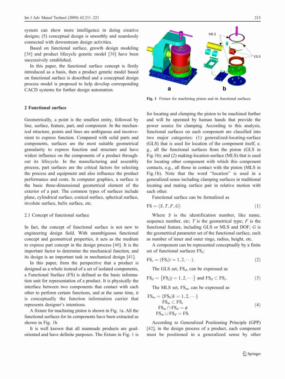
Feature-oriented coding scheme based on GPP is appliedfor functional surface coding. According to the FunctionalDegree of Freedom (FDOF) constrained by each functionalsurface, the commonly used types of functional surfaces arecoded as listed in Table 1. The main distinction betweentraditional Degree of Freedom (DOF) and FDOF lies in thatFDOF is calculated in a relativity sense; therefore, it is afunctional concept instead of one strictly geometrical. Forexample, a long plane constrains three DOFs but twoFDOFs because its width is much smaller than its lengthand is considered only constraining in the length direction.The same is the short cylinder which has four FDOFsconstrained as shown in Fig. 2. Because the length of thecylinder is relatively small compared with its radius, thecylinder functions the same as a circle in DOF case.Another difference between them is that FDOF is the actualnumber of potential moving directions blocked by afunctional surface.
To develop an effective coding without impairing itsgeneric feature for conceptual design, information have
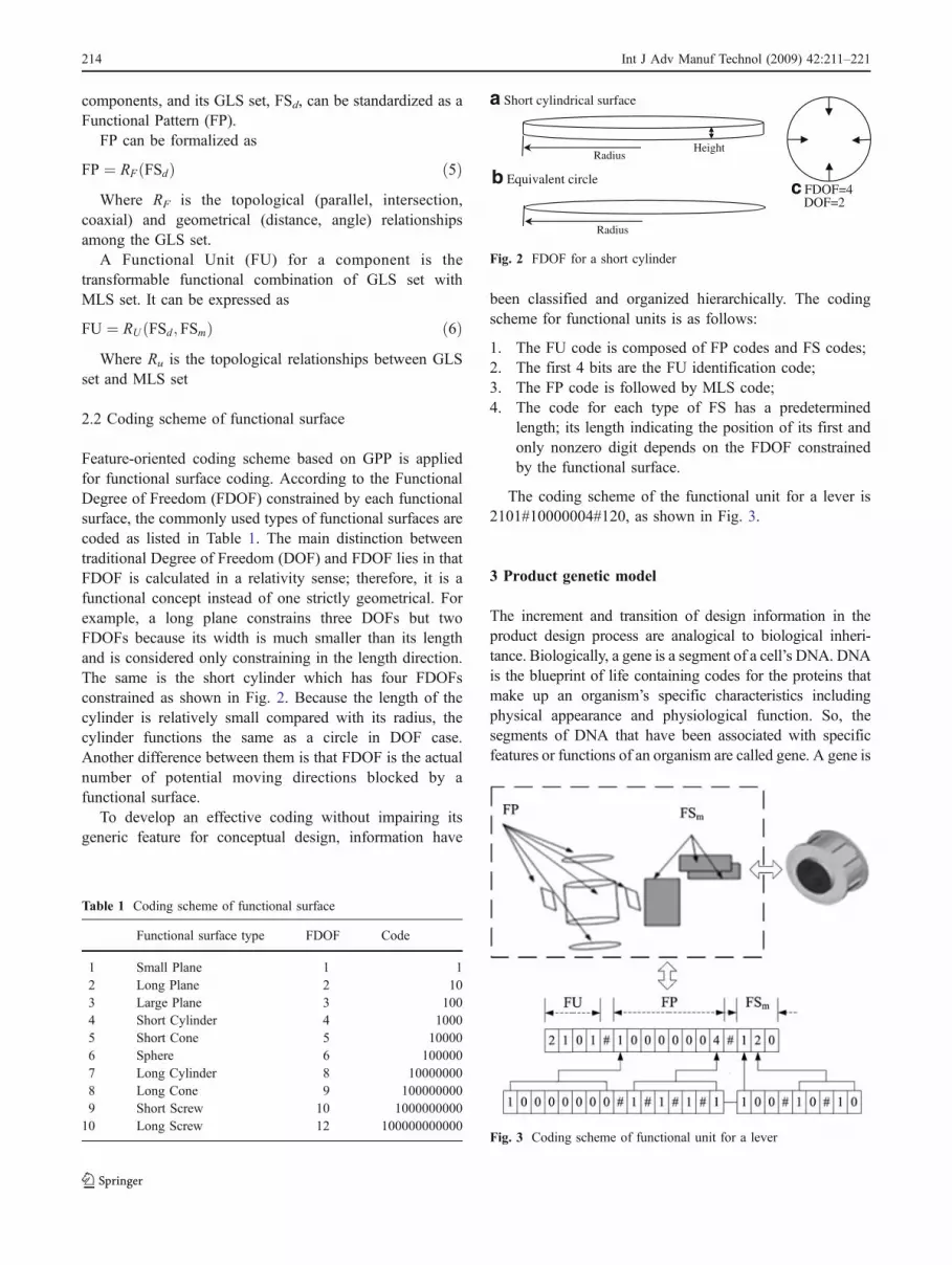
been classified and organized hierarchically. The codingscheme for functional units is as follows:
1. The FU code is composed of FP codes and FS codes;2. The first 4 bits are the FU identification code;3. The FP code is followed by MLS code;4. The code for each type of FS has a predetermined
length; its length indicating the position of its first andonly nonzero digit depends on the FDOF constrainedby the functional surface.
The coding scheme of the functional unit for a lever is2101#10000004#120, as shown in Fig. 3.
3 Product genetic model
The increment and transition of design information in theproduct design process are analogical to biological inheri-tance. Biologically, a gene is a segment of a cell’s DNA. DNAis the blueprint of life containing codes for the proteins thatmake up an organism’s specific characteristics includingphysical appearance and physiological function. So, thesegments of DNA that have been associated with specificfeatures or functions of an organism are called gene. A gene is
Table 1 Coding scheme of functional surface
Functional surface type FDOF Code
1 Small Plane 1 12 Long Plane 2 103 Large Plane 3 1004 Short Cylinder 4 10005 Short Cone 5 100006 Sphere 6 1000007 Long Cylinder 8 100000008 Long Cone 9 1000000009 Short Screw 10 1000000000
10 Long Screw 12 100000000000
a Short cylindrical surface
b Equivalent circle c FDOF=4DOF=2
Radius
Radius
Height
Fig. 2 FDOF for a short cylinder
Fig. 3 Coding scheme of functional unit for a lever
214 Int J Adv Manuf Technol (2009) 42:211–221
a functional and structural unit of DNA. Genes consist ofstructural gene, operational gene, and regulator gene accord-ing to functional actions in the process of the transcription.
Based on the growth design modelling [38] in analogy tothe essential growth process of cell division in organism,further analogy can be made to establish a correspondingconceptual genetic model for artificial products.
Firstly, Product Genome (PG) is defined as the inherit-able knowledge set that can express product function,structure and sequence. It can be expressed as
PG ¼ F; S; Lð Þ ð7ÞWhere F is for the product function, S for product
structure, and L for the sequence of function and structure.According to their purposes in the design process,
product genes can be classified into Functional Genes(FGs) and Structural Genes (SGs). Where
PG ¼ FGs [ SGs ð8Þ
FGs \ SGs ¼ Φ ð9ÞFunctional genes express the functional requirements for
a product, and structural genes express the structuralinformation and the conceptual form of design objects.
Both product gene and functional surface can expressfunctional requirements and structural embodiments. Func-tional surface can be used to formalize the product gene. Thehierarchical model of the product gene, functional unit,functional pattern, and functional surface is shown in Fig. 4.
Mechanical products are complex objects consisting ofmany parts or components. The coding scheme for productgenes is influenced by physical storage structure and theapplied formalization method. In order to process and utilizethe design knowledge efficiently, the hierarchical and varied-length coding schemes for product genes have been adopted toexpress hierarchical relationships among design objects.
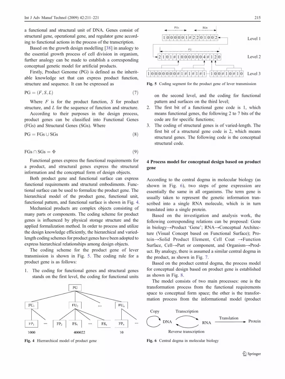
The coding scheme for the product gene of levertransmission is shown in Fig. 5. The coding rule for aproduct gene is as follows:
1. The coding for functional genes and structural genesstands on the first level, the coding for functional units
on the second level, and the coding for functionalpattern and surfaces on the third level;
2. The first bit of a functional gene code is 1, whichmeans functional genes, the following 2 to 7 bits of thecode are for specific functions;
3. The coding of structural genes is of varied-length. Thefirst bit of a structural gene code is 2, which meansstructural genes. The following code is the conceptualstructural code.
4 Process model for conceptual design based on productgene
According to the central dogma in molecular biology (asshown in Fig. 6), two steps of gene expression areessentially the same in all organisms. The term gene isusually taken to represent the genetic information tran-scribed into a single RNA molecule, which is in turntranslated into a single protein.
Based on the investigation and analysis work, thefollowing corresponding relations can be proposed: Genein biology→Product ‘Gene’; RNA→Conceptual Architec-ture (Visual Concept based on Functional Surface); Pro-tein→Solid Product Element, Cell Coat →FunctionSurface, Cell→Part or component, and Organism→Prod-uct. By analogy, there is assumed a similar central dogma inthe product, as shown in Fig. 7.
Based on the product central dogma, the process modelfor conceptual design based on product gene is establishedas shown in Fig. 8.
The model consists of two main processes: one is thetransformation process from the functional requirementsspace to conceptual form space; the other is the transfor-mation process from the informational model (product
Fig. 4 Hierrarchical model of product gene
Fig. 5 Coding segment for the product gene of lever transmission
DNA RNA Protein
Transcription
Reverse transcription
Copy
Translation
Fig. 6 Central dogma in molecular biology
Int J Adv Manuf Technol (2009) 42:211–221 215

gene) to the physical structure (functional surface). The twoprocesses form a hierarchical transformation space. Themain functions involved are as follows: evolution, recon-stitution, evaluation, part match, reverse transcription,representation, and product gene database.
1. EvolutionThe design requirements and the environmental con-
straints should be satisfied when product genes evolve byfollowing specific evolutional policies. The evolutionprocess of product gene can be expressed as
PGiþ1 ¼ Dp Ri; PGið Þ ð10ÞWhere Dp is rule-based evolutional policies, Ri is the
design constraints, PGi is the ith product gene, PGi+1 is theevolutional result.
The typical evolutional rule includes two parts: conditionand conclusion. Its form is as follows:
Rulei: IF condition THEN conclusion
Where condition may be a single condition or thecombination of multiple conditions connected by AND/
OR, and conclusion may be a single conclusion or thecombination of multiple conclusions.
The evolutional rules are classified into two types:functional surface type and functional pattern type.
There are ten types of functional surfaces, so there areonly a limited number of evolutional rules belonging tofunctional surface type. This type of rules should satisfy:FDOF constrained by the functional surfaces in thecondition part should equal to the FDOF constrainedby the functional surfaces in the conclusion part. Forexample:
RuleFP1: IF FP is Large Plane (FDOF=3) THENdecompose it into one Long Plane (FDOF=2)and one Small Plane (FDOF=1);
RuleFP2: IF FP is a Long Plane (FDOF=2) THENdecompose it into two Small Plane(FDOF=1);
RuleFP3: IF FP is Long Cylinder (FDOF=8) THENdecompose it into two Short Cylinders(FDOF=4).
There are many types of functional surfaces, so theevolutional rules are diverse. For example:
RuleFM1: IF FP is Long Cylinder THEN evolve itinto Revolve Guider C;
RuleFM2: IF FP is Large Plane THEN evolve it intoLine Guider B.
2. ReconstitutionFunctional surface is the carrier of both functional and
structural information. Compared with mechanisms, com-ponents, and features, it is further-decomposed entity spacewith smaller granularity and has more flexibility andcreative potential for reconstitution. Therefore, the func-tional surface is an appropriate basis to formalize theproduct gene. With support of a product gene database, theform reconstitution for a product is the synthesis process byfollowing such reconstitution steps as product genes–functional surfaces–functional units–functional products. Itcan be divided into three steps:
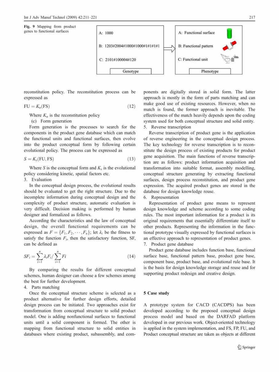
(a) Mapping from product genes to functional surfacesThis is a formalization process, that is to say, it is a
genotype to phenotype transformation process (as shown inFig. 9). The mapping from product genes to functionalsurfaces can be expressed as
FS ¼ Mf PGð Þ ð11Þ
Where Mf is the mapping policy(b) Functional unit reconstitutionFunctional unit is the transformable functional combina-
tion from GLS to MLS. Functional surfaces can bereconstituted into a specific functional unit by some
Reverse transcription
Product gene
Evolution
Product GeneDatabase
Design Requirements
Design constraints
Evolution plocies
Representation3D Product
Parts match
Design evaluation
Form reconstitution
Conceptual form
Product gene
Fig. 8 Process model for conceptual design based on product gene
Organism
Product
Reverse acquisition
DNA RNA Protein
Product Gene Conceptual form Solid assembly
Transcription
Reverse Transcription
Conceptual design Parts Match
Translation
Fig. 7 Central dogma for product design
216 Int J Adv Manuf Technol (2009) 42:211–221
reconstitution policy. The reconstitution process can beexpressed as
FU ¼ Ku FSð Þ ð12ÞWhere Ku is the reconstitution policy(c) Form generationForm generation is the processes to search for the
components in the product gene database which can matchthe functional units and functional surfaces, then evolveinto the product conceptual form by following certainevolutional policy. The process can be expressed as
S ¼ Ks FU; FSð Þ ð13ÞWhere S is the conceptual form and Ks is the evolutional
policy considering kinetic, spatial factors etc.3. Evaluation
In the conceptual design process, the evolutional resultsshould be evaluated to get the right structure. Due to theincomplete information during conceptual design and thecomplexity of product structure, automatic evaluation isvery difficult. Decision making is performed by humandesigner and formalized as follows.
According the characteristics and the law of conceptualdesign, the overall functional requirements can beexpressed as F ¼ F1;F2; � � � ;Fnf g; let li be the fitness tosatisfy the function Fi, then the satisfactory function, SF,can be defined as
SFi ¼Xn
i¼1
liFi=Xn
i¼1
Fi ð14Þ
By comparing the results for different conceptualschemes, human designer can choose a few schemes amongthe best for further development.4. Parts matching
Once the conceptual structure scheme is selected as aproduct alternative for further design efforts, detaileddesign process can be initiated. Two approaches exist fortransformation from conceptual structure to solid productmodel. One is adding nonfunctional surfaces to functionalunits until a solid component is formed. The other ismapping from functional structure to solid entities indatabases where existing product, subassembly, and com-
ponents are digitally stored in solid form. The latterapproach is mostly in the form of parts matching and canmake good use of existing resources. However, when nomatch is found, the former approach is inevitable. Theeffectiveness of the match heavily depends upon the codingsystem used for both conceptual structure and solid entity.5. Reverse transcription
Reverse transcription of product gene is the applicationof reverse engineering in the conceptual design process.The key technology for reverse transcription is to recon-stitute the design process of existing products for productgene acquisition. The main functions of reverse transcrip-tion are as follows: product information acquisition andtransformation into suitable format, assembly modelling,conceptual structure generating by extracting functionalsurfaces, design process reconstitution, and product geneexpression. The acquired product genes are stored in thedatabase for design knowledge reuse.6. Representation
Representation of product gene means to representdesign knowledge and scheme according to some codingrules. The most important information for a product is itsoriginal requirements that essentially differentiate itself toother products. Representing the information in the func-tional prototype visually expressed by functional surfaces isan effective approach to representation of product genes.7. Product gene database
Product gene database includes function base, functionalsurface base, functional pattern base, product gene base,component base, product base, and evolutional rule base. Itis the basis for design knowledge storage and reuse and forsupporting product redesign and creative design.
5 Case study
A prototype system for CACD (CACDPS) has beendeveloped according to the proposed conceptual designprocess model and based on the DARFAD platformdeveloped in our previous work. Object-oriented technologyis applied in the system implementation, and FS, FP, FU, andProduct conceptual structure are taken as objects at different
Fig. 9 Mapping from productgenes to functional surfaces
Int J Adv Manuf Technol (2009) 42:211–221 217
levels of a hierarchical architecture. The fundamental growthdesign module from DARFAD is utilized for the basicdecomposition and reconstitution function. Other mainfunctions in CACDPS includes: product gene acquisition,product gene evolution, mapping from gene to designscheme, product gene database management, and systemmanagement.
To demonstrate how the proposed process model worksin conceptual design, a design study is made on anumerically controlled milling machine as follows. Al-though NC machine is a very complicated product, itsbasic mechanical structure is relatively simple since itscomplex functions have been transferred to its numericalcontrol system. In this paper, the conceptual designprocess for its mechanical structure formation is focused,and other necessary requirements including importantpractical details have been omitted for explanation clarityand simplicity.
1. Design specification
In order to remove the redundant material from theworkpiece, the cutting tool should have relative motionsagainst the workpiece in 3D space. Different movementstrategy will lead to quite different machine tool products.
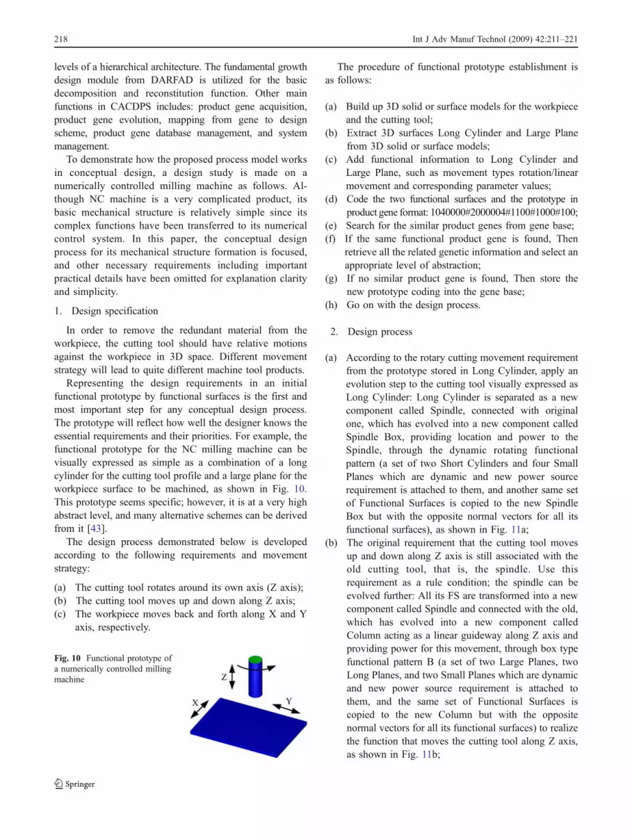
Representing the design requirements in an initialfunctional prototype by functional surfaces is the first andmost important step for any conceptual design process.The prototype will reflect how well the designer knows theessential requirements and their priorities. For example, thefunctional prototype for the NC milling machine can bevisually expressed as simple as a combination of a longcylinder for the cutting tool profile and a large plane for theworkpiece surface to be machined, as shown in Fig. 10.This prototype seems specific; however, it is at a very highabstract level, and many alternative schemes can be derivedfrom it [43].
The design process demonstrated below is developedaccording to the following requirements and movementstrategy:
(a) The cutting tool rotates around its own axis (Z axis);(b) The cutting tool moves up and down along Z axis;(c) The workpiece moves back and forth along X and Y
axis, respectively.
The procedure of functional prototype establishment isas follows:
(a) Build up 3D solid or surface models for the workpieceand the cutting tool;
(b) Extract 3D surfaces Long Cylinder and Large Planefrom 3D solid or surface models;
(c) Add functional information to Long Cylinder andLarge Plane, such as movement types rotation/linearmovement and corresponding parameter values;
(d) Code the two functional surfaces and the prototype inproduct gene format: 1040000#2000004#1100#1000#100;
(e) Search for the similar product genes from gene base;(f) If the same functional product gene is found, Then
retrieve all the related genetic information and select anappropriate level of abstraction;
(g) If no similar product gene is found, Then store thenew prototype coding into the gene base;
(h) Go on with the design process.
2. Design process
(a) According to the rotary cutting movement requirementfrom the prototype stored in Long Cylinder, apply anevolution step to the cutting tool visually expressed asLong Cylinder: Long Cylinder is separated as a newcomponent called Spindle, connected with originalone, which has evolved into a new component calledSpindle Box, providing location and power to theSpindle, through the dynamic rotating functionalpattern (a set of two Short Cylinders and four SmallPlanes which are dynamic and new power sourcerequirement is attached to them, and another same setof Functional Surfaces is copied to the new SpindleBox but with the opposite normal vectors for all itsfunctional surfaces), as shown in Fig. 11a;
(b) The original requirement that the cutting tool movesup and down along Z axis is still associated with theold cutting tool, that is, the spindle. Use thisrequirement as a rule condition; the spindle can beevolved further: All its FS are transformed into a newcomponent called Spindle and connected with the old,which has evolved into a new component calledColumn acting as a linear guideway along Z axis andproviding power for this movement, through box typefunctional pattern B (a set of two Large Planes, twoLong Planes, and two Small Planes which are dynamicand new power source requirement is attached tothem, and the same set of Functional Surfaces iscopied to the new Column but with the oppositenormal vectors for all its functional surfaces) to realizethe function that moves the cutting tool along Z axis,as shown in Fig. 11b;
Fig. 10 Functional prototype ofa numerically controlled millingmachine
218 Int J Adv Manuf Technol (2009) 42:211–221

(c) In the same way, the Large Plane can evolves into theWork Table (still including the workpiece concept init) according to the original requirement that theworkpiece moves back and forth along X andconnected with the old Large Plane, which hasevolved into a linear guide way called Supportproviding the Work Table the guide way and powerto move along X axis, as shown in Fig. 11c;
(d) According to the original requirement that the work-piece moves back and forth along Y axis, the Supportwill evolve further into a new component called CrossSlide and connected with the old Support, which hasevolved into a new component called Base Supportserving as a slide way and providing power for theCross Slide to move back and forth along Y axis,through box type functional pattern B (two LargePlanes, two Long Planes, and two Small Planes whichare dynamic), as shown in Fig. 11d;
(e) Power train evolution process: according to the powersource requirements brought in during the abovedesign process, transmission components can beevolved step by step until the final power sources aredetermined. The details are omitted.
(f) Detail structure evolution process: detailed structurecomponents can be evolved in the same way for thepurposes of exchangeability. For example, the work-piece is separated from the work tale and held on to itby a fixture, and the original Long Cylinder is takenaway from Spindle to become a real Cutter amountedon the spindle end. Note that the explanations aboveare tedious, but the visual operations by the softwareare simple and easy.
(g) After the above evolution procedures, the FU for eachcomponent will take shape automatically andcorresponding product genes can be generated at thesame time.
(h) Product concept verification: new product conceptsgenerated during design process can be analyzedthrough past experience. Existing products can bemodelled in 3D solid form, extracted into productgene format, and stored in product databases includingboth 3D solid and genetic code form. A simpleverification approach is searching the databases forexisting counterparts of similar function. If successfulthen the corresponding concept is feasible. Otherevaluations can be made by both human designerand computer program on different aspects, liketolerance [37].
(i) If all FU can obtain a match from existing databasesthen a solid product model can be generated bysubstituting these FU with corresponding solid compo-nents. The milling machine, as shown in Fig. 11e, isrealized after matching these FU with solid compo-nents stored in the database.
6 Conclusion
Product gene is attracting more and more attention in the fieldof mechanical conceptual design. The following conclusionscan be drawn from the work discussed in this paper:
1. The genetic model based on functional surface isfeasible for conceptual design and can serve as a new
Fig. 11 Design process for mill-ing machine
Int J Adv Manuf Technol (2009) 42:211–221 219

bridge between conceptual and detailed design throughintegration of function with structure;
2. The varied-length coding scheme is easily implementedand can improve conceptual design process by effectivestoring and retrieving in product informationmanagement;
3. The process model for conceptual design based onproduct gene has better analogy with organism growingprocess compared with existing genetic models, and socan help establish a visually operable design process;
4. The case study shows the visually operable designprocess is much simpler than explanations in naturallanguage and so is promising for developing a newgeneration of design automation software systems.
The genetic model has shown much potential to improvedesign efficiency and creativity, but still, a lot of workneeds to be done in future for it to be used in designpractice. Due to the complexity of conceptual design, moredesign cases need to be studied including ones fromdifferent professional areas, and so, more principle knowl-edge can be incorporated to make it really useful inconceptual design in which broad knowledge is neededfor creative and innovative results. The intelligent reasoningtechniques, automatic evaluation, and optimizationapproaches will also need further development in future.
Acknowledgments The authors would like to thank NationalScience Foundation of China (No. 50475129) for their financialsupports.
References
1. Hsu W, Woon IMY (1998) Current research in the conceptualdesign of mechanical products. Comput Aided Des 30(5):377–389doi:10.1016/S0010-4485(97)00101-2
2. O’Sullivan B (2002) Constraint-aided conceptual design. Wiley,Hoboken
3. Miles LD (1972) Techniques of value analysis and engineering.McGraw-Hill, New York
4. Pahl G, Beitz W (1995) Engineering design: a systematicapproach, 2nd edn. Springer, London
5. Chen Y, Feng PE, Lin ZQ (2005) A genetics-based approach forthe principle conceptual design of mechanical products. Int J AdvManuf Technol 27:225–233 doi:10.1007/s00170-004-2164-x
6. Burr J (1990) A theoretical approach to mechatronics design, PhDthesis. Technical University of Denmark, Lyngby
7. Umeda Y, Ishii M, Yoshioka M, Shimomura Y, Tomiyama T(1996) Supporting conceptual design based on the function-behavior-state modeler. Artif Intell Eng Des Manuf 10(4):275–288
8. Qian L, Gero JS (1996) Function-behavior-structure paths andtheir role in analogy-based design. Artif Intell Eng Des Manuf 10(4):289–312 doi:10.1016/S0954-1810(96)90008-4
9. Stiny G, Gips J (1978) Algorithmic aesthetics: computer modelsfor criticism and design in the arts. University of California Press,Berkeley
10. Fitzhorn P (1990) Formal graph languages of shape. ArtificialIntel Eng, Design. Anal Manuf 4(3):151–163
11. Brown KN, McMahon CA, Williams JHS (1994) Constraintunification grammars: Specifying languages of parametricdesigns. In: Gero JS, Sudweeks F (eds) Artificial Intelligence inDesign. Kluwer Academic, Dordrecht, pp 239–256
12. Andersson K (1993) A vocabulary for conceptual design—part ofa design grammar. IFIP WG5.2 Workshop on Formal DesignMethods for CAD. Tallinn, pp 139–152
13. Alberts LK (1993) YMIR: A domain-independent ontology forthe formal representation of engineering design knowledge, PhDthesis. University of Twente, Enchede
14. Ball N, Mattews P, Wallace K (1998) Managing conceptual designobjects: An alternative to geometry. In: Gero JS, Sudweeks F (eds)Artificial Intelligence in Design. Kluwer Academic, Dordrecht, pp67–86
15. Asimow M (1962) Introduction to design. Prentice-Hall, Engle-wood Cliffs
16. Dym C (1994) Engineering design: a synthesis of views.Cambridge University Press, Cambridge
17. Guan X, MacCallum KJ (1996) Adopting a minimum commit-ment principle for computer aided geometric design system. In:Gero JS, Sudweeks F (eds) Artificial Intelligence in Design’96.Kluwer Academic, Dordrecht, pp 623–639
18. van Elsa PA, Vergeest JSM (1998) Displacement feature modelingfor conceptual design. Computer-Aided Des 30(1):19–27doi:10.1016/S0010-4485(97)00049-3
19. Pabon J, Young R, Keirouz W (1992) Integrating parametricgeometry, features and variational modeling for conceptualdesign. Int J Syst Autom Res App l 2:17–36 SARA.
20. Potter S, Culley SJ, Darlington MJ, Chawdhry PK (2003)Automatic conceptual design using experience-derived heuristics.Res Eng Des 14:131–144 doi:10.1007/s00163-003-0034-4
21. Iivonen H, Riitahuhta A (1994) Case-based reasoning in concep-tual design. In: Proc. of the Tenth CIM-Europe Annual Confer-ence, Volume 5 of Sharing CIM Solutions. Denmark, pp. 307–314
22. Shen Z, Smith S (2006) Optimizing the functional design and lifecycle cost of mechanical systems using genetic algorithms. Int J AdvManuf Technol 27:1051–1057 doi:10.1007/s00170-004-2315-0
23. Gero JS, Shi XG (1999) Design development based on an analogywith developmental biology. In: Gu J, Wei Z (eds) CAADRIA’99.Shanghai Scientific and Technological Literature, Shanghai, pp253–264
24. Gero JS (1999) Extensions to evolutionary systems in design fromgenetic engineering and developmental biology. In: Proc. 1999Congress on Evolutionary Computation—CEC99, IEEE, Piscat-away, New Jersey, pp 474–479
25. Holland JH (1975) Adaptation in Natural and Artificial Systems.The University of Michigan Press, Ann Arbor
26. Richard M, Edwin RH (2001) Empirical modeling of the geneticalgorithms. Evol Comput 9(4):461–493 doi:10.1162/10636560152642878
27. Gu XJ, Tan JR, Qi GN (1997) Genetic model for mechanicalproduct information. Chin Mech Eng 8(2):77–79
28. Chen KZ, Feng XA (2004) Virtual genes of manufacturingproducts and their reform for product innovative design. Proceed-ings of the Institution of Mechanical Engineers, Part C. J MechEng Sci 218(5):557–574 doi:10.1243/095440704774061219
29. Parmee IC, Denham MJ (1994) The integration of adaptive searchtechniques with current engineering design practice. Proc. ofAdaptive Computing in Engineering Design and Control’94,Plymouth, 1–13
30. Pham DT, Yang Y (1993) A genetic algorithm based preliminarydesign system. J Automobile Engineers. 207(D2):127–133doi:10.1243/PIME_PROC_1993_207_170_02
31. Rosenman MA (1997) An exploration into evolutionary modelsfor non-routine design. Artif Intell Eng 11:287–293 doi:10.1016/S0954-1810(96)00046-5
220 Int J Adv Manuf Technol (2009) 42:211–221
32. Rosenman MA (1996) A growth model for form generation usinga hierarchical evolutionary approach, Microcomputers in Civilengineering. Spec Issue Evol Syst Des 11:161–172
33. Rosenman MA (1996) The generation of form using an evolution-ary approach. In: Gero JS, Sudweeks F (eds) Artificial Intelligencein Design’96. Kluwer Academic, Dordrecht, pp 643–662
34. Gero JS (2000) Computational models of innovative and creativedesign process. Technol Forecast Soc Change 64:183–196doi:10.1016/S0040-1625(99)00105-5
35. Gero JS, Kazakov VA (1998) Evolving design genes in spacelayout planning problems. Artif Intell Eng 12(3):163–176doi:10.1016/S0954-1810(97)00022-8
36. Huang KZ (1998) Technical report: functional surface decompo-sition and reconstitution principle and its application. China Hi-Tech Development Program (863). Shandong University ofTechnology, Jinan
37. Huang KZ, Wang YD, Yang ZH, Zhang Y, Wang WG, Meng QB,Sun X (2007) Synchronized tolerancing in growth design. Proc.IMechE Part B. J. Eng Manuf 221:1451–1465
38. Huang KZ (2006) Growth Design Modeling. Proc. of ASMEDETC2006/99151, Philadelphia
39. Yang JY, Huang KZ, Ren HW (2008) Study on PLM-OrientedProduct Lifecycle Genetic Model. Int J Manuf Technol Manage14:201–214 IJMTM doi:10.1504/IJMTM.2008.017495
40. Kooler R (1990) Mechanical design methodology. Translated byDang ZL, Tian ST, Tang J et al. Science, Beijing
41. Huang CY (2000) Mechanical innovative design. Higher Educa-tion, Beijing
42. Huang KZ (2006) Generalized Positioning Principle and Struc-tural Design Automation Theory (in Chinese). http://www.paper.edu.cn/downloadpaper.php?serial_ number=200602-84. Accessed30 Feb 2006
43. Huang KZ, Huo ZP, Xu ZG, Li JS, Ai X (1998) Study onschematic design of mechanical product based on decompositionand reconstitution of design requirements. In: Ni J et al (ed)Manufacturing Science and Technology for New Century.Huazhong University of Science and Technology Press, Wuhan,pp 360–364
Int J Adv Manuf Technol (2009) 42:211–221 221