
Mechanical design of a magnetic fusion production reactor
46
Journal of Fusion Energy, VoL 5, No. 4, 1986 Mechanical Design of a Magnetic Fusion Production Reactor' W. S. Neef 2 and D. L. Jassby 3 The mechanical aspects of tandem mirror and tokamak concepts for the tritium production mission are compared and a proposed breeding blanket configuration for each type of reactor is presented in detail, along with a design outline of the complete fusion reactor system. In both cases, the reactor design is developed sufficiently to permit preliminary cost estimates of all components. A qualitative comparison is drawn between both concepts from the view of mechanical design and serviceability, and suggestions are made for technology proof tests on unique mechanical features. Detailed cost breakdowns indicate less than 10% difference in the overall costs of the two reactors. KEY WORDS: magnetic fusion production reactor; tritium production; fusion breeder. 1. GENERAL DESCRIPTION OF TWO FUSION PRODUCTION REACTOR DESIGNS Two distinctly different and competitive reactor designs are presented in this report. The tandem mirror reactor employs open-field line geometry for plasma confinement, while the tokamak is a closed- field line torus. A fusion power of 400 MW was chosen for the tandem mirror. For comparison, a 450-MW tokamak design was chosen from a family of TORFA reactor concepts being studied at the FED Design Center at Oak Ridge, Tennessee. Figure 1 shows, to the same scale, the two reactor concepts. Important design parameters for both reactors are given in Table I. ~Yhis paper represents work carried out from !980 to 1982 and was in draft form in 1982. It was received for publication with only minor editing of its t982 version, explaining the fact that some of the material is dated. 2Lawrence Livermore National laboratory, Livermore, California 94550. 3Princeton Plasma Physics Laboratory, Princeton, New Jersey 08544. 271 One especially significant difference between the two reactors--their use of magnets--should be em- phasized. The tandem mirror, with one exception, uses superconducting magnets for its magnetic fields. A copper insert forms the inner section of the first barrier coil at each end of the reactor. Together, these two inserts consume about 20 MW of power. This particular tokamak (TORFA) design uses normal copper magnets for most of its coils. The magnet power consumed is estimated to be 240 MW. Because two poloidal field coils are to be supercon- ducting, a cryogenic plant will still be required. Locating the poloidal field (PF) coils outside the outer leg of the toroidal field (TF) coils greatly simplifies reactor and blanket assembly and servicing operations. Their greater distance from the plasma calls for large circulating current. Rather than pay the price of large resistive power loss, it was deemed better to use a superconductor for those two coils only. The bred product can be extracted from the tandem mirror by a service machine traveling in a gallery beneath the central cell. New breeding slugs are provided by a similar machine moving in the 0164-03 i 3/86/1200-0271505.00/0 ~1986 Plenum Publishing Corporation
-
Upload
khangminh22 -
Category
Documents
-
view
0 -
download
0
Transcript of Mechanical design of a magnetic fusion production reactor

Journal of Fusion Energy, VoL 5, No. 4, 1986
Mechanical Design of a Magnetic Fusion Production Reactor'
W. S. N e e f 2 and D. L. Jassby 3
The mechanical aspects of tandem mirror and tokamak concepts for the tritium production mission are compared and a proposed breeding blanket configuration for each type of reactor is presented in detail, along with a design outline of the complete fusion reactor system. In both cases, the reactor design is developed sufficiently to permit preliminary cost estimates of all components. A qualitative comparison is drawn between both concepts from the view of mechanical design and serviceability, and suggestions are made for technology proof tests on unique mechanical features. Detailed cost breakdowns indicate less than 10% difference in the overall costs of the two reactors.
KEY WORDS: magnetic fusion production reactor; tritium production; fusion breeder.
1. GENERAL DESCRIPTION OF TWO FUSION PRODUCTION REACTOR DESIGNS
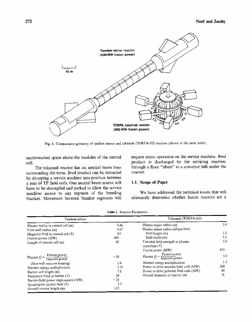
Two distinctly different and competitive reactor designs are presented in this report. The tandem mirror reactor employs open-field line geometry for plasma confinement, while the tokamak is a closed- field line torus. A fusion power of 400 MW was chosen for the tandem mirror. For comparison, a 450-MW tokamak design was chosen from a family of TOR F A reactor concepts being studied at the F ED Design Center at Oak Ridge, Tennessee. Figure 1 shows, to the same scale, the two reactor concepts. Important design parameters for both reactors are given in Table I.
~Yhis paper represents work carried out from !980 to 1982 and was in draft form in 1982. It was received for publication with only minor editing of its t982 version, explaining the fact that some of the material is dated.
2Lawrence Livermore National laboratory, Livermore, California 94550.
3Princeton Plasma Physics Laboratory, Princeton, New Jersey 08544.
271
One especially significant difference between the two reactors-- their use of magnets--should be em- phasized. The tandem mirror, with one exception, uses superconducting magnets for its magnetic fields. A copper insert forms the inner section of the first barrier coil at each end of the reactor. Together, these two inserts consume about 20 MW of power.
This particular tokamak (TORFA) design uses normal copper magnets for most of its coils. The magnet power consumed is estimated to be 240 MW. Because two poloidal field coils are to be supercon- ducting, a cryogenic plant will still be required.
Locating the poloidal field (PF) coils outside the outer leg of the toroidal field (TF) coils greatly simplifies reactor and blanket assembly and servicing operations. Their greater distance from the plasma calls for large circulating current. Rather than pay the price of large resistive power loss, it was deemed better to use a superconductor for those two coils only.
The bred product can be extracted from the tandem mirror by a service machine traveling in a gallery beneath the central cell. New breeding slugs are provided by a similar machine moving in the
0164-03 i 3/86/1200-0271505.00/0 ~1986 Plenum Publishing Corporation
272 Neef and Jassby
Tandem mirror reactor (400-MW fusion power)
10 m
TORFA tokamak reactor (450-MW fusion power)
Fig. 1. Comparative geometry of tandem mirror and tokamak (TORFA-D2) reactors (shown to the same scale).
unobstructed space above the modules of the central cell.
The tokamak reactor has six neutral beam lines surrounding the toms. Bred product can be extracted by dropping a service machine into position between a pair of TF field coils. One neutral beam source will have to be decoupled and parked to allow the service machine access to any segment of the breeding blanket. Movement between blanket segments will
require crane operat ion on the service machine. Bred
p roduc t is discharged by the servicing machine through a floor "chute" to a conveyor belt under the
reactor.
1.1. Scope of Paper
We have addressed the technical issues that will
u l t imate ly de termine whether fusion reactors are a
Tandem mirror
Table I. Reactor Parameters
Tokamak (TORFA-D2)
Plasma radius in central cell (m) First-wall radius (m) Magnetic field in central cell (T) Fusion power (MW) Length of central cell (m)
Fusion power Plasma Q = Injected power
(first-wall neutron loading) Blanket energy multiplication Barrier-cell length (m) Maximum field at barrier (T) Barrier-field power requirement (MW) Quadrupole anchor field (T) Overall reactor length (m)
0.46 0.67 4.0
400 50
-10
1.0 1.35 7.0
24 - 20
2.3 115
Plasma major radius (m) Plasma minor radius (ellipse-like)
Half-height (m) Half-width (m)
Toroidal field strength at plasma centerline (T) Fusion power (MW)
Fusion power Plasma Q = Injected power Blanket energy multiplication Power to drive toroidal field coils (MW) Power to drive poloidal field coils (MW) Overall diameter of reactor (m)
3.9
1.5 1.0 5.0
450
3.0
1.5 20O 40 36

Mechanical Design of a Magnetic Fusion Production Reactor 273
viable option for the production of critical weapon- grade material. Two of the most important ap- proaches to fusion reactor design--tandem mirrors and tokamaks--are examined and compared to de- termine if a clear choice can be made at this time.
The issues discussed here are related to blanket engineering and cost. We assume that the physics to be demonstrated in the MFTF-B tandem mirror at Livermore, TFTR at Princeton, JET at Culham, and Big-Dee at General Atomic will prove satisfactory for the plasma containment quality specified herein.
A blanket design that permits plutonium or tritium production by a flow-through process is pro- posed. Whether the flow of material is by batch or continuous depends on the design details of the remote fueling machines. This design employs the less-costly batch process. The same blanket design can be used for a continuous-flow process.
1.2. Purpose of Breeding-Blanket Design
The design of the cold-water-cooled blanket was instigated in recognition of two important situations.
First, the equipment used by the United States to manufacture nuclear-weapon-grade plutonium and tritium for weapon applications uses a similar low- temperature breeding system. Second, the technology of fusion-power reactors has reached significant milestones in areas other than blankets.
The operation of large superconducting magnet systems has been convincingly demonstrated. Neu- tral beam injection has, for brief periods, augmented plasma operation to the temperature required for sustained reactor operation. Steady operation of these high-voltage injectors at high power remains to be demonstrated. Current progress suggests that con- tinuous operation will be achieved within 5 years.
For tandem mirror reactors, the technology of directly converting the power of end-loss ions to electricity has been demonstrated in laboratory scale experiments.
The largest tandem mirror experimental reactor is MFTF-B at Livermore. Figure 2 compares the tandem mirror production reactor to MFTF-B to show that current experimental hardware is as large as the facility proposed here, although the central cell is not as long.
I BOTH MACHINES SHOWN SAME SCALE
' I l I 4 0 m i
MFTF-B Fig. 2. Comparative size of the tandem mirror reactor and the MFTF-B.

274 Neef and Jassby
In a parallel achievement, the tokamak reactor has demonstrated the ability of a poloidal divertor to maintain the clean vacuum environment required for deuterium-tritium (D-T) plasma.
The cold-water-cooled blanket design shows that the low-temperature coolant system employed for the past several decades in weapon-grade material pro- duction can be applied directly to a fusion driver. We believe that blanket technology needs no further development for this application.
2. TANDEM MIRROR PRODUCTION REACTOR WITH COLD-WATER-COOLED BLANKET
2.1. Blanket Configuration
For the production of tritium, our first blanket design stays close to the low-temperature technol- ogy currently employed in Savannah River fission breeders. A tandem mirror fusion reactor is pro- posed, with an end-plug design following current axicell Livermore physics. The blanket of such a reactor is confined to the cylindrical central cell, which for this application is 50 m long. Four hundred megawatts of fusion power is generated in that central cell. The blanket, having no high-temperature coolants, will produce no electricity.
The accepted practice is to subdivide tandem mirror blankets into short cylindrical modules that can be easily fabricated near the reactor and that can be installed or replaced by remote servicing tools. The final choice of module length will be made after a cost study. We chose a length of 2 m because previous studies have shown that modules of much more than 2 m in length are quite heavy and present transportation problems. However, the length chosen has negligible impact on the details of the blanket design.
Our philosophy is to design a system that allows us to add to or remove breeding material from the blanket without removing the central-cell modules. We have a design that permits batch replacement of breeding material. The reactor must be shut down to allow cooling water interruption in the desired mod- ules. Access for fuel change depends on opening the coolant circuit. The fuel-change machinery required for this batch processing provides for multiple chan- nel changeout simultaneously.
We recognize the advantages of replacing breeding material without reactor shutdown. To ac-
complish this, one must maintain the coolant flow to the region where material exchange is occurring, which would require a much more complex and costly fuel-change machine. Instead, we have elected to postpone our detailed analysis of such a method to a possible continuation of this study. The blanket configuration would not be fundamentally altered, just the mechanical and hydraulic details of the en- trance and exit ports.
2.1.1. Tritium Breeding Slugs
Tritium breeding is accomplished in the same lithium-aluminum (Li-AI) alloy currently used for that purpose at Savannah River. A thin aluminum capsule is deep drawn so it can be closed by welds at one end only. The shell, along with the slug end cap, serves as a permeation barrier to prevent tritium from leaving the Li-A1 alloy where it is born. Aluminum at low temperature is a very effective permeation barrier. Contamination of the cooling water with tritium can be virtually eliminated by employing this aluminum jacket. Figure 3 shows the fuel-slug assembly. (The purpose of the small on-axis hole will be discussed later.) The simple fuel slug--basically a cylinder with a hole in the center--can be dropped into the aluminum capsule. Next, the end cover is welded on, using electron beams on both the outer and inner weld rings.
Should one wish to breed plutonium in this blanket, the same design can be employed. A de- pleted uranium "slug" would replace the Li-A1 alloy. The same aluminum protective jacket could be used so that the frictional properties of the string in the tube would not be changed. Of course, both types of breeding slugs could be on one chain.
The radii at the end of the slug are used to permit close stacking in a conduit. The hole in the center of each slug allows the slugs to be strung on a small cable, like pearls on a string. At this string is pulled through the curved channel, the slugs must move angularly with respect to adjacent slugs in order to negotiate the turns. The convex nose and concave tail provide for efficient use of the volume of this conduit.
It is also possible that a pull cable is unneces- sary. Fuel slugs without the center hole may be pushed through the guide tubes. Our concern with that design is the greater likelihood of cocking and jamming of one or more slugs in some remote part of a guide tube. Simple engineering tests will help us

Mechanical Design of a Magnetic Fusion Production Reactor 275
l ' r,
X2
o 1 2
/ - A l u m i n u m guide tube /
,/
Lithium-aluminum alloy
3 c m
J
Aluminum can
. , ~ ~ t ~_ _ _ L _ _
"' r " 2 ~ ' - _
Fig. 3. Tritium breeding slug.
._._~
�9 Water cooling ( < 100~
�9 A luminum structures
�9 Li At breeding material
�9 Beryll ium neutron multiplier
%
"%,
Fig. 4. Cross section of breeding blanket for tandem mirror production reactor.
276 Neef and Jassby
select the optimum slug configuration and means of locomotion,
Nominally, there will be a 2-ram-diameter clearance between the outside of the fuel slug and the inside wall of the guiding conduit.
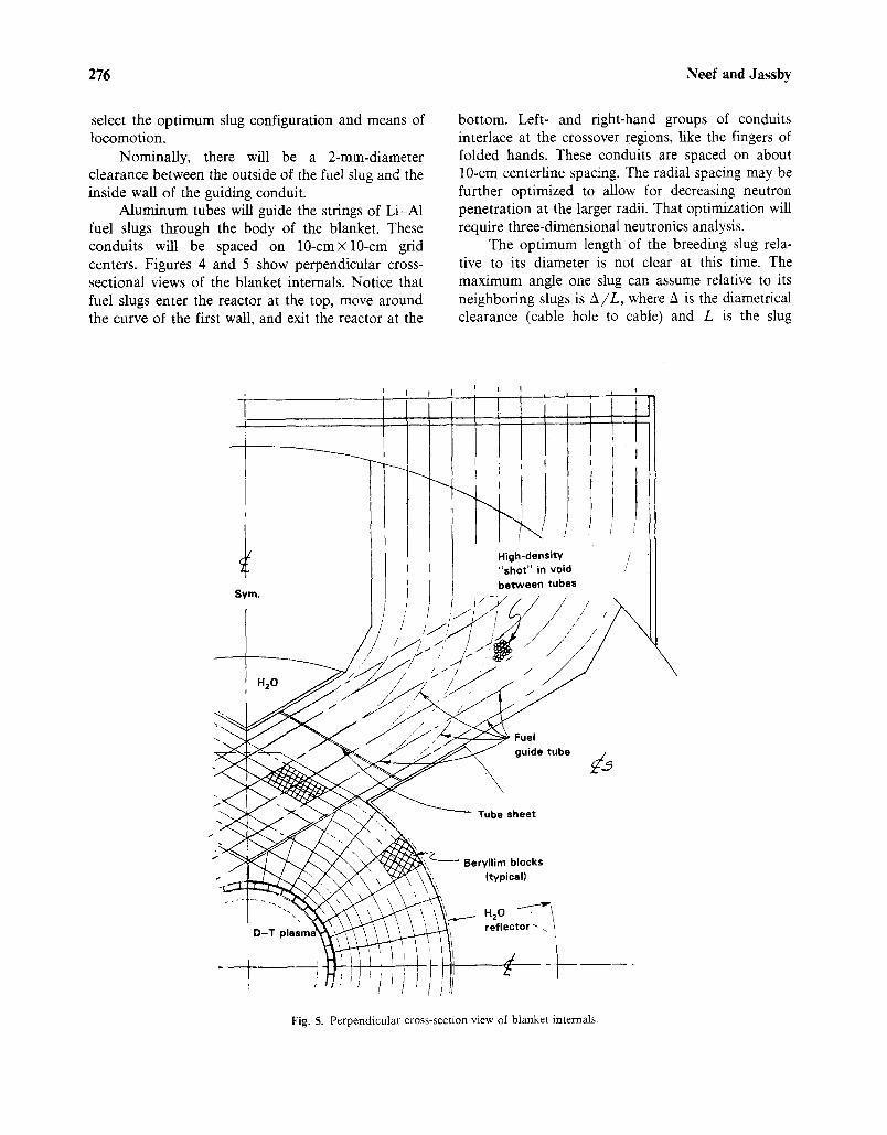
Aluminum tubes will guide the strings of Li-A1 fuel slugs through the body of the blanket. These conduits will be spaced on 10-cmxl0-cm grid centers. Figures 4 and 5 show perpendicular cross- sectional views of the blanket internals. Notice that fuel slugs enter the reactor at the top, move around the curve of the first wall, and exit the reactor at the
bottom. Left- and fight-hand groups of conduits interlace at the crossover regions, like the fingers of folded hands. These conduits are spaced on about 10-cm centerline spacing. The radial spacing may be further optimized to allow for decreasing neutron penetration at the larger radii. That optimization will require three-dimensional neutronics analysis.
The optimum length of the breeding slug rela- tive to its diameter is not clear at this time. The maximum angle one slug can assume relative to its neighboring slugs is A/L, where A is the diametrical clearance (cable hole to cable) and L is the slug
i I I I . I
i t
, H20
Sym,
f
/
High-densi ty " sho t " in void
between tubes
Sj..: I /
Fuel guide tube
t
i
D - T
"t
Tube sheet
Beryl l im blocks (typical)
. . . . ! I
/ f
H20 ,""T-"~ 1 reflector ~
Fig. 5. Perpendicular cross-section view of blanket internals.

Mechanical Design of a Magnetic Fusion Production Reactor 277
length. Both parameters can be very small, which implies close tolerances and a very large number of slugs and, hence, a high manufacturing cost.
If L is large, the inside diameter of the guide tube must be large to provide clearance for the ends of the slug as it negotiates a tube bend. That implies too much void space in the blanket and a costly sacrifice in breeding efficiency. The voids could be occupied with either neutron multiplier or more breeding material.
We believe the optimum lies close to a design where length, diameter, and spherical end radius are all equal.
Entering this complex relationship is the cable diameter, which we would like to be as small as possible, consistent with the strength needed to pull the chain of slugs around the several bends. The clearance between the cable and slug should also be small so as to not waste breeding volume.
Experiments with the frictional aspects of this design will allow slug length, cable diameter, cable- hole clearance, and guide-tube inside diameter to be selected.
2.1.2. Neutron Multiplier
The space between conduits must be occupied by a good neutron multiplier. Beryllium is the logical choice. Experience at the Advanced Test Reactor (ATR) at Idaho Falls has shown that, at low-water temperature, the corrosion of beryllium is very slow - -about 0.006 in/year at 100~ Workers at ATR have operated unprotected beryllium reflectors around their reactor core for about 5 years. Replace- ment was the result of crack development thought to be due to helium gas formation within the beryllium.
Our configuration, shown in Fig. 6, consists of a large number of small blocks, rather than the massive pieces used in the ATR reflector. We do not antic- ipate serious cracking because the dimensions of our blocks are about 10 cm maximum. Should cracks develop or spallation occur, the blanket can continue to function. The migration of a large quantity of small "chips" from the blocks must be prevented by the filters protecting the coolant pumps.
The surface area of our small-block neutron- multiplier matrix is quite large. If we experienced corrosion of 0.006 in/year, 1600 kg/year of beryl- lium would disappear from the blanket! Although that is a small percentage of overall blanket volume
(0.45%), we do not know where in the cooling system it would redeposit. It seems prudent to inhibit corro- sion to reduce potential mass transport. The least objectionable coating material from the standpoint of neutronics considerations is aluminum. We recom- mend a light film of aluminum; about 0.005 in or less will satisfactorily arrest beryllium corrosion and be present as only 0.35% of the blanket's volume.
The geometry of the blanket permits several beryllium block shapes to be duplicated many times. Even so, there are about 100 conduits/m, and many different block shapes will be required to fill all the space between conduits. These beryllium blocks will require cooling and will have several surface grooves to allow water flow in the circumferential direction, i.e., parallel to the conduits.
Notice that each central cell module contains two solenoid magnets. Those magnet coils are mounted outboard of the tube-loading region to per- mit easy assembly. If the magnet coil were in the center of the module, it would have to be wound directly on the module since it would be trapped by those features of the structure related to conduit access and fuel change.
The presence of the magnet coils and associated shielding creates an access problem. The breeding- material conduits directly below the coils must be routed toward the center of the module as they enter and leave the module. Bending such conduit shapes is not a problem. However, the warpage of conduit toward the center of the module should be confined to a radial location outside the tube-crossover region. The space just behind the breeding zone is a water reflector to improve breeding. That space between the conduits is simply filled with water. No complex beryllium parts are needed to accommodate out-of- plane conduit curvature.
As the conduits exit through the shield, a large void is left in the shield to accommodate them. This void must be filled to control neutron leakage and the resultant heating of the superconducting solenoids. We propose filling that space with lead shot and/or steel shot in appropriate combination. The space would be filled by pouring in shot so no complex parts have to be manufactured. The con- duits themselves are also a neutron leakage path. If the portion of the breeding slug chain that is in the shield space had "dummy" slugs made of heavy metal, they would effectively block neutrons and could easily be separated from the breeding slugs after extraction of the string.

278 Neef and Jassby
Hot-pressed beryllium block
Aluminum guide tube (3.7-cm i.d.l
J ' /
/
Lithium-aluminum fuel slug (3.6-cm o.d.)
Aluminum double-shell first wall
Fig. 6. Proposed production blanket, showing internal details.
2.1.3. Cooling the Low-Temperature Blanket
2.1.3.1. First- Wall Cooling. The energy deposi- tion in the first wall is estimated to be 10.6 W. cm-3, which is 4% of the neutron energy incident on that wall. Figure 7 shows a typical cross section of the first wall, with two concentric shells spaced apart by I-beam-shaped stringers. Two cooling tubes are needed between each pair of stringers. They limit the thermal gradient in the aluminum shell to about 35~ from the "hot spot" most remote from the coolant to the inside surface of the water tubes.
The coolant flow rate was chosen to limit the water temperature to 85~ at the first wall and
blanket exit. The drop in film temperature is esti- mated at 10 o C. This leads to a hot-spot temperature of 130 ~ The yield point of 7075-T6 aluminum is 50,000 psi at that temperature.
If the cooling tubes are 1 cm in diameter, the pressure drop along a 2-m-long run of tube is less than 1 psi for the necessary coolant flow rate of 1020 cm 2. s - ] for the complete first wall. The coolant is supplied by radial flow tubes incorporated in the blanket end plates. This radial flow enters a ring manifold that serves to close one end of the first-wall annulus. The first-wall coolant tubes are fed from that ring manifold. An identical ring manifold at the other end of the blanket module serves as a coolant

Mechanical Design of a Magnetic Fusion Production Reactor 279
I
Electron beam weld = (E) 0,2 cm -~
tubes between stringers inner diameter = 0 . 4 c m
67 cm R
/ J
t Fig. 7. Production tandem mirror reactor, showing first-wall aluminum structure.
collector. Radial flow in the end plate returns the water to the main coolant-return pipe.
2.1.3.2. Blanket Cooling. The blanket absorbs 6.1 MW of neutron energy for every meter of its length. The blanket energy-multiplication factor (M) is 1.35, so we must remove 8.24 MW of heat from every meter of blanket length.
Coolant flow is from the top to the bottom of the module. Flow enters both the fuel guide tubes and surrounding neutron-multiplier region. The two parallel flow paths are not totally separated. Holes in the walls of the guide tubes allow communication between coolant paths, which eliminates any possibil- ity of a guide tube becoming obstructed and prevent- ing "downstream" slugs from receiving coolant flow.
Hence, we have coolant flow in and around the neutron multipler and flow in the annular space between the fuel slugs and the guide-tube walls. For a 2-m-long blanket module, the total flow rate
required is 56.31-s-1. The Reynolds number is about 18,000, which ensures turbulent flow. The pressure drop from the top coolant inlet (where the tube bundle emerges from the blanket) to the bottom coolant exit (where the lower end of the tubes emerge from the blanket) is calculated to be 19 psi at that flow rate. With other pressure drops in a closed-loop system taken into account, especially that of the tube side of a shell and tube heat-exchanger, the pump delivery pressure can be estimated at 40 psi. The pump can be just ahead of the heat-exchanger to keep the blanket water pressure as low as possible. The external pressure on the cylindrical first wall will not exceed 30 psi.
Calculation of the critical buckling pressure for our double-shell first-wall design shows that, at 130 ~ C with the yield point at 50,000 psi, the critical pressure exceeds 550 psi--a generous margin of safety. Indeed, it is apparent that optimization of the

280 Neef and Jassby
first-wall design to give a smaller safety factor would improve blanket breeding. The gain would be small since only 4% of the neutrons give up their energy to the first wall. For now we will settle for a very conservative first-wall design.
2.1.3.3. Beryllium Block Temperature. The ther- mal conductivity of beryllium is 2 W-cm K. The blocks can be approximated by a short cylinder of equivalent volume to help analyze the temperature differential within the beryllium.
A cylinder of radius R, with a uniformly distrib- uted heat source and constant thermal conductivity, has a center-to-surface temperature difference ex- pressed by
T o - T~ = 9RZ/4k
where q is volumetric heat deposition. Our neutrons deposit about 7 W-cm -3 in the
beryllium. The resulting temperature difference is 44 ~ C. Since our wall temperature should not exceed 90~ the "hot spot" is only 134~ not a concern for corrosion.
2.1.3.4. Lithium - Aluminum Breeding-Slug Tem- perature. The energy deposition in the tritium breeding slugs is about 20 times the average blanket power density of 5 W. cm -3. The radius of a slug is 1.8 cm, and the conductivity is 2.2 W.cm -1 K - k Therefore, the core temperature of a slug whose surface is at 90~ is only 127~ There will be some additional difference in temperature because of the interface at the slug jacket. The jacket must have the equivalent of a light press fit over the Li-A1 core to minimize that temperature differential.
2.1.4. First- Wall Design
The first wall of the reactor is an annular, hol- low structure cooled by water-cooling tubes that run axially and are spaced about 4 cm apart.
The first wall is attached, at its two ends, to the end plates of the blanket module. The water that cools the blanket is slightly pressurized; this pressure is exerted on the outside of the first-wall assembly. Because a classical cylinder-collapse condition exists, our analysis tests the planned design for structural stability under such loading.
The major components of the blanket are made of aluminum because of the low temperature. We
plan to change the water temperature from 25 to 85~ to extract energy deposited in the blanket.
To increase the buckling stiffness of the shell, the effective moment of inertia of the shell had to be increased. Neutronics considerations call for minimi- zation of mass in the first wall. We have tried to limit the actual metal thickness to about 0.5-0.6 cm of aluminum.
Another advantage of this concentric wall con- struction is the redundancy provided. The wall facing the plasma can develop minor cracks or other flaws with no immediate effect on the plasma. The space between the concentric aluminum cylinders is also evacuated. A separate vacuum pump will be used for that annular space to ensure that a coolant leak will not ruin the plasma vacuum.
The inner cylinder, adjacent to the plasma, can suffer arcing damage or neutron-induced embrittle- ment leading to cracks without developing a vacuum leak and resulting plasma quench. Cooling-water tubes on the back of the cylinder, rather than on the front, give added assurance that the coolant tubes will not be damaged by arcs.
2.1.4.1. Buckling of First Wall. As a reference for cylinder collapse calculations, we have used the work of A. Blake at Lawrence Livermore National Laboratory. Important parameters are:
1. Wall thickness
2. Length of cylinder between stiffeners
3. Mean radius
4. Radial amount of out-of-roundness
5. Modules of elasticity
6. Yield strength
For neutronics reasons, the wall thickness should be 0.5-0.6 cm. The module can be 1-2 m in length; because some advantages accrue to larger modules, we chose a length of 2 m. It is readily shown that a single-thickness (i.e., a one-piece) cylinder meeting these criteria cannot sustain significant external cool- ing pressure. Additional wall stiffness, with no added material, is required.
We chose to use two concentric shells, each 0.08 in thick, spaced apart by I-beam-shaped stringers that can be welded to the cylinders by electron-beam methods, thereby increasing the effective thickness of the shells by increasing their stiffness. Our method was to calculate the moment of inertia of a segment of the double cylinder, including the contribution by the stringer spaces. A second calculation yields the

Mechanical Design of a Magnetic Fusion Production Reactor 281
single-thickness shell, which would produce the same moment of enertia. That thickness is then used in Blake's formulas for cylinder collapse to check the critical buckling pressure. If that pressure is suffi- ciently higher than the hydraulic pressure needed for adequate blanket coolant flow, a solution has been reached.
The wall design shown in Fig. 7 will have a critical buckling pressure of 559 psi if constructed of 7075-T6 aluminum sheet with a yield point of 50,000 psi. This compares favorably with the hydraulic pres- sure of 40 psi shown to be required for water flow through the blanket cooling circuit.
Shell buckling is not the only possible mode of failure. The short arc of the outer cylinder, between the cylinder separators, can fail as a beam with a uniformly distributed load�9 To evaluate this failure mode, we resorted to finite-element stress analysis, using the NIKE 2D computer code. The results showed lower failure pressure. We conclude that the local "oil-canning" demonstrated by the finite-ele- ment technique will be the controlling failure mode.
The finite-element model used for this analysis was composed of two thin sections connected by an I-beam. The I-beam was modeled as being rigidly attached (bonded) to the outer and inner shells. The motion of the segment midplane, represented by the ends of the thin pieces, was confined to radial surfaces that intersect at a line representing the centerline of the reactor's vacuum cylinder (see Fig. 8).
All of the structures was assigned the properties of 7075-T6 aluminum, and pressure was applied uni- formly along the outer surface of the upper shell. One code run (using NIKE 2D) was run for each of a series of applied pressures in 5-psi increments. As nonlinear behavior-representing incipient buckling - -was observed, the increments were decreased.
We determined the failure pressure by local buckling of the outer shell to be only 40 psi. This failure is similar to "oil-can" failures, where sudden large deflections occur at a "critical pressure~
As a second test, we assigned the properties of stainless steel to the shells and stringers. This time failure occurred at an external pressure of 70 psi.
Center o f
I-beam stringer
-... .
Plane strain pressure vessel, p = 50 psi - - - 7
magnification factor = 1 . E + O 0 /
J Frictionless surface ( rad ia l )
" B r i c k wall"
r
Fig. 8. Tandem mirror first wall, showing finite-element analysis grid and boundaries.

282 Neef and Jassby
Table II. Volume Fractions of First Wall and Blanket i l l
First wall Blanket
Outside radius (cm) 72.0 Inside radius (cm) 67.0 Volume fraction (%) of
Aluminum 11.0 Cooling water 5.0 Internal vacuum 84.0
Outside radius (cm) 112.0 Inside radius (cm) 72.0 Volume fraction (%) of
Aluminum guide tubes 0.8 Covering on "fuel" pellet 0.9 Li-A1 alloy pellet 10.0 Beryllium 81.0 Aluminum end plate 3.0 Cooling water 4.2 Pellet pull cables (steel) 0.1
Again, the "oil-can" mode of failure was demon- strated.
2.1.5. Volume Fractions of First Wall and Blanket
To evaluate the breeding capability of the low- temperature blanket design, the material fractions in the first wall and blanket must be calculated. A neutronics code can then be used to test blanket performance.
Our design has an aluminum first-wall structure, a double shell with axial stringers to maintain the wall spacing. This design evolved from two consider- ations. First, we needed a shell capable of withstand- ing external cooling water pressure. Second, we wanted a structure tolerant of small flaws in the material wall facing the plasma. Figure 7 illustrates the design developed.
The material that intercepts neutrons is about 0.55 cm thick. The double-wall construction leads to an actual thickness of 5.0 cm. The moment of inertia of this hollow wall can be converted to an "effective" wall thickness for external buckling calculations. Sec- tion 2.1.4. of this report reviews those calculations. The design-yield first-wall volume fractions are listed in Table II.
The next 40 cm in radius, behind the first wall, is the blanket. It consists of aluminum guide tubes for the breeding material, the breeding slugs within the tubes, the beryllium neutron multiplier surround- ing the tubes, and cooling water. Material fractions calculated for that zone are also listed in Table II.
2.1.6. Module Assembly
We believe that the best assembly method will be to construct the module face up on a floor jig. The
shield, blanket, and first wall can be assembled in that position. This assembly would be lifted by tem- porary stub-axles bolted to the shield, rotated 90 ~ then lowered on and attached to a permanent sup- port cradle.
Coolant plumbing manifolds can be added after the blanket shield is attached to the cradle. At this point, the superconducting solenoid coils can be slipped over each end, shimmed, and locked in place.
The design is only conceptual now, but depends on progressive layers of neutron multiplier and guide tubes starting at the bottom of the blanket annulus. Possible assembly steps are listed below in order of execution:
1. Lay the blanket side-wall plate on the bot- tom level of the assembly jig.
2. Construct the entire shield around the pe- rimeter of the side-wall plate and weld the plate to the shield.
3. Lower the first-wall subassembly into the center and weld it to the inner edge of the face plate.
4. Lay the first row of beryllium blocks. (The left side of the assembly will differ from the right because of the necessary interlacing of tube rows.)
5. Lay in the first row of guide tubes. Shim to establish alignment with the plenum-cham- ber position template, using thin aluminum plates and tube collars machined as re- quired.
6. Lay in the second layer of beryllium blocks, followed b y the second row of guide tubes. Continue to shim as required for accurate alignment with the plenum-chamber tem- plate. Continue this layering until the " top" of the blanket annulus is reached.

Mechanical Design of a Magnetic Fusion Production Reactor 283
. Weld the "top" side-wall plate on the as- sembly after inserting the shims so the entire 2-m-thick assembly has less than a 0.5-ram clearance between the block and tube stack and the inside surface of the end-wall plates. Spring washers in that clearance space serve to restrict blanket vibrations excited by hy- draulic vortices.
2.2. Fueling Scenario
2.2.1. Installing and Removing Fuel Chains
All conduits open into cooling-water plenum boxes. Each module of the central cell is supplied by one water circuit. One large pipe enters each water plenum above the reactor, and one large pipe leaves each plenum below the reactor. Access to change breeding material is obtained with two automatic machines. One machine above the reactor travels on the gantry crane rails and is positioned over the module to be changed. The second, moving in a gallery below the central cell, positions itself below the desired module. The first task of each machine is to remove the rectangular bolted flange cover of the water plenum it faces. After that cover plate is re- moved and temporarily stored, the open ends of all fuel conduits are exposed.
The machine above the reactor has been pre- loaded with reels of breeding slugs, active in the center, dummy at both ends of each string. The top machine attaches its new fuel strings to the exposed top cable ends of the enriched strings. We estimate that about 50 reels of fuel can be changed simulta- neously.
The lower machine pulls the enriched strings out of the bottom of the blanket module. While dong so, it pulls the recharge string into the blanket, since the two strings are attached. After winding the correct length of string on its take-up reels, it stops and decouples the old string from the new string just drawn into place. The lower machine then moves to a central discharge door and lowers its enriched fuel strings into a water pool covering a long conveyor belt. This conveyor belt transports radioactive slugs, with 6 m of water cover, to the chemical processing facility designed to harvest and store tritium. Then the machine returns to the module being serviced for the next load of slug strings.
The process is repeated a second time to changeout one blanket module. Reindexing of the
two machines will be necessary to permit work on similar, but slightly displaced, tube patterns as the total number of about 100 tubes per module is serviced.
2.2.2. Fueling Machines
To replace the bred material in the blanket, two remotely operated service machines will be needed. The one above the central cell will bring new material to be exposed to fusion neutrons and the one below the central cell will extract material that has reached the desired levet of enrichment for chemical processing to other forms.
The top machine will receive newly assembled strings of slugs from racks on the walls of the de- livery corridor (see Figs. 9 and 10 for general plant layout). The delivery corridor runs from the reactor containment building to the fuel-preparation facility, a building several hundreds of meters removed. The top machine resides in a parking area at one end of the reactor bay and rolls on the same rails used by a service gantry crane. A small shuttle car transfers fuel strings from the corridor-wall storage shelves to transfer reels (about 50 reels) in the top machine. The reels will be about 2 m in diameter, so one complete 6-m fuel string is held on one reel in a little less than 360 ~ of its circumference. All reels will operate simultaneously wtfile loading the blanket. Once loaded, this top machine can move along the central cell to a position directly over the cell module to be changed.
As described in Section 2.2.1, the first operation required is to remove the cover plate of the cooling- water plenum box. Quick-operating motorized clamps are used to seal that cover so that removal and storage can be accomplished in about 30 rain.
The ends of the slug strings of all 50 reels are automatically coupled to the exposed cable ends of the strings currently residing in the blanket. All 50 reels would be powered to pull the blanket slugs onto the storage reels, while simultaneously pulling the new strings into the blanket. The connections to the new strings would then be opened both above and below the reactor. Then, both plenum covers would be restored and leak-tested.
The bottom machine, with its load of radioactive enriched slugs, is then caused to move to a central position in its gallery. A transfer canal terminates directly below the gallery at that location. At the bottom of this canal, under 6 m of water, runs a

284 Neef and Jassby
CONTAINMENT B'L D'G ~
SERVICING "PLANTER" REMOTE (LOADING POSITION)
- GRADE
SERVICE FLOOR
,(25)CENTRAL CELL MODULES
,-LEGGED GANTRY CRANE PARKED POSITION)
SERVICE
0 5 10 t .... ( .... I
SCALE: METERS
_
= ~ - - - 7
REMOTE SERVICING "HARVESTER . / ~ H t O (DISCHARGE POSITION) /
BRED FUEL CONVEYOR BELT
CHOKE COIL VACUUM TAP K (Z
PLUG # ANCHOR VACUUM TANK (2) /
DIRECT CONVERTER VACUUM TANK
Fig. 9. Elevation view of containment building with production tandem mirror reactor.
HOT SERVICE BAY
.NEW PARTS SERVICE BAY
TUNNEL FROM FUEL PREPARATION FACILITY
(SEALED BY AIR LOCK DOORS;)
FUEL SLUG SUPPLY
I LOCATED UNDER SERVICE FLOOR (REMOVABLE SECTIONS)
"HARVESTER
0 5 IO I , , , , I , , , , I SCALE: METERS
UNDER WATER CONVEYOR TO BRED FUEL PROCESSING FACILITY (SEALED BY HYDRAULIC "PLUG")
Fig. 10. Top view of containment building with production tandem mirror reactor.

Mechanical Design of a Magnetic Fusion Production Reactor 285
Table IIl. Time (h) to Replace Breeding Slugs in One Blanket Module
i i
Shut down reactor 1.0 Move both service machines to position 0.5 Remove plenum covers 0.5 Attach 50 new strings 0.25 Pull out bred slugs; pull in new ones 1.0 Deliver bred slugs to canal 1.0 Return to module 0.5 Repeat steps 4 through 7 three times 8.25 Replace covers and leak test 1.0 Return to park position 0.5 Start up machine 0.5
15.0 a
~'Conclusion: Allow 16 h or two shifts for this procedure.
conveyor. The 50 reels of "hot" slugs are lowered from the bottom changeout machine onto the sub- merged conveyor belt, which moves the slugs to a nearby chemical processing plant, a distance of several hundred meters from the reactor hall.
We are unable to present a design for the two fueling machines at this time. An extension of this design study will include extensive planning of these two remotely operated robot fuel changers.
We have developed a design target scenario for fuel-change time; it is shown in Table III. A key assumption is that the magnetic field is not shut off. The robot machines must be capable of functioning in a fringe-field environment of about 100 G.
2.3. Reactor Description
2.3.1. Nuclear Island Arrangement
The tandem mirror reactor, to which this blan- ket design is applied, has the axicell end-plug config- uration shown in Fig. 9. At each end of the 50-m-long central cell is a barrier cell characterized by a very high field solenoid--about 24-T field strength--that requires a water-cooled copper insert. This solenoid also has Nb3Sn and NbTi superconducting portions that contribute to the total field but are located in regions where only fields tolerable to the supercon- ductor are felt.
This highest field solenoid is closest to the central cell. Seven meters beyond it is another solenoid having a lower field strength. The low-field region of this barrier mirror forms the electron barrier that separates central-cell electrons from those in the quadrupole end plug.
A C-shaped transition coil follows the barrier solenoid to assist the flux transition from a circular to a quadrupole "fan" shape. The quadrupote is provided by a Yin-Yang coil pair at the extreme end of the reactor. This quadrupole provides magnetohy- drodynamic anchoring of the flux lines.
The central-cell solenoidal field is provided by simple superconducting coils, two of which are mounted near the ends of each central-cell module. The exposed upper and lower ends of the blanket guide tubes are grouped in the middle of each mod- ule to permit coil replacement with no interference. (The alternative is a single, centrally located coil on each module. It would be trapped by the ends of the guide tubes. The magnet conductor would have to be wound directly on the shield exterior and could not be removed except by costly unwinding.)
At both ends of the reactor the escaping ions and electrons enter a region called a direct converter. Included with the direct converter is a "halo dump" where pumping of escaped ion occurs. Most particles confined within plasma-boundary magnetic-flux lines are electrons. They strike water-cooled end plates that are maintained at voltages closely matching the escaping electrons' energy level.
Ions are lost to the "halo" or cold plasma immediately surrounding the burning plasma. This loss is a radial diffusion process encouraged by drift pump coils located in the thermal barrier regions. (See Ref. 1 for a complete description of drift pump- ing.) The pumped ions (He +, D +, T § and high Z + ) exit in the halo annulus and are disposed of in a vacuum pumping annulus at a pressure of several torr. The ions find the pumping annulus by following magnetic field lines, so this annulus must be shaped to conform to the plasma fan. Recircularizing coils can be employed to reduce the eltipticity of the end plasma, thus making the direct converter and halo dump fit into a vacuum tank of smaller size and cost.
2. 3. 2. Beam and Microwave Heating
Each of the two end plugs requires three types of beam injection:
1. The barrier cell "sloshing" ions are injected perpendicular to the reactor axis near one of the mirror reflection points in that cell. The injection energy must be 475 keV, and the total power required is 1.37 MW.
2. Drift pumps (1~ are needed to clear the bar-

286 Neef and Jassby
Table IV. Vacuum Pumping Requirements
Gas input Area of active (Torr 1. s) cryopanels (m 2)
Total cryopanel area (m 2)
Electron dump 7 9 14 Halo pump 17 21 32 Plasma direct converter 28 35 53
rier cell of accumulated trapped positive ions. This method of ash and trapped-ion removal is dependent on small, perpendicu- lar, alternating magnetic fields super- imposed on the background magnetic field. By tuning these B L coils to the sloshing frequency of trapped ions, the ions can be given small additive "kicks" that cause ra- dial drift and lead to final removal by halo pumping. The "drift" carries the particles to field lines outside those that are plugged by ambipolar potential, hence axial loss is per- mitted. This innovative design is described thoroughly in the referenced report on the Mirror Advanced Reactor Study. ~
The end-plug magnets are to be mounted inside cylindrical vacuum tanks (similar to the MFTF-B configuration). The various beam sources will be mounted on the cylindrical walls of these tanks or, in the case of certain pumping beams, may be attached as appendages to structural supports for the transi- tion magnet. The latter location implies the use of sizable ducts from the beam-source box to the tank wall to expel the excess gas that always results from the production of neutral beams.
All the microwave power is injected into the barrier cell. Some power (5.5 MW total for both ends of the reactor) is focused at the potential peak in the barrier region. The balance (13.1 MW total for both ends of the reactor) is focused on the negative ther- mal barrier, which is at a different location in the same barrier region. Each gyrotron is to be rated at 1.0 MW, so about 20 waveguides will be needed.
The large microwave power tubes will be located outside the barrier cell's vacuum vessel. Waveguides with a minimum number of turns, and including a vacuum window, will transport the ECRH powe r the 3- to 4-m distance to the plasma surface.
Previous studies have shown that wave guides can be interspersed, without interference, between sloshing beam-injection lines.
2.3.3. Direct Converter/Halo Plasma, Cryopumping
The location of the direct converter and electron energy dump has been discussed in Section 2.3.1. The plasma fan at the end of the reactor has a wide divergence angle. The included angle for hot plasma ions will be about 80 ~ , and the included angle for the halo-plasma ions will be about 90 ~ So that a toler- able power density of 250 W. cm-2 can be reached at the direct converter, it will be on a circular arc of about 10 m radius. The center of that arc is near the center of the anchor-plug plasma.
We have chosen to house the direct converter within a half-circular appendage tank attached to the vacuum vessel that enclosed the Yin-Yang anchor coils. The outer surface of that appendage tank--both top and bottom, as well as the circular arc wall--has a corrugated appearance. Thus, the surface area available to mount cryopumps is larger. Also, struc- tural benefits accrue to the elimination of large, fiat surfaces carrying 15-psi differential pressure.
The total estimated gas load for this reactor system is 52 Torr 1.s -1.
We allow about one-third of the total cryopump- ing surface to be warming and outgassing at any one time. We assume a pumping speed of 4 L. s-1 cm-2 for liquid helium cryopanels properly baffled against thermal loss and equipped with argon sprays to pump helium gas. Table IV shows the surface area required in various reactor locations.
The halo plasma is pumped at both ends of the reactor. An annular elliptical "skimmer" is provided
4Since this was written there have been several developments that have simplified the direct converter. In the MINIMARS design (see Ref. 2), drift pumping removes ions radially in order to sweep out the alpha ash. This separates the ions from electrons and simplifies the direct converter. Recircularizer coils are now used to allow cylindrical symmetry at the direct converter. Another very important change is the enhanced halo plasma that pumps gas very efficiently and eliminates the need for cryo- pumps.
Mechanical Design of a Magnetic Fusion Production Reactor 287
close to the anchor magnets because the ion energy is very low. An annular cavity containing cryopanels surrounds this skimmer, and all halo ions that escape confinement are pumped in that cavity. (This is analogous to the tokamak's pumped limiter, a key feature of the STARFIRE 3 design.) The elliptical skimmer defines the plasma end-loss ellipse. Its shape is determined by field line plots so that hot ions and electrons pass unimpeded either to the direct con- verter at one end of the reactor or to the electron dump at the other end.
The halo pump cavity is enclosed by the main vacuum housing. Several ducts must connect that cavity to the outer vacuum wall. Those ducts will transport collected gas that is cyclically discharged by the cryopanels.
2.3.4. Containment Building
The "nuclear island" represented by the com- plete tandem mirror reactor must be housed in a structure capable of retaining full structural integrity and gas tightness under conditions of a "worst possi-
ble accident" scenario. The requirements posed by the low-temperature blanket are less demanding than those for previous designs, which included a high-temperature thermal transport system. Since our cooling system will not reach a maximum water temperature of 100~ we will not be forced to design for building pressurization beyond a few pounds per square inch. The shape of the building can conform fairly closely to that of the reactor, leaving adequate space for the movement of cranes and other service machinery between the reactor outer surfaces and the containment building walls.
The part of our operation that raises important containment questions is our frequent replacement of blanket breeding material, which requires ready and frequent access to the reactor vault from a breeding material preparation building. At the same time, ready and frequent access to a bred-material processing facility must also be provided.
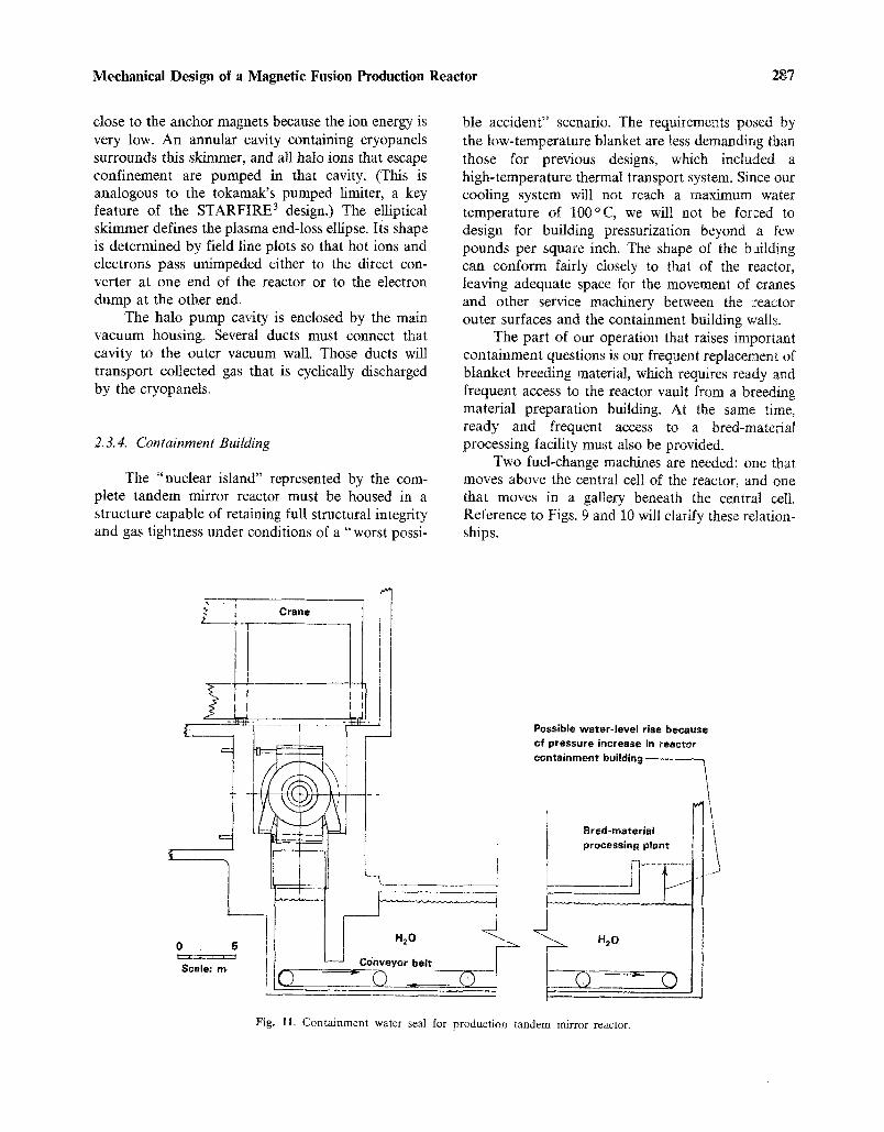
Two fuel-change machines are needed: one that moves above the central cell of the reactor, and one that moves in a gallery beneath the central cell. Reference to Figs. 9 and 10 will clarify these relation- ships.
E
0 5
Scale: m
Crane
0:=
! ____3 Possible water- level rise because
in r ~
11 .roooss,n ~
Fig. 11. Containment water seal for production tandem mirror reactor.

288 Neef and Jassby
An above-grade corridor leads from the reactor vault near the parked location of the top blanket- change machine to the factory, where slugs of breed- ing material are manufactured and stored for instal- lation. This corridor can be provided with a rolling shield door having inflatable gas seals. Common elastomers can probably be used in these seals be- cause radiation levels at the door are low enough to permit them to be used for many years before they become embrittled and must be replaced.
The situation at the bred-material discharge port, where radiation levels are high, is very different. We have chosen a conveyor belt that runs under 6 m of water as our means of egress to the bred-material processing facility. The lower blanket-change ma- chine receives its load while positioned directly be- neath the module being serviced. It then proceeds, together with its load, to the central dump station located mid-gallery. The reels of radioactive slug chains are lowered onto a moving conveyor at the bottom of a water channel. This underground chan- nel or "canal" is sealed by a foundation wall of the containment building, which forms a concrete cur- tain down to about 1 m from the moving conveyor belt (see Fig. 11). An increase in building pressure will cause the water level to rise in the channel outside the curtain. If a pressure change of 5 psi were to occur, the change in water level would be 3.52 m. Allowances for such a "surge" can easily be accom- modated by properly elevating the bred-material pro- cess equipment.
If preferable, a sliding "trap door" can be pro- vided at the point where the blanket-change machine drops its load onto the conveyor. Although this door seal would not be in a low-radiation environment, it would be somewhat protected by water if the door were positioned about 3 m deep in the canal. The protection afforded by 3 m of water should permit elastomer seals to be used.
2.4. Plant Layout
2.4.1. Reactor Containment
We have housed the fusion tandem mirror reactor and its module service bays in a reinforced concrete building 1.5-m-thick walls. The pressure containment requirements will be relatively low, probably less than I atm gauge, since we are using a low-temperature, low-pressure cooling system. The biological shielding afforded is ample, and tritium
permeation will be controlled by a thin steel shell inside the reinforced concrete structure. The standoff space between the shell and concrete will be vacuum-pumped to further reduce tritium loss to the environment.
To reduce costs, the building is sized for normal service activities on central-cell modules and barrier- cell magnets. The central-cell module assembly bay would be used for that activity. Abnormal service, such as a transition or anchor Yin-Yang coil failure, cannot be accomplished inside the containment shell. The wall of the building at the electron-dump end or at the direct converter end would have to be removed to extricate an anchor coil and would have to be rebuilt after magnet replacement. Such a process could require as much as 2 years of reactor down- time.
William Allen of the Bechtel Group, in re- viewing our layout, advised that the containment structure did not allow sufficient maintenance space around the reactor. We believe that more-detailed studies are necessary to define certain special mainte- nance scenarios. Although enlarging the building may prove advantageous, we chose to stay with our initial sizing for this first design.
2.4.2. Heat Transport
The blanket is cooled by a flowing water system designed for an exit temperature of about 90~ This water is pumped to nearby heat exchangers, where its temperature is lowered to 30 ~ C. The sec- ondary coolant is also water and it is pumped to a row of "wet" cooling towers for energy rejection to the atmosphere. If the plant were sited on a river, cooling water could be pumped from the river into the secondary loop.
The tritium loss to coolant will be minimized by an aluminum oxide barrier on the breeding slugs. A backup barrier is provided by double-walled heat- exchanger tubes, where the space between tubes is swept continually by high-pressure helium to purge any lost tritium into a trap and removal system. This loss would be due to permeation through the inside tube wall from the primary loop cooling water.
2.4.3. Facility Power
The plant requires 312 MW of power for con- tinuous operation. A small substation is required to supply this power from a local utility grid.

Mechanical Design of a Magnetic Fusion Production Reactor 289
2.4.4. Auxiliary Buildings
We made a very preliminary study and layout plan for the support buildings and are confident that no major structure has been overlooked. However, the Bechtel Group commented that the buildings would be extremely compact and recommends that future studies consider more generous space allo- cations for equipment areas (more laydown area).
The preliminary layout appears to us to be con- sistent with that provided for a tokamak reactor with an identical purpose and similar size (see Section 3.4.). Any error due to space allocations will prob- ably be less than 10% of the overall cost of such a production facility when extraction and processing plants are included.
2.5. Cost of Plant
Estimates were made to determine the cost of a tandem mirror reactor having a 50-m-long central cell. The end-plug magnet set was assumed to be a
scaled-down axicell design chosen in a 1981 eco- nomic study of possible end-plug magnet configura- tions. 4 Building costs were obtained with the help of William Allen of the Bechtel Group. The estimates are summarized in Table V. The costs of fuel pre- paration and bred-material processing facilities are not included in the table.
2.5.1. Magnets, Shielding Coil Force Structure
The cost of the end-plug magnet set is a major fraction of the cost of the nuclear island. Our most recent detailed cost estimate for an axicell magnet array was done in FY 1984 for the study reported in Ref. 5. In that study, we developed a cost algorithm based on current construction experience with MFTF-B magnets. We also employed a new estimate of the cost of a Nb3Sn superconductor.
The cost of vacuum-vessel enclosures for this magnet coil set is calculated in Section 2.5.5.
Magnet systems for end slugs, including magnet shields and structure
Choke coils Plug coils Transition coils Yin-Yang anchors Recircularizer coil Shields
Central-cell magnets Neutral beams and power supplies Microwaves
Direct converter with power conditioning
Copper insert-coil power supplies
Vacuum-system vessels
Tritium handling and pellet injection
Drift pumps
Blanket Neutron multiplier (Be) Structure
25.0
Instrumentation and control 70.0 Remote maintenance 64.0
Breeding-slug changeout machines 22.0 Top "planter" 16.5 Bottom "harvester" 5.5
Cooling systems 60,0 Heat-transfer system 33.0 Heat-rejection system 27.0
Balance of plant 167.0 Reactor containment building 30.0 Reactor auxiliaries (service) 28.0
Radiation waste building 6.0 Tritium building 12.0 Ventilation building 8.0 Cryogen/cs building 5.0 Electrical building 8.0 Electrical bulks (wire, cable
conduit, etc.) 38.0
Administration building 4.0 Mockup and shop building 11,0 Fuel-fabrication building 5.0 Site improvements 12.0
Total direct cost 1016.3 _ _ i
Table V. Cost Estimate ($Millions) for Production Tandem Mirror Reactor
Central-cell shield 200.8
55.3 38.1 19~7 34.4 14.2 39.0 60.5 10.0 50.0
6.0
10.0
30.0
150.0
5.0
86.0 84.0 2.0
290 Neef and Jassby
2.5.2. Neutral Beams
Estimates of total beam power result from a computer calculation of equilibrium plasma perfor- mance. Sloshing ion injection into barrier cell will be 13.4 MW.
Our most recent estimate of neutral beam injec- tor cost is $2/W. The standard unit-cost guide for fusion reactor design, prepared by Battelle, recom- mends $1.50/W in 1979 dollars. Some contingency is not inappropriate, and so we estimate $10 million as the cost of neutral beams for the complete reactor when power supplies are included.
2.5.3. Microwaves
The plasma performance calculation also yields an estimate of total electron-cyclotron resonance heating (ECRH) and ion-cyclotron resonance heat- ing (ICRH).
1. ICRH directed into MHD anchor cell (MW) 0.3 2. ECRH directed at potential peak in barrier 0.5
(MW) 3. ECRH directed at thermal barrier (MW) 11.1
Total resonance heating (MW) 11.9
Battelle's recommended cost estimate for ECRH was $5/W in 1979 dollars. Our recent experience in purchasing equipment for the MFTF-B experiment indicates that $5/W is still a good estimate in 1982 dollars. (This is in contrast to the WITAMIR-1 study at the University of Wisconsin, which used $2/W, and the STARFIRE study at ANL, which used $1.20/W.)
With a small contingency allowance, we assign $50 million as the cost of ECRH power.
2.5.4. Cost of Direct Converter, Power Conditioning, and Cryopumps
Again we refer to Ref. 5. The amount of power to the direct converters in FPD is only 40% of the amount in this production reactor design. Since the FPD costs for direct conversion totalled $4.7 million, which included the cost of inverters, we believe $11 million will cover those same items in this design. The slightly larger direct converter plates have some effect on the vacuum vessel cost, and that was in- cluded in our vessel estimates.
Two possible methods of pumping the halo plasma are being considered. One involves a large number of cryopumps, all pumping on the region separated from the main end vessel by the "halo scraper." The second method establishes a much higher pressure at the two ends of the halo by refluxing particles from the pump annulus into the region of the halo near the pumps. This method has not been demonstrated yet in fusion experiments. Even though the high pressure method promises to be economical, we present here estimates for the cryogenic method. Cryopaneling should cost less than $1 million. The 4.2-K and 78-K refrigeration system is the expensive part of the vacuum pumping, and its cost is estimated to be $5 million.
2.5.5. End Vacuum Tanks
One large cylindrical vacuum vessel is required at each end of the reactor. They house transition magnets, the Yin-Yang anchor-magnet pair, and the Yin-Yang plug-magnet pair with their attendant shields and force-restraining structures. Also housed is the direct converter.
We performed buckling calculations on simple shell designs to establish the wall thickness required. Our current cost estimate for type-316 stainless steel fabrications of this quality is $19.5/kg.
The costs of the direct converter and electron- dump housings are not included in these estimates. They are covered in Section 2.5.4.
Since there are two tanks, we calculate a total cost for end-plug vacuum vessels of $25.2 million.
2.5. 6. Blanket and Shield
The most significant cost element of the central-cell design is the beryllium neutron multi- plier. The cost estimates are consistent with previous estimates of central-cell costs for pure fusion ma- chines when the added cost of beryllium is taken into account.
2.5.6.1. First Wall. The mass of aluminum in the 50-m-long first-wall structure is 3240 kg. We believe that the quality of workmanship, degree of inspection, and assembly procedures will drive the cost to the equivalent of commercial jet aircraft construction, or to about $210/kg in 1982 dollars. Therefore, the first-wall assembly with its cooling tubes will cost about $680,000.
2.5.6.2. Beryllium. The beryllium in our blanket will probably be formed by "pressureless sintering,"

Mechanical Design of a Magnetic Fusion Production Reactor 291
a new process being developed by the Brush- Wellman Co. Our roughly 10-cm 3 blocks of material are well-suited in size and shape to this new process, which produces parts of approximately 98% theoreti- cal density.
The costs estimated by Brush-Wellman Co., the only domestic supplier of beryllium parts, are:
1. $110/lb for Be powder.
2. $100/lb for pressing and sintering.
3. $10/lb for machining.
No protective coating was assumed. We believe that a 100-/~m coating of aluminum will be desirable to retard the corrosion that might plug coolant paths and estimate the cost of this processing at $5/tb, giving us a total cost of $225/lb, or $495/kg. Our 50 + m of blanket requires 170,000 kg of beryllium- machined blocks at an estimated cost of $84 million.
2.5.6.3. Guide Tubes and Structure. The aluminum guide tubes have a volume fraction of 0.8%, and the module end plates occupy 3% of the total blanket volume of 1.156 • 108 cm 3. Thus, these aluminum parts have a mass of 11,862 kg. The unit cost for curved tubes with accurate contours and good surface finish will probably be comparable to the first-wall cost. The remaining welded-plate struc- ture will cost about half as much. We therefore estimate the cost at $125/kg for a total of $1.5 million.
2.5.6.4. Shield and Solenoid. The total shield volume is about 7• cm 3. Table VI shows our estimate of the volume percent and cost of various shield components.
The cost of the solenoid magnet was estimated from these requirements and known costs:
Required central-cell magnetic field (T) 4.0
MFTF-B solenoid ($/kg) 27.5
Shield o.d. (m) 2.54
Case structure ($/kg) 18.5
Each meter of central-cell length has one coil costing $595,000. The total cost of magnets for a 50-m-long central cell is, therefore, $29.75 million.
2.5.6.5. Total Central-Cell Cost: The total central-cell cost can now be summarized. It repre- sents the basic "empty" structure; that is, the cost of breeding slugs and their pull cables is not included.
Cost ($M)
First wall 0.7
Beryllium blocks 84.0
Guide tubes and structure 1.5
Shield 54.2
Solenoid coils and cases 29.8
Subtotal 170.2
15% contingency 25.5
Total 195.7
This represents a cost of $3.9 million/m for a 50-m-long blanket. Other blanket designs that do not employ beryllium as a neutron multiplier range in cost from $2 million to $3 million/m. Consider the cost of fabricated beryllium, we believe this estimate to be consistent with previous efforts on tandem mirror reactors and reasonable for this special ap- plication.
2.5.7. Building Cost
This cost estimate was based on very pre- liminary layouts of the reactor building and on a site layout comparable to the one proposed by the fusion Engineering Device design group at Oak Ridge, Ten- nessee, for a tokamak of similar complexity. (6)
The Bechtel Group Inc. assisted us and was critical of the preliminary design presented. Bechtel Group comments that the space allotted around the reactor to perform some maintenance operations was
Material
Table VI. Cost of Shield Components
Volume (%) Density (g/cm 3) Mass (kg) Cost ($/kg)
Lead-cement 50.0 9.6 3.35 x 10⁶ 2.5 Steel 30,0 7.85 1.65 x 10⁶ 19.5 Lead 10.0 11.35 0.79 • l06 10 B4C 0,5 2.5 8,750 600 Borated H20 5.0 1.1 38,500 10 Cooling H20 4.5
Total
Cost ($M)
8.4 32.2
7.9 5.3 0.4
54.2 i

292 Neef and Jassby
insufficient. We replied that all maintenance, except disaster repair, would be performed in adjacent hot cells in the reactor auxiliary buildings. Since a very low-temperature blanket will be used, the benefits accruing to the large building volume around a PWR or a breeder do not apply. A loss-of-cooling accident will not vent high-pressure, high-temperature steam into the containment structure.
Costs were estimated on the basis of the original LLNL layout. The costs of all buildings were esti- mated using unit costs based on building volumes. In 1982 dollars, the estimate covered four general classes of buildings:
1. Reactor containment buildings = $6600(V) ~
2. Reactor service buildings = $3300(V) ~
3. Steam generator buildings = $2200(V) ~
4. General maintenance and electrical equipment buildings = $1100(V) ~
The volume is based on external dimensions and is expressed in cubic meters.
The above costs were derived from a recent fission breeder plant design and may be higher than necessary since our criticality problems and accident scenarios are less severe.
2.5.7.1. Containment. Bechtel Group estimated the cost of a complex, including reactor containment, reactor service hot-cell bays, and fuel-transfer tunnel, at $82 million.
2.5. 7.2. Auxiliary Buildings. Estimates of the cost for radioactive waste, tritium processing, ventila- tion, cryogenics, and power supply buildings totaled $43 million.
2.5. 7.3. Cooling System. The cost of two cooling loops was estimated. The primary hot-water loop with all pumps, piping, and heat-exchangers is esti- mated at $33 milfion. The secondary loop or heat- rejection system, which also has pumps and several "wet" cooling towers, will cost about $27 million.
2.5.7.4. Electrical The cost for electrical equipment related to reactor system control, building functions, environment in the buildings, and power to run this material-producing reactor will total about $15 million. Electrical "bulks" such as wire, cable, cable trays, conduit, etc. for all buildings will cost about $65 million.
2.5.7.5. Tandem Mirror Refueling Machines. There are two track-mounted refueling machines, one above and one below the central cell. In Table VII, we have estimated their size and mean density, as
Table VII. Size, Mean Density, and Cost of Tandem Mirror Refueling Machines
Top Bottom
Size, rectangular prism (m) 3.5•215 3.5•215 Approximate mean density,
20% • solid steel 1.57 1.57 (tonnes/m 3)
Unit cost ($/kg) 50 50 Total cost ($M) 16.5 5.3
i
well as cost per unit mass, which is the only way to estimate cost without specific design information.
The total cost of the blanket changeout ma- chines is estimated at $22 million.
2.6. Fusion Component Replacement
The reactor parts that we expect to replace during the operating lifetime of the facility are read- ily accessible.
The central cell, which is composed of 25 mod- ules (each 2 m long), is serviced by a large gantry crane that spans the reactor. Each module is sep- arated from every other module by a pressurized metal-cushion vacuum seal. Depressurization of the seal elements and retraction by evacuating the seal housing provides the removal clearance needed to lift a module assembly from its operating position. A crane lowers the module to a transport truck that rolls through a doorway into the hot-cell service bay. This door is a massive concrete shield panel that normally separates the reactor bay from the hot cell. Figure 12 shows the module service path.
Direct converter elements and cryopanels are mounted in the end-cell vacuum tanks. The corru- gated end wall (a 180 ~ arc) of the direct converter tank has many separate rectangular end panels, each of which has cryopump sections mounted on it. One or more of these panels can be removed to provide access to the back of the direct converter array. Remote disassembly tools will be needed to detach a direct converter unit. The unit that needs replace- ment will be moved out of the reactor building through an airlock located in the end of the contain- ment building. A similar airlock will be provided at the electron dump end. Cryopanels may have to be replaced at that end.
Each end cell has two high-field copper insert magnets located at either end of the barrier coils, one

Mechanical Design of a Magnetic Fusion Production Reactor 293
J-- --1 _ _ ~, ~,-~-.,-~-~
Three-legged J gantry c r a n e -
4eat-exchanger
Hot cell for service of central-cell blanket module
z:=r
Shield doors
0 2 4 6 8 Scale (m) i,,i I I I 1 1 I 1 l c m = 2 m
- - ' : : 9
Fig. 12. Cross section at middle of production tandem mirror reactor.
of which is located at each end of the central cell. We expect that these "normal" coils will have to be removed and replaced as often as once every two years of reactor operation. The inboard magnet in- sert is readily accessible if two central-cell modules are temporarily moved to provide a path for coil removal. The removal path would then be identical to the end module of the central cell.
Access to the second barrier coil is more dif- ficult. The most probable scenario is to remove the inboard "normal" coil first and then move the out- board coil through the hole vacated by the inboard coil. Both copper coils will have elaborate cooling systems and flow distributors. The water supply and return ducts may also have to be replaced because of neutron damage. The primary design criteria for these copper coil assemblies must be ease of replace- ment. Studies for the MARS PROGRAM 1 by Gen- eral Dynamics Corporation addressed the detail de- sign of the two magnets, using a larger scale version of this same axicell end-plug design.
Previous reactor design studies have discussed replacement scenarios for reactor components. The only major difference between this reactor and previ-
ous designs is the "normal" barrier-coil inserts de- scribed above. The barrier coils, themselves, are not peculiar to this design. All future tandem mirror reactors will have the axicell end plug.
2.7. Blanket Replacement
2. 7.1. Bred-Material Replacement Time
The production material in this reactor is in the form of 3.6-cm-diameter by 3.6-cm-long cylinders (slugs) strung on a cable, much like pearls on a necklace. These strings of slugs must be pulled out of their blanket guide tubes and new strings must be inserted. Our means of accomplishing this is to use the two servicing machines described in Section 2.2.1. The time required to replace all of the chains in one central-cell module has been estimated at 16 h. Since there are 25 modules, changeout of the entire blanket would require a continuous, three-workshifts-per-day operation over a period of 17 days. With reasonable allowance for unplanned interruption, three weeks should be allowed for a complete changeout.

294 Neef and Jassby
We have studied another method of fuel change that allows continued reactor operation during fuel replacement. This method requires that each guide tube have a separate access port in the cover plate over the coolant plenum chamber and that each access port be provided with a ball valve. The ball-valve hole must be about 4 cm in diameter to allow fuel slugs to pass through.
An extraction machine couples to the ball-valve flange. This device is filled with water so that open- ing the ball valve does not change the flow path of the blanket cooling water. After valve opening, a cable probe coupler is inserted through the valve to attach to the bred-fuel cable.
At the top of the reactor, a similar machine will have attached a new fuel string to the tail of the bred string that is about to be extracted. The extracted string of slugs is wound on a storage reel within the water-filled body of the service machine. The ball valve is closed after the new string of slugs is re- leased. The service machine releases its seal to the lower ball-valve flange and is then transported to the "canal" discharge location, where the machine is upended and the collected string of slugs is allowed
to sink through the shielding water to the submerged conveyor belt.
This operation on one guide tube will consume about I h. There are roughly 6000 guide tubes in the complete reactor. If four pairs of change machines work simultaneously, they can completely replace all breeding slugs in about 63 days.
If no routine maintenance were required, this scenario would permit continuous reactor operation for many months. Fuel could be bred and extracted in a nearly continuous process, with about 200 slugs/h arriving at the fuel-processing end of the conveyor.
3. TOKAMAK PRODUCTION REACTOR WITH COLD-WATER-COOLED BLANKET
3.1. Blanket Configuration
We took the same blanket concept developed for the tandem mirror reactor and applied it to a TORFA-type tokamak fusion reactor. (7~ The extreme difference in geometry led to a system of "ducts," as
PF coil Inner blankE duct
OH solenoid (typ.)
Structural support / D e m o u n t a b l e TF coil joint (2 per coil) , / T n r ~ i r l ~ l f i A I r l r ~ ; I
tte
dal field
it
et duct or
s (typ.) ent flange
tltiplier
D iver tor coils
nt
:)loidal eld coil
Bottom cassette blanket Track /
Fig. 13. Tokamak TORFA-D2 without neutral beam port.

Mechanical Design of a Magnetic Fusion Production Reactor 295
Fig. 14. Tokamak TORFA-D2 with neutral beam port,
illustrated in Figs. 13-16. The ducts are so named because an array of breeding-slug guide tubes runs lengthwise in a duct. The guide tubes are at about 10-cm centerline spacing. The space between guide tubes is filled with a neutron multiplier (such as beryllium) and cooling water. In the guide tubes are strings of cylindrical slugs placed on a 3-mm-diame- ter pull cable, like pearls on a necklace. The strings of breeding material are pulled through the guide tubes in batches (or possibly in a slow, continuous changeout). As one enriched string is pulled out of the blanket duct, its replacement is attached to the tail end of the string and is pulled into the blanket.
The C-shaped ducts on the outside of the torus are subjected to the most neutrons. The breeding zone is about 40 cm thick; behind that zone is a 40-cm thick water reflector. The width of the duct is controlled by the gap available between adjacent
toroidal field coils. The coil cross section has been shaped to permit the widest possible duct consistent with mechanical support for the plasma vacuum and pol0idal divertor chamber.
The inboard side of the torus also requires a blanket. The duct in that area is 40 cm thick. The vertical portion of the duct does not need a water reflector. The TF coil copper leg in that region provides all the neutron reflection required. Access to the ends of the inboard duct can be achieved only by curving the duct radially outward both top and bottom, which also provides blanket coverage to the top and bottom of the plasma chamber. However, as reference to the top view reveals, this duct must widen as it moves out radially. Since the number of guide tubes in a duct remains constant, we com- pensate for the increased duct width by decreasing its thickness. This permits the ratio of breeding-slug
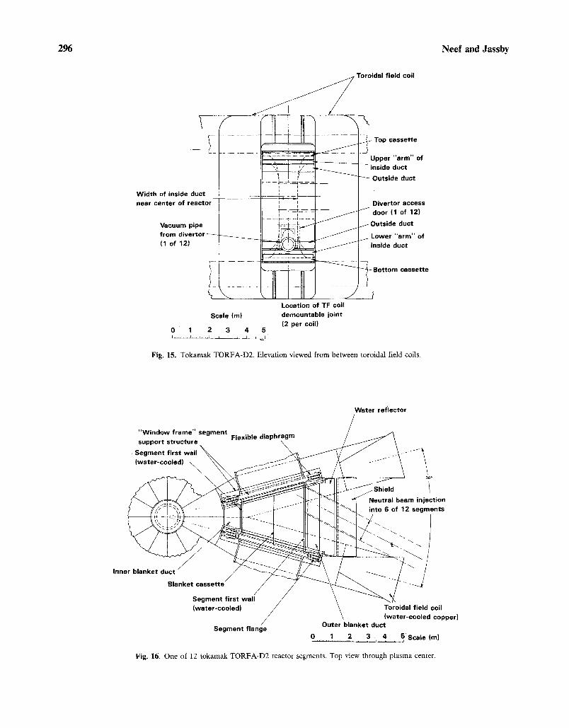
296 Neef and Jassby
Tn.~;~=l ~;=t d coil
sset te
=arm" of uc t
.= duct
Width of ins near center ~r access
I of 12)
Vacul duct
f rom 'a rm" of ( 1 of luct
t cassette
Scale (m)
0 1 2 3 4 5
Locat ion of TF coil demountable jo in t
(2 per coil)
Fig. 15. Tokamak TORFA-D2. Elevation viewed from between toroidal field coils.
Water ref lector
:tion .=nts
Inne
Segment f lange
;oil copper)
0 1 2 3 , 4 5, Scale (m) . . . . . . . . . . . . . . . . i i i L J
Fig. 16. One of 12 tokamak TORFA-D2 reactor segments. Top view through plasma center.

Mechanical Design of a Magnetic Fusion Production Reactor 297
volume to neutron-multiplier volume to remain con- stant.
The thinner duct will not utilize neutrons as efficiently. This suggests that two special blanket cassettes will probably be needed, one above and one below each inboard-duct arm. The breeding zone of the cassette can be tapered to match the reverse taper of the duct. Included as part of the cassette is the water-reflector region for the top (or bottom) of the blanket. The breeding material in the cassettes will not be handled in the same way as the "flow-strings" of slugs in the duct guide tubes. We imagine long, rigid rods of material, spaced in an array identical to guide-tube spacing. Those rods can be extracted with the cassettes in situ, or the cassette assemblies can be removed to a hot cell for replacement of the breeding material.
3.1.1. Breeding Slugs
The tritium breeding alloy of aluminum and lithium is machined into a cylinder about 3.6 cm in diameter with a 3-ram-diameter hole through the center. That cylinder is encased in a jacket of high-purity aluminum that provides a very effective diffusion barrier against the escape of tritium from the alloy.
The tokamak slugs can be identical to those described in Section 2.1.1. for a tandem mirror reac- tor.
3.1.2. Neutron Multiplier
Beryllium was chosen to serve as a neutron multiplier. It will be manufactured in the same manner as described previously in Section 2.1.2. for the tandem mirror reactor.
The length, width, and thickness of a nominal beryllium block will be about 10 cm. A thin coat of aluminum will also be used to retard corrosion by the 85 ~ C water coolant. As in the tandem mirror reac- tor, the 0.015-cm/year corrosion from the surface is not devastating to breeding. Our concern for the whereabouts of more than 1000 kg of beryllium in the cooling-system plumbing, as well as beryllium- produced tritium, drives the decision to add a coat- ing to the beryllium. We estimate that the cost of coating will have only a 270 effect on the cost of the beryllium.
3.1.3. Tokamak Thermal Hydraulics
Each duct and cassette will operate in parallel with all other ducts and cassettes. Master supply and return manifolds will encircle the reactor with throt- tling valves on the supply side to control flow rate so that exit flow temperatures are nearly the same for all circuits.
Each segment of the reactor (30 ~ between toroidal field coils) has two major ducts and two cassettes. Where beam ports are present, the outside duct is shorter and partially replaced by a cassette. The outer duct intercepts only about 40% of the neutrons leaving the plasma. Its large cross-sectional area (0.96 m 2) provides 480 cm 2 of coolant flow area. The Reynolds number for water flow, allowing a 60~ temperature rise, is 11,000. This translates to a pressure loss of less than 5 psi through the duct.
The inside duct, which also partially covers the wedge-shaped top and bottom of a segment, is about twice the length of the outside duct. Because of its large area of coverage, it intercepts about 35% of the plasma neutron power. To keep the duct coolant pressure as low as possible, we allow 10% coolant flow area instead of 5%, which was sufficient for the outer duct. This converts to about a 20-psi pressure drop in the 12.5-m-long duct.
The very wide and thin-walled duct with that much internal water pressure will not be able to hold its shape without internal vanes, which serve as tie rods between the flat sides. The presence of such vanes will detract somewhat from the percentage of neutron multiplier and add some undesirable para- sitic capture by additional structural fraction. The possibility of these vanes being made of zircaloy will be considered during further refinement of this de- sign.
The remaining 25% of the neutron energy will be deposited in the torus support frames, in the first-wall structure, and in the top and bottom cassettes. There are also losses up the beam injection ports that require extra cooling of neutral beam-line compo- nents. As a first guess, prior to neutronic analysis, we assign 10% to the structure, 5% to each of the two cassettes, and 5% to beam-line losses. The divertor hardware at the bottom of the torus will moderate fast neutrons so they will be incapable of (n,2n) reactions in beryllium. However, attenuation of the total neutron flux passing through the divertor region can be kept relatively small so that the number of tritons bred in the blanket regions under the divertor

298 Neef and Jassby
will be almost equal to the number of fusion neu- trons incident on the divertor.
The cooling circuit in a cassette will be different than in the ducts. Water will make a one-way pass through the cassette by piping it directly to the "blind" end of the cassette and allowing it to be heated by the breeding rods and incidental structure as it returns through the body of the cassette.
3.1.4. First-Wall Design
Where the tandem mirror blanket has an in- tegrated first wall forming part of each blanket mod- ule, the tokamak design uses a separate, stand-alone first-wall torus that has its own independent cooling system.
The method of fabricating and assembling the first wall is crucial to this whole concept of blanket ducts.
On the center plane of each of the 12 TF coils, but mounted on a rigid horizontal platform just above the lower legs of those coils, will be 12 "window-frame" structures with oval apertures. These "window frames" are a permanent part of the machine structure and serve as anchor points for the vacuum chamber segments. The lower semicircular portion of the oval torus cross section is used as the poloidal divertor pumping cavity. All of the torus volume above the divertor cavity is assumed to be occupied by the reacting plasma.
This design has 12 torus segments. Each seg- ment has a wide (about 20-cm) oval-shaped flange on each end. Radial inward translation of a torus seg- ment between a pair of TF coils allows the end flanges to mate with the stationary "window frames." The wide flange permits an unusual vacuum-sealing technique.
A differentially pumped multistage seal is em- ployed. It consists of thin sheet-metal diaphragms welded over 5-cm-wide shallow oval grooves on both sides of the "window frames." There will probably be three concentric oval seals. The two spaces be- tween the grooves will be differentially pumped. When the segment flanges are joined to the frames, the diaphragms are inflated to a pressure of about 500 psi.
The flange clamping is designed as follows: The inboard half of the "window frames" is completely inaccessible for welding or bolting. That half of the frames is provided with wedge-shaped female grooves that capture the leading edge of the torus-segment flanges during assembly. The outboard half is acces-
sible; we suggest using either closely spaced bolts or clamps for flange joining. Pressurization of the seal diaphragms will impose reaction forces on the bolts in the outer half of the frame and on the wedge walls that are welded (or bolted) to the inner half of the frame.
No structure of this size and weight can be manufactured to the tolerance required for these vacuum seals unless some intentional flexibility is designed into the structure. We provide that flexibil- ity by using special sheet-metal diaphragms between the two wide oval flanges and water-cooled spool that forms the oval first wall. These diaphragms are similar to the individual thin sheets that are welded at the inside and outside edges to form very flexible metal bellows. Figure 16 shows this feature.
3.1.5. Fabrication and Assembly Procedure
3.1.5.1. Ducts. Because there are many evenly distributed breeding-slug guide tubes in the neutron multiplier, each duct must be built up progressively in layers. The beryllium will be formed into ap- proximately 10-cm cubes that, except for intention- ally machined (or molded) grooves on the block surfaces that provide the necessary coolant passage area, are shaped to completely fill the void space between guide tubes.
Once assembled and pressure-tested, these ducts should serve for the life of the plant. If beryllium cracking occurs, the larger pieces cannot escape be- cause of their geometry. Any small fragments will be captured in a filter or may block a local flow chan- nel. A sufficient redundancy of blanket flow chan- nels will be provided to make this occurrence unim- portant.
3.1.5.2. Cassettes. The breeding material will be inserted into the neutron-multiplier matrix of a cas- sette as rigid rods in straight cylindrical holds. The absence of curved guide tubes will simplify assembly. To keep thermal stresses low and minimize the tend- ency for cracks to develop in the beryllium, these neutron multiplier blocks will also be kept small (probably around 10 cm). There is virtually no dif- ference between a cassette and a duct except for their overall dimensions and the use of straight breeding tubes instead of curved ones. The overall mass of the cassettes will be considerably less than the mass of the duct assemblies.
3.1.5.3. Order o f Assembly. The outline pre- sented here is not complete. Its purpose is to show the necessary order of operations and to mention

Mechanical Design of a Magnetic Fusion Production Reactor 299
certain structural requirements that must be satisfied during assembly. The steps listed here must be re- peated for each of the 12 reactor segments:
1. Install the center post and TF coil inner half.
2. Install the lower PF coils and the toms-sup- port floor that bridges over the bottom legs of the TF coils.
3. Erect 12 torus frame supports on the toms- support floor, one at each TF coil center plane.
4. Attach the "roof" platform that supports the top PF coils to either the center post or the inner TF coil legs (or both, depending on final shape and joint location in the TF coil). This platform must also support the weight of a portion of the inboard blanket duct.
5. Install the inboard blanket with its vertical leg bolted to a vertical leg of a TF coil. The torus support floor must support the hori- zontal lower portion of this duct. The hori- zontal upper portion is supported by the "roof" platform (see 4 above).
6. Install the torus segment by translating it radially inward between the TF coils and into contact with the fixed frames at the TF coil center plane. The inboard edge of the flanges enters wedge receptables on the in- board side of the frame. The outboard edge of the flanges must register properly so bolts can be installed along the accessible half of the flange perimeter. The seal is accom- plished by inflating differentially pumped diaphragms of metal (described in Section 3.1.4.).
7. Install the outer duct. It will be mounted to vertical plates that are part of the fixed "window frames."
8. Lower the one-piece PF coils into place outside the TF coils.
9. Insert the upper and lower cassettes any time after step 5.
3.1.6. Provisions for Beam Ports
Six neutral beam injectors will be used for plasma heating, current drive, and partial fueling. (8~ These beams will be injected at the plasma vertical center plane. Six of the twelve torus segments must have
beam ports, so the outer blanket duct must be drasti- cally altered to provide that space.
There is enough space below the beam ports to install a short C-shaped duct (no vertical straight section) that retains the guide-tube "flow-through" feature. Above the beam port, the tube bend radius would be too small (high friction). Instead, we will provide a cassette with a water reflector. It will have rod breeding material, rather than slugs like the top and bottom cassettes described in Section 3.1. All the rods will be short and of the same length, approach- ing the plasma approximately radially.
3.2. Fueling Scenario
3.2.1. Procedure for Installing and Removing Breeding Material
The ducts that enclose the breeding material guide tubes and neutron multiplier also serve to channel the blanket coolant flow. A plenum chamber at the inlet end of a duct supplies water to each guide tube and to the passages through the neutron multi- plier. That plenum chamber has a single inlet pipe fed by a large ring supply manifold that encircles the reactor. The exit-end plenum acts also as a common collector and returns water to a ring return manifold. To gain access to the open ends of breeding guide tubes, it is necessary to remove the cover plate that forms the end wall of the plenum chamber. Both plenum chambers can be opened by the "refueling" machine for removal and replacement of breeding material.
The neutral beam injector boxes around the periphery of the tokamak reactor are obstacles to the movement of a service or fuel-change machine that might otherwise travel on a circular track. Instead, we are proposing that a crane be used to lift the service machine into a position defined by floor- mounted dowels. Twelve such floor stations are re- quired to serve twelve 30 ~ reactor segments. In every case, it will be necessary to uncouple a neutral-beam injector line and move one beam-source box back to a parking location to clear the space needed to land the service machine for work on the blanket in a given segment. The machine requires a floor area that is about 4 m wide by 7 m long.
As with the tandem mirror reactor, we plan to use a string of fuel slugs on a cable (see Section 3.1.1.). When one string is removed, its replacement is pulled into position by being attached to the tail end of the string being removed. The "new" strings

300 Neef and Jassby
Tweiv( ' L ~ [ . . . . . J . . . . ' '
pass ft collect, in "bat
Concrete foundation for Torfa-D2 reactor
/ /
yor
Fuel-cht in one ( position
1
Neutral beam injector box (6).
Each must be retractable t o
clear space for fuel-change machine. Each position of " F "
requires retraction of one box ,
Fig. 17. Tokamak features affecting bred-fuel handling from blanket.
of breeding slugs will probably be held on circular reels in the fueling machine. As many as 50 strings may be changed simultaneously.
The strings being removed must be transferred to a reprocessing plant. This requires that the bred slugs be moved to a conveyor (or several conveyors) that runs a well-shielded path to the reprocessing building. One scenario requires a "trap door" and chute at each of the 12 service locations. Bred-fuel slugs can be fed (as strings or individually) into these discharge chutes that, like spokes of a wheel, carry the slugs to a single station for loading onto a conveyor belt. A plan view of the TORFA-D2 foun- dation is shown in Fig. 17. Since gravity plays a role, the central collection station will be several meters below the bottom of the lower TF coil legs. The chutes can be water-filled for shielding and could lead to an underwater conveyor similar to the one described in Section 2.2.1.
To get a new supply of breeding-slug strings, the service machine must be returned by crane to its parking location in a well-shielded corner of the main reactor bay. New breeding material is delivered from the fuel-fabrication building to this parking/loading station through an air-locked pas- sageway. This passage is pressure sealed and shielded during reactor operation.
3.2.2. General Description of Fueling Machine
The blanket service machine must be capable of changing the strings of breeding material in the inner and outer duct, as well as the breeding rods used by the cassettes.
The inner duct will have about 30 guide tubes, each 12.5 m long. Each tube will be supplied from a 4-m diameter reel. The 30 reels can be on a common axle and will occupy a width of about 3 m.
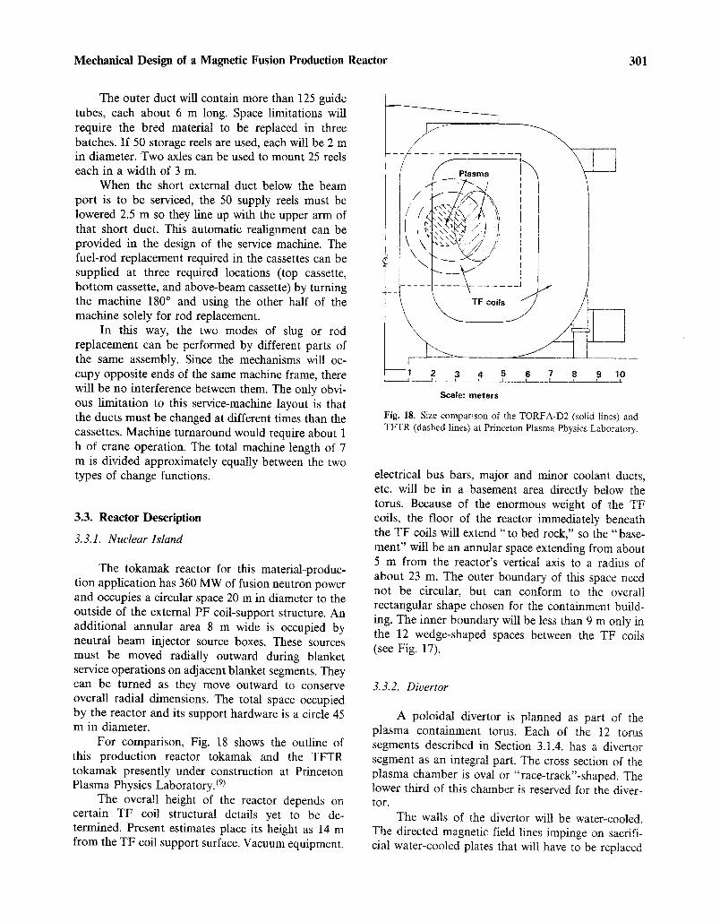
Mechanical Design of a Magnetic Fusion Production Reactor 301
The outer duct will contain more than 125 guide tubes, each about 6 m long. Space limitations will require the bred material to be replaced in three batches. If 50 storage reels are used, each will be 2 m in diameter. Two axles can be used to mount 25 reels each in a width of 3 m.
When the short external duct below the beam port is to be serviced, the 50 supply reels must be lowered 2.5 m so they line up with the upper arm of that short duct. This automatic realignment can be provided in the design of the service machine. The fuel-rod replacement required in the cassettes can be supplied at three required locations (top cassette, bottom cassette, and above-beam cassette) by turning the machine 180 ~ and using the other half of the machine solely for rod replacement.
In this way, the two modes of slug or rod replacement can be performed by different parts of the same assembly. Since the mechanisms will oc- cupy opposite ends of the same machine frame, there will be no interference between them. The only obvi- ous limitation to this service-machine layout is that the ducts must be changed at different times than the cassettes. Machine turnaround would require about 1 h of crane operation. The total machine length of 7 m is divided approximately equally between the two types of change functions.
3.3. Reactor Description
3.3.1. Nuclear Island
The tokamak reactor for this material-produc- tion application has 360 MW of fusion neutron power and occupies a circular space 20 m in diameter to the outside of the external PF coil-support structure. An additional annular area 8 m wide is occupied by neutral beam injector source boxes. These sources must be moved radially outward during blanket service operations on adjacent blanket segments. They can be turned as they move outward to conserve overall radial dimensions. The total space occupied by the reactor and its support hardware is a circle 45 m in diameter.
For comparison, Fig. 18 shows the outline of this production reactor tokamak and the TFTR tokamak presently under construction at Princeton Plasma Physics Laboratory. (9)
The overall height of the reactor depends on certain TF coil structural details yet to be de- termined. Present estimates place its height as 14 m from the TF coil support surface. Vacuum equipment,
I--
~ 7
Plasma
TF coils
2 3 4 5
Scale: meters
l
f
6 7 8 9 10
Fig. 18. Size comparison of the TORFA-D2 (solid lines) and TFTR (dashed lines) at Princeton Plasma Physics Laboratory.
electrical bus bars, major and minor coolant ducts, etc. will be in a basement area directly below the torus. Because of the enormous weight of the TF coils, the floor of the reactor immediately beneath the TF coils will extend "to bed rock," so the "base- ment" will be an annular space extending from about 5 m from the reactor's vertical axis to a radius of about 23 m. The outer boundary of this space need not be circular, but can conform to the overall rectangular shape chosen for the containment build- ing. The inner boundary will be less than 9 m only in the 12 wedge-shaped spaces between the TF coils (see Fig. 17).
3.3.2. Divertor
A poloidal divertor is planned as part of the plasma containment torus. Each of the 12 torus segments described in Section 3.1.4. has a divertor segment as an integral part. The cross section of the plasma chamber is oval or "race-track"-shaped. The lower third of this chamber is reserved for the diver- tor.
The walls of the divertor will be water-cooled. The directed magnetic field lines impinge on sacrifi- cial water-cooled plates that will have to be replaced

302 Neef and Jassby
periodically before they erode enough to uncover a coolant channel. Each divertor segment has an access door to the divertor's interior. This door is about 1 m 2 and utilizes differentially pumped, concentric metal gaskets. A special divertor service machine, located on the same reference dowels that position the blanket service machine, will work through that door to extract and replace wornout divertor armor.
Each of the 12 divertor service doors has a large circular pipe attached to provide continuous vacuum pumping of material entering the divertor. These vacuum pipes all connect to a master ring manifold under the reactor. The main vacuum pumps operate on the ring manifold and must produce a pressure estimated at 5 • 10 .8 Torr in that manifold. This means that the divertor pressure can be about 10 .7 Torr and that the plasma background pressure can be near 10 .6 Torr.
The poloidal coils that produce the field sep- aratrix are below the torus. The separatrix leads ions through slot-like apertures into the 12 divertor cham- bers. Because the coils in that location would be very hard to replace, two or more redundant coils will be provided. Should the primary divertor coil malfunc- tion, it can be replaced by two adjacent coils that have appropriate current sharing to keep the field separatrix in the same location.
3.3.3. Neutral Beams and Microwaves
Steady-state operation of TORFA-D2 is achieved by continuous injection of 150 MW of 250-keV neutral beams, which maintain the plasma temperature against transport and radiation losses and drive the plasma current required for equi- librium. (8~ The characteristics of the neutral beam injectors are shown below:
Beam energy (keV) 250
Injected power (MW) 150
Ion species (% D- ) 100
Overall electrical efficiency (%) 0.55
Number of injectors 6
Angles of injection
At 45 ~ to normal 4
At 20 ~ to normal 2
Duct cross section (cm) 80 • 120
An overall efficiency of at least 55% is expected to be achievable using the Lawrence Berkeley Laboratory
concept now under development, namely the Ehlers D- ion source coupled to a transverse-field focusing accelerator. The ion beam is to be neutralized by the photodetachment method, using an oxygen-iodine laser now being developed at the Air Force Weapons Laboratory and TRW.
Startup of the plasma current is accomplished over a 20-s period by three steps: (1) Two MW of RF energy at the electron cyclotron frequency ( - 100 GHz) ionizes the low-pressure tilling gas in the torus and increases T~ to about 10 eV. (2) The 10-Vs OH (ohmic heating) transformer establishes a current of approximately 500 kA at n e -1013 cm -3. (3) While the density is increased, neutral beams are, with the assistance of the increasing equilibrium field, injected to raise the current to its final value of 5.0 MA.
Only four neutral beam injectors are needed to sustain the plasma current. The OH transformer is not used after startup.
3.4. Plant Layout
The facilities required for operation of TORFA- D2 are listed in Table VIII (See Figs. 19 and 20). The general site arrangement is shown in Fig. 19.
3.4.1. Reactor Building and Hot Cell
Sections of the reactor building and hot cell are illustrated in Fig. 19. The reactor building holds TORFA-D2; it also serves as part of the radiation shielding system to protect operations in the rest of the plant. The walls and roof of this building are constructed of 2-m-thick concrete. The building also forms an integral part of the radioactivity confine- ment system (e.g., in the event of a tritium release). The building must be resistant to earthquakes and to wind-generated and accident-caused missiles.
The hot-cell facilities are provided so that major maintenance of reactor components can be carried out while the reactor itself is operating. Components are transported from the reactor building into the hot cell by overhead crane or by such surface transport as rails.
The reactor building is 60 m long, 50 m wide, and 40 m high. These dimensions are determined by the space need for the tokamak and neutral beam lines, component transport, lay-down areas for the PF coils, crane operations, and the maneuvering of

Mechanical Design of a Magnetic Fusion Production Reactor 303
0 Ventilation buildinq @ Tritium removal from bldg. systems | Motor-generator flywheel building | Transformer corridor @ Ohmic heatina and TF coil electrical ~ . . . . . . . . . . . . n | equ,pment (beam p.s. on 2nd floor} | Red waste treatment | Reactor buildinQ | Fuel-changeout machine loading/
\ unloading station E ] ~ V ] I ~ ] { ~ E ] Cooling towers Circulating water p u m ~ r ~ it house Water i n t a k ~ R ~ ~ t Electrical switchyard
\ ~ [ ~ Vent s t a c k ~ - ] ~ I ]l Cryo- [[ Water treatment J~'---I I H r / IE e II | t II | 2~ Iq . . . . . '1
t Z Jland shopi Hot-~-e3Yfacility, ~ ) )/ | , I =nd = e~ I u r . " . . . . . . n I - I ~ ~ ~ - ' ~ ] J ~ | ---~ 11 PF coil Fuel ,
�9 ~- [ r r a - _ ! I IIJ I f a b . R,ver t | d,ated I /I ~ U I fuel~--n-J ~ ano JI ] ~ ~ / - ~- ) [ - - - - - supply
�9 " / " - - - r r tt U1 / Parking lot ~IA~ ministrati~ [1 Parking lot ] I I
building IJ I I
/ I/" "Jl I I o 2s so Scale (m) I
F i g . 19. P l a n t l a y o u t f o r t o k a m a k T O R F A - D 2 .
maintenance and blanket fueling equipment. The building height allows for clearance of the bucking cylinder and OH solenoid over the top of the reactor.
The basement area houses the vacuum pumps and heat exchangers for the plasma vessel and blan- ket ducts. This arrangement permits the potentially radioactive coolant systems to remain within the reactor building confinement boundary. Much of the piping and cables needed to operate TORFA-D2 will also come through the basement area.
The hot cell is a large general-purpose facility for the disassembly and repair of reactor compo- nents. It also contains smaller cells for decontamina- tion and for storage of radioactive but reusable com- ponents. In overall dimensions, the hot cell is 75 m long, 50 m wide, and 30 m high. The walls and roof of the hot cell are constructed of 2-m-thick concrete, and the building is resistant to earthquakes and missiles. Both the reactor room and hot cell have controlled ventilation.
3.4. 2. Heat Transport
The magnets, blankets, vacuum vessel, and neu- tral beam injectors of TORFA-D2 are cooled directly
by recirculating water. The total peak thermal power to be removed is 1190 MW.
Figure 20 shows an estimated power flow di- agram for the TORFA-D2 reactor. This low-temper- ature blanket is not capable of producing electrical power with acceptable efficiency~ (Further studies are planned with a higher coolant exit temperature. Elec- tricity production, as a byproduct, may prove eco- nomically interesting.)
Figure 21 shows an estimated power flow di- agram for the TMR for comparison purposes.
The primary purposes of the cooling-system structures are to house the circulating water system and to provide adequate heat-removal capacity. The cooling system consists of compressors, pumps, pipes, valves, heat exchangers, and cooling towers. (Heat conversion to electricity is an option recommended for consideration in a follow-on study.) The facilities required to support the cooling system include a water treatment building for purification, a water pump house, and cooling towers (see Fig. 19). Natu- ral draft cooling towers, each of 100-MW capacity, are recommended to minimize operating and mainte- nance costs.
A water-intake structure obtains water from a nearby river for cooling-tower makeup. A water

304 Neef and Jassby
Tokamak 270;~W~ Neutral beam ~1,150 MW 1 ~ I
injectors ,ou ,v, vv Fusion plasma
heat ] Blanket 2 2 0 ; ~ T~ 22~0MW 360MwM = 1.5
coils
heat 50 MWe] Poloidsl field /
co,,
lt 3O.Wel ~ulu, ~ 1-0 iWe [ Coolant systems for |
I - -~ ' - ] blanket, first wall, I ---~--- | L and d i v e r t o r _ J 10 MY
. heat
5 i ~ V:::::s P u m pin g 5h~eMatW
5M .,AC and p,ant /
[ m i s c e l l a n e ~ 5 M ~ W Assumptions heat 1. Steady-state operation 2. Cold blankets 3. Fusion energy gain = 3.0 = Qplasma 4. Neutral beam injector efficiency = 0.55
(electric power to injected power) 5, Spatially averaged blanket energy
multiplication = 1.5
Neutrons--
90 M W 54 , Alphas I M~
150 !1 I
Total rejected heat = 1190MW
Fig. 20. Power-flow diagram for tokamak TORFA-D2.
treatment plant purifies the water according to its intended use; for example, the cooling water for the magnets must be deionized.
3.4.3. Facility Power
The steady-state power of 560 MW required to operate the magnets, neutral-beam injectors, and coolant and pumping systems is taken directly from the utility grid via transformer-rectifier systems (see Fig. 20). Pulsed dc power is also required during startup for the OH and EF systems and is obtained from 2 MGF sets delivering a total of 4 GJ. Follow- ing startup, the EF and divertor coils are operated directly off the grid, while the OH coils are deactivated.
Five buildings house the power-conversion sys- tems:
1. TF coil electric equipment building.
2. OH and PF coil electrical equipment build- ing.
3. Neutral beam injector power supply build- ing.
4. MGF building, containing 2 MGF sets mounted in pits in the floor.
5. Diesel generator building, for emergency power.
The transformer corridors shown in Fig. 19 arc required to bring ac power from the transformers mounted in the electrical switchyard to air-cooled rectifiers that may be mounted on the roofs of the buildings listed above.
The TF coils are fed by a 500-kA buswork system. Water-cooled copper buses are used inside the reactor building while large air-cooled aluminum slabs are used outside. To minimize bus separation forces, each copper bus has a concentric return while alternate aluminum slabs carry current in opposite directions.

Mechanical Design of a Magnetic Fusion Production Reactor 3t15
126 MW
....... 8 4 ~ M w
210 MWe Neutral beam
~ injectors heat
4 2 ~ e ~ ECRH and ICRH 21~MW
t heat
Electric ~ [Axicell copper, coils , grid l ~ ' heat 312 MWe I _ I total ~ 1 0 ~ Coolant systems for ~,1
blanket, first wall, -~=~--- and divertor ,0oiW
5 MWe t V, acuum pumping I ]systems [ 5 MW
heat
5 ~ HVAC and plant j 5 ~ M W miscellaneous
heat
Assumptions 1. Steady-state operation 2. Cold blankets 3, Fusion energy gain = 4.5 aplasrna;
Oplasma X ntrappe d ~ 2.6 4. Neutral beam injector efficiency = 0.60
(electric power to injected power) 5. Spatially averaged blanket energy
multiplication = 1.5
Fusion plasma
I Blanket ] 21 MW M = 1,5
o.w I neu_trons ]
[ MW I
Total rejected heat = 841 MW
Fig. 21. Power-flow diagram for TMR
3.4.4. Auxiliary Buildings
The auxiliary buildings are listed in Table VIII and include the electrical power buildings discussed in the previous section. The radioactive waste build- ing houses the processing and packaging systems for disposal of the low-level radioactive wastes produced within the plant. The control room, which is part of the administration building, houses the plant oper- ators. The mockup and shops building provides space for full-scale mockups of reactor sectors, as well as electrical, mechanical, and vacuum shops. The small cryogenic building supplies liquid helium for the super-conducting PF coils and for some vacuum pumping systems.
The ventilation building holds the voluminous equipment needed to control the air flow and also provides for tritium cleanup within the reactor build- ing, hot-cell facility, and adjacent areas.
3.5. Cost of Plant
The following guidelines were used to develop cost estimates:
1. All costs are in 1982 dollars.
2. Direct capital costs include procurement, fabrication, and shipping.
3. Indirect costs include (a) engineering, de- sign, and management (30%); (b) inspection, installation, and assembly (10%).
4. R&D costs are omitted.
Table VIII gives the estimated direct costs of the major components of TORFA-D2. Adding a 300% overall contingency to the sum of the direct and indirect costs gives a total capital cost of $2060 million.

306 Neef and Jassby
Magnet systems TF coils 113 PF coils 22 Bucking cylinder 2 Intercoil structure 8 OH solenoid 3
Shielding (excludes blankets)
Table VIII. Cost Estimates ($Millions) for TORFA-D2
148 Blanket Neutron multiplier ducts and
cases and miscellaneous Structure
Cooling systems excludes blankets) Refrigeration 3 Heat-transport loops 16 Cooling tower 15
Tritium handling and pellet injection Primary fuel cycle 13 Detritiation systems 18 Cleanup systems 14
Plasma heating Neutral beam systems 300 RF systems (ECRH) 15
Electrical systems PF electrical 38 TF electrical 12 AC power conversion 36
Vacuum system Vacuum vessel 22 Divertor modules and ducts 18 Vacuum pumps 1 Torus support 2
45
100 3
34
45
315
86
43
Blanket cooling system Heat-transport loops 25 Cooling tower 20
Instrumentation and control Plasma and blanket diagnostics Information and control systems
32 35
Remote maintenance equipment In reactor building 33 In hot cell 27
Blanket fuel-changeout machine
Facilities Reactor building 44 Hot cell 41 Electrical equipment building 8 Mockup and shop building 11 Tritium processing building 14 Ventilation building 12 Radioactive waste building 6 Administration building 4 Fuel-fabrication building 5 Site improvements 12 Cryogenics building 3 Electrical equipment building 15
103
45
67
60
12
175
Total 1178
Some additional cost information is included in the following subsections.
3.5.1. Magnets
The cost of the copper magnets is taken as $35/kg fabricated. That of the stainless steel support structure for the TF coils is taken as $22/kg fabri- cated.
3. 5. 2. Neutral Beam Injectors
The actual cost of neutral beam injectors for the TFTR and the estimated cost for future test reactors is about $2/W of injected beam. We use this value in our costing studies.
3.5. 3. Microwaves
Radiofrequency sources providing 200 kW for 10-ms pulses at 60 GHz exist today. High-pulsed sources in the frequency range 90-100 GHz are presently under development and are projected to cost $7/W.
3.5.4. Electrical Systems
The cost of transformer-rectifier systems is taken as $100/kW and that of MGF sets is taken as $1500/MJ. See Fig. 20 for the power requirements of the reactor subsystems. The cost of the neutral beam power supplies is included in the $2/W quoted above.
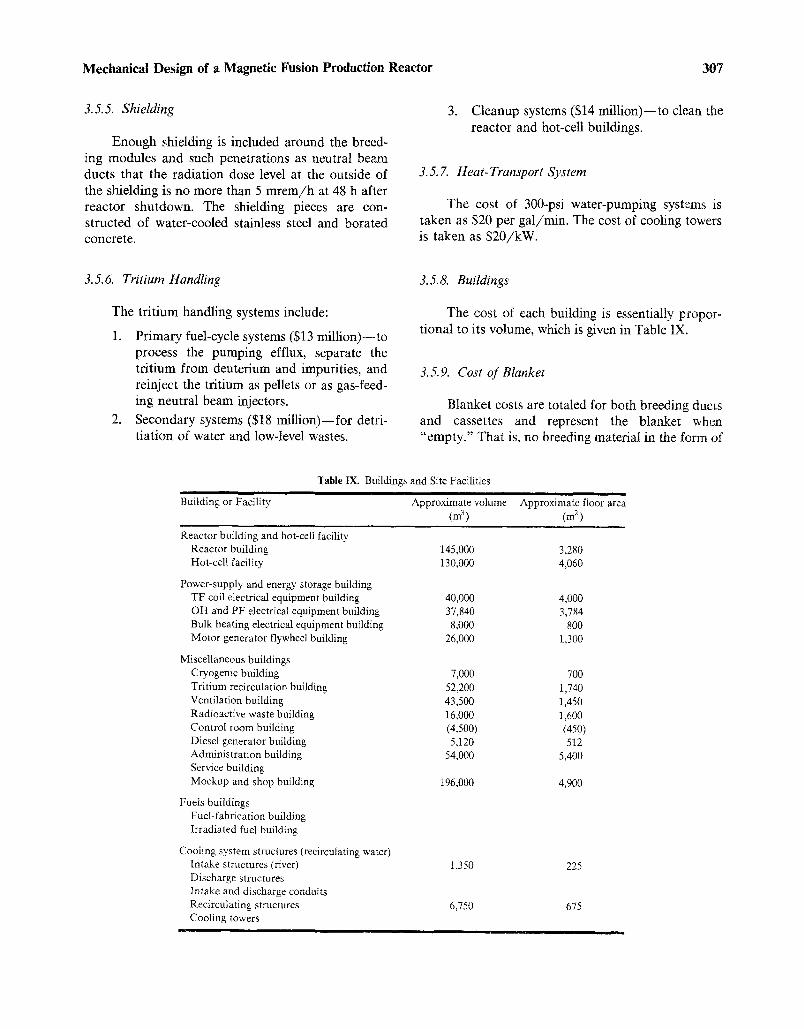
Mechanical Design of a Magnetic Fusion Production Reactor 307
3.5.5. Shielding
Enough shielding is included around the breed- ing modules and such penetrations as neutral beam ducts that the radiation dose level at the outside of the shielding is no more than 5 mrem/h at 48 h after reactor shutdown. The shielding pieces are con- structed of water-cooled stainless steel and borated concrete.
3. Cleanup systems ($14 million)-- to clean the reactor and hot-cell buildings.
3.5. 7. Heat- Transport System
The cost of 300-psi water-pumping systems is taken as $20 per gal/min. The cost of cooling towers is taken as $20/kW.
3.5.6. Tritium Handling
The tritium handling systems include:
1. Primary fuel-cycle systems ($13 million)--to process the pumping efflux, separate the tritium from deuterium and impurities, and reinject the tritium as pellets or as gas-feed- ing neutral beam injectors.
2. Secondary systems ($18 million) - - for detri- tiation of water and low-level wastes.
3.5.8. Buildings
The cost of each building is essentially propor- tional to its volume, which is given in Table IX.
3.5. 9. Cost of Blanket
Blanket costs are totaled for both breeding ducts and cassettes and represent the blanket when "empty." That is, no breeding material in the form of
Building or Facility
Table IX. Buildings and Site Facilities i i i , i
Approximate volume (m 3 )
i i i , i
Approximate floor area (m 2)
Reactor building and hot-cell facility Reactor building Hot-cell facility
Power-supply and energy-storage building TF coil electrical equipment building OH and PF electrical equipment building Bulk heating electrical equipment building Motor generator flywheel building
Miscellaneous buildings Cryogenic building Tritium recirculation building Ventilation building Radioactive waste building Control room building Diesel generator building Administration building Service building Mockup and shop building
Fuels buildings Fuel-fabrication building Irradiated fuel building
Cooling system structures (reeirculating water) Intake structures (river) Discharge structures Intake and discharge conduits Recirculating structures Cooling towers
i
145,000 130,000
40,000 37,840 8,000
26,000
7,000 52,200 43,500 16,000 (4,500) 5,120
54,0O0
196,000
1,350
6,750
3,280 4,060
4,000 3,784
800 1,300
700 1,740 1,450 1,600 (450) 512
5,400
4,900
225
675

308 Nee f and Jassby
Table X. Volume Fraction (%) of Blanket Components
Aluminum guide tubes 1.0 Fuel slugs 11.0 Neutron multiplier 79.4 Structure 3.5 Coolant 5.0 Pull cables 0.1
slugs or rods is included. The gross volume of the blanket costed here is 1.44 x 108 cm 3.
The structure enclosing the ducts and cassettes is assumed to be stainless steel and worth $19.50/kg as fabricated and assembled. The guide tubes are aluminum and will average about $210/kg, consider- ing accurate forming, good surface finish, and special packaging for shipment. The beryllium cost is the same as for the TMR blanket on a unit-cost basis. The material fractions present are shown in Table X.
The cost summary is given in Table XI. Section 2.5.6. substantiates the unit costs in Table XI.
3.5.9.1. Beryllium Cost. As with the tandem mirror reactor blanket (see Section 2.5.6.2.), the beryllium neutron multiplier will probably be cold pressed from powder and then sintered to about 98% theoretical density. The parts will be similar to those used in the T M R and will have maximum dimen- sions of about 10 cm.
The same cost estimates apply and, with a thin coat of aluminum for corrosion protection, the unit mass price is estimated at $495/kg. This totals $99.5 million for all the TORFA-D2 blanket sections.
3.5.9.2. Guide-Tube Cost. The aluminum guide tubes will have the same total mass as the jackets on the breeding slugs. Fabrication costs per unit mass are about the same, but handling and packaging for shipment are much more difficult. The reactor re- quires about 2500 tubes, many as long as 13 m, bent in a U-shape. We estimate the cost per tube at $500 and the total at $1.3 million.
3.5.9.3. Duct Cost and Cassette Case Coat. The duct and cassette structure represents about 4% of the gross volume of the breeding blanket zone. Also required is a water reflector at the back of the breeding zone; the container for that water is costed as part of the ducts.
The total volume of the breeding zone is 1.44 • 108 cm 3. The duct structure is aluminum. The water reflector casings add about 60% to the blanket volume (some duct regions are not backed by water reflec- tors). We estimate the 15,500 kg of blanket duct structure will increase to 25,000 kg when reflectors are added.
Unit cost is estimated at $50/kg for aluminum structures of that size and shape. The casings for the entire blanket consist of the following:
1. 12 inner blanket ducts
2. 6 outer blanket "long" ducts
3. 6 outer blanket "short" ducts
4. 6 outer blanket cassettes
5. 12 top blanket cassettes
6. 12 bottom blanket cassettes
The total cost for the empty structures is esti- mated at $1.25 million.
3.5.10. Tokamak Refueling Machine
With no specific design, there is only one way besides by comparison to estimate the cost of the refueling machine- -by its size and shape and material density. The overall size of the machine is known approximately. A reasonable estimate of material density can be deduced from the type of construction required. We can also compare this type of machin- ery to similar machinery whose unit cost is known (S/uni t mass).
1. Size and shape: 10 m h ighx3 m wide• m long = 150 m 3.
Material
Aluminum Beryllium Stainless steel
Total
a98% full density.
Table XI. Blanket Costs
Volume (%) Density (g/cm 3) Mass (kg) Unit cost ($/kg) Cost ($M)
1.0 23 3,888 50.0 0.2 79.4 ~ 1.81 207,000 495.0 102.0 3.5 7.85 39,564 19.5 0,8
103
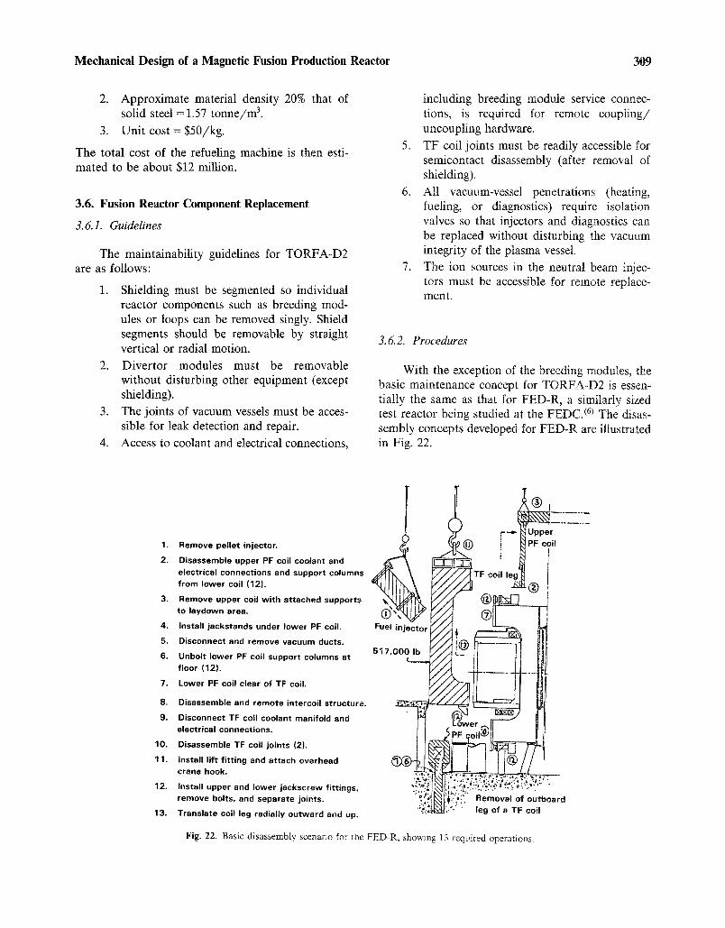
Mechanical Design of a Magnetic Fusion Production Reactor 309
2. Approximate material density 20% that of solid steel = 1.57 tonne /m 3.
3. Unit cost = $50/kg.
The total cost of the refueling machine is then esti- mated to be about $12 million.
3.6. Fusion Reactor Component Replacement
3.6.1. Guidelines
The maintainability guidelines for TORFA-D2 are as follows:
1. Shielding must be segmented so individual reactor components such as breeding mod- ules or loops can be removed singly. Shield segments should be removable by straight vertical or radial motion.
2. Divertor modules must be removable without disturbing other equipment (except shielding).
3. The joints of vacuum vessels must be acces- sible for leak detection and repair.
4. Access to coolant and electrical connections,
including breeding module service connec- tions, is required for remote coupling/ uncoupling hardware.
5. TF coil joints must be readily accessible for semicontact disassembly (after removal of shielding).
6. All vacuum-vessel penetrations (heating, fueling, or diagnostics) require isolation valves so that injectors and diagnostics can be replaced without disturbing the vacuum integrity of the plasma vessel.
7. The ion sources in the neutral beam injec- tors must be accessible for remote replace- ment.
3. 6. 2. Procedures
With the exception of the breeding modules, the basic maintenance concept for TORFA-D2 is essen- tially the same as that for FED-R, a similarly sized test reactor being studied at the FEDC. (6) The disas- sembly concepts developed for FED-R are illustrated in Fig. 22.
1. Remove pel let injector.
2. Disassemble upper PF coil coolant and
electrical connections and support columns f rom lower coil (12).
3. Remove upper coil w i th at tached supports to laydown area.
4. Install jackstands under lower PF coil.
5. Disconnect and remove vacuum ducts.
6. Unbolt lower PF coil support columns at f loor (12).
7. Lower PF coil clear of TF coil.
8. Disassemble and remote intercoi l structure.
9. Disconnect TF coil coolant manifold and electrical connections.
10. Disassemble TF coil joints (2).
11. Install l i f t fitting and attach overhead crane hook.
12. Install upper and lower jackscrew fittings, remove bolts, and separate joints.
13, Translate coil leg radial ly ou tward and up.
4 d
Fuel
517,
Fig. 22. Basic disassembly scenario for the FED-R, showing 13 required operations.

310 Neef and Jassby
A preliminary list of basic maintenance equip- ment for the fusion device magnets includes the overhead crane, hoist cables, lighting fixtures for the TF coil outboard legs and upper PF coil segments, TF coil bolt extractors (1.7 m pull), TF coil joint separators, and jackstands.
3.6.3. Removal of PF and TF Coils
Each internal PF coil has three joints located at 120 ~ intervals. Through bolts at each joint clamp the individual turns together. The PF coils are removed by first removing two TF coil outboard legs, then unbolting the PF coil joints and withdrawing the three segments.
Each TF coil has two joints, each containing about 50 fingers. The joints can be disassembled by semicontact operation (i.e., with long-handled tools) because the dose rate at the joint is 20 mrem/h at 48 h after reactor shutdown. A TF coil outboard leg weighs about 250 tonnes.
After the two joints are disassembled, the coil leg is moved 1.5 m radially outward, then lifted vertically. The total time for this operation is 100 to 150 h, which is dominated by the time needed to disassemble the joints. A reduction in time may be possible if alternate concepts for demountable joints are used.
After one or more outboard TF coil legs are removed, internal components such as PF coils and vacuum vessel sections can be retracted as shown in Fig. 22. Divertor modules can be replaced without prior disassembly of a TF coil.
3.7. Blanket Replacement
3. 7.1. Material Replacement Time and Cost
In each 30 ~ segment of the tokamak are about 120 chains of breeding slugs that must be replaced. Each segment also has fuel rods from cassettes that must be changed periodically. Segments that do not have beam ports have 96 breeding rods divided among two cassettes. Those segments with beam ports have an additional 240 short rods in the cassette above the beam port.
We believe it will be most economical to remove the entire cassette assembly and replace it with a complete new assembly. The removed cassettes would return with the service machine to its shielded park- ing area in the reactor bay. From that point, the
cassettes could be transported to the fuel-processing building in a heavily shielded shuttle car traveling in a tunnel parallel to the one containing the slug conveyor belt. The same shuttle car would return with emptied cassettes, which it would deliver to the fuel preparation facility for reloading with new rods.
The blanket configuration permits the fuel- changing machine to remove two or three cassettes simultaneously (depending on the segment being serviced). This removal and reassembly operation would require one 8-h shift.
To changeout the duct fuel chains, the fuel- changing machine must be turned 180 ~ and be re- mounted on the floor dowels. Replacement of the 120 fuel chains would probably be accomplished in three groups of 40 each. The machine will have to return to its shielded parking station after each group of 40 chains has been replaced to get a new supply of slug chains. This operation will require about two 8-h shifts when turnaround and resupply are included. Therefore, one full day is occupied by the fuel change of one segment. Since blanket sections will be miss- ing during this scenario (the cassettes), neutron pro- duction will have to stop during this period. The copper magnets will be shut off during fuel change. This added time for shutdown and restart adds per- haps 4 h to the overall time, making a total of 28 h.
If total blanket fuel replacement is desired in all 12 segments, we predict that the time required will be 14 days. A cycle period of 2 months would result in 77% reactor availability if routine maintenance can be completed during the blanket-change period.
Should zoned breeding be advantageous, the above scenario would have to be changed. The top and bottom cassettes would be changed less fre- quently because they represent the rear zone of the blanket. Other rear zones are present in the ducts, so individual guide-tube rows would also have to be changed less frequently.
3. 7.2. Beryllium Refabrication
Impurities (principally iron and nickel) can be minimized but not totally eliminated in the beryllium blocks. This neutron multiplier is likely, after several years' exposure to thermonuclear neutrons, to show swelling, spatling, and cracking. The coolant may also corrode unplanned exposed surfaces that are not protected by the aluminum anticorrosion layer.
It may be necessary to replace the beryllium several times during the 40-y life of a production

Mechanical Design of a Magnetic Fusion Production Reactor 311
reactor. Removal and total disassembly of the ducts will be necessary. The total and bottom cassettes may never have to be refabricated because they are at the rear of the blanket.
Once the other duct wall is cut away, the beryl- lium blocks can be removed by a robot. Neutron activation of trace impurities will make this neces- sary. To separate plated aluminum, the beryllium will have to be chemically treated. Each block will then be reduced to powder (chips) by grinding or other mechanical abrasion. It may prove desirable to melt and zone-refine the beryllium to remove impurities resulting from corrosion chemistry. If so, formation of the powder would be accomplished after melting and recasting of billets.
The same pressing, sintering, and machining op- erations used to make the first set of blanket parts can be employed on reprocessed beryllium, but they must be carried out remotely! The impurities present in the beryllium will still contain dangerous levels of induced radioactivity. Our national resources of beryllium are insufficient to consider disposing of thousands of tonnes of "used" beryllium and recon- structing the blanket with virgin material.
4. CONCLUSIONS
4.1. Qualitative Comparison of the Two Reactors from Mechanical Design Point of View
4.1.1. General Shape
The obvious difference between the tandem mir- ror and tokamak reactors is the compact form of the TORFA-D2 "donut" when contrasted to the linear form of a tandem mirror. The overall building volume required to house a tokamak is about two-thirds that required for a tandem mirror of the same fusion power. The tandem mirror, however, has the ad- vantage of practicality in its shape besides the obvi- ously simpler manufacturing geometry of a cylinder versus a torus. Two blanket servicing machines, one planting and one harvesting, can easily work simulta- neously on a TMR (one above the central cell and one below).
The tokamak can only be approached from one side, the outside of the torus. Poloidal field coils and machine supports preclude access from above or below. The presence of TF coils restricts access to the outside of the torus. The tandem mirror also has
magnets covering 30 to 50% of the central cell, so neither design has an advantage.
The blanket servicing machine for the tokamak must be larger and hence heavier than that for the tandem mirror. It plants and harvests, one function above the other, simultaneously. For complete blan- ket service, this heavier machine must be lifted 12 times from one operating position to the next. It cannot roll on a circular track because of the pres- ence of six neutral beam source boxes (see next section).
4.1.2. Beam Aperture
The central cell of the tandem mirror reactor does not have neutral beam apertures. All beam injection in a tandem mirror is into the barrier cells and quadrupole anchors that provide the end plugs for the reacting plasma column. The fractional cover- age of central-cell plasma by the breeding blanket reaches about 95% even when end-loss neutron streaming is taken into account. The tandem mirror also has reacting plasma in nonblanket regions of the end plugs. No calculation of this effect has been completed. We estimate that this end-plug rate could reach 10 to 15% of the total rate and that overall neutron losses could reach 15-20%.
Plasma heating in the TORFA-D2 tokamak is accomplished by direct beam injection i~,to the re- acting plasma toroidal column. The amount of en- ergetic beam required calls for six beam ports. Half of the 12 TF coil intervals must provide a window for beam entrance. The blanket coverage in that window is sacrificed. The necessary position of that window is "prime real estate" for the blanket since neutron wall loading tends to be greater in equatorial regions at the outer wall. We estimate that 17% of the 14.6 MeV neutrons are lost due to incomplete blan- ket coverage because of beam ducts and other penetrations, especially the divertor hardware.
4.1.3. Magnets
The tandem mirror reactor has copper insert coils in the end-barrier cells. The requirement for magnetic fields in excess of 20 T in those regions forces us to use normal conductor. Only those parts of the barrier coils that experience fields of less than 15 T can be of niobium-tin superconductor. Where the field drops below 9 T, niobium-titanium will be

312 Neef and Jassby
used. The power consumed by the copper inserts has been calculated to be about 60 MW. All other mag- nets in the tandem mirror reactor are superconduct- ing, both in the central cell and the end plugs.
The TORFA-D2 tokamak reactor uses normal, water-cooled copper TF coils. Also, those PF coils that lie within the TF coil loop are normal copper. Two poloidal coils that lie outside the TF coils are planned to be of niobium-titanium superconductor. The power consumed by all the normal copper mag- nets is 270 MW.
The normal coils are demountable. In weeks, they permit maintenance and repairs to be made that would require a year or more if the TF coils were superconducting. This demountable design greatly lowers the time and cost of scheduled maintenance. It also reduces the consequences of unplanned reac- tor shutdown.
4.1.4. Blanket Comparisons
The construction and serviceability of the tandem mirror reactor blanket modules give it several advantages over the tokamak.
1. The cylindrical shape of the tandem mirror simplifies fabrication.
2. Having the blanket integrated with the tandem mirror first wall simplifies mainte- nance because disassembly requires fewer remote operations.
3. One service machine offers access to the top of the blanket, while a second machine offers separate access to the underside of the reac- tor. These fuel-change machines roll on tracks and access any section of the breed- ing blanket unhindered by beam lines.
4. The mechanical failure of a module is re- medied by removing that unit and replacing it with a standby module. The tokamak re- pair scenario depends on failure location. If the fault is in the outer duct, repairs can be effected simply by removing that duct. If the inner duct is involved, a complex disassem- bly procedure must be followed. Separate first-waU segments cause the added compli- cation.
5. The blanket is rigidly attached to a simple support base through the integral shield. Tokamak blanket sections are supported separately on various sections of the ma-
tandem
1.
chine frame. Tokamak biological shields are also mountred separately and must be re- moved individually before blanket mainte- nance.
6. Blanket coverage is more complete in a tandem mirror reactor. The TORFA-D2 tokamak has torus-segment support frames about 10 cm thick. These, along with the torus-segment flanges that must also be "in- side" the blanket, cause a nontrivial amount of parasitic neutron capture.
The tokamak has two advantages over the mirror:
Cassette blankets are light and can easily be removed and replaced.
2. Outer ducts are simple to replace once shield segments are removed.
4.1.5. First Wall and Vacuum Seal
The first wall of a tandem mirror reactor is not subjected to the severe surface heat load experienced by the tokamak. Neutron energy deposition for the two designs will be comparable.
We plan to install a separate cooling circuit for the first wall in both reactors. To handle the high surface heat load, the circuit in the tokamak will be larger. Coolant supply in the tandem mirror reactor can be from the circuits used to water-cool the shield. The coolant supply to the tokamak first wall will come from manifolds attached to the permanent frame structure. Separate plumbing connection oper- ations must be completed during the blanket-assem- bly scenario.
The two first-wall designs were influenced strongly by the vacuum seal design and by the need to provide for thermal expansion and swelling. The cylindrical blanket/shield of the tandem mirror reac- tor allows the vacuum seal to be circular and at the back of the shield. However, it is quite large, having a mean diameter of over 5 m. The modules have about a 2-cm axial separation in the blanket area near the plasma, so thermal and irradiation growth can be readily accommodated.
The tokamak has its vacuum envelope inside the blanket, which leads to a structurally separate torus composed of 12 similar wedge-shaped segments (6 with and 6 without beam ports). The segments are mounted to the machine frame by 12 vertical window-frame structures that rise from the rigid base

Mechanical Design of a Magnetic Fusion Production Reactor 313
plate of the reactor. These "window flames" carry pressurized seal diaphragms and their own cooling provisions. Each torus segment has two end flanges that provide the seal contact surface. The segments must be clamped or bolted to the vertical frames to provide seal reaction force. As can be seen in Fig. 16, the inboard half of the flange perimeter is inaccessi- ble to humans or robots. The frames in that region are provided with wedge-shaped sockets that trap the flanges and take the seal force. The outboard half of the flange perimeter will be clamped in one of two ways. Using specially designed bolts and nuts that can be easily removed by remote maintenance tools is one approach. The other is to use quick-acting clamps--perhaps hydraulically or pneumatically op- e ra t ed - tha t grip the flange and frame. Because space is very limited, the bolt solution looks most attrac- tive. Also, clamps represent a lot of mass for the parasitic capture of neutrons.
The seal in the tokamak is also composed of concentric inflatable metal diaphragms, and its shape is similar to the racetrack or oval. While its major dimension is similar to the tandem mirror reactor seal, it is only about half as wide. The noncircularity of the seal will make it more expensive than the tandem mirror design.
The lower third of the vacuum torus is occupied by a plasma divertor. This cavity will contain re- placeable, water-cooled plates on which escaping ions impinge. To cool these divertor plates will require quantities of water comparable to the coolant de- mands of the first wall. Integration of the divertor into the plasma chamber causes the seal dimensions of the TORFA-D2 to approach those of the tandem mirror reactor.
4.1.6. Repair and Maintenance of Breeding Blanket
We have divided our comments on repair and maintenance into four categories: (1) tandem- mirror-reactor good features, (2) tandem-mirror-reac- tor difficult problems, (3) TORFA-D2 good features, and (4) TORFA-D2 difficult problems. The order of listing is not an indication of relative importance.
4.1.7. Tandem-Mirror-Reactor Good Features
1. Cylindrical central cell
2. Many short identical modules
3. First wall part of blanket
4. No beam injection in blanket area
5. Module replacement by simple crane and transporter motions
6. Shield, magnet, and cradle are reusable to assemble a "standby" module
4.1.8.
1.
.
.
Tandem Mirror Reactor Difficult Problems
Assembly of guide tubes, neutron multiplier, and flow baffles, Many pieces must not be free to vibrate when in operation. Hydraulic excitation from flow turbulence is a strong energy source.
The large-diameter vacuum seal requires a withdrawal scheme to create clearance for module removal. The roll-sock seal or welded bellows, both of which are expensive to fabricate, are the only methods that might have enough flexibility to provide several centimeters of clearance.
The swelling and cracking of beryllium may necessitate rebuilding the blanket from re- processed beryllium. The beryllium will be radioactive from impurity activation, and it will cost more to process it than to fabricate new pieces from virgin material. The limited resources of beryllium may compel the use of reprocessed beryllium.
4.1.9. TORFA-D2 Good Features
1. Cassettes are light and easy to replace. The small outer ducts under the beam ports are also easy to replace.
2. The outer duct of the blanket is compara- tively light and can be replaced without disturbing the plasma vacuum.
3. All blanket components can be removed without disturbing either the TF or PF coils.
4. Guide-tube bends are simple. Most tubes lie in a single plane.
4.1. t0. TORFA-D2 Difficult Problems
1. To extract the inboard blanket duct, one must remove both the outer ducts and the torus vacuum segment. These complex re- mote operations call for highly specialized service tools.
2. Because of the swelling and cracking of

314 Neef and Jassby
.
4.
beryllium, we may have to rebuild the blanket from reprocessed beryllium. The beryllium will be radioactive from impurity activation, and it will cost more to process it than to fabricate new pieces from virgin material. The limited supply of beryllium may compel the use of reprocessed beryl- lium. The oval vacuum seal is comparatively dif- ficult to build.
The many pieces composing a duct assembly must not be free to vibrate due to hydraulic excitation.
5. SUGGESTIONS FOR TECHNOLOGY PROOF TESTING
5.1. Fuel Slugs
5.1.1. Cladding
Breeding-slug design will have an important cost impact. Several methods can be used to apply clad- ding to breeding alloys. The methods of construction should be tested, and careful cost comparisons should be made. Many millions of slugs will be processed over a life of a production reactor.
5.1.2. Slug-Chain Tests
Pulling long chains of fuel slugs through the blanket sounds simple; however, there are some potential problems. All of the guide tubes must be curved, and some will require smaller bend radii than will others. Friction, which is the most important factor, will be determined by the number of bends and the radius of each turn. The inside surface finish
of the guide tubes and the need for special coatings must be investigated.
The clearance between the pull cable and the bore of the hole down the center of the fuel slug could be crucial to success. The pull cable exerts forces as a compression on the back of the column being pulled. The individual slugs may tend to turn sideways in the tube depending on the ratio of their length to diameter, the presence of low-friction "pis- ton rings" on the slugs, the diametrical clearance between the slug and guide tube, and the pull-cable hole clearance. We suggest that this fuel-chain con- cept be tested with dummy slugs having the dimen- sions and cladding of the actual slugs, as well as a variety of tube bend radii.
Another series of tests using the same compo- nents, but without employing the pull cable, should be run to push the slugs through the tube. The cable can possibly be eliminated, reducing parasitic neu- tron losses and providing more space for breeding.
5.1.3. Remotely Operated Chain Connectors
Remotely operable connectors for the ends of the fuel chains should be designed and tested. Since many chains must be pulled simultaneously, these connectors must be simple, inexpensive, compact, and highly reliable.
ACKNOWLEDGMENTS
This work was performed under the auspices of the U.S. Department of Energy by the Lawrence Livermore National Laboratory under contract num- ber W-7405-ENG-48.
APPENDIX A: COST COMPARISON SUMMARY
i i
Components Tandem mirror Tokamak , , m
Magnets End plug and shields 188 Central cell 30 TF coils 113 PF coils 22 Bucking cylinder, OH solenoid, and intercoil 13
structure
Neutral beams at $2/W 200 300

Mechanical Design of a Magnetic Fusion Production Reactor 315
Shields
Microwaves
Electrical systems PF electrical
TF electrical AC power conversion Direct converter and power conditioning Copper coil electrical
Vacuum system vessels Divertor modules and ducts Pumps Cryopanels and refrigeration Outgas cyclers and roughing Torus support
Blanket Beryllium neutron multiplier) Structure
Instrumentation and control Plasma and blanket diagnostics Information and control systems
Tritium handling and pellet injection (excludes blanket processing)
Remote maintenance equipment In reactor building In hot cell
Breeding-slug changeout machines
Cooling systems All coils and accessories Cooling towers Blanketing first wall
Facilities Reactor building Hot cell Electrical equipment building Mockup and shop building Tritium processing building Ventilation building Radioactive waste building Administration building Site improvements Transfer tunnels Cryogenics building Electrical equipment Electrical bulks (see electrical systems) Fuel-fabrication building
Totals
54 (Central cell)
100
6 10
38
10 10
84 2
40
45
50
22
23 15 22
55 12 12 11 12 8 6 4
12 15 5
15 65 5
1186 i i i i
45
15
38 12 36
22 18
1
100 3
32 35
45
33 27
12
19 35 25
44 41
8 11 14 12 6 4
12
3 15
5
1178

316 Neef and Jassby
REFERENCES
1. B. G. Logan et al., Mirror advanced reactor study (MARS) final report, Lawrence Livermore National Laboratory, Liver- more, California, UCRL-53480 (1984).
2. J. D. Lee, Ed., MINIMARS conceptual design: Report I, Lawrence Livermore National Laboratory, Livermore, Cali- fornia, UCID-20559 (1985).
3. Starfire--A commercial tokamak fusion power plant study, Argonne National Laboratory, Argonne, Illinois, ANL/FPP- 80-1 (1980).
4. G. Carlson et al., Comparative end-plug study for tandem mirror reactors, Lawrence Livermore National Laboratory, Livermore, California, UCID-19271 (1981).
5. J. D. Lee, Ed., Fusion power demonstration III, Lawrence
Livermore National Laboratory, Livermore, California, UCID- 19975 (1985).
6. FED-R, a fusion engineering device utilizing resistive magnets, Fusion Engineering Design Center, Oak Ridge, Tennessee ORNL/FEDC-82/1 (1982).
7. D. L. Jassby, TORFA--Toroidal reactor for fusion applica- tions, Princeton Plasma Physics Laboratory, Princeton, New Jersey PPPL-1700 (1980).
8. D. L. Jassby, Selection of a toroidal fusion reactor concept for a magnetic fusion production reactor, J. Fusion Energy, com- panion paper in this series.
9. D. J. Grove, The status of TFTR, Proceedings of the 4th Topical Meeting of Technology of Controlled Nuclear Fusion, U.S. De- partment of Energy, 1981, CONF-801011 p. 957-961.