European fast reactor design
11
ELSEVIER Nuclear Engineering and Design 162 (1996) 133 143 Nuclear Engineering and Design European fast reactor design J.C. Lef~vre a, C.H. Mitchell b, G. Hubert c aEFR Associates, Framatome div. Novatome, 10 rue Juliette Rbcamier, 69456 Lyon Cedex 06, France bEFR Associates, NNC Ltd., Warrington Road, Risley, Warrington, Cheshire WA3 6BZ, UK CEFRUG, SEPTEN, 12-14 Avenue Dutrievoz, 69628 Villeurbanne, France Received 4 November 1994 Abstract The European fast reactor (EFR) project was launched in 1988 and has now reached an important step with the completion of the concept validation phase. The twin goals that the customer utilities set at the outset for the design have been demonstrated to be achievable: economic performance with the generating cost of a commercial series of EFR competitive with its contemporary pressurized water reactors; licensable in all participating countries with the requirement of a safety level which meets the ambitious targets of future nuclear plants. The research and development support has been extensive and has provided comprehensive validation of the design features necessary to meet these goals. The paper gives an overview of the project, covering the design and its validation status and the steps taken to demonstrate that the safety and economic goals have been achieved. 1. Introduction The role of fast reactors has always been to secure the long-term fuel supply for electricity generation with its ability to produce over 50 times more power from uranium fuel than the thermal reactors. This remains the ultimate goal but in the meantime the uranium supply is secure and economic for thermal reactors and fast reac- tors are being evaluated as an economic and flexible machine to consume plutonium and trans- mute minor actinides produced by the thermal reactors. It is against this evolving background that the European fast reactor (EFR) project was launched in 1988. It has now reached an impor- tant step with the completion of the concept validation phase. The twin goals that the cus- Elsevier Science S.A. SSDI 0029-5493(95)01141-2 tomer utilities set at the outset for the design have been demonstrated to be achievable: economic performance with the generating cost of a com- mercial series of EFR competitive with its con- temporary pressurized water reactors (PWRs); licensable in all participating countries with the requirement of a safety level which meets the ambitious targets of future nuclear plants. The research and development support has been exten- sive and has provided comprehensive validation of the design features necessary to meet these goals. 2. The EFR programme By March 1988, in response to the European Fast Reactor Utilities Group (EFRUG) request,
-
Upload
independent -
Category
Documents
-
view
6 -
download
0
Transcript of European fast reactor design
E L S E V I E R Nuclear Engineering and Design 162 (1996) 133 143
Nuclear Engineering and Design
European fast reactor design
J . C . L e f ~ v r e a, C . H . M i t c h e l l b, G . H u b e r t c
aEFR Associates, Framatome div. Novatome, 10 rue Juliette Rbcamier, 69456 Lyon Cedex 06, France bEFR Associates, NNC Ltd., Warrington Road, Risley, Warrington, Cheshire WA3 6BZ, UK
CEFRUG, SEPTEN, 12-14 Avenue Dutrievoz, 69628 Villeurbanne, France
Received 4 November 1994
Abstract
The European fast reactor (EFR) project was launched in 1988 and has now reached an important step with the completion of the concept validation phase. The twin goals that the customer utilities set at the outset for the design have been demonstrated to be achievable: economic performance with the generating cost of a commercial series of EFR competitive with its contemporary pressurized water reactors; licensable in all participating countries with the requirement of a safety level which meets the ambitious targets of future nuclear plants. The research and development support has been extensive and has provided comprehensive validation of the design features necessary to meet these goals. The paper gives an overview of the project, covering the design and its validation status and the steps taken to demonstrate that the safety and economic goals have been achieved.
1. Introduction
The role of fast reactors has always been to secure the long-term fuel supply for electricity generation with its ability to produce over 50 times more power from uranium fuel than the thermal reactors. This remains the ultimate goal but in the meantime the uranium supply is secure and economic for thermal reactors and fast reac- tors are being evaluated as an economic and flexible machine to consume plutonium and trans- mute minor actinides produced by the thermal reactors.
It is against this evolving background that the European fast reactor (EFR) project was launched in 1988. It has now reached an impor- tant step with the completion of the concept validation phase. The twin goals that the cus-
Elsevier Science S.A. SSDI 0029-5493(95)01141-2
tomer utilities set at the outset for the design have been demonstrated to be achievable: economic performance with the generating cost of a com- mercial series of EFR competitive with its con- temporary pressurized water reactors (PWRs); licensable in all participating countries with the requirement of a safety level which meets the ambitious targets of future nuclear plants. The research and development support has been exten- sive and has provided comprehensive validation of the design features necessary to meet these goals.
2. The EFR programme
By March 1988, in response to the European Fast Reactor Utilities Group (EFRUG) request,

134 J.C. Lefbvre et al. / Nuclear Engineering and Design 162 (1996) 133-143
~ : ~i!!!i~i!!i!!!i!!i!!!i!!!i: I Year 2 t !i!!!!~i!iii!i!i!i!:!i:i!i!l Year 4
March 1988 April 1990 March 1993
Conceptual Design
Concept Validation
Fig. 1. EFR Programme.
Extended Programme
the design companies were collaborating as EFR Associates and had agreed a work programme with EFRUG. The allocation of responsibilities was established and a design team totalling some 250 engineers commenced work on the European fast reactor.
In June 1990, the organization was centralized with the establishment of the Project Management Team (PMT) in Lyons to coordinate the design work being carried out at the three centres of Bergisch-Gladbach (Siemens), Lyons (Fram- atome) and Risley (NNC). The PMT comprises engineers delegated from the three companies par- ticipating in EFR Associates. In addition, the progressive re-alignment of the research and de- velopment programmes at the European research centres of CEA, Siemens (formerly Interatom), KfK and AEA to meet the needs of EFR, was completed.
The goal is to have a proven fast design reactor available for commercial deployment in the first decades of the next century, when the need for replacement of ageing nuclear power plants arises in Europe. A necessary prerequisite is to have operational experience from an EFR demonstra- tion plant in advance of commercial deployment. To achieve this goal, the EFR programme shown in Fig. 1 has been structured into the following main phases.
2. I. Conceptual design phase March 1988-March 1990
The first two year programme of work was directed at assessing and gradually eliminating various design options until the conceptual design was identified. An initial statement outlining the essential elements of the safety case was produced and the research and development needs were identified, These relate to validation of the com- pact reactor design of the EFR, to the develop- ment of advanced components offering cost- saving potential, and to the substantiation of an up-to-date safety approach.
The aim was to combine the best features of previous designs (RNR 1500 in France, SNR 2 in Germany and CDFR in the UK) with those inno- vative features which offered benefits in terms of safety, reliability and cost.
2.2. Concept validation phase April 1990-March 1993
In this three year period following on from the conceptual design, the system engineering for the EFR was completed and the research and devel- opment results were integrated into the design. Detailed studies concentrated on the analysis of crucial features of the design, on comprehensive

J.C. LeJ~vre et al. / Nuclear Engineering and Design 162 (1996) 133 143 135
assessments of the safety approach, and the eco- nomic prospects.
In advance of any formal involvement of the national regulators, EFRUG decided to seek the advice from a representative panel of assessors composed of senior safety experts from various national organizations.
The economic assessment was a joint activity between EFRUG and EFR Associates. The as- sessment involved a number of qualified nuclear equipment manufacturers in Europe who pro- vided quotations for the main components. Also, the major companies for fuel fabrication and re- processing provided fuel service cost information, enabling an assessment of the fuel cycle costs to be carried out.
The output from this phase is a technically and economically well established nuclear island de- sign and a preliminary non-site-specific safety analysis report, accompanied by initial probabilis- tic risk assessment studies.
2.3. Extended programme since April 1993
The technical and economic achievements of the concept validation phase satisfy the objectives set by EFRUG. However, before commencement of the preconstruction phase, it has always been required to have the essential feedback of a period of successful operation of the Superph6nix. Be- cause of the possible effects on the design, it is also important to have completed the studies which establish the flexibility of the FR to respond to the prevailing needs of the fuel cycle, in particular the potential to manage the plutonium stockpile aris- ing from the thermal reactors and to transmute minor actinides in order to reduce the quantity of high level waste. Therefore EFRUG decided to delay any decision on entering a construction phase. Advantage will be taken of this time to investigate further economic improvements to the inspectability and safety of the design.
3. Robust design
3.1. Nuclear island
by the cylindrical reactor building (RB) with three adjacent steam generator buildings (SGB). In ad- dition the NI incorporates the switchgear build- ings which house the essential and non-essential electrics and the main control room, and the auxiliary building housing the fuel and component handling equipment, decontamination facilities and stores for new and spent fuel (see Figs. 2 and 3).
The turbine house is located opposite the auxil- iary building and connected to the steam genera- tor buildings by feedwater and main steam lines. Tunnels are used for cables and pipes to connect the different buildings.
The reactor building is designed to accommo- date the reactor and its associated protection and cooling systems based on a six circuit sodium cooling system for heat transfer to the steam generators. The building is constructed of unlined reinforced concrete and forms the secondary con- tainment boundary. It is designed to prevent the release of radioactivity, to withstand the pressure resulting from a sodium fire, and to provide radi- ological shielding.
Other major features for sizing the reactor building are the provision for flasking of reactor components via a polar crane and a transfer corridor, fuel handling by an A-frame and via a handling cell, a three safety divisions and two conventional sections electrical system, and provi- sion for protection against aircraft crash.
The reactor building together with the adjacent steam generator buildings, switchgear buildings and auxiliary building are all on a common raft with bearing pads for effective isolation of hori- zontal earthquake-induced loads.
Secondary sodium circuits are employed to sep- arate the steam plant from the core. This means that because of the low activity of the secondary sodium, the dose to operators is very low. The steam generators and decay heat removal circuits are arranged in pairs on a simple radial layout.
The main parameters are given in Table 1.
3.2. Reactor core
The centre of the nuclear island (NI) is formed The EFR core has been designed to have a high

136 J.C. LeJ~vre et al. / Nuclear Engineering and Design 162 (1996) 133-143
tack
Generator
dary Pump
ediate ixchanger
Vessel
Fig. 2. EFR nuclear island, elevation.
burn-up (20% heavy atoms) and long residence time in order to minimize the fuel cycle cost and reactor outage time for refuelling.
Two design options are considered for the reac- tor core: a conventional homogeneous core and and axial heterogeneous core with an internal fertile slice just below core midplane. Both con- cepts (see Fig. 4) have three core zones with different plutonium contents and are fully com- patible with each other. The core is surrounded by one row of breeder subassemblies and an axial breeder blanket located above and below the core.
A feature of the design is flexibility with regard to the breeding characteristics, either the suppres- sion of the axial and radial blanket or the addi- tion of the axial blanket (up to a total of 0.8 m) and of one additional radial breeder row is possi- ble, giving a range of breeding gain from -0 .2 to +0.15.
3.3. Reactor unit
A compact reactor unit (see Fig. 5) has been achieved with considerable simplification of the structures and components and improved surveillance potential. The large pool plant
layout is an evolution from the Superph6nix taking full advantage of the national studies for CDFR, SNR 2 and Superph6nix 2. The core, neutron shield and internal fuel store are supported by a diagrid which sits on a strongback to transfer the weight to the main vessel.
The main vessel also forms part of the primary containment along with the upper closure com- prising the reactor roof, two rotating plugs and the component plugs located in the roof penetra- tions. The upper closure provides the thermal and biological shielding and is separated from the hot pool by argon cover gas and insulation on the downward facing surfaces.
Sodium is circulated through the core by three primary pumps and the heat transferred to the secondary sodium by six intermediate heat ex- changers (IHXs). Hot sodium leaving the core is separated from the cold sodium feeding the core by a single shell called the redan.
Decay heat can be rejected from the hot pool by the six coolers which form part of the direct reactor cooling (DRC) system.
A key to the compactness of the design is the reduction in the rotating plug diameter, made
J.C. LejOvre et al. / ,Nuclear Engineering and Design 162 (1996) 133 143 137
Stack ~rrVAir Exchanger
ling
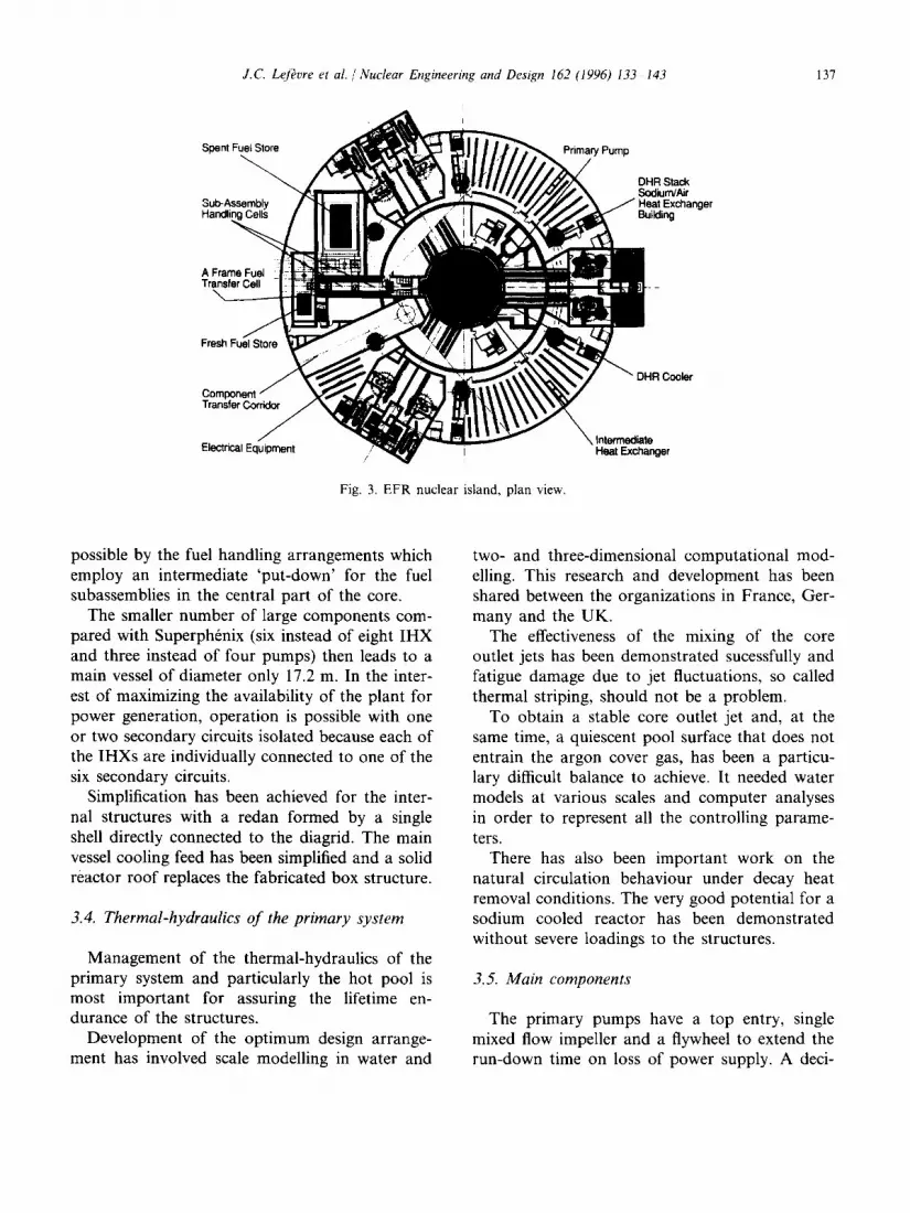
Fig, 3. EFR nuclear island, plan view.
Cooler
possible by the fuel handling arrangements which employ an intermediate 'put-down' for the fuel subassemblies in the central part of the core.
The smaller number of large components com- pared with Superph6nix (six instead of eight IHX and three instead of four pumps) then leads to a main vessel of diameter only 17.2 m. In the inter- est of maximizing the availability of the plant for power generation, operation is possible with one or two secondary circuits isolated because each of the IHXs are individually connected to one of the six secondary circuits.
Simplification has been achieved for the inter- nal structures with a redan formed by a single shell directly connected to the diagrid. The main vessel cooling feed has been simplified and a solid reactor roof replaces the fabricated box structure.
3.4. Thermal-hydraulics of the primary system
Management of the thermal-hydraulics of the primary system and particularly the hot pool is most important for assuring the lifetime en- durance of the structures.
Development of the optimum design arrange- ment has involved scale modelling in water and
two- and three-dimensional computational mod- elling. This research and development has been shared between the organizations in France, Ger- many and the UK.
The effectiveness of the mixing of the core outlet jets has been demonstrated sucessfully and fatigue damage due to jet fluctuations, so called thermal striping, should not be a problem.
To obtain a stable core outlet jet and, at the same time, a quiescent pool surface that does not entrain the argon cover gas, has been a particu- lary difficult balance to achieve. It needed water models at various scales and computer analyses in order to represent all the controlling parame- ters.
There has also been important work on the natural circulation behaviour under decay heat removal conditions. The very good potential for a sodium cooled reactor has been demonstrated without severe loadings to the structures.
3.5. Main components
The primary pumps have a top entry, single mixed flow impeller and a flywheel to extend the run-down time on loss of power supply. A deci-
138 J.C. Lefkvre et al. /Nuclear Engineering and Design 162 (1996) 133 143
sion was taken to opt for a simple design without valves which implies all three pumps must be available for reactor operation.
For the IHX a simple straight tube design is used with the primary sodium on the shell side. Because of the limited head to drive the primary flow, the lower flow resistance on the shell side gives the most compact unit. Extensive analysis has demonstrated that adequate flow and temper- ature distribution are achieved throughout the operating range.
A new feature is incorporated in the design for sealing the IHX to the redan using piston rings. Similar piston rings are used in the Prototype Fast Reactor (PFR) but to accommodate thermal movements between the components and the redan requires a novel design. This feature re- places a gas seal and avoids any question of a large gas inventory being held below the sodium surface and offers some reduction in main vessel diameter.
The IHX has a valve on the primary side so that the reactor can be operated when necessary when equipment and components are unavailable in the associated secondary circuit and steam plant.
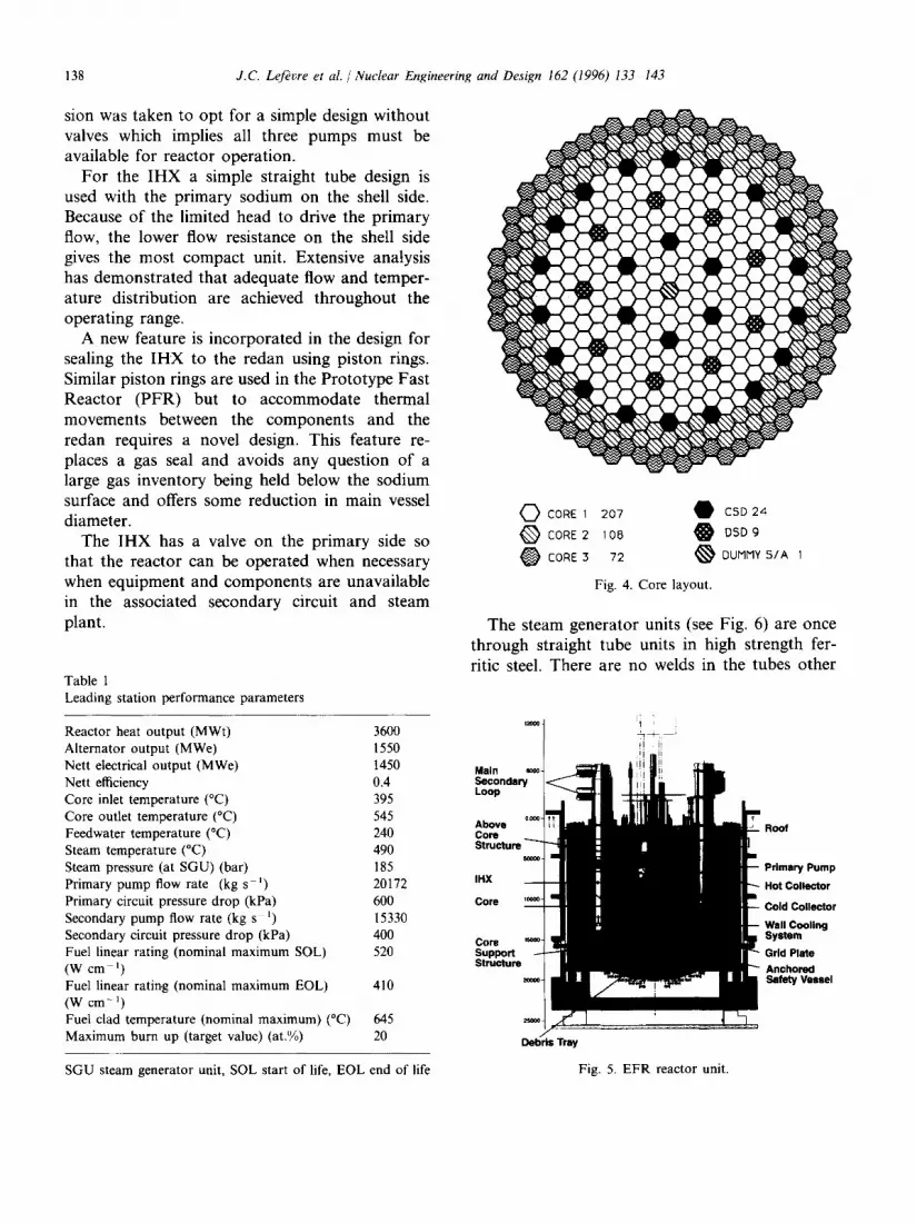
Table 1 Leading station performance parameters
Reactor heat output (MWt) 3600 Alternator output (MWe) 1550 Nett electrical output (MWe) 1450 Nett efficiency 0.4 Core inlet temperature (°C) 395 Core outlet temperature (°C) 545 Feedwater temperature (°C) 240 Steam temperature (°C) 490 Steam pressure (at SGU) (bar) 185 Primary pump flow rate (kg s - t ) 20172 Primary circuit pressure drop (kPa) 600 Secondary pump flow rate (kg s t) 15330 Secondary circuit pressure drop (kPa) 400 Fuel linear rating (nominal maximum SOL) 520 (W cm- ' ) Fuel linear ratir~g (nominal maximum EOL) 410 (W cm -1) Fuel clad temperature (nominal maximum) (°C) 645 Maximum burn up (target value) (at.%) 20
SGU steam generator unit, SOL start of life, EOL end of life
CORE 1 207 • C5D24 0 CORE2 108 0 DSD9
CORE3 72 ~ DUMMY 5/A 1
Fig. 4. Core layout.
The steam generator units (see Fig. 6) are once through straight tube units in high strength fer- ritic steel. There are no welds in the tubes other
'~1 li '
Roof
Primary Pump
Hot Collector
Cold Collector
Wall Cooling System Grid Plate Anchored Safety Vessel
Debris Tray
Fig. 5. EFR reactor unit.
J.C. Lefkvre et al. /Nuclear Engineering and Destgn 162 (1996) 133-143 139
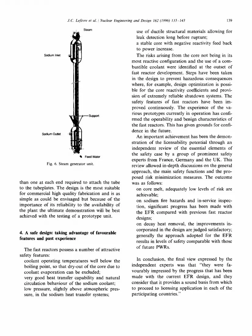
Sodium Inlet
Sodium Outlet
Steam
lib Feed Water
Fig. 6. Steam generator unit.
than one at each end required to attach the tube to the tubeplates. The design is the most suitable for commercial high quality fabrication and is as simple as could be envisaged but because of the importance of its reliability to the availability of the plant the ultimate demonstration will be best achieved with the testing of a prototype unit.
4. A safe design: taking advantage of favourable features and past experience
The fast reactors possess a number of attractive safety features:
coolant operating temperatures well below the boiling point, so that dry-out of the core due to coolant evaporation can be excluded; very good heat transfer capability and natural circulation behaviour of the sodium coolant; low pressure, slightly above atmospheric pres- sure, in the sodium heat transfer systems;
use of ductile structural materials allowing for leak detection long before rupture; a stable core with negative reactivity feed back to power increase.
The risks arising from the core not being in its most reactive configuration and the use of a com- bustible coolant were identified at the outset of fast reactor development. Steps have been taken in the design to prevent hazardous consequences where, for example, design optimization is possi- ble for the core reactivity coefficients and provi- sion of extremely reliable shutdown systems. The safety features of fast reactors have been im- proved continuously. The experience of the va- rious prototypes currently in operation has confi- rmed the operability and benign characteristics of the fast reactors. This has given grounds for confi- dence in the future.
An important achievement has been the demon- stration of the licensability potential through an independent review of the essential elements of the safety case by a group of prominent safety experts from France, Germany and the UK. This review allowed in-depth discussions on the general approach, the main safety functions and the pro- posed risk minimization measures. The outcome was as follows:
on core melt, adequately low levels of risk are achievable; on sodium fire hazards and in-service inspec- tion, significant progress has been made with the EFR compared with previous fast reactor designs; on decay heat removal, the improvements in- corporated in the design are judged satisfactory; generally the approach adopted for the EFR results in levels of safety comparable with those of future PWRs.
In conclusion, the final view expressed by the independent experts was that "they were fa- vourably impressed by the progress that has been made with the current EFR design, and they consider that it provides a sound basis from which to proceed to licensing application in each of the participating countries."
140 J.C. Lef~vre et al. / Nuclear Engineering and Design 162 (1996) 133-143
P r i m a r y S y s t e m
D e c a y H e a t R e m o v a l S y s t e m
Secondary Fuel Handling
0 20 40 60 80
Reference 100% for SPX1
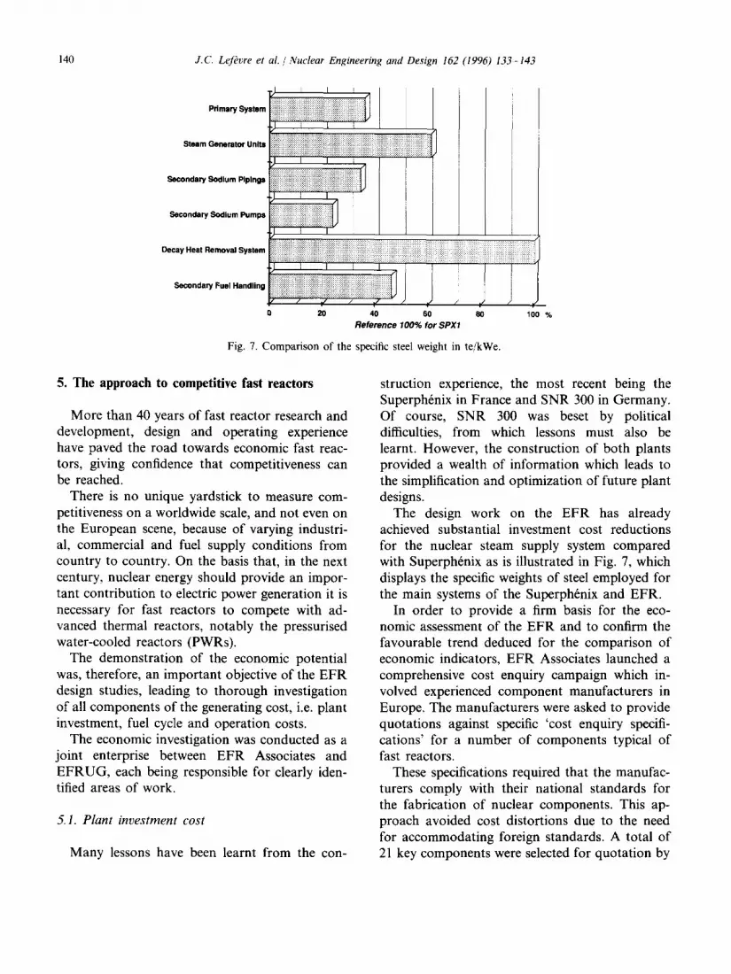
Fig. 7. C o m p a r i s o n o f the specific steel weight in te /kWe.
Secondary S o d i u m P u m p s
I • +. + + + + - : : : : : : : : : :::::: . . . . : .............
i ill' ,ili iiiii iiiiii' ',i iiiii i
hi / ,F J 100 %
5. The approach to competitive fast reactors
More than 40 years of fast reactor research and development, design and operating experience have paved the road towards economic fast reac- tors, giving confidence that competitiveness can be reached.
There is no unique yardstick to measure com- petitiveness on a worldwide scale, and not even on the European scene, because of varying industri- al, commercial and fuel supply conditions from country to country. On the basis that, in the next century, nuclear energy should provide an impor- tant contribution to electric power generation it is necessary for fast reactors to compete with ad- vanced thermal reactors, notably the pressurised water-cooled reactors (PWRs).
The demonstration of the economic potential was, therefore, an important objective of the EFR design studies, leading to thorough investigation of all components of the generating cost, i.e. plant investment, fuel cycle and operation costs.
The economic investigation was conducted as a joint enterprise between EFR Associates and EFRUG, each being responsible for clearly iden- tified areas of work.
5.1. Plant investment cost
Many lessons have been learnt from the con-
struction experience, the most recent being the Superph6nix in France and SNR 300 in Germany. Of course, SNR 300 was beset by political difficulties, from which lessons must also be learnt. However, the construction of both plants provided a wealth of information which leads to the simplification and optimization of future plant designs.
The design work on the EFR has already achieved substantial investment cost reductions for the nuclear steam supply system compared with Superph6nix as is illustrated in Fig. 7, which displays the specific weights of steel employed for the main systems of the Superph6nix and EFR.
In order to provide a firm basis for the eco- nomic assessment of the EFR and to confirm the favourable trend deduced for the comparison of economic indicators, EFR Associates launched a comprehensive cost enquiry campaign which in- volved experienced component manufacturers in Europe. The manufacturers were asked to provide quotations against specific 'cost enquiry specifi- cations' for a number of components typical of fast reactors.
These specifications required that the manufac- turers comply with their national standards for the fabrication of nuclear components. This ap- proach avoided cost distortions due to the need for accommodating foreign standards. A total of 21 key components were selected for quotation by
J.C. Lefkvre et al . / Nuclear Engineering and Design 162 (1996) 133-143 141
manufacturers and corresponding cost enquiries were addressed to 19 manufacturers in four coun- tries, Austria, France, Germany and the UK, with two to three quotations per component giving rise to 57 quotations in all.
Component costs were obtained for the first-off EFR station and for a series unit in a programme of fast reactors so that cost reduction due to the learning effect and series construction could be fully exploited.
The nuclear island cost assessment by EFR Associates was combined with cost estimates of the conventional balance of plant (BOP) by the utilities of E F R U G to establish the construction cost of the whole station under the conditions prevailing in each country. This provided the main input for computation of generating cost.
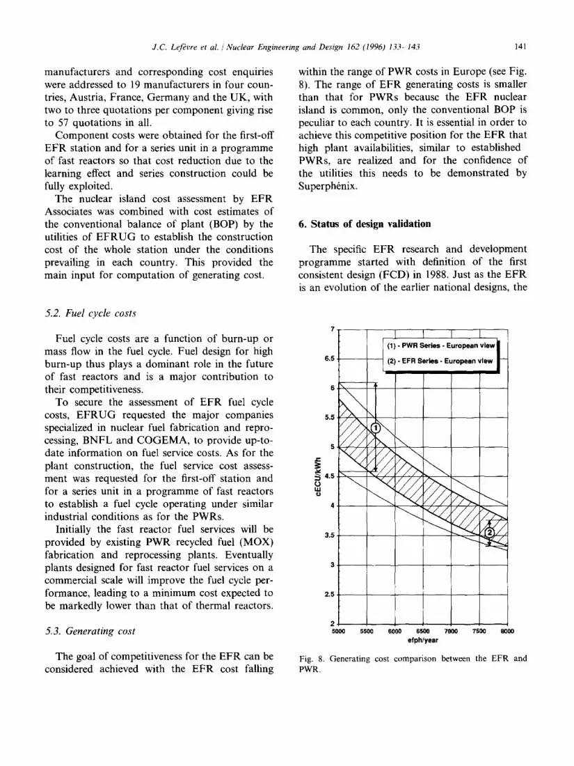
within the range of PWR costs in Europe (see Fig. 8). The range of EFR generating costs is smaller than that for PWRs because the EFR nuclear island is common, only the conventional BOP is peculiar to each country. It is essential in order to achieve this competitive position for the EFR that high plant availabilities, similar to established PWRs, are realized and for the confidence of the utilities this needs to be demonstrated by Superphrnix.
6. Status of design validation
The specific EFR research and development programme started with definition of the first consistent design (FCD) in 1988. Just as the EFR is an evolution of the earlier national designs, the
5.2. Fuel cycle costs
Fuel cycle costs are a function of burn-up or mass flow in the fuel cycle. Fuel design for high burn-up thus plays a dominant role in the future of fast reactors and is a major contribution to their competitiveness.
To secure the assessment of EFR fuel cycle costs, E F R U G requested the major companies specialized in nuclear fuel fabrication and repro- cessing, BNFL and COGEMA, to provide up-to- date information on fuel service costs. As for the plant construction, the fuel service cost assess- ment was requested for the first-off station and for a series unit in a programme of fast reactors to establish a fuel cycle operating under similar industrial conditions as for the PWRs.
Initially the fast reactor fuel services will be provided by existing PWR recycled fuel (MOX) fabrication and reprocessing plants. Eventually plants designed for fast reactor fuel services on a commercial scale will improve the fuel cycle per- formance, leading to a minimum cost expected to be markedly lower than that of thermal reactors.
5.3. Generating cost
The goal of competitiveness for the EFR can be considered achieved with the EFR cost falling
6.5
5.5
5
e-
4.5 r,,) LU
4
3.5
2.5
2 5000 5500 6000 6500 ?000 7500 8000
efphlyear
Fig. 8. Generating cost comparison between the EFR and PWR.
142 J.C. Lefkvre et al. / Nuclear Engineering and Design 162 (1996) 133 143
reorientation of the research and development programme was a continuation of the rationaliza- tion process which had been taking place since 1984 when the European collaboration on fast reactors started.
This reorientation was completed by 1990 when all the key research and development require- ments for EFR concept validation had been defined and agreed. In 1993 most of the work had been completed by the research and development organizations with only a few exceptions related mainly to recent design decisions and long term work on material characterization.
The goal for the core design is a high burnup (20% heavy atoms) and a long residence time in the reactor. Experience from fuel irradiation in the prototype plants validates the design up to 15 at.% with a statistically significant number of fuel pins, some of them having reached 20 at.%. This gives confidence that 20 at.% is a reasonable target for which validation will be obtained by continuing the experimental irradiation programme.
The compact primary system poses questions for the thermal-hydraulics and structural material behaviour. A very substantial programme has been completed with work shared between the three countries for tests of sodium and water models of the reactor at various scales. A number of iterations between the design and research and development teams was necessary to identify the optimum design arrangement.
Operating experience with the prototype fast reactors has revealed the critical importance of the steam generators to the availability of the plant for power generation. The key elements of the design of these components have been vali- dated and it remains to demonstrate that the required reliability is achieved through testing of a steam generator prototype. Furthermore, exten- sive analysis has been completed on the evolution of a leak between sodium and water in the steam generator to establish the soundness of the provi- sions for accident mastering. Research and devel- opment programmes are continuing to obtain confirmation of the material wastage rates and of the feasibility of a highly sensitive leak detection intrumentation to enable efficient prevention of
large sodium-water reactions. The potential that the sodium cooled reactor
has for the removal of residual core heat by passive means, i.e. without the need for emer- gency power supplies, has been confirmed by ex- tensive water modelling and analysis of the primary circuit and by tests of a direct reactor cooling loop in sodium. This not only validated the concept, but demonstrated the sodium-air heat exchanger design by large scale prototype testing.
A number of important safety issues have been settled by the validation programme, including performance of the core monitoring instrumenta- tion, natural degasing behaviour of the primary circuit and, in particular, of the diagrid which feeds the core. Extensive work also has been devoted to sodium fires, and attention given to the experience gained with the Superphrnix restart licensing.
Finally, to give an appreciation of the full extent of the research and development work, there were over 1000 individual tasks performed at 16 research centres in three countries cooperat- ing for the EFR programme. In addition to these specific tasks, there has been the invaluable expe- rience from operation of the prototype plants which provide continuous feedback of informa- tion for future plant design.
7. Conclusion and outlook
The EFR project at the end of the concept validation phase has matched the ambitious ex- pectations of the customer utilities. This has been achieved as a result of the partnership between the design companies, the research and development organizations and the utilities. The success of the project is a shining example of European coopera- tion.
At the completion of the concept validation phase the economic assessment, involving the key manufacturers in the participating coun- tries, confirmed the potential for a series of EFRs to be competitive with the national PWRs.
It was also confirmed that the EFR design and safety features can be confidently expected to be
J.C. Lefkvre et al. / Nuclear Engineering and Design 162 (1996) 133-143 143
licensable in each of the participating countries. This statement can be made following the positive outcome of the independent safety review com- pleted early in 1993.
The feedback o f experience f rom the operat ing plants is invaluable in providing assurance that commercial fast reactors can be successfully oper- ated. This has been done and is always an impor- tant part o f an ongoing activity which has been agreed with E F R U G .
This future p rog ramme reflects the evolution o f the E F R project regarding timescale and aims at further enhancing the flexibility o f the fast reactor for its potential to manage the plutonium stock- pile and t ransmute minor actinides according to the prevailing requirements f rom the fuel cycle. However, securing the long term fuel supply for electricity generation through breeding remains the main aim o f fast reactor development. The objectives o f these ongoing activities can be sum- marized as follows. (1) To establish the flexibility o f the fast reactor
for managing the back end of the fuel cycle. (2) To evaluate the potential for further improve-
ments which have been identified during the concept validation phase, notably regarding in-service inspection and repair and other ad- vanced features which could be introduced within the time that is available for their validation.
(3) To assess the design of a demonst ra t ion plant o f a reduced size f rom the point o f view of demonstra t ing advanced features o f a large plant and as an irradiation facility for the next century.
An objective for the next period is to maximize the extent and benefit o f col laborat ion within Europe, to include all those parties with a strate- gic interest, particularly in the full fuel cycle, and outside Europe, to realize the potential which has been established for extending col laborat ion to Japan, Russia and the USA,
References
M. Aubert, and J.C. Lef~vre, Fast reactor generic studies, ENC 94, Lyons 2-6 October 1994.
B. Carluec, D. Favet and S. Dechelette, Third shutdown level for EFR project, International Working Group on Fast Reactor A1EA, Specialists' Meet., Obninsk, 3-7 July 1995.
B. De Braquilanges, P. Fenemore and H.W. Hammers, The EFR primary system design at the end of phase II, 12th SMIRT, Stuttgart, 15-20 August 1993.
J.P. Debaene, D. Buckthorpe, L. Cornaggia and P. Rathjen, Design and construction rules committee for EFR--cur- rent status and development, Post-12th SMIRT Seminar, Aachen, 23-24 August 1993.
J. Dumesnil, and C. Mauget, Status of R & D programme for the straight tube steam generator validation, ENC 94, Lyons. 2-6 October 1994.
K. Ebbinghaus and J.C. Lefevre, Economics of EFR, 1992 Winter Meet., Int. Conf. on Fifty Years of controlled Nuclear Chain Reaction: Past, Present, and Future, Chicago, 11., 15-20 November 1992, in Trans. Am. Nucl. Soc., TRANSAO 66 1-626 66 (1992) 345 346.
A. Le Bourhis, V. Luster, J.C. Astegiano and V. Tournebize, Sodium fire: current status and perspectives, Sodium Cooled Reactor Safety Conf., Obninsk, 3 7 October 1994.
J.C. Lefevre, G. Hubert and M. Aubert, Le projet de R6acteur Rapide Europ6an EFR--etat actuel et per- spectives, Rev. Gen. NucL No. 6, November-December 1994.