COMPUTERIZED REACTOR PRESSURE VESSEL MATERIALS ...
121
.- NUREG-0688 - _ _ Computerized Reactor Pressure Vessel Materials Information System Manuscript Completed: May 1980 Date Published: October 1980 J. Strosnider, C. Monserrate, with the Appendix prepared by L. D. Kenworthy and C. D. Tether of international Energy Associates Limited Office of Nuclear Reactor Regulation Office of Management and Program Analysis U.S. Nuclear Regulatory Commission Washington, D.C. 20555 , . ~ . , , , ,9 , ,..,m *8et* * | 30\\\1o W \ '
-
Upload
khangminh22 -
Category
Documents
-
view
0 -
download
0
Transcript of COMPUTERIZED REACTOR PRESSURE VESSEL MATERIALS ...

.-
NUREG-0688
- _ ._ _ _
Computerized Reactor PressureVessel Materials Information System
-
Manuscript Completed: May 1980Date Published: October 1980
J. Strosnider, C. Monserrate, with the Appendix prepared by L. D. Kenworthy and C. D. Tetherof international Energy Associates Limited
Office of Nuclear Reactor RegulationOffice of Management and Program AnalysisU.S. Nuclear Regulatory CommissionWashington, D.C. 20555
, . ~ . , ,,
,9,
,..,m*8et*
*
|
30\\\1o W \ '

ABSTRACT
A computerized information system for storage and retrieval ofreactor pressure vessel materials data was established, as partof Task Action Plan A-11, " Reactor Vessel Materials Toughness."Data stored in the system are necessary for evaluating the resistanceof reactor pressure vessels to flaw-induced fracture. This reportincludes (1) a description of the information system; (2) guidanceon accessing the system; and (3) a user's manual for the system.
iii
|
_ _ _ _- ._-.

CONTENTS
Page
ABSTRACT... iii.. .. . . .... . ... .. ..... . .
viiGLOSSARY . . . . ...... . .. ..... . . . .. . ... . . ....
1. INTRODUCTION. 1. . .. .. . . .. ... . ..
2. SYSTEM DESCRIPTION. . . .. .. . . 243. ACCESSING THE SYSTEM. . . . . . ...
64. BEFERENCES. ... . . .. .. .. . . .. .
APPLNDIX -- USERS MANUAL: DATA BASE MATSURV. . . . A-1
:i
i
v
_ __________________ _ ___ ____ _ _ _ .

._
GLOSSARYl
AJ Anderson JacobsonASME American Society of Mechanical EngineersASTM American Society of Testing and Materials i
'
B&W Babcock & WilcoxCMM correlation monitor metalC-numbers component numbersCT compact tensionCV Charpy V-notch upper shelf energyDCRT Division of Computer Research and TechnologyDD data definitionEFPY effective full power yearsEOL end of life
HAZ heat-affected zoneIA immediate accessIBM International Businass MachineJCL job control langua,;eL longitudinalMATSURV materials surveillance information systemNIH National Institutes of HealthNRC U.S. Nuclear Regulatory CommissionNSSS nuclear steam supply systemORNL Oak Ridge National LaboratoryPLI procedural language interface'
RCT round compact tensionRPV reactor pressure vessel
;' PTNDT reference nil ductility temperature,
NDTlT transverse"
TAP Task Action PlanTSO time-sharing optionWOL wedge-opening-loading
,
vii
!
I

__ . . .. - ~ _ _ _ _ . . . - . . . _ , __ ._. _ _.-
!
!
'
11
i
;
1
:i
'.
!
(
The computer software material (see Appendix, Users Manual)was prepared as an account of work sponsored by the
,1 United States Government. Neither the United -StatesNuclear Regulatory Commission, nor any of its contractors,
i subcontractors, or their employees, makes any warranty,; express or implied, or . assumes any legal liability or' responsibility for the accuracy, completeness, or usefulness: of any information , apparatus , product, or process} disclosed, or represents that its use would not infringe
privately owned rights.
i
I
|
'
.
:!
!
!
,
t
! .I
iX
i!
_ . . _ - _,. _..~. _ _ __ . _ . _ - - _- . . . _ _ _

1
COMPUTERIZED REACTOR PRESSURE VESSEL MATERIALSINFORMATION SYSTEM
1. INTRODUCTION
Task Action F;an (TAP) A-11, " Reactor Vessel Materials Toughness," wasestablished by the U.S. Nuclear Regulatory Commission (NRC) to ensure thatreactor pressure vessel (RPV) toughness properties continue to provideadequate margins of safety against RPV failure for various operating condi-
,
tions throughout the life of the vessel.
The fundamental goal of TAP A-11 is to provide an engineering method toassess the safety margin for failure prevention in nuclear RPVs. Safety willbe evaluated by comparing the potential for fracture, related to loading andgeometry of the structure, to the resistance to fracture, related to the RPVmaterials properties. Since material property data are necessary for evaluat-ing RPV integrity, a major subtask of TAP A-11 was to establish an RP.materials data information system.
Appendix H to 10 CFR 50 (Ref.1) requires all operating reactors to have amaterial surveillance program to monitor changes in the fracture toughness offerritic reactor vessel beltline materials resulting from their exposure toneutron irradiation. Under this program, surveillance specimens irradiated inthe reactor vessels of operating plants are removed periodically and tested toprovide fracture toughness data.
Except for several of the older vessels, each surveillance program monitorsbase, weld, and heat-affected-zone (HAZ) materials. In accordance withAppendix H ( ASTM E-185-73) (Ref. 2), specific material selection is based onpredicted radiation damage and should include the vessel-limiting materials(materials with the most nonconservative irradiated fracture toughness pro-perties) . However, because some materials have exhibited more damage thanexpected, the surveillance program at a specific plant does not always containthe most limiting material for that specific RPV. Sometimes the limiting materialof one vessel is contained in the surveillance program of another vessel.B&W has developed an integrated surveillance program which establishes ther=lation between RPV and surveillance materials. The complexity of the12 agrated surveillance program is best handled by a computerized informationsystem . In addition, the ability to cross-reference data from welds made withthe same type of flux or heat of weld wire is useful.
The large amount of, and interrelationships between, reactor vessel andsurveillance material data necessitated a computerized information system forthe storage and retrieval of these data. The great advantage of a compu-terized system is its ability to cross-reference between RPV materials,surveillance materials, and irradiated and unirradiated fracture mechanics test
i data . This feature allows quick identification of limiting RPV materials and
1
|__ _ _ _

__
i
correlation of those materials with pertinent surveillance program specimensand test results.
The system was developed by International Energy Associates Limited under aDepartment of Energy contract to Sandia Laboratories, Albuquerque, NewMexico. With the assistance of the Automated Systems Branch, Office ofManagement and Program Analysis, NRC, the system has been made opera-tional on the National Institutes of Health (NIH) computer and is now availablefor use. This report was prepared to provide a description of the system,provide guidence on accessing the system, and provide a user's manual for
; the system. Ti e following sections discuss these scbjects.
2. SYSTEM DESCRIPTION,
The materials surveillance information computer system (MATSURV) has been3
| established to store information relating to licensee RPV material surveillancei programs . This includes data on materials used '.n RPV fabrication, integrated
radiation exposure, materials designated for use in the surveillance program,
; (surveillance specimens), and results of pre- and post-irradiation tests ofsurveillance specimens. The initial data base was obtained from licenseeresponses to an NRC questionnaire distributed in early 1977. Data from 65i
operating nuclar reactors listed in Section 2.3 of the Appendix (pp. A-10and A-11) are included in the initial data entry. Corrections to the initialdata and additional data entries also are expected to result from nuclear steamsupply system (NSSS) vendor review. Additional data entries also will bemade as more reactors become operational and as the results of surveillance,
' testing become available. The system is structured upon the System 2000data base management system which is maintained on the IBM 370 computerat NIH (System 2000 is a trademark of MRI Systems Corporation).
.
! The basic unit of subdivision in the data base is the plant docket number.General information for each docket is provided including plant name and unit,
number, NSSS vendor, RPV manufacturer, reactor type, maximum end-of-life1(EOL) fluence and fluence rate, RPV design conditions, and RPV base metal |
specifications. Within each docket are three main categories of data: RPV !
materials data, chemical composition data, and heat treatment data.
The RPV materials are further subdivided into three broad sets:i
(1) Vessel.(2) Baseline (preirradiation) surveillance specimens.(3) Irradiated surveillance specimens.
Included in the vessel set are those materials actually used in the fabricationof the RPV beltline region: plates, forgings, and welds. Typical:
examples of the data stored for these materials are manufacturer's identifica-tion, steel producer, heat numbers, weld wire specification, weld flux type,
'
and grade, location in RPV, maximum EOL fluence, maximum fluence rate,iinitial RT * heat treatment sequence, and chemical composition.NDT, !
*As defined in Paragraph 4B of "PVRC Recommendatians on ToughnessRequirements for Ferritic Materials - PVRC Ad H2 Group on Toughness
i Requirements" Welding Research Council Bulletin 175, August 1972.
I 2
- -- - _ . - .-- - -- -- . .-_

.- - . - , - . .. .--
!
1
The baseline set consists of all surveillance specimens set aside for preirradia-tion testing including base metal, weld, HAZ, and correlation monitor metal(CMM) specimens. The CMM specimens are used to correlate the vessel material
,' surveillance tests results with those from test reactor programs. Information
stored in the baseline set includes material specifications, heat numbers, steeli-
producer, weld flux type and grade, heat treatment sequences, and chemicalcomposition sets. Also, test results from baseline specimens are stored. This,
information includes the name of the terting laboratory, the test report number: and date, and the results of Charp, pact, tensile, drop weight, and fracture
mechanics te.,ts.'
Included in the irradiated set are all surveillance specimens designated for;' irradiation in, and periodic withdrawal from, the RPV to monitor changes in
material properties as a function of integrated neutron flux. Surva31ancespecimens are grouped according to the capsules in which they are instal'. d.As in the case of the baseline data set, four specimen types are included in
i this set: base, weld, HAZ, and CMM. Information included in the irradiatedspecimen data base is similar to that for the baseline specimens, includingresults of tests conducted on the irradiated specimens and other basic speci-men information such as material specifications, heat numbers, chemical composi-
! tions, and heat treatment sequences. In addition, capsule information consisting! of location, scheduled removal date, actual removal date, and fluence arej included.I
j Heat treatment sequences and chemical compositions are included with the RPVMaterials Data by reference to heat treatment and chemical composition data;
files . This is possible since certain heat treatment sequences and chemicalI compositions are common to many vessel materials.
Figure 1.1 in the Appendix (p. A-8) illustrates the data base organizationi and hierarchial structure.;
The system has a five-level hierarchy:
Level 0 stores general information concerning a given docket number.;
Level 1 ic entifies and stores basic information on the three RPV materialssets (vess il, baseline, and irradiated). Level 1 also identifies the heat,
treatment .,equences and identifies and stores chemical composition| information.
Level 2 stores more detailed information pertaining to the material setsand the heat treatment temperatures, hold time, and purposes.
; Levels 3 and 4 store the test results from the baseline and irradiated; surveillance specimens.
The component numbers (C-numbers) shown in Figure 1-1 correspond toe
: actual data entry items and are fully identified in the information systemusers manual reproduced in the Appendix to this report.'
3
_ _ _ . _ . - - . . _ _ . _ _ - - _ . _ . _ _ _ _ _ . _ _ _ . _ . . _ _ _ - .~ _ _ _ . _ - . _

!
3. ACCESSING THE SYSTEM
MATSURV may be accessed using either Wylbur for batch mode or TSO forinteractive mode. In batch mode, the job is placed in a queue, whereas ininteractive mode the job gets executed immediately. Wylbur and TSO arecommand languages available at NIH as part of the overall operating system.The following paragraphs explain the system operation using Wylbur or TSO.
The necessary user initials, account number, box number, and user's guidecan be obtained by calling the Chief of the Generic Issues Branch, Division ofSafety Technology, NRC.
3.1 Wylbur
To use the Wylbur system for batch jobs, the user first procures a teletypeterminal and, according to the make and series of the terminal, establishes atelephone connection with the NIH computing facility by dialing area code 301,telephone: 492-2221. When connection is made, the user types one of thefollowing logon commands:
,NIH7000 - if terminal is NIH7000,TI222 - for Alanthus TI222
,37 - for Texas Instruments, Omron, and other ASCII / teletype terminals, AJ832 - for the AJ terminal
,CT45 - for Clean Type 45
After the logon command is entered, a computer logon session message isprinted and the INITIALS? prompt will be displayed. At this point, the userenters his assigned initials. This must be a 3-character alphabetic code.The ACCOUNT? prompt will then be displayed, and the user account numbershould be entered. The KEYWORD? prompt will be displayed and will need a3-character code assigned by the user. Next, the TERMINAL? prompt will bedisplayed and the terminal identification normally given on a label affixed tothe terminal keyboard is entered. If a terminal identification does not exist,a letter such as x, y, or z followed by two digits will do.
If the logon procedure was successfully entered, a left-justified question markwill appear. After the question mark, the user enters the command:
USE & acct lii.JCL. BATCH ON NRC001 CLR
(where account aggi and initials jii are given by Generic Issues Branch).
When the second question mark appears, the JCL (job control language) canbe listed by entering the cccimand:
LIST
The password line should be line number 11. After the third question markthe user enters:
|
4
,

CHANGE ' PASSWORD' TO 'XYZ' IN 11
The PASSWO3D is changed to the XYZ password assigned by the Generic>
i
Issues Branch, NRC.
The command*
COLLECT 12
entered at this point allows various System 2000 commands to be entered.
After collecting the commands, hitting the break or attention key will get outof the collect mode.
Entering any of the following:
RUNRUN HOI.D NOTIFYRUN REMOTE nn (Where an is remote identification number)
will execute the requested job.
RUN will execute the job and print the output at NIH. RUN HOLD NOTIFYwill execute the job, hold the printed output, and notify the user when thejob cnded (if the user remains at the terminal).
RUN REMOTE DD will execute the job and print the output at REMOTE Dn.
The Generic Issues Branch will assign a remote number, if needed, where thejob will get printed, depending on the user's location.
The computer will assign a job number so that the status of the job can betracked. The job can be printed in a remote terminal or fetched on theterminal for display.
Enter LOGOFF to end the Wylbur session.
3.2 TSO
To use the system in an interactive mode, the user must procure a teletypeterminal, and connect it with NIH TSO in the same manner as described forWylbur. The telephone number to dial is area code 301, telephone: 492-2223.
When connection is made, the user enters the command:,
!
LOGON REGION (600)
The following prompts and appropriate user responses are:
INITIALS? "The 3-character code assigned by the NRC"ACCOUNT? "The NIH account identification assigned by the NRC"
| KEYWORD? "The 3-charactc code assigned by the user"|
51

i
! .
1l
TERMINAL? "The terminal identification or x, y, or z followed bytwo digits"
BOX? "The box numbar assigned by the NRC." 1
If the logon is successful, the user gets a logon message similar to:.
WXYZABC LOGON IN PROGRESS AT 10:25:51 ON MAY 1,1980NIH/DCRT/CCB TSOTSO LINE 13FREADY
After the READY prompt the user enters:
EXEC '&aggi _in. MATSURV.CLIST'/ key(where account acci initials in, and keyword key are given by theGeneric Issues Branch, NRC).
The next prompt will be for tl'e MATSURV password which the user mustobtain from the Generic Issues Branch, NRC. After the password is entered,the terminal will prompt the user with this message:
PLEASE WAIT FOR '-- ' PROMPTBEFORE ENTERING COMMANDS
Once the '-- ' prompt appears, the various System 2000 commands can beentered.
Entering EXIT: will print the MATSURV Job Status and end the session.Several lines of computer resource information are printed before logging offautomatically.
REFERENCES
1. Code of ~ Federal Regulations,10 Energy, Appendix H to Part 50, Revisedas of January 1,1980.
2. American Society for Testing and Materials (ASTM) Standard RecommendPractice for Surveillance Tests for Nuclear Reactor Vessels, ASTMDesignation: E-185-73, March 1,1973 Annual Book of ASTM Standards,Part 30 and Part 31.
| 6
||
i
APPENDIX
USERS MANUAL *
DATA BASE MATSURV
Reactor Pressure Vessel Material SurveillanceData Management System
Prepared for the Nuclear Regulatory Commissionunder Contract No. 13-7355 to SandiaLaboratories, Albuquerque, New Mexico
by
L. D. KenworthyC. D. Tether
September 21, 1979
International Energy Associates Limited600 New Hampshire Avenue, N.W.
Washington, D.C. 20037(202) 338-8230
..
;
|
|
*0riginaUy designated as IEAL-120. |
|
,
t
! A-1

!
TABLE OF CONTENTS
PAGE
1. INTRODUCTION 1
2, DATA BASE CONTENTS AND ORGANIZATION 3
2.1 Purpose 3
2.2 E. es of Data 3
2.2.1 Initial Data 3
2.2.2 Subsequent Data 3
2.3 Data Included in Initial Data Base 4
2.4 Data Base Organization 6'
2.4.1 General 6"
2.4.2 Material Set Vessel 6
2.4.3 Material Set Baseline 7
2.4.4 Material Set Irradiated g
2.4.5 Heat Treatment Sequences 3
2.4.6 Chemical Composition Sets 9
2.4.7 Additional Descriptien of Surveillance
Specimen Classification 9
2.4.7.1 Specimen Groupings 9
2.4.7.2 Identity of Surveillance Specimens 10
2.4.7.3 Identity of Surveillance Specimen
Capsules 10,
2.4.7.4 Tracking of Surveillance Specimens 11
2.4.8 Data Base MATSURV Organization Chart 13
2.5 Data Base Definition 13
! 2.5.1 General 13
2.5.2 Component Numcers and Data Entries 14'
:
i
|,
A-3
_ _ _ . _

_ _ _ _ _ _ _ _ _ _ _ _ _ _ _ _ _ _ _ _ - _ _
2.5.2.1 Plant and Vessel Data 142.5.2.2 Material Set Data 162.5.2.3 Material Data 192.5.2.4 Test Data 272.5.2.5 Chemical Composition Data 342.5.2.6 Heat Treacment Sequence Data 35
2.5.3 MATSURV Cata Base Definition for System 2000 361
3. ACCESS TO THE NIH/DCRT COMPUTER CENTER 42
3.1 General42
2.2 Retrieval / Entry Security 423.3 Accessing MATSURV
23.3.1 Sample JCL 433.3.2 Additional DD State rats 433.3.3 System 2000 Run Requests 44
4. RETRIEVAL AND DISPLAY OF DATA 44
4.1 General44
4.2 Retrieva. Exarples, Non-Disjoint Data Sets 454.2.1 Example 1
454.2.2 Example 2 (
464.2.3 Example 3 46
4.3 Retrieval Examples, Disjoint Data Se s 464.3.1 Example 1 47 !4.3.2 Example 2 47
4.4 Report Options48
4.4.1 Cocket Reports 494.4.1.1 Plant Datt Report 504.4.1.2 Reactor Pressure Vessel Base
Metal Report 514.4.1.3 Reactor Pressure Vessel Weld Report 52
I
ii
A-4
|

- _ _
4.4.1.4 Baseline Surveillance SpecimenReport 53
4.4.1.5 Irradiated Surveillance SpecimenReport 59
4.4.1.6 Cliemical Composition Set Report 64
4.4.1.7 Heat Treatment Report 66
4.4.1.8 Example of Requesting CompleteDocket Report 67
5. INSERTICN AND MODIFICATION OF DATA 68
5.1 General 68
5.2 Selection of Existing Data Sets to be Updated 68
5.3 Selection of Type of Update 68
5.4 Examples of Data Modification 69
5.4.1 Example 1 69
5.4.2 Example 2 69
5.4.3 Example 3 i0
5.4.4 Example 4 70
5.4.5 Example 5 70
5.4.5 Example 6 70
5.5 Addition of New Dockets 71
5.5.1 Data Entry en Data Forms 71
5.5.2 Data Entry from Data Forms 72
5.5.3 Loading New Docket Data Into MATSURV 73
5.6 Verification Procedure 73
A-1 - A- 14APPENDIX A. INPUT FORMS
APPENDIX B. LISTING OF DATA FOR A FICTICIOUS DOCKET B-1 - B-5
APPENDIX C. SYSTEM 2000 OVERVIEW C-1 - C-8
D-1 - D-2APPENDIX D. DATA BASE CORRECTIONSE-1
APPEND: E. DEFINITICN ALTERATIONS
FIGURE l-1. DATA BASE MATSURV ORGANIZATION CHART 2
iii
A-5
_ _ _ _ - - _

i
1
i
1. INTRODUCTION
This Users Guide to the data management system MATSURV has been i
prepared to assist the user in all facets of the task of pro-
cessing data related to reactor pressure vessel materials sur-
veillance; prepartion of raw data for input, input of data,
modification of existing data, retrieval and display of data,
and the creatica of data reports. MATSURV is structured upon
the System 2000* data base management iystem which is maintained
on the IBM 370/168 computer at National Institutes of Health.
An overview of System 2000 is provided in Appendix '.
Several examples of data processing operations and instructions
for carrying out such operations are provided in this Guide. To
this end, a ficticious docket file (Docket No. 999) has been
created and the data values for this docket are listed in
Appendix 3.
A complete description of MATSURV, including its organization
and the definition of its contents, is provides in the following
Sections and Appendices of this Users Guide. Figure 1-1 is the
organization chart for the MATSURV system. A discussion of the'
chart appears in Section 2.4.8.
* SYSTEM 2000 is a trademark of MRI Systems Corporation.
A-7i
. - _ _ _ _

.
I
1li
li
| 2
i FIGURE l-1|
DATA BASE MATSURVORGANIZATION CHART
ENTRY
DOCKET DATA
Cl-C21 EL 0
_ ___ _ _ _ __ __ ___ _ _ _
l. VESSEL CHEMICAL HEATMATERIAL SET 2. BASELINE CCMPCSITICN C401 TEEA M NT
OATA 3. IRLM)IATED C301- DATA and . 0ATAC350
0101-C150 C450 !
LEVEL 1
|1
MATERIAL DATAs 7:gg
C404 mtP.
u 01 s250 C405 PURPCSE.
LEVEL 2
.
- ____ _ __ _____________
CHARPY TEST UNSILE EST ORCP WEIC"? FRACTUREDATA DATA TEST CATA MECH. DATA
C501-C550 C601-C650 C701-C750 CS01-CS50
LEVEL ?- __.____ ___________ _ _ _ _ _ _ _
TENSILE TEST FRACT. MECH.RESULTS TEST RESULTS
C604-C616 C804-C807
LEVEL 4
A-8i1

3
2. DATA BASE CONTENT 1. AND CdGANIZATION
2.1 Purpose
The MATSURV data base has been established to store information
relating to licensee reactor pressure vessel (RPV) material
surveillance programs. This includes data on materials used in
RFV fabrication, integrated radiation exposure, materials desig-
nated for use in the surveillance program (surveillance speci-
mens), and results of pre- and post-irradiation tests of surveil-
lance specimens.
2.2 Sources of Data
2.2.1 In;tial Data.
The data initially placed in the data base were obtained from
licensee response to an NRC questionnaire distributed in early
1977. This constitutes all the data in the system at the time
of initial turnover of the system by the contractor to the NRC.
Data from 65 operating nuclear reactors are included in the
initial data entry.
2.2.2 Subsequent Data.
Corrections to the initial data and additional data entries are
expected to result from NSSS vendor review. Additional data
entries will also be made as more reactors begin operation and
as the results of material surveillance specimen testing become
avsilable.
|A-9
|
|
|_
,

_
4
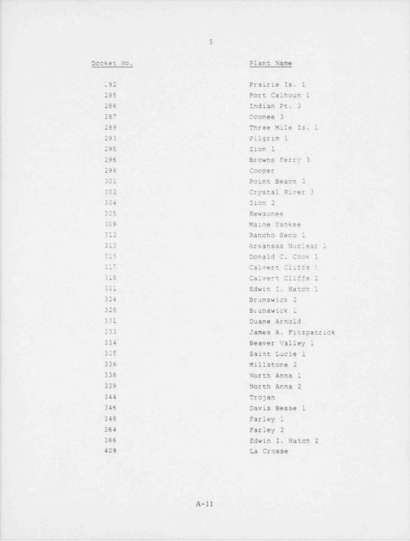
2.3 Dockets Included in Initial Da*= Base
Data for the following reactors are included in the initial data
base:
Docket No. Plant Name
010 Dresden 1* 029 Yankee Rowe
155 Big Rock Point
206 San Onofre 1
213 Haddam Neck219 Oyster Creek
220 Nine Mile Pt. 1
237 Dresden 2
244 Ginna 1
245 Millst ne 1247 Indian Point 2
249 Dresden 3250 Turkey Pt. 3
,
251 Turkey Pt. 4254 Quad Cities 1255 Palisades
659 Browns Ferry 1260 Browns Ferry 2261 H. B. Robinson263 Monticello265 Quad Cities 2266 Point Beach 1
269 Oconee 1
270 oconee 2
271 Vermont Yankee
272 Salem 1277 Peach Bottom 2
278 Peach Bottom 3
280 Surry 1
2'81 Surry 2
i,
! A-10
5
Docket No. Plant Name
292 Prairie Is. 1
285 Fort Calhoun 1
286 Indian Pt. 3
287 Oconee 3289 Three Mile Is. 1
293 Pilgrim 1
295 Zion 1
296 Browns Ferry 3
298 Cooper
301 Point Beach 2
302 Crystal River 3
304 Zion 2
305 Kewaunee
309 Maine Yankee
312 Rancho Seco 1
313 Arkansas Nuclear 1
315 Donald C. Cook 1
317 Calvert Cliffs 1
318 Calvert Cliffs 2
321 Edwin I. Hatch 1
324 Brunswick 2
325 Btunswick 1
331 Duane Arnold
333 James A. Fitzpatrick
334 Beaver Valley 1
305 Saint Lucie 1
336 Millstone 2
338 North Anna 1
339 North Anna 2
344 Trojan,
1
346 Davis Besse 1
348 Farley 1
364 Farley 2
366 Edwin I. Hatch 2
409 La Crosse
A-11

-, .-_ . _ - _ _ _
|
! |i |i
6.
i
|
2.4 Data Base Organization,
;
i
2.4.1 Generali4
The basic unit of subdivision in the data base is the plant '
docket number. All information for a given reactor pressure i; vessel is filed under the docket number with which that vessel
is uniquely associated. General information for each docket is
provided which includes data such as plant name and unit number,NSSS supplier, RPV manufacturer, reactor type, end of life (EOL)
! fluence and fluence rate, RPV design conditions, and RPV basej metal specifications. The RPV materials are further subdivided,' into Material Sets. The Material Sets are three broat categori-
;
! zations of materials as follows:
; 1. Vessel,
2. Baseline (pre-irradiation) Surveillance Specimens,3. Irradiated Surveillance Specimens.
The Material Sets are defined in more detail in suceeding para-j graphs.
r
Continuing the general description, reference files for material
| heat treatment sequences and chemical composition sets have beenestablished. These files permit referencing heat treatment and4
chemical composition information common to the various vessel
materials rather than repeating this information in detail for,
each material. These reference files are also described ingreater detail below.
2.4.2 Material Set VesselJ
b
! The materials that are included in this Material Set are those!
actually used in the fabrication of the RPV beltline region:#
plates, forgings, and welds. The specific data stored for these
!
,
A-12E
,.,-w.,-7 , - .- - - - n 4 - _,,r-, - -- , - -_ .,
7
materials are identified below, but some typical examples are1
1 manufacturer's identification, steel producer, heat numbers,
weld wire specification, flux type and grade, location in RPV,
EOL fluence, fluence rate, and initial RTNDT. As previously
stated, the heat treatment sequence and chemical composition set
that are associated with a particular plate, weld, or forging
are referenced back to the heat treatment and chemical composi-
tion files.
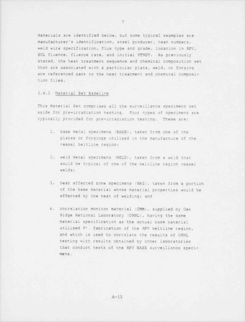
2.4.3 Material Set Baseline
This Material Set comprises all the surveillance specimens set
aside for pre-irradiation testing. Four types of specimens are
typically provided for pre-irradiation testing. These are:
1. base metal specimens (BASE), taken from one of the
plates or forgings utilized in the manufacture of the
vessel beltline region;
2. weld metal specimens (WELD) , taken from a weld that
would be typical of one of the beltline region vessel
welds;
3. heat affected zone specimens (HAZ), taken from a portion
of the base material whose material properties would be
affected by the heat of welding; and
4. correlation monitor material (CMM), supplied by Oak
Ridge National Laboratory (ORNL), having the same
material specification as the actual base niaterial
utilized fr. f abrication of the RPV beltline region,
and which is used to correlate the results of ORNL,
i
testing with results obtained by other laboratories
, that conduct tests of the RPV BASE surveillance speci-1
mens.
I
1
A-13
|
_ _ _ _ _ _

8i
The kind of information that is stored in the data base for theMaterial Set Baseline includes material specifications, heatnumbers, steel producer, flux type and grade, heat treatmentsequences, and chemical composition sets. In addition, infor-
mation is stored on results of testing the baseline specimens.This information includes the name of the testing laboratory,the test report number and date, and the results of Charpy im-pact, tensile, drop weicht, and fracture mechanics tests.
2.4.4 Material Set Irradiated
Included in this Material Set are all the surveillance specimensthat have been designated for irradiation in and periodic with-drawal f;gm the reactor pressure vessel in order that change: inmaterial properties as a function of integrated neutron flux maybe recorded. These surveillance specimens are grouped accordingto the capsules in which they are installed. As in the case ofMaterial Set 3aseline, four types of specimens are included inthis Material Set; BASE, WELO, HAS, and CMM. Informaticn in-
cluded in the data base for the irradiated specimens is similarto that for the baseline specimens t.. that it includes resultsof tests conducted on the irradiated specimens and other basicinformatien on the specimens such as material specifications,heat n'mbers, chemical compositions, and heat treatment sequences.In addition, capsule information is included, and this consistsof location, scheduled removal date, actual removal date, andfluence.
2.4.5 Heat Treatment Secuences
As previously mentioned, several different material items in areactor pressure vessel experience identical heat treatment
sequences; for example, several cf the vessel plates, or all ofthe BASE surveillance specimens (pre- and post-irradiated).Therefore it is pcssible to describe *he heat treatment for agiven RPV and its surveillance specimens with a few heat treat-ment sequence files. These files can then be referenced when
A-14
i
l,
_ - _ _ _ _ .
|
|1
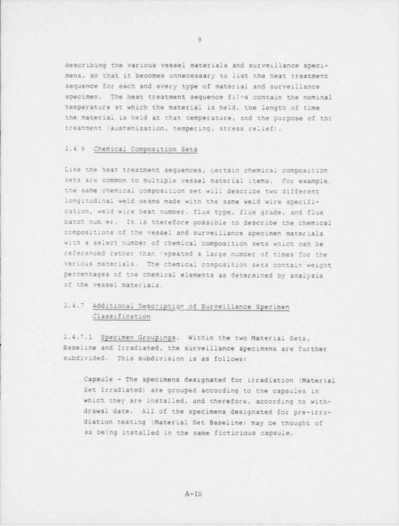
911
describing' the various vessel materials and surveillance speci-mens, so that it becomes unnecessary to list the heat treatment
sequence for each and every type of material and surveillance
specimen. The heat treatment sequence fijas contain the nominal
temperature at which the material is held, the length of time
the material is held at that temperature, and the purpose of the
treatment (austenitation, tempering, stress relief) .
2.4.6 Chemical Composition Sets
Like the heat treatment sequences, certain chemical composition
sets are common to multiple vessel material items. For example,
the same chemical composition set will describe two different
longitudinal weld seams made with the same weld wire specifi-cation, weld wire heat number, flux type, flux grade, and flux
batch num'er. It is therefore possible to describe the chemical
ecmpositions of the vessel and surveillance specimen materials
with a select number of chemical composition sets which can be
referenced rather than repeated a large number of times for the
varicus materials. The chemical composition sets contain weight
percentages of tne chemical elements as determined by analysisof the vessel materials,
2.4.7 Additional Descriptign of Surveillance Specimen
Classification
2.4.7.1 Specimen Groupines. Within the two Material Sets,*
Baseline and Irradiated, the surveillance specimens are further
subdivided. This subdivision is as follows:
Capsule - The specimens designated for irradiation (Material
Set Irradiated) are grouped according to the capsules in
which they are installed, and therefore, according to with-
drawal date. All of the specimens, designated for pre-irra-
diation testing (Material Set Baseline) may be thought ofas being installed in the same ficticious capsule.
|! A-16

c
I l
10|
I
| Material '.?ype - These are base material (BASZ), includingplates and forgings; weld material (WELD); heat affected
zone material (HAZ); and correlation monitor material (CMM).
Purpose - The purpose refers to the type of testing for
which a surveillance orecimen is designated; Charpy impact,tensile, drop weight, and fracture mechanics (wedge-opening-loading, compact tensile, round compact tensile).
Orientation - The specimens for a given purpose may havebeen cut from the RPV surveillance material in' orientationseither longitudinal or transverse to a characteristic
direction of the vessel; for example, the plate rolling
direction in the case of Charpy impact specimens. There-
fete, specimens for a given purpose are further subdivided
according to their orientation.
2.4.7.2 Identity of Surveillance Scecimens. Surveillance speci-
men information contained within a given docket file is repre-sentative only of the r? actor pressure vessel also associated
with that docket file. In the data base MATSURV, therefore, the
surveillance specimens are uniquely .dentified with the reactor
vessel they represent. The docket number serves as an identifier
for both the reactor pressure vessel and its surveillance speci-
mens, even if some, or all, of its specimens are located in
another (host) vessel for irradiation.
2.4.7.3 Identity of Surveillance Specimen capsules. In
MATSURV, a surveillance specimen capsule takes the identity of
the reactor pressure vessel in which it is installed. This is
true even if the capsule contains no specimens representative
of the reactor in which it is installed but instead is serving
to hold, for irradiation, specimens representing other reactors.
A-16

1
|
11
2.4.7.4 Trackina of Surveillance Specimens. Tracking of sur-
veillance specimens is facilitated through the use of a capsule
identification number developed specifically for the data base
MATSURV. This identifier is independent of any used by the
vessel manufacturer or NSSS vendor. The MATSURV capsule identi-
fier consists simply of a docket number with or without
additional numbers, depending on whether information on baseline'
specimens (Material Set Baseline) or irradiated specimens
(Material Set Irradiated) is being processed.
The case for.caseline specimens is simplest and will be illus-
trated first. Here, all baseline surveillance specimens are
considered to be "lecated" in the same ficticious capsule. For
the reactor pressure vessel associated with the ficticious docket -
number 999, for example., the capsule identification number is
just 999-- . In MATSURV, this numcer is filed with test results
for the baseline specimens and serves to identify the test re-
sults with the reactor pressure vessel associated with dccket
939.
Surveillance specimens designated for irradiation (belonging to
Material Set Irradiated) represent a potentially more complicated
situatien since some of them may be located in a host reactor, a
reactor different from the one they represent.
First, however, the normal case is considered where the surveil-
lance specimens are irradiated in the vessel they represent. As
previously described, surveillance specimens for irradiation are
grouped according to the capsules in which they are placed.
Since the capsules take the identity of the vessel in which they*
are installed, and assuming there are eight capsules insta1Asd
in the vessel associated with docket number 999, the capsules
999-08.would be identified tar the numbers 999-01, 999-02, ...,
The capsule identifier is rmployed in two ways in MATSURV:
A-17
-

. --- . _ - . _- . . - .-. - -
1
I<
|'
12
1
|
| 1. to identify a capsule in the vessel having a specific
location, removal date, and fluence, and which has
associated with it a particular testing laboratory and
i test report title or number; andi
2. to indicated the capsule in which the surveillance
| specimens are located.;
For the normal case, therefore, all of the surveillance speci-
mens will be associated with the. capsule identifiers for the
vessel they represent. Those specimens installed in capsule one ,
'
will be associated with capsule identifier 999-01; those speci-
mens installed in capsule 2 will be associated with capsulei 999-02, and so on.1
;
j A case of somewhat greater complexity could arise where some of
; the specimens that are representative of docket 999 are in-I stalled in another (host) reactor. These specimens retain their
identity with docket 999 within MATSURV by virtue of being filed"
in that docket's Material Set Irradiated. In addition, however,
the identifier of the host reactor capsule in which these speci-
mens are installed is also filed with these specimens. For
eaample, if the nest reactor were associated with ficticious
docket number 888 and some of the surveillance specimens repre-
senting the reactor whose docket number is 999 were installed in
host reactor capsule number three, the capsule identifier 888-03
would be included in the surveillance specimen data f~ led in'
Material Set Irradiated for docket 999. This facilitiates ob-
taining test result information for the various (Charpy impact,
ensile, etc.) surve'.llance specimens. For example, the MATSURV
| data base would be requested to search docket 888 to provide the
name of the testing laboratory that conducted tests on the speci-
mens contained in capsule 838-03, and also the title or number4 of the report that contains the test results. From a copy ofi
the report, the test results can be obtained and then loadedI into the MATSURV data base under docket file 999.
1
|
|
|A-18 4
f,
. .- , . -- - . . _ -.

..
13
2.4.8 Data Base MATSURV Organization Chart
The organization of MATSURV which has been described verbally inthe preceeding paragraphs may also be represented in the form ofan organization chart. Such a chart is provided as Figure 1-1.
The hierarchical structure af the system is apparent from the
levels (0 thru 4) within which information is stored. Level 0
stores general information concerning a given docket numbec, asdescribed in paragraph 2.4.1. Level 1 identifies and stores
basic information on the three Material Sets (Vessel, Baseline,
and Irradiated). Level 1 also identifies the heat treatment
sequences and identifies and stores chemical composition infor-i
mation. Level 2 stores more detailed information pertaining to
the Material Sets and also the heat treatment temperatures, hold
times, and purpose. Levels 3 and 4 store the results of tests
run en the baseline and irradiated surveillance specimens.
i,
The component numbers or C-numbers shown on the chart correspondto actual data entry items and are fully identified in the
following paragraphs.
4 2.5 Data Base Definition
2.5.1 General
In the following paragraphs, the componenc numbers and corre-' sponding data entries f'or MATSURV are defined. This definition
process makes reference to the data forms which comprise Appen-dix A of this Users Guide. For the initial data placed in the
system, these forms served as input forms. That is, raw data
were extracted from the original licensee responses and recorded
on the data forms. From these forms, the data were subsequently
entered in the data base MATSURV. The same procedure and forms
| will serve for entry of additional data, especially data in
large quantities, as would be the case for entrv of test results
1
|
A-19
- -.

- - - - _ . . - - . . . _ . - - - . - . _ . . _-_._
i
144
i
| or where a licensee submits a large amount of information on his
material surveillance program at one time. Isolated corrections-
and additions may be made,.if desired, without using the forms '
once familiarity with the system has been gained. However,;
{ ordering of the data within MATSURV is important, so that it
i will be stored in the proper location. The data forms in1
Appendix A have therefore been ordered with this in mind. The
importance of ordering will become more apparent in the dis-
cussion of component numbers and data entries which follows.
2.5.2 Component Numbers and Data Entries
2.5.2.1 Plant and vessel Data. The following component numbers
appear on the data form titled Plant and vessel Data.
1* Docket Number - the part 50 docket number assigned by the
NRC for the reactor.,
2* Plant Name and Unit Numoer - self explanatory.
3* Licensee - the utility holding or :he- has applied for an
operating Ilcense or construction permit.;
4* Reactor Type - boiling water reactor (BWR) , pressurized
water reactor ( PWR) , etc.
i
5* Operating License Date - self explsnatory.
i
6* Initial Criticality Date - self explanatory.-
.!
7* Commercial Operation Date - self explanatory.
i
3* Nuclear Steam System Supplier - the vendor furt.ishing the
NSSS, either Westinghouse, General Electric, Combustion
Engineering, or Babcock and Wilcox.
|
!
'
| A-20 |i
.. . _ _ _ _ _ .- -.. . - . , -_ _- _ _ _ . -.- . --. _ . ._-

_ __ _-
15
9* RPV Manufacturer - the shop or firm that fabricated the
reactor pressure vessel.
10* Fabricated In - shop or field.1
11' RPV I.D. - reactor pressure vessel inside diameter in
inches, to the nearest inch.
12* RPV Thickness - reactor pressure vessal wall thickness in
belt line region in inches, to the nearest hundredth of an
inch.
13* RPV Max. I.D. Belt Line EOL Fluence - the maximum estimated
end-of-life neutron fluence (E>l Mev) at the inside diameter
of the reactor vessel belt line in neutrons per em2 (nvt)divided by lx1018,
NOTE: all fluence valves in MATSURV are divided by lx1018since System 2000 ca'nnot process numbers in exponentialform.
14* RPV Max. I.D. Belt Line Fluence /EFPY - the maximum estimatedfluence (E>l MeV) tate at the inside diameter of the reactorvessel belt line in neutrons per em2 (nvt) per effectivefull power year divided by 1x10¹⁸
15* RPV Max. EOL Fluence at 1/4T - similar to 13* except esti-
mated at one-fourth the vessel wall thickness.
16* ASME Code Section and Date - the section of the ASME Boilerand Pressure Vessel Code to which the reactor pressure
vessel was fabricated and its effective date.
17* Design Pressure - the design pressure for the reactor
pressure vessel in psig.
,
A-21
|,

I
16
I 18* Design Temperature - the design temperature for the reactori pressure vessel in CF.
19' RPV Specification Number - the number of the NSSS vendor's
design specification for the reactor pressure vessel.i
!
20* Base Metal 1 - the ASME material specification for the base
material (plate or forging material) used for fabrication
of the reactor pressure vessel belt line region.
21* Base Metal 2 - identical to 20* but data entry made only if
there were two base materials of different specifications
employed in belt line region fabrication.
2.5.2.2 Material set Data. The following component numbers
appear on the data forms titled Material Set Data. There are
three versions of these forms, each corresponding to one of the
three Material Sets (Vessel, Baseline, and Irradiated). Thusthe Material sets constitute repeating groups of data within a
given docket. Repeating groups permit repetition of component
numbers, such that a component number may have one value in one
repeating group and a different value in another repeating
group. It is here that ordering becomes important. It is
necessary that different data values associated with a repeating
component number be located in the correct repeating group.
For example, comments (150*) relating to Material Set Baseline
will, in general, not be the same as those for Material Set
Irradiated (also 150*). It is therefore necessary that the
different sets of comments be filed in their respective re-
pealing groups.
The component numbers are group-listed according to the Material
Sets in which they appear.
|
.
A-22

_ _ .
|.
17
Material Set Vessel
100* 10l* VISSEL* - serve only to identify the Material
Set as Vessel.
Material Set Baseline
100* 10l* BASELINE * - serve to identify the Material Set
as Baseline.
102* Test Lab. Name - the name of the laboratory that
conducts test of the baseline sur-
veillance specimens.
103* Test Lab. Report Date - the date of the report containing
test results of the baseline speci-
mens.
104* Report No. or Title self explanatory.-
150' Comments - self explanatory.
Material Set Irradiated
100* 10l* IRRADIATED * - serve to identify the Material Set
as Irradiated. Note that a Material
Set Data Form IRRADIATED is filled
out for each surveillance specimen
capsule installed in the reactor
pressure vessel.
102* Test Lab. Name the name of the laboratory that-
conducts tests of the surveillance
specimens that were placed in the j
capsule identified in 107*.
1
1
A-23
._

18
103* Test Lab. Report Date - the date of the report containingtest results for the irradiated
|surveillance specimens that were
placed in the capsule identified in
107*.
104* Report No. or Title - self explanatory.
106* Mfr. Capsule I.D. - NSSS vendor's capsule identifier.
107* NRC Capsule I.D. - the capsule identifier created for
data base MATSURV, as described in
paragraph 2.4.7.4.
109* Scheduled RemovalDate - the date the surveillance speci-,
men capsule is scheduled for with-
drawal.
110* Actual Removal Date - the date the surveillance specimen
capsule is actually withdrawn.
111* Capsule Fluence
at Removal - the neutron fluence (E>l MeV)accumulated by the capsule up to
the time of withdrawal in neutrons
per em2 (nvt) divided by lx1018 asmeasured by the capsule dosimeters.
112* Location in RPV - the azimuthal capsule position in
degrees.
150* Comments - self explanatory.
A-24
_ . _ _ . _ _ . _ _ _ _ _ _ _ _ . , _ . _ _ _ _ _ _ _ ._ __ . _ _ ._ _ __ ._ . _ _
i
i19
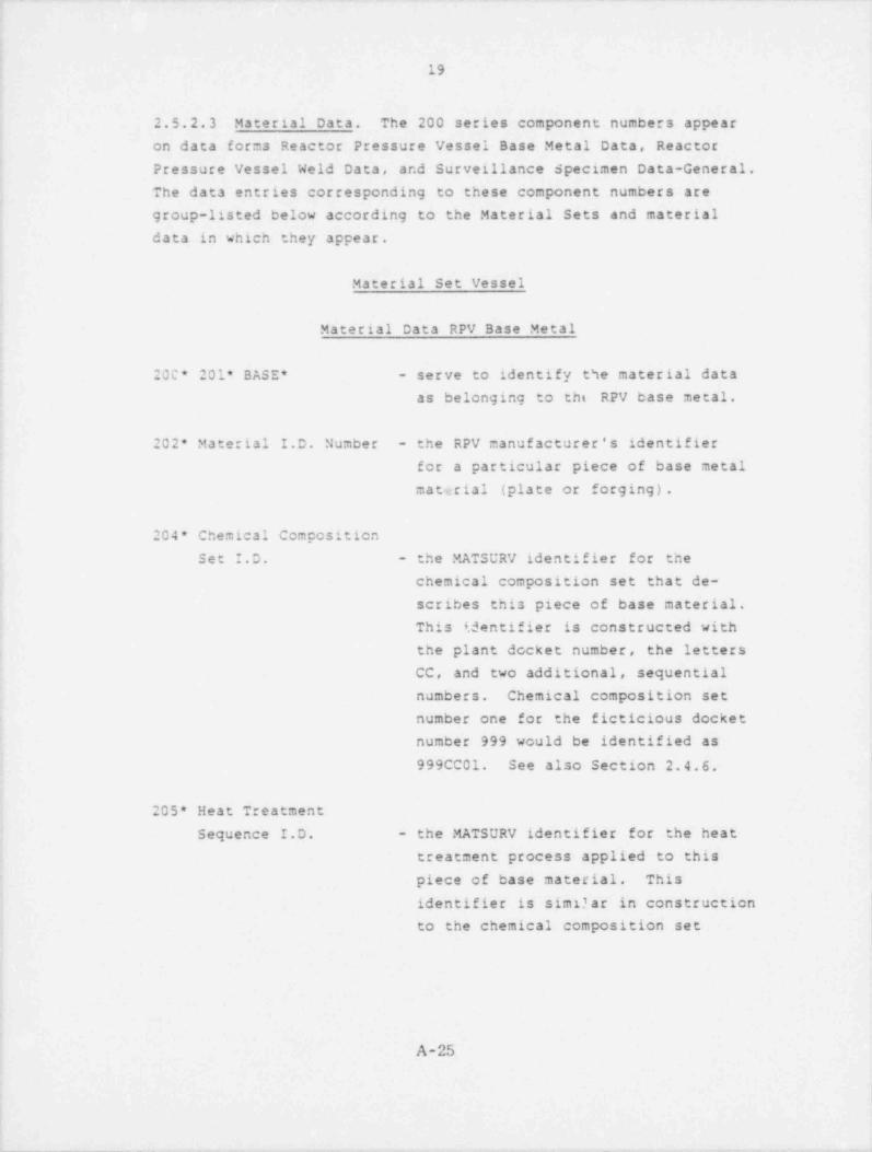
2.5.2.3 Material Data. The 200 series component numbers appear
j on data forms Reactor Pressure Vessel Base Metal Data, Reactor
Pressure Vessel Weld Data, and Surveillance specimen Data-General.
1 The data entries corresponding to these component numbers are4
group-listed below according to the Material Sets and material
data in which they appear.
j Material Set Vessel
!
Material Data RPV Base Metal,
i
20C* 20l* BASE * - serve to identify the material data
as belonging to the RPV base metal.
I
! 202* Material I.D. Number - the RPV manufacturer's identifier
for a particular piece of base metal
material (plate or forging).
| 204* Chemical Composition
Set I.D. - the MATSURV identifier for the
chemical composition set that de-
scribes this piece of base material.'
1 This i.dentifier is constructed with
j the plant docket number, the letters
CC, and two additional, sequential
numbers. Chemical composition set
number one for the ficticious docket !i
number 999 would be identified as
999CC01. See also Section 2.4.6.
205* Heat Treatment
Sequence I.D. - the MATSURV identifier for the heat
treatment process applied to this<
piece of base material. This )
identifier is simd ar in construction
to the chemical composition set;
11
i
| A-251
f
~ _ . _ __. - . . _ . _ - - . - - - . .- _ . - - - - . - - -.

= _ .
20
i identifier. Heat treatment sequence:
1 number one would be identified as'
999BT01 for the ficticious docketnumber 999. See also Section 2.4.5.
206* Material Spec. - the ASME material specification for!
this piece of base material.1
j 207* Heat Number - self explanatory
208* Initial RTNDT - as determined by tests (drop weight,Charpy impact) conducted on samplematerial from this piece of base
metal. Units art OF.
209* Describe Basis forDefining Initial RTNDT - the basis may be the ASME code,
Section III, Appendix G, or someother def.ned basis.
210* Upper Shelf CV1 - the upper shelf energy in foot poundsas determined by Charpy impact testsconducted on sample material from
this piece of base metal.
211* Steel Producer's Name - the manufacturer of this piece ofbase material (plate or forging).
2i2* RPV Test Mat'lOrient. 1 - orientation, longitudinal (L) or
transverse (T), of the test speci-i mens that were cut from this piece
of base metal to determine the upper) shelf energy reported in 210*.
213* Material Form - the form, plate or forging, for this
piece of base material.
A-26
_. -..

- - - - _ . . . - . . . . . . - , _ . - _ . - . . . _ - _ _ . . . - . _ _ _ -
!
t21'
!
| 217* Location in RPV - section of RPV in which this piece
! of base metal is used; e.g., upper '
shell, lower intermediate shell,
etc
:
218* Max. I.D. EOL Fluence - information similar to that pro-2 vided for 13* but specifically for
i this piece of base metal.
I! 219* Fluence /EFPY - information similar to that pro-! vided for 14* but specifically for:
this piece of base metal.
4 220* Max. EOL Fluence at 1/4 T - iiiformation similar to that-
provided for 15* but specifically
for this piece of base metal.
I
224* Upper Shelf CV2 - information similar to that pro- 1
vided for 210* if a second deter--
!I mination of upper shelf energy was
made using &n additional set of
test specimens (with perhaps a
different orientation). fi I
| [
225' RPV Test Mat'l Orient. 2 - information similar to 212* for ;
!test specimens utilized to deter-
mine the upper shelf energy re-
ported in 224*.] *
!250* Comments - self explanatory.
.
The form Reactor Pressure Vessel Base Metal Data is filled outfor each separate piece of base metal used in the fabrication of
|the RPV belt line region.
,
'2
i'
l*
1
1
e i
A-27i ,
'
i i
'4
-__ .-. . . - _ . - . , . . - -. - , ~ , - , - , - - - , , - . . . - - - . , ,- - -- n ~ . . , , . . - , . , . , - , - . , ~ , _

_ . _ _ _ _ _ - . _ _ _ _ . _ _._ _. _ _ _ . _ _ . - . _ _ _ _ _ . _ _ . __ _ - _ _ _ _ _ _ _ - _ _ . . . . . .
22
!
Material Set Vessel
Material Data RPV Welds
200* 20l* WELD * - serve to identify the material data
as pertaining to RPV welds.
i! 202* Weld I.D. Number - the RPV manufacturer's identifier1
j for a p.rticular weld used in fab-1 rication of the vessel. It should
be noted that any given weld seam,
[ for example, a girth weld, may bej described by multiple sets of data.4>
This would occur if both the auto-
matic submerged are and manual are
processes were employed, or if
fluxes of different batch numbersi
were used in a given weld process.
In such cases, a separate Reactor
Pressure vessel Weld Data form is] filled out for each data set cor-
responding to each process or pro-i
cess parameter variation employed5 in making a compleced weld seam.1
204* Chemical Composition Set I.D. - as previously described for
Material Data RPV Base Metal. In
general, a different chemical com-
position set will exist for each
different combination of weld wirespecification, heat number, flux
type and grade, and flux batch
number.
! 20f* Heat Treatment Sequence I.D. - the MATSURV identifier, as
previously described, for the
ii
i
A-28
1
. . - . _ . . . - - . . , , . - -..~., , ,-- - . , - - ,, ._ . _ _ - . - , -.|
-

- - - . . . . . .__-- .. . -. - - _ _ ,- __. . . .
|.
t
23.
,
1 heat treatment process applied to
the particular weld seam.
;
206* Weld Wire Spec. - self explanatory,
i
207* deld Wire Heat Number - self explanatory.
208* Initial RTNDT - as determined by tests (drop weight,
Charpy impact) conducted on sample'
I, mat 2 rial taken from a weld made inco.,formance with the process and
parameters listed on this Reactor
Pressure vessel Weld Data Form. !
! Units are CF. ,
,209* Describe Basis for Defining
f Initial RTNDT - as previously described.
the upper shelf energy in foot pounds210* Upper Snelf CV -<
;as determined by Charpy impact'
tests conducted on sample material
! cehen from a weld made in confor-5 mance with the process and para-
meters listed on this Reactor Pres-i.
sure Vessel Data Form. Units are
OF.-|
,
214* Flux Batch Number - self explanatory.,
self explanatory.215* Flux Type and Grade -
216* Weld Type - the welding process, e.g., manual i
arc, submerged arc, etc.
i
218* Max. I.D. EOL Fluence - information similar to that pro-
vided for 13* but specifically for,
this weld seam.
,
',
l
A-29
I I
~ . __ - . - _ ___ - _ _ _. ~_ _ , . - _ . . - _ _ . - _

24
219* Max. I.D. Fluence /EFPY - information similar to that pro-
eided for 14* but specifically for
this weld seam.
220* Max. EOL Fluence at 1/4 T - information similar to that pro-| vided for 15* but specifically for
this weld seam.
.
221* Base Metal Spec. - the ASME material specification for.
one of the two pieces of base metal
fused by this weld seam.
222* Base Metal Spec. 2 - the ASME material specification for
the second of the two pieces of base
material fused by this weld seam.|
223* Weld Direction - self explanatory. The symbol L is
used for longitudinal or vertical
weld seams (welds having directionsparallel to the longitudinal axis
of the vessel), and the symbol C is
used for circumferential or girth
welds.
250* Comments - self explanatory.
Material Set Baseline
Material Data for Surveillance Specimens - General
The form Surveillance Specimen Data - General is filled out once
for each material region from which surveillance specimens havebeen prepared. The material regions are represented by four typesof surveillance e.pecimens (3ASE, WELD, HAZ, and CMM) as definedin paragraph 2.4.3. Associated with each type of surveillance
A-30

- - . - _
25
specimens are the results of testing Charpy impact, tensile,drop weight, and fracture mechanics specimens. Component |numbers associated with test type and test results are defined |
in later paragraphs. The component numbers defined immediatelybelow pertain to Surveillance Specimen Data - General.
200* 20l* Type - the material region represented by
these surveillance specimens; BASE,
WELD, HAZ, or CMM.
204* Chemical Composition Set I.D. - the identifier for the
chemical ecmposition set associated
with the type material indicated in
200* 201*.
205* Heat Treatment Sequence I.D. - the identifier for the heat' treatment process to which the type
material indicated in 200* 20l* was
exposed.
206* Base Metal - the ASME specification of the base
material designated for use in the
licensee's material surveillance
program, or the ASME specification
of the material from which the
correlation monitor marecial speci-
mens were obtained. The component
number 206* appears twice on data
form Surveillance Specimen Data -
General. As indicated thereon, an
entry is made in 206* Base Metal
only when Type (200* 20l*) is BASE, '
1
HAZ, or CMM. l
20c* Weld Wire Spec. - the specification for the weld wire
used to make the weld that is de-
||
A-31
_

__.
26
signated for the licensee's material
surve'.11ance program. An entry is! made only when Type (200* 201*) is
NELD.
207* Heat Number - this component number also appearstwice on data form SurveillanceSpecimen Data - General. 207* Heat
Number refers to the heat number ofthe material designated for use in
the licensee's material surveillance
program or the material from which
the CMM specimens were prepared.An entry is made only when Type
(200* 201*) is BASE, HAZ, or CMM.
207* Weld Wire Heat Number - the heat number of the weld wireused in making the weld designatedfor use in the licensee $s materialsurveillance program. An entry is
made only when Type (200* 20l*) is
WELD.
211* Steel Producer - of the base material designated for
use in the licensee's material sur-veillance program or of the steel
from which the CMM specimens wereprepared. An entry is made only
when Type (200* 20l*) is BASE, HAZ,
or CMM.
214* Flux Batch Number - self explanatory. Entry made only
when Type (200* 20l*) is WELD.
215* Flux Type and Grade - self explanatory. Entry made only
when Type (200* 20l*) is WELD.
A-32

_
27
216* Weld Type - the welding process, e.g., manual j
arc, submerged arc, etc. Entry is
made only when Type (200* 20l*) is
WELD.
250* Comments - self explanatory.
Material Set Irradiated
Material Data for Surveillance Specimens - General
The form Surveillance Specimen Data - General is also employedin describing surveillance specimens designated for irradiationin the same way in which it is used to group the baseline speci-ments according to type (BASE, WELD, HAZ, CMM). However, each
surveillance specimen capsule that is installed in the reacter
pressure vessel will, in general, contain one or more of thefour types (BASE, WILD, HAZ, CMM) of specimens. Thus, in the
description of the irradiated surveillance specimens, the form
Surveillance Specimen Data - General is employed for each sur-
veillance specimen capsule and for each surveillance specimentype within that capsule. The component numbers have exactlythe smae meaning as when describing baseline surveillance speci-mens and need not be redefined here.
D2.5.2.4 Test Data. Within MATSURV, surveillance specimen test
data is filed in both Material Set Baseline, for baseline speci-
mens, and Material Set Irradiated, for irradiated specimens.
Within each of these Material Sets, the test data is filed under
specimen type (BASE, WELD, HAZ, CMM). The test data is also
organized by test type (Charpy isapact, tensile, drop weight andfracture mechanics) .
Series 500 component numbers are used for enterirg data associated
with Charpy impact tests, series 600 for tensile tests, series
700 for drop weight tests, and series 800 for fracture mechanics
(FM) tests. These compar.ent numbers appear on the respectiveSpecimen Test Data Forms.
A-33

_ , _
28
Charpy Impact Scecimen Dati
500* 512* Charpy Impact serve to identif/ the test data as-
being associated with Charpy impacttesting.
50l* Orientation - refers to the orientation of the
Charpy impact specimens with respectto a characteristic of the reactor
pressure ve sel material. For
plate materials, the. letters L and
T are used to denote whether the,
principal axis of the Charpy speci- |men is longit"dinal or transverse
i
to the principal rolling direction.1For specimens taken from welds and
weld heat affected zones, the letters
L and T denote whether the prinicpalaxis of the specimen is parallel or
transverse : the direction of tnej weld.
502* Capsule I.D. - the MATSURV capsule identifier des-
cribed in paragraph 2.4.7.4.i
503* Candidate Specimens in Capsule - the number of Charpy im-pact specimens of a particular type
(BASE, WELD, HA2, CMM) located in
the capsule identified in 502* and
whose orientation is as given in
501*.
504* Number of Specimens Tested - of that number identified in503*, the number actually tested to
obtain the results filed under! suceeding component numbers.
A-34

... . _ . _ _ .. _ . . _ _ _ _ _ _ . . .._ _ . . _ _ _ ..._ _ _ . . _ .
.
29
hj 505* Upper Shelf CV - the upper shelf energy in foot pou .s
i obtained by testing a subset of t ne
| specimens given in 504*.
|as determined by tests (drop weight,4 506* Initial RTNDT -
Charpy impact) on baseline specimens.I An entry can also be made for irra-
diated specimens, but the value
entered wculd have been obtainedi
from results of tests on baselinespecimens. Units are CF.'
i
' 507* Describe Basis for Defining
as previously defined for 209*. ;Initial RTDNT -
'4
508* 50 Ft. Lb. Shift - the difference in the temp 3ratures
i at which 50 foot pounds of enerry
is absorbed in Charpy tests of|
irradiated and baseline speciment.
An entry would be made only for
irradiated specimens. Units are
CF.
similar to 508*.' 509* 30 Ft. Lb. Shift -
1s
the difference in the temperatures510* 35 Mil L.E. Shift -
} at which 35 mils lateral expansion
occurs in Charpy tests of irradiated
and baseline specimens. An entry
would be made only for irradiated
specimens. Units are OF.1
J
511* Percentage Drop Upper
a measure of comparison in upperShelf CV -'
j shelf energies between irradiated
1
|
.
,
A-35
|
- . . - . . _ - _ _ _ -- - - . - - - - .- - -- , _. . _.-..- . . - - - . . - , . __.

. _ _ _ _ _
i
i i
I
30 |
and baseline specimens. An entry
would be made only for irradiated
specimens,
l 550* Comments - se]* explanatory.
Tensile Specimen Data
600* 605* Tensile - serve to identify the test data as
being r r..iated with tensile
testing.|
|60l* Orientation - refers to the orientation of the
principal axes of the tensile test
specimens. Similar to 50l*.
602* Capsule I.D. - the MATSURV capsule identifier
described in paragraph 2.4.7.4.
603* Candidate Specimensin Capsule - the number of tenaile specimens of
a particular type (BASE, WELD, HAZ,
CMM) located in the capsule identi-
fied in 602* and whose orientationis as given in 60l*.
650* Comments - self explanatory.
610* 611* Test Temperature - the temperature at which the ten-sile tests are conducted. Units
are CF. Provision exists to record
tensile test results for several
test temperatures and the Tensile
Specimen Data Form has been de-
signed accordingly. Any number of
additional results can be included.
A-36

_
31
604* Number of SpecimensTested - of that number identified in
603*, the number actually tested at ;
a particular temperature to obtain I
the results filed under succeeding
component numbers.
these component numbers serve to612* through 616* -
identify the results of the standardtensile tests with which they are
associated as shown on the TensileSpecimen Data Forms.
Drop Weight Specimen Data
700* 706* Drop Weight - serve to identify the test data as
being associated with drop wcighttesting.
/Ol* Orientation - refers to the orientation of the
principal axes of the drop weighttest specimens. Similar to 501*.
702* Capsule I.D. - the MATSURV capsule identifier
described in paragraph 2.4.7.4.
703* Candidate Specimens
in Capsule - the number of drop weight specimens
of a particular type (BASE, WELD,RAZ, CMM) located in the capsule
identified in 702* and whose orient-ation is as given in 701*.
A-37
1

32
704* Number of SpecimensTested - of that number identified in 703*,
the number actually tested to ob-tain the test result recorded in705*.
I
705* NDTT - the nil ductility transition tem-
perature as determined by the dropweight tests. Units are CF.
750* Comments - self explanatory.
Fracture Mechanics Specimen Data
800* 811* Fracture - serve to identify the test dataMechanics as being associated witt fracture
mechanics testing.
SOS * Type Specimen - depending on specimen type, anentry is made as follows: WOL forwedge-opening-loading; CT for com-pact tensile; RCT for round compacttensile.
80l* Orientation - the fracture mechanics specimenorientation according to the orient-
a. ion system defined in ASTM E399.A two-character code is used. Thefirst character designates the
direction normal to the crack planeof the specimen. The second char-acter designates the expected di-
rection of crack propogation in the
specimen. For material of rectan-gular cross section, the orient-
ation designation characters are
A-38
i
-.

|
33
chosen from L, T, and S where L is
the direction of principal defor-
mation (direction of maximum grain
flow), T is the direction of least
deformation, and S is the third
orthogonal direction. For RPVshells fabricated with plate or
ring forging material, the direction
of maximum grain flow is the hoop
or circumferential direction and
consequently the letter L designates
this direction. The letters T and
S correspond, respectively, to
directions parallel to the vessel
vertical axis and the material
thickness.
802* Capsule I.D. - the MATSURV capsule identifier
described in paragraph 2.4.7.4.
803* Candidate Specimens
in Capsule - the number of fracture mechanics
specimens of a particular origin
(BASE, WELD, HAZ, CMM), a particular
type (WOL, RCT, CT), located in the
capsule identified in 802* and
having orientation as given in
80l*.
850* Comments - self explanatory.
808* 807* Test Temperature - the temperature at which the frac-
ture mechanics tests are conducted.
Units are oF. Provision exists to
record test results for several
test temperatures and the Fracture
Mechanics Specimens Data Form has
| A-39|
|

i
!1
!
;
i 34
| been designed accordingly. Any!
; number of additional results can be '
included.
' 804* Number of SpecimensTested - of that number identified in 803*,
the number actually tested at a
particular temperature to obtain
the results filed in 806*.
806* Test Result - the result of the fracture mechanicstests conducted on the specimens
I
identified in 804* at the temper-
ature given in 808* 807*.
2.5.2.5 Chemical Comcosition Data. Series 300 component numbersare used for filing chemical compositions of the reactor pres-sure vessel fabrication and surveillance materials. These com-ponent numbers appear on the Chemical Composition Set Form.Only those chemical elements listed on the Chemical Cc= positionSet Form are included ;n the data base definition and consequentlycomposition information for these elements only can b'e processedby the data base.
300* 301* Chemical CompositionSet I.D. - the fiATSURV chemical composition
identifier constructed as describedin paragraph 2.5.2.3 under componentnumber 204*.
302* through 323* - the weight percentages of the chemical
elements contained in the materialdescribed by this chemical com-
position set.
324* Analysis Code - O or S depending if chemical analysisis determined from the initialqualification test or from subse-
quent tests of surveillance material.
A-40

35
self explanatory.350' Comments -
2.5.2.6 Heat Treatment Secuence Data. Series 400 component
numbers are used for filing information on the heat treatment
process to which the various RPV fabrication and surveillancematerials were exposed. These component numbers appear on theHeat Treatment Sequence Forms.
400* 401* Heat Treatmentthe MATSURV identifier for a parti-Sequence I.D. -
cular heat treatment sequence, con-
structed as described in paragraph
2.5.2.3 under component number
205*.
450* Comments - self explanatory.
402* 403* NominalTemperature - temperature in CF at which the
material is held for the time and
purpose specified in the sequential
compohent numbers 404* and 405*.
404* Hold Time - the number of hours the material is
held at the nominal temperature
given in 402* 403*.
the purpose of the heat treatment405* Purpose -
process; e.g., austenization, tempering,
or stress relief. It should be
noted that a particular heat treatment
sequence can consist of one or more
combinations of Nominal Temperature,
Hold Time, and Purpose, each combination
constituting a separate entry under
component numbers 402* through 405*on the Heat Treatment Sequence Form.
A-41
, _ . , , , , ._ . _ . - . . - .
I!
36
2.5.3 MATSURV Data Base Definition for System 2000
The following print-out is a presentation of the MATSURV data,
| base definition as it exists in System 2000. Ine ,mponentI numbers are listed along with the corresponding titles as they
would sopear on reports generated from the data base. The
titles are atoreviations of those that are used on the riataforms. Hewaver, they have been chosen to be as descriptive as
possible while also being sufficiently brief to facilitate
manipulation of the data base.
4
'' A-42
_ _ _

- . -. - _ . - _ .-. . _ _ _ . . . .- _-_ ~_ .. . . _.. . - - -- . _ _ . _- -___
|
i
37DE$CRISE: DESCRIBE STRINGS:
1 SYSTEM RELEASE NUPBER 2.90DATA BASE NAME IS sATSUhv
DEFINITI04 NUMBER 1
3ATA BASE CYCLE NUMBER 2
le DOCKET (NAME IXX).
2* PLANT (NAME X(20))i
3* LICEN!EE (NAME X(20))4* REACTOR TYPE (NAME I(51)
: 58 0 L DATE (DATE)i 6* I C DATE (DATE)
7* C 0 2 ATE (DATE)8* NSSS (NAME I(20))9* RPV MANUFACTURER (NAME I(20))
10* FAI (NAME X(5))i 11* DIAM -INCHES- (NON-KEY INTEGER NUMPER ?t5))
12* THICK -!NCHES- (NON-KEY OECIMAL NUMBER 99.99)'
13* RPV MAX EOL FLUENCE -NYT- (DECINAL NUMBER 999.9999)14e RPV MAI FLUENCE RATE -NYT/EFPY- (3ECIMAL NUMBER 999.9999)15* RPV MAI E3L FLUENCE 1/4 T -NVT- (3ECIMAL * UMBER 999.9899)16* CODE SECTION (NON-<EY NAMC I(202)17* DESIGN P -PSIG- (NON-KEY INTEGER NUMBER 9999),
18* DESIGN T -DES F- (NON-KEY INTEGER NUMBER 999)19e RPV SPEC (NON-KEY NAME X(20))20* BASE METAL 1 (NAME X(13))'
21* BASE METAL 2 (NAPE I(13))i 100* MAT SET (AG)
10l* DATASET (NAME X(10) IN 100)102* TEST LAB (NON-KEY NAME X(20) IN 100)
3 103* REPORT DATE (NON-KEY DATE IN 100)104* REPORT (NON-(EY NAME X(20) IN 100) i
104* CAPSULE ID (NAMC I(12) IN 100)4 107* NRC CAP ID (NAME Xt6) IN 100); 1098 SCHED REMOVAL (SATE IN 100) ,
110* ACT REMOVAL (SATE IN 100)111* FLUENCE -NVT- (DECIMAL NUMBER 999.9999 IN 100)
i 112e AIIMUTHAL LOCATION -DEG- (NON-MEY INTEGER NUMBER 999 IN 100)
150* MAT SET COMMENTS (NAME I(7) IN 100)200* MAT DATA (RG IN 100)
20l* TYPE (NAME XIXX IN 200)202* MFR ID (NAME X(15) IN 200)<
203* NRC ID (NAME I(12) IN 200)204* CHEM COMP (NAME X(7) IN 200)205* HEAT TREAT (NAME I(7) IN 200)206* SPEC (NAME X(13) IN 200)207* HEAT NO (MAME X(10) IN 200)208* RTNDT -DEG F- (INTEGER NUMBER 9999 IN 200)
,
) .
r
i
A-43
i,
s
, ,. , - - _ - . , - - . , , - . - - _ r - _ --. ,,a-- ,n_ -- - . -_. , , .,_..--_

. .- .. . - - , - - . - _- . - . - -
i
l
!
38
| 209* 1 ASIS Rr4DT (NAME Xf43) !V 200)| 210e UPPER SHELF CV 1 -Fi LBS- (DECIMAL NUMBER 999.99 IN .'00)| 211* STEEL PRODUCER (NAME I(20) IN 200)
2128 TEST CRIENT 1 (NAME X IN 200)2248 UPPER SHELF CV 2 -FT L35- (DECIMAL NUMPER 999.99 IN 200)
; 225* TEST 3RIENT 2 (NAME X IN 200); 213* F3RM (NAME X(10) 14 200)! 214e FLUX SATCH (NAME X(10) IN 200)
215 FLUX TYPE (NAME X(15) IN 2001216* WELD TYPE (NARE Xt:0) I,v 2C01
217e L3 CATION (NAME X(20) IN 200). 219* 1AXEOL FLUENCE -*VT- (DECIMAL NUMIER 999.9999 IN 200)
{ 219e PAXFLUENCE RATE -NVT/EFPT- (DECIMAL NUMBER 999.9999 IN 200: )
| 2208 MAIEOL FLUENCE 1/4 T -NVT- (DECIMAL NUMBER 999.9999 IN 200'
)
221* BASE MTL 1 (NAME X(13) IN 2003222* BASE MTL 2 (NA9E X(13) IN 200)223 DIRECTION (NAME X IN 200)250* CCF"ENTS (NAME X(7) IN 200)500* CHAR *T TESTS (R3 IN 200)
512* CHARPY IMPACT (NAME X(13) IN 500)301* CV SPEC 3RIENT (NAME X IN 500)5028 CV HOST CAPSULE (NAeE X(6) IN 500)503* CV CAND. SPEC (INTESER NUMPER 999 IN 500)504* CV SPEC TESTE3 (INTEGER NUMBER 999 IN 500)505* JPPER SHELF CV -FT L35- (DECIMAL NUMBER 999.99 IN 500)506* INITIAL RTNDT -DEG F- (INTEGER NUMBER 7999 IN 500)507* 3 ASIS (NAME Xt40) IN 500)508* 50 FT L3 SHIFT -DEG F- (INTECER NUMBER 999 IN 500)509* 30 FT L3 SHIFT *E3 F- (INTEGER NUMfER 99' 11 500),
510* 35 *IL L.E. SHIFT -DE3 F- (INTE5ER NUMBER 999 IN 500)511* DROP IN UPPER SNELF CV -PCT- (INTEGER NUMBER 999 IN 500)
11
550* CV COMMENTS (NAME X(7) IN 500)600* TENSILE !ESTS (RG IN 200)
; 6 ', ) * TENSILE (NAME X(7) IN 600)
j 601* TEN SPEC CRIENT (4AME X IN 600)602* TEN HOST CAPSULE (NAME X(6) IN 600)603* TEN CAND. SPEC (INTEGER NUMBER 999 IN 600)
! 650* TEN COMMENTS (NAME X(7) IN 600)610e TEN RESULTS (RG IN 600)
6lle TEST TEMP -DEG F- (INTEGER NUMBER 9999 IN 610)604* TEN SPEC TESTED (INTEGER NUMBER 999 IN 610)
l 612* AV T! ELD -PSI- (INTEGER NUMBER 9(5) IN 610), 613* AV ULT STRENGTH -PSI- (INTEGER # UMBER 9(6) IN 610)! 614* AV ELONG -PCT .(DECIMAL NUM3ER 99.99 IN 610)
615* AV UNIFORM ELONG -PCT- (DECIMAL NUMBER 99.99 IN 610); 6168 AV RED AREA -PCT- (2ECIMAL NUMBER 99.99 IN 610); 700* DROP WT TESTS (RG IN 200)
706* DROP WEIGHT (NAME X(11) IN 700)
i
i
!A-44
! . _ __. . .._ _ _ - - _ - - - . __ _ , - -

_ . . _ _ _ . _ _ . _ _ _ - _ _ _ _ _ _ _ _ _ _ _ _ _ _ . _ ___ ._ _ __
|'
4
3 39I .
*
701* SW SPE: ORIENT (NAME X IN ?00)70:8 DW HOST CAPSULE (NA*E Xt6) IN 700)
i 703* DW CAND. SPEC (INTEGER 9UMBEN 999 IN 700)704* 3W SPEC TESTED (INTEGER NUMPER 999 IN 100)
! 705* 4DTT -3EG F- (!NTEGER NUMBER 999 IN 700)750* DW COMMENTS (NAME X(?) IN 700),
] 900* FM TESTS (R0 IN 000)i Bits FRACTURE MECHANICS (NAME X(IS) IN 200)
901* FM STEC ORIENT (NAME XXX IN 800)902* F9 HOST CAPSULE (NAME *(6) IN 800)
i 933* FM CAND. SPEC (INTEGER gUMBER 999 IN 800)00:e FM SPEC TYPE (%AME XXXX IN 900)353* FM COMMENTS (PAPE X(7) IN 800)B0B* Th RESULTS (R6 IN 800)"
$04* FM SPEC TESTED (INTEGER NUMBER 999 IN 808)8078 FM TEST TEMP -DEG F- (INTEGER NUMPER 9999 IN 809)
I
806 FM TEST RESULT (DECIMAL NUMBER 9(6).9 IN 909)l 300* C09 POSITION (RO)
301* CHEM COMP 13 (9AME I(?) IN 300)30:e CU -W/O- (DECIMAL NUMSER 99.9999 IN 300)303* P -W/O- (DECIMAL NUNIER 99.9999 IN 300)304* CAR 30N -W/O- (DECIMAL NUMPER 99.9999 IN 300)30$* MN -W/0- (3ECIPAL NUMBER '9.9999 IN 300)306* S -W/0- (DECIMAL NUMBER 99.9999 IN 300)307* SI -W/3- (DECIMAL * UMBER 99.9999 IN 300)
| 308* NI -J/O- (DECIMAL NUMBER 99.9999 IN 300)! 309* CR -W/O- (3ECIMAL 1 UMBER 99.9999 !N 300)
310e MO -W/0- (DECIMAL NUMBER 99.9899 IN 300)311* 'l -W/0- (DECIM AL NUMBER 89.9999 IN 300)
,
31:* TI -W/O- (DECIMAL MUMBER 99.9999 IN 300)'
313* AL -W/O- (DECIMAL NUMBER ??.9999 IN 300)31** B -W/O- (DECIMAL NUMBER 99.9999 IN 300)'
315* C3 -W/0- (DECIMAL NUMPER 99.9999 IN 300)316* W -W/C- (DECIMAL NUMPER ?9.9999 IN 300)317* AS W/O- (DECIMAL NUMBER 99.9999 IN 300)318e $N -i/O- (DECIMAL NUMSER 99.9999 IN 300)31?* IR -W/O- (3ECIMAL NUMBER 99.9999 IN 300)3:0* NB -W/O- (DECIMAL NUMBER 99.9999 IN 200)321* 53 -W/0- (3ECIMAL NUN 3ER 99.9999 IN 300)322* IN -W/O- (DICIMAL NUMSER 99.9999 IN 300)323* 4 -W/0- (DEC: MAL NUMBER 99.9999 IN 300)'
324* WHEN ANALY!ED (NAME X IN 300)i 350* CC COMMENTS (NAME I(7) IN 300)
400* HEAT TREATMENT (RG)i 401* HEAT TREAT ID (NAME Xt7) IN 400)
4:0* HT COMMENTS (NAME X(?) IN 400) i,
!
1 402* HT DATA (RG IN 400)403* NOM TEMP -DEG F- (NON-KEY INTESER NUMBER 9(5) IN 402);
t 404* HOLD TIME -HRS- (NCM-KET DECIMAL NUMBER 999.9? IN 402)
| 405* PURPOSE (NON-<ET NAME X(13) IN 400)
i,
A-45,
I
!
l
_ _ . _ _ __ . _ . _ . _ _ _ _ . ._ - _ _ , _ _ _ - , _ _ _ . __ __ _ .__ ,

40
w
100!* HEADER (STRING (L|ST/ REPEAT SUP, TITLE (131)D(1)---- NRC-RPV SURVEILLANCE DATA NANAGENENT
PROGRAM-----FA!!URV---- ,))1003 HEAD: ( S T RIN G ( L IS T/REPEA T ,T!TL E (131 )
i D(1)-----NRC-RPV SURVEILLANCE DATA MANAGEMENT| PROGRAM-----PATSURV---- ,))
100:e PLF00T (STRING (F(10) PLANT 3ATA REPORT.L(6)DLCHET/C' WH SA> >1010* PLPRT (STRING iPRINAME, NULL /C2.C3,C4,C5,C6,C7,C8,C?,C10.C11,Ct ,
C13,C14,C15, C16,C17,C18,C19.020,C21 WH SA))1000* PLTREP (STRING ( *C100t* *C1002*: * C 1010 * ) )130:e CF00T (STRING (F(101 CHEMICAL COMPOSITION SET REFCRT,L(6) DOCKET /C
1 WM SA))13108 CCPRT (STRING (PR/MAME, NULL /C300 WH SA))1300* CCREP (STRING ( *Ct001* *C1302*: *C1310*))1:02* BMF00T (STRING (F(10) REACTOR PRESSCRE VESSEL BASE METAL REFCRT,L
(4)COCKET/ C1 MH SA ))1:10e 39PR r (STRING (PR/N AFE, NULL /C1,C101,C201,C 02,C213.C207,C206,C:t
1.C217,C ff, C219,C2 0,0 10,C12,CO24,C :: f 8,C209,C205,C204,C:50 ud SA AND C101 EO VE !EL AND C201 EU PASE))
1200* B9 REP (STRING (*C1003* *CI:0: *Ct:10* 1)1203 BWF30T (STRING iF(13)REACTCR PRESSURE VESSEL JELD RCFCRT,L(6)3CC
KET/ Cf W4 SA>>1:11e BWPRT (STRING (PR/NAME, NULL /C1,0101,C201,C002,C201.C206.C215,C21
4,C:16,C::t, C:22.C217,C223,C:19,C:19,C :0,0210,C208,C:09,C205,C:04 WH SA AND C101 E3 VESSEL AND C201 E2 WELD ))
1:31* BWREP (STRI*G ( *C1003* *C1203*: *C1 11 * ))1:1:e FSF00T (STRING (F(20)3ASELINE SURVEILLANCE SPECIMEN REFCRT,L(6)3
CCNET, L(B),L(4),L(20) TEST LA3,R(1') TEST LAB * REPORT 3ATE,L(20)REPCRT TIT'.E, L ( 40 C 3 MME NT S/ C1, C101,C 201, C102,r * 03,C10 4,015 0 WH S A ))
1205* 3dr T1 (ST2ING (F(201 BASELINE SURVEILLANCE SPECIMEN REFORT,L(6)00CXET, L'S),L(4)/C1,Ct01,0201 LH SA))
1216* 3SFT2 (STRING ( AND C101 EQ BASELINE AN3 C201 E0 *te ))12:0* BSPRT (STRING (PR/NAME, NULL /C1,0101.C201,C206,C:07,C 11,C205,C00
4,C250, BT C200,C500,C400,C700,CS00 WH SA AND C101 EQ*!* ANJ C201 E3 *2e ))
1225* BSREP (STRING ( *C1003 *C1:1 * *C1216(IASE): *C1000(BASELINE,3ASE) ))
1:26* HSREP (STRING ( *C1003* 'CI:0$* *C1:16(HAZ): *C12:0(IASELINE.HAI) ))
1227* CSREP (STRING ( *C1003* *C12C:s *C1:16(CMM): *C12:0(PASELINE,CMM) *)
1230* Us?RT (STR!RG (PR/NAME NULL /C1,C101,C201,C207,C006.C215,C214,C214,C205,C204, C250,BT C200,C500,C600,C700,C300 UH SA AND C101E2 ele AND C201 EG WELD 11
1231* WSREP (STRING ( *C1003* MC1:0!* *C1216(WELD): *C1270fBASELINE) ))
1213* 3CF00T (STRING (F(20) IRRADIATED SURVEILLANCE !FECIPENT REPCRT,Lt6) DOCKET,5(2) ,L(t:) CAPSULE *!D - NRC+I - MFR,3(t),L(10) TEST LA
#
3,3(1),R(10) TEST LA8+ REPORT + ATE,3(2),L(t!) REPORT TITLE,3(1),R(10) SCHEDULED + REMOVAL +DATE ,B(2),))
1206* 3CFT1 (STRING (F(20)!RRADIATED SURVEILLANCE EFECIME4 REPORT,L(6)
A-46
1

.
41
33CXET,9(2s, L (I L) C A P S UL E + II: - N'c+!D - McR,5(1,1) F(57 L(1:),S(1,2),5(8),L(10),L(4), S(! :.'/Ct,0107.C106.C10t,C201WH SA))
1:14* BCFT: (STRING tR(101 ACTUAL *RE40 VAL +DAIE ,0(t).RIIJ) CAPSULE + FLUEwCE AT+RE30 VAL -NVT .3(2),R(10) A I?UTHAL+LCCATICw+I* kFV -DE3 .5(1,1),3(3),L(!:),Sif,2),3(9),L(10),L(4),L(10).S(1,1)JC1,Ct07,C10 2, C 103, C t 0 4, C10 9, C i t 0, c i l l , C 112. C 106,1 ) l
1 1?* 3CFT:A (STRING (C101.C201,C150 WH SA))1215* SCFT3 (STRING ( AND C101 E3 IRRADIATED AND C201 E3 *1*))1:40* SCREP (STRING ( *C1003* *Ct:13* *C1214* *C121?* *C1215(PASE) AND
Clot EXISTS AT 1)1:44* 3CREP1 (STRING ( *C12:0(IRRADIATED, BASE: AND C101 EXISTS AT ))1:41* HCREP (STRIN3 ( *C1003* *C1:06* *C1215(MA ) AND Clot EXISTS AT )
)
1245* HCREP1 (STRING ( *Ct:20(IERADIATED,HAZ) AND 010f EXISTS AT >>124:s CMCREP (ST8!*G ( *C10038 *C1:36* *C12!5(CNM) AND C101 EXISTS AT
))124e* C?REF1 (STRIN3 ( *C1:00 ( I R R A DI A TF.3,C MM ) AN3 Ct01 EXISTS A1 ))1:43* WCREP (STR!N3 ( *C1003* *C1204* 'C1215(CELD) AND Clot EXISTS AT
))1:47* WCREP! ::* RING ( *C1:30(IRRADIATED) AND C101 iT!STS AT ))1410* HTF30T (STRING (f(50) HEAT TREATMENT REFORT B(9),
L(14) HEAT TREATMENT + SE:CENCE I.D.,
R(1!) NC 9IN AL * TErPERA TURE+-3EG F ,))
1420* NTFT tSTRING (a(3),R(6)MCL3+'!ME+(HRS),3(3),L(40)PURFCSE,L(30)C3MMI.TS/
C401,C403,C404,C405,C4:0 WHERE SAME 1)
1400* HTREF (STR!N3 ( *C1001* *C1410* *C1420*))1500* ERRCHK (S* RING (TALLY /EACH/C1,CS,C9,C10',C 01,C212,C2:5 C223,C51
2,C501, C:02.C605,C401,C602,C706,C701,C702.C3tl CSO:,C502: PR/NAME/C1 C:05,C401: F9 C1,C204,C301: FR/ REPEAT SUF/C1 C101,0f071)
f
A-47

42
3. ACCESS TO THE NIH/DCRT COMPUTER CENTER;
3.1 General
MATSURV exists on the IBM 370/168 computer at the National Institutes
of Health Division of Research and Technology Computer Center (NIH/DCRT)in Bethesda, Maryland. Procedures are being established at NRC by the
Automated Systems Branch, Technical Support Division, Office of Manage-ment and Program Analysis. These procedures will be included in the
" Computerized Information Systems Policies and Procedures Manual".Carlos Monserrate of the Autcoated Systems Branch is the point of con-tact.
3.2 Retrieval / Entry Security
System 2000 provides password protection for the data base. The Master
user may assign other passwords and authorities to these passwords.These password / authorities will be assigned according to the operationalresponsibilities required. The Engineering Branch, Division of Oper-
ating Reactors has the responsibilty of assigning these passwords. Theccmmands to assign or remove passwords / authorities are described in the
System 2000 Manual in the Control Module, Section 3.
In addition, the operating system at NIH assures each user of account
protection and privacy. Only qualified users will be informed of the
Initials, Account, Keyword, and file locations required to accessMATSURV.
3.3 Accessing MATSURV
MATSURV may be accessed using either batch mode (WYLBUR) or interactive(TSO). WYLBUR and TSO are ccmmand languages available at NIH as partof the overall operating system. They are maintained and documented byIBM and NIH. These languages are used to establish and edit p::
cedures. Such procedures may be executed directly (TSO) or submitted
A-48

43
to the operating system queue for subsequent execution (NYLBUR). An
example using WYLBUR will be presented. Items enclosed in (. . .). are
values which must be obtained from the Automated Systems Branch of NRC.
3.3.1 Sample JCL
The following is an example of JCL for a batch job. All user queries
should be inserted as indicated. In particular, they must be before
the EXIT: command.
//(iii>S2K JOB ((acct ),(box), A) , ' S2K MATSURV'/* UNNUMBERED
ff.......***.................. ***.
//* JCL TO ACCESS MATSURV *
//* DATABASE IN BATCH MODE *
77..... ..........******...........
//PROCLIB DD DSN=(acetjjj).PROCLIB, DISP =SHR, UNIT = FILE,
// VOL=SER=(FILENO)
//S*EPl EXEC MTSRVS2K//GO.SYSIN DD *USET . ( passwo rd): DBN IS MATSURV:
Insert desired queries here.EXIT:
/*
Note that iii are the project initials and jjj are the initials for the,
procedure library. These two sets of initials may or may not be the
same.
3.3.2 Additional CD Statements
The user may wish to request additional files, for exainple a separate
report or data file. The following is an example of a DD statement for4
a permanent file.
//GO.RFDOC DD DSN=(acctili).RFDOC, DISP = (NEW, KEEP) , UNIT = FILE ,
// VOL= SER=(fil e no), SPACE = ( TRK , ( 5 0,10 ) , RLSE) ,
// DCB=(RECRM=FB,LRECL=133,BLKSIZE=133)
A-49.

:
44
!
An example of a temporary file DD statement is as follows.
//GO. TEMP DD DSN=& TEMP , UNIT =SYSDA, SPACE = (TRK, (50,10 ) , RLSE) ,
// DCB=(RECFM=FB,LRECL=133,BLKSIZE=133)
ii The System 2000 user would refer to "RFDOC" and " TEMP" respec-
f tively. Any name may be used on the DD card but the GC.(name)l must match that used in the System 2000 commands. Some examples
j follow.
REPORT FILE IS RFDOC:
DATA FILE IS TEMP:
3.3.3 System 2000 Run Recuests
Once the active NYLBUR work space centains the required JCL,
and desired commands the user may submit the job to the batch
processor via the following typed command.
RUN REMOTE ( m ) HOLD NOTIFY
;
REMOTE (m) identifies the routing for this job and should cor-
respond to the closest printer (RJE) unit. Exclusion of this
parameter routs the job to the NIH center. HOLD indicates that
the user wishes to inspect the job output prior to printing.
NOTIFY asks the system to inform the user when the job is com-
pleted. Other options are available and are discussed in the
WYLBUR Manual.
4. RETRIEVAL AND DISPLAY OF DATA
4.1 General
Several methods of retrieval may be used in System 2000. The
most common are Procedural Language Interface (PLI), Queue mode,
and Immediate Access (IA). Only Queue and IA will be discussed
in this section. In addition, the user may be executing in
A-50
_ _

45(
either a batch or a time-sharing environment. The pr' mary em-
phasis in this section is on the batch environment. In batch
the user must have knowledge of all the questions and conditions
prior to submitting the job. This means, in particular, that
asking questions across disjoint data sets is somewhat less than
straightforward. This will be discussed in pars,_aph 4.3 For
non-disjoint data sets the IA Natural Language will easily allow
the user to obtain the desired information in batch as well as
in interactive. The user should refer to the Data Base Defini-
tion, paragraph 2.5.3, to determine the componene numbers / names
of the desired data values.
4.2 Retrieval Examples, Non-Disjoint Data Sets
This type of retrieval makes use of the IA WHERE clause cap-
ability. That is, data sets may be selected for particular
attributes and then several data values may be LISTED or PRINTED.1
In batch environment questions which require the knowledge of
answers to previous questions may be submitted as sequential
program executions or the * DATA * file as described in paragraph
4.3 may be used. In general, however, it is possible to construct
a series of querics appropriate to the batch environment.
4.2.1 Example 1
Identify all dockets whose NSSS (CS) is Westinghouse. Of this
group, print the RPV manufacturer and any Charpy Test data.
Identify the material set and type of the test data.
PR/NAME, REPEAT SUP/C1,C9,C101,C201,C500 WH C8 SPANS W*Y:
A-51
l|
|
i

i
46
i,
4.2.2 Example 2
! Of the dockets selected in Example 1, identify all the Steel
Producers (C211) and associated material set, capsule ID, and
type.
, SAME IS STATIC:I PR C101,C107,C201,C211 WH C211 EXISTS AND SA:
|
Only those entries where there is data for the Steel Producers,
are to be printed.
4.2.3 Example 3.
Identify all dockets where capsules have been removed. Also
orint the associated Test Lab data.
PR/NAME, REPEAT SUP/C1,C100 WH C110 EXISTS:
4.3 Retrieval Examoles, Disjoint Data Sets
Disjoint data sets may be defined to be those data sets which are
on the same level. Descendents of disjoint date sets are also
disjoint. Referring to the MATSURV organization chart, para-
I graph 2.4.8, it can be seen that the following data sets are dis-
: joint.
Chemical Composition Sets, the Heat Treatment Sequence data
tree, and the data tree starting with Material Set (all
starting on Level 1)
Charpy Tests, Drop Weight Tests, Tensile Tests data tree,
and Fracture Mechanics Tests data tree (all starting at
Level 3),
,
i
|
|
| A-52
- - _

47
System 2000 will not allow PRINT /WHERE clauses to cross disjointdata sets directly. If, for example, you wished to know which
specimens had a CU weight percent (w/o) greater than .4, the
following would not be allowed.
PR C1,C101,C204 WH C302 GT .4: |
One way of rephrasing this question is:
PR C1,C101,C204 WH C0 EAS C302 GT .4:
This will, however, not select only those Chemical Composition. Sets where CU ).4 but will print all existing values of C204 if
any Chemical Composition set associated with the docket has CU)>.4.The examples will demonstrate various ways of obtaining the de-sired information.
4.3.1 Example 1
Identify the specimens which have CU w/o greater than .4 usingIA. This may be run in two steps in a batch environment or in
one step in an interactive one.
Step 1 PR C301 WH C302 GT .4:This supplies a list of those Chemical Composition
Sets with the requestad attribute.
Step 2 PR/NAME, REPEAT SUP/Cl,C101,C107,C201,C202 WH
C204 EQ (ccid>:This command must be repeated for each ccid
identified in Step 1. This command may be set
up as a string in the definition for easier
repetitive access.
4.3.2 Example 2
Address the same questica as in Example 1 using Queue mode.This may be run as single step in either baten or interactive.
|1
A-53,
_ - _ _
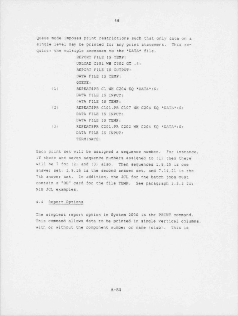
.. .. -- .
|
48
i
i Queue mcde imposes print restrictions such that only data on a
single level may be printed for any print statemert. This re-
quiret the multiple accesses to the * DATA * file.
REPORT FILE IS TEMP:
UNLOAD C301 WH C302 GT .4:i
REPORT FILE IS OUTPUT:
j DATA FILE IS TEMP:
QUEUE:
(1) REPEATSPR Cl WH C204 EQ * DATA *:$:DATA FILE IS INPUT:
OATA FILE IS TEMP: |
(2) REPEATSPR C101,PR C107 WH C204 EQ * DATA *: S:
DATA FILE IS INPUT:
DATA FILE IS TEMP:(3) REPEATSPR C201,PR C202 WH C204 EC * DATA *:S:
DATA FILE IS INPUT: ||
TERMINATE:
j Each print set will be assigned a sequence number. For instance,
| if there are seven sequence numbers assigned to (1) then there"
will be 7 for (2) and (3) also. Then sequences 1,8,15 is one
answer set, 2,9,16 is the second answer set, and 7,14,21 is the
7th answer set. In addition, the JCL for the batch jobs must,
contain a "DD" card for the file TEMP. See paragraph 3.3.2 for
NIH JCL examples.
4.4 Report Options
The simplest report option in System 2000 is the PRINT command.
This command allows data to be printed in single vertical columns,
with or without the component number or name (stub). This is
,
1s
,
A-54 ,
1
|
, - - . - . , , - -r - ,- ---

.. ~. _. _ _ .. .
49
described in the System 2000 Manual in IA Section 3.3 and in Queue
Section 6.3.2. The LIST command, with title and heading options,
allows data to be in rows. This command is somewhat more complicated
and is described in the Systems 2000 Manual in IA Section 3.9. Many of
the component names in MATSURV are longer than 16 characters, thus the
default capability of LIST (use of component names as headings) will
not be allowed for these components. If any such components are in the'
object list, any headings desired must be specified and all entries in
the object list must have a corresponding (type > in the option list.The additional report capability of the Report Writer in System 2000
will not be discussed.
4.4.1 Docket Recorts
The MATSURV definition contains strings set up to output specific re-
ports. The strings are included in the data base definition DESCRIBE'
STRINGS paragraph 2.5.3. As of July 1979 these strings work on Infonet
System 2000 version 2.81 but need some modification for IBM System 2000
j version 2.80. The complete report on a specific docket requires that
all of the commands using thase strings would he established and accessed
for each docket in question. Efficient use of the System 2000 suggests
that some knowledge of the docket in question would be helpful in
setting up the command file. In particular, it is of interest to know
whether there are VESSEL, BASELINE, IRRADIATED data sets, whether they$
i are in that order, and how many IRRADIATED data sets exist for the
docket. Empty (-NULL-) data values are indicated. Each series of re-,
ports should be preceded by commands selecting the data set (s) of in-,
i terest since all reports make use of the WHERE SAME capability of
System 2000 IA. A sample series of commands and reports is included.,
Note that SAME IS STATIC should be requested.
,
,
:f
!
1
A-55,
,m. m. - - ..r __ , . . . _ , _ _ . _ _ . _ _ . , _ , m. _ _

_. _ _ _ _ _ _ _ _ _ _ _ _ _ ,
50,
8
4.4.1.1 Plant Data Reoort. This report consists of the components
described in paragraph 2.5.2.1. The following is the command to
select the data set and create the report.
PR C1 UH C1 EQ 999:le 9f?
-
| *PLTREP*:
---NRC-RPV SURVEILLANCE DATA CANAGEMENT FROGRAM----M A TSURV----07/26/197f
* DOCKET***
* 799
PLANT DATA REPORT
f
PLANT 8 NUCLEAR TESTPLANT ILICENSEE * NRC NUCLEAR POWER CDREACTOR TTPE* PURO L DATE* 07/19/1969I C DATE* 11/07/1969C D DATE* 07/01/1970NSSS* BESTRUILDERSRPV MANUFACTURER * BESTBUILDERSFA38 -NULL-DIAM -INCHES-* -NULL 'THICX -!NCHES-* -NULL-RPV MAI EOL FLUENCE -NYT-* 37.0000RPV MAX FLUENCE RATE -NYT/EFPT-* 1.1500RPV MAX EOL FLUENCE 1/4 T -NVT-* -NULL-CODE SECTION* -NULL-DESIGN P -PSIG-* -NULL-DESIGN T -DEG F-* -NULL-RPV SPECS -NULL-IASE METAL 1* A500-CL2
.3ASE METAL 2* A336
,
A-56
L

-.- _ .- .. , . . _ _ _ _ _ _ _ - - - - _ _
i
51
4.4.1.2 Reactor Pressure Vessel Base Metal Reoort. This re-
port consists of the components described in paragraph 2.5.2.3,
Base Metal.
*8MREP*:
'---NRC-RPV SURVEILLANCE DATA MANAGEllENT PROGRAM----MATSURV----
07/26/1979
* DOCXET***
i e 999
REACTOR PRESSURE VESSEL BASE METAL REPORT
I
|DOCKET * 999
DATASET* VESSELTYPEe BASEMTR ID* 123P116VA1FORM * FORGINGHEAT NO* 123P118SPEC * A3I6STEEL-PRODUCER * NRC UNIVERSAL STEELLOCATION N0ZZLE SHELL<
I MAXECL FLUENCE -NVT-* 37.0000MAIFLUENCE RATE -NVT/EFPY-* 1.1500MAIEOL FLUENCE 1/4 T -NVT-* -NULL-UPPER SHELF CV * -FT LBS-* 117.00-
TEST ORIENT 18 -NULL-UPPER SHELF CV 2 -FT LBS-* -NULL-TEST ORIENT 2* -NULL-RTNDT -DEG F-* 40BASIS RTNST* NRC STD REVIEW PLAN SEC 5.3.2 3 MTE3 5.2HEAT TREAT * 99tHT01CHEM COMPS 999CC01COMMENTS * -NULL-
DCCKET* 999DATASET* VESSEL
TYPE * IASERFR ID* 1255255 val,
i FORM * FOR6 INS
HEAT N0e 125S255SPEC * A500-CL2
A-57
i
. _ . . . _ . . _ _ . . , _ . -_ . . _ - . - - _ . _ . _ _

. . = _ _
i
52
i
STEEL PRODUCER * NRC UNIVERSAL STEELLOCATION * INTERMEDIATE SHELL
i MAXEOL FLUENCE -NVT-* 37.0000MAXFLUENCE RATE -NVT/EFFT-* 1.1500MAXEOL FLUENCE 1/4 T -NVT-* -NULL-UPFER SHELF CV 1 -FT LBS-* 106.00TEST ORIENT 1* -NULL-UPPER SHELF CV 2 -FT LPS-* -:iULL-TEST ORIENT 28 -NULL-RTNDT -DEG F-* 20BASIS RTNDT* NRC STD REVIEU PLAN SEC 5.3.2 3 MTEB S.2HEAT TREAT * 999HT02CHEM COMP * 999CCO2COMMENTSt -NULL-
i
s
4.4.1.3 Reactor Pressure Vessel Weld Report. This report con-
sists of ecsponents described in paragraph 2.5.2.3, RPV Welds.
*BUREP*:
!!
!
!
NRC-RPV SURVEILLANCE DATA MANAGEMENT PRCGRAM---MATSURV--07/2&/1979
* DOCXLT***
*- 999
REACTOR PRESSURE VESSEL UELD REPORT
l
A-58
. . - - . _ . - -. . _ _ . - - - - - . - ,, . . - - ..

DOCKET * 999BATASET* VESSEL
TYPE * UELDMFR ID* SA-1101-71249HEAT N0* 71249SPEC * -NULL-FLUX TYPEe LINDE 80FLUX 3ATCH* B445UELD TYPE * SUBNERGED ARC3ASE MTL 18 A334IASE MTL 2* A508-CL2LOCATION * N0ZZLE TO INTERDIRECTION * CMAXEOL FLUENCE -NVT-* 37.0000MAXFLUENCE RATE -NVT/EFPY-* 1.1500,
MAXEOL FLUENCE 1/4 T -NYT-* -NULL-UPPER SHELF CV 1 -FT LBS-* -NULL-
'RTNDT -DEG F-* O
BASIS RTNDT* NRC STD REVIEU PLAN SEC 5.3.2 1 MTE3 5.2HEAT TREAT * 999HT04CHEM COMPS 999CCD4
DOCKET * 999DATASET* VESSEL
TTPE* UELDMFR ID* 2A *47-61782HEAT N0* 41~.2SPEC * -NL'LL-F_ LUX TY1E* LINDE 80FLUX BATCH * 8350UELI TTFE* SUBPERGED ARCBASE MTL 1* A5CS-CL2BASE MTL 28 A508-CL2LOCATION * INTEF TO LOWER SHELLDIRECTION CMAXECL FLUENCE -NVT-* 37.0000MAIFLUENCE RATE -NVT/EFPT-* 1.1500
iM AXEC' FLUENCE 1/4 T -NVT-* -NULL- 1
UPPER SHELF CV 1 -FT LBS-* -NULL-1 RTNDT -DEG F-* O l
BASIS RTMDT* NRC STD REVIEU PLAN SEC 5.3.2 3 MTE3 5.2 i
HEAT TREAT * 999HT04CHEM COMPS 999CC05
...
I
4.4.1.4 Baseline Surveillance Soecimer Reoort. This report
| consists of the components described in paragraph 2.5.2.2, Base-
line, 2.5.2.3, Baseline, and 2.5.2.4. There is a separate string
for each BASE, WELD, HAZ, CMM report. Data in 2.5.2.2 is printed
only for the BASE report.
i
I:,
t
.
A-59
- _ _ _ . _ . _ _ _ _ _._ __ .,

_._
i
;
544
4
i
) *BSREP*:
i
i;
--- -NRC-RPV SURVEILLANCE DATA HANAGEMENT PROGRAM-----MATSURV-----07/26/1979
.
* DOCHET TEST LAB TEST LAB KEPORT TITLEREPORT DATE
- * * *
* 999 BASELINE BASE 04/01/1969 UCAP-7254,
* 999 BASELINE BASE 04/01/1969 UCAP-7:54
BASELINE SURVEILLANCE SPECIPEN REPORT
i
| DOCKET * 999DATASET* SASELIHE
TYPE * IASESPEC * A508-CL2HEAT ND* 1253255STEEL PRODUCER * NRC UNIVERSAL STEELHEAT TREAT * 999HT05
'
CHEM COMP * 999CCO2COMMENTS * -NULL-
CHARPT IMPACTS CHARPY IMPACTCV SPEC ORIENT * LCV HOST CAPSULES 999---CV CAND. SPEC * -NULL- -CV SPEC TESTC&* -NULL-UPPER SHELF CV -FT LES-e 91.00!
INITIAL RTNDT -DEG F-e 20
BASIS * NRC STD REVIEW PLAN SEC 5.3.2 3 MTES 5.250 FT LE $HIFT -DEG F-* -NULL-30 FT LB SHIFT -DEG F-* -ffLtL-3: MIL L.E. SHIFT -DEG F-* -NULL-DROP IN UPPER SHELF CV -PCI-* -NULL-CV COMMENTS * -NULL-
(
i
A-60i
|
t
. __ _ _ _ -- , . _ _ - _ ._ - __ . - , _ _ _ _ _ . ,

._ , _.
i
$5
- TENSILE * TENSILE'
TEN SPEC ORIENT * L|TEN TOST TAPSULEr P9--!TEN CAND. SPEC * -NULL-
TEN COMMENTS -NULL-!
TEST TEMP -DEG F-8 -NULL-TEN SPEC TESTED * -NULL-AV YIELD -PSI-* 78220AV ULT STRENGTH -PSI-* 97190
J
AV ELONC -PCT-* 23.30AV UNIFCFM ELONS -PCI-* -NULL-AV RED AREA -PCT-* 66.80
FRACTURE MECHANICS * FRACTURE MECHANICSFM SPEC ORIENT * LFM HCST CAPSULE * 999---FM CAND. SPEC * -NULL-FM SPEC TYPE * UOLFM COMMENTS -NULL-
DOCXET* 999DATASET* BASELINE
TTPE* 3ASESPECS A5C8-CL2HEAT ND* 125P666STEEL PRODUCER * NRC UNIVERSAL STEELHEAT TREAT * 999HT05CHEM COMP * 999CC03COMMENTS * -NULL-
CHARPT IMPACT * CHARPY IMPACTCV SPEC ORIENT * LCV HOST CAPSULE * 999---CV CAND. SPEC * -NULL-'
CV SPEC TESTED * -NULL-UPPER SHELF CV -FT L3S-* 120.00INITIAL RTNDT -DEG F-* 40
BASIS * NRC STD REVIEU PLAN SEC 5.3.2 3 MTEB 5.250 FT LB SHIFT -DEG F-* -NULL-30 FT LB SHIFT -DEG F-* -NULL-35 MIL L.E. SHIFT -DEG F-* -NULL-DROP IN UPPER SHELF CV -PCT-* -NULL-t
CV COMMENTS * -NULL-
j TENSILE * TENSILETEN SPEC CRIENT* LTEN HOST CAPSULE * 999---TEN CAND. SPEC * -NULL-TEN COMMENTS * -NULL- '
|
|
/\-61
. .-- , --. . . _ - - _ .-

_ -
56
TEST TEMP -DEG F-* -NULL-'
TEN SPEC TESTED * -NULL-'
AV TIELD -PSI-* 62720[ AV ULT STRENGTH -PSI-* 834501
AV ELONG -PCT-* 26.30AV UNIFORM ELiNG -PCT-* -NULL-AV RED AREA -F?T-* 70.70
,
f FRACTURE MECHANICS + .3ACTURE MECHANICSi FM SPEC ORIENT * L, FM HDST CAPSULE * 9?9---| FM CAND. SPEC * -NULL-'
FM SPEC TTPEe UOLFM CONNENTS* -NULL-
4 _..
! *USREP*:
A
Ii
?
- - -NRC-RPV SURVEILLANCE DATA MANAGEMENT PROGRAM- -MATSURV - ~07/26/1979,
* DOCKET*ee* 999 BASELINE UELD
: BASEL'INE SURVEILLANCE SPECI. TEN REPORT,
f
4
DOCKET * 999DATASET* SASELINE
TTPE* UELDREAT N0* 61782SPECS -NULL-FLUX TYPE * SUIMERGED ARCFLUI BATCH * LINDE 80UELD TYPE * -NULL-PEAT TREATS 997HT07CHEM COMP * 999CC06COMMENTS * -NULL-
,
1
A-62.
. _ y- - + - - - - - - - , .. - ,- . v .

__ _. _. . _ _ _ _ _
.
'<
|
| 57
i!
CHARPY IMFACT* CHARPT IMPACTCV SPEC ORIENT * TCV HOST CAPSULE * 9f9---
$j CV CAND. SPEC * -NULL-
CV SPEC TESTED * -NULL-,
: UPPER SHELF CV -FT LSS-* 79.00INITIAL RTNDT -DES F-* 0
BASIS * NRC STD REVIEU PLAN SEC 5.3.2 1 MTE3 d.2CO FT L3 SHIFT -DES F-* -NULL-30 FT LB SHIFT -DES F-* -NULL-'
35 MIL L.E. SHIFT -DEG F-* -NULL-'
j DROP IN UPPER SHELF CV -PCT-* -NULL-CV COMMENTS * -NULL-
)i TENSILE * TENSILE
TEN SPEC ORIENT * LTEN NCST CAPSULE * 999---;
] TEN CAND. SPEC * -NULL-TEN CCMMENTS* -NULL-
|
1 TEST TEMP -DEG F-* -NULL-
| TEM SPEC TESTED * -NULL-AV TIELD -PSI-* 73520'
AV ULT STRENGTH -PSI-* 87350
{ AV ELONG -PCT-* 22.80| AV UNIFORM ELONG -PCT-* -NULL-
j AV RED AREA -PLT-* 62.00
i FRACIURE MECHANICS * FRACIURE MECHANICSFM SPEC ORIENT * -NULL-FM HOST CAPSULE * 999---FM CAND. SPEC * -NULL-FM SPEC TYPE * 'JDLFM COMMENTS * -NULL-,
_.,
*HSRCP*
;
i
,
-----NRC-RPV SURVEILLANCE DATA MANAGEMENT PRCORAM-----MATSURVi 07/26/19797
* DOCXET-
***
* 999 BASELINE HAZ
* ??? BASELINE HAZ
BASELINE SURVEILLANCE SPECIMEN REPORT
i
!
A-63
.i
e
-- _ - , . .- , e, _ ,.-.--r. r, ,. . . , , ,,m-,- , , , , _ __ - - , , , , - . . _ , _ ~ .,_ .

|
I 581
DOCKET * 999#ATASET* 3ASELINE
| TYPE * HAZSPEC * A509-CL2,
j HEAT ND* 125$255| STEEL PRODUCER * NRC UNIVERSAL STEEL; HEAT TREAT * 999HT05: CHEM COMP * 999CC02
COMMENTS * -NULL-i DOCKET * 999
DATASET* PASELINE4
TYPE * HAZSPEC * A508-CL2
; HEAT NO 125P664STEEL PRODUCER NRC UNIVERSAL STEEL<
HEAT TREAT * 999HTC5CHEM CDHPe 999CC03COMMENTS * -NULL-
...
*CSREP*:
---NRC-RPV SURVEILLANCE DATA MANAGEMENT PROGRAM----MATSURV---07/2&/1979
* DCCXET..e
* 999 BASELINE CMM
BASELINE SURVEILLANCE SPECIMEN REPORT
DOCKET * 999BATASET* 1ASELINE
TYPE * CMM
SPEC * A302-GR3HEAT N0* -NULL-STEEL PRODUCER * NRC UNIVERSAL STEELHEAT TREAT * 999HT08CHEM COMP * 999CC07COMMENTS * -NULL-
...
A-64
. ._ _ _

_.
59
4.4.1.5 Irradiated Surveillance Scecimen Report. This report
consists of the components described in paragraphs 2.5.2.2,
Irradiated, 2.5.2.3, Irradiated, and 2.5.2.4. As in 4.4.1.4,
there are separate BASE, WELD, HA:, CMM reports. Data in 2.5.2.2
is printed only for the BASE report. The form selected to access'
the potential multiple capsules makes use of the " EXISTS A2 (n)"
clause. The user may specify values from 1 to any integer
number. Those sets not existing at n will respond with a
-0 SELECTED DATA SETS- message. It is more efficient to deter-
mine now many irradiated capsules there are and where they exist.
A query which will indicate this is.
PR/ REPEAT SUPPRESS /C1,C101,Cic7:
In our example we see that there are 6 capsules and that these
Irradiated data sets exist at 3 through 8. VESSEL is at 1 and
BASELINE is at 2. We need request these reports only for n of
3 through 3.
*fCREPe 31 *BCRIPt* 3:
NRC-RPV SURVEILLANCE DATA MANAGEMENT FRCURAM- M A T SURV----07/26/1979
* DOCIET CAPSULE TEST LA3 TEST LAB HEPORT TITLE SCHEDULED ACTUAL CAPSL*LE AZIMUTHALID - NRC REPORT REMOYAL REMOVAL FLUENCE AT LOCATI0tID - NFR DATE DATE DATE REMOVAL -NYT- IN RPV -CES-
.
E
ese* ??? ???-01 04/01/1973 FP-RA-1 8- V
IRRADIATED 3ASE RESULTS ARE AVAILABLE IN FP-RA-1=
* ??? ???-01 04/01/1973 FP-RA-1 gi- V
= IRRADIATED BASE RESULTi ARE AVAILABLE IN FP-RA-1
IRRADIATED SURVEILLANCE SPECIMENT REPORT
|
|
A-65
i
. . , . .-- . - . -- -
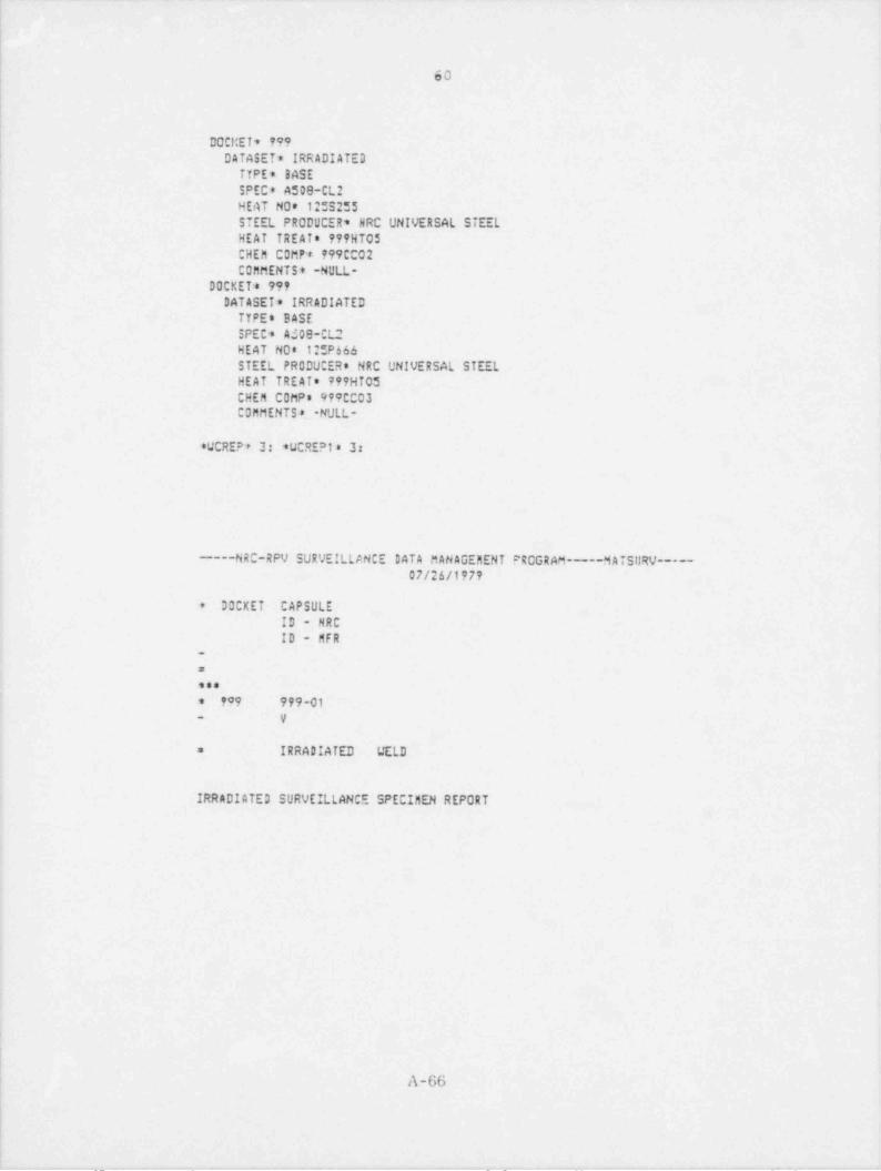
. _ _.. __ _ . . . _ _ _ _ . _ _
60
DOCI:ET* 99'?DATASET* IRRADIATED
TTPE* IASE ;
; SPEC * A508-CL2HEAT N0* 12:5255STEEL PRODUCER * NRC UNIVERSAL STEELi ,
! HEAT TREAT * 999HT05'
!CHEM COMP * 999CCO2
I COMMENTS * -NULL-DOCKET * 999
1 DATASET* IRRADIATEDTTPEe BASESPEC * A309-CL2HEAT N08 12:P666
1 STEEL PRODUCER * NRC UNIVERSAL STEEL |HEAT TREAT * 999HT05 '
CHEM COMPS 999CC03COMMENTS * -NULL-_
*WOREP* 3: *WCRE?t* 3:
,
==NRC-RPV SURVEILLANCE DATA MANAGEMENT PRCGRAM-----MATSURV-----07/24/1979
1
i * DOCKET CAPSULEID - NRCID - MFR4
-
=
*e*
| * 909 999-01*
_ y
IRRADIATED WELD=
r
| IRRADIATED SURVEILLANCE SPECIMEN REPORT
I
',1
f
I,
A-66
_ __ . _ -__ _ ,. . . _ . . _ . . _ . . ._ _ _ . _ _ . . _ _ . . . _ .

. _ _ . - ___ _ _---
61
DOCKET * 799DATASET* IRRADIATEE
TYPE * WELD'
HEAT N0* 61782SPEC * -NULL- |FLUX TYPE * SUBMERGED ARC
,
FLUX BATCH * LINDE 80,
UELD TYPE * -NULL-HEAT TREAT * 999HT07CHEM CDNPe 999CC06CDMMENTS8 -NULL-
...
*HCREP* 3: *HCREP1* *.
---NRC-RPV SURVEILLANCE DATL MANAGEMENT PROGRAM----MATSURV---07/2&/1979
]'
* DOCKET CAPSULEID - NRCID - MFR
-
E
ese* 199 9f9-01- V
IRRAIIATED MAZ' =
! IRRADIATED SURVELLLANCE SPECIMEN REPORT
/L-67,
||
--- y . - p

_ _ _ _ .
62
|
DOCKET * 999. 3ATASET* IRRADIATE 3'
TYPE * HAZSPEC * A500-CL2HEAT N08 125S255STEEL PRODUCER * NRC UNIVERSAL STEEL
,
HEAT TREAT * 9??HT05 i
CHEM COMPS 999CCO2COMMENTS * -NULL-
DOCKET * 999DATASET* IRRADIATE 3
TYPE * HAZ jSPECS A508-Cl2
!HEAT N0* 12:P&44 iSTEEL PRODUCER * NRC UNIVERSAL STEEL iHEAT TREAT * 999HT05
'
CHEM COMP * 999CCO3COMMENTS * -NULL-
_._
|
|
A-68

- . - - - - . . - . . _ - . - . . . -. - ._
63
! *CMCREP* 3: *CMREPl* 3:4
J
|
-----NRC-RPV EURVEILLANCE DATA MANAGEMENT PROGRAM-----MATSURV-----07/26/1979
* DOCKET CAP 1ULEID - NRC ;
j_
ID - MFR j
a
ses* 999 999-01
Y-
lIRRADIATED CMM=
IRRADIATED SURVEILLANCE SPECIMEN REPORT
',
i
,
1
DOCKET * 999DATASETs IRRADIATED
! TYPE * CMMSPECS A302-GRIHEAT N0* -NULL-STEEL PRODUCER * NRC UNIVERSAL STEELHEAT TREAfe 999HT08
; CHEM COMP * 999CC07COMMENTS * -NULL-,
,
...
4
3
:!
i
i
A-69
!
i
_ _ - _ . _ ._ - _, - . - -- - --. . _ . , - _ .-- ,

. - - --
64
4.4.1.6 Chemical Comoosition Set Report. This report consists
of the components described in paragraph 2.5.2.5.*CCREP*:
---NRC-RPV SURVEILLANCE DATA MANAGEMENT PROGRAM----MATSURV----07/26/1979
DOCKET...
* 999
CHEMICAL COMPOSITION SET REPORT
|
|
!
CHER COhP ID* 999C001CU -U/O-* -NULL-
! P -U/O-* .0100CARBON -U/O-* .1900,
MN -U/O-* .45005 -U/O-* .0090SI -u/O-* .:300NI -U/O-* .6900CR -U/O-* .4200MD -U/O-* .6000V -U/O-* -NULL-TI -U/O-* -NULL-AL -U/O-* -NULL-B -U/O-* -NL1.L-CD -U/O-* -NULL-
! U -u/O-* -NULL-AS -U/O-* -NULL-SN -U/O-* -NULL-
I IR -U/O-* -NULL-NB -8/0-* -NULL-SB -U/O-* -NULL-IN -U/O-* -NULL-N -U/O-* -NULL-UHEN ANALYZED * OCC COMMENTS * -NULL-,
i
A-70
a
. . < - - , - - e ,n ,. . , . a _ ...- ,-,. ----

. . - - . . . . .-. - . . ,
651
1
CHEM CORP ID* 999CCO2
[ CU -U/O-* .0700! P -U/O-* .0100
CARBON -U/O-* .18004 MN -U/O-* .6400
S -U/O-* .0070SI -U/O-* .2300MI -U/Q-* .6900CR -U/O-* .3300>
MO -U/0-8 .3800V -U/O-* .0000
'TI -U/O-* -NULL-AL -U/0-+ ,0030
3 -U/O-e -NCLL-CD -U/O-* .0130;
W -U/O-* -NULL-'
AS -U/O-* -NULL-SN -U/O-* .0100ZR -U/O-* -NULL-NB -U/O-* -NULL-S3 -U/U-* -NULL-ZN -u/O-* -NULL-
4 N -U/O-* -NULL-| WHE4 .4NALf2E3* J
CO CCHMENTS* -NULL-
,
;
i1
i
i
a
i,
i
!
;
i;t
,
i;4
; A-71
!
J
. _ _ . _ _ _ - - _ _ - - .-- .~,- _ - , . - - - - - -- y ,

. ..
:
I
\ 66
4.4.1.7 Heat Treatment Reoort. This report consists of the
components described in paragraph 2.5.2.6.*HTREP*
|.
---NRC .".*V SURVEILLANCE I'ATA 8ANAGEMEhl PROGRAM----MATSURV-~ 1
07/26/1979'
* HEAT TREATMENT NOMINAL HOLD PURPOSE COMMENTSSEQUENCE I.D. TEMPERATURE TIME
-DEG F- (HRS)*se
* 999HT01 1550 11.00 AUSTENIZATION* 1220 22.00 TEMPERING* 1125 30.00 STRESS RELIEF* 999HT02 1550 15.50 AUSTENIZATION* 1210 18.00 TEMPCRING* 1125 30.00 STRESS RELIEF
999HT03 1550 9.00' AUSTEMIZATION=
* 1220 12.00 TEMPERINGe 1125 30.00 STRESS RELIEF* 999HT04 Ill: 48.00 STRESS RELIEF* 999HT05 1550 15.50 AUSTENIZATION* 1210 18.00 TEMPERING* 1100 11.25 STRESS RELIEF* 999HT06 1550 9.00 AUSTENIZATION* 1220 12.00 TE!!PERING* 1100 11.00 STRESS RELIEF* 999HT07 1100 11.25 STRESS RELIEF* 999HT00 1650 4.00 AUSTENIZATION* 1200 4.00 TEMPERING
HEAT TREATMENT REPORT
_
A-72
_.

67
4.4.1.8 Example of Requesting Complete Docket Report. The
following ccmmands will generate a complete report for our sampledocket and place it on a separate file for future printing.
This report file will not contain the commands which generatedit or any messages as a result of the commands. The JCL must
contain a *DD" card for the report file RFDOC.
REPORT FILE IS RFDOC:
PR C1 WH C1 EQ 999: SAME IS STATIC:*PLTREP*: *BMREP*: *BWREP*:*BSREP*: *WS REP * : * HS REP * : *CSREP*:
*BCREP* 3: *BCREPl* 3: *WCREP* 3: *WCREPl* 3:*HCREP* 3: *HCREPl* 3: *CMCREP* 3: *CMREPl* 3:*BCREP* 4: *BCREPl* 4: *WCREP* 4: *WCREPl* 4:*HCREP* 4: *HCREPl* 4: *CMCREP* 4: *CMREPl* 4:*BCREP* 5: *BCREPl* 5: *WCREP* 5: *WCREPl* 5:*HCREP* 5: *HCREPl* 5: *CMCREP* 5: *CMREPl* 5:*BCRIP* 6: *BCREPl* 6: *WCREP* 6: *WCREPl* 6:*HCREP* 6: *HCREPl* 6: *CMCREP= 6: *CMREPl* 6:*BCREP* 7: "BCREPl* 7: *WCREP* 7: *WCREPl* 7:* HC REP * 7: *HCREPl* 7: 'CMCREP* 7: *CMREPl* 7:*BCREP* 8: *BCREPl* 8: *WCREP* 8: *WCREPl* 8:*HCRIP* 8: *HCREPl* 8: 'CMCREP* 8: *CMREPl* 8:"CCREP*: *HTREP*:
A-73

.
68
5. INSERTION AND MODIFICATION OF DATA
5.1 General
System 2000 Natural Language is used to insert and/or modifydata. The Immediate Access update commands are descrited in theSystem 2000 Reference Manual in Section 4.0. The Queue Mode updatecommands are described in the System 2000 Manual in Sections6.3.3 through 6.3.7 These commands allow the user to add ormodify data within existing data sets, remove data from existingdata sets, add or modifs partial or total logical entries, orremove part or all of logical entries. There is no output as aresult of the update command litough there are messages indi- ;
cating any errors or the number of selected data sets modified
as a result of the update command. The LOAD command may also beused when an entire docket is to be added. This command isdescribed in the System 2000 Manual. in Section 5.0.
5.2 Selection of Existing Data Sets To Be Updated
Before any update operation the user must decide which type ofupdate operation is appropriate and which data sets are to be
selected. In order to properly modify the data base the user
must uniquely identify the data set (s) to be modified. In
MATSURV this unique identifier is most likely to be one or moreof the following: docket number, materi.1 set (vessel, base-
line, irradiated), NRC capsule identifier, material type (BASE,WELD, HAZ, CMM), test type (Charpy Impact, Drop Weight, Tensile,Fracture Mechanics), or a particular data value. The WHERE clausein System 2000 is used to select the data set (s) of interest.
5.3 Selection of Type of Update
The data base can be modified at a single level (see paragraph| 2.4.8 for MATSURV level description) or multiple levels (tree)l'
which is a single level plus its descendent data sets. The
A-74

69
single level update commands which modify existing data sets
are: ADD, CHANGE, ASSIGN, REMOVE. The multiple level (tree)
update commands which modify existing data sets are: REMOVE
TREE, ASSIGN TREE (IA only). The multiple level (tree) update
commands which create new data sets are: INSERT TREE (IA only),
APPEND TREE (Queue only). Examples of these commands will bepresented. The user should determine whether the changes are to
an existing data set or piece of data'(CHANGE, ASSIGN, ASSIGNTREE, REMOVE, REMOVE TREE) or to a non-existent data set (ADD,ASSIGN, ASSIGN TREE, INSERT TREE, APPEND TREE).
i
5.4 Examoles of Data Modification in IA |
5.4.1 Example 1A fluence value (C15) was erroneously entered as (12) ratherthan (12. >. System 2000 entered the value in the data base as
.0012. To locate and correct this value the following sequence
of commands may be used:
PRINT C1,C15 WHERE C15 EQ .0012:
CHANGE C15 EQ 12.* WHERE SAME:The following single command will accomplish the same purpose:
CHANGE C15 EQ 12* WHERE C15 EQ .0012:
5.4.2 Example 2Several values for Upper Shelf CV (C505), all different, are
identified as being eco small. To identify the values and the
appropriate lower bound the user would use the TALLY command.TALLY /EACH/C505:
The results of this command indicate that, for our example, the
values are too small by two orders of magnitude and the expected
values should be greater than 3.0. The update command is:
CHANGE C505=(C505*100.) WHERE C505 LT 3.:
A-75
I;

. - _ - . - .-__ . . . . - . - . . . _ - . _ _ . _ _-- _ -
!i
{ 701
li
i 5.4.3 Example 3Irradiated capsule 2 of our test docket (999) has an incorrect;
j value for AV ULT STRENGTH (C613). The corresponding AV YIELDj (C612) is known and is 77800. The appropriate command to set
C613 to its correct value of 105000 is:
CHANGE C613 EQ 105000* WHERE C602 EQ 999-02 AND C612 EQ 77800:
Ii 5.4.4 Example 4
.1|
i Charpy test data (C500-C550) has been made available for capsule '
3, BASE specimen. There are two Charpy tests for this data, cne
j has an orientation of (L), the other of (T). Our new data isi for the ( L) test orientation.
ADD C500 EQ 505*91. *506*75* 508*40* END* WHERE2
C502 EQ 999-03 AND C501 EQ L:
1 5.4.5 Example 5
Fracture Mechanics data (C800-C850) has been made available for*
capsule 4, WELD specimen. The test in question has not pre-
vicusly been specified for this specimen. In our example onlyI one set of Weld specimens exists in this capsule (i.e. one com-
k bination of heat no., wire, and flux).1
INSERT TREE C800 *1 EQ 811* FRACTURE MECHANICS * 80l* L-S*a
1
j 802* 999-04* 803* 6* 805* WOL* 808* 807* 78* 804* 3* 806* 135.*; 808* 807* 100* 804* 3* 806* 205.* END* WHERE C107 EQ 999-04
AND C201 EQ WELD:}3
5.4.6 Example 6;1 Data was entered for the design pressure (C17) for the wrongf docket. The test docket has no information on the design pres-
} sure. To find the data value, remove it from our test docket
j (999) and insert it in the correct docket (888) requires the
j following:
| PRINT C17 WH Cl EQ 999:'
REMOVE C17'WHERE SAME:
| ASSIGN C17 EQ (value printed above>* WHERE Cl EQ 888:
i
i
d
i A-76!
'- - - |

- - - __. . . - -- - _ - _ .- . . __ _ _ _ _ . .-. .-__
,
| 71
5.5 Addition of New Dockets,
i
It is expected that data for additional dockets will be madeavailable by report format. The appropriate data is to be written
on the NRC-Surveillance Program Data Forms. The detailed data'
description may be found in Paragraph 2.5, the data forms are in
Appendix A. Prior to data entry the forms for the docket should
be ordered as follows:
i ELANT AND VESSEL DATA FORM .
HEAT TREATMENT SEQUENCE FORM (S)
CHEMICAL COMPOSITIC.1 SET FORM (S)'
MATERIAL SET DATA FORM-VESSEL
REACTOR PRESSURE VESSEL BASE METAL DATA FORM (S)i
| REACTOR PRESSURE VESSEL WELD DATA FORM (S)
MATERIAL SET DATE FORM-BASELINE
The following group of forms should be repeated for
j each type (BASE, WELD,HAZ,CMM) for which data is avail-| abis.
SURVEILLANCE SPECIMEN DATA FORM-GENEPAL
CHARPY IMPACT SPECIMEN DATA FORM (S) for this specimenTENSILE SPECIMEN DATA FORM (S) for this specimenDROP TEIGHT SPECIMEN DATA FORM (S) for this specimenFRACTURE MECKANICS SPECIMEN DATA FORM (S) for this specimen
The following group of forms should be repeated for
each irradiated capsule associated with this docket.
l MATERIAL SET DATA FORM-IRRADIATED
SPECIMEN DATA FORM groups (see BASELINE)
] appropriate to this capsule..
1
5.5.1 Data Entry On Data Forms
|
The data is to be entered as "lorder string" values, a format
'inique to System 2000. The data forms have been specifically
designed to include any separators or special characters requiredby System 2000. All uch preprinted characters must be entered.
1
,
A-77,
i
__ - - - _ . - - - _ . - . , _. . - . _ .

72
These include but are not limited to the system separater (*),decimal point ( .), and slash (/>. Only valued components needbe entered. Leading zeros are not required, decimal pointswhere preprinted must be entered but trailing zeros followingdecimal points :re not necessary.
5.5.2 Data Entry From Data Forms,
j The data may be punched on cards or entered directly on a diskI
file. In either case a single line of data may not exceed 80'
characters. Data entry personnel must enter the component (code)number followed by an (*>, followed by the data value followed |
|by another (*). The first data value on each form, except for '
the PLANT AND VESSEL DATA FORM, has a double component numberat'. ached to it. In all cases MATSURV requires that this data
value exists if there is any other data on the form. In addition, j
the HEAT TREAT:iENT, TENSILE TEST, AND FRACTURE MECHANICS FORMSIhave additional data groups which have a double component number
associated with the first value of the group. This value doesnot have to exist. If, however, any other value in the line
(Heat Treatment), column (Tensile Test), group (Fracture Mechanics)does exist, the first existing data value must have its componentnumber preceded by the data group component. For example, a
sequence has data on1',for the hold time andheat treatment ypurpose. The entry sould then be 4 0 2 * 4 0 4 *(nold time >* 4 0 5 *(pu r pos e|>* .Note that component 403* is not specified. Or, a Tensile Test
Specimen has no test temperature value but does have the numberof specimens. The entry would be 610*604*(number of specimens)*.Again note that the entry with no value is not included. The
last line associated with the docket data must be END**. A
complete list of the test docket as it was entered onto a disk
file is include in Appendix B.
A-78

__ _ __ _ _.-
73;
5.5.3 Loadina New Docket Data Into MATSURV
Once the docket has been placed on a disk file in loader string formatit is a simpli matter to incorpcrate it into the data base. In gen-
eral, it is w.se to perform a " scanning" operation on this data priorto actual loading. The user with the " LOAD" password capability enters
System 2000. The following commands will allow scanning only:
DISABLE EXECUTION:
DATA FILE IS (name of file containing docket data):LOAD:
Any errors will be noted during the scanning phase.
If no errors are encountered the user should proceed with the following
to load the docket data into the data base:
ENABLE EXDCUTION:
DATA FILE IS INPUT:
DATA FILE IS (name of file containing docket data):LOAD:
i
If errors occurred they must be corrected using the operating system
editor. Enter System 2000 again and use the following commands to load
the docket data.
DATA FILE IS (name of file containing docket data):Note that in all cases a "DD" card for the docket data file is required.
See paragraph 3.3.2 for a description of this card.
5.6 Verification Procedures
Several procedures may be used to verify that data has been correctly
entered. Some items should assume prespecified values. For example,
the base plate test material orientation must be (L> or (T), the type ofreactor must be (SWR), (PWR), or (HTGR), and certain naming conventionsdeveloped for MATSURV (Chemical Composition Set ID, capsule ID, or Heat
Treatment ID) should be followed. All entries in the data base for a
particular component can be checked using the following:
TALLY /EACH/(comp 1),(comp 2), . . .(comp n):where comp i is one of the components of interest.
!
A-79
|
- . .'

74
This command will produce a list of the separate values each ofthe specified components assumes. Any extraneous values can be
inspected in further detail and changed if necessary.
There should also be a link between tne Chemical Composition SetID's (C301) and the specimens referencing them (C204) as well asbetween the Heat Treat Sequence ID's (C401) and the specimensreferencing them (C205). In addition the IRRADIATED capsule IDshould also be linked to the docket number. This may be doneusing the following.
PR/NAME/C1,C204,C301:
PR/NAME/C1,C205,C401:
PR/NAME, REPEAT SUP/Cl,C101,C107:;
A list will be produced for each docket consisting of the docketnumber, ID's specified, and references to these ID's. A stringto do all of the above operations exists in the-MATSURV defini-tion. It may be referenced as follows.
*ERRCHK':
Specific components can be retrieved by using the TALLY or PRINTcommands. They may be restricted to particular data sets usingthe WHERE clause, see System 2000 Manual Section IA 3.11. This may
be of particular interest for the values with a decimal picture.For example:
PR/NAME, REPEAT SUP/C1,Cl3,C14,C15:
will print the RPV fluence values and out-of-range values willbe easily identified. If a range is known for a particular com-
ponent the following may be used to identify values outside ofthe range, for example:
PR Cl,Cl3 WHERE Cl3 NE .0l*10.:
If only a lower bound is known the following may be used.PR Cl,Cl3 WHERE C13 LT .01:
A-80
, ,- -

75
Similarly for a known upper bound.PR Cl,Cl3 WHERE Cl3 GT 10.:
Finally, a full report on each data group may be generated.Several strings exist in the MATSURV definition for this pur-pose. They are further described, along with examples, in para-graph 4.4. These reports identify those components for which nodata exists (-NULL-) and prints the values for all others. These
to |reports may be compared with other documents for the docketverify that the data is correct.
A-81
.
'bs.d

_ ._ _ . _ _ _ _ . _ . . . __ _. ._. - . _ . _ _ ...__ , _ _._ __ _ _ _ . ._ . _ _ . . _ _ . _ ._
4
44
1
ii
1 A-1:
1:1
1<
\,f
i
>
I APPENDIX AI
1
INPUT FORMS iI
lI
$
,
! c
t
4
.
i i
! I|
'
I
J4
1
j
'f
1
I
,
J
4
f
4
t
I
f
i
,
4
l
1
|<
A-83
. . . _ __ . . . . . - __ __ . _ _ _ _ _ _ _ _ _ _ . . __ _._ . _ . _ , _ _ _ , _ _ _ _. . _ . _ _ _ _ , _ , . _ . _

_ _ _ _ ___
; A-2
NRC-RPV .crveillance Cara Management Program
P_ ~r %ssu Dm 64 ~c
msDocxer Nunsea i * II *
Pt e r Nane, Untr N une s, 21* iiI!Iti||lIiiiiliiI 4,
Licensa t ( Urztrru Nee) l 3 l* IiiiII II|tiIIIIii l*
Reacrazh(B ,Pm HTod i 4 # 1iiiI+
OeenaTrn.. L2cen:e Dne(nnoom) e l' I iA i IA i i i l +:Intrrat Grricatuy Dme i s 1* i IA i vi i i i l *CommcRcrat Onamon Dare 17 l* I t/l I i/l | I i Ir
I Nu.cteu smn S=n Sm<rga La_b I i i i i i i i iliiii!iii n ,
R PV Mwa,.scruaza i9|-||11IiiIiiii!riiI!iii i,.
Fmrcane 2 n (ssoP, erst.0)lio si ! I i i -
RPV I. D. ( ~mes) luiniiiiI*RP V Tszcxne ss (1smes) la k i U ! l-
'RPV MaxID. Beame E0L Euma n I* i i i .1 i i i 1 *RPV M=.ID.beFwmc4FRfiTk i i 1 I i ! l4'RPVMu.E0_ Ftussa c % T lis k i i i I I i |*.
ASM E Coce Sectron 3 Dare SI ' ' ' '| || |i t i i *
Desrc.n Passsuu (Psza) 571+ 1 I l '-
hGsIGN EMPERAruRs / F) is15III-RPV Sucmcmo~ Nunera i s k I I I I I I I I I I I I ! I I I I I I i *
A s E I ETA L 1 (SPEC 6 R-C h 120 h IIIIIIII|||!!4CASE M ere t 2 (Spec-6R-ct) 12: W 'g *I\IcTE' Ituiscr vrtsrs - ScTud' vA6ue /Iv'tO'8
'
PLANT NAME DOCKET NO.PAGE OF
ENTERED BY DATECHECKED BY DA;g
A-84
__

.
A-3
NRC-?SV Sc:*reillance *:ata M?nagement 7:0 gram
GAT REATMENT EdtlFNCE RM
H eer Tigerneur 6eauruce L1J or renars RPV :
,
H eer lacernesr buence ID 6ecxerso.+W+seedl4od*l4oi 4 I I I I I I I
Hes,TmwrConneurs HsoI* I I I e1
I
l *
NO M INAL HOLD PuR PO S E
TEt1 PERATURE {0FbTTME(HRb
'402.p 403 * I!j * 4o4jx j I w 405* |||1 | ||| w,
Ii | | |! +4 02'* 403* II' * 4c6 II 4 4 05 *
,
402 * 4o31 1I * 4 04 * Ii | x 4o5 x | | | | j ji y,
102 4 403!* III * 4ce iI I * 405* | | | ||| 4
404j* I ', I *40ff |' i {l x4 02 * 4 03!* II +
403M || x 4@ || | x gogg | {|| *4 02* , ,
I
!
|!
|? UNI NME 3CC52: MC.PAOZ OF
IEIRIO 3Y 3A;g
CHICII 3Y 3g73
A-85
__ __ . . --.

A-4NRC-RPV Surveillance Data Management Program
BETWEMIf4L OMooSITTON OAM
C.umca CongostTron Se, I ! I og I ! goe vsrs R PV
Cnnrca Congostrion $crID.(cocxer nad+serns.) soc |*!aoil,! l | | | | | : )-
Et. ens ~r M/W
Cu 13c2 *l I l.I I I I At 13:31 *l I l.1 I I I ;!
* *
P 3031 x i 1.1IiI B Iwl 4 1 1.1 1 I i | |+ -
C 3* l i 1.1 I I | l
Co 13wl *l I l.I I I I | **
Mu 3o51 1 I 1.1 i i I %/ 13:51 l i 1.1 i | I i i--
S Isc61-lIl.1iiI As 3,71 I i .I I I i ;- -
S1 13o71 1 i !.I i i 1 Sn Isia |i 1.1 ; I |- - -
Nr iso 81 H I 1 Ii| Za 13iel*l i I. I I i- -,
Ca i=o91*IIl.1IIi N3 1r20 i1.1!|i* --
Mo !3rol * I i1.1 I l i Se I s a l H I i.! i i i (--
V lsiilwl I l.I I I I > Zu L5pj rl i !.1 i |+
1
T1 13a! 4 ! 1.1 i i I N 132ssii!.IIII |" -
|
N A LVSI5 bOCE II24I* *
HEnIGL boMPOSITION bMEWII350M |I|||||'| | I I I I | | |*
Analysis Code c*s Q or S dependen if chemicalanalvscs c~s determened from t e initia.f gualifica tinbeS$ or Yotr) SubSefuen$ QMa|y3is of SLcYveL| ancem a te yc'al.
PLA:;T :;AME DCCKET NO.
PAGE OF
ENTERED 3Y CATE
CHECKED BY CATE
A-86
. _ _ _ .

_ _ . . _ _ _ _ _ _. . . _
A-5NRC-RPV Surveillance Data Management Program
Mme,_ S r- Dm Fo m||
|
!
Darg $ gT llool*lloilK vlEl5|SlE|L| %!i
i
.
&
PLANT NAME DOCKET NO.
PAGE OF
ENTERED BY DATE
CEECKED BY DATE
A-87

. _ _ _ _ _ _ _ _ -
A-6NRC-RPV Surveillance Data Management Program
R = m c ro a P.-s V . Bm M n4u D 4 7. Fo m: BaseMarat Preca No. n or O roarazs RPV |
;
Tvee 1200l .120ild e ol3 iel * |M Areu4t ID. Nunya iIIIIIIiil I1 1 *2m *
M4TsarAL Foan 12;p iilIiI i ij -
H e AT N unata 12o7 1 i i| II '- -
Morearat Sosc. (Sm.oe.cd 12c 4 i | I I I I I -
S rest. PacouceR's Nene 12iis iiIilI! III IIiil1 -
Loc vron rn @V 12ivi,i i i | | | i i l i il |I *
b. ID. EDL Fou Mce (m) [2,* I i I,i I i l l-.ID FtutscaAE$4rn)!mN I I i. I -
N E0L Ft.ussce n %T(svr)12s i 1.1 i i n-U me $setv Cv 1(Fr.uss') 12ios I I,I I |*RPVrest san.0ama.1 dc2T) laziaU.PPER bH ELF bV 2 [ hr-L&S)!224L I ! !. '
RPV w nm.0ma2(Loh mi>~-_
ImuAt RLr( F) ! 2 o 11 I i 1-bf5CRISE REIS FOR bEF1NJNG
kutRbr ' ''
H s41 ceerneur S eq. I.D. 124 ii!|||l.-
b H E MICAL (OMpoSITJON BET)b2O II i | | |*Connesu 12rc . I I I I I I I l i I I,
NOTE: FLU ENCE VALUGS : QcTUnt. VALUE$fixlO''PLANT NAME DCCKET NO.PAGE OF
EN"'ERED BY DATE&CHECKED BY DATE
A-88!

_
A-7
NRC-RPV Scrveillance Data Management Program
acrx Paes:ua e ha \duc 16 Fo~Ve to f~~l or C or r :s RPVS~ccri i i i =ce rur s \,/, . ex .
I3es 1200l*12cib wieltIci+
Vete ID. Nuneca I 20S i|IitiiiiiI||ii*
Weto Wue Hea1 Nurece 120rl. I i ! ! i | j i i |*
Wato \Jras $psc 2ce I x 1
FtuxEpee,soGaaoe 12 s|* |||| |||||||||i|+
Ftu x Barc s N urue a 12, 4 iiii!i|||1Weto Type I ml+ t1Ii!III IIIi|| IIII sBase M em % 1(seec.3g.cu) pu is IiI!iii|1 |||-
Base Merat Sesc 2 (wec a cu)in21* !l!!||!IiiilI.Weto LocarzoN 2n RPV i 2a6 1Ii!tiiiiiii i i i e
lVeua D1cicr en (Led) inu~
w
' Max. ID E01. Ftuence Gvr) !2is t. I i 1,1 | t i l .' Max.ID stuests/E.EPh. %)l2,o ii ,1iiI .
' Max.EOL Ftuene er 4 T(nvr) 1 :ok I i ,i li12 -
Upgra fasets Cv (F:-t as) 12io l, IiI,|| |-
Inrrut RTm ( T) 20 4 |*
iSCAT6e BASIS FOR bef:NING|2m|,-
inn:at Rb -,
-
E AT | R e ATM E NT EG.1 b |20S k |II!| | '*
bHEMIcA bOM Po$rTIoM ET 2 ^-
58riS[uide vacues- actutu mues/d5 IIIIIIIIIIIIIIlIlIIi *
?LANT NAME OCCKET NO.'
PAGE OF
ENTERED BY DATE
CHECKED 3Y DATE
A-89

. . - -
A-8
NRC-RPV Surveillance Data Management Program
I A T E RI Alb T bATa Fo m
; Dn74 S er lico lici elAlsIs leirinlei i+.-'
Te sr La e. N ur,e l ioz!- 1III IIIii!IIIii!lI *
TEsr LAe. Regou 6 6m)lios - I v1 I vi i I i l +-
Re90arNo.esTzra Iml- 1IIIII|1iil|IIIII||1 *
| |oMMEN T! p g;,7M
i
<
PLANT NAME CCCKET NO.PAGE OF
ENTERED BY DATE
CHECKED 3Y CATE
A-90
-_ __ - _ - _ . _ . . __

A-9 |
NRC-RPV Serveillance Cata Management Program
Sume m me S e rm,~ D - L - C ,~., m
.
Ins (eme/wetohn/cnr) 1:m LI:ci b +
Sme Merat (spec-se.ct) 1206 Ii | | I l | I I I i en m es-,
M A DE CNL)'
Hear Nureedgca use/saz/cnn) !=i, I l I I i 1 %ca uu,sgcm.ySreet Paocucea(ruuse/seken) i 2n ;, 7 ||||l| |1||i|| | <
_
b/etoW:ve Hem Nure,a i2 07 | I I I | | | | | lx amTa 2 racee
\de'ok/tr e Spe c. Im |||||||1| | | | + cua mW C.L D
Flux ! P6 ANO b-MOE |216!*'~
-
V
FuuxSmaNumua 1a4 I I I I l I l i | 1*\deto be 2e Illi||||||||[[||||IqH en1Tasynwr sec.In. ImL iiiII| *
M E M ICA L OMpoSITJoN $i b. 204 * l||l) |NConneurs 1250 |||||||||||||||||j|| ,.
| |
,
PLANT NAME CCCKET NO.
PAGE OF j
ENTERED 'dY DATE
CHECKED BY CATE
A-91
I
)

,.
sec-arv sur ,.uianc. 5 da aanas.m.n:^g:estam
Cua ny Ine4cr S uc1mru Den Fons
Puneose 15cd*lso clulelalelyl 111nielalc!rl **
OgreNrerzon (L.ca T) so+]+CAesuca ID (rostoccxtr so.-cosucedfohI I l-l I I *CANDIDArf bPECIMENS IN PSU LE !TO3h I ! l*
Te sr Re sutrs Fett-Nun;cx ce Sgec1neus Te$rso leoek III- !
llPPER bHELF Cv (Fr-teS) ros a Il--
*
Is1noe RT~or ( F) 15c6> l|I* |
Descaxse SA$15 FCR EF1NING
| |,I"bINmot RT- .
50 Fr-us S m r ( F) => III*
30 Fr-es 5 sin (F) rc9F l|I*
35 M:t L E Lin ( F) lack III*
ERCENTA&E DROP 0FPER bHEGG ITH Y I|*
(OMM EN75 fSC|*| *
Prat'C NAME CCCKET NO.PAGE OF
22 CERED BY DATECHECKED BY CATE
A-92

. ._ _ . . .
A-llNRC-RPV Surveillance Data Management ?regram
Ye.. e . - b c ._:n - i s , O 2 -a h e ,y
| 600|4| 6c.$.T|C|N|5|I|L|2| +QR905E-
0gunrar:os ( LcaT) l eci - _-
L4a_e J.D. (scsrxxtrst-ww &--
'
i unc2tgre sec1rensIs Cusute l603L i !-- ,
i
IIi!I 1 !I II|1 II'(cm-ssrs .
Ill|'| I i| ||| | ! I I- *- -
! i e rr R_crutrs Feucw-
!
IIsr 5M pccaru Res ( = F) sciqi i i Hso+6nH I I I Foo-tel I i i -l -
'
N ura ci: 5.ecy.encTisrte 6:2H i : i- ecM i i l- 4:A Fii i*0 2% Ave.Meto$umam (M 6eHII!IH6cHIIIIF 6a M I I I I k
Ave.Ucrrecre Tmsae 5:asr/Ri; est Iiitilh @ liii!. 6is- t i i i 1 -
Au.TcTetEt.onsancN(N) 94 i I.l I h|6!-iH I l.LJ_J- 6 a h. l !.I i (*
An. Llursom Etensanes (Y.) MH i 1.1 I H6!=M I l.I h 6elI!.IIl*
Avo. Ritucr cn zu Ana (%) SeH I U l I6:6- I .II 6!cW I !.i i l*-
lesT lengrecruees ( F) *chEH I I I H4 ciel I I i He*@ | I I '1F |scci1||+Nurm og Sgec:rennTitrec euk i 4 6c4 -
0 2 Lave.Wuo $rn.usm (Psa si2 - ! I k,eiz 4 I I I i F 6:2 *! I_<,
Avc umnmTisua Smusw(Ps96aH i i i i pl i i i I i spH i i i i i -
._J16u_U.fi'l+ig!lU|FAvs. TcTet Etomnon (fo) 6l t 4
Ave.L(nrece Etcor:cs(0 6tsH , _ ] W615 I ,| | y 6i5 *! l,' .
Ave.Retucno~ 1n Aeso d) ;6!6H I l.1 I bi6161 FFl.FFN6MH I U l FPLAN':' NAME DCCKET NO.
PAGE CF
ENTERED BY DATE
CHECKED BY DATE
A-93
. --. - - - . _

A-12NRC-RPV Surveillance Cata Management Program
b ROP G r GH T b pEC T f1EN D414 sur
Punsose 17 col a i 7:<i* olatolpi Ivleir.4 lair! *
Oas enr+r1on (Lee T) I wn; *.
CapsuuID.(sosr occx s nc.-onute d rdM, l I l-l I I *! Cucun $ssansss :n Cusute w I I I *i'
Trsr Raum FettowNunara og GrenensTesTze 17o4u I| -
NDTT PF) Irc 1x I I*
OMMENTS75Ch .*i
PLANT NAME CCCKET NO.PAGE OF
ENTERED BY DATEi CHECKED BY CATE
A-94
s
_ . . _ .

- _ _ _ _ _ - - _ _ _ _ _ _ _ - _ _ _ _ _ _ _ _ _
4
A-13NRC-RPV Surveillance Cata . Management Program
R.A c T t1 R E ECH A NT(6 bpECT MEN! bATA Fee s'
I!
;kRPOSE | 20C| * |? H }#TIR|A |C|T!ulR|E| |MlElclWIAlult|cl5| *
PE hPEcIrgN fM4T/RGT) ! ?Oh ! | | '*
Oanu-mes (m A mR99)lw m H I -i
A PSULE b W Gs COCG NC.-(AP5utE NC702b| | | |-I | ! ''
' .- , ,
L A N0![. A~I 2 M !M ENS _'J bi.P5u tc I ? 5h||||*,I i | | |1 i || { | |
.
?.
|L C M M ENT: |2-!0!M i !i i I|| | i I III;I || +.
Es- E 4t t"5 Fe tt s , !EST bM PERATuRs F) hosl M _I i l-
s
bMSER Cf: OEC' MEN: |55730 !T0b |I *
T :t Re tu;T | ?:t I ! l.l I i l-E
IE ST . EMEER ATURE (F) ire 80 * 1 I | |-- -
M] | I | *.s
?.JMEE 5 0F D PEc; MENS i EsT5 t
$ ;T $35 U T | E6ki I I I,! l ! | 'I
*| $0 ffEST M P !? 4 T Ll:?2 1'*
Nt1Mase : Sgcc r4sss TesTeo Itce I l !- :-
C ST , EsutT' ISCdIE I I I,! ! I | *
c f} i?O5bk?Rh ! |k*EST M PE RA TU RE
iNUVSER CF $ F E CI M E NS bit 5 L|?C'|*\ ' I l ''
' b R e su a- !sosHl
. !
!
|PLANT NA.ME CCCKET NO.
PAGE OF
E' CERED BY CATE
CHECKED 3Y CATE
A-95

_- _ -
A-14NRC-RPV Surveillance Cata Management Prog:sm
'|
| ATERIAL BET bATA Foar || CADNE ] og [~} paa rsrs R PVI
__
YPE |lN I x | 'Oi !* I|R |RI A|o |7| AIT |sle | *
EST BAG. N Ame lic2 !> II I I i lii *
| Test LAs. Reaur Ders/~m)lios!- I vi i iA ! i I -
! Re w No. cc Trrte Im l. I II ii iI iI -
Scaecuuo REscvacDm im . i IA i v !iir,
AcTuAt Renovac Dere Ino l. I vi i iA i i i l*"
'Capsuu Ftuence ar Rmovat 1I .!lI l*ni -
Loca r: 0~ zn RPV(a Draers) lia > I I*-
N RC Cegsute ID. l'o71- 1 i i I i !*1
T1re. Ce e stice I D. h eel- 1IIIIIII I I I*'
eMMENTS | | !}|'
,
| [ *
i
{
INOTE FLU ENCE VALUES: ACTuAtyn tuss /l xlO'#
PLANT NAME OCCKZT NO.PAGE OF
l ENTERED BY OATECHECKID BY DATE
A-96
. _. . -. , - _ . -

- - & - . " -- ~.m u+o a - - - a . , w -- --
B-1
$,
I
,
APPENDIX B
;
LISTING OF DATA FOR A FICTICIOUS DOCKET
!;
I
4
3
4
1
A-97
-- ~ - ._.. - -_____.

B-2
1*999* 2* NUCLEAR TESTPLANT 1* 3*NRC NUCLEAR POWER CO* 4*PWR*5*09/19/1969* 6*11/09/1969* 7*37/01/1970*S*BESTSUILDERS* 9*BEST3UILDERS* 13*37.* 14*1.15*20*A508-CL2* 21*A336*400*401*999HT01* 402*403*1550* 404*11.00* 40$*AUSTENIZATION*402*403*1220* 404*:2.00* 40$* TEMPERING *402*403*1125* 404*30.00* 405* STRESS RELIEF *400*401*999HTO:* 402*403*1550* 404*15.50* 405*AUSTENIZATION*40 *403*1:10* 404*18.00* 405* TEMPERING *402*403*1125* 404*30.00* 405* STRESS RELIEF *400*40l*999HT03* 402*403*1550* 404*9.00* 405*AUSTENIZATION*402*403*12:0* 404*12.00* 405*TEMPERINC*402*403*1125* 404*30.00* 405* STRESS RELIEF *400*401*999HT04* 40 *403*1115* 404*48.00* 405* STRESS RELIEF *400*401*999HTOS* 40:*403*1550* 404*15.50* 405*AUSTENIZATIOr*402*403*1210* 404*18.00* 405* TEMPERING * |402*403*1100* 404*11.25* 405* STRESS RELIEF *400*401*999HT06* 40:*403*1550* 404*9.00* 40$*AUf!ENIZATION*402*403*12:0* 404*12.00* 405* TEMPERING *
|40:*403*1100* 404*11.00* 405* STRESS RELIEF *400*401*999HT07* 40 *403*1100* 404*11.25* 40$* STRESS RELIEF *
l400*401*999BT08* 402*403*1650* 404*4.00* 405*AUSTENIZATION* '
402*403*1:00* 404*6.00* 405* TEMPERING *300*301*999CC01* 303*0.010* 304*0.19* 305*0.65* 306*0.009* 307*0.23*308*0.69* 309*0.42* 310*0.60* 324*Q*300*301*999CCO:* 30:*0.07* 303*0.010* 304*0.18* 305*0.66* 306*0.007* j
307*0.23* 308*0.69* 309*0.33* 310*0.58* 311*0.0:* 313*0.003* ;
315*0.015* 318*0.01* 324*Q* '
300*301*999CC03* 302*0.05* 303*0.01:* 304*0.19* 305*0.67* 306*0.011*307*0.20* 308*0.69* 309*0.37* 310*0.57* 311*0.02* 313*0.004*315*0.013* 318*0.01* 324*Q*300*301*999CC04* 302*0.21* 303*0.0 1* 304*0.070* 305*1.28* 306*0.014*307*0.52* 308*0.57* 309*0.17* 310*0.36* 324*Q*300*301*999CC05* 302*0.20* 303*0.01:* 304*0.082* 305*1.34* 306*0.012*307*0.45* 308*0.39* 309*0.06* 310*0.39* 3:4*Q*-300*301*999CC06* 302*0.23* 303*C.012* 304*0.075* 305*1.31* 306*0.016*307*0.59* 308*0.56* 309*0.59* 310*0.36* 311*0.001* 313*0.020*315*0.001* 3:3*0.015* 3:4*Q* 350*N CONTENT IN N2 FORM *300*301*999CC07* 30 *0.20* 303*0.011* 304*0.24* 305*1.34* 306*0.023*307*0.23* 308*0.18* 309*0.11* 310*0.51* 324*Q*350*6 IN THICK A3023 CMM* ,
1
100*101* VESSEL *
200*201* BASE * 202*123P118 val * 213*FORGINC* 207*123P118*206* A336* 211*NRC UNIVERSAL STEEL * 217*N0ZZLE SHELL*218*37.* 219*1.15* 210*117.* 208*+40*209'NRC STD REVIEW PLAN SEC 5.3.2 & MTE3 5.:*205*999HT01* 204*999CCCl*200* 01*3ASE* 20:*125S255 val * 213*FORCINC* 207*125S 55*206*A508-CL:* 211*NRC UNIVERSAL STEEL * 217* INTERMEDIATE SHELL*21S*37.* 219*1.15* 210*106.* 208*+20*!
A-98l

._
B-3
209*NRC STD REVIEW PLAN SEC 5.3.2 & MTEB 5.2*205*999HT02* 204*999CCO2*200*201* BASE * 202*125P666 val * 213* FORGING * 207*125P666*206*A508-CL2* 211*NRC UNIVERSAL STEEL * 217* LOWER SHELL*218*37.* 219*1.15* 210*114.* 208*+40*209*NRC STD REVIEW PLAN SEC 5.3.2 & MTEB 5.2*205*999HT03* 204*999CC03*200*201* WELD * 202*SA-1101-71249* 207*71249* 215*LINDE 80*214*8445* 216*SUBMERCED ARC * 221*A336* 222*A508-CL2*217* NOZZLE TO INTER * 223*C* 218*37.* 219*1.15* 208*0*209*NRC STD REVIEW PLAN SEC 5.3.2 & MTE3 5.2*205*999HT04* 204*999CC04*200*201* WELD * 202*SA-847-6;782* 207*61782* 215*LINDE 80*214*8350* 216*SUBHERCED ARC * 221*A508-CL2* 222*A508-CL2*217*INTIR TO LCWER SHELL*223*C* 218*37.* 219*1.15* 208*0*209*NRC STD REVIEW PLAN SEC 5.3.2 & MTES 5.2*20$*999HT04* 204*999CC05*100*101* BASELINE * 103*04/01/1969* 104*WCAP-7254*200*201* BASE * 206*A508-CL2* 207*1255255*211*NRC UNIVERSAL STEEL * 205*999HT05* 204*999CCO2*500*512*CHARPY IMPACT * 501*L* 502*999---* $05*91.* 506*+20*507*NRC STD REVIEW PLAN SEC 5.3.2 & MTES 5.2*600*605* TENSILE * $01*L* 602*999---* 610*612*78220* $13*97190*614*23.3* 616*66.8*800*811* FRACTURE MECHANICS * 805*WOL* 801*L* 802*999-- *200*201* BASE * 206*A508-CL2* 207*125P666*211*NRC CNIVERSAL STEEL * 205*999HT05* 204*999CC03*500*512*CHARPY IMPACT * 501*L* 502*999---* 505*120.* 506*+40*507*NRC ST3 REVIEW PLAN SEC 5.3.2 & MTEB 5.2*600*605* TENSILE * 601*L* 602*999-- * 610*612*62720* 613*S3650*614*26.3* 616*70.7*800*811* FRACTURE MECHANICS * 805*WOL* 801*L* 802*999---*200*201*WIL3* 207*61782* 214*LINDE 80* 213*8436*215*SUBMERCED ARC * 205*999HT07* 204*999CC06*500*512*CHARPY IMPACT * 501*T* 502*999 - * 505*79.* 506*0*507*NRC STD REVIEW PLAN SEC 5.3.2 & MTES 5.2*600*605* TENSILE * 601*L* 602*999-- * 610*612*73520* 613*87350*614*22.8* 616*62.0*800*811* FRACTURE MECHANICS * 805*WOL* 802*999---* i
200*201*HA2* 206*A508-CL2* 207*1155255*211*NRC UNIVERSAL STEEL * 205*999BT05* 204*999CCu2*200*201*RA2* 206*A508-CL2* 207*125P666*211*NRC UNIVERSAL STEEL * 205*999HT05* 2u4*999CC03*200*201*CMM* 206*A302-CR3* 211*NRC UNIVERSAL STEEL *,
205*999HT08* 204*999CC07*100*101* IRRADIATED * 103*04/01/1973* 104*FP-RA-1* 112*80*107*999-01* 106*V* 150*RESULTS ARE AVAILA3LE IN FP-RA-1*200*201* BASE * 206*A508-CL2* 207*125S255*211*NRC UNIVERSAL STEEL * 205*999ET05* 204*999CC02*200*201* BASE * 206*A508-CL2* 207*125P666*!
A-99
;
il
i

-- - ._ .-
|
B-4 !
|211*NRC, UNIVERSAL STEEL * 205*999HT05* 204*999CC03*!
200*201* WELD * 207*61782* 214*LINDE 80* 213*8436*215*SUBMERCED ARC * 205*999HT07* 204*999CC06* I
200*201*HAZ* 206*A508-CL:*207*1253255*211*NRC UNIVERSt.L STEEL * 205*999HT05* 204*999CCO:*200*201*HA * 206*A508-CL:* 207*125P666*211*NRC UNIVERSAL STEEL * 205*999HT05* 204*999CC03*200*201*CMM* 206*A302-CR3* 211*NRC UNIVERSAL STEEL *1
'
205*999HT08* 204*999CC07*100*101* IRRADIATED * 102*NRCTEST LA30RATORY*103*11/01/1974* 104*WCAP-8421* 111*7.6* 112*260*
; 107*999-02* 106*R*'
200*201* BASE * 206*A308-CL:* 207*125S255*211*NRC UNIVERSAL STEEL * 205*999HT05* 204*999CCO:* |500*512*CHARPY IMPACT * 501*L* 502*999---* 503*10= 504*10*600*605* TENSILE * 601*L* 602*999-02* 603*6* !610*611*85* 604*003* 61 *77870* 613*96520* 614*20.6* 616*72.* i610*611*:1:* 604*003* 61:*76450* 613*93600* 614*18.4* 616*70.0*610*611*550* 604*003* 612*77800* 613*101430* 616*66.9* l800*811* FRACTURE MECHANICS * 805*WCL* 801*L* 30 *999-02*803*6* 850*K2D IS DYNAMIC TOUGHNESS DEVELOPED BY EQUIVALENT
ENERCY CONCIPT*808*807*78* 804*3* 806*196.2* I808*807*100* 804*3* 806*104.4*808*86/*115* 804*3* 806*147.8*200*:013?ASE* 206*A508-CL:* 207*125P666*211*NRC Uh?'ERSAL STEEL * 20$*999HT05* 204*999CC03*500*512* CHAR 1Y IMPACT * 301*L* 502*999-0 * 303*10*600*605 * TENSILE * 601*L* 602*999-02* 603*6 *610*611*85* 604*003* 61:*67150* 613*87530* 614*20.4* 616*70.4*610*611*21:* 604*003* 61:*66120* 613*84600* 614*20.5* 616*72.0*610*611*550* 604*003* 612*6:030* 613*86350* 614*17.8* 616*69.6* |
800*811* FRACTURE MECHANICS * 80$*WOL* 801*L* 802*999-0:*803*6* 850* KID IS DYNAMIC TOUGHNESS DEVELOPED BY EQUIVALENT
ENERGY CONCEPT. WOL RESULTS ARE AVAILA3LE IN ANALYSIS OF !WOL DYNAMIC FRACTURE TEST RESULTS FOR CAPSULE R, 12/19/75 {RECEIVED BY NRC ON 4/12/76* |
808*807*78* 804*3* 806*145.7*808*807*100* 804*3* 806*210.0*808*807*140* 804*3* 806*133.4*200*201* WELD * 207*61782* 214*LINDE 80* 213*8436*215*SUBMERCED ARC * 205*999HT07* 204*999CC06* j500*512*CHARPY IMPACT * 501*T* 502*999-02* 503*10* 504*10*600*605* TENSILE * 601*L* 602*999-02* 603*3*610*611*85* 604*003* 612*93760* 613*106440* 614*20.0* 616*63.1*610*611*:12* 604*003* 61:*87420* 613*101240* 614*19.8* 616*58.9*610*611*550* 604*003* 612*78940* 613*98160* 614*16.5* 616*54.1*80C*811* FRACTURE MECHANICS * 805*WOL* 801*L* 802*999-02*803*3* 850* KID IS DYNAMIC TOUCHNESS DEVELOPED BY EQUIVALENT
ENERGY CONCEPT. WOL RESULTS ARE AVAILA3LE IN ANALYSIS OFWOL DYNAMIC FRACTf7RE TEST RESULTS FOR CAPSULE R, 12/29/75RECEIVED BY NRC 4/12/76*
!
A-100
1
,
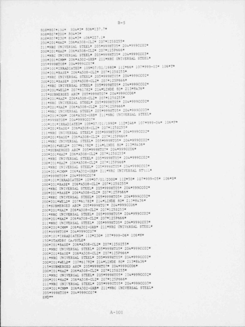
i
'
i B-5
808*807*150* 304*3* 806*137.7*808*807*200* 304*3*808*807*230* 804*3* 606*:27.1*
! 200*20!*HAZ* 206*A508-CL:* 207*125S255*211*NRC UNIVERSAL STEEL * 205*999HT05* 204*999CC02*200*201*HAZ* 206*A508-CL * 207*125P666*211*NRC UNIVERSAL STEEL * 205*999HT05* 204*999CC03*200*201*CMM* 206* A302-GR3* 211*NRC UNIVERSAL STEEL **
205*999HT08* 204*999CC07*100*101* IRRADIATED * 109*07/01/1980* 112*66* 107*999-03* 106*T*200*201* BASE * 206*A508-CL:* 207*125S255*211*NRC UNIVERSAL STEEL * 205*999HT05* 204*999CCO2*200*201* BASE * 206*A508-CL:* 207*1:5P666*211*NRC UNIVERSAL STEEL * 20$*999ET05* 204*999CCO =200*201* WELD * 207*61782* 214*LINDE 90* 213*8436*215* SUBMERGED ARC * 205*999HT07* 204*999CC06* |200*201*HAZ* 206*A508-CL:* 207*125S255* '
211*NRC UNIVERSAL STEEL * 205*999HT05* 204*999CCO2*200*201*HAZ* 206*A508-CL:* 207*1:5P666*211*NRC UNIVERSAL STEEL * 205*999ET05* 204*999CC03*200*:01*CMM* 206*A302-GRB* 211*NRC UNIVERSAL STEEL *20$*999HT08* 204*999CC07*100*101* IRRADIATED * 109*07/01/1990* 112*:46* 107*999-04* 106*P*200*201* BASE * 206*A508-CL2* 207*125S:55*211*NRC UNIVERSAL STEEL * 205*999HT05* 204*999CCO *200*201* BASE * 206*A508-CL:* 207*125P666*211*NRC UNIVERSAL STEEL * 205*999HT05* 204*999CC02*200*201* WELD * 207*61782* 214*LINDE 80* 213*8436*215*SUBHERCED ARC * 205*999HT07* 204*999CC06*200*201*HA2* 206*A508-CL:* 207*1 55:55*211*NRC UNIVERSAL STEEL * 205*999ET05* 204*999CCO2*200*201*HA * 206* A509-CL2* 207*1:5P666*211*NRC UNIVERSAL STEEL * 205*999ET05* 204=999CC03*200*201*CMM* 206*A302-CR3* 211*NRC UNIVERSAL ST E L*205*999ETOS* 204*999CC07*100*101* IRRADIATED * 109*07/01/2000* 112*50* 107*999-0$* 106*S*200*201* BASE * 206*A508-CL:* 207*1255255*211*NRC UNIVERSAL STEEL * 20$*999HT05* 204*999CCO2* i
I
200*201* BASE * 206*A508-CL:* 207*125P666*211*NRC UNIVERSAL STEEL * 205*999ET05* 204*999CCO:*200*201* WELD * 207*61782* 214*LINDE 80* 213*8436*215*SUBMERCED ARC * 205*999ET07* 204*999CC06*200*201*HAZ* 206*A508-CL2* 207*1:55255*211*NRC UNIVERSAL STEEL * 205*999BT05* 204*999CC02*200*201*HAZ* 206*A508-CL2* 207*125P666* ,
|211*NRC UNIVERSAL STEEL * 105*999HT05* 204*999CC03* |
200*201*CMM* 206*A302-GR3* 211*NRC UNIVERSAL STEEL *205*999HT08* 204*999CC07*100*101* IRRADIATED * 112*230* 107*999-06* 106*N*150* STANDBY CA/SULE*200*201* BASE * 206*A508-CL2* 207*1:5S255*211*NRC UNIVERSAL STEEL * 205*999BT05* 204*999CCO:*200* 01* BASE * 206*A508-CL * 207*1:5P666*
|211*NRC UNIVERSAL STEEL * 205*999HT05* 204*999CC02*200*201*WEID* 207*61782* 214*LINDE 80* 213*8436*215*SUBMERCED ARC * 205*999HT07* 204*999CC06*200*:01*HAZ* 206*A508-CL:* 207*125S255*211*NRC UNIVERSAL STEEL * 205*999ET05* 204*999CCO:*200*201*HA:* 206*A508-CL:* 207*1:5P666*
'
211*NRC UNIVERSAL STEEL * 205*999aT05* 204*999CC03*200*201*CMM* 206*A302-GR3* 211*NRC UNIVERSAL STEEL *205*999BT08* 204*999CC07*END**
A-101

C-1
APPENDIX C
SYSTEM 2000 OVERVIEW
C.1 seneral
This Appendix provides a brief overview of the System 2000* database management system. The following material has been extractedfrom Chapters 5 and 6 of the MRI Systems Corporation General fInformation Manual.
C.2 The System 2000 Modular Conceot
System 2000 iT a general-purpose data base management systemthat operates on IBM 360 and 370 series, Univac 1100 series andCDC 6000 and CYBER 70 series computers. The basic System 2000,with selected optional features, provides the basis for developinginformation systems tailored to the requirements of the applicationand the user.
Optional System 2000 features include a report writer, a user-oriented language providing on-line access to non-programmers, aprocedural language interface for programmer use, sequentialfile processing capability, and for IBM 360 and 370 installations,a teleprocessing monitor, a multi-user capability and a multiple- I
|
thread feature.1
The following provides a brief overview of the basic system andthese optional features. The teleprocessing monitor dependsupon the Immediate Access Feature; all optional features requirethe Basic System 2000.
|
f* SYSTEM 2000 is a trademark of MRI Systems Corporation.
A-103
c - __ - _ _ _ _

C-2
C.3 Basic System 2000,
i
Basic System 2000 provides the user with a comprehensive set ofdata base management capabilities. These include the ability to
define new data bases, modify the definition of existing databases, and to retrieve and update values in these data bases.
Ide basic components of data base definitions are data elements
and repeating groups. Values are stored in data elements. Re-
peating groups describe a structure for storing multiple sets ofdata values and also serve to link hierarchical levels of thedefinition.
Values for each element and logical entry (record) may vary inlength. The user may specify without restriction which elements
|in the data base are to be inverted and become key fields, and !
what hierarchical relationship an element will have with other
elements in the data base. Data security is maintained by pass-
word control to the data base and additional password control toeach component.
Basic Gystem 2000 provides archival copies of data bases and re-cords an audit trail of changes made to a data base. It is cap-
able of reconstructing a .ata base by applying the audit trail,completely or in part, to an archival copy of that data base.
|
C.4 Procedural Language Feature
The Procedural Language Feature enables users to manipulate datain a System 2000 data base from a procedural programming languagesuch as COBOL, Fortran, or assembly language. This feature pro-
vides the mechanism for addressing any part of the data base of
A-104
;

C-3
interest to the procedural program, to retrieve data in a sequence,
and format suitable for procedural processing, and to update the i
data base from the program. Interrelationships between two or
more data bases can be established which permit network datastructures to be defined.
Data base qualification is performed by use of an inverted file,facilitating the very rapid screening of data of interest. Re-
trieved data may be sorted on one or more keys prior to returnof the first set of data to the program. A complete set of
status flags are provided to the programs to permit easy checkingof abnormal or terminal conditions.
C.5 Immediate Access Feature
The Immediate Access Feature provides a user-oriented languagewith which a non-programmer may express his requests for re-trieval or update of a data base. The English-like language is
easily learned. It includes a complete set of easy-to-understand
diagnostic messages and is highly suited for interactive usefrom remote keyboard terminals.
The Immediate Access Feature also provides statistical functions
such as SUM, COUNT, AVERAGE, MAXIMUM, MINIMUM, and STANDARD
DEVIATION.
A variety of formatting options is provided for retrieved inform-ation. Reports may be sorted on up to 32 keys. Arithmetic
functions may be described within the user's command, and thecompeted results returned as output.
A-105

C-4
3
C.6 Report Writer Feature
The Report Nriter Feature enables the user to prepare reportspecifications following a set of quickly-learned report for-matting conventions. The user specifies column, row and pageheadings, dates and footnote captions. Also specified is the
nested blocking of the retrieved data that controls the sequenceof the data blocks at the time the report is produced. Other
capabilities permit the user to specify format conventions fordata fields, accumulate sub-and-grand totals for data blocks,and define synonym tables for expansion of coded data. Up to ;
100 reports may be produced in one pass of the data base. l
C.7 Secuential File Feature
The System 2000 Sequential File Feature makes possible the pro-cessing of a major part of the data base from sequential media,such as magnetic tape. Consequently, expensive direct access
devices are not required for the bulk of the data base. Whenutilizing the Sequential File Feature, System 2000, retrievaland update commands are ordered by type by the system, and thenprocessed against directories residing on direct access storage.The actual retrieval and update operations then take place se-quentially on a single pass of relevant portions of the database.
C.8 Teleprocessing Monitor Feature
The teleptocessing Monitor Feature enables a user to exercise
the complete set of System 2000 capabilities from a remote key-board terminal. It provides support for Models 33/35 tele-
typewriters, IBM 2741 hard-copy terminals, and IBM 226G CRTterminals. Polling lists may be user generated allowing priorities
.
1
.
A-106
I

C-5
of terminal access to be established. The user is allowed to
"page" through extensive retrieval lists with "page" size beingadaptable to terminal requirements.
System 2000 has been interfaced with ccmmercially available |1
teleprocessing monitors such as TCAM, ALPHA, HYPER-FASTER and |'
BEST. MRI will interface System 2000 to other teleprocessingmonitors for a nominal fee.
C.9 Multi-User Feature
The Multi-user Feature permits communication between one or moreregions or partitions and a single copy of System 2000. Immediate
Access commands from the teleprocessing monitor, and System 2000requests from other procedural language programs in partitionsor regions are proce; sed with simultaneous use of one or moredata bases coordinated by the Feature. Data bases are protected
from simultaneous updates in this environment.
C.10 Multicle Thread Feature
The Multiple Thread Feature is designed to support installationswhere teleprocessing demand rates exceed the through-put cap-abilities of the standard system. The Multiple Thread Feature
queues input and output terminal messages and controls the con-current processing of multiple System 2000 commands. The user
declares the number of threads, from one to eight, based on de-
mand cate, core availability, and peripheral storage consider-ations. j
|
C.ll IBM 360/370 Series Hardware Configuration
System 2000 runs under the MFT, MVT, TSO, VS1, or VS2 operatingsystems. Standard interfaces to OS are utilized, thus making
A-107
1

. . _ - .. _ .. _ - . _ _. __ _ _ _ _ ._ _
C _6i
I |
System 2000 essentially independent of operating system releases.Minimum hardware requirements for System 2000 are an IBM 360/40,with sufficient on-line disk storage for data bases and scratch
files. Core requirements for System 2000 including buffersrange from 140K to 160K, depending on the number of data bases,
to be accessed concurrently and the terminal configuration involved.Both the Decimal and Floating Point Features are required.
Ii C.12 Special Capabilities Of System 2000
C.12.1 Data Base Security1
System 2000 provides, as part of the basic system, a wide rangei of features to insure data base integrity. Complete activity
audit is maintained, and the system provides up to five levelsof security. Security can be provided at remote terminals
1
through the use of terminal identification or passwords. Pass-
word security is also available at the system, data base, ccm-7 mand, and ce;ponent levels.
!
| Component level security enables the data base administrator to
| offer four types of access for each component in the cata basedefinition. Thus, for each component in the data base there
exist sixteen possible access combinations. Password holders
can be restricted, on a ccmponent-by-component basis, to retrievinginformation only, using the element in retrieval WHERE clause,updating only, and using the element in an updating WHERE clause.,
An example of the use of component level security comes from aj, personnel application. A receptionist could be provided access1
j to the data base but restricted to retrieving only name, telephone,
number, and location. All other information in the data base4
) would be locked out from her access passwords,ii
t
I
A-108
- _ ., .. _ - - _ . - . . . _ . . - _ .. .-. _--_ - -
. . - . - - . . -.. . . -- - _
t
!
! C-7i ia '
lC.12.2 Sequential Files
,
The Sequential File Feature is an optional feature for System i
2000. In Chapter 3, HOW SYSTEM 2000 MANAGES DATA, data baseswere described as consisting of three segments: the definition,'
the pointers describing the elements' interrelationships and theinverted index, and the logical entries. When the data base is ,
I being used, the definition and pointers must reside on a directi access device or they may reside on less costly magnetic tape.
Furthermore, data for selected repeating groups may reside onmagnetic tape while the remaining portions are in direct accessstorage. Thus, if the data base is so defined, infrequently
accessed portions of the data base may be used from tape whilei frequently accessed portions are used from a direct access de-
vice. Processing takes place in Queue Access and is sequentials
i through the data values. Savings possible through the use of
the Sequential Files can reduce storage costs by as much as ten-to-one or more.
;
C.12.3 Ccmmand Concatenation:i
.:,!
The STRINGS capability of System 2000 enables users to concatenate
frequently used command series and label the series with a short#
word. STRINGS are part of the DEFINE module's capabilities andare added as components of the data base definition. Strings
may be nested inside one another and an extremely long and com-plex character string built up in this manner.,
!
|Strings may also be defined that address, in effect, values
located in other strings. This provides a way of simplifying |
input commands so that all a non-programming user need do isi
I invoke the string and specify the values.
i
-
4
1
4
:
A-109
,
_. ._ _ _ _- -. -- - ~ . . .- - . , ,.n -- - - , , , _ . , , . ,- , . _ _,

C-8
C.12.4 Restart and Recovery
System 2000 provides a full range of error detection and correction
capabilities and the housekeeping procedures for restart and re-
covery. Capabilities provide for activit) .;Jit and system dia-gnostics. System 2000 also provides a complete set of easy-to-understand error messages and user diagnostics.
The update file records all update transactions against a database and may be used to "back '. tack" from the current data baseto an earlier, archival version.
!
A-110

D-1
APPENDIX D
DATA BASE CORRECTIONS
D.1 Data Base Corrections
Several corrections to MATSURV have been made. They are itemized
in paragraphs D.l.1 and D.l.2.
D.l.1 Corrections Prior to Installation at NIH
Correction Date July 17, 1979
As a result of generating complete docket reports the following
data entry errors were noted and corrected prior to delivery of
MATSURV to the Nuclear Regulatory Commission. These errors were
not corrected on the reports.
1) Fluence values (Cl3, C218) less than .01 were multiplied
by 10000, s240 values)
2) Quarter fluence values (C15, C220) of .0012 were set
to 12. (7 values)
3) Upper shelf CV values (C210, C224, C505) less than 10
were multiplied by 100. (113 values)
4) Average reduced area values (C616) less than 1. were
multiplied by 100. (1 value)
5) Average ultimate strength values (613) were set as
follows for the teat data in capsules 155-02, 244-02,
262-02, and 339-- . (7 values)Capsule Cl3 Corresponding C12
155-02 100800 79500244-02 101430 77800
106440 93760101240 87420
261-02 112000 96200105000 82300
139--- 102000 84900
A-111

,. _ _ _- . , _ _ . -
i.
D-2
i
.:
j 6) Fracture Mechanics Test Results of .999 were erroneouslyf entered. No test data existed and these results were
removed for the cases for type 3ASE and the case for
type WELD where the FM test temp (C807) was 190. (3values)
i
; D.l.2 Corrections Subsequent to Installation at NIH
Correction Date July 25, 1979
i
j Additional data corrections were made after' delivery. Again
these errors were not corrected in the reports.f 1) The Fracture Mechanics Test result (C806) of .999 in
capsule 261-02 was corrected to 51800. I
|
2) The thickness value for docket 261 was corrected from4
9.99 to 9.13.,
I1
1j 3) The thickness value for docket 298 was corrected from )i
: 9.99 to 8.38. 1t
4
D.2 Future Data Base Additions / Corrections!
The suggested procedure is for the holder of the Master passwordL
(Data Base Administrator) to perform all updates. Requested' updatesshould be identified to the 1.evel of detail described in paragraph 5.2.i
|'
i
|1 1
\ |
!
f
I
:!
i.
I |
lI
| A-112i
;
!. , ~ . _ , ._ _ _ . _ - _ . . . _ .. ~. - . _ , . . . - - _ . - . . . - _ - . - - , - . _ - - - - - - - - _ . . _ _ _ _ . . - .

.- - .. .. . .. . .. - . . -- . _ . . .
!
|<
i
E-1'
i
:
APPENDIX E |
| DEFINITION ALTERATIONS
E.1 Data Base Definition Changes
The rules governing data base definitions are very stringent.
For the most part adding or deleting components is allowed but
will cause a reload of MATSURV. Change of picture size or of
the repeating group with which a particular element is associated
is not allowed. Changing, adding, or deleting of strings or
functions occurs easily. For further information see the System
2000 Users Manual, Define Module Section 4.
U.S. GDVENENT PRINTING OFFIS 1980-0 -41.h. 331
|
|
<
k
A-113

'
U.S. NUCLE AQ KEOULATORY COMMISslON! BIBLIOGRAPHIC DA's A SHEET NUREG-0688
4 TITLE AND SUBTITLE (Aad Voturne No. of apprmr,etel 2. fLeave blask),
| Computerized Reactor Pressure Vessel Information System a. RECIPIENT *S ACCESSION NO.I
7. AUTHOR (S) 5. DATE REPORT COMPLETEDJ. Strosnider, C. Monserrate " "'" |*"^"
May 19809. PERFORMING ORGANIZATION NAME AND MAILINC ADDRESS (Inctu* I,p Co*/ DATE REPORT ISSUED
Office of Nuclear Reactor Regulation October |}MONTH
)ffice of Management and Program Analysiss (t,,,, ue, i
! d.S. Nuclear Regulatory CommissionWashinoton, DC 20555
e. freeve u >*>
12. SPONSORING ORGANIZ ATION NAME AND M AILING ADDRESS (tactuw Ira Com/ p
Same as above.11. CONTRACT NO.
13. TV'E OF REPORT PE R40D COVE RE D (/nclustre dears)
|Tec hnical
15. SUPPLEMENTARY NOTES 14. (Leave Natkl
16. ABSTR ACT 000 =ords or less)
A computerized information system for storage and ietrieval of reactor pressurevessel materials data was' established, as part of Task Action Plan A-ll," Reactor Vessel Materials Toughness." Data stored in the system are necessaryfor evaluating the resistance of reactor pressure vessels to flaw-induced
I frac ture. This report includes (1) a description of the information system;'
(2) guidance on accessing the system; and (3) a user's manual for the system.!
.
17. KEY WORDS AND DOCUMENT AN ALYSIS 17a DESCRIPTORS
17b. IDE N TI FIE RS|.OPEN-E N DE D TE RMS
18. AVAILABILITY STATEMENT IggRl (Ns report) 21. N O. 0F P AGE S
Un1imited 2c gecgp pgp(Wspege) 22. P RICEgc,
NGC FORM 335 17 77)