
SPECIFICATION PLATFORM SUPPLY VESSEL
162
SPECIFICATION PLATFORM SUPPLY VESSEL
-
Upload
khangminh22 -
Category
Documents
-
view
0 -
download
0
Transcript of SPECIFICATION PLATFORM SUPPLY VESSEL

SPECIFICATION PLATFORM SUPPLY VESSEL

Page 1 of 162
Table of contents
Introduction 3
System codes 3
000 General items 4
030 Classification and certificates 12
040 Tests / trials 16
060 Assistance 19
070 Delivery and client costs 20
100 Shipbuilding (hull and outfitting) 23
110 Hull 23
120 Superstructure 26
130 Hatches / doors / windows 26
140 Stairs / ladders / platforms 30
150 Additions to ship's construction 32
160 Corrosion protection / deck covering 35
200 Main machinery 37
210 Propulsion system 37
220 Steering system 39
300 Primary ship systems 41
310 Bilge / ballast / internal fifi 46
320 Fuel oil system 50
330 Cooling water system 52
340 Fresh / sea water / sewage system 54
350 Filling, sounding and de-aeration system 57
360 Lubrication system 60
370 HVAC system 61
380 Exhaust system 67
400 Electrical system 69
410 Power generating system 70
420 Cables 77
430 Switchboards & components 79
440 Alarm / monitoring system 83
440 Alarm / monitoring / control system 87
450 Lighting 92
500 Deck equipment 94

Page 2 of 162
510 Anchor equipment 94
520 Mooring system 94
540 Hoisting equipment 95
550 Deck winches 96
570 Lifesaving / fire protection 96
600 Secondary ship systems 100
620 Compressed air system 103
630 Cargo handling system 105
640 (Oil) pollution control 111
650 External fire-fighting system 112
660 Pre-wetting system 115
670 Fixed internal fire-fighting system 115
680 Cold store / freezing room system 116
690 Remaining secondary ship systems 117
692 Waste treatment system 117
700 Joinery / accommodation 118
710 Joinery 118
720 Wheelhouse / crew accommodation 122
740 Technical spaces 127
750 Stores / workshops 128
780 Service yard eq & spares 130
800 Nautical / communication 131
810 Navigation lighting / signals 131
820 Nautical / bridge system 132
830 Dynamic positioning system 140
840 Internal communication system 144
850 External communication system 146
860 Infotainment / office / automation 149
870 Meteorological equipment 150
Abbreviations & units 152
Abbreviations 152
Units 155
Annex 156
01 Void 157
02 Makers list 158
03 Paint specification 161

Page 3 of 162
Introduction
System codes
000 General items
100 Shipbuilding (hull & outfitting)
200 Main machinery
300 Main ship systems
400 Electrical systems
500 Deck equipment
600 Auxiliary ship systems
700 Joinery and accommodation
800 Nautical, navigation and communication equipment
900 Special equipment
Options

Page 4 of 162
000 General items
000.01 General description and main dimensions
This Specification and accompanying GA Plan describe the supplies and deliveries for
the design, construction and outfitting of a versatile Platform Supply Vessel
The vessel is designed for unrestricted service and is especially suited for transport of
supplies and crew to and from offshore drilling rigs and production platforms in support
of hydro carbon exploration and production activities.
The vessel can be fitted with lots of optional systems such as external fire-fighting, oil-
recovery etc.
000.02 Principal dimensions
Length over all 80.0 m
Length between perpendiculars 74.8 m
Beam moulded 16.20 m
Service draft 5.00 m
Summer draft from base 6.15 m
Depth moulded at half-length 7.50 m
Total wooden deck area 719 m2
Total vertical exposed deck area 696 m2
Cargo deck strength 5 t/m2
Cargo deck length, approx. 53.5 m
Cargo deck width, approx. 13.6 m
Frame spacing, approx. 600 / 700 mm
Gross Tonnage, approx. 3040 GT
000.03 Performances
Speed at service draft approx. 13.5 kn
Deadweight at summer draft, approx. 3500 t
Fuel consumption at maximum speed 780 kg/hr
Fuel consumption at service draught, 12 kn 570 kg/hr
Deck cargo max. (VCG 1.0 m above main deck) 1450 t

Page 5 of 162
Conditions for speed and fuel consumption performances
The speed and fuel consumption values are based on the following assumptions:
o Sailing in deep water of minimal 5 times the vessels draught;
o Clean hull;
o Windforce < 4 Bft
o Including 200 kW auxiliary load for hotel and cargo purposes
o Optimal generator running configuration
000.04 Deadweight
At the above-mentioned draught, the corresponding deadweight is all told.
The deadweight all told is the difference between total displacement of the Vessel in
seawater (1.025 t/m3) at even keel and the lightweight of the Vessel, as determined
during the inclining test.
The Vessel's deadweight includes:
o Cargo;
o Ballast water;
o Fuel oil (service);
o Fresh water (service);
o Miscellaneous liquids (lub. oil, sewage etc.);
o Crew with effects;
o Provisions;
o Inventories.
000.05 Tank capacities (approx.)
Service
Ballast water 1460 m3
Fuel oil 400 m3
Fresh water 800 m3
Sewage 26 m3
Lubrication oil (1) 13 m3
Dirty oil 9 m3
Sludge 6 m3
Bilge water holding tank 10 m3
Bilge water settling tank 15 m3
Wash water hot 14 m3

Page 6 of 162
Dirty wash water/Slob 12 m3
Foam 7 m3
Roll reduction 170 m3
Cargo
Drill water: combined with ballast water
Fresh water: combined with service fresh water (2) 790 m3
Fuel oil 920 m3
Base oil (combined with fuel oil) 895 m3
Liquid mud (3) / brine (s.g. 2.8 ton/m3) 865 m3
Dry bulk (s.g. 2.5 ton/m3) 259 m3
Recovered oil capacity (combined tanks) 1500 m3
Notes: (1) Dedicated lubrication oil tanks (not necessarily integrated in construction) are provided for:
engines, hydraulic oil, propulsion thrusters and bow thrusters. (2) Part of the fresh water capacity is dedicated for vessel service only
(3) The tanks are only suitable for liquids of the NLS P-type with a flashpoint above 60 °C and
category Z.
000.06 Range/ endurance / operational profile
Endurance
The endurance of the vessel is based on the assumptions as mentioned below.
Endurance 28 days
Operational profile
Endurance of the vessel is based on the following operational profile:
o 75% of the time at transit, 12 kn and 5.0m draught, windforce < 4 Bft
o 20% of the time at dynamic position at windforce 4 Bft
o 5% of the time in port;
Fuel oil
The endurance of the vessel is based on the following conditions:
o Sailing in deep water of minimal 5 times the vessels draught;
o Clean hull;
o Fuel oil with a specific gravity of 0.84 t/m3 and calorific value 42700 kJ/kg
o 95% filling of tanks at departure

Page 7 of 162
o 3% fuel oil remaining at arrival
o Day tanks full at arrival
Fresh water
The Vessel is provided with fresh water tank capacity, sufficient for the above
mentioned endurance and the number of persons as specified, based on an average
consumption of 135 lt/pers/day.
Sewage
The Vessel is provided with a sewage plant with sufficient capacity for the number of
persons as specified. In addition tank capacity is arranged for a minimum of 4 days.
Lubrication oil
The lubrication oil storage capacity for the engines is sufficient for the mentioned
endurance and with a minimum of 1 refill. Lubrication oil for other equipment is
sufficient for at least 1 refill.
Provision stores
The capacity of the provision stores is based on 22 persons and endurance as
specified with 2 days of spare. In case more persons are on board, endurance is
reduced.
000.07 Environmental conditions
The vessel’s machinery and equipment are designed to operate under the following
conditions:
Minimum seawater temperature 0 °C
Maximum seawater temperature 32 °C
Minimum outside air temperature -8 °C
Maximum outside air temperature 40 °C
Maximum Relative Humidity at 40 °C 65 %
Equipment outside air conditioned spaces (see section 372) is suitable for the
maximum specified outside temperature + ISO specified ∆T. (∆T = 12.5 °C)

Page 8 of 162
000.08 Fuel oil quality
The systems of the vessel are designed to run on DMA grade low sulphur fuel oil.
Reference is made to ISO 8217.
000.09 Definitions
This specification describes the hull, equipment and machinery of the vessel.
The following words and/or expressions used in this specification have the meaning as
defined hereinafter:
Vessel The vessel as described in this specification
Owner The corporate body or legal person who will have
Ownership of the vessel.
Builder X Shipyards, its licensee
Builder's standards Way of construction and/or outfitting as
customary at Builder's yard.
Standard execution The execution of the vessel, built and equipped
with the materials, fittings and items as described
in this specification.
Or equivalent Substitution by equivalent equipment of different
Manufacturer as may be regulated by availability.
000.10 Quality policy
A Total Quality Management Program (TQM) is adopted to every facet of X Shipyards
operations. The quality of X Shipyards organisation and products is continuously
maintained and upgraded.
The Quality Management system of X Shipyards has been approved by Lloyd’s
Register Quality Assurance Limited to the ISO 9001: 2008 standards. This is
applicable to design, construction and delivery of ships, including after-sales services
and the delivery of prefabricated shipbuilding kits.
000.11 Environmental awareness
X Shipyards is committed to ensure continuous improvement of the products and
production methods with the objective to reduce the environmental impact. X is duly
focussing on optimizing its design and constantly working on environmentally relevant
product innovations.

Page 9 of 162
In addition progressive actions have been taken to reduce the environmental impacts
of our facilities and to bring awareness to our employees in relation to every day’s
activities.
X Shipyards has been approved by Lloyd’s Register Quality Assurance to the ISO
14001: 2004 standards.
000.12 Workmanship
The workmanship of the hull and fittings throughout is of good normal marine practice,
care being taken to ensure fair lines, smooth surfaces and neat welding in accordance
with good shipyard practice and the latest IACS standards.
Many procedures and design criteria have been standardised and laid down in X hand
books. The handbooks will serve as guidance in cases where no other, more specific,
criteria or procedures are in place. However, this specification will be governing above
the handbooks.
000.13 Materials
All materials used are according to Class requirements, where applicable, or to
equivalent standards, taking into account their use in a marine environment and
specified environmental conditions. All materials will be new and free of defects.
The following material qualities if used (unless stated otherwise) are:
Material Use Quality
Steel Plate & Bulb profiles (HP)
Remaining profiles
Bolts, nuts etc. inside
Bolts, nuts etc. outside
above size M16
Grade A or AH36
Steel EN 10025-2 – S235JR
Steel
Hot dip galvanized steel quality 8.8
Stainless
steel
Bolts, nuts, etc. up to size
M16 for outside and wet
spaces and under water
line all sizes
Other objects
Stainless steel A4
Stainless steel AISI 316L

Page 10 of 162
Material Use Quality
Galvanised
steel
Galvanised hull parts,
piping
According:
ISO 1461
EN 10240
CuNiFer All objects CUNi10Fe1Mn
According: DIN 17664
Bronze Propellers
Other objects
NiAl-bronze
According: DIN 1705
Aluminium Non construction:
Plate
Extrusions
Knuckled plating
EN AW-5083 (AlMg4.5Mn0.7)
EN AW-6082 (AlSi1MgMn) or
EN AW-6060 (AlMgSi)
Minimum inside bending radius:
1.5 x t
Construction:
Plate
Extrusions
Knuckled plating
EN AW-5083 (AlMg4.5Mn0.7)
σ0.2 > 125 N/mm2, after welding
EN AW-6082 (AlSi1MgMn)
σ0.2 > 125 N/mm2, after welding
Minimum inside bending radius:
1.5 x t
Synthetic
piping
Sea cooling water, ballast
Grey water
Glass Reinforced Epoxy (GRE)
Polypropylene (PPFR)
Wood All wood New, well-seasoned, straight, reasonably
free from warps and cracks, sapwood,
knots, wormholes and other defects which
render it deficient in strength for the
purpose required or not complying to the
finishing quality standard. All wood is
impregnated with anti-pest and anti-rot
composition or has a finish, except for
wooden planks on cargo decks.

Page 11 of 162
All plates, bars and profiles are well and cleanly rolled, straight and free from cracks,
surface flaws, laminations, roughness and other defects.
Castings are of good quality, close grained, free from cracks, blowholes and other
defects.
000.14 Makers list
The makers list is enclosed in annex 02.
If the Owner prefers a particular supplier/make other than mentioned in the makers list
and should the Owner's preference involve a cost change and/or other changes in
delivery time or technical performance, the Builder will inform the Owner accordingly.
The Builder may propose equal suppliers. The Owner may take exception to any such
supplier after substantiated reasons in writing.
The Builder is free to choose any of the proposed suppliers to which the Owner has not
taken exception.
000.15 Modifications
The Owner has the right to ask for modifications during construction of the Vessel.
Such modifications are settled in accordance with the terms and conditions of the
contract between the Owner and the Builder (Variation to Contract (VTC) procedure).
The Builder has the right to modify constructions and/or designs prior to the date of
order of the Vessel, provided such modifications do not affect the intent of this
specification.
000.16 Delivery
The Vessel is delivered ex-yard to the Owner as per contract.
000.17 Dynamic positioning
The vessel is provided with a DP2 system compliant with the Class notation as
specified in section 030. The following ern number is calculated by the X Research
department:
o ERN (99, 98, 81, 62).
All DP related systems and equipment are separated into two independent
Redundancy groups (“half-ship” philosophy). Equipment belonging to one redundancy
group does not have any direct supplies from the other redundancy group. This means
Page 12 of 162
that for instance main and backup supplies for equipment are taken from the same
redundancy group (no crossing of redundancy groups).
In addition due consideration is made to have a Mean Time Between Failure (MTBF)
design philosophy resulting in a vessel with high reliability.
The Worst Case Failure Design Intent (WCFDI) will be the loss of 1 main busbar
resulting in the loss of the forward bowthruster and 1 azimuthing thruster.
A Failure Mode and Effect Analysis (FMEA) of the DP system (power station, thrusters
and control systems) is performed by a renowned third party which is an IMCA
member. The FMEA supplier will be appointed as fast as possible after contract.
The FMEA will be performed according to IMCA guidelines and Class requirement.
030 Classification and certificates 031 Classification society
The vessel is built under supervision and in accordance with the rules and regulations
of Lloyd’s Register.
Notation:
100A1 Offshore Supply Ship, SG 2.8 (MUD tanks), ECO (IHM, OW, P), WDL( 5 t/m2
Aft to fr 75) LMC, UMS, DP(AA), Fire-Fighting Ship 1 (2400 m³/h) with water spray,
*IWS, IBS, NAV-1, CAC 3
Descriptive Note: Green Passport
Descriptive Note: Prepared for Oil Recovery
032 Flag state authorities The Vessel is designed and constructed according to the regulations of the National
Maritime Authorities of Saint Vincent as far as set out in this specification for
unrestricted sailing area and continuous operation. All additional modifications and/or
requirements are dealt with as per VTC procedure.
033 Other authorities / certificates 033.01 Other regulations
The following rules and regulations are met and certified by the appropriate bodies:

Page 13 of 162
IMO - Conventions
o Tonnage convention
International Convention on Tonnage Measurement of Ships, 1969;
o Load Line convention
International convention on Load Lines, 1966, as modified by the 1988 Protocol,
as amended;
o SOLAS convention
International Convention for the Safety of Life at Sea, 2004, as amended;
o MARPOL Annex 1, 4, 5 and 6
International Convention for the Prevention of Pollution from Ships, 1973/1978,
as amended;
o COLREG convention
International Regulations for Preventing Collisions at Sea, 1972, as amended;
o AFS convention
International Convention on the Control of Harmful Anti-Fouling Systems on
Ships, 2001
(For EU flagged ships the Council Regulation (EC) No. 782/2003 on the
prohibition of organotin compounds on ships is applicable).
IMO - Codes
o LSA Code
International Life-Saving Appliance Code, Res. MSC.48(66);
o FSS Code
Fire Safety Systems, Resolution MSC.98(73);
o FTP Code
International Code for Application of Fire Test Procedures, Res. MSC.61(67), as
amended by Res. MSC.101(73) and Res. MSC.173(79);
o Intact Stability (IS) Code 2008
o NOx Technical Code
Technical Code on Control of Emission of Nitrous Oxides from Marine Diesel
Engines, as amended by MEPC Circ. 369
The engines comply with the IMO TIER II regulations;
o Alarms and Indicators
Code on Alarms and Indicators, 1995, Res. A.830(19);

Page 14 of 162
o Noise Levels Code
Code on Noise Levels on Board Ships, as adopted in MSC 337(91)
(For vibrations levels see section 078);
o CSS Code
Code of Safe Practice for Cargo Stowage and Securing, Res. A.714(17), as
amended by MSC/Circ.664, MSC/Circ.691, MSC/Circ.740, MSC/Circ.812 and
MSC/Circ.1026.
IMO - Resolutions
o IMO Resolution MSC.215(82), Performance standard for protective coatings for
dedicated seawater ballast tanks in all types of ships and double side skin
spaces of bulk carriers;
o IMO Resolution MSC.235(82), Guidelines for the Design and Construction of
Offshore Supply Vessels;
o IMO Resolution A.673(16), Guidelines for the Transport and Handling of Limited
Amounts of Hazardous and Noxious Liquid Substances in Bulk on Offshore
Support Vessels, as amended by Res. MSC.184(79) and Res. MSC.236(82);
o MSC/circular 645, Guidelines for vessels with dynamic positioning systems.
o IMO Resolution A601 (15), 1987 - Provision and display of manoeuvring
information on board ships
o IMO Resolution MSC 137 (76) - Standards for ship manoeuvrability (if L > 100
m)
ILO
o MLC 2006
Maritime Labour Convention (applicable parts regarding execution of the
vessel). (1) Note: (1) Design is based on the assumption that National Authorities grant exemption on MLC 2006
regulation 3.1.9 to allow the chief navigating officer to have a cabin without separated
sleeping and sitting room. The yard will cooperate as far as reasonable in obtaining this
exemption but it is the primary responsibility of the ship-owner. As per MLC 2006
regulations, this exemption is to be granted after consultation of ship owners and sea farers
organisations. The ship yard has no formal influence in this process.

Page 15 of 162
Miscellaneous
o MED certification of marine equipment for EU flagged ships (steering wheel
marking, EU Council Directive 96/98, as amended);
o Rules and regulations governing tonnage and navigation of the Panama and the
Suez canal (specially required hardware not included and considered to be hired
by Owner when required);
o ISO 6954; Guidelines for overall evaluation of vibration;
o International Electro technical Commission (IEC) publication number 60092, for
design of electrical installations;
o IEC publication number 60533 for the installation of cables.
o Lloyd’s “Ship vibration and noise guidance notes” section 5 and 7 are adhered to
for acceptable machinery and structural vibration levels.
033.02 Documents and certificates
Documents and certificates are handed over at delivery. (one original and one copy)
At delivery some documents and/or certificates may be delivered in provisional form
(e.g. .stability booklets). Final form is delivered as soon as approved by Class.
Issued by Class
o Certificate of class (hull, machinery and automation)
Issued by National Maritime Authorities (1)
o Safety construction, equipment and radio certificate
o Load line certificate
o International Tonnage certificate
o International Oil Pollution Prevention (IOPP) certificate
o International Air Pollution Prevention (IAPP) certificate
o International Sewage Pollution Prevention certificate
o International Anti Fouling System certificate
o Certificate of Fitness
o Panama tonnage certificate
o Suez tonnage certificate
o Declaration of Marine Labour Compliance (DMLC) Certificate (2)
Note: (1) National Maritime Authorities may authorise Class

Page 16 of 162
(2) Probably a “partial certificate” as yard can only take responsibility for execution of vessel
(Part 3) according MLC 2006.
Issued by Manufacturer
o Class certificate on components as specified by Class
o Engine International Air Pollution Prevention (EIAPP) certificate
o Anchor and cable certificates
o Navigation equipment certificate
o Lifesaving appliances certificate
o MED approvals
o NOx Technical File
Issued by Builder (approved by Class if applicable)
o Builder’s certificate
o Trial test reports
o Stability booklets
o Coating Technical File
o Compass calibration report
o Engine room log-book
o Asbestos free declaration report
o Inventory list
o Procedures & Arrangements manual
o Cargo securing manual
o Oil record book
o Garbage record book
o Shipboard Marine Pollution Emergency Plan (SMPEP)
o Safety manual
o Dynamic Positioning manual
040 Tests / trials The Builder will demonstrate the specified performance of the Vessel through FAT’s,
HAT’s and SAT’s according to normal Builders standards and or Class requirements.
A schedule and procedures for such testing is drawn up prior to commencement of
testing and submitted to the Owner for approval.

Page 17 of 162
Unsatisfactory test or part of it is repeated after correction of defects to the satisfaction
of the Authorities concerned.
041 Provisions for factory tests 041.01 Factory Acceptance Tests (FAT)
Relevant equipment built to the Classification requirements are factory tested at the
Manufacturers works to the satisfaction of the Classification society and Builder (were
appropriate). Owner will attend factory tests at his own costs.
042 Provisions for harbour tests 042.01 Yard testing
All tanks, piping systems and main hull compartments are tested for oil and water
tightness to Classification society requirements prior to paint application.
Water tightness of exterior doors, windows and hatch covers are tested by means of
hose testing.
042.02 Harbour Acceptance Trials (HAT)
The HAT’s are held in accordance with the commissioning program.
The trials include:
o Inclining test;
o Main generators;
o Piping systems, valves and cocks;
o Auxiliary machinery;
o HVAC systems;
o Electrical systems, incl. alarm & control systems;
o Deck machinery;
o Hydraulic systems;
o Domestic systems.
Inclining test
An inclining experiment is carried out by the Builder in the presence of a Class and
Owners representative on completion of the Vessel. Any other work that may influence
the test will not be carried out at the same time. Inclination will be as per IS Code.

Page 18 of 162
043 Provisions for sea trials 043.01 Sea Acceptance Trials (SAT)
A separate SAT program is submitted to the Owner for approval at least one month
before the scheduled trial date.
Approx. 3-4 weeks prior to the delivery of the vessel, technical sea trials are carried out
in order to determine the vessel's performances, according to Class requirements and
this specification.
The SAT includes:
o Speed trials;
o Endurance trials (4 hours);
o Steering trials;
o Manoeuvring trials;
o DP trials;
o Anchor trials;
o Noise and vibration measurements;
o External Fire-fighting trials (if applicable);
o All other Class required testing.
Speed trials
The speed of the vessel is measured during sea trials under the following conditions:
o Propulsion motors running at 100% (75%, 50%) MCR
o Minimum water depth of 5 times Vessels draft;
o Clean hull and propeller;
The measured maximum free running speed is determined as the "mean of means"
out of results of minimal three opposite runs, to approval of the Owner. Additional two
other speeds, at approx. 75% and 50% MCR, are measured by performing one
opposite runs per speed.
Speed is measured by means of DGPS.
In case the conditions of the Vessel and/or the weather differ, a suitable calculation is
made to present the results in accordance with the above stated conditions.
Manoeuvring trials
The following tests will be carried out to check the manoeuvrability of the Vessel:
o Crash stop ahead:

Page 19 of 162
− Full speed ahead : Full astern;
− Half speed ahead : Full astern;
o Turning circle test;
o Zig-zag manoeuvring test (10'/10', 20'/20');
o Man overboard turn test.
Tests will be performed in accordance with IMO resolution MSC.137 (76).
Noise and vibration measurements
Vibration measurements on main systems and components will be carried out under
the following conditions:
o Free sailing at maximum speed;
Vibration criteria according section 030 will apply during all measured conditions.
For vibration measuring procedures in accommodation areas, ISO 6954 (2000) is
adhered to.
Noise measurements in accommodation spaces and working spaces will be carried out
under the following conditions:
o Free sailing at 100% MCR;
o DP-mode with main propellers running on 40% MCR and side thrusters each
running on 40% MCR.
Noise criteria according section 030 will apply during all measured conditions.
048 Fuel oil All fuel oil, lubrication oil etc. necessary for the trials is for account of the Builder.
Stores remaining in tanks at the time of delivery and which is not part of this
specification are taken over by the Owner and paid for at current prices.
060 Assistance 062 Model tests
Hull form has been optimised by means of analytical methods both by X Research
department and MARIN. Computational Fluid Dynamics (CFD) calculations have been
performed. The following modeltests have been performed:

Page 20 of 162
o Resistance and propulsion.
o Seakeeping at 2 different wave conditions and 5 headings.
o Dynamic positioning at 2 different wave conditions and 5 headings.
o Manoeuvring.
Modeltest results are used to calibrate analytical models.
070 Delivery and client costs 071 Manuals / documentation 071.02 Drawings
Documents and instruction manuals are written in the English language unless
specified otherwise. The following as-built drawings and manuals are delivered (2x
paper copies, 1x digital on CD):
o GA Plan
o Arrangements from decks and technical spaces
o Diagrams
o instruction manuals from the various suppliers
The following plans, coloured where necessary, are placed on board, behind glass (or
plastic):
o Fire control and safety plan;
o Bilge- and ballast plan;
o Capacity plan;
o Fuel oil system plan;
o External Fire-fighting Plan (if applicable);
o Wheelhouse poster;
o Damage control plan (if applicable).
071.05 Hydrostatics and stability booklet
The Builder will submit a preliminary and a final trim and stability booklet to the
regulatory bodies for approval.
The stability- and trim particulars (containing instruction to the ship’s master) are
delivered in the form of a Class approved booklet.

Page 21 of 162
071.06 Noise and vibrations
All reasonable and practical steps are taken in the design of the structure to minimise
noise and vibration.
Any defects found to be excessive during trials are rectified by the Builder.
Measures to obtain the required noise levels are based on a X Research noise
prediction and include the following:
Code Item Measures
371 ER fans Silencers subject to prediction advices
380 Exhausts Resilient mounted
380 Silencers 35 dB(A)
411 Generator sets Resilient mounted
711 Floors Execution subject to prediction advices
713 Ceilings Execution subject to prediction advices
715 Insulation Execution subject to prediction advices
072 Ship models / photo’s / film One ship model, scale 1:100, is delivered during handing over ceremony of the vessel.
073 Cleaning The Vessel is delivered properly cleaned.
074 Client supervision Builder will provide facilities for inspection and provide suitable equipped offices for 3
Owner’s Representatives, with toilet, washing facilities, telephone, telefax services,
print facility, internet connection, plans and document filing cabinets, large pin board for
pinning up drawings, etc.
Boarding, lodging and transport costs of Owners representatives are for Owners
account.

Page 22 of 162
075 Owner deliveries Owner’s supply is handled as per contractual agreement with respect to insurance,
handling, storage and installation.
Components and equipment not specifically described in this specification and not
specifically specified by the Class are not a Builder's delivery. The following items are
not included and are considered Owner’s supply:
o Crockery, pottery and other galley utensils
o Bed linen, blankets, pillows
o Work clothes, work vests, safety harnesses etc.
o Small nautical instruments and sea charts
o Tools other than specified in section 756
o Spare parts and other loose equipment (see also section 782)

Page 23 of 162
100 Shipbuilding (hull and outfitting)
110 Hull 110.01 General description
The hull shows the following characteristics:
o Round bilge;
o Forecastle as per GA Plan;
o Constructed with a combined transverse and longitudinal frame system;
o Constructed with a double bottom;
o Aft ship designed to reduce aft-ship slamming;
o Slender bow shape to reduce slamming, resistance in waves and accelerations;
o Internal deck height (steel to steel) approx. 2.80 m;
o Heavy plate inserts in way of bow thrusters, sea chests, anchor pockets and
other openings;
o Skeg, as per GA Plan, for adequate protection of the propellers and rudders and
to enhance course stability;
o Sheer strake along the top of the main deck (as per Class requirements) and
along the top of the forecastle deck level
o Transom stern;
o It will be possible to dry dock the vessel with 60% deadweight.
110.02 Tank configuration
In general, tanks are provided with:
o Cut outs in floors and beams for drainage and air escape;
o Manholes (see section 132);
o Docking plugs (see section 139);
o Filling, discharge, sounding and de-aeration pipes where applicable (see section
350).
Capacities are given in section 000.
When cargo tanks are positioned free of the bottom the suction is placed in a suction
well. In other cases the suction is positioned at the lowest point of the tank.
Special attention is given to cargo tanks containing Liquid muds. These tanks are
constructed with a flat bottom with sufficient slope towards the pumps suctions. Tank

Page 24 of 162
walls are flat or made of corrugated bulkheads. The principal tank design avoids
stiffeners located inside of the tank.
110.03 Sea chests
Dedicated sea chests for the prime movers and auxiliary systems will be integrated in
the hull bottom construction in the engine room and are connected via an integrated
hull crossover. A comprehensive venting of the chest and of the highest point of both
pipes will be arranged. Thickness of the plates in the chest will be according to Class +
2mm.
Chests will have drainage points for docking.
Strainers will be provided on both sides of the cross over. The strainers will be made of
strong material and will be hot dip galvanised.
Powerful air blowing will be arranged for removal of blockage and debris.
o The PS sea chest is provided with a high positioned grating;
o The SB sea chest is provided with a low positioned grating;
o The chests are provided with hinged gratings, flush with the hull.
Separate sea chest will be made for the external fire-fighting system.
The vessel will have a sea chest of “straight pipe type” arranged well forward in the
engine room to supply the installation of a fresh water generator plant as per section
340. The inlet will have flush grating and air blowing connection.
110.04 Bilge keels
Bilge keels are fitted at port and starboard side, welded to a double plate. Attention is
paid to the precise positioning in relation to the flow lines around the hull.
Size of the keel will be as large as possible, though well inboard of the moulded line
and well above the baseline. End of the bilge keel shall be well faired versus the shell
to avoid ropes etc. to get attached.
110.05 Anchor pockets/hawse pipes
The anchors are stowed in pockets, flush with the hull line. The hawse pipes are made
of thick-walled steel. The rims and the upper edge of the hawse pipes are protected
with round bars. Attention is paid to a good lead of the chain to the chain stoppers and
anchor windlass.

Page 25 of 162
110.06 Chain lockers
Two navigation anchor chain lockers are fitted. Access to the lockers is provided with
step holes in the bulkheads.
If stiffeners are used, they are fitted outside the locker bulkheads as far as practical.
Each chain locker is provided with a perforated thick steel plate, fitted approx. 0.30 m
above the bottom, forming an ample bilge space, which is accessible for cleaning.
110.07 Bulwark
Bulwarks are generally arranged as per GA Plan, freeing ports are arranged as per
Class requirements.
110.08 Bulwark opening
On the main deck bulwark doors are fitted at port- and starboard side as per GA Plan.
Turn direction Inward
Breadth opening 900 mm
Lockable yes
Hinges Stainless steel w/bronze bearing and grease
lubricant
110.09 Cargo rail (Securing of deck cargo)
At both sides of the aft deck a cargo rail is fitted:
o Height approx. 2.8 m;
o Closed construction;
o Inside plating of minimum 12 mm thickness, running up to 1.1 m above cargo
rail.
o Loading / discharging stations will be arranged on main deck inside cargo rail.
o Safe havens: approx. 7 m apart with a 100 mm sill (from the steel deck), allow
access from the cargo deck to the side decks. In way of these openings the side
decks are free of any obstacles and or piping.
o Free passage way in the cargo rail to be 700 mm in width and 2,05 m in height
as far as practicable. In way of coamings and other obstructions less width is
acceptable but it shall be possible to transport a person on a stretcher.
o Stern shall be closed by bulwark.

Page 26 of 162
120 Superstructure 120.01 Deckhouse
An all-steel welded deckhouse is situated on the B-deck, as per GA Plan. Inner
bulkheads in way of stair casings and common sanitary/laundry spaces are
constructed out of steel and may be of the corrugated type. Pillars below girders within
deckhouses are positioned near accommodation partition bulkheads to avoid
interference with walkways etc.
120.02 Wheelhouse
A steel welded wheelhouse with windows as per GA Plan is mounted on top of the
deckhouse. The design and the location of the wheelhouse ensure an optimal view in
all directions.
120.03 Technical room
On the C-deck a technical room is situated for installation of electronic equipment.
120.04 Casings
Casings (for ventilation, exhausts, piping etc.) are executed as per GA Plan. Ladders,
steps and gratings are fitted for items requiring maintenance.
Sufficient space is provided inside the casing for installation of housing for optional
SCR catalytic reactors. A manhole will be added on top of the casing for easily access.
Drainage from casing top will be led overboard below waterline.
130 Hatches / doors / windows 131 Hatches 131.01 General
Entrance and escape hatches are fitted generally as per GA Plan:
o Relevant exits are fitted with central closing/opening mechanisms;
o All hatch covers are weather tight (unless stated otherwise) by means of
gaskets;
o All hinges are adjustable and provided with grease nipples.
o Hatches leading to deck shall be able to lock from inside.
131.02 Entrance/escape hatches
The following entrance/escape hatches are fitted:

Page 27 of 162
o 2 from propulsion room, leading to each side of main deck;
o 2 from cargo room, leading to each side of main deck;
o 1 from engine room, leading to main deck;
o 1 from bow thruster room/bosun store, leading to A- and B-deck.
Escape hatches have gas springs for easy opening. An open/closed indication is
provided on the bridge.
Exits in the cargo rail to have hinges forward. An open/closed indication is provided on
the bridge. The size of the hatches shall be 800 x 800 millimeters.
131.03 Flush hatches for equipment removal
o 1 bolted, water tight, hatch is fitted in the main deck above the engine room
(approx. 2000 x 2700 mm) for removal of large components. Similar cut-out shall
be in tween deck below.
o 1 bolted, water tight, hatch is fitted in the main deck above the cargo
compartment(s) (approx. 1000 x 1000 mm) for removal of large components.
o 1 bolted, water tight, hatch is fitted in the main deck above the propulsion room
(approx. 1000 x 1000 mm) for removal of large components
The hatches are flush with the wooden deck.
131.04 Cut out locations
For removal of components the following cut out locations are provided:
o Above E-motors in propulsion room.
The cut-out shall be free of pipes, cable trays, etc.
132 Manholes / manhole covers 132.01 Manholes
In general all tanks are accessible via manholes, 400 x 600 mm. The manholes are
closed by watertight plate covers and secured by bolts. Larger tanks (> 5 m3) have two
manholes, spaced as far apart (one high and one low) as practicable.
Tank numbers are welded next to and on each manhole cover.
Manholes in engine room to have a coaming of 75 mm.
Manholes are located outside the cargo deck if possible.

Page 28 of 162
Manholes located outside the cargo deck are provided with a small tank head.
Manholes in the cargo deck are flush with the wooden deck.
Mud/brine tanks to have larger manholes according to rules, approx. 600 x 800 mm
with large inspection plug, situated on main deck.
All manholes on exposed decks shall have stainless bolts and nuts.
133 Watertight / weather tight doors 133.01 Watertight doors
The watertight bulkheads are fitted with steel doors as per GA Plan:
Breadth 700 mm , but for bowthruster room the electrical
motor shall pass through without dismantling.
Control local by one handle (quick acting type)
Closing device toggles
Open/closed indication yes (wheelhouse)
Where required watertight sliding doors are provided:
Breadth 700 mm
Control local and remote from bridge
Closing device electric-hydraulic
Open/closed indication yes (wheelhouse)
133.02 Weather tight doors
Steel weather tight doors of 700 mm wide are fitted with:
o Adjustable hinges and toggles, equally spaced along the circumference;
o Toggles operated by one handle (quick acting type);
o Locking device for when opened;
o Pad locks (except stated otherwise)
o Eyebrow above the door opening, where appropriate.
133.03 Deckhouse doors
The deckhouse is fitted with 700 mm wide steel weather tight doors (see also section
133.02), as per GA Plan.
Doors leading to accommodation are in addition fitted with:
o Insulation (except doors to work spaces).

Page 29 of 162
o Dead light, diameter approx. 200 mm, with blind cover if required by Class.
o Cylinder locks.
133.04 Wheelhouse doors
The wheelhouse is fitted with steel doors. Each door is provided with:
o Hard glass window;
o Door stopper;
o dead light with blind cover;
o cylinder locks.
135 Windows / portholes / blindages 135.01 Portholes
The portholes are generally fitted as per GA Plan and have the following
characteristics:
Diameter 400 mm
Material windows Single hard glass
Material glass frames stainless steel
Material frames steel
Openable no
Steel storm cover yes
Curtain yes
135.02 Deckhouse windows
The windows are generally fitted as per GA Plan. The cabins in the deckhouse are
provided with at least one window. The windows have the following characteristics:
Dimensions 400 x 600 mm
Material windows Single hard glass
Material glass frames stainless steel
Material frames steel
Openable no
Steel storm cover if required class
Curtain yes

Page 30 of 162
135.03 Wheelhouse windows
The wheelhouse is provided with windows all around as per GA Plan. The window size
ensures an optimal view around. The windows have the following characteristics:
Material windows Single hard glass
Tinted glass no, except sky windows (tinted green)
Material glass frames stainless steel
Material frames steel
Openable no
Electrical heating yes, only windows fitted with window wipers
Steel storm cover if required class
Curtain see 720
135.04 Window wipers wheelhouse
Dual speed, electrical straight line window wipers shall be installed for all windows
defined within the rules for field of vision. The arrangement of the control switches can
be found in 720.
135.05 Window wash system
All wheelhouse windows with a window wiper are equipped with a window wash
provision. The system comprises:
o Nozzles.
o Compressed air blow-down.
o 2 lines forward and two lines aft.
139 Docking plugs / drain plugs Bottom shell tanks are provided with bronze docking plugs. Plugs for fresh water tanks
and dry tanks have square sockets. Plugs for all other tanks have hexagonal sockets.
A spanner with square and hexagonal key is supplied with the Vessel.
140 Stairs / ladders / platforms 141 Stairs / ladders / climbing steps
All interior stairs are made of steel with rubber anti-slip steps and step noses, except in
way of technical spaces where stairs have non-slip perforated steps. The inclination
angle of the stairs is according the FSS code. Handrails will be provided on both sides.

Page 31 of 162
Exterior stairs are made of galvanised steel with non-slip perforated steps provided
with a double bar railing.
The Vessel is provided with ladders (400 mm wide) with square bars, generally fitted:
o In large tanks;
o In escape routes;
o In relevant casings, minimum 300 mm width ;
o To the top deck.
Interior ladders are made of steel; exterior ladders are made of galvanised steel.
Where appropriate climbing steps are used instead of ladders.
Stairs and ladders are welded to the construction. Stairs and ladders are only bolted
where allowed and appropriate (e.g. technical spaces).
142 Railings / handrails / grips 142.01 Outside railing
Galvanised railings consisting of one top rail, two lower bars and stanchions every
second frame are fitted as indicated on the GA Plan.
Storm rails are provided on the outside of the accommodation where necessary.
142.02 Inside railing
Steel railings are provided in machinery spaces at appropriate locations.
143 Platforms / gratings 143.01 Platforms for window access
Platforms are fitted for cleaning/service, giving access to the aft wheelhouse windows.
The platforms consist of:
o square bars to minimise visibility loss;
o Galvanised railing.
143.02 Gratings on main deck
On the main deck, between the wooden deck and the deckhouse, galvanised gratings
are fitted above deck level.
143.03 Gratings on cargo rail
Hot dip galvanised gratings are fitted on top of the cargo rail where needed for access.

Page 32 of 162
144 Boarding platform gangway 144.01 Gangway
The Vessel is provided with a 7 m long, 600 mm wide aluminium gangway with rotating
platform, removable stanchions and safety net. The gangway is handled by the deck
crane.
144.02 Pilot/embarkation ladder
1 Pilot ladder and 2 embarkation ladders are provided.
150 Additions to ship's construction 151 Fenders
Side fenders are provided as per GA Plan:
Type D-type
Material rubber extrusions
Size 300 x 300
153 Bollards / bitts Double bollards are fitted on both sides of the vessel generally as per GA Plan.
Bollards will have reinforcements below deck.
154 Lifting lugs 154.01 Lifting lugs
In general sufficient lifting lugs are provided in way of:
o Pumps (> 50 kg);
o Generators;
o Main and side thrusters;
o Turbo chargers.
154.02 Hoisting beams (for hoisting equipment see 540)
In the engine room the following hoisting equipment is installed:
o 1 hoisting beam above each main engine, SWL 1 t.

Page 33 of 162
o Below tweendeck, in centreline from engine room to propulsion room.
Each hoisting beam is provided with the following:
o 1 manual operated trolley
o End stoppers
o SWL marking
156 Lashing material The following lashing materials are provided:
o Lashing eyes/points in the cargo rail:
− 20 approx. 1.80 m above deck level, 10 at each side, with SWL of 6 t;
− 20 approx. 0.25 m above deck level, 10 at each side with SWL of 15 t.
o 2 rows of combined container fittings/lashing pots for removable
stanchions/lashing points. The fittings are spaced approx. 5 m apart transversely
and approx. 4.2 m longitudinally;
o 10 removable stanchions, approximate dimensions length 800 mm, dia. 89x10.
Removable stanchions are stored inside the cargo rail.
157 Rope guards 157.01 Wire guidance tugger winches
Aft of the winches wire guides are provided consisting of heavy steel pipe. Lay out
matching winch configuration.
158 Masts A fixed steel mast for navigation lights and antennae is fitted on the top deck. The mast
is fitted with climbing steps and a safety rail system for easy hook up when working in
the mast. All bolts used in the mast shall be of stainless steel 316L. High attention shall
be paid to corrosion prevention of the mast. All steel parts shall be pre-outfitted before
conservation is commenced.
159 Markings hull / superstructure 159.01 Markings
Description Location Marking
Ship’s name Stern & forward PS & SB Steel plate, 5 mm

Page 34 of 162
Description Location Marking
Port of registry Stern Steel plate, 5 mm
IMO identification
number
As per SOLAS Steel plate, 5 mm
Company mark Side of funnels or
deckhouse, PS & SB
To be determined
Draft marks Side shell aft & forward
PS & SB, amidships
Steel plate, 5 mm
Freeboard marks Side shell amidships PS
& SB
Steel plate, 5 mm
Side thruster positions Side shell in way of
thrusters
Steel plate, 5 mm
Tank boundaries Bottom & side shell Intermittent welds, 5 mm
Bottom plug/tank nr. Bottom shell in way of
plugs
Intermittent welds, 5 mm
IWS markings Where applicable Intermittent welds, 5 mm
Bulkhead marking At hull at each bulkhead Intermittent welds, 5 mm
Paint marks
(division line)
Side shell P&S every
tenth frame
Intermittent welds, 5 mm
159.02 Text plates
The following items are marked by text plates:
o Pumps and valves;
o Filling, sounding and de-aeration pipes;
o Ventilation hatches and goosenecks;
o Switchboard panels;
o Doors.
Materials text plates:
o Outside and in engine room: brass;
o Inside: synthetic.

Page 35 of 162
The text plates are in the English language. Extent of information will be as per yard’s
standards.
160 Corrosion protection / deck covering 161 Paint system 161.01 General
The paint specification is based on “International Marine Coatings” (International Paint)
and can be found in Annex 03.
The underwater paint system is designed for lifetime up to 60 months.
Paint colours to be mutually agreed with the Owner.
161.02 Preparation for painting
The hull plates are cleaned and cleared of mill scale by blast cleaning (SA 2.5) and
coated with a primer prior to fabrication (approved by Class and Owner).
The primer has no deteriorative effect on subsequent welding work and is compatible
with paints or other coatings subsequently applied. All welds, edges etc. are hand-
painted with a stripe coat before spraying.
Sharp edges of all structural members and holes (slots, scallops, drain holes, air holes,
etc.) in ballast tanks, oil tanks, void spaces, tanks in engine room and weather deck
areas will be grinded.
161.03 Paint application
The paint and the application of the paint are checked by an inspector of the paint
Manufacturer.
After installation of engines, auxiliaries, etc. damaged paintwork is repainted in original
colours and quality.
The piping in the vessel is coded after painting using coloured tape according to DIN
2403.
161.04 Coating technical file
For future maintenance the Builder will supply a coating technical file of the complete
Vessel, including maintenance procedures, list of required materials and further
relevant recommendations and information.

Page 36 of 162
162 Deck covering (outside) As per GA Plan, the main deck is sheathed with 75 mm fir wood locked in steel T and L
bars.
Suitable plates are welded where applicable to give a gradual slope transition to the
unsheathed deck area.
163 Cathodic protection The underwater parts of the hull are protected by an Impressed Current Cathodic
Protection system (ICCP). The ICCP consists of:
o Power unit with control system and reference cells
o Anodes, fitted in a recess on the hull
o Paint system around anodes sufficiently strengthened (anode shield)
Additional to the ICCP, sacrificial zinc anodes are installed in tunnel thrusters, sea
chests and on the nozzles.
The anodes are welded to double plates.
The size of the anodes is sufficient for a lifetime up to 60 months.
164 Active anti fouling system The sea chests are provided with an Impressed Current Anti-Fouling system (ICAF) for
marine growth prevention. The ICAF consists of:
o Power unit with control system
o One copper anode for each sea chest. In addition an aluminium anode may be
provided for corrosion prevention according manufacturers recommendation.
Anodes are designed for a life time up to 60 months.
165 Galvanizing In general, if not specified otherwise, the following parts are hot dip galvanized:
o External stairs and hand rails
o Strainer plates in bilge wells
o External steel gratings
o Inside of air ducts if too small for painting

Page 37 of 162
200 Main machinery
210 Propulsion system 210.01 General
The ER installation is arranged and fitted generally as per GA Plan and this
specification.
A Diesel Electric propulsion system is arranged consisting of:
o 2 frequency drives, installed on rubber vibration dampers, suitable for the
purpose. For details see section 400.
o 2 propulsion E-motors. For details see section 400.
o 2 Azimuth thrusters.
210.02 Thruster details, governing both aft and forward thrusters
o Seal to be of 3 ring type with leakage detector and precise pressure control. The
liner to be ceramic coated;
o Bearings and gearwheels to be of renowned make and quality;
o All main shafts to have earthing devices;
o Bearings to have physical locking of outer housing to avoid rotation;
o Rope guard and rope cutting knives to be mounted;
o Cathodic protection under the rope guard;
212 Flexible couplings Flexible couplings are fitted between electric motors and azimuth thrusters. Type and
size are established on the basis of TVC’s (Torsional Vibration Calculations).
213 Propulsion thruster installation 213.01 Propeller installation
Make see makers list (Annex 02)
Type Azimuthing thrusters
Maximum power 1500 kW each
Input speed 0 - 1100 rpm
Reduction ratio t.b.d
Propellers Diameter 2300 mm;

Page 38 of 162
Nozzle 19A, with stainless steel ring in way of propeller
Ice class No
Direction of rotation Inwards over the top (seen from aft)
Blade finishing class ISO 484 Class II
Material NiAl-Bronze
Lub oil pump Yes, electrical
Shaft lock Yes, simple device with interlock to clutch-in.
213.02 Steering installation general
The azimuthing thrusters are steered by electric steering installation. Each unit is
provided with two electrically driven steering motors. Steering motors are fed through a
frequency controller.
213.03 Offline water separators
Each thruster is provided with a dedicated water separator to remove water and
contaminants from the oil in the thrusters:
214 Control system propulsion 214.01 General
The wheelhouse is provided with propulsion control panels for:
o Main propulsion/steering;
o Side thrusters.
The vessel is fitted with a joystick control system combining the above systems.
The joystick system is integrated in the DP-system (see section 830).
214.02 Main propulsion/steering control
The vessel is provided with an electronic remote controlled system for the main
propulsion and steering, comprising of:
o Speed control;
o Normal steering, Follow Up (FU) type
o Emergency steering, Non Follow Up (NFU) type
o The combinator and steering control are combined in a single hand control unit
for each azimuth thruster.

Page 39 of 162
o RPM and position indicators for all thrusters mounted in wheelhouse consoles
foreward and aft.
214.03 Take-over switches:
o Take over from Engine room to Bridge
o Take over manual control fore and aft for azimuth and bow thrusters
o Take over manual control to joystick or DP control.
o Take over manual control to auto pilot control
214.04 Side thruster control
The vessel is provided with an electronic remote controlled system for the side thusters
by means of speed control. Control levers for both thrusters are mounted close to each
other, 1 after the other.
220 Steering system
223 Transverse thrusters 223.01 General
Each tunnel thruster will consist of:
o Welded tunnel manufactured from certified steel with conical, smooth transition
to the shell
o Grid in shell adjusted according to streamline analysis and bolted on one side.
o For motor and drive characteristics, see section 400.
223.02 Bow thruster data
Number 2
Type tunnel thruster
Power 735 kW each
Propeller type fixed pitch
Propeller diameter 1740 mm
Input speed 1500 rpm
Ice class no
DP suitable yes
Shaft brake no

Page 40 of 162
223.03 Offline water separators
Each thruster is provided with a dedicated water separator to remove water and
contaminants from the oil in the thrusters:

Page 41 of 162
300 Primary ship systems
300.01 General
The vessel is provided with the following main systems:
o Bilge/ ballast/ deck wash/ internal Fi-Fi (see section 310)
o Fuel oil (see section 320)
o Cooling (see section 330)
o Sanitary (see section 340)
o Filling sounding and de-aeration (see section 350)
o Lubrication oil (see section 360)
o HVAC (see section 370)
o Exhaust (see section 380)
300.02 Design principles - general
The design and layout of the piping system, the materials, installation and testing are to
Builder’s Standards and comply with the relevant rules of the Classification Society.
Pipe and flange dimensions are in accordance with ISO standards.
300.03 Design principles – construction details
o Size of pipe lines are designed for the maximum capacity of one pump, unless
specified otherwise.
o All systems are adequately supported to prevent excessive vibrations during
sailing.
o Connections of piping systems to flexible and/or resilient mounted equipment
are provided with flexible expansion joints fitted as close as possible to the
equipment.
o For copper, copper alloys and stainless steel pipes (if applicable), flat steel
clamps with polyethylene lining are provided. Bolts on clamps inside tanks are
provided with self-locking nuts.
o When pipe flanges are placed behind panelling, the panelling is removable at
that location. Where fresh water systems pass fuel-, lubrication oil or other oil
tanks, a double pipe is fitted.
o At the lowest points of oil piping systems, drain plugs are fitted.
o At the highest points of cooling water piping de-aeration plugs are fitted.

Page 42 of 162
o Piping systems for lubrication- and hydraulic oil are pickled after fabrication,
neutralised and rinsed with oil. After that, the piping systems are assembled and
flushed.
o Piping systems that have to be checked by Class are pressure tested before the
insulation and/or paint is applied.
o Remote controlled valves manual have emergency control.
o All valves and pipelines are clearly marked with tags and/or colour codes (colour
codes according ISO 14726).
300.04 Pipe materials
SC System Dimension Material
311 Bilge-/ deck wash/
internal Fi-Fi
All dimensions Galvanised steel
311 Oily bilge All dimensions Galvanised steel
312 Ballast water All dimensions GRE
321 Fuel oil DN < 25 mm
DN ≥ 25 mm
Steel precision pipe
Steel
330 Cross over All dimensions Integrated in
construction
331 Cooling water
(Sea water part)
All dimensions GRE
333 Cooling water
(Fresh water part)
All dimensions Steel
341 Fresh water supply All dimensions Copper
343 Sanitary gravity
discharge
All dimensions Thin-walled stainless
steel (Blucher or
equivalent)
344 Sanitary vacuum
discharge
All dimensions Thin-walled stainless
steel (Blucher or
equivalent)
346 Deck drains All dimensions Galvanised steel

Page 43 of 162
SC System Dimension Material
351 Filling / sounding /
de-aeration
Potable water
Ballast water
Other
Stainless steel
Galvanised steel
Steel
361 Lubrication oil DN ≤ 25 mm
DN ≥ 32 mm
Steel precision pipe
Steel
371 Ventilation system Main ducting
Other ducting
Rectangular galvanized
steel ducts
Galvanized Spiro
(insulated where
appropriate)
372 Refrigerant AC All dimensions Copper
373 Heating All dimensions Steel
380 Exhausts Indoor
Outdoor
Steel
Stainless steel
300.05 Valves
SC System Type Control
311 Bilge water Screw down Manual
312 Ballast water Butterfly remote
320 Fuel oil Screw down/gate Manual
330 Cooling water Butterfly Manual
341 Fresh water supply Butterfly/gate Manual
343 Sanitary discharge Gate Manual
361 Lubrication oil Screw down/gate Manual
372 Refrigerant AC Screw down Manual
373 Heating Ball Manual

Page 44 of 162
300.06 Pump overview (main components)
System Pump type(1) Qty. Cap.
[m3/hr]
Press.
[bar]
Pump materials:
Housing
Impeller
Shaft seal
311
Bilge/ Gen.
service/
internal Fi-Fi
Centrifugal 2 55
35
2
5
Bronze
Bronze
Mechanical
311
Stripping
(oily-bilge ER)
Membrane 1 5 2 Bronze
Bronze
Mechanical
311
Bilge cargo
Room
Centrifugal
2 55 2 Bronze
Bronze
Mechanical
311
Stripping
(oily-bilge
cargo room)
Membrane 1 5 2 Bronze
Bronze
Mechanical
312
Ballast water
Centrifugal 1 0-150 (2)
8 Bronze
Bronze
N.A.
313
Emergency
Fi-Fi / bilge
Centrifugal 1 Acc.
Class
Acc.
Class
Bronze
Bronze
Mechanical
321
Fuel oil
transfer
Side channel 1 30 2 Cast iron
Cast Iron
Mechanical
321
Fuel oil
header
Side channel 2 5 2 Cast iron
Cast Iron
Mechanical

Page 45 of 162
System Pump type(1) Qty. Cap.
[m3/hr]
Press.
[bar]
Pump materials:
Housing
Impeller
Shaft seal
331
Sea water
Cooling
Auxiliaries
Centrifugal 3(3) 100% t.b.d. Bronze
Bronze
Mechanical
333
Fresh water
cooling
auxiliaries
Centrifugal 3(3) 100% t.b.d. Cast iron
Bronze
Mechanical
361
Lubrication oil
Gear wheel 2 3 4 Cast iron
Cast iron
Mechanical
362
Dirty oil /
sludge
Gear wheel 1 3 4 Cast iron
Cast iron
Mechanical
Notes: (1) All pumps are electrically driven (unless mentioned otherwise)
(2) Capacity without ballast water treatment effects (approx. 5 - 10 % capacity decrease)
(3) Two circulation pumps will be installed, one for each system. A third pump will be stand-by and may serve both systems. Automatic switch-over
shall be provided.
300.07 Pump overview – control
System Start-stop Emerg. Stop Flow control
311
Bilge/ Gen.service/
internal Fi-Fi
Local
MSB
Local Manual valve
311
Stripping (oily-bilge)
Local
Local Manual valve

Page 46 of 162
System Start-stop Emerg. Stop Flow control
311
Bilge pump room
Local
MSB
Local; SOS
locker
Manual valve
312
Ballast water
Local
MSB
IAS
Local RPM
313
Emergency Fi-Fi
Local
MSB
Wheelhouse
Maindeck
Local Manual valve
321
Fuel oil transfer
Local
MSB
Local -
331
Sea water
Cooling Auxiliaries
Local
MSB
Local RPM
333
Fresh water cooling
auxiliaries
Local
MSB
Local Manual valve
361
Lubrication oil
Local
MSB
Local -
362
Dirty oil / sludge
Local
MSB
Local -
310 Bilge / ballast / internal fifi 310.01 General
The vessel is provided with:
o Combined bilge/ internal Fi-Fi system
o Separate bilge system for the cargo room
o Ballast water system
o Oily bilge system

Page 47 of 162
311 Bilge system 311.01 Bilge system
The main bilge line is connected to self-priming general service pumps.
Each general service pump has a capacity according to Class.
For a better suction performance a vacuum unit or ejector is placed for each general
service pump.
The following compartments (with bilge alarm) are connected to the bilge system with
sufficient number of suction locations:
o Propulsion room;
o Engine room;
o Bow thruster room;
o Voids (layout as required by Class).
The suction lines of these compartments are each connected to the bilge manifold in
the engine room. The pumps discharge overboard.
In machinery spaces the suction line ends are provided with tailpipe filters, in other
spaces galvanised strainer baskets are provided (if easy accessible). The bow chain
locker and Bosun store are bilged by means of an ejector driven by the General
Service pumps, no strainers are fitted.
Bilge wells are equipped with level alarm monitoring as per Class requirements for an
unmanned engine room.
The valves are as far as practicable grouped in a manifold in the engine room.
311.02 Bilge system cargo pump room
The cargo pump room is provided with a separate bilge system.
Bilge contents are discharged to the slop tank. The bilge pump can also be used to
empty the slop tank to deck shore connections (PS + SB).
311.03 Stripping (oily-bilge) system
Engine room
Besides the main bilge system a stripping (oily-bilge) system is installed, served by one
pump.
The following compartments are connected to the system:

Page 48 of 162
o Engine room;
o Bow thruster room;
The suction lines of these compartments are each connected to the oily-bilge manifold
in the engine room. In the suction line ends galvanised strainer baskets are provided.
The pump discharges in the bilge water tank.
The pump is also used to drain the bilge water tank to a deck connection to discharge
the oily-bilge water to shore.
In the engine room a suction hose is connected to the stripping system to drain drip
trays and non-self-draining area’s in the engine room.
Cargo room
A dedicated stripping (oily-bilge) system is provided in the cargo room. The following
compartments are connected to the system:
o Cargo room
o Air locks via hose connection
o Propulsion room via a hose connection
311.04 Bilge water separator
A MARPOL approved type bilge water separator is installed in the ER.
Capacity 0.5 m3/hr
Self-priming pump yes
Alarm functions 5 ppm, failures
Start manual
Stop automatic
The suction of the bilge water separator is connected to the bilge water tank and the
stripping system. The clean water is discharged overboard. The separated oil is
discharged into the sludge tank.
311.05 Drip trays
All fuel-, lubrication- and hydraulic oil pumps, filters and tanks which are not integrated
in ships construction are provided with drip trays and/or gutters. Drip trays and/or
gutters can be emptied by a hose, connected to the sludge system.

Page 49 of 162
Drip trays situated above main deck can be emptied by an air driven portable pump
set. A fixed discharge line to the slob tank is provided.
312 Ballast system 312.01 Ballast water system
The vessel is equipped with a ring line ballast system to provide draught, trim and list
control. Tanks are grouped in 4 groups, forward, aft, portside and starboard. It will be
possible to transfer ballast from any group to any other group.
The ballast system is provided with one pump. The general service pumps may act as
a back-up. Cross connection is provided by means of hand-operated isolation valves.
312.02 Ballast water treatment system
The vessel is provided with a ballast water treatment
Filter Mesh filter of approx. 40 micron, used during
ballasting, by-passed during de-ballasting
Disinfection By means of UV chambers; the intensity of the
UV lamps is automatically adjusted, based on the
feed-back of a UV filter mounted upstream
Back-flushing A back-flushing pump is provided for flushing the
filter.
Control Manual and automatic
Sampling Sampling connections are provided before the
filter and after the UV chamber
Capacity Suitable for the ballast pump
313 Deckwash / internal fifi system 313.01 Internal fire-fighting system
An internal fire-fighting system with hose connections is fitted throughout the Vessel
and is also used as deck wash system. The system is served by the general service
pumps.
The paint store is provided with spray nozzles connected to the system.
The vessel is delivered with international shore connection at PS & SB, which are
connected to the internal fire-fighting system.
One emergency fire-fighting pump is installed outside the engine room with a capacity
according Class.

Page 50 of 162
Fire hoses and nozzles are of an approved type (Storz couplings) and stored in boxes
near the fire-hydrants, quantity according Class.
313.02 Navigation anchor washing system
The anchor washing system is fed by the general service pumps and consists out of 2
spraying nozzles at each anchor hawse pipe.
320 Fuel oil system 320.01 General
The vessel is provided with:
o Fuel oil transfer system;
o Automatic purifier;
o Fuel oil supply system.
321 Fuel oil transfer system 321.01 General
All fuel oil bunker tanks are connected to a central fuel oil piping system with fuel oil
transfer pumps. With this central piping system the fuel oil can be transferred from the
bunker tanks:
o To other bunker tanks;
o To the fuel oil settling tank.
o To both day tanks.
The day tanks are normally filled by a purifier from the settling tank. The purifier is
constantly running. Overfilling of the day tanks is protected by an overflow line back to
the settling tank. From the day tanks fuel is distributed to the various consumers.
The day tanks and the settling tank are provided with:
o Gauge glass
o Low level alarm
o Overflow alarm for stopping the supply
For filling see section 350.
For starting up a manual operated fuel pump is installed to fill up the day tanks.

Page 51 of 162
The emergency generator set has its own day tank of sufficient capacity according to
Class requirements. This tank is filled by separate filling pump from the day tank. The
tank is provided with:
o Gauge glass
o Low level alarm
o High overflow alarm
321.02 Fuel oil purifier
A self-cleaning fuel oil purifier is installed in the engine room:
Number of pumps 1
Capacity 1.4 m3/hr
Alarm functions yes
Start/stop manual
Heating no
Sludge is discharged to the sludge tank.
322 Fuel oil supply system 322.01 General
Between the day tanks and the consumers 2 independent fuel oil supply systems are
provided, in compliance with the requirements for DP notation. Return fuel oil is led to
the day tanks.
Port side engines are served by the port side day tank, starboard engines are served
by starboard day tank. A cross over connection with manual operated valve is provided
for back-up.
322.02 Filter and water trap
For each engine a duplex type water separator with filter is mounted in the fuel oil
supply line.
Cleaning and change-over of the filters can be performed without stopping of the
connected engines.

Page 52 of 162
322.03 Fuel oil supply system emergency generator set
The emergency generator set has its own supply system from the day tank. In the
supply line a water trap is installed. The alarms are presented on the engine alarm
panel.
322.04 Quick closing valves
The quick closing valves may be closed in groups. However, due consideration will be
made to avoid loss of power beyond what is needed for DP requirements. During no
circumstances will valves continuing to different “sides” of the vessel be closed by one
handle. The valves will also be possible to close locally.
330 Cooling water system 330.01 General
The vessel is provided with two independent inter-cooling systems (sea water cooled
fresh water by plate type heat exchangers) for all relevant equipment.
330.02 Cooling media
In general the following cooling media are adopted:
SC Item Cooling medium
333 Fresh cooling water Sea water
372 AC system Fresh water
411 Diesel engines – generator Fresh water
411 Main alternators Fresh water
411 Emergency generator Air (radiator)
411 Emergency alternator Air
413 Electro motor main and side thrusters Fresh water
413 Electro motors bow side thrusters Fresh water
414 Soft starter Air
414 Frequency drive propulsion and side thrusters Fresh water
414 Frequency drive other systems Air
Page 53 of 162
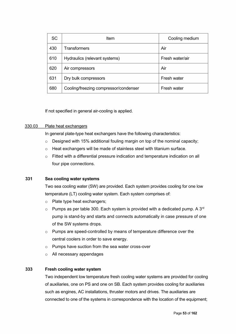
SC Item Cooling medium
430 Transformers Air
610 Hydraulics (relevant systems) Fresh water/air
620 Air compressors Air
631 Dry bulk compressors Fresh water
680 Cooling/freezing compressor/condenser Fresh water
If not specified in general air-cooling is applied.
330.03 Plate heat exchangers
In general plate-type heat exchangers have the following characteristics:
o Designed with 15% additional fouling margin on top of the nominal capacity;
o Heat exchangers will be made of stainless steel with titanium surface.
o Fitted with a differential pressure indication and temperature indication on all
four pipe connections.
331 Sea cooling water systems Two sea cooling water (SW) are provided. Each system provides cooling for one low
temperature (LT) cooling water system. Each system comprises of:
o Plate type heat exchangers;
o Pumps as per table 300. Each system is provided with a dedicated pump. A 3rd
pump is stand-by and starts and connects automatically in case pressure of one
of the SW systems drops.
o Pumps are speed-controlled by means of temperature difference over the
central coolers in order to save energy.
o Pumps have suction from the sea water cross-over
o All necessary appendages
333 Fresh cooling water system Two independent low temperature fresh cooling water systems are provided for cooling
of auxiliaries, one on PS and one on SB. Each system provides cooling for auxiliaries
such as engines, AC installations, thruster motors and drives. The auxiliaries are
connected to one of the systems in correspondence with the location of the equipment;

Page 54 of 162
e.g. engines located on SB are connected to the SB system. The connections are in
full correspondence with the redundancy requirements for DP-2. Each system
comprises of:
o Ring line with expansion tank, de-aeration plugs and drain valves and other
necessary appendages
o Pumps as per table 300. Each system is provided with a dedicated pump. A 3rd
pump is stand-by and starts and connects automatically in case pressure of one
of the LT systems drops.
o Heat transfer to sea water (see section 331)
340 Fresh / sea water / sewage system 340.01 General
The vessel is provided with:
o Fresh water supply system;
o Sanitary and discharge system
341 Fresh water supply system 341.01 General
The fresh water supply system consists of:
o 1 hydrophore with 2 pumps, with direct suction from the fresh water tanks and
serving the fresh water ring line system;
o 1 UV sterilizer + filter;
o Cold water circuit with circulation pump
o Hot water circuit with boiler and circulation pump.
o Eye wash system
o Fresh water maker
All fresh water tanks have the possibility to add chemicals.
341.02 Hot water circuit
The hot water circuit consist of:
o 1 heat exchanger, integrated in the hot water boiler (See section 373);
o 2 hot water circulation pumps (1 stand-by for the other)

Page 55 of 162
341.03 Eye wash stations
2 Eye wash stations are provided according to Class requirements:
o 1 on main deck, aft of the superstructure;
o 1 in the engine room.
341.04 Fresh water maker
A fresh water maker is installed with the following properties:
Type Reverse Osmosis
Capacity 20 m3/day at 32oC sea water temperature
Rehardening filter Included
343 Sanitary gravity discharge system 343.01 General
The sanitary gravity discharge system consists of:
o Sanitary equipment
o Grey water system
o Sewage tank
o Sewage pump
343.02 Sanitary equipment
The sanitary equipment is supplied as indicated on the GA Plan. Type and size is to
Builder's Standards.
Floors in sanitary sloped with drain
Taps brass chromium, with red and blue indication for
hot and cold fresh water.
Showers thermostatic mixing taps
Flushing toilets fresh water
For more details see Section 720.
343.03 Grey water system
All grey water from the showers, wash basins, laundry and galley are discharged by
gravity directly to sewage plant. The discharge of the galley is provided with a grease
trap. Alternatively the discharges can be led to the sewage tank.
Page 56 of 162
In galley and all wet spaces deck scuppers with removable filters plates and water
traps are provided. The filter plates are in line with the floor covering.
343.04 Sewage tank
The sewage tank is provided with a flushing connection from the internal fire-fighting
system.
343.05 Sewage pump
A sewage pump is provided to discharge the contents of the sewage tank directly
overboard or to third parties via the shore connection. The sewage pump has local
start / stop.
344 Sanitary vacuum discharge system The black water (toilets) is handled by a vacuum plant. The vacuum plant comprises of
2 vacuum pump units each 100% capacity. The vacuum unit is connected to the
sewage plant.
345 Sewage treatment system The vessel is provided with a sewage treatment plant
MARPOL compliant yes
Capacity for number of persons as specified in section 000
Automation fully automatic
High level alarm tank yes
346 Internal deck scuppers / drainpipes o By design/construction of the drain system, the ship's possible trim shall be
taken into consideration.
o Sufficient number of drain pipes from open deck areas to be provided where
there is no drainage through shipside scuppers. All external drains to be fitted
with drain wells (wide pipe in upper part).
o Drain pipes from superstructure in general to be routed outside the
superstructure and as far as practical to be terminated close to a drain pot on
the deck below.

Page 57 of 162
o Drain pipes from top of wheelhouse top to be routed inside bridge bulkheads
with outlet through the bulkhead close to a drain pot outside on bridge deck.
Drain pipes from top of funnel to be routed inside casing and terminated
overboard.
o All drains on forward end of vessel shall as far as practicable be led to hawse
pipes in order to keep front B-deck dry.
o Approx 5 drains on each side shall be arranged on main deck, leading down and
through the shell. In the inlet 3 parallel solid bars are arranged.
350 Filling, sounding and de-aeration system 351 Filling / sounding / de-aeration 351.01 General
The Vessel is provided with:
o Filling system
o Sounding system
o De-aeration system
351.02 Lay-out
o Filling stations (for fuel oil, freshwater, lub oil and hydraulic oil) are provided on
deck;
o Remote sounding system as per table below.
o Sounding pipes shall, as far as practicable, be arranged in the mid area of the
tank. Sounding pipes shall have long radius bends, if needed. A vent drill hole
shall be added close to the deck penetration. Sounding pipes run to the bottom
(if practically possible) of their respective tanks. Sounding pipes terminating on
weather decks are fitted with bronze screw caps and keep chain attached to
pipe;
o Sounding pipes for tanks in machinery spaces are fitted with a small test cock
and weighted self-closing cocks and bronze screw caps complete with keep
chain;
o De-aerations on the main- and B-deck are protected with steel bars, where
necessary;
o De-aerations of the sewage tank and plant are led through the top of funnel.
o Air pipe for oil tanks to be of ordinary steel and for water tanks to be of
galvanized steel.

Page 58 of 162
o The de-aeration pipe's height above deck to the opening where sea can
penetrate shall be minimum 760 mm on main deck.
o The de-aeration pipes from the stabilizing tank to be arranged on both sides of
the vessel with water traps in addition to tank ventilation valves arranged as high
as possible.
o The de-aeration pipes from a cargo tank shall be extended below the tank top
and the end shall be cut in 45 degrees. The upper end of this cut shall be
approx. 50 mm below the top of the tank.
De-aeration and sounding - lay out
Compartment Central/dedicated
De-aeration
Self-closing
De-aeration
Sounding
Ballast water and
anti-roll
Dedicated Yes Remote + local
Cargo fuel oil / base
oil
Central/dedicated Yes, flame screen,
special consideration
for switching
between fluids.
Remote + local
Fuel oil Service Central, through fuel
leakage tank
Yes, flame screen Remote + local
Lube oil tanks Central, via dirty oil
tank
Local (see-thru or
similar)
Azimuthing thruster
lube oil tank
Dedicated Yes Local
Urea Dedicated Yes Remote + local
Tank cleaning Dedicated Yes, flame screen Remote + local
Black water Dedicated No, top of casing Remote + local
Grey water Dedicated Yes Remote + local
Sludge Dedicated Yes, flame screen Local
Dirty oil Dedicated Yes, flame screen Remote + local
Foam Dedicated Yes Local

Page 59 of 162
Compartment Central/dedicated
De-aeration
Self-closing
De-aeration
Sounding
Fresh water Dedicated Yes Remote + local
Methanol (option) Dedicated, high
velocity p/v
Yes Remote + local
Liquid mud/ brine Dedicated Yes, special
consideration for
mud
Remote, local,
and ullage hatch
in manhole,
density
Dry bulk Central via filter N/A Remote
Sea chest Dedicated Large size
gooseneck de-
aeration, closable
with class approved
bronze valves
No
Large void spaces Dedicated Yes Local
Small void spaces No, closed by tack
welded manhole
No de-aeration No
Crank case Dedicated for each
engine
No; continuously
rising pipes through
funnel. Fitted with
drain pots on tween
deck level.
352 Remote tank sounding system 352.01 Tank sounding system
The sounding system comprises:
o 1 pressure sensor in each tank to be measured.
o 2 pressure sensors in each mud/brine/base oil tank in order to calculate density
of the cargo being carried. Density calculation is automatically calculated by the
sounding system.
o Indication of vessels forward and aft draft.

Page 60 of 162
o Integrated in the IAS (section 440) and interfaced with:
− Loading computer (see section 440).
o Dedicated mimics for each fluid type with grouped tanks (fuel oil service, fresh
water, miscellaneous)
o Graphical picture for each tank which is included in the system with the following
information:
− Tank name
− Maximum filling level (m3)
− Actual filling level (%, m and m3 corrected for trim)
− Alarm limits
360 Lubrication system 360.01 General
The Vessel is provided with:
o Lubrication oil system
o Dirty oil system
o Sludge system
o Crank case de-aeration
361 Lubrication system 361.01 Lubrication oil system
The lubrication oil system consists of:
o Lubrication oil storage tanks
o Electrically driven lubrication oil pump as per table 300 with local start/stop to fill
main generator sumps by hose;
o Electrically driven lubrication oil pump as per table 300 with local start/stop to fill
azimuthing thrusters by hose;
o Hand pumps to fill bow thrusters.
o Overflow and ventilation from the lubrication oil tanks, except the lubrication oil
tank in the propulsion room, are to the deck filling station.
362 Dirty-oil system 362.01 Dirty oil system
The dirty oil system consists of:
o Dirty oil tank, with a high level alarm

Page 61 of 162
o Electrically driven dirty oil pump with local/start stop to empty:
− Main generator engine sumps by hose
− Dirty oil tank
− Sludge tank
o Shore connection
363 Sludge system The sludge tank can be emptied by means of the dirty oil pump.
364 Crank case de-aeration All the engines are provided with crank case de-aerations. See table in section 351 for
piping details.
370 HVAC system 370.01 General
The Vessel is provided with:
o Forced ventilation system
o Air conditioning system
o Heating system
371 Forced ventilation system 371.01 Overview of air changes
Compartment Fan type Capacity Number
of fans
Engine room 2-speed supply;
2-speed reversible
50%
50%
1
1
Bow thruster room supply As per ISO
requirements
2
Propulsion room supply 100 m3/hr 1

Page 62 of 162
Compartment Fan type Capacity Number
of fans
Emergency generator
room
supply As per ISO
requirements
1
Cargo room 2-speed supply;
spark-minimising
20 airchanges / hr
each fan
2
CO2 room Exhaust 6 airchanges / hr 1
Stores Exhaust 8 airchanges / hr 1/store
Workshop Exhaust 8 airchanges / hr 1
Paint store Exhaust (Ex-proof) 10 airchanges / hr 1
Galley Exhaust fan in
ventilation hood
40 airchanges / hr 1
Sanitary units Exhaust 15 airchanges / hr 1 per
deck
Treatment room Exhaust 12 airchanges / hr 1
Laundry Exhaust 15 airchanges / hr 1
Changing room Exhaust 10 airchanges / hr 1
Engine control room supply 100 m3/hr 1
Switchboard room supply 100 m3/hr 1
In general all fans are local controlled.
371.02 Machinery spaces
o Air intakes and outlets are provided with a fire flap.
o The inlet gratings for the ventilation casings are provided with mist eliminators
o The air outlets are provided with overpressure grids or a de-aerator
o Drainage from fan ducts is arranged.
o Fans are arranged with access for maintenance.
o The air in the engine room is duly distributed towards engines,
turbochargers, the fuel oil separator, other heat dissipation equipment, towards

Page 63 of 162
compressors, etc. A part of the air shall be lead below the floor plates on
tanktop;
o For emergency stops see section 570
371.03 Galley
Above the cooking range in the galley one exhaust ventilation hood is provided with
removable grease filters.
Air is supplied via the accommodation space and direct from outside.
371.04 Sanitary spaces
The duct piping is of the "Spiralo" type and each exhaust point is provided with a
controllable nozzle.
372 Air conditioning system 372.01 General
The Vessel is provided with air conditioning systems for:
o Accommodation spaces (cabins, galley, mess rooms, offices etc);
o Wheelhouse, 2 x 100% redundant;
o Engine control room and switchboard room, 2 x 100% redundant.
372.02 Design conditions
Outside conditions as specified in section 000
Temperature accommodation, winter 22 °C
Temperature accommodation spaces, summer 27 °C
Temperature wheelhouse, summer 25 °C
Relative Humidity accommodation spaces 55 %
Return air accommodation approx. 60 %
Return air wheelhouse approx.. 85 %
372.03 AC accommodation spaces and wheelhouse
The air conditioning system for the accommodation spaces and wheelhouse
comprises:
o Air handling unit of the high pressure direct expansion type;
o Fresh air intakes, provided with mist eliminators;
o 1 frequency controlled (by air pressure sensor) ventilator of 100% capacity;

Page 64 of 162
o Cooling by means of evaporators, supplied by common compressors (see
section 372.07);
o Heating by means of hot water from vessels hot water system (373), exchanger
of copper tubes and dimensioned for water of 60 Centigrades
o Ducting system;
o Cabin units with manual flow control.
o Refrigerant leakage detector (portable);
o Fire dampers are fitted according Class;
o Re-circulated air is collected on each deck level and led to the air handling unit;
o The system is designed with a slight overpressure on each deck;
372.04 AC wheelhouse (Back-up & Boost)
The AC system for the wheelhouse comprises the following:
o Connection with AC system for accommodation with a capacity of 1 x 100%.
o 1 Split type air conditioning unit with a capacity of 1 x 100% for redundancy.
o The condensing unit will be air cooled an places on top of the wheelhouse
o Cooling medium: R410A
372.05 (AC-03) AC Switch Board Room (SBR)
The SBR is provided with a dedicated air handling unit (down flow unit).
The unit comprises:
o Filter section
o Heating section with electrical heater
o Cooling section with two (2) cooling coils
o Fan section with two (2) fans, each of 100% capacity and 2 cooling coils.
o 2 Dedicated compressor / condensing units are provided for the SBR, each with
100% capacity.
o For cooling see section 330.
372.06 AC Engine control room (ECR)
The ECR is equipped with two (2) split type air-conditioning units, each unit will have
100% capacity.
o The condensing unit will be air cooled an places in the engine room
o Cooling medium: R410A

Page 65 of 162
372.07 AC Propulsion room
The Propulsion room is equipped with two (2) self-contained AC unit, each of 100%
capacity.
o For cooling see section 330.
o Cooling medium: R407C
372.08 AC Technical space (back-up)
The Technical space is equipped with one (1) Split type air conditioning unit with a
capacity of 1 x 100%
o The condensing unit will be air cooled an places on top of the wheelhouse
o Cooling medium: R410A
372.09 AC compressors / condenser units for Accommodation and Wheelhouse
2 sets of compressors and condensers are installed on a common base frame in the
engine room with the following characteristics:
Capacity 60% each
Cooling medium R407C
Serving AC accommodation and wheelhouse
Cooling see section 330
372.10 Condensing units for SBR
2 sets of compressors and condensers are installed on a common base frame in the
engine room with the following characteristics:
Capacity 100% each
Cooling medium R407c
Cooling See section 330
373 Heating system 373.01 General
A hot water circulation system will be installed for the following heating purposes:
o Accommodation and wheelhouse;
o Drinking water;
o Heating of tank cleaning water;
The water is heated by the following heat sources:
o Waste heat from the two larger generator engines HT system (3512 engines);

Page 66 of 162
o Electric boiler.
373.02 Design conditions
Outside conditions as specified in section 000
Temperature accommodation spaces 22 °C
Temperature technical spaces minimum 5 °C
373.03 Electric boiler
An automatic hot water boiler shall be installed supplying heat for tank washing, air
condition plant and hot water for accommodation. The boiler shall supply heat in
addition to the heat recovery system.
Heat capacity Approx. 300 kW
Circulation pumps 2 x 100% (one will be stand-by)
373.04 Circulation system
The circulation water will be circulated over heat exchangers mounted in the HT
system of the large generator engines (3512C engines). HT water will be cooled in
these heat exchangers. HT water will further be cooled by the engines LT system in
case temperature is still too high.
The boiler is installed in series of the engines and heats the circulation water to the
setpoint temperature in case dissipated heat of the engines was not sufficient.
373.05 Space heaters
The following spaces are fitted with heating elements in order to maintain a minimum
temperature of 5 °C:
o Mast in compartments where equipment dictates heating;
o Battery room;
o Bow thrusters room;
o Propulsion room;
o Cargo room;
o Emergency generator room;
o CO2 room;
o Paint locker;
o Engine and deck workshops;
o Deck lockers;

Page 67 of 162
Heating elements shall be powered by the hot water heating system (373) whenever
practical. For back-up purposes also electrical heaters shall be provided.
380 Exhaust system 380.01 General
The system consists of:
o Exhaust piping with expansion joints;
o Silencers with spark arrestor.
380.02 Exhaust piping
o For the exhaust materials see section 300;
o The exhausts shall be insulated with heat resistant insulation blankets of
minimum 50 mm thickness.
o They shall be covered with thin metal sheeting in the engine room
o Stainless steel compensators are fitted as expansion joints;
o All exhaust piping is resiliently mounted to rigid points of the Vessel's structure;
o All exhaust pipes will have large drain pots in engine room easily accessible,
with heat resistant cock valves. The drain will be led below chequered plates.
o The pipes to end above the funnel and to be directed aftwards and outwards and
upwards by approx. 45 degrees. End-cut to be vertical.
o The exhaust piping of the emergency set passes through a dedicated cofferdam
to the end of the funnel topdeck.
380.03 Exhaust silencers
o The exhaust silencers (35 dBA of the resonance & absorption type) with spark
arrestors are of adequate capacity;
o Exhaust silencers in the ER are insulated with heat resistant material and
cladded with metal sheeting;
o Exhaust silencers in the funnel are insulated with blankets;
o All silencers are resiliently mounted to rigid points of the Vessel's structure.

Page 68 of 162
382 Exhaust gas cleaning system 382.01 General
The exhaust system is prepared for future installation of an exhaust gas cleaning
system of the Selective Catalytic Reduction (SCR) type. The preparations involve the
following:
o Casings to install catalyst blocks
o Electric cabling and foundations for pumps, analysers and control systems
o Tank in the double bottom for storage of urea. The tank is provided with the
following:
− Urea resistant coating
− Fill and deaeration lines and sounding as per table in section 350

Page 69 of 162
400 Electrical system
400.01 General
The main electrical power is generated by:
o 4 diesel engine driven generators;
o 1 emergency / harbour generator;
o 1 shore supply.
The system is designed for parallel operation of all and any of the 4 generators with
closed bus. It will be possible to operate any thruster motor with any one of the
generators running, however limited to the power available. Any of the generators may
be started from a “black ship” condition.
o The design and lay-out of the electric system, the materials, installation and
testing are to Builder's Standards, Class regulations and Flag Authorities stated
under section 031 and 035;
o Operating conditions/requirements which are taken into account (unless stated
otherwise):
Environmental conditions see section 000
Quality suitable for marine application
Atmosphere damp and saline
Vibrations see section 078
Enclosure protection (1) IP 56 for components placed on open deck
IP 23 for alternators and thruster motors
IP 21 for components placed in enclosed spaces
Maximum conductor temperature 90 °C (core) for all power, propulsion and lighting
cables
Explosion proof in hazardous areas if required by Class.
Note: (1) Unless specified otherwise in the relevant sections of this specification
400.02 Networks
For the supply to the electric consumers and installations the following floating
networks (without a neutral) are provided:

Page 70 of 162
o 690 V, 60 Hz, (3 phases) for supply of propulsion drives, bow thrusters, cargo
pumps (where appropriate) and distribution converters;
o 440 V, 60 Hz, (3 phases) for power consumers;
o 230 V, 60 Hz, (1 phase) for lighting, small power consumers, nautical
equipment, navigation lighting, etc. via transformers;
o 24 V, Direct Current (DC) for controls, alarms, navigational- and navigation
equipment, radio equipment, etc.
410 Power generating system 411 Generator sets 411.01 Diesel generators
Diesel engine particulars
The following diesel generating sets are installed in the Engine Room:
Make Caterpillar Caterpillar
Type 3512 C TA HD C32 TTA
Number 2 2
Maximum Continuous engine rating 1424 bkW 994 bkW
Rotation speed 1800 RPM 1800 RPM
Maximum Continuous Electrical rating 1360 ekW 944 ekW
Fuel see section 000
Cooling system see section 330
Starting system air, see section 620
Mounting with alternator on resiliently mounted skid
The diesel engines are further provided with:
o Fuel oil system;
o Cooling water system, consisting of separate HT and LT system including:
− Gear driven pumps;
− Engine integrated expansion tanks;
− Thermostats.
o Lubrication oil system, including:
− Cooler;
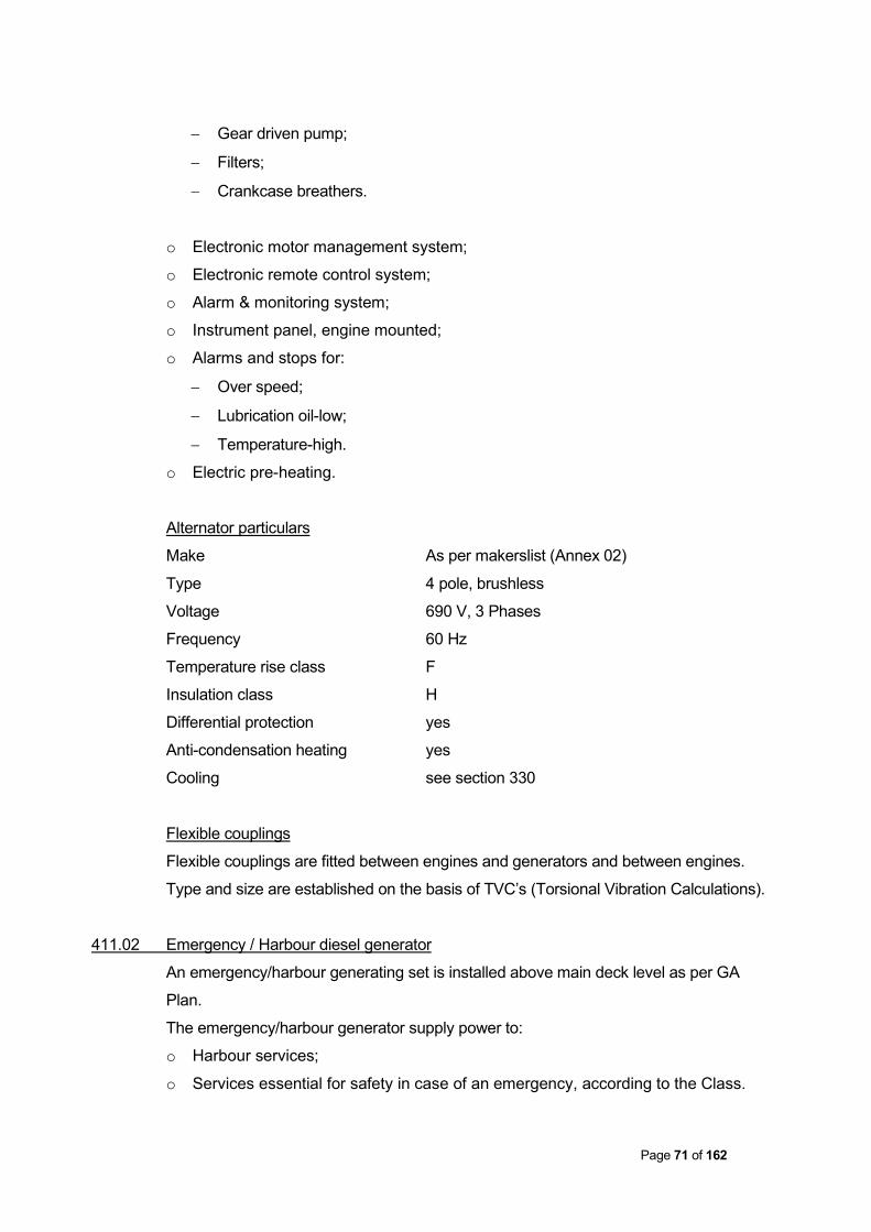
Page 71 of 162
− Gear driven pump;
− Filters;
− Crankcase breathers.
o Electronic motor management system;
o Electronic remote control system;
o Alarm & monitoring system;
o Instrument panel, engine mounted;
o Alarms and stops for:
− Over speed;
− Lubrication oil-low;
− Temperature-high.
o Electric pre-heating.
Alternator particulars
Make As per makerslist (Annex 02)
Type 4 pole, brushless
Voltage 690 V, 3 Phases
Frequency 60 Hz
Temperature rise class F
Insulation class H
Differential protection yes
Anti-condensation heating yes
Cooling see section 330
Flexible couplings
Flexible couplings are fitted between engines and generators and between engines.
Type and size are established on the basis of TVC’s (Torsional Vibration Calculations).
411.02 Emergency / Harbour diesel generator
An emergency/harbour generating set is installed above main deck level as per GA
Plan.
The emergency/harbour generator supply power to:
o Harbour services;
o Services essential for safety in case of an emergency, according to the Class.

Page 72 of 162
The emergency/harbour generator is connected to the 440 V main switchboard and the
emergency switchboard.
The emergency generation system is capable of exciting the emergency generator
ready to take the full load within 45 s.
Diesel engine particulars
Make Caterpillar
Type C9
Power 250 bkW
Speed 1800 rpm
Fuel see section 000
Cooling system see section 330
Starting system electrical
Emergency starting electrical
Mounting with alternator on resiliently mounted skid
The diesel engine is further provided with:
o Fuel oil system;
o Cooling water system, consisting of a combined HT and LT system including:
− Gear driven pumps
− Expansion tanks
− Thermostats.
o Lubrication oil system, including:
− Cooler;
− Gear driven pump;
− Filters;
− Crankcase breathers.
o Electronic motor management system;
o Electronic remote control system;
o Alarm & monitoring system;
o Instrument panel, engine mounted;
o Alarms for:
− Over speed;
− Lubrication oil-low;
− Temperature-high.

Page 73 of 162
o Pre-heating
Alternator particulars
Make see makers list
Type horizontal, self-ventilating, drip proof, self-
exciting, brushless type
Capacity 238 ekW / 297 kVA (at cosφ = 0,8)
Voltage 440 V, 3 Phases
Frequency 60 Hz
Temperature rise Class H
Insulation Class H
Anti-condensation heating yes
Cooling see section 330
413 Electrical motors 413.01 General
o Motors of 0.5 kW, or more, are of the squirrel cage induction type;
o Designed for continuous duty (S1), unless stated otherwise;
o Electric motors with a power higher than 15% of the total power of one of the
smaller main generators are fitted with special starting equipment;
o Insulation class F;
o Temperature rise class F;
o Anti-condensation heating (in general 230 V) is fitted for motors which are either:
− Placed outside and/or
− Provided with a water cooling system and/or
− Of 10 kW and above.
o Electric motors of approx. 100 kW and above are connected to the PMS via an
interlock (powerrequest).
o All electrical motors with a power of 10 kW or more will have hour meters and
ampere meters. Hour meters will be displayed locally on the starter panels and
in the IAS.
413.02 Propulsion motors
The vessel is fitted with 2 electric propulsion motors:
Make see makers list (Annex 02)

Page 74 of 162
Type squirrel cage motor for continuous operation,
fresh water cooled
Power 1500 kW on output shaft
Voltage 690 V, 3 Phases
Frequency 0 - 55 Hz
Speed 0 - 1100 rpm
Duty class S1 (continuous duty)
Temperature rise class F
Insulation class H
Cooling See section 330
Mounting horizontal
Bearings roller type
413.03 Bowthruster motors
Make see makers list (Annex 02)
Type squirrel cage motor for continuous operation,
fresh water cooled
Power 735 kW on output shaft
Voltage 690 V, 3 Phases
Frequency 0 - 55 Hz
Speed 0 - 1641 rpm
Duty class S1 (continuous duty)
Temperature rise class F
Insulation class H
Cooling see section 330
Mounting Vertical
414 Frequency converters 414.01 General
Frequency converters are installed for the following equipment:
o Azimuthing thrusters
o Bowthrusters;
o Cargo pumps;
o AC unit fans.

Page 75 of 162
After a black-out it will be possible to reset the drives from the IAS and locally on the
thruster control panels.
A failure in any power supply system which is not used for driving the motors will not
cause a thruster failure.
414.02 Frequency converters azimuth thrusters and bow thrusters
The vessel is fitted with 2 frequency converters for the main propulsion and side
thrusters:
Make see makers list (Annex 02)
Type Active Front End;
Voltage 690 V, 3 Phases
Frequency 0 – 55 Hz
Duty class S1 (continuous duty)
Cooling see section 330
414.03 Frequency converters other consumers
Make see makers list (Annex 02)
Type Passive, 6-pulse
Cooling see section 330
415 Shore connection / batteries / UPS 415.01 Shore connection
A shore supply connection is installed with the following characteristics:
Power 400 A
Voltage 440 V, 3 phases
Frequency 60 Hz
Correct phase rotation included
Earth connection yes
The shore connection is capable for the simultaneous run of the following equipment:
o Lighting
o Galley
o AC system on 50% capacity
o Normal ventilation of spaces (engines not running)

Page 76 of 162
Uninterrupted take over from shore to vessel’s electrical power and vice versa is not
provided.
415.02 Battery sets
The 24 V DC system is sub-divided in separate circuits, each having its own battery
set. Following battery sets/24 V circuits are provided:
o 2 set located in vicinity of the wheelhouse to power controls, alarms, emergency
lighting and electronic equipment;
o 1 set located in the battery locker on top deck in the void space of the mast, with
a capacity according to the relevant requirements of the Class, for GMDSS-radio
equipment;
o 2 sets for starting the emergency generator set;
o 2 sets in engine room for engine control circuits (DP 2 requirement);
The batteries are:
o Stored in well ventilated places
o Of the lead-acid and semi-traction type, except batteries for emergency
generator which are of the traction type
o Charged by battery chargers
415.03 Battery charging equipment
Battery chargers will be of renowned make and type, and are to be capable of
automatically maintain the 24V battery in a fully charged condition (automatic voltage
regulation).
For the batteries for wheelhouse equipment and for batteries for the engine room, 2
chargers for each battery set will be installed. The chargers will be capable of operating
in parallel and will each have 100% capacity to take the entire DC consumption in case
of failure in one charger.
For batteries not belonging to the ship like batteries for vehicles and workboats:1
portable battery charging unit is provided.
415.04 Uninterrupted Power Supply (UPS) for the 230 V systems
Battery supplied systems are installed to provide uninterrupted power supply to a
number of consumers. The consumers, which are provided with a battery back-up
supply, are subdivided in the following groups:
o Systems, as specified by Class and SOLAS;

Page 77 of 162
o Computer based systems, to prevent loss of information for 15 minutes.
416 Motor starters A motor starter is a device, which can start and stop an electric motor by command
of an operator or an automatic provision. In case of high power motors the
following starters may be used:
o Star-delta starter;
o Static soft starter;
o Variable speed starter (Frequency converter).
Control and monitoring features of the motor starters are stated in the relevant
sections of this specification.
Motor starters have the following features (if applicable):
o interlock to prevent unintentional switching-in;
o thermal over current protection of motor, with reset;
o Short-circuit protection.
420 Cables 420.01 General
Cables are:
o Of the marine type;
o Oil and water resistant
o Of armoured type in cargo pump room;
o Type approved by Class;
o Designed for application on board of ships and the size, construction and
selection of cabling will comply with IEC 60092 and IEC 60553 regulations for
the electrical installation of ships.
o In general fitted on cable trays in accordance with Yard’s standards.
o External cable trays or cable pipes shall be galvanised or be of stainless steel.
o Cables shall not be painted.
420.02 Cable design
o Compliant to the IEC requirements (see section 035) for:
− Construction;
− Flame retardation;

Page 78 of 162
− Low smoke index;
− Low corrosion.
o Current rating (cable cross-section) is minimal equal to the simultaneous load,
taking into account selectivity, voltage loss and power demand;
420.03 Electro Magnetic Interference (EMI)
To prevent or reduce EMI, cables transferring different signals or voltage levels are
divided into the following sensitivity groups:
Group 1 Interfering cables
Group 2 Non-interfering and non-susceptible cables
Group 3 Sensitive signal cables
Group 4 Susceptible cables
420.04 Cable runs
Cable runs are:
o Designed to keep the lengths of cable and number of penetrations of watertight
bulkheads and decks to a minimum;
o Fixed in accessible positions;
o Designed with spare capacity for future installation of additional cables.
Cables are fixed by:
o Standard cable bundle strips (“tie-rap” or equivalent);
o Stainless steel tie-raps outside;
o Metal tie raps for cables fixed underneath the cable run, on vertical cable runs
and in the engine room.
420.05 Bulkhead penetrations
Bulkhead penetrations are provided in way of watertight / fire resistant bulkheads or
decks. The penetrations are generally of the Multi Cable Transit (MCT) type.
If required, EMC-Multi Cable Transits are used for additional mutual interference
reduction, to shield susceptible equipment from interfering signals.
420.06 Cable designation and markings
o Cables and related equipment have a unique number corresponding with the
documentation and drawings as per yards standards at both ends.

Page 79 of 162
o Cable conductors are marked at both ends by means of an “identification collar”
indicating the specific numbers.
o Cables of skid mounted delivered equipment are marked according to
equipment supplier's standard.
420.07 Power sockets
The number of electrical sockets is tailored to the rooms and spaces within the Vessel.
The following electrical watertight power sockets are provided on the cargo deck:
o Ten 440 V, 60 Hz, 32 A CEE form;
o Two 230 V, 60 Hz, 16 A;
o As needed for Recovered Oil operations as specified in section 640.
430 Switchboards & components 430.01 General
The vessel is fitted with the following switchboards:
o 690/440/230 V main switchboard (MSB);
o 440/230 V emergency switchboard (ESB);
o Distribution panels.
The main switchboard is divided in two sections.
Switchgear and distribution system comply with:
o Construction, in accordance with IEC;
o Vibration, in accordance with Lloyd’s vibration test;
o The number of different breaker frame sizes is kept to a minimum.
o Each cable connection is labelled with a unique code.
430.02 690 V panels
The large consumers (main propulsion, bow thrusters, cargo pumps and as far as
practical any other consumer) will be supplied from the 690 V distribution switchboard.
The switchboard will be capable of being operated by the PMS system.
Manual control of all main breakers shall be possible.
Monitoring functions at the generator breaker panels and the transformer panel
o On/off indication of the breaker

Page 80 of 162
o Metering indications (V, A, kW, Hz)
o Synchro-check relay (generator and bus tie breaker)
Monitoring functions at the side thrusters:
o On/off indication of the breaker
o Meter indications (A, kW)
Monitoring functions at the converter panels:
o On/off indication of the switch
o Metering indications (A, kW)
Protection functions at the generator breakers:
o Time-delayed short circuit current
o Sustained overcurrent
o Reversed power
o Delayed under-voltage
Protection functions at the distribution switches (to direct supplied consumers):
o Time-delayed short circuit current
o Sustained over current
430.03 440 V panels
The large consumers, local distribution panels and motor starter panels are supplied
from the 440 V distribution switchboard.
Manual and remote control, via the PMS of main breaker is possible.
Monitoring functions at transformer panels:
o On/off indication of the breaker;
o Metering indications (V, A, kW, Hz).
Protection functions at shore and transformer panels:
o Time-delayed short circuit current;
o Sustained over current;
o Under-voltage.
o Phase sequence protection (shore connection only).
Page 81 of 162
Protection functions at the outgoing circuits (to distribution panels or end consumers),
by means of circuit breakers:
o Short-circuit current;
o Sustained over current (if applicable).
430.04 230 V panels
The 230 V panels serve:
o All lighting;
o Socket outlets;
o Other consumers.
Control breakers
Control breakers: manual.
430.05 Emergency switchboard
All class specified essential consumers are directly fed by the ESB.
The interconnection breaker between the MSB and the ESB is switched off by a zero
voltage relay in case of voltage fail at the MSB. Subsequently the emergency
generator is started.
Control breakers
Control main breaker: manual and remote.
Control breakers: manual.
Switchboard functions (440 V part)
Monitoring functions at the inter-connection breaker panels:
o On/off indication of the breakers;
o V, A, kW and Hz indications;
o Zero voltage relay to disconnect main and emergency switchboard;
o Synchro-check relay
o Provisions for synchronising with MSB for harbour mode
Monitoring functions at the generator panel:
o On/off indication of the breakers;
o V, A, kW and Hz indications.
Page 82 of 162
Protection functions at the inter-connection breakers:
o Time-delayed short circuit current;
o Sustained over current;
o Zero voltage relay.
Protection functions at the outgoing circuits (to end consumers), by means of circuit
breakers:
o Short circuit current;
o Sustained over current (if applicable).
430.06 24 V DC panels
24 V DC distribution panels are powered from the 24 V DC rectifiers/batteries.
Distribution to the (end) consumers is realized by means of fused switches or miniature
circuit breakers.
430.07 Transformers
The following transformers are supplied:
o 2 step down transformers, each capable of taking the entire load of both sides
(port and starboard), 690 V - 440 V, 3 phases;
o 2 step down transformers, each capable of taking the entire load of both sides
(port and starboard), to provide power for general lightings and power supplies
of the vessel, 440 V - 230 V, 3 phases;
o 1 step down transformers for emergency supply (440 V - 230 V, 3 phases);
o Cooling: see section 330.
o Installed on rubber vibration dampers, suitable for the purpose.
430.08 Protective devices
The electrical system is provided with protective devices, such as:
o Thermal over current relays;
o Moulded Case Circuit Breakers (MCCB) with current limiting characteristics;
o Breakers;
o Fuses;
o Miniature circuit breakers;
o Earth fault protection for all distribution circuits.
The protective devices include the following:

Page 83 of 162
o Suitable for placing in the specific switchboard;
o Plug-in or removable drawer type;
o Closing mechanism controlled by a pre-loaded spring;
o Easy interchange of components
440 Alarm / monitoring system 440.01 General
The vessel is provided with an Integrated Automation System (IAS).
The system includes:
o Power Management System (PMS);
o Machinery automation;
o Cargo handling automation;
o Ballast system automation;
o Tank sounding;
o Alarms & monitoring (AMS);
o Interface with the separate loading and stability program;
The system is designed with redundant topology with respect to operator stations,
communication network and power supply. The system is designed with a
decentralised/remote I/O system and includes:
o Approx. 2000 I/O’s;
o Approx. 100 spare I/O’s.
440.02 Screens and Local operator panels (LOP).
The system comprises of 2 sets of independent 20” screens:
o One operator station with 1x 20“ screen fitted in the wheelhouse forward;
o One operator station with 1x 20“ screen fitted in the wheelhouse aft;
o Two operator stations, each with 2x 20” screens fitted in the ECR.
Local operator panels are placed in
o Wheelhouse;
o Mess room;
o Engineers cabins.

Page 84 of 162
440.03 Power Management System
The electrical system is provided with a basic PMS and functions independent from the
AMS. The PMS has the following functions:
o Takes care over synchronisation, load sharing and heavy consumers.
o Starts a diesel generator set on black-out.
o Automatic start/ stop of the diesel generator sets based on the requested load
demand of the electrical system;
o Prevent starting of large consumers until sufficient power is available;
o Reduce power to relevant consumers in case of generator overload.
The PMS will be included in the FMEA.
440.04 Machinery automation
The machinery automation consists of:
o Remote start/stop of specified equipment;
o Control;
o Safety functions.
440.05 Cargo handling automation
See section 630.
440.06 Alarms & monitoring
The alarm & monitoring system (AMS) detects and reports alarms and events to the
operator when abnormal conditions occur.
The AMS features:
o Modularised I/O;
o Decentralised I/O;
o Alarm summary;
o Interface to external sub systems (i.e. main engines).
The AMS comprises of the necessary digital alarms for the propulsion installation and
other ships duty. The alarms (acoustical and visual) are presented:
o Screens in the ECR;
o Screens in the wheelhouse.

Page 85 of 162
440.07 Alarms ECR & wheelhouse
The alarms according to maker and Class are presented.
An accept pushbutton is installed to reset the acoustical alarm and to indicate
acknowledgement.
The alarm system presents as a minimum alarms of the following systems:
o Propulsion alarms;
o Generator sets;
o Emergency generator (group alarm);
o Fuel oil day tanks;
o Compressed air system
o General bilge system;
o Dead man alarm ER;
o Dead man alarm wheelhouse (only in ECR).
440.08 AMS propulsion installation
Main engines alarm & stop:
o Over speed;
o Lubrication oil pressure too low;
o Cooling water temperature too high.
Main generator engines alarms:
o Level expansion tanks ME, (interlock; main engine starting in case of low level
expansion tank);
o Overload (speed reduction).
Main alternators alarm:
o Winding temperature;
o Breaker trip;
o Reverse power.
Azimuth thrusters alarm & stop:
o Oil pressure too low;
o Temperature too high.
Azimuth thrusters alarm:
o Power supply failure.

Page 86 of 162
440.10 General alarm
In the wheelhouse in the navigation console a general alarm is installed. The general
alarm is incorporated in the intercom/PA system (see also section 881).
Light columns, including signals for the general alarm, fire alarm, machinery alarm and
telephone are provided in:
o Propulsion room
o Engine room
o Cargo room
o Bow thruster room
440.11 Fire detection and alarm system
An automatic fire-/ smoke detection alarm system is provided (SOLAS class as per
section 700) and consists of:
o Central unit in wheelhouse
o Smoke detectors in accommodation corridors
o Heat detectors in galley and cabins
o Smoke detectors in machinery spaces
o Break glass call points in engine room and accommodation corridors
o Connection to the signal installation engine room
o Connection to the general alarm system
o Signal units in the chief engineer’s and first officer’s cabin and in the mess room
440.12 Bridge watch alarm
A bridge watch alarm is mounted on the bridge with alarm and indication light on the
bridge and trough a time delay connected to the captain’s cabin, 1st officer, chief
engineer, mess room and ECR.
440.13 Dead man alarm ER
The dead man alarm system is an integral part of the alarm and monitoring system and
consists of approx. 6 reset pushbuttons, if the timer is not reset within 30 minutes an
alarm will be activated.
440.14 Loading computer
1 Class approved loading computer is provided separate from the IAS. The program
has hardware and software interfaces to the tank sounding system.
Page 87 of 162
The loading computer is provided with modules for:
o Loading conditions including:
− Trim;
− Longitudinal strength;
− Intact stability.
o Damage stability.
For make see makers list.
440.15 Gas detection system
A fixed H2S / LEL sensing system is installed. The system consists of the following:
o H2S / LEL sensor (1) near air intakes of the engine rooms, bow thrusters room,
pump room and steering gear rooms (approx. 7 locations).
o Integrated in the vessel IAS / AMS
o Gas alarms are presented via the alarm columns (see above)
In addition 3 hand-held, battery operated, multi-purpose, “triple” gas detectors for
sensing H2S, LEL, and O2 (1) are provided.
Notes
(1) Sensors are wearing parts and have a limited lifetime
440 Alarm / monitoring / control system The following systems are provided:
o Alarm systems
o Machinery automation
o Power Management system (PMS)
o Fire alarm system
o Loading computer
441 Alarm- and monitoring system 441.01 General
The Alarm- and Monitoring System (AMS) detect and reports alarms and events to the
operator. The AMS has interfaces to all equipment to be monitored by data (serial)
links or hardwired. AMS is configured to the satisfaction of Class, according the X
standards and according recommendations of the AMS supplier.

Page 88 of 162
441.02 AMS configuration
The operator interfaces are located at several locations in the vessel and are
connected by a redundant network. Interface signals are clustered together at
decentralised locations. Clusters consist of remote I/O stations or other devices which
are capable to serve the AMS network.
The AMS-system is supplied by an un-interruptible power supply.
441.03 AMS features
The following AMS-features are available as a minimum:
o On the operator stations and panels; the presentation of:
− Grouped alarms
− Individual alarms as per Class
− Alarm summaries
o Storing of all collected data for at least one week.
o Logging/storage of alarms and changes in the AMS-parameter settings.
o Period of storage is according to Class requirements with a minimum of one
week.
o Trend data of all analogue signals is collected by the system to present this data
graphical on the main workstations screens. Trending period to present is at least
one week. Sampling times to be defined individual for each signal.
o Easy export functionality of all stored data to a worldwide accepted format
o A failure in a workstation will not lead into a loss of information at other AMS
stations.
o Settings of parameters in the AMS will be protected against changes by a
password.
441.04 AMS workstations configuration
A workstation consists of:
o One local controller or PC (Marine type Personal Computer)
o One monitor of at approx. 20”
o One keyboard (included acknowledgement / accept functions)
o One trackball
Operating- and application software limits the use of hard disks for daily tasks to a
minimum.

Page 89 of 162
441.05 AMS Local operation panel (LOP)
A Local Operator Panel consists of a wall mounted panel with LCD screen and function
keys. Group alarms and descriptions are displayed and acknowledgement / accept
functions are part of the functions keys. Also the audible alarm is integrated in the LOP.
441.06 AMS Workstation configuration
The following workstations are provided:
Wheelhouse navigation console (WH):
o One AMS workstation forward
o One AMS workstation aft
o One Audible- and one visual alarm
Engine control room (ECR):
o Two AMS workstations
o One Audible- and one visual alarm
o Storage device.
Local operation panels (LOP’s):
o Wheelhouse
o Mess room
o Chief engineers cabin
o 2ND engineers cabin
441.07 Capacity
The system has sufficient I/O’s to comply with Class requirements, additional
functionality as specified in this specification and 10% space for future expansion.
441.08 Light columns
Light columns consist of:
o Visual and audible warning signals
o Signals for general alarm, fire alarm, CO2 alarm, H2S alarm, engine room alarm,
telephone and intercom (See Section 841)
Light columns are provided on the following locations:

Page 90 of 162
o Engine room
o Propulsion room
o Switchboard room
o Cargo room
o Bow thruster room
o Engine Control Room
Exact amount and location of columns is defined according the function of the spaces
described in the space identification plan.
441.08 Bridge watch alarm
A bridge navigational watch alarm system (BNWAS) is installed to monitor bridge
activity and detect operator disability which could lead to marine accidents.
One BNWAS reset button is provide in the Wheelhouse and indication lights, audible
alarms and alarm reset buttons are provided in the Wheelhouse, captain’s cabin, first
officer cabin, chief engineer cabin mess room and ECR.
441.09 Engineers’ alarm
The following functions are provided:
o Engineers’ alarm; comprising reset push buttons in the engine room with time
delays. Not resetting the push buttons within a pre-set time results in a pre-alarm
in the engine room only and eventually in a general alarm in the engineers
cabins, mess roomsnd wheelhouse.
o Engineers call alarm for informing of all engineers in engine room and
accommodation spaces.
441.10 Other alarms
A lock-in alarm is provided in each cool/freeze store in case personnel trapped in the
cool/freeze store.
A hospital calling alarm system is provided which is activated when the push button is
pressed. Buzzer units are activated in the Chief Officer’s cabin and in the wheelhouse.
441.11 Gas detection system
A fixed H2S / LEL sensing system is installed. The system consists of the following:
o H2S / LEL sensor (1) near air intakes of the engine rooms, bow thrusters room,
pump room and steering gear rooms (approx. 7 locations).

Page 91 of 162
o Integrated in the vessel IAS / AMS
o Gas alarms are presented via the alarm columns (see above)
In addition 3 hand-held, battery operated, multi-purpose, “triple” gas detectors for
sensing H2S, LEL, and O2 (1) are provided.
Notes
(2) Sensors are wearing parts and have a limited lifetime
442 Machinery automation An Integrated Automation System (IAS) is provided. The system consists of
workstations from which the following systems can be controlled:
Generators Via PMS
Fuel oil transfer As per table 300
Bilge system Idem
Ballast system Idem
Cargo system As per table 600
Ventilation system Status indication of fans
Tank sounding As per table Section 350
Each system is provided with an intuitive mimic. Mimics may be combined, based on
Client requests.
The workstations are combined with the AMS. The number of I/O’s is included from the
capacity of the AMS.
443 Power Management System The electrical system is provided with a basic PMS and functions independent from the
IAS. The PMS can be operated from any IAS operator station and from a local panel
mounted in the synchronisation panel in the MSB. The PMS has the following
functions:
o Taking care of starting, stopping, synchronisation and load sharing of diesel
generators, based on actual load and start requests from large consumers
o Prevent starting of large consumers until sufficient power is available
o Starting a diesel generator set on black-out
o Reduce power to lower priority consumers in case of limited power available
o Non-preferent switching

Page 92 of 162
444 Fire detection and alarm system A dedicated automatic fire-/ smoke detection alarm system is provided (SOLAS class
as per section 710) and consists of:
o Central control unit in wheelhouse
o Smoke detectors in accommodation corridors
o Smoke and flame detectors in machinery spaces
o Manual call points in machinery spaces and accommodation corridors
o Output connection to light columns, general alarm system and AMS
445 Loading computer A Class approved loading computer is provided separate from the AMS and PMS.
The program has hardware and software interfaces to the tank sounding system.
The loading computer is provided with modules for:
o Loading conditions including:
− Trim
− Longitudinal strength
− Intact stability.
− Damage stability (only in case of deterministic dam stab).
For make see makers list.
450 Lighting 450.01 General
The vessel is provided with the following lighting systems:
o General lighting;
o Emergency (exit) lighting;
o External lighting.
450.02 General lighting
o Fluorescent fittings in accommodation, corridors, lobbies, working spaces and
other regularly used compartments;
o Operational lighting is used to illuminate writing/reading places of consoles,
which are placed in spaces for marine operations;
o All cabins are provided with individual switched bunk-, desk- and mirror lights;

Page 93 of 162
o Large public areas like wash places, sanitary spaces, service areas, corridors
and similar areas are supplied from two different groups;
o Red filter lights each complete with individual dimmer switch are arranged above
each work station in the wheelhouse and in way of the wheelhouse internal
access.
450.03 Emergency lighting
Escape routes are provided with emergency lighting in case of failure of the normal
ship’s supply. The emergency lighting is realized through stand-alone units with built-in
batteries and are switched on automatically in case of a power failure in the 230 V
supply.
450.04 External lighting
o Permanently installed floodlights to illuminate the ship identification markings
and life raft stations
o Permanently fitted upper deck lighting to illuminate accommodation ladders,
stairs and all upper deck areas, to facilitate safe work on deck;
o The following floodlights are provided:
− 8 floodlights of 400 W in the cargo rail area, protected in separate cut outs, for
lighting the aft deck;
− 4 floodlights of 500 W on top deck level to illuminate the aft part of the vessel
− 2 floodlights of 500 W for lighting the fore deck
o All upper deck floodlights, except the crane working lights, are switched from the
bridge;
o Lighting in gas dangerous areas is executed with Ex-equipment.
450.05 Overview of illumination levels
Illumination levels are as per Class requirements.
450.06 Security lightning
Additional socket outlets, foundations and portable lamps for shipside illumination shall
be provided.

Page 94 of 162
500 Deck equipment
510 Anchor equipment 510.01 Anchors and chain
Anchors 2
Type High Holding Power (HHP)
Weight 2000 kg approx
Chain diameter 42 mm
Total length 9 x 27.5m on each side
Quality U3
510.02 Anchor winch
On the forecastle deck 1 anchor winch is fitted as per GA Plan.
Make see makers list
Capacity according Class
Power supply electric-hydraulic
Cable lifters 2
Warping heads 2 (horizontal)
Rope drum(s) 2x; each suitable for storage of 100m x 44mm
rope
Control local
510.03 Chain stoppers
2 Hand operated chain stoppers of suitable size are installed.
520 Mooring system 520.01 Capstans
2 Capstans are fitted on the aft deck as per GA Plan.
Make see makers list
Pull (maximum) 5 t
Speed 15 m/min @ 5 t pull
Power supply electrical
Control local, controlled from a safe location at the cargo
rail

Page 95 of 162
520.02 Mooring lines
Mooring lines according to Class are provided, each line with a spliced eye.
Number 8
Minimum breaking strength According Class
Length 85 m each
Material polypropylene
Storage 2 baskets are provided on foredeck
520.03 Panama chocks
Panama chocks are fitted in the bulwark of the vessel, as per GA Plan.
520.04 Warping rollers
The fore deck is provided with warping rollers to guide the mooring lines (as per GA
Plan).
540 Hoisting equipment 540.01 Deck crane
1 marine deck crane is fitted as per GA Plan.
Make see makers list
Type knuckle-telescopic boom
Load at maximum reach 1.4 t @ 16 m
Load at minimum reach 5.5 t @ 5.4 m
Sea state harbour condition
Winch yes
Winch pull 3.0 t (3th layer)
Hook speed 0-18 m/min
Wire length 40 m
Heave compensation no
Power supply Electric-hydraulic;
Control radio controlled (5 functions)
Emergency control local
Floodlight 1x LED fitted on crane arm
Piping Stainless steel
The crane foundation is surveyed by class.

Page 96 of 162
The crane is constructed according DIN standards and (over)load tested during HAT in
presence of a class surveyor.
The crane is designed for operations in safe zones. This results that the crane is not to
be used during oil recovery operations.
540.02 Hoisting equipment ER
1 manual chain hoist, SWL 1t, which can be connected to the hoisting beams (see
section 154).
550 Deck winches 550.01 Tugger winches
The vessel is equipped with tugger winches, situated as per GA Plan.
Number 2
Pull (maximum) 10 t (1st layer)
Speed 0-15 m/min @ 10 t pull, approximately 50 m/min
without load.
Drum capacity 100 m of 22 mm diameter wire
Wire 100 m of 18 mm diameter wire on each drum
Warping head no
Power supply electric-hydraulic
The tugger winches are controlled from a central control panel on A-deck behind the
deckhouse. Station shall have guard for operator by means of strong pipes and
grating. Control is by means of a joy stick that activates the proportional valves in the
tugger winches.
570 Lifesaving / fire protection 570.01 General
The live saving and fire protection equipment are delivered and fitted according to
Class and SOLAS and shall have an approval date not exceeding 3 months at vessels
delivery to Owner.
570.02 Rescue boat
One rescue boat, fitted out according to SOLAS, is located on the aft part of the
forecastle deck, as per GA Plan.

Page 97 of 162
Type rigid/inflatable (RIB)
Maximum capacity 5 seated persons and 1 lying down
Propulsion approx. 18.5 kW (25 hp) petrol outboard motor
Speed 6 kn (fully loaded)
570.03 Davit rescue boat
One davit, of the slewing type, is installed to handle the rescue boat. The davit is in
accordance with the SOLAS regulations, with hydraulic slewing (stored power device)
and electric hoist.
570.04 Life rafts
Number of life rafts 4
Capacity per life raft 25
Container material GRP
Way of launching ejector
Hydrostatic release yes
570.05 Other lifesaving equipment
o Min. 4 life buoys, with vessel name, with line;
o Min. 2 life buoys, with vessel name, with self-igniting light and smoke signal;
o Min. 2 life buoys, with vessel name, with self-igniting light;
o Life jackets with retro reflective material and whistle (number as per SOLAS);
o Immersion suits (number as per SOLAS);
o 2 boat hooks;
o 1 stretcher;
o 1 first aid kit;
o 1 set of oxygen resuscitator;
o 2 fireman’s outfits, consisting of:
− Protective clothing;
− Safety lamp and axe;
− Self-contained breathing apparatus (incl. spare charges);
− 300 bar breathing air compressor for recharging.
− Portable UHF as per section 850
o 4 Emergency Escape Breathing Devices;
o 4 (single shot) line-throwing devices each with 250 m line;
o 1 set of distress signals according to Class;

Page 98 of 162
o 4 Chemical suits
570.07 Fire prevention
The following measures are taken:
o Bulkhead system according to SOLAS, for method see section 710;
o Supply- and exhaust ventilation ducts which cross fire integrity zones are
provided with fire dampers (see section 371/372).
o De-aeration of lubrication- and fuel oil tanks are provided with flame arresting
caps;
o De-aeration of battery boxes are provided with flame arresting caps (if above
400AH);
o No fuel-, lubrication oil- and hydraulic oil pipes are routed above the diesel
engines, exhaust gas pipes and electrical cabinets;
o Prevention signs for open fires and/or smoking are provided in appropriate
locations.
o Emergency stops according table below:
Item Bridge SOS
locker
Ventilators machinery spaces category A X X
Other machinery spaces X X
Ventilators accommodation X
Fuel oil pumps X
Lubrication oil pumps X
SOS valves X
570.08 Fire-fighting equipment
Internal fire-fighting equipment is provided as per SOLAS requirements.
570.09 Fire extinguishers
The following fire extinguishers are placed on board:
Compartment Weight
[kg]
Extinguisher type
Accommodation spaces 6 dry powder

Page 99 of 162
Compartment Weight
[kg]
Extinguisher type
Engine room 150 foam + applicator
Bow thruster room 6 dry powder
Propulsion room 6 dry powder
Cargo room 6 dry powder/foam
Near switchboards and radio/navigation
equipment / technical space
5 CO2
Spare charges of each type are stored in a special locker.

Page 100 of 162
600 Secondary ship systems
600.01 General
The vessel is provided with the following auxiliary systems:
o Compressed air (see section 620);
o Cargo handling (see section 630);
o Oil recovery (see section 640);
o External fire-fighting system (see section 650);
o Fixed internal fire extinguishing (see section 670);
o Cold and freeze (see section 680).
600.02 Pipe materials
SC System Dimension Material
621 Starting air DN ≤ 32 mm
DN ≥ 40 mm
Steel precision pipe
Steel
622 Service air Inside
Outside
Steel precision pipe
Stainless steel
622 Control air Inside
Outside
Steel precision pipe
Stainless steel
630 Fuel oil / base oil All dimensions Steel
630 Fresh water All dimensions Galvanized steel
630 Drill water Combined with ballast system, see section 310
630 Dry bulk All dimensions Steel
630 Liquid mud / brine All dimensions Galvanized steel
632 Hot water tank cleaning All dimensions Galvanised steel
670 Water mist All dimensions Galvanised steel
670 CO2 All dimensions Galvanised steel
680 Cool and freeze
Fresh water
Refrigerant
All dimensions
All dimensions
Steel precision pipe
Copper

Page 101 of 162
600.03 Valves
SC System Type Control
620 Compressed air Ball/screw down Manual
630 Fuel oil / base oil Butterfly, lug type Remote, air
630 Fresh water Butterfly, lug type Remote, air
630 Drill water See section 300
630 Dry bulk Butterfly, lug type Remote, air
630 Liquid mud / Brine Butterfly, lug type Remote, air
632 Hot water tank
cleaning
Butterfly Manual
670 Water mist As per manufacturer requirements Automatic/
Manual
670 CO2 As per manufacturer requirements Manual
600.04 Pump overview (main components)
System Pump type(1) Qty. Cap.
[m3/hr]
Head (2)
[m] at
s.g.
[kg/m3]
Pump materials:
Housing
Impeller
Shaft seal
630
Fuel oil
Screw 1 150 80
850
Cast iron
St.st
Mechanical
630
Base oil
Screw 1 150 80
850
Cast iron
St.st
Mechanical
630
Fresh water
Centrifugal 2 150 80
1000
Cast iron
Bronze
Mechanical
630
Drill water
See section 300, Ballast pumps

Page 102 of 162
System Pump type(1) Qty. Cap.
[m3/hr]
Head (2)
[m] at
s.g.
[kg/m3]
Pump materials:
Housing
Impeller
Shaft seal
630
Liquid mud /
brine
Eccentric
Screw
1 75 70
2800
Cast iron
St.st
Gland
630
Brine
Screw 1 75 70
2800
Cast iron
St.st
Gland
632
Tank cleaning
Centrifugal 1 12 100 Bronze
Bronze
Mechanical
632
Dirty wash
water
Centrifugal 1 12 60 Bronze
Bronze
Mechanical
600.05 Pump overview – control
System Start-stop Emerg. Stop Flow control
630
Fuel oil
MSB
IAS
Main deck
Wheelhouse
RPM
630
Base oil
MSB
IAS
Main deck
Wheelhouse
RPM
630
Fresh water
MSB
IAS
Main deck
Wheelhouse
RPM
630
Drill water
MSB
IAS
Main deck
Wheelhouse
RPM
630
Liquid mud
MSB
IAS
Main deck
Wheelhouse
RPM
630
Brine
MSB
IAS
Main deck
Wheelhouse
RPM

Page 103 of 162
System Start-stop Emerg. Stop Flow control
632
Tank cleaning
MSB
IAS
n/a No
632
Dirty wash water
MSB
IAS
n/a No
Notes: (1) All pumps and compressors are electrically driven (2) Static head measured from discharge connection on pump
620 Compressed air system 620.01 General
The vessel is provided with:
o Air start system;
o Working air system;
o Control air system;
o Dry bulk cargo discharge system (see section 630).
621 Starting air system 621.01 Air start system
The following engines are air started:
o Main diesel generator engines.
The system consists of:
o Air compressors;
o Oil and water separators;
o Air vessels;
o Starting motors (engine mounted)
Air compressors
Number 2
Capacity as per Class and engine manufactures
requirements

Page 104 of 162
Working pressure 30 bar
Drive electrical
Cooling see section 330
Control Automatic.
Air vessels
Number 2
Capacity as per Class and engine manufactures
requirements
622 Working / control air system 622.01 Working air system
The system consists of:
o Air compressor;
o Air vessel;
o Drying unit;
o Connections in:
− Workshops;
− Propulsion room
− Engine room
− On main deck.
− Bow thruster room
− Hydrophore
− Sea chests
− Control air system
− Miscellaneous consumers
Air compressor
Number 1
Capacity 108 m3/hr
Working pressure 10 bar
Drive electrical
Cooling see section 330
Back up Starting air vessels, through a reducer

Page 105 of 162
Air vessel
Number 1
Capacity 250 L
622.02 Control air system
Control air serves the relevant systems as mentioned in this specification and is
pressurized by the working air system and consists of:
o Air compressor and vessel from working air system;
o Necessary reducers;
o Filters
630 Cargo handling system 630.01 General
The Vessel is provided with separate loading/unloading cargo handling systems for:
o Fuel oil
o Base oil
o Fresh water
o Drill water (combined with ballast system, see section 310)
o Dry bulk
o Liquid mud
o Brine
630.02 Fuel oil system
The system comprises:
o Cargo tanks as per tank plan
o Pump (see table 600)
o A flow meter as specified in 631;
o Pressure indicators;
o Valves;
o Deck connections;
o Loading via bypass of pump;
o Central overflow tank. All ventilation pipes of individual fuel oil tanks vent into the
overflow tank. All ventilation pipes have a loop of approximately 1m above main
deck before running to the overflow tank. A flow alarm is installed in the central
line. The overflow tank shall be vented to open deck with proper distance to any

Page 106 of 162
air inlet to the accommodation. The overflow tank has a capacity (volume) of
minimum 10 minutes of maximum pumping rate. The tank has a 20% filling
alarm;
630.03 Base oil system
The system comprises:
o Cargo tanks as per tank plan. Tanks are combined with the fuel oil system.
o Pump (see table 600)
o A flow meter as specified in 631;
o Pressure indicators;
o Valves;
o Deck connections;
o Loading via bypass of pump;
o De-aeration to open overflow tank
630.04 Fresh water system
The fresh water system transfers the fresh water from the cargo tanks to the unloading
manifolds at the main deck.
The system comprises:
o Cargo tanks as per tank plan
o Pump (see table 600)
o Filter provided with the following properties:
− Single filter unit provided with by-pass
− Basket type with 60 mu mesh
− Stainless steel housing, cover and basket
o flow meter as specified in 631;
o Valves;
o Deck connections.
630.05 Drill water system
The system is combined with the ballast system. Additional to the ballast system it
comprises of:
o Cargo tanks as per tank plan
o Pump (see table 600)
o Flow meter as specified in 631;
o Pressure indicators;

Page 107 of 162
o Filters;
o Valves;
o Deck connections.
630.06 Dry bulk system
The dry bulk system is divided in two parts such that it is capable of loading and
discharging two different cargos’ simultaneously. The system comprises of:
o Compressors;
o Air dryers;
o Vent filter tanks;
o Mucking ejector, driven from air system;
o Cargo tanks;
o Valves with spring return (NC);
o Deck connections.
Compressors
Make see makers list
Number 2
Capacity sufficient for a discharge rate of 75 t/hr,
approximately 28 m3/min
Cooling see section 330
Control remote start/stop
The compressors act as a back-up for each other.
Air dryer
Make see makers list
Number 2
Capacity equal to compressors
Dew point 3 °C
Cooling see section 330
The air dryers act as a back-up for each other.
Vent filter tanks
Number 2

Page 108 of 162
Cargo tanks
Number/Capacity As per tank plan
Safe working pressure 5.5 bar
Manholes two hinged manholes, one in the side and one on
the top. Side access to be opened inwards, top
access to be opened outwards, access ladders
to be welded inside tank.
Visual level indication yes (ft3 and m3 within the tank)
Remote level indication Tank radar measures ullage in the tank which is
converted to volume by the control system. This
gives a good indication of the tank contents but
due to the nature of dry bulk cargo, differences
with actual content may occur due to unknown
density and non-flat cargo surface
Sample point yes 4” pipe + valve + air connection
Piping
Diameter 6” (including reducers for 6” – 5”)
Bending radius Approx 5xD
Bulk intake rate 100 t/hr
Design consideration Easy to dismantle for blockage removal.
Vent pipes 1x above waterline, 1x below waterline.
630.07 Liquid Mud system
The mud system comprises:
o Cargo tanks according tankplan;
o Pump (see table 600). Pump is provided with dry running protection.
o 1 agitator for each tank
− Electrically driven
− Blades diameter approx. 0.55m
− Power approx. 12 kW
o Valves;
o 95% level alarm in each tank, interfaced with IAS;
o Loading filters with bypass possibilities;

Page 109 of 162
o Deck connections;
o Sample points near the loading station (1" lines with valve)
o Recirculation with discharge to top of tank, located diagonally of the suction
point;
o Loading with bypass at the pumps.
Suction pipes are arranged with hose connections to enable flushing via the internal
fire-fighting system, in order to remove blocking of suction pipes. One connection is
provided per tank and approximately three additional connections are provided.
630.08 Brine system
The brine system has the same lay-out as the Liquid Mud system. Tanks are combined
with the Liquid Mud system.
630.09 Cargo (un)loading stations
Cargo (un)loading stations are located at main deck:
o SB & PS aft;
o SB & PS amidships.
Medium PS Mid SB Mid PS Aft SB Aft
Fuel oil 1 1 1 1
Base oil 1 1 1 1
Fresh water 1 1 1 1
Drill water 1 1 1 1
Dry bulk 2 2 2 2
Liquid mud 1 1 1 1
Brine 1 1 1 1
Couplings
Medium Size Coupling Type Sampling
cock
Fuel oil 4” Avery Hardoll Yes

Page 110 of 162
Medium Size Coupling Type Sampling
cock
Base oil 4” Avery Hardoll Yes
Fresh water 4” Weco Yes
Drill water 4” Weco Yes
Dry bulk 4” Weco No
Liquid mud 4” Avery Hardoll Yes
Brine 4” Avery Hardoll Yes
Cargo handling drip trays
At cargo stations (for contaminating cargoes only) drip trays are provided with a drain
to the dirty wash water tank.
630.10 Sample cocks on cargo tanks
Sample cocks of approximately 0.5” diameter shall be provided on the suction pipe of
each cargo tank. Sample cock valves shall be self-closing and provided with blind
plugs.
631 Cargo alarm / monitoring system The IAS system (section 440) is provided with cargo control functionality:
o Control of pumps/compressors (start / stop / flow);
o Control of valves;
o Reading of discharge rates (from calibrated flow meters, accuracy of the flow
meters is 0.5%). Flow meters have print-out facility.
o Monitoring of discharge pressure (via pressure gauge in discharge line)
o Tank content sounding, monitoring and alarms (see section 350)
The control and monitoring can be carried out from following positions:
o Aft in the wheelhouse;
o ECR.
632 Tank cleaning system The system comprises:
o Clean, hot wash water tank;

Page 111 of 162
o Wash water pump;
o Spray nozzles in liquid mud/ brine tanks;
o Dirty wash water tank;
o Dirty wash water pump;
o Shore connection on SB.
The system is able to run on both sea and fresh water. Sea water is taken from a sea
chest. Fresh water is taken from the fresh water service system. The water is pre-
heated up to a temperature of maximum 60 °C by the general purpose heating system
(373). During tank cleaning the pre-heated water in combination with chemicals is
brought to the final temperature using the boiler (section 373).
The heated wash water is injected through rotating spray nozzles in the liquid mud/
brine tanks by means of the wash water pump.
The dirty wash water is pumped to the dirty wash water tank by means of the dirty
wash water pump. This pump is also used to empty the dirty wash water tank via the
shore connection and serves as standby for the wash water pump.
Hot water pipes and exposed surfaces of the hot-water tankcleaning tank are
insulated.
640 (Oil) pollution control 640.01 General
The vessel is designed to be equipped with containerised oil recovery equipment. The
equipment can be installed on dedicated locations and recovered oil can be collected
in cargo tanks as indicated on the tankplan.
640.02 Rules and regulations
Requirements are based on guidelines from NOFO 2009. The vessel does only
comply with NOFO as far as specified in this specification.
640.03 Foundations for Oil recovery equipment
On the aft part of the maindeck foundations shall be provided for mounting oil recovery
operations equipment.
640.04 Equipment
The system comprises:

Page 112 of 162
o Air connections;
o Cargo tanks appointed for recovered oil;
o Explosion proof equipment in the cargo room as far as required by Class. Non
explosion proof equipment needs to be disconnected with one central switch;
o Loading filter to protect the cargo pumps;
o Emulsion injection connection;
o Electrical power supply connections on main deck.
The electrical power connections shall have the following specifications:
o At the rear of the deckhouse:
o 2 x CEAG Outlet 1 -- phase 16A/230v Eex-ed
o 2 x CEAG Outlet 3 – phase 32A/440 Eex-ed
o Port astern in the cargo rail:
o 2 x CEAG Outlet 1 - phase 16A/230v Eex-ed
o Starboard aft in the cargo rail:
o 2 x CEAG Outlet 1 - phase 16A/230v Eex-ed
The compressed air system on deck must be able to supply at least 6 bar and 5
m3/min. It shall be supplied by the dry bulk cargo compressors. The following
connections shall be provided:
o 1 x quick snap Type Hansen connection (female) ½ inch;
o 2 x Type Camlock connection (female)1½ inch;
o 1 x connection for power tools (claw coupling).
All connections must have a shut off valve and be installed on the port side aft.
650 External fire-fighting system 650.01 General
The vessel is fitted with an external fire-fighting system complying with Fire-fighting 1
notation. The system comprises:
o Fire-fighting pumps;
o Fire-fighting monitors;
o Control system;
o Fire-fighting connections;
o Foam system.

Page 113 of 162
650.03 Fire-fighting pumps
The fire-fighting pumps are driven from the front side of 2 of the generator engines via
a flexible coupling and clutch.
Number 2
Make see makers list
Type Centrifugal
Speed approx. 1800 rpm
Flexible coupling
Flexible couplings are fitted between engines and fire-fighting pumps. Type and size
are established on the basis of TVC’s (Torsional Vibration Calculations) and will take
into account the reduced rotational speed used during clutch-in of the fire-fighting
pump. The couplings are easy to replace. Due consideration is made to the alignment
and the alignment calculations.
Inter-lock are arranged for fire-fighting pumps to secure that clutch-in shall only be
possible with reduced rpm and closed main valve on pressure side.
Local switch for clutch-out shall be arranged in engine room.
650.04 Pump and pipe characteristics
Piping
SC System Dimension Material
650 External fire-fighting All dimensions Galvanised steel
660 Pre-wetting system All dimensions Galvanised steel
Valves
SC System Type Control
650 External fire-fighting Butterfly
Gate
Remote
660 Pre-wetting system Butterfly Remote

Page 114 of 162
Pump characteristics
System Pump type(1) Qty. Cap.
[m3/hr]
Head
[m]
Pump materials:
Housing
Impeller
Shaft seal
650
External fire-
fighting
Centrifugal 2 1840 120 Cast iron
NiAlBr
Gland
Pump control
System Start-stop Emerg. Stop Flow control
650
External fire-
fighting
IAS Local RPM
650.05 Fire-fighting monitors
The Fi-Fi monitors are fitted on top of the wheelhouse as per GA Plan.
Number 2
Make see makers list
Water capacity/monitor 1200 m3/hr
Control Remote
Water branch pipe yes
Foam pipe no
650.06 Control system
An electric remote control system/joy-stick control of monitors shall be installed.
Connection box for joystick control of the monitors from forward end of the wheelhouse
and at bridge wings shall be arranged. Joystick will be provided with 15 metres cable.
650.07 Fire-fighting connections
On each side of the aft deck 4 fire-fighting connections are fitted.

Page 115 of 162
650.08 Foam system
A foam system is provided. Water will be supplied from the general service / internal
fire-fighting pumps. The system comprises:
o Foam pump and foam injector
o Foam valves inside cargorail, 2 on each side
650.09 Piping system
Piping system has the following properties:
o Piping is executed with galvanised steel.
o Proper drainage shall be arranged to avoid freezing.
o A fire hose coupling connection will be arranged on the suction pipe of the main
pump for the possibility of FW flushing of the pipe system.
o Due consideration will be made to fastening of the pipes to the ships structure.
o Reference is made to sea chest (section 110)
660 Pre-wetting system The vessel is provided with a pre wetting system as per Class requirements for FiFi 1.
The system is served by the main external fire-fighting system (650) with a crossover
supply from either side.
670 Fixed internal fire-fighting system The vessel is provided with the following central fire-extinguishing installations:
o CO2 system for the ER
o Local water mist system in the ER;
o CO2 system for the cargo pump room.
o CO2 system for the exhaust hood in the galley.
o Foam system for the deep fat fryer
CO2 system ER
The system comprises:
o CO2 bottles, located in the CO2 room;
o Spray nozzles in the ER;
o Operating- and control panel, located outside the engine room at main deck
level.

Page 116 of 162
CO2 system cargo pump room
The system comprises:
o CO2 bottles, located in the CO2 room. Capacity will be combined with the
capacity needed for the engine room in accordance with Class;
o Spray nozzles in the cargo pump room;
o Operating- and control panel, located outside the engine room at main deck
level;
The total capacity of CO2 bottles will be calculated for the largest of engine room
and cargo pump room.
Local water mist system ER
According Class for vessels with a GT value > 2000 and machinery spaces of category
A > 500 m3, the vessel is provided with a water mist system above:
o Diesel engines;
o Purifier
The system comprises:
o Water mist fire-fighting pump
o Spray nozzles
o Flame detectors
o Local operating- and control
680 Cold store / freezing room system The vessel is provided with:
o 1 Cool store with gross capacity of approx. 12 m3, temperature 4 °C;
o 1 Freeze store with gross capacity of approx. 10 m3, temperature -22 °C.
The system comprises of:
o 2 compressors/condensers; standby for each other, each having drip trays
underneath with electric heating for de-icing and drain pipe;
o Capacity shall be calculated for an outside temperature of 40 Centigrades and a
seawater temperature of 32 Centigrades.
o Temperatures to be monitored from galley.

Page 117 of 162
o Locked in alarms per regulations and door release from inside in emergency
cases.
o 2 cooling units;
o Fixed refrigerant leakage detector.
690 Remaining secondary ship systems 691 Sea keeping improvement devices
Two passive free surface type anti-roll tanks are provided.
692 Waste treatment system 692.01 Trash compacter
A trash compacter is installed to minimize volume of general household waste and to
enhance easy and hygienic garbage handling. The trash compacter has the following
characteristics:
Make See makerslist
Pressing power 30 kN
Types of waste general household waste, including tins, paper,
carton and wet waste;
Filling opening Ø 500 mm
Capacity of bags 160 L

Page 118 of 162
700 Joinery / accommodation
700.01 General
All accommodation areas are designed according to X’s high standards. This includes
usage of modern, durable materials fully in compliance with SOLAS and all other
relevant regulations.
Crew comfort is ensured by minimised sound and vibration and use of high quality
furniture. Comfort is optimised by light colour schemes being used on walls and
ceilings. All accessories, such as curtains, wall decorations and bed linen are selected
in close cooperation with the owner, to create a customised environment matching
requirements exactly. The accommodation features state-of-the-art infotainment
systems, more details of which can be found in section 860.
The layout is shown on the GA Plan and comprises:
Cabins
o 16 single berth crew cabins with own sanitary space
o 3 double berth passenger cabins with own sanitary space
Communal spaces
o Mess room;
o Day room;
o Fitness room;
o Treatment room;
o Offices.
Services spaces
o Changing room
o Galley
o Laundry
710 Joinery 710.01 General
o Fire integrity method: SOLAS IC
o Free height in accommodation is not less than 2.1 m

Page 119 of 162
o Width of corridors is not less than 1.0 m (between walls)
710.02 Materials
Location Floor covering Bulkhead / Lining Ceiling Doors
Width (2), (4)
Wheelhouse Vinyl System panels (1)
Up to underside
windows
System panels 700 mm
Capt. / Chief eng. Cabins
Separate sleeping room
Vinyl System panels (1) System panels 700 mm
Officers cabins Vinyl System panels (1) System panels 700 mm
Crew cabins Vinyl System panels (1) System panels 700 mm
Mess room(s) Vinyl System panels (1) System panels 900 mm
Galley Epoxy St. St. system
panels (1)
System panels 900 mm
Offices Vinyl System panels (1) System panels 700 mm
Treatment room Vinyl System panels (1) System panels 900 mm
Gym (if applicable) Epoxy System panels (1) System panels 700 mm
Private sanitary Tiles Synthetic Non-
combustible
panels
550 mm
Public sanitary Tiles Painted steel and/or
System panels
System panels 600 mm
Stores Painted steel Painted steel Non-
combustable
panels
700 mm
Provision stores Epoxy System panels (1) Non-
combustable
panels
700 mm
Changing room Epoxy System panels (1) System panels 700 mm

Page 120 of 162
Location Floor covering Bulkhead / Lining Ceiling Doors
Width (2), (4)
Laundry Epoxy Painted steel Non-
combustable
panels
700 mm
Staircases Rubber; with
aluminium
stepnoses
System panels (1) System panels 700 mm
Corridors Vinyl System panels (1) System panels 700 mm
Engine control room /
Switchboard room
Rubber System panels (1) System panels 700 mm
Workshops (3) Painted steel Painted steel Painted steel 700 mm
711 Floors Floor top materials are as described in the table above. Floating floor systems are
used in locations where X Noise predictions dictate so.
Wet spaces are provided with drainage gutter.
Spaces with vinyl floors are provided with profile type of plinths of approx. 4cm height.
Spaces with epoxy floors are provided with integrated epoxy plinths of approx. 10cm
height.
712 Walls Wall materials are as described in the table above. In general, system panels are used,
consisting of metal sheeting with mineral wool in between. The exact type of the panels
is selected taking into account the relevant room-to-room noise criteria as specified in
section 030.
713 Ceilings System panels for ceilings are constructed of metal sheeting and are removable. In
public rooms they are perforated and provided with an overlay of mineral wool in order
to achieve maximum sound absorption. Panels in the wheelhouse are provided with a
matt finish in order to reduce glare.

Page 121 of 162
714 Internal doors Internal doors have the following properties:
o The entrances to the accommodation and wheelhouse are fitted with teak
wooden counter doors behind each steel door (at the inside).
o Constructed of non-combustible panels; except the teak wooden counter doors
o Doors of cabins, office space etc. are arranged to open into served
compartments.
o Ventilation louver with shutter is provided on the door of public spaces, office
spaces and common toilet.
o Provided with door catches
o Fire doors are provided with:
− A self-closing device with soft closing function, as required acc. Class / IMO.
Magnet-type door catches, controlled from the fire detection system.
715 Insulation 715.01 General
The following insulation is provided:
o Fire insulation
o Thermal insulation
o Acoustical insulation
Insulation on external walls and decks is covered with aluminium foil to prevent
condensation.
Insulation in engine rooms is covered with a vapour barrier.
Insulation where visible is covered with glass cloth.
Where damage of walls is probable e.g. in workshops and stores, insulation is covered
with galvanised metal sheeting.
Insulation may have combined functions (e.g. fire and thermal).
715.02 Lay-out
Insulation is provided for:
o Bulkheads and decks according SOLAS
o Steel inside bulkheads and decks, as per sound level requirements
o Thermal insulation consists of 50 mm mineral wool between frames, 25 mm
mineral wool around frames and over the entire surface an extra layer of 25 mm.
Page 122 of 162
o Hot water systems
o Exhausts (see section 380)
716 Fixed furniture 716.01 Hand railings
Corridors and staircases are provided with a wooden handrail on one side.
719 Accommodation accessories 719.01 Master key system
All doors inside are equipped with cylinder locks. Each door is delivered with 2 keys.
In addition a master key system is provided.
720 Wheelhouse / crew accommodation 721 Wheelhouse 721.01 General
The wheelhouse of ergonomic design comprises the following features:
o Purpose designed and located control stations
o Inclined wheelhouse windows
o Sun awn protection by top head extension
o Comfortable seating for off watch personnel
o Uniformity in lay-out and execution of control panels (as far as practicable)
721.02 Consoles
Consoles are described in section 820.
721.03 Furniture
o 2 adjustable pilot chairs forward, manually movable, with storage for binoculars
o 2 adjustable operator chairs with floor railing system aft. The chairs are
electrically movable from a seated position and contain relevant controls and
touch screens for DP operations;
o 1 chart table with drawers and 1 chair
o 1 chair for Radio desk console
o 1 flag locker
o 1 book locker

Page 123 of 162
o 1 clinometer
o 1 mechanical marine clock, with silence sectors
o 1 cupboard with sink
o 1 common coffee machine
o 1 sofa with table
o Locker for safety equipment
o Window sun screens
722 Living quarters 722.01 Cabin inventory
Item Captain Chief
Eng
Off. Crew Pass.
Bunk with 2 drawers and lamp 1 1 1 1 -
Double bunk with drawers,
curtains and lamp
- - - - 1
Desk with drawers, lamp and
chair
1 1 1 1 1
Notice board 1 1 - - -
Sofa with table 1 1 - - -
Bookshelf, waste bin, curtains
and wall decoration
1 1 1 1 1
Refrigerator, approx 60 L 1 1 - - -
Locker 2 2 2 2 2
Coat hook 4 4 4 2 4
Safe 1 - - - -
Key locker 1 - - - -
Clock 1 1 1 - -
Sanitary unit
o 1 Toilet (hanging)
o 1 Paper holder + spare holder
o 1 Brush with holder

Page 124 of 162
o 1 Storm handle
o 1 Shower + curtain
o 1 Mixing tap
o 1 Soap/sponge tray
o 1 Locker with mirror, lighting and socket
o 2 Towel hooks
o 1 Wash basin
o 1 Cloth hook
o Tiled floor
722.02 Mattresses
Length 210 cm
Breadth 80 or 90 cm
Thickness 15 cm
Material Polyurethane foam; density approx. 35-40 kg/m3
Certification MED certificate
723 Galley / pantry 723.01 Galley
The galley is equipped with:
o 1 galley range with:
− 4 hot plates each 3 kW;
− Griddle plate;
− Oven, capacity 4.7 kW;
o 1 exhaust hood;
o 1 stabilised deep fat fryer, approx. 10 L;
o 1 microwave oven, approx. 1800 W;
o 1 refrigerator, approx. 200 L gross;
o 1 meat mincer
o 1 potato peeler, capacity 5 kg/charge;
o 1 rice cooker, capacity approx. 4.2 L;
o 1 food mixer;
o 1 toaster.
o 1 sink with food waste disposer and pre-wash shower;
o 1 dish washer, marine type, capacity approx. 34 baskets/hr;
o 1 waste bin;

Page 125 of 162
o 1 hot water boiler, approx. 15 L;
o 1 deep double sink with single lever mixing tap;
o Worktables and cupboards.
724 Mess room 724.01 Mess room
The capacity of the mess room is based on 18 persons per shift.
The mess room is fitted with:
o Tables are provided with sea fastening arrangement for chairs by means of
elastic bands;
o Cupboards;
o 1 Toaster
o 1 Coffee machine, double type
o 1 Microwave oven
o 1 refrigerator, approx. 125 L gross;
o 1 Hot dish, approx. 1 meter
o Clock
o Notice board
o 4 Coat hooks
o Waste bin, wall decoration, curtains
724.02 Day room
The dayroom is fitted with:
o 1 Comfortable seating combination, leather covering
o Cupboards
o Entertainment equipment as per section 860
o 1 notice board
o 1 clock
o Notice board
o 4 Coat hooks
o Waste bin, wall decoration, curtains
726 Laundry room 726.01 Laundry/linen store
The laundry space is equipped with:
o 2 washing machines, industrial type, 6 kg

Page 126 of 162
o 2 tumble dryer, industrial type, 5 kg (by filling factor 1:25)
o 1 iron board with steam iron
o 1 working table with lockers
o 1 stainless steel sink with hot and cold water
o Storage facilities for linen
o Soap locker
727 Treatment room 727.01 Treatment room
The treatment room is equipped with:
o Bunk with 2 drawers and lamp 1 writing table with chair
o 1 bookshelf
o 4 Coat hooks
o 1 approved medicine locker
o 1 Sanitary unit as per Section 722
o 1 Treatment table
o Proper drainage
o 1 stainless steel hand washbasin.
728 Crew sanitary spaces 728.01 Changing room
The changing room is equipped with:
o 8 steel lockers1 stainless steel hand washbasin
o 1 wooden bench
o 1 toilet
o 1 shower.
729 Other accommodation spaces 729.01 Fitness room
A fitness room is provided. Equipment is considered to be Owners Furnished
Equipment.
729.02 Office
Two offices are provided.

Page 127 of 162
Office C-deck
o Conference table with 4 chairs;
o 2 writing desks, each with 1 chair;
o Filing cabinet.
Office B-deck
o Conference table with 2 chairs;
o 1 writing desks with 1 chair;
o Filing cabinet.
740 Technical spaces 741 Main engine room 741.01 Main engine room
o Steel chequered plates. Floor plates are secured by means of stainless steel
bolts
o Stainless steel washbasin near the ECR
742 Propulsion / bow thruster / cargo room 742.01 Arrangement other machinery spaces
The propulsion room, cargo room and bow thruster room are partly provided with
removable aluminium floor plates or gratings, with anti-slip profile. The floor plates are
secured by means of stainless steel bolts.
744 Engine control room 744.01 General
o 1 desk with chair;
o 1 dustbin;
o 1 clinometers;
o 1 clock;
o Ample wooden shelf and cabinets with storm securing.
744.02 Furniture:
The ECR is equipped with:
o Ample book shelves with storm protection;

Page 128 of 162
o Writing desk;
o 2 printers, (alarm and graphics);
o 3 chairs;
o 2 operator stations with a total of 4 monitors for IAS;
o Other items normally arranged in such a room.
750 Stores / workshops 751 Cool / freeze / dry stores 751.01 Dry provision store
A dry store is available, adjacent to and accessible from the galley, as per GA Plan.
This store is equipped with wooden racks.
751.02 Cool and freeze store
The stores are constructed out of pre-fabricated panels with high quality galvanized
steel sheeting finished with polyester coating.
Each store is fitted with aluminium racks with synthetic shelves.
For the cooling and freezing system see section 680.
752 Rope / boatswain / deck stores 752.02 Deck stores
Main deck, A-deck and B-deck are provided with stores with sufficient wooden racks as
per General Arrangement Plan.
Deck store at main deck is provided with work bench and vice.
The stores are provided with sufficient welded frames with wooden shelves.
754 Paint store The paint store is provided with sufficient racks and is well ventilated (see section 371).
756 Engine room workshop / tools 756.01 General
The vessel is provided with:
o 1 workshop in the ER;
o 1 workshop on main deck (combined with deck store);

Page 129 of 162
A part of the ER workshop is provided for the storage of spare parts.
756.02 Toolset
The following tools are supplied:
Item Engine room
workshop
Main deck
workshop
Work bench, 1200 x 600 mm, with vice 1 1
Steel plated tool locker 1 -
X standard tool set 1 -
Manufacturers tools (if applicable) 1 -
Grinder 1 -
Grease gun with a set of required heads - 1
756.03 High pressure cleaning equipment
In the deck store on the main deck a high pressure cleaner is installed.
Capacity 1150 lt/hr
Working pressure 30 - 200 bar
The cleaner is connected to the freshwater system with its own fresh water supply
pump:
Make/type t.b.d.
Capacity 1.4 m3/hr at 3 bar
The unit is fixed mounted and is provided with two fixed stainless steel supply lines,
one on main and one on tween deck with ample connection possibilities, 25 m hose,
pistol, nozzle and a suction strainer.
756.04 Ac and Ox locker
On main deck arrangements are provided for storage of the 2x Ac and 2x Ox bottles
(Owner’s supply).

Page 130 of 162
780 Service yard eq & spares 782 Obligatory spare parts
Spare parts are not included, but can be offered separately by X Services.
The Builder has a proven after sales service and a parts supply organisation to
guarantee future operation of the Vessel.
Reference of organisation, stock and jobs is available upon request. Of each delivered
vessel the makes, types and numbers are registered for future reference and parts
supply.
795 Miscellaneous 795.01 Covers
Bisonyl covers are provided for:
o Rescue boat
o Magnetic compass
o Crane controls
o Search lights
795.02 Rigging
The mast is provided with flag lines.

Page 131 of 162
800 Nautical / communication
The vessel is provided with an integrated navigation system comprising:
o Nautical equipment;
o Navigation equipment;
o Dynamic positioning equipment;
o Communication equipment.
810 Navigation lighting / signals 811 Navigation lighting 811.01 Navigation lights
The vessel is provided with 230 V navigation lights which are controlled from a
dedicated navigation light panel in the wheelhouse. The navigation light panel
comprises:
o Combined switches;
o Indicators for normal work and failure.
The following lights are provided:
o Mast head lights;
o Side light SB & PS, in sidelight box as per GA Plan;
o Stern light;
o Anchor light fore & aft;
o RIM / NUC lights;
811.02 Navigation light boxes
Two sidelight boxes are welded on the bridge deck.
812 Searchlight system 812.01 Searchlights
Two 230 V, 2000 W searchlights are mounted on the top deck with remote control in
the wheelhouse. One searchlight faces aft, one forward.

Page 132 of 162
813 Signals / flags 813.01 Acoustical signalling equipment
The following acoustical signalling equipment is provided:
o 1 hand operated loud hailer;
o 1 ship's bell;
o 1 electrical horn (push button and fog signal repeater control in the wheelhouse).
813.02 Optical signalling equipment
The following optical signalling equipment is provided:
o 1 day signal lamp
o 1 set of international signalling flags (70 x 84);
o 1 national flag (100 x 150);
o 1 set of relevant daylight signals (balls and diamonds).
820 Nautical / bridge system 821 Integrated bridge system 821.01 General
The vessel is provided with an integrated navigation system comprising:
o Nautical equipment;
o Navigation equipment;
o Dynamic positioning equipment;
o Communication equipment.
Relevant sensors and workstation are connected by means of a redundant (double)
network system.
821.02 Consoles
The wheelhouse contains the following consoles:
Forward 1 control console
Overhead consoles
Aft 3 control consoles
Overhead consoles
SB 1 GMDSS console

Page 133 of 162
The consoles have the following properties:
o Constructed out of steel.
o Provided with a matt colour
o Provided with hand rails
o Provided with removable front panels for service access
o Protection class IP 21
Controls
System
Code
Item For-
ward
Aft Chart
table
Radio
desk
Wings ECR
133 Water tight door indication X
135 Wiper control forward
including window wash control
X
135 Wiper control aft
including window wash control
X
135 Wiper control wing
including window wash control
X
213 Thruster control lever X X
213 Propeller speed indicator/
Thrust direction indicator
X X X
213 Back up thruster control panel X
223 Side thruster control X X
223 Side thruster speed indicator X X X
411 Start-stop gen sets Via PMS
440 Take over ER-wheelhouse
control
X X
440 Indication light take over ER-
wheelhouse control
X X
440 ER alarm panel X X

Page 134 of 162
System
Code
Item For-
ward
Aft Chart
table
Radio
desk
Wings ECR
440 Take over fore-aft control X X
440 General alarm X X
440 Bridge watch alarm X X
450 Lighting fore deck X
450 Lighting aft deck X
630 Cargo handling system control X X
811 Navigation light control X
812 Searchlight control fore X X
812 Searchlight control aft X X
813 Horn control X X
822 Radar display X X
823 ECDIS X X
824 DGPS navigation X
825 Gyro repeater X X
826 Auto pilot X
828 Echo sounder read out X X
829 Speedlog read out X X
831 DP control X
835 Joystick control X X X
841 PA system (incl. loudhailer fore
deck)
X
841 PA system (incl. loudhailer aft
deck)
X
847 CCTV display X X X

Page 135 of 162
System
Code
Item For-
ward
Aft Chart
table
Radio
desk
Wings ECR
851 VHF station X X X X
858 AIS display X
872 Anemometer readout X X
The approximate wheelhouse console arrangement is shown below (minor changes
may apply):
A
G
Com, Saf H

Page 136 of 162
Console A (WS Navigation)
o 5x 23” Multi-functional Display (MFD) for radar, ECDIS and Conning
o Take command buttons
o Horn
o Morse light control
o Window wiper control
o Search light control
o Dimmers
o Sound reception
o Autopilot
o Thruster control levers
o Steering mode selector
o Internal telephone, PA
o VHF
o Alarm panel LOP (see section 440)
Console Com, Saf
o DGPS, Echosounder, speedlog
o GMDSS
o Navtex
o FBB, VSAT (if provided)
o Direction finder
o AIS
o DGPS
o Internal telephone, PA
o Navigation light panel
o Fire alarm
o Water tight / fire doors
o Cargo computer with 19” screen
o ECDIS with 19” screen
Console G (Ships handling)
o DP reference systems
o 20” MFD
o DP & Joystick control station with 20” screen

Page 137 of 162
o Take command switch
o UHF
o Searchlight, horn
o Internal telephone
o Window wiper control
o Decklights
o Dimmers
o Conning
Console H (Aft support)
o DP & Joystick control station with 20” screen
o IAS / AMS (section 440) with cargo control, 20” screen
o 20” MFD
o Take command switch
o UHF
o Internal telephone
Bridge wings
o DP Joystick (portable);
o Internal telephone
o VHF.
Operator chairs
o Thruster control levers
o VHF
o Various controls
Overhead panel foreward and aft
o Thrusters RPM and direction
o Wind meter
o Heading information
821.03 Conning display system
The conning display system provides information as:
o DGPS
o Heading and rate of turn

Page 138 of 162
o Speed and distance
o Speed through the water
o Depth
o Wind direction and speed
o Propeller RPM and thruster angle
821.04 Small navigation equipment
The following small navigation equipment is provided:
o 1 sextant;
o 2 chart dividers;
o 2 navigation set squares;
o 1 parallel ruler;
o 1 pair of binoculars, 7 x 50.
Sea charts, handbooks, etc. are Owner's supply and are not included in this
specification.
822 Radar equipment The vessel is provided with the following radar equipment:
X-band S-band
Number 1 1
Aerial size approx. 1.8 m, 6 ft approx. 3.65 m, 12 ft
Transceiver approx. 10 kW approx. 30 kW
ARPA plot function Yes Yes
Range 96 nm 96 nm
Display AIS targets Yes Yes
Interfaces with IBS network
VDR
IBS network
VDR

Page 139 of 162
823 Electronic Chart System The bridge is provided with a type approved Electronic Chart Display and Information
System (ECDIS). The information can be presented on the switchable ECDIS/Conning
screens.
The system comprises of:
o ECDIS software;
o Dual redundant PC;
o Hardware as mentioned by conning system (see section 800)
o 2 UPS;
o Interfaces to:
− IBS network
− VDR
824 (D)GPS navigation For navigation purposes 2 DGPS are provided, each comprising:
o DGPS aerial/receivers
o Interfaces to:
− IBS network
− VDR
825 Compass / Gyro A gyro compass system is installed comprising:
o 3x Master compass with automatic speed and latitude control;
o Repeaters in:
− Forward console;
− Aft console;
− Propulsion room.
o Bearing repeaters at wings;
o Standard spare parts;
o Interfaces to:
− IBS network
− VDR
− AIS
− Spare outlets
o This gyro compasses will be common with the DP gyro compasses.

Page 140 of 162
826 Autopilot An autopilot is installed:
o Automatic course control
o Interfaces to:
− IBS network
− VDR
− Azimuthing thrusters
828 Echo sounder 1 echo sounder is provided comprising:
o Depth range 0-500 m;
o 200 kHz transducer fitted in vessel’s bottom;
o 12” colour screen;
o Interfaces to:
− IBS network
− VDR
829 Speed log 1 Doppler speed log is provided comprising:
o Indicator/control unit
o Fixed single axis transducer fitted in vessel’s bottom
o Interfaces to:
− IBS network
− VDR
830 Dynamic positioning system 831 Dynamic positioning 831.01 General
The vessel is provided with a dynamic positioning (DP) system according IMO Class 2
and Lloyds Register DP (AA) notation, located in the wheelhouse.
The system comprises the following:
o Power and control system;
o Operator stations;
o Joystick system;

Page 141 of 162
o Position reference systems;
o Heading reference systems;
o Motion reference systems;
o Wind sensors.
832 Power and control systems 832.01 Power system
The power system consists of prime movers, propellers, generators, all necessary
auxiliary systems, switchboards etc. as specified in the relevant sections.
832.02 Control system
The control system consists of 2 redundant computer systems with all related
interfaces to thrusters, controls and sensors.
o The systems run independent from each other.
o If 1 systems fails, the other system will take over without user interaction and
without significant loss of position and heading.
o The system shall include on-line consequence analysis, on-line DP capability
analysis, motion prediction analysis, DP operation output alarm etc.
o The loss and recovery of one or multiple position, motion, heading or other
sensor inputs system shall not lead to significant change in thrust output.
832.03 Power supply
The DP control system shall be powered by 2 independent UPS systems.
832.04 DP modes
The DP system includes the following modes, which can be selected by a selector
switch:
o Automatic mode;
o Joystick mode;
o Manual mode;
o Mixed manual / joystick mode;
o Mixed manual / auto mode;
o Auto heading mode;
o Auto pilot mode;
o Auto position mode

Page 142 of 162
o Auto track mode
832.05 Alarm printer
1 alarm printer is provided.
833 Position reference systems 833.01 General
The DP system is fitted with two independent systems to measure vessel position.
Both systems have a different working principle as per Class requirements. The
following systems are provided:
o Differential Global Position System (DGPS) system;
o Laser reference unit.
833.02 DPGS
2 DPGS systems are provided which function independent from the navigational
DGPS system. The system has the following functionality:
o Receipt of GPS, Galileo and GLONASS
o Receipt of SBAS correction signals
o Possibility for receipt of Fugro correction signals via Fugro L-band service and
internet
o 15”monitor mounted in wheelhouse aft ceiling console for GPS health check
833.03 Laser reference unit
A laser reference unit is provided with the following characteristics:
o Range up to 800 m, 360° (except blind sectors due to masts etc);
o 0.5% positional accuracy;
o Provided with one loose reflector.
834 Heading reference systems 835.01 Gyro systems
The DP system is fitted with two independent gyro systems. One gyro will be combined
with the navigation gyro (see section 825).

Page 143 of 162
835 Other reference systems 835.01 General
The following reference systems are provided:
o Motion reference units;
o Wind sensors.
835.02 Motion reference units
3 motion reference units (roll and pitch sensors) are provided.
835.03 Wind sensors
2 wind sensors are provided with the following properties:
o Measuring wind speed and wind direction;
o Each having independent display and interface to DP system.
o 1 Sensor of static type, 1 sensor of propeller type.
836 Operator stations 836.01 General
The following operator stations are provided:
o Main operator station on the aft wheelhouse.
o Joystick system.
836.02 Operator station
The operator station is provided on the aft wheelhouse with a clear view on the working
deck area. The station consists of the following:
o 19” TFT screens;
o Keyboards with trackerballs.
836.03 Joystick system
A joystick system is provided with the following functionality:
o Control of heading and position with one joystick;
o Selectable automatic heading control;
o Initiation of alarm in case of any failure.

Page 144 of 162
840 Internal communication system 840.01 General
The vessel is provided with the following internal communication systems:
o Intercom
o Public Address (PA)
o Telephone
o Sound reception system (in case of closed bridge wings)
o Closed Circuit Television (CCTV)
841 Intercom 841.01 Intercom
The intercom is integrated in the internal telephone system (see section 842).
In addition intercom stations are provided at the following locations:
o Engine room (with headset and rotation lamp);
o Propulsion room (with headset and rotation lamp);
o Fore deck;
o Close to the deck crane;
o Mess room;
o Engine control room;
o Aft deck SB and PS;
Stations outside are of IP 56 type.
841.02 PA system
A Public Address (PA) system is provided.
o Speakers according Class
o Integrated in the internal telephone system (see section 842).
842 Internal telephone system An internal telephone system is provided with connections in:
o Wheelhouse
o Mess/dayrooms
o Galley
o Cabins
o Treatment room
o ECR and Switchboard room

Page 145 of 162
o Cargo room
o Propulsion room
o Bow thruster room.
847 CCTV system A colour CCTV system is provided comprising:
o Camera’s, fixed, wide angle lenses, non-movable:
− 2 in upper engine room;
− 3 in lower engine room;
− 1 in upper dry bulk room;
− 3 in lower cargo room;
− 2 in propulsion room;
− 1 in bow thruster room;
− 1 on B-deck, facing the mooring equipment;
− 1 on wheelhouse top, facing fi-fi monitors;
− 2 on main deck facing aft covering the gangway entrance and the ship side;
o 1 of 19” TFT flat screen in the wheelhouse forward console with video matrix;
o 2 of 15” TFT flat screen in the wheelhouse aft overhead console with video
matrix;
o 2 of 19” TFT flat screen in the Engine Control Room with video matrix;
Fewer number of cameras may be considered if they have pan/tilt/zoom functionality.
849 Emergency communication 849.01 Personal locator beacon
A system is provided for locating of deck personnel in case of MOB situation.
The system comprises:
o A direction finder base unit with antenna, operating on a dedicated VHF
frequency
o 4 personnel locator beacons, to be carried by deck personnel
849.02 Engine room telegraph
An engine-room telegraph is provided which gives a visual indication of the propulsion
orders and responses both in the machinery spaces and on the navigation bridge.
o Interfaces to:

Page 146 of 162
− VDR
850 External communication system 850.01 General
The vessel is provided with the following external communication systems:
o Global Maritime Distress & Safety System (GMDSS)
o GSM telephone system
o Automatic Identification System (AIS)
851 (GMDSS) communication station 851.01 General
The GMDSS system is suited for area A3 and comprises:
o 2 simplex/semi duplex VHF sets of 25 W comprising:
− DSC
− Built in speakers
− 2 aerials
− 2 additional slave units
− Interface to DGPS
o 3 hand-held two way watertight VHF sets with 1 battery charger each
o 1 MF/HF radio telephone (SSB) comprising:
− Transceiver unit, output 150 W PEP
− DSC watch receiver, 1 channel
− Loudspeaker
− Transceiver control unit with handset
− Aerial tuning unit
− Aerial materials
o 2 Inmarsat C systems, each comprising:
− Transceiver/receiver aerial
− Data terminal with keyboard
− Printer
− Distress alert button
− Interface to DGPS
− LRIT included in one of the Inmarsat C units
− SSAS included in the other Inmarsat C unit

Page 147 of 162
o 1 Navtex receiver
o 1 EPIRB
o 2 SART’s
851.02 Ship Security Alert System
A Ship Security Alert System shall be fitted in accordance with IMO MSC Circular
1072/1073. This system shall be integrated with the Inmarsat C system.
851.03 VHF
In addition to the GMDSS units as described above, the vessel is provided with 2
additional VHF units, each consisting of the following:
o VHF set 25W
o Aerials
o Built-in speaker
o Installed in the wheelhouse aft console
851.04 UHF
The vessel is provided with a UHF system, consisting of the following:
o 3 Fixed installed base units
− 2 in the wheelhouse aft console and
− 1 in the ECR
o 4 Portable radios, intrinsically safe
o 1 Battery charger
856 External telephone 856.01 GSM telephone
The vessel is provided with a GSM telephone system. The system comprises:
o Dual band antenna and GSM unit
o Interfaced with internal telephone system
857 Satellite data communication 857.01 Fleet Broadband
A Fleet Broadband (FBB250) is provided for email, internet, voice and SMS
functionality. The system has the following properties:
o Data rate up to 284 kbps.
o Antenna unit.

Page 148 of 162
o Antenna control unit
o Interface to internal telephone system.
o Interface to ships LAN network.
857.02 V-SAT
One Very Small Aperture Satellite (VSAT) communication system will be installed for
voice and broadband data communication. The VSAT terminal comprises:
o Antenna unit;
o Antenna control unit;
o Interface to internal telephone system.
o Interface to ships LAN network.
o Call Data Manager, providing cost registration system (1) and priority
management to certain communication streams;
Note (1) The Call Data Manager is used to maintain the user database of the system. In order for the
system to be able to control access to, and to keep track of the use of outgoing telephone
lines, a database of authorized users is found on a system disk. The CDM application
enables the user to inspect the call data records stored by the system, and to print the call
data either as a simple print out or as an invoice printing. Exporting data to ASCII files is also
possible. The CDM application is used to maintain the charge rate database. The charge
rates can be set for each type of outgoing line (trunk group) and a possibility for setting the
rates depending on the destination of the telephone calls (B number) is given.
858 AIS An AIS is provided comprising:
o Control/display unit;
o Pilot plug;
o Combined AIS VHF/GPS antenna;
o Interface to:
− DGPS
− Gyro compass
− Radars
− ECDIS

Page 149 of 162
859 VDR A VDR shall be arranged according to regulations.
860 Infotainment / office / automation 860.01 General
The vessel is provided with an infotainment (information and entertainment) system,
comprising of:
o Entertainment;
o Communication;
o Data.
861 Entertainment 861.01 Entertainment
The entertainment system comprises:
o One marine stabilized satellite television & radio;
o 1 central DVD player;
o 10 television channels and 1 DVD channel.
862 Communication / data 862.01 Communication
The communication system comprises:
o E-mail;
o External telephone;
o PA announcement;
o Internal telephone.
862.03 Cabin provisions
Each crew / officer cabin is provided with:
o Wall plugs for internet, telephone and TV;
o Telephone suitable for internal and external phone calls.
o 26” LED TV set
Each passenger cabin is provided with:
o Wall plugs telephone;
o Telephone suitable for internal and external phone calls.

Page 150 of 162
The dayroom is provided with:
o Wall plugs for internet, telephone and TV;
o 46” LED TV set;
o Blu-ray player;
o Telephone.
Offices are provided with:
o Wall plugs for internet, telephone and TV;
o Telephone suitable for internal and external phone calls.
o 26” LED TV set
Engine Control Room is provided with:
o Wall plugs for internet and telephone;
o Telephone suitable for internal and external phone calls.
870 Meteorological equipment 870.01 General
The vessel is provided with the following metrological equipment:
o Small meteorological equipment
o 1 Anemometer
871 Baro / thermo / hygro meter(s) The following small meteorological equipment is provided in the wheelhouse:
o 1 aneroid barometer
o 1 thermometer
o 1 hygrometer
872 Anemometer Wind speed and direction indication is provided via the conning display system (section
820). Sensors from the DP system (section 830) are used.
-0-0-0-

Page 151 of 162

Page 152 of 162
Abbreviations & units
Abbreviations
AHT Anchor Handling & Towing
AHTS Anchor Handling Tug Supplier
AC Air Conditioning
AFS Anti Fouling System
AIS Automatic Identification System (for ships)
AMS Alarm & Monitoring System
ARPA Automatic Radar Plotting Aid
BV Bureau Veritas
CCTV Closed Circuit TeleVision
CPP Controllable Pitch Propeller
DGPS Differential Global Positioning System
DIN Deutsches Institut für Normung eV
DP Dynamic Positioning
ECDIS Electronic Chart Display and Information System
EMC Electro Magnetic Compatibility
EMI Electro Magnetic Interference
EPIRB Emergency Position Indication Radio Beacon
ESB Emergency Switch Board
EU European Union
FAT Factory Acceptance Test
FPP Fixed Pitch Propeller
FSS Fire Safety System (code)
GA Plan General Arrangement Plan
GMDSS Global Maritime Distress & Safety System
GPS Global Positioning System
GRE Glass Reinforced Epoxy
GRP Glass Reinforced Plastic
GWP Global Warming Potential
HAT Harbour Acceptance Test
HHP High Holding Power
HP High Pressure
HT High Temperature

Page 153 of 162
HVAC Heating Ventilation & Air Conditioning
IACS International Association of Classification
Societies
IAS Integrated Automation System
IEC International Electric Committee
ILO International Labour Organization
IMO International Maritime Organization
ISO International Standardisation Organization
ISPS International Ships & Port facility Security
LAN Local Area Network
LEL Lower Explosive Limit
LP Low Pressure
LT Low Temperature
MAC Maximum Allowable Concentration
MBL Minimum Breaking Load
MCR Maximum Continuous Rating
MCT Multi Cable Transit
MED Maritime Equipment Directive
MOB Man Over Board (boat)
MSB Main Switch Board
MWL Maximum Work Load
NLS Noxious Liquid Substances
NUC Not Under Command (lighting)
ODP Ozone Depletion Potential
PPM Parts Per Million
PTO Power Take Off
RH Relative Humidity
RIM Restricted In Manoeuvrability (lighting)
ROV Remotely Operated Vehicle
SART Search And Rescue Transponder
SASS Ship Alert Security System
SAT Sea Acceptance Trials
ECR Switch Board Room
SMPEP Shipboard Marine Pollution Emergency Plan
Plan for Oil and/or Noxious Liquid Substances
SOLAS Safety Of Life At Sea (convention)

Page 154 of 162
SOPEP Shipboard Oil Pollution Emergency Plan
SSAS Ship Security Alert System
SSCC Ship Sanitation Control Certificate
SSB Single Side Band
SWL Safe Working Load
TFT Thin Film Transistor (Liquid Crystal Display, LCD
technology)
TQM Total Quality Management (system)
UMS Unmanned Machinery Space
UPS Uninterruptible Power Supply
UTP Unshielded Twisted Pair (Cat. 6 network cabling)
VTC Variation To Contract

Page 155 of 162
Units
Area Square meters m2
Data speed Mega bits per second Mbps
Distance Nautical mile nm (1852 m)
Electrical current Ampere A
Energy Joule J
Force Newton N
Force Ton force t (9806 N)
Frequency Hertz Hz
Length Meter m
Light intensity Lux lx
Mass Kilogram kg
Mass Ton t (1000 kg)
Max. Allowable Concentration Particles per million ppm
Power (Kilo) Watt (k)W
Pressure Pascal Pa (N/m2)
Pressure - bar (105 Pa)
Pressure Pounds/square inch psi (6895 Pa)
Sound pressure Decibel dB
Specific gravity Ton/cubic meter t/m3
Speed (rotation) Revolutions/minute rpm
Speed Meters/second m/s
Speed Knots kn (1 nm/hr)
Temperature Degrees Celsius °C
Time Second s
Voltage Volt V
Volume Cubic meters m3
Wind force Beaufort Bft

Page 156 of 162
Annex

Page 157 of 162
01 Void

Page 158 of 162
02 Makers list
Code Item Supplier
031 Classification Lloyds Register
048 Lubricants, hydraulic oils Exxon Mobil
135 Windows Trinox
135 Window wipers Wynn
161 Paint International Paint
211 Propulsion motors Marelli
213 Thruster installation Schottel
214 Controls Schottel
223 Bow thruster installation Schottel
223 Bow thruster motors Marelli
300 Valves and fittings Econosto, PCC
300 Pumps Allweiler
310 Bilge water separator Facet
321 Purifier Alfa Laval
330 Heat exchanger Alfa Laval
341 Freshwater pressure set Reikon
341 Hot water calorifiers Ulmatec
343 Vacuum toilet system Jets
343 Sewage treatment BioCompact G&O (TBU)
350 Remote tanksounding AE Sensors
370 HVAC system Johnson Controls
380 Silencers Axces
401 Electrical installation Eekels
410 Engine generator set Caterpillar

Page 159 of 162
Code Item Supplier
410 Alternator generator set Stamford
410 Emergency generator set Caterpillar
413 Motors thrusters Marelli Motori
414 Drives thrusters Eekels / Vacon
430 Main circuit breakers Merlin Gerin 440 Alarm and monitoring Hoglund 480 Loading software Sarc
510 Anchors & chain X Trading Suzhou
510 Anchor winch DMT
520 Capstans DMT
540 Deck cranes Heila (Double-D)
550 Tugger winch DMT
570 Life rafts RFD
570 Rescue boat (MOB) Narwhal
570 Davit Ned-Deck Marine
570 Fire protection equipment De Wolf
620 Starting air compressors Sauer
620 Working air compressor Sauer
630 Dry bulk system Alphatechnique
630 Liquid mud agitators Allweiler 630 Cargo control systems Hoglund 630 Cargo pumps Allweiler
650 External fire-fighting pumps Promac (Jason)
670 Fixed installation for internal fire-fighting MX Brandbeveiliging
700 Carpentry work Helmers
740 Wheelhouse chairs Norsap
752 Galley equipment Bouter
800 Navigational equipment Alphatron
830 DP system Marine Technology

Page 160 of 162
Code Item Supplier

Page 161 of 162
03 Paint specification
The paint specification is appended in a separate document.