Specification - Hindalco
15
-
Upload
khangminh22 -
Category
Documents
-
view
1 -
download
0
Transcript of Specification - Hindalco

TABLE - 1
Wrought alloys : Near equivalent designations
Introduction 9
Introduction10
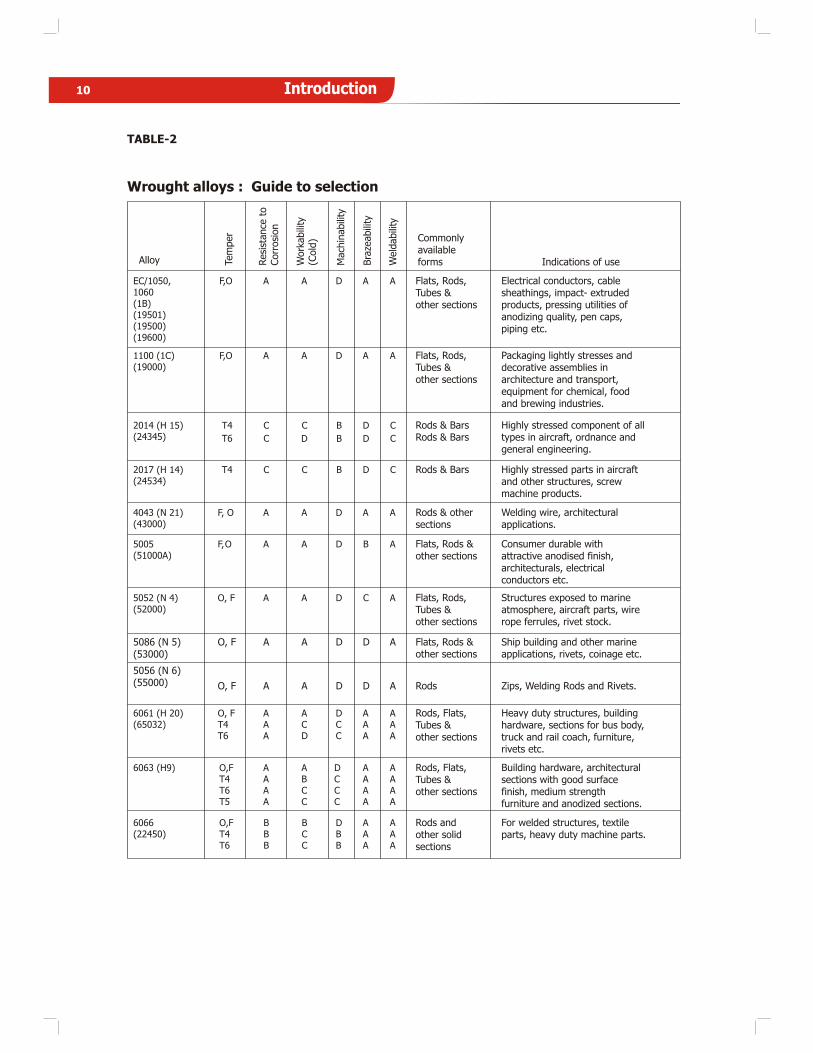
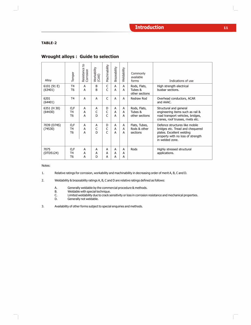
TABLE-2
Wrought alloys : Guide to selection
Indications of use
EC/1050,1060(1B)(19501)(19500)(19600)
F,O A A D A A Flats, Rods,Tubes &other sections
Electrical conductors, cablesheathings, impact- extrudedproducts, pressing utilities ofanodizing quality, pen caps,piping etc.
1100 (1C)(19000)
F,O A A D A A Flats, Rods,Tubes &other sections
Packaging lightly stresses anddecorative assemblies inarchitecture and transport,equipment for chemical, foodand brewing industries.
2014 (H 15)(24345)
T4
T6
C
C
C
D
B
B
D
D
C
C
Rods & BarsRods & Bars
Highly stressed component of alltypes in aircraft, ordnance andgeneral engineering.
2017 (H 14)(24534)
T4 C C B D C Rods & Bars Highly stressed parts in aircraftand other structures, screwmachine products.
4043 (N 21)(43000)
F, O A A D A A Rods & othersections
Welding wire, architecturalapplications.
5005(51000A)
F,O A A D B A Flats, Rods &other sections
Consumer durable withattractive anodised finish,architecturals, electricalconductors etc.
5052 (N 4)(52000)
O, F A A D C A Flats, Rods,Tubes &other sections
Structures exposed to marineatmosphere, aircraft parts, wirerope ferrules, rivet stock.
5086 (N 5)
5056 (N 6)(55000)
O, F A A D D A Flats, Rods &other sections
Ship building and other marineapplications, rivets, coinage etc.
O, F A A D D A Rods Zips, Welding Rods and Rivets.
6061 (H 20)(65032)
O, FT4T6
AAA
ACD
DCC
AAA
AAA
Rods, Flats,Tubes &other sections
Heavy duty structures, buildinghardware, sections for bus body,truck and rail coach, furniture,rivets etc.
6063 (H9) O,FT4T6T5
AAAA
ABCC
DCCC
AAAA
AAAA
Rods, Flats,Tubes &other sections
Building hardware, architecturalsections with good surfacefinish, medium strengthfurniture and anodized sections.
6066(22450)
O,FT4T6
BBB
BCC
DBB
AAA
AAA
Rods andother solidsections
For welded structures, textileparts, heavy duty machine parts.
Alloy Tem
per
Resi
stance
toCorr
osi
on
Work
abili
ty(C
old
)
Mach
inabili
ty
Bra
zeabili
ty
Weld
abili
ty
Commonlyavailableforms
(53000)
Introduction 11
Notes:
1. Relative ratings for corrosion, workability and machinability in decreasing order of merit A, B, C and D.
2. Weldability & brazeability ratings A, B, C and D are relative ratings defined as follows:
A. Generally weldable by the commercial procedure & methods.B. Weldable with special technique.C. Limited weldability due to crack sensitivity or loss in corrosion resistance and mechanical properties.D. Generally not weldable.
3. Availability of other forms subject to special enquiries and methods.
6101 (91 E)(63401)
T4T6
AA
BB
CC
AA
AA
Rods, Flats,Tubes &other sections
High strength electricalbusbar sections.
6201(64401)
T4 A A C A A Redraw Rod Overhead conductors, ACARand AAAC.
6351 (H 30)(64430)
O,FT4T6
AAA
ACD
DCC
AAA
AAA
Rods, Flats,Tubes &other sections
Structural and generalengineering items such as rail &road transport vehicles, bridges,cranes, roof trusses, rivets etc.
7039 (D74S)(74530)
O,FT4T6
AAA
ACD
DCC
AAA
AAA
Flats, Tubes,Rods & othersections
Defence structures like mobilebridges etc. Tread and chequeredplates. Excellent weldingproperty with no loss of strengthin welded zone.
7075(DTD5124)
O,FT4T6
AAA
AAD
AAA
AAA
AAA
Rods Highly stressed structuralapplications.
TABLE-2
Wrought alloys : Guide to selection
Indications of useAlloy Tem
per
Resi
stance
toCorr
osi
on
Work
abili
ty(C
old
)
Mach
inabili
ty
Bra
zeabili
ty
Weld
abili
ty
Commonlyavailableforms

TABLE-3
Wrought alloys : Chemical composition limits (per cent)
Introduction12
1 C 19000 1100 - 0.10 - - - 0.5 0.6 - 0.1 0.1 Aluminium 99.0% Min
1200 - 0.05 - - Si+Fe 1.0 - 0.05 0.1 Aluminium 99.0% Min
1 B 19500 1050 - 0.05 - - - 0.25 0.4 - 0.05 0.1 Aluminium 99.5% Min
1 E 19501 - - 0.04 - - - 0.15 0.35 - 0.03 0.1 Aluminium 99.5% Min
- 1350 - 0.05 - - - 0.10 0.40 - 0.01 0.1 Aluminium 99.5% Min
- 19600 1060 - 0.05 - - - 0.25 0.35 - 0.03 0.1 Aluminium 99.6% Min
- 19700 1070 - 0.03 - - - 0.2 0.25 - 0.03 0.1 Aluminium 99.7% Min
H 15 24345 2014 3.8 5.0 0.2 0.8 0.5 1.2 0.7 0.3 1.2 0.5 -
H 14 24534 2017 3.5 4.7 0.4 1.2 0.2 0.7 0.7 0.4 1.2 0.5 -
N3 31000 3003 - 0.1 - 0.1 - 0.6 0.7 1.0 1.5 0.4 -
N21 43000 4043 - 0.1 - 0.2 4.5 6.0 0.6 - 0.5 0.2 -
N2 46000 4047 - 0.1 - 0.2 10.0 13.0 0.6 - 0.5 0.2 -
N4 52000 5052 - 0.1 1.7 2.6 - 0.6 0.5 - 0.5 0.4 Cr + Mn = 0.5
N5 53000 5086 - 0.1 2.8 4.0 - 0.6 0.5 - 0.5 0.4 Cr + Mn = 0.5
N6 55000 5056 - 0.1 4.5 5.6 - 0.6 0.7 - 0.5 0.4 Chromium upto 0.25
N8 54300 5083 - 0.1 4.0 4.9 - 0.4 0.7 0.5 1.0 0.4 Chromium upto 0.25
H 20 65032 - 0.15 0.4 0.7 1.2 0.4 0.8 0.7 0.2 0.8 0.4 **Cr =0.15-0.35
%
- - 6061 0.15 0.4 0.8 1.2 0.4 0.8 0.7 - 0.15 0.4 Chromium 0.04 to 0.35
H 9 63400 6063 - 0.1 0.4 0.9 0.3 0.7 0.6 - 0.3 0.4 -
- - 6066 0.7 1.2 0.8 1.4 0.9 1.8 0.7 0.6 1.1 0.4 -
- 64423 - 0.5 1.0 0.5 1.3 0.7 1.3 0.8 - 1.0 - -
91E 63401 6101 - 0.05 0.4 0.9 0.3 0.7 0.5 - 0.03 0.1 -
- 64401 6201 - 0.1 0.6 0.9 0.5 0.9 0.5 - 0.03 0.1 -
H 30 64430 6351 - 0.1 0.4 1.2 0.6 1.3 0.6 0.4 1.0 0.3 -
6082 - 0.1 0.6 1.2 0.7 1.3 0.5 0.4 1.0 0.3 Chromium upto 0.25
- 74530 7039 - 0.2 1.0 1.5 - 0.4 0.7 0.2 0.7 0.4 Zinc 4.0 - 5.0 %
- - 7075 1.2 2.0 2.1 2.9 - 0.5 0.5 - 0.3 0.2 Zinc (5.1 -6.1)% &
Chromium(0.18-0.28) %
* Titanium and/or other grain refining elements**Either Mn or Cr shall be present
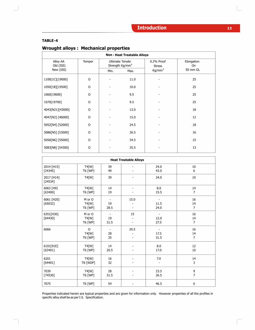
TABLE-4
Wrought alloys : Mechanical properties
Non - Heat Treatable Alloys
Ultimate Tensile
Strength Kg/mm2
Alloy AA
Old (ISS)
New (ISS)
Temper
Min. Max.
0.2% Proof
Stress
Kg/mm2
Elongation
On
50 mm GL
Heat Treatable Alloys
2014 [H15]
[24345]
T4[W]
T6 [WP]
39
49
-
-
24.0
43.0
10
6
2017 [H14]
[24534]
T4[W] 39 - 24.0 10
6063 [H9]
[63400]
T4[W]
T6 [WP]
14
19
-
-
8.0
15.5
14
7
6061 [H20]
[65032]
M or O
T4[W]
T6 [WP]
-
19
28.5
15.0
-
-
-
11.5
24.0
16
14
7
6351[H30]
[64430]
M or O
T4[W]
T6 [WP]
-
19
31.5
15
-
-
-
12.0
27.5
16
14
7
6066 O
T4[W]
T6 [WP]
-
28
35
20.5
-
-
-
17.5
31.5
16
14
7
6101[91E]
[63401]
T4[W]
T6 [WP]
14
20.5
-
-
8.0
17.0
12
10
6201
[64401]
T4[W]
T8 [WDP]
16
32
-
-
7.0
-
14
3
7039
[74530]
T4[W]
T6 [WP]
28
31.5
-
-
23.5
26.5
9
7
7075 T6 [WP] 54 - 46.5 6
1100[1C][19000] O - 11.0 - 25
1050[1B][19500] O - 10.0 - 25
1060[19600] O - 9.5 - 25
1070[19700] O - 9.5 - 25
4043[N21][43000] O - 13.0 - 18
4047[N2] [46000] O - 15.0 - 12
5052[N4] [52000] O - 24.5 - 18
5086[N5] [53000] O - 26.5 - 16
5056[N6] [55000] O - 34.5 - 15
5083[N8] [54300] O - 35.5 - 13
Properties indicated herein are typical properties and are given for information only. However properties of all the profiles in specific alloy shall be as per I.S. Specification.
Introduction 13
14 Introduction
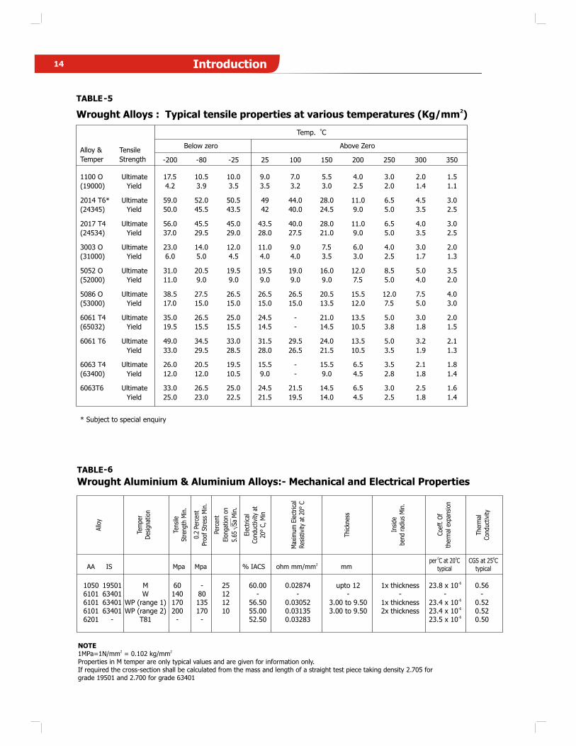
TABLE-5
2Wrought Alloys : Typical tensile properties at various temperatures (Kg/mm )
TABLE-6
Temp.oC
Below zero Above ZeroAlloy &
Temper
Tensile
Strength -200 -80 -25 25 100 150 200 250 300 350
1100 O
(19000)
Ultimate
Yield
17.5
4.2
10.5
3.9
10.0
3.5
9.0
3.5
7.0
3.2
5.5
3.0
4.0
2.5
3.0
2.0
2.0
1.4
1.5
1.1
2014 T6*
(24345)
Ultimate
Yield
59.0
50.0
52.0
45.5
50.5
43.5
49
42
44.0
40.0
28.0
24.5
11.0
9.0
6.5
5.0
4.5
3.5
3.0
2.5
2017 T4
(24534)
Ultimate
Yield
56.0
37.0
45.5
29.5
45.0
29.0
43.5
28.0
40.0
27.5
28.0
21.0
11.0
9.0
6.5
5.0
4.0
3.5
3.0
2.5
3003 O
(31000)
Ultimate
Yield
23.0
6.0
14.0
5.0
12.0
4.5
11.0
4.0
9.0
4.0
7.5
3.5
6.0
3.0
4.0
2.5
3.0
1.7
2.0
1.3
5052 O
(52000)
Ultimate
Yield
31.0
11.0
20.5
9.0
19.5
9.0
19.5
9.0
19.0
9.0
16.0
9.0
12.0
7.5
8.5
5.0
5.0
4.0
3.5
2.0
5086 O
(53000)
Ultimate
Yield
38.5
17.0
27.5
15.0
26.5
15.0
26.5
15.0
26.5
15.0
20.5
13.5
15.5
12.0
12.0
7.5
7.5
5.0
4.0
3.0
6061 T4
(65032)
Ultimate
Yield
35.0
19.5
26.5
15.5
25.0
15.5
24.5
14.5
-
-
21.0
14.5
13.5
10.5
5.0
3.8
3.0
1.8
2.0
1.5
6061 T6 Ultimate
Yield
49.0
33.0
34.5
29.5
33.0
28.5
31.5
28.0
29.5
26.5
24.0
21.5
13.5
10.5
5.0
3.5
3.2
1.9
2.1
1.3
6063 T4
(63400)
Ultimate
Yield
26.0
12.0
20.5
12.0
19.5
10.5
15.5
9.0
-
-
15.5
9.0
6.5
4.5
3.5
2.8
2.1
1.8
1.8
1.4
6063T6 Ultimate
Yield
33.0
25.0
26.5
23.0
25.0
22.5
24.5
21.5
21.5
19.5
14.5
14.0
6.5
4.5
3.0
2.5
2.5
1.8
1.6
1.4
* Subject to special enquiry
-61050 19501 M 60 - 25 60.00 0.02874 upto 12 1x thickness 23.8 x 10 0.566101 63401 W 140 80 12 - - - - - -
-66101 63401 WP (range 1) 170 135 12 56.50 0.03052 3.00 to 9.50 1x thickness 23.4 x 10 0.52
-66101 63401 WP (range 2) 200 170 10 55.00 0.03135 3.00 to 9.50 2x thickness 23.4 x 10 0.52
-66201 - T81 - - 52.50 0.03283 23.5 x 10 0.50
Allo
y
Tem
per
Des
igna
tion
Tens
ileSt
reng
thM
in.
0.2
Perc
ent
Proo
fSt
ress
Min
.
Perc
ent
Elon
gatio
non
5.65
SaM
in.
Elec
tric
alCon
duct
ivity
at20
°C,M
in
Max
imum
Elec
tric
alRes
istiv
ityat
20°
C
Thi
ckne
ss
Insi
debe
ndra
dius
Min
.
Coe
ff.O
fth
erm
alex
pans
ion
The
rmal
Con
duct
ivity
2AA IS Mpa Mpa % IACS ohm mm/mm mm
0CGS at 25 C
typical
0 0per C at 20 C
typical
NOTE2 2
1MPa=1N/mm = 0.102 kg/mmProperties in M temper are only typical values and are given for information only.If required the cross-section shall be calculated from the mass and length of a straight test piece taking density 2.705 for grade 19501 and 2.700 for grade 63401
Wrought Aluminium & Aluminium Alloys:- Mechanical and Electrical Properties
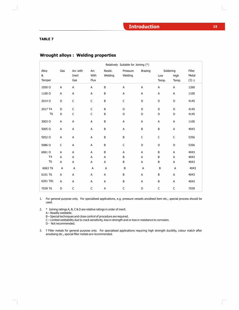
Wrought alloys : Welding properties
Relatively Suitable for Joining (*)
1050 O A A A B A A A A 1260
SolderingAlloy
&
Temper
Gas Arc with
Inert
Gas
Arc
With
Flux
Resist.
Welding
Pressure
Welding
Brazing
Low
Temp.
High
Temp.
Filler
Metal
(3)
1100 O A A A B A A A A 1100
2014 O D C C B C D D D 4145
D C C B D D D D 41452017 T4
T6 D C C B D D D D 4145
3003 O A A A B A A A A 1100
5005 O A A A B A B B A 4043
5052 O A A A B B C C C 5356
5086 O C A A B C D D D 5356
A A A B A A B A 4043
A A A A B A B A 4043
6061 O
T4
T6 A A A A B A B A 4043
6063 T6 A A A A B A B A 4043
6101 T6 A A A A B A B A 4043
6201 T81 A A A A B A B A 4043
7039 T6 D C C A C D C C 7039
TABLE 7
1. For general purpose only. For specialised applications, e.g. pressure vessels anodised item etc., special process should be used.
2. * Joining ratings A, B, C & D are relative ratings in order of merit.A – Readily weldable.B – Special techniques and close control of procedure are required.C – Limited weldability due to crack sensitivity, loss in strength and or loss in resistance to corrosion.D - Not recommended.
3. Filler metals for general purpose only. For specialised applications requiring high strength ductility, colour match after anodising etc., special filler metals are recommended.
15Introduction
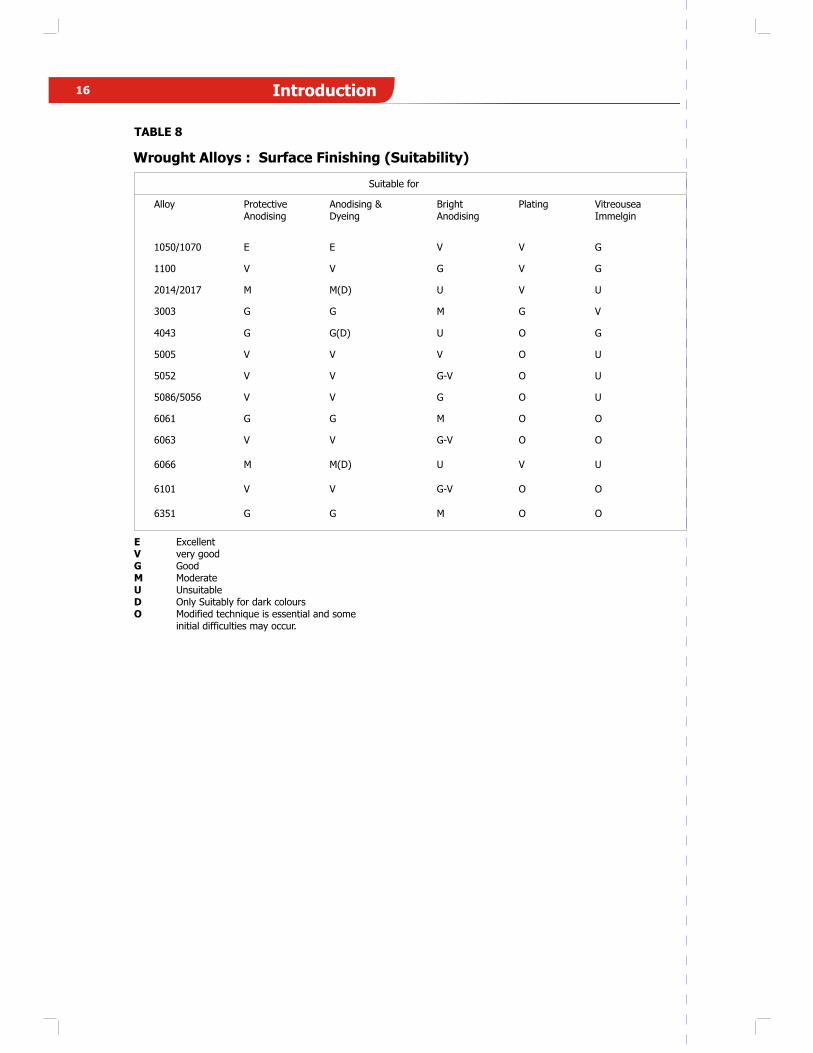
Wrought Alloys : Surface Finishing (Suitability)
Suitable for
Alloy ProtectiveAnodising
Anodising &Dyeing
BrightAnodising
Plating VitreouseaImmelgin
1050/1070 E E V V G
1100 V V G V G
2014/2017 M M(D) U V U
3003 G G M G V
4043 G G(D) U O G
5005 V V V O U
5052 V V G-V O U
5086/5056 V V G O U
6061 G G M O O
6063 V V G-V O O
6066 M M(D) U V U
6101 V V G-V O O
6351 G G M O O
TABLE 8
E ExcellentV very goodG GoodM ModerateU UnsuitableD Only Suitably for dark coloursO Modified technique is essential and some
initial difficulties may occur.
16 Introduction

17Introduction
TABLE : 9
Round Bars/Rods : Diameter Tolerance
Tolerance (mm)
Class A Class B
Specified Diametermm
+ - ±
Upto 12.0 0.03 0.07 0.20
Over 12.0 Upto 25.0 0.05 0.10 0.25
Over 25.0 Upto 40.0 0.07 0.13 0.30
Over 40.0 Upto 50.0 0.13 0.13 0.38
Over 50.0 Upto 56.0 0.15 0.15 0.46
Over 56.0 Upto 71.0 0.20 0.20 0.53
Over 71.0 Upto 80.0 0.25 0.25 0.61
Over 80.0 0.5% 0.5% 1%
Notes:1. Class ‘A’ is for drawn rods.2. Class ‘B’ is normal tolerance for extruded rods.
Standard Manufacturing Tolerances
The Standard manufacturing tolerance given here are applicable to the average shape. Wider tolerance may be requiredfor some shapes, and closer tolerances may be possible for others. For 5052, 5056, 5083, 5086 and other high magnesium alloys, special (wider) tolerances will be applicable.
Tolerances stricter than standard shall be subjected to special enquiry.
TABLE : 10
Solid Sections : Width Tolerance (at closed ends)
Specified width or Width across flats mm Tolerance mm ±
4
5
6
8
10
12
16
20
25
32
40
50
60
80
100
120
160
200
250
0.18
0.20
0.20
0.23
0.23
0.25
0.28
0.30
0.30
0.38
0.46
0.46
0.53
0.69
0.69
0.76
1.02
1.14
1.40
Notes:1. For intermediate size, take tolerance for the next higher value.2. Width tolerances on open ends of Solid Sections such as Channels, I-Beams, etc. are given separately in Table-11.
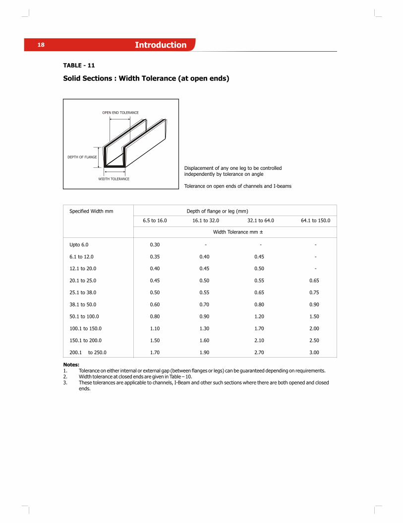
TABLE - 11
Solid Sections : Width Tolerance (at open ends)
Depth of flange or leg (mm)
6.5 to 16.0 16.1 to 32.0 32.1 to 64.0 64.1 to 150.0
Specified Width mm
Width Tolerance mm ±
-
-
-
0.65
0.75
0.90
1.50
2.00
2.50
Upto 6.0
6.1 to 12.0
12.1 to 20.0
20.1 to 25.0
25.1 to 38.0
38.1 to 50.0
50.1 to 100.0
100.1 to 150.0
150.1 to 200.0
200.1 to 250.0
0.30
0.35
0.40
0.45
0.50
0.60
0.80
1.10
1.50
1.70
-
0.40
0.45
0.50
0.55
0.70
0.90
1.30
1.60
1.90
-
0.45
0.50
0.55
0.65
0.80
1.20
1.70
2.10
2.70 3.00
Notes:1. Tolerance on either internal or external gap (between flanges or legs) can be guaranteed depending on requirements.2. Width tolerance at closed ends are given in Table – 10.3. These tolerances are applicable to channels, I-Beam and other such sections where there are both opened and closed
ends.
OPEN END TOLERANCE
DEPTH OF FLANGE
WIDTH TOLERANCE
Displacement of any one leg to be controlledindependently by tolerance on angle
Tolerance on open ends of channels and I-beams
18 Introduction
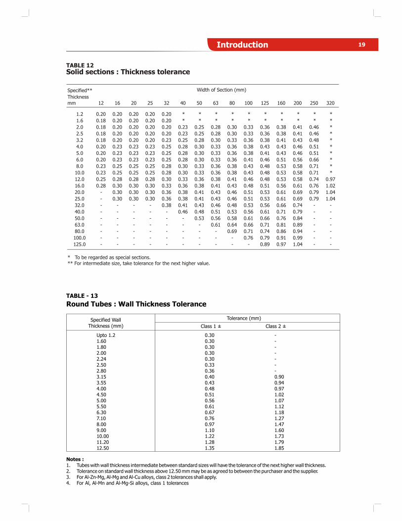
TABLE 12
Specified**
Thickness
mm 12 16 20 25 32 40 50 63 80 100 125 160 200 250 320
1.2 0.20 0.20 0.20 0.20 0.20 * * * * * * * * * *
1.6 0.18 0.20 0.20 0.20 0.20 * * * * * * * * * *
2.0 0.18 0.20 0.20 0.20 0.20 0.23 0.25 0.28 0.30 0.33 0.36 0.38 0.41 0.46 *
2.5 0.18 0.20 0.20 0.20 0.20 0.23 0.25 0.28 0.30 0.33 0.36 0.38 0.41 0.46 *
3.2 0.18 0.20 0.20 0.20 0.23 0.25 0.28 0.30 0.33 0.36 0.38 0.41 0.43 0.48 *
4.0 0.20 0.23 0.23 0.23 0.25 0.28 0.30 0.33 0.36 0.38 0.43 0.43 0.46 0.51 *
5.0 0.20 0.23 0.23 0.23 0.25 0.28 0.30 0.33 0.36 0.38 0.41 0.43 0.46 0.51 *
6.0 0.20 0.23 0.23 0.23 0.25 0.28 0.30 0.33 0.36 0.41 0.46 0.51 0.56 0.66 *
8.0 0.23 0.25 0.25 0.25 0.28 0.30 0.33 0.36 0.38 0.43 0.48 0.53 0.58 0.71 *
10.0 0.23 0.25 0.25 0.25 0.28 0.30 0.33 0.36 0.38 0.43 0.48 0.53 0.58 0.71 *
12.0 0.25 0.28 0.28 0.28 0.30 0.33 0.36 0.38 0.41 0.46 0.48 0.53 0.58 0.74 0.97
16.0 0.28 0.30 0.30 0.30 0.33 0.36 0.38 0.41 0.43 0.48 0.51 0.56 0.61 0.76 1.02
20.0 - 0.30 0.30 0.30 0.36 0.38 0.41 0.43 0.46 0.51 0.53 0.61 0.69 0.79 1.04
25.0 - 0.30 0.30 0.30 0.36 0.38 0.41 0.43 0.46 0.51 0.53 0.61 0.69 0.79 1.04
32.0 - - - - 0.38 0.41 0.43 0.46 0.48 0.53 0.56 0.66 0.74 - -
40.0 - - - - - 0.46 0.48 0.51 0.53 0.56 0.61 0.71 0.79 - -
50.0 - - - - - - 0.53 0.56 0.58 0.61 0.66 0.76 0.84 - -
63.0 - - - - - - - 0.61 0.64 0.66 0.71 0.81 0.89 - -
80.0 - - - - - - - - 0.69 0.71 0.74 0.86 0.94 - -
100.0 - - - - - - - - - 0.76 0.79 0.91 0.99 - -
125.0 - - - - - - - - - - 0.89 0.97 1.04 - -
* To be regarded as special sections.** For intermediate size, take tolerance for the next higher value.
Width of Section (mm)
Solid sections : Thickness tolerance
Upto 1.2 0.30 -1.60 0.30 -1.80 0.30 -2.00 0.30 -2.24 0.30 -2.50 0.33 -2.80 0.36 -3.15 0.40 0.903.55 0.43 0.944.00 0.48 0.974.50 0.51 1.025.00 0.56 1.075.50 0.61 1.126.30 0.67 1.187.10 0.76 1.278.00 0.97 1.479.00 1.10 1.6010.00 1.22 1.7311.20 1.28 1.7912.50 1.35 1.85
Round Tubes : Wall Thickness Tolerance
TABLE - 13
Specified WallThickness (mm)
Tolerance (mm)
Class 1 ± Class 2 ±
Notes :1. Tubes with wall thickness intermediate between standard sizes will have the tolerance of the next higher wall thickness.2. Tolerance on standard wall thickness above 12.50 mm may be as agreed to between the purchaser and the supplier.3. For Al-Zn-Mg, Al-Mg and Al-Cu alloys, class 2 tolerances shall apply.4. For Al, Al-Mn and Al-Mg-Si alloys, class 1 tolerances
19Introduction
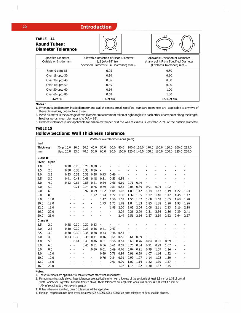
TABLE - 14
Round Tubes :Diameter Tolerance
Specified DiameterOutside or Inside mm
Allowable Deviation of Mean Diameter1/2 (AA+BB) from
Specified Diameter (Dia. Tolerance) mm ±
Allowable Deviation of Diameterat any point From Specified Diameter
(Ovalness Tolerance) mm ±
From 9 upto 18
Over 18 upto 30
Over 30 upto 40
Over 40 upto 50
Over 50 upto 60
Over 60 upto 80
Over 80
0.25
0.30
0.36
0.45
0.54
0.60
1% of dia
0.50
0.60
0.80
0.90
1.00
1.30
2.5% of dia
Notes :1. When outside diameter, inside diameter and wall thickness are all specified, standard tolerances are applicable to any two of
these dimensions, but not to all three.2. Mean diameter is the average of two diameter measurement taken at right angles to each other at any point along the length.
In other words, mean diameter is ½ (AA + BB).3. Ovalness tolerance is not applicable for annealed temper or if the wall thickness is less than 2.5% of the outside diameter.
TABLE 15
Hollow Sections: Wall Thickness Tolerance
Width or overall dimensions (mm)
Wall
Thickness Over 10.0 20.0 30.0 40.0 50.0 60.0 80.0 100.0 120.0 140.0 160.0 180.0 200.0 225.0
mm Upto 20.0 33.0 40.0 50.0 60.0 80.0 100.0 120.0 140.0 160.0 180.0 200.0 225.0 250.0
Class B
Over Upto
1.0 1.5 0.28 0.28 0.28 0.30 - - - - - - - - - -
1.5 2.0 0.30 0.33 0.33 0.36 - - - - - - - - - -
2.0 2.5 0.33 0.33 0.36 0.38 0.43 0.46 - - - - - - - -
2.5 3.0 0.41 0.43 0.46 0.48 0.51 0.53 0.56 - - - - - - -
3.0 4.0 0.53 0.56 0.58 0.61 0.64 0.66 0.69 0.71 0.74 - - - - -
4.0 5.0 - 0.71 0.74 0.76 0.79 0.81 0.84 0.86 0.89 0.91 0.94 1.02 - -
5.0 6.0 - - 0.97 0.99 1.02 1.04 1.07 1.09 1.12 1.14 1.17 1.19 1.22 1.24
6.0 8.0 - - - 1.22 1.24 1.27 1.30 1.32 1.35 1.37 1.40 1.42 1.45 1.47
8.0 10.0 - - - - 1.47 1.50 1.52 1.55 1.57 1.60 1.63 1.65 1.68 1.70
10.0 12.0 - - - - 1.73 1.75 1.78 1.8 1.83 1.85 1.88 1.90 1.93 1.96
12.0 16.0 - - - - - 1.98 2.00 2.03 2.06 2.08 2.11 2.13 2.16 2.18
16.0 20.0 - - - - - - 2.24 2.26 2.29 2.31 2.34 2.36 2.39 2.41
20.0 25.0 - - - - - - 2.49 2.51 2.54 2.57 2.59 2.62 2.64 2.67
Class A
1.5 2.0 0.28 0.30 0.30 0.33 - - - - - - - - - -
2.0 2.5 0.30 0.30 0.33 0.36 0.41 0.43 - - - - - - - -
2.5 3.0 0.30 0.30 0.36 0.38 0.43 0.46 0.51 - - - - - - -
3.0 4.0 0.33 0.36 0.38 0.41 0.46 0.51 0.56 0.61 0.69 - - - - -
4.0 5.0 - 0.41 0.43 0.46 0.51 0.56 0.61 0.69 0.76 0.84 0.91 0.99 - -
5.0 6.0 - - 0.46 0.51 0.56 0.61 0.69 0.76 0.84 0.91 0.99 1.07 - -
6.0 8.0 - - - 0.56 0.61 0.69 0.76 0.84 0.91 0.99 1.07 1.14 - -
8.0 10.0 - - - 0.69 0.76 0.84 0.91 0.99 1.07 1.14 1.22 - -
10.0 12.0 - - - - 0.76 0.84 0.91 0.99 1.07 1.14 1.22 1.30 - -
12.0 16.0 - - - - - 0.91 0.99 1.07 1.14 1.22 1.30 1.37 - -
16.0 20.0 - - - - - - 1.07 1.14 1.22 1.30 1.37 1.45 - -
Notes:1. These tolerances are applicable to hollow sections other than round tubes.2. For non-heat-treatable alloys, these tolerances are applicable when wall thickness of the section is at least 1.5 mm or 1/32 of overall
width, whichever is greater. For heat-treated alloys , these tolerances are applicable when wall thickness is at least 1.5 mm or1/24 of overall width, whichever is greater.
3. Unless otherwise specified, class B tolerances will be applicable.4. For high- magnesium non-heat-treatable alloys (5052, 5056, 5083, 5086), an extra tolerance of 50% shall be allowed.
A
A
A
A
B
B A
A
20 Introduction
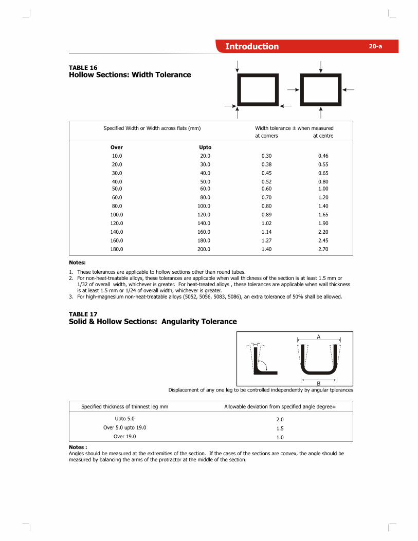
TABLE 16
Hollow Sections: Width Tolerance
Specified Width or Width across flats (mm) Width tolerance ± when measured
Notes:
1. These tolerances are applicable to hollow sections other than round tubes.2. For non-heat-treatable alloys, these tolerances are applicable when wall thickness of the section is at least 1.5 mm or
1/32 of overall width, whichever is greater. For heat-treated alloys , these tolerances are applicable when wall thickness is at least 1.5 mm or 1/24 of overall width, whichever is greater.
3. For high-magnesium non-heat-treatable alloys (5052, 5056, 5083, 5086), an extra tolerance of 50% shall be allowed.
Over
10.0
20.0
30.0
40.0
50.0
60.0
80.0
100.0
120.0
140.0
160.0
180.0
at corners
0.30
0.38
0.45
0.52
0.60
0.70
0.80
0.89
1.02
1.14
1.27
1.40
at centre
0.46
0.55
0.65
0.80
1.00
1.20
1.40
1.65
1.90
2.20
2.45
2.70
Upto
20.0
30.0
40.0
50.0
60.0
80.0
100.0
120.0
140.0
160.0
180.0
200.0
TABLE 17
Solid & Hollow Sections: Angularity Tolerance
Specified thickness of thinnest leg mm Allowable deviation from specified angle degree±
Displacement of any one leg to be controlled independently by angular tplerances
Upto 5.0 2.0
Over 5.0 upto 19.0 1.5
Over 19.0 1.0
Notes :Angles should be measured at the extremities of the section. If the cases of the sections are convex, the angle should be measured by balancing the arms of the protractor at the middle of the section.
A
B
20-aIntroduction
20-b Introduction
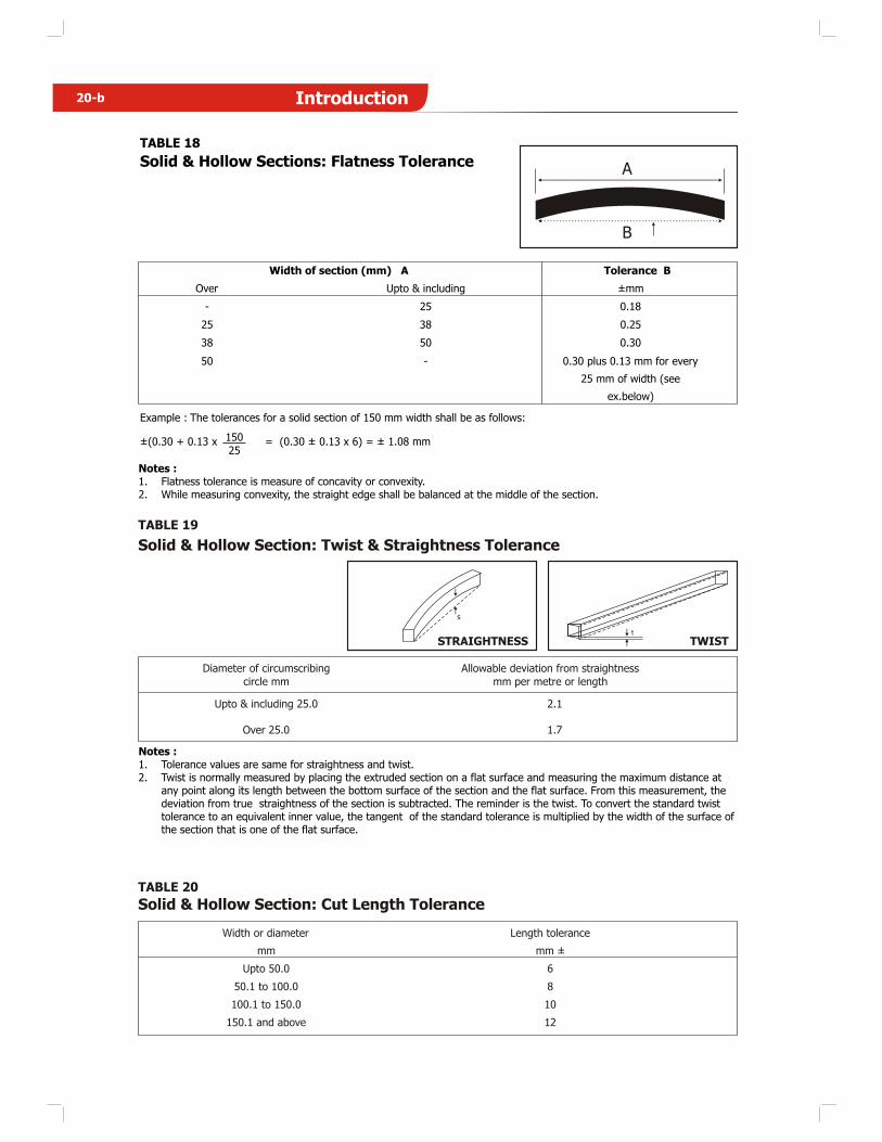
TABLE 19
TWISTSTRAIGHTNESS
Solid & Hollow Section: Twist & Straightness Tolerance
Diameter of circumscribing
circle mm
Allowable deviation from straightness
mm per metre or length
Upto & including 25.0
Over 25.0
2.1
1.7
TABLE 20
Solid & Hollow Section: Cut Length Tolerance
Width or diameter
mm
Length tolerance
mm ±
Upto 50.0 6
50.1 to 100.0 8
100.1 to 150.0 10
150.1 and above 12
TABLE 18
Solid & Hollow Sections: Flatness Tolerance
Width of section (mm) A
Over
-
25
38
50
Upto & including
25
38
50
-
Tolerance B
±mm
0.18
0.25
0.30
0.30 plus 0.13 mm for every
25 mm of width (see
ex.below)
Example : The tolerances for a solid section of 150 mm width shall be as follows:
±(0.30 + 0.13 x 150 = (0.30 ± 0.13 x 6) = ± 1.08 mm25
Notes :1. Flatness tolerance is measure of concavity or convexity.2. While measuring convexity, the straight edge shall be balanced at the middle of the section.
A
B
Notes :1. Tolerance values are same for straightness and twist.2. Twist is normally measured by placing the extruded section on a flat surface and measuring the maximum distance at
any point along its length between the bottom surface of the section and the flat surface. From this measurement, the deviation from true straightness of the section is subtracted. The reminder is the twist. To convert the standard twisttolerance to an equivalent inner value, the tangent of the standard tolerance is multiplied by the width of the surface of the section that is one of the flat surface.
t
s