Technical Specification - WBSEDCL
40
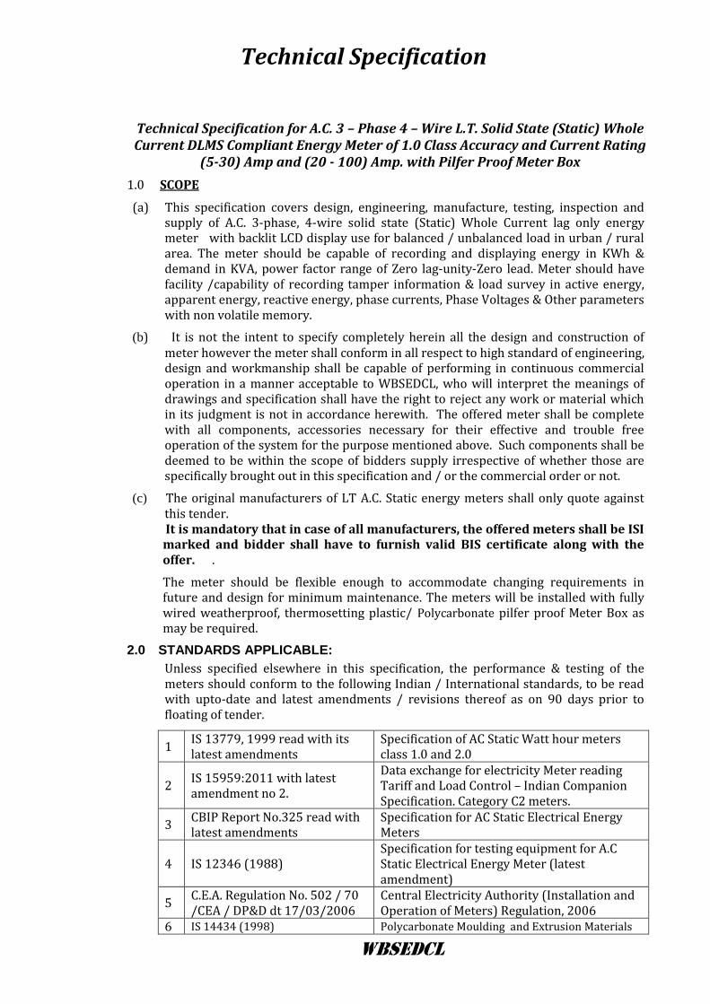
Technical Specification WBSEDCL Technical Specification for A.C. 3 – Phase 4 – Wire L.T. Solid State (Static) Whole Current DLMS Compliant Energy Meter of 1.0 Class Accuracy and Current Rating (5-30) Amp and (20 - 100) Amp. with Pilfer Proof Meter Box 1.0 SCOPE (a) This specification covers design, engineering, manufacture, testing, inspection and supply of A.C. 3-phase, 4-wire solid state (Static) Whole Current lag only energy meter with backlit LCD display use for balanced / unbalanced load in urban / rural area. The meter should be capable of recording and displaying energy in KWh & demand in KVA, power factor range of Zero lag-unity-Zero lead. Meter should have facility /capability of recording tamper information & load survey in active energy, apparent energy, reactive energy, phase currents, Phase Voltages & Other parameters with non volatile memory. (b) It is not the intent to specify completely herein all the design and construction of meter however the meter shall conform in all respect to high standard of engineering, design and workmanship shall be capable of performing in continuous commercial operation in a manner acceptable to WBSEDCL, who will interpret the meanings of drawings and specification shall have the right to reject any work or material which in its judgment is not in accordance herewith. The offered meter shall be complete with all components, accessories necessary for their effective and trouble free operation of the system for the purpose mentioned above. Such components shall be deemed to be within the scope of bidders supply irrespective of whether those are specifically brought out in this specification and / or the commercial order or not. (c) The original manufacturers of LT A.C. Static energy meters shall only quote against this tender. It is mandatory that in case of all manufacturers, the offered meters shall be ISI marked and bidder shall have to furnish valid BIS certificate along with the offer. . The meter should be flexible enough to accommodate changing requirements in future and design for minimum maintenance. The meters will be installed with fully wired weatherproof, thermosetting plastic/ Polycarbonate pilfer proof Meter Box as may be required. 2.0 STANDARDS APPLICABLE: Unless specified elsewhere in this specification, the performance & testing of the meters should conform to the following Indian / International standards, to be read with upto-date and latest amendments / revisions thereof as on 90 days prior to floating of tender. 1 IS 13779, 1999 read with its latest amendments Specification of AC Static Watt hour meters class 1.0 and 2.0 2 IS 15959:2011 with latest amendment no 2. Data exchange for electricity Meter reading Tariff and Load Control – Indian Companion Specification. Category C2 meters. 3 CBIP Report No.325 read with latest amendments Specification for AC Static Electrical Energy Meters 4 IS 12346 (1988) Specification for testing equipment for A.C Static Electrical Energy Meter (latest amendment) 5 C.E.A. Regulation No. 502 / 70 /CEA / DP&D dt 17/03/2006 Central Electricity Authority (Installation and Operation of Meters) Regulation, 2006 6 IS 14434 (1998) Polycarbonate Moulding and Extrusion Materials
-
Upload
khangminh22 -
Category
Documents
-
view
0 -
download
0
Transcript of Technical Specification - WBSEDCL
Technical Specification
WBSEDCL
Technical Specification for A.C. 3 – Phase 4 – Wire L.T. Solid State (Static) Whole Current DLMS Compliant Energy Meter of 1.0 Class Accuracy and Current Rating
(5-30) Amp and (20 - 100) Amp. with Pilfer Proof Meter Box
1.0 SCOPE
(a) This specification covers design, engineering, manufacture, testing, inspection and supply of A.C. 3-phase, 4-wire solid state (Static) Whole Current lag only energy meter with backlit LCD display use for balanced / unbalanced load in urban / rural area. The meter should be capable of recording and displaying energy in KWh & demand in KVA, power factor range of Zero lag-unity-Zero lead. Meter should have facility /capability of recording tamper information & load survey in active energy, apparent energy, reactive energy, phase currents, Phase Voltages & Other parameters with non volatile memory.
(b) It is not the intent to specify completely herein all the design and construction of meter however the meter shall conform in all respect to high standard of engineering, design and workmanship shall be capable of performing in continuous commercial operation in a manner acceptable to WBSEDCL, who will interpret the meanings of drawings and specification shall have the right to reject any work or material which in its judgment is not in accordance herewith. The offered meter shall be complete with all components, accessories necessary for their effective and trouble free operation of the system for the purpose mentioned above. Such components shall be deemed to be within the scope of bidders supply irrespective of whether those are specifically brought out in this specification and / or the commercial order or not.
(c) The original manufacturers of LT A.C. Static energy meters shall only quote against this tender. It is mandatory that in case of all manufacturers, the offered meters shall be ISI marked and bidder shall have to furnish valid BIS certificate along with the offer. .
The meter should be flexible enough to accommodate changing requirements in future and design for minimum maintenance. The meters will be installed with fully wired weatherproof, thermosetting plastic/ Polycarbonate pilfer proof Meter Box as may be required.
2.0 STANDARDS APPLICABLE:
Unless specified elsewhere in this specification, the performance & testing of the meters should conform to the following Indian / International standards, to be read with upto-date and latest amendments / revisions thereof as on 90 days prior to floating of tender.
1 IS 13779, 1999 read with its latest amendments
Specification of AC Static Watt hour meters class 1.0 and 2.0
2 IS 15959:2011 with latest amendment no 2.
Data exchange for electricity Meter reading Tariff and Load Control – Indian Companion Specification. Category C2 meters.
3 CBIP Report No.325 read with latest amendments
Specification for AC Static Electrical Energy Meters
4 IS 12346 (1988) Specification for testing equipment for A.C Static Electrical Energy Meter (latest amendment)
5 C.E.A. Regulation No. 502 / 70 /CEA / DP&D dt 17/03/2006
Central Electricity Authority (Installation and Operation of Meters) Regulation, 2006
6 IS 14434 (1998) Polycarbonate Moulding and Extrusion Materials
WBSEDCL Page 2
Meters matching with requirements of other national or international standards that ensure equal or better performance than the above mentioned standards should also be considered. When the equipment offered by the bidder conforms to standards other than those specified above, salient points of difference between standards adopted and the standards specified in this specification shall be clearly brought out in the relevant schedule. A copy of such standards along with their English translation shall invariably be furnished along with the offer.
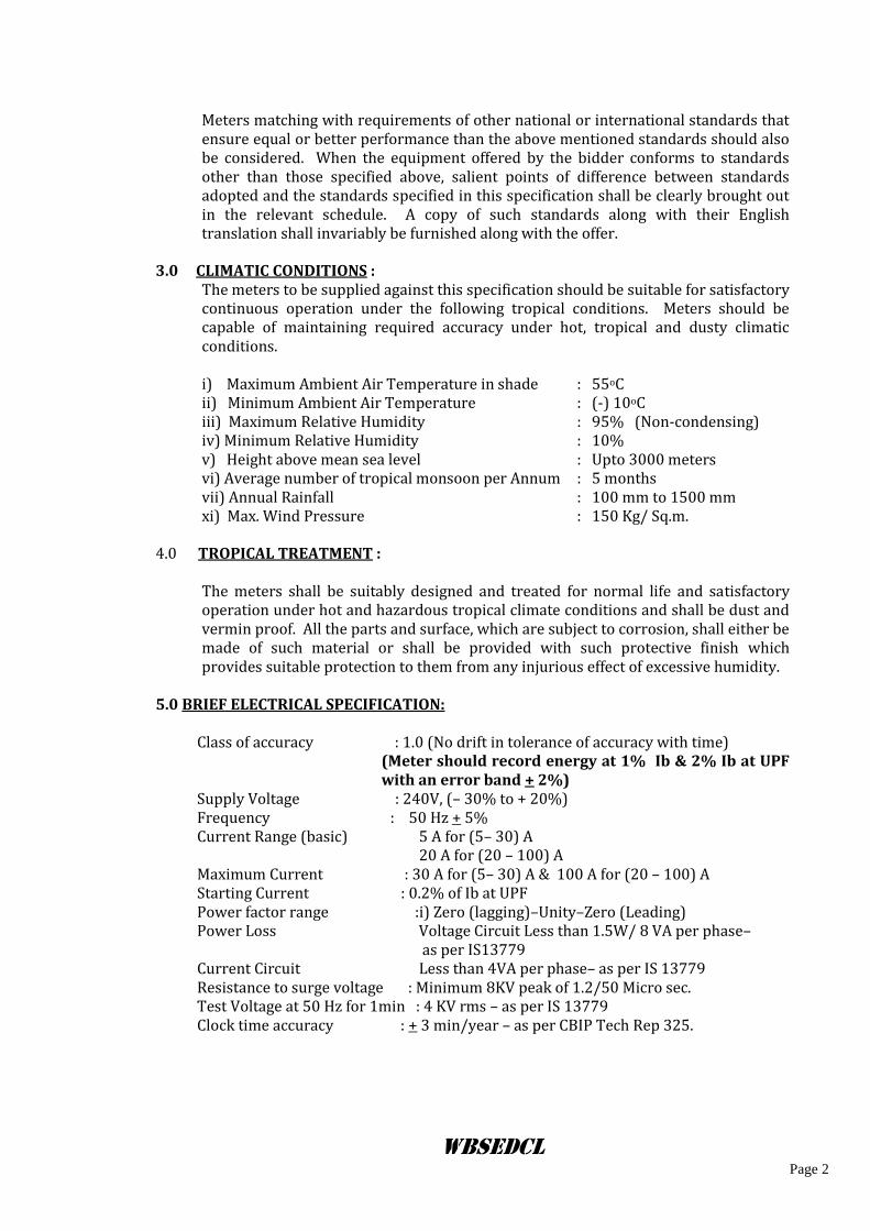
3.0 CLIMATIC CONDITIONS : The meters to be supplied against this specification should be suitable for satisfactory continuous operation under the following tropical conditions. Meters should be capable of maintaining required accuracy under hot, tropical and dusty climatic conditions. i) Maximum Ambient Air Temperature in shade : 55oC ii) Minimum Ambient Air Temperature : (-) 10oC iii) Maximum Relative Humidity : 95% (Non-condensing) iv) Minimum Relative Humidity : 10% v) Height above mean sea level : Upto 3000 meters vi) Average number of tropical monsoon per Annum : 5 months vii) Annual Rainfall : 100 mm to 1500 mm xi) Max. Wind Pressure : 150 Kg/ Sq.m.
4.0 TROPICAL TREATMENT : The meters shall be suitably designed and treated for normal life and satisfactory operation under hot and hazardous tropical climate conditions and shall be dust and vermin proof. All the parts and surface, which are subject to corrosion, shall either be made of such material or shall be provided with such protective finish which provides suitable protection to them from any injurious effect of excessive humidity.
5.0 BRIEF ELECTRICAL SPECIFICATION:
Class of accuracy : 1.0 (No drift in tolerance of accuracy with time)
(Meter should record energy at 1% Ib & 2% Ib at UPF with an error band + 2%)
Supply Voltage : 240V, (– 30% to + 20%) Frequency : 50 Hz + 5% Current Range (basic) 5 A for (5– 30) A 20 A for (20 – 100) A Maximum Current : 30 A for (5– 30) A & 100 A for (20 – 100) A Starting Current : 0.2% of Ib at UPF Power factor range :i) Zero (lagging)–Unity–Zero (Leading) Power Loss Voltage Circuit Less than 1.5W/ 8 VA per phase–
as per IS13779 Current Circuit Less than 4VA per phase– as per IS 13779 Resistance to surge voltage : Minimum 8KV peak of 1.2/50 Micro sec. Test Voltage at 50 Hz for 1min : 4 KV rms – as per IS 13779 Clock time accuracy : + 3 min/year – as per CBIP Tech Rep 325.
WBSEDCL Page 3
6.0 MAXIMUM CONTINUOUS CURRENT :
The maximum continuous current in meters should be the current at which the meter purports to meet the accuracy requirement of the specification. The same is indicated in Clause 5.0 above.
7.0 CONSTRUCTION :
The case, winding, voltage circuit, sealing arrangements, registers, terminal block, terminal cover & name plate etc. shall be in accordance with the relevant standards. The meter should be compact & reliable in design, easy to transport & immune to vibration & shock involved in the transportation & handling. The construction of the meter should ensure consistence performance under all conditions especially during heavy / heavy rains / very hot weathers. The insulating materials used in the meter should be non-hygroscopic, non-ageing & have tested quality. The meter should be sealed in such a way that the internal parts of the meter becomes inaccessible and attempts to open the meter shall result in viable damage to the meter cover. This is to be achieved by using continuous Ultrasonic welding on all the four sides of the Meter base and cover or any other technology which is either equally or more efficacious. The meter should comply latest technology such as Microcircuit or Application Specific Integrated Circuit (ASIC) to ensure reliable performance. The mounting of the components on the PCB should compulsorily be Surface Mounted Technology (SMT) type. Power supply component may be of PTH type. The electronic components used in the meter should be of high quality and there should be no drift in the accuracy of the meter for at least ten years. The circuitry of the meter should be compatible with 16 Bit (or better) ASIC with compatible processor and meter should be based on Digital measuring and sampling technique.
The meter should be housed in a safe, high grade, unbreakable, fire resistant, UV stabilized, virgin Polycarbonate casing of projection mounting type. The meter cover should be transparent / translucent. But the viewing portion should be transparent for easy reading of displayed parameters, and observation of operation indicators. The meter base may not be transparent, but it should not be black in colour.” The meter casing should not change in shape, colour, size and dimensions when subjected to 200 hrs on UV test as per ASTMD 53.” It should withstand 650 deg. C. glow wire test and heat deflection test as per ISO 75 or as per IEC 60068 -2-5.
In addition to the above, the meter cover should be sealable to the meter base with at least 2 nos. bar coded seals bearing the identification marks of the Manufacturer. Suitable arrangement should be made for fitting/fixing of utility seal at two sides of meter terminal cover in such a manner that any access to the terminal can not be possible without removing the seal. There should also be provision for sealing at the optical port.
The bidder shall submit relevant documents regarding the source of procurement of polycarbonate material. The polycarbonate material procured from the following manufacturers should be used.
a) G.E. Plastics LEXAN 943A, or equivalent like 143, 123R for Top cover & Terminal cover/ LEXAN 503R or equivalent like 143R, 500Rfor Base & Terminal Block
b) BAYER Grade corresponding to above c) DOW Chemicals -Do- d) MITSUBISHI -Do- e) TEJIN -Do- f) DUPONT -Do-
WBSEDCL Page 4
8.0 METER CASE AND COVER: The meter should have a case, which can be sealed in such a way that the internal parts of the meter are accessible only after breaking the seal and cover. This is to be achieved by use of Ultrasonic Welding (Ultrasonically continuously welded at three sides so that the cover cannot be separated from the base without breaking/damaging the case and cover) i.e. break to open type. In case, ultrasonic welding using plate / strip is used, the material of plate / strip should be same as that of cover and base and the strip. The manufacturer’s logo should be embossed on the strip / plate. The material of the meter body (case and cover) shall be of Engineering Plastic. The meter cover should be fixed to the meter base (case) with Unidirectional Screws, so that the same cannot be opened by use of screwdrivers. These unidirectional screws should be covered with transparent caps, ultrasonically welded with the meter body and the screw covers should be embedded in the meter body in a groove. The meter shall withstand external magnetic influence as per latest amendments of CBIP Technical Report No.325.
9.0 TERMINAL BLOCK AND COVER : The terminals may be grouped in a terminal block having adequate insulating properties and mechanical strength. The terminal block should be made from best quality non-hygroscopic, flame retardant material (capable of passing the flammability tests) with nickel plated brass inserts / alloy inserts for connecting terminals. It should be rigidly fixed to the base of the meter so that it cannot be separated from the meter base without breaking either the meter base or the terminal block and this fixing arrangement should be in parallel to the meter base in such a way that it cannot be viewed or approached from any part of the meter without breaking the meter. The terminals in the terminal block shall be of adequate length in order to have proper grip of conductor. The screws shall have thread size not less than M4 and head having 6 mm. Diameters. The screws shall not have pointed ends at the end of threads. All terminals and connecting screws and washers should be of tinned / nickel plated brass material. The terminal should withstand glow wire test at 960 + 15 ºC and the terminal should withstand at least 135 ºC.as per IS. The internal diameter of terminal hole should be minimum 5.5 mm for (5– 30) A & 9.5 mm for (20– 100) A and center to center distance is 13 mm. The holes in the insulating material shall be of sufficient size to accommodate the insulation of conductor also. The terminal cover shall be transparent re-enforced Polycarbonate, Engineering Plastic with minimum thickness 2.0 mm and the terminal cover shall be of extended type completely covering the terminal block and fixing holes. The space inside the terminal cover should be sufficient to accommodate adequate length of external cables.
WBSEDCL Page 5
10.0 MARKING OF THE METER :
The marking on the meter should be in accordance with relevant clauses of IS 13779. The basic marking on the meter nameplate should be as follows (all other markings as per IS shall also be there):- a) Manufacturer’s name & trade mark b) Type Designation c) No. of phases & wires d) Serial number (Size not less than 5mm) e) Month & Year of manufacture f) Reference Voltage g) Rated Current h) Operating Frequency i) Principal unit(s) of measurement j) Meter Constant (impulse/kwh) k) Class index of meter l) Property of WBSEDCL m) Purchase Order No. & Date
n) Guarantee (Guaranteed for a period of 5 ½ Yrs. From date of delivery) o) BIS marking p) Place of manufacture q) Meter Sl. No. in alpha numerical form, Dt. of manufacturer, Rating of the meter
and P.O. reference should be bar coded. Readable by single layer Bar code reader.
r) DLMS category marking C2 11.0 DISPLAY OF MEASURED VALUES :
The meter shall have Alphanumeric display with at least 8 full digit with LCD backlit display, having minimum character height of 10 mm. KWH Energy registration should be with at least 6 full digits. All display digits for KWH shall be displayed in the meter display (figures prefixing the value in display should show 0 in display). The data should be stored in non-volatile memory. The non-volatile memory should retain data for a period of not less than 10 years under unpowered condition. Battery back-up memory will not be considered as NVM. It should be possible to easily identify the single or multiple displayed parameters through symbols / legend on the meter display itself or through display annunciation which should be self explanatory and symmetric. The register shall be able to record and display starting from zero, for a minimum of 2500 hours. The energy corresponding to rated maximum current at reference voltage and unity power factor. The register should not roll over in between this duration. In addition to provide Serial Number of the meter on the display plate, the meter serial no. should also be programmed into meter memory for identification through communication port for CMRI , laptop and meter reading printout. Visibility of display in poor light conditions is an important criterion. STN or TN or any better type of advanced LCD to be used. Proper legends for the displayed parameters to be provided (Factory programmable). Back lit provided for clear visibility should be uniform throughout all part of the LCD.
WBSEDCL Page 6
The meters should have auto-display mode for pre-selected parameters. Push-Button mode of display should display all parameters and it should have priority over auto mode. The meter should give clear message on display to indicate that the meter has experienced tampers and the nature of tamper with date and time of first occurrence, last occurrence and last restoration, if the Last tamper status is not restored, then meter will indicate first occurrence, pen-ultimate restoration and last occurrence. Connection check, Phase sequence and self diagnostic should give clear message on display. The meter shall have a test output (blinking LED) accessible from the front and be capable of being monitored with suitable testing equipment. The operation indicator must be visible from the front. Test output device should be provided in the form of two separate LED for active and reactive energy. Separate LED should also be used with proper separation and indication.
12.0 DISPLAY SEQUENCE : The meter should display the required parameters in two different modes as follows: (Display sequence for both auto and Push button must be maintained, no interchange in sequence or display parameter will be accepted. All the display should have proper legend to identify the same.)
A. Auto Display Mode: The following parameters should be displayed in auto cycle mode, in the following sequence.
1. Total Cumulative Active Forwarded Energy ( up to date) 2. History1 Cumulative Active Forwarded Energy upto 24:00 hrs of last day of last month. 3. History1 TOD Cumulative Active Forwarded Energy upto 24:00 hrs of last day of last month
Each parameter should be on meter display for 10 seconds and the time between two auto cycle should be at 60 seconds gap.
B. Push Button mode :
In addition to the auto display mode parameters, the following parameters should be displayed on pressing the push button (all display of auto mode and the following).
1. LCD test 2. Meter serial number 3. Real Date (dd mm yy) 4. Real Time (hh mm ss) 5. Rising Apparent Demand with elapsed time 6. History1 Cumulative Active Forwarded Energy upto 24:00 hrs of last day of last month. 7. History1 TOD Cumulative Active Forwarded Energy upto 24:00 hrs of last day of last month 8. History1 Cumulative Apparent Energy upto 24:00 hrs of last day of last month 9. History1 TOD Cumulative Apparent Energy upto 24:00 hrs of last day of last month 10. History1 Apparent Demand upto 24:00 hrs of last day of last month 11. History1 TOD Apparent Demand upto 24:00 hrs of last day of last month 12. History1Power OFF Hours 13. Cumulative Billing Count 14. Cumulative Tamper Count
WBSEDCL Page 7
15. Cover Open Information with date and time. 16. Total Cumulative Active Forwarded Energy ( up to date) 17. TOD Wise Cumulative Active Forwarded Energy (Upto date Zone 1, 2, 3) 18. Cumulative Reactive Energy (Lag ,Upto date) 19. Cumulative Reactive Energy (Lead, Upto date) 20. Cumulative Apparent Energy (Upto date) 21. TOD Cumulative Apparent Energy (Upto date Zone 1, 2, 3) 22. Present Month MD in KW and KVA since last MD reset with date and time. 23. Cumulative Active and Apparent Demand since manufacture 24. Instantaneous Phase Voltages 25. Instantaneous Phase Currents 26. Instantaneous Neutral Current* i.e. Actual Current flowing through the Neutral* 27. Instantaneous Power Factor 28. Inst. Power Factor – Phase Wise 29. Average Power Factor ( Previous Month) 30. Avg. Load Factor (Previous Month) 31. Instantaneous Active Power 32. Instantaneous Apparent Power 33. Instantaneous Frequency 34. Present Tamper Status (PT/CT/Others) 35. First Occurrence with Date & Time 36. Last Occurrence with Date & Time 37. Last Restoration with Date & time 38. Previous 3 months (at least) cumulative KWh, KVAh and Maximum Demand in KVA at 24.00
hrs. of last date of the month. 39. Cumulative Power failure in hour: minute from the date of manufacturing. 40. High resolution display for KWh, KVARH and KVAH ( minimum 2+4) 41. Phase Sequence 42. Connection check ( For CT Reversal Connection Not OK) 43. Self Diagnosis
Display for Auto and manual mode must be listed by two headers A) Auto Display Mode and B) Push Button Mode (Parameters should be pasted in front of the PP Box
13.0 ANTI TAMPER FEATURES : The meter should have the following anti-tamper features: i) Current Reversal: The meter shall be capable of recording energy correctly
even if the input and output terminals are interchanged in one, two or all the three phases including logging of tamper.
ii) The meter shall work correctly irrespective of phase sequence of supply (there must be an indication in display & down loaded data). Tamper alerts is not required. But it must be shown in instantaneous parameters both in tabular as well as in phasor diagram.
iii) The meter shall work correctly even in absence of neutral as per IS13779. Accuracy in between 70% Vref to 50 % Vref must be maintained within +4%.
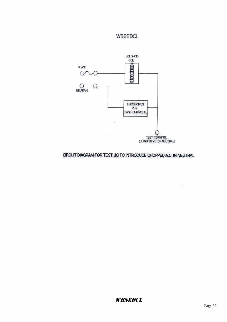
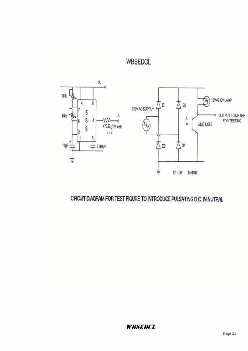
iv) Meter should record energy within maximum error of + 4% on injection of DC (approximately 550V), pulsating DC (7-10 Hz), Chopped AC in Neutral. However meters which are immune or maintain better accuracy, will be preferred. Maximum chopping for AC injection will be 25% to 30% at peak end.
v) The registration shall not be affected more than + 4% if high frequency (60-100 Hz) A.C. Voltage w.r.t. earth is applied to the meter neutral. Meters which are immune or will maintain better accuracy, will be preferred.
vi) High Frequency Jammer Circuit Test – Meter should be immune on this test
WBSEDCL Page 8
vii) The meter should be immune to Electro Static Discharge or Sparks of 35 KV (approx) induced by using frequency-generating devices having very high output voltage.
N.B.:-Tests in this respect will be conducted by using commonly available devices and during spark discharge test, spark will be applied directly at all vulnerable points of the meter for a period of 10 to 20 minutes. .The accuracy of the meter and acceptance criteria as per guidelines specified in Appendix J of CBIP 325. After application of spark discharge meter should record correctly within the specified limits of errors. Beyond 35 KV the meter should record tamper if not immune. It should record the event under Indian Event Reference of others type with Event ID’s 249 for Occurrence and 250 for Restoration with OBIS (0.0.99.98.4.255). Other details are applicable as per “Others Tamper Profile of IS 15959.
The meter shall be capable of recording; occurrences and restoration with date and time i.r.o. the following tamper conditions:
a. Missing Potential for all phases (phase wise), even without any load drawl. b. Current reversal for all phases (phase wise). (It must not be restored without
threshold current). c. Power failure.. Minimum 50 events need to be given separately). Occurrence time
shall be of 5 minutes & restoration time shall be instantaneous. d. Magnetic Disturbances (As per IS 13779 & CBIP 325 along with latest amendments) e. Neutral Disturbances (If it logged). f. C.T. open g. C.T. Bypass/ C.T. Short. h. Over Current ( during existence of this tamper current unbalance tamper should not log).
N.B.: Threshold Values of all above occurrence and restoration of tampers given in
Annexure V.
Snapshot values of Phase Voltage, Phase Current & Phase wise Power Factor, Active Energy value during occurrence & restoration to be provided in all the above mentioned tamper conditions in BCS with date and time. (In Event logging Snapshots should be considered when the actual phenomenon occurred) The occurrence and restoration of tamper should be equal to 5 min. (Except Magnetic and Neutral Disturbances tampers) Magnetic tamper should appear instantaneously, ND within 3 min. All authenticated commands should be Base Computer Software controlled. All transactions with meter should be date and time logged, in the downloaded data minimum last 12 such transactions need to be provided.
Properly designed meter tamper logic should be provided and clearly explained in the bid. The tamper logic should be capable of discriminating the system abnormalities from source side and load side and it should not log/record tamper due to any source side abnormalities. More than one tamper CT related/ PT related/ others should not be logged at a time. A minimum of 300 events (one event means either occurrence or restoration) of all types of tamper with date & time stamping should be available in meter memory compartment wise. The logging will be on FIFO basis. The events will be divided into three compartments like CT related (148 Events), PT related (88 Events) and others (64 Events).
Meter should have a continuous and clear indication in its display if top cover is removed or opened and even re-fixed (non rollover) and
WBSEDCL Page 9
only cover open must be logged in BCS without any restoration. Auto scroll display may be sacrificed for that COVER OPEN.
13.1 Measurement of Harmonics: The meter should be capable of measuring fundamental energy as well total energy i.e., fundamental plus Harmonics energy. Total energy shall be made available on meter display and the same shall be used for billing purpose. Provision for measuring Fundamental energy should be kept for utilization in future. The total energy and Fundamental energy shall be logged in the meter memory and be capable of downloading to the BCS through the CMRI and be available for viewing at the BCS end.
14.0 RESETTING OF MAX. DEMAND:
The meter should be capable of recording the Apparent MD with integration period
of 15 & 5 minutes (programmable). By default the DIP should be of 15 minutes. MD
reset should be through each of the three means:
1) Automatic resetting at preset date & time (at present it will be at 00.00 hrs of the
first day of the month).
2) Manually i.e., by push button.
3) Through authenticated command from MRI or through Remote Communication.
The means by which the reset has been done should be made available to downloaded data. Facility to invoke any of the above through authenticated MRI command should be provided at BCS end.. MD reset button should have proper sealing arrangement. There should be separate Push button for scrolling display (up and down) and MD reset.
15.0 LOAD SURVEY:
The meter should be capable of recording load survey for the following parameters for a period of minimum 60 power on days - subject to availability of all parameters listed below with 15 minutes integration period.
i) Energy in KWh ii) Demand in KVA iii) Current – phase-wise iv) Voltage – phase-wise v) Average Power Factor
The NVM shall not require any additional battery backup to retain the data in case of power failure, for upto 10 years and the data storage shall be independent of battery backup unit. The life of the RTC battery in circuit condition should be minimum 6 years in case of power failure. It should be possible to transfer this data to base computer software through MRI, Lap top and RMR. The data so obtained should be displayed in both graphical & numeric form in the BCS. The BCS with all details is to be provided by the supplier at no extra cost. Load Survey integration period is programmable (15 minute or 5 minute programmable)

WBSEDCL Page 10
16.0 TIME OF DAY FACILITIES :
The meter should have facilities to record Active, Apparent Energies and Apparent MD in at least 8 zones. The time zones should be user programmable through authenticated MRI, Laptop, and RMR command. Necessary software for the same is to be provided by the bidder. At present TOD timings will be programmable as follows: TOD – 1 06:00 Hrs to 17:00 Hrs, TOD – 2 17:00 Hrs to 23:00 Hrs, TOD – 3 23:00 Hrs to 06:00 Hrs of next day. 8 no TOD Energy registers should be visible in display as well as BCS end (Desirable
condition for future upgradation of meter)
17.0 METER READING DURING POWER OFF:
It should be possible to read the meter-display visually and with MRI and Lap top in absence of input voltages with the help of internal battery backup (through optical port only). In case of external battery the arrangements should be such that hands free operation is possible. In case of external battery 10 years guarantee must be given for external battery. Separate battery should be used for this purpose (Not RTC or processor battery).
18.0 SELF DIAGNOSTIC FEATURES:
The meter shall be capable of performing complete self-diagnostic check to monitor the circuits for any malfunctioning to ensure integrity of data memory location all the time. If possible, the details of malfunctioning should be recorded in the meter memory. The bidder should furnish the details of self-diagnostic capability feature, viz Memory status (NVM) and Battery status, RTC Status etc. and clear indication should be in display and BCS.
19.0 IMMUNITY TO ELECTRO MAGNETIC DISTURBANCE: The meter should be designed in such a way so that external electromagnetic field or electrostatic discharges do not influence the performance of the meter as per IS 13779.
20.0 TECHNICAL SUPPORT, MANUALS & TRAINING : Extensive technical support, detailed technical literature (should supply with each meter at the time of packing) & training is to be provided by the manufacturer. Supply of External Battery Packs if required to be provided by the manufacturer and should be clearly offered in their bids.
21.0 INFLUENCE QUANTITIES :
The meter shall work satisfactory with guaranteed accuracy as per limit of IS: 13779 (clause No.9.2.1 and 11.2) under presence of the following quantities:
WBSEDCL Page 11
i) Electro magnetic field ii) External magnetic field iii) Radio frequency interference iv) Vibration
v) Voltage variation (70% - 120% of Vref) in 0.5 lag and UPF both in 5% and 100% of Ib.
vi) Frequency variation (+/-) 5% of 50 Hz in 0.5 lag and UPF both in 5% and 100% of Ib
22.0 POWER CONSUMPTION BY METER :
Voltage Circuit: The active and apparent power consumption in the voltage circuit including the power supply of meter at reference voltage. Reference temperature and reference frequency should not exceed 1.5 Watt and 8 VA per phase respectively. Current Circuit: The apparent power taken by each current circuit at basic current, reference frequency and reference temperature should not exceed 4 VA per phase in power up condition.
23.0 STARTING CURRENT: The meter should start registering energy at 0.2 % of basic current at unity power factor and should be fully functional within five seconds after the rated voltage is applied.
23.1 RUNNING AT NO LOAD:
When 70% & 120% voltage is applied and no current flows in the current circuit, the test output of the meter should not produce more than one pulse.
24.0 COMMUNICATION CAPABILITY:
The meter shall have a galvanically isolated optical communication port as per IEC 1107/ANSI/HDLC so that it can be easily connected to a hand-held common meter reading instrument (CMRI) for data transfer. The billing data & the tamper data downloading time should be less than 5 minutes. The optical port should be provided with proper sealing arrangement so that the optical cover should not be opened without breaking the seal. The stored data in the meter should be available through CMRI even when the display of the meter is not available. The above ports suitable for interface of the meter with appropriate protocol to Common Meter Reading Instrument (CMRI),LAPTOP and PC. A separate suitable serial port (RS-232/RJ-11) capable of being hooked (into a remote metering device such as modem, etc. should be provided inside the terminal cover to enable future Automatic meter reading) in such a way that the same can not be accessed without interfering the Terminal cover and seal. It should not be possible to alter date in the meter by-passing commands from the CMRI or Laptop. For correction of RTC time, change of TOD timing, etc. it should be possible to perform this functions through CMRI and Laptop but only through authenticated commands sets by BCS after scheduling for particular meter Sl no (as
WBSEDCL Page 12
per DLMS protocol). Billing parameters should be factory programmable. No alteration, change should be possible through authenticated commands sets by the BCS without scheduling the meters. Moreover, no alternation change should be possible using CMRI only, i.e. the control has to be with the BCS (as per DLMS protocol). The BCS shall have multi-level password for data protection & security. This BCS & CMRI Soft Ware should be capable to communicate with all meters previously supplied by the manufactures.. Bidder has to submit CMRI software(.exe format) also at the time of sample meter testing. Seal tracking software should be submitted and installed at PC and Laptop of the Purchaser before commencement of supply of the meters i.e. it must be supplied before or at the time of offering first lot inspection.
25.0 BASE COMPUTER SYSTEM & SOFTWARE REQUIREMENTS:
The Common Meter reading Instrument (CMRI) should be capable of being loaded with user-friendly software (MS-DOS 5.0 or higher version compatible) for reading / downloading meter data. Windows based Base Computer Software (BCS) should be provided for receiving data from CMRI and Laptop and downloading instructions from base computer software to CMRI and Laptop.
The BCS should be compatible at WIN Xp and Windows 7,8,8.1 & 10(both 32 bit and 64 bit) operating systems and copy righted. The data stored in the meters memory including defrauded energy should be available on the BCS. Only one BCS should be provided for downloading data and programming of meter from CMRI and Laptop. Before performing and transaction through authenticated CMRI or Laptop the software should be programmed so as to take full meter reading as back up and the said data must be available at BCS end.
This BCS should have, amongst other requirements, features and facilities described later in this specification, the facility to convert meter-reading data into user definable ASCII file format so that it may be possible for the user to integrate the same with the user’s billing data and process the selected data in desired manner. All the data available in the meter including energy, MD, all Transaction data with date and time, New TOD time Zones and history data should be available in BCS after down loading, more over convertible to user defined ASCII file format for integration with third party software. The vendor should supply necessary base computer software for reading / viewing of meter data and converting to user defined ASCII files formats. The user should have the flexibility to select the parameters to be converted into ASCII file. The vendor should also supply the necessary CMRI & Laptop software (during sample testing also).
The bidder has to supply the Meter Reading protocol (API), free of cost. The protocol should not be complicated & should be easily understandable to introduced compatibility between meters, BCS and CMRI of other makes. The bidder shall indicate the relevant standard to which the protocol complies. The compatibility of transferring data from the meter to CMRI & then to the BCS should be easily established. Any change or up gradation of CMRI software or BCS in future, required for any reason, has to be done by the supplier at their own cost. All transactions should be made at the time of reading. No extra operations will be allowed for transactions. All transactions should be available in downloaded data with date and time stamping.
WBSEDCL Page 13
The same software should be capable of preparing CMRI to read the meter information or to reconfigure the meter for change of TOD timings and or time setting of the meter etc. The exhaustive on-line help should be available with the software so that user can use all the features of the software by just reading the help contents.
Test for automated Meter reading will be conducted by downloading Meter data through Modem at our system through third party software also In BCS 12 months data back-up data for KWh- total &TOD wise, , KVArh( lag-total) , KVArh(lead-total), KVAh (- total &TOD wise) & MD( in KW and KVA- total &TOD wise) , Average load factor, average power factor must be available.
26.0 ACCURACY: There shall be no drift in accuracy, for a period of (10) ten years from the date of supply. In case any drift is noticed which is beyond the permissible limits, the bidder shall replace by a new meter without any extra cost.
WBSEDCL Page 14
General Requirements:-
1. GUARANTEED TECHNICAL PARTICULARS : The bidder shall furnish all the necessary information as desired in the Schedule of Guaranteed Technical Particulars and data, appended with this Specification. If the bidder desire to furnish any other information in addition to the details as asked for, the same may be furnished against the last item of this Annexure. – I
2. TECHNICAL DEVIATIONS :
Any deviation in Technical Specification as specified in the Specification shall be specifically and clearly indicated in the Schedule of deviation format.
3.0 TESTS : 3.1 Type Testing of Meter
The offered meters should be type tested at any NABL accredited laboratory in accordance with IS 13779 with latest amendments, CBIP Report 325 with latest amendments. The type test report should not be more than 3 (three) years old. A copy of the Type Test results should be enclosed with the offer. If there is any modification in the design / parameters of the specifications or use of constituent materials in the offered meters submitted with the offer, from the meter which was submitted type tested, which may affect the characteristics as well as parameters of the meter, revised type test certificates as per the design, parameters and constituent material used in the offered meter, shall have to be submitted failing which the offer may be liable to be rejected.
Type Test Certificate from any NABL accredited Lab. shall only be considered. Type test certificate should contain the following information clearly:
1) Type of display or LCD. 2) Class of accuracy. 3) Meter constant. 4) Type of meter.
3.2 Acceptance tests A) The acceptance tests as stipulated in CBIP / IS (with latest amendments) shall be carried out by the supplier in presence of purchaser’s representative. B) Also the following additional tests are to be carried out on one meter randomly selected from each lot offered for inspection / acceptance testing.
i) Magnetic induction of external origin (AC , DC & Permanent magnet) ii) Tamper & Fraud protection, as per Clause of 12 of this specification. iii) Test of endurance upto 150% of Imax, for two hours for (5-30 )A meters & endurance upto 120% of Imax, for two hours for (20-100 )A followed by verification of limits of error. iv) Verification of internal components. v) Dry Heat Test as per IS 13779 / 99, Clause 12.6.1, of one meter from the offered
WBSEDCL Page 15
lot is to be arranged by the supplier at any NABL accredited laboratory, at his cost. In case of failure of Meters as specified in Annexure – H of IS-13779 (For A above) the entire lot will be treated as rejected. In case of failure of any single meter (as per B above) the entire lot will be rejected.
3.3 Routine Tests :
Each and every meter of the offered lot shall undergo the routine tests as well as functional tests as per IS: 13779/1999, CBIP Report 325 and after sealing the meters, the manufacturers will have to submit the routine test report of all the meters as well as a statement showing seal Sl. Nos. against each meter Sl.No. of offered lot in soft copy (MS WORD or EXCEL format), to (a) The Chief Engineer( Procurement and Contract) (b) The Chief Engineer( DTD), along with offer letter for acceptance test. 4.0. TEST FACILITIES : The tests for equipment / instrument shall be carried out as per relevant Standards and test certificates shall be furnished for scrutiny. The Bidder shall indicate the details of the equipment available with him for carrying out the various tests as per relevant Standards. The bidder shall indicate the sources of all equipments / instruments. NOTE : The standard meters used for conducting tests shall be calibrated periodically at any NABL Accredited Test Laboratories and test certificates shall be available at Works for verification by purchasers representative. The manufacturer shall have at least the following testing facilities to ensure accurate calibration:-
AC high voltage test Insulation test Test of no load condition Test of Starting condition Test on Limits of error ( Automatic Testing facility with ICT) Power loss in voltage and current circuit Test of Repeatability of error (at 100% Ib UPF and 5% Ib UPF. Deviation of Errors should be
with in 0.1). Test of meter constant Test of magnetic influence (As per CBIP 325 & 0.5 Tesla Permanent Magnet)
5.0 INSPECTION:
The purchaser may carry out the inspection at any stage of manufacture. The manufacturer shall grant free access to the purchaser’s representative at a reasonable time when the work is in progress. Inspection and acceptance of any equipment under this specification by the purchaser shall not relieve the supplier of his obligation of furnishing the equipment in accordance with the specification and shall not prevent subsequent rejection if the equipment is found to be defective. All acceptance tests and inspection shall be made at the place of manufacturer unless otherwise especially agreed upon by the Bidder and purchaser at the time of purchase. The Bidder shall provide all reasonable facilities without charge to the inspector, to satisfy him that the equipment is being furnished in accordance with this specification.
WBSEDCL Page 16
The supplier shall keep the purchaser informed in advance, about the manufacturing programme for each lot so that arrangement can be made for inspection. The purchaser reserves the right to insist for witnessing the acceptance / routine testing of the bought out items. The supplier shall give 15 days for local supply / 30 days in case of foreign supply advance intimation to enable the purchaser to depute his representative for witnessing the acceptance and routine tests. The purchaser reserves the right to get type test any meter, for meter casing etc. from any of the offered lots, reserve at any destination stores.
6.0 SUBMISSION OF SAMPLE METER
Tender paper will be submitted to the office of the Material Controller, Central Store & Purchase Department, WBSEDCL, Bidyut Bhavan (4th floor),Block-B, Salt Lake, Kol-91, on any working day, from 11.00 A.M. to 04.00 P.M. on week days & from 11.00 A.M. to 01.00 P.M. on Saturday within the specified period of submission of the tender document for which he will be given a receipt by the Office of the Material Controller.
The bidder will submit his sample Meters in sealed casing / cartoon along with relevant Meter documents (As per Annexure-IV), on any working day, from 11.00 A.M. to 04.00 P.M. on weeks days & from 11.00 A.M. to 01.00 P.M. on Saturday within the specified period of submission latest by 01.00 P.M. on the last day of submission of bid to the Office of the Chief Engineer (DTD), Abhikshan, Sec-V, Salt Lake, Kolkata-91. The bidder will be given a receipt, jointly signed by the bidder and DTD officials, mentioning the samples and papers submitted by the bidder as per check list. (a) While submitting the samples and required documents as per Annexure-IV, the bidder has to submit two numbers of sealed meters as per the specifications stated herein before, without the welding of the meter base and cover and body screw caps. (b) They should also submit one prototype of meter base and cover (with body screw caps) properly welded. (c) The date of testing of sample meters will be intimated to the bidders by C.E.(DTD) and on the date of testing of sample meters of a particular bidder, he shall come prepared with the following :
BCS (as per specification) CMRI compatible with BCS and loaded with CMRI software and laptop
compatible with BCS. Modem and accessories for testing the remote meter reading. Any other accessories required for observing the performance and
capabilities of the meters.
During such testing, other bidders will also be allowed to witness the testing. 7.0 QUALITY ASSURANCE PLAN :
The design life of the meter shall be minimum 20 years and to prove the design life the firm shall have at least the following quality Assurance Plan: -
The factory shall be completely dust proof. The testing rooms shall be temperature and humidity controlled as per relevant
standards.
WBSEDCL Page 17
The testing and calibrating equipments should be automatic and all test equipment shall have their valid calibration certificates.
Meter will be tested (in case of lot test) in fully automatic test bench with ICT. No human intervention will be allowed during testing.
Power supplies used in testing equipment shall be distortion free with sinusoidal wave- forms and maintaining constant voltage, current and frequency as per the relevant standards.
During the manufacturing of the meters the following checks shall be carried out. i) Meter frame dimensions tolerances shall be minimum. ii) The assembly of parts shall be done with the help of jigs and fixtures so that human errors are eliminated. iii) The meters shall be batch tested on automatic, computerized test bench and the results shall be printed directly without any human errors.
The Bidder shall invariably furnish the following information along with his bid, failing which his bid shall be liable for rejection. Information shall be separately given for individual type of material offered.
Statement giving list of important raw materials, names of sub-suppliers for the raw
materials, list of standards according to which the raw materials are tested, list of tests normally carried out on raw materials.
Information and copies of test certificates in respect of bought out accessories.
List of manufacturing facilities available.
Level of automation achieved and lists of areas where manual processing exists.
List of areas in manufacturing process, where stage inspections are normally carried
out of quality control and details of such tests and inspections.
List of testing equipment available with the bidder for final testing of equipment specified and test-plant limitations, if any, vis-à-vis type, special acceptance and routine tests specified in the relevant standards and this specification. These limitations shall be very clearly brought out in schedule of deviations.
The laboratory of manufacturer must be well equipped for testing of the meters. They must have computerized standard power source and standard equipment calibrated not later than a year (or as per standard practice). The details of testing facilities available for conducting
1. The routine tests 2. Acceptance tests
shall be furnished with the bid. 8.0. MANUFACTURING ACTIVITIES:
All the materials, electronics and power components, ICs used in the manufacture of the meter shall be of highest quality and reputed make to ensure higher reliability, longer life and sustained accuracy. The manufacturer should use Application Specific Integrated Circuit (ASIC) or Micro controller for metering functions.
WBSEDCL Page 18
The electronic components shall be mounted on the printed circuit board using latest Surface Mounted Technology (SMT) except power components by deploying automatic SMT pick and place machine and re flow solder process. The electronic components used in the meter shall be of high quality and there shall be no drift in the accuracy of the meter at least up to 10 years. Further, the Bidder should own or have assured access (through hire, lease or sub-contract) of the mentioned facilities. The PCB material should be of glass epoxy FR-4 grade conforming to relevant standards. All insulating materials used in the construction of meters shall be non-hygroscopic, non-aging and tested quality. All parts that likely to develop corrosion shall be effectively protected against corrosion by providing suitable protective coating. Quality should be ensured at the following stages:
At PCB manufacturing stage, each board shall be subjected to bare board testing. At insertion stage, all components should undergo testing for conforming to design parameters and orientation. Complete assembled and soldered PCB should undergo functional testing using test equipments (testing jig). Prior to final testing and calibration, all meters shall be subjected to accelerated ageing test to eliminate infant mortality, i.e., meters are to be kept in ovens for 72 hours at 55 deg Centigrade temperature & atmospheric humid condition. After 72 hours meters should work correctly. Facilities / arrangement for conducting ageing test should be available with the manufacturer. The calibration of meters shall be done in-house.
The bidder should submit the list of components used in the meter along with the offer.
A detailed list of bought-out items, which are used in the manufacture of the meter, should be furnished indicating the name of firms from whom these items are procured. The bidder shall also give the details of quality assurance procedures followed by him in respect of the bought-out items.
The details of testing facilities available for conducting the routine and acceptance tests and other special tests on the meter shall be furnished with the bid. The facility available if any for conducting type test may also be furnished.
9.0 DOCUMENTATION: Seventy-five sets of operating manuals shall be supplied to the office of the CE (DTD) for distribution at sites. One set of routine test certificates shall accompany each dispatch consignment. The acceptance test certificates in case pre-dispatch inspection or a routine test certificate in cases where inspection is waived has to be approved by the purchaser.
10.0 GUARANTEE:
a) The Meters and Pilfer Proof Meter Boxes shall be guaranteed arising out of faulty design,
materials, bad workmanship for a period of 5½ years from the date of supply. However, Bank Guarantee shall remain valid for 7½ years with a claim period of 6 months. The meters/ Pilfer Proof Meter Boxes found defective within the above guarantee period should be replaced by the
WBSEDCL Page 19
supplier free of cost within one month on receipt of intimation. If the defective meters / Pilfer Proof Meter Boxes are not replaced within the above specified period, WBSEDCL will recover twice the cost of meters/Pilfer Proof Meter Boxes from the supplier. Life of battery used for the meter should be guaranteed for 10 years.
b) Name plate of the meter is to be marked with “Guarantee of the Meter”: 5-1/2 years from the date of supply.
11.0 REPLACEMENT OF DEFECTIVE METERS :
The meters declared defective by the WBSEDCL shall be replaced by the supplier up to the full satisfaction of the WBSEDCL at the cost of supplier. Failure to do so within the time limit prescribed shall lead to imposition of penalty of twice the cost of meter. The same may lead to black listing even, as decided by WBSEDCL. In this connection the decision of WBSEDCL shall be final.
12.0 PACKING & FORWARDING :
The equipment shall be packed in cartons / crates suitable for vertical / horizontal transport as the case may be, and suitable to withstand handling during transport and outdoor storage during transit. The supplier shall be responsible for any damage to the equipment during transit, due to improper and inadequate packing. The easily damageable material shall be carefully packed and marked with the appropriate caution symbol. Wherever necessary, proper arrangement for lifting, such as lifting hooks etc., shall be provided. Supplier without any extra cost shall supply any material found short inside the packing cases immediately. The packing shall be done as per the standard practice as mentioned in IS 15707: 2006. Each package shall clearly indicate the marking details (for e.g, manufacturer’s name, Sl. Nos. of meters in the package, quantity of meter, and other details as per supply order). However, he should ensure the packing is such that, the material should not get damaged during transit by Rail / Road.
13.0 GENERAL:
Principle of operation of the meter, outlining the methods and stages of computation of various parameters starting from input voltage and current signals including the sampling rate, if applicable shall be furnished by the bidder. The Components used for manufacture of meter should be of high quality and the bidders should confirm component specification as specified below in Annexure-III Bidders should compulsorily fill Annexure-I, Annexure-II & Annexure-III for technical qualification.
WBSEDCL Page 20
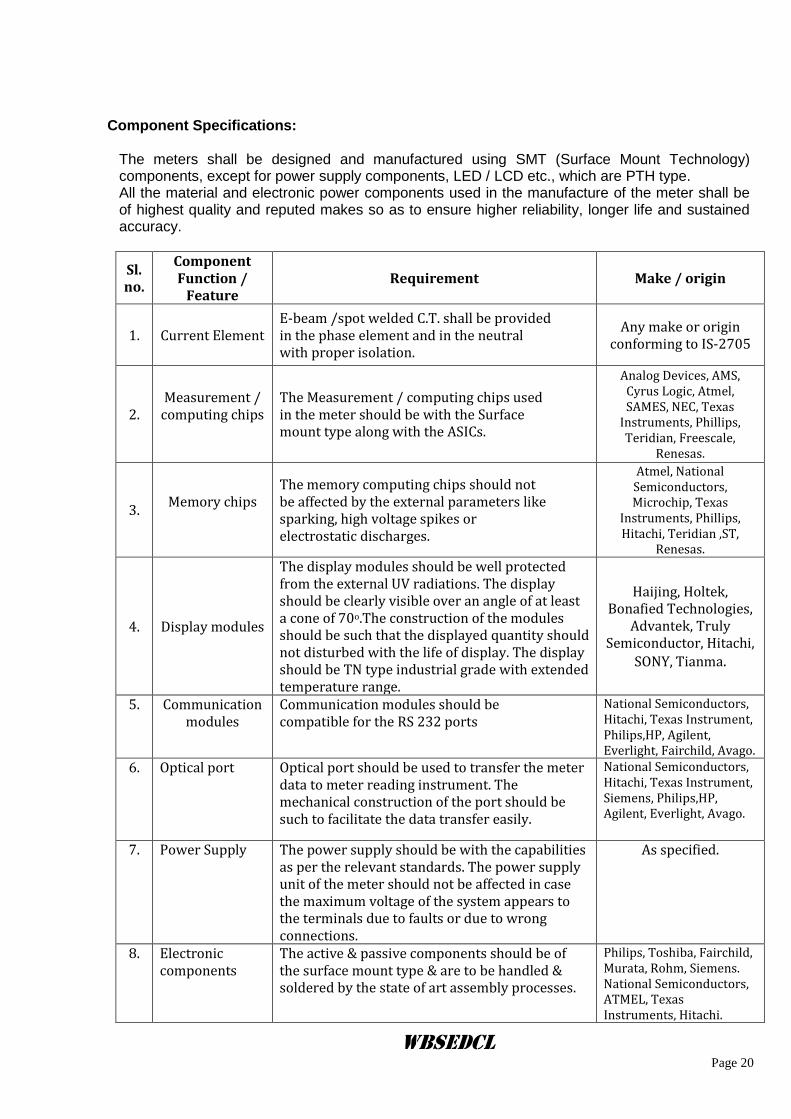
Component Specifications:
The meters shall be designed and manufactured using SMT (Surface Mount Technology) components, except for power supply components, LED / LCD etc., which are PTH type. All the material and electronic power components used in the manufacture of the meter shall be of highest quality and reputed makes so as to ensure higher reliability, longer life and sustained accuracy.
Sl.no.
Component Function /
Feature Requirement Make / origin
1. Current Element E-beam /spot welded C.T. shall be provided in the phase element and in the neutral with proper isolation.
Any make or origin conforming to IS-2705
2. Measurement /
computing chips
The Measurement / computing chips used in the meter should be with the Surface mount type along with the ASICs.
Analog Devices, AMS, Cyrus Logic, Atmel, SAMES, NEC, Texas
Instruments, Phillips, Teridian, Freescale,
Renesas.
3. Memory chips
The memory computing chips should not be affected by the external parameters like sparking, high voltage spikes or electrostatic discharges.
Atmel, National Semiconductors, Microchip, Texas
Instruments, Phillips, Hitachi, Teridian ,ST,
Renesas.
4. Display modules
The display modules should be well protected from the external UV radiations. The display should be clearly visible over an angle of at least a cone of 70o.The construction of the modules should be such that the displayed quantity should not disturbed with the life of display. The display should be TN type industrial grade with extended temperature range.
Haijing, Holtek, Bonafied Technologies,
Advantek, Truly Semiconductor, Hitachi,
SONY, Tianma.
5. Communication modules
Communication modules should be compatible for the RS 232 ports
National Semiconductors, Hitachi, Texas Instrument, Philips,HP, Agilent, Everlight, Fairchild, Avago.
6. Optical port
Optical port should be used to transfer the meter data to meter reading instrument. The mechanical construction of the port should be such to facilitate the data transfer easily.
National Semiconductors, Hitachi, Texas Instrument, Siemens, Philips,HP, Agilent, Everlight, Avago.
7. Power Supply
The power supply should be with the capabilities as per the relevant standards. The power supply unit of the meter should not be affected in case the maximum voltage of the system appears to the terminals due to faults or due to wrong connections.
As specified.
8. Electronic components
The active & passive components should be of the surface mount type & are to be handled & soldered by the state of art assembly processes.
Philips, Toshiba, Fairchild, Murata, Rohm, Siemens. National Semiconductors, ATMEL, Texas Instruments, Hitachi.
WBSEDCL Page 21
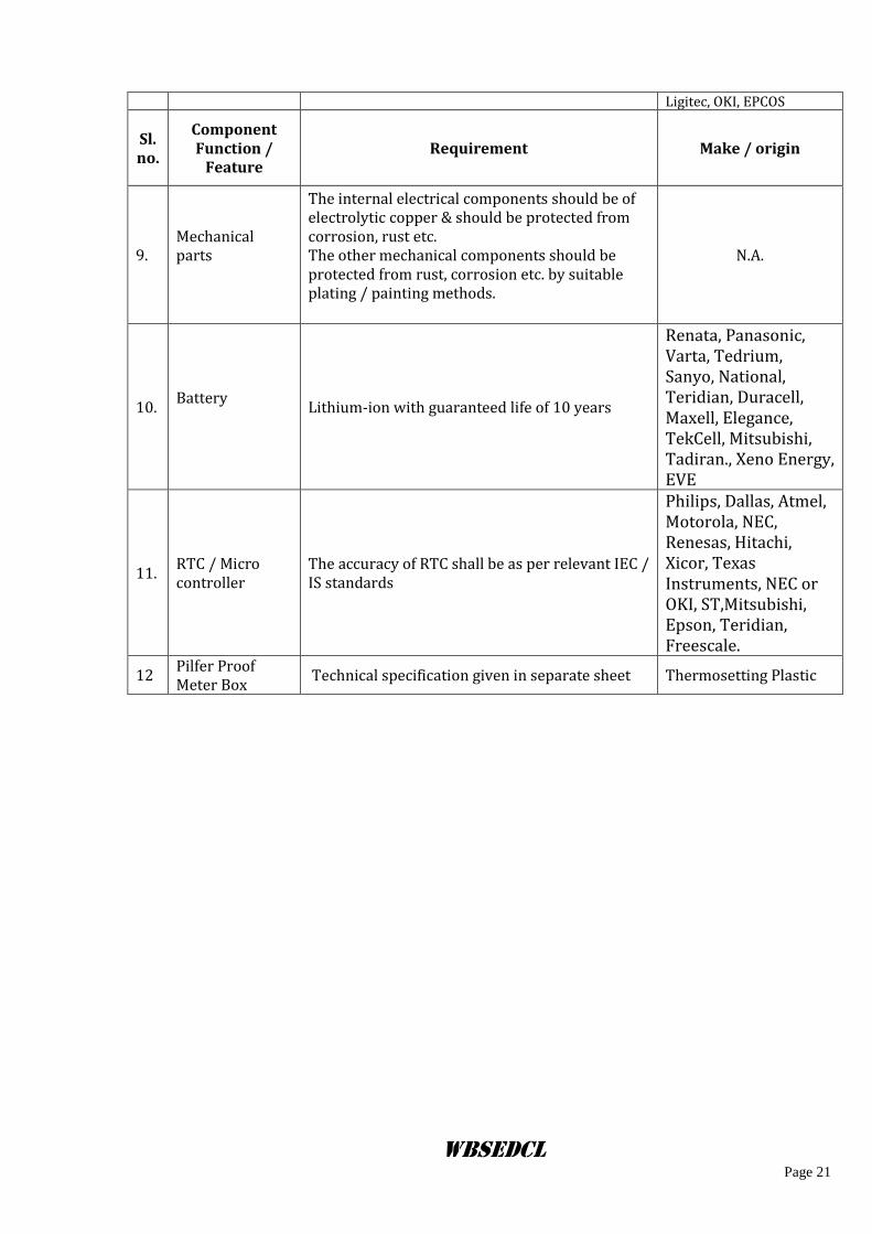
Ligitec, OKI, EPCOS
Sl.no.
Component Function /
Feature Requirement Make / origin
9. Mechanical parts
The internal electrical components should be of electrolytic copper & should be protected from corrosion, rust etc. The other mechanical components should be protected from rust, corrosion etc. by suitable plating / painting methods.
N.A.
10. Battery
Lithium-ion with guaranteed life of 10 years
Renata, Panasonic, Varta, Tedrium, Sanyo, National, Teridian, Duracell, Maxell, Elegance, TekCell, Mitsubishi, Tadiran., Xeno Energy, EVE
11. RTC / Micro controller
The accuracy of RTC shall be as per relevant IEC / IS standards
Philips, Dallas, Atmel, Motorola, NEC, Renesas, Hitachi, Xicor, Texas Instruments, NEC or OKI, ST,Mitsubishi, Epson, Teridian, Freescale.
12 Pilfer Proof Meter Box
Technical specification given in separate sheet Thermosetting Plastic
WBSEDCL Page 22
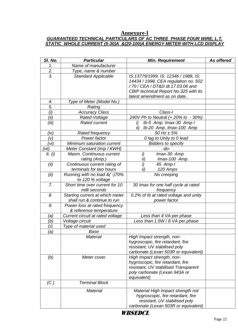
Annexure-I
GUARANTEED TECHNICAL PARTICULARS OF AC THREE PHASE FOUR WIRE, L.T. STATIC WHOLE CURRENT (5-30)A &(20-100)A ENERGY METER WITH LCD DISPLAY
Sl. No. Particular Min. Requirement As offered
1. Name of manufacturer
2. Type, name & number
3. Standard Applicable IS:13779/1999, IS: 12346 / 1988, IS: 14434 / 1998, CEA regulation no. 502 / 70 / CEA / DT&D dt.17.03.06 and CBIP technical Report No.325 with its latest amendment as on date..
4. Type of Meter (Model No.)
5. Rating
(i) Accuracy Class Class-I
(ii) Rated Voltage 240V Ph to Neutral (+ 20% to - 30%)
(iii) Rated current i) Ib-5 Amp. Imax-30 Amp I ii) Ib-20 Amp. Imax-100 Amp
(iv) Rated frequency 50 Hz ± 5%
(v) Power factor 0 lag to Unity to 0 lead
(vi) Minimum saturation current Bidders to specify
(vii) Meter Constant (imp / KWH) -do-
6. (i) Maxm. Continuous current rating (Amp.)
i) Imax-30 Amp ii) Imax-100 Amp.
(ii) Continuous current rating of terminals for two hours
i) 45 Amp I ii) 120 Amps
(ii) Running with no load &( -)70% to 120 % voltage
No creeping
7. Short time over current for 10 milli seconds
30 Imax for one half cycle at rated frequency
8. Starting current at which meter shall run & continue to run
0.2% of Ib at rated voltage and unity power factor
9. Power loss at rated frequency & reference temperature
(a) Current circuit at rated voltage Less than 4 VA per phase
(b) Voltage circuit Less than 1.5W / 8 VA per phase
10. Type of material used
(a) Base
Material High Impact strength, non-hygroscopic, fire retardant, fire resistant, UV stabilised poly carbonate (Lexan 503R or equivalent)
(b) Meter cover High Impact strength, non-hygroscopic, fire retardant, fire resistant, UV stabilised Transparent poly carbonate (Lexan 943A or equivalent)
(C ) Terminal Block
Material Material High Impact strength not hygroscopic, fire retardant, fire
resistant, UV stabilised poly carbonate (Lexan 503R or equivalent)
WBSEDCL Page 23
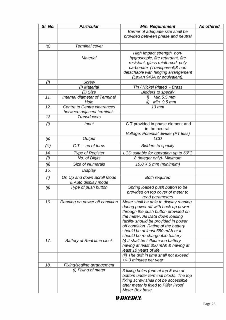
Sl. No. Particular Min. Requirement As offered
Barrier of adequate size shall be provided between phase and neutral
(d) Terminal cover
Material
High Impact strength, non-hygroscopic, fire retardant, fire resistant, glass reinforced poly carbonate (Transparent)& non
detachable with hinging arrangement (Lexan 943A or equivalent).
(f) Screw
(i) Material Tin / Nickel Plated - Brass
(ii) Size Bidders to specify
11. Internal diameter of Terminal Hole
i) Min.5.5 mm ii) Min 9.5 mm
12. Centre to Centre clearances between adjacent terminals
13 mm
13 Transducers
(i) Input C.T provided in phase element and in the neutral.
Voltage: Potential divider (PT less)
(ii) Output LCD
(iii) C.T. – no of turns Bidders to specify
14. Type of Register LCD suitable for operation up to 60oC
(i) No. of Digits 8 (integer only)- Minimum
(ii) Size of Numerals 10.0 X 5 mm (minimum)
15. Display
(i) On Up and down Scroll Mode & Auto display mode
Both required
(ii) Type of push button Spring loaded push button to be provided on top cover of meter to
read parameters
16. Reading on power off condition Meter shall be able to display reading during power off with back up power through the push button provided on the meter. All Data down loading facility should be provided in power off condition. Rating of the battery should be at least 650 mAh or it should be re-chargeable battery
17. Battery of Real time clock (i) It shall be Lithium-ion battery having at least 350 mAh & having at least 10 years of life
(ii) The drift in time shall not exceed +/- 3 minutes per year
18. Fixing/sealing arrangement
(i) Fixing of meter 3 fixing holes (one at top & two at bottom under terminal block). The top fixing screw shall not be accessible after meter is fixed to Pilfer Proof Meter Box base.
WBSEDCL Page 24
Sl. No. Particular Min. Requirement As offered
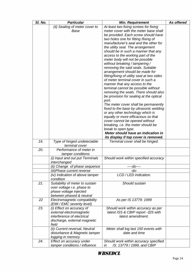
(ii) Sealing of meter cover to Base
At least two fixing screws for fixing meter cover with the meter base shall be provided. Each screw should have two holes one for fitting /fixing of manufacturer’s seal and the other for the utility seal. The arrangement should be in such a manner that any access to the working part of the meter body will not be possible without breaking / tampering / removing the said seals. Suitable arrangement should be made for fitting/fixing of utility seal at two sides of meter terminal cover in such a manner that any access to the terminal cannot be possible without removing the seals. There should also be provision for sealing at the optical port. The meter cover shall be permanently fixed to the base by ultrasonic welding or any other technology which is equally or more efficacious so that cover cannot be opened without breaking, i.e. the meter should be break to open type. Meter should have an indication in its display if top cover is removed.
19. Type of hinged undetectable terminal cover
Terminal cover shall be hinged.
20. Performance of meter in tamper conditions
(i) Input and out put Terminals interchanged
Should work within specified accuracy
(ii) Change of phase sequence ----do----
(iii)Phase current reverse -do-
(iv) Indication of above tamper condition
LCD / LED indication.
21. Suitability of meter to sustain over voltage i.e. phase to phase voltage injected between phased & neutral
Should sustain
22 Electromagnetic compatibility (EMI / EMC severity level)
As per IS 13779: 1999
23. (i) Effect on accuracy of external electromagnetic interference of electrical discharge, external magnetic field
Should work within accuracy as per latest ISS & CBIP report -325 with
latest amendment.
(ii) Current reversal, Neutral disturbance & Magnetic tamper logging in memory
Meter shall log last 150 events with date and time
24. Effect on accuracy under tamper conditions / influence
Should work within accuracy specified in IS: 13779 / 1999, and CBIP
WBSEDCL Page 25
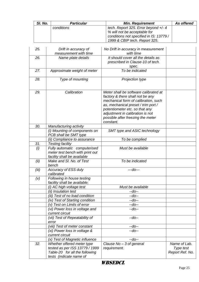
Sl. No. Particular Min. Requirement As offered
conditions tech. Report 325. Error beyond +/- 4 % will not be acceptable for conditions not specified in IS: 13779 / 1999 & CBIP tech. Report 325.
25. Drift in accuracy of
measurement with time No Drift in accuracy in measurement
with time
26. Name plate details It should cover all the details as prescribed in Clause-10 of tech.
spec.
27. Approximate weight of meter To be indicated
28. Type of mounting Projection type
29. Calibration Meter shall be software calibrated at factory & there shall not be any mechanical form of calibration, such as, mechanical preset / trim port / potentiometer etc. so that any adjustment in calibration is not possible after freezing the meter constant.
30. Manufacturing activity
(i) Mounting of components on PCB shall be SMT type
SMT type and ASIC technology
(ii) Compliance to assurance To be complied
31. Testing facility
(i) Fully automatic computerised meter test bench with print out facility shall be available
Must be available
(ii) Make and Sl. No. of Test bench
To be indicated
(iii) Accuracy of ESS duly calibrated
---do---
(v) Following in house testing facility shall be available;
(i) AC high voltage test Must be available
(ii) Insulation test --do--
(iii) Test of no load condition --do--
(iv) Test of Starting condition --do--
(v) Test on Limits of error --do--
(vi) Power loss in voltage and current circuit
--do--
(vii) Test of Repeatability of error
--do--
(viii) Test of meter constant --do--
(xi) Power loss in voltage & current circuit
--do--
(x) Test of Magnetic influence --do--
32. Whether offered meter type tested as per ISS 13779 / 1999 Table-20 for all the following tests (indicate name of
Clause No – 3 of general requirement.
Name of Lab. Type test
Report Ref. No.
WBSEDCL Page 26
Sl. No. Particular Min. Requirement As offered
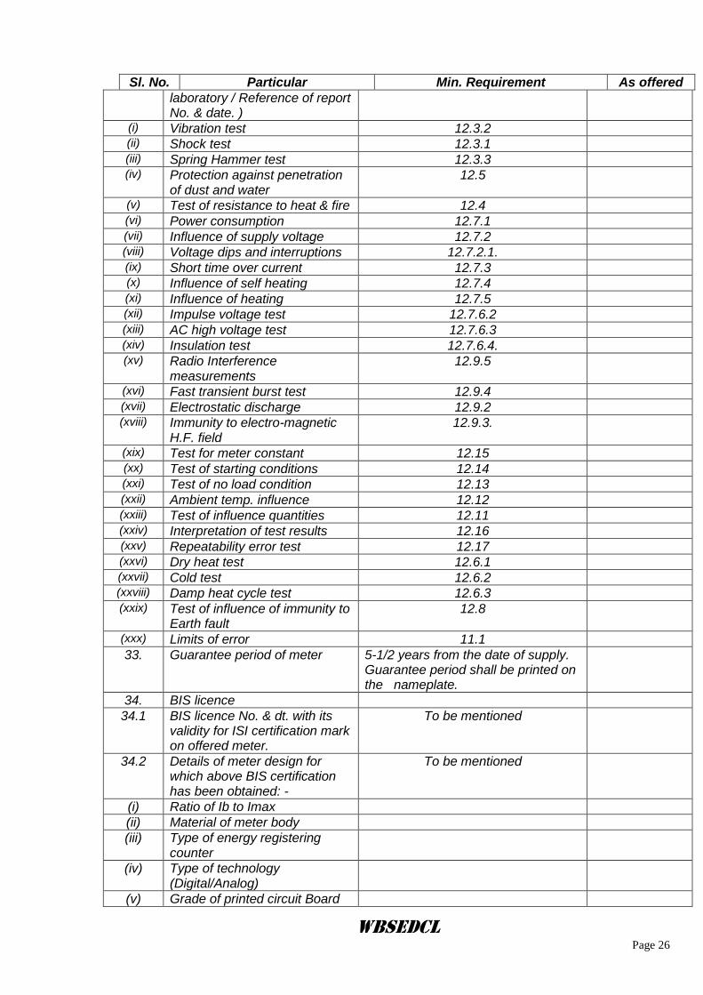
laboratory / Reference of report No. & date. )
(i) Vibration test 12.3.2 (ii) Shock test 12.3.1 (iii) Spring Hammer test 12.3.3 (iv) Protection against penetration
of dust and water 12.5
(v) Test of resistance to heat & fire 12.4 (vi) Power consumption 12.7.1 (vii) Influence of supply voltage 12.7.2 (viii) Voltage dips and interruptions 12.7.2.1. (ix) Short time over current 12.7.3 (x) Influence of self heating 12.7.4 (xi) Influence of heating 12.7.5 (xii) Impulse voltage test 12.7.6.2 (xiii) AC high voltage test 12.7.6.3 (xiv) Insulation test 12.7.6.4. (xv) Radio Interference
measurements 12.9.5
(xvi) Fast transient burst test 12.9.4 (xvii) Electrostatic discharge 12.9.2 (xviii) Immunity to electro-magnetic
H.F. field 12.9.3.
(xix) Test for meter constant 12.15 (xx) Test of starting conditions 12.14 (xxi) Test of no load condition 12.13 (xxii) Ambient temp. influence 12.12 (xxiii) Test of influence quantities 12.11 (xxiv) Interpretation of test results 12.16 (xxv) Repeatability error test 12.17 (xxvi) Dry heat test 12.6.1 (xxvii) Cold test 12.6.2 (xxviii) Damp heat cycle test 12.6.3 (xxix) Test of influence of immunity to
Earth fault 12.8
(xxx) Limits of error 11.1
33. Guarantee period of meter 5-1/2 years from the date of supply. Guarantee period shall be printed on the nameplate.
34. BIS licence
34.1 BIS licence No. & dt. with its validity for ISI certification mark on offered meter.
To be mentioned
34.2 Details of meter design for which above BIS certification has been obtained: -
To be mentioned
(i) Ratio of Ib to Imax
(ii) Material of meter body
(iii) Type of energy registering counter
(iv) Type of technology (Digital/Analog)
(v) Grade of printed circuit Board
WBSEDCL Page 27
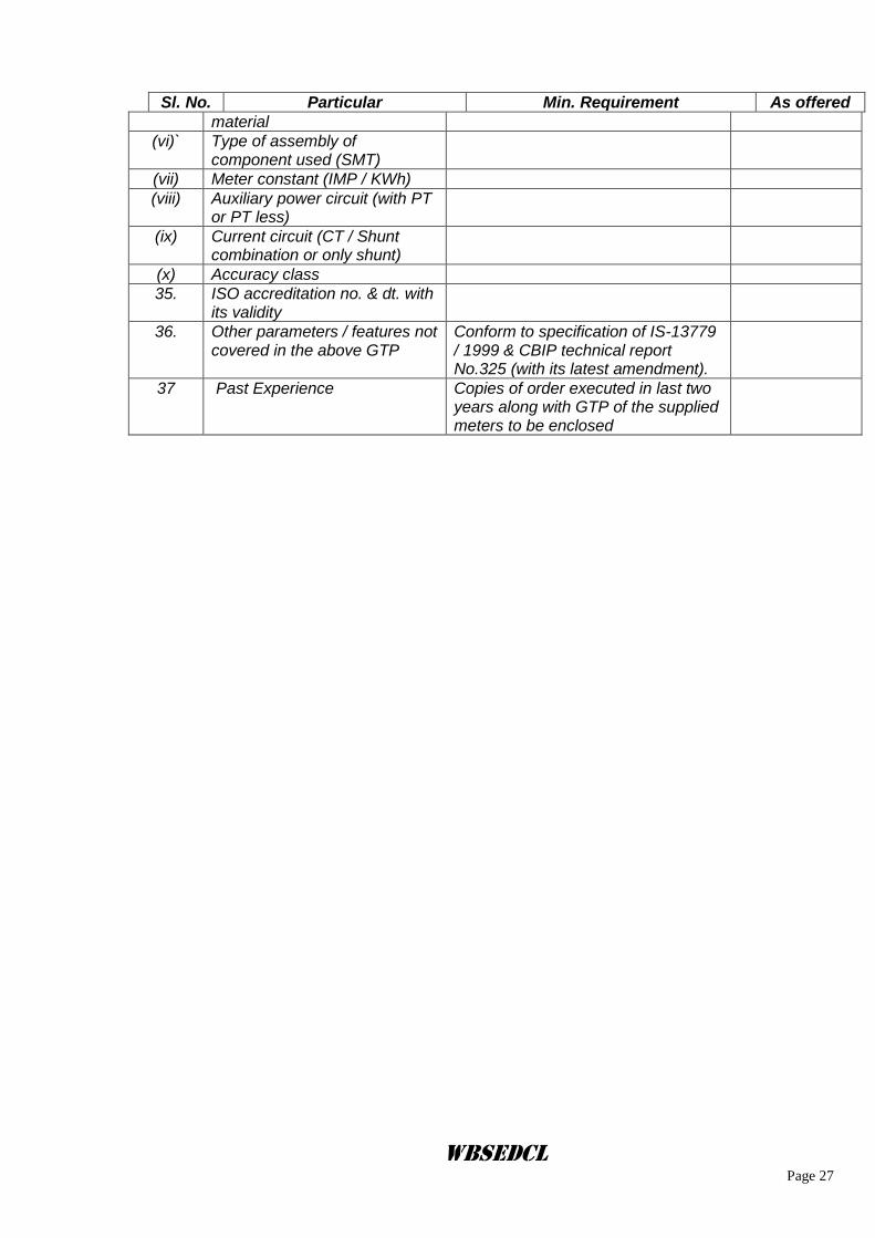
Sl. No. Particular Min. Requirement As offered
material
(vi)` Type of assembly of component used (SMT)
(vii) Meter constant (IMP / KWh)
(viii) Auxiliary power circuit (with PT or PT less)
(ix) Current circuit (CT / Shunt combination or only shunt)
(x) Accuracy class
35. ISO accreditation no. & dt. with its validity
36. Other parameters / features not covered in the above GTP
Conform to specification of IS-13779 / 1999 & CBIP technical report No.325 (with its latest amendment).
37 Past Experience Copies of order executed in last two years along with GTP of the supplied meters to be enclosed
WBSEDCL Page 28
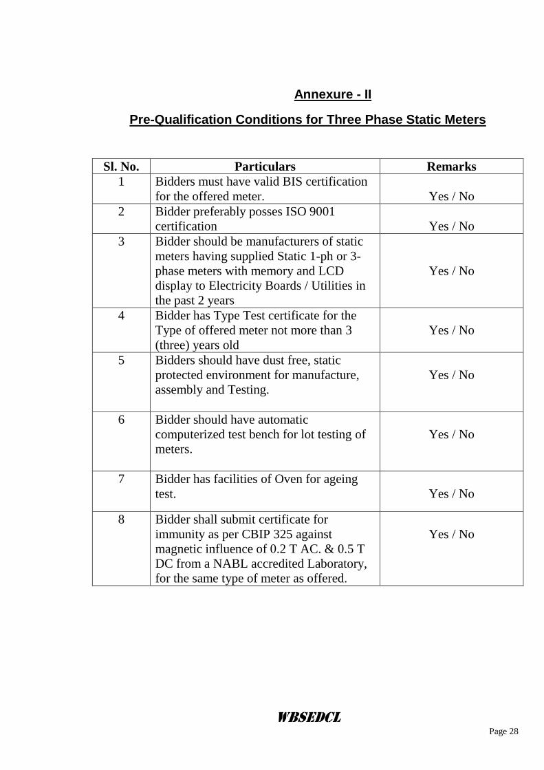
Annexure - II
Pre-Qualification Conditions for Three Phase Static Meters
Sl. No. Particulars Remarks
1 Bidders must have valid BIS certification
for the offered meter.
Yes / No
2 Bidder preferably posses ISO 9001
certification
Yes / No
3 Bidder should be manufacturers of static
meters having supplied Static 1-ph or 3-
phase meters with memory and LCD
display to Electricity Boards / Utilities in
the past 2 years
Yes / No
4 Bidder has Type Test certificate for the
Type of offered meter not more than 3
(three) years old
Yes / No
5 Bidders should have dust free, static
protected environment for manufacture,
assembly and Testing.
Yes / No
6 Bidder should have automatic
computerized test bench for lot testing of
meters.
Yes / No
7 Bidder has facilities of Oven for ageing
test.
Yes / No
8 Bidder shall submit certificate for
immunity as per CBIP 325 against
magnetic influence of 0.2 T AC. & 0.5 T
DC from a NABL accredited Laboratory,
for the same type of meter as offered.
Yes / No
WBSEDCL Page 29
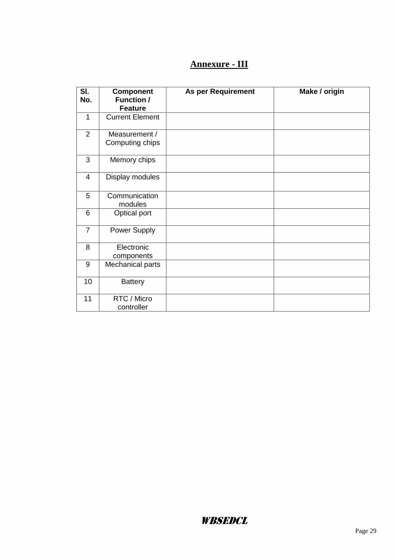
Annexure - III
Sl. No.
Component Function /
Feature
As per Requirement
Make / origin
1 Current Element
2 Measurement / Computing chips
3 Memory chips
4 Display modules
5 Communication modules
6 Optical port
7 Power Supply
8 Electronic components
9 Mechanical parts
10 Battery
11 RTC / Micro controller
WBSEDCL Page 30
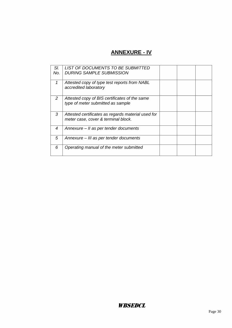
ANNEXURE - IV
Sl. No.
LIST OF DOCUMENTS TO BE SUBMITTED DURING SAMPLE SUBMISSION
1 Attested copy of type test reports from NABL accredited laboratory
2 Attested copy of BIS certificates of the same type of meter submitted as sample
3 Attested certificates as regards material used for meter case, cover & terminal block.
4 Annexure – II as per tender documents
5 Annexure – III as per tender documents
6 Operating manual of the meter submitted
WBSEDCL Page 31
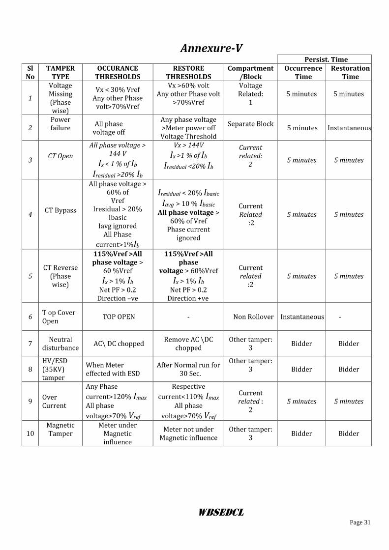
Annexure-V Persist. Time
Sl No
TAMPER TYPE
OCCURANCE THRESHOLDS
RESTORE THRESHOLDS
Compartment/Block
Occurrence Time
Restoration Time
1
Voltage Missing (Phase wise)
Vx < 30% Vref Any other Phase
volt>70%Vref
Vx >60% volt Any other Phase volt
>70%Vref
Voltage Related:
1
5 minutes
5 minutes
2 Power failure
All phase voltage off
Any phase voltage >Meter power off Voltage Threshold
Separate Block
5 minutes Instantaneous
3 CT Open
All phase voltage > 144 V
Ix < 1 % of Ib
Iresidual >20% Ib
Vx > 144V
Ix >1 % of Ib
Iresidual <20% Ib
Current related:
2
5 minutes 5 minutes
4 CT Bypass
All phase voltage > 60% of
Vref Iresidual > 20%
Ibasic Iavg ignored
All Phase
current>1%Ib
Iresidual < 20% Ibasic
Iavg > 10 % Ibasic All phase voltage >
60% of Vref Phase current
ignored
Current Related
:2 5 minutes 5 minutes
5 CT Reverse
(Phase wise)
115%Vref >All phase voltage >
60 %Vref
Ix > 1% Ib Net PF > 0.2
Direction –ve
115%Vref >All phase
voltage > 60%Vref
Ix > 1% Ib Net PF > 0.2
Direction +ve
Current related
:2 5 minutes 5 minutes
6 T op Cover Open
TOP OPEN - Non Rollover Instantaneous -
7 Neutral
disturbance AC\ DC chopped
Remove AC \DC chopped
Other tamper: 3
Bidder
Bidder
8 HV/ESD (35KV) tamper
When Meter effected with ESD
After Normal run for 30 Sec.
Other tamper: 3
Bidder Bidder
9 Over Current
Any Phase
current>120% Imax All phase
voltage>70% Vref
Respective
current<110% Imax All phase
voltage>70% Vref
Current related :
2 5 minutes 5 minutes
10 Magnetic Tamper
Meter under Magnetic influence
Meter not under Magnetic influence
Other tamper: 3
Bidder Bidder
WBSEDCL Page 32
WBSEDCL Page 33
WBSEDCL Page 34
TECHNICAL SPECIFICATION FOR PILFER PROOF METER BOX (SINGLE DOOR TYPE & WITHOUT CUT OUT) SUITABLE FOR
3 PHASE WHOLE CURRENT (5-30)A & (20-100)A STATIC ENERGY METER
SCOPE :
1. This specification covers the manufacture and supply of Pilfer Proof Moulded Meter Box
suitable to house 3-Phase Static Energy Meters. The Meter Box shall be suitable for wall mounted type.
2. Technical requirement and standard: The meter box shall be made out of hot pressed
molded, unbreakable, high grade, fire retardant thermosetting plastic e.g. glass fiber reinforced polyester SMC (Sheet Molding Compound) as per S1 grade of IS) 13410, or Glass Reinforced Polyester Dough Molding Compounds as per Grade D1 of IS 13411, with flame retardant properties having good di-electric & mechanical strength. The Top cover of the Meter Box shall be as per enclosed drawing with provision of separate window arrangement as shown. The material must be U.V. stabilized to ensure that the Meter Box should not change in colour, shape, size, dimension when subjected to 200 hrs. of U.V. Ageing Test. The Meter Box should have top tapered surface / round corners to prevent stay of rain water at the top of the Meter Box. The Meter Box shall be capable of withstanding the mechanical, electrical and thermal stress as well as the effects of humidity which are likely to be encountered in service. At the same time the same should ensure the desired degree of safety. The plastic material used should be adequately stabilized against detrimental effect of light and weather. The surface appearance of the molded parts must be smooth, non-porous and homogeneous, free of ripples, defects and marks. No fillers of fibers should be visible at any place. The Box shall comply in all respect with the requirement of latest Amendments of I.S. 13410-1992 Specification for “General, requirements for enclosures for accessories for fixing electric installations.” Applicable degree of protection shall be I.P. 42 or better. The SMC material which will be used by bidder for this molded Meter Box conforms to Relevant IS/13410-1992 with latest amendment.
The Enclosures shall generally comply with the provision of IS 14772 or IEC 695. The enclosures shall be suitable for outdoor application. The enclosure shall be with good workmanship. Soft neoprene/nitrile rubber gaskets shall be provided all round wherever required for protection against entry of dust and water. The gasket shall confirm to Type-III as per IS-11149. The enclosure shall comply with IP-54 degree of protection.
The Enclosures shall be off- white/admiral grey/Ivory or as specified by the owner.
3. General constructional requirement :
Dimension : Length - 400 mm, Breadth - 300 mm, Height - 200 mm. for (5-30)A meter Length - 525 mm, Breadth - 300 mm, Height - 200 mm. for (20-100)A meter Thickness of the enclosure shall not be less than 2 mm on all sides including door. The enclosure shall have 4 mm thickness of the tongue and groove area.
WBSEDCL Page 35
There should be a minimum 30mm clearance on all sides from the meter surface (projected) except the bottom side which should be minimum 200 mm from the lower edge of terminal block. Meter mountings inside the meter box will be such that the meter base support inside box should be preferably raised by about 10 +/- 2 mm for each items for each of working. Fixing arrangement of meters and other equipment to the base of the meter box should be as per provision of the drawing and as per the specification.
Viewing Window: A viewing window (175 x 85 mm or as per requirement of the owner) made up of scratch and break resistant, UV resistant, transparent Polycarbonate / toughened glass shall be provided on the door for reading the meter without inconvenience. The minimum thickness of the viewing window shall be 4.0 mm. The window shall be securely fixed with meter enclosure from inside Suitable neoprene gasket shall be provided so that there shall not be any ingress of moisture through this window into the meter box.
Hinges : A minimum of 2 nos. brass/stainless steel hinges on each door shall be provided inside the enclosure. The hinges of the door shall be concealed and they shall be fixed to the flanges provided on the body and cover of the enclosure in such a manner that the door opens by a minimum of 120 degrees.
Locking Arrangement : The cover should be fitted with base and should be of concealed hinges. It should have some knobs provided with covers. The covers are to be fixed on the base of Meter Box in such a way that any access from outside is not possible. There should be provision of padlock simultaneously with holes for sealing arrangement covering the top of the Meter Box. The door shall be provided with SS latch or U clamp similar cable entry holes should be provided in the bottom of the Meter Box as per the drawing enclosed and the intermediate partition plates.
Sealing Arrangement :
The meter box shall have provision for minimum 2 nos. seals to make it fully tamper proof.
Arrangement for Inlet & Outlet Cable Entry : Two (2) nos. circular holes having 40 mm dia shall be provided at the bottom of the Meter Box for inlet and outlet of armoured aluminium cables. High grade double compression MS cable glands fixed or aluminium cable glands on both sides by check nuts are to be provided for securely fixing the cable at the bottom of meter box. A suitable arrangement like clamping nut may be provided with the gland so that opening dia can be reduced to the size of Cable.
Base and cover details : The cover shall be made overlapping type having collars on all 4(four) sides. The cover of the Meter Box shall be provided with Gasket of sufficient size to completely fit in the grooves of the base. The gasket should be made of high quality neoprene rubber. The base of the Meter Box must have a groove to hold the Gasket and the overlap of the top cover with base must be minimum 6 mm.
Fixing arrangement of Meter Box : For fixing the Meter Box to wall or wooden board, 4 no. holes (two top side holes to be keyholes) of minimum 4 mm dia shall be provided at the four corners of meter cup-board. The meter is to be installed in the Meter Box and the Box in assembled condition shall have provision to fix it on wall. The 4 no. self threaded screws of min. size of 4 mm dia and 25 mm long shall be provided with each Meter Box.
WBSEDCL Page 36
Marking / Embossing :
The following information shall be clearly & indelibly embossed (not printed) on the cover and base of the Meter Box. The top & bottom corner of Meter Box Sl.No. shall be same for the particular Meter Box
i) Property of WBSEDCL ii) Name / Brand name of Manufacturer- iii) Meter Box Sl.Nos. (Embossed or laser printed on both the base & covers of Meter Box) iv) Sign of danger
N.B.: Sticker or Permanent Marker for marking is not accepted. Drawing :
Detailed dimensional drawing showing clearly the dimensions & material for Meter Box and its constructional features have been furnished with the tender specification which is binding on the part of the manufacturer.
4. Submission of Sample : Bidder shall submit a sample Meter Box as per our specification (or, as available with Bidder, however in the event of order it will be as per Specification before first inspection) along with the sample meter to the office of the Chief Engineer, (DTD), Abhikshan Bhavan, Sector-V, Salt Lake, Kolkata-91 before the last day of submission of bid.
Submission of sample meter box as per size available with the bidder but conforming to our specification towards its quality is acceptable. Type testing including material identification (IR Spectrometry test) of one meter box manufactured as per specification is to be conducted at any NABL accredited laboratory/CIPET by the supplier at their own cost after placement of order. For type testing the meter box will be selected from the first offered lot of meter with meter box. If the type test results are not found satisfactory, the offered lot of meter along with meter box will be rejected.
5. Testing :
a) Type Test: The Meter Box offered shall be type tested as per relevant I.S. standards and the Technical Specification stated below :
The bidder must furnish type test report including material verification of the offered /sample meter box from any NABL/Govt. approved laboratory as available with them along with technical bid without which the offer will not be considered. Type test report should not be more than 5 (five) years old.
b) Acceptance Test : The acceptance test as indicated in the enclosed table (Annexure-V) shall be carried out at the time of inspection of the offered material.
c) Routine Test : The routine tests as indicated in the enclosed table (Annexure-V) shall be carried out and routine test certificates / reports shall be submitted to the purchaser’s inspection office at the time of inspection of the offered material enclosed table (Annexure-V) shall be carried out at the time of inspection of the offered material.
6. Guarantee : The Pilfer Proof Meter Box should be guaranteed against any manufacturing defects arising
out of faulty design or bad workmanship or component failure for a period of 5 ½ years from the date of supply. The meter box found defective within the above guarantee period shall be replaced by the Supplier free of cost within one month of the receipt of intimation of failure/defect. Defective meter box are to be replaced by new one with new sl. nos. as allotted by C.E (DTD).
7. Replacement of defective Meter Box :
WBSEDCL Page 37
The Meter Box declared defective by the WBSEDCL shall be replaced by the supplier up to the full satisfaction of the WBSEDCL at the cost of supplier as per terms of GCC within 60 (sixty) days from the date of intimation by the purchaser. Failure to do so within the time limit prescribed shall lead to imposition of penalty of twice the cost of meter box. The same may lead to black listing even, as decided by WBSEDCL. In this connection the decision of WBSEDCL shall be final.
8. Inspection : The inspection will be carried out as per inspection & testing clause of General Conditions of Contract (GCC).
9. Guaranteed Technical Particulars :
The bidder shall furnish all the necessary information as per Annexure-VI Guaranteed Technical Particulars. If the bidder desire to furnish any other information in addition to the details as asked for, the same may be furnished.
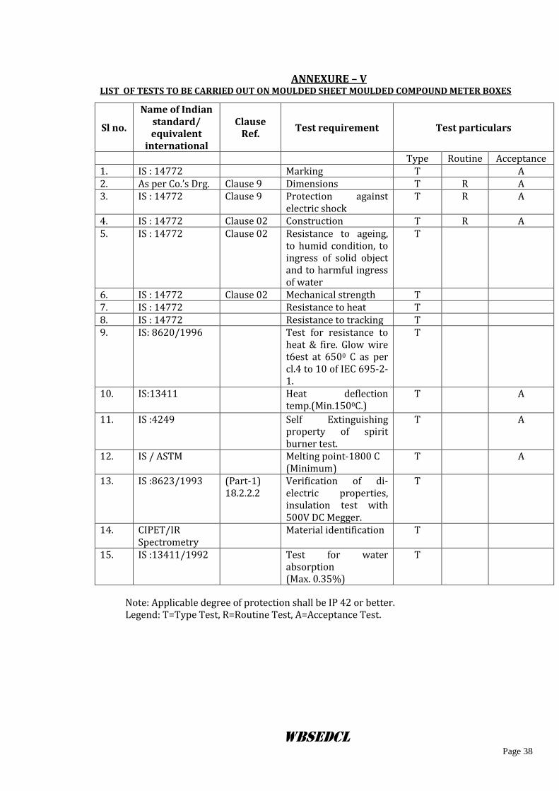
WBSEDCL Page 38
ANNEXURE – V LIST OF TESTS TO BE CARRIED OUT ON MOULDED SHEET MOULDED COMPOUND METER BOXES
Note: Applicable degree of protection shall be IP 42 or better. Legend: T=Type Test, R=Routine Test, A=Acceptance Test.
Sl no.
Name of Indian standard/ equivalent
international
Clause Ref.
Test requirement Test particulars
Type Routine Acceptance 1. IS : 14772 Marking T A 2. As per Co.’s Drg. Clause 9 Dimensions T R A 3. IS : 14772 Clause 9 Protection against
electric shock T R A
4. IS : 14772 Clause 02 Construction T R A 5. IS : 14772 Clause 02 Resistance to ageing,
to humid condition, to ingress of solid object and to harmful ingress of water
T
6. IS : 14772 Clause 02 Mechanical strength T 7. IS : 14772 Resistance to heat T 8. IS : 14772 Resistance to tracking T 9. IS: 8620/1996 Test for resistance to
heat & fire. Glow wire t6est at 6500 C as per cl.4 to 10 of IEC 695-2-1.
T
10. IS:13411 Heat deflection temp.(Min.1500C.)
T A
11. IS :4249 Self Extinguishing property of spirit burner test.
T A
12. IS / ASTM Melting point-1800 C (Minimum)
T A
13. IS :8623/1993 (Part-1) 18.2.2.2
Verification of di-electric properties, insulation test with 500V DC Megger.
T
14. CIPET/IR Spectrometry
Material identification T
15. IS :13411/1992 Test for water absorption (Max. 0.35%)
T
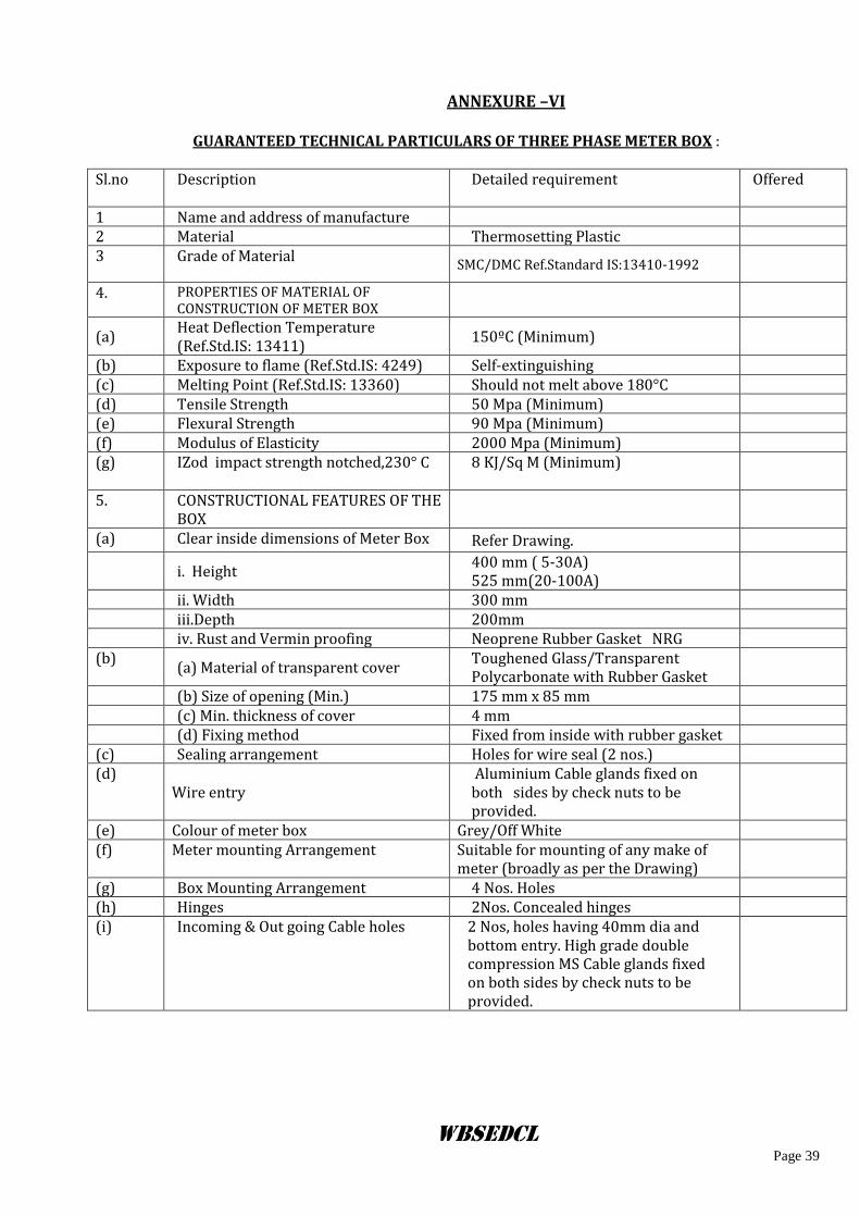
WBSEDCL Page 39
ANNEXURE –VI
GUARANTEED TECHNICAL PARTICULARS OF THREE PHASE METER BOX :
Sl.no Description
Detailed requirement Offered
1 Name and address of manufacture 2 Material Thermosetting Plastic 3 Grade of Material
SMC/DMC Ref.Standard IS:13410-1992
4. PROPERTIES OF MATERIAL OF CONSTRUCTION OF METER BOX
(a) Heat Deflection Temperature (Ref.Std.IS: 13411)
150ºC (Minimum)
(b) Exposure to flame (Ref.Std.IS: 4249) Self-extinguishing (c) Melting Point (Ref.Std.IS: 13360) Should not melt above 180°C (d) Tensile Strength 50 Mpa (Minimum) (e) Flexural Strength 90 Mpa (Minimum) (f) Modulus of Elasticity 2000 Mpa (Minimum) (g) IZod impact strength notched,230° C 8 KJ/Sq M (Minimum)
5. CONSTRUCTIONAL FEATURES OF THE BOX
(a) Clear inside dimensions of Meter Box Refer Drawing.
i. Height
400 mm ( 5-30A) 525 mm(20-100A)
ii. Width 300 mm iii.Depth 200mm iv. Rust and Vermin proofing Neoprene Rubber Gasket NRG (b)
(a) Material of transparent cover Toughened Glass/Transparent Polycarbonate with Rubber Gasket
(b) Size of opening (Min.) 175 mm x 85 mm (c) Min. thickness of cover 4 mm (d) Fixing method Fixed from inside with rubber gasket (c) Sealing arrangement Holes for wire seal (2 nos.) (d)
Wire entry Aluminium Cable glands fixed on both sides by check nuts to be provided.
(e) Colour of meter box Grey/Off White (f) Meter mounting Arrangement Suitable for mounting of any make of
meter (broadly as per the Drawing)
(g) Box Mounting Arrangement 4 Nos. Holes (h) Hinges 2Nos. Concealed hinges (i) Incoming & Out going Cable holes 2 Nos, holes having 40mm dia and
bottom entry. High grade double compression MS Cable glands fixed on both sides by check nuts to be provided.
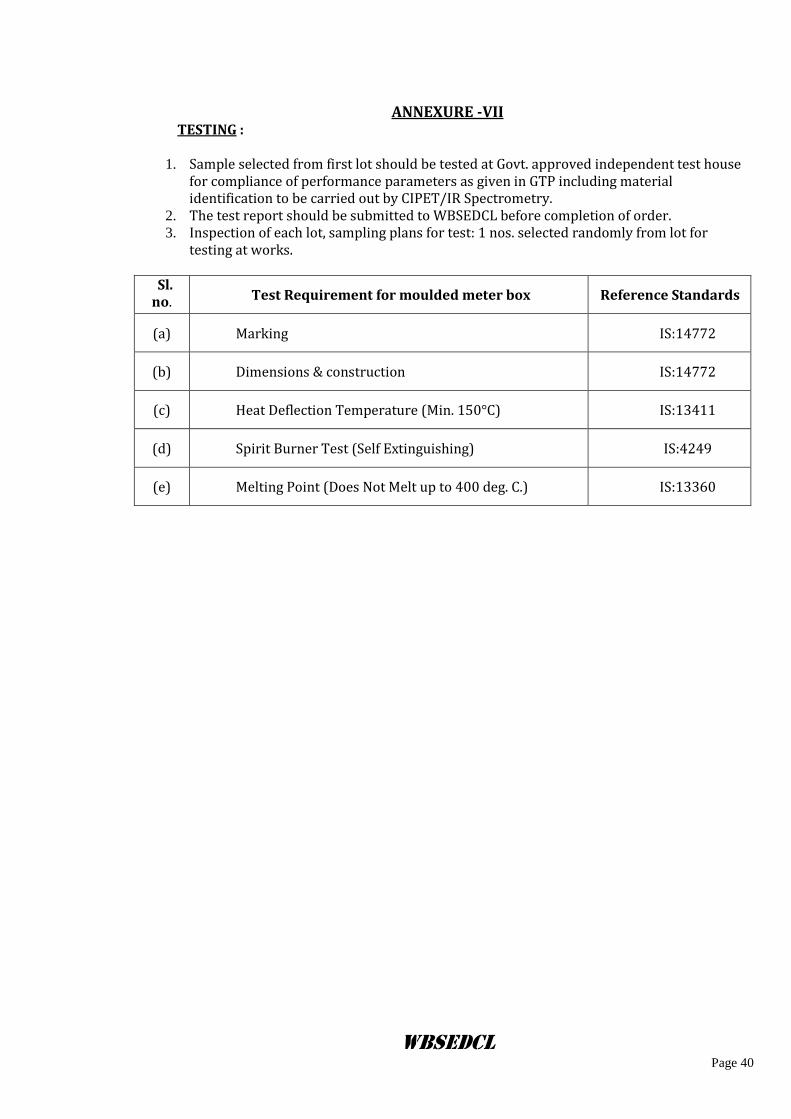
WBSEDCL Page 40
ANNEXURE -VII
TESTING :
1. Sample selected from first lot should be tested at Govt. approved independent test house for compliance of performance parameters as given in GTP including material identification to be carried out by CIPET/IR Spectrometry.
2. The test report should be submitted to WBSEDCL before completion of order. 3. Inspection of each lot, sampling plans for test: 1 nos. selected randomly from lot for
testing at works.
Sl. no. Test Requirement for moulded meter box Reference Standards
(a) Marking IS:14772
(b) Dimensions & construction IS:14772
(c) Heat Deflection Temperature (Min. 150°C) IS:13411
(d) Spirit Burner Test (Self Extinguishing) IS:4249
(e) Melting Point (Does Not Melt up to 400 deg. C.) IS:13360