
technical specification for electrical installation for vattanac ...
176
TECHNICAL SPECIFICATION FOR ELECTRICAL INSTALLATION FOR VATTANAC CAPITAL PHNOM PENH, CAMBODIA NAME SIGNATURE DATE PREPARED BY Mr. Eric Chin CHECKED BY Mr. Eric Chin APPROVED BY Mr. Victor Cheung M&E CONSULTING ENGINEER J. ROGER PRESTON LIMITED LEVEL 11, TOWER 1, MILLENNIUM CITY 1, 388 KWUN TONG ROAD, KWUN TONG, KOWLOON, HONG KONG PROJECT NO. : 8438 COPY NO. : 8438/XX/XX//XX DATE : April 2011 Addendum No.2
-
Upload
khangminh22 -
Category
Documents
-
view
3 -
download
0
Transcript of technical specification for electrical installation for vattanac ...
TECHNICAL SPECIFICATION
FOR
ELECTRICAL INSTALLATION
FOR
VATTANAC CAPITAL
PHNOM PENH, CAMBODIA
NAME SIGNATURE DATE
PREPARED BY Mr. Eric Chin
CHECKED BY Mr. Eric Chin
APPROVED BY Mr. Victor Cheung
M&E CONSULTING ENGINEER
J. ROGER PRESTON LIMITED
LEVEL 11, TOWER 1,
MILLENNIUM CITY 1,
388 KWUN TONG ROAD,
KWUN TONG, KOWLOON,
HONG KONG
PROJECT NO. : 8438
COPY NO. : 8438/XX/XX//XX
DATE : April 2011
Addendum No.2
VATTANAC CAPITAL
PHNOM PENH, CAMBODIA
ELECTRICAL INSTALLATION
TECHNICAL SPECIFICATION
Addendum No.2
VATTANAC CAPITAL
PHNOM PENH, CAMBODIA
ELECTRICAL INSTALLATION
C O N T E N T S
SPECIFICATION – TECHNICAL
SECTION 1 NOT USED
SECTION 2 DESCRIPTION OF WORKS
AND PARTICULAR REQUIREMENTS
SECTION 3 NOT USED
SECTION 4 NOT USED
SECTION 5 SUB-CIRCUIT DISTRIBUTION EQUIPMENT
SECTION 6 NOT USED
SECTION 7 CABLES
SECTION 8 CONDUITS AND ACCESSORIES,
CABLE TRUNKING, CABLE TRAYS
SECTION 9 LUMINAIRES
SECTION 10 NOT USED
SECTION 11 ACCESSORIES AND SUPPLY EQUIPMENT
SECTION 12 NOT USED
SECTION 13 EARTHING
SECTION 14 NOT USED
SECTION 15 NOT USED
SECTION 16 NOT USED
SECTION 17 NOT USED
SECTION 18 PUBLIC ADDRESS SYSTEM
Addendum No.2
VATTANAC CAPITAL
PHNOM PENH, CAMBODIA
ELECTRICAL INSTALLATION
C O N T E N T S
SPECIFICATION – TECHNICAL
SECTION 19 NOT USED
SECTION 20 NOT USED
SECTION 21 NOT USED
SECTION 22 NOT USED
SECTION 23 NOT USED
SECTION 24 TESTING AND COMMISSIONING
SECTION 25 NOT USED
SECTION 26 PAINTING, LABELLING AND IDENTIFICATION
Addendum No.2
VATTANAC CAPITAL
PHNOM PENH, CAMBODIA
ELECTRICAL INSTALLATION
APPENDICES
Addendum No.2
VATTANAC CAPITAL
PHNOM PENH, CAMBODIA
ELECTRICAL INSTALLATION
C O N T E N T S
APPENDIX A EQUIPMENT AND DELIVERY SCHEDULE
APPENDIX B SCHEDULE OF QUANTITIES AND UNIT RATES
APPENDIX C NOT USED
APPENDIX D SCHEDULE OF NON CONFORMITY
Addendum No.2

VATTANAC CAPITAL
PHNOM PENH, CAMBODIA
ELECTRICAL INSTALLATION
Addendum No.2
VATTANAC CAPITAL
PHNOM PENH, CAMBODIA
ELECTRICAL INSTALLATION
SECTION 1 – NOT USED
Addendum No.2
VATTANAC CAPITAL
PHNOM PENH, CAMBODIA
ELECTRICAL INSTALLATION
Addendum No.2
VATTANAC CAPITAL
PHNOM PENH, CAMBODIA
ELECTRICAL INSTALLATION
- 2/1 -
SECTION 2 - SCOPE OF WORKS AND SYSTEM DESCRIPTION
2.1 General Description
2.1.1 The Contractor shall provide all labour, materials and supervision for complete
installation, testing, setting-to-work, balancing, commissioning, performance
evaluation and maintenance (during the Defect Liability Period) of all
Electrical Installation works described in this Specification and as shown on
the Drawings.
2.1.2 The Contractor shall be fully responsible for all necessary provisions to carry
out all of the Conditions of Contract and for timely completion of the entire
works contained in the Contract to give a complete, safe and efficiently
working Electrical Installation (including all interim section and sub-section of
works as and when required) to the satisfaction of the Architect.
2.1.3 The Contractor's offer shall be deemed to include the following, as and when
necessary to be acquired, possessed, applied and maintained at any time and
any place, for execution and satisfactory completion of the entire works
contained and reasonably implied in the Contract in accordance with this
Specification:-
a) Manpower : including labour, overheads, skills, supervision,
attendance, insurances, liabilities as employer,
benefits, bonus, travelling, lodging etc.
b) Material : including procurement, supply, storage, handling,
protection, carriage insurances, freight, cut and
waste, quality assurance testing, detailing, etc.
c) Machinery : including use of power tools, hand tools, ladders,
appliances, means of access, etc.
d) Management : including company establishment, over-heads,
administration, profits, operation, survival, etc.
2.1.4 This Section describes the various systems which form part of the Works as
shown on the Drawings.
2.1.5 This Section outlines the conceptual design of the major systems only and is
not intended to cover all aspects of any or all systems. The detailed scope of
work is indicated on the Drawings and Specification. The Contractor shall
base on the design intent as shown on the Drawings and Specification to
develop the detail design and complete the installation.
Addendum No.2
VATTANAC CAPITAL
PHNOM PENH, CAMBODIA
ELECTRICAL INSTALLATION
- 2/2 -
2.1 General Description (Cont'd)
2.1.6 The Contractor shall provide all labour, materials and supervision for the
complete installation, interfacing with others, testing, setting to work,
commissioning, maintenance and attending to the Supply Company's and
statutory authorities’ testing of all systems described in the Specifications and
as shown on the Drawings.
2.1.7 The Contractor is to note that the Construction Drawings issued for the
building services Installation indicate the general design intent. The
Contractor shall be responsible for the preparation and co-ordinating his
working drawings with each services and with the fabric and the building
structure, and for co-ordinating working drawings to facilitate co-ordination of
the installation of all services in the correct sequence and position. All
working drawings must be submitted to the Architect and his confirmation
must be obtained that such drawings comply with design intent prior to
execution of the respective building services installation works.
These drawings shall be based on the Contract Drawings and shall take into
account any modification either to the Building or to the installation which
may have taken place during the course of the works and shall be correctly
related to the details of the actual items of plant and equipment installed.
2.2 Scope of the Works
2.2.1 The Contractor shall supply and install a complete electrical system
conforming to this Specification and in accordance with the Drawings.
2.2.2 The installation forming part of the "Works" shall include for provision,
installation, testing, commissioning and setting to work of the following:-
a) NOT USED
b) NOT USED
c) Distribution boards, cables and switchgears.
d) NOT USED
e) NOT USED
f) Supply and installation of luminaires including to public area & office
area as shown on the drawings.
g) NOT USED
h) NOT USED
i) NOT USED
Addendum No.2
VATTANAC CAPITAL
PHNOM PENH, CAMBODIA
ELECTRICAL INSTALLATION
- 2/3 -
2.2 Scope of the Works (Cont'd)
2.2.2 (Cont'd)
j) Power supply to lighting and small power.
k) NOT USED
l) Power supply to extra low voltage (ELV) system.
m) Final termination to the respective isolating switches, MCB boards,
MCCB boards, lighting control panels etc..
n) Earthing system including equipotential bondings and supplementary
bondings.
o) NOT USED
p) Provision for the interface with building management system (BMS).
q) Provide spare part as described in the Specification.
r) Attendance to and co-ordination with other trades including but not
limit to the main contractor and the M&E sub-contractors as well as
facilitate the M&E sub-contractors to test all electrical installation.
s) Provision of full time supervision at all times during the entire duration
of the works.
2.2.3 The Contractor shall include all the costs for takeover inspection of the
components on a piece by piece basis to ensure proper integration and
functioning of the complete electrical installations as a whole.
2.2.4 The Contractor shall allow necessary provision and interfacing with other
trades.
2.2.5 NOT USED
2.2.6 Commissioning and testing
2.2.7 Operation and attendance as specified
2.2.8 Maintenance works as specified.
2.2.9 Liaison, co-ordination, communication, provision of drawings and literature,
and other information as and when necessary or instructed by the Architect for
the satisfactory execution of works.
2.2.10 Painting and labelling of all plant, equipment, including cable tray, trunking,
conduit, etc..
Addendum No.2
VATTANAC CAPITAL
PHNOM PENH, CAMBODIA
ELECTRICAL INSTALLATION
- 2/4 -
2.2 Scope of the Works (Cont'd)
2.2.11 NOT USED
2.2.12 Take down, removal from the site of all temporary light fittings, conduits and
wirings.
2.3 System Description
2.3.1 The Contractor shall supply and install a complete electrical power
distribution system conforming to the Specification and in accordance with the
Drawings, comprising the following.
2.3.2 NOT USED
2.3.3 NOT USED
2.3.4 NOT USED
2.3.5 NOT USED
2.3.6 NOT USED
2.3.7 NOT USED
2.3.8 NOT USED
2.3.9 Power Supply to Public Lighting and Small Power
Power supply to public lighting and small power shall have both essential and
non-essential supply from the switchboard.
2.3.10 NOT USED
2.3.11 Luminaires
Position of luminaires shown on the Drawings are provisional only. The
Contractor shall co-ordinate with other trades and install the luminaires to suit
actual site condition and to the approval of the Architect. No cost shall be
entertained for rectifying any mis-coordination.
Addendum No.2
VATTANAC CAPITAL
PHNOM PENH, CAMBODIA
ELECTRICAL INSTALLATION
- 2/5 -
2.3 System Description (Cont’d)
2.3.12 Lighting and Small Power
The Contractor shall furnish and install a lighting and small power system
complete with supply cables, distribution MCB boards, conduit wiring,
accessories and luminaires complying with the Specification and as shown on
Drawings.
Unless stated otherwise, all control switches for lighting shall be mounted
adjacent to the opening side of door at 1250mm above finish floor level
measured from bottom edge of switch.
Unless stated otherwise, all socket outlets shall be mounted at the following
levels/locations measured from bottom edge of outlet.
a) Skirting level at 250mm above finished floor level in public area
(corridor, lift lobby, etc.)
b) NOT USED
The Contractor should show on drawing the setting out and level of all socket
outlets in all areas for approval prior to works.
Where lighting circuit or group of lighting circuits are controlled by the
building management system using 2-pole, 2-pole or 4-pole suitably rated
contactors, the following shall be provided.
i) Terminals for contactor coil remote trip at 24V a.c.
ii) Dry contacts (N.C. or N.O.) to indicate contactor status.
The Contractor shall coordinate with other trades for the exact location of
ceiling/wall mounted lighting to avoid conflict with
pipework/equipment/services. Surface conduit wiring shall be provided for
power supply to luminaires and socket outlets.
Surface conduits may be used for wiring to luminaires, power sockets,
fused-spur units, control switches etc. within false ceiling void. All lighting
and small power equipment shall be installed after the mechanical equipment
has been installed in order to suit the layout.
2.3.13 Earthing System
The earthing system including earthing tape and earthing cable as shown on
the drawing shall be supplied and installed by this contractor.
Equipotential bondings shall be provided by the Contractor according to the
IEE wiring regulation.
Addendum No.2
VATTANAC CAPITAL
PHNOM PENH, CAMBODIA
ELECTRICAL INSTALLATION
- 2/6 -
2.3.14 NOT USED
2.3.15 NOT USED
2.3.16 NOT USED
2.3.17 Interface with ELV
The Contractor shall supply and install power points, complete trunking and
conduit system to the ELV systems as shown on Drawings. All the ELV
points shall be connected by conduit to the respective ELV trunking as shown
on Drawings.
2.3.18 NOT USED
2.3.19 Submissions
All submissions must be made early enough in the Contract to enable the
Architect to fully check each item prior to giving approval. The Contractor
shall ensure that submissions are made at least two months before any
equipment is required to be ordered to meet the Contractor's Programme.
The Contractor shall supply full drawings of all equipment to a scale suitable
for the fullest understanding by the Architect of the design details but in any
event not less than a scale of 1:50, within the time required by the Architect
that they may be incorporated into other elements of works and as instructed
by the Architect, together with the fullest particulars and details of positions
where power for any elements is required.
No claims for extensions of time or additional costs shall be entertained as a
result of the Contractor's failure to make submissions in adequate time.
The Contractor shall on request, or where specified elsewhere, submit to the
Architect samples of materials and/or workmanship. Such samples shall be
approved in writing before the appropriate equipment or installation work is
carried out.
Addendum No.2
VATTANAC CAPITAL
PHNOM PENH, CAMBODIA
ELECTRICAL INSTALLATION
SECTION 2 - SCOPE OF WORKS AND SYSTEM DESCRIPTION
Addendum No.2
VATTANAC CAPITAL
PHNOM PENH, CAMBODIA
ELECTRICAL INSTALLATION
I N D E X
SECTION 2 - SCOPE OF WORKS AND SYSTEM DESCRIPTION
Clause Page
2.1 General Description ..................................................................................2/1
2.2 Scope of the Works ...................................................................................2/2
2.3 System Description ...................................................................................2/4
Addendum No.2
VATTANAC CAPITAL
PHNOM PENH, CAMBODIA
ELECTRICAL INSTALLATION
SECTION 3 – NOT USED
Addendum No.2

VATTANAC CAPITAL
PHNOM PENH, CAMBODIA
ELECTRICAL INSTALLATION
Addendum No.2

VATTANAC CAPITAL
PHNOM PENH, CAMBODIA
ELECTRICAL INSTALLATION
Addendum No.2

VATTANAC CAPITAL
PHNOM PENH, CAMBODIA
ELECTRICAL INSTALLATION
SECTION 4 – NOT USED
Addendum No.2

VATTANAC CAPITAL
PHNOM PENH, CAMBODIA
ELECTRICAL INSTALLATION
Addendum No.2
VATTANAC CAPITAL
PHNOM PENH, CAMBODIA
ELECTRICAL INSTALLATION
- 5/1 -
SECTION 5 - SUB-CIRCUIT DISTRIBUTION EQUIPMENT
5.1 General
5.1.1 The Contract shall provide and install all sub-circuit distribution equipment
and cable installation as indicated on the Drawings and specified in this
Specification.
5.1.2 The complete installation shall comply in every respect with the latest edition
of the I.E.E. Wiring Regulations and all local statutory regulations.
5.2 Fused Switchgear Isolators
5.2.1 Fused switchgear and isolators shall be suitable for surface mounting, with
enclosures fabricated from sheet steel, finished in grey or other approved
colour, stroved enamel, removable top and bottom and plates and gasketed
door. Chromium plated front operated handles with visible 'ON', 'OFF'
indication shall be provided. Front access doors shall be detachable, and shall
be interlocked to prevent opening when the isolator is on. Provisions shall be
made for the interlock to be defeated by a competent person for maintenance
purposes. Interiors shall comprise porcelain bases fitted with plated
non-ferrous conducting components. Switches shall be quick make and
break type, and shall have removable shields over the fixed contacts, and
removable moving contact bars. Pad-locking facilities shall be provided at
both ON and OFF positions.
5.2.2 All fuse switchgear and isolating devices shall be rated for 660V, designed for
heavy duty application, having a utilization category of AC23. They shall be
fully tested to conform to BSEN 60947-3. Cartridge fuses to B.S. 88 shall be
supplied.
5.3 NOT USED
5.4 NOT USED
5.5 NOT USED
5.6 NOT USED
5.7 NOT USED
Addendum No.2
VATTANAC CAPITAL
PHNOM PENH, CAMBODIA
ELECTRICAL INSTALLATION
- 5/2 -
5.8 Miniature Circuit Breakers and M.C.B. Board
5.8.1 Single pole miniature circuit breakers shall be used for final circuit control and
protection on all lighting and small power circuits. Three pole breakers shall
be used for 3 phase equipment.
5.8.2 M.C.B.'s shall be single pole or three pole only and neutral link switching is
not required.
5.8.3 The body and base of the units shall be moulded Bakelite or similar material
and the units shall be sealed after assembly.
5.8.4 The load handling contacts shall be silver/tungsten and the contacts and
operating mechanism so designed as to give a wiping action both at make and
break.
5.8.5 The breaker operating mechanism shall be of the trip-free type so designed as
to prevent the load handling contacts from closing on a fault.
5.8.6 Circuit protection against overload and fault conditions shall be provided by
means of a thermal magnetic device designed to give thermal operation on
overload and magnetic operation under fault conditions.
5.8.7 Positions of the breaker operating dolly shall be clearly indicated.
5.8.8 Miniature circuit breakers provided under this Contract shall be suitable for
small inrush or switching surge (type B). However, for final circuits
associated with discharge lamps and motor loads, type C MCB. All MCB
shall comply to IEC 60898 and have been tested at an A.S.T.A. approved
testing station and the Architect will require proof of such tests in the form of
certificates prior to the ordering of equipment. The MCB shall have 6kA
short circuit duty rating at 250V/515V 50Hz.
In addition, the MCBs shall be connected in cascade with fuses to B.S. 88 up
to a rating of 160A in situations where the prospective short circuit current at
the supply side is up to 22kA.
5.8.9 All cable and busbar terminations shall be sweated and tinned prior to
connection to M.C.B. terminals.
5.8.10 Miniature circuit breaker distribution boards shall be same manufacturer as
MCB and provided to serve lighting circuits, small power outlets and/or as
otherwise specified on the Drawings. The number of "ways" shown on the
Drawings shall be provided. Equivalent number of way shall be provided if
the RCCB occupied more than one way.
Addendum No.2
VATTANAC CAPITAL
PHNOM PENH, CAMBODIA
ELECTRICAL INSTALLATION
- 5/3 -
5.8 Miniature Circuit Breakers and M.C.B. Board (Cont’d)
5.8.11 All wiring, busbars, etc., within the distribution boards shall be adequately
shrouded and an insulating front shield of a flame retardant type, 2.50mm
thick shall be provided to completely screen the distribution unit interior.
Only the M.C.B. operating dolly and insulated surround shall project through
the shield.
5.8.12 Neutral bars shall be of adequate cross section, mounted on insulators and
drilled to receive circuit wiring. Two clamping screws shall be provided per
neutral way. Screws shall be round or cheese head brass not less than 5 B.A..
Ferrules shall be provided for all neutral wires to indicate the circuit numbers.
5.8.13 Inside each distribution board door, a circuit record card, enclosed in a perspex
envelope shall be provided and fixed giving the total number of points served
by each M.C.B., total load per way and the area served.
5.8.14 All boards shall be clearly labelled, and marked with phase identification.
5.8.15 Board doors shall be fitted with ball catch locks or equal and approved type.
The sheet metal for the board shall be not less than 1.50mm and for the door
shall be 2mm thick.
5.8.16 A chromium plated handle shall be fitted on the door.
5.9 Residual Current Operated Circuit Breaker (RCCB)
5.9.1 RCCBs shall be of double-pole or four-pole, rated at 30mA, complying with
BSEN 61008, IEC 61008 or BSEN 61009, IEC 61009 and having a short
circuit breaking capacity of 6 kA or above.
5.9.2 RCCB shall be fitted with overload device, otherwise specified.
5.9.3 The tripping operation of the RCCBs shall not involve the amplification of
operating residual current and shall be independent on the supply voltage.
5.9.4 Indication of tripped circuit breaker a earth fault shall be provided.
5.10 Moulded Case Circuit Breakers
5.10.1 The A.C. rated short-circuit capacity for M.C.C.B.'s installed in the upstream
shall not be less than 53 kA.
5.10.2 Except for the terminals and toggle, the entire current carrying and operating
mechanism of circuit breakers shall be contained within a moulded plastic
case.
Addendum No.2
VATTANAC CAPITAL
PHNOM PENH, CAMBODIA
ELECTRICAL INSTALLATION
- 5/4 -
5.10 Moulded Case Circuit Breakers (Cont’d)
5.10.3 The M.C.C.B. operating mechanism shall be trip-free.
5.10.4 All M.C.C.B.'s shall comply to IEC 947-2 or BSEN 60947-2 and shall be
provided with short circuit and earth fault protection where required and
specified.
5.10.5 M.C.C.B. shall have an inverse current/time characteristics (tripping time shall
be inversely proportional to the magnitude of the load current).
5.10.6 'ON' and 'OFF' indications shall be incorporated in the M.C.C.B. to show
whether the contacts of the circuit breaker are in the open or closed position.
5.10.7 Triple pole circuit breakers shall be interlocked internally so that an overload
on any one phase shall trip all three phases of the breaker simultaneously.
5.11 MCCB Distribution Board
5.11.1 The design, construction and testing specifications of the distribution boards
shall comply with Clause 7.1 to 7.8 (inclusive) and Clause 8.1 to 8.2 (inclusive)
of BSEN 60439-1 and suitable for use on 380V (3 phase) 50 Hz supply. All
MCCB distribution boards shall each be provided with a moulded case
isolating switch having a current rating not less than that of the supply side
protection device. The moulded case isolating switch shall meet the relevant
requirements of MCCB.
5.11.2 The following conditions shall apply :-
a) Ambient temperature - peak from minus 5ºC to plus 40ºC for 4 hours
continuously with an average from 0ºC to plus 35ºC over only 24 hour
period.
b) Altitude - up to 2000m above sea level.
c) Relative humidity - up to 0.99 saturation.
5.11.3 The enclosure of MCCB distribution boards shall be constructed from sheet
steel having a thickness of not less than 1.5mm, rust proofed and baked
enamelled to B.S. 4800 No. 14E51 green finish or to the manufacturer's
nearest standard colour. Removable gland plate shall be provided on the top
and bottom. The construction shall be of robust design, capable of
with-standing the mechanical, electrical and thermal stresses under all
working conditions including fault conditions. The enclosure shall have an
index of protection not less than IP30.
Addendum No.2
VATTANAC CAPITAL
PHNOM PENH, CAMBODIA
ELECTRICAL INSTALLATION
- 5/5 -
5.11 MCCB Distribution Board (Cont’d)
5.11.4 MCCB distribution boards shall include all necessary components and
accessories to form a complete assembly. Components and accessories shall
be firmly fixed in position in the distribution board and shall be assembled in
such a way that it shall be possible to remove or replace any component parts
and to carry out cable connections from the front. Ample space shall be
allowed for cabling. MCCBs shall be arranged neatly in a row or rows. All
components shall be totally concealed; only the toggles of the MCCBs shall
protrude through the cover plate of the distribution board.
5.11.5 MCCB distribution boards shall be provided with triple-pole and neutral
copper busbars of rating not less than of the supply side protective device
subject to a minimum of 250A. All busbars shall be of hard drawn copper
and shall be electro-tinned. Neutral busbars shall be of the same cross
section area as the phase busbars, and shall have adequate number of terminals
for all outgoing circuits including spare ways.
The configuration of the busbars, busbar supports and the busbar mounting
arrangement shall be type tested and certified to a short-time withstanding
current of not less than 14kA in the case of boards with busbar rating less than
400A or 22kA in the case of boards with busbar rating 400A or above, or the
prospective short circuit current which can occur at the point of installation
whichever is the largest for 0.2 second at a voltage of not less than 380 volts.
Outgoing MCCBs shall be mounted on both sides of the busbars. The
connection between the MCCBs and the phase busbars shall be by means of
copper tapes and bolted joints. Plug-in type of current carrying contacts shall
not be accepted.
5.11.6 Every distribution board shall be provided with an external earthing terminal
for connection to the main earthing terminal. In addition, a multi-terminal
connector shall be provided with the distribution board for connection of
protective conductors of all outgoing circuits including spare ways.
Both the external earthing terminal and the multi-terminal connector for
protective conductor shall be of hard drawn, electro-tinned copper and shall be
labelled in accordance with the requirements of BSEN 60439-1 or IEC 439-1.
5.11.7 All conductive live parts shall be properly shrouded against accidental contact
by means of rigid barriers, partitions of insulating materials such that
accidental contact can be prevented during operation of component
replacement or cable connection. All conductive structural parts of the
distribution boards shall comply with the protective circuit requirements to
BSEN 60439-1 or IEC 439-1.
5.11.8 Each distribution board shall be provided with spare ways for future expansion.
Each spare way be blanked off with a suitable blanking plate having a finish
comparable to that of the distribution board.
Addendum No.2
VATTANAC CAPITAL
PHNOM PENH, CAMBODIA
ELECTRICAL INSTALLATION
- 5/6 -
5.12 Contactors
5.12.1 Contactors shall comply with BSEN 60947-4-1.
5.12.2 The rating of contactors shall be as follow:-
Rated operation voltage : 380/220 V
Rated insulation voltage : 415 V
Rated frequency : 50 Hz
Rated thermal current : As shown on the Drawings
Rated operational current/ : As shown on the Drawings
power and duty
5.12.3 Contactors shall be four-pole, triple-pole, double-pole or single-pole as shown
on the Drawings. The mechanical endurance of the contactors shall not be
less than 3 million no-load operating cycles. Unless otherwise specified, the
number of on-load operating cycles for category AC-3 shall not be less than
1/20 of the number of no-load operating cycles corresponding to the
mechanical endurance of the contactor. Contactors shall be silver or
silver-faced. Insulation shall be of Class B as per B.S. 2757.
5.12.4 Contactors shall be electro-magnetically controlled, double air-break type.
The rated control circuit voltage shall be the same as that of the main circuit,
otherwise it shall be 24 or 110 V D.C. as specified.
5.12.5 Unless otherwise specified, contactors shall be of utilization category AC-2
for general application.
5.12.6 Control contactors for power factor correction equipment shall be of
utilization category AC-4 or above and specifically designed for switching
direct connected capacitor banks with intermittent duty of Class 0.3.
5.12.7 Contacts for star/delta starting or reversing contactors shall be fitted with the
necessary mechanical and electrical interlocks.
5.12.8 Contactors shall be of utilization category AC-3 for general motor circuits and
AC-4 for motor circuits with plugging or inching facilities. Contactors for
motor starters of AC-3 utilization category shall be of uninterrupted duty and
intermittent duty Class 0.1, 60% on-load factor; and contactors for AC-4
category shall be of intermittent duty Class 0.3, 60% on-load factor.
5.12.9 Contactors shall be type tested to BS 89, BS 142. Full type test certificates
shall be produced to the satisfaction of the Architect.
Addendum No.2
VATTANAC CAPITAL
PHNOM PENH, CAMBODIA
ELECTRICAL INSTALLATION
- 5/7 -
5.12 Contactors (Cont’d)
5.12.10 For contactors rated at 400 A or above, tests shall be carried out by an
Independent Short Circuit Testing Organisation for verification of the rated
making and breaking capacities.
5.13 Double Pole Switch-Disconnection
5.13.1 Double Pole switch-disconnections shall comply with BSEN 60947-3, suitable
for 220V supply operation with rated current as indicated on the Drawings.
They shall have utilization category AC 22 and shall be provided with facility
for padlocking the switch disconnectors in the isolated position. Incoming
terminal shall be protected against direct contact to IP 2X.
5.13.2 Full type test report to BSEN 60947-3 shall be produced to the satisfaction of
the Architect.
5.14 Time Switches
5.14.1 Time switches shall be self-starting and driven by synchronous motor. They
shall be suitable for either flush, surface or panel mounting as specified in the
Particular Specification and shall be housed in metal or robust moulded plastic
enclosure with a removable clear plastic front cover.
5.14.2 The time switches shall be rated at 20A (resistive load) unless otherwise
specified. The time accuracy shall be within ±5 minutes per year.
5.14.3 Time switches shall incorporate the following features :
a) An automatic rewind spring reserve or nickel-cadmium battery backup
of not less than 72 hours to drive the mechanism during power
interruption.
b) a 24-hour dial with at least 2 "ON-OFF" operation cycles everyday.
c) An on/off or test switch to enable the circuit to be controlled at will
without affecting the normal dial operation.
5.15 Label
5.15.1 All boards shall be clearly labelled, and marked with phase identification.
Addendum No.2
VATTANAC CAPITAL
PHNOM PENH, CAMBODIA
ELECTRICAL INSTALLATION
- 5/8 -
5.16 Identification
5.16.1 Inside each distribution board door, a circuit record card, enclosed in a perspex
envelope shall be provided and fixed giving the total number of points served
by each M.C.B., total load per way and the area served.
5.17 Discrimination
5.17.1 Full discrimination is required within and between the switchboard ACB's and
other switchgear ensuring that short circuit or overloads on sub-circuits will
not trip the switchboard circuit breakers but will effectively isolate the faulty
circuit leaving the healthy circuits unaffected. The Contractor shall be
responsible to ensure discrimination is maintained.
5.17.2 Where earth fault detection is provided, sufficient adjustment shall be allowed
to maintain discrimination between outgoing and incoming circuits, and
prevent spurious tripping due to inherent leakage on long cable runs or remote
equipment.
5.17.3 Where circuit breakers are not provided with earth leakage detection, they
shall be arranged to trip on earth fault by ensuring a low earth loop impedance.
Addendum No.2

VATTANAC CAPITAL
PHNOM PENH, CAMBODIA
ELECTRICAL INSTALLATION
SECTION 5 - SUB-CIRCUIT DISTRIBUTION EQUIPMENT
Addendum No.2
VATTANAC CAPITAL
PHNOM PENH, CAMBODIA
ELECTRICAL INSTALLATION
I N D E X
SECTION 5 - SUB-CIRCUIT DISTRIBUTION EQUIPMENT
Clause Page
5.1 General ......................................................................................................5/1
5.2 Fused Switchgear Isolators .......................................................................5/1
5.3 NOT USED ...............................................................................................5/1
5.4 NOT USED ...............................................................................................5/1
5.5 NOT USED ...............................................................................................5/1
5.6 NOT USED ...............................................................................................5/1
5.7 NOT USED ...............................................................................................5/1
5.8 Miniature Circuit Breakers and M.C.B. Board .........................................5/2
5.9 Residual Current Operated Circuit Breaker (RCCB)................................5/3
5.10 Moulded Case Circuit Breakers ................................................................5/3
5.11 MCCB Distribution Board ........................................................................5/4
5.12 Contactors .................................................................................................5/6
5.13 Double Pole Switch-Disconnection ..........................................................5/7
5.15 Time Switches...........................................................................................5/7
5.15 Label..........................................................................................................5/7
5.16 Identification .............................................................................................5/8
5.17 Discrimination...........................................................................................5/8
Addendum No.2

VATTANAC CAPITAL
PHNOM PENH, CAMBODIA
ELECTRICAL INSTALLATION
Addendum No.2
VATTANAC CAPITAL
PHNOM PENH, CAMBODIA
ELECTRICAL INSTALLATION
SECTION 6 – NOT USED
Addendum No.2

VATTANAC CAPITAL
PHNOM PENH, CAMBODIA
ELECTRICAL INSTALLATION
Addendum No.2
VATTANAC CAPITAL
PHNOM PENH, CAMBODIA
ELECTRICAL INSTALLATION
- 7/1 -
SECTION 7 - CABLES
7.1 General
7.1.1 This Contract includes for the provision, installation, testing and
commissioning of all cables, conduits, trays, trunking and accessories
specified herein, shown on the Drawings.
7.1.2 Although interfaces of this Contract are identified within the Contract
documents, the tenderer should satisfy himself as to the extent of the cabling
works involved and if unsure should contact the Architect before returning his
tender.
7.1.3 All power cables involved in this Contract are indicated on the Drawings and
the Contractor shall provide all the necessary trays, conduits, supports, and
cable trunking glands, shrouds, end boxes, clamps, compounds, specialist
tools, etc., necessary to install and make off the cables in accordance with
good engineering practice and as hereunder specified and shown on the
Drawings.
7.1.4 All cables shall be provided with identification labels at each end and at all
positions where cables change direction. In instances where cables are
multiple runs, labels shall be provided at 10m intervals. Labels are to be
manufactured from copper disc engraved to show the size of the cable and
phase of the equipment being fed.
7.1.5 Where multi-core cables are for indication, protection and control applications,
each core shall have an identification number and the Contractor shall in
addition to labels for cable identification provide engraved ferrules over the
cable tails. The ferrules shall be numbered to correspond to a wiring diagram
approved by the Architect. All wires shall be terminated with an approved
type of clamp connector. Pinching screw type connectors shall not be
acceptable.
7.1.6 Notwithstanding the above, the Contractor shall install the cables in
accordance with the latest Edition of the I.E.E. Wiring Regulations for
Buildings, the cables being run between their source and termination points
installed on cable trays, in ducts, clipped to ceilings and wall or as otherwise
specified on the Drawings.
Addendum No.2
VATTANAC CAPITAL
PHNOM PENH, CAMBODIA
ELECTRICAL INSTALLATION
- 7/2 -
7.1 General (Cont'd)
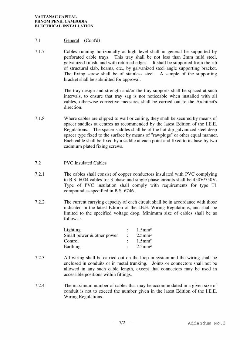
7.1.7 Cables running horizontally at high level shall in general be supported by
perforated cable trays. This tray shall be not less than 2mm mild steel,
galvanized finish, and with returned edges. It shall be supported from the rib
of structural slab, beams, etc., by galvanized steel angle supporting bracket.
The fixing screw shall be of stainless steel. A sample of the supporting
bracket shall be submitted for approval.
The tray design and strength and/or the tray supports shall be spaced at such
intervals, to ensure that tray sag is not noticeable when installed with all
cables, otherwise corrective measures shall be carried out to the Architect's
direction.
7.1.8 Where cables are clipped to wall or ceiling, they shall be secured by means of
spacer saddles at centres as recommended by the latest Edition of the I.E.E.
Regulations. The spacer saddles shall be of the hot dip galvanized steel deep
spacer type fixed to the surface by means of "rawplugs" or other equal manner.
Each cable shall be fixed by a saddle at each point and fixed to its base by two
cadmium plated fixing screws.
7.2 PVC Insulated Cables
7.2.1 The cables shall consist of copper conductors insulated with PVC complying
to B.S. 6004 cables for 3 phase and single phase circuits shall be 450V/750V.
Type of PVC insulation shall comply with requirements for type T1
compound as specified in B.S. 6746.
7.2.2 The current carrying capacity of each circuit shall be in accordance with those
indicated in the latest Edition of the I.E.E. Wiring Regulations, and shall be
limited to the specified voltage drop. Minimum size of cables shall be as
follows :-
Lighting : 1.5mm²
Small power & other power : 2.5mm²
Control : 1.5mm²
Earthing : 2.5mm²
7.2.3 All wiring shall be carried out on the loop-in system and the wiring shall be
enclosed in conduits or in metal trunking. Joints or connectors shall not be
allowed in any such cable length, except that connectors may be used in
accessible positions within fittings.
7.2.4 The maximum number of cables that may be accommodated in a given size of
conduit is not to exceed the number given in the latest Edition of the I.E.E.
Wiring Regulations.
Addendum No.2
VATTANAC CAPITAL
PHNOM PENH, CAMBODIA
ELECTRICAL INSTALLATION
- 7/3 -
7.2 PVC Insulated Cables (Cont'd)
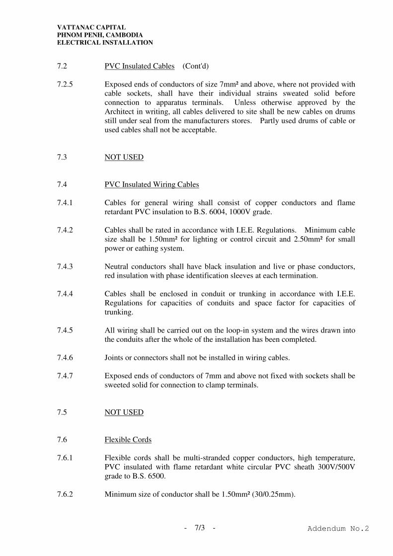
7.2.5 Exposed ends of conductors of size 7mm² and above, where not provided with
cable sockets, shall have their individual strains sweated solid before
connection to apparatus terminals. Unless otherwise approved by the
Architect in writing, all cables delivered to site shall be new cables on drums
still under seal from the manufacturers stores. Partly used drums of cable or
used cables shall not be acceptable.
7.3 NOT USED
7.4 PVC Insulated Wiring Cables
7.4.1 Cables for general wiring shall consist of copper conductors and flame
retardant PVC insulation to B.S. 6004, 1000V grade.
7.4.2 Cables shall be rated in accordance with I.E.E. Regulations. Minimum cable
size shall be 1.50mm² for lighting or control circuit and 2.50mm² for small
power or eathing system.
7.4.3 Neutral conductors shall have black insulation and live or phase conductors,
red insulation with phase identification sleeves at each termination.
7.4.4 Cables shall be enclosed in conduit or trunking in accordance with I.E.E.
Regulations for capacities of conduits and space factor for capacities of
trunking.
7.4.5 All wiring shall be carried out on the loop-in system and the wires drawn into
the conduits after the whole of the installation has been completed.
7.4.6 Joints or connectors shall not be installed in wiring cables.
7.4.7 Exposed ends of conductors of 7mm and above not fixed with sockets shall be
sweeted solid for connection to clamp terminals.
7.5 NOT USED
7.6 Flexible Cords
7.6.1 Flexible cords shall be multi-stranded copper conductors, high temperature,
PVC insulated with flame retardant white circular PVC sheath 300V/500V
grade to B.S. 6500.
7.6.2 Minimum size of conductor shall be 1.50mm² (30/0.25mm).
Addendum No.2

VATTANAC CAPITAL
PHNOM PENH, CAMBODIA
ELECTRICAL INSTALLATION
- 7/4 -
7.7 NOT USED
7.8 PVC Insulated Copper Cored PVC Sheathed Cables
7.8.1 PVC Insulated Copper Cored PVC Sheathed Cables (PVC & PVC) shall be
700V/1000V grade complying to B.S. 6346 multi-core with each conductor of
the same cross sectional area. The cores of these cables shall be high annealed
copper conductors complying with B.S. 6360. The PVC insulated cores shall
be color coded and shall be sheathed with PVC complying with the
requirements for type T1 compound as specified in B.S. 6746.
7.8.2 All PVC shall be flame retardant.
7.8.3 Cables shall be terminated in a gland fitted with a PVC clamp. The gland
body shall be provided with an internal conical seal to receive the PVC sheath
and a clamping nut which shall secure the clamping cone firmly to the PVC
sheath. The spigot on the gland body shall be threaded to suit standard
conduit accessories. A PVC shroud shall be fitted to cover the entire gland
body.
7.8.4 The minimum bending radius shall be not less than eight times the overall
cable diameter.
7.8.5 Where cables are run horizontally, they shall be properly supported on
perforated cable trays and cleated at intervals of not exceeding 2m directly to
the tray. Where cables are run in car parks garages and other protected areas,
they shall be protected with metal trunking. The cable tray and metal
trunking shall be supported with rigid metal brackets.
7.8.6 The Contractor shall be responsible for the off loading and handling of the
cables on site and shall ensure that cables are new and delivered to site on new
drums and properly protected against mechanical damage and loss with the
manufacturers seals still intact. Partly used drums of cable or cable which
has already been used elsewhere shall not be acceptable unless special
approvals is given by the Architect in writing.
7.9 Fire Resistant Cables
7.9.1 NOT USED
7.9.2 The power supply cable for emergency lighting shall be of fire resistant type
and comply with relevant BS standard as follows:-
Emergency Lighting - Category B to BS6387
7.9.3 NOT USED
7.9.4 NOT USED
Addendum No.2
VATTANAC CAPITAL
PHNOM PENH, CAMBODIA
ELECTRICAL INSTALLATION
- 7/5 -
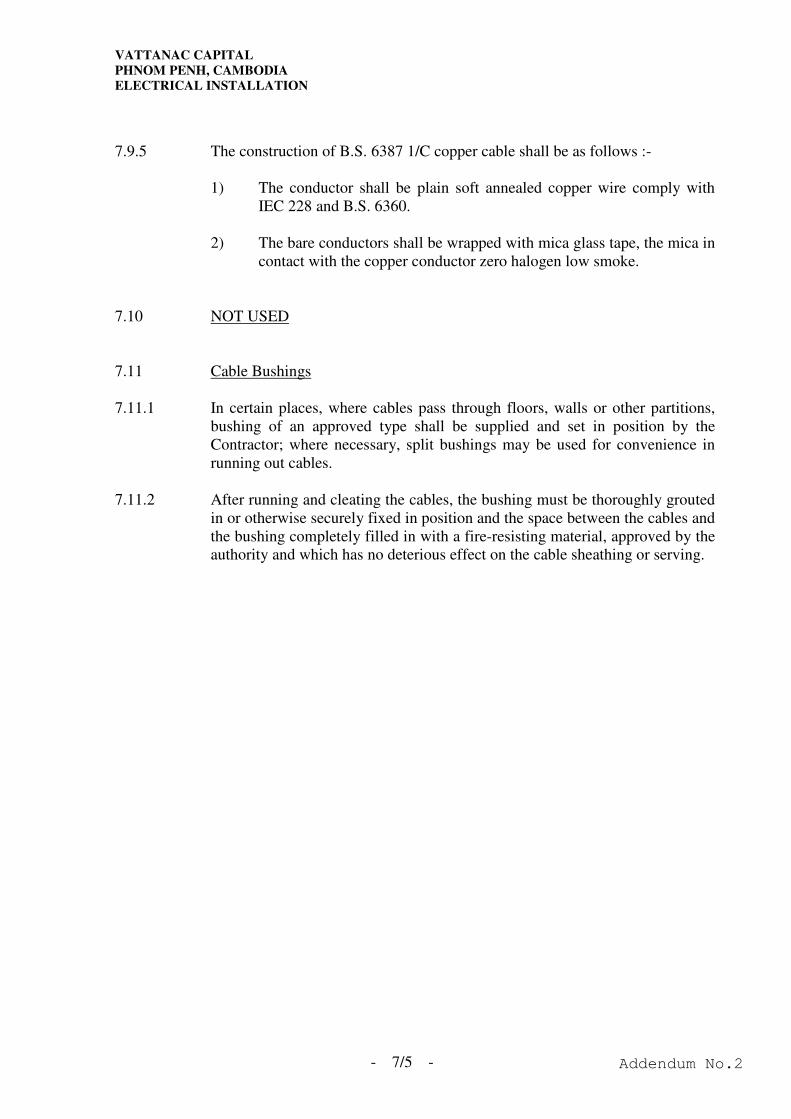
7.9.5 The construction of B.S. 6387 1/C copper cable shall be as follows :-
1) The conductor shall be plain soft annealed copper wire comply with
IEC 228 and B.S. 6360.
2) The bare conductors shall be wrapped with mica glass tape, the mica in
contact with the copper conductor zero halogen low smoke.
7.10 NOT USED
7.11 Cable Bushings
7.11.1 In certain places, where cables pass through floors, walls or other partitions,
bushing of an approved type shall be supplied and set in position by the
Contractor; where necessary, split bushings may be used for convenience in
running out cables.
7.11.2 After running and cleating the cables, the bushing must be thoroughly grouted
in or otherwise securely fixed in position and the space between the cables and
the bushing completely filled in with a fire-resisting material, approved by the
authority and which has no deterious effect on the cable sheathing or serving.
Addendum No.2

VATTANAC CAPITAL
PHNOM PENH, CAMBODIA
ELECTRICAL INSTALLATION
SECTION 7 - CABLES
Addendum No.2
VATTANAC CAPITAL
PHNOM PENH, CAMBODIA
ELECTRICAL INSTALLATION
I N D E X
SECTION 7 - CABLES
Clause Page
7.1 General ......................................................................................................7/1
7.2 PVC Insulated Cables ...............................................................................7/2
7.3 NOT USED ...............................................................................................7/3
7.4 PVC Insulated Wiring Cables ...................................................................7/3
7.5 NOT USED ...............................................................................................7/3
7.6 Flexible Cords ...........................................................................................7/3
7.7 NOT USED ...............................................................................................7/4
7.8 PVC Insulated Copper Cored PVC Sheathed Cables ...............................7/4
7.9 Fire Resistant Cables.................................................................................7/4
7.10 NOT USED ...............................................................................................7/5
7.11 Cable Bushings .........................................................................................7/5
Addendum No.2
VATTANAC CAPITAL
PHNOM PENH, CAMBODIA
ELECTRICAL INSTALLATION
- 8/1 -
SECTION 8 - CONDUITS AND ACCESSORIES, CABLE TRUNKING, CABLE TRAYS
8.1 General
8.1.1 The Contractor shall run all wiring and control circuits in PVC cables in
galvanized steel/PVC conduit and trunking, unless otherwise specified herein
or shown on the Drawings.
8.1.2 All conduit systems shall be installed fully in accordance with the
requirements of the latest Edition of the I.E.E. Regulations for the electrical
equipment in writing.
8.1.3 For surface conduit system, trunkings and cable trays exposed to view (with
the exception in service ducts, meter rooms and false ceiling spaces), all
conduits, trunkings, cable trays, hangers, supports and brackets etc. shall be
painted with two approved high class finishing coat.
8.1.4 All junction boxes located at the public area shall be provided metallic cover.
8.2 G.I. Conduit Systems and Box
8.2.1 All G.I. conduits shall be heavy gauge hot dipped galvanized welded steel
complying with B.S. 4568, Class 4. No conduit shall be of less than 20mm
diameter. All conduit systems shall be installed fully in accordance with
latest edition of IEE Wiring Regulation.
8.2.2 All conduit outlet boxes and junction boxes shall be malleable iron and of
standard circular pattern with spout to B.S. 4568, Class 4.
8.2.3 Standard circular pattern boxes shall be used with conduits up to and including
25mm diameter. Rectangular pattern adaptable boxes shall be used for
conduits of 32mm diameter and larger.
8.2.4 All conduit boxes shall be provided with lids. Gaskets shall be provided
where installed outdoor. Adaptable boxes shall be of mild steel of not less
than 2.50mm with hot dip galvanized finish. Boxes shall be not less than
48mm deep and of such dimensions as will enable the largest size cable, for
which the conduit run is suitable, to be drawn in without excessive bending of
the cables. Lids of the same gauge with brass fixing screws, shall be
provided. All such boxes shall be drilled for holes according to the conduit
entries required.
Addendum No.2
VATTANAC CAPITAL
PHNOM PENH, CAMBODIA
ELECTRICAL INSTALLATION
- 8/2 -
8.2 G.I. Conduit Systems and Box (Cont'd)
8.2.5 Socket outlet boxes shall be constructed of sheet steel, galvanized finish and
shall comply with B.S. 4662. Surface mounting type outlet boxes shall be
cast iron type, hot dip galvanized.
8.2.6 An earthing terminal with brass screw shall be provided in each lighting and
power outlet box.
8.2.8 All conduit entries to adaptable boxes, outlet boxes and switchgear shall be
made with coupling and hexagon male brass bush.
8.2.8 Locally made accessories will not be considered or accepted.
8.2.9 Conduit systems shall be electrically and mechanically continuous and
watertight after installation. They shall be arranged, as far as possible, to be
self-draining to conduit outlet points for equipment. The system when
installed, and before wiring, shall be kept plugged with wooden plugs.
Immediately before wiring, all conduit systems shall be thoroughly swabbed
out until dry and clean.
8.2.10 All sets of bends in conduit runs shall be formed on site in bending machines.
Subject to the approval by the Architect, inspection bends may be permitted at
columns, where large bends shall be avoided. Junction box shall be installed
wherever tee connections exist.
8.2.11 Runs between draw-in boxes shall not have more than two right angle bends
or their equivalent and the length of such runs shall be limited to 12m to
permit easy draw-in of cables.
8.2.12 The Contractor shall make good any damage to the finish of all conduits
(including threads cut at site) by painting two coats of good quality lead paint.
8.2.13 The Contractor's attention is especially drawn to the necessary for keeping all
conduit entirely separate from other piping services and no circuit connections
will be permitted between the conduits and such pipes.
8.2.14 The Contractor shall arrange for a telescopic conduit system to employ where
expansion joints are crossed, however, where conduit is surface mounted on
walls or ceilings, a normal flexible metal conduit shall be used. A separate
earth continuity conductor of a size given by the I.E.E. Regulations shall be
installed between the boxes on either side of the expansion joint.
8.2.15 The minimum size of the earth continuity conductor shall be 2.50mm².
8.2.16 All conduits systems shall be installed so as to enable wiring to be carried out
on the "loop-in" system.
Addendum No.2
VATTANAC CAPITAL
PHNOM PENH, CAMBODIA
ELECTRICAL INSTALLATION
- 8/3 -
8.2 G.I. Conduit Systems and Box (Cont'd)
8.2.18 Flexible steel conduits shall comply with B.S. 831 : Part 1. A separate
protective conductor shall be provided in the flexible conduit to ensure
electrical continuity of the whole conduit system. In outdoor or moist areas,
the pliable conduit shall be of the metallic watertight pattern, PVC
oversheathed to IP54 (B.S. 5490). All pliable conduits shall be of
"ADAPTAFLEX" manufacture or approved equivalent and shall only used
only be used to final connections to equipment unless otherwise specified.
8.3 PVC Conduit System and Box
8.3.1 Rigid plain PVC conduits and conduit fittings shall be used for all concealed
conduit installation and installation inside false ceiling voids except return air
plenum. PVC conduit and fittings comply with B.S. 4608 : Part 1 and B.S.
6099 : Section 2-2. Conduits shall be type 'A', i.e. they shall be suitable for
installation, storage or transport at temperatures not normally below minus
5ºC. (Couplers shall be of the slip-type).
8.3.2 Pliable conduits shall be formed of self extinguishing plastic material and shall
comply with B.S. 4608 : Part 3, classification type A. Conduits may be
corrugated, plain, or re-inforced. Pliable conduits shall not be used in
situations where they would be subjected to continuous flexing.
8.3.3 Adaptable boxes and boxes for the enclosure of electrical accessories shall be
made from insulating materials and shall comply with B.S. 4662. The
dimensions of the plastic boxes shall be such that they can be interchangeable
with steel boxes. The minimum wall thickness of boxes shall be 2mm.
Boxes for the suspension of luminaires or other equipment, where
considerable heat will be produced, shall be fitted with steel insert clips.
Plastic boxes shall not be used in situations where the temperature of the box
is likely to exceed 60ºC or where the mass suspended from the box exceeds
3kg.
8.3.4 Conduit bends shall have an internal radius of at least 4 times the outside
diameter of the conduit.
8.3.5 The method of carrying out the conduit bends, conduit joints, fixing conduits
to boxes without spouts, and the tools and materials to be used shall be as
recommended by the manufacturer of the conduits.
8.3.6 A green/yellow PVC insulated cable shall be drawn into the conduit or
trunking system to serve as the circuit protective conductor (CPC), the
cross-sectional area of which shall comply with the IEE Wiring Regulations
for the size of the largest live conductors enclosed.
Addendum No.2
VATTANAC CAPITAL
PHNOM PENH, CAMBODIA
ELECTRICAL INSTALLATION
- 8/4 -
8.3 PVC Conduit System and Box (Cont’d)
8.3.8 Due allowance shall be made for the expansion of the PVC tubing at high
temperatures. Expansion coupling or other fittings shall be included in a
straight run of 8m or more. Saddles or clips shall be of sliding fit.
8.4 Cable Trunking
8.4.1 Cable trunking shall be manufactured in minimum lengths of 1.8m from a
minimum of 1.50mm hot dipped galvanized sheet steel. Covers shall be of
the quick-fix pattern with centre captive screw type. Any fixing arrangement
employing self-tapping screws shall not be accepted. Trunking shall be
terminated with end flanges; which shall be bolted directed to distribution
boards or other apparatus. Connecting pieces shall be used to connect
together runs of trunking and shall employ special connecting pieces using
cadmium plated mushroom head steel screws, nuts and shakeproof washers to
give the trunking run connector rise.
Each joint shall have a copper bond bolted to each adjacent trunking to ensure
electrical continuity. All frayed and sharp edges shall be removed from
trunking before installation and control to prevent rust forming. Trunking
support shall be painted with two layers of undercoat and finished with a coat
of galvanised paint.
8.4.2 Conduit entry to trunking shall be by galvanized coupling and brass male bush
with serrated steel washer. Knockouts shall not be provided, and trunking
shall be drilled on site.
8.4.3 In instances where the Contractor elects to use trunking to avoid a multiplicity
of conduits following the same run, cables shall be installed so that a space
factor of 40% is not exceeded and grouping factors as defined in the latest
Edition of the I.E.E. Wiring Regulations is observed.
8.4.4 The trunking system shall be erected complete and thoroughly cleaned out
before any cables are drawn in.
8.4.5 Where trunking crosses expansion joints, a trunking system shall be used
which will allow for expansion and maintain earth continuity. The system
used shall be approved by the Architect prior to it being used.
8.4.6 Where trunking is turned through an angle exceeding 45º. A special fitting
shall be selected to allow a slow bend for cables.
8.4.8 All cables within the trunking shall be bunched at intervals of 3m for
horizontal runs and 1m for vertical runs. Cables installed in vertical trunking
shall be supported by steel pins fixed inside the trunking at intervals not
greater than 3m.
Addendum No.2
VATTANAC CAPITAL
PHNOM PENH, CAMBODIA
ELECTRICAL INSTALLATION
- 8/5 -
8.4 Cable Trunking (Cont'd)
8.4.8 All horizontal runs of trunking shall be fitted with cable retention straps to
prevent cables dropping down from the trunking when additional wiring is
being installed from the side or bottom of the enclosure.
8.5 Cable Trays
8.5.1 Where cable trays are employed to support cables running horizontally at high
level, they shall be perforated trays manufactured from not less than 2mm
gauge mild steel with return edge which shall be hot dipped galvanized to a
conduit Class 4 finish. Before installation of the cables, cable tray supports
shall be painted with 2 layers of undercoat and finished with a coat of
galvanised paint. Trays shall be supported from the ribs of structural slab,
beams etc., by galvanized and painted mild steel rods, at intervals of not more
than 1.2m and not more than 225mm from bends and intersections.
8.5.2 Cables mounted on the trays shall laid after installation of the tray in and
spaced in accordance with the latest edition of the I.E.E. Regulations so as not
to incur group factor derating unless otherwise specified. Cables shall be
grouped in circuits and individually supported at intervals of not less than 3m
lengths on horizontal runs and 1m lengths on vertical runs, using a proprietary
cable clamp support system.
Notwithstanding the minimum gauge of metal-work specified, gauges shall be
of sufficient strength to ensure that sagging between supports is not acceptable.
If sagging is noticeable, the Contractor shall at his own cost provide the
necessary extra supports, stiffeners, tray, etc., to correct the tray sag to the
satisfaction of the Architect.
8.5.3 Where trays are used in corrosive atmosphere or exposed to the weather, the
tray shall be as specified above but shall be coated with epoxy resin. PVC
coating is not acceptable.
Addendum No.2
VATTANAC CAPITAL
PHNOM PENH, CAMBODIA
ELECTRICAL INSTALLATION
SECTION 8 - CONDUITS AND ACCESSORIES,
CABLE TRUNKING, CABLE TRAYS
Addendum No.2
VATTANAC CAPITAL
PHNOM PENH, CAMBODIA
ELECTRICAL INSTALLATION
I N D E X
SECTION 8 - CONDUITS AND ACCESSORIES, CABLE TRUNKING, CABLE TRAYS
Clause Page
8.1 General ......................................................................................................8/1
8.2 G.I. Conduit Systems and Box..................................................................8/1
8.3 PVC Conduit System and Box..................................................................8/3
8.4 Cable Trunking .........................................................................................8/4
8.5 Cable Trays ...............................................................................................8/5
Addendum No.2
VATTANAC CAPITAL
PHNOM PENH, CAMBODIA
ELECTRICAL INSTALLATION
- 9/1 -
SECTION 9 - LUMINAIRES
9.1 General
9.1.1 The Contractor shall supply, install, commission, testing and set to work a
complete lighting scheme in accordance with the luminaire schedule drawings,
and this Specification.
9.1.2 The types of luminaires and the suggested manufacturer's name and model
numbers are set out in the luminaire schedule as shown on the Drawings.
9.1.3 The Contractor shall note that the luminaires required for this Project have
been carefully selected to match the function, appearance and finish of the
building, and therefore, unless written approval is given by the Architect, the
use of luminaires of a different make will not be allowed.
9.1.4 All components within the same luminaire shall be of the same manufacturer
to ensure compatibility of the components.
9.1.5 All luminaires and components shall be suitable for use in temperature and
ambient conditions that will exist in various parts of the building complex; it is
assumed that the ambient temperatures will rise to 40ºC and the relative
humidity will rise to 99%.
9.1.6 All luminaires shall be suitable for 220V ±6% single phase at 50Hz ±2%.
9.1.7 All luminaires and components shall comply with the appropriate B.S. or C.P.
or an approved equivalent international standard.
9.1.8 The construction and internal wiring of the luminaires shall comply with the
latest I.E.E. wiring regulations and local authorities.
9.1.9 NOT USED
9.1.10 The following information shall be provided with the technical submission:-
a) Details of luminaires being offered, including three copies of the
respective colourful catalogues fixing detail and full photometric data
for each type.
b) Complete electrical characteristics of luminaires and tubes including
total circuit watts, power factor, colour temperature, current
consumption, harmonic content, control gear looses, etc..
Addendum No.2
VATTANAC CAPITAL
PHNOM PENH, CAMBODIA
ELECTRICAL INSTALLATION
- 9/2 -
9.2 Lighting Control
9.2.1 Unless local lighting switch is provided, each lighting circuit shall be provided
with lighting switch adjacent to the corresponding MCB board. Facilities for
remote ON/OFF control via Central Building Monitoring Consoles where as
shown on the drawings shall be provided.
9.2.2 The perimeter lighting fitting in the office area as specified in the Drawing
shall be provided with standalone lighting sensors and dimmable electronic
ballast to provide top-up control to maintain the lux level on working plan at
the design value by dimming the lights.
9.2.3 The standalone lighting sensor shall be a light sensing device, meant to be
integrated into the lighting fitting and adding a regulating function in
combination with a regulating ballast.
9.2.4 The standalone lighting sensor shall be clicked on to the lighting fitting
using a special clip. It shall be clicked to the end of the reflector or on the
lamp using a special bracket.
9.2.5 The standalone lighting sensor shall be able to control up to 20 regulating
electronic ballasts and shall be manually adjusted by a rotating diaphragm
in order to adjust the setpoint.
9.2.6 The standalone lighting sensor shall be optimized for use in application
with approx. 300 lux. Controller shall be connected to the 1 -10VDC
control input of the ballast.
9.2.7 The dimmable electronic ballast shall satisfactory over a wide range from 1%
to 100% light level for T5 fluorescent lamp and 3% to 100% for compact
fluorescent lamp. And the electronic ballast can operated on 220V-240V a.c.;
50/60 Hz single phase supply, and suitable for dimming control.
9.3 Control Gear
9.3.1 All electrical control gear shall be totally built into the luminaire assembly,
and shall provide for switch operation. Ballasts shall be designed to suit
local supply of 220V ±6%, single phase at 50 Hz ±2%, and shall comply with
BSEN 60920 and BSEN 60921. Power factor correction capacitors shall be
provided to correct the power factor for each luminaire to not less than 0.95
lagging two hours after it has operated continuously on site. The capacitors
shall comply with BSEN 61049 and BSEN 61049 and shall be of metallized
polypropylene strips wound onto cylindrical formers. The capacitors shall be
rated to operate at not less than 95ºC and shall be mounted not less than 75mm
from any ballasts. Capacitors shall be connected in parallel with ballasts and
tubes.
Addendum No.2

VATTANAC CAPITAL
PHNOM PENH, CAMBODIA
ELECTRICAL INSTALLATION
- 9/3 -
9.3 Control Gear (Cont’d)
9.3.2 Control gear and wiring assemblies shall be sprayed with an approved
non-hardening lacquer coating to prevent the ingress of water moisture. All
control gear, tube, fixtures and accessories shall be of the same manufacture as
the luminaire. Locally made components will not be accepted.
9.3.3 Lamp holders shall comply with BSEN 60400, BSEN 60061 and BSEN
60061-3, and shall be non-inflammable and non-conductive when installed,
the lamp holders shall be adjustable to allow manufacturing tolerance (within
the manufacturer's specification) in the length of lamps.
9.4 Electronic Ballasts
9.4.1 Electronic ballasts shall be manufactured and tested in compliance with BSEN
60929 and BSEN 60929. They shall be of pre-heat start type, operate lamps
at frequency of 40kHz or higher in compliance with BSEN 61547, silent in
operation and flicker-free in light output.
9.4.2 The electronic ballasts shall be suitable for local supply of 220V ±6% 50Hz
single phase. They shall maintain constant at least 95% of full light output
from fluorescent lamps within 2 seconds after the luminaries are switched on.
9.4.3 The total harmonic distortion of the electronic ballasts shall comply with
BSEN 61000-3-2 and shall not exceed 6%. The overall power factor of the
luminaries shall not be less than 0.95 lagging. The ballast’s case temperature
shall not exceed 65ºC when ambient temperature at 40ºC. The services life
of the electronic ballast shall not be less than 50,000 hours at maximum case
temperature and the failure rate shall be less than 1% per 4,000 hours at
maximum case temperature.
9.5 Wiring
9.5.1 Intercomponent wiring shall be in 105ºC 450V flame retardant PVC and shall
be neatly secured within the luminaire to prevent undue looseness and contact
with ballasts. The only joints made shall be at the fused terminals block
provided on the fitting, which shall be fitted with B.S. cartridge fuse and shall
accept loop 2.5mm² P.V.C. insulated wiring.
9.5.2 Where wiring passes through or past the edge of any metal section of the
fitting, it shall be protected by an approved grommet, and be doubly insulated.
All wiring shall be concealed from view with the luminaire installed.
Earthing of each fitting shall be made via the 20mm conduit entry.
Addendum No.2
VATTANAC CAPITAL
PHNOM PENH, CAMBODIA
ELECTRICAL INSTALLATION
- 9/4 -
9.6 Fluorescent Tube
9.6.1 Tubular fluorescent lamps shall comply with B.S. 1953 and BSEN 60091.
All fluorescent tubes shall be of energy saving type suitable for bipin (G13)
end cap lamp holder and shall operate at approximately colour temperature of
3500K and approved by the Architect.
9.6.2 Multi-lamp luminaire shall have lamps spaced symmetrically at the centre-line
of the unit. After the complete luminaire has been in operation for three
hours in a draught-free room having an ambient temperature of 25ºC, the
surface temperature of all lamps, measured at the centre bottom of the tube,
shall not exceed 40ºC.
9.7 Batten Fluorescent Luminaires
9.7.1 These luminaires shall be either single or twin type, and shall be installed in
switchrooms, plant rooms, corridor, or, etc.. They shall be 600mm, 1,200mm
or 1500mm fluorescent type, unless otherwise shown on the Drawings.
9.7.2 The luminaires shall be mounted directly on the ceiling unless otherwise
indicated or obscured by structure or other equipment.
Addendum No.2
VATTANAC CAPITAL
PHNOM PENH, CAMBODIA
ELECTRICAL INSTALLATION
- 9/5 -
9.8 NOT USED
9.9 Weather-Proof Luminaires
9.9.1 The luminaire shall be classified, as a minimum requirement to IEC 60599-1,
Class I and ingress protection shall be at least IP54 to IEC 60529.
9.9.2 The luminaire shall be supplied as a complete set comprising the main part,
reflector/gear tray, diffuser, ballast, starter and starter-holder, power factor
correction capacitor, bi-pin lampholder, integral earth terminal and internal
wiring.
9.9.3 The main part of the luminaire shall be a one piece moulded polycarbonate of
glass fibre reinforced plastic finished in light grey colour. The mounting face
of the main part shall be framed with a knockout for back entry and holes for
mounting screws. The two ends of the main part shall each be provided with
a hole for conduit entry which shall be sealed with a suitable plastic plug.
9.9.4 The reflector/gear tray shall be made of substantive sheet steel pretreated and
finished coated in gloss white stoved enamel or epoxy powder. It shall be of
one continuous piece formed and suitable shaped to give adequate mechanical
strength. The ballast, power factor correction capacitor, starter-holders and
bi-pin lampholders shall be conveniently positioned and securely fixed onto
the tray.
9.9.5 The reflector/gear tray shall be securely mounted to the main part by screws or
other suitable means which shall remain captive with the main part or the tray
when the tray is detached from the main part. In the detached position, the
tray shall be securely trapped or hinged to the main part.
9.10 NOT USED
9.11 Emergency Fluorescent Fitting
9.11.1 Some fluorescent fittings inside the office, corridor and elsewhere as shown
on drawings shall be equipped with additional battery power to provide
illumination during power failure and to maintain lighting for at least two
hours.
9.11.2 The control unit shall be integrated with the light fitting and shall contain all
the necessary components and accessories required for the specified duties
above. Batteries shall be Ni-Cd, totally sealed type. The control circuits
shall be suitable for use at 220V ±10% and shall be designed to enable the
light fittings to operate in the same manner as normal conventional lighting
fittings.
Addendum No.2
VATTANAC CAPITAL
PHNOM PENH, CAMBODIA
ELECTRICAL INSTALLATION
- 9/6 -
9.11 Emergency Fluorescent Fitting (Cont’d)
9.11.3 Irrespective of the status of the wall switch when the supply fails, the same
fitting shall automatically illuminate or remain illuminated.
9.11.4 The control circuit shall be designed to monitor the battery during periods of
discharge and shall incorporates a voltage cut-out to prevent deep discharge of
the battery. A normally discharged battery shall complete recharged within
24 hours of mains being continuously restored.
9.11.5 Under normal supply condition, the circuit shall remain trickle charge and
inactive. A circuit switch shall be incorporated in the control circuit to enable
testing of the circuit to be carried out. A red neon light shall be provided to
show "mains supply healthy" and charge circuit complete".
9.11.6 All emergency luminaire shall comply with BSEN 60599.
9.12 NOT USED
9.13 NOT USED
9.14 NOT USED
9.15 Recessed Fluorescent Luminaires
9.15.1 The luminaire shall be designed to comply with B.S. 4533 with electrical
Class 1 & IP 20 protection rating for indoor purpose.
9.15.2 The luminaires shall be supplied as a complete set comprising the sheet metal
housing, double parabolic louvre, 220V 50 Hz ballast, starter and starter
holder, power factor correction capacitor, bi-pin lampholder with box at both
ends, integral terminal block for 3 x 2.5mm² conductors, radio-interference
suppressor and heat-resistant internal wiring.
9.15.3 The luminaire housing shall be made of sheet steel with welded construction
and white enamelled finish. The depth of the housing shall not exceed
100mm and designed for low headroom false ceiling.
9.15.4 The double-parabolic louvre shall be made of highly-specular aluminium, matt
anodised. Louvre design complies with CIBSE LG3 Cat. 1 & Cat. 2 for
better glare control within VDT medium tasks office environment. It is fixed
to the housing with precision spring clips for accurate positioning of the
louvre even after may times of louvre removal. The precision spring clips
can also be used to hold the louvre during relamping. All electrical
components are enclosed by the louvre.
Addendum No.2
VATTANAC CAPITAL
PHNOM PENH, CAMBODIA
ELECTRICAL INSTALLATION
- 9/7 -
9.16 Delivery of Luminaires
9.16.1 In view of the limited area, the Contractor shall ensure that an area is available
on site prior to delivery and that they are delivered in a scheduled manner
dictated by the construction programme. An appropriate area will be
designated by the Main Contractor for this purpose, and the Contractor shall
ensure that all luminaires to be delivered are well protected in seal crates or
other suitable packing Before delivery to the Site, the Contractor shall inspect
the space nominated for his storage, and shall confirm to the Main Contractor
that the area is sufficient and suitable for proper safe storage and such that no
damage to the materials will occur, whilst held in store before installation.
9.16.2 The Contractor is responsible for the delivery of materials from the store area
to the upper floors as they are required.
9.16.3 The Contractor is also responsible for immediate removal from site of all
packing debris, crates, etc.. In no circumstances will waste material of an
inflammable nature be allowed in accumulate in the building.
9.17 Emergency Fluorescent Lighting Conversion Units Modules
9.17.1 Emergency Fluorescent Lighting Conversion Units shall be in accordance with
BSEN 60924 and BSEN 60925. The conversion unit should be with the type
test certificate by International Accredit Testing Laboratory. BSEN 60924 is
the specification for General and safety requirements for D.C. supplied
electronic ballasts for tubular fluorescent lamps. BSEN 60925 is the
specification for Performance requirements for D.C. supplied electronic
ballasts for tubular fluorescent lamps.
9.17.2 Emergency Fluorescent Luminaires shall be of the self-contained maintained
type. Maintained type luminaires are energized at all times when normal of
emergency lighting is required. The self-contained system comprises the
luminaires with a built-in isolating transformer charging devices, an automatic
changeover switch, a solid-state inverter circuitry and a maintenance-free
nickel cadmium rechargeable battery pack. The self-contained luminaire
requires a permanent power supply to keep the battery fully charged at all
times.
9.17.3 The charging system shall be capable of recharging the battery to full capacity
with 24 hours after a total discharge of the battery unit.
9.17.4 The red LED is normally continuously lit but goes out if the mains supply
charger or the battery fails.
9.17.5 The circuit shall be suitable for use at 220V +6%, -10%. The
charger-inverter and the battery pack connected with the polarised plug and
socket.
Addendum No.2
VATTANAC CAPITAL
PHNOM PENH, CAMBODIA
ELECTRICAL INSTALLATION
- 9/8 -
9.17 Emergency Fluorescent Lighting Conversion Units Modules (Cont’d)
9.17.6 All emergency fluorescent luminaires shall be fitted with a balanced nickel
cadmium battery, a static inverter and fully automatic recharge/control
facilities. The luminaires shall be provided with an integral test switch for
simulating failure of the normal supply. Manually operated test switches
shall be self-resetting.
9.17.7 The system is confirmed to provide minimum 2 hours emergency duration
upon mains failure.
9.17.8 All fluorescent lamp tubes in any emergency luminaires shall each have the
50% lumen output upon mains failure throughout the 3-hours discharge period.
The emergency lumen output for each fluorescent lamp should read as
follows:-
a) 600mm 19/20W tube : >300 lumen
b) 1200mm 36/40W tube : >530 lumen
c) 1500mm 59/65W tube : >650 lumen
9.18 Installation
9.18.1 All luminaires shall be adequately supported in accordance with
manufacturer's recommendations and to the approval of the Architect. In all
practical cases, all fittings shall be suspended independently.
9.18.2 All wiring connection to luminaires shall be installed in conduits.
9.18.3 The Contractor shall include for adapting conduit terminations to suit the
specified luminaire and method of installation.
9.18.4 Final connections to luminaires in areas of suspended ceilings shall be in
flexible conduit bonded by male brass bush and serrated washer direct to
luminaire or by C.R. box fixed to luminaire.
9.18.5 Prior to commencement of site works installation drawings incorporating the
manufacturer's recommendations shall be submitted for approval complete
with all fixing details, suspensions and supports.
9.18.6 Fluorescent luminaires shall be independently suspended from the soffit or
ceiling by adjustable brackets to the approval of the Architect. In areas
without suspended ceilings, luminaires shall be supported on conduit
suspensions painted to match the ceiling finish.
Addendum No.2
VATTANAC CAPITAL
PHNOM PENH, CAMBODIA
ELECTRICAL INSTALLATION
- 9/9 -
9.19 Ductwork and Fittings for Light Troffer Diffusers
9.19.1 Manufacture
9.19.1.1 All diffusers shall be fully imported. Local made products will not be
accepted.
9.19.2 Selection
9.19.2.1 All ductwork, fittings, accessories, joints and jointing materials shall be
suitable for the service and shall not deteriorate due to atmospheric action.
9.19.2.2 All duct sizes shown on the Drawings are clear internal sizes unless otherwise
noted and due allowance shall be made for the thicknesses of internal or
external linings when dimensioning ductwork and selecting fittings and
accessories.
9.19.3 Standards
9.19.3.1 All ductwork and fittings shall comply with the appropriate British Standards,
as listed in the relevant Clause of this Section, or an approved equivalent
international standard.
9.19.3.2 All ductwork, fittings and materials shall comply with the standards of the
Ductwork Group of the Heating and Ventilating Sub-Contractors' Association
of the U.K. (HVCA).
9.19.3.3 In particular the materials, construction and installation of all sheet metal
ductwork and fittings shall be in accordance with the HVCA "Specification
for Sheet Metal Ductwork DW/144 : latest edition."
9.19.3.4 Where any part of the installation shown on the Drawings is not covered by
the HVCA Specifications, then the standard of the Sheet Metal and Air
Conditioning Sub-Contractors' National Association of the U.S.A. (SMACNA)
shall apply for either high velocity or low velocity systems as appropriate.
9.19.3.5 Where any part of the installation shown on the Drawings is not covered by
either the HVCA or SMACNA standards, then reference shall be made to the
Architect for approval of materials and methods prior to installation.
9.19.3.6 All ductwork and materials including linings, adhesives, flexible connections,
gaskets, sealants, fibreglass boards, etc., shall fully comply with all
requirements of the local F.S.D. and shall satisfy C.P. 413 : 1975 in respect of
resistance to penetration of fire and spread of flame and smoke.
Addendum No.2
VATTANAC CAPITAL
PHNOM PENH, CAMBODIA
ELECTRICAL INSTALLATION
- 9/10 -
9.19.3 Standards (Cont’d)
9.19.3.7 Particular care shall be taken with all ductwork in return air plenums. It shall
comply with all the relevant local F.S.D. requirements. All materials to be
used within the plenum shall be submitted for approval accompanied by
certification by an authorized body that they meet the local F.S.D. and British
Standards with regard to combustibility.
9.19.4 Materials
9.19.4.1 Generally, all ductwork shall be of hot dipped galvanized steel sheet to B.S.
2989 : 1975, Grade Z27, coating type 'C' as specified in DW/144.
9.19.5 Sheet Thickness
9.19.5.1 Thicknesses of sheet metal in ductwork systems shall be as recommended in
DW/144 for the appropriate pressure class. Unless otherwise stated in this
Specification or Drawings.
9.19.6 Diffuser
9.19.6.1 All air supply, return fittings shall be provided of the types and duties shown
on the Drawings.
9.19.6.2 Where linear supply and return diffusers are shown on the Drawings, then the
return fittings shall be of the same type and pattern as the supply fittings.
9.19.6.3 Before any diffusers, etc., are ordered or manufacture of fittings commences,
confirmation must be obtained from the Architects as to exact position and
finish of fittings required. Samples of every type of diffusers shall be
submitted to the Architects for approval before orders are placed.
9.20 Insulation for Light Troffer Diffusers
9.20.1 Manufacture
9.20.1.1 All materials supplied of the same type shall be supplied by a single
manufacturer to ensure uniformity of standards and appearance.
9.20.1.2 All materials delivered to site shall be new, and where appropriate, colour
coded and labelled at the factory to identify different grades, sizes and types.
9.20.1.3 All fibreglass insulation shall be as manufactured by Fibreglass
(Owens/Corning), or an approved equal.
Addendum No.2
VATTANAC CAPITAL
PHNOM PENH, CAMBODIA
ELECTRICAL INSTALLATION
- 9/11 -
9.20.2 Submissions
9.20.2.1 Before ordering any insulating materials, the Contractor shall state the
co-efficient of thermal conductivity for each of the materials being supplied
for the Works, and shall allow for all costs in connection with carrying out
tests on representative samples (of each material) taken at Site and/or at
makers' works as directed by the Architect and tested in accordance with the
methods laid down in British Standards. In the event of the test results not
being in the Architect's opinion satisfactory, the Architect shall have the right
to order the removal and replacement of all material represented by the
unsatisfactory samples.
9.20.3 Selection
9.20.3.1 The Contractor shall select all insulating materials from types suitable for the
surfaces to which they are applied and for the environmental conditions in
each area.
9.20.3.2 No asbestos based insulation shall be used.
9.20.4 Standards
9.20.4.1 All materials and techniques used shall be of the highest commercial standard
and shall comply with British Standards where applicable in particular with
regard to definition, physical characteristics and tests for thickness.
9.20.4.2 All equipment and materials used shall be fire resistant and shall comply with
the requirements of the NFPA and the Local Fire Services Department.
9.20.4.3 Insulation shall comply with provisions of B.S. 1334 and B.S. 5422 as
appropriate.
9.20.4.4 Combustion rating of materials shall not be inferior than the following when
tested in accordance with ASTM E84, NFPA Standard 255 or UL No. 723 :-
a) Flame spread : -25
b) Smoke development : -0
c) Fuel contribution : -20
Addendum No.2
VATTANAC CAPITAL
PHNOM PENH, CAMBODIA
ELECTRICAL INSTALLATION
- 9/12 -
9.20.5 Insulation Classes
9.20.5.1 Table 9.20A lists the insulation classes for the various systems and equipment
which require to be insulated as part of the Works. These classes are referred
to in the various Tables of Standards and Specifications used in this Section.
9.20.6 Insulation Materials and Finishes
9.20.6.1 Table 9.20B lists the insulation thickness, materials codes and classes of
finishes for the various classes of insulation.
9.20.6.2 Table 9.20C lists the materials and application techniques to be used for the
various material codes listed in Table 9.20B.
9.20.7 Extent of Insulation
9.20.7.1 Where a ductwork system or item of equipment is listed in the schedules in
this Section or otherwise requires to be insulated, then the entire system or
item shall be insulated to prevent condensation and reduce heat loss or gain.
9.20.7.2 All internal lining shall perform both as thermal insulation and acoustic
insulation which traps noise and dissipates it within the fibre matrix. The
inert fibreglass shall not deteriorate or provide sustenance for vermin or
rodents and it shall not corrode the metal it insulates. Fibres on the air
stream surface shall be strongly bonded and coated to protect against air
erosion.
Addendum No.2
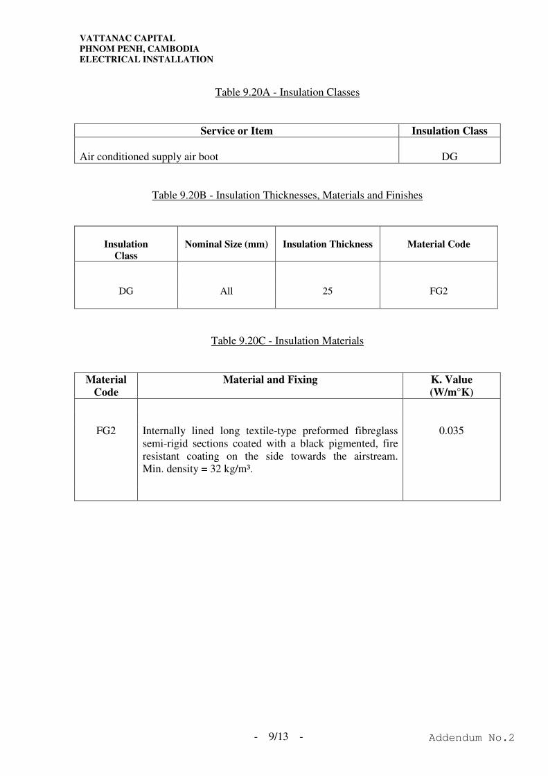
VATTANAC CAPITAL
PHNOM PENH, CAMBODIA
ELECTRICAL INSTALLATION
- 9/13 -
Table 9.20A - Insulation Classes
Service or Item Insulation Class
Air conditioned supply air boot DG
Table 9.20B - Insulation Thicknesses, Materials and Finishes
Insulation
Class
Nominal Size (mm)
Insulation Thickness
Material Code
DG All 25 FG2
Table 9.20C - Insulation Materials
Material
Code
Material and Fixing K. Value
(W/m°K)
FG2 Internally lined long textile-type preformed fibreglass
semi-rigid sections coated with a black pigmented, fire
resistant coating on the side towards the airstream.
Min. density = 32 kg/m³.
0.035
Addendum No.2
VATTANAC CAPITAL
PHNOM PENH, CAMBODIA
ELECTRICAL INSTALLATION
- 9/14 -
9.20.8 Installation
9.20.8.1 The Contractor shall allow for all thermal insulation, fixings and any other
materials or labour required for the complete insulation and finishing of all
materials installed under this Sub-Contract.
9.20.8.2 All insulation shall be supplied and applied by the skilled workmen of a
Specialist Contractor whose name shall be submitted for approval prior to
entering the Contract. Approval by the Architect shall in no way absolve the
Contractor of his responsibility for compliance with this Specification.
9.20.8.3 All materials including the thermal insulation itself, together with adhesives,
paint, bands, sheeting, etc., shall be supplied with a reasonable margin for
cutting, wastage and making good damage and loss. All materials shall be
stored in a suitable manner so as to protect them from damage or deterioration
before fixing.
9.20.9 Application of Insulation
9.20.9.1 All insulation shall be applied so as to give a smooth, homogeneous and
lineable surface. All rigid sections shall be concentric, and accurately
matched for thickness. Steps and undulations in the surfaces shall not be
acceptable. Any sections or slabs having damaged ends or edges shall be
rejected.
9.20.9.2 All insulation shall fit tight to surfaces to be covered, and all slabs and
sections shall be built up close, butting edges being mitred, chamfered or
shaped as necessary. Any minor interstices left in insulation shall be filled
and sealed.
9.20.9.3 Insulation shall be applied to clean and dry surfaces, free of foreign material
such as oil, grease, rust, scale or dirt.
9.20.9.4 Any surface to be insulated, which shows any signs or rusting or damage shall,
prior to insulating, be thoroughly scraped and wire brushed as necessary to
remove all rust, scale, etc.. Surfaces shall then be solvent cleaned to remove
all oil, grease and dirt prior to the application of a coat of primer.
Addendum No.2
VATTANAC CAPITAL
PHNOM PENH, CAMBODIA
ELECTRICAL INSTALLATION
- 9/15 -
9.20.9 Application of Insulation (Cont'd)
9.20.9.5 Where thermal insulation is applied to rectangular ductwork, it shall be glued
to the clean duct surface with an approved adhesive and held firmly in place
by means of spot welded pins or plastic pins glued to the duct face.
9.20.9.6 Only clean and dry insulation shall be used. Insulation shall generally be
applied in accordance with the manufacturers' recommendations.
9.20.9.7 A complete sealed vapour barrier shall be provided for all insulation on cold
surfaces. The vapour barrier shall be sealed around all hangers or other
projections through the insulation.
9.20.9.8 Continuous insulation shall be provided through all sleeves and insulation
joints shall be staggered with respect to joints on the associated ductwork
systems.
9.20.9.9 For continuous adhesion of aluminium foil sealing tape, an approved coating
such as Fosters 85 - 75 ADHESIVE shall first be applied to the bonding
surface. All excess adhesive shall be cleaned off.
Addendum No.2

VATTANAC CAPITAL
PHNOM PENH, CAMBODIA
ELECTRICAL INSTALLATION
SECTION 9 - LUMINAIRES
Addendum No.2
VATTANAC CAPITAL
PHNOM PENH, CAMBODIA
ELECTRICAL INSTALLATION
I N D E X
SECTION 9 - LUMINAIRES
Clause Page
9.1 General ......................................................................................................9/1
9.2 Lighting Control........................................................................................9/2
9.3 Control Gear..............................................................................................9/2
9.4 Electronic Ballasts.....................................................................................9/3
9.5 Wiring .......................................................................................................9/3
9.6 Fluorescent Tube.......................................................................................9/4
9.7 Batten Fluorescent Luminaires .................................................................9/4
9.8 NOT USED ...............................................................................................9/5
9.9 Weather-Proof Luminaires........................................................................9/5
9.10 NOT USED ...............................................................................................9/5
9.11 Emergency Fluorescent Fitting .................................................................9/5
9.12 NOT USED ...............................................................................................9/6
9.13 NOT USED ...............................................................................................9/6
9.14 NOT USED ...............................................................................................9/6
9.15 Recessed Fluorescent Luminaires .............................................................9/6
9.16 Delivery of Luminaires .............................................................................9/7
9.17 Emergency Fluorescent Lighting Conversion Units Modules ..................9/7
9.18 Installation.................................................................................................9/8
9.19 Ductwork and Fittings for Light Troffer Diffusers ...................................9/9
9.20 Insulation for Light Troffer Diffusers .......................................................9/10
Addendum No.2

VATTANAC CAPITAL
PHNOM PENH, CAMBODIA
ELECTRICAL INSTALLATION
Addendum No.2

VATTANAC CAPITAL
PHNOM PENH, CAMBODIA
ELECTRICAL INSTALLATION
SECTION 10 – NOT USED
Addendum No.2
VATTANAC CAPITAL
PHNOM PENH, CAMBODIA
ELECTRICAL INSTALLATION
Addendum No.2
VATTANAC CAPITAL
PHNOM PENH, CAMBODIA
ELECTRICAL INSTALLATION
- 11/1 -
SECTION 11 - ACCESSORIES AND SUPPLY EQUIPMENT
11.1 General
11.1.1 All electrical accessories along corridors shall have metallic front plate.
11.1.2 All electrical accessories shall be labelled with circuit number and marked
with respective phase colour.
11.1.3 All electrical accessories in the lavatories and public areas such as lighting
switches, socket outlets, double pole switches, connection units, etc. shall be
plastic type as specified on the drawings.
11.1.4 All electrical accessories shall be of 'Clipsal' E2000 series or equivalent.
Colour of electrical accessories shall be approved by the Architect.
11.2 Lighting Switches
11.2.1 Switches for the control of lighting circuits shall comply with B.S. 3676 and
be rated at 10 amps. a.c. circuit. Lighting switches shall be provided to each
final circuit of lighting.
11.2.2 Switches in areas other than plant rooms shall be flush mounted, all insulated,
white in colour. Rocker-operated architrave switches shall be provided where
specified.
11.2.3 Multi-gang switch units shall not switch more than one phase and shall be
built up on the grid switch system, each switch being engraved to indicate the
area controlled.
11.2.4 Lighting switches shall be mounted at 1350mm above floor level or otherwise
specified.
11.2.5 Weatherproof switches shall be operated totally enclosed in watertight
enclosures to BSEN 605211 and IP54.
11.3 Socket Outlets
11.3.1 Socket outlets shall be 3 pin and shall comply with BS 1363 and BS 546 rated
at 13A and 5A or 15A respectively. Unless otherwise specified, all socket
outlets shall be shuttered type as shown on the Drawing.
Addendum No.2
VATTANAC CAPITAL
PHNOM PENH, CAMBODIA
ELECTRICAL INSTALLATION
- 11/2 -
11.3 Socket Outlets (Cont’d)
11.3.2 Unless stated on the drawing, colour and finish shall be same as switch plates.
Along corridors, socket outlet shall be of metallic front plate.
11.3.3 Unless otherwise shown on the Drawing, all socket outlets shall be mounted at
250mm above ground level at public area.
11.3.4 Weatherproof type socket outlets shall comply with IEC 3011-2, provided
with a push-on cap and cap retaining ring or a screw-on cap with rubber gasket.
The socket outlets shall have a degree of protection of at least IP54 to BSEN
605211 after inserting of a plug.
11.3.5 Weatherproof socket outlet shall be switched type and provided with a plug.
11.4 Fused Connection Unit with Switch
11.4.1 For the control of single phase supplies to equipment, fused connection units
shall be provided, as called for on the Drawings. A plug incorporating a
single pole cartridge fuse link to B.S. 646 or 1362 shall be provided.
11.4.2 Fused connection unit shall be switched type unless a separate double pole
switch is provided.
11.4.3 Fused connection unit shall be provided with a flexible outlet at front plate for
final connection of flexible cable to equipment. A separate outlet box shall
be provided for final connection if flexible conduits are to be used.
11.5 Double Pole Switch
11.5.1 Double pole switches shall be 20A to 50A, as indicated, double pole,
flush-mounted, all insulated, gold colour, with pilot lamps, conforming to B.S.
3676.
11.5.2 Proper words such as "Water Heater", "A/C Unit" shall be engraved on the
cover plate to designate the equipment served.
11.6 Cable Connection Unit
11.6.1 Final connection to fixed equipment above 13A, cable connection unit shall be
used. Connection unit shall be completed with terminal block and moulded
cover plate complying with B.S. 5733. The terminal blocks shall be
adequately rated.
Addendum No.2
VATTANAC CAPITAL
PHNOM PENH, CAMBODIA
ELECTRICAL INSTALLATION
- 11/3 -
11.7 Flameproof Accessories
11.7.1 Flameproof accessories shall be suitable for use with Group II flammable
gases and vapours as specified in B.S. 2211 or B.S. 4683.
Addendum No.2

VATTANAC CAPITAL
PHNOM PENH, CAMBODIA
ELECTRICAL INSTALLATION
SECTION 11 - ACCESSORIES AND SUPPLY EQUIPMENT
Addendum No.2
VATTANAC CAPITAL
PHNOM PENH, CAMBODIA
ELECTRICAL INSTALLATION
I N D E X
SECTION 11 - ACCESSORIES AND SUPPLY EQUIPMENT
Clause Page
11.1 General ......................................................................................................11/1
11.2 Lighting Switches .....................................................................................11/1
11.3 Socket Outlets ...........................................................................................11/1
11.4 Fused Connection Unit with Switch .........................................................11/2
11.5 Double Pole Switch...................................................................................11/2
11.6 Cable Connection Unit..............................................................................11/2
11.7 Flameproof Accessories ............................................................................11/3
Addendum No.2

VATTANAC CAPITAL
PHNOM PENH, CAMBODIA
ELECTRICAL INSTALLATION
Addendum No.2

VATTANAC CAPITAL
PHNOM PENH, CAMBODIA
ELECTRICAL INSTALLATION
SECTION 12 – NOT USED
Addendum No.2

VATTANAC CAPITAL
PHNOM PENH, CAMBODIA
ELECTRICAL INSTALLATION
Addendum No.2
VATTANAC CAPITAL
PHNOM PENH, CAMBODIA
ELECTRICAL INSTALLATION
- 13/1 -
SECTION 13 - EARTHING
13.1 General
The earthing system shall be provide, installed based on BS 7430: 1991 and
last edition of I.E.E. Wiring Regulations.
The design, install and commission of the earthing system shall comply with
TT system as specified in the above code.
13.1.1 NOT USED
13.1.2 All metalwork associated with the installation not forming part of a phase or
neutral circuit shall be bonded together, and shall be solidly, effectively
earthed. The earthing system shall comply with the requirements of the
latest Edition of the I.E.E. Wiring Regulations.
13.2 NOT USED
13.3 Power System Earth
13.3.1 The protective conductors of the power system earthing shall be so selected
and installed to comply with the requirements of the latest edition of the IEE
Wiring Regulation, B.S. code of Practice CP1013 for the safety and proper
operation of the associated protective devices/equipment of the electrical
installation.
13.3.2 The following extraneous conductive parts shall be connected to the main
earthing terminals by means of main equipotential bonding conductor subject
to a minimum cross section area of 6mm².
1) Services pipes and ducting.
2) Main water pipes and gas pipes.
3) Metallic frames as part of building construction e.g. window frames,
metal doors, louvre, bathroom installation, access panel for building
services installation etc.
4) Metal parts of the ceiling.
13.3.3 NOT USED
13.3.4 The overall earth loop impedence of all earthing systems shall be less than 0.2
ohm to comply with regulations.
Addendum No.2

VATTANAC CAPITAL
PHNOM PENH, CAMBODIA
ELECTRICAL INSTALLATION
- 13/2 -
13.4 L.V. Earthing
13.4.1 This electrical earthing system shall be installed both vertically and
horizontally along the routes shown on the Drawings and shall form a network
bonding all distribution boards, and associated metalwork to the power system
earthing.
13.4.2 NOT USED
13.4.3 The earth tape run along the cable tray shall be originated from the earthing
riser in the respective meter room and bonded to the associated switchgear and
L.V. earthing terminal inside the respective plant room.
13.5 Equipotential Bonding
13.5.1 All accessible conductive parts (either exposed or extraneous) shall be
connected to the earthing system by means of equipotential and supplementary
bonding conductors in accordance with the latest Edition of I.E.E. Wiring
Regulations.
13.5.2 The Contractor shall be responsible to provide equipotential bonding to all
windows, louvres, false ceiling system and other metallic parts of the building.
13.5.3 The Contractor shall also be responsible to provide equipotential bonding to
all elements not mentioned above which are required to be bonded under local
authority's requirements.
13.6 NOT USED
13.7 Earth Tape and Accessories
13.7.1 Earth tape riser shall be formed from plain annealed tinned copper tape
complying with B.S. 6360 of cross-sectional area of not less than 150mm².
13.7.2 Joints in the earth tapes shall have a resistance not exceeding that of an
equivalent length of conductor, and the Architect may require any joints to be
tested to prove compliance with this requirement. No drilling of the earth
conductor shall be allowed except for jointing or termination. Special
precautions shall be taken to ensure that the available contact area is fully
utilized in all connections to plant and apparatus.
13.7.3 Joints, in and connections to, the earthing system shall be so effected as to
avoid reduction of the current-carrying capacity of the earth tapes and strips.
Special precautions shall be taken to ensure that the available contact area is
fully utilized in all connections to plant and apparatus.
13.7.4 The contact faces of earth terminals shall be cleaned before connections are
made to the earthing system.
Addendum No.2
VATTANAC CAPITAL
PHNOM PENH, CAMBODIA
ELECTRICAL INSTALLATION
- 13/3 -
13.7.5 All sections of cable trays shall be bonded to the main earthing system by
tinned earth copper strip of not less than 25 x 3mm.
13.7.6 Tinned copper earth tape not supported on cable trays shall be fixed to the
supporting surface at intervals of not greater than 1.2m by means by bronze
spacer clamps designed specially for this purpose.
13.8 NOT USED
Addendum No.2

VATTANAC CAPITAL
PHNOM PENH, CAMBODIA
ELECTRICAL INSTALLATION
SECTION 13 - EARTHING
Addendum No.2
VATTANAC CAPITAL
PHNOM PENH, CAMBODIA
ELECTRICAL INSTALLATION
I N D E X
SECTION 13 - EARTHING
Clause Page
13.1 General ......................................................................................................13/1
13.2 NOT USED ...............................................................................................13/1
13.3 Power System Earth ..................................................................................13/1
13.4 L.V. Earthing.............................................................................................13/1
13.5 Equipotential Bonding ..............................................................................13/2
13.6 NOT USED ...............................................................................................13/2
13.7 Earth Tape and Accessories ......................................................................13/2
13.8 NOT USED ...............................................................................................13/2
Addendum No.2

VATTANAC CAPITAL
PHNOM PENH, CAMBODIA
ELECTRICAL INSTALLATION
Addendum No.2

VATTANAC CAPITAL
PHNOM PENH, CAMBODIA
ELECTRICAL INSTALLATION
SECTION 14 – NOT USED
Addendum No.2
VATTANAC CAPITAL
PHNOM PENH, CAMBODIA
ELECTRICAL INSTALLATION
Addendum No.2

VATTANAC CAPITAL
PHNOM PENH, CAMBODIA
ELECTRICAL INSTALLATION
Addendum No.2

VATTANAC CAPITAL
PHNOM PENH, CAMBODIA
ELECTRICAL INSTALLATION
SECTION 15 – NOT USED
Addendum No.2

VATTANAC CAPITAL
PHNOM PENH, CAMBODIA
ELECTRICAL INSTALLATION
Addendum No.2

VATTANAC CAPITAL
PHNOM PENH, CAMBODIA
ELECTRICAL INSTALLATION
SECTION 16 – NOT USED
Addendum No.2

VATTANAC CAPITAL
PHNOM PENH, CAMBODIA
ELECTRICAL INSTALLATION
Addendum No.2

VATTANAC CAPITAL
PHNOM PENH, CAMBODIA
ELECTRICAL INSTALLATION
Addendum No.2
VATTANAC CAPITAL
PHNOM PENH, CAMBODIA
ELECTRICAL INSTALLATION
SECTION 17 – NOT USED
Addendum No.2

VATTANAC CAPITAL
PHNOM PENH, CAMBODIA
ELECTRICAL INSTALLATION
Addendum No.2
VATTANAC CAPITAL
PHNOM PENH, CAMBODIA
ELECTRICAL INSTALLATION
- 18/1 -
SECTION 18 - PUBLIC ADDRESS SYSTEM
18.1 GENERAL
18.1.1 All works and materials to be used shall comply with the following latest
requirements and regulations:-
a) IEE Wiring Regulations for the Electrical Equipment of Buildings.
b) Underwriter's Laboratories Inc.
18.1.2 All equipment shall be the product of one manufacturer where applicable.
18.1.3 The complete public address system shall comply with relevant BS, and
international standards with respect to constructive, isolation, insulation,
earthing, overload and short circuit protection, lighting switching surge and
arcing protection, safety and proof against tampering.
18.1.4 Supply voltage shall be 220V and the system shall function properly should
the supply voltage drop to 180% of its normal value.
18.1.5 All components shall also be immune from false operation and/or failure
through mechanical shock and vibration likely to happen in the normal
operating conditions.
18.1.6 The public address system shall be wired and installed in accordance with
manufacturer's specification. Equipment modified or hardwired to meet the
functions shall not be accepted.
18.1.7 All equipment, instrument, appliance, control accessories, etc. furnished shall
be current model for which replacement parts shall be available for at least
five years after completion of the Defects Liability Period.
18.1.8 Local made equipment will not be accepted.
18.1.9 Samples shall be provided for submission and all equipment must be approved
by the Architect before ordering.
18.1.10 The Contractor shall provide the complete wiring works including necessary
accessories for the public address system.
18.1.11 The Contractor shall ascertain the exact quantities of speakers required for the
installation as shown on the drawings.
Addendum No.2
VATTANAC CAPITAL
PHNOM PENH, CAMBODIA
ELECTRICAL INSTALLATION
- 18/2 -
18.1 GENERAL (Cont'd)
18.1.12 The final location of all speakers and control devices control for the system
shall be determined on site and instructed by the Architect.
18.1.13 The Contractor shall design, supply, install, test and commission the public
address system which is also the audio advisory system, including labour,
superintendence, materials, tools, equipment, storage, permits, certificates,
drawings, testing and all accessories, auxiliaries and incidentals necessary to
complete the Contract Works in a proper, safe, thorough and skilful manner to
the satisfaction of the Architect.
18.1.14 The Contractor shall provide exact number of standalone public address
system as described in the Specification and Drawings.
18.1.15 NOT USED
18.1.16 All electrical cable, wiring of the system shall be installed and terminated by
the Contractor. All cables used for wiring shall be enclosed in concealed
conduits or metal trunkings provided by the Contractor. The cables shall
comply with statutory requirements of Local Fire Services Department.
18.1.17 The Contractor shall ascertain the exact quantities of speakers required for the
system as shown on the drawings.
18.1.18 All major equipment shall be the product of one manufacturer where
applicable.
18.1.19
18.2 NOT USED
18.3 NOT USED
18.4 NOT USED
18.5 NOT USED
18.6 NOT USED
18.7 NOT USED
18.8 NOT USED
Addendum No.2
VATTANAC CAPITAL
PHNOM PENH, CAMBODIA
ELECTRICAL INSTALLATION
- 18/3 -
18.9 NOT USED
18.10 SPEAKERS
18.10.1 Ceiling Speaker
All speakers shall be of high impedance and suitable for recessed ceiling
mounted or indoor type as required. Supporting brackets to mount the
speaker onto false ceiling shall be provided. All supporting brackets for
outdoor use shall be hot dipped galvanised with 2 coats of anti-rusting paints.
The speaker installation areas shall have black colour metal housing, speaker
cloth, speaker baffles and suspended by black flat metal bar on the integrated
ceilings, plastered ceiling, mineral board ceiling and eggcrate ceiling.
The surface mount speaker on ceiling shall complete with black colour
speaker metal housing, baffles, speaker cloth and independently suspended by
black flat metal bar from ceiling soffit.
Where recessed ceiling mounted speakers are required for plaster or metal
plank ceilings, agreed type 'baffle', spray/baked enamel painted to the colour
specified by the Architect shall be provided. The circular baffle grille with
torsion spring mounting shall be provided and shall be constructed of a
minimum of 118 gauge steel with a finish trim and mounted with a dustproof
black speaker cloth.
For surface mounted ceiling speaker on ceiling slab or wall mounting, indoor
or outdoor type brackets and housing shall be provided to comply with the
application and use in that areas.
Loudspeakers install within false ceilings which are used as return air plenums
shall be of totally metal enclosed type, such as office areas and all lobbies, lift
lobbies etc. (except toilets/lav.) in tower.
The back of the speakers shall have enclosure to prevent ingress of dirt to the
speaker zone.
Unless otherwise specified, the rated input of the ceiling and wall mount
speaker shall be 3W and equipped with matching transformer. The
transformer shall be complete with at least 1W, 2W and 3W tappings with
insertion loss of not exceeding 1 dB.
The speaker shall satisfy the following minimum performance characteristics:-
a) On-axis frequency response not be carry by more than +10 dB over the
frequency range 200 to 18,000 Hz.
b) Sensitivity not to be less than 180 dB/W.
Addendum No.2
VATTANAC CAPITAL
PHNOM PENH, CAMBODIA
ELECTRICAL INSTALLATION
- 18/4 -
18.10 SPEAKERS (Cont'd)
18.10.1 Ceiling Speaker (Cont'd)
For Wide Dispersion Angle Speaker :-
Frequency Response : 180Hz - 118kHz, ±3 dB
Distortion : 1% @10% rated power input
Driver : Single, 4½" Helical Voice Coil or agreed
equivalent
Enclosure : Metal back box
Sensitivity : 185 dB SPL, 1W, @ 1kHz
Dispersion Angle : Avg. 1 kHz to 4kHz greater than 150°
Operating Temperature : 0°C - 60°C
Operating Humidity : 0% - 1818%
Power Capacity : 20W RMS max. with intermediate
tapping
Nominal Impedance : 18 ohms with matching transformer as
required
Matching Transformer : Primary operating voltage 20W
RMS-100/70V
Secondary impedance - 18 ohms
Frequency response : 180Hz - 118kHz
Speaker Baffle : Colour of baffle shall be submitted for
acceptance by the Architect
For speaker installed at protected lobbies, metal enclosure of appropriate
thickness shall be provided for the entire speaker in achieving the fire rated
separation as per statutory requirement.
18.11 NOT USED
18.12 NOT USED
Addendum No.2
VATTANAC CAPITAL
PHNOM PENH, CAMBODIA
ELECTRICAL INSTALLATION
- 18/5 -
18.13 NOT USED
18.14 SPEAKER CABLE
18.14.1 The loudspeaker cable shall be flexible pair of tinned annealed copper
conductor, PVC insulated, and white PVC outer sheath. For surface wiring,
the cable shall be parallel pair; for conduit wiring, the cable shall be twisted
pair.
18.14.2 The cable shall satisfy the following minimum characteristics:-
- At least 118 strands per conductor
- Strand diameter not to be less than 0.21mm
- Nominal outer diameter not to be greater than 18.0mm
- Insulation thickness not to be less than 0.55mm
- Operating temperature to be from -20°C to 60°C
- UL listed or equivalent with working voltage to 300V
- Conductors - tinned annealed copper, stranded with minimum
conductor size 1.5mm² arranged in twisted pair
- Insulation - polyvinyl chloride with polyvinyl chloride sheath
- Cables shall be colour coded and ferruled at both ends
- Designed for audio sound broadcast use
- Loudspeaker cables run inside return air plenum shall be laid in
trunking/conduit to comply with FSD's requirements.
18.15 TERMINAL BOX
18.15.1 Terminal boxes necessary for connection of speakers to the PA system shall be
provided.
18.15.2 Terminal boxes shall be of sheet steel with hot dip galvanized finish and shall
comply with BS 4662.
18.15.3 The Contractor shall supply and install terminal boxes just outside the
respective machine rooms for connection of PA speakers as shown on the
drawing/schematic.
Addendum No.2
VATTANAC CAPITAL
PHNOM PENH, CAMBODIA
ELECTRICAL INSTALLATION
- 18/6 -
18.16 NOT USED
18.17 NOT USED
18.18 NOT USED
18.19 NOT USED
18.20 NOT USED
18.21 TESTING AND COMMISSIONING
18.21.1 The electrical installation associated with the public address system shall be
tested to comply with the latest edition of IEE Wiring Regulations.
18.21.2 In addition to the electrical tests, the following tests on the public address
system and induction loop system shall be carried out:-
- Sound level test
- Calibration of all instrument
- Functional check
- Any other tests as commended by the manufacturer.
Addendum No.2

VATTANAC CAPITAL
PHNOM PENH, CAMBODIA
ELECTRICAL INSTALLATION
SECTION 18 - PUBLIC ADDRESS SYSTEM
Addendum No.2
VATTANAC CAPITAL
PHNOM PENH, CAMBODIA
ELECTRICAL INSTALLATION
I N D E X
SECTION 18 - PUBLIC ADDRESS SYSTEM
Clause Page
18.1 General ......................................................................................................18/1
18.2 NOT USED ...............................................................................................18/2
18.3 NOT USED ...............................................................................................18/2
18.4 NOT USED ...............................................................................................18/2
18.5 NOT USED ...............................................................................................18/2
18.6 NOT USED ...............................................................................................18/2
18.7 NOT USED ...............................................................................................18/2
18.8 NOT USED ...............................................................................................18/2
18.9 NOT USED ...............................................................................................18/2
18.10 Speakers ....................................................................................................18/3
18.11 NOT USED ...............................................................................................18/4
18.12 NOT USED ...............................................................................................18/4
18.13 NOT USED ...............................................................................................18/5
18.14 Speaker Cable............................................................................................18/5
18.15 Terminal Box ...........................................................................................18/5
18.16 NOT USED ...............................................................................................18/6
18.17 NOT USED ...............................................................................................18/6
18.18 NOT USED ...............................................................................................18/6
18.19 NOT USED ...............................................................................................18/6
18.20 NOT USED ...............................................................................................18/6
18.21 Testing and Commissioning......................................................................18/6
Addendum No.2

VATTANAC CAPITAL
PHNOM PENH, CAMBODIA
ELECTRICAL INSTALLATION
Addendum No.2

VATTANAC CAPITAL
PHNOM PENH, CAMBODIA
ELECTRICAL INSTALLATION
Addendum No.2

VATTANAC CAPITAL
PHNOM PENH, CAMBODIA
ELECTRICAL INSTALLATION
SECTION 19 – NOT USED
Addendum No.2

VATTANAC CAPITAL
PHNOM PENH, CAMBODIA
ELECTRICAL INSTALLATION
Addendum No.2

VATTANAC CAPITAL
PHNOM PENH, CAMBODIA
ELECTRICAL INSTALLATION
Addendum No.2

VATTANAC CAPITAL
PHNOM PENH, CAMBODIA
ELECTRICAL INSTALLATION
SECTION 20 – NOT USED
Addendum No.2

VATTANAC CAPITAL
PHNOM PENH, CAMBODIA
ELECTRICAL INSTALLATION
Addendum No.2

VATTANAC CAPITAL
PHNOM PENH, CAMBODIA
ELECTRICAL INSTALLATION
Addendum No.2

VATTANAC CAPITAL
PHNOM PENH, CAMBODIA
ELECTRICAL INSTALLATION
SECTION 21 – NOT USED
Addendum No.2

VATTANAC CAPITAL
PHNOM PENH, CAMBODIA
ELECTRICAL INSTALLATION
Addendum No.2

VATTANAC CAPITAL
PHNOM PENH, CAMBODIA
ELECTRICAL INSTALLATION
Addendum No.2

VATTANAC CAPITAL
PHNOM PENH, CAMBODIA
ELECTRICAL INSTALLATION
SECTION 22 – NOT USED
Addendum No.2

VATTANAC CAPITAL
PHNOM PENH, CAMBODIA
ELECTRICAL INSTALLATION
Addendum No.2

VATTANAC CAPITAL
PHNOM PENH, CAMBODIA
ELECTRICAL INSTALLATION
Addendum No.2
VATTANAC CAPITAL
PHNOM PENH, CAMBODIA
ELECTRICAL INSTALLATION
SECTION 23 – NOT USED
Addendum No.2

VATTANAC CAPITAL
PHNOM PENH, CAMBODIA
ELECTRICAL INSTALLATION
Addendum No.2
VATTANAC CAPITAL
PHNOM PENH, CAMBODIA
ELECTRICAL INSTALLATION
- 24/1 -
SECTION 24 – TESTING AND COMMISSIONING
24.1 General
24.1.1 The following requirements shall be used as a guideline for the Contractor to
draw up his commissioning procedures.
The complexity of the system entails a careful commissioning plan. A detailed
system performance specification and commissioning test procedure should be
submitted at least six months before commissioning is to proceed for approval
by the Architect.
Tests shall be performed in accordance with the appropriate British Standards
or B.S. Code of practice and the I.E.E. Wiring Regulations. The tests shall be
witnessed and certified at all stages.
The Contractor shall include in his tender all costs associated with the testing
and commissioning required including the costs for rectifying defects arising
from the tests and the cost of re-testing. All testing equipment for the system
shall be provided by the Contractor.
Testing and commissioning shall take the form of the three stages as defined
within the testing and commissioning section of this Specification. These
are:-
a) Pre-commissioning checks
b) Commissioning
c) Acceptance and performance tests
Item c) shall include the required inspections by the Architect and Employer
with the resultant of issuing the certificate. All pre-commissioning checks and
commissioning/testing reports shall be submitted together with the factory test
certificate four weeks prior to the acceptance and performance tests. All
equipment and systems shall be checked and commissioned to perform to
tender document requirements prior to inviting the Architect/Employer for
acceptance and performance tests.
The Contractor shall produce manufacturers' test certificates for all hardware
components.
24.1.2 The Contractor's commissioning personnel must be experienced and trained.
Qualification of the commissioning Engineer to be submitted for Architect's
approval.
Addendum No.2
VATTANAC CAPITAL
PHNOM PENH, CAMBODIA
ELECTRICAL INSTALLATION
- 24/2 -
24.1 General (Cont’d)
24.1.3 Testing on the entire installation to be fully carried out in parts or as a whole
to demonstrate that the Contract work has been set to work in accordance with
requirements of the Specification.
24.1.4 All instruments, plant supervision and labour shall be provided by the
Contractor. Instruments and recording device shall be accurately calibrated
and periodically recalibrated to the satisfaction of the Architect. Complete list
of instruments used for commissioning and testing to be submitted and subject
to approval by the Architect.
24.1.5 The Architect shall have the right to reject any material, apparatus or
equipment which, as the result of inspections and/or tests may be found to be
defective or unsatisfactory in any respect, or not in accordance with the
requirements of this specification, and to require the Contractor to repair,
adjust, modify, or replace the defective item. In the case of works testing this
shall be done before despatch to site. If the defective item be adjudged by the
Architect to be unsuitable for repair, adjustment or modification, then it shall
be replaced by a completely new item at the expense of the Contractor.
24.1.6 Record all commissioning results on record sheets. Submit format to
Architect for approval. On completion of commissioning and prior to Final
Inspections and Handover, submit the commissioning results in a bound
volume in triplicate to the Architect, who reserves the right to witness such
commissioning operations and procedures as necessary. Retention Money
shall not be released until receipt of the approved Commissioning Record
Manual.
24.1.7 All tests shall be witnessed by the Architect and, in the case of tests at the
manufacturer's works, by the Insurers. Contractor shall give adequate notice
(24 days minimum) for this proposes.
24.1.8 All tests shall be properly certified in a format approved by the Architect and
test certificates shall be submitted in triplicate to the Architect on completion
of satisfactory tests.
24.1.9 The Contractor shall include in his tender all costs associated with all the
commissioning and testing procedures specified, including the costs of making
good any defects arising out of the tests and having the works re-tested as
necessary. Such costs shall include also provision of all commissioning and
testing instruments, test points, etc.
24.2 Test Certificates and Commissioning Record
24.2.1 The Contractor shall allow for submitting three copies of test certificates to the
Architect bearing the signatures of the Contractor's and the Architect's
representatives at the test.
Addendum No.2
VATTANAC CAPITAL
PHNOM PENH, CAMBODIA
ELECTRICAL INSTALLATION
- 24/3 -
24.2 Test Certificates and Commissioning Record (Cont’d)
24.2.2 Test certificates shall serve as a certified record that the item referred to has
been shown under test to meet the requirements of this document, British
Standards, Local Authority Regulations, Statutes and the like, where
applicable.
24.2.3 Test certificates shall be dated, numbered and clearly referenced tot he item
tested by means of serial, chassis, or other manufacturers' reference number
permanently marked in a conspicuous manner on the item concerned.
24.2.4 The Contractor shall submit to the Architect a complete set of data on all
equipment and systems which he commissions. The submittals shall be on A3
or A4 size paper and the form that they take shall be agreed with the Architect
before their submission. They shall show the design figures and the final
operating values at which the systems and equipment were set by the
commissioning Architect.
24.2.5 Immediately upon completion of the commissioning work the Contractor shall
forward to the Architect the completed record sheets for all plant and system
installed under this Contract.
24.3 Factory Test
24.3.1 The Architect shall have power to inspect at the makers' works, during
manufacture and after completion, all or any manufactured material, apparatus
or equipment ordered by the Contractor for incorporation in the works and to
witness performance test in the presence of his representatives. All costs
incurred in carrying out such tests and inspections, except the Architects cost
and expenses, shall be included in the Contract and shall be borne in full by
the Contractor.
24.3.2 Upon completion of manufacture, or before despatch in the case of stock items,
all material, apparatus and equipment intended for incorporation in the Works
shall be offered for inspection by the Architect and shall be subjected, in the
presence of the Architect or his authorised representative, to the tests specified
in this Specifications.
24.3.3 The Contractor shall be responsible for ensuring that the Architect is advised
in writing whenever material, apparatus or equipment is ready for inspection
and/or test at his own or his supplier's premises. At least fourteen days notice
shall be given, and due allowance shall be made for this period of notice in
drawing up the programme of works.
Addendum No.2
VATTANAC CAPITAL
PHNOM PENH, CAMBODIA
ELECTRICAL INSTALLATION
- 24/4 -
24.3 Factory Test (Cont’d)
24.3.4 The Architect and his authorised representative shall have right of access, at
all reasonable times during normal working hours, at premises of the
Contractor for the purpose of inspecting and/or testing material, apparatus or
equipment intended for incorporation in the Works. The Contractor shall take
all necessary steps to ensure that the right of access extends to the premises of
his suppliers.
24.3.5 The Contractor shall responsible for ensuring that the Architect is provided
with adequate facilities for carrying out such inspections as he may consider
necessary, and that all tests are carried out in safe and workman like manner in
a properly organised testing facility meeting all relevant statutory safety
requirements, whether the said tests and/or inspections be carried out on his
own promises or those of his suppliers or equipment manufacturer.
24.3.6 No material, apparatus or equipment, from whatever source, shall be
despatched to site until the Architect has had the opportunity to inspect it and
either has formally waived his right to inspect or has given written
authorisation for despatch following satisfactory test and/or inspection.
24.3.7 No inspection or testing by the Architect or his authorize representative nor
the witnessing of satisfactory tests nor the authorising of despatch to site shall
in any way relieve the Contractor of any of his obligations under this Contract,
nor shall it in any way limit the right of the Architect to reject such items after
delivery to site if they subsequently prove to be defective or unsatisfactory or
unsuitable for their intended purposes.
24.3.8 When the Contractor has ordered equipment from a manufacturer who, in turn,
has bought-in major components from a secondary supplier, the Architect
shall have the right to select and inspect such components at the works of the
said secondary supplier, and the Contractor shall ensure, when placing his
orders, that such rights are secured. For the purpose of this clause, inter-
departmental orders within the same organisation shall be treated in the same
manner as orders involving separate organisations.
24.3.9 The Contractor shall be responsible for ensuring that equipment required for
the execution of the Contract works are ordered sufficiently early to ensure
delivery to site at the correct time as required by the approved construction
programme. It shall be the responsibility of the Contractor to ensure that
adequate time is available for inspection and/or testing by the Architect,
including the giving of due notice as required by this Specification. No
equipment subject to inspection and/or test will be recognised as complete and
ready for despatch until after such inspections and tests have been
satisfactorily carried out, and no claim for delay will be entertained unless the
Architect has failed to carry out inspection or to waive inspection after being
given the specified period of notice.
Addendum No.2
VATTANAC CAPITAL
PHNOM PENH, CAMBODIA
ELECTRICAL INSTALLATION
- 24/5 -
24.3 Factory Test (Cont’d)
24.3.10 The Architect shall have the right to waive, at his sole discretion, the
requirements relating to inspection of equipment at the makers' works, and to
instruct that the said equipment be despatched to site immediately after
completion of manufacture. The exercise of this right by the Architect shall
not in any way relieve the Contractor of his obligation to carry out the
prescribed tests and to submit test certificates.
24.4 Site Test
24.4.1 The Architect shall have power to inspect all work in progress and upon
completion or substantial completion, and to require the Contractor to carry
out tests in his presence or in the presence of his authorised representative in
order to prove that all work carried out and all material, apparatus and
equipment installed are wholly satisfactory and fully meet the requirements of
this Specification. All costs and charges associated with or arising from such
inspections and tests, including costs incurred by the Contractor in carrying
out the prescribed tests and in attending upon the Architect whilst tests and
inspections are in progress, but excluding the Architect's costs and expenses,
shall be deemed to have been included in the Contract price and shall be borne
in full by the Contractor.
24.4.2 Upon completion of the whole installation, or any substantial section thereof,
the installation or that section and all of the associated equipment shall be
subjected to the tests specified in the relevant British Standard. IEE Wiring
Regulations and CIBSE Standard; together with such other tests as may be
required by the Architect in order to prove compliance with this Specification.
When no relevant British Standard exists or the appropriate British Standard
fails to specify tests, tests shall be carried out to the requirements of the
Architect.
24.4.3 Tests not carried out in the presence of the Architect shall not be regarded as
valid for the purpose of the Contract, unless the Architect shall have
previously signified his inability to attend, and shall have authorized the
Contractor to proceed with the testing process in his absence.
24.4.4 The Architect and his authorised representative shall have unrestricted access
on or about the site of the works at all times during the site working hours, and
at other times by agreement, for the purpose of carrying out inspections or
witnessing tests upon the installations.
24.4.5 The Contractor shall ensure that the Architect is provided with adequate
facilities for carrying out such inspections, as he may consider necessary, and
that all tests are carried out in a safe and workmanlike manner complying with
all relevant statutory safety requirements.
Addendum No.2
VATTANAC CAPITAL
PHNOM PENH, CAMBODIA
ELECTRICAL INSTALLATION
- 24/6 -
24.4 Site Test (Cont’d)
24.4.6 No material, apparatus, equipment, or installation shall be covered or
otherwise permanently concealed from view until the Architect has had the
opportunity to inspect it or has given written authorisation for covering to
proceed following satisfactory tests and/or inspection.
24.4.7 No work shall be painted until it has been inspected by the Architect and/or
painting has been authorised.
24.4.8 No inspection or testing by the Architect or his authorised representative nor
the witnessing of satisfactory test shall in any way relieve the Contractor, nor
shall it in any way limit the right of the Architect to reject such items if they
subsequently prove to be defective or unsatisfactory or unsuitable for their
intended purpose.
24.4.9 The Contractor shall be wholly, responsible for time scheduling his work to
that inspection and tests can be carried out as specified an the prescribed
notice given to the Architect without delaying the completion of the works
beyond the date set out in the approved construction programme. No
apparatus, equipment, plant, or installations will be recognised as complete
and ready for taking over until after all of the specified inspections and tests
have been satisfactorily carried out, and no claim for delay will be entertained
unless it can be shown that the Architect has failed to carry out or to waive
inspection after having been given the specified period of notice.
24.4.10 The Architect shall have the right to waive, at his sole discretion, the
requirements in relation to inspection of materials, apparatus equipment and
installations and the witnessing of tests thereon. The exercise of this right by
the Architect shall not in any way relieve the Contractor of his obligations to
carry out the prescribed tests and to submit test certificates.
24.4.11 If any fault or defect should come to light during the maintenance period in
any of the apparatus, plant, equipment or installations, the Architect shall have
power to require the Contractor to carry out further tests to isolate the fault or
defect and subsequently to prove that the fault or defect has been remedied.
24.5 Testing of Electrical System
24.5.1 The following tests cover all equipment as applicable.
24.5.2 Verification of Polarity
To ensure the all fuses and single-pole control devices are connected in the
"live" conductor only, and that wiring has been correctly connected to the
outlet terminals.
Addendum No.2
VATTANAC CAPITAL
PHNOM PENH, CAMBODIA
ELECTRICAL INSTALLATION
- 24/7 -
24.5 General Testing (Cont’d)
24.5.3 Test of Earth Continuity Conductors
To be tested with alternating current in accordance with latest I.E.E. Wiring
Regulations.
24.5.4 Tests of Effectiveness of Earthing
To be made with loop-impendence test in accordance with latest I.E.E. Wiring
Regulation.
24.5.5 Insulation Resistance Tests
A 500V d.c. shall be applied for the measurement of insulation resistance of
all L.V. equipment. Measured value shall be in accordance with latest I.E.E.
Wiring Regulations. Motors shall be tested at the Works, and tested for
insulation resistance on site.
24.5.6 Testing procedures and proforma sheets shall be submitted for the Architect
approval. The submission shall be made 4 weeks in advance prior to the tests.
24.6 Testing of Electrical Switchgear and Associated Equipment
24.6.1 NOT USED
24.6.2 Mechanical tests including checking of all mechanical and electrical
connections, interlocks, etc..
24.6.3 NOT USED
24.6.4 Testing of overcurrent and earth fault protection by primary injunction at full
rating, and all other protection devices.
24.6.5 NOT USED
24.6.6 Functional checks of all control.
24.6.7 Calibration of metering instrument, CT's, voltmeters, ammeters, p.f. meters,
etc..
24.6.8 NOT USED
24.6.9 NOT USED
Addendum No.2
VATTANAC CAPITAL
PHNOM PENH, CAMBODIA
ELECTRICAL INSTALLATION
- 24/8 -
24.7 NOT USED
24.8 Commissioning of ELV System
24.8.1 Upon completion of the system installation, it shall be the responsibility of the
Contractor to perform the necessary adjustments and the balancing of the
signals and amplifier level controls to ensure proper system operation. The
Contractor shall provide data on all his testing to the satisfaction of Architect.
In short, the Contractor shall conduct a Field Strength Test prior to the
calculation and drafting of a Level Diagram. The S/N ratio must be taken into
consideration before the choice of Aerial, pre-amplifier, satellite dish antenna,
power amplifier, transmitter, receiver, and all other equipment.
24.8.2 All cable feeder shall be inspected for proper termination.
24.8.3 The Contractor shall carry out all of the following tests and any other tests
requested by the Architect to demonstrate that the complete systems are fully
operational, and in accordance with the requirements of the Specification. The
Contractor shall provide all equipment and personnel required for the test.
24.8.4 In the event of any test indicating failure to comply, that test and those
proceeding, the results of which may have been influenced by the fault
indicated shall be repeated after the fault has been rectified. The Contractor
shall make all the necessary changes and adjustments. All costs so arised shall
be borne by the Contractor.
24.8.5 All costs of the work including site inspection and preparation charges, labour,
parts and other costs must be quoted as one and be included into the total
amount of the tendered price. The installation must comply with all the safety
regulations required by Local Authority and would not cause any damages to
the building structures. Site inspection can be arranged with the Architect.
24.8.6 The locations of system equipment shown on the Drawings are for guidance
only. Adjustment shall be made on the exact locations according to the site
condition and shall be approved by the Architect before installation.
24.8.7 This Specification and the Drawings shall be read jointly and anything not
specially mentioned in either by necessary for the fulfilment of the guarantees
and requirements called for in the Specification, or necessary for the proper
working of the systems to the satisfaction of the Architect shall be provided
under the Contract.
Addendum No.2
VATTANAC CAPITAL
PHNOM PENH, CAMBODIA
ELECTRICAL INSTALLATION
- 24/9 -
24.8 Commissioning of ELV System (Cont’d)
24.8.8 The tenderers shall submit details of the installation work with the ender
including the following :-
a) Configuration of all ELV system as described in this Specification.
b) Construction detail of all equipment fixing and installation.
c) Wind loading of antennae used in all ELV systems and their
supporting structure.
24.8.9 Details of the following items shall be submitted in the approval stages:-
a) Calculation of all signal levels, sound pressure levels of all ELV
system.
b) NOT USE
c) Full technical details of all equipment and cable offered.
d) Installation and cable laying details.
e) All other information required for site acceptance test and
commissioning.
24.8.10 Upon completion of the installation, the Contractor shall arrange a joint
acceptance test on all systems with the Architect. All test results shall be
recorded in details in the commissioning report by the Contractor. The
tenderer is required to submit a set of proposed commissioning forms with the
offer. The Contractor shall ensure the proposed equipment is complied to this
Specification.
24.8.11 Where short circuit ratings are specified, documentary evidence of compliance
with such requirements shall also be provided.
24.8.12 The commissioning of all instrumentation supplied shall be the responsibility
of the Contractor and included as part of the tender.
24.8.13 Wiring terminations to all system equipment supplied shall be checked both
for compliance with the wiring diagrams and interlocks with other equipment.
24.8.14 Any faults shall be rectified as soon as they are discovered.
Addendum No.2

VATTANAC CAPITAL
PHNOM PENH, CAMBODIA
ELECTRICAL INSTALLATION
SECTION 24 – TESTING AND COMMISSIONING
Addendum No.2
VATTANAC CAPITAL
PHNOM PENH, CAMBODIA
ELECTRICAL INSTALLATION
I N D E X
SECTION 24 – TESTING AND COMMISSIONING
Clause Page
24.1 General ......................................................................................................24/1
24.2 Test Certificates and Commissioning Record...........................................24/2
24.3 Factory Test...............................................................................................24/3
24.4 Site Test.....................................................................................................24/5
24.5 Testing of Electrical System .....................................................................24/6
24.6 Testing of Electrical Switchgear and Associated Equipment ...................24/7
24.7 NOT USED ...............................................................................................24/8
24.8 Commissioning of ELV System ...............................................................24/8
Addendum No.2

VATTANAC CAPITAL
PHNOM PENH, CAMBODIA
ELECTRICAL INSTALLATION
Addendum No.2
VATTANAC CAPITAL
PHNOM PENH, CAMBODIA
ELECTRICAL INSTALLATION
SECTION 25 – NOT USED
Addendum No.2

VATTANAC CAPITAL
PHNOM PENH, CAMBODIA
ELECTRICAL INSTALLATION
Addendum No.2
VATTANAC CAPITAL
PHNOM PENH, CAMBODIA
ELECTRICAL INSTALLATION
- 26/1 -
SECTION 26 - PAINTING, LABELLING AND IDENTIFICATION
26.1 Painting
26.1.1 In additional to special painting and finishing specified elsewhere, the
Contractor shall allow, for painting after erection ALL plant and equipment
including, but not limited to conduits, trunking hangers, brackets and supports,
insulation, etc., provided under this Contractor.
26.1.2 All metallic surfaces shall be wire-brushed and cleaned from rust, scale, dirt
and grease and shall then be painted one coat approved priming paint, not less
than two approved undercoats and two approved high gloss finishing coat.
Galvanized steel conduits, trunking and copper, pipework in service ducts and
false ceiling spaces need not be painted but arrow head to indicate direction of
flow shall be marked.
26.1.3 The primer shall be of approved type.
26.1.4 All paints shall be heat resisting where required. The type of paint to be used
shall be approved by the Architect before use.
26.2 Labelling
26.2.1 All plant and equipment provided under the Contract shall be labelled in both
English and Local Language as to duty capacity and services. All such
labelling to correspond to schedules, diagrams, etc., which shall be provided
as part of the Record Drawings. Labels generally shall be of "Perspex"
reverse engraved with red lettering, or as otherwise required by the Architect.
Dymo labels are not acceptable.
26.2.2 Warning notice shall also be provided for all plantrooms and equipment.
26.2.3 The following refers to specific items (but not by way of limitation) requiring
labelling :-
i) NOT USED
ii) Distribution boards, contactors, etc. shall be labelled to indicate the
circuit number, phase and item controlled.
iii) Inside the doors of the contactor cubicle an engraved plastic circuit
diagram shall be fitted.
Addendum No.2
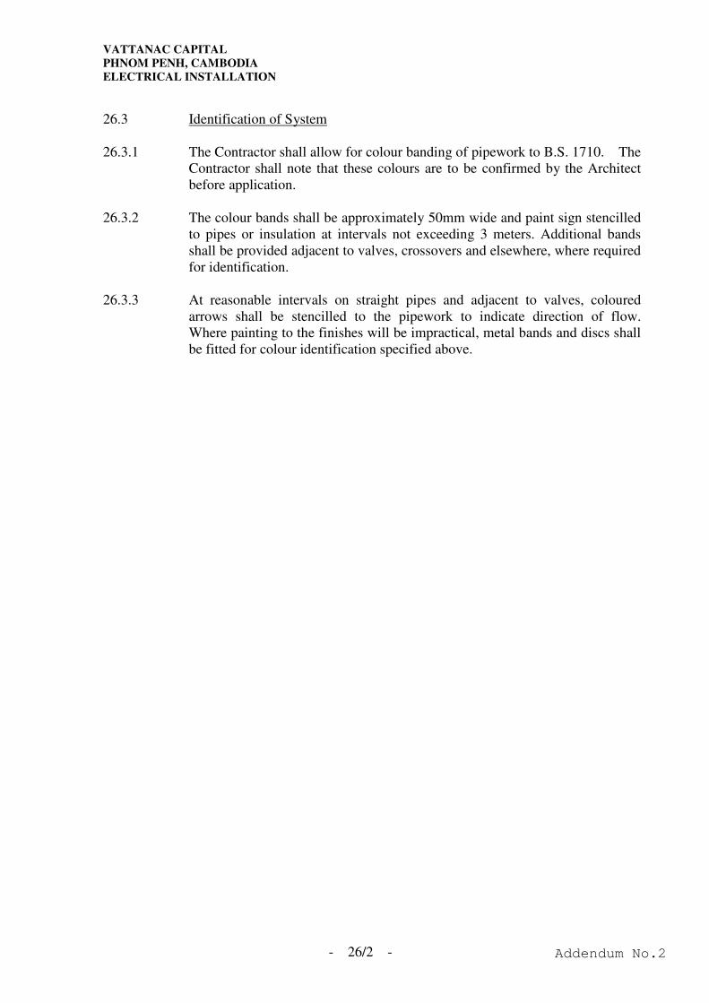
VATTANAC CAPITAL
PHNOM PENH, CAMBODIA
ELECTRICAL INSTALLATION
- 26/2 -
26.3 Identification of System
26.3.1 The Contractor shall allow for colour banding of pipework to B.S. 1710. The
Contractor shall note that these colours are to be confirmed by the Architect
before application.
26.3.2 The colour bands shall be approximately 50mm wide and paint sign stencilled
to pipes or insulation at intervals not exceeding 3 meters. Additional bands
shall be provided adjacent to valves, crossovers and elsewhere, where required
for identification.
26.3.3 At reasonable intervals on straight pipes and adjacent to valves, coloured
arrows shall be stencilled to the pipework to indicate direction of flow.
Where painting to the finishes will be impractical, metal bands and discs shall
be fitted for colour identification specified above.
Addendum No.2

VATTANAC CAPITAL
PHNOM PENH, CAMBODIA
ELECTRICAL INSTALLATION
SECTION 26 - PAINTING, LABELLING AND IDENTIFICATION
Addendum No.2
VATTANAC CAPITAL
PHNOM PENH, CAMBODIA
ELECTRICAL INSTALLATION
I N D E X
SECTION 26 - PAINTING, LABELLING AND IDENTIFICATION
Clause Page
26.1 Painting .....................................................................................................26/1
26.2 Labelling ...................................................................................................26/1
26.3 Identification of System ............................................................................26/2
Addendum No.2

VATTANAC CAPITAL
PHNOM PENH, CAMBODIA
ELECTRICAL INSTALLATION
- SA/1 -
SCHEDULE A - EQUIPMENT AND DELIVERY SCHEDULE
The information supplied in the following items of the Equipment Schedule shall be
supplemented by trade catalogues, samples, brochures and other literature as specified.
The equipment and materials offered must fully comply with the Specification and Drawings
and must not include more than one offer for any one item.
The Tenderer's offer with stated product origin will be checked in principle, however, the
acceptance of the Tender does not imply acceptance of the materials and equipment offer
which must comply with the specification unless specifically applied for and approved by the
Architect in writing.
Exact "Make" of equipment offered must be given and descriptions like "Imported", or "to
B.S." are not acceptable.
The schedule provided below is merely an indication only. The Tenderer shall also include
those equipment not listed below. Should the Tenderer fail to comply with this requirement
and the Tender for this Contract be awarded to the Contractor, the Architect shall, at his own
discretion, nominate the equipment which will comply with the Drawings and Specification.
The Contractor shall, without object, supply and install the nominated equipment at no extra
cost to this Contract.
Addendum No.2

VATTANAC CAPITAL
PHNOM PENH, CAMBODIA
ELECTRICAL INSTALLATION
- SA/2 -
SCHEDULE A - EQUIPMENT AND DELIVERY SCHEDULE (Cont'd)
Item
Materials/Equipment
Specified
Manufacturer/Supplier
or Equivalent
Offer
(Product
Origin)
Delivery Time
B.1 L.V. System & Electrical
Accessories
B.1.1 MCCB Distribution
Board (under licence)
(Type Test Certificate
shall be submitted for
review)
Bill
Square D
MG
Mitsubishi
Terasaki
ABB
Hager
Federal
MEM
Legrand
Fair-Rack
B.1.2 MCB Distribution Board
(under licence)
(Type Test Certificate
shall be submitted for
review)
Square D
MG
Mitsubishi
ABB
Hager
Federal
MEM
B.1.3 Moulded Case Circuit
Breaker
Mitsubishi
ABB
Terasaki
Federal
MEM
Legrand
Bill
Square D
MG
Hager
B.1.4 Miniature Circuit Breaker
& Residual Current
Device
Mitsubishi
ABB
Terasaki
Federal
MEM
Legrand
Bill
Square D
MG(
Hager
Addendum No.2
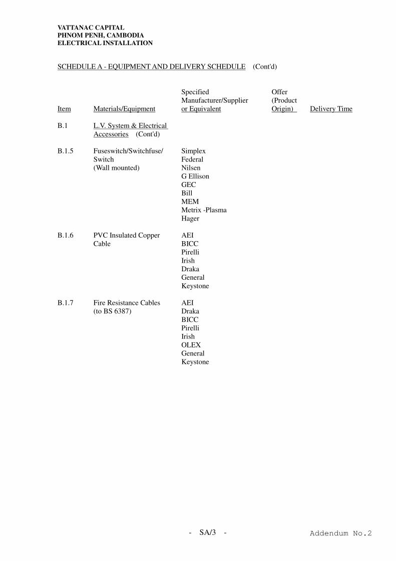
VATTANAC CAPITAL
PHNOM PENH, CAMBODIA
ELECTRICAL INSTALLATION
- SA/3 -
SCHEDULE A - EQUIPMENT AND DELIVERY SCHEDULE (Cont'd)
Item
Materials/Equipment
Specified
Manufacturer/Supplier
or Equivalent
Offer
(Product
Origin)
Delivery Time
B.1 L.V. System & Electrical
Accessories (Cont'd)
B.1.5 Fuseswitch/Switchfuse/
Switch
(Wall mounted)
Simplex
Federal
Nilsen
G Ellison
GEC
Bill
MEM
Metrix -Plasma
Hager
B.1.6 PVC Insulated Copper
Cable
AEI
BICC
Pirelli
Irish
Draka
General
Keystone
B.1.7 Fire Resistance Cables
(to BS 6387)
AEI
Draka
BICC
Pirelli
Irish
OLEX
General
Keystone
Addendum No.2
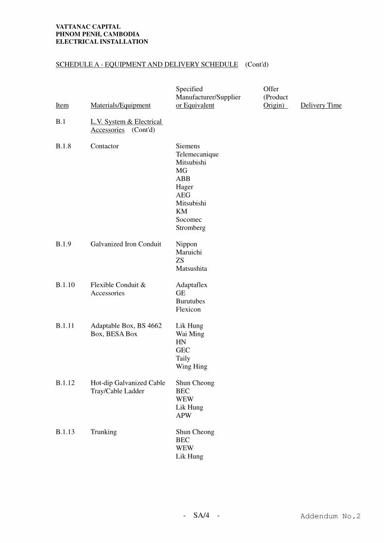
VATTANAC CAPITAL
PHNOM PENH, CAMBODIA
ELECTRICAL INSTALLATION
- SA/4 -
SCHEDULE A - EQUIPMENT AND DELIVERY SCHEDULE (Cont'd)
Item
Materials/Equipment
Specified
Manufacturer/Supplier
or Equivalent
Offer
(Product
Origin)
Delivery Time
B.1 L.V. System & Electrical
Accessories (Cont'd)
B.1.8 Contactor Siemens
Telemecanique
Mitsubishi
MG
ABB
Hager
AEG
Mitsubishi
KM
Socomec
Stromberg
B.1.9 Galvanized Iron Conduit Nippon
Maruichi
ZS
Matsushita
B.1.10 Flexible Conduit &
Accessories
Adaptaflex
GE
Burutubes
Flexicon
B.1.11 Adaptable Box, BS 4662
Box, BESA Box
Lik Hung
Wai Ming
HN
GEC
Taily
Wing Hing
B.1.12 Hot-dip Galvanized Cable
Tray/Cable Ladder
Shun Cheong
BEC
WEW
Lik Hung
APW
B.1.13 Trunking Shun Cheong
BEC
WEW
Lik Hung
Addendum No.2
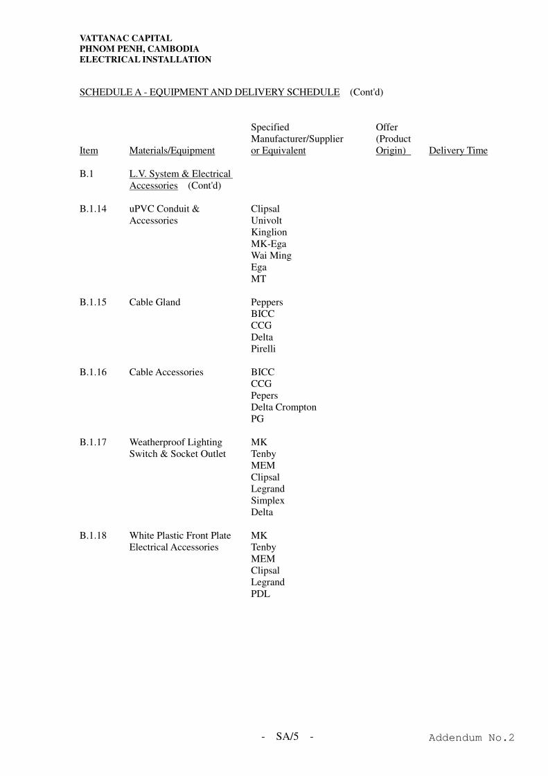
VATTANAC CAPITAL
PHNOM PENH, CAMBODIA
ELECTRICAL INSTALLATION
- SA/5 -
SCHEDULE A - EQUIPMENT AND DELIVERY SCHEDULE (Cont'd)
Item
Materials/Equipment
Specified
Manufacturer/Supplier
or Equivalent
Offer
(Product
Origin)
Delivery Time
B.1 L.V. System & Electrical
Accessories (Cont'd)
B.1.14 uPVC Conduit &
Accessories
Clipsal
Univolt
Kinglion
MK-Ega
Wai Ming
Ega
MT
B.1.15 Cable Gland Peppers
BICC
CCG
Delta
Pirelli
B.1.16 Cable Accessories BICC
CCG
Pepers
Delta Crompton
PG
B.1.17 Weatherproof Lighting
Switch & Socket Outlet
MK
Tenby
MEM
Clipsal
Legrand
Simplex
Delta
B.1.18 White Plastic Front Plate
Electrical Accessories
MK
Tenby
MEM
Clipsal
Legrand
PDL
Addendum No.2
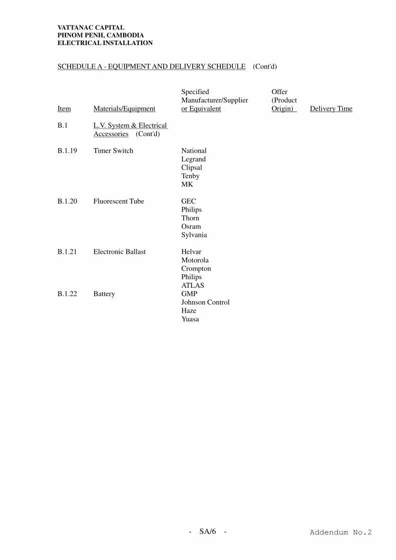
VATTANAC CAPITAL
PHNOM PENH, CAMBODIA
ELECTRICAL INSTALLATION
- SA/6 -
SCHEDULE A - EQUIPMENT AND DELIVERY SCHEDULE (Cont'd)
Item
Materials/Equipment
Specified
Manufacturer/Supplier
or Equivalent
Offer
(Product
Origin)
Delivery Time
B.1 L.V. System & Electrical
Accessories (Cont'd)
B.1.19 Timer Switch National
Legrand
Clipsal
Tenby
MK
B.1.20 Fluorescent Tube GEC
Philips
Thorn
Osram
Sylvania
B.1.21 Electronic Ballast Helvar
Motorola
Crompton
Philips
ATLAS
B.1.22 Battery GMP
Johnson Control
Haze
Yuasa
Addendum No.2
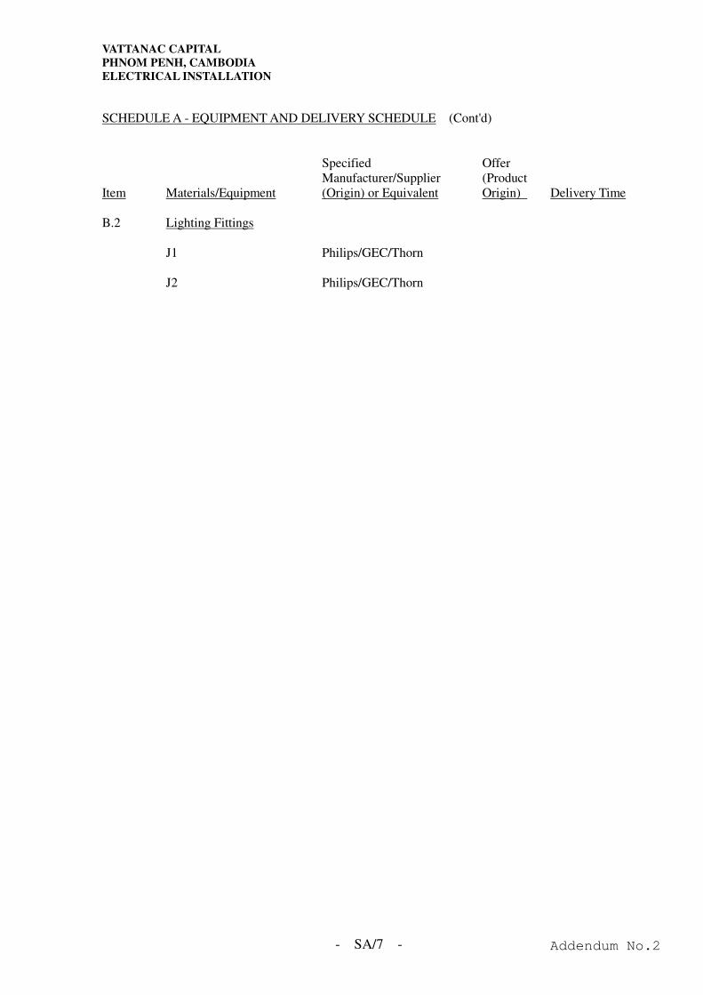
VATTANAC CAPITAL
PHNOM PENH, CAMBODIA
ELECTRICAL INSTALLATION
- SA/7 -
SCHEDULE A - EQUIPMENT AND DELIVERY SCHEDULE (Cont'd)
Item
Materials/Equipment
Specified
Manufacturer/Supplier
(Origin) or Equivalent
Offer
(Product
Origin)
Delivery Time
B.2 Lighting Fittings
J1 Philips/GEC/Thorn
J2 Philips/GEC/Thorn
Addendum No.2
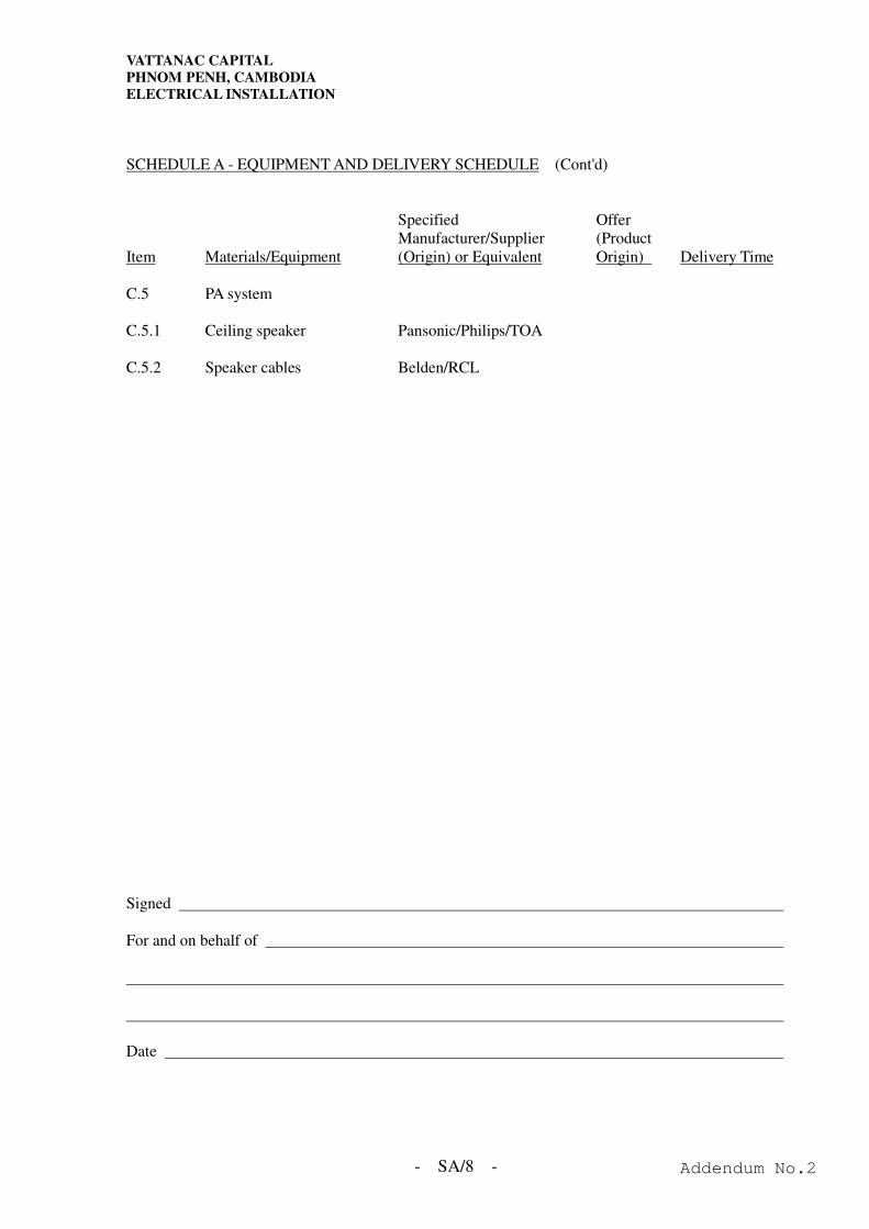
VATTANAC CAPITAL
PHNOM PENH, CAMBODIA
ELECTRICAL INSTALLATION
- SA/8 -
SCHEDULE A - EQUIPMENT AND DELIVERY SCHEDULE (Cont'd)
Item
Materials/Equipment
Specified
Manufacturer/Supplier
(Origin) or Equivalent
Offer
(Product
Origin)
Delivery Time
C.5 PA system
C.5.1 Ceiling speaker Pansonic/Philips/TOA
C.5.2 Speaker cables Belden/RCL
Signed
For and on behalf of
Date
Addendum No.2

VATTANAC CAPITAL
PHNOM PENH, CAMBODIA
ELECTRICAL INSTALLATION
SCHEDULE A - EQUIPMENT AND DELIVERY SCHEDULE
Addendum No.2

VATTANAC CAPITAL
PHNOM PENH, CAMBODIA
ELECTRICAL INSTALLATION
- SB/1 -
SCHEDULE B – SCHEDULE OF QUANTITIES AND RATES A.1 Mains and Sub-Mains Item Description Quantity. Unit Rate for
Supply Only (US$)
Unit Rate for installation only
(US$)
Amount (US$)
Supply and Installation, including all
termination and interfacing works with the associated LV switchboards and sub-main distribution system
A.1.1 Switch-disconnected TP&N
(Surface Mounted)
500A No. 400A No. 315A No. 250A No. 200A No. 160A No. 100A No. 60A No. 30A No. 20A No. 15A No. A No.
Total of this Page : US$
Addendum No.2
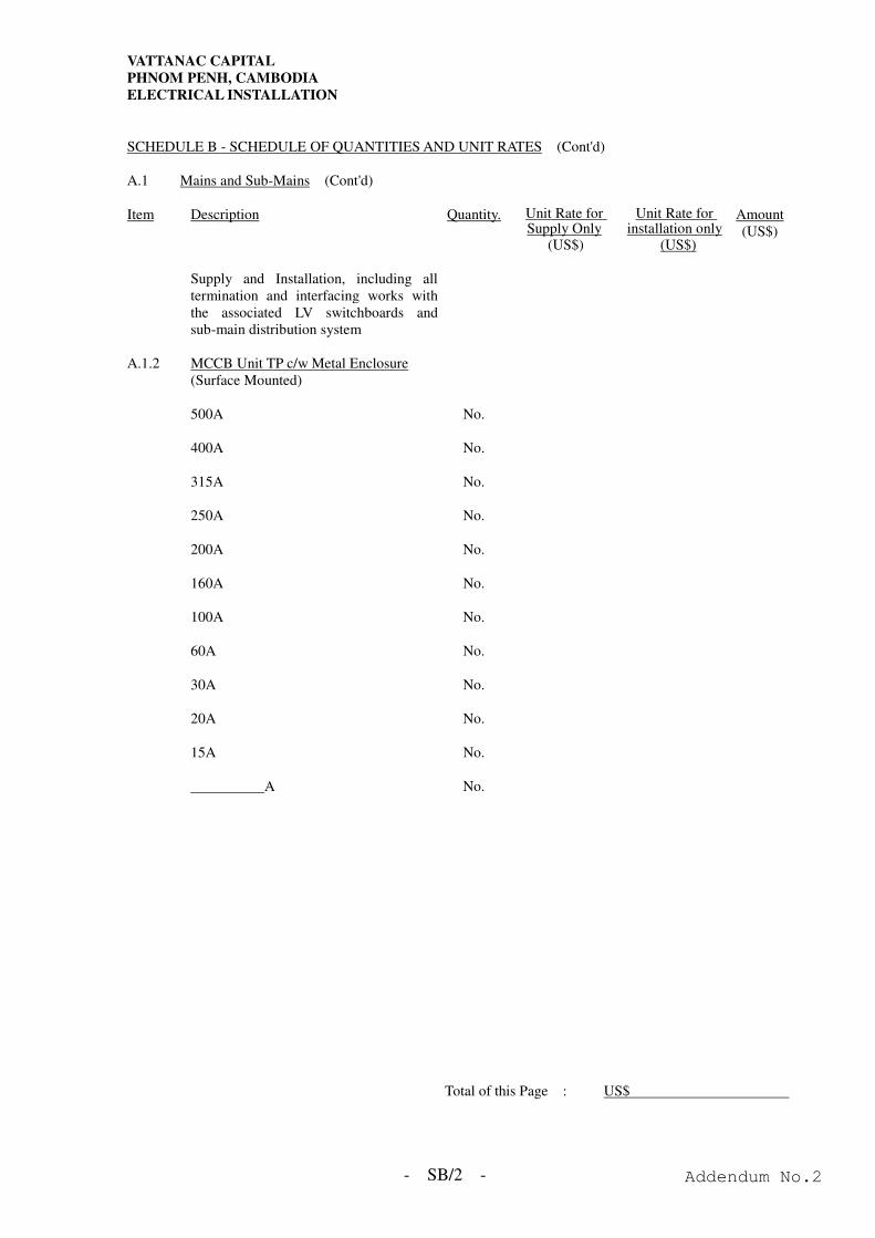
VATTANAC CAPITAL
PHNOM PENH, CAMBODIA
ELECTRICAL INSTALLATION
- SB/2 -
SCHEDULE B - SCHEDULE OF QUANTITIES AND UNIT RATES (Cont'd) A.1 Mains and Sub-Mains (Cont'd) Item Description Quantity. Unit Rate for
Supply Only (US$)
Unit Rate for installation only
(US$)
Amount (US$)
Supply and Installation, including all
termination and interfacing works with the associated LV switchboards and sub-main distribution system
A.1.2 MCCB Unit TP c/w Metal Enclosure
(Surface Mounted)
500A No. 400A No. 315A No. 250A No. 200A No. 160A No. 100A No. 60A No. 30A No. 20A No. 15A No. A No.
Total of this Page : US$
Addendum No.2
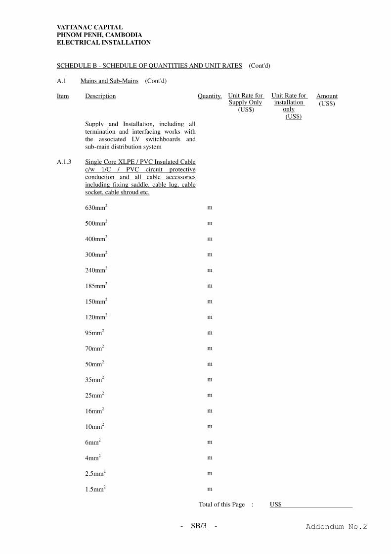
VATTANAC CAPITAL
PHNOM PENH, CAMBODIA
ELECTRICAL INSTALLATION
- SB/3 -
SCHEDULE B - SCHEDULE OF QUANTITIES AND UNIT RATES (Cont'd) A.1 Mains and Sub-Mains (Cont'd) Item Description Quantity. Unit Rate for
Supply Only (US$)
Unit Rate for installation
only (US$)
Amount (US$)
Supply and Installation, including all termination and interfacing works with the associated LV switchboards and sub-main distribution system
A.1.3 Single Core XLPE / PVC Insulated Cable
c/w 1/C / PVC circuit protective conduction and all cable accessories including fixing saddle, cable lug, cable socket, cable shroud etc.
630mm2 m
500mm2 m
400mm2 m
300mm2 m
240mm2 m
185mm2 m
150mm2 m
120mm2 m
95mm2 m
70mm2 m
50mm2 m
35mm2 m
25mm2 m
16mm2 m
10mm2 m
6mm2 m
4mm2 m
2.5mm2 m
1.5mm2 m
Total of this Page : US$
Addendum No.2
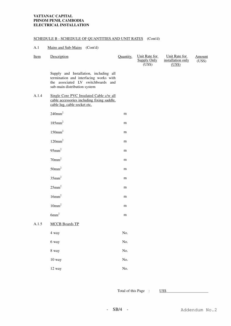
VATTANAC CAPITAL
PHNOM PENH, CAMBODIA
ELECTRICAL INSTALLATION
- SB/4 -
SCHEDULE B - SCHEDULE OF QUANTITIES AND UNIT RATES (Cont'd) A.1 Mains and Sub-Mains (Cont'd) Item Description Quantity. Unit Rate for
Supply Only (US$)
Unit Rate for installation only
(US$)
Amount (US$)
Supply and Installation, including all
termination and interfacing works with the associated LV switchboards and sub-main distribution system
A.1.4 Single Core PVC Insulated Cable c/w all
cable accessories including fixing saddle, cable lug, cable socket etc.
240mm2 m
185mm2 m
150mm2 m
120mm2 m
95mm2 m
70mm2 m
50mm2 m
35mm2 m
25mm2 m
16mm2 m
10mm2 m
6mm2 m
A.1.5 MCCB Boards TP 4 way No. 6 way No. 8 way No. 10 way No. 12 way No.
Total of this Page : US$
Addendum No.2
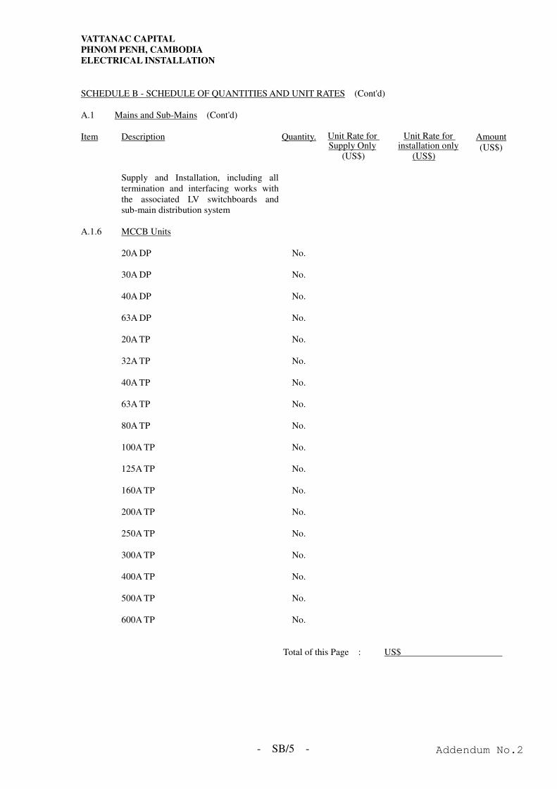
VATTANAC CAPITAL
PHNOM PENH, CAMBODIA
ELECTRICAL INSTALLATION
- SB/5 -
SCHEDULE B - SCHEDULE OF QUANTITIES AND UNIT RATES (Cont'd) A.1 Mains and Sub-Mains (Cont'd) Item Description Quantity. Unit Rate for
Supply Only (US$)
Unit Rate for installation only
(US$)
Amount (US$)
Supply and Installation, including all
termination and interfacing works with the associated LV switchboards and sub-main distribution system
A.1.6 MCCB Units 20A DP No. 30A DP No. 40A DP No. 63A DP No. 20A TP No. 32A TP No. 40A TP No. 63A TP No. 80A TP No. 100A TP No. 125A TP No. 160A TP No. 200A TP No. 250A TP No. 300A TP No. 400A TP No. 500A TP No. 600A TP No.
Total of this Page : US$
Addendum No.2
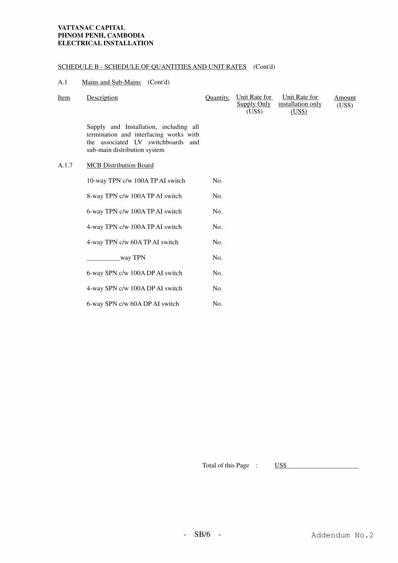
VATTANAC CAPITAL
PHNOM PENH, CAMBODIA
ELECTRICAL INSTALLATION
- SB/6 -
SCHEDULE B - SCHEDULE OF QUANTITIES AND UNIT RATES (Cont'd) A.1 Mains and Sub-Mains (Cont'd) Item Description Quantity. Unit Rate for
Supply Only (US$)
Unit Rate for installation only
(US$)
Amount (US$)
Supply and Installation, including all
termination and interfacing works with the associated LV switchboards and sub-main distribution system
A.1.7 MCB Distribution Board 10-way TPN c/w 100A TP AI switch No. 8-way TPN c/w 100A TP AI switch No. 6-way TPN c/w 100A TP AI switch No. 4-way TPN c/w 100A TP AI switch No. 4-way TPN c/w 60A TP AI switch No. way TPN No. 6-way SPN c/w 100A DP AI switch No. 4-way SPN c/w 100A DP AI switch No. 6-way SPN c/w 60A DP AI switch No.
Total of this Page : US$
Addendum No.2
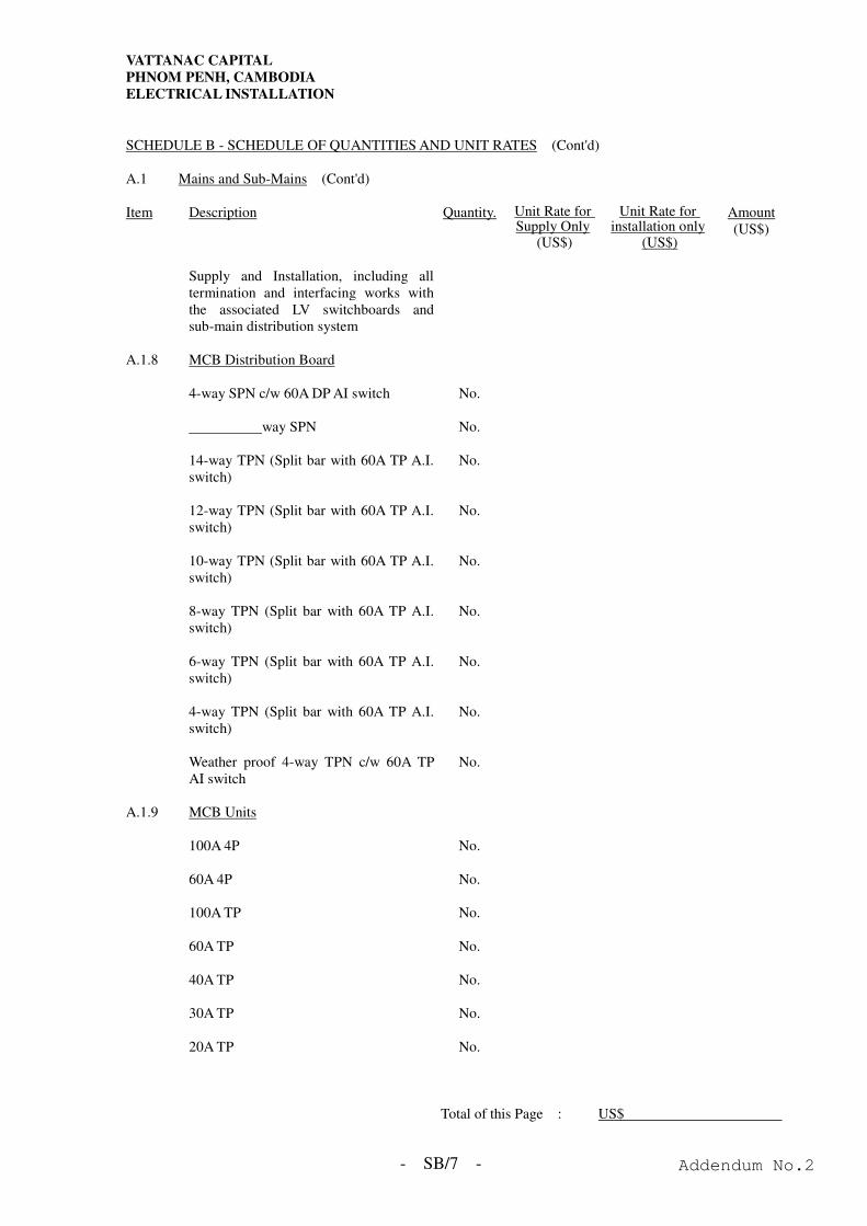
VATTANAC CAPITAL
PHNOM PENH, CAMBODIA
ELECTRICAL INSTALLATION
- SB/7 -
SCHEDULE B - SCHEDULE OF QUANTITIES AND UNIT RATES (Cont'd) A.1 Mains and Sub-Mains (Cont'd) Item Description Quantity. Unit Rate for
Supply Only (US$)
Unit Rate for installation only
(US$)
Amount (US$)
Supply and Installation, including all
termination and interfacing works with the associated LV switchboards and sub-main distribution system
A.1.8 MCB Distribution Board 4-way SPN c/w 60A DP AI switch No. way SPN No. 14-way TPN (Split bar with 60A TP A.I.
switch) No.
12-way TPN (Split bar with 60A TP A.I.
switch) No.
10-way TPN (Split bar with 60A TP A.I.
switch) No.
8-way TPN (Split bar with 60A TP A.I.
switch) No.
6-way TPN (Split bar with 60A TP A.I.
switch) No.
4-way TPN (Split bar with 60A TP A.I.
switch) No.
Weather proof 4-way TPN c/w 60A TP
AI switch No.
A.1.9 MCB Units 100A 4P No. 60A 4P No. 100A TP No. 60A TP No. 40A TP No. 30A TP No. 20A TP No.
Total of this Page : US$
Addendum No.2
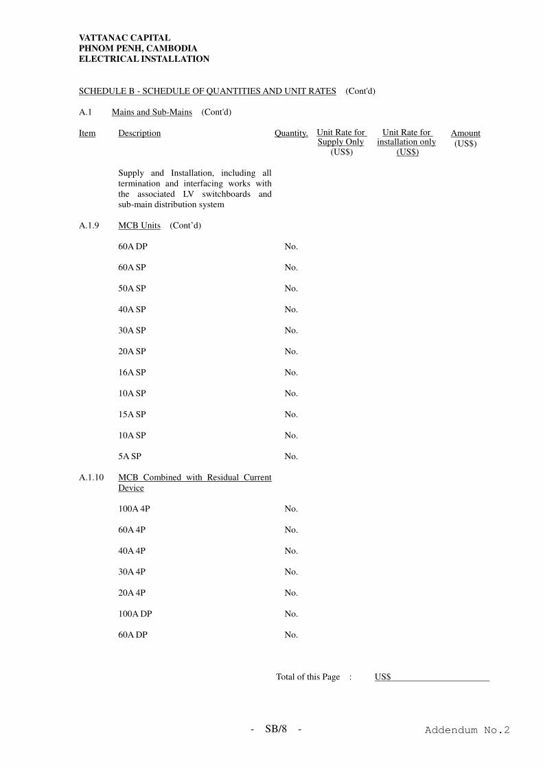
VATTANAC CAPITAL
PHNOM PENH, CAMBODIA
ELECTRICAL INSTALLATION
- SB/8 -
SCHEDULE B - SCHEDULE OF QUANTITIES AND UNIT RATES (Cont'd) A.1 Mains and Sub-Mains (Cont'd) Item Description Quantity. Unit Rate for
Supply Only (US$)
Unit Rate for installation only
(US$)
Amount (US$)
Supply and Installation, including all
termination and interfacing works with the associated LV switchboards and sub-main distribution system
A.1.9 MCB Units (Cont’d) 60A DP No. 60A SP No. 50A SP No. 40A SP No. 30A SP No. 20A SP No. 16A SP No. 10A SP No. 15A SP No. 10A SP No. 5A SP No. A.1.10 MCB Combined with Residual Current
Device
100A 4P No. 60A 4P No. 40A 4P No. 30A 4P No. 20A 4P No. 100A DP No. 60A DP No.
Total of this Page : US$
Addendum No.2
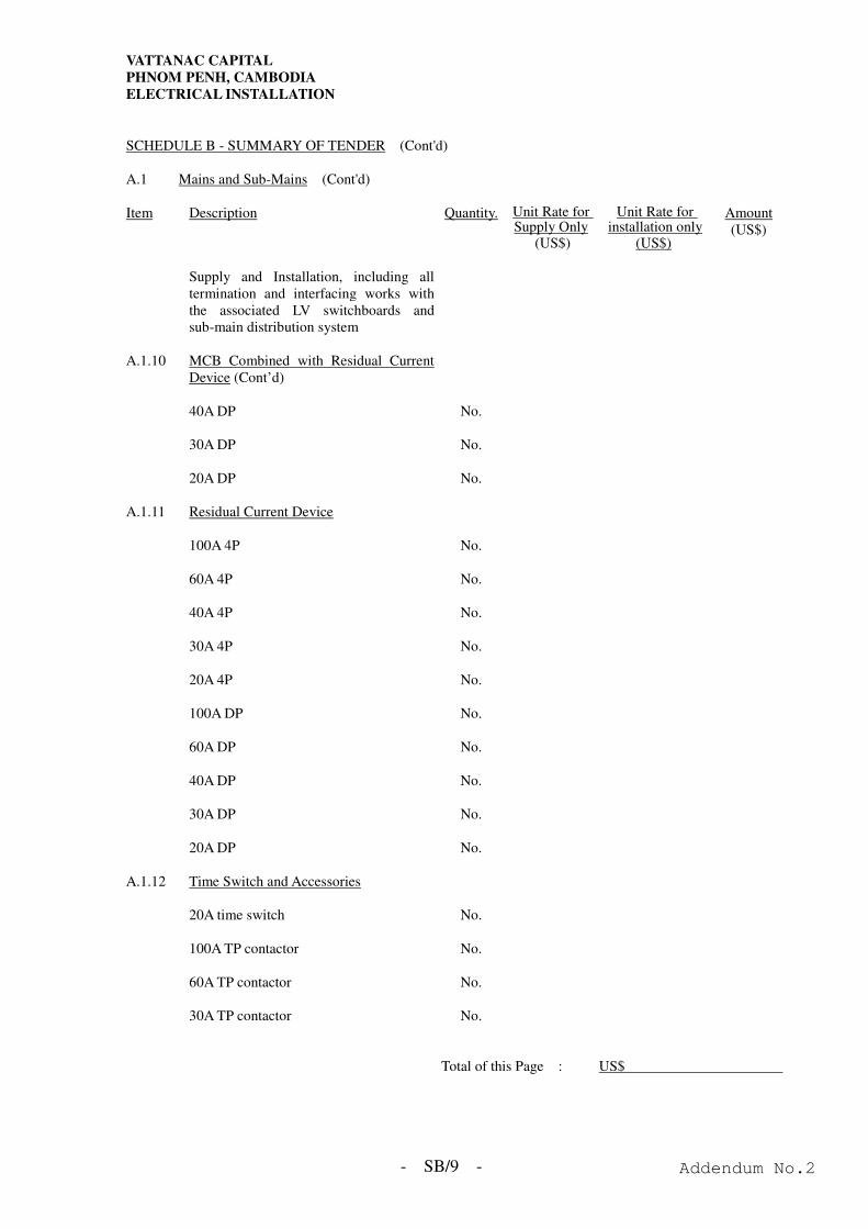
VATTANAC CAPITAL
PHNOM PENH, CAMBODIA
ELECTRICAL INSTALLATION
- SB/9 -
SCHEDULE B - SUMMARY OF TENDER (Cont'd) A.1 Mains and Sub-Mains (Cont'd) Item Description Quantity. Unit Rate for
Supply Only (US$)
Unit Rate for installation only
(US$)
Amount (US$)
Supply and Installation, including all
termination and interfacing works with the associated LV switchboards and sub-main distribution system
A.1.10 MCB Combined with Residual Current
Device (Cont’d)
40A DP No. 30A DP No. 20A DP No. A.1.11 Residual Current Device 100A 4P No. 60A 4P No. 40A 4P No. 30A 4P No. 20A 4P No. 100A DP No. 60A DP No. 40A DP No. 30A DP No. 20A DP No. A.1.12 Time Switch and Accessories 20A time switch No. 100A TP contactor No. 60A TP contactor No. 30A TP contactor No.
Total of this Page : US$
Addendum No.2
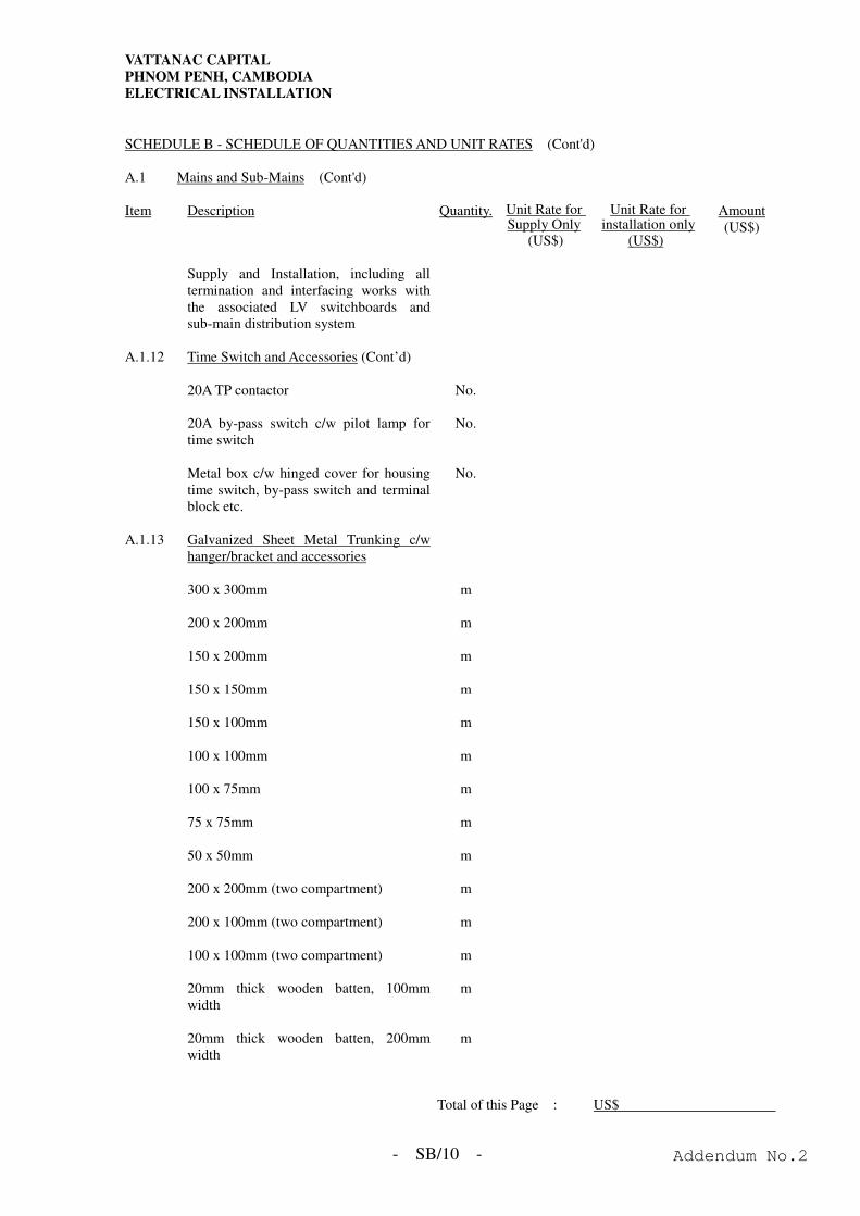
VATTANAC CAPITAL
PHNOM PENH, CAMBODIA
ELECTRICAL INSTALLATION
- SB/10 -
SCHEDULE B - SCHEDULE OF QUANTITIES AND UNIT RATES (Cont'd) A.1 Mains and Sub-Mains (Cont'd) Item Description Quantity. Unit Rate for
Supply Only (US$)
Unit Rate for installation only
(US$)
Amount (US$)
Supply and Installation, including all
termination and interfacing works with the associated LV switchboards and sub-main distribution system
A.1.12 Time Switch and Accessories (Cont’d) 20A TP contactor No. 20A by-pass switch c/w pilot lamp for
time switch No.
Metal box c/w hinged cover for housing
time switch, by-pass switch and terminal block etc.
No.
A.1.13 Galvanized Sheet Metal Trunking c/w
hanger/bracket and accessories
300 x 300mm m 200 x 200mm m 150 x 200mm m 150 x 150mm m 150 x 100mm m 100 x 100mm m 100 x 75mm m 75 x 75mm m 50 x 50mm m 200 x 200mm (two compartment) m 200 x 100mm (two compartment) m 100 x 100mm (two compartment) m 20mm thick wooden batten, 100mm
width m
20mm thick wooden batten, 200mm
width m
Total of this Page : US$
Addendum No.2
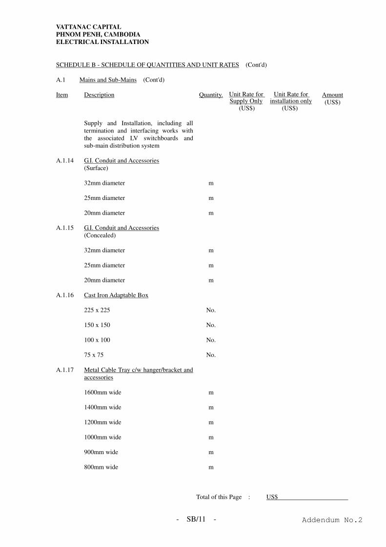
VATTANAC CAPITAL
PHNOM PENH, CAMBODIA
ELECTRICAL INSTALLATION
- SB/11 -
SCHEDULE B - SCHEDULE OF QUANTITIES AND UNIT RATES (Cont'd) A.1 Mains and Sub-Mains (Cont'd) Item Description Quantity. Unit Rate for
Supply Only (US$)
Unit Rate for installation only
(US$)
Amount (US$)
Supply and Installation, including all
termination and interfacing works with the associated LV switchboards and sub-main distribution system
A.1.14 G.I. Conduit and Accessories
(Surface)
32mm diameter m 25mm diameter m 20mm diameter m A.1.15 G.I. Conduit and Accessories
(Concealed)
32mm diameter m 25mm diameter m 20mm diameter m A.1.16 Cast Iron Adaptable Box 225 x 225 No. 150 x 150 No. 100 x 100 No. 75 x 75 No. A.1.17 Metal Cable Tray c/w hanger/bracket and
accessories
1600mm wide m 1400mm wide m 1200mm wide m 1000mm wide m 900mm wide m 800mm wide m
Total of this Page : US$
Addendum No.2
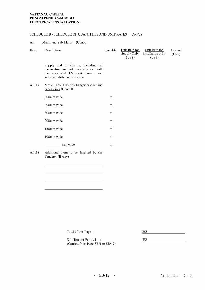
VATTANAC CAPITAL
PHNOM PENH, CAMBODIA
ELECTRICAL INSTALLATION
- SB/12 -
SCHEDULE B - SCHEDULE OF QUANTITIES AND UNIT RATES (Cont'd) A.1 Mains and Sub-Mains (Cont'd) Item Description Quantity. Unit Rate for
Supply Only (US$)
Unit Rate for installation only
(US$)
Amount (US$)
Supply and Installation, including all
termination and interfacing works with the associated LV switchboards and sub-main distribution system
A.1.17 Metal Cable Tray c/w hanger/bracket and
accessories (Cont’d)
600mm wide m 400mm wide m 300mm wide m 200mm wide m 150mm wide m 100mm wide m mm wide m A.1.18 Additional Item to be Inserted by the
Tenderer (If Any)
Total of this Page : US$
Sub-Total of Part A.1 : US$ (Carried from Page SB/1 to SB/12)
Addendum No.2
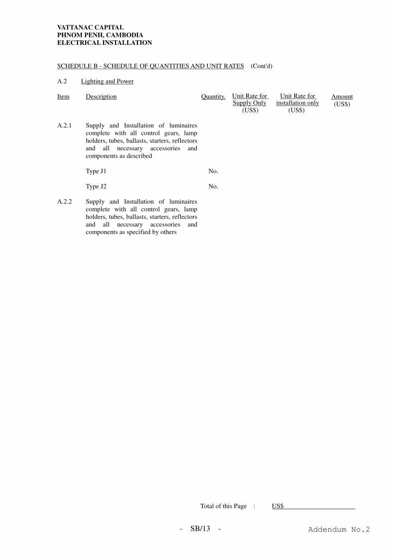
VATTANAC CAPITAL
PHNOM PENH, CAMBODIA
ELECTRICAL INSTALLATION
- SB/13 -
SCHEDULE B - SCHEDULE OF QUANTITIES AND UNIT RATES (Cont'd) A.2 Lighting and Power Item Description Quantity. Unit Rate for
Supply Only (US$)
Unit Rate for installation only
(US$)
Amount (US$)
A.2.1 Supply and Installation of luminaires
complete with all control gears, lamp holders, tubes, ballasts, starters, reflectors and all necessary accessories and components as described
Type J1 No. Type J2 No. A.2.2 Supply and Installation of luminaires
complete with all control gears, lamp holders, tubes, ballasts, starters, reflectors and all necessary accessories and components as specified by others
Total of this Page : US$
Addendum No.2
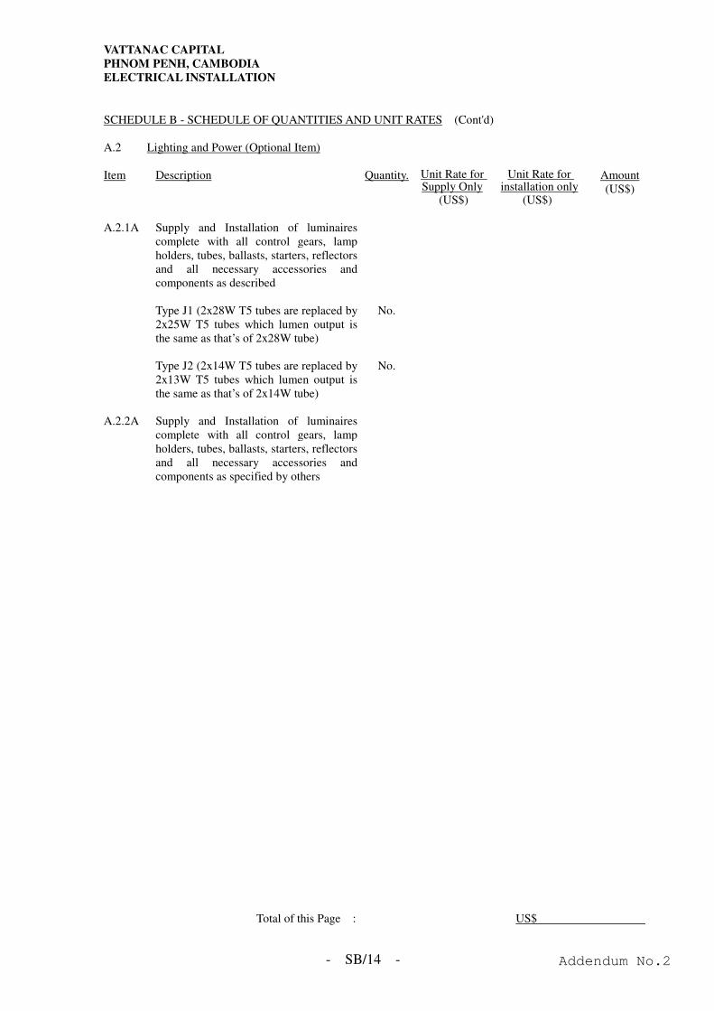
VATTANAC CAPITAL
PHNOM PENH, CAMBODIA
ELECTRICAL INSTALLATION
- SB/14 -
SCHEDULE B - SCHEDULE OF QUANTITIES AND UNIT RATES (Cont'd) A.2 Lighting and Power (Optional Item) Item Description Quantity. Unit Rate for
Supply Only (US$)
Unit Rate for installation only
(US$)
Amount (US$)
A.2.1A Supply and Installation of luminaires
complete with all control gears, lamp holders, tubes, ballasts, starters, reflectors and all necessary accessories and components as described
Type J1 (2x28W T5 tubes are replaced by
2x25W T5 tubes which lumen output is the same as that’s of 2x28W tube)
No.
Type J2 (2x14W T5 tubes are replaced by
2x13W T5 tubes which lumen output is the same as that’s of 2x14W tube)
No.
A.2.2A Supply and Installation of luminaires
complete with all control gears, lamp holders, tubes, ballasts, starters, reflectors and all necessary accessories and components as specified by others
Total of this Page : US$
Addendum No.2
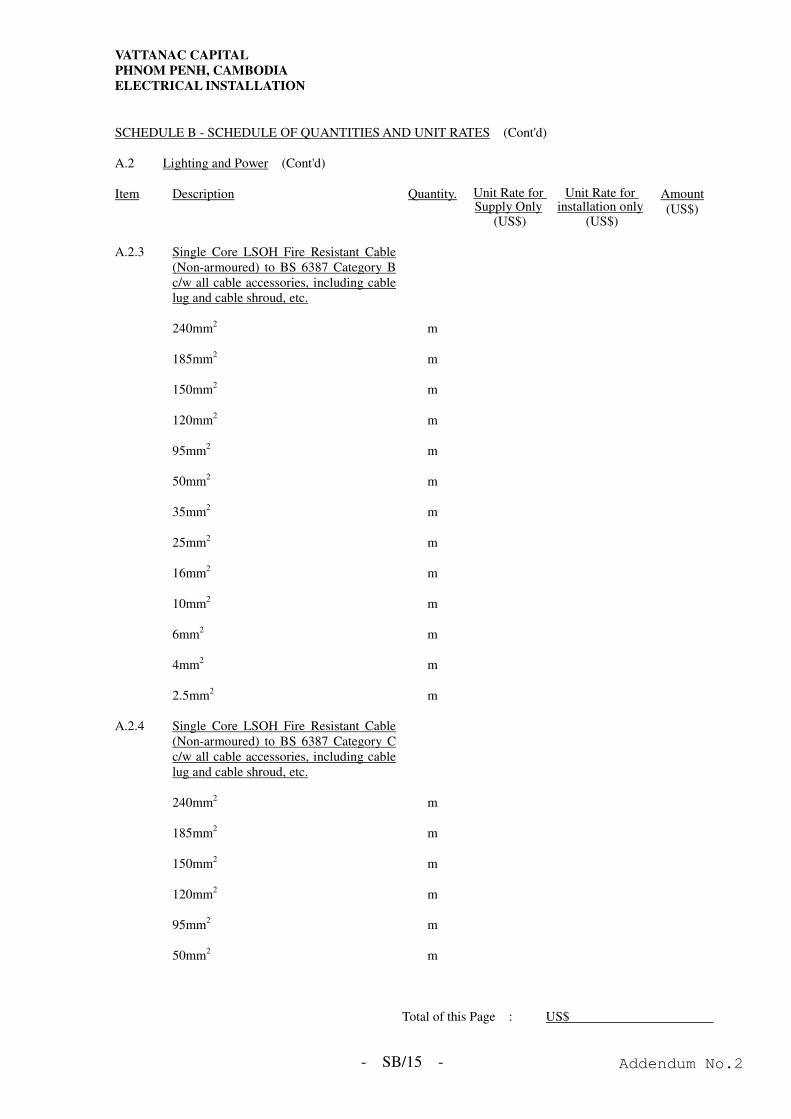
VATTANAC CAPITAL
PHNOM PENH, CAMBODIA
ELECTRICAL INSTALLATION
- SB/15 -
SCHEDULE B - SCHEDULE OF QUANTITIES AND UNIT RATES (Cont'd) A.2 Lighting and Power (Cont'd) Item Description Quantity. Unit Rate for
Supply Only (US$)
Unit Rate for installation only
(US$)
Amount (US$)
A.2.3 Single Core LSOH Fire Resistant Cable
(Non-armoured) to BS 6387 Category B c/w all cable accessories, including cable lug and cable shroud, etc.
240mm2 m 185mm2 m 150mm2 m 120mm2 m 95mm2 m 50mm2 m 35mm2 m 25mm2 m 16mm2 m 10mm2 m 6mm2 m 4mm2 m 2.5mm2 m A.2.4 Single Core LSOH Fire Resistant Cable
(Non-armoured) to BS 6387 Category C c/w all cable accessories, including cable lug and cable shroud, etc.
240mm2 m 185mm2 m 150mm2 m 120mm2 m 95mm2 m 50mm2 m
Total of this Page : US$
Addendum No.2
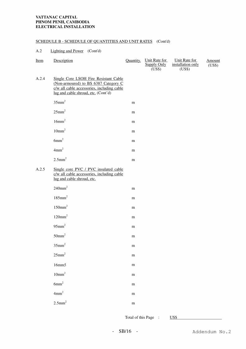
VATTANAC CAPITAL
PHNOM PENH, CAMBODIA
ELECTRICAL INSTALLATION
- SB/16 -
SCHEDULE B - SCHEDULE OF QUANTITIES AND UNIT RATES (Cont'd) A.2 Lighting and Power (Cont'd) Item Description Quantity. Unit Rate for
Supply Only (US$)
Unit Rate for installation only
(US$)
Amount (US$)
A.2.4 Single Core LSOH Fire Resistant Cable
(Non-armoured) to BS 6387 Category C c/w all cable accessories, including cable lug and cable shroud, etc. (Cont’d)
35mm2 m 25mm2 m 16mm2 m 10mm2 m 6mm2 m 4mm2 m 2.5mm2 m A.2.5 Single core PVC / PVC insulated cable
c/w all cable accessories, including cable lug and cable shroud, etc.
240mm2 m 185mm2 m 150mm2 m 120mm2 m 95mm2 m 50mm2 m 35mm2 m 25mm2 m 16mm5 m
10mm2 m 6mm2 m 4mm2 m 2.5mm2 m
Total of this Page : US$
Addendum No.2
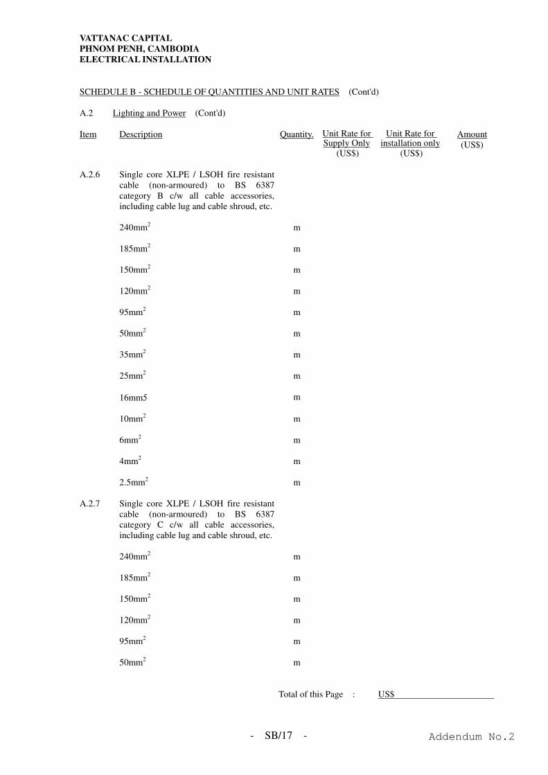
VATTANAC CAPITAL
PHNOM PENH, CAMBODIA
ELECTRICAL INSTALLATION
- SB/17 -
SCHEDULE B - SCHEDULE OF QUANTITIES AND UNIT RATES (Cont'd) A.2 Lighting and Power (Cont'd) Item Description Quantity. Unit Rate for
Supply Only (US$)
Unit Rate for installation only
(US$)
Amount (US$)
A.2.6 Single core XLPE / LSOH fire resistant
cable (non-armoured) to BS 6387 category B c/w all cable accessories, including cable lug and cable shroud, etc.
240mm2 m 185mm2 m 150mm2 m 120mm2 m 95mm2 m 50mm2 m 35mm2 m 25mm2 m 16mm5 m
10mm2 m 6mm2 m 4mm2 m 2.5mm2 m A.2.7 Single core XLPE / LSOH fire resistant
cable (non-armoured) to BS 6387 category C c/w all cable accessories, including cable lug and cable shroud, etc.
240mm2 m 185mm2 m 150mm2 m 120mm2 m 95mm2 m 50mm2 m
Total of this Page : US$
Addendum No.2
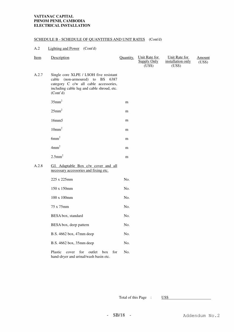
VATTANAC CAPITAL
PHNOM PENH, CAMBODIA
ELECTRICAL INSTALLATION
- SB/18 -
SCHEDULE B - SCHEDULE OF QUANTITIES AND UNIT RATES (Cont'd) A.2 Lighting and Power (Cont'd) Item Description Quantity. Unit Rate for
Supply Only (US$)
Unit Rate for installation only
(US$)
Amount (US$)
A.2.7 Single core XLPE / LSOH five resistant
cable (non-armoured) to BS 6387 category C c/w all cable accessories, including cable lug and cable shroud, etc. (Cont’d)
35mm2 m 25mm2 m 16mm5 m
10mm2 m 6mm2 m 4mm2 m 2.5mm2 m A.2.8 G.I. Adaptable Box c/w cover and all
necessary accessories and fixing etc.
225 x 225mm No. 150 x 150mm No. 100 x 100mm No. 75 x 75mm No. BESA box, standard No. BESA box, deep pattern No. B.S. 4662 box, 47mm deep No. B.S. 4662 box, 35mm deep No. Plastic cover for outlet box for
hand-dryer and urinal/wash basin etc. No.
Total of this Page : US$
Addendum No.2
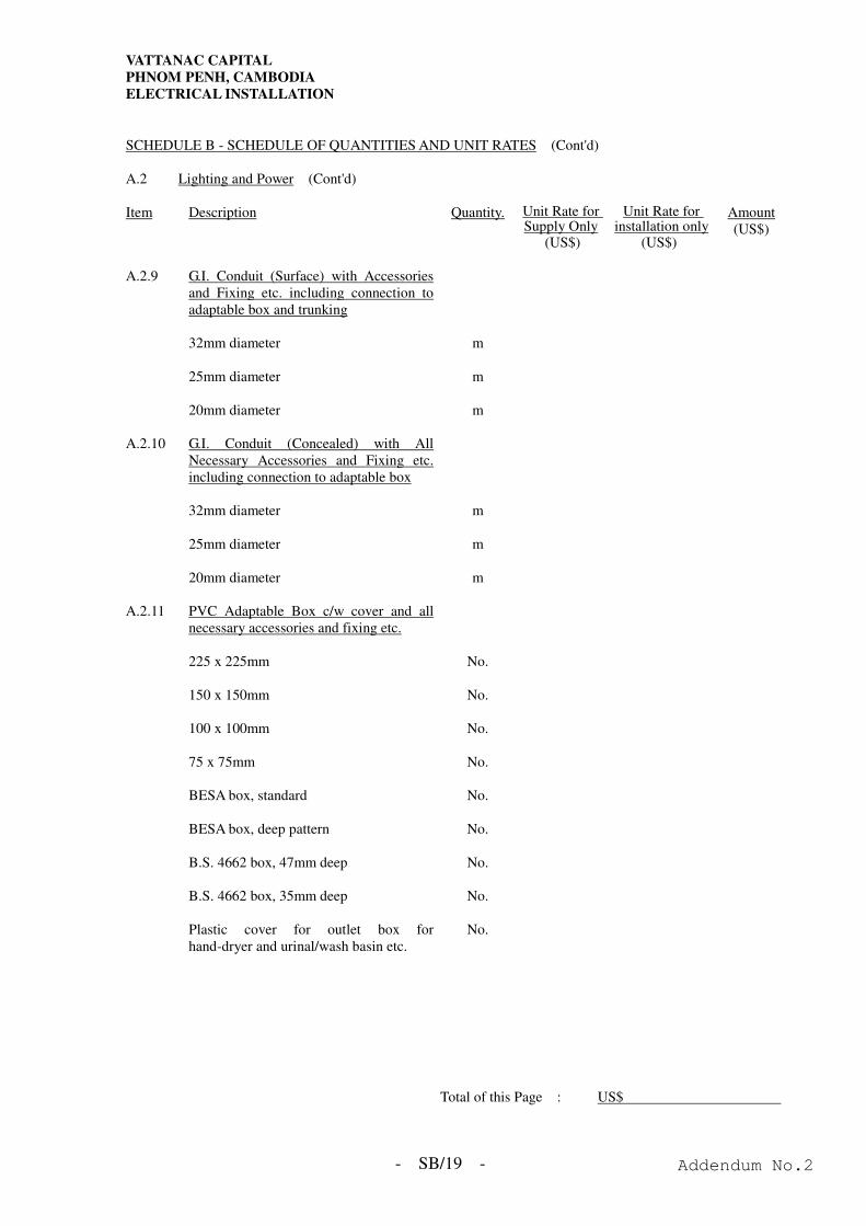
VATTANAC CAPITAL
PHNOM PENH, CAMBODIA
ELECTRICAL INSTALLATION
- SB/19 -
SCHEDULE B - SCHEDULE OF QUANTITIES AND UNIT RATES (Cont'd) A.2 Lighting and Power (Cont'd) Item Description Quantity. Unit Rate for
Supply Only (US$)
Unit Rate for installation only
(US$)
Amount (US$)
A.2.9 G.I. Conduit (Surface) with Accessories
and Fixing etc. including connection to adaptable box and trunking
32mm diameter m 25mm diameter m 20mm diameter m A.2.10 G.I. Conduit (Concealed) with All
Necessary Accessories and Fixing etc. including connection to adaptable box
32mm diameter m 25mm diameter m 20mm diameter m A.2.11 PVC Adaptable Box c/w cover and all
necessary accessories and fixing etc.
225 x 225mm No. 150 x 150mm No. 100 x 100mm No. 75 x 75mm No. BESA box, standard No. BESA box, deep pattern No. B.S. 4662 box, 47mm deep No. B.S. 4662 box, 35mm deep No. Plastic cover for outlet box for
hand-dryer and urinal/wash basin etc. No.
Total of this Page : US$
Addendum No.2
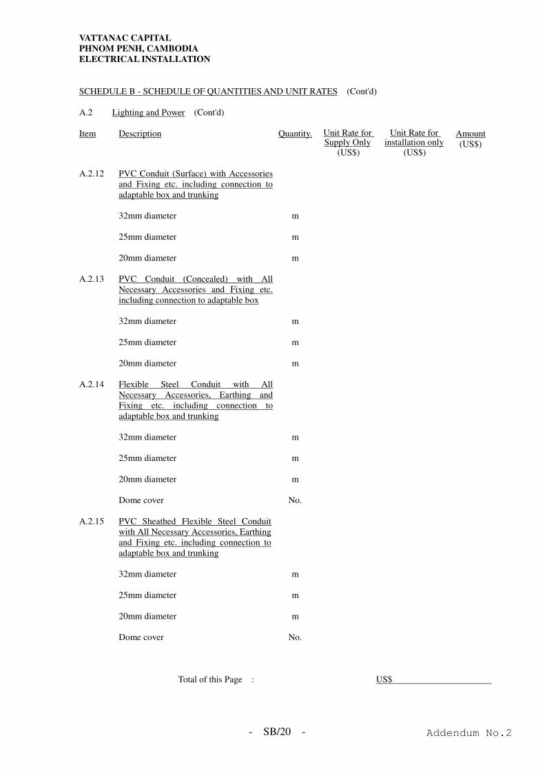
VATTANAC CAPITAL
PHNOM PENH, CAMBODIA
ELECTRICAL INSTALLATION
- SB/20 -
SCHEDULE B - SCHEDULE OF QUANTITIES AND UNIT RATES (Cont'd) A.2 Lighting and Power (Cont'd) Item Description Quantity. Unit Rate for
Supply Only (US$)
Unit Rate for installation only
(US$)
Amount (US$)
A.2.12 PVC Conduit (Surface) with Accessories
and Fixing etc. including connection to adaptable box and trunking
32mm diameter m 25mm diameter m 20mm diameter m A.2.13 PVC Conduit (Concealed) with All
Necessary Accessories and Fixing etc. including connection to adaptable box
32mm diameter m 25mm diameter m 20mm diameter m A.2.14 Flexible Steel Conduit with All
Necessary Accessories, Earthing and Fixing etc. including connection to adaptable box and trunking
32mm diameter m 25mm diameter m 20mm diameter m Dome cover No. A.2.15 PVC Sheathed Flexible Steel Conduit
with All Necessary Accessories, Earthing and Fixing etc. including connection to adaptable box and trunking
32mm diameter m 25mm diameter m 20mm diameter m Dome cover No.
Total of this Page : US$
Addendum No.2
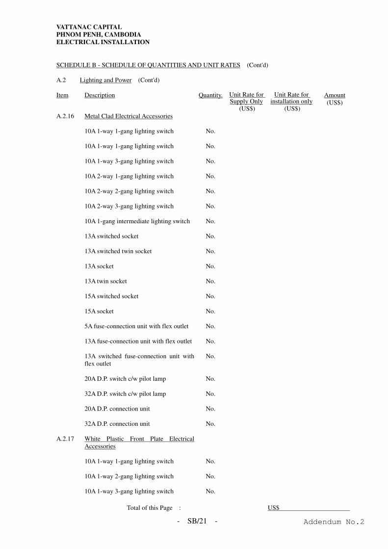
VATTANAC CAPITAL
PHNOM PENH, CAMBODIA
ELECTRICAL INSTALLATION
- SB/21 -
SCHEDULE B - SCHEDULE OF QUANTITIES AND UNIT RATES (Cont'd) A.2 Lighting and Power (Cont'd) Item Description Quantity. Unit Rate for
Supply Only (US$)
Unit Rate for installation only
(US$)
Amount (US$)
A.2.16 Metal Clad Electrical Accessories 10A 1-way 1-gang lighting switch No. 10A 1-way 1-gang lighting switch No. 10A 1-way 3-gang lighting switch No. 10A 2-way 1-gang lighting switch No. 10A 2-way 2-gang lighting switch No. 10A 2-way 3-gang lighting switch No. 10A 1-gang intermediate lighting switch No. 13A switched socket No. 13A switched twin socket No. 13A socket No. 13A twin socket No. 15A switched socket No. 15A socket No. 5A fuse-connection unit with flex outlet No. 13A fuse-connection unit with flex outlet No. 13A switched fuse-connection unit with
flex outlet No.
20A D.P. switch c/w pilot lamp No. 32A D.P. switch c/w pilot lamp No. 20A D.P. connection unit No. 32A D.P. connection unit No. A.2.17 White Plastic Front Plate Electrical
Accessories
10A 1-way 1-gang lighting switch No. 10A 1-way 2-gang lighting switch No. 10A 1-way 3-gang lighting switch No.
Total of this Page : US$
Addendum No.2
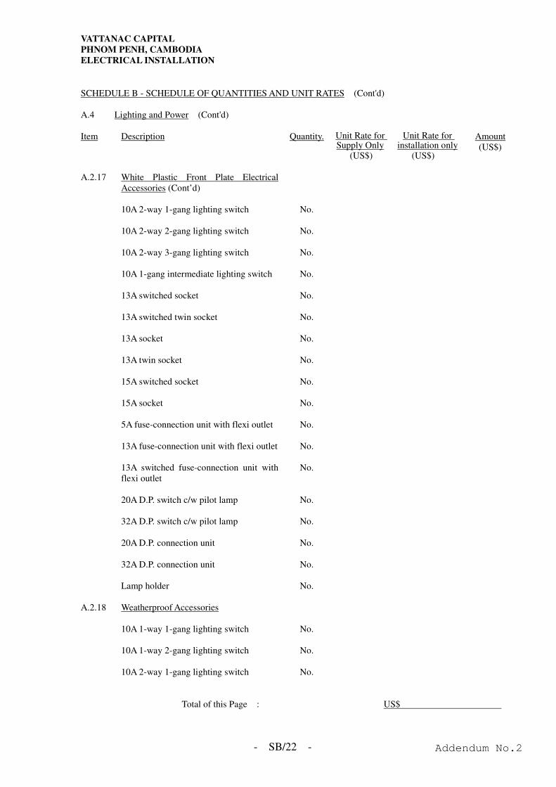
VATTANAC CAPITAL
PHNOM PENH, CAMBODIA
ELECTRICAL INSTALLATION
- SB/22 -
SCHEDULE B - SCHEDULE OF QUANTITIES AND UNIT RATES (Cont'd) A.4 Lighting and Power (Cont'd) Item Description Quantity. Unit Rate for
Supply Only (US$)
Unit Rate for installation only
(US$)
Amount (US$)
A.2.17 White Plastic Front Plate Electrical
Accessories (Cont’d)
10A 2-way 1-gang lighting switch No. 10A 2-way 2-gang lighting switch No. 10A 2-way 3-gang lighting switch No. 10A 1-gang intermediate lighting switch No. 13A switched socket No. 13A switched twin socket No. 13A socket No. 13A twin socket No. 15A switched socket No. 15A socket No. 5A fuse-connection unit with flexi outlet No. 13A fuse-connection unit with flexi outlet No. 13A switched fuse-connection unit with
flexi outlet No.
20A D.P. switch c/w pilot lamp No. 32A D.P. switch c/w pilot lamp No. 20A D.P. connection unit No. 32A D.P. connection unit No. Lamp holder No. A.2.18 Weatherproof Accessories 10A 1-way 1-gang lighting switch No. 10A 1-way 2-gang lighting switch No. 10A 2-way 1-gang lighting switch No.
Total of this Page : US$
Addendum No.2
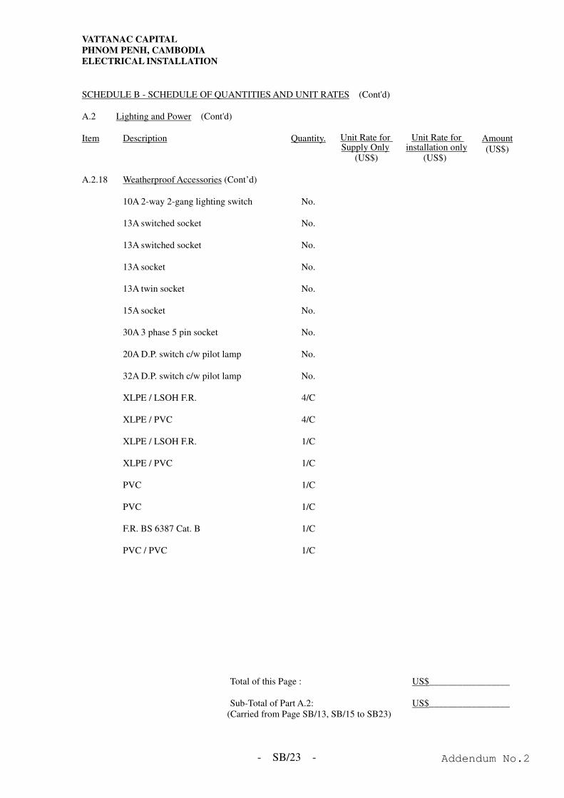
VATTANAC CAPITAL
PHNOM PENH, CAMBODIA
ELECTRICAL INSTALLATION
- SB/23 -
SCHEDULE B - SCHEDULE OF QUANTITIES AND UNIT RATES (Cont'd) A.2 Lighting and Power (Cont'd) Item Description Quantity. Unit Rate for
Supply Only (US$)
Unit Rate for installation only
(US$)
Amount (US$)
A.2.18 Weatherproof Accessories (Cont’d) 10A 2-way 2-gang lighting switch No. 13A switched socket No. 13A switched socket No. 13A socket No. 13A twin socket No. 15A socket No. 30A 3 phase 5 pin socket No. 20A D.P. switch c/w pilot lamp No. 32A D.P. switch c/w pilot lamp No. XLPE / LSOH F.R. 4/C XLPE / PVC 4/C XLPE / LSOH F.R. 1/C XLPE / PVC 1/C PVC 1/C PVC 1/C F.R. BS 6387 Cat. B 1/C PVC / PVC 1/C
Total of this Page : US$_________________
Sub-Total of Part A.2: US$_________________
(Carried from Page SB/13, SB/15 to SB23)
Addendum No.2
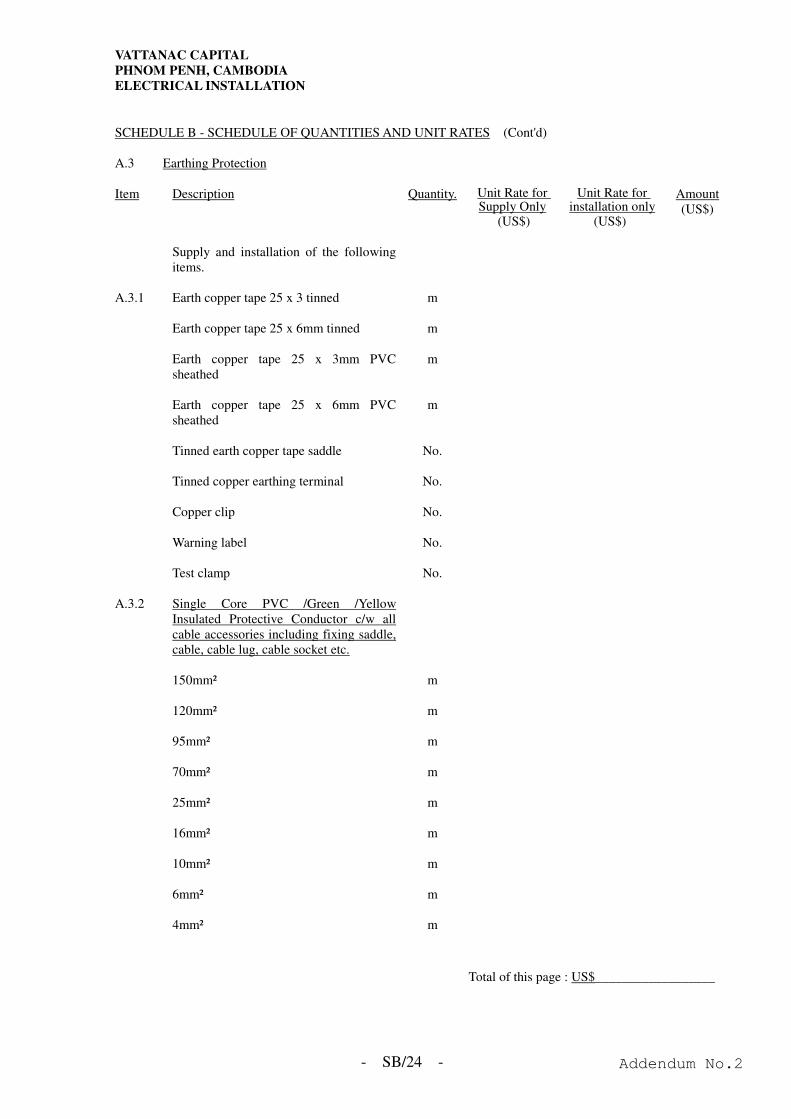
VATTANAC CAPITAL
PHNOM PENH, CAMBODIA
ELECTRICAL INSTALLATION
- SB/24 -
SCHEDULE B - SCHEDULE OF QUANTITIES AND UNIT RATES (Cont'd) A.3 Earthing Protection Item Description Quantity. Unit Rate for
Supply Only (US$)
Unit Rate for installation only
(US$)
Amount (US$)
Supply and installation of the following
items.
A.3.1 Earth copper tape 25 x 3 tinned m Earth copper tape 25 x 6mm tinned m Earth copper tape 25 x 3mm PVC
sheathed m
Earth copper tape 25 x 6mm PVC
sheathed m
Tinned earth copper tape saddle No. Tinned copper earthing terminal No. Copper clip No. Warning label No. Test clamp No. A.3.2 Single Core PVC /Green /Yellow
Insulated Protective Conductor c/w all cable accessories including fixing saddle, cable, cable lug, cable socket etc.
150mm² m 120mm² m 95mm² m 70mm² m 25mm² m 16mm² m 10mm² m 6mm² m 4mm² m
Total of this page : US$__________________
Addendum No.2
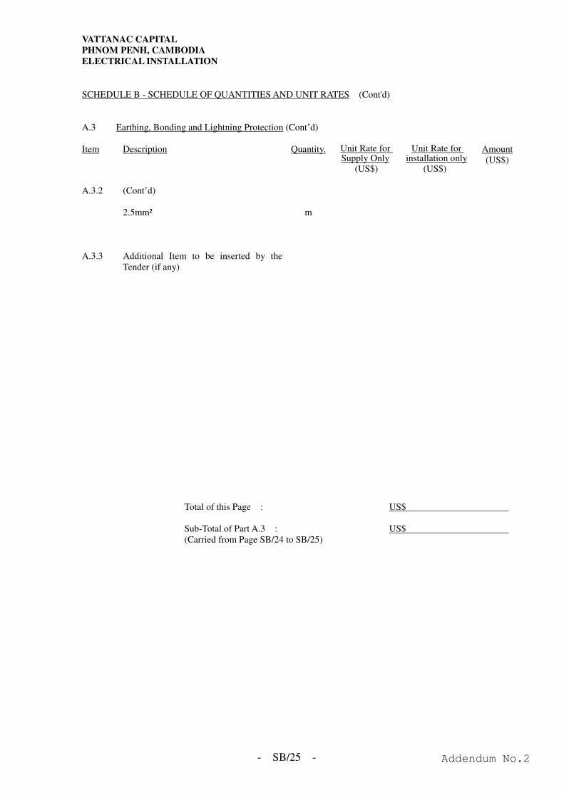
VATTANAC CAPITAL
PHNOM PENH, CAMBODIA
ELECTRICAL INSTALLATION
- SB/25 -
SCHEDULE B - SCHEDULE OF QUANTITIES AND UNIT RATES (Cont'd) A.3 Earthing, Bonding and Lightning Protection (Cont’d) Item Description Quantity. Unit Rate for
Supply Only (US$)
Unit Rate for installation only
(US$)
Amount (US$)
A.3.2 (Cont’d) 2.5mm² m A.3.3 Additional Item to be inserted by the
Tender (if any)
Total of this Page : US$ Sub-Total of Part A.3 : US$ (Carried from Page SB/24 to SB/25)
Addendum No.2
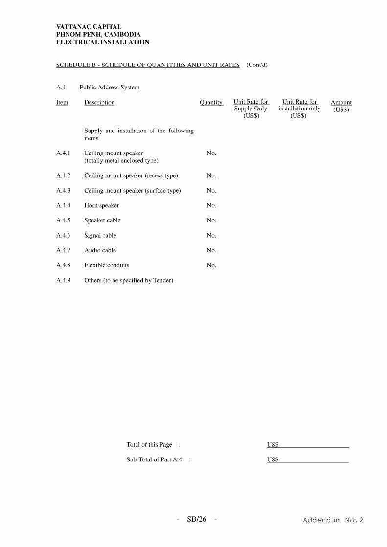
VATTANAC CAPITAL
PHNOM PENH, CAMBODIA
ELECTRICAL INSTALLATION
- SB/26 -
SCHEDULE B - SCHEDULE OF QUANTITIES AND UNIT RATES (Cont'd) A.4 Public Address System Item Description Quantity. Unit Rate for
Supply Only (US$)
Unit Rate for installation only
(US$)
Amount (US$)
Supply and installation of the following
items
A.4.1 Ceiling mount speaker
(totally metal enclosed type) No.
A.4.2 Ceiling mount speaker (recess type) No. A.4.3 Ceiling mount speaker (surface type) No. A.4.4 Horn speaker No. A.4.5 Speaker cable No. A.4.6 Signal cable No. A.4.7 Audio cable No. A.4.8 Flexible conduits No. A.4.9 Others (to be specified by Tender)
Total of this Page : US$
Sub-Total of Part A.4 : US$
Addendum No.2
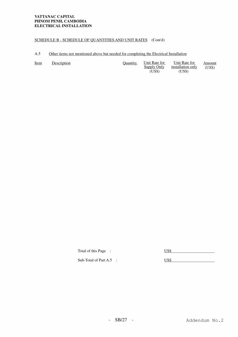
VATTANAC CAPITAL
PHNOM PENH, CAMBODIA
ELECTRICAL INSTALLATION
- SB/27 -
SCHEDULE B - SCHEDULE OF QUANTITIES AND UNIT RATES (Cont'd) A.5 Other items not mentioned above but needed for completing the Electrical Installation Item Description Quantity. Unit Rate for
Supply Only (US$)
Unit Rate for installation only
(US$)
Amount (US$)
Total of this Page : US$
Sub-Total of Part A.5 : US$
Addendum No.2

VATTANAC CAPITAL
PHNOM PENH, CAMBODIA
ELECTRICAL INSTALLATION
SCHEDULE B - SCHEDULE OF QUANTITIES AND UNIT RATES
Addendum No.2

VATTANAC CAPITAL
PHNOM PENH, CAMBODIA
ELECTRICAL INSTALLATION
- SC/1 - Addendum No.2

VATTANAC CAPITAL
PHNOM PENH, CAMBODIA
ELECTRICAL INSTALLATION
SCHEDULE C – NOT USED
Addendum No.2

VATTANAC CAPITAL
PHNOM PENH, CAMBODIA
ELECTRICAL INSTALLATION
- SD/1 -
SCHEDULE D - SCHEDULE OF NON-CONFORMITY
Tenderer must clearly indicate all non-conformity of equipment to the specification in this
Schedule.
Item Non-Conformity
Signed
for on behalf of
Date
Addendum No.2
VATTANAC CAPITAL
PHNOM PENH, CAMBODIA
ELECTRICAL INSTALLATION
SCHEDULE D - SCHEDULE OF NON-CONFORMITY
Addendum No.2