SPECIFICATION - Taoglas
10
SPE-14-8-113-F Page 1 of 10 SPECIFICATION Part No. : WPC.25B.35 Description : 2dBi 25mm 2.4 GHz Patch Antenna With MMCX Female Connector Features : Ceramic Patch 25*25*4.5mm Compact Integration via On-board MMCX Female Connector ROHS and REACH Compliant Bottom Top
-
Upload
khangminh22 -
Category
Documents
-
view
1 -
download
0
Transcript of SPECIFICATION - Taoglas
SPE-14-8-113-F Page 1 of 10
SPECIFICATION
Part No. : WPC.25B.35
Description : 2dBi 25mm 2.4 GHz Patch Antenna
With MMCX Female Connector
Features : Ceramic Patch
25*25*4.5mm
Compact Integration
via On-board MMCX Female Connector
ROHS and REACH Compliant
Bottom Top
SPE-14-8-113-F Page 2 of 10
1. Introduction
The WPC.25B.35 2.4 GHz Ceramic Patch Antenna is an excellent solution for Wi-Fi, ZigBee,
Bluetooth and ISM band at 2.4GHz. It has a PCB under the ceramic antenna with a MMCX
female mounted connector mounted to the back-side, allowing for simple installation in tight
device environments, and can be placed directly over metal ground-planes without
compromising performance.
The antenna can be stuck to the inside of a plastic enclosure by adding adhesive tape or glue.
Attaching a cable between the MMCX connector and device PCB completes the connection.
Taoglas offers many types of suitable cable assemblies from MMCX(M) to U.FL, MMCX(M) to
SMA, MMCX(M) to TNC, MMCX to Fakra, etc.
This passive patch antenna has a typical gain response from 2.5 dBi. The radiation pattern is
largely omnidirectional, with no distinct nulls, allowing for broad coverage area for wireless
applications. Higher gain can be achieved, depending on the ground-plane, the space
available, and clearance afforded. The antenna also delivers more than 70% efficiency across
the band. The WPC.25B.35’s high gain performance and excellent efficiency make it a perfect
solution for metering and remote monitoring applications. The ceramic used is robust and
reliable, can be used in automotive environments.
Many module manufacturers specify peak gain limits for any antennas that are to be
connected to that module. Those peak gain limits are based on free-space conditions. In
practice, the peak gain of an antenna tested in free-space can degrade by at least 1 or 2dBi
when put inside a device. So ideally you should go for a slightly higher peak gain antenna than
mentioned on the module specification to compensate for this effect, giving you better
performance.
Upon testing of any of our antennas with your device and a selection of appropriate layout,
integration technique, or cable, Taoglas can make sure any of our antennas’ peak gain will be
below the peak gain limits. Taoglas can then issue a specification and/or report for the
selected antenna in your device that will clearly show it complying with the peak gain limits,
SPE-14-8-113-F Page 3 of 10
so you can be assured you are meeting regulatory requirements for that module.
For example, a module manufacturer may state that the antenna must have less than 2dBi
peak gain, but you don’t need to select an embedded antenna that has a peak gain of less
than 2dBi in free-space. This will give you a less optimized solution. It is better to go for a
slightly higher free-space peak gain of 3dBi or more if available. Once that antenna gets
integrated into your device, performance will degrade below this 2dBi peak gain due to the
effects of GND plane, surrounding components, and device housing. If you want to be
absolutely sure, contact Taoglas and we will test. Choosing a Taoglas antenna with a higher
peak gain than what is specified by the module manufacturer and enlisting our help will
ensure you are getting the best performance possible without exceeding the peak gain limits.
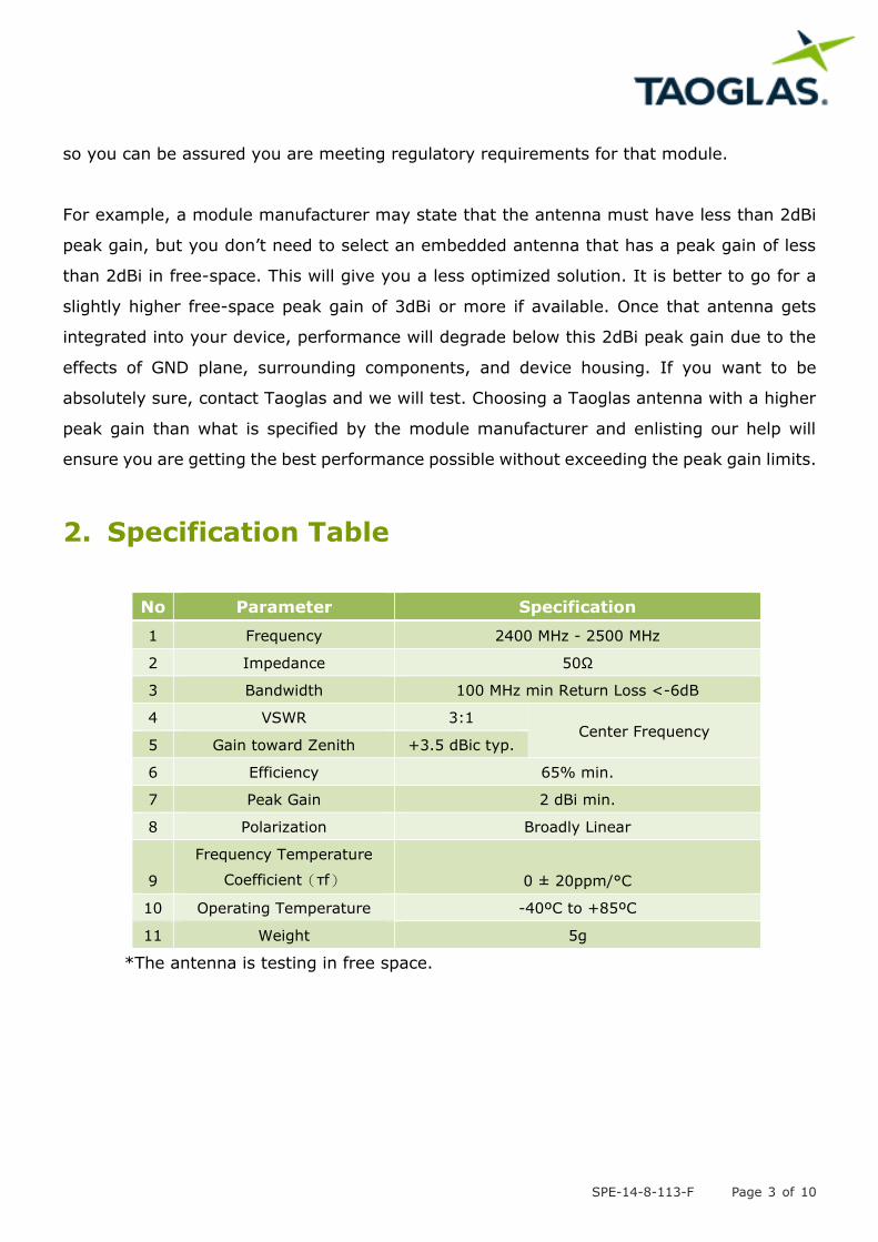
2. Specification Table
No Parameter Specification
1 Frequency 2400 MHz - 2500 MHz
2 Impedance 50Ω
3 Bandwidth 100 MHz min Return Loss <-6dB
4 VSWR 3:1 Center Frequency
5 Gain toward Zenith +3.5 dBic typ.
6 Efficiency 65% min.
7 Peak Gain 2 dBi min.
8 Polarization Broadly Linear
9
Frequency Temperature
Coefficient(τf) 0 ± 20ppm/°C
10 Operating Temperature -40ºC to +85ºC
11 Weight 5g
*The antenna is testing in free space.
SPE-14-8-113-F Page 4 of 10
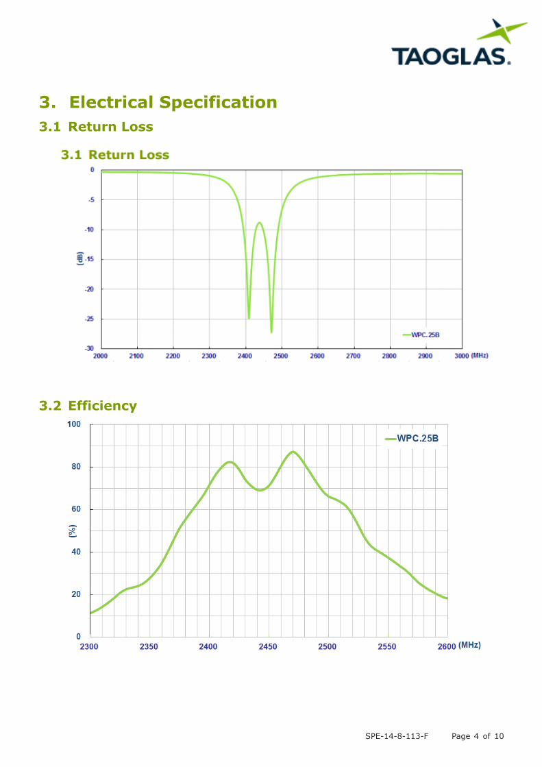
3. Electrical Specification
3.1 Return Loss
3.2 Efficiency
SPE-14-8-113-F Page 5 of 10
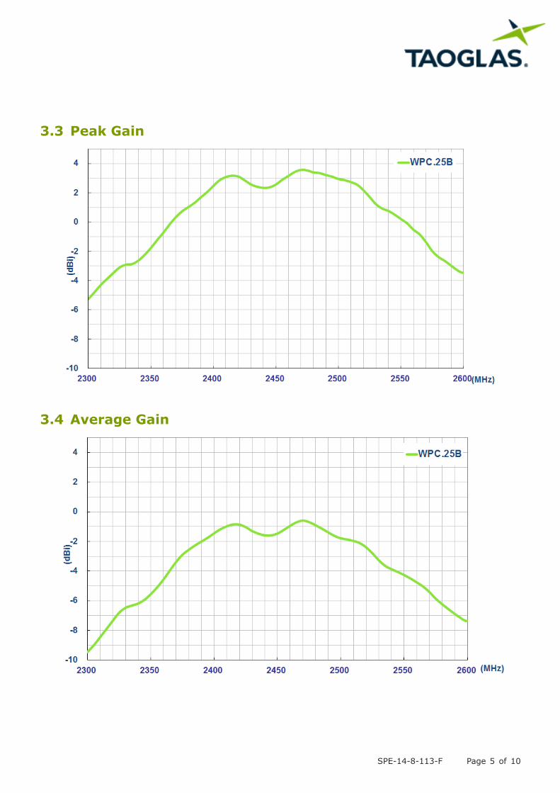
3.3 Peak Gain
3.4 Average Gain
SPE-14-8-113-F Page 6 of 10
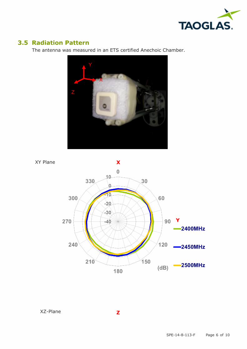
3.5 Radiation Pattern The antenna was measured in an ETS certified Anechoic Chamber.
XY Plane
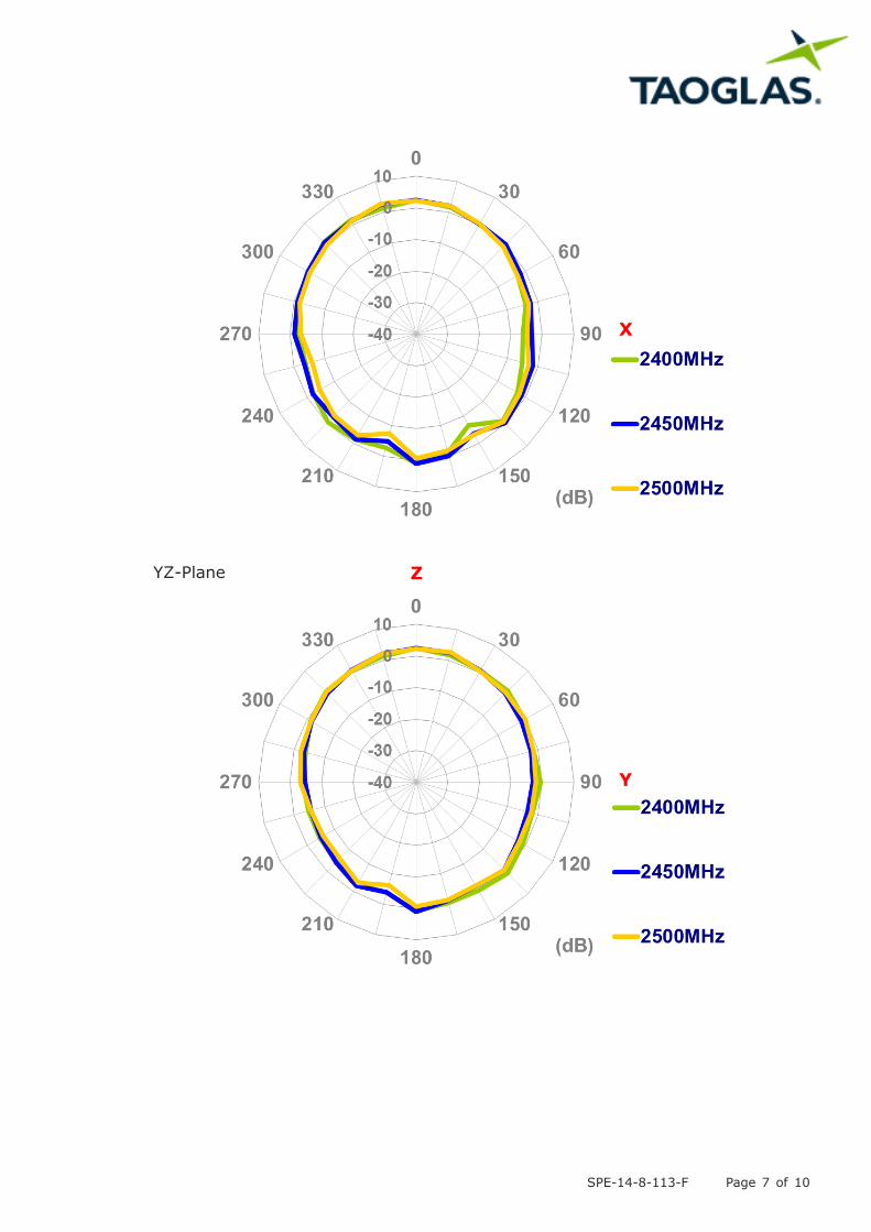
XZ-Plane
Y
X
Z
X
Y
Z
SPE-14-8-113-F Page 7 of 10
YZ-Plane
X
Y
Z
SPE-14-8-113-F Page 8 of 10
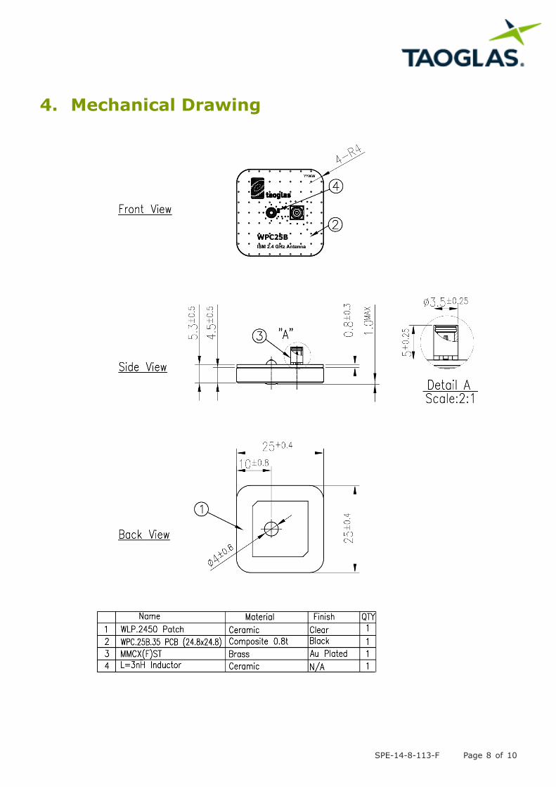
4. Mechanical Drawing
SPE-14-8-113-F Page 9 of 10
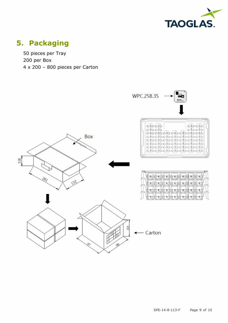
5. Packaging
50 pieces per Tray
200 per Box
4 x 200 – 800 pieces per Carton

SPE-14-8-113-F Page 10 of 10
Taoglas makes no warranties based on the accuracy or completeness of the contents of this document and reserves
the right to make changes to specifications and product descriptions at any time without notice. Taoglas reserves
all rights to this document and the information contained herein.
Reproduction, use or disclosure to third parties without express permission is strictly prohibited.
© Taoglas