TECHNICAL SPECIFICATION PROGRAMMABLE LOGIC ...
44
TECHNICAL SPECIFICATION PROGRAMMABLE LOGIC CONTROLLER MAKE: Schneider electric or ECIL or Allen broadly or ABB or Siemens 1.0 SCOPE: This specification covers general technical requirements for the design, development manufacture, fabrication, inspection, shop testing, assembly, packing, supply, transportation, delivery to site, installation, testing, internal and external wiring, testing at site, commissioning, start up, test runs and guarantee of PLC systems, HMI systems, SCADA development for the up gradation of Dryers., MAPS. Supply of hard & soft copies of as built drawings, relevant technical literature, operation & maintenance manuals, test & calibration procedures, test reports and training of PURCHASER's personnel are also included in the scope. It is not the intent to specify completely herein all details of construction of material & installation of instruments, equipment and control devices. The procurement and installation of items shall conform in all respects to applicable codes for design and workmanship and be capable of performing in continuous commercial operation. All the equipment, material drawings and work required for completion of subject scope as detailed above is included in SUPPLIER's scope whether specially indicated or not. 2.0 APPLICABLE STANDARDS, SPECIFICATIONS AND DRAWINGS: The design, manufacture and performance assessment of the equipment shall conform to well established practices or codes. IS, BS, ISA and SAMA specifications shall be followed wherever applicable. The standards, specifications/data sheets and drawings of all major items, including the bought out items required for manufacture of the system shall be submitted for PURCHASER's reference and approval. Standards and specifications applicable to this specification are as listed below. In the event of conflict between the provisions of this specification and the applicable standards and specifications, this specification shall govern. MIL STD-461A : Electromagnetic Emission and susceptibility - Requirements for the control of Electromagnetic interference. MIL STD-462 : Measurement of electromagnetic interference characteristics. IEC-801 : Electromagnetic compatibility for industrial process measurement and control equipment. IEEE-472 : Surge withstand capability. IS-13947(Part-1 ) : Specification for low voltage switch gear and control gear. ANSI/IEEE Std. 730 : Standard for software quality assurance plans 1984.
-
Upload
khangminh22 -
Category
Documents
-
view
0 -
download
0
Transcript of TECHNICAL SPECIFICATION PROGRAMMABLE LOGIC ...

TECHNICAL SPECIFICATION
PROGRAMMABLE LOGIC CONTROLLER
MAKE: Schneider electric or ECIL or Allen broadly or ABB or Siemens
1.0 SCOPE:
This specification covers general technical requirements for the design, development
manufacture, fabrication, inspection, shop testing, assembly, packing, supply,
transportation, delivery to site, installation, testing, internal and external wiring, testing at
site, commissioning, start up, test runs and guarantee of PLC systems, HMI systems,
SCADA development for the up gradation of Dryers., MAPS. Supply of hard & soft
copies of as built drawings, relevant technical literature, operation & maintenance
manuals, test & calibration procedures, test reports and training of PURCHASER's
personnel are also included in the scope.
It is not the intent to specify completely herein all details of construction of material &
installation of instruments, equipment and control devices. The procurement and
installation of items shall conform in all respects to applicable codes for design and
workmanship and be capable of performing in continuous commercial operation. All the
equipment, material drawings and work required for completion of subject scope as
detailed above is included in SUPPLIER's scope whether specially indicated or not.
2.0 APPLICABLE STANDARDS, SPECIFICATIONS AND DRAWINGS:
The design, manufacture and performance assessment of the equipment shall conform to well
established practices or codes. IS, BS, ISA and SAMA specifications shall be followed
wherever applicable. The standards, specifications/data sheets and drawings of all major
items, including the bought out items required for manufacture of the system shall be
submitted for PURCHASER's reference and approval.
Standards and specifications applicable to this specification are as listed below. In the event
of conflict between the provisions of this specification and the applicable standards and
specifications, this specification shall govern.
MIL STD-461A : Electromagnetic Emission and susceptibility - Requirements for the control of Electromagnetic interference. MIL STD-462 : Measurement of electromagnetic interference characteristics. IEC-801 : Electromagnetic compatibility for industrial process measurement and control equipment. IEEE-472 : Surge withstand capability. IS-13947(Part-1 ) : Specification for low voltage switch gear and control gear. ANSI/IEEE Std. 730 : Standard for software quality assurance plans 1984.

ANSI/IEEE Std. 830 : guide to software requirement Specification 1984. IS 9000 PARTR- III & V : Basic environmental testing procedure for electrical and
electronics items.
3.0 Materials, processes and workmanship:
Materials, processes and standard parts which are not specifically designated herein and
which are necessary for fulfillment of this specification shall be of industrial/MIL grade and
in accordance with practice pertinent to the manufacture of this type of equipment. Suitable
care shall be taken in design, procurement and manufacture of the equipment to ascertain the
desired quality.
All electrical and electronic components used shall be of industrial/MIL grade and standard
components readily available in the market from multiple vendors.
All connectors shall provide good contact and eliminate possibility of plugging in wrong
direction. All the small electrical and electronic components shall be wired on PCB. All
PCBs shall be epoxy based copper laminated type with EURO connectors & having gold
plated contacts and shall conform to national/international standards.
All components used shall be ''type approved" or shall have gone through a satisfactory
quality assurance test program. All ICs used shall be standard types available in the open
market. Use of any proprietary IC shall be specifically intimated for review & approval by
the PURCHASER.
All input/output connections between various modules inside the units shall be through
shielded multipin connectors. Wiring inside the units shall be carried out using PTFE
(Teflon) insulated multi strand wires. All cable shields shall be connected to the ground for
draining the static charge.
Screwed type connections shall be used for field wires and soldered type for internal
wiring & wiring of electronic circuits. Plug in type of arrangement shall be
specifically avoided for low level signal circuits to avoid loose contacts. AC and DC
voltage terminals shall be segregated and AC terminals shall be shrouded & physically
isolated from DC terminals. Wires shall be identified with the ferrule tag numbers on
both ends.
4.0 Technical Specifications:
4.1Main PLC and CPU requirements
• The total operation shall be controlled by One Engineering station cum Operator
Station located at Dryer operator Room and shall be hooked up with the Main PLC
CPU, HMIs.
• System shall be based on advanced high end Automation Platform. Each CPU shall
handle up to 512 Discrete IO, 24 Analog IO.
• Each CPU System and I/O Subsystems shall be from same series and same make.

• The complete system should be based on MODBUS protocols or HART protocol or
any open source protocols and any reserved function codes and user defined functions
codes used can be produced for approval.
• All the modules shall be rack mounted.
• All I/O modules shall be HOT Swappable i.e. on power on condition: Modules can be
plugged into or out of the rack without any damage to or electrical noise. No output
shall be affected while replacing these modules.
• All I/O modules shall have channel level diagnostics.
• Programming language shall be based on: Ladder, Instruction List, Structure Text,
SFC or Block diagram.
• Lithium battery shall be provided for RAM backup. (Application program shall
remain for a period of 3 years without power supply to the PLC rack).
• One computer should be provided with suitable configuration and should work as
engineering cum operator station. Engineering station shall be loaded with licensed
version of programming software for PLC programme development,SCADA
development and and HMI development. Engineering station shall be used as
operator station also.
• All the SCADA Screens development for 1500 tags is in the scope of Supplier as per
the requirement of Purchaser.
• Programming package support Windows 7 or higher version.
• All trends in History and Real Time shall be available at the engineering Station.
• The complete developing of the PLC, HMI, and SCADA programs is in the scope of
SUPPLIER according to the requirement of PURCHASER.
• PLC complete programming software should be installed and all the PLC’s
programme can be changed from engineering station.
• Necessary programming cable shall be provided for Programming the PLC.
Programming over Ethernet network shall be possible.
• The SCADA should be configured for all the digital, analog inputs and outputs.
• All HMI screens can be seen and can be programmed from the engineering station.
To meet these requirements additional accessories and schemes required for
commissioning of the above can be provided and the same shall be sent for approval.
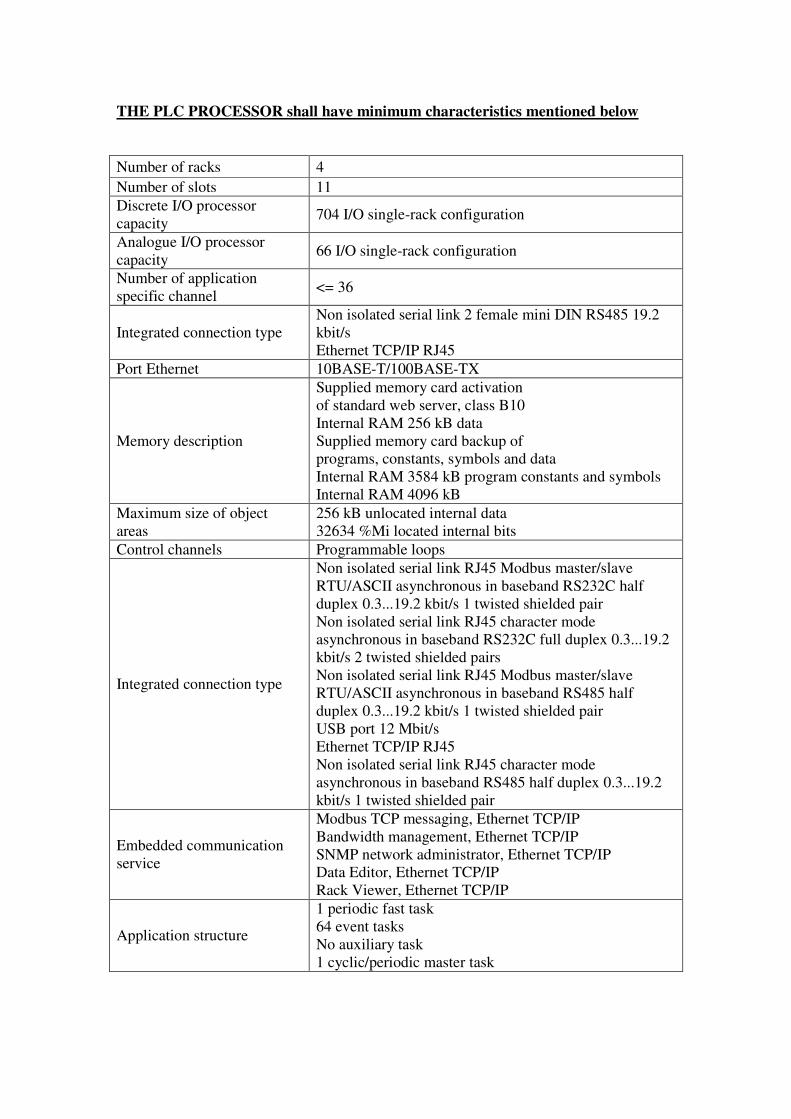
THE PLC PROCESSOR shall have minimum characteristics mentioned below
Number of racks 4
Number of slots 11
Discrete I/O processor
capacity 704 I/O single-rack configuration
Analogue I/O processor
capacity 66 I/O single-rack configuration
Number of application
specific channel <= 36
Integrated connection type
Non isolated serial link 2 female mini DIN RS485 19.2
kbit/s
Ethernet TCP/IP RJ45
Port Ethernet 10BASE-T/100BASE-TX
Memory description
Supplied memory card activation
of standard web server, class B10
Internal RAM 256 kB data
Supplied memory card backup of
programs, constants, symbols and data
Internal RAM 3584 kB program constants and symbols
Internal RAM 4096 kB
Maximum size of object
areas
256 kB unlocated internal data
32634 %Mi located internal bits
Control channels Programmable loops
Integrated connection type
Non isolated serial link RJ45 Modbus master/slave
RTU/ASCII asynchronous in baseband RS232C half
duplex 0.3...19.2 kbit/s 1 twisted shielded pair
Non isolated serial link RJ45 character mode
asynchronous in baseband RS232C full duplex 0.3...19.2
kbit/s 2 twisted shielded pairs
Non isolated serial link RJ45 Modbus master/slave
RTU/ASCII asynchronous in baseband RS485 half
duplex 0.3...19.2 kbit/s 1 twisted shielded pair
USB port 12 Mbit/s
Ethernet TCP/IP RJ45
Non isolated serial link RJ45 character mode
asynchronous in baseband RS485 half duplex 0.3...19.2
kbit/s 1 twisted shielded pair
Embedded communication
service
Modbus TCP messaging, Ethernet TCP/IP
Bandwidth management, Ethernet TCP/IP
SNMP network administrator, Ethernet TCP/IP
Data Editor, Ethernet TCP/IP
Rack Viewer, Ethernet TCP/IP
Application structure
1 periodic fast task
64 event tasks
No auxiliary task
1 cyclic/periodic master task
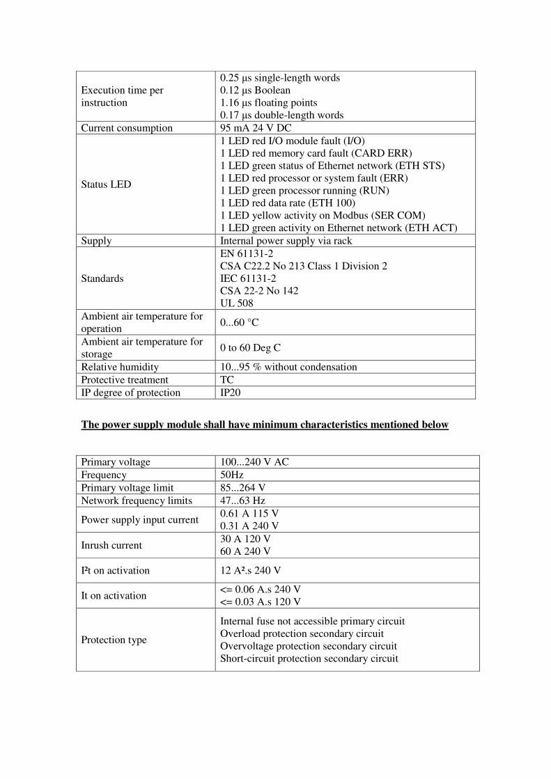
Execution time per
instruction
0.25 µs single-length words
0.12 µs Boolean
1.16 µs floating points
0.17 µs double-length words
Current consumption 95 mA 24 V DC
Status LED
1 LED red I/O module fault (I/O)
1 LED red memory card fault (CARD ERR)
1 LED green status of Ethernet network (ETH STS)
1 LED red processor or system fault (ERR)
1 LED green processor running (RUN)
1 LED red data rate (ETH 100)
1 LED yellow activity on Modbus (SER COM)
1 LED green activity on Ethernet network (ETH ACT)
Supply Internal power supply via rack
Standards
EN 61131-2
CSA C22.2 No 213 Class 1 Division 2
IEC 61131-2
CSA 22-2 No 142
UL 508
Ambient air temperature for
operation 0...60 °C
Ambient air temperature for
storage 0 to 60 Deg C
Relative humidity 10...95 % without condensation
Protective treatment TC
IP degree of protection IP20
The power supply module shall have minimum characteristics mentioned below
Primary voltage 100...240 V AC
Frequency 50Hz
Primary voltage limit 85...264 V
Network frequency limits 47...63 Hz
Power supply input current 0.61 A 115 V
0.31 A 240 V
Inrush current 30 A 120 V
60 A 240 V
I²t on activation 12 A².s 240 V
It on activation <= 0.06 A.s 240 V
<= 0.03 A.s 120 V
Protection type
Internal fuse not accessible primary circuit
Overload protection secondary circuit
Overvoltage protection secondary circuit
Short-circuit protection secondary circuit
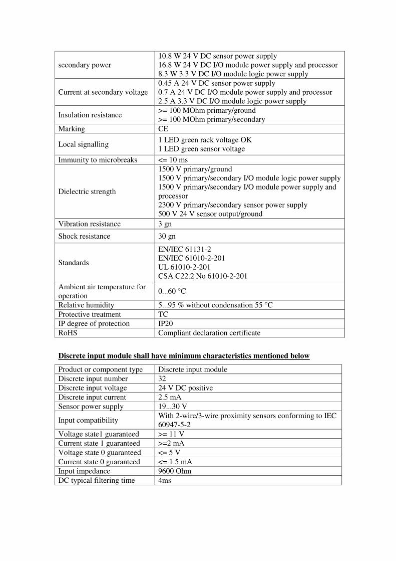
secondary power
10.8 W 24 V DC sensor power supply
16.8 W 24 V DC I/O module power supply and processor
8.3 W 3.3 V DC I/O module logic power supply
Current at secondary voltage
0.45 A 24 V DC sensor power supply
0.7 A 24 V DC I/O module power supply and processor
2.5 A 3.3 V DC I/O module logic power supply
Insulation resistance >= 100 MOhm primary/ground
>= 100 MOhm primary/secondary
Marking CE
Local signalling 1 LED green rack voltage OK
1 LED green sensor voltage
Immunity to microbreaks <= 10 ms
Dielectric strength
1500 V primary/ground
1500 V primary/secondary I/O module logic power supply
1500 V primary/secondary I/O module power supply and
processor
2300 V primary/secondary sensor power supply
500 V 24 V sensor output/ground
Vibration resistance 3 gn
Shock resistance 30 gn
Standards
EN/IEC 61131-2
EN/IEC 61010-2-201
UL 61010-2-201
CSA C22.2 No 61010-2-201
Ambient air temperature for
operation 0...60 °C
Relative humidity 5...95 % without condensation 55 °C
Protective treatment TC
IP degree of protection IP20
RoHS Compliant declaration certificate
Discrete input module shall have minimum characteristics mentioned below
Product or component type Discrete input module
Discrete input number 32
Discrete input voltage 24 V DC positive
Discrete input current 2.5 mA
Sensor power supply 19...30 V
Input compatibility With 2-wire/3-wire proximity sensors conforming to IEC
60947-5-2
Voltage state1 guaranteed >= 11 V
Current state 1 guaranteed >=2 mA
Voltage state 0 guaranteed <= 5 V
Current state 0 guaranteed <= 1.5 mA
Input impedance 9600 Ohm
DC typical filtering time 4ms
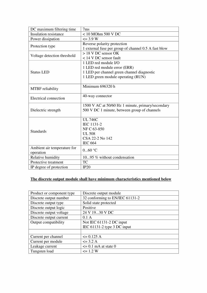
DC maximum filtering time 7ms
Insulation resistance < 10 MOhm 500 V DC
Power dissipation <= 3.9 W
Protection type Reverse polarity protection
1 external fuse per group of channel 0.5 A fast blow
Voltage detection threshold > 18 V DC sensor OK
< 14 V DC sensor fault
Status LED
1 LED red module I/O
1 LED red module error (ERR)
1 LED per channel green channel diagnostic
1 LED green module operating (RUN)
MTBF reliability Minimum 696320 h
Electrical connection 40-way connector
Dielectric strength
1500 V AC at 50/60 Hz 1 minute, primary/secondary
500 V DC 1 minute, between group of channels
Standards
UL 746C
IEC 1131-2
NF C 63-850
UL 508
CSA 22-2 No 142
IEC 664
Ambient air temperature for
operation 0...60 °C
Relative humidity 10...95 % without condensation
Protective treatment TC
IP degree of protection IP20
The discrete output module shall have minimum characteristics mentioned below
Product or component type Discrete output module
Discrete output number 32 conforming to EN/IEC 61131-2
Discrete output type Solid state protected
Discrete output logic Positive
Discrete output voltage 24 V 19...30 V DC
Discrete output current 0.1 A
Output compatibility
Not IEC 61131-2 DC input
IEC 61131-2 type 3 DC input
Current per channel <= 0.125 A
Current per module <= 3.2 A
Leakage current <= 0.1 mA at state 0
Tungsten load <= 1.2 W
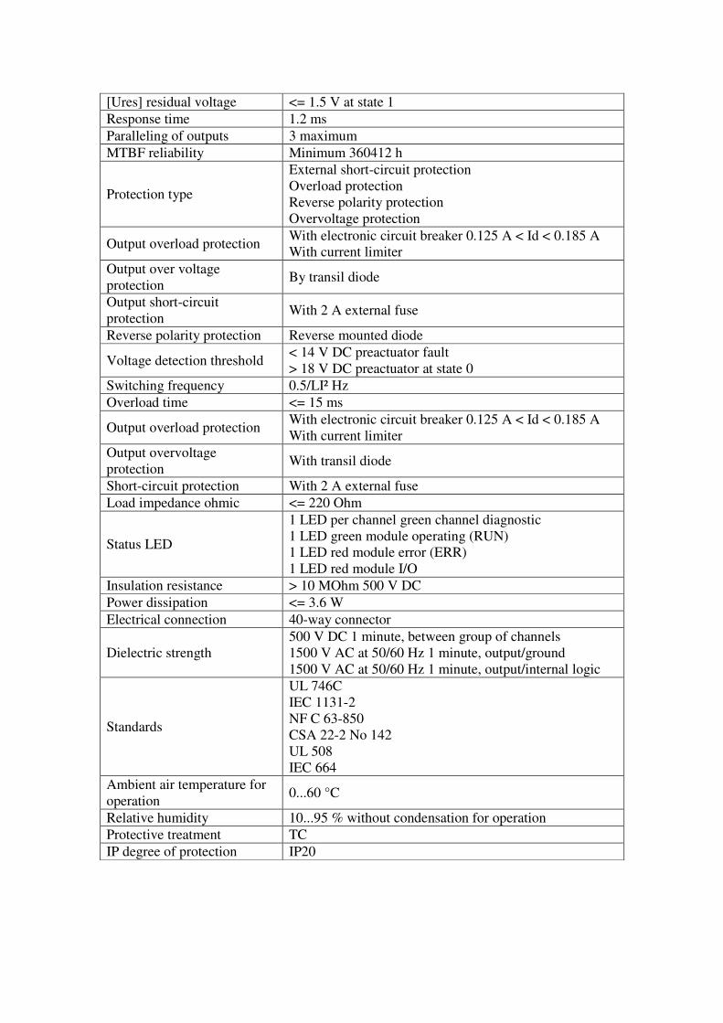
[Ures] residual voltage <= 1.5 V at state 1
Response time 1.2 ms
Paralleling of outputs 3 maximum
MTBF reliability Minimum 360412 h
Protection type
External short-circuit protection
Overload protection
Reverse polarity protection
Overvoltage protection
Output overload protection With electronic circuit breaker 0.125 A < Id < 0.185 A
With current limiter
Output over voltage
protection By transil diode
Output short-circuit
protection With 2 A external fuse
Reverse polarity protection Reverse mounted diode
Voltage detection threshold < 14 V DC preactuator fault
> 18 V DC preactuator at state 0
Switching frequency 0.5/LI² Hz
Overload time <= 15 ms
Output overload protection With electronic circuit breaker 0.125 A < Id < 0.185 A
With current limiter
Output overvoltage
protection With transil diode
Short-circuit protection With 2 A external fuse
Load impedance ohmic <= 220 Ohm
Status LED
1 LED per channel green channel diagnostic
1 LED green module operating (RUN)
1 LED red module error (ERR)
1 LED red module I/O
Insulation resistance > 10 MOhm 500 V DC
Power dissipation <= 3.6 W
Electrical connection 40-way connector
Dielectric strength
500 V DC 1 minute, between group of channels
1500 V AC at 50/60 Hz 1 minute, output/ground
1500 V AC at 50/60 Hz 1 minute, output/internal logic
Standards
UL 746C
IEC 1131-2
NF C 63-850
CSA 22-2 No 142
UL 508
IEC 664
Ambient air temperature for
operation 0...60 °C
Relative humidity 10...95 % without condensation for operation
Protective treatment TC
IP degree of protection IP20
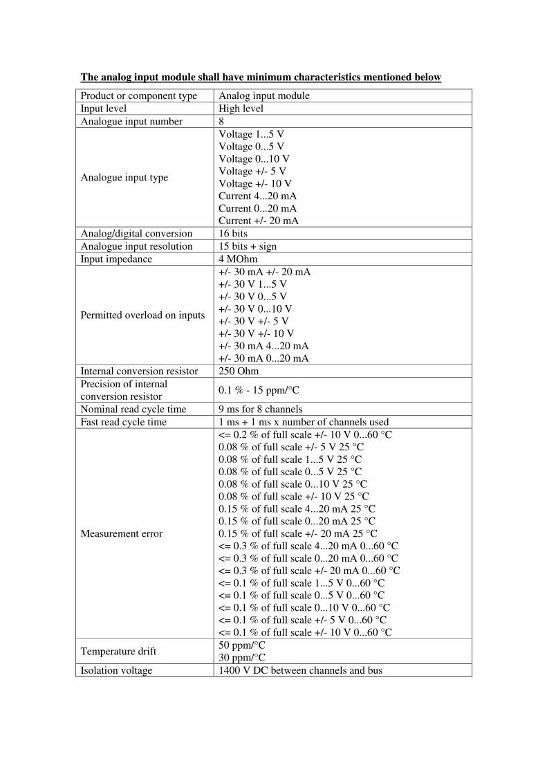
The analog input module shall have minimum characteristics mentioned below
Product or component type Analog input module
Input level High level
Analogue input number 8
Analogue input type
Voltage 1...5 V
Voltage 0...5 V
Voltage 0...10 V
Voltage +/- 5 V
Voltage +/- 10 V
Current 4...20 mA
Current 0...20 mA
Current +/- 20 mA
Analog/digital conversion 16 bits
Analogue input resolution 15 bits + sign
Input impedance 4 MOhm
Permitted overload on inputs
+/- 30 mA +/- 20 mA
+/- 30 V 1...5 V
+/- 30 V 0...5 V
+/- 30 V 0...10 V
+/- 30 V +/- 5 V
+/- 30 V +/- 10 V
+/- 30 mA 4...20 mA
+/- 30 mA 0...20 mA
Internal conversion resistor 250 Ohm
Precision of internal
conversion resistor 0.1 % - 15 ppm/°C
Nominal read cycle time 9 ms for 8 channels
Fast read cycle time 1 ms + 1 ms x number of channels used
Measurement error
<= 0.2 % of full scale +/- 10 V 0...60 °C
0.08 % of full scale +/- 5 V 25 °C
0.08 % of full scale 1...5 V 25 °C
0.08 % of full scale 0...5 V 25 °C
0.08 % of full scale 0...10 V 25 °C
0.08 % of full scale +/- 10 V 25 °C
0.15 % of full scale 4...20 mA 25 °C
0.15 % of full scale 0...20 mA 25 °C
0.15 % of full scale +/- 20 mA 25 °C
<= 0.3 % of full scale 4...20 mA 0...60 °C
<= 0.3 % of full scale 0...20 mA 0...60 °C
<= 0.3 % of full scale +/- 20 mA 0...60 °C
<= 0.1 % of full scale 1...5 V 0...60 °C
<= 0.1 % of full scale 0...5 V 0...60 °C
<= 0.1 % of full scale 0...10 V 0...60 °C
<= 0.1 % of full scale +/- 5 V 0...60 °C
<= 0.1 % of full scale +/- 10 V 0...60 °C
Temperature drift 50 ppm/°C
30 ppm/°C
Isolation voltage 1400 V DC between channels and bus
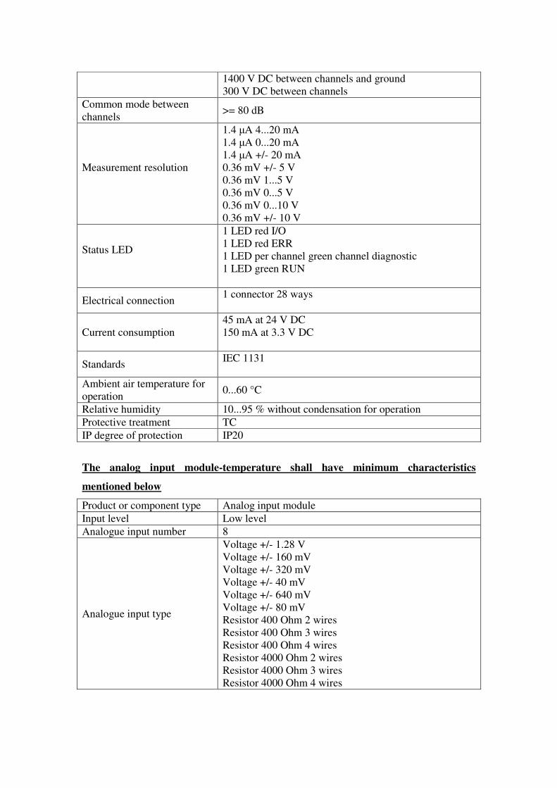
1400 V DC between channels and ground
300 V DC between channels
Common mode between
channels >= 80 dB
Measurement resolution
1.4 µA 4...20 mA
1.4 µA 0...20 mA
1.4 µA +/- 20 mA
0.36 mV +/- 5 V
0.36 mV 1...5 V
0.36 mV 0...5 V
0.36 mV 0...10 V
0.36 mV +/- 10 V
Status LED
1 LED red I/O
1 LED red ERR
1 LED per channel green channel diagnostic
1 LED green RUN
Electrical connection 1 connector 28 ways
Current consumption
45 mA at 24 V DC
150 mA at 3.3 V DC
Standards IEC 1131
Ambient air temperature for
operation 0...60 °C
Relative humidity 10...95 % without condensation for operation
Protective treatment TC
IP degree of protection IP20
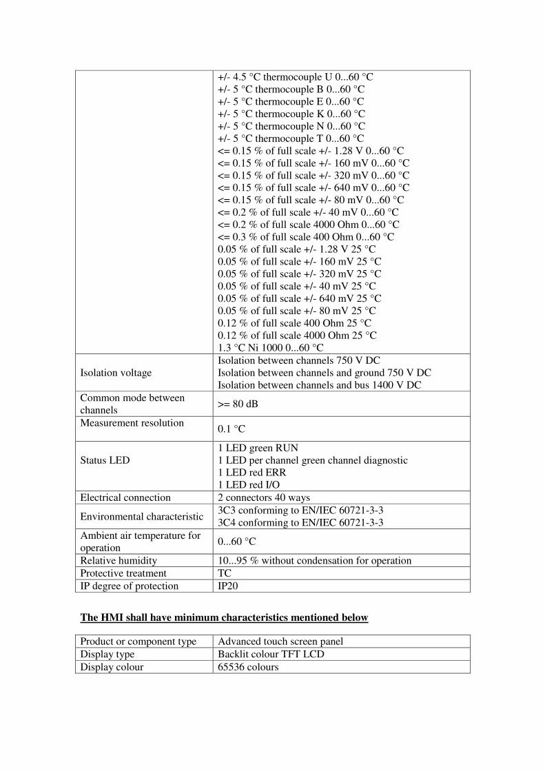
The analog input module-temperature shall have minimum characteristics
mentioned below
Product or component type Analog input module
Input level Low level
Analogue input number 8
Analogue input type
Voltage +/- 1.28 V
Voltage +/- 160 mV
Voltage +/- 320 mV
Voltage +/- 40 mV
Voltage +/- 640 mV
Voltage +/- 80 mV
Resistor 400 Ohm 2 wires
Resistor 400 Ohm 3 wires
Resistor 400 Ohm 4 wires
Resistor 4000 Ohm 2 wires
Resistor 4000 Ohm 3 wires
Resistor 4000 Ohm 4 wires
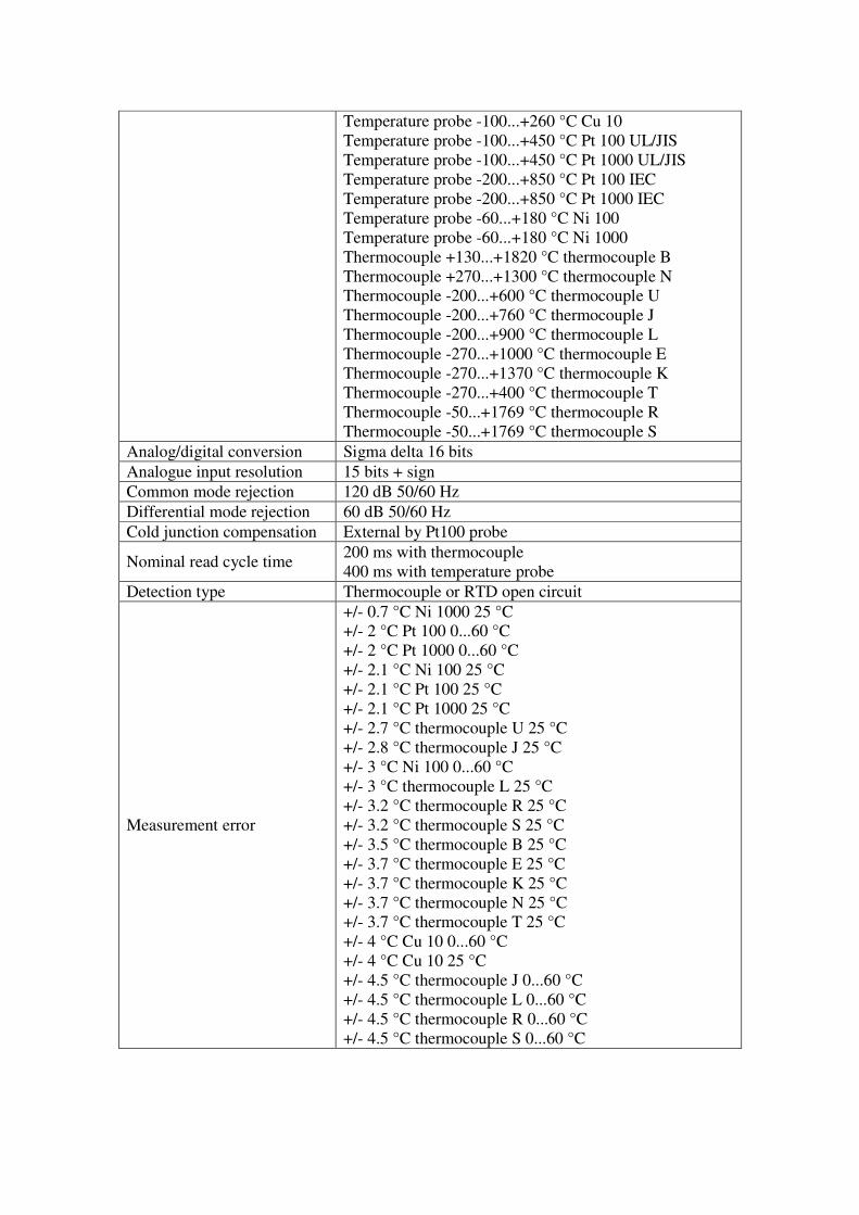
Temperature probe -100...+260 °C Cu 10
Temperature probe -100...+450 °C Pt 100 UL/JIS
Temperature probe -100...+450 °C Pt 1000 UL/JIS
Temperature probe -200...+850 °C Pt 100 IEC
Temperature probe -200...+850 °C Pt 1000 IEC
Temperature probe -60...+180 °C Ni 100
Temperature probe -60...+180 °C Ni 1000
Thermocouple +130...+1820 °C thermocouple B
Thermocouple +270...+1300 °C thermocouple N
Thermocouple -200...+600 °C thermocouple U
Thermocouple -200...+760 °C thermocouple J
Thermocouple -200...+900 °C thermocouple L
Thermocouple -270...+1000 °C thermocouple E
Thermocouple -270...+1370 °C thermocouple K
Thermocouple -270...+400 °C thermocouple T
Thermocouple -50...+1769 °C thermocouple R
Thermocouple -50...+1769 °C thermocouple S
Analog/digital conversion Sigma delta 16 bits
Analogue input resolution 15 bits + sign
Common mode rejection 120 dB 50/60 Hz
Differential mode rejection 60 dB 50/60 Hz
Cold junction compensation External by Pt100 probe
Nominal read cycle time 200 ms with thermocouple
400 ms with temperature probe
Detection type Thermocouple or RTD open circuit
Measurement error
+/- 0.7 °C Ni 1000 25 °C
+/- 2 °C Pt 100 0...60 °C
+/- 2 °C Pt 1000 0...60 °C
+/- 2.1 °C Ni 100 25 °C
+/- 2.1 °C Pt 100 25 °C
+/- 2.1 °C Pt 1000 25 °C
+/- 2.7 °C thermocouple U 25 °C
+/- 2.8 °C thermocouple J 25 °C
+/- 3 °C Ni 100 0...60 °C
+/- 3 °C thermocouple L 25 °C
+/- 3.2 °C thermocouple R 25 °C
+/- 3.2 °C thermocouple S 25 °C
+/- 3.5 °C thermocouple B 25 °C
+/- 3.7 °C thermocouple E 25 °C
+/- 3.7 °C thermocouple K 25 °C
+/- 3.7 °C thermocouple N 25 °C
+/- 3.7 °C thermocouple T 25 °C
+/- 4 °C Cu 10 0...60 °C
+/- 4 °C Cu 10 25 °C
+/- 4.5 °C thermocouple J 0...60 °C
+/- 4.5 °C thermocouple L 0...60 °C
+/- 4.5 °C thermocouple R 0...60 °C
+/- 4.5 °C thermocouple S 0...60 °C
+/- 4.5 °C thermocouple U 0...60 °C
+/- 5 °C thermocouple B 0...60 °C
+/- 5 °C thermocouple E 0...60 °C
+/- 5 °C thermocouple K 0...60 °C
+/- 5 °C thermocouple N 0...60 °C
+/- 5 °C thermocouple T 0...60 °C
<= 0.15 % of full scale +/- 1.28 V 0...60 °C
<= 0.15 % of full scale +/- 160 mV 0...60 °C
<= 0.15 % of full scale +/- 320 mV 0...60 °C
<= 0.15 % of full scale +/- 640 mV 0...60 °C
<= 0.15 % of full scale +/- 80 mV 0...60 °C
<= 0.2 % of full scale +/- 40 mV 0...60 °C
<= 0.2 % of full scale 4000 Ohm 0...60 °C
<= 0.3 % of full scale 400 Ohm 0...60 °C
0.05 % of full scale +/- 1.28 V 25 °C
0.05 % of full scale +/- 160 mV 25 °C
0.05 % of full scale +/- 320 mV 25 °C
0.05 % of full scale +/- 40 mV 25 °C
0.05 % of full scale +/- 640 mV 25 °C
0.05 % of full scale +/- 80 mV 25 °C
0.12 % of full scale 400 Ohm 25 °C
0.12 % of full scale 4000 Ohm 25 °C
1.3 °C Ni 1000 0...60 °C
Isolation voltage
Isolation between channels 750 V DC
Isolation between channels and ground 750 V DC
Isolation between channels and bus 1400 V DC
Common mode between
channels >= 80 dB
Measurement resolution
0.1 °C
Status LED
1 LED green RUN
1 LED per channel green channel diagnostic
1 LED red ERR
1 LED red I/O
Electrical connection 2 connectors 40 ways
Environmental characteristic 3C3 conforming to EN/IEC 60721-3-3
3C4 conforming to EN/IEC 60721-3-3
Ambient air temperature for
operation 0...60 °C
Relative humidity 10...95 % without condensation for operation
Protective treatment TC
IP degree of protection IP20
The HMI shall have minimum characteristics mentioned below
Product or component type Advanced touch screen panel
Display type Backlit colour TFT LCD
Display colour 65536 colours
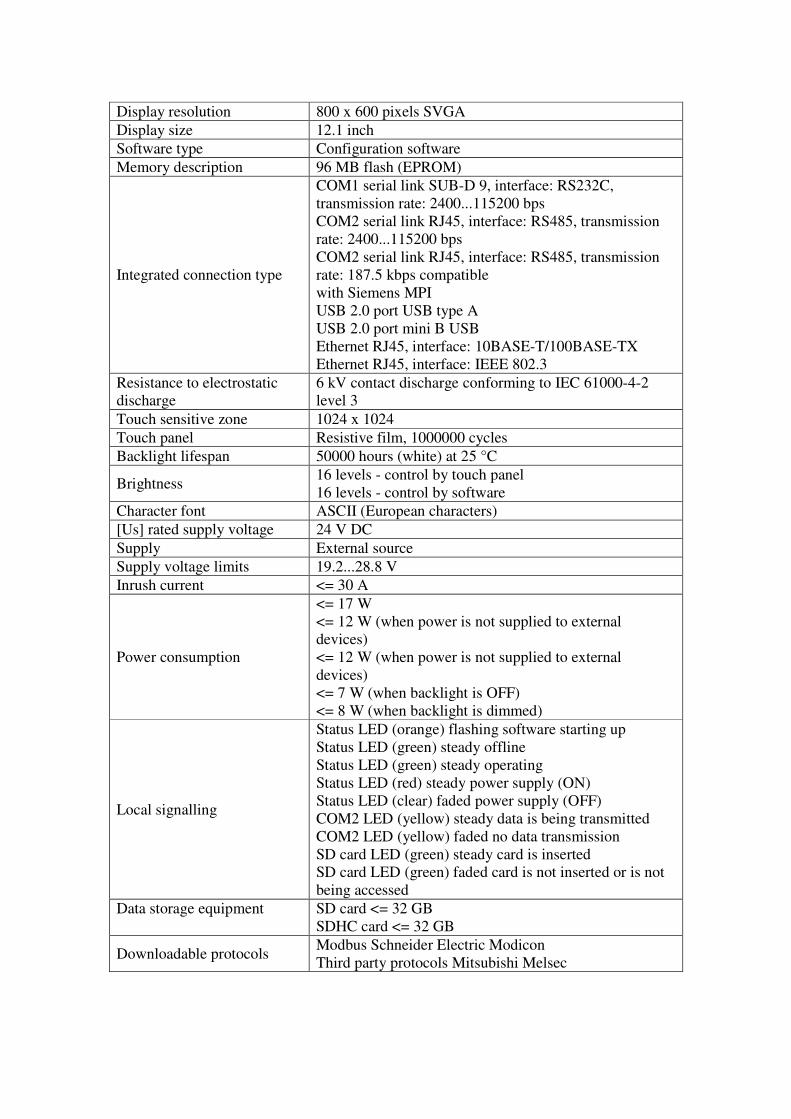
Display resolution 800 x 600 pixels SVGA
Display size 12.1 inch
Software type Configuration software
Memory description 96 MB flash (EPROM)
Integrated connection type
COM1 serial link SUB-D 9, interface: RS232C,
transmission rate: 2400...115200 bps
COM2 serial link RJ45, interface: RS485, transmission
rate: 2400...115200 bps
COM2 serial link RJ45, interface: RS485, transmission
rate: 187.5 kbps compatible
with Siemens MPI
USB 2.0 port USB type A
USB 2.0 port mini B USB
Ethernet RJ45, interface: 10BASE-T/100BASE-TX
Ethernet RJ45, interface: IEEE 802.3
Resistance to electrostatic
discharge
6 kV contact discharge conforming to IEC 61000-4-2
level 3
Touch sensitive zone 1024 x 1024
Touch panel Resistive film, 1000000 cycles
Backlight lifespan 50000 hours (white) at 25 °C
Brightness 16 levels - control by touch panel
16 levels - control by software
Character font ASCII (European characters)
[Us] rated supply voltage 24 V DC
Supply External source
Supply voltage limits 19.2...28.8 V
Inrush current <= 30 A
Power consumption
<= 17 W
<= 12 W (when power is not supplied to external
devices)
<= 12 W (when power is not supplied to external
devices)
<= 7 W (when backlight is OFF)
<= 8 W (when backlight is dimmed)
Local signalling
Status LED (orange) flashing software starting up
Status LED (green) steady offline
Status LED (green) steady operating
Status LED (red) steady power supply (ON)
Status LED (clear) faded power supply (OFF)
COM2 LED (yellow) steady data is being transmitted
COM2 LED (yellow) faded no data transmission
SD card LED (green) steady card is inserted
SD card LED (green) faded card is not inserted or is not
being accessed
Data storage equipment
SD card <= 32 GB
SDHC card <= 32 GB
Downloadable protocols Modbus Schneider Electric Modicon
Third party protocols Mitsubishi Melsec
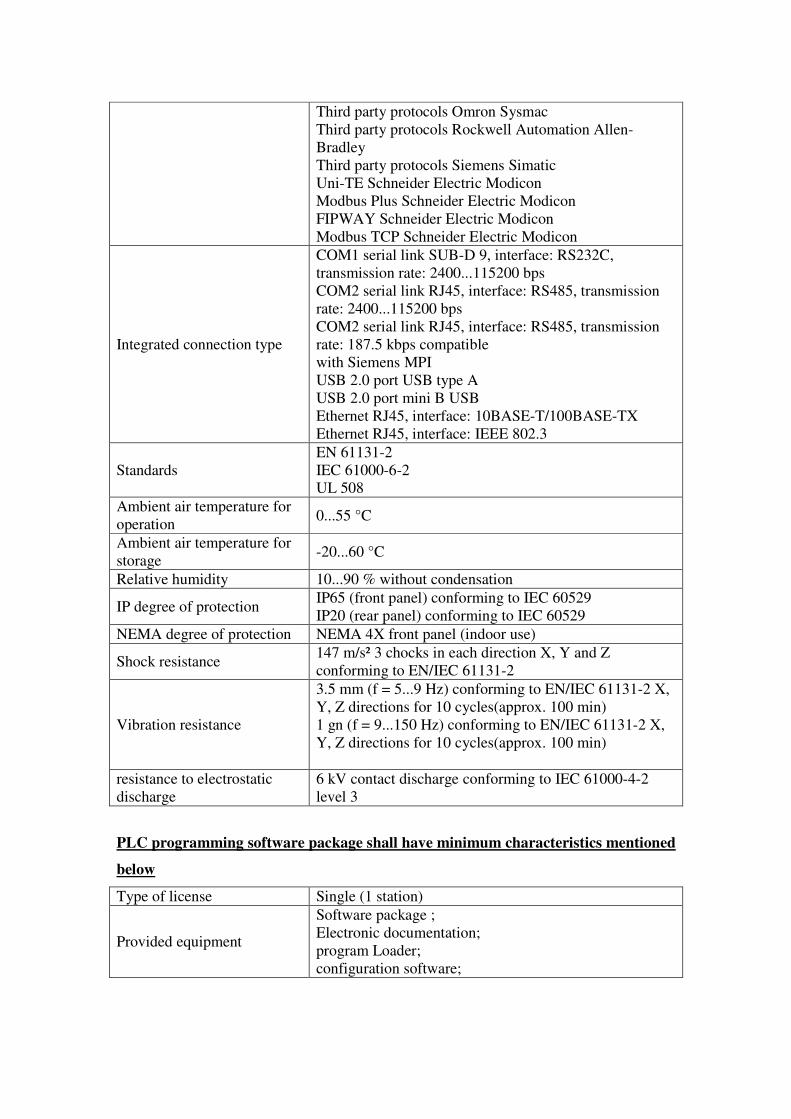
PLC programming software package shall have minimum characteristics mentioned
below
Type of license Single (1 station)
Provided equipment
Software package ;
Electronic documentation;
program Loader;
configuration software;
Third party protocols Omron Sysmac
Third party protocols Rockwell Automation Allen-
Bradley
Third party protocols Siemens Simatic
Uni-TE Schneider Electric Modicon
Modbus Plus Schneider Electric Modicon
FIPWAY Schneider Electric Modicon
Modbus TCP Schneider Electric Modicon
Integrated connection type
COM1 serial link SUB-D 9, interface: RS232C,
transmission rate: 2400...115200 bps
COM2 serial link RJ45, interface: RS485, transmission
rate: 2400...115200 bps
COM2 serial link RJ45, interface: RS485, transmission
rate: 187.5 kbps compatible
with Siemens MPI
USB 2.0 port USB type A
USB 2.0 port mini B USB
Ethernet RJ45, interface: 10BASE-T/100BASE-TX
Ethernet RJ45, interface: IEEE 802.3
Standards
EN 61131-2
IEC 61000-6-2
UL 508
Ambient air temperature for
operation 0...55 °C
Ambient air temperature for
storage -20...60 °C
Relative humidity 10...90 % without condensation
IP degree of protection IP65 (front panel) conforming to IEC 60529
IP20 (rear panel) conforming to IEC 60529
NEMA degree of protection NEMA 4X front panel (indoor use)
Shock resistance 147 m/s² 3 chocks in each direction X, Y and Z
conforming to EN/IEC 61131-2
Vibration resistance
3.5 mm (f = 5...9 Hz) conforming to EN/IEC 61131-2 X,
Y, Z directions for 10 cycles(approx. 100 min)
1 gn (f = 9...150 Hz) conforming to EN/IEC 61131-2 X,
Y, Z directions for 10 cycles(approx. 100 min)
resistance to electrostatic
discharge
6 kV contact discharge conforming to IEC 61000-4-2
level 3
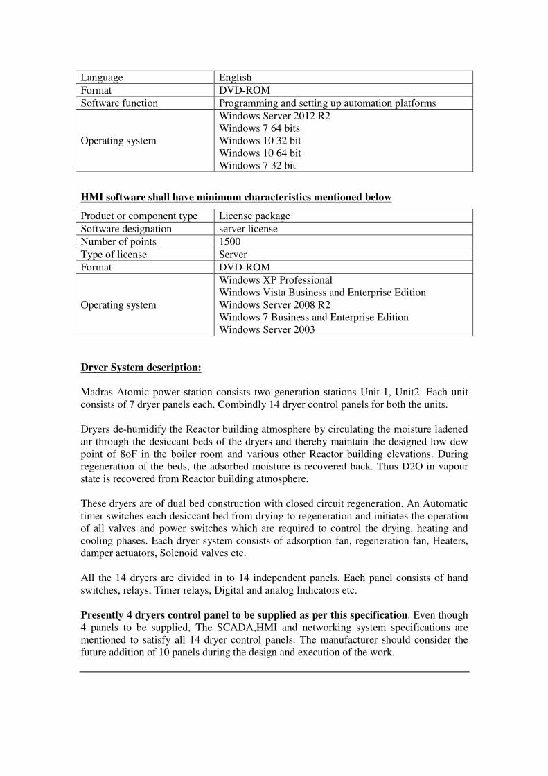
Language English
Format DVD-ROM
Software function Programming and setting up automation platforms
Operating system
Windows Server 2012 R2
Windows 7 64 bits
Windows 10 32 bit
Windows 10 64 bit
Windows 7 32 bit
HMI software shall have minimum characteristics mentioned below
Product or component type License package
Software designation server license
Number of points 1500
Type of license Server
Format DVD-ROM
Operating system
Windows XP Professional
Windows Vista Business and Enterprise Edition
Windows Server 2008 R2
Windows 7 Business and Enterprise Edition
Windows Server 2003
Dryer System description:
Madras Atomic power station consists two generation stations Unit-1, Unit2. Each unit
consists of 7 dryer panels each. Combindly 14 dryer control panels for both the units.
Dryers de-humidify the Reactor building atmosphere by circulating the moisture ladened
air through the desiccant beds of the dryers and thereby maintain the designed low dew
point of 8oF in the boiler room and various other Reactor building elevations. During
regeneration of the beds, the adsorbed moisture is recovered back. Thus D2O in vapour
state is recovered from Reactor building atmosphere.
These dryers are of dual bed construction with closed circuit regeneration. An Automatic
timer switches each desiccant bed from drying to regeneration and initiates the operation
of all valves and power switches which are required to control the drying, heating and
cooling phases. Each dryer system consists of adsorption fan, regeneration fan, Heaters,
damper actuators, Solenoid valves etc.
All the 14 dryers are divided in to 14 independent panels. Each panel consists of hand
switches, relays, Timer relays, Digital and analog Indicators etc.
Presently 4 dryers control panel to be supplied as per this specification. Even though
4 panels to be supplied, The SCADA,HMI and networking system specifications are
mentioned to satisfy all 14 dryer control panels. The manufacturer should consider the
future addition of 10 panels during the design and execution of the work.

4.2 The complete PLC System
• The complete design, development, Installation, Testing at factory, Transportation,
Erection, commissioning, testing at Plant site of complete PLC and HMI systems with
the minimum requirements mentioned in this specification is in the scope of
SUPPLIER.
• Each panel should house PLC Processor, I/O cards, Power supplies for that unit and
Miniature circuit breakers. Main ON indication should be provided for each
compartment.
• Supply of PLC, HMI, and SCADA systems mentioned below along with spares is in
complete scope of SUPPLIER, whether specifically stated or NOT.
• All the special cables and internal cables for connecting the various instruments in the
specification should be provided by SUPPLIER whether specifically stated or NOT.
• Complete development of SCADA Screens for all the processes is in the scope of
SUPPLIER.
• Analog Input cards should be able to accept Powered & Non powered Inputs.
• Brining the cables near to the PLC panel is in the scope of PURCHASER.
Connecting those cables to the PLC system is in the scope of SUPPLIER.
All the detailed drawings as annexure-1
Dryer-16 PLC-1
DIGITAL
INPUTS
DIGITAL
OUTPUTS
ANALOG INPUTS
THERMOCOUPLES
ANALOG
INPUTS
4-20milliA
TOTAL 48 32 8 8
PLC-1 system shall consist following minimum main components:
Sl. No. Description 1 Processor module
2 12 slot Ruggedized rack for CPU, Power supply, I/O cards
3 Power supply module
4 Discrete 32 input module
5 Discrete 16 input module
6 Discrete 32 output module
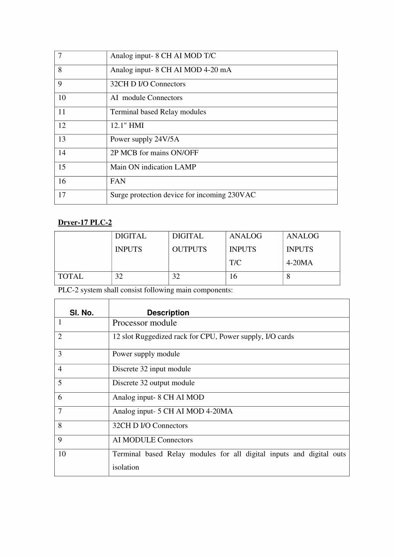
7 Analog input- 8 CH AI MOD T/C
8 Analog input- 8 CH AI MOD 4-20 mA
9 32CH D I/O Connectors
10 AI module Connectors
11 Terminal based Relay modules
12 12.1" HMI
13 Power supply 24V/5A
14 2P MCB for mains ON/OFF
15 Main ON indication LAMP
16 FAN
17 Surge protection device for incoming 230VAC
Dryer-17 PLC-2
DIGITAL
INPUTS
DIGITAL
OUTPUTS
ANALOG
INPUTS
T/C
ANALOG
INPUTS
4-20MA
TOTAL 32 32 16 8
PLC-2 system shall consist following main components:
Sl. No. Description 1 Processor module
2 12 slot Ruggedized rack for CPU, Power supply, I/O cards
3 Power supply module
4 Discrete 32 input module
5 Discrete 32 output module
6 Analog input- 8 CH AI MOD
7 Analog input- 5 CH AI MOD 4-20MA
8 32CH D I/O Connectors
9 AI MODULE Connectors
10 Terminal based Relay modules for all digital inputs and digital outs
isolation

11 12.1" HMI
12 Power supply 24V/5A
13 2P MCB for mains ON/OFF
14 Main ON indication LAMP
16 FAN
17 Surge protection device for incoming 230VAC
Dryer-18 PLC-3
DIGITAL
INPUTS
DIGITAL
OUTPUTS
ANALOG
INPUTS
T/C
ANALOG
INPUTS
4-20MA
TOTAL 32 32 16 8
PLC-3 system shall consist following main components:
Sl. No. Description 1 Processor module
2 12 slot Ruggedized rack for CPU, Power supply, I/O cards
3 Power supply module
4 Discrete 32 input module
5 Discrete 32 output module
6 Analog input- 8 CH AI MOD
7 Analog input- 5 CH AI MOD 4-20MA
8 32CH D I/O Connector
9 AI MODULE Connector
10 Terminal based Relay modules for all digital inputs and digital outs
isolation
11 12.1" HMI
12 Power supply 24V/5A
13 2P MCB for mains ON/OFF
14 Main ON indication LAMP
15 FAN
16 Surge protection device for incoming 230VAC
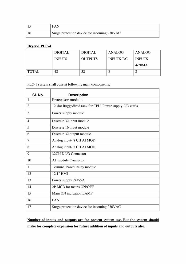
Dryer-1 PLC-4
DIGITAL
INPUTS
DIGITAL
OUTPUTS
ANALOG
INPUTS T/C
ANALOG
INPUTS
4-20MA
TOTAL 48 32 8 8
PLC-1 system shall consist following main components:
Sl. No. Description 1 Processor module
2 12 slot Ruggedized rack for CPU, Power supply, I/O cards
3 Power supply module
4 Discrete 32 input module
5 Discrete 16 input module
6 Discrete 32 output module
7 Analog input- 8 CH AI MOD
8 Analog input- 5 CH AI MOD
9 32CH D I/O Connector
10 AI module Connector
11 Terminal based Relay module
12 12.1" HMI
13 Power supply 24V/5A
14 2P MCB for mains ON/OFF
15 Main ON indication LAMP
16 FAN
17 Surge protection device for incoming 230VAC
Number of inputs and outputs are for present system use. But the system should
make for complete expansion for future addition of inputs and outputs also.
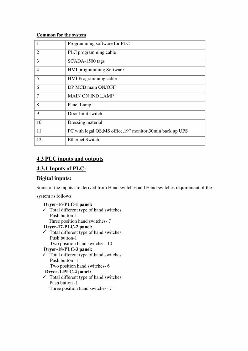
Common for the system
1 Programming software for PLC
2 PLC programming cable
3 SCADA-1500 tags
4 HMI programming Software
5 HMI Programming cable
6 DP MCB main ON/OFF
7 MAIN ON IND LAMP
8 Panel Lamp
9 Door limit switch
10 Dressing material
11 PC with legal OS,MS office,19” monitor,30min back up UPS
12 Ethernet Switch
4.3 PLC inputs and outputs
4.3.1 Inputs of PLC:
Digital inputs:
Some of the inputs are derived from Hand switches and Hand switches requirement of the
system as follows
Dryer-16-PLC-1 panel:
� Total different type of hand switches:
Push button-1
Three position hand switches- 7
Dryer-17-PLC-2 panel:
� Total different type of hand switches:
Push button-1
Two position hand switches- 10
Dryer-18-PLC-3 panel:
� Total different type of hand switches:
Push button -1
Two position hand switches- 6
Dryer-1-PLC-4 panel:
� Total different type of hand switches:
Push button -1
Three position hand switches- 7
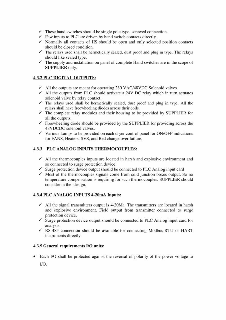
� These hand switches should be single pole type, screwed connection.
� Few inputs to PLC are driven by hand switch contacts directly.
� Normally all contacts of HS should be open and only selected position contacts
should be closed condition.
� The relays used shall be hermetically sealed, dust proof and plug in type. The relays
should like sealed type.
� The supply and installation on panel of complete Hand switches are in the scope of
SUPPLIER only.
4.3.2 PLC DIGITAL OUTPUTS:
� All the outputs are meant for operating 230 VAC/48VDC Solenoid valves.
� All the outputs from PLC should activate a 24V DC relay which in turn actuates
solenoid valve by relay contact. � The relays used shall be hermetically sealed, dust proof and plug in type. All the
relays shall have freewheeling diodes across their coils. � The complete relay modules and their housing to be provided by SUPPLIER for
all the outputs.
� Freewheeling diode should be provided by the SUPPLIER for providing across the
48VDCDC solenoid valves.
� Various Lamps to be provided on each dryer control panel for ON/OFF indications
for FANS, Heaters, SVS, and Bed change over failure.
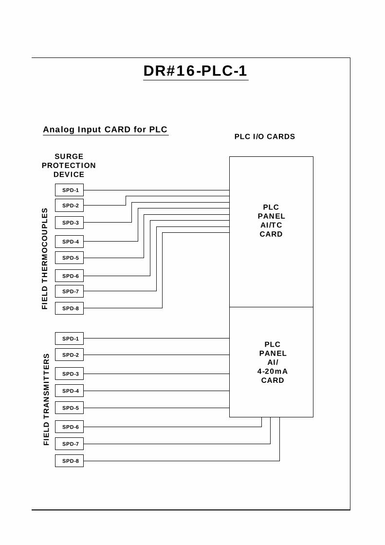
4.3.3 PLC ANALOG INPUTS THERMOCOUPLES:
� All the thermocouples inputs are located in harsh and explosive environment and
so connected to surge protection device
� Surge protection device output should be connected to PLC Analog input card
� Most of the thermocouples signals come from cold junction boxes output. So no
temperature compensation is requiring for such thermocouples. SUPPLIER should
consider in the design.
4.3.4 PLC ANALOG INPUTS 4-20mA Inputs:
� All the signal transmitters output is 4-20Ma. The transmitters are located in harsh
and explosive environment. Field output from transmitter connected to surge
protection device.
� Surge protection device output should be connected to PLC Analog input card for
analysis.
� RS-485 connection should be available for connecting Modbus-RTU or HART
instruments directly.
4.3.5 General requirements I/O units:
• Each I/O shall be protected against the reversal of polarity of the power voltage to
I/O.

• Each I/O module shall have a LED per channel to indicate the status of each
input/output.
• Each input shall be provided with filters to filter out any noise in the input line or
noise because of input contact bouncing.
• Output contacts from the PLC shall be potential free / dry contacts with contact
ratings 220 V AC, 5 Amps.
• It is recommended that all I/O shall be fused. Each output shall be short circuit proof
and protected by fuse. Visual indication of fuse blown indication must be provided
for each output.
• For Analog I/O modules shall have Optical Isolation for Inputs and outputs. For
Digital I/O Free Wheel Diode is to be used.
• Watchdog timer shall be a software device. Watchdog timer shall continuously
monitor the healthiness of processor. Any hardware or software problem in the
processor sub-system, which shall include CPU, memory, power supply,
communication interface etc. shall cause the watchdog timer to report processor
failure.
• PLC processor shall always monitor the status of PLC input and output modules for
their healthy condition and annunciate the same through engineering station and
printer.
• It shall be possible to modify, add or delete the application program on line without
affecting the outputs.
• It shall be possible to printout the ladder / logic diagram on the PLC printer. In
addition printer shall also be able to print the following.
a) Diagnostic messages, as and when they appear.
b) Diagnostic report when called for.
c) Processor alarms connected to PLC as and when they appear and alarm
report whenever initiated.
d) I/O map showing status of all inputs and Corresponding outputs in a user
defined formats.
• The PLC console shall be provided with self-diagnostics feature, which shall display
error messages and initiate an audible alarm if the fault is detected.
• The diagnostic shall include but not limited to the following:
• Failure of main or I/O processor
• Memory faults, both PROM and EPROM
• Microprocessor faults
• Communication faults
• I/O interface or address faults
• Voltage signal discrepancy on input and output
• Power supply faults
• Final assembly should be done in the presence of DEPRATMENT Personnel.
• All the spares should be tested at the SUPPLIERS location in the presence of
departmental persons.
• Training should be given for 3 departmental persons about the complete
Programming of PLC, HMI systems and SCADA systems.
• All the components used in the system with complete purchase technical
specification should be submitted for PURCHASER reference purpose.
• Terminal based relay module should be used in all the DI/DO isolations as per the
drawings attached.
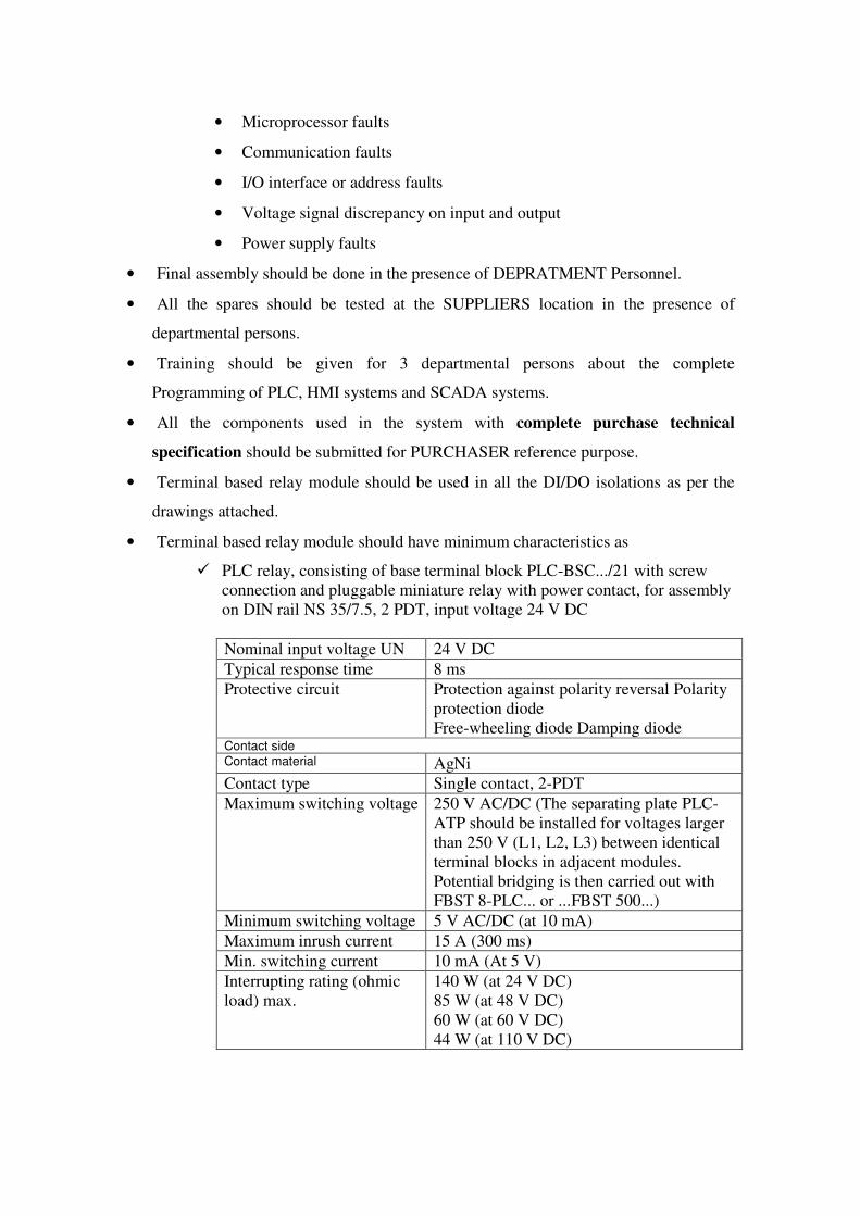
• Terminal based relay module should have minimum characteristics as
� PLC relay, consisting of base terminal block PLC-BSC.../21 with screw
connection and pluggable miniature relay with power contact, for assembly
on DIN rail NS 35/7.5, 2 PDT, input voltage 24 V DC
Nominal input voltage UN 24 V DC
Typical response time 8 ms
Protective circuit Protection against polarity reversal Polarity
protection diode
Free-wheeling diode Damping diode Contact side Contact material AgNi
Contact type Single contact, 2-PDT
Maximum switching voltage 250 V AC/DC (The separating plate PLC-
ATP should be installed for voltages larger
than 250 V (L1, L2, L3) between identical
terminal blocks in adjacent modules.
Potential bridging is then carried out with
FBST 8-PLC... or ...FBST 500...)
Minimum switching voltage 5 V AC/DC (at 10 mA)
Maximum inrush current 15 A (300 ms)
Min. switching current 10 mA (At 5 V)
Interrupting rating (ohmic
load) max.
140 W (at 24 V DC)
85 W (at 48 V DC)
60 W (at 60 V DC)
44 W (at 110 V DC)
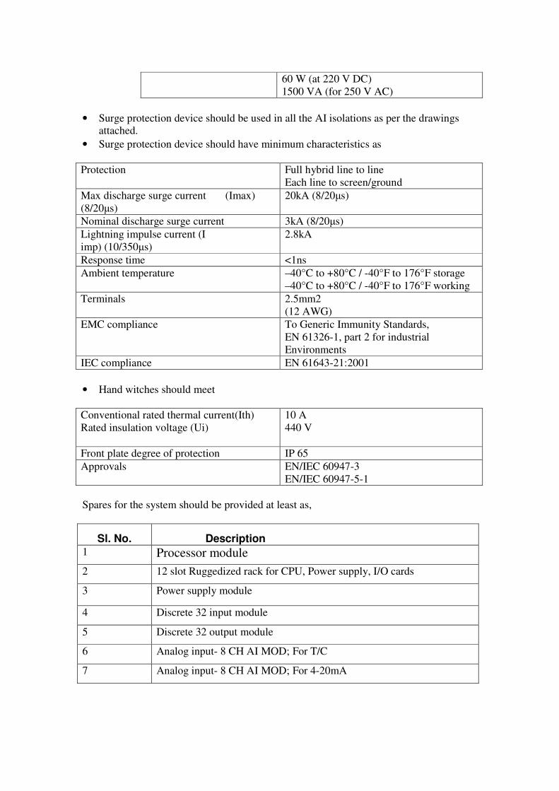
60 W (at 220 V DC)
1500 VA (for 250 V AC)
• Surge protection device should be used in all the AI isolations as per the drawings attached.
• Surge protection device should have minimum characteristics as
Protection Full hybrid line to line
Each line to screen/ground
Max discharge surge current (Imax)
(8/20µs)
20kA (8/20µs)
Nominal discharge surge current 3kA (8/20µs)
Lightning impulse current (I
imp) (10/350µs)
2.8kA
Response time <1ns
Ambient temperature –40°C to +80°C / -40°F to 176°F storage
–40°C to +80°C / -40°F to 176°F working
Terminals 2.5mm2
(12 AWG)
EMC compliance To Generic Immunity Standards,
EN 61326-1, part 2 for industrial
Environments
IEC compliance EN 61643-21:2001
• Hand witches should meet
Conventional rated thermal current(Ith)
Rated insulation voltage (Ui)
10 A
440 V
Front plate degree of protection IP 65
Approvals EN/IEC 60947-3
EN/IEC 60947-5-1
Spares for the system should be provided at least as,
Sl. No. Description 1 Processor module
2 12 slot Ruggedized rack for CPU, Power supply, I/O cards
3 Power supply module
4 Discrete 32 input module
5 Discrete 32 output module
6 Analog input- 8 CH AI MOD; For T/C
7 Analog input- 8 CH AI MOD; For 4-20mA

8 32CH D I/O Connector
9 8 CH AI Connector Thermocouple
10 8 CH AI Connector 4020mA inputs
13 12.1" HMI
14 Power supply 24V/5A
15 2P MCB for mains ON/OFF
16 Main ON indication LAMP
17 MCB
4.4 SYSTEM SOFTWARE
• The complete PC along with the printer to be supplied by SUPPLIER as per
specification.
• The software shall be window 7 or window 8 or Windows 10 based. It should be capable
of facilitating all the data processing operations. All the analysis data and alarm status
shall be stored in hard disk for retrieval at a later stage. It should display all information
in user friendly color display formats. A high level of system security shall be achieved
through the use of passwords. All software tools required for creating of data base,
graphics and diagnostics shall be provided. Positioning shall be done using arrow keys as
far as possible. Need for use of mouse/touch pad shall be as low as possible.
• System software for I/O map showing status on inputs and the corresponding outputs
giving Tag numbers as per logic diagrams in the user defined formats to be provided.
• System software for the report generation for reports like hourly on demand, shiftily,
daily and weekly report shall be provided whenever specified in job specifications, in
the user defined format.
• The PC should be supplied with full installations of PLC, HMI, SCADA software’s
with full licenses.
• The complete development of PLC logic development using ladder logic is in the
scope of SUPPLIER as per PURCHASER Requirement.
• The complete development of SCADA programs as per the purchaser requirement is
in the scope of SUPPLIER.SCADA program development includes development of
screens depicting complete system process, Alarm pages, Trending pages. The pages
should display the process values as per PURCHASER requirements wherever
required.
• The complete development off-line software packages for PLC programming, HMI
development, SCADA should be handed over after completing commissioning so that
the owner(PURCHASER) to modify/add/delete any part of program later.
• Logics for developing programming will be given after placing the PO and during the
development stage.
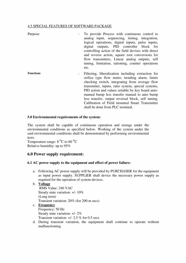
4.5 SPECIAL FEATURES OF SOFTWARE PACKAGE
Purpose : To provide Process with continuous control to
analog input, sequencing, timing, integration,
logical operations, digital inputs, pulse inputs,
digital outputs, PID controller block for
controlling action of the field devises with direct
and reverse action, square root conversions for
flow transmitters, Linear analog outputs, self
tuning, limitation, rationing, counter operations
etc.
Functions : Filtering, liberalization including extraction for
orifice type flow meter, trending alarm, limits
checking switch, integrating from average flow
transmitter, inputs, ratio system, special systems,
PID action and values settable by key board auto-
manual bump less transfer manual to auto bump
less transfer, output reversal block, self tuning,
Calibration of Field mounted Smart Transmitter
shall be done from PLC terminal.
5.0 Environmental requirements of the system:
The system shall be capable of continuous operation and storage under the
environmental conditions as specified below. Working of the system under the said environmental conditions shall be demonstrated by performing environmental
tests.
Temperature range: 8 O
C to 60 OC
Relative humidity: up to 95%
6.0 Power supply requirement:
6.1 AC power supply to the equipment and effect of power failure:
a. Following AC power supply will be provided by PURCHASER for the equipment
as input power supply. SUPPLIER shall device the necessary power supply as
required for the operation of system devices.
b. Voltage
RMS Value: 240 VAC
Steady state variation: +/- 10%
(Long term)
Transient variation: 20% (for 200 m secs)
c. Frequency
Frequency: 50 Hz
Steady state variation: +/- 2%
Transient variation: +/- 2.5 % for 0.5 secs
d. During transient variation, the equipment shall continue to operate without
malfunctioning.
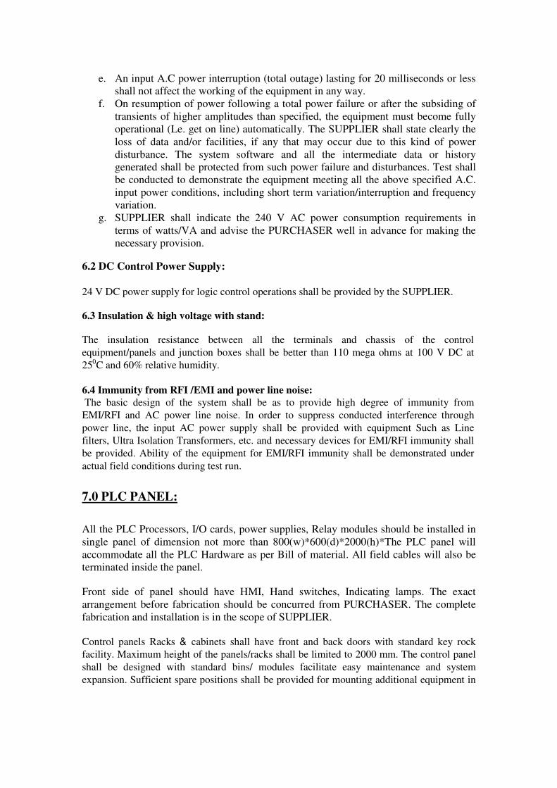
e. An input A.C power interruption (total outage) lasting for 20 milliseconds or less
shall not affect the working of the equipment in any way.
f. On resumption of power following a total power failure or after the subsiding of
transients of higher amplitudes than specified, the equipment must become fully
operational (Le. get on line) automatically. The SUPPLIER shall state clearly the
loss of data and/or facilities, if any that may occur due to this kind of power
disturbance. The system software and all the intermediate data or history
generated shall be protected from such power failure and disturbances. Test shall
be conducted to demonstrate the equipment meeting all the above specified A.C.
input power conditions, including short term variation/interruption and frequency
variation.
g. SUPPLIER shall indicate the 240 V AC power consumption requirements in
terms of watts/VA and advise the PURCHASER well in advance for making the
necessary provision.
6.2 DC Control Power Supply:
24 V DC power supply for logic control operations shall be provided by the SUPPLIER.
6.3 Insulation & high voltage with stand:
The insulation resistance between all the terminals and chassis of the control
equipment/panels and junction boxes shall be better than 110 mega ohms at 100 V DC at
250C and 60% relative humidity.
6.4 Immunity from RFI /EMI and power line noise:
The basic design of the system shall be as to provide high degree of immunity from
EMI/RFI and AC power line noise. In order to suppress conducted interference through
power line, the input AC power supply shall be provided with equipment Such as Line
filters, Ultra Isolation Transformers, etc. and necessary devices for EMI/RFI immunity shall
be provided. Ability of the equipment for EMI/RFI immunity shall be demonstrated under
actual field conditions during test run.
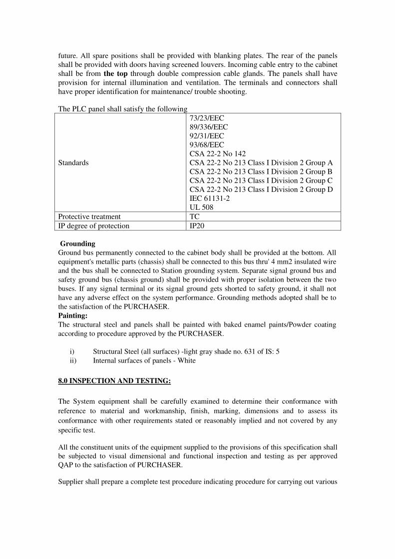
7.0 PLC PANEL:
All the PLC Processors, I/O cards, power supplies, Relay modules should be installed in
single panel of dimension not more than 800(w)*600(d)*2000(h)*The PLC panel will
accommodate all the PLC Hardware as per Bill of material. All field cables will also be
terminated inside the panel.
Front side of panel should have HMI, Hand switches, Indicating lamps. The exact
arrangement before fabrication should be concurred from PURCHASER. The complete
fabrication and installation is in the scope of SUPPLIER.
Control panels Racks & cabinets shall have front and back doors with standard key rock
facility. Maximum height of the panels/racks shall be limited to 2000 mm. The control panel
shall be designed with standard bins/ modules facilitate easy maintenance and system
expansion. Sufficient spare positions shall be provided for mounting additional equipment in
future. All spare positions shall be provided with blanking plates. The rear of the panels
shall be provided with doors having screened louvers. Incoming cable entry to the cabinet
shall be from the top through double compression cable glands. The panels shall have
provision for internal illumination and ventilation. The terminals and connectors shall
have proper identification for maintenance/ trouble shooting.
The PLC panel shall satisfy the following
Standards
73/23/EEC
89/336/EEC
92/31/EEC
93/68/EEC
CSA 22-2 No 142
CSA 22-2 No 213 Class I Division 2 Group A
CSA 22-2 No 213 Class I Division 2 Group B
CSA 22-2 No 213 Class I Division 2 Group C
CSA 22-2 No 213 Class I Division 2 Group D
IEC 61131-2
UL 508
Protective treatment TC
IP degree of protection IP20
Grounding
Ground bus permanently connected to the cabinet body shall be provided at the bottom. All
equipment's metallic parts (chassis) shall be connected to this bus thru' 4 mm2 insulated wire
and the bus shall be connected to Station grounding system. Separate signal ground bus and
safety ground bus (chassis ground) shall be provided with proper isolation between the two
buses. If any signal terminal or its signal ground gets shorted to safety ground, it shall not
have any adverse effect on the system performance. Grounding methods adopted shall be to
the satisfaction of the PURCHASER.
Painting:
The structural steel and panels shall be painted with baked enamel paints/Powder coating
according to procedure approved by the PURCHASER.
i) Structural Steel (all surfaces) -light gray shade no. 631 of IS: 5
ii) Internal surfaces of panels - White
8.0 INSPECTION AND TESTING:
The System equipment shall be carefully examined to determine their conformance with
reference to material and workmanship, finish, marking, dimensions and to assess its
conformance with other requirements stated or reasonably implied and not covered by any
specific test.
All the constituent units of the equipment supplied to the provisions of this specification shall
be subjected to visual dimensional and functional inspection and testing as per approved
QAP to the satisfaction of PURCHASER.
Supplier shall prepare a complete test procedure indicating procedure for carrying out various
tests and test setup etc. and submit for PURCHASER's approval prior to final acceptance
testing.
The SUPPLIER shall carry out inward inspection on all the electrical and electronic
components to check their conformance with the relevant specification and standards prior to
assembly and wiring as per QAP.
Electrical wiring shall be inspected and continuity checked to ensure conformity with the
relevant wiring diagrams.
The assembled panel shall be inspected to ensure that they conform to the relevant
drawings.
8.1 Burn -in test:
All the electronic sub-units after integrating shall be subjected to Burn-in test under
simulated conditions. The burn-in period shall be of 100 hrs during which time the entire
system equipment shall be kept switched on under the ambient conditions. The
performance of the system shall be checked before, during and after the test and there
shall not be any deviation from the specified performance requirement.
Voltage proof test:
All electrical circuits shall be tested for insulation w.r.t ground and shall meet the requirements. However, electronic components shall be suitably bypassed for this test. Functional test:
Each system including various sub units shall be completely wired and interconnected for
the purpose of functional tests to verify the performance requirements. Alarm conditions
shall be simulated and the complete operational sequence shall be checked.
Insulation test:
The insulation test at 100 V DC on all the electronic assemblies shall be done. The insulation resistance shall be better than 50 Mohms
Inward Inspection at site:
After obtaining shipping release from PURCHASER’s authorized representative,
equipment shall be packed properly and transported to the site. As this process may cause
some damage to the equipment, they shall be checked and inspected for physical damage
and quality verification by the SUPPLIER. Transportation of Total system to plant site is
in the scope of SUPPLIER.
9.0 ERECTION, COMMISSIONING AND TEST RUNS:
SUPPLIER shall be responsible for erection work as indicated in scope (refer para 1.0). SUPPLIER shall prepare and submit the erection and commissioning procedure for
PURCHASER's review and approval. SUPPLIER shall have to depute atleast one
engineer along with technician at site for the required period at the time of system erection & commissioning. Erection and commissioning of the complete Dryer
PLC,SCADA,HMI system shall be carried out by the SUPPLIER at Site as per approved
procedure. All process functions, controls, displays and alarm conditions shall be
successfully demonstrated during commissioning. SUPPLIER shall ensure that trained &
qualified personnel are involved in erection & commissioning of the system.
Personnel engaged in the commissioning work at site will have to follow the guidelines
as given and security procedures controlling entry and movement. During erection &

commissioning at PURCHASER's premises, SUPPLIER or his authorized representative will have to ensure that all safety regulations (both industrial safety and radiological
safety) in force are strictly followed. In such matters, PURCHASER'S instructions,
wherever given, will be binding. The erection & commissioning job involves:
1) Installation of all the instruments and hardware.
2) Checking of wiring inside the Panel.
3) Setting, alignment and functional checking of all the instruments supplied by
SUPPLIER.
4) Over all system commissioning.
5) Generation of commissioning document.
6) Handing over of the system along with all documents & spares to Site's
authorized personnel after successful test run.
10.0 DOCUMENTATION:
10.1Drawings:
Immediately after placement of P.O., SUPPLIER shall submit three(3) copies of all the
system drawings such as general arrangement, fabrication drgs., schematics, elementary
wiring diagram and bill of material, terminal loops etc. along with drawing list to the
PURCHASER for approval prior to fabrication and on acceptance of the same, they shall
form part of requirements of this specification. All drawings and documents shall
necessarily be as per PURCHASER's documentation procedures.
10.2 Quality assurance plan:
SUPPLIER shall provide their detailed Quality Assurance Plan (Q.A.P.) mentioning the
steps followed to ensure quality of the product for items fabricated at their works and for
bought out items. The Q.A.P. shall be prepared to ensure that all the tests on
components/equipment of the system and final assembled system are included for quality
assurance. The same shall be submitted for PURCHASER's approval and approved
Q.A.P. shall be followed to ensure the quality of the product.
The Test Procedure in detail covering all the functional requirements of this specification
shall be prepared mentioning the step-wise inspection and test procedures. The test
procedure also shall be submitted to the PURCHASER for approval prior to the
commencement of testing.
The SUPPLIER shall also submit one set of as built drawings in reproducible form to the
PURCHASER.
10.3 Operation & Maintenance manual:
The SUPPLIER shall submit five (5) copies of operating and maintenance manual of the
system along with soft copies.
a) The system technical description:
The system technical description shall be given in detail with reference to
drawings. The working of all modules / units _circuits shall be described. The
system description shall be specific to the equipment furnished and not of general
nature. It shall consists of data of the equipment, adjustment, calibrations,
complete instructions of installation, commissioning, working & operation of the
equipment & parts, catalogues, data sheets and drawings. The instructions for

assembly and installation shall show the identification part number of the
dismantled apparatus or equipment.
b) The system operation instructions shall be descriptive and in detail. Step by step
operating instructions shall be given for operation of the system. Various
adjustment & calibrations shall be clearly defined and mentioned.
c) Maintenance instruction:
Trouble shooting methods, routine and periodic maintenance, test
equipment to be used, test points with test voltages and pattern/wave shapes shall
be covered
The system components which should satisfy the below specification
PERSONAL COMPUTER
1. Processor Type: core i-7,
2. RAM: 4GB minimum, DDR3
3. HDD: 500 GB (minimum)
4. DVD RW
5. Monitor size: 20” LED
6. Ethernet Card: Integrated 10/100 mbps LAN controller ; Two LAN connections
7. Ports: Serial – 2nos.Parallel, USB-4nos. PS2 Keyboard and Mouse
8. Graphics: Integrated Intel extreme graphics controller
9. Sound: Integrated Sound
10. Operating System: Windows 7 or 8 preloaded server package
COLOR LASER PRINTER
1. Speed : min upto 16 ppm in A4
2. Paper Handling size :A4 Size, Auto Duplex
3. Resolution : upto 1200 X 600 Dpi
4. Accessories: Communication cable, Driver software, Manual to be supplied
5. Interface : Standard USB 2.0 Port
6. Printer memory : 2 MB
7. Network : Ready :
8. Supply: 220 V AC
Network Switch 8 Port
1. Type : Managed, Industrial grade, Fanless type
2. No. of Copper Connection : 8 RJ45 connectors
3. 19” rack mountable
4. Auto sense the network speed of connected node to run in different speed.
5. Supply 220 V AC
6. connectivity : UTP Copper Cable
U P S
1. Type: Online
2. Input supply: 180 to 250 V AC, 50 Hz
3. Rating : 2 KVA
4. Output: 230 V AC, 50 Hz
5. Output waveform: Sine wave
6. Should come with computer connectivity for display of alarms
7. Battery Backup time : 30 Min. (with supplied Battery)

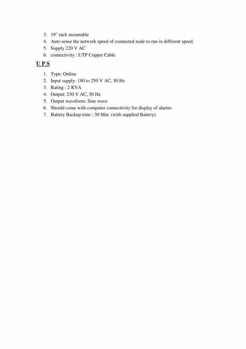
ANNEXURE-1
DR#16-PLC-1PLC I/O CARDSINPUT/OUTPUT FOR PLC
PANNEL HANDSWITCH CONTACTS&
OTHER DIGITAL CONTACTS
FIE
LD D
I
RELAY-1
RELAY-2
RELAY-3
RELAY-4
RELAY-5
RELAY-6
RELAY-7
RELAY-8
PLCPANELDI-16CARD
RELAY-11
RELAY-13
RELAY-14
RELAY-15
RELAY-16
RELAY-9
RELAY-10
RELAY-12
PLCPANEL
DOCARD
RELAY-1
RELAY-2
RELAY-3
RELAY-4
RELAY-5
RELAY-6
RELAY-7
RELAY-8
RELAY-9
RELAY-10
FIE
LD S
V &
TO
MC
Cs
RELAY-11
RELAY-12
RELAY-13
RELAY-14
RELAY-15
RELAY-16
RELAY-17
RELAY18
RELAY-19
RELAY-20
RELAY-21
RELAY-22
RELAY-23
RELAY-24
RELAY-25
RELAY-26
RELAY-27
RELAY-28
RELAY-29
RELAY-30
RELAY-31
RELAY-32
PLCPANELDI-32CARD
PLC I/O CARDS
PLCPANELAI/TCCARD
PLCPANEL
AI/4-20mACARD
SURGEPROTECTION
DEVICE
SPD-1
SPD-2
SPD-3
SPD-4
SPD-5
FIE
LD T
HE
RM
OC
OU
PLE
S
SPD-6
SPD-7
SPD-8
SPD-1
SPD-2
FIE
LD T
RA
NS
MIT
TE
RS
SPD-4
SPD-3
SPD-5
SPD-7
SPD-6
SPD-8
DR#16-PLC-1
Analog Input CARD for PLC
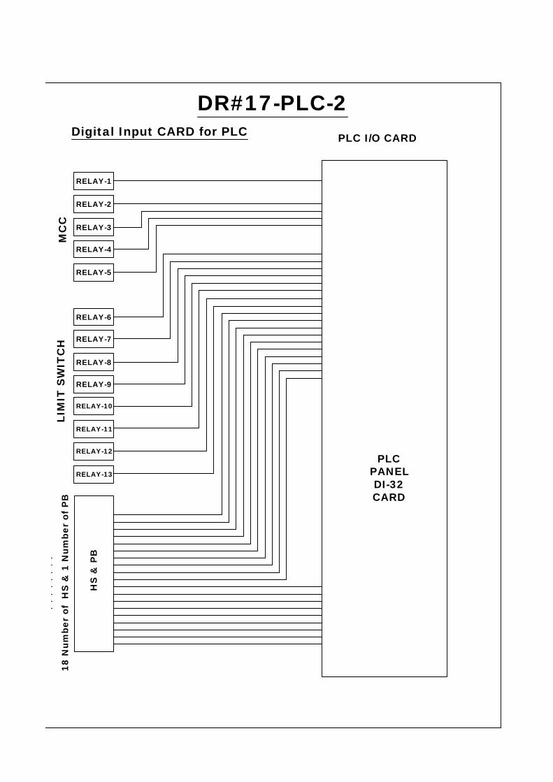
DR#17-PLC-2PLC I/O CARDDigital Input CARD for PLC
PLCPANELDI-32CARD
MC
C
RELAY-2
RELAY-3
RELAY-4
RELAY-5
RELAY-6
RELAY-7
RELAY-8
RELAY-9
RELAY-10
RELAY-11
RELAY-12
RELAY-13
LIM
IT S
WIT
CH
HS
& P
B
18 N
umbe
r of
HS
& 1
Num
ber
of P
B
RELAY-1

PLC I/O CARDSDigital output CARD for PLC
PLCPANELDo-32CARD
FIE
LD D
I
SO
LIN
OID
VA
LVE
RELAY-1
RELAY-2
RELAY-3
RELAY-4
RELAY-5
RELAY-6
RELAY-1
RELAY-1
RELAY-2
RELAY-3
RELAY-4
RELAY-5
AN
NLA
MP
S
RELAY-6
RELAY-7
RELAY-8
RELAY-1
RELAY-2
RELAY-3
RELAY-4
TO
FA
NS
DR#17-PLC-2
RELAY-1
RELAY-2
RELAY-3
RELAY-4
RELAY-5
RELAY-6
RELAY-7
RELAY-11
RELAY-12
RELAY-13
RELAY8
RELAY-9
RELAY-10
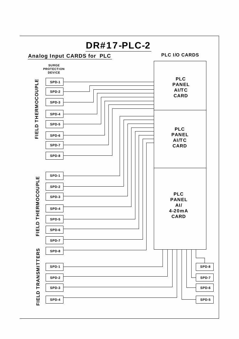
PLC I/O CARDS
PLCPANELAI/TCCARD
PLCPANEL
AI/4-20mACARD
SURGEPROTECTION
DEVICE
SPD-1
SPD-2
SPD-3
SPD-4
SPD-5
FIE
LD T
HE
RM
OC
OU
PLE
SPD-6
SPD-7
SPD-8
SPD-2
SPD-3
SPD-5
SPD-4
SPD-6
SPD-1
SPD-7
PLCPANELAI/TCCARD
FIE
LD T
HE
RM
OC
OU
PLE
SPD-8
SPD-2
SPD-3
SPD-4
SPD-1
SPD-7
SPD-6
SPD-5
SPD-8
FIE
LD T
RA
NS
MIT
TE
RS
Analog Input CARDS for PLCDR#17-PLC-2

DR#18-PLC-3PLC I/O CARDSDigital Input CARD for PLC
PLCPANELDI-32CARD
MC
C
RELAY-1
RELAY-2
RELAY-3
RELAY-4
RELAY-1
RELAY-2
RELAY-3
RELAY-4
RELAY-5
RELAY-6
RELAY-7
RELAY-8
LIM
IT S
WIT
CH
10 HAND SWITCH& 1 PB
RELAY-1
RELAY-2
RELAY-3
RELAY-4
RELAY-5
RELAY-6
RELAY-7
RELAY-8
RELAY-9
HA
ND
SW
ITC
H&
P
B
OT
HE
R I
NP
UT
S

PLC I/O CARDSDigital Output CARD for PLC
PLCPANNELDo-32CARD
RELAY-1
RELAY-2
RELAY-3
RELAY-4
RELAY-5
RELAY-6
RELAY-7
RELAY-8
RELAY-9
RELAY-10
RELAY-1
RELAY-2
RELAY-1
RELAY-1
RELAY-2
RELAY-3
RELAY-4
LAM
PS
SO
LIN
OID
VA
LVE
SA
NN
ON
/ O
FF C
ON
TR
OL
DR#18-PLC-3
RELAY-1
RELAY-2
RELAY-3
RELAY-4
RELAY-5
RELAY-6
RELAY-7
RELAY-8
RELAY-9
RELAY-10
RELAY-11
RELAY-12
RELAY-13
RELAY-14
RELAY-15OT
HE
R O
UT
PU
TS
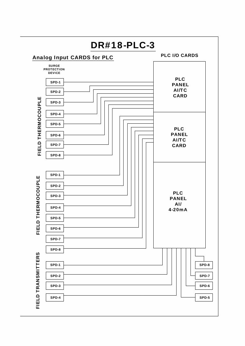
PLC I/O CARDSAnalog Input CARDS for PLC
PLCPANELAI/TCCARD
PLCPANEL
AI/4-20mA
SURGEPROTECTION
DEVICE
SPD-1
SPD-2
SPD-3
SPD-4
SPD-5
FIE
LD T
HE
RM
OC
OU
PLE
SPD-6
SPD-7
SPD-8
SPD-2
SPD-3
SPD-5
SPD-4
SPD-6
SPD-1
PLCPANELAI/TCCARD
FIE
LD T
HE
RM
OC
OU
PLE
SPD-2
SPD-3
SPD-4
SPD-1
SPD-7
SPD-6
SPD-5
SPD-8
FIE
LD T
RA
NS
MIT
TE
RS
SPD-7
SPD-8
DR#18-PLC-3
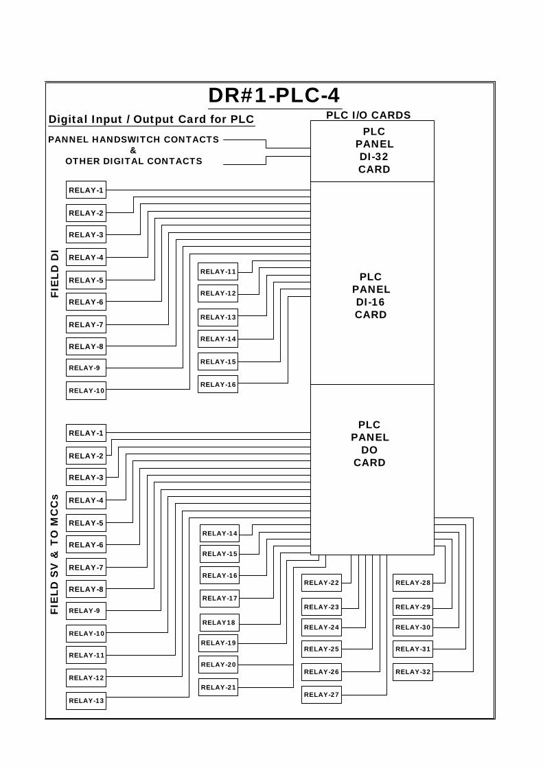
DR#1-PLC-4PLC I/O CARDSDigital Input / Output Card for PLC
PANNEL HANDSWITCH CONTACTS&
OTHER DIGITAL CONTACTS
FIE
LD D
I
RELAY-1
RELAY-2
RELAY-3
RELAY-4
RELAY-5
RELAY-6
RELAY-7
RELAY-8
PLCPANELDI-16CARD
RELAY-11
RELAY-13
RELAY-14
RELAY-15
RELAY-16
RELAY-9
RELAY-10
RELAY-12
PLCPANEL
DOCARD
RELAY-1
RELAY-2
RELAY-3
RELAY-4
RELAY-5
RELAY-6
RELAY-7
RELAY-8
RELAY-9
RELAY-10
FIE
LD S
V &
TO
MC
Cs
RELAY-11
RELAY-12
RELAY-13
RELAY-14
RELAY-15
RELAY-16
RELAY-17
RELAY18
RELAY-19
RELAY-20
RELAY-21
RELAY-22
RELAY-23
RELAY-24
RELAY-25
RELAY-26
RELAY-27
RELAY-28
RELAY-29
RELAY-30
RELAY-31
RELAY-32
PLCPANELDI-32CARD
PLC I/O CARDS
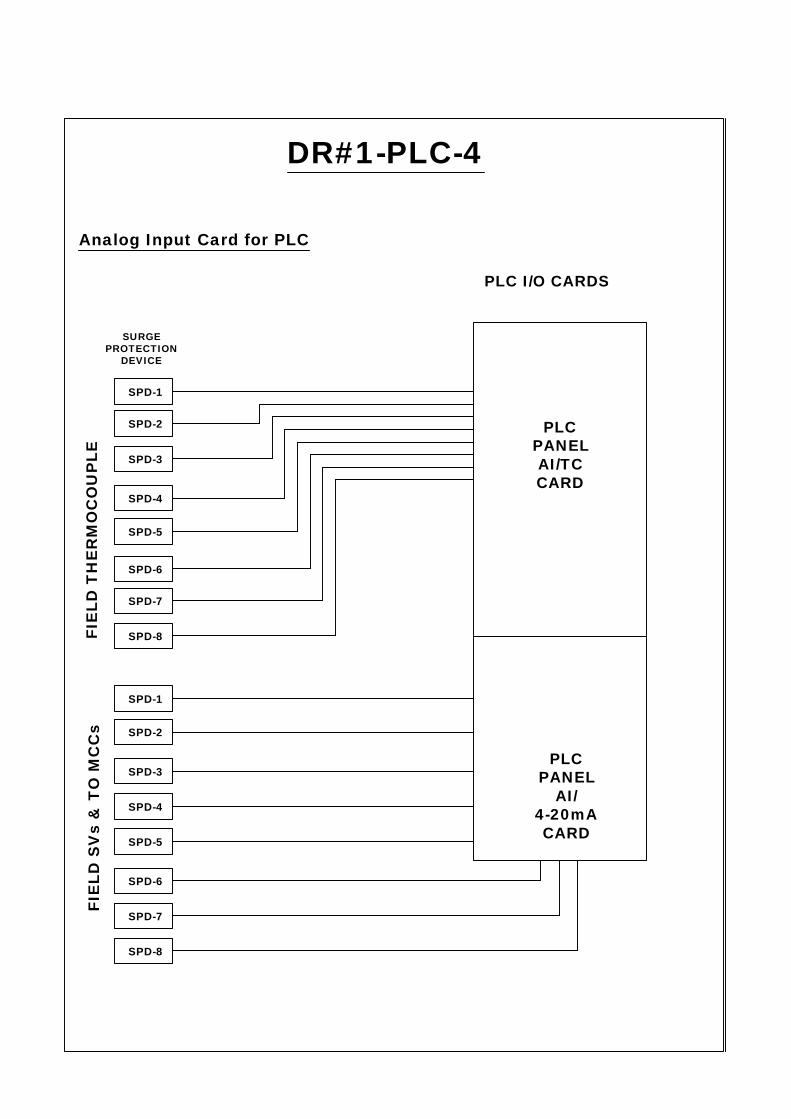
PLCPANELAI/TCCARD
PLCPANEL
AI/4-20mACARD
SURGEPROTECTION
DEVICE
SPD-1
SPD-2
SPD-3
SPD-4
SPD-5
FIE
LD T
HE
RM
OC
OU
PLE
SPD-6
SPD-7
SPD-8
SPD-1
SPD-2
FIE
LD S
Vs
& T
O M
CC
s
SPD-4
SPD-3
SPD-5
SPD-7
SPD-6
SPD-8
DR#1-PLC-4
Analog Input Card for PLC
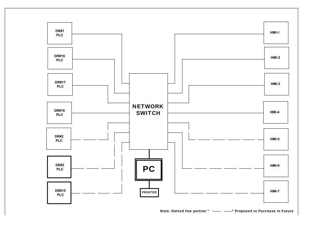
NETWORKSWITCH
HMI-3
HMI-4
HMI-5
HMI-6
HMI-7
HMI-2
HMI-1
PC
PRINTER
DR#1
PLC
DR#16
PLC
DR#17
PLC
DR#18
PLC
DR#2
PLC
DR#3
PLC
DR#15
PLC
Note: Dotted line portion " " Proposed to Purchase in Future