MAXL Specification
12
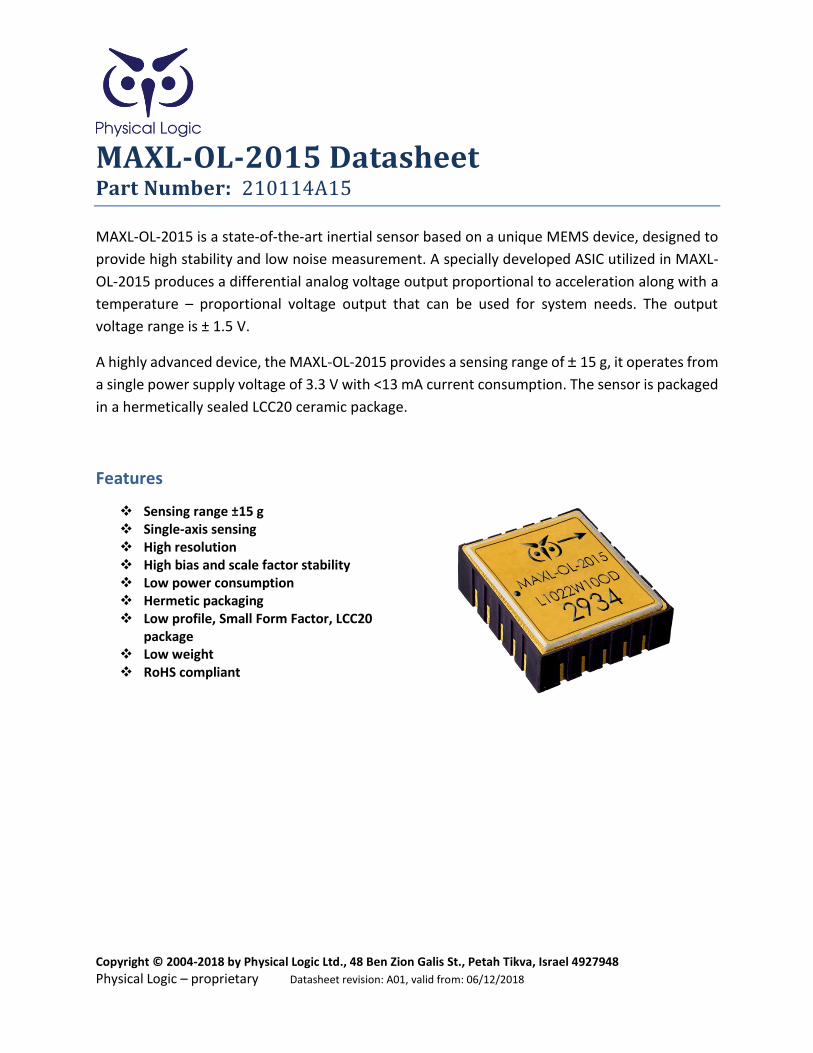
Copyright © 2004-2018 by Physical Logic Ltd., 48 Ben Zion Galis St., Petah Tikva, Israel 4927948 Physical Logic – proprietary Datasheet revision: A01, valid from: 06/12/2018 MAXL-OL-2015 Datasheet Part Number: 210114A15 MAXL-OL-2015 is a state-of-the-art inertial sensor based on a unique MEMS device, designed to provide high stability and low noise measurement. A specially developed ASIC utilized in MAXL- OL-2015 produces a differential analog voltage output proportional to acceleration along with a temperature – proportional voltage output that can be used for system needs. The output voltage range is ± 1.5 V. A highly advanced device, the MAXL-OL-2015 provides a sensing range of ± 15 g, it operates from a single power supply voltage of 3.3 V with <13 mA current consumption. The sensor is packaged in a hermetically sealed LCC20 ceramic package. Features Sensing range ±15 g Single-axis sensing High resolution High bias and scale factor stability Low power consumption Hermetic packaging Low profile, Small Form Factor, LCC20 package Low weight RoHS compliant
-
Upload
khangminh22 -
Category
Documents
-
view
0 -
download
0
Transcript of MAXL Specification
Copyright © 2004-2018 by Physical Logic Ltd., 48 Ben Zion Galis St., Petah Tikva, Israel 4927948
Physical Logic – proprietary Datasheet revision: A01, valid from: 06/12/2018
MAXL-OL-2015 Datasheet Part Number: 210114A15
MAXL-OL-2015 is a state-of-the-art inertial sensor based on a unique MEMS device, designed to
provide high stability and low noise measurement. A specially developed ASIC utilized in MAXL-
OL-2015 produces a differential analog voltage output proportional to acceleration along with a
temperature – proportional voltage output that can be used for system needs. The output
voltage range is ± 1.5 V.
A highly advanced device, the MAXL-OL-2015 provides a sensing range of ± 15 g, it operates from
a single power supply voltage of 3.3 V with <13 mA current consumption. The sensor is packaged
in a hermetically sealed LCC20 ceramic package.
Features
Sensing range ±15 g Single-axis sensing High resolution High bias and scale factor stability Low power consumption Hermetic packaging Low profile, Small Form Factor, LCC20
package Low weight RoHS compliant

Copyright © 2004-2018 by Physical Logic Ltd., 48 Ben Zion Galis St., Petah Tikva, Israel 4927948
Physical Logic – proprietary Datasheet revision: A01, valid from: 06/12/2018
Table of Contents 1 Accelerometer Functional Characteristics ............................................................................................ 3
2 Accelerometer Environmental Characteristics ..................................................................................... 4
3 Absolute Maximum Ratings .................................................................................................................. 5
4 Packaging information .......................................................................................................................... 5
5 Physical specifications ........................................................................................................................... 6
6 Operational Principles ........................................................................................................................... 6
7 MAXL-OL-2015 pin-out. ........................................................................................................................ 8
8 Pin configuration and function description .......................................................................................... 8
9 MAXL-OL-2015 Typical application ..................................................................................................... 10
10 Electrical specifications ................................................................................................................... 10
11 Temperature Sensor ....................................................................................................................... 11
12 Quality ............................................................................................................................................. 11
13 Notes on parameters used in the datasheet .................................................................................. 12
List of figures
Figure 1 Package general dimensions bottom and side view ....................................................................... 5
Figure 2 Simplified view of sensor interface ................................................................................................. 6
Figure 3 Pinout Description (Top View) ........................................................................................................ 8
Figure 4 Typical accelerometer application ................................................................................................ 10
List of tables
Table 1 Accelerometer Functional Characteristics ....................................................................................... 3
Table 2 Accelerometer Environmental Characteristics ................................................................................ 4
Table 3 Absolute maximum ratings .............................................................................................................. 5
Table 4 Physical specifications ...................................................................................................................... 6
Table 5 Pin description .................................................................................................................................. 8
Table 6 Temperature Sensor Specifications ............................................................................................... 11
Page 3 of 12 Physical Logic – proprietary Datasheet revision: A01, valid from: 06/12/2018
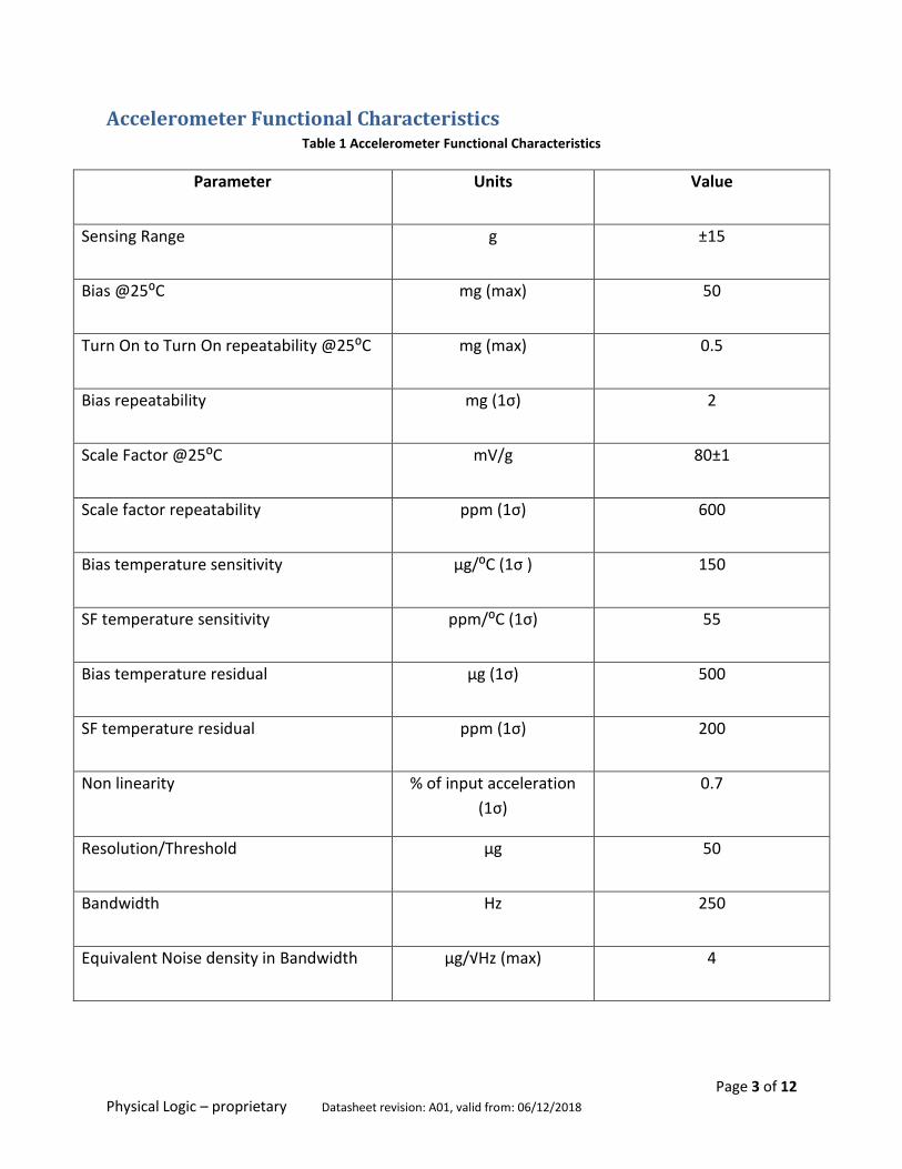
Accelerometer Functional Characteristics Table 1 Accelerometer Functional Characteristics
Parameter Units Value
Sensing Range g ±15
Bias @25⁰C mg (max) 50
Turn On to Turn On repeatability @25⁰C mg (max) 0.5
Bias repeatability mg (1σ) 2
Scale Factor @25⁰C mV/g 80±1
Scale factor repeatability ppm (1σ) 600
Bias temperature sensitivity µg/⁰C (1σ ) 150
SF temperature sensitivity ppm/⁰C (1σ) 55
Bias temperature residual µg (1σ) 500
SF temperature residual ppm (1σ) 200
Non linearity % of input acceleration
(1σ)
0.7
Resolution/Threshold µg 50
Bandwidth Hz 250
Equivalent Noise density in Bandwidth µg/√Hz (max) 4

Page 4 of 12 Physical Logic – proprietary Datasheet revision: A01, valid from: 06/12/2018
1 Accelerometer Environmental Characteristics The accelerometer was qualified according to the Table 2
Table 2 Accelerometer Environmental Characteristics
Operating temperature
range
-40⁰C to +85⁰C
Storage temperature
range
-54⁰C to +90⁰C
Operational vibration 2.5g RMS, 20-2000Hz, 2h each axis
Non-operational
vibration
7.7g RMS, 10-500Hz, 1h each axis
Operational shock 40g 11msec., saw tooth, 2 shocks each axis
Non-operational shock 75g 6msec., saw tooth, 2 shocks each axis
Non-operational high
shock
500g 1msec., half sine, 2 shocks each axis
EDS sensitivity Class 2 (MIL-STD-883-G), HBM 2kV

Page 5 of 12 Physical Logic – proprietary Datasheet revision: A01, valid from: 06/12/2018
2 Absolute Maximum Ratings Stresses above those listed as “absolute maximum ratings” may cause permanent damage to the
device. This is a stress rating only and functional operation of the device under these conditions
is not implied. Exposure to maximum rating conditions for extended periods may affect device
reliability.
Table 3 Absolute maximum ratings
Ratings Unit Maximum value
Supply voltage (VIN) V 3 - 3.6
Input voltage on any control pin
V VIN + 0.3
Operating temperature range C -40 to 85
Storage temperature range C -54 to 90
Electrostatic discharge protection
kV (HBM) 2
Soldering temperature (reflow)
C 260
3 Packaging information The packaging is a standard LCC housing with a total of 20 pins. Sealing process is qualified at
5·10-8 atm·cm3/s (requirements MIL-STD-883-E). The precise dimensions are given in the Figure
1.The weight of the product is typically smaller than 0.7 grams.
Figure 1 Package general dimensions bottom and side view
Page 6 of 12 Physical Logic – proprietary Datasheet revision: A01, valid from: 06/12/2018
4 Physical specifications Table 4 Physical specifications
Packaging LCC, 20 pin
Sealing Hermetically sealed. Sealing process is qualified at 5·10-8 atm·cm3/s
(requirements MIL-STD-883-E)
Weight <0.7 gram
Size 8.9X8.9X3.24 mm
Mounting The bottom plane of the LCC is to be used as a reference plane for axis
alignment. Any other way of fixing the sensor on the PCB may degrade the
sensor’s performance.
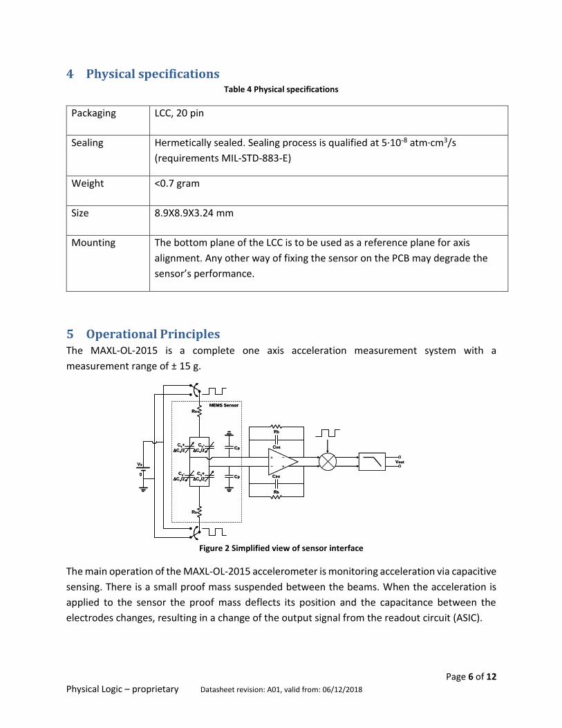
5 Operational Principles The MAXL-OL-2015 is a complete one axis acceleration measurement system with a
measurement range of ± 15 g.
Figure 2 Simplified view of sensor interface
The main operation of the MAXL-OL-2015 accelerometer is monitoring acceleration via capacitive
sensing. There is a small proof mass suspended between the beams. When the acceleration is
applied to the sensor the proof mass deflects its position and the capacitance between the
electrodes changes, resulting in a change of the output signal from the readout circuit (ASIC).
Vs
0
Cs+
Cs/2
Cs-
Cs/2
Cs-
Cs/2
Cs+
Cs/2Cp
Cp Cint
Cint
Rb
Rb
Vout
Rs
Rs
MEMS Sensor
–
+ –
+Vs
0
Cs+
Cs/2
Cs-
Cs/2
Cs-
Cs/2
Cs+
Cs/2Cp
Cp Cint
Cint
Rb
Rb
Vout
Rs
Rs
MEMS Sensor
–
+ –
+

Page 7 of 12 Physical Logic – proprietary Datasheet revision: A01, valid from: 06/12/2018
The complete measurement chain of the MAXL-OL-2015 sensor is composed of a low-noise
amplifier which converts into an analog voltage the capacitive unbalancing of the MEMS sensor,
an independent analog 1st order low pass filter, which is responsible for reducing high level
frequency noise (In standard configuration the low pass filter is at 300 Hz frequency, the BW can
be adjusted on request). A simplified view of the sensor interface is shown in Figure 2.
The MAXL-OL-2015 will provide its best performance when connected in a differential
configuration using both the OUTP and OUTN output signals. But a differential connection may
not always be available. In such cases, it is possible to connect the accelerometer in single ended
mode by connecting OUTP and GND, leaving OUTN disconnected.
Note that for a single-ended connection, the signal to noise ratio is reduced by half, the signal is
more susceptible to external noise pickup. It is also possible to connect OUTP and GND (P signal)
and separately OUTN and GND (N signal) to acquire a differential output by external subtraction
of N signal from P signal.
MAXL-OL-2015 model is as follows:
Vout = OUTP – OUTN = K1(K0 + Ai + K2Ai2 + K3Ai3 + KipAip + KopAop + KiipAiAip + KiopAiAop + N)
Here
- Ai, Aip, Aop are external accelerations in direction of sensor’s axes:
i : input axis (x)
ip : in-plane axis (y)
op: out-of-plane axis (z)
- K1 is sensor’s scale factor in V/g
- K0 is sensor’s bias in g
- K2 is second order non linearity in g/g2
- K3 is third order non linearity in g/g3
- Kip is in-plane cross-axis non linearity in rad
- Kop is out-of-plane cross-axis non linearity in rad
- Kiip & Kiop are cross coupling coefficients in rad/g
- N is residual noise in g
Page 8 of 12 Physical Logic – proprietary Datasheet revision: A01, valid from: 06/12/2018
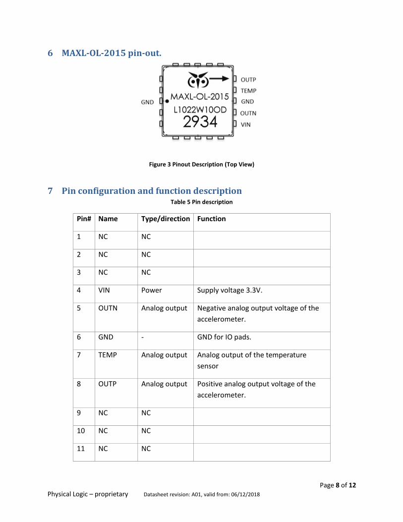
6 MAXL-OL-2015 pin-out.
Figure 3 Pinout Description (Top View)
7 Pin configuration and function description Table 5 Pin description
Pin# Name Type/direction Function
1 NC NC
2 NC NC
3 NC NC
4 VIN Power Supply voltage 3.3V.
5 OUTN Analog output Negative analog output voltage of the
accelerometer.
6 GND - GND for IO pads.
7 TEMP Analog output Analog output of the temperature
sensor
8 OUTP Analog output Positive analog output voltage of the
accelerometer.
9 NC NC
10 NC NC
11 NC NC

Page 9 of 12 Physical Logic – proprietary Datasheet revision: A01, valid from: 06/12/2018
Pin# Name Type/direction Function
12 NC NC
13 NC NC
14 NC NC
15 NC NC For internal use. Leave unconnected.
16 GND - For internal use. Connect to GND.
17 NC NC For internal use. Leave unconnected.
18 NC NC For internal use. Leave unconnected.
19 NC NC
20 NC NC
Page 10 of 12 Physical Logic – proprietary Datasheet revision: A01, valid from: 06/12/2018
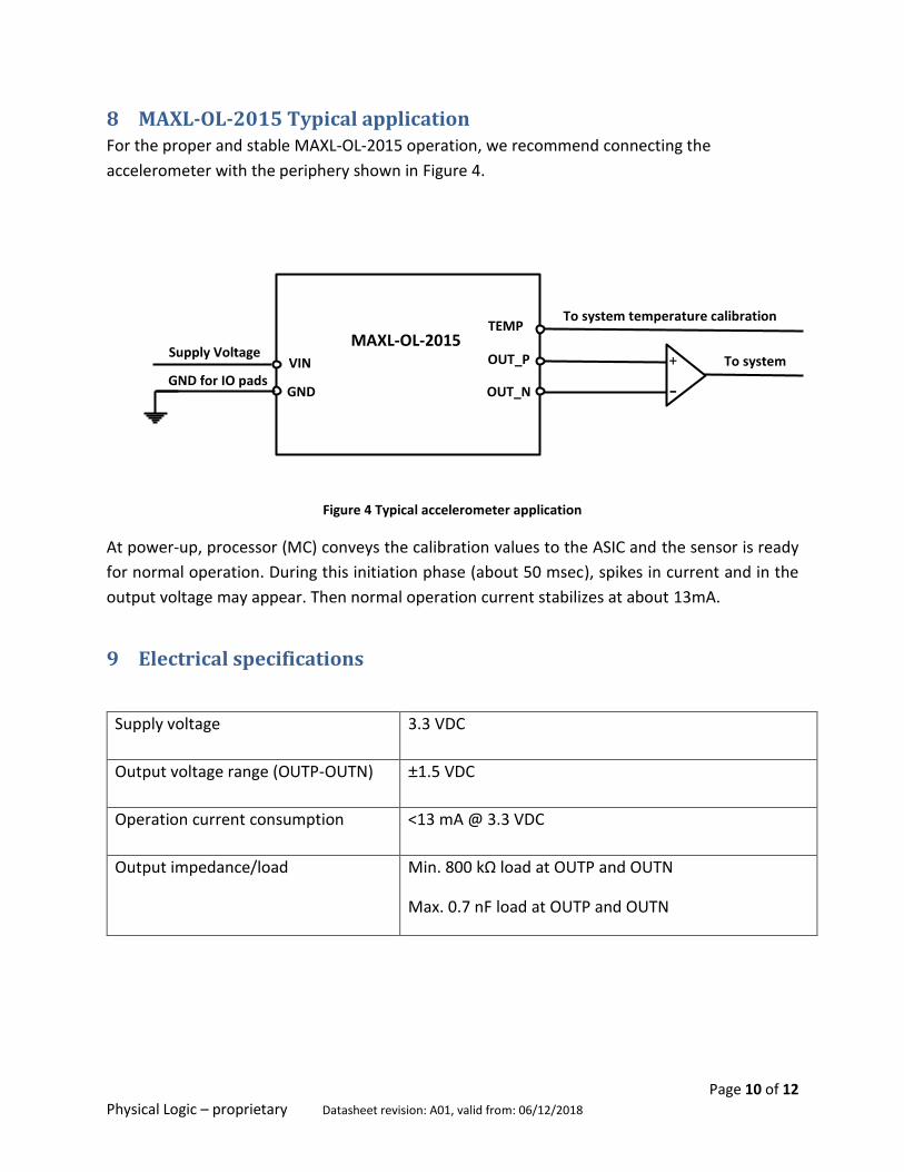
8 MAXL-OL-2015 Typical application For the proper and stable MAXL-OL-2015 operation, we recommend connecting the
accelerometer with the periphery shown in Figure 4.
Figure 4 Typical accelerometer application
At power-up, processor (MC) conveys the calibration values to the ASIC and the sensor is ready
for normal operation. During this initiation phase (about 50 msec), spikes in current and in the
output voltage may appear. Then normal operation current stabilizes at about 13mA.
9 Electrical specifications
Supply voltage 3.3 VDC
Output voltage range (OUTP-OUTN) ±1.5 VDC
Operation current consumption <13 mA @ 3.3 VDC
Output impedance/load Min. 800 kΩ load at OUTP and OUTN
Max. 0.7 nF load at OUTP and OUTN
+
-
VIN
GND
TEMP
OUT_P
OUT_N
To system
To system temperature calibration
GND for IO pads
Supply Voltage MAXL-OL-2015
Page 11 of 12 Physical Logic – proprietary Datasheet revision: A01, valid from: 06/12/2018
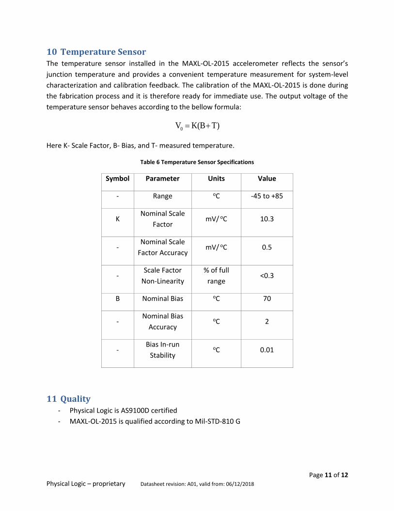
10 Temperature Sensor The temperature sensor installed in the MAXL-OL-2015 accelerometer reflects the sensor’s
junction temperature and provides a convenient temperature measurement for system-level
characterization and calibration feedback. The calibration of the MAXL-OL-2015 is done during
the fabrication process and it is therefore ready for immediate use. The output voltage of the
temperature sensor behaves according to the bellow formula:
T)K(BV0
Here K- Scale Factor, B- Bias, and T- measured temperature.
Table 6 Temperature Sensor Specifications
Symbol Parameter Units Value
- Range oC -45 to +85
K Nominal Scale
Factor mV/
oC 10.3
- Nominal Scale
Factor Accuracy mV/
oC 0.5
- Scale Factor
Non-Linearity
% of full
range <0.3
B Nominal Bias oC 70
- Nominal Bias
Accuracy oC 2
- Bias In-run
Stability oC 0.01
11 Quality - Physical Logic is AS9100D certified
- MAXL-OL-2015 is qualified according to Mil-STD-810 G

Page 12 of 12 Physical Logic – proprietary Datasheet revision: A01, valid from: 06/12/2018
12 Notes on parameters used in the datasheet Bias [mg] – Accelerometer’s output when no external acceleration is applied along its input axis.
Bias repeatability [mg] – Deviation in accelerometer’s bias measured after exposing it to a single
-40⁰C to +85⁰C temperature cycle.
Scale Factor [mV/g] – The ratio of the output change (given in volts) to a change of exactly one
g in external acceleration along the input axis.
Scale factor repeatability [ppm] – Deviation in accelerometer’s scale factor measured after
exposing it to a single -40⁰C to +85⁰C temperature cycle.
Temperature sensitivity [µg/⁰C] – Sensitivity of accelerometer’s output to ambient temperature,
worst case in operating temperature range, measured in static position with input axis
orthogonal to earth gravity vector.
Non linearity [% of full range] – Maximum deviation of accelerometer’s output from a linear fit
based on 0g and 1g output, given as a percentage of the input acceleration in full range.
Bandwidth [Hz] – A rang of frequency in which the gain of frequency response is higher than -
3dB.
Equivalent noise density in band [µg/√Hz] – A criterion, calculated by dividing sensor’s output
RMS by square root of the bandwidth.
Physical Logic keeps the right to update the content of this datasheet