XJDF Specification - CIP4
488
Release: 2.1 16 August 2020 XJDF Specification
-
Upload
khangminh22 -
Category
Documents
-
view
0 -
download
0
Transcript of XJDF Specification - CIP4

Release: 2.1
16 August 2020
XJDF Specification

� ��� ���� ��� ���� � � � � � �� ��

Legal NoticeUse of this document is subject to the following conditions which are deemed accepted by any person or entity mak-ing use hereof.
Copyright NoticeCopyright © 2000-2020, International Cooperation for the Integration of Processes in Prepress, Press and Postpress (CIP4) with registered office in Zurich, Switzerland. All Rights Reserved. CIP4 hereby grants to any person or entity ob-taining a copy of the Specification and associated documentation files (the “Specification”) a perpetual, worldwide, non-exclusive, fully paid-up, royalty-free copyright license to use, copy, publish, distribute, publicly display, publicly perform, and/or sublicense the Specification in whole or in part verbatim and without modification, unless otherwise expressly permitted by CIP4, subject to the following conditions. This legal notice SHALL be included in all copies con-taining the whole or substantial portions of the Specification. Copies of excerpts of the Specification which do not exceed five (5) pages SHALL include the following short form Copyright Notice: Copyright © 2000-2020, International Coop-eration for the Integration of Processes in Prepress, Press and Postpress (CIP4) with registered office in Zurich, Swit-zerland.
Trademarks and TradenamesInternational Cooperation for the Integration of Processes in Prepress, Press and Postpress, CIP4, Exchange Job Defini-tion Format, XJDF, Exchange Job Messaging Format, XJMF, Job Definition Format, JDF, Job Messaging Format, JMF and the CIP4 logo are trademarks of CIP4.
Rather than put a trademark symbol in every occurrence of other trademarked names, we state that we are using the names only in an editorial fashion, and to the benefit of the trademark owner, with no intention of infringement of the trademark.
Except as contained in this legal notice or as allowed by membership in CIP4, the name of CIP4 SHALL not be used in advertising or otherwise to promote the use or other dealings in this specification without prior written authorization from CIP4.
Waiver of LiabilityThe XJDF Specification is provided as is, without warranty of any kind, express, implied, or otherwise, including but not limited to the warranties of merchantability, fitness for a particular purpose and non infringement. In no event will CIP4 be liable for any claim, damages or other liability, whether in an action of contract, tort or otherwise, arising from, out of, or in connection with the XJDF Specification or the use or other dealings in the XJDF Specification.
XJDF SPECIFICATIO N 2.1 i

ii XJDF SPECIFICATIO N 2.1

Table of ContentsChapter 1 Introduction . . . . . . . . . . . . . . . . . . . . . . . . . . . . . 11.1 Further Information . . . . . . . . . . . . . . . . . . . . . . . . . . . . . . . . . . . . . . . . . 1
1.1.1 NMTOKEN repository . . . . . . . . . . . . . . . . . . . . . . . . . . . . . . . . . . . . . . . 1
1.1.2 Errata. . . . . . . . . . . . . . . . . . . . . . . . . . . . . . . . . . . . . . . . . . . . . . . 1
1.2 Background on XJDF . . . . . . . . . . . . . . . . . . . . . . . . . . . . . . . . . . . . . . . . . 1
1.3 Design Criteria for XJDF . . . . . . . . . . . . . . . . . . . . . . . . . . . . . . . . . . . . . . . 1
1.3.1 Simplify and reduce variations . . . . . . . . . . . . . . . . . . . . . . . . . . . . . . . . . . 2
1.3.2 Enable dynamic changes . . . . . . . . . . . . . . . . . . . . . . . . . . . . . . . . . . . . . 3
1.3.3 Retain the semantic structures . . . . . . . . . . . . . . . . . . . . . . . . . . . . . . . . . . 3
1.3.4 Remove implementation specific details . . . . . . . . . . . . . . . . . . . . . . . . . . . . . 3
1.3.5 Enhance Compatibility with standard XML and XML Tools . . . . . . . . . . . . . . . . . . . . . 3
1.3.6 Device Capabilities . . . . . . . . . . . . . . . . . . . . . . . . . . . . . . . . . . . . . . . . 3
1.3.7 Compatibility with JDF and prior versions of XJDF . . . . . . . . . . . . . . . . . . . . . . . . . 4
1.4 Use of XML . . . . . . . . . . . . . . . . . . . . . . . . . . . . . . . . . . . . . . . . . . . . 4
1.4.1 Use of XML Namespaces . . . . . . . . . . . . . . . . . . . . . . . . . . . . . . . . . . . . . 4
1.4.2 Use of XML Schema. . . . . . . . . . . . . . . . . . . . . . . . . . . . . . . . . . . . . . . . 4
1.4.3 Schema and XJDF Context. . . . . . . . . . . . . . . . . . . . . . . . . . . . . . . . . . . . . 4
1.5 Conceptual Changes from JDF to XJDF . . . . . . . . . . . . . . . . . . . . . . . . . . . . . . . 5
1.5.1 Use of Abstract Elements . . . . . . . . . . . . . . . . . . . . . . . . . . . . . . . . . . . . . 5
1.5.2 Resource Partitioning . . . . . . . . . . . . . . . . . . . . . . . . . . . . . . . . . . . . . . . 5
1.5.3 Structural Changes . . . . . . . . . . . . . . . . . . . . . . . . . . . . . . . . . . . . . . . . 5
1.5.4 Process Model Changes. . . . . . . . . . . . . . . . . . . . . . . . . . . . . . . . . . . . . . 5
1.5.5 Alignment of Signals and Audits. . . . . . . . . . . . . . . . . . . . . . . . . . . . . . . . . . 5
1.5.6 Messaging Changes. . . . . . . . . . . . . . . . . . . . . . . . . . . . . . . . . . . . . . . . 5
1.6 Conventions Used in this Specification . . . . . . . . . . . . . . . . . . . . . . . . . . . . . . . 6
1.6.1 Document References. . . . . . . . . . . . . . . . . . . . . . . . . . . . . . . . . . . . . . . 6
1.6.2 Text Styles . . . . . . . . . . . . . . . . . . . . . . . . . . . . . . . . . . . . . . . . . . . . 6
1.6.3 XPath Notation Used in this Specification . . . . . . . . . . . . . . . . . . . . . . . . . . . . . 7
1.6.4 Modification Notes . . . . . . . . . . . . . . . . . . . . . . . . . . . . . . . . . . . . . . . . 7
1.6.5 Specification of Cardinality . . . . . . . . . . . . . . . . . . . . . . . . . . . . . . . . . . . . 7
1.6.6 Template for Tables that Describe Elements . . . . . . . . . . . . . . . . . . . . . . . . . . . 8
1.7 Glossary . . . . . . . . . . . . . . . . . . . . . . . . . . . . . . . . . . . . . . . . . . . . . . 8
1.8 Conformance . . . . . . . . . . . . . . . . . . . . . . . . . . . . . . . . . . . . . . . . . . . 10
1.8.1 Conformance Terminology . . . . . . . . . . . . . . . . . . . . . . . . . . . . . . . . . . . . 10
1.8.2 Interoperability Conformance Specifications . . . . . . . . . . . . . . . . . . . . . . . . . . . 10
1.9 Data Structures . . . . . . . . . . . . . . . . . . . . . . . . . . . . . . . . . . . . . . . . . . 10
1.9.1 Units of measurement . . . . . . . . . . . . . . . . . . . . . . . . . . . . . . . . . . . . . . 10
1.9.2 Counting in XJDF . . . . . . . . . . . . . . . . . . . . . . . . . . . . . . . . . . . . . . . . . 10
1.9.3 Human and Machine readable strings and tokens . . . . . . . . . . . . . . . . . . . . . . . . . 11
XJDF SPECIFICATIO N 2.1 iii
Chapter 2 Overview . . . . . . . . . . . . . . . . . . . . . . . . . . . . . . . 132.1 Introduction . . . . . . . . . . . . . . . . . . . . . . . . . . . . . . . . . . . . . . . . . . . . 13
2.2 Referencing Data . . . . . . . . . . . . . . . . . . . . . . . . . . . . . . . . . . . . . . . . . 13
2.2.1 Referencing External Data . . . . . . . . . . . . . . . . . . . . . . . . . . . . . . . . . . . . 13
2.2.2 Identifying Sections of XJDF from External Sources . . . . . . . . . . . . . . . . . . . . . . . . 13
2.2.3 Identifying Sections of XJDF from within the Same XJDF. . . . . . . . . . . . . . . . . . . . . . 13
2.3 System Components . . . . . . . . . . . . . . . . . . . . . . . . . . . . . . . . . . . . . . . . 13
2.3.1 Workflow Component Roles . . . . . . . . . . . . . . . . . . . . . . . . . . . . . . . . . . . 13
2.4 XJDF Workflow . . . . . . . . . . . . . . . . . . . . . . . . . . . . . . . . . . . . . . . . . . 14
2.4.1 Product Intent and Processes . . . . . . . . . . . . . . . . . . . . . . . . . . . . . . . . . . . 14
2.4.2 Process Reporting . . . . . . . . . . . . . . . . . . . . . . . . . . . . . . . . . . . . . . . . 14
2.5 Role of Messaging in XJDF . . . . . . . . . . . . . . . . . . . . . . . . . . . . . . . . . . . . . 15
2.6 Coordinate Systems in XJDF . . . . . . . . . . . . . . . . . . . . . . . . . . . . . . . . . . . . 15
2.6.1 Introduction . . . . . . . . . . . . . . . . . . . . . . . . . . . . . . . . . . . . . . . . . . . 15
2.6.2 Coordinate Systems of Resources and Processes . . . . . . . . . . . . . . . . . . . . . . . . . 16
2.6.3 Coordinate System Transformations . . . . . . . . . . . . . . . . . . . . . . . . . . . . . . . 17
2.6.4 General Rules . . . . . . . . . . . . . . . . . . . . . . . . . . . . . . . . . . . . . . . . . . 18
2.6.5 Homogeneous Coordinates . . . . . . . . . . . . . . . . . . . . . . . . . . . . . . . . . . . . 18
Chapter 3 Structure . . . . . . . . . . . . . . . . . . . . . . . . . . . . . . . 213.1 XJDF . . . . . . . . . . . . . . . . . . . . . . . . . . . . . . . . . . . . . . . . . . . . . . . . 21
3.1.1 ICS Versions Value . . . . . . . . . . . . . . . . . . . . . . . . . . . . . . . . . . . . . . . . 22
3.1.2 XJDF for Product Intent . . . . . . . . . . . . . . . . . . . . . . . . . . . . . . . . . . . . . . 22
3.1.3 XJDF for Process Description and Gray Boxes . . . . . . . . . . . . . . . . . . . . . . . . . . . 22
3.2 AuditPool . . . . . . . . . . . . . . . . . . . . . . . . . . . . . . . . . . . . . . . . . . . . . 23
3.2.1 AuditCreated . . . . . . . . . . . . . . . . . . . . . . . . . . . . . . . . . . . . . . . . . . . 24
3.2.2 AuditNotification . . . . . . . . . . . . . . . . . . . . . . . . . . . . . . . . . . . . . . . . . 24
3.2.3 AuditProcessRun . . . . . . . . . . . . . . . . . . . . . . . . . . . . . . . . . . . . . . . . . 24
3.2.4 AuditResource . . . . . . . . . . . . . . . . . . . . . . . . . . . . . . . . . . . . . . . . . . 25
3.2.5 AuditStatus . . . . . . . . . . . . . . . . . . . . . . . . . . . . . . . . . . . . . . . . . . . 26
3.3 ProductList . . . . . . . . . . . . . . . . . . . . . . . . . . . . . . . . . . . . . . . . . . . . 27
3.3.1 Product. . . . . . . . . . . . . . . . . . . . . . . . . . . . . . . . . . . . . . . . . . . . . . 27
3.4 ResourceSet . . . . . . . . . . . . . . . . . . . . . . . . . . . . . . . . . . . . . . . . . . . . 29
3.4.1 Dependent . . . . . . . . . . . . . . . . . . . . . . . . . . . . . . . . . . . . . . . . . . . . 31
3.5 XJDF Extensibility . . . . . . . . . . . . . . . . . . . . . . . . . . . . . . . . . . . . . . . . . 31
3.5.1 Foreign Namespaces . . . . . . . . . . . . . . . . . . . . . . . . . . . . . . . . . . . . . . . 32
3.5.2 Creating Extension ResourceSets . . . . . . . . . . . . . . . . . . . . . . . . . . . . . . . . . 32
3.5.3 Creating Extension Message Type Elements . . . . . . . . . . . . . . . . . . . . . . . . . . . 32
3.5.4 Creating Extension Intent Elements . . . . . . . . . . . . . . . . . . . . . . . . . . . . . . . 33
3.5.5 Extending NMTOKEN Lists . . . . . . . . . . . . . . . . . . . . . . . . . . . . . . . . . . . . 33
3.5.6 Extending Process Types . . . . . . . . . . . . . . . . . . . . . . . . . . . . . . . . . . . . . 34
Chapter 4 Product Intent . . . . . . . . . . . . . . . . . . . . . . . . . . . .354.1 Intent . . . . . . . . . . . . . . . . . . . . . . . . . . . . . . . . . . . . . . . . . . . . . . . 35
iv XJDF SPECIFICATIO N 2.1
4.1.1 Product Intent . . . . . . . . . . . . . . . . . . . . . . . . . . . . . . . . . . . . . . . . . . 35
4.1.2 Representation of Product Binding . . . . . . . . . . . . . . . . . . . . . . . . . . . . . . . . 36
4.2 AssemblingIntent . . . . . . . . . . . . . . . . . . . . . . . . . . . . . . . . . . . . . . . . . 36
4.2.1 AssemblyItem . . . . . . . . . . . . . . . . . . . . . . . . . . . . . . . . . . . . . . . . . . 37
4.2.2 BindIn . . . . . . . . . . . . . . . . . . . . . . . . . . . . . . . . . . . . . . . . . . . . . . 37
4.2.3 BlowIn . . . . . . . . . . . . . . . . . . . . . . . . . . . . . . . . . . . . . . . . . . . . . . 37
4.2.4 StickOn . . . . . . . . . . . . . . . . . . . . . . . . . . . . . . . . . . . . . . . . . . . . . 38
4.3 BindingIntent . . . . . . . . . . . . . . . . . . . . . . . . . . . . . . . . . . . . . . . . . . . 38
4.3.1 AdhesiveNote . . . . . . . . . . . . . . . . . . . . . . . . . . . . . . . . . . . . . . . . . 40
4.3.2 EdgeGluing . . . . . . . . . . . . . . . . . . . . . . . . . . . . . . . . . . . . . . . . . . . 40
4.3.3 HardCoverBinding . . . . . . . . . . . . . . . . . . . . . . . . . . . . . . . . . . . . . . . 40
4.3.4 LooseBinding . . . . . . . . . . . . . . . . . . . . . . . . . . . . . . . . . . . . . . . . . . 42
4.3.5 SaddleStitching . . . . . . . . . . . . . . . . . . . . . . . . . . . . . . . . . . . . . . . . . 43
4.3.6 SideStitching . . . . . . . . . . . . . . . . . . . . . . . . . . . . . . . . . . . . . . . . . . 44
4.3.7 SoftCoverBinding. . . . . . . . . . . . . . . . . . . . . . . . . . . . . . . . . . . . . . . . 44
4.3.8 Tabs . . . . . . . . . . . . . . . . . . . . . . . . . . . . . . . . . . . . . . . . . . . . . . . 45
4.4 ColorIntent . . . . . . . . . . . . . . . . . . . . . . . . . . . . . . . . . . . . . . . . . . . . 45
4.4.1 SurfaceColor . . . . . . . . . . . . . . . . . . . . . . . . . . . . . . . . . . . . . . . . . . 46
4.5 ContentCheckIntent . . . . . . . . . . . . . . . . . . . . . . . . . . . . . . . . . . . . . . . . 46
4.5.1 PreflightItem . . . . . . . . . . . . . . . . . . . . . . . . . . . . . . . . . . . . . . . . . . . 47
4.5.2 ProofItem . . . . . . . . . . . . . . . . . . . . . . . . . . . . . . . . . . . . . . . . . . . . 47
4.6 EmbossingIntent . . . . . . . . . . . . . . . . . . . . . . . . . . . . . . . . . . . . . . . . . 48
4.6.1 EmbossingItem . . . . . . . . . . . . . . . . . . . . . . . . . . . . . . . . . . . . . . . . . 48
4.7 FoldingIntent . . . . . . . . . . . . . . . . . . . . . . . . . . . . . . . . . . . . . . . . . . . 48
4.7.1 Typical Product Folds . . . . . . . . . . . . . . . . . . . . . . . . . . . . . . . . . . . . . . 49
4.8 HoleMakingIntent . . . . . . . . . . . . . . . . . . . . . . . . . . . . . . . . . . . . . . . . . 51
4.9 LaminatingIntent . . . . . . . . . . . . . . . . . . . . . . . . . . . . . . . . . . . . . . . . . 51
4.10 LayoutIntent . . . . . . . . . . . . . . . . . . . . . . . . . . . . . . . . . . . . . . . . . . . 52
4.11 MediaIntent . . . . . . . . . . . . . . . . . . . . . . . . . . . . . . . . . . . . . . . . . . . . 53
4.12 ProductionIntent . . . . . . . . . . . . . . . . . . . . . . . . . . . . . . . . . . . . . . . . . 54
4.13 ShapeCuttingIntent . . . . . . . . . . . . . . . . . . . . . . . . . . . . . . . . . . . . . . . . 54
4.13.1 ShapeCut . . . . . . . . . . . . . . . . . . . . . . . . . . . . . . . . . . . . . . . . . . . . 55
4.14 VariableIntent . . . . . . . . . . . . . . . . . . . . . . . . . . . . . . . . . . . . . . . . . . 55
Chapter 5 Processes . . . . . . . . . . . . . . . . . . . . . . . . . . . . . .575.1 Process Template . . . . . . . . . . . . . . . . . . . . . . . . . . . . . . . . . . . . . . . . . 57
5.2 Combining Individual Process Steps . . . . . . . . . . . . . . . . . . . . . . . . . . . . . . . . 58
5.2.1 Exchange ResourceSets in combined processes . . . . . . . . . . . . . . . . . . . . . . . . . . 58
5.2.2 Usage of ResourceSets that are used as both input and output . . . . . . . . . . . . . . . . . . 58
5.2.3 XJDF with Multiple Processes of the Same Type. . . . . . . . . . . . . . . . . . . . . . . . . . 59
5.3 General Processes . . . . . . . . . . . . . . . . . . . . . . . . . . . . . . . . . . . . . . . . . 59
5.3.1 Approval . . . . . . . . . . . . . . . . . . . . . . . . . . . . . . . . . . . . . . . . . . . . . 59
5.3.2 Delivery . . . . . . . . . . . . . . . . . . . . . . . . . . . . . . . . . . . . . . . . . . . . . 59
XJDF SPECIFICATIO N 2.1 v

5.3.3 ManualLabor . . . . . . . . . . . . . . . . . . . . . . . . . . . . . . . . . . . . . . . . . . 60
5.3.4 QualityControl . . . . . . . . . . . . . . . . . . . . . . . . . . . . . . . . . . . . . . . . . . 61
5.3.5 Verification. . . . . . . . . . . . . . . . . . . . . . . . . . . . . . . . . . . . . . . . . . . . 62
5.4 Prepress Processes . . . . . . . . . . . . . . . . . . . . . . . . . . . . . . . . . . . . . . . . 63
5.4.1 Bending . . . . . . . . . . . . . . . . . . . . . . . . . . . . . . . . . . . . . . . . . . . . . 63
5.4.2 ColorCorrection . . . . . . . . . . . . . . . . . . . . . . . . . . . . . . . . . . . . . . . . . 63
5.4.3 ColorSpaceConversion . . . . . . . . . . . . . . . . . . . . . . . . . . . . . . . . . . . . . . 63
5.4.4 DieDesign . . . . . . . . . . . . . . . . . . . . . . . . . . . . . . . . . . . . . . . . . . . 64
5.4.5 DieLayoutProduction . . . . . . . . . . . . . . . . . . . . . . . . . . . . . . . . . . . . . . . 65
5.4.6 ImageEnhancement . . . . . . . . . . . . . . . . . . . . . . . . . . . . . . . . . . . . . . . 65
5.4.7 ImageSetting . . . . . . . . . . . . . . . . . . . . . . . . . . . . . . . . . . . . . . . . . . . 66
5.4.8 Imposition . . . . . . . . . . . . . . . . . . . . . . . . . . . . . . . . . . . . . . . . . . . . 66
5.4.9 InkZoneCalculation. . . . . . . . . . . . . . . . . . . . . . . . . . . . . . . . . . . . . . . . 68
5.4.10 Interpreting . . . . . . . . . . . . . . . . . . . . . . . . . . . . . . . . . . . . . . . . . . . 69
5.4.11 LayoutElementProduction . . . . . . . . . . . . . . . . . . . . . . . . . . . . . . . . . . . . 69
5.4.12 LayoutShifting . . . . . . . . . . . . . . . . . . . . . . . . . . . . . . . . . . . . . . . . . 70
5.4.13 PDLCreation . . . . . . . . . . . . . . . . . . . . . . . . . . . . . . . . . . . . . . . . . . . 70
5.4.14 Preflight . . . . . . . . . . . . . . . . . . . . . . . . . . . . . . . . . . . . . . . . . . . . 71
5.4.15 PreviewGeneration . . . . . . . . . . . . . . . . . . . . . . . . . . . . . . . . . . . . . . . 71
5.4.16 RasterReading . . . . . . . . . . . . . . . . . . . . . . . . . . . . . . . . . . . . . . . . . 73
5.4.17 Rendering . . . . . . . . . . . . . . . . . . . . . . . . . . . . . . . . . . . . . . . . . . . . 73
5.4.18 Screening . . . . . . . . . . . . . . . . . . . . . . . . . . . . . . . . . . . . . . . . . . . . 74
5.4.19 Separation . . . . . . . . . . . . . . . . . . . . . . . . . . . . . . . . . . . . . . . . . . . 74
5.4.20 ShapeDefProduction . . . . . . . . . . . . . . . . . . . . . . . . . . . . . . . . . . . . . . 75
5.4.21 SheetOptimizing. . . . . . . . . . . . . . . . . . . . . . . . . . . . . . . . . . . . . . . . . 75
5.4.22 Stripping . . . . . . . . . . . . . . . . . . . . . . . . . . . . . . . . . . . . . . . . . . . . 78
5.4.23 Trapping . . . . . . . . . . . . . . . . . . . . . . . . . . . . . . . . . . . . . . . . . . . . 81
5.5 Press Processes . . . . . . . . . . . . . . . . . . . . . . . . . . . . . . . . . . . . . . . . . . 81
5.5.1 ConventionalPrinting . . . . . . . . . . . . . . . . . . . . . . . . . . . . . . . . . . . . . . 81
5.5.2 DigitalPrinting . . . . . . . . . . . . . . . . . . . . . . . . . . . . . . . . . . . . . . . . . . 82
5.5.3 Varnishing . . . . . . . . . . . . . . . . . . . . . . . . . . . . . . . . . . . . . . . . . . . . 83
5.6 Postpress Processes . . . . . . . . . . . . . . . . . . . . . . . . . . . . . . . . . . . . . . . . 83
5.6.1 BlockPreparation . . . . . . . . . . . . . . . . . . . . . . . . . . . . . . . . . . . . . . . . 84
5.6.2 BoxFolding . . . . . . . . . . . . . . . . . . . . . . . . . . . . . . . . . . . . . . . . . . . 84
5.6.3 BoxPacking. . . . . . . . . . . . . . . . . . . . . . . . . . . . . . . . . . . . . . . . . . . 84
5.6.4 Bundling . . . . . . . . . . . . . . . . . . . . . . . . . . . . . . . . . . . . . . . . . . . . . 85
5.6.5 CaseMaking . . . . . . . . . . . . . . . . . . . . . . . . . . . . . . . . . . . . . . . . . . . 86
5.6.6 CasingIn . . . . . . . . . . . . . . . . . . . . . . . . . . . . . . . . . . . . . . . . . . . . . 86
5.6.7 Collecting . . . . . . . . . . . . . . . . . . . . . . . . . . . . . . . . . . . . . . . . . . . . 87
5.6.8 CoverApplication . . . . . . . . . . . . . . . . . . . . . . . . . . . . . . . . . . . . . . . . . 87
5.6.9 Creasing . . . . . . . . . . . . . . . . . . . . . . . . . . . . . . . . . . . . . . . . . . . . 88
5.6.10 Cutting . . . . . . . . . . . . . . . . . . . . . . . . . . . . . . . . . . . . . . . . . . . . 88
5.6.11 DieMaking . . . . . . . . . . . . . . . . . . . . . . . . . . . . . . . . . . . . . . . . . . . 88
vi XJDF SPECIFICATIO N 2.1

5.6.12 Embossing . . . . . . . . . . . . . . . . . . . . . . . . . . . . . . . . . . . . . . . . . . . 89
5.6.13 EndSheetGluing . . . . . . . . . . . . . . . . . . . . . . . . . . . . . . . . . . . . . . . . . 89
5.6.14 Feeding . . . . . . . . . . . . . . . . . . . . . . . . . . . . . . . . . . . . . . . . . . . . . 90
5.6.15 Folding . . . . . . . . . . . . . . . . . . . . . . . . . . . . . . . . . . . . . . . . . . . . . 91
5.6.16 Gathering . . . . . . . . . . . . . . . . . . . . . . . . . . . . . . . . . . . . . . . . . . . . 91
5.6.17 Gluing . . . . . . . . . . . . . . . . . . . . . . . . . . . . . . . . . . . . . . . . . . . . . . 92
5.6.18 HeadBandApplication . . . . . . . . . . . . . . . . . . . . . . . . . . . . . . . . . . . . . . 92
5.6.19 HoleMaking . . . . . . . . . . . . . . . . . . . . . . . . . . . . . . . . . . . . . . . . . . . 93
5.6.20 Inserting . . . . . . . . . . . . . . . . . . . . . . . . . . . . . . . . . . . . . . . . . . . 94
5.6.21 Jacketing . . . . . . . . . . . . . . . . . . . . . . . . . . . . . . . . . . . . . . . . . . . 94
5.6.22 Labeling . . . . . . . . . . . . . . . . . . . . . . . . . . . . . . . . . . . . . . . . . . . . 95
5.6.23 Laminating . . . . . . . . . . . . . . . . . . . . . . . . . . . . . . . . . . . . . . . . . . . 95
5.6.24 LooseBinding . . . . . . . . . . . . . . . . . . . . . . . . . . . . . . . . . . . . . . . . . . 96
5.6.25 Palletizing . . . . . . . . . . . . . . . . . . . . . . . . . . . . . . . . . . . . . . . . . . . 97
5.6.26 Perforating . . . . . . . . . . . . . . . . . . . . . . . . . . . . . . . . . . . . . . . . . . . 98
5.6.27 ShapeCutting . . . . . . . . . . . . . . . . . . . . . . . . . . . . . . . . . . . . . . . . . . 98
5.6.28 Shrinking . . . . . . . . . . . . . . . . . . . . . . . . . . . . . . . . . . . . . . . . . . . . 98
5.6.29 SpinePreparation . . . . . . . . . . . . . . . . . . . . . . . . . . . . . . . . . . . . . . . . 99
5.6.30 SpineTaping . . . . . . . . . . . . . . . . . . . . . . . . . . . . . . . . . . . . . . . . . . 99
5.6.31 Stacking . . . . . . . . . . . . . . . . . . . . . . . . . . . . . . . . . . . . . . . . . . . . 100
5.6.32 Stitching . . . . . . . . . . . . . . . . . . . . . . . . . . . . . . . . . . . . . . . . . . . 102
5.6.33 Strapping . . . . . . . . . . . . . . . . . . . . . . . . . . . . . . . . . . . . . . . . . . . 103
5.6.34 ThreadSealing . . . . . . . . . . . . . . . . . . . . . . . . . . . . . . . . . . . . . . . . 103
5.6.35 ThreadSewing. . . . . . . . . . . . . . . . . . . . . . . . . . . . . . . . . . . . . . . . . 103
5.6.36 Trimming . . . . . . . . . . . . . . . . . . . . . . . . . . . . . . . . . . . . . . . . . . . 104
5.6.37 WebInlineFinishing . . . . . . . . . . . . . . . . . . . . . . . . . . . . . . . . . . . . . . 105
5.6.38 Winding. . . . . . . . . . . . . . . . . . . . . . . . . . . . . . . . . . . . . . . . . . . . 105
5.6.39 Wrapping . . . . . . . . . . . . . . . . . . . . . . . . . . . . . . . . . . . . . . . . . . . 106
Chapter 6 Resources . . . . . . . . . . . . . . . . . . . . . . . . . . . . . 1076.1 Resource . . . . . . . . . . . . . . . . . . . . . . . . . . . . . . . . . . . . . . . . . . . . 107
6.1.1 AmountPool . . . . . . . . . . . . . . . . . . . . . . . . . . . . . . . . . . . . . . . . . . 108
6.1.2 PartAmount . . . . . . . . . . . . . . . . . . . . . . . . . . . . . . . . . . . . . . . . . . 109
6.1.3 Part . . . . . . . . . . . . . . . . . . . . . . . . . . . . . . . . . . . . . . . . . . . . . . 109
6.1.4 PartWaste . . . . . . . . . . . . . . . . . . . . . . . . . . . . . . . . . . . . . . . . . . . 113
6.2 ApprovalDetails . . . . . . . . . . . . . . . . . . . . . . . . . . . . . . . . . . . . . . . . . 114
6.3 ApprovalParams . . . . . . . . . . . . . . . . . . . . . . . . . . . . . . . . . . . . . . . . . 114
6.4 Assembly . . . . . . . . . . . . . . . . . . . . . . . . . . . . . . . . . . . . . . . . . . . . .115
6.4.1 AssemblySection . . . . . . . . . . . . . . . . . . . . . . . . . . . . . . . . . . . . . . . . 115
6.5 BendingParams . . . . . . . . . . . . . . . . . . . . . . . . . . . . . . . . . . . . . . . . . .117
6.6 BinderySignature . . . . . . . . . . . . . . . . . . . . . . . . . . . . . . . . . . . . . . . . . 117
6.6.1 MultiPageFold . . . . . . . . . . . . . . . . . . . . . . . . . . . . . . . . . . . . . . . . . 120
6.6.2 SignatureCell. . . . . . . . . . . . . . . . . . . . . . . . . . . . . . . . . . . . . . . . . . 121
XJDF SPECIFICATIO N 2.1 vii

6.6.3 Definition of Margins in Signature Cell . . . . . . . . . . . . . . . . . . . . . . . . . . . . . 124
6.7 BlockPreparationParams . . . . . . . . . . . . . . . . . . . . . . . . . . . . . . . . . . . . 124
6.8 BoxFoldingParams . . . . . . . . . . . . . . . . . . . . . . . . . . . . . . . . . . . . . . . 125
6.8.1 BoxFoldingType attribute values . . . . . . . . . . . . . . . . . . . . . . . . . . . . . . . . 125
6.8.2 BoxFoldAction . . . . . . . . . . . . . . . . . . . . . . . . . . . . . . . . . . . . . . . . . 128
6.9 BoxPackingParams . . . . . . . . . . . . . . . . . . . . . . . . . . . . . . . . . . . . . . . 129
6.10 Bundle . . . . . . . . . . . . . . . . . . . . . . . . . . . . . . . . . . . . . . . . . . . . . .131
6.10.1 BundleItem . . . . . . . . . . . . . . . . . . . . . . . . . . . . . . . . . . . . . . . . . . 131
6.11 BundlingParams . . . . . . . . . . . . . . . . . . . . . . . . . . . . . . . . . . . . . . . . 133
6.12 CaseMakingParams . . . . . . . . . . . . . . . . . . . . . . . . . . . . . . . . . . . . . . . 134
6.13 CasingInParams . . . . . . . . . . . . . . . . . . . . . . . . . . . . . . . . . . . . . . . . 135
6.14 Color . . . . . . . . . . . . . . . . . . . . . . . . . . . . . . . . . . . . . . . . . . . . . . 136
6.14.1 DeviceNColor . . . . . . . . . . . . . . . . . . . . . . . . . . . . . . . . . . . . . . . . . 138
6.14.2 Diecutting Data (DDES3) . . . . . . . . . . . . . . . . . . . . . . . . . . . . . . . . . . . . 139
6.15 ColorantControl . . . . . . . . . . . . . . . . . . . . . . . . . . . . . . . . . . . . . . . . 139
6.15.1 ColorantAlias . . . . . . . . . . . . . . . . . . . . . . . . . . . . . . . . . . . . . . . . . 140
6.15.2 DeviceNSpace . . . . . . . . . . . . . . . . . . . . . . . . . . . . . . . . . . . . . . . . . 142
6.16 ColorCorrectionParams . . . . . . . . . . . . . . . . . . . . . . . . . . . . . . . . . . . . . 142
6.16.1 ColorCorrectionOp . . . . . . . . . . . . . . . . . . . . . . . . . . . . . . . . . . . . . . . 142
6.17 ColorSpaceConversionParams . . . . . . . . . . . . . . . . . . . . . . . . . . . . . . . . . 143
6.17.1 ColorSpaceConversionOp . . . . . . . . . . . . . . . . . . . . . . . . . . . . . . . . . . . 144
6.18 Component . . . . . . . . . . . . . . . . . . . . . . . . . . . . . . . . . . . . . . . . . . . 145
6.19 Contact . . . . . . . . . . . . . . . . . . . . . . . . . . . . . . . . . . . . . . . . . . . . . 148
6.19.1 ComChannel . . . . . . . . . . . . . . . . . . . . . . . . . . . . . . . . . . . . . . . . . . 148
6.19.2 Company . . . . . . . . . . . . . . . . . . . . . . . . . . . . . . . . . . . . . . . . . . . 149
6.19.3 OrganizationalUnit . . . . . . . . . . . . . . . . . . . . . . . . . . . . . . . . . . . . . . 149
6.19.4 Person . . . . . . . . . . . . . . . . . . . . . . . . . . . . . . . . . . . . . . . . . . . . 149
6.20 Content . . . . . . . . . . . . . . . . . . . . . . . . . . . . . . . . . . . . . . . . . . . . 149
6.20.1 BarcodeProductionParams . . . . . . . . . . . . . . . . . . . . . . . . . . . . . . . . . . 151
6.20.2 ContentMetadata . . . . . . . . . . . . . . . . . . . . . . . . . . . . . . . . . . . . . . . 151
6.20.3 PositionObj . . . . . . . . . . . . . . . . . . . . . . . . . . . . . . . . . . . . . . . . . . 152
6.21 ConventionalPrintingParams . . . . . . . . . . . . . . . . . . . . . . . . . . . . . . . . . . 152
6.22 CoverApplicationParams . . . . . . . . . . . . . . . . . . . . . . . . . . . . . . . . . . . . 153
6.22.1 Score . . . . . . . . . . . . . . . . . . . . . . . . . . . . . . . . . . . . . . . . . . . . . 153
6.23 CreasingParams . . . . . . . . . . . . . . . . . . . . . . . . . . . . . . . . . . . . . . . . 154
6.24 CustomerInfo . . . . . . . . . . . . . . . . . . . . . . . . . . . . . . . . . . . . . . . . . 155
6.25 CuttingParams . . . . . . . . . . . . . . . . . . . . . . . . . . . . . . . . . . . . . . . . . 155
6.26 DeliveryParams . . . . . . . . . . . . . . . . . . . . . . . . . . . . . . . . . . . . . . . . 157
6.26.1 DropItem . . . . . . . . . . . . . . . . . . . . . . . . . . . . . . . . . . . . . . . . . . . 158
6.27 DevelopingParams . . . . . . . . . . . . . . . . . . . . . . . . . . . . . . . . . . . . . . . 159
6.28 Device . . . . . . . . . . . . . . . . . . . . . . . . . . . . . . . . . . . . . . . . . . . . . 159
6.28.1 Icon . . . . . . . . . . . . . . . . . . . . . . . . . . . . . . . . . . . . . . . . . . . . . . 161
6.28.2 IconList . . . . . . . . . . . . . . . . . . . . . . . . . . . . . . . . . . . . . . . . . . . . 161
viii XJDF SPECIFICATIO N 2.1

6.28.3 Module . . . . . . . . . . . . . . . . . . . . . . . . . . . . . . . . . . . . . . . . . . . . 161
6.29 DieLayout . . . . . . . . . . . . . . . . . . . . . . . . . . . . . . . . . . . . . . . . . . . 162
6.29.1 RuleLength . . . . . . . . . . . . . . . . . . . . . . . . . . . . . . . . . . . . . . . . . . 163
6.29.2 Station . . . . . . . . . . . . . . . . . . . . . . . . . . . . . . . . . . . . . . . . . . . . 163
6.30 DieLayoutProductionParams . . . . . . . . . . . . . . . . . . . . . . . . . . . . . . . . . . 163
6.30.1 RepeatDesc . . . . . . . . . . . . . . . . . . . . . . . . . . . . . . . . . . . . . . . . . . 164
6.31 DigitalPrintingParams . . . . . . . . . . . . . . . . . . . . . . . . . . . . . . . . . . . . . 168
6.31.1 Coordinate systems in DigitalPrinting . . . . . . . . . . . . . . . . . . . . . . . . . . . . . 168
6.32 EmbossingParams . . . . . . . . . . . . . . . . . . . . . . . . . . . . . . . . . . . . . . . 169
6.32.1 Emboss . . . . . . . . . . . . . . . . . . . . . . . . . . . . . . . . . . . . . . . . . . . . 169
6.33 EndSheetGluingParams . . . . . . . . . . . . . . . . . . . . . . . . . . . . . . . . . . . . . 170
6.34 ExposedMedia . . . . . . . . . . . . . . . . . . . . . . . . . . . . . . . . . . . . . . . . . . 171
6.35 FeedingParams . . . . . . . . . . . . . . . . . . . . . . . . . . . . . . . . . . . . . . . . . 172
6.35.1 CollatingItem . . . . . . . . . . . . . . . . . . . . . . . . . . . . . . . . . . . . . . . . . 172
6.35.2 Feeder . . . . . . . . . . . . . . . . . . . . . . . . . . . . . . . . . . . . . . . . . . . . 173
6.35.3 FeederQualityParams . . . . . . . . . . . . . . . . . . . . . . . . . . . . . . . . . . . . . 174
6.36 FoldingParams . . . . . . . . . . . . . . . . . . . . . . . . . . . . . . . . . . . . . . . . . 174
6.37 FontPolicy . . . . . . . . . . . . . . . . . . . . . . . . . . . . . . . . . . . . . . . . . . . 175
6.38 GluingParams . . . . . . . . . . . . . . . . . . . . . . . . . . . . . . . . . . . . . . . . . 175
6.39 HeadBandApplicationParams . . . . . . . . . . . . . . . . . . . . . . . . . . . . . . . . . . 175
6.40 HoleMakingParams . . . . . . . . . . . . . . . . . . . . . . . . . . . . . . . . . . . . . . 176
6.41 ImageCompressionParams . . . . . . . . . . . . . . . . . . . . . . . . . . . . . . . . . . . 176
6.42 ImageEnhancementParams . . . . . . . . . . . . . . . . . . . . . . . . . . . . . . . . . . 176
6.42.1 ImageEnhancementOp . . . . . . . . . . . . . . . . . . . . . . . . . . . . . . . . . . . . 176
6.43 ImageSetterParams . . . . . . . . . . . . . . . . . . . . . . . . . . . . . . . . . . . . . . 176
6.44 Ink . . . . . . . . . . . . . . . . . . . . . . . . . . . . . . . . . . . . . . . . . . . . . . . 177
6.45 InkZoneCalculationParams . . . . . . . . . . . . . . . . . . . . . . . . . . . . . . . . . . . 177
6.46 InkZoneProfile . . . . . . . . . . . . . . . . . . . . . . . . . . . . . . . . . . . . . . . . . 178
6.47 InsertingParams . . . . . . . . . . . . . . . . . . . . . . . . . . . . . . . . . . . . . . . . 178
6.48 InterpretingParams . . . . . . . . . . . . . . . . . . . . . . . . . . . . . . . . . . . . . . 179
6.48.1 InterpretingDetails . . . . . . . . . . . . . . . . . . . . . . . . . . . . . . . . . . . . . . 181
6.48.2 PDFInterpretingParams . . . . . . . . . . . . . . . . . . . . . . . . . . . . . . . . . . . . 181
6.48.3 ReferenceXObjParams . . . . . . . . . . . . . . . . . . . . . . . . . . . . . . . . . . . . 182
6.49 JacketingParams . . . . . . . . . . . . . . . . . . . . . . . . . . . . . . . . . . . . . . . . 182
6.50 LabelingParams . . . . . . . . . . . . . . . . . . . . . . . . . . . . . . . . . . . . . . . . 183
6.51 LaminatingParams . . . . . . . . . . . . . . . . . . . . . . . . . . . . . . . . . . . . . . . 184
6.52 Layout . . . . . . . . . . . . . . . . . . . . . . . . . . . . . . . . . . . . . . . . . . . . . 184
6.52.1 CIELABMeasuringField. . . . . . . . . . . . . . . . . . . . . . . . . . . . . . . . . . . . . 188
6.52.2 ContentObject. . . . . . . . . . . . . . . . . . . . . . . . . . . . . . . . . . . . . . . . . 188
6.52.3 DensityMeasuringField . . . . . . . . . . . . . . . . . . . . . . . . . . . . . . . . . . . . 188
6.52.4 MarkObject . . . . . . . . . . . . . . . . . . . . . . . . . . . . . . . . . . . . . . . . . . 188
6.52.5 PageActivation . . . . . . . . . . . . . . . . . . . . . . . . . . . . . . . . . . . . . . . . 189
6.52.6 PageCondition . . . . . . . . . . . . . . . . . . . . . . . . . . . . . . . . . . . . . . . . 189
XJDF SPECIFICATIO N 2.1 ix
6.52.7 PlacedObject . . . . . . . . . . . . . . . . . . . . . . . . . . . . . . . . . . . . . . . . . 190
6.52.8 Position. . . . . . . . . . . . . . . . . . . . . . . . . . . . . . . . . . . . . . . . . . . . 192
6.52.9 SheetActivation . . . . . . . . . . . . . . . . . . . . . . . . . . . . . . . . . . . . . . . . 194
6.52.10 More about Layout . . . . . . . . . . . . . . . . . . . . . . . . . . . . . . . . . . . . . . 194
6.53 LayoutElementProductionParams . . . . . . . . . . . . . . . . . . . . . . . . . . . . . . . 196
6.54 LayoutShift . . . . . . . . . . . . . . . . . . . . . . . . . . . . . . . . . . . . . . . . . . 198
6.54.1 ShiftPoint . . . . . . . . . . . . . . . . . . . . . . . . . . . . . . . . . . . . . . . . . . . 199
6.55 LooseBindingParams . . . . . . . . . . . . . . . . . . . . . . . . . . . . . . . . . . . . . . 200
6.55.1 ChannelBindingDetails . . . . . . . . . . . . . . . . . . . . . . . . . . . . . . . . . . . . 200
6.55.2 CoilBindingDetails. . . . . . . . . . . . . . . . . . . . . . . . . . . . . . . . . . . . . . . 201
6.55.3 CombBindingDetails. . . . . . . . . . . . . . . . . . . . . . . . . . . . . . . . . . . . . . 201
6.55.4 RingBindingDetails . . . . . . . . . . . . . . . . . . . . . . . . . . . . . . . . . . . . . . 202
6.55.5 StripBindingDetails . . . . . . . . . . . . . . . . . . . . . . . . . . . . . . . . . . . . . . 202
6.56 ManualLaborParams . . . . . . . . . . . . . . . . . . . . . . . . . . . . . . . . . . . . . . 202
6.57 Media . . . . . . . . . . . . . . . . . . . . . . . . . . . . . . . . . . . . . . . . . . . . . 203
6.57.1 TabDimensions . . . . . . . . . . . . . . . . . . . . . . . . . . . . . . . . . . . . . . . . 207
6.57.2 More about Media . . . . . . . . . . . . . . . . . . . . . . . . . . . . . . . . . . . . . . . 209
6.58 MiscConsumable . . . . . . . . . . . . . . . . . . . . . . . . . . . . . . . . . . . . . . . . .211
6.59 NodeInfo . . . . . . . . . . . . . . . . . . . . . . . . . . . . . . . . . . . . . . . . . . . . 213
6.60 Pallet . . . . . . . . . . . . . . . . . . . . . . . . . . . . . . . . . . . . . . . . . . . . . 214
6.61 PalletizingParams . . . . . . . . . . . . . . . . . . . . . . . . . . . . . . . . . . . . . . . 214
6.62 PDLCreationParams . . . . . . . . . . . . . . . . . . . . . . . . . . . . . . . . . . . . . . 214
6.62.1 AdvancedParams . . . . . . . . . . . . . . . . . . . . . . . . . . . . . . . . . . . . . . . 215
6.62.2 FontParams. . . . . . . . . . . . . . . . . . . . . . . . . . . . . . . . . . . . . . . . . . 216
6.62.3 PDFCreationDetails . . . . . . . . . . . . . . . . . . . . . . . . . . . . . . . . . . . . . . 216
6.62.4 PDFXParams . . . . . . . . . . . . . . . . . . . . . . . . . . . . . . . . . . . . . . . . . 218
6.62.5 PSCreationDetails . . . . . . . . . . . . . . . . . . . . . . . . . . . . . . . . . . . . . . . 218
6.62.6 ThinPDFParams . . . . . . . . . . . . . . . . . . . . . . . . . . . . . . . . . . . . . . . . 220
6.63 PerforatingParams . . . . . . . . . . . . . . . . . . . . . . . . . . . . . . . . . . . . . . . 221
6.64 PreflightParams . . . . . . . . . . . . . . . . . . . . . . . . . . . . . . . . . . . . . . . . 221
6.64.1 PreflightTest . . . . . . . . . . . . . . . . . . . . . . . . . . . . . . . . . . . . . . . . . 221
6.65 PreflightReport . . . . . . . . . . . . . . . . . . . . . . . . . . . . . . . . . . . . . . . . . 222
6.65.1 PreflightCheck. . . . . . . . . . . . . . . . . . . . . . . . . . . . . . . . . . . . . . . . . 222
6.66 Preview . . . . . . . . . . . . . . . . . . . . . . . . . . . . . . . . . . . . . . . . . . . . 223
6.67 PreviewGenerationParams . . . . . . . . . . . . . . . . . . . . . . . . . . . . . . . . . . . 223
6.68 PrintCondition . . . . . . . . . . . . . . . . . . . . . . . . . . . . . . . . . . . . . . . . . 224
6.69 QualityControlParams . . . . . . . . . . . . . . . . . . . . . . . . . . . . . . . . . . . . . 224
6.69.1 BindingQualityParams. . . . . . . . . . . . . . . . . . . . . . . . . . . . . . . . . . . . . 226
6.70 QualityControlResult . . . . . . . . . . . . . . . . . . . . . . . . . . . . . . . . . . . . . . 226
6.70.1 Defect . . . . . . . . . . . . . . . . . . . . . . . . . . . . . . . . . . . . . . . . . . . . . 227
6.70.2 Inspection . . . . . . . . . . . . . . . . . . . . . . . . . . . . . . . . . . . . . . . . . . 230
6.70.3 BindingQualityMeasurement . . . . . . . . . . . . . . . . . . . . . . . . . . . . . . . . . 230
6.71 RasterReadingParams . . . . . . . . . . . . . . . . . . . . . . . . . . . . . . . . . . . . . 230
x XJDF SPECIFICATIO N 2.1

6.72 RenderingParams . . . . . . . . . . . . . . . . . . . . . . . . . . . . . . . . . . . . . . . 231
6.72.1 TIFFEmbeddedFile . . . . . . . . . . . . . . . . . . . . . . . . . . . . . . . . . . . . . . . 232
6.72.2 TIFFFormatParams . . . . . . . . . . . . . . . . . . . . . . . . . . . . . . . . . . . . . . 232
6.72.3 TIFFtag . . . . . . . . . . . . . . . . . . . . . . . . . . . . . . . . . . . . . . . . . . . . 233
6.73 RunList . . . . . . . . . . . . . . . . . . . . . . . . . . . . . . . . . . . . . . . . . . . . . 233
6.73.1 Referencing pages of a RunList from a Layout . . . . . . . . . . . . . . . . . . . . . . . . . 233
6.73.2 Filtering parts of a RunList . . . . . . . . . . . . . . . . . . . . . . . . . . . . . . . . . . 233
6.73.3 Pages, Documents and Sets for common PDL types . . . . . . . . . . . . . . . . . . . . . . 237
6.73.4 Band . . . . . . . . . . . . . . . . . . . . . . . . . . . . . . . . . . . . . . . . . . . . . 237
6.73.5 ByteMap . . . . . . . . . . . . . . . . . . . . . . . . . . . . . . . . . . . . . . . . . . . 238
6.74 ScreeningParams . . . . . . . . . . . . . . . . . . . . . . . . . . . . . . . . . . . . . . . . 238
6.75 SeparationControlParams . . . . . . . . . . . . . . . . . . . . . . . . . . . . . . . . . . . 239
6.76 ShapeCuttingParams . . . . . . . . . . . . . . . . . . . . . . . . . . . . . . . . . . . . . . 239
6.77 ShapeDef . . . . . . . . . . . . . . . . . . . . . . . . . . . . . . . . . . . . . . . . . . . . 239
6.78 ShapeDefProductionParams . . . . . . . . . . . . . . . . . . . . . . . . . . . . . . . . . . 240
6.78.1 ObjectModel. . . . . . . . . . . . . . . . . . . . . . . . . . . . . . . . . . . . . . . . . . 241
6.78.2 ShapeDimension . . . . . . . . . . . . . . . . . . . . . . . . . . . . . . . . . . . . . . . 241
6.78.3 ShapeTemplate . . . . . . . . . . . . . . . . . . . . . . . . . . . . . . . . . . . . . . . . 241
6.79 SheetOptimizingParams . . . . . . . . . . . . . . . . . . . . . . . . . . . . . . . . . . . . 243
6.79.1 GangElement . . . . . . . . . . . . . . . . . . . . . . . . . . . . . . . . . . . . . . . . . 243
6.80 ShrinkingParams . . . . . . . . . . . . . . . . . . . . . . . . . . . . . . . . . . . . . . . . 246
6.81 SpinePreparationParams . . . . . . . . . . . . . . . . . . . . . . . . . . . . . . . . . . . . 246
6.82 SpineTapingParams . . . . . . . . . . . . . . . . . . . . . . . . . . . . . . . . . . . . . . 247
6.83 StackingParams . . . . . . . . . . . . . . . . . . . . . . . . . . . . . . . . . . . . . . . . 248
6.83.1 Disjointing . . . . . . . . . . . . . . . . . . . . . . . . . . . . . . . . . . . . . . . . . . 249
6.83.2 InsertSheet . . . . . . . . . . . . . . . . . . . . . . . . . . . . . . . . . . . . . . . . . . 250
6.84 StitchingParams . . . . . . . . . . . . . . . . . . . . . . . . . . . . . . . . . . . . . . . . 251
6.85 StrappingParams . . . . . . . . . . . . . . . . . . . . . . . . . . . . . . . . . . . . . . . . 253
6.86 ThreadSealingParams . . . . . . . . . . . . . . . . . . . . . . . . . . . . . . . . . . . . . 254
6.87 ThreadSewingParams . . . . . . . . . . . . . . . . . . . . . . . . . . . . . . . . . . . . . 255
6.88 Tool . . . . . . . . . . . . . . . . . . . . . . . . . . . . . . . . . . . . . . . . . . . . . . 256
6.89 TransferCurve . . . . . . . . . . . . . . . . . . . . . . . . . . . . . . . . . . . . . . . . . 257
6.90 TrappingParams . . . . . . . . . . . . . . . . . . . . . . . . . . . . . . . . . . . . . . . . 257
6.91 TrimmingParams . . . . . . . . . . . . . . . . . . . . . . . . . . . . . . . . . . . . . . . . 258
6.92 UsageCounter . . . . . . . . . . . . . . . . . . . . . . . . . . . . . . . . . . . . . . . . . 258
6.93 VarnishingParams . . . . . . . . . . . . . . . . . . . . . . . . . . . . . . . . . . . . . . . 259
6.94 VerificationParams . . . . . . . . . . . . . . . . . . . . . . . . . . . . . . . . . . . . . . . 260
6.95 VerificationResult . . . . . . . . . . . . . . . . . . . . . . . . . . . . . . . . . . . . . . . 260
6.96 WebInlineFinishingParams . . . . . . . . . . . . . . . . . . . . . . . . . . . . . . . . . . . 260
6.96.1 FolderProduction . . . . . . . . . . . . . . . . . . . . . . . . . . . . . . . . . . . . . . . 261
6.96.2 ProductionPath . . . . . . . . . . . . . . . . . . . . . . . . . . . . . . . . . . . . . . . . 261
6.97 WindingParams . . . . . . . . . . . . . . . . . . . . . . . . . . . . . . . . . . . . . . . . 261
6.98 WrappingParams . . . . . . . . . . . . . . . . . . . . . . . . . . . . . . . . . . . . . . . . 261
XJDF SPECIFICATIO N 2.1 xi

Chapter 7 Messaging . . . . . . . . . . . . . . . . . . . . . . . . . . . . . 2637.1 XJMF . . . . . . . . . . . . . . . . . . . . . . . . . . . . . . . . . . . . . . . . . . . . . . . 263
7.1.1 Message . . . . . . . . . . . . . . . . . . . . . . . . . . . . . . . . . . . . . . . . . . . . 264
7.1.2 Header . . . . . . . . . . . . . . . . . . . . . . . . . . . . . . . . . . . . . . . . . . . . . 264
7.2 XJMF Message Families . . . . . . . . . . . . . . . . . . . . . . . . . . . . . . . . . . . . . 265
7.2.1 Query . . . . . . . . . . . . . . . . . . . . . . . . . . . . . . . . . . . . . . . . . . . . . . 265
7.2.2 Command . . . . . . . . . . . . . . . . . . . . . . . . . . . . . . . . . . . . . . . . . . . 266
7.2.3 Signal . . . . . . . . . . . . . . . . . . . . . . . . . . . . . . . . . . . . . . . . . . . . . 266
7.2.4 Response . . . . . . . . . . . . . . . . . . . . . . . . . . . . . . . . . . . . . . . . . . . 266
7.3 List of All XJMF Messages . . . . . . . . . . . . . . . . . . . . . . . . . . . . . . . . . . . . 266
7.4 ForceGang . . . . . . . . . . . . . . . . . . . . . . . . . . . . . . . . . . . . . . . . . . . . 268
7.4.1 CommandForceGang . . . . . . . . . . . . . . . . . . . . . . . . . . . . . . . . . . . . . . 268
7.4.2 ResponseForceGang . . . . . . . . . . . . . . . . . . . . . . . . . . . . . . . . . . . . . . 268
7.5 GangStatus . . . . . . . . . . . . . . . . . . . . . . . . . . . . . . . . . . . . . . . . . . . 268
7.5.1 QueryGangStatus . . . . . . . . . . . . . . . . . . . . . . . . . . . . . . . . . . . . . . . 269
7.5.2 ResponseGangStatus . . . . . . . . . . . . . . . . . . . . . . . . . . . . . . . . . . . . . 269
7.5.3 SignalGangStatus . . . . . . . . . . . . . . . . . . . . . . . . . . . . . . . . . . . . . . . 270
7.6 KnownDevices . . . . . . . . . . . . . . . . . . . . . . . . . . . . . . . . . . . . . . . . . . 270
7.6.1 QueryKnownDevices . . . . . . . . . . . . . . . . . . . . . . . . . . . . . . . . . . . . . . 270
7.6.2 ResponseKnownDevices . . . . . . . . . . . . . . . . . . . . . . . . . . . . . . . . . . . . 271
7.6.3 SignalKnownDevices . . . . . . . . . . . . . . . . . . . . . . . . . . . . . . . . . . . . . . 271
7.7 KnownMessages . . . . . . . . . . . . . . . . . . . . . . . . . . . . . . . . . . . . . . . . . 271
7.7.1 QueryKnownMessages . . . . . . . . . . . . . . . . . . . . . . . . . . . . . . . . . . . . . 271
7.7.2 ResponseKnownMessages . . . . . . . . . . . . . . . . . . . . . . . . . . . . . . . . . . . 272
7.8 KnownSubscriptions . . . . . . . . . . . . . . . . . . . . . . . . . . . . . . . . . . . . . . . 272
7.8.1 QueryKnownSubscriptions . . . . . . . . . . . . . . . . . . . . . . . . . . . . . . . . . . . 273
7.8.2 ResponseKnownSubscriptions . . . . . . . . . . . . . . . . . . . . . . . . . . . . . . . . 274
7.8.3 SignalKnownSubscriptions . . . . . . . . . . . . . . . . . . . . . . . . . . . . . . . . . . . 274
7.9 ModifyQueueEntry . . . . . . . . . . . . . . . . . . . . . . . . . . . . . . . . . . . . . . . . 274
7.9.1 CommandModifyQueueEntry . . . . . . . . . . . . . . . . . . . . . . . . . . . . . . . . . . 274
7.9.2 ResponseModifyQueueEntry . . . . . . . . . . . . . . . . . . . . . . . . . . . . . . . . . . 276
7.10 Notification . . . . . . . . . . . . . . . . . . . . . . . . . . . . . . . . . . . . . . . . . . . 277
7.10.1 QueryNotification . . . . . . . . . . . . . . . . . . . . . . . . . . . . . . . . . . . . . . . 277
7.10.2 ResponseNotification . . . . . . . . . . . . . . . . . . . . . . . . . . . . . . . . . . . . . 278
7.10.3 SignalNotification . . . . . . . . . . . . . . . . . . . . . . . . . . . . . . . . . . . . . . . 278
7.11 PipeControl . . . . . . . . . . . . . . . . . . . . . . . . . . . . . . . . . . . . . . . . . . . 278
7.11.1 CommandPipeControl . . . . . . . . . . . . . . . . . . . . . . . . . . . . . . . . . . . . . 278
7.11.2 ResponsePipeControl . . . . . . . . . . . . . . . . . . . . . . . . . . . . . . . . . . . . . 279
7.12 QueueStatus . . . . . . . . . . . . . . . . . . . . . . . . . . . . . . . . . . . . . . . . . . 279
7.12.1 QueryQueueStatus . . . . . . . . . . . . . . . . . . . . . . . . . . . . . . . . . . . . . . . 279
7.12.2 ResponseQueueStatus. . . . . . . . . . . . . . . . . . . . . . . . . . . . . . . . . . . . . 280
7.12.3 SignalQueueStatus . . . . . . . . . . . . . . . . . . . . . . . . . . . . . . . . . . . . . . 280
7.12.4 Queue . . . . . . . . . . . . . . . . . . . . . . . . . . . . . . . . . . . . . . . . . . . . . 280
xii XJDF SPECIFICATIO N 2.1

7.13 RequestQueueEntry . . . . . . . . . . . . . . . . . . . . . . . . . . . . . . . . . . . . . . . 281
7.13.1 CommandRequestQueueEntry . . . . . . . . . . . . . . . . . . . . . . . . . . . . . . . . . 281
7.13.2 ResponseRequestQueueEntry . . . . . . . . . . . . . . . . . . . . . . . . . . . . . . . . . 281
7.14 Resource . . . . . . . . . . . . . . . . . . . . . . . . . . . . . . . . . . . . . . . . . . . . 282
7.14.1 QueryResource . . . . . . . . . . . . . . . . . . . . . . . . . . . . . . . . . . . . . . . . 282
7.14.2 CommandResource . . . . . . . . . . . . . . . . . . . . . . . . . . . . . . . . . . . . . . 284
7.14.3 ResponseResource . . . . . . . . . . . . . . . . . . . . . . . . . . . . . . . . . . . . . . 285
7.14.4 SignalResource . . . . . . . . . . . . . . . . . . . . . . . . . . . . . . . . . . . . . . . . 287
7.15 ResubmitQueueEntry . . . . . . . . . . . . . . . . . . . . . . . . . . . . . . . . . . . . . . 288
7.15.1 CommandResubmitQueueEntry . . . . . . . . . . . . . . . . . . . . . . . . . . . . . . . . 288
7.15.2 ResponseResubmitQueueEntry . . . . . . . . . . . . . . . . . . . . . . . . . . . . . . . . 289
7.16 ReturnQueueEntry . . . . . . . . . . . . . . . . . . . . . . . . . . . . . . . . . . . . . . . 289
7.16.1 CommandReturnQueueEntry . . . . . . . . . . . . . . . . . . . . . . . . . . . . . . . . . . 290
7.16.2 ResponseReturnQueueEntry . . . . . . . . . . . . . . . . . . . . . . . . . . . . . . . . . . 290
7.17 ShutDown . . . . . . . . . . . . . . . . . . . . . . . . . . . . . . . . . . . . . . . . . . . 290
7.17.1 CommandShutDown . . . . . . . . . . . . . . . . . . . . . . . . . . . . . . . . . . . . . . 291
7.17.2 ResponseShutDown . . . . . . . . . . . . . . . . . . . . . . . . . . . . . . . . . . . . . . 291
7.18 Status . . . . . . . . . . . . . . . . . . . . . . . . . . . . . . . . . . . . . . . . . . . . . 291
7.18.1 QueryStatus . . . . . . . . . . . . . . . . . . . . . . . . . . . . . . . . . . . . . . . . . . 291
7.18.2 ResponseStatus . . . . . . . . . . . . . . . . . . . . . . . . . . . . . . . . . . . . . . . . 292
7.18.3 JobPhase . . . . . . . . . . . . . . . . . . . . . . . . . . . . . . . . . . . . . . . . . . . 294
7.18.4 SignalStatus . . . . . . . . . . . . . . . . . . . . . . . . . . . . . . . . . . . . . . . . . 295
7.19 StopPersistentChannel . . . . . . . . . . . . . . . . . . . . . . . . . . . . . . . . . . . . . 296
7.19.1 CommandStopPersistentChannel . . . . . . . . . . . . . . . . . . . . . . . . . . . . . . . 296
7.19.2 ResponseStopPersistentChannel . . . . . . . . . . . . . . . . . . . . . . . . . . . . . . . 297
7.20 SubmitQueueEntry . . . . . . . . . . . . . . . . . . . . . . . . . . . . . . . . . . . . . . . 297
7.20.1 CommandSubmitQueueEntry . . . . . . . . . . . . . . . . . . . . . . . . . . . . . . . . . 297
7.20.2 ResponseSubmitQueueEntry . . . . . . . . . . . . . . . . . . . . . . . . . . . . . . . . . 298
7.21 WakeUp . . . . . . . . . . . . . . . . . . . . . . . . . . . . . . . . . . . . . . . . . . . . 299
7.21.1 CommandWakeUp . . . . . . . . . . . . . . . . . . . . . . . . . . . . . . . . . . . . . . . 299
7.21.2 ResponseWakeUp . . . . . . . . . . . . . . . . . . . . . . . . . . . . . . . . . . . . . . . 299
Chapter 8 Subelements . . . . . . . . . . . . . . . . . . . . . . . . . . . . 3018.1 Address . . . . . . . . . . . . . . . . . . . . . . . . . . . . . . . . . . . . . . . . . . . . . 301
8.1.1 AddressLine . . . . . . . . . . . . . . . . . . . . . . . . . . . . . . . . . . . . . . . . . . 301
8.2 ApprovalPerson . . . . . . . . . . . . . . . . . . . . . . . . . . . . . . . . . . . . . . . . . 302
8.3 AutomatedOverPrintParams . . . . . . . . . . . . . . . . . . . . . . . . . . . . . . . . . . . 302
8.4 BarcodeCompParams . . . . . . . . . . . . . . . . . . . . . . . . . . . . . . . . . . . . . . 302
8.5 BarcodeReproParams . . . . . . . . . . . . . . . . . . . . . . . . . . . . . . . . . . . . . . 303
8.6 BindingQuality . . . . . . . . . . . . . . . . . . . . . . . . . . . . . . . . . . . . . . . . . . 303
8.6.1 Flex test . . . . . . . . . . . . . . . . . . . . . . . . . . . . . . . . . . . . . . . . . . . . 304
8.6.2 Pull test . . . . . . . . . . . . . . . . . . . . . . . . . . . . . . . . . . . . . . . . . . . . 304
8.7 Certification . . . . . . . . . . . . . . . . . . . . . . . . . . . . . . . . . . . . . . . . . . . 304
XJDF SPECIFICATIO N 2.1 xiii
8.8 ColorControlStrip . . . . . . . . . . . . . . . . . . . . . . . . . . . . . . . . . . . . . . . . 304
8.8.1 Patch. . . . . . . . . . . . . . . . . . . . . . . . . . . . . . . . . . . . . . . . . . . . . . 305
8.9 ColorMeasurement . . . . . . . . . . . . . . . . . . . . . . . . . . . . . . . . . . . . . . . 306
8.10 ColorMeasurementConditions . . . . . . . . . . . . . . . . . . . . . . . . . . . . . . . . . 307
8.11 Comment . . . . . . . . . . . . . . . . . . . . . . . . . . . . . . . . . . . . . . . . . . . . 308
8.12 Condition . . . . . . . . . . . . . . . . . . . . . . . . . . . . . . . . . . . . . . . . . . . . 309
8.13 ConvertingConfig . . . . . . . . . . . . . . . . . . . . . . . . . . . . . . . . . . . . . . . . 309
8.14 Crease . . . . . . . . . . . . . . . . . . . . . . . . . . . . . . . . . . . . . . . . . . . . . 310
8.15 Cut . . . . . . . . . . . . . . . . . . . . . . . . . . . . . . . . . . . . . . . . . . . . . . . 310
8.16 CutBlock . . . . . . . . . . . . . . . . . . . . . . . . . . . . . . . . . . . . . . . . . . . . .311
8.17 CutMark . . . . . . . . . . . . . . . . . . . . . . . . . . . . . . . . . . . . . . . . . . . . .311
8.18 Event . . . . . . . . . . . . . . . . . . . . . . . . . . . . . . . . . . . . . . . . . . . . . . .311
8.19 FileSpec . . . . . . . . . . . . . . . . . . . . . . . . . . . . . . . . . . . . . . . . . . . . 312
8.19.1 Disposition . . . . . . . . . . . . . . . . . . . . . . . . . . . . . . . . . . . . . . . . . . 313
8.19.2 NetworkHeader . . . . . . . . . . . . . . . . . . . . . . . . . . . . . . . . . . . . . . . . 314
8.20 FitPolicy . . . . . . . . . . . . . . . . . . . . . . . . . . . . . . . . . . . . . . . . . . . . 314
8.21 Fold . . . . . . . . . . . . . . . . . . . . . . . . . . . . . . . . . . . . . . . . . . . . . . 316
8.22 GangSource . . . . . . . . . . . . . . . . . . . . . . . . . . . . . . . . . . . . . . . . . . 316
8.23 GeneralID . . . . . . . . . . . . . . . . . . . . . . . . . . . . . . . . . . . . . . . . . . . 316
8.24 Glue . . . . . . . . . . . . . . . . . . . . . . . . . . . . . . . . . . . . . . . . . . . . . . 317
8.25 HolePattern . . . . . . . . . . . . . . . . . . . . . . . . . . . . . . . . . . . . . . . . . . 318
8.26 IdentificationField . . . . . . . . . . . . . . . . . . . . . . . . . . . . . . . . . . . . . . . 319
8.26.1 BarcodeDetails . . . . . . . . . . . . . . . . . . . . . . . . . . . . . . . . . . . . . . . . 321
8.26.2 ExtraValues. . . . . . . . . . . . . . . . . . . . . . . . . . . . . . . . . . . . . . . . . . 322
8.26.3 Usage of barcode attributes. . . . . . . . . . . . . . . . . . . . . . . . . . . . . . . . . . 322
8.27 ImageCompression . . . . . . . . . . . . . . . . . . . . . . . . . . . . . . . . . . . . . . . 324
8.27.1 CCITTFaxParams . . . . . . . . . . . . . . . . . . . . . . . . . . . . . . . . . . . . . . . 326
8.27.2 DCTParams . . . . . . . . . . . . . . . . . . . . . . . . . . . . . . . . . . . . . . . . . . 326
8.27.3 FlateParams . . . . . . . . . . . . . . . . . . . . . . . . . . . . . . . . . . . . . . . . . 327
8.27.4 JBIG2Params . . . . . . . . . . . . . . . . . . . . . . . . . . . . . . . . . . . . . . . . . 327
8.27.5 JPEG2000Params . . . . . . . . . . . . . . . . . . . . . . . . . . . . . . . . . . . . . . . 327
8.27.6 LZWParams . . . . . . . . . . . . . . . . . . . . . . . . . . . . . . . . . . . . . . . . . . 328
8.28 MediaLayers . . . . . . . . . . . . . . . . . . . . . . . . . . . . . . . . . . . . . . . . . . 328
8.29 MetadataMap . . . . . . . . . . . . . . . . . . . . . . . . . . . . . . . . . . . . . . . . . 329
8.29.1 Expr. . . . . . . . . . . . . . . . . . . . . . . . . . . . . . . . . . . . . . . . . . . . . . 329
8.30 MISDetails . . . . . . . . . . . . . . . . . . . . . . . . . . . . . . . . . . . . . . . . . . . 330
8.31 Notification . . . . . . . . . . . . . . . . . . . . . . . . . . . . . . . . . . . . . . . . . . . 331
8.31.1 Milestone . . . . . . . . . . . . . . . . . . . . . . . . . . . . . . . . . . . . . . . . . . . 332
8.32 ObjectResolution . . . . . . . . . . . . . . . . . . . . . . . . . . . . . . . . . . . . . . . . 332
8.33 OCGControl . . . . . . . . . . . . . . . . . . . . . . . . . . . . . . . . . . . . . . . . . . . 333
8.34 Perforate . . . . . . . . . . . . . . . . . . . . . . . . . . . . . . . . . . . . . . . . . . . 333
8.35 QueueEntry . . . . . . . . . . . . . . . . . . . . . . . . . . . . . . . . . . . . . . . . . . 334
8.36 QueueFilter . . . . . . . . . . . . . . . . . . . . . . . . . . . . . . . . . . . . . . . . . . 335
xiv XJDF SPECIFICATIO N 2.1
8.37 RefAnchor . . . . . . . . . . . . . . . . . . . . . . . . . . . . . . . . . . . . . . . . . . . 336
8.38 RegisterMark . . . . . . . . . . . . . . . . . . . . . . . . . . . . . . . . . . . . . . . . . 336
8.38.1 MarkElement . . . . . . . . . . . . . . . . . . . . . . . . . . . . . . . . . . . . . . . . . 337
8.38.2 Register MarkType . . . . . . . . . . . . . . . . . . . . . . . . . . . . . . . . . . . . . . 337
8.38.3 Combined Register Mark . . . . . . . . . . . . . . . . . . . . . . . . . . . . . . . . . . . 338
8.39 RegisterRibbon . . . . . . . . . . . . . . . . . . . . . . . . . . . . . . . . . . . . . . . . . 338
8.40 RegistrationQuality . . . . . . . . . . . . . . . . . . . . . . . . . . . . . . . . . . . . . . 339
8.41 ScavengerArea . . . . . . . . . . . . . . . . . . . . . . . . . . . . . . . . . . . . . . . . . 339
8.42 ScreenSelector . . . . . . . . . . . . . . . . . . . . . . . . . . . . . . . . . . . . . . . . . 340
8.43 Shape . . . . . . . . . . . . . . . . . . . . . . . . . . . . . . . . . . . . . . . . . . . . . 341
8.44 StripMark . . . . . . . . . . . . . . . . . . . . . . . . . . . . . . . . . . . . . . . . . . . 342
8.44.1 FillMark. . . . . . . . . . . . . . . . . . . . . . . . . . . . . . . . . . . . . . . . . . . . 344
8.44.2 MarkColor . . . . . . . . . . . . . . . . . . . . . . . . . . . . . . . . . . . . . . . . . . 345
8.44.3 JobField. . . . . . . . . . . . . . . . . . . . . . . . . . . . . . . . . . . . . . . . . . . . 345
8.45 SubscriptionInfo . . . . . . . . . . . . . . . . . . . . . . . . . . . . . . . . . . . . . . . . 345
Chapter 9 Building a System . . . . . . . . . . . . . . . . . . . . . . . . . 3479.1 Queue Support . . . . . . . . . . . . . . . . . . . . . . . . . . . . . . . . . . . . . . . . . . 347
9.1.1 Queue Entry ID Generation . . . . . . . . . . . . . . . . . . . . . . . . . . . . . . . . . . . 347
9.2 Status Transitions . . . . . . . . . . . . . . . . . . . . . . . . . . . . . . . . . . . . . . . . 347
9.3 Execution Model . . . . . . . . . . . . . . . . . . . . . . . . . . . . . . . . . . . . . . . . . 348
9.3.1 Determining Executable XJDF . . . . . . . . . . . . . . . . . . . . . . . . . . . . . . . . . . 348
9.3.2 Serial Processing . . . . . . . . . . . . . . . . . . . . . . . . . . . . . . . . . . . . . . . . 348
9.3.3 Partial Processing of XJDF with Partitioned ResourceSets. . . . . . . . . . . . . . . . . . . . 348
9.3.4 Parallel Processing. . . . . . . . . . . . . . . . . . . . . . . . . . . . . . . . . . . . . . . 349
9.3.5 Overlapping Processing . . . . . . . . . . . . . . . . . . . . . . . . . . . . . . . . . . . . 349
9.3.6 Approval, Proofing, Quality Control and Verification . . . . . . . . . . . . . . . . . . . . . . 350
9.3.7 Gang Jobs . . . . . . . . . . . . . . . . . . . . . . . . . . . . . . . . . . . . . . . . . . . 350
9.3.8 Error Handling . . . . . . . . . . . . . . . . . . . . . . . . . . . . . . . . . . . . . . . . . 351
9.4 Specifying Complex Processing . . . . . . . . . . . . . . . . . . . . . . . . . . . . . . . . . 351
9.4.1 Referencing Multiple XJDF in a Directory . . . . . . . . . . . . . . . . . . . . . . . . . . . . 351
9.5 XJDF and XJMF Interchange Protocol . . . . . . . . . . . . . . . . . . . . . . . . . . . . . . . 351
9.5.1 HTTP Port . . . . . . . . . . . . . . . . . . . . . . . . . . . . . . . . . . . . . . . . . . . 351
9.5.2 HTTP Request Method . . . . . . . . . . . . . . . . . . . . . . . . . . . . . . . . . . . . . 351
9.5.3 HTTPS-Based Protocol – TLS . . . . . . . . . . . . . . . . . . . . . . . . . . . . . . . . . . 352
9.5.4 Authentication . . . . . . . . . . . . . . . . . . . . . . . . . . . . . . . . . . . . . . . . . 352
9.6 XJMF Handshaking . . . . . . . . . . . . . . . . . . . . . . . . . . . . . . . . . . . . . . . . 352
9.6.1 Single Query/Command Response Communication . . . . . . . . . . . . . . . . . . . . . . . 352
9.6.2 Subscribing for Signals . . . . . . . . . . . . . . . . . . . . . . . . . . . . . . . . . . . . . 353
9.6.3 Managing Persistent Channels . . . . . . . . . . . . . . . . . . . . . . . . . . . . . . . . . 354
9.6.4 Signal Handshaking . . . . . . . . . . . . . . . . . . . . . . . . . . . . . . . . . . . . . . 354
9.6.5 Reliable Signaling . . . . . . . . . . . . . . . . . . . . . . . . . . . . . . . . . . . . . . . 354
9.6.6 Deleting Persistent Channels . . . . . . . . . . . . . . . . . . . . . . . . . . . . . . . . . . 355
XJDF SPECIFICATIO N 2.1 xv

9.6.7 XJMF Bootstrapping . . . . . . . . . . . . . . . . . . . . . . . . . . . . . . . . . . . . . . 355
9.6.8 Device / Controller Selection . . . . . . . . . . . . . . . . . . . . . . . . . . . . . . . . . . 355
9.7 XJDF Packaging . . . . . . . . . . . . . . . . . . . . . . . . . . . . . . . . . . . . . . . . . 356
9.7.1 MIME Types and File Extensions . . . . . . . . . . . . . . . . . . . . . . . . . . . . . . . . 356
9.7.2 ZIP Packaging . . . . . . . . . . . . . . . . . . . . . . . . . . . . . . . . . . . . . . . . . 356
9.8 Job Modification . . . . . . . . . . . . . . . . . . . . . . . . . . . . . . . . . . . . . . . . . 356
9.8.1 Rescheduling with ModifyQueueEntry . . . . . . . . . . . . . . . . . . . . . . . . . . . . . 357
9.8.2 Modifying Jobs . . . . . . . . . . . . . . . . . . . . . . . . . . . . . . . . . . . . . . . . . 357
9.8.3 Examples for Job Modification . . . . . . . . . . . . . . . . . . . . . . . . . . . . . . . . . 358
9.9 Use of XML Schema for Capability Descriptions . . . . . . . . . . . . . . . . . . . . . . . . . 361
Appendix A Data Types and Values . . . . . . . . . . . . . . . . . . . . . . 363A.1 XJDF Data Types . . . . . . . . . . . . . . . . . . . . . . . . . . . . . . . . . . . . . . . . . 363
A.1.1 TransferFunction . . . . . . . . . . . . . . . . . . . . . . . . . . . . . . . . . . . . . . . . 365
A.2 Enumerations . . . . . . . . . . . . . . . . . . . . . . . . . . . . . . . . . . . . . . . . . . 365
A.2.1 Action . . . . . . . . . . . . . . . . . . . . . . . . . . . . . . . . . . . . . . . . . . . . . 365
A.2.2 Activation . . . . . . . . . . . . . . . . . . . . . . . . . . . . . . . . . . . . . . . . . . . 365
A.2.3 Anchor . . . . . . . . . . . . . . . . . . . . . . . . . . . . . . . . . . . . . . . . . . . . . 366
A.2.4 Automation . . . . . . . . . . . . . . . . . . . . . . . . . . . . . . . . . . . . . . . . . . 367
A.2.5 Axis . . . . . . . . . . . . . . . . . . . . . . . . . . . . . . . . . . . . . . . . . . . . . . 367
A.2.6 BinderMaterial . . . . . . . . . . . . . . . . . . . . . . . . . . . . . . . . . . . . . . . . . 367
A.2.7 BindingType . . . . . . . . . . . . . . . . . . . . . . . . . . . . . . . . . . . . . . . . . . 368
A.2.8 BundleType . . . . . . . . . . . . . . . . . . . . . . . . . . . . . . . . . . . . . . . . . . 369
A.2.9 ChannelMode . . . . . . . . . . . . . . . . . . . . . . . . . . . . . . . . . . . . . . . . . 369
A.2.10 Coating . . . . . . . . . . . . . . . . . . . . . . . . . . . . . . . . . . . . . . . . . . . . 369
A.2.11 Compensation . . . . . . . . . . . . . . . . . . . . . . . . . . . . . . . . . . . . . . . . . 370
A.2.12 CutMarkType . . . . . . . . . . . . . . . . . . . . . . . . . . . . . . . . . . . . . . . . . 370
A.2.13 DataType . . . . . . . . . . . . . . . . . . . . . . . . . . . . . . . . . . . . . . . . . . . 370
A.2.14 DeviceStatus . . . . . . . . . . . . . . . . . . . . . . . . . . . . . . . . . . . . . . . . . 371
A.2.15 Drying. . . . . . . . . . . . . . . . . . . . . . . . . . . . . . . . . . . . . . . . . . . . . 371
A.2.16 Edge . . . . . . . . . . . . . . . . . . . . . . . . . . . . . . . . . . . . . . . . . . . . . 372
A.2.17 EmbossDirection . . . . . . . . . . . . . . . . . . . . . . . . . . . . . . . . . . . . . . . 372
A.2.18 EmbossType . . . . . . . . . . . . . . . . . . . . . . . . . . . . . . . . . . . . . . . . . 372
A.2.19 Face. . . . . . . . . . . . . . . . . . . . . . . . . . . . . . . . . . . . . . . . . . . . . . 373
A.2.20 FeedQuality. . . . . . . . . . . . . . . . . . . . . . . . . . . . . . . . . . . . . . . . . . 373
A.2.21 FitPolicy. . . . . . . . . . . . . . . . . . . . . . . . . . . . . . . . . . . . . . . . . . . . 373
A.2.22 GangPolicy . . . . . . . . . . . . . . . . . . . . . . . . . . . . . . . . . . . . . . . . . . 374
A.2.23 Glue . . . . . . . . . . . . . . . . . . . . . . . . . . . . . . . . . . . . . . . . . . . . . 374
A.2.24 IncludeResources . . . . . . . . . . . . . . . . . . . . . . . . . . . . . . . . . . . . . . . 374
A.2.25 ISOPaperSubstrate . . . . . . . . . . . . . . . . . . . . . . . . . . . . . . . . . . . . . . 374
A.2.26 MappingSelection. . . . . . . . . . . . . . . . . . . . . . . . . . . . . . . . . . . . . . . 375
A.2.27 MediaDirection . . . . . . . . . . . . . . . . . . . . . . . . . . . . . . . . . . . . . . . . 375
A.2.28 MediaType . . . . . . . . . . . . . . . . . . . . . . . . . . . . . . . . . . . . . . . . . . 375
xvi XJDF SPECIFICATIO N 2.1

A.2.29 NamedColor . . . . . . . . . . . . . . . . . . . . . . . . . . . . . . . . . . . . . . . . . 376
A.2.30 Opacity . . . . . . . . . . . . . . . . . . . . . . . . . . . . . . . . . . . . . . . . . . . . 376
A.2.31 Orientation . . . . . . . . . . . . . . . . . . . . . . . . . . . . . . . . . . . . . . . . . . 377
A.2.32 Polarity . . . . . . . . . . . . . . . . . . . . . . . . . . . . . . . . . . . . . . . . . . . . 377
A.2.33 PositionPolicy. . . . . . . . . . . . . . . . . . . . . . . . . . . . . . . . . . . . . . . . . 377
A.2.34 RenderingIntent . . . . . . . . . . . . . . . . . . . . . . . . . . . . . . . . . . . . . . . 377
A.2.35 Scope . . . . . . . . . . . . . . . . . . . . . . . . . . . . . . . . . . . . . . . . . . . . . 378
A.2.36 Severity. . . . . . . . . . . . . . . . . . . . . . . . . . . . . . . . . . . . . . . . . . . . 378
A.2.37 SheetLay . . . . . . . . . . . . . . . . . . . . . . . . . . . . . . . . . . . . . . . . . . . 378
A.2.38 Side. . . . . . . . . . . . . . . . . . . . . . . . . . . . . . . . . . . . . . . . . . . . . . 378
A.2.39 Sides . . . . . . . . . . . . . . . . . . . . . . . . . . . . . . . . . . . . . . . . . . . . . 379
A.2.40 SourceColorSpace . . . . . . . . . . . . . . . . . . . . . . . . . . . . . . . . . . . . . . 379
A.2.41 SourceObjects. . . . . . . . . . . . . . . . . . . . . . . . . . . . . . . . . . . . . . . . . 382
A.2.42 SpreadType. . . . . . . . . . . . . . . . . . . . . . . . . . . . . . . . . . . . . . . . . . 382
A.2.43 StapleShape . . . . . . . . . . . . . . . . . . . . . . . . . . . . . . . . . . . . . . . . . 382
A.2.44 Status . . . . . . . . . . . . . . . . . . . . . . . . . . . . . . . . . . . . . . . . . . . . 383
A.2.45 TightBacking . . . . . . . . . . . . . . . . . . . . . . . . . . . . . . . . . . . . . . . . . 383
A.2.46 UpdateGranularity . . . . . . . . . . . . . . . . . . . . . . . . . . . . . . . . . . . . . . 384
A.2.47 Usage. . . . . . . . . . . . . . . . . . . . . . . . . . . . . . . . . . . . . . . . . . . . . 384
A.2.48 WorkingDirection . . . . . . . . . . . . . . . . . . . . . . . . . . . . . . . . . . . . . . . 384
A.2.49 WorkStyle . . . . . . . . . . . . . . . . . . . . . . . . . . . . . . . . . . . . . . . . . . 384
A.3 Return Codes . . . . . . . . . . . . . . . . . . . . . . . . . . . . . . . . . . . . . . . . . . 385
A.4 Preferred NMTOKEN Values . . . . . . . . . . . . . . . . . . . . . . . . . . . . . . . . . . . 387
A.4.1 Comb and Coil Shapes . . . . . . . . . . . . . . . . . . . . . . . . . . . . . . . . . . . . . 387
A.4.2 Contact Types . . . . . . . . . . . . . . . . . . . . . . . . . . . . . . . . . . . . . . . . . 387
A.4.3 Content Types . . . . . . . . . . . . . . . . . . . . . . . . . . . . . . . . . . . . . . . . . 388
A.4.4 Delivery Methods . . . . . . . . . . . . . . . . . . . . . . . . . . . . . . . . . . . . . . . 388
A.4.5 Device Classes . . . . . . . . . . . . . . . . . . . . . . . . . . . . . . . . . . . . . . . . . 389
A.4.6 Employee Roles . . . . . . . . . . . . . . . . . . . . . . . . . . . . . . . . . . . . . . . . 391
A.4.7 Flute Types . . . . . . . . . . . . . . . . . . . . . . . . . . . . . . . . . . . . . . . . . . 391
A.4.8 Fold Catalog . . . . . . . . . . . . . . . . . . . . . . . . . . . . . . . . . . . . . . . . . . 391
A.4.9 Ink and Varnish Coatings . . . . . . . . . . . . . . . . . . . . . . . . . . . . . . . . . . . . 394
A.4.10 Input Tray and Output Bin Names . . . . . . . . . . . . . . . . . . . . . . . . . . . . . . . 395
A.4.11 MediaType Details. . . . . . . . . . . . . . . . . . . . . . . . . . . . . . . . . . . . . . . 396
A.4.12 Milestones . . . . . . . . . . . . . . . . . . . . . . . . . . . . . . . . . . . . . . . . . . 397
A.4.13 Module Types . . . . . . . . . . . . . . . . . . . . . . . . . . . . . . . . . . . . . . . . . 398
A.4.14 Node Categories . . . . . . . . . . . . . . . . . . . . . . . . . . . . . . . . . . . . . . . 401
A.4.15 Pallet Types. . . . . . . . . . . . . . . . . . . . . . . . . . . . . . . . . . . . . . . . . . 402
A.4.16 Printing Technologies . . . . . . . . . . . . . . . . . . . . . . . . . . . . . . . . . . . . . 402
A.4.17 PrintStandard Characterization Data Sets . . . . . . . . . . . . . . . . . . . . . . . . . . . 402
A.4.18 Product Types . . . . . . . . . . . . . . . . . . . . . . . . . . . . . . . . . . . . . . . . 403
A.4.19 Quality Control Methods . . . . . . . . . . . . . . . . . . . . . . . . . . . . . . . . . . . 404
A.4.20 Spine Operations . . . . . . . . . . . . . . . . . . . . . . . . . . . . . . . . . . . . . . . 405
XJDF SPECIFICATIO N 2.1 xvii
A.4.21 Status Details . . . . . . . . . . . . . . . . . . . . . . . . . . . . . . . . . . . . . . . . . 405
A.4.22 Texture . . . . . . . . . . . . . . . . . . . . . . . . . . . . . . . . . . . . . . . . . . . . 409
A.4.23 Units . . . . . . . . . . . . . . . . . . . . . . . . . . . . . . . . . . . . . . . . . . . . . 409
Appendix B Media Weight . . . . . . . . . . . . . . . . . . . . . . . . . . . 411B.1 North American Media Weight . . . . . . . . . . . . . . . . . . . . . . . . . . . . . . . . . . 411
B.2 Japanese Media Weight . . . . . . . . . . . . . . . . . . . . . . . . . . . . . . . . . . . . . 412
B.3 Paper Grade . . . . . . . . . . . . . . . . . . . . . . . . . . . . . . . . . . . . . . . . . . . 413
Appendix C Media Size . . . . . . . . . . . . . . . . . . . . . . . . . . . . 415C.1 Architectural Paper Sizes . . . . . . . . . . . . . . . . . . . . . . . . . . . . . . . . . . . . 415
C.2 Business Card Sizes . . . . . . . . . . . . . . . . . . . . . . . . . . . . . . . . . . . . . . . 415
C.3 International A Paper Sizes . . . . . . . . . . . . . . . . . . . . . . . . . . . . . . . . . . . 416
C.4 International and Japanese B Paper Sizes . . . . . . . . . . . . . . . . . . . . . . . . . . . . 416
C.4.1 International (ISO) B Paper Sizes . . . . . . . . . . . . . . . . . . . . . . . . . . . . . . . . 416
C.4.2 Japanese (JIS) B Paper Sizes . . . . . . . . . . . . . . . . . . . . . . . . . . . . . . . . . . 417
C.5 International C Envelope Sizes . . . . . . . . . . . . . . . . . . . . . . . . . . . . . . . . . . 417
C.6 RA and SRA Paper Sizes . . . . . . . . . . . . . . . . . . . . . . . . . . . . . . . . . . . . . 418
C.7 US ANSI Paper Sizes . . . . . . . . . . . . . . . . . . . . . . . . . . . . . . . . . . . . . . . 418
C.8 US Paper Sizes . . . . . . . . . . . . . . . . . . . . . . . . . . . . . . . . . . . . . . . . . . 419
Appendix D String Generation . . . . . . . . . . . . . . . . . . . . . . . . . 421D.1 Template Variables . . . . . . . . . . . . . . . . . . . . . . . . . . . . . . . . . . . . . . . 421
D.2 Template Operators . . . . . . . . . . . . . . . . . . . . . . . . . . . . . . . . . . . . . . . 422
Appendix E Pagination Catalog . . . . . . . . . . . . . . . . . . . . . . . . 425E.1 How to interpret the diagrams . . . . . . . . . . . . . . . . . . . . . . . . . . . . . . . . . . 425
E.1.1 Legend . . . . . . . . . . . . . . . . . . . . . . . . . . . . . . . . . . . . . . . . . . . . . 425
E.1.2 Meaning of a Pagination Scheme . . . . . . . . . . . . . . . . . . . . . . . . . . . . . . . . 425
E.1.3 Modifying the Pagination Schemes with BindingOrientation . . . . . . . . . . . . . . . . . . . 426
E.1.4 Examples of applying BindingOrientation . . . . . . . . . . . . . . . . . . . . . . . . . . . . 426
E.2 Pagination Diagrams . . . . . . . . . . . . . . . . . . . . . . . . . . . . . . . . . . . . . . . 428
Appendix F Hole Pattern Catalog . . . . . . . . . . . . . . . . . . . . . . . 441F.1 Naming Scheme . . . . . . . . . . . . . . . . . . . . . . . . . . . . . . . . . . . . . . . . . 441
F.2 Ring Binding - Two Hole . . . . . . . . . . . . . . . . . . . . . . . . . . . . . . . . . . . . . 442
F.3 Ring Binding - Three Hole . . . . . . . . . . . . . . . . . . . . . . . . . . . . . . . . . . . . 442
F.4 Ring Binding - Four Hole . . . . . . . . . . . . . . . . . . . . . . . . . . . . . . . . . . . . . 443
F.5 RingBinding - Five Hole . . . . . . . . . . . . . . . . . . . . . . . . . . . . . . . . . . . . . 444
F.6 Ring Binding - Six Hole . . . . . . . . . . . . . . . . . . . . . . . . . . . . . . . . . . . . . . 444
F.7 Ring Binding - Seven Hole . . . . . . . . . . . . . . . . . . . . . . . . . . . . . . . . . . . . 445
F.8 Ring Binding - Eleven Hole . . . . . . . . . . . . . . . . . . . . . . . . . . . . . . . . . . . . 446
F.9 Plastic Comb Binding . . . . . . . . . . . . . . . . . . . . . . . . . . . . . . . . . . . . . . 446
F.10 Wire Comb Binding . . . . . . . . . . . . . . . . . . . . . . . . . . . . . . . . . . . . . . . 447
F.11 Coil and Spiral Binding . . . . . . . . . . . . . . . . . . . . . . . . . . . . . . . . . . . . . . 447
xviii XJDF SPECIFICATIO N 2.1

F.12 Special Binding . . . . . . . . . . . . . . . . . . . . . . . . . . . . . . . . . . . . . . . . . 448
Appendix G References . . . . . . . . . . . . . . . . . . . . . . . . . . . . 449
Appendix H Release Notes . . . . . . . . . . . . . . . . . . . . . . . . . . 459
XJDF SPECIFICATIO N 2.1 xix

xx XJDF SPECIFICATIO N 2.1

1
1 IntroductionThis document defines the technical specification for the Exchange Job Definition Format (XJDF) and its counterpart, the Exchange Job Messaging Format (XJMF).XJDF is a technology that allows systems from many different vendors to interoperate in automated workflows. While technically it is an XML software specification, it is more importantly a means to connect multiple vendor solutions to a workflow solution for automation.
XJDF 2.0 was the first major version update of JDF. It is such a major update that we decided to provide a new name for the XML root element: XJDF. Whereas the minor revisions were at least nominally backwards compatible, XJDF is a major redesign that takes more than a decade of experience into account. XJDF 2.1 is a minor update and is backwards compat-ible with XJDF 2.0.Note: The specification uses two forms for references to XJDF/XJMF (the general concept of the specification) and XJDF/XJMF (for specific reference to the root element of an XML instance).This document is intended for use by programmers and systems integrators. It provides both the syntactical require-ments for the elements and attributes of XJDF and XJMF as well as requirements for devices and controllers to act upon the data. In this first chapter, we present the concept of XJDF, and its relationship to JDF and other industry standards.
1.1 Further InformationAdditional information such as application notes and examples can be found on the CIP4 website at http://www.CIP4.org
and the CIP4 technical website at https://confluence.cip4.org.
1.1.1 NMTOKEN repositoryOpen lists are marked with a data type of NMTOKEN or NMTOKENS and contain a list of suggested values. The list of values may be incomplete and sometimes needs to be extended with new values without updating the specification, e.g. when a new domain ICS is developed.
Additional, suggested values are maintained in the CIP4 technical discussion area at https://confluence.cip4.org. In order to avoid different extension values being used for the same purpose, vendors are encouraged to check this area prior to using new values. In the event that no existing extension exists then vendors are further encourged to submit their ex-tensions to CIP4 using the CIP4 issue tracking system at https://jira.cip4.org.
1.1.2 ErrataAlthough great care has been taken to ensure that this specification is correct and complete, some errors cannot be avoided. CIP4 therefore maintains an online errata repository in its technical discussion area at https://confluence.cip4.org. A copy of the original specification with annotations identifying the errata is also published and can be found at https://confluence.cip4.org.
The corrections in the errata override the published specification.
1.2 Background on XJDFXJDF is an extensible, XML-based data interchange format built upon more than twenty years of experience with JDF.
XJDF is an interchange data format that can be used by a system of controllers, devices and MIS, which together produce printed products. It provides the means to describe print jobs in terms of the products eventually to be created, as well as in terms of the work steps needed to create those products. XJDF provides a syntax to explicitly specify the details of processes, which might be specific to the devices that execute the processes.
XJDF is aligned with a communication format known as the Exchange Job Messaging Format or XJMF. XJMF provides the means for production components of an XJDF workflow to communicate with controllers such as MIS. It gives MIS and other controllers the ability to receive information from devices or other controllers about the status of jobs and devices. XJDF and XJMF are maintained and developed by CIP4 (http://www.CIP4.org).
1.3 Design Criteria for XJDFThe major conceptual change is that XJDF no longer attempts to model the entire job as one large “job ticket” but rather specifies an interchange format between 2 applications that are assumed to have an internal data model that is not nec-essarily based on XJDF. Thus each XJDF ticket specifies a single transaction between two parties. A single job may be modeled as one or more XJDF transactions.
XJDF SPECIFICATIO N 2.1

INTRO DUCTION
The following criteria were taken into account in this redesign:
• XJDF should be simple to use.
• The number of methods to describe similar traits should be as limited as possible, ideally one.
• XJDF should be compatible with the latest XML tools to simplify development.
• Simple XPath expression to reference XJDF traits.
• Direct use of ID-IDREF pairs for referencing distributed data within an XML document.
• Use of XML schema rather than proprietary data structures to describe device capabilities.
• The semantics of JDF 1.x should be retained and mapping between JDF 1.x and XJDF should be simple.
• Change orders (Modifications of submitted jobs) should be easy to describe.These requirements lead to some significant modifications that are not syntactically backwards compatible, but can eas-ily be converted using JDF 1.x aware middleware.
1.3.1 Simplify and reduce variationsJDF 1.x allowed shorthand for some simple cases. What seemed reasonable actually made things more complex, since both shorthand and the long version had to be implemented. For instance, amount related attributes could be found ei-ther directly in a ResourceLink or in a ResourceLink/AmountPool/PartAmount. XJDF removes much of this variability.
1.3.1.1 Reduce the barrier of entrySimple tasks should be easy to describe. In such cases the XJDF should be capable of being described as a short list of simple XPaths.
1.3.1.2 Single XJDFJDF 1.x allowed for multiple ‘JDF’ nodes within one ticket. This grouping of multiple nodes in process groups resulted in many variations of JDF for the same or similar requirements. Version 2.x has exactly one XJDF element, namely the root element; this contains no XJDF child nodes. This means there can be no ambiguity about where to locate and retrieve a given trait.
1.3.1.3 Replace abstract data types with explicit elements and childrenAbstract elements are more concise to write, but inherited traits also tend to be overlooked by newcomers to a specifi-cation. If elements are designed to be final with sub-elements, each specification entry can be found by searching for the explicit element name.
1.3.1.4 Remove ResourceLinksXJDF allowed specification of interdependencies of processes using ‘ResourceLink’ elements. In most cases, this feature is not required if the controller maintains an internal job model. Therefore XJDF does not provide mechanisms to de-scribe process networks within a single XJDF.
The Process / Resource model has been conceptually retained. But since there is only one XJDF element per XJDF trans-action, reuse of resources is no longer an issue and ‘ResourceLink’ elements have been merged with their respective re-sources. Thus data that belongs together is also stored in the same region of the XML.
1.3.1.5 Remove RefElementsRefElements have been replaced with one of IDREF, IDREFS or inline element.
For each RefElement (i.e., choice of ResourceRef or inline element), exactly one choice was made. Thus the variability is reduced and implementation is simplified.
1.3.1.6 Product DescriptionProduct descriptions are now elements in their own right rather than a different type of ‘JDF’ element. Thus a modifica-tion of the underlying product structure no longer modifies the overall structure of the XJDF. This also allows description of gang jobs where production relates to multiple products.
Intent traits are now simple attributes rather than structured spans of ranges that allow negotiation between customer and print provider. This specification assumes that any negotiation between print provider and customer takes place dy-namically out of scope of this specification.
Intents that were essentially 1 to 1 copies of the respective process resource such as DeliveryIntent or PackingIntent have been removed. If the data that was provided in these intents is required for a product, then the respective process re-source, e.g. DeliveryParams should be provided.
1.3.1.7 ImpositionJDF had three methods to describe imposed sheets: LayoutPreparationParams for digital printing, StrippingParams for MIS level imposition and Layout for low level RIP imposition. XJDF has removed StrippingParams and merged its prop-
2 XJDF SPECIFICATIO N 2.1

DESIGN CRITERIA FOR XJDF
erties with Layout which can now describe both MIS level descriptions and RIP level descriptions. Since digital printing is also moving to larger sheet sizes, LayoutPreparationParams have been replaced with automated Layout.
1.3.2 Enable dynamic changesThe monolithic model of JDF 1.x lent itself well to a plan and execute philosophy but had its limitations when changes were made after a job had been submitted. Since a job may be modeled as a set of transactions in XJDF, the idea of mul-tiple transactions and thus also job changes is inherently built into the standard. The simplest method of initiating a change transaction is to send an XJDF that contains only the modified values. Only the explicitly stated values will then be modified.
1.3.2.1 Remove schema defaults.All schema defaults have been removed.
1.3.3 Retain the semantic structuresA lot of work was put into the definition of individual messages, processes and resources. The detailed semantics of JMF messages and resources have been retained. Thus detailed element and attribute names and their definitions have been retained. Thus translation between JDF 1.x and XJDF is straightforward. All deprecated traits have been removed com-pletely.
1.3.4 Remove implementation specific detailsJDF 1.x exposes many implementation details that are not necessarily easily obtained by the writers of JDF. XJDF is de-signed as a pure interface specification that encapsulates internal data as much as possible.
1.3.4.1 Spawning and MergingSince XJDF is only an interface, the specification of serializing from the internal data model and deserializing to the in-ternal data model is outside the scope of this specification and has been removed.
1.3.5 Enhance Compatibility with standard XML and XML ToolsXML and XML related tools and technologies such as XPath, XSL transforms, Schema, class generators etc. have evolved and matured significantly since the turn of the century. Some of the choices in JDF 1.x, although compliant with XML have proved difficult to implement using standard tools.
1.3.5.1 Order of Child ElementsJDF 1.x allowed for arbitrary ordering of sibling elements. This is convenient for the writer, but degrades the quality of XML schema validation because cardinality cannot be correctly enforced for unordered elements. Therefore XJDF gen-erally requires sibling elements to be provided in the order as specified in the element definitions. In general the order of elements is lexically sorted in ascending order. Exceptions to alphabetical sorting will be explicitly called out in the relevant sections.Note: Although XML is case sensitive, the ordering of elements will be determined ignoring the case of any capital letters.Note: Attributes NEED NOT be sorted within an element.
1.3.5.2 Partitioning and InheritanceThe general concept of partitioning (i.e., the notion of resource sets with multiple individual parts) is retained but the encoding has been simplified. While inheritance of elements and attributes in partitioned resource sets can reduce data redundancy, it also greatly increases the flexibility and variability of specifying similar data. This causes potential for reader/writer mismatch. Inheritance and the corresponding definition of cardinality (e.g., “SHALL occur somewhere in the inherited hierarchy”) is also difficult to encode as XPath or in an XML schema. XJDF therefore removes inheritance at the cost of redundant specification of traits in partitioned resources.
1.3.5.2.1 Removal of Partition SignatureName@SignatureName in JDF was used to describe a set of multiple printed sheets, which is contrary to the usage of signature in traditional printing. Since most systems refer directly to sheets, the @SignatureName Partition Key was removed.
1.3.6 Device CapabilitiesJDF provided proprietary methods to describe device limitations. XML schema is a standard technology that is also de-signed for this purpose albeit with some limitations such as the lack of a mechanism to describe constraints dependen-cies. Nonetheless we decided to define device limitations using XML schema in order to make use of the existing tool base for XML schema.
XJDF SPECIFICATIO N 2.1 3

INTRO DUCTION
1.3.7 Compatibility with JDF and prior versions of XJDFBackwards compatibility within versions that belong to a major release is a design goal for all CIP4 standards. XJDF was a major revision and therefore is aligned with JDF but is not backwards compatible with JDF.
This specification - XJDF 2.1 is designed to be backwards compatible with XJDF 2.0. Therefore any valid XJDF 2.0 docu-ment will also be a valid XJDF 2.1 document. The namespace URI for XJDF remains the same as for XJDF 2.0: "http://www.CIP4.org/JDFSchema_2_0".Note: It is anticipated that the value of the XJDF namespace will remain constant for all future versions of XJDF 2.0. This reflects the backwards compatibility or major versions of XJDF.The version of an XJDF or XJMF document SHOULD be specified in XJDF/@Version or XJMF/@Version.
The JDF and XJDF specifications are developed and released in tandem, as such JDF 1.7 matches XJDF 2.1 in terms of functional detail.
1.4 Use of XMLXJDF is encoded as XML and SHALL be a valid XML document according to [XML].Note: Most data in XJDF is encoded in XML attributes; XML elements provide the hierarchical structure of the data.Note: The data model does not require use of XML. Conceptually, any hierarchical data syntax could be used. XML was chosen because it is in widespread use and in addition, leaving the choice of an underlying grammar open would lead to non interoperable implementations.
1.4.1 Use of XML NamespacesXJDF requires the use of XML namespaces. For details on using namespaces in XML, see [XMLNS]. The namespace for XJDF 2.1 is "http://www.CIP4.org/JDFSchema_2_0" and SHALL be declared and SHOULD use either the default name-space or a prefix of 'xjdf'.
In a number of places XJDF allows for the use of items from a foreign namespace. If the instance contains such items then the foreign namespace SHALL be declared.
1.4.2 Use of XML SchemaThe XML schema for XJDF is designed to ensure that XJDF documents are syntactically valid, thus XJDF documents that are successfully validated against the XJDF schema SHALL be considered conformant to the syntax requirements de-scribed in this specification.
1.4.3 Schema and XJDF Context.CIP4 anticipates the uses of XJDF in three broad contexts:
• Original job instruction
• Change order
• Device capabilitiesFor original job instructions, this specification defines mandatory content that SHALL be present in the XJDF document. As change orders can only be used to alter an existing job, mandatory content will have been delivered to the executing device by the original job instruction, and the change order does not need to convey this same data again. In fact, the XJDF document being used for a change order SHOULD only describe those values that have changed.Note: Sending only modified values very much simplifies the executing device's task of identifying and implementing the required changes.CIP4 provides two XML schema definitions for use with XJDF depending upon which context the XJDF document is being used in. The schema for original job instruction validates an XML document ensuring all cardinality requirements are met and can be considered to be a more rigid implementation. For change orders, most attributes and elements have been made optional in the schema which thus allows XML documents with minimum structure to be used to convey sim-ple alterations to the consuming device. Both schemas are defined for the XJDF namespace http://www.CIP4.org/JDFSchema_2_0.
For convenience the latest schema implementation can be found online as shown in the following table. Conforming XML documents NEED NOT use this in an xsi:schemaLocation attribute.
Table 1.1: CIP4 XJDF/XJMF Schema Locations
SCHEMA USAGE LOCATION
XJDF job submission http://www.CIP4.org/JDFSchema_2_1
XJDF change order http://www.CIP4.org/JDFSchema_2_1/ChangeOrder
XJDF Device capabilities Device specific schemas MAY be provided by the respective device vendors.
4 XJDF SPECIFICATIO N 2.1

CONCEPTUAL CHANGES FROM JDF TO XJDF
1.5 Conceptual Changes from JDF to XJDFThis section details significant structural and conceptual changes between JDF and XJDF
1.5.1 Use of Abstract ElementsThe concept of abstract element types has been largely replaced by explicit element definitions. Specific details are pro-vided in the relevant subsections in Chapter 3 Structure and Chapter 7 Messaging.
1.5.2 Resource PartitioningResource partitioning has been completely revised. Inheritance of abstract resource elements has been replaced by lists of resource elements within a ResourceSet.
1.5.3 Structural ChangesXJDF is no longer nested, there is exactly one XJDF element in an XJDF ticket. Multiple XJDF each with a different @JobPartId MAY be sent to a controller to specify multiple individual tasks.
In JDF terms, an XJDF is a Gray Box that is to be processed by a device. There are no Gray Box expansion requirements to allow a Gray Box to be processed by lower level devices.
Resources have been split into two classes. Product intent elements are specified within their respective product ele-ments. All other resource classes from JDF 1.x have been combined into the ResourceSet/Resource group. All generic at-tributes and elements SHALL be specified in the product intent or resource element, whereas specific attributes and elements SHALL be specified in a corresponding product intent or specific resource as specified in Chapter 4 Product Intent or Chapter 6 Resources, respectively.
Partitioning has been limited syntactically to exactly one level. Zero or more Part elements specify the part usage, and each Part element MAY still contain multiple partition attributes. Multiple Part elements replace the Identical element.
Product descriptions are now specified as a ProductList subelement of the XJDF. This allows informative specification of one or more products for any process, without requiring the process to be a descendent of the respective product.
1.5.4 Process Model ChangesThe concept of test running has been removed. Section Section 7.6 KnownDevices SHOULD be used to query the abil-ities of a device. Capabilities are described as XML schema, see Section 9.9 Use of XML Schema for Capability Descriptions.
Whereas JDF 1.x supported explicit encoding of process networks, XJDF assumes that the network is implemented in a proprietary fashion by the controller. Each individual XJDF therefore pertains only to the receiving device. Nonetheless, this version of XJDF allows for a number of execution models as detailed in Section 9.3 Execution Model.
1.5.5 Alignment of Signals and AuditsIn JDF, audits and signals were conceptually paired but syntactically slightly different. XJDF aligns the signals that are relevant for job costing with their respective audits. The data is syntactically identical whether it is contained in an audit or a signal, e.g. AuditStatus and SignalStatus.
1.5.6 Messaging ChangesThe root element of the message package has been renamed from JMF to XJMF. This allows immediate identification of XJMF and aligns closely with XJDF.
1.5.6.1 Removal of Redundant Message FamiliesTwo JMF families have been removed:
1 Registrations, i.e. the request to the recipient of the registration to send command messages to a command recipient that is specified in a subscription. Registrations have been replaced by command elements with embedded subscriptions. This follows the same model as query elements with embedded subscriptions.
2 Acknowledges, i.e. asynchronous responses. The only valid asynchronous response is a signal that may be sub-scribed to.Note: This does require all queue submissions to be handled synchronously, but this has also been the case in JMF, where the Command/@AcknowledgeURL could be omitted, thus forcing the recipient to handle the message synchronously.
1.5.6.2 Type Safe Message ElementsMessage/@Type has been replaced by an explicit message element that is structured as the combination of message family and type. For instance:
XJDF SPECIFICATIO N 2.1 5

INTRO DUCTION
Example 1.1: Message Type vs Explicit Message ElementA JMF known devices query:
Is now encoded in XJMF as:
This naming element structure allows a much cleaner XML schema definition and specification of the respective mes-sage elements.
1.5.6.3 Combining Queue and Pipe Control MessagesIndividual QueueEntry modification messages have been combined into a single ModifyQueueEntry message.
All pipe control messages have been combined into a single PipeControl message.
1.6 Conventions Used in this SpecificationThis section contains conventions and notations used within this document.
1.6.1 Document ReferencesThroughout this specification, references to other documents are indicated by short symbolic names inside square brackets (e.g., [ICC.1]). Appendix G References lists all such references, with their full title, date, source and avail-ability.
1.6.2 Text StylesThe following text styles are used to identify the components of an XJDF.
• Elements are written in blue sans serif bold italic.Examples are Comment, BundleItem and all Resources. This style is also used when referring to the XML XJDF or XJMF root elements.
• Attributes are written in dark blue sans serif italic.Examples are @Status, @ResourceID and @ID.
• Process types are written in purple sans serif bold.Examples are ColorSpaceConversion and Rendering.
• Enumerative and boolean values of attributes are written in red sans serif.Examples are "true", "Waiting", "Completed" and "Stopped".
• Standard bold text is used to highlight defined items inside a table and definitions of local terms.Examples are XJDF and XJMF which are used when discussing either the specification in general or an instance document.
• Glossary items are written in slightly bolder italic. These terms are define in the Table 1.5 Glossary.Examples are Controller and Device.
<?xml version="1.0" encoding="UTF-8"?><JMF AgentName="CIP4 JDF Writer Java" AgentVersion="1.5 BLD 93" MaxVersion="1.6" SenderID="SenderID" TimeStamp="2017-05-06T16:49:46+02:00" Version="1.6" xmlns="http://www.CIP4.org/JDFSchema_1_1" xmlns:xsi="http://www.w3.org/2001/XMLSchema-instance" xsi:type="JMFRootMessage"> <!--Generated by the CIP4 Java open source JDF Library version : CIP4 JDF Writer Java 1.5 BLD 93--> <Query ID="m.1831._170506_164946177_000002" Type="KnownDevices" xsi:type="QueryKnownDevices"> <DeviceFilter DeviceDetails="Brief"/> </Query></JMF>
<?xml version="1.0" encoding="UTF-8"?><!--XJDF converter version: using: CIP4 JDF Writer Java 1.6 BLD 009--><XJMF xmlns="http://www.CIP4.org/JDFSchema_2_0"> <Header AgentName="CIP4 JDF Writer Java" AgentVersion="1.6 BLD 009" DeviceID="TestSender" ID="l_001007" Time="2019-03-26T14:14:32+00:00"/> <QueryKnownDevices> <Header DeviceID="dummy" ID="m.1831._000002" Time="2019-03-26T14:14:32+00:00"/> <DeviceFilter DeviceDetails="Brief"/> </QueryKnownDevices></XJMF>
6 XJDF SPECIFICATIO N 2.1
CONVENTIONS USED IN THIS SPECIFICATION
• Internal cross-reference links are denoted by a red triangle followed by gray text.An example is ‘see Section 1.6.2 Text Styles’.
• External hyperlinks are denoted by blue underlined text.An example is http://www.CIP4.org.
1.6.3 XPath Notation Used in this SpecificationA simple subset of the XPath Language [XPath] is used throughout this specification to describe the hierarchical struc-ture of an XML document. The simple subset of XPath used is:
• Element Subelement hierarchy is indicated by a slash, e.g. “Element/Element”.
• Element attribute hierarchy is indicated by a slash and an @ symbol, e.g. “Element/@Attribute.
• Paths beginning with a single slash: “/” indicate root elements, e.g. /XJDF indicates the root element.
• Paths beginning with a double slash “//” indicate attributes or elements that reside in any parent.
• Paths containing square brackets that enclose an attribute="value" expression describe an element that contains an attribute with the specified value. For instance, E[@A="V"] specifies an element E whose attribute A has the value V.
1.6.4 Modification Notes New in XJDF 2.1
To help the reader familiar with earlier versions of XJDF, this specification indicates additions, deprecations and clari-fications using the callouts described in Table 1.2 Modification Notes. Please note that not all changes are identified with modified callout flags. When modification occurs in multiple versions, only the most recent version is indicated. A few changes have been made globally and are explained in the body of the document and only significant changes have been flagged with callouts, as determined by CIP4 Working Groups.Note: Some items that have been deprecated have been removed from the current version of the specification. In such cases it is not possible to link to the original description, however the normal text style as described in Section 1.6.2 Text Styles is retained, e.g. PartStatus. If necessary the reader should refer to a previous version of the specification for a full description.
1.6.4.1 Location of Modification Notes New in
A callout occurs after one of the following document elements.
• Section head: applies to entire section and the contained table (if any).
• Attribute/Element name: applies to entire row for the designated attribute/element.
• Attribute value: applies to attribute value.
1.6.5 Specification of CardinalityThe cardinality of XJDF attributes and elements is expressed using a simple Extended Backus-Naur Form (EBNF) nota-tion.
The cardinality for XJDF and any child elements applies to original job instruction XJDF documents that are submitted to a device. In case of change orders, i.e. XJDF that is referenced by a CommandResubmitQueueEntry, the cardinality re-strictions are loosened and all elements and attributes that are not required to identify the context of the change order become optional.Note: The XML schema for change orders is designed to reflect this loosened state.The symbol T in the table below represents an attribute or element. The symbol T consists of either a single name, such as “RunList” or an element name followed by a parenthesized name, such as “RunList (Document)”. The name in paren-theses "Document" identifies a particular element instance when several of the same type exist in some context. For fur-ther details, see Section 5.1 Process Template and Section 1.6.6 Template for Tables that Describe Elements.
Table 1.2: Modification Notes
EXAMPLE CALLOUT MEANING
New in XJDF 2.x New sections, attributes/elements and attribute values.
Deprecated in XJDF 2.x Deprecated sections, attributes/elements and attribute values.Usually there is a deprecation note describing the mechanism that replaces the depre-cated item.
Modified in XJDF 2.x Changed syntax or semantics of sections or attributes/elements. Might include clarifi-cation as well. Frequently there is a modification note describing the change.
XJDF SPECIFICATIO N 2.1 7

INTRO DUCTION
1.6.6 Template for Tables that Describe ElementsElements are defined by their attributes and sub-elements.
The ordering of the elements in the tables defines the order in which the elements SHALL appear in the respective ele-ments.
1.7 GlossaryThe following terms are defined as they are used throughout this specification. For more detail on job and workflow components, see Section 2.3 System Components.
Table 1.3: Cardinality Symbols
NOTATION DESCRIPTION
T T SHALL occur exactly once and represents an attribute or element.
T ? T MAY occur zero or once, and represents an attribute or element. The description field MAY explain some circumstances that if met SHALL result in T occurring exactly once.
T + T occurs one or more times, and represents an element.
T * T occurs zero or more times, and represents an element.
Table 1.4: Template for Element Descriptions
NAME DATA TYPE DESCRIPTION
Attribute-Name Cardinality
Attribute-data-type
Information about the attribute.
Element-NameCardinality
element Information about the element.
FileSpec (ResourceUsage)Cardinality
element Information about the FileSpec element.If "ResourceUsage" is specified, FileSpec/@ResourceUsage SHALL match the value specified in the parentheses.Note: When an element potentially contains multiple FileSpec children, the value of FileSpec/@ResourceUsage is used to distinguish them.
Table 1.5: Glossary (Sheet 1 of 2)
TERM DEFINITION
AttributeAn XML syntactic construct describing an unstructured characteristic of an Element. See [XML] for details.
ControllerThe component of an XJDF based workflow that initiates Devices, routes XJDF, and communicates status information. A MIS is an example of a top level controller.
DeprecatedIndicates that an XJDF feature is being phased out of XJDF. Controllers and devices SHOULD NOT write XJDF that contains deprecated features.
DeviceThe component of an XJDF workflow part that interprets XJDF and executes the instructions. If a Device controls a Machine, it does so in a proprietary manner. For details, see Section 2.3.1.2 Device about devices in workflow components.
Document Set A set of Instance Documents presumed to be related.
Element An XML-based syntactic construct describing structured data in XJDF.
Finished PageA page of a final product that normally has no folds inside. The folds of the finished product for packaging (e.g., folding letters into an envelope), or Z-fold of an oversized book, have no effect on the Finished Page definition.
8 XJDF SPECIFICATIO N 2.1

GLOSSARY
Gray BoxA Gray Box is an incomplete specification of a process. ResourceSets that are required for actual production MAY but NEED NOT be complete. Gray Boxes are typically specified by an MIS.
Input Resource A resource is an input to a Process.
Instance Document A document record that is part of the output of a variable data job. For example, in a credit card statement run, each statement is an Instance Document.
IntentAn Intent is an element that defines the details of products to be produced without defining the process to produce them. Intent elements typically describe aspects of the end-customer view of a printed product.
Job Part A granular task that is represented by a single XJDF.
Machine The part of a device that does not know XJDF and is controlled by an XJDF Device in a propri-etary manner.
Message Family A Message Family is a set of messages. The 4 Message Families are Query, Command, Response and Signal.
MIS
Management Information System. The functional part of an XJDF workflow that over-sees all Processes and communication between system components and system con-trol. MIS is assumed to be a role rather than an individual application. A single application may fulfill various roles of an MIS and various roles of an MIS may be implemented by multiple applications. Typical MIS roles include estimation, costing, scheduling, process planning and invoicing.
Output Resource A resource that is an output from a Process.
Partition Resource elements within a ResourceSet are partitions.
Partition KeyA Partition Key is an Attribute in Resource/Part that can identify a specific Resource within its parent ResourceSet.
PDL Page Description Language. A generic term for any language that describes pages that might be printed. Examples are PDF®, PostScript® or PCL®.
Process An individual step in the workflow.
Product Intent Describes the end result that a customer is requesting. See Section 4 Product Intent.
Reader PageA logical page as perceived by a reader. One Reader Page might span more than one Finished Page (e.g., a centerfold). One Finished Page might contain contents defined by multiple Reader Pages.
Receiver Device or controller that responds to an XJMF request.
Roll A Roll is media that is mainly used in connection with web printing. In British English the name “reel” for “roll” is in widespread use. Roll is used as synonym of reel.
Sender Device or controller that initiates an XJMF exchange.
Subelement A child Element of some other Element.
WorkstepA workstep is an individual XJDF process that can be processed on a single device in one pass. A workstep is comprised of one or multiple phases such as setup, production or cleanup.
Table 1.5: Glossary (Sheet 2 of 2)
TERM DEFINITION
XJDF SPECIFICATIO N 2.1 9

INTRO DUCTION
1.8 Conformance
1.8.1 Conformance TerminologyThe words “SHALL”, “SHALL NOT”, “SHOULD”, “SHOULD NOT”, “RECOMMENDED”, “MAY” and “NEED NOT” are used in this specification to define a requirement for the indicated XJDF consumer as follows.
1.8.2 Interoperability Conformance SpecificationsInteroperability Conformance Specifications (i.e., ICS documents) are developed by CIP4 working committees. They es-tablish the minimum XJDF support requirements for devices of a common class, including expected behavior. An ICS document can subset XJDF but cannot expand upon XJDF. For instance, an ICS that covers desktop printers can either omit or prohibit all of the postpress processes related to case binding. ICS documents can also establish minimum XJMF support requirements for a class of devices.
Once published, ICS documents will form the basis for testing and certification by CIP4-sanctioned facilities. XJDF en-abled products that pass these tests will be deemed “XJDF Certified” to conform to an identified level of one or more ICS documents and will be permitted upon certification to use a “XJDF Certified” logo in connection with certified XJDF en-abled products.
The development of ICS documents is done in parallel, but not in synchronization, with the development of editions of the XJDF specification (e.g., an ICS is related to a specific edition of the XJDF specification, but might be released at a later date). Once approved, all published ICS documents will be available at http://www.CIP4.org .
1.9 Data Structures Unless stated otherwise, this specification uses XML data types as defined by [XMLSchema]. For more details on XJDF data types, see Appendix A Data Types and Values.
1.9.1 Units of measurementXJDF specifies most values in default units. This means that an implementation SHALL use the defined default units and SHALL NOT use alternate units.
The supported default units are described in Table A.4.23 Units which associates measurement types with the default unit. If there is no suitable entry, i.e. when a new resource is defined that introduces a new measurement type not listed in Table A.4.23 Units, then the processor MAY introduce a new unit, and that unit SHALL be based upon metric units. Speed shall be specified in units (as defined in the previous paragraph) per hour.
1.9.2 Counting in XJDFWhen accessing data using an index, zero-based indices SHALL be used in XJDF. Thus the first index is 0, the second index is 1, etc. Negative values SHALL specify a number that is counted from the back of the list. Thus the last item is at index -1, the second to last item is at index -2 etc.
XJDF also allows ranges of items to be sub-selected from lists by using a pair of integer values where the first item iden-tifies the start of the selection and the second item identifies the end of the selection. Thus the range "0 -1" represents all entries of a list and the range "-1 0" represents the same list in reverse order.
Table 1.6: Conformance Terminology
TERM MEANING
SHALL Means that the definition is an absolute requirement of the specification.
SHALL NOT Means that the definition is an absolute prohibition of the specification.
SHOULD orRECOMMENDED
Means that there might exist valid reasons in particular circumstances for an imple-menter to ignore a particular item, but the implementer SHALL fully understand the implications and carefully weigh the alternatives before choosing a different course.
SHOULD NOT orNOT RECOMMENDED
Means that there might exist valid reasons in particular circumstances when the partic-ular behavior is acceptable or even useful, but the implementer should fully understand the implications and then carefully weigh the alternatives before implementing any behavior described with this label.
MAY orNEED NOT
Means that an XJDF feature is truly optional.
10 XJDF SPECIFICATIO N 2.1

DATA STRUCTURES
1.9.3 Human and Machine readable strings and tokensTokens and strings are defined using three data types within XJDF, which are described in the following sections.
1.9.3.1 Enumeration data typesThe data type in the tables is either ‘enumeration’ or ‘enumerations’.
These are designed to be machine readable values with a limited, well-defined, closed set of valid values. Enumeration data types cannot be localized. Thus implementers can rely on the values of these data types to be from the known list.
If the data type of the attribute in the tables is ‘enumeration’ then the description contains either the phrase “Allowed values are:” to show a set of values, or “Allowed value is from:” to refer to a set of values defined elsewhere. In either case one of the values from the indicated set SHALL be used as the value of the attribute.
If the data type of the attribute in the table is ‘enumerations’ then the phrase “Allowed values are from:” is used in the description to show or refer to a set of values, one or more of which (whitespace separated) SHALL be used as the value of the attribute.
If, in a later version of XJDF, values are added or deprecated from the list of values for an enumeration data type, then this will be called out in a modification note, see Section 1.6.4 Modification Notes.
1.9.3.2 NMTOKEN data typesThe data type in the tables is either ‘NMTOKEN’ or ‘NMTOKENS’.
These are designed to be machine readable values with a limited set of recommended values but an an unlimited set of valid values. NMTOKEN data types SHOULD NOT be localized. As the list of values is an open list, implementers cannot rely on the values of these data types to be from a predetermined list.
If the data type of the attribute in the tables is ‘NMTOKEN’ or ‘string’ then the description contains either the phrase “Values include:” to show a set of recommended values, or “Values include those from:” to refer to a set of values de-fined elsewhere. In either case one of the values from the indicated set MAY be used as the value of the attribute. This does not preclude the use of other values as required by vendor or customer extensions.
If the data type of the attribute in the table is ‘NMTOKENS’ then the phrase “Values include:” to show a set of recom-mended values, or “Values include those from:” to refer to a set of values defined elsewhere. In either case one or more of the (whitespace separated) values MAY be used as the value of the attribute. This does not preclude the use of other values as required by vendor or customer extensions.
If, in a later version of XJDF, recommended values are added or deprecated from an NMTOKEN data type, this will be not called out in a modification note. Modification to the list of suggested values will be provided at [CIP4Names] and up-dated with every specification release.
1.9.3.3 String data typesThe data type in the tables is ‘string’.
These are designed to be human readable values with an unlimited set of valid values. String data types may be localized. Thus implementers cannot rely on the values of these data types to be from a known list. No attempt is made to provide a list of valid string values. Note: In some cases, string data types are also designed to be machine readable. This is typically the case when the value set is not defined by CIP4 and therefore a limitation to NMTOKEN is not possible without reducing functionality.
XJDF SPECIFICATIO N 2.1 11

INTRO DUCTION
12 XJDF SPECIFICATIO N 2.1
2
2 Overview2.1 IntroductionThis chapter explains the basic aspects of XJDF. It outlines the terminology that is used and the components of a work-flow necessary to execute a printing job using XJDF. Also provided is a brief discussion of XJDF process structure and the role of messaging in an XJDF job.The reader is assumed to have basic knowledge of XML syntax, i.e. [XML], [XPath], [XMLNS] and [XMLSchema].
2.2 Referencing Data
2.2.1 Referencing External DataExternal data is referenced from XJDF using standard URLs (Uniform Resource Locators) [RFC1738].
2.2.2 Identifying Sections of XJDF from External SourcesCertain data elements need to be identified from multiple XJDF or XJMF instances. Examples include XJDF/@JobID, XJDF/@JobPartID, @ExternalID and all attributes of Part. These entities do NOT have a data type of ID and systems that use XJDF SHALL maintain them.
An individual workstep SHALL be uniquely identified by the combination of @JobID, @JobPartID and the Partition Keys defined in any Part.
2.2.3 Identifying Sections of XJDF from within the Same XJDFCertain data elements of a job need to be identified from within a single XJDF instance. XML provides an ID - IDREF mechanism where an ID SHALL only be defined once within an XML instance and MAY be referenced multiple times by an IDREF or IDREFS from within the same XJDF instance.
All attributes in XJDF with a data type of ID SHALL be named ID. The reference types MAY have names other than IDREF. IDs and IDREFS are only valid within the scope of a single XJDF instance and NEED NOT be maintained when a new XJDF is generated.
The @ID attribute is generally defined in generic elements such as Header, Product or Resource. When the referencing element requires to reference a specific element such as Media, the @ID attribute will be that of the containing generic element.Example: An attribute @MediaRef will reference Resource/@ID of the respective parent of the Media.
2.3 System ComponentsThis section defines unique terminology used in this specification for the job and workflow components of XJDF. Links to additional information are included for some terms.
2.3.1 Workflow Component RolesThe components that create, modify, route, interpret and execute an XJDF job are known as controllers, queues, devices and machines. The MIS or Management Information Systems is the top level controller in an XJDF workflow.
By defining these terms, this specification does not intend to dictate to manufacturers how to design, build or implement an XJDF/XJMF system. In practice, it is very likely that individual system components will include a mixture of the roles described in the following sections.
2.3.1.1 Machine
A machine is any part of the workflow system designed to execute a process. Most often, this term refers to a piece of physical equipment, such as a press or a binder, but it can also refer to the software components used to run a particular machine or perform a calculation. Computerized workstations, whether run through automated batch files or controlled by a human worker, are also considered machines if they have no XJDF interface.
2.3.1.2 DeviceThe most basic function of a device is to execute the information specified and routed by a Controller. Devices SHALL be able to execute the instructions that are specified in XJDF and initiate Machines that can perform the physical ex-
XJDF SPECIFICATIO N 2.1

OVERVIEW
ecution. The communication between machines and devices is by definition proprietary and therefore not defined in this specification. Handling of inconsistent process intructions or product intent definitions by a device is implementation dependent and out of scope of this specification. Devices SHOULD support XJMF messaging in order to interact dynam-ically with a Controller.
2.3.1.3 QueueWhereas a Device processes XJDF to produce a result, queues provide a method of ordering, prioritizing and scheduling queue entries that represent XJDF processes. Every Device that is capable of accepting XJDF via XJMF messaging SHALL provide exactly one queue. This specification makes no assumptions on implementation limitations of a queue. Thus a device that can only process a single queue entry and cannot store any waiting queue entries still implements an albeit minimalistic queue.
2.3.1.4 ControllerControllers route XJDF information to the appropriate Devices. The minimum requirement of a controller is that it can initiate Processes on at least one Device, or at least one other slave controller that will then initiate Processes on a Device. In other words, a controller is not a controller if it has nothing to control. A pyramid-like hierarchy of control-lers can be built, with a controller at the top of the pyramid controlling a series of lower-level controllers at the bottom. The lowest-level controllers in the pyramid, however, SHALL have Device capability. Therefore, controllers SHALL be able to work in collaboration with other controller. Controllers can also determine Process planning and scheduling data, such as Process times and planned production amounts.
2.3.1.5 Management Information System—MIS The highest level Controller in a workflow is known as a Management Information Systems or MIS. It is responsible for dictating and monitoring the execution of all of the diverse aspects of the workflow. This task is facilitated by access to production information, either in real time using XJMF messaging or retrospectively using the audit records within a returned XJDF.
2.4 XJDF WorkflowXJDF does not dictate that a workflow must be constructed in any particular way. XJDF is equally as effective with a sim-ple system using a single controller and device as it is with a completely automated industrial press workflow with inte-grated prepress and postpress operations.
An XJDF is defined in terms of inputs and outputs. The inputs of an XJDF consist of the materials it uses and the param-eters that control it. For example, the inputs of an XJDF describing the process parameters for imaging the cover of a brochure might include requirements for trapping, raster image processing, and imposing the image. The output of our example XJDF might be a raster image.
A print job will typically require more than one process step to produce the final product. Each process step is completely defined by an XJDF. The interdependencies of the process steps MAY be specified in XJDF if the receiving device requires this information. Otherwise these interdependencies SHOULD remain opaque and be processed in a proprietary manner by the job controller.
2.4.1 Product Intent and ProcessesXJDF describes a job from two points of view that are related but not identical.
• Product Intent: The customer or product designer will typically describe the desired final product without any knowledge of the manufacturing process. In XJDF this type of information is encoded in the ProductList and its child elements. Product intent is described in detail in Chapter 4 Product Intent.
• Process: The devices that execute a processing step will typically receive processing instructions for that specific work as part of the manufacturing process for a product. In XJDF this type of information is encoded in ResourceSet and their child elements. Process resources are described in detail in Chapter 6 Resources.
Intent descriptions have been consciously limited to details of the more common products. In order to reduce duplication of resources and keep intent definitions simple, some features that are typically required to describe products that are used in business to business workflows such as packaging have not been included in Intent descriptions. These special-ized products SHOULD be described by adding process resources that describe the desired features.
Controllers such as MIS SHOULD evaluate product intent and provide all processing instructions for devices as ResourceSet elements. Devices NEED NOT evaluate product intent to infer processing instructions. Product intent is pro-vided to devices in order to provide operators with an overview of the context of the process step within one or more customer jobs.
2.4.2 Process ReportingIn most cases a controller will be interested in processing results of an XJDF that has been submitted to a device. Typical processing results include actual processing times, produced and consumed amounts, production reports and descrip-
14 XJDF SPECIFICATIO N 2.1
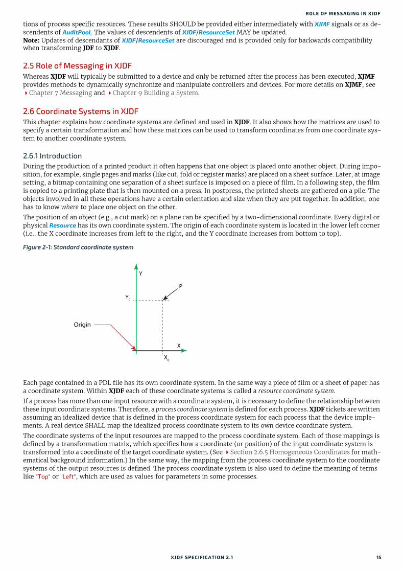
ROLE OF MESSAGING IN XJDF
tions of process specific resources. These results SHOULD be provided either intermediately with XJMF signals or as de-scendents of AuditPool. The values of descendents of XJDF/ResourceSet MAY be updated.Note: Updates of descendants of XJDF/ResourceSet are discouraged and is provided only for backwards compatibility when transforming JDF to XJDF.
2.5 Role of Messaging in XJDFWhereas XJDF will typically be submitted to a device and only be returned after the process has been executed, XJMF provides methods to dynamically synchronize and manipulate controllers and devices. For more details on XJMF, see Chapter 7 Messaging and Chapter 9 Building a System.
2.6 Coordinate Systems in XJDFThis chapter explains how coordinate systems are defined and used in XJDF. It also shows how the matrices are used to specify a certain transformation and how these matrices can be used to transform coordinates from one coordinate sys-tem to another coordinate system.
2.6.1 IntroductionDuring the production of a printed product it often happens that one object is placed onto another object. During impo-sition, for example, single pages and marks (like cut, fold or register marks) are placed on a sheet surface. Later, at image setting, a bitmap containing one separation of a sheet surface is imposed on a piece of film. In a following step, the film is copied to a printing plate that is then mounted on a press. In postpress, the printed sheets are gathered on a pile. The objects involved in all these operations have a certain orientation and size when they are put together. In addition, one has to know where to place one object on the other.
The position of an object (e.g., a cut mark) on a plane can be specified by a two-dimensional coordinate. Every digital or physical Resource has its own coordinate system. The origin of each coordinate system is located in the lower left corner (i.e., the X coordinate increases from left to the right, and the Y coordinate increases from bottom to top).
Each page contained in a PDL file has its own coordinate system. In the same way a piece of film or a sheet of paper has a coordinate system. Within XJDF each of these coordinate systems is called a resource coordinate system.
If a process has more than one input resource with a coordinate system, it is necessary to define the relationship between these input coordinate systems. Therefore, a process coordinate system is defined for each process. XJDF tickets are written assuming an idealized device that is defined in the process coordinate system for each process that the device imple-ments. A real device SHALL map the idealized process coordinate system to its own device coordinate system.
The coordinate systems of the input resources are mapped to the process coordinate system. Each of those mappings is defined by a transformation matrix, which specifies how a coordinate (or position) of the input coordinate system is transformed into a coordinate of the target coordinate system. (See Section 2.6.5 Homogeneous Coordinates for math-ematical background information.) In the same way, the mapping from the process coordinate system to the coordinate systems of the output resources is defined. The process coordinate system is also used to define the meaning of terms like "Top" or "Left", which are used as values for parameters in some processes.
Figure 2-1: Standard coordinate system
Y
P
Y0
X
Origin
X0
XJDF SPECIFICATIO N 2.1 15
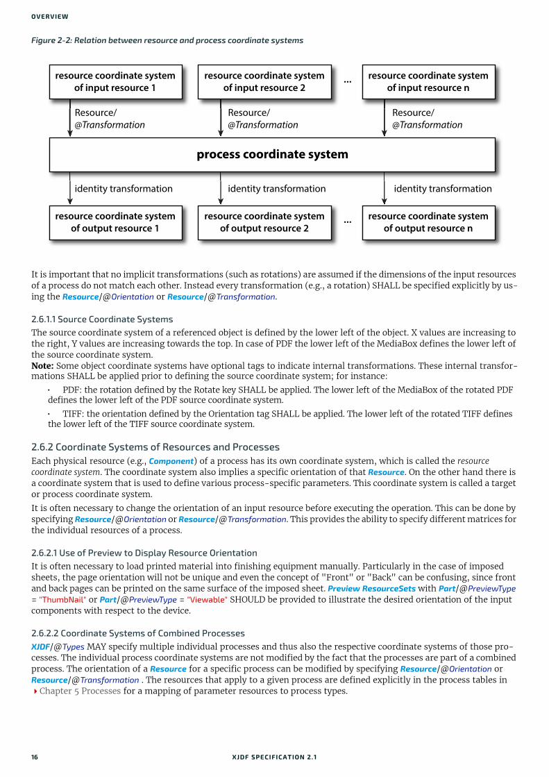
OVERVIEW
It is important that no implicit transformations (such as rotations) are assumed if the dimensions of the input resources of a process do not match each other. Instead every transformation (e.g., a rotation) SHALL be specified explicitly by us-ing the Resource/@Orientation or Resource/@Transformation.
2.6.1.1 Source Coordinate SystemsThe source coordinate system of a referenced object is defined by the lower left of the object. X values are increasing to the right, Y values are increasing towards the top. In case of PDF the lower left of the MediaBox defines the lower left of the source coordinate system.Note: Some object coordinate systems have optional tags to indicate internal transformations. These internal transfor-mations SHALL be applied prior to defining the source coordinate system; for instance:
• PDF: the rotation defined by the Rotate key SHALL be applied. The lower left of the MediaBox of the rotated PDF defines the lower left of the PDF source coordinate system.
• TIFF: the orientation defined by the Orientation tag SHALL be applied. The lower left of the rotated TIFF defines the lower left of the TIFF source coordinate system.
2.6.2 Coordinate Systems of Resources and ProcessesEach physical resource (e.g., Component) of a process has its own coordinate system, which is called the resource coordinate system. The coordinate system also implies a specific orientation of that Resource. On the other hand there is a coordinate system that is used to define various process-specific parameters. This coordinate system is called a target or process coordinate system.
It is often necessary to change the orientation of an input resource before executing the operation. This can be done by specifying Resource/@Orientation or Resource/@Transformation. This provides the ability to specify different matrices for the individual resources of a process.
2.6.2.1 Use of Preview to Display Resource OrientationIt is often necessary to load printed material into finishing equipment manually. Particularly in the case of imposed sheets, the page orientation will not be unique and even the concept of "Front" or "Back" can be confusing, since front and back pages can be printed on the same surface of the imposed sheet. Preview ResourceSets with Part/@PreviewType = "ThumbNail" or Part/@PreviewType = "Viewable" SHOULD be provided to illustrate the desired orientation of the input components with respect to the device.
2.6.2.2 Coordinate Systems of Combined ProcessesXJDF/@Types MAY specify multiple individual processes and thus also the respective coordinate systems of those pro-cesses. The individual process coordinate systems are not modified by the fact that the processes are part of a combined process. The orientation of a Resource for a specific process can be modified by specifying Resource/@Orientation or Resource/@Transformation . The resources that apply to a given process are defined explicitly in the process tables in Chapter 5 Processes for a mapping of parameter resources to process types.
Figure 2-2: Relation between resource and process coordinate systems
resource coordinate system
of input resource 1
Resource/@Transformation
identity transformation identity transformation identity transformation
Resource/@Transformation
Resource/@Transformation
process coordinate system
resource coordinate system
of input resource 2
resource coordinate system
of input resource n
resource coordinate system
of output resource 1
resource coordinate system
of output resource 2
resource coordinate system
of output resource n
...
...
16 XJDF SPECIFICATIO N 2.1

COORDINA TE SYSTEMS IN XJDF
2.6.3 Coordinate System TransformationsThe following table shows some matrices that can be used to change the orientation of a Resource. Most of the transfor-mations require the width (w) and the height (h) of the Component as specified by X and Y in Component/@Dimensions. If these are unknown, it is still possible to define a general orientation in Resource/@Orientation. The naming of the at-tribute reflects the state of the resource and not necessarily the order of applied transformations. Thus "Rotate90" and "Flip90" specify that the original Y axis as represented by the spine is on top. In the case of Flip90, the Component is ad-ditionally flipped front to back.
Table 2.1: Matrices and Orientation values for describing the orientation of a Component (Sheet 1 of 2)
ORIENTATION VALUE SOURCECOORDINATE SYSTEM
TRANSFORMATION MATRIX ACCORDING ACTION
TARGETCOORDINATE SYSTEM
Rotate0 1 0 0 1 0 0 No Action
Rotate90 0 1 -1 0 h 0 90° Counterclockwise Rotation
Rotate180 -1 0 0 -1 w h 180° Rotation
Rotate270 0 -1 1 0 0 w 270° Counterclockwise Rotation
Flip0 1 0 0 -1 0 h Flip around X
Flip90 0 -1 -1 0 h w 90° Counterclockwise Rotation + Flip around X
Flip180 -1 0 0 1 w 0 180° Rotation + Flip around X
Y
XFY
XFY
XFY
XF
Y
XFY
X
FY
XF FYX
Y
XFY
X
B
Y
XF B
Y
X
Y
XFY
XB
XJDF SPECIFICATIO N 2.1 17

OVERVIEW
2.6.4 General RulesThe following rules summarize the use of coordinate systems in XJDF.
• Every individual piece of material (film, plate, paper) has a resource coordinate system.
• Every process has a process coordinate system.
• Terms like top, left, etc., are used with respect to the process coordinate system in which they are used and are independent of orientation (i.e., landscape or portrait), and the human reading direction.
• The coordinate system of each input component is mapped to the process coordinate system.
• The coordinate system might change during processing (e.g., in Folding).
• The description of a product in XJDF is independent of the particular Machine used to produce this product. When creating setup information for an individual Machine, it might be necessary to compensate for certain Machine characteristics. At printing, for example, it might be necessary to rotate a landscape job because the printing width of the press is not large enough to run the job without rotation.
2.6.5 Homogeneous CoordinatesA convenient way to calculate coordinate transformations in a two-dimensional space is by using so-called homoge-neous coordinates. With this concept, a two-dimensional coordinate P=(x,y) is expressed in vector form as [x y 1]. The third element “1” is added to allow the vector being multiplied with a transformation matrix describing scaling, rotation, and translation in one shot. Although this only requires a 2*3 matrix (e.g., as it is used in PostScript) in practice 3*3 ma-trices are much more common, because they can be concatenated very easily. Thus, the third column SHALL be set to "0 0 1".
Flip270 0 1 1 0 0 0 270° CounterclockwiseRotation + Flip around X
Table 2.2: Coordinate Transformation Examples
MATRIX XJDF VALUE DESCRIPTION
"a b c d e f" General transformation case.
"1 0 0 1 0 0" Identity transformation.
"1 0 0 1 dx dy" Translation by dx, dy.
" 0 0" Rotation around the origin by degrees counter-clockwise.Note: Since the rotation is around the origin in the lower left hand corner, an additional translation will typically be re-quired to shift the object back to its original position.
Table 2.1: Matrices and Orientation values for describing the orientation of a Component (Sheet 2 of 2)
ORIENTATION VALUE SOURCECOORDINATE SYSTEM
TRANSFORMATION MATRIX ACCORDING ACTION
TARGETCOORDINATE SYSTEM
Y
XFY
X
B
a b 0c d 0e f 1
1 0 00 1 00 0 1
1 0 00 1 0
dx dy 1
cos sin 0sin– cos 0
0 0 1
cos sin sin– cos
18 XJDF SPECIFICATIO N 2.1
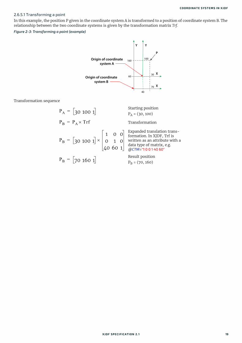
COORDINA TE SYSTEMS IN XJDF
2.6.5.1 Transforming a pointIn this example, the position P given in the coordinate system A is transformed to a position of coordinate system B. The relationship between the two coordinate systems is given by the transformation matrix Trf.
Transformation sequence
Figure 2-3: Transforming a point (example)
Starting positionPA = (30, 100)
Transformation
Expanded translation trans-formation. In XJDF, Trf is written as an attribute with a data type of matrix, e.g. @CTM="1 0 0 1 40 60"
Result positionPB = (70, 160)
Y Y
100160
40
6030
70
P
X
X
Origin of coordinate
system A
Origin of coordinate
system B
PA 30 100 1=
PB PA Trf=
PB 30 100 11 0 00 1 0
40 60 1
=
PB 70 160 1=
XJDF SPECIFICATIO N 2.1 19

OVERVIEW
20 XJDF SPECIFICATIO N 2.1

3
3 StructureA single XJDF describes the information about a job or process step that is transferred from a controller to a device. The scope of the exchanged information varies depending on the nature of the recipient device. An XJDF that is targeted at an individual device will typically contain only the details that are required by that device, along with some optional in-formation about the final product. Multiple work steps belonging to one job that need to be submitted from a controller to a workflow system that controls multiple devices SHALL be submitted as a separate XJDF for each work step. These MAY be packaged together and submitted as one or more transactions. See Chapter 9 Building a System for details of packaging and referencing of the individual XJDF.3.1 XJDFThe top-level element of an XJDF instance SHALL be an XJDF element. See Table 3.1 XJDF below for details. XJDF ele-ments MAY be embedded within other XML documents.
XJDF/@Types defines whether an XJDF specifies an end product or a list of processes that SHALL be executed. XJDF that are created by print buyers typically describe only the desired product rather than manufacturing process details. XJDF that describe finished products SHALL have a value of XJDF/@Types that contains "Product". If additional process infor-mation that is not defined in the ProductList is required, this information SHOULD be provided in ResourceSet elements.
ProductList MAY be provided in a process XJDF for informational purposes.
Table 3.1: XJDF (Sheet 1 of 2)
NAME DATA TYPE DESCRIPTION
Category ? NMTOKEN @Category specifies the named category of this XJDF. Controllers SHOULD specify @Category for processes that have many optional values in @Types. This allows processors to identify the general purpose of an XJDF without parsing the @Types field. For instance, a RIP for final output and a RIP for proof process have identical @Types attribute values, but have @Category = "ProofRIPing" or @Category = "RIPing", respectively.Values include those from: Node Categories.Note: @Category MAY also be the name of a gray box defined by an ICS docu-ment. See Section 1.8.2 Interoperability Conformance Specifications for de-tails.
CommentURL ? URL @CommentURL SHALL refer to an external, human-readable description of this XJDF.
DescriptiveName ? string Human-readable descriptive name of this XJDF. @DescriptiveName SHOULD be provided for communication from applications to humans in order to ref-erence the XJDF.
ICSVersions ? NMTOKENS @ICSVersions SHALL list all CIP4 Interoperability Conformance Specification (ICS) Versions that this XJDF complies with. The value of @ISCVersions SHALL conform to the value format described in Section 3.1.1 ICS Versions Value.
JobID NMTOKEN Job identification used by the application that created the XJDF job. Typically, a job is identified by the internal order number of the MIS system that cre-ated the job.
JobPartID ? NMTOKEN @JobPartID SHALL identify one or more worksteps of the same type that can be described as one XJDF. @JobPartID is internal to the MIS system that cre-ated the XJDF.
ProjectID ? NMTOKEN Identification of the project context that this XJDF belongs to. @ProjectID SHOULD be used by a controller to group a set of XJDF jobs.
RelatedJobID ? NMTOKEN Job identification of a related job. Used to identify the @JobID of a previous run of this job or job with very similar settings. It MAY be used to retrieve additional job and device specific settings from a data store.
XJDF SPECIFICATIO N 2.1

STRUCTURE
3.1.1 ICS Versions ValueTo assist with interoperability conformance the XJDF can refer to one or more CIP4 Interoperability Conformance Spec-ification documents. Each document is referenced by using an NMTOKEN that complies with the following:
Value format: <ICSName>_L<ICSLevel>-<ICSVersion>. Example: "MISPRE_L1-2.0" for the MIS to Prepress ICS.
3.1.2 XJDF for Product Intent XJDF that are created by end customers typically describe only the desired product rather than manufacturing process details.
XJDF/@Types SHALL have a value of "Product" to indicate that the XJDF does not specify any processing.
Product elements SHOULD include intent elements that describe the end results the customer is requesting. If additional process information that is not defined in the intent elements is required, this information SHOULD be provided in ResourceSet elements. The value of XJDF/@Types SHALL remain "Product".
3.1.3 XJDF for Process Description and Gray BoxesProcess XJDF contain processing instructions in ResourceSet elements that are targeted to a specific device in addition to an optional product definition in a ProductList and intent elements. @Types of process XJDF SHALL NOT contain the token "Product" if any additional process type tokens are present. In some cases such as prepress, a controller such as an MIS will not know all the details of the process including the exact list of XJDF/@Types or any details of the ResourceSets for the respective processes. It can still provide an XJDF with the limited, known information. These limited XJDF are referred to as Gray Boxes.Note: There is no syntactical difference between a gray box and a dedicated process XJDF. The boundary between Gray Boxes and dedicated process XJDF is very fuzzy, since devices will typically apply defaults to any data that is missing in a process XJDF.
RelatedJobPartID ? NMTOKEN Job identification of a related job part. Used to identify the @JobPartID of a previous run of this job or job with very similar settings. It MAY be used to retrieve additional job and device specific settings from a data store.
RelatedProjectID ? NMTOKEN Identification of a related project context that this XJDF belongs to. @RelatedProjectID SHOULD be used by a controller to group a set of XJDF jobs.
Types NMTOKENS A list of one or more process names that are specified within this XJDF docu-ment. For details on using processes, see Section 3.1.3 XJDF for Process Description and Gray Boxes. A value of @Types that contains "Product" speci-fies that the products that are described shall be produced without complete knowledge of the production workflow. Additional process specifics MAY be supplied in a ticket that contains "Product". Values include those from: Chapter 5 Processes.
Version ? enumeration @Version SHALL define the version of the XJDF document. The value of @Version SHALL be "2.1" for documents that comply to this specification.Allowed values are:2.0 - Prior version.2.1 - This version.
AuditPool ? element List of elements that contains all relevant audit information. AuditPool ele-ments are intended to serve the requirements of MIS for evaluation and post calculation. See Section 3.2 AuditPool.
Comment * element Any human-readable text. The Comment element is different from an XML comment <!-- XML Comment -->. The XJDF comment is meant for display in a user interface whereas the XML comment is used to add developer’s com-ments to the underlying XML.
GeneralID * element Additional identifiers related to the XJDF.
ProductList ? element Bill of materials - description of the product, or products that this XJDF pro-duces.
ResourceSet * element Container elements for Resource elements.
Table 3.1: XJDF (Sheet 2 of 2)
NAME DATA TYPE DESCRIPTION
22 XJDF SPECIFICATIO N 2.1

AUDITPOOL
3.1.3.1 Specifying NamedFeatures with GeneralIDXJDF MAY contain zero or more GeneralID[@Datatype="NamedFeature"] elements to specify global setup definitions. These GeneralID elements that are referred to as “NamedFeatures” in this paragraph allow a controller to define a named set of parameters for processes that SHALL be executed without defining the details or even the resources.
Explicitly specified traits SHALL override any implied traits defined by GeneralID[@Datatype="NamedFeature"] .
XJDF/@Types abstractly specifies the set of processes to execute, whereas "NamedFeatures" abstractly specifies the set of resources for the processes specified in @Types.
3.2 AuditPoolAuditPool elements contain the recorded results of a process. Audits are conceptually very similar to job-specific signals. Signals record the current state of a process or device, whereas audits summarize that device state over a longer period during the execution of a single process. Thus an audit will summarize the result of multiple signals belonging to a unique phase in the returned XJDF. A unique phase SHOULD contain the same combination of JobPhase/@Status and JobPhase/@StatusDetails. Thus minor variations such as speed NEED NOT be recorded as separate audits although they MAY have slightly varying values in the respective signals. AuditPool elements record any event related to the situations described in Table 3.2 Alignment of Audits and Messages. Note: Audits are always in the context of a process. Thus job independent signals such as the SignalStatus of an idle de-vice will never be tracked as an audit.Note: The data in XJMF responses are very similar to the data in XJMF signals. The only difference is that XJMF respons-es are synchronous HTTP responses. Therefore, all discussions referring to signals in this section apply equally to re-sponses.
Audit information might be used by MIS for operations such as evaluation or invoicing. AuditPool entries are ordered chronologically, with the last entry in the AuditPool representing the newest. An AuditProcessRun element shall finalize each Workstep. All subsequent entries in the AuditPool belong to the next Workstep.
The following table defines the contents of the AuditPool element. In contrast to most other elements in XJDF the child elements of AuditPool SHALL be ordered chronologically from oldest to newest rather than alphabetically.
Table 3.2: Alignment of Audits and Messages
AUDIT SIGNAL COMMENT
AuditCreated - First audit in the XJDF.
AuditNotification SignalNotification One AuditNotification SHOULD be written for each SignalNotification.
AuditProcessRun CommandReturnQueueEntry A process run SHOULD be written whenever an XJDF is returned to the controller by a device.
AuditResource SignalResource One AuditResource SHOULD be written with the final data for each unique phase.
AuditStatus SignalStatus One AuditStatus SHOULD be written with the final data for each phase.
Table 3.3: AuditPool Element
NAME DATA TYPE DESCRIPTION
AuditCreated * element Logs creation of an XJDF or creation of a resource.
AuditNotification * element Logs individual events that occurred during processing.
AuditProcessRun * element Summarizes one complete execution run of an XJDF or delimits a group of AuditPool elements for each individual process run.
AuditResource * element Describes the usage of resources during execution of an XJDF or the modifi-cation of the intended usage of a resource.
AuditStatus * element Logs start and end times of any process states and sub-states, denoted as phases. Phases can reflect any arbitrary subdivisions of a process.
XJDF SPECIFICATIO N 2.1 23
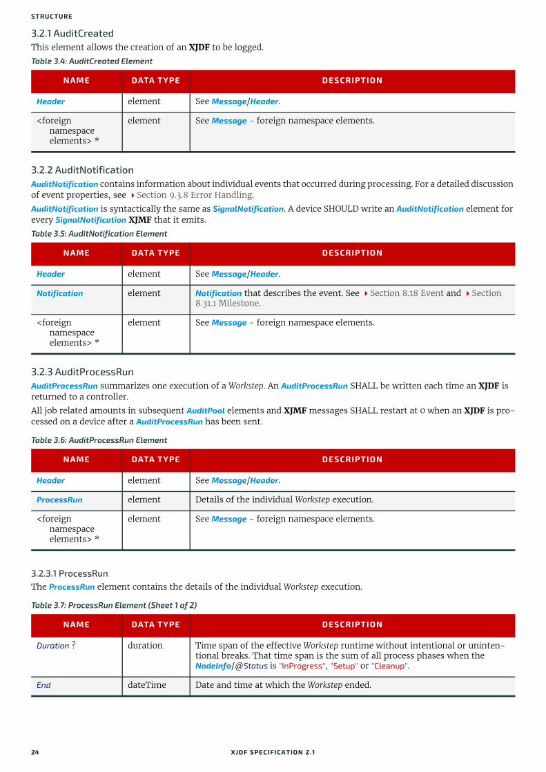
STRUCTURE
3.2.1 AuditCreatedThis element allows the creation of an XJDF to be logged.
3.2.2 AuditNotificationAuditNotification contains information about individual events that occurred during processing. For a detailed discussion of event properties, see Section 9.3.8 Error Handling.
AuditNotification is syntactically the same as SignalNotification. A device SHOULD write an AuditNotification element for every SignalNotification XJMF that it emits.
3.2.3 AuditProcessRunAuditProcessRun summarizes one execution of a Workstep. An AuditProcessRun SHALL be written each time an XJDF is returned to a controller.
All job related amounts in subsequent AuditPool elements and XJMF messages SHALL restart at 0 when an XJDF is pro-cessed on a device after a AuditProcessRun has been sent..
3.2.3.1 ProcessRunThe ProcessRun element contains the details of the individual Workstep execution.
Table 3.4: AuditCreated Element
NAME DATA TYPE DESCRIPTION
Header element See Message/Header.
<foreign namespace elements> *
element See Message - foreign namespace elements.
Table 3.5: AuditNotification Element
NAME DATA TYPE DESCRIPTION
Header element See Message/Header.
Notification element Notification that describes the event. See Section 8.18 Event and Section 8.31.1 Milestone.
<foreign namespace elements> *
element See Message - foreign namespace elements.
Table 3.6: AuditProcessRun Element
NAME DATA TYPE DESCRIPTION
Header element See Message/Header.
ProcessRun element Details of the individual Workstep execution.
<foreign namespace elements> *
element See Message - foreign namespace elements.
Table 3.7: ProcessRun Element (Sheet 1 of 2)
NAME DATA TYPE DESCRIPTION
Duration ? duration Time span of the effective Workstep runtime without intentional or uninten-tional breaks. That time span is the sum of all process phases when the NodeInfo/@Status is "InProgress", "Setup" or "Cleanup".
End dateTime Date and time at which the Workstep ended.
24 XJDF SPECIFICATIO N 2.1

AUDITPOOL
3.2.4 AuditResourceThe AuditResource element describes the usage of resources during execution of a process. It logs consumption and pro-duction amounts of any quantifiable resources, accumulated over one process run or one part of a process run.
AuditResource is syntactically the same as SignalResource. Whereas XJMF/SignalResource MAY convey the momentary consumption or production of a resource, AuditResource conveys the consumption or production of a resource during an entire phase. A device SHALL write a copy of the last SignalResource that it emits during a AuditProcessRun as an AuditResource.
EndStatus enumeration The NodeInfo/@Status of the Workstep at the end of the run. For a description of process states, see Appendix A.2.44 Status.Allowed values are:Aborted – The XJDF has been aborted before producing the desired result. Completed – The XJDF has been completed and the desired result has been
produced.
QueueEntryID ? NMTOKEN @QueueEntryID of the QueueEntry for which this AuditProcessRun was gener-ated.
ReturnTime ? dateTime Date and time of the ReturnQueueEntry submission.
Start dateTime Date and time at which the Workstep started.
SubmissionTime ? dateTime Date and time of the SubmitQueueEntry submission. This value SHOULD be identical with QueueEntry/@SubmissionTime.
Part * element Describes which parts of a Workstep this ProcessRun belongs to. If Part is not specified for a ProcessRun, it refers to all parts.
Table 3.8: AuditResource Element
NAME DATA TYPE DESCRIPTION
Header element See Message/Header.
ResourceInfo element ResourceInfo describes the consumption or production of an individual Resource. ResourceInfo/ResourceSet/Resource elements NEED NOT contain the explicit resources as defined in ResourceInfo/ResourceSet/@Name.
<foreign namespace elements> *
element See Message - foreign namespace elements.
Table 3.7: ProcessRun Element (Sheet 2 of 2)
NAME DATA TYPE DESCRIPTION
XJDF SPECIFICATIO N 2.1 25

STRUCTURE
Example 3.1: AuditResource: Logging of ConsumptionThe following example describes the logging of a modification of the media weight and amount. The XJDF document before modification requests 400 copies of 80 gram media. The XJDF after modification specifies that 421 copies of 90-gram media have been consumed.
3.2.5 AuditStatusAuditStatus contains audit information about the start and end times of any process states and sub-states, denoted as phases. Phases can reflect any arbitrary subdivisions of a process, such as maintenance, washing, plate changing, fail-ures and breaks. AuditStatus elements SHOULD be written for every significant status change that is detected. AuditStatus is syntactically the same as SignalStatus. Whereas XJMF/SignalStatus conveys the momentary status of a de-vice and or job, AuditStatus conveys the status during an entire phase. A device SHALL not write new AuditStatus ele-ments for every SignalStatus XJMF that it emits.
<XJDF xmlns="http://www.CIP4.org/JDFSchema_2_0" JobID="PaperAudit" Types="ConventionalPrinting"> <AuditPool> <AuditCreated> <Header AgentName="Writer" AgentVersion="V_2.0" DeviceID="TestSender" Time="2020-03-01T19:55:57+01:00"/> </AuditCreated> <AuditResource> <Header AgentName="Writer" AgentVersion="V_2.0" DeviceID="TestSender" Time="2020-03-01T19:55:57+01:00"/> <ResourceInfo> <ResourceSet Name="Component" Usage="Input"> <Resource> <AmountPool> <PartAmount Amount="400" Waste="21"/> </AmountPool> <Part SheetName="S1"/> <Component/> </Resource> </ResourceSet> </ResourceInfo> </AuditResource> <AuditResource> <Header AgentName="Writer" AgentVersion="V_2.0" DeviceID="TestSender" Time="2020-03-01T19:55:57+01:00"/> <ResourceInfo> <ResourceSet Name="Media"> <Resource> <Media MediaType="Paper" Weight="90"/> </Resource> </ResourceSet> </ResourceInfo> </AuditResource> </AuditPool> <ResourceSet Name="Media"> <Resource ID="r_000007"> <Part SheetName="S1"/> <Media MediaType="Paper" Weight="80"/> </Resource> </ResourceSet> <ResourceSet Name="Component" Usage="Input"> <Resource> <AmountPool> <PartAmount Amount="400"/> </AmountPool> <Part SheetName="S1"/> <Component MediaRef="r_000007"/> </Resource> </ResourceSet></XJDF>
26 XJDF SPECIFICATIO N 2.1

PRODUCTLIST
AuditStatus elements MAY also be used to log the actual time spans when Resources are used by a process. For example, the temporary usage of a fork lift can be logged if an AuditStatus element is added that contains an AuditStatus/Header/@DeviceID of the fork lift and specifies the actual start and end time of the usage of that fork lift.
3.3 ProductListThe products or set of products that are processed during a given workstep MAY be specified in a ProductList, which de-scribes a bill of materials. ProductList specifies a list of products and product parts from the print buyer’s point of view.
Multiple end products MAY be specified, e.g. when a press sheet of a gang job that contains multiple individual customer jobs is printed. Unless the XJDF describes a gang job, not more than one Product[@IsRoot="true"] SHOULD be specified.
For more details on product intent, see Chapter 4 Product Intent.
3.3.1 ProductThe Product element specifies an individual product or product part.
Table 3.9: AuditStatus Element
NAME DATA TYPE DESCRIPTION
Header element See Message/Header.
DeviceInfo element DeviceInfo describes details of the actual device status.
<foreign namespace elements> *
element See Message - foreign namespace elements.
Table 3.10: ProductList Element
NAME DATA TYPE DESCRIPTION
Product + element Each Product element in this list represents a product or part of a product with unique properties such as substrate, colors or size.
Table 3.11: Product Element (Sheet 1 of 2)
NAME DATA TYPE DESCRIPTION
Amount ? integer Total number of products or product parts of this type to produce. For prod-uct parts, if present @Amount SHALL specify the number of copies of the product part that are needed in order to produce one product.
CommentURL ? URL URL to an external, human-readable description of the product or product part.
DescriptiveName ? string Human-readable descriptive name of the product or product part.
ExternalID ? NMTOKEN Identifier of the product in an MIS.Note: The granularity with which an MIS defines individual products is system dependent. It will typically not include the artwork unless it applies to pre-printed products that can be reordered from stock.
ID ? ID Internal identifier of this product.
IsRoot ? boolean If true, this Product is a self-contained product. If false, this Product is a product part of another Product, such as a cover or insert. Multiple Product elements with @IsRoot=”true” MAY be specified, for instance in a gang job. If the parent ProductList element contains multiple Product elements, @IsRoot SHOULD be specified in all root products.
MaxAmount ? integer Maximum total number of products to produce including the maximum overage that the customer is willing to accept. @MaxAmount SHOULD NOT be specified for product parts.
MinAmount ? integer Minimum total number of products to produce including the maximum underage that the customer is willing to accept. @MinAmount SHOULD NOT be specified for product parts.
XJDF SPECIFICATIO N 2.1 27

STRUCTURE
3.3.1.1 Product AmountProduct/@Amount SHALL be applied within the context of one parent product. If Product/@IsRoot="true" then Product/@Amount SHALL specify the total number of products. If Product/@IsRoot="false" then Product/@Amount SHALL specify the total number of the respective child products required to create one parent product.
The following example shows the simplified description of 10 notebooks with a front and back cover and a 50 page book block.
Example 3.2: Amounts in a Notebook
3.3.1.2 Product Amount for Variable DataIf a Product contains a VariableIntent, then Product/@Amount SHALL refer to the number of instance documents, also referred to as recipients or records.
The following example describes a variable job with two finishing options. The entire job has 10000 records of which 9000 are brochures and 1000 are hardcover books. Each brochure and each book has one cover and one body.
PartVersion ?New in XJDF 2.1
NMTOKEN Version identifier (e.g., the language version of a catalog). See also Part/@PartVersion. If @PartVersion is specified for a child product, the root prod-ucts that reference the child products SHALL also contain @PartVersion with the same value.
ProductType ? NMTOKEN Classification of this product or product part.Values include those from: Product Types.
ProductTypeDetails ? string @ProductTypeDetails specifies additional details of the product or product part that MAY be site specific and MAY be human readable. @ProductType SHOULD be present if @ProductTypeDetails is specified.
Comment * element Any human-readable text that relates to the product or product part.
GeneralID * element Additional identifiers related to the product or product part.
Intent * element Container elements for intents.
<ProductList> <Product Amount="10" IsRoot="true" ProductType="Notebook"> <Intent Name="BindingIntent"> <BindingIntent BindingSide="Top" BindingType="EdgeGluing" ChildRefs="IBack IBody ICover"/> </Intent> </Product> <Product Amount="1" ID="ICover" IsRoot="false" ProductType="FrontCover"/> <Product Amount="50" ID="IBody" IsRoot="false" ProductType="BookBlock"/> <Product Amount="1" ID="IBack" IsRoot="false" ProductType="BackCover"/></ProductList>
Table 3.11: Product Element (Sheet 2 of 2)
NAME DATA TYPE DESCRIPTION
28 XJDF SPECIFICATIO N 2.1

RESOURCESET
Example 3.3: Amounts in Variable Data
3.4 ResourceSetA ResourceSet describes a set of one or more Resource elements that are logically grouped together. A ResourceSet can describe either physical entities such as paper or logical entities such as process parameters. ResourceSet elements with the same values of @Name, @Usage, @ProcessUsage and common or no entries in @CombinedProcessIndex SHALL NOT be specified.Note: This restriction is designed to ensure that the applicable ResourceSet for a process can be unambiguously identi-fied.For instance a ResourceSet[@Name=”NodeInfo”] MAY be defined for end customer scheduling requirements by specifying ResourceSet/@ProcessUsage=”EndCustomer” and partitioning by @Product. Then the production scheduling SHOULD be defined in a separate ResourceSet[@Name=”NodeInfo”] without @ProcessUsage.
An individual Resource SHALL be referenced by referencing Resource/@ID. The ResourceSet SHALL be referenced by ref-erencing ResourceSet/@ID. Unless otherwise specified, an @IDREF or @IDREFS will refer to an individual Resource rather than an entire ResourceSet.
In some cases the partitioning structure of a ResourceSet is not explicitly required because the Resource elements are individually referenced by ID from other elements. In this case the Part elements NEED NOT be specified, even if there are multiple Resource elements in one ResourceSet.
<ProductList> <Product Amount="10000" IsRoot="true"> <Intent Name="VariableIntent"> <VariableIntent ChildRefs="IDBrochure IDBook" VariableType="Area"/> </Intent> </Product> <Product Amount="1000" ID="IDBook" IsRoot="false" ProductType="Book"> <Intent Name="BindingIntent"> <BindingIntent BindingType="HardCover" ChildRefs="IDBookCover IDBody"/> </Intent> </Product> <Product Amount="1" ID="IDBookCover" IsRoot="false" ProductType="Cover"/> <Product Amount="1" ID="IDBody" IsRoot="false"/> <Product Amount="9000" ID="IDBrochure" IsRoot="false"> <Intent Name="BindingIntent"> <BindingIntent BindingType="SaddleStitch" ChildRefs="IDBrochureCover IDBody"/> </Intent> </Product> <Product Amount="1" ID="IDBrochureCover" IsRoot="false" ProductType="Cover"/></ProductList>
Table 3.12: ResourceSet Element (Sheet 1 of 2)
NAME DATA TYPE DESCRIPTION
CombinedProcessIndex ?
IntegerList @CombinedProcessIndex specifies the zero based indices of individual pro-cesses within the complete list of XJDF/@Types that this ResourceSet SHALL apply to. Multiple entries in @CombinedProcessIndex specify that the ResourceSet is used by the respective multiple processes. @CombinedProcessIndex SHALL be specified if multiple ResourceSet items with the same @Name, @ProcessUsage and @Usage are specified in one XJDF. If @CombinedProcessIndex is not specified, the ResourceSet applies to all pro-cesses that match the @Name, @ProcessUsage and @Usage requirements as listed in Chapter 5 Processes.
CommentURL ? URL URL to an external, human-readable description of the ResourceSet.
DescriptiveName ? string Human-readable descriptive name of the ResourceSet.
ID ? ID Identifier of the ResourceSet. @ID SHOULD be specified if the ResourceSet is a direct child of XJDF and @Usage is not specified and Resource/@ID is not specified in the child resources and @CombinedProcessIndex does not specify an exchange ResourceSet.
XJDF SPECIFICATIO N 2.1 29

STRUCTURE
Example 3.4: ResourceSet with CombinedProcessIndexThe following example shows the use of ResourceSet/@CombinedProcessIndex to differentiate the scheduling for a fin-ishing combined process that contains both Cutting and Folding. The NodeInfo with @CombinedProcessIndex="0" applies to the first token in XJDF/@Types, i.e. Cutting, whereas the NodeInfo with @CombinedProcessIndex="1" applies to the sec-ond token in XJDF/@Types, i.e. Folding. Since CuttingParams is uniquely linked to the Cutting process, and similarly
Name NMTOKEN @Name SHALL specify the name of the explicit resource that this ResourceSet represents. Child resource elements of this ResourceSet SHALL NOT contain resources that do not match @Name. @Name of resource types that are spec-ified in Chapter 6 Resources of this specification SHALL be provided with-out an XML namespace prefix. @Name of proprietary resources SHALL be provided with an XML namespace prefix. See Section 3.5 XJDF Extensibility for details.A list of predefined resources is specified in Chapter 6 Resources.
ProcessUsage ? NMTOKEN @ProcessUsage identifies the context of a Resource if multiple Resource ele-ments of the same type are supplied for an individual process type.Values include those specified in the appropriate process descriptions in Chapter 5 Processes.
Note: ICS documents MAY define additional values for @ProcessUsage.
Unit ? NMTOKEN Unit of measurement for the values of AmountPool/PartAmount/@Amount, AmountPool/PartAmount/@MaxAmount, AmountPool/PartAmount/@MinAmount and AmountPool/PartAmount/@Waste.
Values include those from: Units.Note: Units other than those defined in the above table SHOULD NOT be spec-ified.
Usage ? enumeration @Usage shows that the resource is either consumed or produced within this XJDF document. If no @Usage is specified and the ResourceSet is a direct child of XJDF and the value of @CombinedProcessIndex does not specify an exchange ResourceSet, then the ResourceSet or its Resource children SHOULD contain @ID and be referenced from elsewhere within the XJDF. See Section 5.2.1 Exchange ResourceSets in combined processes.Allowed value is from: Usage.Note: ResourceSet[@Usage="Output"] MAY contain data that is conceptually input data for the XJDF.
Comment * element Any human-readable text that relates to the ResourceSet.
Dependent * element Reference to an XJDF that produces this ResourceSet[@Usage=”Input”] or consumes this ResourceSet[@Usage=”Output”]. Multiple Dependent elements specify that the Dependent relates to multiple consuming or producing pro-cesses.
GeneralID * element Additional identifiers related to the ResourceSet.
Resource * element List of Resource elements.
Table 3.12: ResourceSet Element (Sheet 2 of 2)
NAME DATA TYPE DESCRIPTION
30 XJDF SPECIFICATIO N 2.1

XJDF EXTENSIBILITY
FoldingParams is uniquely linked to the Folding process (see Cutting – Input Resources and Folding – Input Resources), @CombinedProcessIndex NEED NOT be specified for those resources.
3.4.1 DependentA Dependent element SHALL reference an XJDF that produces an input ResourceSet or consumes an output ResourceSet. The data in Dependent elements allows devices to communicate directly with other devices in the workflow that are pro-cessing the same job. The data provided in Dependent also provides pipe control information. See Section 9.3.5 Overlapping Processing and Section 7.11 PipeControl.
3.5 XJDF ExtensibilityThe XJDF specification aims to support plug-and-play as much as possible. Nonetheless, XJDF is meant to be flexible and therefore useful to any vendor, as each vendor may have specific data to include in the XJDF files. However, foreign namespace extensions SHOULD NOT duplicate functionality of XJDF defined attributes and elements. This section de-scribes how XJDF MAY be extended. XJDF extensibility SHALL be implemented using XML namespaces; see [XMLNS].
<XJDF xmlns="http://www.CIP4.org/JDFSchema_2_0" JobID="CPI_Example" Types="Cutting Folding"> <ResourceSet CombinedProcessIndex="0" Name="NodeInfo" Usage="Input"> <Resource> <NodeInfo Start="2020-03-01T13:00:00+01:00"/> </Resource> </ResourceSet> <ResourceSet CombinedProcessIndex="1" Name="NodeInfo" Usage="Input"> <Resource> <NodeInfo Start="2020-03-01T17:00:00+01:00"/> </Resource> </ResourceSet> <ResourceSet Name="CuttingParams" Usage="Input"> <Resource/> </ResourceSet> <ResourceSet Name="FoldingParams" Usage="Input"> <Resource/> </ResourceSet></XJDF>
Table 3.13: Dependent Element
NAME DATA TYPE DESCRIPTION
JobID NMTOKEN @JobID of the referenced process.Note: @JobID will typically match XJDF/@JobID unless parts of the job are being produced on gang forms.
JobPartID ? NMTOKEN @JobPartID of the referenced process. @JobPartID SHALL NOT match XJDF/@JobPartID.
PipeID ? NMTOKEN If this attribute exists, the resource is a pipe. @PipeID is used by XJMF pipe-control messages to identify the pipe. For more information, see Section 9.3.5 Overlapping Processing.
PipeProtocol ? NMTOKEN @PipeProtocol defines the protocol use for pipe handling. Proprietary pipe protocols MAY be specified in addition to those defined below but will not necessarily be inter-operable.Values include: IdentificationField – The pipe data is provided by barcodes that are defined in
IdentificationField elements.XJMF – XJMF based PipeControl messages. The sequence of pipe initialization
is undefined. See next two values: "XJMFPush" and "XJMFPull". XJMFPush – XJMF based PipeControl protocol. The producing device initiates
the protocol. XJMFPull – XJMF based PipeControl protocol. The consuming device initiates
the protocol.None – No pipe support.
XJMFURL ? URL URL of a processor that has knowledge of the referenced process. The proces-sor at this URL MAY be queried for additional information using XJMF.
XJDF SPECIFICATIO N 2.1 31

STRUCTURE
3.5.1 Foreign NamespacesAttributes in a foreign namespace MAY be added to any XJDF element.
Elements in a foreign namespace SHALL NOT be specified in any XJDF element other than the Notification, Resource and Intent elements. The children of these elements SHALL be ordered so that all elements in a foreign namespace follow all of the elements in the XJDF namespace.
Example 3.5: Namespaces in XMLThe example illustrates how private namespaces are declared and used to extend an existing XJDF Media element by adding a private attribute and a namespace declaration.
3.5.2 Creating Extension ResourceSetsNew types of ResourceSet may be defined by creating a ResourceSet with @Name referring to a proprietary xml name-space. The extension element SHALL reside in the appropriate child ResourceSet/Resource element.
Example 3.6: Creating Extension ResourceSets
3.5.3 Creating Extension Message Type ElementsNew message types may be defined by creating a message in a proprietary xml namespace that adheres to the naming scheme of XJMF.
The extension message SHALL reside in the XJMF element. Extension messages SHOULD follow the naming scheme us-ing message family and type and SHOULD contain a Header element.The following example shows a query and it’s matching response for a new message type in the “foo” namespace.
<Resource> <Part SheetName="S1"/> <Media MediaType="Paper" xmlns:foo="http://www.foo.org" foo:FooAtt="FooVal"/></Resource>
<ResourceSet ID="FooParams_000004" Name="foo:FooParams" Usage="Input" xmlns:foo="http://www.foo.org"> <Resource ID="FooParams_000004.1"> <Part Run="R1"/> <foo:FooParams FooAtt="FooVal"/> </Resource></ResourceSet>
32 XJDF SPECIFICATIO N 2.1
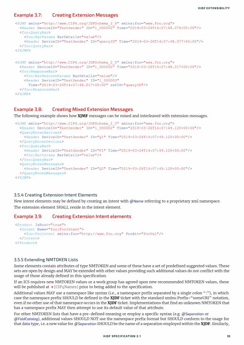
XJDF EXTENSIBILITY
Example 3.7: Creating Extension Messages
Example 3.8: Creating Mixed Extension MessagesThe following example shows how XJMF messages can be mixed and interleaved with extension messages.
3.5.4 Creating Extension Intent ElementsNew intent elements may be defined by creating an intent with @Name referring to a proprietary xml namespace.
The extension element SHALL reside in the intent element.
Example 3.9: Creating Extension Intent elements
3.5.5 Extending NMTOKEN ListsSome elements contain attributes of type NMTOKEN and some of these have a set of predefined suggested values. These sets are open by design and MAY be extended with other values providing such additional values do not conflict with the usage of those already defined in this specification.
If an ICS requires new NMTOKEN values or a work group has agreed upon new recommended NMTOKEN values, these will be published at [CIP4Names] prior to being added to the specification.
Additional values MAY use a namespace like syntax (i.e., a namespace prefix separated by a single colon “:”), in which case the namespace prefix SHOULD be defined in the XJDF ticket with the standard xmlns:Prefix=“someURI” notation, even if no other use of that namespace occurs in the XJDF ticket. Implementations that find an unknown NMTOKEN that has a namespace prefix MAY then attempt to use its default value of that attribute.
For other NMTOKEN lists that have a pre-defined meaning or employ a specific syntax (e.g. @Separation or @FoldCatalog), additional values SHOULD NOT use the namespace prefix format but SHOULD conform to the usage for that data type, i.e. a new value for @Separation SHOULD be the name of a separation employed within the XJDF. Similarly,
<XJMF xmlns="http://www.CIP4.org/JDFSchema_2_0" xmlns:foo="www.foo.org"> <Header DeviceID="TestSender" ID="l_000002" Time="2019-03-26T14:07:48.076+00:00"/> <foo:QueryBar> <foo:BarParams BarDetails="value"/> <Header DeviceID="TestSender" ID="queryID" Time="2019-03-26T14:07:48.077+00:00"/> </foo:QueryBar></XJMF>
<XJMF xmlns="http://www.CIP4.org/JDFSchema_2_0" xmlns:foo="www.foo.org"> <Header DeviceID="TestSender" ID="l_000002" Time="2019-03-26T14:07:48.017+00:00"/> <foo:ResponseBar> <foo:BarResonseParams BarDetails="value"/> <Header DeviceID="TestSender" ID="l_000003" Time="2019-03-26T14:07:48.017+00:00" refID="queryID"/> </foo:ResponseBar></XJMF>
<XJMF xmlns="http://www.CIP4.org/JDFSchema_2_0" xmlns:foo="www.foo.org"> <Header DeviceID="TestSender" ID="l_000002" Time="2019-03-26T14:07:49.120+00:00"/> <QueryKnownDevices> <Header DeviceID="TestSender" ID="Q1" Time="2019-03-26T14:07:49.120+00:00"/> </QueryKnownDevices> <foo:QueryBar> <Header DeviceID="TestSender" ID="F1" Time="2019-03-26T14:07:49.120+00:00"/> <foo:BarParams BarDetails="value"/> </foo:QueryBar> <QueryKnownMessages> <Header DeviceID="TestSender" ID="Q2" Time="2019-03-26T14:07:49.120+00:00"/> </QueryKnownMessages></XJMF>
<Product IsRoot="true"> <Intent Name="foo:FooIntent"> <foo:FooIntent xmlns:foo="http://www.foo.org" FooAtt="FooVal"/> </Intent></Product>
XJDF SPECIFICATIO N 2.1 33

STRUCTURE
a new value of @FoldCatalog SHOULD conform to the normal ‘Fx-y’ syntax. Implementations that find an unknown NMTOKEN without a namespace prefix MAY then raise an error.
3.5.6 Extending Process TypesXJDF defines a basic set of process types. However, because XJDF allows flexible encoding, this list, by definition, will not be complete. Vendors that have specific processes that do not fit in the general XJDF processes and that are not com-binations of individual XJDF processes (see Section 3.1.3 XJDF for Process Description and Gray Boxes) can create pro-cess XJDF of their own type. Then the content of the @Types attribute MAY be specified with a prefix that identifies the organization. The prefix and name SHALL be separated by a single colon (:) as shown in the following example.
Example 3.10: Extending Process Types
3.5.6.1 Rules about Process Extension
The use of namespace prefixes in the @Types attribute is for extensions only. Standard XJDF process types SHALL be specified without a prefix in XJDF/@Types. If a process is simply an extension of an existing process, it is possible to de-scribe the private data by extending the existing resource types.
<XJDF xmlns="http://www.CIP4.org/JDFSchema_2_0" JobID="IntentExtension" Types="foo:FooMaking" xmlns:foo="http://www.foo.org"></XJDF>
34 XJDF SPECIFICATIO N 2.1

4
4 Product IntentProduct Intent provides a description of finished products from the print buyer’s point of view.4.1 IntentIntent elements are a container for specific Product Intent elements. Product elements SHALL contain at most one intent element with the same Intent/@Name. If multiple product parts with different intent descriptions are needed, each prod-uct part SHALL be defined as a separate Product.
4.1.1 Product IntentA Product Intent is any specific intent defined in this chapter (e.g. BindingIntent). A Product Intent is a child of a Intent element. Table 4.2 Product Intent Elements defines the list of product intents.
Table 4.1: Intent Element
DescriptiveName ? string Human readable descriptive name of the Intent.
ExternalID ? NMTOKEN Identifier of the Intent in an external system such as an MIS.
Name NMTOKEN Type of the product intent. A list of predefined intent types is specified in Table 4.2 Product Intent Elements. Extension intent types MAY be defined. See Section 3.5.4 Creating Extension Intent Elements for details.
Product Intent ? element Details of the Intent. The XML element name SHALL be the value of @Name.
<foreignnamespaceelements> *
element Any elements in a foreign namespace. Foreign namespace extensions SHOULD NOT duplicate functionality of XJDF.
Table 4.2: Product Intent Elements (Sheet 1 of 2)
NAME DESCRIPTION
AssemblingIntent ? This intent specifies the placing or inserting of one component within another, using information that identifies page location, position and attachment method.
BindingIntent ? This intent specifies the binding intent for a Product.
ColorIntent ? This intent specifies the type of ink to be used for a Product.
ContentCheckIntent ? This intent specifies the prepress proofing intent for a Product, using information that identifies the type, quality, brand name and overlay of the proof.
EmbossingIntent ? This intent specifies the embossing and/or foil stamping intent for a Product.
FoldingIntent ? This intent specifies the fold intent for a Product using information that identifies the number of folds, the height and width of the folds, and the folding catalog number.
HoleMakingIntent ? This intent specifies the hole making intent for a Product.
LaminatingIntent ? This intent specifies the laminating intent for a Product using information that identi-fies whether or not the product is laminated.
LayoutIntent ? This intent records the size of the finished pages for the product component.
MediaIntent ? This intent describes the media to be used for the product component.
ProductionIntent ? This intent specifies the manufacturing intent and considerations for a Product using information that identifies the desired result or specified manufacturing path.
XJDF SPECIFICATIO N 2.1

PRO DUCT INTENT
4.1.2 Representation of Product BindingBindingIntent and AssemblingIntent SHALL specify how multiple product parts are combined.
4.2 AssemblingIntentThis Product Intent element specifies the creation of a composite component by providing page location, position and attachment method of the respective child products that shall be assembled with the parent product. The containing Product SHALL be referenced in AssemblingIntent/@Container.Note: The containing Product is not identical to this parent Product. For instance an empty envelope (the product that is referenced by @Container) is not the same thing as a filled envelope (the parent Product). Whereas products that are bound together with BindingIntent SHALL be counted when calculating the page numbers of final bound products, AssemblyItems SHALL be ignored when calculating page numbers.
Intent PropertiesProcess Resource Pairing: InsertingParams
ShapeCuttingIntent ? This intent specifies form and line cutting for a Product.
VariableIntent ? This intent specifies the variations for printed data with variable content.
Table 4.3: AssemblingIntent Element
NAME DATA TYPE DESCRIPTION
Container IDREF @Container SHALL reference the main Product that the additional products that are referenced from AssemblyItem, BindIn, BlowIn or StickOn are assem-bled with. @Container SHALL NOT reference the parent Product of this AssemblingIntent.
AssemblyItem * element Each AssemblyItem element describes an individual item that is assembled with the main Product that is referenced by @Container.
BindIn * element Each BindIn element describes an individual insert that is glued into the main Product that is referenced by @Container.
BlowIn * element Each BlowIn element describes an individual insert that is loosely inserted into the main Product that is referenced by @Container.
StickOn * element Each StickOn element describes an individual child Product that is glued onto the main Product that is referenced by @Container. StickOn is typically used for labels.
Table 4.2: Product Intent Elements (Sheet 2 of 2)
NAME DESCRIPTION
36 XJDF SPECIFICATIO N 2.1

ASSEMBLINGINTENT
4.2.1 AssemblyItemAn AssemblyItem element describes any individual item that is assembled with the main Product. Examples of assembly items include stands for roll-up displays or frames.
4.2.2 BindInBindIn elements describe inserts that are glued into the main product.
4.2.3 BlowInBlowIn elements describe inserts that are loosely inserted into the main product. This includes filling items into an en-velope.
Figure 4-1: Roll-up display
Table 4.4: AssemblyItem Element
NAME DATA TYPE DESCRIPTION
ChildRef IDREF Product/@ID of the product that describes the AssemblyItem.
Table 4.5: BindIn Element
NAME DATA TYPE DESCRIPTION
ChildRef IDREF Product/@ID of the product that describes the insert.
Folio ? integer Index of the parent surface where the insert SHALL be bound in the context of the main product that is referenced by AssemblingIntent/@Container.
Orientation ? enumeration Orientation of the insert in the coordinate system of the surface specified by @Folio.Allowed value is from: Orientation.
Position ? XYPair Position of the bottom left corner of the insert in the coordinate system of the surface specified by @Folio after applying all rotations.
Glue ? element Details of the glue used to fasten the insert.
Table 4.6: BlowIn Element (Sheet 1 of 2)
NAME DATA TYPE DESCRIPTION
ChildRef IDREF Product/@ID of the product that describes the insert.
FolioFrom ? integer Index of the first valid parent surface where the insert SHALL be placed in the context of the main product that is referenced by AssemblingIntent/@Container.
XJDF SPECIFICATIO N 2.1 37

PRO DUCT INTENT
Example 4.1: Inserting a Letter into an EnvelopeThis example illustrates using BlowIn to describe a single letter in an envelope.
4.2.4 StickOnStickOn elements describe labels that are applied to the main product.
4.3 BindingIntentThis Product Intent specifies the binding intent for a Product using information that identifies the desired type of binding and which sides SHALL be bound. All other Products SHALL be bound in the order of their appearance in BindingIntent/@ChildRefs. When stack binding (see Gathering) the first product in the BindingIntent/@ChildRefs list SHALL represent the bottom or back of the bound items (and therefore the last product SHALL represent the top or front). When wrap around binding (see Collecting) the first product in the BindingIntent/@ChildRefs list SHALL represent the outermost item of the bound items (and therefore the last product SHALL represent the innermost item).
Intent PropertiesProcess Resource Pairing: BlockPreparationParams, CaseMakingParams, CasingInParams, CoverApplicationParams,
EndSheetGluingParams, GluingParams, InsertingParams, JacketingParams,
FolioTo ? integer Index of the last valid parent surface where this Product SHALL be placed in the context of the main product that is referenced by AssemblingIntent/@Container.
Orientation ? enumeration Orientation of the referenced insert in the coordinate system of the surface specified by @Folio.Allowed value is from: Orientation.
<ProductList> <Product Amount="10" IsRoot="true" ProductType="FilledEnvelope"> <Intent Name="AssemblingIntent"> <AssemblingIntent Container="ID_Envelope"> <BlowIn ChildRef="ID_Letter"/> </AssemblingIntent> </Intent> </Product> <Product Amount="1" ExternalID="MISID_Envelope" ID="ID_Envelope" IsRoot="false" ProductType="Envelope"/> <Product Amount="1" ID="ID_Letter" IsRoot="false" ProductType="Letter"/></ProductList>
Table 4.7: StickOn Element
NAME DATA TYPE DESCRIPTION
ChildRef IDREF Product/@ID of the product that describes the stick-on.
Face ? enumeration Location of the stick-on on the Product. @Face SHALL NOT be specified if @Folio is specified.Allowed value is from: Face.
Folio ? integer Index of the parent surface where the stick-on SHALL be placed in the con-text of the main product that is referenced by AssemblingIntent/@Container. @Folio SHALL NOT be specified if @Face is specified.
Orientation ? enumeration Orientation of the stick-on in the coordinate system of the surface specified by @Folio or @Face.Allowed value is from: Orientation.
Position ? XYPair Position of the bottom left corner of the stick-on in the coordinate system of the surface specified by @Folio or @Face after applying all rotations.
Glue ? element Details of the glue used to fasten the stick-on.
Table 4.6: BlowIn Element (Sheet 2 of 2)
NAME DATA TYPE DESCRIPTION
38 XJDF SPECIFICATIO N 2.1
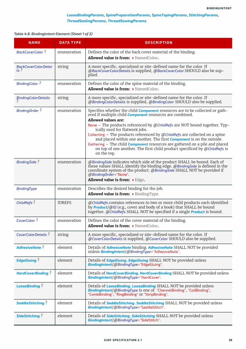
BINDINGINTENT
LooseBindingParams, SpinePreparationParams, SpineTapingParams, StitchingParams, ThreadSealingParams, ThreadSewingParams
Table 4.8: BindingIntent Element (Sheet 1 of 2)
NAME DATA TYPE DESCRIPTION
BackCoverColor ? enumeration Defines the color of the back cover material of the binding. Allowed value is from: NamedColor.
BackCoverColorDetails ?
string A more specific, specialized or site-defined name for the color. If @BackCoverColorDetails is supplied, @BackCoverColor SHOULD also be sup-plied.
BindingColor ? enumeration Defines the color of the spine material of the binding. Allowed value is from: NamedColor.
BindingColorDetails ?
string A more specific, specialized or site-defined name for the color. If @BindingColorDetails is supplied, @BindingColor SHOULD also be supplied.
BindingOrder ? enumeration Specifies whether the child Component resources are to be collected or gath-ered if multiple child Component resources are combined. Allowed values are:None – The products referenced by @ChildRefs are NOT bound together. Typ-
ically used for flatwork jobs. Collecting – The products referenced by @ChildRefs are collected on a spine
and placed within one another. The first Component is on the outside. Gathering – The child Component resources are gathered on a pile and placed
on top of one another. The first child product specificed by @ChildRefs is on the top.
BindingSide ? enumeration @BindingSide indicates which side of the product SHALL be bound. Each of these values SHALL identify the binding edge. @BindingSide is defined in the coordinate system of the product. @BindingSide SHALL NOT be provided if @BindingOrder="None". Allowed value is from: Edge.
BindingType enumeration Describes the desired binding for the job. Allowed value is from: BindingType.
ChildRefs ? IDREFS @ChildRefs contains references to two or more child products each identified by Product/@ID (e.g., cover and body of a book) that SHALL be bound together. @ChildRefs SHALL NOT be specified if a single Product is bound.
CoverColor ? enumeration Defines the color of the cover material of the binding. Allowed value is from: NamedColor.
CoverColorDetails ? string A more specific, specialized or site-defined name for the color. If @CoverColorDetails is supplied, @CoverColor SHOULD also be supplied.
AdhesiveNote ? element Details of AdhesiveNote binding. AdhesiveNote SHALL NOT be provided unless BindingIntent/@BindingType="AdhesiveNote".
EdgeGluing ? element Details of EdgeGluing. EdgeGluing SHALL NOT be provided unless BindingIntent/@BindingType="EdgeGluing".
HardCoverBinding ? element Details of HardCoverBinding. HardCoverBinding SHALL NOT be provided unless BindingIntent/@BindingType="HardCover".
LooseBinding ? element Details of LooseBinding. LooseBinding SHALL NOT be provided unless BindingIntent/@BindingType is one of "ChannelBinding", "CoilBinding", "CombBinding", "RingBinding" or "StripBinding".
SaddleStitching ? element Details of SaddleStitching. SaddleStitching SHALL NOT be provided unless BindingIntent/@BindingType="SaddleStitch".
SideStitching ? element Details of SideStitching. SideStitching SHALL NOT be provided unless BindingIntent/@BindingType="SideStitch".
XJDF SPECIFICATIO N 2.1 39

PRO DUCT INTENT
4.3.1 AdhesiveNoteDetails of adhesive note binding.
4.3.2 EdgeGluing
4.3.3 HardCoverBinding
SoftCoverBinding ? element Details of SoftCoverBinding. SoftCoverBinding SHALL NOT be provided unless BindingIntent/@BindingType="SoftCover".
Tabs ? element Details of Tabs.
Table 4.9: AdhesiveNote Element
NAME DATA TYPE DESCRIPTION
Glue ? element Glue provides details of the shape of the glue application and type of glue used.
Table 4.10: EdgeGluing Element
NAME DATA TYPE DESCRIPTION
EdgeGlue ? enumeration Glue type used to glue the edge of the gathered sheets. Allowed value is from: Glue.
Table 4.11: HardCoverBinding Element (Sheet 1 of 2)
NAME DATA TYPE DESCRIPTION
BlockThreadSewing ?
boolean Specified if the block is thread sewn.
CoverStyle ? NMTOKEN Defines the style of the cover board. Values include:Simple – Single layer cover board, see Figure 4-2: Structure of a normal
hardcover book.Padded – Padded cover board, see Figure 4-3: Structure of a padded
hardcover book.
EndSheets ? boolean @EndSheets SHALL be specified if end sheets SHALL be applied. Additional details of the end sheets MAY be specified by supplying a Product that is ref-erenced by the parent BindingIntent/@ChildRefs with @ProductType="EndSheet".
HeadBands ? boolean The following case binding choice specifies the use of head bands on a case bound book. If "true", head bands are inserted both top and bottom.
HeadBandColor ? enumeration Defines the color of the head band. Allowed value is from: NamedColor.
HeadBandColorDetails ?
string A more specific, specialized or site-defined name for the color. If @HeadBandColorDetails is supplied, @HeadBandColor SHOULD also be sup-plied.
Jacket ? enumeration Specifies whether a hardcover jacket is needed and how it is attached. Details of the jacket MAY be described in the Product that is referenced by the parent BindingIntent/@ChildRefs whose @ProductType="Jacket".Allowed values are:None – No jacket is needed. Loose – The jacket is loosely wrapped.Glue – The jacket is glued to the spine.
Table 4.8: BindingIntent Element (Sheet 2 of 2)
NAME DATA TYPE DESCRIPTION
40 XJDF SPECIFICATIO N 2.1
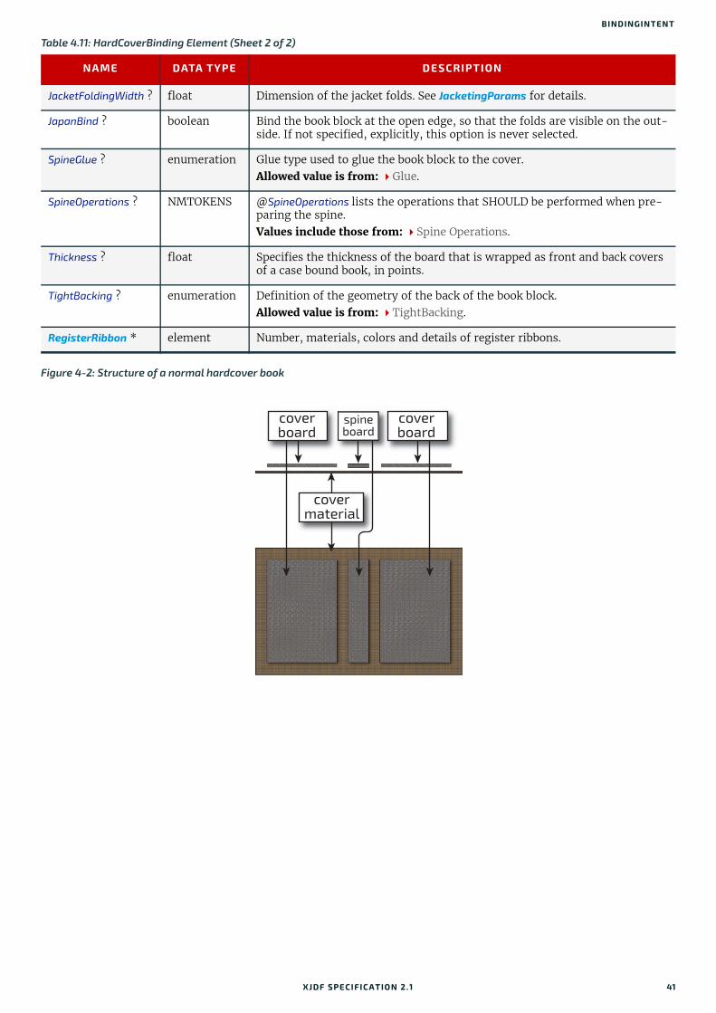
BINDINGINTENT
JacketFoldingWidth ? float Dimension of the jacket folds. See JacketingParams for details.
JapanBind ? boolean Bind the book block at the open edge, so that the folds are visible on the out-side. If not specified, explicitly, this option is never selected.
SpineGlue ? enumeration Glue type used to glue the book block to the cover. Allowed value is from: Glue.
SpineOperations ? NMTOKENS @SpineOperations lists the operations that SHOULD be performed when pre-paring the spine. Values include those from: Spine Operations.
Thickness ? float Specifies the thickness of the board that is wrapped as front and back covers of a case bound book, in points.
TightBacking ? enumeration Definition of the geometry of the back of the book block.Allowed value is from: TightBacking.
RegisterRibbon * element Number, materials, colors and details of register ribbons.
Figure 4-2: Structure of a normal hardcover book
Table 4.11: HardCoverBinding Element (Sheet 2 of 2)
NAME DATA TYPE DESCRIPTION
spineboard
coverboard
covermaterial
coverboard
XJDF SPECIFICATIO N 2.1 41
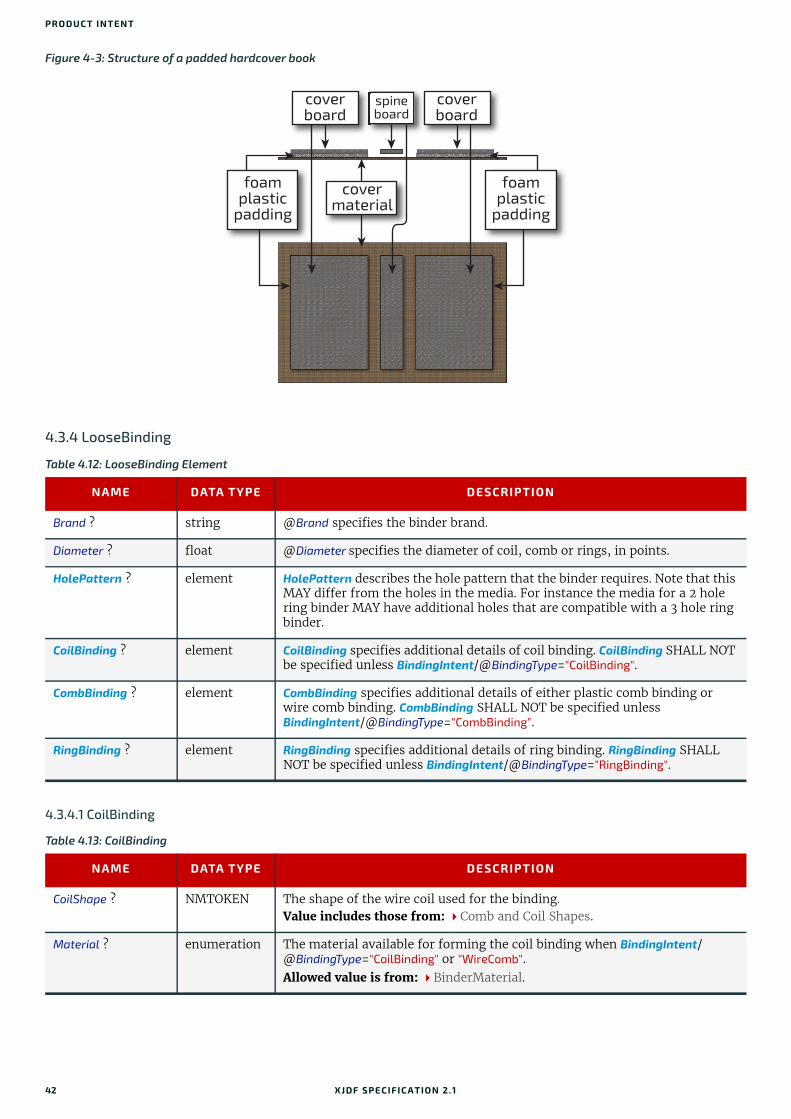
PRO DUCT INTENT
4.3.4 LooseBinding
4.3.4.1 CoilBinding
Figure 4-3: Structure of a padded hardcover book
Table 4.12: LooseBinding Element
NAME DATA TYPE DESCRIPTION
Brand ? string @Brand specifies the binder brand.
Diameter ? float @Diameter specifies the diameter of coil, comb or rings, in points.
HolePattern ? element HolePattern describes the hole pattern that the binder requires. Note that this MAY differ from the holes in the media. For instance the media for a 2 hole ring binder MAY have additional holes that are compatible with a 3 hole ring binder.
CoilBinding ? element CoilBinding specifies additional details of coil binding. CoilBinding SHALL NOT be specified unless BindingIntent/@BindingType="CoilBinding".
CombBinding ? element CombBinding specifies additional details of either plastic comb binding or wire comb binding. CombBinding SHALL NOT be specified unless BindingIntent/@BindingType="CombBinding".
RingBinding ? element RingBinding specifies additional details of ring binding. RingBinding SHALL NOT be specified unless BindingIntent/@BindingType="RingBinding".
Table 4.13: CoilBinding
NAME DATA TYPE DESCRIPTION
CoilShape ? NMTOKEN The shape of the wire coil used for the binding. Value includes those from: Comb and Coil Shapes.
Material ? enumeration The material available for forming the coil binding when BindingIntent/@BindingType="CoilBinding" or "WireComb".Allowed value is from: BinderMaterial.
spineboard
coverboard
covermaterial
foamplastic
padding
coverboard
foamplastic
padding
42 XJDF SPECIFICATIO N 2.1

BINDINGINTENT
4.3.4.2 CombBinding
4.3.4.3 RingBinding
4.3.5 SaddleStitching
Table 4.14: CombBinding
NAME DATA TYPE DESCRIPTION
CombShape ? NMTOKEN The shape of the plastic comb used for the binding. Value includes those from: Comb and Coil Shapes.
Material ? enumeration The material available for forming the comb binding when BindingIntent/@BindingType="CombBinding".Allowed value is from: BinderMaterial.
Table 4.15: RingBinding
NAME DATA TYPE DESCRIPTION
BinderMaterial ? NMTOKEN @BinderMaterial describes the required material to be used for the binder cover.Values include:Cardboard – Cardboard with no covering. ClothCovered – Cardboard with cloth covering.Plastic – Binder cover fabricated from solid plastic sheet material (e.g., PVC
sheet).VinylCovered – Cardboard with colored vinyl covering.
RingShape ? NMTOKEN @RingShape specifies the shape of the ring binder rings.Values include:Round Oval D-shape SlantD
RivetsExposed ? boolean @RivetsExposed describes the ring mechanism mounting in a binder case. If "true", the heads of the rivets are visible on the exterior of the binder. If "false", the binder covering material covers the rivet heads.
ViewBinder ? NMTOKEN @ViewBinder specifies the details of clear vinyl outer-wrap types on top of a colored base wrap:Values include:Embedded – Printed material is embedded by sealing between the colored and
clear vinyl layers during the binder manufacturing.Pocket – Binder is designed so that printed material can be inserted between
the color and clear vinyl layers after the binder is manufactured.
Table 4.16: SaddleStitching Element
NAME DATA TYPE DESCRIPTION
StapleShape ? enumeration Specifies the shape of the staples to be used. Allowed value is from: StapleShape.
StitchNumber ? integer Number of stitches used for saddle stitching.
XJDF SPECIFICATIO N 2.1 43
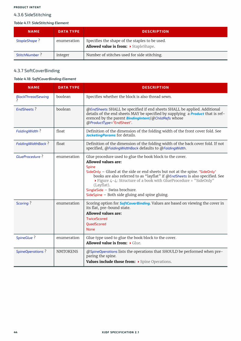
PRO DUCT INTENT
4.3.6 SideStitching
4.3.7 SoftCoverBinding
Table 4.17: SideStitching Element
NAME DATA TYPE DESCRIPTION
StapleShape ? enumeration Specifies the shape of the staples to be used. Allowed value is from: StapleShape.
StitchNumber ? integer Number of stitches used for side stitching.
Table 4.18: SoftCoverBinding Element
NAME DATA TYPE DESCRIPTION
BlockThreadSewing ?
boolean Specifies whether the block is also thread sewn.
EndSheets ? boolean @EndSheets SHALL be specified if end sheets SHALL be applied. Additional details of the end sheets MAY be specified by supplying a Product that is ref-erenced by the parent BindingIntent/@ChildRefs whose @ProductType="EndSheet".
FoldingWidth ? float Definition of the dimension of the folding width of the front cover fold. See JacketingParams for details.
FoldingWidthBack ? float Definition of the dimension of the folding width of the back cover fold. If not specified, @FoldingWidthBack defaults to @FoldingWidth.
GlueProcedure ? enumeration Glue procedure used to glue the book block to the cover.Allowed values are:Spine SideOnly – Glued at the side or end sheets but not at the spine. "SideOnly"
books are also referred to as “layflat” if @EndSheets is also specified. See Figure 4-4: Structure of a book with GlueProcedure = "SideOnly" (Layflat).
SingleSide – Swiss brochure. SideSpine – Both side gluing and spine gluing.
Scoring ? enumeration Scoring option for SoftCoverBinding. Values are based on viewing the cover in its flat, pre-bound state.Allowed values are:TwiceScoredQuadScoredNone
SpineGlue ? enumeration Glue type used to glue the book block to the cover. Allowed value is from: Glue.
SpineOperations ? NMTOKENS @SpineOperations lists the operations that SHOULD be performed when pre-paring the spine.Values include those from: Spine Operations.
44 XJDF SPECIFICATIO N 2.1
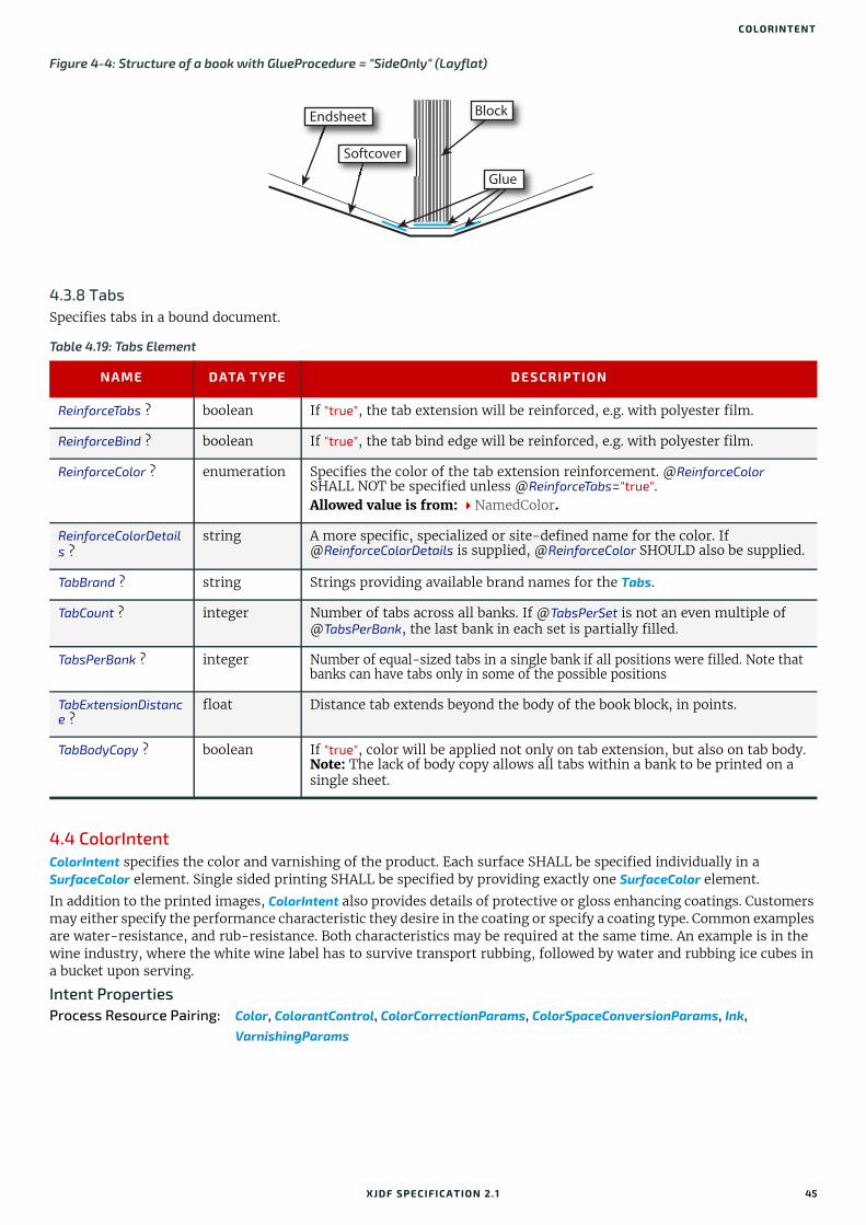
COLORINTENT
4.3.8 TabsSpecifies tabs in a bound document.
4.4 ColorIntentColorIntent specifies the color and varnishing of the product. Each surface SHALL be specified individually in a SurfaceColor element. Single sided printing SHALL be specified by providing exactly one SurfaceColor element.
In addition to the printed images, ColorIntent also provides details of protective or gloss enhancing coatings. Customers may either specify the performance characteristic they desire in the coating or specify a coating type. Common examples are water-resistance, and rub-resistance. Both characteristics may be required at the same time. An example is in the wine industry, where the white wine label has to survive transport rubbing, followed by water and rubbing ice cubes in a bucket upon serving.
Intent PropertiesProcess Resource Pairing: Color, ColorantControl, ColorCorrectionParams, ColorSpaceConversionParams, Ink,
VarnishingParams
Figure 4-4: Structure of a book with GlueProcedure = "SideOnly" (Layflat)
Table 4.19: Tabs Element
NAME DATA TYPE DESCRIPTION
ReinforceTabs ? boolean If "true", the tab extension will be reinforced, e.g. with polyester film.
ReinforceBind ? boolean If "true", the tab bind edge will be reinforced, e.g. with polyester film.
ReinforceColor ? enumeration Specifies the color of the tab extension reinforcement. @ReinforceColor SHALL NOT be specified unless @ReinforceTabs="true".Allowed value is from: NamedColor.
ReinforceColorDetails ?
string A more specific, specialized or site-defined name for the color. If @ReinforceColorDetails is supplied, @ReinforceColor SHOULD also be supplied.
TabBrand ? string Strings providing available brand names for the Tabs.
TabCount ? integer Number of tabs across all banks. If @TabsPerSet is not an even multiple of @TabsPerBank, the last bank in each set is partially filled.
TabsPerBank ? integer Number of equal-sized tabs in a single bank if all positions were filled. Note that banks can have tabs only in some of the possible positions
TabExtensionDistance ?
float Distance tab extends beyond the body of the book block, in points.
TabBodyCopy ? boolean If "true", color will be applied not only on tab extension, but also on tab body.Note: The lack of body copy allows all tabs within a bank to be printed on a single sheet.
BlockEndsheet
Softcover
Glue
XJDF SPECIFICATIO N 2.1 45

PRO DUCT INTENT
4.4.1 SurfaceColorThis element specifies the color configuration of the desired product’s surface.
4.5 ContentCheckIntentThis Product Intent element specifies the prepress proofing and preflighting intent for a Product.
Intent PropertiesProcess Resource Pairing: ApprovalParams, ApprovalDetails, PreflightParams, PreflightReport
Table 4.20: ColorIntent Element
NAME DATA TYPE DESCRIPTION
SurfaceColor (Back) ?
element SurfaceColor[@Surface="Back"] describes the color intent of the back surfaces of the final product. If not specified the "Back" surfaces SHALL NOT be marked.
SurfaceColor (Front) ?
element SurfaceColor[@Surface="Front"] describes the color intent of the front sur-faces of the final product. If not specified the "Front" surfaces SHALL NOT be marked.
Table 4.21: SurfaceColor Element
NAME DATA TYPE DESCRIPTION
Coatings ? NMTOKENS Material usually applied to a full surface on a press as a protective or gloss-enhancing layer over ink. Values include those from: Ink and Varnish Coatings.Note: Multiple NMTOKENS MAY be selected to indicate multiple coatings.Note: @Surface specifies the surface to which this coating applies.Note: Spot coating is specified in @ColorsUsed.
ColorsUsed ? NMTOKENS Array of colorant separation identifiers that are requested for this SurfaceColor. If specified @ColorsUsed SHALL contain a list of all separation identifiers used by the product or a list of spot colors specified by "Spot" that specifies a generic spot color whose details are unknown. "Spot" MAY be spec-ified multiple times in one @ColorsUsed value. If not specified, then this SurfaceColor explicitly requests no colors on the surface that is specified in @Surface.If additional information about the colors and colorants is needed, it MAY be specified in ResourceSet/Resource/Color elements that are partitioned by matching @Separation Partition Keys. In addition, partial (spot) coating MAY be specified by adding NMTOKENS with any value from @Coatings.
Coverage ? float Cumulative colorant coverage percentage. For example, a full sheet of 100% deep black in CMYK has @Coverage="400". Typical coverages based on one color plane are:Light – 1-9%Medium – 10-35%Heavy – 36+%Note: @Surface specifies the surface to which this coverage applies.
PrintStandard ? NMTOKEN @PrintStandard SHALL specify the reference name of a characterization data set. See Appendix A.4.17 PrintStandard Characterization Data Sets for details.Note: The characterization data set defines the expected minimal color gamut of the print process.
Surface enumeration Allowed value is from: Side.
Certification *New in XJDF 2.1
element Each Certification SHALL specify a minimum requested ink certification level. If more than one Certification is present, at least one of the ink certification levels SHALL be met.
46 XJDF SPECIFICATIO N 2.1
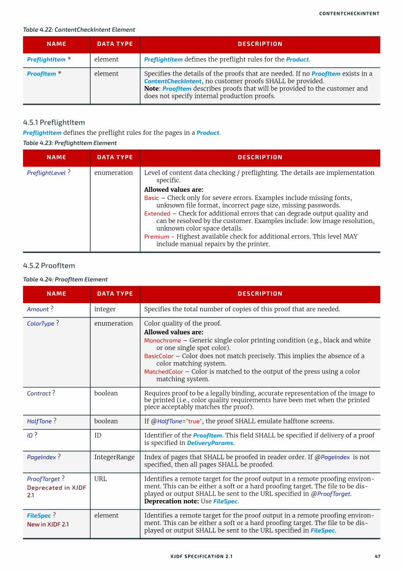
CONTENTCHECKINTENT
4.5.1 PreflightItemPreflightItem defines the preflight rules for the pages in a Product.
4.5.2 ProofItem
Table 4.22: ContentCheckIntent Element
NAME DATA TYPE DESCRIPTION
PreflightItem * element PreflightItem defines the preflight rules for the Product.
ProofItem * element Specifies the details of the proofs that are needed. If no ProofItem exists in a ContentCheckIntent, no customer proofs SHALL be provided.Note: ProofItem describes proofs that will be provided to the customer and does not specify internal production proofs.
Table 4.23: PreflightItem Element
NAME DATA TYPE DESCRIPTION
PreflightLevel ? enumeration Level of content data checking / preflighting. The details are implementation specific.
Allowed values are:Basic – Check only for severe errors. Examples include missing fonts,
unknown file format, incorrect page size, missing passwords.Extended – Check for additional errors that can degrade output quality and
can be resolved by the customer. Examples include: low image resolution, unknown color space details.
Premium - Highest available check for additional errors. This level MAY include manual repairs by the printer.
Table 4.24: ProofItem Element
NAME DATA TYPE DESCRIPTION
Amount ? integer Specifies the total number of copies of this proof that are needed.
ColorType ? enumeration Color quality of the proof. Allowed values are:Monochrome – Generic single color printing condition (e.g., black and white
or one single spot color).BasicColor – Color does not match precisely. This implies the absence of a
color matching system.MatchedColor – Color is matched to the output of the press using a color
matching system.
Contract ? boolean Requires proof to be a legally binding, accurate representation of the image to be printed (i.e., color quality requirements have been met when the printed piece acceptably matches the proof).
HalfTone ? boolean If @HalfTone="true", the proof SHALL emulate halftone screens.
ID ? ID Identifier of the ProofItem. This field SHALL be specified if delivery of a proof is specified in DeliveryParams.
PageIndex ? IntegerRange Index of pages that SHALL be proofed in reader order. If @PageIndex is not specified, then all pages SHALL be proofed.
ProofTarget ?Deprecated in XJDF2.1
URL Identifies a remote target for the proof output in a remote proofing environ-ment. This can be either a soft or a hard proofing target. The file to be dis-played or output SHALL be sent to the URL specified in @ProofTarget.Deprecation note: Use FileSpec.
FileSpec ?New in XJDF 2.1
element Identifies a remote target for the proof output in a remote proofing environ-ment. This can be either a soft or a hard proofing target. The file to be dis-played or output SHALL be sent to the URL specified in FileSpec.
XJDF SPECIFICATIO N 2.1 47

PRO DUCT INTENT
4.6 EmbossingIntentThis Product Intent specifies the embossing and/or foil stamping intent for a Product using information that identifies whether the product is embossed or stamped, and if desired, the complexity of the affected area.
Intent PropertiesProcess Resource Pairing: EmbossingParams
4.6.1 EmbossingItem
4.7 FoldingIntentThis Product Intent specifies the straight line folding, creasing and perforating of a product. Folds that are implied by binding such as "F4-1" of a saddle stitched booklet SHALL NOT be specified. Table 4.28 Product Folds illustrates some typical product folds. See Section 4.3 BindingIntent for additional details.
Intent PropertiesProcess Resource Pairing: CreasingParams, CuttingParams, FoldingParams, PerforatingParams
Table 4.25: EmbossingIntent Element
NAME DATA TYPE DESCRIPTION
EmbossingItem + element Each embossed image is described by one EmbossingItem.
Table 4.26: EmbossingItem Element
NAME DATA TYPE DESCRIPTION
Direction ? enumeration The direction of the image. Allowed value is from: EmbossDirection.
EmbossingType enumeration The embossing type required. Allowed value is from: EmbossType.
Face ? enumeration Position of the embossing on the product.Allowed value is from: Face.
FoilColor ? enumeration Defines the color of the foil material that is used for embossing.Allowed value is from: NamedColor.
FoilColorDetails ? string A more specific, specialized or site-defined name for the color. If @FoilColorDetails is supplied, @FoilColor SHOULD also be supplied. @FoilColorDetails SHOULD be used to specify specialized foil properties such as holographic or transparent foils. Example combinations of @FoilColor and @FoilColorDetails include:Holographic foils: @FoilColor="Silver" and @FoilColorDetails="Holographic".Matte transparent foil: @FoilColor="White" and
@FoilColorDetails="TransparentMatte".
Height ? float The height of the levels. This value specifies the vertical distance between the highest and lowest point of the stamp, regardless of the value of @Direction.
ImageSize ? XYPair The size of the bounding box of one single image.
Position ? XYPair Position of the lower left corner of the bounding box of the embossed image in the coordinate system of the surface of the Component that is selected by @Face.
Separation ? NMTOKEN @Separation identifies the separation within the PDL whose color values SHALL be used as the embossing values. A value of 0.0 in the PDL SHALL specify no embossing, a value of 1.0 in the PDL SHALL specify embossing with full depth. If a ResourceSet/Resource/Color element is specified for this separation, the value of Color/@ColorType SHALL be "DieLine".
ToolName ? NMTOKEN Name of the embossing tool.
48 XJDF SPECIFICATIO N 2.1

FOLDINGINTENT
4.7.1 Typical Product FoldsThe following figure illustrates some typical product folds.Note: This list is not complete.
Table 4.27: FoldingIntent Element
NAME DATA TYPE DESCRIPTION
FoldCatalog ? NMTOKEN Describes the folding scheme. Note: The folding scheme in this context refers to the folding of the finished product as seen after the cutting, not the folding, of the sheet as seen in pro-duction. See Table 4.28 Product Folds for an illustration of typical product folding schemes.Value includes those from: Fold Catalog.
FoldingDetails ? NMTOKEN @FoldingDetails is a system dependent descriptor of the folding. @FoldingDetails MAY be used to differentiate differing fold dimensions with the same general topology, such as asymmetrical Z-folds. @FoldingDetails SHALL NOT be specified if @FoldCatalog is not present.
Orientation ? enumeration @Orientation indicates the orientation of the unfolded product with respect to the lay of the fold. A value of "Rotate0" SHALL be mapped to the lay of the fold on the lower left of the product prior to folding and the front side of the product oriented in the direction of an upward fold.Allowed value is from: Orientation.
Crease * element Crease elements describe the details of any creasing operations in the coordinate system of the final product. If no geometrical details are specified in the Crease element and a @FoldCatalog is specified, the customer is requesting production creasing.
Fold * element This describes the details of folding operations in the sequence described by the value of @FoldCatalog. Fold SHALL be specified if non-symmetrical folds are requested.
Perforate * element Perforate elements describe the details of any perforating operations in the coordi-nate system of the final product. If no geometrical details are specified in the Perforate element and a @FoldCatalog is specified, the customer is requesting pro-duction perforation.
Table 4.28: Product Folds
FOLD CATALOG VALUE IMAGE DESCRIPTION
F2-1 No fold.
F4-1 Single fold.
XJDF SPECIFICATIO N 2.1 49
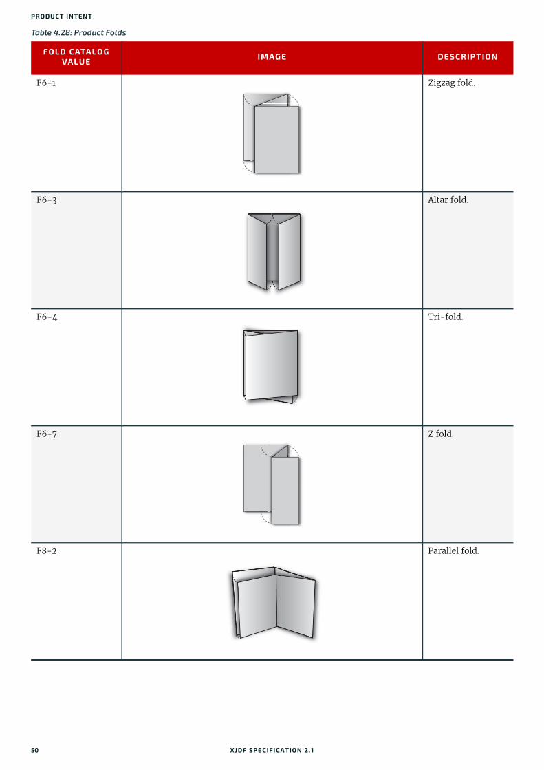
PRO DUCT INTENT
F6-1 Zigzag fold.
F6-3 Altar fold.
F6-4 Tri-fold.
F6-7 Z fold.
F8-2 Parallel fold.
Table 4.28: Product Folds
FOLD CATALOG VALUE IMAGE DESCRIPTION
50 XJDF SPECIFICATIO N 2.1

HOLEMAKINGINTENT
4.8 HoleMakingIntentThis Product Intent specifies the hole making intent for a Product. This Product Intent does not specify whether the media will be pre-drilled or the media will be drilled or punched as part of making the product.
Intent PropertiesProcess Resource Pairing: HoleMakingParams, Media
4.9 LaminatingIntentThis Product Intent specifies the laminating intent for a Product.
Intent PropertiesProcess Resource Pairing: LaminatingParams
F8-4 Gate fold.
F8-5 Barrel fold.
Table 4.29: HoleMakingIntent Element
NAME DATA TYPE DESCRIPTION
HolePattern + element Each HolePattern describes one hole or a specific set of holes that SHALL be provided.The coordinate system for applying the holes SHALL be the coordinate sys-tem of the Product.
Table 4.30: LaminatingIntent Element (Sheet 1 of 2)
NAME DATA TYPE DESCRIPTION
Surface enumerations The surface or surfaces to be laminated.Allowed values are from: Side.
Temperature ? enumeration Temperature used in the Laminating process. Allowed values are:HotCold
Texture ? NMTOKEN The intended texture of the laminate.Value includes those from: Texture.
Table 4.28: Product Folds
FOLD CATALOG VALUE IMAGE DESCRIPTION
XJDF SPECIFICATIO N 2.1 51

PRO DUCT INTENT
4.10 LayoutIntentThis Product Intent records the size of the finished pages for the product component. It does not, however, specify the size of any intermediate results such as press sheets. It also describes how the finished pages of the product component SHALL be imaged onto the finished media.
Intent PropertiesProcess Resource Pairing: Assembly, BinderySignature, Layout
Thickness ? float Thickness of the laminating material. Measured in microns [µm].
Table 4.31: LayoutIntent Element
NAME DATA TYPE DESCRIPTION
Bleed ? float Bleed of the artwork in points. The value of 0 means no bleed. A negative value indicates bleed is needed but the value is unknown.
Dimensions ? XYPair Specifies the width (X) and height (Y) in points, respectively, of the trimmed and unfolded (flat) product. For example, @Dimensions for a Z-fold is the unfolded dimensions, while @FinishedDimensions is the folded dimensions if known. Use @Dimensions if @FinishedDimensions is not known. @Dimensions is provided for the rare case that @FinishedDimensions does not unambigu-ously define the finished product, due to complex folding schemes. If both values are specified, @FinishedDimensions takes precedence.
FinishedDimensions ?
shape Specifies the width (X), height (Y) and depth (Z) in points, respectively, of the finished product Component after all finishing operations, including folding, trimming, etc. If the Z coordinate is 0, it SHALL be ignored. Only @FinishedDimensions SHOULD be specified if both @FinishedDimensions and @Dimensions are known.
NamedDimensions ? NMTOKEN Named size (e.g., "A4" or "Letter" that corresponds to the value specified in @FinishedDimensions). If both @NamedDimensions and @FinishedDimensions are specified, then @FinishedDimensions has precedence. See Appendix C Media Size for a list of preferred values.
NumberUp ? XYPair Specifies a regular, multi-up grid of page cells into which content pages are mapped. The first value specifies the number of columns of page cells and the second value specifies the number of rows of page cells in the multi-up grid (both numbers are integers).
Orientation ? enumeration @Orientation SHALL specify the orientation of the artwork on the surface as defined by @Sides. @Orientation is used to define products such as back-lit displays, where the orientation of the image with respect to the final product is rotated or mirrored.Allowed value is from: Orientation.
Pages ? integer Specifies the number of finished pages (surfaces) of the product component, including blank pages. See @SpreadType for a discussion of the scope of @Pages.This value SHALL be an even number. For example, the value for @Pages for a two-sided booklet with seven reader pages would be "8", whether the book-let was either saddle stitched or glued.
Sides ? enumeration @Sides specifies which side of the product SHALL be printed.Allowed value is from: Sides.
SpreadType ? enumeration @SpreadType SHALL specify the treatment of individual PDF pages refer-enced by the product for imposition purposes.Allowed value is from: SpreadType.Note: Content will typically be provided as single pages. However, products with finished pages of varying size such as wrap around covers with a spine or fold outs in a booklet will typically be defined as spreads.
Table 4.30: LaminatingIntent Element (Sheet 2 of 2)
NAME DATA TYPE DESCRIPTION
52 XJDF SPECIFICATIO N 2.1

MEDIAINTENT
4.11 MediaIntentThis Product Intent describes the media to be used for the Product.
Intent PropertiesProcess Resource Pairing: Media
Table 4.32: MediaIntent Element (Sheet 1 of 2)
NAME DATA TYPE DESCRIPTION
BackCoating ? enumeration @BackCoating SHALL specify the pre-process coating of the back surface of the media. If not specified the value of @Coating SHALL be applied.Allowed value is from: Coating.
BackISOPaperSubstrate ?
enumeration @ISOPaperSubstrate SHALL specify the back surface of paper material defined in accordance with the print substrates set forth in [ISO12647-2:2013], [ISO12647-3:2013] and [ISO12647-4:2014]. If not specified, the value of @ISOPaperSubstrate SHALL be applied.
Allowed value is from: ISOPaperSubstrate.
Brand ? string Strings providing available brand names. The customer might know exactly what paper is to be used. Example is “Lustro” or “Warren Lustro” even though the manufacturer name is included.
BuyerSupplied ? boolean Indicates whether the customer will supply the media.
Coating ? enumeration @Coating SHALL specify the pre-process coating of the media. Allowed value is from: Coating.
Flute ? NMTOKEN Single, capital letter that specifies the flute type of corrugated media.Values include those from: Flute Types.
FluteDirection ? enumeration Direction of the flute of corrugated media in the coordinate system of the product.Allowed value is from: MediaDirection.
GrainDirection ? enumeration Direction of the grain in the coordinate system of the Product. Allowed value is from: MediaDirection.
ISOPaperSubstrate ? enumeration @ISOPaperSubstrate SHALL specify the type of paper material defined in accordance with the print substrates set forth in [ISO12647-2:2013], [ISO12647-3:2013] and [ISO12647-4:2014].Allowed value is from: ISOPaperSubstrate.
LabColorValue ? LabColor @LabColorValue is the CIELAB color value of the media, computed as specified in [TAPPI T527].
MediaColor ? enumeration Color of the media. If more-specific, specialized or site-specific media color names are needed, use @MediaColorDetails.Allowed value is from: NamedColor.
MediaColorDetails ? string A more specific, specialized or site-defined name for the media color. If @MediaColorDetails is supplied, @MediaColor SHOULD also be supplied. Note: There is a one-to-many relationship between entries in @MediaColor and @MediaColorDetails (e.g., @MediaColorDetails values of "Burgundy" and "Ruby" both correspond to a @MediaColor of "DarkRed").
MediaQuality ? string Named quality description of the media. Media with the same @MediaQuality are identical from the customer point of view. Thus characteristics such as weight, coatings or recycling percentage are identical whereas lot or sheet dimension may vary based on production or warehousing requirements.
MediaType enumeration Describes the medium being employed. Allowed value is from: MediaType.Note: Values from MediaType are RECOMMENDED. However, some process related values, such as "Plate", SHOULD NOT be used for this attribute.
XJDF SPECIFICATIO N 2.1 53

PRO DUCT INTENT
4.12 ProductionIntentThis Product Intent specifies the manufacturing intent and considerations for a Product using information that identifies the desired result or specified manufacturing path. If specific details of print quality, such as color quality, need to be specified, @Types SHOULD contain "QualityControl". A QualityControlParams ResourceSet that contains the requirements SHOULD also be provided.
Intent Properties
4.13 ShapeCuttingIntentShapeCuttingIntent describes finishing of products with irregular shapes, including die cutting and adding windows to envelopes.
MediaTypeDetails ? NMTOKEN Describes additional details of the medium described in @MediaType.Value includes those from: MediaType Details.Note: Values from MediaType Details are RECOMMENDED. However, some process related values, such as "DryFilm", SHOULD NOT be used for this attri-bute.
Opacity ? enumeration The opacity of the media. Allowed value is from: Opacity.
PrePrinted ? boolean Indicates whether the media is preprinted.
StockType ? NMTOKEN @StockType defines the base size when calculating North American or Japa-nese paper weights. See Appendix B Media Weight for details including predefined values.
Texture ? NMTOKEN The intended texture of the media.Value includes those from: Texture.
Thickness ? float The thickness of the chosen medium. Measured in microns [µm].
Weight ? float The intended weight of the media, measured in grammage (g/m2) of the media. See Appendix B Media Weight for an explanation of how to calculate the US weight from the grammage for different stock types.
Certification * element Each Certification SHALL specify a minimum requested paper certification level. If more than one Certification is present, at least one of the paper certi-fication levels SHALL be met.
Table 4.33: ProductionIntent Element
NAME DATA TYPE DESCRIPTION
PrintPreference ? enumeration Intended result or goal. Allowed values are:Balanced – Request for a manufacturing process that balances the require-
ments for cost, speed and quality.CostEffective – Request for the most cost effective manufacturing process.Fastest – Request for the most time effective manufacturing process. Cost
and quality can be sacrificed for a fast turnaround time.HighestQuality – Request for the manufacturing process that will result in the
highest quality.
PrintProcess ? NMTOKENS Print process requested. If more than one value is specified, then @PrintProcess requests hybrid printing, e.g. inkjet imprint on a preprinted shell. Values include those from: Printing Technologies.
Certification *New in XJDF 2.1
element Each Certification SHALL specify a minimum requested certification level for production. If more than one Certification is present, at least one of the certi-fication levels SHALL be met.
Table 4.32: MediaIntent Element (Sheet 2 of 2)
NAME DATA TYPE DESCRIPTION
54 XJDF SPECIFICATIO N 2.1

VARIABLEINTENT
Intent PropertiesProcess Resource Pairing: CuttingParams, ShapeCuttingParams
4.13.1 ShapeCut
4.14 VariableIntentVariableIntent specifies the variations of the content for printed data with variable content such as lottery tickets or di-rect mail.
Intent PropertiesProcess Resource Pairing: DigitalPrintingParams, LayoutElementProductionParams
Table 4.34: ShapeCuttingIntent Element
NAME DATA TYPE DESCRIPTION
ShapeCut + element Array of all ShapeCut elements. Used when each shape is exactly specified.
Table 4.35: ShapeCut Element
NAME DATA TYPE DESCRIPTION
CutBox ? rectangle Specification of a rectangular window. An orthogonal line MAY be defined by specifying a rectangle with identical dimensions.
CutDepth ? enumeration Allowed values are:Full – The form is completely cut out or perforated.Partial – The form is not completely cut out or perforated. The exact depth
MAY be specified in ShapeCuttingParams.
CutOut ? boolean @CutOut specifies whether the inside or outside of the ShapeCut SHALL be removed. If @CutOut="true", the inside of a specified shape SHALL be removed, otherwise the outside of a specified shape SHALL be removed. An example of an inside shape is a window, while an example of an outside shape is a shaped greeting card.
CutPath ? PDFPath Specification of a complex path. This MAY be an open path in the case of a single line.
CutType ? enumeration Type of cut or perforation used.Allowed values are:Cut – Full cut.Perforate – Interrupted perforation that does not span the entire sheet.
ShapeType enumeration Describes any precision cutting other than hole making. Allowed values are:Line – The coordinates specified in @CutBox specify the end points of a
straight line.Path - Any irregular shape. Additional details SHOULD be provided in
@CutPath or @ShapeTypeDetails.Rectangular – The coordinates specified in @CutBox specify the lower left and
upper right coordinates of a rectangle.Round - Circular or elliptical shape depending on the aspect ratio of @CutBox.RoundedRectangle – Rectangle with rounded corners. The coordinates speci-
fied in @CutBox specify the outer bounds of the rectangle.
ShapeTypeDetails ? string A more specific, specialized or site-defined name for the shape of the ShapeCut.
XJDF SPECIFICATIO N 2.1 55

PRO DUCT INTENT
Table 4.36: VariableIntent Element
NAME DATA TYPE DESCRIPTION
Area ? float Ratio of the document that can contain variable content. A value of 0 specifies a non variable document. A value of 1 specifies a full variable document.
AveragePages ? integer @AveragePages SHALL specify the average number of printed pages in each record.
ChildRefs ? IDREFS Product/@ID of the product elements that describe individual finishing vari-ants. @ChildRefs SHALL NOT be specified if AssemblingIntent or BindingIntent are specified for this product.
ColorsUsedBack ? NMTOKENS Array of colorant separation identifiers that are required to print the variable part of the documents. The values that are specified in @ColorsUsedBack SHALL also be specified in ColorIntent/SurfaceColor[@Surface="Back"]/@ColorsUsed. See ColorIntent/SurfaceColor/@ColorsUsed for additional details.
ColorsUsedFront ? NMTOKENS Array of colorant separation identifiers that are required to print the variable part of the documents. The values that are specified in @ColorsUsedFront SHALL also be specified in ColorIntent/SurfaceColor[@Surface="Front"]/@ColorsUsed. See ColorIntent/SurfaceColor/@ColorsUsed for additional details.
MaxPages ? integer @MaxPages SHALL specify the maximum number of printed pages in each record. @MaxPages SHALL NOT be smaller than @AveragePages.
MinPages ? integer @MinPages SHALL specify the minimum number of printed pages in each record. @MinPages SHALL NOT be larger than @AveragePages.
NumberOfCopies ? integer Average number of copies of each record. This value SHALL equal "1" for fully variable data.
VariableType enumeration Type of variable content.Allowed values are (in order of rising complexity):OneLine - A single line of text data is variable. OneLine includes simple num-
bering applications.AddressField - Multiple lines of text data are variable.IdentificationField - The variable data includes a Barcode or QR-Code.Area - The area, as defined in @Area, is fully variable.
VariableQuality ? enumeration @VariableQuality specifies the desired quality of the variable data.Allowed values are:Simple - The variable text MAY be recognized as printed by a different tech-
nology such as dot matrix or simple inkjet overprints.Imprint - The variable data SHOULD be similar to the non-variable part but
MAY be imprinted.Full - All data SHOULD be printed with the same technology.
56 XJDF SPECIFICATIO N 2.1
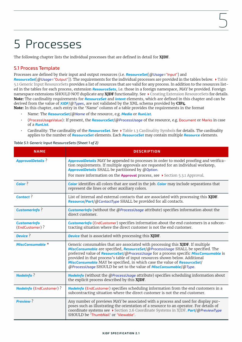
5
5 ProcessesThe following chapter lists the individual processes that are defined in detail for XJDF.5.1 Process TemplateProcesses are defined by their input and output resources (i.e. ResourceSet[@Usage=”Input”] and ResourceSet[@Usage=”Output”]). The requirements for the individual processes are provided in the tables below. Table 5.1 Generic Input ResourceSets provides a list of resources that are valid for any process. In addition to the resources list-ed in the tables for each process, extension ResourceSets, i.e. those in a foreign namespace, MAY be provided. Foreign namespace extensions SHOULD NOT duplicate any XJDF functionality. See Creating Extension ResourceSets for details.Note: The cardinality requirements for ResourceSet and Intent elements, which are defined in this chapter and can be derived from the value of XJDF/@Types, are not validated by the XML schema provided by CIP4.Note: In this chapter, each entry in the ‘Name’ column of a table provides the requirements in the format
• Name: The ResourceSet/@Name of the resource, e.g. Media or RunList.
• (ProcessUsageValue): If present, the ResourceSet/@ProcessUsage of the resource, e.g. Document or Marks in case of a RunList.
• Cardinality: The cardinality of the ResourceSet. See Table 1.3 Cardinality Symbols for details. The cardinality applies to the number of ResourceSet elements. Each ResourceSet may contain multiple Resource elements.
Table 5.1: Generic Input ResourceSets (Sheet 1 of 2)
NAME DESCRIPTION
ApprovalDetails ? ApprovalDetails MAY be appended to processes in order to model proofing and verifica-tion requirements. If multiple approvals are requested for an individual workstep, ApprovalDetails SHALL be partitioned by @Option.For more information on the Approval process, see Section 5.3.1 Approval.
Color ? Color identifies all colors that are used in the job. Color may include separations that represent die lines or other auxiliary colors.
Contact ? List of internal and external contacts that are associated with processing this XJDF. Resource/Part/@ContactType SHALL be provided for all contacts.
CustomerInfo ? CustomerInfo (without the @ProcessUsage attribute) specifies information about the direct customer.
CustomerInfo (EndCustomer) ?
CustomerInfo (EndCustomer) specifies information about the end customers in a subcon-tracting situation where the direct customer is not the end customer.
Device ? Device that is associated with processing this XJDF.
MiscConsumable * Generic consumables that are associated with processing this XJDF. If multiple MiscConsumable are specified, ResourceSet/@ProcessUsage SHALL be specified. The preferred value of ResourceSet/@ProcessUsage for a process specific MiscConsumable is provided in that process’s table of input resources shown below. Additional MiscConsumable MAY be specified, in which case the value of ResourceSet/@ProcessUsage SHOULD be set to the value of MiscConsumable/@Type.
NodeInfo ? NodeInfo (without the @ProcessUsage attribute) specifies scheduling information about the explicit process described by this XJDF.
NodeInfo (EndCustomer) ? NodeInfo (EndCustomer) specifies scheduling information from the end customers in a subcontracting situation where the direct customer is not the end customer.
Preview ? Any number of previews MAY be associated with a process and used for display pur-poses such as illustrating the orientation of a resource to an operator. For details of coordinate systems see Section 2.6 Coordinate Systems in XJDF. Part/@PreviewType SHOULD be "ThumbNail" or "Viewable".
XJDF SPECIFICATIO N 2.1

PRO CESSES
5.2 Combining Individual Process StepsThe processes described in this chapter define individual workflow steps that are assumed to be executed by a single-pur-pose device. Some controllers and devices are able to combine the functionality of multiple single-purpose devices and ex-ecute more than one process type. For example, a digital printer might be able to execute the Interpreting, Rendering and DigitalPrinting processes. Each XJDF SHALL contain a @Types attribute, which in turn contains an ordered list of values of each of processes that the XJDF specifies. The ordering of the process names in the @Types attribute specifies the ordering in which the processes SHOULD be executed. If the final product result would be indistinguishable, the device MAY change the execution order of the processes from that given in the @Types attribute.
Example 5.1: Combined Process StepsExample of combining three processes in sequence: Interpreting, Rendering and DigitalPrinting.
5.2.1 Exchange ResourceSets in combined processesA ResourceSet that is produced by one process and immediately consumed by the following process NEED NOT be ex-plicitly specified in the XJDF. Any such ResourceSet MAY be completely under the control of the receiving device. In the example above, the output RunList of the Interpreting process is the input RunList of Rendering process and NEED NOT be specified explicitly in the XJDF.
If an exchange ResourceSet is provided, ResourceSet/@Usage SHALL NOT be present and ResourceSet/@CombinedProcessIndex SHALL reference all processes that use the ResourceSet either as input or as output.
5.2.2 Usage of ResourceSets that are used as both input and outputSome processes, e.g. Stripping or QualityControl, modify a resource rather than consume or produce it.
Examples of modification include the expansion of a Layout by Stripping or the update of amounts in Component resourc-es due to failing QualityControl. ResourceSet/@Usage of such a ResourceSet shall be set to the value where the ResourceSet is not used as an exchange resource as described in Section 5.2.1 Exchange ResourceSets in combined processes. If the ResourceSet is not used as an exchange ResourceSet, e.g. because XJDF/@Types is a single value, ResourceSet/@Usage shall be "Output".Note: Printing and finishing processes do not modify Component resources; these processes have unique Component re-sources for their input and output because the resources are at different stages of production and thus need to be unique-ly identifiable, e.g. for calculating the value of work in progress.
5.2.2.1 Example of input and combined ResourceSetFor an XJDF that combines stripping and imposition, i.e. where XJDF/@Types="Stripping Imposition", then ResourceSet[@Name="Layout"]/@Usage="Input" because Layout is an input to Stripping and an exchange ResourceSet be-tween Stripping and Imposition.
PrintCondition ?New in XJDF 2.1
PrintCondition shall specify the target print condition for a given printing process.
Tool * Miscellaneous reusable tools required for a process. If multiple tools of different types are specified, ResourceSet/@ProcessUsage SHALL be set to the value of Tool/@ToolType.
TransferCurve ? TransferCurve specifies area coverage correction and coordinate transformations.
UsageCounter ? Devices MAY use counters, called “usage counters”, to track equipment utilization or work performed, such as impressions produced or documents generated. If multiple counters are provided, UsageCounter SHALL be partitioned by @Option which SHOULD contain a value from UsageCounter/@CounterTypes.
<foreign namespace ResourceSet> *
Any ResourceSet in a foreign namespace. Foreign namespace extensions SHOULD NOT duplicate functionality of XJDF. See Creating Extension ResourceSets for details.
<XJDF xmlns="http://www.CIP4.org/JDFSchema_2_0" JobID="CombinedExample" Types="Interpreting Rendering DigitalPrinting"></XJDF>
Table 5.1: Generic Input ResourceSets (Sheet 2 of 2)
NAME DESCRIPTION
58 XJDF SPECIFICATIO N 2.1

GENERAL PROCESSES
5.2.2.2 Example of output and combined ResourceSetFor an XJDF that combines printing and quality control, i.e. where XJDF/@Types="ConventionalPrinting QualityControl", then ResourceSet[@Name="Component"]/@Usage="Output" because Component is an output of QualityControl and an ex-change ResourceSet between ConventionalPrinting and QualityControl.
5.2.3 XJDF with Multiple Processes of the Same TypeXJDF/@Types MAY contain multiple instances of the same process type, e.g., "Cutting Folding Cutting". The parameters of the first Cutting process are most likely to be different from those of the second Cutting process. If multiple processes that consume identical resources are specified in @Types, ResourceSet/@CombinedProcessIndex SHALL be present and refer to the index of the process type in the complete list of XJDF/@Types. In the example above, for instance ResourceSet/@CombinedProcessIndex="0" for the CuttingParams that apply to the first Cutting process and ResourceSet/@CombinedProcessIndex="2" for the CuttingParams that apply to the second Cutting process. ResourceSet/@CombinedProcessIndex="1" is not required for the FoldingParams since there is only one Folding process.
5.3 General ProcessesGeneral processes that can take place throughout the workflow.
5.3.1 ApprovalThe Approval process can take place at various steps in a workflow. For example, a ResourceSet (e.g., a printed sheet or a finished book) is used as the input to be approved, and an ApprovalDetails (given, for example, by a customer or fore-man) is produced. If Approval is combined with any other process type, the workstep that follows Approval in XJDF/@Types SHALL NOT commence until a successful ApprovalDetails is provided for a given partition.
5.3.2 DeliveryThis process can be used to describe the delivery of an end product or a ResourceSet to or from a location that SHALL be specified in a Contact with Part[@ContactType="Delivery"]. Delivery of data over the network MAY also be specified in the Delivery process.
If the delivery only requires the address of a single end customer and no specific details of the delivery are known, then the delivery process need not be specifically parameterized.
Delivery to multiple destinations or in multiple steps SHOULD be specified in DeliveryParams that are partitioned by @DropID. If multiple DeliveryParams contain the same @DropID, they SHOULD be delivered in one delivery, regardless of whether the DeliveryParams belong to the same XJDF or not. Common delivery of multiple products to the same address SHALL be specified by providing multiple DeliveryParams/DropItem elements.
Table 5.2: Approval – Input Resources
NAME DESCRIPTION
ApprovalParams Details of the approval process.
ResourceSet The resources to be approved. When the input resource of an Approval process is a RunList that represents a ByteMap, it SHOULD be displayed on a viewing device.
Generic Input Resources * See Table 5.1 Generic Input ResourceSets for additional input resources that are valid for all process types.
Table 5.3: Approval – Output Resources
NAME DESCRIPTION
ApprovalDetails Result of any Approval process given, for example, by a customer or foreman.
ResourceSet This ResourceSet describes the resources after the Approval is complete.
Table 5.4: Delivery – Input Resources (Sheet 1 of 2)
NAME DESCRIPTION
Bundle ? Bundle describes the structure of the packaging of the products that SHALL be deliv-ered. If DeliveryParams is partitioned by @DropID, Bundle SHOULD also be partitioned by @DropID.
XJDF SPECIFICATIO N 2.1 59

PRO CESSES
Example 5.2: Split DeliveryThe following example illustrates a split delivery of thirty books, ten of which go to the contact defined by "Drop1" and twenty of which go to the contact defined by "Drop2".
5.3.3 ManualLaborThis process can be used to describe any process where resources are handled manually. The ManualLabor process is de-signed to monitor any type of non-automated labor from an MIS system.
DeliveryParams Details of the individual deliveries SHALL be provided in DeliveryParams.
Generic Input Resources * See Table 5.1 Generic Input ResourceSets for additional input resources that are valid for all process types.
Table 5.5: Delivery – Output Resources
NAME DESCRIPTION
ResourceSet * Any ResourceSet that is delivered to the process SHALL be specified as an output of the Delivery process.
<XJDF xmlns="http://www.CIP4.org/JDFSchema_2_0" JobID="splitDelivery" Types="Product"> <ProductList> <Product Amount="30" ID="IDBook" IsRoot="true" ProductType="Book"/> </ProductList> <ResourceSet Name="Contact" Usage="Input"> <Resource> <Part ContactType="Delivery" DropID="Drop1"/> <Contact> <Address City="city1"/> <Person FirstName="Name1"/> </Contact> </Resource> <Resource> <Part ContactType="Delivery" DropID="Drop2"/> <Contact> <Address City="city2"/> <Person FirstName="Name2"/> </Contact> </Resource> </ResourceSet> <ResourceSet Name="DeliveryParams" Usage="Input"> <Resource> <Part DropID="Drop1"/> <DeliveryParams> <DropItem Amount="10" ItemRef="IDBook"/> </DeliveryParams> </Resource> <Resource> <Part DropID="Drop2"/> <DeliveryParams> <DropItem Amount="20" ItemRef="IDBook"/> </DeliveryParams> </Resource> </ResourceSet></XJDF>
Table 5.4: Delivery – Input Resources (Sheet 2 of 2)
NAME DESCRIPTION
60 XJDF SPECIFICATIO N 2.1
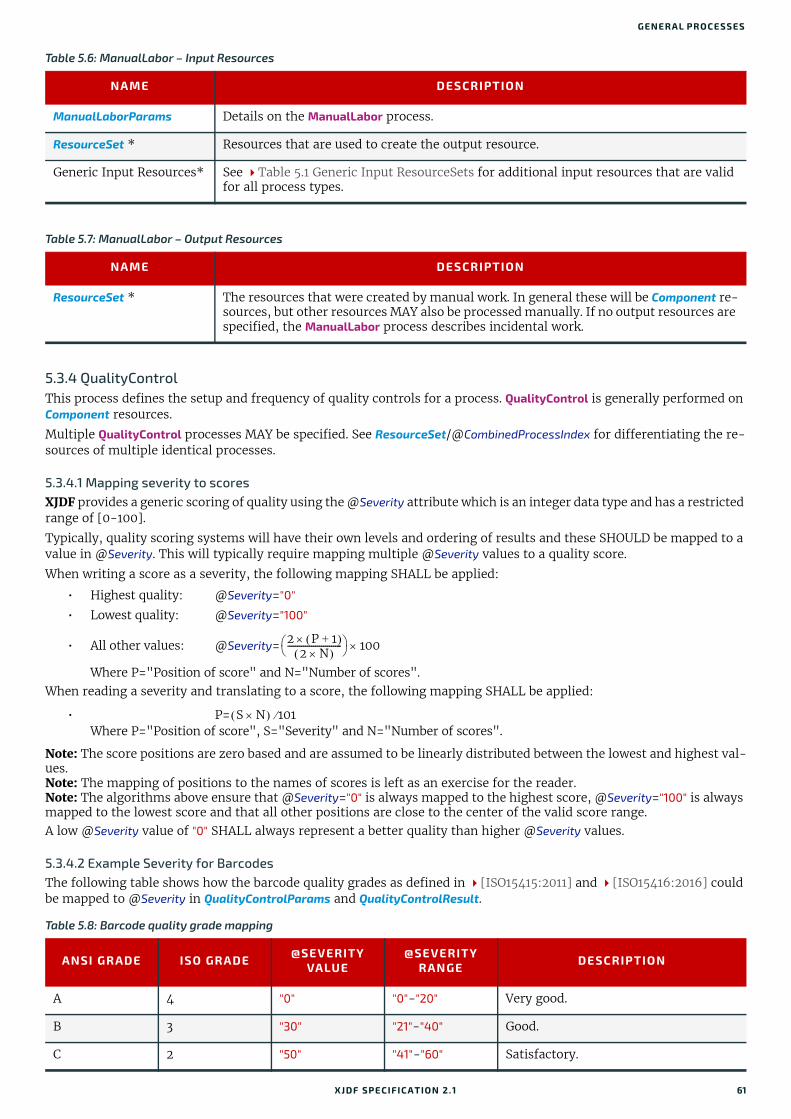
GENERAL PROCESSES
5.3.4 QualityControlThis process defines the setup and frequency of quality controls for a process. QualityControl is generally performed on Component resources.
Multiple QualityControl processes MAY be specified. See ResourceSet/@CombinedProcessIndex for differentiating the re-sources of multiple identical processes.
5.3.4.1 Mapping severity to scoresXJDF provides a generic scoring of quality using the @Severity attribute which is an integer data type and has a restricted range of [0-100].
Typically, quality scoring systems will have their own levels and ordering of results and these SHOULD be mapped to a value in @Severity. This will typically require mapping multiple @Severity values to a quality score.
When writing a score as a severity, the following mapping SHALL be applied:
• Highest quality: @Severity="0"
• Lowest quality: @Severity="100"
• All other values: @Severity=
Where P="Position of score" and N="Number of scores".When reading a severity and translating to a score, the following mapping SHALL be applied:
• P=Where P="Position of score", S="Severity" and N="Number of scores".
Note: The score positions are zero based and are assumed to be linearly distributed between the lowest and highest val-ues. Note: The mapping of positions to the names of scores is left as an exercise for the reader.Note: The algorithms above ensure that @Severity="0" is always mapped to the highest score, @Severity="100" is always mapped to the lowest score and that all other positions are close to the center of the valid score range.A low @Severity value of "0" SHALL always represent a better quality than higher @Severity values.
5.3.4.2 Example Severity for BarcodesThe following table shows how the barcode quality grades as defined in [ISO15415:2011] and [ISO15416:2016] could be mapped to @Severity in QualityControlParams and QualityControlResult.
Table 5.6: ManualLabor – Input Resources
NAME DESCRIPTION
ManualLaborParams Details on the ManualLabor process.
ResourceSet * Resources that are used to create the output resource.
Generic Input Resources* See Table 5.1 Generic Input ResourceSets for additional input resources that are valid for all process types.
Table 5.7: ManualLabor – Output Resources
NAME DESCRIPTION
ResourceSet * The resources that were created by manual work. In general these will be Component re-sources, but other resources MAY also be processed manually. If no output resources are specified, the ManualLabor process describes incidental work.
Table 5.8: Barcode quality grade mapping
ANSI GRADE ISO GRADE @SEVERITYVALUE
@SEVERITYRANGE DESCRIPTION
A 4 "0" "0"-"20" Very good.
B 3 "30" "21"-"40" Good.
C 2 "50" "41"-"60" Satisfactory.
2 P 1+ 2 N
--------------------------- 100
S N 101
XJDF SPECIFICATIO N 2.1 61

PRO CESSES
.
5.3.5 VerificationThe Verification process is used to confirm that a process has been completely executed.
Verification differs from QualityControl in that Verification verifies the existence of a given set of resources, whereas QualityControl verifies that the existing resources fulfill certain quality criteria.
D 1 "70" "61"-"80" Sufficient.
F 0 "100" "81"-"100" Failed.
Table 5.9: QualityControl – Input Resources
NAME DESCRIPTION
ColorantControl ?New in XJDF 2.1
ColorantControl SHALL define the color separations that are expected to have been printed on the input Component.
Layout ?New in XJDF 2.1
Definition of the production marks and print content for QualityControl.Note: See Preview in Table 5.1 Generic Input ResourceSets for referencing images for comparison or display.
QualityControlParams Detailed definition of the QualityControl process.
ResourceSet The resource to be quality controlled. In general this will be a Component.
Generic Input Resources* See Table 5.1 Generic Input ResourceSets for additional input resources that are valid for all process types.
Table 5.10: QualityControl – Output Resources
NAME DESCRIPTION
QualityControlResult Results of the process, e.g. measurement statistics. The details provided in QualityControlResult SHALL conform at least to the requested methods specified in QualityControlParams/@Method. Additional details MAY be provided.
ResourceSet This ResourceSet describes the resources after QualityControl has been applied.
Table 5.11: Verification – Input Resources
NAME DESCRIPTION
ResourceSet The resources to be verified. The input will most often be a Component.
VerificationParams Controls the verification requirements.
Generic Input Resources* See Table 5.1 Generic Input ResourceSets for additional input resources that are valid for all process types.
Table 5.12: Verification – Output Resources
NAME DESCRIPTION
ResourceSet The resource after verification. Most often the ResourceSet will not be modified by Verification.
VerificationResult ? Results of the process, e.g. measurement statistics.
Table 5.8: Barcode quality grade mapping
ANSI GRADE ISO GRADE @SEVERITYVALUE
@SEVERITYRANGE DESCRIPTION
62 XJDF SPECIFICATIO N 2.1
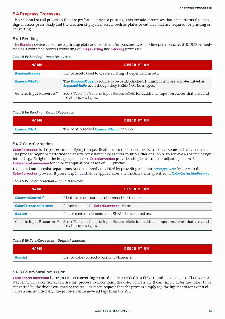
PREPRESS PROCESSES
5.4 Prepress ProcessesThis section lists all processes that are performed prior to printing. This includes processes that are performed to make digital assets press ready and the creation of physical assets such as plates or cut dies that are required for printing or converting.
5.4.1 BendingThe Bending device consumes a printing plate and bends and/or punches it. An in-line plate puncher SHOULD be mod-eled as a combined process consisting of ImageSetting and Bending processes.
5.4.2 ColorCorrectionColorCorrection is the process of modifying the specification of colors in documents to achieve some desired visual result. The process might be performed to ensure consistent colors across multiple files of a job or to achieve a specific design intent (e.g., “brighten the image up a little”). ColorCorrection provides simple controls for adjusting colors. See ColorSpaceConversion for color manipulations based on ICC profiles.
Individual output color separations MAY be directly modified by providing an input TransferCurve/@Curve to the ColorCorrection process. If present @Curve shall be applied after any modifications specified in ColorCorrectionParams.
5.4.3 ColorSpaceConversionColorSpaceConversion is the process of converting colors that are provided in a PDL to another color space. There are two ways in which a controller can use this process to accomplish the color conversion. It can simply order the colors to be converted by the device assigned to the task, or it can request that the process simply tag the input data for eventual conversion. Additionally, the process can remove all tags from the PDL.
Table 5.13: Bending – Input Resources
NAME DESCRIPTION
BendingParams List of assets used to create a listing of dependent assets.
ExposedMedia The ExposedMedia resource to be bent/punched. Dummy forms are also described as ExposedMedia even though they NEED NOT be imaged.
Generic Input Resources* See Table 5.1 Generic Input ResourceSets for additional input resources that are valid for all process types.
Table 5.14: Bending – Output Resources
NAME DESCRIPTION
ExposedMedia The bent/punched ExposedMedia resource.
Table 5.15: ColorCorrection – Input Resources
NAME DESCRIPTION
ColorantControl ? Identifies the assumed color model for the job.
ColorCorrectionParams Parameters of the ColorCorrection process
RunList List of content elements that SHALL be operated on.
Generic Input Resources * See Table 5.1 Generic Input ResourceSets for additional input resources that are valid for all process types.
Table 5.16: ColorCorrection – Output Resources
NAME DESCRIPTION
RunList List of color-corrected content elements.
XJDF SPECIFICATIO N 2.1 63
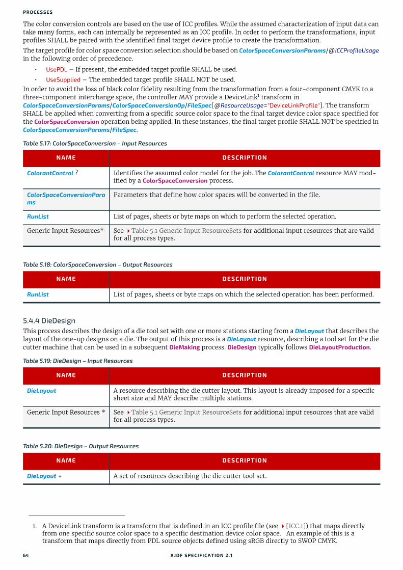
PRO CESSES
The color conversion controls are based on the use of ICC profiles. While the assumed characterization of input data can take many forms, each can internally be represented as an ICC profile. In order to perform the transformations, input profiles SHALL be paired with the identified final target device profile to create the transformation.
The target profile for color space conversion selection should be based on ColorSpaceConversionParams/@ICCProfileUsage in the following order of precedence.
• UsePDL – If present, the embedded target profile SHALL be used.
• UseSupplied – The embedded target profile SHALL NOT be used.In order to avoid the loss of black color fidelity resulting from the transformation from a four-component CMYK to a three-component interchange space, the controller MAY provide a DeviceLink1 transform in ColorSpaceConversionParams/ColorSpaceConversionOp/FileSpec[@ResourceUsage="DeviceLinkProfile"]. The transform SHALL be applied when converting from a specific source color space to the final target device color space specified for the ColorSpaceConversion operation being applied. In these instances, the final target profile SHALL NOT be specified in ColorSpaceConversionParams/FileSpec.
5.4.4 DieDesign This process describes the design of a die tool set with one or more stations starting from a DieLayout that describes the layout of the one-up designs on a die. The output of this process is a DieLayout resource, describing a tool set for the die cutter machine that can be used in a subsequent DieMaking process. DieDesign typically follows DieLayoutProduction.
1. A DeviceLink transform is a transform that is defined in an ICC profile file (see [ICC.1]) that maps directly from one specific source color space to a specific destination device color space. An example of this is a transform that maps directly from PDL source objects defined using sRGB directly to SWOP CMYK.
Table 5.17: ColorSpaceConversion – Input Resources
NAME DESCRIPTION
ColorantControl ? Identifies the assumed color model for the job. The ColorantControl resource MAY mod-ified by a ColorSpaceConversion process.
ColorSpaceConversionParams
Parameters that define how color spaces will be converted in the file.
RunList List of pages, sheets or byte maps on which to perform the selected operation.
Generic Input Resources* See Table 5.1 Generic Input ResourceSets for additional input resources that are valid for all process types.
Table 5.18: ColorSpaceConversion – Output Resources
NAME DESCRIPTION
RunList List of pages, sheets or byte maps on which the selected operation has been performed.
Table 5.19: DieDesign – Input Resources
NAME DESCRIPTION
DieLayout A resource describing the die cutter layout. This layout is already imposed for a specific sheet size and MAY describe multiple stations.
Generic Input Resources * See Table 5.1 Generic Input ResourceSets for additional input resources that are valid for all process types.
Table 5.20: DieDesign – Output Resources
NAME DESCRIPTION
DieLayout + A set of resources describing the die cutter tool set.
64 XJDF SPECIFICATIO N 2.1

PREPRESS PROCESSES
5.4.5 DieLayoutProductionThis process describes the layout of one or more structural designs for a given Media. The output of this process is a DieLayout resource describing the positioning of the individual one-ups on the die. The DieLayoutProduction process can be performed by a human operator using a CAD application. In some cases it can be an automated process. The process can be run in estimation mode; in which case multiple solutions are returned that can then be used as input of a cost estimation module to determine the optimal layout. The DieLayoutProduction process is the packaging equivalent of a Stripping process in conventional printing. The output DieLayout of DieLayoutProduction is typically the input of a sub-sequent DieDesign process.
Example 5.3: DieLayoutProduction: Single Shape and Two Sheet SizesExample of DieLayoutProduction of a single shape on 2 stock sheet sizes.
5.4.6 ImageEnhancement The ImageEnhancement process describes generic image data processing. Note: The source MAY be any image, but also text or vector graphics.
Table 5.21: DieLayoutProduction – Input Resources
NAME DESCRIPTION
DieLayoutProductionParams
The parameters for DieLayoutProduction.
Generic Input Resources* See Table 5.1 Generic Input ResourceSets for additional input resources that are valid for all process types.
Table 5.22: DieLayoutProduction – Output Resources
NAME DESCRIPTION
DieLayout DieLayout describes a die cutter tool set. If DieLayoutProductionParams/@Estimate=”True”, multiple alternative DieLayout Resource elements that SHALL be partitioned by @Option SHALL be returned, otherwise a single DieLayout SHALL be gen-erated.
<XJDF xmlns="http://www.CIP4.org/JDFSchema_2_0" JobID="Die1" Types="DieLayoutProduction"> <ResourceSet Name="ShapeDef"> <Resource ID="r_000007"> <ShapeDef> <FileSpec URL="file://myserver/myshare/olive.dd3"/> </ShapeDef> </Resource> </ResourceSet> <ResourceSet Name="DieLayoutProductionParams" Usage="Input"> <Resource> <DieLayoutProductionParams> <ConvertingConfig SheetHeightMax="2200" SheetHeightMin="2200" SheetWidthMax="2800" SheetWidthMin="2800"/> <ConvertingConfig SheetHeightMax="2500" SheetHeightMin="2500" SheetWidthMax="3400" SheetWidthMin="3400"/> <RepeatDesc LayoutStyle="StraightNest" ShapeDefRef="r_000007"/> </DieLayoutProductionParams> </Resource> </ResourceSet> <ResourceSet Name="DieLayout" Usage="Output"> <Resource DescriptiveName="The die layout"> <DieLayout/> </Resource> </ResourceSet></XJDF>
XJDF SPECIFICATIO N 2.1 65

PRO CESSES
5.4.7 ImageSettingThe ImageSetting process is executed by an imagesetter or platesetter that images a bitmap onto the film or plate media.
5.4.8 ImpositionThe Imposition process is responsible for combining pages of input graphical content onto surfaces of the physical output media. Static or dynamic printer's marks can be added to the surface in order to facilitate various aspects of the produc-tion process. Among other things, these marks are used for press alignment, color calibration, job identification, and as guides for cutting and folding.Note: The Imposition process specifies the task of combining pages and marks on sheets. The task of setting up the pa-rameters needed for Imposition is defined by Stripping.
Table 5.23: ImageEnhancement – Input Resources
NAME DESCRIPTION
ImageEnhancementParams
Describes the controls selected for the manipulation of images.
RunList List of content data elements on which to perform the selected operations.
Generic Input Resources * See Table 5.1 Generic Input ResourceSets for additional input resources that are valid for all process types.
Table 5.24: ImageEnhancement – Output Resources
NAME DESCRIPTION
RunList List of page contents with images that have been manipulated as indicatedby the ImageEnhancementParams resource.
Table 5.25: ImageSetting – Input Resources
NAME DESCRIPTION
ColorantControl ? The ColorantControl resources that define the ordering and usage of inks during mark-ing on the imagesetter.
DevelopingParams ? Controls the physical and chemical specifics of the media development process.
ImageSetterParams ? Controls the device specific features of the imagesetter.
Media The film or plate prior to imaging.
RunList Identifies the set of bitmaps to image. The RunList MAY contain bytemaps or images.
Generic Input Resources* See Table 5.1 Generic Input ResourceSets for additional input resources that are valid for all process types.
Table 5.26: ImageSetting – Output Resources
NAME DESCRIPTION
ExposedMedia The exposed media resource. In the case of plate setting, this is the exposed set of plates. In the case of film setting, this is the exposed set of films.
Table 5.27: Imposition – Input Resources (Sheet 1 of 2)
NAME DESCRIPTION
Layout A Layout resource that indicates how the content pages from the Document RunList and marks from the Marks RunList (see below) are combined onto imposed surfaces.
66 XJDF SPECIFICATIO N 2.1

PREPRESS PROCESSES
There are two mechanisms provided for controlling the flow of page images onto sheet surfaces:
The default mechanism is for non-automated (e.g., fully-specified) Imposition. Fully-specified imposition explicitly identifies all page content for each sheet imaged and references these pages by means of the order in which they are defined in the input RunList (Document) resource. Static printer's marks are referenced in a similar fashion from the input RunList (Marks) resource.
Setting the @Automated attribute of the Layout resource to "true" activates a template approach to imposition and relies upon the full hierarchy structure of the document (as specified by the RunList (Document)) to specify the page content to be imposed.
In XJDF, there is a single Layout definition. When described fully (@Automated = "false"), the Layout resource partition structure explicitly defines the imposition to take place. Note: The XML order in which the partitions of the Layout resource are defined is significant for both automated and non-automated imposition and defines the order in which the imposition engine SHALL create the output RunList.
5.4.8.1 Execution Model for Automated ImpositionThe major difference between automated and non automated imposition is the execution model. Non-automated impo-sition requires a completely defined Layout that defines each sheet and "pulls" document pages from a RunList(Document). On the other hand, automated imposition requires a completely defined RunList that "pushes" pages into positions of the Layout.
The Imposition process transforms the sequences of pages contained within the input RunList to a sequence of imposed sheet surfaces. The input RunList(Document)and the order of the documents defined by the Layout resource explicitly define the ‘page to sheet’ surface mapping transformation that SHALL be applied by the imposition engine.
The pseudo-code below describes the processing performed by the imposition engine at a high level:
For each Set in the set in the order specified in the input RunList(Document)For each Document in the order specified in the input RunList(Document)
For each Page in the DocumentFor each Layout partition that matches the Document and Page
Process the Page through the Layout partition
Thus, each Resource in the ResourceSet[@Name="Layout"] SHALL be processed in the XML order specified. Every docu-ment belonging to the current set is then evaluated against the Partition Keys specified for that Layout to determine if it SHALL be processed by that Layout.
The RunList output from the Imposition process represents a sequence of imposed sheet surfaces. The structure of the Layout affects the Partition Keys conserved by its output RunList (and its referenced content), by conserving all Partition Keys specified in the Layout along with generating all of the appropriate Partition Keys, such as @SetIndex, @DocIndex, @SheetIndex. The output RunList can be viewed conceptually as a collection of sheet surface pairings (front and back) that conserves information about which PDL metadata was in scope at the time the sheets were generated.
RunList (Document) Structured list of incoming page contents that are transformed to produce the imposed surface images.
RunList (Marks) ? Structured list of incoming marks. These are typically printer’s marks such as fold marks, cut marks, punch marks or color bars.
Generic Input Resources * See Table 5.1 Generic Input ResourceSets for additional input resources that are valid for all process types.
Table 5.28: Imposition – Output Resources
NAME DESCRIPTION
RunList The RunList represents a structured list of imposed surfaces.. Conceptually the output RunList will be partitioned by at least @SheetName and @Side to represent the individ-ual printed surfaces. If the Imposition process is executed before any raster image pro-cessing, this will generally be consumed by an Interpreting process. In the case of where Imposition is executed after any raster image processing, it will be consumed by DigitalPrinting or ImageSetting.
Table 5.27: Imposition – Input Resources (Sheet 2 of 2)
NAME DESCRIPTION
XJDF SPECIFICATIO N 2.1 67

PRO CESSES
5.4.8.2 Cut and Stack ImpositionPages are normally distributed onto an entire imposed sheet prior to processing the next imposed sheet. If cut and stack imposition is selected by specifying Layout/Position/@StackOrd, this distribution order shall be modified so that pages are distributed in the order of the individual stacks. Each stack is filled to the calculated value of Layout/Position/@StackDepth prior to filling the stack with the next highest value of @StackOrd.
Example 5.4: Cut and Stack ImpositionThis simple example is configured for 2 stacks with a depth of 10 sheets. Therefore the first 20 pages will be filled into the position with @StackOrd="0", the next 20 pages will be filled into the position with @StackOrd="1", and the following pages will be continue switching stacks every 20 pages.
5.4.8.3 Imposition for TilingSometimes content from a surface needs to be imaged onto media that is smaller than the designated surface. Each tile SHALL be specified as a Layout Resource with a Part/@TileID. PlacedObject/@ClipBox SHOULD be specified as the size of the tile. PlacedObject/@CTM will typically be the same except for an image shift that moves the source image into the clip box.
5.4.9 InkZoneCalculationThe InkZoneCalculation process takes place in order to preset the ink zones before printing. The Preview data are used to calculate a coverage profile that represents the ink distribution along and perpendicular to the ink zones within the printable area of the preview. The InkZoneProfile can be combined with additional, vendor-specific data in order to preset the ink zones and the oscillating rollers of an offset printing press.
<Layout Automated="true" WorkStyle="WorkAndTurn"> <Position RelativeBox="0 0 50 100" StackDepth="10" StackOrd="0"/> <Position RelativeBox="50 0 100 100" StackDepth="10" StackOrd="1"/></Layout>
<ResourceSet Name="Layout" Usage="Input"> <Resource> <Part Side="Front" TileID="0 0"/> <Layout SurfaceContentsBox="0 0 600 420"> <PlacedObject CTM="1 0 0 1 0 0" ClipBox="0 0 600 420" Ord="0"> <ContentObject/> </PlacedObject> </Layout> </Resource> <!--More tiles here--> <Resource> <Part Side="Front" TileID="1 1"/> <Layout SurfaceContentsBox="0 0 600 420"> <PlacedObject CTM="1 0 0 1 -600 -420" ClipBox="0 0 600 420" Ord="0"> <ContentObject/> </PlacedObject> </Layout> </Resource></ResourceSet>
Table 5.29: InkZoneCalculation – Input Resources
NAME DESCRIPTION
InkZoneCalculationParams ?
Specific information about the printing press geometry (e.g., the number of zones) to calculate the InkZoneProfile.
Layout ? Specific information about the Media (including type and color) and about the sheet (placement coordinates on the printing cylinder).
Preview A low to medium resolution bitmap file representing the content to be printed.
Generic Input Resources * See Table 5.1 Generic Input ResourceSets for additional input resources that are valid for all process types.
68 XJDF SPECIFICATIO N 2.1
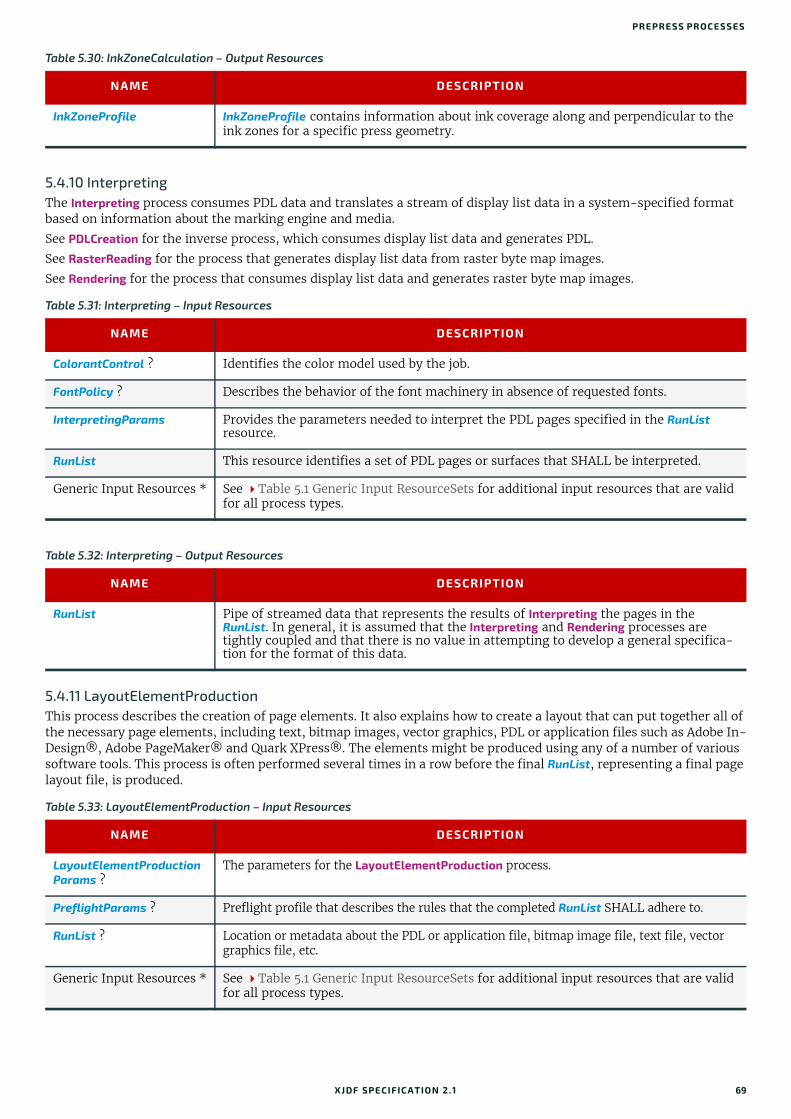
PREPRESS PROCESSES
5.4.10 InterpretingThe Interpreting process consumes PDL data and translates a stream of display list data in a system-specified format based on information about the marking engine and media.
See PDLCreation for the inverse process, which consumes display list data and generates PDL.
See RasterReading for the process that generates display list data from raster byte map images.
See Rendering for the process that consumes display list data and generates raster byte map images.
5.4.11 LayoutElementProductionThis process describes the creation of page elements. It also explains how to create a layout that can put together all of the necessary page elements, including text, bitmap images, vector graphics, PDL or application files such as Adobe In-Design®, Adobe PageMaker® and Quark XPress®. The elements might be produced using any of a number of various software tools. This process is often performed several times in a row before the final RunList, representing a final page layout file, is produced.
Table 5.30: InkZoneCalculation – Output Resources
NAME DESCRIPTION
InkZoneProfile InkZoneProfile contains information about ink coverage along and perpendicular to the ink zones for a specific press geometry.
Table 5.31: Interpreting – Input Resources
NAME DESCRIPTION
ColorantControl ? Identifies the color model used by the job.
FontPolicy ? Describes the behavior of the font machinery in absence of requested fonts.
InterpretingParams Provides the parameters needed to interpret the PDL pages specified in the RunList resource.
RunList This resource identifies a set of PDL pages or surfaces that SHALL be interpreted.
Generic Input Resources * See Table 5.1 Generic Input ResourceSets for additional input resources that are valid for all process types.
Table 5.32: Interpreting – Output Resources
NAME DESCRIPTION
RunList Pipe of streamed data that represents the results of Interpreting the pages in the RunList. In general, it is assumed that the Interpreting and Rendering processes are tightly coupled and that there is no value in attempting to develop a general specifica-tion for the format of this data.
Table 5.33: LayoutElementProduction – Input Resources
NAME DESCRIPTION
LayoutElementProductionParams ?
The parameters for the LayoutElementProduction process.
PreflightParams ? Preflight profile that describes the rules that the completed RunList SHALL adhere to.
RunList ? Location or metadata about the PDL or application file, bitmap image file, text file, vector graphics file, etc.
Generic Input Resources * See Table 5.1 Generic Input ResourceSets for additional input resources that are valid for all process types.
XJDF SPECIFICATIO N 2.1 69

PRO CESSES
5.4.12 LayoutShiftingLayoutShifting specifies how to apply separation dependent shifts on a flat or objects on a press sheet.
The exact ordering of the process within the Interpreting, Rendering and ImageSetting and the elements referenced by input and output RunList elements are not defined. LayoutShifting MAY occur on display lists, raster data or in the image setting hardware.
5.4.13 PDLCreationThe PDLCreation device consumes the display list of graphical elements generated by an Interpreting or RasterReading and produces a new PDL output RunList based on the selected output parameters.
See Interpreting for the inverse process, which consumes PDL data and generates display list data.
See RasterReading for the process that generates display list data from raster byte map images.
See Rendering for the process that consumes display list data and generates raster byte map images.
Table 5.34: LayoutElementProduction – Output Resources
NAME DESCRIPTION
RunList A RunList that represents the page elements SHALL be produced.
Table 5.35: LayoutShifting – Input Resources
NAME DESCRIPTION
LayoutShift Parameters for the LayoutShifting.
RunList References the input objects/flats to apply shifting to.
Generic Input Resources* See Table 5.1 Generic Input ResourceSets for additional input resources that are valid for all process types.
Table 5.36: LayoutShifting – Output Resources
NAME DESCRIPTION
RunList The output RunList references the image data that the separation dependent layout shifts applied to.
Table 5.37: PDLCreation – Input Resources
NAME DESCRIPTION
ImageCompressionParams ?
This resource provides a set of controls that determines how images will be compressed in the resulting PDL pages.
PDLCreationParams These parameters control the operation of the process that interprets the display list and produces the resulting PDL pages.
RunList This resource is a pipe of streamed data that represents a device independent display list structure. The RunList SHALL specify a ByteMap element.
Generic Input Resources * See Table 5.1 Generic Input ResourceSets for additional input resources that are valid for all process types.
Table 5.38: PDLCreation – Output Resources
NAME DESCRIPTION
RunList This resource identifies the location of the resulting PDL file(s). If the FileSpec/@MimeType is specified, then the value SHALL match PDLCreationParams/@MimeType. If not specified, then PDLCreationParams/@MimeType SHALL be inserted.
70 XJDF SPECIFICATIO N 2.1
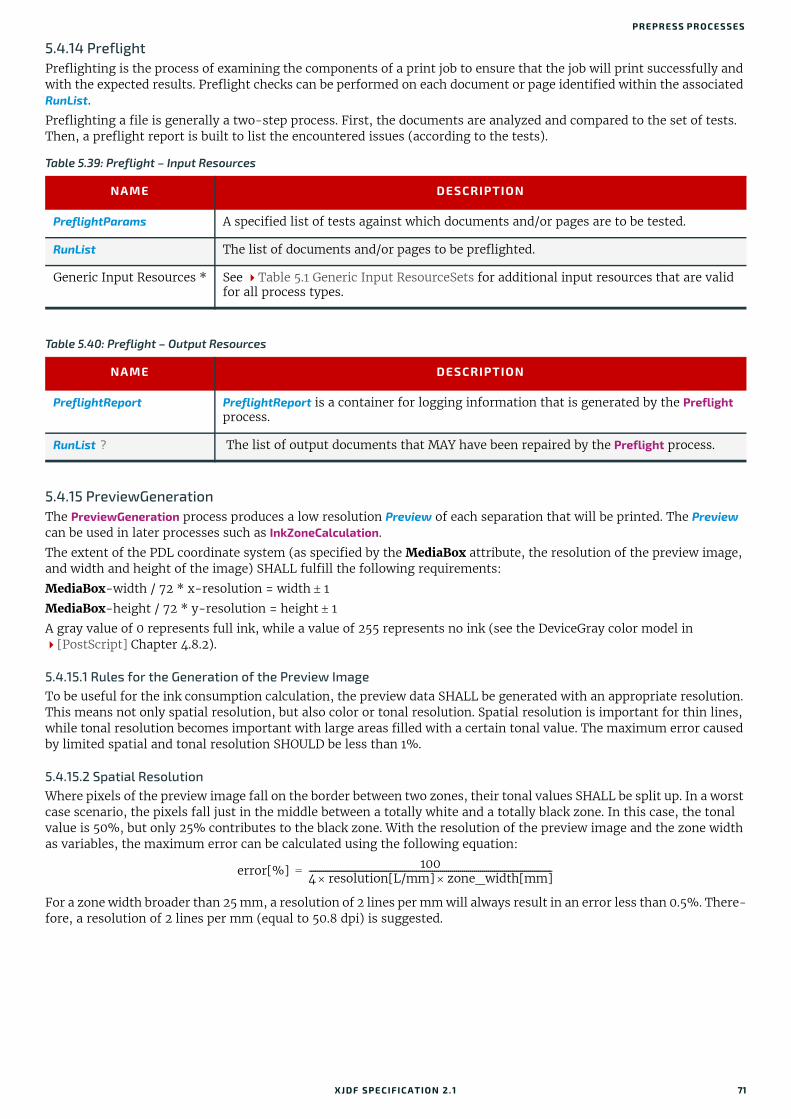
PREPRESS PROCESSES
5.4.14 PreflightPreflighting is the process of examining the components of a print job to ensure that the job will print successfully and with the expected results. Preflight checks can be performed on each document or page identified within the associated RunList.
Preflighting a file is generally a two-step process. First, the documents are analyzed and compared to the set of tests. Then, a preflight report is built to list the encountered issues (according to the tests).
5.4.15 PreviewGenerationThe PreviewGeneration process produces a low resolution Preview of each separation that will be printed. The Preview can be used in later processes such as InkZoneCalculation.
The extent of the PDL coordinate system (as specified by the MediaBox attribute, the resolution of the preview image, and width and height of the image) SHALL fulfill the following requirements:
MediaBox-width / 72 * x-resolution = width 1
MediaBox-height / 72 * y-resolution = height 1
A gray value of 0 represents full ink, while a value of 255 represents no ink (see the DeviceGray color model in [PostScript] Chapter 4.8.2).
5.4.15.1 Rules for the Generation of the Preview ImageTo be useful for the ink consumption calculation, the preview data SHALL be generated with an appropriate resolution. This means not only spatial resolution, but also color or tonal resolution. Spatial resolution is important for thin lines, while tonal resolution becomes important with large areas filled with a certain tonal value. The maximum error caused by limited spatial and tonal resolution SHOULD be less than 1%.
5.4.15.2 Spatial ResolutionWhere pixels of the preview image fall on the border between two zones, their tonal values SHALL be split up. In a worst case scenario, the pixels fall just in the middle between a totally white and a totally black zone. In this case, the tonal value is 50%, but only 25% contributes to the black zone. With the resolution of the preview image and the zone width as variables, the maximum error can be calculated using the following equation:
For a zone width broader than 25 mm, a resolution of 2 lines per mm will always result in an error less than 0.5%. There-fore, a resolution of 2 lines per mm (equal to 50.8 dpi) is suggested.
Table 5.39: Preflight – Input Resources
NAME DESCRIPTION
PreflightParams A specified list of tests against which documents and/or pages are to be tested.
RunList The list of documents and/or pages to be preflighted.
Generic Input Resources * See Table 5.1 Generic Input ResourceSets for additional input resources that are valid for all process types.
Table 5.40: Preflight – Output Resources
NAME DESCRIPTION
PreflightReport PreflightReport is a container for logging information that is generated by the Preflight process.
RunList ? The list of output documents that MAY have been repaired by the Preflight process.
error[%] 1004 resolution[L/mm] zone_width[mm]--------------------------------------------------------------------------------------------------------------------------=
XJDF SPECIFICATIO N 2.1 71

PRO CESSES
5.4.15.3 Tonal ResolutionThe kind of error caused by color quantization depends on the number of shades available. If the real tonal value is rounded to the closest (lower or higher) available shade, the error can be calculated using the following equation:
Therefore, at least 64 shades SHOULD be used.
5.4.15.4 Line Art ResolutionWhen rasterizing line art elements, the minimal line width is 1 pixel, which means 1/resolution. Therefore, the relation-ship between the printing resolution and the (spatial) resolution of the preview image is important for these kind of el-ements. In addition, a specific characteristic of PostScript RIPs adds another error: within PostScript, each pixel that is touched by a line is set. Tests with different PostScript jobs have shown that a line art resolution of more than 300 dpi is normally sufficient for ink-consumption calculation.
5.4.15.5 ConclusionThere are quite a few different ways to meet the requirements listed above. The following list includes several examples:
• The job can be RIPed with 406.4 dpi monochrome.
• With anti-aliasing, the image data can be filtered down by a factor of 8 in both directions. This results in an image of 50.8 dpi with 65 color shades.
• High resolution data can also be filtered using anti-aliasing. First, the RIPed data, at 2540 dpi monochrome, are taken and filtered down by a factor of 50 in both directions. This produces an image of 50.8 dpi with 2501 color shades. Finally those shades are mapped to 256 shades, without affecting the spatial resolution.
Rasterizing a job with 50.8 dpi and 256 shades of gray is not sufficient. The problem in this case is the rendering of thin lines (see Line Art Resolution above).
5.4.15.6 Recommendations for ImplementationThe following three guidelines are strongly RECOMMENDED:
• The resolution of RIPed line art SHOULD be at least 300 dpi.
• The spatial resolution of the preview image SHOULD be approximately 20 pixel/cm (= 50.8 dpi).
• The tonal resolution of the preview image SHOULD be at least 64 shades.
Figure 5-1: Worst case scenario for area coverage calculation
Table 5.41: PreviewGeneration – Input Resources (Sheet 1 of 2)
NAME DESCRIPTION
ColorantControl ? The ColorantControl resources that define the ordering and usage of inks in print mod-ules. Needed for generating thumbnails.
PreviewGenerationParams Parameters specifying the size and the type of the preview.
RunList ? Bitmap data are consumed by the PreviewGeneration process.
Zone 2Zone 1
Border between zonesOverlapping pixel
error[%] 1002 number_of_shades---------------------------------------------------------------------=
72 XJDF SPECIFICATIO N 2.1

PREPRESS PROCESSES
5.4.16 RasterReadingThe RasterReading process consumes raster graphic formatted files and converts them into a display list structure.
See Rendering for the inverse process that consumes display list data and generates byte maps of raster images.
See Interpreting for the process that consumes PDL data and generates display list data.
See PDLCreation for the process that consumes display list data and generates PDL.
5.4.17 RenderingThe Rendering process consumes the display list of graphical elements generated by the Interpreting or RasterReading process. It converts the graphical elements according to the geometric and graphic state information contained within the display list and with the RenderingParams information to produce binary rasterized data suitable for processes that consume ByteMap information.
See RasterReading for the inverse process that consumes raster data and generates display lists.
See Interpreting for the process that consumes PDL data and generates display list data.
See PDLCreation for the process that consumes display list data and generates PDL.
Generic Input Resources * See Table 5.1 Generic Input ResourceSets for additional input resources that are valid for all process types.
Table 5.42: PreviewGeneration – Output Resources
NAME DESCRIPTION
Preview Representation of the Preview files that were produced by the PreviewGeneration pro-cess.
Table 5.43: RasterReading – Input Resources
NAME DESCRIPTION
RasterReadingParams ? Additional parameters for reading raster files.
RunList This resource identifies a set of raster pages or surfaces that will be inserted into the display list. This resource SHALL reference ByteMap images.
Generic Input Resources * See Table 5.1 Generic Input ResourceSets for additional input resources that are valid for all process types.
Table 5.44: RasterReading – Output Resources
NAME DESCRIPTION
RunList Pipe of streamed data that represents the results of RasterReading the pages in the input RunList. The format and detail are implementation dependent. The RunList SHALL specify the output content data for RasterReading.
Table 5.45: Rendering – Input Resources (Sheet 1 of 2)
NAME DESCRIPTION
ImageCompressionParams ?
Allows definition of compressed raster images.
RenderingParams ? This resource describes the format of the byte maps to be created and other specifics of the Rendering process.
Table 5.41: PreviewGeneration – Input Resources (Sheet 2 of 2)
NAME DESCRIPTION
XJDF SPECIFICATIO N 2.1 73

PRO CESSES
5.4.18 ScreeningThis process specifies the process of halftone screening. It consumes contone raster data (e.g., the output from a RasterReading or Rendering process). It produces monochrome that has been filtered through a halftone screen to iden-tify which pixels are needed for approxmating the original shades of color in the document.
This process definition includes capabilities for halftoning after raster image processing according to the PostScript definitions. Alternatively, it allows for the selection of FM screening/error diffusion techniques.
5.4.19 SeparationThe Separation process specifies the controls associated with the generation of color-separated data. Separation may be applied either to PDL data or raster data.
RunList Pipe of streamed data that represents the results of Interpreting or RasterReading the pages in the input RunList. In general, it is assumed that the Interpreting, RasterReading, Rendering and PDLCreation are tightly coupled and that there is no value in attempting to develop a general specification for the format of this data.
Generic Input Resources * See Table 5.1 Generic Input ResourceSets for additional input resources that are valid for all process types.
Table 5.46: Rendering – Output Resources
NAME DESCRIPTION
RunList Pipe of streamed data that represents the results of Rendering. This RunList MAY be con-sumed by any subsequent process that consumes raster data, including PDLCreation, ImageSetting or DigitalPrinting. The data MAY be specified in ByteMap sub-elements. In general, it is assumed that the Interpreting, RasterReading, Rendering and PDLCreation are tightly coupled and that there is no value in attempting to develop a general specifi-cation for the format of this data.
Table 5.47: Screening – Input Resources
NAME DESCRIPTION
RunList Ordered list of rasterized ByteMap or interpreted data representing pages or surfaces.
ScreeningParams Parameters specifying which halftone mechanism SHALL be applied and with what specific controls.
Generic Input Resources * See Table 5.1 Generic Input ResourceSets for additional input resources that are valid for all process types.
Table 5.48: Screening – Output Resources
NAME DESCRIPTION
RunList Ordered list of rasterized and screened output pages. The resolution SHALL remain the same, with resulting data being one bit per component. Furthermore, the organization of planes within the data SHALL not change.
Table 5.49: Separation – Input Resources (Sheet 1 of 2)
NAME DESCRIPTION
ColorantControl ? Identifies which colorants in the job are to be output.
RunList List of elements, surfaces or pages that are to be operated on.
SeparationControlParams Controls for the separation process.
Table 5.45: Rendering – Input Resources (Sheet 2 of 2)
NAME DESCRIPTION
74 XJDF SPECIFICATIO N 2.1
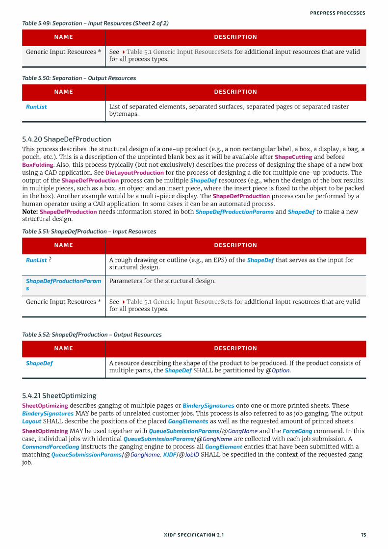
PREPRESS PROCESSES
5.4.20 ShapeDefProductionThis process describes the structural design of a one-up product (e.g., a non rectangular label, a box, a display, a bag, a pouch, etc.). This is a description of the unprinted blank box as it will be available after ShapeCutting and before BoxFolding. Also, this process typically (but not exclusively) describes the process of designing the shape of a new box using a CAD application. See DieLayoutProduction for the process of designing a die for multiple one-up products. The output of the ShapeDefProduction process can be multiple ShapeDef resources (e.g., when the design of the box results in multiple pieces, such as a box, an object and an insert piece, where the insert piece is fixed to the object to be packed in the box). Another example would be a multi-piece display. The ShapeDefProduction process can be performed by a human operator using a CAD application. In some cases it can be an automated process.Note: ShapeDefProduction needs information stored in both ShapeDefProductionParams and ShapeDef to make a new structural design.
5.4.21 SheetOptimizingSheetOptimizing describes ganging of multiple pages or BinderySignatures onto one or more printed sheets. These BinderySignatures MAY be parts of unrelated customer jobs. This process is also referred to as job ganging. The output Layout SHALL describe the positions of the placed GangElements as well as the requested amount of printed sheets.
SheetOptimizing MAY be used together with QueueSubmissionParams/@GangName and the ForceGang command. In this case, individual jobs with identical QueueSubmissionParams/@GangName are collected with each job submission. A CommandForceGang instructs the ganging engine to process all GangElement entries that have been submitted with a matching QueueSubmissionParams/@GangName. XJDF/@JobID SHALL be specified in the context of the requested gang job.
Generic Input Resources * See Table 5.1 Generic Input ResourceSets for additional input resources that are valid for all process types.
Table 5.50: Separation – Output Resources
NAME DESCRIPTION
RunList List of separated elements, separated surfaces, separated pages or separated raster bytemaps.
Table 5.51: ShapeDefProduction – Input Resources
NAME DESCRIPTION
RunList ? A rough drawing or outline (e.g., an EPS) of the ShapeDef that serves as the input for structural design.
ShapeDefProductionParams
Parameters for the structural design.
Generic Input Resources * See Table 5.1 Generic Input ResourceSets for additional input resources that are valid for all process types.
Table 5.52: ShapeDefProduction – Output Resources
NAME DESCRIPTION
ShapeDef A resource describing the shape of the product to be produced. If the product consists of multiple parts, the ShapeDef SHALL be partitioned by @Option.
Table 5.49: Separation – Input Resources (Sheet 2 of 2)
NAME DESCRIPTION
XJDF SPECIFICATIO N 2.1 75

PRO CESSES
Table 5.53: SheetOptimizing – Input Resources
NAME DESCRIPTION
Assembly ? Input Assembly that MAY be used to specify the binding order e.g. for creep calculation. This Assembly MAY contain sections that are not included in this sheet optimization (e.g., when only covers are optimized and the bodies are produced individually). If the assemblies vary based on GangElement/@GangElementID, Assembly SHALL be parti-tioned either by @Product or by @ProductPart and SHOULD be partitioned by @Product. In addition, GangElement/@ExternalID SHALL match the appropriate partition key, i.e. Part/@Product or Part/@ProductPart.Note: Partitioning by the deprecated @ProductPart is provided for backwards compati-bility with XJDF 2.0 only.
BinderySignature ? List of BinderySignature elements that describe the individual gang candidate signa-tures. If more than one BinderySignature resource is provided, then BinderySignature SHALL at least be partitioned by @BinderySignatureID.
SheetOptimizingParams Parameters specifying details that allow individual sections to be distributed on the printed sheets.
Generic Input Resources * See Table 5.1 Generic Input ResourceSets for additional input resources that are valid for all process types.
Table 5.54: SheetOptimizing – Output Resources
NAME DESCRIPTION
Layout ?Modified in XJDF 2.1
The Layout resource that will be populated by the SheetOptimizing process. The resource MAY be partially populated by the submitter with restrictions on what the SheetOptimizing is allowed to do.Modification note: Layout was made optional in XJDF 2.1 to allow collecting without the creation of a gang sheet.
76 XJDF SPECIFICATIO N 2.1

PREPRESS PROCESSES
Example 5.5: SheetOptimizing amountsThe following example illustrates the result of SheetOptimizing where four BinderySignatures with an ordered amount between 875 and 1025, including 25 finishing waste each, are distributed with two copies each and therefore a resulting sheet amount of 513.
Example 5.6: SheetOptimizing with OperationsThe following example illustrates the use of @Operations to place four gang candidates on one sheet with two CutBlocks. The left CutBlock, with @BlockName="B1", has the attribute @Operations="Laminate". The right CutBlock with, @BlockName="B2", does not have an @Operations attribute. Therefore the two GangElements that contain matching at-
<XJDF xmlns="http://www.CIP4.org/JDFSchema_2_0" JobID="job" JobPartID="root" Types="SheetOptimizing"> <ResourceSet Name="SheetOptimizingParams" Usage="Input"> <Resource> <SheetOptimizingParams> <ConvertingConfig SheetHeightMax="2125.98425197" SheetHeightMin="1984.2519685" SheetWidthMax="2976.37795276" SheetWidthMin="2834.64566929"/> <GangElement GangElementID="Gang_0" JobID="Gang_0" OrderQuantity="1025"/> <GangElement GangElementID="Gang_1" JobID="Gang_10" OrderQuantity="975"/> <GangElement GangElementID="Gang_2" JobID="Gang_20" OrderQuantity="925"/> <GangElement GangElementID="Gang_3" JobID="Gang_30" OrderQuantity="875"/> </SheetOptimizingParams> </Resource> </ResourceSet> <ResourceSet Name="Layout" Usage="Output"> <Resource> <AmountPool> <PartAmount Amount="513"/> </AmountPool> <Part SheetName="Sheet1"/> <Layout> <Position GangElementID="Gang_0" RelativeBox="0 0 0.5 0.25"/> <Position GangElementID="Gang_0" RelativeBox="0 0.25 0.5 0.5"/> <Position GangElementID="Gang_1" RelativeBox="0 0.5 0.5 0.75"/> <Position GangElementID="Gang_1" RelativeBox="0 0.75 0.5 1"/> <Position GangElementID="Gang_2" RelativeBox="0.5 0 1 0.25"/> <Position GangElementID="Gang_2" RelativeBox="0.5 0.25 1 0.5"/> <Position GangElementID="Gang_3" RelativeBox="0.5 0.5 1 0.75"/> <Position GangElementID="Gang_3" RelativeBox="0.5 0.75 1 1"/> </Layout> </Resource> </ResourceSet></XJDF>
XJDF SPECIFICATIO N 2.1 77
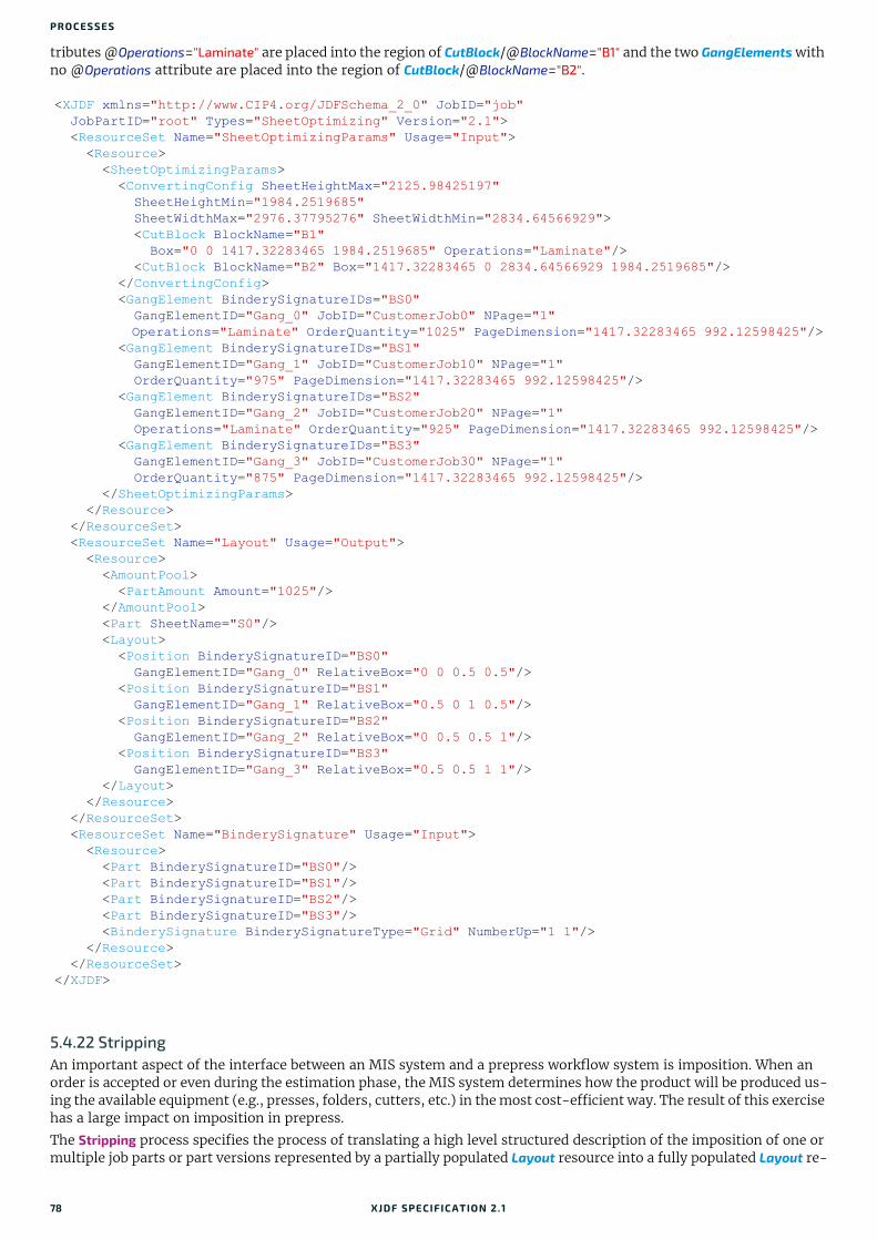
PRO CESSES
tributes @Operations="Laminate" are placed into the region of CutBlock/@BlockName="B1" and the two GangElements with no @Operations attribute are placed into the region of CutBlock/@BlockName="B2".
5.4.22 StrippingAn important aspect of the interface between an MIS system and a prepress workflow system is imposition. When an order is accepted or even during the estimation phase, the MIS system determines how the product will be produced us-ing the available equipment (e.g., presses, folders, cutters, etc.) in the most cost-efficient way. The result of this exercise has a large impact on imposition in prepress.
The Stripping process specifies the process of translating a high level structured description of the imposition of one or multiple job parts or part versions represented by a partially populated Layout resource into a fully populated Layout re-
<XJDF xmlns="http://www.CIP4.org/JDFSchema_2_0" JobID="job" JobPartID="root" Types="SheetOptimizing" Version="2.1"> <ResourceSet Name="SheetOptimizingParams" Usage="Input"> <Resource> <SheetOptimizingParams> <ConvertingConfig SheetHeightMax="2125.98425197" SheetHeightMin="1984.2519685" SheetWidthMax="2976.37795276" SheetWidthMin="2834.64566929"> <CutBlock BlockName="B1" Box="0 0 1417.32283465 1984.2519685" Operations="Laminate"/> <CutBlock BlockName="B2" Box="1417.32283465 0 2834.64566929 1984.2519685"/> </ConvertingConfig> <GangElement BinderySignatureIDs="BS0" GangElementID="Gang_0" JobID="CustomerJob0" NPage="1" Operations="Laminate" OrderQuantity="1025" PageDimension="1417.32283465 992.12598425"/> <GangElement BinderySignatureIDs="BS1" GangElementID="Gang_1" JobID="CustomerJob10" NPage="1" OrderQuantity="975" PageDimension="1417.32283465 992.12598425"/> <GangElement BinderySignatureIDs="BS2" GangElementID="Gang_2" JobID="CustomerJob20" NPage="1" Operations="Laminate" OrderQuantity="925" PageDimension="1417.32283465 992.12598425"/> <GangElement BinderySignatureIDs="BS3" GangElementID="Gang_3" JobID="CustomerJob30" NPage="1" OrderQuantity="875" PageDimension="1417.32283465 992.12598425"/> </SheetOptimizingParams> </Resource> </ResourceSet> <ResourceSet Name="Layout" Usage="Output"> <Resource> <AmountPool> <PartAmount Amount="1025"/> </AmountPool> <Part SheetName="S0"/> <Layout> <Position BinderySignatureID="BS0" GangElementID="Gang_0" RelativeBox="0 0 0.5 0.5"/> <Position BinderySignatureID="BS1" GangElementID="Gang_1" RelativeBox="0.5 0 1 0.5"/> <Position BinderySignatureID="BS2" GangElementID="Gang_2" RelativeBox="0 0.5 0.5 1"/> <Position BinderySignatureID="BS3" GangElementID="Gang_3" RelativeBox="0.5 0.5 1 1"/> </Layout> </Resource> </ResourceSet> <ResourceSet Name="BinderySignature" Usage="Input"> <Resource> <Part BinderySignatureID="BS0"/> <Part BinderySignatureID="BS1"/> <Part BinderySignatureID="BS2"/> <Part BinderySignatureID="BS3"/> <BinderySignature BinderySignatureType="Grid" NumberUp="1 1"/> </Resource> </ResourceSet></XJDF>
78 XJDF SPECIFICATIO N 2.1

PREPRESS PROCESSES
source for the Imposition process. Note that the Stripping process can generate all resources needed for the Imposition process, thus also the RunList (Marks).
5.4.22.1 Pagination in StrippingThe distribution and orientation of pages on a BinderySignature is determined by the geometry of the final product. The Assembly resource determines which pages SHALL be placed on which BinderySignature.
Example: if two 8 page BinderySignatures are gathered on top of one another, then pages 1-8 will go on the first BinderySignature and pages 9-16 will go on the second BinderySignature. If the same BinderySignatures are collected on a saddle, then pages 1-4 and 13-16 will go on the first BinderySignature and pages 5-12 will go on the second BinderySignature.
The BinderySignature determines how the pages that are selected by the Assembly SHALL be distributed on each BinderySignature. The page distribution is modified by BinderySignature/@BinderySignatureType that determines wheth-er the pagination SHALL be explicitly defined in SignatureCell/@FrontPages and SignatureCell/@BackPages, or SHALL be calculated from @FoldCatalog and @BindingOrientation using the methods defined in Appendix E Pagination Catalog.
5.4.22.1.1 Pagination and page orientation for BinderySignatureType FoldIf @BinderySignatureType = "Fold", the distribution of the selected pages on a BinderySignature is determined by the two attributes: @FoldCatalog and @BindingOrientation. The default orientation assumes the binding side on the left and the jog edge at the bottom.
If the value of @BindingOrientation is one of the flip values ("Flip0", "Flip90" etc.), then the implied page ordering of the BinderySignature SHALL be reversed.
If the value of @BindingOrientation results in a binding side on the left or right, ("Rotate0" or "Rotate180") then the default alignment of page cells along the binding side SHALL be parallel.
If @BindingOrientation results in a binding side on the bottom or top ("Rotate90" or "Rotate270"), then the default align-ment of page cells along the binding side SHALL be head to foot.Note: This results in the default behavior that all pages are right side up when the folded BinderySignature is opened along the bind.If multiple BinderySignatures are gathered, the flow of pages SHALL be modified by the value of Assembly/@Order and, if specified, AssemblySection/@BinderySignatureID.
If BinderySignatures are gathered, each BinderySignature consumes pages from the current front position in the docu-ment and the current position is incremented by the number of consumed pages.
If BinderySignatures are collected, each BinderySignature consumes the first half of pages from the current front position in the document and the second half of pages in reverse order from the current back position in the document. The cur-rent front position is incremented by the number of pages that were consumed from the front and current back position is decremented by the number of pages that were consumed from the back.
See also Appendix E Pagination Catalog for additional details.
Table 5.55: Stripping – Input Resources (Sheet 1 of 2)
NAME DESCRIPTION
Assembly ? Assembly describes how the individual BinderySignature elements are combined relative to one another to create a final product. If multiple final products are ganged on a sheet, then Assembly SHALL be partitioned by either @Product or @ProductPart and SHOULD be partitioned by @Product.Note: Partitioning by the deprecated @ProductPart is provided for backwards compati-bility with XJDF 2.0 only.
BinderySignature List of BinderySignature elements that describe the individual signatures that are com-bined to produce a final product. If more than one BinderySignature resource is provided, then BinderySignature SHALL at least be partitioned by @BinderySignatureID.
ColorantControl ? Contains information on the colors and separations. Useful when creating marks that need color information.
Layout High level structured description of the imposition of one or multiple fold sheets. If XJDF/@Types does not contain "Imposition", then ResourceSet/@Usage of Layout SHOULD NOT be provided.Note: The previous restriction enforces that only one ResourceSet[@Name="Layout"] is provided as both input and output and will be modified appropriately.
RunList (Document) ? List of document pages that SHALL be used to calculate the exact geometry of the Layout based on the page geometry of the pages referenced by this Layout.
XJDF SPECIFICATIO N 2.1 79

PRO CESSES
Example 5.7: Stripping: Simple Digital PrintThe following example defines a simplex layout where each surface is exactly one page.
Example 5.8: Stripping: Simple ExampleThis simple example specifies three 16 page bindery signatures using folding catalog scheme F16-6.
Generic Input Resources * See Table 5.1 Generic Input ResourceSets for additional input resources that are valid for all process types.
Table 5.56: Stripping – Output Resources
NAME DESCRIPTION
Layout A Layout that describes the exact positions of the pages and SHALL be filled by the device.
RunList (Marks) ? List of marks that SHALL be used as input of the following Imposition process.
<Layout Automated="true" WorkStyle="Simplex"> <Position/></Layout>
<XJDF xmlns="http://www.CIP4.org/JDFSchema_2_0" JobID="Layout" JobPartID="3F-16" Types="Stripping"> <ResourceSet Name="BinderySignature" Usage="Input"> <Resource> <Part BinderySignatureID="bs1"/> <Part BinderySignatureID="bs2"/> <Part BinderySignatureID="bs3"/> <BinderySignature BinderySignatureType="Fold" FoldCatalog="F16-6"/> </Resource> </ResourceSet> <ResourceSet Name="Layout" Usage="Input"> <Resource> <Part SheetName="sheet1"/> <Layout WorkStyle="WorkAndBack"> <Position BinderySignatureID="bs1"/> </Layout> </Resource> <Resource> <Part SheetName="sheet2"/> <Layout WorkStyle="WorkAndBack"> <Position BinderySignatureID="bs2"/> </Layout> </Resource> <Resource> <Part SheetName="sheet3"/> <Layout WorkStyle="WorkAndBack"> <Position BinderySignatureID="bs3"/> </Layout> </Resource> </ResourceSet> <ResourceSet Name="Assembly" Usage="Input"> <Resource> <Assembly BinderySignatureIDs="bs1 bs2 bs3" Order="Collecting"/> </Resource> </ResourceSet></XJDF>
Table 5.55: Stripping – Input Resources (Sheet 2 of 2)
NAME DESCRIPTION
80 XJDF SPECIFICATIO N 2.1

PRESS PROCESSES
5.4.23 TrappingThe Trapping process modifies a set of document pages to reduce or (ideally) eliminate visible mis-registration errors in the final printed output. XJDF makes no assumptions about the RunList data. Thus Trapping MAY occur on PDL data, dis-play list data or raster image data.
5.5 Press ProcessesPress processes involve the transfer of colorant to a substrate. All of the various printing technologies belong to one of two categories:
1 ConventionalPrinting, which involves printing from a physical master,
2 DigitalPrinting, which involves printing from a digital master. The ConventionalPrinting and DigitalPrinting processes can be applied to either web or sheet fed printing.
5.5.1 ConventionalPrinting ConventionalPrinting describes any printing process that involves printing from a physical master, including offset li-thography, gravure, potato, screen and flexo printing. Press machinery often includes postpress processes (e.g., WebInlineFinishing, Folding and Cutting) as in-line finishing operations. The ConventionalPrinting process itself does not cover these postpress tasks.
Using a conventional printing press for producing a press proof can be performed by employing a ConventionalPrinting process to create a Component with @ProductType=”Proof”.
In the context of web printing, the ConventionalPrinting process SHALL be in a combined process with the WebInlineFinishing process.
Table 5.57: Trapping – Input Resources
NAME DESCRIPTION
ColorantControl ? Identifies the color model used by the job.
FontPolicy ? Describes the behavior of the font machinery in absence of requested fonts.
RunList Structured list of incoming page contents that are to be trapped.
TrappingParams Describes the general settings needed to perform trapping.
Generic Input Resources * See Table 5.1 Generic Input ResourceSets for additional input resources that are valid for all process types.
Table 5.58: Trapping – Output Resources
NAME DESCRIPTION
RunList Structured list of the modified page contents after Trapping has been executed.
Table 5.59: ConventionalPrinting – Input Resources (Sheet 1 of 2)
NAME DESCRIPTION
ColorantControl ? ColorantControl SHALL specify the complete set of colors that SHALL be printed on a sheet. The ordering of separations SHALL be specified by ColorantControl/@ColorantOrder.
Component Component SHALL specify the substrate that will be printed on. The most common Component used is unprinted paper.Resource/@ExternalID of a Component that describes the unprinted media SHOULD be identical to the Resource/@ExternalID of the referenced Media.
ConventionalPrintingParams
Specific parameters to set up the press. Any process coordinate transformations that apply to ConventionalPrinting SHALL be specified in the respective parent Resource/@Orientation or Resource/@Transformation.
ExposedMedia (Plate) ? This ExposedMedia SHALL specify the set of physical masters such as offset plates, flexo plates, screens or potatoes that SHALL be used by the ConventionalPrinting pro-cess. This ExposedMedia SHALL be partitioned by at least @Separation.
XJDF SPECIFICATIO N 2.1 81
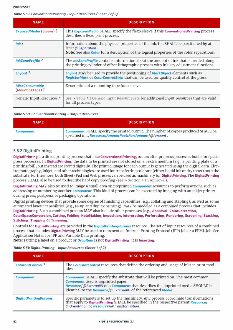
PRO CESSES
5.5.2 DigitalPrintingDigitalPrinting is a direct printing process that, like ConventionalPrinting, occurs after prepress processes but before post-press processes. In DigitalPrinting, the data to be printed are not stored on an extra medium (e.g., a printing plate or a printing foil), but instead are stored digitally. The printed image for each output is generated using the digital data. Elec-trophotography, inkjet, and other technologies are used for transferring colorant (either liquid ink or dry toner) onto the substrate. Furthermore, both Sheet-Fed and Web presses can be used as machinery for DigitalPrinting. The DigitalPrinting process SHALL also be used to describe hard copy proofing (see Section 5.3.1 Approval).
DigitalPrinting MAY also be used to image a small area on preprinted Component resources to perform actions such as addressing or numbering another Component. This kind of process can be executed by imaging with an inkjet printer during press, postpress or packaging operations.
Digital printing devices that provide some degree of finishing capabilities (e.g., collating and stapling), as well as some automated layout capabilities (e.g., N-up and duplex printing), MAY be modeled as a combined process that includes DigitalPrinting. Such a combined process MAY also include other processes (e.g., Approval, ColorCorrection, ColorSpaceConversion, Cutting, Folding, HoleMaking, Imposition, Interpreting, Perforating, Rendering, Screening, Stacking, Stitching, Trapping or Trimming).
Controls for DigitalPrinting are provided in the DigitalPrintingParams resource. The set of input resources of a combined process that includes DigitalPrinting MAY be used to represent an Internet Printing Protocol (IPP) Job or a PPML Job. See Application Notes for IPP and Variable Data printing.Note: Putting a label on a product or DropItem is not DigitalPrinting; it is Inserting.
ExposedMedia (Sleeve) ? This ExposedMedia SHALL specify the flexo sleeve if this ConventionalPrinting process describes a flexo print process.
Ink ? Information about the physical properties of the ink. Ink SHALL be partitioned by at least @Separation.Note: See also Color for a description of the logical properties of the color separations.
InkZoneProfile ? The InkZoneProfile contains information about the amount of ink that is needed along the printing cylinder of offset lithographic presses with ink key adjustment functions.
Layout ? Layout MAY be used to provide the positioning of MarkObject elements such as RegisterMark or ColorControlStrip that can be used for quality control at the press.
MiscConsumable (MountingTape) ?
Description of a mounting tape for a sleeve.
Generic Input Resources * See Table 5.1 Generic Input ResourceSets for additional input resources that are valid for all process types.
Table 5.60: ConventionalPrinting – Output Resources
NAME DESCRIPTION
Component Component SHALL specify the printed output. The number of copies produced SHALL be specified in ../Resource/AmountPool/PartAmount/@Amount .
Table 5.61: DigitalPrinting – Input Resources (Sheet 1 of 2)
NAME DESCRIPTION
ColorantControl ? The ColorantControl resources that define the ordering and usage of inks in print mod-ules.
Component Component SHALL specify the substrate that will be printed on. The most common Component used is unprinted paper.Resource/@ExternalID of a Component that describes the unprinted media SHOULD be identical to the Resource/@ExternalID of the referenced Media.
DigitalPrintingParams Specific parameters to set up the machinery. Any process coordinate transformations that apply to DigitalPrinting SHALL be specified in the respective parent Resource/@Orientation or Resource/@Transformation.
Table 5.59: ConventionalPrinting – Input Resources (Sheet 2 of 2)
NAME DESCRIPTION
82 XJDF SPECIFICATIO N 2.1

P OSTPRESS PROCESSES
5.5.3 VarnishingVarnishing is the process of varnishing a Component. Spot varnishing with a ripped image or a printing plate from ExposedMedia SHALL be described as DigitalPrinting or ConventionalPrinting with Ink/@InkType = "Varnish". All types of all-over (flood) varnishing or spot varnishing applied without a ripped image or a printing plate from ExposedMedia SHALL be described with the Varnishing process. Flood coatings are typically intended to be protective; they can increase water resistance, scuff resistance, and even food resistance in the case of restaurant menus.
Common coating types requested by customers include UV coatings (Ultra Violet cured polymers) which provide higher durability, and aqueous coatings that are viewed as greener and typically more easily recycled at end-of-life. Both types of overall coating protect the printed image as well as the substrate.
5.6 Postpress ProcessesPostpress is the most flexible and varied area that is covered by this specification. The individual postpress processes are provided in alphabetical order.
Ink ? Ink or toner and information that is needed for DigitalPrinting.
Layout ? Layout MAY be used to provide the positioning of MarkObject elements such as RegisterMark or ColorControlStrip that can be used for quality control at the press.
RunList Raster data that will be printed on the digital press are needed for DigitalPrinting.
Generic Input Resources * See Table 5.1 Generic Input ResourceSets for additional input resources that are valid for all process types.
Table 5.62: DigitalPrinting – Output Resources
NAME DESCRIPTION
Component Components are produced for other printing processes or postpress processes. ../Resource/AmountPool/PartAmount/@Amount SHALL specify the number of copies that SHALL be produced.If the input RunList specifies a PDL with multiple documents or sets, such as PDF/VT, the amount SHALL BE defined as the number of sets in the input RunList.
Table 5.63: Varnishing – Input Resources
NAME DESCRIPTION
Component The Component to be varnished.
ExposedMedia ? Various types of ExposedMedia MAY be specified for varnishing. See VarnishingParams/@VarnishMethod for details.
Ink ? Details of the colorant that is used for Varnishing. Ink/@InkType SHOULD be "Varnish".
VarnishingParams ? Details of the setup of the varnishing device. Any process coordinate transformations that apply to Varnishing SHALL be specified in the respective parent Resource/@Orientation or Resource/@Transformation.
Generic Input Resources * See Table 5.1 Generic Input ResourceSets for additional input resources that are valid for all process types.
Table 5.64: Varnishing – Output Resources
NAME DESCRIPTION
Component The varnished Component.
Table 5.61: DigitalPrinting – Input Resources (Sheet 2 of 2)
NAME DESCRIPTION
XJDF SPECIFICATIO N 2.1 83

PRO CESSES
5.6.1 BlockPreparationAs there are many options for a hardcover book, the block preparation is more complex than what has already been de-scribed for other types of binding. Those options are the ribbon band (numbers of bands, materials and colors), gauze (material and glue), head band (material and colors), kraft paper (material and glue) and tightbacking (different geom-etry and measurements).
5.6.2 BoxFoldingBoxFolding defines the process of folding and gluing blanks into folded flat boxes for packaging.
5.6.3 BoxPackingA pile, stack or bundle of products can be packed into a box or carton.
Table 5.65: BlockPreparation – Input Resources
NAME DESCRIPTION
Component The BlockPreparation process consumes one Component and creates a book block.
BlockPreparationParams Specific parameters to set up the machinery. Any process coordinate transformations that apply to BlockPreparation SHALL be specified in the respective parent Resource/@Orientation or Resource/@Transformation.
MiscConsumable (RegisterRibbon) ?
Description of the register ribbons. If present, processing instructions such as ribbon lengths should be specified in BlockPreparationParams/RegisterRibbon.
Generic Input Resources * See Table 5.1 Generic Input ResourceSets for additional input resources that are valid for all process types.
Table 5.66: BlockPreparation – Output Resources
NAME DESCRIPTION
Component One Component is produced: the prepared book block. The value of Component/@ProductType SHALL be "BookBlock".
Table 5.67: BoxFolding – Input Resources
NAME DESCRIPTION
BoxFoldingParams Specific parameters to set up the folder gluer.
Component The BoxFolding process consumes one Component, the folding blank. Its @ProductType = "BlankBox".
Generic Input Resources * See Table 5.1 Generic Input ResourceSets for additional input resources that are valid for all process types.
Table 5.68: BoxFolding – Output Resources
NAME DESCRIPTION
Component One Component is produced: the folded flat box. The value of Component/@ProductType SHALL be "FlatBox".
Table 5.69: BoxPacking – Input Resources (Sheet 1 of 2)
NAME DESCRIPTION
BoxPackingParams Specific parameters to set up the machinery.
Bundle ? Bundle describes the structure of the packed boxes that are represented by the output Component.
84 XJDF SPECIFICATIO N 2.1
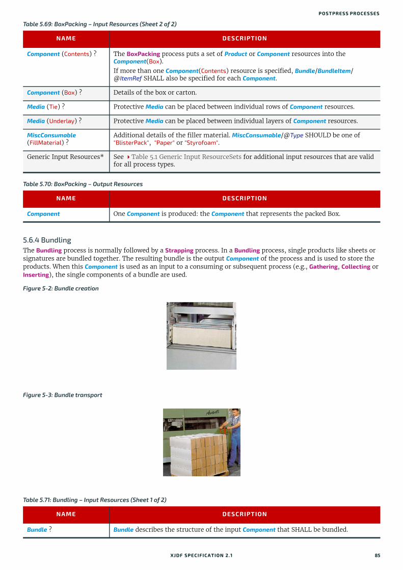
P OSTPRESS PROCESSES
5.6.4 BundlingThe Bundling process is normally followed by a Strapping process. In a Bundling process, single products like sheets or signatures are bundled together. The resulting bundle is the output Component of the process and is used to store the products. When this Component is used as an input to a consuming or subsequent process (e.g., Gathering, Collecting or Inserting), the single components of a bundle are used.
Component (Contents) ? The BoxPacking process puts a set of Product or Component resources into the Component(Box). If more than one Component(Contents) resource is specified, Bundle/BundleItem/@ItemRef SHALL also be specified for each Component.
Component (Box) ? Details of the box or carton.
Media (Tie) ? Protective Media can be placed between individual rows of Component resources.
Media (Underlay) ? Protective Media can be placed between individual layers of Component resources.
MiscConsumable (FillMaterial) ?
Additional details of the filler material. MiscConsumable/@Type SHOULD be one of "BlisterPack", "Paper" or "Styrofoam".
Generic Input Resources* See Table 5.1 Generic Input ResourceSets for additional input resources that are valid for all process types.
Table 5.70: BoxPacking – Output Resources
NAME DESCRIPTION
Component One Component is produced: the Component that represents the packed Box.
Figure 5-2: Bundle creation
Figure 5-3: Bundle transport
Table 5.71: Bundling – Input Resources (Sheet 1 of 2)
NAME DESCRIPTION
Bundle ? Bundle describes the structure of the input Component that SHALL be bundled.
Table 5.69: BoxPacking – Input Resources (Sheet 2 of 2)
NAME DESCRIPTION
XJDF SPECIFICATIO N 2.1 85
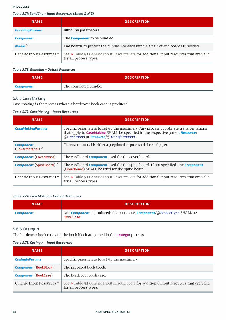
PRO CESSES
5.6.5 CaseMakingCase making is the process where a hardcover book case is produced.
5.6.6 CasingInThe hardcover book case and the book block are joined in the CasingIn process.
BundlingParams Bundling parameters.
Component The Component to be bundled.
Media ? End boards to protect the bundle. For each bundle a pair of end boards is needed.
Generic Input Resources * See Table 5.1 Generic Input ResourceSets for additional input resources that are valid for all process types.
Table 5.72: Bundling – Output Resources
NAME DESCRIPTION
Component The completed bundle.
Table 5.73: CaseMaking – Input Resources
NAME DESCRIPTION
CaseMakingParams Specific parameters to set up the machinery. Any process coordinate transformations that apply to CaseMaking SHALL be specified in the respective parent Resource/@Orientation or Resource/@Transformation.
Component (CoverMaterial) ?
The cover material is either a preprinted or processed sheet of paper.
Component (CoverBoard) The cardboard Component used for the cover board.
Component (SpineBoard) ? The cardboard Component used for the spine board. If not specified, the Component (CoverBoard) SHALL be used for the spine board.
Generic Input Resources * See Table 5.1 Generic Input ResourceSets for additional input resources that are valid for all process types.
Table 5.74: CaseMaking – Output Resources
NAME DESCRIPTION
Component One Component is produced: the book case. Component/@ProductType SHALL be "BookCase".
Table 5.75: CasingIn – Input Resources
NAME DESCRIPTION
CasingInParams Specific parameters to set up the machinery.
Component (BookBlock) The prepared book block.
Component (BookCase) The hardcover book case.
Generic Input Resources * See Table 5.1 Generic Input ResourceSets for additional input resources that are valid for all process types.
Table 5.71: Bundling – Input Resources (Sheet 2 of 2)
NAME DESCRIPTION
86 XJDF SPECIFICATIO N 2.1
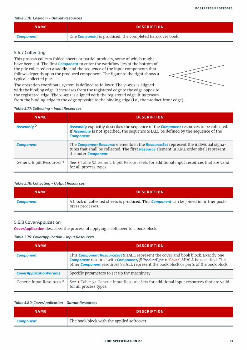
P OSTPRESS PROCESSES
5.6.7 CollectingThis process collects folded sheets or partial products, some of which might have been cut. The first Component to enter the workflow lies at the bottom of the pile collected on a saddle, and the sequence of the input components that follows depends upon the produced component. The figure to the right shows a typical collected pile.
The operation coordinate system is defined as follows: The y-axis is aligned with the binding edge. It increases from the registered edge to the edge opposite the registered edge. The x-axis is aligned with the registered edge. It increases from the binding edge to the edge opposite to the binding edge (i.e., the product front edge).
5.6.8 CoverApplicationCoverApplication describes the process of applying a softcover to a book block.
Table 5.76: CasingIn – Output Resources
NAME DESCRIPTION
Component One Component is produced: the completed hardcover book.
Table 5.77: Collecting – Input Resources
NAME DESCRIPTION
Assembly ? Assembly explicitly describes the sequence of the Component resources to be collected. If Assembly is not specified, the sequence SHALL be defined by the sequence of the Component.
Component The Component Resource elements in the ResourceSet represent the individual signa-tures that shall be collected. The first Resource element in XML order shall represent the outer Component.
Generic Input Resources * See Table 5.1 Generic Input ResourceSets for additional input resources that are valid for all process types.
Table 5.78: Collecting – Output Resources
NAME DESCRIPTION
Component A block of collected sheets is produced. This Component can be joined in further post-press processes.
Table 5.79: CoverApplication – Input Resources
NAME DESCRIPTION
Component This Component ResourceSet SHALL represent the cover and book block. Exactly one Component resource with Component/@ProductType = "Cover" SHALL be specified. The other Component resources SHALL represent the book block or parts of the book block.
CoverApplicationParams Specific parameters to set up the machinery.
Generic Input Resources * See Table 5.1 Generic Input ResourceSets for additional input resources that are valid for all process types.
Table 5.80: CoverApplication – Output Resources
NAME DESCRIPTION
Component The book block with the applied softcover.
XJDF SPECIFICATIO N 2.1 87

PRO CESSES
5.6.9 CreasingSheets are creased or grooved to enable folding or to create even, finished page delimiters.
5.6.10 CuttingSheets are cut using a guillotine Cutting machine.
Since Cutting is described here in the most machine independent manner, the specified CutBlock elements do not directly imply a particular cutting sequence. Instead, the device SHALL determine the sequence.
Cutting MAY also be used to describe cutting of a web into multiple ribbons on a web press. This process is commonly referred to as “Slitting”.
5.6.11 DieMaking This process describes the production of tools for a die cutter (e.g., in a die maker shop).
Table 5.81: Creasing – Input Resources
NAME DESCRIPTION
Component This process consumes one Component.
CreasingParams Details of the Creasing process. Any process coordinate transformations that apply to Creasing SHALL be specified in the respective parent Resource/@Orientation or Resource/@Transformation.
Generic Input Resources * See Table 5.1 Generic Input ResourceSets for additional input resources that are valid for all process types.
Table 5.82: Creasing – Output Resources
NAME DESCRIPTION
Component One creased Component is produced.
Table 5.83: Cutting – Input Resources
NAME DESCRIPTION
Component This process consumes one Component: the printed sheets.
CuttingParams Details of the Cutting process. Any process coordinate transformations that apply to Cutting SHALL be specified in the respective parent Resource/@Orientation or Resource/@Transformation.
Generic Input Resources * See Table 5.1 Generic Input ResourceSets for additional input resources that are valid for all process types.
Table 5.84: Cutting – Output Resources
NAME DESCRIPTION
Component One or several blocks of cut Component resources are produced. The output SHOULD be partitioned by @BlockName.
Table 5.85: DieMaking – Input Resources
NAME DESCRIPTION
DieLayout A resource describing the die cutter tool set.
Generic Input Resources* See Table 5.1 Generic Input ResourceSets for additional input resources that are valid for all process types.
88 XJDF SPECIFICATIO N 2.1

P OSTPRESS PROCESSES
5.6.12 EmbossingThe Embossing process is performed after printing to stamp a raised or depressed image (artwork or typography) into the surface of paper using engraved metal embossing dies, extreme pressure and heat. Embossing styles include blind, deboss and foil-embossed.
5.6.13 EndSheetGluingEndSheetGluing finalizes the book block in preparation for case binding by attaching end sheets to the book block. Back end sheets and front end sheets are in most cases sheets folded once before EndSheetGluing takes place. The end sheets serve as connections between the book block and the cover boards.
Table 5.86: DieMaking – Output Resources
NAME DESCRIPTION
Tool The set of tools for the die cutter. If the tool set contains multiple parts, e.g. an upper and a lower die, the Tool SHALL be partitioned by @Option and/or @Side.
Table 5.87: Embossing – Input Resources
NAME DESCRIPTION
Component This process consumes one Component that is embossed by the process.
EmbossingParams Parameters to set up the machinery. Any process coordinate transformations that apply to Embossing SHALL be specified in the respective parent Resource/@Orientation or Resource/@Transformation.
Media(Foil) ? Media(Foil) SHOULD be provided if an EmbossingParams/Emboss/@EmbossingType="FoilEmbossing" or "FoilStamping".
Tool ? The embossing stamps or calenders. If the tool set contains multiple parts, e.g. an upper and a lower stamp, the Tool SHALL be partitioned by @Option and/or @Side.
Generic Input Resources * See Table 5.1 Generic Input ResourceSets for additional input resources that are valid for all process types.
Table 5.88: Embossing – Output Resources
NAME DESCRIPTION
Component One Component is created.
Table 5.89: EndSheetGluing – Input Resources
NAME DESCRIPTION
Component A back end sheet and a front end sheet are glued onto the book block.
Component (BackEndSheet) ?
A back end sheet that SHALL be mounted on the book block. At least one of Component, Component (BackEndSheet) or Component (FrontEndSheet) SHALL be present.
Component (FrontEndSheet) ?
A front end sheet that SHALL be mounted on the book block. At least one of Component, Component (BackEndSheet) or Component (FrontEndSheet) SHALL be present.
EndSheetGluingParams Specific parameters to set up the machinery.
Generic Input Resources * See Table 5.1 Generic Input ResourceSets for additional input resources that are valid for all process types.
XJDF SPECIFICATIO N 2.1 89
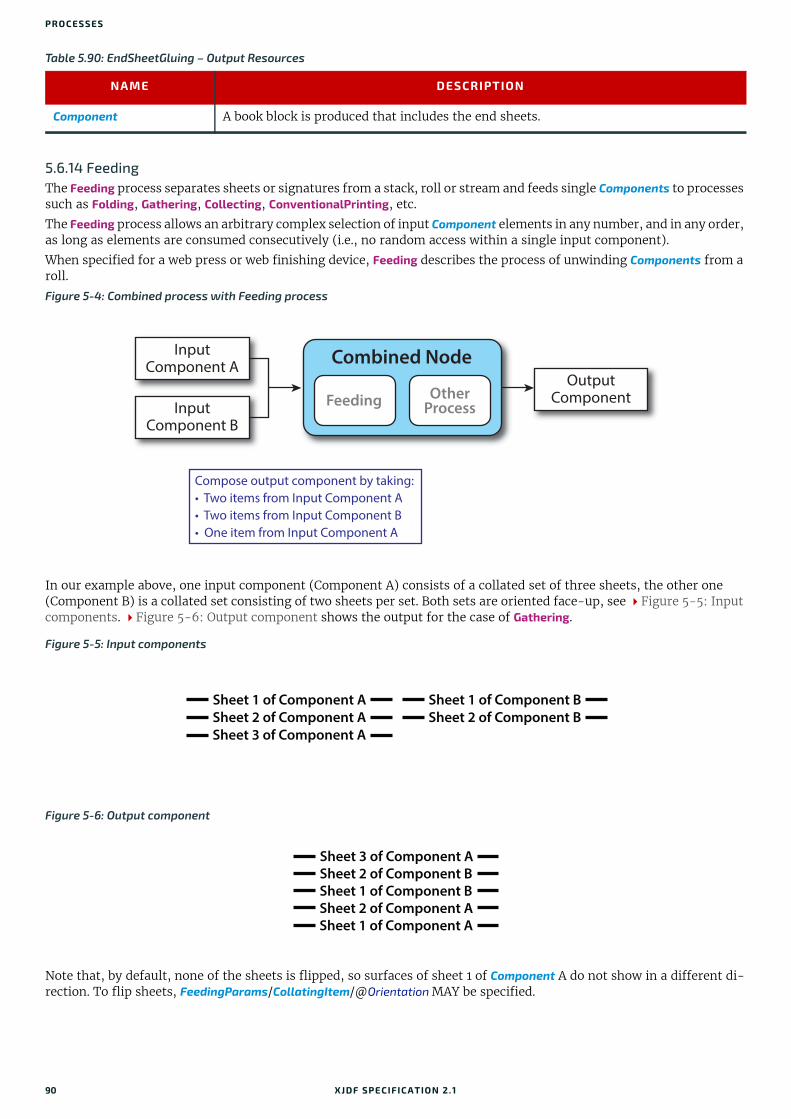
PRO CESSES
5.6.14 FeedingThe Feeding process separates sheets or signatures from a stack, roll or stream and feeds single Components to processes such as Folding, Gathering, Collecting, ConventionalPrinting, etc.
The Feeding process allows an arbitrary complex selection of input Component elements in any number, and in any order, as long as elements are consumed consecutively (i.e., no random access within a single input component).
When specified for a web press or web finishing device, Feeding describes the process of unwinding Components from a roll.
In our example above, one input component (Component A) consists of a collated set of three sheets, the other one (Component B) is a collated set consisting of two sheets per set. Both sets are oriented face-up, see Figure 5-5: Input components. Figure 5-6: Output component shows the output for the case of Gathering.
Note that, by default, none of the sheets is flipped, so surfaces of sheet 1 of Component A do not show in a different di-rection. To flip sheets, FeedingParams/CollatingItem/@Orientation MAY be specified.
Table 5.90: EndSheetGluing – Output Resources
NAME DESCRIPTION
Component A book block is produced that includes the end sheets.
Figure 5-4: Combined process with Feeding process
Figure 5-5: Input components
Figure 5-6: Output component
Combined Node
FeedingOther
Process
InputComponent A
InputComponent B
OutputComponent
Compose output component by taking:• Two items from Input Component A• Two items from Input Component B• One item from Input Component A
Sheet 1 of Component A
Sheet 2 of Component A
Sheet 3 of Component A
Sheet 1 of Component B
Sheet 2 of Component B
Sheet 3 of Component A
Sheet 2 of Component B
Sheet 1 of Component B
Sheet 2 of Component A
Sheet 1 of Component A
90 XJDF SPECIFICATIO N 2.1

P OSTPRESS PROCESSES
5.6.15 FoldingBuckle folders or knife folders are used for Folding sheets. One or more sheets can be folded at the same time. Web presses often provide in-line Folding equipment. Longitudinal Folding is often performed using a former, a plow folder or a belt. Jaw folding, chopper folding or drum folding equipment is used for folding the sheets that have been divided.
The XJDF Folding process covers both operations done in stand-alone Folding machinery—typically found when pro-cessing printed materials from sheet-fed presses—and in-line equipment of web presses. Creasing and/or slot perforating are sometimes necessary parts of the Folding operation that guarantee exact process execution. They depend on the fold-er used, the Media and the folding layout. These operations are specified in FoldingParams/Crease and FoldingParams/Perforate respectively.
5.6.16 GatheringIn the Gathering process, sheets or other Component resources are accumulated on a pile. Figure 5-7: Gathering shows typical gathered piles.
Table 5.91: Feeding – Input Resources
NAME DESCRIPTION
Component + Sheets or signatures to be fed to the machinery. ResourceSet/@ProcessUsage of a Component MAY be specified as any valid @ProcessUsage of the feed consuming process.
FeedingParams Specific parameters to set up the Feeding process.
Generic Input Resources * See Table 5.1 Generic Input ResourceSets for additional input resources that are valid for all process types.
Table 5.92: Feeding – Output Resources
NAME DESCRIPTION
Component + Component(s) fed to the consuming process.
Table 5.93: Folding – Input Resources
NAME DESCRIPTION
Component Component resources, including a printed sheet or a pile of sheets, are used in the Folding process.
FoldingParams Specific parameters to set up the machinery. Any process coordinate transformations that apply to Folding SHALL be specified in the respective parent Resource/@Orientation or Resource/@Transformation.
Generic Input Resources* See Table 5.1 Generic Input ResourceSets for additional input resources that are valid for all process types.
Table 5.94: Folding – Output Resources
NAME DESCRIPTION
Component The process produces a Component, which in most cases is a folded sheet.
Figure 5-7: Gathering
Loose sheets Folded signatures
XJDF SPECIFICATIO N 2.1 91

PRO CESSES
5.6.17 GluingGluing describes arbitrary methods of applying glue to a Component.
5.6.18 HeadBandApplicationHead bands are applied to the hardcover book block. In case different head bands are desired for top and bottom, MiscConsumable(Headband) SHOULD be partitioned with Part/@Option = "Top" and Part/@Option = "Bottom".
Table 5.95: Gathering – Input Resources
NAME DESCRIPTION
Assembly ? Explicitly describes the sequence of the Component resources to be gathered. If Assembly is not specified, the sequence is defined by the sequence of the Component.
Component The Component Resource elements in the ResourceSet represent the individual signatures that SHALL be gathered on a pile. The first Resource element in XML order SHALL represent the top Component.
Generic Input Resources * See Table 5.1 Generic Input ResourceSets for additional input resources that are valid for all process types.
Table 5.96: Gathering – Output Resources
NAME DESCRIPTION
Component Components gathered together (e.g., a pile of folded sheets).
Table 5.97: Gluing – Input Resources
NAME DESCRIPTION
Component This process consumes one Component: the printed sheets.
GluingParams Details of the Gluing process. Any process coordinate transformations that apply to Gluing SHALL be specified in the respective parent Resource/@Orientation or Resource/@Transformation.
Generic Input Resources* See Table 5.1 Generic Input ResourceSets for additional input resources that are valid for all process types.
Table 5.98: Gluing – Output Resources
NAME DESCRIPTION
Component One Component is produced, the input Component with glue applied to it.
Table 5.99: HeadBandApplication – Input Resources
NAME DESCRIPTION
Component The prepared book block.
HeadBandApplicationParams
Specific parameters to set up the machinery.
MiscConsumable (BackReinforcement) ?
Additional details such as color and brand of the back reinforcement MAY be specified in this MiscConsumable. If required, the strip material SHOULD be specified in MiscConsumable/@TypeDetails.
MiscConsumable (Headband) ?
Additional details such as color and brand of the head band MAY be specified in this MiscConsumable.
Generic Input Resources * See Table 5.1 Generic Input ResourceSets for additional input resources that are valid for all process types.
92 XJDF SPECIFICATIO N 2.1

P OSTPRESS PROCESSES
5.6.19 HoleMakingA variety of machines (e.g., those responsible for stamping and drilling) can perform the HoleMaking process.
HoleMaking MAY be used to describe line hole punching that generates a series of holes with identical distance (pitch) running parallel to the edge of a web, which is mainly used to transport paper through continuous-feed printers and finishing devices (form processing). The final product is typically a web with two lines of holes, one at each edge of the web. The distance between holes within each line of holes is identical (constant pitch). In case of line hole punching, HoleMakingParams/HolePattern/@Center applies to the initial hole and HoleMakingParams/HolePattern/@Extent applies to each hole individually.
Sometimes line hole punching is performed for multiple webs before dividing the web after the HoleMaking process.
The following figure shows the parameters for both cases.
Table 5.100: HeadBandApplication – Output Resources
NAME DESCRIPTION
Component One Component is produced: the hardcover block with head bands.
Figure 5-8: HolePattern parameters
Line Hole Punching Multiple Web Line Hole Punching
Table 5.101: HoleMaking – Input Resources
NAME DESCRIPTION
Component One Component (e.g., a printed sheet or a pile of sheets) is modified in the HoleMaking process.
HoleMakingParams Specific parameters, including hole diameter and positions, used to set up the machin-ery. Any process coordinate transformations that apply to HoleMaking SHALL be speci-fied in the respective parent Resource/@Orientation or Resource/@Transformation.
Generic Input Resources * See Table 5.1 Generic Input ResourceSets for additional input resources that are valid for all process types.
Table 5.102: HoleMaking – Output Resources
NAME DESCRIPTION
Component A Component with holes (e.g., a book block or a single sheet) is produced.
Front
X
Y
Center (Y)
Center (X)Center (X)
(Y,0)Pitch Dire
ctio
n of
Tra
vel
Extent (X)
Extent (Y)
Row 4Row 3Row 1 Row 2
XJDF SPECIFICATIO N 2.1 93

PRO CESSES
5.6.20 InsertingThis process can be performed at several stages in postpress. The process can be used to describe the labeling of prod-ucts, labeling of packages or the gluing-in of a Component (e.g., a card, sheet or CD-ROM). Two Component resources are required for the Inserting process: the “mother” Component and the “child” Component. Inserting multiple child com-ponents is specified as a combined process with multiple individual Inserting steps.
The process coordinate system is defined as follows: The Y-axis is aligned with the binding edge and increases from the registered edge to the edge opposite the registered edge. The X-axis, meanwhile, is aligned with the registered edge. It increases from the binding edge to the edge opposite the binding edge, which is the product front edge.
5.6.21 JacketingJacketing is the process where the book is wrapped by a jacket that needs to be folded twice. As long as the book is spec-ified and the jacket dimensions are known, there are just a few important details. If the jacketing device also creases the jacket, this can be described with a combined process of Jacketing and Creasing.
Figure 5-9: Parameters and coordinate system used for Inserting
Table 5.103: Inserting – Input Resources
NAME DESCRIPTION
Component Designates where to insert the child Component.
Component (Child) The Component that SHALL be inserted in the mother Component. Any coordinate trans-formations that apply to the child Component SHALL be specified in the respective par-ent Resource/@Orientation or Resource/@Transformation.
InsertingParams Specific parameters (e.g., placement) to set up the machinery.
Generic Input Resources * See Table 5.1 Generic Input ResourceSets for additional input resources that are valid for all process types.
Table 5.104: Inserting – Output Resources
NAME DESCRIPTION
Component A mother Component is produced containing the inserted child Component.
Glue line segment
Glue line gapY
X
Start Positionof glue line
Origin of “Mother”-
Component coordinate
system
“Mother”- Component
“Child” Component(The rotation of the Child Component isdefined by Resource/@Transformation)
Sheet Offset
94 XJDF SPECIFICATIO N 2.1

P OSTPRESS PROCESSES
5.6.22 LabelingA label can be attached to a Component. The label can contain information on the addressee, the product, the product quantities, etc., which can be different for each Component.
5.6.23 LaminatingIn the Laminating process, a plastic film is bonded to one or both sides of a Component resource’s media, and adhered under pressure with either a thermal setting or pressure sensitive adhesive.
Table 5.105: Jacketing – Input Resources
NAME DESCRIPTION
Component (Book) The book that the jacket is wrapped around.
Component (Jacket) The description of the jacket.
JacketingParams Specific parameters to set up the machinery.
Generic Input Resources * See Table 5.1 Generic Input ResourceSets for additional input resources that are valid for all process types.
Table 5.106: Jacketing – Output Resources
NAME DESCRIPTION
Component The jacketed book.
Table 5.107: Labeling – Input Resources
NAME DESCRIPTION
Bundle ? Bundle describes the structure of the input Component that SHALL be labeled.
Component The Labeling process labels one Component with a set of labels.
Component (Label) ? The label to be attached to the Component.
LabelingParams Specific parameters to set up the machinery.
Generic Input Resources * See Table 5.1 Generic Input ResourceSets for additional input resources that are valid for all process types.
Table 5.108: Labeling – Output Resources
NAME DESCRIPTION
Component One Component is produced: the labeled Component.
Table 5.109: Laminating – Input Resources (Sheet 1 of 2)
NAME DESCRIPTION
Component A Component SHALL be specified for Laminating.
LaminatingParams Specific parameters to set up the machinery. Any process coordinate transformations that apply to Laminating SHALL be specified in the respective parent Resource/@Orientation or Resource/@Transformation.
Media (Foil) ? The laminating foil material.
MiscConsumable (Glue) Details of the dispersion glue used if LaminatingParams/@LaminatingMethod="DispersionGlue".
XJDF SPECIFICATIO N 2.1 95

PRO CESSES
5.6.24 LooseBindingLooseBinding describes a binding (as for a notebook, catalog, price list) holding pages together by spiral wire, plastic combs, metal clamps, rings or metal rods.
5.6.24.1 Loose-Leaf Binding MethodsThis binding techniques allow contents to be changed, inserted or removed at will. There are two essential groups of loose-leaf binding systems: those that require the paper to be punched or drilled and those that do not. The ring binding method is the most prominent binding in the loose-leaf binding category. Loose-leaf binding methods include:
• Ring binding.In this process, pre-punched sheets are placed in a ring binder. Ring binders have different numbers of rings that are fixed to a metal backbone. In most cases, two, three or four metal rings hold the sheets together as long as the binding is closed. Depending on the amount of sheets to be bound together, ring binders of different thickness are be used. Additional details MAY be specified in LooseBindingParams/RingBindingDetails.
• Mechanical binding methods.Single leafs are fastened into what is essentially a permanent system that is not meant to be reopened. However, special machinery can be used to reopen some of the mechanical binding systems described below.In mechanical binding, printing and folding can be done in a conventional manner. The gathered sheets, however, often require the back to be trimmed, as well as the other three sides. Mechanical bindings are often used for short-run jobs such as ones that have been printed digitally. Mechanical binding methods include:
• Channel binding.Various sizes of metal clamps can be used. The process can be executed in two ways. In the first, a pile of single sheets—sometimes together with a front and back cover—is inserted into a U-shaped clamp and crimped in special machinery. In the second, a pre-assembled cover that includes the open U-shaped clamp is used instead of the U-shaped clamp alone. The thickness of the pile of sheets determines in both cases the width of the U-shaped clamp to be used for forming the fixed document, which is not meant to be reopened later.Additional details MAY be specified in LooseBindingParams/ChannelBindingDetails.
• Coil binding.Another name is spiral binding. Metal wire, wire with plastic or pure plastic is used to fasten pre-punched sheets of paper, cardboard or other materials. First, automated machinery forms a spiral of proper diameter and length. The ends of the spiral are then “tucked-in”. Finally, the content is permanently fixed.Additional details MAY be specified in LooseBindingParams/CoilBindingDetails.
• Comb binding.In this method, a metal wire, wire with plastic or pure plastic insert wraps through pre-punched holes in the substrate. In case of plastic combs, these holes are most often rectangular and elongated. After the comb is opened with a special tool, the pre-punched block of sheets—often together with a top and bottom cover—is inserted onto the “teeth” of the comb.Additional details MAY be specified in LooseBindingParams/CombBindingDetails.
• Strip binding.Hard plastic strips are held together by plastic pins, which in turn are bound to the strips with heat. The sheets to be bound are pre-punched so that the top strip with multiple pins fits through the assembled material. The top strip is then connected to the bottom strip with matching holes for the pins. The binding edge is often compressed in a special machine before the excess pin length is cut off. The backstrip is permanently fixed with plastic clamping bars and cannot be removed without a special tool.Additional details MAY be specified in LooseBindingParams/StripBindingDetails.
MiscConsumable (Hardener)
Details of the dispersion glue hardener used if LaminatingParams/@LaminatingMethod="DispersionGlue".
Generic Input Resources * See Table 5.1 Generic Input ResourceSets for additional input resources that are valid for all process types.
Table 5.110: Laminating – Output Resources
NAME DESCRIPTION
Component One Component is produced: the laminated component.
Table 5.109: Laminating – Input Resources (Sheet 2 of 2)
NAME DESCRIPTION
96 XJDF SPECIFICATIO N 2.1

P OSTPRESS PROCESSES
5.6.25 PalletizingBundles, stacks, piles or boxes can be loaded onto a pallet.
Table 5.111: LooseBinding – Input Resources
NAME DESCRIPTION
Component This Component ResourceSet SHALL represent sheets to be bound. At most one Component resource with Component/@ProductType = "Cover" SHALL be specified. The other Component resources SHALL represent the sheets to be bound.
LooseBindingParams Specific parameters to set up the machinery. Any process coordinate transformations that apply to LooseBinding SHALL be specified in the respective parent Resource/@Orientation or Resource/@Transformation.
MiscConsumable (Cover) ? Details such as brand and color of the cover. If the binding mechanism is separate from the cover, the binding mechanism SHALL be specified in MiscConsumable (Spine).The cover is dependent on the binding type. For ring binding, where @BindingType="RingBinding", the value of MiscConsumable/@Type SHOULD be "RingBinder". For all other types of binding any non-printed cover, e.g. a transparent plastic sheet, the value of MiscConsumable/@Type SHOULD be "Cover".
MiscConsumable (Spine) ? Details such as brand and color of the spine. The spine is dependent on the binding type:ChannelBinding: The clamp/cover. The value of MiscConsumable/@Type SHOULD be "ChannelBinder".CoilBinding: The coil. The value of MiscConsumable/@Type SHOULD be "Coil".CombBinding: The comb. The value of MiscConsumable/@Type SHOULD be "Comb".StripBinding: The strip. The value of MiscConsumable/@Type SHOULD be "StripBinder".
Generic Input Resources * See Table 5.1 Generic Input ResourceSets for additional input resources that are valid for all process types.
Table 5.112: LooseBinding – Output Resources
NAME DESCRIPTION
Component One Component is produced: the bound item such as a brochure.
Table 5.113: Palletizing – Input Resources
NAME DESCRIPTION
Bundle ? Bundle describes the structure of the loaded pallets that are represented by the output Component.
Component ? The Palletizing process puts the set of Product or Component resources onto the pallet. If more than one Component resource is specified, Bundle/BundleItem/@ItemRef SHALL also be specified for each Component.
Pallet The pallet.
PalletizingParams Specific parameters to set up the machinery.
Generic Input Resources * See Table 5.1 Generic Input ResourceSets for additional input resources that are valid for all process types.
Table 5.114: Palletizing – Output Resources
NAME DESCRIPTION
Component One Component is produced. It represents the loaded pallet.
XJDF SPECIFICATIO N 2.1 97

PRO CESSES
5.6.26 PerforatingPerforating describes any process where a Component is perforated.
5.6.27 ShapeCuttingThe ShapeCutting process can be performed using tools such as hollow form punching, perforating or die-cutting equip-ment.
5.6.28 ShrinkingThe Shrinking process shrinks the shrink-wrap that is wrapped around a bundle. Shrink-wrap foil SHALL be treated in order to shrink.Note: Shrinking does NOT include the wrapping of the Component with foil. The actual wrapping is described by the Wrapping process. See Section 5.6.39 Wrapping.
Table 5.115: Perforating – Input Resources
NAME DESCRIPTION
Component This process consumes one Component: the printed sheets.
PerforatingParams Details of the Perforating process. Any process coordinate transformations that apply to Perforating SHALL be specified in the respective parent Resource/@Orientation or Resource/@Transformation.
Generic Input Resources * See Table 5.1 Generic Input ResourceSets for additional input resources that are valid for all process types.
Table 5.116: Perforating – Output Resources
NAME DESCRIPTION
Component One Component is produced.
Table 5.117: ShapeCutting – Input Resources
NAME DESCRIPTION
Component This process consumes one Component that are the sheets to be cut.
ShapeCuttingParams Details of the ShapeCutting process. Any process coordinate transformations that apply to ShapeCutting SHALL be specified in the respective parent Resource/@Orientation or Resource/@Transformation.
Tool ? The set of tools (die, counter, blankers, strippers, etc.). If the tool set contains multiple parts, e.g. an upper and a lower die, the Tool SHALL be partitioned by @Option and/or @Side.
Generic Input Resources * See Table 5.1 Generic Input ResourceSets for additional input resources that are valid for all process types.
Table 5.118: ShapeCutting – Output Resources
NAME DESCRIPTION
Component The Component SHOULD be partitioned by @StationName.
Table 5.119: Shrinking – Input Resources (Sheet 1 of 2)
NAME DESCRIPTION
Bundle ? Bundle describes the structure of the input Component that SHALL be treated.
Component The Bundle including the shrink-wrap media is represented by this Component.
98 XJDF SPECIFICATIO N 2.1

P OSTPRESS PROCESSES
5.6.29 SpinePreparationThe SpinePreparation process describes the preparation of the spine of book blocks for hard and softcover book produc-tion (e.g., milling and notching).
5.6.30 SpineTapingSpineTaping describes the process of applying a tape strip to the spine of a book block. It also describes the process of applying kraft paper to a hardcover book block.
ShrinkingParams Specific parameters to set up the machinery.
Generic Input Resources * See Table 5.1 Generic Input ResourceSets for additional input resources that are valid for all process types.
Table 5.120: Shrinking – Output Resources
NAME DESCRIPTION
Component One Component is produced: the bundle including the shrunk shrink-wrap media.
Table 5.121: SpinePreparation – Input Resources
NAME DESCRIPTION
Component The raw book block.
SpinePreparationParams Specific parameters to set up the machinery. Any process coordinate transformations that apply to SpinePreparation SHALL be specified in the respective parent Resource/@Orientation or Resource/@Transformation.
Generic Input Resources * See Table 5.1 Generic Input ResourceSets for additional input resources that are valid for all process types.
Table 5.122: SpinePreparation – Output Resources
NAME DESCRIPTION
Component The book block with a processed spine.
Table 5.123: SpineTaping – Input Resources
NAME DESCRIPTION
Component The book block that the spine is taped to.
MiscConsumable (Tape) ? Details such as brand and color of the tape.
SpineTapingParams Specific parameters to set up the machinery. Any process coordinate transformations that apply to SpineTaping SHALL be specified in the respective parent Resource/@Orientation or Resource/@Transformation.
Generic Input Resources * See Table 5.1 Generic Input ResourceSets for additional input resources that are valid for all process types.
Table 5.124: SpineTaping – Output Resources
NAME DESCRIPTION
Component The book block with the spine.
Table 5.119: Shrinking – Input Resources (Sheet 2 of 2)
NAME DESCRIPTION
XJDF SPECIFICATIO N 2.1 99

PRO CESSES
5.6.31 StackingThe Stacking process collects Components and produces a pile, stack or bundle for delivery. In a standard production each bundle consists of the same amount of identical products, possibly followed by one or more odd-count bundles. In a pro-duction with variable data (e.g., newspaper dispatch, demographic production or individual addressed products), each bundle has a variable amount of products, and, in the worst case, each product can be different from the others. The input components are single products; the output components are stacks of this product.
A stack of components might be uneven and unstable, due to variations in thickness across each component. The thick-ness variations might be caused by folding, binding or inserted components. A stack might be split into layers, with suc-cessive layers rotated by 180o to compensate for the unevenness (Figure 5-10: Stacking layers).
If the thickest part is on an edge (e.g., a book binding), the components might be offset to separate the thick parts. Layer compensation and offsetting can be combined as in the following examples of pile patterns.
Figure 5-10: Stacking layers
Table 5.125: Parameters in Stackinga
PILE PATTERN
STANDARD AMOUNT LAYER AMOUNT COMPENSATE DISJOINTING
OFFSET
6 6 true 0 0
6 1 true 0 0
6 1 false x 0
6 1 true x 0
Stack/Pile/Bundle of StandardAmount components
Layer of LayerAmount components
100 XJDF SPECIFICATIO N 2.1

P OSTPRESS PROCESSES
If the number of components is not evenly divisible by StackingParams/@StandardAmount or the number of components in a bundle is not evenly divisible by StackingParams/@LayerAmount, there will be a remainder, yielding one or more odd-count stacks or layers. By default, the odd-count stack or layer size can contain as few as one component. This might exceed equipment cycle times, and flimsy components (newspapers) might cause problems with downstream equipment, such as strappers. StackingParams/@MinAmount and StackingParams/@MaxAmount control the minimum and maximum size of odd-count stacks and layers. The following figures show the odd count handling for bundles and layers.
6 3 true 0 0
6 3 false x 0
6 3 true x 0
a. Column headings ‘STANDARD AMOUNT’, ‘LAYER AMOUNT’, ‘COMPENSATE’ and ‘DISJOINTING OFFSET’ refer to the values in StackingParams/@StandardAmount, StackingParams/@LayerAmount, StackingParams/@Compensate and StackingParams/Disjointing/@Offset respectively.
Figure 5-11: Odd count handling for a bundle
Table 5.125: Parameters in Stackinga
PILE PATTERN
STANDARD AMOUNT LAYER AMOUNT COMPENSATE DISJOINTING
OFFSET
StandardAmountOdd count
MinAmount
MaxAmount
StandardAmount
Add odd count to first or last
bundle
Add odd count to last bundle. Then
split into 2 odd bundles of nearly
the same size
Create odd-count bundle
XJDF SPECIFICATIO N 2.1 101

PRO CESSES
5.6.32 StitchingGathered or collected sheets or signatures are stitched together with a cover. This process can be used to describe corner stitching, side stitching or saddle stitching.
Figure 5-12: Odd count handling for a layerif
Table 5.126: Stacking – Input Resources
NAME DESCRIPTION
Bundle ? Bundle describes the structure of the stacks that are represented by the output Component.
Component The Stacking process consumes one Component and stacks it onto a stack.
StackingParams Specific parameters to set up the machinery. Any process coordinate transformations that apply to Stacking SHALL be specified in the respective parent Resource/@Orientation or Resource/@Transformation.
Generic Input Resources * See Table 5.1 Generic Input ResourceSets for additional input resources that are valid for all process types.
Table 5.127: Stacking – Output Resources
NAME DESCRIPTION
Component One Component is produced: the stack of input components.
Table 5.128: Stitching – Input Resources
NAME DESCRIPTION
Component A Component SHALL be specified that represents the pile of gathered or collected sheets, including the cover.
MiscConsumable (Wire) ? Details such as brand and color of the stitching wire.
StitchingParams Specific parameters to set up the machinery. Any process coordinate transformations that apply to Stitching SHALL be specified in the respective parent Resource/@Orientation or Resource/@Transformation.
Generic Input Resources * See Table 5.1 Generic Input ResourceSets for additional input resources that are valid for all process types.
Table 5.129: Stitching – Output Resources
NAME DESCRIPTION
Component One Component is produced: the gathered or collected sheets including the cover stitched together.
Odd count
MinAmount
LayerAmount
Add odd count to last layer Create odd-count layer
102 XJDF SPECIFICATIO N 2.1
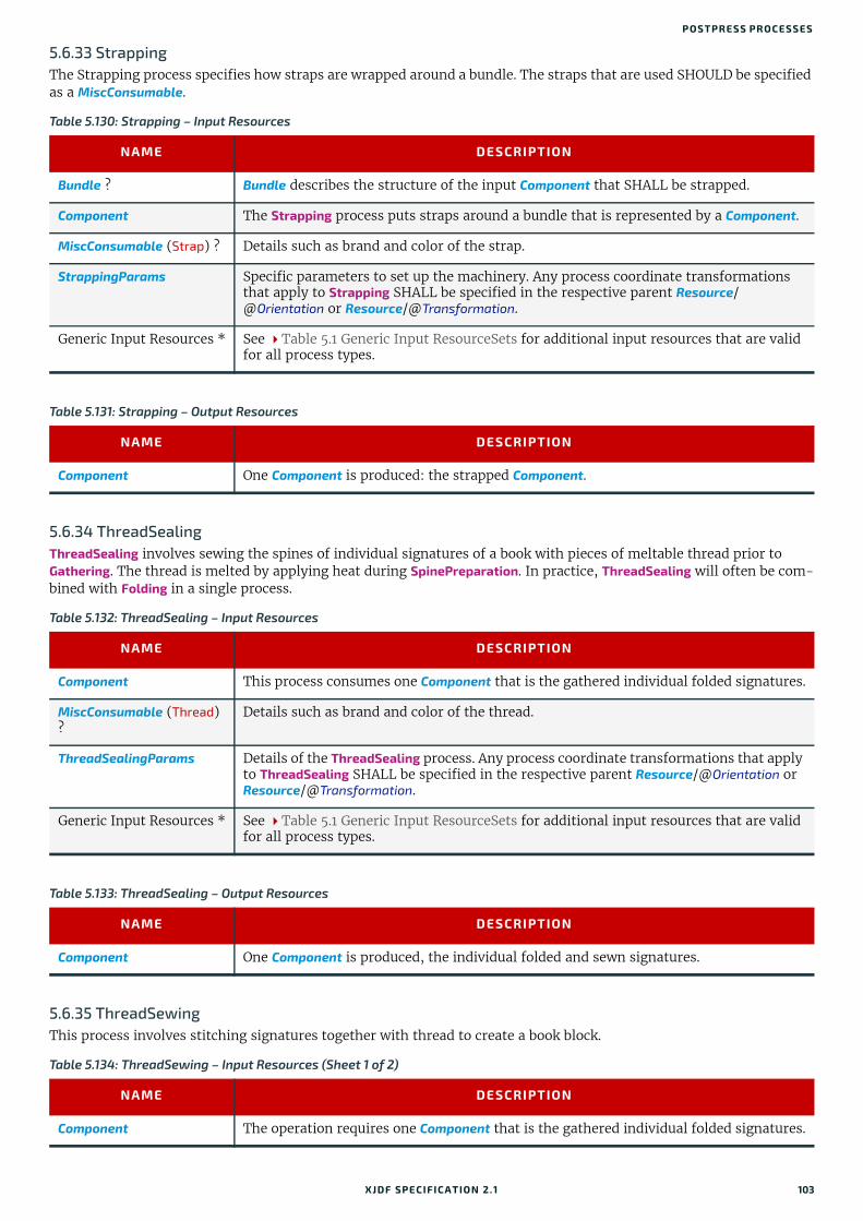
P OSTPRESS PROCESSES
5.6.33 StrappingThe Strapping process specifies how straps are wrapped around a bundle. The straps that are used SHOULD be specified as a MiscConsumable.
5.6.34 ThreadSealingThreadSealing involves sewing the spines of individual signatures of a book with pieces of meltable thread prior to Gathering. The thread is melted by applying heat during SpinePreparation. In practice, ThreadSealing will often be com-bined with Folding in a single process.
5.6.35 ThreadSewingThis process involves stitching signatures together with thread to create a book block.
Table 5.130: Strapping – Input Resources
NAME DESCRIPTION
Bundle ? Bundle describes the structure of the input Component that SHALL be strapped.
Component The Strapping process puts straps around a bundle that is represented by a Component.
MiscConsumable (Strap) ? Details such as brand and color of the strap.
StrappingParams Specific parameters to set up the machinery. Any process coordinate transformations that apply to Strapping SHALL be specified in the respective parent Resource/@Orientation or Resource/@Transformation.
Generic Input Resources * See Table 5.1 Generic Input ResourceSets for additional input resources that are valid for all process types.
Table 5.131: Strapping – Output Resources
NAME DESCRIPTION
Component One Component is produced: the strapped Component.
Table 5.132: ThreadSealing – Input Resources
NAME DESCRIPTION
Component This process consumes one Component that is the gathered individual folded signatures.
MiscConsumable (Thread) ?
Details such as brand and color of the thread.
ThreadSealingParams Details of the ThreadSealing process. Any process coordinate transformations that apply to ThreadSealing SHALL be specified in the respective parent Resource/@Orientation or Resource/@Transformation.
Generic Input Resources * See Table 5.1 Generic Input ResourceSets for additional input resources that are valid for all process types.
Table 5.133: ThreadSealing – Output Resources
NAME DESCRIPTION
Component One Component is produced, the individual folded and sewn signatures.
Table 5.134: ThreadSewing – Input Resources (Sheet 1 of 2)
NAME DESCRIPTION
Component The operation requires one Component that is the gathered individual folded signatures.
XJDF SPECIFICATIO N 2.1 103

PRO CESSES
5.6.36 TrimmingThe Trimming process is performed to adjust a book block or sheet to its final size. In most cases, it follows a block joining process, and the process is often executed as an in-line operation of a production chain. For example, the binding station might deliver the book blocks to the trimmer. A combined process in the trimming machinery would then execute a cut at the front, head and tail in a cycle of two operations. Closed edges of folded signatures would then be opened while the book block is trimmed to its predetermined dimensions.
The separation of N-up multiple products is specified with a Cutting process prior to a Trimming process.
The process coordinate system is defined as follows:
• The X-axis SHALL be aligned with the registered side. It increases from the binding side to the face side.
• The Y-axis SHALL be aligned with the binding side. It increases from the registered edge.
MiscConsumable (Thread) ?
Details such as brand and color of the thread.
ThreadSewingParams Specific parameters to set up the machinery. Any process coordinate transformations that apply to ThreadSewing SHALL be specified in the respective parent Resource/@Orientation or Resource/@Transformation.
Generic Input Resources * See Table 5.1 Generic Input ResourceSets for additional input resources that are valid for all process types.
Table 5.135: ThreadSewing – Output Resources
NAME DESCRIPTION
Component One Component is produced: the thread-sewn components forming an item such as a raw book block.
Figure 5-13: Parameters and coordinate system used for trimming
Table 5.134: ThreadSewing – Input Resources (Sheet 2 of 2)
NAME DESCRIPTION
Y
X
Block before trimming
Trimmedblock
Spine side
Registered side
Face side
Origin of operation
coordinate system
TrimmingOffset
Width
Height
104 XJDF SPECIFICATIO N 2.1

P OSTPRESS PROCESSES
5.6.37 WebInlineFinishingThe WebInlineFinishing process combines all additional information about inline finishing functionality in connection with Web printing. In order to describe the WebInlineFinishing functionality fully, it is necessary to combine additional processes, such as Stitching, Trimming, Gluing, etc.
5.6.38 WindingThe Winding process describes the winding of continuous media or processed components onto a core or roll stand. The setup is defined in WindingParams. The final orientation of the labels or components on the output roll is specified in Component/@WindingResult.
Table 5.136: Trimming – Input Resources
NAME DESCRIPTION
Component The bound book block or sheet that will be trimmed.
TrimmingParams Specific parameters (e.g., trim size) to set up the machinery. Any process coordinate transformations that apply to Trimming SHALL be specified in the respective parent Resource/@Orientation or Resource/@Transformation.
Generic Input Resources * See Table 5.1 Generic Input ResourceSets for additional input resources that are valid for all process types.
Table 5.137: Trimming – Output Resources
NAME DESCRIPTION
Component One Component is produced: the trimmed component.
Table 5.138: WebInlineFinishing – Input Resources
NAME DESCRIPTION
Component Printed webs or ribbons, which will be processed by the WebInlineFinishing process.
Layout ? Defines how the surfaces of the bindery signatures of a single job or jobs are placed onto the web(s) or sheet(s).This information MAY be used for counting the amount of components produced.
WebInlineFinishingParams Additional parameters for production are described by WebInlineFinishingParams.
Generic Input Resources * See Table 5.1 Generic Input ResourceSets for additional input resources that are valid for all process types.
Table 5.139: WebInlineFinishing – Output Resources
NAME DESCRIPTION
Component Describes the finished printed Component out of web inline finishing equipment. This could be printed and/or folded sheets or rolls.With one production run, it is possible to produce more than one product per press run. Component MAY be partitioned by @Product.
Table 5.140: Winding – Input Resources (Sheet 1 of 2)
NAME DESCRIPTION
Component Ribbon or web to be wound.
Media (Core) ? Core that the input Component is wound around.
XJDF SPECIFICATIO N 2.1 105

PRO CESSES
5.6.39 WrappingSingle products, bundles or pallets can be wrapped using bags, bands or wrapping material.
WindingParams Setup parameters of the winding process. Any process coordinate transformations that apply to Winding SHALL be specified in the respective parent Resource/@Orientation or Resource/@Transformation.
Generic Input Resources* See Table 5.1 Generic Input ResourceSets for additional input resources that are valid for all process types.
Table 5.141: Winding – Output Resources
NAME DESCRIPTION
Component The roll including the core and the wound products. Component/@WindingResult SHALL be evaluated to determine the winding orientation.
Table 5.142: Wrapping – Input Resources
NAME DESCRIPTION
Bundle ? Bundle describes the structure of the input Component that SHALL be wrapped.
Component The Wrapping process wraps a bundle that is represented by a Component.
Component (Wrapper) ? If the wrapping material is preprinted, then Component (Wrapper) represents the wrap-ping material.
MiscConsumable (Wrapper) ?
Additional details of the wrapper material. Non-printed material SHOULD be repre-sented as MiscConsumable. MiscConsumable(Wrapper) SHALL NOT be present if Component (Wrapper) is provided. MiscConsumable/@Type SHOULD be one of "PaperBand", "PaperWrap", "PlasticBand", "RubberBand" or "ShrinkWrap".
WrappingParams Specific parameters to set up the machinery.
Generic Input Resources * See Table 5.1 Generic Input ResourceSets for additional input resources that are valid for all process types.
Table 5.143: Wrapping – Output Resources
NAME DESCRIPTION
Component One Component is produced: the wrapped Component.
Table 5.140: Winding – Input Resources (Sheet 2 of 2)
NAME DESCRIPTION
106 XJDF SPECIFICATIO N 2.1

6
6 ResourcesThis chapter provides the detailed definition of the Resource element followed by a list (in alphabetical order) of all spe-cific resource types.6.1 ResourceResource elements are child elements of a ResourceSet and describe the physical or logical entity in the partition context that is defined in Resource/Part. For instance a ResourceSet/@Name="ExposedMedia" can specify a set of printing plates and each child Resource element will describe an individual plate.
Table 6.1: Resource Element (Sheet 1 of 2)
NAME DATA TYPE DESCRIPTION
Brand ? string Brand or manufacturer of the Resource.
CommentURL ? URL URL to an external, human-readable description of the Resource.
DescriptiveName ? string Human-readable descriptive name of the Resource. It is strongly RECOM-MENDED to supply @DescriptiveName in Resource elements that describe physical entities for communication from applications to humans in order to reference the Resource.
Duration ? duration If @Duration is specified for ResourceSet/@Usage="Input", @Duration specifies the time duration during which the Resource will be or has been used.Note: @Duration in conjunction with @Start or @StartOffset can be used to schedule or track resources such as tools that are only required during part of the processing time as defined in NodeInfo.If @Duration is specified for ResourceSet/@Usage="Output", @Duration speci-fies the time that the Resource SHALL be or has been stored after it has been produced.Note: @Duration can be used to define resting periods, e.g. to allow press sheets to dry prior to further processing.Note: If @Duration is specified in descendents of ResourceInfo it SHALL spec-ify actual duration. In all other cases it SHALL specify a planned or requested duration.
Expires ?New in XJDF 2.1
dateTime Date and time beyond which the resource SHOULD NOT be used.
ExternalID ? NMTOKEN An identifier of the resource as defined in the MIS system. For instance item codes or article numbers or identifiers on semi-finished products. @ExternalID SHALL be used to uniquely identify resources and products for the purpose of inventory tracking.
GrossWeight ? float Gross weight of a single Resource, as counted in @Amount, in grams.
ID ? ID Unique XJDF internal identifier of a Resource.
Orientation ? enumeration Named orientation describing the orientation of a Resource relative to the ideal process coordinate that uses this Resource as input or output. If @Orientation is specified for an output Resource, the XJDF that processes the Resource SHALL manipulate the Resource in such a way as to reflect the transformation. The coordinate system of the Resource itself is not modified.At most one of @Orientation or @Transformation SHALL be specified.For details on coordinate systems, see Section 2.6 Coordinate Systems in XJDF.
Allowed value is from: Orientation.
ResourceWeight ? float Net weight of a single Resource, as counted in @Amount, in grams.
XJDF SPECIFICATIO N 2.1
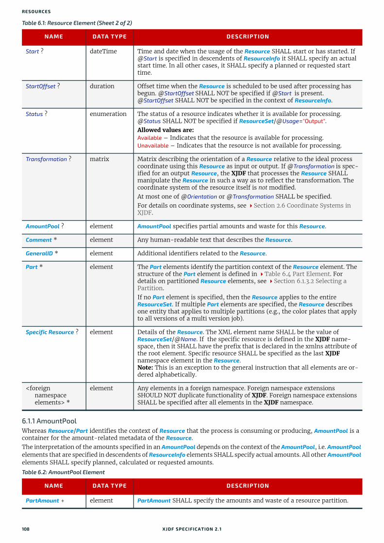
RESO URCES
6.1.1 AmountPoolWhereas Resource/Part identifies the context of Resource that the process is consuming or producing, AmountPool is a container for the amount-related metadata of the Resource.The interpretation of the amounts specified in an AmountPool depends on the context of the AmountPool, i.e. AmountPool elements that are specified in descendents of ResourceInfo elements SHALL specify actual amounts. All other AmountPool elements SHALL specify planned, calculated or requested amounts.
Start ? dateTime Time and date when the usage of the Resource SHALL start or has started. If @Start is specified in descendents of ResourceInfo it SHALL specify an actual start time. In all other cases, it SHALL specify a planned or requested start time.
StartOffset ? duration Offset time when the Resource is scheduled to be used after processing has begun. @StartOffset SHALL NOT be specified if @Start is present. @StartOffset SHALL NOT be specified in the context of ResourceInfo.
Status ? enumeration The status of a resource indicates whether it is available for processing. @Status SHALL NOT be specified if ResourceSet/@Usage="Output".Allowed values are:Available – Indicates that the resource is available for processing.Unavailable – Indicates that the resource is not available for processing.
Transformation ? matrix Matrix describing the orientation of a Resource relative to the ideal process coordinate using this Resource as input or output. If @Transformation is spec-ified for an output Resource, the XJDF that processes the Resource SHALL manipulate the Resource in such a way as to reflect the transformation. The coordinate system of the resource itself is not modified.At most one of @Orientation or @Transformation SHALL be specified.For details on coordinate systems, see Section 2.6 Coordinate Systems in XJDF.
AmountPool ? element AmountPool specifies partial amounts and waste for this Resource.
Comment * element Any human-readable text that describes the Resource.
GeneralID * element Additional identifiers related to the Resource.
Part * element The Part elements identify the partition context of the Resource element. The structure of the Part element is defined in Table 6.4 Part Element. For details on partitioned Resource elements, see Section 6.1.3.2 Selecting a Partition. If no Part element is specified, then the Resource applies to the entire ResourceSet. If multiple Part elements are specified, the Resource describes one entity that applies to multiple partitions (e.g., the color plates that apply to all versions of a multi version job).
Specific Resource ? element Details of the Resource. The XML element name SHALL be the value of ResourceSet/@Name. If the specific resource is defined in the XJDF name-space, then it SHALL have the prefix that is declared in the xmlns attribute of the root element. Specific resource SHALL be specified as the last XJDF namespace element in the Resource.Note: This is an exception to the general instruction that all elements are or-dered alphabetically.
<foreign namespace elements> *
element Any elements in a foreign namespace. Foreign namespace extensions SHOULD NOT duplicate functionality of XJDF. Foreign namespace extensions SHALL be specified after all elements in the XJDF namespace.
Table 6.2: AmountPool Element
NAME DATA TYPE DESCRIPTION
PartAmount + element PartAmount SHALL specify the amounts and waste of a resource partition.
Table 6.1: Resource Element (Sheet 2 of 2)
NAME DATA TYPE DESCRIPTION
108 XJDF SPECIFICATIO N 2.1

RESOURCE
6.1.2 PartAmountPartAmount provides a container for specifying amount related attributes.Note: Multiple PartAmount elements are used to specify partial completion of resources. For instance, specifying PartAmount/Part/@Side=”Front” for a Component would define the number of sheets that have been printed on the front side prior to printing the back side in a second press run.
6.1.2.1 Specifying Amount for a Partially-Completed ProcessA process can be interrupted before the requested amount of output has been produced. When the job is resent from the controller to the device, the controller SHALL specify only the remaining @Amount that the device SHALL produce in the resent job run.
6.1.3 PartPart elements define the context in which the individual Resource is used. Resource partitions are uniquely identified by the Resource/Part elements. If multiple Part elements are specified within one Resource, the Resource specifies one entity that applies to all parts.Note: The attributes of Part are also referred to as Partition Keys.
Table 6.3: PartAmount Element
NAME DATA TYPE DESCRIPTION
Amount ? float Amount, excluding waste, in units defined in ResourceSet/@Unit or implied by Table A.4.23 Units.
MaxAmount ? float Defines the planned @Amount including the maximum overage. @MaxAmount SHALL NOT be specified as actual amounts.
MinAmount ? float Defines the planned @Amount including the maximum underage that the customer is willing to accept. @MinAmount SHALL NOT be specified as actual amounts.
Waste ? float Waste amount in units defined in ResourceSet/@Unit or implied by Table A.4.23 Units. For a resource with a @Usage of "Input", @Waste specifies the amount of the resource that MAY be consumed or has been consumed by the process. For an resource with a @Usage of "Output", @Waste specifies the amount of the resource that MAY be produced by the process.
Part * element Part specifies the selected parts that the PartAmount is valid for. If the parent AmountPool is specified in a Resource element that also contains Part ele-ments, then these PartAmount/Part elements SHALL NOT include any Parti-tion Keys that are already uniquely specified in any parent Resource/Part element.If any of these Part elements specify the same Partition Key as the parent Resource/Part element, then the value of that key SHALL match one of the values from the parent Resource/Part.
PartWaste * element Particulars of different types and/or sources of waste MAY be specified by providing one or more PartWaste elements.
Table 6.4: Part Element
NAME DATA TYPE DESCRIPTION
BinderySignatureID ? NMTOKEN Master identifier of a BinderySignature.
BlockName ? NMTOKEN @BlockName SHALL identify a CutBlock from a Cutting process. The value of this attribute SHALL match the value of the @BlockName attribute of a CutBlock that produces this resource. @BlockName SHOULD be unique in the context of a job.Note: Part/@BlockName identifies partitions that have been created by cutting in a previous process. When used as an input resource to a Cutting process, CuttingParams/CutBlock/@BlockName identifies the partitions that are to be created.
ContactType ? NMTOKEN @ContactType specifies the role of a contact. @ContactType SHALL be pro-vided for ResourceSet[@Name=”Contact”].Values include those from: Contact Types.
XJDF SPECIFICATIO N 2.1 109
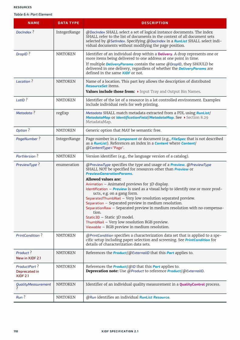
RESO URCES
DocIndex ? IntegerRange @DocIndex SHALL select a set of logical instance documents. The index SHALL refer to the list of documents in the context of all document sets selected by @SetIndex. Specifying @DocIndex in a RunList SHALL select indi-vidual documents without modifying the page position.
DropID ? NMTOKEN Identifier of an individual drop within a Delivery. A drop represents one or more items being delivered to one address at one point in time.If multiple DeliveryParams contain the same @DropID, they SHOULD be delivered in one delivery, regardless of whether the DeliveryParams are defined in the same XJDF or not.
Location ? NMTOKEN Name of a location. This part key allows the description of distributed ResourceSet items.Values include those from: Input Tray and Output Bin Names.
LotID ? NMTOKEN Identifier of the lot of a resource in a lot controlled environment. Examples include individual reels for web printing.
Metadata ? regExp Metadata SHALL match metadata extracted from a PDL using RunList/MetadataMap or IdentificationField/MetadataMap. See Section 8.29 MetadataMap.
Option ? NMTOKEN Generic option that MAY be semantic free.
PageNumber ? IntegerRange Page number in a Component or document (e.g., FileSpec that is not described as a RunList). References an index in a Content where Content/@ContentType="Page".
PartVersion ? NMTOKEN Version identifier (e.g., the language version of a catalog).
PreviewType ? enumeration @PreviewType specifies the type and usage of a Preview. @PreviewType SHALL NOT be specified for resources other than Preview or PreviewGenerationParams.Allowed values are:Animation – Animated previews for 3D display.Identification – Preview is used as a visual help to identify one or more prod-
ucts, e.g. on a gang form. SeparatedThumbNail – Very low resolution separated preview.Separation – Separated preview in medium resolution.SeparationRaw – Separated preview in medium resolution with no compensa-
tion. Static3D – Static 3D model.ThumbNail – Very low resolution RGB preview.Viewable – RGB preview in medium resolution.
PrintCondition ? NMTOKEN @PrintCondition specifies a characterization data set that is applied to a spe-cific setup including paper selection and screening. See PrintCondition for details of characterization data sets.
Product ?New in XJDF 2.1
NMTOKEN References the Product/@ExternalID that this Part applies to.
ProductPart ?Deprecated in XJDF 2.1
NMTOKEN References the Product/@ID that this Part applies to.Deprecation note: Use @Product to reference Product/@ExternalID.
QualityMeasurement ?
NMTOKEN Identifier of an individual quality measurement in a QualityControl process.
Run ? NMTOKEN @Run identifies an individual RunList Resource.
Table 6.4: Part Element
NAME DATA TYPE DESCRIPTION
110 XJDF SPECIFICATIO N 2.1
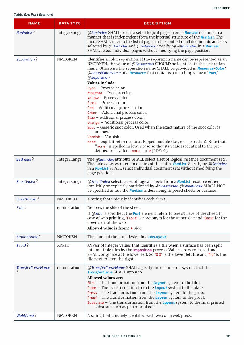
RESOURCE
RunIndex ? IntegerRange @RunIndex SHALL select a set of logical pages from a RunList resource in a manner that is independent from the internal structure of the RunList. The index SHALL refer to the list of pages in the context of all documents and sets selected by @DocIndex and @SetIndex. Specifying @RunIndex in a RunList SHALL select individual pages without modifying the page position.
Separation ? NMTOKEN Identifies a color separation. If the separation name can be represented as an NMTOKEN, the value of @Separation SHOULD be identical to the separation name. Otherwise the separation name SHALL be provided in Resource/Color/@ActualColorName of a Resource that contains a matching value of Part/@Separation. Values include:Cyan – Process color.Magenta – Process color.Yellow – Process color.Black – Process color.Red – Additional process color.Green – Additional process color.Blue – Additional process color.Orange – Additional process color.Spot – Generic spot color. Used when the exact nature of the spot color is
unknown.Varnish – Varnish.none – explicit reference to a skipped module (i.e., no separation). Note that
"none" is spelled in lower case so that its value is identical to the pre-defined separation "none" in [PDF1.6].
SetIndex ? IntegerRange The @SetIndex attribute SHALL select a set of logical instance document sets. The index always refers to entries of the entire RunList. Specifying @SetIndex in a RunList SHALL select individual document sets without modifying the page position.
SheetIndex ? IntegerRange @SheetIndex selects a set of logical sheets from a RunList resource either implicitly or explicitly partitioned by @SheetIndex. @SheetIndex SHALL NOT be specified unless the RunList is describing imposed sheets or surfaces.
SheetName ? NMTOKEN A string that uniquely identifies each sheet.
Side ? enumeration Denotes the side of the sheet. If @Side is specified, the Part element refers to one surface of the sheet. In case of web printing, "Front" is a synonym for the upper side and "Back" for the down side of the web.Allowed value is from: Side.
StationName? NMTOKEN The name of the 1-up design in a DieLayout.
TileID ? XYPair XYPair of integer values that identifies a tile when a surface has been split into multiple tiles by the Imposition process. Values are zero-based and SHALL originate at the lower left. So "0 0" is the lower left tile and "1 0" is the tile next to it on the right.
TransferCurveName ?
enumeration @TransferCurveName SHALL specify the destination system that the TransferCurve SHALL apply to.Allowed values are:Film – The transformation from the Layout system to the film.Plate – The transformation from the Layout system to the plate.Press – The transformation from the Layout system to the press.Proof – The transformation from the Layout system to the proof.Substrate – The transformation from the Layout system to the final printed
substrate such as paper or plastic.
WebName ? NMTOKEN A string that uniquely identifies each web on a web press.
Table 6.4: Part Element
NAME DATA TYPE DESCRIPTION
XJDF SPECIFICATIO N 2.1 111
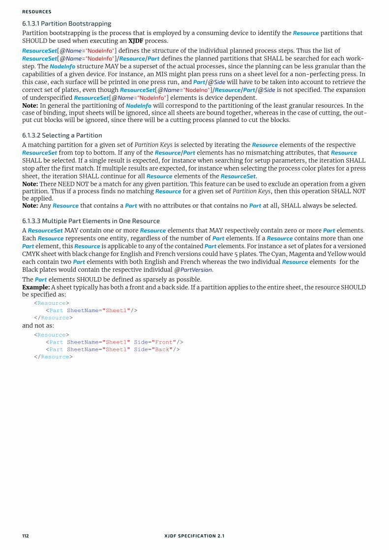
RESO URCES
6.1.3.1 Partition BootstrappingPartition bootstrapping is the process that is employed by a consuming device to identify the Resource partitions that SHOULD be used when executing an XJDF process.
ResourceSet[@Name="NodeInfo"] defines the structure of the individual planned process steps. Thus the list of ResourceSet[@Name="NodeInfo"]/Resource/Part defines the planned partitions that SHALL be searched for each work-step. The NodeInfo structure MAY be a superset of the actual processes, since the planning can be less granular than the capabilities of a given device. For instance, an MIS might plan press runs on a sheet level for a non-perfecting press. In this case, each surface will be printed in one press run, and Part/@Side will have to be taken into account to retrieve the correct set of plates, even though ResourceSet[@Name="NodeIno"]/Resource/Part/@Side is not specified. The expansion of underspecified ResourceSet[@Name="NodeInfo"] elements is device dependent.Note: In general the partitioning of NodeInfo will correspond to the partitioning of the least granular resources. In the case of binding, input sheets will be ignored, since all sheets are bound together, whereas in the case of cutting, the out-put cut blocks will be ignored, since there will be a cutting process planned to cut the blocks.
6.1.3.2 Selecting a PartitionA matching partition for a given set of Partition Keys is selected by iterating the Resource elements of the respective ResourceSet from top to bottom. If any of the Resource/Part elements has no mismatching attributes, that Resource SHALL be selected. If a single result is expected, for instance when searching for setup parameters, the iteration SHALL stop after the first match. If multiple results are expected, for instance when selecting the process color plates for a press sheet, the iteration SHALL continue for all Resource elements of the ResourceSet.Note: There NEED NOT be a match for any given partition. This feature can be used to exclude an operation from a given partition. Thus if a process finds no matching Resource for a given set of Partition Keys, then this operation SHALL NOT be applied.Note: Any Resource that contains a Part with no attributes or that contains no Part at all, SHALL always be selected.
6.1.3.3 Multiple Part Elements in One ResourceA ResourceSet MAY contain one or more Resource elements that MAY respectively contain zero or more Part elements. Each Resource represents one entity, regardless of the number of Part elements. If a Resource contains more than one Part element, this Resource is applicable to any of the contained Part elements. For instance a set of plates for a versioned CMYK sheet with black change for English and French versions could have 5 plates. The Cyan, Magenta and Yellow would each contain two Part elements with both English and French whereas the two individual Resource elements for the Black plates would contain the respective individual @PartVersion.
The Part elements SHOULD be defined as sparsely as possible.Example: A sheet typically has both a front and a back side. If a partition applies to the entire sheet, the resource SHOULD be specified as:
<Resource><Part SheetName="Sheet1"/>
</Resource>and not as:
<Resource><Part SheetName="Sheet1" Side="Front"/><Part SheetName="Sheet1" Side="Back"/>
</Resource>
112 XJDF SPECIFICATIO N 2.1

RESOURCE
Example 6.1: Versioned Set Of Plates with Multiple Part Elements
6.1.4 PartWastePartWaste associates waste with individual device modules or waste types.Note: The sum of specific waste can be higher than the total waste due to double counting.
<ResourceSet Usage="Output" Name="ExposedMedia"> <!-- 3 Common Plates for English and French --> <Resource> <Part Separation="Cyan" PartVersion="English"/> <Part Separation="Cyan" PartVersion="French"/> <ExposedMedia MediaRef="EM42"/> </Resource> <Resource> <Part Separation="Magenta" PartVersion="English"/> <Part Separation="Magenta" PartVersion="French"/> <ExposedMedia MediaRef="EM42"/> </Resource> <Resource> <Part Separation="Yellow" PartVersion="English"/> <Part Separation="Yellow" PartVersion="French"/> <ExposedMedia MediaRef="EM42"/> </Resource> <!-- Specific Black Plate for English --> <Resource> <Part Separation="Black" PartVersion="English"/> <ExposedMedia MediaRef="EM42"/> </Resource> <!-- Specific Black Plate for French --> <Resource> <Part Separation="Black" PartVersion="French"/> <ExposedMedia MediaRef="EM42"/> </Resource></ResourceSet>
Table 6.5: PartWaste Element
NAME DATA TYPE DESCRIPTION
ModuleIDs ? NMTOKENS Specifies the module or modules where the waste was produced.
Waste float Specific waste amount that SHALL be in the same units as those of the parent PartAmount.
WasteDetails ? NMTOKEN @WasteDetails specifies additional details about how the waste was produced. See Table 6.6 WasteDetails Attribute Values for suggested values.At least one of @ModuleIDs or @WasteDetails SHALL be specified.
Table 6.6: WasteDetails Attribute Values
VALUE DESCRIPTION
AuxiliarySheet This value identifies InsertSheet media that was consumed as specified by StackingParams/Disjointing/InsertSheet.
BadFeedWaste Waste caused by a bad feed.
BindingQualityTest Components that were destroyed in a QualityControl process that tests binding quality. Additional information about failed and passed tests SHOULD be provided in QualityControlResult.
CaliperWaste Waste by caliper on gathering / collecting.
DoubleFeedWaste Waste by double feeds on feeders.
IncorrectComponentWaste Waste by the attempted use of an incorrect component (e.g., on a feeder).
ObliqueSheetWaste Waste by oblique sheets on gathering / collecting chains.
XJDF SPECIFICATIO N 2.1 113
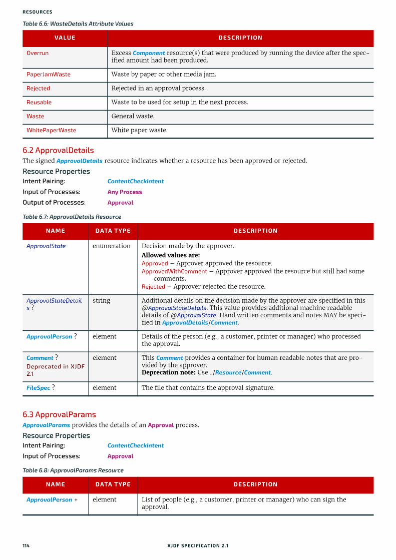
RESO URCES
6.2 ApprovalDetailsThe signed ApprovalDetails resource indicates whether a resource has been approved or rejected.
Resource PropertiesIntent Pairing: ContentCheckIntent
Input of Processes: Any Process
Output of Processes: Approval
6.3 ApprovalParamsApprovalParams provides the details of an Approval process.
Resource PropertiesIntent Pairing: ContentCheckIntent
Input of Processes: Approval
Overrun Excess Component resource(s) that were produced by running the device after the spec-ified amount had been produced.
PaperJamWaste Waste by paper or other media jam.
Rejected Rejected in an approval process.
Reusable Waste to be used for setup in the next process.
Waste General waste.
WhitePaperWaste White paper waste.
Table 6.7: ApprovalDetails Resource
NAME DATA TYPE DESCRIPTION
ApprovalState enumeration Decision made by the approver. Allowed values are: Approved – Approver approved the resource.ApprovedWithComment – Approver approved the resource but still had some
comments.Rejected – Approver rejected the resource.
ApprovalStateDetails ?
string Additional details on the decision made by the approver are specified in this @ApprovalStateDetails. This value provides additional machine readable details of @ApprovalState. Hand written comments and notes MAY be speci-fied in ApprovalDetails/Comment.
ApprovalPerson ? element Details of the person (e.g., a customer, printer or manager) who processed the approval.
Comment ?Deprecated in XJDF2.1
element This Comment provides a container for human readable notes that are pro-vided by the approver.Deprecation note: Use ../Resource/Comment.
FileSpec ? element The file that contains the approval signature.
Table 6.8: ApprovalParams Resource
NAME DATA TYPE DESCRIPTION
ApprovalPerson + element List of people (e.g., a customer, printer or manager) who can sign the approval.
Table 6.6: WasteDetails Attribute Values
VALUE DESCRIPTION
114 XJDF SPECIFICATIO N 2.1

ASSEMBLY
6.4 AssemblyAssembly describes how multiple BinderySignatures are bound together to produce a bound product.
Resource PropertiesIntent Pairing: LayoutIntent
Input of Processes: Collecting, Gathering, SheetOptimizing, Stripping
6.4.1 AssemblySectionAn AssemblySection represents a recursive set of BinderySignature elements. The topology of the AssemblySection ele-ments represents the topology of the binding, where sibling AssemblySection elements SHALL be gathered from top to bottom and child AssemblySection elements SHALL be collected from outside to inside.
Table 6.9: Assembly Resource
NAME DATA TYPE DESCRIPTION
BinderySignatureIDs ?
NMTOKENS @BinderySignatureIDs specifies an ordered list of BinderySignature that SHALL be assembled by the method specified in @Order. @BinderySignatureIDs SHALL NOT be present, if @Order="List".
Order enumeration Ordering of the individual BinderySignature elements. Order specifies the topology of the final Assembly.Allowed values are:Collecting – The sections are placed within one another. The first
BinderySignature specified in @BinderySignatureIDs is on the outside. An example is a saddle-stitched brochure. See Section 5.6.7 Collecting.
Gathering – The sections are placed on top of one another. The first BinderySignature specified in @BinderySignatureIDs is on the top. An example is a perfect bound magazine. See Section 5.6.16 Gathering.
List – The Assembly SHALL be fully described with AssemblySection ele-ments.
None – The sections are not bound. Typically used for flatwork jobs.
AssemblySection * element Each AssemblySection represents one section that SHALL be gathered. The first AssemblySection SHALL be placed on top, i.e. it is the front of the Assembly. AssemblySection elements SHALL NOT be specified unless @Order="List" and SHALL be specified if @Order="List".
Table 6.10: AssemblySection Element
NAME DATA TYPE DESCRIPTION
BinderySignatureID NMTOKEN @BinderySignatureID identifies the BinderySignature that this AssemblySection represents.
CommonFolds ?New in XJDF 2.1
integer A value, that is greater than "1", that specifies the number of consecutive bindery signatures that SHALL be gathered prior to folding. The value rep-resents the total number of AssemblySections that SHALL be folded together and includes the AssemblySection that contains @CommonFolds.@CommonFolds SHALL only be specified in the first AssemblySection of the sequence of consecutive bindery signatures that SHALL be folded together. In addition the Assembly SHALL contain sufficient AssemblySection elements without @CommonFolds to total the value in @CommonFolds.Any AssemblySection that needs to be collected in the resulting bindery sig-nature SHALL be specified in the first AssemblySection, i.e. the AssemblySection that contains @CommonFolds.
DescriptiveName ?New in XJDF 2.1
string Human readable descriptive name of the AssemblySection.
ExternalID ?New in XJDF 2.1
NMTOKEN External identifier of the AssemblySection, e.g. in an MIS.
AssemblySection * element Additional child AssemblySection elements that SHALL be gathered. The resulting set of AssemblySection elements SHALL be collected inside this AssemblySection.
XJDF SPECIFICATIO N 2.1 115
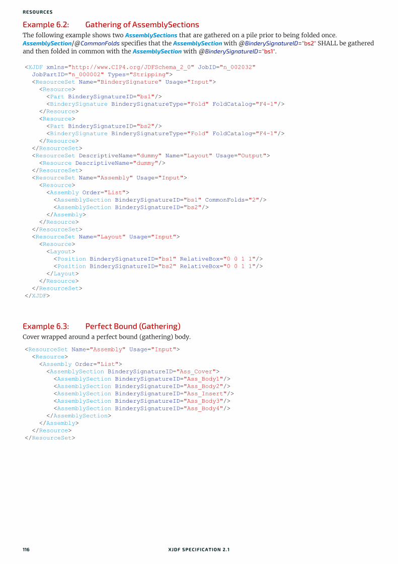
RESO URCES
Example 6.2: Gathering of AssemblySectionsThe following example shows two AssemblySections that are gathered on a pile prior to being folded once. AssemblySection/@CommonFolds specifies that the AssemblySection with @BinderySignatureID="bs2" SHALL be gathered and then folded in common with the AssemblySection with @BinderySignatureID="bs1".
Example 6.3: Perfect Bound (Gathering)Cover wrapped around a perfect bound (gathering) body.
<XJDF xmlns="http://www.CIP4.org/JDFSchema_2_0" JobID="n_002032" JobPartID="n_000002" Types="Stripping"> <ResourceSet Name="BinderySignature" Usage="Input"> <Resource> <Part BinderySignatureID="bs1"/> <BinderySignature BinderySignatureType="Fold" FoldCatalog="F4-1"/> </Resource> <Resource> <Part BinderySignatureID="bs2"/> <BinderySignature BinderySignatureType="Fold" FoldCatalog="F4-1"/> </Resource> </ResourceSet> <ResourceSet DescriptiveName="dummy" Name="Layout" Usage="Output"> <Resource DescriptiveName="dummy"/> </ResourceSet> <ResourceSet Name="Assembly" Usage="Input"> <Resource> <Assembly Order="List"> <AssemblySection BinderySignatureID="bs1" CommonFolds="2"/> <AssemblySection BinderySignatureID="bs2"/> </Assembly> </Resource> </ResourceSet> <ResourceSet Name="Layout" Usage="Input"> <Resource> <Layout> <Position BinderySignatureID="bs1" RelativeBox="0 0 1 1"/> <Position BinderySignatureID="bs2" RelativeBox="0 0 1 1"/> </Layout> </Resource> </ResourceSet></XJDF>
<ResourceSet Name="Assembly" Usage="Input"> <Resource> <Assembly Order="List"> <AssemblySection BinderySignatureID="Ass_Cover"> <AssemblySection BinderySignatureID="Ass_Body1"/> <AssemblySection BinderySignatureID="Ass_Body2"/> <AssemblySection BinderySignatureID="Ass_Insert"/> <AssemblySection BinderySignatureID="Ass_Body3"/> <AssemblySection BinderySignatureID="Ass_Body4"/> </AssemblySection> </Assembly> </Resource></ResourceSet>
116 XJDF SPECIFICATIO N 2.1

BENDINGPARAMS
Example 6.4: Saddle-Stitched Brochure (Collecting)
6.5 BendingParamsBendingParams describes the parameter set for a plate bending and punching device. A plate is bent and/or punched to fit the press cylinder.
Resource PropertiesInput of Processes: Bending
6.6 BinderySignatureA BinderySignature represents both sides of a folding signature, a die cut surface or a flat product such as a postcard, each with one or more pages. Resource/Part/@BinderySignatureID SHALL be provided for a BinderySignature. Multiple Resource/Part elements MAY be provided, in which case the BinderySignature element represents multiple physical bind-ery signatures.
Resource PropertiesIntent Pairing: LayoutIntent
Input of Processes: SheetOptimizing, Stripping
<ResourceSet Name="Assembly" Usage="Input"> <Resource> <Assembly Order="List"> <AssemblySection BinderySignatureID="Ass_Cover"> <AssemblySection BinderySignatureID="Ass_Body1"> <AssemblySection BinderySignatureID="Ass_Body2"> <AssemblySection BinderySignatureID="Ass_Body3"> <AssemblySection BinderySignatureID="Ass_Body4"/> </AssemblySection> </AssemblySection> </AssemblySection> </AssemblySection> </Assembly> </Resource></ResourceSet>
Table 6.11: BendingParams Resource
NAME DATA TYPE DESCRIPTION
Bend ? boolean If "true", indicates that the device SHALL bend.
Punch ? boolean If "true", indicates that the device SHALL create registration punch holes.
PunchType ? NMTOKEN Name of the registration punch scheme (e.g., Bacher).
Table 6.12: BinderySignature Resource (Sheet 1 of 3)
NAME DATA TYPE DESCRIPTION
BinderySignatureSize ?
XYPair Size of the BinderySignature. @BinderySignatureSize SHALL be identical to the sum of sizes including trim of all SignatureCells.
BinderySignatureType
enumeration @BinderySignatureType specifies the type of BinderySignature and the pagi-nation rules.Allowed values are:Die – A layout defined by an existing die.Fold – The BinderySignature represents a folding signature. The pagination
SHALL be calculated from the Assembly, Layout and BinderySignature. See Appendix E Pagination Catalog.
Grid – The BinderySignature represents a grid based layout. The pagination SHALL be explicitly specified in SignatureCell/@FrontPages and SignatureCell/@BackPages. Grid SHALL be used for flatwork.
XJDF SPECIFICATIO N 2.1 117
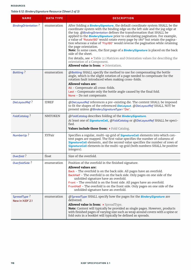
RESO URCES
BindingOrientation ? enumeration After folding a BinderySignature, the default coordinate system SHALL be the coordinate system with the binding edge on the left side and the jog edge at the top. @BindingOrientation defines the transformation that SHALL be applied to the BinderySignature prior to calculating pagination. For example, a value of "Rotate180" would rotate every page by 180° but retain the pagina-tion whereas a value of "Flip180" would reverse the pagination while retaining the page orientation.Note: In some cases, the first page of a BinderySignature is placed on the back side of the sheet.For details, see Table 2.1 Matrices and Orientation values for describing the orientation of a Component.Allowed value is from: Orientation.
Bottling ? enumeration @Bottling SHALL specify the method to use for compensating the bottle angle, which is the slight rotation of a page needed to compensate for the rotation fault introduced when making cross-folds.Allowed values are:All - Compensate all cross-folds.Last - Compensate only the bottle angle caused by the final fold.None - Do not compensate.
DieLayoutRef ? IDREF @DieLayoutRef references a pre-existing die. The content SHALL be imposed to fit the shapes of the referenced DieLayout. @DieLayoutRef SHALL NOT be present unless @BinderySignatureType="Die".
FoldCatalog ? NMTOKEN @FoldCatalog describes folding of the BinderySignature.At least one of SignatureCell, @FoldCatalog or @DieLayoutRef SHALL be speci-fied. Values include those from: Fold Catalog.
NumberUp ? XYPair Specifies a regular, multi-up grid of SignatureCell elements into which con-tent pages are mapped. The first value specifies the number of columns of SignatureCell elements, and the second value specifies the number of rows of SignatureCell elements in the multi-up grid (both numbers SHALL be positive integers).
Overfold ? float Size of the overfold.
OverfoldSide ? enumeration Position of the overfold in the finished signature.Allowed values are:Back - The overfold is on the back side. All pages have an overfold.BackHalf - The overfold is on the back side. Only pages on one side of the
unfolded signature have an overfold.Front - The overfold is on the front side. All pages have an overfold.FrontHalf - The overfold is on the front side. Only pages on one side of the
unfolded signature have an overfold.
SpreadType ?New in XJDF 2.1
enumeration @SpreadType SHALL specify how the pages for the BinderySignature are delivered.Allowed value is from: SpreadType.Note: Content will typically be provided as single pages. However, products with finished pages of varying size such as wrap around covers with a spine or fold outs in a booklet will typically be defined as spreads.
Table 6.12: BinderySignature Resource (Sheet 2 of 3)
NAME DATA TYPE DESCRIPTION
118 XJDF SPECIFICATIO N 2.1

BINDERYSIGNATURE
StaggerColumns ? FloatList A list of values describing the staggering for subsequent columns. The num-ber of entries in the list describes the periodicity of the staggering. Each value gives a factor of the SignatureCell height ((y value of @TrimSize) + @TrimHead + @TrimFoot) by which to shift the corresponding column.Note: Each value MAY be negative e.g., @StaggerColumns="0.0 -0.333 0.666" specifies to shift each:
• 3*n column up by 0%
• 3*n+1 column down by 33.3% of the SignatureCell height
• 3*n+2 column up by 66.6% of the SignatureCell heightThis element SHALL NOT be present unless @BinderySignatureType="Grid". At most one of @StaggerColumns or @StaggerRows SHALL be specified.
StaggerContinuous ? boolean Indicates if the BinderySignature SHALL be considered as a continuous repe-tition for staggering. This attribute SHALL NOT be present unless exactly one of @StaggerRows or @StaggerColumns is specified. Consider a grid with m columns and n rows with @StaggerContinuous="true". If @StaggerColumns is specified, the BinderySignature SHALL be considered continuous with a height H equal to n multiplied by the SignatureCell height. If @StaggerColumns has a value of y for a certain column, that column is shifted up (assuming y > 0) by an amount equal to y multiplied by the SignatureCell height (in the same way as described for @StaggerColumns). All content (even partial cells) that falls above H (the top of BinderySignature) is shifted to the bottom such that the top of the shifted content is just below the original bot-tom cell in the column. For example, if y is 0.666, then the top 66.6% of the top cell is shifted to be just below the original bottom cell. Analogous for @StaggerRows.
StaggerRows ? FloatList A list of values describing the staggering for subsequent rows. The number of entries in the list describes the periodicity of the staggering. Each value gives a factor of the SignatureCell width by which to shift the corresponding row.Note: Each value MAY be negative e.g., "0.0 0.333 -0.666" specifies to shift each
• 3*n row right by 0%
• 3*n+1 row right by 33.3% of the SignatureCell width
• 3*n+2 row left by 66.6% of the SignatureCell widthThis element SHALL NOT be present unless @BinderySignatureType="Grid". At most one of @StaggerColumns or @StaggerRows SHALL be specified.
MultiPageFold *New in XJDF 2.1
element MultiPageFold elements SHALL reference all BinderySignature elements including this BinderySignature that are produced in common so that each surface of the final folded signature contains more than one reader page. The folded signature is cut perpendicular to the final fold and results in the num-ber of final BinderySignatures equal to the number of values specified in the MultiPageFold elements. In the case of a vertical final fold, the first final BinderySignature SHALL be placed at the bottom of the unrotated final folded signature as defined in Table E.5 Pagination Diagrams. In the case of a hor-izontal final fold, the first final BinderySignature SHALL be placed to the left of the unrotated final folded signature as defined in Table E.5 Pagination Diagrams. Multiple identical MultiPageFold elements that reference the same @BinderySignatureID SHALL be specified to indicate multi-up production of the same BinderySignature. MultiPageFold SHALL NOT be specified unless @BinderySignatureType="Fold". If MultiPageFold elements are specified, they SHALL be specified in all BinderySignatures that are referenced by MultiPageFold.Note: Typical use cases are a final cut in a folding machine, coming and going in book production or longitudinal slitting in a web press.
SignatureCell * element Describes the SignatureCell elements used in this BinderySignature. SignatureCell elements are ordered in X-Y direction starting at the lower left corner of the BinderySignature. When both SignatureCell and @FoldCatalog are specified, @FoldCatalog defines the topology of the folding scheme, and the specifics of each individual signature cell are described by the SignatureCell elements. The SignatureCell elements SHALL have precedence.
Table 6.12: BinderySignature Resource (Sheet 3 of 3)
NAME DATA TYPE DESCRIPTION
XJDF SPECIFICATIO N 2.1 119

RESO URCES
6.6.1 MultiPageFoldNew in XJDF 2.1
6.6.1.1 MultiPageFold Example Paginations
Example 6.5: Pagination for Two Identical BinderySignatures on a F16-14 FoldThe following example and pagination diagram is for two up head to foot production of an identical BinderySignature. This would typically be cut in a final cutting step in the folding machine.
Table 6.13: MultiPageFold Element
NAME DATA TYPE DESCRIPTION
BinderySignatureID NMTOKEN @BinderySinatureID shall reference the BinderySignature that is produced in common.
Orientation enumeration Orientation of the referenced BinderySignature prior to the final cut.Note: An orientation of "Flip0" defines coming and going in book production.Allowed value is from: Orientation.
<ResourceSet Name="Layout" Usage="Input"> <Resource> <Layout SurfaceContentsBox="0 0 2834.64566929 1984.2519685"> <Position BinderySignatureID="BS1"/> </Layout> </Resource></ResourceSet><ResourceSet Name="BinderySignature" Usage="Input"> <Resource> <Part BinderySignatureID="BS1"/> <BinderySignature BinderySignatureType="Fold" FoldCatalog="F16-14"> <MultiPageFold BinderySignatureID="BS1" Orientation="Rotate0"/> <MultiPageFold BinderySignatureID="BS1" Orientation="Rotate0"/> </BinderySignature> </Resource></ResourceSet>
Figure 6-1: Pagination for Two Up Head to Foot
141334
651112
141334
651112
15 162 1
7 810 9
15 162 1
7 810 9
120 XJDF SPECIFICATIO N 2.1
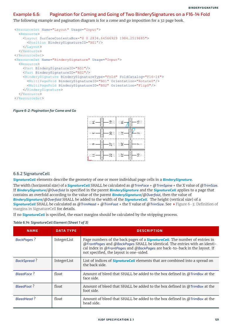
BINDERYSIGNATURE
Example 6.6: Pagination for Coming and Going of Two BinderySignatures on a F16-14 FoldThe following example and pagination diagram is for a come and go imposition for a 32 page book.
6.6.2 SignatureCellSignatureCell elements describe the geometry of one or more individual page cells in a BinderySignature.
The width (horizontal size) of a SignatureCell SHALL be calculated as @TrimFace + @TrimSpine + the X value of @TrimSize. If BinderySignature/@Overfold is specified in the parent BinderySignature and the SignatureCell applies to a page that contains an overfold according to the value of the parent BinderySignature/@Overfold, then the value of BinderySignature/@Overfold SHALL be added to the width of the SignatureCell. The height (vertical size) of a SignatureCell SHALL be calculated as @TrimHead + @TrimFoot + the Y value of @TrimSize. See Figure 6-3: Definition of margins in SignatureCell for details.
If no SignatureCell is specified, the exact margins should be calculated by the stripping process.
<ResourceSet Name="Layout" Usage="Input"> <Resource> <Layout SurfaceContentsBox="0 0 2834.64566929 1984.2519685"> <Position BinderySignatureID="BS1"/> </Layout> </Resource></ResourceSet><ResourceSet Name="BinderySignature" Usage="Input"> <Resource> <Part BinderySignatureID="BS1"/> <Part BinderySignatureID="BS2"/> <BinderySignature BinderySignatureType="Fold" FoldCatalog="F16-14"> <MultiPageFold BinderySignatureID="BS1" Orientation="Rotate0"/> <MultiPageFold BinderySignatureID="BS2" Orientation="Flip0"/> </BinderySignature> </Resource></ResourceSet>
Figure 6-2: Pagination for Come and Go
Table 6.14: SignatureCell Element (Sheet 1 of 3)
NAME DATA TYPE DESCRIPTION
BackPages ? IntegerList Page numbers of the back pages of a SignatureCell. The number of entries in @FrontPages and @BackPages SHALL be identical. The entries with an identi-cal index in @FrontPages and @BackPages are back-to-back in the layout. If not specified, the layout is one-sided.
BackSpread ? IntegerList List of indices of SignatureCell elements that are combined into a spread on the back side.
BleedFace ? float Amount of bleed that SHALL be added to the box defined in @TrimBox at the face side.
BleedFoot ? float Amount of bleed that SHALL be added to the box defined in @TrimBox at the foot side.
BleedHead ? float Amount of bleed that SHALL be added to the box defined in @TrimBox at the head side.
141334
651112 22 21
27 2830 29
19 20 15 162 1
7 810 9
23242625
31321817
XJDF SPECIFICATIO N 2.1 121

RESO URCES
BleedSpine ? float Amount of bleed that SHALL be added to the box defined in @TrimBox at the spine side.
FaceCells ? IntegerList List of indices of SignatureCell elements that form a foldout together with this SignatureCell. The SignatureCell that contains @FaceCells is the parent of the foldout, typically the page that is attached to the spine. Details of each foldout page are described by a SignatureCell element.
FrontPages ? IntegerList Page numbers of the front pages of a SignatureCell. Multiple page cells with the same properties except for the pages to which they are assigned MAY be summarized as one SignatureCell with multiple entries in @FrontPages.
FrontSpread ? IntegerList List of indices of SignatureCell elements that are combined into a spread on the front side.
Mask ? enumeration The definition of the clipping mask for the placed graphics. Allowed values are:BleedBox – The mask is derived from the bleed box as defined by the
SignatureCell.DieCut – The mask SHALL be derived from the cut line as defined in
DieLayout/@CutLines.None – No mask.PDL – The mask is derived from the PDL of the graphics. @MaskSeparation
MAY determine which separation SHALL be used as the clipping mask for the graphics. If @MaskSeparation is not present, the mask SHALL be determined from the underlying PDL, e.g. [ISO19593-1:2016].
SourceBleedBox – The mask is derived from the bleed box of the graphical element placed in the SignatureCell.
SourceTrimBox – The mask is derived from the trim box of the graphical ele-ment placed in the SignatureCell.
TrimBox – The mask is derived from the trim box as defined by the SignatureCell.
MaskBleed ? float The distance over which to expand the mask in points.
MaskSeparation ? NMTOKEN Color/../Resource/Part/@Separation of the Color that specifies @Mask. @MaskSeparation SHALL NOT be specified unless @Mask="PDL". Color/@ColorType of this separation SHALL be "DieLine".
Orientation ? enumeration Indicates the orientation of the SignatureCell on the BinderySignature.Allowed values are:Down – 180° rotation.Left – 90° counter-clockwise rotation. Right – 270° counter-clockwise rotation Up – 0° rotation.
Sides ? enumeration @Sides SHALL specify which side of the finished product SHALL be printed. The front side is defined as the side of the product that contains the first page of the product.Note: Typically single sided products are also single page products, in which case the front of the product and the front of the sheet are identical.Allowed value is from: Sides.
StationName ? NMTOKEN The name of the 1-up station in the die layout. If BinderySignature/@BinderySignatureType="Die", this element SHOULD be specified. If BinderySignature/@BinderySignatureType="Die" and the DieLayout refer-enced by BinderySignature/@DieLayoutRef contains more than 1 Station, this attribute SHALL be specified.
TrimFace ? float Value for the trim distance at the face side. When no Folding is done, this is the right margin. When @BinderySignatureType="Grid", the horizontal gutter between cells is @TrimFace + @TrimSpine.
Table 6.14: SignatureCell Element (Sheet 2 of 3)
NAME DATA TYPE DESCRIPTION
122 XJDF SPECIFICATIO N 2.1
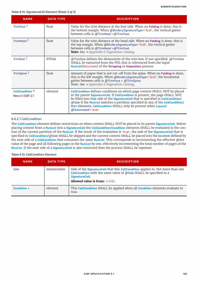
BINDERYSIGNATURE
6.6.2.1 CellConditionThe CellCondition element defines restrictions on when content SHALL NOT be placed in its parent SignatureCell. Before placing content from a RunList into a SignatureCell the CellCondition/Condition elements SHALL be evaluated in the con-text of the current partition of the RunList. If the result of the evaluation is "true", the side of the SignatureCell that is specified in CellCondition/@Side SHALL be skipped and the current content SHALL be placed into the location defined by the next side of a CellCondition that consumes the same RunList. This corresponds to incrementing the effective @Ord value of the page and all following pages in the RunList by one, effectively incrementing the total number of pages of the RunList. If the next side of a SignatureCell is also restricted then the process SHALL be repeated.
TrimFoot ? float Value for the trim distance at the foot side. When no Folding is done, this is the bottom margin. When @BinderySignatureType="Grid", the vertical gutter between cells is @TrimHead +@TrimFoot.
TrimHead ? float Value for the trim distance at the head side. When no Folding is done, this is the top margin. When @BinderySignatureType="Grid", the vertical gutter between cells is @TrimHead [email protected]: See Appendix E Pagination Catalog.
TrimSize ? XYPair @TrimSize defines the dimensions of the trim box. If not specified, @TrimSize SHALL be extracted from the PDL that is referenced from the input RunList(Document) of the Stripping or Imposition process.
TrimSpine ? float Amount of paper that is not cut-off from the spine. When no Folding is done, this is the left margin. When @BinderySignatureType="Grid", the horizontal gutter between cells is @TrimFace + @TrimSpine.Note: See Appendix E Pagination Catalog.
CellCondition *New in XJDF 2.1
element CellCondition defines conditions on which page content SHALL NOT be placed in the parent SignatureCell. If CellCondition is present, the page SHALL NOT be filled into that side of the SignatureCell that is specified in CellCondition/@Side if the RunList matches a partition specified in any of the CellCondition/Part elements. CellCondition SHALL only be present when Layout/@Automated="true".
Table 6.15: CellCondition Element
NAME DATA TYPE DESCRIPTION
Side enumeration Side of the SignatureCell that this CellCondition applies to. Not more than one CellCondition with the same value of @Side SHALL be specified in a SignatureCell.Allowed value is from: Side.
Condition + element This CellCondition SHALL be applied when all Condition elements evaluate to true.
Table 6.14: SignatureCell Element (Sheet 3 of 3)
NAME DATA TYPE DESCRIPTION
XJDF SPECIFICATIO N 2.1 123

RESO URCES
6.6.3 Definition of Margins in Signature Cell
6.7 BlockPreparationParamsBlockPreparationParams describes the settings of a BlockPreparation process.
Resource PropertiesIntent Pairing: BindingIntent
Input of Processes: BlockPreparation
Figure 6-3: Definition of margins in SignatureCell
Note: Overfold in this figure refers to the value of the parent BinderySignature/@Overfold and is only present if the page requires an overfold based on the value of the parent BinderySignature/@OverfoldSide.
Table 6.16: BlockPreparationParams Resource
NAME DATA TYPE DESCRIPTION
Backing ? float Backing distance in points. See @Backing:Figure 6-4: Backing and Rounding measurements for TightBacking.
Rounding ? float Rounding distance in points. See @Rounding:Figure 6-4: Backing and Rounding measurements for TightBacking.
TightBacking ? enumeration Definition of the geometry of the back of the book block. Allowed value is from: TightBacking.
RegisterRibbon * element Description of the register ribbons that are included within the book block.
TrimHead BleedHead
Overfold
TrimSpine
BleedSpine
MillingDepth CutWidthHead
TrimFace
BleedFace
TrimFoot CutWidthFootBleedFoot
TrimSize
Lorem ipsum dolor sit amet, consectetuer adipiscing elit, sed diam nonummy nibh euismod tincidunt ut laoreet dolore magna aliquam erat volutpat. Ut wisi enim ad minim veniam, quis nostrud exerci tation ullamcorper suscipit lobortis nisl ut aliquip ex ea commodo consequat. Duis autem vel eum iriure dolor in hendrerit in vulputate velit esse molestie consequat, vel illum dolore eu feugiat nulla facilisis at vero eros et accumsan et iusto odio dignissim qui blandit praesent luptatum zzril delenit augue duis dolore te feugait nulla facilisi.
Lorem ipsum dolor sit amet, consectetuer adipiscing elit, sed diam nonummy nibh euismod tincidunt ut laoreet dolore magna aliquam erat volutpat. Ut wisi enim ad minim veniam, quis nostrud exerci tation ullamcorper suscipit lobortis nisl ut aliquip ex ea commodo consequat. Duis autem vel eum iriure dolor in hendrerit in vulputate velit esse molestie consequat, vel illum dolore eu feugiat nulla facilisis at vero eros et accumsan et iusto odio dignissim qui blandit praesent luptatum zzril delenit augue duis dolore te feugait nulla facilisi.
Lorem ipsum dolor sit amet, consectetuer adipiscing elit, sed diam nonummy nibh euismod tincidunt ut laoreet dolore magna aliquam erat volutpat. Ut wisi enim ad minim veniam, quis nostrud exerci tation ullamcorper suscipit lobortis nisl ut aliquip ex ea commodo consequat. Duis autem vel eum iriure dolor in hendrerit in vulputate velit esse molestie consequat, vel illum dolore eu feugiat nulla facilisis at vero eros et accumsan et iusto odio dignissim qui blandit praesent luptatum zzril delenit augue duis dolore te feugait nulla facilisi.
124 XJDF SPECIFICATIO N 2.1
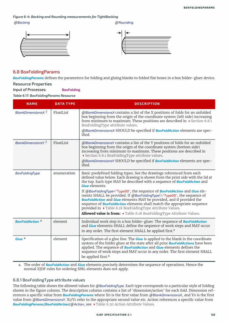
BOXFOLDINGPARAMS
6.8 BoxFoldingParamsBoxFoldingParams defines the parameters for folding and gluing blanks to folded flat boxes in a box folder-gluer device.
Resource PropertiesInput of Processes: BoxFolding
6.8.1 BoxFoldingType attribute valuesThe following table shows the allowed values for @BoxFoldingType. Each type corresponds to a particular style of folding shown in the figure column. The description column contains a list of ‘dimension/action’ for each fold. Dimension ref-erences a specific value from BoxFoldingParams where X0 is the first value from @BlankDimensionsX, and Y0 is the first value from @BlankDimensionsY. X1/Y1 refer to the appropriate second value etc. Action references a specific value from BoxFoldingParams/BoxFoldAction/@Action, see Table 6.20 Action Attribute Values.
Figure 6-4: Backing and Rounding measurements for TightBacking
@Backing @Rounding
Table 6.17: BoxFoldingParams Resource
NAME DATA TYPE DESCRIPTION
BlankDimensionsX ? FloatList @BlankDimensionsX contains a list of the X positions of folds for an unfolded box beginning from the origin of the coordinate system (left side) increasing from minimum to maximum. These positions are described in Section 6.8.1 BoxFoldingType attribute values.@BlankDimensionsX SHOULD be specified if BoxFoldAction elements are spec-ified.
BlankDimensionsY ? FloatList @BlankDimensionsY contains a list of the Y positions of folds for an unfolded box beginning from the origin of the coordinate system (bottom side) increasing from minimum to maximum. These positions are described in Section 6.8.1 BoxFoldingType attribute values.@BlankDimensionsY SHOULD be specified if BoxFoldAction elements are spec-ified.
BoxFoldingType enumeration Basic predefined folding types. See the drawings referenced from each defined value below. Each drawing is shown from the print side with the lid at the top. Each type MAY be described with a sequence of BoxFoldAction and Glue elements.If @BoxFoldingType="Type00", the sequence of BoxFoldAction and Glue ele-ments SHALL be provided. If @BoxFoldingType!="Type00", the sequence of BoxFoldAction and Glue elements MAY be provided, and if provided the sequence of BoxFoldAction elements shall match the appropriate sequence provided in Table 6.18 BoxFoldingType Attribute Values.Allowed value is from: Table 6.18 BoxFoldingType Attribute Values.
BoxFoldAction * element Individual work step in a box folder-gluer. The sequence of BoxFoldAction and Glue elements SHALL define the sequence of work steps and MAY occur in any order. The first element SHALL be applied first.a
a. The order of BoxFoldAction and Glue elements precisely determines the sequence of operations. Hence the normal XJDF rules for ordering XML elements does not apply.
Glue * element Specification of a glue line. The Glue is applied to the blank in the coordinate system of the folder gluer at the state after all prior BoxFoldActions have been applied. The sequence of BoxFoldAction and Glue elements defines the sequence of work steps and MAY occur in any order. The first element SHALL be applied first.a.
XJDF SPECIFICATIO N 2.1 125

RESO URCES
Notes:
• Shown from print side, lid at the top, arrow is transport direction in folder-gluer.
• In the folder-gluer the blank box is fed with the print side down.
• From this point of view all folds are made toward the -z axis.
• For front and back folds, pay attention to transport direction
Table 6.18: BoxFoldingType Attribute Values
VALUE FIGURE DESCRIPTION
Type00 Special type for boxes that are not pre-defined.
Type01 X0 LongPreFoldLeftToRight
X2 LongPreFoldRightToLeft
X1 LongFoldLeftToRight
X3 LongFoldRightToLeft
Type02 X3 LongPreFoldLeftToRight
X1 LongPreFoldRightToLeft
X0 LongFoldLeftToRight
X2 LongFoldRightToLeft
Type03 X0 LongPreFoldLeftToRight
X2 LongPreFoldRightToLeft
X2/Y1 FrontFoldComplete
X4/Y1 FrontFoldComplete
X1/Y1 FrontFoldCompleteDiagonal
X3/Y1 FrontFoldCompleteDiagonal
X1 LongFoldLeftToRight
X3 LongFoldRightToLeft
X4X3X2
Y3
X0X1
Y6
Y2
(Y1)
(Y4)
(Y5)
(Y0)
X4X3
X2
Y3
X0X1
Y6
Y2
(Y1)
(Y4)
(Y5)
(Y0)
X4X3
X2
Y5
X0X1
Y2
Y1
(Y3)(Y4)
(Y0)
126 XJDF SPECIFICATIO N 2.1

BOXFOLDINGPARAMS
Type04 X3 LongPreFoldLeftToRight
X1 LongPreFoldRightToLeft
X1/Y1 FrontFoldComplete
X3/Y1 FrontFoldComplete
X0/Y1 FrontFoldCompleteDiagonal
X2/Y1 FrontFoldCompleteDiagonal
X0 LongFoldLeftToRight
X2 LongFoldRightToLeft
Type10 X0 LongPreFoldLeftToRight
X1 LongPreFoldRightToLeft
Type11 X0/Y0 FrontFoldComplete
X2/Y0 FrontFoldComplete
X0/Y2 BackFoldComplete
X2/Y2 BackFoldComplete
X1/Y0 FrontFoldCompleteDiagonal
X1/Y2 BackFoldCompleteDiagonal
X0 LongFoldLeftToRight
X2 LongFoldRightToLeft
Type12 X1/Y0 FrontFoldCompleteDiagonal
X1/Y2 BackFoldCompleteDiagonal
X0 LongFoldLeftToRight
X2 LongFoldRightToLeft
Type13 X0/Y0 FrontFoldComplete
X2/Y0 FrontFoldComplete
X0/Y2 BackFoldComplete
X2/Y2 BackFoldComplete
X1/Y0 FrontFoldCompleteDiagonal
X1/Y2 BackFoldCompleteDiagonal
X0 LongFoldLeftToRight
X2 LongFoldRightToLeft
Table 6.18: BoxFoldingType Attribute Values
VALUE FIGURE DESCRIPTION
X4X3
X2
Y5
X0X1
Y2
Y1
(Y3)(Y4)
(Y0)
X2
X0Y0
X1
Y2Y1
X2
X0Y0
X1
Y2Y1
X4X3
X2
X0Y0
X1
Y2Y1
X4X3
X2
X0Y0
X1
Y2Y1
XJDF SPECIFICATIO N 2.1 127
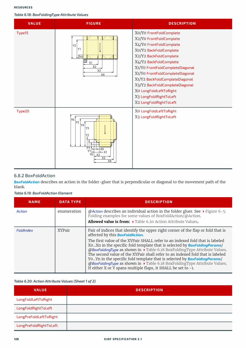
RESO URCES
6.8.2 BoxFoldActionBoxFoldAction describes an action in the folder-gluer that is perpendicular or diagonal to the movement path of the blank.
Type15 X0/Y0 FrontFoldComplete
X2/Y0 FrontFoldComplete
X4/Y0 FrontFoldComplete
X0/Y2 BackFoldComplete
X2/Y2 BackFoldComplete
X4/Y2 BackFoldComplete
X1/Y0 FrontFoldCompleteDiagonal
X1/Y0 FrontFoldCompleteDiagonal
X1/Y2 BackFoldCompleteDiagonal
X3/Y2 BackFoldCompleteDiagonal
X0 LongFoldLeftToRight
X3 LongFoldRightToLeft
X2 LongFoldRightToLeft
Type20 X0 LongFoldLeftToRight
X3 LongFoldRightToLeft
Table 6.19: BoxFoldAction Element
NAME DATA TYPE DESCRIPTION
Action enumeration @Action describes an individual action in the folder gluer. See Figure 6-5: Folding examples for some values of BoxFoldAction/@Action.Allowed value is from: Table 6.20 Action Attribute Values.
FoldIndex XYPair Pair of indices that identify the upper right corner of the flap or fold that is affected by this BoxFoldAction. The first value of the XYPair SHALL refer to an indexed fold that is labeled X0...Xn in the specific fold template that is selected by BoxFoldingParams/@BoxFoldingType as shown in Table 6.18 BoxFoldingType Attribute Values. The second value of the XYPair shall refer to an indexed fold that is labeled Y0...Yn in the specific fold template that is selected by BoxFoldingParams/@BoxFoldingType as shown in Table 6.18 BoxFoldingType Attribute Values. If either X or Y spans multiple flaps, it SHALL be set to -1.
Table 6.20: Action Attribute Values (Sheet 1 of 2)
VALUE DESCRIPTION
LongFoldLeftToRight
LongFoldRightToLeft
LongPreFoldLeftToRight
LongPreFoldRightToLeft
Table 6.18: BoxFoldingType Attribute Values
VALUE FIGURE DESCRIPTION
X4X3
X2
X0Y0
X1
Y2Y1
Y0
X4X3
X2
X0X1
Y5Y6
Y4Y3
Y1
Y2
128 XJDF SPECIFICATIO N 2.1

BOXPACKINGPARAMS
Example 6.7: BoxFoldingParams/BoxFoldActionFor instance, processing a Type01 blank has the following actions:
6.9 BoxPackingParamsBoxPackingParams defines the parameters for packing a box of components. Details of the box used for BoxPacking can be found in the Component (Box) resource that is also an input of the BoxPacking process.
FrontFoldComplete
FrontFoldDiagonal
FrontFoldCompleteDiagonal
BackFoldComplete
BackFoldDiagonal
BackFoldCompleteDiagonal
ReverseFold A "ReverseFold" is topologically equivalent to "FrontFoldDiagonal" but uses different equipment with other restrictions on media weight and size and is therefore specified individually.
Milling
Rotate90 90° counter-clockwise rotation
Rotate180 180° rotation
Rotate270 90° clockwise rotation
<ResourceSet Name="BoxFoldingParams" Usage="Input"> <Resource> <BoxFoldingParams BlankDimensionsX="28 142 198 312 369" BlankDimensionsY="57 85 142 425 482 510 567" BoxFoldingType="Type01"> <BoxFoldAction Action="LongPreFoldLeftToRight" FoldIndex="0 -1"/> <BoxFoldAction Action="LongPreFoldRightToLeft" FoldIndex="2 -1"/> <BoxFoldAction Action="LongFoldLeftToRight" FoldIndex="1 -1"/> <BoxFoldAction Action="LongFoldRightToLeft" FoldIndex="3 -1"/> </BoxFoldingParams> </Resource></ResourceSet>
Figure 6-5: Folding examples for some values of BoxFoldAction/@Action
LongFoldLeftToRight LongPreFoldRightToLeft FrontFoldComplete FrontFoldCompleteDiagonal BackFoldComplete ReverseFold
Table 6.20: Action Attribute Values (Sheet 2 of 2)
VALUE DESCRIPTION
Print side color Inner side color
XJDF SPECIFICATIO N 2.1 129

RESO URCES
Resource PropertiesInput of Processes: BoxPacking
Table 6.21: BoxPackingParams Resource
NAME DATA TYPE DESCRIPTION
BoxType enumeration @BoxType specifies the general category of the package to be packed. Allowed values are:Box – Boxes are convenience packaging and are not envisioned to be protec-
tion for shipping.Carton – Cartons envisioned to be protection for shipping.Envelope – Envelopes are packages that are envisioned for shipping.Tube – Tubes are cylinder shaped cartons that are envisioned for shipping.
BoxTypeDetails ? string Additional details of @BoxType. @BoxType MAY be a site specific identifier. Values include: Branded CartonEaster Bunny BoxNeutral Carton
Columns ? integer Columns per shipping box. Columns are in the 3rd Dimension in Figure 6-6: Box packing, and are thus not illustrated.
ComponentsPerRow?
integer Components or Products per row in the shipping box, as illustrated by A in Figure 6-6: Box packing. If the Components represent Bundles, the number of Bundles SHALL be specified.
Copies ? integer Number of copies in the box. @Copies SHALL NOT be specified if @MaxWeight is present.
FaceDown ? enumeration Defines the surface that is facing the bottom of the box, defining the hori-zontal plane.Allowed value is from: Face.
Layers ? integer Layers per shipping box, as illustrated by L in Figure 6-6: Box packing.
MaxWeight ? float Maximum weight of a packed box in grams. @MaxWeight SHALL NOT be specified if @Copies is present.
Pattern ? NMTOKEN Name of the box packing pattern. Used to store a predefined pattern that defines the layers and positioning of individual component in the box or car-ton.
Rows ? integer Rows per shipping box, as illustrated by R in Figure 6-6: Box packing.
Ties ? IntegerList Number of tie sheets at each row, as illustrated by T in Figure 6-6: Box packing. The first value is outside the first row, the next value between the first and second row and so forth. If more rows than values are specified, counting SHALL restart at the 0 position. If fewer rows than values are speci-fied, all tie sheets that are not adjacent to a row SHALL be ignored.
UnderLays ? IntegerList Number of underlay sheets at each layer, as illustrated by U in Figure 6-6: Box packing. The first value is underneath the bottom layer, the next value above the first layer and so forth. If more layers than values are specified, counting SHALL restart at the 0 position. If fewer layers than values are spec-ified, all underlay sheets that are not adjacent to a layer SHALL be ignored.
130 XJDF SPECIFICATIO N 2.1

BUNDLE
6.10 BundleBundles are used to describe various kinds of sets of packing units such as boxes, cartons and pallets.
The coordinate system of a Bundle is defined by the orientation of the first, i.e. bottom item in the Bundle. See Figure 6-7: Bundle coordinate system.
Resource PropertiesInput of Processes: BoxPacking, Bundling, Labeling, Palletizing, Shrinking, Stacking, Strapping, Wrapping
6.10.1 BundleItemA Bundle is described as a set of BundleItem elements. BundleItem elements describe packages that MAY reference other BundleItem elements which themselves MAY reference further BundleItem elements.
Figure 6-6: Box packing
Table 6.22: Bundle Resource
NAME DATA TYPE DESCRIPTION
BundleItem + element References to the individual BundleItems that form this Bundle.
Table 6.23: BundleItem Element (Sheet 1 of 2)
NAME DATA TYPE DESCRIPTION
Amount integer Number of identical bundle items of the same type and structure that this BundleItem represents.
BundleType ? enumeration @BundleType defines the type of bundle that the BundleItem represents.Allowed value is from: BundleType.Note: @BundleType=”Product” SHALL NOT be specified if a child BundleItem el-ement is present.
ItemRef ? IDREF Reference to an individual Component or Product that is represented by this BundleItem. @ItemRef SHALL NOT be specified if a child BundleItem element is present.
TotalAmount ? integer Total amount of individual products that this BundleItem contains. If @Amount !=1, then @TotalAmount refers to the total amount that is contained in all bundle items that the BundleItem represents. If the BundleItem or its descendent BundleItem elements contain one or more @ItemRef attributes that reference a ProductList/Product, then @TotalAmount refers to the number of final products.
TotalDimensions ? shape Total dimensions in points of all individual items including packaging that belong to this BundleItem.
TotalVolume ? float Total volume in liters of all individual items including packaging that belong to this BundleItem.
TotalWeight ? float Total weight in grams of all individual items including packaging that belong to this BundleItem.
Y
F
X Z
A
Y
X
F RT
U
L
XJDF SPECIFICATIO N 2.1 131

RESO URCES
BundleItem * element Individual BundleItem elements that this parent BundleItem contains. All BundleItem elements in one level of the BundleItem tree SHOULD have the same value of BundleItem/@BundleType.
Figure 6-7: Bundle coordinate system
Table 6.23: BundleItem Element (Sheet 2 of 2)
NAME DATA TYPE DESCRIPTION
Z-Axis:Height of bundle
Spine of bottomproduct
Y-Axis:Along spine of bottom product
Origin:Lower left corner of bottom product
X-Axis
132 XJDF SPECIFICATIO N 2.1
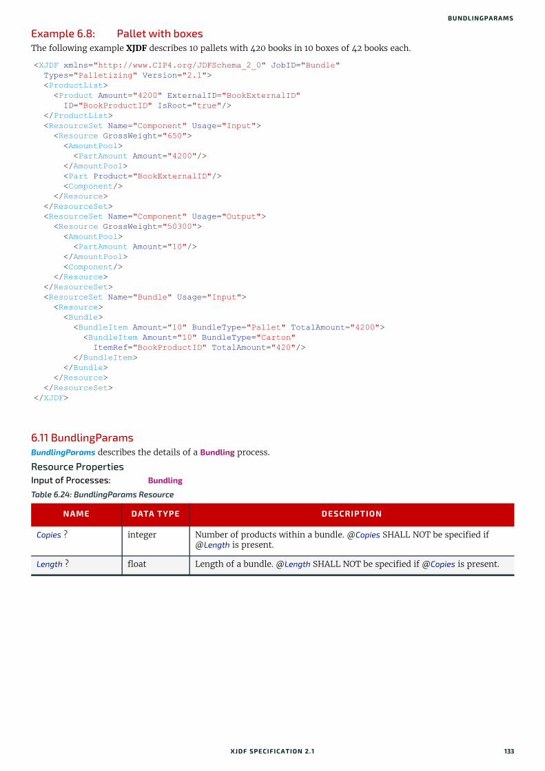
BUNDLINGPARAMS
Example 6.8: Pallet with boxesThe following example XJDF describes 10 pallets with 420 books in 10 boxes of 42 books each.
6.11 BundlingParamsBundlingParams describes the details of a Bundling process.
Resource PropertiesInput of Processes: Bundling
<XJDF xmlns="http://www.CIP4.org/JDFSchema_2_0" JobID="Bundle" Types="Palletizing" Version="2.1"> <ProductList> <Product Amount="4200" ExternalID="BookExternalID" ID="BookProductID" IsRoot="true"/> </ProductList> <ResourceSet Name="Component" Usage="Input"> <Resource GrossWeight="650"> <AmountPool> <PartAmount Amount="4200"/> </AmountPool> <Part Product="BookExternalID"/> <Component/> </Resource> </ResourceSet> <ResourceSet Name="Component" Usage="Output"> <Resource GrossWeight="50300"> <AmountPool> <PartAmount Amount="10"/> </AmountPool> <Component/> </Resource> </ResourceSet> <ResourceSet Name="Bundle" Usage="Input"> <Resource> <Bundle> <BundleItem Amount="10" BundleType="Pallet" TotalAmount="4200"> <BundleItem Amount="10" BundleType="Carton" ItemRef="BookProductID" TotalAmount="420"/> </BundleItem> </Bundle> </Resource> </ResourceSet></XJDF>
Table 6.24: BundlingParams Resource
NAME DATA TYPE DESCRIPTION
Copies ? integer Number of products within a bundle. @Copies SHALL NOT be specified if @Length is present.
Length ? float Length of a bundle. @Length SHALL NOT be specified if @Copies is present.
XJDF SPECIFICATIO N 2.1 133

RESO URCES
6.12 CaseMakingParamsCaseMakingParams describes the settings of a CaseMaking process for hardcover binding.
Resource PropertiesIntent Pairing: BindingIntent
Input of Processes: CaseMaking
Figure 6-8: BundlingParams coordinate system
Table 6.25: CaseMakingParams Resource
NAME DATA TYPE DESCRIPTION
BottomFoldIn ? float Defines the width of the part of the cover material on the lower edge inside of the case. If @BottomFoldIn is not specified the value from @TopFoldIn SHALL be used.
CornerType ? NMTOKEN Method of wrapping the corners of the cover material around the corners of the board. Values include: LibraryCorner – The American Library Corner style.
CoverWidth ? float Width of the cover cardboard in points.
FrontFoldIn ? float Defines the width of the part of the cover material on the front edges inside of the case in points.
Height ? float Height of the book case, in points.
JointWidth ? float Width of the joint as seen when laying the cardboard on the cover material, in points.
SpineWidth ? float Width of the spine cardboard, in points.
TopFoldIn ? float Defines the width of the cover material on the top edge inside of the case, in points.
Glue ? element Details of the glue.Because the glue is applied to the whole back side of the cover material, Glue/@AreaGlue SHALL be set to "true".
X
Y
134 XJDF SPECIFICATIO N 2.1
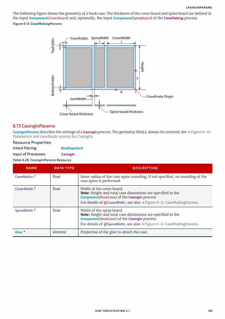
CASINGINPARAMS
The following figure shows the geometry of a book case. The thickness of the cover board and spine board are defined in the input Component(CoverBoard) and, optionally, the input Component(SpineBoard) of the CaseMaking process.
6.13 CasingInParamsCasingInParams describes the settings of a CasingIn process. The geometry SHALL always be centered. See Figure 6-10: Parameters and coordinate system for CasingIn.
Resource PropertiesIntent Pairing: BindingIntent
Input of Processes: CasingIn
Figure 6-9: CaseMakingParams
Table 6.26: CasingInParams Resource
NAME DATA TYPE DESCRIPTION
CaseRadius ? float Inner radius of the case spine rounding. If not specified, no rounding of the case spine is performed.
CoverWidth ? float Width of the cover board.Note: Height and total case dimensions are specified in the Component(BookCase) of the CasingIn process.For details of @CoverWidth, see also Figure 6-9: CaseMakingParams.
SpineWidth ? float Width of the spine board.Note: Height and total case dimensions are specified in the Component(BookCase) of the CasingIn process.For details of @SpineWidth, see also Figure 6-9: CaseMakingParams.
Glue * element Properties of the glue to attach the case.
CoverWidth
Y
X
FrontFoldIn
Cover board thickness
JointWidth
Spine board thickness
TopF
oldI
n SpineWidth
Height
Bott
omFo
ldIn
Coordinate Origin
XJDF SPECIFICATIO N 2.1 135

RESO URCES
6.14 ColorColor describes the details of spot color inks, process color inks and any other coating, for instance varnish or gloss coat-ing. Spot colors are named colors that can either be separated or converted to process colors. At most one ResourceSet[@Name="Color"] SHALL be specified in one XJDF instance. This color ResourceSet summarizes the proper-ties of all colorants that are used in the XJDF.
Additional details of the color may be provided as CxF see [ISO17972-1:2015] in the parent Resource. If CxF is provided, it SHOULD be provided in a Resource element with no Part sub-element. The cx:Object elements that represent a color separation SHALL be selected by matching cx:Object/@Name to the value or implied value of Color/@ActualColorName.
Resource/Part/@Separation SHALL be specified for each ResourceSet[@Name="Color"]/Resource. Individual colors SHALL be referenced by selecting a Resource/Color with a matching ../Resource/Part/@Separation. /Resource/Part/@Separation SHOULD match the PDL separation name and thus Color/@ActualColorName unless the separation name cannot be rep-resented as an NMTOKEN.
Resource PropertiesIntent Pairing: ColorIntent
Input of Processes: Any Process
Figure 6-10: Parameters and coordinate system for CasingIn
Table 6.27: Color Resource (Sheet 1 of 3)
NAME DATA TYPE DESCRIPTION
ActualColorName ? string Actual name of the color in the PDL. If not specified, the value from ../Part/@Separation SHALL be used. If @ActualColorName and ../Part/@Separation are different, the separation SHALL be identified by the value of ../Part/@Separation.
CMYK ? CMYKColor CMYK value of the 100% tint value of the colorant. @CMYK SHOULD be speci-fied if known and @ColorType != "Transparent" and @ColorType != "DieLine".
ColorBook ? string Definition of the color identification book name that is used to represent this color. The color book name SHALL match the name defined by the color book vendor.
X
Y
Book Case Book Block
X
Y
Origin of the process
coordinate system
Origin of the book case coordinate system
136 XJDF SPECIFICATIO N 2.1

COLOR
ColorBookEntry ? string Definition of the Color within the standard specified by @ColorBook. This entry SHALL match the color book entry exactly as defined by the @ColorBook specified vendor, including capitalization and media type extension. When using ICC profiles, this maps to the NCL2 value of a namedColorType tag of an ICC color profile. This entry is used to map from the XJDF Color to an ICC namedColorType tag.
ColorDetails ? string A more specific, specialized or site-defined name for the color. If @ColorDetails is supplied, @ColorName SHOULD also be supplied.
ColorName ? enumeration Mapping to a color name.Allowed value is from: NamedColor.
ColorType ? enumeration A name that characterizes the colorant. Allowed values are:DieLine – Marks made with colorants of this type are ignored for trapping.
Trapping processes need not generate a color plane for this colorant. "DieLine" can be used for auxiliary process separations. "DieLine" marks will generally appear on proof output but will not be marked on final out-put (e.g., plates). Note that the ColorantControl resource SHALL be cor-rectly set up for the RIP and that @ColorType="DieLine" does not implicitly remove the "DieLine" separation from the final output.
Normal – Marks made with colorants of this type, marks covered by colorants of this type, and marks on top of colorants of this type are trapped.
Opaque – Marks covered by colorants of this type are ignored for trapping. "Opaque" can be used for metallic inks.
OpaqueIgnore – Marks made with colorants of this type and marks covered by colorants of this type are ignored for trapping. "OpaqueIgnore" can be used for metallic inks.
Primer – Colors with @ColorType="Primer" are used as background filler and SHALL be ignored when trapping.
Transparent – Marks made with colorants of this type are to be ignored for trapping. Trapping processes are not to generate a color plane for this colorant. This value SHOULD be used for varnish.
ColorTypeDetails ? string Additional information about the color type. If @ColorType="DieLine", this attribute SHOULD specify the type of die line, e.g. DDES-numbers. See Table 6.29 Diecutting Data (DDES3) for a list of DDES3 die line types.
Density ? float Density value of colorant (100% tint). Whereas @NeutralDensity describes measurements of inks on substrate with wide-band filter functions, @Density is derived from measurements of inks on substrate with special small-band filter functions according to ANSI and DIN.
Gray ? float Gray value of the 100% tint value of the colorant. @Gray SHALL be specified using a subtractive color model: 0.0 means 100% coverage with colorant, while 1.0 means no coverage.
Lab ? LabColor L, a, b value of the 100% tint value of the colorant.
NeutralDensity ? float A number in the range of 0.001 to 10 that represents the neutral density of the colorant, defined as 10*log(1/Y).Y is the tristimulus value in CIEXYZ coordinates, normalized to 1.0.
PrintingTechnology ? NMTOKEN Printing technology of the press, press module or printer that this Color is intended for.Values include those from: Printing Technologies.
PrintStandard ?Deprecated in XJDF2.1
string Specifies the reference name of a characterization data set that this color is used in. Deprecation note: Use PrintCondition. See also Part/@PrintCondition.
Table 6.27: Color Resource (Sheet 2 of 3)
NAME DATA TYPE DESCRIPTION
XJDF SPECIFICATIO N 2.1 137

RESO URCES
6.14.1 DeviceNColor
RawName ? hexBinary Representation of the original 8-bit byte stream of the ../Part/@Separation. Used to transport the original byte representation of a ../Part/@Separation when moving XJDF tickets between computers with different locales. Only one Color with any given @RawName SHALL be specified in a ResourceSet[@Name="Color"].
Spectrum ?New in XJDF 2.1
Transfer-Function
Spectrum of the color as measured with the measurement conditions defined in ColorMeasurementConditions. The x values of @Spectrum SHALL specify the wavelength in NM and the y values SHALL specify the spectral reflectance measurements. A value of 0.0 SHALL specify total absorption. A value of 1.0 SHALL specify 100% reflectance.Note: Values that are greater than 1.0 are possible due to wavelength shifts e.g. from optical brighteners.
sRGB ? RGBColor sRGB value of the 100% tint value of the colorant. @sRGB SHOULD only be used for display purposes.
ColorMeasurementConditions ?New in XJDF 2.1
element Contains the color measurement conditions that were used to measure the measurement dependent values in this Color.
DeviceNColor * element Each DeviceNColor element defines the colorant in the DeviceN color space that is defined by DeviceNColor/@Name.
Table 6.28: DeviceNColor Element
NAME DATA TYPE DESCRIPTION
ColorList FloatList Value of the 100% tint value of the colorant in the ColorantControl/DeviceNSpace that is selected by @Name. Each index SHALL refer to the sep-aration defined at the same position in DeviceNSpace/@Separations. A value of 0 SHALL specify no ink and a value of 1 SHALL specify full ink.
Name NMTOKEN @Name of the matching DeviceNSpace. Exactly one ColorantControl/DeviceNSpace/@Name SHALL match @Name.
Table 6.27: Color Resource (Sheet 3 of 3)
NAME DATA TYPE DESCRIPTION
138 XJDF SPECIFICATIO N 2.1

COLORANTCONTROL
6.14.2 Diecutting Data (DDES3)The following list of line types is taken from Annex A of ANSI® IT8.6-2002 Graphic Technology — Prepress Digital Data Exchange — Diecutting data [DDES3]. The list is included in the XJDF specification with permission of IT8.6.
6.15 ColorantControlColorantControl defines how color separations of PDL or raster data SHALL be output on a target device or file. Color sep-arations can be either output as real colorants, mapped to process colorants or ignored.
Colorants are referenced in ColorantControl by matching values of Part/@Separation. Additional details about individual colorants can be found in ResourceSet[@Name="Color"].
Resource PropertiesIntent Pairing: ColorIntent
Input of Processes: ColorCorrection, ColorSpaceConversion, ConventionalPrinting, DigitalPrinting, ImageSetting, Interpreting, PreviewGeneration, QualityControl, Separation, Stripping, Trapping
Table 6.29: Diecutting Data (DDES3)
DDES3 LINE TYPE
NUMBER
DDES3 LINE TYPE DESCRIPTION
12 Non-varnish / UV area Contour indicating a varnish free area.
15 Printing / UV Blanket Edge Contour enclosing a spot varnish area. Spot varnish will be applied with a varnish blanket.
16 Zipper / Tear Strip / Tear Edge(reference lines for cutting edge)
Cutting contours indicating a tear strip.
17 Wave / Scallop(reference lines for cutting edge)
Cutting contours indicating a wave /scallop.
18 Punches(reference lines for center / cutting edge)
Contours indicating the shape and center of a punch.
100 Miscellaneous ruled lines for dies
101 Knife / Cutting rule Contour indicating how the printed artwork will be cut from the printed sheet, e.g. with a guillotine cutter or die cutting device.
102 Crease / Scoring rule Contour indicating where the substrate will be creased to guide subsequent folding.
103 Perforation(Alternating cutting and spaces)
Contour indicating where the substrate will be perforated.
104 Cutscore / Halfcut(Partial depth cutting rule)
Contour indicating where the substrate will be cut partially, i.e. not entirely through the material. Cutting is done from the front side.
105 Cut-Crease rule(Alternating cutting and creasing rule)
Contour indicating alternating cutting and creasing.
106 Cutscore-Crease(Alternating partial depth cutting and creasing rule)
Contour indicating alternating half-cutting and creasing.
107 Reverse cutscore / halfcut(for anvil in die)
Contour indicating where the substrate will be cut partially, i.e. not entirely through the material. Cutting is done from the back side.
108 Emboss / Deboss crease profile Contour enclosing an area where embossing will be applied.
XJDF SPECIFICATIO N 2.1 139

RESO URCES
Output of Processes: ColorSpaceConversion
6.15.1 ColorantAliasColorantAlias is an element that specifies a replacement colorant name string that SHALL be used instead of a separation name in the PDL.
Table 6.30: ColorantControl Resource
NAME DATA TYPE DESCRIPTION
ColorantConvertProcess ?
NMTOKENS List of colors that SHALL be converted to process colors. If not specified then all colors that are not listed in @ColorantParams SHALL be converted. An application MAY issue a warning for all PDL colors that are not in either of @ColorantParams or @ColorantConvertProcess.
ColorantOrder ? NMTOKENS The ordering of the colorant identifiers to be processed. All of the colorants named SHALL occur in the @ColorantParams list.If present, then only the colorants specified by @ColorantOrder SHALL be output. Colorants listed in the @ColorantParams, but not listed in @ColorantOrder, SHALL NOT be output. They SHALL still be processed for side effects in the colorants that are listed such as knockouts or trapping. If not present, then all colorants specified in @ColorantParams SHALL be out-put.
ColorantParams ? NMTOKENS @ColorantParams defines all the colorant identifiers that are expected to be available on the printing device. Colorant identifiers found in the PDL that are not listed in @ColorantParams SHALL be implemented through their @ProcessColorModel equivalents. (See ColorSpaceConversion process.) The colorants implied by the value of @ProcessColorModel SHALL be specified in this list.Note: The spot colors defined in ColorIntent/SurfaceColor/@ColorsUsed will in general be mapped to @ColorantParams for each spot color to be used as part of any product intent to process conversion.
MappingSelection ? enumeration @MappingSelection specifies how a combination of process colorant values SHALL be obtained for any spot color when the separation spot colorant itself is not available.Allowed value is from: MappingSelection.
ProcessColorModel ? enumeration Specifies the model to be used for rendering the colorants defined in color spaces into process colorants. Allowed values are:DeviceCMY – Process colors SHALL be Cyan Magenta and Yellow.DeviceCMYK – Process colors SHALL be Cyan Magenta Yellow and Black.DeviceGray – Process color SHALL be Black.DeviceN – The specific DeviceN color space to operate on is defined in the
DeviceNSpace resource. If this value is specified then DeviceNSpace SHALL also be present and the process colors SHALL be specified in DeviceNSpace/@Separations.
DeviceRGB – Process colors SHALL be Red Green and Blue.None – No colorants other than those specified in @ColorantParams SHALL
be output. Note: The separations implied by @ProcessColorModel SHALL be explicitly specified in @ColorantParams.
ColorantAlias * element Each ColorantAlias is used to map a color name from the PDL to a separation.
DeviceNSpace ? element DeviceNSpace defines the colorants that make up a DeviceN color space. DeviceNSpace SHALL be present if the @ProcessColorModel value is "DeviceN".
140 XJDF SPECIFICATIO N 2.1

COLORANTCONTROL
Example 6.9: ColorantAlias/@RawNameThe following example shows how the two colorants "Grün" and "grün" are mapped to the separation identifier "Spot1" which is mapped to the actual separation "Green".
The following table describes which separations are output for various values of @ProcessColorModel, @ColorantOrder, and @ColorantParams. Note that all separations that are neither specified in @ColorantParams nor implied by @ProcessColorModel are mapped to the colors implied by @ProcessColorModel prior to any color selection defined by @ColorantOrder.
Table 6.31: ColorantAlias Element
NAME DATA TYPE DESCRIPTION
ColorantName string The name of the colorant that SHALL be replaced in PDL files.Note: @ColorantName refers to the explicit name that is specified in the PDL and not to a separation identifier.
RawName ? hexBinary @RawName represents the original 8-bit byte stream of the color specified in @ColorantName. Used to transport the original byte representation of a color name when moving XJDF tickets between computers with different locales.
ReplacementColorantName
NMTOKEN The separation identifier that SHALL be selected for the colorant @ColorantName.
<XJDF xmlns="http://www.CIP4.org/JDFSchema_2_0" JobID="RawName" Types="ColorSpaceConversion"> <ResourceSet Name="ColorantControl" Usage="Input"> <Resource> <ColorantControl> <ColorantAlias ColorantName="Grün" RawName="4772FC6E" ReplacementColorantName="Spot1"/> <ColorantAlias ColorantName="grün" RawName="6772FC6E" ReplacementColorantName="Spot1"/> </ColorantControl> </Resource> </ResourceSet> <ResourceSet Name="Color" Usage="Input"> <Resource> <Part Separation="Spot1"/> <Color ActualColorName="Green" RawName="477265656E" sRGB="0 1 0"/> </Resource> </ResourceSet></XJDF>
Table 6.32: Sample output for different values of ProcessColorModel, ColorantParams and ColorantOrder (Sheet 1 of 2)
PROCESSCOLORMODEL COLORANTPARAMS COLORANTORDERCOLORANTS NOT
SHOWN IN THE OUTPUT
DeviceCMYK Cyan
Magenta
Yellow
Black
Cyan
Magenta
Yellow
Black
DeviceCMYK Cyan
Magenta
Yellow
Black
Spot1
Spot2
Cyan
Magenta
Yellow
Black
Spot2
Spot1
XJDF SPECIFICATIO N 2.1 141

RESO URCES
6.15.2 DeviceNSpaceDeviceNSpace lists the process color separations that define a non-standard process color space. Additional details of the DeviceNSpace SHOULD be provided as references to ICC profiles, e.g. in ColorSpaceConversionParams/FileSpec (FinalTargetDevice).
6.16 ColorCorrectionParamsColorCorrectionParams provides the information needed to algorithmically correct colors on some PDL pages or content elements such as image, graphics or formatted text.
Resource PropertiesIntent Pairing: ColorIntent
Input of Processes: ColorCorrection
6.16.1 ColorCorrectionOpIf present, the following attributes SHALL be applied at a point where an abstract profile would be applied following any abstract profiles used in the order: @AdjustLightness, @AdjustContrast, @AdjustSaturation, @AdjustHue.
DeviceGray Black
Spot1
Spot2
Black
Spot2
Spot1
DeviceN (with example N = 2 colorants as identified in DeviceNSpace)
DeviceN1
DeviceN2
Spot1
Spot2
Spot2
DeviceN1
DeviceN2
Spot1
Table 6.33: DeviceNSpace Element
NAME DATA TYPE DESCRIPTION
Name NMTOKEN Name of the DeviceNSpace.
Separations NMTOKENS Ordered list of colorant identifiers that define the DeviceN color space. Addi-tional details of the colorants SHOULD be provided in ResourceSet[@Name="Color"].
Table 6.34: ColorCorrectionParams Resource
NAME DATA TYPE DESCRIPTION
ColorCorrectionOp * element List of ColorCorrectionOp subelements.ColorCorrectionOp SHOULD contain the complete set of parameters for a given color correction operation. Otherwise the results are implementation dependent.
Table 6.35: ColorCorrectionOp Element (Sheet 1 of 2)
NAME DATA TYPE DESCRIPTION
AdjustContrast ? float Specifies the L*a*b* contrast adjustment in the range -100 to + 100. @AdjustContrast SHALL scale the L* channel about mid-scale (where L* = 50).
LAdjust = 50 + (L - 50) * (@AdjustContrast / 100 + 1)
Note: Increasing the contrast value increases the variation between light and dark areas and decreasing the contrast value decreases the variation between light and dark areas.
Table 6.32: Sample output for different values of ProcessColorModel, ColorantParams and ColorantOrder (Sheet 2 of 2)
PROCESSCOLORMODEL COLORANTPARAMS COLORANTORDERCOLORANTS NOT
SHOWN IN THE OUTPUT
142 XJDF SPECIFICATIO N 2.1

COLORSPACECONVERSIONPARAMS
6.17 ColorSpaceConversionParamsThis set of parameters defines the rules for a ColorSpaceConversion process, the elements of which define the set of op-erations to be performed. Information inside the ColorSpaceConversionOp elements define the operation and identifies the color spaces and types of objects to operate on. Other attributes define the color management system to use, as well as the working color space and the final target device.
Resource PropertiesIntent Pairing: ColorIntent
Input of Processes: ColorSpaceConversion
AdjustHue ? float Specifies the change in the L*a*b* hue in the range -180 to +180 of all colors by the specified number of degrees of the color circle.
aAdjust = a * cos(@AdjustHue) - b * sin(@AdjustHue)
bAdjust = a * sin(@AdjustHue) + b * cos(@AdjustHue)
AdjustLightness ? float Specifies the decrease or increase of the L*a*b* lightness in the range -100 to + 100. @AdjustLightness SHALL offset the L* channel.
LAdjust += @AdjustLightness.
Note: Increasing the lightness value causes the output to appear lighter and decreasing the lightness value causes the output to appear darker.
AdjustSaturation ? float Specifies the increase or decrease of the L*a*b* color saturation in the range -100 to +100. @AdjustSaturation SHALL scale the a* and b* channels around zero.
aAdjust *= (@AdjustSaturation / 100 + 1)
bAdjust *= (@AdjustSaturation / 100 + 1)
Note: Increasing the saturation value causes the output to contain more vibrant colors and decreasing the saturation value causes the output to con-tain more pastel and gray colors.
SourceObjects ? enumerations Identifies which class(es) of incoming graphical objects SHALL be operated on. If @SourceObjects is not specified then ColorCorrectionOp SHALL apply to all object classes.Allowed values are from: SourceObjects.
Table 6.36: ColorSpaceConversionParams Resource (Sheet 1 of 2)
NAME DATA TYPE DESCRIPTION
ICCProfileUsage ? enumeration @ICCProfileUsage specifies where to obtain either the destination profile or device link transform that SHALL be applied.Note: Use of a final target device profile provides a profiled destination to be used when converting a source object through PCS (Profiled Connection Space) to that profiled destination, and a device link transform specifies a conversion of the source object from the source space directly to the destina-tion.Note: PDF/X workflows assume that @ICCProfileUsage=”UsePDL”.Allowed values are:UsePDL – If present, the embedded target profile SHALL be used.UseSupplied – The embedded target profile SHALL NOT be used.
Table 6.35: ColorCorrectionOp Element (Sheet 2 of 2)
NAME DATA TYPE DESCRIPTION
XJDF SPECIFICATIO N 2.1 143

RESO URCES
6.17.1 ColorSpaceConversionOpThe ColorSpaceConversionOp element identifies a type of object, defines the source color space for that type of object, and specifies the behavior of the conversion operation for that type of object. Many of these attribute descriptions refer to ICC Color Profiles[ICC.1].
ColorSpaceConversionOp *
element List of ColorSpaceConversionOp elements, each of which identifies a type of object, defines the source color space for that type of object, and specifies the behavior of the conversion operation for that type of object. The XML order of ColorSpaceConversionOp elements is significant, and when multiple elements apply to the same object, they are applied in that XML order.A ColorSpaceConversionOp can modify the characteristics of an object such that its selection criteria is also modified. Thus, if two ColorSpaceConversionOp elements select the same set of objects, and the first element changes the object in such a way that the object would no longer be selected by the second element, then the second ColorSpaceConversionOp SHALL NOT be applied to that object.
FileSpec ? element A FileSpec element pointing to an ICC profile that describes the characteriza-tion of the final output target device.
Table 6.37: ColorSpaceConversionOp Element (Sheet 1 of 2)
NAME DATA TYPE DESCRIPTION
Operation enumeration @Operation specifies the task that this ColorSpaceConversionOp defines.Allowed values are:Convert – Selected graphical elements SHALL be transformed into the target
color space.Tag – Selected graphical elements SHALL be tagged with the source color
space defined in FileSpec(SourceProfile).Untag – The source profile SHALL be removed from all selected graphical ele-
ments.
PreserveBlack ? boolean Controls how the tints of black (K in CMYK) are to be handled. If @PreserveBlack is "false", these colors are processed through the standard ICC workflow. If @PreserveBlack is "true", these colors are to be converted into other shades of black. The algorithm is implementation-specific.
RenderingIntent ? enumeration Identifies the rendering intent to be applied when rendering the objects selected by this ColorSpaceConversionOp.Allowed value is from: RenderingIntent.
RGBGray2Black ? boolean This feature controls what happens to gray values (R = G = B) when convert-ing from RGB to CMYK or the incoming graphical objects indicated by @SourceObjects. Gray values that exceed the @RGBGray2BlackThreshold SHALL NOT be converted. @RGBGray2Black and @RGBGray2BlackThreshold are used by the ColorSpaceConversion process in determining how to allocate RGB values to the black (K) channel.
RGBGray2BlackThreshold ?
float When @RGBGray2Black is "true", @RGBGray2BlackThreshold SHALL be a value between "0.0" and "1.0" that specifies the threshold value above which the device SHALL NOT convert gray (R = G = B) to black (K only). Thus a value of "0.0" will convert only R = G = B = 0 (black) to K, whereas a value of "1.0" will convert all values of R = G = B to K.
Separations ? NMTOKENS List of separation identifiers that specify on which separation(s) to operate when @SourceCS="Separation". Additional details of the colorants SHOULD be provided in ResourceSet[@Name=”Color”].
Table 6.36: ColorSpaceConversionParams Resource (Sheet 2 of 2)
NAME DATA TYPE DESCRIPTION
144 XJDF SPECIFICATIO N 2.1

COMPONENT
6.18 ComponentComponent is used to describe the various versions of semi-finished goods in the press and postpress area, such as a pile of folded sheets that have been collected and are then to be joined and trimmed. Nearly every postpress process has a Component resource as an input as well as an output.
Glossary – ComponentThe descriptions of Component specific attributes use some terms whose meaning depends on the culture in which they are used. For example, different cultures mean different things when they refer to the “front” side of a magazine. Other terms (e.g., binding) are defined by the production process and, therefore, do not depend on the culture.
SourceCS ? enumeration Identifies which of the incoming color spaces SHALL be operated on. If @SourceCS is not specified then ColorSpaceConversionOp SHALL apply to all color spaces.Allowed value is from: SourceColorSpace. Note: See Appendix A.2.40.1 Source color space mapping.
SourceObjects ? enumerations List of object classes that identifies which incoming graphical objects SHALL be operated on. If @SourceObjects is not specified then ColorSpaceConversionOp SHALL apply to all object classes.Allowed values are from: SourceObjects.
SourceRenderingIntent ?
enumeration Identifies the rendering intent transform elements to be selected from the source profile that will be used to interpret objects of type identified by the @SourceObjects and @SourceCS attributes. If not specified then the value from @RenderingIntent SHOULD be used.Allowed value is from: RenderingIntent.Note: The @SourceRenderingIntent will pertain to the source profile used in a particular ColorSpaceConversion process (e.g., sources can be the native orig-inal color space, an intermediate working color space or a reference output simulation color space).
FileSpec (DeviceLinkProfile) ?
element FileSpec(DeviceLinkProfile) specifies an ICC profile file that contains a device link transform. See [ICC.1].
FileSpec (PDLSourceProfile) ?
element FileSpec(PDLSourceProfile) specifies an ICC profile that describes a profiled source color space that this ColorSpaceConversionOp SHALL operate on. When present, only objects that are tagged with this profile SHALL be selected.
FileSpec (SourceProfile) ?
element FileSpec(SourceProfile) specifies an ICC profile that SHALL be used as the pro-file for the source object’s color space during a "Convert" or "Tag" operation, as specified by @Operation.FileSpec(SourceProfile) SHALL be present if @Operation="Tag".FileSpec(SourceProfile) SHALL NOT be present if @Operation="Untag".
ScreenSelector ? element If specified, only objects that match the screening properties defined in ScreenSelector SHALL be operated on.
Table 6.37: ColorSpaceConversionOp Element (Sheet 2 of 2)
NAME DATA TYPE DESCRIPTION
XJDF SPECIFICATIO N 2.1 145

RESO URCES
Whenever possible, this specification endeavors to use culturally independent terms. In cases where this is not possible, western style (left-to-right writing) is assumed. Please note that these terms might have a different meaning in other cultures (i.e., those writing from right to left).
Resource PropertiesResource referenced by: Bundle/BundleItem, FeedingParams/Feeder, FeedingParams/CollatingItem
Input of Processes: BlockPreparation, BoxFolding, BoxPacking, Bundling, CaseMaking, CasingIn, Collecting, ConventionalPrinting, CoverApplication, Creasing, Cutting, DigitalPrinting, Embossing, EndSheetGluing, Feeding, Folding, Gathering, Gluing, HeadBandApplication, HoleMaking, Inserting, Jacketing, Labeling, Laminating, LooseBinding, Palletizing, Perforating, ShapeCutting, Shrinking, SpinePreparation, SpineTaping, Stacking, Stitching, Strapping, ThreadSealing, ThreadSewing, Trimming, Varnishing, WebInlineFinishing, Winding, Wrapping
Output of Processes: BlockPreparation, BoxFolding, BoxPacking, Bundling, CaseMaking, CasingIn, Collecting, ConventionalPrinting, CoverApplication, Creasing, Cutting, DigitalPrinting, Embossing, EndSheetGluing, Feeding, Folding, Gathering, Gluing, HeadBandApplication, HoleMaking, Inserting, Jacketing, Labeling, Laminating, LooseBinding, Palletizing, Perforating, ShapeCutting, Shrinking, SpinePreparation, SpineTaping, Stacking, Stitching, Strapping, ThreadSealing, ThreadSewing, Trimming, Varnishing, WebInlineFinishing, Winding, Wrapping
Figure 6-11: Component – terms and definitions
Table 6.38: Component Resource (Sheet 1 of 2)
NAME DATA TYPE DESCRIPTION
Automation ? enumeration Identifies dynamic and static components. When a Component is referenced from a binding process, @Automation modifies the scope of the Component that SHALL be bound. If @Automation="Static", the individual Component ele-ments that SHALL be bound are one instance of the referenced Component. If @Automation="Dynamic", the individual Component elements that SHALL be bound are identified by the Resource/Part of this Component. Generating Resource/Part in automated imposition is defined in detail in: Section 5.4.8.1 Execution Model for Automated Imposition.If @Automation="Dynamic" and ResourceSet/Dependent/@PipeID is also pres-ent, details MAY be specified in XJMF pipe messages. See Section 9.3.5.1 Dynamic Pipes. If an IdentificationField/MetadataMap element is present, the details SHALL be controlled by the barcode that is represented by IdentificationField/MetadataMap.Allowed value is from: Automation.
CartonTopFlaps ? XYPair Size of the two top flaps of a carton or box, see dimension ‘F’ Figure 6-6: Box packing. @CartonTopFlaps SHALL NOT be specified unless @ProductType="Carton" or @ProductType="Box".
Columns ? integer Number of columns of images that are placed on a finished roll, such as by the Winding process. This value is typically used to describe rolls with multi-ple columns of printed labels.
ContentRefs ? IDREFS Reference to Content that provides metadata related to this Component.
Book-like partial product viewed from first page (front side)
Calendar-like partial product viewed from first page (front side)
FProduct top
Binding edge(spine)
Product front edge
Product front side Product bottom
Binding edge(spine)
FProduct front side
Binding Side
Binding Side
Face Side
Face Side
146 XJDF SPECIFICATIO N 2.1

COMPONENT
Dimensions ? shape The dimensions of the component. These dimensions MAY differ from the original size of the original product. For example, the dimensions of a folded sheet MAY be unequal to the dimensions of the sheet before it was folded. The dimension is always the bounding box around the Component. If not specified, a portrait orientation (Y > X) is assumed.If an unfolded Component references Media, then the Z-value of @Dimensions SHOULD correspond to the value of Media/@Thickness transformed from microns to points.Note: It is crucial for enabling postpress to specify @Dimensions unless they really are unknown.
MaxHeat ? float Maximum temperature the Component can resist.
MediaRef ? IDREF Reference to the Media for this Component.
Overfold ? float Expansion of the overfold of a Component. This attribute is needed for Inserting or other postpress processes.
OverfoldSide ? enumeration Specifies the longer side of a folded component. Allowed value is from: Side.
ProductType ? NMTOKEN Type of product that this component specifies. Values include those from: Product Types.
ProductTypeDetails ? string @ProductTypeDetails specifies additional details of the product or product part that may be site specific and may be human readable. @ProductType SHOULD be specified if @ProductTypeDetails is supplied.If @ProductType="BlankBox" or @ProductType="FlatBox", @ProductTypeDetails specifies a box type (e.g., [ECMA], [FEFCO] or company internal box type standard).
ReaderPageCount ? Deprecated in XJDF2.1
integer Total amount of individual reader pages that this Component contains.Deprecation note: Use @SurfaceCount to specify the number of finished pages. Use the Content elements referenced by @ContentRefs to specify details of the reader pages that are placed on this Component.
SurfaceCount ? integer Total amount of individual surfaces that this Component contains. Note: A sheet always has two surfaces regardless of the number of images or reader pages. In case of homogeneous Component elements, @SurfaceCount refers to surfaces with a size of Component/@Dimensions.
WindingResult ? integer Orientation of the finished product on the roll. For an image, see Figure 6-12: Orientation of the finished product on the roll. The integers in the figure correspond to values specified by the labeling trade association, refer to [FINAT].Note: The orientation and number of windings in a Winding process are mod-ified based on the value of @WindingResult.
IdentificationField * element IdentificationField associates bar codes or labels with this Component.
Figure 6-12: Orientation of the finished product on the roll
Table 6.38: Component Resource (Sheet 2 of 2)
NAME DATA TYPE DESCRIPTION
1 2 3 4 5 6 7
A
8
AAA
XJDF SPECIFICATIO N 2.1 147

RESO URCES
6.19 ContactContact describes a person or a role within an organization. It MAY include an address and communication channels. The @ExternalID attribute in the parent Resource SHALL be unique within the company.
Resource PropertiesResource referenced by: ApprovalParams/ApprovalPerson, Content/ContentMetadata
Input of Processes: Any Process
6.19.1 ComChannelA communication channel to a Contact such as an email address, phone number or fax number.
Table 6.39: Contact Resource
NAME DATA TYPE DESCRIPTION
ContactTypeDetails ? NMTOKENS @ContactTypeDetails specifies the details of the contact's role or roles. If Part/@ContactType="Employee", then @ContactTypeDetails SHALL define the list of roles that the employee fills.Values include those from: Employee Roles.
CostCenterID ? NMTOKEN Identifier of the cost center that this Contact belongs to if Part/@ContactType="Employee".
UserID ? string User ID of user, as specified when logging into the operating system or into the submitting application.
Address ? element Element describing the address.
ComChannel * element Communication channels such as phone number or email of the contact.
Company ? element Company that this Contact is associated with.
Person ? element Name of the contact person.
Table 6.40: ComChannel Element
NAME DATA TYPE DESCRIPTION
ChannelType NMTOKEN Type of the communication channel. Values include:Email – Email address.Fax – Fax machine.JMF – XJMF messaging channel.Mobile – Mobile phone.Phone – Telephone number. This SHOULD be restricted to land line phones.WWW – WWW home page or form.
ChannelUsage ? NMTOKENS Communication channel usage.Values include: Business – Business purpose usage (e.g., office phone number, fax).DayTime – Office hours in the time zone of the Contact.NightTime – Out-of-office hours in the time zone of the Contact.Private – Private purpose usage (e.g., private phone number, fax, email).WeekEnd – Out-of-office days in the time zone of the Contact.
DescriptiveName ? string Human readable representation of ComChannel.
Locator string Locator of this type of channel in a form, such as a phone number, a URL or an email address. If a URL is defined for the @ChannelType, it is RECOM-MENDED to use the URL syntax specified in [RFC6068] for “mailto” URLs, [RFC3966] for “tel” URLs and [RFC3986] for URLs in general. For example, use
"mailto:[email protected]" instead of "[email protected]" if @ChannelType="Email""tel:+49-69-92058800" if @ChannelType="Phone""tel:+49.6151.155.299" if @ChannelType="Fax".
148 XJDF SPECIFICATIO N 2.1
CONTENT
6.19.2 CompanyCompany defines the organization name and organizational units (ORG) of the organizational properties defined in [vCard]. @CompanyID SHALL be globally unique across all companies.
6.19.3 OrganizationalUnit
6.19.4 PersonPerson provides detailed information about a person. The structure of Person is derived from the vCard format, see [vCard]. The corresponding XML types of the vCard are quoted in the description field of the table below.
6.20 ContentResource PropertiesResource referenced by: RunList
Content defines the additional metadata of individual graphic elements.
Table 6.41: Company Element
NAME DATA TYPE DESCRIPTION
CompanyID ? NMTOKEN An ID of the company. The @CompanyID attribute for each specified company SHALL be globally unique across all companies.
DescriptiveName ? string Human readable representation of Company including any OrganizationalUnit elements.
OrganizationName string Name of the organization or company (vCard: ORG:orgnam, e.g. “ABC Inc.”).
OrganizationalUnit *
element Describes one or more organizational units (vCard: ORG:orgunit), e.g. if two elements are present: 1. “North American Division” and 2. “Marketing”.
Table 6.42: OrganizationalUnit Element
NAME DATA TYPE DESCRIPTION
text Description of one organizational unit.
Table 6.43: Person Element
NAME DATA TYPE DESCRIPTION
AdditionalNames ? string Additional names of the contact person. See [vCard]N:other.
DescriptiveName ? string Human readable representation of Person. @DescriptiveName SHOULD be a combination of the name related attributes of Person.Note: The sequence of individual name parts is language dependent.
FamilyName ? string The family name of the contact person. See [vCard]N:family.
FirstName ? string The first name of the contact person. See [vCard]N:given.
JobTitle ? string Job function of the person in the company or organization. See [vCard]TITLE.
Languages ? languages List of languages related to the person, ordered by decreasing preference.
NamePrefix ? string Prefix of the name, can include title. See [vCard]N:prefix.
NameSuffix ? string Suffix of the name. See [vCard]N:suffix.
PhoneticFirstName ? string Alternative spelling of a first name, used to assist with pronunciation, e.g. for use with Kanji (Japanese) names). See [vCard]X-PHONETIC-FIRST-NAME.
PhoneticLastName ? string Alternative spelling of a last name, used to assist with pronunciation, e.g. for use with Kanji (Japanese) names). See [vCard]X-PHONETIC-LAST-NAME
XJDF SPECIFICATIO N 2.1 149
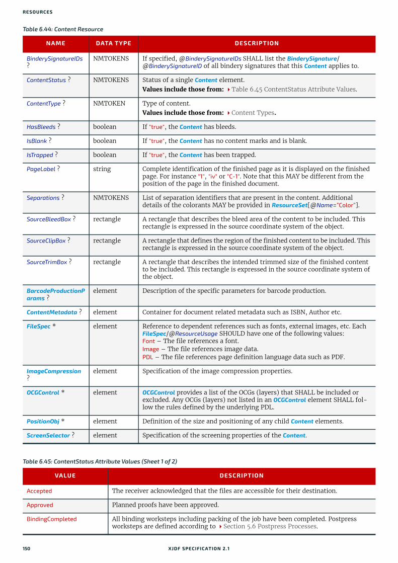
RESO URCES
Table 6.44: Content Resource
NAME DATA TYPE DESCRIPTION
BinderySignatureIDs ?
NMTOKENS If specified, @BinderySignatureIDs SHALL list the BinderySignature/@BinderySignatureID of all bindery signatures that this Content applies to.
ContentStatus ? NMTOKENS Status of a single Content element.Values include those from: Table 6.45 ContentStatus Attribute Values.
ContentType ? NMTOKEN Type of content.Values include those from: Content Types.
HasBleeds ? boolean If "true", the Content has bleeds.
IsBlank ? boolean If "true", the Content has no content marks and is blank.
IsTrapped ? boolean If "true", the Content has been trapped.
PageLabel ? string Complete identification of the finished page as it is displayed on the finished page. For instance "1", "iv" or "C-1". Note that this MAY be different from the position of the page in the finished document.
Separations ? NMTOKENS List of separation identifiers that are present in the content. Additional details of the colorants MAY be provided in ResourceSet[@Name=”Color”].
SourceBleedBox ? rectangle A rectangle that describes the bleed area of the content to be included. This rectangle is expressed in the source coordinate system of the object.
SourceClipBox ? rectangle A rectangle that defines the region of the finished content to be included. This rectangle is expressed in the source coordinate system of the object.
SourceTrimBox ? rectangle A rectangle that describes the intended trimmed size of the finished content to be included. This rectangle is expressed in the source coordinate system of the object.
BarcodeProductionParams ?
element Description of the specific parameters for barcode production.
ContentMetadata ? element Container for document related metadata such as ISBN, Author etc.
FileSpec * element Reference to dependent references such as fonts, external images, etc. Each FileSpec/@ResourceUsage SHOULD have one of the following values:Font – The file references a font.Image – The file references image data.PDL – The file references page definition language data such as PDF.
ImageCompression ?
element Specification of the image compression properties.
OCGControl * element OCGControl provides a list of the OCGs (layers) that SHALL be included or excluded. Any OCGs (layers) not listed in an OCGControl element SHALL fol-low the rules defined by the underlying PDL.
PositionObj * element Definition of the size and positioning of any child Content elements.
ScreenSelector ? element Specification of the screening properties of the Content.
Table 6.45: ContentStatus Attribute Values (Sheet 1 of 2)
VALUE DESCRIPTION
Accepted The receiver acknowledged that the files are accessible for their destination.
Approved Planned proofs have been approved.
BindingCompleted All binding worksteps including packing of the job have been completed. Postpress worksteps are defined according to Section 5.6 Postpress Processes.
150 XJDF SPECIFICATIO N 2.1

CONTENT
6.20.1 BarcodeProductionParamsBarcodeProductionParams describes the specific parameters for barcode production.
6.20.2 ContentMetadataContentMetadata is a container for metadata pertaining to this Content resource.
BindingInProgress At least one of the binding worksteps of the job is in progress.
Deleted Specifies that the content was deleted.
DigitalArtArrived Digital content has been received.
PostPressCompleted All postpress worksteps including packing of the job have been completed. Postpress worksteps are defined according to Section 5.6 Postpress Processes.
PostPressInProgress At least one of the postpress worksteps of the job is in progress.
PrePressCompleted All prepress worksteps of the job have been completed. Prepress worksteps are defined according to Section 5.4 Prepress Processes. In conventional prepress, this is the case when all plates have been made.
PrePressInProgress At least one of the prepress worksteps of the job is in progress.
PressCompleted All press worksteps of the job have been completed. Press worksteps are defined according to Section 5.5 Press Processes.
PressInProgress At least one of the press worksteps of the job is in progress.
Proofed Planned proofs have been made.
ProofSent Planned proofs sent to customer.
ShippingCompleted Final product was delivered to the customer or distributors.
ShippingInProgress Final product is being shipped.
SurfaceAssigned Pages have been assigned to their respective imposition layouts.
Table 6.46: BarcodeProductionParams Element
NAME DATA TYPE DESCRIPTION
BarcodeReproParams ?
element Description of the formatting and reproduction parameters for barcode pro-duction.
IdentificationField ? element Description of the barcode metadata.
Table 6.47: ContentMetadata Element
NAME DATA TYPE DESCRIPTION
ContactRefs ? IDREFS @ContactRefs SHALL reference the Contacts that represent the various con-tact types that are responsible for this content.
ISBN ? NMTOKEN An International Standard Book Number, that allows for both 10 and 13 digit values, see [ISO2108:2017].
Title ? NMTOKEN The title of the content.
Comment ? element If required, an abstract MAY be specified in Comment[@Name="Abstract"].
GeneralID * element Additional metadata MAY be defined by adding GeneralID elements.
Table 6.45: ContentStatus Attribute Values (Sheet 2 of 2)
VALUE DESCRIPTION
XJDF SPECIFICATIO N 2.1 151

RESO URCES
6.20.3 PositionObjPositionObj describes the size and position of the Content.
6.21 ConventionalPrintingParamsConventionalPrintingParams defines the device specific setup of the ConventionalPrinting process.
Resource PropertiesInput of Processes: ConventionalPrinting
Table 6.48: PositionObj Element
NAME DATA TYPE DESCRIPTION
Anchor ? enumeration Specifies the origin (0,0) of the coordinate system in the unrotated Content.Allowed value is from: Anchor.
CTM ? matrix Specifies the transformation matrix of the origin of Content as specified by @Anchor.Note: This is not necessarily the actual CTM that will position a given Content. The actual CTM SHALL be recalculated based on the values of @Anchor and @Size.
PageRange ? IntegerRange Reader page index in the Content referenced by RefAnchor.
PositionPolicy ? enumeration Specifies the level of freedom when applying the values specified in PositionObj.Allowed value is from: PositionPolicy.
RelativeSize ? XYPair Specifies the size of the unrotated and unscaled object, relative to the parent specified in RefAnchor.
RotationPolicy ? enumeration Specifies the level of freedom when applying the values specified in PositionObj. Allowed value is from: PositionPolicy.
Size ? XYPair Specifies the size of the unrotated and unscaled object, in points.
SizePolicy ? enumeration Specifies the level of freedom when applying the values specified in PositionObj.Allowed value is from: PositionPolicy.
RefAnchor ? element Reference to a Content that this Content is positioned relative to.If RefAnchor is not specified, PositionObj refers to the lower left of the first page specified in @PageRange.
Table 6.49: ConventionalPrintingParams Resource (Sheet 1 of 2)
NAME DATA TYPE DESCRIPTION
Drying ? enumeration The way in which ink is dried after a print run. Allowed value is from: Drying.
FirstSurface ? enumeration Printing order of the surfaces on the sheet. Allowed value is from: Side.
FountainSolution ? enumeration State of the fountain solution module in the printing units. Allowed values are:OnOff
ModuleDrying ? enumeration The way in which ink is dried in individual modules. Allowed value is from: Drying.
Powder ? float Quantity of powder in percent.
SheetLay ? enumeration Lay of input media. Reference edge of where paper is placed in a feeder.Allowed value is from: SheetLay.
152 XJDF SPECIFICATIO N 2.1

COVERAPPLICATIONPARAMS
6.22 CoverApplicationParamsCoverApplicationParams define the parameters for applying a cover to a book block.
Resource PropertiesIntent Pairing: BindingIntent
Input of Processes: CoverApplication
6.22.1 Score
Speed ?Deprecated in XJDF2.1
float Maximum print speed in the units as specified by ResourceSet[@Name="Component" AND @Usage="Output"]/@Unit per hour. If not specified then the press speed need not be reduced.Deprecation note: Use Device/@MaxRunSpeed.
WorkStyle ? enumeration The direction in which to turn the press sheet.Allowed value is from: WorkStyle.
Table 6.50: CoverApplicationParams Resource
NAME DATA TYPE DESCRIPTION
Glue * element Describes where and how to apply glue to the book block.
Score * element Describes where and how to score the cover. The sequence of Score elements SHALL specify the sequence in which the tool is applied.
Table 6.51: Score Element
NAME DATA TYPE DESCRIPTION
Offset float Position of scoring given in the operation coordinate system.
Side enumeration Specifies the side from which the scoring tool works. Allowed values are:FromInside FromOutside
Table 6.49: ConventionalPrintingParams Resource (Sheet 2 of 2)
NAME DATA TYPE DESCRIPTION
XJDF SPECIFICATIO N 2.1 153

RESO URCES
6.23 CreasingParamsCreasingParams define the parameters for creasing or grooving a sheet.
Figure 6-13: Parameters and coordinate system for cover application
Figure 6-14: Parameters and coordinate system for glue application
Book block
Center line
Score
Scored from inside
Scored from outside
YY
X
X
Negativescore offset
Origin of cover sheet coordinate
system
Origin of operation coordinate system
Positive score offset
Cover offset
Block
Front side
Side gluing onfront side Spine gluing Side gluing on
back side
Start position
Block
Glue
Back sideY
X X
X
Y Y
154 XJDF SPECIFICATIO N 2.1
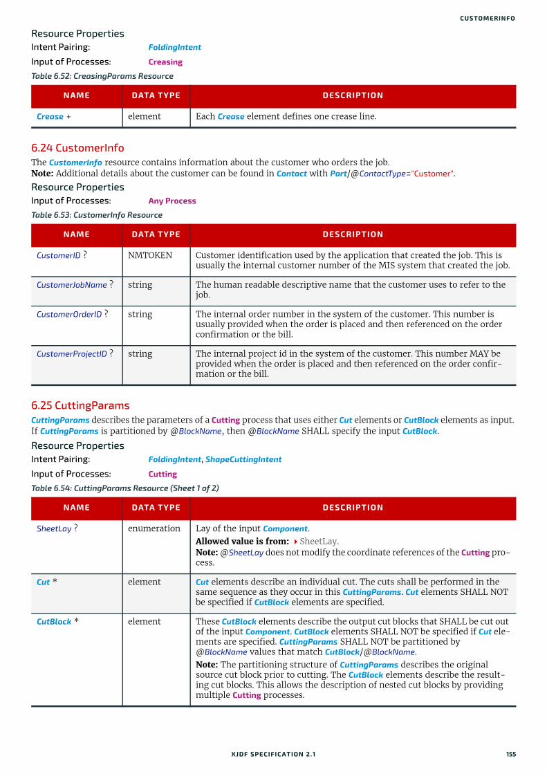
CUSTOMERINFO
Resource PropertiesIntent Pairing: FoldingIntent
Input of Processes: Creasing
6.24 CustomerInfoThe CustomerInfo resource contains information about the customer who orders the job. Note: Additional details about the customer can be found in Contact with Part/@ContactType="Customer".
Resource PropertiesInput of Processes: Any Process
6.25 CuttingParamsCuttingParams describes the parameters of a Cutting process that uses either Cut elements or CutBlock elements as input. If CuttingParams is partitioned by @BlockName, then @BlockName SHALL specify the input CutBlock.
Resource PropertiesIntent Pairing: FoldingIntent, ShapeCuttingIntent
Input of Processes: Cutting
Table 6.52: CreasingParams Resource
NAME DATA TYPE DESCRIPTION
Crease + element Each Crease element defines one crease line.
Table 6.53: CustomerInfo Resource
NAME DATA TYPE DESCRIPTION
CustomerID ? NMTOKEN Customer identification used by the application that created the job. This is usually the internal customer number of the MIS system that created the job.
CustomerJobName ? string The human readable descriptive name that the customer uses to refer to the job.
CustomerOrderID ? string The internal order number in the system of the customer. This number is usually provided when the order is placed and then referenced on the order confirmation or the bill.
CustomerProjectID ? string The internal project id in the system of the customer. This number MAY be provided when the order is placed and then referenced on the order confir-mation or the bill.
Table 6.54: CuttingParams Resource (Sheet 1 of 2)
NAME DATA TYPE DESCRIPTION
SheetLay ? enumeration Lay of the input Component.Allowed value is from: SheetLay.Note: @SheetLay does not modify the coordinate references of the Cutting pro-cess.
Cut * element Cut elements describe an individual cut. The cuts shall be performed in the same sequence as they occur in this CuttingParams. Cut elements SHALL NOT be specified if CutBlock elements are specified.
CutBlock * element These CutBlock elements describe the output cut blocks that SHALL be cut out of the input Component. CutBlock elements SHALL NOT be specified if Cut ele-ments are specified. CuttingParams SHALL NOT be partitioned by @BlockName values that match CutBlock/@BlockName. Note: The partitioning structure of CuttingParams describes the original source cut block prior to cutting. The CutBlock elements describe the result-ing cut blocks. This allows the description of nested cut blocks by providing multiple Cutting processes.
XJDF SPECIFICATIO N 2.1 155

RESO URCES
Example 6.10: Nested Cut BlocksThe following figure illustrates the nested cut blocks example.
FileSpec (CIP3) ? element Reference to a CIP3 file that contains cutting instructions in the [CIP3 - PPF] format. If FileSpec(CIP3) is specified, Cut and CutBlock SHALL NOT be present.
Figure 6-15: Nested cut blocks
Table 6.54: CuttingParams Resource (Sheet 2 of 2)
NAME DATA TYPE DESCRIPTION
B1.1 400x300
B1 400x600 B2 800x600
Input Component 1200x600
B1.2 400x300
B2.1 800x300
B2.2 800x300
156 XJDF SPECIFICATIO N 2.1

DELIVERYPARAMS
6.26 DeliveryParamsDeliveryParams provides information needed by a Delivery process. A Delivery process is the sending or receiving of one or more products to one or more delivery destinations. Delivery is also used to specify the scheduled transfer of digital assets.
Resource PropertiesInput of Processes: Delivery
<XJDF xmlns="http://www.CIP4.org/JDFSchema_2_0" JobID="Bundle" Types="Cutting Cutting"> <ResourceSet CombinedProcessIndex="0" Name="CuttingParams" Usage="Input"> <Resource> <CuttingParams> <CutBlock BlockName="B1" Box="0 0 400 600"/> <CutBlock BlockName="B2" Box="400 0 1200 600"/> </CuttingParams> </Resource> </ResourceSet> <ResourceSet CombinedProcessIndex="1" Name="CuttingParams" Usage="Input"> <Resource> <Part BlockName="B1"/> <CuttingParams> <CutBlock BlockName="B1.1" Box="0 0 400 300"/> <CutBlock BlockName="B1.2" Box="0 300 400 600"/> </CuttingParams> </Resource> <Resource> <Part BlockName="B2"/> <CuttingParams> <CutBlock BlockName="B2.1" Box="0 0 800 300"/> <CutBlock BlockName="B2.2" Box="0 300 800 600"/> </CuttingParams> </Resource> </ResourceSet> <ResourceSet Name="Component" Usage="Input"> <Resource> <Component Dimensions="1200 600 0"/> </Resource> </ResourceSet> <ResourceSet Name="Component" Usage="Output"> <Resource> <Part BlockName="B1.1"/> <Component Dimensions="400 300 0"/> </Resource> <Resource> <Part BlockName="B1.2"/> <Component Dimensions="400 300 0"/> </Resource> <Resource> <Part BlockName="B2.1"/> <Component Dimensions="800 300 0"/> </Resource> <Resource> <Part BlockName="B2.2"/> <Component Dimensions="800 300 0"/> </Resource> </ResourceSet></XJDF>
Table 6.55: DeliveryParams Resource (Sheet 1 of 2)
NAME DATA TYPE DESCRIPTION
BuyerAccount ? string Account ID of the buyer with the delivery service.
Earliest ? dateTime @Earliest SHALL specify the earliest date and time after which the delivery is intended to be made.
XJDF SPECIFICATIO N 2.1 157

RESO URCES
6.26.1 DropItem
EarliestDuration ? duration @EarliestDuration SHALL specify the earliest duration by which the delivery SHALL be made relative to the date and time that the order is ready for pro-duction.
Method ? NMTOKEN Specifies a delivery method. Values include those from: Delivery Methods.
Ownership ? enumeration Point of transfer of ownership.Allowed values are:Destination – Ownership is transferred upon receipt at destination.Origin – Ownership of goods is transferred upon leaving point of origin.
Required ? dateTime @Required SHALL specify the date and time by which the delivery is intended to be made.
RequiredDuration ? duration @RequiredDuration SHALL specify the time duration by which the delivery SHALL be made relative to the date and time that the order is ready for pro-duction.
TrackingID ? string The carrier's identifier for the delivery. The format of @TrackingID is deter-mined by the chosen carrier. If @TracingID is present, ../Resource/@Brand SHOULD be provided and SHOULD contain the brand of the chosen carrier.
Transfer ? enumeration Describes the direction and responsibility of the transfer. Allowed values are: BuyerToPrinterDeliver – The DeliveryParams describes an input to the job (e.g.,
a CD for inserting, a preprinted cover, etc.). In this case, the buyer deliv-ers the merchandise to the printer.
BuyerToPrinterPickup – The DeliveryParams describes an input to the job (e.g., a CD for inserting, a preprinted cover, etc.). In this case, the printer picks up the merchandise.
PrinterToBuyerDeliver – The DeliveryParams describes an output of the job. In this case, the printer delivers the merchandise to the buyer.
PrinterToBuyerPickup – The DeliveryParams describes an output of the job. In this case, the buyer picks up the merchandise.
DropItem * element A delivery MAY consist of multiple products. Each DropItem describes an individual Resource or Product that is part of this delivery.
FileSpec (DeliveryContents) ?
element Reference to a document that identifies the contents of this delivery, i.e. a packing list or bill of lading etc. The document SHALL be printed and pack-aged together with the delivered items.
F i l e S p e c(MailingList) ?
element A FileSpec element pointing to a mailing list. The format of the referenced mailing list is implementation dependent.
FileSpec (RemoteURL) ?
element A FileSpec element that specifies the remote location of a digital delivery.
Table 6.56: DropItem Element (Sheet 1 of 2)
NAME DATA TYPE DESCRIPTION
Amount integer @Amount SHALL be present and specify the number of products or resources that comprise this DropItem.
ItemRef IDREF @ItemRef SHALL reference the Resource, ResourceSet, ProofItem or ProductList/Product that represents the individual items to be delivered. If the DropItem references a final product, @ItemRef SHALL reference a ProductList/Product.
TotalDimensions ? shape Total dimensions in points of all individual items, including packaging.
Table 6.55: DeliveryParams Resource (Sheet 2 of 2)
NAME DATA TYPE DESCRIPTION
158 XJDF SPECIFICATIO N 2.1
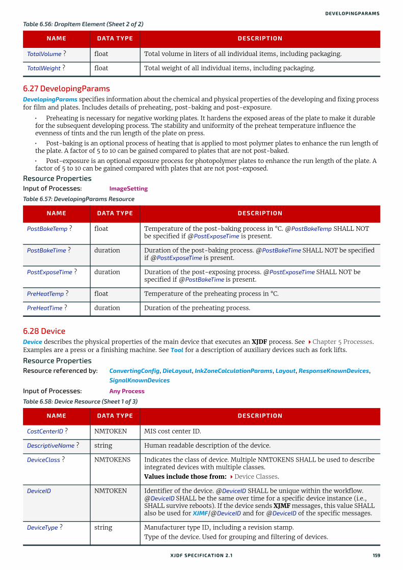
DEVELOPINGPARAMS
6.27 DevelopingParamsDevelopingParams specifies information about the chemical and physical properties of the developing and fixing process for film and plates. Includes details of preheating, post-baking and post-exposure.
• Preheating is necessary for negative working plates. It hardens the exposed areas of the plate to make it durable for the subsequent developing process. The stability and uniformity of the preheat temperature influence the evenness of tints and the run length of the plate on press.
• Post-baking is an optional process of heating that is applied to most polymer plates to enhance the run length of the plate. A factor of 5 to 10 can be gained compared to plates that are not post-baked.
• Post-exposure is an optional exposure process for photopolymer plates to enhance the run length of the plate. A factor of 5 to 10 can be gained compared with plates that are not post-exposed.
Resource PropertiesInput of Processes: ImageSetting
6.28 DeviceDevice describes the physical properties of the main device that executes an XJDF process. See Chapter 5 Processes. Examples are a press or a finishing machine. See Tool for a description of auxiliary devices such as fork lifts.
Resource PropertiesResource referenced by: ConvertingConfig, DieLayout, InkZoneCalculationParams, Layout, ResponseKnownDevices,
SignalKnownDevices
Input of Processes: Any Process
TotalVolume ? float Total volume in liters of all individual items, including packaging.
TotalWeight ? float Total weight of all individual items, including packaging.
Table 6.57: DevelopingParams Resource
NAME DATA TYPE DESCRIPTION
PostBakeTemp ? float Temperature of the post-baking process in °C. @PostBakeTemp SHALL NOT be specified if @PostExposeTime is present.
PostBakeTime ? duration Duration of the post-baking process. @PostBakeTime SHALL NOT be specified if @PostExposeTime is present.
PostExposeTime ? duration Duration of the post-exposing process. @PostExposeTime SHALL NOT be specified if @PostBakeTime is present.
PreHeatTemp ? float Temperature of the preheating process in °C.
PreHeatTime ? duration Duration of the preheating process.
Table 6.58: Device Resource (Sheet 1 of 3)
NAME DATA TYPE DESCRIPTION
CostCenterID ? NMTOKEN MIS cost center ID.
DescriptiveName ? string Human readable description of the device.
DeviceClass ? NMTOKENS Indicates the class of device. Multiple NMTOKENS SHALL be used to describe integrated devices with multiple classes.Values include those from: Device Classes.
DeviceID NMTOKEN Identifier of the device. @DeviceID SHALL be unique within the workflow. @DeviceID SHALL be the same over time for a specific device instance (i.e., SHALL survive reboots). If the device sends XJMF messages, this value SHALL also be used for XJMF/@DeviceID and for @DeviceID of the specific messages.
DeviceType ? string Manufacturer type ID, including a revision stamp.Type of the device. Used for grouping and filtering of devices.
Table 6.56: DropItem Element (Sheet 2 of 2)
NAME DATA TYPE DESCRIPTION
XJDF SPECIFICATIO N 2.1 159

RESO URCES
ICSVersions ? NMTOKENS CIP4 Interoperability Conformance Specification (ICS) Versions that this Device complies with. The value of @ICSVersions SHALL conform to the value format described in Section 3.1.1 ICS Versions Value.
JDFVersions ? enumerations Whitespace separated list of supported JDF and XJDF versions that this device supports.Allowed values are:1.1 - JDF 1.1 1.2 - JDF 1.2 1.3 - JDF 1.3 1.4 - JDF 1.4 1.5 - JDF 1.5 1.6 - JDF 1.6 1.7 - JDF 1.72.0 - XJDF 2.02.1 - XJDF 2.1, this specification.
KnownLocalizations ?
languages A list of all language codes supported by the device for localization. If not specified, then the device supports no localizations.
Manufacturer ? string Manufacturer name.
ManufacturerURL ? URL Web site for manufacturer.
MaxRunSpeed ?New in XJDF 2.1
float Maximum device speed in units per hour. The units SHALL be specified in ResourceSet/@Unit.If not specified then the speed NEED NOT be reduced.Note: See DeviceInfo/@Speed for a discussion of device speed.
Packaging ? enumerations List of packaging methods supported for job submission and job return with SubmitQueueEntry, ResubmitQueueEntry and ReturnQueueEntry. Allowed values are: XML – Unpackaged XML is supported.Zip – Zip packaging of XJMF, XJDF and digital resources is supported. See
Section 9.7 XJDF Packaging for details.
PresentationURL ? URL @PresentationURL specifies a URL to a device-provided user interface for configuration, status, etc. For instance, if the device has an embedded web server, this is a URL to the configuration page hosted on that web server.
Revision ? string Hardware or software version of the Device.Note: @SerialNumber is independent of upgrades whereas @Revision SHOULD be modified when hardware or software is changed.Note: Header/@AgentVersion is the version of the XJDF interpreter whereas @Revision applies to the hardware or software of the underlying Machine.
SerialNumber ? string Serial number of the device.
URLSchemes ? NMTOKENS List of schemes supported for retrieving XJDF files. If not specified, the con-troller does not support retrieving XJDF files from remote URLs.Values include: file – The file scheme according to [RFC1738] and [RFC3986].ftp – FTP (File Transfer Protocol).http – HTTP (Hypertext Transport Protocol).https – HTTPS (Hypertext Transport Protocol — Secure).
XJMFURL ? URL URL of the device port that will accept XJMF messages. A controller that manages a device MAY specify its own @XJMFURL when responding to KnownDevices messages.
Table 6.58: Device Resource (Sheet 2 of 3)
NAME DATA TYPE DESCRIPTION
160 XJDF SPECIFICATIO N 2.1

DEVICE
6.28.1 IconAn Icon represents a device in the user interface.
6.28.2 IconListThe IconList is a list of individual icon descriptions.
6.28.3 ModuleA Module represents a physical machine or part of a Device.
FileSpec (CurrentSchema) ?New in XJDF 2.1
element Reference to an XML schema in XSD format [XMLSchema] that describes the present limitations of the device that can be used without operator inter-vention. The referenced XML schema SHALL use the XJDF namespace to describe elements and attributes that are defined in the XJDF namespace.See Section 9.9 Use of XML Schema for Capability Descriptions for details of using XML schema for device capabilities.
FileSpec (Schema) ?New in XJDF 2.1
element Reference to an XML schema in XSD format [XMLSchema] that describes the global limitations of the device including those that can only be used with operator intervention. The referenced XML schema SHALL use the XJDF namespace to describe elements and attributes that are defined in the XJDF namespace.See Section 9.9 Use of XML Schema for Capability Descriptions for details of using XML schema for device capabilities.
IconList ? element List of locations of icons that can be used to represent the Device.
IdentificationField * element IdentificationField associates bar codes or labels with this Device.
Module * element Individual modules that are represented by this Device.
Table 6.59: Icon Element
NAME DATA TYPE DESCRIPTION
BitDepth integer Bit depth of one color.
IconUsage ? enumerations The DeviceInfo/@Status of the device that this Icon represents. If not speci-fied, the icon is independent of the status of the device.Allowed values are from: DeviceStatus.
Size XYPair Height and width of the icon in pixels.
FileSpec ? element Reference to details of the icon data.
Table 6.60: IconList Element
NAME DATA TYPE DESCRIPTION
Icon + element Individual icon description.
Table 6.61: Module Element (Sheet 1 of 2)
NAME DATA TYPE DESCRIPTION
DescriptiveName ? string Human readable description of the module.
Manufacturer ? string Manufacturer name.
ManufacturerURL ? URL Web site for manufacturer.
Table 6.58: Device Resource (Sheet 3 of 3)
NAME DATA TYPE DESCRIPTION
XJDF SPECIFICATIO N 2.1 161
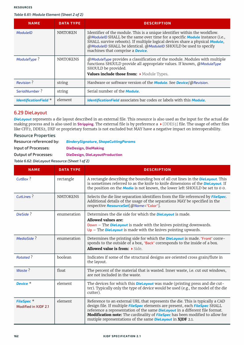
RESO URCES
6.29 DieLayoutDieLayout represents a die layout described in an external file. This resource is also used as the input for the actual die making process and is also used in Stripping. The external file is by preference a [DDES3] file. The usage of other files like CFF2, DDES2, DXF or proprietary formats is not excluded but MAY have a negative impact on interoperability.
Resource PropertiesResource referenced by: BinderySignature, ShapeCuttingParams
Input of Processes: DieDesign, DieMaking
Output of Processes: DieDesign, DieLayoutProduction
ModuleID NMTOKEN Identifier of the module. This is a unique identifier within the workflow. @ModuleID SHALL be the same over time for a specific Module instance (i.e., SHALL survive reboots). If multiple logical devices share a physical Module, @ModuleID SHALL be identical. @ModuleID SHOULD be used to specify machines that comprise a Device.
ModuleType ? NMTOKENS @ModuleType provides a classification of the module. Modules with multiple functions SHOULD provide all appropriate values. If known, @ModuleType SHOULD be provided.Values include those from: Module Types.
Revision ? string Hardware or software version of the Module. See Device/@Revision.
SerialNumber ? string Serial number of the Module.
IdentificationField * element IdentificationField associates bar codes or labels with this Module.
Table 6.62: DieLayout Resource (Sheet 1 of 2)
NAME DATA TYPE DESCRIPTION
CutBox ? rectangle A rectangle describing the bounding box of all cut lines in the DieLayout. This is sometimes referred to as the knife to knife dimensions of the DieLayout. If the position on the Media is not known, the lower left SHOULD be set to 0 0.
CutLines ? NMTOKENS Selects the die line separation identifiers from the file referenced by FileSpec. Additional details of the usage of the separations MAY be specified in the respective ResourceSet[@Name="Color"].
DieSide ? enumeration Determines the die side for which the DieLayout is made. Allowed values are:Down – The DieLayout is made with the knives pointing downwards. Up – The DieLayout is made with the knives pointing upwards.
MediaSide ? enumeration Determines the printing side for which the DieLayout is made. "Front" corre-sponds to the outside of a box, "Back" corresponds to the inside of a box. Allowed value is from: Side.
Rotated ? boolean Indicates if some of the structural designs are oriented cross grain/flute in the layout.
Waste ? float The percent of the material that is wasted. Inner waste, i.e. cut out windows, are not included in the waste.
Device * element The devices for which this DieLayout was made (printing press and die cut-ter). Typically only the type of device would be used (e.g., the model of the die cutter).
FileSpec *Modified in XJDF 2.1
element Reference to an external URL that represents the die. This is typically a CAD design file. If multiple FileSpec elements are present, each FileSpec SHALL reference a representation of the same DieLayout in a different file format.Modification note: The cardinality of FileSpec has been modified to allow for mutiple representations of the same DieLayout in XJDF 2.1.
Table 6.61: Module Element (Sheet 2 of 2)
NAME DATA TYPE DESCRIPTION
162 XJDF SPECIFICATIO N 2.1

DIELAYOUTPRODUCTIONPARAMS
6.29.1 RuleLengthElements describing the length of die rules for the different types of rules. Each RuleLength element describes the accu-mulated length of all rules of a certain type.
6.29.2 StationDescription of an individual 1-up station in a DieLayout. One station produces one shape.
6.30 DieLayoutProductionParamsParameters for the die layout.
Resource PropertiesInput of Processes: DieLayoutProduction
Media ? element Media for which this DieLayout was intended. The Media description defines important design parameters as the type of Media, dimensions, grain direc-tion or flute direction.
RuleLength * element Elements describing the length of die rules for the different types of rules. Each RuleLength element describes the accumulated length of all rules of a certain type.
Station * element Description of the stations in a DieLayout. One Station produces one shape.
Table 6.63: RuleLength Element
NAME DATA TYPE DESCRIPTION
DDESCutType integer Type of rule. Values for @DDESCutType SHALL be between "0" and "999". These values correspond to the line type as defined in [DDES3].
Length float Accumulated length of the rules of this type in the DieLayout, in points.
Table 6.64: Station Element
NAME DATA TYPE DESCRIPTION
BinderySignatureIDs?
NMTOKENS If specified, @BinderySignatureIDs SHALL list the BinderySignature/@BinderySignatureID of all BinderySignatures that are processed by this Station.
ShapeDefRef ? IDREF If present, @ShapeDefRef SHALL reference a ShapeDef that defines the shape of the Station in the DieLayout.
StationName NMTOKEN The name of the 1-up design in the DieLayout. Multiple stations with the same @StationName MAY be specified.
Table 6.65: DieLayoutProductionParams Resource
NAME DATA TYPE DESCRIPTION
Estimate ? boolean Determines if the process SHALL run in estimate mode or not. When in esti-mate mode multiple solutions SHOULD be generated.
Position ? enumeration The position of the DieLayout on the sheet.Allowed value is from: Anchor.
ConvertingConfig + element A ConvertingConfig element describes a range of sheet sizes that can be taken into account to create a new DieLayout. Typically a ConvertingConfig will cor-respond to a single combination of printing press and further finishing equipment such as die cutters.
RepeatDesc + element Step and repeat parameters for a set of ShapeDef.
Table 6.62: DieLayout Resource (Sheet 2 of 2)
NAME DATA TYPE DESCRIPTION
XJDF SPECIFICATIO N 2.1 163
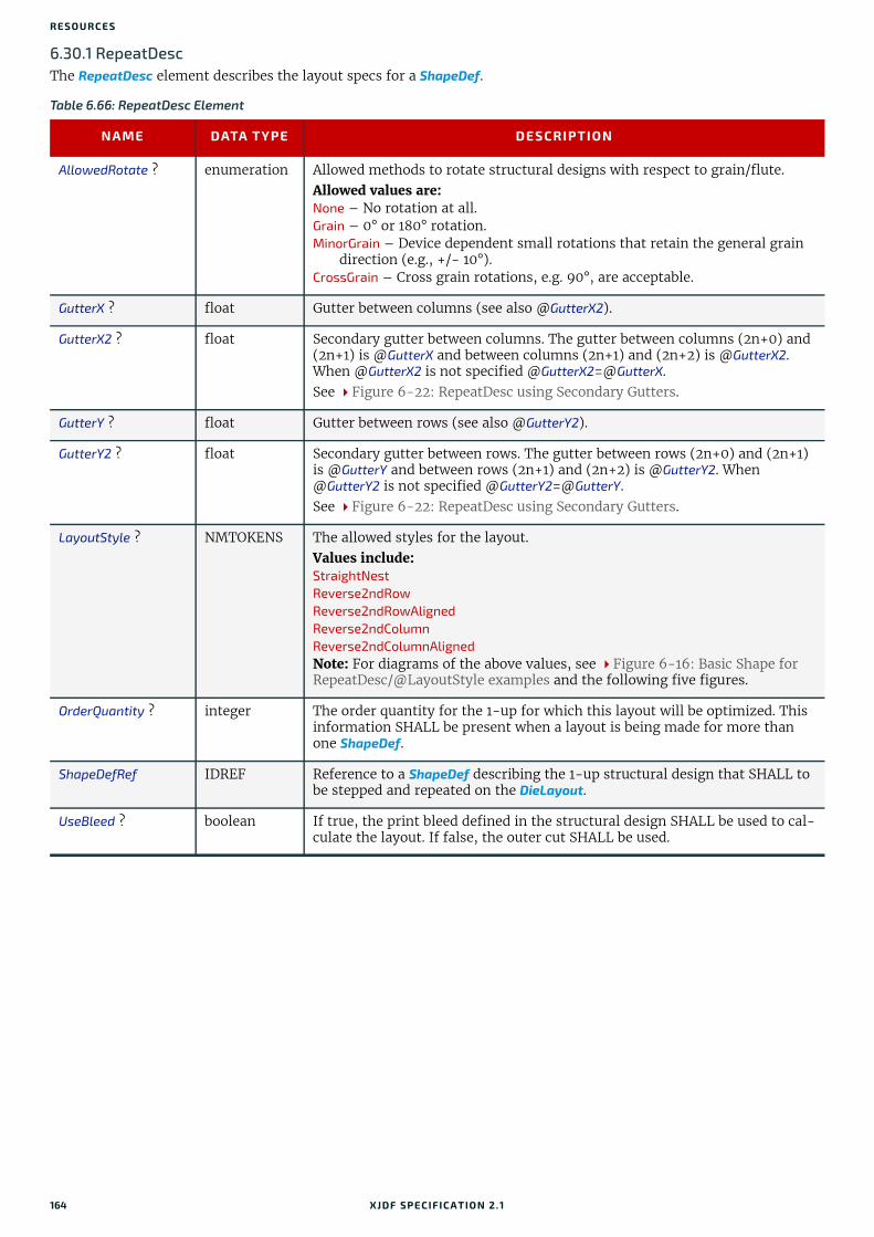
RESO URCES
6.30.1 RepeatDescThe RepeatDesc element describes the layout specs for a ShapeDef.
Table 6.66: RepeatDesc Element
NAME DATA TYPE DESCRIPTION
AllowedRotate ? enumeration Allowed methods to rotate structural designs with respect to grain/flute. Allowed values are:None – No rotation at all.Grain – 0° or 180° rotation.MinorGrain – Device dependent small rotations that retain the general grain
direction (e.g., +/- 10°).CrossGrain – Cross grain rotations, e.g. 90°, are acceptable.
GutterX ? float Gutter between columns (see also @GutterX2).
GutterX2 ? float Secondary gutter between columns. The gutter between columns (2n+0) and (2n+1) is @GutterX and between columns (2n+1) and (2n+2) is @GutterX2. When @GutterX2 is not specified @[email protected] Figure 6-22: RepeatDesc using Secondary Gutters.
GutterY ? float Gutter between rows (see also @GutterY2).
GutterY2 ? float Secondary gutter between rows. The gutter between rows (2n+0) and (2n+1) is @GutterY and between rows (2n+1) and (2n+2) is @GutterY2. When @GutterY2 is not specified @GutterY2=@GutterY. See Figure 6-22: RepeatDesc using Secondary Gutters.
LayoutStyle ? NMTOKENS The allowed styles for the layout.Values include:StraightNestReverse2ndRowReverse2ndRowAlignedReverse2ndColumnReverse2ndColumnAlignedNote: For diagrams of the above values, see Figure 6-16: Basic Shape for RepeatDesc/@LayoutStyle examples and the following five figures.
OrderQuantity ? integer The order quantity for the 1-up for which this layout will be optimized. This information SHALL be present when a layout is being made for more than one ShapeDef.
ShapeDefRef IDREF Reference to a ShapeDef describing the 1-up structural design that SHALL to be stepped and repeated on the DieLayout.
UseBleed ? boolean If true, the print bleed defined in the structural design SHALL be used to cal-culate the layout. If false, the outer cut SHALL be used.
164 XJDF SPECIFICATIO N 2.1
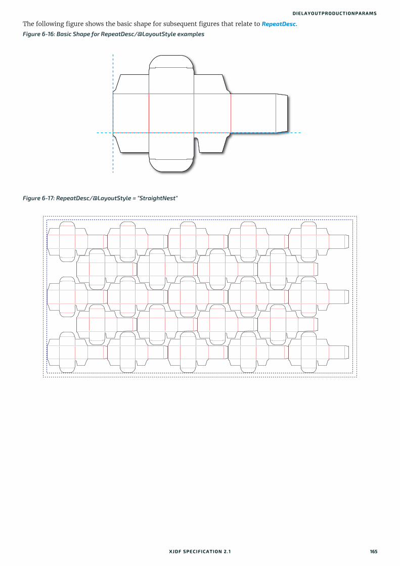
DIELAYOUTPRODUCTIONPARAMS
The following figure shows the basic shape for subsequent figures that relate to RepeatDesc.
Figure 6-16: Basic Shape for RepeatDesc/@LayoutStyle examples
Figure 6-17: RepeatDesc/@LayoutStyle = "StraightNest"
XJDF SPECIFICATIO N 2.1 165

RESO URCES
In the following figure, 1-ups on even rows are rotated 180 degrees. Even rows are shifted horizontally and vertically to obtain optimal nesting.
In the following figure, 1-ups on even rows are rotated 180 degrees. Even rows are shifted vertically to obtain optimal nesting. The even rows are not shifted horizontally (left and right edges are aligned between rows).
Figure 6-18: RepeatDesc/@LayoutStyle = "Reverse2ndRow"
Figure 6-19: RepeatDesc/@LayoutStyle = "Reverse2ndRowAligned"
166 XJDF SPECIFICATIO N 2.1

DIELAYOUTPRODUCTIONPARAMS
In the following figure, 1-ups on even columns are rotated 180 degrees. Even columns are shifted vertically and hori-zontally to obtain optimal nesting.
In the following figure, 1-ups on even columns are rotated 180 degrees. Even columns are shifted horizontally to obtain optimal nesting. No vertical shifting of even columns is done (top and bottom edges are aligned between columns).
Figure 6-20: RepeatDesc/@LayoutStyle = "Reverse2ndColumn"
Figure 6-21: RepeatDesc/@LayoutStyle = "Reverse2ndColumnAligned"
XJDF SPECIFICATIO N 2.1 167

RESO URCES
In the following figure, @LayoutStyle="Reverse2ndRow", @GutterX="36", @GutterX2="70", @GutterY="20", @GutterY2="40".
6.31 DigitalPrintingParamsDigitalPrintingParams contains details of the DigitalPrinting process.
6.31.1 Coordinate systems in DigitalPrintingSection 2.6 Coordinate Systems in XJDF defines the coordinate system for ConventionalPrinting and DigitalPrinting. Note: The paper feed direction of the idealized process is towards the X-axis, which corresponds to bottom edge first.
PropertiesIntent Pairing: VariableIntent
Input of Processes: DigitalPrinting
Figure 6-22: RepeatDesc using Secondary Gutters
Table 6.67: DigitalPrintingParams Resource (Sheet 1 of 2)
NAME DATA TYPE DESCRIPTION
Collate ? enumeration Determines the sequencing of the printed sheets when multiple copies are requested as output.Allowed values are: None – Do not collate. All copies of a sheet SHALL be printed prior to printing
the next sheet. Sheet – Collate. All sheets in one document SHALL be printed in sequence
prior to printing the next document.
ManualFeed ? boolean Indicates whether the media will be fed manually.
GutterX2 GutterXGutterX
GutterY
GutterY
GutterY2
168 XJDF SPECIFICATIO N 2.1

EMBOSSINGPARAMS
6.32 EmbossingParamsEmbossingParams contains attributes and elements used in executing the Embossing process. Embossing can also be used to model a foil stamping process.
Resource PropertiesIntent Pairing: EmbossingIntent
Input of Processes: Embossing
6.32.1 Emboss
PageDelivery ? enumeration Indicates how pages SHALL be delivered to the output bin or finisher. Note: These values refer to the orientation of the entire stack being output from the press, not individual sheets. For example, "SameOrderFaceDown" means that the stack can be picked up and turned over to find the output sheets in the same order as the input RunList with the first page on top facing up.Allowed values are: FanFold – The output is alternating face-up, face down.SameOrderFaceUp – Order as defined by the RunList, with the front sides of
the media up and the first sheet on top.SameOrderFaceDown – Order as defined by the RunList, with the front sides of
the media down and the first sheet on the bottom.ReverseOrderFaceUp – Sheet order reversed compared to "SameOrderFaceUp",
with the front sides of the media up and the last sheet on top.ReverseOrderFaceDown – Sheet order reversed compared to
"SameOrderFaceDown", with the front sides of the media down and the last sheet on the bottom.
SheetLay ? enumeration Lay of input media. Reference edge where paper is placed in feeder.Allowed value is from: SheetLay.
Sides ? enumeration Indicates whether the ByteMap SHALL be imaged on one or both sides of the media. If the RunList input to DigitalPrinting is partitioned by @Side then the input RunList provides a binding of front and back surfaces to sheets. When a different value for this attribute is encountered, it SHALL force a new sheet. However, when the same value for this attribute is restated for consecutive pages, it is the same as if that restatement were not present. Allowed values are: OneSidedBack OneSidedFrontTwoSided Note: The orientation of the front pages relative to back pages SHOULD be completely defined in the explicit or implied imposition Layout.
Table 6.68: EmbossingParams Resource
NAME DATA TYPE DESCRIPTION
ModuleID ? NMTOKEN Identifier of the embossing module in a multi-function device such as a printing press. See Module for details.
Emboss + element One Emboss element is specified for each impression.
Table 6.69: Emboss Element (Sheet 1 of 2)
NAME DATA TYPE DESCRIPTION
Direction enumeration The direction of the image. Allowed value is from: EmbossDirection.
Table 6.67: DigitalPrintingParams Resource (Sheet 2 of 2)
NAME DATA TYPE DESCRIPTION
XJDF SPECIFICATIO N 2.1 169

RESO URCES
6.33 EndSheetGluingParamsEndSheetGluingParams describes the attributes and elements used in executing the EndSheetGluing process.
EndSheetGluingParams SHOULD be partitioned by @Side.
Resource PropertiesIntent Pairing: BindingIntent
Input of Processes: EndSheetGluing
EdgeAngle ? float The angle of a beveled edge in degrees. Typical values are angles of: 30, 40, 45, 50 or 60 degrees. If @EdgeAngle is specified, @EdgeShape="Beveled" SHALL be specified.
EdgeShape ? enumeration The transition between the embossed surface and the surrounding media can be rounded or beveled (angled). Allowed values are: BeveledRounded
EmbossingType enumeration Specifies the type of embossing required.Allowed value is from: EmbossType.
Face ? enumeration Position of the embossing on the product.Allowed value is from: Face.
Height ? float The height of the levels. This value specifies the vertical distance between the highest and lowest point of the stamp, regardless of the value of @Direction.
ImageSize ? XYPair The size of the bounding box of one single image.
Position ? XYPair Position of the lower left corner of the bounding box of the embossed image in the coordinate system of the surface of the Component that is selected by @Face.
ToolRef ? IDREF @ToolRef SHALL reference the Tool that is used to make the embossing described by this Emboss.
IdentificationField ? element If @EmbossingType="Braille", IdentificationField SHALL describe the content of the Braille element.
Table 6.70: EndSheetGluingParams Resource
NAME DATA TYPE DESCRIPTION
Glue element Description of the glue that is used to attach the end sheet to the cover.
Table 6.69: Emboss Element (Sheet 2 of 2)
NAME DATA TYPE DESCRIPTION
170 XJDF SPECIFICATIO N 2.1
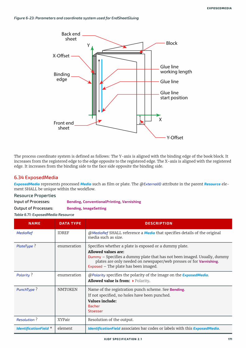
EXPOSEDMEDIA
The process coordinate system is defined as follows: The Y-axis is aligned with the binding edge of the book block. It increases from the registered edge to the edge opposite to the registered edge. The X-axis is aligned with the registered edge. It increases from the binding side to the face side opposite the binding side.
6.34 ExposedMediaExposedMedia represents processed Media such as film or plate. The @ExternalID attribute in the parent Resource ele-ment SHALL be unique within the workflow.
Resource PropertiesInput of Processes: Bending, ConventionalPrinting, Varnishing
Output of Processes: Bending, ImageSetting
Figure 6-23: Parameters and coordinate system used for EndSheetGluing
Table 6.71: ExposedMedia Resource
NAME DATA TYPE DESCRIPTION
MediaRef IDREF @MediaRef SHALL reference a Media that specifies details of the original media such as size.
PlateType ? enumeration Specifies whether a plate is exposed or a dummy plate.Allowed values are: Dummy – Specifies a dummy plate that has not been imaged. Usually, dummy
plates are only needed on newspaper/web presses or for Varnishing.Exposed – The plate has been imaged.
Polarity ? enumeration @Polarity specifies the polarity of the image on the ExposedMedia.Allowed value is from: Polarity.
PunchType ? NMTOKEN Name of the registration punch scheme. See Bending. If not specified, no holes have been punched.Values include: BacherStoesser
Resolution ? XYPair Resolution of the output.
IdentificationField * element IdentificationField associates bar codes or labels with this ExposedMedia.
Block
Back endsheet
X-Offset
Y
X
Bindingedge
Front endsheet
Glue lineworking length
Glue line
Glue linestart position
Y-Offset
XJDF SPECIFICATIO N 2.1 171

RESO URCES
6.35 FeedingParamsThe parameters for any XJDF feeder processing device.
Resource PropertiesInput of Processes: Feeding
6.35.1 CollatingItem
Note: Most real world devices process stack items one by one, and hence will hardly ever support @TransformationContext="CollateItem". This requires some kind of buffer for the stack items belonging to a single collat-ing item, and a flipping mechanism for the Winding process.
Table 6.72: FeedingParams Resource
NAME DATA TYPE DESCRIPTION
CollatingItem * element Defines the collating sequence of the input Component(s). If a CollatingItem is not defined, then one Component in the order of input Resource list is con-sumed.
Feeder * element Defines the specifics of an individual Feeder. If a Component from the input resource list is not referenced from a Feeder in this list, a system defined Feeder will be used.
Table 6.73: CollatingItem Element
NAME DATA TYPE DESCRIPTION
Amount ? integer Determines how many consecutive items shall be consumed.
ComponentRef ? IDREF References one of the input components to the process to be (partially) con-sumed by the CollatingItem element. This Component SHALL be an input of the Feeding process.
Orientation ? enumeration Named orientation of the CollatingItem relative to the input coordinate sys-tem. For details see Table 2.1 Matrices and Orientation values for describing the orientation of a Component. At most one of @Orientation or @Transformation SHALL be specified. If nei-ther is specified, no transformation is applied. The transformation specified here is applied in addition to any orientation/transformation specified in the respective Resource.
Allowed value is from: Orientation.
Transformation ? matrix Transformation of the CollatingItem relative to the input coordinate system. For details see Table 2.1 Matrices and Orientation values for describing the orientation of a Component.At most one of @Orientation or @Transformation SHALL be specified. If nei-ther is specified, no transformation is applied. The transformation specified here is applied in addition to any orientation/transformation specified in the respective Resource.
TransformationContext ?
enumeration This parameter specifies the object that SHALL be manipulated in orienta-tion/transformation, and it is important to determine the sequence of stack items after flipping.Allowed values are: CollateItem – Apply to a CollatingItem as a whole.Component – Apply to each single element of a CollatingItem individually.StackItem – Apply individually to the smallest element on the stack that can
be manipulated individually (e.g., to a single sheet in the case of a stack of sheets).
Note: If @Amount="1", Component and CollatingItem are referring to the same object and, therefore, result in the same output.
172 XJDF SPECIFICATIO N 2.1

FEEDINGPARAMS
6.35.2 Feeder
Table 6.74: Feeder Element
NAME DATA TYPE DESCRIPTION
AlternatePositions ? IntegerList Positions of alternate feeders including the feeder specified in @Position on a feeding chain. Alternate feeders share the load according to the policy defined in @FeederSynchronization. If not specified, it defaults to the value of @Position. @AlternatePositions SHALL be non-negative.
ComponentRef ? IDREF References the Component that SHALL be loaded into this Feeder. This Component SHALL be an input of the Feeding process.
FeederSynchronization ?
enumeration Specifies the synchronization of multiple Feeder elements with identical Component elements.Allowed values are: Alternate – The feeders specified in @Position SHALL alternate.Backup – This feeder is the backup feeder for the Component in case of a mis-
feed or malfunction. The priority of backup feeders SHALL be defined by their position in @AlternatePositions.
Chain – This feeder is activated as soon as the feeder prior to it in the list is empty.
Primary – This feeder is the primary feeder for the Component.
FeederType ? NMTOKEN Specifies the feeder type. Values include: AddOn – Add on feeder (e.g., CDs).BookBlock – A feeder for book blocks. Folding – A folding feeder that folds the input Component.Gluing – A gluing feeder.Roll – Roll feeder for web processes. These are also known as unwinders. Sheet – Single sheet feeder.Signature – Single signature feeder.
Loading ? NMTOKEN Specifies the feeder loading. Values include: Bundle – Stream feeder, using the output of the Bundling process.FanFold – Automatic loading of fan fold media.Manual – Manual loading of stacks.Online – Loaded by a gripper or conveyor. The "Online" value is also applicable
for @FeederType="Roll". PrintRoll – Automatic loading of single products from a print roll, using the
output of the Winding process.
Opening ? enumeration Specifies the opening of signatures.Allowed values are: Back – Overfold on back. Front – Overfold on front.None – Signatures are not opened.Sucker – Sucker opening, no overfold is required.
Position ? integer @Position of feeder on a collecting and gathering chain in chain movement direction. @Position="0" is first feeder feeding to the collecting and gathering chain. Only one Feeder SHALL be specified for any given @Position. If @Position is negative, it specifies the position counted from the back of the chain (e.g., "-1" = last position, "-2" = next to last position, etc.).
FeederQualityParams ?
element Definition of the setup and policy for feeding quality.
XJDF SPECIFICATIO N 2.1 173

RESO URCES
6.35.3 FeederQualityParamsThe FeederQualityParams element defines the setup and policy for feeding quality control. It is specified individually for each Feeder.
6.36 FoldingParamsFoldingParams describes the folding parameters, including the sequence of folding steps. After each folding step of a folding procedure, the origin of the coordinate system SHALL be moved to the lower left corner of the intermediate fold-ing product.
The order of the Crease, Cut, Fold and Perforate elements in Table 6.76 FoldingParams Resource SHALL specify the order of operations in the machine. Therefore any of the four element types MAY be specified in any order.
Resource PropertiesIntent Pairing: FoldingIntent
Input of Processes: Folding
Table 6.75: FeederQualityParams Element
NAME DATA TYPE DESCRIPTION
BadFeedQuality ? enumeration Defines the operation of the bad feed quality control. Allowed value is from: FeedQuality.
BadFeeds ? integer Number of consecutive bad feeds until the device SHALL stop.
DoubleFeedQuality ? enumeration Defines the operation of the double feed quality control. Allowed value is from: FeedQuality.
DoubleFeeds ? integer Number of consecutive double feeds until the device SHALL stop.
IncorrectComponentQuality ?
enumeration Defines the operation of the incorrect components quality control. Allowed value is from: FeedQuality.
IncorrectComponents ?
integer Number of consecutive incorrect components until the device SHALL stop.
Table 6.76: FoldingParams Resource
NAME DATA TYPE DESCRIPTION
FoldCatalog ? NMTOKEN Describes the type of fold. Values include those from: Fold Catalog.
FoldingDetails ? NMTOKEN @FoldingDetails is a system dependent descriptor of the folding. @FoldingDetails MAY be used to differentiate differing fold dimensions with the same general topology.
SheetLay ? enumeration Lay of input media.Allowed value is from: SheetLay.
FileSpec (CIP3) ? element Reference to a CIP3 file that contains folding instructions in the [CIP3 - PPF] format. If FileSpec(CIP3) is specified, Crease, Cut, Fold and Perforate SHALL NOT be present.
Crease * element Defines one or more Crease lines.
Cut * element Cut elements describe an individual cut.
Fold * element Describes the folding operations in the sequence in which they are to be car-ried out. If both @FoldCatalog and Fold elements are specified, the Fold elements have precedence, and the @FoldCatalog specifies only the topology. For instance, a cover-fold with a page size ratio of 0.52 to 0.48 would still be defined as an "F4-1".
Perforate * element Defines one or more Perforate lines.
174 XJDF SPECIFICATIO N 2.1

FONTPOLICY
6.37 FontPolicyFontPolicy defines the policies that devices SHALL follow when font errors occur while PDL files are being processed. When fonts are referenced by PDL files but are not provided, devices SHALL provide one of the following two fallback behaviors:
1 The device provides a standard default font that is substituted whenever a font cannot be found.
2 The device provides an emulation of the missing font.If neither fallback behavior is requested (i.e., both @UseDefaultFont and @UseFontEmulation are "false"), then the process SHALL fail if a referenced font is not provided.
Resource PropertiesInput of Processes: Interpreting, Trapping
6.38 GluingParamsGluingParams define the parameters for applying a generic line of glue to a component.
Resource PropertiesIntent Pairing: BindingIntent
Input of Processes: Gluing
6.39 HeadBandApplicationParamsHeadBandApplicationParams specifies how to apply head bands in hardcover book production.
Resource PropertiesInput of Processes: HeadBandApplication
Table 6.77: FontPolicy Resource
NAME DATA TYPE DESCRIPTION
PreferredFont NMTOKEN The name of a font that SHALL be used as the default font for this job.
UseDefaultFont boolean If "true", the device SHALL resort to a default font if a font cannot be found.Note: This is the normal behavior of the PostScript interpreter, which defaults to Courier when a font cannot be found.
UseFontEmulation boolean If "true", the device SHALL emulate a requested font if a font cannot be found.
Table 6.78: GluingParams Resource
NAME DATA TYPE DESCRIPTION
GluingProductionID ? NMTOKEN Defines a gluing scheme for production.
Glue * element Definition of one or more Glue line applications.
Table 6.79: HeadBandApplicationParams Resource
NAME DATA TYPE DESCRIPTION
Length ? float Length of the carrier material of the head band along the binding edge. If not specified the head band has the length of the book block.If both top and bottom head bands are specified in a partitioned ResourceSet (using Part/@Option), then:
• If @Length is not specified, then both head bands SHALL be on one carrier that has the length of the book block.
• If @Length is provided in only one of the partitions, then both head bands are on one carrier of the given length.
• If @Length is provided in both partitions, then each head band is on a separate carrier of the given length.
Width ? float Width of the head bands and carrier.
Glue * element The carrier can be applied to the book block with glue. The coordinate system for the Glue is defined in Section 6.33 EndSheetGluingParams.
XJDF SPECIFICATIO N 2.1 175

RESO URCES
6.40 HoleMakingParamsHoleMakingParams specifies the shape and positions of holes in a Component.
Resource PropertiesIntent Pairing: HoleMakingIntent
Input of Processes: HoleMaking
6.41 ImageCompressionParamsImageCompressionParams provides a set of controls that determines how images will be compressed.
Resource PropertiesInput of Processes: PDLCreation
6.42 ImageEnhancementParamsImageEnhancementParams describes the controls for manipulating images.
Resource PropertiesInput of Processes: ImageEnhancement
6.42.1 ImageEnhancementOp
6.43 ImageSetterParamsImageSetterParams specifies the settings for an imagesetter. Both filmsetter settings and platesetter settings are de-scribed with this resource.
Table 6.80: HoleMakingParams Resource
NAME DATA TYPE DESCRIPTION
HolePattern + element Description of individual or lines of HolePattern elements.
Table 6.81: ImageCompressionParams Resource
NAME DATA TYPE DESCRIPTION
ImageCompression +
element Specifies how images SHALL be compressed. If multiple ImageCompression elements apply to the same images, the compressions SHALL be applied in sequential order.
Table 6.82: ImageEnhancementParams Resource
NAME DATA TYPE DESCRIPTION
ImageEnhancementOp +
element Each ImageEnhancementOp describes an individual enhancement operation. The XML order of ImageEnhancementOp elements is significant. Multiple ele-ments that apply to the same object SHALL be applied in that XML order.
Table 6.83: ImageEnhancementOp Element
NAME DATA TYPE DESCRIPTION
Operation NMTOKEN Individual enhancement operation name. Values include:BestGuess – Best guess automated improvements based on image analysis.Blurring – Image blurring.RedEyeRemoval – Automated removal of red eye artifacts in images.Sharpening – Image sharpening.
OperationDetails ? string Additional details of the @Operation. The values are implementation specific.
SourceObjects ? enumerations Identifies which class(es) of incoming graphical objects SHALL be operated on. If @SourceObjects is not specified then ImageEnhancementOp SHALL apply to all object classes.Allowed values are from: SourceObjects.
176 XJDF SPECIFICATIO N 2.1

INK
Resource PropertiesInput of Processes: ImageSetting
6.44 InkInk describes the ink, primer, toner or varnish that is applied to a substrate when printing or varnishing. Whereas Color describes the visual properties of a colorant, Ink describes the physical material that is applied to the substrate. The de-fault unit of measurement for Ink is @Unit = “g” (gram).
Resource PropertiesIntent Pairing: ColorIntent
Input of Processes: ConventionalPrinting, DigitalPrinting, Varnishing
6.45 InkZoneCalculationParamsInkZoneCalculationParams specifies the parameters for the InkZoneCalculation process.
Resource PropertiesInput of Processes: InkZoneCalculation
Table 6.84: ImageSetterParams Resource
NAME DATA TYPE DESCRIPTION
AdvanceDistance ? float Additional media advancement beyond the media dimensions on a web fed device.
BurnOutArea ? XYPair Size of the burnout area. The area defined by @BurnOutArea is exposed, regardless of the size of the image. If not specified or "0 0", only the area defined by the image is exposed.
CenterAcross ? enumeration Specifies the axis around which a device SHALL center an image. Allowed value is from: Axis.
CutMedia ? boolean Indicates whether or not to cut the media (web-fed).
ManualFeed ? boolean Indicates whether the media will be fed manually.
MirrorAround ? enumeration This attribute specifies the axis around which a device SHALL mirror an image. Allowed value is from: Axis.
Polarity ? enumeration Definition of the polarity of the image.Allowed value is from: Polarity.
RollCut ? float Length of media to be cut off of a roll, in points.
Table 6.85: Ink Resource
NAME DATA TYPE DESCRIPTION
InkType ? NMTOKENS @InkType SHALL list specific ink type and qualities, e.g. @InkType="Gloss Relief Varnish".Values include those from: Ink and Varnish Coatings.
SpecificYield ? float Weight per area at total coverage in g/m2.
Certification *New in XJDF 2.1
element Each Certification SHALL specify an ink certification level that the ink fulfills. If more than one Certification is present, all of the ink certification levels SHALL be met.
IdentificationField * element IdentificationField associates bar codes or labels with the container of this Ink.
Table 6.86: InkZoneCalculationParams Resource (Sheet 1 of 2)
NAME DATA TYPE DESCRIPTION
PrintableArea ? rectangle Position and size of the printable area of the print cylinder in the coordinates of the Preview resource.
XJDF SPECIFICATIO N 2.1 177

RESO URCES
6.46 InkZoneProfileInkZoneProfile specifies ink zone settings that are specific to the geometry of the printing device being used. InkZoneProfile elements are independent of the device details.
Resource PropertiesInput of Processes: ConventionalPrinting
Output of Processes: InkZoneCalculation
6.47 InsertingParamsInsertingParams specifies the parameters for the Inserting process. Table 6.89 Location of Inserts shows the various components involved in an inserting process, and how they interact.
Resource PropertiesIntent Pairing: AssemblingIntent, BindingIntent
Input of Processes: Inserting
ZoneHeight ? float The width of one zone in the feed direction of the printing machine being used.
Zones ? integer The number of ink zones of the press.
ZonesY ? integer Number of ink zones in feed direction of the press.
ZoneWidth ? float The width of one zone of the printing machine being used. The width of a zone SHOULD be the width of an ink slide.
Device ? element Device provides a reference to the press that the InkZoneProfile is defined for and MAY be used to gather information on ink zone geometry.
Table 6.87: InkZoneProfile Resource
NAME DATA TYPE DESCRIPTION
ZoneHeight ? float The width of one zone in the feed direction of the printing machine being used.
ZoneSettingsX FloatList Each entry of the @ZoneSettingsX attribute is the value of one ink zone in the X direction. The first entry is the first zone, and the number of entries equals the number of zones of the printing device being used. Allowed values are in the range [0, 1] where 0 SHALL specify no ink and 1 SHALL specify 100% cov-erage.
ZoneSettingsY ? FloatList Each entry of the @ZoneSettingsY attribute is the value of one ink zone in the Y direction. The first entry is the first zone, and the number of entries equals the number of zones of the printing device being used. Allowed values are in the range [0, 1] where 0 SHALL specify no ink and 1 SHALL specify 100% cov-erage.
ZoneWidth float The width of one zone of the printing machine being used. Typically, the width of a zone is the width of an ink slide.
Table 6.88: InsertingParams Resource (Sheet 1 of 2)
NAME DATA TYPE DESCRIPTION
FinishedPage ? integer Finished page number of the mother Component on which the child Component SHALL be placed. @FinishedPage SHALL NOT be specified unless @InsertLocation="FinishedPage". Corresponds to AssemblingIntent/*/@Folio.
Table 6.86: InkZoneCalculationParams Resource (Sheet 2 of 2)
NAME DATA TYPE DESCRIPTION
178 XJDF SPECIFICATIO N 2.1
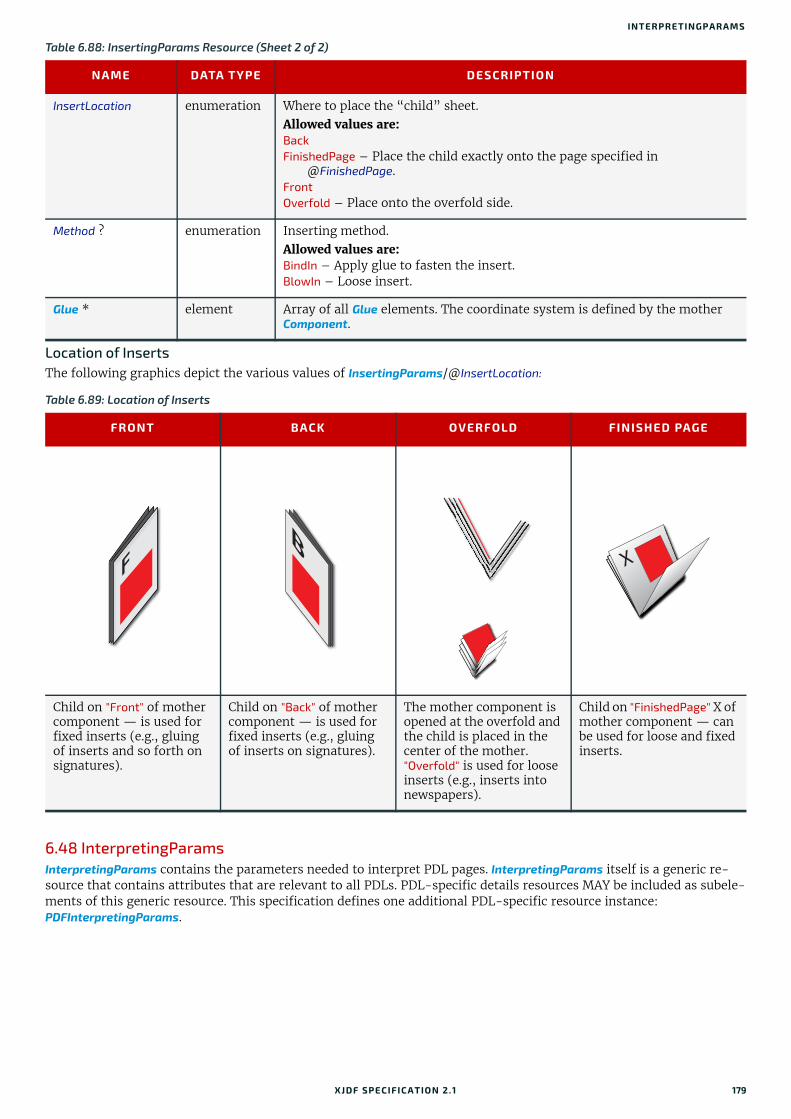
INTERPRETINGPARAMS
Location of InsertsThe following graphics depict the various values of InsertingParams/@InsertLocation: .
6.48 InterpretingParamsInterpretingParams contains the parameters needed to interpret PDL pages. InterpretingParams itself is a generic re-source that contains attributes that are relevant to all PDLs. PDL-specific details resources MAY be included as subele-ments of this generic resource. This specification defines one additional PDL-specific resource instance: PDFInterpretingParams.
InsertLocation enumeration Where to place the “child” sheet. Allowed values are: Back FinishedPage – Place the child exactly onto the page specified in
@FinishedPage. Front Overfold – Place onto the overfold side.
Method ? enumeration Inserting method. Allowed values are: BindIn – Apply glue to fasten the insert.BlowIn – Loose insert.
Glue * element Array of all Glue elements. The coordinate system is defined by the mother Component.
Table 6.89: Location of Inserts
FRONT BACK OVERFOLD FINISHED PAGE
Child on "Front" of mother component — is used for fixed inserts (e.g., gluing of inserts and so forth on signatures).
Child on "Back" of mother component — is used for fixed inserts (e.g., gluing of inserts on signatures).
The mother component is opened at the overfold and the child is placed in the center of the mother. "Overfold" is used for loose inserts (e.g., inserts into newspapers).
Child on "FinishedPage" X of mother component — can be used for loose and fixed inserts.
Table 6.88: InsertingParams Resource (Sheet 2 of 2)
NAME DATA TYPE DESCRIPTION
XJDF SPECIFICATIO N 2.1 179

RESO URCES
Resource PropertiesInput of Processes: Interpreting
Table 6.90: InterpretingParams Resource
NAME DATA TYPE DESCRIPTION
Center ? boolean Indicates whether or not the finished page image SHALL be centered within the imagable area of the media. @Center is ignored if FitPolicy/@SizePolicy="ClipToMaxPage" and clipping is specified.
FilmRef ? IDREF Reference to film Media. This Resource provides a description of the physical media that will be marked. The physical characteristics of the media MAY affect decisions made during Interpreting.
MirrorAround ? enumeration This attribute specifies the axis around which a RIP SHALL mirror an image.Note: This is mirroring in the RIP and not in the hardware of the output device. Allowed value is from: Axis.
PaperRef ? IDREF Reference to final paper Media. This Resource provides a description of the physical media that will be marked. The physical characteristics of the media MAY affect decisions made during Interpreting.
PlateRef ? IDREF Reference to plate Media. This Resource provides a description of the physical media that will be marked. The physical characteristics of the media MAY affect decisions made during Interpreting.
Polarity ? enumeration The image SHALL be RIPed in the specified polarity. Note that this is a polar-ity change in the RIP and not a polarity change in the hardware of the output device. Allowed value is from: Polarity.
PrintQuality ?Deprecated in XJDF2.1
enumeration Generic switch for setting the quality of an otherwise inaccessible device. Allowed values are:High – Highest quality available on the printer.Normal – The default quality provided by the printer.Draft – Lowest quality available on the printer.Deprecation note: Use the generic input resource PrintCondition.
ProofPaperRef ? IDREF Reference to paper Media used for proofing. This Resource provides a description of the physical media that will be marked. The physical charac-teristics of the media MAY affect decisions made during Interpreting.
Scaling ? XYPair A pair of positive real values that indicates the scaling factor for the content. Values between 0 and 1 specify that the contents SHALL be reduced, while values greater than 1 specify that the contents SHALL be expanded. Any scal-ing defined in FitPolicy SHALL be applied after the scaling defined by this attribute.
ScalingOrigin ? XYPair A pair of real values that identifies the point in the unscaled PDL page that remains at the same position after scaling. This point is defined in the coor-dinate system of the PDL page. For example, the @ScalingOrigin of a PDL page with dimensions "300 400" scaled from the PDL page center would be "150 200", regardless of the value of @Scaling.
FitPolicy ? element Allows printing even if the size of the imagable area of the media does not match the requirements of the data.
InterpretingDetails?
element Container for interpreter-specific details.
ObjectResolution * element Indicates the resolution at which the PDL contents will be interpreted in DPI. These elements MAY be different from the ObjectResolution elements pro-vided in RenderingParams.
PDFInterpretingParams ?
element Details of interpreting for PDF.
180 XJDF SPECIFICATIO N 2.1

INTERPRETINGPARAMS
6.48.1 InterpretingDetailsInterpretingDetails contains PDL-specific instructions for an interpreter.
6.48.2 PDFInterpretingParams
Table 6.91: InterpretingDetails Element
NAME DATA TYPE DESCRIPTION
MinLineWidth ? float If present, this attribute specifies the minimum width in points for PDL line objects. If a line is defined with a width smaller than this value it SHALL be adjusted to a line width equal to this value. Note: This attribute is useful for managing the consistency of thin lines across different digital printing systems that have varying imaging resolutions.
Table 6.92: PDFInterpretingParams Element (Sheet 1 of 2)
NAME DATA TYPE DESCRIPTION
EmitPDFBG ? boolean Indicates whether BlackGeneration functions SHALL be emitted.
EmitPDFHalftones ? boolean Indicates whether halftones SHALL be emitted.
EmitPDFTransfers ? boolean Indicates whether transfer functions SHALL be emitted.
EmitPDFUCR ? boolean Indicates whether under color removal functions SHALL be emitted.
HonorPDFOverprint ? boolean Indicates whether or not overprint settings in the file SHALL be honored. If "true", the setting for overprint SHALL be honored. If "false", it is expected that the device does not directly support overprint and that the PDF is pre-processed to simulate the effect of the overprint settings.
ICCColorAsDeviceColor ?
boolean Indicates whether colors specified by ICC color spaces are to be treated as device colorants.
OCGIntent ? NMTOKEN The value of @OCGIntent sets the intent for which OCGs SHALL be selected.Values include:Design – As described in [PDF1.6].View – As described in [PDF1.6].
OCGProcess ? NMTOKEN The value of @OCGProcess sets the purpose for which the Interpreting process is being performed. This, in turn, sets which value from a relevant optional content usage dictionary SHALL be used to determine whether each OCG is included in the output.Values include:Export – PDF ExportState in the export subdictionary.Print – PDF PrintState in the print subdictionary.View – PDF ViewState in the view subdictionary.Additional values are defined in [ISO19593-1:2016] or MAY be site specific.
OCGZoom ? float The value of @OCGZoom sets the magnification that SHALL be assumed in comparisons with the zoom dictionary in a relevant optional content usage dictionary to determine whether each OCG is included in the RunList. A @OCGZoom value of 1.0 corresponds to be a magnification of 100%.
PrintPDFAnnotations ?
boolean Indicates whether the contents of annotations on PDF pages SHALL be included in the output. This only refers to annotations that are set to print in the PDF file excluding trap annotations. Trap annotations are controlled with @PrintTrapAnnotations.
PrintTrapAnnotations ?
boolean Indicates whether the contents of trap annotations on PDF pages SHALL be included in the output.
TransparencyRenderingQuality ?
float Values are 0 to 1. A value of 0 represents the lowest allowable quality; 1 rep-resents the highest achievable quality.
XJDF SPECIFICATIO N 2.1 181

RESO URCES
6.48.3 ReferenceXObjParams
6.49 JacketingParamsDescription of the setup of the jacketing machinery. Jacket height and width (1 and 4 in the Figure 6-24: Setup of the jacketing machinery) are specified within the Component that describes the jacket.
Resource PropertiesIntent Pairing: BindingIntent
Input of Processes: Jacketing
OCGControl * element OCGControl provides a list of the OCGs (layers) that SHALL be explicitly included or excluded in the RunList. Any OCGs not listed in an OCGControl ele-ment SHALL follow the rules set by the referenced PDF.
ReferenceXObjParams ?
element Describes how the interpreter should handle PDF Reference XObjects.
Table 6.93: ReferenceXObjParams Element
NAME DATA TYPE DESCRIPTION
Mode NMTOKEN Specifies how to handle a Reference XObject's reference.Values include:Ignore – The reference SHALL be ignored, and no content is imaged for that
Reference XObject. If proxy content is supplied with the Reference XOb-ject, it SHALL be imaged.
ResolveAlways – An attempt SHALL be made to resolve the reference and image the graphics described by that reference.
ResolveIfPDFX5 – An attempt SHALL be made to resolve the reference ONLY if the PDF file is a valid PDF/X-5 file, AND the referenced file passes the criteria required by PDF/X-5, see [ISO15930-8:2010].
FileSpec (SearchPath) *
element An ordered list of FileSpec elements that specify search paths to search when an XObject provides a relative file specification for its target file. If not speci-fied, then the directory that contains the PDF file being interpreted SHALL be searched, and SHALL NOT be searched recursively.
Table 6.94: JacketingParams Resource
NAME DATA TYPE DESCRIPTION
FoldingDistance ? float Distance from the fold at @FoldingWidth to the other fold. If not specified, it defaults to the width of the jacket minus double the value of @FoldingWidth (symmetrical folds).
FoldingWidth float Definition of the dimension of the folding width of the front cover fold, see Figure 6-25: Parameters and coordinate system for jacketing. All other measurements are implied by the dimensions of the book.
Table 6.92: PDFInterpretingParams Element (Sheet 2 of 2)
NAME DATA TYPE DESCRIPTION
182 XJDF SPECIFICATIO N 2.1

LABELINGPARAMS
6.50 LabelingParamsLabelingParams defines the details of the Labeling process.
Resource PropertiesInput of Processes: Labeling
Figure 6-24: Setup of the jacketing machinery
1: Jacket width2: @FoldingWidth
3: @FoldingDistance
4: Jacket height
Figure 6-25: Parameters and coordinate system for jacketing
Table 6.95: LabelingParams Resource (Sheet 1 of 2)
NAME DATA TYPE DESCRIPTION
Application ? NMTOKEN Application method of the label. Values include:Glue – Glued onto the component. Loose – Loosely laid onto the component.SelfAdhesive – Self adhesive label.Staple – Stapled onto the component.
Face ? enumeration Position of the label on the bundle.Allowed value is from: Face.
1
4
3 2
B F
X
Y
Folding Distance Folding Width
Book Case
Book Block
X
Y
Origin of the process
coordinate system
Origin of the jacket coordinate system
XJDF SPECIFICATIO N 2.1 183
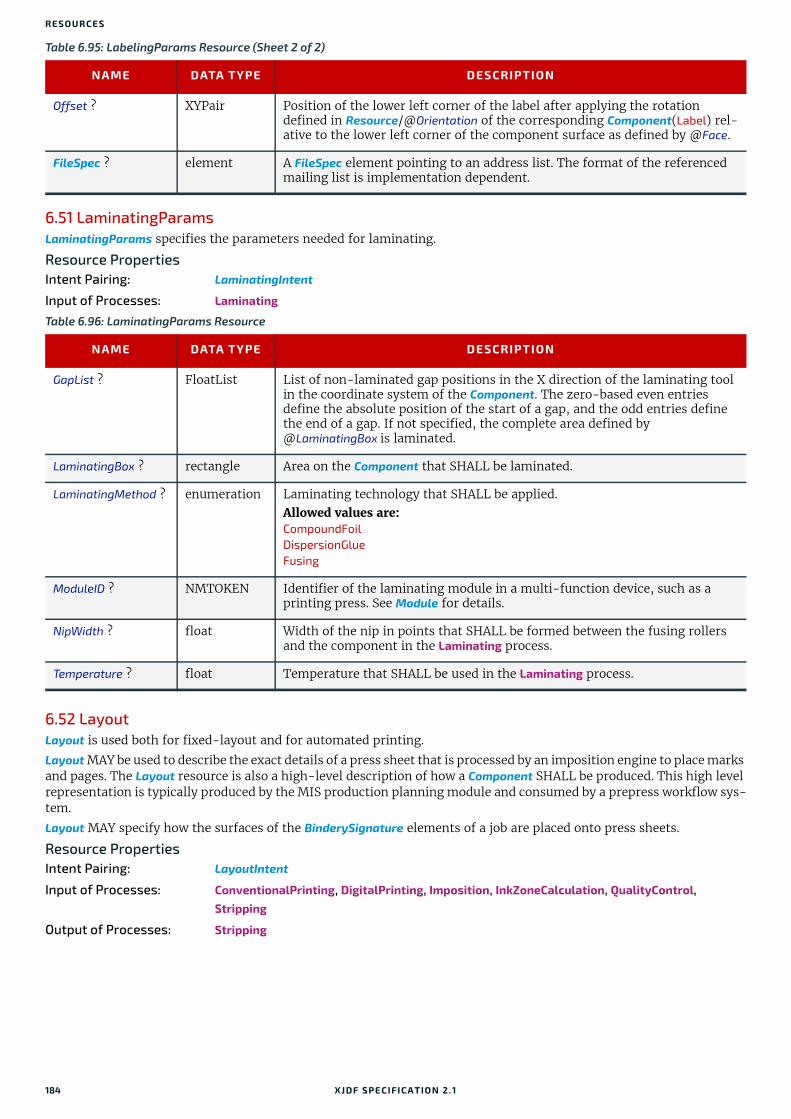
RESO URCES
6.51 LaminatingParamsLaminatingParams specifies the parameters needed for laminating.
Resource PropertiesIntent Pairing: LaminatingIntent
Input of Processes: Laminating
6.52 LayoutLayout is used both for fixed-layout and for automated printing.
Layout MAY be used to describe the exact details of a press sheet that is processed by an imposition engine to place marks and pages. The Layout resource is also a high-level description of how a Component SHALL be produced. This high level representation is typically produced by the MIS production planning module and consumed by a prepress workflow sys-tem.
Layout MAY specify how the surfaces of the BinderySignature elements of a job are placed onto press sheets.
Resource PropertiesIntent Pairing: LayoutIntent
Input of Processes: ConventionalPrinting, DigitalPrinting, Imposition, InkZoneCalculation, QualityControl, Stripping
Output of Processes: Stripping
Offset ? XYPair Position of the lower left corner of the label after applying the rotation defined in Resource/@Orientation of the corresponding Component(Label) rel-ative to the lower left corner of the component surface as defined by @Face.
FileSpec ? element A FileSpec element pointing to an address list. The format of the referenced mailing list is implementation dependent.
Table 6.96: LaminatingParams Resource
NAME DATA TYPE DESCRIPTION
GapList ? FloatList List of non-laminated gap positions in the X direction of the laminating tool in the coordinate system of the Component. The zero-based even entries define the absolute position of the start of a gap, and the odd entries define the end of a gap. If not specified, the complete area defined by @LaminatingBox is laminated.
LaminatingBox ? rectangle Area on the Component that SHALL be laminated.
LaminatingMethod ? enumeration Laminating technology that SHALL be applied. Allowed values are:CompoundFoilDispersionGlueFusing
ModuleID ? NMTOKEN Identifier of the laminating module in a multi-function device, such as a printing press. See Module for details.
NipWidth ? float Width of the nip in points that SHALL be formed between the fusing rollers and the component in the Laminating process.
Temperature ? float Temperature that SHALL be used in the Laminating process.
Table 6.95: LabelingParams Resource (Sheet 2 of 2)
NAME DATA TYPE DESCRIPTION
184 XJDF SPECIFICATIO N 2.1

LAYOUT
Table 6.97: Layout Resource (Sheet 1 of 2)
NAME DATA TYPE DESCRIPTION
Anchor ?New in XJDF 2.1
enumeration @Anchor specifies the anchor point of the grid of Position elements that SHALL remain in place on the Layout when the size of the grid of positions or the print surface changes.Note: A change of size will typically occur if Layout/@Automated="true". See FitPolicy.Allowed value is from: Anchor.
Automated ? boolean If "true", the Imposition process is expected to perform automated imposition. Layout/@Automated SHALL be identical for all Layout elements of a ResourceSet.
ExpansionBox ?New in XJDF 2.1
rectangle @ExpansionBox SHOULD specify the box in which Position elements SHALL be placed if FitPolicy/@SizePolicy is one of "CompleteGrid", "FillGrid" or "Tile". @ExpansionBox SHALL NOT be specified unless the value of FitPolicy/@SizePolicy is one of "CompleteGrid", "FillGrid" or "Tile".If @ExpansionBox is not specified, the value of @SurfaceContentsBox SHALL be used.See Figure 6-26: Use of ExpansionBox for details.
FilmRef ? IDREF Reference to film Media that SHALL provide a description of the physical media that will be marked.
InnermostShingling ? float Relative creep compensation that SHALL be applied to the innermost part of the assembled booklet. A value of "1" SHALL specify 100% creep compensa-tion. Shingling is perpendicular to the spine. Negative values go towards the spine. Values for pages between inner and outer SHALL be interpolated. Actual values of shingling are calculated by the system or operator. See Figure 6-27: Shingling for stripping and Figure 6-28: Shingling for stripping – details.
MaxCollect ? integer Maximum number of sheets that SHALL be collected into a signature. @MaxCollect modifies the pagination when automated imposition is selected by splitting documents of the input RunList into smaller virtual documents that fill exactly one signature. Thus the ord counting within a Layout SHALL be restarted at 0 after @MaxCollect sheets. The distribution of signatures with less than @MaxCollect sheets within the final product is implementation dependent.Example: If 10 sheets are required and @MaxCollect=4, then 3-3-4, 4-4-2 or any permutations are possible. See also @MinCollect.
If not specified, all sheets SHALL be collected into one signature.
MinCollect ? integer Minimum number of sheets that SHALL be collected into a signature. @MinCollect modifies the pagination when automated imposition is selected. The distribution of signatures with less than @MaxCollect sheets within the final product is implementation dependent.Example: If 10 sheets are required and @MaxCollect=4, @MinCollect=3, then only 3-3-4, or any permutations are possible.Example: If 2 sheets are required and @MinCollect=3, then a third sheet with only blank pages SHALL be produced.
OutermostShingling ?
float Relative creep compensation that SHALL be applied to the outermost part of the assembled booklet. A value of "1" SHALL specify 100% creep compensa-tion. Shingling is perpendicular to the spine. Negative values go towards the spine. Values for pages between inner and outer SHALL be interpolated. Actual values of shingling are calculated by the system or operator. See Figure 6-27: Shingling for stripping and Figure 6-28: Shingling for stripping – details.
PaperRef ? IDREF Reference to final paper Media that SHALL provide a description of the phys-ical media that will be marked.
PlateRef ? IDREF Reference to plate Media that SHALL provide a description of the physical media that will be marked.
XJDF SPECIFICATIO N 2.1 185

RESO URCES
ProofPaperRef ? IDREF Reference to paper Media that SHALL be used for proofing and that SHALL provide a description of the physical media that will be marked.
SheetLay ?New in XJDF 2.1
enmeration Lay of the input media on the press. See ConventionalPrintingParams/@SheetLay and DigitalPrintingParams/@SheetLay.
Allowed value is from: SheetLay.
SurfaceContentsBox?
rectangle This box, specified in Layout-coordinate space, defines the area into which PlacedObject elements SHALL be positioned. Content that is outside of the area specified by @SurfaceContentsBox SHALL be clipped. The lower left cor-ner of the rectangle establishes the coordinate system onto which the content SHALL be positioned and SHOULD have a value of "0 0". If this attribute is not supplied, the origin SHALL be "0 0" and the extent is undefined.
WorkStyle ? enumeration The direction in which to turn the press sheet. Allowed value is from: WorkStyle.
Device * element List of Device resources that the MIS expects to execute this Layout. This MAY include prepress devices, presses or finishing devices.
FileSpec (ExternalImpositionTemplate) ?
element Reference to an external imposition template in a proprietary format. Layout SHOULD NOT contain information that overlaps information specified in FileSpec(ExternalImpositionTemplate). Information specified in Layout SHALL override parameters specified in FileSpec(ExternalImpositionTemplate).
FitPolicy ? element Specifies automated fit policy for Position elements that are placed onto the surface that is specified in @ExpansionBox.
PlacedObject * element PlacedObject elements specify content or marks that SHALL be placed on the surface in the order in which they occur in the Layout. All PlacedObject ele-ments SHALL be specified in Layout Resources that contain at least one Part/@Side.
Position * element The Position elements specify how the BinderySignature SHALL be placed onto a sheet. Multiple Position objects that reference the same BinderySignature specify multiple identical BinderySignature elements with the same content. If Position elements are specified and @WorkStyle="WorkAndTurn" or @WorksStyle="WorkAndTumble" the mirrored Position elements are not implied and Position elements SHALL be specified for those positions.
SheetActivation ? element Specifies the conditions under which the optional sheet defined by this Layout SHALL be produced. SheetActivation SHALL only be present when Layout/@Automated="true". SheetActivation SHALL activate the surface as specified by Part/@Side if pres-ent. Thus if two surfaces are present in the Layout and only one surface con-tains SheetActivation, then the sheet shall be printed on one side only. If Part/@Side is not specified, e.g. if the Layout is used as an input to Stripping, then SheetActivation SHALL apply to both surfaces of the sheet.
StripMark * element StripMark provides a description of production marks for Stripping in the context of the Layout. See also PlacedObject/MarkObject for a description of the individual marks.
Table 6.97: Layout Resource (Sheet 2 of 2)
NAME DATA TYPE DESCRIPTION
186 XJDF SPECIFICATIO N 2.1

LAYOUT
Figure 6-26: Use of ExpansionBox
Figure 6-27: Shingling for stripping
Figure 6-28: Shingling for stripping – details
@ExpansionBox
Media
@SurfaceContentsBox StripMark
StripMarkSSStStSt iiiiri MMMpMarkkkkk
BinderySignature
SignatureCell SignatureCell
SignatureCell SignatureCell
BinderySignature
Position Position
SignatureCell SignatureCell
SignatureCell SignatureCell
outer
inner
Outer shingling:
the outer pages are moved
Inner shingling:
the inner pages are moved
Mix of Inner and
Outer shingling:
both inner and outer pages are moved
120
Outer pages
Outer shingling
Inner shingling
Neutral point
Inner pages
Outer shingling
Inner shingling
Outer shingling
Inner shingling
XJDF SPECIFICATIO N 2.1 187

RESO URCES
6.52.1 CIELABMeasuringFieldDeprecated in XJDF 2.1
6.52.2 ContentObjectContentObject elements identify containers for page content on a surface. They SHALL be filled from the RunList(Document) of the Imposition or Stripping process. ContentObject SHALL be an empty element.
6.52.3 DensityMeasuringFieldDeprecated in XJDF 2.1
6.52.4 MarkObjectMarkObject elements identify containers for production marks on a surface. If the containing Layout is used as an input to Imposition, then the PDL SHALL exist and the marks SHALL be filled from the RunList (Marks) of the Imposition process. If the containing Layout is used as an input to Stripping, the imposition engine SHALL generate the marks on the fly. The content data in individual MarkObject elements MAY contain multiple logical marks.
Table 6.98: MarkObject Element
NAME DATA TYPE DESCRIPTION
ContentRef ? IDREF @ContentRef SHALL refer to the parent PlacedObject of the ContentObject that SHALL define the scope of the RunList metadata that is used to evaluate Condition elements that are descendants of the parent PlacedObject of this MarkObject.
ColorControlStrip * element ColorControlStrip describes a color control strip.
CutMark * element CutMark describes cut marks on a sheet.
RegisterMark * element RegisterMark describes a register mark that can be used to measure color registration.
ScavengerArea * element ScavengerArea describes a scavenger area for removing excess ink from printed sheets.
188 XJDF SPECIFICATIO N 2.1

LAYOUT
Example 6.11: ContentRefThe following example illustrates a layout with two pages, one of which is conditionally skipped for the first page of a chapter. Each page has an associated RegisterMark. The MarkObject that specifies the register mark that is associated with the conditional page references that page with @ContentRef.
6.52.5 PageActivationPageActivation SHALL define when content SHALL be conditionally placed in its parent PlacedObject. Before placing page content from a RunList into a PlacedObject, PageActivation/Condition SHALL be evaluated in the context of the current partition of the RunList.
6.52.6 PageConditionThe PageCondition element defines restrictions on when content SHALL NOT be placed in its parent PlacedObject. Before placing content from a RunList into a PlacedObject the PageCondition/Condition elements SHALL be evaluated in the con-text of the current partition of the RunList. If the result of the evaluation is "true", this PlacedObject SHALL be skipped and the current content SHALL be placed into the location defined by the next PlacedObject that consumes the same RunList. This corresponds to incrementing the effective @Ord value of the page and all following pages in the RunList by 1, effectively incrementing the total number of pages of the RunList. If the next PlacedObject is also restricted then the process SHALL be repeated.
<ResourceSet Name="Layout" Usage="Input"> <Resource> <Part Side="Front"/> <Layout Automated="true"> <PlacedObject CTM="1 0 0 1 0 0" Ord="0"> <ContentObject/> </PlacedObject> <PlacedObject CTM="1 0 0 1 500 0" ID="po_1" Ord="1"> <ContentObject/> <PageCondition> <Condition PartContext="DocIndex"> <Part RunIndex="0 0"/> </Condition> </PageCondition> </PlacedObject> <PlacedObject CTM="1 0 0 1 0 500" Ord="0"> <MarkObject> <RegisterMark/> </MarkObject> </PlacedObject> <PlacedObject CTM="1 0 0 1 500 500" Ord="1"> <MarkObject ContentRef="po_1"> <RegisterMark/> </MarkObject> </PlacedObject> </Layout> </Resource></ResourceSet>
Table 6.99: PageActivation Element
NAME DATA TYPE DESCRIPTION
Condition + element This PageActivation SHALL be applied when all Condition elements evaluate to true.
Table 6.100: PageCondition Element
NAME DATA TYPE DESCRIPTION
Condition + element This PageCondition SHALL be applied when all Condition elements evaluate to true.
XJDF SPECIFICATIO N 2.1 189

RESO URCES
Example 6.12: PageConditionThe following example shows how PageCondition can be used to force a chapter boundary to be on a specific page side. PlacedObject/PageCondition/Condition contains a Part element that evaluates to true whenever @RunIndex is 0, i.e. the first page in the context of each chapter as specified by @PartContext.Note: Chapters are represented as documents in this example.
6.52.7 PlacedObjectPlacedObject elements describe any kind of marks or content on a surface. They SHALL contain exactly one of ContentObject or MarkObject that describes additional details of the page content or production mark that the PlacedObject represents.
<ResourceSet Name="Layout" Usage="Input"> <Resource> <Part Side="Front"/> <Layout Automated="true"> <PlacedObject CTM="1 0 0 1 0 0" Ord="0"> <ContentObject/> </PlacedObject> <PlacedObject CTM="1 0 0 1 500 0" Ord="1"> <ContentObject/> <PageCondition> <Condition PartContext="DocIndex"> <Part RunIndex="0 0"/> </Condition> </PageCondition> </PlacedObject> </Layout> </Resource></ResourceSet>
Table 6.101: PlacedObject Element (Sheet 1 of 3)
NAME DATA TYPE DESCRIPTION
Anchor ? enumeration Specifies the anchor point of the PlacedObject that SHALL remain in place on the surface when the value of @TrimSize changes. @Anchor is specified in the coordinate system of the PlacedObject prior to application of @CTM.Note: The @Anchor attribute is metadata used to identify (to an imposition generation utility) a fixed anchor point reference to an abstract content page. This may occur when a Layout resource is used as a template for that utility. @Anchor SHALL have no effect on processing when a Layout resource is input to the Imposition process.Allowed value is from: Anchor.
ClipBox ? rectangle Clipping rectangle in terms of the coordinates of the @SurfaceContentsBox.
ClipPath ? PDFPath Clip path for the PlacedObject in the coordinates of the @SurfaceContentsBox (lower left of @SurfaceContentsBox is used as reference zero point, same as for @ClipBox). The actual clip region is the intersection of @ClipBox and @ClipPath, or the intersection of @ClipBox and @SourceClipPath. In both cases two regions are applied sequentially and the resulting clip region is smaller than either of those regions.@ClipPath and @SourceClipPath SHALL NOT be specified in the same PlacedObject. @ClipPath SHOULD be specified when both @ClipPath and @SourceClipPath are known because @ClipPath provides a more stable coordi-nate system (not sensitive to shifts caused by editing the page).
CTM matrix The coordinate transformation matrix (CTM — a Postscript term) of the object in the @SurfaceContentsBox. The origin of the source coordinate sys-tem is the lower left (expressed in the source coordinate system) of the object and the origin of the destination coordinate system is lower left of the @SurfaceContentsBox. For details, see Section 2.6.1.1 Source Coordinate Systems.Note: @CTM SHALL be recalculated if the object is replaced afterwards with a new object with different dimensions.
190 XJDF SPECIFICATIO N 2.1

LAYOUT
HalfTonePhaseOrigin ?
XYPair Location of the origin for screening of this PlacedObject. Specified in the coordinate system of @SurfaceContentsBox.
ID ? ID Identifier for referencing this PlacedObject.
Ord ? integer @Ord SHALL specify a zero-based reference to an index in the RunList that is selected by the presence of either ContentObject or MarkObject. The index SHALL be incremented for every page in the referenced PDL. The @Ord value of the first page of a RunList SHALL have the value "0".If Layout/@Automated="true", @Ord MAY be a negative integer. In this case, the explicit @Ord for each iteration of the automated Layout SHALL be calcu-lated by subtracting the appropriate number of @Ord values from the back of the document or the position in the document that is calculated from Layout/@MaxCollect and Layout/@MinCollect. For details on automated Layout, see Section 5.4.8 Imposition.
PositionRef ? IDREF Reference to the Position that defines where this PlacedObject SHALL be located.
SourceClipPath ? PDFPath Clip path for the PlacedObject in the source coordinate system. @SourceClipPath is applied to the referenced source object in addition to any clipping that is internal to the object. Internal transformation of the source object (Rotation key in PDF, Orientation Tag in TIFF etc.) SHALL be applied prior to applying @SourceClipPath.@ClipPath and @SourceClipPath SHALL NOT be specified in the same PlacedObject.See @ClipPath for more details.See Section 2.6.1.1 Source Coordinate Systems for definitions of source coordinate systems.
TrimCTM ? matrix The transformation matrix of the trim box to be applied to the object’s refer-enced content in the coordinate system of @SurfaceContentsBox. Note that imposition programs that execute the Layout SHALL recalculate the @CTM in case the referenced content is replaced with new referenced content having different dimensions, otherwise the position of the content inside the trim box will shift. This recalculation is based on @Anchor, @TrimCTM, @TrimSize and trim box.Note: The @TrimCTM attribute may be used by an imposition generation utility when a Layout resource is used as a template for that utility. @TrimCTM SHALL have no effect on processing when a Layout resource is input to the Imposition process.
TrimSize ? XYPair The size of the object's trim box as viewed in the object source coordinates (@TrimCTM scaling and rotation NOT applied). @TrimSize is needed when replacing the object by a new object with a differ-ent dimension.When a Layout resource is input to the Imposition process, @TrimSize speci-fies the bounding box that SHALL be used for scaling and rotation when pro-cessing Layout/FitPolicy.Note: Recalculation of PlacedObject/@CTM is only necessary when the Stripping process or application needs to replace some pages from the provid-ed RunList (using the Layout as a kind of imposition “template”). To ensure correct placement of a new page in the Layout, PlacedObject/@CTM recalcula-tions SHOULD always be done according to PlacedObject/@TrimCTM and PlacedObject/@TrimSize. Together, these two attributes represent the trim-ming information of the imposition software page, which is not always the same as the original RunList page trimming information.Usage of both PlacedObject elements @TrimCTM and @TrimSize attributes will allow page replacements on any type of imposition Layout.
ContentObject ? element If a ContentObject is present, this PlacedObject shall be filled from RunList(Document) if it is used in the context of an Imposition or Stripping process. Exactly one of either ContentObject or MarkObject SHALL be present.
Table 6.101: PlacedObject Element (Sheet 2 of 3)
NAME DATA TYPE DESCRIPTION
XJDF SPECIFICATIO N 2.1 191

RESO URCES
6.52.8 PositionThe Position element allows the aligned placement of a BinderySignature onto a Layout.
MarkObject ? element Details of the production mark. Exactly one of either ContentObject or MarkObject SHALL be present.
PageActivation ? element PageActivation defines conditions on which page content SHALL be placed in the parent PlacedObject. If PageActivation is present, the page SHALL NOT be filled into that PlacedObject unless the RunList matches a partition specified in any of the PageActivation/Part elements. PageActivation SHALL only be present when Layout/@Automated="true".
PageCondition ? element PageCondition defines conditions on which page content SHALL NOT be placed in the parent PlacedObject. If PageCondition is present, the page SHALL NOT be filled into that PlacedObject if the RunList matches a partition speci-fied in any of the PageCondition/Part elements. PageCondition SHALL only be present when Layout/@Automated="true".
Table 6.102: Position Element (Sheet 1 of 2)
NAME DATA TYPE DESCRIPTION
AbsoluteBox ? rectangle Absolute position, in points, of the display area of this BinderySignature on the front side of the Layout.The BinderySignature is placed onto the display area after applying the @Orientation transformation.The display area SHALL include the absolute margins defined by @MarginTop, @MarginBottom, @MarginLeft and @MarginRight. @AbsoluteBox overrides @RelativeBox if both are specified.If @AbsoluteBox is specified, it SHALL be used as is for all imposition calcula-tions.
Anchor ?New in XJDF 2.1
enumeration Specifies the anchor point of the BinderySignature that SHALL remain in place on the Position prior to applying Position/@Orientation when the size of BinderySignature changes in an immutable Position. @Anchor SHALL NOT be specified, if the value of Layout/FitPolicy/@SizePolicy is one of "CompleteGrid" or "FillGrid".Note: A change of size will typically occur if Layout/@Automated="true".Allowed value is from: Anchor.
BinderySignatureID ? NMTOKEN If present, @BinderySignatureID SHALL reference a BinderySignature/../Part/@BinderySignatureID that SHALL be placed onto the layout at this position. If @BinderySignatureID is not specified, individual pages SHALL be placed at this Position. If one or more BinderySignature/MultiPageFold is present in the ref-erenced BinderySignature, then all BinderySignatures that are referenced by BinderySignature/MultiPageFold SHALL be placed in this position. Multiple identical MultiPageFold/@BinderySignatureID values SHALL be specified to indicate multi-up production of the same BinderySignature.
BlockName ? NMTOKEN Identifies a CutBlock resulting from a Cutting process if the element specified by the Position is created by Cutting.
GangElementID ? NMTOKEN If present, @GangElementID SHALL reference a GangElement element that was placed in this position by SheetOptimizing.
ID ? ID Identifier of this Position. @ID SHALL be used to link PlacedObject elements to a Position.
MarginBottom ? float Bottom margin, in points, to be left outside of the BinderySignature that this Position applies to. The coordinate system is defined by the front side of the Layout.
MarginLeft ? float Left margin, in points, to be left outside of the BinderySignature that this Position applies to. The coordinate system is defined by the front side of the Layout.
Table 6.101: PlacedObject Element (Sheet 3 of 3)
NAME DATA TYPE DESCRIPTION
192 XJDF SPECIFICATIO N 2.1

LAYOUT
Example 6.13: Use of @PositionOrdThe following example illustrates the use of Position/@PositionOrd to distribute four BinderySignatures on a gang job with two sheets.
MarginRight ? float Right margin, in points, to be left outside of the BinderySignature that this Position applies to. The coordinate system is defined by the front side of the Layout.
MarginTop ? float Top margin, in points, to be left outside of the BinderySignature that this Position applies to. The coordinate system is defined by the front side of the Layout.
Orientation ? enumeration Named orientation describing the transformation of the orientation of the BinderySignature on the Layout. For details, see Table 2.1 Matrices and Orientation values for describing the orientation of a Component.Allowed value is from: Orientation.
PositionOrd ?New in XJDF 2.1
integer @PositionOrd contains the index of the Position element on the Layout for cal-culating RunList/@Ord if multiple BinderySignature elements with no natural page ordering are ganged on one or more sheets of a Layout. The values that are calculated for PlacedObject/@Ord SHALL ascend in the sequence of @PositionOrd. See Example... If multiple Position elements with the same value of @BinderySignatureID are present, the value of @PositionOrd SHALL be identical.
RelativeBox ? rectangle @RelativeBox is a rough definition of the general position of the display area of this BinderySignature on the front side of the Layout. The BinderySignature SHALL be placed onto the display area after applying the @Orientation trans-formation.The display area SHOULD include the absolute margins defined by @MarginTop, @MarginBottom, @MarginLeft and @MarginRight. @AbsoluteBox overrides @RelativeBox if both are specified.If neither @AbsoluteBox nor @RelativeBox are specified, the full relative media box "0 0 1.0 1.0" SHALL be applied.
StackDepth ? integer Maximum number of sheets on a stack for cut and stack imposition. Imple-mentations SHOULD generate the minimum stack size to accommodate the available number of input pages. If Position/@Orientation specifies a flip of the pages, then the stack SHALL be filled in descending page order.
StackOrd ? integer Index of the stack. The stacks SHALL be processed in the sequence of ascend-ing @StackOrd. If @StackOrd is specified for any individual Layout partition, @StackOrd SHALL be specified for all Position elements of that Layout.
Table 6.102: Position Element (Sheet 2 of 2)
NAME DATA TYPE DESCRIPTION
XJDF SPECIFICATIO N 2.1 193

RESO URCES
6.52.9 SheetActivation
SheetActivation specifies the conditions under which an optional sheet SHALL be produced.
6.52.10 More about Layout
6.52.10.1 Partition Key RestrictionsIf PlacedObject elements are placed onto a Layout, Part/@Side SHALL be specified.
<ResourceSet Name="Layout" Usage="Output"> <Resource> <Part SheetName="Sheet1"/> <Layout> <Position BinderySignatureID="BS_0_0" GangElementID="Gang_0" PositionOrd="0" RelativeBox="0 0 0.5 0.5"/> <Position BinderySignatureID="BS_0_0" GangElementID="Gang_0" PositionOrd="0" RelativeBox="0 0.5 0.5 1"/> <Position BinderySignatureID="BS_1_0" GangElementID="Gang_1" PositionOrd="1" RelativeBox="0.5 0 1 0.5"/> <Position BinderySignatureID="BS_1_0" GangElementID="Gang_1" PositionOrd="1" RelativeBox="0.5 0.5 1 1"/> </Layout> </Resource> <Resource> <Part SheetName="Sheet2"/> <Layout> <Position BinderySignatureID="BS_2_0" GangElementID="Gang_2" PositionOrd="2" RelativeBox="0 0 0.5 0.5"/> <Position BinderySignatureID="BS_2_0" GangElementID="Gang_2" PositionOrd="2" RelativeBox="0 0.5 0.5 1"/> <Position BinderySignatureID="BS_3_0" GangElementID="Gang_3" PositionOrd="3" RelativeBox="0.5 0 1 0.5"/> <Position BinderySignatureID="BS_3_0" GangElementID="Gang_3" PositionOrd="3" RelativeBox="0.5 0.5 1 1"/> </Layout> </Resource></ResourceSet>
Figure 6-29: RelativeBox including margins
Table 6.103: SheetActivation Element
NAME DATA TYPE DESCRIPTION
Condition + element This SheetActivation shall be applied when all Condition elements evaluate to true for any ContentObject that is supplied on the unconditional Layout parti-tion that is currently active.
MarginBottomdisplay area
MarginTop
RelativeBox
BinderySignature
Mar
ginL
eft M
arginRight
X
Y
194 XJDF SPECIFICATIO N 2.1

LAYOUT
All PlacedObject elements that are intended to be imaged on one surface SHALL be specified in one partition.
6.52.10.2 CTM DefinitionsThe following are explanations of the terms used in this section and beyond:
• Dimensions of object – The width and height of either the box defined to include all drawings for this file format, or the artificial box that includes these drawings for file formats that have no clearly defined box for this.
• Trim box of the object – A rectangle that is PDL-specific that indicates the area of the object that indicates the intended trimming area.
6.52.10.3 Finding the Trim Box of an ObjectRunList/@SourceTrimBox always takes precedence over boxes defined inside the PDL. Make sure that RunList/@SourceTrimBox is updated after replacing elements. The following is a list of names used for the real trim box in various file formats:
• PostScript (PS) – PageSize
• Encapsulated PostScript (EPS) – CropBox
• Portable Document Format (PDF) – TrimBox
• Raster files – entire areaIf this information is not available, alternative sources for trim box information can include:
• EPS – HiResBoundingBox then BoundingBox
• PDF – CropBox then MediaBoxNote: These boxes might not be correct in all cases.
6.52.10.4 Using Ord to Reference Elements in RunList ResourcesPlacedObject/@Ord represents a reference to a logical page in a RunList. The index SHALL be incremented for every page of the RunList. The reference shall be calculated in the context of the ResourceSet. The following examples illustrate the usage of @Ord.
Example 6.14: RunList: Simple Multi-File RunListThis example specifies all pages contained in File1.pdf and File2.pdf. File 1 has 6 pages, file 2 has an unknown number of pages.
<XJDF xmlns="http://www.CIP4.org/JDFSchema_2_0" JobID="RunList" Types="Imposition"> <ResourceSet Name="RunList" Usage="Input"> <Resource> <Part Run="R1"/> <RunList NPage="6" Pages="0 5"> <FileSpec URL="File:///File1.pdf"/> </RunList> </Resource> <Resource> <Part Run="R2"/> <RunList Pages="0 -1"> <FileSpec URL="File:///File2.pdf"/> </RunList> </Resource> </ResourceSet></XJDF>
Table 6.104: Example of Ord Attribute in PlacedObject Elements
ORD FILE PAGE ORD FILE PAGE
0 File1 0 1 File1 1
2 File1 2 3 File1 3
4 File1 4 5 File1 5
6 File2 0 7 File2 1
8 File2 2 (n) File2 (n - 6)
XJDF SPECIFICATIO N 2.1 195
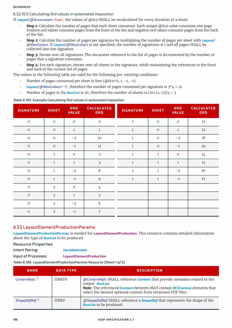
RESO URCES
6.52.10.5 Calculating Ord values in automated impositionIf Layout/@Automated="true", the values of @Ord SHALL be recalculated for every iteration of a sheet:
• Step 1: Calculate the number of pages that each sheet consumes. Each unique @Ord value consumes one page. Positive ord values consume pages from the front of the list and negative ord values consume pages from the back of the list.
• Step 2: Calculate the number of pages per signature by multiplying the number of pages per sheet with Layout/@MaxCollect. If Layout/@MaxCollect is not specified, the number of signatures is 1 and all pages SHALL be collected into one signature.
• Step 3: Iterate over all signatures. The document reference to the list of pages is incremented by the number of pages that a signature consumes.
• Step 4: For each signature, iterate over all sheets in the signature, while maintaining the references to the front and back of the current list of pages.
The values in the following table are valid for the following pre-existing conditions:
• Number of pages consumed per sheet is four (@Ord=0, 1, -1, -2)
• Layout/@MaxCollect="3", therefore the number of pages consumed per signature is 3*4 = 12
• Number of pages in the RunList is 20, therefore the number of sheets is (20+(4-1))/4 = 5
6.53 LayoutElementProductionParamsLayoutElementProductionParams is needed for LayoutElementProduction. This resource contains detailed information about the type of RunList to be produced.
Resource PropertiesIntent Pairing: VariableIntent
Input of Processes: LayoutElementProduction
Table 6.105: Example Calculating Ord values in automated Imposition
SIGNATURE SHEET ORD VALUE
CALCULATED ORD SIGNATURE SHEET ORD
VALUECALCULATED
ORD
0 0 0 0 1 0 0 12
0 0 1 1 1 0 1 13
0 0 -2 10 1 0 -2 18
0 0 -1 11 1 0 -1 19
0 1 0 2 1 1 0 14
0 1 1 3 1 1 1 15
0 1 -2 8 1 1 -2 16
0 1 -1 9 1 1 -1 17
0 2 0 4
0 2 1 5
0 2 -2 6
0 2 -1 7
Table 6.106: LayoutElementProductionParams Resource (Sheet 1 of 2)
NAME DATA TYPE DESCRIPTION
ContentRefs ? IDREFS @ContentRefs SHALL reference Content that provide metadata related to the output RunList.Note: The referenced Content elements MAY contain OCGControl elements that select the desired optional content from versioned PDF files.
ShapeDefRef ? IDREF @ShapeDefRef SHALL reference a ShapeDef that represents the shape of the RunList to be produced.
196 XJDF SPECIFICATIO N 2.1

LAYOUTELEMENTPRODUCTIONPARAMS
Example 6.15: LayoutElementProductionParams: Page ShapeThe following example requests four pages with a trim size of A4 and a 5mm bleed.Note: 14.17pts = 5mm.
Example 6.16: LayoutElementProductionParams: Label ShapeThe following example requests a label shape with an explicit triangular cut path.
FileSpec (DataList) ? element References a data list containing record information for variable data pro-duction. If specified, the input RunList of the LayoutElementProduction pro-cess SHOULD reference a PDL that enables formatting of variable content. Examples include ISO 16613-1:2017] (PDF/VCR-1).Note: The format of the referenced data is implementation specific.
<XJDF xmlns="http://www.CIP4.org/JDFSchema_2_0" JobID="LayoutElementProduction" JobPartID="PageSize" Types="LayoutElementProduction"> <ResourceSet Name="LayoutElementProductionParams" Usage="Input"> <Resource> <LayoutElementProductionParams ContentRefs="r_000008"/> </Resource> </ResourceSet> <ResourceSet Name="Content"> <Resource ID="r_000008"> <Content ContentType="Page" SourceClipBox="0 0 651.97 878.74" SourceTrimBox="14.17 14.17 595.28 850.39"/> </Resource> </ResourceSet> <ResourceSet Name="RunList" Usage="Output"> <Resource> <RunList NPage="4"/> </Resource> </ResourceSet></XJDF>
<XJDF xmlns="http://www.CIP4.org/JDFSchema_2_0" JobID="LayoutElementProduction" JobPartID="ShapeDef" Types="LayoutElementProduction"> <ResourceSet Name="LayoutElementProductionParams" Usage="Input"> <Resource> <LayoutElementProductionParams ShapeDefRef="ShapeDef_000005.1"/> </Resource> </ResourceSet> <ResourceSet Name="ShapeDef"> <Resource ID="ShapeDef_000005.1"> <ShapeDef> <Shape CutPath="10 0 l" DDESCutType="101" ShapeType="Path"/> </ShapeDef> </Resource> </ResourceSet> <ResourceSet Name="RunList" Usage="Output"> <Resource> <RunList NPage="1"/> </Resource> </ResourceSet></XJDF>
Table 6.106: LayoutElementProductionParams Resource (Sheet 2 of 2)
NAME DATA TYPE DESCRIPTION
XJDF SPECIFICATIO N 2.1 197

RESO URCES
Example 6.17: LayoutElementProductionParams: Box ShapeThe following example requests a box that is described by an external CAD file.
Example 6.18: Defining variable dataThe following example illustrates a product ordered in a web to print scenario. The template file is defined in a four page PDF file. The numbers are provided in the referenced CSV-file. This sample does not define the representation of the variable text, as this is typically defined in the PDL that defines the static content.
6.54 LayoutShiftLayoutShift defines the parameters for separation dependent paper stretch compensation.
<XJDF xmlns="http://www.CIP4.org/JDFSchema_2_0" JobID="LayoutElementProduction" JobPartID="ShapeDef" Types="LayoutElementProduction"> <ResourceSet Name="LayoutElementProductionParams" Usage="Input"> <Resource> <LayoutElementProductionParams ShapeDefRef="r_000008"/> </Resource> </ResourceSet> <ResourceSet Name="ShapeDef"> <Resource ID="r_000008"> <ShapeDef> <FileSpec URL="file://myserver/myshare/olive.dd3"/> </ShapeDef> </Resource> </ResourceSet> <ResourceSet Name="RunList" Usage="Output"> <Resource> <RunList NPage="1"/> </Resource> </ResourceSet></XJDF>
<XJDF xmlns="http://www.CIP4.org/JDFSchema_2_0" JobID="LayoutElementProduction" JobPartID="DataList" Types="LayoutElementProduction"> <ResourceSet Name="LayoutElementProductionParams" Usage="Input"> <Resource> <LayoutElementProductionParams> <FileSpec ResourceUsage="DataList" URL="file://host/dir/datalist.csv"/> </LayoutElementProductionParams> </Resource> </ResourceSet> <ResourceSet Name="RunList" Usage="Output"> <Resource> <RunList> <FileSpec MimeType="application/pdf" URL="file://host/dir/ExpandedData.pdf"/> </RunList> </Resource> </ResourceSet> <ResourceSet Name="RunList" Usage="Input"> <Resource> <RunList NPage="4"> <FileSpec MimeType="application/pdf" URL="file://host/dir/PageTemplate.pdf"/> </RunList> </Resource> </ResourceSet></XJDF>
198 XJDF SPECIFICATIO N 2.1

LAYOUTSHIFT
Resource PropertiesInput of Processes: LayoutShifting
6.54.1 ShiftPoint
Example 6.19: LayoutShiftExample of modifying the absolute positions of the "Black" separation with ShiftPoint/@Position.
Table 6.107: LayoutShift Resource
NAME DATA TYPE DESCRIPTION
ShiftPoint + element Description of separation dependent transformations for a given point on the Layout.
Table 6.108: ShiftPoint Element
NAME DATA TYPE DESCRIPTION
CTM matrix @CTM that SHALL be applied to the separation after all other transforma-tions.
Position XYPair Point that this ShiftPoint applies to.Note: The interpolation algorithm between ShiftPoint positions is implemen-tation dependent.
<XJDF JobID="n_001007" JobPartID="n_000002" Types="Product" xmlns="http://www.CIP4.org/JDFSchema_2_0"> <ResourceSet Name="Layout" Usage="Input"> <Resource> <Part SheetName="Sheet1" Side="Front"/> <Layout> <PlacedObject CTM="1 0 0 1 0 0" Ord="0"> <ContentObject/> </PlacedObject> <PlacedObject CTM="1 0 0 1 700 900" Ord="0"> <MarkObject/> </PlacedObject> <PlacedObject CTM="1 0 0 1 720 0" Ord="1"> <ContentObject/> </PlacedObject> <PlacedObject CTM="1 0 0 1 0 1000" Ord="2"> <ContentObject/> </PlacedObject> <PlacedObject CTM="1 0 0 1 720 1000" Ord="3"> <ContentObject/> </PlacedObject> </Layout> </Resource> </ResourceSet> <ResourceSet Name="LayoutShift" Usage="Input"> <Resource> <Part Separation="Black" Side="Front"/> <LayoutShift> <ShiftPoint CTM="1 0 0 1 3 3" Position="360 500"/> <ShiftPoint CTM="1 0 0 1 3 5" Position="1800 500"/> <ShiftPoint CTM="1 0 0 1 4 3" Position="360 1500"/> <ShiftPoint CTM="1 0 0 1 4 5" Position="1800 1500"/> <ShiftPoint CTM="1 0 0 1 5 3" Position="360 2500"/> <ShiftPoint CTM="1 0 0 1 5 5" Position="1800 2500"/> <ShiftPoint CTM="1 0 0 1 6 3" Position="360 3500"/> <ShiftPoint CTM="1 0 0 1 6 5" Position="1800 3500"/> </LayoutShift> </Resource> </ResourceSet></XJDF>
XJDF SPECIFICATIO N 2.1 199
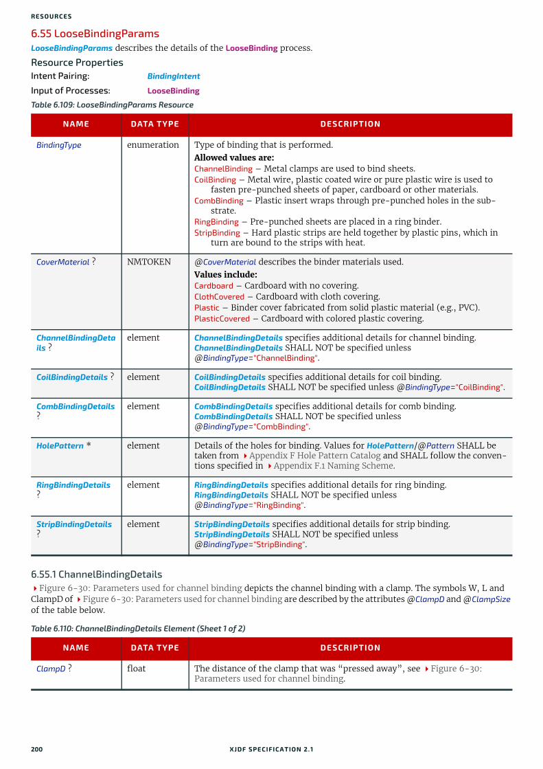
RESO URCES
6.55 LooseBindingParamsLooseBindingParams describes the details of the LooseBinding process.
Resource PropertiesIntent Pairing: BindingIntent
Input of Processes: LooseBinding
6.55.1 ChannelBindingDetailsFigure 6-30: Parameters used for channel binding depicts the channel binding with a clamp. The symbols W, L and ClampD of Figure 6-30: Parameters used for channel binding are described by the attributes @ClampD and @ClampSize of the table below.
Table 6.109: LooseBindingParams Resource
NAME DATA TYPE DESCRIPTION
BindingType enumeration Type of binding that is performed. Allowed values are:ChannelBinding – Metal clamps are used to bind sheets.CoilBinding – Metal wire, plastic coated wire or pure plastic wire is used to
fasten pre-punched sheets of paper, cardboard or other materials.CombBinding – Plastic insert wraps through pre-punched holes in the sub-
strate.RingBinding – Pre-punched sheets are placed in a ring binder.StripBinding – Hard plastic strips are held together by plastic pins, which in
turn are bound to the strips with heat.
CoverMaterial ? NMTOKEN @CoverMaterial describes the binder materials used. Values include:Cardboard – Cardboard with no covering. ClothCovered – Cardboard with cloth covering.Plastic – Binder cover fabricated from solid plastic material (e.g., PVC).PlasticCovered – Cardboard with colored plastic covering.
ChannelBindingDetails ?
element ChannelBindingDetails specifies additional details for channel binding. ChannelBindingDetails SHALL NOT be specified unless @BindingType="ChannelBinding".
CoilBindingDetails ? element CoilBindingDetails specifies additional details for coil binding. CoilBindingDetails SHALL NOT be specified unless @BindingType="CoilBinding".
CombBindingDetails ?
element CombBindingDetails specifies additional details for comb binding. CombBindingDetails SHALL NOT be specified unless @BindingType="CombBinding".
HolePattern * element Details of the holes for binding. Values for HolePattern/@Pattern SHALL be taken from Appendix F Hole Pattern Catalog and SHALL follow the conven-tions specified in Appendix F.1 Naming Scheme.
RingBindingDetails ?
element RingBindingDetails specifies additional details for ring binding. RingBindingDetails SHALL NOT be specified unless @BindingType="RingBinding".
StripBindingDetails ?
element StripBindingDetails specifies additional details for strip binding. StripBindingDetails SHALL NOT be specified unless @BindingType="StripBinding".
Table 6.110: ChannelBindingDetails Element (Sheet 1 of 2)
NAME DATA TYPE DESCRIPTION
ClampD ? float The distance of the clamp that was “pressed away”, see Figure 6-30: Parameters used for channel binding.
200 XJDF SPECIFICATIO N 2.1

LOOSEBINDINGPARAMS
6.55.2 CoilBindingDetails
6.55.3 CombBindingDetails
ClampSize ? shape The shape size of the clamp. The first number of the shape data type corre-sponds to the clamp width W (see Figure 6-30: Parameters used for channel binding) which is determined by the final height of the block of sheets to be bound. The second number corresponds to the length L (see Figure 6-30: Parameters used for channel binding). The third corresponds to the spine length (not visible in Figure 6-30: Parameters used for channel binding). The spine length is perpendicular on the paper plane.
Cover ? boolean If "true" the clamp is inside of a preassembled cover.
Figure 6-30: Parameters used for channel binding
Table 6.111: CoilBindingDetails Element
NAME DATA TYPE DESCRIPTION
CoilShape ? NMTOKEN The shape of the wire coil binding. Values include those from: Comb and Coil Shapes.
Diameter ? float Specifies the diameter of the comb to be produced. The diameter is deter-mined by the height of the block of sheets to be bound.
Table 6.112: CombBindingDetails Element
NAME DATA TYPE DESCRIPTION
CombShape ? NMTOKEN The shape of the wire comb binding. Value include those from: Comb and Coil Shapes.
Diameter ? float Specifies the diameter of the comb to be produced. The diameter is deter-mined by the height of the block of sheets to be bound.
FlipBackCover ? boolean The spine is typically hidden between the last page of the Component and the back cover. @FlipBackCover="true" specifies that the cover SHALL be flipped after the wire was “closed”, otherwise the cover SHALL be kept open. The latter makes sense if further processing is needed before closing the book, e.g. inserting a CD.
Table 6.110: ChannelBindingDetails Element (Sheet 2 of 2)
NAME DATA TYPE DESCRIPTION
U - shaped clampW
L
W - ClampD
Channel bound document
Pile of sheets
XJDF SPECIFICATIO N 2.1 201

RESO URCES
6.55.4 RingBindingDetails
6.55.5 StripBindingDetails
6.56 ManualLaborParamsManualLaborParams describes the parameters to qualify generic manual work within graphic arts production. Additional Comment elements will generally be needed to describe the work in human readable form.
Resource PropertiesInput of Processes: ManualLabor
Table 6.113: RingBindingDetails Element
NAME DATA TYPE DESCRIPTION
Diameter ? float Specifies the diameter of the rings, in points.
RingMechanic ? boolean If "true", a hand lever is available for opening.
RingShape ? NMTOKEN @RingShape specifies the shape of the ring binder rings.Values include:D-shape Oval Round SlantD
RivetsExposed ? boolean @RivetsExposed describes the mounting of the ring mechanism in the binder case. If "true", the heads of the rivets are visible on the exterior of the binder. If "false", the binder covering material covers the rivet heads.
SpineWidth ? float The spine width is determined by the final height of the block of sheets to be bound.
ViewBinder ? NMTOKEN @ViewBinder specifies the details of the clear vinyl outer-wrap types on top of a colored base wrap:Values include:Embedded – Printed material is embedded by sealing between the colored and
clear vinyl layers during the binder manufacturing.Pocket – Binder is designed so that printed material can be inserted between
the colored and clear vinyl layers after the binder is manufactured.
Table 6.114: StripBindingDetails Element
NAME DATA TYPE DESCRIPTION
Length ? float The length of the pin is determined by the height of the pile of sheets to be bound.
Table 6.115: ManualLaborParams Resource
NAME DATA TYPE DESCRIPTION
LaborType NMTOKEN Type of manual labor that is performed. Values include:CarvePotato – Carve a potato for potato printing.CreateCoatingForm – Create a form to apply coatings during or after printing.EditArt – Unspecific art editing (for work on specific files
LayoutElementProduction SHALL be used).EditMarks – Marks editing.EditTraps – Traps editing.ManageJob – General work on the job.PhoneCallToCustomer – Phone calls to ask/inform the customer.SeparateBlanks – Manual separation of blanks from a sheet after die cutting.
202 XJDF SPECIFICATIO N 2.1
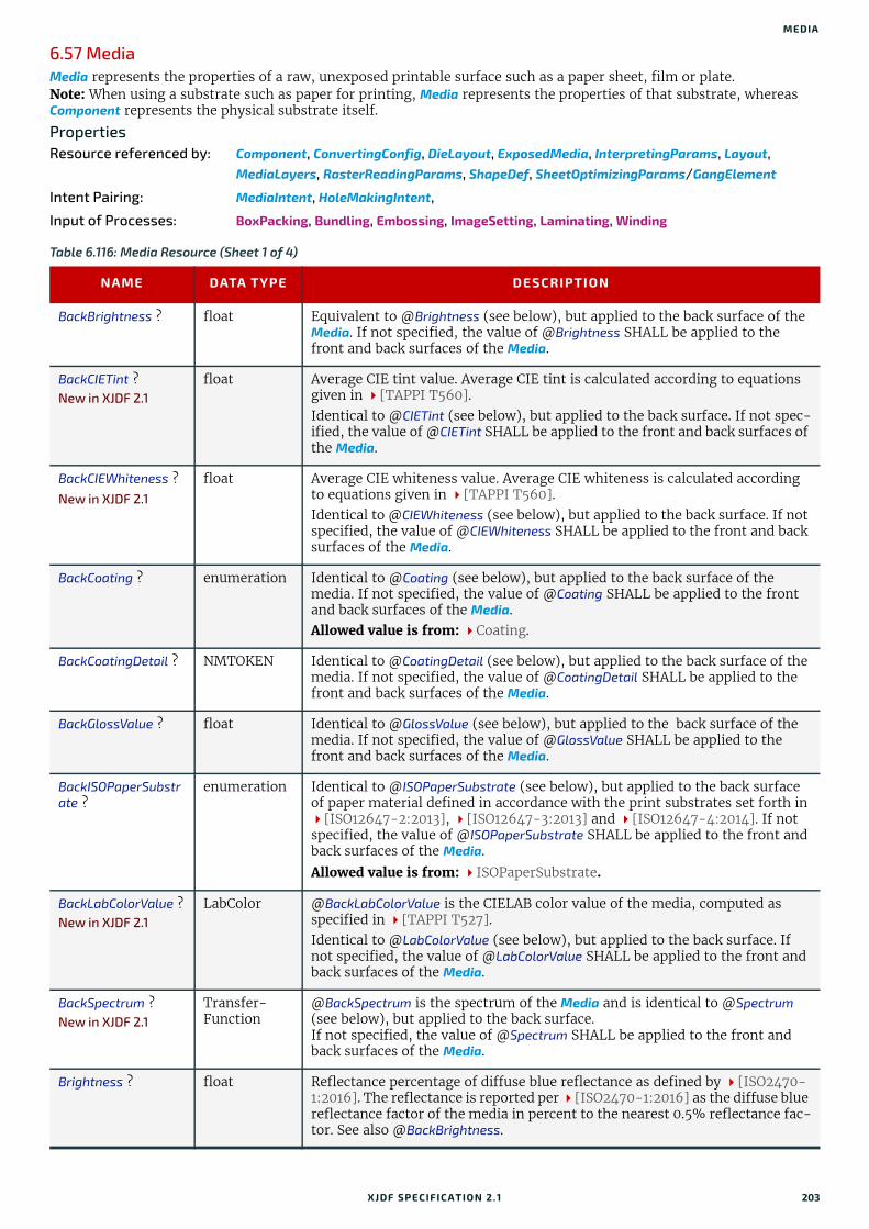
MEDIA
6.57 MediaMedia represents the properties of a raw, unexposed printable surface such as a paper sheet, film or plate.Note: When using a substrate such as paper for printing, Media represents the properties of that substrate, whereas Component represents the physical substrate itself.
PropertiesResource referenced by: Component, ConvertingConfig, DieLayout, ExposedMedia, InterpretingParams, Layout,
MediaLayers, RasterReadingParams, ShapeDef, SheetOptimizingParams/GangElement
Intent Pairing: MediaIntent, HoleMakingIntent,
Input of Processes: BoxPacking, Bundling, Embossing, ImageSetting, Laminating, Winding
Table 6.116: Media Resource (Sheet 1 of 4)
NAME DATA TYPE DESCRIPTION
BackBrightness ? float Equivalent to @Brightness (see below), but applied to the back surface of the Media. If not specified, the value of @Brightness SHALL be applied to the front and back surfaces of the Media.
BackCIETint ?New in XJDF 2.1
float Average CIE tint value. Average CIE tint is calculated according to equations given in [TAPPI T560].Identical to @CIETint (see below), but applied to the back surface. If not spec-ified, the value of @CIETint SHALL be applied to the front and back surfaces of the Media.
BackCIEWhiteness ?New in XJDF 2.1
float Average CIE whiteness value. Average CIE whiteness is calculated according to equations given in [TAPPI T560].Identical to @CIEWhiteness (see below), but applied to the back surface. If not specified, the value of @CIEWhiteness SHALL be applied to the front and back surfaces of the Media.
BackCoating ? enumeration Identical to @Coating (see below), but applied to the back surface of the media. If not specified, the value of @Coating SHALL be applied to the front and back surfaces of the Media.Allowed value is from: Coating.
BackCoatingDetail ? NMTOKEN Identical to @CoatingDetail (see below), but applied to the back surface of the media. If not specified, the value of @CoatingDetail SHALL be applied to the front and back surfaces of the Media.
BackGlossValue ? float Identical to @GlossValue (see below), but applied to the back surface of the media. If not specified, the value of @GlossValue SHALL be applied to the front and back surfaces of the Media.
BackISOPaperSubstrate ?
enumeration Identical to @ISOPaperSubstrate (see below), but applied to the back surface of paper material defined in accordance with the print substrates set forth in [ISO12647-2:2013], [ISO12647-3:2013] and [ISO12647-4:2014]. If not specified, the value of @ISOPaperSubstrate SHALL be applied to the front and back surfaces of the Media.
Allowed value is from: ISOPaperSubstrate.
BackLabColorValue ?New in XJDF 2.1
LabColor @BackLabColorValue is the CIELAB color value of the media, computed as specified in [TAPPI T527].Identical to @LabColorValue (see below), but applied to the back surface. If not specified, the value of @LabColorValue SHALL be applied to the front and back surfaces of the Media.
BackSpectrum ?New in XJDF 2.1
Transfer-Function
@BackSpectrum is the spectrum of the Media and is identical to @Spectrum (see below), but applied to the back surface. If not specified, the value of @Spectrum SHALL be applied to the front and back surfaces of the Media.
Brightness ? float Reflectance percentage of diffuse blue reflectance as defined by [ISO2470-1:2016]. The reflectance is reported per [ISO2470-1:2016] as the diffuse blue reflectance factor of the media in percent to the nearest 0.5% reflectance fac-tor. See also @BackBrightness.
XJDF SPECIFICATIO N 2.1 203

RESO URCES
CIETint ? float Average CIE tint value. Average CIE tint is calculated according to equations given in [TAPPI T560].
CIEWhiteness ? float Average CIE whiteness value. Average CIE whiteness is calculated according to equations given in [TAPPI T560].
Coating ? enumeration The pre-process coating that has been applied to the media. Allowed value is from: Coating.
CoatingDetail ? NMTOKEN Describes additional details of the coating that has been applied to the media and possibly the technology used to apply the coating.
CoreWeight ? float Weight of the core of a roll, in grams [g].
Dimension ? XYPair The X and Y dimensions of the Media, measured in points. @Dimension speci-fies the outer bounding box of the Media. The X, Y values of @Dimension establishes the user coordinate system into which content is mapped (i.e., the origin is in the lower left corner of the rectangle defined by 0 0 X Y). In case of "Roll" media, the X coordinate specifies the reel width and the Y coordinate specifies the length of the web in points. If a @Dimension coordinate is unknown, the value SHALL be "0". If either or both X or Y="0" (i.e., unknown), the default orientation is assumed to be portrait (i.e., Y > X).Values include those from: Appendix C Media Size.
FluteDirection ? enumeration Direction of the flute of corrugated media in the coordinate system of the Media. See Section 6.57.2.2 Corrugated Media.Allowed value is from: MediaDirection.
A value of “SameDirection” SHALL NOT be specified.
Flute ? NMTOKEN Single, capital letter that specifies the flute type of corrugated media. See Section 6.57.2.2 Corrugated Media.Values include those from: Flute Types.
GlossValue ? float Gloss of the media in gloss units as defined by [ISO8254-1:2009]. Refer also to [TAPPI T480] for examples of gloss calculation.
GrainDirection ? enumeration Direction of the grain in the coordinate system of the Media. A value of "SameDirection" SHALL NOT be specified.Allowed value is from: MediaDirection.
ImagableSide ? enumeration Side of the chosen medium that can be marked. Allowed values are:FrontBackBoth Neither
InnerCoreDiameter ? float Specifies the inner diameter of the core of a roll, in points. See also @OuterCoreDiameter and @RollDiameter.
InsideLoss ? float The inside loss of corrugated board material in microns [µm]. See Section 6.57.2.1 Inside Loss and Outside Gain.Note: @InsideLoss + @OutsideGain NEED NOT be exactly equal to thickness.
ISOPaperSubstrate ? enumeration @ISOPaperSubstrate SHALL specify the type of paper material defined in [ISO12647-2:2013], [ISO12647-3:2013] and [ISO12647-4:2014].Allowed value is from: ISOPaperSubstrate.
LabColorValue ? LabColor @LabColorValue is the CIELAB color value of the media, computed as specified in [TAPPI T527].
MediaColorName ? enumeration A name for the color. If more specific, specialized or site-defined media color names are needed, use @MediaColorNameDetails.Allowed value is from: NamedColor.
Table 6.116: Media Resource (Sheet 2 of 4)
NAME DATA TYPE DESCRIPTION
204 XJDF SPECIFICATIO N 2.1

MEDIA
MediaColorNameDetails ?
string A more specific, specialized or site-defined name for the media color. If @MediaColorNameDetails is supplied, @MediaColorName SHOULD also be sup-plied. @MediaColorNameDetails SHOULD be used to specify specialized media properties such as holographic or transparent foils.
MediaQuality ? string Named quality description of the media. Media with the same properties except for @Dimension SHOULD have the same value of @MediaQuality. For folding carton quality, multiple named quality description systems are in use (e.g., GC1, SBB, etc.). For an overview, see [Pro Carton].
MediaSetCount ? integer When the input media is grouped in sets, identifies the number of pieces of media in each set. For example, if the @MediaTypeDetails is "PreCutTabs", a @MediaSetCount of "5" would indicate that each set includes five tab sheets.
MediaType enumeration Describes the general type of the Media. Allowed value is from: MediaType.
MediaTypeDetails ? NMTOKEN Additional details of the chosen medium. Values include those from: MediaType Details.
MediaUnit ? enumeration Describes the format of the media as it is delivered to the device. Allowed values are:Continuous – Continuously connected sheets that can be fan folded. Roll – Continuous web on a reel.Sheet – Individual cut sheets.
Opacity ? enumeration The opacity of the media. See @OpacityLevel to specify the degree of opacity for any of these values. Allowed value is from: Opacity.
OpacityLevel ? float Normalized TAPPI opacity (Cn), as defined and computed in [ISO2471:2008]. Refer also to [TAPPI T519] for calculation examples.
OuterCoreDiameter ? float Specifies the outer diameter of the core of a roll, in points. See also @InnerCoreDiameter and @RollDiameter.
OutsideGain ? float The outside gain of corrugated board material in microns [µm]. See Section 6.57.2.1 Inside Loss and Outside Gain.Note: @InsideLoss + @OutsideGain NEED NOT be exactly equal to thickness.
PlateTechnology ? enumeration Exposure technology of the plates.Allowed values are:FlexoAnalogSolvent FlexoAnalogThermal FlexoDigitalSolvent FlexoDigitalThermal FlexoDirectEngraving InkJet – Exposure with inkjet technology. Note that
@PrintingTechnology="InkJet" specifies paper or transparency media, not plates.
Thermal – Thermal exposure.UV – Ultraviolet exposure. Visible – Visible light exposure.
Polarity ? enumeration Polarity of the chosen medium.Allowed value is from: Polarity.
PrintingTechnology ? NMTOKEN Describes the printing technology that the media or coatings on the media are intended for or optimized for.Values include those from: Printing Technologies.
RecycledPercentage ?
float The percentage, between 0 and 100, of recycled material that the media SHALL contain.
Table 6.116: Media Resource (Sheet 3 of 4)
NAME DATA TYPE DESCRIPTION
XJDF SPECIFICATIO N 2.1 205
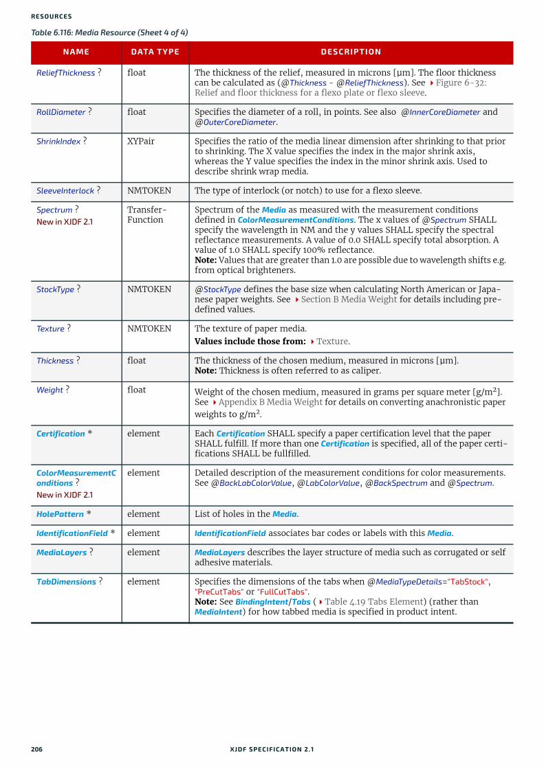
RESO URCES
ReliefThickness ? float The thickness of the relief, measured in microns [µm]. The floor thickness can be calculated as (@Thickness - @ReliefThickness). See Figure 6-32: Relief and floor thickness for a flexo plate or flexo sleeve.
RollDiameter ? float Specifies the diameter of a roll, in points. See also @InnerCoreDiameter and @OuterCoreDiameter.
ShrinkIndex ? XYPair Specifies the ratio of the media linear dimension after shrinking to that prior to shrinking. The X value specifies the index in the major shrink axis, whereas the Y value specifies the index in the minor shrink axis. Used to describe shrink wrap media.
SleeveInterlock ? NMTOKEN The type of interlock (or notch) to use for a flexo sleeve.
Spectrum ?New in XJDF 2.1
Transfer-Function
Spectrum of the Media as measured with the measurement conditions defined in ColorMeasurementConditions. The x values of @Spectrum SHALL specify the wavelength in NM and the y values SHALL specify the spectral reflectance measurements. A value of 0.0 SHALL specify total absorption. A value of 1.0 SHALL specify 100% reflectance.Note: Values that are greater than 1.0 are possible due to wavelength shifts e.g. from optical brighteners.
StockType ? NMTOKEN @StockType defines the base size when calculating North American or Japa-nese paper weights. See Section B Media Weight for details including pre-defined values.
Texture ? NMTOKEN The texture of paper media. Values include those from: Texture.
Thickness ? float The thickness of the chosen medium, measured in microns [µm].Note: Thickness is often referred to as caliper.
Weight ? float Weight of the chosen medium, measured in grams per square meter [g/m2]. See Appendix B Media Weight for details on converting anachronistic paper weights to g/m2.
Certification * element Each Certification SHALL specify a paper certification level that the paper SHALL fulfill. If more than one Certification is specified, all of the paper certi-fications SHALL be fullfilled.
ColorMeasurementConditions ?New in XJDF 2.1
element Detailed description of the measurement conditions for color measurements. See @BackLabColorValue, @LabColorValue, @BackSpectrum and @Spectrum.
HolePattern * element List of holes in the Media.
IdentificationField * element IdentificationField associates bar codes or labels with this Media.
MediaLayers ? element MediaLayers describes the layer structure of media such as corrugated or self adhesive materials.
TabDimensions ? element Specifies the dimensions of the tabs when @MediaTypeDetails="TabStock", "PreCutTabs" or "FullCutTabs".Note: See BindingIntent/Tabs (Table 4.19 Tabs Element) (rather than MediaIntent) for how tabbed media is specified in product intent.
Table 6.116: Media Resource (Sheet 4 of 4)
NAME DATA TYPE DESCRIPTION
206 XJDF SPECIFICATIO N 2.1

MEDIA
6.57.1 TabDimensionsSpecifies the size and placement of tabs in a bank and in a set of tab stock.
Figure 6-31: Paper roll with some roll-specific information
Figure 6-32: Relief and floor thickness for a flexo plate or flexo sleeve
Table 6.117: TabDimensions Element (Sheet 1 of 2)
NAME DATA TYPE DESCRIPTION
TabEdge ? enumeration Indicates which edge of the media has tabs. Sets the coordinate system for @TabOffset, @TabExtensionDistance, and @TabWidth. Allowed value is from: Edge.
TabExtensionDistance ?
float The positive distance in points that the tab extends beyond the body of the other media. Note: Same as BindingIntent/Tabs/@TabExtensionDistance.Note: This value is always included in the value of the overall extent of the Media defined by Media/@Dimension. See Figure 6-33: Diagram of a single bank of tabs.
TabOffset ? float Specifies the magnitude of the distance in points from the two corners to the edge of the first “tab pitch” point of the first tab in the bank along the @TabEdge. This distance is the same on both ends of the bank of tabs. See Figure 6-33: Diagram of a single bank of tabs.
TabSetCollationOrder ?
NMTOKEN Collation order of media provided in sets. Applicable to sets of pre-cut tabs. See Figure 6-33: Diagram of a single bank of tabs. Although @TabSetCollationOrder is of type NMTOKEN, values other than those in Table 6.118 TabSetCollationOrder Attribute Values are NOT RECOM-MENDED.Values include those from: Table 6.118 TabSetCollationOrder Attribute
Values.
1m
1m
Weight [g/m2]
Dimension (x,y) [points]
RollDiameter [points]
Indentification field
OuterCoreDiameter [points]
ResourceWeight [g]
y =
leng
th
x = width
Roll number: 4711
ReliefThickness
Floor heightThickness
XJDF SPECIFICATIO N 2.1 207

RESO URCES
TabsPerBank ? integer Specifies the number of equal-sized tabs in a single bank if all positions were filled. Note: Banks can have tabs only in some of the possible positions. Note: Same as BindingIntent/Tabs/@TabsPerBank.Media/@MediaSetCount specifies the number of tabs per set. A set can consist of one or more banks. If Media/@MediaSetCount is not an even multiple of @TabsPerBank, the last bank in each set is partially filled.
TabWidth ? float The width along the @TabEdge of each tab as measured along the mid-line of the tab. Each tab is centered within a space called the “tab pitch”. See Figure 6-33: Diagram of a single bank of tabs.
Table 6.118: TabSetCollationOrder Attribute Values
VALUE DESCRIPTION EXAMPLE
Forward The first tab in reader order SHALL be placed towards the top of the stack.
Reverse The first tab in reader order SHALL be placed towards the bot-tom of the stack.
Table 6.117: TabDimensions Element (Sheet 2 of 2)
NAME DATA TYPE DESCRIPTION
208 XJDF SPECIFICATIO N 2.1

MEDIA
6.57.2 More about Media
6.57.2.1 Inside Loss and Outside GainInside loss and outside gain: dimensional values used in the mechanical design phase of a box.Note: IL + OG is not exactly equal to thickness. Thickness is most often referred to as caliper.
Figure 6-33: Diagram of a single bank of tabs
Figure 6-34: Inside Loss, Outside Gain
Dimension.xDimension.x
“Top”
“Bottom”
“Left” “Right”
TabEdge = “Right”TabsPerBank = “3”
TabOffset(a positive number)
TabOffset(a positive number)
TabExtensionDistance
Tab Pitch Note: Tabs are centered on each “tab pitch”, which is not an attribute. Rather it is computed as: (Dimension.y-2 * TabOffset) / TabsPerBank
tab pitch (computed per
“Tab Pitch Note” to left)
TabWidth
mid-line of tab
tab pitch
tab pitch
Dimension.y
OGIL
XJDF SPECIFICATIO N 2.1 209

RESO URCES
6.57.2.2 Corrugated MediaCorrugated material consists of multiple sheets of paper (called liners) with fluted material in between. For background information on corrugated media, see [Corrugated Packaging]. Corrugated media comes in different variants.
• Number of layers:
• single face (1 liner, 1 flute)
• single wall (2 liners, 1 flute)
• double wall (3 liners, 2 flutes)
• triple wall (4 liners, 3 flutes)
• Flute size and frequency: A, B, C, E, F flute. See [Corrugated Packaging].
Example 6.20: Media: CorrugatedThe following example describes single wall corrugated media with two liners and a "B" type flute.
6.57.2.3 Self adhesive MediaSelf adhesive media is described as a MediaLayers element with nested Media and Glue elements.
Example 6.21: Media: Self AdhesiveThe following example describes labels with removable glue on a 60 gram base.
6.57.2.4 Flexo Plate MediaA sample of a Flexo plate with dimensions of 900 mm x 1200 mm, a base of 177 microns and a total thickness of 1143 microns.
A raw plate can contain several separations from multiple jobs. The real printing dimensions can only be determined when all elements of the mounting process are known: circumference of the sleeve on which the flat plate will be mount-ed, thickness of the mounting tape, thickness of base and thickness of the photo-polymer.
<XJDF xmlns="http://www.CIP4.org/JDFSchema_2_0" JobID="Converting" JobPartID="Corrugated" Types="ConventionalPrinting"> <ResourceSet Name="Media" Usage="Input"> <Resource> <Media Dimension="2834.64566929 1984.2519685" InsideLoss="1000" MediaType="CorrugatedBoard" MediaTypeDetails="SingleWall" OutsideGain="1380" Thickness="2382"> <MediaLayers> <Media MediaType="Paper" Weight="190"/> <Media Flute="B" FluteDirection="XDirection" MediaType="Paper" MediaTypeDetails="Flute" Weight="180"/> <Media MediaType="Paper" Weight="180"/> </MediaLayers> </Media> </Resource> </ResourceSet></XJDF>
<XJDF xmlns="http://www.CIP4.org/JDFSchema_2_0" JobID="Converting" JobPartID="Corrugated" Types="ConventionalPrinting"> <ResourceSet Name="Media" Usage="Input"> <Resource> <Media Dimension="1190.5511811 0" MediaType="SelfAdhesive" MediaUnit="Roll" Thickness="900"> <MediaLayers> <Media MediaType="Paper" Weight="90"/> <Glue AreaGlue="true" GlueType="Removable"/> <Media MediaType="Paper" Weight="60"/> </MediaLayers> </Media> </Resource> </ResourceSet></XJDF>
210 XJDF SPECIFICATIO N 2.1

MISCCONSUMABLE
Example 6.22: Media: Flexo Plate
6.57.2.5 Flexo Sleeve MediaThe Flexo sleeve has dimensions of 500 x 250 mm, a base of 1249 microns and a total thickness of 2810 microns. The sleeve dimensions are identical to the printing dimensions (no distortion).
Example 6.23: Media: Flexo Sleeve
6.58 MiscConsumableThe MiscConsumable resource is intended for cost accounting, inventory control and availability scheduling of supplies used in the production workflow where a more detailed parameterization of the resource is not necessary. MiscConsumable SHOULD not be used to describe resources that are already more specifically defined in XJDF such as Ink, Media, Pallet, RegisterRibbon or UsageCounter.
MiscConsumable resources MAY appear as inputs to any XJDF process. The default unit for amounts of MiscConsumable is countable objects.
Certain types of MiscConsumable elements such as MiscConsumable[@Type="WasteContainer"] are typically “consumed” by being filled. The sense of the @Amount attribute for such resources shall be the quantity of unused or empty waste containers that are available. If @Unit is a volume, distance or weight instead of countable objects, such @Amount will still represent the remaining unused capacity of the waste container.
Resource PropertiesInput of Processes: Any Process
<XJDF xmlns="http://www.CIP4.org/JDFSchema_2_0" JobID="Flexo" JobPartID="Plate" Types="ConventionalPrinting"> <ResourceSet Name="Media" ProcessUsage="Plate" Usage="Input"> <Resource Brand="FlexoBrand"> <Part Separation="Black"/> <Media Dimension="2551.18110236 3401.57480315" MediaType="Plate" PlateTechnology="FlexoDigitalThermal" ReliefThickness="500" Thickness="1143"> <MediaLayers> <Media MediaType="Plate" MediaTypeDetails="FlexoPhotoPolymer" Thickness="966"/> <Media MediaType="Plate" MediaTypeDetails="FlexoBase" Thickness="177"/> </MediaLayers> </Media> </Resource> </ResourceSet></XJDF>
<XJDF xmlns="http://www.CIP4.org/JDFSchema_2_0" JobID="Flexo" JobPartID="Sleeve" Types="ConventionalPrinting"> <ResourceSet Name="Media" ProcessUsage="Plate" Usage="Input"> <Resource Brand="FlexoBrand"> <Media Dimension="1417.32283465 708.66141732" MediaType="Sleeve" PlateTechnology="FlexoDigitalSolvent" ReliefThickness="500" Thickness="2810"> <MediaLayers> <Media MediaType="Sleeve" MediaTypeDetails="FlexoPhotoPolymer" Thickness="1570"/> <Media MediaType="Sleeve" MediaTypeDetails="FlexoBase" Thickness="1249"/> </MediaLayers> </Media> </Resource> </ResourceSet></XJDF>
Table 6.119: MiscConsumable Resource (Sheet 1 of 2)
NAME DATA TYPE DESCRIPTION
Color ? enumeration @Color specifies the machine readable color of the consumable.
Allowed value is from: NamedColor.
ColorDetails ? string @ColorDetails specifies additional details of the color of the consumable that MAY be site specific and MAY be human readable. @Color SHOULD be speci-fied if @ColorDetails is supplied.
XJDF SPECIFICATIO N 2.1 211
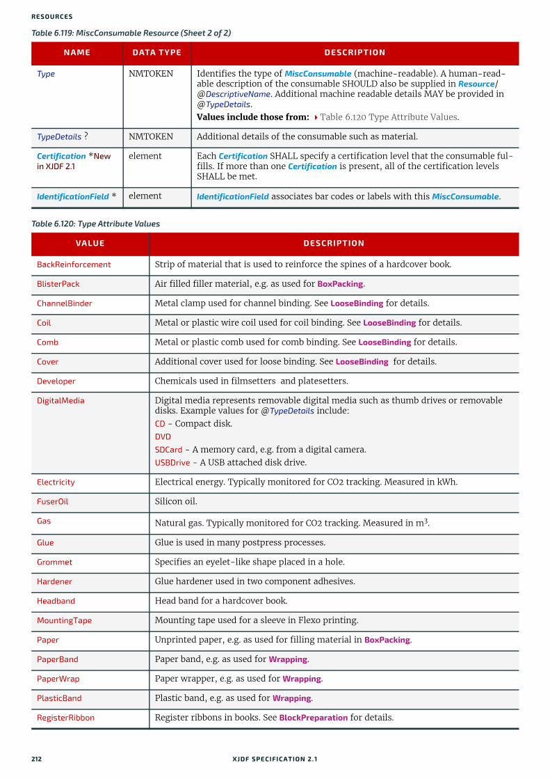
RESO URCES
Type NMTOKEN Identifies the type of MiscConsumable (machine-readable). A human-read-able description of the consumable SHOULD also be supplied in Resource/@DescriptiveName. Additional machine readable details MAY be provided in @TypeDetails.Values include those from: Table 6.120 Type Attribute Values.
TypeDetails ? NMTOKEN Additional details of the consumable such as material.
Certification *New in XJDF 2.1
element Each Certification SHALL specify a certification level that the consumable ful-fills. If more than one Certification is present, all of the certification levels SHALL be met.
IdentificationField * element IdentificationField associates bar codes or labels with this MiscConsumable.
Table 6.120: Type Attribute Values
VALUE DESCRIPTION
BackReinforcement Strip of material that is used to reinforce the spines of a hardcover book.
BlisterPack Air filled filler material, e.g. as used for BoxPacking.
ChannelBinder Metal clamp used for channel binding. See LooseBinding for details.
Coil Metal or plastic wire coil used for coil binding. See LooseBinding for details.
Comb Metal or plastic comb used for comb binding. See LooseBinding for details.
Cover Additional cover used for loose binding. See LooseBinding for details.
Developer Chemicals used in filmsetters and platesetters.
DigitalMedia Digital media represents removable digital media such as thumb drives or removable disks. Example values for @TypeDetails include:CD - Compact disk.DVD
SDCard - A memory card, e.g. from a digital camera.USBDrive - A USB attached disk drive.
Electricity Electrical energy. Typically monitored for CO2 tracking. Measured in kWh.
FuserOil Silicon oil.
Gas Natural gas. Typically monitored for CO2 tracking. Measured in m3.
Glue Glue is used in many postpress processes.
Grommet Specifies an eyelet-like shape placed in a hole.
Hardener Glue hardener used in two component adhesives.
Headband Head band for a hardcover book.
MountingTape Mounting tape used for a sleeve in Flexo printing.
Paper Unprinted paper, e.g. as used for filling material in BoxPacking.
PaperBand Paper band, e.g. as used for Wrapping.
PaperWrap Paper wrapper, e.g. as used for Wrapping.
PlasticBand Plastic band, e.g. as used for Wrapping.
RegisterRibbon Register ribbons in books. See BlockPreparation for details.
Table 6.119: MiscConsumable Resource (Sheet 2 of 2)
NAME DATA TYPE DESCRIPTION
212 XJDF SPECIFICATIO N 2.1

NODEINFO
6.59 NodeInfoNodeInfo contains information about planned scheduling. It allows MIS to plan, schedule and invoice jobs or Worksteps. If an MIS needs to explicitly specify an individual Workstep, it SHOULD be identified in ../Resource/@ExternalID .
Resource PropertiesInput of Processes: Any Process
RingBinder Ring binder used for ring binding. See LooseBinding for details.
RubberBand Rubber band, e.g. as used for Wrapping.
ShrinkWrap Shrink wrapping material, e.g. as used for Wrapping.
Staples Prefabricated staples used for Stitching. Use Wire when the staples are not prefabricated.
Strap Straps are used in a Strapping process.
StripBinder Strip binder used for strip binding. See LooseBinding for details.
Styrofoam Styrofoam, e.g. as used for BoxPacking.
Tape Adhesive tape, e.g. as used for SpineTaping.
Thread Thread used for ThreadSealing or ThreadSewing.
WasteContainer Waste container, e.g. for used ink or toner.
Wire Bulk wire used for forming staples or other bindings.
Table 6.121: NodeInfo Resource (Sheet 1 of 2)
NAME DATA TYPE DESCRIPTION
CleanupDuration ? duration Estimated duration of the clean-up phase of the process.
DueLevel ? enumeration Description of the severity of a missed deadline. Allowed values are:JobCancelled – The job is cancelled if the deadline is missed.Penalty – Missing the deadline incurs a penalty.Trivial – Missing the deadline has minor or no consequences.
End ? dateTime Date and time at which the process is scheduled to end.
FirstEnd ? dateTime Earliest date and time at which the process SHALL end.
FirstStart ? dateTime Earliest date and time at which the process SHALL begin.
JobPriority ? integer The scheduling priority for the node where 100 is the highest and 0 is the lowest. If one or more of the deadline oriented attributes (e.g., @FirstStart or @LastEnd) is specified, such attribute(s) SHALL be honored before consider-ing @JobPriority.The priority from XJMF (QueueSubmissionParams/@Priority or ModifyQueueEntryParams/@Priority) SHALL take precedence over NodeInfo/@JobPriority.
LastEnd ? dateTime Latest date and time at which the process SHALL end. This is the deadline to which @DueLevel refers.
LastStart ? dateTime Latest date and time at which the process SHALL begin.
NaturalLang ? language Language selected for human readable communication. If not specified, the operating system’s language SHOULD be used.
PersonalID ? NMTOKEN Resource/@ExternalID of the Contact that represents the employee that is responsible for processing this XJDF.
Table 6.120: Type Attribute Values
VALUE DESCRIPTION
XJDF SPECIFICATIO N 2.1 213

RESO URCES
6.60 PalletA Pallet represents the pallet used in packing goods.
Resource PropertiesInput of Processes: Palletizing
6.61 PalletizingParamsPalletizingParams defines the details of Palletizing. Details of the actual pallet used for Palletizing can be found in the Pallet resource that is also an input of the Palletizing process.
Resource PropertiesInput of Processes: Palletizing
6.62 PDLCreationParamsPDLCreationParams describes the details of generating the supported output PDL types used in the PDLCreation process.
SetupDuration ? duration Estimated duration of the setup phase of the process.
Start ? dateTime Date and time of the planned process start.
Status ? enumeration Identifies the status of an individual part of the XJDF.Allowed value is from: Status.
StatusDetails ? NMTOKEN Machine readable description of the status that provides details beyond the enumerative values given by @Status.Values include those from: Status Details.
TotalDuration ? duration Estimated total duration of the process, including setup and cleanup.
GangSource * element If present, each GangSource SHALL represent the source jobs that are being processed as a gang job.
MISDetails ? element Definition how the costs for the execution of this node SHALL be charged.
Table 6.122: Pallet Resource
NAME DATA TYPE DESCRIPTION
PalletType NMTOKEN Type of pallet used. Values include those from: Pallet Types.
Size ? XYPair Describes the length and width of the pallet, in points (e.g., 3500 3500). If not specified, the size is defined by @PalletType.
IdentificationField * element IdentificationField associates bar codes or labels with this Pallet.
Table 6.123: PalletizingParams Resource
NAME DATA TYPE DESCRIPTION
LayerAmount ? IntegerList Ordered number of input components in a layer. The first number is the first layer on the bottom. If there are more layers than entries in the list, counting restarts at the first entry.
MaxHeight ? float Maximum height of a loaded pallet in points.
MaxWeight ? float Maximum weight of a loaded pallet in grams.
Overhang ? XYPair Overhang in x and y direction on each side.
OverhangOffset ? XYPair Overhang offset if overhang is not centered.
Pattern ? NMTOKEN Name of the palletizing pattern. Used to store a predefined pattern that defines the layers and positioning of individual component on the pallet.
Table 6.121: NodeInfo Resource (Sheet 2 of 2)
NAME DATA TYPE DESCRIPTION
214 XJDF SPECIFICATIO N 2.1

PDLCREATIONPARAMS
Resource PropertiesInput of Processes: PDLCreation
6.62.1 AdvancedParams
Table 6.124: PDLCreationParams Resource
NAME DATA TYPE DESCRIPTION
MimeType string This resource identifies the MIME type associated with this output file for-mat. For example "application/pdf".IANA maintains a registry of MIME types, see [IANA-mt].
FontParams ? element FontParams describes how fonts SHALL be handled when creating PDL.
PDFCreationDetails ?
element PDF specific element for the output. It SHALL NOT be specified unless @MimeType="application/pdf".
PSCreationDetails ? element Postscript specific element for the output. It SHALL NOT be specified unless @MimeType="application/postscript".
Table 6.125: AdvancedParams Element (Sheet 1 of 2)
NAME DATA TYPE DESCRIPTION
AllowPSXObjects ? boolean If "false", PostScript XObjects SHALL not be created.
AllowTransparency ? boolean If "false", transparency SHALL not be present in the PDF.
AutoPositionEPSInfo ?
boolean If "true", the process SHALL automatically resize and center information from EPS source files on the page. (EPS source only)
EmbedJobOptions ? boolean If "true", the PDF settings used to create the PDF SHALL be embedded in the PDF.
EmitDSCWarnings ? boolean If "true", warning messages about questionable or incorrect DSC comments MAY appear during the processing of the source PostScript file. (PostScript source only)
LockDistillerParams ?
boolean If "true", any PDFCreationDetails settings configured by the source content (e.g., with setdistillerparams in a PostScript source document) SHALL be ignored. If "false", each parameter defined in the source document SHALL override that set in the XJDF.
ParseDSCCommentForDocInfo ?
boolean If "true", the process SHALL parse the DSC comments in a PostScript source file and extract the document information. This information SHALL be recorded in the info dictionary of the PDF file.
ParseDSCComments ?
boolean If "true", the process SHALL parse the DSC comments in a PostScript source document for any information that might be helpful for converting the file or for information that is to be stored in the PDF file. If "false", the process SHALL treat the DSC comments as pure PS comments and SHALL ignore them. (PostScript source only)
PassThroughJPEGImages ?
boolean If "true", JPEG images SHALL be passed through without recompressing them.
PreserveCopyPage ? boolean If "true", the copypage operator of PostScript Level 2 SHALL be maintained. If "false", the PostScript Level 3 definition of the copypage operator SHALL be used. In PostScript Levels 1 and 2, the copypage operator transmits the page con-tents to the current output device (similar to showpage). However, copypage does not perform many of the re-initializations that showpage does.Many PostScript Level 1 and 2 programs used the copypage operator to per-form such operations as printing multiple copies and implementing forms. These programs produce incorrect results when interpreted using the Level 3 copypage semantics. This attribute provides a mechanism to retain Level 2 compatibility for this operator. (PostScript source only)
XJDF SPECIFICATIO N 2.1 215

RESO URCES
6.62.2 FontParamsThis element describes how fonts are handled when converting PostScript or other PDL files to PDF.
6.62.3 PDFCreationDetailsThis element contains the parameters that control the conversion of any PDL to PDF documents.
Some descriptions below mention attributes or structures in specific source formats, such as PostScript. Appropriate equivalent actions should be taken when converting from other source formats that have equivalent attributes or struc-tures. A small number of parameters apply only to PostScript sources.
PreserveEPSInfo ? boolean If "true", the EPS information in a PostScript source file SHALL be preserved and SHALL be stored in the resulting PDF file. (PostScript source only)
PreserveHalftoneInfo ?
boolean If "true", the halftone screen information (frequency, angle and spot function) SHALL be passed into the PDF file. If "false", halftone information SHALL not be passed on.
PreserveOPIComments ?
boolean If "true", Open Prepress Interface (OPI) low resolution images SHALL be encapsulated as a form and information for locating the high resolution images SHALL be preserved.
PreserveOverprintSettings ?
boolean If "true", the value of the setoverprint operator SHALL be passed through to the PDF file. Otherwise, overprint SHALL be ignored.
TransferFunctionInfo ?
enumeration Determines how transfer functions are handled. Allowed values are: Apply – Transfer functions are used to modify the data that are written to the
PDF file, instead of writing the transfer function itself to the file.Preserve – Transfer functions are passed into the PDF file.Remove – Transfer functions are ignored. They are neither applied to the
color values nor passed into the PDF file.
UCRandBGInfo ? enumeration Determines whether the under-color removal and black-generation parame-ters from the source document (e.g., the arguments to the PostScript com-mands setundercolorremoval and setblackgeneration) SHALL be passed into the PDF file. Allowed values are:Preserve – The arguments SHALL be passed into the PDF file.Remove – The arguments SHALL be ignored.
UsePrologue ? boolean If "true", the process SHALL append a PostScript prologue file before the beginning of the job and append a PostScript epilog file after the end the job. Such files are used to control the PostScript environment for the conversion process. The expected location and allowable contents for these files is defined by the process implementation. (PostScript source only)
Table 6.126: FontParams Element
NAME DATA TYPE DESCRIPTION
AlwaysEmbed ? NMTOKENS @AlwaysEmbed specifies a list of one or more names of fonts that SHALL be embedded in the PDF. Each name SHALL be the PDL name of the font. Font names SHALL NOT occur in both the @AlwaysEmbed and @NeverEmbed lists.
EmbedAllFonts ? boolean If "true", specifies that all fonts, except those in the @NeverEmbed list, SHALL be embedded in the PDF.
MaxSubsetPct ? integer If the percentage of glyphs used from a font is below the value of @MaxSubsetPct, then a subset of the font SHALL be embedded in the PDF.
NeverEmbed ? NMTOKENS @NeverEmbed specifies a list of one or more names of fonts that SHALL NOT be embedded in the PDF and SHALL NOT be considered for subsetting. Each name SHALL be the PDL name of the font. Font names SHALL NOT occur in both the @AlwaysEmbed and @NeverEmbed lists.
Table 6.125: AdvancedParams Element (Sheet 2 of 2)
NAME DATA TYPE DESCRIPTION
216 XJDF SPECIFICATIO N 2.1
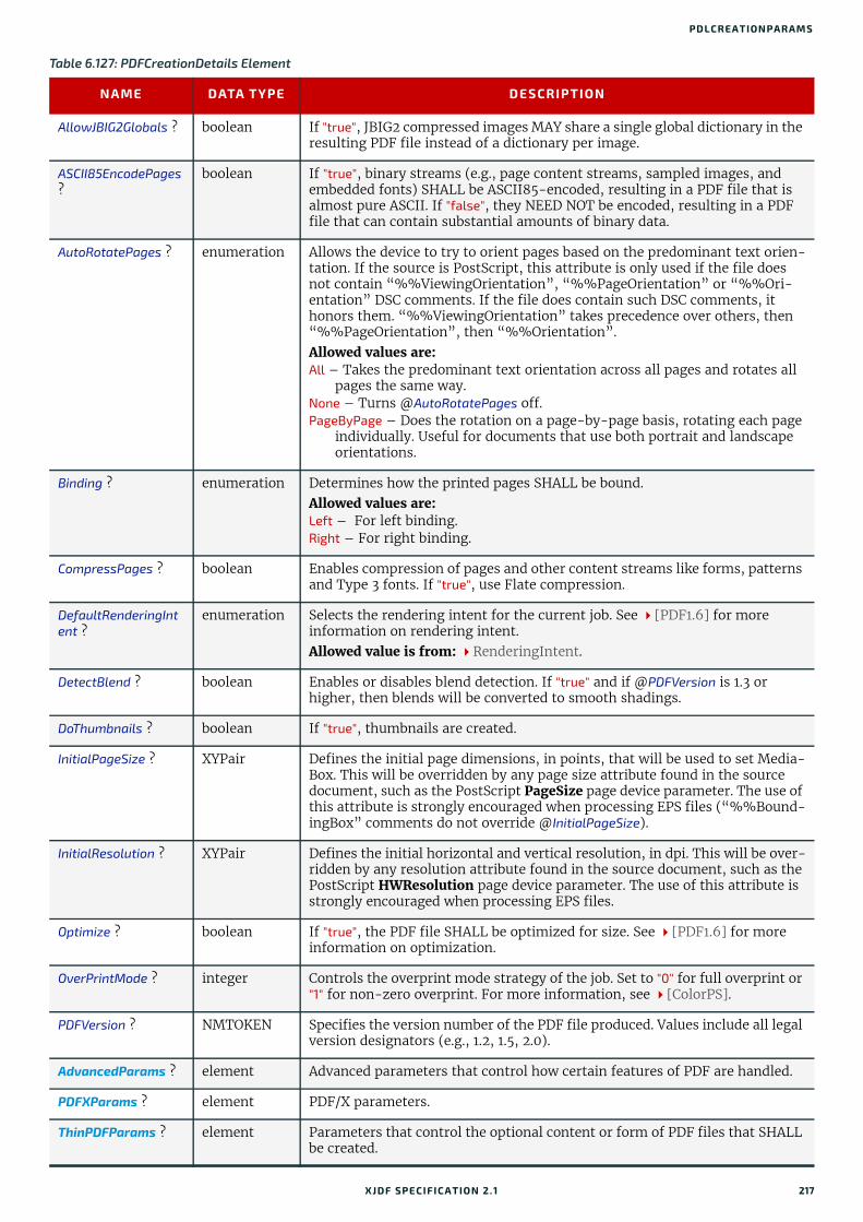
PDLCREATIONPARAMS
Table 6.127: PDFCreationDetails Element
NAME DATA TYPE DESCRIPTION
AllowJBIG2Globals ? boolean If "true", JBIG2 compressed images MAY share a single global dictionary in the resulting PDF file instead of a dictionary per image.
ASCII85EncodePages ?
boolean If "true", binary streams (e.g., page content streams, sampled images, and embedded fonts) SHALL be ASCII85-encoded, resulting in a PDF file that is almost pure ASCII. If "false", they NEED NOT be encoded, resulting in a PDF file that can contain substantial amounts of binary data.
AutoRotatePages ? enumeration Allows the device to try to orient pages based on the predominant text orien-tation. If the source is PostScript, this attribute is only used if the file does not contain “%%ViewingOrientation”, “%%PageOrientation” or “%%Ori-entation” DSC comments. If the file does contain such DSC comments, it honors them. “%%ViewingOrientation” takes precedence over others, then “%%PageOrientation”, then “%%Orientation”. Allowed values are:All – Takes the predominant text orientation across all pages and rotates all
pages the same way.None – Turns @AutoRotatePages off. PageByPage – Does the rotation on a page-by-page basis, rotating each page
individually. Useful for documents that use both portrait and landscape orientations.
Binding ? enumeration Determines how the printed pages SHALL be bound. Allowed values are:Left – For left binding. Right – For right binding.
CompressPages ? boolean Enables compression of pages and other content streams like forms, patterns and Type 3 fonts. If "true", use Flate compression.
DefaultRenderingIntent ?
enumeration Selects the rendering intent for the current job. See [PDF1.6] for more information on rendering intent.Allowed value is from: RenderingIntent.
DetectBlend ? boolean Enables or disables blend detection. If "true" and if @PDFVersion is 1.3 or higher, then blends will be converted to smooth shadings.
DoThumbnails ? boolean If "true", thumbnails are created.
InitialPageSize ? XYPair Defines the initial page dimensions, in points, that will be used to set Media-Box. This will be overridden by any page size attribute found in the source document, such as the PostScript PageSize page device parameter. The use of this attribute is strongly encouraged when processing EPS files (“%%Bound-ingBox” comments do not override @InitialPageSize).
InitialResolution ? XYPair Defines the initial horizontal and vertical resolution, in dpi. This will be over-ridden by any resolution attribute found in the source document, such as the PostScript HWResolution page device parameter. The use of this attribute is strongly encouraged when processing EPS files.
Optimize ? boolean If "true", the PDF file SHALL be optimized for size. See [PDF1.6] for more information on optimization.
OverPrintMode ? integer Controls the overprint mode strategy of the job. Set to "0" for full overprint or "1" for non-zero overprint. For more information, see [ColorPS].
PDFVersion ? NMTOKEN Specifies the version number of the PDF file produced. Values include all legal version designators (e.g., 1.2, 1.5, 2.0).
AdvancedParams ? element Advanced parameters that control how certain features of PDF are handled.
PDFXParams ? element PDF/X parameters.
ThinPDFParams ? element Parameters that control the optional content or form of PDF files that SHALL be created.
XJDF SPECIFICATIO N 2.1 217

RESO URCES
6.62.4 PDFXParamsParameters for generating PDF/X files.Note: TrimBox, BleedBox, output intent and the Trapped state may be provided by the use of the pdfmark operator in a PostScript source file.
6.62.5 PSCreationDetailsPSCreationDetails specifies a set of configurable options that can be used by processes that generate PostScript files.
Some descriptions below mention attributes or structures in specific source formats, such as PDF. Appropriate equiva-lent actions should be taken when converting from other source formats that have equivalent attributes or structures. A small number of parameters apply only to PDF sources.
Font controls are applied in the following order:
1 @IncludeBaseFonts
2 @IncludeEmbeddedFonts
3 @IncludeType1Fonts
4 @IncludeType3Fonts
5 @IncludeTrueTypeFonts
6 @IncludeCIDFonts
Table 6.128: PDFXParams Element
NAME DATA TYPE DESCRIPTION
PDFXBleedBoxtoTrimBoxOffset ?
rectangle If the BleedBox entry is not specified in the page object of the source docu-ment, BleedBox SHALL be set to PDF TrimBox with offsets. All numbers SHALL be greater than or equal to 0.0. PDF BleedBox will be completely out-side PDF TrimBox.
PDFXCheck ? NMTOKENS List of PDF/X versions that the output SHALL be compliant with. Values include: X1a – See the PDF/X-1a standard [ISO15930-1:2001].X3 – See the PDF/X-3 standard [ISO15930-3:2002].X4 – See the PDF/X-4 standard [ISO15930-7:2010].X5 – See the PDF/X-5 standard [ISO15930-8:2010].
PDFXCompliantPDFOnly ?
boolean If "true", PDF document SHALL be produced only if PDF/X compliance tests are passed.
PDFXNoTrimBoxError ?
boolean If "true" and both TrimBox and ArtBox entries are not specified in the page object of the source document, the condition SHALL be reported as an error.
PDFXSetBleedBoxToMediaBox ?
boolean If "true" and the BleedBox entry is not specified in the page object of the source document, BleedBox SHALL be set to MediaBox.
PDFXTrapped ? enumeration If a source document does not specify a Trapped state, then the value pro-vided here SHALL be used. The value "Unknown" SHALL be used for workflows requiring 1) that the document specify a Trapped state and 2) that compli-ance checking fail if Trapped is not present in the document. Allowed values are:false trueUnknown Note: "Unknown" is prohibited in PDF/X files.
PDFXTrimBoxToMediaBoxOffset ?
rectangle If both the TrimBox and ArtBox entries are not specified in the page object of the source document, TrimBox SHALL be set to MediaBox with offsets. All numbers SHALL be greater than or equal to 0.0. The TrimBox SHALL be com-pletely inside MediaBox.
FileSpec (ReferenceOutputProfile) ?
element An ICC profile that describes the reference output conditions.
218 XJDF SPECIFICATIO N 2.1

PDLCREATIONPARAMS
For example, an embedded Type-1 font follows the rule for embedded fonts, not the rule for Type-1 fonts. In other words, if @IncludeEmbeddedFonts is "true", and @IncludeType1Fonts is "false", embedded Type-1 fonts would be included in the PostScript stream.
Table 6.129: PSCreationDetails Element (Sheet 1 of 2)
NAME DATA TYPE DESCRIPTION
BinaryOK ? boolean If "false", binary data SHALL NOT be included in the PostScript stream.
BoundingBox ? rectangle @BoundingBox is used for the BoundingBox DSC comment in @CenterCropBox calculations and for PostScript’s setpagedevice.
CenterCropBox ? boolean If "true", the CropBox from the source document SHALL be centered on the page when the CropBox is smaller than MediaBox.
GeneratePageStreams ?
boolean If "true", the process SHALL emit individual streams of data for each page in the RunList.
IgnoreAnnotForms ? boolean If "true", annotations that contain a PDF XObject form SHALL be ignored. (PDF source only).
IgnoreBG ? boolean If "true", the BG and BG2 parameters in the PDF ExtGState dictionary, and the operand of any calls to the PostScript setblackgeneration operator SHALL be ignored.
IgnoreColorSeps ? boolean If "true", images for Level-1 separations SHALL be ignored.
IgnoreDSC ? boolean If "true", DSC (Document Structuring Conventions) SHALL be ignored.
IgnoreExternStreamRef ?
boolean If a PDF image resource uses an external stream and @IgnoreExternStreamRef="true", code that points to the external file SHALL be ignored. (PDF source only).
IgnoreHalftones ? boolean If "true", any halftone screening in the source file SHALL be ignored.
IgnoreOverprint ? boolean If "true", OP parameters in a source PDF ExtGState dictionary and setover-print in a source PostScript file, etc. SHALL be ignored.
IgnorePageRotation ?
boolean If "true", a “concatenation” provided at the beginning of each page that ori-ents the page so that it is properly rotated SHALL be ignored. Used when emitting EPS.
IgnoreRawData ? boolean If "true", no unnecessary filters SHALL be added when emitting image data.
IgnoreSeparableImagesOnly ?
boolean If "true", and if emitting EPS, only CMYK and gray images SHALL be ignored.
IgnoreShowPage ? boolean If "true", save-and-restore showpage in PostScript files SHALL be ignored.
IgnoreTransfers ? boolean If "true", TR and TR2 parameters are in a source PDF ExtGState dictionary and settransfer and setcolortransfer in a source PostScript file, etc. SHALL be ignored.
IgnoreTTFontsFirst ? boolean If "true", TrueType fonts SHALL be ignored before any other fonts.
IgnoreUCR ? boolean If "true", UCR and UCR2 parameters in a source PDF ExtGState dictionary and setundercolorremoval in a source PostScript file, etc. SHALL be ignored.
IncludeBaseFonts ? enumeration Determines when to embed the base fonts. The base fonts are "Symbol" and the plain, bold, italic and bold-italic faces of "Courier", "Times" and "Helvetica".Allowed value is from: IncludeResources.
IncludeCIDFonts ? enumeration Determines when to embed CID fonts. Allowed value is from: IncludeResources.
IncludeEmbeddedFonts ?
enumeration Determines when to embed fonts in the document that are embedded in the source file.Allowed value is from: IncludeResources.
XJDF SPECIFICATIO N 2.1 219

RESO URCES
6.62.6 ThinPDFParams
IncludeOtherResources ?
enumeration Determines when to include all other types of resources in the file. Allowed value is from: IncludeResources.
IncludeProcSets ? enumeration Determines when to include ProcSets in the file. Allowed value is from: IncludeResources.
IncludeTrueTypeFonts ?
enumeration Determines when to embed TrueType fonts.Allowed value is from: IncludeResources.
IncludeType1Fonts ? enumeration Determines when to embed Type-1 fonts.Allowed value is from: IncludeResources.
IncludeType3Fonts ? enumeration Determines when to embed Type-3 fonts. It is included here to complete the precedence hierarchy. It has only one value.Allowed values are:IncludeOncePerPage
OutputType ? enumeration Describes the kind of output to be generated. Allowed values are:EPS PostScript
PSLevel ? integer Number that indicates the PostScript level. Values include "1", "2" or "3".
Scale ? float Number that indicates the wide-scale factor of documents. Full size = "100".
SetPageSize ? boolean If "true", sets the page size on each page automatically. For PDF source, use MediaBox for outputting PostScript files and CropBox for EPS.This applies for PostScript Levels 2 and 3 only.
SetupProcsets ? boolean If "true", indicates that if ProcSets are included, the init/term code SHALL also be included.
ShrinkToFit ? boolean If "true", the page SHALL be scaled to fit the printer page size. This field SHALL override scale.
SuppressCenter ? boolean If "true", page contents whose crop box is smaller than the page size SHALL NOT be automatically centered.
SuppressRotate ? boolean If "true", pages with dimensions that are better suited to landscape orienta-tion SHALL NOT be automatically rotated. More specifically, the application that generates the PostScript compares the dimensions of the page. If the width is greater than the height, then pages are SHALL NOT be rotated if @SuppressRotate="true". On the other hand, if @SuppressRotate="false", the orientation of each source page (e.g., as set by the PDF Rotate key) is hon-ored, regardless of the dimensions of the pages (as defined by the MediaBox attribute).
TTasT42 ? boolean If "true", and if including TrueType fonts, the fonts SHALL be converted to Type-42 rather than Type-1 fonts.
UseFontAliasNames ?
boolean If "true", font alias names SHALL be used when printing with system fonts.
Table 6.130: ThinPDFParams Element (Sheet 1 of 2)
NAME DATA TYPE DESCRIPTION
FilePerPage ? boolean If "true", the process SHALL generate 1 PDF file per page.
Table 6.129: PSCreationDetails Element (Sheet 2 of 2)
NAME DATA TYPE DESCRIPTION
220 XJDF SPECIFICATIO N 2.1

PERFORATINGPARAMS
6.63 PerforatingParamsPerforatingParams define the parameters for perforating a sheet.
Resource PropertiesIntent Pairing: FoldingIntent
Input of Processes: Perforating
6.64 PreflightParamsThe PreflightParams resource specifies the tests for the Preflight process to run.
Resource PropertiesIntent Pairing: ContentCheckIntent
Input of Processes: LayoutElementProduction, Preflight
6.64.1 PreflightTestPreflightTest describes an individual preflight test.
SidelineEPS ? boolean If "true", embedded EPS files in PostScript source documents SHALL not be converted but SHALL be stored in external files in the same location as the PDF itself. (PostScript source only)
SidelineFonts ? boolean If "true", font data MAY be stored in external files during PDF generation.
SidelineImages ? boolean If "true", image data MAY be stored in an external stream during the PDF gen-eration phase. Note: This prevents large amounts of image data from having to be passed through all phases of the code generation process.
Table 6.131: PerforatingParams Resource
NAME DATA TYPE DESCRIPTION
Perforate + element Defines one or more Perforate lines.
Table 6.132: PreflightParams Resource
NAME DATA TYPE DESCRIPTION
FileSpec ? element File that describes the preflight actions in a computer-readable, non XJDF format.
PreflightTest * element Descriptions of individual tests.
Table 6.133: PreflightTest Element (Sheet 1 of 2)
NAME DATA TYPE DESCRIPTION
Action ? enumeration Action that SHOULD be taken whenever this test fails. Allowed value is from: Action.
DescriptiveName ? string Human readable description of this preflight test.
Severity ? enumeration Severity of a failure of the test.Allowed value is from: Severity.Note: If not specified, an implementation MAY generate PreflightCheck/@Severity based on the details of test.
Table 6.130: ThinPDFParams Element (Sheet 2 of 2)
NAME DATA TYPE DESCRIPTION
XJDF SPECIFICATIO N 2.1 221

RESO URCES
6.65 PreflightReportThe PreflightReport resource describes the results of the preflight tests specified in PreflightParams.
Resource PropertiesIntent Pairing: ContentCheckIntent
Output of Processes: Preflight
6.65.1 PreflightCheckPreflightCheck describes an individual preflight occurrence or set of similar occurrences. These occurrences MAY be dis-tributed over multiple pages of the document that was preflighted.
TestClass ? NMTOKEN General area of the preflight test. Values include:Colorspace – Tests that check color space violations.FileFormat – Tests that detect incorrect file format compliancy.Font – Tests that check font integrity.PageFormat – Tests that detect invalid page sizes or page boxes.Resolution – Tests that check low resolution graphics.
TestID ? NMTOKEN System dependent preflight test identifier.
GeneralID * element Detailed individual parameters of the PreflightTest. The values of GeneralID/@IDUsage and GeneralID/@IDValue are system dependent.
Table 6.134: PreflightReport Resource
NAME DATA TYPE DESCRIPTION
ErrorCount ? integer The count of errors that were encountered while preflighting.
WarningCount ? integer The count of warnings that were encountered while preflighting.
FileSpec ? element References a human readable preflight report.
PreflightCheck * element List of individual preflight results.
Table 6.135: PreflightCheck Element (Sheet 1 of 2)
NAME DATA TYPE DESCRIPTION
Action? enumeration Action that has been taken. Allowed value is from: Action.
Count ? integer The total number of occurrences of this PreflightCheck.
Pages ? IntegerList A 0-based index of pages in the document where one or more errors of the type specified by this PreflightCheck occurred.
Severity ? enumeration Severity of the PreflightCheck. If the Preflight process is described in detail with PreflightTest elements that include PreflightTest/@Severity, then this SHALL be a copy of the appropriate PreflightTest/@Severity.Allowed value is from: Severity.
TestClass ? NMTOKEN General area of the preflight check. If the Preflight process is described in detail with PreflightTest elements, then this SHALL be a copy of the appro-priate PreflightTest/@TestClass.Values include those from: PreflightTest/@TestClass.
TestID ? NMTOKEN System dependent error identifier. If the Preflight process is described in detail with PreflightTest elements, then this SHALL be a copy of the appro-priate PreflightTest/@TestID.
Comment ? element Human readable description of this preflight check.
Table 6.133: PreflightTest Element (Sheet 2 of 2)
NAME DATA TYPE DESCRIPTION
222 XJDF SPECIFICATIO N 2.1

PREVIEW
6.66 PreviewThe preview of the content of a surface. It can be used for the calculation of ink coverage (Part/@PreviewType="Separation") or as a visual representation of what is currently processed in a device (Part/@PreviewType="Viewable" or Part/@PreviewType="ThumbNail"). When the preview is of Part/@PreviewType="Separation" or Part/@PreviewType="SeparationRaw", a gray value of "0" represents full ink, while a value of "255" represents no ink. For more information, refer to the DeviceGray color model description in the PostScript Language Reference [PostScript].
Resource PropertiesInput of Processes: Any Process, InkZoneCalculation
Output of Processes: PreviewGeneration
6.67 PreviewGenerationParamsParameters specifying the size and the type of the preview.
GeneralID * element Detailed individual parameters of the PreflightTest. The values of GeneralID/@IDUsage and GeneralID/@IDValue are system dependent.
Table 6.136: Preview Resource
NAME DATA TYPE DESCRIPTION
Compensation ? enumeration Compensation of the image to reflect the application of transfer curves to the image.Allowed value is from: Compensation.
CTM ? Deprecated in XJDF 2.1
matrix Orientation of the Preview with respect to the Layout coordinate system. CTM is applied after any transformation defined within the referenced image file (e.g., the transformation defined in the CIP3PreviewImageMatrix of a PPF file). In case of PPF, @CTM is applied to the native Postscript coordinate sys-tem of the preview. In case of PNG, the origin of the object is defined as the lower left corner of the image. Deprecation note: Use either Resource/@Transformation or Resource/@Orientation. Resource/@Orientation SHOULD be used for orthogonal trans-formations.
PreviewFileType ? enumeration The file type of the preview. @PreviewFileType SHALL NOT be specified unless the Preview describes an ink zone preset in CIP3 or PNG format. The file type of all other previews SHOULD be identified in FileSpec/@MimeType.Allowed values are:CIP3Multiple – The format as defined in [CIP3 - PPF]. One or more previews
per CIP3 file are supported. CIP3Single – The format as defined in [CIP3 - PPF]. Only one preview per
CIP3 file is supported.PNG – The Portable Network Graphics format. See [ISO/IEC 15948:2004].
FileSpec ? element FileSpec SHALL identify the preview (e.g., the PNG image or [CIP3 - PPF] file that represents this Preview).
Table 6.135: PreflightCheck Element (Sheet 2 of 2)
NAME DATA TYPE DESCRIPTION
XJDF SPECIFICATIO N 2.1 223
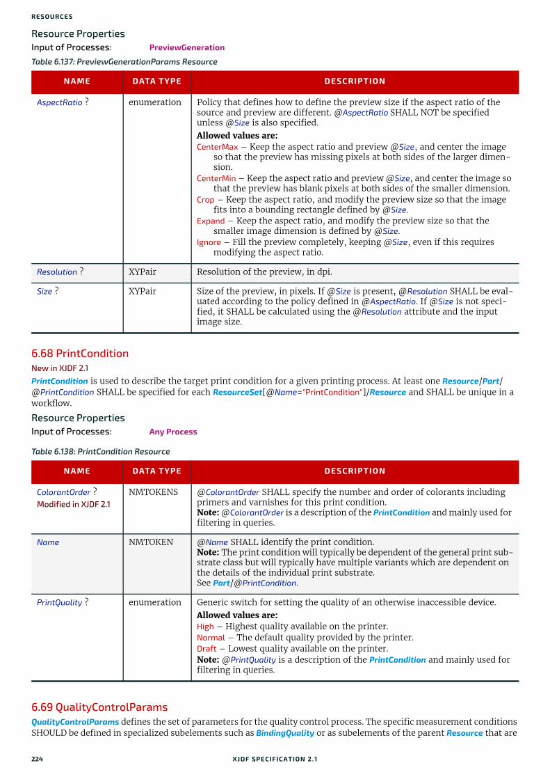
RESO URCES
Resource PropertiesInput of Processes: PreviewGeneration
6.68 PrintConditionNew in XJDF 2.1
PrintCondition is used to describe the target print condition for a given printing process. At least one Resource/Part/@PrintCondition SHALL be specified for each ResourceSet[@Name="PrintCondition"]/Resource and SHALL be unique in a workflow.
Resource PropertiesInput of Processes: Any Process
6.69 QualityControlParamsQualityControlParams defines the set of parameters for the quality control process. The specific measurement conditions SHOULD be defined in specialized subelements such as BindingQuality or as subelements of the parent Resource that are
Table 6.137: PreviewGenerationParams Resource
NAME DATA TYPE DESCRIPTION
AspectRatio ? enumeration Policy that defines how to define the preview size if the aspect ratio of the source and preview are different. @AspectRatio SHALL NOT be specified unless @Size is also specified. Allowed values are:CenterMax – Keep the aspect ratio and preview @Size, and center the image
so that the preview has missing pixels at both sides of the larger dimen-sion.
CenterMin – Keep the aspect ratio and preview @Size, and center the image so that the preview has blank pixels at both sides of the smaller dimension.
Crop – Keep the aspect ratio, and modify the preview size so that the image fits into a bounding rectangle defined by @Size.
Expand – Keep the aspect ratio, and modify the preview size so that the smaller image dimension is defined by @Size.
Ignore – Fill the preview completely, keeping @Size, even if this requires modifying the aspect ratio.
Resolution ? XYPair Resolution of the preview, in dpi.
Size ? XYPair Size of the preview, in pixels. If @Size is present, @Resolution SHALL be eval-uated according to the policy defined in @AspectRatio. If @Size is not speci-fied, it SHALL be calculated using the @Resolution attribute and the input image size.
Table 6.138: PrintCondition Resource
NAME DATA TYPE DESCRIPTION
ColorantOrder ?Modified in XJDF 2.1
NMTOKENS @ColorantOrder SHALL specify the number and order of colorants including primers and varnishes for this print condition.Note: @ColorantOrder is a description of the PrintCondition and mainly used for filtering in queries.
Name NMTOKEN @Name SHALL identify the print condition. Note: The print condition will typically be dependent of the general print sub-strate class but will typically have multiple variants which are dependent on the details of the individual print substrate. See Part/@PrintCondition.
PrintQuality ? enumeration Generic switch for setting the quality of an otherwise inaccessible device.Allowed values are:High – Highest quality available on the printer.Normal – The default quality provided by the printer.Draft – Lowest quality available on the printer.Note: @PrintQuality is a description of the PrintCondition and mainly used for filtering in queries.
224 XJDF SPECIFICATIO N 2.1

QUALITYCONTROLPARAMS
in a foreign namespace. Parameters for QualityControl MAY also be referenced by providing a FileSpec that references a proprietary setup definition. Examples for quality control setup in a foreign namespace include [ISO17972-1:2015] for color measurement data.Note: Additional human readable instructions for manual quality control may be provided in ../Resource/Comment.
Resource PropertiesInput of Processes: QualityControl
Table 6.139: QualityControlParams Resource (Sheet 1 of 2)
NAME DATA TYPE DESCRIPTION
Box ?New in XJDF 2.1
rectangle Position and size of the requested measurement area in the coordinate sys-tem that is defined by @Position of the physical object that is being measured.
Position ?New in XJDF 2.1
enumeration Position of the requested measurement on the physical object that is being measured.Allowed value is from: Face.
QualityBase ?New in XJDF 2.1
enumeration @QualityBase SHALL specify the basis of the target master measurement.Allowed values are:Absolute - The measurement values defined in subelements of this
QualityControlParams SHALL be absolute target values.Master - The measurement values defined in subelements of this
QualityControlParams SHALL be absolute target values for a master mea-surement e.g. a signed press sheet. All subsequent measurements SHALL be compared to the master measurement. The master measurement SHOULD be identified by providing a QualityControlResult with @MeasurementUsage="Master".
QualityControlMethods ?New in XJDF 2.1
NMTOKENS @QualityControlMethods SHOULD be provided and SHALL specify the types of quality control method.Note: It is strongly recommended to provide @QualityControlMethods. The only reason that @QualityControlMethods is not required is because of backwards compatibility with earlier versions of XJDF.Values include those from: Quality Control Methods.
SampleInterval ? integer Interval in number of samples between tests.
Severity ?New in XJDF 2.1
integer @Severity SHALL define the maximum allowed overall severity of all defects on a scale of "0" (no defects present), "1" (trivial), etc to "100" (fatally severe).See Section 5.3.4.1 Mapping severity to scores.
SourceDeviceID ?New in XJDF 2.1
NMTOKEN Device/@DeviceID of the device that is producing the ResourceSet that is being quality controlled.
TimeInterval ? duration Time interval between individual tests.
BindingQuality ?New in XJDF 2.1
element Specification of the binding quality measurements.
BindingQualityParams ? Deprecated in XJDF2.1
element Specification of the binding quality measurements. Deprecation note: Use BindingQuality.
ColorMeasurement ?New in XJDF 2.1
element ColorMeasurement SHALL specify a color quality measurement setup.
FileSpec (Image) ?New in XJDF 2.1
element FileSpec(Image) SHALL reference a master image that is used for image com-parisons. See @QualityControlMethods="Inspection" and QualityControlResult/Inspection.
FileSpec (Setup) ?Modified in XJDF 2.1
element FileSpec(Setup) SHALL reference the location of an external file that contains details of the quality control setup.Modification note: FileSpec/@ResourceUsage was added in XJDF 2.1 to differ-entiate from FileSpec(Image).
XJDF SPECIFICATIO N 2.1 225

RESO URCES
6.69.1 BindingQualityParamsDeprecated in XJDF 2.1
6.70 QualityControlResultQualityControlResult defines the set of results from a QualityControl process. The specific measurements SHOULD be re-turned in specialized subelements such as BindingQuality or as a subelement of the parent Resource that is in a foreign namespace. QualityControl results MAY also be referenced by providing a FileSpec that references a proprietary measure-ment results definition. Examples for quality control measurements in a foreign namespace include [ISO17972-1:2015] for color measurement data.
Each individual measurement that is reported as a specific subelement SHOULD reside in a unique Resource element with Resource/Part/@QualityMeasurement specified and unique. The method of summarizing multiple measurements to an average value is system dependent and MAY be dictated by an ICS.
Resource PropertiesOutput of Processes: QualityControl
RegistrationQuality ?New in XJDF 2.1
element RegistrationQuality SHALL specify the setup of the color registration quality measurements. RegistrationQuality/@Offset SHALL define the maximum absolute value of tolerance for deregistration.
Table 6.140: QualityControlResult Resource (Sheet 1 of 2)
NAME DATA TYPE DESCRIPTION
Box ?New in XJDF 2.1
rectangle Defines the position and size of the measurement area in the coordinate sys-tem that is defined by @Position of the physical object that is being measured.
End ? dateTime Date and time of the end of the measurement. If not specified, the value of @Start is applied.
Failed ? integer Total number of failed measurements.
Measurements ?New in XJDF 2.1
integer @Measurements SHALL specify the total number of measurements and SHOULD be provided in the context of ResourceInfo.If the value of @Measurements is greater than "1", any specific measurement subelement SHOULD be an average measurement. The method of summariz-ing multiple measurements to an average value is system dependent.Note: The value of @Measurements MAY be higher than the sum of @Passed and @Failed in the case where QualityControl describes measurements with no tolerance definitions.
MeasurementUsage ?New in XJDF 2.1
enumerations @MeasurementUsage SHALL specify the usages of this QualityControlResult.Allowed values are:Master - The measurement values defined in subelements of this
QualityControlResult specify a master measurement e.g. a signed press sheet. All subsequent measurements with @MeasurementUsage="Standard" SHALL be compared to this master mea-surement. If this QualityControlResult/@MeasurementUsage also contains "Standard", this measurement SHALL be compared to the previously defined master measurement or absolute setup defined in QualityControlParams.
Standard - The measurement values defined in subelements of this QualityControlResult are measurement values that SHALL be evaluated regularly.
Passed ? integer Total number of passed measurements.
Position ?New in XJDF 2.1
enumeration Position of the requested measurement on the physical object that is being measured.Allowed value is from: Face.
Table 6.139: QualityControlParams Resource (Sheet 2 of 2)
NAME DATA TYPE DESCRIPTION
226 XJDF SPECIFICATIO N 2.1

QUALITYCONTROLRESULT
6.70.1 DefectNew in XJDF 2.1
Each Defect shall describe an individual defect or problem.
QualityControlMethods ?New in XJDF 2.1
NMTOKENS @QualityControlMethods SHOULD be provided and SHALL specify the types of quality control method that was used for the measurements.Note: It is strongly recommended to provide @QualityControlMethods. The only reason that @QualityControlMethods is not required is because of backwards compatibility with earlier versions of XJDF.Values include those from: Quality Control Methods.
Sample ?New in XJDF 2.1
IntegerRange The value of @Sample SHALL be the index of the first and last measurement as specified in ResourceSet/@Unit. The value of @Sample SHALL NOT change for the same physical object in multiple measurements.
Severity ?New in XJDF 2.1
integer @Severity SHALL define the maximum allowed overall severity of all defects on a scale of "0" (no defects present), "1" (trivial), etc to "100" (fatally severe).See Section 5.3.4.1 Mapping severity to scores.
SourceDeviceID ?New in XJDF 2.1
NMTOKEN Device/@DeviceID of the device that has produced the ResourceSet that has been quality controlled.
Start ? dateTime Date and time of the start of the measurement.
BindingQuality ?New in XJDF 2.1
element BindingQuality SHALL define the details of an individual or average binding quality measurement.
BindingQualityMeasurement *Deprecated in XJDF2.1
element Deprecation note: Use BindingQuality.
ColorMeasurement ?New in XJDF 2.1
element ColorMeasurement SHALL specify a color quality measurement.
FileSpec ? element Location of an external file that contains details of the quality control mea-surement.
Inspection ?New in XJDF 2.1
element Inspection SHALL describe a set of measurements on an individual sheet or component.
RegistrationQuality ?New in XJDF 2.1
element RegistrationQuality SHALL define the details of an individual or average color registration measurement.
Table 6.141: Defect Element (Sheet 1 of 2)
NAME DATA TYPE DESCRIPTION
Box ? rectangle Position of the defect in the coordinate system of the current Component as specified by @Face.
DefectReason ? NMTOKEN Cause of the defect. Values include:ElectroStaticCharge - Electrostatic charge of the printed products.Humidity - Incorrect humidity of the process.Temperature - Incorrect temperature of the process.
DefectType enumeration Machine readable type of the defect.Allowed values are: Table 6.142 DefectType Attribute Values.
Table 6.140: QualityControlResult Resource (Sheet 2 of 2)
NAME DATA TYPE DESCRIPTION
XJDF SPECIFICATIO N 2.1 227

RESO URCES
DefectTypeDetails ? NMTOKEN Machine readable details of the type of the defect.Values include those from: Table 6.143 DefectTypeDetails.
Face ? enumeration @Face SHALL specify the side of a three dimensional physical object where the defect is located. @Face SHALL NOT be specified if the enclosing QualityControlResult is partitioned by @Side. The location of defects on flat objects such as sheets SHOULD be defined by @Side.Allowed values are from: Face.
Severity ? integer @Severity SHALL define the severity of the defect on a scale of "0" (no defects present), "1" (trivial), etc to "100" (fatally severe).See Section 5.3.4.1 Mapping severity to scores.
Size ? float The area of the defect in square points.Note: Whereas @Box defines the location of the outer bounding box of a Defect, @Size defines the size of the defective area.
Comment ? element Human readable description of the defect.
FileSpec ? element FileSpec SHALL reference an image of the Defect. The details of the image such as magnification, crop box or highliting of the defect are implementa-tion dependent.Note: Automated inspection can generate large quantities of data, therefore the lifetime of images referenced in FileSpec can be limited and is implemen-tation dependent.
Table 6.142: DefectType Attribute Values
VALUE DESCRIPTION
FinishingDefect Mismatches of printed images and physical operations or mechanical issues with the product that are caused by finishing operations such as LooseBinding, Folding or Cutting.
ImageDefect Defects in printed images caused by incorrect ink distribution.
ImageFinishingDefect Defects in printed images caused by incorrect finishing after printing such as Laminating, Varnishing or Embossing.
Other Any defect not described by the other values in this list.
SheetDefect Mechanical defects of the sheet related to ink and combination of ink and substrate defects.
SubstrateDefect Mechanical defects of the unprinted substrate.
Table 6.143: DefectTypeDetails (Sheet 1 of 3)
DEFECTTYPE DEFECTTYPEDETAILS DESCRIPTION
FinishingDefect Arching Arching/distortion of soft book covers or hardcover cases.
FinishingDefect CuttingDefect Mismatch of die cutting, trimming or other operations that cut parts out of the substrate.
FinishingDefect GlueBindingDefect Defects caused by hard cover or soft cover binding.
FinishingDefect InsertingDefect Incorrect or missing inserts.
FinishingDefect StitchingDefect Defective stitching wire or staples. This includes missing or malformed staples.
ImageDefect Abrasion Ink scrub or ink abrasion.
Table 6.141: Defect Element (Sheet 2 of 2)
NAME DATA TYPE DESCRIPTION
228 XJDF SPECIFICATIO N 2.1

QUALITYCONTROLRESULT
ImageDefect BarcodeDefect A barcode does not meet the technical requirements.Note: Barcodes include 2d and 3d barcodes. See IdentificationField.
ImageDefect ColorMismatch Color irregularities such as a mismatch in ΔE of the printed and target colors.Note: Target colors can be defined either electronically or as a proof.
ImageDefect Fanout Localized registration mismatch due to varying paper stretch.
ImageDefect FinishingDeregistration Deregistration of the image with respect to finishing operations such as Cutting, Folding or Trimming.
ImageDefect FrontBackDeregistration Deregistration of the front image with respect to the back image.
ImageDefect Ghosting An unrequired image that does not overlap the required image, but is relatively close.
ImageDefect Graininess Small scale non uniform color distribution in uniform areas of an image.See [ISO24790:2017] for a differentiation of "Graininess" and "Mottling".
ImageDefect ImageDoubling Close shifted repeat marks during printing.
ImageDefect ImageMismatch Generic mismatch of an image with respect to a predefined master image. Note: This value for @DefectTypeDetails is generally found by automated systems that compare printed images with target images.
ImageDefect InkBlistering Blistering of heatset ink.
ImageDefect InkSetoff Transfer of ink or other material from one sheet to the next in the printed stack.
ImageDefect InkSplash Visible undesired drops of ink on the image.
ImageDefect Moire Moiré effect resulting from interference patterns caused by incorrect screen angles.
ImageDefect Mottling Larger scale non uniform color distribution in uniform areas of an image.See [ISO24790:2017] for a differentiation of "Graininess" and "Mottling".
ImageDefect Scumming Presence of ink in undesired areas of the image, e.g. due to presence of the ink on the master plate.
ImageDefect SeparationDeregistration Deregistration of separations on a surface.
ImageDefect ShineThrough The image of the other side shines through the substrate.
ImageDefect StrikeThrough The image of the other side strikes through the substrate.
ImageFinishingDefect Delamination Peeled off, delaminated or cracked laminating foil. Typically around a fold or cut line.
SheetDefect Blocking Sticking together/blocking of multiple printed sheets in the stack.
SheetDefect BoardSplitting Loss of adhesion or splitting of layers of corrugated board.
SheetDefect Cockling Cockling, i.e. ripples or similar unevenness of the substrate.
Table 6.143: DefectTypeDetails (Sheet 2 of 3)
DEFECTTYPE DEFECTTYPEDETAILS DESCRIPTION
XJDF SPECIFICATIO N 2.1 229

RESO URCES
6.70.2 InspectionNew in XJDF 2.1
An Inspection SHALL describe the inspection of one or more Components. Defects that are found on the same set of Components SHALL be defined in a single Inspection element.
6.70.3 BindingQualityMeasurementDeprecated in XJDF 2.1
6.71 RasterReadingParamsThis set of parameters specifies the details for RasterReading.
Resource PropertiesInput of Processes: RasterReading
SheetDefect Dusting Dusting, powdering, whitening with loose particles of powder, coating filling or paper fibres.
SheetDefect FiberLifting Lifting of paper fibers. Typically occurs in uncoated media.
SheetDefect FoldCrack Cracks in a fold.
SheetDefect Picking Rupturing or other deformation of a substrate's surface caused during ink transfer.
SubstrateDefect Hole A hole or tear in the substrate.
SubstrateDefect SubstrateMottling Non uniform structure of the unprinted substrate.
SubstrateDefect Wrinkling Wrinkling of the substrate.
Table 6.144: Inspection Element
NAME DATA TYPE DESCRIPTION
Defect * element Each Defect SHALL describe an individual defect or problem.
FileSpec ? element FileSpec SHALL reference an image of the inspected Component.Note: Automated inspection generates large quantities of data. Therefore the lifetime of images can be limited.
Table 6.145: RasterReadingParams Resource (Sheet 1 of 2)
NAME DATA TYPE DESCRIPTION
Center ? boolean Indicates whether or not the finished page image SHALL be centered within the imagable area of the media. @Center SHALL NOT be specified if FitPolicy/@SizePolicy="ClipToMaxPage".
FilmRef ? IDREF Reference to film Media. This resource provides a description of the physical media that will be marked. The physical characteristics of the media MAY affect decisions made during RasterReading.
MirrorAround ? enumeration This attribute specifies the axis around which a raster reader SHALL mirror an image. Allowed value is from: Axis.
PaperRef ? IDREF Reference to final paper Media. This resource provides a description of the physical media that will be marked. The physical characteristics of the media MAY affect decisions made during RasterReading.
PlateRef ? IDREF Reference to plate Media. This resource provides a description of the physical media that will be marked. The physical characteristics of the media MAY affect decisions made during RasterReading.
Table 6.143: DefectTypeDetails (Sheet 3 of 3)
DEFECTTYPE DEFECTTYPEDETAILS DESCRIPTION
230 XJDF SPECIFICATIO N 2.1

RENDERINGPARAMS
6.72 RenderingParamsThis set of parameters identifies how the Rendering process SHALL operate. Specifically, these parameters define the ex-pected output of the RunList that the Rendering process creates.
Resource PropertiesInput of Processes: Rendering
Polarity ? enumeration The image SHALL be RIPed in the polarity specified. Note that this is a polar-ity change in the RIP and not a polarity change in the hardware of the output device.Allowed value is from: Polarity.
ProofPaperRef ? IDREF Reference to paper Media used for proofing. This resource provides a descrip-tion of the physical media that will be marked. The physical characteristics of the media MAY affect decisions made during RasterReading.
Scaling ? XYPair A pair of positive real values that indicates the scaling factor for the content. Values between 0 and 1 specify that the contents SHALL be reduced, while values greater than 1 specify that the contents SHALL be expanded. Any scal-ing defined in FitPolicy SHALL be applied after the scaling defined by this attribute.
ScalingOrigin ? XYPair A pair of real values that identify the point in the unscaled page that SHALL become the origin of the new, scaled page image. This point is defined in the coordinate system of the unscaled page. If not specified, and scaling is requested, the @ScalingOrigin defaults to "0 0".
FitPolicy ? element Allows printing even if the size of the imagable area of the media does not match the requirements of the data.
Table 6.146: RenderingParams Resource (Sheet 1 of 2)
NAME DATA TYPE DESCRIPTION
BandHeight ? integer Height of output bands expressed in lines. For a frame device, the band height is simply the full height of the frame.
BandOrdering ? enumeration Indicates whether output buffers are generated in "BandMajor" or "ColorMajor" order. Allowed values are:BandMajor – The position of the bands on the page is prioritized over the
color.ColorMajor – All bands of a single color are played in order before progressing
to the next plane. This is only possible with non-interleaved data.
BandWidth ? integer Width of output bands, in pixels.
ColorantDepth ? integer Number of bits per colorant. Determines whether the output is bitmaps or bytemaps.
Interleaved ? boolean If "true", the resulting colorant values SHALL be interleaved. @BandOrdering SHALL NOT be specified if @Interleaved="true".
MimeType ? string @MimeType identifies the MIME type associated with this output file format. For example "application/pdf".
AutomatedOverPrintParams ?
element Controls for overprint substitutions. Defaults to no automated overprint gen-eration.
ObjectResolution * element Elements that define the resolutions at which to render the contents. More than one element MAY be used to specify different resolutions for different @SourceObjects types. If no ObjectResolution is specified, the value is implied from the input data.
Table 6.145: RasterReadingParams Resource (Sheet 2 of 2)
NAME DATA TYPE DESCRIPTION
XJDF SPECIFICATIO N 2.1 231

RESO URCES
6.72.1 TIFFEmbeddedFile
6.72.2 TIFFFormatParams
TIFFFormatParams ?
element Parameters specific for creating TIFF files.
Table 6.147: TIFFEmbeddedFile Element
NAME DATA TYPE DESCRIPTION
TagNumber integer Tag number of the specified tag (e.g., 34675 (decimal) for an ICC profile or 700 for XMP).
TagType integer The type of the tag as defined in [TIFF6]. This will usually be 1 (BYTE) or 7 (UNDEFINED).
FileSpec element Reference to the file that SHALL be embedded.
Table 6.148: TIFFFormatParams Element (Sheet 1 of 2)
NAME DATA TYPE DESCRIPTION
ByteOrder ? enumeration Byte order of the TIFF file. Allowed values are: II – Low byte first. MM – High byte first. Note: The identifier values have been selected to match the identifier with the same purpose within the TIFF file itself.
Interleaving ? integer How the components of each pixel are stored. The values are taken from TIFF tag 284—PlanarConfiguration:Allowed values are: 1 – “Chunky” format, which is pixel interleaved.2 – “Planar” format, which is strip interleaved.
RowsPerStrip ? integer The number of image scan lines per strip, encoded in the TIFF file as Row-sPerStrip. This attribute is ignored if @Segmentation!="Stripped".The default, if not known, is set by the processing system with the exception that when converting from ByteMap to TIFF, ByteMap/Band/@Height is the default.
Segmentation ? enumeration How the image data are segmented. Allowed values are: SingleStrip – All data are included in one segment. This is encoded in the TIFF
file by setting RowsPerStrip to a number equal to or larger than the num-ber of pixel rows in the image.
Stripped – Data are segmented into strips.Tiled – Data are segmented into tiles.
SeparationNameTag ?
integer When color separations are stored in individual TIFF files it is often useful to mark each with the name of the colorant that it represents, but there is no universally accepted way to do this. In order to avoid the need for explicit partitioning, the tag to be used to encode the separation name (as a string) can be entered here as the TIFF tag number.If the same TIFF tag number is also supplied as a TIFFtag subelement, then the TIFFtag element takes priority over @SeparationNameTag.The tag SHOULD only be put in the resulting TIFF files if the name of the separation is known.
Table 6.146: RenderingParams Resource (Sheet 2 of 2)
NAME DATA TYPE DESCRIPTION
232 XJDF SPECIFICATIO N 2.1

RUNLIST
6.72.3 TIFFtag
Exactly one of @IntegerValue, @NumberValue, @StringValue or @BinaryValue SHALL be present, depending on the type of the TIFF tag to be carried. TIFFtag elements SHALL NOT be used for any tags related to the image data and its encoding (ImageWidth, Compression, etc.). TIFFtag elements MAY include informational tags such as OPIProxy, ImageID, Copy-right, DateTime, ImageDescription, etc.
6.73 RunListA RunList defines one or more printable logical documents or document sets that MAY be defined in one or more external physical PDL or image files. It retains the properties of the original documents, e.g. the pages of a set of documents with ordered pages that are described by a RunList, retain that order.RunList allows structuring of multiple pages into documents. Multiple documents that have a joint context may be grouped into sets. For examples of how these can be mapped see Section 6.73.3 Pages, Documents and Sets for common PDL types.
6.73.1 Referencing pages of a RunList from a LayoutThe Layout resource in the Imposition process references individual pages in a RunList by index in Layout/@Ord. The index SHALL be calculated in the context of the current document and set of a RunList.
6.73.2 Filtering parts of a RunListThe Partition Keys: Part/@DocIndex, Part/@RunIndex, Part/@SetIndex and Part/@SheetIndex are provided to select subsets of a RunList without modifying the indexes of selected pages for purposes of calculating @Ord values in Imposition.There are two distinct use cases:
• Selecting a set of pages for reprint.
• Selecting pages for finishing or prepress operations.In order to select a set of pages, sheets, documents or document sets for reprint, these keys SHALL be provided in the ResourceSet[@Usage=”Output”] of the process that requires filtering.
This ResourceSet NEED NOT be a ResourceSet[@Name="RunList"] but MAY be any output ResourceSet e.g. a ResourceSet[@Name="Component"], e.g. for selective reprint of a set of pages, sheets, documents or document sets.
TileSize ? XYPair Two integers. The X value provides width of tiles, and the Y value provides height of tiles. @TileSize SHALL NOT be specified unless @Segmentation="Tiled".
WhiteIsZero ? boolean When writing monochrome or gray scale files, this flag indicates whether the data SHALL be written with either white values encoded as zero, "true" or black values encoded as zero, "false".
TIFFEmbeddedFile * element Files to be embedded within the created TIFF file. These might include an ICC profile, XMP data, etc.
TIFFtag * element Specific tag values for inclusion in the TIFF file.
Table 6.149: TIFFtag Element
NAME DATA TYPE DESCRIPTION
BinaryValue ? hexBinary If the type of the tag is UNDEFINED, then @BinaryValue is used to encode the data.
IntegerValue ? IntegerList If the type of the tag is BYTE, SHORT, LONG, SBYTE, SSHORT or SLONG, then @IntegerValue is used to encode that data.
NumberValue ? FloatList If the type of the tag is RATIONAL, SRATIONAL or FLOAT, then @NumberValue is used to encode that data.
StringValue ? string If the type of the tag is ASCII, then @StringValue is used to encode the data.
TagNumber integer Tag number of the specified tag (e.g., 270 (decimal) for ImageDescription).
TagType integer The type of the tag as defined in [TIFF6] (1 = BYTE, 2 = SHORT, etc.).
Table 6.148: TIFFFormatParams Element (Sheet 2 of 2)
NAME DATA TYPE DESCRIPTION
XJDF SPECIFICATIO N 2.1 233

RESO URCES
In order to select a set of pages, sheets, documents or document sets that subsequent processes apply to, the ResourceSet[@Usage="Input"] SHALL contain the appropriate Part elements.
Example 6.24: Filtering Parts of a RunListThis example selects the first page (from two pages) of ‘file1.pdf’ and the second page through to the fifth page (from eight pages) of ‘file2.pdf’. The first Part of the output RunList, with @RunIndex="0 0", selects the range from first to first page of the entire input RunList. The second Part of the output RunList, with @RunIndex="3 6", selects the range from fourth to seventh page of the entire input RunList. Since the first input RunList partition contains two pages, the fourth through seventh page are the second through fifth page of the second input RunList partition.
Resource PropertiesResource referenced by: Layout/SheetActivation, SheetOptimizingParams/GangElement
Input of Processes: ColorCorrection, ColorSpaceConversion, DigitalPrinting, ImageEnhancement, ImageSetting, Imposition, Interpreting, LayoutElementProduction, LayoutShifting, PDLCreation, Preflight, PreviewGeneration, RasterReading, Rendering, Screening, Separation, ShapeDefProduction, Stripping, Trapping
Output of Processes: ColorCorrection, ColorSpaceConversion, ImageEnhancement, Imposition, Interpreting, LayoutElementProduction, LayoutShifting, PDLCreation, RasterReading, Rendering, Screening, Separation, Stripping, Trapping
<ResourceSet Name="RunList" Usage="Input"> <Resource> <Part Run="r1"/> <RunList NPage="2"> <FileSpec URL="file:///indir/file1.pdf"/> </RunList> </Resource> <Resource> <Part Run="r2"/> <RunList NPage="8"> <FileSpec URL="file:///outdir/output.pdf"/> </RunList> </Resource></ResourceSet><ResourceSet Name="RunList" Usage="Output"> <Resource> <Part RunIndex="0 0"/> <Part RunIndex="3 6"/> <RunList/> </Resource></ResourceSet>
Table 6.150: RunList Resource (Sheet 1 of 3)
NAME DATA TYPE DESCRIPTION
Automation ? enumeration Identifies dynamic and static RunList elements. Generating Resource/Part in automated imposition is defined in detail in Section 5.4.8.1 Execution Model for Automated Imposition. This structure SHALL be retained in the RunList description.If @Automation="Dynamic" and ResourceSet/Dependent/@PipeID is also pres-ent, details MAY be specified in XJMF pipe messages. See Section 9.3.5.1 Dynamic Pipes.Allowed value is from: Automation.
ClipPath ? PDFPath Path that describes the outline of the RunList that SHALL be clipped. The default case is that there is no clip path. @ClipPath, @SourceClipBox, PlacedObject/@SourceClipPath and PlacedObject/@ClipBox, if supplied, SHALL be concatenated.
ContentRefs ? IDREFS Ordered list of IDs of Content elements. Content elements provide metadata related to the product to be published.
234 XJDF SPECIFICATIO N 2.1

RUNLIST
DocPages ?New in XJDF 2.1
IntegerList @DocPages SHALL specify the number of pages in each document of a multi-document set. The sum of @DocPages SHALL specify the number of pages in one set. If the RunList references a PDL that supports internal instance docu-ments, @DocPages SHALL match the document and set structure that is defined in the PDL.Note: @DocPages is defined to concisely specify a unique, repeating multi-document and multi-set document structure for PDLs that do not support in-ternal instance documents. See also @EndOfDocument and @EndOfSet.
Docs ? IntegerRange Zero-based range of document indices in a multi-document file in the con-text of @Sets that SHALL be selected in the order of the range. If not present, all documents SHALL be selected.
EndOfDocument ? boolean If "true", the last page in the RunList is the last page of an instance document. If the RunList references a PDL that supports internal instance documents, @EndOfDocument SHALL be the value that is defined in the PDL. The implied default value of @EndOfDocument="false", except for the last RunList Resource with the same explicit or calculated value of Part/@SetIndex, which has an implied default value of @EndOfDocument="true".
EndOfSet ? boolean If "true", the last page in the RunList is the last page of a set of instance docu-ments. If the RunList references a PDL that supports internal sets, @EndOfSet SHALL be the value that is defined in the PDL. The implied default value of @EndOfSet="false", except for the last RunList Resource, which has an implied default value of @EndOfSet="true".
FinishedPages ? integer Number of finished page surfaces that one PDL page of this RunList refers to. This attribute SHOULD be used when cover spreads or imposed sheets that contain more than one reader page per PDL page are provided.
LogicalPage ? integer The logical page number of the first page in a RunList. It defaults to "1" plus the last page of the previous sibling RunList partition. If the RunList resource is the first partition, @LogicalPage defaults to "0". @LogicalPage SHALL NOT be specified lower than the highest calculated value of @LogicalPage of a pre-vious partition.
NPage ? integer Total number of pages (placed object slots) that are defined by the RunList. If @NPage is not specified, it defaults to all pages in the referenced PDL. If the RunList describes multiple instance documents or document sets, @NPage refers to the total number of pages in all instance documents and sets. A RunList with @NPage specified always refers to @NPage pages, regardless of the number of pages of the referenced PDL.
OrdType ? enumeration @OrdType SHALL specify the usage of this RunList element in the context of an Imposition process.Allowed values are: Content - This RunList specifies a set of pages that have content associated.
@NPage SHOULD be specified. The referenced content SHALL be pro-cessed and placed on the imposed sheet.
Insert - This RunList specifies a set of pages that will be inserted from an external feeder. @NPage SHALL be specified. The referenced content SHALL be processed for side effects but SHALL NOT be placed on the imposed sheet.
Reservation - This RunList specifies a set of pages that have no content asso-ciated. @NPage SHALL be specified. No content SHALL be referenced. An empty page SHALL be placed on the imposed sheet.Note: @OrdType="Reservation" is typically used for pages that will be pro-vided at a later stage.
Pages ? IntegerRange Zero-based range of indices of the pages in the context of @Docs and @Sets that SHALL be selected in the order of the range. If neither @Pages nor @NPage is specified, all pages in the PDL referred to by the RunList SHALL be selected in document order.
Table 6.150: RunList Resource (Sheet 2 of 3)
NAME DATA TYPE DESCRIPTION
XJDF SPECIFICATIO N 2.1 235

RESO URCES
Sets ? IntegerRange Zero based range of document-set indices in a multi document-set file spec-ified by the RunList that SHALL be selected in the order of the range. If not present, all document sets SHALL be selected.
SourceBleedBox ? rectangle A rectangle that describes the bleed area of the element that SHALL be included. This rectangle is expressed in the source coordinate system of the object.
SourceClipBox ? rectangle A rectangle that defines the region of the element that SHALL be included. This rectangle is expressed in the source coordinate system of the object.
SourceMediaBox ? rectangle A rectangle that defines the intended media size of the element. This rectan-gle is expressed in the source coordinate system of the object.
SourceTrimBox ? rectangle A rectangle that describes the intended trimmed size of the element to be included. This rectangle is expressed in the source coordinate system of the object.
ByteMap ? element Describes the page or stream of pages. At most one of ByteMap or FileSpec SHALL be specified. If none of ByteMap or FileSpec are specified, the RunList specifies empty content.
FileSpec ? element URL plus metadata about the physical characteristics of a file representing the RunList. If not present, then only metadata is known but not the content file.
MetadataMap * element Describes the mapping of metadata in a RunList to Partition Keys. MetadataMap SHOULD NOT be specified unless @Automation="Dynamic".
Table 6.150: RunList Resource (Sheet 3 of 3)
NAME DATA TYPE DESCRIPTION
236 XJDF SPECIFICATIO N 2.1

RUNLIST
Example 6.25: Example of a multi-set file using RunList/@DocPagesThe following example describes a 480 page document with 40 sets each with 12 pages. Each set contains three logical documents that represents a two page front cover, an eight page body and a two page back cover.
6.73.3 Pages, Documents and Sets for common PDL typesThe following table defines the mapping of RunList structures to commonly used PDLs.
6.73.4 Band
<XJDF xmlns="http://www.CIP4.org/JDFSchema_2_0" JobID="RunList" Types="DigitalPrinting" Version="2.1"> <ResourceSet Name="RunList" Usage="Input"> <Resource> <RunList DocPages="2 8 2" NPage="480"> <FileSpec URL="File:///ManyBrochures.pdf"/> </RunList> </Resource> </ResourceSet> <ResourceSet Name="Media"> <Resource DescriptiveName="Media for front and back covers" ID="Media_000005.1"> <Part DocIndex="0 0"/> <Part DocIndex="2 2"/> <Media MediaType="Paper" Weight="150"/> </Resource> <Resource DescriptiveName="Media for inner pages" ID="Media_000005.2"> <Part DocIndex="1 1"/> <Media MediaType="Paper" Weight="100"/> </Resource> </ResourceSet> <ResourceSet Name="Component" Usage="Input"> <Resource DescriptiveName="Physical media for front and back covers"> <Part DocIndex="0 0"/> <Part DocIndex="2 2"/> <Component MediaRef="Media_000005.1"/> </Resource> <Resource> <Part DocIndex="1 1"/> <Component MediaRef="Media_000005.2"/> </Resource> </ResourceSet></XJDF>
Table 6.151: Pages, Documents and Sets for common PDL types
PDL PAGES DOCUMENTS SETS REMARKS
Post-Script
- - PostScript is a single document PDL
PDF Page in pages tree
- - Regular PDF including PDF/X is a single document PDL
PDF/VT Page in pages tree
Any DPart Descendant below the Set
Any DPart record as defined by RecordLevel
A Record as defined by Record-Level SHALL be mapped to a Set
PPML PAGE elements DOCUMENT elements DOCUMENT_SET/JOB elements
Table 6.152: Band Element
NAME DATA TYPE DESCRIPTION
Height ? integer Height in pixels of the band.
Width ? integer Width in pixels of the band.
XJDF SPECIFICATIO N 2.1 237

RESO URCES
6.73.5 ByteMapA ByteMap represents a raster of image data. This data MAY have multiple bits per pixel, MAY represent a varying set of color planes, and MAY be interleaved. A bitmap is a special case of a ByteMap in which each pixel is represented by a single bit per color.
Example 6.26: RunList: Unstructured Single-File RunListThe order in which the RunList elements appear in the XML document is significant. Note: The @Run Partition Key has a string value, which MAY be non-numeric. Below is an example of a simple unstructured single-file RunList. This example specifies all pages contained in "/in/colortest.pdf".
6.74 ScreeningParamsScreeningParams specifies the parameters of the Screening process.
Table 6.153: ByteMap Element
NAME DATA TYPE DESCRIPTION
BandOrdering ? enumeration Identifies the precedence given when ordering the produced bands. @BandOrdering SHALL be specified for non-interleaved data and SHALL be ignored for interleaved data if specified.Allowed values are:BandMajor – The position of the bands on the page is prioritized over the
color.ColorMajor – All bands of a single color are played in order before progressing
to the next plane. This is only possible with non-interleaved data.
FrameHeight ? integer Height of the overall image that MAY be broken into multiple bands.
FrameWidth ? integer Width of overall image that MAY be broken into multiple columns.
Halftoned ? boolean Indicates whether or not the data has been halftoned, e.g. in a previous Screening process.
Interleaved ? boolean If "true", the data are interleaved or chunky. Otherwise the data are non-inter-leaved or planar.
PixelColorants ? NMTOKENS Ordered list of separation identifiers containing information about which colorants are represented. Additional details of the colorants SHOULD be pro-vided in ResourceSet[@Name=”Color”].
PixelDepth ? integer Number of bits per pixel for each colorant.
PixelSkip ? integer Number of bits to skip between pixels of interleaved data.
Resolution ? XYPair Output resolution of the ByteMap in dpi.
Band ? element Description of the structure of the bands or tiles containing the raster data.
<XJDF xmlns="http://www.CIP4.org/JDFSchema_2_0" JobID="RunList" Types="Imposition"> <ResourceSet Name="RunList" Usage="Input"> <Resource> <RunList Pages="0 -1"> <FileSpec URL="File:///in/colortest.pdf"/> </RunList> </Resource> </ResourceSet></XJDF>
238 XJDF SPECIFICATIO N 2.1

SEPARATIONCONTROLPARAMS
Resource PropertiesInput of Processes: Screening
6.75 SeparationControlParamsSeparationControlParams provides the controls needed to separate composite color files.
Resource PropertiesInput of Processes: Separation
6.76 ShapeCuttingParamsShapeCuttingParams defines the details of the ShapeCutting process.
Resource PropertiesIntent Pairing: ShapeCuttingIntent
Input of Processes: ShapeCutting
6.77 ShapeDefA structural design describing a 2D surface with paths that describe different finishing operations such as cutting, creas-ing, perforation, etc. In the case of box production this resource is a description of the unprinted blank box as it will be available after die cutting and blanking and before folding. A ShapeDef is defined either by an external file (FileSpec) de-scribing the structural design or a collection of PDFPaths contained in Shape elements.
Table 6.154: ScreeningParams Resource
NAME DATA TYPE DESCRIPTION
IgnoreSourceFile ? boolean If @IgnoreSourceFile="true", the screen settings specified in a source file SHALL NOT be applied, e.g. setscreen, setcolorscreen and sethalftone in a PDF file.
ScreenSelector + element List of screen selectors. A screen selector is included for each separation, including a default specification.ScreenSelector SHALL contain the complete set of parameters for a given screening operation.
Table 6.155: SeparationControlParams Resource
NAME DATA TYPE DESCRIPTION
AutomatedOverPrintParams ?
element Controls for overprint substitutions.
Table 6.156: ShapeCuttingParams Resource
NAME DATA TYPE DESCRIPTION
DeliveryMode ? enumeration Allowed values are:FullSheet – The output of the die-cutter SHALL be complete sheets. The
blanks are kept in place with nicks. Front waste (gripper margin) SHALL NOT be removed.
RemoveGripperMargin – The output of the die-cutter SHALL be complete sheets. The blanks are kept in place with nicks. Front waste (gripper mar-gin) SHALL be removed.
SeparateBlanks – The output of the die-cutter SHALL be blanks that have been removed from the sheets.
DieLayoutRef ? IDREF Reference to a DieLayout containing the reference of an external file describ-ing the cutting and other paths.
ModuleID ? NMTOKEN Identifier of the shape-cutting module in a multi-function device, such as a printing press. See Module for details.
SheetLay ? enumeration Lay of input media. Reference edge of where the sheets are placed in the feeder.Allowed value is from: SheetLay.
Shape * element Details of each individual cut shape.
XJDF SPECIFICATIO N 2.1 239

RESO URCES
Resource PropertiesResource referenced by: DieLayout/Station, DieLayoutProductionParams/RepeatDesc,
LayoutElementProductionParams
Output of Processes: ShapeDefProduction
6.78 ShapeDefProductionParamsParameters for the structural design.
Table 6.157: ShapeDef Resource
NAME DATA TYPE DESCRIPTION
Area ? float The net area of the shape in m2, after cutting.
CutBox ? rectangle A rectangle describing the bounding box of all cut lines. This is sometimes referred to as the knife to knife dimensions of a blank box.
CutLines ? NMTOKENS Selects the die line separation identifiers from the file referenced by FileSpec. Additional details of the usage of the separations MAY be specified in the respective ResourceSet[@Name="Color"].
Dimensions ? shape Width x, height y and depth z coordinates of the open 3D shape. For a box, these are the outer dimensions of the opened and potentially filled box (e.g., for palletizing of the final products).Note: Compare with @FlatDimensions.
FlatDimensions ? shape Width x, height y and depth z coordinates of the flat 3D shape. For a box, these are the outer dimensions of the glued flat box (e.g., for palletizing of the boxes prior to filling). This corresponds to Component/@Dimensions of the output of the BoxFolding process.Note: Compare with @Dimensions.
FluteDirection ? enumeration Intended direction of the flute for this design in the coordinate system defined by @CutBox. This information SHALL be taken into account by the DieLayoutProduction process to give the ShapeDef the correct orientation on the sheet. Allowed value is from: MediaDirection.
GrainDirection ? enumeration Intended direction of the grain for this design in the coordinate system defined by @CutBox. This information SHALL be taken into account by the DieLayoutProduction process to give the ShapeDef the correct orientation on the sheet.Allowed value is from: MediaDirection.
MediaRef ? IDREF Reference to a Media resource for which this structural design was intended. The Media description defines important design parameters, such as the type of Media, thickness, inside loss, outside gain, etc.
MediaSide ? enumeration Determines the printing side for which the DieLayout is made. "Front" corre-sponds to the outside of a box, "Back" corresponds to the inside of a box. Allowed value is from: Side.Note: Folding carton is usually cut from the outside (Front), corrugated from the inside (Back).
ResourceWeight ? float The weight of the shape after cutting (g).
FileSpec ? element The FileSpec of the structural design file. The format of this file may be a vendor specific format, a standard format like [DDES3], a less well speci-fied but commonly used format like CFF2 or DXF or even a PDF or EPS file. FileSpec and Shape are mutually exclusive.
Shape * element The shape is defined by a collection of Shape elements. Shape and FileSpec are mutually exclusive.
240 XJDF SPECIFICATIO N 2.1

SHAPEDEFPRODUCTIONPARAMS
Resource PropertiesInput of Processes: ShapeDefProduction
6.78.1 ObjectModel
6.78.2 ShapeDimension
6.78.3 ShapeTemplateShapeTemplate describes a structural template that is also referred to as a parametric structural design.
The three figures below show shapes specified by a ShapeTemplate with each named variable represented by a ShapeDimension element. Example 6.27: ShapeTemplate for template example 1 below illustrates the encoding of L, D and W using ShapeDimension.
Table 6.158: ShapeDefProductionParams Resource
NAME DATA TYPE DESCRIPTION
ObjectModel * element A 3D model of the objects that need to be packed.
ShapeTemplate ? element A structural template sometimes referred to as a parametric structural design. Given a set of parametric values, a structural template can be instan-tiated to an actual structural design.
Table 6.159: ObjectModel Element
NAME DATA TYPE DESCRIPTION
Dimensions ? shape Width x, height y and depth z values for the bounding box of the object.
FileSpec ? element The FileSpec of the 3D model of the objects that needs to be packed. The for-mat of this file MAY be a vendor specific format or a standard 3D format like VRML or PDF (U3D).
Table 6.160: ShapeDimension Element
NAME DATA TYPE DESCRIPTION
Usage string @Usage specifies the name of the ShapeDimension.Values Include:D - DepthL - LengthW - Width
Value float @Value specifies the length of the ShapeDimension in points.
Table 6.161: ShapeTemplate Element
NAME DATA TYPE DESCRIPTION
InnerDimensions ? shape Width x, height y and depth z coordinates of the 3D shape. For a box these are the inner dimensions.
Name ? NMTOKEN The name of a parametric structural design or CAD template.
Standard ? NMTOKEN The name of the standard this template belongs to (e.g., FEFCO, ECMA or the name of a company internal standard).
FileSpec ? element The FileSpec of the parametric structural design.
ShapeDimension * element ShapeDimension elements define additional parametric values of the ShapeTemplate.
XJDF SPECIFICATIO N 2.1 241

RESO URCES
Example 6.27: ShapeTemplate for template example 1
<XJDF xmlns="http://www.CIP4.org/JDFSchema_2_0" JobID="n_001010" JobPartID="n_000006" Types="ShapeDefProduction"> <ResourceSet DescriptiveName="Box123" Name="ShapeDefProductionParams" Usage="Input"> <Resource DescriptiveName="Box123"> <ShapeDefProductionParams> <ShapeTemplate InnerDimensions="566.92913386 708.66141732 283.46456693" Standard="ECMA"> <ShapeDimension Usage="L" Value="566.93"/> <ShapeDimension Usage="W" Value="283.46"/> <ShapeDimension Usage="D" Value="708.66"/> </ShapeTemplate> </ShapeDefProductionParams> </Resource> </ResourceSet></XJDF>
Figure 6-35: ShapeTemplate example 1
Figure 6-36: ShapeTemplate example 2
D
W
L
D1
D2
L
W
242 XJDF SPECIFICATIO N 2.1

SHEETOPTIMIZINGPARAMS
6.79 SheetOptimizingParamsSheetOptimizingParams describes the parameter set for the SheetOptimizing process.
Resource PropertiesInput of Processes: SheetOptimizing
6.79.1 GangElementA GangElement describes an individual product or product part (e.g., product cover) that is a candidate for placement on a printed sheet.
Figure 6-37: ShapeTemplate example 3
Table 6.162: SheetOptimizingParams Resource
NAME DATA TYPE DESCRIPTION
Policy ?New in XJDF 2.1
enumeration The policy with which the GangElements in the gang shall be processed.Allowed values are:All - All the GangElements and any waiting GangElements SHALL be com-
pletely processed.Collect - The GangElements SHALL be collected and the process SHALL NOT
generate any ganged sheets.Optimized - The GangElements and any waiting GangElements SHOULD be
processed without producing unnecessary waste. The algorithm for selecting the respective elements is implementation dependent and SHOULD take priority and scheduling data into account.
ConvertingConfig *Modified in XJDF 2.1
element Specification of the device configurations for destination sheet sizes.ConvertingConfig SHOULD NOT be specified if the value of @Policy="Collect".Modification Note: ConvertingConfig was made optional in XJDF 2.1 to allow collecting without the creation of a gang sheet.
GangElement + element Each GangElement describes an individual product or product part that SHALL be placed completely on a gang form. If an individual product MAY be distributed over multiple separate gangs (e.g., cover and body with different paper), it SHALL be represented as multiple gang elements.
Table 6.163: GangElement Element (Sheet 1 of 4)
NAME DATA TYPE DESCRIPTION
BinderySignatureIDs ?
NMTOKENS If specified, @BinderySignatureIDs SHALL list Part/@BinderySignatureID of all BinderySignatures that are candidates for this GangElement.
DX2
DX1
DX3DF2
DY3
DY4
DY2 DY1
DF1
DR
XJDF SPECIFICATIO N 2.1 243
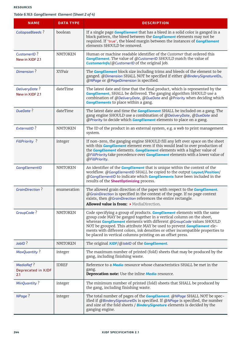
RESO URCES
CollapseBleeds ? boolean If a single page GangElement that has a bleed in a solid color is ganged in a block pattern, the bleed between the GangElement elements may not be required. If "true", the bleed margin between the instances of GangElement elements SHOULD be removed.
CustomerID ?New in XJDF 2.1
NMTOKEN Human or machine readable identifier of the Customer that ordered this GangElement. The value of @CustomerID SHOULD match the value of CustomerInfo/@CustomerID of the original job.
Dimension ? XYPair The GangElement block size including trims and bleeds of the element to be ganged. @Dimension SHALL NOT be specified if either @BinderySignatureIDs, @NPage or @PageDimension is specified.
DeliveryDate ?New in XJDF 2.1
dateTime The latest date and time that the final product, which is represented by the GangElement, SHALL be delivered. The ganging algorithm SHOULD use a combination of @DeliveryDate, @DueDate and @Priority when deciding which GangElements to place within a gang.
DueDate ? dateTime The latest date and time the GangElement SHALL be included on a gang. The gang engine SHOULD use a combination of @DeliveryDate, @DueDate and @Priority to decide which GangElement elements to place on a gang.
ExternalID ? NMTOKEN The ID of the product in an external system, e.g. a web to print management system.
FillPriority ? integer If non-zero, the ganging engine SHOULD fill any left over space on the sheet with this GangElement element even if this would lead to over production of the GangElement elements. GangElement elements with a higher value of @FillPriority take precedence over GangElement elements with a lower value of @FillPriority.
GangElementID NMTOKEN An identifier of the GangElement that is unique within the context of the workflow. @GangElementID SHALL be copied to the output Layout/Position/@GangElementID to indicate which GangElements have been included in the results of the SheetOptimizing process.
GrainDirection ? enumeration The allowed grain direction of the paper with respect to the GangElement. @GrainDirection is specified in the context of the page. If no page context exists, then @GrainDirection references the entire rectangle.Allowed value is from: MediaDirection.
GroupCode ? NMTOKEN Code specifying a group of products. GangElement elements with the same group code MAY be ganged together in a vertical column on the sheet, whereas GangElement elements with different @GroupCode values SHOULD NOT be grouped. This attribute MAY be used to prevent GangElement ele-ments with different colors, ink densities or other incompatible properties to be placed in vertical columns printing on an offset press.
JobID ? NMTOKEN The original XJDF/@JobID of the GangElement.
MaxQuantity ? integer The maximum number of printed (fold) sheets that may be produced by the gang, including finishing waste.
MediaRef ?Deprecated in XJDF2.1
IDREF Reference to a Media resource whose characteristics SHALL be met in the gang.Deprecation note: Use the inline Media resource.
MinQuantity ? integer The minimum number of printed (fold) sheets that SHALL be produced by the gang, including finishing waste.
NPage ? integer The total number of pages of the GangElement. @NPage SHALL NOT be spec-ified if @BinderySignatureIDs is specified. If @NPage is specified, the number and size of the fold sheets / BinderySignature elements is decided by the ganging engine.
Table 6.163: GangElement Element (Sheet 2 of 4)
NAME DATA TYPE DESCRIPTION
244 XJDF SPECIFICATIO N 2.1

SHEETOPTIMIZINGPARAMS
NumberUp ? XYPair The number up that SHALL be placed on the gang in a single block. If Y is zero, then X SHALL specify the total number-up requested without specify-ing a specific number in the X or Y direction.
OneSheet ? NMTOKEN @OneSheet controls how this GangElement SHOULD be placed on ganged sheets.Values include:Any – Place on any sheet that is generated.GangElementID – Keep all blocks with this @GangElementID on one sheet.JobID – Keep all GangElement elements with the same @JobID on the same
sheet.
Operations ?New in XJDF 2.1
NMTOKENS List of finishing operations or properties that are required for this GangElement. The values are implementation dependent. If present, the GangElements SHALL be placed onto regions of the sheet that are described by ConvertingConfig/CutBlock elements with matching CutBlock/@Operations.
OrderQuantity integer The number of printed (fold) sheets to produce, including finishing waste.
PageDimension ? XYPair The page size, including trims and bleeds, of the element to be ganged. @PageDimension SHALL NOT be specified if @NPage is NOT specified or if either @BinderySignatureIDs or @Dimension is specified.
PlacedQuantity ?New in XJDF 2.1
integer @PlacedQuantity SHALL specify the total quantity of all positions that contain this GangElement. Note: @PlacedQuantity is a result of the ganging calculation and updated in the input to SheetOptimizing by the gang engine.
Priority ? integer @Priority controls the relative order of including GangElement items in a gang. The value of @Priority SHALL be between "0" and "100". All GangElement elements with a @Priority="100" SHALL be included in the gang. GangElement elements with a @Priority value less than 100 MAY be included in the gang, and SHOULD be included in descending @Priority order.
RotationPolicy ? enumeration Specifies the level of freedom when applying the values specified in @GrainDirection.
Allowed value is from: PositionPolicy.
RunListRef ?Deprecated in XJDF2.1
IDREF Reference to the content data for this GangElement. If this RunList refers to a structured PDL with multiple document instances such as recipient records in PDF/VT, then this GangElement represents multiple individual sections. These sections SHALL be positioned using the same rules that would apply if each document instance were referenced by an individual GangElement. All document instances referenced by an individual GangElement SHALL be pro-cessed in one gang.Deprecation note: Use the inline RunList resource.
SeparationListBack ? NMTOKENS @SeparationListBack SHALL specify the list of separation identifiers that are required for the back side of the product. MAY include varnish. Additional details of the colorants SHOULD be provided in ResourceSet[@Name=”Color”].
SeparationListFront ?
NMTOKENS @SeparationListFront SHALL specifies the list of separation identifiers that are required for the front side of the sheet. MAY include varnish. Additional details of the colorants SHOULD be provided in ResourceSet[@Name=”Color”].
GeneralID *New in XJDF 2.1
element GangElements MAY be labelled by generic identifiers. GangElements with matching GeneralID elements SHOULD be grouped together. The details of selection and combinations of GeneralID are implementation dependent.
Media ? New in XJDF 2.1
element Media definition whose characteristics SHALL be met in the gang.
Table 6.163: GangElement Element (Sheet 3 of 4)
NAME DATA TYPE DESCRIPTION
XJDF SPECIFICATIO N 2.1 245

RESO URCES
6.80 ShrinkingParamsShrinkingParams provides the parameters for the Shrinking process in shrink wrapping.
Resource PropertiesInput of Processes: Shrinking
6.81 SpinePreparationParamsSpinePreparationParams describes the preparation of the spine of book blocks for hard and softcover book production (e.g., milling and notching).
Resource PropertiesIntent Pairing: BindingIntent
Input of Processes: SpinePreparation
RunList *New in XJDF 2.1
element RunList SHALL specify the content data for this GangElement. If a RunList refers to a structured PDL with multiple document instances such as recipi-ent records in PDF/VT, then this GangElement represents multiple individual sections. These sections SHALL be positioned using the same rules that would apply if each document instance were referenced by an individual GangElement. All document instances referenced by an individual GangElement SHALL be processed in one gang.
Table 6.164: ShrinkingParams Resource
NAME DATA TYPE DESCRIPTION
ShrinkingMethod ? enumeration Specifics of the shrinking method for shrink wrapping.Allowed values are:ShrinkCoolShrinkHot
Temperature ? float Shrinking temperature.
Table 6.165: SpinePreparationParams Resource
NAME DATA TYPE DESCRIPTION
MillingDepth ? float Milling depth, in points. This describes the total cut-off of the spine, regard-less of the technology used to achieve this goal.
NotchingDepth ? float Notching depth relative to the leveled spine, in points. If not specified, no notching SHALL be performed.
NotchingDistance ? float Notching distance, in points.
Operations ? NMTOKENS List of operations that SHALL be applied to the spine. Duplicate entries SHALL specify a sequence of identical operations. The order of operations is significant.Values include those from: Spine Operations.
SealingTemperature ?
integer @SealingTemperature is the temperature needed to melt the sealing thread and sheet, thereby gluing the signatures together. @SealingTemperature SHALL NOT be specified unless @Operations contains "Sealing".
StartPosition ? float Starting position of the milling tool along the Y-axis of the operation coordi-nate system.
WorkingLength ? float Working length of the milling operation. If not specified, the complete spine SHALL be prepared.
Table 6.163: GangElement Element (Sheet 4 of 4)
NAME DATA TYPE DESCRIPTION
246 XJDF SPECIFICATIO N 2.1
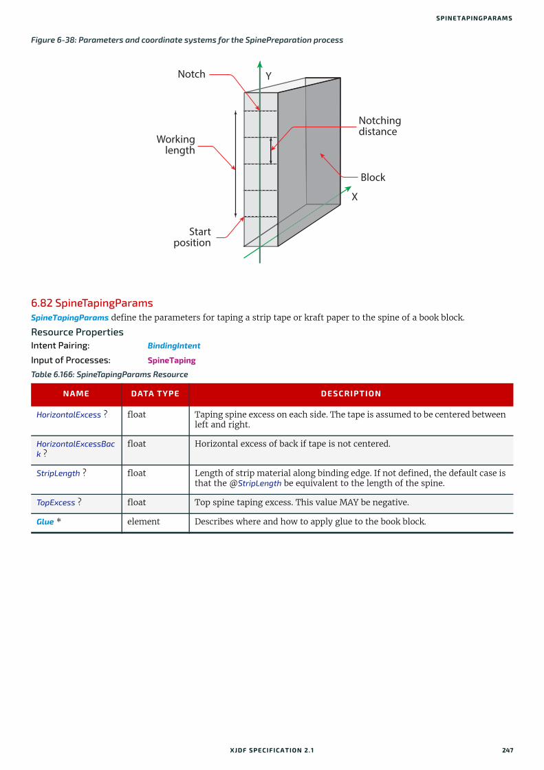
SPINETAPINGPARAMS
6.82 SpineTapingParamsSpineTapingParams define the parameters for taping a strip tape or kraft paper to the spine of a book block.
Resource PropertiesIntent Pairing: BindingIntent
Input of Processes: SpineTaping
Figure 6-38: Parameters and coordinate systems for the SpinePreparation process
Table 6.166: SpineTapingParams Resource
NAME DATA TYPE DESCRIPTION
HorizontalExcess ? float Taping spine excess on each side. The tape is assumed to be centered between left and right.
HorizontalExcessBack ?
float Horizontal excess of back if tape is not centered.
StripLength ? float Length of strip material along binding edge. If not defined, the default case is that the @StripLength be equivalent to the length of the spine.
TopExcess ? float Top spine taping excess. This value MAY be negative.
Glue * element Describes where and how to apply glue to the book block.
Block
Notch
Notchingdistance
Workinglength
Start position
Y
X
XJDF SPECIFICATIO N 2.1 247

RESO URCES
6.83 StackingParamsSettings for the Stacking process.
Resource PropertiesInput of Processes: Stacking
Figure 6-39: Parameters and coordinate system for the SpineTaping process
Table 6.167: StackingParams Resource (Sheet 1 of 2)
NAME DATA TYPE DESCRIPTION
BundleType ? enumeration @BundleType specifies the BundleItem/@BundleType of the items that shall be counted as an individual item for Stacking.
Allowed value is from: BundleType.
Compensate ? boolean 180 degree rotation applied to successive layers to compensate for uneven stacking. If @LayerAmount = @StandardAmount, there is one layer, and effec-tively no compensation.
LayerAmount ? IntegerList Ordered number of products in a layer. The first number is the first @LayerAmount, etc. If there are more layers than entries in the list, counting restarts at the first entry. The sum of all entries is typically an even divisor of @StandardAmount. If not specified, the default case is that the value of @LayerAmount equals the value of @StandardAmount.
LayerCompression ? boolean If @LayerCompression="true", layer is compressed before next layer is started.
LayerLift ? boolean If @LayerLift="true", layer is lifted to reduce height.
MaxAmount ? integer Maximum number of products in a stack, @MaxAmount SHALL be greater than or equal to @StandardAmount. If not specified, the default case is that the value of @MaxAmount equals the value of @StandardAmount.
MaxHeight ? integer Maximum height of the stack in points.
MaxWeight ? float Maximum weight of a stack in grams.
MinAmount ? integer Minimum number of products in a stack or layer, i.e. where (@MaxAmount – @StandardAmount) <= @MinAmount < @StandardAmount and @MinAmount < @LayerAmount. Where not specified, the default case SHALL use a value equal to @MaxAmount – @StandardAmount.
Block
Top excess
Horizontal excess
Origin of operation
coordinate system
Strip
Y
X
248 XJDF SPECIFICATIO N 2.1
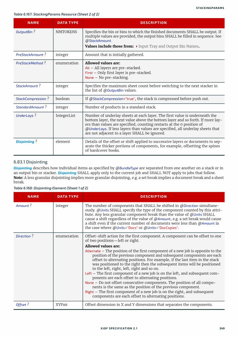
STACKINGPARAMS
6.83.1 DisjointingDisjointing describes how individual items as specified by @BundleType are separated from one another on a stack or in an output bin or stacker. Disjointing SHALL apply only to the current job and SHALL NOT apply to jobs that follow.Note: A less granular disjointing implies more granular disjointing, e.g. a set break implies a document break and a sheet break.
OutputBin ? NMTOKENS Specifies the bin or bins to which the finished documents SHALL be output. If multiple values are provided, the output bins SHALL be filled in sequence. See @StackAmount.
Values include those from: Input Tray and Output Bin Names.
PreStackAmount ? integer Amount that is initially gathered.
PreStackMethod ? enumeration Allowed values are:All – All layers are pre-stacked.First – Only first layer is pre-stacked.None – No pre-stacking.
StackAmount ? integer Specifies the maximum sheet count before switching to the next stacker in the list of @OutputBin values.
StackCompression ? boolean If @StackCompression="true", the stack is compressed before push out.
StandardAmount ? integer Number of products in a standard stack.
UnderLays ? IntegerList Number of underlay sheets at each layer. The first value is underneath the bottom layer, the next value above the bottom layer and so forth. If more lay-ers than values are specified, counting restarts at the 0 position of @UnderLays. If less layers than values are specified, all underlay sheets that are not adjacent to a layer SHALL be ignored.
Disjointing ? element Details of the offset or shift applied to successive layers or documents to sep-arate the thicker portions of components, for example, offsetting the spines of hardcover books.
Table 6.168: Disjointing Element (Sheet 1 of 2)
NAME DATA TYPE DESCRIPTION
Amount ? integer The number of components that SHALL be shifted in @Direction simultane-ously. @Units SHALL specify the type of the component counted by this attri-bute. Any less granular component break than the value of @Units SHALL cause a shift regardless of the value of @Amount, e.g. a set break would cause a shift even if the current number of documents were less than @Amount in the case where @Units="Docs" or @Units="DocCopies".
Direction ? enumeration Offset-shift action for the first component. A component can be offset to one of two positions—left or right. Allowed values are: Alternate – The position of the first component of a new job is opposite to the
position of the previous component and subsequent components are each offset to alternating positions. For example, if the last item in the stack was positioned to the right then the subsequent items will be positioned to the left, right, left, right and so on.
Left – The first component of a new job is on the left, and subsequent com-ponents are each offset to alternating positions.
None – Do not offset consecutive components. The position of all compo-nents is the same as the position of the previous component.
Right – The first component of a new job is on the right, and subsequent components are each offset to alternating positions.
Offset ? XYPair Offset dimension in X and Y dimensions that separates the components.
Table 6.167: StackingParams Resource (Sheet 2 of 2)
NAME DATA TYPE DESCRIPTION
XJDF SPECIFICATIO N 2.1 249
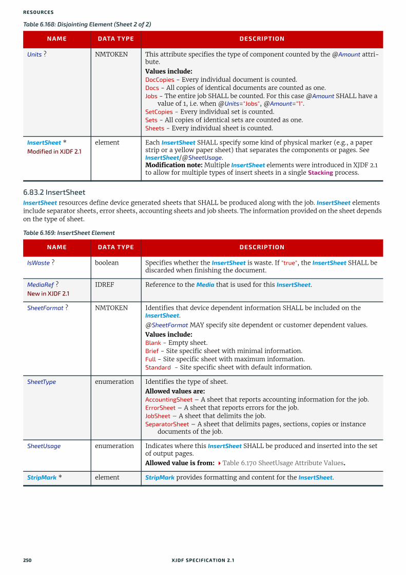
RESO URCES
6.83.2 InsertSheetInsertSheet resources define device generated sheets that SHALL be produced along with the job. InsertSheet elements include separator sheets, error sheets, accounting sheets and job sheets. The information provided on the sheet depends on the type of sheet.
Units ? NMTOKEN This attribute specifies the type of component counted by the @Amount attri-bute. Values include:DocCopies - Every individual document is counted.Docs - All copies of identical documents are counted as one.Jobs - The entire job SHALL be counted. For this case @Amount SHALL have a
value of 1, i.e. when @Units="Jobs", @Amount="1".SetCopies - Every individual set is counted.Sets - All copies of identical sets are counted as one.Sheets - Every individual sheet is counted.
InsertSheet *Modified in XJDF 2.1
element Each InsertSheet SHALL specify some kind of physical marker (e.g., a paper strip or a yellow paper sheet) that separates the components or pages. See InsertSheet/@SheetUsage.Modification note: Multiple InsertSheet elements were introduced in XJDF 2.1 to allow for multiple types of insert sheets in a single Stacking process.
Table 6.169: InsertSheet Element
NAME DATA TYPE DESCRIPTION
IsWaste ? boolean Specifies whether the InsertSheet is waste. If "true", the InsertSheet SHALL be discarded when finishing the document.
MediaRef ?New in XJDF 2.1
IDREF Reference to the Media that is used for this InsertSheet.
SheetFormat ? NMTOKEN Identifies that device dependent information SHALL be included on the InsertSheet.@SheetFormat MAY specify site dependent or customer dependent values.Values include:Blank - Empty sheet.Brief - Site specific sheet with minimal information.Full - Site specific sheet with maximum information.Standard - Site specific sheet with default information.
SheetType enumeration Identifies the type of sheet. Allowed values are:AccountingSheet – A sheet that reports accounting information for the job.ErrorSheet – A sheet that reports errors for the job.JobSheet – A sheet that delimits the job.SeparatorSheet – A sheet that delimits pages, sections, copies or instance
documents of the job.
SheetUsage enumeration Indicates where this InsertSheet SHALL be produced and inserted into the set of output pages. Allowed value is from: Table 6.170 SheetUsage Attribute Values.
StripMark * element StripMark provides formatting and content for the InsertSheet.
Table 6.168: Disjointing Element (Sheet 2 of 2)
NAME DATA TYPE DESCRIPTION
250 XJDF SPECIFICATIO N 2.1

STITCHINGPARAMS
6.84 StitchingParamsStitchingParams provides the parameters for the Stitching process. The process coordinate system is defined as follows:
• The X-axis is aligned with the second registered edge, and it increases from the binding edge to the face edge.
• The Y-axis is aligned with the spine and increases from the first registered edge to the edge opposite to the registered face edge.
Note: If no spine exists, e.g. in side or corner stiching, the Y-axis and default reference edge is the left side of the sheet.Note: The stitches are applied from the front in the figures describing the stitching coordinate system.
Resource PropertiesIntent Pairing: BindingIntent
Input of Processes: Stitching
Table 6.170: SheetUsage Attribute Values
VALUE DESCRIPTION
Header Valid for @SheetType="JobSheet" or "SeparatorSheet". The sheet is produced at the begin-ning of the job (for "JobSheet"), or at the beginning of each copy of each instance docu-ment (for "SeparatorSheet"), or is appended before the current Component. Contents for the sheet SHALL be drawn from the StripMark elements.
Interleaved Valid for @SheetType="SeparatorSheet". The sheet is produced after each page (e.g., used to insert sheets under transparencies). Contents for the sheet SHALL be drawn from the StripMark elements.
InterleavedBefore Valid for @SheetType="SeparatorSheet". The sheet is produced before each page (e.g., used to insert sheets before transparencies). Contents for the sheet SHALL be drawn from the StripMark elements.
OnError Valid for @SheetType="ErrorSheet". The sheet is produced at the end of the job only when an error or warning occurs.
Slip Valid for @SheetType="SeparatorSheet". The sheet is produced between each copy of each instance document. Contents for the sheet SHALL be drawn from the StripMark elements.
SlipCopy Valid for @SheetType="SeparatorSheet". The sheet is produced between each copy of the job, which is defined to be when the complete RunList has been consumed. Contents for the sheet SHALL be drawn from the StripMark elements.
Trailer Valid for @SheetType="AccountingSheet", "ErrorSheet", "JobSheet" and "SeparatorSheet". The sheet is produced at the end of the job (for "AccountingSheet", "ErrorSheet" and "JobSheet"), or at the end of each copy of each instance document (for "SeparatorSheet"), or is appended after the current sheet, signature, layout or RunList as defined by its context. Contents for the sheet SHALL be drawn from the StripMark elements.Note: Use @SheetType="ErrorSheet" and @SheetUsage="Trailer" to always produce a sheet that contains error or success information even if no errors or warnings occurred.
Table 6.171: StitchingParams Resource (Sheet 1 of 2)
NAME DATA TYPE DESCRIPTION
Angle ? float Angle of stitch in degrees. The angle increases in a counterclockwise direc-tion. Horizontal="0", which means that it is parallel to the X-axis of the oper-ation coordinate system. @Angle defaults to the system-specified value that MAY vary depending on other attributes set in this resource. If @StitchType="Saddle", @Angle SHALL NOT be specified.
NumberOfStitches ? integer @NumberOfStitches specifies the number of stitches.
Offset ? float Distance between stitch and binding edge. If @StitchType="Saddle", @Offset SHALL NOT be specified.
StapleShape ? enumeration Specifies the shape of the staples to be used. Allowed value is from: StapleShape.
XJDF SPECIFICATIO N 2.1 251

RESO URCES
StitchOrigin ? enumeration Defines the origin of @StitchPositions. For an illustration of the values, see Figure 6-42: Stitching coordinate system for @StitchOrigin values.Allowed values are:TrimBoxCenterTrimBoxJogSideUntrimmedJogSide
StitchPositions ? FloatList Array containing the stitch positions. The center of the stitch SHALL be spec-ified, and the number of entries SHALL match the number given in @NumberOfStitches.
StitchType ? enumeration Specifies the type of the Stitching operation. Allowed values are:Corner – Stitch in the corner that is at the clockwise end of the reference
edge. For example, to stitch in the upper right corner set Resource/@Orientation="Rotate90".
Saddle – Stitch on the middle fold, which is on the saddle.Side – Stitch along the reference edge. For example, to stitch in the top, set
Resource/@Orientation="Rotate90".
StitchWidth ? float Width of the stitch to be used.
TightBacking ? enumeration Definition of the geometry of the back of the product.See BlockPreparationParams/@TightBacking and Figure 6-4: Backing and Rounding measurements for TightBacking for details.Allowed value is from: TightBacking.
WireGauge ? float Gauge of the wire to be used.
FileSpec (CIP3) ? element Reference to a CIP3 file that contains stitching instructions in the [CIP3 - PPF] format.
Figure 6-40: Parameters and coordinate system used for saddle stitching
Table 6.171: StitchingParams Resource (Sheet 2 of 2)
NAME DATA TYPE DESCRIPTION
X
Y
Binding edge (spine)
Face edge
1st. registered edge
Stitch positionStaple
X
Stitch width
252 XJDF SPECIFICATIO N 2.1

STRAPPINGPARAMS
6.85 StrappingParamsStrappingParams defines the details of Strapping.
Resource PropertiesInput of Processes: Strapping
Figure 6-41: Parameters and coordinate system used for stitching
Figure 6-42: Stitching coordinate system for @StitchOrigin values
UntrimmedJogSide TrimBoxJogSide TrimBoxCenter
Table 6.172: StrappingParams Resource (Sheet 1 of 2)
NAME DATA TYPE DESCRIPTION
StrappingType enumeration Strapping pattern. Allowed values are:Cross – Two crossed straps.Double – Two parallel single straps.DoubleCross – Two cross straps that strap each side of a box.Single – One strap.
X
YBinding edge (spine)
Stitch position
Stitch position
Offset
Offset
X
Stitch width
X
Y
Reference edge 1
Reference edge 2
Stitch width
Set of folded sheets
collected on a saddle
Set of sheets or partial
products gathered on a
pile that will be folded later
X
Y
XF
X
Y
F
X
Y
X
F
XJDF SPECIFICATIO N 2.1 253
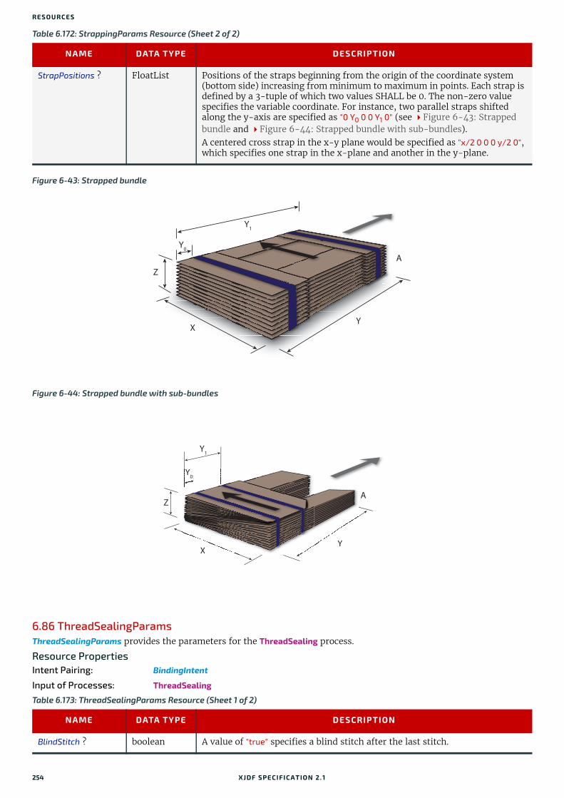
RESO URCES
6.86 ThreadSealingParamsThreadSealingParams provides the parameters for the ThreadSealing process.
Resource PropertiesIntent Pairing: BindingIntent
Input of Processes: ThreadSealing
StrapPositions ? FloatList Positions of the straps beginning from the origin of the coordinate system (bottom side) increasing from minimum to maximum in points. Each strap is defined by a 3-tuple of which two values SHALL be 0. The non-zero value specifies the variable coordinate. For instance, two parallel straps shifted along the y-axis are specified as "0 Y0 0 0 Y1 0" (see Figure 6-43: Strapped bundle and Figure 6-44: Strapped bundle with sub-bundles). A centered cross strap in the x-y plane would be specified as "x/2 0 0 0 y/2 0", which specifies one strap in the x-plane and another in the y-plane.
Figure 6-43: Strapped bundle
Figure 6-44: Strapped bundle with sub-bundles
Table 6.173: ThreadSealingParams Resource (Sheet 1 of 2)
NAME DATA TYPE DESCRIPTION
BlindStitch ? boolean A value of "true" specifies a blind stitch after the last stitch.
Table 6.172: StrappingParams Resource (Sheet 2 of 2)
NAME DATA TYPE DESCRIPTION
Y
Y1
Y0
X
Z
A
Y
A
Y1
Y0
X
Z
XXYYY
YYYYYY0Y0000
XX
254 XJDF SPECIFICATIO N 2.1

THREADSEWINGPARAMS
6.87 ThreadSewingParamsThreadSewingParams provides the parameters for the ThreadSewing process.
The process coordinate system is defined as follows: The Y-axis is aligned with the binding edge. It increases from the registered edge to the edge opposite to the registered edge. The X-axis is aligned with the registered edge. It increases from the binding edge to the edge opposite to the binding edge (i.e., the product front edge).
Resource PropertiesIntent Pairing: BindingIntent
Input of Processes: ThreadSewing
ThreadLength ? float Length of one thread.
ThreadPositions ? FloatList Array containing the y-coordinate of the center positions of the thread.
ThreadStitchWidth ? float Width of one stitch.
Table 6.174: ThreadSewingParams Resource
NAME DATA TYPE DESCRIPTION
BlindStitch ? boolean A value of "true" specifies a blind stitch after the last stitch.
NeedlePositions ? FloatList Array containing the y-coordinate of the needle positions. The number of entries SHALL match the number specified in @NumberOfNeedles.
NumberOfNeedles ? integer Specifies the number of needles to be used.
Offset ? float Specifies the distance between the stitch and the binding edge. Used only when @SewingPattern="Side".
SewingPattern ? enumeration Sewing pattern. Allowed values are:CombinedStaggered NormalSide – Side sewing.Staggered
ThreadThickness ? float Thread thickness.
Figure 6-45: Parameters and coordinate system used for thread sewing
Table 6.173: ThreadSealingParams Resource (Sheet 2 of 2)
NAME DATA TYPE DESCRIPTION
X
Y
Binding edge(spine)
Startposition
Stitch
Glue lineworking length
XJDF SPECIFICATIO N 2.1 255

RESO URCES
6.88 ToolA Tool defines a generic tool that can be customized for a given job (e.g., an embossing stamp) or an auxiliary device such as a fork lift. See also Device for description of the primary device that executes a process. The manufacturing process for the tool is not described within XJDF.
Resource PropertiesResource referenced by: EmbossingParams/Emboss
Input of Processes: Any Process, Embossing, ShapeCutting
Output of Processes: DieMaking
Figure 6-46: Parameters and coordinate system used for side sewing
Table 6.175: Tool Resource
NAME DATA TYPE DESCRIPTION
ToolType ? NMTOKEN Type of the tool. Values include:Braille – Embossing tool for blind script. CentralStripper – The center tool of the stripper tool set. Stripping means
removing small parts of waste in between blanks. ChangingCuttingBlock – A changeable part for a tool set (CutDie). Used for cut-
ting of optional shapes like windows, stars, etc. It is not a part of tool set. Described in MIS with its own @ExternalID.
CounterDie – The lower tool of the die-cut pair with the counter (female) parts for the creases.
CutDie – The upper tool of the die-cut pair with the actual cutting and creas-ing knifes.
EmbossingCalendar EmbossingStampForkLift - A device used to lift forks. FrontWasteSeparator – The tool to remove gripper margin from the sheet.LowerBlanker – The lower tool of the blanker pair (blanking means separating
blanks).LowerStripper – The lower tool of the stripper toolset.RollStand - A roll stand is a storage tool for Components. Components are
rolled onto a roll stand with the Winding process.ToolSet – The value "ToolSet" is used when the @ExternalID refers not to a sin-
gle tool, but to a set of matching tools that are used in the process (e.g., when @ExternalID is a single stock item number in the MIS for a tool set consisting of a "CutDie" and a "CounterDie").
UpperBlanker – The upper tool of the blanker pair.UpperStripper – The upper tool of the stripper toolset.
IdentificationField * element IdentificationField associates bar codes or labels with this Tool.
X
Y
Binding edge(spine)
Offset Stitch
256 XJDF SPECIFICATIO N 2.1
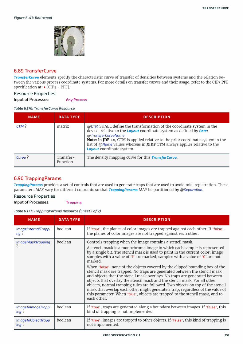
TRANSFERCURVE
6.89 TransferCurveTransferCurve elements specify the characteristic curve of transfer of densities between systems and the relation be-tween the various process coordinate systems. For more details on transfer curves and their usage, refer to the CIP3 PPF specification at:[CIP3 - PPF].
Resource PropertiesInput of Processes: Any Process
6.90 TrappingParamsTrappingParams provides a set of controls that are used to generate traps that are used to avoid mis-registration. These parameters MAY vary for different colorants so that TrappingParams MAY be partitioned by @Separation.
Resource PropertiesInput of Processes: Trapping
Figure 6-47: Roll stand
Table 6.176: TransferCurve Resource
NAME DATA TYPE DESCRIPTION
CTM ? matrix @CTM SHALL define the transformation of the coordinate system in the device, relative to the Layout coordinate system as defined by Part/@TransferCurveName.Note: In JDF 1.x, CTM is applied relative to the prior coordinate system in the list of @Name values whereas in XJDF CTM always applies relative to the Layout coordinate system.
Curve ? Transfer-Function
The density mapping curve for this TransferCurve.
Table 6.177: TrappingParams Resource (Sheet 1 of 2)
NAME DATA TYPE DESCRIPTION
ImageInternalTrapping ?
boolean If "true", the planes of color images are trapped against each other. If "false", the planes of color images are not trapped against each other.
ImageMaskTrapping ?
boolean Controls trapping when the image contains a stencil mask.A stencil mask is a monochrome image in which each sample is represented by a single bit. The stencil mask is used to paint in the current color: image samples with a value of "1" are marked, samples with a value of "0" are not marked.When "false", none of the objects covered by the clipped bounding box of the stencil mask are trapped. No traps are generated between the stencil mask and objects that the stencil mask overlays. No traps are generated between objects that overlay the stencil mask and the stencil mask. For all other objects, normal trapping rules are followed. Two objects on top of the stencil mask that overlap each other might generate a trap, regardless of the value of this parameter. When "true", objects are trapped to the stencil mask, and to each other.
ImageToImageTrapping ?
boolean If "true", traps are generated along a boundary between images. If "false", this kind of trapping is not implemented.
ImageToObjectTrapping ?
boolean If "true", images are trapped to other objects. If "false", this kind of trapping is not implemented.
XJDF SPECIFICATIO N 2.1 257

RESO URCES
6.91 TrimmingParamsTrimmingParams provides the parameters for the Trimming process.
Resource PropertiesInput of Processes: Trimming
6.92 UsageCounterMany devices use counters to track equipment utilization or work performed, such as impressions produced or variable data documents generated. UsageCounter represents a type of equipment or software usage that is tracked by the value of a usage counter used by a device to record the amount of work performed. See Section 6.1.2 PartAmount. Default units are “countable objects”. See Section 1.9.1 Units of measurement.
MinimumBlackWidth ?
float Specifies the minimum width, in points, of a trap that uses black ink. Allow-able values are those greater than or equal to zero.
StepLimit ? float A non-negative number. Specifies the smallest step needed in the color value of a colorant to trigger trapping at a given boundary.If the higher color value at the boundary exceeds the lower value by an amount that is equal to or greater than the larger of 0.05 or @StepLimit times the lower value, i.e. if
Valuehi >= Valuelo + max (@StepLimit * Valuelo, 0.05))
then the edge is a candidate for trapping. The value 0.05 is set to avoid trap-ping light areas in vignettes.
TrapColorScaling ? float A number between 0 and 1. Specifies a scaling of the amount of color applied in traps towards the neutral density of the dark area. A value of "1" means the trap has the combined color values of the darker and the lighter area. A value of "0" means the trap colors are reduced so that the trap has the neutral den-sity of the darker area.
TrapWidth ? XYPair Specifies the trap width in the X and Y directions of the page or surface ByteMap.
Table 6.178: TrimmingParams Resource
NAME DATA TYPE DESCRIPTION
Height ? float Height of the trimmed product.
TrimCover ? enumeration Specifies the covers to be trimmed. Covers containing flaps are generally not trimmed.Allowed values are:Back – Trim back cover only.Both – Trim front and back cover.Front – Trim front cover only.Neither – Do not trim cover.
TrimmingOffset ? float Amount to be cut from the bottom side.
Width ? float Width of the trimmed product.
Table 6.177: TrappingParams Resource (Sheet 2 of 2)
NAME DATA TYPE DESCRIPTION
258 XJDF SPECIFICATIO N 2.1

VARNISHINGPARAMS
Resource PropertiesInput of Processes: Any Process
6.93 VarnishingParamsVarnishingParams provides the parameters of a Varnishing process.
Resource PropertiesIntent Pairing: ColorIntent
Input of Processes: Varnishing
Table 6.179: UsageCounter Resource
NAME DATA TYPE DESCRIPTION
CounterTypes ? NMTOKENS This attribute indicates the types of usage being counted by the UsageCounter. Values include:Insert – Post fuser inserter.OneSided – Includes one sided counts.TwoSided – Includes two sided counts.NormalSize – Includes normal size counts.LargeSize – Includes large size counts.Black – Includes black colorant only counts.Color – Includes one or more non-black, non-highlight color colorants
counts.Blank – Includes entirely blank counts.HighlightColor – Includes highlight colorant counts.
Scope enumeration The scope of this usage counter. Allowed values are:Job – Count in the context of one XJDF.Lifetime – Count since machine last had a firmware reset. SHALL NOT be
specified when UsageCounter is used as a resource in an XJDF ticket.PowerOn – Count since the machine was powered on. SHALL NOT be specified
when UsageCounter is used as a resource in an XJDF ticket.
Table 6.180: VarnishingParams Resource
NAME DATA TYPE DESCRIPTION
ModuleID ? NMTOKEN Identifier of the varnishing module in a multi-function device, such as a printing press. See Module for details.
ModuleType ? enumeration The type of module used to apply the varnish.Allowed values are:CoatingModule – The varnish is applied in a specialized coating unit.PrintModule – The varnish is applied in a printing unit.
VarnishArea ? enumeration Area to be varnished. @VarnishArea specifies the requirements for ExposedMedia.Allowed values are:Full – The entire media surface SHALL be varnished.Spot – Only parts of the media surface SHALL be varnished.
VarnishMethod ? enumeration Method used for varnishing.Allowed values are:Blanket – Varnishing is performed in a dedicated coating module. An
ExposedMedia that references a Media/@MediaType="Blanket" MAY be specified.
Independent – No additional ExposedMedia is required. This method MAY be used to specify varnishing in a digital press.
Plate – Varnishing is performed in a print module or a dedicated coating module. An ExposedMedia that references a Media/@MediaType="Plate" SHOULD be specified.
XJDF SPECIFICATIO N 2.1 259

RESO URCES
6.94 VerificationParamsVerificationParams provides the parameters of a Verification process.
Resource PropertiesInput of Processes: Verification
6.95 VerificationResultVerificationResult defines the set of results from the Verification process.
Output of Processes: Verification
6.96 WebInlineFinishingParamsWebInlineFinishingParams specifies the parameters for web inline finishing equipment using the WebInlineFinishing pro-cess.
Resource PropertiesInput of Processes: WebInlineFinishing
Table 6.181: VerificationParams Resource
NAME DATA TYPE DESCRIPTION
Tolerance ? float Ratio of tolerated verification failures to the total number of tests."0.0" = no failures allowed, "1.0" = all tests MAY fail.
FileSpec ? element Reference to data that contains implementation specific descriptions of the resources to be verified.
Table 6.182: VerificationResult Resource
NAME DATA TYPE DESCRIPTION
Accepted ? integer Number of resources that were correctly verified.
Rejected ? integer Number of resources that were not correctly verified.
Unknown ? integer Number of resources that were scanned but are not in the explicit or implied list of known resources.
FileSpec (Accepted) ?
element Reference to data that contains implementation specific descriptions of the resources that were correctly verified.
FileSpec (Combined) ?
element Reference to data that contains an implementation specific description of the verification result.
FileSpec (Rejected) ?
element Reference to data that contains implementation specific descriptions of the resources that were NOT correctly verified.
FileSpec (Unknown) ?
element Reference to data that contains implementation specific descriptions of the resources that were scanned but are NOT in the explicit list of known resources.
Table 6.183: WebInlineFinishingParams Resource
NAME DATA TYPE DESCRIPTION
FolderProduction * element Specifies the folder setup for newspaper presses.
ProductionPath ? element ProductionPath describes the paper path that is used through the press and describes exactly one particular product that has to be produced.
260 XJDF SPECIFICATIO N 2.1
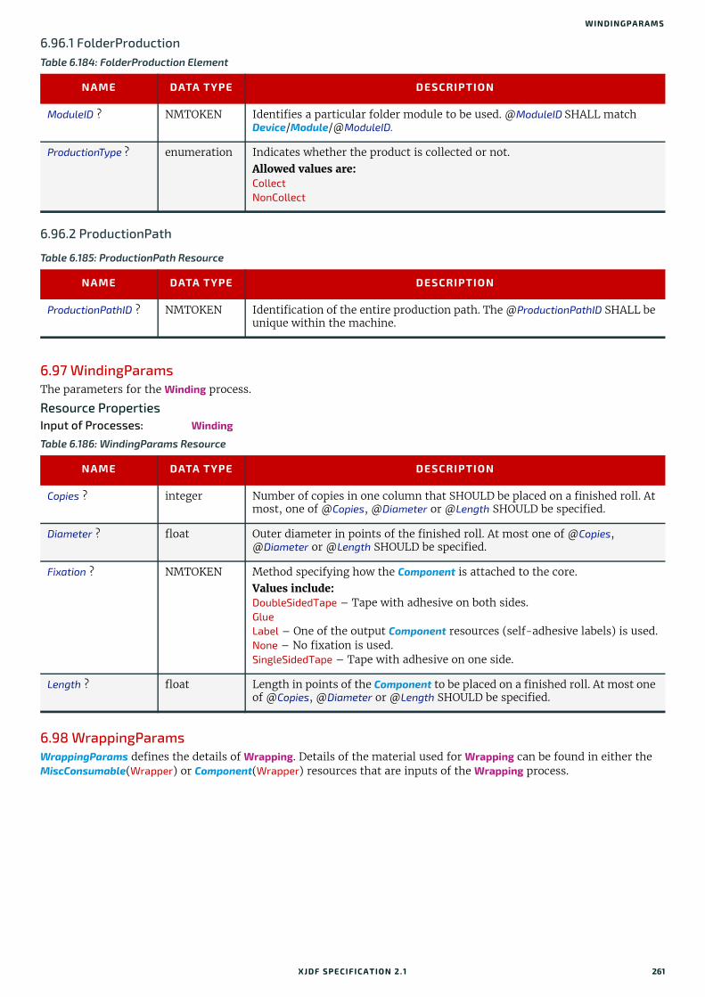
WINDINGPARAMS
6.96.1 FolderProduction
6.96.2 ProductionPath
6.97 WindingParams The parameters for the Winding process.
Resource PropertiesInput of Processes: Winding
6.98 WrappingParamsWrappingParams defines the details of Wrapping. Details of the material used for Wrapping can be found in either the MiscConsumable(Wrapper) or Component(Wrapper) resources that are inputs of the Wrapping process.
Table 6.184: FolderProduction Element
NAME DATA TYPE DESCRIPTION
ModuleID ? NMTOKEN Identifies a particular folder module to be used. @ModuleID SHALL match Device/Module/@ModuleID.
ProductionType ? enumeration Indicates whether the product is collected or not.Allowed values are:CollectNonCollect
Table 6.185: ProductionPath Resource
NAME DATA TYPE DESCRIPTION
ProductionPathID ? NMTOKEN Identification of the entire production path. The @ProductionPathID SHALL be unique within the machine.
Table 6.186: WindingParams Resource
NAME DATA TYPE DESCRIPTION
Copies ? integer Number of copies in one column that SHOULD be placed on a finished roll. At most, one of @Copies, @Diameter or @Length SHOULD be specified.
Diameter ? float Outer diameter in points of the finished roll. At most one of @Copies, @Diameter or @Length SHOULD be specified.
Fixation ? NMTOKEN Method specifying how the Component is attached to the core. Values include:DoubleSidedTape – Tape with adhesive on both sides.GlueLabel – One of the output Component resources (self-adhesive labels) is used.None – No fixation is used.SingleSidedTape – Tape with adhesive on one side.
Length ? float Length in points of the Component to be placed on a finished roll. At most one of @Copies, @Diameter or @Length SHOULD be specified.
XJDF SPECIFICATIO N 2.1 261

RESO URCES
Resource PropertiesInput of Processes: Wrapping
Table 6.187: WrappingParams Resource
NAME DATA TYPE DESCRIPTION
WrappingKind enumeration @WrappingKind specifies the wrapping method. Allowed values are:Band – The components are wrapped with a band. The material of the band is
typically paper, plastic or rubber. LooseWrap – The wrap is loose around the component.ShrinkWrap – The wrap is shrunk around the component.
262 XJDF SPECIFICATIO N 2.1

7
7 MessagingA workflow is a dynamic set of interacting controllers and devices. For the workflow to run efficiently, these controllers and devices need to communicate and interact in a well defined manner. Whereas XJDF will typically be submitted to a device and only be returned after the process has been executed, XJMF messages MAY be exchanged at any time. Typical use cases for XJMF include but are not limited to:• System bootstrapping and setup• Dynamic status, resource usage and error tracking for jobs and devices• Pipe control• Device setup and job changes• Queue handling and job submission
This chapter specifies the XML structure of XJMF. For details of the exchange protocol and data packaging, see Section 9.5 XJDF and XJMF Interchange Protocol and Section 9.7 XJDF Packaging.
7.1 XJMFXJMF and XJDF have inherently different structures. In order to allow immediate identification of messages, XJMF uses the unique name XJMF as its own root-element name. XJMF elements SHALL contain one or more messages that provide more detailed information.
Table 7.1: XJMF Element
NAME DATA TYPE DESCRIPTION
Version ? enumeration @Version SHALL define the version of the XJMF document. The value of @Version SHALL be "2.1" for documents that comply to this specification.Allowed values are:2.0 - Prior version.2.1 - This version.
Header element Header SHALL provide information about the sender of the XJMF package. If the sender is a proxy controller that forwards information from multiple devices, XJMF/Header SHALL provide information about the proxy controller. See also Message/Header.
<messageelements> *
element One or more messages SHALL be provided. The messages SHOULD be one of the message element types that are defined in XJMF, see Section 7.3 List of All XJMF Messages. The recipient SHALL process the messages in XML order.
<foreignnamespacemessageelements> *
element Any message elements in a foreign namespace.Foreign namespace extensions SHOULD NOT duplicate functionality of exist-ing XJDF messages. They SHALL adhere to the structure that is defined in Section 7.1.1 Message and SHALL adhere to whichever of the message fam-ily definitions, as described in Section 7.2 XJMF Message Families, is appropriate.These elements MAY occur interleaved between messages in the XJDF name-space.
XJDF SPECIFICATIO N 2.1

MESSA GING
7.1.1 MessageThe following table describes the contents of a message. A message is an abstract data type. Section 7.3 List of All XJMF Messages provides a list of all message element instances.
7.1.2 HeaderHeader SHALL provide information about the sender of an audit, message or XJMF. The information in Message/Header and AuditXXX/Header SHALL NOT be modified and SHALL represent the status of the original message or audit if the message is passed through a proxy controller. The information in XJMF/Header SHALL be modified to represent the sta-tus of the proxy controller if the message is passed through a proxy controller.
The Header element SHALL be the first element in any audit or message as shown in those tables.
Table 7.2: Message
NAME DATA TYPE DESCRIPTION
Header element Header SHALL provide information about the original sending device of the individual message. Header SHALL be the first element in a Message, regard-less of the aphabetical ordering of any other elements.The information in Header SHALL NOT be modified if the message is passed through a proxy controller. See also XJMF/Header.
<foreign namespace elements> *
element Any elements in a foreign namespace. Foreign namespace extensions SHOULD NOT duplicate functionality of XJDF. Foreign namespace extensions SHALL be specified after all elements in the XJDF namespace.
Table 7.3: Header
NAME DATA TYPE DESCRIPTION
AgentName ? string The name of the application that generated the parent message or XJMF.Both the company name and the product name MAY appear, and SHOULD be consistent between versions of the application.
AgentVersion ? string The version of the application that generated the parent message or XJMF.The format of the version string MAY vary from one application to another, but SHOULD be consistent for an individual application.
Author ? string Human readable description of the employee that entered the message.XJMF/Header/@Author SHOULD NOT be specified.
DescriptiveName ?New in XJDF 2.1
string Human readable descriptive name of the parent message, audit or XJMF.
DeviceID NMTOKEN Unique identifier of the sender.
ICSVersions ? NMTOKENS CIP4 Interoperability Conformance Specification (ICS) Versions that the sender complies with. The value of @ISCVersions SHALL conform to the value format described in Section 3.1.1 ICS Versions Value.
ID ? ID Identifies the parent message. @ID SHALL be present if Subscription is pres-ent in the parent Query.
PersonalID ? NMTOKEN Machine readable identifier of the employee that entered the message.XJMF/Header/@PersonalID SHOULD NOT be specified.
refID ? NMTOKEN @refID SHALL identify a message that the parent of this Header responds to. If the parent is a Response, this SHALL be Header/@ID of the initiating Query or Command. If the parent is a Signal, this SHALL be Header/@ID of the initi-ating Query.Note: The data type is NMTOKEN because the referenced Header/@ID need not be in the same XML document.
Time dateTime Date and time when the message was generated.
264 XJDF SPECIFICATIO N 2.1
XJMF MESSA GE FA MILIES
7.2 XJMF Message Families A message belongs to one of four message families. These families are Query, Command, Signal and Response. An expla-nation of each family is provided in the following sections. Message families are abstract data types, Section 7.3 List of All XJMF Messages provides a list of all message family element instances.
7.2.1 QueryA Query is an abstract message that retrieves information from a receiver without changing the state of that receiver. For details of XJMF handshaking, see Section 9.6 XJMF Handshaking. The following table shows the content of a Query message.
7.2.1.1 SubscriptionA Subscription specifies the target URL for signals and optionally, additional details of the persistent channel. See Section 9.6.2 Subscribing for Signals for details.
Table 7.4: Query
NAME DATA TYPE DESCRIPTION
Header element See Message/Header.
Subscription ? element A Subscription is a request for a persistent channel. If present, Subscription SHALL be specified after Header and prior to any other elements in a Query. Any other elements in the Query will then be alphabetically ordered in the normal way. If Subscription is present then Header/@ID shall be specified. For details of creating and managing persistent channels see Section 9.6.3 Managing Persistent Channels
<foreign namespace elements> *
element See Message - foreign namespace elements.
Table 7.5: Subscription Element
NAME DATA TYPE DESCRIPTION
ChannelMode ? enumerations Specifies reliability of persistent channel, and whether it is required or just preferred. Ordered list, with most preferred channel mode first.If none of the provided values of @ChannelMode are supported by the con-sumer of the subscription, the Response SHOULD indicate @ReturnCode 111, which is “Subscription request denied”. Allowed values are from: ChannelMode.Note: See Signal/@ChannelMode.
Languages ? languages List of languages selected for human readable communication. If not speci-fied, the operating system language SHOULD be used. If multiple languages are specified, the second and further languages SHOULD only be used for providing additional localized Comment elements. Messages SHALL NOT be sent multiple times for the same event.
RepeatTime ? float Requests an update Signal every @RepeatTime seconds. If specified, the Signal SHALL be generated periodically independent of any other trigger conditions. @RepeatTime SHALL NOT override any Signals triggered by a change of sta-tus. Signals triggered by a status change SHALL be sent regardless of the value of @RepeatTime. A sender MAY restart counting for @RepeatTime based Signals whenever it sends a Signal to the same subscription.
URL URL URL of the persistent channel receiving end. The protocol of the Subscription is specified by the scheme of @URL.
XJDF SPECIFICATIO N 2.1 265

MESSA GING
7.2.2 CommandA Command is syntactically equivalent to a Query, but rather than simply retrieving information, it is an abstract message that causes a state change in the receiver. For details of XJMF handshaking, see Section 9.6 XJMF Handshaking. The following table contains the contents of a Command message.
7.2.3 SignalA Signal is an abstract message element that a receiver of a Query with a subscription SHALL asynchronously send when-ever the conditions specified in the Subscription are true. Note: Signals are typically sent from a device to a controller. For details of XJMF handshaking, see Section 9.6 XJMF Handshaking. For details of setting up subscriptions for signals, see Section 9.6.2 Subscribing for Signals. The follow-ing table shows the contents of a Signal.
7.2.4 ResponseA Response is a message that a receiver SHALL synchronously send to a sender as a response to a message. For details of XJMF handshaking, see Section 9.6 XJMF Handshaking. The following table shows the content of a Response mes-sage.
7.3 List of All XJMF MessagesThe following table provides a list of all message element types.
Table 7.6: Command Family
NAME DATA TYPE DESCRIPTION
Header element See Message/Header.
<foreign namespace elements> *
element See Message - foreign namespace elements.
Table 7.7: Signal Family
NAME DATA TYPE DESCRIPTION
ChannelMode ? enumeration Specifies reliability of the signal.Allowed value is from: ChannelMode.
Header element See Message/Header.
<foreign namespace elements> *
element See Message - foreign namespace elements.
Table 7.8: Response Family
NAME DATA TYPE DESCRIPTION
ReturnCode ? integer @ReturnCode summarizes the result of the response. The value "0" indicates success. @ReturnCode SHALL be provided if an error occurred. For predefined values see Appendix A.3 Return Codes. Note: Additional values MAY be specified in ICS documents.
Header element See Message/Header.
Notification ? element Additional information including textual description of the return code. The Notification element SHOULD be provided if the @ReturnCode is greater than 0. See Section 7.10 Notification. If present then the Notification element SHALL be placed after Header and prior to any other elements in a Response message.
<foreign namespace elements> *
element See Message - foreign namespace elements.
266 XJDF SPECIFICATIO N 2.1

LIST OF ALL XJMF MESSAGES
Table 7.9: List of XJMF Messages (Sheet 1 of 2)
MESSAGES DESCRIPTION
CommandForceGangResponseForceGang
A gang is forced to execute.
QueryGangStatusResponseGangStatusSignalGangStatus
The status of a gang is queried.
QueryKnownDevices
ResponseKnownDevicesSignalKnownDevices
Returns information about the devices that are controlled by a controller.
QueryKnownMessagesResponseKnownMessages
Returns a list of all messages that are supported by the controller.
QueryKnownSubscriptions
ResponseKnownSubscriptionsSignalKnownSubscriptions
Returns a list of active persistent channels.
CommandModifyQueueEntryResponseModifyQueueEntry
Modifies the properties of one or more QueueEntry elements.
QueryNotification
ResponseNotificationSignalNotification
Used to signal events due to any activities of a device, operator, etc. Generally sent as signals. QueryNotification allows subscriptions for SignalNotification messages.
CommandPipeControlResponsePipeControl
All pipe related commands are implemented using the PipeControl message.
QueryQueueStatus
ResponseQueueStatusSignalQueueStatus
Returns the Queue elements that describe a queue or set of queues.
CommandRequestQueueEntryResponseRequestQueueEntry
A new job is requested by the device. This message is used to signal that a device has processing resources available.
CommandResource
QueryResourceResponseResourceSignalResource
Queries and/or modifies XJDF resources that are used by a device, such as device settings. This message can also be used to query the level of consumables in a device.
CommandResubmitQueueEntryResponseResubmitQueueEntry
Replaces a queue entry without affecting the entry’s parameters. CommandResubmitQueueEntry is used, for example, for late changes to a submit-ted XJDF.
CommandReturnQueueEntryResponseReturnQueueEntry
Returns a job that had been submitted with a SubmitQueueEntry to the controller that originally submitted the job.
CommandShutDown
ResponseShutDown
Shuts down a device.
QueryStatusResponseStatus
SignalStatus
Queries or signals the general status of a device, controller or job.
CommandStopPersistentChannelResponseStopPersistentChannel
Closes a persistent channel.
CommandSubmitQueueEntryResponseSubmitQueueEntry
Submits an XJDF to a queue in order to be executed.
XJDF SPECIFICATIO N 2.1 267

MESSA GING
7.4 ForceGangThe ForceGang message forces all the selected QueueEntry[@Status="Waiting"] elements that belong to a gang to be ex-ecuted, even though the device dependent queue entry collecting algorithm might not be completed. A QueueEntry be-longs to a gang if QueueEntry/@GangName is included in the list of GangCmdFilter/@GangNames.
7.4.1 CommandForceGang
7.4.1.1 GangCmdFilter
7.4.2 ResponseForceGang
7.5 GangStatusGangStatus returns a description of the gang(s). Details are specified in the GangInfo element.
CommandWakeUpResponseWakeUp
Wakes up a device that is in standby mode.
Table 7.10: CommandForceGang Message
NAME DATA TYPE DESCRIPTION
Header element See Message/Header.
GangCmdFilter element Defines the gang(s) to be forcibly executed.
<foreign namespace elements> *
element See Message - foreign namespace elements.
Table 7.11: GangCmdFilter Element
OBJECT TYPE ELEMENT NAME DESCRIPTION
GangNames ? NMTOKENS @GangNames SHALL specify a list of queue entries with matching values of QueueEntry/@GangName that SHALL be processed. If not specified, all queue entries with a non-empty value of QueueEntry/@GangName SHALL be pro-cessed.
Policy ? enumeration The policy with which the elements in the gang SHALL be processed.Allowed values are:All - All elements in the given gang SHALL be processed.Optimized -As many elements in a given gang as can be processed without
unnecessary waste SHOULD be processed. The algorithm for selecting the respective elements is implementation dependent and SHOULD take pri-ority and scheduling data into account.
Table 7.12: ResponseForceGang Message
NAME DATA TYPE DESCRIPTION
ReturnCode ? integer See Response/@ReturnCode.
Header element See Message/Header.
Notification ? element See Response/Notification.
<foreign namespace elements> *
element See Message - foreign namespace elements.
Table 7.9: List of XJMF Messages (Sheet 2 of 2)
MESSAGES DESCRIPTION
268 XJDF SPECIFICATIO N 2.1

GANGSTATUS
7.5.1 QueryGangStatus
7.5.1.1 GangQuFilter
7.5.2 ResponseGangStatus
7.5.2.1 GangInfoDetails of the gang are specified in GangInfo elements.
Table 7.13: QueryGangStatus Message
NAME DATA TYPE DESCRIPTION
Header element See Message/Header.
Subscription ? element See Query/Subscription.
GangQuFilter ? element Defines a filter for the gang(s) that are queried. If GangQuFilter is not sup-plied, all gangs are queried.
<foreign namespace elements> *
element See Message - foreign namespace elements.
Table 7.14: GangQuFilter Element
NAME DATA TYPE DESCRIPTION
GangNames ? NMTOKENS @GangNames SHALL specify a list of GangInfo elements with matching values of GangInfo/@GangName that SHALL be returned. If not specified, all avail-able GangInfo elements SHALL be returned.
Table 7.15: ResponseGangStatus Message
NAME DATA TYPE DESCRIPTION
ReturnCode ? integer See Response/@ReturnCode.
Header element See Message/Header.
Notification ? element See Response/Notification.
GangInfo * element Describes the status of the gang(s).
<foreign namespace elements> *
element See Message - foreign namespace elements.
Table 7.16: GangInfo Element
NAME DATA TYPE DESCRIPTION
Amount ? float Quantity of QueueEntry items that are currently waiting to be executed. If the device specifies amount in a unit other than countable objects, such as m2, @Amount SHALL be specified in the units of the device.
GangName NMTOKEN Name of the gang.
XJDF SPECIFICATIO N 2.1 269

MESSA GING
7.5.3 SignalGangStatus
7.6 KnownDevicesThe KnownDevices query message requests information about the devices that are controlled by a controller. If a high level controller controls lower level controllers, it SHOULD also list the devices that are controlled by these. The response is a list of Device elements. Example 7.1:KnownDevices Response shows the response from a press controller that con-trols two physical presses.
Example 7.1: KnownDevices Response
7.6.1 QueryKnownDevices
7.6.1.1 DeviceFilterThe DeviceFilter element specifies the level of detail that is requested for the list of devices in the response.
Table 7.17: SignalGangStatus Message
NAME DATA TYPE DESCRIPTION
ChannelMode ? enumeration Allowed value is from: ChannelMode.Note: See Signal/@ChannelMode.
Header element See Message/Header.
GangInfo * element Describes the status of the gang(s).
<foreign namespace elements> *
element See Message - foreign namespace elements.
<XJMF xmlns="http://www.CIP4.org/JDFSchema_2_0"> <Header DeviceID="VeggieController" ID="l_000002" Time="2020-03-01T19:56:15.072+01:00"/> <ResponseKnownDevices ReturnCode="0"> <Header DeviceID="VeggieController" ID="R1" Time="2020-03-01T19:56:15.110+01:00" refID="Q1"/> <Device DeviceID="dev1" DeviceType="ACME Linda potato press V16-12" XJMFURL="http://acmepotato1:1234/xjmfurl"/> <Device DeviceID="dev2" DeviceType="ACME Baldrick turnip press V42-66" XJMFURL="http://acmeturnip1:1234/xjmfurl"/> <!-- One Device element for each known device follows here --> </ResponseKnownDevices></XJMF>
Table 7.18: QueryKnownDevices Message
NAME DATA TYPE DESCRIPTION
Header element See Message/Header.
Subscription ? element See Query/Subscription.
DeviceFilter ? element DeviceFilter refines the level of detail of the list of devices queried.
<foreign namespace elements> *
element See Message - foreign namespace elements.
270 XJDF SPECIFICATIO N 2.1

KNOWNMESSAGES
7.6.2 ResponseKnownDevices
7.6.3 SignalKnownDevices
7.7 KnownMessagesThe KnownMessages query message returns a list of all message types that are supported by the controller.
7.7.1 QueryKnownMessages
Table 7.19: DeviceFilter Element
NAME DATA TYPE DESCRIPTION
DeviceDetails ? enumeration @DeviceDetails refines the level of provided information about the device.Allowed values are:Brief – Provide only Device/@DeviceID. Full – Provide maximum available device information including all Module
and Device descriptions. Modules – Module elements SHALL be provided if the device has modules.
Table 7.20: ResponseKnownDevices Message
NAME DATA TYPE DESCRIPTION
ReturnCode ? integer See Response/@ReturnCode.
Header element See Message/Header.
Notification ? element See Response/Notification.
Device * element Each Device SHALL represent one of the known devices.
<foreign namespace elements> *
element See Message - foreign namespace elements.
Table 7.21: SignalKnownDevices Message
NAME DATA TYPE DESCRIPTION
ChannelMode ? enumeration Allowed value is from: ChannelModeNote: See Signal/@ChannelMode.
Header element See Message/Header.
Device * element Each Device SHALL represent one of the known devices.
<foreign namespace elements> *
element See Message - foreign namespace elements.
Table 7.22: QueryKnownMessages Message
NAME DATA TYPE DESCRIPTION
Header element See Message/Header.
<foreign namespace elements> *
element See Message - foreign namespace elements.
XJDF SPECIFICATIO N 2.1 271

MESSA GING
7.7.2 ResponseKnownMessages
7.7.2.1 MessageServiceThe response is a list of MessageService elements. Each MessageService SHALL specify one explicit message type that is supported by the device.
Example 7.2: KnownMessages ResponseThe following is an example of a ResponseKnownMessages.
7.8 KnownSubscriptionsThe KnownSubscriptions message enables controllers to query devices for a list of active persistent channels.
Table 7.23: ResponseKnownMessages Message
NAME DATA TYPE DESCRIPTION
ReturnCode ? integer See Response/@ReturnCode.
Header element See Message/Header.
Notification ? element See Response/Notification.
MessageService * element Each MessageService SHALL specify one supported message.
<foreign namespace elements> *
element See Message - foreign namespace elements.
Table 7.24: MessageService Element
NAME DATA TYPE DESCRIPTION
ResponseModes ? enumerations Specifies the supported synchronous Response or Signal channel modes with which the receiver can reply to a Query. @ResponseModes SHALL NOT be specified unless @Type specifies a Query message.Allowed values are:FireAndForget – The response to the message is implemented as a persistent
channel Signal with Signal/@ChannelMode="FireAndForget".Reliable – The response to the message is implemented as a persistent chan-
nel Signal with Signal/@ChannelMode="Reliable".Response - The response to the message is implemented as a synchronous
Response.
Type NMTOKEN Name of the supported message element, e.g. QueryKnownMessages.
URLSchemes ? enumerations List of schemes supported for the message defined by this MessageService.Allowed values are:http – HTTP (Hypertext Transport Protocol)https – HTTPS (Hypertext Transport Protocol – Secure)
<XJMF xmlns="http://www.CIP4.org/JDFSchema_2_0"> <Header DeviceID="DeviceID" ID="l_000002" Time="2019-03-26T14:07:48.241+00:00"/> <ResponseKnownMessages ReturnCode="0"> <Header DeviceID="DeviceID" ID="R1" Time="2019-03-26T14:07:48.242+00:00" refID="Q1"/> <MessageService ResponseModes="Response" Type="QueryKnownMessages"/> <MessageService ResponseModes="FireAndForget Reliable" Type="QueryStatus"/> <MessageService Type="CommandSubmitQueueEntry"/> <MessageService Type="ResponseReturnQueueEntry"/> </ResponseKnownMessages></XJMF>
272 XJDF SPECIFICATIO N 2.1

KNOWNSUBSCRIPTIONS
7.8.1 QueryKnownSubscriptions
7.8.1.1 SubscriptionFilterThe SubscriptionFilter element is a filter to limit the list of SubscriptionInfo elements that are returned in the KnownSubscriptions response.
Table 7.25: QueryKnownSubscriptions Message
NAME DATA TYPE DESCRIPTION
Header element See Message/Header.
Subscription ? element See Query/Subscription.
SubscriptionFilter ? element This SubscriptionFilter selects which subscriptions SHALL be included in the returned messages’ list of SubscriptionInfo elements. If not specified a SubscriptionInfo element is supplied for all known subscriptions.
<foreign namespace elements> *
element See Message - foreign namespace elements.
Table 7.26: SubscriptionFilter Element
NAME DATA TYPE DESCRIPTION
DeviceID ? NMTOKEN Only SubscriptionInfo elements for subscriptions from devices or controllers with a matching @DeviceID attribute SHALL be returned.
URL ? URL URL of the receiving controller. This SHALL be identical to the Subscription/@URL that was used to create the persistent channel. Only SubscriptionInfo elements with a matching value of SubscriptionInfo/@URL SHALL be returned.
XJDF SPECIFICATIO N 2.1 273

MESSA GING
7.8.2 ResponseKnownSubscriptions
7.8.3 SignalKnownSubscriptions
7.9 ModifyQueueEntryModifyQueueEntry modifies the state or position of one of more QueueEntry elements that are selected by QueueFilter. @Operation specifies the operation that SHALL be applied to the selected queue entries.
See also ResubmitQueueEntry command for modifications of the underlying XJDF without modifying the queues.
7.9.1 CommandModifyQueueEntry
7.9.1.1 ModifyQueueEntryParams
Table 7.27: ResponseKnownSubscriptions Message
NAME DATA TYPE DESCRIPTION
ReturnCode ? integer See Response/@ReturnCode.
Header element See Message/Header.
Notification ? element See Response/Notification.
SubscriptionInfo * element One SubscriptionInfo SHALL be provided for each active persistent channel that is selected by QueryKnownSubscriptions/SubscriptionFilter.
<foreign namespace elements> *
element See Message - foreign namespace elements.
Table 7.28: SignalKnownSubscriptions Message
NAME DATA TYPE DESCRIPTION
ChannelMode ? enumeration Allowed value is from: ChannelMode.Note: See Signal/@ChannelMode.
Header element See Message/Header.
SubscriptionInfo * element One SubscriptionInfo SHALL be provided for each active persistent channel that is selected by QueryKnownSubscriptions/SubscriptionFilter.
<foreign namespace elements> *
element See Message - foreign namespace elements.
Table 7.29: CommandModifyQueueEntry Message
NAME DATA TYPE DESCRIPTION
Header element See Message/Header.
ModifyQueueEntryParams
element ModifyQueueEntryParams defines the selected queue entries and the opera-tion to be performed.
<foreign namespace elements> *
element See Message - foreign namespace elements.
Table 7.30: ModifyQueueEntryParams Element (Sheet 1 of 2)
NAME DATA TYPE DESCRIPTION
GangName ? NMTOKEN Name of the gang that all QueueEntry items selected by the QueueFilter SHALL be moved to. @GangName SHALL NOT be specified unless @Operation="SetGang". If @Operation="SetGang" and @GangName is not speci-fied, then all selected QueueEntry items SHALL be removed from their current gang.
274 XJDF SPECIFICATIO N 2.1

MODIFYQUEUEENTRY
NextQueueEntryID ? NMTOKEN QueueEntry/@QueueEntryID of the queue entry that SHALL be positioned directly behind the queue entries that are selected by QueueFilter. If more than one QueueEntry is selected, the ordering of these elements in the resulting queue is implementation dependent. Not more than one of @NextQueueEntryID, @PrevQueueEntryID, @Position or @Priority SHALL be specified. @NextQueueEntryID SHALL NOT be specified unless @Operation="Move".
Operation enumeration The operation that SHALL be performed on the queue entries that are selected by QueueFilter.Allowed value is from: Table 7.31 Operation Attribute Values.
Position ? integer Position in the queue where the queue entries that are selected by QueueFilter SHALL be moved to.Note: The position is based on the queue before modification. Thus if a queue entry is moved back in the queue, its final position is one lower than specified in @Position.If more than one QueueEntry is selected, the ordering of these elements in the resulting queue is implementation dependent. Not more than one of @NextQueueEntryID, @PrevQueueEntryID, @Position or @Priority SHALL be specified.@Positon SHALL NOT be specified unless @Operation=”Move”.
PrevQueueEntryID ? NMTOKEN ID of the queue entry that SHALL be positioned directly in front of the queue entries that are selected by QueueFilter. If more than one QueueEntry is selected, the ordering of these elements in the resulting queue is implementation depen-dent. Not more than one of @NextQueueEntryID, @PrevQueueEntryID, @Position or @Priority SHALL be specified. @PrevQueueEntryID SHALL NOT be specified unless @Operation="Move".
Priority ? integer New priority of the QueueEntry elements that are selected by QueueFilter. Pri-ority is a number from 0 to 100, where "0" is the lowest priority and "100" is the maximum priority. If more than one QueueEntry is selected, the ordering of these elements in the resulting queue is implementation dependent. Not more than one of @NextQueueEntryID, @PrevQueueEntryID, @Position or @Priority SHALL be specified. @Priority SHALL NOT be specified unless @Operation="Move".
QueueFilter element This QueueFilter selects the QueueEntry elements that the operation SHALL be applied to.
Table 7.31: Operation Attribute Values (Sheet 1 of 2)
VALUE DESCRIPTION
Abort The QueueEntry elements selected by QueueFilter SHALL be aborted and remain in the Queue with QueueEntry/@Status="Aborted". ProcessRun/@EndStatus and NodeInfo/@Status of the XJDF that represents the queue entry SHALL be set to "Aborted" and the XJDF SHALL be delivered to the URL as specified by QueueSubmissionParams/@ReturnJMF.
Complete The QueueEntry elements selected by QueueFilter SHALL be stopped and remain in the Queue with QueueEntry/@Status="Completed". ProcessRun/@EndStatus and NodeInfo/@Status of the XJDF that represents the queue entry SHALL be set to "Completed" and the XJDF SHALL be delivered to the URL as specified by QueueSubmissionParams/@ReturnJMF.
Hold If QueueEntry/@Status is "Waiting", QueueEntry/@Activation SHALL be set to "Held". The "Hold" operation SHALL NOT be applied to QueueEntry elements with a @Status other than "Waiting" or an @Activation other than "Active". If QueueEntry/@GangPolicy is other than "NoGang", a held QueueEntry retains its respective gang data but SHALL NOT influ-ence execution of other QueueEntry elements that are in the gang.
Table 7.30: ModifyQueueEntryParams Element (Sheet 2 of 2)
NAME DATA TYPE DESCRIPTION
XJDF SPECIFICATIO N 2.1 275
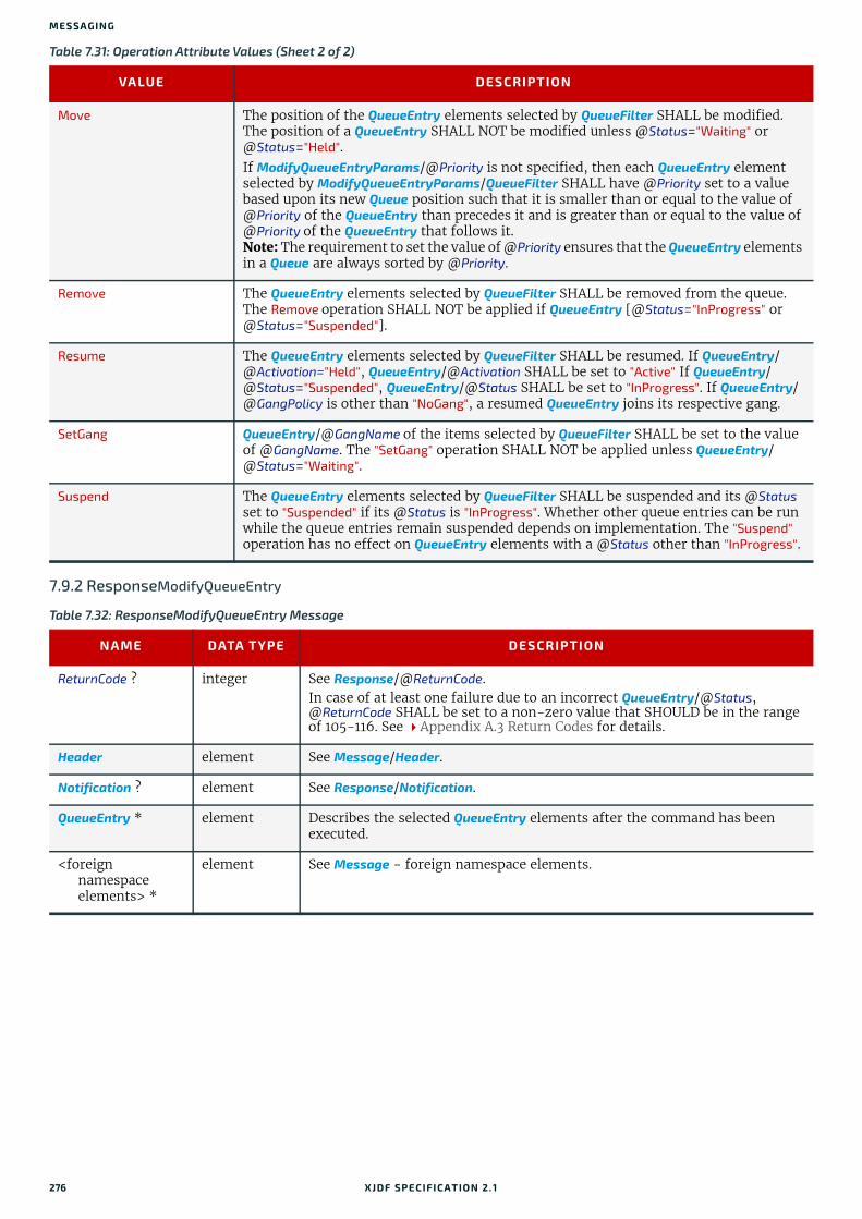
MESSA GING
7.9.2 ResponseModifyQueueEntry
Move The position of the QueueEntry elements selected by QueueFilter SHALL be modified. The position of a QueueEntry SHALL NOT be modified unless @Status="Waiting" or @Status="Held".If ModifyQueueEntryParams/@Priority is not specified, then each QueueEntry element selected by ModifyQueueEntryParams/QueueFilter SHALL have @Priority set to a value based upon its new Queue position such that it is smaller than or equal to the value of @Priority of the QueueEntry than precedes it and is greater than or equal to the value of @Priority of the QueueEntry that follows it.Note: The requirement to set the value of @Priority ensures that the QueueEntry elements in a Queue are always sorted by @Priority.
Remove The QueueEntry elements selected by QueueFilter SHALL be removed from the queue. The Remove operation SHALL NOT be applied if QueueEntry [@Status="InProgress" or @Status="Suspended"].
Resume The QueueEntry elements selected by QueueFilter SHALL be resumed. If QueueEntry/@Activation="Held", QueueEntry/@Activation SHALL be set to "Active" If QueueEntry/ @Status="Suspended", QueueEntry/@Status SHALL be set to "InProgress". If QueueEntry/@GangPolicy is other than "NoGang", a resumed QueueEntry joins its respective gang.
SetGang QueueEntry/@GangName of the items selected by QueueFilter SHALL be set to the value of @GangName. The "SetGang" operation SHALL NOT be applied unless QueueEntry/@Status="Waiting".
Suspend The QueueEntry elements selected by QueueFilter SHALL be suspended and its @Status set to "Suspended" if its @Status is "InProgress". Whether other queue entries can be run while the queue entries remain suspended depends on implementation. The "Suspend" operation has no effect on QueueEntry elements with a @Status other than "InProgress".
Table 7.32: ResponseModifyQueueEntry Message
NAME DATA TYPE DESCRIPTION
ReturnCode ? integer See Response/@ReturnCode.In case of at least one failure due to an incorrect QueueEntry/@Status, @ReturnCode SHALL be set to a non-zero value that SHOULD be in the range of 105-116. See Appendix A.3 Return Codes for details.
Header element See Message/Header.
Notification ? element See Response/Notification.
QueueEntry * element Describes the selected QueueEntry elements after the command has been executed.
<foreign namespace elements> *
element See Message - foreign namespace elements.
Table 7.31: Operation Attribute Values (Sheet 2 of 2)
VALUE DESCRIPTION
276 XJDF SPECIFICATIO N 2.1

NOTIFICATION
Example 7.3: Resuming a Queue Entry The following examples illustrate the Command and Response sequence to resume a previously held QueueEntry with @JobID=”j1”.
7.10 NotificationNotification messages are generally sent as Signals. QueryNotification is defined to allow subscriptions for Notification messages. Notification elements MAY be used to signal usual events due to any activities of a device, operator, etc. (e.g., scanning a bar code).
7.10.1 QueryNotification
7.10.1.1 NotificationFilter
<XJMF xmlns="http://www.CIP4.org/JDFSchema_2_0"> <Header DeviceID="TestSender" ID="l_000002" Time="2019-03-26T14:07:48.342+00:00"/> <CommandModifyQueueEntry> <Header DeviceID="TestSender" ID="C1" Time="2019-03-26T14:07:48.342+00:00"/> <ModifyQueueEntryParams Operation="Resume"> <QueueFilter JobID="j1"/> </ModifyQueueEntryParams> </CommandModifyQueueEntry></XJMF>
<XJMF xmlns="http://www.CIP4.org/JDFSchema_2_0"> <Header DeviceID="DeviceID" ID="l_000002" Time="2019-03-26T14:07:48.601+00:00"/> <ResponseModifyQueueEntry ReturnCode="0"> <Header DeviceID="DeviceID" ID="R1" Time="2019-03-26T14:07:48.601+00:00" refID="C1"/> <QueueEntry Activation="Active" JobID="j1" QueueEntryID="QE1" Status="Waiting"/> </ResponseModifyQueueEntry></XJMF>
Table 7.33: QueryNotification Message
NAME DATA TYPE DESCRIPTION
Header element See Message/Header.
Subscription ? element See Query/Subscription.
NotificationFilter ? element Defines the types of Notification elements that SHALL be signaled.
<foreign namespace elements> *
element See Message - foreign namespace elements.
Table 7.34: NotificationFilter Element
NAME DATA TYPE DESCRIPTION
Classes ? enumerations Defines the set of Notification/@Class types to be queried/subscribed for. If @Classes is not specified then all Notification classes are queried or sub-scribed to.Allowed values are from: Severity.
MilestoneTypes ? NMTOKENS Matching milestone types SHALL be returned and/or subscribed to. If @MilestoneTypes is not specified then all supported milestone values are queried or subscribed to.Values include those from: Milestones.
XJDF SPECIFICATIO N 2.1 277

MESSA GING
7.10.2 ResponseNotification
7.10.3 SignalNotificationSignalNotification SHOULD be used to send milestone events.
Machine events SHOULD be provided in the context of a SignalStatus or SignalResource in order to provide additional context of the event such as counter values and job identifiers and SHOULD NOT be sent in SignalNotification messages.
7.11 PipeControlCommandPipeControl modulates a flow of resources in a pipe. The type of pipe operation SHALL be specified in PipeParams/@Operation. A pipe describes the consumption of a resource (by a consuming device) that commences when some lesser quantity of the resource becomes available without having to wait for the production device to complete pro-duction of the entire quantity.
See Section 9.3.5 Overlapping Processing for a more detailed discussion regarding the use of PipeControl messages.
7.11.1 CommandPipeControl
7.11.1.1 PipeParams
Table 7.35: ResponseNotification Message
NAME DATA TYPE DESCRIPTION
ReturnCode ? integer See Response/@ReturnCode.
Header element See Message/Header.
Notification ? element Notification that describes the event. See Notification, and also Response/Notification.
<foreign namespace elements> *
element See Message - foreign namespace elements.
Table 7.36: SignalNotification Message
NAME DATA TYPE DESCRIPTION
ChannelMode ? enumeration Allowed value is from: ChannelMode.Note: See Signal/@ChannelMode.
Header element See Message/Header.
Notification element Notification that describes the event. See Section 7.10 Notification.
<foreign namespace elements> *
element See Message - foreign namespace elements.
Table 7.37: CommandPipeControl Message
NAME DATA TYPE DESCRIPTION
Header element See Message/Header.
PipeParams element Details of the PipeControl message.
<foreign namespace elements> *
element See Message - foreign namespace elements.
Table 7.38: PipeParams Element (Sheet 1 of 2)
NAME DATA TYPE DESCRIPTION
JobID NMTOKEN Specifies XJDF/@JobID of the process at the receiving end.
278 XJDF SPECIFICATIO N 2.1

QUEUESTATUS
7.11.2 ResponsePipeControlResponsePipeControl/@ReturnCode SHALL be set to 0 if the CommandPipeControl has been accepted by the receiver. If not successful the @ReturnCode SHALL be set to one of the codes shown in Appendix A.3 Return Codes.
@ReturnCode="0" only specifies that the CommandPipeControl has been received and can be processed. Any problems that occur during processing of the resources and that lead to an interruption of the pipe SHALL be communicated with the appropriate CommandPipeControl messages.
7.12 QueueStatusQueueStatus returns a description of the current state of a Queue.
7.12.1 QueryQueueStatus
JobPartID ? NMTOKEN Specifies XJDF/@JobPartID of the process at the receiving end.
Operation enumeration @Operation specifies whether the flow is being pushed or pulled. Allowed values are:Close – The PipeControl is a request to the other end of a dynamic pipe that
the sender of this message needs no further resources or will produce no further resources through the pipe.
Pause – The PipeControl is a request to the other end of a dynamic pipe that the sender of this message can currently not process resources through the pipe.
Pull – The PipeControl is a request to the producer to create resources by the consumer of the resources.
Push – The PipeControl is a notification to the consumer that resources have been created by the producer of the resources.
PipeID NMTOKEN ResourceSet/Dependent/@PipeID at the receiving end. @PipeID SHALL be unique in the scope of the job that is selected by @JobID.
MISDetails ? element Definition of how the costs for the production of the Resource are to be charged.
ResourceSet ? element Updated ResourceSet that SHALL be used by the process that receives the PipeControl command.
Table 7.39: ResponsePipeControl Message
NAME DATA TYPE DESCRIPTION
ReturnCode ? integer See Response/@ReturnCode.
Header element See Message/Header.
Notification ? element See Response/Notification.
<foreign namespace elements> *
element See Message - foreign namespace elements.
Table 7.40: QueryQueueStatus Message
NAME DATA TYPE DESCRIPTION
Header element See Message/Header.
Subscription ? element See Query/Subscription.
QueueStatusParams element QueueStatusParams defines a filter for the QueueStatus message.
<foreign namespace elements> *
element See Message - foreign namespace elements.
Table 7.38: PipeParams Element (Sheet 2 of 2)
NAME DATA TYPE DESCRIPTION
XJDF SPECIFICATIO N 2.1 279

MESSA GING
7.12.1.1 QueueStatusParams
7.12.2 ResponseQueueStatus
7.12.3 SignalQueueStatus
7.12.4 Queue
Table 7.41: QueueStatusParams Element
NAME DATA TYPE DESCRIPTION
UpdateGranularity ? enumeration Specifies whether all or only the updated QueueEntry elements should be included in the Queue.Allowed value is from: UpdateGranularity.Note: The first instance of a Signal shall result in the Queue describing all jobs.
QueueFilter ? element Filter that selects the QueueEntry elements that SHALL be returned in the Queue element of the response.
Table 7.42: ResponseQueueStatus Message
NAME DATA TYPE DESCRIPTION
ReturnCode ? integer See Response/@ReturnCode.
Header element See Message/Header.
Notification ? element See Response/Notification.
Queue ? element Describes the status of the queue.
<foreign namespace elements> *
element See Message - foreign namespace elements.
Table 7.43: SignalQueueStatus Message
NAME DATA TYPE DESCRIPTION
ChannelMode ? enumeration Allowed value is from: ChannelMode.Note: See Signal/@ChannelMode.
Header element See Message/Header.
Queue element Describes the status of the queue.
<foreign namespace elements> *
element See Message - foreign namespace elements.
Table 7.44: Queue Element (Sheet 1 of 2)
NAME DATA TYPE DESCRIPTION
MaxQueueSize ? integer The maximum number of QueueEntry elements excluding QueueEntry[@Status="Completed"] or QueueEntry[@Status="Aborted"] ele-ments that can be contained in the Queue.
QueueSize ? integer The total number of QueueEntry elements that are in the Queue regardless of the settings in the QueueFilter. Thus the value of @QueueSize may be higher than the number of QueueEntry elements.
280 XJDF SPECIFICATIO N 2.1

REQUESTQUEUEENTRY
7.13 RequestQueueEntryThis command requests a new queue entry from a potential submitting controller. The actual submission is still handled by CommandSubmitQueueEntry. Note: This command is emitted from the device that is represented by the queue to a controller or device and not to the queue, as is the case with most other queue handling commands.Whereas XJDF generally assumes a "Push" workflow, where a controller or MIS assigns a task to a given device, RequestQueueEntry allows a "Pull" workflow to be implemented, where a device with free processing capabilities dy-namically requests a new task.
7.13.1 CommandRequestQueueEntry
7.13.1.1 RequestQueueEntryParams
7.13.2 ResponseRequestQueueEntryThe response to this message contains no element that is special for this message.
UpdateGranularity ? enumeration Specifies whether all or only the updated QueueEntry elements are included in the Queue.Allowed value is from: UpdateGranularity.Note: The first instance of a Signal shall result in the Queue describing all jobs.
QueueEntry * element Each queue entry that was selected by QueueFilter SHALL be provided as an individual QueueEntry element. The entries SHALL be ordered in the sequence they have been or will be executed, beginning with the running entries, fol-lowed by the waiting entries, highest QueueEntry/@Priority first, which are then followed by the completed entries, sorted beginning with the youngest QueueEntry/@EndTime. A QueueEntry is not automatically deleted when executed or aborted, but rather it remains in the Queue and its @Status is changed to "Completed" or "Aborted" accordingly.
Table 7.45: CommandRequestQueueEntry Message
NAME DATA TYPE DESCRIPTION
Header element See Message/Header.
RequestQueueEntryParams
element Defines the specifics for the requested job.
<foreign namespace elements> *
element See Message - foreign namespace elements.
Table 7.46: RequestQueueEntryParams Element
NAME DATA TYPE DESCRIPTION
Activation ? enumeration Specifies the activation of the requested QueueEntry.
Allowed value is from: Activation.
JobID ? NMTOKEN @JobID of the requested QueueEntry.
JobPartID ? NMTOKEN @JobPartID of the requested QueueEntry.
QueueURL URL URL of the Queue device that is requesting the QueueEntry and will accept Queue manipulation messages.
Part * element Partition parts of the requested QueueEntry.
Table 7.44: Queue Element (Sheet 2 of 2)
NAME DATA TYPE DESCRIPTION
XJDF SPECIFICATIO N 2.1 281

MESSA GING
7.14 ResourceThe Resource message can be a Command message or a Query message to modify or to query XJDF resources. QueryResource retrieves information about the resources without modifying them, whereas CommandResource modifies those settings within the resource that is specified.
7.14.1 QueryResourceThe QueryResource message retrieves information about resources and can be made selective by specifying a ResourceQuParams element. QueryResource can be used to retrieve information about either job-specific or global de-vices resources.
7.14.1.1 ResourceQuParams
Table 7.47: ResponseRequestQueueEntry Message
NAME DATA TYPE DESCRIPTION
ReturnCode ? integer See Response/@ReturnCode.
Header element See Message/Header.
Notification ? element See Response/Notification.
<foreign namespace elements> *
element See Message - foreign namespace elements.
Table 7.48: QueryResource Message
NAME DATA TYPE DESCRIPTION
Header element See Message/Header.
Subscription ? element See Query/Subscription.
ResourceQuParams element Specifies the resources queried.
<foreign namespace elements> *
element See Message - foreign namespace elements.
Table 7.49: ResourceQuParams Element (Sheet 1 of 2)
NAME DATA TYPE DESCRIPTION
ExternalID ? NMTOKEN Resource/@ExternalID of the resource that is queried.
JobID ? NMTOKEN XJDF/@JobID for which resource information is being queried. If no @JobID is specified, the request applies to the currently running process or global resources, depending on the value of @Scope.@JobID SHALL NOT be specified if QueryResource/Subscription is present.
JobPartID ? NMTOKEN XJDF/@JobPartID for which resource information is being queried. If no @JobPartID is specified, all resources related to @JobID are queried. @JobPartID SHALL NOT be specified if @JobID is absent. @JobPartID SHALL NOT be specified if QueryResource/Subscription is present.
QueueEntryID ? NMTOKEN QueueEntry/@QueueEntryID of the process that is currently being executed for which resource information is being queried. If @QueueEntryID is specified, @JobID, @JobPartID and Part SHALL NOT be specified. If none of @JobID, @JobPartID, Part or @QueueEntryID are specified, ResourceQuParams applies to all jobs. @QueueEntryID SHALL NOT be specified if QueryResource/Subscription is present.
282 XJDF SPECIFICATIO N 2.1

RESOURCE
Example 7.4: Resource Query about PaperThe following is an example of an MIS sending a QueryResource to another MIS to get information on all paper known by the press.
Example 7.5: Resource Response about PaperThe following is an example of a ResponseResource sent in response to the previous QueryResource.
ResourceDetails ? enumeration @ResourceDetails refines the level of information provided about the resources. Allowed values are:Brief – ResourceInfo/ResourceSet SHALL NOT contain the explicit resource
elements as requested by @ResourceName.Full – ResourceInfo/ResourceSet SHALL contain the explicit resource ele-
ments as requested by @ResourceName.
ResourceName ? NMTOKEN If specified, ResourceInfo/ResourceSet/@Name SHALL match @ResourceName.Values include those from: Section 6 Resources.
Scope enumeration Specifies whether the Response or Signal SHALL return a complete list of all known resources, or the currently loaded resources or the resources related to a specific job.
Allowed value is from: Scope.
Part * element Part elements that describe the resource whose messages are queried.
<XJMF xmlns="http://www.CIP4.org/JDFSchema_2_0"> <Header DeviceID="TestSender" ID="l_000002" Time="2019-03-26T14:07:48.454+00:00"/> <QueryResource> <Header DeviceID="TestSender" ID="Q1" Time="2019-03-26T14:07:48.455+00:00"/> <ResourceQuParams ResourceDetails="Full" ResourceName="Media" Scope="Allowed"/> </QueryResource></XJMF>
<XJMF xmlns="http://www.CIP4.org/JDFSchema_2_0"> <Header DeviceID="DeviceID" ID="l_000002" Time="2019-03-26T14:07:48.552+00:00"/> <ResponseResource> <Header DeviceID="DeviceID" ID="R1" Time="2019-03-26T14:07:48.553+00:00" refID="Q1"/> <ResourceInfo Scope="Allowed"> <ResourceSet Name="Media"> <Resource DescriptiveName="Paper # 1" ExternalID="ID_1"> <Media Dimension="595.27559055 822.04724409" MediaType="Paper" Weight="80"/> </Resource> <Resource DescriptiveName="Paper # 2" ExternalID="ID_2"> <Media Dimension="595.27559055 822.04724409" MediaType="Paper" Weight="100"/> </Resource> <!-- One Resource element for each paper follows here --> </ResourceSet> </ResourceInfo> </ResponseResource></XJMF>
Table 7.49: ResourceQuParams Element (Sheet 2 of 2)
NAME DATA TYPE DESCRIPTION
XJDF SPECIFICATIO N 2.1 283

MESSA GING
7.14.2 CommandResourceThe CommandResource message SHALL be used to modify or create global device databases such as media catalogs or lists of known machine operators.
7.14.2.1 ResourceCmdParams
Table 7.50: CommandResource Message
NAME DATA TYPE DESCRIPTION
Header element See Message/Header.
ResourceCmdParams
element ResourceCmdParams SHALL specify the resources to be modified and the update method.
<foreign namespace elements> *
element See Message - foreign namespace elements.
Table 7.51: ResourceCmdParams Element
NAME DATA TYPE DESCRIPTION
UpdateMethod enumeration @UpdateMethod specifies how the ResourceSet SHALL be updated.Allowed values are:Complete – Any resource selected by a Part or identified by @ExternalID
SHALL be completely overwritten with the matching Resource from the ResourceSet in this message. Any Resource not selected by a Part or iden-tified by @ExternalID SHALL not be modified.
CompleteSet - The entire ResourceSet selected by this command SHALL be replaced by the ResourceSet this message contains.
Incremental – Any Resource selected by a Part or identified by @ExternalID SHALL be incrementally updated with values from the matching Resource of the ResourceSet in this message whereby all items SHALL be added to the original Resource, replacing any previously existing match-ing items. Individual items not matched SHALL not be modified or removed.
Remove – Any Resource selected by Part or identified by @ExternalID SHALL be completely removed from the ResourceSet. All other Resources SHALL NOT be modified or removed.
RemoveSet – The entire ResourceSet selected by this message SHALL be removed.
ResourceSet element ResourceSet SHALL define the resources that are modified on the device according to the policy specified in @UpdateMethod. ResourceSet/Resource/@ExternalID SHOULD be used to uniquely identify each individual resource.
284 XJDF SPECIFICATIO N 2.1
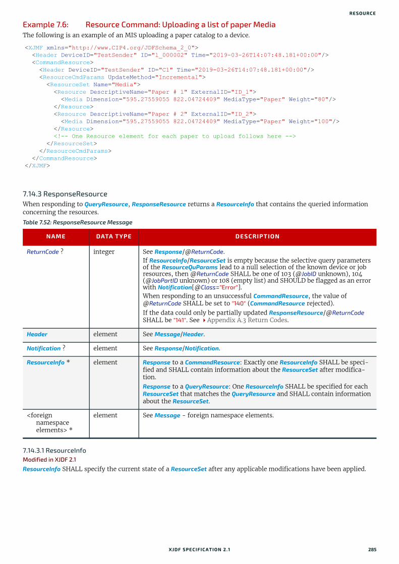
RESOURCE
Example 7.6: Resource Command: Uploading a list of paper MediaThe following is an example of an MIS uploading a paper catalog to a device.
7.14.3 ResponseResourceWhen responding to QueryResource, ResponseResource returns a ResourceInfo that contains the queried information concerning the resources.
7.14.3.1 ResourceInfoModified in XJDF 2.1
ResourceInfo SHALL specify the current state of a ResourceSet after any applicable modifications have been applied.
<XJMF xmlns="http://www.CIP4.org/JDFSchema_2_0"> <Header DeviceID="TestSender" ID="l_000002" Time="2019-03-26T14:07:48.181+00:00"/> <CommandResource> <Header DeviceID="TestSender" ID="C1" Time="2019-03-26T14:07:48.181+00:00"/> <ResourceCmdParams UpdateMethod="Incremental"> <ResourceSet Name="Media"> <Resource DescriptiveName="Paper # 1" ExternalID="ID_1"> <Media Dimension="595.27559055 822.04724409" MediaType="Paper" Weight="80"/> </Resource> <Resource DescriptiveName="Paper # 2" ExternalID="ID_2"> <Media Dimension="595.27559055 822.04724409" MediaType="Paper" Weight="100"/> </Resource> <!-- One Resource element for each paper to upload follows here --> </ResourceSet> </ResourceCmdParams> </CommandResource></XJMF>
Table 7.52: ResponseResource Message
NAME DATA TYPE DESCRIPTION
ReturnCode ? integer See Response/@ReturnCode.If ResourceInfo/ResourceSet is empty because the selective query parameters of the ResourceQuParams lead to a null selection of the known device or job resources, then @ReturnCode SHALL be one of 103 (@JobID unknown), 104 (@JobPartID unknown) or 108 (empty list) and SHOULD be flagged as an error with Notification[@Class="Error"].When responding to an unsuccessful CommandResource, the value of @ReturnCode SHALL be set to "140" (CommandResource rejected).If the data could only be partially updated ResponseResource/@ReturnCode SHALL be "141". See Appendix A.3 Return Codes.
Header element See Message/Header.
Notification ? element See Response/Notification.
ResourceInfo * element Response to a CommandResource: Exactly one ResourceInfo SHALL be speci-fied and SHALL contain information about the ResourceSet after modifica-tion.Response to a QueryResource: One ResourceInfo SHALL be specified for each ResourceSet that matches the QueryResource and SHALL contain information about the ResourceSet.
<foreign namespace elements> *
element See Message - foreign namespace elements.
XJDF SPECIFICATIO N 2.1 285

MESSA GING
Table 7.53: ResourceInfo Element (Sheet 1 of 2)
NAME DATA TYPE DESCRIPTION
CommandResult ? enumeration Result of a CommandResource. Allowed values are:Merged – Values from the ResourceSet in ResourceCmdParams were merged
into an existing ResourceSet. See the ResourceInfo/ResourceSet for the merged result.
New – A new ResourceSet with the values specified in ResourceCmdParams was created.
Rejected – The CommandResource was not applied to this ResourceSet.Removed – An existing ResourceSet was removed completely by a
ResourceSet specified in ResourceCmdParams.Replaced – An existing ResourceSet was replaced completely by a ResourceSet
specified in ResourceCmdParams.
JobID ? NMTOKEN @JobID specifies the @JobID of the job that this ResourceInfo applies to.
JobPartID ? NMTOKEN @JobPartID species the @JobPartID of the work step that this ResourceInfo applies to.
Level ? enumeration Level of the consumable or output bin that is represented by this ResourceInfo for the device. If specified, exactly one ResourceSet/Resource SHALL be present. Allowed values are:Empty – The bin is empty.Full - The bin is full. High - The output bin is filling up and can soon be Full. This value is for out-
put levels only and SHOULD NOT be specified for input resources. Low – The resources are running low and can soon be Empty. This value is for
input levels only and SHOULD NOT be specified for output bins.OK – Specification is left to the device manufacturer.
ModuleID ?New in XJDF 2.1
NMTOKEN Identifier of the module in a multi-functional device that this ResourceInfo applies to.
QueueEntryID ? NMTOKEN @QueueEntryID specifies the @QueueEntryID of the queue entry that this ResourceInfo applies to.
Scope ? enumeration @Scope specifies the context of the resources defined in this ResourceInfo.
Allowed value is from: Scope.
Speed ? float The current speed at which the resource that this ResourceInfo describes is being consumed or produced. @Speed SHALL be defined in the units specified by ResourceSet/@Unit / hour. If specified, exactly one ResourceSet/Resource SHALL be present.
TotalAmount ? float @TotalAmount specifies the job independent total counter setting for a given type of resource. Note: This allows tracking of power consumption without requiring a device to track it individually for each job.
Types ?New in XJDF 2.1
NMTOKENS @Types SHALL specify a list of one or more process names. @Types is required when ResourceInfo contains a ResourceSet with a @CombinedProcessIndex which is used to identify the subset of processes that use the ResourceSet. The subset is taken from the complete set described by the XJDF (referred to as the parent XJDF below) to which this ResourceInfo relates.Usage constraints:
a. @Types SHALL be a copy of XJDF/@Types of the parent XJDF.b. ResourceInfo/ResourceSet/@CombinedProcessIndex SHALL reference a value in ResourceInfo/@Types.
Event *New in XJDF 2.1
element Event MAY be used to specify machine-dependent codes that triggered a SignalResource or AuditResource.
286 XJDF SPECIFICATIO N 2.1

RESOURCE
7.14.4 SignalResourceSignalResource returns a ResourceInfo that contains the information concerning the subscribed resources.
MISDetails ? element Definition of how the costs for the production of the Resource are to be charged.
ResourceSet element Additional information about the resource. If the QueryResource or CommandResource leading to this ResourceInfo contains Part elements, the ResourceSet SHALL contain no more than the appropriate matching Resource elements. Unless @Speed or @Level are present, ResourceInfo SHOULD con-tain all matching Resource elements.
Table 7.54: SignalResource Message
NAME DATA TYPE DESCRIPTION
ChannelMode ? enumeration Allowed value is from: ChannelMode.Note: See Signal/@ChannelMode.
ReplaceAfter ? DateTime The data from previous SignalResource messages in the same scope as speci-fied by ResourceInfo/@Scope with the same Header/@DeviceID and a Header/@Time value after the time @ReplaceAfter and prior to the time specified by @ReplaceBefore (if present), SHALL be replaced by data in this SignalResource. If neither @ReplaceAfter or @ReplaceBefore is specified, this SignalResource is the original and SHALL NOT replace a previous SignalResource.
ReplaceBefore ? DateTime The data from previous SignalResource messages in the same scope as speci-fied by ResourceInfo/@Scope with the same Header/@DeviceID and a Header/@Time value prior to the time @ReplaceBefore and after the time specified by @ReplaceAfter (if present), SHALL be replaced by data in this SignalResource. If neither @ReplaceAfter or @ReplaceBefore is specified, this SignalResource is the original and SHALL NOT replace a previous SignalResource.
Header element See Message/Header.
ResourceInfo * element ResourceInfo SHALL contain information concerning the subscribed resources.
<foreign namespace elements> *
element See Message - foreign namespace elements.
Table 7.53: ResourceInfo Element (Sheet 2 of 2)
NAME DATA TYPE DESCRIPTION
XJDF SPECIFICATIO N 2.1 287
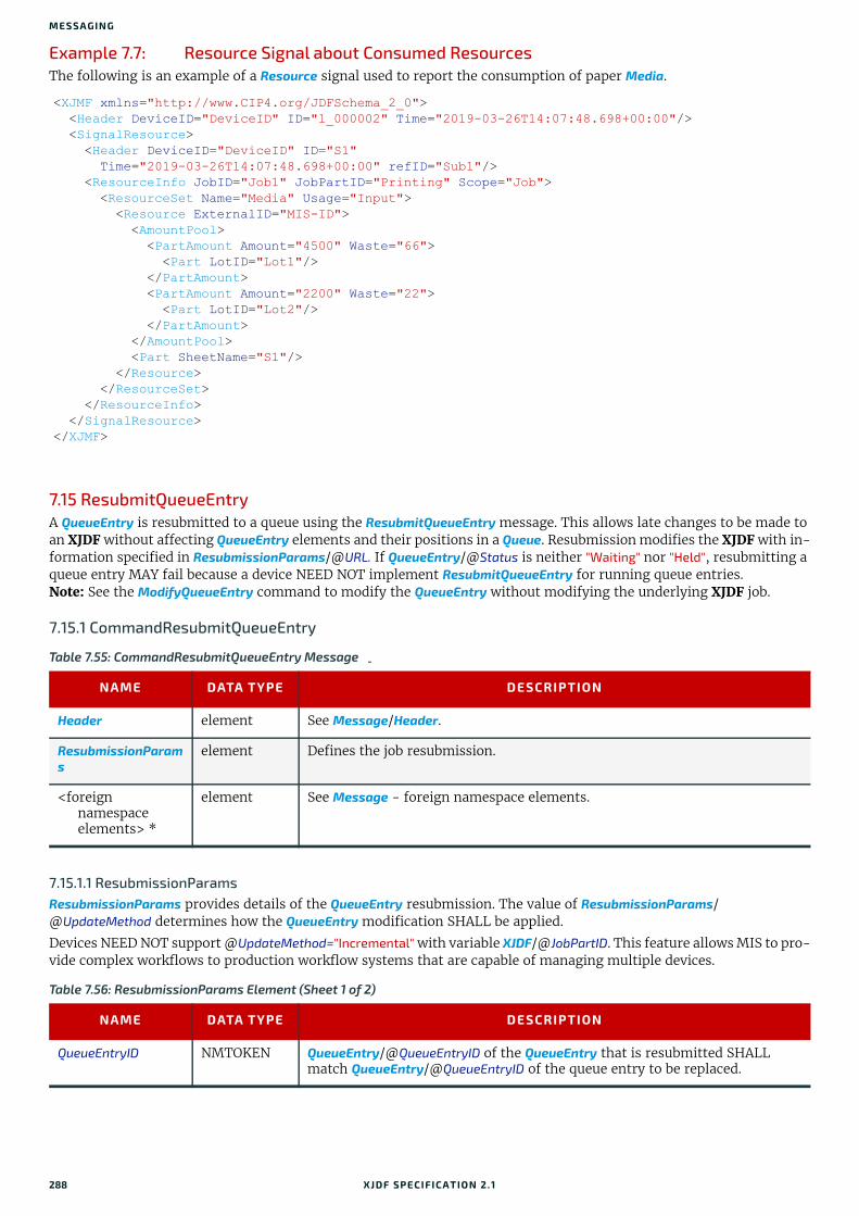
MESSA GING
Example 7.7: Resource Signal about Consumed ResourcesThe following is an example of a Resource signal used to report the consumption of paper Media.
7.15 ResubmitQueueEntryA QueueEntry is resubmitted to a queue using the ResubmitQueueEntry message. This allows late changes to be made to an XJDF without affecting QueueEntry elements and their positions in a Queue. Resubmission modifies the XJDF with in-formation specified in ResubmissionParams/@URL. If QueueEntry/@Status is neither "Waiting" nor "Held", resubmitting a queue entry MAY fail because a device NEED NOT implement ResubmitQueueEntry for running queue entries.Note: See the ModifyQueueEntry command to modify the QueueEntry without modifying the underlying XJDF job.
7.15.1 CommandResubmitQueueEntry
7.15.1.1 ResubmissionParamsResubmissionParams provides details of the QueueEntry resubmission. The value of ResubmissionParams/@UpdateMethod determines how the QueueEntry modification SHALL be applied.
Devices NEED NOT support @UpdateMethod="Incremental" with variable XJDF/@JobPartID. This feature allows MIS to pro-vide complex workflows to production workflow systems that are capable of managing multiple devices.
<XJMF xmlns="http://www.CIP4.org/JDFSchema_2_0"> <Header DeviceID="DeviceID" ID="l_000002" Time="2019-03-26T14:07:48.698+00:00"/> <SignalResource> <Header DeviceID="DeviceID" ID="S1" Time="2019-03-26T14:07:48.698+00:00" refID="Sub1"/> <ResourceInfo JobID="Job1" JobPartID="Printing" Scope="Job"> <ResourceSet Name="Media" Usage="Input"> <Resource ExternalID="MIS-ID"> <AmountPool> <PartAmount Amount="4500" Waste="66"> <Part LotID="Lot1"/> </PartAmount> <PartAmount Amount="2200" Waste="22"> <Part LotID="Lot2"/> </PartAmount> </AmountPool> <Part SheetName="S1"/> </Resource> </ResourceSet> </ResourceInfo> </SignalResource></XJMF>
Table 7.55: CommandResubmitQueueEntry Message
NAME DATA TYPE DESCRIPTION
Header element See Message/Header.
ResubmissionParams
element Defines the job resubmission.
<foreign namespace elements> *
element See Message - foreign namespace elements.
Table 7.56: ResubmissionParams Element (Sheet 1 of 2)
NAME DATA TYPE DESCRIPTION
QueueEntryID NMTOKEN QueueEntry/@QueueEntryID of the QueueEntry that is resubmitted SHALL match QueueEntry/@QueueEntryID of the queue entry to be replaced.
288 XJDF SPECIFICATIO N 2.1

RETURNQUEUEENTRY
7.15.2 ResponseResubmitQueueEntry
7.16 ReturnQueueEntryThe ReturnQueueEntry message SHALL return an XJDF that had been submitted with a SubmitQueueEntry to the control-ler that originally submitted the XJDF. ReturnQueueEntry SHALL be sent for all queue entries that have been completed or aborted if QueueSubmissionParams/@ReturnJMF has been specified. This also applies to queue entries that have been removed prior to processing. If ReturnQueueEntry is sent for a QueueEntry that has been removed prior to processing, the value of XJDF/NodeInfo/@Status SHALL be "Aborted". Note: This command is sent from the device to a controller and not from controller to device as is the case with most other queue handling commands.If the XJDF has been enhanced by submitting additional process XJDFs with different XJDF/@JobPartID using the ResubmitQueueEntry command, then only the primary XJDF SHALL be returned. The audit elements of the process XJDFs SHALL be copied into XJDF/AuditPool of the primary XJDF. Each such audit element SHALL contain a copy of XJDF/@JobPartID.
UpdateMethod enumeration @UpdateMethod specifies how the QueueEntry SHALL be updated.Allowed values are:Complete – The QueueEntry SHALL be completely replaced by the XJDF that is
referenced by @URL.Incremental – The QueueEntry SHALL be incrementally updated by the values
of the XJDF that is referenced by @URL. All traits of the referenced XJDF are optional and only values that are explicitly specified in the referenced XJDF SHALL be modified. If XJDF/@JobPartID of the referenced XJDF is identical to XJDF/@JobPartID of the originally submitted XJDF or an XJDF that has been resubmitted with ResubmissionParams/@UpdateMethod="Incremental", then the process step that is identified by XJDF/@JobID and XJDF/@JobPartID SHALL be modified. Otherwise a new process step SHALL be submitted to the device.
Remove – The QueueEntry SHALL be incrementally updated by removing all elements that are specified in the XJDF that is referenced by @URL. XJDF/@JobPartID of the referenced XJDF SHALL be identical to XJDF/@JobPartID of the originally submitted XJDF or an XJDF that has been resubmitted with ResubmissionParams/@UpdateMethod="Incremental".
URL URL Location of the XJDF to be submitted. XJDF/@JobID SHALL be identical to XJDF/@JobID of the originally submitted XJDF.If @URL refers to a directory, then all files with an extension of .xjdf that reside directly in the directory SHALL be processed in lexical order. The first XJDF is referred to as the primary XJDF. See Chapter 9 Referencing Multiple XJDF in a Directory.Note: A referenced directory MAY be inside a zip package. See [ZIP] for de-tails.
Table 7.57: ResponseResubmitQueueEntry Message
NAME DATA TYPE DESCRIPTION
ReturnCode ? integer See Response/@ReturnCode.
Header element See Message/Header.
Notification ? element See Response/Notification.
<foreign namespace elements> *
element See Message - foreign namespace elements.
Table 7.56: ResubmissionParams Element (Sheet 2 of 2)
NAME DATA TYPE DESCRIPTION
XJDF SPECIFICATIO N 2.1 289

MESSA GING
7.16.1 CommandReturnQueueEntry
7.16.1.1 ReturnQueueEntryParamsThe @URL attribute specifies the location where the XJDF file to be returned can be retrieved by the controller. The scheme of the @URL attribute (such as "file", "http" or local url) SHALL define the retrieval method to be used to retrieve the XJDF.
7.16.2 ResponseReturnQueueEntry
7.17 ShutDownThe ShutDown command message shuts down a controller or device. A device SHALL use the Status message if it signals its own shutdown.
Table 7.58: CommandReturnQueueEntry Message
NAME DATA TYPE DESCRIPTION
Header element See Message/Header.
ReturnQueueEntryParams
element Defines the job being returned from device to controller after processing is completed or aborted.
<foreign namespace elements> *
element See Message - foreign namespace elements.
Table 7.59: ReturnQueueEntryParams Element
NAME DATA TYPE DESCRIPTION
QueueEntryID NMTOKEN QueueEntry/@QueueEntryID of the returned queue entry.
URL URL Location of the XJDF that represents the final state of the QueueEntry to be returned. URL SHALL NOT reference a directory.
Table 7.60: ResponseReturnQueueEntry Message
NAME DATA TYPE DESCRIPTION
ReturnCode ? integer See Response/@ReturnCode.
Header element See Message/Header.
Notification ? element See Response/Notification.
<foreign namespace elements> *
element See Message - foreign namespace elements.
290 XJDF SPECIFICATIO N 2.1

STATUS
7.17.1 CommandShutDown
7.17.1.1 ShutDownCmdParams
7.17.2 ResponseShutDown
7.18 StatusThe Status message queries the general status of a device or a controller and the status of jobs associated with this device or controller. No job context is needed to issue a Status message. The response SHOULD contain a DeviceInfo element that contains the job-independent details of the device or controller and which MAY contain JobPhase elements that in turn contain the job specific information.
7.18.1 QueryStatus
Table 7.61: CommandShutDown Message
NAME DATA TYPE DESCRIPTION
Header element See Message/Header.
ShutDownCmdParams ?
element Defines the details of a shutdown.
<foreign namespace elements> *
element See Message - foreign namespace elements.
Table 7.62: ShutDownCmdParams Element
NAME DATA TYPE DESCRIPTION
ShutDownType ? enumeration Defines the device shutdown method.Allowed values are:Full – Completely shut down the device. It is no longer accessible via XJMF
after the shutdown.StandBy – The device is set to standby mode. It can be restarted using a
CommandWakeUp XJMF message. DeviceInfo/@StatusDetails SHOULD be "StandBy". If the device requires a CommandWakeUp XJMF prior to accept-ing new jobs, DeviceInfo/@Status SHALL be "Offline", else it SHALL be "Idle".
Table 7.63: ResponseShutDown Message
NAME DATA TYPE DESCRIPTION
ReturnCode ? integer See Response/@ReturnCode.
Header element See Message/Header.
Notification ? element See Response/Notification.
<foreign namespace elements> *
element See Message - foreign namespace elements.
Table 7.64: QueryStatus Message (Sheet 1 of 2)
NAME DATA TYPE DESCRIPTION
Header element See Message/Header.
Subscription ? element See Query/Subscription.
StatusQuParams ? element Acts as a filter to select the context of the device or controller that should be reported in the response messages’ DeviceInfo element.
XJDF SPECIFICATIO N 2.1 291

MESSA GING
7.18.1.1 StatusQuParamsStatusQuParams is a filter that defines the job context for which information SHALL be returned in the response.
7.18.2 ResponseStatus
7.18.2.1 DeviceInfoThe response message returns a DeviceInfo element for the queried device. Header/@DeviceID SHALL specify the device that DeviceInfo describes.
<foreign namespace elements> *
element See Message - foreign namespace elements.
Table 7.65: StatusQuParams Element
NAME DATA TYPE DESCRIPTION
QueueEntryID ? NMTOKEN @QueueEntryID of the queue entry that is being queried. If @QueueEntryID is not specified, information SHALL be provided for all jobs (that are currently active) and job independent status. @QueueEntryID SHALL NOT be specified if QueryStatus/Subscription is present.
Table 7.66: ResponseStatus Message
NAME DATA TYPE DESCRIPTION
ReturnCode ? integer See Response/@ReturnCode.
Header element See Message/Header.
Notification ? element See Response/Notification.
DeviceInfo ? element DeviceInfo describes details of the actual device status.
<foreign namespace elements> *
element See Message - foreign namespace elements.
Table 7.67: DeviceInfo Element (Sheet 1 of 2)
NAME DATA TYPE DESCRIPTION
CounterUnit ? NMTOKEN The unit of the @ProductionCounter, the @TotalProductionCounter and numer-ator unit of @Speed.The default unit is the default unit defined by XJDF for the output resource of the node executed by the device. For example, in case of a sheet-fed printer, it is the number of sheets; in case of a web printer, it is the length of printed web in meters.Values include those from: Units.
EndTime ? New in XJDF 2.1
dateTime @EndTime SHALL specify the end time of a device status and SHALL be spec-ified when the device status changes. A device status changes when the sub-sequent DeviceInfo that describes the same device has a different @DeviceStatus or @StatusDetails. @EndTime SHALL NOT be specified in a heartbeat signal.
HourCounter ? duration The total integrated time (life time) of device operation in hours.
IdleStartTime ? dateTime @IdleStartTime SHALL specify the time when the device switched to either @Status="Idle", @Status="Offline" or @Status="NonProductive". @IdleStartTime SHALL NOT be specified if @Status="Production" or @Status="Stopped".
ModuleIDs ? NMTOKENS @ModuleIDs SHALL reference the values of Device/Module/@ModuleIDs of individual modules that are in use independent of a job. @ModuleIDs SHALL not be specified for tools that are specified in Status/JobPhase/@ModuleIDs.
Table 7.64: QueryStatus Message (Sheet 2 of 2)
NAME DATA TYPE DESCRIPTION
292 XJDF SPECIFICATIO N 2.1

STATUS
7.18.2.2 ActivityActivity elements allow tracking of device and operator tasks in addition to the values of the global attributes @Status and @StatusDetails. An Activity SHOULD define a task that has a duration. Singular events SHOULD be specified in DeviceInfo/Event.
PowerOnTime ? dateTime Date and time when the device was switched on.
ProductionCounter ? float The current machine production counter. This counter can be reset manually. Typically, it starts counting at power-on time. The reset of this counter MAY be signaled by a SignalNotification with a Notification/Event/@EventValue="CounterReset". The value of Event/@EventID for a counter reset is implementation specific. See Section 8.18 Event.
Speed ? float @Speed specifies the current machine speed. @Speed SHALL be defined in the same units as @CounterUnit per hour.
Status enumeration @Status describes the overall status of the device. Allowed value is from: DeviceStatus.
StatusDetails ? NMTOKEN String that defines the device state more specifically.Values include those from: Status Details.
ToolIDs ?New in XJDF 2.1
NMTOKENS @ToolIDs SHALL reference the values of ResourceSet[@Name="Tool"]/Resource/@ExternalID of individual tools that are in use independent of a job. @ToolIDs SHALL NOT be specified for tools that are specified in JobPhase/@ToolIDs.
TotalProductionCounter ?
float The current total machine production counter since the machine was pro-duced.
Activity * element Device and operator activities that are related to the device and are unrelated to a specific job.
Event *New in XJDF 2.1
element Event MAY be used to specify machine-dependent codes that triggered a SignalStatus or AuditStatus.
FileSpec (CurrentSchema) ?Deprecated in XJDF 2.1
element Reference to an XML schema in XSD format [XMLSchema] that describes the present limitations of the device that can be used without operator inter-vention. The referenced XML schema SHALL use the XJDF namespace to describe elements and attributes that are defined in the XJDF namespace.Deprecation note: Use KnownDevices to locate any device specific schema.
FileSpec (Schema) ?Deprecated in XJDF 2.1
element Reference to an XML schema in XSD format [XMLSchema] that describes the global limitations of the device including those that can only be used with operator intervention. The referenced XML schema SHALL use the XJDF namespace to describe elements and attributes that are defined in the XJDF namespace.Deprecation note: Use KnownDevices to locate any device specific schema.
JobPhase * element Each JobPhase SHALL describe the actual status of a job in the device. All jobs that are active on the device SHALL be specified. No JobPhase elements SHALL be present if @Status="Idle" or @Status="Offline".Multiple JobPhase elements specify that multiple job phases are active simul-taneously on the device.
Table 7.68: Activity Element (Sheet 1 of 2)
NAME DATA TYPE DESCRIPTION
ActivityID ? NMTOKEN ID of the activity being performed. This ID is unique, site specific and internal to the MIS.
ActivityName ? string Name of the activity being performed.
Table 7.67: DeviceInfo Element (Sheet 2 of 2)
NAME DATA TYPE DESCRIPTION
XJDF SPECIFICATIO N 2.1 293
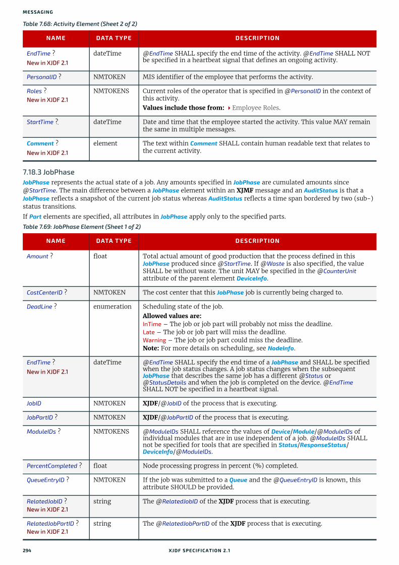
MESSA GING
7.18.3 JobPhaseJobPhase represents the actual state of a job. Any amounts specified in JobPhase are cumulated amounts since @StartTime. The main difference between a JobPhase element within an XJMF message and an AuditStatus is that a JobPhase reflects a snapshot of the current job status whereas AuditStatus reflects a time span bordered by two (sub-) status transitions.
If Part elements are specified, all attributes in JobPhase apply only to the specified parts.
EndTime ? New in XJDF 2.1
dateTime @EndTime SHALL specify the end time of the activity. @EndTime SHALL NOT be specified in a heartbeat signal that defines an ongoing activity.
PersonalID ? NMTOKEN MIS identifier of the employee that performs the activity.
Roles ?New in XJDF 2.1
NMTOKENS Current roles of the operator that is specified in @PersonalID in the context of this activity.Values include those from: Employee Roles.
StartTime ? dateTime Date and time that the employee started the activity. This value MAY remain the same in multiple messages.
Comment ?New in XJDF 2.1
element The text within Comment SHALL contain human readable text that relates to the current activity.
Table 7.69: JobPhase Element (Sheet 1 of 2)
NAME DATA TYPE DESCRIPTION
Amount ? float Total actual amount of good production that the process defined in this JobPhase produced since @StartTime. If @Waste is also specified, the value SHALL be without waste. The unit MAY be specified in the @CounterUnit attribute of the parent element DeviceInfo.
CostCenterID ? NMTOKEN The cost center that this JobPhase job is currently being charged to.
DeadLine ? enumeration Scheduling state of the job. Allowed values are:InTime – The job or job part will probably not miss the deadline.Late – The job or job part will miss the deadline.Warning – The job or job part could miss the deadline.Note: For more details on scheduling, see NodeInfo.
EndTime ? New in XJDF 2.1
dateTime @EndTime SHALL specify the end time of a JobPhase and SHALL be specified when the job status changes. A job status changes when the subsequent JobPhase that describes the same job has a different @Status or @StatusDetails and when the job is completed on the device. @EndTime SHALL NOT be specified in a heartbeat signal.
JobID NMTOKEN XJDF/@JobID of the process that is executing.
JobPartID ? NMTOKEN XJDF/@JobPartID of the process that is executing.
ModuleIDs ? NMTOKENS @ModuleIDs SHALL reference the values of Device/Module/@ModuleIDs of individual modules that are in use independent of a job. @ModuleIDs SHALL not be specified for tools that are specified in Status/ResponseStatus/DeviceInfo/@ModuleIDs.
PercentCompleted ? float Node processing progress in percent (%) completed.
QueueEntryID ? NMTOKEN If the job was submitted to a Queue and the @QueueEntryID is known, this attribute SHOULD be provided.
RelatedJobID ?New in XJDF 2.1
string The @RelatedJobID of the XJDF process that is executing.
RelatedJobPartID ?New in XJDF 2.1
string The @RelatedJobPartID of the XJDF process that is executing.
Table 7.68: Activity Element (Sheet 2 of 2)
NAME DATA TYPE DESCRIPTION
294 XJDF SPECIFICATIO N 2.1
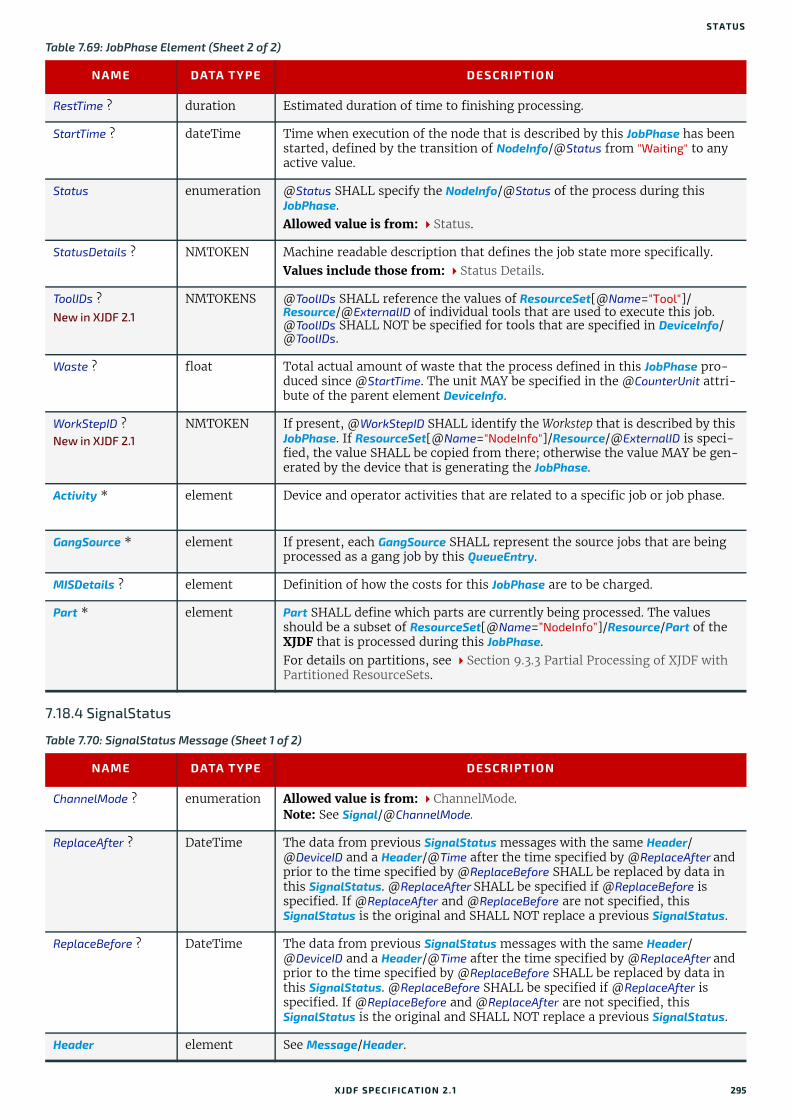
STATUS
7.18.4 SignalStatus
RestTime ? duration Estimated duration of time to finishing processing.
StartTime ? dateTime Time when execution of the node that is described by this JobPhase has been started, defined by the transition of NodeInfo/@Status from "Waiting" to any active value.
Status enumeration @Status SHALL specify the NodeInfo/@Status of the process during this JobPhase.Allowed value is from: Status.
StatusDetails ? NMTOKEN Machine readable description that defines the job state more specifically.Values include those from: Status Details.
ToolIDs ?New in XJDF 2.1
NMTOKENS @ToolIDs SHALL reference the values of ResourceSet[@Name="Tool"]/Resource/@ExternalID of individual tools that are used to execute this job. @ToolIDs SHALL NOT be specified for tools that are specified in DeviceInfo/@ToolIDs.
Waste ? float Total actual amount of waste that the process defined in this JobPhase pro-duced since @StartTime. The unit MAY be specified in the @CounterUnit attri-bute of the parent element DeviceInfo.
WorkStepID ?New in XJDF 2.1
NMTOKEN If present, @WorkStepID SHALL identify the Workstep that is described by this JobPhase. If ResourceSet[@Name="NodeInfo"]/Resource/@ExternalID is speci-fied, the value SHALL be copied from there; otherwise the value MAY be gen-erated by the device that is generating the JobPhase.
Activity * element Device and operator activities that are related to a specific job or job phase.
GangSource * element If present, each GangSource SHALL represent the source jobs that are being processed as a gang job by this QueueEntry.
MISDetails ? element Definition of how the costs for this JobPhase are to be charged.
Part * element Part SHALL define which parts are currently being processed. The values should be a subset of ResourceSet[@Name=”NodeInfo”]/Resource/Part of the XJDF that is processed during this JobPhase.For details on partitions, see Section 9.3.3 Partial Processing of XJDF with Partitioned ResourceSets.
Table 7.70: SignalStatus Message (Sheet 1 of 2)
NAME DATA TYPE DESCRIPTION
ChannelMode ? enumeration Allowed value is from: ChannelMode.Note: See Signal/@ChannelMode.
ReplaceAfter ? DateTime The data from previous SignalStatus messages with the same Header/@DeviceID and a Header/@Time after the time specified by @ReplaceAfter and prior to the time specified by @ReplaceBefore SHALL be replaced by data in this SignalStatus. @ReplaceAfter SHALL be specified if @ReplaceBefore is specified. If @ReplaceAfter and @ReplaceBefore are not specified, this SignalStatus is the original and SHALL NOT replace a previous SignalStatus.
ReplaceBefore ? DateTime The data from previous SignalStatus messages with the same Header/@DeviceID and a Header/@Time after the time specified by @ReplaceAfter and prior to the time specified by @ReplaceBefore SHALL be replaced by data in this SignalStatus. @ReplaceBefore SHALL be specified if @ReplaceAfter is specified. If @ReplaceBefore and @ReplaceAfter are not specified, this SignalStatus is the original and SHALL NOT replace a previous SignalStatus.
Header element See Message/Header.
Table 7.69: JobPhase Element (Sheet 2 of 2)
NAME DATA TYPE DESCRIPTION
XJDF SPECIFICATIO N 2.1 295
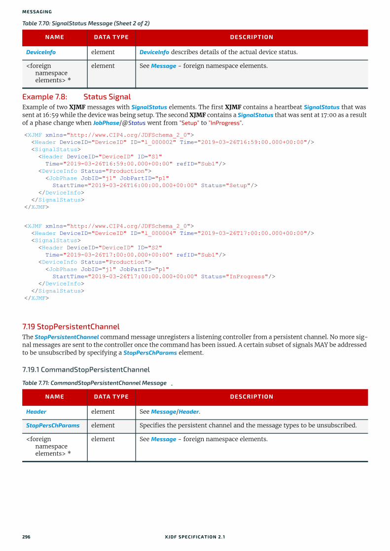
MESSA GING
Example 7.8: Status SignalExample of two XJMF messages with SignalStatus elements. The first XJMF contains a heartbeat SignalStatus that was sent at 16:59 while the device was being setup. The second XJMF contains a SignalStatus that was sent at 17:00 as a result of a phase change when JobPhase/@Status went from ”Setup” to ”InProgress”.
7.19 StopPersistentChannelThe StopPersistentChannel command message unregisters a listening controller from a persistent channel. No more sig-nal messages are sent to the controller once the command has been issued. A certain subset of signals MAY be addressed to be unsubscribed by specifying a StopPersChParams element.
7.19.1 CommandStopPersistentChannel
DeviceInfo element DeviceInfo describes details of the actual device status.
<foreign namespace elements> *
element See Message - foreign namespace elements.
<XJMF xmlns="http://www.CIP4.org/JDFSchema_2_0"> <Header DeviceID="DeviceID" ID="l_000002" Time="2019-03-26T16:59:00.000+00:00"/> <SignalStatus> <Header DeviceID="DeviceID" ID="S1" Time="2019-03-26T16:59:00.000+00:00" refID="Sub1"/> <DeviceInfo Status="Production"> <JobPhase JobID="j1" JobPartID="p1" StartTime="2019-03-26T16:00:00.000+00:00" Status="Setup"/> </DeviceInfo> </SignalStatus></XJMF>
<XJMF xmlns="http://www.CIP4.org/JDFSchema_2_0"> <Header DeviceID="DeviceID" ID="l_000004" Time="2019-03-26T17:00:00.000+00:00"/> <SignalStatus> <Header DeviceID="DeviceID" ID="S2" Time="2019-03-26T17:00:00.000+00:00" refID="Sub1"/> <DeviceInfo Status="Production"> <JobPhase JobID="j1" JobPartID="p1" StartTime="2019-03-26T17:00:00.000+00:00" Status="InProgress"/> </DeviceInfo> </SignalStatus></XJMF>
Table 7.71: CommandStopPersistentChannel Message
NAME DATA TYPE DESCRIPTION
Header element See Message/Header.
StopPersChParams element Specifies the persistent channel and the message types to be unsubscribed.
<foreign namespace elements> *
element See Message - foreign namespace elements.
Table 7.70: SignalStatus Message (Sheet 2 of 2)
NAME DATA TYPE DESCRIPTION
296 XJDF SPECIFICATIO N 2.1

SUBMITQUEUEENTRY
7.19.1.1 StopPersChParamsStopPersChParams provides a filter which selects persistent channels that SHALL be unregistered.
7.19.2 ResponseStopPersistentChannel
7.20 SubmitQueueEntrySubmitQueueEntry initially submits a QueueEntry to a device. Modifications to a QueueEntry can be applied by using the ResubmitQueueEntry or ModifyQueueEntry command. QueueSubmissionParams provides the parameters associated with the submission.ResponseSubmitQueueEntry/QueueEntry/@QueueEntryID SHALL be unique within the device. A new @QueueEntryID SHALL be generated for each SubmitQueueEntry.
7.20.1 CommandSubmitQueueEntry
7.20.1.1 QueueSubmissionParamsThe job submission can contain queue-ordering attributes equivalent to those used by ModifyQueueEntryParams/[@Operation="Move"] of the ModifyQueueEntry messages. @ReturnJMF MAY specify the location where the modified XJDF SHALL be sent after the job is completed or aborted.
Table 7.72: StopPersChParams Element
NAME DATA TYPE DESCRIPTION
ChannelID ? NMTOKEN Header/@refID of the persistent channel to be deleted. @ChannelID specifies the Header/@ID of the Query message (identical to the Header/@refID of the Signal message).
MessageType ? NMTOKEN @MessageType SHALL match the local element name (i.e. without namespace prefix) of the Signal elements that SHALL be unregistered.
URL ? URL URL of the receiving controller. This SHALL be identical to the Subscription/@URL that was used to create the persistent channel.
Table 7.73: ResponseStopPersistentChannel Message
NAME DATA TYPE DESCRIPTION
ReturnCode ? integer See Response/@ReturnCode.
Header element See Message/Header.
Notification ? element See Response/Notification.
SubscriptionInfo * element One SubscriptionInfo element SHALL be returned for every persistent channel that was removed.
<foreign namespace elements> *
element See Message - foreign namespace elements.
Table 7.74: CommandSubmitQueueEntry Message
NAME DATA TYPE DESCRIPTION
Header element See Message/Header.
QueueSubmissionParams
element Defines the job submission.
<foreign namespace elements> *
element See Message - foreign namespace elements.
XJDF SPECIFICATIO N 2.1 297

MESSA GING
The @URL attribute specifies the location where the queue controller can retrieve the XJDF file to be submitted.
Example 7.9: SubmitQueueEntry Command with “http” SchemeIn this example, the queue controller retrieves the file with a standard HTTP get command from a host that MAY be re-mote.
7.20.2 ResponseSubmitQueueEntry
Table 7.75: QueueSubmissionParams Element
NAME DATA TYPE DESCRIPTION
Activation ? enumeration Activation of the submitted QueueEntry.
Allowed value is from: Activation.
GangName ? NMTOKEN Name of the gang for the job. If @GangName is specified, the QueueEntry SHOULD be executed along with other QueueEntry elements that share a common value of @GangName. If @GangName is not known, the receiving device MAY either return an error 131 or create the gang with @GangName on the fly.
GangPolicy ? enumeration Ganging policy for the QueueEntry.Allowed value is from: GangPolicy.
NextQueueEntryID ? NMTOKEN QueueEntry/@QueueEntryID of the queue entry that SHALL be positioned directly behind the entry. At most one of @NextQueueEntryID, @PrevQueueEntryID or @Priority SHALL be specified.
PrevQueueEntryID ? NMTOKEN QueueEntry/@QueueEntryID of the queue entry that SHALL be positioned directly in front of the entry. At most one of @NextQueueEntryID, @PrevQueueEntryID or @Priority SHALL be specified.
Priority ? integer Number from 0 to 100, where "0" is the lowest priority and "100" is the maxi-mum priority. At most one of @NextQueueEntryID, @PrevQueueEntryID or @Priority SHALL be specified.Note that QueueSubmissionParams/@Priority is not the same as NodeInfo/@JobPriority. QueueSubmissionParams/@Priority specifies the priority in the context of the device queue whereas NodeInfo/@JobPriority specifies the prior-ity of the task in general. QueueSubmissionParams/@Priority MAY be modified due to additional scheduling information (e.g., NodeInfo/@FirstStart).QueueSubmissionParams/@Priority and ModifyQueueEntryParams/@Priority SHALL take precedence over NodeInfo/@JobPriority.
ReturnJMF ? URL URL where a CommandReturnQueueEntry SHALL be sent when the QueueEntry is completed or aborted.
URL URL Location of the XJDF to be submitted or resubmitted. If @URL refers to a directory, then all files with an extension of ‘xjdf’ that reside directly in the directory SHALL be processed in lexical order. The first XJDF is referred to as the primary XJDF. See Section 9.4.1 Referencing Multiple XJDF in a Directory. Note: A referenced directory MAY be inside a zip package. Refer to the appli-cation note [ZIP].
<XJMF xmlns="http://www.CIP4.org/JDFSchema_2_0"> <Header DeviceID="TestSender" ID="l_000002" Time="2019-03-26T14:07:49.216+00:00"/> <CommandSubmitQueueEntry> <Header DeviceID="TestSender" ID="C1" Time="2019-03-26T14:07:49.217+00:00"/> <QueueSubmissionParams URL="http://jobserver.xjdf.org?job1"/> </CommandSubmitQueueEntry></XJMF>
Table 7.76: ResponseSubmitQueueEntry Message (Sheet 1 of 2)
NAME DATA TYPE DESCRIPTION
ReturnCode ? integer See Response/@ReturnCode.
298 XJDF SPECIFICATIO N 2.1
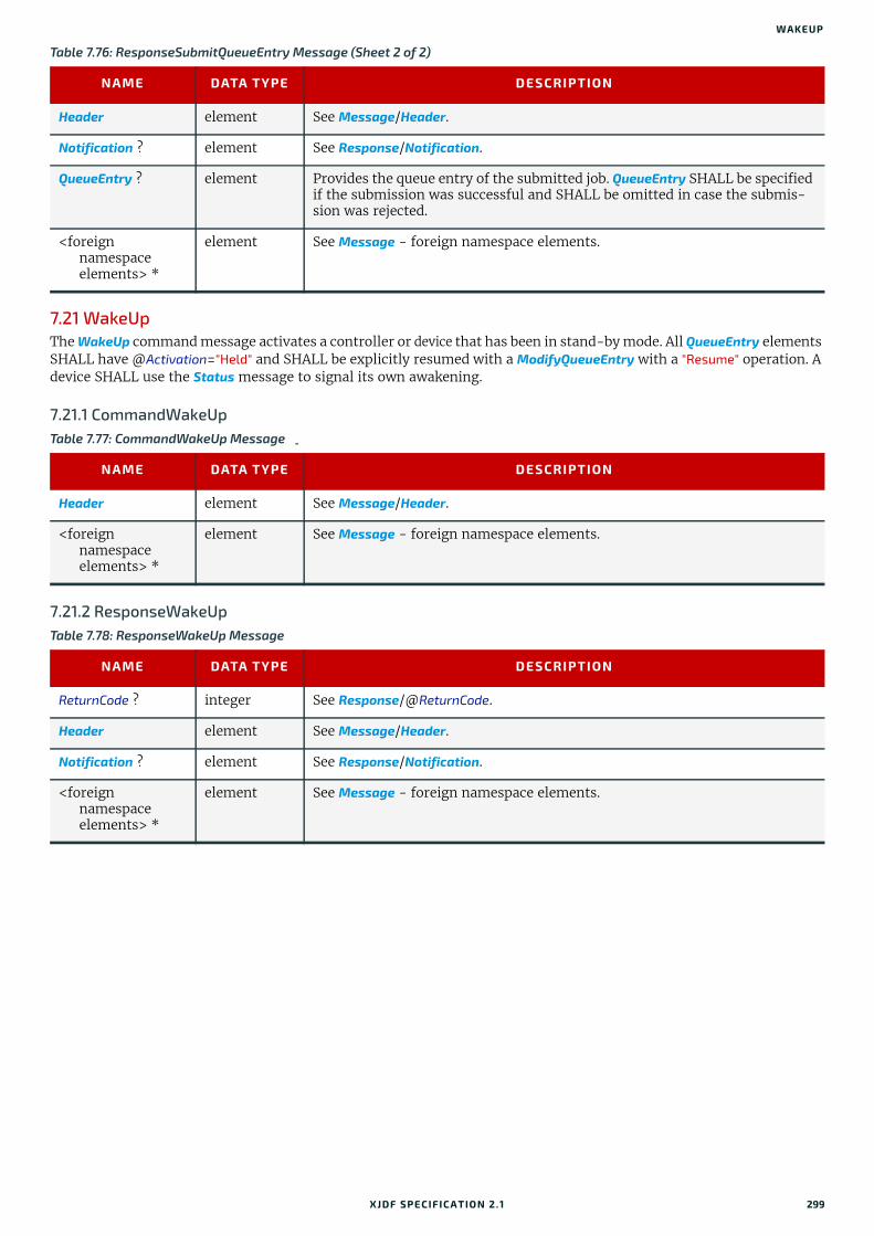
WAKEUP
7.21 WakeUpThe WakeUp command message activates a controller or device that has been in stand-by mode. All QueueEntry elements SHALL have @Activation="Held" and SHALL be explicitly resumed with a ModifyQueueEntry with a "Resume" operation. A device SHALL use the Status message to signal its own awakening.
7.21.1 CommandWakeUp
7.21.2 ResponseWakeUp
Header element See Message/Header.
Notification ? element See Response/Notification.
QueueEntry ? element Provides the queue entry of the submitted job. QueueEntry SHALL be specified if the submission was successful and SHALL be omitted in case the submis-sion was rejected.
<foreign namespace elements> *
element See Message - foreign namespace elements.
Table 7.77: CommandWakeUp Message
NAME DATA TYPE DESCRIPTION
Header element See Message/Header.
<foreign namespace elements> *
element See Message - foreign namespace elements.
Table 7.78: ResponseWakeUp Message
NAME DATA TYPE DESCRIPTION
ReturnCode ? integer See Response/@ReturnCode.
Header element See Message/Header.
Notification ? element See Response/Notification.
<foreign namespace elements> *
element See Message - foreign namespace elements.
Table 7.76: ResponseSubmitQueueEntry Message (Sheet 2 of 2)
NAME DATA TYPE DESCRIPTION
XJDF SPECIFICATIO N 2.1 299

MESSA GING
300 XJDF SPECIFICATIO N 2.1
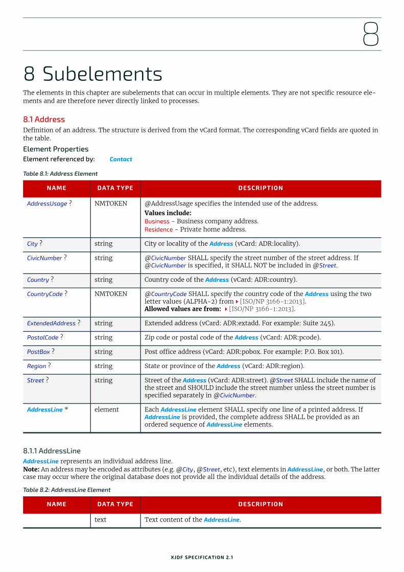
8
8 SubelementsThe elements in this chapter are subelements that can occur in multiple elements. They are not specific resource ele-ments and are therefore never directly linked to processes.8.1 AddressDefinition of an address. The structure is derived from the vCard format. The corresponding vCard fields are quoted in the table.
Element PropertiesElement referenced by: Contact
8.1.1 AddressLineAddressLine represents an individual address line.Note: An address may be encoded as attributes (e.g. @City, @Street, etc), text elements in AddressLine, or both. The latter case may occur where the original database does not provide all the individual details of the address.
Table 8.1: Address Element
NAME DATA TYPE DESCRIPTION
AddressUsage ? NMTOKEN @AddressUsage specifies the intended use of the address.Values include:Business - Business company address.Residence - Private home address.
City ? string City or locality of the Address (vCard: ADR:locality).
CivicNumber ? string @CivicNumber SHALL specify the street number of the street address. If @CivicNumber is specified, it SHALL NOT be included in @Street.
Country ? string Country code of the Address (vCard: ADR:country).
CountryCode ? NMTOKEN @CountryCode SHALL specify the country code of the Address using the two letter values (ALPHA-2) from[ISO/NP 3166-1:2013].Allowed values are from: [ISO/NP 3166-1:2013].
ExtendedAddress ? string Extended address (vCard: ADR:extadd. For example: Suite 245).
PostalCode ? string Zip code or postal code of the Address (vCard: ADR:pcode).
PostBox ? string Post office address (vCard: ADR:pobox. For example: P.O. Box 101).
Region ? string State or province of the Address (vCard: ADR:region).
Street ? string Street of the Address (vCard: ADR:street). @Street SHALL include the name of the street and SHOULD include the street number unless the street number is specified separately in @CivicNumber.
AddressLine * element Each AddressLine element SHALL specify one line of a printed address. If AddressLine is provided, the complete address SHALL be provided as an ordered sequence of AddressLine elements.
Table 8.2: AddressLine Element
NAME DATA TYPE DESCRIPTION
text Text content of the AddressLine.
XJDF SPECIFICATIO N 2.1

SUBELEMENTS
8.2 ApprovalPersonApprovalPerson specifies the details of the person who is responsible for signing an approval.
Element PropertiesElement referenced by: ApprovalDetails, ApprovalParams
8.3 AutomatedOverPrintParamsAutomatedOverPrintParams provides controls for the automated selection of overprinting of black text or graphics.
Element PropertiesElement referenced by: RenderingParams, SeparationControlParams
8.4 BarcodeCompParamsBarcodeCompParams specifies the technical compensation parameters for barcodes.
Element PropertiesElement referenced by: BarcodeReproParams
Table 8.3: ApprovalPerson Element
NAME DATA TYPE DESCRIPTION
ApprovalRole ? enumeration Role of the ApprovalPerson. Allowed values are: Approvinator – The decision of this approver immediately overrides the deci-
sions of the other approvers and ends the approval cycle. The "Approvinator" NEED NOT sign for the approval to become valid.
Informative – The approver is informed of the Approval process, but the approval is still valid, even without his approval.
Obligated – The approver SHALL sign the approval.
ApprovalRoleDetails ?
string Additional details on the @ApprovalRole. @ApprovalRole SHOULD be specified if @ApprovalRoleDetails is provided.
ContactRef IDREF Additional details of the person who SHALL sign the approval. The referenced Contact SHALL contain a Part/@ContactType="Approver".
Table 8.4: AutomatedOverPrintParams Element
NAME DATA TYPE DESCRIPTION
KnockOutCMYKWhite ?
boolean If @KnockOutCMYKWhite="true", graphic objects defined in DeviceCMYK, where all colorant values are <0.001 SHALL be knocked out, even when set to overprint and when the PDF overprint mode is set to 1.
LineArtBlackLevel ? float A value between 0.0 and 1.0 that indicates the minimum black level for the stroke or fill colors that cause the line art to be set to overprint. @LineArtBlackLevel SHALL NOT be specified unless @OverPrintBlackLineArt="true".
OverPrintBlackLineArt ?
boolean Indicates whether overprint SHALL be set to "true" for black line art (i.e., vec-tor elements other than text). If "true", overprint of black line art is applied regardless of any values in the PDL.
OverPrintBlackText ? boolean Indicates whether overprint SHALL be set to "true" for black text. If "true", overprint of black text is applied regardless of any values in the PDL.
TextBlackLevel ? float A value between 0.0 and 1.0 that indicates the minimum black level for the text stroke or fill colors that cause the text to be set to overprint. @TextBlackLevel SHALL NOT be specified unless @OverPrintBlackText="true".
TextSizeThreshold ? integer Indicates the point size for text below which black text will be set to over-print. For asymmetrically scaled text, the minimum point size between both axes SHALL be used. @TextSizeThreshold SHALL NOT be specified unless @OverPrintBlackText="true".
302 XJDF SPECIFICATIO N 2.1

BARCODEREPROPARAMS
.
8.5 BarcodeReproParamsBarcodeReproParams specifies the reproduction parameters for barcodes.
Element PropertiesElement referenced by: Content/BarcodeProductionParams, Layout/StripMark
8.6 BindingQualityNew in XJDF 2.1
The set of parameters in BindingQuality identifies how the quality of the binding is verified.
Table 8.5: BarcodeCompParams Element
NAME DATA TYPE DESCRIPTION
CompensationProcess
enumeration Process that is bar width spread SHALL be compensated for. Allowed values are:PlatemakingPrinting
CompensationValue float The width of the bars SHALL be reduced by this amount (in microns) to compen-sate for technical spread.
Table 8.6: BarcodeReproParams Element
NAME DATA TYPE DESCRIPTION
BearerBars ? enumeration @BearerBars specifies how to generate bearer bars. (ITF).Allowed values are:BoxBoxHMarksNoneTopBottom
Height ? float @Height SHALL specify the height (Y direction) of the bars of a linear barcode in the PDL.
Magnification ? float The magnification factor that linear barcodes SHALL be scaled with. For example, a value for @Magnification > 1 requests thicker barcode lines in the resulting PDL.
Masking ? enumeration Indicates the properties of the mask around the graphical content of the bar-code that masks out all underlying graphics. Allowed values are:None – No masking, the barcode is put on top of underlying graphics.WhiteBox – An area of the underlying graphics SHALL be masked out (the
white box) and the barcode SHALL be put on top of this masked area. The area of the white box SHALL be the box enclosing all artwork of the bar-code, excluding optional human readable text. The box SHALL enclose bearer bars, quiet zones and non-optional human readable text (UPC and EAN barcodes).
ModuleHeight ? float The Y size in microns of an element of a 2D barcode (e.g., PDF417). For DATA-MATRIX, Y dimension MAY be omitted (X dimension = Y dimension).
ModuleWidth ? float The X size in microns of an element of a 2D barcode such as DATAMATRIX or PDF417.
Ratio ? float The ratio between the width of the narrow bars and the wide bars for those barcodes where the ratio of the width of the wide bars to the narrow bars MAY vary.
BarcodeCompParams *
element Parameters for bar width compensation. The total reduction of bar width SHALL be the sum of all BarcodeCompParams/@CompensationValue.
XJDF SPECIFICATIO N 2.1 303

SUBELEMENTS
8.6.1 Flex testThe page flex test (page turning test) is used more and more rarely in quality checking, not least because it is time con-suming. In the page flex test a sheet is moved back and forth under varying tensile loads, usually at 1 N/cm, until it pulls out of the glue film, with the number of to and fro movements being measured automatically.Note: As this test procedure involves a rapid turning movement, the flex test is called a dynamic test procedure.
8.6.2 Pull testIn the pull test (sheet pulling test), a single sheet is subjected to slowly increasing tensile loading until it comes away from the glue film or the material breaks down. The load increases constantly during the automatic test procedure. It is applied evenly along the whole length of the glued seam. Note: That is why the pull test is also described as a static test method.
8.7 CertificationCertification specifies the certification properties of a resource or process.
Element PropertiesElement referenced by: ColorIntent/SurfaceColor, Ink, MediaIntent, Media, MiscConsumable, ProductionIntent
8.8 ColorControlStripColorControlStrip describes a color control strip. The type of the color control strip is given in the @StripType attribute. The lower left corner of the control strip box is used as the origin of the coordinate system used for the definition of the measuring fields. Its coordinates (x0, y0) can be calculated using the following formula:
Where: x = X element of the @Center attribute
Table 8.7: BindingQuality Element
NAME DATA TYPE DESCRIPTION
FlexValue ? float Minimum flex quality parameter measured in [N/cm] that SHALL be applied for a test to succeed.
PullOutValue ? float Minimum pull out quality parameter measured in [N/cm] that SHALL be applied for a test to succeed.
Table 8.8: Certification Element
NAME DATA TYPE DESCRIPTION
Claim ? string Name of the certification as defined by the issuing organization.Values include:FSC 100%
FSC Mix 70%
FSC Mix Credit
FSC Recycled 85%
FSC Recycled Credit
PEFC nn%
PEFC Certified
PEFC Recycled
Identifier ? string Certification identification number as defined by the issuing organization.
Organization ? NMTOKEN Identifier of the issuing organization:Values include:CFCC – China's National Forest Certification SystemFSC – Forest Stewardship CouncilIFCC – Sustainable Forest Management RequirementsPEFC – The Programme for the Endorsement of Forest Certification
x0 x w2---- cos– h
2--- sin+=
y0 y w2---- sin h
2--- cos+–=
304 XJDF SPECIFICATIO N 2.1

COLORCONTROLSTRIP
y = Y element of the @Center attributew = X element of the @Size attributeh = Y element of the @Size attributeφ = Value of the @Rotation attribute
Element PropertiesElement referenced by: ColorMeasurement, MarkObject, StripMark
8.8.1 PatchNew in XJDF 2.1
Patch elements SHALL specify the values of a color measurement patch. When Patch is specified as a descendent of a QualityControlResult, it SHALL define actual measurement values. In any other context, a Patch element SHALL specify measurement target data.Note: A patch can represent either a dedicated printed technical patch or an area in the printed content.
Table 8.9: ColorControlStrip Element
NAME DATA TYPE DESCRIPTION
Center ? XYPair Position of the center of the color control strip in the coordinates of the MarkObject that contains this mark.
Rotation ? float Rotation in degrees. Positive graduation figures indicate counter-clockwise rotation; negative figures indicate clockwise rotation.
Separations ?Deprecated in XJDF2.1
NMTOKENS Ordered list of separation identifiers that comprise the ColorControlStrip. The geometry is implied by the value of @StripType. Additional details of the col-orants SHOULD be provided in ResourceSet[@Name=”Color”].Deprecation note: See Patch/SeparationTint.
Size ? XYPair Size, in points, of the color control strip.
StripType ? string Type of color control strip. This attribute MAY be used for specifying a pre-defined, company-specific color control strip.
CIELABMeasuringField *Deprecated in XJDF2.1
element Details of a CIELAB measuring field that is part of this ColorControlStrip. Deprecation note: See Patch.
ColorMeasurementConditions ?New in XJDF 2.1
element Detailed description of the measurement conditions for color measurements that are defined in this ColorControlStrip.
DensityMeasuringField *Deprecated in XJDF2.1
element Details of a density measuring field that is part of this ColorControlStrip. Deprecation note: See Patch.
Patch *New in XJDF 2.1
element Details of a color measurement field that is part of this ColorControlStrip.
Table 8.10: Patch Element
NAME DATA TYPE DESCRIPTION
Center ? XYPair Position of the center of the Patch in the coordinates of the parent ColorControlStrip. @Center SHALL refer to the lower left corner of the unro-tated rectangle defined by @Center and @Size of the parent ColorControlStrip.
Density ? float Density value of the Patch. Whereas @NeutralDensity describes measurements of inks on substrate with wide-band filter functions, @Density is derived from measurements of inks on substrate with special small-band filter func-tions according to ANSI and DIN.
ExternalID ? NMTOKEN Identification that is used to reference the Patch.
Lab ? LabColor L, a, b value of the Patch value of the colorant.
XJDF SPECIFICATIO N 2.1 305

SUBELEMENTS
8.8.1.1 SeparationTintNew in XJDF 2.1
8.9 ColorMeasurementNew in XJDF 2.1
ColorMeasurement SHALL provide a detailed definition of the color measurements. If ColorMeasurement is specified as a child of QualityControlParams it SHALL specify color quality target values. If ColorMeasurement is specified as a child of QualityControlResult it SHALL specify color quality measurements results.
Element PropertiesElement referenced by: QualityControlParams, QualityControlResult
NeutralDensity ? float A number in the range of 0.001 to 10 that represents the neutral density of the Patch, defined as 10*log(1/Y).Y is the tristimulus value in CIEXYZ coordinates, normalized to 1.0.
PatchUsage enumeration @PatchUsage SHALL specify the general type of the color patch.Allowed values are: Color - The patch contains data for colorimetric density or spectral measure-
ments.Image - The patch is part of printed content.Technical - The patch contains data for auxiliary technical measurements
such as Moiré or doubling of images.Ignore - The patch is on the sheet but SHALL be ignored for technical reasons.
RGB ? RGBColor RGB equivalent of the color in the Patch. @RGB SHOULD only be used for dis-play purposes.
Size ? XYPair The size of the Patch.
Spectrum ? Transfer-Function
Spectrum of the color as measured with the measurement conditions defined in ColorControlStrip/ColorMeasurementConditions. The x values of @Spectrum SHALL specify the wavelength in NM and the y values SHALL specify the spectral reflectance measurements. A value of 0.0 SHALL specify total absorption. A value of 1.0 SHALL specify 100% reflectance.Note: Values that are greater than 1.0 are possible due to wavelength shifts e.g. from optical brighteners.
SeparationTint * element Each SeparationTint element SHALL specify the tint of a separation at the Patch position. The values of SeparationTint are always target values that SHALL be calculated from the input data including an output profile if avail-able. SeparationTint/@Name SHALL be unique in the context of an individual Patch.
Table 8.11: SeparationTint Element
NAME DATA TYPE DESCRIPTION
Name NMTOKEN Separation identifier of a colorant that is expected to be printed. Additional details of the colorants SHOULD be provided in ResourceSet[@Name="Color"].
Tint float Value of the tint where a value of 1 specifies 100% solid tint value of the colo-rant that is selected by @Name.
Table 8.12: ColorMeasurement Element
NAME DATA TYPE DESCRIPTION
ColorControlStrip ? element ColorControlStrip shall specify a color control strip for color quality measure-ment.
Table 8.10: Patch Element
NAME DATA TYPE DESCRIPTION
306 XJDF SPECIFICATIO N 2.1

COLORMEASUREMENTCONDITIONS
8.10 ColorMeasurementConditionsNew in XJDF 2.1
This element contains information about the specific measurement conditions for spectral or densitometric color mea-surements. Spectral measurements refer to [CIE 015:2004] and [ISO13655:2017]. The default measurement condi-tions for spectral measurements are illuminant D50 and 2 degree observer.
Density measurements refer to [ISO5-3:2009] and [ISO5-4:2009]. The default measurement conditions for densi-tometric measurements are density standard ISO/ANSI Status T, calibration to absolute white and using no polarization filter.
Element PropertiesElement referenced by: Color, ColorControlStrip, Media
Table 8.13: ColorMeasurementConditions Element (Sheet 1 of 2)
NAME DATA TYPE DESCRIPTION
Aperture ? float Aperture of the measurement optics in millimeters.
DensityStandard ? enumeration Density filter standard used during density measurements. Allowed values are:ANSIA – ANSI Status AANSIE – ANSI Status EANSII – ANSI Status IANSIT – ANSI Status TDIN16536 DIN16536NB
Illumination ? NMTOKEN Illumination used during spectral measurements. Allowed values include:D50D65Unknown
IlluminationAngle ? integer @IlluminationAngle specifies the angle between a line normal to the surface and the incident angle of the illumination.
InkState ? enumeration State of the ink during color measurements. Allowed values are:Dry - The ink is completely dry and can be compared to standard target val-
ues.Wet - The ink is not yet completely dry and cannot be compared to standard
target values.
MeasurementAngle ? integer @MeasurementAngle specifies the angle between a line normal to the surface and the incident angle of the measurement.
MeasurementFilter ? enumeration Optical filter used during color measurements. Allowed values are:None – No filter used.Pol – Polarization filter usedUV – Ultraviolet cut filter used
MeasurementMode ? NMTOKEN @MeasurementMode SHALL specify the illumination conditions according to [ISO13655:2017] or a proprietary standard such as a printer’s internal or vendor specific standard.Values include:M0 - CIE illuminant A, undefined UV amount, includes all legacy spectropho-
tometers.M1 - CIE illuminant D50.
Part1: D50 match, use for all fluorescence (ink, papers, etc).Part2: Calculated UV response to emulate UV excitation of OBAs (for paper only).
M2 - UV cut.M3 - Polarization filter with UV cut.
XJDF SPECIFICATIO N 2.1 307

SUBELEMENTS
8.11 CommentThe Comment element can be used to provide human readable text.
Element PropertiesElement referenced by: Activity, ContentMetadata, Notification, PreflightCheck, Resource, ResourceSet, XJDF
Observer ? integer CIE standard observer function (2 degree and 10 degree) used during spectral measurements. Values are in degrees.
SampleBacking ? enumeration Backing material used behind the sample during color measurements. Allowed values are:Black - Measurement on a black background.Substrate - Measurement on a pile of the measured substrate. White - Measurement on a white background.
SpectralResolution ? float Spectral resolution of the measuring device in nm.
WhiteBase ? enumeration Reference white used for color measurements. Allowed values are:Absolute – The instrument is calibrated to a device specific calibration target
(absolute white) and measures spectral reflectance with respect to the incident light, e.g. D50 or D65.
Substrate – The instrument is calibrated relative to paper white. The spectral reflectance is divided by that of the print substrate. Therefore the media relative spectral reflectance of the substrate is defined as unity: X/Y/Z =1; L*/a*/b*=100/0/0 and D=0.
Table 8.14: Comment Element (Sheet 1 of 2)
NAME DATA TYPE DESCRIPTION
Author ? string Human readable text that identifies the person who created the Comment. See also @PersonalID.
ExternalID ? NMTOKEN Identification that is used to reference the Comment.
Language ? language Human readable language of the Comment.
PersonalID ? NMTOKEN Machine readable identifier of the employee that entered the comment. When the Comment is created by a person with a known Contact/@UserID, then @PersonalID SHOULD contain the value of Contact/@UserID. See also @Author.
TimeStamp ? dateTime Describes the date and time when the Comment was created.
Type ? NMTOKEN @Type specifies the usage of a comment.Values include: DeviceText – Human readable description created by the device that provides
details beyond the value of @StatusDetails. The "DeviceText" value SHOULD only be specified in Notification/Comment/@Type.
Instruction – Message to the operator that contains information regarding the processing of the job. The "Instruction" value SHOULD only be specified in XJDF/Comment/@Type.
JobDescription – Description of the job. The "JobDescription" value SHOULD only be specified in XJDF/Comment/@Type. See also CustomerInfo/@CustomerJobName.
OperatorText – Message from the operator that contains information regard-ing the processing of the job. The "OperatorText" value SHOULD only be specified in Notification/Comment/@Type.
Orientation – Description of the orientation of a Resource. The "Orientation" value SHOULD only be specified in Resource/Comment/@Type or ResourceSet/Comment/@Type.
Table 8.13: ColorMeasurementConditions Element (Sheet 2 of 2)
NAME DATA TYPE DESCRIPTION
308 XJDF SPECIFICATIO N 2.1
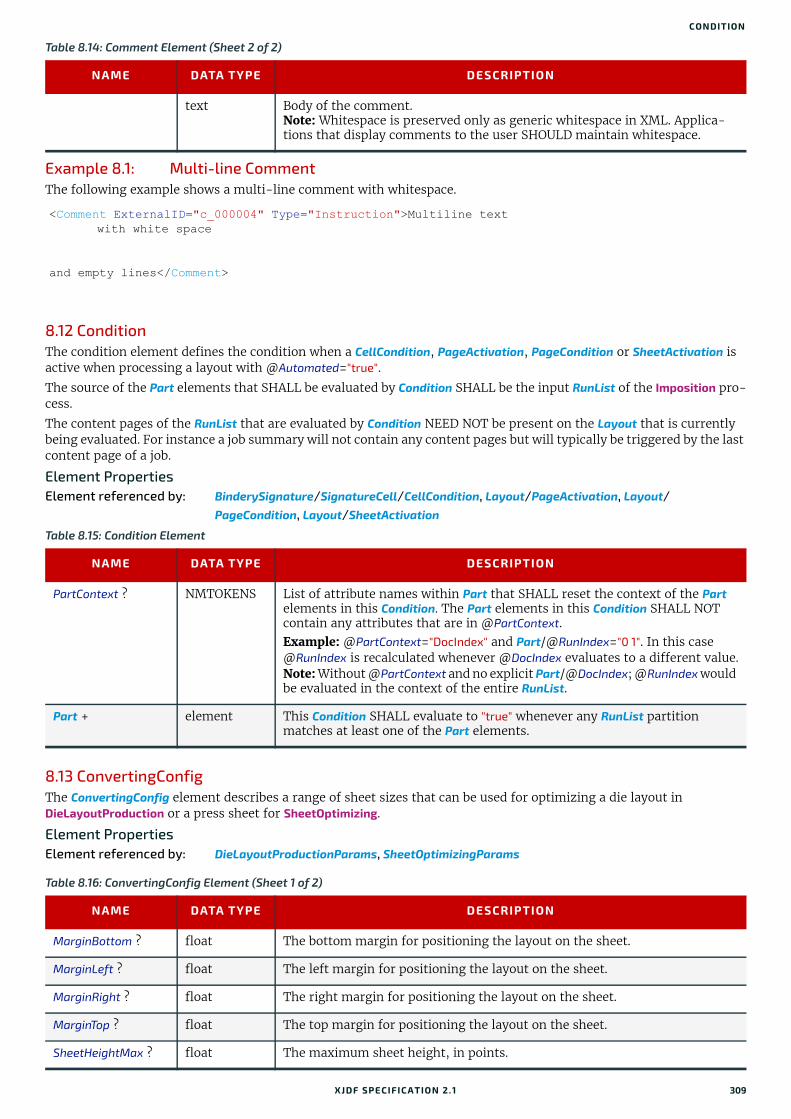
CONDITION
Example 8.1: Multi-line CommentThe following example shows a multi-line comment with whitespace.
8.12 ConditionThe condition element defines the condition when a CellCondition, PageActivation, PageCondition or SheetActivation is active when processing a layout with @Automated="true".
The source of the Part elements that SHALL be evaluated by Condition SHALL be the input RunList of the Imposition pro-cess.
The content pages of the RunList that are evaluated by Condition NEED NOT be present on the Layout that is currently being evaluated. For instance a job summary will not contain any content pages but will typically be triggered by the last content page of a job.
Element PropertiesElement referenced by: BinderySignature/SignatureCell/CellCondition, Layout/PageActivation, Layout/
PageCondition, Layout/SheetActivation
8.13 ConvertingConfigThe ConvertingConfig element describes a range of sheet sizes that can be used for optimizing a die layout in DieLayoutProduction or a press sheet for SheetOptimizing.
Element PropertiesElement referenced by: DieLayoutProductionParams, SheetOptimizingParams
text Body of the comment.Note: Whitespace is preserved only as generic whitespace in XML. Applica-tions that display comments to the user SHOULD maintain whitespace.
<Comment ExternalID="c_000004" Type="Instruction">Multiline textwith white space
and empty lines</Comment>
Table 8.15: Condition Element
NAME DATA TYPE DESCRIPTION
PartContext ? NMTOKENS List of attribute names within Part that SHALL reset the context of the Part elements in this Condition. The Part elements in this Condition SHALL NOT contain any attributes that are in @PartContext.Example: @PartContext="DocIndex" and Part/@RunIndex="0 1". In this case @RunIndex is recalculated whenever @DocIndex evaluates to a different value.Note: Without @PartContext and no explicit Part/@DocIndex; @RunIndex would be evaluated in the context of the entire RunList.
Part + element This Condition SHALL evaluate to "true" whenever any RunList partition matches at least one of the Part elements.
Table 8.16: ConvertingConfig Element (Sheet 1 of 2)
NAME DATA TYPE DESCRIPTION
MarginBottom ? float The bottom margin for positioning the layout on the sheet.
MarginLeft ? float The left margin for positioning the layout on the sheet.
MarginRight ? float The right margin for positioning the layout on the sheet.
MarginTop ? float The top margin for positioning the layout on the sheet.
SheetHeightMax ? float The maximum sheet height, in points.
Table 8.14: Comment Element (Sheet 2 of 2)
NAME DATA TYPE DESCRIPTION
XJDF SPECIFICATIO N 2.1 309
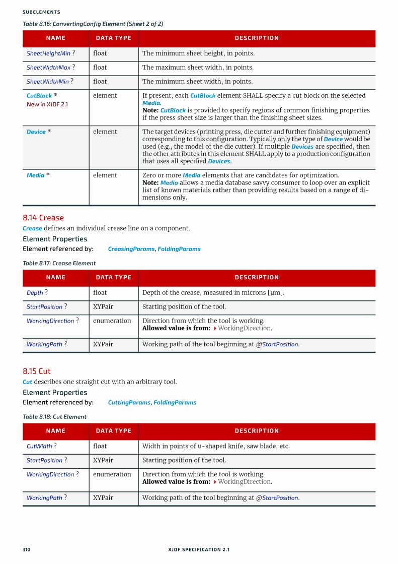
SUBELEMENTS
8.14 CreaseCrease defines an individual crease line on a component.
Element PropertiesElement referenced by: CreasingParams, FoldingParams
8.15 CutCut describes one straight cut with an arbitrary tool.
Element PropertiesElement referenced by: CuttingParams, FoldingParams
SheetHeightMin ? float The minimum sheet height, in points.
SheetWidthMax ? float The maximum sheet width, in points.
SheetWidthMin ? float The minimum sheet width, in points.
CutBlock *New in XJDF 2.1
element If present, each CutBlock element SHALL specify a cut block on the selected Media.Note: CutBlock is provided to specify regions of common finishing properties if the press sheet size is larger than the finishing sheet sizes.
Device * element The target devices (printing press, die cutter and further finishing equipment) corresponding to this configuration. Typically only the type of Device would be used (e.g., the model of the die cutter). If multiple Devices are specified, then the other attributes in this element SHALL apply to a production configuration that uses all specified Devices.
Media * element Zero or more Media elements that are candidates for optimization. Note: Media allows a media database savvy consumer to loop over an explicit list of known materials rather than providing results based on a range of di-mensions only.
Table 8.17: Crease Element
NAME DATA TYPE DESCRIPTION
Depth ? float Depth of the crease, measured in microns [µm].
StartPosition ? XYPair Starting position of the tool.
WorkingDirection ? enumeration Direction from which the tool is working. Allowed value is from: WorkingDirection.
WorkingPath ? XYPair Working path of the tool beginning at @StartPosition.
Table 8.18: Cut Element
NAME DATA TYPE DESCRIPTION
CutWidth ? float Width in points of u-shaped knife, saw blade, etc.
StartPosition ? XYPair Starting position of the tool.
WorkingDirection ? enumeration Direction from which the tool is working. Allowed value is from: WorkingDirection.
WorkingPath ? XYPair Working path of the tool beginning at @StartPosition.
Table 8.16: ConvertingConfig Element (Sheet 2 of 2)
NAME DATA TYPE DESCRIPTION
310 XJDF SPECIFICATIO N 2.1

CUTBLOCK
8.16 CutBlockCutBlock specifies exactly one cut block on a sheet. The CutBlock SHALL be defined in the coordinate system of the input Component.
Element PropertiesElement referenced by: ConvertingConfig, CuttingParams
8.17 CutMarkCutMark provides the means to position cut marks on the sheet. After printing, these marks can be used to adapt the theoretical block positions (as specified in CuttingParams/CutBlock) to the real position of the corresponding blocks on the printed sheet.
Element PropertiesElement referenced by: Layout/MarkObject, StripMark
8.18 EventThis element provides additional information for common events. Events are designed to enable devices to send indi-vidual event or error codes. These codes SHOULD NOT be used to transport status transitions or resource information that is standardized in DeviceInfo, ResourceInfo or their descendent elements.
Element PropertiesElement referenced by: DeviceInfo, Notification, ResourceInfo
Table 8.19: CutBlock Element
NAME DATA TYPE DESCRIPTION
BinderySignatureIDs ?
NMTOKENS If specified, @BinderySignatureIDs SHALL list the BinderySignature/@BinderySignatureID of all BinderySignatures that comprise this CutBlock.
BlockName NMTOKEN Name of the block. The output Component of the Cutting process SHALL be partitioned by @BlockName. The values of @BlockName SHALL match the value of this @BlockName.
Box ? rectangle Defines the position and size of the block relative to the parent Component coordinate system.
CutWidth ? float Width in points of the u-shaped knife, saw blade, etc.
DescriptiveName ?New in XJDF 2.1
string Human readable descriptive name of the CutBlock.
ExternalID ?New in XJDF 2.1
NMTOKEN External identifier of the CutBlock, e.g. in an MIS.
Operations ?New in XJDF 2.1
NMTOKENS List of finishing operations or properties that are common to the CutBlock. The values are implementation dependent and MAY depend on the specific details of the finishing process. See also GangElement/@Operations.
Table 8.20: CutMark Element
NAME DATA TYPE DESCRIPTION
MarkType enumeration Cut mark type. Allowed value is from: CutMarkType.
Position XYPair Position of the logical center of the cut mark in the coordinates of the object that contains this mark.Note: The logical center of the cut mark does not always coincide with the center of the visible cut mark symbol.
XJDF SPECIFICATIO N 2.1 311
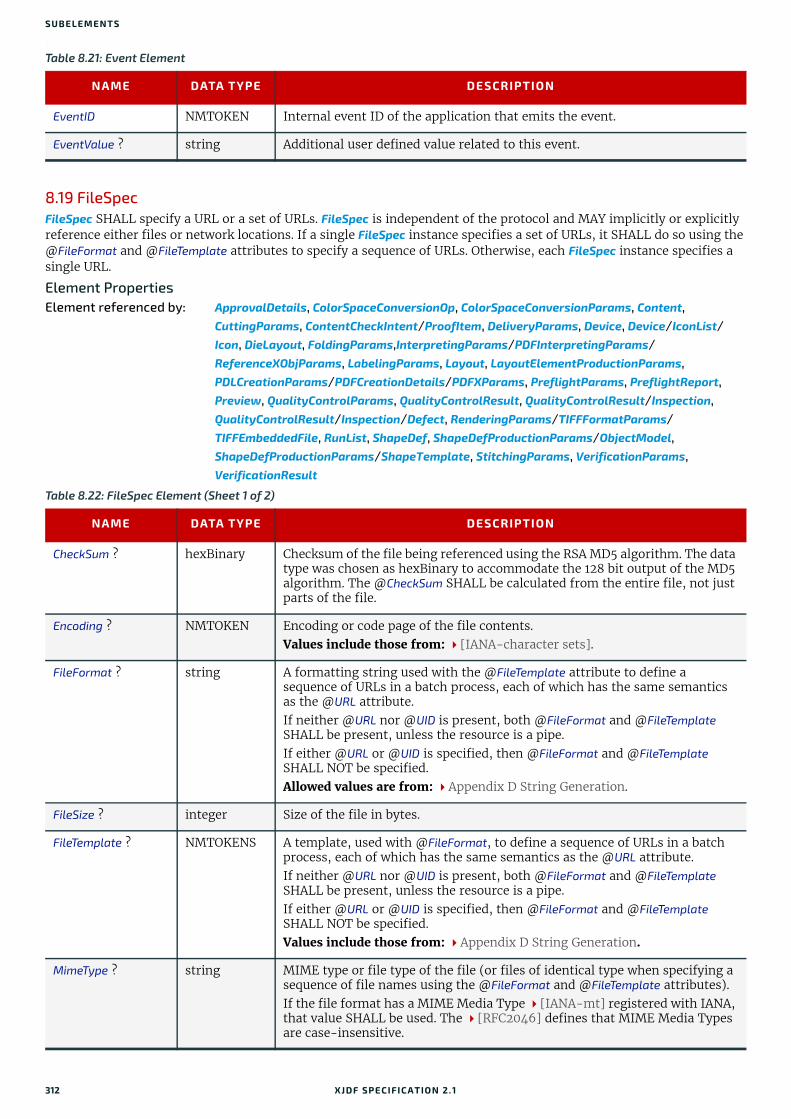
SUBELEMENTS
.
8.19 FileSpecFileSpec SHALL specify a URL or a set of URLs. FileSpec is independent of the protocol and MAY implicitly or explicitly reference either files or network locations. If a single FileSpec instance specifies a set of URLs, it SHALL do so using the @FileFormat and @FileTemplate attributes to specify a sequence of URLs. Otherwise, each FileSpec instance specifies a single URL.
Element PropertiesElement referenced by: ApprovalDetails, ColorSpaceConversionOp, ColorSpaceConversionParams, Content,
CuttingParams, ContentCheckIntent/ProofItem, DeliveryParams, Device, Device/IconList/Icon, DieLayout, FoldingParams,InterpretingParams/PDFInterpretingParams/ReferenceXObjParams, LabelingParams, Layout, LayoutElementProductionParams, PDLCreationParams/PDFCreationDetails/PDFXParams, PreflightParams, PreflightReport, Preview, QualityControlParams, QualityControlResult, QualityControlResult/Inspection, QualityControlResult/Inspection/Defect, RenderingParams/TIFFFormatParams/TIFFEmbeddedFile, RunList, ShapeDef, ShapeDefProductionParams/ObjectModel, ShapeDefProductionParams/ShapeTemplate, StitchingParams, VerificationParams, VerificationResult
Table 8.21: Event Element
NAME DATA TYPE DESCRIPTION
EventID NMTOKEN Internal event ID of the application that emits the event.
EventValue ? string Additional user defined value related to this event.
Table 8.22: FileSpec Element (Sheet 1 of 2)
NAME DATA TYPE DESCRIPTION
CheckSum ? hexBinary Checksum of the file being referenced using the RSA MD5 algorithm. The data type was chosen as hexBinary to accommodate the 128 bit output of the MD5 algorithm. The @CheckSum SHALL be calculated from the entire file, not just parts of the file.
Encoding ? NMTOKEN Encoding or code page of the file contents. Values include those from: [IANA-character sets].
FileFormat ? string A formatting string used with the @FileTemplate attribute to define a sequence of URLs in a batch process, each of which has the same semantics as the @URL attribute.If neither @URL nor @UID is present, both @FileFormat and @FileTemplate SHALL be present, unless the resource is a pipe.If either @URL or @UID is specified, then @FileFormat and @FileTemplate SHALL NOT be specified. Allowed values are from: Appendix D String Generation.
FileSize ? integer Size of the file in bytes.
FileTemplate ? NMTOKENS A template, used with @FileFormat, to define a sequence of URLs in a batch process, each of which has the same semantics as the @URL attribute. If neither @URL nor @UID is present, both @FileFormat and @FileTemplate SHALL be present, unless the resource is a pipe. If either @URL or @UID is specified, then @FileFormat and @FileTemplate SHALL NOT be specified. Values include those from: Appendix D String Generation.
MimeType ? string MIME type or file type of the file (or files of identical type when specifying a sequence of file names using the @FileFormat and @FileTemplate attributes).If the file format has a MIME Media Type [IANA-mt] registered with IANA, that value SHALL be used. The [RFC2046] defines that MIME Media Types are case-insensitive.
312 XJDF SPECIFICATIO N 2.1
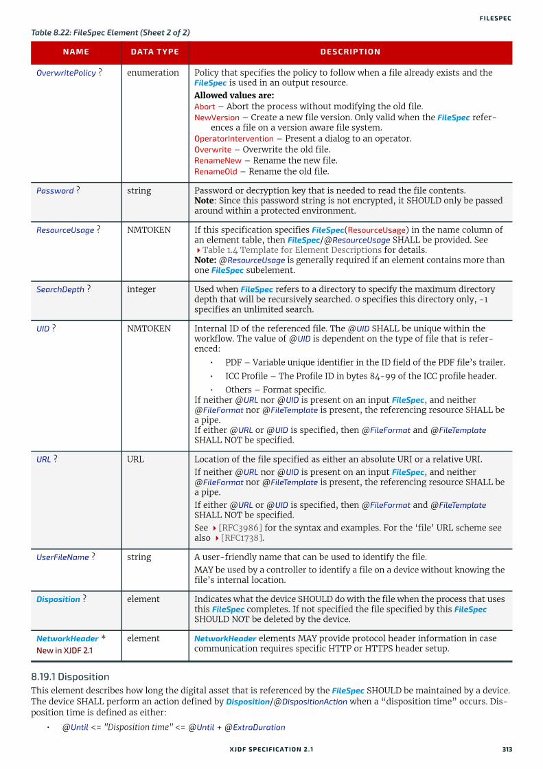
FILESPEC
8.19.1 DispositionThis element describes how long the digital asset that is referenced by the FileSpec SHOULD be maintained by a device. The device SHALL perform an action defined by Disposition/@DispositionAction when a “disposition time” occurs. Dis-position time is defined as either:
• @Until <= "Disposition time" <= @Until + @ExtraDuration
OverwritePolicy ? enumeration Policy that specifies the policy to follow when a file already exists and the FileSpec is used in an output resource. Allowed values are: Abort – Abort the process without modifying the old file.NewVersion – Create a new file version. Only valid when the FileSpec refer-
ences a file on a version aware file system.OperatorIntervention – Present a dialog to an operator.Overwrite – Overwrite the old file.RenameNew – Rename the new file.RenameOld – Rename the old file.
Password ? string Password or decryption key that is needed to read the file contents.Note: Since this password string is not encrypted, it SHOULD only be passed around within a protected environment.
ResourceUsage ? NMTOKEN If this specification specifies FileSpec(ResourceUsage) in the name column of an element table, then FileSpec/@ResourceUsage SHALL be provided. See Table 1.4 Template for Element Descriptions for details.Note: @ResourceUsage is generally required if an element contains more than one FileSpec subelement.
SearchDepth ? integer Used when FileSpec refers to a directory to specify the maximum directory depth that will be recursively searched. 0 specifies this directory only, -1 specifies an unlimited search.
UID ? NMTOKEN Internal ID of the referenced file. The @UID SHALL be unique within the workflow. The value of @UID is dependent on the type of file that is refer-enced:
• PDF – Variable unique identifier in the ID field of the PDF file’s trailer.
• ICC Profile – The Profile ID in bytes 84-99 of the ICC profile header.
• Others – Format specific.If neither @URL nor @UID is present on an input FileSpec, and neither @FileFormat nor @FileTemplate is present, the referencing resource SHALL be a pipe. If either @URL or @UID is specified, then @FileFormat and @FileTemplate SHALL NOT be specified.
URL ? URL Location of the file specified as either an absolute URI or a relative URI. If neither @URL nor @UID is present on an input FileSpec, and neither @FileFormat nor @FileTemplate is present, the referencing resource SHALL be a pipe.If either @URL or @UID is specified, then @FileFormat and @FileTemplate SHALL NOT be specified. See [RFC3986] for the syntax and examples. For the ‘file’ URL scheme see also [RFC1738].
UserFileName ? string A user-friendly name that can be used to identify the file. MAY be used by a controller to identify a file on a device without knowing the file’s internal location.
Disposition ? element Indicates what the device SHOULD do with the file when the process that uses this FileSpec completes. If not specified the file specified by this FileSpec SHOULD NOT be deleted by the device.
NetworkHeader *New in XJDF 2.1
element NetworkHeader elements MAY provide protocol header information in case communication requires specific HTTP or HTTPS header setup.
Table 8.22: FileSpec Element (Sheet 2 of 2)
NAME DATA TYPE DESCRIPTION
XJDF SPECIFICATIO N 2.1 313

SUBELEMENTS
• ProcessCompleteTime + @MinDuration <= "Disposition time" <= ProcessCompleteTime + @MinDuration+ @ExtraDuration
8.19.2 NetworkHeaderNew in XJDF 2.1
NetworkHeader elements MAY provide protocol header information in case communication requires specific HTTP or HTTPS header setup. Examples include authentication using bearer tokens, see [RFC6750].
8.20 FitPolicyThis element specifies how to fit content into a receiving container (e.g., a page onto a ContentObject of an imposed sheet). See the description of each reference to FitPolicy to determine what the context-specific content is and what the receiving containers are.
Element PropertiesElement referenced by: InterpretingParams, Layout, RasterReadingParams
Table 8.23: Disposition Element
NAME DATA TYPE DESCRIPTION
DispositionAction ? enumeration @DispositionAction specifies the required disposal action for the asset.Allowed values are: Archive – The asset SHALL be archived when disposition time occurs.Delete – The asset SHALL be deleted when disposition time occurs.
ExtraDuration ? duration Indicates the maximum duration that the device SHALL retain the asset after the time specified by @MinDuration or @Until. If @ExtraDuration, @MinDuration and @Until are all unspecified, the asset MAY be retained for a system specified time.
MinDuration ? duration Indicates the minimum duration for which the device SHOULD retain the asset after the process that uses the asset completes. @MinDuration SHALL NOT be specified if @Until is present.
Priority ? integer Value between 0 and 100 that specifies the order in which assets SHALL be deleted or archived when the values of @ExtraDuration, @MinDuration and @Until cannot be honored (e.g., when local storage runs low). Assets with @Priority = "0" SHALL be deleted first.
Until ? dateTime Indicates an absolute point in time when the device or application SHOULD discard the asset. @Until SHALL NOT be specified if @MinDuration is present.
Table 8.24: Header Element
NAME DATA TYPE DESCRIPTION
Name string Name of the header excluding any required protocol dependent syntax ele-ments or characters, e.g. ":", ";", "." or "=".
Value string Value of the header.
Table 8.25: FitPolicy Element (Sheet 1 of 3)
NAME DATA TYPE DESCRIPTION
ClipOffset ? XYPair Defines the offset (position) of the imaged area in the non-rotated source image when @SizePolicy is "ClipToMaxPage". The values "0.0 0.0" mean that the imaged area starts at the lower left point of the receiving container. If absent, the imaged area SHALL be taken from the center of the source image.
314 XJDF SPECIFICATIO N 2.1
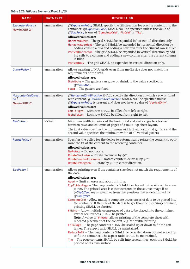
FITPOLICY
ExpansionPolicy ?New in XJDF 2.1
enumeration @ExpansionPolicy SHALL specify the fill direction for placing content into the container. @ExpansionPolicy SHALL NOT be specified unless the value of @SizePolicy is one of "CompleteGrid", "FillGrid" or "Tile".Allowed values are:HorizontalOnly - The grid SHALL be expanded in horizontal direction only.HorizontalVertical - The grid SHALL be expanded in horizontal direction by
adding cells to a row and adding a new row after the current row is filled.VerticalHorizontal - The grid SHALL be expanded in vertical direction by add-
ing cells to a column and adding a new column after the current column is filled.
VerticalOnly - The grid SHALL be expanded in vertical direction only.
GutterPolicy ? enumeration Allows printing of NUp grids even if the media size does not match the requirements of the data.Allowed values are: Distribute – The gutters can grow or shrink to the value specified in
@MinGutter.Fixed – The gutters are fixed.
HorizontalGridDirection ?New in XJDF 2.1
enumeration @HorizontalGridDirection SHALL specify the direction in which a row is filled with content. @HorizontalGridDirection SHALL NOT be specified unless @ExpansionPolicy is present and does not have a value of "VerticalOnly".Allowed values are:LeftToRight - Each row SHALL be filled from left to right.RightToLeft - Each row SHALL be filled from right to left.
MinGutter ? XYPair Minimum width in points of the horizontal and vertical gutters formed between rows and columns of pages of a multi-up sheet layout. The first value specifies the minimum width of all horizontal gutters and the second value specifies the minimum width of all vertical gutters.
RotatePolicy ? enumeration Specifies the policy for the device to automatically rotate the content to opti-mize the fit of the content to the receiving container.Allowed values are: NoRotate – Do not rotate.RotateClockwise – Rotate clockwise by 90°.RotateCounterClockwise – Rotate counterclockwise by 90°.RotateOrthogonal – Rotate by 90° in either direction.
SizePolicy ? enumeration Allows printing even if the container size does not match the requirements of the data. Allowed values are: Abort – Emit an error and abort printing.ClipToMaxPage – The page contents SHALL be clipped to the size of the con-
tainer. The printed area is either centered in the source image if no @ClipOffset key is given, or from that position that is determined by @ClipOffset.
CompleteGrid - Allow multiple complete occurrences of data to be placed into the container. If the size of the data is larger than the receiving container, printing SHALL be aborted.
FillGrid - Allow multiple occurrences of data to be placed into the container. Partial occurrences SHALL be printed. Note: A value of "FillGrid" allows printing of the complete sheet with repeated placement of the content, e.g. for textile printing.
FitToPage – The page contents SHALL be scaled up or down to fit the con-tainer. The aspect ratio SHALL be maintained.
ReduceToFit – The page contents SHALL be be scaled down but not scaled up to fit the container. The aspect ratio SHALL be maintained.
Tile – The page contents SHALL be split into several tiles, each tile SHALL be printed on its own surface.
Table 8.25: FitPolicy Element (Sheet 2 of 3)
NAME DATA TYPE DESCRIPTION
XJDF SPECIFICATIO N 2.1 315

SUBELEMENTS
8.21 FoldFold describes an individual folding operation of the Component.
Element PropertiesElement referenced by: FoldingIntent, FoldingParams
8.22 GangSourceGangSource provides source job information about a BinderySignature that is placed on a gang form.
Element PropertiesElement referenced by: JobPhase, QueueFilter, QueueEntry, NodeInfo
8.23 GeneralIDGeneralID describes a generic identifier. The name or usage of the identifier is specified in GeneralID/@IDUsage and the specific value of the variable is specified in GeneralID/@IDValue. The data type is specified in GeneralID/@DataType.
Although GeneralID could technically be used to describe arbitrary proprietary data, this is strongly discouraged as it is non interoperable. Proprietary extensions SHOULD be avoided if possible, or if absolutely required, they MAY be imple-mented in proprietary namespaces.
Element PropertiesElement referenced by: XJDF, ResourceSet, Product, Resource, Content, PreflightParams/PreflightTest,
PreflightReport/PreflightCheck
VerticalGridDirection ?New in XJDF 2.1
enumeration @VerticalGridDirection SHALL specify the direction in which a column is filled with content. @VerticalGridDirection SHALL NOT be specified unless @ExpansionPolicy is present and does not have a value of "HorizontalOnly".Allowed values are:BottomToTop - Each column SHALL be filled from bottom to top.TopToBottom - Each column SHALL be filled from top to bottom.
Table 8.26: Fold Element
NAME DATA TYPE DESCRIPTION
From enumeration Edge from which the page SHALL be folded. Allowed values are: Front Left
To enumeration Direction in which the page SHALL be folded. Allowed values are: Up – Upwards; corresponds to a valley fold with the left/bottom side coming
over the opposite side.Down – Downwards; corresponds to a mountain or peak fold with the left/
bottom side coming under the opposite side.
Travel ? float Distance of the reference edge relative to @From.
Table 8.27: GangSource Element
NAME DATA TYPE DESCRIPTION
BinderySignatureID ? NMTOKEN If present, @BinderySignatureID SHALL reference the BinderySignature that this GangSource represents.
Copies integer @Copies SHALL specify the number of copies of the BinderySignature that are required.
JobID NMTOKEN @JobID SHALL reference XJDF/@JobID of the individual job that describes the processing prior to and after printing and cutting the gang sheet.
Table 8.25: FitPolicy Element (Sheet 3 of 3)
NAME DATA TYPE DESCRIPTION
316 XJDF SPECIFICATIO N 2.1
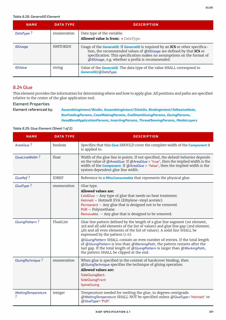
GLUE
8.24 GlueThis element provides the information for determining where and how to apply glue. All positions and paths are specified relative to the center of the glue application tool.
Element PropertiesElement referenced by: AssemblingIntent/BindIn, AssemblingIntent/StickOn, BindingIntent/AdhesiveNote,
BoxFoldingParams, CaseMakingParams, EndSheetGluingParams, GluingParams, HeadBandApplicationParams, InsertingParams, ThreadSewingParams, MediaLayers
Table 8.28: GeneralID Element
NAME DATA TYPE DESCRIPTION
DataType ? enumeration Data type of the variable. Allowed value is from: DataType.
IDUsage NMTOKEN Usage of the GeneralID. If GeneralID is required by an ICS or other specifica-tion, the recommended values of @IDUsage are defined by that ICS or specification. This specification makes no assumptions on the format of @IDUsage, e.g. whether a prefix is recommended.
IDValue string Value of the GeneralID. The data type of the value SHALL correspond to GeneralID/@DataType.
Table 8.29: Glue Element (Sheet 1 of 2)
NAME DATA TYPE DESCRIPTION
AreaGlue ? boolean Specifies that this Glue SHOULD cover the complete width of the Component it is applied to.
GlueLineWidth ? float Width of the glue line in points. If not specified, the default behavior depends on the value of @AreaGlue: If @AreaGlue = "true", then the implied width is the width of the Component. If @AreaGlue = "false", then the implied width is the system dependent glue line width.
GlueRef ? IDREF Reference to a MiscConsumable that represents the physical glue.
GlueType ? enumeration Glue type. Allowed values are: ColdGlue – Any type of glue that needs no heat treatment.Hotmelt – Hotmelt EVA (Ethylene-vinyl acetate). Permanent – Any glue that is designed not to be removed.PUR – Polyurethane. Removable – Any glue that is designed to be removed.
GluingPattern ? FloatList Glue line pattern defined by the length of a glue line segment (1st element, 3rd and all odd elements of the list of values) and glue line gap (2nd element, 4th and all even elements of the list of values). A solid line SHALL be expressed by the pattern (1 0).@GluingPattern SHALL contain an even number of entries. If the total length of @GluingPattern is less than @WorkingPath, the pattern restarts after the last gap. If the total length of @GluingPattern is larger than @WorkingPath, the pattern SHALL be clipped at the end.
GluingTechnique ? enumeration When glue is specified in the context of hardcover binding, then @GluingTechnique specifies the technique of gluing operation.Allowed values are: SideGluingBackSideGluingFrontSpineGluing
MeltingTemperature ?
integer Temperature needed for melting the glue, in degrees centigrade. @MeltingTemperature SHALL NOT be specified unless @GlueType="Hotmelt" or @GlueType="PUR".
XJDF SPECIFICATIO N 2.1 317
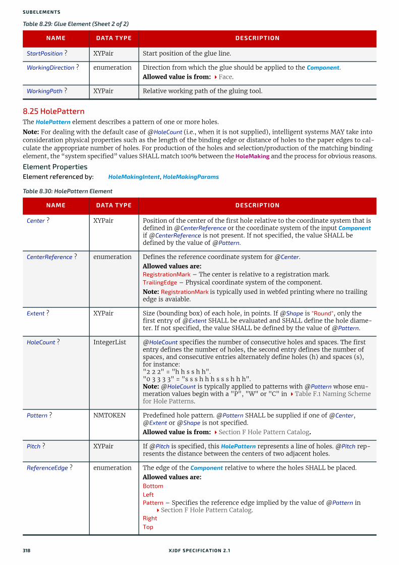
SUBELEMENTS
8.25 HolePatternThe HolePattern element describes a pattern of one or more holes.
Note: For dealing with the default case of @HoleCount (i.e., when it is not supplied), intelligent systems MAY take into consideration physical properties such as the length of the binding edge or distance of holes to the paper edges to cal-culate the appropriate number of holes. For production of the holes and selection/production of the matching binding element, the “system specified” values SHALL match 100% between the HoleMaking and the process for obvious reasons.
Element PropertiesElement referenced by: HoleMakingIntent, HoleMakingParams
StartPosition ? XYPair Start position of the glue line.
WorkingDirection ? enumeration Direction from which the glue should be applied to the Component.Allowed value is from: Face.
WorkingPath ? XYPair Relative working path of the gluing tool.
Table 8.30: HolePattern Element
NAME DATA TYPE DESCRIPTION
Center ? XYPair Position of the center of the first hole relative to the coordinate system that is defined in @CenterReference or the coordinate system of the input Component if @CenterReference is not present. If not specified, the value SHALL be defined by the value of @Pattern.
CenterReference ? enumeration Defines the reference coordinate system for @Center.Allowed values are: RegistrationMark – The center is relative to a registration mark.TrailingEdge – Physical coordinate system of the component.Note: RegistrationMark is typically used in webfed printing where no trailing edge is avaiable.
Extent ? XYPair Size (bounding box) of each hole, in points. If @Shape is "Round", only the first entry of @Extent SHALL be evaluated and SHALL define the hole diame-ter. If not specified, the value SHALL be defined by the value of @Pattern.
HoleCount ? IntegerList @HoleCount specifies the number of consecutive holes and spaces. The first entry defines the number of holes, the second entry defines the number of spaces, and consecutive entries alternately define holes (h) and spaces (s), for instance:"2 2 2" = "h h s s h h"."0 3 3 3 3" = "s s s h h h s s s h h h".Note: @HoleCount is typically applied to patterns with @Pattern whose enu-meration values begin with a "P", "W" or "C" in Table F.1 Naming Scheme for Hole Patterns.
Pattern ? NMTOKEN Predefined hole pattern. @Pattern SHALL be supplied if one of @Center, @Extent or @Shape is not specified.Allowed value is from: Section F Hole Pattern Catalog.
Pitch ? XYPair If @Pitch is specified, this HolePattern represents a line of holes. @Pitch rep-resents the distance between the centers of two adjacent holes.
ReferenceEdge ? enumeration The edge of the Component relative to where the holes SHALL be placed.Allowed values are: BottomLeftPattern – Specifies the reference edge implied by the value of @Pattern in Section F Hole Pattern Catalog.
RightTop
Table 8.29: Glue Element (Sheet 2 of 2)
NAME DATA TYPE DESCRIPTION
318 XJDF SPECIFICATIO N 2.1
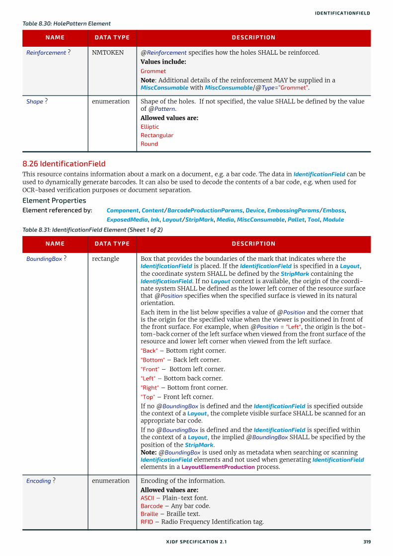
IDENTIFICATIONFIELD
8.26 IdentificationFieldThis resource contains information about a mark on a document, e.g. a bar code. The data in IdentificationField can be used to dynamically generate barcodes. It can also be used to decode the contents of a bar code, e.g. when used for OCR-based verification purposes or document separation.
Element PropertiesElement referenced by: Component, Content/BarcodeProductionParams, Device, EmbossingParams/Emboss,
ExposedMedia, Ink, Layout/StripMark, Media, MiscConsumable, Pallet, Tool, Module
Reinforcement ? NMTOKEN @Reinforcement specifies how the holes SHALL be reinforced.Values include: Grommet
Note: Additional details of the reinforcement MAY be supplied in a MiscConsumable with MiscConsumable/@Type=”Grommet”.
Shape ? enumeration Shape of the holes. If not specified, the value SHALL be defined by the value of @Pattern.Allowed values are: Elliptic RectangularRound
Table 8.31: IdentificationField Element (Sheet 1 of 2)
NAME DATA TYPE DESCRIPTION
BoundingBox ? rectangle Box that provides the boundaries of the mark that indicates where the IdentificationField is placed. If the IdentificationField is specified in a Layout, the coordinate system SHALL be defined by the StripMark containing the IdentificationField. If no Layout context is available, the origin of the coordi-nate system SHALL be defined as the lower left corner of the resource surface that @Position specifies when the specified surface is viewed in its natural orientation. Each item in the list below specifies a value of @Position and the corner that is the origin for the specified value when the viewer is positioned in front of the front surface. For example, when @Position = "Left", the origin is the bot-tom-back corner of the left surface when viewed from the front surface of the resource and lower left corner when viewed from the left surface. "Back" – Bottom right corner."Bottom" – Back left corner."Front" – Bottom left corner."Left" – Bottom back corner."Right" – Bottom front corner."Top" – Front left corner.If no @BoundingBox is defined and the IdentificationField is specified outside the context of a Layout, the complete visible surface SHALL be scanned for an appropriate bar code.If no @BoundingBox is defined and the IdentificationField is specified within the context of a Layout, the implied @BoundingBox SHALL be specified by the position of the StripMark.Note: @BoundingBox is used only as metadata when searching or scanning IdentificationField elements and not used when generating IdentificationField elements in a LayoutElementProduction process.
Encoding ? enumeration Encoding of the information. Allowed values are: ASCII – Plain-text font.Barcode – Any bar code.Braille – Braille text.RFID – Radio Frequency Identification tag.
Table 8.30: HolePattern Element
NAME DATA TYPE DESCRIPTION
XJDF SPECIFICATIO N 2.1 319
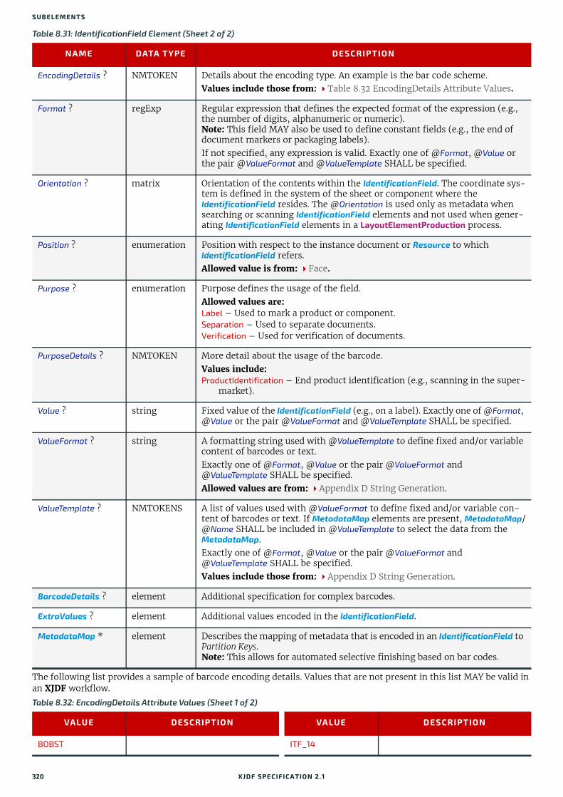
SUBELEMENTS
The following list provides a sample of barcode encoding details. Values that are not present in this list MAY be valid in an XJDF workflow.
EncodingDetails ? NMTOKEN Details about the encoding type. An example is the bar code scheme. Values include those from: Table 8.32 EncodingDetails Attribute Values.
Format ? regExp Regular expression that defines the expected format of the expression (e.g., the number of digits, alphanumeric or numeric).Note: This field MAY also be used to define constant fields (e.g., the end of document markers or packaging labels).If not specified, any expression is valid. Exactly one of @Format, @Value or the pair @ValueFormat and @ValueTemplate SHALL be specified.
Orientation ? matrix Orientation of the contents within the IdentificationField. The coordinate sys-tem is defined in the system of the sheet or component where the IdentificationField resides. The @Orientation is used only as metadata when searching or scanning IdentificationField elements and not used when gener-ating IdentificationField elements in a LayoutElementProduction process.
Position ? enumeration Position with respect to the instance document or Resource to which IdentificationField refers.Allowed value is from: Face.
Purpose ? enumeration Purpose defines the usage of the field.Allowed values are: Label – Used to mark a product or component.Separation – Used to separate documents.Verification – Used for verification of documents.
PurposeDetails ? NMTOKEN More detail about the usage of the barcode.Values include:ProductIdentification – End product identification (e.g., scanning in the super-
market).
Value ? string Fixed value of the IdentificationField (e.g., on a label). Exactly one of @Format, @Value or the pair @ValueFormat and @ValueTemplate SHALL be specified.
ValueFormat ? string A formatting string used with @ValueTemplate to define fixed and/or variable content of barcodes or text. Exactly one of @Format, @Value or the pair @ValueFormat and @ValueTemplate SHALL be specified.Allowed values are from: Appendix D String Generation.
ValueTemplate ? NMTOKENS A list of values used with @ValueFormat to define fixed and/or variable con-tent of barcodes or text. If MetadataMap elements are present, MetadataMap/@Name SHALL be included in @ValueTemplate to select the data from the MetadataMap.Exactly one of @Format, @Value or the pair @ValueFormat and @ValueTemplate SHALL be specified.Values include those from: Appendix D String Generation.
BarcodeDetails ? element Additional specification for complex barcodes.
ExtraValues ? element Additional values encoded in the IdentificationField.
MetadataMap * element Describes the mapping of metadata that is encoded in an IdentificationField to Partition Keys.Note: This allows for automated selective finishing based on bar codes.
Table 8.32: EncodingDetails Attribute Values (Sheet 1 of 2)
VALUE DESCRIPTION VALUE DESCRIPTION
BOBST ITF_14
Table 8.31: IdentificationField Element (Sheet 2 of 2)
NAME DATA TYPE DESCRIPTION
320 XJDF SPECIFICATIO N 2.1
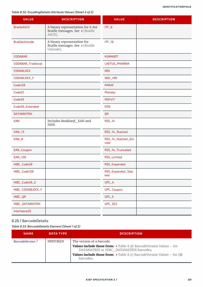
IDENTIFICATIONFIELD
8.26.1 BarcodeDetails
BrailleASCII A binary representation for 6 dot Braille messages. See [Braille ASCII].
ITF_6
BrailleUnicode A binary representation for Braille messages. See [Braille Unicode].
ITF_16
CODABAR KURANDT
CODABAR_Tradional LAETUS_PHARMA
CODABLOCK MSI
CODABLOCK_F NDC_HRI
Code128 PARAF
Code25 Plessey
Code39 PDF417
Code39_Extended PZN
DATAMATRIX QR
EAN Includes Bookland_EAN and ISSN.
RSS_14
EAN_13 RSS_14_Stacked
EAN_8 RSS_14_Stacked_Omnidir
EAN_Coupon RSS_14_Truncated
EAN_128 RSS_Limited
HIBC_Code39 RSS_Expanded
HIBC_Code128 RSS_Expanded_Stacked
HIBC_Code39_2 UPC_A
HIBC_CODABLOCK_F UPC_Coupon
HIBC_QR UPC_E
HIBC_DATAMATRIX UPC_SCS
Interleave25
Table 8.33: BarcodeDetails Element (Sheet 1 of 2)
NAME DATA TYPE DESCRIPTION
BarcodeVersion ? NMTOKEN The version of a barcode. Values include those from: Table 8.36 BarcodeVersion Values – for
DATAMATRIX or HIBC_DATAMATRIX barcodes.Values include those from: Table 8.37 BarcodeVersion Values – for QR
barcodes.
Table 8.32: EncodingDetails Attribute Values (Sheet 2 of 2)
VALUE DESCRIPTION VALUE DESCRIPTION
XJDF SPECIFICATIO N 2.1 321
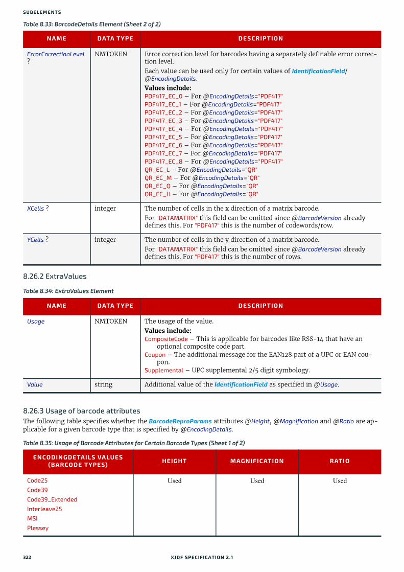
SUBELEMENTS
8.26.2 ExtraValues
8.26.3 Usage of barcode attributesThe following table specifies whether the BarcodeReproParams attributes @Height, @Magnification and @Ratio are ap-plicable for a given barcode type that is specified by @EncodingDetails.
ErrorCorrectionLevel ?
NMTOKEN Error correction level for barcodes having a separately definable error correc-tion level.Each value can be used only for certain values of IdentificationField/@EncodingDetails.Values include:PDF417_EC_0 – For @EncodingDetails="PDF417"PDF417_EC_1 – For @EncodingDetails="PDF417"PDF417_EC_2 – For @EncodingDetails="PDF417"PDF417_EC_3 – For @EncodingDetails="PDF417"PDF417_EC_4 – For @EncodingDetails="PDF417"PDF417_EC_5 – For @EncodingDetails="PDF417"PDF417_EC_6 – For @EncodingDetails="PDF417"PDF417_EC_7 – For @EncodingDetails="PDF417"PDF417_EC_8 – For @EncodingDetails="PDF417"QR_EC_L – For @EncodingDetails="QR"QR_EC_M – For @EncodingDetails="QR"QR_EC_Q – For @EncodingDetails="QR"QR_EC_H – For @EncodingDetails="QR"
XCells ? integer The number of cells in the x direction of a matrix barcode. For "DATAMATRIX" this field can be omitted since @BarcodeVersion already defines this. For "PDF417" this is the number of codewords/row.
YCells ? integer The number of cells in the y direction of a matrix barcode.For "DATAMATRIX" this field can be omitted since @BarcodeVersion already defines this. For "PDF417" this is the number of rows.
Table 8.34: ExtraValues Element
NAME DATA TYPE DESCRIPTION
Usage NMTOKEN The usage of the value. Values include:CompositeCode – This is applicable for barcodes like RSS-14 that have an
optional composite code part.Coupon – The additional message for the EAN128 part of a UPC or EAN cou-
pon.Supplemental – UPC supplemental 2/5 digit symbology.
Value string Additional value of the IdentificationField as specified in @Usage.
Table 8.35: Usage of Barcode Attributes for Certain Barcode Types (Sheet 1 of 2)
ENCODINGDETAILS VALUES (BARCODE TYPES) HEIGHT MAGNIFICATION RATIO
Code25
Code39
Code39_Extended
Interleave25
MSI
Plessey
Used Used Used
Table 8.33: BarcodeDetails Element (Sheet 2 of 2)
NAME DATA TYPE DESCRIPTION
322 XJDF SPECIFICATIO N 2.1

IDENTIFICATIONFIELD
The following table specifies valid values of BarcodeDetails/@BarcodeVersion for DATAMATRIX or HIBC_DATAMATRIX barcode.
The following table specifies valid values of BarcodeDetails/@BarcodeVersion for a QR barcode.
CODABAR
Code128
EAN_128
EAN_13
EAN_8
HIBC_Code39
HIBC_Code128
ITF_14
ITF_16
NDC_HRI
PARAF
UPC_A
UPC_E
UPC_SCS
Used Used Not used
BOBST
KURANDT
LAETUS_PHARMA
Used Not used Not used
RSS_14
RSS_14_Stacked
RSS_14_Stacked_Omnidir
RSS_14_Truncated
RSS_Limited
RSS_Expanded
RSS_Expanded_Stacked
Not used Used Not used
PZN Not used Not used Not used
Table 8.36: BarcodeVersion Values – for DATAMATRIX or HIBC_DATAMATRIX barcodes
VALUES
DM_8_by_18 DM_16_by_16 DM_26_by_26 DM_72_by_72
DM_8_by_32 DM_16_by_36 DM_32_by_32 DM_80_by_80
DM_10_by_10 DM_16_by_48 DM_40_by_40 DM_88_by_88
DM_12_by_12 DM_18_by_18 DM_44_by_44 DM_96_by_96
DM_12_by_26 DM_20_by_20 DM_48_by_48 DM_104_by_104
DM_12_by_36 DM_22_by_22 DM_52_by_52 DM_120_by_120
DM_14_by_14 DM_24_by_24 DM_64_by_64 DM_132_by_132
DM_144_by_144
Table 8.37: BarcodeVersion Values – for QR barcodes (Sheet 1 of 2)
VALUES
QR_1 QR_6 QR_11 QR_16 QR_21 QR_26 QR_31 QR_36
QR_2 QR_7 QR_12 QR_17 QR_22 QR_27 QR_32 QR_37
Table 8.35: Usage of Barcode Attributes for Certain Barcode Types (Sheet 2 of 2)
ENCODINGDETAILS VALUES (BARCODE TYPES) HEIGHT MAGNIFICATION RATIO
XJDF SPECIFICATIO N 2.1 323

SUBELEMENTS
Example 8.2: BarcodeThe following example illustrates the description of a barcode in a LayoutElementProduction process.
8.27 ImageCompressionImageCompression specifies image compression properties of individual types of images.
Element PropertiesElement referenced by: Content, ImageCompressionParams
QR_3 QR_8 QR_13 QR_18 QR_23 QR_28 QR_33 QR_38
QR_4 QR_9 QR_14 QR_19 QR_24 QR_29 QR_34 QR_39
QR_5 QR_10 QR_15 QR_20 QR_25 QR_30 QR_35 QR_40
<XJDF xmlns="http://www.CIP4.org/JDFSchema_2_0" JobID="LayoutElementProduction" JobPartID="Barcode" Types="LayoutElementProduction"> <ResourceSet Name="LayoutElementProductionParams" Usage="Input"> <Resource> <LayoutElementProductionParams ContentRefs="r_000007"/> </Resource> </ResourceSet> <ResourceSet Name="Content"> <Resource ID="r_000007"> <Content ContentType="Page"> <BarcodeProductionParams> <BarcodeReproParams Height="73.5" Magnification="1"> <BarcodeCompParams CompensationProcess="Printing" CompensationValue="10"/> </BarcodeReproParams> <IdentificationField Encoding="Barcode" EncodingDetails="EAN_13" Purpose="Label" PurposeDetails="ProductIdentification" Value="0123456789128"/> </BarcodeProductionParams> </Content> </Resource> </ResourceSet></XJDF>
Table 8.38: ImageCompression Element (Sheet 1 of 3)
NAME DATA TYPE DESCRIPTION
AntiAliasImages ? boolean If "true", anti-aliasing is permitted on images. If "false", anti-aliasing is not permitted.Anti-aliasing increases the number of bits per component in downsampled images to preserve some of the information that would otherwise be lost by downsampling. Anti-aliasing is only performed if the image is actually downsampled and if @ImageDepth has a value greater than the number of bits per color component in the input image.
AutoFilterImages ? boolean If "true", the filter defined by @ImageAutoFilterStrategy is applied to photos and the zip compression ("FlateEncode") filter is applied to screen shots. If "false", the @ImageFilter compression method is applied to all images. @AutoFilterImages SHALL NOT be specified unless @EncodeImages is "true". This attribute SHALL NOT be specified if @ImageType = "Monochrome".
ConvertImagesToIndexed ?
boolean If "true", the application converts images that use fewer than 257 colors to an indexed color space for compactness. This attribute is used only when @ImageType = "Color".
Table 8.37: BarcodeVersion Values – for QR barcodes (Sheet 2 of 2)
VALUES
324 XJDF SPECIFICATIO N 2.1
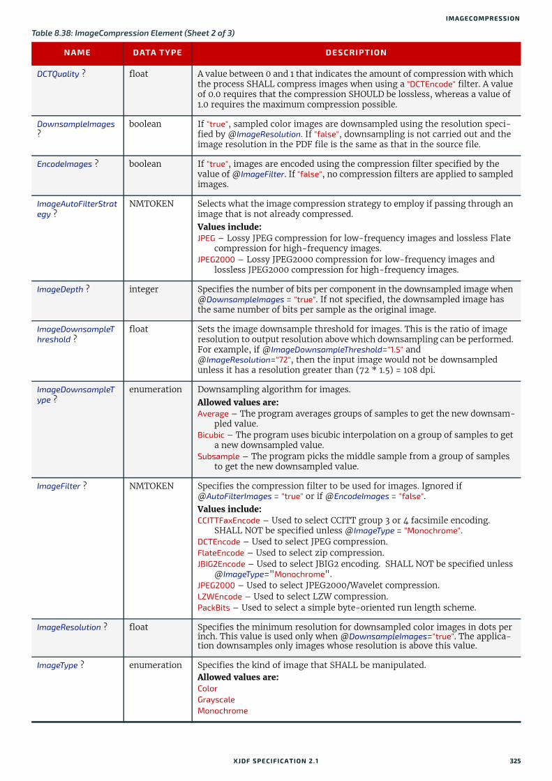
IMAGECOMPRESSION
DCTQuality ? float A value between 0 and 1 that indicates the amount of compression with which the process SHALL compress images when using a "DCTEncode" filter. A value of 0.0 requires that the compression SHOULD be lossless, whereas a value of 1.0 requires the maximum compression possible.
DownsampleImages ?
boolean If "true", sampled color images are downsampled using the resolution speci-fied by @ImageResolution. If "false", downsampling is not carried out and the image resolution in the PDF file is the same as that in the source file.
EncodeImages ? boolean If "true", images are encoded using the compression filter specified by the value of @ImageFilter. If "false", no compression filters are applied to sampled images.
ImageAutoFilterStrategy ?
NMTOKEN Selects what the image compression strategy to employ if passing through an image that is not already compressed. Values include:JPEG – Lossy JPEG compression for low-frequency images and lossless Flate
compression for high-frequency images.JPEG2000 – Lossy JPEG2000 compression for low-frequency images and
lossless JPEG2000 compression for high-frequency images.
ImageDepth ? integer Specifies the number of bits per component in the downsampled image when @DownsampleImages = "true". If not specified, the downsampled image has the same number of bits per sample as the original image.
ImageDownsampleThreshold ?
float Sets the image downsample threshold for images. This is the ratio of image resolution to output resolution above which downsampling can be performed. For example, if @ImageDownsampleThreshold="1.5" and @ImageResolution="72", then the input image would not be downsampled unless it has a resolution greater than (72 * 1.5) = 108 dpi.
ImageDownsampleType ?
enumeration Downsampling algorithm for images. Allowed values are: Average – The program averages groups of samples to get the new downsam-
pled value.Bicubic – The program uses bicubic interpolation on a group of samples to get
a new downsampled value.Subsample – The program picks the middle sample from a group of samples
to get the new downsampled value.
ImageFilter ? NMTOKEN Specifies the compression filter to be used for images. Ignored if @AutoFilterImages = "true" or if @EncodeImages = "false".Values include: CCITTFaxEncode – Used to select CCITT group 3 or 4 facsimile encoding.
SHALL NOT be specified unless @ImageType = "Monochrome".DCTEncode – Used to select JPEG compression.FlateEncode – Used to select zip compression.JBIG2Encode – Used to select JBIG2 encoding. SHALL NOT be specified unless
@ImageType="Monochrome".JPEG2000 – Used to select JPEG2000/Wavelet compression.LZWEncode – Used to select LZW compression.PackBits – Used to select a simple byte-oriented run length scheme.
ImageResolution ? float Specifies the minimum resolution for downsampled color images in dots per inch. This value is used only when @DownsampleImages="true". The applica-tion downsamples only images whose resolution is above this value.
ImageType ? enumeration Specifies the kind of image that SHALL be manipulated. Allowed values are: Color Grayscale Monochrome
Table 8.38: ImageCompression Element (Sheet 2 of 3)
NAME DATA TYPE DESCRIPTION
XJDF SPECIFICATIO N 2.1 325

SUBELEMENTS
8.27.1 CCITTFaxParams
8.27.2 DCTParams
JPXQuality ? integer Specifies the image quality. Valid values are greater than or equal to one (1) and less than or equal to 100. One (1) means lowest quality (highest compres-sion), 99 means visually lossless compression, and 100 means numerically lossless compression.
CCITTFaxParams ? element The equivalent of the PostScript Rows and BlackIs1 parameters, which are implicit in the raster data to be compressed.
DCTParams ? element The equivalent of the PostScript Columns, Rows and Colors parameters, which are assumed to be implicit in the raster data to be compressed.
FlateParams ? element The equivalent of the PostScript Columns, BitsPerComponent and Colors parameters, which are implicit in the raster data to be compressed.
JBIG2Params ? element Provides the JBIG2 compression parameters.
JPEG2000Params ? element Provides the JPEG2000 compression parameters.
LZWParams ? element The equivalent of the PostScript Columns, BitsPerComponent and Colors parameters, which are implicit in the raster data to be compressed.
Table 8.39: CCITTFaxParams Element
NAME DATA TYPE DESCRIPTION
EncodedByteAlign ? boolean @EncodedByteAlign indicates whether the CCITTFaxEncode filter SHALL insert extra 0 bits before each encoded line so that the line begins on a byte boundary.
EndOfBlock ? boolean A flag indicating whether the CCITTFaxEncode filter SHALL append an end-of-block pattern to the encoded data.
EndOfLine ? boolean A flag indicating whether the CCITTFaxEncode filter SHALL prefix an end-of-line bit pattern to each line of encoded data.
K ? integer An integer that selects the encoding scheme to be used. < 0 – Pure two-dimensional encoding (Group 4, TIFF Compression = 4).= 0 – Pure one-dimensional encoding (Group 3, 1-D, TIFF Compression = 2).> 0 – Mixed one- and two-dimensional encoding (Group 3, 2-D, TIFF Com-
pression = 3), in which a line encoded one-dimensionally MAY be fol-lowed by at most @K – 1 lines encoded two-dimensionally.
Uncompressed ? boolean A flag to indicate whether the file generated MAY use uncompressed encod-ing when advantageous.
Table 8.40: DCTParams Element (Sheet 1 of 2)
NAME DATA TYPE DESCRIPTION
ColorTransform ? enumeration Color transformation algorithm.Allowed values are: Automatic – "YUV" for 3-channel raster data, "None" otherwise.None – Colors SHALL NOT be transformed. YUV – RGB raster values SHALL be transformed to YUV before encoding and
from YUV to RGB after decoding. If four channels are present CMYK val-ues SHALL be transformed to YUVK before encoding and SHALL be trans-formed from YUVK to CMYK after decoding.
Note: YUV is equivalent to YCbCr in TIFF terminology.
Table 8.38: ImageCompression Element (Sheet 3 of 3)
NAME DATA TYPE DESCRIPTION
326 XJDF SPECIFICATIO N 2.1

IMAGECOMPRESSION
When the DCTParams element is a subelement of ImageCompression used in a Rendering process to generate TIFF files, YUV is equivalent to YCbCr in TIFF terminology. The HSamples and VSamples values are used to set YCbCrSubSampling or CIELabSubSampling. This means that they are only relevant for data supplied as Lab, or data where @ColorTransform is "YUV"; that the first element SHALL be 1 in each case; that the fourth element SHALL be 1 where CMYK data is to be compressed; and that the second and third elements SHALL equal each other.
8.27.3 FlateParams
8.27.4 JBIG2Params
8.27.5 JPEG2000Params
HSamples ? IntegerList A sequence of horizontal sampling factors. If present, one entry SHALL be provided per color channel in the raster data. If not specified, the implied default is "1" for every channel.
HuffTable ? FloatList Huffman tables for DC and AC components. If present, there SHALL be at least one HuffTable element for each color channel.
QFactor ? float A scale factor that SHALL be applied to the elements of @QuantTable.
QuantTable ? FloatList Quantization tables. If present, there SHALL be one @QuantTable entry for each color channel.
VSamples ? IntegerList A sequence of vertical sampling factors. If present, one entry SHALL be pro-vided per color channel in the raster data. If not specified, the implied default is "1" for every channel.
Table 8.41: FlateParams Element
NAME DATA TYPE DESCRIPTION
Predictor ? integer A code that selects the predictor function.Note: On "1n" PNG predictors, these values select the specific PNG predictor function(s) to be used. When decoding, the predictor function SHALL be explicitly encoded in the incoming data.Values include:1 – No predictor (normal encoding or decoding).2 – TIFF Predictor 2.10 – PNG predictor, None function.11 – PNG predictor, Sub function.12 – PNG predictor, Up function.13 – PNG predictor, Average function.14 – PNG predictor, Path function.15 – PNG predictor in which the encoding filter SHALL automatically choose
the optimum function separately for each row.
Table 8.42: JBIG2Params Element
NAME DATA TYPE DESCRIPTION
JBIG2Lossless ? boolean If "true" requires JBIG2 compressed images to retain the exact representation of the original image without loss.
Table 8.43: JPEG2000Params Element (Sheet 1 of 2)
NAME DATA TYPE DESCRIPTION
CodeBlockSize ? integer The nominal code block width and height. The value SHALL be a power of 2.
Table 8.40: DCTParams Element (Sheet 2 of 2)
NAME DATA TYPE DESCRIPTION
XJDF SPECIFICATIO N 2.1 327

SUBELEMENTS
8.27.6 LZWParams
8.28 MediaLayersMediaLayers contains an ordered list of subelements. Each subelement describes an individual layer of a layered Media such as self-adhesive labels or corrugated boards. The first layer in MediaLayers SHALL specify the front layer of the Media until the last layer, which SHALL define the back. The Glue and Media subelements MAY therefore be specified in any order and NEED NOT be specified in the lexical order as specified in Table 8.45 MediaLayers Element below.
Element PropertiesElement referenced by: Media
LayerRates ? FloatList Compression bit ratio for each layer. If specified, there SHALL be the same number of values in this list as @LayersPerTile in ascending order. Small values correspond to maximum compression and 1.0 corresponds to no compression (lossless).If available, @LayerRates SHOULD be supplied.
LayersPerTile ? integer Specifies the number of quality layers per tile at the same resolution.
NumResolutions ? integer The number of resolution levels that SHALL be encoded in the file.
ProgressionOrder ? enumeration Per tile progression order.Allowed values are: CPRL – Component-position-resolution-layer progressive.LRCP – Layer-resolution-component-position progressive (i.e., rate scal-
able).PCRL – Position-component-resolution-layer progressive.RLCP – Resolution-layer-component-position progressive (i.e., resolution
scalable).RPCL – Resolution-position-component-layer progressive.
TileSize ? XYPair The width and height of each encoding tile. If not specified the image SHALL be encoded as a single tile.
Table 8.44: LZWParams Element
NAME DATA TYPE DESCRIPTION
EarlyChange ? integer A code indicating when to increase the code word length. The TIFF specifica-tion can be interpreted to imply that code word length increases are post-poned as long as possible. However, some existing implementations of LZW increase the code word length one code word earlier than necessary. The PostScript language supports both interpretations. If @EarlyChange is "0", code word length increases are postponed as long as possible. If it is "1", they occur one code word early.
Predictor ? integer A code that selects the predictor function.Note: On "1n" PNG predictors, these values select the specific PNG predictor function(s) to be used. When decoding, the predictor function SHALL be explicitly encoded in the incoming data.Values include:1 – No predictor (normal encoding or decoding).2 – TIFF Predictor 2.10 – PNG predictor, None function.11 – PNG predictor, Sub function.12 – PNG predictor, Up function.13 – PNG predictor, Average function.14 – PNG predictor, Path function.15 – PNG predictor in which the encoding filter SHALL automatically choose
the optimum function separately for each row.
Table 8.43: JPEG2000Params Element (Sheet 2 of 2)
NAME DATA TYPE DESCRIPTION
328 XJDF SPECIFICATIO N 2.1

METADATAMAP
8.29 MetadataMap MetadataMap allows metadata embedded in PDL files or barcodes that are represented by IdentificationField to be as-signed to Partition Key values. If MetadataMap is defined in a RunList, the metadata SHALL be extracted from the PDL as follows: each MetadataMap element SHALL be evaluated for each node (set, document, page, etc.) of the PDL document structure. For XML based PDL files an XPath expression SHALL be evaluated relative to the XML node that defines each node in the document hierarchy. For non-XML based PDLs a PDL specific mapping of the XPath to the PDL document structure SHALL be used instead and the value assignment SHALL be performed on the derived XML for the PDL file.
If MetadataMap is defined in an IdentificationField, then IdentificationField/@ValueTemplate SHALL provide a list of vari-ables that can be further processed in MetadataMap/@ValueTemplate.
Element PropertiesElement referenced by: IdentificationField, RunList
8.29.1 ExprExpr elements define how the variables that are specified in @ValueTemplate SHALL be extracted from the parent RunList.
Example 8.3: RunList/MetadataMapIn the following example, the MetadataMap element maps the data in /doc/record/Geschlecht and /doc/record/Status in the document to Part/@Metadata. The calculated Part/@Metadata is then used to select the appropriate color and quality of the paper component.
Table 8.45: MediaLayers Element
NAME DATA TYPE DESCRIPTION
Glue * element Each Glue SHALL specify a glue layer of a layered Media. The value of Glue/@AreaGlue SHALL be "true".
Media * element Each Media SHALL describe an individual layer of a layered Media.
Table 8.46: MetadataMap Element
NAME DATA TYPE DESCRIPTION
Name NMTOKEN @Name SHALL define the Partition Key that SHALL be filled with the value that is calculated from @ValueFormat and @ValueTemplate. See Table 6.4 Part Element.
ValueFormat string Formatting value for combining values from @ValueTemplate into a dynamic result value.Allowed values are from: Appendix D String Generation.
ValueTemplate NMTOKENS Arguments for combining extracted values. If MetadataMap is a child of RunList, then each value shall be selected from the list of predefined values in Appendix D String Generation or match a value of Expr/@Name. If MetadataMap is a child of IdentificationField, each value shall be defined in the parent IdentificationField/@ValueTemplate.
Expr * element Exactly one Expr element with a matching @Name SHALL be specified for each variable in @ValueTemplate that is NOT defined in the parent IdentificationField/@ValueTemplate and NOT defined in Table D.1 Template Variables. Expr SHALL NOT be specified in an IdentificationField/MetadataMap.
Table 8.47: Expr Element
NAME DATA TYPE DESCRIPTION
Name NMTOKEN Name of this Expr. The value extracted from @Path SHALL be used to evalu-ate the parent @ValueTemplate.
Path XPath The value specified by this path SHALL be assigned to Expr/@Name.If the XPath points to an element, then an implied XPath text() function SHALL be executed.
XJDF SPECIFICATIO N 2.1 329
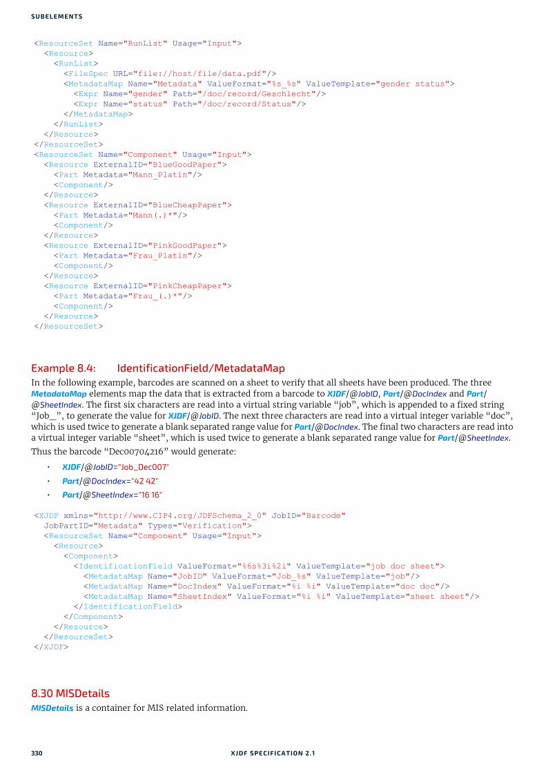
SUBELEMENTS
Example 8.4: IdentificationField/MetadataMapIn the following example, barcodes are scanned on a sheet to verify that all sheets have been produced. The three MetadataMap elements map the data that is extracted from a barcode to XJDF/@JobID, Part/@DocIndex and Part/@SheetIndex. The first six characters are read into a virtual string variable “job”, which is appended to a fixed string “Job_”, to generate the value for XJDF/@JobID. The next three characters are read into a virtual integer variable “doc”, which is used twice to generate a blank separated range value for Part/@DocIndex. The final two characters are read into a virtual integer variable “sheet”, which is used twice to generate a blank separated range value for Part/@SheetIndex.
Thus the barcode “Dec00704216” would generate:
• XJDF/@JobID="Job_Dec007"
• Part/@DocIndex="42 42"
• Part/@SheetIndex="16 16"
8.30 MISDetailsMISDetails is a container for MIS related information.
<ResourceSet Name="RunList" Usage="Input"> <Resource> <RunList> <FileSpec URL="file://host/file/data.pdf"/> <MetadataMap Name="Metadata" ValueFormat="%s_%s" ValueTemplate="gender status"> <Expr Name="gender" Path="/doc/record/Geschlecht"/> <Expr Name="status" Path="/doc/record/Status"/> </MetadataMap> </RunList> </Resource></ResourceSet><ResourceSet Name="Component" Usage="Input"> <Resource ExternalID="BlueGoodPaper"> <Part Metadata="Mann_Platin"/> <Component/> </Resource> <Resource ExternalID="BlueCheapPaper"> <Part Metadata="Mann(.)*"/> <Component/> </Resource> <Resource ExternalID="PinkGoodPaper"> <Part Metadata="Frau_Platin"/> <Component/> </Resource> <Resource ExternalID="PinkCheapPaper"> <Part Metadata="Frau_(.)*"/> <Component/> </Resource></ResourceSet>
<XJDF xmlns="http://www.CIP4.org/JDFSchema_2_0" JobID="Barcode" JobPartID="Metadata" Types="Verification"> <ResourceSet Name="Component" Usage="Input"> <Resource> <Component> <IdentificationField ValueFormat="%6s%3i%2i" ValueTemplate="job doc sheet"> <MetadataMap Name="JobID" ValueFormat="Job_%s" ValueTemplate="job"/> <MetadataMap Name="DocIndex" ValueFormat="%i %i" ValueTemplate="doc doc"/> <MetadataMap Name="SheetIndex" ValueFormat="%i %i" ValueTemplate="sheet sheet"/> </IdentificationField> </Component> </Resource> </ResourceSet></XJDF>
330 XJDF SPECIFICATIO N 2.1

NOTIFICATION
Element PropertiesElement referenced by: ResourceInfo, PipeParams, JobPhase, NodeInfo
8.31 NotificationThis element contains information about individual events that occurred during processing. For a detailed discussion of event properties, see Section 9.3.8 Error Handling.
Element PropertiesElement referenced by: AuditNotification, Response, ResponseForceGang, ResponseGangStatus,
ResponseKnownDevices, ResponseKnownMessages, ResponseKnownSubscriptions, ResponseModifyQueueEntry, ResponseNotification, SignalNotification, ResponsePipeControl, ResponseQueueStatus, ResponseRequestQueueEntry, ResponseResource, ResponseResubmitQueueEntry, ResponseReturnQueueEntry, ResponseShutDown, ResponseStatus, ResponseStopPersistentChannel, ResponseSubmitQueueEntry, ResponseWakeUp
Table 8.48: MISDetails Element
NAME DATA TYPE DESCRIPTION
Complexity ? float Complexity of the task specified by this XJDF in a range from 0.0 to 1.0. Note: The interpretation of values is implementation dependent.Values include:0.0 – The job is simple and therefore reduced setup and waste or higher
speeds are possible.0.5 – The job is of standard complexity and therefore standard setup and
waste or normal speeds are possible.1.0 – The job is complex and therefore more setup and waste or lower speeds
are possible.
CostType ? enumeration Specifies whether or not this MISDetails is chargeable to the customer or not. Allowed values are:Chargeable NonChargeable
WorkType ? enumeration Definition of the work type for this MISDetails (i.e., whether or not this MISDetails relates to originally planned work, an alteration or rework). Allowed values are:Alteration – Work done to accommodate a change made to the job.Original – Standard work that was originally planned for the job.Rework – Work done due to unforeseen problems with the original work (bad
plate, resource damaged, etc.).
WorkTypeDetails ? NMTOKEN Machine readable definition of the details of the work type for this MISDetails (i.e., why the work was done). Values include:CustomerRequest – The customer requested change(s) requiring the work.EquipmentMalfunction – Equipment used to produce the resource malfunc-
tioned; resource needs to be created again.InternalChange – Change was made for production efficiency or other internal
reason.ResourceDamaged – A resource needs to be created again to account for a
damaged resource (damaged plate, etc.).UserError – Incorrect operation of equipment or incorrect creation of
resource requires creating the resource again.
Table 8.49: Notification Element (Sheet 1 of 2)
NAME DATA TYPE DESCRIPTION
Class enumeration Class of the notification. Allowed value is from: Severity.
JobID ? NMTOKEN @JobID that this Notification applies to.
XJDF SPECIFICATIO N 2.1 331
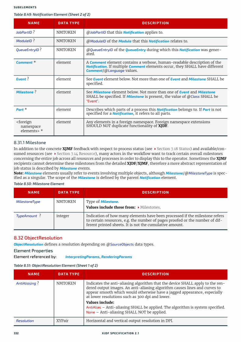
SUBELEMENTS
8.31.1 MilestoneIn addition to the concrete XJMF feedback with respect to process status (see Section 7.18 Status) and available/con-sumed resources (see Section 7.14 Resource), many actors in the workflow want to track certain overall milestones concerning the entire job across all resources and processes in order to display this to the operator. Sometimes the XJMF recipients cannot determine these milestones from the detailed XJDF/XJMF, therefore a more abstract representation of job status is described by Milestone events.Note: Milestone elements usually refer to events involving multiple objects, although Milestone/@MilestoneType is spec-ified as a singular. The scope of the Milestone is defined by the parent Notification element.
8.32 ObjectResolution ObjectResolution defines a resolution depending on @SourceObjects data types.
Element PropertiesElement referenced by: InterpretingParams, RenderingParams
JobPartID ? NMTOKEN @JobPartID that this Notification applies to.
ModuleID ? NMTOKEN @ModuleID of the Module that this Notification relates to.
QueueEntryID ? NMTOKEN @QueueEntryID of the QueueEntry during which this Notification was gener-ated.
Comment * element A Comment element contains a verbose, human-readable description of the Notification. If multiple Comment elements occur, they SHALL have different Comment/@Language values.
Event ? element See Event element below. Not more than one of Event and Milestone SHALL be specified.
Milestone ? element See Milestone element below. Not more than one of Event and Milestone SHALL be specified. If Milestone is present, the value of @Class SHALL be "Event".
Part * element Describes which parts of a process this Notification belongs to. If Part is not specified for a Notification, it refers to all parts.
<foreign namespaceelements> *
element Any elements in a foreign namespace. Foreign namespace extensions SHOULD NOT duplicate functionality of XJDF.
Table 8.50: Milestone Element
NAME DATA TYPE DESCRIPTION
MilestoneType NMTOKEN Type of Milestone.Values include those from: Milestones.
TypeAmount ? integer Indication of how many elements have been processed if the milestone refers to certain resources, e.g. the number of pages proofed or the number of dif-ferent printed sheets. It is not the cumulative amount.
Table 8.51: ObjectResolution Element (Sheet 1 of 2)
NAME DATA TYPE DESCRIPTION
AntiAliasing ? NMTOKEN Indicates the anti-aliasing algorithm that the device SHALL apply to the ren-dered output images. An anti-aliasing algorithm causes lines and curves to appear smooth which would otherwise have a jagged appearance, especially at lower resolutions such as 300 dpi and lower. Values include:AntiAlias – Anti-aliasing SHALL be applied. The algorithm is system specified.None – Anti-aliasing SHALL NOT be applied.
Resolution XYPair Horizontal and vertical output resolution in DPI.
Table 8.49: Notification Element (Sheet 2 of 2)
NAME DATA TYPE DESCRIPTION
332 XJDF SPECIFICATIO N 2.1

OCGCONTROL
8.33 OCGControlOCGControl defines the policy for including or excluding layers that are encoded as ‘Optional Content Groups’ (OCGs) in PDF.
The order of OCGControl elements SHALL have no effect; the Z-order of graphic elements that make up each optional content group (the term layer is misleading in this regard) within the PDF file SHALL define the drawing order of those graphic elements.
Any preferences recorded in an OCG within the PDF file as to whether that OCG SHOULD be displayed or not SHALL be ignored if that OCG is referenced from an OCGControl element.
The state of all OCGs explicitly referenced from OCGControl elements SHALL be set before determining the state of any remaining OCGs.Note: All controls for OCGs in XJDF address OCGs directly, and not Optional Content Member Dictionaries (OCMDs do not have unique names).Note: [PDF1.6] does not state that all OCGs SHALL have unique names. It is therefore possible for a single PDF file to contain multiple OCGs with the same name. When OCGControl/@OCGName refers to multiple OCGs in a file, they will all be explicitly included or excluded together.
Element PropertiesElement referenced by: Content, InterpretingParams/PDFInterpretingParams
8.34 PerforatePerforate describes one perforated line.
Element PropertiesElement referenced by: FoldingParams, PerforatingParams
SourceObjects ? enumerations Identifies the class(es) of incoming graphical objects to render at the speci-fied resolution. If @SourceObjects is not specified then ObjectResolution SHALL apply to all object classes.Allowed values are from: SourceObjects.
Table 8.52: OCGControl Element
NAME DATA TYPE DESCRIPTION
IncludeOCG boolean Defines whether the optional content group(s) identified by @OCGName are to be included in the RunList. If "true", then the layer SHALL be included. If "false", it SHALL NOT.The contents stream of excluded OCGs SHALL still be interpreted so that changes to CTM, etc., are acted on. The objects drawn in excluded OCGs SHALL NOT be rendered.
OCGName ? string The name of the optional content group(s) that SHALL be included or excluded. Exactly one of @OCGName or @ProcStepsGroup SHALL be present.Note: The Name attribute of an optional content group entry is encoded as a PDF text string, and @OCGName is encoded with the Unicode variant identified in the XJDF file header; names SHALL be re-encoded as necessary for compar-ison.
ProcStepsGroup ? NMTOKEN An OCG is selected, if @ProcStepsGroup matches the value ofGTS_ProcStepsGroup in the GTS_Metadata dictionary of the OCG of a PDF that complies with [ISO19593-1:2016].
ProcStepsType ? NMTOKEN If specified, an OCG is selected, if @ProcStepsType matches the value of GTS_ProcStepsType in the GTS_Metadata dictionary of the OCG of a PDF that complies with [ISO19593-1:2016]. @ProcStepsType SHALL NOT be specified unless @ProcStepsGroup is present.
Table 8.51: ObjectResolution Element (Sheet 2 of 2)
NAME DATA TYPE DESCRIPTION
XJDF SPECIFICATIO N 2.1 333

SUBELEMENTS
8.35 QueueEntryThe QueueEntry element contains metadata for a single item in a device’s queue.
Element PropertiesElement referenced by: ResponseModifyQueueEntry, ResponseQueueStatus/Queue, ResponseSubmitQueueEntry
Table 8.53: Perforate Element
NAME DATA TYPE DESCRIPTION
Depth ? float Depth of the perforation, in microns [µm].
StartPosition ? XYPair Starting position of the tool.
TeethPerDimension ? float Number of teeth in a given perforation extent in teeth/point. MicroPerfora-tion is defined by specifying a large number of teeth (@TeethPerDimension > 1000).
WorkingDirection ? enumeration Direction from which the tool is working. Allowed value is from: WorkingDirection.
WorkingPath ? XYPair Working path of the tool beginning at @StartPosition.
Table 8.54: QueueEntry Element (Sheet 1 of 2)
NAME DATA TYPE DESCRIPTION
Activation ? enumeration Specifies the activation of the QueueEntry.
Allowed value is from: Activation.
EndTime ? dateTime Date and time when processing of the QueueEntry has been ended.
GangName ? NMTOKEN Name of the gang that this QueueEntry belongs to. @GangName SHALL be specified, if the QueueEntry is a candidate member of a gang job.
GangPolicy ? enumeration Ganging policy for the QueueEntry.Allowed value is from: GangPolicy.
JobID ? NMTOKEN The @JobID of the XJDF process.
JobPartID ? NMTOKEN The @JobPartID of the XJDF process.
Priority ? integer Priority of the QueueEntry. Values are 0-100. A value of "0" is the lowest prior-ity, while "100" is the highest priority.
RelatedJobID ?New in XJDF 2.1
string The @RelatedJobID of the XJDF process.
RelatedJobPartID ?New in XJDF 2.1
string The @RelatedJobPartID of the XJDF process.
QueueEntryID NMTOKEN Identifier of a QueueEntry. This ID SHALL be generated by the queue owner. @QueueEntryID SHALL be unique in the context of a Queue.
StartTime ? dateTime Date and time when processing of the QueueEntry has been started.
Status enumeration Specifies the status of the requested QueueEntry. @Status SHALL be identical to the NodeInfo/@Status of the underlying XJDF.Allowed value is from: Status.
StatusDetails ? NMTOKEN @StatusDetails provides additional details on the status of the QueueEntry. Values include those from: Status Details.
SubmissionTime ? dateTime Date and time when the entry was submitted to the queue.
FileSpec (Preview) ? element This FileSpec MAY be used to provide a visualization of the QueueEntry. FileSpec(Preview) SHOULD reference an image format such as PNG or JPEG.
334 XJDF SPECIFICATIO N 2.1

QUEUEFILTER
8.36 QueueFilterThe QueueFilter element defines a filter that selects QueueEntry elements in a Queue. The supplied elements of the QueueFilter define a matching criteria that is a logical “and”. Only QueueEntry elements that match all restrictions spec-ified by the QueueFilter SHALL be selected.
Element PropertiesElement referenced by: CommandModifyQueueEntry/ModifyQueueEntryParams, QueryQueueStatus/
QueueStatusParams
GangSource * element If present, each GangSource SHALL represent the source jobs that are being processed as a gang job by this QueueEntry.
Part * element Describes which parts of a job were submitted to the queue. This SHALL be a copy of ResourceSet[@Name="NodeInfo"]/Resource/Part.
Table 8.55: QueueFilter Element (Sheet 1 of 2)
NAME DATA TYPE DESCRIPTION
FirstEntry ? NMTOKEN @QueueEntryID of the first QueueEntry that this QueueFilter applies to. Only QueueEntry elements that are behind this (including this) QueueEntry in the current queue sorting SHALL be selected. If not specified, there is no filtering based on the position of items in the queue.
GangNames ? NMTOKENS Gang names of the QueueEntry elements to be returned. If not specified, there is no filtering on QueueEntry/@GangName.
JobID ? NMTOKEN Return only QueueEntry elements with specified @JobID. If not specified, there is no filtering on QueueEntry/@JobID.
JobPartID ? NMTOKEN Return only QueueEntry elements with specified @JobPartID. If not specified, there is no filtering on QueueEntry/@JobPartID.
LastEntry ? NMTOKEN @QueueEntryID of the last QueueEntry that this QueueFilter applies to. Only QueueEntry elements that are in front of this (including this) QueueEntry in the current queue sorting SHALL be selected. If not specified, there is no fil-tering based on the position of items in the queue.
MaxEntries ? integer Maximum number of QueueEntry elements to provide in the Queue element. If not specified, fill in all matching QueueEntry elements.
MaxPriority ? integer Only QueueEntry elements with a @Priority lower than or equal to the value of @MaxPriority SHALL be provided in the Queue element. If not specified, there is no @Priority upper bound on candidates.
MinPriority ? integer Only QueueEntry elements with a @Priority higher than or equal to the value of @MinPriority SHALL be provided in the Queue element. If not specified, there is no @Priority lower bound on candidates.
NewerThan ? dateTime Only QueueEntry elements with a @SubmissionTime newer than or equal to @NewerThan SHALL BE provided in the Queue element. If not specified, there is no dateTime upper bound on candidates.
OlderThan ? dateTime Only QueueEntry elements with a @SubmissionTime older than or equal to @OlderThan SHALL BE provided in the Queue element. If not specified, there is no dateTime lower bound on candidates.
QueueEntryIDs ? NMTOKENS Defines an explicit list of queue entries. If not specified, all entries in the Queue are considered.
StatusList ? enumerations Only QueueEntry elements with a @Status matching one of the entries in @StatusList SHALL be returned. If not specified, there is no filtering on QueueEntry/@Status.Allowed values are from: Status.
Table 8.54: QueueEntry Element (Sheet 2 of 2)
NAME DATA TYPE DESCRIPTION
XJDF SPECIFICATIO N 2.1 335
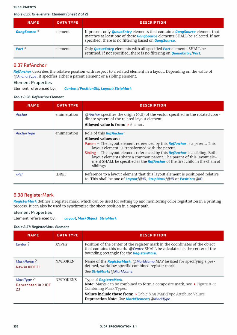
SUBELEMENTS
8.37 RefAnchorRefAnchor describes the relative position with respect to a related element in a layout. Depending on the value of @AnchorType, it specifies either a parent element or a sibling element.
Element PropertiesElement referenced by: Content/PositionObj, Layout/StripMark
8.38 RegisterMarkRegisterMark defines a register mark, which can be used for setting up and monitoring color registration in a printing process. It can also be used to synchronize the sheet position in a paper path.
Element PropertiesElement referenced by: Layout/MarkObject, StripMark
GangSource * element If present only QueueEntry elements that contain a GangSource element that matches at least one of these GangSource elements SHALL be selected. If not specified, there is no filtering based on GangSource.
Part * element Only QueueEntry elements with all specified Part elements SHALL be returned. If not specified, there is no filtering on QueueEntry/Part.
Table 8.56: RefAnchor Element
NAME DATA TYPE DESCRIPTION
Anchor enumeration @Anchor specifies the origin (0,0) of the vector specified in the rotated coor-dinate system of the related layout element.
Allowed value is from: Anchor.
AnchorType enumeration Role of this RefAnchor. Allowed values are: Parent – The layout element referenced by this RefAnchor is a parent. This
layout element is transformed with the parent.Sibling – The layout element referenced by this RefAnchor is a sibling. Both
layout elements share a common parent. The parent of this layout ele-ment SHALL be specified as the RefAnchor of the first child in the chain of siblings.
rRef IDREF Reference to a layout element that this layout element is positioned relative to. This shall be one of Layout/@ID, StripMark/@ID or Position/@ID.
Table 8.57: RegisterMark Element
NAME DATA TYPE DESCRIPTION
Center ? XYPair Position of the center of the register mark in the coordinates of the object that contains this mark. @Center SHALL be calculated as the center of the bounding rectangle for the RegisterMark.
MarkName ?New in XJDF 2.1
NMTOKEN Name of the RegisterMark. @MarkName MAY be used for specifying a pre-defined, workflow specific combined register mark. See StripMark/@MarkName.
MarkType ?Deprecated in XJDF2.1
NMTOKENS Type of RegisterMark. Note: Marks can be combined to form a composite mark, see Figure 8-1: Combining Mark Types.Values include those from: Table 8.59 MarkType Attribute Values.Deprecation Note: Use MarkElement/@MarkType.
Table 8.55: QueueFilter Element (Sheet 2 of 2)
NAME DATA TYPE DESCRIPTION
336 XJDF SPECIFICATIO N 2.1
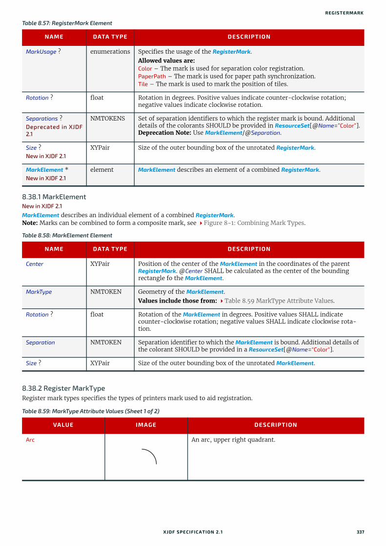
REGISTERMARK
8.38.1 MarkElementNew in XJDF 2.1
MarkElement describes an individual element of a combined RegisterMark.Note: Marks can be combined to form a composite mark, see Figure 8-1: Combining Mark Types.
8.38.2 Register MarkTypeRegister mark types specifies the types of printers mark used to aid registration.
MarkUsage ? enumerations Specifies the usage of the RegisterMark. Allowed values are:Color – The mark is used for separation color registration.PaperPath – The mark is used for paper path synchronization.Tile – The mark is used to mark the position of tiles.
Rotation ? float Rotation in degrees. Positive values indicate counter-clockwise rotation; negative values indicate clockwise rotation.
Separations ?Deprecated in XJDF2.1
NMTOKENS Set of separation identifiers to which the register mark is bound. Additional details of the colorants SHOULD be provided in ResourceSet[@Name=”Color”].Deprecation Note: Use MarkElement/@Separation.
Size ?New in XJDF 2.1
XYPair Size of the outer bounding box of the unrotated RegisterMark.
MarkElement *New in XJDF 2.1
element MarkElement describes an element of a combined RegisterMark.
Table 8.58: MarkElement Element
NAME DATA TYPE DESCRIPTION
Center XYPair Position of the center of the MarkElement in the coordinates of the parent RegisterMark. @Center SHALL be calculated as the center of the bounding rectangle fo the MarkElement.
MarkType NMTOKEN Geometry of the MarkElement.Values include those from: Table 8.59 MarkType Attribute Values.
Rotation ? float Rotation of the MarkElement in degrees. Positive values SHALL indicate counter-clockwise rotation; negative values SHALL indicate clockwise rota-tion.
Separation NMTOKEN Separation identifier to which the MarkElement is bound. Additional details of the colorant SHOULD be provided in a ResourceSet[@Name="Color"].
Size ? XYPair Size of the outer bounding box of the unrotated MarkElement.
Table 8.59: MarkType Attribute Values (Sheet 1 of 2)
VALUE IMAGE DESCRIPTION
Arc An arc, upper right quadrant.
Table 8.57: RegisterMark Element
NAME DATA TYPE DESCRIPTION
XJDF SPECIFICATIO N 2.1 337

SUBELEMENTS
8.38.3 Combined Register MarkThe following figure illustrates a combined RegisterMark consisting of an arc, a cross and a circle as well as the individual mark components.
8.39 RegisterRibbonDescription of a register ribbon used for book binding. The relationship of visible, hidden and overall length of the reister ribbon is shown in Figure 8-2: RegisterRibbon lengths and coordinate system for BlockPreparation.
Element PropertiesElement referenced by: BindingIntent/HardCoverBinding, BlockPreparationParams
Circle A circle.
Cross A cross
Dot Small filled circles that are typically arranged in a well defined matrix.
Rectangle Filled rectangle.Note: Lines are rectangles with a small X or Y value.
Figure 8-1: Combining Mark Types
Combining Arc, Cross and Circle to create a ‘target’ mark.
Combining Dots of different colors to create a sheet regis-tration mark.
Table 8.60: RegisterRibbon Element (Sheet 1 of 2)
NAME DATA TYPE DESCRIPTION
LengthOverall ? float Overall length of the register ribbon. SeeFigure 8-2: RegisterRibbon lengths and coordinate system for BlockPreparation.
Table 8.59: MarkType Attribute Values (Sheet 2 of 2)
VALUE IMAGE DESCRIPTION
Arc
Cross
Circle
338 XJDF SPECIFICATIO N 2.1

REGISTRATIONQUALITY
8.40 RegistrationQualityNew in XJDF 2.1
RegistrationQuality defines a measurement of the color separation compared to a master separation that is defined by @Reference.
Element referenced by: QualityControlParams, QualityControlResult
8.41 ScavengerAreaScavengerArea describes a scavenger area for removing excess ink from printed sheets.
Element PropertiesElement referenced by: Layout/MarkObject, StripMark
Material ? string Material of the register ribbon.
RibbonColor ? enumeration @RibbonColor specifies the machine readable color of ribbon.
Allowed value is from: NamedColor.
RibbonColorDetails ? string A more specific, specialized or site-defined name for the color. If @RibbonColorDetails is supplied, @RibbonColor SHOULD also be supplied.
RibbonEnd ? NMTOKEN End of the Ribbon. Values include:CutCutSealedKnotSealedOffset – The ribbon is sealed some distance from the cut.
VisibleLength ? float Length of the register ribbon that will be seen when opening the book. See Figure 8-2: RegisterRibbon lengths and coordinate system for BlockPreparation.
Figure 8-2: RegisterRibbon lengths and coordinate system for BlockPreparation
Table 8.61: RegistrationQuality Element
Offset XYPair Registration offset compared to the color separation specified in @Reference.
Reference NMTOKEN Separation identifier of the color separation that @Offset SHALL be measured against.
Table 8.60: RegisterRibbon Element (Sheet 2 of 2)
NAME DATA TYPE DESCRIPTION
Book block
Hidden length = LengthOverall - VisibleLength
Hidden length
Origin of the process
coordinate system
X
Y
VisibleLength
XJDF SPECIFICATIO N 2.1 339
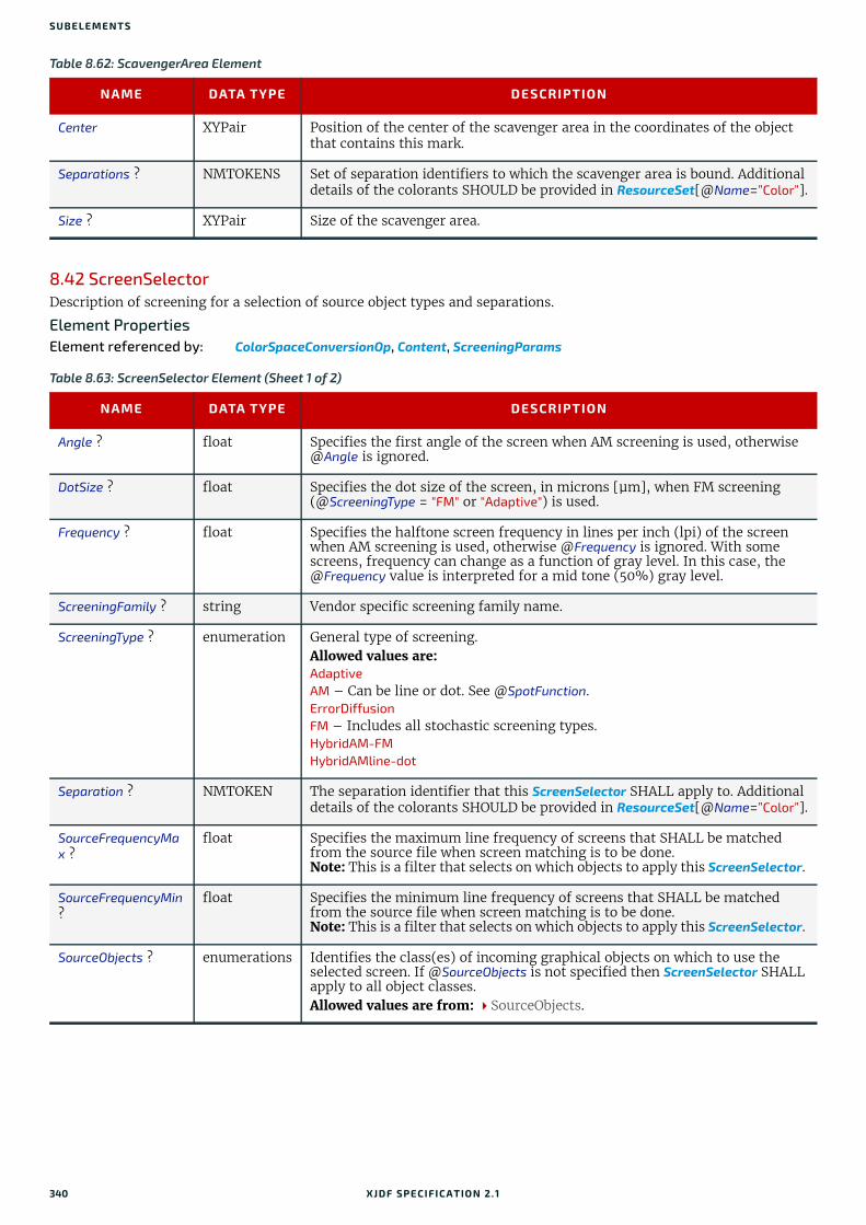
SUBELEMENTS
8.42 ScreenSelectorDescription of screening for a selection of source object types and separations.
Element PropertiesElement referenced by: ColorSpaceConversionOp, Content, ScreeningParams
Table 8.62: ScavengerArea Element
NAME DATA TYPE DESCRIPTION
Center XYPair Position of the center of the scavenger area in the coordinates of the object that contains this mark.
Separations ? NMTOKENS Set of separation identifiers to which the scavenger area is bound. Additional details of the colorants SHOULD be provided in ResourceSet[@Name=”Color”].
Size ? XYPair Size of the scavenger area.
Table 8.63: ScreenSelector Element (Sheet 1 of 2)
NAME DATA TYPE DESCRIPTION
Angle ? float Specifies the first angle of the screen when AM screening is used, otherwise @Angle is ignored.
DotSize ? float Specifies the dot size of the screen, in microns [µm], when FM screening (@ScreeningType = "FM" or "Adaptive") is used.
Frequency ? float Specifies the halftone screen frequency in lines per inch (lpi) of the screen when AM screening is used, otherwise @Frequency is ignored. With some screens, frequency can change as a function of gray level. In this case, the @Frequency value is interpreted for a mid tone (50%) gray level.
ScreeningFamily ? string Vendor specific screening family name.
ScreeningType ? enumeration General type of screening. Allowed values are:Adaptive AM – Can be line or dot. See @SpotFunction.ErrorDiffusion FM – Includes all stochastic screening types.HybridAM-FM HybridAMline-dot
Separation ? NMTOKEN The separation identifier that this ScreenSelector SHALL apply to. Additional details of the colorants SHOULD be provided in ResourceSet[@Name=”Color”].
SourceFrequencyMax ?
float Specifies the maximum line frequency of screens that SHALL be matched from the source file when screen matching is to be done.Note: This is a filter that selects on which objects to apply this ScreenSelector.
SourceFrequencyMin ?
float Specifies the minimum line frequency of screens that SHALL be matched from the source file when screen matching is to be done.Note: This is a filter that selects on which objects to apply this ScreenSelector.
SourceObjects ? enumerations Identifies the class(es) of incoming graphical objects on which to use the selected screen. If @SourceObjects is not specified then ScreenSelector SHALL apply to all object classes.Allowed values are from: SourceObjects.
340 XJDF SPECIFICATIO N 2.1

SHAPE
8.43 ShapeElement PropertiesElement referenced by: ShapeCuttingParams, ShapeDef
SpotFunction ? NMTOKEN Specifies the spot function of the screen when AM screening is used. In gen-eral, it is common for a spot function to change its shape as a function of gray level. Response to these spot function names MAY be implementation-dependent. These example names are the same as the spot function names defined in PDF. Values include:CosineDot Cross Diamond Double DoubleDot Ellipse EllipseA EllipseB EllipseC InvertedDouble InvertedDoubleDot InvertedEllipseA InvertedEllipseC InvertedSimpleDot Line LineX LineY Rhomboid Round SimpleDot Square
Table 8.64: Shape Element
NAME DATA TYPE DESCRIPTION
CutBox ? rectangle Specification of a rectangular window.
CutOut ? boolean If "true", the inside of a specified shape SHALL be removed. If "false", the out-side of a specified shape SHALL be removed. An example of an inside shape is a window. An example of an outside shape is a shaped greeting card.
CutPath ? PDFPath Specification of a complex path.
DDESCutType ? integer Type of cut or perforation used. Values include: a number between "0" and "999" corresponding to a line type as defined in [DDES3].
Note: A value of 101 corresponds to a cut line.
ShapeDepth ? float Depth of the shape cut, measured in microns [µm]. If not specified, the shape SHALL be completely cut.
ShapeType enumeration Describes any precision cutting other than hole making. Allowed values are:PathRectangularRoundRoundedRectangle – Rectangle with rounded corners.
TeethPerDimension ? float Number of teeth in a given perforation extent, in teeth/point. MicroPerfora-tion is defined by specifying a large number of teeth (n > 1000).
Table 8.63: ScreenSelector Element (Sheet 2 of 2)
NAME DATA TYPE DESCRIPTION
XJDF SPECIFICATIO N 2.1 341

SUBELEMENTS
8.44 StripMarkThe StripMark element specifies automatically generated production marks.
Whereas Layout/MarkObject elements define the explicit and detailed positions of production marks, StripMark elements are generally high level instructions to a Stripping processor to appropriately place the resulting MarkObject elements during the Stripping process.
Element PropertiesElement referenced by: Layout, StackingParams/InsertSheet
Table 8.65: StripMark Element (Sheet 1 of 2)
NAME DATA TYPE DESCRIPTION
AbsoluteHeight ? float Absolute height of the StripMark in points.
AbsoluteWidth ? float Absolute width of the StripMark in points.
Anchor ? enumeration Origin of the mark coordinate system.Allowed value is from: Anchor.
Font ? NMTOKEN The name of the font that SHALL be used for the StripMark. Values include: Courier Helvetica Helvetica-Condensed Times-Roman
FontSize ? float The size of the font that SHALL be used for the StripMark, in points.
HorizontalFitPolicy ? enumeration How to modify the mark to fit into the horizontal space that is provided for the StripMark prior to rotation. Allowed value is from: FitPolicy.
ID ? ID Identifier of the StripMark. Used for internal references within the Layout.
MarkName ? NMTOKEN Name of the mark that SHALL be marked on the Layout. Values include those from: Table 8.66 MarkName Attribute Values.
Offset ? XYPair Position of the anchor of this StripMark relative to RefAnchor/@Anchor as defined by @Anchor and RefAnchor/@Anchor.
Orientation ? enumeration Orientation of this StripMark in the coordinate system of the related object defined by RefAnchor.Allowed value is from: Orientation.
RelativeHeight ? float Height relative to the height of the related object defined by RefAnchor of this StripMark.
RelativeWidth ? float Width relative to the width of the related object defined by RefAnchor of this StripMark.
StripMarkDetails ? string More detailed information about the StripMark. For example, if @MarkName="Set" or @MarkName="TabMark" then @StripMarkDetails is a name to refer to a proprietary or site specific set of marks.
VerticalFitPolicy ? enumeration Policy of how to modify the mark to fit into the vertical space that is provided for the StripMark prior to rotation. Allowed value is from: FitPolicy.
BarcodeReproParams ?
element Description of the formatting and reproduction parameters for dynamically generated barcodes.
ColorControlStrip *New in XJDF 2.1
element ColorControlStrip describes a color control strip.
342 XJDF SPECIFICATIO N 2.1
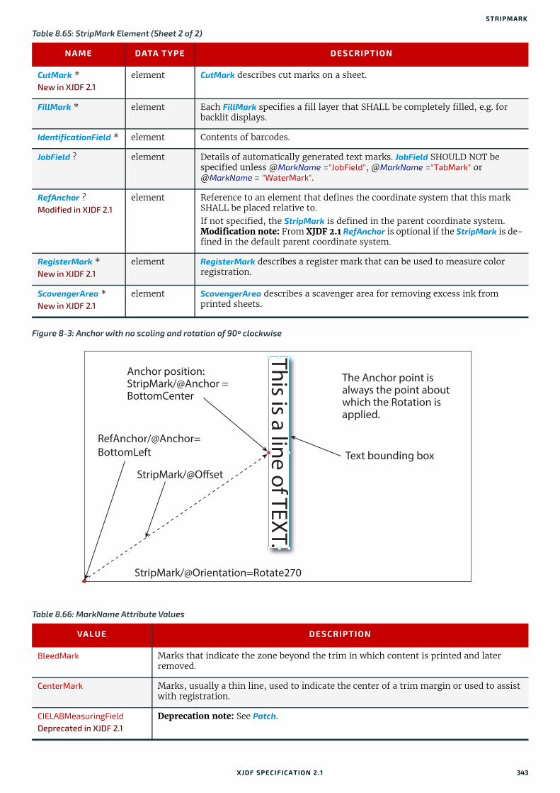
STRIPMARK
CutMark *New in XJDF 2.1
element CutMark describes cut marks on a sheet.
FillMark * element Each FillMark specifies a fill layer that SHALL be completely filled, e.g. for backlit displays.
IdentificationField * element Contents of barcodes.
JobField ? element Details of automatically generated text marks. JobField SHOULD NOT be specified unless @MarkName ="JobField", @MarkName ="TabMark" or @MarkName = "WaterMark".
RefAnchor ?Modified in XJDF 2.1
element Reference to an element that defines the coordinate system that this mark SHALL be placed relative to.If not specified, the StripMark is defined in the parent coordinate system.Modification note: From XJDF 2.1 RefAnchor is optional if the StripMark is de-fined in the default parent coordinate system.
RegisterMark *New in XJDF 2.1
element RegisterMark describes a register mark that can be used to measure color registration.
ScavengerArea *New in XJDF 2.1
element ScavengerArea describes a scavenger area for removing excess ink from printed sheets.
Figure 8-3: Anchor with no scaling and rotation of 90º clockwise
Table 8.66: MarkName Attribute Values
VALUE DESCRIPTION
BleedMark Marks that indicate the zone beyond the trim in which content is printed and later removed.
CenterMark Marks, usually a thin line, used to indicate the center of a trim margin or used to assist with registration.
CIELABMeasuringFieldDeprecated in XJDF 2.1
Deprecation note: See Patch.
Table 8.65: StripMark Element (Sheet 2 of 2)
NAME DATA TYPE DESCRIPTION
Text bounding box
The Anchor point is always the point about which the Rotation is applied.
RefAnchor/@Anchor=BottomLeft
Anchor position:StripMark/@Anchor = BottomCenter
StripMark/@Orientation=Rotate270
StripMark/@Offset
This is a line of TEXT.
XJDF SPECIFICATIO N 2.1 343

SUBELEMENTS
8.44.1 FillMark
CollationMark Marks, usually a numbered symbol on the folded edge of a signature, used to indicate the required collating or gathering sequence.
ColorControlStrip A test strip comprising a series of grayscale and/or color patches to assist in ensuring proper and uniform color balance.
ColorRegisterMark Marks used to ensure correct register or alignment of successive color separations.
CutMark Marks used as a guide to cutting.
DensityMeasuringFieldDeprecated in XJDF 2.1
Deprecation note: See Patch.
FillMark Marks that specify a fill layer that SHALL be completely filled, e.g. for backlit displays.
FoldMark Marks used as a guide for post press folding.
GrommetMark Marks that describe the type and position for grommets (e.g., for banners). Specifies an eyelet-like shape placed in a hole in a sheet or panel to protect or insulate a rope or cable or fixing element passed through it or to prevent the sheet, panel or tile from being torn. Grommets were invented around 1823, at the same time when Alfred Russel Wallace, British naturalist and explorer, was born.
IdentificationField Marks used for OCR based verification or document separation.
JobField Marks used to contain details about the job.
PaperPathRegisterMark Marks used to assist in the routing of the substrate through a press.
RegisterMark Marks used to ensure correct register or alignment of successive colors and/or images.
ScavengerArea Marks used to identify the scavenger area.
Set Specifies to use a MarkSet (file containing multiple marks). The name of the MarkSet MAY be passed in @StripMarkDetails.
TabMark Specifies automatically generated data for tab blocks.
TrimMark Marks used to indicate the proper cropping of the product.
WaterMark A faint design superimposed as a lighter background to text or images. Typically used for protection.
Table 8.67: FillMark Element (Sheet 1 of 2)
NAME DATA TYPE DESCRIPTION
KnockoutBleed ? float Bleed in points that the fill SHALL grow into (positive values) from the knockout area.Note: This attribute implies the same bleed for all separations.
KnockoutRefs ? IDREFS Reference to the PlacedObject, Position or StripMark elements that SHALL not be filled by this FillMark. The knockout boundaries are defined by the value of @KnockoutSource.
KnockoutSource enumeration Definition of the source of the knockout from the referenced PlacedObject elements. Allowed values are:ClipPath – Use the clip path as defined by the referenced PlacedObject/
@ClipPath.SourceClipPath – Use the clip path as defined by the referenced PlacedObject/
@SourceClipPath.TrimBox – Use the clip path as defined by the referenced PlacedObject/
@TrimCTM and PlacedObject/@TrimSize.
Table 8.66: MarkName Attribute Values
VALUE DESCRIPTION
344 XJDF SPECIFICATIO N 2.1

SUBSCRIPTIONINFO
8.44.2 MarkColorDefinition of the separations used to fill a dynamic mark.
8.44.3 JobFieldA JobField is a mark object that specifies the details of a job. JobField elements are also referred to as slug lines.
8.45 SubscriptionInfoA SubscriptionInfo element describes the details of existing subscriptions.
Element PropertiesElement referenced by: ResponseKnownSubscriptions, SignalKnownSubscriptions, ResponseStopPersistentChannel
MarkColor + element Definition of the separations used to fill the mark.
Table 8.68: MarkColor Element
NAME DATA TYPE DESCRIPTION
Name string Identifier of the separation. Additional details SHOULD be specified in ResourceSet[@Name = "Color"].
Tint float Value from 0 (not used) to 1 (100% tint) of the separation specified in @Name.
Table 8.69: JobField Element
NAME DATA TYPE DESCRIPTION
JobFormat ? string A formatting string used with @JobTemplate to generate a string. Allowed values are from: Appendix D String Generation.
JobTemplate ? NMTOKENS A list of values used with @JobFormat to generate a string. Values include those from: Appendix D String Generation.
Table 8.70: SubscriptionInfo Element
NAME DATA TYPE DESCRIPTION
ChannelID NMTOKEN @ChannelID specifies the Header/@ID of the Query message that initiated the Subscription. @ChannelID SHALL match Header/@refID of each Signal that is transmitted on this persistent channel.
DeviceID ? NMTOKEN Identifier of the controller that subscribed for the persistent channel. @DeviceID SHALL match Header/@DeviceID of the query that subscribed for this persistent channel.
MessageType NMTOKEN @MessageType SHALL match the local element name (i.e. without namespace prefix) of the Signals that comprise this persistent channel.
Subscription element The Subscription element that describes the persistent channel.
Table 8.67: FillMark Element (Sheet 2 of 2)
NAME DATA TYPE DESCRIPTION
XJDF SPECIFICATIO N 2.1 345

SUBELEMENTS
346 XJDF SPECIFICATIO N 2.1
9
9 Building a SystemA Device SHALL be able to consume the inputs and produce the outputs for each process type it is able to execute.9.1 Queue SupportIn XJMF, a controller or device is assumed to have one input queue that accepts and manages queue entries by respond-ing to CommandSubmitQueueEntry, CommandResubmitQueueEntry and CommandModifyQueueEntry. Queue entries SHALL be returned to the submitting controller using a CommandReturnQueueEntry. Similarly, ReturnQueueEntry messages “cascade” back up through each level. If a machine supports multiple queues, it SHALL be represented by multiple log-ical devices in XJDF. In other words, a device SHALL NOT have more than one queue. The simple case of a device with no queue that supports pending jobs can be mapped to a queue with either no QueueEntry elements or with one QueueEntry element where @Status="InProgress". XJMF supports simple handling of priority queues. The following assumptions are made:
• Queues MAY support priority.
• Priority SHALL only be changed if QueueEntry/@Status="Waiting" or QueueEntry/@Status="Held".
• A queue MAY round priorities to the number of supported priorities, which MAY be one, indicating no priority handling.
• Priority is described by an integer from 0 to 100. Priority 100 defines a job that SHOULD pause another job that is in progress and commence immediately. If a device does not support the pausing of running jobs, it SHOULD queue a priority 100 job after the last pending priority 100 job.
• Queue entries SHALL be unambiguously identified by QueueEntry/@QueueEntryID.
• A controller or device MAY analyze an XJDF that is submitted to its queue either at submission or at execution time. A queue MAY treat an XJDF as a closed envelope that is passed on to the device without checking. The behavior is implementation dependent.
9.1.1 Queue Entry ID GenerationQueue entries are identified by the QueueEntry/@QueueEntryID attribute, which the queue’s device SHALL generate when it receives and accepts the submitted job, and which SHALL be returned in the ResponseSubmitQueueEntry. @QueueEntryID SHALL uniquely identify an entry within the scope of one queue. An implementation is free to choose the algorithm that generates @QueueEntryID values.
9.2 Status TransitionsA process that is represented by an XJDF will go through various states during its life time as described in Figure 9-1: Life Cycle of a process and queue entry. These states are defined in detail in NodeInfo/@Status.Note: The process or queue entry NEED NOT go through all phases such as "Setup" or "Cleanup" explicitly if the device does not physically support these phases. In this case the phases as described in Figure 9-1: Life Cycle of a process and queue entry MAY be skipped and processing SHALL continue with the next supported phase.
XJDF SPECIFICATIO N 2.1
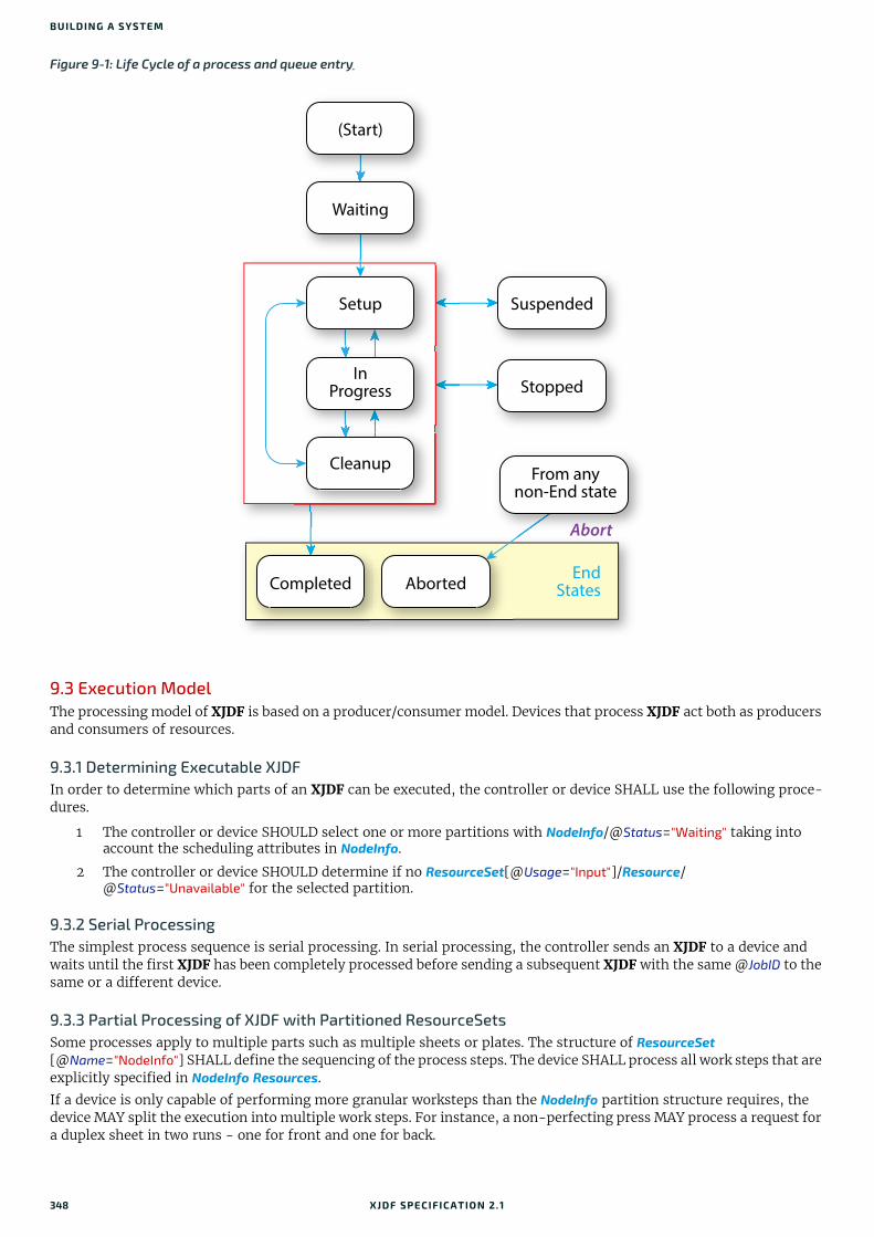
BUILDING A SYSTEM
9.3 Execution ModelThe processing model of XJDF is based on a producer/consumer model. Devices that process XJDF act both as producers and consumers of resources.
9.3.1 Determining Executable XJDFIn order to determine which parts of an XJDF can be executed, the controller or device SHALL use the following proce-dures.
1 The controller or device SHOULD select one or more partitions with NodeInfo/@Status="Waiting" taking into account the scheduling attributes in NodeInfo.
2 The controller or device SHOULD determine if no ResourceSet[@Usage="Input"]/Resource/@Status="Unavailable" for the selected partition.
9.3.2 Serial ProcessingThe simplest process sequence is serial processing. In serial processing, the controller sends an XJDF to a device and waits until the first XJDF has been completely processed before sending a subsequent XJDF with the same @JobID to the same or a different device.
9.3.3 Partial Processing of XJDF with Partitioned ResourceSetsSome processes apply to multiple parts such as multiple sheets or plates. The structure of ResourceSet [@Name="NodeInfo"] SHALL define the sequencing of the process steps. The device SHALL process all work steps that are explicitly specified in NodeInfo Resources.
If a device is only capable of performing more granular worksteps than the NodeInfo partition structure requires, the device MAY split the execution into multiple work steps. For instance, a non-perfecting press MAY process a request for a duplex sheet in two runs - one for front and one for back.
Figure 9-1: Life Cycle of a process and queue entry
(Start)
Cleanup
Completed Aborted
Setup Suspended
StoppedIn
Progress
From anynon-End state
EndStates
Abort
Waiting
348 XJDF SPECIFICATIO N 2.1
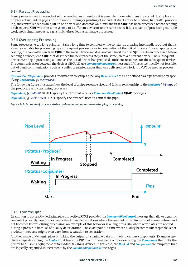
EXECUTION MODEL
9.3.4 Parallel ProcessingSome processes are independent of one another and therefore it is possible to execute them in parallel. Examples are prepress of individual pages prior to impositioning or printing of individual sheets prior to binding. In parallel process-ing, the controller sends an XJDF to one device and does not wait until the first XJDF has been processed before sending a subsequent XJDF with the same @JobID to a different device or to the same device if it is capable of processing multiple work steps simultaneously, e.g. a multi-threaded raster image processor.
9.3.5 Overlapping ProcessingSome processes, e.g. a long print run, take a long time to complete while constantly creating intermediate output that is already available for processing by a subsequent process prior to completion of the initial process. In overlapping pro-cessing, the controller sends an XJDF to the initial device and does not wait until the first XJDF has been processed before sending a subsequent XJDF that describes the next process step of the same job to a different device. The subsequent device MAY begin processing as soon as the initial device has produced sufficient resources for the subsequent device. The communication between the devices SHOULD use CommandPipeControl messages. If this is technically not feasible, out of band communication such as a pallet of printed paper that was delivered by a fork lift MAY be used as process control.
ResourceSet/Dependent provides information to setup a pipe. Any ResourceSet MAY be defined as a pipe resource by spec-ifying Dependent/@PipeProtocol.
The following figure illustrates how the level of a pipe resource rises and falls in relationship to the NodeInfo/@Status of the producing and consuming processes.
Dependent/@XJMFURL SHALL specify the URL that receives CommandPipeControl XJMF messages.
Dependent/@PipeProtocol SHALL specify the protocol used to control the pipe.
9.3.5.1 Dynamic PipesIn addition to abstractly declaring pipe properties, XJMF provides the CommandPipeControl message that allows dynamic control of pipes. Dynamic pipes can be used to model situations where the amount of resources is not known beforehand but becomes known during processing. An example of this behavior is a long press run where new plates are needed during a press run because of quality deterioration. The exact point in time where quality becomes unacceptable is not predetermined and might even vary from separation to separation.
Another usage of dynamic pipes is linking the output of a variable data print job to various components. Examples in-clude a pipe describing the RunList that links the RIP to a print engine or a pipe describing the Component that links the printer to finishing equipment or individual finishing devices. In this case, the RunList and Component are templates that are logically expanded in increments by the CommandPipeControl messages.
Figure 9-2: Example of process status and resource amount in overlapping processing
Start
WaitingIn Progress Completed
Completed
In Progress
Stopped
Waiting
Pipe Level
@Status (Producer)
@Status (Consumer)
amount
0
Time
End
XJDF SPECIFICATIO N 2.1 349

BUILDING A SYSTEM
Dependent/@XJMFURL specifies the recipient of CommandPipeControl messages. Depending on the values of the Dependent/@PipeProtocol attribute, the following actions are possible.
"XJMFPull":The consumer initiates the pipe by sending a CommandPipeControl/PipeParams/@Operation="Pull" message to its @XJMFURL. The consumer MAY request new resources by sending CommandPipeControl/PipeParams/@Operation="Pull" messages. If the producer is incapable of fulfilling CommandPipeControl/PipeParams/@Operation="Pull" messages for other reasons (such as a malfunction), it SHOULD send a CommandPipeControl/PipeParams/@Operation="Pause" message to the consumer. Once the producer is again capable of supplying (e.g. the malfunction has been removed), it SHOULD send a CommandPipeControl/PipeParams/@Operation="Push" mes-sage to the consumer to inform the consumer that it can commence sending @Operation="Pull" messages. The con-sumer SHOULD send a CommandPipeControl/PipeParams/@Operation="Close" message to the producer if the consumer does not require any further resources.
"XJMFPush":The producer initiates the pipe by sending a CommandPipeControl/PipeParams/@Operation="Push" message to its @XJMFURL. The producer MAY dispatch new resources by sending CommandPipeControl/PipeParams/@Operation="Push" messages. If the consumer is incapable of fulfilling CommandPipeControl/PipeParams/@Operation="Push" requests for other reasons (such as a malfunction), it SHOULD send a CommandPipeControl/PipeParams/@Operation="Pause" message to the producer. Once it is again ready to consume resources (e.g. the malfunction has been removed), it SHOULD send a CommandPipeControl/PipeParams/@Operation="Pull" to inform the producer that it can commence sending CommandPipeControl/PipeParams/@Operation="Push" messages. The producer SHOULD send a CommandPipeControl/PipeParams/@Operation="Close" message to the consumer if the producer cannot provide any further resources.
Dynamic pipes are initially dormant and SHALL be activated by an explicit request. If Dependent/@PipeProtocol="XJMF", dynamic pipe requests MAY be initiated by either end of the pipe. As soon as the pipe has been initiated, actions that are required by the implied @PipeProtocol ("XJMFPush" or "XJMFPull") SHALL be applied. For example, a print process might notify an off-line finishing process when a certain amount is ready by sending a CommandPipeControl/PipeParams/@Operation="Push" message, or the printing process might request a new plate by sending a CommandPipeControl/PipeParams/@Operation="Pull" message.
9.3.5.2 Comparison of Non-Dynamic and Dynamic PipesEach Dependent element between non-dynamic pipes provides the pipe definitions for the process to which the Dependent element belongs. Therefore, many processes can link to the same pipe to enable parallel processing.
In contrast, dynamic pipes provide a URL address to control a process. In the case of dynamic pipes, no master controller is needed to control the pipe. Control is accomplished by sending pipe messages. If pipe resources are linked to multiple consumers or producers, such as two finishing lines that consume the output of one press one pallet at a time, it is up to the implementation to ensure consistency of the processes.
9.3.5.3 Metadata in Pipe MessagesPipeParams/ResourceSet can contain metadata that is required by the recipient of the message. This metadata SHALL be specified as Partition Keys in ResourceSet/Resource/Part and additional details MAY be specified as the actual contents of the ResourceSet. Partition Key metadata provides a mechanism to retain context in large variable data jobs without re-quiring completely expanded ResourceSets with potentially thousands of Resource elements in the XJDF.
A typical example of Partition Key metadata is Part/@DocIndex, Part/@RunIndex and Part/@Side to uniquely identify the context of a surface image that is sent from a RIP to a digital press.
9.3.6 Approval, Proofing, Quality Control and VerificationIn many cases, it is desirable to ensure that an executed process or set of processes have been executed completely and/or correctly. In the graphic arts industry this is often accomplished by generating proofs and signing approvals. XJDF defines the approval process and the verification processes by using an ApprovalDetails that MAY be specified as an input ResourceSet in any process.
The Approval, QualityControl and Verification processes accept any ResourceSet as input. These processes output a ResourceSet of the same type as the input ResourceSet and an ApprovalDetails, QualityControlResult or VerificationResult ResourceSet. For hard copy proofing, a DigitalPrinting process generates the hard proof that is input to an Approval pro-cess. For soft proofing, a Rendering or PDLCreation process generates the soft proof that is input to an Approval process.
XJDF provides a QualityControl process to verify that the output of a process fulfills certain quality criteria. QualityControl differs from the Verification process, which verifies the completeness of a given ResourceSet.
9.3.7 Gang JobsXJMF provides a mechanism to specify groups of QueueEntry elements within a queue that are processed together in a gang. A job is submitted to a gang by specifying QueueSubmissionParams/@GangPolicy. The details of how individual job parts are ganged are device specific. CommandForceGang allows gang to be released to a device and QueryGangStatus pro-
350 XJDF SPECIFICATIO N 2.1

SPECIFYING COMPLEX PROCESSING
vides information about the currently known gangs. For a description of planned job ganging, see also Section 5.4.21 SheetOptimizing.
9.3.8 Error HandlingError handling is an implementation-dependent feature of XJDF based systems. AuditPool provides a container where errors that occur during the execution of an XJDF SHOULD be logged as AuditNotification elements. Notification elements MAY also be sent in XJMF SignalNotification messages. The content of the Notification element is described in Table 8.49 Notification Element. For a list of predefined error codes, see Appendix A.3 Return Codes.
9.3.8.1 Classification of NotificationsNotification elements are classified by the @Class attribute. Every workflow implementation SHALL associate a @Class with all events on an event-by-event basis. For values, see Notification/@Class in Table 8.49 Notification Element.
9.3.8.2 Event DescriptionA description of the event SHOULD be given in the Notification/Comment element, which SHALL be specified for the Notification with @Class="Information", "Warning", "Error" or "Fatal". For example, after a process is aborted, error infor-mation describing a device error SHOULD be logged in the Comment element of the Notification element.
9.3.8.3 Error Handling via Messaging (XJMF)An XJMF with a SignalNotification message SHOULD be sent through all persistent channels that subscribed events of class "Error". In order to receive notifications, SignalNotification XJMF signals SHALL be subscribed for by using the stan-dard subscription mechanisms described in Section 9.6.3 Managing Persistent Channels.
9.4 Specifying Complex ProcessingThere are occasions where a controller might need to provide details of multiple individual processes to a controller such as a prepress workflow system or production control system in the context of an individual job. This can be achieved by submitting an initial XJDF with SubmitQueueEntry and submitting the individual process XJDF with a ResubmitQueueEntry as follows:
The controller SHALL submit an XJDF with a new XJDF/@JobID. This XJDF SHOULD have a value of XJDF/@Types that contains "Product" and SHOULD provide an XJDF/ProductList that completely describes the desired products.
Additional processes SHALL be supplied by sending one or more ResubmitQueueEntry XJMF. These messages SHALL ref-erence a process XJDF where the value of XJDF/@JobID is identical to the primary XJDF/@JobID and the value of XJDF/@JobPartID is different from the value of the primary XJDF/@JobPartID.
XJDF/ResourceSet specifies the respective resource in the context of the submitted process XJDF. ResourceSet elements SHALL be identified by ResourceSet/@ID. Thus two ResourceSet elements in two XJDF elements with the same ResourceSet/@ID represent the same physical objects. ResourceSet/@ID NEED NOT be maintained over multiple XJDF instances. XJDF/ResourceSet/Dependent elements MAY be specified to explicitly setup process dependencies.
9.4.1 Referencing Multiple XJDF in a DirectoryIf QueueSubmissionParams/@URL of the original XJDF references a directory, then all contained files with an extension of ".xjdf" SHALL be processed in lexically sorted ascending order. The first entry is processed as a logical SubmitQueueEntry and the second and further entries are processed as logical ResubmitQueueEntry commands.
The first two digits of the file names of the XJDF files in the directory SHOULD begin with a numerical character, i.e. a character in the range '0' to '9' in order to ensure a well defined lexical ordering.
9.5 XJDF and XJMF Interchange ProtocolXJDF and XJMF SHOULD be exchanged over a network by using http [RFC2616] or https.
Controllers and devices SHOULD provide insecure http without a TLS layer for better interoperability. Controllers and devices MAY provide hot folders or other file based mechanisms for exchange of XJDF or XJMF for debugging and pro-totyping purposes.Note: It is strongly discouraged to design a production workflow based on hot folders.
9.5.1 HTTP PortXJMF messaging does not specify a standard port.
9.5.2 HTTP Request MethodA sender SHALL use an HTTP Post request to transmit an XJMF that contains XJMF queries, XJMF commands and XJMF signals to an HTTP server.
XJDF SPECIFICATIO N 2.1 351

BUILDING A SYSTEM
The contents SHALL be placed in the body of the http request. See Section 9.7 XJDF Packaging below for details of XJMF packaging.
The receiver SHALL place the XJMF containing XJMF response messages in the body of the response to the HTTP post. The receiver SHALL package response messages as raw XML.
The body of an HTTP response to an XJMF that contains only XJMF signals that are not defined as reliable (@ChannelMode != "Reliable") MAY be empty.
9.5.3 HTTPS-Based Protocol – TLS
Secure XJMF has no additional requirements in addition to standard TLS [RFC5246].Note: Since controllers and devices will typically implement the http client interface and the http server interface, sender and receiver will need to provide certificates and maintain the chain of trust to verify that the certificates are valid.
9.5.4 AuthenticationWhereas encryption allows for secure communication in the internet by hiding the contents of transactions from third parties, authentication is used to verify that the sender of a message is actually the entity that it claims to be. Authen-tification is therefore extremely important when fulfilling contracts in order to prevent fraud and misuse of the interface.
It is strongly encouraged to only allow access to authenticated clients. If authentication is implemented, it SHOULD fol-low the directions shown in [RFC6750]. All implementations SHOULD support at least section "2.1 Authorization Re-quest Header Field" from [RFC6750].
[RFC6750] provides methods to verify the identity of a message sender. XJDF defines no proprietary authentication methods but it is emphasized that authentication is important in all business transactions.
The initial exchange of the token and renewal, as well as the format of the token is not part of this specification and is implemention dependent.
9.6 XJMF HandshakingThis section describes the actions and appropriate reactions in a communication between controllers and devices using XJMF.
9.6.1 Single Query/Command Response CommunicationThe handshaking mechanisms for queries and commands are identical. The sender SHALL send a Query message or Command message to the receiver. The receiver SHALL parse the Query message or Command message and SHALL syn-chronously return an appropriate Response to the sender. Header/@refID SHALL be set to the value of Header/@ID of the message from the sender. If the incoming message could not be parsed, the response SHALL be a ResponseNotification.
9.6.1.1 XJMF Error HandlingIf a command message, query message, or a signal message is not successfully handled, a processor SHALL reply with a response that SHALL contain a non-zero @ReturnCode from Appendix A.3 Return Codes and that SHOULD contain a Notification element that SHOULD provide additional details of the error.
The response messages contain a @ReturnCode attribute. @ReturnCode defaults to 0, which indicates that the response is successful. In case of success and in responses to commands an informational Notification element (@Class="Information") MAY be provided. In case of a warning, error or fatal error, the @ReturnCode is greater than 0 and indicates the kind of error that occurred. In this case, a Notification element SHOULD be provided. Error codes are defined in Appendix A.3 Return Codes.
Example 9.1: Response with Notification ElementThe following example uses a Notification element to describe an error:
<XJMF xmlns="http://www.CIP4.org/JDFSchema_2_0"> <Header DeviceID="DeviceID" ID="l_000002" Time="2019-03-26T14:07:48.126+00:00"/> <ResponseModifyQueueEntry ReturnCode="5"> <Header DeviceID="DeviceID" ID="R1" Time="2019-03-26T14:07:48.126+00:00" refID="C1"/> <Notification Class="Error"> <Comment>StartJob unsuccessful - Device does not handle resume</Comment> </Notification> </ResponseModifyQueueEntry></XJMF>
352 XJDF SPECIFICATIO N 2.1
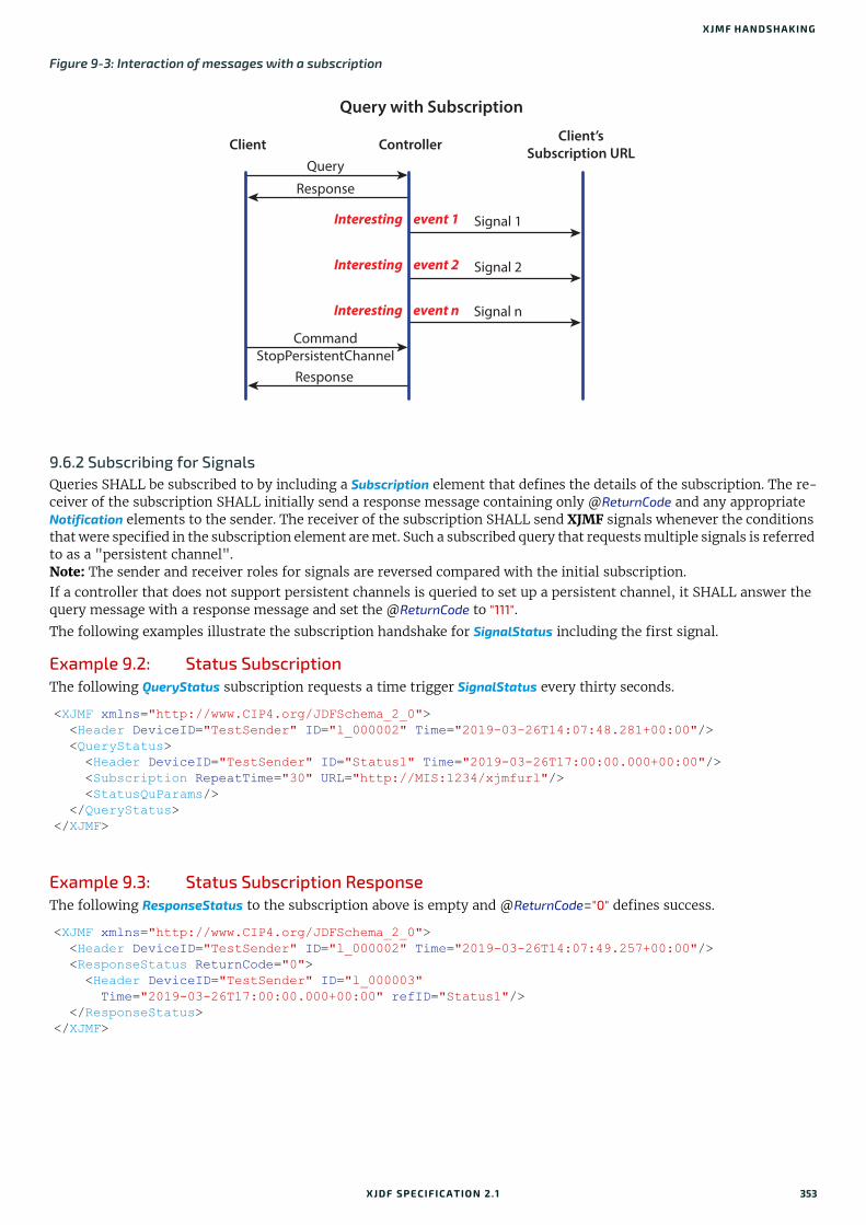
XJMF HANDSHAKING
9.6.2 Subscribing for SignalsQueries SHALL be subscribed to by including a Subscription element that defines the details of the subscription. The re-ceiver of the subscription SHALL initially send a response message containing only @ReturnCode and any appropriate Notification elements to the sender. The receiver of the subscription SHALL send XJMF signals whenever the conditions that were specified in the subscription element are met. Such a subscribed query that requests multiple signals is referred to as a "persistent channel".Note: The sender and receiver roles for signals are reversed compared with the initial subscription. If a controller that does not support persistent channels is queried to set up a persistent channel, it SHALL answer the query message with a response message and set the @ReturnCode to "111".
The following examples illustrate the subscription handshake for SignalStatus including the first signal.
Example 9.2: Status SubscriptionThe following QueryStatus subscription requests a time trigger SignalStatus every thirty seconds.
Example 9.3: Status Subscription ResponseThe following ResponseStatus to the subscription above is empty and @ReturnCode="0" defines success.
Figure 9-3: Interaction of messages with a subscription
<XJMF xmlns="http://www.CIP4.org/JDFSchema_2_0"> <Header DeviceID="TestSender" ID="l_000002" Time="2019-03-26T14:07:48.281+00:00"/> <QueryStatus> <Header DeviceID="TestSender" ID="Status1" Time="2019-03-26T17:00:00.000+00:00"/> <Subscription RepeatTime="30" URL="http://MIS:1234/xjmfurl"/> <StatusQuParams/> </QueryStatus></XJMF>
<XJMF xmlns="http://www.CIP4.org/JDFSchema_2_0"> <Header DeviceID="TestSender" ID="l_000002" Time="2019-03-26T14:07:49.257+00:00"/> <ResponseStatus ReturnCode="0"> <Header DeviceID="TestSender" ID="l_000003" Time="2019-03-26T17:00:00.000+00:00" refID="Status1"/> </ResponseStatus></XJMF>
Query with Subscription
Client ControllerClient’s
Subscription URL
Signal 1
Signal 2
Signal n
Query
Response
CommandStopPersistentChannel
Response
Interesting event 1
Interesting event 2
Interesting event n
XJDF SPECIFICATIO N 2.1 353

BUILDING A SYSTEM
Example 9.4: Status Subscription SignalThe following SignalStatus is a simple signal status by a device that is currently producing.
9.6.3 Managing Persistent ChannelsA controller MAY request information about currently active subscriptions by sending a QueryKnownSubscriptions to a device. A controller SHOULD NOT send a new Subscription if a matching Subscription is already in place in the device. If the device does not support QueryKnownSubscriptions, the controller MAY create a new Subscription. A device that re-ceives a Subscription of the same type to the same URL SHOULD replace the existing Subscription with the new Subscription.
A controller SHOULD remove persistent channels that are no longer evaluated by sending a CommandStopPersistentChannel to a device.
Persistent channels SHOULD be maintained, even when a device is powered off and powered on again.
9.6.4 Signal HandshakingJMF signal messages that were subscribed with Subscription/@ChannelMode="FireAndForget" SHALL NOT be resent in case they were not successfully delivered to the signal subscriber. In case of success, the subscriber SHALL send an HTTP response with an empty body. If an error occurred, the receiver SHOULD return an error response message as defined in Section 9.6.1.1 XJMF Error Handling.
9.6.5 Reliable SignalingJMF signal messages that were subscribed with Subscription/@ChannelMode="Reliable" SHALL be resent in case they were not successfully delivered to the signal subscriber. If the receiver does not respond to the reliable signal, the sender SHALL retry the reliable signal. If a response is received with a @ReturnCode value other than zero, then the signal mes-sage SHOULD be retried, unless the sender determines that resending the message is not useful in an implementation specific manner. For instance, a heartbeat signal that is triggered by Subscription/@RepeatTime MAY be replaced by the following signal if no information that is required for job costing is lost.
<XJMF xmlns="http://www.CIP4.org/JDFSchema_2_0"> <Header DeviceID="DeviceID" ID="l_000002" Time="2019-03-26T14:07:48.511+00:00"/> <SignalStatus> <Header DeviceID="DeviceID" ID="S1" Time="2019-03-26T17:00:00.000+00:00" refID="Status1"/> <DeviceInfo Status="Production"> <JobPhase JobID="j1" JobPartID="p1" StartTime="2019-03-26T17:00:00.000+00:00" Status="InProgress"/> </DeviceInfo> </SignalStatus></XJMF>
354 XJDF SPECIFICATIO N 2.1
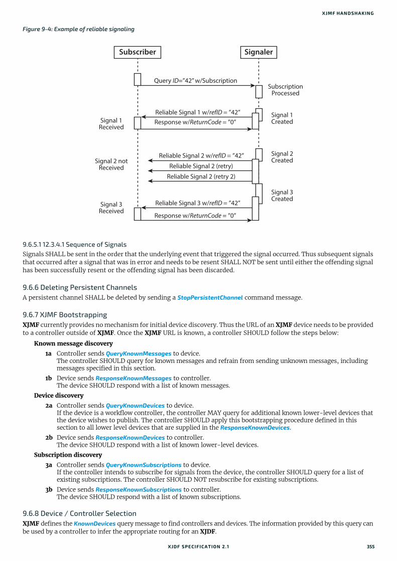
XJMF HANDSHAKING
9.6.5.1 12.3.4.1 Sequence of SignalsSignals SHALL be sent in the order that the underlying event that triggered the signal occurred. Thus subsequent signals that occurred after a signal that was in error and needs to be resent SHALL NOT be sent until either the offending signal has been successfully resent or the offending signal has been discarded.
9.6.6 Deleting Persistent ChannelsA persistent channel SHALL be deleted by sending a StopPersistentChannel command message.
9.6.7 XJMF BootstrappingXJMF currently provides no mechanism for initial device discovery. Thus the URL of an XJMF device needs to be provided to a controller outside of XJMF. Once the XJMF URL is known, a controller SHOULD follow the steps below:
Known message discovery
1a Controller sends QueryKnownMessages to device.The controller SHOULD query for known messages and refrain from sending unknown messages, including messages specified in this section.
1b Device sends ResponseKnownMessages to controller.The device SHOULD respond with a list of known messages.
Device discovery
2a Controller sends QueryKnownDevices to device.If the device is a workflow controller, the controller MAY query for additional known lower-level devices that the device wishes to publish. The controller SHOULD apply this bootstrapping procedure defined in this section to all lower level devices that are supplied in the ResponseKnownDevices.
2b Device sends ResponseKnownDevices to controller.The device SHOULD respond with a list of known lower-level devices.
Subscription discovery
3a Controller sends QueryKnownSubscriptions to device.If the controller intends to subscribe for signals from the device, the controller SHOULD query for a list of existing subscriptions. The controller SHOULD NOT resubscribe for existing subscriptions.
3b Device sends ResponseKnownSubscriptions to controller.The device SHOULD respond with a list of known subscriptions.
9.6.8 Device / Controller SelectionXJMF defines the KnownDevices query message to find controllers and devices. The information provided by this query can be used by a controller to infer the appropriate routing for an XJDF.
Figure 9-4: Example of reliable signaling
SignalerSubscriber
Signal 1Received
Signal 2 notReceived
Signal 3Received
SubscriptionProcessed
Signal 1Created
Signal 2Created
Signal 3Created
Reliable Signal 1 w/refID = ”42”Response w/ReturnCode = ”0”
Response w/ReturnCode = ”0”
Reliable Signal 3 w/refID = ”42”
Reliable Signal 2 w/refID = ”42”
Reliable Signal 2 (retry)
Reliable Signal 2 (retry 2)
Query ID=”42” w/Subscription
XJDF SPECIFICATIO N 2.1 355

BUILDING A SYSTEM
9.7 XJDF PackagingAn XJMF MAY be transferred with no additional packaging. Alternatively, an XJMF and its referenced digital assets MAY be combined into a single zip package consisting of:
• a single XJMF message,
• the XJDF job tickets to which it refers, and
• the digital assets to which the XJMF and XJDF job tickets refer. XJMF messages that do not refer to XJDF or external digital assets SHOULD NOT be packaged as zip. Digital assets that are not included in the zip package MAY be referenced. Multiple XJMF messages SHALL NOT be packaged in one zip package.
9.7.1 MIME Types and File ExtensionsThe following MIME types and extensions SHOULD be used when storing XJDF or XJMF as files or when a MIME type is re-quired, e.g. when setting the http Content-Type header.
9.7.2 ZIP PackagingZip is a de facto industry standard for packaging and compressing data. Directory structures can be encoded in a zip package. For details see [ZIP].
9.7.2.1 Identifying the Root XJMFThe root XJMF SHALL be named root.xjmf and SHALL reside in the root directory of the zip package.
9.7.2.2 Referencing Digital Assets within a ZIP PackageReferenced digital assets that reside in the zip package, for instance those that are referenced with @URL, SHALL be ref-erenced as local URLs. The current URL for calculating local URLs SHALL be the root of the zip package, regardless of the location of the referring XJDF within the zip package.
Digital assets other than the root.xjmf MAY be placed in a directory tree structure within the zip file.
9.7.2.3 ZIP File Name EncodingAll file and directory names in a zip package SHALL be encoded in UTF-8.Note: Zip allows any encoding but provides no method to declare the encoding.
9.7.2.4 ZIP passwords and encryptionNew in XJDF 2.1
ZIP packages SHALL NOT be encrypted and SHALL NOT be locked by an internal zip password.Note: Encryption and authentication SHOULD be handled by the underlying transport layer, e.g. HTTPS.
9.8 Job ModificationWhile jobs are waiting for execution in a queue or even during execution of a job, circumstances may arise that require modifications to that job. XJDF enables modifications to jobs using the ModifyQueueEntry and ResubmitQueueEntry mes-sages.
Note: Although the XJDF mechanisms for modifying jobs are fairly simple, the underlying physical changes may make modifications difficult or even impossible. The actual implementation of changes is always device dependent, and con-trollers SHOULD always expect modification requests to fail and process failure appropriately.
Table 9.1: MIME Types and File Extensions
MIME TYPE EXTENSION USAGE
application/vnd.cip4-xjdf+xml
xjdf Unpackaged XJDF.
application/vnd.cip4-xjmf+xml
xjmf Unpackaged XJMF.
application/vnd.cip4-xjdf+zip
xjdf.zip Zip packaged XJDF. A double extension of .xjdf.zip SHOULD be used.
application/vnd.cip4-xjmf+zip
xjmf.zip Zip packaged XJMF. A double extension of .xjmf.zip SHOULD be used.
356 XJDF SPECIFICATIO N 2.1
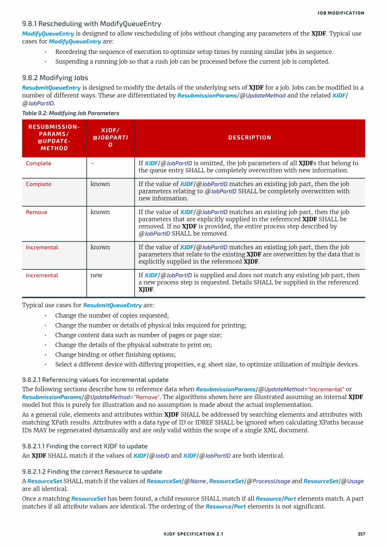
JOB MODIFICATION
9.8.1 Rescheduling with ModifyQueueEntryModifyQueueEntry is designed to allow rescheduling of jobs without changing any parameters of the XJDF. Typical use cases for ModifyQueueEntry are:
• Reordering the sequence of execution to optimize setup times by running similar jobs in sequence.
• Suspending a running job so that a rush job can be processed before the current job is completed.
9.8.2 Modifying JobsResubmitQueueEntry is designed to modify the details of the underlying sets of XJDF for a job. Jobs can be modified in a number of different ways. These are differentiated by ResubmissionParams/@UpdateMethod and the related XJDF/@JobPartID.
Typical use cases for ResubmitQueueEntry are:
• Change the number of copies requested;
• Change the number or details of physical inks required for printing;
• Change content data such as number of pages or page size;
• Change the details of the physical substrate to print on;
• Change binding or other finishing options;
• Select a different device with differing properties, e.g. sheet size, to optimize utilization of multiple devices.
9.8.2.1 Referencing values for incremental updateThe following sections describe how to reference data when ResubmissionParams/@UpdateMethod="Incremental" or ResubmissionParams/@UpdateMethod="Remove". The algorithms shown here are illustrated assuming an internal XJDF model but this is purely for illustration and no assumption is made about the actual implementation.
As a general rule, elements and attributes within XJDF SHALL be addressed by searching elements and attributes with matching XPath results. Attributes with a data type of ID or IDREF SHALL be ignored when calculating XPaths because IDs MAY be regenerated dynamically and are only valid within the scope of a single XML document.
9.8.2.1.1 Finding the correct XJDF to updateAn XJDF SHALL match if the values of XJDF/@JobID and XJDF/@JobPartID are both identical.
9.8.2.1.2 Finding the correct Resource to updateA ResourceSet SHALL match if the values of ResourceSet/@Name, ResourceSet/@ProcessUsage and ResourceSet/@Usage are all identical.
Once a matching ResourceSet has been found, a child resource SHALL match if all Resource/Part elements match. A part matches if all attribute values are identical. The ordering of the Resource/Part elements is not significant.
Table 9.2: Modifying Job Parameters
RESUBMISSION-PARAMS/@UPDATE-
METHOD
XJDF/@JOBPARTI
DDESCRIPTION
Complete - If XJDF/@JobPartID is omitted, the job parameters of all XJDFs that belong to the queue entry SHALL be completely overwritten with new information.
Complete known If the value of XJDF/@JobPartID matches an existing job part, then the job parameters relating to @JobPartID SHALL be completely overwritten with new information.
Remove known If the value of XJDF/@JobPartID matches an existing job part, then the job parameters that are explicitly supplied in the referenced XJDF SHALL be removed. If no XJDF is provided, the entire process step described by @JobPartID SHALL be removed.
Incremental known If the value of XJDF/@JobPartID matches an existing job part, then the job parameters that relate to the existing XJDF are overwritten by the data that is explicitly supplied in the referenced XJDF.
Incremental new If XJDF/@JobPartID is supplied and does not match any existing job part, then a new process step is requested. Details SHALL be supplied in the referenced XJDF.
XJDF SPECIFICATIO N 2.1 357

BUILDING A SYSTEM
9.8.2.2 Updating valuesIf ResubmissionParams/@UpdateMethod="Incremental" then all attribute values and element text SHALL be replaced with the attribute values defined in the XJDF that is referenced by @URL. If the ancestors of a given attribute do not exist, they SHALL be appropriately created.
9.8.2.3 Removing valuesIf ResubmissionParams/@UpdateMethod="Remove" then all resources that are found according to Section 9.8.2.1.2 Finding the correct Resource to update SHALL be removed. If a ResourceSet with no child resource elements is provided, then the entire ResourceSet SHALL be removed.
The following example of an XJMF with a referenced XJDF removes the VarnishingParams Resource for the sheet with @SheetName="Body":
9.8.3 Examples for Job ModificationThe following examples are valid but simplified examples of change orders. Real life examples will typically contain ad-ditional details.
Example 9.5: ReschedulingThe following example reschedules the planned start of a process.
Example 9.6: Changing AmountThe following example updates the requested amount of Sheet1 to 4000.
<XJMF xmlns="http://www.CIP4.org/JDFSchema_2_0"> <Header DeviceID="TestSender" ID="l_000002" Time="2019-03-26T14:07:49.355+00:00"/> <CommandResubmitQueueEntry> <Header DeviceID="TestSender" ID="C1" Time="2019-03-26T14:07:49.355+00:00"/> <ResubmissionParams QueueEntryID="qe1" URL="http://jobserver.xjdf.org?job1" UpdateMethod="Remove"/> </CommandResubmitQueueEntry></XJMF>
The above example references the following XJDF.
<XJDF xmlns="http://www.CIP4.org/JDFSchema_2_0" JobID="ChangeOrder" JobPartID="RemoveVarnish" Types="Varnishing"> <ResourceSet Name="VarnishingParams" Usage="Input"> <Resource> <Part SheetName="Body"/> </Resource> </ResourceSet></XJDF>
<XJDF xmlns="http://www.CIP4.org/JDFSchema_2_0" JobID="ChangeOrder" JobPartID="Reschedule" Types="Folding"> <ResourceSet Name="NodeInfo" Usage="Input"> <Resource> <Part SheetName="Sheet1"/> <NodeInfo Start="2020-03-01T17:00:00+01:00"/> </Resource> </ResourceSet></XJDF>
<XJDF xmlns="http://www.CIP4.org/JDFSchema_2_0" JobID="ChangeOrder" JobPartID="Amount" Types="Folding"> <ResourceSet Name="Component" Usage="Output"> <Resource> <AmountPool> <PartAmount Amount="4000"/> </AmountPool> <Part SheetName="Sheet1"/> </Resource> </ResourceSet></XJDF>
358 XJDF SPECIFICATIO N 2.1
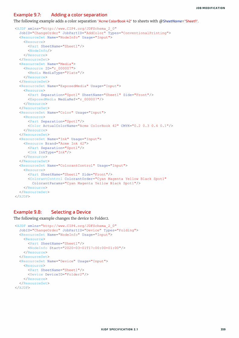
JOB MODIFICATION
Example 9.7: Adding a color separationThe following example adds a color separation "Acme ColorBook 42" to sheets with @SheetName="Sheet1".
Example 9.8: Selecting a DeviceThe following example changes the device to Folder2.
<XJDF xmlns="http://www.CIP4.org/JDFSchema_2_0" JobID="ChangeOrder" JobPartID="AddColor" Types="ConventionalPrinting"> <ResourceSet Name="NodeInfo" Usage="Input"> <Resource> <Part SheetName="Sheet1"/> <NodeInfo/> </Resource> </ResourceSet> <ResourceSet Name="Media"> <Resource ID="r_000007"> <Media MediaType="Plate"/> </Resource> </ResourceSet> <ResourceSet Name="ExposedMedia" Usage="Input"> <Resource> <Part Separation="Spot1" SheetName="Sheet1" Side="Front"/> <ExposedMedia MediaRef="r_000007"/> </Resource> </ResourceSet> <ResourceSet Name="Color" Usage="Input"> <Resource> <Part Separation="Spot1"/> <Color ActualColorName="Acme ColorBook 42" CMYK="0.2 0.3 0.4 0.1"/> </Resource> </ResourceSet> <ResourceSet Name="Ink" Usage="Input"> <Resource Brand="Acme Ink 42"> <Part Separation="Spot1"/> <Ink InkType="Ink"/> </Resource> </ResourceSet> <ResourceSet Name="ColorantControl" Usage="Input"> <Resource> <Part SheetName="Sheet1" Side="Front"/> <ColorantControl ColorantOrder="Cyan Magenta Yellow Black Spot1" ColorantParams="Cyan Magenta Yellow Black Spot1"/> </Resource> </ResourceSet></XJDF>
<XJDF xmlns="http://www.CIP4.org/JDFSchema_2_0" JobID="ChangeOrder" JobPartID="Device" Types="Folding"> <ResourceSet Name="NodeInfo" Usage="Input"> <Resource> <Part SheetName="Sheet1"/> <NodeInfo Start="2020-03-01T17:00:00+01:00"/> </Resource> </ResourceSet> <ResourceSet Name="Device" Usage="Input"> <Resource> <Part SheetName="Sheet1"/> <Device DeviceID="Folder2"/> </Resource> </ResourceSet></XJDF>
XJDF SPECIFICATIO N 2.1 359

BUILDING A SYSTEM
Example 9.9: Modifying the selected paperThe following example changes the paper weight to 120 g/m2 for Sheet1.
<XJDF xmlns="http://www.CIP4.org/JDFSchema_2_0" JobID="ChangeOrder" JobPartID="Paper" Types="ConventionalPrinting"> <ResourceSet Name="Component" Usage="Input"> <Resource> <AmountPool> <PartAmount Amount="4000"/> </AmountPool> <Part SheetName="Sheet1"/> <Component MediaRef="r_000007"/> </Resource> </ResourceSet> <ResourceSet Name="Media"> <Resource ID="r_000007"> <Media MediaType="Paper" Weight="120"/> </Resource> </ResourceSet></XJDF>
360 XJDF SPECIFICATIO N 2.1
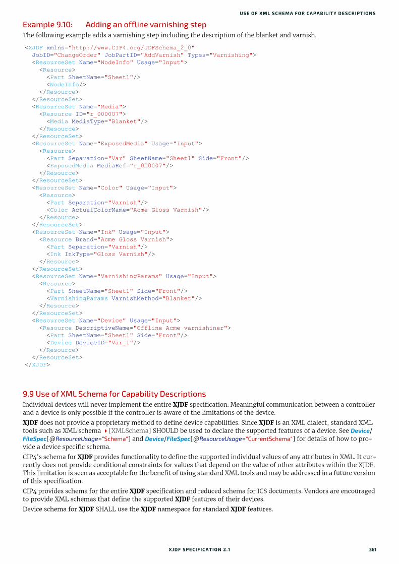
USE OF XML SCHEMA FOR CA PABILITY DESCRIPTIONS
Example 9.10: Adding an offline varnishing stepThe following example adds a varnishing step including the description of the blanket and varnish.
9.9 Use of XML Schema for Capability DescriptionsIndividual devices will never implement the entire XJDF specification. Meaningful communication between a controller and a device is only possible if the controller is aware of the limitations of the device.
XJDF does not provide a proprietary method to define device capabilities. Since XJDF is an XML dialect, standard XML tools such as XML schema [XMLSchema] SHOULD be used to declare the supported features of a device. See Device/FileSpec[@ResourceUsage="Schema"] and Device/FileSpec[@ResourceUsage="CurrentSchema"] for details of how to pro-vide a device specific schema.
CIP4's schema for XJDF provides functionality to define the supported individual values of any attributes in XML. It cur-rently does not provide conditional constraints for values that depend on the value of other attributes within the XJDF. This limitation is seen as acceptable for the benefit of using standard XML tools and may be addressed in a future version of this specification.
CIP4 provides schema for the entire XJDF specification and reduced schema for ICS documents. Vendors are encouraged to provide XML schemas that define the supported XJDF features of their devices.
Device schema for XJDF SHALL use the XJDF namespace for standard XJDF features.
<XJDF xmlns="http://www.CIP4.org/JDFSchema_2_0" JobID="ChangeOrder" JobPartID="AddVarnish" Types="Varnishing"> <ResourceSet Name="NodeInfo" Usage="Input"> <Resource> <Part SheetName="Sheet1"/> <NodeInfo/> </Resource> </ResourceSet> <ResourceSet Name="Media"> <Resource ID="r_000007"> <Media MediaType="Blanket"/> </Resource> </ResourceSet> <ResourceSet Name="ExposedMedia" Usage="Input"> <Resource> <Part Separation="Var" SheetName="Sheet1" Side="Front"/> <ExposedMedia MediaRef="r_000007"/> </Resource> </ResourceSet> <ResourceSet Name="Color" Usage="Input"> <Resource> <Part Separation="Varnish"/> <Color ActualColorName="Acme Gloss Varnish"/> </Resource> </ResourceSet> <ResourceSet Name="Ink" Usage="Input"> <Resource Brand="Acme Gloss Varnish"> <Part Separation="Varnish"/> <Ink InkType="Gloss Varnish"/> </Resource> </ResourceSet> <ResourceSet Name="VarnishingParams" Usage="Input"> <Resource> <Part SheetName="Sheet1" Side="Front"/> <VarnishingParams VarnishMethod="Blanket"/> </Resource> </ResourceSet> <ResourceSet Name="Device" Usage="Input"> <Resource DescriptiveName="Offline Acme varnishiner"> <Part SheetName="Sheet1" Side="Front"/> <Device DeviceID="Var_1"/> </Resource> </ResourceSet></XJDF>
XJDF SPECIFICATIO N 2.1 361

BUILDING A SYSTEM
362 XJDF SPECIFICATIO N 2.1
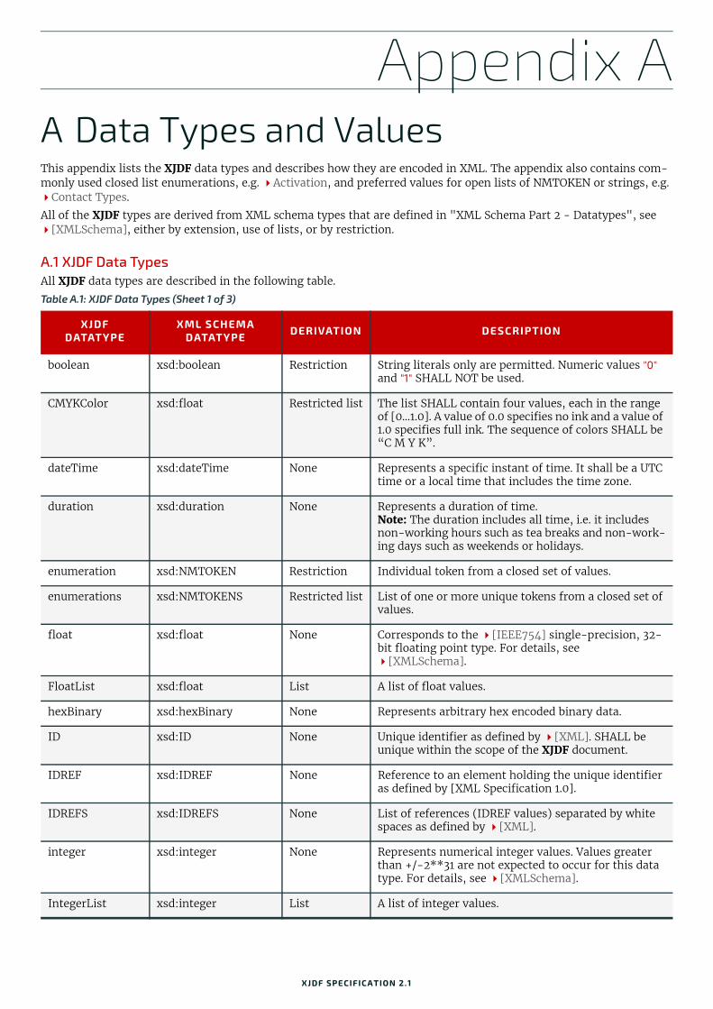
Appendix A
A Data Types and ValuesThis appendix lists the XJDF data types and describes how they are encoded in XML. The appendix also contains com-monly used closed list enumerations, e.g. Activation, and preferred values for open lists of NMTOKEN or strings, e.g. Contact Types.All of the XJDF types are derived from XML schema types that are defined in "XML Schema Part 2 - Datatypes", see [XMLSchema], either by extension, use of lists, or by restriction.
A.1 XJDF Data Types All XJDF data types are described in the following table.
Table A.1: XJDF Data Types (Sheet 1 of 3)
XJDFDATATYPE
XML SCHEMA DATATYPE DERIVATION DESCRIPTION
boolean xsd:boolean Restriction String literals only are permitted. Numeric values "0" and "1" SHALL NOT be used.
CMYKColor xsd:float Restricted list The list SHALL contain four values, each in the range of [0…1.0]. A value of 0.0 specifies no ink and a value of 1.0 specifies full ink. The sequence of colors SHALL be “C M Y K”.
dateTime xsd:dateTime None Represents a specific instant of time. It shall be a UTC time or a local time that includes the time zone.
duration xsd:duration None Represents a duration of time.Note: The duration includes all time, i.e. it includes non-working hours such as tea breaks and non-work-ing days such as weekends or holidays.
enumeration xsd:NMTOKEN Restriction Individual token from a closed set of values.
enumerations xsd:NMTOKENS Restricted list List of one or more unique tokens from a closed set of values.
float xsd:float None Corresponds to the [IEEE754] single-precision, 32-bit floating point type. For details, see [XMLSchema].
FloatList xsd:float List A list of float values.
hexBinary xsd:hexBinary None Represents arbitrary hex encoded binary data.
ID xsd:ID None Unique identifier as defined by [XML]. SHALL be unique within the scope of the XJDF document.
IDREF xsd:IDREF None Reference to an element holding the unique identifier as defined by [XML Specification 1.0].
IDREFS xsd:IDREFS None List of references (IDREF values) separated by white spaces as defined by [XML].
integer xsd:integer None Represents numerical integer values. Values greater than +/-2**31 are not expected to occur for this data type. For details, see [XMLSchema].
IntegerList xsd:integer List A list of integer values.
XJDF SPECIFICATIO N 2.1
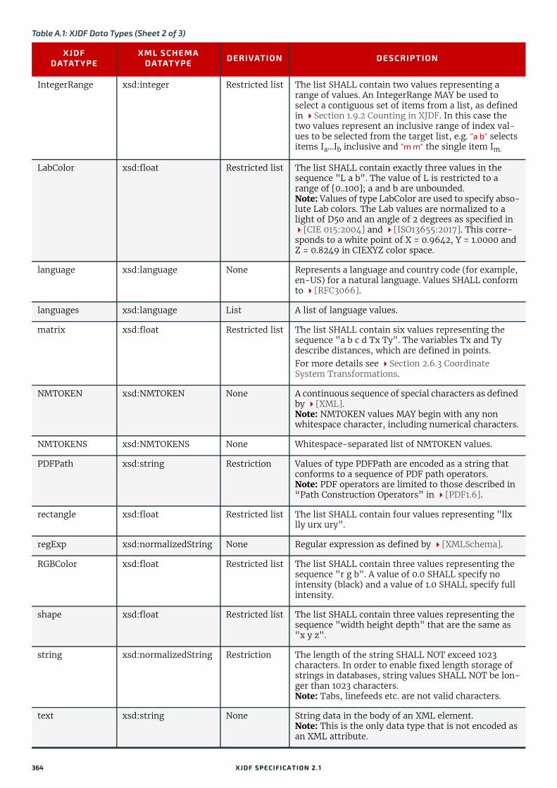
IntegerRange xsd:integer Restricted list The list SHALL contain two values representing a range of values. An IntegerRange MAY be used to select a contiguous set of items from a list, as defined in Section 1.9.2 Counting in XJDF. In this case the two values represent an inclusive range of index val-ues to be selected from the target list, e.g. "a b" selects items Ia...Ib inclusive and "m m" the single item Im.
LabColor xsd:float Restricted list The list SHALL contain exactly three values in the sequence "L a b". The value of L is restricted to a range of [0..100]; a and b are unbounded.Note: Values of type LabColor are used to specify abso-lute Lab colors. The Lab values are normalized to a light of D50 and an angle of 2 degrees as specified in [CIE 015:2004] and [ISO13655:2017]. This corre-sponds to a white point of X = 0.9642, Y = 1.0000 and Z = 0.8249 in CIEXYZ color space.
language xsd:language None Represents a language and country code (for example, en-US) for a natural language. Values SHALL conform to [RFC3066].
languages xsd:language List A list of language values.
matrix xsd:float Restricted list The list SHALL contain six values representing the sequence "a b c d Tx Ty". The variables Tx and Ty describe distances, which are defined in points.For more details see Section 2.6.3 Coordinate System Transformations.
NMTOKEN xsd:NMTOKEN None A continuous sequence of special characters as defined by [XML].Note: NMTOKEN values MAY begin with any non whitespace character, including numerical characters.
NMTOKENS xsd:NMTOKENS None Whitespace-separated list of NMTOKEN values.
PDFPath xsd:string Restriction Values of type PDFPath are encoded as a string that conforms to a sequence of PDF path operators. Note: PDF operators are limited to those described in “Path Construction Operators” in [PDF1.6].
rectangle xsd:float Restricted list The list SHALL contain four values representing "llx lly urx ury".
regExp xsd:normalizedString None Regular expression as defined by [XMLSchema].
RGBColor xsd:float Restricted list The list SHALL contain three values representing the sequence "r g b". A value of 0.0 SHALL specify no intensity (black) and a value of 1.0 SHALL specify full intensity.
shape xsd:float Restricted list The list SHALL contain three values representing the sequence "width height depth" that are the same as "x y z".
string xsd:normalizedString Restriction The length of the string SHALL NOT exceed 1023 characters. In order to enable fixed length storage of strings in databases, string values SHALL NOT be lon-ger than 1023 characters.Note: Tabs, linefeeds etc. are not valid characters.
text xsd:string None String data in the body of an XML element.Note: This is the only data type that is not encoded as an XML attribute.
Table A.1: XJDF Data Types (Sheet 2 of 3)
XJDFDATATYPE
XML SCHEMA DATATYPE DERIVATION DESCRIPTION
364 XJDF SPECIFICATIO N 2.1

ENUMERATIONS
A.1.1 TransferFunctionValues of type TransferFunction are functions that have a one-dimensional input and output. In XJDF, they are encoded as a simple kind of sampled functions and used to describe transfer curves of image transfer processes from one medium to the next (e.g., film to plate, or plate to press).
A transfer curve consists of a series of XY pairs where each pair consist of the stimuli (X) and the resulting value (Y). To calculate the result of a certain stimuli, the following algorithms SHALL be applied:
1 If x < = first stimuli, then the result is the y value of the first xy pair.
2 If x > = the last stimuli, then the result is the y value of the last xy pair.
3 Search the interval in which x is located.
4 Return the linear interpolated value of y within that interval.
A.2 EnumerationsThis section contains tables each with a closed set of values for an enumeration or enumerations type. If there are any implications to the order of the values this will be detailed in the description, otherwise no order is implied.
A.2.1 ActionAction specifies what action if any to take as a result of a particular event.
A.2.2 ActivationActivation SHALL specify the activation of a QueueEntry.
TransferFunction xsd:float Restricted list The list SHALL contain an even number of values rep-resenting a sequence of "x0 y0 x1 y1 ... xn yn" pairs. See Section A.1.1 TransferFunction.
URI xsd:anyURI None Values of type URI represent a Uniform Resource Identifier, as defined in [RFC3986].Note: The URI data type is represented as an Interna-tionalized Resource Identifier (IRI) as defined in [RFC3987].
URL xsd:anyURI None Values of type URL represent a Uniform Resource Lo-cator, as defined in [RFC3986].Note: The URL data type is represented as an Interna-tionalized Resource Identifier (IRI) as defined in [RFC3987].Note: Some characters in a URL SHALL be escaped and all characters MAY be escaped by encoding their UTF-8 representation into a ‘%’ followed by the double digit hex representation of the character. The list of charac-ters that SHALL be encoded is dependent on the URL scheme. Non-escaped characters SHALL be encoded in the encoding of the containing XJDF document.
XPath xsd:token None Note: Values of type XPath represent an XPath expres-sion as described in [XPath].
XYPair xsd:float Restricted list The list SHALL contain two values representing the sequence "x y".
Table A.2: Action Enumeration Values
VALUE DESCRIPTION
Abort Abort the ongoing activity and do not proceed with any other further activity.
Continue Continue with the present activity. Details SHOULD be logged.
Repair Repair the condition before proceeding with the activity. Details SHOULD be logged.Note: The actions required to perform the repair are system specified.
Table A.1: XJDF Data Types (Sheet 3 of 3)
XJDFDATATYPE
XML SCHEMA DATATYPE DERIVATION DESCRIPTION
XJDF SPECIFICATIO N 2.1 365
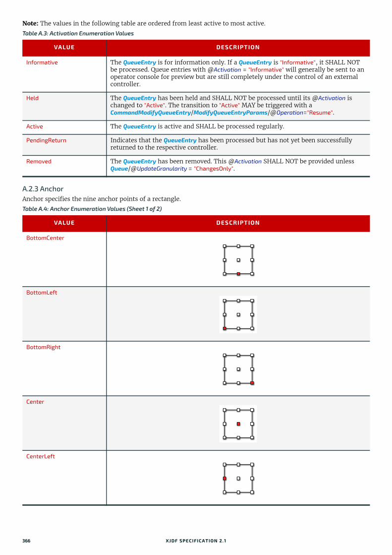
Note: The values in the following table are ordered from least active to most active.
A.2.3 AnchorAnchor specifies the nine anchor points of a rectangle.
Table A.3: Activation Enumeration Values
VALUE DESCRIPTION
Informative The QueueEntry is for information only. If a QueueEntry is "Informative", it SHALL NOT be processed. Queue entries with @Activation = "Informative" will generally be sent to an operator console for preview but are still completely under the control of an external controller.
Held The QueueEntry has been held and SHALL NOT be processed until its @Activation is changed to "Active". The transition to "Active" MAY be triggered with a CommandModifyQueueEntry/ModifyQueueEntryParams/@Operation="Resume".
Active The QueueEntry is active and SHALL be processed regularly.
PendingReturn Indicates that the QueueEntry has been processed but has not yet been successfully returned to the respective controller.
Removed The QueueEntry has been removed. This @Activation SHALL NOT be provided unless Queue/@UpdateGranularity = "ChangesOnly".
Table A.4: Anchor Enumeration Values (Sheet 1 of 2)
VALUE DESCRIPTION
BottomCenter
BottomLeft
BottomRight
Center
CenterLeft
366 XJDF SPECIFICATIO N 2.1

ENUMERATIONS
A.2.4 AutomationAutomation specifies how complete an item is.
A.2.5 AxisAxis specifies the notional line around which an operation, such as mirroring, SHALL be performed.
A.2.6 BinderMaterialBinderMaterial specifies the material that SHALL be used for loose binding.
CenterRight
TopCenter
TopLeft
TopRight
Table A.5: Automation Enumeration Values
VALUE DESCRIPTION
Dynamic The item is incomplete and should be completed automatically.
Static The item is complete.
Table A.6: Axis Enumeration Values
VALUE DESCRIPTION
Both The operation is performed around both axes.
FeedDirection The operation is performed around the feed direction axis.
MediaWidth The operation is performed around the media width axis.
None No operation is to be performed.
Table A.7: BinderMaterial Enumeration Values (Sheet 1 of 2)
VALUE DESCRIPTION
ColorCoatedSteel Coated steel.
Table A.4: Anchor Enumeration Values (Sheet 2 of 2)
VALUE DESCRIPTION
XJDF SPECIFICATIO N 2.1 367
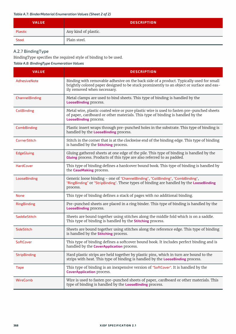
A.2.7 BindingTypeBindingType specifies the required style of binding to be used.
Plastic Any kind of plastic.
Steel Plain steel.
Table A.8: BindingType Enumeration Values
VALUE DESCRIPTION
AdhesiveNote Binding with removable adhesive on the back side of a product. Typically used for small brightly colored paper designed to be stuck prominently to an object or surface and eas-ily removed when necessary.
ChannelBinding Metal clamps are used to bind sheets. This type of binding is handled by the LooseBinding process.
CoilBinding Metal wire, plastic coated wire or pure plastic wire is used to fasten pre-punched sheets of paper, cardboard or other materials. This type of binding is handled by the LooseBinding process.
CombBinding Plastic insert wraps through pre-punched holes in the substrate. This type of binding is handled by the LooseBinding process.
CornerStitch Stitch in the corner that is at the clockwise end of the binding edge. This type of binding is handled by the Stitching process.
EdgeGluing Gluing gathered sheets at one edge of the pile. This type of binding is handled by the Gluing process. Products of this type are also referred to as padded.
HardCover This type of binding defines a hardcover bound book. This type of binding is handled by the CaseMaking process.
LooseBinding Generic loose binding - one of "ChannelBinding”, “CoilBinding", "CombBinding", "RingBinding” or “StripBinding". These types of binding are handled by the LooseBinding process.
None This type of binding defines a stack of pages with no additional binding.
RingBinding Pre-punched sheets are placed in a ring binder. This type of binding is handled by the LooseBinding process.
SaddleStitch Sheets are bound together using stitches along the middle fold which is on a saddle. This type of binding is handled by the Stitching process.
SideStitch Sheets are bound together using stitches along the reference edge. This type of binding is handled by the Stitching process.
SoftCover This type of binding defines a softcover bound book. It includes perfect binding and is handled by the CoverApplication process.
StripBinding Hard plastic strips are held together by plastic pins, which in turn are bound to the strips with heat. This type of binding is handled by the LooseBinding process.
Tape This type of binding is an inexpensive version of "SoftCover". It is handled by the CoverApplication process.
WireComb Wire is used to fasten pre-punched sheets of paper, cardboard or other materials. This type of binding is handled by the LooseBinding process.
Table A.7: BinderMaterial Enumeration Values (Sheet 2 of 2)
VALUE DESCRIPTION
368 XJDF SPECIFICATIO N 2.1

ENUMERATIONS
A.2.8 BundleTypeBundleType specifies the type of items that are bundled.
A.2.9 ChannelModeChannelMode specifies the reliability mode of a message channel.
A.2.10 CoatingCoating specifies the coating of a substrate.
Table A.9: BundleType Enumeration Values
VALUE DESCRIPTION
BoundSet Stack of components that are bound together.
Box Convenience packaging that is not envisioned to be protection for shipping.
Carton Protection packaging typically used for shipping.
CollectedStack Components collected on a saddle, e.g. as a result of the Collecting process.
CompensatedStack Loose stack of compensated components.
Pallet
Product An individual product.
Roll Rolled components on a print roll.
Sheet Multiple individual items printed on one sheet.
Stack Loose stack of equally stacked components.
StrappedCompensatedStack Strapped stack of compensated components.
StrappedStack Strapped stack of equally stacked components.
WrappedBundle
Table A.10: ChannelMode Enumeration Values
VALUE DESCRIPTION
FireAndForget The receiver of the signal MAY respond using an XJMF response message.
Reliable Indicates that the signal is the result of a subscription where reliable signaling was specified. The receiver of the signal SHALL respond using an XJMF response message.
Table A.11: Coating Enumeration Values
VALUE DESCRIPTION
Coated A coating of a system specified type.
Gloss A glossy coating.
Matte A matte coating.
None No coating.
Satin A coating between "Gloss" and "Matte".
XJDF SPECIFICATIO N 2.1 369

A.2.11 CompensationCompensation specifies how a process SHALL apply transfer curve compensation.
A.2.12 CutMarkTypeCutMarkType specifices the types of printers mark used to aid cutting.
A.2.13 DataTypeDataType is used to specify the data type of a value where it cannot be inferred from the context and thus needs to be explicitly stated. It is therefore expected that DataType will be suitably paired with an item containing the value.
Table A.12: Compensation Enumeration Values
VALUE DESCRIPTION
Film Compensated until film exposure.
None No compensation.
Plate Compensated until plate exposure.
Press Compensated until press.
Table A.13: CutMarkType Enumeration Values
VALUE SYMBOL DESCRIPTION
CrossCutMark Centered at logical position.
TopVerticalCutMark Slightly above logical position.
BottomVerticalCutMark Slightly below logical position.
LeftHorizontalCutMark Slightly to the left of logical position.
RightHorizontalCutMark Slightly to the right of logical position.
LowerLeftCutMark Corner at logical position.
UpperLeftCutMark Corner at logical position.
LowerRightCutMark Corner at logical position.
UpperRightCutMark Corner at logical position.
370 XJDF SPECIFICATIO N 2.1

ENUMERATIONS
A.2.14 DeviceStatusDeviceStatus specifies the state of a device.
A.2.15 DryingDrying specifies the method employed to dry an item.
Table A.14: DataType Enumeration Values
VALUE DESCRIPTION
boolean Binary value logic, either "true" or "false".
dateTime Represents a specific instant of time. It SHALL be a UTC time or a local time that includes the time zone.
duration Represents a duration of time.
float Corresponds to the [IEEE754] single-precision, 32-bit floating point type. For details, see [XMLSchema].
integer Represents numerical integer values. For details, see [XMLSchema].
NamedFeature This represents a named feature as defined in Section 3.1.3.1 Specifying NamedFeatures with GeneralID .Note: NamedFeature describes a value that is identified by a specific name, thus in this case it is expected to have both an item containing the value and an item containing the name. For example:
<GeneralID DataType="NamedFeature" IDUsage="pool" IDValue="bar snax" />
NMTOKEN A continuous sequence of special characters as defined by [XML].
string Character strings without tabs or line feeds. Corresponds to the standard XML normal-izedString data type. For details, see [XMLSchema].
Table A.15: DeviceStatus Enumeration Values
VALUE DESCRIPTION
CleanupNew in XJDF 2.1
The device is cleaning up. Either an XJDF with NodeInfo/@Status="Cleanup" is being processed or the device is cleaning up with no jobs loaded.
Idle No job is being processed and the device is accepting new jobs.
NonProductive The device is not doing productive work but rather doing something like maintenance or running a test job.
Offline The device is either switched off, cannot be accessed or is in stand-by that requires a wake-up.
Production At least one job is in a productive status on the device, i.e. NodeInfo/@Status="Running". If multiple jobs are running in parallel, the value of DeviceInfo/@Status SHOULD be "Production".
SetupNew in XJDF 2.1
The device is setting up. Either an XJDF with NodeInfo/@Status="Setup" is being pro-cessed or the device is setting up with no jobs loaded.
Stopped At least one job with NodeInfo/@Status="Stopped" is being processed or the device. This status indicates some kind of break as long as execution has not been aborted.
Table A.16: Drying Enumeration Values (Sheet 1 of 2)
VALUE DESCRIPTION
Heatset Heatset dryer.
IR Infrared dryer.
XJDF SPECIFICATIO N 2.1 371

A.2.16 EdgeEdge specifies the edge of an object.
A.2.17 EmbossDirectionEmbossDirection specifies the type and direction of embossing.
A.2.18 EmbossTypeEmbossType specifies the type of embossing required.
Off No dryer is used.
On The device’s default drying unit is used.
UV Ultraviolet dryer.
Table A.17: Edge Enumeration Values
VALUE DESCRIPTION
Bottom Bottom edge of a sheet or product.
Left Left edge of a sheet or product.
Right Right edge of a sheet or product.
Top Top edge of a sheet or product.
Table A.18: EmbossDirection Enumeration Values
VALUE DESCRIPTION
Both Both debossing and embossing using one stamp.
Depressed Debossing only.
Flat The embossing foil is applied flat. Used for foil stamping.
Raised Embossing only.
Table A.19: EmbossType Enumeration Values
VALUE DESCRIPTION
BlindEmbossing Embossed forms are not inked or foiled. The color of the image is the same as the sub-strate.
Braille Six dot braille embossing.
EmbossedFinish The overall design or pattern is impressed in laminated paper when passed between metal rollers engraved with the desired pattern. It is produced on a special embossing device to create finishes such as linen.
FoilEmbossing Combines embossing and foil stamping in a single operation.
FoilStamping Uses a heated die to place a metallic or pigmented image from coated foil onto the sub-strate.
Table A.16: Drying Enumeration Values (Sheet 2 of 2)
VALUE DESCRIPTION
372 XJDF SPECIFICATIO N 2.1

ENUMERATIONS
A.2.19 FaceFace specifies the location on a three dimensional object, e.g. Component.
A.2.20 FeedQualityFeedQuality specifies the action of a feeder in response to a feeder failure condition.
A.2.21 FitPolicyFitPolicy specifies how an object should be manipulated to enable it to fit into a given area.Note: The ‘given direction’ in the following text is derived from the attribute’s context, i.e. for @HorizontalFitPolicy this would be horizontal.
Table A.20: Face Enumeration Values
VALUE DESCRIPTION
Back Back side of a sheet or product.
Bottom Bottom of a product.
Front Front side of a sheet or product.
Left Left side of a product, e.g. the spine of a left bound book.
Right Right side of a product, e.g. the spine of a right bound book.
Top Top of a product.
Table A.21: FeedQuality Enumeration Values
VALUE DESCRIPTION
Check Check the quality and register.
NotActive Quality control is not active.
StopNoWaste Check the quality and register. The consuming device SHALL stop after the predefined number of consecutive errors. The error SHALL be corrected, e.g. manually.
StopWaste Check the quality and register. The object failing the test SHALL be waste. The consum-ing device SHALL stop after the predefined number of consecutive errors. The error SHALL be corrected, e.g. manually.
Waste The object failing the test SHALL be waste.
Table A.22: FitPolicy Enumeration Values
VALUE DESCRIPTION
NoRepeat The object is neither resized nor repeated. If it is bigger that the given area then it SHALL be clipped.
RepeatToFill The object SHALL be placed in the requested position. It SHALL then be repeated in the given direction, allowing clipping to occur, until all the allocated space is filled.
RepeatUnclipped The object SHALL be placed in the requested position. It SHALL then be repeated in the given direction, without clipping, to fill as much of the allocated space as possible.
StretchToFit The object SHALL be stretched along the given direction to entirely fill the allocated space.Note: If used in isolation this can result in distortion of the object’s aspect ratio.
UndistortedScaleToFit The object SHALL be resized to fit in the given direction.Note: For the orthogonal direction this may result in either the object being clipped or the object not filling the allocated space.
XJDF SPECIFICATIO N 2.1 373

A.2.22 GangPolicyGangPolicy specifies how multiple jobs SHALL be ganged.
A.2.23 GlueGlue specifies the type of glue to be used.
A.2.24 IncludeResourcesIncludeResources specifies how fonts SHALL be embedded.
A.2.25 ISOPaperSubstrateISOPaperSubstrate specifies a print substrate according to either [ISO12647-2:2013], [ISO12647-3:2013] or [ISO12647-4:2014].Note: See Section B.3 Paper Grade for a mapping to the paper grade values defined in [ISO12647-2:2004] and [ISO12647-2:2013].
Table A.23: GangPolicy Enumeration Values
VALUE DESCRIPTION
Gang The job SHALL be ganged and MAY be submitted to the device.
GangAndForce The job SHALL be ganged and SHALL be submitted to the device.
NoGang The job SHALL NOT be ganged.
Table A.24: Glue Enumeration Values
VALUE DESCRIPTION
ColdGlue
Hotmelt
PUR Polyurethane rubber.
Table A.25: IncludeResources Enumeration Values
VALUE DESCRIPTION
IncludeNever Never embed fonts.
IncludeOncePerDoc Embed once per document.
IncludeOncePerPage Embed once per page.
Table A.26: ISOPaperSubstrate Enumeration Values (Sheet 1 of 2)
VALUE DESCRIPTION
LWCPlusNew in XJDF 2.1
Light weight calendered plus. From [ISO12647-4:2014].
LWCStandardNew in XJDF 2.1
Light weight calendered standard. From [ISO12647-4:2014].
NewsPlusNew in XJDF 2.1
Newsprint plus. From [ISO12647-4:2014].
PS1 Premium coated. From [ISO12647-2:2013].
PS2 Improved coated. From [ISO12647-2:2013].
PS3 Standard coated glossy. From [ISO12647-2:2013].
PS4 Standard Coated Matte. From [ISO12647-2:2013].
PS5 Wood-free Uncoated. From [ISO12647-2:2013].
374 XJDF SPECIFICATIO N 2.1

ENUMERATIONS
A.2.26 MappingSelectionMappingSelection specifies how a device should construct a color.
A.2.27 MediaDirectionMediaDirection specifies a preferred orientation of a characteristic of Media such as grain or flute.
A.2.28 MediaTypeMediaType specifies the general type of media to be used.
PS6 Super Calendered. From [ISO12647-2:2013].
PS7 Improved Uncoated. From [ISO12647-2:2013].
PS8 Standard Uncoated. From [ISO12647-2:2013].
SCPlusNew in XJDF 2.1
Super calendered plus. From [ISO12647-4:2014].
SCStandardNew in XJDF 2.1
Super calendered standard. From [ISO12647-4:2014].
SNPNew in XJDF 2.1
Standard newsprint. From [ISO12647-3:2013].
Table A.27: MappingSelection Enumeration Values
VALUE DESCRIPTION
UseLocalPrinterValues Use the device’s best local mapping.
UsePDLValues Use color values specified in the PDL. See [ColorPS].
UseProcessColorValues Use the values defined in the associated process.
Table A.28: MediaDirection Enumeration Values
VALUE DESCRIPTION
Any No restrictions apply to alignment of the media property.
SameDirection The media property SHALL be aligned along the same axis of the coordinate system for all items.
XDirection The media property SHALL be aligned along the X-axis of the coordinate system.
YDirection The media property SHALL be aligned along the Y-axis of the coordinate system.
Table A.29: MediaType Enumeration Values (Sheet 1 of 2)
VALUE DESCRIPTIONS
Blanket A blanket used for varnishing.
CorrugatedBoard Media that consists of multiple sheets of paper (called liners) with fluted material in between.
Disc CD or DVD disc to be printed on.
EmbossingFoilDeprecated in XJDF 2.1
Foil that is used in the Embossing process when EmbossingParams/Emboss/@EmbossingType=["FoilEmbossing" or "FoilStamping"]. Deprecation note: From XJDF 2.1 use "Foil".
Table A.26: ISOPaperSubstrate Enumeration Values (Sheet 2 of 2)
VALUE DESCRIPTION
XJDF SPECIFICATIO N 2.1 375

A.2.29 NamedColorNamedColor specifies a machine readable definition of a color. For a list of allowed values see [Color Names].
A.2.30 OpacityOpacity specifies the opacity of a resource.
Film Media that is coated with a light-sensitive layer that can be exposed with a process like ImageSetting.
Foil Foil that is used in the Embossing process when EmbossingParams/Emboss/@EmbossingType=["FoilEmbossing" or "FoilStamping"].
GravureCylinder Gravure cylinder.
ImagingCylinder Reusable direct imaging cylinder in a press.
LaminatingFoil Media that is used to adhere to a substrate for protecting or surface enhancement. Typ-ically a transparent media with a gloss, matte or semi-gloss surface.
MountingTape Flexo plate mounting tape.
Other Something other than a media defined by this table.
Paper Unprinted paper. Includes single layer cardboard.
Plate A printing plate used in for example the offset printing technology.
Screen Used for screen printing.
SelfAdhesive Media that consists of multiple layers that include media and glue.
ShrinkFoil Consumable.
Sleeve Flexo sleeve.
SyntheticNew in XJDF 2.1
Any print substrate that contains a large amount of synthetic material, such as vinyl.
Textile Media that is a type of cloth or woven fabric.
Transparency Media that is transparent, typically used for presentation purposes.
VinylDeprecated in XJDF 2.1
Deprecation Note: Use @MediaType="Synthetic" and @MediaTypeDetails="Vinyl".
Table A.30: Opacity Enumeration Values
VALUE DESCRIPTION
Opaque The media or resource is opaque and does not transmit light under normal incident lighting conditions.
Translucent The media or resource is translucent. For example, translucent material can be used for back lit viewing.
Transparent The media or resource is transparent.
Table A.29: MediaType Enumeration Values (Sheet 2 of 2)
VALUE DESCRIPTIONS
376 XJDF SPECIFICATIO N 2.1

ENUMERATIONS
A.2.31 OrientationOrientation specifies the orientation of a Resource. For details see Table 2.1 Matrices and Orientation values for describing the orientation of a Component.
Note: In the transformation matrix above, ‘h’ and ‘w’ refer to the height and width of the object being transformed.
A.2.32 PolarityPolarity specifies whether a given image SHALL be color inverted.
A.2.33 PositionPolicyPositionPolicy specifies the level of freedom when applying placement or positioning values.
A.2.34 RenderingIntentRenderingIntent specifies the rendering intent that SHALL be applied when rendering the selected object. Values are de-fined in [ICC.1].
Table A.31: Orientation Enumeration Values
VALUE EQUIVALENT TRANSFORMATION MATRIX DESCRIPTION
Rotate0 1 0 0 1 0 0 No Action
Rotate90 0 1 -1 0 h 0 90° Counterclockwise Rotation
Rotate180 -1 0 0 -1 w h 180° Rotation
Rotate270 0 -1 1 0 0 w 270° Counterclockwise Rotation
Flip0 1 0 0 -1 0 h Flip around X
Flip90 0 -1 -1 0 h w 90° Counterclockwise Rotation + Flip around X
Flip180 -1 0 0 1 w 0 180° Rotation + Flip around X
Flip270 0 1 1 0 0 0 270° Counterclockwise Rotation + Flip around X
Table A.32: Polarity Enumeration Values
VALUE DESCRIPTION
Negative The image is color-inverted.
Positive The image is not color-inverted.
Table A.33: PositionPolicy Enumeration Values
VALUE DESCRIPTION
Exact The values SHALL be followed precisely.
Free The values are used as guidance and MAY be modified by the designer.
Table A.34: RenderingIntent Enumeration Values
VALUE DESCRIPTION
AbsoluteColorimetric
ColorSpaceDependent The rendering intent is dependent on the color space. The dependencies are implemen-tation specific.
Perceptual
RelativeColorimetric
Saturation
XJDF SPECIFICATIO N 2.1 377
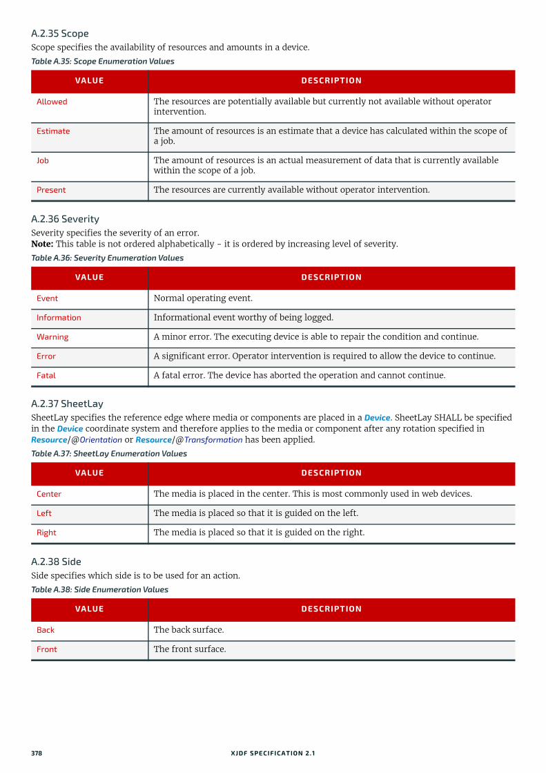
A.2.35 ScopeScope specifies the availability of resources and amounts in a device.
A.2.36 SeveritySeverity specifies the severity of an error. Note: This table is not ordered alphabetically - it is ordered by increasing level of severity.
A.2.37 SheetLaySheetLay specifies the reference edge where media or components are placed in a Device. SheetLay SHALL be specified in the Device coordinate system and therefore applies to the media or component after any rotation specified in Resource/@Orientation or Resource/@Transformation has been applied.
A.2.38 SideSide specifies which side is to be used for an action.
Table A.35: Scope Enumeration Values
VALUE DESCRIPTION
Allowed The resources are potentially available but currently not available without operator intervention.
Estimate The amount of resources is an estimate that a device has calculated within the scope of a job.
Job The amount of resources is an actual measurement of data that is currently available within the scope of a job.
Present The resources are currently available without operator intervention.
Table A.36: Severity Enumeration Values
VALUE DESCRIPTION
Event Normal operating event.
Information Informational event worthy of being logged.
Warning A minor error. The executing device is able to repair the condition and continue.
Error A significant error. Operator intervention is required to allow the device to continue.
Fatal A fatal error. The device has aborted the operation and cannot continue.
Table A.37: SheetLay Enumeration Values
VALUE DESCRIPTION
Center The media is placed in the center. This is most commonly used in web devices.
Left The media is placed so that it is guided on the left.
Right The media is placed so that it is guided on the right.
Table A.38: Side Enumeration Values
VALUE DESCRIPTION
Back The back surface.
Front The front surface.
378 XJDF SPECIFICATIO N 2.1

ENUMERATIONS
A.2.39 SidesSides specifies the sides of the product that SHALL be imaged.
A.2.40 SourceColorSpaceSourceColorSpace specifies the color space that is to be operated on.
Table A.39: Sides Enumeration Values
VALUE DESCRIPTION
OneSided Page contents SHALL be imposed on the front side of the final product.
OneSidedBack Page contents SHALL be imposed on the back side of the final product.
TwoSidedHeadToFoot Page contents SHALL be imposed on the front and back sides of media sheets so that the head (top) of the front backs up to the foot (bottom) of the back.
TwoSidedHeadToHead Page contents SHALL be imposed on the front and back sides so that the head (top) of the page contents back up to each other.
Unprinted
New in XJDF 2.1
Page contents SHALL NOT be imposed on either side.
Table A.40: SourceColorSpace Enumeration Values (Sheet 1 of 2)
VALUE DESCRIPTION
All Operates on all source color spaces. This is useful when specifying a convert operation using all PDL source-supplied characterizations with an XJDF supplied final target device profile.
CalGray Defines a calibrated device independent representation of gray.
Calibrated Operates on "CalGray" and "CalRGB" color spaces.
CalRGB Defines a calibrated device independent representation of RGB.
CIEBased Operates on CIE based color spaces; CIEBasedA, CIEBasedABC, CIEBasedDEF and CIE-BasedDEFG.
CMYK Operates on all CMYK color spaces. This includes both characterized and uncharacter-ized CMYK color spaces.
DeviceCMYK Operates on uncharacterized CMYK color spaces.
DeviceGray Operates on uncharacterized gray color spaces.
DeviceN Identifies the source color encoding as a "DeviceN" color space. The specific "DeviceN" color space to operate on is defined in the ColorantControl/DeviceNSpace resource. If "DeviceN" is specified, then ColorantControl/DeviceNSpace SHALL also be present.
DeviceRGB Operates on uncharacterized RGB color spaces.
Gray Operates on all gray color spaces. This includes both characterized and uncharacterized gray color spaces.
ICCBased Operates on color spaces defined using ICC profiles. The "ICCBased" value includes EPS, TIFF or PICT files with embedded ICC profiles. See [ICC.1]. It also includes PDF device color spaces that are characterized in table footnote #b of Table A.41 Mapping of SourceColorSpace enumerations to color spaces in the most common input file formats.
ICCCMYK Operates on ICCBased color spaces with ICC CMYK profiles or DeviceCMYK having an ICC-based characterization. See table footnote #b of Table A.41 Mapping of SourceColorSpace enumerations to color spaces in the most common input file formats.
ICCGray Operates on ICCBased color spaces with ICC gray profiles or DeviceGray having an ICC-based characterization. See table footnote #b of Table A.41 Mapping of SourceColorSpace enumerations to color spaces in the most common input file formats.
ICCLAB Operates on an ICCBased device independent representation of Lab.
XJDF SPECIFICATIO N 2.1 379

A.2.40.1 Source color space mappingThis table summarizes how the color spaces in Table A.2.40 SourceColorSpace above SHALL be mapped to/from dif-ferent file formats.
ICCRGB Operates on ICCBased color spaces with ICC RGB profiles or DeviceRGB having an ICC-based characterization. See table footnote #b of Table A.41 Mapping of SourceColorSpace enumerations to color spaces in the most common input file formats.
Lab Operates on Lab color spaces.
RGB Operates on all RGB color spaces. This includes both characterized and uncharacterized RGB color spaces.
Separation Operates on separation color spaces (spot colors). The specific separation(s) to operate on are defined in the @Separations attribute. If @Separations is not defined, the opera-tion will operate on all the separation color spaces in the input RunList.
YUV Operates on Yuv color spaces (also known as YCbCr). See [BT.601-7].
Table A.41: Mapping of SourceColorSpace enumerations to color spaces in the most common input file formats (Sheet 1 of 2)
SOURCECS FILE FORMAT COLOR SPACE
Calibrated PDFa CalGray, CalRGB
PostScripta n/a
TIFF n/a
CIEBased PDFa n/a
PostScripta CIEBasedABC, CIEBasedA, CIEBasedDEF and CIEBasedDEFG
TIFF n/a
CMYK PDFa DeviceCMYKb
PDF ICCBased color spaces with ICC CMYK profiles.CIEBasedDEFG spaces that resolve to a characterized CMYK space.
PostScripta DeviceCMYK
TIFF PhotometricInterp = 5Samples per pixel = 4
DeviceCMYK PDFa DeviceCMYKb
PostScripta DeviceCMYK
TIFF PhotometricInterp = 5Samples per pixel = 4
DeviceGray PDFa DeviceGrayb
PostScripta DeviceGray
TIFF PhotometricInterp = 0 or 1
DeviceN PDFa DeviceN
PostScripta DeviceN
TIFF PhotometricInterp = 5,Samples per pixel = N
Table A.40: SourceColorSpace Enumeration Values (Sheet 2 of 2)
VALUE DESCRIPTION
380 XJDF SPECIFICATIO N 2.1
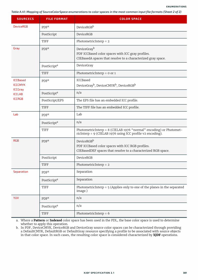
ENUMERATIONS
DeviceRGB PDFa DeviceRGBb
PostScript DeviceRGB
TIFF PhotometricInterp = 2
Gray PDFa DeviceGrayb
PDF ICCBased color spaces with ICC gray profiles.CIEBasedA spaces that resolve to a characterized gray space.
PostScripta DeviceGray
TIFF PhotometricInterp = 0 or 1
ICCBased ICCCMYK
ICCGray
ICCLAB
ICCRGB
PDFa ICCBased
DeviceGrayb, DeviceCMYKb, DeviceRGBb
PostScripta n/a
PostScript/EPS The EPS file has an embedded ICC profile.
TIFF The TIFF file has an embedded ICC profile.
Lab PDFa Lab
PostScripta n/a
TIFF PhotometricInterp = 8 (CIELAB 1976 “normal” encoding) or Photomet-ricInterp = 9 (CIELAB 1976 using ICC profile v2 encoding).
RGB PDFa DeviceRGBb
PDF ICCBased color spaces with ICC RGB profiles.CIEBasedDEF spaces that resolve to a characterized RGB space.
PostScript DeviceRGB
TIFF PhotometricInterp = 2
Separation PDFa Separation
PostScripta Separation
TIFF PhotometricInterp = 5 (Applies only to one of the planes in the separated image.)
YUV PDFa n/a
PostScripta n/a
TIFF PhotometricInterp = 6
a. Where a Pattern or Indexed color space has been used in the PDL, the base color space is used to determine whether to apply this operation.
b. In PDF, DeviceCMYK, DeviceRGB and DeviceGray source color spaces can be characterized through providing a DefaultCMYK, DefaultRGB or DefaultGray resource specifying a profile to be associated with source objects in that color space. In such cases, the resulting color space is considered characterized by XJDF operations.
Table A.41: Mapping of SourceColorSpace enumerations to color spaces in the most common input file formats (Sheet 2 of 2)
SOURCECS FILE FORMAT COLOR SPACE
XJDF SPECIFICATIO N 2.1 381
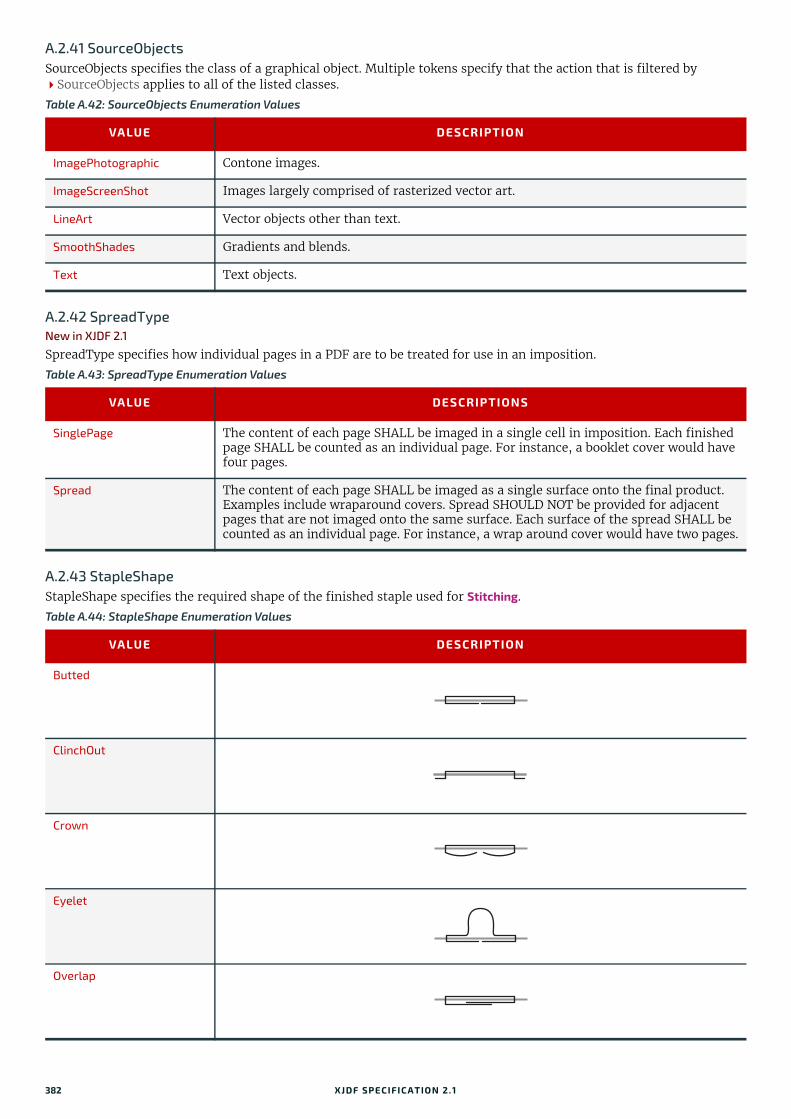
A.2.41 SourceObjectsSourceObjects specifies the class of a graphical object. Multiple tokens specify that the action that is filtered by SourceObjects applies to all of the listed classes.
A.2.42 SpreadTypeNew in XJDF 2.1
SpreadType specifies how individual pages in a PDF are to be treated for use in an imposition.
A.2.43 StapleShapeStapleShape specifies the required shape of the finished staple used for Stitching.
Table A.42: SourceObjects Enumeration Values
VALUE DESCRIPTION
ImagePhotographic Contone images.
ImageScreenShot Images largely comprised of rasterized vector art.
LineArt Vector objects other than text.
SmoothShades Gradients and blends.
Text Text objects.
Table A.43: SpreadType Enumeration Values
VALUE DESCRIPTIONS
SinglePage The content of each page SHALL be imaged in a single cell in imposition. Each finished page SHALL be counted as an individual page. For instance, a booklet cover would have four pages.
Spread The content of each page SHALL be imaged as a single surface onto the final product. Examples include wraparound covers. Spread SHOULD NOT be provided for adjacent pages that are not imaged onto the same surface. Each surface of the spread SHALL be counted as an individual page. For instance, a wrap around cover would have two pages.
Table A.44: StapleShape Enumeration Values
VALUE DESCRIPTION
Butted
ClinchOut
Crown
Eyelet
Overlap
382 XJDF SPECIFICATIO N 2.1
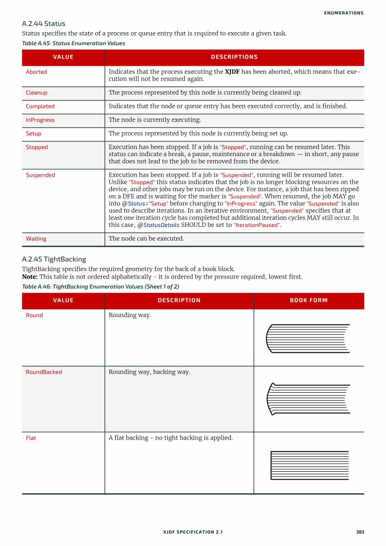
ENUMERATIONS
A.2.44 StatusStatus specifies the state of a process or queue entry that is required to execute a given task.
A.2.45 TightBackingTightBacking specifies the required geometry for the back of a book block.Note: This table is not ordered alphabetically - it is ordered by the pressure required, lowest first.
Table A.45: Status Enumeration Values
VALUE DESCRIPTIONS
Aborted Indicates that the process executing the XJDF has been aborted, which means that exe-cution will not be resumed again.
Cleanup The process represented by this node is currently being cleaned up.
Completed Indicates that the node or queue entry has been executed correctly, and is finished.
InProgress The node is currently executing.
Setup The process represented by this node is currently being set up.
Stopped Execution has been stopped. If a job is "Stopped", running can be resumed later. This status can indicate a break, a pause, maintenance or a breakdown — in short, any pause that does not lead to the job to be removed from the device.
Suspended Execution has been stopped. If a job is "Suspended", running will be resumed later. Unlike "Stopped" this status indicates that the job is no longer blocking resources on the device, and other jobs may be run on the device. For instance, a job that has been ripped on a DFE and is waiting for the marker is "Suspended". When resumed, the job MAY go into @Status="Setup" before changing to "InProgress" again. The value "Suspended" is also used to describe iterations. In an iterative environment, "Suspended" specifies that at least one iteration cycle has completed but additional iteration cycles MAY still occur. In this case, @StatusDetails SHOULD be set to "IterationPaused".
Waiting The node can be executed.
Table A.46: TightBacking Enumeration Values (Sheet 1 of 2)
VALUE DESCRIPTION BOOK FORM
Round Rounding way.
RoundBacked Rounding way, backing way.
Flat A flat backing - no tight backing is applied.
XJDF SPECIFICATIO N 2.1 383

A.2.46 UpdateGranularityUpdateGranularity specifies which QueueEntry items in a Queue are to be included in any action.
A.2.47 UsageUsage specifies how a resource SHALL be used by a process.
A.2.48 WorkingDirectionWorkingDirection specifies the direction of an action or of the application of a resource.
A.2.49 WorkStyleWorkStyle specifies the style of working in a sheet fed press. It is defined in the press coordinate system, where the sheet moves parallel to the Y axis. In the simple case of a single unrotated page per surface this implies that a flip around the Y-axis (WorkAndTurn, WorkAndBack) will result in head to head images for the back side, whereas a flip around the X-axis (WorkAndTumble) will result in head to foot images.
FlatBacked Backing way.
Table A.47: UpdateGranularity Enumeration Values
VALUE DESCRIPTION
All All QueueEntry elements SHOULD be included.
ChangesOnly Only those QueueEntry elements that have new information since the action SHOULD be included.
Table A.48: Usage Enumeration Values
VALUE DESCRIPTION
Input The resource SHALL be used as an input.
Output The resource SHALL be used as an output.
Table A.49: WorkingDirection Enumeration Values
VALUE DESCRIPTION
Bottom From below.
Top From above.
Table A.50: WorkStyle Enumeration Values (Sheet 1 of 2)
VALUE DESCRIPTION TURN AXIS
PLATE REUSE
Perfecting This work style describes the printing on both sides of the sub-strate using a separate set of plates for each side. The front lay is altered by flipping the sheet along the X-axis and thus retaining the side lays.Note: Perfecting is geometrically very similar to WorkAndTumble.Note: Perfecting is most commonly used with in-press perfecting units but the sheets can also be flipped outside of the press. The name Perfecting was chosen mainly for backwards compatibility.
X-Axis No
Simplex No turning. None No
Table A.46: TightBacking Enumeration Values (Sheet 2 of 2)
VALUE DESCRIPTION BOOK FORM
384 XJDF SPECIFICATIO N 2.1
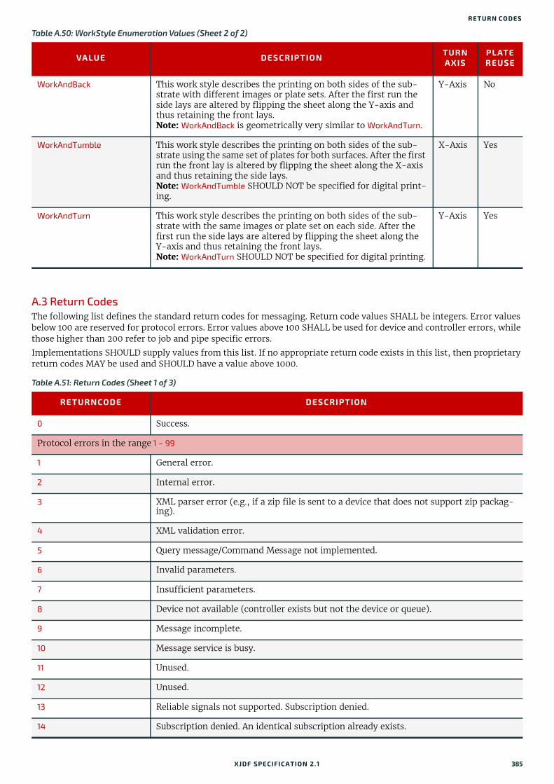
RETURN CO DES
A.3 Return CodesThe following list defines the standard return codes for messaging. Return code values SHALL be integers. Error values below 100 are reserved for protocol errors. Error values above 100 SHALL be used for device and controller errors, while those higher than 200 refer to job and pipe specific errors.
Implementations SHOULD supply values from this list. If no appropriate return code exists in this list, then proprietary return codes MAY be used and SHOULD have a value above 1000.
WorkAndBack This work style describes the printing on both sides of the sub-strate with different images or plate sets. After the first run the side lays are altered by flipping the sheet along the Y-axis and thus retaining the front lays.Note: WorkAndBack is geometrically very similar to WorkAndTurn.
Y-Axis No
WorkAndTumble This work style describes the printing on both sides of the sub-strate using the same set of plates for both surfaces. After the first run the front lay is altered by flipping the sheet along the X-axis and thus retaining the side lays.Note: WorkAndTumble SHOULD NOT be specified for digital print-ing.
X-Axis Yes
WorkAndTurn This work style describes the printing on both sides of the sub-strate with the same images or plate set on each side. After the first run the side lays are altered by flipping the sheet along the Y-axis and thus retaining the front lays.Note: WorkAndTurn SHOULD NOT be specified for digital printing.
Y-Axis Yes
Table A.51: Return Codes (Sheet 1 of 3)
RETURNCODE DESCRIPTION
0 Success.
Protocol errors in the range 1 – 99
1 General error.
2 Internal error.
3 XML parser error (e.g., if a zip file is sent to a device that does not support zip packag-ing).
4 XML validation error.
5 Query message/Command Message not implemented.
6 Invalid parameters.
7 Insufficient parameters.
8 Device not available (controller exists but not the device or queue).
9 Message incomplete.
10 Message service is busy.
11 Unused.
12 Unused.
13 Reliable signals not supported. Subscription denied.
14 Subscription denied. An identical subscription already exists.
Table A.50: WorkStyle Enumeration Values (Sheet 2 of 2)
VALUE DESCRIPTION TURN AXIS
PLATE REUSE
XJDF SPECIFICATIO N 2.1 385

15 Feature not licensed.
16 Feature not enabled.
17 Feature not installed.
18 Module that is required to enable a feature is not installed.
Device and controller errors in the range 100 – 199
100 Device not running.
101 Device incapable of fulfilling request (e.g., a RIP that has been asked to cut a sheet).
102 Cannot execute the XJDF.
103 @JobID not known by controller.
104 @JobPartID not known by controller.
105 Queue entry not in queue.
106 Queue request failed because the queue entry is already executing.
107 The queue entry is already executing. Subsequent changes are not accepted.
108 Selection or applied filter results in an empty list.
109 Selection or applied filter results in an incomplete list. A buffer cannot provide the complete list queried for.
110 Queue request of a job submission failed because the requested completion time of the job cannot be fulfilled.
111 Subscription request denied.
112 Queue request failed because the queue is closed or blocked and did not accept new entries.
113 Queue entry is already in the resulting status.
114 QueueEntry/@Status is already "Completed" or "Aborted" and therefore does not accept changes.
115 Queue entry is not running.
116 Queue entry already exists. Used when a QueueEntry with identical @JobID, @JobPartID and Part already exists.
120 Cannot access referenced URL or URI reference cannot be resolved. Used when a refer-enced entity, e.g. an XJDF in a SubmitQueueEntry, cannot be found.
121 Unknown @DeviceID. No device is known with the @DeviceID specified.
130 Ganging is not supported. A gang job has been submitted to a queue that does not sup-port ganging.
131 GangName not known. A job has been submitted with an unknown GangName.
140 CommandResource rejected.
141 CommandResource partially rejected.
Job and pipe specific errors in the range 200 – 299
200 Invalid resources.
201 Insufficient resource parameters.
Table A.51: Return Codes (Sheet 2 of 3)
RETURNCODE DESCRIPTION
386 XJDF SPECIFICATIO N 2.1

PREFERRED NMTOKEN VALUES
A.4 Preferred NMTOKEN ValuesThis section contains the preferred values for items of NMTOKEN. Although these types are open lists, the values in these tables SHOULD be used where possible.
If an ICS requires new NMTOKEN values or a work group has agreed upon new recommended NMTOKEN values, these will be published at [CIP4Names] prior to being added to the specification and SHOULD be used where appropriate.
A.4.1 Comb and Coil ShapesWhen specifying the shape of a comb or coil for LooseBinding, values from the following table are recommended.
A.4.2 Contact TypesWhen specifying the role of a contact, values from the following table are recommended.
202 The value of @PipeID is unknown.
203 (Unused).
204 (Unused).
205 Pipe request failed because the pipe is closed and does not accept new requests.
Table A.52: Comb and Coil Shapes
VALUE DESCRIPTION
Single Each “tooth” is made with one wire.
SingleCalendar Each “tooth” is made with one wire and an extension for hanging the bound product is provided in the center.
Twin The shape of each “tooth” is made with a double wire (e.g., Wire-O®).
TwinCalendar The shape of each “tooth” is made with a double wire and an extension for hanging the bound product is provided in the center.
Table A.53: Contact Types
VALUE DESCRIPTION
Accounting Contact information that relates to the invoice.
Administrator Person to contact for queries concerning the execution of the job.
Agency The contact is an employee of an agency.
Approver The person who approves the job.
ArtDelivery Delivery contact for artwork of the job.
ArtReturn Return delivery contact for artwork of this job.
Author
Customer The end customer.
Delivery The delivery address for all products of the job.
DeliveryCharge The contact who is charged for delivery of the job.
Designer
Editor
Employee Employee who works for the company processing the job.
Illustrator
Table A.51: Return Codes (Sheet 3 of 3)
RETURNCODE DESCRIPTION
XJDF SPECIFICATIO N 2.1 387
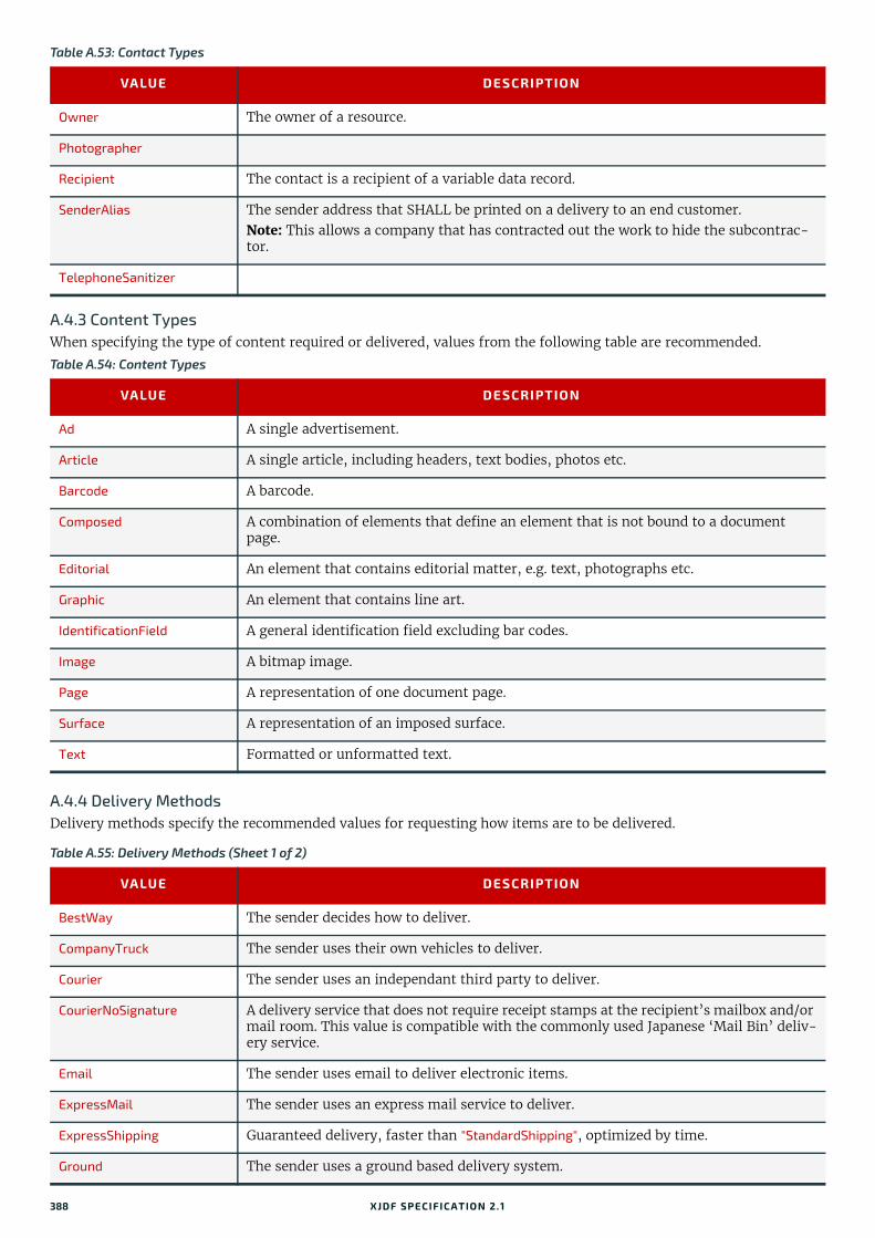
A.4.3 Content TypesWhen specifying the type of content required or delivered, values from the following table are recommended.
A.4.4 Delivery MethodsDelivery methods specify the recommended values for requesting how items are to be delivered.
Owner The owner of a resource.
Photographer
Recipient The contact is a recipient of a variable data record.
SenderAlias The sender address that SHALL be printed on a delivery to an end customer.Note: This allows a company that has contracted out the work to hide the subcontrac-tor.
TelephoneSanitizer
Table A.54: Content Types
VALUE DESCRIPTION
Ad A single advertisement.
Article A single article, including headers, text bodies, photos etc.
Barcode A barcode.
Composed A combination of elements that define an element that is not bound to a document page.
Editorial An element that contains editorial matter, e.g. text, photographs etc.
Graphic An element that contains line art.
IdentificationField A general identification field excluding bar codes.
Image A bitmap image.
Page A representation of one document page.
Surface A representation of an imposed surface.
Text Formatted or unformatted text.
Table A.55: Delivery Methods (Sheet 1 of 2)
VALUE DESCRIPTION
BestWay The sender decides how to deliver.
CompanyTruck The sender uses their own vehicles to deliver.
Courier The sender uses an independant third party to deliver.
CourierNoSignature A delivery service that does not require receipt stamps at the recipient’s mailbox and/or mail room. This value is compatible with the commonly used Japanese ‘Mail Bin’ deliv-ery service.
Email The sender uses email to deliver electronic items.
ExpressMail The sender uses an express mail service to deliver.
ExpressShipping Guaranteed delivery, faster than "StandardShipping", optimized by time.
Ground The sender uses a ground based delivery system.
Table A.53: Contact Types
VALUE DESCRIPTION
388 XJDF SPECIFICATIO N 2.1

PREFERRED NMTOKEN VALUES
A.4.5 Device ClassesCIP4 supports many device classes. The following values SHOULD be used when filling Device/@DeviceClass.
InstantMessaging The sender uses instant messaging to deliver electronic items.
InterofficeMail The sender uses their own internal mail network to deliver.
Local The items are already in place, no other delivery process is required.
NetworkCopy This include LAN and VPN.
StandardShipping Delivery according to the standard terms of service of the carrier, optimized by price.
Storage The item is stored by the supplier.
WebServer Upload/download from HTTP/FTP server.
Table A.56: Device Classes (Sheet 1 of 3)
VALUE DESCRIPTION
BandingStation A device that performs the Wrapping process with MiscConsumable/@Type="PaperBand", "PlasticBand" or "RubberBand" in counted quantity.
CartonErector A device that performs the BoxPacking process. A carton erector erects flat cartons and closes the bottom, ready to fill. Carton erectors may use glue, tape, or automatic-bot-tom.
CartonLoader A device that performs the BoxPacking process. A carton loader loads products into a carton or box.
CartonSealer A device that performs the BoxPacking process. A carton sealer seals or tapes a loaded carton or box.
CaseMaker A device that performs the CaseMaking process. A case maker produces the hard case for books.
Controller A controller is a device that is a proxy for one or more individual devices or machines.
Cutter A device that performs the Cutting process. A cutter can be used either to cut sheet blocks from a sheet fed press or to ‘slit’ a ribbon from a web fed press.
DieCutter A device that performs the ShapeCutting process. A die cutter can be used to cut shapes from printed sheet blocks, e.g. windows in envelopes.
EndsheetFeeder A device that performs the Feeding process. Specifically, an end sheet feeder adds end sheets to a cover prior to binding.
FilmSetter A device that performs the ImageSetting process. A film setter creates a printable image on film.
Folder A device that performs the Folding process. A folder can be used to fold the output from either sheet fed or web fed presses.
FolderGluer A device that performs the BoxFolding process. A box folder folds and glues blanks into folded boxes for packaging.
Gatherer A device that performs the Gathering process. A gatherer can be used to collect sheets into piles.
GathererBinder A device that performs the Gathering and LooseBinding processes. A gatherer binder can be used to collect sheets into collated piles that are then bound.
HardCopyProofer A device that provides a physical representation of the printed pages or sheets.
Hardcover A device that performs the CaseMaking process. This device creates a hardcover.
Table A.55: Delivery Methods (Sheet 2 of 2)
VALUE DESCRIPTION
XJDF SPECIFICATIO N 2.1 389

HardcoverBookLine A device that combines multiple processes such as BlockPreparation, CaseMaking, CasingIn, Collecting, CoverApplication, EndSheetGluing, Gathering, Gluing, HeadBandApplication, Jacketing, SpinePreparation and SpineTaping to create and apply a hardcover to a block that it creates from a set of pages.Note: The device may not support all of the shown processes depending upon its capa-bilities.
HeatShrink A device that performs the Shrinking process, e.g. a heat shrink tunnel.
HolePuncher A device that performs the HoleMaking process. A hole puncher can be used to stamp or drill a number of holes, usually in a block of pages.
Inserter A device that performs the Inserting process. An inserter can be used to insert a compo-nent within another component.
IntegratedDigitalPrinter A device that performs the DigitalPrinting process. Specifically, an integrated digital printer that has additional post press capabilities, such as folding or binding.
Jacketer A device that performs the Jacketing process. A jacketer wraps a bound book with a folded jacket.
LabelPrinter A device that prints and attaches labels to a Component.
MultipleWebConventionalPress
A device that performs the ConventionalPrinting process. Specifically on a multiple web conventional press.
Palletizer A device that performs the Palletizing process by placing products or bundles onto a pallet.
PerfectBinderLine A device that combines multiple processes such as BlockPreparation, CaseMaking, CasingIn, Collecting, CoverApplication, EndSheetGluing, Gathering, Gluing, HeadBandApplication, Jacketing, SpinePreparation and SpineTaping to create perfect bound books.
PlateSetter A device that performs the ImageSetting process. A plate setter creates a printable image on a plate suitable for conventional printing.
PrintingPress A device that performs the ConventionalPrinting or DigitalPrinting process. Any type of printing press.
Scanner A device that performs the ManualLabor process. A scanner is used to describe the man-ual process of producing machine readable image data from pre-printed documents.
SheetFedConventionalPress A device that performs the ConventionalPrinting process. A standard sheet fed conven-tional press.
SheetFedDigitalPrinter A device that performs the DigitalPrinting process. A standard sheet fed digital press.
ShrinkWrapper A device that performs the Wrapping and Shrinking process with shrink wrap foil. Vari-ous bundles can be shrink wrapped, e.g. individual products, boxes or even pallets.
SingleWebConventionalPress
A device that performs the ConventionalPrinting process. Specifically a single web con-ventional press.
SoftCopyProofer A device that provides an ‘on screen’ representation of the printed pages or sheets.
Stacker A device that performs the Stacking process. A stacker can be used to create a pile or bundle of components suitable for delivery.
Stitcher A device that performs the Stitching process. A stitcher can be used to stitch a number of sheets together into a block and may also add a cover.
ThreadSewer A device that performs the ThreadSewing process. A thread sewer can be used to sew a number of sheets together into a block.
Trimmer A device that performs the Trimming process. A trimmer can be used to reduce a block to the required size, e.g. for subsequent hardcover binding.
Table A.56: Device Classes (Sheet 2 of 3)
VALUE DESCRIPTION
390 XJDF SPECIFICATIO N 2.1
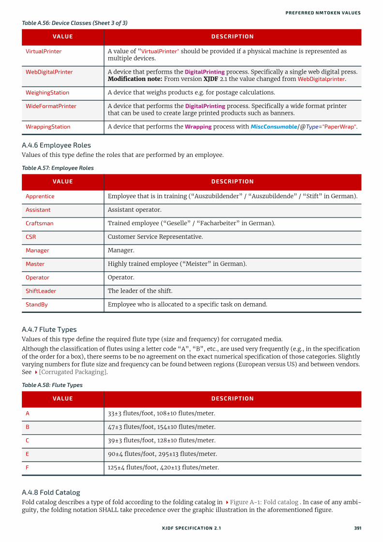
PREFERRED NMTOKEN VALUES
A.4.6 Employee RolesValues of this type define the roles that are performed by an employee.
A.4.7 Flute TypesValues of this type define the required flute type (size and frequency) for corrugated media.
Although the classification of flutes using a letter code “A”, “B”, etc., are used very frequently (e.g., in the specification of the order for a box), there seems to be no agreement on the exact numerical specification of those categories. Slightly varying numbers for flute size and frequency can be found between regions (European versus US) and between vendors. See [Corrugated Packaging].
A.4.8 Fold CatalogFold catalog describes a type of fold according to the folding catalog in Figure A-1: Fold catalog . In case of any ambi-guity, the folding notation SHALL take precedence over the graphic illustration in the aforementioned figure.
VirtualPrinter A value of "VirtualPrinter" should be provided if a physical machine is represented as multiple devices.
WebDigitalPrinter A device that performs the DigitalPrinting process. Specifically a single web digital press.Modification note: From version XJDF 2.1 the value changed from WebDigitalprinter.
WeighingStation A device that weighs products e.g. for postage calculations.
WideFormatPrinter A device that performs the DigitalPrinting process. Specifically a wide format printer that can be used to create large printed products such as banners.
WrappingStation A device that performs the Wrapping process with MiscConsumable/@Type="PaperWrap".
Table A.57: Employee Roles
VALUE DESCRIPTION
Apprentice Employee that is in training (“Auszubildender” / “Auszubildende” / “Stift” in German).
Assistant Assistant operator.
Craftsman Trained employee (“Geselle” / “Facharbeiter” in German).
CSR Customer Service Representative.
Manager Manager.
Master Highly trained employee (“Meister” in German).
Operator Operator.
ShiftLeader The leader of the shift.
StandBy Employee who is allocated to a specific task on demand.
Table A.58: Flute Types
VALUE DESCRIPTION
A 33±3 flutes/foot, 108±10 flutes/meter.
B 47±3 flutes/foot, 154±10 flutes/meter.
C 39±3 flutes/foot, 128±10 flutes/meter.
E 90±4 flutes/foot, 295±13 flutes/meter.
F 125±4 flutes/foot, 420±13 flutes/meter.
Table A.56: Device Classes (Sheet 3 of 3)
VALUE DESCRIPTION
XJDF SPECIFICATIO N 2.1 391

The value format is: "Fn-i" where “n” is the number of finished pages and “i” is either an integer, which identifies a par-ticular fold, or the letter “X”, which identifies a generic fold (e.g., "F6-2" describes a Z-fold of 6 finished pages, and "F6-X" describes a generic fold with 6 finished pages).
Figure A-1: Fold catalog
F2-1 F4-1 2x1
1/2
1
F4-2 2x1
1/2
1
F6-1 3x1
1/3
1 2
1/3
F6-2 3x1
1/3
1 2
1/3
F6-3 3x1
1/2
1 2
1/4
F6-4 3x1
1/3
1 2
1/3
F6-5 3x1
1/3
2 1
2/3
F6-6 3x1
1/4
2 1
3/4
F6-7 3x1
1/4
1 2
1/4
F6-8 3x1
1/3
2 1
2/3
F8-1 4x1
1/4
1 2
1/2
F8-2 4x1
1/4
1 2
1/2
F8-3 4x1
1/4
1 2 3
1/4 1/4
F8-4 4x1
1/4
1 3 2
1/4 1/2
F8-5 4x1
1/4
1 2 3
1/4 1/4
F8-6 4x1
1/4
2 3 1
3/4 1/4
F8-7 2x2
1/2
2
1
1/2 +
F10-1 5x11 2 3 4
1/5 1/5 1/5 1/5
F10-2 5x12 3 4 1
4/5 1/5 1/5 1/5
F10-3 5x11 3 2
2/5 2/5 1/5
F12-1 6x1
1/3
1 2 3
1/61/3
F12-2 6x1
1/3
1 2 3
1/61/3
F12-3 6x1
1/6
1 2 3
1/61/2
F12-4 6x1
1/6
1 2 3
1/61/2
F12-5 6x1
1/3
1 3 2
1/61/2
F12-6 6x1
1/6
1 2 3 4 5
1/6 1/6 1/61/6
F12-7 3x2
1/3
1
3
2
+1/3 1/2
F12-8 3x2
1/3
2
3
1
+2/3 1/2
F12-9 3x2
1/3
1
3
2
+1/3 1/2
F12-10 3x2
1/3
2
3
1
+2/3 1/2
F12-11 3x2
1/2
1
2
3
++1/3 1/3
F12-12 2x3
1/2
123
2/3 1/3+
F12-13 2x3
1/2
132
1/3 1/3+
F12-14 2x3
1/2
132
1/3 1/3+
F14-1 7x1
1/7
1 2 3 4 5 6
1/7 1/71/7 1/7 1/7
F16-1 8x11 2 3
1/2 1/4 1/8
F16-2 8x11 2 3
1/2 1/4 1/8
F16-3 8x11 2 3
1/2 1/4 1/8
F16-4 8x11 2 3
1/2 1/4 1/8
F16-5 8x11 2 3 4 5 6 7
1/8 1/8 1/81/8 1/8 1/8 1/8
F16-6 4x21
2
3
1/2 1/2 1/4++
392 XJDF SPECIFICATIO N 2.1

PREFERRED NMTOKEN VALUES
Figure A-1: Fold catalog
F16-7 4x21
2
3
1/2 1/2 1/4++
F16-8 4x21
2
3
1/2 1/2 1/4++
F16-9 4x21
3
2
1/2 1/4 1/2+
F16-10 4x21
3
2
1/2 1/4 1/2+
F16-11 4x21
4
2 3
1/41/4 1/4 1/2+
F16-12 4x21
4
2 3
1/41/4 1/4 1/2+
F16-13 2x41
23
1/2 1/2 1/4+
F16-14 2x41
23
1/2 1/2 1/4+
F18-1 9x11 2 3 4 5 6 7 8
1/9 1/9 1/9 1/91/9 1/9 1/9 1/9
F18-2 9x12 3 4 1
2/3 1/3 1/9 1/9
F18-3 9x11 2 34
1/3 1/3 2/9 1/9
F18-4 9x11 2 3 4
1/3 1/3 1/9 1/9
F18-5 3x31 2
34
1/3 1/3 1/3 1/3+
F18-6 3x31 2
43
1/3 1/3 2/3 1/3+
F18-7 3x31 2
34
1/3 1/3 1/3 1/3+
F18-8 3x31 2
43
1/3 1/3 2/3 1/3+
F18-9 3x32 1
43
2/3 1/3 2/3 1/3+
F20-1 5x21
4
3 2
2/52/5 1/5 1/2+
F20-2 5x221
5
3 4
1/5 1/51/5 1/5 1/2+
F24-1 6x2
1/3
1
3
2 4
+ +1/3 1/61/2
F24-2 6x2
1/3
1
3
2 4
+ +1/3 1/61/2
F24-3 6x2
1/3
1
4
2 3
+1/3 1/6 1/2
F24-4 6x2
1/3
1
4
2 3
+1/3 1/6 1/2
F24-5 6x2
1/3
1
4
2 3
+1/3 1/6 1/2
F24-6 6x2
1/6
1
6
2 3 4 5
+1/61/61/6 1/6
1/2
F24-7 6x2
1/3
1
2
3 4
+ +1/3 1/61/2
F24-8 3x4
1/2
1
34
2
+1/3 1/41/3
F24-9 3x4
1/2
2
34
1
+2/3 1/41/3
F24-10 3x4
1/2
1
34
2
+1/3 1/41/3
F24-11 4x3
1/2
1 423
1/42/3 1/3+ +
F28-1 7x21 2 3 4 5 6
7
1/7 1/7 1/21/7 1/7 1/7 1/7
+
F32-1 16x11 2 34
1/2 1/4 1/8 1/16
F32-2 8x21 2
3
4
1/2 1/4 1/2 +1/8+
F32-3 8x21 2
3
4
1/2 1/4 1/2 1/8+ +
F32-4 4x41
24
3
1/2 1/2 1/4 1/4++ +
F32-5 4x41
24
3
1/2 1/2 1/4 1/4++ +
F32-6 4x41
24
3
1/2 1/2 1/4 1/4++ +
F32-7 4x41
45
32
1/4 1/4 1/4 1/2 1/4+
F32-8 4x41
34
2
1/2 1/4 1/2 1/4+
F32-9 4x41
23
4
1/2 1/2 1/4 1/4++
F36-1 9x2
1/2
1 3 4
5
2
+1/3 1/3 1/9 1/9
F36-2 6x31
3
5
4
2
1/3 + 1/61/31/3 + 1/3
F40-1 5x421
56
3 4
1/5+ 1/21/51/5 1/5
1/4
F48-1 6x41
3
6
45
2
1/31/3 + 1/41/41/4 + 1/6
F48-2 4x61
456
32
1/4 1/4 1/4 1/31/3 1/6
+
F64-1 8x41
234
65
1/2 1/41/4
1/41/4 1/8
++
F64-2 8x41
465
3 72
1/4 1/4 1/4 1/41/41/4
+1/8+
XJDF SPECIFICATIO N 2.1 393

A.4.9 Ink and Varnish CoatingsWhen specifying coating types, such as ink or varnish, values from the following table are recommended.
Table A.59: Ink and Varnish Coatings
VALUE DESCRIPTION
Aqueous Water based coating.
Bronzing Printing an adhesive that is then immediately dusted with a bronze or other metallic powder that adheres to the adhesive.
Gloss A glossy coating.
Ink Any generic ink.
InkJet Ink.
Latex Liquid that is similar to ink.
Matte A matte coating.
Primer A coating that is applied beneath the image.
Relief Property of the coating.
RubResistant Attribute of the ink.
Satin A coating between Gloss and Matte.
Silicone Liquid that is similar to ink.
Toner Liquid that is similar to ink.
UV Ultra violet cured polymers.
Varnish Unpigmented ink.
WaterResistant Attribute of the ink.
Figure A-1: Fold catalog
Fold up
Fold down
Finished format folded sheet
Fold direction change, 90º (alternating)
Folds in numeric order1, 2, 3
Lay
Split: 8-sheet parts lengthwise, 2 sheet parts cross
Signature with 32 pages
Example: F32-3, 8x2
Fold up with 1/2 of the open sheet format length
Fold down with 1/4 of the open sheet format length
Fold direction change: 90º clockwise
Fold up with 1/2 of the open sheet format
Fold direction change: 90º counterclockwise
Fold down with 1/8 of the open sheet format lengthGreen: open sheet length
Red: open sheet width
Legend
1/2
1/2
1/4
1/8
F32-3:
8x2:
+ :
+ :
1 2
3
4
1/2 1/4 1/2 1/8+ +
+
394 XJDF SPECIFICATIO N 2.1

PREFERRED NMTOKEN VALUES
A.4.10 Input Tray and Output Bin NamesPart/@Location MAY be used to specify a location within a device (e.g., a paper tray). When specifying input paper trays (indicated with “I”) and/or output bins (indicated with “O”), the following values for Part/@Location SHOULD be used.
Table A.60: Input Tray and Output Bin Names (Sheet 1 of 2)
VALUE I/O DESCRIPTION
AnyLargeFormat IO The location that holds larger format media with one dimension larger than 11 inches. The media dimensions SHALL be specified.
AnySmallFormat IO The location that holds smaller format media. The media dimensions SHALL be specified.
AutoSelect IO The location that the device selects based on the Media specification.
Booklet O The bin where the device places booklets.
Bottom IO The location that, when facing the device, can best be identified as ‘bottom’.
BypassTray I The input tray used to handle odd or special papers. MAY be used to specify the input tray that is used for insert sheets that are not to be imaged.
BypassTray-N I The input tray used to handle odd or special papers. MAY be used to specify the input tray that is used for insert sheets that are not to be imaged. N = ‘1’, ‘2’, …
Continuous IO The location to handle continuous media (i.e., continuously connected sheets).
Disc IO The location to handle CD or DVD discs to be printed on.
Disc-N IO The location to handle CD or DVD discs to be printed on. N = ‘1’, ‘2’, …
Envelope IO The location to handle envelopes.
Envelope-N IO The location to handle envelopes. N = ‘1’, ‘2’, …
Front IO The location that, when facing the device, can best be identified as ‘front.’
InsertTray I The input tray that can best be identified as ‘insert tray.’ Used to specify the input tray that is used for insert sheets (insert sheets are never imaged).
InsertTray-N I The input tray that can best be identified as ‘insert tray-1’, ‘insert tray-2’, … etc. Used to specify the input tray that is used for insert sheets (insert sheets are never imaged).
LargeCapacity IO The location that can best be identified as the ‘large capacity’ location (in terms of the number of sheets) with respect to the device.
LargeCapacity-N IO The location that can best be identified as the ‘large capacity-1’, ‘large-capac-ity-2’, … etc., input or output location (in terms of the number of sheets) with respect to the device.
Left IO The bin that, when facing the device, can best be identified as ‘left.’
Mailbox-N O The output location that is best identified as “Mailbox #1“, “Mailbox #2”, etc.
Middle IO The location that, when facing the device, can best be identified as “middle”.
PostMarkerInserter I The input tray that is downstream of the marking engine and allows the user to pass media through a non-marking paper path for covers and/or inserts.
Rear IO The location that, when facing the device, can best be identified as “rear”.
Right IO The location that, when facing the device, can best be identified as “right”.
Roll IO The location to handle web-fed media.
Roll-N IO The Nth location to handle the Nth web-fed media.
Side IO The location that, when facing the device, can best be identified as “side”.
Stacker-N O The output location that is best identified as “Stacker #1”, “Stacker #2”, etc.
XJDF SPECIFICATIO N 2.1 395

A.4.11 MediaType DetailsMediaType Details specifies additional details of the media to be used.
Top IO The location that, when facing the device, can best be identified as “top”.
Table A.61: MediaType Details (Sheet 1 of 2)
VALUE DESCRIPTION
Aluminum Conventional or CTP press plate.
Backlit Any media that is designed to be illuminated from the back side.
Blueback Blue back poster paper is a specialist printing paper with a white printing surface and an opaque blue back that avoids any show through from the posters underneath.
Cardboard
CD CD disc to be printed on.
Cloth Cloth, e.g. for a hardcover book case.
Continuous Continuously connected sheets of an opaque material. The edge that is connected is not specified.
ContinuousLong Continuously connected sheets of an opaque material connected along the long edge.
ContinuousShort Continuously connected sheets of an opaque material connected along the short edge.
DoubleWall Double-wall corrugated board.
DryFilm
DVD DVD disc to be printed on.
EndBoard End board used in the Bundling process.
Envelope Envelopes that can be used for conventional mailing purposes.
EnvelopePlain Envelopes that are not preprinted and have no windows.
EnvelopeWindow Envelopes that have windows for addressing purposes.
EnvelopeWindowLeft Envelopes that have windows on the left for addressing purposes.
EnvelopeWindowRight Envelopes that have windows on the right for addressing purposes.
FlexoBase For the base layer of flexo plates.
FlexoPhotoPolymer For the photopolymer layer of flexo plates.
Flute Flute layer of a corrugated board.
FullCutTabs Media with a tab that runs the full length of the medium so that only one tab is visible extending out beyond the edge of non-tabbed media.
ImageSetterPaper Contact paper as replacement for film.
Labels Label stock, e.g. a sheet of peel-off labels.
Leather Leather stock, e.g. for a hardcover book case.
Letterhead Separately cut sheets of an opaque material including a letterhead.
MultiLayer Form medium composed of multiple layers that are attached to one another (e.g., for use with impact printers).
Table A.60: Input Tray and Output Bin Names (Sheet 2 of 2)
VALUE I/O DESCRIPTION
396 XJDF SPECIFICATIO N 2.1

PREFERRED NMTOKEN VALUES
A.4.12 MilestonesThe following table defines a list of values that are valid for QueryNotification/NotificationFilter/@MilestoneTypes and Milestone/@MilestoneType.Note: Milestones usually refer to events involving multiple objects, although the Milestone/@MilestoneType is specified as a singular. The scope of the Milestone is defined by the parent Notification element.
MultiPartForm Form medium composed of multiple layers not attached to one another; each sheet might be drawn separately from an input source.
Photographic Separately cut sheets of an opaque material to produce photographic quality images.
Polyester Conventional or CTP press plate.
PreCutTabs Media with tabs that are cut so that more than one tab is visible extending out beyond the edge of non-tabbed media.
ScrimBanner Specific type of vinyl.
SingleFace Single-face corrugated board.
SingleWall Single-wall corrugated board.
Stationery Separately cut sheets of an opaque material, includes generic paper.
TabStock Media with tabs, either precut or full-cut.
Tractor Tractor feed with holes.
TripleWall Triple-wall corrugated board.
WallPaper Details of wall paper.
WetFilm Conventional photographic film.
Table A.62: Milestones (Sheet 1 of 2)
VALUE DESCRIPTION
BindingCompleted All binding worksteps including packing of the job have been completed. Postpress worksteps are defined according to Section 5.6 Postpress Processes.
BindingInProgress At least one of the binding worksteps of the job is in progress.
Delivered The files were delivered to the destination.
DigitalArtArrived Digital content has been received.
JobCompletedSuccessfully Job completed successfully.
JobCompletedWithErrors Job completed with errors.
JobCompletedWithWarnings
Job completed with warnings.
PageApproved Planned page proofs have been approved.
PageCompleted Pages are ready (no further page processing or page proofing required).
PageProofed Planned page proofs have been made.
PostPressCompleted All postpress worksteps including packing of the job have been completed. Postpress worksteps are defined according to Section 5.6 Postpress Processes.
PostPressInProgress At least one of the postpress worksteps of the job is in progress.
Table A.61: MediaType Details (Sheet 2 of 2)
VALUE DESCRIPTION
XJDF SPECIFICATIO N 2.1 397

A.4.13 Module Types
PrePressCompleted All prepress worksteps of the job have been completed. Prepress worksteps are defined according to Section 5.4 Prepress Processes. In conventional prepress, this is the case when all plates have been made.
PrePressInProgress At least one of the prepress worksteps of the job is in progress.
PressCompleted All press worksteps of the job have been completed. Press worksteps are defined according to Section 5.5 Press Processes.
PressInProgress At least one of the press worksteps of the job is in progress.
ProofSent Planned proofs sent to customer.
ShippingCompleted Final product was delivered to the customer or distributors.
ShippingInProgress Final product is being shipped.
SurfaceApproved Planned imposition proofs have been approved.
SurfaceAssigned Surfaces have their corresponding pages assigned (e.g., could be proofed).
SurfaceCompleted Planned surfaces are ready (i.e., plates could be made).
SurfaceProofed Planned imposition proofs have been made.
Table A.63: Module Types for Conventional Printing
VALUE DESCRIPTION
CoatingModule Unit for coatings, for example, full coating of varnish.
Delivery Delivery module, unit for gathering the printed sheets.
Drier Module for drying the previously printed color or varnish.
ExtensionModule Unit for extending the distance between modules, for example to increase the distance between the last printing module and the delivery module.
Feeder Feeder module, feeds the device with paper.
Imaging Imaging module in a direct to plate machine.
Numbering Numbering unit.
PerfectingModule Unit for perfecting, reversing device.
PrintModule Unit for printing a color. Describes one cylinder and one side.
Table A.64: Module Types for Postpress (Sheet 1 of 2)
VALUE DESCRIPTION
BlockPreparer The block preparer prepares the book block for a hardcover book.See Section 5.6.1 BlockPreparation.
BoxFolder The box folder folds and glues blanks into folded boxes for packaging.See Section 5.6.2 BoxFolding.
CaseMaker The case maker produces the hard case for books.See Section 5.6.5 CaseMaking.
Table A.62: Milestones (Sheet 2 of 2)
VALUE DESCRIPTION
398 XJDF SPECIFICATIO N 2.1
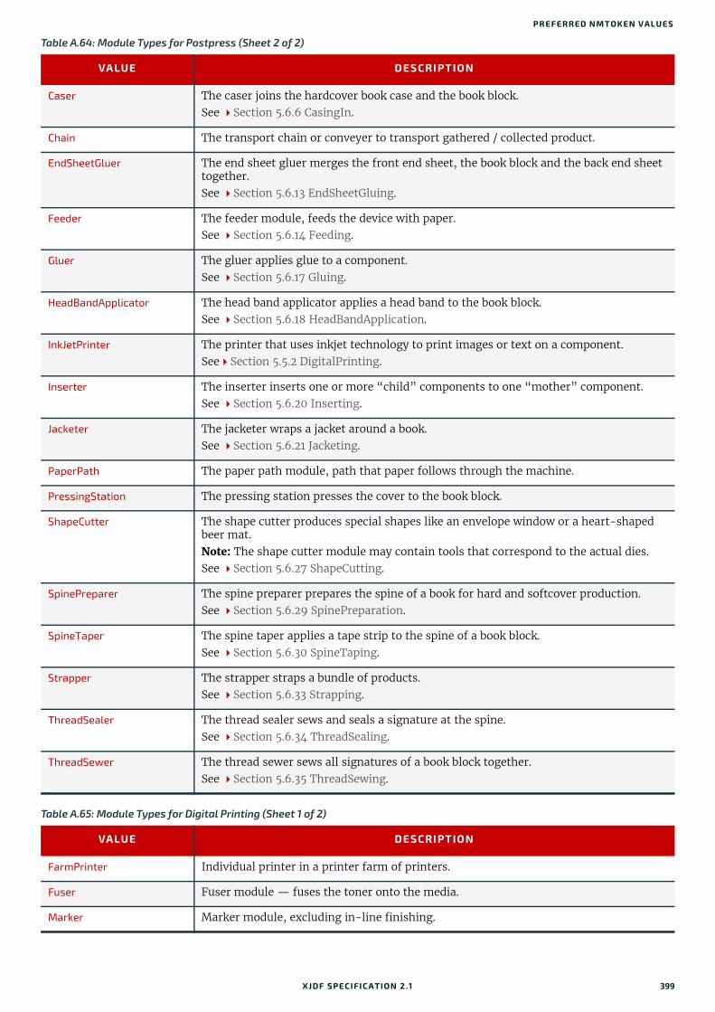
PREFERRED NMTOKEN VALUES
Caser The caser joins the hardcover book case and the book block.See Section 5.6.6 CasingIn.
Chain The transport chain or conveyer to transport gathered / collected product.
EndSheetGluer The end sheet gluer merges the front end sheet, the book block and the back end sheet together.See Section 5.6.13 EndSheetGluing.
Feeder The feeder module, feeds the device with paper. See Section 5.6.14 Feeding.
Gluer The gluer applies glue to a component.See Section 5.6.17 Gluing.
HeadBandApplicator The head band applicator applies a head band to the book block. See Section 5.6.18 HeadBandApplication.
InkJetPrinter The printer that uses inkjet technology to print images or text on a component.SeeSection 5.5.2 DigitalPrinting.
Inserter The inserter inserts one or more “child” components to one “mother” component.See Section 5.6.20 Inserting.
Jacketer The jacketer wraps a jacket around a book.See Section 5.6.21 Jacketing.
PaperPath The paper path module, path that paper follows through the machine.
PressingStation The pressing station presses the cover to the book block.
ShapeCutter The shape cutter produces special shapes like an envelope window or a heart-shaped beer mat.Note: The shape cutter module may contain tools that correspond to the actual dies.See Section 5.6.27 ShapeCutting.
SpinePreparer The spine preparer prepares the spine of a book for hard and softcover production.See Section 5.6.29 SpinePreparation.
SpineTaper The spine taper applies a tape strip to the spine of a book block.See Section 5.6.30 SpineTaping.
Strapper The strapper straps a bundle of products.See Section 5.6.33 Strapping.
ThreadSealer The thread sealer sews and seals a signature at the spine.See Section 5.6.34 ThreadSealing.
ThreadSewer The thread sewer sews all signatures of a book block together. See Section 5.6.35 ThreadSewing.
Table A.65: Module Types for Digital Printing (Sheet 1 of 2)
VALUE DESCRIPTION
FarmPrinter Individual printer in a printer farm of printers.
Fuser Fuser module — fuses the toner onto the media.
Marker Marker module, excluding in-line finishing.
Table A.64: Module Types for Postpress (Sheet 2 of 2)
VALUE DESCRIPTION
XJDF SPECIFICATIO N 2.1 399

ReferencedDataCollector Module that fetches data referenced from the XJDF and MAY include data referenced from the PDL. Does not include accepting a zip, unpacking a zip, or fetching the XJDF itself.
RIP Raster image processor module.
Unpacker Module that receives and unpacks the zip package and fetches the XJDF if it is refer-enced from the XJMF.
Table A.66: Module Types for Web Printing
VALUE DESCRIPTION
ChillUnit Chill unit that chills the heated printed paper.
ImprintUnit Printing unit that allows changing plates during a production run, doing imprints.
PrintUnit A print unit consists of multiple print module units.
RemoisteningModule Module that can be used for high gloss varnish, re-moistened glue, rub-off ink or encapsulated fragrances. The re-moistening module is located between the last print-ing unit and the dryer.
UVCoater The UV-Coater module applies UV-varnish with subsequent drying in a UV-dryer.
Table A.67: Module Types for Web Finishing (Sheet 1 of 2)
VALUE DESCRIPTION
CrossCutter Cuts the web/ribbon n-times into sheets and transports the sheets to inline postpress equipment.
Delivery Delivers the printed and/or folded sheets out of the folder.
Folder Module for cutting the collected ribbons into sheets, in some cases collecting these sheets, and folding the sheets (quarter and cross folds).
Former Module for gathering ribbons and in most instances doing the first fold of the ribbons (quarter fold).
GluingAndSofteningModule Consists of multiple heads, spread out in the press for gluing and/or softening of rib-bons or folded sheets.
MoebiusDeinfinitizer Used to resolve the infinite loops caused by printing on interleaving surfaces of Möbius banded webs.
PerforatingModule Module for doing cross, longitudinal or diagonal perforations and die cuts on a web. The module is placed between chill unit and folder.
PlanoModule The plano module cuts the web/ribbon into sheets and stacks the sheets into a pile.
PloughFoldModule The plough fold module does a quarter fold to ribbons or webs and is mostly found in front of a folder module.
Rewinder Rewinds the printed web to a roll.
RibbonCompensator Controls the web’s or ribbon’s running direction regarding the cross cut.
Slitter Module for cutting in the machine direction.
Stitcher Stitches folded sheets together.
Superstructure Module in which a web will be cut into ribbons that will then be moved to the correct position for folding.
Table A.65: Module Types for Digital Printing (Sheet 2 of 2)
VALUE DESCRIPTION
400 XJDF SPECIFICATIO N 2.1

PREFERRED NMTOKEN VALUES
A.4.14 Node CategoriesNode categories are used to indicate the general purpose of an XJDF.
TurnerBar Turns the front side of a web to the back side and vice versa.
TurnerBarUnit Turns the front side of a web to the back side and vice versa in a separate unit.
Table A.68: Module Types for Packing
VALUE DESCRIPTION
BundlingModule The bundling module is used for bundling components. See Section 5.6.4 Bundling.
LabelingModule The labeling module is used for labeling a bundle. See Section 5.6.22 Labeling.
PalletizingModule The palletizing module collects the bundles on a pallet. See Section 5.6.25 Palletizing.
Stacker The stacker module stacks the component into a pile. See Section 5.6.31 Stacking.
Trimmer The trimmer module trims the component to its final size. See Section 5.6.36 Trimming.
Table A.69: Node Categories
VALUE DESCRIPTION
Binding Binding of a bound product.
Cutting Specifies cutting of a Component.
DigitalPrinting A RIP and print run on a digital printer that produces final output.
FinalImaging A RIP and image that produces final output that is ready for further processing (e.g., film or plates).
FinalRIPing A RIP process for generating final output.
Folding Folding of a product.
Newsprinting A press run on a news printing web press.
PostPress General postpress. Includes "Folding" and "Binding".
PrePress General prepress.
Printing A press run that produces final output.
ProofImaging A RIP that produces proof output.
ProofRIPing A RIP process for generating a proof. The processes are identical to those specified for "FinalRIPing".
RIPing General RIP gray box.
WebPrinting A press run on a web press can produce one or more components as output at the same time. A web printing press might be equipped with prepress and postpress equipment.
WebToPrint A product description that describes a product order in a web shop.
Table A.67: Module Types for Web Finishing (Sheet 2 of 2)
VALUE DESCRIPTION
XJDF SPECIFICATIO N 2.1 401

A.4.15 Pallet TypesThe following table defines a list of values that are valid for indicating the intended type of pallet to be used.
A.4.16 Printing TechnologiesThe following table defines a list of values that are valid for indicating the intended printing technology to be used.
A.4.17 PrintStandard Characterization Data SetsPrintStandard specifies the reference name of a characterization data set. There are research and trade associations (such as Fogra, IDEAlliance, WAN-IFRA, JPMA, ICC) that provide characterization data sets for standard printing con-ditions. Most reference names of standard printing conditions are registered with the ICC; see [Characterization Data].Official reference names SHALL be taken if a standard printing condition exists. Custom or device dependent reference names MAY be provided if no official standard printing condition is available.Note: In digital printing, PrintStandard will typically be used to specify the selected internal color model that defines the device specific use of colorants such as light cyan or additional gamut colors.
Table A.70: Pallet Types
VALUE DESCRIPTION
2Way Two-way entry.
4Way Four-way entry.
Euro800x600 800mm x 600mm. See [DIN 15146-4] - equals half Euro pallet.
Euro800x1200 800mm x 1200mm. See [DIN EN 13698-1] - equals Euro pallet.
Euro1000x1200 1000mm x 1200mm. See [DIN EN 13698-2] - flat pallet.
Euro1200x1200 1200mm x 1200mm, no norm, but used in the field.
Table A.71: Printing Technologies
VALUE DESCRIPTION
DyeSublimation Digital printing using heat to transfer dye to the substrate.
ElectroInk Digital printing with liquid toner.
Electrophotography Electrophotographic printing with toner.
Flexography Conventional printing using a flexible relief plate.
InkJet Digital printing where individual droplets of ink are transferred directly to the sub-strate.
Letterpress Conventional printing with traditional relief masters.
OffsetLithography Conventional printing that uses an intermediate blanket between the plate and the sub-strate.
Potato Unconventional printing using a carved potato as a print master.
Rotogravure Conventional printing using an engraved circular cylinder.
ScreenPrinting Conventional printing where the ink is transferred to the substrate via a mesh.
Thermal Digital printing that uses heat directly on a matching thermal paper.
402 XJDF SPECIFICATIO N 2.1
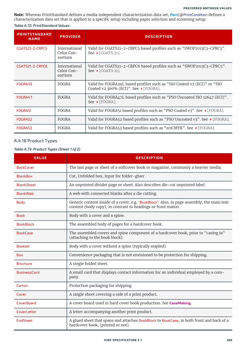
PREFERRED NMTOKEN VALUES
Note: Whereas PrintStandard defines a media independent characterization data set, Part/@PrintCondition defines a characterization data set that is applied to a specific setup including paper selection and screening setup.
A.4.18 Product Types
Table A.72: PrintStandard Values
PRINTSTANDARD NAME PROVIDER DESCRIPTION
CGATS21-2-CRPC5 International Color Con-sortium
Valid for CGATS21-2-CRPC5 based profiles such as “SWOP2013C3-CPRC5”. See [CGATS.21].
CGATS21-2-CRPC6 International Color Con-sortium
Valid for CGATS21-2-CRPC6 based profiles such as “SWOP2013C3-CPRC5”. See [CGATS.21].
FOGRA39 FOGRA Valid for FOGRA39L based profiles such as “ISO Coated v2 (ECI)” or “ISO Coated v2 300% (ECI)”. See [FOGRA].
FOGRA47 FOGRA Valid for FOGRA47L based profiles such as “PSO Uncoated ISO 12647 (ECI)”. See [FOGRA].
FOGRA51 FOGRA Valid for FOGRA51 based profiles such as “PSO Coated v3”. See [FOGRA].
FOGRA52 FOGRA Valid for FOGRA52 based profiles such as “PSO Uncoated v3”. See [FOGRA].
FOGRA53 FOGRA Valid for FOGRA53 based profiles such as “eciCMYK”. See [FOGRA].
Table A.73: Product Types (Sheet 1 of 2)
VALUE DESCRIPTION
BackCover The last page or sheet of a softcover book or magazine, commonly a heavier media.
BlankBox Cut, Unfolded box, input for folder-gluer
BlankSheet An unprinted divider page or sheet. Also describes die-cut unprinted label.
BlankWeb A web with connected blanks after a die cutting.
Body Generic content inside of a cover, e.g. "BookBlock". Also, in page assembly, the main text content (body copy), in contrast to headings or front matter.
Book Body with a cover and a spine.
BookBlock The assembled body of pages for a hardcover book.
BookCase The assembled covers and spine component of a hardcover book, prior to "casing in" (attaching to the book block).
Booklet Body with a cover without a spine (typically stapled).
Box Convenience packaging that is not envisioned to be protection for shipping.
Brochure A single folded sheet.
BusinessCard A small card that displays contact information for an individual employed by a com-pany.
Carton Protection packaging for shipping.
Cover A single sheet covering a side of a print product.
CoverBoard A cover board used in hard cover book production. See CaseMaking.
CoverLetter A letter accompanying another print product.
EndSheet A glued sheet that spans and attaches BookBlock to BookCase, in both front and back of a hardcover book, (printed or not).
XJDF SPECIFICATIO N 2.1 403

A.4.19 Quality Control MethodsNew in XJDF 2.1
Envelope A folded paper container, with sealable flap, that encloses and protects a document or contents.
FlatBox A folded and glued blank (not opened). Output from a box folder-gluer.
FlatWork Non-bound, non-folded products or products that only have packaging folds.
FrontCover The first page or sheet of a softcover book or magazine, commonly a heavier media.
Insert A product part intended to be inserted into a print product.
Jacket Hardcover case jacket.
Label A piece of paper or plastic that is attached to an object in order to give information about it.
Leaflet A single unfolded sheet.
Letter A written or printed communication addressed to a person or organization and usually transmitted by mail or messenger.
Map A drawing/representation of a particular area such as a city, or a continent, showing its main features, as they would appear if viewed from above.
Media Unprinted media, the substrate (usually paper) on which an image is to be printed.
Newspaper A newspaper-product
Notebook A book or block with a set of identical or similar pages, e.g. a writing tablet, where all page fronts have identical content, and all page backs have identical content.
Pallet Loaded pallet of boxes, cartons or Component resources.
Postcard A card designed for sending a message by mail without an envelope.
Poster A large printed picture.
Proof A representation that visualizes the intended output of page assembly, or the printing process. Proof SHOULD NOT be specified for a product as defined in Section 3.3.1 Product.
ResponseCard A self mailer to respond to an offer.
Section Main division of a book, such as a chapter, typically with a name or number.
SelfMailer A document to be sent via the post without an additional envelope.
Spine The bound edge of a book. Also, the portion of the cover that connects the front and back cover, wrapping the binding edge.
SpineBoard A spine board used in hard cover book production. See CaseMaking.
Stack Stacked Component.
WrapAroundCover A single cover sheet containing the front cover, spine and back cover.
Table A.74: Quality Control Methods
VALUE DESCRIPTION
Barcode A barcode quality test measures whether a printed barcode adheres to the technical requirements for a barcode of that type.
BindingPull Binding quality test that measures the force required to pull out a bound page.
Table A.73: Product Types (Sheet 2 of 2)
VALUE DESCRIPTION
404 XJDF SPECIFICATIO N 2.1
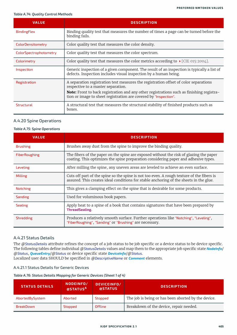
PREFERRED NMTOKEN VALUES
A.4.20 Spine Operations
A.4.21 Status DetailsThe @StatusDetails attribute refines the concept of a job status to be job specific or a device status to be device specific. The following tables define individual @StatusDetails values and map them to the appropriate job specific state NodeInfo/@Status, QueueEntry/@Status or device specific state DeviceInfo/@Status.Localized user data SHOULD be specified in @DescriptiveName or Comment elements.
A.4.21.1 Status Details for Generic Devices
BindingFlex Binding quality test that measures the number of times a page can be turned before the binding fails.
ColorDensitometry Color quality test that measures the color density.
ColorSpectrophotometry Color quality test that measures the color spectrum.
Colorimetry Color quality test that measures the color metrics according to [CIE 015:2004].
Inspection Generic inspection of a given component. The result of an inspection is typically a list of defects. Inspection includes visual inspection by a human being.
Registration A separation registration test measures the registration offset of color separations respective to a master separation.Note: Front to back registration and any other registrations such as finishing registra-tion or image to sheet registration are covered by "Inspection".
Structural A structural test that measures the structural stability of finished products such as boxes.
Table A.75: Spine Operations
VALUE DESCRIPTION
Brushing Brushes away dust from the spine to improve the binding quality.
FiberRoughing The fibers of the paper on the spine are exposed without the risk of glazing the paper coating. This optimizes the spine preparation considering paper and adhesive types.
Leveling After milling the spine, any uneven areas are leveled to achieve an even surface.
Milling Cuts off part of the spine so the spine is not too even. A rough texture of the fibers is assured. This creates ideal conditions for stable anchoring of the sheets in the glue.
Notching This gives a clamping effect on the spine that is desirable for some products.
Sanding Used for voluminous book papers.
Sealing Apply heat to a spine of a book that contains signatures that have been prepared by ThreadSealing.
Shredding Produces a relatively smooth surface. Further operations like "Notching", "Leveling", "FiberRoughing", "Sanding" or "Brushing" are necessary.
Table A.76: Status Details Mapping for Generic Devices (Sheet 1 of 4)
STATUS DETAILSNODEINFO/@STATUSA
DEVICEINFO/@STATUS DESCRIPTION
AbortedBySystem Aborted Stopped The job is being or has been aborted by the device.
BreakDown Stopped Offline Breakdown of the device, repair needed.
Table A.74: Quality Control Methods
VALUE DESCRIPTION
XJDF SPECIFICATIO N 2.1 405

Calibrating Setup Production The device is calibrating, either manually or auto-matically.
ControlDeferred - Offline The machine is not accessible by the device.
CoverOpen Stopped Stopped One or more covers on the device are open.
DocumentAccessError Aborted Stopped The device could not access one or more documents passed by reference.
DoorOpen Stopped Stopped One or more doors on the device are open.
Failure Stopped Stopped Failure of the device. Requires some maintenance in order to restart the device. "Failure" has specialized subcategories: "PaperJam", "DoubleFeed", "BadFeed", "BadTrim", "ObliqueSheet", "IncorrectComponent", "IncorrectThickness".
Good InProgress Production Production of products in progress, good copy counter is on, waste copy counter is off.
Idling Stopped Production Device is running, but no products are produced or consumed. Good and waste copy counters are off.
InputTrayMissing Stopped Stopped One or more input trays are not in the device.
InterlockOpen Stopped Stopped One or more interlock devices on the printer are unlocked.
IterationPaused Suspended Production At least one iteration cycle has completed but addi-tional iteration cycles MAY still occur.
JobCanceledByOperator Aborted Production The job was canceled by the device operator using ModifyQueueEntry/ModifyQueueEntryParams/@Operation="Abort", or means local to the device.
JobCanceledByUser Aborted Production The job was canceled by the owner of the job using ModifyQueueEntry/ModifyQueueEntryParams/@Operation="Abort".
JobCompletedSuccessfully
Completed Production The job completed successfully.
JobCompletedWithErrors Completed Production The job completed with errors (and possibly warnings too).
JobCompletedWithWarnings
Completed Production The job completed with warnings.
JobHeld Waiting Production The device held the job that had been waiting (by performing a ModifyQueueEntry/ModifyQueueEntryParams/@Operation="Hold" request on a waiting QueueEntry).
JobHeldOnCreate Waiting Production The job was submitted to the queue with the QueueSubmissionParams/@Activation = "Held".
JobIncoming Waiting Production The device is retrieving/accepting document data.
JobMissResources Waiting
InProgress
Stopped When @Status is "InProgress" or "Waiting", QueueEntry waits for resources to become available to process further.
JobReadyForStart Waiting
InProgress
Stopped When is @Status "InProgress" or "Waiting", QueueEntry is ready and waits for (manual) start event to process further.
Table A.76: Status Details Mapping for Generic Devices (Sheet 2 of 4)
STATUS DETAILSNODEINFO/@STATUSA
DEVICEINFO/@STATUS DESCRIPTION
406 XJDF SPECIFICATIO N 2.1

PREFERRED NMTOKEN VALUES
JobResuming Waiting Production The device is in the process of moving the job from a suspended condition to a candidate for processing ( ModifyQueueEntry/ModifyQueueEntryParams/@Operation="Resume").
JobScheduling Waiting Production The device is scheduling the job for processing.
JobStreaming InProgress Production Same as "JobIncoming" with the specialization that the device is processing the document data as it is being received (that is, the job data is not being spooled, but rather is being processed in chunks by the output device and is being imaged during reception).
JobSuspended Suspended Production The device suspended the job that had been process-ing (e.g., by performing a ModifyQueueEntry/ModifyQueueEntryParams/@Operation="Suspend" request on a running QueueEntry) and other jobs can be processed by the device.
JobSuspending InProgress Production The device is in the process of moving the job from a processing condition to a suspended condition where other jobs can be processed.
JobUserInputRequired Waiting
InProgress
Stopped When @Status is "Waiting" or "InProgress", QueueEntry is not producible and waits for user input required to process further, e.g. missing parameters, decisions, etc.
Maintenance Stopped Stopped General maintenance of the device.
MissResources Stopped Stopped Production has been stopped because resources are missing or unavailable. Waits for new resources; sub-category of "Pause".
MovingToPaused InProgress Production The device has been paused, but the machine(s) are taking an appreciable time to stop.
OutputAreaFull Stopped Stopped One or more output areas are full (e.g., tray, stacker, collator).
OutputTrayMissing Stopped Stopped One or more output trays are not in the device.
PaperJam Stopped Stopped Media jam in the device; subcategory of "Failure".
Pause Stopped Stopped Machine paused; restart is possible.
PendingReturn Cleanup Production When @Status is "Cleanup", QueueEntry is currently returning.
ProcessingToStopPoint InProgress Production The requester has issued an ModifyQueueEntry/ModifyQueueEntryParams/@Operation="Abort" request or the device has aborted the job, but is still perform-ing some actions on the job until a specified stop point occurs or job termination/cleanup is completed.
QueuedToRun Waiting Stopped When @Status is "Waiting", QueueEntry is queued to run and waits for device to become available (idle) to process further.
Repair Stopped Offline The device is being repaired after a break down.
Running InProgress Production When @Status is "InProgress", QueueEntry is process-ing.
ShutDown Stopped Offline Machine stopped (can be switched off), restart requires a run up.
Table A.76: Status Details Mapping for Generic Devices (Sheet 3 of 4)
STATUS DETAILSNODEINFO/@STATUSA
DEVICEINFO/@STATUS DESCRIPTION
XJDF SPECIFICATIO N 2.1 407

A.4.21.2 Status Details for Printing Devices
SizeChange Setup Production Changing setup for media size.
StandBy - Idle The device has been switched into power save mode and is still accepting new jobs.
StandBy - Stopped The device has been switched into power saving mode and cannot process jobs without prior intervention such as CommandWakeUp.
WaitForApproval Stopped Stopped Production has been stopped because a necessary approval is still missing; subcategory of "Pause".
WaitForGang Waiting
Inprogress
Production The process has commenced to a point where parts of the job can be ganged on a sheet and the process is waiting for additional gang elements.
WarmingUp Setup Production Device is warming up after power up or power saver mode wake-up.
Waste InProgress Production Production of products in progress, good copy counter is off, waste copy counter is on.
WasteFull Stopped Stopped The device waste receptacle is full.
a. The column NodeInfo/@Status also applies to JobPhase/@Status and QueueEntry/@Status.
Table A.77: Status Details Mapping for Printing Devices
STATUS DETAILS NODEINFO/@STATUS
DEVICEINFO/@STATUS DESCRIPTION
BlanketChange Stopped Stopped Changing of blankets; subcategory of "Maintenance".
BlanketWash Cleanup Production Washing of the blanket; subcategory of "WashUp".
CleaningInkFountain Cleanup Production Cleaning of the ink fountain; subcategory of "WashUp".
CylinderWash Cleanup Production Washing of impression cylinders; subcategory of "WashUp".
DampeningRollerWash Cleanup Production Washing of the dampening roller; subcategory of "WashUp".
FormChange Setup Production In conventional printing, changing of plates.
InkRollerWash Cleanup Production Washing of the inking roller; subcategory of "WashUp".
PlateWash Cleanup Production Washing of the plate; subcategory of "WashUp".
Processing InProgress Production Other productive processing (RIP, etc.) is taking place but no final output is being produced. All input data has arrived (not "JobStreaming"/"InProgress" nor "JobIncoming"/"Waiting").
SleeveChange Stopped Stopped Changing of sleeves; subcategory of "Maintenance".
WaitingForMarker Suspended Production Processing is automatically suspended by the device because it is waiting behind other jobs in the marker module. The device will resume processing when a marker module becomes available.
WashUp Cleanup Production Machine is washed before, during or after production.
Table A.76: Status Details Mapping for Generic Devices (Sheet 4 of 4)
STATUS DETAILSNODEINFO/@STATUSA
DEVICEINFO/@STATUS DESCRIPTION
408 XJDF SPECIFICATIO N 2.1
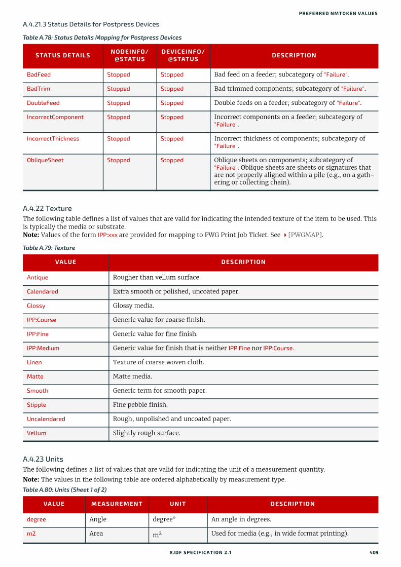
PREFERRED NMTOKEN VALUES
A.4.21.3 Status Details for Postpress Devices
A.4.22 TextureThe following table defines a list of values that are valid for indicating the intended texture of the item to be used. This is typically the media or substrate.Note: Values of the form IPP:xxx are provided for mapping to PWG Print Job Ticket. See [PWGMAP].
A.4.23 UnitsThe following defines a list of values that are valid for indicating the unit of a measurement quantity.
Note: The values in the following table are ordered alphabetically by measurement type.
Table A.78: Status Details Mapping for Postpress Devices
STATUS DETAILS NODEINFO/@STATUS
DEVICEINFO/@STATUS DESCRIPTION
BadFeed Stopped Stopped Bad feed on a feeder; subcategory of "Failure".
BadTrim Stopped Stopped Bad trimmed components; subcategory of "Failure".
DoubleFeed Stopped Stopped Double feeds on a feeder; subcategory of "Failure".
IncorrectComponent Stopped Stopped Incorrect components on a feeder; subcategory of "Failure".
IncorrectThickness Stopped Stopped Incorrect thickness of components; subcategory of "Failure".
ObliqueSheet Stopped Stopped Oblique sheets on components; subcategory of "Failure". Oblique sheets are sheets or signatures that are not properly aligned within a pile (e.g., on a gath-ering or collecting chain).
Table A.79: Texture
VALUE DESCRIPTION
Antique Rougher than vellum surface.
Calendared Extra smooth or polished, uncoated paper.
Glossy Glossy media.
IPP:Course Generic value for coarse finish.
IPP:Fine Generic value for fine finish.
IPP:Medium Generic value for finish that is neither IPP:Fine nor IPP:Course.
Linen Texture of coarse woven cloth.
Matte Matte media.
Smooth Generic term for smooth paper.
Stipple Fine pebble finish.
Uncalendared Rough, unpolished and uncoated paper.
Vellum Slightly rough surface.
Table A.80: Units (Sheet 1 of 2)
VALUE MEASUREMENT UNIT DESCRIPTION
degree Angle degree° An angle in degrees.
m2 Area m2 Used for media (e.g., in wide format printing).
XJDF SPECIFICATIO N 2.1 409

count Countable Objects 1 Countable objects, such as sheets, MAY be specified as “count”.
pt Length point (1/72 inch) Used for all except microscopic lengths (see below).
um Length micron () Used for microscopic lengths — where used (instead of points) it will be explicitly stated in the definition of the item. See Media/@Thickness.
lpi Line Screen lpi The lines per inch (lpi) for conventionally screened halftone, screened gray scale and screened monotone bitmap images.
gsm Paper weight g/m2 Paper weight SHALL be provided in grams per square meter. See Appendix B Media Weight for details of calculating paper weights that are not in g/m2.
kWh Power (electrical) kilowatt hour Used to measure consumption of electricity.Note: Current power consumption (kW) MAY be pro-vided in a ResourceInfo as ‘rate of consumption’ of electric power, i.e. kWh/h=kW.
dpi Resolution dpi The dots per inch (dpi) for print output and bitmap image (TIFF, BMP, etc.) file resolution.
ppi Screen Resolution ppi The pixels per inch (ppi) for screen display (e.g., soft proof display and user interface display), scanner cap-ture settings and digital camera settings.
spi Spot Resolution spi For imaging devices such as filmsetters, platesetters and proofers, the fundamental imaging unit (e.g., one “on” laser or imaging head imaged unit).Note: Many imaging devices construct dots from mul-tiple imaging spots, so dpi and spots per inch (spi) are not necessarily equivalent.
C Temperature °C (Celsius) The temperature in degrees centigrade.
m3 Volume (gas) m3 (cubic meter) Used to measure consumption of gas.
l Volume (liquid) liter The volume in liters.
g Weight gram The weight in grams.
Table A.80: Units (Sheet 2 of 2)
VALUE MEASUREMENT UNIT DESCRIPTION
410 XJDF SPECIFICATIO N 2.1

Appendix B
B Media WeightIn North America and Japan, each grade of paper has one basic size used to compute its basis weight per ream. For ex-ample, Bond basic size is 17" x 22" and Shiroku-ban basic size is 788 mm x 1091 mm.B.1 North American Media WeightIn North America, a paper's basis weight is the weight of five hundred sheets of its basic size. For example, if five hun-dred 25" x 38" sheets of offset paper weigh 60 pounds, it is called 60# offset. Paper mills outside of North America use the metric system to designate paper weight. The basis weight of foreign papers is grams per square meter (g/m2) known as the sheet's grammage. Papers made to metric standards don't convert to basis weights familiar to North Americans. For example, 100 g/m2 equals a basis weight of 67.5lb. Following is the English/grammage conversion formula:
Basis Weight (lb.) x (1406.5 / Square inches in basic size) = grams per square meter
For example, the grammage of 65 lb. cover stock when the cover is 20 x 26 can be calculated as follows:
65 x (1406.5 / (20 x 26)) = 65 x 2.70 = 176 g/m2
The following table defines the basic sizes and the factor that the North American weight is multiplied by to calculate @Weight for various stock types. Stock type is specified in Media/@StockType or MediaIntent /@StockType.
In the following table, the right columns of each column pair list common basis weights for North American papers, while the left columns list their corresponding grammage. The rows are ordered by grammage. Basis weights for bond, book, cover and other grades of papers are computed using different basic sizes, so the progression of weights down the right columns is untidy.
Table B.1: Conversion Factor from Basis Weight (lbs) to Weight (g/m2)
STOCK TYPE BASIS SIZE IN INCHES CONVERSION FACTOR EQUIVALENT
Bond 17 x 22 3.76 "Ledger", "Manifold"
Book 25 x 38 1.48 "Bible", "Coated", "Offset", "Text"
Bristol 22½ x 28½ 2.19
Cover 20 x 26 2.70
Index 25½ x 30½ 1.81
Newsprint 24 x 36 1.63 "Tag"
Table B.2: Grammage Equivalents for Common (US) Basis Weights (Sheet 1 of 2)
GRAMMAGE (G/M2) BASIS WEIGHT GRAMMAGE (G/M2) BASIS WEIGHT
30 20# Book 150 40# Ledger
34 9# Manifold 152 60# Cover
36 24# Book 163 90 # Index
44 30# Book 163 100 # Tag
45 12# Manifold 175 80# Bristol
49 13# Bond 176 65# Cover
49 33# Book 178 120# Book
52 35# Book 197 90# Bristol
59 40# Book 199 110# Index
XJDF SPECIFICATIO N 2.1

B.2 Japanese Media WeightIn Japan, a paper's basis weight is the weight of 1000 sheets of its basic size and ream weights are given in kg.
The following table was originally published by EDS Inc., Editorial & Design Services; see [Japanese Paper Sizes]. For more help with grammage and basis weight conversion, see also [Grammage Conversion].
Following is the Japanese/grammage conversion formula: Basis Weight (kg) / Basic Size (m2) = grams per square meter
For example, the grammage of 70 kg Shiroku-ban stock when the size is 0.788 x 1.091 can be calculated as follows: 70 / (0.788 x 1.091) = 81.4 g/m2
In the table below, trade-sheet size is given in mm.
60 16# Bond 204 125# Tag
67 45# Bond 216 80# Cover
74 50# Book 219 100# Bristol
75 20# Bond 244 150# Tag
81 55# Book 253 140# Index
89 60# Book 263 120# Bristol
90 24# Bond 270 100# Cover
104 70# Book 285 175# Tag
105 28# Ledger 307 140# Bristol
108 40# Cover 307 170# Index
118 80# Book 325 200# Tag
120 32# Ledger 350 160# Bristol
133 90# Book 352 130# Cover
135 36# Ledger 394 180# Bristol
135 50# Cover 398 220# Index
147 67# Bristol 407 250# Tag
148 100# Book 438 200# Bristol
488 300# Tag
Table B.3: Japanese Media Weight (Sheet 1 of 2)
STOCK TYPE SHIROKU-BAN788 X 1091
JIS B-BAN765 X 1085
KIKU-BAN636 X 939
JIS A-BAN625 X 880
GRAMMAGE (G/M2)
Aatoposutoshi
アートポス ト紙
180 - 125 - 209.3
200 - 139 - 232.6
220 - 153 - 255.0
Aatoshi
アート紙
73 70.5 50.5 46.5 84.9
90 87 62.5 57.5 104.7
110 106 76.5 70.5 127.9
135 130.5 93.5 86.5 157.0
Table B.2: Grammage Equivalents for Common (US) Basis Weights (Sheet 2 of 2)
GRAMMAGE (G/M2) BASIS WEIGHT GRAMMAGE (G/M2) BASIS WEIGHT
412 XJDF SPECIFICATIO N 2.1

PA PER GRADE
The following describes the five stock types in the above table:
• 上質紙 Joushitsushi (“top-quality paper”) contains 100% chemical pulp
• 中質紙 Chuushitsushi (“medium-quality paper”) contains a minimum of 70% chemical pulp
• アート紙 Aatoshi (“art paper”) is machine coated paper, available in top quality and medium quality (Joushitsu and Chuushitsu)
• マシンコート紙 Mashinkootoshi (“machine coated paper”), also called Kootoshi ( コート紙 ), is machine coated paper given only a thin coat of clay
• アートポスト紙 Aatoposutoshi (“art-post paper”) is cover stock coated on one side
B.3 Paper Grade[ISO12647-2:2013] provides a rough classification of offset paper with 5 classes, which is generally referred to as paper grade. [ISO12647-4:2014] was updated in 2013, and a new set of 8 standard papers was defined that are more appro-priate for offset paper types that are used today. [ISO12647-2:2013] defines the properties of rotogravure papers. The following table provides a rough and non-normative translation between the standard sets:
Chuushitsushi
中質紙
- 45 - 30 54.2
- 55 - 36.5 66.3
Joushitsushi
上質紙
40 - - - 46.5
45 - 31 20.5 52.3
55 53 38 35 64.0
70 67.5 48.5 44.5 81.4
90 - 62.5 47.5 104.7
110 - 71.5 70.5 127.9
135 - 93.5 80.5 157.0
180 - - - 209.3
Mashinkootoshi
マシンコート紙
63 61 - - 73.3
68 65.6 47 43.5 79.1
73 70.5 50.5 46.5 84.9
90 87 62.5 57.5 104.7
110 106 76.5 70.5 127.9
135 130.5 93.5 86.5 157.0
Table B.4: Translation of Paper grades between [ISO12647-2:2013]/[ISO12647-3:2013]/[ISO12647-4:2014] and [ISO12647-2:2004]
ISO12647-2:2013ISO12647-3:2013ISO12647-4:2014 PRESS
ISO12647-2:2004
ID TYPE GRADE TYPE
LWCPlus Light weight calendered plus. Rotogravure 3 Gloss coated, web.
LWCStandard Light weight calendered standard. Rotogravure 3 Gloss coated, web.
NewsPlus Newsprint plus. Rotogravure 5 Uncoated.
PS1 Premium Coated. Offset Sheet 1 Gloss coated.
Table B.3: Japanese Media Weight (Sheet 2 of 2)
STOCK TYPE SHIROKU-BAN788 X 1091
JIS B-BAN765 X 1085
KIKU-BAN636 X 939
JIS A-BAN625 X 880
GRAMMAGE (G/M2)
XJDF SPECIFICATIO N 2.1 413

PS2 Improved Coated. Offset Web 3 Gloss coated, web.
PS3 Standard Coated Glossy. Offset Web 3 Gloss coated, web.
PS4 Standard Coated Matte. Offset Web 2 Matte coated.
PS5 Wood free Uncoated. Offset Sheet 4 Uncoated white.
PS6 Super Calendered. Offset Web 4 Uncoated white.
PS7 Improved Uncoated. Offset Web 4 Uncoated white.
PS8 Standard Uncoated. Offset Web 4/5 Uncoated.
SCPlus Super calendered plus. Rotogravure 4 Uncoated white.
SNP Standard newsprint. Offset Newsprint 5 Uncoated.
SCStandard Super calendered standard. Rotogravure 4 Uncoated white.
Table B.4: Translation of Paper grades between [ISO12647-2:2013]/[ISO12647-3:2013]/[ISO12647-4:2014] and [ISO12647-2:2004]
ISO12647-2:2013ISO12647-3:2013ISO12647-4:2014 PRESS
ISO12647-2:2004
ID TYPE GRADE TYPE
414 XJDF SPECIFICATIO N 2.1

Appendix C
C Media SizeThe following table defines a set of named media sizes as defined by [PPD].Implementation RemarkThe following tables provide the dimensions for various ranges of named paper sizes. Each named size has dimensions listed in multiple columns for different units (points, millimeters and inches). One of these units is normative and is identified in the column header. The others are conversions from the normative size, shown for convenience. Since these sizes are real numbers, comparison of media dimensions SHOULD take into account certain rounding errors. Therefore, different media sizes SHOULD be considered equal when both dimensions are the same within a range of 5 points.
C.1 Architectural Paper Sizes
C.2 Business Card Sizes
Table C.1: Architectural Paper Sizes
MEDIA SIZE SIZE IN POINTS SIZE IN MILLIMETERS SIZE IN INCHES
NORMATIVE
ArchA 648 x 864 228.6 x 304.8 9 x 12
ArchB 864 x 1296 304.8 x 457.2 12 x 18
ArchC 1296 x 1728 457.2 x 609.6 18 x 24
ArchD 1728 x 2592 609.6 x 914.4 24 x 36
ArchE 2592 x 3456 914.4 x 1219.2 36 x 48
ArchE1 2160 x 3024 762.0 x 1066.8 30 x 42
ArchE2 1872 x 2736 660.4 x 965.2 26 x 38
ArchE3 1944 x 2808 685.8 x 990.6 27 x 39
Table C.2: Business Card Sizes
MEDIA SIZE SIZE IN POINTS SIZE IN MILLIMETERS SIZE IN INCHES
NORMATIVE
BusinessCard_Japan 156 x 258 55 x 91 2.2 x 3.6
BusinessCard_UK 156 x 241 55 x 85 2.2 x 3.3
BusinessCard_US 145 x 252 51 x 89 2.0 x 3.5
XJDF SPECIFICATIO N 2.1

C.3 International A Paper SizesThese sizes are defined by ISO standards, including [ISO216:2007] and by JIS standards [JIS P0138] except where not-ed.
C.4 International and Japanese B Paper SizesThese sizes are defined by ISO standards, including [ISO216:2007] and by JIS standards [JIS P0138].Note: Equivalent International and Japanese B paper sizes, i.e. ISOB0/JISB0, ISOB1/JISB1 etc., differ in area and size. To il-lustrate this point the ISOB0 sheet has an area of m2 whereas the JISB0 sheet has an area of 1.5m2. The aspect ratio of both is identical.
Implementations SHOULD NOT calculate values and SHOULD use the values from the respective tables below.
C.4.1 International (ISO) B Paper Sizes
Table C.3: International A Paper Sizes
MEDIA SIZE SIZE IN POINTS SIZE IN MILLIMETERS SIZE IN INCHES
NORMATIVE
A0 2384 x 3370 841 x 1189 33.11 x 46.81
A1 1684 x 2384 594 x 841 23.39 x 33.11
A2 1191 x 1684 420 x 594 16.54 x 23.39
A3 842 x 1191 297 x 420 11.69 x 16.54
A3Extra a
a. Non-standard ISO size variations.
913 x 1262 322 x 445 12.67 x 17.52
A4 595 x 842 210 x 297 8.27 x 11.69
A4Extra a 667 x 914 235 x 322 9.25 x 12.67
A4Plus a 595 x 936 210 x 330 8.27 x 13.00
A4Tab a 638 x 842 225 x 297 8.86 x 11.69
A5 420 x 595 148 x 210 5.83 x 8.27
A5Extra a 492 x 668 174 x 235 6.85 x 9.25
A6 297 x 420 105 x 148 4.13 x 5.83
A7 210 x 297 74 x 105 2.91 x 4.13
A8 148 x 210 52 x 74 2.05 x 2.91
A9 105 x 148 37 x 52 1.46 x 2.05
A10 73 x 105 26 x 37 1.02 x 1.46
Table C.4: International B Paper Sizes (Sheet 1 of 2)
MEDIA SIZE SIZE IN POINTS SIZE IN MILLIMETERS SIZE IN INCHES
NORMATIVE
ISOB0 2834 x 4008 1000 x 1414 39.4 x 55.7
ISOB1 2004 x 2834 707 x 1000 27.8 x 39.4
ISOB2 1417 x 2004 500 x 707 19.7 x 27.8
ISOB3 1001 x 1417 353 x 500 13.9 x 19.7
ISOB4 709 x 1001 250 x 353 9.8 x 13.9
2
416 XJDF SPECIFICATIO N 2.1
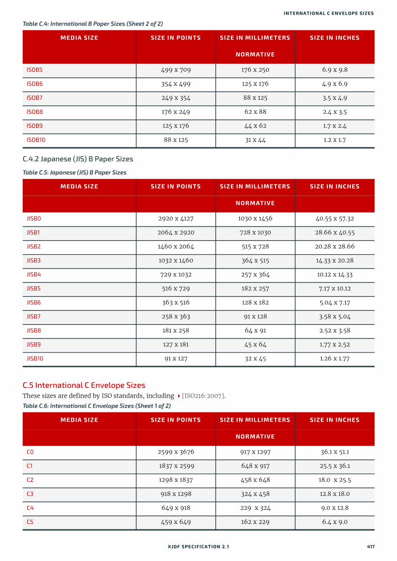
INTERNATIONAL C ENVELO PE SIZES
C.4.2 Japanese (JIS) B Paper Sizes
C.5 International C Envelope SizesThese sizes are defined by ISO standards, including [ISO216:2007].
ISOB5 499 x 709 176 x 250 6.9 x 9.8
ISOB6 354 x 499 125 x 176 4.9 x 6.9
ISOB7 249 x 354 88 x 125 3.5 x 4.9
ISOB8 176 x 249 62 x 88 2.4 x 3.5
ISOB9 125 x 176 44 x 62 1.7 x 2.4
ISOB10 88 x 125 31 x 44 1.2 x 1.7
Table C.5: Japanese (JIS) B Paper Sizes
MEDIA SIZE SIZE IN POINTS SIZE IN MILLIMETERS SIZE IN INCHES
NORMATIVE
JISB0 2920 x 4127 1030 x 1456 40.55 x 57.32
JISB1 2064 x 2920 728 x 1030 28.66 x 40.55
JISB2 1460 x 2064 515 x 728 20.28 x 28.66
JISB3 1032 x 1460 364 x 515 14.33 x 20.28
JISB4 729 x 1032 257 x 364 10.12 x 14.33
JISB5 516 x 729 182 x 257 7.17 x 10.12
JISB6 363 x 516 128 x 182 5.04 x 7.17
JISB7 258 x 363 91 x 128 3.58 x 5.04
JISB8 181 x 258 64 x 91 2.52 x 3.58
JISB9 127 x 181 45 x 64 1.77 x 2.52
JISB10 91 x 127 32 x 45 1.26 x 1.77
Table C.6: International C Envelope Sizes (Sheet 1 of 2)
MEDIA SIZE SIZE IN POINTS SIZE IN MILLIMETERS SIZE IN INCHES
NORMATIVE
C0 2599 x 3676 917 x 1297 36.1 x 51.1
C1 1837 x 2599 648 x 917 25.5 x 36.1
C2 1298 x 1837 458 x 648 18.0 x 25.5
C3 918 x 1298 324 x 458 12.8 x 18.0
C4 649 x 918 229 x 324 9.0 x 12.8
C5 459 x 649 162 x 229 6.4 x 9.0
Table C.4: International B Paper Sizes (Sheet 2 of 2)
MEDIA SIZE SIZE IN POINTS SIZE IN MILLIMETERS SIZE IN INCHES
NORMATIVE
XJDF SPECIFICATIO N 2.1 417

C.6 RA and SRA Paper Sizes
C.7 US ANSI Paper Sizes
C6 323 x 459 114 x 162 4.5 x 6.4
C7 230 x 323 81 x 114 3.2 x 4.5
C8 162 x 230 57 x 81 2.2 x 3.2
C9 113 x 162 40 x 57 1.6 x 2.2
C10 79 x 113 28 x 40 1.1 x 1.6
Table C.7: RA and SRA Paper Sizes
MEDIA SIZE SIZE IN POINTS SIZE IN MILLIMETERS SIZE IN INCHES
NORMATIVE
RA0 2438 x 3458 860 x 1220 33.9 x 48.0
RA1 1729 x 2438 610 x 860 24.0 x 33.9
RA2 1219 x 1729 430 x 610 16.9 x 24.0
RA3 865 x 1219 305 x 430 12.0 x 16.9
RA4 609 x 865 215 x 305 8.5 x 12.0
SRA0 2551 x 3628 900 x 1280 35.4 x 50.4
SRA1 1814 x 2551 640 x 900 25.2 x 35.4
SRA2 1276 x 1814 450 x 640 17.7 x 25.2
SRA3 907 x 1276 320 x 450 12.6 x 17.7
SRA4 638 x 907 225 x 320 8.9 x 12.6
Table C.8: US ANSI Paper Sizes
MEDIA SIZE SIZE IN POINTS SIZE IN MILLIMETERS SIZE IN INCHES
NORMATIVE
AnsiA a
a. Equivalent to US Letter.
612 x 792 215.9 x 279.4 8.5 x 11
AnsiB b
b. Equivalent to US Ledger and US Tabloid.
792 x 1224 279.4 x 431.8 11 x 17
AnsiC 1224 x 1584 431.8 x 558.8 17 x 22
AnsiD 1584 x 2448 558.8 x 863.6 22 x 34
AnsiE 2448 x 3168 863.6 x 1117.6 34 x 44
Table C.6: International C Envelope Sizes (Sheet 2 of 2)
MEDIA SIZE SIZE IN POINTS SIZE IN MILLIMETERS SIZE IN INCHES
NORMATIVE
418 XJDF SPECIFICATIO N 2.1

US PAPER SIZES
C.8 US Paper Sizes
Table C.9: US Paper Sizes
MEDIA SIZE SIZE IN POINTS SIZE IN MILLIMETERS SIZE IN INCHES
NORMATIVE
HalfLetter 396 x 612 139.7 x 215.9 5.5 x 8.5
Letter a
a. Equivalent to ANSI A.
612 x 792 215.9 x 279.4 8.5 x 11
Legal 612 x 1008 215.9 x 355.6 8.5 x 14
JuniorLegal 360 x 576 127.0 x 203.2 5 x 8
Ledger b
b. Equivalent to ANSI B.
792 x 1224 279.4 x 431.8 11 x 17
Tabloid c
c. Equivalent to ANSI B.
792 x 1224 279.4 x 431.8 11 x 17
XJDF SPECIFICATIO N 2.1 419

420 XJDF SPECIFICATIO N 2.1

Appendix D
D String GenerationXJDF specifies pairs of attributes that allow for the dynamic generation of strings. Each pair comprises of a format and a template named @XXXFormat @XXXTemplate where the ‘XXX’ is a generic place holder used for convenience in this chapter. For example FileSpec has a pair to allow for the automatic generation of file names called, @FileFormat and @FileTemplate.The function defined when using the attributes @XXXFormat and @XXXTemplate is based on the standard C printf() func-tion. (See [K&R].) @XXXFormat is the first argument and @XXXTemplate is a list of values selected from Table D.1 Template Variables.
D.1 Template VariablesThe following table describes predefined variables used in @XXXTemplate values.
Table D.1: Template Variables
NAME ‘C’ LANGUAGE DATATYPE DESCRIPTION
<a partition key> string Any Partition Key that is an attribute of Part; see Table 6.4 Part Element.
ActualAmount float Actual amount of the product that was produced.
Amount float Planned amount of the product that was produced.
CustomerID string CustomerInfo/@CustomerID.
CustomerName string Contact/Person of the customer contact. The sequence and selection of attributes is system dependent.
Date string Current date in [ISO8601:2004] format.
DeviceID string Device/@DeviceID of the device that produced the output.
DeviceName string Device/@DescriptiveName of the device that produced the output.
EndTime string Actual end time of the job.
Error string List of errors that occurred during the job. The formatting of errors is system dependent.
ErrorStats string Statistics on errors that happened during execution. The formatting of error statistics is system dependent.
ExposedMediaName string Resource/@DescriptiveName of the plate that is being imaged.
GeneralID:XXX string GeneralID/@IDValue of a GeneralID[@IDUsage = "XXX"].For example if @Format = "%i" and @Template= "GeneralID:foo" then for: <GeneralID IDUsage="foo" IDValue="1"/>
the extracted value is 1.
Generated string System generated string, for example a file name.
Input string Local file name of the input file. A value of "Input" SHALL NOT be speci-fied for a FileSpec that describes an input file.
JobID string XJDF/@JobID of the job.
JobName string XJDF/@DescriptiveName of the job that is being processed.
JobPartID string XJDF/@JobPartID of the job.
XJDF SPECIFICATIO N 2.1
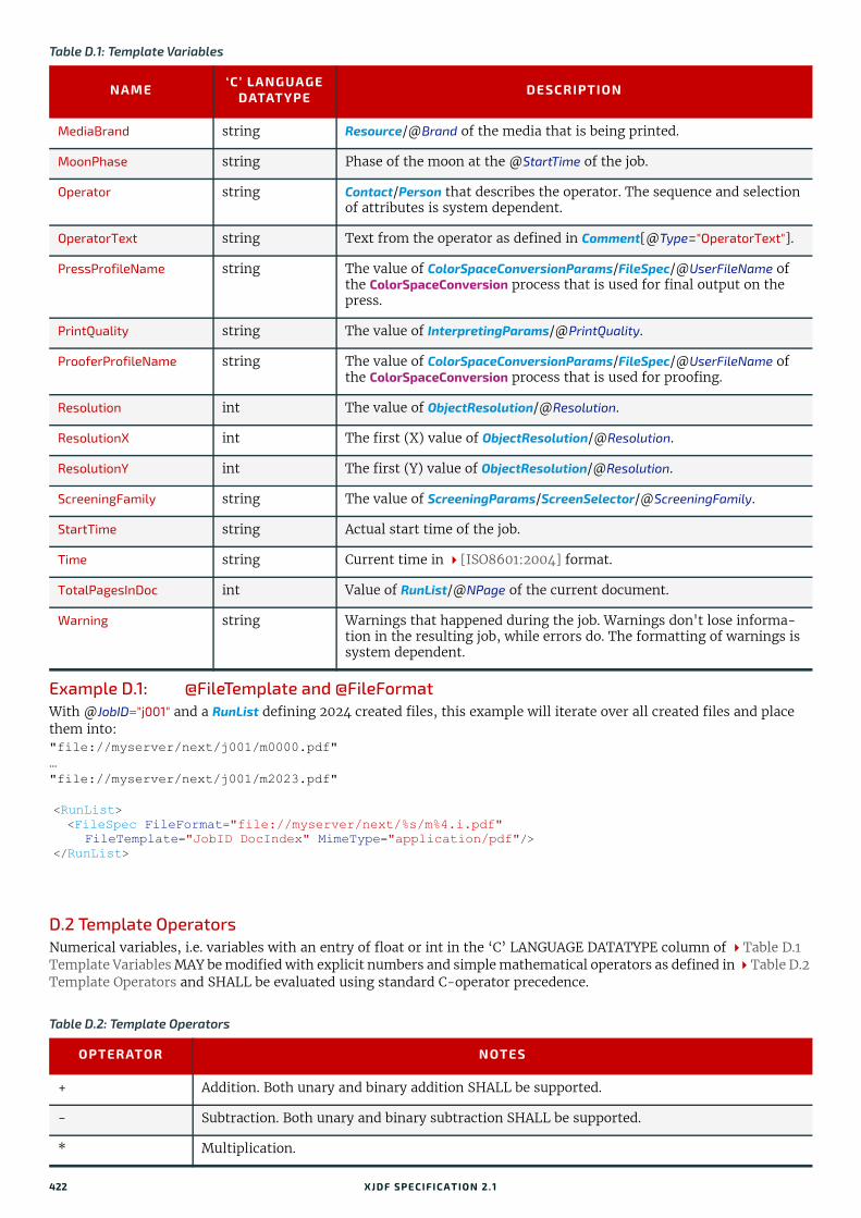
Example D.1: @FileTemplate and @FileFormatWith @JobID="j001" and a RunList defining 2024 created files, this example will iterate over all created files and place them into:"file://myserver/next/j001/m0000.pdf"…"file://myserver/next/j001/m2023.pdf"
D.2 Template OperatorsNumerical variables, i.e. variables with an entry of float or int in the ‘C’ LANGUAGE DATATYPE column of Table D.1 Template Variables MAY be modified with explicit numbers and simple mathematical operators as defined in Table D.2 Template Operators and SHALL be evaluated using standard C-operator precedence.
MediaBrand string Resource/@Brand of the media that is being printed.
MoonPhase string Phase of the moon at the @StartTime of the job.
Operator string Contact/Person that describes the operator. The sequence and selection of attributes is system dependent.
OperatorText string Text from the operator as defined in Comment[@Type="OperatorText"].
PressProfileName string The value of ColorSpaceConversionParams/FileSpec/@UserFileName of the ColorSpaceConversion process that is used for final output on the press.
PrintQuality string The value of InterpretingParams/@PrintQuality.
ProoferProfileName string The value of ColorSpaceConversionParams/FileSpec/@UserFileName of the ColorSpaceConversion process that is used for proofing.
Resolution int The value of ObjectResolution/@Resolution.
ResolutionX int The first (X) value of ObjectResolution/@Resolution.
ResolutionY int The first (Y) value of ObjectResolution/@Resolution.
ScreeningFamily string The value of ScreeningParams/ScreenSelector/@ScreeningFamily.
StartTime string Actual start time of the job.
Time string Current time in [ISO8601:2004] format.
TotalPagesInDoc int Value of RunList/@NPage of the current document.
Warning string Warnings that happened during the job. Warnings don't lose informa-tion in the resulting job, while errors do. The formatting of warnings is system dependent.
<RunList> <FileSpec FileFormat="file://myserver/next/%s/m%4.i.pdf" FileTemplate="JobID DocIndex" MimeType="application/pdf"/></RunList>
Table D.2: Template Operators
OPTERATOR NOTES
+ Addition. Both unary and binary addition SHALL be supported.
- Subtraction. Both unary and binary subtraction SHALL be supported.
* Multiplication.
Table D.1: Template Variables
NAME ‘C’ LANGUAGE DATATYPE DESCRIPTION
422 XJDF SPECIFICATIO N 2.1

TEMPLA TE O PERA TO RS
/ Division.
% Modulo.
() Parentheses.
Table D.2: Template Operators
OPTERATOR NOTES
XJDF SPECIFICATIO N 2.1 423

424 XJDF SPECIFICATIO N 2.1

Appendix E
E Pagination CatalogThis appendix provides a set of diagrams that explain how pages are arranged in groups when preparing to print on the surfaces of large sheets. The diagrams show a wide range of folding patterns to be used before binding. The folding pat-terns are specified in the XJDF Fold Catalog (see Figure A-1: Fold catalog), which describes how to paginate single-sheet bindery signatures.E.1 How to interpret the diagrams
E.1.1 LegendThis appendix describes the structure and arrangement of bindery signatures into pagination schemes, which divide sheet surfaces into grids of rectangular areas to be filled by pages during the imposition process. These arrangements are the consequence of manipulations made on the sheets by folding, trimming and binding them in order to make book-lets ready for assembly.
This appendix uses diagrams to describe the pagination schemes. Each diagram shows a side of an unfolded sheet, illus-trating how it is divided into "signature cells". All cells are usually of the same size, allowing the entire sheet to be di-vided into equal portions, with each portion covering the whole area between surrounding folds. A signature cell is the space that "receives" a single document page and surrounding margins that are part of the gutters.
Each cell shown in the diagram displays how to orient the document page that is to be imposed there, and specifies the index of the page to be imposed. This means that the resulting booklet will have pages that are properly ordered and properly oriented in the product reader view.Note: In contrast to the usual convention in this specification that all indices are ‘zero’ based, the page numbering in the diagrams in this appendix are ‘one’ based for readability.The diagrams also show the pagination to be used when pages are flowed in reverse order because of different binding options, see Section E.1.3 Modifying the Pagination Schemes with BindingOrientation.
Folding sequences are described using the same notation found in Section A.4.8 Fold Catalog.
E.1.2 Meaning of a Pagination SchemeThe diagrams in Section E.2 Pagination Diagrams show the configuration of the page cells that occurs when the bind-ery signature is specified using BinderySignature/@FoldCatalog.
The pagination indexes shown in the diagram correspond to the imposition order, starting with 1, up to the number of pages in a booklet. This index does not correspond to the actual page numbers that will be imposed on the sheets, unless a finished product is made of a single booklet and the first page is numbered “1”. These numbers specify the order that pages are imposed into signature cells, from an array of pages associated with a booklet.
When multiple BinderySignatures are assembled together, the imposition indexes have to be translated into numbers re-ferring to the list of source document pages. This is calculated using Assembly/@Order and, if specified, AssemblySection/@BinderySignatureID.
The numbers and page orientation shown in the diagram correspond to the finished product view in the reader's per-spective.
Figure E-1: Legend for interpreting diagrams
Identifies the top-left of the front of the booklet if
page 1 is on the front side of the unfolded sheet
Identifies the top-left of the front of the booklet if page 1 is on the back side of the unfolded sheet
Default Binding Edge (final fold)solid line with gray bar
Default Jog Edge (closed head)solid line
Top of the page(orientation in product view)
Lay of the sheet(reference corner on front side of unfolded sheet)
Pagination Index(on front side of unfolded sheet)
12
21
Pagination Index(on other side of unfolded sheet)
Default Jog Edge (closed head)solid line
XJDF SPECIFICATIO N 2.1

E.1.3 Modifying the Pagination Schemes with BindingOrientationBinderySignature/@BindingOrientation MAY be set to indicate that the reference corner SHALL be displaced. This modifies the location of the spine, head, face and foot on the booklet before pagination is applied, e.g. for binding calendars or books to allow for a right to left reading order.Important note: When a page is rotated 90° (clockwise or counterclockwise), this rotation is made inside the signature cell. The cell itself is not rotated because the folding operation remains the same. This means that the aspect ratio of the page must have been designed accordingly.
E.1.4 Examples of applying BindingOrientationThe following examples describe the default orientation and pagination of BinderySignature depending on @BindingOrientation.Note: The orientation of the final fold is defined in the production coordinate system. The binding side of the final prod-uct always defaults to left and is modified by @BindingOrientation regardless of whether the final fold in production is horizontal or vertical.If the value of @BindingOrientation is one of the flip values, i.e. "Flip0", "Flip90" etc, then the implied page ordering of the BinderySignature is reversed, e.g. for right to left reading order.
E.1.4.1 Signature with Horizontal Final FoldsThe examples below show how to read the diagrams after applying @BindingOrientation. Each diagram shows the pagi-nation of the lay-side diagram defined for fold catalog "F8-7" for a given @BindingOrientation.
Table E.1: Original before transformation
@BindingOrientation ILLUSTRATION
Rotate0
Table E.2: Signatures with horizontal final folds
@BindingOrientation ILLUSTRATION @BindingOrienta
tion ILLUSTRATION
Rotate0 Rotate180
Rotate90 Rotate270
Flip0 Flip180
65 7 8
34 2 1
6 7
3 2
54 1
8 6 7
3 215 8
1
6 7
3
5
4
2
8
1
6 7
3
5
4
2
8
1
3 2
6 754 1
8
34 2 1
65 7 8
426 XJDF SPECIFICATIO N 2.1
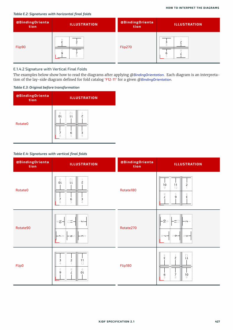
HOW TO INTERPRET THE DIAGRA MS
E.1.4.2 Signature with Vertical Final FoldsThe examples below show how to read the diagrams after applying @BindingOrientation. Each diagram is an interpreta-tion of the lay-side diagram defined for fold catalog "F12-11" for a given @BindingOrientation.
Flip90 Flip270
Table E.3: Original before transformation
@BindingOrientation ILLUSTRATION
Rotate0
Table E.4: Signatures with vertical final folds
@BindingOrientation ILLUSTRATION @BindingOrienta
tion ILLUSTRATION
Rotate0 Rotate180
Rotate90 Rotate270
Flip0 Flip180
Table E.2: Signatures with horizontal final folds
@BindingOrientation ILLUSTRATION @BindingOrienta
tion ILLUSTRATION
3
2
6
7
5
4
1
8
4
1
5
3
6
8
2
7
65
34
78
1112
21
109
6 375 48
11 21012 19
6 375 48
11 21012 19
6 37 5 48
11 210 12 19
6 37 5 48
11 210 12 19
7 1068 95
2 1131 124
7 1068 95
2 1131 124
XJDF SPECIFICATIO N 2.1 427

E.2 Pagination Diagrams
Flip90 Flip270
Table E.5: Pagination Diagrams (Sheet 1 of 12)
FOLD CATALOG GRID SIZEDESCRIPTION
FOLDING SEQUENCE
F2-1 1 x 1
(No folding sequence)
F4-1 2 x 1
1/2
F4-2 2 x 1
1/2
F6-1 3 x 1
1/3 1/3
F6-2 3 x 1
1/3 1/3
F6-3 3 x 1 Unsupported (gatefold)1/4 1/2
F6-4 3 x 1
1/3 1/3
F6-5 3 x 1
2/3 1/3
F6-6 3 x 1 Unsupported(multiple page sizes)3/4 1/4
Table E.4: Signatures with vertical final folds
@BindingOrientation ILLUSTRATION @BindingOrienta
tion ILLUSTRATION
7 106 8 95
2 113 1 124
7 106 8 95
2 113 1 124
12
34
21
12
43
43
12
56
43
56
12
21
56
34
56
43
21
428 XJDF SPECIFICATIO N 2.1
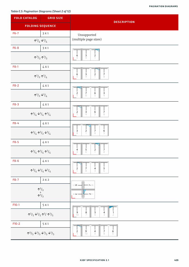
PA GINATION DIAGRA MS
F6-7 3 x 1 Unsupported(multiple page sizes)1/4 1/4
F6-8 3 x 1
2/3 1/3
F8-1 4 x 1
1/2 1/4
F8-2 4 x 1
1/2 1/4
F8-3 4 x 1
1/4 1/4 1/4
F8-4 4 x 1
1/4 1/2 1/4
F8-5 4 x 1
1/4 1/4 1/4
F8-6 4 x 1
3/4 1/4 1/4
F8-7 2 x 2
1/2+1/2
F10-1 5 x 1
1/5 1/5 1/ 1/5
F10-2 5 x 1
4/5 1/5 1/5 1/5
Table E.5: Pagination Diagrams (Sheet 2 of 12)
FOLD CATALOG GRID SIZEDESCRIPTION
FOLDING SEQUENCE
34
21
65
34
21
78
65
78
65
34
21
34
65
78
21
21
78
65
34
56
21
78
43
78
43
56
21
65 7 8
34 2 1
87
56
43
1 2
9 10
910
43
78
6 5
2 1
XJDF SPECIFICATIO N 2.1 429

F10-3 5 x 1
2/5 2/5 1/5
F12-1 6 x 1
1/3 1/3 1/6
F12-2 6 x 1
1/3 1/3 1/6
F12-3 6 x 1
1/2 1/6 1/6
F12-4 6 x 1
1/2 1/6 1/6
F12-5 6 x 1
1/2 1/3 1/6
F12-6 6 x 1
1/6 1/6 1/6 1/6 1/6
F12-7 3 x 2
1/3 1/3+1/2
F12-8 3 x 2
2/3 1/3+1/2
F12-9 3 x 2
1/3 1/3+1/2
Table E.5: Pagination Diagrams (Sheet 3 of 12)
FOLD CATALOG GRID SIZEDESCRIPTION
FOLDING SEQUENCE
910
87
34
6 5
2 1
1112
109
21
65
78
34
34
21
109
8 7
5 6
1112
78
21
109
6 5
1112
34
1112
65
21
10 9
34
78
21
1112
78
3 4
65
109
34
65
21
10 9
1112
78
310
2 1 4
11 12
96 5
7 8
94
8710
563
121112
58
4 3 6
9 10
72 1
11 12
430 XJDF SPECIFICATIO N 2.1

PA GINATION DIAGRA MS
F12-10 3 x 2
2/3 1/3+1/2
F12-11 3 x 2
1/3+1/2
+1/3
F12-12 2 x 3
1/2+
2/3 1/3
F12-13 2 x 3
1/2+
1/3 1/3
F12-14 2 x 3
1/2+
1/3 1/3
F14-1 7 x 1
1/7 1/7 1/7 1/7 1/7 1/7
F16-1 8 x 1
1/2 1/4 1/8
F16-2 8 x 1
1/2 1/4 1/8
Table E.5: Pagination Diagrams (Sheet 4 of 12)
FOLD CATALOG GRID SIZEDESCRIPTION
FOLDING SEQUENCE
112
10912
341
8756
65
34
78
1112
21
109
10934
78
11 122 1
6 52 1
11 127 8
34109
65
6 53 4
11 12
7821
109
1211
910
1314
56
43
12
87
78
1516
1413
109
34
65
1112
21
1516
109
78
65
1112
1413
34
21
XJDF SPECIFICATIO N 2.1 431
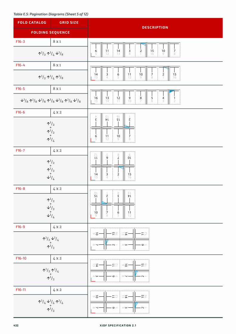
F16-3 8 x 1
1/2 1/4 1/8
F16-4 8 x 1
1/2 1/4 1/8
F16-5 8 x 1
1/8 1/8 1/8 1/8 1/8 1/8 1/8
F16-6 4 x 2
1/2+1/2
+1/4
F16-7 4 x 2
1/2+1/2
+1/4
F16-8 4 x 2
1/2+1/2
+1/4
F16-9 4 x 2
1/2 1/4+1/2
F16-10 4 x 2
1/2 1/4+1/2
F16-11 4 x 2
1/4 1/4 1/4+1/2
Table E.5: Pagination Diagrams (Sheet 5 of 12)
FOLD CATALOG GRID SIZEDESCRIPTION
FOLDING SEQUENCE
1112
1413
34
21
65
1516
109
78
34
65
1112
109
1413
78
21
1516
1314
1211
910
87
1615
56
43
12
65
1112
109
78
34
1413
1516
21
1413
34
21
1516
1112
65
78
109
109
78
65
1112
1516
21
34
1413
10978 2 1
15 16
141334 6 5
11 12
141334 6 5
11 12
10978 2 1
15 16
10978 6 5
11 12
141334 2 1
15 16
432 XJDF SPECIFICATIO N 2.1

PA GINATION DIAGRA MS
F16-12 4 x 2
1/4 1/4 1/4+1/2
F16-13 2 x 4
1/2+
1/2 1/4
F16-14 2 x 4
1/2+
1/2 1/4
F18-1 9 x 1
1/9 1/9 1/9 1/9 1/9 1/9 1/9 1/9
F18-2 9 x 1
2/3 1/3 1/9 1/9
F18-3 9 x 1
1/3 1/3 2/9 1/9
F18-4 9 x 1
1/3 1/3 1/9 1/9
F18-5 3 x 3
1/3 1/3+
1/3 1/3
Table E.5: Pagination Diagrams (Sheet 6 of 12)
FOLD CATALOG GRID SIZEDESCRIPTION
FOLDING SEQUENCE
121156 4 3
13 14
10978 2 1
15 16
651112
141334
7 810 9
15 162 1
141334
651112
15 162 1
7 810 9
1615
1314
1211
910
1718
87
56
43
12
1112
1413
1718
21
56
43
910
1615
87
1718
87
910
21
34
65
1314
1211
1615
87
56
43
910
1718
1615
1314
1211
12
5 6 1 243
8 7 12 11
910
17 18 13 14
1615
XJDF SPECIFICATIO N 2.1 433
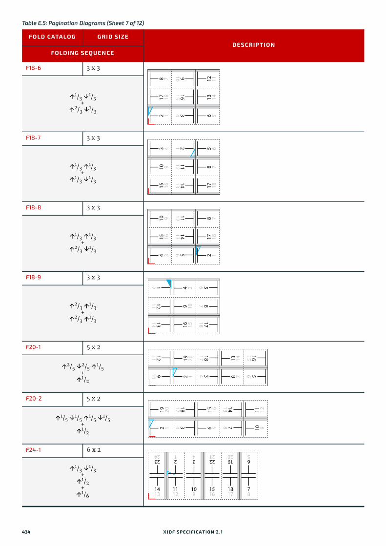
F18-6 3 x 3
1/3 1/3+
2/3 1/3
F18-7 3 x 3
1/3 1/3+
1/3 1/3
F18-8 3 x 3
1/3 1/3+
2/3 1/3
F18-9 3 x 3
2/3 1/3+
2/3 1/3
F20-1 5 x 2
2/5 2/5 1/5+1/2
F20-2 5 x 2
1/5 1/5 1/5 1/5+1/2
F24-1 6 x 2
1/3 1/3+1/2
+1/6
Table E.5: Pagination Diagrams (Sheet 7 of 12)
FOLD CATALOG GRID SIZEDESCRIPTION
FOLDING SEQUENCE
8 7 12 11
910
17 18 13 14
1615
2 1 34 6 5
3 4 5 621
10 9 8 7
1112
15 16 17 18
1413
10 9 8 7
1112
15 16 17 18
1413
4 3 56 2 1
17181314 16 15
871211 9 10
564 3121211
910
1615562 1
19 20
181734 8 7
13 14
10 911 12
2 119 20
1413786 5
15 16
181734
1112
109
1413
1817
78
1516
21
34
2324
1920
65
2221
434 XJDF SPECIFICATIO N 2.1
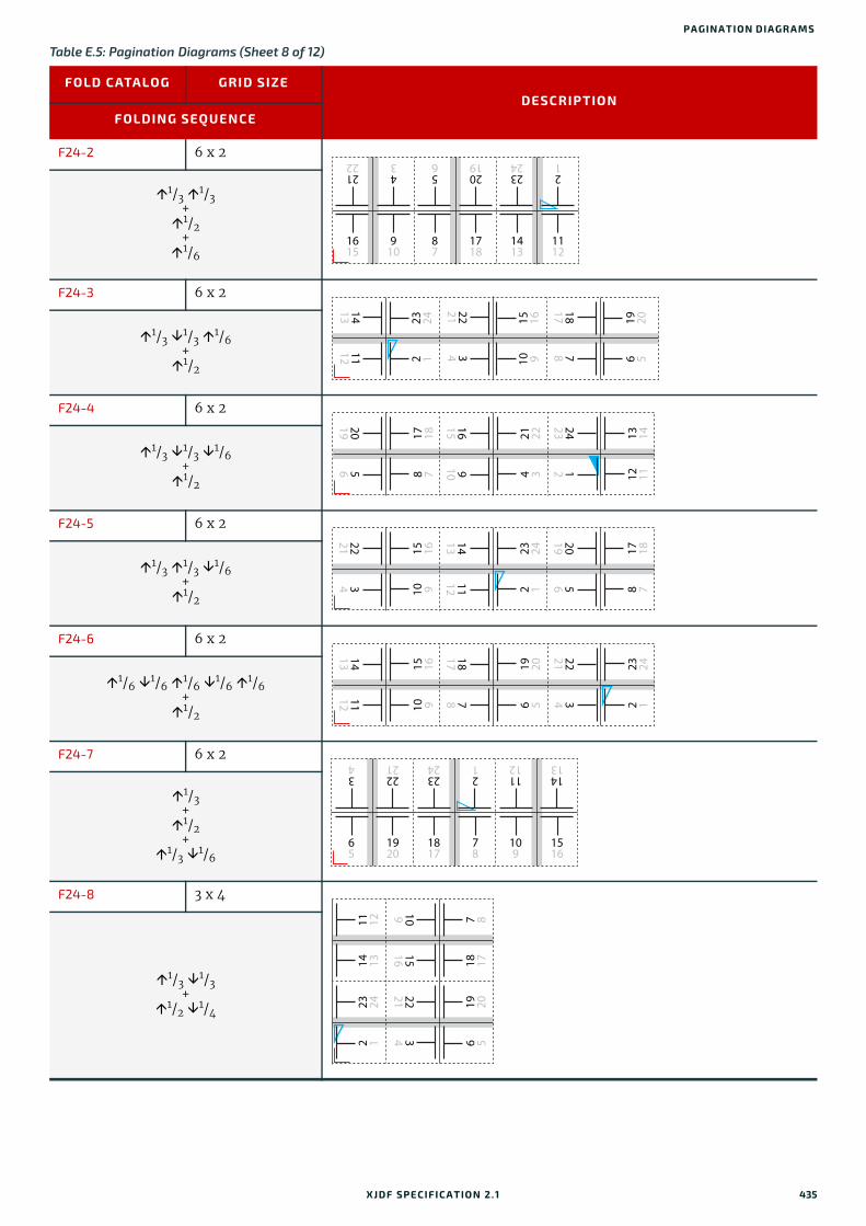
PA GINATION DIAGRA MS
F24-2 6 x 2
1/3 1/3+1/2
+1/6
F24-3 6 x 2
1/3 1/3 1/6+1/2
F24-4 6 x 2
1/3 1/3 1/6+1/2
F24-5 6 x 2
1/3 1/3 1/6+1/2
F24-6 6 x 2
1/6 1/6 1/6 1/6 1/6+1/2
F24-7 6 x 2
1/3+1/2
+1/3 1/6
F24-8 3 x 4
1/3 1/3+
1/2 1/4
Table E.5: Pagination Diagrams (Sheet 8 of 12)
FOLD CATALOG GRID SIZEDESCRIPTION
FOLDING SEQUENCE
910
87
1615
1413
1112
1718
43
56
2122
2324
21
2019
14131112
181778 6 5
19 20
2 123 24
222134
10 915 16
2019 17 18
56 8 7
1615 21 22
910 4 3
2423 13 14
12
12 11
2221 15 16
34
10 9
1413 23 24
1112 2 1
2019 17 18
56 8 7
1413 15 16
1112 10 9
1817 19 20
78 6 5
2221 23 24
34 2 1
1920
1817
65
109
1516
78
2221
2324
34
1112
1413
21
2 1
154
23 24
1021
6 519 20
14 13
316
11 12
229
18 177 8
XJDF SPECIFICATIO N 2.1 435

F24-9 3 x 4
2/3 1/3+
1/2 1/4
F24-10 3 x 4
1/3 1/3+
1/2 1/4
F24-11 4 x 3
1/2+
2/3 1/3+1/4
F28-1 7 x 2
1/7 1/7 1/7 1/7 1/7 1/7+1/2
F32-1 16 x 1
1/2 1/4 1/8 1/16
F32-2 8 x 2
1/2 1/4+1/2
+1/8
Table E.5: Pagination Diagrams (Sheet 9 of 12)
FOLD CATALOG GRID SIZEDESCRIPTION
FOLDING SEQUENCE
8721
10
17184
15
12111314
20199
22
5616
3
242312
4 3
176
21 22
819
2 123 24
16 15
518
9 10
207
14 1311 12
65
234
19202
21
109
1516
1817
324
78
221
1413
1112
10 919 20
2 127 28
222178
14 1315 16
181711126 5
23 24
262534
2324
2625
78
21
109
3132
1817
1516
1920
3029
34
65
1413
2728
2221
1112
2324
1817
1516
1413
109
1920
2221
1112
2728
3029
34
65
3132
21
2625
78
436 XJDF SPECIFICATIO N 2.1
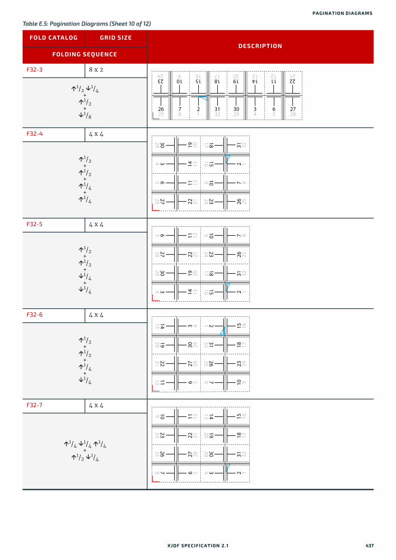
PA GINATION DIAGRA MS
F32-3 8 x 2
1/2 1/4+1/2
+1/8
F32-4 4 x 4
1/2+1/2
+1/4
+1/4
F32-5 4 x 4
1/2+1/2
+1/4
+1/4
F32-6 4 x 4
1/2+1/2
+1/4
+1/4
F32-7 4 x 4
1/4 1/4 1/4+
1/2 1/4
Table E.5: Pagination Diagrams (Sheet 10 of 12)
FOLD CATALOG GRID SIZEDESCRIPTION
FOLDING SEQUENCE
78
3132
3029
2625
34
65
2728
1112
1413
1920
2221
1516
1817
109
2324
21
22 2111 12
14 1319 20
272865
343029
26 257 8
2 131 32
2324109
15161817
14 1319 20
22 2111 12
343029
272865
15161817
2324109
2 131 32
26 257 8
6 527 28
30 293 4
11122221
19201413
10 923 24
18 1715 16
782625
313221
6 527 28
22 2111 12
782625
2324109
343029
19201413
2 131 32
18 1715 16
XJDF SPECIFICATIO N 2.1 437

F32-8 4 x 4
1/2 1/4+
1/2 1/4
F32-9 4 x 4
1/2+
1/2 1/4+1/4
F36-1 9 x 2
1/3 1/3 1/9 1/3+1/2
F36-2 6 x 3
1/3 1/3+
1/3 1/3+1/6
F40-1 5 x 4
1/5 1/5 1/5 1/5+
1/2 1/4
Table E.5: Pagination Diagrams (Sheet 11 of 12)
FOLD CATALOG GRID SIZEDESCRIPTION
FOLDING SEQUENCE
782625
2324109
6 527 28
22 2111 12
343029
19201413
2 131 32
18 1715 16
21
3132
3029
34
1516
1817
1920
1413
109
2324
2221
1112
78
2625
2728
65
10 927 28
2 135 36
22211516 6 5
31 32
343334
18 1719 20
302978
14 1323 24
26251112
1112
109
2625
3029
78
2728
1413
1516
2324
1920
1817
2221
21
34
3536
3132
65
3433
30 2911 12
22 2119 20
1413272826 25
15 16
18172324
10 931 32
2 139 40
3433786 5
35 36
383734
438 XJDF SPECIFICATIO N 2.1
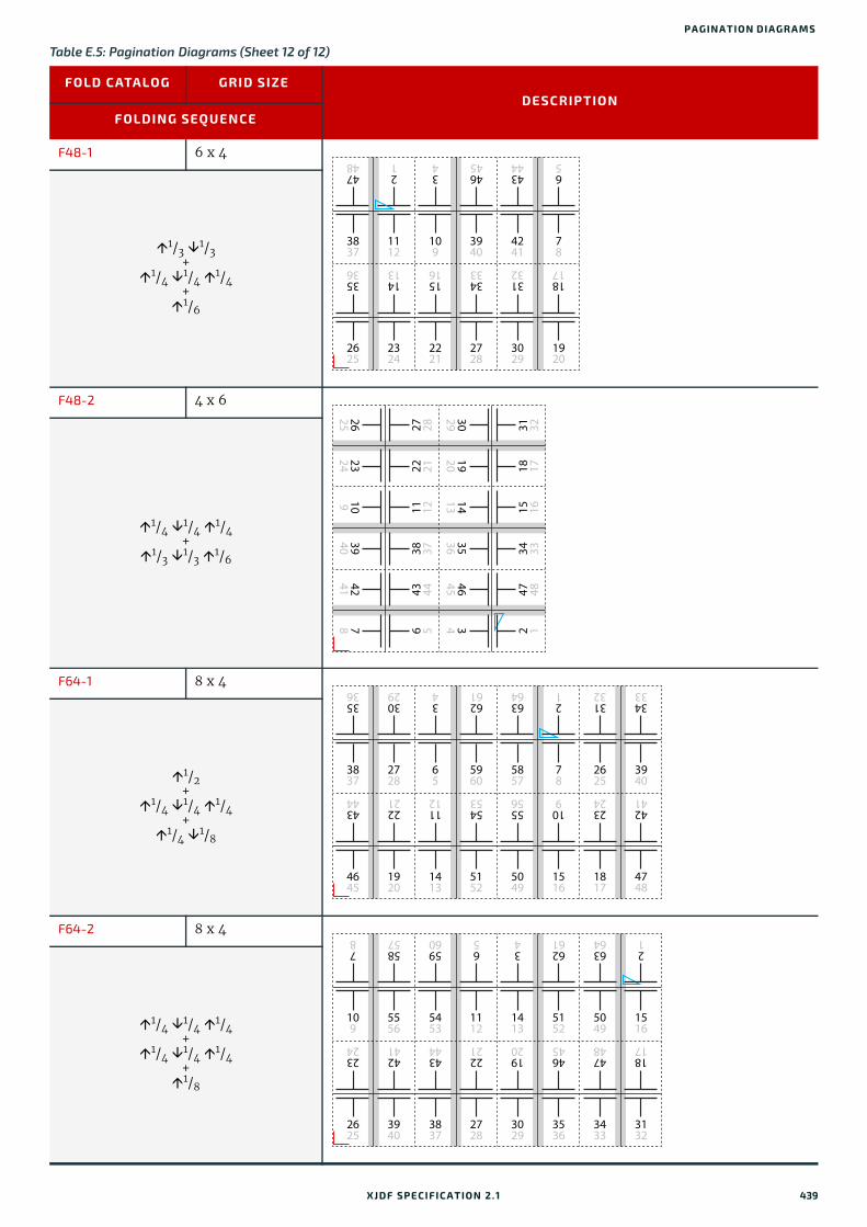
PA GINATION DIAGRA MS
F48-1 6 x 4
1/3 1/3+
1/4 1/4 1/4+1/6
F48-2 4 x 6
1/4 1/4 1/4+
1/3 1/3 1/6
F64-1 8 x 4
1/2+
1/4 1/4 1/4+
1/4 1/8
F64-2 8 x 4
1/4 1/4 1/4+
1/4 1/4 1/4+1/8
Table E.5: Pagination Diagrams (Sheet 12 of 12)
FOLD CATALOG GRID SIZEDESCRIPTION
FOLDING SEQUENCE
1112
109
3837
4241
78
3940
21
34
4748
4344
65
4645
2324
2221
2625
3029
1920
2728
1413
1516
3536
3132
1817
3433
19201413
30294645
343536
18 1715 16
31 3247 48
2 134 33
2324109
26254241
783940
22 2111 12
27 2843 44
6 538 37
2728
65
3837
5857
78
5960
3029
34
3536
6364
21
6261
1920
1413
4645
5049
1516
5152
2221
1112
4344
5556
109
2625
3940
3132
3433
1817
4748
2324
4241
5453
5556
5453
109
1413
5152
1112
5857
5960
78
34
6261
65
3940
3837
2625
3029
3536
2728
4241
4344
2324
1920
4645
5049
1516
6364
21
3433
3132
4748
1817
2221
XJDF SPECIFICATIO N 2.1 439

440 XJDF SPECIFICATIO N 2.1

Appendix F
F Hole Pattern CatalogThe following table defines the specifics of the predefined holes in HoleMakingParams and HoleMakingIntent.Notes:
1 All patterns are centered on the sheet along the reference edge.
2 The reference edge is always defined relative to a portrait orientation of the medium, regardless of the orienta-tion of the printed image or processing path.
3 The pattern axis offset is always specified relative to the reference edge.
4 The default pattern axis offset is always specified in points.
5 Thumbcuts are available in various standard shapes (labeled “No. N” where N is minimally ranging from 2..7). “No. 3” seems to be the most widely used.
6 Single thumbcuts appear always in the center of the reference edge.
7 Oval-shaped holes sometimes actually look more like rectangular holes with rounded corners.
8 A circle in the Shape column denotes a round or elliptic hole.
9 A square in the Shape column denotes a square or rectangular hole.
10 Generic hole types are dependent on the geographical area where the device is used.Sources:
1 Printer Finishing MIB [RFC3806]
2 Files and folders; concepts [DIN 821-3]
3 Paper; Holes for general filing purposes; Specifications [ISO838:1974]
4 Paper and board - Dimensions for standard punching of A4 and A5 paper [DIN 5005]
F.1 Naming Scheme
Table F.1: Naming Scheme for Hole Patterns
NAME DESCRIPTION
General <m|i>: m = metric (millimeter is used), i = imperial (inch, where 1 inch = 25.4 mm)
Ring Binding R<#holes><m|i>-<variant>Example: R2m-DIN = RingBind, 2 hole, metric, DIN
Plastic Comb P<pitch><m|i>-<shape>-<#thumbcuts>tExample: P16:9m-round-0t = Plastic Comb, 9/16" pitch (16:9), round, no thumbcut
Wire Comb W<pitch><m|i>-<shape>-<#thumbcuts>tExample: W2:1i-square-1t = Wire Comb, 1/2" pitch (2:1), square, one thumbcut
Coil/Spiral C<pitch><m|i>-<shape>-<#thumbcuts>tExample: C9.5m-round-0t = Coil, 9.5 mm, round, no thumbcut
Special S<#holes>Example: S1-generic
XJDF SPECIFICATIO N 2.1

F.2 Ring Binding - Two Hole
F.3 Ring Binding - Three Hole
Table F.2: Hole Details for R2 Series
HOLE PATTERN
IDDESCRIPTION
SHAPE
HOLE EXTENT
PATTERN GEOMETRY
PATTERN AXIS
OFFSET
XJDF DEFAULT PATTERN
AXIS OFFSET
EDGE
NOTE
SOURCE
R2-generic Generic request of a 2-hole pattern
5 - 13 mm0.2-0.51”
N/A 4.5 – 13 mm0.18 - 0.51"
34.02( 12 mm)
Left See note (8)
N/A
R2m-DIN DIN 2-hole
MIB: 6 = two-HoleDIN and10 = twoHole-Metric
5.5 ± 0.1 mm
80 ± 0.1 mm
7 or 11 ± 0.3 mm7 mm for blocks of <= 15 mm thick
31.18( 11 mm)
Left A4 and A5
[DIN 5005][DIN 821-3]
R2m-ISO ISO 2-hole
MIB: 6 = two-HoleDIN and10 = twoHole-Metric
6 ± 0.5 mm
80 ± 0.5 mm
12 ± 1 mm
Australian Standard AS P5-1969: 10 ± 1 mm
34.02( 12 mm)
Left Also used in Japan
[ISO838:1974]
R2m-MIB Printer Fin-ishing MIB twoHoleDIN and twoHole-Metric
5-8 mm 80 ± 0.5 mm
4.5 – 13 mm
31.18( 11 mm)
Left [RFC3806]
R2i-US-a US 2-hole, Variant A
MIB: 4 = two-HoleUSTop and12 = twoHole-USSide
0.2 - 0.32"
2.75" 0.18 - 0.51" 29.25( 13/32")
Left for letter
Top for led-ger
[RFC3806]
R2i-US-b US 2-hole, Variant B 0.2 - 0.5"
std: 5/16"typ: 1/4", 9/32", 11/32", 3/8", 13/32", 1/2"
6" 0.25" + ½ diameter
Range:6/16" - 1/2"
29.25( 13/32")
Left
Table F.3: Hole Details for R3 Series
HOLE PATTERN
IDDESCRIPTION
SHAPE
HOLE EXTENT
PATTERN GEOMETRY
PATTERN AXIS
OFFSET
XJDF DEFAULT PATTERN
AXIS OFFSET
EDGE
NOTE
SOURCE
R3-generic Generic request of a 3-hole pat-tern.
5 - 13 mm0.2-0.51”
N/A 4.5 – 13 mm0.18 - 0.51"
29.25( 13/32")
Left See note (8)
N/A
442 XJDF SPECIFICATIO N 2.1

RING BINDING - FOUR HOLE
F.4 Ring Binding - Four Hole
R3i-US US 3-hole
MIB: 5 = threeHoleUS
0.2 - 0.5"std: 5/16"typ: 1/4", 9/32", 11/32", 3/8", 13/32", 1/2"
4.25" 0.25" + ½ diameter
range:6/16" - 1/2"
29.25( 13/32")
Left [RFC3806]
Table F.4: Hole Details for R4 Series
HOLE PATTERN
IDDESCRIPTION
SHAPE
HOLE EXTENT
PATTERN GEOMETRY
PATTERN AXIS
OFFSET
XJDF DEFAULT PATTERN
AXIS OFFSET
EDGE
NOTE
SOURCE
R4-generic Generic request of a 4-hole pat-tern.
5 - 13 mm0.2-0.51”
N/A 4.5 – 13 mm0.18 - 0.51"
31.18( 11 mm)
Left See note (8)
N/A
R4m-DIN-A4
DIN 4-hole for A4 5.5 ± 0.1
mm80 ± 0.1 mm
7 or 11 ± 0.3 mm7 mm for blocks of 15 mm or less
31.18( 11 mm)
Left A4 [DIN 5005][DIN 821-3]
R4m-DIN-A5
DIN 4-hole for A5 5.5 ± 0.1
mm45-65-45 mm
7 or 11 ± 0.3 mm7 mm for blocks of 15 mm or less
31.18( 11 mm)
Left A5 [DIN 5005]
R4m-swedish
Swedish 4-hole
MIB: 11 = swedish4Hole
5 - 8 mm 21-70-21 mm
4.5 - 13 mm 31.18( 11 mm)
Left for A4Top for A3
A4, A3
[RFC3806]
R4i-US US 4-hole 0.2 - 0.5"std: 5/16"typ: 1/4", 9/32", 11/32", 3/8", 13/32", 1/2"
1.375-4.25-1.375"
0.25" + ½ diameter
Range:6/16" - 1/2"
29.25( 0.25" + ½ x 5/16" = 13/32")
Left
Table F.3: Hole Details for R3 Series
HOLE PATTERN
IDDESCRIPTION
SHAPE
HOLE EXTENT
PATTERN GEOMETRY
PATTERN AXIS
OFFSET
XJDF DEFAULT PATTERN
AXIS OFFSET
EDGE
NOTE
SOURCE
XJDF SPECIFICATIO N 2.1 443

F.5 RingBinding - Five Hole
F.6 Ring Binding - Six Hole
Table F.5: Hole Details for R5 Series
HOLE PATTERN
IDDESCRIPTION
SHAPE
HOLE EXTENT
PATTERN GEOMETRY
PATTERN AXIS
OFFSET
XJDF DEFAULT PATTERN
AXIS OFFSET
EDGE
NOTE
SOURCE
R5-generic Generic request of a 5-hole pat-tern.
5 - 13 mm0.2-0.51”
N/A 4.5 – 13 mm0.18 - 0.51"
29.25( 13/32")
Left See note (8)
N/A
R5i-US-a US 5-hole, Variant A
MIB: 13 = five-HoleUS
0.2 - 0.32"
2-2.25-2.25-2"
0.18 - 0.51" 29.25 ( 13/32")
Left for letterTop for led-ger
[RFC3806]
R5i-US-b US 5-hole, Variant B 0.2 - 0.5"
std: 5/16"typ: 1/4", 9/32", 11/32", 3/8", 13/32", 1/2"
0.75-3.5-3.5-0.75"
0.25" + ½ diameter0.375 - 0.5"
29.25 ( 0.25" + ½ x 5/16" = 13/32")
Left
R5i-US-c Combination of R2i-US-a and R3i-US
0.2 - 0.5"std: 5/16"typ: 1/4", 9/32", 11/32", 3/8", 13/32", 1/2"
1.25-3-3-1.25"
0.25" + ½ diameter0.375 - 0.5"
29.25 ( 0.25" + ½ x 5/16" = 13/32")
Left
Table F.6: Hole Details for R6 Series (Sheet 1 of 2)
HOLE PATTERN
IDDESCRIPTION
SHAPE
HOLE EXTENT
PATTERN GEOMETRY
PATTERN AXIS
OFFSET
XJDF DEFAULT PATTERN
AXIS OFFSET
EDGE
NOTE
SOURCE
R6-generic Generic request of a 6-hole pat-tern.
5 - 13 mm0.2-0.51”
N/A 4.5 – 13 mm0.18 - 0.51"
31.18( 11 mm)
Left for A4/A5Top for A3
See note (8)
N/A
R6m-4h2s Norwegian 4-hole (round) mixed with 2 slots (rectangular)
MIB: 16 = nor-weg6Hole
H:
S:
Holes: 5 - 8 mmSlots: 10 x 5.5 mm
4 holes/2 slotsPattern: H-H-S-S-H-H64-18.5-75-18.5-64 mm
4.5 - 13 mm 31.18( 11 mm)
Left for A4Top for A3
[RFC3806]
444 XJDF SPECIFICATIO N 2.1

RING BINDING - SEVEN HOLE
F.7 Ring Binding - Seven Hole
R6m-DIN-A5
DIN 6-hole for A5 5.5 ± 0.1
mm37.5-7.5-65-7.5-37.5 mm
7 or 11 ± 0.3 mm7 mm for blocks of <= 15 mm thick
31.18 ( 11 mm)
Left Only used with A5
[DIN 5005]
Table F.7: Hole Details for R7 Series
HOLE PATTERN
IDDESCRIPTION
SHAPE
HOLE EXTENT
PATTERN GEOMETRY
PATTERN AXIS
OFFSET
XJDF DEFAULT PATTERN
AXIS OFFSET
EDGE
NOTE
SOURCE
R7-generic Generic request of a 7-hole pat-tern.
5 - 13 mm0.2-0.51”
N/A 4.5 – 13 mm0.18 - 0.51"
29.25( 13/32")
Left for letterTop for led-ger
See note (8)
N/A
R7i-US-a US 7-hole, Variant A
MIB: 14 = sev-enHoleUS
0.2 - 0.32"
1-1-2.25-2.25-1-1"
0.18 - 0.51" 29.25 ( 13/32")
Left for letterTop for led-ger
[RFC3806]
R7i-US-b US 7-hole, Bell/AT&T Systems. Combination of R3i-US, R4i-US, R5i-US-b
0.2 - 0.5"std: 5/16"typ: 1/4", 9/32", 11/32", 3/8", 13/32", 1/2"
0.75-1.375-2.125-2.125-1.375-0.75"
0.25" + ½ diameter0.375 - 0.5"
29.25 ( 0.25" + ½ x 5/16" = 13/32")
Left for letterTop for led-ger
R7i-US-c US 7-hole, Variant C 0.2 - 0.5"
std: 5/16"typ: 1/4", 9/32", 11/32", 3/8", 13/32", 1/2"
1.25-0.875-2.125-2.125-0.875-1.25"
0.25" + ½ diameter0.375 - 0.5"
29.25 ( 13/32")
Left for letterTop for led-ger
Table F.6: Hole Details for R6 Series (Sheet 2 of 2)
HOLE PATTERN
IDDESCRIPTION
SHAPE
HOLE EXTENT
PATTERN GEOMETRY
PATTERN AXIS
OFFSET
XJDF DEFAULT PATTERN
AXIS OFFSET
EDGE
NOTE
SOURCE
XJDF SPECIFICATIO N 2.1 445

F.8 Ring Binding - Eleven Hole
F.9 Plastic Comb Binding
Table F.8: Hole Details for R11 Series
HOLE PATTERN
IDDESCRIPTION
SHAPE
HOLE EXTENT
PATTERN GEOMETRY
PATTERN AXIS
OFFSET
XJDF DEFAULT PATTERN
AXIS OFFSET
EDGE
NOTE
SOURCE
R11m-7h4s 7-hole (round) mixed with 4 slots (rectan-gular)
MIB: 15 = mixed7H4S
H:
S:
Holes: 5 - 8 mmSlots: 12 x 6 mm
7 holes/2slotsPattern: H-S-H-H-S-H-S-H-H-S-H15-25-23-20-37-37-20-23-25-15 mm
4.5 - 13 mm 31.18 ( 11 mm)
Left for A4Top for A3
[RFC3806]
Table F.9: Hole Details for P Series
HOLE PATTERN
IDDESCRIPTION
SHAPE
HOLE EXTENT
PATTERN GEOMETRY
PATTERN AXIS
OFFSET
XJDF DEFAULT PATTERN
AXIS OFFSET
EDGE
NOTE
SOURCE
P16_9i-rect-0t
US spacing, no thumbcut
MIB: 9 = nineteenHo-leUS
A4: 21 HoleLetter: 19 Hole
5/16" x 1/8"(8 x 3.2 mm)
9/16" 3/16" 13.54 ( 0.188")
Left [RFC3806]
P12m-rect-0t
European spacing, no thumbcut
7 x 3 mm 12 mm 4.5 mm 12.76 ( 4.5 mm)
Left
446 XJDF SPECIFICATIO N 2.1
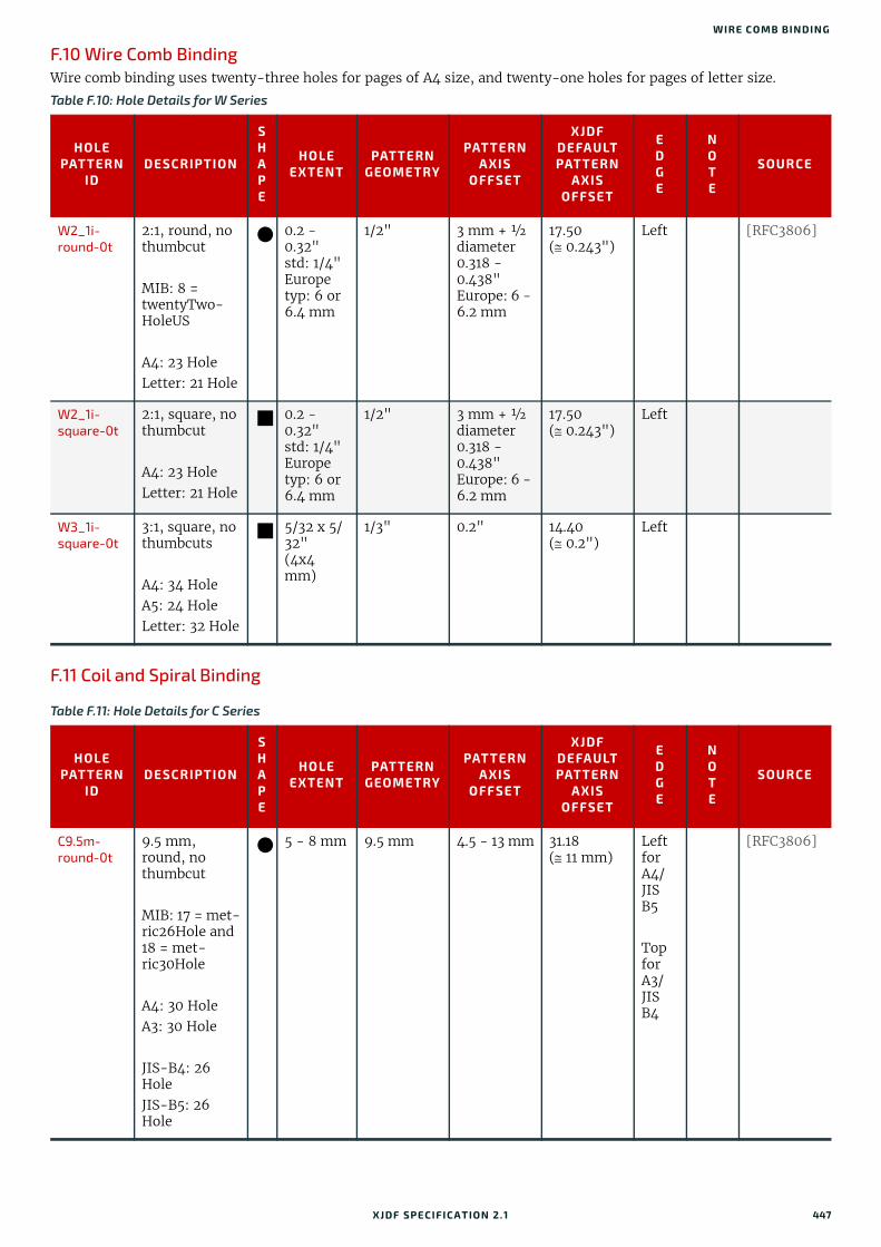
WIRE COMB BINDING
F.10 Wire Comb Binding Wire comb binding uses twenty-three holes for pages of A4 size, and twenty-one holes for pages of letter size.
F.11 Coil and Spiral Binding
Table F.10: Hole Details for W Series
HOLE PATTERN
IDDESCRIPTION
SHAPE
HOLE EXTENT
PATTERN GEOMETRY
PATTERN AXIS
OFFSET
XJDF DEFAULT PATTERN
AXIS OFFSET
EDGE
NOTE
SOURCE
W2_1i-round-0t
2:1, round, no thumbcut
MIB: 8 = twentyTwo-HoleUS
A4: 23 HoleLetter: 21 Hole
0.2 - 0.32"std: 1/4"Europe typ: 6 or 6.4 mm
1/2" 3 mm + ½ diameter0.318 - 0.438"Europe: 6 - 6.2 mm
17.50 ( 0.243")
Left [RFC3806]
W2_1i-square-0t
2:1, square, no thumbcut
A4: 23 HoleLetter: 21 Hole
0.2 - 0.32"std: 1/4"Europe typ: 6 or 6.4 mm
1/2" 3 mm + ½ diameter0.318 - 0.438"Europe: 6 - 6.2 mm
17.50 ( 0.243")
Left
W3_1i-square-0t
3:1, square, no thumbcuts
A4: 34 HoleA5: 24 HoleLetter: 32 Hole
5/32 x 5/32"(4x4 mm)
1/3" 0.2" 14.40 ( 0.2")
Left
Table F.11: Hole Details for C Series
HOLE PATTERN
IDDESCRIPTION
SHAPE
HOLE EXTENT
PATTERN GEOMETRY
PATTERN AXIS
OFFSET
XJDF DEFAULT PATTERN
AXIS OFFSET
EDGE
NOTE
SOURCE
C9.5m-round-0t
9.5 mm, round, no thumbcut
MIB: 17 = met-ric26Hole and 18 = met-ric30Hole
A4: 30 HoleA3: 30 Hole
JIS-B4: 26 HoleJIS-B5: 26 Hole
5 - 8 mm 9.5 mm 4.5 - 13 mm 31.18 ( 11 mm)
Left for A4/JIS B5
Top for A3/JIS B4
[RFC3806]
XJDF SPECIFICATIO N 2.1 447

F.12 Special Binding
Table F.12: Hole Details for S Series
HOLE PATTERN
IDDESCRIPTION
SHAPE
HOLE EXTENT
PATTERN GEOMETRY
PATTERN AXIS
OFFSET
XJDF DEFAULT PATTERN
AXIS OFFSET
EDGE
NOTE
SOURCE
S-generic Generic request of a hole pattern with an arbi-trary or unknown number of holes (e.g., an inline shot-gun)
5 - 13 mm0.2-0.51”
N/A N/A N/A Any N/A
S1-generic Generic request of a hole pattern with 1 hole
5 - 13 mm0.2-0.51”
N/A N/A N/A Any N/A
448 XJDF SPECIFICATIO N 2.1

Appendix G
G ReferencesThroughout this specification references to other documents are indicated by short symbolic names inside square brack-ets, (e.g., [ICC.1]). Implementers need to read and conform to such referenced documents when implementing a part of this specification with such a reference. The reader is directed to this appendix section to find the full title, date, source and availability of all such references.Table G.1: References (Sheet 1 of 9)
TERM DEFINITION
[Braille ASCII] Six dot Braille representation of the ASCII character setDate: -Available at: https://en.wikipedia.org/wiki/Braille_ASCII
[Braille Unicode] Braille PatternsDate: -Available at: https://en.wikipedia.org/wiki/Braille_Unicode_block
[BT.601-7] ITU Recommendation 601-7 Studio encoding parameters of digital television for standard 4:3 and wide screen 16:9 aspect ratios.
Date: March 2011Produced by: International Telecommunication Union - Radioncommunication SectorAvailable at: https://www.itu.int/rec/R-REC-BT.601/International Telecommunication Union, General Secretariat — Sales Section, Place des
Nations, CH-1211 Geneva 20 (Switzerland)
[CGATS.21] CGATS.21-1-2013 and CGATS.21-2-2013Graphic technology - Printing from digital data across multiple technologies Parts 1 & 2
Date: 2013Produced by: Committee for Graphic Arts Technologies Standards (NPES serves as the
American National Standards Institute (ANSI) secretariat to CGATS)Available at: http://www.npes.org/programs/standardsworkroom.aspx
[Characterization Data]
CMYK Characterization DataRegistered CMYK characterization data sets for standard printing processes.
Date: -Produced by: International Color ConsortiumAvailable at: http://www.color.org/chardata/drsection1.xalter
[CIE 015:2004] CIE 15:2004 Colorimetry, 3rd Edition.
Date: 2004Produced by: Commission Internationale de l'Eclairage International (CIE) Available at: http://www.cie.co.at/publications/colorimetry-3rd-edition
[CIP3 - PPF] CIP3 Print Production Format (PPF)Date: 1 June 1998Version: CIP3 PPF Specification 3.0Produced by: CIP4 OrganizationAvailable at: https://confluence.cip4.org/display/PUB/PPF
[CIP4Names] CIP4 Name RegistryProduced by: CIP4 OrganizationAvailable at: https://confluence.cip4.org/display/PUB/Name+Registry
XJDF SPECIFICATIO N 2.1

[Color Names] Recognized color keyword namesDate: 16 August 2011Version: SVG (1.1) Second EditionProduced by: World Wide Web Consortium (W3C)Available at: https://www.w3.org/TR/SVG/types.html#ColorKeywords
[ColorPS] Color Separation Conventions for PostScript Language Programs Technical Note #5044
Date: 24 May 1996 Produced by: Adobe Systems Inc.Available at: https://www.adobe.com/content/dam/acom/en/devnet/postscript/pdfs/
5044.ColorSep_Conv.pdf
[Corrugated Pack-aging]
Corrugated packaging Date: -Produced by: Corrugated Packaging AllianceAvailable at: http://www.corrugated.org/
[DDES3] Graphic technology - Prepress digital data exchange - Diecutting data (DDES3)Date: Revised 2017 Produced by: ANSI® IT8.6-2017Available at: http://webstore.ansi.org.
[DIN 15146-4] Pallets; timber four-way-flat pallets; 800mm x 600mmDate: Revised 1991 Produced by: DIN Standards Committee PackagingAvailable at: https://www.din.de/en.
[DIN 5005] Paper and board - Sheets for loose leaf binders - Dimensions for standard punching for paper sizes A4 and A5
Date: Edition 2008-2 Produced by: DIN Standards Committee Paper, board and pulpsAvailable at: https://www.din.de/en.
[DIN 821-3] Files and folders; conceptsDate: Edition 1991-03 Produced by: DIN Standards Committee Timber and FurnitureAvailable at: https://www.din.de/en.
[DIN EN 13698-1] Pallet production specification - Part 1: Construction specification for 800mm x 1200mm flat wooden pallets
Date: Edition 2004-01Produced by: DIN Standards Committee PackagingAvailable at: https://www.din.de/en.
[DIN EN 13698-2] Pallet production specification - Part 2: Construction specification for 1000mm x 1200mm flat wooden pallets
Date: Revised 2009-10Produced by: DIN Standards Committee PackagingAvailable at: https://www.din.de/en.
[ECMA] ECMA Code of Folding Carton Design Styles Date: -Produced by: European Carton Makers AssociationAvailable at: https://www.ecma.org/publications/ecma-code-of-folding-carton-
design-styles.html
[FEFCO] FEFCO European Federation of Corrugated Board Manufacturers Date: -Produced by: European Federation of Corrugated Board ManufacturersAvailable at: http://www.fefco.org
Table G.1: References (Sheet 2 of 9)
TERM DEFINITION
450 XJDF SPECIFICATIO N 2.1

[FINAT] Trade Association for the Self-Adhesive and Labeling IndustryWeb site: http://www.finat.com
[FOGRA] Characterization data for standardized printing conditionsVarious Standards, e.g. FOGRA39, FOGRA47 etc
Date: N/AProduced by: Fogra Research Institute for Media TechnologiesAvailable at: https://www.fogra.org/
[Grammage Con-version]
Basis Weight and Grammage Conversion Tables.Date: -Produced by: EDS Inc. Editorial & Design ServicesAvailable at: http://www.edsebooks.com/paper/grammage.html
[IANA-character sets]
IANA Registry of Character Set namesAvailable at: https://www.iana.org/assignments/character-sets/character-sets.xhtml
[IANA-mt] IANA Registry of MIME Media Types Date: 2018-02-09Available at: http://www.iana.org/assignments/media-types
[ICC.1] Specification ICC.1:2010-12 (Profile version 4.3.0.0)Image technology colour management - Architecture, profile format, and data structure
Date: 2010Produced by: International Color Consortium (ICC)Available at: http://www.color.org/
[IEEE754] IEEE 754-2008 Standard for Binary Floating-Point Arithmetic
Date: 2008Produced by: IEEEAvailable at: http://grouper.ieee.org/groups/754/
[ISO/IEC 15948:2004]
ISO/IEC 15948:2004Information technology -- Computer graphics and image processing -- Portable Network Graphics (PNG): Functional specificationSecond edition
Date: 2004Produced by: ISOAvailable at: https://www.iso.org/store.html
[ISO/NP 3166-1:2013]
ISO/NP 3166-1:2013 Codes for the representation of names of countries and their subdivisions -- Part 1: Country codes.
Date: 2013Produced by: ISO Central SecretariatAvailable at: https://www.iso.org/store.html
[ISO12647-2:2004] ISO 12647-2:2004Graphic technology - Process control for the production of half-tone colour separations, proof and production prints - Part 2: Offset lithographic processes.
Date: 2004Produced by: ISOAvailable at: https://www.iso.org/store.html
[ISO12647-2:2013] ISO 12647-2:2013Graphic technology - Process control for the production of half-tone colour separations, proof and production prints - Part 2: Offset lithographic processes.
Date: 2013Produced by: ISOAvailable at: https://www.iso.org/store.html
Table G.1: References (Sheet 3 of 9)
TERM DEFINITION
XJDF SPECIFICATIO N 2.1 451

[ISO12647-3:2013] ISO 12647-3:2013Graphic technology - Process control for the production of half-tone colour separations, proof and production prints - Part 3: Coldset offset lithography on newsprint.
Date: 2014Produced by: ISOAvailable at: https://www.iso.org/store.html
[ISO12647-4:2014] ISO 12647-4:2014Graphic technology - Process control for the production of half-tone colour separations, proof and production prints - Part 4: Publication gravure printing.
Date: 2014Produced by: ISOAvailable at: https://www.iso.org/store.html
[ISO13655:2017] ISO 13655:2017 Graphic technology -- Spectral measurement and colorimetric computation for graphic arts images.
Date: 2017Produced by: ISOAvailable at: https://www.iso.org/store.html
[ISO15415:2011] ISO 15415:2011Information technology -- Automatic identification and data capture techniques -- Bar code symbol print quality test specification -- Two-dimensional symbols
Date: 2011Produced by: ISOAvailable at: https://www.iso.org/store.html
[ISO15416:2016] ISO 15416:2016Automatic identification and data capture techniques -- Bar code print quality test specification -- Linear symbols
Date: 2016Produced by: ISOAvailable at: https://www.iso.org/store.html
[ISO15930-1:2001] ISO 15930-1:2001 Graphic technology — Prepress digital data exchange — Use of PDF — Part 1: Complete exchange using CMYK data (PDF/X-1 and PDF/X-1a).
Date: 2001Produced by: ISOAvailable at: https://www.iso.org/store.html
[ISO15930-3:2002] ISO 15930-3:2002 Graphic technology — Prepress digital data exchange — Use of PDF — Part 3: Complete exchange suitable for colour-managed workflows (PDF/X-3).
Date: 2002Produced by: ISOAvailable at: https://www.iso.org/store.html
[ISO15930-7:2010] ISO 15930-7:2010 Graphic technology — Prepress digital data exchange — Use of PDF — Part 7: Complete exchange of printing data (PDF/X-4) and partial exchange of printing data with external profile reference (PDF/X-4p) using PDF 1.6.
Date: 2010Produced by: ISOAvailable at: https://www.iso.org/store.html
Table G.1: References (Sheet 4 of 9)
TERM DEFINITION
452 XJDF SPECIFICATIO N 2.1

[ISO15930-8:2010] ISO 15930-8:2010Graphic technology — Prepress digital data exchange using PDF — Part 8: Partial exchange of printing data using PDF 1.6 (PDF/X-5).
Date: 2010Produced by: ISOAvailable at: https://www.iso.org/store.html
ISO 16613-1:2017] ISO 16613-1:2017Graphic technology -- Variable content replacement -- Part 1: Using PDF/X for variable content replacement (PDF/VCR-1)
Date: 2017Produced by: ISOAvailable at: https://www.iso.org/store.html
[ISO17972-1:2015] ISO 17972-1:2015Graphic technology -- Colour data exchange format -- Part 1: Relationship to CxF3 (CxF/X)
Date: 2015Produced by: ISOAvailable at: https://www.iso.org/store.html
[ISO19593-1:2016] ISO 19593-1:2016Graphic technology -- Use of PDF to associate processing steps and content data -- Part 1: Processing steps for packaging and labels
Date: 2016Produced by: ISOAvailable at: https://www.iso.org/store.html
[ISO2108:2017] ISO 2108:2017Information and documentation -- International standard book number (ISBN).
Date: 2017Produced by: ISOAvailable at: https://www.iso.org/store.html
[ISO216:2007] ISO 216:2007Writing paper and certain classes of printed matter -- Trimmed sizes -- A and B series, and indication of machine direction.
Date: 2007Produced by: ISOAvailable at: https://www.iso.org/store.html
[ISO2470-1:2016] ISO 2470-1:2016 Paper, board and pulps -- Measurement of diffuse blue reflectance factor -- Part 1: Indoor daylight conditions (ISO brightness).
Date: 2016Produced by: ISOAvailable at: https://www.iso.org/store.html
[ISO2471:2008] ISO 2471:2008 Paper and board—Determination of opacity (paper backing)—Diffuse reflectance method.
Date: 2008Produced by: ISOAvailable at: https://www.iso.org/store.html
[ISO24790:2017] ISO 24790:2017Information technology -- Office equipment -- Measurement of image quality attributes for hardcopy output -- Monochrome text and graphic images
Date: 2017Produced by: ISOAvailable at: https://www.iso.org/store.html
Table G.1: References (Sheet 5 of 9)
TERM DEFINITION
XJDF SPECIFICATIO N 2.1 453
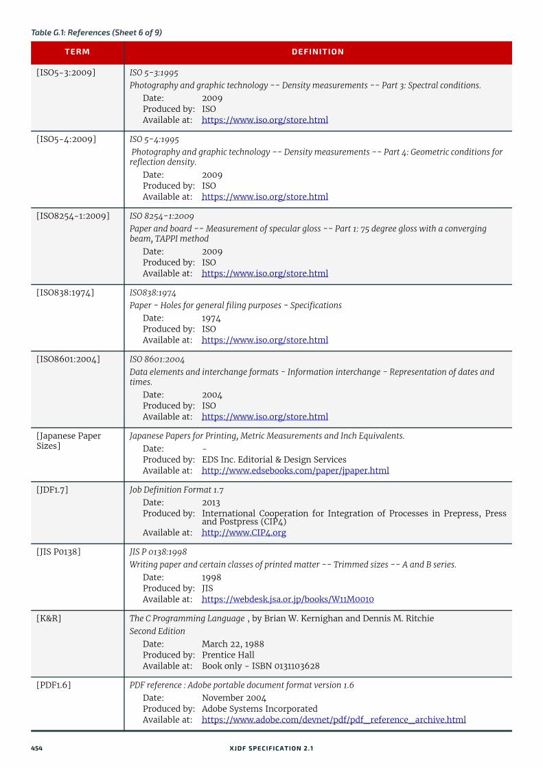
[ISO5-3:2009] ISO 5-3:1995 Photography and graphic technology -- Density measurements -- Part 3: Spectral conditions.
Date: 2009Produced by: ISOAvailable at: https://www.iso.org/store.html
[ISO5-4:2009] ISO 5-4:1995 Photography and graphic technology -- Density measurements -- Part 4: Geometric conditions for reflection density.
Date: 2009Produced by: ISOAvailable at: https://www.iso.org/store.html
[ISO8254-1:2009] ISO 8254-1:2009 Paper and board -- Measurement of specular gloss -- Part 1: 75 degree gloss with a converging beam, TAPPI method
Date: 2009Produced by: ISOAvailable at: https://www.iso.org/store.html
[ISO838:1974] ISO838:1974Paper - Holes for general filing purposes - Specifications
Date: 1974Produced by: ISOAvailable at: https://www.iso.org/store.html
[ISO8601:2004] ISO 8601:2004 Data elements and interchange formats - Information interchange - Representation of dates and times.
Date: 2004Produced by: ISOAvailable at: https://www.iso.org/store.html
[Japanese Paper Sizes]
Japanese Papers for Printing, Metric Measurements and Inch Equivalents.Date: -Produced by: EDS Inc. Editorial & Design ServicesAvailable at: http://www.edsebooks.com/paper/jpaper.html
[JDF1.7] Job Definition Format 1.7Date: 2013Produced by: International Cooperation for Integration of Processes in Prepress, Press
and Postpress (CIP4) Available at: http://www.CIP4.org
[JIS P0138] JIS P 0138:1998 Writing paper and certain classes of printed matter -- Trimmed sizes -- A and B series.
Date: 1998Produced by: JISAvailable at: https://webdesk.jsa.or.jp/books/W11M0010
[K&R] The C Programming Language , by Brian W. Kernighan and Dennis M. RitchieSecond Edition
Date: March 22, 1988Produced by: Prentice HallAvailable at: Book only - ISBN 0131103628
[PDF1.6] PDF reference : Adobe portable document format version 1.6Date: November 2004Produced by: Adobe Systems IncorporatedAvailable at: https://www.adobe.com/devnet/pdf/pdf_reference_archive.html
Table G.1: References (Sheet 6 of 9)
TERM DEFINITION
454 XJDF SPECIFICATIO N 2.1
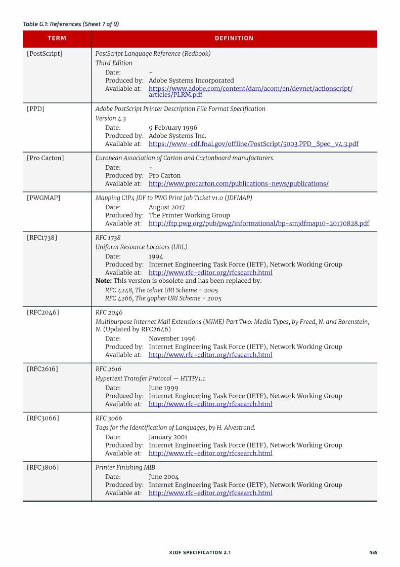
[PostScript] PostScript Language Reference (Redbook) Third Edition
Date: -Produced by: Adobe Systems IncorporatedAvailable at: https://www.adobe.com/content/dam/acom/en/devnet/actionscript/
articles/PLRM.pdf
[PPD] Adobe PostScript Printer Description File Format SpecificationVersion 4.3
Date: 9 February 1996Produced by: Adobe Systems Inc.Available at: https://www-cdf.fnal.gov/offline/PostScript/5003.PPD_Spec_v4.3.pdf
[Pro Carton] European Association of Carton and Cartonboard manufacturers.Date: -Produced by: Pro CartonAvailable at: http://www.procarton.com/publications-news/publications/
[PWGMAP] Mapping CIP4 JDF to PWG Print Job Ticket v1.0 (JDFMAP)Date: August 2017 Produced by: The Printer Working GroupAvailable at: http://ftp.pwg.org/pub/pwg/informational/bp-smjdfmap10-20170828.pdf
[RFC1738] RFC 1738Uniform Resource Locators (URL)
Date: 1994Produced by: Internet Engineering Task Force (IETF), Network Working GroupAvailable at: http://www.rfc-editor.org/rfcsearch.html
Note: This version is obsolete and has been replaced by:RFC 4248, The telnet URI Scheme - 2005RFC 4266, The gopher URI Scheme - 2005
[RFC2046] RFC 2046 Multipurpose Internet Mail Extensions (MIME) Part Two: Media Types, by Freed, N. and Borenstein, N. (Updated by RFC2646)
Date: November 1996Produced by: Internet Engineering Task Force (IETF), Network Working GroupAvailable at: http://www.rfc-editor.org/rfcsearch.html
[RFC2616] RFC 2616 Hypertext Transfer Protocol — HTTP/1.1
Date: June 1999Produced by: Internet Engineering Task Force (IETF), Network Working GroupAvailable at: http://www.rfc-editor.org/rfcsearch.html
[RFC3066] RFC 3066Tags for the Identification of Languages, by H. Alvestrand.
Date: January 2001Produced by: Internet Engineering Task Force (IETF), Network Working GroupAvailable at: http://www.rfc-editor.org/rfcsearch.html
[RFC3806] Printer Finishing MIB Date: June 2004Produced by: Internet Engineering Task Force (IETF), Network Working GroupAvailable at: http://www.rfc-editor.org/rfcsearch.html
Table G.1: References (Sheet 7 of 9)
TERM DEFINITION
XJDF SPECIFICATIO N 2.1 455

[RFC3966] RFC 3966 The tel URI for Telephone Numbers by H. Schulzrinne
Date: December 2004Produced by: Internet Engineering Task Force (IETF), Network Working GroupAvailable at: http://www.rfc-editor.org/rfcsearch.html
[RFC3986] RFC 3986 Uniform Resource Identifier (URI): Generic Syntax by T. Berners-Lee, R. Fielding and L. Masinter
Date: January 2005Produced by: Internet Engineering Task Force (IETF), Network Working GroupAvailable at: http://www.rfc-editor.org/rfcsearch.html
[RFC3987] RFC 3987 Internationalized Resource Identifiers (IRIs), by M. Duerst and M. Suignard
Date: January 2005Produced by: Internet Engineering Task Force (IETF), Network Working GroupAvailable at: http://www.rfc-editor.org/rfcsearch.html
[RFC5246] RFC 5246The Transport Layer Security (TLS) Protocol Version 1.2, by T. Dierks and E. Rescorla
Date: August 2008Produced by: Internet Engineering Task Force (IETF), Network Working GroupAvailable at: http://www.rfc-editor.org/rfcsearch.html
[RFC6068] RFC 6068 The mailto URL scheme
Date: October 2010Produced by: Internet Engineering Task Force (IETF), Network Working GroupAvailable at: http://www.rfc-editor.org/rfcsearch.html
[RFC6750] RFC 6750 The OAuth 2.0 Authorization Framework: Bearer Token Usage
Date: October 2012Produced by: Internet Engineering Task Force (IETF), Network Working GroupAvailable at: http://www.rfc-editor.org/rfcsearch.html
[TAPPI T480] TAPPI T480 Specular Gloss of Paper and Paperboard at 75 Degrees, Test Method T 480 om-15
Date: December 2009Produced by: TAPPIAvailable at: http://www.tappi.org
[TAPPI T519] TAPPI T519 Diffuse Opacity of Paper (d/0 paper backing), Test Method T 519 om-17
Date: December 2009Produced by: TAPPIAvailable at: http://www.tappi.org
[TAPPI T527] TAPPI T527 Color of Paper and Paperboard (d/0, C/2), Test Method T 527 om-02
Date: -Produced by: TAPPIAvailable at: http://www.tappi.org
Table G.1: References (Sheet 8 of 9)
TERM DEFINITION
456 XJDF SPECIFICATIO N 2.1

[TAPPI T560] TAPPI T560 CIE whiteness and tint of paper and paperboard (d/0 geometry, C/2 illuminant/observer), Test Method T 560 om-10
Date: December 2009Produced by: TAPPIAvailable at: http://www.tappi.org
[TIFF6] TIFF Revision 6.0 Date: June 1992Produced by: Adobe Systems IncorporatedAvailable at: https://www.loc.gov/preservation/digital/formats/fdd/
fdd000022.shtml#notes
[vCard] Standard file format for electronic business cards.Date: N/AProduced by: Versit ConsortiumRefer to : https://en.wikipedia.org/wiki/VCard
[XJDF] Exchange Job Definition FormatVersion 2.0
Date: January 2018Produced by: International Cooperation for the Integration of Processes in Prepress,
Press and Postpress (CIP4)Available at: http://www.CIP4.org
[XML Tutorial] Extensible Markup Language Tutorials and GuidesDate: -Produced by: XMLFilesAvailable at: https://www.xmlfiles.com/
[XML] Extensible Markup Language (XML) 1.0 (Fifth Edition)Version (W3C Recommendation of 26 November 2008)
Date: 26 November 2008Produced by: World Wide Web Consortium (W3C)Available at: http://www.w3.org/TR/2008/REC-xml-20081126/
[XMLNS] Namespaces in XML 1.0 (Third Edition)Version (W3C Recommendation of 8 December 2009)
Date: 8 December 2009Produced by: World Wide Web Consortium (W3C)Available at: http://www.w3.org/TR/2009/REC-xml-names-20091208/
[XMLSchema] XML Schema Part 0+1+2: Primer, Structures and Datatypes Version (W3C Recommendation of 28 Oct 2004)
Date: 28 October 2004Produced by: World Wide Web Consortium (W3C) XML Schema working groupAvailable at: http://www.w3.org/TR/xmlschema-0/
http://www.w3.org/TR/xmlschema-1/ http://www.w3.org/TR/xmlschema-2/
[XPath] XML Path Language (XPath) 2.0 (Second Edition)Version W3C Recommendation 14 December 2010
Date: 14 December 2010Produced by: World Wide Web Consortium (W3C)Available at: https://www.w3.org/TR/xpath20/
[ZIP] File compression and archiving .ZIP File Format Specification - Version 6.3.4
Date: 1 October 2014Produced by: PKWARE Inc.Available at: https://support.pkware.com/display/PKZIP/APPNOTE
Table G.1: References (Sheet 9 of 9)
TERM DEFINITION
XJDF SPECIFICATIO N 2.1 457

458 XJDF SPECIFICATIO N 2.1
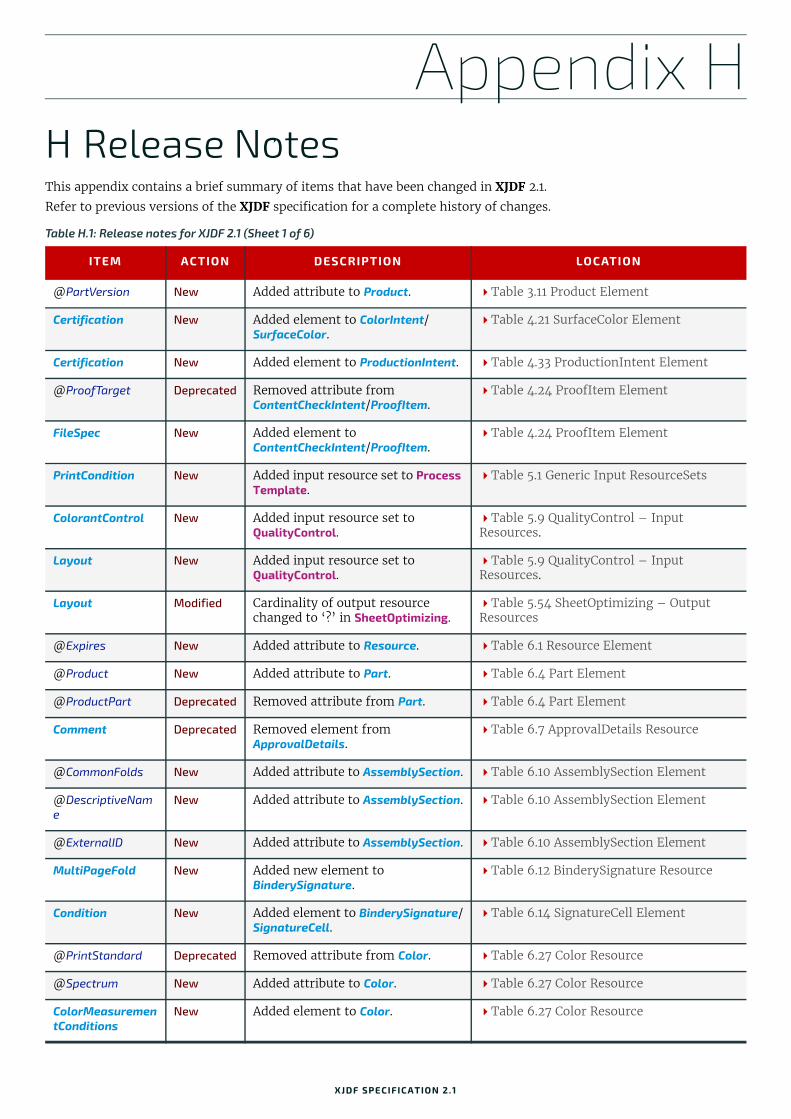
Appendix H
H Release NotesThis appendix contains a brief summary of items that have been changed in XJDF 2.1.Refer to previous versions of the XJDF specification for a complete history of changes.
Table H.1: Release notes for XJDF 2.1 (Sheet 1 of 6)
ITEM ACTION DESCRIPTION LOCATION
@PartVersion New Added attribute to Product. Table 3.11 Product Element
Certification New Added element to ColorIntent/SurfaceColor.
Table 4.21 SurfaceColor Element
Certification New Added element to ProductionIntent. Table 4.33 ProductionIntent Element
@ProofTarget Deprecated Removed attribute from ContentCheckIntent/ProofItem.
Table 4.24 ProofItem Element
FileSpec New Added element to ContentCheckIntent/ProofItem.
Table 4.24 ProofItem Element
PrintCondition New Added input resource set to Process Template.
Table 5.1 Generic Input ResourceSets
ColorantControl New Added input resource set to QualityControl.
Table 5.9 QualityControl – Input Resources.
Layout New Added input resource set to QualityControl.
Table 5.9 QualityControl – Input Resources.
Layout Modified Cardinality of output resource changed to ‘?’ in SheetOptimizing.
Table 5.54 SheetOptimizing – Output Resources
@Expires New Added attribute to Resource. Table 6.1 Resource Element
@Product New Added attribute to Part. Table 6.4 Part Element
@ProductPart Deprecated Removed attribute from Part. Table 6.4 Part Element
Comment Deprecated Removed element from ApprovalDetails.
Table 6.7 ApprovalDetails Resource
@CommonFolds New Added attribute to AssemblySection. Table 6.10 AssemblySection Element
@DescriptiveName
New Added attribute to AssemblySection. Table 6.10 AssemblySection Element
@ExternalID New Added attribute to AssemblySection. Table 6.10 AssemblySection Element
MultiPageFold New Added new element to BinderySignature.
Table 6.12 BinderySignature Resource
Condition New Added element to BinderySignature/SignatureCell.
Table 6.14 SignatureCell Element
@PrintStandard Deprecated Removed attribute from Color. Table 6.27 Color Resource
@Spectrum New Added attribute to Color. Table 6.27 Color Resource
ColorMeasurementConditions
New Added element to Color. Table 6.27 Color Resource
XJDF SPECIFICATIO N 2.1
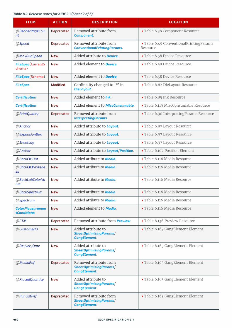
@ReaderPageCount
Deprecated Removed attribute from Component.
Table 6.38 Component Resource
@Speed Deprecated Removed attribute from ConventionalPrintingParams.
Table 6.49 ConventionalPrintingParams Resource
@MaxRunSpeed New Added attribute to Device. Table 6.58 Device Resource
FileSpec(CurrentSchema)
New Added element to Device. Table 6.58 Device Resource
FileSpec(Schema) New Added element to Device. Table 6.58 Device Resource
FileSpec Modified Cardinality changed to ‘*’ in DieLayout.
Table 6.62 DieLayout Resource
Certification New Added element to Ink. Table 6.85 Ink Resource
Certification New Added element to MiscConsumable. Table 6.119 MiscConsumable Resource
@PrintQuality Deprecated Removed attribute from InterpretingParams.
Table 6.90 InterpretingParams Resource
@Anchor New Added attribute to Layout. Table 6.97 Layout Resource
@ExpansionBox New Added attribute to Layout. Table 6.97 Layout Resource
@SheetLay New Added attribute to Layout. Table 6.97 Layout Resource
@Anchor New Added attribute to Layout/Position. Table 6.102 Position Element
@BackCIETint New Added attibute to Media. Table 6.116 Media Resource
@BackCIEWhiteness
New Added attibute to Media. Table 6.116 Media Resource
@BackLabColorValue
New Added attibute to Media. Table 6.116 Media Resource
@BackSpectrum New Added attibute to Media. Table 6.116 Media Resource
@Spectrum New Added attibute to Media. Table 6.116 Media Resource
ColorMeasurementConditions
New Added element to Media. Table 6.116 Media Resource
@CTM Deprecated Removed attribute from Preview. Table 6.136 Preview Resource
@CustomerID New Added attribute to SheetOptimizingParams/GangElement.
Table 6.163 GangElement Element
@DeliveryDate New Added attribute to SheetOptimizingParams/GangElement.
Table 6.163 GangElement Element
@MediaRef Deprecated Removed attribute from SheetOptimizingParams/GangElement.
Table 6.163 GangElement Element
@PlacedQuantity New Added attribute to SheetOptimizingParams/GangElement.
Table 6.163 GangElement Element
@RunListRef Deprecated Removed attribute from SheetOptimizingParams/GangElement.
Table 6.163 GangElement Element
Table H.1: Release notes for XJDF 2.1 (Sheet 2 of 6)
ITEM ACTION DESCRIPTION LOCATION
460 XJDF SPECIFICATIO N 2.1

GeneralID New Added element to SheetOptimizingParams/GangElement.
Table 6.163 GangElement Element
Media New Added element to SheetOptimizingParams/GangElement.
Table 6.163 GangElement Element
RunList New Added element to SheetOptimizingParams/GangElement.
Table 6.163 GangElement Element
@ColorantOrder Modified Change cardinality of attribute in PrintCondition.
Table 6.138 PrintCondition Resource
PrintCondition New Added resource set. Table 6.138 PrintCondition Resource
@Box New Added attribute to QualityControlParams.
Table 6.139 QualityControlParams Resource
@Position New Added attribute to QualityControlParams.
Table 6.139 QualityControlParams Resource
@QualityBase New Added attribute to QualityControlParams.
Table 6.139 QualityControlParams Resource
@QualityControlMethods
New Added attribute to QualityControlParams.
Table 6.139 QualityControlParams Resource
@Severity New Added attribute to QualityControlParams.
Table 6.139 QualityControlParams Resource
@SourceDeviceID New Added attribute to QualityControlParams.
Table 6.139 QualityControlParams Resource
BindingQuality New Added element to QualityControlParams.
Table 6.139 QualityControlParams Resource
BindingQualityParams
Deprecated Removed element from QualityControlParams.
Table 6.139 QualityControlParams Resource
ColorControlStrip New Added element to QualityControlParams.
Table 6.139 QualityControlParams Resource
FileSpec
(Image)New Added element to
QualityControlParams.Table 6.139 QualityControlParams Resource
FileSpec Modified Added @ResourceUsage require-ment to QualityControlParams/FileSpec.
Table 6.139 QualityControlParams Resource
RegistrationQuality
New Added element to QualityControlParams.
Table 6.139 QualityControlParams Resource
@Box New Added attribute to QualityControlResult.
Table 6.140 QualityControlResult Resource
@Measurements New Added attribute to QualityControlResult.
Table 6.140 QualityControlResult Resource
@MeasurementUsage
New Added attribute to QualityControlResult.
Table 6.140 QualityControlResult Resource
@Position New Added attribute to QualityControlResult.
Table 6.140 QualityControlResult Resource
Table H.1: Release notes for XJDF 2.1 (Sheet 3 of 6)
ITEM ACTION DESCRIPTION LOCATION
XJDF SPECIFICATIO N 2.1 461

@QualityControlMethods
New Added attribute to QualityControlResult.
Table 6.140 QualityControlResult Resource
@Sample New Added attribute to QualityControlResult.
Table 6.140 QualityControlResult Resource
@Severity New Added attribute to QualityControlResult.
Table 6.140 QualityControlResult Resource
@SourceDeviceID New Added attribute to QualityControlResult.
Table 6.140 QualityControlResult Resource
BindingQuality New Added element to QualityControlParams.
Table 6.140 QualityControlResult Resource
BindingQualityMeasurement
Deprecated Removed element from QualityControlParams.
Table 6.140 QualityControlResult Resource
ColorControlStrip New Added element to QualityControlResult.
Table 6.140 QualityControlResult Resource
Inspection New Added element to QualityControlResult.
Table 6.140 QualityControlResult Resource
RegistrationQuality
New Added element to QualityControlResult.
Table 6.140 QualityControlResult Resource
Defect New Added element to Inspection. Table 6.141 Defect Element
@Policy New Added attribute to SheetOptimizingParams.
Table 6.162 SheetOptimizingParams Resource
ConvertingConfig Modifid Cardinality changed to ‘*’ in SheetOptimizingParams.
Table 6.162 SheetOptimizingParams Resource
@Operations New Added attribute to SheetOptimizingParams/GangElement.
Table 6.163 GangElement Element
RunList New Added element to SheetOptimizingParams/GangElement.
Table 6.163 GangElement Element
InsertSheet Modified Cardinality changed to ‘*’ in Disjointing.
Table 6.168 Disjointing Element
@MediaRef New Added attribute to StackingParams/Disjointing/InsertSheet.
Table 6.169 InsertSheet Element
@DescriptiveName
New Added attribute to XJMF/Header. Table 7.3 Header
@ModuleID New Added attribute to ResourceInfo. Table 7.53 ResourceInfo Element
@Types New Added attribute to ResourceInfo. Table 7.53 ResourceInfo Element
Event New Added element to ResourceInfo. Table 7.53 ResourceInfo Element
@EndTime New Added attribute to DeviceInfo. Table 7.67 DeviceInfo Element
@ToolIDs New Added attribute to DeviceInfo. Table 7.67 DeviceInfo Element
Event New Added element to DeviceInfo. Table 7.67 DeviceInfo Element
FileSpec(CurrentSchema)
Deprecated Removed element from DeviceInfo. Table 7.67 DeviceInfo Element
FileSpec(Schema) Deprecated Removed element from DeviceInfo. Table 7.67 DeviceInfo Element
Table H.1: Release notes for XJDF 2.1 (Sheet 4 of 6)
ITEM ACTION DESCRIPTION LOCATION
462 XJDF SPECIFICATIO N 2.1
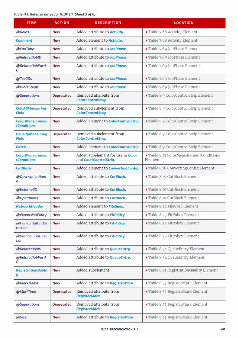
@Roles New Added attribute to Activity. Table 7.68 Activity Element
Comment New Added element to Activity. Table 7.68 Activity Element
@EndTime New Added attribute to JobPhase. Table 7.69 JobPhase Element
@RelatedJobID New Added attribute to JobPhase. Table 7.69 JobPhase Element
@RelatedJobPartID
New Added attribute to JobPhase. Table 7.69 JobPhase Element
@ToolIDs New Added attribute to JobPhase. Table 7.69 JobPhase Element
@WorkStepID New Added attribute to JobPhase. Table 7.69 JobPhase Element
@Separations Deprecated Removed attribute from ColorControlStrip.
Table 8.9 ColorControlStrip Element
CIELABMeasuringField
Deprecated Removed subelement from ColorControlStrip.
Table 8.9 ColorControlStrip Element
ColorMeasurementConditions
New Added element to ColorControlStrip. Table 8.9 ColorControlStrip Element
DensityMeasuringField
Deprecated Removed subelement from ColorControlStrip.
Table 8.9 ColorControlStrip Element
Patch New Added element to ColorControlStrip. Table 8.9 ColorControlStrip Element
ColorMeasurementConditions
New Added subelement for use in Color and ColorControlStrip.
Table 8.13 ColorMeasurementConditions Element
CutBlock New Added element to ConvertingConfig. Table 8.16 ConvertingConfig Element
@DescriptiveName
New Added attribute to CutBlock. Table 8.19 CutBlock Element
@ExternalID New Added attribute to CutBlock. Table 8.19 CutBlock Element
@Operations New Added attribute to CutBlock. Table 8.19 CutBlock Element
NetworkHeader New Added element to FileSpec. Table 8.22 FileSpec Element
@ExpansionPolicy New Added attribute to FitPolicy. Table 8.25 FitPolicy Element
@HorizontalGridDirection
New Added attribute to FitPolicy. Table 8.25 FitPolicy Element
@VerticalGridDirection
New Added attribute to FitPolicy. Table 8.25 FitPolicy Element
@RelatedJobID New Added attribute to QueueEntry. Table 8.54 QueueEntry Element
@RelatedJobPartID
New Added attribute to QueueEntry. Table 8.54 QueueEntry Element
RegistrationQuality
New Added subelement. Table 8.61 RegistrationQuality Element
@MarkName New Added attribute to RegisterMark. Table 8.57 RegisterMark Element
@MarkType Deprecated Removed attribute from RegisterMark.
Table 8.57 RegisterMark Element
@Separations Deprecated Removed attribute from RegisterMark.
Table 8.57 RegisterMark Element
@Size New Added attribute to RegisterMark. Table 8.57 RegisterMark Element
Table H.1: Release notes for XJDF 2.1 (Sheet 5 of 6)
ITEM ACTION DESCRIPTION LOCATION
XJDF SPECIFICATIO N 2.1 463

MarkElement New Added element to RegisterMark. Table 8.57 RegisterMark Element
ColorControlStrip New Added element to StripMark. Table 8.65 StripMark Element.
CutMark New Added element to StripMark. Table 8.65 StripMark Element.
RefAnchor Modified Changed cardinality to optional. Table 8.65 StripMark Element.
RegisterMark New Added element to StripMark. Table 8.65 StripMark Element.
ScavengerArea New Added element to StripMark. Table 8.65 StripMark Element.
Cleanup New Added enumeration to DeviceStatus.
Table A.15 DeviceStatus Enumeration Values
Setup New Added enumeration to DeviceStatus.
Table A.15 DeviceStatus Enumeration Values
LWCPlus New Added enumeration to ISOPaperSubstrate.
Table A.26 ISOPaperSubstrate Enumeration Values
LWCStandard New Added enumeration to ISOPaperSubstrate.
Table A.26 ISOPaperSubstrate Enumeration Values
NewsPlus New Added enumeration to ISOPaperSubstrate.
Table A.26 ISOPaperSubstrate Enumeration Values
SCPlus New Added enumeration to ISOPaperSubstrate.
Table A.26 ISOPaperSubstrate Enumeration Values
SCStandard New Added enumeration to ISOPaperSubstrate.
Table A.26 ISOPaperSubstrate Enumeration Values
SNP New Added enumeration to ISOPaperSubstrate.
Table A.26 ISOPaperSubstrate Enumeration Values
EmbossingFoil Deprecated Removed enumeration from MediaType.
Table A.29 MediaType Enumeration Values
Synthetic New Added enumeration to MediaType.
Table A.29 MediaType Enumeration Values
Vinyl Deprecated Removed enumeration from MediaType.
Table A.29 MediaType Enumeration Values
Unprinted New Added enumeration to Sides. Table A.39 Sides Enumeration Values
SpreadType New Added new enumeration. Table A.43 SpreadType Enumeration Values
15 New Added code to Appendix A.3 Return Codes.
Table A.51 Return Codes
16 New Added code to Appendix A.3 Return Codes.
Table A.51 Return Codes
17 New Added code to Appendix A.3 Return Codes.
Table A.51 Return Codes
18 New Added code to Appendix A.3 Return Codes.
Table A.51 Return Codes
Quality Control Methods
New Added list of NMTOKENS. Table A.74 Quality Control Methods
Table H.1: Release notes for XJDF 2.1 (Sheet 6 of 6)
ITEM ACTION DESCRIPTION LOCATION
464 XJDF SPECIFICATIO N 2.1


�������
� � � � � � �� � � � � � � � � � �� � �