Specification - Mouser Electronics México
138
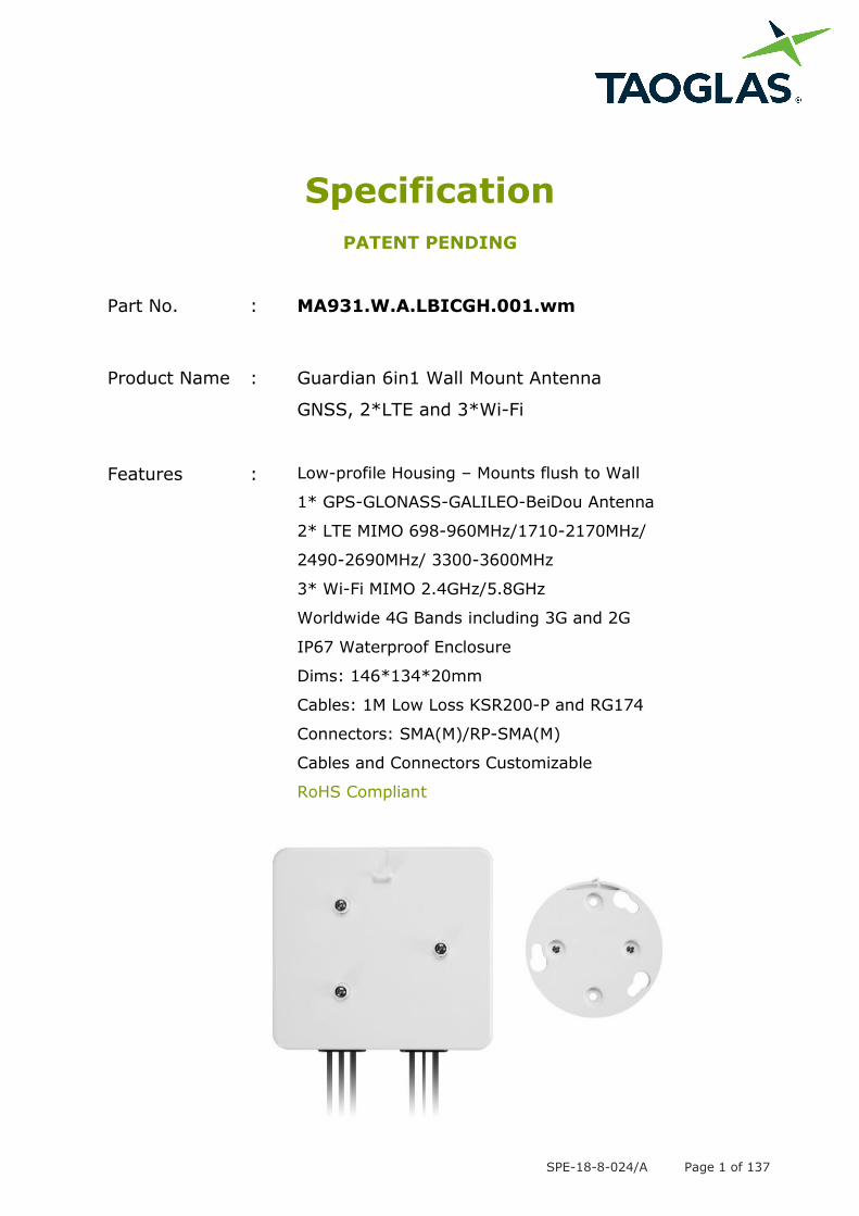
SPE-18-8-024/A Page 1 of 137 Specification PATENT PENDING Part No. : MA931.W.A.LBICGH.001.wm Product Name : Guardian 6in1 Wall Mount Antenna GNSS, 2*LTE and 3*Wi-Fi Features : Low-profile Housing – Mounts flush to Wall 1* GPS-GLONASS-GALILEO-BeiDou Antenna 2* LTE MIMO 698-960MHz/1710-2170MHz/ 2490-2690MHz/ 3300-3600MHz 3* Wi-Fi MIMO 2.4GHz/5.8GHz Worldwide 4G Bands including 3G and 2G IP67 Waterproof Enclosure Dims: 146*134*20mm Cables: 1M Low Loss KSR200-P and RG174 Connectors: SMA(M)/RP-SMA(M) Cables and Connectors Customizable RoHS Compliant
-
Upload
khangminh22 -
Category
Documents
-
view
0 -
download
0
Transcript of Specification - Mouser Electronics México
SPE-18-8-024/A Page 1 of 137
Specification
PATENT PENDING
Part No. : MA931.W.A.LBICGH.001.wm
Product Name : Guardian 6in1 Wall Mount Antenna
GNSS, 2*LTE and 3*Wi-Fi
Features : Low-profile Housing – Mounts flush to Wall
1* GPS-GLONASS-GALILEO-BeiDou Antenna
2* LTE MIMO 698-960MHz/1710-2170MHz/
2490-2690MHz/ 3300-3600MHz
3* Wi-Fi MIMO 2.4GHz/5.8GHz
Worldwide 4G Bands including 3G and 2G
IP67 Waterproof Enclosure
Dims: 146*134*20mm
Cables: 1M Low Loss KSR200-P and RG174
Connectors: SMA(M)/RP-SMA(M)
Cables and Connectors Customizable
RoHS Compliant
SPE-18-8-024/A Page 2 of 137
1. Introduction
The MA931 Guardian is a next generation combination antenna. The first panel antenna
worldwide designed for IoT Gateway and Router devices. It is a low profile 6in1 wall
mount antenna. It is a heavy-duty, fully IP67 waterproof external M2M antenna for use
by RF professionals in IoT Gateway and Routers, HD Video Streaming, Transportation
and Remote Monitoring Applications.
This antenna delivers powerful MIMO antenna technology for worldwide 4G LTE bands
at 698-960MHz/1710-2170MHz/2490-2690MHz/3300-3600MHz, dualband 2.4/5.8GHz
Wi-Fi, plus GPS-GLONASS-GALILEO-BeiDou for location accuracy. It enables designers
to cover a wide range of technologies by installing a single antenna.
4G wireless applications demand high speed data uplink and downlink. High efficiency
and high gain MIMO antennas are necessary to achieve the required signal to noise
ratio and throughput required to solve these challenges. Taoglas also takes care to
have high isolation among these antennas to prevent self-interference. Low loss cables
used to keep efficiency high over long cable lengths.
The GPS-GLONASS-GALILEO-BeiDou active antenna has been carefully designed for
excellent performance across all GNSS bands, leading to higher location accuracy and
stability of tracking in urban environments.
The housing is IP67 waterproof and comes with a 3M foam adhesive. The antenna can
be mounted internally or externally on a vehicle. The MA931 comes with 1 meter, low
loss KSR-200P coaxial cables for the LTE and Wi-Fi antennas, and RG174 coaxial cable
for the GNSS antenna as standard. Customized cables and connector versions are also
available.
SPE-18-8-024/A Page 3 of 137
1. Specification
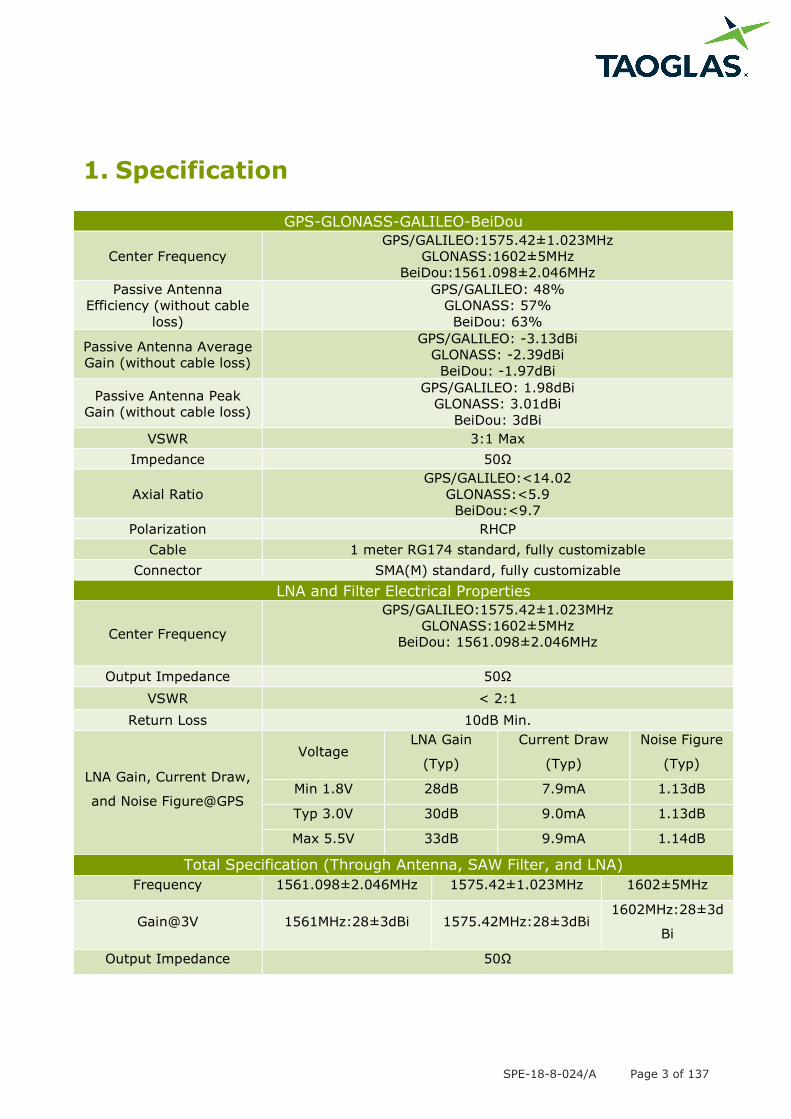
GPS-GLONASS-GALILEO-BeiDou
Center Frequency
GPS/GALILEO:1575.42±1.023MHz
GLONASS:1602±5MHz
BeiDou:1561.098±2.046MHz
Passive Antenna
Efficiency (without cable
loss)
GPS/GALILEO: 48%
GLONASS: 57%
BeiDou: 63%
Passive Antenna Average
Gain (without cable loss)
GPS/GALILEO: -3.13dBi
GLONASS: -2.39dBi
BeiDou: -1.97dBi
Passive Antenna Peak
Gain (without cable loss)
GPS/GALILEO: 1.98dBi
GLONASS: 3.01dBi
BeiDou: 3dBi
VSWR 3:1 Max
Impedance 50Ω
Axial Ratio
GPS/GALILEO:<14.02
GLONASS:<5.9
BeiDou:<9.7
Polarization RHCP
Cable 1 meter RG174 standard, fully customizable
Connector SMA(M) standard, fully customizable
LNA and Filter Electrical Properties
Center Frequency
GPS/GALILEO:1575.42±1.023MHz
GLONASS:1602±5MHz
BeiDou: 1561.098±2.046MHz
Output Impedance 50Ω
VSWR < 2:1
Return Loss 10dB Min.
LNA Gain, Current Draw,
and Noise Figure@GPS
Voltage LNA Gain
(Typ)
Current Draw
(Typ)
Noise Figure
(Typ)
Min 1.8V 28dB 7.9mA 1.13dB
Typ 3.0V 30dB 9.0mA 1.13dB
Max 5.5V 33dB 9.9mA 1.14dB
Total Specification (Through Antenna, SAW Filter, and LNA)
Frequency 1561.098±2.046MHz 1575.42±1.023MHz 1602±5MHz
Gain@3V 1561MHz:28±3dBi 1575.42MHz:28±3dBi 1602MHz:28±3d
Bi
Output Impedance 50Ω
SPE-18-8-024/A Page 4 of 137
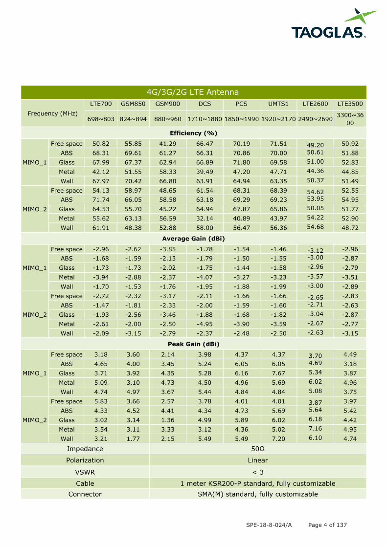
4G/3G/2G LTE Antenna
Frequency (MHz)
LTE700 GSM850 GSM900 DCS PCS UMTS1 LTE2600 LTE3500
698~803 824~894 880~960 1710~1880 1850~1990 1920~2170 2490~2690 3300~36
00
Efficiency (%)
MIMO_1
Free space 50.82 55.85 41.29 66.47 70.19 71.51 49.20 50.92
ABS 68.31 69.61 61.27 66.31 70.86 70.00 50.61 51.88
Glass 67.99 67.37 62.94 66.89 71.80 69.58 51.00 52.83
Metal 42.12 51.55 58.33 39.49 47.20 47.71 44.36 44.85
Wall 67.97 70.42 66.80 63.91 64.94 63.35 50.37 51.49
MIMO_2
Free space 54.13 58.97 48.65 61.54 68.31 68.39 54.62 52.55
ABS 71.74 66.05 58.58 63.18 69.29 69.23 53.95 54.95
Glass 64.53 55.70 45.22 64.94 67.87 65.86 50.05 51.77
Metal 55.62 63.13 56.59 32.14 40.89 43.97 54.22 52.90
Wall 61.91 48.38 52.88 58.00 56.47 56.36 54.68 48.72
Average Gain (dBi)
MIMO_1
Free space -2.96 -2.62 -3.85 -1.78 -1.54 -1.46 -3.12 -2.96
ABS -1.68 -1.59 -2.13 -1.79 -1.50 -1.55 -3.00 -2.87
Glass -1.73 -1.73 -2.02 -1.75 -1.44 -1.58 -2.96 -2.79
Metal -3.94 -2.88 -2.37 -4.07 -3.27 -3.23 -3.57 -3.51
Wall -1.70 -1.53 -1.76 -1.95 -1.88 -1.99 -3.00 -2.89
MIMO_2
Free space -2.72 -2.32 -3.17 -2.11 -1.66 -1.66 -2.65 -2.83
ABS -1.47 -1.81 -2.33 -2.00 -1.59 -1.60 -2.71 -2.63
Glass -1.93 -2.56 -3.46 -1.88 -1.68 -1.82 -3.04 -2.87
Metal -2.61 -2.00 -2.50 -4.95 -3.90 -3.59 -2.67 -2.77
Wall -2.09 -3.15 -2.79 -2.37 -2.48 -2.50 -2.63 -3.15
Peak Gain (dBi)
MIMO_1
Free space 3.18 3.60 2.14 3.98 4.37 4.37 3.70 4.49
ABS 4.65 4.00 3.45 5.24 6.05 6.05 4.69 3.18
Glass 3.71 3.92 4.35 5.28 6.16 7.67 5.34 3.87
Metal 5.09 3.10 4.73 4.50 4.96 5.69 6.02 4.96
Wall 4.74 4.97 3.67 5.44 4.84 4.84 5.08 3.75
MIMO_2
Free space 5.83 3.66 2.57 3.78 4.01 4.01 3.87 3.97
ABS 4.33 4.52 4.41 4.34 4.73 5.69 5.64 5.42
Glass 3.02 3.14 1.36 4.99 5.89 6.02 6.18 4.42
Metal 3.54 3.11 3.33 3.12 4.36 5.02 7.16 4.95
Wall 3.21 1.77 2.15 5.49 5.49 7.20 6.10 4.74
Impedance 50Ω
Polarization Linear
VSWR < 3
Cable 1 meter KSR200-P standard, fully customizable
Connector SMA(M) standard, fully customizable
SPE-18-8-024/A Page 5 of 137
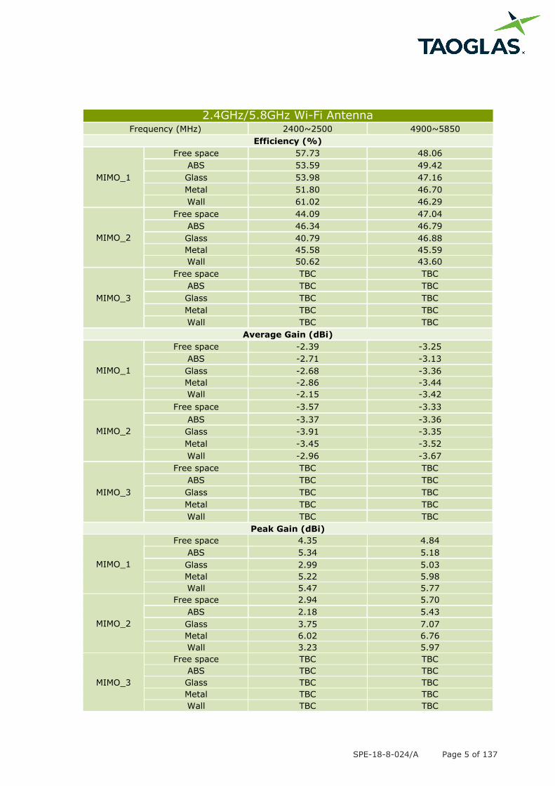
2.4GHz/5.8GHz Wi-Fi Antenna Frequency (MHz) 2400~2500 4900~5850
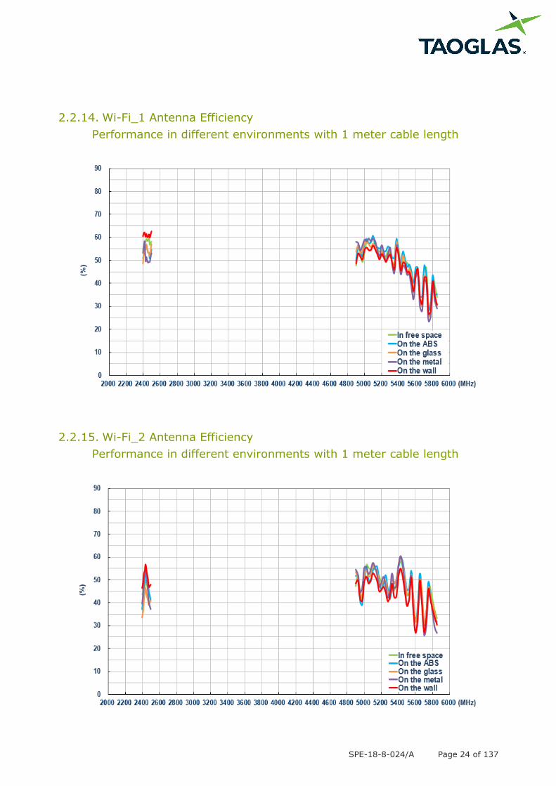
Efficiency (%)
MIMO_1
Free space 57.73 48.06
ABS 53.59 49.42
Glass 53.98 47.16
Metal 51.80 46.70
Wall 61.02 46.29
MIMO_2
Free space 44.09 47.04
ABS 46.34 46.79
Glass 40.79 46.88
Metal 45.58 45.59
Wall 50.62 43.60
MIMO_3
Free space TBC TBC
ABS TBC TBC
Glass TBC TBC
Metal TBC TBC
Wall TBC TBC
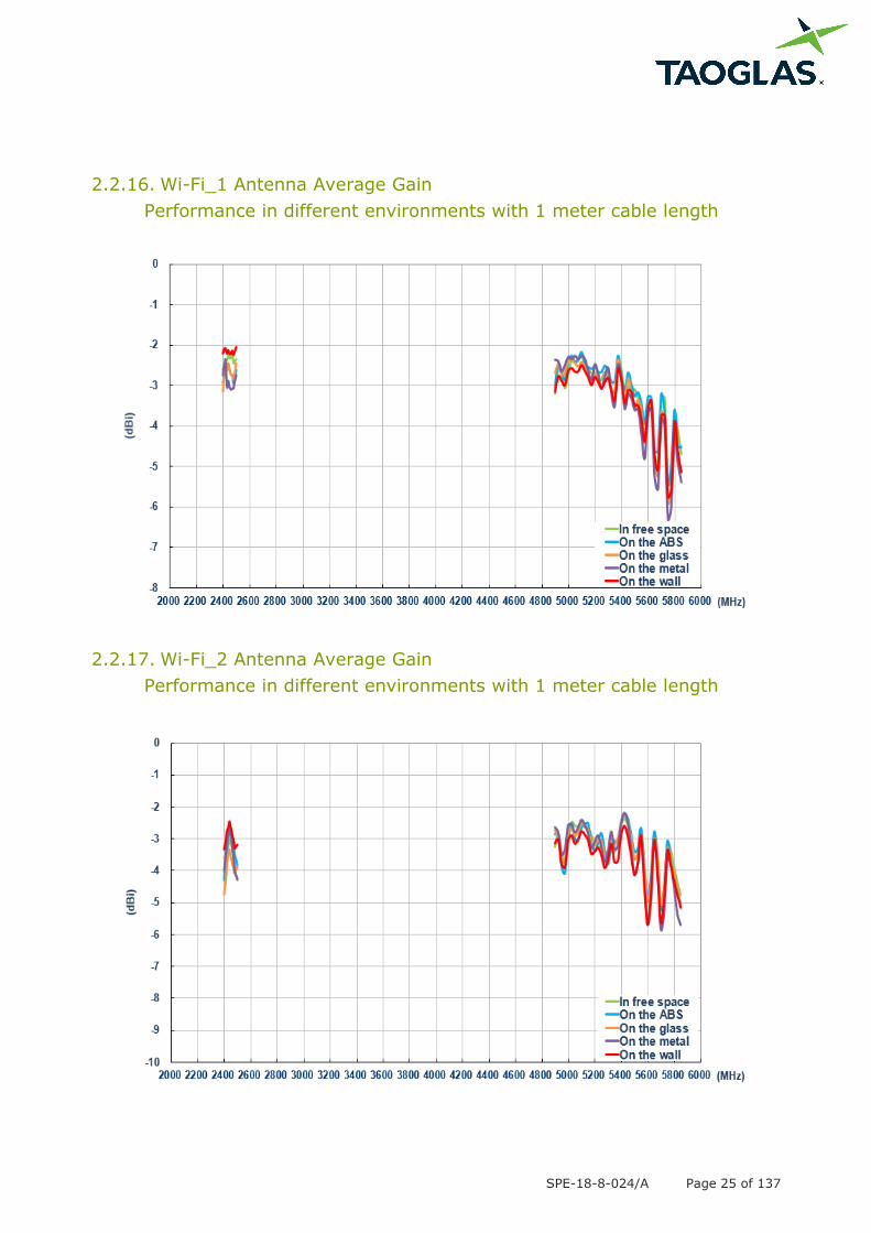
Average Gain (dBi)
MIMO_1
Free space -2.39 -3.25
ABS -2.71 -3.13
Glass -2.68 -3.36
Metal -2.86 -3.44
Wall -2.15 -3.42
MIMO_2
Free space -3.57 -3.33
ABS -3.37 -3.36
Glass -3.91 -3.35
Metal -3.45 -3.52
Wall -2.96 -3.67
MIMO_3
Free space TBC TBC
ABS TBC TBC
Glass TBC TBC
Metal TBC TBC
Wall TBC TBC
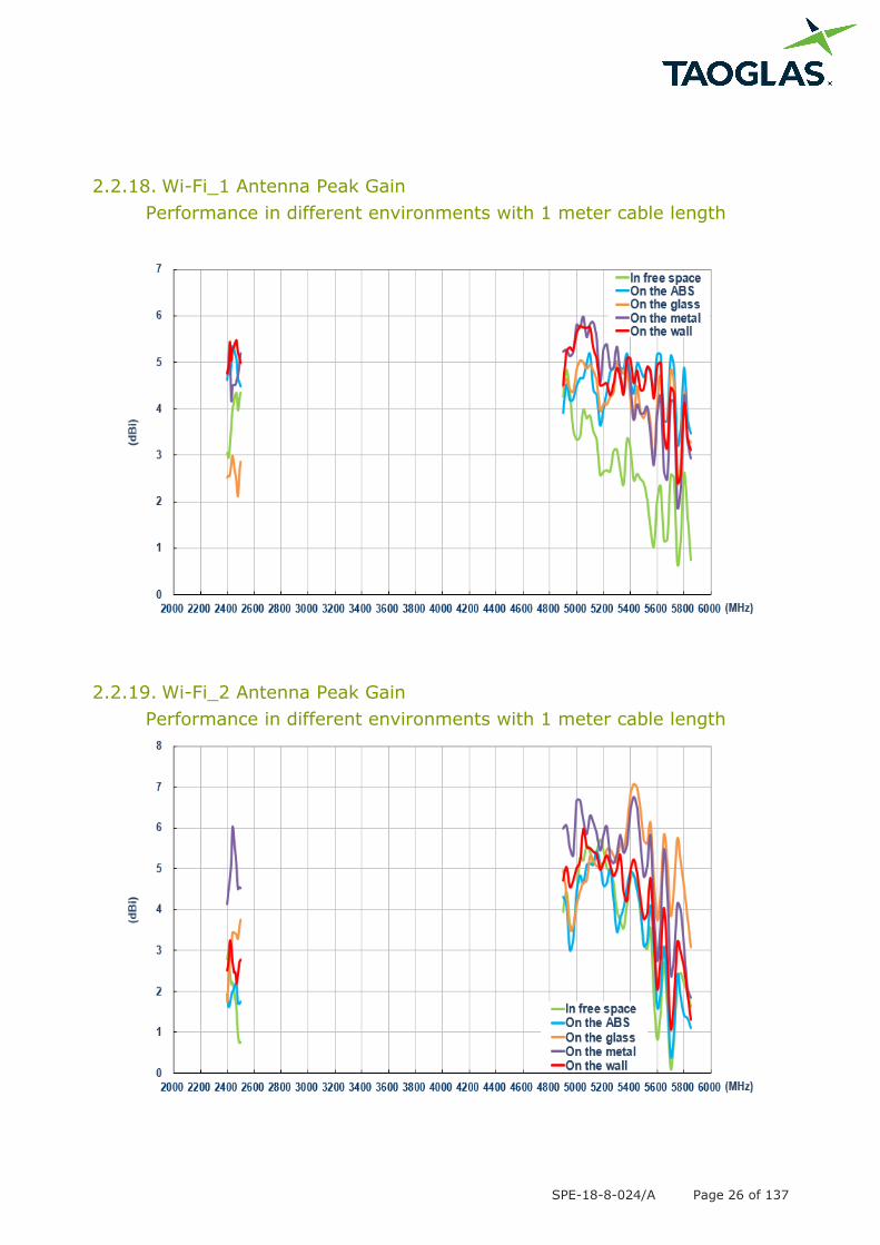
Peak Gain (dBi)
MIMO_1
Free space 4.35 4.84
ABS 5.34 5.18
Glass 2.99 5.03
Metal 5.22 5.98
Wall 5.47 5.77
MIMO_2
Free space 2.94 5.70
ABS 2.18 5.43
Glass 3.75 7.07
Metal 6.02 6.76
Wall 3.23 5.97
MIMO_3
Free space TBC TBC
ABS TBC TBC
Glass TBC TBC
Metal TBC TBC
Wall TBC TBC
SPE-18-8-024/A Page 6 of 137
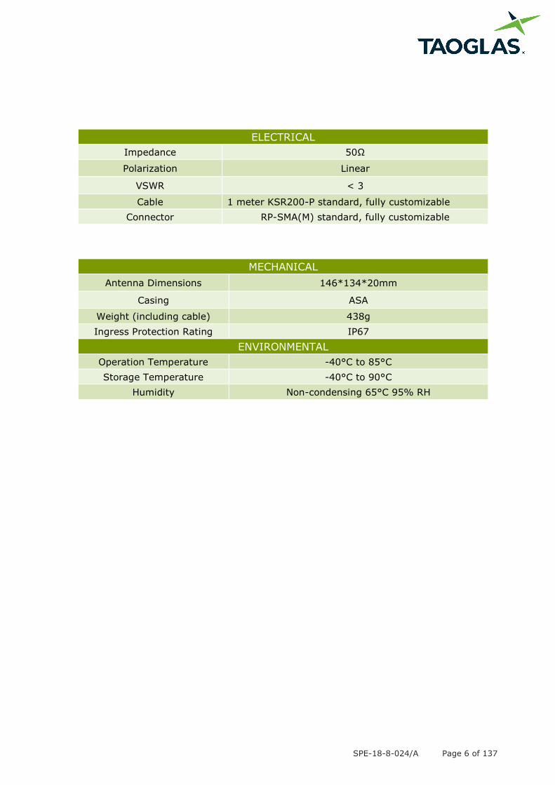
ELECTRICAL
Impedance 50Ω
Polarization Linear
VSWR < 3
Cable 1 meter KSR200-P standard, fully customizable
Connector RP-SMA(M) standard, fully customizable
MECHANICAL
Antenna Dimensions 146*134*20mm
Casing ASA
Weight (including cable) 438g
Ingress Protection Rating IP67
ENVIRONMENTAL
Operation Temperature -40°C to 85°C
Storage Temperature -40°C to 90°C
Humidity Non-condensing 65°C 95% RH
SPE-18-8-024/A Page 7 of 137
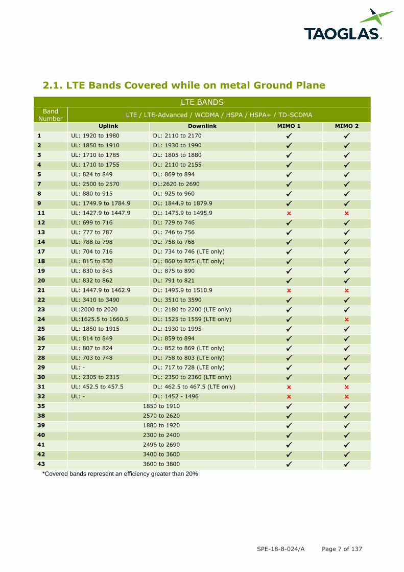
2.1. LTE Bands Covered while on metal Ground Plane
LTE BANDS
Band Number
LTE / LTE-Advanced / WCDMA / HSPA / HSPA+ / TD-SCDMA
Uplink Downlink MIMO 1 MIMO 2
1 UL: 1920 to 1980 DL: 2110 to 2170
2 UL: 1850 to 1910 DL: 1930 to 1990
3 UL: 1710 to 1785 DL: 1805 to 1880
4 UL: 1710 to 1755 DL: 2110 to 2155
5 UL: 824 to 849 DL: 869 to 894
7 UL: 2500 to 2570 DL:2620 to 2690
8 UL: 880 to 915 DL: 925 to 960
9 UL: 1749.9 to 1784.9 DL: 1844.9 to 1879.9
11 UL: 1427.9 to 1447.9 DL: 1475.9 to 1495.9
12 UL: 699 to 716 DL: 729 to 746
13 UL: 777 to 787 DL: 746 to 756
14 UL: 788 to 798 DL: 758 to 768
17 UL: 704 to 716 DL: 734 to 746 (LTE only)
18 UL: 815 to 830 DL: 860 to 875 (LTE only)
19 UL: 830 to 845 DL: 875 to 890
20 UL: 832 to 862 DL: 791 to 821
21 UL: 1447.9 to 1462.9 DL: 1495.9 to 1510.9
22 UL: 3410 to 3490 DL: 3510 to 3590
23 UL:2000 to 2020 DL: 2180 to 2200 (LTE only)
24 UL:1625.5 to 1660.5 DL: 1525 to 1559 (LTE only)
25 UL: 1850 to 1915 DL: 1930 to 1995
26 UL: 814 to 849 DL: 859 to 894
27 UL: 807 to 824 DL: 852 to 869 (LTE only)
28 UL: 703 to 748 DL: 758 to 803 (LTE only)
29 UL: - DL: 717 to 728 (LTE only)
30 UL: 2305 to 2315 DL: 2350 to 2360 (LTE only)
31 UL: 452.5 to 457.5 DL: 462.5 to 467.5 (LTE only)
32 UL: - DL: 1452 - 1496
35 1850 to 1910
38 2570 to 2620
39 1880 to 1920
40 2300 to 2400
41 2496 to 2690
42 3400 to 3600
43 3600 to 3800
*Covered bands represent an efficiency greater than 20%
SPE-18-8-024/A Page 8 of 137
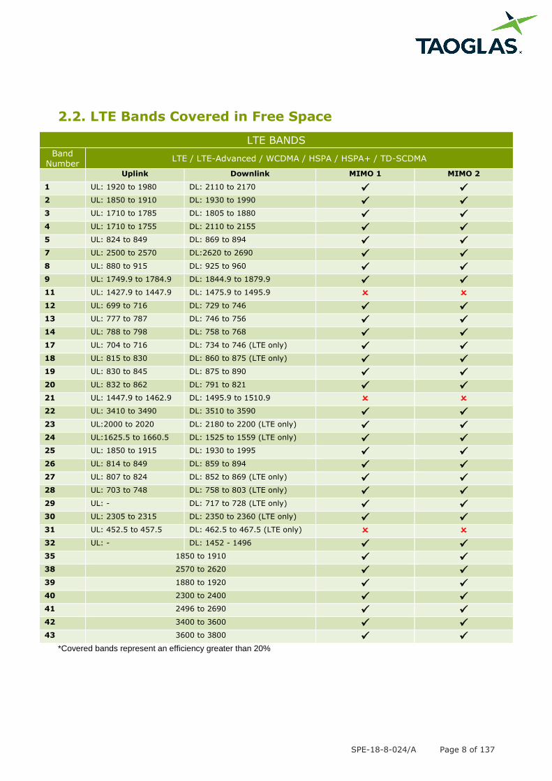
2.2. LTE Bands Covered in Free Space
LTE BANDS
Band Number
LTE / LTE-Advanced / WCDMA / HSPA / HSPA+ / TD-SCDMA
Uplink Downlink MIMO 1 MIMO 2
1 UL: 1920 to 1980 DL: 2110 to 2170
2 UL: 1850 to 1910 DL: 1930 to 1990
3 UL: 1710 to 1785 DL: 1805 to 1880
4 UL: 1710 to 1755 DL: 2110 to 2155
5 UL: 824 to 849 DL: 869 to 894
7 UL: 2500 to 2570 DL:2620 to 2690
8 UL: 880 to 915 DL: 925 to 960
9 UL: 1749.9 to 1784.9 DL: 1844.9 to 1879.9
11 UL: 1427.9 to 1447.9 DL: 1475.9 to 1495.9
12 UL: 699 to 716 DL: 729 to 746
13 UL: 777 to 787 DL: 746 to 756
14 UL: 788 to 798 DL: 758 to 768
17 UL: 704 to 716 DL: 734 to 746 (LTE only)
18 UL: 815 to 830 DL: 860 to 875 (LTE only)
19 UL: 830 to 845 DL: 875 to 890
20 UL: 832 to 862 DL: 791 to 821
21 UL: 1447.9 to 1462.9 DL: 1495.9 to 1510.9
22 UL: 3410 to 3490 DL: 3510 to 3590
23 UL:2000 to 2020 DL: 2180 to 2200 (LTE only)
24 UL:1625.5 to 1660.5 DL: 1525 to 1559 (LTE only)
25 UL: 1850 to 1915 DL: 1930 to 1995
26 UL: 814 to 849 DL: 859 to 894
27 UL: 807 to 824 DL: 852 to 869 (LTE only)
28 UL: 703 to 748 DL: 758 to 803 (LTE only)
29 UL: - DL: 717 to 728 (LTE only)
30 UL: 2305 to 2315 DL: 2350 to 2360 (LTE only)
31 UL: 452.5 to 457.5 DL: 462.5 to 467.5 (LTE only)
32 UL: - DL: 1452 - 1496
35 1850 to 1910
38 2570 to 2620
39 1880 to 1920
40 2300 to 2400
41 2496 to 2690
42 3400 to 3600
43 3600 to 3800
*Covered bands represent an efficiency greater than 20%
SPE-18-8-024/A Page 9 of 137
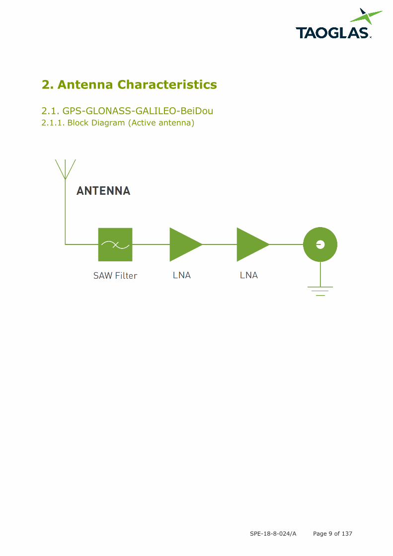
2. Antenna Characteristics
2.1. GPS-GLONASS-GALILEO-BeiDou
2.1.1. Block Diagram (Active antenna)
SPE-18-8-024/A Page 10 of 137
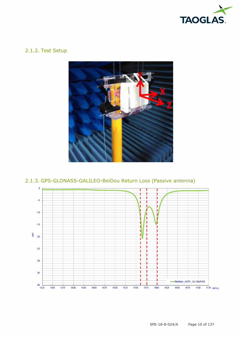
2.1.2. Test Setup
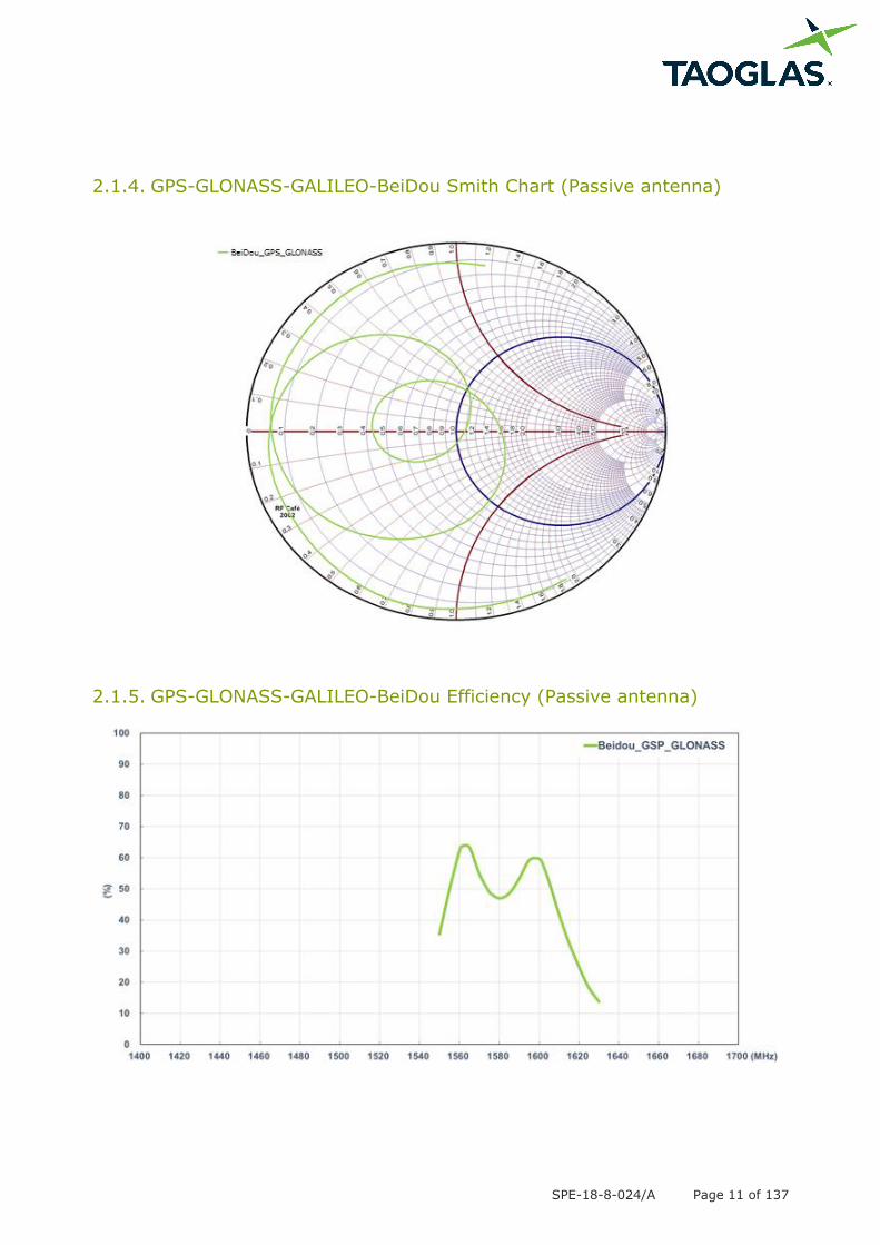
2.1.3. GPS-GLONASS-GALILEO-BeiDou Return Loss (Passive antenna)
SPE-18-8-024/A Page 11 of 137
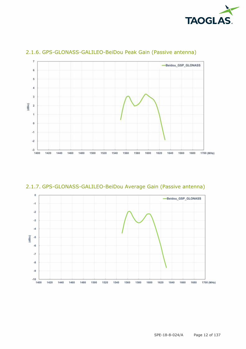
2.1.4. GPS-GLONASS-GALILEO-BeiDou Smith Chart (Passive antenna)
2.1.5. GPS-GLONASS-GALILEO-BeiDou Efficiency (Passive antenna)
SPE-18-8-024/A Page 12 of 137
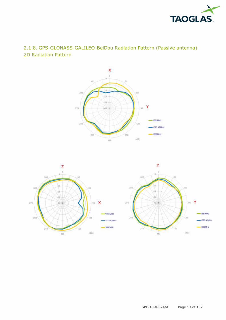
2.1.6. GPS-GLONASS-GALILEO-BeiDou Peak Gain (Passive antenna)
2.1.7. GPS-GLONASS-GALILEO-BeiDou Average Gain (Passive antenna)
SPE-18-8-024/A Page 13 of 137
2.1.8. GPS-GLONASS-GALILEO-BeiDou Radiation Pattern (Passive antenna)
2D Radiation Pattern
SPE-18-8-024/A Page 14 of 137
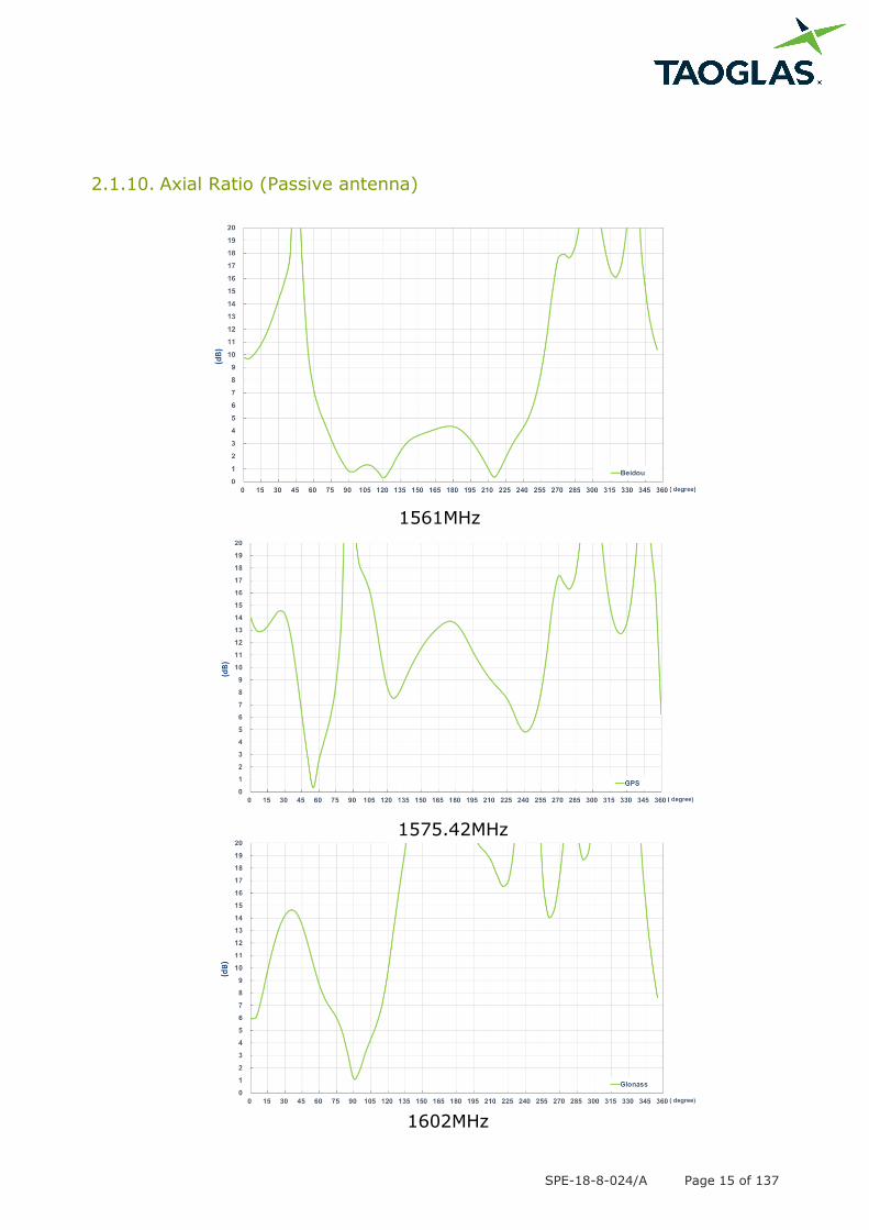
1561MHz
1575.42MHz 1602MHz
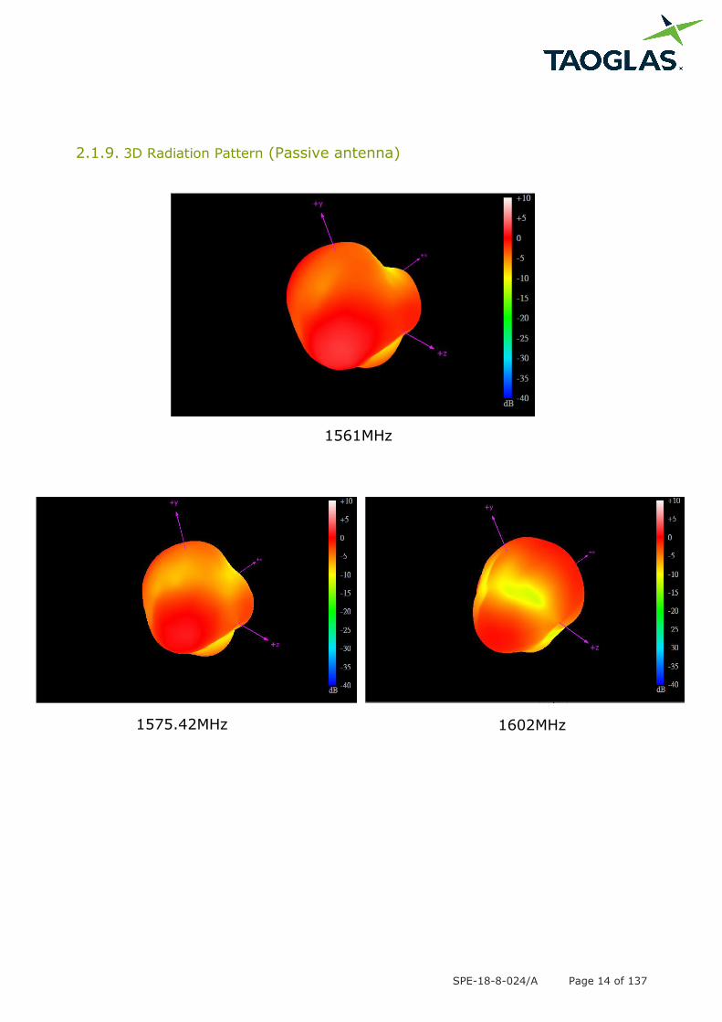
2.1.9. 3D Radiation Pattern (Passive antenna)
SPE-18-8-024/A Page 15 of 137
1575.42MHz
1602MHz
1561MHz
2.1.10. Axial Ratio (Passive antenna)
SPE-18-8-024/A Page 16 of 137
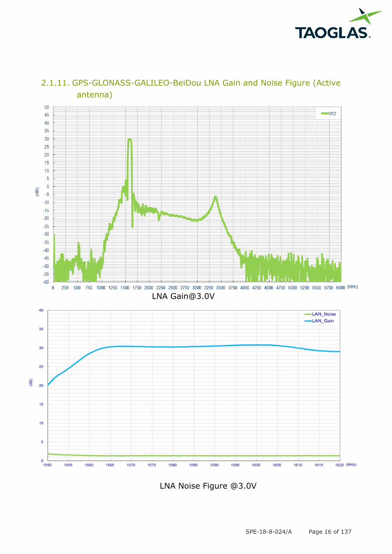
2.1.11. GPS-GLONASS-GALILEO-BeiDou LNA Gain and Noise Figure (Active
antenna)
LNA Noise Figure @3.0V
SPE-18-8-024/A Page 17 of 137
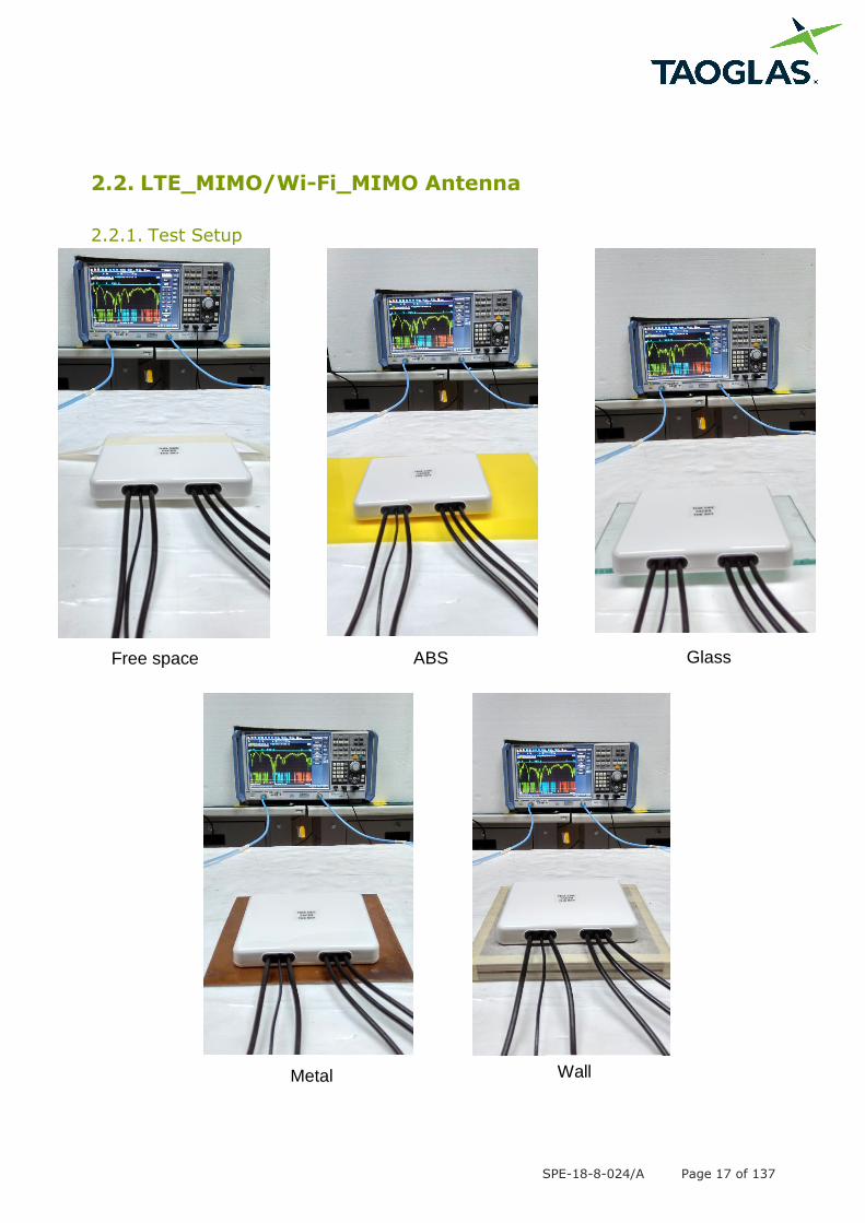
2.2. LTE_MIMO/Wi-Fi_MIMO Antenna
2.2.1. Test Setup
Glass Free space ABS
Metal Wall
SPE-18-8-024/A Page 18 of 137
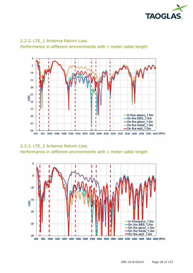
2.2.2. LTE_1 Antenna Return Loss
Performance in different environments with 1 meter cable length
2.2.3. LTE_2 Antenna Return Loss
Performance in different environments with 1 meter cable length
SPE-18-8-024/A Page 19 of 137
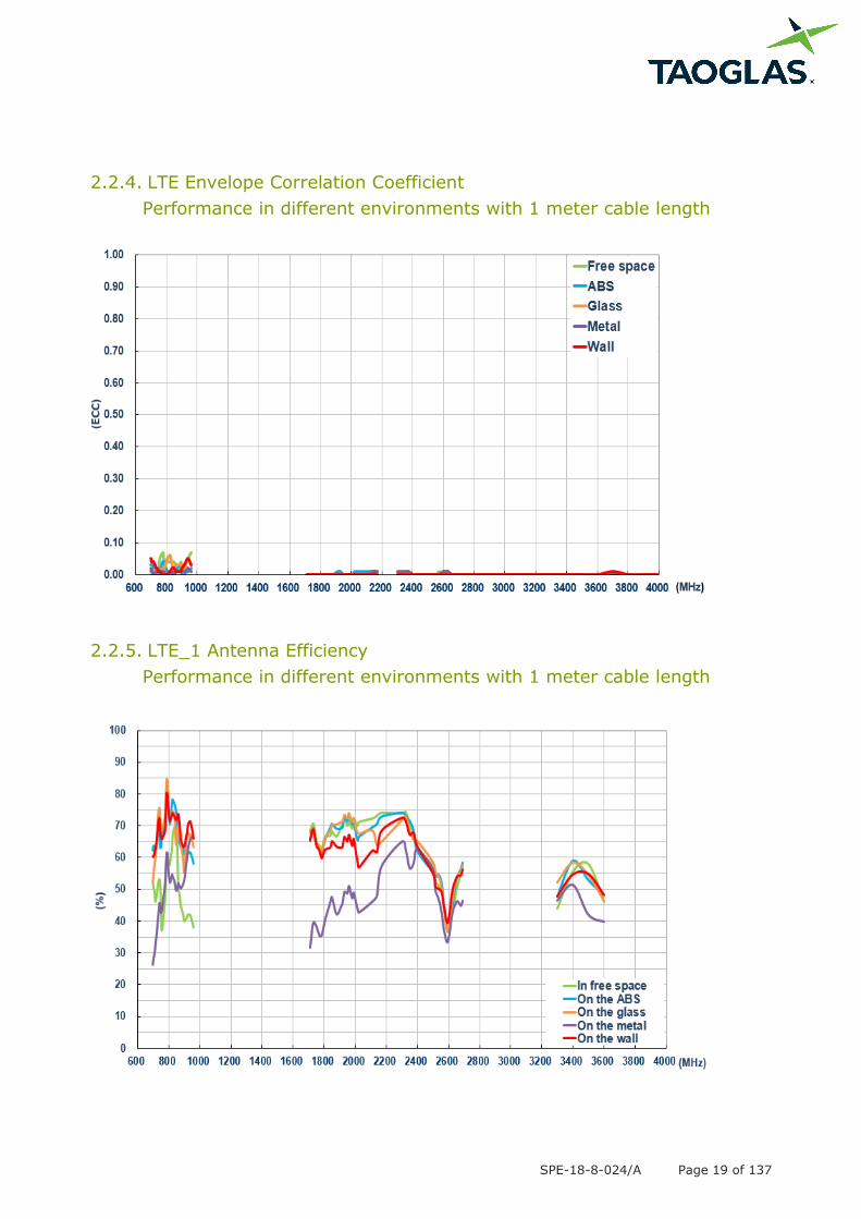
2.2.4. LTE Envelope Correlation Coefficient
Performance in different environments with 1 meter cable length
2.2.5. LTE_1 Antenna Efficiency
Performance in different environments with 1 meter cable length
SPE-18-8-024/A Page 20 of 137
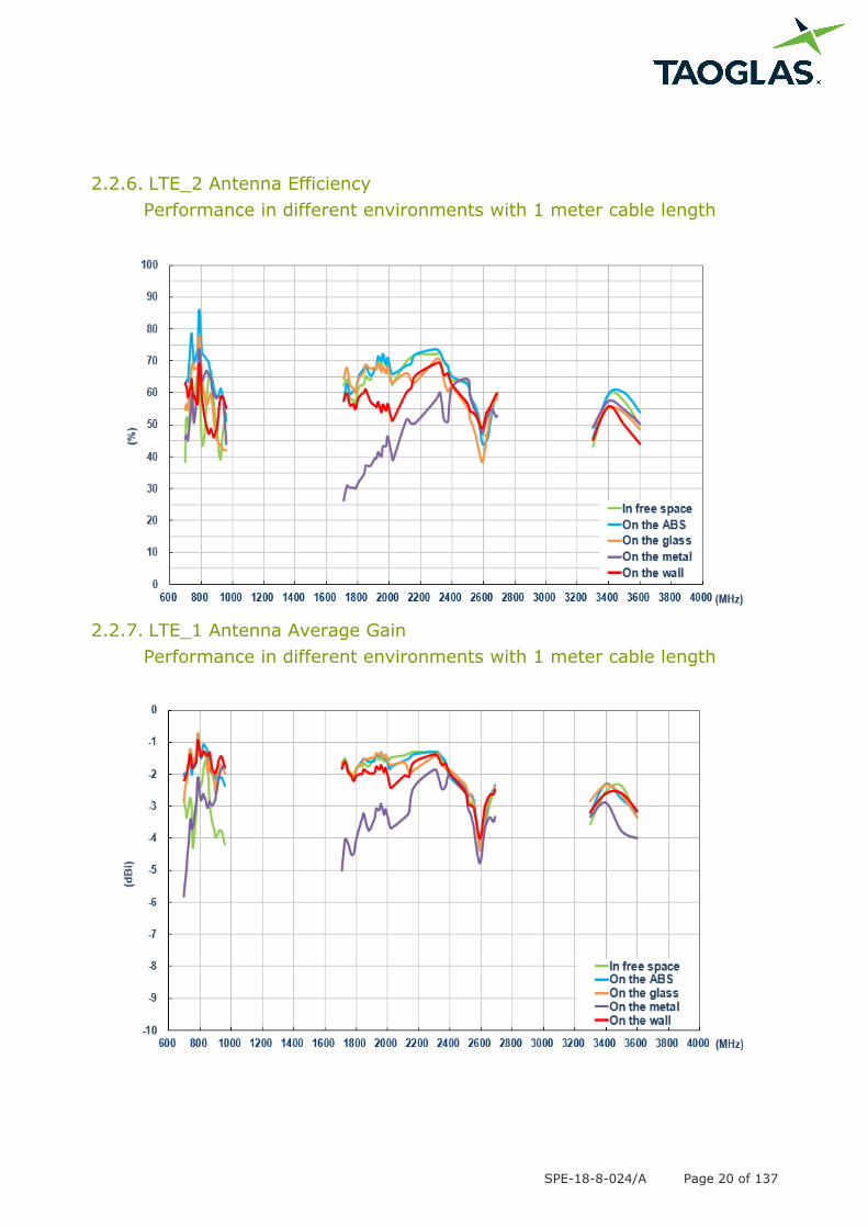
2.2.6. LTE_2 Antenna Efficiency
Performance in different environments with 1 meter cable length
2.2.7. LTE_1 Antenna Average Gain
Performance in different environments with 1 meter cable length

SPE-18-8-024/A Page 21 of 137
2.2.8. LTE_2 Antenna Average Gain
Performance in different environments with 1 meter cable length
2.2.9. LTE_1 Antenna Peak Gain
Performance in different environments with 1 meter cable length

SPE-18-8-024/A Page 22 of 137
2.2.10. LTE_2 Antenna Peak Gain
Performance in different environments with 1 meter cable length
2.2.11. Wi-Fi_1 Antenna Return Loss
Performance in different environments with 1 meter cable length
SPE-18-8-024/A Page 23 of 137
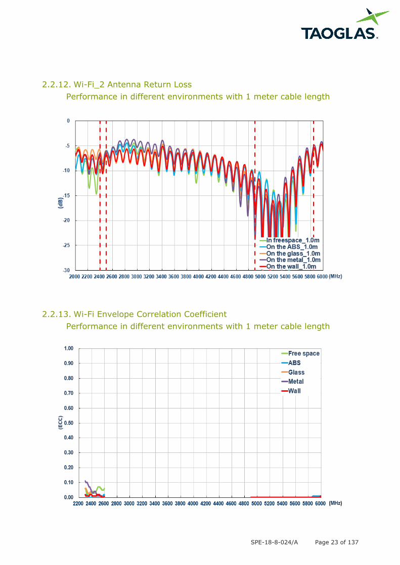
2.2.12. Wi-Fi_2 Antenna Return Loss
Performance in different environments with 1 meter cable length
2.2.13. Wi-Fi Envelope Correlation Coefficient
Performance in different environments with 1 meter cable length
SPE-18-8-024/A Page 24 of 137
2.2.14. Wi-Fi_1 Antenna Efficiency
Performance in different environments with 1 meter cable length
2.2.15. Wi-Fi_2 Antenna Efficiency
Performance in different environments with 1 meter cable length
SPE-18-8-024/A Page 25 of 137
2.2.16. Wi-Fi_1 Antenna Average Gain
Performance in different environments with 1 meter cable length
2.2.17. Wi-Fi_2 Antenna Average Gain
Performance in different environments with 1 meter cable length
SPE-18-8-024/A Page 26 of 137
2.2.18. Wi-Fi_1 Antenna Peak Gain
Performance in different environments with 1 meter cable length
2.2.19. Wi-Fi_2 Antenna Peak Gain
Performance in different environments with 1 meter cable length

SPE-18-8-024/A Page 27 of 137
2.2.20. Test Setup for Antenna Radiation Pattern
In free space
Y
Z
X
SPE-18-8-024/A Page 28 of 137
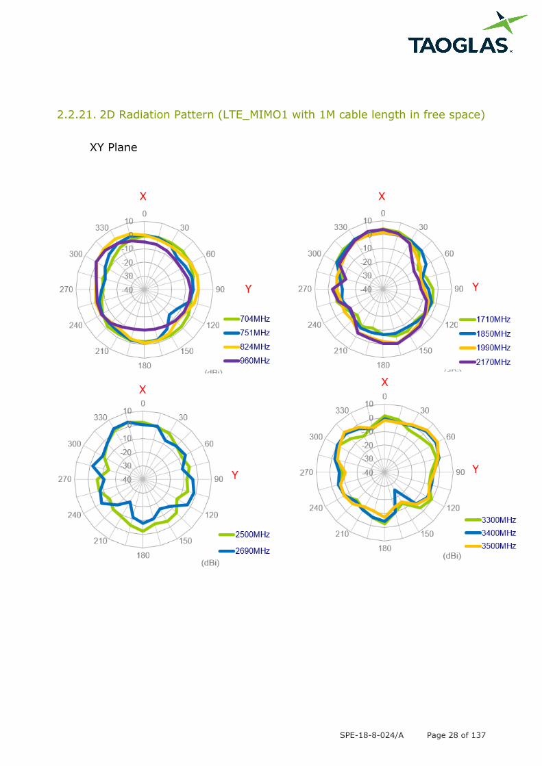
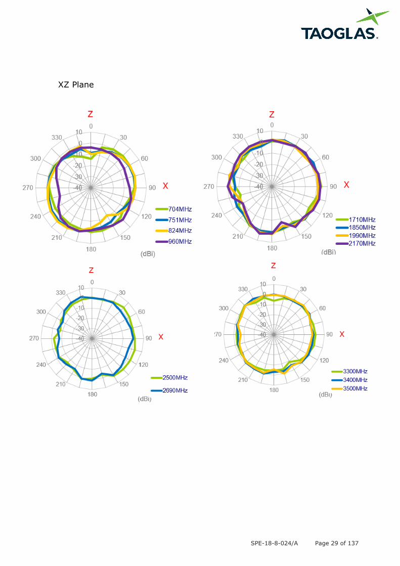
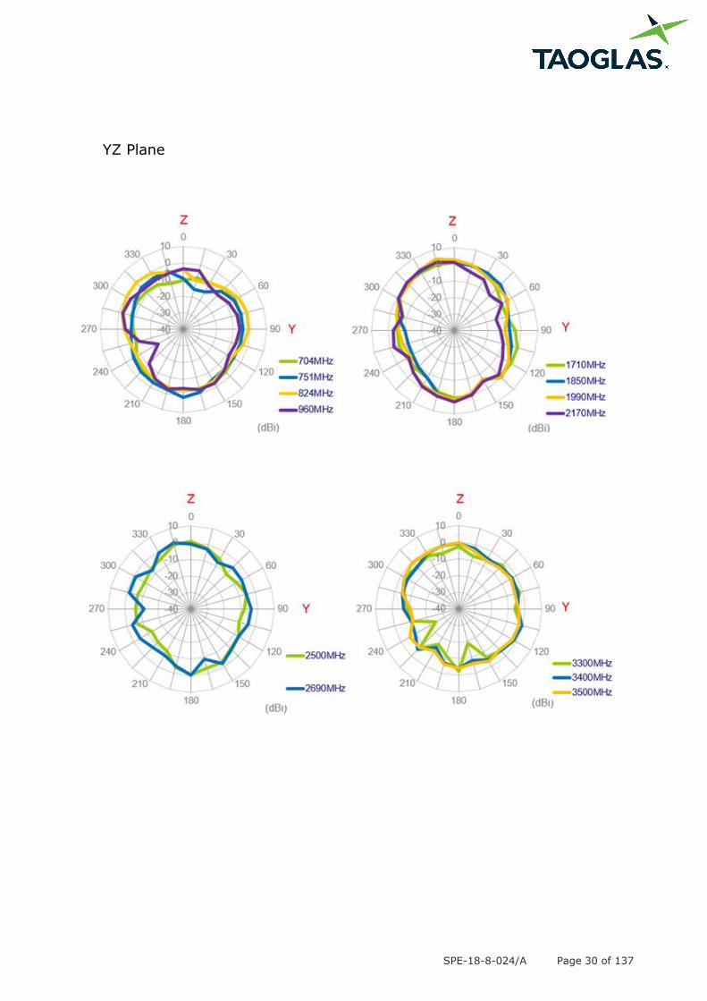
2.2.21. 2D Radiation Pattern (LTE_MIMO1 with 1M cable length in free space)
XY Plane
SPE-18-8-024/A Page 29 of 137
XZ Plane
SPE-18-8-024/A Page 30 of 137
YZ Plane
SPE-18-8-024/A Page 31 of 137
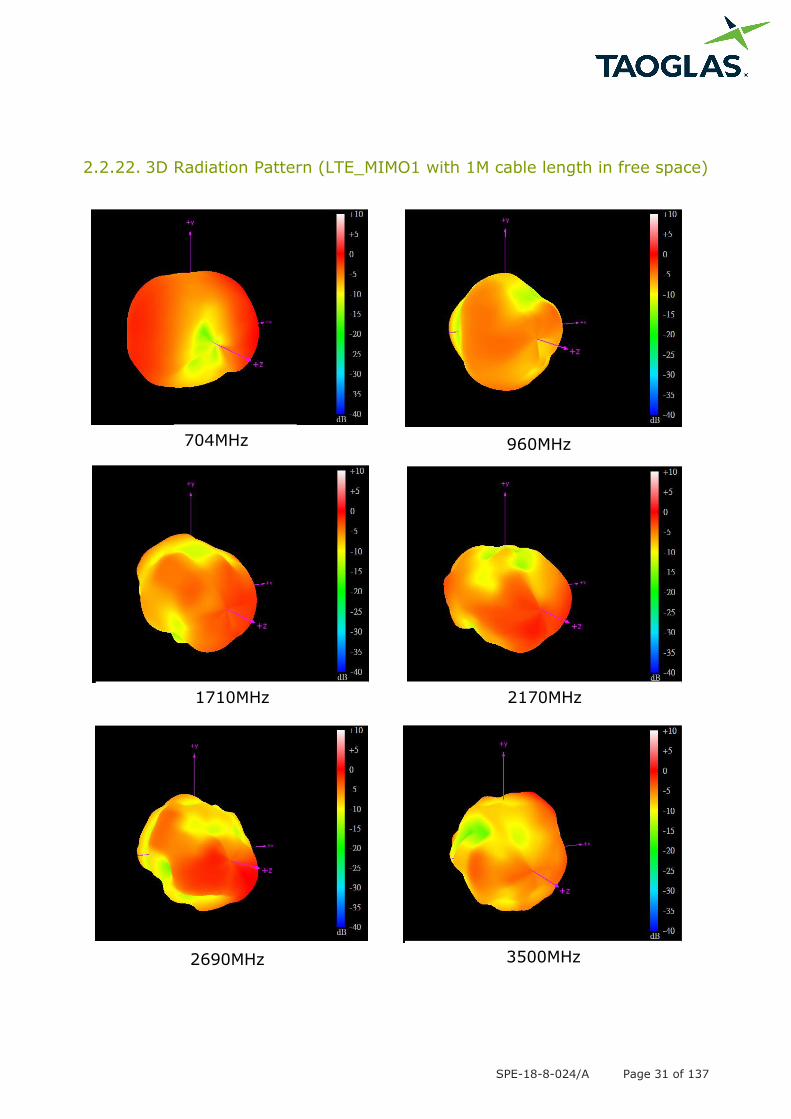
2.2.22. 3D Radiation Pattern (LTE_MIMO1 with 1M cable length in free space)
704MHz 960MHz
1710MHz 2170MHz
2690MHz 3500MHz
SPE-18-8-024/A Page 32 of 137
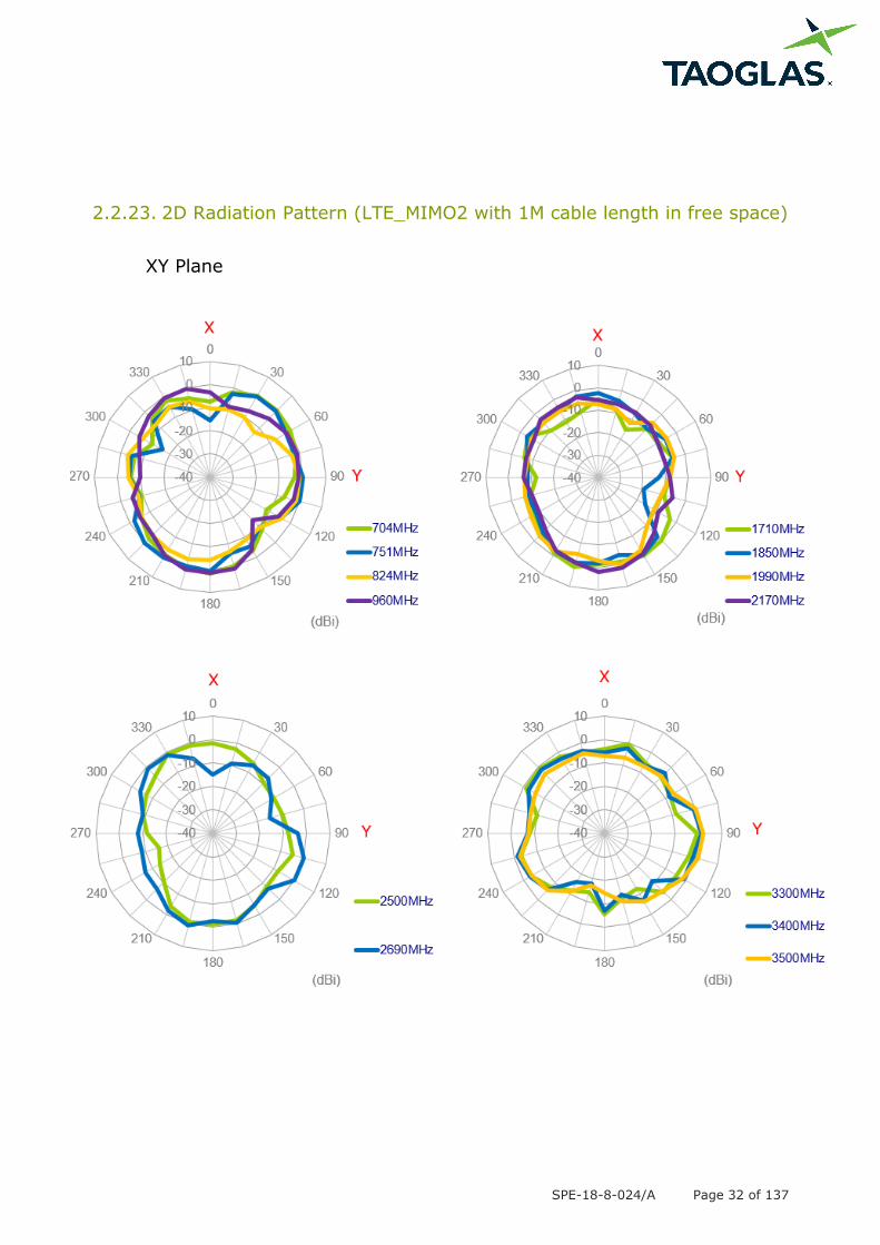
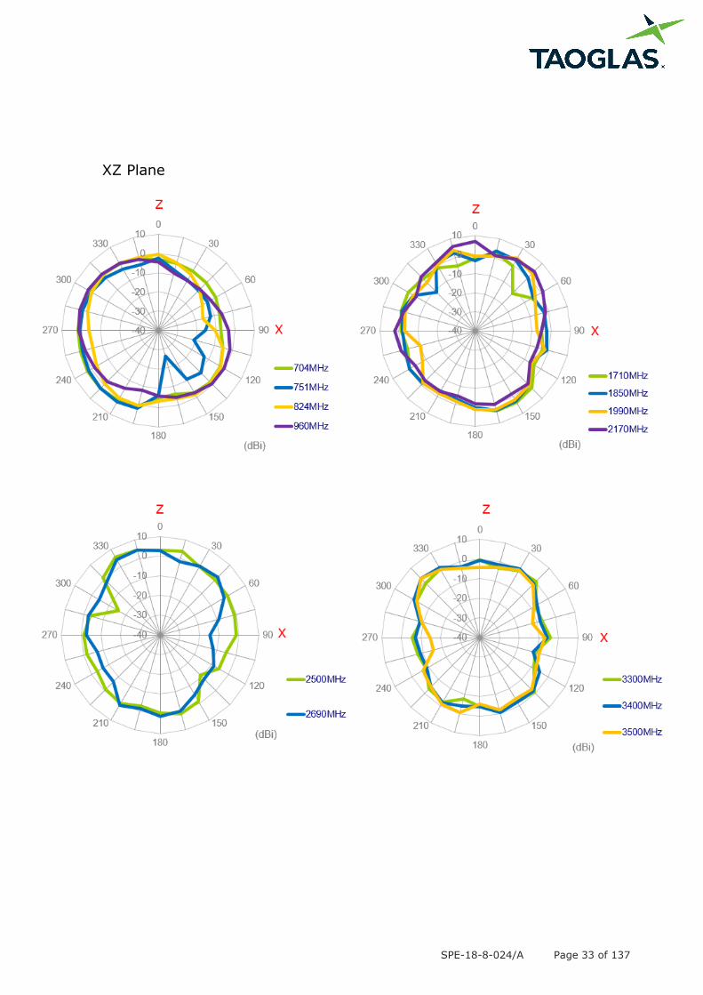
2.2.23. 2D Radiation Pattern (LTE_MIMO2 with 1M cable length in free space)
XY Plane
SPE-18-8-024/A Page 33 of 137
XZ Plane

SPE-18-8-024/A Page 34 of 137
YZ Plane

SPE-18-8-024/A Page 35 of 137
3.2.24 3D Radiation Pattern (LTE_MIMO2 with 1M cable length in free
space)
704MHz 960MHz
1710MHz 2170MHz
2690MHz 3500MHz
SPE-18-8-024/A Page 36 of 137
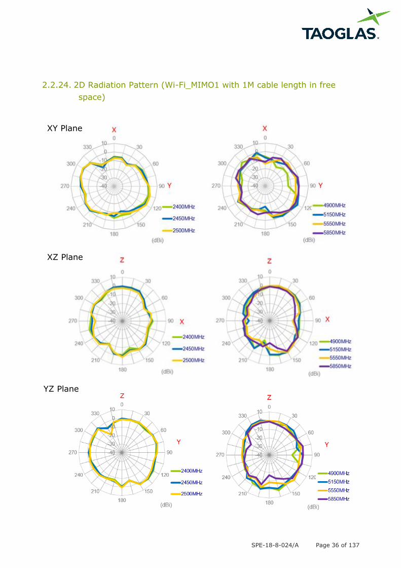
2.2.24. 2D Radiation Pattern (Wi-Fi_MIMO1 with 1M cable length in free
space)
XY Plane
XZ Plane
YZ Plane
SPE-18-8-024/A Page 37 of 137
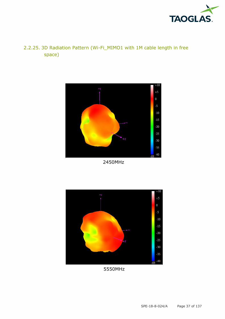
2.2.25. 3D Radiation Pattern (Wi-Fi_MIMO1 with 1M cable length in free
space)
2450MHz
5550MHz
SPE-18-8-024/A Page 38 of 137
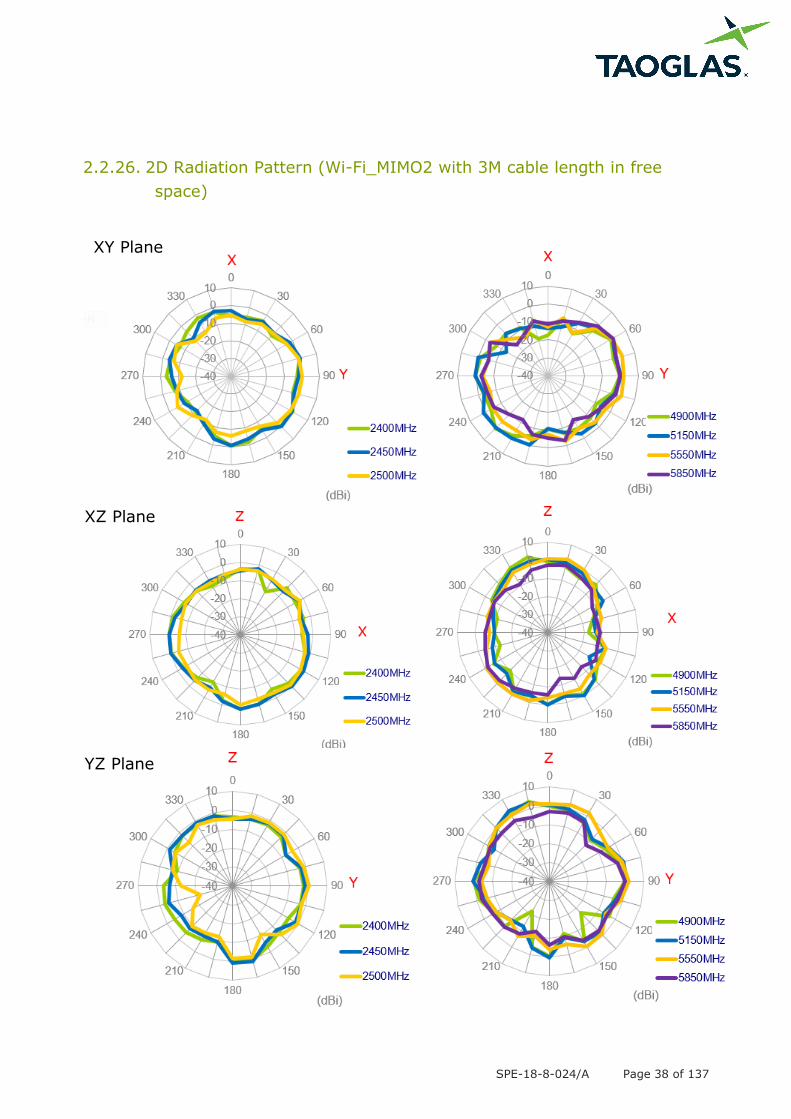
2.2.26. 2D Radiation Pattern (Wi-Fi_MIMO2 with 3M cable length in free
space)
XY Plane
XZ Plane
YZ Plane
SPE-18-8-024/A Page 39 of 137
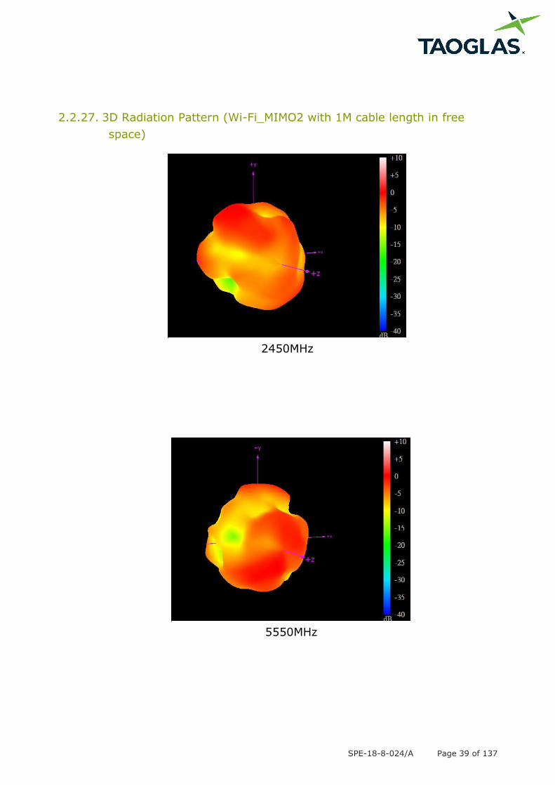
2.2.27. 3D Radiation Pattern (Wi-Fi_MIMO2 with 1M cable length in free
space)
2450MHz
5550MHz
SPE-18-8-024/A Page 40 of 137
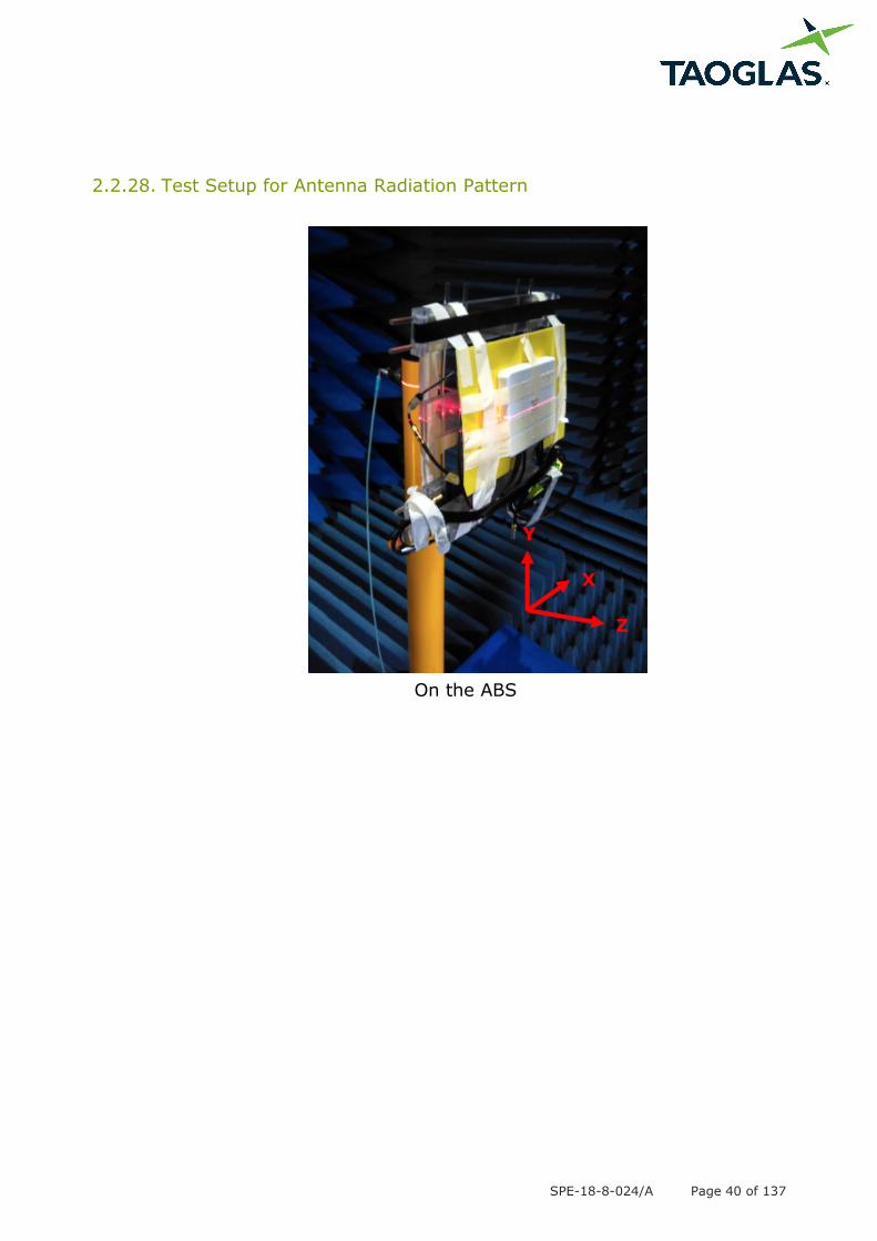
2.2.28. Test Setup for Antenna Radiation Pattern
On the ABS
Y
Z
X
SPE-18-8-024/A Page 41 of 137
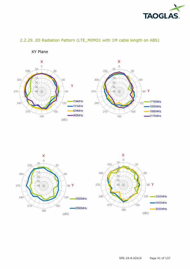
2.2.29. 2D Radiation Pattern (LTE_MIMO1 with 1M cable length on ABS)
XY Plane
SPE-18-8-024/A Page 42 of 137
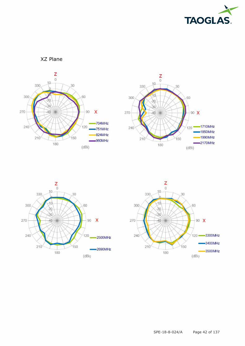
XZ Plane
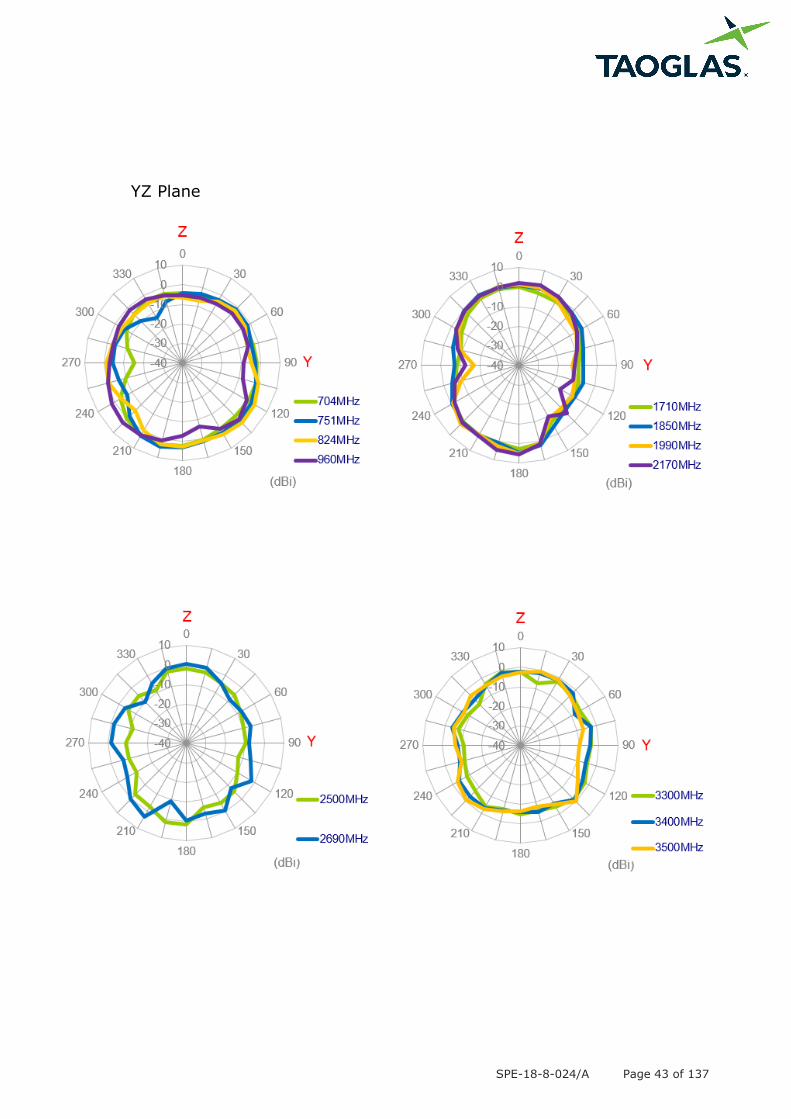
SPE-18-8-024/A Page 43 of 137
YZ Plane
SPE-18-8-024/A Page 44 of 137
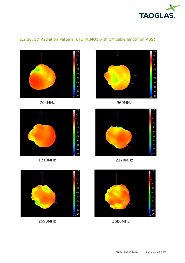
2.2.30. 3D Radiation Pattern (LTE_MIMO1 with 1M cable length on ABS)
704MHz 960MHz
1710MHz 2170MHz
2690MHz 3500MHz
SPE-18-8-024/A Page 45 of 137
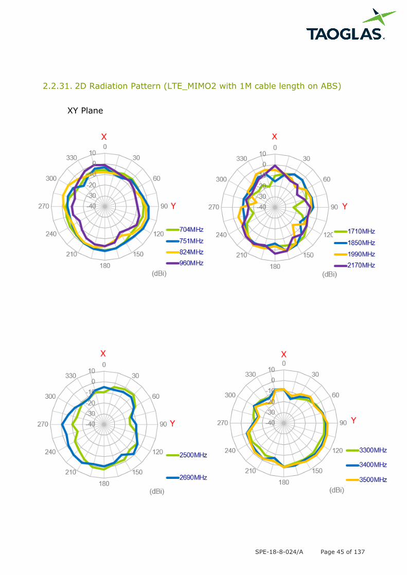
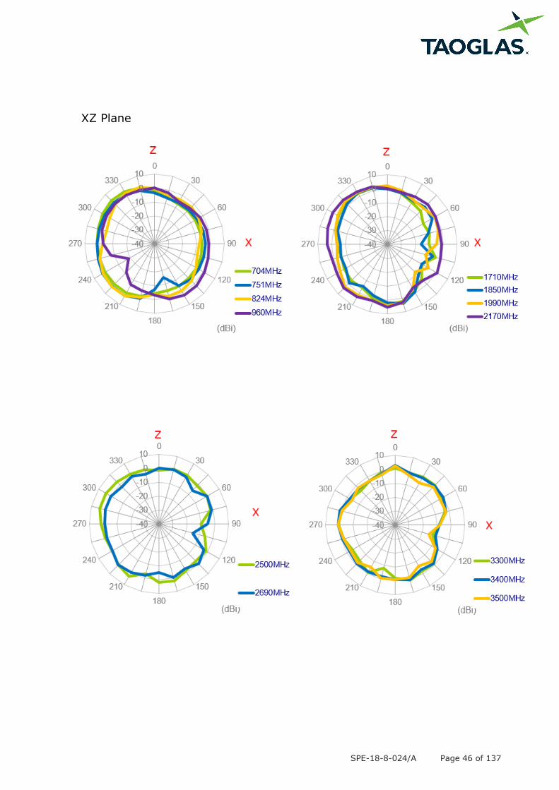
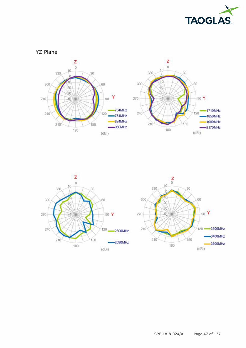
2.2.31. 2D Radiation Pattern (LTE_MIMO2 with 1M cable length on ABS)
XY Plane
SPE-18-8-024/A Page 46 of 137
XZ Plane
SPE-18-8-024/A Page 47 of 137
YZ Plane

SPE-18-8-024/A Page 48 of 137
2.2.32. 3D Radiation Pattern (LTE_MIMO2 with 1M cable length on ABS)
704MHz 960MHz
1710MHz 2170MHz
2690MHz 3500MHz
SPE-18-8-024/A Page 49 of 137
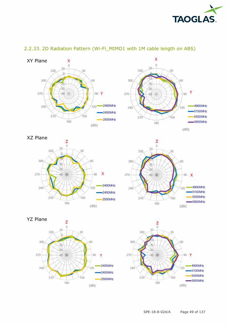
2.2.33. 2D Radiation Pattern (Wi-Fi_MIMO1 with 1M cable length on ABS)
XY Plane
XZ Plane
YZ Plane
SPE-18-8-024/A Page 50 of 137
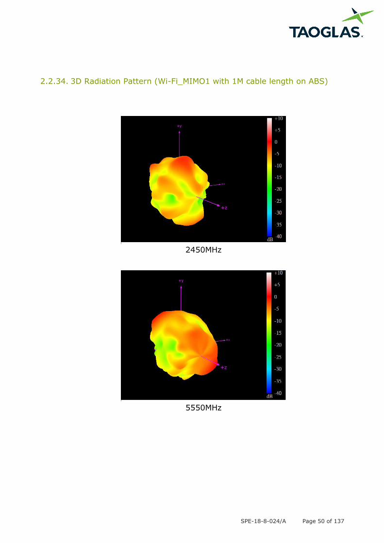
2.2.34. 3D Radiation Pattern (Wi-Fi_MIMO1 with 1M cable length on ABS)
2450MHz
5550MHz
SPE-18-8-024/A Page 51 of 137
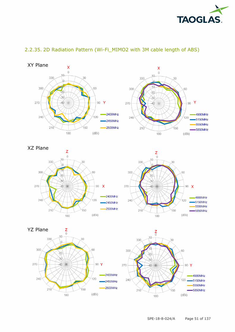
2.2.35. 2D Radiation Pattern (Wi-Fi_MIMO2 with 3M cable length of ABS)
XY Plane
XZ Plane
YZ Plane
SPE-18-8-024/A Page 52 of 137
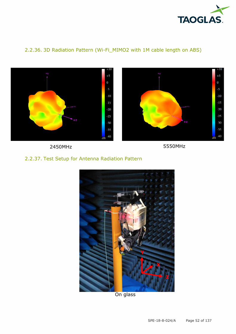
2.2.36. 3D Radiation Pattern (Wi-Fi_MIMO2 with 1M cable length on ABS)
2.2.37. Test Setup for Antenna Radiation Pattern
On glass
Y
Z
X
2450MHz 5550MHz
SPE-18-8-024/A Page 53 of 137
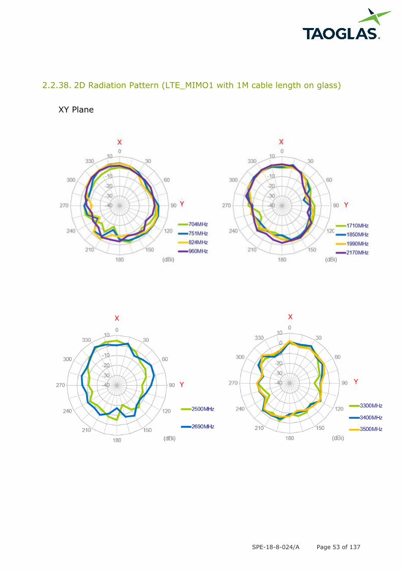
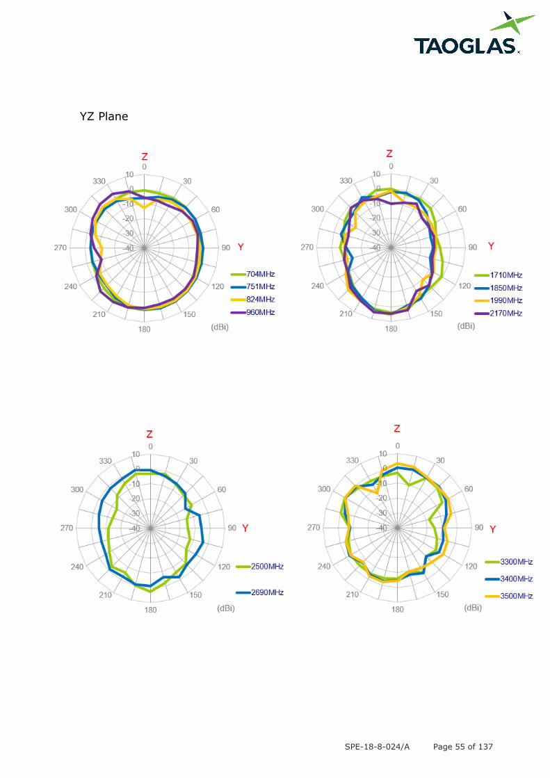
2.2.38. 2D Radiation Pattern (LTE_MIMO1 with 1M cable length on glass)
XY Plane

SPE-18-8-024/A Page 54 of 137
XZ Plane
SPE-18-8-024/A Page 55 of 137
YZ Plane
SPE-18-8-024/A Page 56 of 137
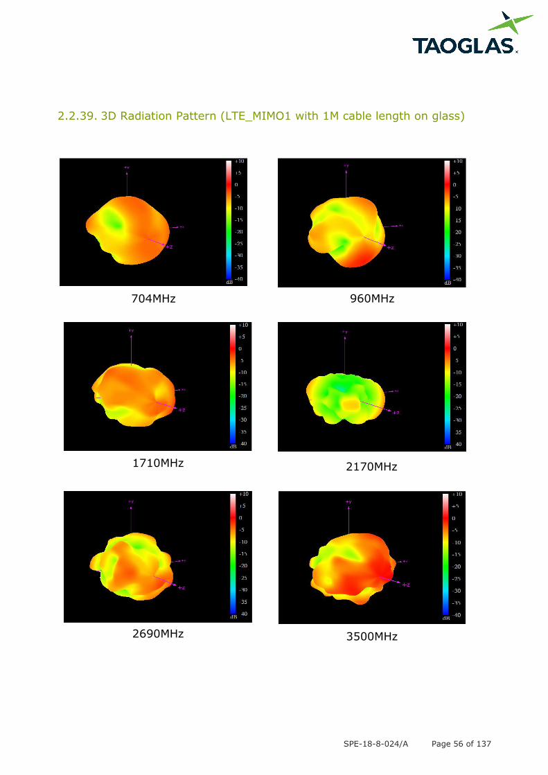
2.2.39. 3D Radiation Pattern (LTE_MIMO1 with 1M cable length on glass)
704MHz 960MHz
1710MHz 2170MHz
2690MHz 3500MHz
SPE-18-8-024/A Page 57 of 137
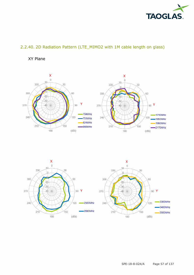
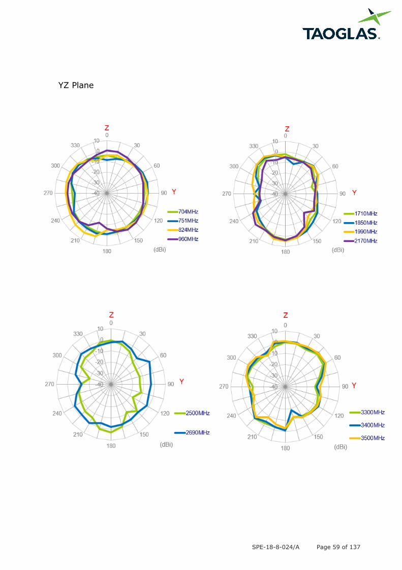
2.2.40. 2D Radiation Pattern (LTE_MIMO2 with 1M cable length on glass)
XY Plane

SPE-18-8-024/A Page 58 of 137
XZ Plane
SPE-18-8-024/A Page 59 of 137
YZ Plane
SPE-18-8-024/A Page 60 of 137
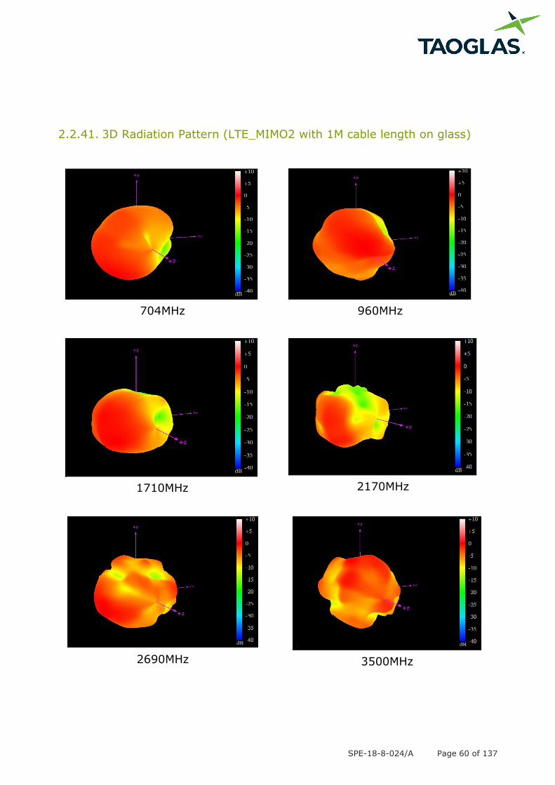
2.2.41. 3D Radiation Pattern (LTE_MIMO2 with 1M cable length on glass)
704MHz 960MHz
1710MHz 2170MHz
2690MHz 3500MHz
SPE-18-8-024/A Page 61 of 137
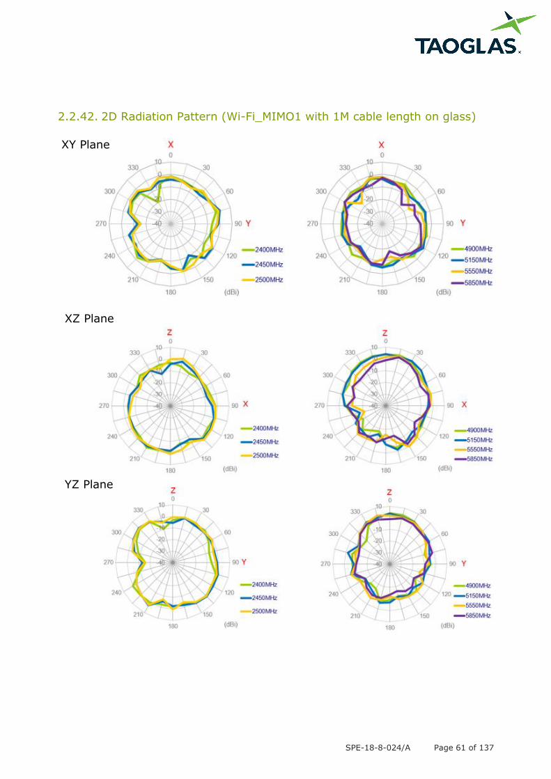
2.2.42. 2D Radiation Pattern (Wi-Fi_MIMO1 with 1M cable length on glass)
XY Plane
XZ Plane
YZ Plane

SPE-18-8-024/A Page 62 of 137
2.2.43. 3D Radiation Pattern (Wi-Fi_MIMO1 with 1M cable length on glass)
2450MHz
5550MHz
SPE-18-8-024/A Page 63 of 137
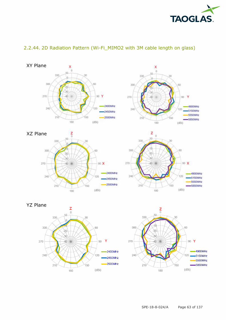
2.2.44. 2D Radiation Pattern (Wi-Fi_MIMO2 with 3M cable length on glass)
XY Plane
XZ Plane
YZ Plane
SPE-18-8-024/A Page 64 of 137
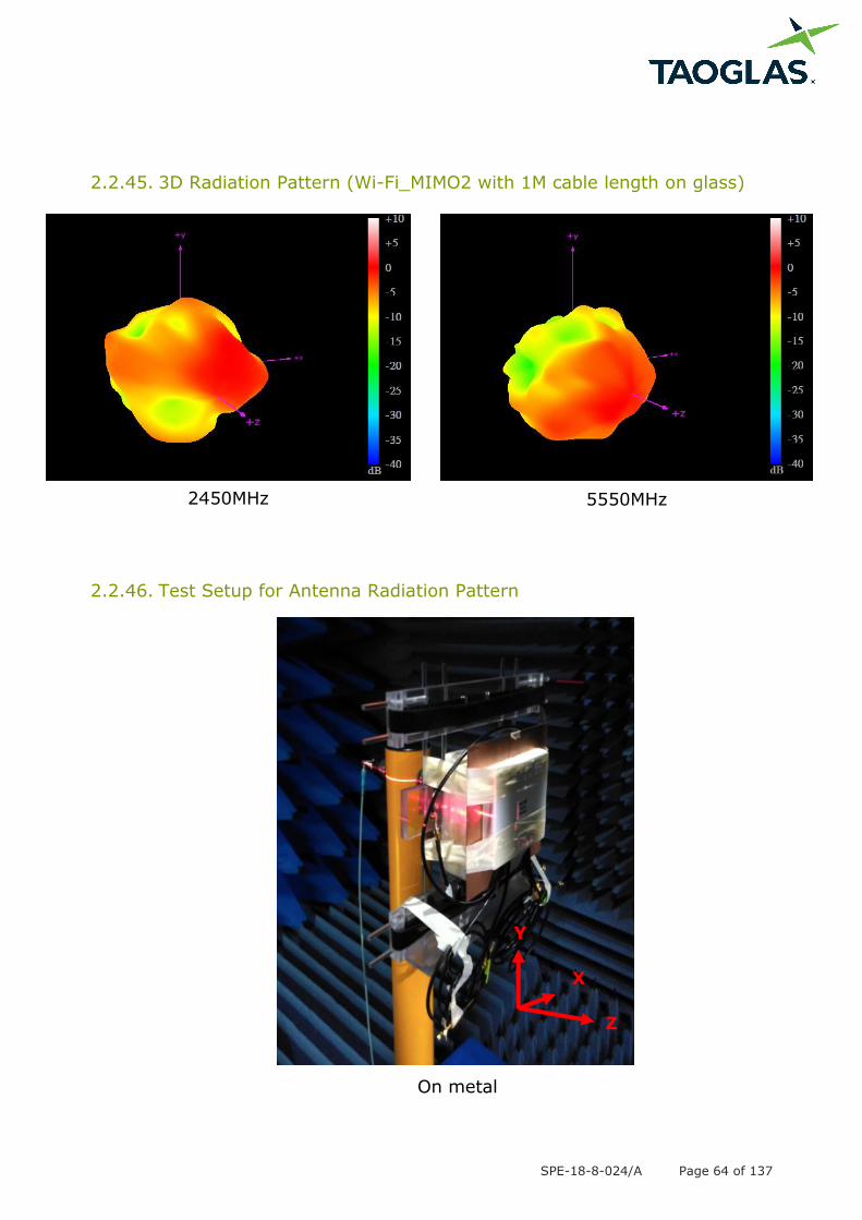
2.2.45. 3D Radiation Pattern (Wi-Fi_MIMO2 with 1M cable length on glass)
2.2.46. Test Setup for Antenna Radiation Pattern
On metal
Y
Z
X
2450MHz 5550MHz
SPE-18-8-024/A Page 65 of 137
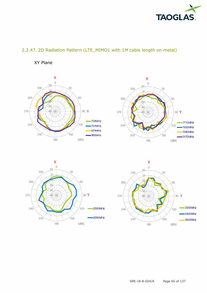
2.2.47. 2D Radiation Pattern (LTE_MIMO1 with 1M cable length on metal)
XY Plane

SPE-18-8-024/A Page 66 of 137
XZ Plane
SPE-18-8-024/A Page 67 of 137
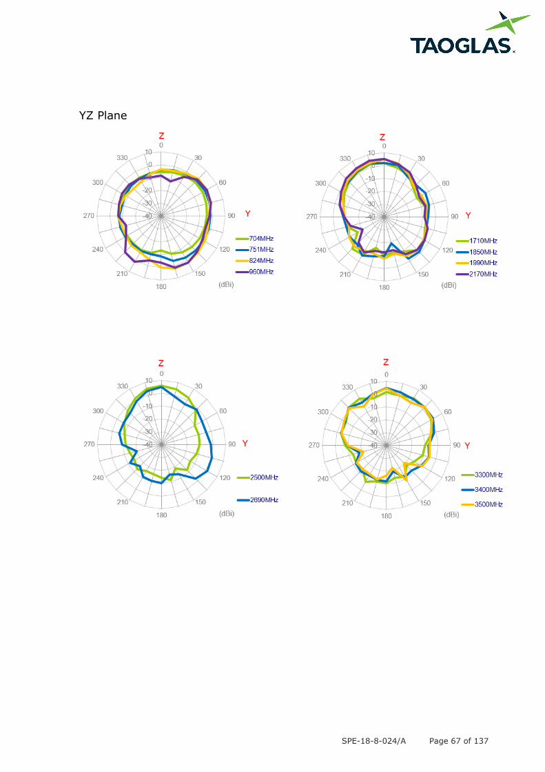
YZ Plane

SPE-18-8-024/A Page 68 of 137
2.2.48. 3D Radiation Pattern (LTE_MIMO1 with 1M cable length on metal)
704MHz 960MHz
1710MHz 2170MHz
2690MHz 3500MHz
SPE-18-8-024/A Page 69 of 137
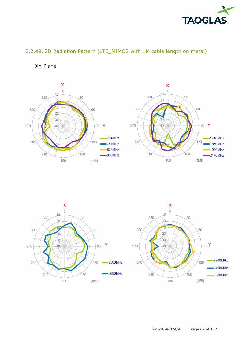
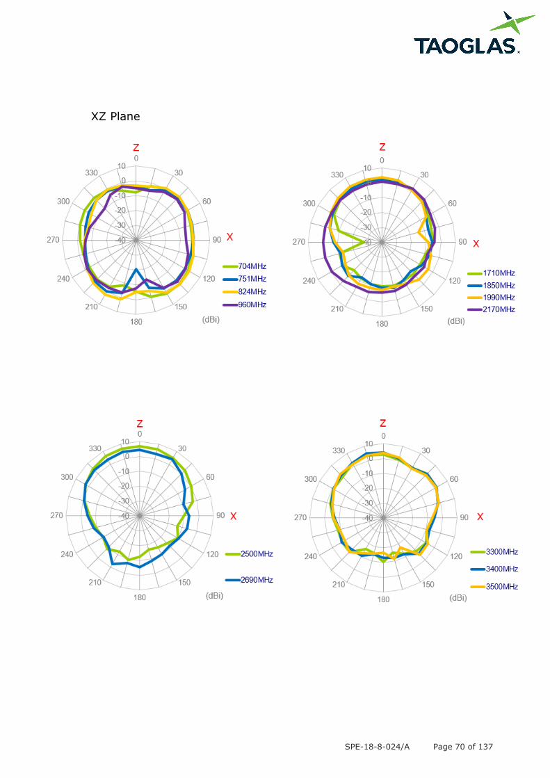
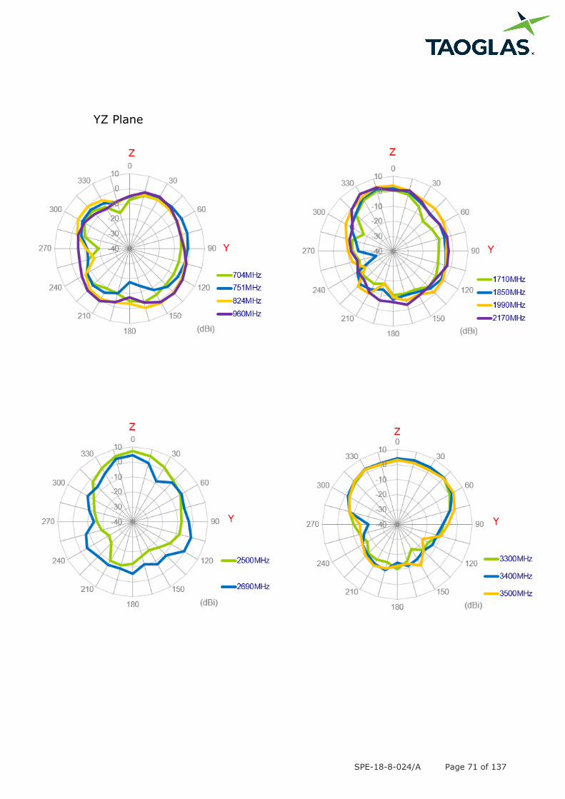
2.2.49. 2D Radiation Pattern (LTE_MIMO2 with 1M cable length on metal)
XY Plane
SPE-18-8-024/A Page 70 of 137
XZ Plane
SPE-18-8-024/A Page 71 of 137
YZ Plane
SPE-18-8-024/A Page 72 of 137
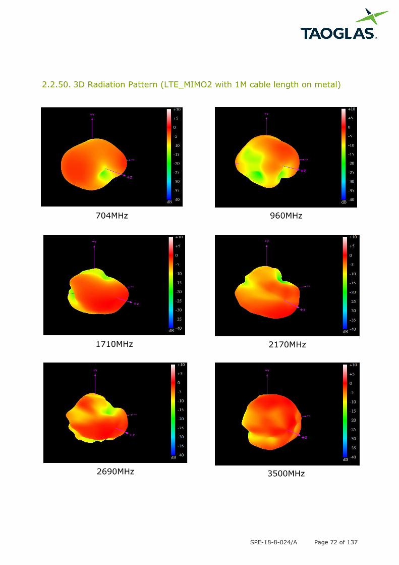
2.2.50. 3D Radiation Pattern (LTE_MIMO2 with 1M cable length on metal)
704MHz 960MHz
1710MHz 2170MHz
2690MHz 3500MHz
SPE-18-8-024/A Page 73 of 137
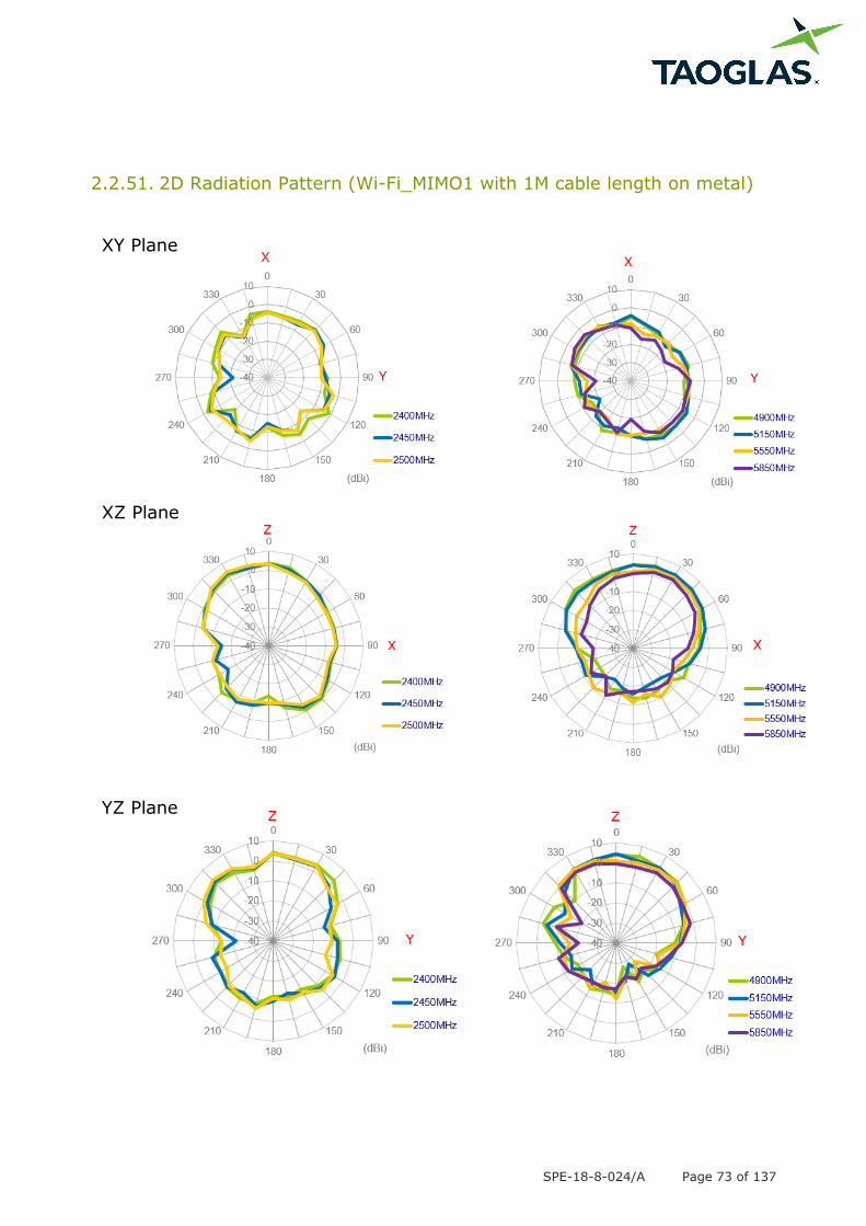
2.2.51. 2D Radiation Pattern (Wi-Fi_MIMO1 with 1M cable length on metal)
XY Plane
XZ Plane
YZ Plane
SPE-18-8-024/A Page 74 of 137
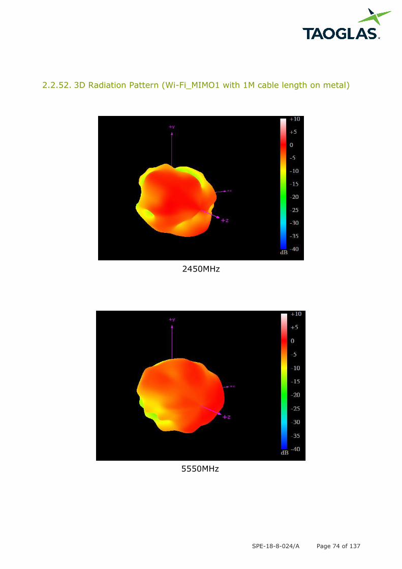
2.2.52. 3D Radiation Pattern (Wi-Fi_MIMO1 with 1M cable length on metal)
2450MHz
5550MHz
SPE-18-8-024/A Page 75 of 137
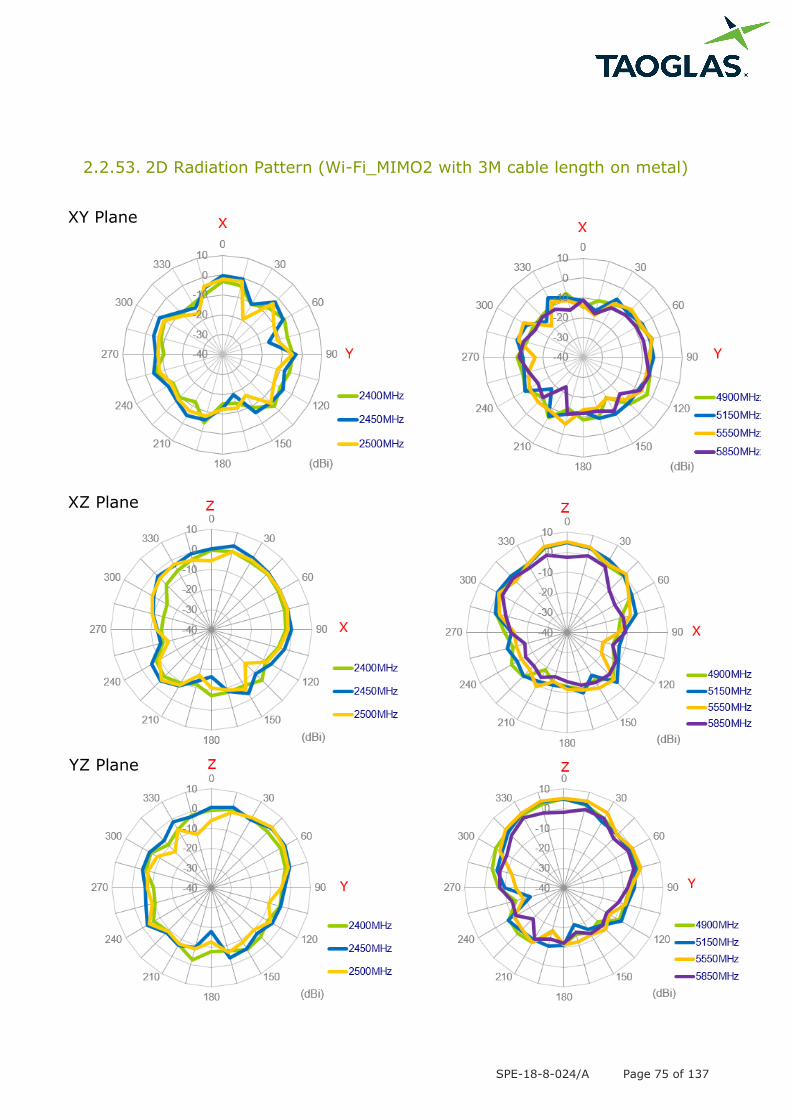
2.2.53. 2D Radiation Pattern (Wi-Fi_MIMO2 with 3M cable length on metal)
XY Plane
XZ Plane
YZ Plane
SPE-18-8-024/A Page 76 of 137
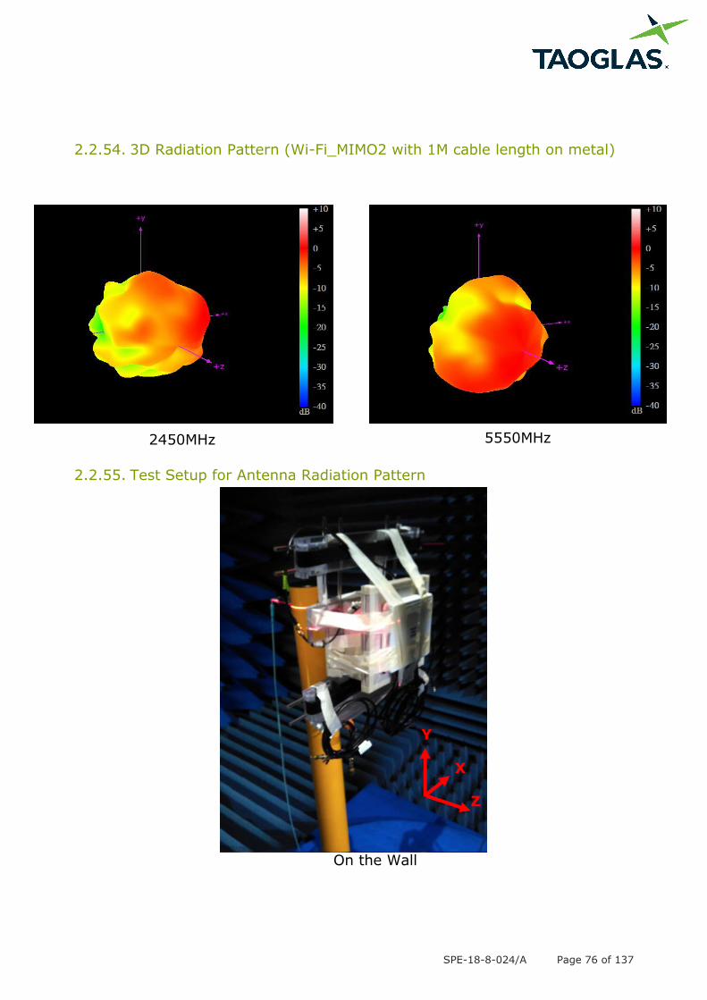
2.2.54. 3D Radiation Pattern (Wi-Fi_MIMO2 with 1M cable length on metal)
2.2.55. Test Setup for Antenna Radiation Pattern
On the Wall
Y
Z
X
2450MHz 5550MHz
SPE-18-8-024/A Page 77 of 137
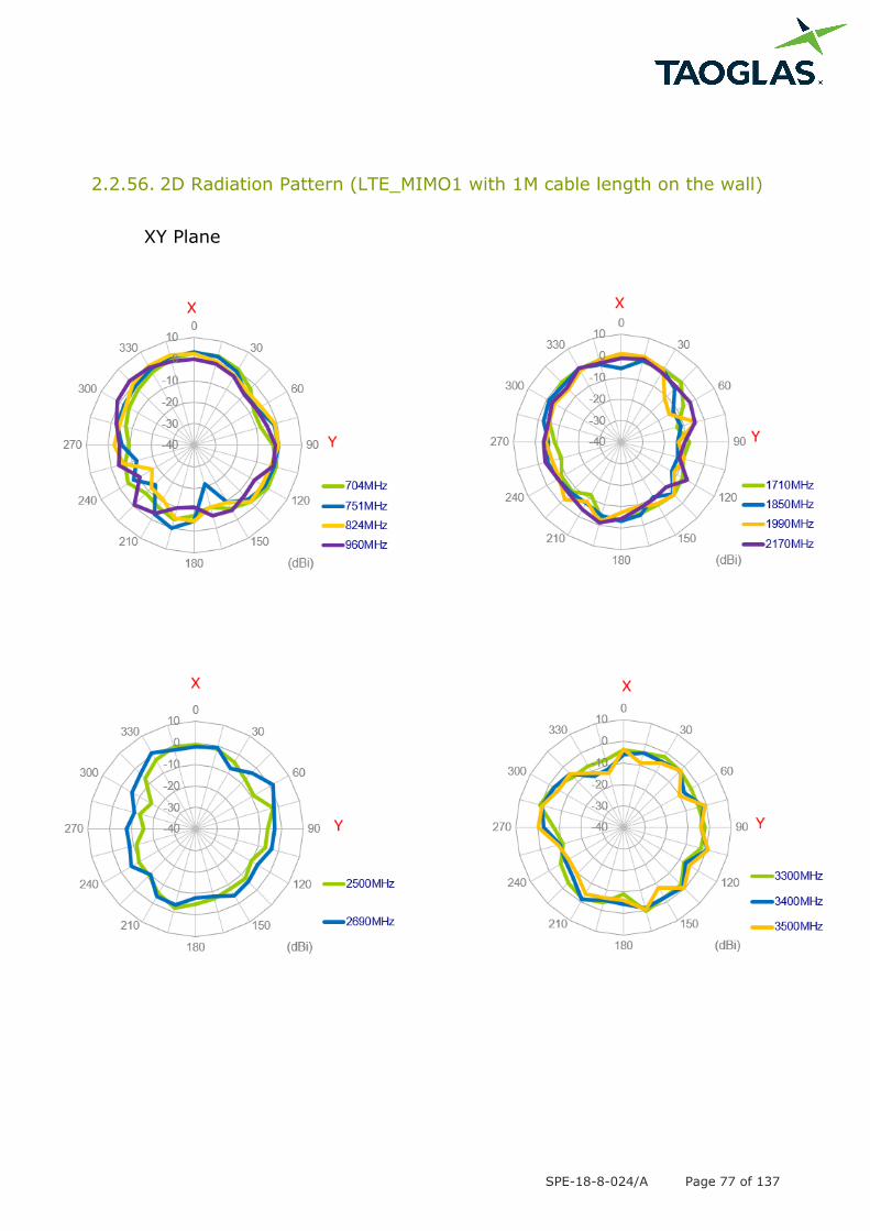
2.2.56. 2D Radiation Pattern (LTE_MIMO1 with 1M cable length on the wall)
XY Plane
SPE-18-8-024/A Page 78 of 137
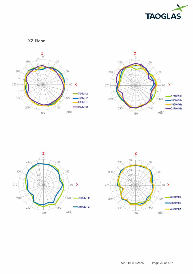
XZ Plane
SPE-18-8-024/A Page 79 of 137
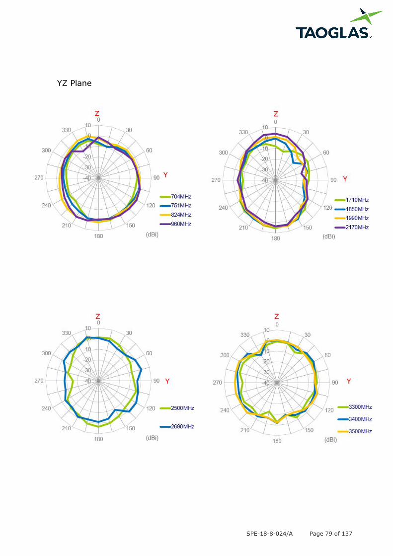
YZ Plane
SPE-18-8-024/A Page 80 of 137
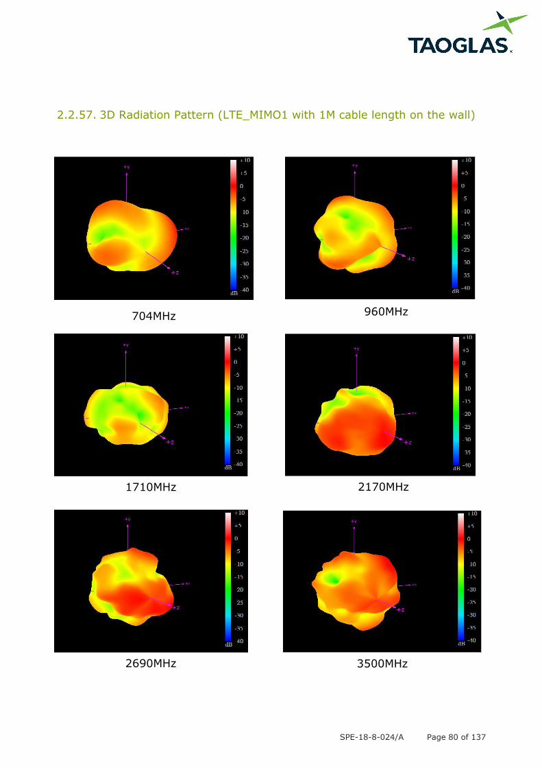
2.2.57. 3D Radiation Pattern (LTE_MIMO1 with 1M cable length on the wall)
704MHz 960MHz
1710MHz 2170MHz
2690MHz 3500MHz
SPE-18-8-024/A Page 81 of 137
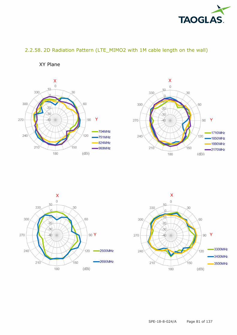
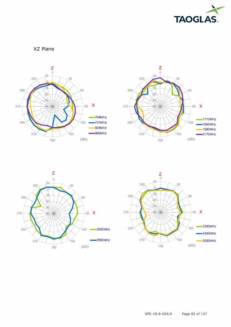
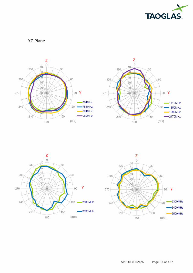
2.2.58. 2D Radiation Pattern (LTE_MIMO2 with 1M cable length on the wall)
XY Plane
SPE-18-8-024/A Page 82 of 137
XZ Plane
SPE-18-8-024/A Page 83 of 137
YZ Plane

SPE-18-8-024/A Page 84 of 137
2.2.59. 3D Radiation Pattern (LTE_MIMO2 with 1M cable length on the wall)
704MHz 960MHz
1710MHz 2170MHz
2690MHz 3500MHz
SPE-18-8-024/A Page 85 of 137
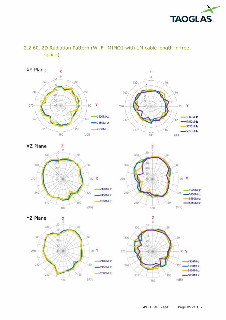
2.2.60. 2D Radiation Pattern (Wi-Fi_MIMO1 with 1M cable length in free
space)
XY Plane
XZ Plane
YZ Plane
SPE-18-8-024/A Page 86 of 137
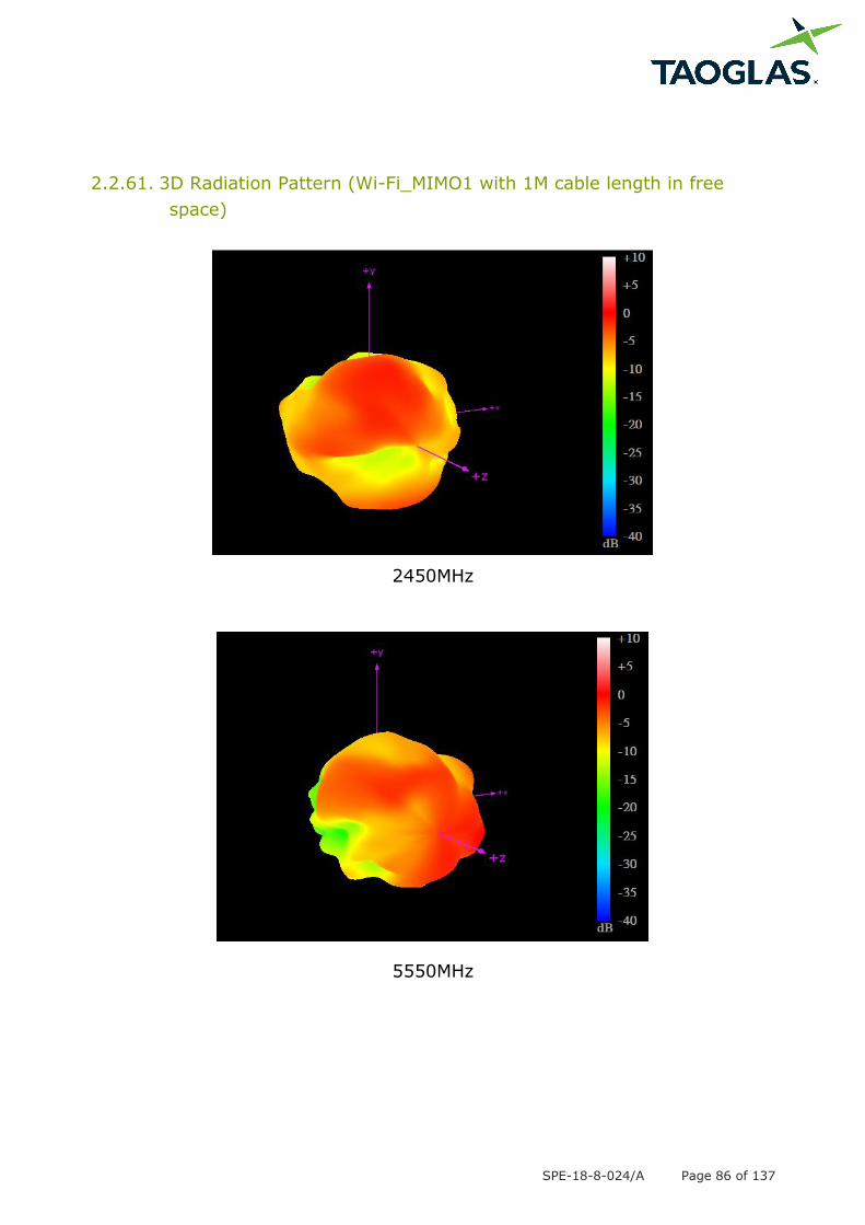
2.2.61. 3D Radiation Pattern (Wi-Fi_MIMO1 with 1M cable length in free
space)
2450MHz
5550MHz
SPE-18-8-024/A Page 87 of 137
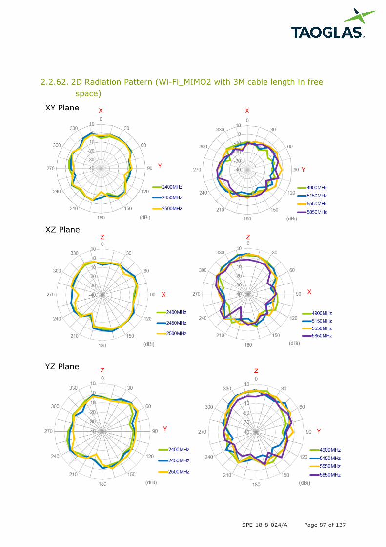
2.2.62. 2D Radiation Pattern (Wi-Fi_MIMO2 with 3M cable length in free
space)
XY Plane
XZ Plane
YZ Plane
SPE-18-8-024/A Page 88 of 137
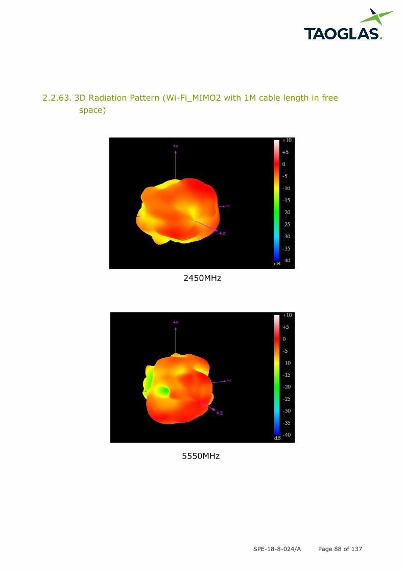
2.2.63. 3D Radiation Pattern (Wi-Fi_MIMO2 with 1M cable length in free
space)
2450MHz
5550MHz
SPE-18-8-024/A Page 89 of 137
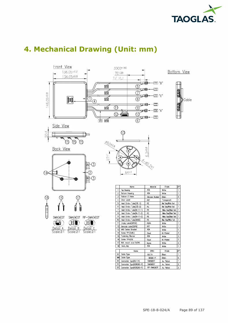
4. Mechanical Drawing (Unit: mm)
SPE-18-8-024/A Page 90 of 137
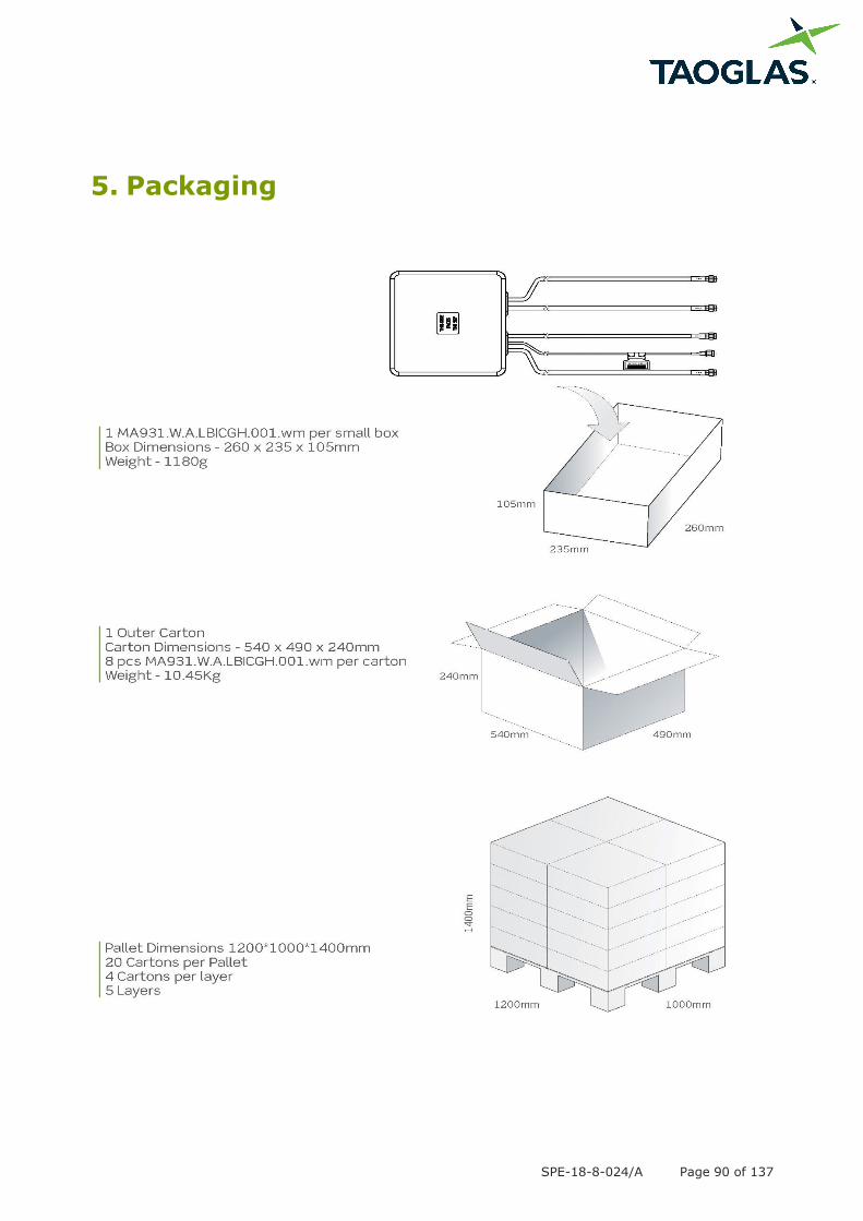
5. Packaging
SPE-18-8-024/A Page 91 of 137
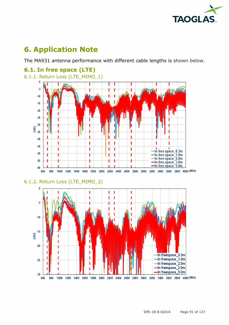
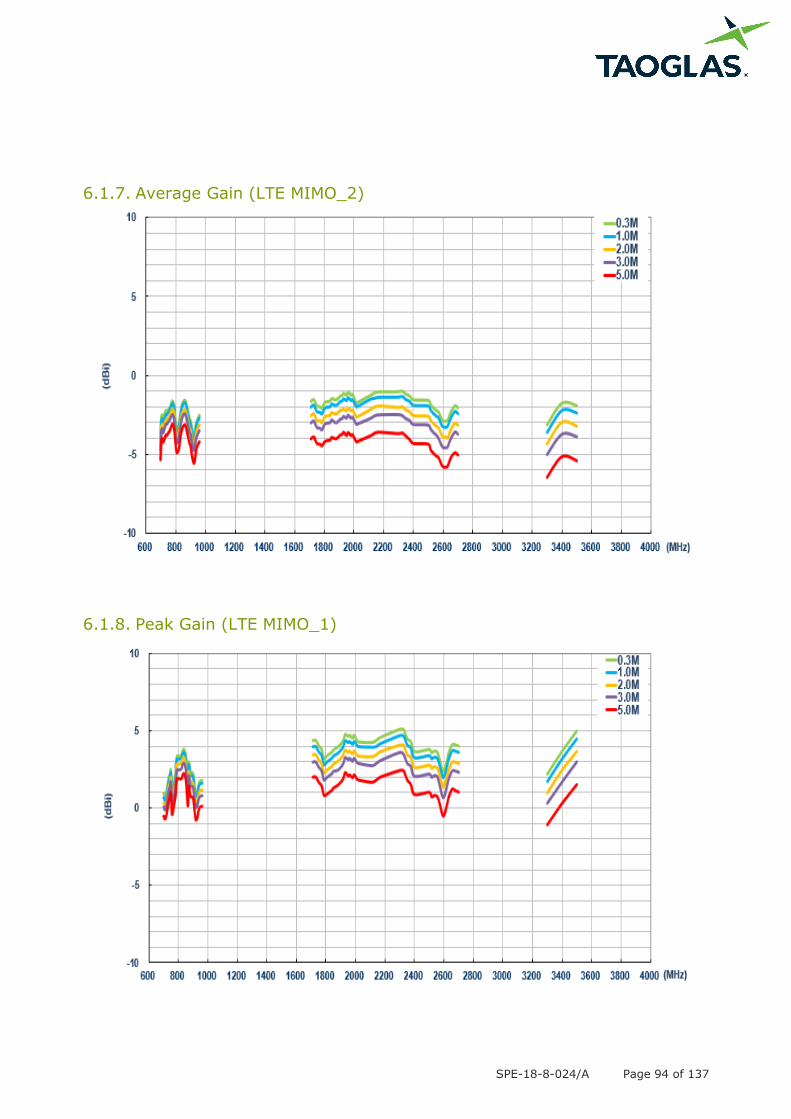
6. Application Note
The MA931 antenna performance with different cable lengths is shown below.
6.1. In free space (LTE)
6.1.1. Return Loss (LTE_MIMO_1)
6.1.2. Return Loss (LTE_MIMO_2)
SPE-18-8-024/A Page 92 of 137
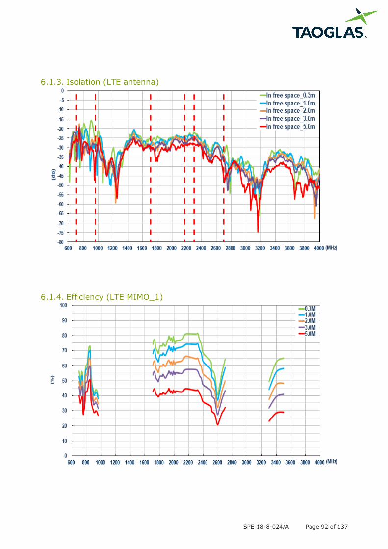
6.1.3. Isolation (LTE antenna)
6.1.4. Efficiency (LTE MIMO_1)
SPE-18-8-024/A Page 93 of 137
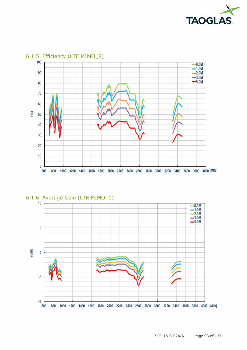
6.1.5. Efficiency (LTE MIMO_2)
6.1.6. Average Gain (LTE MIMO_1)
SPE-18-8-024/A Page 94 of 137
6.1.7. Average Gain (LTE MIMO_2)
6.1.8. Peak Gain (LTE MIMO_1)
SPE-18-8-024/A Page 95 of 137
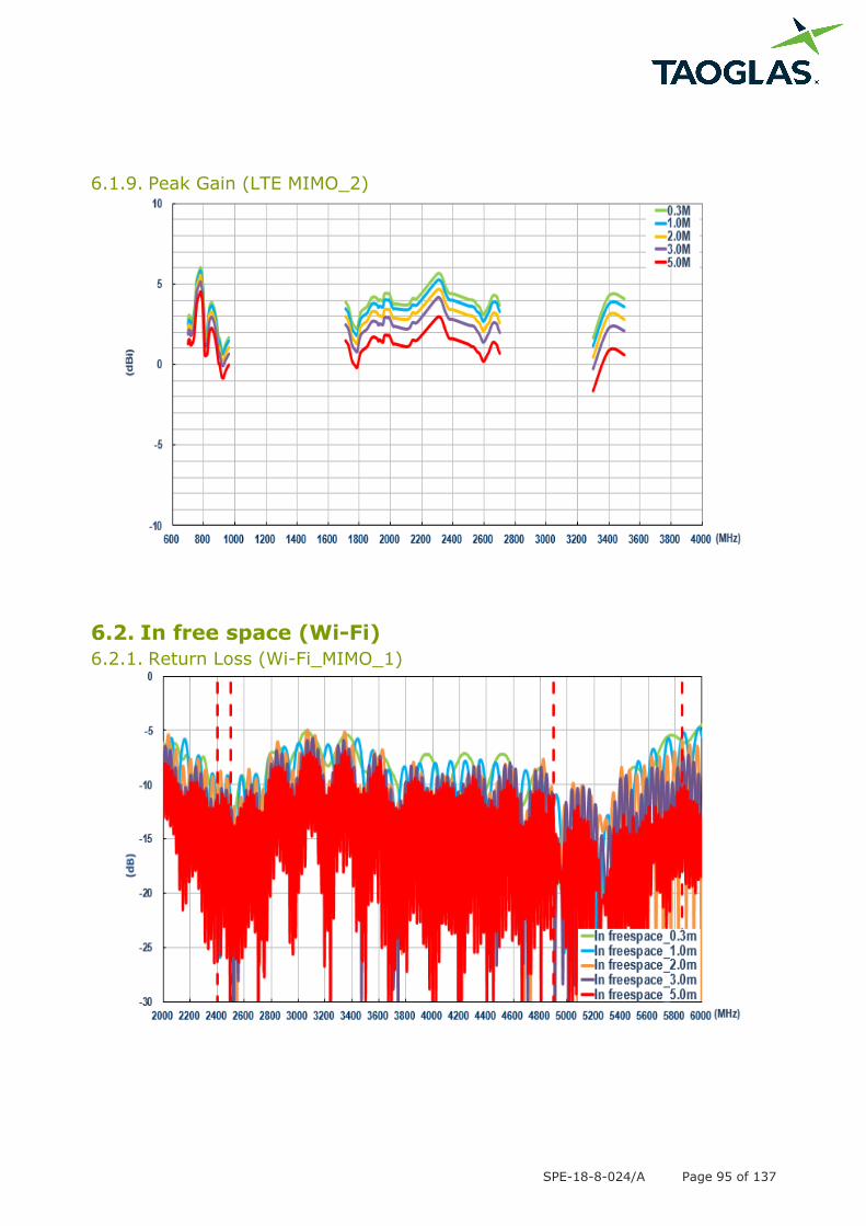
6.1.9. Peak Gain (LTE MIMO_2)
6.2. In free space (Wi-Fi)
6.2.1. Return Loss (Wi-Fi_MIMO_1)
SPE-18-8-024/A Page 96 of 137
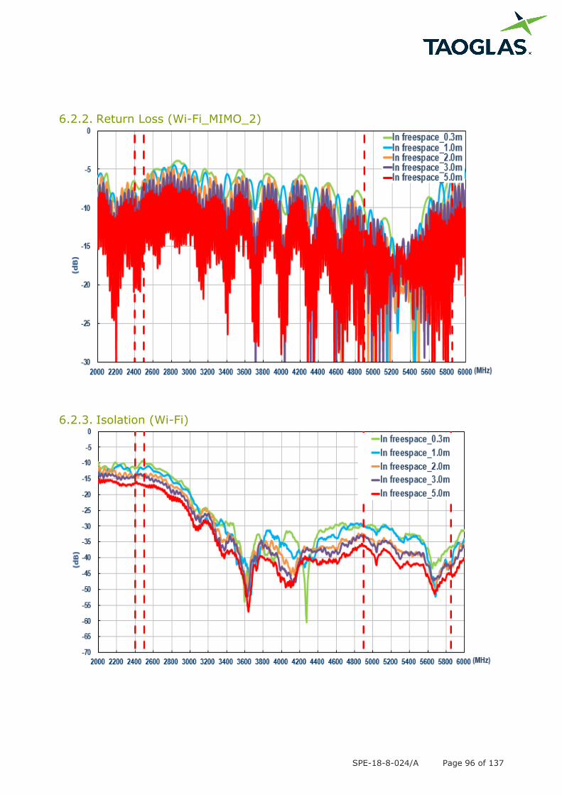
6.2.2. Return Loss (Wi-Fi_MIMO_2)
6.2.3. Isolation (Wi-Fi)
SPE-18-8-024/A Page 97 of 137
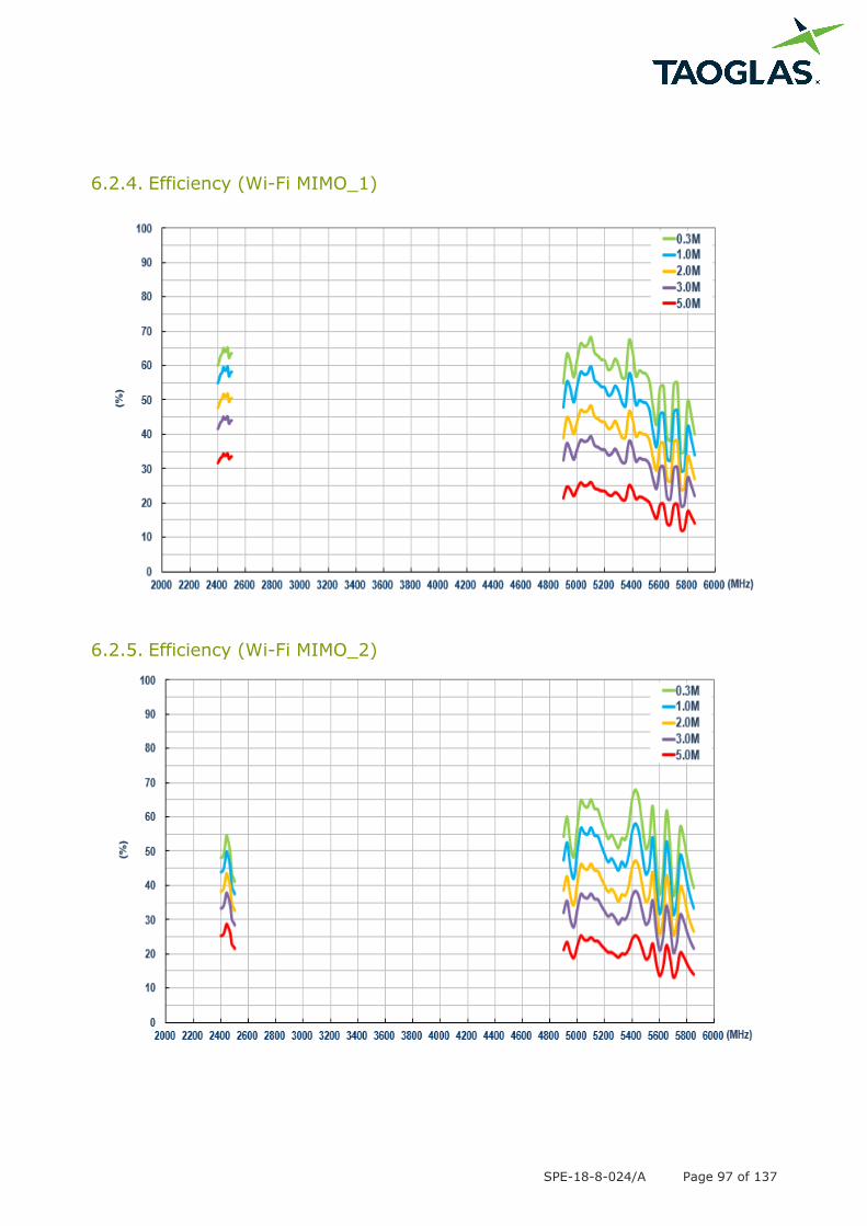
6.2.4. Efficiency (Wi-Fi MIMO_1)
6.2.5. Efficiency (Wi-Fi MIMO_2)
SPE-18-8-024/A Page 98 of 137
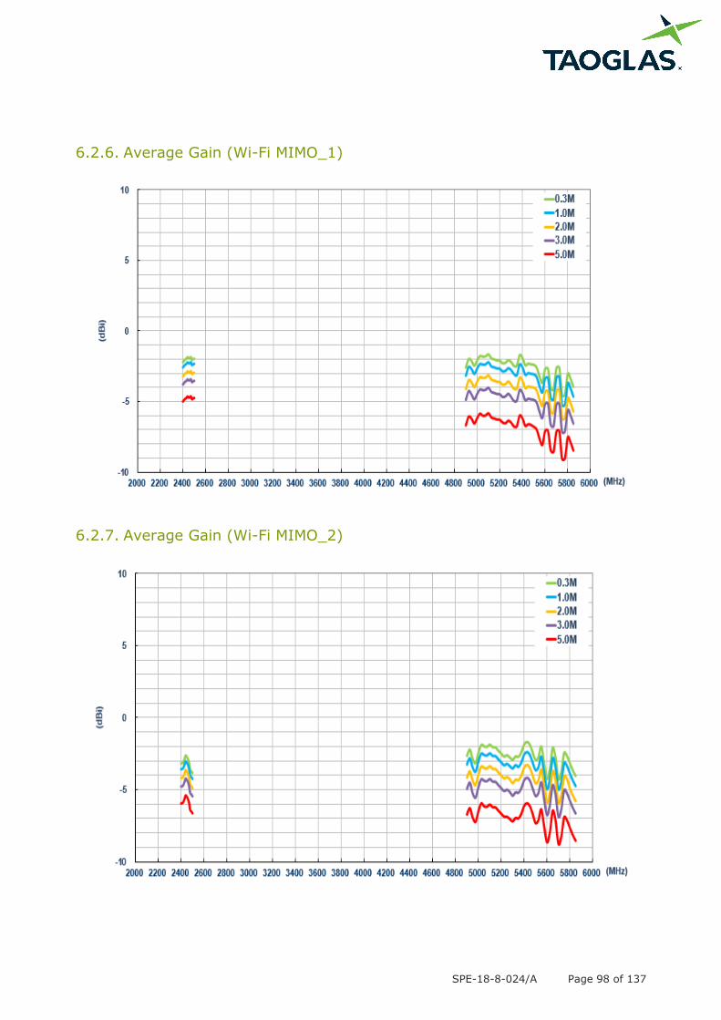
6.2.6. Average Gain (Wi-Fi MIMO_1)
6.2.7. Average Gain (Wi-Fi MIMO_2)
SPE-18-8-024/A Page 99 of 137
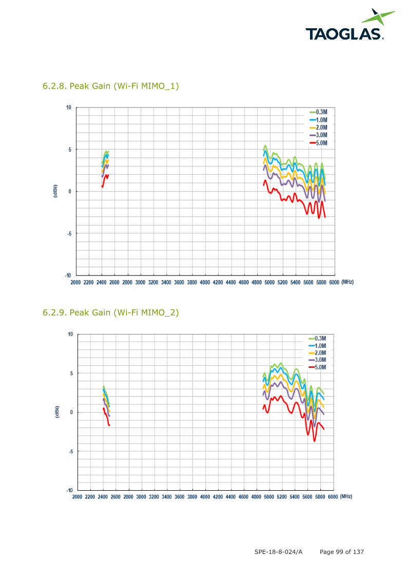
6.2.8. Peak Gain (Wi-Fi MIMO_1)
6.2.9. Peak Gain (Wi-Fi MIMO_2)

SPE-18-8-024/A Page 100 of 137
6.3. On the ABS (LTE)
6.3.1. Return Loss (LTE_MIMO_1)
6.3.2. Return Loss (LTE_MIMO_2)
SPE-18-8-024/A Page 101 of 137
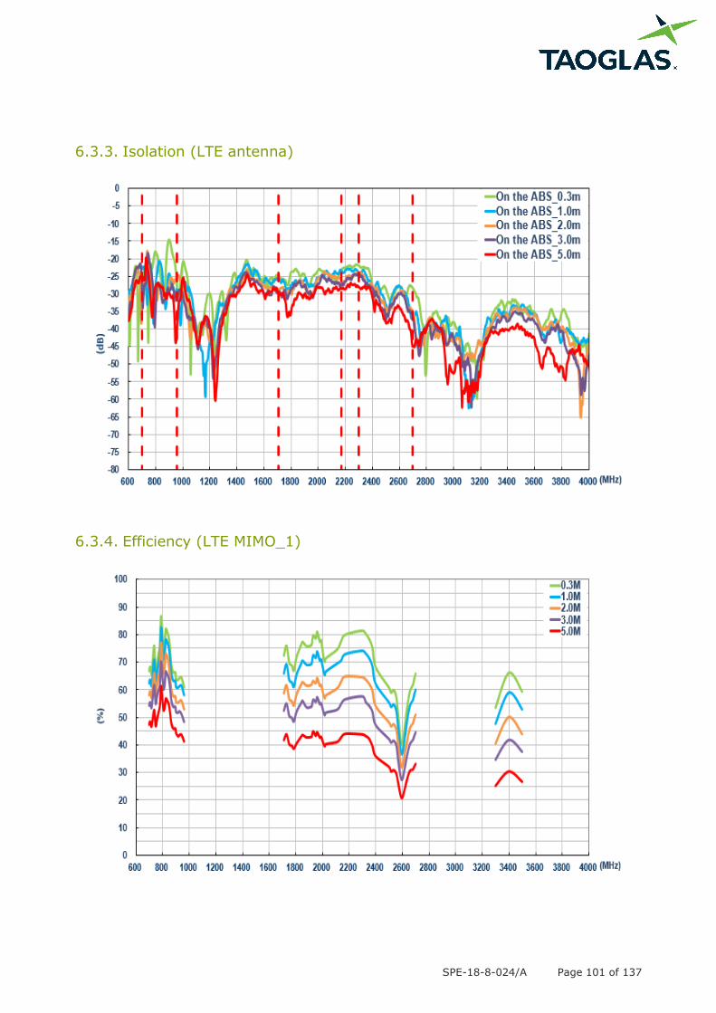
6.3.3. Isolation (LTE antenna)
6.3.4. Efficiency (LTE MIMO_1)
SPE-18-8-024/A Page 102 of 137
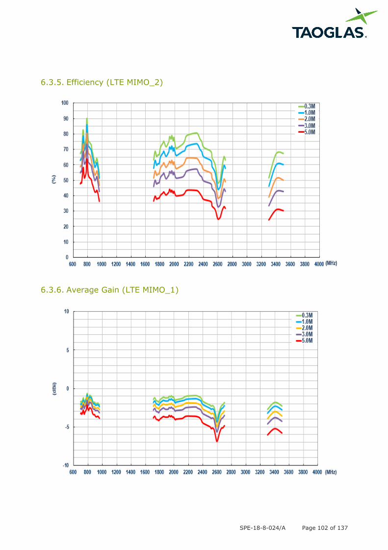
6.3.5. Efficiency (LTE MIMO_2)
6.3.6. Average Gain (LTE MIMO_1)
SPE-18-8-024/A Page 103 of 137
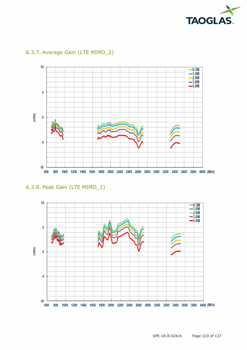
6.3.7. Average Gain (LTE MIMO_2)
6.3.8. Peak Gain (LTE MIMO_1)
SPE-18-8-024/A Page 104 of 137
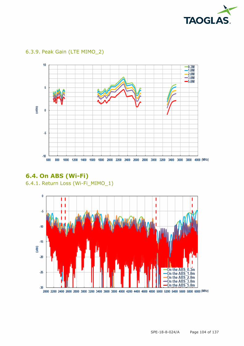
6.3.9. Peak Gain (LTE MIMO_2)
6.4. On ABS (Wi-Fi)
6.4.1. Return Loss (Wi-Fi_MIMO_1)
SPE-18-8-024/A Page 105 of 137
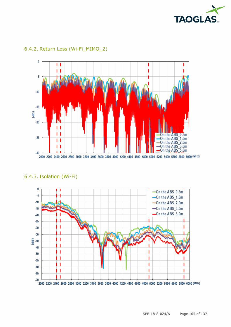
6.4.2. Return Loss (Wi-Fi_MIMO_2)
6.4.3. Isolation (Wi-Fi)
SPE-18-8-024/A Page 106 of 137
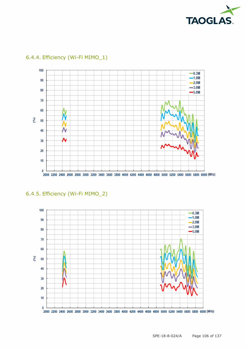
6.4.4. Efficiency (Wi-Fi MIMO_1)
6.4.5. Efficiency (Wi-Fi MIMO_2)
SPE-18-8-024/A Page 107 of 137
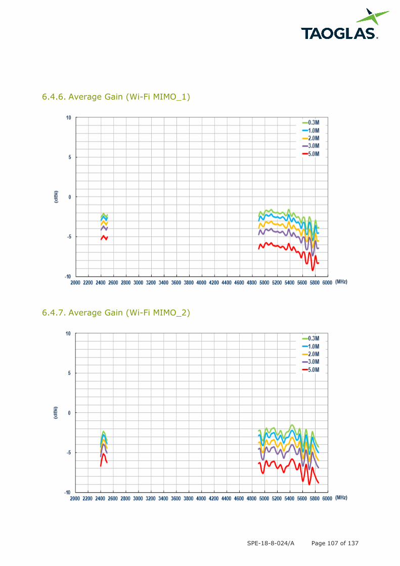
6.4.6. Average Gain (Wi-Fi MIMO_1)
6.4.7. Average Gain (Wi-Fi MIMO_2)
SPE-18-8-024/A Page 108 of 137
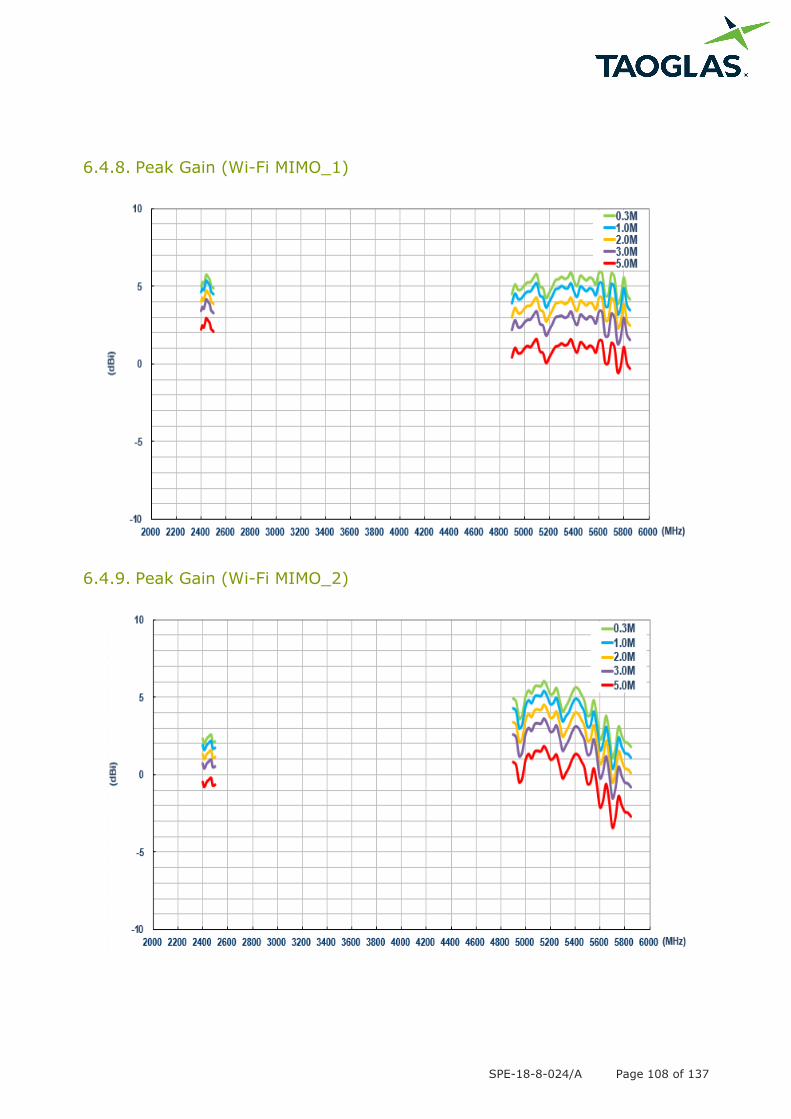
6.4.8. Peak Gain (Wi-Fi MIMO_1)
6.4.9. Peak Gain (Wi-Fi MIMO_2)
SPE-18-8-024/A Page 109 of 137
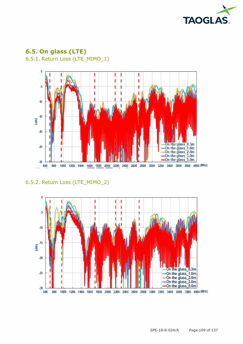
6.5. On glass (LTE)
6.5.1. Return Loss (LTE_MIMO_1)
6.5.2. Return Loss (LTE_MIMO_2)
SPE-18-8-024/A Page 110 of 137
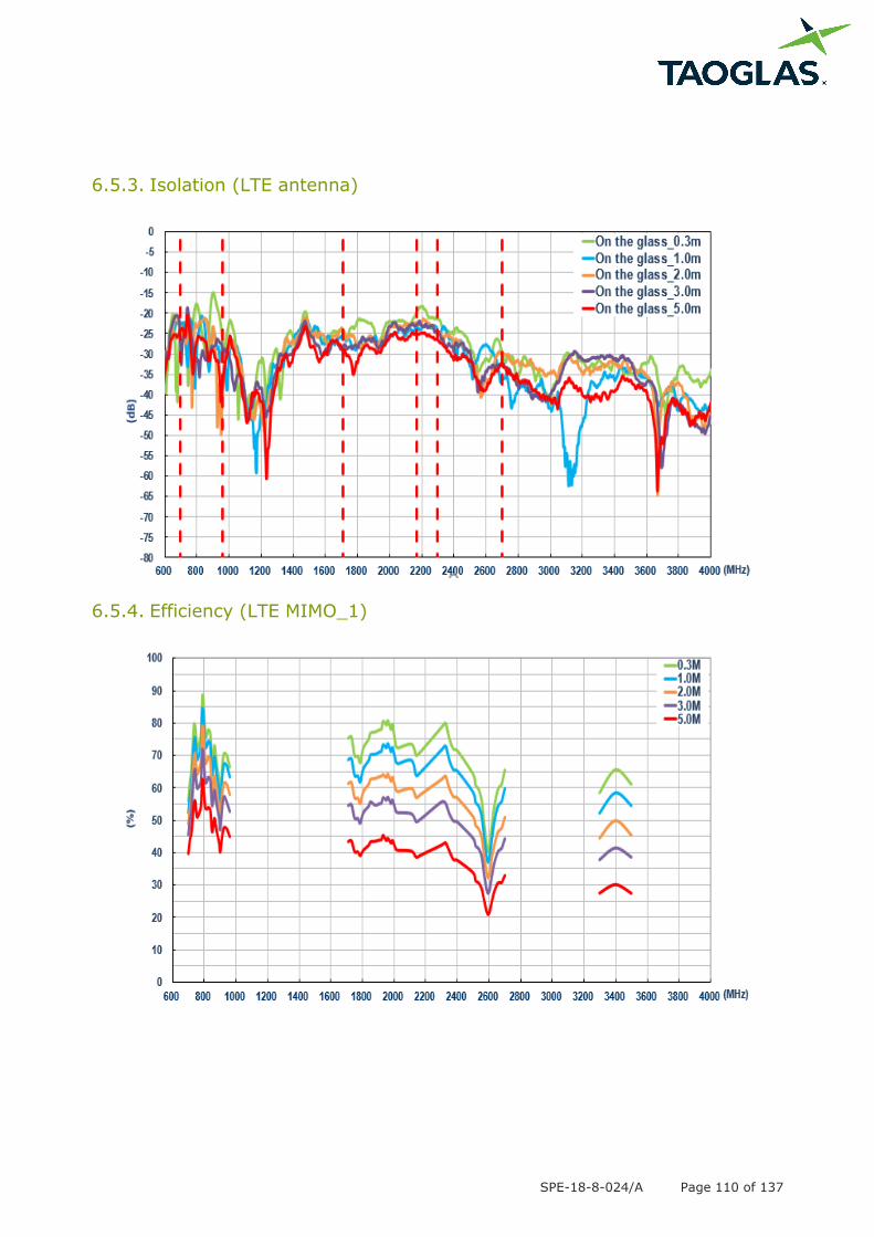
6.5.3. Isolation (LTE antenna)
6.5.4. Efficiency (LTE MIMO_1)

SPE-18-8-024/A Page 111 of 137
6.5.5. Efficiency (LTE MIMO_2)
6.5.6. Average Gain (LTE MIMO_1)
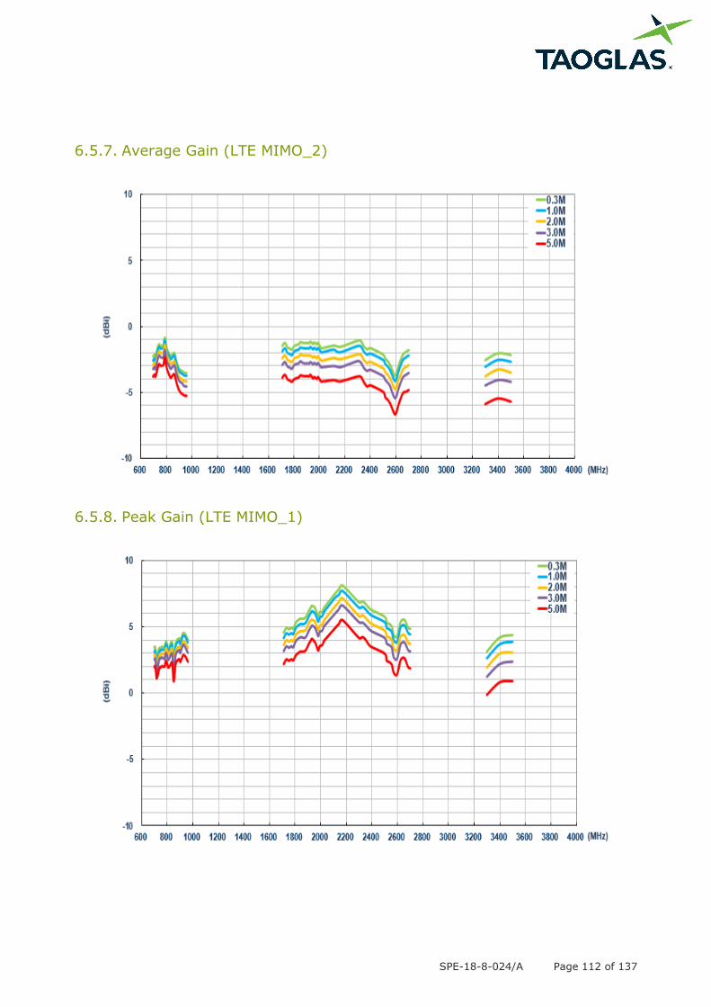
SPE-18-8-024/A Page 112 of 137
6.5.7. Average Gain (LTE MIMO_2)
6.5.8. Peak Gain (LTE MIMO_1)
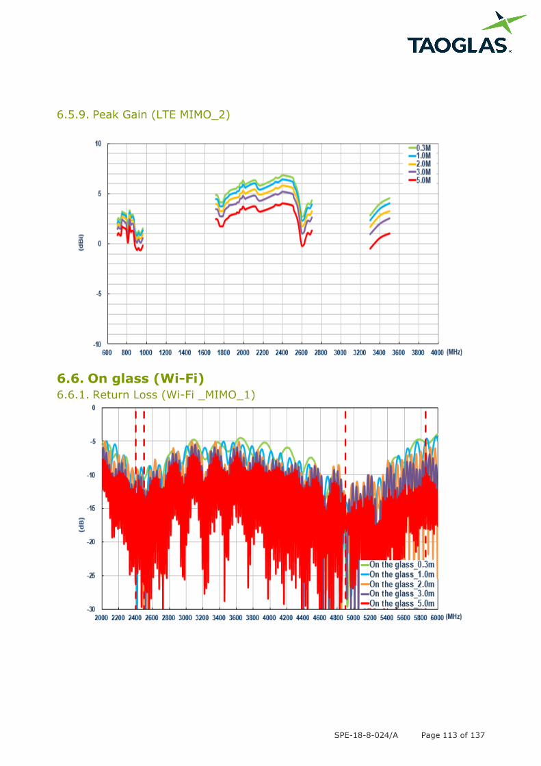
SPE-18-8-024/A Page 113 of 137
6.5.9. Peak Gain (LTE MIMO_2)
6.6. On glass (Wi-Fi)
6.6.1. Return Loss (Wi-Fi _MIMO_1)
SPE-18-8-024/A Page 114 of 137
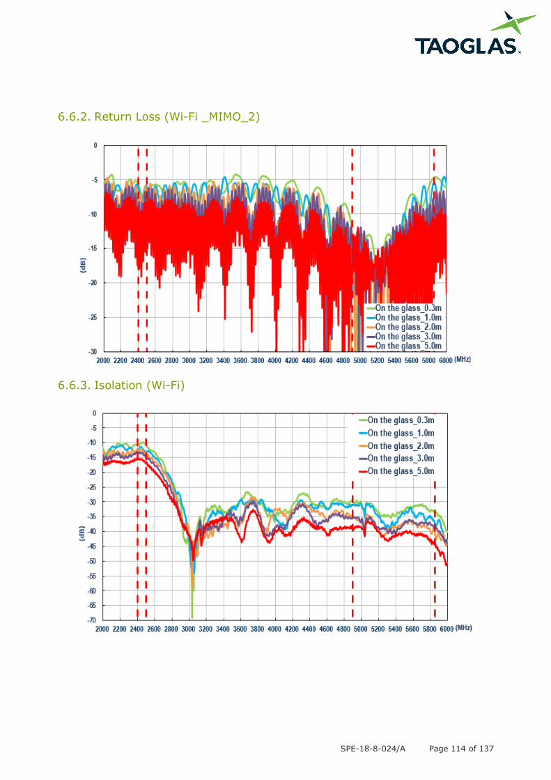
6.6.2. Return Loss (Wi-Fi _MIMO_2)
6.6.3. Isolation (Wi-Fi)
SPE-18-8-024/A Page 115 of 137
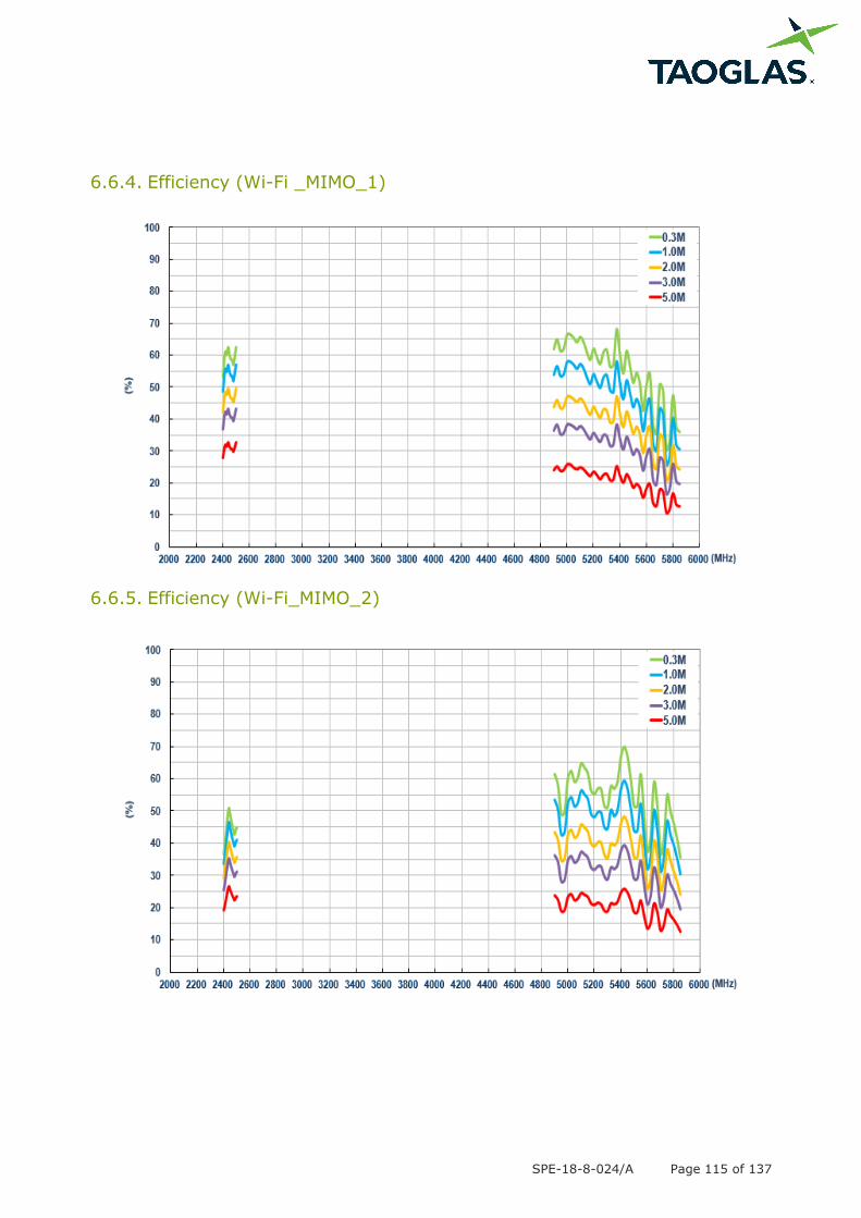
6.6.4. Efficiency (Wi-Fi _MIMO_1)
6.6.5. Efficiency (Wi-Fi_MIMO_2)
SPE-18-8-024/A Page 116 of 137
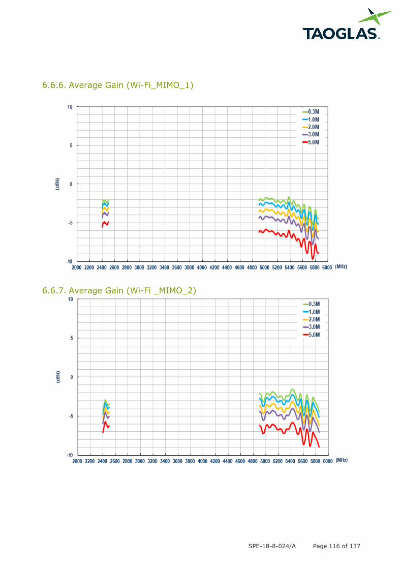
6.6.6. Average Gain (Wi-Fi_MIMO_1)
6.6.7. Average Gain (Wi-Fi _MIMO_2)
SPE-18-8-024/A Page 117 of 137
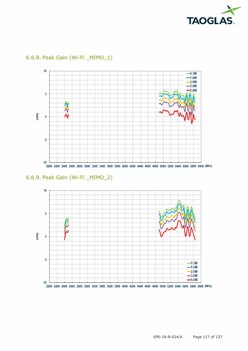
6.6.8. Peak Gain (Wi-Fi _MIMO_1)
6.6.9. Peak Gain (Wi-Fi _MIMO_2)
SPE-18-8-024/A Page 118 of 137
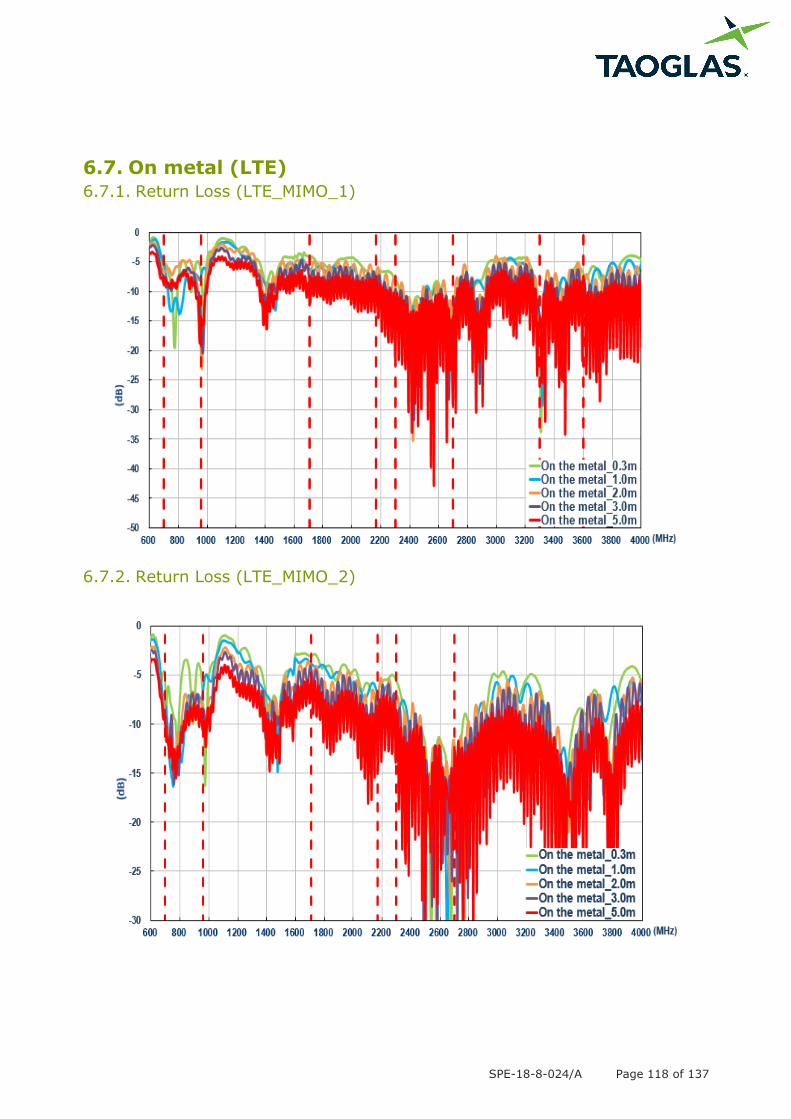
6.7. On metal (LTE)
6.7.1. Return Loss (LTE_MIMO_1)
6.7.2. Return Loss (LTE_MIMO_2)
SPE-18-8-024/A Page 119 of 137
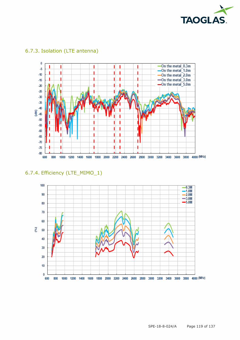
6.7.3. Isolation (LTE antenna)
6.7.4. Efficiency (LTE_MIMO_1)
SPE-18-8-024/A Page 120 of 137
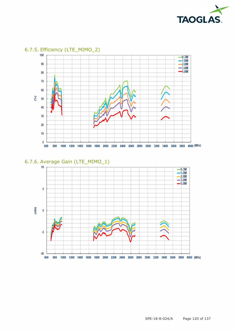
6.7.5. Efficiency (LTE_MIMO_2)
6.7.6. Average Gain (LTE_MIMO_1)
SPE-18-8-024/A Page 121 of 137
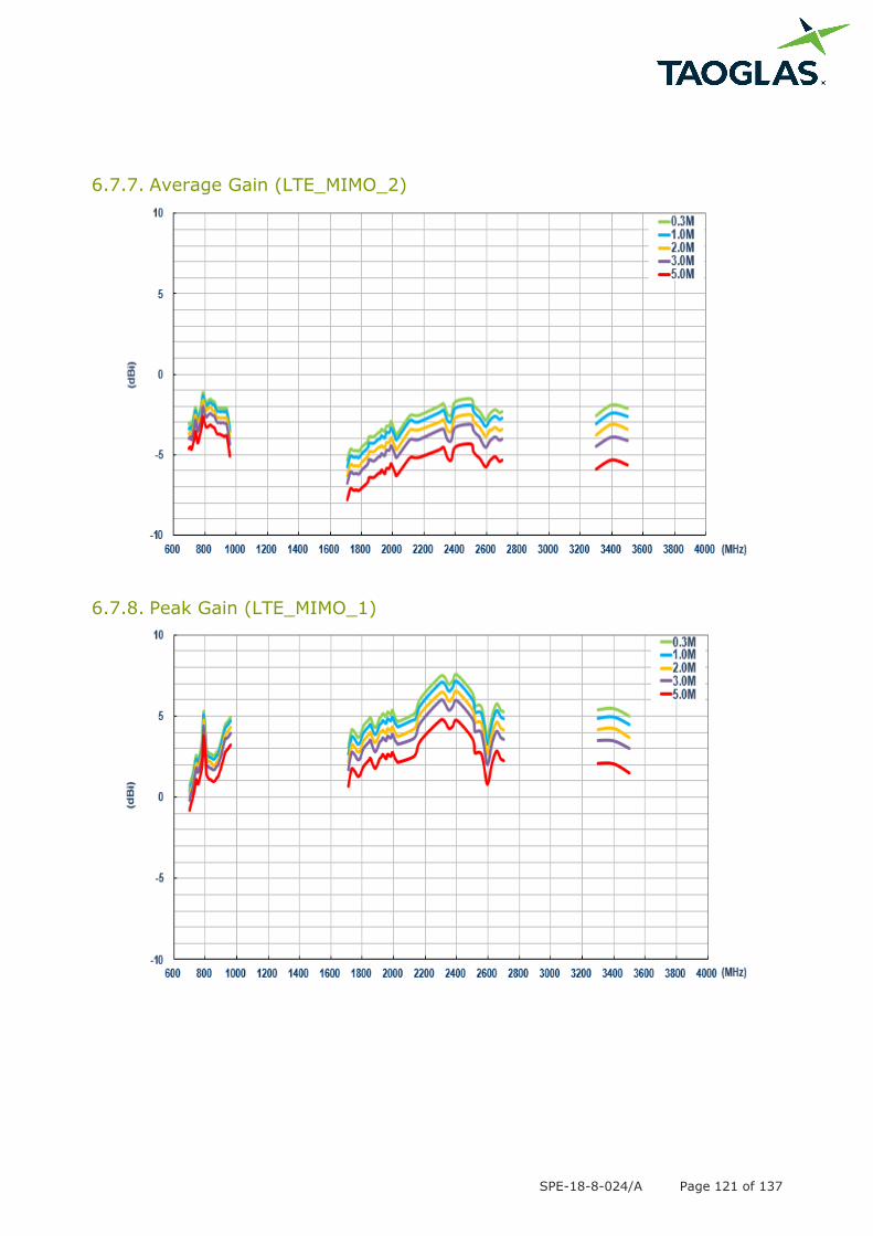
6.7.7. Average Gain (LTE_MIMO_2)
6.7.8. Peak Gain (LTE_MIMO_1)
SPE-18-8-024/A Page 122 of 137
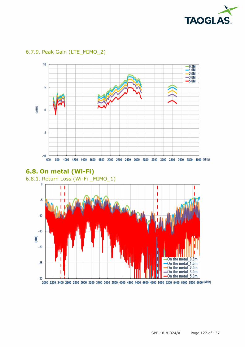
6.7.9. Peak Gain (LTE_MIMO_2)
6.8. On metal (Wi-Fi)
6.8.1. Return Loss (Wi-Fi _MIMO_1)
SPE-18-8-024/A Page 123 of 137
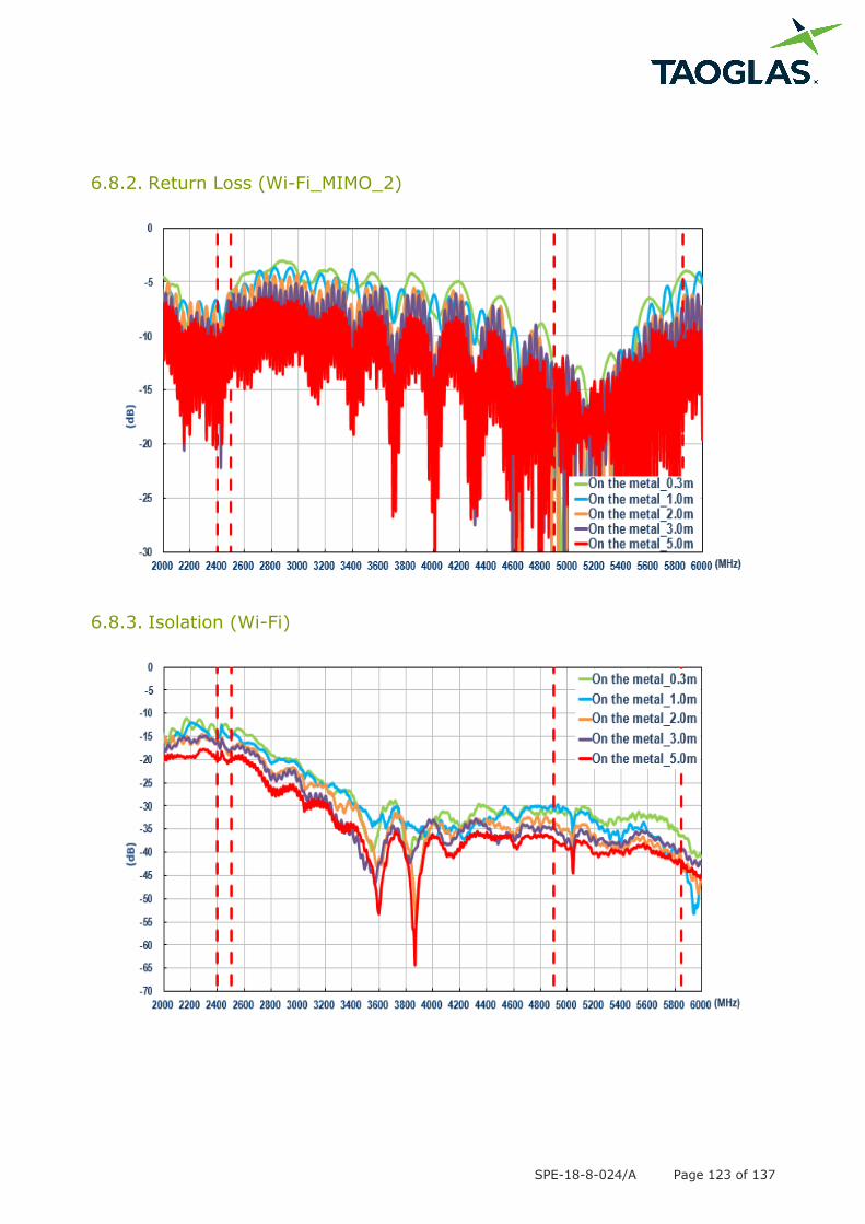
6.8.2. Return Loss (Wi-Fi_MIMO_2)
6.8.3. Isolation (Wi-Fi)

SPE-18-8-024/A Page 124 of 137
6.8.4. Efficiency (Wi-Fi_MIMO_1)
6.8.5. Efficiency (Wi-Fi_MIMO_2)
SPE-18-8-024/A Page 125 of 137
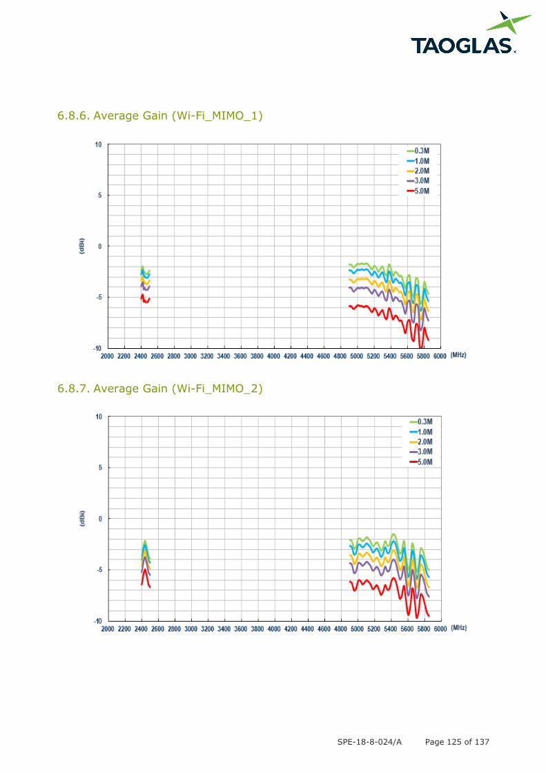
6.8.6. Average Gain (Wi-Fi_MIMO_1)
6.8.7. Average Gain (Wi-Fi_MIMO_2)
SPE-18-8-024/A Page 126 of 137
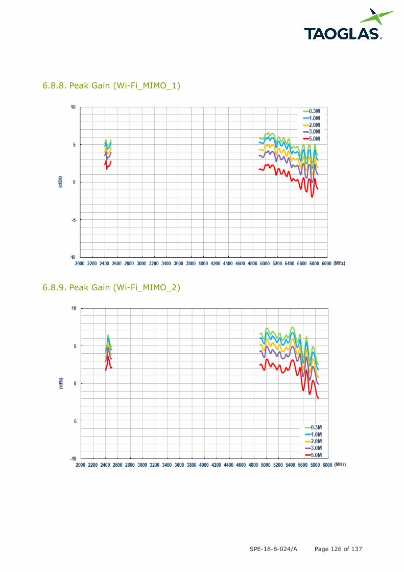
6.8.8. Peak Gain (Wi-Fi_MIMO_1)
6.8.9. Peak Gain (Wi-Fi_MIMO_2)
SPE-18-8-024/A Page 127 of 137
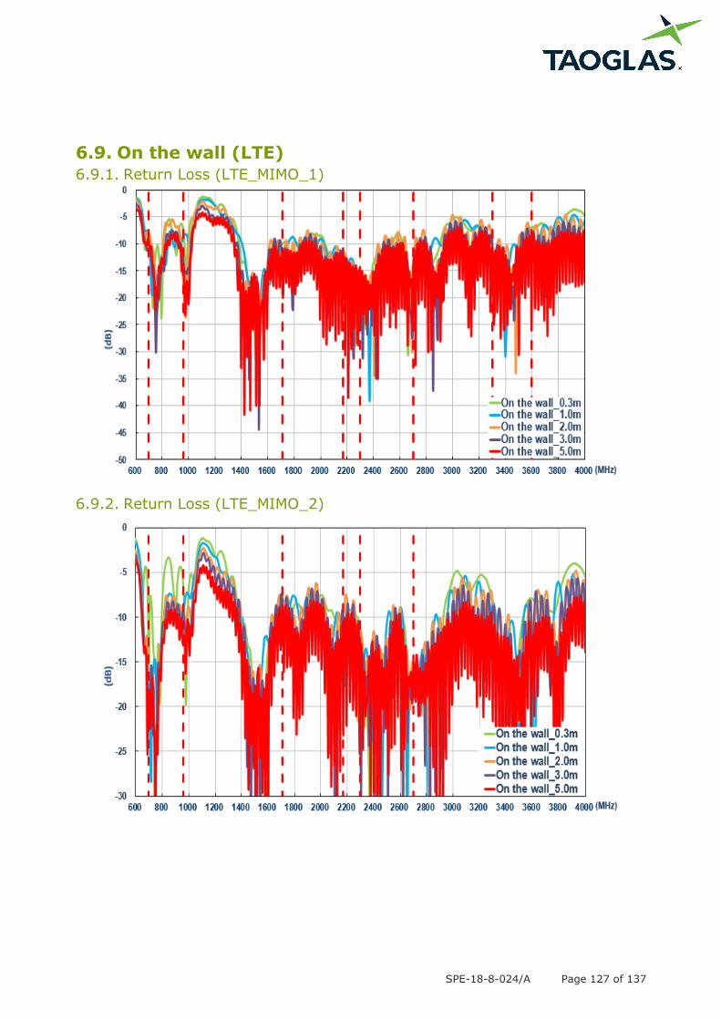
6.9. On the wall (LTE)
6.9.1. Return Loss (LTE_MIMO_1)
6.9.2. Return Loss (LTE_MIMO_2)
SPE-18-8-024/A Page 128 of 137
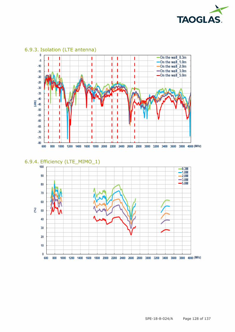
6.9.3. Isolation (LTE antenna)
6.9.4. Efficiency (LTE_MIMO_1)
SPE-18-8-024/A Page 129 of 137
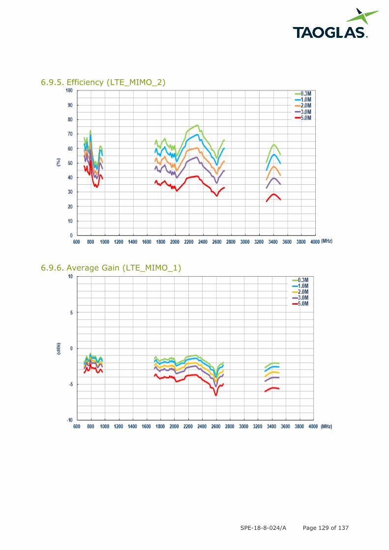
6.9.5. Efficiency (LTE_MIMO_2)
6.9.6. Average Gain (LTE_MIMO_1)

SPE-18-8-024/A Page 130 of 137
6.9.7. Average Gain (LTE_MIMO_2)
6.9.8. Peak Gain (LTE_MIMO_1)
SPE-18-8-024/A Page 131 of 137
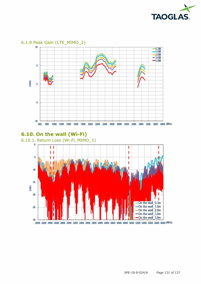
6.1.9 Peak Gain (LTE_MIMO_2)
6.10. On the wall (Wi-Fi)
6.10.1. Return Loss (Wi-Fi_MIMO_1)
SPE-18-8-024/A Page 132 of 137
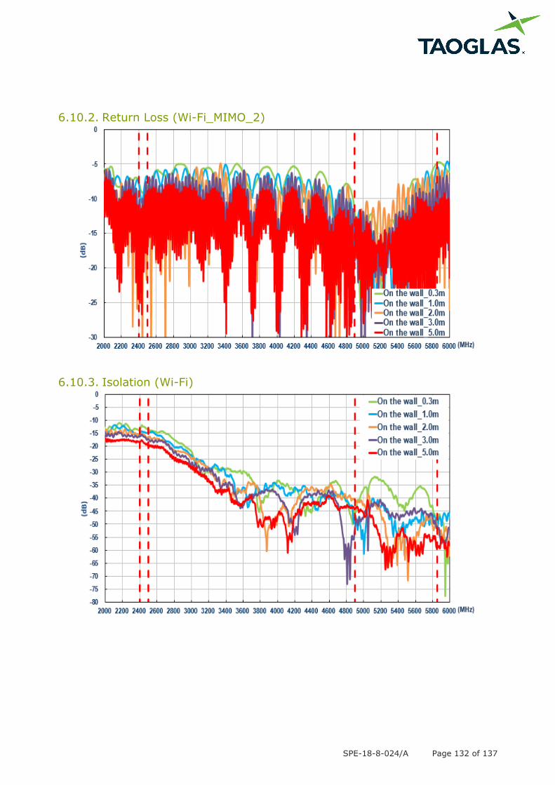
6.10.2. Return Loss (Wi-Fi_MIMO_2)
6.10.3. Isolation (Wi-Fi)
SPE-18-8-024/A Page 133 of 137
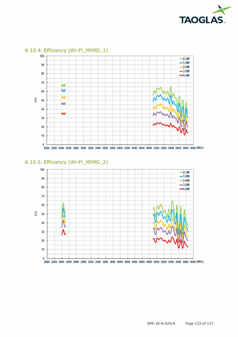
6.10.4. Efficiency (Wi-Fi_MIMO_1)
6.10.5. Efficiency (Wi-Fi_MIMO_2)
SPE-18-8-024/A Page 134 of 137
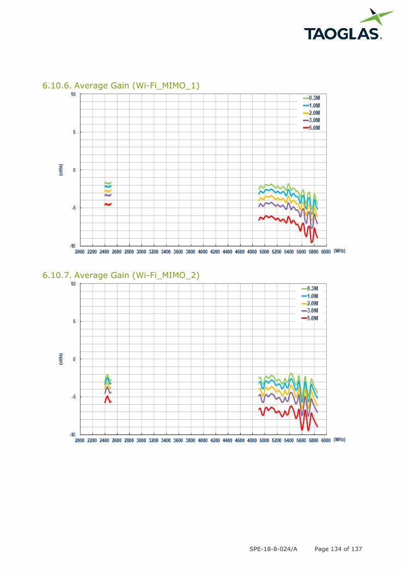
6.10.6. Average Gain (Wi-Fi_MIMO_1)
6.10.7. Average Gain (Wi-Fi_MIMO_2)
SPE-18-8-024/A Page 135 of 137
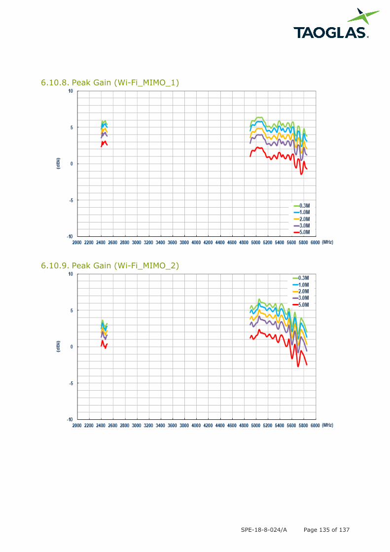
6.10.8. Peak Gain (Wi-Fi_MIMO_1)
6.10.9. Peak Gain (Wi-Fi_MIMO_2)

SPE-18-8-024/A Page 136 of 137
7. Installation Instructions
SPE-18-8-024/A Page 137 of 137
Taoglas makes no warranties based on the accuracy or completeness of the contents of this document
and reserves the right to make changes to specifications and product descriptions at any time without
notice. Taoglas reserves all rights to this document and the information contained herein.
Reproduction, use or disclosure to third parties without express permission is strictly prohibited.
Copyright © Taoglas Ltd.
Mouser Electronics
Authorized Distributor
Click to View Pricing, Inventory, Delivery & Lifecycle Information: Taoglas:
MA931.W.A.LBICGH.001.wm