
warranty - Mouser Electronics
231
-
Upload
khangminh22 -
Category
Documents
-
view
4 -
download
0
Transcript of warranty - Mouser Electronics


WARRANTY Parallax Inc. warrants its products against defects in materials and workmanship for a period of 90 days from receipt of product. If you discover a defect, Parallax Inc. will, at its option, repair or replace the merchandise, or refund the purchase price. Before returning the product to Parallax, call for a Return Merchandise Authorization (RMA) number. Write the RMA number on the outside of the box used to return the merchandise to Parallax. Please enclose the following along with the returned merchandise: your name, telephone number, shipping address, and a description of the problem. Parallax will return your product or its replacement using the same shipping method used to ship the product to Parallax.
14-DAY MONEY BACK GUARANTEE If, within 14 days of having received your product, you find that it does not suit your needs, you may return it for a full refund. Parallax Inc. will refund the purchase price of the product, excluding shipping/handling costs. This guarantee is void if the product has been altered or damaged. See the Warranty section above for instructions on returning a product to Parallax. COPYRIGHTS AND TRADEMARKS This documentation is copyright 2005 by Parallax Inc. By downloading or obtaining a printed copy of this documentation or software you agree that it is to be used exclusively with Parallax products. Any other uses are not permitted and may represent a violation of Parallax copyrights, legally punishable according to Federal copyright or intellectual property laws. Any duplication of this documentation for commercial uses is expressly prohibited by Parallax Inc. Duplication for educational use is permitted, subject to the following Conditions of Duplication: Parallax Inc. grants the user a conditional right to download, duplicate, and distribute this text without Parallax's permission. This right is based on the following conditions: the text, or any portion thereof, may not be duplicated for commercial use; it may be duplicated only for educational purposes when used solely in conjunction with Parallax products, and the user may recover from the student only the cost of duplication. This text is available in printed format from Parallax Inc. Because we print the text in volume, the consumer price is often less than typical retail duplication charges. BASIC Stamp, Stamps in Class, Boe-Bot SumoBot, SX-Key and Toddler are registered trademarks of Parallax, Inc. If you decide to use registered trademarks of Parallax Inc. on your web page or in printed material, you must state that "(registered trademark) is a registered trademark of Parallax Inc.” upon the first appearance of the trademark name in each printed document or web page. HomeWork Board, Parallax, and the Parallax logo are trademarks of Parallax Inc. If you decide to use trademarks of Parallax Inc. on your web page or in printed material, you must state that "(trademark) is a trademark of Parallax Inc.”, “upon the first appearance of the trademark name in each printed document or web page. Other brand and product names are trademarks or registered trademarks of their respective holders.
ISBN 1-928982-35-2

DISCLAIMER OF LIABILITY Parallax Inc. is not responsible for special, incidental, or consequential damages resulting from any breach of warranty, or under any legal theory, including lost profits, downtime, goodwill, damage to or replacement of equipment or property, or any costs of recovering, reprogramming, or reproducing any data stored in or used with Parallax products. Parallax Inc. is also not responsible for any personal damage, including that to life and health, resulting from use of any of our products. You take full responsibility for your BASIC Stamp application, no matter how life-threatening it may be.
INTERNET DISCUSSION LISTS We maintain active web-based discussion forums for people interested in Parallax products. These lists are accessible from www.parallax.com.
• Propeller Chip – This list is specifically for our customers using Propeller chips and products. • BASIC Stamp – This list is widely utilized by engineers, hobbyists and students who share their
BASIC Stamp projects and ask questions. • Stamps in Class® – Created for educators and students, subscribers discuss the use of the Stamps in
Class curriculum in their courses. The list provides an opportunity for both students and educators to ask questions and get answers.
• Parallax Educators – A private forum exclusively for educators and those who contribute to the development of Stamps in Class. Parallax created this group to obtain feedback on our curricula and to provide a place for educators to develop and obtain Teacher’s Guides.
• Robotics – Designed for Parallax robots, this forum is intended to be an open dialogue for robotics enthusiasts. Topics include assembly, source code, expansion, and manual updates. The Boe-Bot®, Toddler®, SumoBot®, HexCrawler and QuadCrawler robots are discussed here.
• SX Microcontrollers and SX-Key – Discussion of programming the SX microcontroller with Parallax assembly language SX – Key® tools and 3rd party BASIC and C compilers.
• Javelin Stamp – Discussion of application and design using the Javelin Stamp, a Parallax module that is programmed using a subset of Sun Microsystems’ Java® programming language.
ERRATA While great effort is made to assure the accuracy of our texts, errors may still exist. If you find an error, please let us know by sending an email to [email protected]. We continually strive to improve all of our educational materials and documentation, and frequently revise our texts. Occasionally, an errata sheet with a list of known errors and corrections for a given text will be posted to our web site, www.parallax.com. Please check the individual product page’s free downloads for an errata file.
ACKNOWLEGEMENTS Many thanks to fellow Parallaxians Jen Jacobs for cover and title page art and Chris Savage for technical review of this edition.


Table of Contents · Page i
Table of Contents
Preface......................................................................................................... iii Author’s Note ................................................................................................................. iii Getting the Most from StampWorks................................................................................v Steps to Success ............................................................................................................v
Preparing the StampWorks Lab ................................................................... 1 StampWorks Kit Contents...............................................................................................1 Setting Up the Hardware and Software ..........................................................................2 Notes on Using Integrated Circuits in StampWorks Experiments...................................9
Programming Essentials............................................................................. 11 Contents of a Working Program ...................................................................................11 Branching – Redirecting Program Flow ........................................................................12 Looping – Running Code Again and Again...................................................................14 Subroutines – Reusable Code that Saves Program Space..........................................16
The Elements of PBASIC Style.................................................................... 19 Time to Experiment .................................................................................... 25
Learn the Programming Concepts................................................................................25 Building the Projects .....................................................................................................25 What to do Between Projects .......................................................................................25 Experiment #1: Flash an LED.......................................................................................26 Experiment #2: Flash an LED (Advanced) ...................................................................29 Experiment #3: Display a Counter with LEDs...............................................................33 Experiment #4: Science Fiction LED Display ...............................................................36 Experiment #5: LED Graph (Dot or Bar) .......................................................................40 Experiment #6: A Simple Game ...................................................................................46 Experiment #7: A Lighting Controller ............................................................................51
Building Circuits on Your Own.................................................................... 57 Using 7-Segment LED Displays .................................................................. 59
Experiment #8: A Single-Digit Counter .........................................................................60 Experiment #9: A Digital Die.........................................................................................63 Experiment #10: A Digital Clock ...................................................................................67
Using Character LCDs ................................................................................. 73 Experiment #11: Basic LCD Demonstration .................................................................75 Experiment #12: Creating Custom LCD Characters.....................................................82 Experiment #13: Reading the LCD RAM ......................................................................88

Page ii ·StampWorks
Moving Forward ......................................................................................... 93 Experiment #14: Scanning and Debouncing Multiple Inputs ........................................94 Experiment #15: Counting Events ................................................................................98 Experiment #16: Frequency Measurement ................................................................101 Experiment #17: Advanced Frequency Measurement ...............................................106 Experiment #18: A Light Controlled Theremin............................................................109 Experiment #19: Sound Effects (SFX)........................................................................112 Experiment #20: Infrared Object Detection ................................................................119 Experiment #21: Analog Input with PULSIN...............................................................123 Experiment #22: Analog Output with PWM ................................................................126 Experiment #23: Expanded Digital Outputs with Shift Registers................................130 Experiment #24: Expanded Digital Inputs with Shift Registers...................................137 Experiment #25: Mixed IO with Shift Registers ..........................................................143 Experiment #26: Hobby Servo Control .......................................................................146 Experiment #27: Stepper Motor Control .....................................................................150 Experiment #28: Voltage Measurement .....................................................................156 Experiment #29: Temperature Measurement .............................................................161 Experiment #30: High Resolution Temperature Measurement ..................................168 Experiment #31: Advanced 7-Segment Multiplexing..................................................173 Experiment #32: I2C Communications .......................................................................179 Experiment #33: Using a Real-Time Clock.................................................................188 Experiment #34: Serial Communications with a PC ...................................................197 Experiment #35: (BONUS) BS2px ADC .....................................................................206
Power PBASIC .......................................................................................... 211 Striking Out on Your Own ........................................................................ 219

Preface · Page iii
Preface
AUTHOR’S NOTE
Dear friends, It seems like ages ago that Ken Gracey handed me a new prototyping and development board and asked, “What do you think we could do with this?” That board, of course, was the original NX-1000 and what we went on to create together was the first edition of the book you’re now reading: StampWorks. A lot of things have changed since then, and yet many things remain comfortably constant: there are still many ways to learn microcontroller programming and one of the best – in our opinion – is to do so using the BASIC Stamp® microcontroller. Our philosophy has always been rooted in the belief that learning by doing provides the fastest, deepest, most satisfying results. We teach theory by putting it into practice. That’s what StampWorks is all about. Most of you that find your way to StampWorks will have had some applicable experience; perhaps you’ve worked your way through our excellent Stamps in Class student guides and are looking to build on that experience. Perhaps you have an electronics and/or programming background and are looking to apply those skills with the BASIC Stamp microcontroller. Either way, this book will teach you to apply the skills that you have and develop new ones along the way so that you can confidently translate your ideas into working projects. Microcontrollers are a part of our daily lives – whether we see them or not – so learning to design with and program them is a very valuable skill. Like earlier editions, this book assumes that you’re ready to work – ready to read component documentation, willing to open the BASIC Stamp IDE help file for details on a PBASIC command, that you’re unafraid to do a web search if necessary to obtain data that will be required for a challenge; in short, whatever it takes to succeed. We’ll push a bit harder this time, but we’ll do it together. My goal is that even if this isn’t your first exposure to StampWorks, it will be a worthwhile and pleasurable experience.

Page iv ·StampWorks
Among the changes that affect this edition of StampWorks is an updated PBASIC language: PBASIC 2.5. For those that come from a PC programming background, PBASIC 2.5 will make the transition to embedded programming a bit easier to deal with. And what I’m especially excited about is a new development platform: the Parallax Professional Development Board. My colleague, John Barrowman, with feedback from customers and Parallax staff alike, put about all of the features we would ever want into one beautiful product. For those of you have an NX-1000 (any of the variants), don’t worry; most of the experiments will run on it without major modification. Finally, as far as the text goes, many of the project updates are a direct result of those that have come before you, and you, my friend, have the opportunity to affect future updates. Please, if you ever have a question, comment, or suggestion, feel free to e-mail them to [email protected].
Preface · Page v
GETTING THE MOST FROM STAMPWORKS
Before you get started, you’ll want to have a copy of the BASIC Stamp Syntax and Reference Manual (version 2.1 or higher) handy – either printed or in PDF (available as a free download from www.parallax.com). Through the course of this book I will ask you to review specific sections of the BASIC Stamp Manual in preparation for an experiment. At other times I may ask you to go to the Internet to download a datasheet; by doing this we can focus on the details of the experiment and not have to print a lot of redundant information. STEPS TO SUCCESS
Read (or review if you have previous BASIC Stamp programming experience) sections 1 – 4 of the BASIC Stamp Syntax and Reference Manual. This will introduce you to the BASIC Stamp microcontroller, its programming IDE, and its memory organization. And if you’ve never worked with microcontrollers or programming of any kind, I strongly suggest that you download and work your way through our What’s A Microcontroller? student guide. This outstanding resource is used in schools all over the world and is considered the best introduction to microcontroller principals and programming available anywhere. The focus of StampWorks is on embedded programming and circuit integration. That said, this is not a text on electronics principles. If you are new to the world of electronics, a great beginning text is Getting Started in Electronics by renowned electronics author, Forrest M. Mims. You can find this at your favorite bookseller. Read “Preparing the StampWorks Lab” in the next section. This will introduce you to the Parallax Professional Development Board (PDB) and get it ready for the experiments that follow. Finally, work your way through the experiments, referring to the BASIC Stamp Syntax and Reference Manual (or online Help file) as needed. This is the fun part – and the part that is the most work. Don’t allow yourself to be satisfied with simply loading and running the code – dig in and work with it, modify it, make it your own. By the time you’ve completed the experiments in this book I believe you will be ready and will have the confidence to take on your own BASIC Stamp microcontroller projects; from projects that may be very simple to those that are moderately complex. The real key is to make sure you truly understand an experiment before

Page vi ·StampWorks
moving on to another. Oftentimes we will rely on what we’ve previously worked through as support for a new experiment. Taken one at a time, the experiments are not difficult and if you work through them methodically, you’ll find your confidence and abilities increasing at a very rapid pace.

Preparing the StampWorks Lab · Page 1
Preparing the StampWorks Lab STAMPWORKS KIT CONTENTS
Before getting to the experiments, let’s start by taking inventory of the kit and then preparing the PDB for use in the experiments that follow. Once this is done, you’ll be able to move through the experiments smoothly, and when you’ve completed StampWorks you’ll be ready for just about any project you can imagine.
StampWorks Lab Kit Contents #27297 (parts and quantities subject to change without notice)
Stock Code # Description Marking Qty 27218 BASIC Stamp Syntax and Reference Manual 1 27220 StampWorks Manual v2.1 1 23138 Professional Development Board 1 BS2-IC BASIC Stamp 2 module 1 750-00007 Power supply, 12 vdc, 1 amp 1 800-00003 Serial cable 1 805-00006 USB cable, Mini-A to Mini-B 1 700-00050 22-gauge wire, solid, red 1 700-00051 22-gauge wire, solid, white 1 700-00052 22-gauge wire, solid, black 1 200-01030 0.01 µF capacitor 103 2 200-01040 0.1 µF capacitor 104 2 150-02210 220 ohm resistor Red-Red-Brn 3 150-04710 470 ohm resistor Yel-Vio-Brn 3 150-01020 1 k-ohm resistor Brn-Blk-Red 3 150-04720 4.7 k-ohm resistor Yel-Vio-Red 3 150-01030 10 k-ohm resistor Brn-Blk-Org 3 350-00009 CdS photoresistor 2 350-00003 IR LED 1 350-90000 LED stand-off (for IR LED) 1 350-90001 LED shield (for IR LED) 1 350-00014 IR receiver 1 603-00006 Parallel LCD module 1 604-00009 LM555 timer 1 602-00015 LM358 dual op-amp 1 602-00009 74HC595, serial-in-parallel-out shift register 2 602-00010 74HC165, parallel-in-serial-out shift register 2 ADC0831 ADC0831, 8-bit A/D converter 1 604-00002 DS1620, digital thermometer 1 603-00014 MC14489 LED multiplexer 1 604-00020 24LC32 EEPROM 1 900-00005 Servo, Parallax Standard 1 27964 Stepper motor, 12 vdc, unipolar 1

Page 2 · StampWorks
SETTING UP THE HARDWARE AND SOFTWARE
To set up the StampWorks lab for experiments, you’ll need the following items:
• Professional Development Board • BASIC Stamp 2 module • 12-volt wall pack (2.1 mm, center-positive plug) • Programming cable (serial or USB) • Red and black hook-up wire (22-gauge, solid) • Wire cutters/strippers (not included in the StampWorks Kit)
Installing the BASIC Stamp Module
Start by removing the BASIC Stamp 2 module from its protective foam and carefully inserting it into the 40-pin DIP socket on the PDB (upper-left, near the DB-9 programming connector). You’ll notice that the BASIC Stamp 2 module and the PDB socket are marked with semi-circle alignment guides. The BASIC Stamp 2 module should be inserted into the socket so that the alignment guides match. Ensure that the BASIC Stamp 2 module is fully left-aligned in the socket as shown in the illustration below.
Make the Programming Connection
Use a programming cable (either serial or USB, but not both at the same time) to connect the PDB to your PC. It is best to select a serial (COM) port that is not already in use. If, however, you’re forced to unplug another device, for example, a PDA or electronic organizer from your computer, make sure that you also disable its communication software before attempting to program your BASIC Stamp microcontroller.

Preparing the StampWorks Lab · Page 3
Computer System Requirements
You will need either a desktop or laptop PC to run the BASIC Stamp Editor software. For the best experience with the StampWorks experiments, check that you computer system meets the following requirements:
• Microsoft Windows® 2000/XP or newer operating system • An available serial or USB port (with VCP driver installed) • World Wide Web access
Installing the BASIC Stamp Editor
Download the latest version of the BASIC Stamp Editor for Windows (version 2.1 or later) from www.parallax.com. Run the program installer, following the on-screen prompts.
Download the StampWorks Program Files
The sample programs listed in this book, with the exception of Experiment 35, were written for the BASIC Stamp 2. These programs and some additional bonus programs are available for free download from www.parallax.com. Many of them contain additional code to support conditional compliation with different BASIC Stamp models.
Note: For USB programming, make sure that you have the latest FDTI VCP (Virtual Com Port) driver. Step-by-step installation instructions of the VCP driver may be obtained via the StampWorks Product Page http at www.parallax.com.
Note: While third-party developers have made BASIC Stamp editors available for operating systems other than Windows, these editors are not supported by Parallax. This text assumes that you’re running the official Parallax BASIC Stamp Editor on a Windows computer. If you’re using another operating system and editor, you may need to make adjustments in editor-specific instructions.

Page 4 · StampWorks
Preparing the Breadboard
In the center of the PDB is a solderless breadboard where we will build circuits that are not integral to the PDB lab board itself (a variety of components are included in the StampWorks kit). It’s important to understand how this breadboard works. With a little bit of preparation, it will be even easier to use with the experiments that follow. The innermost portion of the breadboard is where we will connect the components. This section of the breadboard consists of several columns of sockets (there are numbers printed along the top for reference). For each column there are two sets of rows. The rows are labeled A through E and F through J, respectively. For any column, sockets A through E are electrically connected. The same holds true for rows F through J. Above and below the main section of breadboard are two horizontal rows of sockets, each divided in the center. These horizontal rows (often called “rails” or “buses”) will be used to carry +5 volts (Vdd) and Ground (Vss). The preparation of the breadboard involves connecting the rails so that they run from end-to-end, connecting the top and bottom rails together and, finally, connecting the rails to the Vdd and Vss connections of the PDB power supply. Here’s what the breadboard looks like on the outside:
Preparing the StampWorks Lab · Page 5
If the breadboard was X-Rayed, we would see the internal connections and the breaks in the Vdd and Vss rails that need to be connected. Here’s a view of the breadboard’s internal connections:
Start by setting your wire stripper for 22 gauge (0.34 mm2). Take the spool of black wire and strip a ¼-inch (6 mm) length of insulation from the end of the wire. With your needle-nose pliers, carefully bend the bare wire 90 degrees so that it looks like this:
Now push the bare wire into the topmost (ground) rail, into the socket that is just above breadboard column 29 (this socket is just left of the middle of the breadboard, near the top). Hold the wire so that it extends to the right. Mark the insulation by lightly pinching it with the wire cutters at the socket above column 32. Be careful not to cut the wire. Remove the wire from the breadboard and cut it about ¼-inch (6 mm) beyond the mark you just made. With your wire strippers, remove the insulation at the mark. Now bend the second bare end 90 degrees so that the wire forms a squared “U” shape with the insulation in the middle.

Page 6 · StampWorks
If you’ve measured and cut carefully, this “U” shaped wire will plug comfortably into the ground rail at sockets 29 and 32. This will create a single ground rail. Repeat this process with black wire for the bottom-most rail. Then, connect the two rails together using the same process at column 60 (right-most sockets on each rail). With the red wire, connect the top and bottom inside rail halves together. These rails will carry +5 volts, or Vdd. Connect the Vdd rails together at column 59. Now take a 1½-inch (4 cm) section of black wire and a 1½-inch (4 cm) section of red wire and strip ¼-inch (6 mm) insulation from the ends of both. Bend each wire into a rounded “U” shape. These wires are not designed to lie flat like the other connections, making them easy to remove from the StampWorks lab board if necessary. Carefully plug one end of the red wire into any of the terminal sockets of the VDD block (near pin 1 of the BASIC Stamp socket) and the other end into the Vdd (+5) rail at column 5. Then, plug one end of the black wire into any of the sockets of the VSS block and other end into the ground rail at column 1. Be very careful with these last two connections. If the Vdd and Vss rails get connected together damage may occur when power is applied to the PDB. When completed, the PDB breadboard will look like this:

Preparing the StampWorks Lab · Page 7
Final Checkout
With the BASIC Stamp module installed and the breadboard prepared it is time for a final checkout before proceeding to the experiments. If you haven’t done so already, connect a programming cable (serial or USB) between your PC and the PDB. Connect a 12-volt DC power supply to the PDB power connector. Move the PDB power switch to ON; a blue LED next to the power switch should illuminate. If it doesn’t, move the power switch to OFF and recheck all connections, as well as the power supply. Start the BASIC Stamp Editor and enter the following short program: ' $STAMP BS2 Main: DEBUG "Ready for StampWorks 2.1!" END

Page 8 · StampWorks
Now run the program. If all went well the program will be downloaded to the BASIC Stamp module and a Debug Terminal window will appear.
If an error occurs, check the following items:
• Is the BASIC Stamp module plugged into the PDB correctly? • Is the PDB power switch set to ON? Is the blue ON LED lit? • Is the programming cable connected between the PC and the PDB? • Have you (manually) selected the wrong PC com port? • Is the PC com port being used by another program? • If using USB, have you installed the FTDI VCP driver?
When the Debug Terminal window appears and tells you that the StampWorks lab is ready, it’s time to talk about BASIC Stamp programming.

Preparing the StampWorks Lab · Page 9
NOTES ON USING INTEGRATED CIRCUITS IN STAMPWORKS EXPERIMENTS
There are two ways to draw integrated circuits (ICs) in a schematic: One way is considered “chip-centric” in which I/O pins appear in the schematic according to their physical location on the device. StampWorks uses schematics drawn for efficiency, meaning that I/O pins are placed to make the schematic legible. I/O pins on all chips are counted according to their indicator, starting with Pin 1 and counting in a counter-clockwise direction as shown below:

Page 10 · StampWorks

Programming Essentials · Page 11
Programming Essentials
CONTENTS OF A WORKING PROGRAM
In Sections 1 - 4 of the BASIC Stamp Syntax and Reference Manual you were introduced to the BASIC Stamp, its architecture, and the concepts of variables and constants. In this section, we’ll introduce the various elements of a program: linear code, branching, loops, and subroutines. The examples in this discussion use pseudo-code to demonstrate and describe program structure. Italics are used to indicate the sections of pseudo-code that require replacement with valid programming statements in order to allow the example to compile and run correctly. You need not enter any of the examples here as all of these concepts will be used in the experiments that follow. People often think of computers and microcontrollers as “smart” devices and yet, they will do nothing without a specific set of instructions. This set of instructions is called a program, and it is our job to write it. Programs for the BASIC Stamp are written in a language called PBASIC, a Parallax-specific version of the BASIC (Beginner’s All-purpose Symbolic Instruction Code) programming language. BASIC is very popular because of its simplicity and English-like syntax. Since its creation at Dartmouth College in the mid 1960’s it has become one of the dominant programming languages available for platforms as small as the BASIC Stamp microcontroller, and as large as mainframe computer systems. A working program can be as simple as a list of statements. Like this:
statement 1 statement 2 statement 3 END
This is a very simple, yet valid program structure. What you’ll find, however, is that most programs do not run in a straight, linear fashion like the listing above. Program flow is often redirected with branching, looping, and subroutines, with short linear sections in between. The requirements for program flow are determined by the goal of the program and the conditions under which the program is running.

Page 12 · StampWorks
BRANCHING – REDIRECTING PROGRAM FLOW
A branching instruction is one that causes the flow of the program to change from its linear path. In other words, when the program encounters a branching instruction, it will, in almost all cases, not be running the next [linear] line of code. The program will usually go somewhere else, often creating a program loop. There are two categories of branching instructions: unconditional and conditional. PBASIC has two instructions, GOTO and GOSUB that cause unconditional branching. Here’s an example of an unconditional branch using GOTO:
Label: statement 1 statement 2 statement 3 GOTO Label
We call this an unconditional branch because it always happens. GOTO redirects the program to another location. The location is specified as part of the GOTO instruction and is called an address. Remember that addresses start a line of code and are followed by a colon (:). You’ll frequently see GOTO at the end of the main body of code, forcing the program statements to run again. Conditional branching will cause the program flow to change under a specific set of circumstances. The simplest conditional branching is done with an IF-THEN construct. PBASIC includes two distinct versions of IF-THEN; the first is used specifically to redirect program flow to another point based on a tested condition. Take a look at this listing:
Start: statement 1 statement 2 statement 3 IF (condition) THEN Start
In this example, statements 1- 3 will run at least once and then continue to run as long as the condition evaluates as True. When required, the condition can be tested prior to the code statements:

Programming Essentials · Page 13
Start: IF (condition) THEN statement 1 statement 2 statement 3 ENDIF
Note that the code statements are nested in an IF-THEN-ENDIF structure which does not require a branch label. If the condition evaluates as False, the program will continue at the line that follows ENDIF. Another use of this conditional structure is to add the ELSE clause:
Start: IF (condition) THEN statement 1 statement 2 statement 3 ELSE statement 4 statement 5 statement 6 ENDIF
If the condition evaluates as True then statements 1 – 3 will run, otherwise statements 4 – 6 will run. As your requirements become more sophisticated, you’ll find that you’ll want your program to branch to any number of locations based on the value of a control variable. One approach is to use multiple IF-THEN constructs.
IF (index = 0) THEN Label_0 IF (index = 1) THEN Label_1 IF (index = 2) THEN Label_2
This approach is valid and does get used. Thankfully, PBASIC has a special command called BRANCH that allows a program to jump to any number of addresses based on the value of an index variable. BRANCH is a little more complicated in its setup, but very powerful in that it can replace multiple IF-THEN statements. BRANCH requires a control (index) variable and a list of addresses The previous listing can be replaced with one line of code:
BRANCH index, [Label_0, Label_1, Label_2]
Page 14 · StampWorks
When index is zero, the program will branch to Label_0, when index is one the program will branch to Label_1 and so on. Related to BRANCH is ON-GOTO, in fact, it can serve as direct replacement:
ON index GOTO Label_0, Label_1, Label_2
Programmers coming from a PC background are probably more familiar with ON-GOTO, hence its inclusion in PBASIC 2.5.
LOOPING – RUNNING CODE AGAIN AND AGAIN
As demonstrated in the previous section, program loops can be created with conditional and unconditional branching instructions. Modern variants of BASIC, including PBASIC 2.5, simplify looping with the DO-LOOP structure. With DO-LOOP the branching label is no longer required. Here's how DO-LOOP is used to force unconditional looping of number of code statements:
DO statement 1 statement 2 statement 3 LOOP
As in the previous example, statements 1 - 3 will run in order, continuously. The DO-LOOP construct can be made conditional by testing before or after the loop statements:
DO WHILE (condition) statement 1 statement 2 statement 3 LOOP
In this example the loop statements will only run if and while the condition evaluates as True.
DO statement 1 statement 2 statement 3 LOOP WHILE (condition)

Programming Essentials · Page 15
In the second example, the loop statements will run at least once, even if the condition evaluates as False. As you can see, the strength of DO-LOOP is that it simplifies how and where the condition testing occurs. DO-LOOP adds another type of testing with UNTIL.
DO statement 1 statement 2 statement 3 LOOP UNTIL (condition) DO UNTIL (condition) statement 1 statement 2 statement 3 LOOP
By using UNTIL, the loop statements will run while the condition evaluates as False. And, as demonstrated earlier, placing the test at the end of the loop will cause the loop statements to run at least one time. Another example of looping is the programmed loop using FOR-NEXT.
FOR controlVar = startVal TO endVal STEP stepSize statement 1 statement 2 statement 3 NEXT
The FOR-NEXT construct is used to run a section of code a specific number of times. FOR-NEXT uses a control variable to determine the number of loop iterations. The size of the variable will determine the upper limit of loop iterations. For example, the upper limit when using a byte-sized control variable would be 255. In the example below, controlVar could be defined as a Nib (4-bit) variable as the end value is less than 16:
FOR controlVar = 1 TO 10 statement 1 statement 2 statement 3 NEXT

Page 16 · StampWorks
The STEP option of FOR-NEXT is used when the loop needs to count in increments other than one. If, for example, the loop needed to count even numbers, the code would look something like this:
FOR counter = 2 TO 20 STEP 2 statement 1 statement 2 statement 3 NEXT
SUBROUTINES – REUSABLE CODE THAT SAVES PROGRAM SPACE
The final programming concept we’ll discuss is the subroutine. A subroutine is a section of code that can be called from anywhere in the program. GOSUB is used to redirect the program to the subroutine code. The subroutine is terminated with the RETURN instruction. RETURN causes the program to jump back to the line of code that follows the calling GOSUB.
Start: DO GOSUB My_Sub PAUSE 1000 LOOP My_Sub: statement 1 statement 2 statement 3 RETURN
In this example, the code in the My_Sub subroutine is executed and then the program jumps back to the line PAUSE 1000. Advanced programmers will take advantage of subroutines and the ON-GOSUB instruction. ON-GOSUB works like ON-GOTO, except that the program returns to the line that follows ON-GOSUB. This technique is very useful for creating task manager program structures as shown next:
Main: DO GOSUB Critical_Task ON task GOSUB Task_1, Task_2, Task_3 task = task + 1 // 3 LOOP

Programming Essentials · Page 17
Critical_Task: statement(s) RETURN Task_1: statement(s) RETURN Task_2: statement(s) RETURN Task_3: statement(s) RETURN
With this type of program the code section at Critical_Task is interleaved between the other tasks. And by placing all task code into discrete subroutines, they can be called from any point in the program. This allows one task to test for a condition and call another subroutine if required, or to set the next task by modifying the task pointer.

Page 18 · StampWorks

The Elements of PBASIC Style · Page 19
The Elements of PBASIC Style Like most versions of the BASIC programming language, PBASIC is very forgiving and the compiler enforces no particular formatting style. So long as the source code is syntactically correct, it will compile and download to the BASIC Stamp without trouble. Why, then, would one suggest a specific style for PBASIC? With millions of BASIC Stamp microcontrollers sold, and tens of thousands of active users world-wide, it is very likely that you'll be sharing your PBASIC code with someone, if not co-developing a BASIC Stamp-based project. Writing code in an organized, predictable manner will save you – and your potential colleagues – time; in analysis, in troubleshooting, and especially when you return to a project after a long break. The style guidelines presented here are just that: guidelines. They have been developed from style guidelines used by professional programmers using other high-level languages such as Java®, C/C++ and Visual Basic®. Use these guidelines as is, or modify them to suit your needs. The key is selecting a style that works well for you or your organization and sticking to it.
1. Do It Right the First Time
Many programmers, especially new ones, fall into the "I'll knock it out now and fix it later." trap. Invariably, the "fix it later" part never happens and sloppy code makes its way into production projects. If you don't have time to do it right, when will you find time to do it again? Start clean and you'll be less likely to introduce errors in your code. And if errors do pop up, clean and organized formatting will make them easier to find and fix.
2. Be Organized and Consistent
Using a blank program template will help you organize your programs and establish a consistent presentation. The BASIC Stamp Editor allows you to specify a file template for the File | New function (see Edit | Preferences | Files & Directories...).

Page 20 · StampWorks
3. Use Meaningful Names
Be verbose when naming constants, variables, and program labels. The compiler will allow names up to 32 characters long. Using meaningful names will reduce the number of comments and make your programs easier to read, debug and maintain.
4. Naming I/O Pins
BASIC Stamp I/O pins are a special case as various elements of the PBASIC language require a pin to be a constant value, an input variable or an output variable. Begin I/O pin names with an uppercase letter and use mixed case, using uppercase letters at the beginning of new words within the name. When using the BS2, the PIN definition is used. This will cause the compiler to use the correct variant (constant value, input bit, or output bit) for the pin.
HeaterCtrl PIN 15
Since connections don't change during the program run, I/O pins are named like constants (#5) using mixed case, beginning with an uppercase letter.
5. Naming Constants
Begin constant names with an uppercase letter and use mixed case, using uppercase letters at the beginning of new words within the name.
AlarmCode CON 25
6. Naming Variables
Begin variable names with a lowercase letter and use mixed case, using uppercase letters at the beginning of new words within the name. Avoid the use of internal variable names (such as B0 or W1) in your programs. Allow the compiler to automatically assign RAM space by declaring a variable of specific type.
waterLevel VAR Word

The Elements of PBASIC Style · Page 21
7. Variable Type Definitions
Conserve BASIC Stamp user RAM by declaring the variable type required to hold the expected values of the variable.
bitValue VAR Bit ' 0 - 1 nibValue VAR Nib ' 0 - 15 byteValue VAR Byte ' 0 - 255 wordValue VAR Word ' 0 - 65535
8. Program Labels
Begin program labels with an uppercase letter, use mixed case, separate words within the label with an underscore character and begin new words with a number or uppercase letter. Labels should be preceded by at least one blank line, begin in column 1 and must be terminated with a colon (except after GOTO and THEN where they appear at the end of the line and without a colon).
Print_ZString: DO READ eeAddr, char eeAddr = eeAddr + 1 IF (char = 0) THEN EXIT DEBUG char LOOP RETURN
9. PBASIC Keywords
All PBASIC language keywords, including SYMBOL, CON, VAR, PIN and serial/debugging format modifiers (DEC, HEX, BIN) and control characters (CR, LF) should be uppercase. The BASIC Stamp editor will correctly format PBASIC keywords automatically, and allow you to set color highlighting by category to suit your personal tastes.
Main: DEBUG "BASIC Stamp", CR END

Page 22 · StampWorks
10. Indent Nested Code
Nesting blocks of code improves readability and helps reduce the introduction of errors. Indenting each level with two spaces is recommended to make the code readable without taking up too much space.
Main: ..DO ....FOR testLoop = 1 TO 10 ......IF (checkLevel < threshold) THEN ........lowLevel = lowLevel + 1 ........LedOkay = IsOff ......ELSE ........LedOkay = IsOn ......ENDIF ......PAUSE 100 ....NEXT ..LOOP WHILE (testMode = Yes)
Note: The dots are used to illustrate the level of nesting and are not a part of the code.
11. Condition Statements
Enclose condition statements in parenthesis for clarity. Check_Temp: IF (indoorTemp >= setPoint) THEN AcCtrl = IsOn ELSE lowLevel = lowLevel + 1 ENDIF Fill_Water_Tank: DO WHILE (waterLevel = IsLow) TankFill = IsOn PAUSE 250 LOOP Get_Delay: DO DEBUG HOME, "Enter time (5 – 30)... ", CLREOL DEBUGIN DEC2 tmDelay LOOP UNTIL ((tmDelay >= 5) AND (tmDelay =< 30))

The Elements of PBASIC Style · Page 23
12. Be Generous With White Space
White space (spaces and blank lines) has no effect on compiler or BASIC Stamp performance, so be generous with it to make listings easier to read. As suggested in #8 above, allow at least one blank line before program labels (two blanks lines before a subroutine label is recommended). Separate items in a parameter list with a space.
Main: DO ON task GOSUB Update_Motors, Scan_IR, Close_Gripper LOOP Update_Motors: PULSOUT leftMotor, leftSpeed PULSOUT rightMotor, rightSpeed PAUSE 20 task = (task + 1) // NumTasks RETURN
An exception to this guideline is with the Bits parameter used with SHIFTIN and SHIFTOUT, the REP modifier for DEBUG and SEROUT, and the byte count and terminating byte value for SERIN. In these cases, format without additional white space.
SHIFTIN A2Ddata, A2Dclock, MSBPOST, [result\9] DEBUG REP "*"\25, CR SERIN IRbSIO, IRbBaud, [buffer\8\255]
13. Use Conditional Compilation for Compatibility
Some commands such as SERIN and SEROUT use different parameters based on the target BASIC Stamp. Use conditional compilation for maximum compatibility of your programs.
#SELECT $STAMP #CASE BS2, BS2E, BS2PE T1200 CON 813 T2400 CON 396 T9600 CON 84 #CASE BS2SX, BS2P T1200 CON 2063 T2400 CON 1021

Page 24 · StampWorks
T9600 CON 240 #CASE BS2PX T1200 CON 3313 T2400 CON 1646 T9600 CON 396 #ENDSELECT
The StampWorks files (available for download from www.parallax.com) include a blank programming template (Template.BS2) that will help you get started writing organized code. It's up to you to follow the rest of the guidelines above – or develop and use guidelines of your own.

Time to Experiment · Page 25
Time to Experiment LEARN THE PROGRAMMING CONCEPTS
What follows is a series of programming experiments that you can build and run with your StampWorks lab. The purpose of these experiments is to teach programming concepts and the use of external components with the BASIC Stamp. The experiments are focused and designed so that as you gain experience, you can combine the individual concepts to produce sophisticated programs. BUILDING THE PROJECTS
This section of the manual is simple but important because you will learn important programming lessons and construction techniques using your StampWorks lab. As you move through the rest of the manual, construction details will not be included (you’ll be experienced by then and can make your own choices) and the discussion of the program will be less verbose, focusing specifically on special techniques or external devices connected to the BASIC Stamp. WHAT TO DO BETWEEN PROJECTS
The circuit from one project may not be electrically compatible with another and could, in some cases, cause damage to the BASIC Stamp if the old program is run with the new circuit. For this reason, a blank program should be downloaded to the BASIC Stamp before connecting the new circuit. This will protect the BASIC Stamp by resetting the I/O lines to inputs. Here’s a simple program that will clear and reset the BASIC Stamp.
' $STAMP BS2 Main: DEBUG "BASIC Stamp clear." END
For convenience, save this program to a file called CLEAR.BS2.

Page 26 · StampWorks
EXPERIMENT #1: FLASH AN LED
LEDs are everywhere; virtually every piece of electronic equipment that provides some indication to a user can or does use LEDs. The purpose of this simple experiment is to flash an LED with the BASIC Stamp, as flashing LEDs are frequently used as alarm and status indicators.
Look It Up: PBASIC Elements to Know
• $STAMP (compiler directive) • $PBASIC (compiler directive) • PIN • CON • HIGH • LOW • PAUSE • GOTO
Building the Circuit
All StampWorks experiments use a dashed line to indicate components that are installed on the PDB. The LED is available on the “LEDS” section of the PDB, just to the right of the BASIC Stamp socket.
The PDB has 16 discrete LEDs built in; connect just one to the BASIC Stamp module.
1. Start with a three-inch (8 cm) segment of white hook-up wire. Strip ¼-inch (6 mm) of insulation from each end.
2. Plug one end into BASIC Stamp connection for P0. 3. Plug the other end into LED 0.

Time to Experiment · Page 27
Program: SW21-EX01-Flash_LED.BS2: ' $STAMP BS2 ' $PBASIC 2.5 ' -----[ Program Description ]--------------------------------------------- ' ' Flashes an LED connected to P0. This program will work, unmodified, on ' any BS2-family module. ' -----[ I/O Definitions ]------------------------------------------------- AlarmLed PIN 0 ' LED on P0 ' -----[ Constants ]------------------------------------------------------- FlashTm CON 500 ' delay 500 milliseconds ' -----[ Program Code ]---------------------------------------------------- Main: HIGH AlarmLed ' turn the LED on PAUSE FlashTm LOW AlarmLed ' turn the LED off PAUSE FlashTm GOTO Main
Behind the Scenes
Each of the BASIC Stamp’s I/O pins has three bits associated with its control. A bit in the DIRS register determines whether the pin is an input (bit = 0) or an output (bit = 1). If the pin is configured as an output, the current state of that pin is stored in the associated bit in the OUTS register. If the pin is configured as an input, the current pin value is taken from the associated bit in the INS register. HIGH and LOW actually perform two functions with one command: the selected pin is configured as an output (1 in the DIRS register) and the state bit is modified in the OUTS register (1 for HIGH, 0 for LOW).

Page 28 · StampWorks
For example, this:
HIGH 0
… actually performs the same function as:
DIR0 = 1 ' make P0 an output OUT0 = 1 ' set P0 high
but does it with just one line of code. Conservation of program space is an important aspect of microcontroller programming, and when we can save code space we should – we’ll probably want or need that space later.
Write Code like a Pro
Note that even in this very simple program, we are following the style guidelines detailed in “The Elements of PBASIC Style”. By using this professional style, the program becomes somewhat self-documenting, requiring fewer comments, and it allows the program to be modified far more easily. If, for example, we wanted to change the LED pin assignment or the flash rate, we would only have to make small changes to the declarations sections and not have to edit the entire listing. When our programs grow to several hundred lines, using cleverly-named pin definitions and constant values will save us a lot of time and frustration.
A very common beginner’s error is this:
OUTPUT 0
HIGH 0
There is no need to manually configure the pin as an output as this function is part of the HIGH command. While doing this won’t harm the program, it does consume valuable code space. There are very few occasions when INPUT and OUTPUT are required for proper program operation, as most PBASIC commands handle setting the pin’s I/O state.

Time to Experiment · Page 29
EXPERIMENT #2: FLASH AN LED (ADVANCED)
Now that we’ve got things moving, let’s step up a bit and explore an advanced approach to flashing an LED. The method revealed in this experiment provides the best in program readability and ease-of-maintenance.
Look It Up: PBASIC Elements to Know
• OUTPUT • DO-LOOP • VAR • Nib (variable type) • BIT0..BIT15 (variable modifier)
Building the Circuit
This experiment uses the same circuit as Experiment #1.
Program: SW21-EX02-Flash_LED-Adv.BS2: ' $STAMP BS2 ' $PBASIC 2.5 ' -----[ Program Description ]--------------------------------------------- ' ' Flashes an LED connected to P0. This program will work, unmodified, on ' any BS2-family module. ' -----[ I/O Definitions ]------------------------------------------------- Strobe PIN 0 ' LED on P0 ' -----[ Constants ]------------------------------------------------------- IsOn CON 1 ' on for active-high LED IsOff CON 0 ' off for active-high LED FlashOn CON 50 ' on for 50 ms FlashOff CON 950 ' off for 950 ms ' -----[ Initialization ]--------------------------------------------------

Page 30 · StampWorks
Reset: Strobe = IsOff OUTPUT Strobe ' enable pin to drive LED ' -----[ Program Code ]---------------------------------------------------- Main: DO Strobe = IsOn PAUSE FlashOn Strobe = IsOff PAUSE FlashOff LOOP
Behind the Scenes
The version of the LED blinker gets to the core of the hardware and works at a lower level – a little more setup work, yes, but the result is a program with greater readability, as well as flexibility for modification. And there is no mistaking the meaning of:
Strobe = IsOn
On reset, the LED control pin, called Strobe, is set to its off state by writing the IsOff constant to it, and then the pin is made an output so that it can drive the LED. This is one of those rare cases where the OUTPUT keyword is used; the reason is that after this point, LED control will be by writing to a bit in the OUTS register. This initialization section demonstrates the context-sensitivity of the PIN declaration. In actual fact, these lines of code:
Strobe = IsOff OUTPUT Strobe
… are translated by the compiler to: OUT0 = 0 OUTPUT 0
Note how the compiler intelligently substitutes OUT0 in the first line of code, and the number 0 in the second. Of course, we could have written the code as the compiler ultimately translates it. The difference is that Strobe is more meaningful (to us
Time to Experiment · Page 31
humans) in terms of program functionality, and any design change would have been more difficult to deal with. The main program loop is handled with the DO-LOOP construct, and separate on- and off-times are provided for flashing the LED. As with the pin configuration, we can easily change the flash behavior by making a simple edit in the declarations section. Since the LED has two states, having independent timing values for each state gives us the greatest flexibility.
Taking it Further
Another advantage to direct use of output bits is that we can create code segments like this:
DO Strobe = cntr.BIT0 PAUSE 500 cntr = cntr + 1 LOOP
Can you tell what’s happening here? Since Strobe is actually a bit variable (OUT0 in this program), we can write any bit value to it – even a bit that’s part of another variable. In the example above, BIT0 (the LSB) of cntr will be written to the LED control pin through each iteration of the program loop. Using our active-high configuration, this will cause the LED to light when the value of cntr is odd because BIT0, which has a value of one, will be on when cntr is odd. Q: Without changing the PAUSE 500 line, how could we make the LED flash at half the current rate? A: Write the value of cntr.BIT1 to the LED. Do you understand why this is?
When does one make the choice between DO-LOOP and GOTO Label? While both styles are functionally equivalent, DO-LOOP provides the convenience of not having to define a program label for the GOTO. The downside of DO-LOOP is that it can be difficult to follow when very long sections of code are embedded within it – especially when indentation guidelines are ignored.
While there is no hard and fast rule, a reasonable guideline is that about ten lines of code or fewer are fine for DO-LOOP; longer sections are best used with GOTO Label.

Page 32 · StampWorks
Write Code like a Pro
This version of the LED blinker is how a professional programmer would approach the task. Why? What if you were asked to write a program that required several LEDs and you assumed that they were active-high, yet after hours of work on the program you were handed a schematic with LED connections that looked like this:
The LED in the schematic above is active-low; you must take the control pin low to light the LED. Now you would be forced to change the HIGH commands that control LEDs to LOW, and then original LOW commands to HIGH which would be a lot of work and possibly lead to the introduction of program errors. The professional programmer builds flexibility into the program so that an electrical design change can be accommodated with ease. By using the strategy employed in this experiment, we only have to change the following declarations:
IsOn CON 0 ' on for active-low LED IsOff CON 1 ' off for active-low LED
The rest of the program remains unchanged and is ready to run.

Time to Experiment · Page 33
EXPERIMENT #3: DISPLAY A COUNTER WITH LEDS
Most applications will require more than one LED, and from a programming stand-point it is convenient to update all LEDs at the same time if possible. This experiment demonstrates updating multiple LEDs by displaying a running 4-bit counter.
Look It Up: PBASIC Elements to Know
• OUTS, OUTL, OUTH, OUTA - OUTD • DIRS, DIRL, DIRH, DIRA - DIRD • FOR-NEXT
Building the Circuit
For this experiment we will add three more LEDs to the circuit used in Experiments #1 and #2.
1. Start with four three-inch (8 cm) segments of white hook-up wire. Strip ¼-inch (6 mm) of insulation from each end.
2. Plug one end of a wire into BASIC Stamp connection for P0. 3. Plug the other end into LED 0. 4. Repeat steps 2 and 3 for P1 – P3 connecting to LEDs 1 – 3, respectively.

Page 34 · StampWorks
Program: SW21-EX03-Counter_LEDs.BS2: ' $STAMP BS2 ' $PBASIC 2.5 ' -----[ Program Description ]--------------------------------------------- ' ' Displays a 4-bit binary counter on LEDs connected to P0 - P3. This ' program will work, unmodified, on any BS2-family module. ' -----[ I/O Definitions ]------------------------------------------------- LEDs VAR OUTA ' LEDs on P0 - P3 LEDsDirs VAR DIRA ' DIRS control for LEDs ' -----[ Constants ]------------------------------------------------------- MinCount CON 0 ' counter start value MaxCount CON 15 ' counter end value DelayTm CON 100 ' delay time for LEDs ' -----[ Variables ]------------------------------------------------------- cntr VAR Nib ' 4-bit counter variable ' -----[ Initialization ]-------------------------------------------------- Reset: LEDsDirs = %1111 ' make LEDs outputs ' -----[ Program Code ]---------------------------------------------------- Main: DO FOR cntr = MinCount TO MaxCount ' loop through all values LEDs = cntr ' move count to LEDs PAUSE DelayTm ' hold a bit NEXT LOOP ' repeat forever

Time to Experiment · Page 35
Behind the Scenes
As explained in Experiment #1, the state of the BASIC Stamp output bits is stored in a RAM register called OUTS. The variable OUTA is the lower 4-bits of OUTS, corresponding to I/O pins P0 – P3. Since OUTA is part of the BASIC Stamp’s general purpose (RAM) memory, values can be written to and read from it like any other variable. In this program we simply transfer (copy) the contents of 4-bit variable cntr to OUTA (alias for the LEDs). Since P0 – P3 have been made outputs, this causes the value of cntr to be displayed on the LEDs in binary format. Challenge yourself: Modify the program to count backwards. Q: Can we get the same results without using the cntr variable? A: Yes – simply use LEDs as the control variable for the FOR-NEXT loop.
Write Code like a Pro
Since we’re dealing with multiple LEDs as a group and we cannot take advantage of the PIN type declaration, we’re forced to use a standard variable (OUTA in this case) to update the LEDs simultaneously. When possible, it’s best to group outputs to match the natural boundaries of the BASIC Stamp I/O and memory structure. Our programs will not always be as neat and tidy as this experiment, but when we do indeed end up with groupings of four or eight pins, it’s best to use the BASIC Stamp’s natural boundaries. And note that while the LEDsDirs variable does not actually control the state of the I/O pins, it does set pin directions and this is required for making these pins outputs with a single line of code. For this reason, it is defined near the LEDs declaration in the I/O definitions block. If we needed to make a design change that moved the LEDs to OUTD, for example, the required changes would take place in the same area of the program.
LEDs VAR OUTD ' LEDs on P12 – P15 LEDsDirs VAR DIRD ' DIRS control for LEDs

Page 36 · StampWorks
EXPERIMENT #4: SCIENCE FICTION LED DISPLAY
We’ve seen how LEDs can be used to display a binary value (Experiment #3), and now we’ll take it just one more step and do something a bit artistic. In this experiment we’ll “ping-pong” one lit LED across a bank of eight to create a science-fiction (think evil robot warrior) type display. Circuits like this are frequently used in film and television props.
Look It Up: PBASIC Elements to Know
• WHILE (related to DO-LOOP) • UNTIL (related to DO-LOOP) • < (less than operator) • << (shift left operator) • >> (shift right operator)
Building the Circuit
For this experiment we will add four more LEDs to the circuit used in Experiment #3.
1. Start with eight three-inch (8 cm) segments of white hook-up wire. Strip ¼-inch (6 mm) of insulation from each end.
2. Plug one end of a wire into BASIC Stamp connection for P0.

Time to Experiment · Page 37
3. Plug the other end into LED 0. 4. Repeat steps 2 and 3 for P1 – P7 connecting to LEDs 1 – 7, respectively.
Program: SW21-EX04-SciFi_LEDs.BS2: ' $STAMP BS2 ' $PBASIC 2.5 ' -----[ Program Description ]--------------------------------------------- ' ' "Ping-Pongs" a single LED back-and-forth across a bank of eight. This ' program will work, unmodified, on any BS2-family module. ' -----[ I/O Definitions ]------------------------------------------------- LEDs VAR OUTL ' LEDs on P0 - P7 LEDsDirs VAR DIRL ' DIRS control for LEDs ' -----[ Constants ]------------------------------------------------------- DelayTm CON 100 ' delay time for lit LED ' -----[ Initialization ]-------------------------------------------------- Reset: LEDS = %00000001 ' start with right LED on LEDsDirs = %11111111 ' make LEDs outputs ' -----[ Program Code ]---------------------------------------------------- Main: DO WHILE (LEDs < %10000000) ' test for left extreme PAUSE DelayTm ' on-time for lit LED LEDs = LEDs << 1 ' shift LED left LOOP DO PAUSE DelayTm LEDs = LEDs >> 1 ' shift LEDs right LOOP UNTIL (LEDs = %00000001) ' test for right extreme GOTO Main

Page 38 · StampWorks
Behind the Scenes
This experiment demonstrates the ability to directly manipulate the BASIC Stamp output pins just as we could any other variable. This program also demonstrates conditional looping by adding pre- and post-loop tests to DO-LOOP. The program starts by initializing the LEDs to %00000001 – this turns on the LED connected to P0. Then we drop into the first DO-LOOP where the value of LEDs is immediately tested. If the value of LEDs (currently %00000001) is less than %10000000 then the code within the DO-LOOP is allowed to run, otherwise the program continues at the line that follows LOOP. Since LEDs is initially less than the test value, the program drops into the loop where it runs a small PAUSE, then the lit LED is moved to the left with the << (shift-left) operator. Shifting left by one bit performs the same function as multiplying by two, albeit far more efficiently. After the shift the program goes back to the DO WHILE line where the value of LEDs (now %00000010) is tested again. After seven passes through the upper loop, LEDs will have a value of %10000000 and the test will fail (result will be False); this will force the program to jump to the top of the second DO-LOOP. The second DO-LOOP is nearly identical to the first except that the value of LEDs is shifted right one bit with >> (same as dividing by two), and the test occurs at the end of the loop. Note that when the test is placed at the end of the DO-LOOP structure, the loop code will run at least one time. After seven iterations of the bottom loop the test will fail and the code will drop to the GOTO Main line which takes us back to the top of the program.
Beginning programmers will often ask, “When should I use WHILE versus UNTIL in a loop test?”
It is in fact possible to write functionally equivalent code using WHILE or UNTIL. That said, your programs will be easier to others to follow (and for you to pick up later) if the listing reads logically. To that end, it is suggested that WHILE is used to run the loop while a condition is true; and UNTIL is used to run the loop until a condition becomes true.
Time to Experiment · Page 39
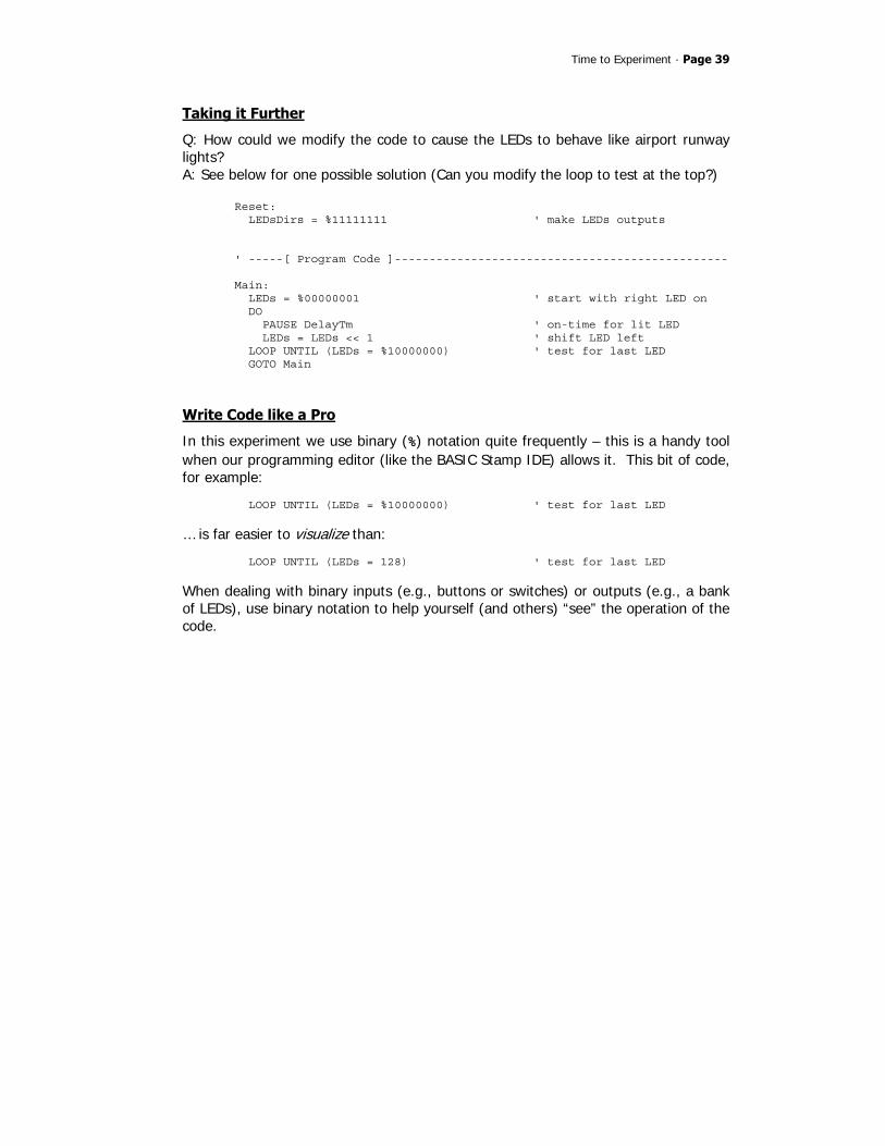
Taking it Further
Q: How could we modify the code to cause the LEDs to behave like airport runway lights? A: See below for one possible solution (Can you modify the loop to test at the top?)
Reset: LEDsDirs = %11111111 ' make LEDs outputs ' -----[ Program Code ]------------------------------------------------ Main: LEDs = %00000001 ' start with right LED on DO PAUSE DelayTm ' on-time for lit LED LEDs = LEDs << 1 ' shift LED left LOOP UNTIL (LEDs = %10000000) ' test for last LED GOTO Main
Write Code like a Pro
In this experiment we use binary (%) notation quite frequently – this is a handy tool when our programming editor (like the BASIC Stamp IDE) allows it. This bit of code, for example:
LOOP UNTIL (LEDs = %10000000) ' test for last LED
… is far easier to visualize than: LOOP UNTIL (LEDs = 128) ' test for last LED
When dealing with binary inputs (e.g., buttons or switches) or outputs (e.g., a bank of LEDs), use binary notation to help yourself (and others) “see” the operation of the code.
Page 40 · StampWorks
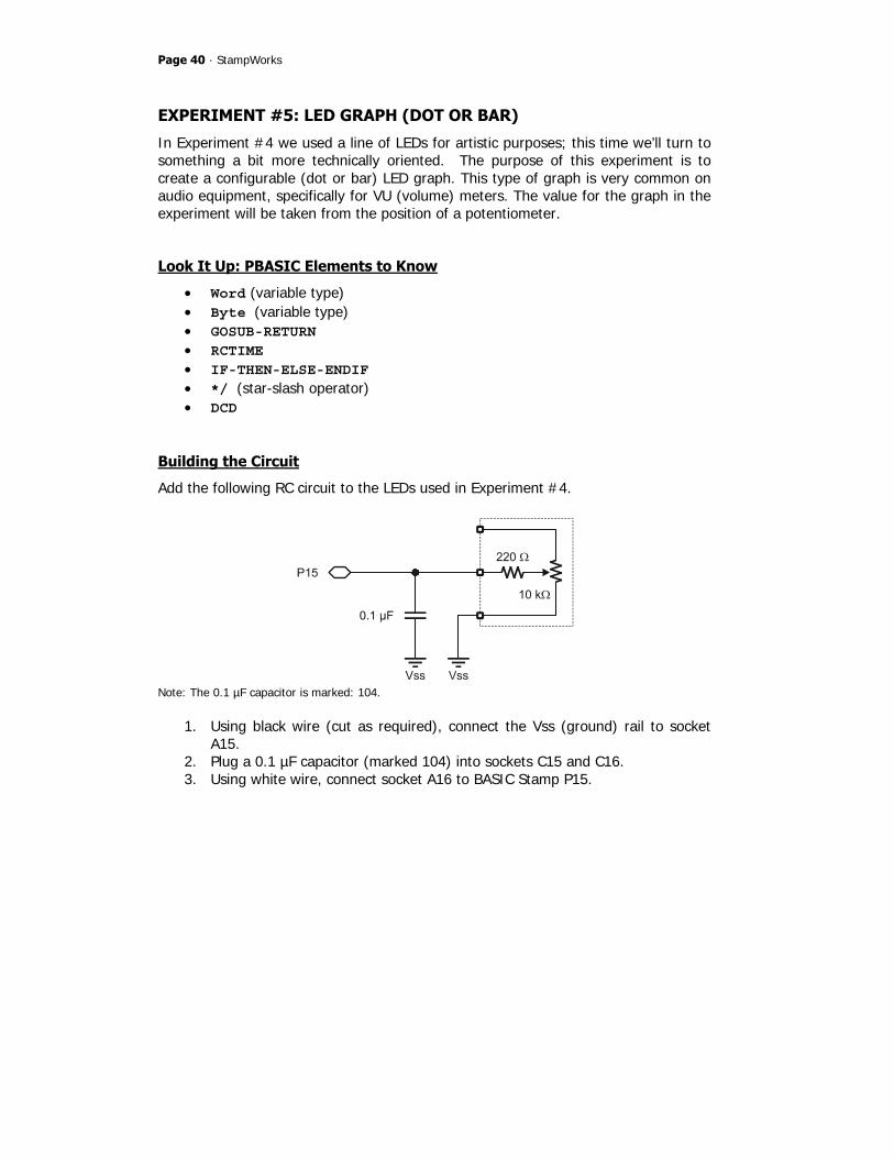
EXPERIMENT #5: LED GRAPH (DOT OR BAR)
In Experiment #4 we used a line of LEDs for artistic purposes; this time we’ll turn to something a bit more technically oriented. The purpose of this experiment is to create a configurable (dot or bar) LED graph. This type of graph is very common on audio equipment, specifically for VU (volume) meters. The value for the graph in the experiment will be taken from the position of a potentiometer.
Look It Up: PBASIC Elements to Know
• Word (variable type) • Byte (variable type) • GOSUB-RETURN • RCTIME • IF-THEN-ELSE-ENDIF • */ (star-slash operator) • DCD
Building the Circuit
Add the following RC circuit to the LEDs used in Experiment #4.
Note: The 0.1 µF capacitor is marked: 104.
1. Using black wire (cut as required), connect the Vss (ground) rail to socket A15.
2. Plug a 0.1 µF capacitor (marked 104) into sockets C15 and C16. 3. Using white wire, connect socket A16 to BASIC Stamp P15.

Time to Experiment · Page 41
4. Using white wire, connect socket B16 to the wiper (center terminal) of the 10K potentiometer.
5. Using black wire, connect the Vss (ground) rail to the bottom terminal of the 10K potentiometer.
Program: SW21-EX05-LED_Graph.BS2: ' $STAMP BS2 ' $PBASIC 2.5 ' -----[ Program Description ]--------------------------------------------- ' ' Displays a linear (bar) or dot graph using eight LEDs. This program ' will require modifications (to the constants LoScale and HiScale) when ' running on the BS2Sx, BS2p, or BS2px. ' -----[ I/O Definitions ]------------------------------------------------- LEDs VAR OUTL ' LEDs on P0 - P7 LEDsDirs VAR DIRL ' DIRS control for LEDs Pot PIN 15 ' Pot circuit IO ' -----[ Constants ]------------------------------------------------------- DotGraf CON 0 ' define graph types BarGraf CON 1 GraphMode CON BarGraf ' define graph mode IsOn CON 1 IsOff CON 0 LoScale CON 10 ' raw low reading HiScale CON 695 ' raw high reading Span CON HiScale - LoScale ' between lo-to-hi Scale CON $FFFF / Span ' scale factor 0..255 ' -----[ Variables ]------------------------------------------------------- rawVal VAR Word ' raw value from pot grafVal VAR Byte ' graph value hiBit VAR Byte ' highest lighted bit newBar VAR Byte ' workspace for bar graph

Page 42 · StampWorks
' -----[ Initialization ]-------------------------------------------------- Reset: LEDsDirs = %11111111 ' make LEDs outputs ' -----[ Program Code ]---------------------------------------------------- Main: DO GOSUB Read_Pot ' get raw pot value grafVal = (rawVal - LoScale) */ Scale ' z-adjust, then scale GOSUB Show_Graph ' now show it PAUSE 50 LOOP ' -----[ Subroutines ]----------------------------------------------------- Read_Pot: HIGH Pot ' charge cap PAUSE 1 ' for 1 millisecond RCTIME Pot, 1, rawVal ' read the Pot RETURN Show_Graph: hiBit = DCD (grafVal / 32) ' get highest bit IF (GraphMode = BarGraf) THEN newBar = 0 ' clear bar workspace IF (grafVal > 0) THEN DO WHILE (hiBit > 0) ' all bar LEDs lit? newBar = newBar << 1 ' no - shift left newBar.BIT0 = IsOn ' light low end hiBit = hiBit >> 1 ' mark bit lit LOOP ENDIF LEDs = newBar ' output new level ELSE LEDs = hiBit ' show dot value ENDIF RETURN

Time to Experiment · Page 43
Behind the Scenes
Now we’re getting into it – this program, while short, is a bit on the sophisticated side as it allows us to enter raw readings from the potentiometer and the program will take care of the rest. After initializing the outputs (P0 – P7) to drive LEDs, the program reads the 10K potentiometer with the RCTIME function. Using DEBUG to display the raw value, it was determined that RCTIME returned a low value of 10 and a high value of 746. Since grafVal is a byte-sized variable, rawVal must be scaled down to fit into eight bits. To scale the raw value to fit into grafVal we’ll want to divide it by 2.73 (695 / 255). The problem for us is that division in PBASIC is integer-only, so we’d end up with troublesome rounding errors. Since division is the same as multiplying by a value’s reciprocal, we can multiply rawVal by 0.366906. In some cases we can do a multiply and divide to approximate the fractional value, but this is not possible because the 16-bit (final) values used in PBASIC may cause high bit truncation. This is where the */ (star-slash) operator comes in: this operator allows us to multiply a value by another with a resolution of 1/256. The way this works is that */ does a multiplication of two values, then takes the middle two bytes of the 32-bit result – the net effect is that we’re multiplying then immediately dividing by 256 (hence the resolution of 1/256). If the fractional value is going to be a constant we can calculate the*/ parameter in advance by multiplying the fractional value by 256. In our case this would be: 0. 366906 x 256 = 93.92 (round up to 94) As it turns out we can very easily calculate the value of Scale by dividing $FFFF (maximum 16-bit value) by the pot span (difference between high and low readings). Better yet, we can embed this calculation in a constant definition – this saves us valuable variable space. At the top of the listing we have:
LoScale CON 10 ' raw low reading HiScale CON 695 ' raw high reading Span CON HiScale - LoScale ' between lo-to-hi Scale CON $FFFF / Span ' scale factor 0..255

Page 44 · StampWorks
If we decide to replace the BS2 with a faster microcontroller, for example a BS2p, the only thing we need to do is read the pot and enter the low and high readings from it. After we make those changes the Scale constant will be updated on the next compilation and the program will run just as it did on the BS2. You may be wondering why the LoScale value is something greater than 0. If you look at the schematic, there is a 220-ohm resistor between the pot’s wiper and the center connection. The purpose of this resistor is to protect the BASIC Stamp when the pot is turned all the way to Vss and the P15 is made an output and high; it also causes a bit of delay in the capacitor discharge, hence the minimum value that is greater than zero. With grafVal scaled to a byte we can move on to creating the bar or dot graph with the LEDs. The program uses the DCD operator to determine highest lighted bit value from grafVal. With eight LEDs in the graph, grafVal is divided by 32, forcing the result of DCD to output values from %00000001 (DCD 0) to %10000000 (DCD 7). In Dot mode, this is all that’s required and a single LED that represents the scale of the pot input is lit. In Bar Mode, however, the lower LEDs must be filled in. This is accomplished in a simple loop. The control value for the loop is the variable, hiBit, which is also calculated using DCD. In this loop, hiBit will be tested for zero to exit, so each iteration through the loop will decrement (decrease) this value. If hiBit is greater than zero, the bar graph workspace variable, newBar, is shifted left and its bit 0 is set. For example, if DCD returned %1000 in hiBit, here’s how hiBit and newBar would be affected through the loop:
hiBit newBar 1000 0001 0100 0011 0010 0111 0001 1111 0000 (done - exit loop and display value)
The purpose for the variable, newBar, is to prevent the LEDs from flashing with each update. This allows the program to start with an “empty” graph and build to the
Time to Experiment · Page 45
current value. With this technique, the program does not have to remember the value of the previous graph.
Write Code like a Pro
As your programs become more and more complex, it’s important to code and test a section at a time. In this program there are two separate subroutines; each was independently coded and tested before incorporating them together. Independent testing of code modules is particularly important when the program is already working – there is nothing more frustrating than “breaking” a perfectly good program by adding untested code.
Page 46 · StampWorks
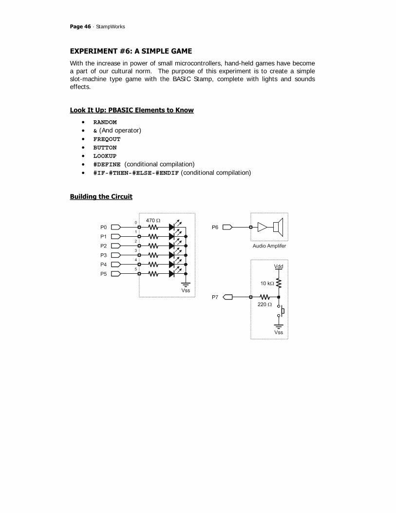
EXPERIMENT #6: A SIMPLE GAME
With the increase in power of small microcontrollers, hand-held games have become a part of our cultural norm. The purpose of this experiment is to create a simple slot-machine type game with the BASIC Stamp, complete with lights and sounds effects.
Look It Up: PBASIC Elements to Know
• RANDOM • & (And operator) • FREQOUT • BUTTON • LOOKUP • #DEFINE (conditional compilation) • #IF-#THEN-#ELSE-#ENDIF (conditional compilation)
Building the Circuit

Time to Experiment · Page 47
1. Using white wire, connect BASIC Stamp pins P0 – P5 to LEDs 0 – 5. 2. Using white wire, connect BASIC Stamp pin P6 to the Audio Amplifier
(set the speaker selection shunt to SPK). 3. Using white wire, connect BASIC Stamp pin P7 to a pushbutton.
Program: SW21-EX06-Las_Vegas.BS2 ' $STAMP BS2 ' $PBASIC 2.5 ' -----[ Program Description ]--------------------------------------------- ' ' This program simulates a very simple slot machine game, complete with ' sound FX. The constants TAdj and FAdj may require adjustment when using ' on faster BASIC Stamp modules. ' -----[ I/O Definitions ]------------------------------------------------- LEDs VAR OUTL ' LED outputs LEDsDirs VAR DIRL ' DIRS control for LEDs Speaker PIN 6 ' speaker output PlayBtn PIN 7 ' button input to play ' -----[ Constants ]------------------------------------------------------- TAdj CON $100 ' time adjust factor FAdj CON $100 ' frequency adjust factor ' -----[ Variables ]------------------------------------------------------- rndVal VAR Word ' random number pattern VAR Byte ' light pattern tone VAR Word ' tone output swData VAR Byte ' workspace for BUTTON delay VAR Word ' delay while "spinning" spin1 VAR Byte ' loop counter spin2 VAR Byte ' loop counter ' -----[ Initialization ]-------------------------------------------------- Reset: LEDsDirs = %00111111 ' make LEDs outputs

Page 48 · StampWorks
' -----[ Program Code ]---------------------------------------------------- Main: DO GOSUB Get_Random ' get random number/tone FREQOUT Speaker, 35 */ TAdj, tone */ FAdj ' sound the tone PAUSE 100 BUTTON PlayBtn, 0, 255, 10, swData, 1, Spin ' check for play LOOP Spin: LEDs = %00111111 ' simulate machine reset PAUSE 750 LEDs = %00000000 PAUSE 500 delay = 75 ' initialize delay FOR spin1 = 1 TO 25 ' spin the wheel GOSUB Get_Random ' get random number FREQOUT Speaker, 25 */ TAdj, 425 */ FAdj ' wheel click PAUSE delay ' pause between clicks delay = delay */ $0119 ' multiply delay by 1.1 NEXT IF (pattern = %00111111) THEN ' if all lit, you win FOR spin1 = 1 TO 5 FOR spin2 = 0 TO 3 LOOKUP spin2, [$00, $0C, $12, $21], LEDs LOOKUP spin2, [665, 795, 995, 1320], tone FREQOUT Speaker, 35 */ TAdj, tone */ FAdj PAUSE 65 NEXT NEXT ELSE FREQOUT Speaker, 1000 */ TAdj, 330 */ FAdj ' otherwise, groan... ENDIF Clear_Game: LEDs = %00000000 ' clear LEDs PAUSE 1000 GOTO Main ' do it again ' -----[ Subroutines ]----------------------------------------------------- Get_Random: RANDOM rndVal ' get pseudo-random number tone = rndVal & $7FF ' keep in reasonable range pattern = rndVal & %00111111 ' mask out unused bits LEDs = pattern ' show the pattern RETURN

Time to Experiment · Page 49
Behind the Scenes
One of the key aspects of this program is that it demonstrates how to put more randomness into the pseudo-random nature of the RANDOM function. This is done by adding a “human touch.” The program waits in a loop at Main. The top of this loop calls Get_Random to create a pseudo-random value, a tone for the speaker and to put the new pattern on the LEDs. On returning to the loop, the tone is played and the button input is checked for a press. The program will remain in this loop until we press the button. The BUTTON instruction is used to debounce the input. Here’s what gives the program its randomness: the time variations between button presses (during which the RANDOM function is continually called, hence tumbling the value). When the button is pressed, the LEDs are lit and cleared to simulate the game resetting. Then, a FOR-NEXT loop is used to simulate the rolling action of a slot machine. For each roll, a “click” sound is generated and the delay between clicks is modified (increased by 10%) to simulate natural decay (slowing) of the “wheels.” If all six LEDs are lit after the last spin, the program plays a little light and sound show to celebrate our good fortune. This section uses LOOKUP to play a preset pattern of LEDs and tones before returning to the top of the program. If any of the LEDs are not lit, a groan will be heard from the speaker and the game will restart.
Taking It Further
Can you modify the program so that fewer than six LEDs are required for a win? How can this be done?
Write Code like a Pro
Instead of waiting for an actual “win” we can rig the game to win every time by inserting a line of code:
pattern = %00111111
. . . before the section that tests the pattern bits. This is useful for fine-tuning the celebration routine – just be sure to remove this code before delivering the final

Page 50 · StampWorks
project. In some programs where we may have several sections used for testing, or we need the ability to turn test code on and off, inserting a conditional compilation block will facilitate the quick removal and restoration of test code. We can use #DEFINE to create a conditional constant
#DEFINE _TestMode = 1
When _TestMode is defined as 1 the code nested in #IF-#THEN will run, otherwise it will not even be compiled or downloaded to the BASIC Stamp.
#IF _TestMode #THEN pattern = %00111111 #ENDIF
Be aware that enabling conditional compilation blocks like the one shown above will increase the program size – if you’re going to be creating a large program you should enable them from the beginning so that you don’t run out of space when you need them later.

Time to Experiment · Page 51
EXPERIMENT #7: A LIGHTING CONTROLLER
The purpose of this experiment is to create a small lighting controller, suitable for holiday displays and outdoor decorations. The outputs of this circuit will be LEDs only (To control high-voltage lighting take a look at Matt Gilliland’s Microcontroller Application Cookbook).
Look It Up: PBASIC Elements to Know
• DATA • // (Modulus operator) • ON-GOSUB • READ
Building the Circuit
Page 52 · StampWorks
1. Using white wire, connect BASIC Stamp pins P0 – P5 to LEDs 0 – 5. 2. Plug a 0.1 µF (marked 104) capacitor into sockets C15 and C16. 3. Using white wire, connect socket A16 to BASIC Stamp P6. 4. Using a blackwire, connect socket A15 to the Vss (ground) rail. 5. Using white wire, connect socket B16 to the wiper (center terminal) of the
10K potentiometer. 6. Using black wire, connect the Vss (ground) rail to the bottom terminal of the
10K potentiometer. 7. Using white wire, connect BASIC Stamp pin P7 to a pushbutton.
Program: SW21-EX07-Light_Show.BS2 ' $STAMP BS2 ' $PBASIC 2.5 ' -----[ Program Description ]--------------------------------------------- ' ' Runs a small, multi-mode light show controller using six outputs (runs ' on LEDs, but with proper interfacing could run incandescent lamps). ' This program will require modifications (to the constants LoSpeed and ' Scale) when running on the BS2Sx, BS2p, or BS2px. ' -----[ I/O Definitions ]------------------------------------------------- Lights VAR OUTL ' light control outputs LightsDirs VAR DIRL ' DIRS for lights outputs Speed PIN 6 ' speed control Pot input LtMode PIN 7 ' mode select input ' -----[ Constants ]------------------------------------------------------- LoSpeed CON 10 ' low end of POT reading Scale CON $0163 ' 1.3868 with */ ' -----[ Variables ]------------------------------------------------------- rawSpd VAR Word ' speed input from POT delay VAR Word ' time between patterns btnVar VAR Byte ' workspace for BUTTON mode VAR Byte ' selected mode offset VAR Byte ' offset into patterns rndVal VAR Word ' workspace for RANDOM

Time to Experiment · Page 53
' -----[ EEPROM Data ]----------------------------------------------------- SeqA DATA %000001, %000010, %000100, %001000, %010000 DATA %100000 SeqB DATA %100000, %010000, %001000, %000100, %000010 DATA %000001, %000010, %000100, %001000, %010000 SeqC DATA %000000, %001100, %010010, %100001 SeqD DATA %100100, %010010, %001001 SeqE DATA %0 AMax CON SeqB - SeqA ' calculate length BMax CON SeqC - SeqB CMax CON SeqD - SeqC DMax CON SeqE - SeqD ' -----[ Initialization ]-------------------------------------------------- Reset: LightsDirs = %00111111 ' make outputs ' -----[ Program Code ]---------------------------------------------------- Main: GOSUB Read_Speed ' read speed pot delay = (rawSpd - LoSpeed) */ Scale + 50 ' calc delay (50-1000 ms) PAUSE delay ' wait between patterns Switch_Check: BUTTON LtMode, 0, 255, 0, btnVar, 0, Show ' new mode? mode = mode + 1 // 5 ' yes, update mode var Show: ON mode GOSUB ModeA, ModeB, ModeC, ModeD, ModeE GOTO Main ' -----[ Subroutines ]----------------------------------------------------- Read_Speed: HIGH Speed ' charge cap PAUSE 1 ' for 1 millisecond RCTIME Speed, 1, rawSpd ' read the Pot RETURN ModeA: offset = offset + 1 // AMax ' update offset (0 - 5)

Page 54 · StampWorks
READ (SeqA + offset), Lights ' output new light pattern RETURN ModeB: offset = offset + 1 // BMax READ (SeqB + offset), Lights RETURN ModeC: offset = offset + 1 // CMax READ (SeqC + offset), Lights RETURN ModeD: offset = offset + 1 // DMax READ (SeqD + offset), Lights RETURN ModeE: RANDOM rndVal ' get random number Lights = rndVal & %00111111 ' light random channels RETURN
Behind the Scenes
Overall, this program is simpler than it first appears. The main body of the program is a loop. Timing through the main loop is controlled by the position of the potentiometer. RCTIME is used to read the pot and during development the maximum pot reading was found to be 695, and the minimum reading was 10. What we’d like to do is convert the span 10 – 695 to 50 – 1000. The process is actually quite simple: the desired output span (950) is divided by the input span (685) to provide a scale factor of 1.3868. This factor is converted for use with */ by multiplying by 256 (355 or $0163). In application the low end pot value is subtracted from the raw input, the scale factor applied, and then the minimum output value of 50 is added. Those with a flair for mathematics will recognize the familiar y = mx+b equation. The code at Switch_Check looks to see if the button is pressed. If it is, the variable, mode, is incremented (increased by 1). The modulus (//) operator is used to keep mode in the range of zero to four. This works because the modulus operator returns the remainder of an integer division. Since any number divided by itself will

Time to Experiment · Page 55
return a remainder of zero, using modulus in this manner causes mode to “wrap-around” from four to zero. The final element of the main loop is called Show. This code uses ON-GOSUB to call the code that will output the light sequence specified by mode. Modes A through D work similarly, retrieving light sequences from the BASIC Stamp’s EEPROM (stored in DATA statements). Mode E outputs a random light pattern. Take a look at the code section labeled ModeA. The first thing that happens is that the variable, offset, is updated – again using the “wrap-around” technique with the modulus operator. The value of offset is added to the starting position of the specified light sequence and the current light pattern is retrieved from EEPROM with READ. Notice that the DATA statements for each sequence are labeled (SeqA, SeqB, etc.). Internally, each of these labels is converted to a constant value that is equal to the starting address of the sequence. The length of each sequence is calculated with these constants. By using this technique, light patterns can be updated (shortened or lengthened) without having to modify the operational code called by Show. ModeE is very straightforward, using the RANDOM function to output new pattern of lights with each pass through the main loop.
Take it Further
Add a new lighting sequence. What sections of the program need to be modified to make this work?
Write Code like a Pro
The modulus operator (//) is extremely useful, yet shunned by many beginning programmers as “mysterious.” It’s not, really, in fact its operation is very simple: it returns the remainder of an integer division. In practice what this means is that the modulus of any value will fall into the range of zero to the value minus one. Beginners will often do this:
idx = idx + 1 IF (idx = 5) THEN idx = 0 ENDIF
Page 56 · StampWorks
The pro will replace that code with:
idx = idx + 1 // 5
But what if we wanted to go the other direction, that is, wrap from zero back up to some number?
idx = idx - 1 IF (idx = 0) THEN idx = 4 ENDIF
Yes, this is possible too. Here’s how: idx = idx + 4 // 5
Can you see what’s happening? We’re adding the number of elements in the sequence (5) minus one to idx; the net effect is that we end up subtracting one from idx when modulus is used to remove the whole result of the division. This is a very handy trick – keep it in your bag.
Building Circuits on Your Own · Page 57
Building Circuits on Your Own With the experience you’ve gained in the previous experiments you’re ready to assemble what follows without specific point-to-point wiring instructions. Don’t be nervous, you can do it. The projects are fairly simple and you’ll see that they’re electrically similar to the projects you’ve already built; what we’re going to focus on is new code techniques. Proceed slowly and be sure to double-check your connections before you apply power. Remember, it’s always best to clear the BASIC Stamp’s memory and I/O setup between experiments – and that can be done with a very simple program: ' $STAMP BS2 Main: DEBUG "The BASIC Stamp is ready." END
Are you ready for some more fun? You should be, and know that you’re well on you way to designing your own BASIC Stamp projects and experiments. Okay, then, let’s continue with 7-Segment LED displays….

Page 58 · StampWorks

Using 7-Segment LED Displays · Page 59
Using 7-Segment LED Displays As you look around and notice devices that use them, you’ll see that LEDs come in all manner of shape, size, and color. Early on, LED manufacturers found that they could package seven rectilinear-shaped LEDs in a Figure-8 pattern and when specific groups of LEDs were lit, the display could be any of the decimal digits and even a few alpha characters. We call these packaged groups of LEDs 7-segment displays. In order to simplify wiring, 7-segment LED displays have a common internal connection; the LEDs used on the PDB are common-cathode, that is, the cathodes of the LEDs within the display are connected together and that connection must be made low (connected to Vss) in order to light any of the LEDs in the package. The diagram below shows the connections of a common-cathode LED display in relation to the current-limiting resistors on the PDB.
Note that the PDB has five, 7-segment, common-cathode LED modules, and the terminal marked “A” in the “SEGMENTS” section is connected to the A-segment LED in all five modules. In the experiments that follow we will learn how to get the most out of 7-segment displays.

Page 60 · StampWorks
EXPERIMENT #8: A SINGLE-DIGIT COUNTER
The purpose of this experiment is to get us started with 7-segment LED displays by creating a simple, single-digit decimal counter.
Building the Circuit
Program: SW21-EX08-7-Seg_Counter.BS2 ' $STAMP BS2 ' $PBASIC 2.5 ' -----[ Program Description ]--------------------------------------------- ' ' Displays decimal digits (0 - 9) on a 7-Segment display connected to ' P0-P7. This program will work, unmodified, on any BS2-family module. ' -----[ I/O Definitions ]------------------------------------------------- Segs VAR OUTL ' Segments on P0 - P7 SegsDirs VAR DIRL ' DIRS for segments

Using 7-Segment LED Displays · Page 61
' -----[ Variables ]------------------------------------------------------- idx VAR Nib ' counter variable ' -----[ EEPROM Data ]----------------------------------------------------- ' .GFEDCBA ' -------- Digit0 DATA %00111111 Digit1 DATA %00000110 Digit2 DATA %01011011 Digit3 DATA %01001111 Digit4 DATA %01100110 Digit5 DATA %01101101 Digit6 DATA %01111101 Digit7 DATA %00000111 Digit8 DATA %01111111 Digit9 DATA %01100111 ' -----[ Initialization ]-------------------------------------------------- Reset: SegsDirs = %01111111 ' make outputs for LEDs ' -----[ Program Code ]---------------------------------------------------- Main: FOR idx = 0 TO 9 ' loop through digits READ (Digit0 + idx), Segs ' move pattern to display PAUSE 1000 NEXT GOTO Main
Behind the Scenes
This experiment is very similar to the light show program in basic operation: a pattern is read from the EEPROM and transferred directly to the LED segments. In this program, sending specific patterns to the 7-segment LED creates the digits zero through nine. To demonstrate that all five modules have the segment lines tied together (and connected to terminals A through DP, respectively), move the Vss connection from DIGIT 0 to DIGIT 4. See what happens?

Page 62 · StampWorks
Take it Further
Update the program to create a single-digit hexadecimal counter. Use the patterns below for the HEX digits.
Write Code like a Pro
Note that the DATA table the stores the 7-segment patterns uses verbose label names and the patterns are placed in sequential order. By storing the segment information in EEPROM instead of constants, transferring these patterns to the display is greatly simplified. Had we elected to store the patterns as constant values, we’d have to use the following bit of code to make the transfer:
LOOKUP idx, [Digit0, Digit1, Digit2, Digit3, Digit4, Digit5, Digit6, Digit7, Digit8, Digit9], Segs
As you can see, using READ is a bit tidier. In most programs, storing table values in DATA statements will simplify coding and save code space if the same values are to be used in more than one place in the program.
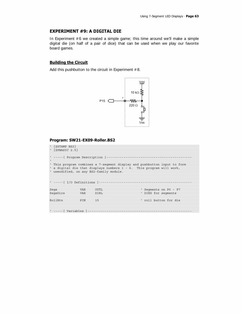
Using 7-Segment LED Displays · Page 63
EXPERIMENT #9: A DIGITAL DIE
In Experiment #6 we created a simple game; this time around we’ll make a simple digital die (on half of a pair of dice) that can be used when we play our favorite board games.
Building the Circuit
Add this pushbutton to the circuit in Experiment #8.
Program: SW21-EX09-Roller.BS2 ' $STAMP BS2 ' $PBASIC 2.5 ' -----[ Program Description ]--------------------------------------------- ' ' This program combines a 7-segment display and pushbutton input to form ' a digital die that displays numbers 1 - 6. This program will work, ' unmodified, on any BS2-family module. ' -----[ I/O Definitions ]------------------------------------------------- Segs VAR OUTL ' Segments on P0 - P7 SegsDirs VAR DIRL ' DIRS for segments RollBtn PIN 15 ' roll button for die ' -----[ Variables ]-------------------------------------------------------
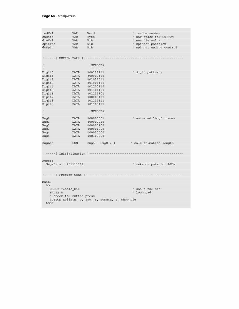
Page 64 · StampWorks
rndVal VAR Word ' random number swData VAR Byte ' workspace for BUTTON dieVal VAR Nib ' new die value spinPos VAR Nib ' spinner position doSpin VAR Nib ' spinner update control ' -----[ EEPROM Data ]----------------------------------------------------- ' .GFEDCBA ' -------- Digit0 DATA %00111111 ' digit patterns Digit1 DATA %00000110 Digit2 DATA %01011011 Digit3 DATA %01001111 Digit4 DATA %01100110 Digit5 DATA %01101101 Digit6 DATA %01111101 Digit7 DATA %00000111 Digit8 DATA %01111111 Digit9 DATA %01100111 ' .GFEDCBA ' -------- Bug0 DATA %00000001 ' animated "bug" frames Bug1 DATA %00000010 Bug2 DATA %00000100 Bug3 DATA %00001000 Bug4 DATA %00010000 Bug5 DATA %00100000 BugLen CON Bug5 - Bug0 + 1 ' calc animation length ' -----[ Initialization ]-------------------------------------------------- Reset: SegsDirs = %01111111 ' make outputs for LEDs ' -----[ Program Code ]---------------------------------------------------- Main: DO GOSUB Tumble_Die ' shake the die PAUSE 5 ' loop pad ' check for button press BUTTON RollBtn, 0, 255, 5, swData, 1, Show_Die LOOP

Using 7-Segment LED Displays · Page 65
Show_Die: READ (Digit0 + dieVal), Segs ' transfer die to segments PAUSE 3000 ' hold for viewing GOTO Main ' start again ' -----[ Subroutines ]----------------------------------------------------- Tumble_Die: RANDOM rndVal ' stir random value dieVal = (rndVal // 6) + 1 ' get die val, 1 - 6 doSpin = (doSpin + 1) // 10 ' update spin timer IF (doSpin = 0) THEN ' time for update spinPos = (spinPos + 1) // BugLen ' yes, point to next pos READ (Bug0 + spinPos), Segs ' output to segments ENDIF RETURN
Behind the Scenes
This program borrows heavily from what we’ve already done and should be easy to understand. What we’ve done here is added a bit of programming creativity to make a very simple program visually interesting. Of note is the Tumble_Die subroutine which actually does quite a lot of work. The first thing this routine does is shake the random number generator. Since the main loop will call this subroutine about every five milliseconds, it’s getting a lot of shaking and should give us nice random results. From the random number the die value is created. Remember what we learned about the modulus operator: it will always return a value between zero and the divisor. Since there are six faces on a die, we divide the random value by six and take the modulus; this gives us zero to five. Adding one “fixes” the value so it’s between one and six. Finally, this same subroutine is responsible for updating the animated “bug” used to indicate the die being shaken. If we updated the frame through every pass of the subroutine the display would look more like a flickering zero than an animation – we need to slow things down, perhaps updating the animation every tenth time through (which would give us a bit more than 50 ms per frame). This is accomplished by using doSpin as a timer. This value gets incremented then divided by 10 (with //) on every pass; when the modulus result is zero it’s time to update the animation

Page 66 · StampWorks
“frame.” The delay between frames allows us to seem them more clearly and creates a more inviting display.
Take it Further
Update the program to make the animated bug run around in a “Figure-8” pattern as show below.

Using 7-Segment LED Displays · Page 67
EXPERIMENT #10: A DIGITAL CLOCK
The purpose of this experiment is to create a simple digital clock using four, 7-Segment displays. Through this experiment we’ll gain a bit of insight to the process of display multiplexing, and discover a trick that lets us know when an input has changed to a specified state.
Look It Up: PBASIC Elements to Know
• DIG (digit operator)
Building the Circuit

Page 68 · StampWorks
Program: SW21-EX10-Clock.BS2 ' $STAMP BS2 ' $PBASIC 2.5 ' -----[ Program Description ]--------------------------------------------- ' ' This program takes an external 1 Hz signal from the pulse generator and ' synthesizes a simple clock/timer. This code will run, unmodified, on and ' BS2-family module. ' -----[ I/O Definitions ]------------------------------------------------- Segs VAR OUTL ' Segments on P0 - P7 Digs VAR OUTC ' Digit control pins Tic PIN 15 ' 1 Hz input ' -----[ Constants ]------------------------------------------------------- Blank CON %00000000 ' all segments off DecPnt CON %10000000 ' decimal point on IsHigh CON 1 IsLow CON 0 ' -----[ Variables ]------------------------------------------------------- nTic VAR Bit ' new tic input oTic VAR Bit ' old tic value xTic VAR Bit ' change (1 when 0 -> 1) secs VAR Word ' seconds time VAR Word ' formatted time theDig VAR Nib ' current display digit ' -----[ EEPROM Data ]----------------------------------------------------- ' .GFEDCBA ' -------- Digit0 DATA %00111111 ' digit patterns Digit1 DATA %00000110 Digit2 DATA %01011011 Digit3 DATA %01001111 Digit4 DATA %01100110 Digit5 DATA %01101101 Digit6 DATA %01111101 Digit7 DATA %00000111
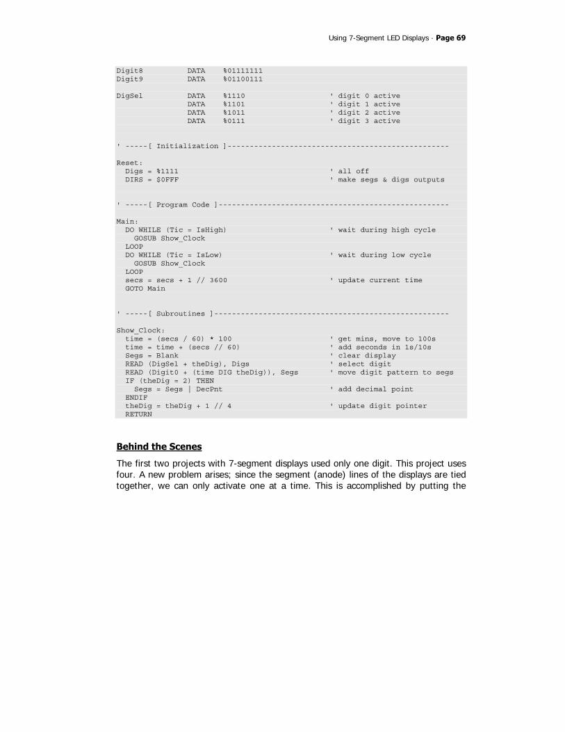
Using 7-Segment LED Displays · Page 69
Digit8 DATA %01111111 Digit9 DATA %01100111 DigSel DATA %1110 ' digit 0 active DATA %1101 ' digit 1 active DATA %1011 ' digit 2 active DATA %0111 ' digit 3 active ' -----[ Initialization ]-------------------------------------------------- Reset: Digs = %1111 ' all off DIRS = $0FFF ' make segs & digs outputs ' -----[ Program Code ]---------------------------------------------------- Main: DO WHILE (Tic = IsHigh) ' wait during high cycle GOSUB Show_Clock LOOP DO WHILE (Tic = IsLow) ' wait during low cycle GOSUB Show_Clock LOOP secs = secs + 1 // 3600 ' update current time GOTO Main ' -----[ Subroutines ]----------------------------------------------------- Show_Clock: time = (secs / 60) * 100 ' get mins, move to 100s time = time + (secs // 60) ' add seconds in 1s/10s Segs = Blank ' clear display READ (DigSel + theDig), Digs ' select digit READ (Digit0 + (time DIG theDig)), Segs ' move digit pattern to segs IF (theDig = 2) THEN Segs = Segs | DecPnt ' add decimal point ENDIF theDig = theDig + 1 // 4 ' update digit pointer RETURN
Behind the Scenes
The first two projects with 7-segment displays used only one digit. This project uses four. A new problem arises; since the segment (anode) lines of the displays are tied together, we can only activate one at a time. This is accomplished by putting the

Page 70 · StampWorks
segment pattern on the anodes and then enabling the desired digit (by making its cathode low). It would be nice, though, if we could see all four digits at the same time. Well, we can’t, but if we switch between them fast enough we can fool our eyes into thinking that they are. The human eye has a property known as Persistence of Vision (POV), which causes it to hold an image briefly. The brighter the image, the longer it holds in our eyes. POV is what causes us to see a bright spot in our vision after a friend snaps a flash photo. We can use POV to our advantage by rapidly cycling through each of the four digits, displaying the proper segments for that digit for a short period. If the cycle is fast enough, the POV of our eyes will cause the all four digits to appear to be lit at the same time. This process is called multiplexing. Multiplexing is the process of sharing data lines; in this case, the segment lines to the 7-segment displays. If we didn’t multiplex, 28 output lines would be required to control four 7-segment displays. That’s 12 more lines than are available on the BASIC Stamp module. To be honest, multiplexing in PBASIC is not terribly practical, but it does allow us to gain an understanding of the process so that when we turn to multiplexers for assistance (see Experiment #31), we are able to get the results we desire. The main loop of the program proceeds in three stages:
• Display the current time while the signal generator input is high • Display the current time while the signal generator input is low • Update the seconds counter
Note again how the modulus operator (//) is used to keep seconds in the range of 0 to 3599 (the number of seconds in one hour). The real work in this experiment happens in the subroutine called Show_Clock. Its purpose is to reformat the raw seconds into a time format (MMSS) and then update the current digit. Since the routine can only show one digit at a time, it must be called very frequently, otherwise display strobing will occur. As we saw earlier, the main loop of the program does nothing but call this subroutine while waiting for the Signal Generator input to change.

Using 7-Segment LED Displays · Page 71
The clock display is created by moving the minutes value (secs / 60) into the thousands and hundreds columns of the variable time. The remaining seconds (secs // 60) are added to time, placing them in the tens and ones columns. Here’s how the conversion math works: Example: 754 seconds 754 / 60 = 12 12 x 100 = 1200 (time = 1200) 754 // 60 = 34 1200 + 34 = 1234 (time = 1234; 12 minutes and 34 seconds) Now that the time display value is ready, the segments are cleared for the next update. Clearing the current segments value keeps the display sharp. If this isn’t done, the old segments value will cause “ghosting” in the display. Once the display is clear the current digit is selected and the segments get updated. Pay special attention to the DIG operator; it is quite handy. DIG returns the single digit value from the specified position of a number. For example: 725 DIG 1 = 2 Remember, the right-most digit is digit 0. By updating the variable, theDig, we use it as a column pointer for both the cathode control as well as pulling the digit offset from time for use in reading the segments. The PDB display does not have the colon (:) normally found on a digital clock, so we’ll enable the decimal point behind digit 2 (ones digit of hours). When theDig is not pointing to this digit the decimal point illumination is skipped. The final step is to update theDig for the next calling of the subroutine.
Take it Further
Update the program to use a 10 Hz input from the Signal Generator and blink the decimal point on every other transition (see SW21-EX10-Clock-DP_Blink.BS2 for full listing).
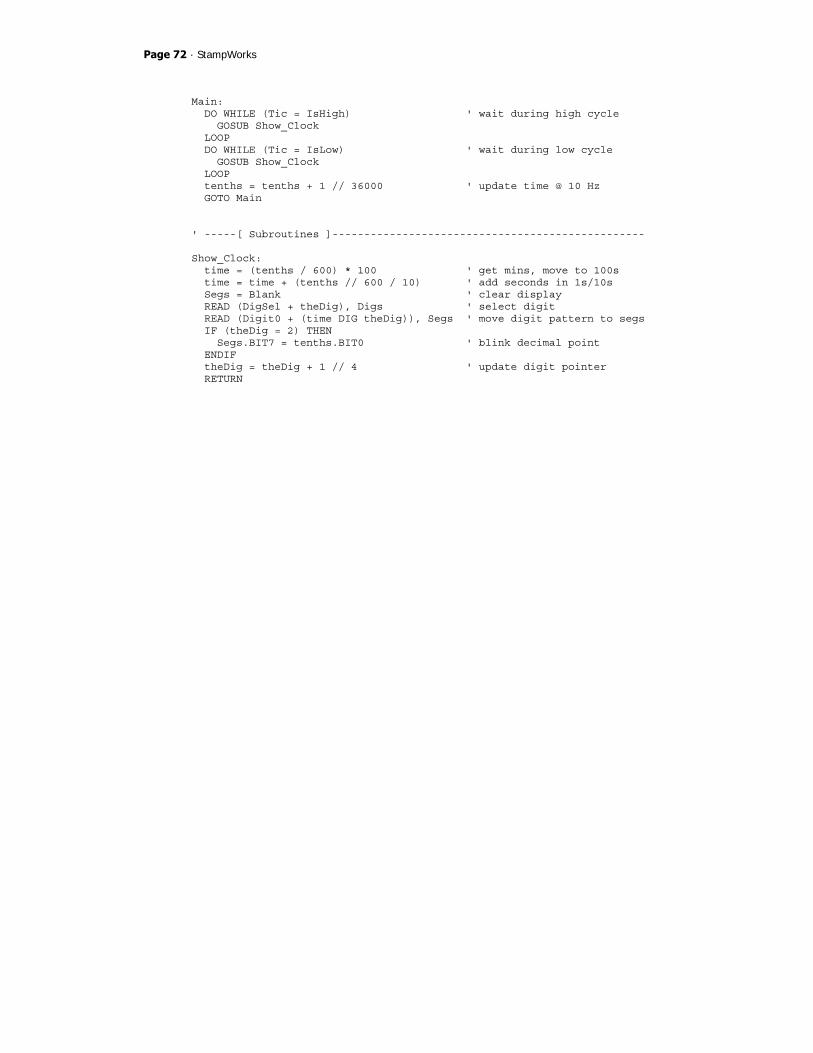
Page 72 · StampWorks
Main: DO WHILE (Tic = IsHigh) ' wait during high cycle GOSUB Show_Clock LOOP DO WHILE (Tic = IsLow) ' wait during low cycle GOSUB Show_Clock LOOP tenths = tenths + 1 // 36000 ' update time @ 10 Hz GOTO Main ' -----[ Subroutines ]------------------------------------------------- Show_Clock: time = (tenths / 600) * 100 ' get mins, move to 100s time = time + (tenths // 600 / 10) ' add seconds in 1s/10s Segs = Blank ' clear display READ (DigSel + theDig), Digs ' select digit READ (Digit0 + (time DIG theDig)), Segs ' move digit pattern to segs IF (theDig = 2) THEN Segs.BIT7 = tenths.BIT0 ' blink decimal point ENDIF theDig = theDig + 1 // 4 ' update digit pointer RETURN

Using Character LCDs · Page 73
Using Character LCDs While LEDs and 7-segment displays make great output devices, there will be projects that require providing more complex information to the user. Of course, nothing beats the PC video display, but these are large, expensive, and almost always impractical for microcontroller projects. Character LCD modules, on the other hand, fit the bill well. These inexpensive modules allow both text and numeric output, use very few I/O lines, and require little effort from the BASIC Stamp. And since the introduction of the BS2p, character LCD instructions have become part of the PBASIC 2.0 and later 2.5 languages. That said, we can still use the stock BS2 to drive these versatile displays and the experiments that follow will demonstrate how. Character LCD modules are available in a wide variety of configurations: one-line, two-line, and four-line are very common. The number of columns (characters) per line is also variable, with 16- and 20- character displays being the most common and popular.
The datasheet for the parallel LCD (2 lines x 16 characters) included in the StampWorks Kit is available for download from www.parallax.com.
The LCD module connects to the PDB by a 14-pin IDC header (X1). The header is keyed, preventing the connector from being inserted upside-down.
Initialization
The character LCD must be initialized before displaying characters on it. The projects that follow initialize the LCD in accordance with the specification for the Hitachi HD44780 controller. The Hitachi controller is the most popular available and many
Page 74 · StampWorks
controllers are compatible with it. When in doubt, be sure to download and examine the driver documentation for an LCD that does not work properly with these programs.
Modes of Operation
There are two essential modes of operation with character LCDs: writing a character on the LCD, and sending a command to the LCD (to clear the screen, for example). When sending a character, the RS line is high and the data sent is interpreted as a character to be displayed at the current cursor position. The code sent is usually the ASCII code for the character to be displayed. Several non-ASCII characters also are available in the LCD ROM, as well as up to eight user-programmable custom characters (stored in an area called CGRAM). Commands are sent to the LCD by taking the RS line low before sending the data. Several standard commands are available to manage and manipulate the LCD display. Clear $01 Clears the LCD and moves cursor to first position of first line Home $02 Moves cursor to first position of first line Cursor Left $10 Moves cursor to the left Cursor Right $14 Moves cursor to the right Display Left $18 Shifts entire display to the left Display Right $1C Shifts entire display to the right Connecting the LCD The standard parallel LCD has a 14-pin IDC connector at the end of its cable. The connector is “keyed” so that it is always inserted correctly into the PDB. Simply align the connector key (small bump) with the slot in X1 and press the connector into the socket until it is firmly seated.

Using Character LCDs · Page 75
EXPERIMENT #11: BASIC LCD DEMONSTRATION
This experiment demonstrates character LCD interfacing and control fundamentals by putting the LCD module through its paces.
Look It Up: PBASIC Elements to Know
• PULSOUT • HIGHNIB, LOWNIB • ^ (Exclusive Or operator) • #ERROR
Building the Circuit
Note on connections: On the PDB, X2 splits the LCD data buss between the left and right sides of the lower portion of the connector.

Page 76 · StampWorks
Be sure to insert the wires for DB4-DB7 into the right side of the connector as shown below:
Program: SW21-EX11-LCD_Demo.BS2 ' $STAMP BS2 ' $PBASIC 2.5 ' -----[ Program Description ]--------------------------------------------- ' ' This program demonstrates essential character LCD control. ' ' The connections for this program conform to the BS2p-family LCDCMD, ' LCDIN, and LCDOUT instructions. Use this program for the BS2, BS2e, ' or BS2sx. There is a separate program for the BS2p, BS2pe, and BS2px. ' -----[ I/O Definitions ]------------------------------------------------- E PIN 1 ' Enable pin RW PIN 2 ' Read/Write RS CON 3 ' Register Select LcdBus VAR OUTB ' 4-bit LCD data bus ' -----[ Constants ]------------------------------------------------------- LcdCls CON $01 ' clear the LCD LcdHome CON $02 ' move cursor home LcdCrsrL CON $10 ' move cursor left LcdCrsrR CON $14 ' move cursor right LcdDispL CON $18 ' shift chars left LcdDispR CON $1C ' shift chars right LcdDDRam CON $80 ' Display Data RAM control

Using Character LCDs · Page 77
LcdCGRam CON $40 ' Character Generator RAM LcdLine1 CON $80 ' DDRAM address of line 1 LcdLine2 CON $C0 ' DDRAM address of line 2 #DEFINE LcdReady = ($STAMP >= BS2P) ' -----[ Variables ]------------------------------------------------------- char VAR Byte ' character sent to LCD idx VAR Byte ' loop counter ' -----[ EEPROM Data ]----------------------------------------------------- Msg DATA "The BASIC STAMP!", 0 ' store message ' -----[ Initialization ]-------------------------------------------------- Reset: #IF ($STAMP >= BS2P) #THEN #ERROR "Please use BS2p version: SW21-EX11-LCD_Demo.BSP" #ENDIF DIRL = %11111110 ' setup pins for LCD PAUSE 100 ' let the LCD settle Lcd_Setup: LcdBus = %0011 ' 8-bit mode PULSOUT E, 3 PAUSE 5 PULSOUT E, 3 PULSOUT E, 3 LcdBus = %0010 ' 4-bit mode PULSOUT E, 1 char = %00001100 ' disp on, no crsr or blink GOSUB LCD_Cmd char = %00000110 ' inc crsr, no disp shift GOSUB LCD_Cmd ' -----[ Program Code ]---------------------------------------------------- Main: char = LcdCls ' clear the LCD GOSUB LCD_Cmd PAUSE 500 idx = Msg ' get EE address of message

Page 78 · StampWorks
Write_Message: DO READ idx, char ' get character from EE IF (char = 0) THEN EXIT ' if 0, message is complete GOSUB LCD_Out ' write the character idx = idx + 1 ' point to next character LOOP PAUSE 2000 ' wait 2 seconds Cursor_Demo: char = LcdHome ' move the cursor home GOSUB LCD_Cmd char = %00001110 ' turn the cursor on GOSUB LCD_Cmd PAUSE 500 char = LcdCrsrR FOR idx = 1 TO 15 ' move cursor l-to-r GOSUB LCD_Cmd PAUSE 150 NEXT FOR idx = 14 TO 0 ' move cursor r-to-l by char = LcdDDRam + idx ' moving to a specific GOSUB LCD_Cmd ' column PAUSE 150 NEXT char = %00001101 ' cursor off, blink on GOSUB LCD_Cmd PAUSE 2000 char = %00001100 ' blink off GOSUB LCD_Cmd Flash_Demo: FOR idx = 1 TO 10 ' flash display char = char ^ %00000100 ' toggle display bit GOSUB LCD_Cmd PAUSE 250 NEXT PAUSE 1000 Shift_Demo: FOR idx = 1 TO 16 ' shift display char = LcdDispR GOSUB LCD_Cmd PAUSE 100 NEXT PAUSE 1000
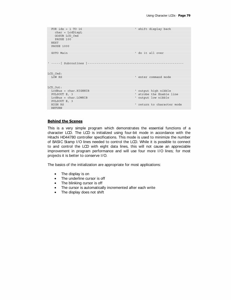
Using Character LCDs · Page 79
FOR idx = 1 TO 16 ' shift display back char = LcdDispL GOSUB LCD_Cmd PAUSE 100 NEXT PAUSE 1000 GOTO Main ' do it all over ' -----[ Subroutines ]----------------------------------------------------- LCD_Cmd: LOW RS ' enter command mode LCD_Out: LcdBus = char.HIGHNIB ' output high nibble PULSOUT E, 3 ' strobe the Enable line LcdBus = char.LOWNIB ' output low nibble PULSOUT E, 3 HIGH RS ' return to character mode RETURN
Behind the Scenes
This is a very simple program which demonstrates the essential functions of a character LCD. The LCD is initialized using four-bit mode in accordance with the Hitachi HD44780 controller specifications. This mode is used to minimize the number of BASIC Stamp I/O lines needed to control the LCD. While it is possible to connect to and control the LCD with eight data lines, this will not cause an appreciable improvement in program performance and will use four more I/O lines; for most projects it is better to conserve I/O. The basics of the initialization are appropriate for most applications:
• The display is on • The underline cursor is off • The blinking cursor is off • The cursor is automatically incremented after each write • The display does not shift

Page 80 · StampWorks
Note that this program initializes the LCD for just one line, even though two lines are physically available on the LCD. See the following experiment for initializing the LCD for multi-line mode. With the use of four data bits on the LCD bus, two write cycles are necessary to send a byte to the LCD. The BASIC Stamp’s HIGHNIB and LOWNIB variable modifiers make this process exceedingly easy. Each nibble is latched into the LCD by pulsing the E (enable) line high with PULSOUT. The main portion of the program starts by clearing the LCD and displaying a message that has been stored in a DATA statement. This technique of storing messages in EEPROM is very useful and makes programs easier to update. In this program, characters are written until a zero is encountered. This method lets us change the length of the string without worrying about loop control settings. With the message displayed, the cursor position is returned home (first position of first line) and turned on (an underline cursor appears). The cursor is sent back and forth across the LCD using two distinct techniques. The first uses the cursor-right command. Moving the cursor left is accomplished by manually positioning the cursor to a specific column position. Manual cursor positioning is required by many LCD programs for tidy formatting of the information in the display. With the cursor back home, it is turned off and the blink attribute is enabled. Blink causes the current cursor position to alternate between the character and a solid black box. This can be useful as an attention getter. Another attention-getting technique is to flash the entire display. This is accomplished by toggling the display enable bit. The Exclusive OR operator (^) simplifies bit toggling, as any bit XORed with a 1 will invert: 1 ^ 1 = 0 0 ^ 1 = 1 Using the display shift commands, the entire display is shifted off-screen to the right, then back. What this demonstrates is that the visible display is actually a window into the LCD’s display memory (called the DDRAM). One method of using the additional memory is to write messages off-screen and shift the visible display to them.
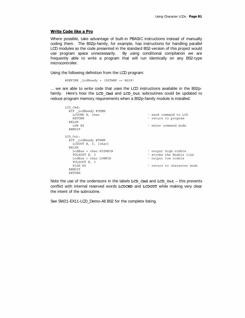
Using Character LCDs · Page 81
Write Code like a Pro
Where possible, take advantage of built-in PBASIC instructions instead of manually coding them. The BS2p-family, for example, has instructions for handling parallel LCD modules so the code presented in the standard BS2-version of this project would use program space unnecessarily. By using conditional compilation we are frequently able to write a program that will run identically on any BS2-type microcontroller. Using the following definition from the LCD program:
#DEFINE _LcdReady = ($STAMP >= BS2P)
… we are able to write code that uses the LCD instructions available in the BS2p-family. Here’s how the LCD_Cmd and LCD_Out subroutines could be updated to reduce program memory requirements when a BS2p-family module is installed:
LCD_Cmd: #IF _LcdReady #THEN LCDCMD E, char ' send command to LCD RETURN ' return to program #ELSE LOW RS ' enter command mode #ENDIF LCD_Out: #IF _LcdReady #THEN LCDOUT E, 0, [char] #ELSE LcdBus = char.HIGHNIB ' output high nibble PULSOUT E, 3 ' strobe the Enable line LcdBus = char.LOWNIB ' output low nibble PULSOUT E, 3 HIGH RS ' return to character mode #ENDIF RETURN
Note the use of the underscore in the labels LCD_Cmd and LCD_Out – this prevents conflict with internal reserved words LCDCMD and LCDOUT while making very clear the intent of the subroutine. See SW21-EX11-LCD_Demo-All.BS2 for the complete listing.

Page 82 · StampWorks
EXPERIMENT #12: CREATING CUSTOM LCD CHARACTERS
This program demonstrates the creation of custom LCD characters, animation with the custom characters, and initializing the LCD for multi-line mode.
Building the Circuit
Use the same circuit as in Experiment #11.
Program: SW21-EX11-LCD_Demo.BS2 ' $STAMP BS2 ' $PBASIC 2.5 ' -----[ Program Description ]--------------------------------------------- ' ' This program demonstrates custom character creation and animation on a ' character LCD. ' ' The connections for this program conform to the BS2p-family LCDCMD, ' LCDIN, and LCDOUT instructions. Use this program for the BS2, BS2e, ' or BS2sx. There is a separate program for the BS2p, BS2pe, and BS2px. ' -----[ I/O Definitions ]------------------------------------------------- E PIN 1 ' Enable pin RW PIN 2 ' Read/Write RS CON 3 ' Register Select LcdBus VAR OUTB ' 4-bit LCD data bus ' -----[ Constants ]------------------------------------------------------- LcdCls CON $01 ' clear the LCD LcdHome CON $02 ' move cursor home LcdCrsrL CON $10 ' move cursor left LcdCrsrR CON $14 ' move cursor right LcdDispL CON $18 ' shift chars left LcdDispR CON $1C ' shift chars right LcdDDRam CON $80 ' Display Data RAM control LcdCGRam CON $40 ' Character Generator RAM LcdLine1 CON $80 ' DDRAM address of line 1 LcdLine2 CON $C0 ' DDRAM address of line 2 #DEFINE _LcdReady = ($STAMP >= BS2P)
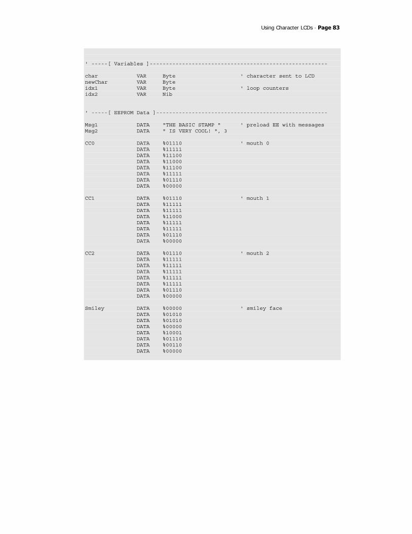
Using Character LCDs · Page 83
' -----[ Variables ]------------------------------------------------------- char VAR Byte ' character sent to LCD newChar VAR Byte idx1 VAR Byte ' loop counters idx2 VAR Nib ' -----[ EEPROM Data ]----------------------------------------------------- Msg1 DATA "THE BASIC STAMP " ' preload EE with messages Msg2 DATA " IS VERY COOL! ", 3 CC0 DATA %01110 ' mouth 0 DATA %11111 DATA %11100 DATA %11000 DATA %11100 DATA %11111 DATA %01110 DATA %00000 CC1 DATA %01110 ' mouth 1 DATA %11111 DATA %11111 DATA %11000 DATA %11111 DATA %11111 DATA %01110 DATA %00000 CC2 DATA %01110 ' mouth 2 DATA %11111 DATA %11111 DATA %11111 DATA %11111 DATA %11111 DATA %01110 DATA %00000 Smiley DATA %00000 ' smiley face DATA %01010 DATA %01010 DATA %00000 DATA %10001 DATA %01110 DATA %00110 DATA %00000
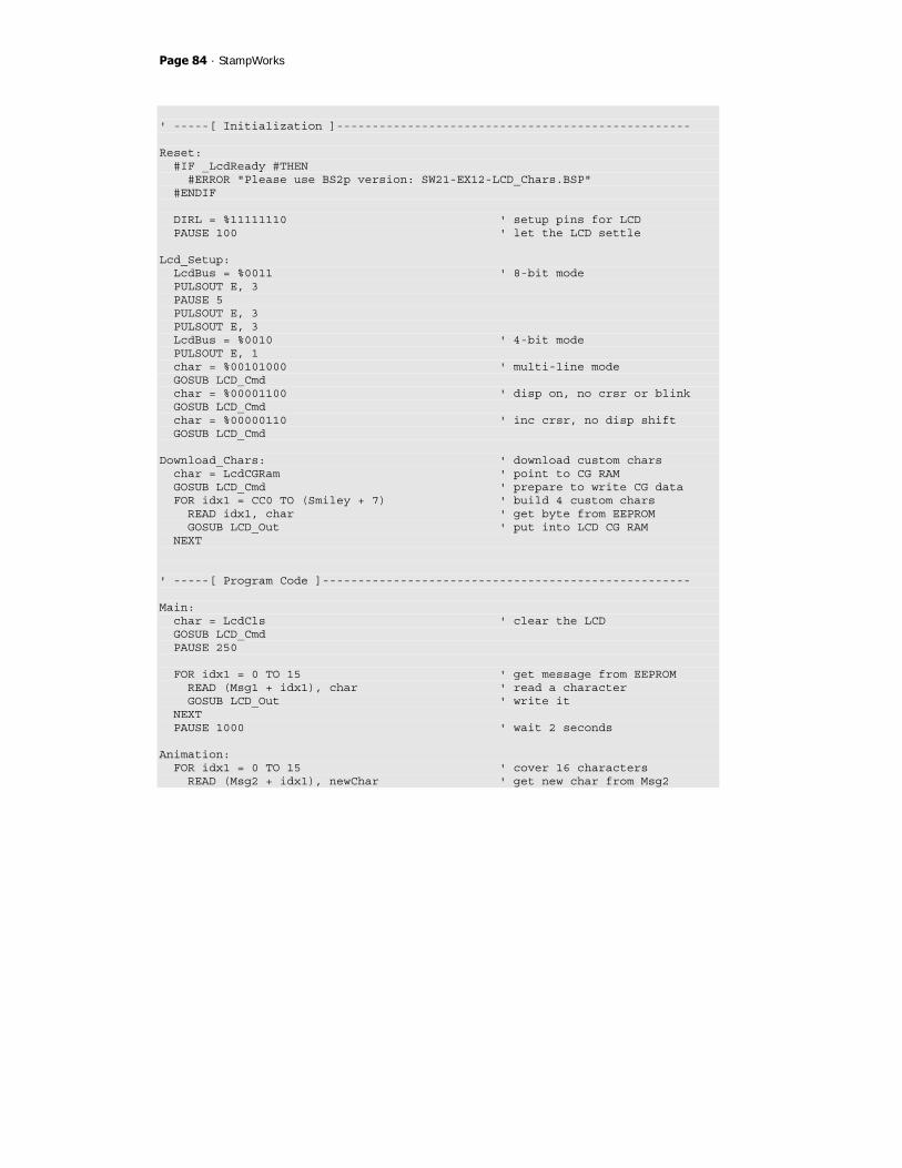
Page 84 · StampWorks
' -----[ Initialization ]-------------------------------------------------- Reset: #IF _LcdReady #THEN #ERROR "Please use BS2p version: SW21-EX12-LCD_Chars.BSP" #ENDIF DIRL = %11111110 ' setup pins for LCD PAUSE 100 ' let the LCD settle Lcd_Setup: LcdBus = %0011 ' 8-bit mode PULSOUT E, 3 PAUSE 5 PULSOUT E, 3 PULSOUT E, 3 LcdBus = %0010 ' 4-bit mode PULSOUT E, 1 char = %00101000 ' multi-line mode GOSUB LCD_Cmd char = %00001100 ' disp on, no crsr or blink GOSUB LCD_Cmd char = %00000110 ' inc crsr, no disp shift GOSUB LCD_Cmd Download_Chars: ' download custom chars char = LcdCGRam ' point to CG RAM GOSUB LCD_Cmd ' prepare to write CG data FOR idx1 = CC0 TO (Smiley + 7) ' build 4 custom chars READ idx1, char ' get byte from EEPROM GOSUB LCD_Out ' put into LCD CG RAM NEXT ' -----[ Program Code ]---------------------------------------------------- Main: char = LcdCls ' clear the LCD GOSUB LCD_Cmd PAUSE 250 FOR idx1 = 0 TO 15 ' get message from EEPROM READ (Msg1 + idx1), char ' read a character GOSUB LCD_Out ' write it NEXT PAUSE 1000 ' wait 2 seconds Animation: FOR idx1 = 0 TO 15 ' cover 16 characters READ (Msg2 + idx1), newChar ' get new char from Msg2

Using Character LCDs · Page 85
FOR idx2 = 0 TO 4 ' 5 characters in cycle char = LcdLine2 + idx1 ' set new DDRAM address GOSUB LCD_Cmd ' move cursor position LOOKUP idx2, [0, 1, 2, 1, newChar], char ' get animation "frame" GOSUB LCD_Out ' write "frame" PAUSE 100 ' animation delay NEXT NEXT PAUSE 2000 GOTO Main ' do it all over ' -----[ Subroutines ]----------------------------------------------------- LCD_Cmd: LOW RS ' enter command mode LCD_Out: LcdBus = char.HIGHNIB ' output high nibble PULSOUT E, 3 ' strobe the Enable line LcdBus = char.LOWNIB ' output low nibble PULSOUT E, 3 HIGH RS ' return to character mode RETURN
Behind the Scenes
In this program, the LCD is initialized for multi-line mode (note the additional lines after entering 4-bit mode). This will allow both lines of the LCD module to display information. With the display initialized, custom character definitions are downloaded to the LCD. The LCD has room for eight, user-definable customer characters. The data is stored for these characters in an area called CGRAM and must be downloaded to the LCD after power-up and initialization (CGRAM is volatile, so custom character definitions are lost when power is removed from the LCD). Each custom character requires eight bytes, the first byte being the top line of the character, the last byte being the bottom line of the character. The eighth byte is usually $00 as this is where the cursor is positioned when under the character.

Page 86 · StampWorks
The standard LCD font is five bits wide by seven bits tall. You can create custom characters that are eight bits tall, but as explained before the eighth line is generally reserved for the underline cursor. Here’s an example of a custom character definition:
The shape of the character is determined by the ones and zeros in the data bytes. A 1 in a given bit position will light a pixel; zero will extinguish it. The bit patterns for custom characters are stored in the BASIC Stamp’s EEPROM with DATA statements. To move the patterns into the LCD the cursor is moved to the CGRAM then each data byte is written. Since the LCD has been initialized for auto-incrementing, there is no need to address each data byte individually. Before the characters can be used, the display must be returned to “normal” mode by moving the cursor back to the DDRAM area. The usual method is to clear the display or home the cursor. Interestingly, the LCD retrieves the bit patterns from memory while refreshing the display. In advanced applications, the CGRAM memory can be updated while the program is running to create unusual display effects. The heart of this program is the animation loop. This code grabs a character from the second message, then, for each character in that message, displays the animation sequence at the desired character location on the second line of the LCD. A LOOKUP table is used to cycle the custom characters for the animation sequence. At the end of the sequence, the new character is revealed.

Using Character LCDs · Page 87
Write Code like a Pro
Note the use of binary formatted numbers in the DATA statements for this program. While the beginning programmer may consider this technique overly verbose, the professional knows that the small amount of up-front work to use this format saves a lot of time later when editing or redefining characters. The purpose of the various numeric formats supported by the BASIC Stamp IDE is to assist the programmer – once downloaded to the BASIC Stamp the values are all stored in a binary format.
Take it Further
Create your own custom character sequence. Update the initialization and animation code to accommodate your custom character set.

Page 88 · StampWorks
EXPERIMENT #13: READING THE LCD RAM
This program demonstrates the use of the LCD’s CGRAM space as external memory.
Look It Up: PBASIC Elements to Know
• INS, INL, INH, INA - IND
Building the Circuit
Use the same circuit as in Experiment #11.
Program: SW21-EX13-LCD_Read.BSP ' $STAMP BS2 ' $PBASIC 2.5 ' -----[ Program Description ]--------------------------------------------- ' ' This program demonstrates how to read data from the LCD's display RAM ' (DDRAM) or character RAM (CGRAM). ' ' The connections for this program conform to the BS2p-family LCDCMD, ' LCDIN, and LCDOUT instructions. Use this program for the BS2, BS2e, ' or BS2sx. There is a separate program for the BS2p, BS2pe, and BS2px. ' -----[ I/O Definitions ]------------------------------------------------- E PIN 1 ' Enable pin RW PIN 2 ' Read/Write RS CON 3 ' Register Select LcdDirs VAR DIRB ' bus DDR LcdBusOut VAR OUTB ' 4-bit LCD data bus LcdBusIn VAR INB ' -----[ Constants ]------------------------------------------------------- LcdCls CON $01 ' clear the LCD LcdHome CON $02 ' move cursor home LcdCrsrL CON $10 ' move cursor left LcdCrsrR CON $14 ' move cursor right LcdDispL CON $18 ' shift chars left LcdDispR CON $1C ' shift chars right

Using Character LCDs · Page 89
LcdDDRam CON $80 ' Display Data RAM control LcdCGRam CON $40 ' Character Generator RAM LcdLine1 CON $80 ' DDRAM address of line 1 LcdLine2 CON $C0 ' DDRAM address of line 2 #DEFINE _LcdReady = ($STAMP >= BS2P) ' -----[ Variables ]------------------------------------------------------- char VAR Byte ' character sent to LCD idx VAR Byte ' loop counter rndVal VAR Word ' random value addr VAR Byte ' address to write/read tOut VAR Byte ' test value - out to LCD tIn VAR Byte ' test value - in from LCD temp VAR Word ' use for formatting width VAR Nib ' width of value to display ' -----[ Initialization ]-------------------------------------------------- Reset: #IF _LcdReady #THEN #ERROR "Please use BS2p version: SW21-EX13-LCD_Read.BSP" #ENDIF DIRL = %11111110 ' setup pins for LCD PAUSE 100 ' let the LCD settle Lcd_Setup: LcdBusOut = %0011 ' 8-bit mode PULSOUT E, 3 PAUSE 5 PULSOUT E, 3 PULSOUT E, 3 LcdBusOut = %0010 ' 4-bit mode PULSOUT E, 1 char = %00101000 ' multi-line mode GOSUB LCD_Cmd char = %00001100 ' disp on, no crsr or blink GOSUB LCD_Cmd char = %00000110 ' inc crsr, no disp shift GOSUB LCD_Cmd Display: char = LcdHome GOSUB LCD_Cmd PAUSE 2 FOR idx = 0 TO 15

Page 90 · StampWorks
LOOKUP idx, ["ADDR=?? OUT:???"], char GOSUB LCD_Out NEXT char = LcdLine2 GOSUB LCD_Cmd PAUSE 2 FOR idx = 0 TO 15 LOOKUP idx, [" IN:???"], char GOSUB LCD_Out NEXT ' -----[ Program Code ]---------------------------------------------------- Main: RANDOM rndVal ' generate random number addr = rndVal.LOWBYTE & $3F ' create address (0 to 63) tOut = rndVal.HIGHBYTE ' create test value char = LcdCGRam + addr ' set CGRAM pointer GOSUB LCD_Cmd char = tOut GOSUB LCD_Out ' move the value to CGRAM PAUSE 100 char = LcdCGRam + addr ' reset CGRAM pointer GOSUB LCD_Cmd GOSUB LCD_In ' read value from LCD tIn = char ' display results char = LcdLine1 + 5 ' show address @ L1/C5 GOSUB LCD_Cmd temp = addr width = 2 GOSUB Put_Val char = LcdLine1 + 13 ' show output @ L1/C13 GOSUB LCD_cmd temp = tOut width = 3 GOSUB Put_Val char = LcdLine2 + 13 ' show output @ L2/C13 GOSUB LCD_Cmd temp = tIn width = 3 GOSUB Put_Val PAUSE 1000

Using Character LCDs · Page 91
GOTO Main ' do it again ' -----[ Subroutines ]----------------------------------------------------- LCD_Cmd: LOW RS ' enter command mode LCD_Out: LcdBusOut = char.HIGHNIB ' output high nibble PULSOUT E, 3 ' strobe the Enable line LcdBusOut = char.LOWNIB ' output low nibble PULSOUT E, 3 HIGH RS ' return to character mode RETURN LCD_In: HIGH RS ' data command HIGH RW ' read LcdDirs = %0000 ' make data lines inputs HIGH E char.HIGHNIB = LcdBusIn ' get high nibble LOW E HIGH E char.LOWNIB = LcdBusIn ' get low nibble LOW E LcdDirs = %1111 ' make buss lines outputs LOW RW ' return to write mode RETURN Put_Val: FOR idx = (width - 1) TO 0 ' display digits l-to-r char = (temp DIG idx) + "0" ' convert digit to ASCII GOSUB LCD_Out ' write to LCD NEXT RETURN
Behind the Scenes
This program demonstrates the versatility of the BASIC Stamp’s I/O lines and their ability to be reconfigured mid-program. Writing to the LCD was covered in the last two experiments. To read data back, the BASIC Stamp’s I/O lines that serve as the LCD bus must be reconfigured as inputs. This is no problem for the BASIC Stamp.

Page 92 · StampWorks
Aside from the I/O reconfiguration, reading from the LCD requires the use of an additional control line: RW. In most programs this line can be held low to allow writing to the LCD. For reading from the LCD RAM the RW line is made high. Using the RANDOM function this program generates an address that fits within the CGRAM, as well a data byte to write to the LCD. The address is kept in the range of 0 to 63 by masking out the highest bits of the LOWBYTE; the HIGHBYTE is used as the data to be written to the LCD. The LCD’s CGRAM is normally used for custom character maps. For programs that do not require custom characters, this area (up to 64 bytes) can be used as a storage space by the BASIC Stamp. In programs that require fewer than eight custom characters the remaining bytes of CGRAM can be used as off-board memory (subtract eight bytes from the CGRAM for each custom character definition). Reading data from the LCD is identical to writing: the address is set and the data is retrieved. For this to take place, the LCD data lines must be reconfigured as inputs. Pulsing the E (enable) line makes the data (one nibble at a time) available for the BASIC Stamp. Once again, HIGHNIB and LOWNIB are used, this time to build a single byte from the two nibbles returned during the read operation. When the retrieved data is ready, the address, output data and input data are written to the LCD for examination. A short subroutine, Put_Val, handles writing numerical values to the LCD. To use this routine, move the cursor to the desired location, put the value to be displayed in temp, the number of characters to display in width, and then call Put_Val. The subroutine uses the DIG operator to extract a digit from temp and adds 48 (the ASCII code for “0”) to convert the digit value to a character so that it can be displayed on the LCD.

Moving Forward · Page 93
Moving Forward The first sections of this book dealt specifically with output devices, because the choice of output is often critical to the success of a project. By now, you should be very comfortable with LEDs, 7-Segment displays, and even character LCD modules. From this point forward we will work through a variety of experiments; some are simple, others are somewhat complex, all of them will round your education as a BASIC Stamp programmer and help build the confidence you need to develop your own BASIC Stamp-controlled applications. Remember, the key to success here is to complete each experiment and to take on any challenge that is presented. Then, go further by challenging yourself. Each time you modify a program you will learn something. It’s okay if your experiments don’t work as expected the first time you run them, because you will still be learning. Be patient and push yourself to learn a little more each day. Very soon you will find yourself being considered an expert BASIC Stamp programmer.

Page 94 · StampWorks
EXPERIMENT #14: SCANNING AND DEBOUNCING MULTIPLE INPUTS
This experiment will teach you how to debounce multiple BASIC Stamp inputs. With modification, any number of inputs, from two to 16, can be debounced using this method.
Look It Up: PBASIC Elements to Know
• ~ (Invert operator) • DEBUG • HOME (used with DEBUG) • IBIN (used with DEBUG) • LOWBIT() (variable modifier)
Building the Circuit

Moving Forward · Page 95
Program: SW21-EX14-Debounce.BS2 ' $STAMP BS2 ' $PBASIC 2.5 ' -----[ Program Description ]--------------------------------------------- ' ' This program demonstrates the simultaneous debouncing of multiple inputs. ' The input subroutine is easily adjusted to handle any number of inputs. ' -----[ I/O Definitions ]------------------------------------------------- BtnBus VAR INA ' four inputs, pins 0 - 3 ' -----[ Variables ]------------------------------------------------------- btns VAR Nib ' debounced inputs idx VAR Nib ' loop counter ' -----[ Program Code ]---------------------------------------------------- Main: DO GOSUB Get_Buttons ' get debounced inputs DEBUG HOME, "Inputs = ", IBIN4 btns ' display in binary mode PAUSE 50 LOOP ' -----[ Subroutines ]----------------------------------------------------- Get_Buttons: btns = %1111 ' enable all four inputs FOR idx = 1 TO 5 btns = btns & ~BtnBus ' test inputs PAUSE 5 ' delay between tests NEXT RETURN
Behind the Scenes
When debouncing only one input, the BASIC Stamp’s BUTTON instruction works perfectly well and even adds a couple of useful features (like auto-repeat). To debounce two or more inputs, however, we need to create a bit of code. The
Page 96 · StampWorks
workhorse of this experiment is the subroutine Get_Buttons. As presented, it will accommodate four normally-open, active-low inputs but it can easily be modified for any number of inputs from two to 16. The purpose of Get_Buttons is to ensure that the inputs stay pressed for at least 25 milliseconds with no contact “bouncing.” Debounced inputs will be returned in the variable, btns, with a valid input represented by a “1” in the respective button position. The Get_Buttons routine starts by assuming that all button inputs will be valid, so all the bits of btns variable are set to one. Then, using a FOR-NEXT loop, the inputs are scanned and compared to the previous state. Since the inputs are active-low (zero when pressed), the Invert operator (~) flips them. The And operator (&) is used to update the current state. For a button to be valid, it must remain pressed through the entire FOR-NEXT loop. Here’s how the debouncing technique works: When a button is pressed, the input to the BASIC Stamp will be zero. The Invert operator will flip zero to one. One “Anded” with one is still one, so that button remains valid. If the button is not pressed, the raw input to the BASIC Stamp will be one (because of the 10K pull-up to Vdd). One is inverted to zero. Zero “Anded” with any number is zero and will cause the button to remain invalid through the entire debounce loop. The debounced button inputs are displayed in a DEBUG window with the IBIN4 modifier so that the value (state, pressed = “1”) of each button is clearly displayed.
Write Code like a Pro
Many programs will require the ability to “single shot” a button input, that is, to activate some event or process only after the change-of-state of a button. By keeping track of the last scan value we can report to the program which buttons changed between the current scan and the last.

Moving Forward · Page 97
Here’s the modified subroutine: Get_Buttons: nBtns = %1111 ' enable all four inputs FOR idx = 1 TO 5 nBtns = nBtns & ~BtnBus ' test new inputs PAUSE 5 ' delay between tests NEXT xBtns = nBtns ^ oBtns & nBtns ' look for 0 -> 1 changes oBtns = nBtns ' save this scan RETURN
The real work is done by this line of code: xBtns = nBtns ^ oBtns & nBtns ' look for 0 -> 1 changes
The current button state (nBtns) is compared with the previous scan value (oBtns) using the Exclusive OR (^) operator. This will cause a bit to be ‘1’ when there is a difference between the previous scan and the current. This [comparison] value is then ANDed with nBtns which holds ‘1’ for each pressed button. The result is that xBtns will have a ‘1’ for each button that was ‘0’ on the last scan and is ‘1’ on this scan. Note that if the button remains pressed and Get_Buttons is called again, the respective bit of xBtns will change from ‘1’ to ‘0’ since there was no change of button state. See listing SW21-EX14-Debounce-Adv.BS2 for a full demonstration.
Take it Further
Modify the program to scan, debounce, and display eight buttons (Hint: Use INL or INH).

Page 98 · StampWorks
EXPERIMENT #15: COUNTING EVENTS
This experiment demonstrates an events-based program delay.
Look It Up: PBASIC Elements to Know
• CLS, CR, CRSRXY (used with DEBUG)
Building the Circuit
Program: SW21-EX15-Event_Count.BS2 ' $STAMP BS2 ' $PBASIC 2.5 ' -----[ Program Description ]--------------------------------------------- ' ' Counts extenal events by wait for a low-to-high transition on the event ' input pin. ' -----[ I/O Definitions ]------------------------------------------------- EventIn PIN 15 ' event input pin ' -----[ Variables ]------------------------------------------------------- nScan VAR Bit ' new scan (changed) oScan VAR Bit ' old scan of input xScan VAR Bit ' scan change eCount VAR Word ' event count target VAR Word ' target count value ' -----[ Initialization ]-------------------------------------------------- Reset:
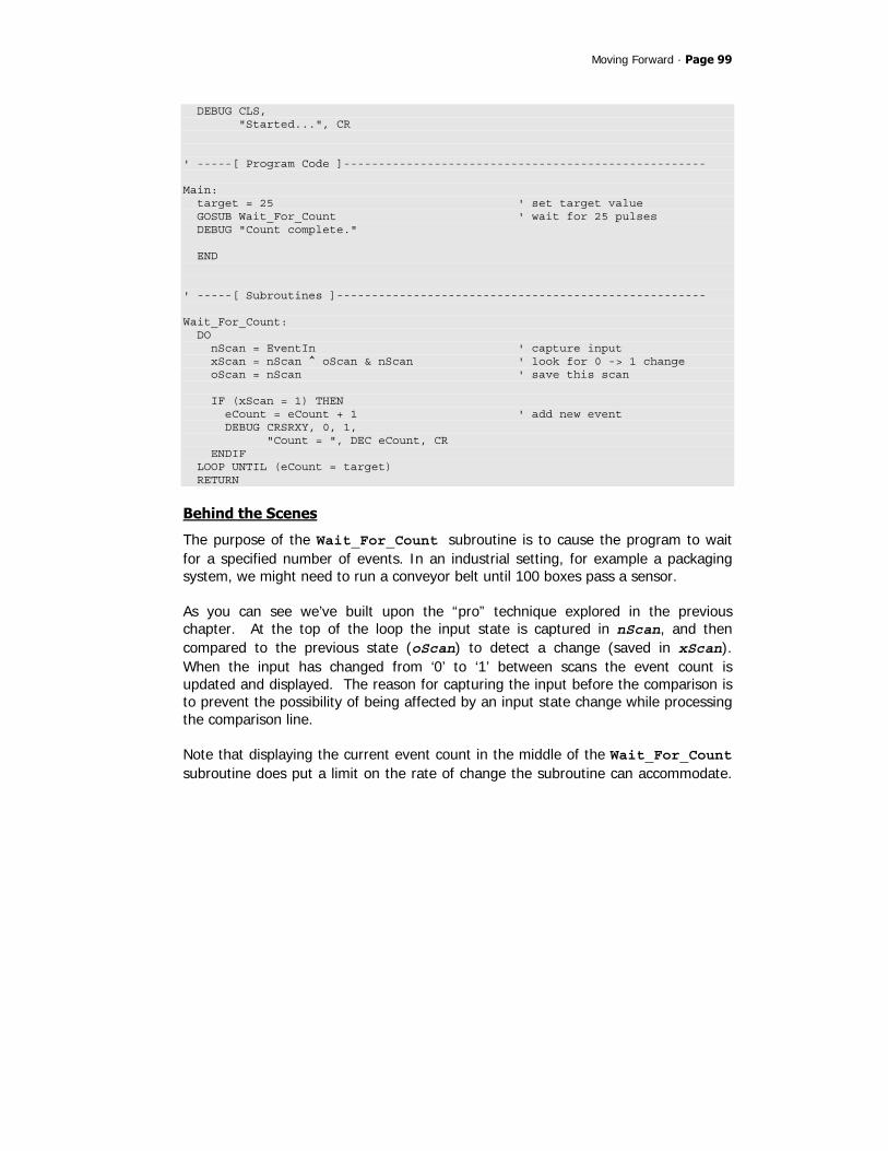
Moving Forward · Page 99
DEBUG CLS, "Started...", CR ' -----[ Program Code ]---------------------------------------------------- Main: target = 25 ' set target value GOSUB Wait_For_Count ' wait for 25 pulses DEBUG "Count complete." END ' -----[ Subroutines ]----------------------------------------------------- Wait_For_Count: DO nScan = EventIn ' capture input xScan = nScan ^ oScan & nScan ' look for 0 -> 1 change oScan = nScan ' save this scan IF (xScan = 1) THEN eCount = eCount + 1 ' add new event DEBUG CRSRXY, 0, 1, "Count = ", DEC eCount, CR ENDIF LOOP UNTIL (eCount = target) RETURN
Behind the Scenes
The purpose of the Wait_For_Count subroutine is to cause the program to wait for a specified number of events. In an industrial setting, for example a packaging system, we might need to run a conveyor belt until 100 boxes pass a sensor. As you can see we’ve built upon the “pro” technique explored in the previous chapter. At the top of the loop the input state is captured in nScan, and then compared to the previous state (oScan) to detect a change (saved in xScan). When the input has changed from ‘0’ to ‘1’ between scans the event count is updated and displayed. The reason for capturing the input before the comparison is to prevent the possibility of being affected by an input state change while processing the comparison line. Note that displaying the current event count in the middle of the Wait_For_Count subroutine does put a limit on the rate of change the subroutine can accommodate.

Page 100 · StampWorks
This is due to DEBUG requiring several milliseconds to send its output to the Debug Terminal window. Removing the DEBUG output (simple using conditional compilation) will increase the events input rate that can be detected. Note, too, that the subroutine expects a clean input. A noisy input could cause spurious counts, leading to early termination of the subroutine. This is easily fixed by adapting the Get_Buttons subroutine from the last experiment.
Scan_Input: ' use with "noisy" inputs nScan = 1 FOR idx = 1 TO 5 nScan = nScan & EventIn PAUSE 5 NEXT xScan = nScan ^ oScan & nScan ' look for 0 -> 1 change oScan = nScan ' save this scan RETURN
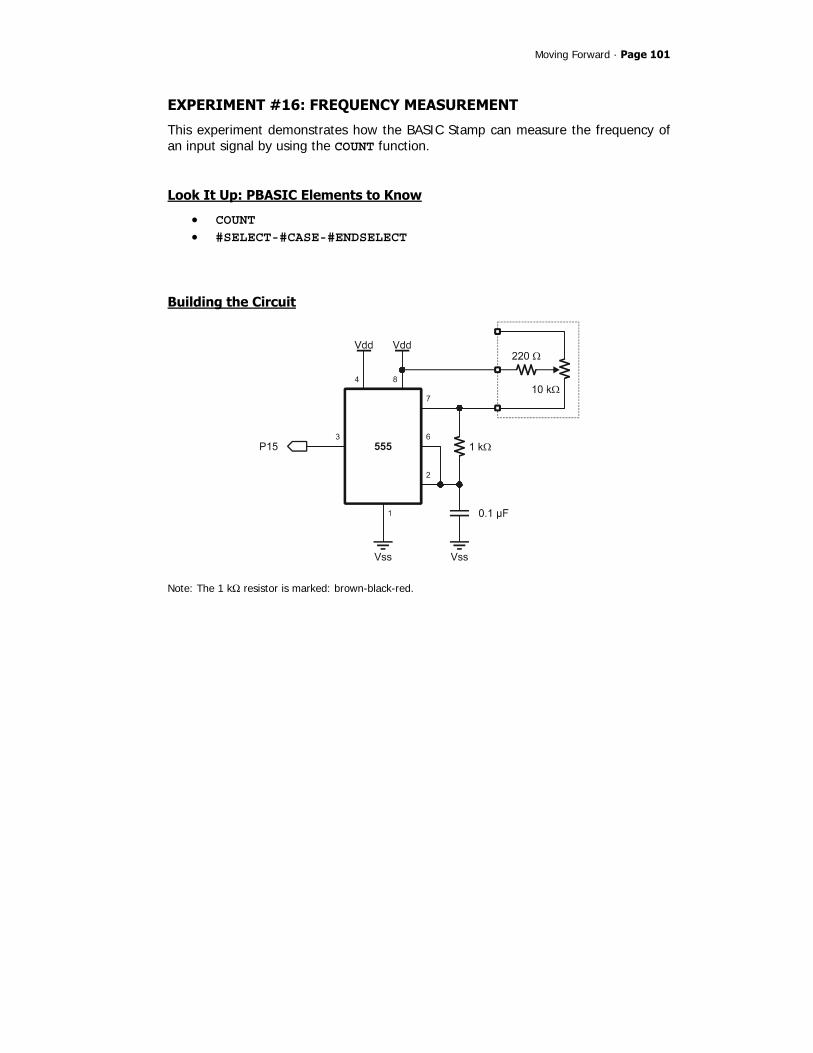
Moving Forward · Page 101
EXPERIMENT #16: FREQUENCY MEASUREMENT
This experiment demonstrates how the BASIC Stamp can measure the frequency of an input signal by using the COUNT function.
Look It Up: PBASIC Elements to Know
• COUNT • #SELECT-#CASE-#ENDSELECT
Building the Circuit
Note: The 1 kΩ resistor is marked: brown-black-red.
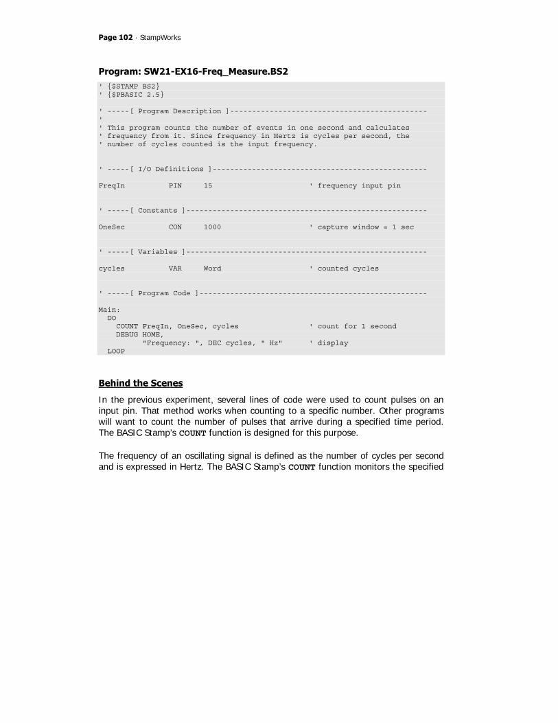
Page 102 · StampWorks
Program: SW21-EX16-Freq_Measure.BS2 ' $STAMP BS2 ' $PBASIC 2.5 ' -----[ Program Description ]--------------------------------------------- ' ' This program counts the number of events in one second and calculates ' frequency from it. Since frequency in Hertz is cycles per second, the ' number of cycles counted is the input frequency. ' -----[ I/O Definitions ]------------------------------------------------- FreqIn PIN 15 ' frequency input pin ' -----[ Constants ]------------------------------------------------------- OneSec CON 1000 ' capture window = 1 sec ' -----[ Variables ]------------------------------------------------------- cycles VAR Word ' counted cycles ' -----[ Program Code ]---------------------------------------------------- Main: DO COUNT FreqIn, OneSec, cycles ' count for 1 second DEBUG HOME, "Frequency: ", DEC cycles, " Hz" ' display LOOP
Behind the Scenes
In the previous experiment, several lines of code were used to count pulses on an input pin. That method works when counting to a specific number. Other programs will want to count the number of pulses that arrive during a specified time period. The BASIC Stamp’s COUNT function is designed for this purpose. The frequency of an oscillating signal is defined as the number of cycles per second and is expressed in Hertz. The BASIC Stamp’s COUNT function monitors the specified

Moving Forward · Page 103
pin for a given amount of time (the Duration parameter). To create a simple frequency meter, the specified time window is set to 1000 milliseconds (one second).
Note the comparison between the BASIC Stamp output and the input frequency measured with a Parallax USB Oscilloscope on the next page:

Page 104 · StampWorks
When using the COUNT function with a Duration of one second, the frequency measurement is very accurate up to the specified input of the BASIC Stamp module (input frequency varies from module-to-module).
Write Code like a Pro
COUNT is one of several BASIC Stamp functions that behave differently based on the module being used. The BS2, for example, expresses the Duration parameter in units of one millisecond, while the BS2p expressed this parameter in units of 0.287 milliseconds.

Moving Forward · Page 105
This is another situation where conditional compilation directives are particularly useful. To accommodate COUNT using any BASIC Stamp 2 module, we can add this block to our program:
#SELECT $STAMP #CASE BS2, BS2E DurAdj CON $100 ' Duration / 1 #CASE BS2SX DurAdj CON $280 ' Duration / 0.400 #CASE BS2P, BS2PX DurAdj CON $37B ' Duration / 0.287 #CASE BS2PE DurAdj CON $163 ' Duration / 0.720 #ENDSELECT
Now that we have a multiplier for the Duration parameter, the COUNT code is modified like this:
COUNT FreqIn, OneSec */ DurAdj, cycles ' count for for 1 second
… and the program will behave in the same manner using an BS2-family module.
Take it Further
Improve the responsiveness (make it update more frequently) of this program by changing the COUNT period. What other adjustment has to be made? How does this change affect the ability to measure very low frequency signals?
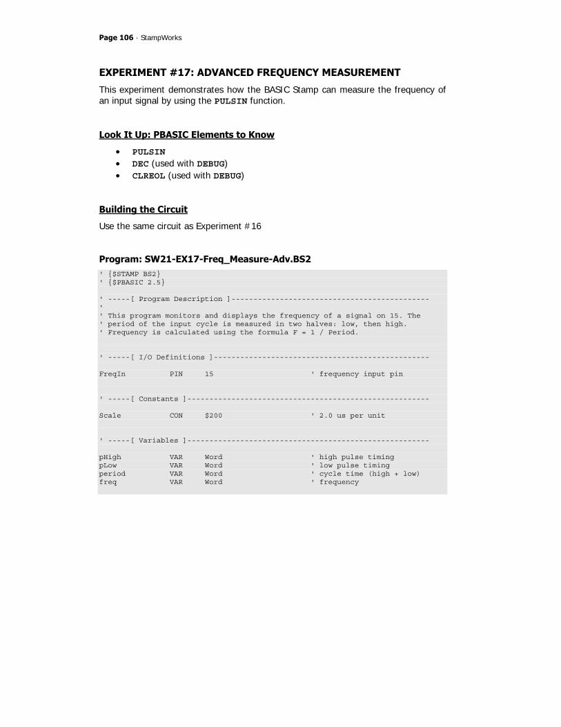
Page 106 · StampWorks
EXPERIMENT #17: ADVANCED FREQUENCY MEASUREMENT
This experiment demonstrates how the BASIC Stamp can measure the frequency of an input signal by using the PULSIN function.
Look It Up: PBASIC Elements to Know
• PULSIN • DEC (used with DEBUG) • CLREOL (used with DEBUG)
Building the Circuit
Use the same circuit as Experiment #16
Program: SW21-EX17-Freq_Measure-Adv.BS2 ' $STAMP BS2 ' $PBASIC 2.5 ' -----[ Program Description ]--------------------------------------------- ' ' This program monitors and displays the frequency of a signal on 15. The ' period of the input cycle is measured in two halves: low, then high. ' Frequency is calculated using the formula F = 1 / Period. ' -----[ I/O Definitions ]------------------------------------------------- FreqIn PIN 15 ' frequency input pin ' -----[ Constants ]------------------------------------------------------- Scale CON $200 ' 2.0 us per unit ' -----[ Variables ]------------------------------------------------------- pHigh VAR Word ' high pulse timing pLow VAR Word ' low pulse timing period VAR Word ' cycle time (high + low) freq VAR Word ' frequency

Moving Forward · Page 107
' -----[ Initialization ]-------------------------------------------------- Reset: DEBUG CLS, ' setup report output "Period.(uS)... ", CR, "Freq (Hz)..... " ' -----[ Program Code ]---------------------------------------------------- Main: DO PULSIN FreqIn, 0, pLow ' get high side of input PULSIN FreqIn, 1, pHigh ' get low side of input period = (pLow + pHigh) */ Scale ' scale to uSecs freq = 62500 / period * 16 ' calculate frequency DEBUG CRSRXY, 15, 0, DEC period, CLREOL, ' display values CRSRXY, 15, 1, DEC freq, CLREOL LOOP
Behind the Scenes
In the last experiment, we learned that the frequency of a signal is defined as the number of cycles per second. We created a simple frequency meter by counting the number of pulses (cycles) in one second. This method works well, especially for low-frequency signals. There will be times, however, when project requirements will dictate a quicker response time for frequency measurement. The frequency of a signal can be calculated from its period, or the time for one complete cycle as shown in the illustration below:
By measuring the period of an incoming signal, its frequency can be calculated with the equation (where the period is expressed in seconds):
Frequency = 1 / Period

Page 108 · StampWorks
The BASIC Stamp’s PULSIN function is designed to measure the width of an incoming pulse. By using PULSIN to measure the high and low portions of an incoming signal, its period and frequency can be calculated. The result of PULSIN (on the BS2) is expressed in units of two microseconds. First the PULSIN values are converted to µs by the following formula:
period = (pLow + pHigh) */ Scale Scale refers to the units of the PULSIN command. Thus, the formula for calculating frequency becomes:
Frequency = 1,000,000 / period (µs) This creates a problem for BASIC Stamp math though, as values are limited to 16 bits (maximum value is 65,535). To fix the formula, we can divide 1,000,000 by 16 (62,500) and rewrite the formula like this:
Frequency = 62,500 / period (µs) * 16 This formula works with any BS2 module – after the raw measurements from PULSIN have been converted to microseconds. This is the purpose of the Scale constant in the program: it converts the raw input from PULSIN to microseconds for the generalized frequency calculations. Run the program and adjust the 10 kΩ potentiometer. Notice that the Debug Terminal window is updated without delay and that there is no waiting as when using COUNT to determine frequency. This method of measuring a frequency works better at higher frequencies (above 100 Hz).

Moving Forward · Page 109
EXPERIMENT #18: A LIGHT CONTROLLED THEREMIN
This experiment demonstrates FREQOUT by creating a light-controlled Theremin (the first electronic musical instrument ever produced). While the output from our BASIC Stamp-based Theremin is not quite as haunting as the real thing, it is a fun project and demonstrates the ability to use a non-standard input (light level) for program control.
Look It Up: PBASIC Elements to Know
• FREQOUT
Building the Circuit
Note: The 220 Ω resistor is marked: red-red-brown.
Program: SW21-EX18-Theremin.BS2 ' $STAMP BS2 ' $PBASIC 2.5 ' -----[ Program Description ]--------------------------------------------- ' ' This program uses RCTIME with a photocell to create a light-controlled ' Theremin. ' -----[ I/O Definitions ]------------------------------------------------- Speaker CON 0 ' speaker output PitchCtrl CON 1 ' pitch control input

Page 110 · StampWorks
' -----[ Constants ]------------------------------------------------------- TAdj CON $100 ' time adjust factor FAdj CON $100 ' frequency adjust factor Threshold CON 200 ' cutoff frequency to play NoteTm CON 40 ' note timing ' -----[ Variables ]------------------------------------------------------- tone VAR Word ' frequency output ' -----[ Program Code ]---------------------------------------------------- Main: DO HIGH PitchCtrl ' discharge cap PAUSE 1 ' for 1 ms RCTIME PitchCtrl, 1, tone ' read the light sensor tone = tone */ FAdj ' scale input IF (tone > Threshold) THEN ' play? FREQOUT Speaker, NoteTm */ TAdj, tone ENDIF LOOP
Behind the Scenes
A Theremin is an interesting musical device used to create those weird, haunting sounds often heard in old horror movies. This version uses the light falling onto a photocell to create the output tone. Since the photocell is a resistive device, RCTIME can be used to read its value. FREQOUT is used to play the note. The constant, Threshold, is used to control the cutoff point of the Theremin. When the photocell reading falls below this value, no sound is played. This value should be adjusted to the point where the Theremin stops playing when the photocell is not covered in ambient light.
Behind the Scenes…Going Deeper
You may wonder how the BASIC Stamp is able to create a musical note using a pure digital output. The truth is that it gets a little help from the outside world. At the

Moving Forward · Page 111
front end of the PDB’s audio amplifier is a low-pass filter circuit that takes the pure digital output (a special type of PWM output) from FREQOUT and smoothes it into a nice sine wave that produces a clean musical note. To see this in action, build the following circuit:
Using an oscilloscope, monitor the points marked “A” and “B” in the circuit while running the following short program:
Main: FREQOUT Speaker, 1000, 440 GOTO Main
On a stock BS2 this will generate a 440 Hz tone for one second. Note the digital output at point “A” and the sine-wave produced after the filter circuit at point “B” (the 10 kΩ resistor represents the audio amplifier input).

Page 112 · StampWorks
EXPERIMENT #19: SOUND EFFECTS (SFX)
This experiment uses DTMFOUT and FREQOUT to mimic telephone system sounds, create sound effects, and even play a simple song.
Look It Up: PBASIC Elements to Know
• DTMFOUT • INPUT
Building the Circuit
Program: SW21-EX19-Sound_FX.BS2 ' $STAMP BS2 ' $PBASIC 2.5 ' -----[ Program Description ]--------------------------------------------- ' ' Demonstrates sound FX and simple music using FREQOUT and DTMFOUT. ' -----[ I/O Definitions ]------------------------------------------------- Speaker PIN 0 ' speaker on pin 0 ' -----[ Constants ]------------------------------------------------------- R CON 0 ' rest C CON 33 ' ideal is 32.703 Cs CON 35 ' ideal is 34.648 D CON 37 ' ideal is 36.708 Ds CON 39 ' ideal is 38.891 E CON 41 ' ideal is 41.203 F CON 44 ' ideal is 43.654 Fs CON 46 ' ideal is 46.249

Moving Forward · Page 113
G CON 49 ' ideal is 48.999 Gs CON 52 ' ideal is 51.913 A CON 55 ' ideal is 55.000 As CON 58 ' ideal is 58.270 B CON 62 ' ideal is 61.735 N1 CON 500 ' whole note duration N2 CON N1/2 ' half note N3 CON N1/3 ' third note N4 CON N1/4 ' quarter note N8 CON N1/8 ' eighth note TAdj CON $100 ' x 1.0 (time adjust) FAdj CON $100 ' x 1.0 (freq adjust) ' -----[ Variables ]------------------------------------------------------- idx VAR Word ' loop counter note1 VAR Word ' first tone for FREQOUT note2 VAR Word ' second tone for FREQOUT onTime VAR Word ' duration for FREQOUT offTime VAR Word oct1 VAR Nib ' octave for freq1 (1 - 8) oct2 VAR Nib ' octave for freq2 (1 - 8) eePntr VAR Byte ' EEPROM pointer digit VAR Byte ' DTMF digit clickDly VAR Word ' delay betweens "clicks" ' -----[ EEPROM Data ]----------------------------------------------------- Phone1 DATA "123-555-1212", 0 ' stored telephone numbers Phone2 DATA "916-624-8333", 0 ' -----[ Program Code ]---------------------------------------------------- Main: DEBUG CLS, "BASIC Stamp Sound FX Demo", CR, CR Dial_Tone: DEBUG "Dial tone", CR onTime = 35 */ TAdj note1 = 35 */ FAdj FREQOUT Speaker, onTime, note1 ' "click" PAUSE 100 onTime = 2000 */ TAdj note1 = 350 */ FAdj

Page 114 · StampWorks
note2 = 440 */ FAdj FREQOUT Speaker, onTime, note1, note2 ' combine 350 Hz & 440 Hz Dial_Phone1: ' dial phone from EE DEBUG "Dialing number: " eePntr = Phone1 ' initialize eePntr pointer GOSUB Dial_Phone Phone_Busy: PAUSE 1000 DEBUG CR, " - busy...", CR onTime = 400 */ TAdj note1 = 480 */ FAdj note2 = 620 */ FAdj FOR idx = 1 TO 8 FREQOUT Speaker, onTime, note1, note2 ' combine 480 Hz and 620 Hz PAUSE 620 NEXT onTime = 35 */ TAdj note1 = 35 */ FAdj FREQOUT Speaker, onTime, note1 ' "click" Dial_Phone2: DEBUG "Calling Parallax: " eePntr = Phone2 GOSUB Dial_Phone Phone_Rings: PAUSE 1000 DEBUG CR, " - ringing" onTime = 2000 */ TAdj note1 = 440 */ FAdj note2 = 480 */ FAdj FREQOUT Speaker, onTime, note1, note2 ' combine 440 Hz and 480 Hz PAUSE 4000 FREQOUT Speaker, onTime, note1, note2 ' combine 440 Hz and 480 Hz PAUSE 2000 Camptown_Song: DEBUG CR, "Play a Camptown song", CR FOR idx = 0 TO 13 LOOKUP idx, [ G, G, E, G, A, G, E, R, E, D, R, E, D, R], note1 LOOKUP idx, [ 4, 4, 4, 4, 4, 4, 4, 4, 4, 4, 4, 4, 4, 4], oct1 LOOKUP idx, [N2, N2, N2, N2, N2, N2, N2, N2, N2, N1, N2, N2, N1, N8], onTime GOSUB Play_1_Note NEXT Howler:

Moving Forward · Page 115
DEBUG "Howler -- watch out!!!", CR FOR idx = 1 TO 4 onTime = 1000 */ TAdj note1 = 1400 */ FAdj note2 = 2060 */ FAdj FREQOUT Speaker, onTime, note1, note2 ' combine 1400 Hz and 2060 Hz onTime = 1000 */ TAdj note1 = 2450 */ FAdj note2 = 2600 */ FAdj FREQOUT Speaker, onTime, note1, note2 ' combine 2450 Hz and 2600 Hz NEXT Roulette_Wheel: DEBUG "Roulette Wheel", CR onTime = 5 */ TAdj ' onTime for "click" note1 = 35 */ FAdj ' frequency for "click" clickDly = 250 ' delay between clicks FOR idx = 1 TO 8 ' spin up wheel FREQOUT Speaker, onTime, note1 ' click PAUSE clickDly clickDly = clickDly */ $00BF ' accelerate (speed * 0.75) NEXT FOR idx = 1 TO 10 ' spin stable FREQOUT Speaker, onTime, note1 PAUSE clickDly NEXT FOR idx = 1 TO 20 ' slow down FREQOUT Speaker, onTime, note1 PAUSE clickDly clickDly = clickDly */ $010C ' decelerate (speed * 1.05) NEXT FOR idx = 1 TO 30 ' slow down and stop FREQOUT Speaker, onTime, note1 PAUSE clickDly clickDly = clickDly */ $0119 ' decelerate (speed * 1.10) NEXT Computer_Beeps: ' looks great with randmom LEDs DEBUG "1950's Sci-Fi Computer", CR FOR idx = 1 TO 50 ' run about 5 seconds onTime = 50 */ TAdj RANDOM note1 ' create random note note1 = (note1 // 2500) */ FAdj ' don't let note go to high FREQOUT Speaker, onTime, note1 ' play it PAUSE 100 ' short pause between notes NEXT Space_Transporter: DEBUG "Space Transporter", CR onTime = 10 */ TAdj

Page 116 · StampWorks
FOR idx = 5 TO 5000 STEP 5 ' frequency sweep up note1 = idx */ FAdj FREQOUT Speaker, onTime, note1, note1 */ 323 NEXT FOR idx = 5000 TO 5 STEP 50 ' frequency sweep down note1 = idx */ FAdj FREQOUT Speaker, onTime, note1, note1 */ 323 NEXT DEBUG CR, "Sound demo complete." INPUT Speaker END ' -----[ Subroutines ]----------------------------------------------------- Dial_Phone: DO READ eePntr, digit ' read a digit IF (digit = 0) THEN EXIT ' when 0, number is done DEBUG digit ' display digit IF (digit >= "0" AND digit <- "9") THEN ' don't digits onTime = 150 */ TAdj offTime = 75 */ TAdj DTMFOUT Speaker, onTime, offTime, [digit - 48] ENDIF eePntr = eePntr + 1 ' update eePntr pointer LOOP RETURN Play_1_Note: note1 = note1 << (oct1 - 1) ' note + octave onTime = onTime */ TAdj note1 = note1 */ FAdj FREQOUT Speaker, onTime, note1 ' play it RETURN Play_2_Notes: note1 = note1 << (oct1 - 1) ' note + octave note2 = note2 << (oct2 - 1) ' note + octave onTime = onTime */ TAdj note1 = note1 */ FAdj note2 = note2 */ FAdj FREQOUT Speaker, onTime, note1, note2 ' play both RETURN

Moving Forward · Page 117
Behind the Scenes
With a bit of programming creativity, the BASIC Stamp microcontroller is able to create and mimic some very interesting sound effects, particularly those used in telephone system. Since most of the sounds we hear on the telephone (other than voice) are generated with two tones, the BASIC Stamp’s FREQOUT and DTMFOUT functions can be used to generate the effects. DTMFOUT is actually a specialized version of FREQOUT that plays two simultaneous tones that are superimposed on each other. The purpose of DTMFOUT is to create the dual-tones required to dial a telephone. The figure below shows the raw and filtered output of DTMFOUT. In the filtered output the interaction of the two tones is clearly visible.
Page 118 · StampWorks
The DTMF tones used in telephone systems are standardized, so instead of passing a tone (or tones), the digit(s) to be dialed are passed as parameters. In actual dialing applications, the DTMF on-time and off-time can be specified to deal with telephone line quality. This program also presents the BASIC Stamp’s basic musical ability by playing a simple song. Constants for note frequency (in the first octave) and note timing simplify the operational code. The Play_1_Note subroutine adjusts note frequency for the specified octave. The musical quality can suffer a bit in the higher octaves because of rounding errors. Using the ideal values shown, the constants table can be expanded to create accurate musical notes. Keep in mind that each octave doubles the frequency of a note. Octave 2 = Octave 1 * 2 Octave 3 = Octave 2 * 2 Octave 4 = Octave 3 * 2 And so on…
Challenge
Convert (a portion of) your favorite song to play on the BASIC Stamp.

Moving Forward · Page 119
EXPERIMENT #20: INFRARED OBJECT DETECTION
This experiment demonstrates an interesting side-effect of using FREQOUT without the audio filter circuit of Experiment #18; the effect allows us to modulate an Infrared (IR) LED for use with an IR detector.
Look It Up: PBASIC Elements to Know
• Bit (variable type)
Building the Circuit
The StampWorks parts kit includes an IR LED (clear) and a 38.5 kHz detector. In order to prevent “spill” from the LED, it should be placed in a protective shield as shown in the diagram above.

Page 120 · StampWorks
Program: SW21-EX20-IR_Detect.BS2 ' $STAMP BS2 ' $PBASIC 2.5 ' -----[ Program Description ]--------------------------------------------- ' ' This program uses FREQOUT without a filter to modulate an IR LED for ' detection by a demodulating receiver. ' -----[ I/O Definitions ]------------------------------------------------- IrLed PIN 0 ' IR LED output IrDectect PIN 1 ' detector input ' -----[ Constants ]------------------------------------------------------- IrMod CON 38500 ' 38.5 kHz (harmonic) ModTime CON 1 ' 1 ms NoDetect CON 1 ' detector is active-low ' -----[ Variables ]------------------------------------------------------- object VAR Bit ' -----[ Program Code ]---------------------------------------------------- Main: DO GOSUB Scan_IR IF (object = NoDetect) THEN DEBUG HOME, "All clear", CLREOL ELSE DEBUG HOME, "Intruder Alert!", CLREOL ENDIF PAUSE 100 LOOP ' -----[ Subroutines ]----------------------------------------------------- Scan_IR: FREQOUT IrLed, ModTime, IrMod ' module IR LED object = IrDectect ' scan detector RETURN

Moving Forward · Page 121
Behind the Scenes
As explained in Experiment #18, the raw output of FREQOUT is designed to be filtered (producing a very clean sine wave) before application to an audio amplifier. If we remove the filter, the raw output will be filled with a lot of harmonic content above the specified output frequency. The harmonic content happens to be strong enough to modulate an IR LED. By specifying 38.5 kHz for FREQOUT – which is actually above the legal value for a frequency – what we get is a fundamental plus a harmonic at 38.5 kHz; this harmonic is used to modulate the IR LED. Why modulate? Because the environment is filled with natural and man-made IR signals, and by modulating and demodulating at a specific frequency we are able to detect our source. The figure below shows the harmonic spike created by FREQOUT; note that it is near enough to the target of 38.5 kHz to be useful.
The IR detector is special as well. Note that the FREQOUT instruction must end before we can sample the output from the detector. The detector in use holds its output long enough to allow the pin scan to occur.

Page 122 · StampWorks
Going Deeper
IR detection opens up a lot of possibilities with hand-held remote control. Yes, the TV and other remotes we’ve become so accustomed to can be made useful in our projects. This subject, however, requires a book unto itself – and that book is available. Parallax engineer, Andy Lindsay, has written an excellent book titled IR Remote for the Boe-Bot. While the book focuses on robotics applications, the remote control code may be used with virtually any application where user input is required. It’s prequel, Robotics with the Boe-Bot (also written by Andy) is another good source of IR object detection techniques.
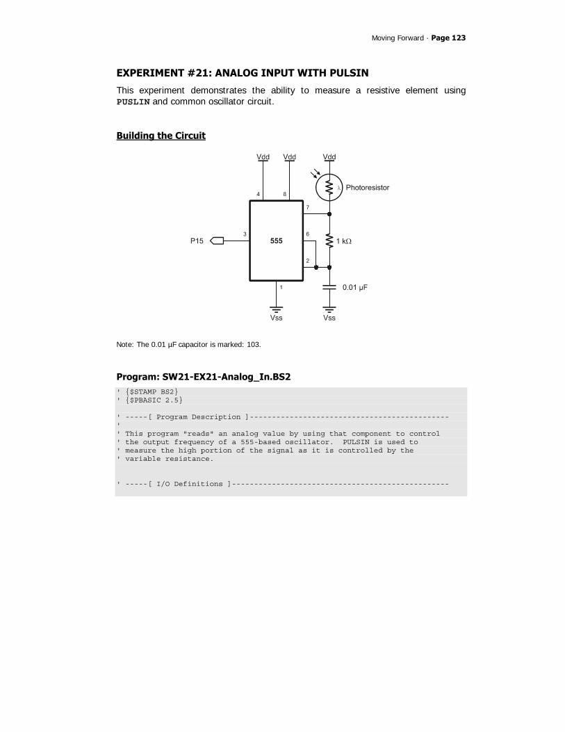
Moving Forward · Page 123
EXPERIMENT #21: ANALOG INPUT WITH PULSIN
This experiment demonstrates the ability to measure a resistive element using PUSLIN and common oscillator circuit.
Building the Circuit
Note: The 0.01 µF capacitor is marked: 103.
Program: SW21-EX21-Analog_In.BS2 ' $STAMP BS2 ' $PBASIC 2.5 ' -----[ Program Description ]--------------------------------------------- ' ' This program "reads" an analog value by using that component to control ' the output frequency of a 555-based oscillator. PULSIN is used to ' measure the high portion of the signal as it is controlled by the ' variable resistance. ' -----[ I/O Definitions ]-------------------------------------------------

Page 124 · StampWorks
PulseInput PIN 15 ' pulse in from 555 ' -----[ Constants ]------------------------------------------------------- Scale CON $200 ' 2.0 us per unit P90 CON $E666 ' 0.90 P75 CON $C000 ' 0.75 P50 CON $8000 ' 0.50 P25 CON $4000 ' 0.25 P10 CON $1999 ' 0.10 ' -----[ Variables ]------------------------------------------------------- rValue VAR Word ' raw value sValue VAR Word ' smoothed value ' -----[ Initialization ]-------------------------------------------------- Reset: DEBUG CLS, "Analog Input ", CR, "------------ ", CR, "Raw value... ", CR, "Filtered.... " ' -----[ Program Code ]---------------------------------------------------- Main: DO PULSIN PulseInput, 1, rValue ' get high portion of input rValue = rValue */ Scale ' convert to microseconds sValue = (rValue ** P50) + (sValue ** P50) ' apply digital filter DEBUG CRSRXY, 13, 2, DEC rValue, CLREOL, ' print results CRSRXY, 13, 3, DEC sValue, CLREOL PAUSE 50 LOOP
Moving Forward · Page 125
Behind the Scenes
In this experiment the 555 is configured as an astable (free-running) oscillator. Analyzing the output, the width of the high side of the signal is primarily controlled by the resistance of the photocell. By measuring the high portion of the 555’s output with PULSIN, the BASIC Stamp is able to determine the relative resistance of – hence light falling on – the photocell. The 555’s capacitor is charged through the CdS photocell and the 1K resistor while the output (pin 3) is high. Once the threshold level is reached (about 2/3 Vdd) and detected by pin 6 the 555 output and pin 7 will go low, causing the capacitor to discharge through the 1K resistor. When the capacitor discharges to about 1/3 Vdd and is detected by pin 2, the output goes back high and pin 7 is disconnected to allow the capacitor to charge again. Since the CdS is only in the charge path (the 555 output is high), we only need to measure that side of the signal to determine relative resistance. The advantage to this scheme is that it is very fast acting; the disadvantage is that quickly changing values can create challenges for some programs. We can slow the changes with a bit of digital filtering. By adding a portion of the previous measurement to a portion of the current measurement, we are able to control how quickly the value will reach the new setting. The ratio of raw-to-filtered readings in this equation will determine the responsiveness of the filter. The larger the raw portion, the faster the input response. To dampen quickly-changing inputs, we would use a small portion of the current reading with a large portion of the previous reading. The key to correct digital filtering is to ensure that the relative percentages add up to 100% (e.g. 25/75. 50/50, 90/10, etc.).

Page 126 · StampWorks
EXPERIMENT #22: ANALOG OUTPUT WITH PWM
This experiment demonstrates the creation of a stable analog output voltage using PWM and an off-the-shelf op-amp.
Look It Up: PBASIC Elements to Know
• PWM
Building the Circuit
Note: The 10 kΩ resistor is marked: brown-black-orange. The LM358 requires at least 6.5 volts on its Vcc pin (8) to provide a five-volt output from PWM. By using the PDB’s Vin connection (near the RS-232 DCE port) and a 12-volt power supply, this requirement is satisfied.

Moving Forward · Page 127
Program: SW21-EX22-Analog_Out.BS2 ' $STAMP BS2 ' $PBASIC 2.5 ' -----[ Program Description ]--------------------------------------------- ' ' This program demonstrates how the PWM command can be used with an opamp ' buffer to create a variable voltage output. ' -----[ I/O Definitions ]------------------------------------------------- D2Aout PIN 0 ' analog out pin ' -----[ Constants ]------------------------------------------------------- CycAdj CON $100 ' x 1.0, cycle adjust OnTime CON 5 ' 5 ms ' -----[ Variables ]------------------------------------------------------- level VAR Byte ' analog level mVolts VAR Word ' output in millivolts ' -----[ Initialization ]-------------------------------------------------- Reset: DEBUG CLS, "Analog Output ", CR, "--------------- ", CR, "level.... ", CR, "mVolts... " ' -----[ Program Code ]---------------------------------------------------- Main: DO FOR level = 0 TO 255 ' increase voltage to LED PWM D2Aout, level, (OnTime */ CycAdj) GOSUB Show_Level NEXT FOR level = 255 TO 0 ' decrease voltage to LED PWM D2Aout, level, (OnTime */ CycAdj) GOSUB Show_Level NEXT LOOP ' do it again

Page 128 · StampWorks
' -----[ Subroutines ]----------------------------------------------------- Show_Level: mVolts = level */ $139B ' level * 19.6 mV DEBUG CRSRXY, 10, 2, DEC level, CLREOL, CRSRXY, 10, 3, DEC1 (mVolts / 1000), ".", DEC3 mVolts RETURN
Behind the Scenes
While most BASIC Stamp applications will deal with digital signals, some will require analog output; a variable voltage between zero and some maximum voltage. The BASIC Stamp’s PWM instruction is designed to generate an analog voltage when combined with an R/C filter. The PWM instruction produces a series of pulses which have a programmable on-time to off-time ratio (duty cycle). The output voltage of the circuit corresponds directly to the Duty parameter of the PWM instruction – a larger value for Duty will result in a higher output voltage. A Duty of 255 will charge the capacitor to five volts. In order to ensure that the capacitor is properly charged, the Duration parameter should be set to at least five R/C time constants. In the circuit above, one time constant is one millisecond (10 kΩ x 0.1 µF), so setting the Duration to 10 milliseconds guarantees the capacitor will be changed to the level set by Duty. In this experiment, one half of the LM358 is configured as a voltage follower and serves to provide a buffered output to the LED or other circuitry. The op-amp buffer prevents the capacitor from discharging too quickly under load. The LED brightens and dims because the changing voltage through its series resistor changes the current through the LED. Notice that the LED seems to snap on and get brighter, then dim to some level and snap off. This happens when the output of the LM358 crosses the forward voltage threshold (the minimum voltage for the LED to light) of the LED (about 2.3 volts for the blue LEDs on the PDB – other LEDs will differ).
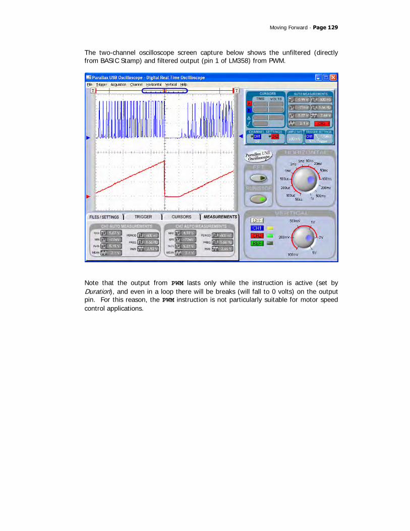
Moving Forward · Page 129
The two-channel oscilloscope screen capture below shows the unfiltered (directly from BASIC Stamp) and filtered output (pin 1 of LM358) from PWM.
Note that the output from PWM lasts only while the instruction is active (set by Duration), and even in a loop there will be breaks (will fall to 0 volts) on the output pin. For this reason, the PWM instruction is not particularly suitable for motor speed control applications.
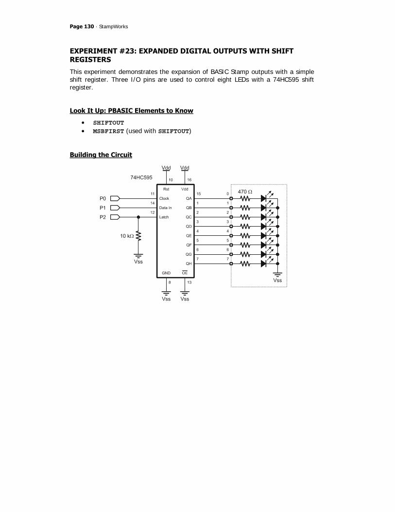
Page 130 · StampWorks
EXPERIMENT #23: EXPANDED DIGITAL OUTPUTS WITH SHIFT REGISTERS
This experiment demonstrates the expansion of BASIC Stamp outputs with a simple shift register. Three I/O pins are used to control eight LEDs with a 74HC595 shift register.
Look It Up: PBASIC Elements to Know
• SHIFTOUT • MSBFIRST (used with SHIFTOUT)
Building the Circuit

Moving Forward · Page 131
Program: SW21-EX23-74HC595-1.BS2 ' $STAMP BS2 ' $PBASIC 2.5 ' -----[ Program Description ]--------------------------------------------- ' ' This program demonstrates a simple method of turning three BASIC Stamp ' I/O pins into eight digital outputs with a 74HC595 shift register. ' -----[ I/O Definitions ]------------------------------------------------- Clock PIN 0 ' shift clock (74HC595.11) SerData PIN 1 ' serial data (74HC595.14) Latch PIN 2 ' output latch (74HC595.12) ' -----[ Constants ]------------------------------------------------------- DelayTime CON 100 ' -----[ Variables ]------------------------------------------------------- pattern VAR Byte ' zig-zag pattern ' -----[ Initialization ]-------------------------------------------------- Reset: LOW Latch ' make output and low pattern = %00000001 ' -----[ Program Code ]---------------------------------------------------- Main: DO GOSUB Out_595 ' put pattern on 74x595 PAUSE DelayTime ' hold pattern = pattern << 1 ' shift pattern left LOOP UNTIL (pattern = %10000000) DO GOSUB Out_595 PAUSE DelayTime pattern = pattern >> 1 ' shift pattern right LOOP UNTIL (pattern = %00000001) GOTO Main

Page 132 · StampWorks
' -----[ Subroutines ]----------------------------------------------------- Out_595: SHIFTOUT SerData, Clock, MSBFIRST, [pattern] ' send pattern to '595 PULSOUT Latch, 5 ' latch outputs RETURN
Behind the Scenes
The BASIC Stamp is extraordinarily flexible in its ability to redefine the direction (input or output) of its I/O pins, yet very few applications require this flexibility. For the most part, microcontroller applications will define pins as either inputs or outputs at initialization and the definitions will remain unchanged through the program. We can use the fact that outputs are outputs and conserve valuable BASIC Stamp I/O pins at the same time by using a simple component called a serial-in, parallel-out shift register. In this experiment, the 74HC595 shift register is used. With just three BASIC Stamp I/O pins, this program is able to control eight LEDs. The 74HC595 converts a synchronous serial data stream to eight parallel outputs. Synchronous serial data actually has two components: the serial data and a serial clock. The BASIC Stamp’s SHIFTOUT instruction handles the details of the data and clock lines and writes data to a synchronous device, in this case, the 74HC595. The figure below illustrates the relationship between the clock and data signals for the value $AF.

Moving Forward · Page 133
With the 74HC595, the data must be latched to the outputs after the shift process. Latching is accomplished by briefly pulsing the Latch control line (low-high-low). This feature prevents the 74HC595 outputs from “rippling” as new data is being shifted into or through the device. Note that the Latch line is pulled low through a resistor; this prevents noise from inadvertently latching invalid data to the 74HC595 outputs while the BASIC Stamp is initializing and the I/O pins are in a high-impedance state (floating).
Taking it Further
Being serial devices, shift registers can be cascaded, allowing the BASIC Stamp to control dozens of 74HC595 outputs with the same three I/O pins.
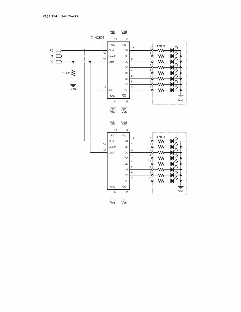
Page 134 · StampWorks

Moving Forward · Page 135
To connect cascaded 74HC595s, the clock and latch lines are all tied together and the QH’ serial output from one stage connects to the serial input of the next stage.
Program: SW21-EX23-74HC595-2.BS2 ' $STAMP BS2 ' $PBASIC 2.5 ' -----[ Program Description ]--------------------------------------------- ' ' This program demonstrates a simple method of turning three BASIC Stamp ' I/O pins into sixteen digital outputs with a 74HC595 shift register. ' -----[ I/O Definitions ]------------------------------------------------- Clock PIN 0 ' shift clock (74HC595.11) SerData PIN 1 ' serial data (74HC595.14) Latch PIN 2 ' output latch (74HC595.12) ' -----[ Constants ]------------------------------------------------------- DelayTime CON 100 ' -----[ Variables ]------------------------------------------------------- counter VAR Byte ' binary counter pattern VAR Byte ' zig-zag pattern ' -----[ Initialization ]-------------------------------------------------- Reset: LOW Latch ' make output and low pattern = %00000001 ' -----[ Program Code ]---------------------------------------------------- Main: DO counter = counter + 1 ' update counter GOSUB Out_595x2 ' put pattern on 74x595 PAUSE DelayTime ' hold pattern = pattern << 1 ' shift pattern left LOOP UNTIL (pattern = %10000000) DO counter = counter + 1

Page 136 · StampWorks
GOSUB Out_595x2 PAUSE DelayTime pattern = pattern >> 1 ' shift pattern right LOOP UNTIL (pattern = %00000001) GOTO Main ' -----[ Subroutines ]----------------------------------------------------- Out_595x2: SHIFTOUT SerData, Clock, MSBFIRST, [counter] ' send counter to 595-2 SHIFTOUT SerData, Clock, MSBFIRST, [pattern] ' send pattern to 595-1 PULSOUT Latch, 5 ' latch outputs RETURN
Behind the Scenes
The 74HC595 has a serial output pin (9) that allows the cascading of multiple devices for more outputs – the serial output from one 595 feeds the serial input of the next device in line. This works by moving the data in QH to the QH’ output (9) on a new clock pulse. When connecting cascaded 595s, the Clock and Latch pins should be tied together to keep all devices synchronized. In our program we must be concerned with the order of shifted values when working with cascaded devices. Subsequent SHIFTOUT sequences will "push" the data through each register until the data is loaded into the correct device. In the illustration below the value intended for 595-2 is output first and will be shifted through 595-1.
After the data has been output to all shift registers in the chain, the Latch pulse is applied to transfer the new data to the 74HC595 output pins.

Moving Forward · Page 137
EXPERIMENT #24: EXPANDED DIGITAL INPUTS WITH SHIFT REGISTERS
This experiment demonstrates the expansion of BASIC Stamp inputs with a simple shift register – the 74HC165 which is a complementary device to the 74HC595 used in Experiment #23.
Look It Up: PBASIC Elements to Know
• SHIFTIN • MSBPRE (used with SHIFTIN)
Building the Circuit

Page 138 · StampWorks
Program: SW21-EX24-74HC165-1.BS2 ' $STAMP BS2 ' $PBASIC 2.5 ' -----[ Program Description ]--------------------------------------------- ' ' This program demonstrates a simple method of turning three BASIC Stamp ' I/O pins into eight digital inputs with a 74HC165 shift register. ' -----[ I/O Definitions ]------------------------------------------------- Clock PIN 0 ' shift clock (74HC165.2) SerData PIN 1 ' serial data (74HC165.7) Load PIN 2 ' output latch (74HC165.1) ' -----[ Constants ]------------------------------------------------------- DelayTime CON 100 ' -----[ Variables ]------------------------------------------------------- switches VAR Byte ' switch data ' -----[ Initialization ]-------------------------------------------------- Reset: HIGH Load ' make output and high DEBUG CLS, "Switches 76543210", CR, "-------- --------", CR, "Status ........" ' -----[ Program Code ]---------------------------------------------------- Main: DO GOSUB Get_165 ' get switch inputs DEBUG CRSRXY, 10, 2, BIN8 switches ' display current status PAUSE DelayTime ' pad the loop a bit LOOP ' -----[ Subroutines ]----------------------------------------------------- Get_165: PULSOUT Load, 5 ' load switch inputs SHIFTIN SerData, Clock, MSBPRE, [switches] ' shift them in RETURN

Moving Forward · Page 139
Behind the Scenes
The experiment demonstrates SHIFTIN, the complementary function to SHIFTOUT. In this case, three BASIC Stamp I/O pins are used to read the state of eight DIP switches. To read the data from the 74HC165, the parallel inputs are latched by briefly pulsing the Load line (high-low-high), then using SHIFTIN to move the data into the BASIC Stamp. Note that the DIP-switches are pulled-up to Vdd, so setting them to the closed position puts a logic low (0) on the shift register inputs. By using the Q\ (inverted Data Out) pin from the 74HC165, the switch data arrives at the BASIC Stamp with "1" bit indicating that a switch is closed.
Taking it Further
As with the 74HC595, we can cascade the 74HC165 to create more inputs with the same three I/O pins. Connect your choice of inputs to the circuit below:
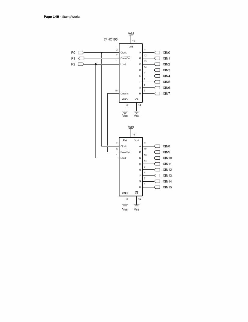
Page 140 · StampWorks

Moving Forward · Page 141
Program: SW21-EX24-74HC165-2.BS2 ' $STAMP BS2 ' $PBASIC 2.5 ' -----[ Program Description ]--------------------------------------------- ' ' This program demonstrates a simple method of turning three BASIC Stamp ' I/O pins into sixteen digital inputs with two 74HC165 shift registers ' that have been cascaded. ' -----[ I/O Definitions ]------------------------------------------------- Clock PIN 0 ' shift clock (74HC165.2) SerData PIN 1 ' serial data (74HC165.7) Load PIN 2 ' output latch (74HC165.1) ' -----[ Constants ]------------------------------------------------------- DelayTime CON 100 ' -----[ Variables ]------------------------------------------------------- xInputs VAR Word ' external inputs ' -----[ Initialization ]-------------------------------------------------- Reset: HIGH Load ' make output and high DEBUG CLS, "XInputs FEDCBA9876543210", CR, "------- ----------------", CR, "Status ................" ' -----[ Program Code ]---------------------------------------------------- Main: DO GOSUB Get_165x2 ' get inputs DEBUG CRSRXY, 10, 2, BIN16 xInputs ' display current status PAUSE DelayTime ' pad the loop a bit LOOP ' -----[ Subroutines ]----------------------------------------------------- Get_165x2: PULSOUT Load, 5 ' load inputs SHIFTIN SerData, Clock, MSBPRE, [xInputs\16] ' shift them in RETURN

Page 142 · StampWorks
Behind the Scenes
This program is very similar to 74HC595 cascading in that the serial output from one shift register is fed into the serial input of the next device up the chain. It is important to note that cascaded stages are connected using the non-inverted output; only the stage connected directly to the BASIC Stamp uses the inverted output (all data passing through will be inverted here). In the program the Get_165x2 subroutine has been updated to accommodate the second 74HC165. Since a Word variable was defined for the external inputs, the bit modifier is used with SHIFTIN; this allows all sixteen bits to be collected at one time. The bit modifier is only required when the number of bits differs from eight (default bit count). We could also define separate Byte variables for each device. The code fragment below shows how we could handle this situation:
Get_165x2: PULSOUT Load, 5 ' load inputs SHIFTIN SerData, Clock, MSBPRE, [switches, buttons] RETURN
In this example, the variable called switches would be loaded with the data from the first shift register in the chain (i.e., the device connected to the BASIC Stamp).

Moving Forward · Page 143
EXPERIMENT #25: MIXED IO WITH SHIFT REGISTERS
This experiment demonstrates the ability to mix the 74HC595 and 74HC165 and use the fewest number of BASIC Stamp I/O pins.
Building the Circuit
Note: The 4.7 kΩ resistor is marked: yellow-violet-red.

Page 144 · StampWorks
Program: SW21-EX25-Mixed_IO.BS2 ' $STAMP BS2 ' $PBASIC 2.5 ' -----[ Program Description ]--------------------------------------------- ' ' This program demonstrates the ability to use the 74HC595 and 74HC165 ' together with the fewest number of BASIC Stamp IO pins. This is ' accomplished by placing a 4.7K resistor between the data out (pin 7) of ' the 74HC165 and the data in (pin 14) of the 74HC595. The serial data ' pin from the BASIC Stamp connects to the 74HC595. ' -----[ I/O Definitions ]------------------------------------------------- Clock PIN 0 ' shift clock SerData PIN 1 ' serial data (74HC595.14) Latch PIN 2 ' output latch (74HC595.12) Load PIN 3 ' input load (74HC165.1) ' -----[ Constants ]------------------------------------------------------- DelayTime CON 100 ' -----[ Variables ]------------------------------------------------------- xInputs VAR Byte ' external inputs ' -----[ Initialization ]-------------------------------------------------- Reset: LOW Latch HIGH Load DEBUG CLS, "XInputs 76543210", CR, "------- --------", CR, "Status ........" ' -----[ Program Code ]---------------------------------------------------- Main: DO GOSUB Get_165 ' get inputs GOSUB Put_595 ' move to extended outputs DEBUG CRSRXY, 10, 2, BIN8 xInputs ' display current status PAUSE DelayTime ' pad the loop a bit LOOP

Moving Forward · Page 145
' -----[ Subroutines ]----------------------------------------------------- Get_165: PULSOUT Load, 5 ' load inputs SHIFTIN SerData, Clock, MSBPRE, [xInputs] ' shift them in RETURN Put_595: SHIFTOUT SerData, Clock, MSBFIRST, [xInputs] ' send inputs to 595 PULSOUT Latch, 5 ' latch 595 outputs INPUT SerData ' float data I/O line RETURN
Behind the Scenes
This program is a fairly simple combination of the previous experiments – with one critical detail: the placement of a 4.7 kΩ resistor between the 74HC165 data output pin and the 74HC595 data input pin. The reason that this is required is the 74HC165 data output pin is just that, an output, and if that pin were connect directly to the BASIC Stamp a data collision could occur (when the BASIC Stamp puts the serial data pin in output mode for SHIFTOUT) that would cause a short circuit. The resistor provides a load that safely limits the current between the BASIC Stamp had the 74HC165. The resistor also gives the BASIC Stamp a load to drive its output across, so no matter what the state of the 74HC165 output pin, the data input of the 74HC595 will always be correct. Do not leave the 4.7 kΩ resistor out of the circuit; otherwise your BASIC Stamp module could be damaged. Notice that the serial data line is made an input (floating) at the end of the Put_595 subroutine. This stops current flow between the BASIC Stamp and the 74HC165 when the pins are in opposite states.

Page 146 · StampWorks
EXPERIMENT #26: HOBBY SERVO CONTROL
This experiment demonstrates the control of a standard hobby servo. Hobby servos frequently are used with microcontrollers in amateur robotics and animatronics.
Look It Up: PBASIC Elements to Know
• MAX (maximum operator) • SDEC, SDEC1 – SDEC16 (used with DEBUG)
Building the Circuit

Moving Forward · Page 147
Program: SW21-EX26-Servo_Control.BS2 ' $STAMP BS2 ' $PBASIC 2.5 ' -----[ Program Description ]--------------------------------------------- ' ' This program shows how to control a standard servo with the BASIC Stamp. ' Servo position is controlled by reading position of a potentiometer that ' is part of opposing RCTIME networks. ' -----[ I/O Definitions ]------------------------------------------------- PotCW PIN 0 ' clockwise pot input PotCCW PIN 1 ' counter-cw pot input Servo PIN 2 ' servo control pin ' -----[ Constants ]------------------------------------------------------- Scale CON $00C6 ' to scale RCTIME values Center CON 1500 ' servo center position PwAdj CON $0080 ' pulse width adjust (0.5) ' -----[ Variables ]------------------------------------------------------- rcRt VAR Word ' rc reading - right rcLf VAR Word ' rc reading - left diff VAR Word ' difference sPos VAR Word ' servo position pWidth VAR Word ' pulse width for servo ' -----[ Initialization ]-------------------------------------------------- Reset: LOW Servo ' initialize for PULSOUT ' -----[ Program Code ]---------------------------------------------------- Main: HIGH PotCW ' read clockwise position PAUSE 1 RCTIME PotCW, 1, rcRt HIGH PotCCW ' read ccw position PAUSE 1

Page 148 · StampWorks
RCTIME PotCCW, 1, rcLf rcRt = (rcRt */ Scale) MAX 500 ' scale RCTIME to 0-500 rcLf = (rcLf */ Scale) MAX 500 sPos = rcLf - rcRt ' position (-500 to 500) pWidth = (Center + sPos) ' finalize pulse width PULSOUT Servo, (pWidth */ PwAdj) ' move the servo PAUSE 20 ' servo refresh delay GOTO Main
Behind the Scenes
Hobby servos are specialized electromechanical devices used most frequently to position the control surfaces of model aircraft. The position of the servo output shaft is determined by the width of an incoming control pulse. The control pulse is typically between one and two milliseconds wide. The servo will center when the control signal is 1.5 milliseconds. In order to maintain its position, the servo must be periodically updated. The typical update frequency is about 50 times per second, or every 20 milliseconds as shown in the illustration below
The BASIC Stamp’s PULSOUT command is ideal command for controlling hobby servos. In this experiment, two RCTIME circuits are constructed around a single 10K potentiometer. This configuration allows the code to split the potentiometer (at the wiper), measuring each side independently. By doing this we are able to determine the relative position of the potentiometer. The readings from each side are scaled to between 0 and 500 with the */ and MAX operators. By subtracting one side from the other, a servo position value between –500 and +500 is returned.
Moving Forward · Page 149
The value for the constant Scale is determined empirically. After constructing the circuit, insert appropriate DEBUG statements to display the raw potentiometer readings from both sides (they may not match exactly due to component differences). Take the lower of the two values and divide that into 500 (desired output). Convert this fractional value to the */ operand by multiplying by 256. Example: Raw RCTIME value: 645 250 / 645 = 0.775 0.775 x 256 = 198 (this is the value called Scale) The difference between the two scaled RCTIME values is added to the centering position of 1500 (microseconds). Remember that on the BASIC Stamp 2 module, PULSOUT works in two-microsecond units. What this means is that the pulse width value needs to be divided by two in order to create the correct pulse output for the servo. This is done by using the */ with the PwAdj constant set to $0080 (0.5). This program demonstrates that the BASIC Stamp does indeed work with negative numbers. You can see the value of sPos by inserting this line after the calculation:
DEBUG Home, "Position: ", SDEC sPos, " "
Negative numbers are stored in two’s complement format. The SDEC (signed decimal) modifier prints standard decimal with the appropriate sign.
Challenge
Replace the potentiometer with two photocells and update the code to cause the servo to point toward at the brightest light source. Can you think of a method that uses two potentiometers and two servos to create a sun tracker?

Page 150 · StampWorks
EXPERIMENT #27: STEPPER MOTOR CONTROL
This experiment demonstrates the control of a small 12-volt stepper motor. Stepper motors convert a pattern of inputs and the rate-of-change of those inputs into precise rotational motion. The rotational angle and direction for each change (step) is determined by the construction of the motor as well as the step pattern input. Stepper motors are used as precision positioning devices in robotics and industrial control applications.
Look It Up: PBASIC Elements to Know
• ABS • MIN (minimum operator)
Building the Circuit
Remove the servo from Experiment #26 and add a stepper motor as shown below.

Moving Forward · Page 151
Program: SW21-EX27-Stepper_Control.BS2 ' $STAMP BS2 ' $PBASIC 2.5 ' -----[ Program Description ]--------------------------------------------- ' ' This program demonstrates simple stepper motor control. A potentiometer ' allows for speed and direction control. Using the L293D driver, this ' program will work with unipolar and bipolar stepper motors. ' -----[ I/O Definitions ]------------------------------------------------- PotCW PIN 0 ' clockwise pot input PotCCW PIN 1 ' counter-cw pot input Coils VAR OUTB ' output to stepper coils ' -----[ Constants ]------------------------------------------------------- Scale CON $100 ' to scale RCTIME Mitsumi CON 48 ' steps/rev by type Howard CON 100 RevSteps CON Mitsumi ' steps per revolution NumSteps CON 4 ' use 4-step sequence LastStep CON NumSteps - 1 ' last step in sequence #DEFINE Testing = 0 ' 1 for POT testing ' -----[ Variables ]------------------------------------------------------- idx VAR Byte ' loop counter stpIdx VAR Nib ' step pointer stpDelay VAR Byte ' delay for speed control rcRt VAR Word ' rc reading - right rcLf VAR Word ' rc reading - left diff VAR Word ' difference in readings ' -----[ EEPROM Data ]----------------------------------------------------- ' __ ' ABAB ' ----- Step1 DATA %1100 Step2 DATA %0110

Page 152 · StampWorks
Step3 DATA %0011 Step4 DATA %1001 ' -----[ Initialization ]-------------------------------------------------- Setup: DIRB = %1111 ' make P4..P7 outputs stpDelay = 5 ' set step delay ' -----[ Program Code ]---------------------------------------------------- Demo: FOR idx = 1 TO RevSteps ' 1 rev forward GOSUB Step_Fwd NEXT PAUSE 200 FOR idx = 1 TO RevSteps ' 1 rev back GOSUB Step_Rev NEXT PAUSE 200 Main: HIGH PotCW ' read clockwise position PAUSE 1 RCTIME PotCW, 1, rcRt HIGH PotCCW ' read ccw position PAUSE 1 RCTIME PotCCW, 1, rcLf rcRt = (rcRt */ Scale) MAX 600 ' set speed limits rcLf = (rcLf */ Scale) MAX 600 diff = ABS (rcRt - rcLf) ' get difference stpDelay = 100 - (diff / 6) MIN 2 ' calculate step delay IF (diff < 25) THEN ' allow for dead band GOTO Main ELSE ' do a step IF (rcLf < rcRt) THEN GOSUB Step_Fwd ELSE GOSUB Step_Rev ENDIF ENDIF GOTO Main ' repeat

Moving Forward · Page 153
' -----[ Subroutines ]----------------------------------------------------- ' Turn stepper clockwise one full step Step_Fwd: stpIdx = stpIdx + 1 // NumSteps ' point to next step GOTO Do_Step ' Turn stepper counter-clockwise one full step Step_Rev: stpIdx = stpIdx + LastStep // NumSteps ' point to previous step GOTO Do_Step ' Read new step data and output to pins Do_Step: READ (Step1 + stpIdx), Coils ' output new coil data PAUSE stpDelay ' pause between steps RETURN
Behind the Scenes
Stepper motors differ from standard DC motors in that they do not spin freely when power is applied. For a stepper motor to rotate, the power source must be continuously pulsed in specific patterns. The step sequence (pattern) determines the direction of the stepper’s rotation. The time between sequence steps determines the rotational speed. Each step causes the stepper motor to rotate a fixed angular increment. The stepper motor supplied with the current StampWorks kit rotates 7.5 degrees per step. This means that one full rotation (360 degrees) of the stepper requires 48 steps. Use the table below as a guide to the motor connections.
Manufacturer Mitsumi Howard Industries Degrees per Step 7.5 3.6 Steps per Revolution 48 100 Phase 1 Brown White Phase 2 Orange Red Phase 3 Black Green Phase 4 Yellow Brown Common Red Black

Page 154 · StampWorks
The step sequences for the motor are stored in DATA statements. The Step_Fwd subroutine will read the next sequence from the table to be applied to the coils. The StepRev subroutine is identical except that it will read the previous step. Note the trick with the modulus (//) operator used in StepRev. By adding the maximum value of the sequence to the current value and then applying the modulus operator, the sequence goes in reverse. As a review, here’s the modulus math for full steps (four steps per cycle): 0 + 3 // 4 = 3 3 + 3 // 4 = 2 2 + 3 // 4 = 1 1 + 3 // 4 = 0 This experiment reads both sides of the 10K potentiometer to determine its relative position. The differential value between the two readings is kept positive by using the ABS function. The position is used to determine the rotational direction and the strength of the position is used to determine the rotational speed. Remember, the shorter the delay between steps, the faster the stepper will rotate. A dead-band check is used to cause the motor to stop rotating when the RCTIME readings are nearly equal.
Taking It Further
Surplus stepper motors are very easy to come by, and the experimenter is often faced with two challenges: 1) How to control a bipolar (4-wire) stepper motor and, 2) How to determine the coil sequence of an unknown motor. By using the L293D the first challenge is nullified; the L293D is a push-pull driver (versus the ULN2x03 that only sinks current) and will work – without any modifications to the code – with unipolar and bipolar stepper motors. The second challenge can be overcome with a multimeter. Create a table with the wire colors as column and row headings, jotting down the resistance measured between the wires. For example:

Moving Forward · Page 155
Yel Blk Org Brn Red Yel x Blk 225 x Org 225 225 x Brn 225 225 225 x Red 112 112 112 112 x
Note how that when the Red wire is part of a pair the resistance is half the other readings; this is the common wire. Some unipolar motors have six wires. In this case, two of the wires will be common. To determine the wiring sequence, follow these steps:
1. Connect the coil wires in any order. Run the program; if it moves smoothly, you’re done.
2. If Step 1 doesn’t work, swap the #1 and #4 wire connections. Retest. 3. If Step 2 doesn’t work, swap the #2 and #3 wire connections. The motor
should now run. If the motor is spinning in the direction opposite of what is expected, swap the #1 and #4 leads, and the #2 and #3 leads. The motor should now be spinning smoothly and in the desired direction.
Challenge
Rewrite the program to run the motor in half steps. Keep in mind that while half steps provide greater position accuracy, the motor torque is reduced and may not be able to move devices connected to it. Here’s the step sequence:
Step1 = %1000 Step2 = %1100 Step3 = %0100 Step4 = %0110 Step5 = %0010 Step6 = %0011 Step7 = %0001 Step8 = %1001

Page 156 · StampWorks
EXPERIMENT #28: VOLTAGE MEASUREMENT
This experiment demonstrates the use of the popular ADC0831 analog-to-digital converter IC to read a variable voltage input
Look It Up: PBASIC Elements to Know
• MSBPOST (used with SHIFTIN)
Building the Circuit
Program: SW21-EX28-ADC0831-Simple.BS2 ' $STAMP BS2 ' $PBASIC 2.5 ' -----[ Program Description ]--------------------------------------------- ' ' This program demonstrates reading a variable voltage with an ADC0831 ' analog-to-digital converter chip. This program uses a Vref input of ' 5.000 volts (Vdd) for a bit resolution of 19.6 millivolts. ' -----[ I/O Definitions ]------------------------------------------------- CS PIN 0 ' chip select (ADC0831.1) Clock PIN 1 ' clock (ADC0831.7)
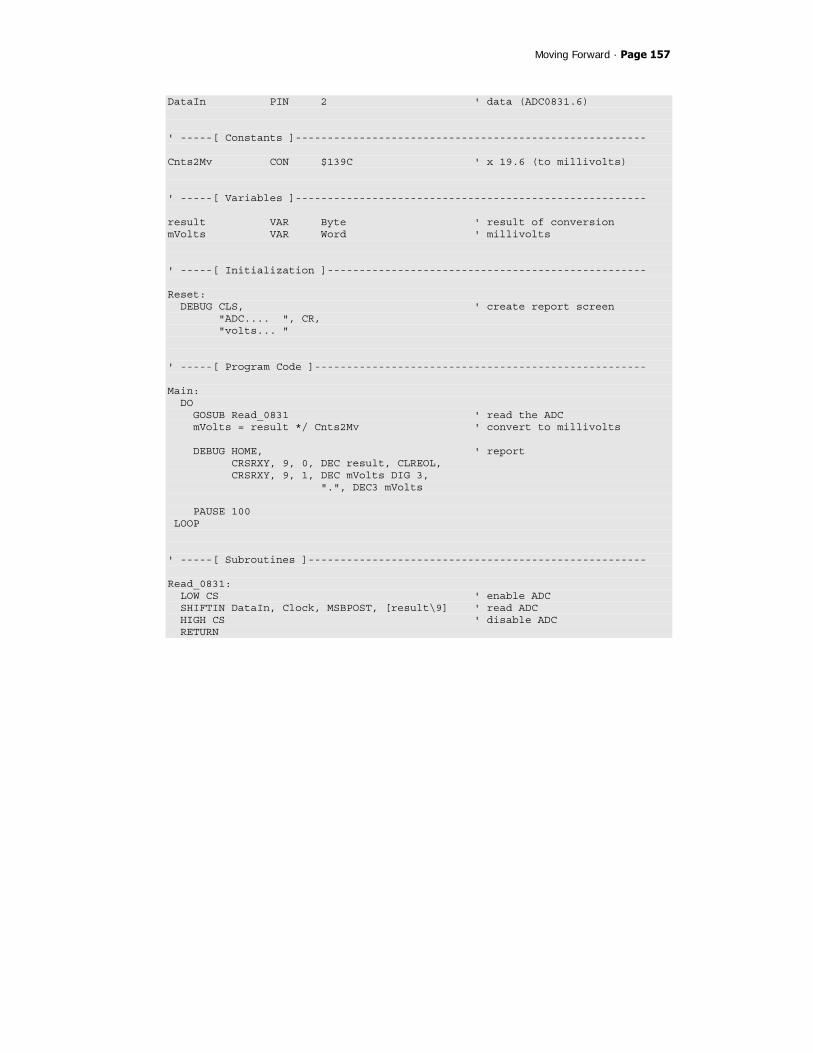
Moving Forward · Page 157
DataIn PIN 2 ' data (ADC0831.6) ' -----[ Constants ]------------------------------------------------------- Cnts2Mv CON $139C ' x 19.6 (to millivolts) ' -----[ Variables ]------------------------------------------------------- result VAR Byte ' result of conversion mVolts VAR Word ' millivolts ' -----[ Initialization ]-------------------------------------------------- Reset: DEBUG CLS, ' create report screen "ADC.... ", CR, "volts... " ' -----[ Program Code ]---------------------------------------------------- Main: DO GOSUB Read_0831 ' read the ADC mVolts = result */ Cnts2Mv ' convert to millivolts DEBUG HOME, ' report CRSRXY, 9, 0, DEC result, CLREOL, CRSRXY, 9, 1, DEC mVolts DIG 3, ".", DEC3 mVolts PAUSE 100 LOOP ' -----[ Subroutines ]----------------------------------------------------- Read_0831: LOW CS ' enable ADC SHIFTIN DataIn, Clock, MSBPOST, [result\9] ' read ADC HIGH CS ' disable ADC RETURN

Page 158 · StampWorks
Behind the Scenes
Previous projects have used RCTIME to read resistive components. This is a form of analog input, but isn’t voltage measurement. For that, the BASIC Stamp needs help from an external device. The simplest way to measure a variable voltage is with an analog-to-digital converter. In this experiment, the National Semiconductor ADC0831 is used to convert a voltage (0 – 5) to a synchronous serial signal that can be read by the BASIC Stamp with SHIFTIN. One thing of note about the Read_0831 subroutine is that we specify nine bits in SHIFTIN, even though the result is only eight bits? Why? The ADC0831 requires one pulse on the clock line after being activated to do the voltage conversion. The next eight clock pulses move the data out of the device as shown in the illustration below:
The first clock pulse (gray) after the CS line goes low causes the ADC0831 to do the voltage conversion. The MSBPOST mode is used with SHIFTIN as the data bits are presented MSB first, and after the clock line falls. The POST modes sample the data line after each clock pulse. The voltage measurement – which is actually the positive difference between the Vin+ (pin 2) and Vin- (pin 3) pins – will be a value between 0 and 255 (Vref). In our first application we have connected Vin- to ground and Vref to Vdd; this gives us a voltage span of 5.00 volts. Dividing five (volts) by 255, we find that each bit in the result is equal to 19.6 millivolts. For display purposes, the result is converted to millivolts by multiplying by 19.6 (result */ $139C).
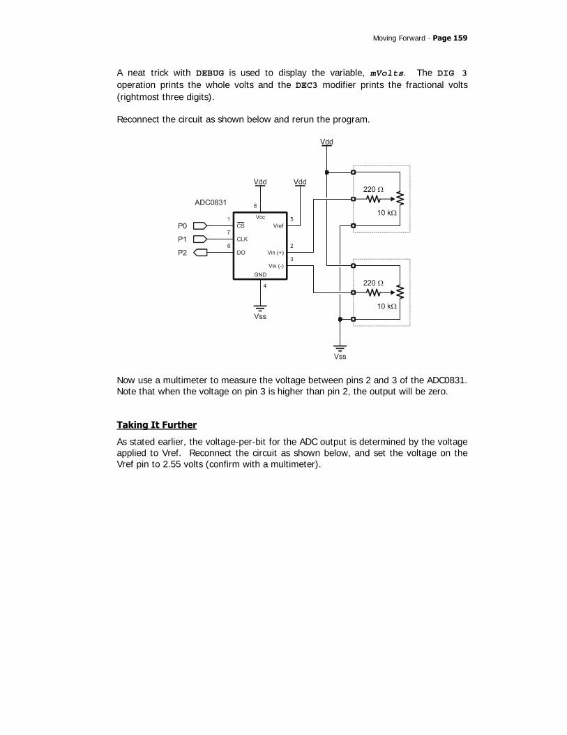
Moving Forward · Page 159
A neat trick with DEBUG is used to display the variable, mVolts. The DIG 3 operation prints the whole volts and the DEC3 modifier prints the fractional volts (rightmost three digits). Reconnect the circuit as shown below and rerun the program.
Now use a multimeter to measure the voltage between pins 2 and 3 of the ADC0831. Note that when the voltage on pin 3 is higher than pin 2, the output will be zero.
Taking It Further
As stated earlier, the voltage-per-bit for the ADC output is determined by the voltage applied to Vref. Reconnect the circuit as shown below, and set the voltage on the Vref pin to 2.55 volts (confirm with a multimeter).

Page 160 · StampWorks
By reducing the Vref voltage the resolution per output bit is increased. With a Vref of 2.55 volts, the voltage per bit is 0.01 volts, nearly twice as when 5.00 volts was used for Vref, and the conversion to millivolts is simplified. This configuration is useful for sensors like the GP2D12 distance sensor that has a voltage output of 0 to 2.4 volts. Before running the program modify the Cnts2Mv constant to reflect the Vref change. With each bit equal to 0.01 volts (1/100) we can multiply by 10 to convert to millivolts (1/1000).
Cnts2Mv CON $0A00 ' x 10 (to millivolts)
Note that as the ADC0831 cannot measure below zero volts (floor value is 0), it cannot measure above Vref. If the differential voltage between pins 2 and 3 is greater than Vref, the output will be limited to 255. Keep this limitation in mind for designs where the voltage input could move above Vref.

Moving Forward · Page 161
EXPERIMENT #29: TEMPERATURE MEASUREMENT
This experiment demonstrates the use of a popular digital temperature sensor IC: the DS1620. Accurate temperature measurement is a necessary component of environmental control applications (heating and air conditioning).
Look It Up: PBASIC Elements to Know
• LSBFIRST (used with SHIFTOUT) • LSBPRE (used with SHIFTIN) • BYTE0, BYTE1 (variable modifier)
Building the Circuit
Program: SW21-EX29-DS1620-Simple.BS2 ' $STAMP BS2 ' $PBASIC 2.5 ' -----[ Program Description ]--------------------------------------------- ' ' This program measures temperature using the Dallas Semiconductor DS1620 ' temperature sensor. Resolution is 0.5 degrees Celsius. ' -----[ I/O Definitions ]-------------------------------------------------

Page 162 · StampWorks
DQ CON 0 ' DS1620.1 (data I/O) Clock CON 1 ' DS1620.2 Reset CON 2 ' DS1620.3 ' -----[ Constants ]------------------------------------------------------- RdTmp CON $AA ' read temperature WrHi CON $01 ' write TH (high temp) WrLo CON $02 ' write TL (low temp) RdHi CON $A1 ' read TH RdLo CON $A2 ' read TL RdCntr CON $A0 ' read counter RdSlope CON $A9 ' read slope StartC CON $EE ' start conversion StopC CON $22 ' stop conversion WrCfg CON $0C ' write config register RdCfg CON $AC ' read config register DegSym CON 186 ' degrees symbol ' -----[ Variables ]------------------------------------------------------- tempIn VAR Word ' raw temperature sign VAR tempIn.BIT8 ' 1 = negative temperature tC VAR Word ' Celsius tF VAR Word ' Fahrenheit ' -----[ Initialization ]-------------------------------------------------- Setup: HIGH Reset ' alert the DS1620 SHIFTOUT DQ, Clock, LSBFIRST, [WrCfg, %10] ' use with CPU; free-run LOW Reset PAUSE 10 HIGH Reset SHIFTOUT DQ, Clock, LSBFIRST, [StartC] ' start conversions LOW Reset DEBUG CLS, "DS1620 ", CR, "---------" ' -----[ Program Code ]---------------------------------------------------- Main: DO
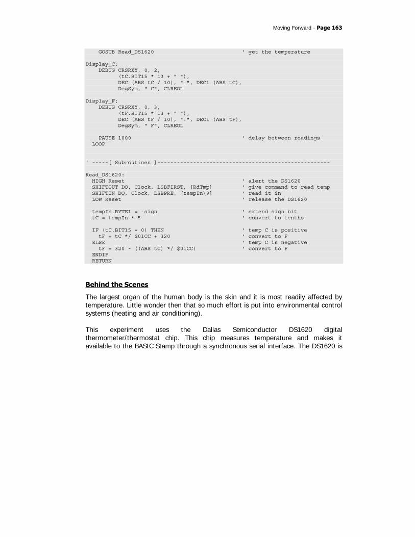
Moving Forward · Page 163
GOSUB Read_DS1620 ' get the temperature Display_C: DEBUG CRSRXY, 0, 2, (tC.BIT15 * 13 + " "), DEC (ABS tC / 10), ".", DEC1 (ABS tC), DegSym, " C", CLREOL Display_F: DEBUG CRSRXY, 0, 3, (tF.BIT15 * 13 + " "), DEC (ABS tF / 10), ".", DEC1 (ABS tF), DegSym, " F", CLREOL PAUSE 1000 ' delay between readings LOOP ' -----[ Subroutines ]----------------------------------------------------- Read_DS1620: HIGH Reset ' alert the DS1620 SHIFTOUT DQ, Clock, LSBFIRST, [RdTmp] ' give command to read temp SHIFTIN DQ, Clock, LSBPRE, [tempIn\9] ' read it in LOW Reset ' release the DS1620 tempIn.BYTE1 = -sign ' extend sign bit tC = tempIn * 5 ' convert to tenths IF (tC.BIT15 = 0) THEN ' temp C is positive tF = tC */ $01CC + 320 ' convert to F ELSE ' temp C is negative tF = 320 - ((ABS tC) */ $01CC) ' convert to F ENDIF RETURN
Behind the Scenes
The largest organ of the human body is the skin and it is most readily affected by temperature. Little wonder then that so much effort is put into environmental control systems (heating and air conditioning). This experiment uses the Dallas Semiconductor DS1620 digital thermometer/thermostat chip. This chip measures temperature and makes it available to the BASIC Stamp through a synchronous serial interface. The DS1620 is

Page 164 · StampWorks
an intelligent device and, once programmed, is capable of stand-alone operation using the THi, TLo, and TCom control outputs. The connections to the DS1620 are similar to other synchronous serial devices, with the exception of the 1K resistor in the DQ line. Do not leave this out; the DQ pin of the DS1620 is bi-directional so it could – under the right conditions – be an output and in the opposite state of the BASIC Stamp pin that it connects to. This condition could lead to damage to one device or the other. The 1K resistor limits the current between the BASIC Stamp and the DS1620 to a safe level should a programming error occur. The DS1620 requires initialization before use. In active applications like this, the DS1620 is configured for free running with a CPU. After the configuration data is sent to the DS1620, a delay of 10 milliseconds is required so that the configuration can be written to the DS1620’s internal EEPROM (this delay is required after any write to the EEPROM). After the delay, the DS1620 is instructed to start continuous conversions. This will ensure a current temperature reading when the BASIC Stamp requests it. The DS1620 requires about one second to complete a temperature conversion, so access to new temperature should be no more frequent than every second. To retrieve the current temperature, the Read Temperature ($AA) command byte is sent to the DS1620. Then the latest conversion value is read back. The data returned is nine bits wide, and holds the temperature in half-degrees Celsius units. Bit8 indicates the sign of the temperature. If negative (sign bit is 1), the other eight bits hold the two’s-complement value of the temperature. The sign bit is extended to the upper byte of tempIn to allow positive or negative values in the equations that follow. This is required because the BASIC Stamp stores negative values in 16-bit two’s complement format, but only nine bits are returned from the DS1620. You see how the sign gets properly extended with the following test program:
DEBUG BIN8 -0, CR, ' %00000000 (positive) BIN8 -1 ' %11111111 (negative)
With a full (signed) 16-bit value in tempIn, the Celsius temperature is calculated by multiplying tempIn by five. If the current temperature was 22.5 degrees C, tC would now hold 225.

Moving Forward · Page 165
To convert from Celsius (in tenths) to Fahrenheit (also in tenths) a modification of the standard temperature equation is used: Ftenths = (Ctenths * 1.8) + 320 Note that 32 degrees from the standard equation has also been converted to tenths. For the conversion of negative temperatures the order of elements in the equation is reversed. The reason for this is that negative numbers cannot be divided in PBASIC. The ABS operator is used to convert the intermediate result to a positive value. When subtracted from 320 the result will be properly aligned (and signed); some negative values in the Celsius range are still positive in Fahrenheit. The display routine uses a little trick that looks at Bit15 of the value; if Bit15 is one then the temperature is negative and a “-“ will precede the temperature reading, otherwise a space will be printed.

Page 166 · StampWorks
Taking It Further
The DS1620 has thermostat outputs that can be used to control other devices. These outputs are typically used in stand-alone mode, but will also work autonomously when the DS1620 is connected to the BASIC Stamp or another host. Connect two LEDs to the DS1620 THi and TLo outputs as shown below:
With the LEDs connected, add the following code after the DS1620 initialization:
Set_Alarms: HIGH Reset tC = (THi - 32 */ $008E) * 2 ' convert to 0.5 C SHIFTOUT DQ, Clock, LSBFIRST, [WrHi, tC\9] ' write high temp LOW Reset PAUSE 10 HIGH Reset tC = (TLo - 32 * 5 / 9) * 2 SHIFTOUT DQ, Clock, LSBFIRST, [WrLo, tC\9] ' write low temp LOW Reset PAUSE 10
Behind the Scenes
The THi output will go high when the current temperature is at or above the value stored in the high-temperature register. The TLo output will go high when the current temperature is at or below the low-temperature register.

Moving Forward · Page 167
In the program the constants THi and TLo are used to set the high and low temperature thresholds. These values are expressed in whole degrees Fahrenheit, and are converted to half-degrees Celsius before being written to the appropriate register. Chalf = (F - 32) x 5 / 9 x 2 Finally, note that as in the setup of the configuration register, a 10 millisecond PAUSE is required after every EEPROM write. Once the thresholds are written to the thermostat registers the THi and TLo outputs will operate independently and without further program interface. The BASIC Stamp can read the configuration register to get the status of the DS1620 THi and TLo outputs. See Experiment #30.

Page 168 · StampWorks
EXPERIMENT #30: HIGH RESOLUTION TEMPERATURE MEASUREMENT
This experiment demonstrates advanced use of the DS1620 temperature sensor, allowing for high resolution (0.05 degrees C) measurements.
Building the Circuit
Use the circuit from Experiment #29.
Program: SW21-EX30-DS1620-HiRes.BS2 ' $STAMP BS2 ' $PBASIC 2.5 ' -----[ Program Description ]--------------------------------------------- ' ' This program measures temperature using the Dallas Semiconductor DS1620 ' temperature sensor. Resolution is <0.05 degrees Celsius. ' ' NOTE: After downloading program, power must be cycled for proper ' operation. ' -----[ I/O Definitions ]------------------------------------------------- DQ CON 0 ' DS1620.1 (data I/O) Clock CON 1 ' DS1620.2 Reset CON 2 ' DS1620.3 ' -----[ Constants ]------------------------------------------------------- RdTmp CON $AA ' read temperature WrHi CON $01 ' write TH (high temp) WrLo CON $02 ' write TL (low temp) RdHi CON $A1 ' read TH RdLo CON $A2 ' read TL RdCntr CON $A0 ' read counter RdSlope CON $A9 ' read slope StartC CON $EE ' start conversion StopC CON $22 ' stop conversion WrCfg CON $0C ' write config register RdCfg CON $AC ' read config register DegSym CON 186 ' degrees symbol

Moving Forward · Page 169
' -----[ Variables ]------------------------------------------------------- tempIn VAR Word ' raw temperature config VAR Byte ' configuration register done VAR config.BIT7 ' 1 when conversion done tHiFlag VAR config.BIT6 ' 1 when temp >= THi tLoFlag VAR config.BIT5 ' 1 when temp <= TLo busy VAR config.BIT4 ' 1 when EE update writing cRem VAR Word ' count remaining slope VAR Word ' slope (counts per degree) tC VAR Word ' Celsius tF VAR Word ' Fahrenheit ' -----[ Initialization ]-------------------------------------------------- Setup: HIGH Reset ' alert DS1620 SHIFTOUT DQ, Clock, LSBFIRST, [WrCfg, %11] ' with CPU, one-shot mode LOW Reset ' release DS1620 PAUSE 10 DEBUG CLS, "DS1620-HR ", CR, "----------" ' -----[ Program Code ]---------------------------------------------------- Main: DO GOSUB Read_DS1620_HR ' get hi-res temperature Display_C: DEBUG CRSRXY, 0, 2, (tC.BIT15 * 13 + " "), DEC (ABS tC / 100), ".", DEC2 (ABS tC), DegSym, " C", CLREOL Display_F: DEBUG CRSRXY, 0, 3, (tF.BIT15 * 13 + " "), DEC (ABS tF / 100), ".", DEC2 (ABS tF), DegSym, " F", CLREOL LOOP

Page 170 · StampWorks
' -----[ Subroutines ]----------------------------------------------------- Read_DS1620_HR: ' get hi-resolution temp HIGH Reset ' alert the DS1620 SHIFTOUT DQ, Clock, LSBFIRST, [StartC] ' start conversion LOW Reset ' release the DS1620 DO HIGH Reset SHIFTOUT DQ, Clock, LSBFIRST, [RdCfg] ' read config register SHIFTIN DQ, Clock, LSBPRE, [config\8] LOW Reset LOOP UNTIL (done = 1) ' wait for conversion HIGH Reset SHIFTOUT DQ, Clock, LSBFIRST, [RdTmp] ' read raw temperature SHIFTIN DQ, Clock, LSBPRE, [tempIn\9] LOW Reset HIGH Reset SHIFTOUT DQ, Clock, LSBFIRST, [RdCntr] ' read counter SHIFTIN DQ, Clock, LSBPRE, [cRem\9] LOW Reset HIGH Reset SHIFTOUT DQ, Clock, LSBFIRST, [RdSlope] ' read slope SHIFTIN DQ, Clock, LSBPRE, [slope\9] LOW Reset tempIn = tempIn >> 1 ' remove half degree bit tempIn.BYTE1 = -tempIn.BIT7 ' extend sign bit tC = tempIn * 100 ' convert to 100ths tC = tC - 25 + (slope - cRem * 100 / slope) ' fix fractional temp IF (tC.BIT15 = 0) THEN tF = tC */ $01CC + 3200 ' convert pos C to Fahr ELSE tF = 3200 - ((ABS tC) */ $01CC) ' convert neg C to Fahr ENDIF RETURN
Behind the Scenes
Digging deeper into the mechanics of the DS1620 we find that temperature is derived by using two temperature-controlled oscillators. When one oscillator rolls-over within a gate period determined by the other, the temperature counter – which has been preloaded with -55 degrees C – gets incremented. Fractional temperatures can be determined by looking at the count remaining at the end of a conversion

Moving Forward · Page 171
cycle and comparing this to another register called the slope accumulator. The purpose of the slope accumulator is to correct the non-linear behavior of the oscillators over temperature. For high-resolution temperature measurements we can read the temperature, remove the half-degree bit (which was estimated by the DS1620 circuit), and then calculate the fractional portion using the values from the slope and counts remaining registers. The following equation is used to derive high-resolution temperature from the DS1620: tC = (tempIn / 2) – 0.25 + ((slope – remaining) / slope) To use the DS1620 in this mode requires a slightly different initialization sequence: in order to read the slope and counts remaining registers, the DS1620 must be programmed for one-shot mode. Note that if the DS1620 had been previously programmed for continuous conversion (as in Experiment #29) the power must be cycled after reprogramming for one-shot mode before the DS1620 will respond properly. In one-shot mode the temperature is read by sending the StartC command ($EE) and then continuously reading the configuration register until Bit7 goes high – this indicates the end of the conversion cycle. When the cycle is complete the temperature, counts remaining, and slope registers can be read from the DS1620. Note that the configuration register that is used to signal the end of the conversion also holds flags for the THi and TLo outputs of the DS1620. The high resolution conversion begins by removing the half-degree bit – this is accomplished by shifting tempIn right by one (When dividing or multiplying by powers of two (2, 4, 8, 16, …) it is more efficient to use shift operators instead of * or /). The next step is to extend the sign bit so that tempIn holds a correct 16-bit value. The shift operation just used has moved the sign bit; it is now located in Bit7. The temperature is then converted to 100ths to maintain the resolution available from the process, and the equation above is applied to derive tC. Note that the parameters of the high-resolution have also been converted for 100ths. If the current temperature was 23.75 degrees C, tC would now hold 2375.

Page 172 · StampWorks

Moving Forward · Page 173
EXPERIMENT #31: ADVANCED 7-SEGMENT MULTIPLEXING
This experiment demonstrates the use of 7-segment displays with an external multiplexing controller. Multi-digit seven-segment displays are frequently used on vending machines to display the amount of money entered.
Building the Circuit
Connect four pushbuttons to P4-P7 (see Experiment #14) and add the multiplexing circuit below.
Page 174 · StampWorks
Program: SW21-EX31-MC14489.BS2 ' $STAMP BS2 ' $PBASIC 2.5 ' -----[ Program Description ]--------------------------------------------- ' ' This program is a coin counter -- it will count nickels, dimes, quarters, ' and dollars using pushbutton inputs. The "bank" is displayed on four ' 7-segment LED displays that are controlled with a MC14489. ' -----[ I/O Definitions ]------------------------------------------------- Clock PIN 0 ' shift clock (MC14489.11) SerData PIN 1 ' serial data (MC14489.12) Enable PIN 2 ' enable (MC14489.10) Coins VAR INB ' coin inputs (P4 - P7) ' -----[ Constants ]------------------------------------------------------- FullValue CON 500 ' bank full = $5.00 ' Hex values for Letters Ltr_F CON $F ' display in Hex mode ' Special Decode characters Blank CON $0 ' display in Special mode Ltr_U CON $A Ltr_L CON $5 ' -----[ Variables ]------------------------------------------------------- money VAR Word ' current money count idx VAR Nib ' loop counter deposit VAR Nib ' coins deposited nickel VAR deposit.BIT0 ' bit values of deposit dime VAR deposit.BIT1 quarter VAR deposit.BIT2 dollar VAR deposit.BIT3 config VAR Byte ' decode configuration dpCtrl VAR Nib ' decimal point control segs5 VAR Nib ' segs - digit 5 segs4 VAR Nib segs3 VAR Nib segs2 VAR Nib segs1 VAR Nib ' segs - digit 1

Moving Forward · Page 175
' -----[ Initialization ]-------------------------------------------------- Reset: HIGH Enable ' disable MC14489 GOSUB Show_The_Money ' initialize display segs config = %00110001 ' use 3 digits, hex mode GOSUB Update_Cfg ' -----[ Program Code ]---------------------------------------------------- Main: DO GOSUB Get_Coins ' wait for coins LOOP UNTIL (deposit > 0) money = money + (nickel * 5) ' add coins money = money + (dime * 10) money = money + (quarter * 25) money = money + (dollar * 100) GOSUB Show_The_Money ' update the display PAUSE 250 IF (money < FullValue) THEN Main ' scan until full DO PAUSE 500 config.BIT0 = ~config.BIT0 ' toggle display GOSUB Update_Cfg LOOP ' -----[ Subroutines ]----------------------------------------------------- Get_Coins: deposit = %1111 ' enable all coin inputs FOR idx = 1 TO 10 deposit = deposit & ~Coins ' test inputs PAUSE 5 ' delay between tests NEXT RETURN ' Display money value until that value meets or ' exceeds the bank limit. Show_The_Money: IF (money < FullValue) THEN ' show money count dpCtrl = %1011 ' display bright, show DP segs5 = Blank segs4 = Blank

Page 176 · StampWorks
segs3 = money DIG 2 ' dollar digit segs2 = money DIG 1 ' tens digit segs1 = money DIG 0 ' ones digit GOSUB Update_Segs ELSE ' show "FULL" config = Blank GOSUB Update_Cfg config = %11101111 ' setup for "FULL" dpCtrl = %1000 ' display bright, no DPs segs5 = Blank segs4 = Ltr_F ' F segs3 = Ltr_U ' U (Special Decode) segs2 = Ltr_L ' L (Special Decode) segs1 = Ltr_L ' L (Special Decode) GOSUB Update_Segs ' show message GOSUB Update_Cfg ' display on ENDIF RETURN ' Update MC14489 configuration register Update_Cfg: LOW Enable ' enable MC14489 SHIFTOUT SerData, Clock, MSBFIRST, [config] ' send config register HIGH Enable ' disable MC14489 RETURN ' Update MC14489 decimal point control and segments registers Update_Segs: LOW Enable SHIFTOUT SerData, Clock, MSBFIRST, [dpCtrl\4, segs5\4, segs4\4, segs3\4, segs2\4, segs1\4] HIGH Enable RETURN
Behind the Scenes
As demonstrated in Experiment #10, 7-segment display multiplexing requires a lot of effort that consumes most of the computational resources of the BASIC Stamp. Enter the Motorola MC14489 display multiplexer. By using just three BASIC Stamp I/O pins it will effectively control up to five 7-segment displays. The interface is simple, allowing the display of numbers (all hex values), a few letters (those that can be displayed on a 7-segment LED), and a few special characters (e.g., dash, degrees
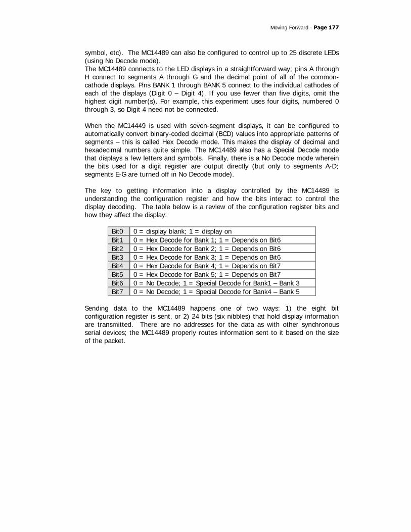
Moving Forward · Page 177
symbol, etc). The MC14489 can also be configured to control up to 25 discrete LEDs (using No Decode mode). The MC14489 connects to the LED displays in a straightforward way; pins A through H connect to segments A through G and the decimal point of all of the common-cathode displays. Pins BANK 1 through BANK 5 connect to the individual cathodes of each of the displays (Digit 0 – Digit 4). If you use fewer than five digits, omit the highest digit number(s). For example, this experiment uses four digits, numbered 0 through 3, so Digit 4 need not be connected. When the MC14449 is used with seven-segment displays, it can be configured to automatically convert binary-coded decimal (BCD) values into appropriate patterns of segments – this is called Hex Decode mode. This makes the display of decimal and hexadecimal numbers quite simple. The MC14489 also has a Special Decode mode that displays a few letters and symbols. Finally, there is a No Decode mode wherein the bits used for a digit register are output directly (but only to segments A-D; segments E-G are turned off in No Decode mode). The key to getting information into a display controlled by the MC14489 is understanding the configuration register and how the bits interact to control the display decoding. The table below is a review of the configuration register bits and how they affect the display:
Bit0 0 = display blank; 1 = display on Bit1 0 = Hex Decode for Bank 1; 1 = Depends on Bit6 Bit2 0 = Hex Decode for Bank 2; 1 = Depends on Bit6 Bit3 0 = Hex Decode for Bank 3; 1 = Depends on Bit6 Bit4 0 = Hex Decode for Bank 4; 1 = Depends on Bit7 Bit5 0 = Hex Decode for Bank 5; 1 = Depends on Bit7 Bit6 0 = No Decode; 1 = Special Decode for Bank1 – Bank 3 Bit7 0 = No Decode; 1 = Special Decode for Bank4 – Bank 5
Sending data to the MC14489 happens one of two ways: 1) the eight bit configuration register is sent, or 2) 24 bits (six nibbles) that hold display information are transmitted. There are no addresses for the data as with other synchronous serial devices; the MC14489 properly routes information sent to it based on the size of the packet.

Page 178 · StampWorks
For the counter program we initially want to use Hex (numeric) decoding for digits 0 – 2, blank digits 3 and 4, and set the decimal point to be on digit 2. The proper configuration register value for this requirement is %00110001 (review the configuration bit table above). The Update_Cfg subroutine handles sending the configuration register to the MC14489. The decimal point is controlled by one of the six nibble-sized registers passed to the MC14489 for display. The position of the decimal point(s) – if used – is transmitted using the Update_Segs subroutine along with the control values for each of the display digits. Most of the work takes place in the subroutine called Show_The_Money. When the money count is less than 500, the value will be displayed on the 7-segment LEDs. The routine scans through each digit of money and sends the digit position and value (from the DIG operator) to the MC14489. Since the display shows dollars and cents, the decimal point on the third digit is enabled. When the value of money reaches or passes 500, the display will change to “FULL.” This is accomplished by setting Banks 1 – 3 (digits 0 – 2) to Special Decode so that the letters “U” and “L” can be displayed. The letter “F” is part of the hexadecimal number set so Bank 4 (digit 3) is left in Hex Decode mode. The main loop of the program is simple: it scans the switch inputs with Get_Coins and updates the money count for each switch pressed. When the “bank” is full, the program enters an infinite loop that toggles the display bit of the configuration register; this is a simple way to flash the display without modifying display contents.
Challenge
Modify the code in Experiment #28 to display the input voltage on the seven-segment displays.
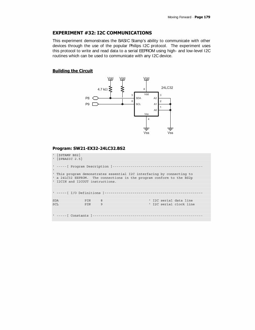
Moving Forward · Page 179
EXPERIMENT #32: I2C COMMUNICATIONS
This experiment demonstrates the BASIC Stamp’s ability to communicate with other devices through the use of the popular Philips I2C protocol. The experiment uses this protocol to write and read data to a serial EEPROM using high- and low-level I2C routines which can be used to communicate with any I2C device.
Building the Circuit
Program: SW21-EX32-24LC32.BS2 ' $STAMP BS2 ' $PBASIC 2.5 ' -----[ Program Description ]--------------------------------------------- ' ' This program demonstrates essential I2C interfacing by connecting to ' a 24LC32 EEPROM. The connections in the program conform to the BS2p ' I2CIN and I2COUT instructions. ' -----[ I/O Definitions ]------------------------------------------------- SDA PIN 8 ' I2C serial data line SCL PIN 9 ' I2C serial clock line ' -----[ Constants ]-------------------------------------------------------

Page 180 · StampWorks
Ack CON 0 ' acknowledge bit Nak CON 1 ' no ack bit EE24LC32 CON %1010 << 4 ' device ID ' -----[ Variables ]------------------------------------------------------- slvAddr VAR Byte ' I2C slave address devNum VAR Nib ' device number (0 - 7) addrLen VAR Nib ' bytes in word addr (0 - 2) wrdAddr VAR Word ' word address i2cData VAR Byte ' data to/from device i2cWork VAR Byte ' work byte for TX routine i2cAck VAR Bit ' Ack bit from device test VAR Nib outVal VAR Byte inVal VAR Byte fails VAR Word ' -----[ Initialization ]-------------------------------------------------- Reset: #IF ($STAMP >= BS2P) #THEN #ERROR "Please use BS2p version: SW21-EX32-24LC32.BSP" #ENDIF Setup: devNum = %000 ' chip select (%000 - %111) slvAddr = EE24LC32 | (devNum << 1) ' setup slave ID addrLen = 2 ' 2 bytes in word address DEBUG CLS, "24LC32 Demo ", CR, "---------------", CR, "Address... ", CR, "Output.... ", CR, "Input..... ", CR, "Status.... ", CR, "Errors.... " ' -----[ Program Code ]---------------------------------------------------- Main: fails = 0 FOR wrdAddr = 0 TO 4095 ' test all locations DEBUG CRSRXY, 11, 2, DEC4 wrdAddr

Moving Forward · Page 181
FOR test = 0 TO 3 ' use four patterns LOOKUP test, [$FF, $AA, $55, $00], outVal DEBUG CRSRXY, 11, 3, IHEX2 outVal i2cData = outVal GOSUB Write_Byte PAUSE 10 GOSUB Read_Byte inVal = i2cData DEBUG CRSRXY, 11, 4, IHEX2 inVal, CRSRXY, 11, 5 IF (inVal = outVal) THEN DEBUG "Pass " ELSE fails = fails + 1 DEBUG "Fail ", CRSRXY, 11, 6, DEC fails EXIT ' terminate location ENDIF PAUSE 10 NEXT NEXT IF (fails = 0) THEN DEBUG CRSRXY, 11, 6, "None. All locations test good." ENDIF END ' =====[ High Level I2C Subroutines]======================================= ' Random location write ' -- pass device slave address in "slvAddr" ' -- pass bytes in word address (0, 1 or 2) in "addrLen" ' -- word address to write passed in "wrdAddr" ' -- data byte to be written is passed in "i2cData" Write_Byte: GOSUB I2C_Start ' send Start i2cWork = slvAddr & %11111110 ' send slave ID (write) GOSUB I2C_TX_Byte IF (i2cAck = Nak) THEN Write_Byte ' wait until not busy IF (addrLen > 0) THEN IF (addrLen = 2) THEN i2cWork = wrdAddr.BYTE1 ' send word address (1) GOSUB I2C_TX_Byte ENDIF i2cWork = wrdAddr.BYTE0 ' send word address (0) GOSUB I2C_TX_Byte ENDIF i2cWork = i2cData ' send data GOSUB I2C_TX_Byte GOSUB I2C_Stop RETURN

Page 182 · StampWorks
' Random location read ' -- pass device slave address in "slvAddr" ' -- pass bytes in word address (0, 1 or 2) in "addrLen" ' -- word address to write passed in "wrdAddr" ' -- data byte read is returned in "i2cData" Read_Byte: GOSUB I2C_Start ' send Start IF (addrLen > 0) THEN i2cWork = slvAddr & %11111110 ' send slave ID (write) GOSUB I2C_TX_Byte IF (i2cAck = Nak) THEN Read_Byte ' wait until not busy IF (addrLen = 2) THEN i2cWork = wrdAddr.BYTE1 ' send word address (1) GOSUB I2C_TX_Byte ENDIF i2cWork = wrdAddr.BYTE0 ' send word address (0) GOSUB I2C_TX_Byte GOSUB I2C_Start ENDIF i2cWork = slvAddr | %00000001 ' send slave ID (read) GOSUB I2C_TX_Byte GOSUB I2C_RX_Byte_Nak GOSUB I2C_Stop i2cData = i2cWork RETURN ' -----[ Low Level I2C Subroutines ]--------------------------------------- ' *** Start Sequence *** I2C_Start: ' I2C start bit sequence INPUT SDA INPUT SCL LOW SDA Clock_Hold: DO : LOOP UNTIL (SCL = 1) ' wait for clock release RETURN ' *** Transmit Byte *** I2C_TX_Byte: SHIFTOUT SDA, SCL, MSBFIRST, [i2cWork\8] ' send byte to device SHIFTIN SDA, SCL, MSBPRE, [i2cAck\1] ' get acknowledge bit RETURN

Moving Forward · Page 183
I2C_RX_Byte_Nak: i2cAck = Nak ' no Ack = high GOTO I2C_RX I2C_RX_Byte: i2cAck = Ack ' Ack = low I2C_RX: SHIFTIN SDA, SCL, MSBPRE, [i2cWork\8] ' get byte from device SHIFTOUT SDA, SCL, LSBFIRST, [i2cAck\1] ' send ack or nak RETURN ' *** Stop Sequence *** I2C_Stop: ' I2C stop bit sequence LOW SDA INPUT SCL INPUT SDA RETURN
Behind the Scenes
The I2C-bus is a two-wire, synchronous bus that uses a Master-Slave relationship between components. The Master initiates communication with the Slave and is responsible for generating the clock signal. If requested to do so, the Slave can send data back to the Master. This means the data pin (SDA) is bi-directional and the clock pin (SCL) is [usually] controlled exclusively by the Master. The transfer of data between the Master and Slave works like this:
Master sending data • Master initiates transfer • Master addresses Slave • Master sends data to Slave • Master terminates transfer
Master receiving data • Master initiates transfer • Master addresses Slave • Master receives data from Slave • Master terminates transfer

Page 184 · StampWorks
The I2C specification actually allows for multiple Masters to exist on a common bus and provides a method for arbitrating between them. That's a bit beyond the scope of what we need to do so we're going to keep things simple. In our setup, the BS2 (or BS2e or BS2sx) will be the Master and anything connected to it will be a Slave. You'll notice in I2C schematics that the SDA (serial data) and SCL (serial clock) lines are pulled up to Vdd (usually through 4.7 kΩ). The specification calls for device bus pins to be open drain. To put a high on either line, the associated bus pin is made an input (floats) and the pull-up takes the line to Vdd. To make a line low, the bus pin pulls it to Vss (ground). This scheme is designed to protect devices on the bus from a short to ground. Since neither line is driven high, there is no danger. We're going to cheat a bit. Instead of writing code to pull a line low or release it (certainly possible – I did it), we're going to use SHIFTOUT and SHIFTIN to move data back and forth. Using SHIFTOUT and SHIFTIN is faster and saves precious code space. If you're concerned about a bus short damaging the BASIC Stamp's SDA or SCL pins during SHIFTOUT and SHIFTIN, you can protect each of them with a 220 ohm resistor. If you’re careful with your wiring and code this won’t be necessary.
Low Level I2C Code
At its lowest level, the I2C Master needs to do four things:
• Generate a Start condition • Transmit 8-bit data to the Slave • Receive 8-bit data from Slave – with or without Acknowledge • Generate Stop condition
A Start condition is defined as a high-to-low transition on the SDA line while the SCL line is high. All transmissions begin with a Start condition. A Stop condition is defined as a low-to-high transition of the SDA line while the clock line is high. A Stop condition terminates a transfer and can be used to abort it as well.
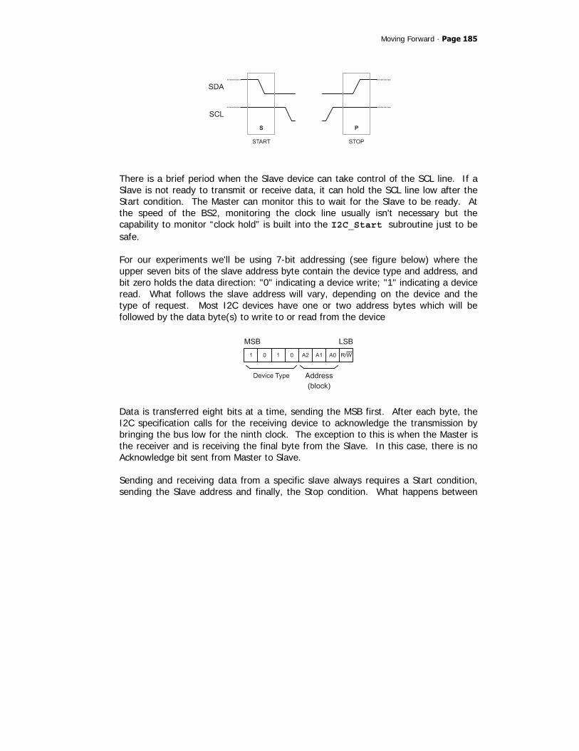
Moving Forward · Page 185
There is a brief period when the Slave device can take control of the SCL line. If a Slave is not ready to transmit or receive data, it can hold the SCL line low after the Start condition. The Master can monitor this to wait for the Slave to be ready. At the speed of the BS2, monitoring the clock line usually isn't necessary but the capability to monitor “clock hold” is built into the I2C_Start subroutine just to be safe. For our experiments we'll be using 7-bit addressing (see figure below) where the upper seven bits of the slave address byte contain the device type and address, and bit zero holds the data direction: "0" indicating a device write; "1" indicating a device read. What follows the slave address will vary, depending on the device and the type of request. Most I2C devices have one or two address bytes which will be followed by the data byte(s) to write to or read from the device
Data is transferred eight bits at a time, sending the MSB first. After each byte, the I2C specification calls for the receiving device to acknowledge the transmission by bringing the bus low for the ninth clock. The exception to this is when the Master is the receiver and is receiving the final byte from the Slave. In this case, there is no Acknowledge bit sent from Master to Slave. Sending and receiving data from a specific slave always requires a Start condition, sending the Slave address and finally, the Stop condition. What happens between

Page 186 · StampWorks
the Slave address and the Stop are dependent on the device and the application process. What you'll need to do is get the data sheet for the I2C device you want to connect to. You will find that most data sheets for I2C-compatible parts have very clear protocol definitions – usually in graphic form – that make implementing the low-level I2C routines very simple. The experiment uses the low-level I2C routines to implement the Write_Byte and Read_Byte routines. These routines are generalized to work with any I2C device, allowing the slave address, number of address bytes, and the address to read or write (if required). Note that each routine begins with an I2C Start condition and is terminated with the Stop condition. The code in between sends the device command/type code, the address to deal with and then actually deals with (writes or reads) the data. While this takes a few lines of code, it is actually very straightforward. The core of the demo program loops through the available addresses of the 24LC32 EEPROM, writing and reading back four distinct bit patterns. If the value read back does not match the value written, a variable called fails is incremented. The Debug Terminal window gives current status of the program as shown below. Note that with 4096 addresses and four writes and reads at each address, this program takes a bit of time to run through to completion.

Moving Forward · Page 187
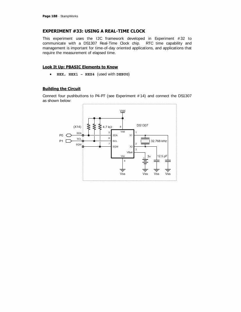
Page 188 · StampWorks
EXPERIMENT #33: USING A REAL-TIME CLOCK
This experiment uses the I2C framework developed in Experiment #32 to communicate with a DS1307 Real-Time Clock chip. RTC time capability and management is important for time-of-day oriented applications, and applications that require the measurement of elapsed time.
Look It Up: PBASIC Elements to Know
• HEX, HEX1 – HEX4 (used with DEBUG)
Building the Circuit
Connect four pushbuttons to P4-P7 (see Experiment #14) and connect the DS1307 as shown below:

Moving Forward · Page 189
Program: SW21-EX33-DS1307.BS2 ' $STAMP BS2 ' $PBASIC 2.5 ' -----[ Program Description ]--------------------------------------------- ' ' This program demonstrates the access and control of an external real- ' time-clock chip, the DS1307. ' -----[ I/O Definitions ]------------------------------------------------- SDA PIN 0 ' I2C serial data line SCL PIN 1 ' I2C serial clock line BtnBus VAR INB ' four inputs, pins 4 - 7 ' -----[ Constants ]------------------------------------------------------- Ack CON 0 ' acknowledge bit Nak CON 1 ' no ack bit DS1307 CON %1101 << 4 ' -----[ Variables ]------------------------------------------------------- slvAddr VAR Byte ' I2C slave address devNum VAR Nib ' device number (0 - 7) addrLen VAR Nib ' bytes in word addr (0 - 2) wrdAddr VAR Word ' word address i2cData VAR Byte ' data to/from device i2cWork VAR Byte ' work byte for TX routine i2cAck VAR Bit ' Ack bit from device secs VAR Byte ' DS1307 time registers mins VAR Byte hrs VAR Byte day VAR Byte ' weekday date VAR Byte ' day in month, 1 - 31 month VAR Byte year VAR Byte control VAR Byte ' SQW I/O control btns VAR Nib ' debounced button inputs btnBack VAR btns.BIT3 ' roll back btnDay VAR btns.BIT2 ' +/- day btnHr VAR btns.BIT1 ' +/- hours btnMn VAR btns.BIT0 ' +/- minutes idx VAR Nib ' loop control

Page 190 · StampWorks
pntr VAR Byte ' ee pointer char VAR Byte ' character for display ' -----[ EEPROM Data ]----------------------------------------------------- DayNames DATA "SunMonTueWedThuFriSat" ' -----[ Initialization ]-------------------------------------------------- Reset: #IF ($STAMP >= BS2P) #THEN #ERROR "Please use BS2p version: SW21-EX33-DS1307.BSP" #ENDIF Setup: slvAddr = DS1307 ' 1 byte in word address addrLen = 1 DEBUG CLS, "DS1307 Demo", CR, "-----------" Reset_Clock: GOSUB Get_Buttons ' scan buttons idx = btns & %0011 ' isolate hrs & mins IF (idx = %11) THEN ' if both pressed, reset secs = $00 mins = $00 hrs = $06 ' 6:00 AM day = $07 ' Saturday date = $01 ' 1st month = $01 ' January year = $05 ' 2005 control = 0 ' disable SQW output GOSUB Set_Clock ' block write clock regs ENDIF ' -----[ Program Code ]---------------------------------------------------- Main: GOSUB Get_Clock ' read DS1307 hrs = hrs & $3F DEBUG CRSRXY, 0, 2, HEX2 hrs, ":", HEX2 mins, ":", HEX2 secs, CR GOSUB Print_Day PAUSE 100 GOSUB Get_Buttons IF (btns > %0000) THEN ' button pressed? IF (btns <> %1000) THEN ' ignore back only hrs = hrs.NIB1 * 10 + hrs.NIB0 ' BCD to decimal

Moving Forward · Page 191
mins = mins.NIB1 * 10 + mins.NIB0 IF (btnBack = 0) THEN ' increment values day = ((day - 1) + btnDay // 7) + 1 ' keep 1 - 7 hrs = hrs + btnHr // 24 ' keep 0 - 23 mins = mins + btnMn // 60 ' keep 0 - 59 ELSE day = ((day - 1) + (btnDay * 6) // 7) + 1 hrs = hrs + (btnHr * 23) // 24 mins = mins + (btnMn * 59) // 60 ENDIF hrs = (hrs / 10 << 4) + (hrs // 10) ' decimal to BCD mins = (mins / 10 << 4) + (mins // 10) secs = $00 GOSUB Set_Clock ' update DS1307 ENDIF ENDIF GOTO Main ' -----[ Subroutines ]----------------------------------------------------- Get_Buttons: btns = %1111 ' enable all four inputs FOR idx = 1 TO 5 btns = btns & ~BtnBus ' test inputs PAUSE 5 ' delay between tests NEXT RETURN Print_Day: pntr = DayNames + ((day - 1) * 3) ' point to 1st char FOR idx = 0 TO 2 ' print 3 letters READ (pntr + idx), char ' read letter DEBUG char ' print it NEXT RETURN ' Do a block write to clock registers Set_Clock: GOSUB I2C_Start ' send Start i2cWork = slvAddr & %11111110 ' send slave ID (write) GOSUB I2C_TX_Byte IF (i2cAck = Nak) THEN Set_Clock ' wait until not busy i2cWork = 0 ' point at secs register GOSUB I2C_TX_Byte FOR idx = 0 TO 7 ' write secs to control

Page 192 · StampWorks
i2cWork = secs(idx) GOSUB I2C_TX_Byte NEXT GOSUB I2C_Stop RETURN ' Do a block read from clock registers Get_Clock: GOSUB I2C_Start ' send Start i2cWork = slvAddr & %11111110 ' send slave ID (write) GOSUB I2C_TX_Byte IF (i2cAck = Nak) THEN Get_Clock ' wait until not busy i2cWork = 0 ' point at secs register GOSUB I2C_TX_Byte GOSUB I2C_Start i2cWork = slvAddr | %00000001 ' send slave ID (read) GOSUB I2C_TX_Byte FOR idx = 0 TO 6 ' read secs to year GOSUB I2C_RX_Byte secs(idx) = i2cWork NEXT GOSUB I2C_RX_Byte_Nak ' read control control = i2cWork GOSUB I2C_Stop RETURN ' =====[ High Level I2C Subroutines]======================================= ' Random location write ' -- pass device slave address in "slvAddr" ' -- pass bytes in word address (0, 1 or 2) in "addrLen" ' -- word address to write passed in "wrdAddr" ' -- data byte to be written is passed in "i2cData" Write_Byte: GOSUB I2C_Start ' send Start i2cWork = slvAddr & %11111110 ' send slave ID (write) GOSUB I2C_TX_Byte IF (i2cAck = Nak) THEN Write_Byte ' wait until not busy IF (addrLen > 0) THEN IF (addrLen = 2) THEN i2cWork = wrdAddr.BYTE1 ' send word address (1) GOSUB I2C_TX_Byte ENDIF i2cWork = wrdAddr.BYTE0 ' send word address (0) GOSUB I2C_TX_Byte ENDIF i2cWork = i2cData ' send data GOSUB I2C_TX_Byte
Moving Forward · Page 193
GOSUB I2C_Stop RETURN ' Random location read ' -- pass device slave address in "slvAddr" ' -- pass bytes in word address (0, 1 or 2) in "addrLen" ' -- word address to write passed in "wrdAddr" ' -- data byte read is returned in "i2cData" Read_Byte: GOSUB I2C_Start ' send Start IF (addrLen > 0) THEN i2cWork = slvAddr & %11111110 ' send slave ID (write) GOSUB I2C_TX_Byte IF (i2cAck = Nak) THEN Read_Byte ' wait until not busy IF (addrLen = 2) THEN i2cWork = wrdAddr.BYTE1 ' send word address (1) GOSUB I2C_TX_Byte ENDIF i2cWork = wrdAddr.BYTE0 ' send word address (0) GOSUB I2C_TX_Byte GOSUB I2C_Start ENDIF i2cWork = slvAddr | %00000001 ' send slave ID (read) GOSUB I2C_TX_Byte GOSUB I2C_RX_Byte_Nak GOSUB I2C_Stop i2cData = i2cWork RETURN ' -----[ Low Level I2C Subroutines]---------------------------------------- ' *** Start Sequence *** I2C_Start: ' I2C start bit sequence INPUT SDA INPUT SCL LOW SDA Clock_Hold: DO : LOOP UNTIL (SCL = 1) ' wait for clock release RETURN ' *** Transmit Byte *** I2C_TX_Byte: SHIFTOUT SDA, SCL, MSBFIRST, [i2cWork\8] ' send byte to device SHIFTIN SDA, SCL, MSBPRE, [i2cAck\1] ' get acknowledge bit RETURN

Page 194 · StampWorks
' *** Receive Byte *** I2C_RX_Byte_Nak: i2cAck = Nak ' no Ack = high GOTO I2C_RX I2C_RX_Byte: i2cAck = Ack ' Ack = low I2C_RX: SHIFTIN SDA, SCL, MSBPRE, [i2cWork\8] ' get byte from device SHIFTOUT SDA, SCL, LSBFIRST, [i2cAck\1] ' send ack or nak RETURN ' *** Stop Sequence *** I2C_Stop: ' I2C stop bit sequence LOW SDA INPUT SCL INPUT SDA RETURN
Behind the Scenes
While it is possible to implement rudimentary timekeeping functions in code with PAUSE, problems arise when BASIC Stamp needs to handle other activities. This is especially true when an application needs to handle time, day, and date. The cleanest solution is an external real-time clock. In this experiment, we’ll use the Maxim-Dallas DS1307. Like the 24LC32, the DS1307 connects to its host though an I2C bus. Unlike the 24LC32, however, it is not addressable, so only one DS1307 can exist on a given I2C bus. Once programmed the DS1307 runs by itself and accurately keeps track of seconds, minutes, hours, day of week, date, month, year (with leap year compensation through the year 2100), and a control register for the SQW output. As a bonus, the DS1307 contains 56 bytes of RAM (registers $08 - $3E) that can be used for general-purpose storage. And for projects that use main’s power, the DS1307 is easily backed-up by a 3v Lithium battery (good for up to 10 years). Like most I2C devices, the DS1307 is register-based, that is, each element of the time and date is stored in its own register (memory address). For convenience, two

Moving Forward · Page 195
modes of reading and writing are available: register and block. With register access, individual elements can be written or read. With block access we take advantage of the automatic incrementing of the DS1307’s internal address pointer; this allows groups of bytes to be written to or read from the DS1307 by specifying the starting address of the block. Of note are the Set_Clock and Get_Clock subroutines that use block mode to read and write blocks of eight bytes from/to the DS1307. Also note that these subroutines take advantage of the fact that PBASIC allows the RAM space to be treated like an array – even when an array is not explicitly declared. You’ll see in both routines that secs is used as the base of the array. What this means is that the minutes register corresponds to secs(1), hours to secs(2), etc. The listing below shows the how the clock registers are mapped to the implicit secs() array
secs VAR Byte ' secs(0) mins VAR Byte ' secs(1) hrs VAR Byte ' secs(2) day VAR Byte ' secs(3) date VAR Byte ' secs(4) month VAR Byte ' secs(5) year VAR Byte ' secs(6) control VAR Byte ' secs(7)
As you can see in the listing, the array elements are based on the declaration order of the same variable type; changing the order of declaration will change the position within the array. This is a very powerful technique as PBASIC does not allow the aliasing of declared array elements. Using the technique above gives us the greatest possible programming flexibility. There is a small variation in the Set_Clock and Get_Clock subroutines having to do with the I2C protocol specification. In Set_Clock, all time registers are written to the DS1307 in a loop (using the secs array). In Get_Clock, though, only the first seven bytes are read in the loop; the final byte is read after. The reason for this is that the I2C specification requires a Nak after the final read operation. This program demonstrates the conversion of BCD to decimal values, and back. The DS1307 stores clock registers as BCD which can be directly displayed using the HEX2 modifier with DEBUG, but cannot be modified mathematically. The NIB modifier available for Byte and Word variables makes BCD-to-Decimal conversion a snap:

Page 196 · StampWorks
decVal = (bcdVal.NIB1 * 10) + bcdVal.NIB0 Once a value has been adjusted, the conversion back to BCD is equally simple:
bcdVal = (decVal / 10 << 4) + bcdVal // 10 Of the four pushbuttons connected, three are used to advance the minutes, hours, and day (the seconds are reset when any other element is changed). To roll an element back, the fourth button is held down. Note how the modulus operator is used and keeps each element update to a single line of code.
Taking It Further
In applications where time-based math is concerned, a simple solution – if minutes resolution is adequate – is to convert the time to a single value in minutes: rawTime = (hours * 60) + minutes This will result in a value of 0 (midnight) to 1439 (23:59 or 11:59 PM). With this single value mathematic operations are simplified. Getting back to hours and minutes is simple too: hours = rawTime / 60 hours = rawTime // 60 This will result in 24-hour time format. For 12 hour format, calculate hours like this: hours = 12 – (24 – (rawTime / 60) // 12) To determine the state of AM/PM, simply look at the rawTime value; AM times are between 0 and 719, PM times are between 720 and 1439.
Challenge
Reconnect the MC11489 multiplexer and display the running time on the 7-segment LEDs.

Moving Forward · Page 197
EXPERIMENT #34: SERIAL COMMUNICATIONS WITH A PC
This experiment demonstrates the BASIC Stamp’s ability to communicate with other computers through any of its IO pins. It also demonstrates the ability to store nonvolatile information in the BASIC Stamp’s EEPROM space.
Look It Up: PBASIC Elements to Know
• SERIN • SEROUT • WAIT (SERIN modifier) • SELECT-CASE • WRITE
Building the Circuit

Page 198 · StampWorks
Program: SW21-EX34-Serial_IO.BS2 ' $STAMP BS2 ' $PBASIC 2.5 ' -----[ Program Description ]--------------------------------------------- ' ' This program demonstrates serial communications with a PC, using flow ' control to ensure the BASIC Stamp is ready before the PC attempts to ' send new information. ' -----[ I/O Definitions ]------------------------------------------------- TX PIN 15 ' transmit to PC RTS PIN 14 ' Request To Send RX PIN 13 ' receive from PC CTS PIN 12 ' Clear To Send DQ CON 4 ' DS1620.1 (data I/O) Clock CON 5 ' DS1620.2 Reset CON 6 ' DS1620.3 LEDs VAR OUTA ' LED outputs ' -----[ Constants ]------------------------------------------------------- T2400 CON 396 ' True for inverter T9600 CON 84 T38K4 CON 6 SevenBit CON $2000 Inverted CON $4000 Open CON $8000 Baud CON T9600 CMenu CON $FF ' show command menu CGetId CON $F0 ' get string ID CSetId CON $F1 ' set string ID CTemp CON $A0 ' get DS1620,display raw count CTmpC CON $A1 ' get DS1620 - display in C CTmpF CON $A2 ' get DS1620 - display in F CGetLeds CON $B0 ' get digital output status CSetLeds CON $B1 ' set LED outputs RdTmp CON $AA ' read temperature WrHi CON $01 ' write TH (high temp) WrLo CON $02 ' write TL (low temp) RdHi CON $A1 ' read TH RdLo CON $A2 ' read TL

Moving Forward · Page 199
RdCntr CON $A0 ' read counter RdSlope CON $A9 ' read slope StartC CON $EE ' start conversion StopC CON $22 ' stop conversion WrCfg CON $0C ' write config register RdCfg CON $AC ' read config register ' -----[ Variables ]------------------------------------------------------- cmd VAR Byte ' command from PC/terminal eeAddr VAR Byte ' EE address pointer param VAR Byte ' parameter to/from tempIn VAR Word ' raw data from DS1620 sign VAR tempIn.BIT8 ' 1 = negative temperature tC VAR Word ' degrees C in tenths tF VAR Word ' degrees F in tenths ' -----[ EEPROM Data ]----------------------------------------------------- ID DATA "StampWorks 2.1", CR ' CR-terminated string ' -----[ Initialization ]-------------------------------------------------- Setup: DIRA = %1111 ' LED pins are outputs HIGH Reset ' alert the DS1620 SHIFTOUT DQ, Clock, LSBFIRST, [WrCfg, %10] ' use with CPU; free-run LOW Reset PAUSE 10 HIGH Reset SHIFTOUT DQ, Clock, LSBFIRST, [StartC] ' start conversions LOW Reset GOSUB Show_Menu ' -----[ Program Code ]---------------------------------------------------- Main: cmd = 0 SERIN RX\CTS, Baud, [WAIT ("?"), HEX cmd] ' wait for ? and command SELECT cmd ' process command entry CASE CMenu GOSUB Show_Menu ' refresh menu CASE CGetId

Page 200 · StampWorks
GOSUB Show_ID ' show ID string CASE CSetId GOSUB Set_ID ' set new ID GOSUB Show_ID ' confirm new ID CASE CTemp GOSUB Show_Temp ' show raw counts CASE CTmpC GOSUB Show_Temp_C ' show tC (tenths) CASE CTmpF GOSUB Show_Temp_F ' show tF (tenths) CASE CGetLeds GOSUB Show_Leds ' show LED status CASE CSetLeds GOSUB Set_Leds ' set LED status GOSUB Show_Leds ' confirm new status CASE ELSE SEROUT TX\RTS, Baud, ["Invalid command.", CR] ENDSELECT GOTO Main ' -----[ Subroutines ]----------------------------------------------------- Show_Menu: SEROUT TX\RTS, Baud, [CLS, "========================", CR, " StampWorks Monitor ", CR, "========================", CR, "?FF - Show Menu", CR, "?F0 - Display ID", CR, "?F1 - Set ID", CR, "?A0 - DS1620 (Raw count)", CR, "?A1 - Temperature (C)", CR, "?A2 - Temperature (F)", CR, "?B0 - Display LED Status", CR, "?B1 - Set LEDs", CR, CR, "Please enter a command.", CR, CR] RETURN Show_ID: SEROUT TX\RTS, Baud, ["ID = "] ' label output
Moving Forward · Page 201
eeAddr = ID ' point to first character DO READ eeAddr, param ' read a character SEROUT TX\RTS, Baud, [param] ' print it eeAddr = eeAddr + 1 ' point to next LOOP UNTIL (param = CR) RETURN Set_ID: eeAddr = ID ' point to ID location DO SERIN RX\CTS, Baud, [param] ' get character from PC WRITE eeAddr, param ' write to EE eeAddr = eeAddr + 1 ' point to next location LOOP UNTIL (param = CR) ' CR = end of new ID RETURN Show_Temp: ' display raw counts GOSUB Read_DS1620 ' read temperature tempIn = tempIn & $1FF ' return to 9 bits SEROUT TX\RTS, Baud, ["DS1620 = ", DEC tempIn, CR] RETURN Show_Temp_C: GOSUB Read_DS1620 param = tC.BIT15 * 2 + "+" ' create sign char SEROUT TX\RTS, Baud, ["TempC = ", ' label param, ' display sign DEC (ABS tC / 10), ".", ' whole degrees DEC1 (ABS tC), CR] ' fractional degrees RETURN Show_Temp_F: GOSUB Read_DS1620 param = tF.BIT15 * 2 + "+" ' create sign char SEROUT TX\RTS, Baud, ["TempF = ", ' label param, ' display sign DEC (ABS tF / 10), ".", ' whole degrees DEC1 (ABS tF), CR] ' fractional degrees RETURN Read_DS1620: HIGH Reset ' alert the DS1620 SHIFTOUT DQ, Clock, LSBFIRST, [RdTmp] ' give command to read temp SHIFTIN DQ, Clock, LSBPRE, [tempIn\9] ' read it in LOW Reset ' release the DS1620

Page 202 · StampWorks
tempIn.BYTE1 = -sign ' extend sign bit tC = tempIn * 5 ' convert to tenths IF (tC.BIT15 = 0) THEN ' temp C is positive tF = tC */ $01CC + 320 ' convert to F ELSE ' temp C is negative tF = 320 - ((ABS tC) */ $01CC) ' convert to F ENDIF RETURN Show_Leds: SEROUT TX\RTS, Baud, ["Status = ", BIN4 LEDs, CR] RETURN Set_Leds: SERIN RX\CTS, Baud, [BIN param] ' use binary input LEDs = param.LOWNIB ' set the outputs RETURN
Behind the Scenes
Without asynchronous serial communications the world would not be what it is today. Businesses would be hard pressed to exchange information with each other. There would be no ATMs for checking our bank accounts and withdrawing funds. There would be no Internet. Previous experiments have used synchronous serial communications. In that scheme, two lines are required: clock and data. The benefit is the automatic synchronization of sender and receiver. The downside is that it requires at least two wires to send a message in one direction. Asynchronous serial communications requires only a single wire to transmit a message. What is necessary to allow this scheme is that both the sender and receiver must agree on the communications speed before the transmission can be received. Some "smart" systems can detect the communications speed (baud rate), the BASIC Stamp cannot. In this experiment we’ll use SEROUT to send information to a terminal program and SERIN to take data in. The input will usually be a command and sometimes the command will be accompanied with new data. Note that the SERIN connection is actually defined as two pins:
SERIN RX\CTS, Baud, [WAIT ("?"), HEX cmd]

Moving Forward · Page 203
The CTS connection tells the PC that the BASIC Stamp is ready to receive data. Remember that the BASIC Stamp does not buffer serial data and if the PC sent a byte when the BASIC Stamp was busy processing another instruction that byte would be lost. After initializing the LED outputs and the DS1620, the program enters the main loop and waits for input from the terminal program. First, SERIN waits for the "?" character to arrive, ignoring everything else until that happens. The question mark, then, is what signifies the start of a query. Once a question mark arrives, the HEX modifier causes the BASIC Stamp to look for valid hex characters (0 - 9, A - F). The arrival of any non-hex character (usually a carriage return [Enter] when using a terminal) tells the BASIC Stamp to stop accepting input (to the variable called cmd) and continue on. What actually has happened is that the BASIC Stamp has used the SERIN instruction to do a text-to-numeric conversion. Now that a command is available, the program uses SELECT-CASE to process valid commands, and sends a message to the terminal if the command entered is not used by the program. For valid commands the BASIC Stamp responds to a request sending a text string using SEROUT. As with SERIN, flow control is used with SEROUT as well. The RTS (Request To Send) connection allows the PC to let the BASIC Stamp know that it is ready to receive data. Each of the response strings consists of a label, the equal sign, the value of that particular parameter and finally, a carriage return. When using a terminal program, the output is easily readable. Something like this:
ID = StampWorks 2.1
The carriage return at the end of the output gives us a new line when using a terminal program and serves as an "end of input" when we process the input with our own program (similar to StampPlot Lite). The equal sign can be used as a delimiter when another computer program communicates with the BASIC Stamp. We’ll use it to distinguish the label from its value. Most of the queries are requests for information. Two of them, however, can modify information that is stored in the BASIC Stamp.

Page 204 · StampWorks
The first command is "?F1" which will allow us to write a string value to the BASIC Stamp’s EEPROM (in a location called ID). When $F1 is received as a command value, the program jumps to the subroutine called Set_ID. On entry to Set_ID, the EE pointer called eeAddr is initialized, and then the BASIC Stamp waits for a character to arrive. Notice that no modifier is used here. Since terminal programs and the BASIC Stamp represent characters using ASCII codes, we don’t have to do anything special. When a character does arrive, WRITE is used to put the character into EEPROM and the address pointer is incremented. If the last character was a carriage return (13), the program displays the new string (using the code at Show_ID), otherwise it loops back and waits for another character. The second modifying query is “?B1” which allows us to set the status of four LEDs. Take a look at the subroutine called Set_Leds. This time, the BIN modifier of SERIN is used so that we can easily define individual bits we wish to control. By using the BIN modifier, our input will be a string of ones and zeros (any other character will terminate the binary input). In this program, a “1” will cause the LED to turn on and a “0” will cause the LED to turn off. Here’s an example of using the B1 query.
?B1 0011<CR>
The figure below shows an actual on-line session using the BASIC Stamp’s Debug Terminal window.

Moving Forward · Page 205
To run the experiment, follow these steps:
1. Remove components from previous experiment. 2. Enter and download the program 3. Remove power from PDB and build the circuit 4. Move the programming cable to the RS-232 DCE port (if required) 5. Open a Debug Terminal window by clicking on the Debug icon; select the
com port connected to the RS-232 DCE connector, and then check RTS 6. Set the PDB power switch to on.
Challenge (for PC programmers)
Write a PC program that interfaces with this experiment.

Page 206 · StampWorks
EXPERIMENT #35: (BONUS) BS2PX ADC
This experiment takes advantage of the comparator feature available in the BS2px microcontroller. By applying a known voltage (using PWM) to one side of the comparator it can be used to determine an unknown voltage on the other input.
Look It Up: PBASIC Elements to Know
• COMPARE (BS2px only)
Building the Circuit
Program: SW21-EX35-BS2px-ADC.BPX ' $STAMP BS2px ' $PBASIC 2.5 ' -----[ Program Description ]--------------------------------------------- ' ' Creates a simple 8-bit ADC with the BS2px using the internal comparator.
Moving Forward · Page 207
' -----[ I/O Definitions ]------------------------------------------------- Vin PIN 1 ' unknown voltage input DacIn PIN 2 ' input from R/C DAC DacOut PIN 3 ' DAC via PWM + R/C ' -----[ Variables ]------------------------------------------------------- adcVal VAR Byte ' adc value (0 - 255) bias VAR Byte ' bias for ADC conversion result VAR Bit ' comparator result bit mVolts VAR Word ' input in millivolts ' -----[ Initialization ]-------------------------------------------------- Check_Stamp: #IF ($STAMP <> BS2PX) #THEN #ERROR "This program requires the BS2px" #ENDIF Setup: DEBUG CLS, "BS2px ADC Demo", CR, "==============", CR, "Raw..... ", CR, "Volts... " ' -----[ Program Code ]---------------------------------------------------- Main: DO GOSUB Get_ADC ' read comparator ADC mVolts = adcVal */ $139B ' convert to millivolts DEBUG CRSRXY, 9, 2, ' show results DEC adcVal, " ", CRSRXY, 9, 3, DEC1 (mVolts / 1000), ".", DEC3 mVolts PAUSE 250 LOOP ' -----[ Subroutines ]----------------------------------------------------- ' Simple ADC conversion ' -- outputs voltage on P3 until it crosses voltage on P2

Page 208 · StampWorks
Get_ADC: adcVal = 0 ' clear ADC bias = 128 ' start in middle DO adcVal = adcVal + bias ' add bias to adc result PWM DacOut, adcVal, 15 ' output new test value COMPARE 2, result ' check comparator IF (result = 1) THEN ' if unknown lower than test adcVal = adcVal - bias ' -- reduce adcVal ENDIF bias = bias / 2 ' check next half LOOP UNTIL (bias = 0) RETURN
Behind the Scenes
A comparator is a circuit used to compare two voltages; when the voltage on the + (noninverting) input of the comparator is greater than the voltage on the – (inverting) input, the output will be high, otherwise it is low. Using this behavior an unknown voltage can be determined by applying a known voltage to the other side of the comparator and checking the output. This process can, of course, be done with any BASIC Stamp and an external comparator. For this experiment we will take advantage of the built-in comparator feature of the BS2px. By doing so we use just three I/O pins and a few standard components. A simplistic method for determining the unknown voltage would be a loop that essentially sneaks up on the unknown voltage:
Get_ADC_Simple: ' slow version adcVal = 0 DO PWM DacOut, adcVal, 15 ' output new value COMPARE 2, result ' check comparator IF (result = 1) THEN EXIT ' voltage found adcVal = adcVal + 1 ' increment result LOOP UNTIL (adcVal = 255) RETURN
The problem with this strategy is the length of conversion when the unknown voltage is biased toward the high side of the scale. The solution this problem is a technique

Moving Forward · Page 209
called a binary search. In simple terms a binary search is able to eliminate half the available possibilities in a single test. With this method a large number of possibilities can be checked with very few tests. In the Get_ADC subroutine the variable called bias is used to split the available possibilities, hence it starts at 128 before entering the loop. In the working part of the test loop bias is added to adcVal – this voltage is output via PWM to one side of the comparator. If the unknown voltage is lower than the current test voltage (in adcVal), the current value of bias is removed before bias is divided for the next test. The new value of bias is added to adcVal and the comparator is checked again. This process is repeated until bias is divided down to zero – this takes eight iterations of the test loop to “find” the unknown voltage, no matter what that voltage is. This is far quicker than the slow method presented above. The table below illustrates the test loop with a voltage input of 3.3 volts (168 counts):
Step bias adcVal (counts) adcVal (volts) Remove bias? 1 128 128 2.50 No 2 64 192 3.76 Yes 3 32 160 3.14 No 4 16 176 3.45 Yes 5 8 168 3.29 No 6 4 172 3.37 Yes 7 2 170 3.33 Yes 8 1 169 3.31 Yes
End 0 168 3.29 Note that the input is actually determined by Step 5, but the nature of the algorithm requires it to run all the way through until bias is divided down to zero.

Page 210 · StampWorks

Power PBASIC · Page 211
Power PBASIC Before I close, I’d like to share a few things that I think separate Power PBASIC programmers from the rest of the field. Simple things, really, yet highly effective and, sadly, usually underutilized. It’s up to you to master or adopt these strategies, but I think that if you do you will be rewarded for your efforts.
Adopt “The Elements of PBASIC Style”
I know I harp on about this, and I do it for a very good reason: in the 12 years I’ve been writing programs for BASIC Stamp microcontrollers I find that most programmers create bugs through sloppy programming practice. Adopt the philosophy that neatness counts and your programs will have fewer bugs – I know this from experience.
Be Stingy with Variable Declarations
Many programmers, especially those born after the invention of the personal computer, have learned programming on platforms with resources far greater than that of the BASIC Stamp microcontroller, and along the way have never really worried about managing variable space. These programmers usually don’t take very long to find that techniques used in their PC programs don’t fly on the BASIC Stamp (or other small micros). Analyze your programs and declare variable type as required by the code. If a variable has an upper limit of 10, use a Nib, not a Byte or Word as this would simply be wasting variable space.
Arrays are Implicit – Take Advantage
A question that frequently comes up is, “How can I alias an element of an array?” The answer is: you can’t – at least when you declare an array like this:
colors VAR Byte(3)

Page 212 · StampWorks
With just a little more effort we can have the same array and have aliases to elements in it. Here’s how:
colors VAR Byte red VAR colors green VAR Byte blue VAR Byte
The variable called colors can still be treated like an array: colors(0) = 50 colors(1) = 10 colors(2) = 35
This section of code does exactly the same thing: red = 50 green = 10 blue = 35
This works because the BASIC Stamp variable space can be treated as an implicit array. The size of the elements will depend on the variable one selects as the base. The other key to this trick is that the compiler declares variables of the same type in the order they appear in your listing. In this example the variables colors and red occupy the same space in memory, with green and blue following in that order.
Overlay Variables to Save Code
Let’s say you have two sets of byte-sized flag variables. You could define them like this:
flags0 VAR Byte flags1 VAR Byte
This works fine, of course, but you can save a bit of code and execution speed by aliasing these bytes to a single Word variable like this:
flags VAR Word flags0 VAR flags.BYTE0 flags1 VAR flags.BYTE1

Power PBASIC · Page 213
The second declaration consumes no more variable space than the first, but allows access to all flags with one line of code:
flags = 0
This saves program space and improves execution speed because the PBASIC interpreter only has to fetch one instruction from the program EEPROM, whereas the previous declaration would require separate lines of code to set both variables; each line requires access to the program EEPROM and affects program speed. Yes, this seems like a very small thing, but remember: a lot of small things in a program add up to better performance.
Learn to Use the Variable Modifiers
Another common question is, “How can I convert from BCD to decimal, and then back?” While these conversions can be done with standard programming techniques, the use of PBASIC variable modifiers makes it much simpler. First, let’s convert a variable from BCD to decimal:
decVal = bcdVal.NIB1 * 10 + bcdVal.NIB0
How easy is that? Since BCD uses nibbles for digit storage, this seems to be the most obvious solution yet many programmers user more complicated code for not mastering variable modifiers. Going the other direction (decimal to BCD) is equally easy:
bcdVal = ((decVal DIG 1) << 4) + (decVal DIG 0)
Another useful variable modifier is the LOWBIT() array. This modifier lets us access any bit inside any variable using a variable index. If, for example, you needed to count the number of set bits in a Word, you could do it like this:
Count_Bits: bitCount = 0 FOR idx = 0 TO 15 bitCount = bitCount + wordVar.LOWBIT(idx) NEXT

Page 214 · StampWorks
I/O Pins are Variables Too
Remember that I/O pins are variables (INS and OUTS) and when doing simple scanning there is no need to use an intermediary variable. Instead of:
Main: DO startStatus = IN3 LOOP WHILE (startStatus = 1)
… you can declare an input with the PIN type declaration and do it directly: StartBtn PIN 3 Main: DO : LOOP WHILE (StartBtn = 1)
I don’t typically advocate putting multiple statements on a single line, but this is one of those cases (an empty DO-LOOP) where it is the cleaner approach. We can extend this with combinatorial logic. Let’s say, for example, that you want to count the number of times two discrete inputs are both high while running a loop. Here’s the Power PBASIC style for doing that:
Count_Buttons: btnCount = 0 FOR idx = 1 TO 250 btnCount = btnCount + (Btn1 & Btn2) PAUSE 40 NEXT
This works because we want to add one to the count variable when both buttons are pressed. By combining Btn1 and Btn2 with a logical AND we reduce the parenthetical statement to zero or one, and the only time one will be returned is when both buttons are pressed (assuming active-high inputs).
You Can do Fractions with the */ and ** Operators
The */ and ** operators allow the BASIC Stamp to multiply by fractional values. The result will of course be an integer, but these operators will still simplify the process, and oftentimes improve the accuracy of the result (over standard multiply and divide techniques).

Power PBASIC · Page 215
When would you use */ versus **? When your fractional result is greater than one, */ is usually the operator of choice. When the fractional value is less than one then ** will give the best resolution. To use */, multiply the fractional value by 256 and use this as the operand for */.
Pi CON $0324
Then… area = radius * radius */ Pi
When you need to multiply by a value less than one, especially very small values, the ** operator is best. When using ** you multiply your fractional value by 65536 and use that result as the ** operand.
scale = rawInput ** 25 ' x 0.00038146
Master the Modulus (//) Operator
Modulus is very simple to use, yet I still see lots of programmers doing this: count = count + 1 IF (count = 10) THEN count = 0 ENDIF
Why? Isn’t this version simpler? count = (count + 1) // 10
Rollover is easy, what about rolling under (from zero back to some maximum). That’s easy too:
count = (count + 9) // 10
This looks different, but behaves just like: IF (count < 0) THEN count = count – 1 ELSE count = 0 ENDIF

Page 216 · StampWorks
What happened to the -1? It was applied to the divisor and that value is added to the intermediate result. The key to mastering modulus is remembering that it will return a value between zero and the divisor used. Let’s say you want to generate a pseudo-random number between 20 and 50 when a button is pressed. Here’s how:
Main: DO RANDOM randVal LOOP UNTIL (StartBtn = Pressed) selection = randVal // 31 + 20
Do you see how this works? The span between 20 and 50 is 30, so we use 31 as the divisor for modulus.
Use Conditional Compilation
BASIC Stamp microcontrollers have been around a few years, and as would be expected, new models are faster and have more features than the older ones. The BASIC Stamp IDE allows for conditional compilation so that you can construct a code that will run on any BS2 module. The most common problem for BASIC Stamp programmers when moving from one module to another is with SERIN and SEROUT. By using conditional compilation to define baudmode constants these problems are eliminated. The code fragment below is abbreviated from the definitions provided in my standard programming template (Template.BS2).
#SELECT $STAMP #CASE BS2, BS2E, BS2PE T2400 CON 396 T9600 CON 84 T19K2 CON 32 T38K4 CON 6 #CASE BS2SX, BS2P T2400 CON 1021 T9600 CON 240 T19K2 CON 110 T38K4 CON 45 #CASE BS2PX T2400 CON 1646 T9600 CON 396 T19K2 CON 188 T38K4 CON 84 #ENDSELECT

Power PBASIC · Page 217
SevenBit CON $2000 Inverted CON $4000 Open CON $8000 Baud CON T9600
Conditional compilation also simplifies the removal of debugging code – code you would normally have to delete or “comment out” before finalizing your program.
#DEFINE _DebugMode = 1 #IF (_DebugMode = 1) #THEN DEBUG HOME, DEC status #ENDIF
By changing the value of _DebugMode to zero the DEBUG statements (enclosed in #IF-#THEN-#ENDIF blocks) are removed and can just as easily be restored.
Break Your Program into Tasks
Since the BASIC Stamp runs an interpreter, interrupts are not possible. How, then, does one create a program that can be responsive to short-term events? The answer is to take advantage of ON-GOSUB and setup your core program like this:
Main: DO GOSUB Critical_Task ON task GOSUB Task0, Task1, Task2 task = task + 1 // NumTasks LOOP Critical_Task: ' task code RETURN Task0: ' task 0 code RETURN Task1: ' task 1 code RETURN Task2: ' task 1 code IF (Emergency) THEN GOSUB Special_Task ENDIF

Page 218 · StampWorks
RETURN Special_Task: ' special task code RETURN
This simple, yet powerful framework can be applied to virtually any application. In the Main loop the subroutine called Critical_Task is executed through every iteration of the loop, with the currently-selected task following. Under “normal” circumstances the order of execution would be: Critical_Task Task0 Critical_Task Task1 Critical_Task Task2 Note that all task code is embedded in subroutines. This design allows a task to be called from any point in the program – even from another task. Note that Task2 has the ability to check for an emergency condition and if that condition exists can call Special_Task. The key to using this framework is to break your program into small, lean tasks. By doing this, your program will have the best responsiveness and the greatest amount of flexibility.

Striking Out on Your Own · Page 219
Striking Out on Your Own Congratulations, you’re a BASIC Stamp programmer! So what’s next? Well, that’s up to you. Many new programmers get stuck when it comes to developing their own projects. Don’t worry, this is natural – and there are ways out of being stuck. The following workflow tips and resources will help you succeed in bringing your good ideas to fruition.
Plan Your Work, Work Your Plan
You’ve heard it a million times: plan, plan, and plan. Nothing gets a programmer into more trouble than bad or inadequate planning. This is particularly true with the BASIC Stamp as resources are so limited. Most of the programs we’ve fixed were “broken” due to bad planning and poor formatting which lead to errors.
Talk It Out
Talk yourself through the program. Don’t just think it through, talk it through. Talk to yourself–out loud–as if you were explaining the operation of the program to a fellow programmer. Often, just hearing our own voice is what makes the difference. Better yet, talk it out as if the person you’re talking to isn’t a programmer. This will force you to explain details. Many times we take things for granted when we’re talking to ourselves or others of similar ability.
Write It Out
Design the details of your program on a white (dry erase) board before you sit down at your computer. And use a lot of colors. You’ll find working through a design visually will offer new insights, and the use of this medium allows you to write code snippets within your functional diagrams.
Design with “Sticky Notes”
Get out a pad of small “sticky notes”. Write module names or concise code fragments on individual notes and then stick them up on the wall. Now stand back and take a

Page 220 · StampWorks
look. Then move them around. Add notes, take some away; just do what feels right to you. This exercise works particularly well with groups. How do you know when you’re done? When the sticky notes stop moving! It’s a good idea to record the final outcome before starting your editor. Another tip: this trick works even better when combined with writing it out (above). You can draw lines between and around notes to indicate program flow or logical groupings. If it’s not quite right, just erase the lines or move some notes. Try this trick; it really does work.
Going Beyond the Box
By now, your appetite for BASIC Stamp projects has probably grown well beyond what you ever expected. So where do you turn now? Don’t worry; there are many BASIC Stamp and related resources available, both in print and on the Internet. Here’s a list to get you started:
Books & Magazines
Microcontroller Application Cookbooks by Matt Gilliland Microcontroller Projects with BASIC Stamps by Al Williams Getting Started In Electronics by Forrest Mims Engineer’s Notebook by Forrest Mims Nuts & Volts Magazine “Stamp Applications” column Internet Sites
• www.parallax.com (Parallax main site) • www.emesystems.com/BS2index.htm (Tracy Allen’s BASIC Stamp resources
– very technical) • www.al-williams.com (Al Williams web site) • www.seetron.com (Scott Edwards Electronics web site) • www.hth.com/losa (List of Stamp Applications – great idea source)

Mouser Electronics
Authorized Distributor
Click to View Pricing, Inventory, Delivery & Lifecycle Information: Parallax:
BS2-IC 604-00002 350-90000 800-00003 805-00006 750-00007 27218