
Technical specification for
107
Technical specification for page 1 of 107 30 Ton Voith-Hydro Tractor tug- Machinery _________ ISRAEL PORTS AND RAILWAYS AUTHORITY TECHNICAL SPECIFICATION for 30 Ton Pull VOITH-HYDRO TRACTOR TUG MACHINERY SPECIFICATION Issue: January, 1993
-
Upload
khangminh22 -
Category
Documents
-
view
11 -
download
0
Transcript of Technical specification for

Technical specification for page 1 of 107
30 Ton Voith-Hydro Tractor tug- Machinery _________
ISRAEL PORTS AND RAILWAYS
AUTHORITY
TECHNICAL SPECIFICATION
for
30 Ton Pull VOITH-HYDRO
TRACTOR TUG
MACHINERY SPECIFICATION
Issue: January, 1993

Technical specification for page 2 of 107
30 -Ton Voith-Hydro Tractor tug- Machinery _________
TABLE OF CONTENTS
1. GENERAL SECTION 10
1.1 General Provisions 10
1.2 Regulation, Inspection, Tests and Trial 10
1.3 Approval of Technical Information and Purchase Equipment 10
1.4 Material, Design and Supervision 10
1.5 Units, Scales of Instruments, Nameplates, Inventory and Spares 10
1.6 Guarantee 10
1.7 Vibration and Noise 10
1.8 Drawings, Description and Instructions 10
1.9 Spare Parts and Tolls 11
1.10 Description of Machinery Installation 12
2. MAIN ENGINE 14
2.0 General 14
2.1 Main Propulsion 14
2.2 Lay-Out of Propulsion System 14
2.3 Direction of Rotation 14
2.4 Fuel Consumption 15
2.5 Lub. Oil Consumption 15
2.6 Classification 15
2.7 Acceptance Rests 16
2.8 Construction Details 16
2.8.1 Basic Engine Component 16
2.8.2 Turbo- Charging System 17
2.8.3 Governor 17
2.8.4 Power Transmission 17
2.8.5 Power Take-Off 18
2.8.6 Turning Gear 18
2.8.7 Safety Equipment 18
2.8.8 Oil Mist detector 18

Technical specification for page 3 of 107
30 Ton Voith-Hydro Tractor tug- Machinery _________
2.9 Enginery System 18
2.9.1 Fuel System 18
2.9.2 Lub.Oil System Turbo- 19
2.9.3 Cooling System 19
2.9.4 Starting Air System 20
2.9.5 Exhaust Gas System 20
2.9.6 Intake Air System 21
2.10 Enginery Mounted Measuring Instruments and Control Equipment 21
2.10.1 Enginery Mounted measuring Instruments Panel 21
2.10.2 Local Measuring Instruments Mounted on Engine 22
2.10.3 Engine Local Control Panel 22
2.11 Control, Safety Monitoring and Alarms 22
2.11.1 General 22
2.11.2 Main Engine Control 22
2.11.3 Safety Precautions 22
2.11.4 Instruments for Main Propulsion Plant 23
2.11.5 Alarms Means 24
2.12 Torsional Vibrations 25
3. SHAFTING AND PROPELLERS 26
3.1 General 26
3.2 Propellers 26
3.3 Shafting And Hydraulic Couplings 27
3.4 Controls 27
3.5 Measuring and Monitoring Instruments 28
3.6 V.H.P Main Particulars 28
3.7 Spares and Tools 29
3.8 Alarms and Safety 29

Technical specification for page 4 of 107
30 Ton Voith-Hydro Tractor tug- Machinery _________
4. ELECTRICAL GENERATING PLANT 30
4.1 General 30
4.2 Main Particulars 30
4.3 Engine Construction 31
4.4 Engine System 32
4.4.1 Starting System 32
4.4.2 Cooling System 32
4.4.3 Lub-Oil System 33
4.4.4 Fuel System 33
4.4.5 Speed and Load Control 33
4.4.6 Intake Gas System 33
4.5 Instrumentation 34
4.6 Control and Safety Devices 34
4.7 Remote Indication and Alarm Sensor 34
4.8 List of Outfitting 30
4.9 Generator set Mounting 36
4.10 Classifications 36
4.11 Tests 36
5. PUNPS 37
5.1 General 37
5.2 Centrifugal Pumps 37
5.3 Rotary Positives Displacements Pump and Ejectors 38
5.4 Lists of Pumps 39
5.4.1 Bilge, Ballast and Fire Pumps 39
5.4.2 Lubricating Oil Stand-By Pumps 40
5.4.3 Fuel Transfer Pump 40
5.4.4 Lub. Oil transfer Pump 40
5.4.5 Dirty Oil Pump 40
5.4.6 Sewage Ejector 41
5.4.7 External fire Fighting Pumps 41
5.4.8 Foam Pumps 42

Technical specification for page 5 of 107
30 Ton Voith-Hydro Tractor tug- Machinery _________
5.4.9 Fresh Water Sanitary Pumps 42
5.4.10 Seawater Cooling Pumps for Air Conditioning 43
5.4.11 Hydraulic Pumps 43
6. SEPARATOR, COMPRESSORS, AIR VESSELS, FANS, 43
HEAT EXCHANGERS, REFRIGERATING MACHINERY, ETC.
6.1 General 43
6.2 Separator Centrifuge 43
6.2.1 General 43
6.2.2 Construction and Functions 44
6.2.3 Main Particulars 45
6.3 Compressors and Pressure Vessels Centrifuge 45
6.3.1 Main Air Compressor 45
6.3.2 Pressure Vessels 47
6.3.3 Air Dryer 48
6.3.4 Manual Operation of Quick Closing Valve 48
6.4 Heat Exchangers 48
6.4.1 General 48
6.4.2 Lub. Oil Coolers 49
6.4.3 Fresh Water for Main Engine 49
6.4.4 Generator Set Engine Lub. Oil Coolers (Attached) 49
6.4.5 Gear Oil Cooler for fire Pumps 50
6.4.6 Voith-Hydro Reduction Gear Oil Coolers 50
6.4.7 Hot Water Calorfire 50
6.4.8 Sea Water Condenser for Air Conditioning 50
6.5 Strainers and Filters 51
6.5.1 General 51
6.5.2 Strainers on Ballast/ Bilge System 51
6.5.3 Filters in Fuel Oil System 51
6.5.4 Filters in Lub. Oil System 51

Technical specification for page 6 of 107
30 Ton Voith-Hydro Tractor tug- Machinery _________
7. MISCELLANEOUS EQUIPMENT 52
7.1 Tanks in Engine Room 52
7.2 List of Tanks 52
7.3 Level Indicators for Fuel Tanks 53
7.4 Floors, Ladders and Gratings 54
7.5 Ventilation Air Ducting 54
7.6 Funned 55
7.7 Whistle 55
7.8 Engineer's Workshops 55
7.8.1 Electric Grinder 56
7.8.2 Miscellaneous Equipment 56
7.9 Engineer's Stores 56
7.10 Electrical Working Place 56
7.11 Welding Rectifier 57
7.12 Main Engine lifting Beams 58
7.13 Engine Parts Lifting Post 58
7.14 lifting Facilities 58
7.15 Bilge water Separator 59
7.16 Sanitary device 60
7.17 Tanks sounding Board 60
7.18 Drip trays and Coamings 60
7.19 Local Pressure gauges and Thermometers 60
7.20 Flow Meters 61
7.21 Greasing Nipples 61
7.22 Name Plates 61
7.23 Painting 62
8. PIPING, VALVES AND FITTINGS 64
8.1 Piping 64
8.2 Joints and Flanges 66
8.3 Gaskets 67
8.4 Galvanizing 67

Technical specification for page 7 of 107
30 Ton Voith-Hydro Tractor tug- Machinery _________
8.5 Protection and Cleaning 67
8.6 Penetration Pieces 67
8.7 Clips, Supports and Expansion Compensators 68
8.8 Valves and Cocks 68
8.9 Sea chests and Sea Valves 69
8.10 Venting and Draining Arrangements 69
8.11 Test Pressures of Piping Systems 70
8.12 Schedule of Valves 70
8.13 Flow Velocities 71
8.14 Pipe Table 73
8.15 Dimension of Pipes 74
8.16 Insulation 74
8.16.1 General 74
8.16.2 Insulation Thickness 74
8.16.3 Insulation of Surface Temperature 74
8.16.4 Exhaust Gas Pipe 75
8.16.5 Refrigeration Pipes 75
8.16.6 Miscellaneous Pipe Work in Machinery Spaces 75
8.16.7 Application 76
9. SYSTENS IN ENGINE ROOM 76
9.1 Main Engine Cooling System 76
9.1.1 Main Engine F.W. Cooling System 77
9.1.2 Main Engine S.W. Cooling System 77
9.2 Air Condition Seawater Cooling 78
9.3 Lub. Oil and Hydraulic System 78
9.3.1 Filling and Transfer 78
9.3.2 Lub. Oil and Service System 79
9.4 Fuel Oil System 80
9.4.1 Fuel Oil Filling and Transfer System 80
9.4.2 Fuel Oil Purifying System 81
9.4.3 Main Engine Fuel Service System 81

Technical specification for page 8 of 107
30 Ton Voith-Hydro Tractor tug- Machinery _________
9.4.4 Diesel Alternator Fuel Service Oil System 81
9.5 Compressed Air System 82
9.5.1 Main System 82
9.5.2 Control and Service Air System 82
9.5.3 Diesel Alternator Air System 83
9.5.4 Working Air System 83
9.5.5 Exhaust Gas System 84
9.6 Bilge and Ballast System 84
9.6.1 Engine Room Bilge System 84
9.6.2 Ballast System 85
9.7 Fire main and Deck Wash Line 86
9.8 Hydraulic 87
9.9 Level Indicating System 87
10. HULL PIPING SYSTEMS 88
10.1 General 88
10.2 Pipe Table 89
10.3 Air and Venting Pipe 91
10.4 Sounding Pipes 92
10.5 Scuppers and Sewage System 92
10.6 Fresh Water Service System 94
10.6.1 General 94
10.6.2 Filling and Make-Up 94
10.6.3 Cold and Hot Water distribution System 94
10.7 Air Service Line on Deck 95
10.8 Fire Fighting Equipment for Engine Room 95
10.8.1 Fire Extinguishing General 95
10.8.2 Sea Water Fire Extinguishing 95
10.8.3 CO2 Fire Extinguishing System 95
10.8.4 Fire Extinguishers 96
10.9 Air Conditioning and Ventilation 96
10.9.1 General 96

Technical specification for page 9 of 107
30 Ton Voith-Hydro Tractor tug- Machinery _________
10.9.2 Air Conditioning System 97
10.9.3 Air Conditioning Principle of Operation & Design Cond. 98
10.9.4 Refrigerating Plant for Air Condition 98
10.9.5 Air Handling Unit 99
10.9.6 Mechanical Ventilation 100
10.9.7 Air Condition and Ventilation Control Panel 101
10.9.8 Engine Room Ventilation 101
10.9.9 Ventilation and Air Condition Air Filters 102
10.9.10 Natural Ventilation 102
10.9.11 Room Heater 103
10.9.12 Trails and Tests of A.C. and Ventilation Systems 103
10.10 External Fire Fighting System 103
10.10.1 General 103
10.10.2 High Pressure Firefighting System 103
10.10.3 High Pressure Fire Fighting Pumps 104
10.10.4 Foam Pumps and Piping 104
10.10.5 Foam Tanks 105
10.10.6 Foam Mixers 105
10.10.7 Motor Operated Valves for Water and Foam 105
10.10.8 Monitors 107
10.10.9 Controls and Tests 107
10.10.10 Hydrants, Hoses, Etc. 107
10.11 Self Protecting Sprinkler System 108
11. DELIVERY DOCUMENTATION 108
11.1 Delivery Drawings and Instruction Books 108
11.2 Ship Biography and Preventive Maintenance Schedule 109
12. SPARE PARTS AND TOOLS 110
12.1 Spare Parts for Main Engines 110
12.2 Standard and Service Tools for Main Engines 110
12.3 Spare Parts for Diesel Generator 110
12.4 Tools for Diesel Generator 111
13. LIST OF SOCUMENTION 112

Technical specification for page 10 of 107
30 Ton Voith-Hydro Tractor tug- Machinery _________
1. GENERAL
1.1 General Provisions
See Hull Specification
1.2 Regulation, Inspection, Tests and Trial
See Hull Specification
1.3 Approval of Technical Information and Purchase Equipment
See Hull Specification
1.4 Material, Design and Supervision
See Hull Specification
1.5 Units, Scales of Instruments, Nameplates, Inventory and Spares
See Hull Specification
1.6 Guarantee
See Hull Specification
1.7 Vibration and Noise
See Hull Specification
1.8 Drawings, Description and Instructions
1.8.1 General
a) Name and composition of drawings, descriptions and instructions books to
follow the Maker's or supplier's usual practice.
b) Where one print is specified. It means for Owner's information only.
c) Technical description and documentation of major machinery and equipment be
submitted for Owner's information and approval, prior to ordering the equipment
generally, marked equipment of same kind and type, to have consecutive running
numbers.

Technical specification for page 11 of 107
30 Ton Voith-Hydro Tractor tug- Machinery _________
d) Yard to obtain from Makers, maintenance, space parts, operational instructions
or CD-ROM or 3.5" disk if available, in addition to the manuals.
e) One paper print of all plans, data sheets, reports and records, including those
which are not mentioned in the specification are to be submitted to Owner's
representative in the Yard for inspection and survey purpose.
f) All delivery drawings, sheets, etc., mentioned above, will carry the building
number.
g) All delivery plans, data sheets, reports and records are to be in English.
h) *Denotes white prints imbedded in formica and framed.
i) All plans delivered to the vessel shall be delivered in filed subdivided according
to the headings given in the previous [ages, with a list of plans amended to each
file.
j) Working drawings in principle shall be approved by Owner's surveyor.
k) For procedure of approval of drawings and technical documentation, see Hull
Specification- General.
l) "V" Denotes- shall be submitted to Voith-Hydro for approval.
m) "P" denotes- shall be to Owner's practice.
1.9 Spare Parts and Tools
Spare parts and tools shall be supplies for machinery and equipment on board. Spares
shall be supplied as per Manufacturer's or subcontractors standard recommendations.
Unless otherwise specified, bur not less than requires by Class.
V.H.P, seals supply term, according to Owner's request.
In general, one (1) set if the spares shall be supplied for each type size of machinery, but
when tow (2) or more sets of the same size of machinery are fitted, only one (1) set of
spares shall be supplied as common spares for them, except if specially noted.
Standard and special tools for all machinery and equipment, as recommended by the
Makers, shall be provided.
Triplicate lists of every item of spare parts shall be prepared for Owners and all items
shall be checked and listed before the vessel is handed over.
Maker's item number on each part.
Technical specification for page 12 of 107
30 Ton Voith-Hydro Tractor tug- Machinery _________
Spare parts and tools lists shall include Owner's and Maker's identification codes.
Builders shall provide adequate storage protection, safe keeping and handling of all
spares on board at date of delivery,
Spares shall be packed in suitable coxes separately for each kind of machinery and
equipment
Boxes shall be stored on shelves- small parts are to be stored in cupboards. An itemized
list of contents and installed location be furnished on board.
Each spare part shall be marked at its front, giving the name of machinery or equipment
for which the spares serve and furnish with the list of contents.
Special consideration for storage and lasting shall be given to large items.
Note! Whenever mentioned in this specification "Manufacturer and/or Maker's standard
recommendations" means that their recommendations of spare parts are sufficient for two
(2) years of service, notwithstanding above, spare specifically listed in this specification
for each equipment shall be supplied as specified.
1.10 Description of Machinery Installation
The vessel shall be fitted with two main engines driving independently through Voith
turbo couplings and two Voith-Hydro propellers. The main engines shall be located in the
aft part of the engine room while the Voith-Hydro units shall be placed forward.
The two systems shall be completely independent from one another and shall continue
normal operation also in case of break-down of electric power supply.
All vital propulsion auxiliaries shall be attached to main engines.
The construction and workmanship of main engine and auxiliaries will comply with the
latest requirements of Classification Society and experience of Makers in force and/ or
available at the date of signing the contract.
The machinery installation shall be designed for safe and reliable operation.
The propulsion machinery will consist of two sets of water cooled, 4 stroke, single acting
direct injection, non-reversible exhaust turbo-charged type marine diesel engine, having
following principal characteristic:
Type: SBV6M628
Make:MOTOREN-WERKE MANHEIM AG
Output: 1095 KW ay 900 rpm at standard conditions.

Technical specification for page 13 of 107
30 Ton Voith-Hydro Tractor tug- Machinery _________
The engine shall be designed to operate on gas oil, as specified and outfitted for
unattended engine operation.
The electric power shall be supplies by two (2) water cooled diesel alteration.
One generator shall be capable to carry the load at all operating conditions, except
firefighting.
The attached pumps shall be provided with spare units as specified to maintain the main
engine at maximum continuous power with sea temperature of 370C under all
circumstances, one for two (2) identical machinery units. (It is understood that whatever a
spare pump is mentioning, this pump may be installed instead).
In addition to the above, such auxiliary machinery, equipment and outfit, as described in
the following machinery particular and detailed specification shall be provided.
The machinery plans shall conform with LRS Rules and regulations for unattended
engine room Class notation, UMS.
LRS Rules and regulations on noise and vibrations shall be observed to the extent that the
operation and living conditions on board will not be impaired by noise or vibrations.
Main engine cooling shall be performed by plate heat exchangers.
Heat exchangers shall be calculated by plate heat exchangers.
For future dismantling of large equipment units, a free area under main deck in engine
room shall be provided.
The free area in the engine room shall be accessible through a bolted plate positioned on
the boat deck and through engine casing.
The plant will generally be controlled from the wheelhouse.
A control station situated in the switchboard room, on main deck level, shall be provided.
The wheelhouse main console will contain all instruments, monitoring and indication
gauges for operation and control of the main engine propulsion plant, including start/ stop
of the main engine and the assistance towing winch.
The tank level indicators shall be installed in the tug entrance to ER.
The engine room shall be designed and equipped for efficient and convenient operation
and maintenance. Where obstacles shall be notice by the Supervision team regarding
space for maintenance, Yard is to modify accordingly.

Technical specification for page 14 of 107
30 Ton Voith-Hydro Tractor tug- Machinery _________
Only reliable first lass Makers and Subcontractors shall be employed,
The plant shall be suitable for full power operation in tropical conditions with Sea water
temperature of 370C, ambient temperature of 45
0C and 60% relative humidity.
2. MAIN ENGINE
2.0 General
The main engine shall be of the MOTOREN-WERKE MANNHEIM AG (hereinafter
"Deutz MWM") standard type to latest design and with all improvement included up to
date of signing of contract.
2.1 Main propulsion
Number of sets: 2
Type of engine: Marine diesel engine. Four stoke, single acting,
direct injection, unidirectional, turbo charged with charge
air cooler, water cooled, SBV6M628
Number of cylinders: 6 in line
Cylinder bore: 240 mm
Piston stroke: 280 mm
Volume/ Cylinder: 12.7 liter
Mean piston speed: 9.3 m/s
Mean effective pressure: 20.36 Bar
Maximum continuous output: 1095 Kw at 900 rpm to DIN 6271
Turbo charge: ABB VTR
The stated output in based on:
Maximum draw-in combustion in temperature: 450C
Relative humidity: 60%
Raw water temperature: 370C
Barometric pressure: 1000 mbar
2.2 Layout of Propulsion System
Output according DIN at 450
C air temperature: 1095 Kw
Revolution: 900 rpm.

Technical specification for page 15 of 107
30 Ton Voith-Hydro Tractor tug- Machinery _________
2.3 Direction of Rotation
Port engine: Refers to the left hand propulsion engine as seen in forward cruising
direction.
Left hand design: i.e., when facing the driving end, the exhaust side is at the left.
Direction of rotation: i.e. when facing the driving end of the engine, the crankshaft
rotates is counter-clockwise direction.
Starboard engine: Refers to the right hand propulsion engine as seen in forward
crushing direction.
Left hand design: i.e., when facing the driving end, the exhaust side is at the left.
Direction of rotation: i.e. when facing the driving end of the engine, the crankshaft
rotates is counter-clockwise direction.
Note! The control equipment including the pneumatic control and local instrument shall
be positioned facing the ship centerline.
2.4 Fuel Consumption
Spec. ISO fuel consumption:
201 g/kwh with attached pumps, according to DIN ISO 3046P1/04.91 resp. DIN 6271
with margin of +5%, when burning a fuel with lower calorific value of at least 42.700
kJ/kg.
2.5 Lub. Oil Consumption
Approximately 1g/kwh+20% at full load, oil changes mot considered.
Note! Providing of rating and consumptions data:
The rating and consumption data measured during test trials on the test bench and
recorded in the acceptance report are to be considered as proven.
Technical specification for page 16 of 107
30 Ton Voith-Hydro Tractor tug- Machinery _________
2.6 Classification
The engine, accessories and control system shall be designed, built ,equipped and tested
under the survey of LRS.
The system shall comply with latest regulation of LRS, "IMOT"- Israel Ministry of
Transport and "SOLAS" for unattended machinery space and receive Class notation of:
LR + 100 A1 TUG + LMC UMS Fi-Fi1 With Water spray.
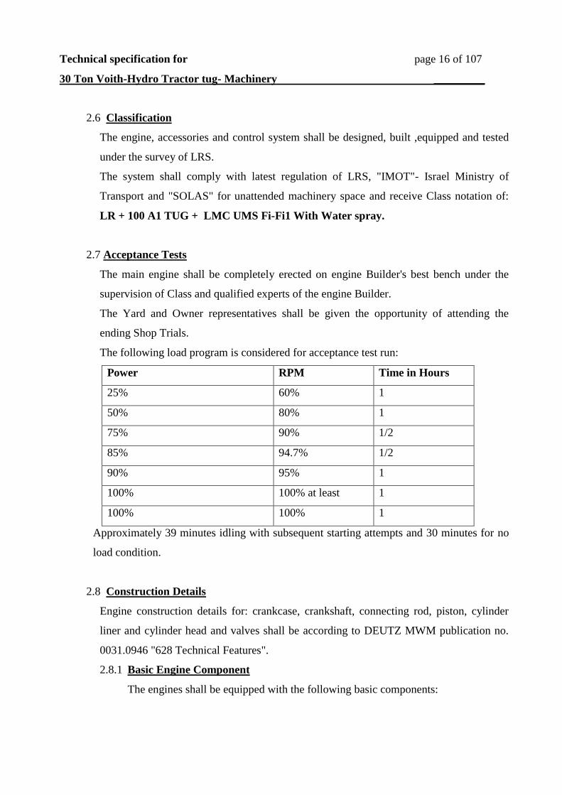
2.7 Acceptance Tests
The main engine shall be completely erected on engine Builder's best bench under the
supervision of Class and qualified experts of the engine Builder.
The Yard and Owner representatives shall be given the opportunity of attending the
ending Shop Trials.
The following load program is considered for acceptance test run:
Time in Hours RPM Power
1 60% 25%
1 80% 50%
1/2 90% 75%
1/2 94.7% 85%
1 95% 90%
1 100% at least 100%
1 100% 100%
Approximately 39 minutes idling with subsequent starting attempts and 30 minutes for no
load condition.
2.8 Construction Details
Engine construction details for: crankcase, crankshaft, connecting rod, piston, cylinder
liner and cylinder head and valves shall be according to DEUTZ MWM publication no.
0031.0946 "628 Technical Features".
2.8.1 Basic Engine Component
The engines shall be equipped with the following basic components:
Technical specification for page 17 of 107
30 Ton Voith-Hydro Tractor tug- Machinery _________
Engine crankcase, oil point, moving parts and cylinder heads, each containing the
following valves:
2 Exhaust valves Nimonic with Rorocap valve rotator.
1 Injector, uncooled.
1 Starting valve.
2 Inlet valves with valve seat lubrication.
1 indicator valve.
1 Safety valve with spark-free discharge with dust and oil proof rocker
chamber covers and automatic rocker arm lubrication.
Back fire protection in starting air lines.
Explosion relief valves on crankcase doors.
2.8.2 Turbocharging System
1 exhaust gas turbocharging, make ABB, type VTR, arranged on the bracket at
driving end, with intake air silence and air cleaner for taking in the air from the
engine room.
Note: It is preferable to install non-water cooled turbo charger.
Exhaust pipe, Insulated with sheet metal hood- from cylinders to exhaust gas
turbocharger, with installed expansion joints with contact protection, exhaust
elbows on cylinder head cooled-by engine jacket water. Sheet metal cover from
turbo charger to silencer and from expansion joints with inner tube.
Exhaust branch, adapter tube and corrugated tube compensator for the exhaust pipe.
Branch position vertically upwards. Charging pipe from exhaust gas turbocharger
to cylinders. Scavenging device, at intake air end.
1 Jacket-water cooled charge in charge airline. The turbocharger to include
permanent cleaning device, suitable for diesel oil operation.
2.8.3 Governor
Hydraulic speed governor, make: WOODWARD, type UG-8L.
S.S.A manometer on governor, 0-10 Bar, according to Maker standard.
2.8.4 Power Transmission
The power transmission flange shall be suitable for connection of the VOITH turbo
coupling. The engine is not provided with flywheel.

Technical specification for page 18 of 107
30 Ton Voith-Hydro Tractor tug- Machinery _________
A bearing between the turbo coupling and the engine is not necessary. (Deutz MWM
guarantees).
2.8.5 Power Take-Off
A P.T.O shaft shall be at the aft end of the engine. The P.T.O shall be suitable for
driving an external firefighting pump with a power consumption as required by the
Fi-Fi system. (To be agreed upon the Fi-Fi 1 equipment Maker).
2.8.6 Turning Gear
Barring gear (pull rod type) for manual turning of the engine be supplied.
Limit switches shall be fitted to prevent engine starting during manual engine
turning.
2.8.7 Safety equipment
Crankcase breather including oil trap and connecting facilities for deck
mounting. Drain oil trap to crankcase, according to Maker standard.
Crankcase explosion on cylinder of frame covers of engine.
Spark-free discharge on cylinder heads.
Solenoid valve for emergency stop device.
Emergency stop switch unit.
2.8.8 Oil Mist Detector
An oil mist detector, Schaller make, shall be mounted on each main engine.
The oil mist detector shall check he oil mist concentration in the crankcase
continuously. The unit shall provide an alarm contact if and when the oil mist
concentration exceeds a predetermined value and at the same time shall stop the
engine.
2.9 Engine Systems
2.9.1 Fuel System
Additionally to the attached pumps, the fuel system shall consist of the following:
1 Charge type duplex pre-filter with duplex strainers with local differential
pressure indicator and alarm switch.

Technical specification for page 19 of 107
30 Ton Voith-Hydro Tractor tug- Machinery _________
1 fuel pump supplying fuel injection pump.
Connection for standby pump.
Double-walled injection lines.
Fuel intermediate tank 201., loose.
Fuel back leakage tank with high level alarm switch, 501,m loose.
Back leakage injection manifold.
High-level tank, with low alarm contact.
Change-over type duplex fuel filter with local differential pressure indication,
and contacts for alarm, loose.
2.9.2 Lub. Oil System
The lub, oil system shall include:
Sump lubrication, gear pump for forced feed circulation lubrication.
Connection for standby oil pump.
Hand pump for drawing lub. oil during oil change.
Connection to dirty oil pimp (elect) for oil change.
Partial-flow centrifugal filter.
Lub. oil edge type filter with cleaning possibilities during operation series-
connected lub. oil fine filter (duplex).
Dipstick for checking oil level.
Crankcase breather.
Check valve for breather pipe.
Tubular oil cooler.
2.9.3 Cooling System
The engine, lub, oil and charge air cooling will have a joint circulation system with
high temperature and low temperature control valves for regulation of the required
inlet temperature in the circuits.
The cooling system shall include:
Circulation F.W. centrifugal pump, engine mounted (non self-priming),
Engine drive non self-priming S.W. centrifugal cooling pump.
Temperature regulation for L.T. circuit operation (LTC) DN-50.
Temperature regulation for high-temperature circuit (HTC) DN-65.

Technical specification for page 20 of 107
30 Ton Voith-Hydro Tractor tug- Machinery _________
Temperature regulation for low-temperature partial circuit (LTC) DN-20.
(charge air cooler and lub. oil cooler).
Connection for engine pre-heating system.
Heater for pump for indirect engine preheating. Make HILZINGER. Pump and
heating elements to stop when reaching nominal temperature of working
engine.
Cooling water heat exchanger, plate type, make ALOHA-LEVEL.
The plate type heat exchanger shall be designed for 110% load and 70%
cleanliness factor.
All S.W. cooling shall be of St St. 316L.
The closed cooling circuit shall be used as cooling fluid for the following:
V.H.P. oil cooler.
F.F pump gear oil cooler.
Suction and delivery connections for standby circulating pump.
2.9.4 Starting Air System
The engine to be start with compressed air 30 bar, passing periodically the
individual cylinder via the starting valves.
The main starting device shall have a master starting valve and camshaft controller,
and pilot air distribution, with manual override.
Accessories:
Two compressed air bottles, 250 liter capacity each, 30 bar working pressure.
One control air vessel, 80 liter capacity, 10 bar working pressure.
One control air vessel, 63 liter capacity, 10 bar working pressure.
One air dryer for each engine.
2.9.5 Exhaust Gas System
The exhaust gas elbow between the cylinder head and the exhaust gas manifold to
be water cooled. They are connected to the water side by sliding pieces serving as
the water manifold.
For removing the cylinder head, the insulation enclosing the exhaust manifold need
not to be removed.

Technical specification for page 21 of 107
30 Ton Voith-Hydro Tractor tug- Machinery _________
The exhaust gas system to include the following equipment per each engine:
Exhaust silence with spark arrestor, make HUSS, type AF 30. Silencing effect
of 30 dB(A).
1 corrugated steel expansion piece, N.D.360, with inner tube.
Exhaust uptake pipes, all the way, insulated and covered with galvanized sheet
metal. Easy access for silencers cleaning to be provided.
2.9.6 Intake Air System
Intake air manifold on engine
1 Intake air filter, wet type, on engine, with silencer.
1 Intercooler, in L.T. circuit including corresponding piping, built on engine.
2.10 Engine Mounted Measuring Instruments and control Equipment
On each engine the following equipment shall be provided:
2.10.1 Engine Mounted Measuring Instruments Panel (panel facing ship centerline)
Engine Mounted Measuring Instruments Panel with the following indicators:
1 pressure gauge: S.W. pressure
1 pressure gauge: fuel delivery pressure
1 pressure gauge: lub, oil pressure behind filter
1 pressure gauge: jacket water pressure cooling.
1 hour meter:
1 differential pressure lub. oil filter: engine mounted
1 differential pressure fuel filter: engine mounted
1 pressure gauge: starting air pressure
1 pressure gauge: charge air.
1 pressure gauge: speed setting sir pressure
1 pressure gauge: control air.
1 control lamp: remote control unit
1 push button: releasing emergency stop.
Tachometer Unit
Tacho-generator with drive and electric speed indicator.
Technical specification for page 22 of 107
30 Ton Voith-Hydro Tractor tug- Machinery _________
2.10.2 Local Measuring Instruments Mounted on Engine Thermometers:
1 thermometer for lub. oil after cooler.
1 thermometer for lub. oil before cooler.
1 angle thermometer for jacket water outlet on engine.
1 angle thermometer for jacket water in turbocharger.
1 thermometer for exhaust gas behind turbocharger.
1 thermometer for charge air inlet on cylinder.
1 thermometer for jacket water inlets.
1 thermometer for exhaust gas for each cylinder. Round 00
- 6500
"SIKA" type.
2.10.3 Engine Local Control Panel
Control panel on the engine shall include:
Lever: start-stop operation
Lever: engine speed minimum to maximum.
Switch over lever: local-remote control.
2.11 Control, Safety Monitoring and Alarms
2.11.1 General
Remote Control and Instrumentation
In addition to the above control and instrumentation panels built on engine, a
remote control and monitoring system shall be provided.
2.11.2 Main engine Control
A centralized pneumatic remote control system for bridge operation shall be
provided for operation of the main propulsion machinery considered as unattended
engine room,
Manual operation of the engine from the engine side shall also be provided.
Means with adequate extent shall be provided for remote manual or for local
control in the engine room.
The main propulsion control system shall consist of remote start, speed control and
stop of the main engines from the wheelhouse.
In addition, a local control station for the manual control in the emergency cases
shall be provided near each engine.

Technical specification for page 23 of 107
30 Ton Voith-Hydro Tractor tug- Machinery _________
A panel for the selection of the mode of operation local/ remote shall be installed in
the engine room near the engines.
2.11.3 Safety Precaution- Slow- Down, Shut Down
There shall be three levels of safeties:
1. An automatic shut-down by the NORIS electronic monitor.
2. Means for a visual and audible alarm for all machinery parameters as listed in
the attached table.
3. An emergency stop push button under cover shall be provided and installed on
the wheelhouse control desk.
Shut-Down
A NORIS system shall be provided and shall protect the main engines from:
1. Over speed.
2. High cooling water temperature (950), (with over-ride possibility).
3. Low lub. Oil pressure.
4. Oil mist in the crankcase.
Slow-Down
Means for parameters requiring the manual load reduction of the main engines as
manifested by the alarm system shall include the following parameters:
1. Main engine overload which shall be sensed by a switch provided by the engine
manufacturer on the governor (100% load alarm).
2. High charge air temperature (650C alarm).
3. High lub. oil temperature (750C alarm).
4. High cooling water temperature (850C alarm).
5. Exhaust gas temperature after turbine.
2.11.4 Instruments for Main Propulsion Plant
The following instruments and facilities shall be provided in the bridge control/
console.
Pressure gauges
Main engine lub, oil pressure
Main engine fuel pressure after filter
Main engine starting air pressure

Technical specification for page 24 of 107
30 Ton Voith-Hydro Tractor tug- Machinery _________
Main engine jacket cooling water
Main engine control air pressure (non-electric)
RPM air setting (non-electric)
Cooling sea water pressure
VSP lub. oil pressure
VSP control lub. oil pressure
Temperature gauges
Air inlet temperature to engine
Fresh cooling water outlet temperature from engine
Main lub. oil inlet temperature to engine
In addition, the following instruments shall be provided:
1.Load indicator- Deutz MWM supply
2.RPM indicator- Deutz MWM supply
3. Pressure and temperature gauges on bridge with color marked zones: green,
yellow, red.
Maneuvering Section (to include following items):
Main engine hour meter
Remote control valve for pneumatic start and speed control.
Control position indicator, engine-bridge.
Emergency stop,
The remote indicators for wheelhouse control console shall be electrically
illuminated of size 96 mm. And have a black background, and yellow numbers
and pointer.
2.11.5 Alarm Means
Temperature Sensors/ Switches
All temperature sensors shall be of the PT-100 type, expect where otherwise
required, which shall be thermocouples.
Level Switches
All level switches that shall be used on board, shall be of float type fitted with
magnetic switch, of waterproof type. (MOBERY make)

Technical specification for page 25 of 107
30 Ton Voith-Hydro Tractor tug- Machinery _________
Pressure Transducers/ Switches
All systems pressure, such as lub. Oil, cooling water, fuel oil, etc., shall be
monitored by analogue pressure transducers of current transmitting type with an
output of 4-20 mA. (All TRAFAG make type 8202).
2.12 Torsional Vibration
Torsional vibration calculation shall be carried out by the Deutz MWM for whole power
plant, including the following elements - Eng. PTO, engine itself, shaft line, coupling and
V.H. propeller.
The torsional vibration results shall be submitted to LRS approval.

Technical specification for page 26 of 107
30 Ton Voith-Hydro Tractor tug- Machinery _________
3. SHAFTING AND PROPELLERS
3.1 General
Two (2) Voith-Hydro propeller assemblies shall be installed underneath the fore body.
Each propeller shall be a complete independent drive unit with integrated oil and cooling
system and capable of running even when the other unit is out of operation.
The propellers shall be of standard design and material, approved by Class and Statutory
Authorities.
The V.H, propellers and their accessories shall be supplied classified and inspected by
LRS.
3.2 Propellers
Each propeller is fitted with five (5) blades of forged seawater resistant steel.
The propellers will rotate in contrary direction, each relatively to the other.
Stbd. Propeller rotates clockwise
P.S. Propeller rotates anti-clockwise
In each propeller the level gear unit is preceded by spur gear unit, flanged on the propeller
casing and forms an integral part of the propeller.
The oil pump for control and lub. oil supply for the propeller is flanged to the preceding
unit filters and associated accessories. An oil expansion tank will be arranged at least
00.5m above the maximum draft.
The space between the rotor and propeller shall be properly vented with the vent pipe and
non-return valve above waterline.
Zinc anodes shall be fitted to the rotor casing bottom for protection against corrosion. (15
anodes per rotor)
The main seal located in the propeller casing to prevent escape of filling oil from
propeller casing and penetration of water from outside, and to be provided with additional
protection against sand and dirt.
Any leakage of water or oil shall be discharged from the bores in the intermediate ring
into leakage water channel to be directed to the bilge. The oil pressure shaft seal is chiefly
intended to keep oil pressure in rotor casing, higher than the external pressure (water
pressure). Leak channel to be directed to an observation tank, covered by perplex, with
drain cock and pumping facilities for V.H. use only.
Technical specification for page 27 of 107
30 Ton Voith-Hydro Tractor tug- Machinery _________
A separate leak tank for each unit- Port and Stbd.- including High level Alarm shall be
provided.
3.3 Shafting and Hydraulic Coupling
The propeller shall be coupled to the main engine via a Voith turbo coupling. The input
side of the Voith turbo coupling shall be connected to the engine output flange without an
intermediate bearing.
The engine Maker shall be responsible to verify that the engine crankcase can absorb the
pro-rata weight of the turbo coupling as a cantilever load.
The complete propulsion system shall be checked by the engine manufacture with regards
to torsional vibration in order to guarantee satisfactory operation.
High temp. lub. oil visual alarm of the turbo coupling shall be provided near the pilot
stand on the bridge, in addition to the alarm in the alarm panel.
The end side of the turbo coupling is supported by the pillow block.
Arranged on the periphery of each coupling are fusible plugs which splash off the oil
when excessively overheated, after alarm warning.
The turbo coupling shall be provided with the ship mounted oil collected casing.
For compensation of tolerances and temperature affects stresses, the output side shaft of
turbo coupling is connected with propeller input shaft, via gear coupling consisting of two
halves. One half is mounted on the output shaft of the turbo coupling, (make Tacke, type
SBG), whilst the other half is on the input shaft of Voith- Hydro propeller and connected
by ab intermediate shaft.
3.4 Controls
One (1) control stand shall be provided per vessel for the mechanical transmission of the
control shaft movements to the Voith-Hydro propeller. This control shall be arranged in
the wheelhouse. The control stand shall be fitted with one steering wheel for the control
of adjustment of transverse pitch and two speed levels for joint or optionally independent
control of longitudinal components of both propellers. The control stand has light scales
for pitch indication with lighting of variable intensity.
The control stand is interconnected by mechanical lines, to both V.H.P.
The control stand is designed so that the connecting lines for synchronization are located
in the cofferdam space, below deck. For checking the rod adjustment 100 mm control tool
to be provided. Adjustment screws to be marked after adjustment.

Technical specification for page 28 of 107
30 Ton Voith-Hydro Tractor tug- Machinery _________
Control oil pressure shall be displayed in the wheelhouse console (centerline) by electric
instruments.
From the control stand, mechanical control lines lead to the Voith propellers. In design of
superstructures, a conveniently accessible trunk shall be design for control lines, with
easy access for greasing and maintenance.
The vessel shall be able to operate with one propeller only (by mechanical disconnecting
of the connection rods of the unserviceable propeller).
3.5 Measuring and Monitoring Instruments
Measuring Instruments installed for purpose of monitoring the propellers shall be provided
for monitoring the oil system.
The monitoring shall be locally from the wheelhouse.
The following measuring Instruments shall be provided:
Location Designation Type of Control
Engine Room/ Bridge Gauge and Pressure transducer Control Oil Pressure-
Analog
Engine Room/ Bridge Gauge and Pressure transducer Lub, Oil Pressure- Analog
Engine Room Gauge Pressure Rotor-Case. Oil Pressure
Engine Room Thermometer Oil Temperature
Engine Room Thermometer bearing Temperature
Engine Room Interlock Switch Zero Pitch- V.H,P,
Engine Room Binary switch Differential pressure LO
purifier filter
Bridge-Red warning light Visual Alarm Turbo Coupling Oil temp
3.6 V.H.P Main Particulars
Two (2) Numbers of sets:
Abt.1095 KW Input power, each:
900 RPM Speed of pinion shaft:
26G II/165 with preceding gear Type:
2600 mm Diameter of rotor casing:
5 Number of blades:
1650 mm Length of blade:

Technical specification for page 29 of 107
30 Ton Voith-Hydro Tractor tug- Machinery _________
3.7 Spares and Tools
A full set of spares, to Maker's standards recommendation shall be provided.
Special tools for operator, overhauling, dismantling and lifting of the propellers and their
components shall be supplied as per Maker's standard recommendation and stowed on
board.
3.8 Alarm and Safety
Automatic Actions Alarm Monitoring Parameter
Inhibit Engine Start Not Zero Propeller- Zero Pitch
High/ Low Lub. Oil pressure
High/ Low Control Oil pressure
Visual Alarm Bridge High Coupling temperature.
Technical specification for page 30 of 107
30 Ton Voith-Hydro Tractor tug- Machinery _________
4. ELECTRICAL GENERATING PLANT
4.1 GENERAL
Electric power of 380V, 3ph, 50Hz, shall be supplied by two (2) diesel generators sets.
The sets shall be sized to suit the electrical loading conditions- as described in Electrical
Specification.
For firefighting duties, when all machinery and domestic loads are on line and both foam
pumps are in operation, both sets shall run parallel.
Otherwise, in all other events and under tropical conditions, only one diesel generators
shall be sufficient to carry the load while the second set is stand-by.
In case the electrical plant is being out of commission, the emergency battery plant shall
be capable to supply the vital consumers at sea, such as emergency lighting, radio, and
navigation equipment.
The auxiliary engine shall be constructed and outfitted to Class notation for unattended
operation.
4.2 Main Particulars
4.2.1 Auxiliary Diesel Engine
Number of sets: Two (2)
Type of engine; DEUTZ MWM, 4 stroke, diesel engine type:
D234V6,6 cylinders in V configuration, direct injection water cooled- naturally
aspirated.
Engine output: ISO standard output according to din 6271 (ISO 3046
part 1/04.91), 104 Kw at 1500 rpm, related to maximum 2980K (25
0C) intake air
temperature, maximum 2980K (25
0C) sea water temperature, 1000 mbar and 60%
relative humidity, 10% overload possible for one hour within a period of 12 hours.
Service rating: According to DIN 6271 (ISO-3046I part 1/04.91) (for load sharing),
104 Kw at 1500 rpm, related to 1000 mbar 3180K (45
0C) intake air temperature,
3100K (37
0C) sea water temperature and 60% relative humidity.
Technical specification for page 31 of 107
30 Ton Voith-Hydro Tractor tug- Machinery _________
4.2.2. Engine Data
Direction of rotation: Anti0clockwise when facing flywheel
Engine design: "V" configuration 600
Bore: 128 mm
Stroke: 140 mm
Displacement: 10.8 dm3
Mean effect: 7.70 bar
Mean piston: 7 m/s
4.2.3. Fuel and Lub, Oil Consumption
ISO Specification fuel consumption 213g/kwh at fuel load and according to DIN 6271and
ISO-3046/I with margin of +5% with engine mounted pump, when burning a fuel with
lower calorific value of at least 42.700 kJ/Kg.
Fuel specification for gas oil according to DIN 51691, BS-2869, ASTM-D-975-78,
burning the same fuel oil as M.E.
Lub. oil consumption approximately 1g/kwh at full load, oil changes mot considered.
4.2.4. Guarantee for Rating and Consumption data:
The rating and consumption data measured during test trials, on out test bench and
recorded by the test reports shall be considered as proven.
4.2.5 Alternators
See Electrical Specification, chapter 2.2.4.
4.3 Engine Construction
The engine shall be erected with the generators on common welded bass plates, flexibly
mounted on the vessel. Access to the mountings for maintenance.
Torsional vibration shall be calculated and reported to the Owner with ordering.
Water cooling system shall be effective in full range of operation and temperatures.
The engine shall be supplied with integrated sump.
Engine construction details shall be in accordance with Maker's standard description.
Engine Construction Particularities
Basic engine
Combustion system

Technical specification for page 32 of 107
30 Ton Voith-Hydro Tractor tug- Machinery _________
Direct injection by multi-hole nozzles
Cylinder block/ crankcase cast iron
Underslung bearing and wet type cylinder liners with wear resistant oil holding surface
and protection against cavitation in the gap strong semi-circular bearing covers, bearing
shells of three metal version engine brackets-front and rear.
Flywheel housing of cast iron, size according to SAE 1.
Cylinder heads, individual cylinder heads of special cast iron.
Valves overhead, each one inlet and one exhaust valve actuated by push rod, rocker arms
and tapper lever, with rotocaps.
Piston of light alloy, piston cooling is by spray nozzles by means of cooling oil.
Crankcase of chrome molybdenum steel, bolted on counter weights according to the
requirements of Classification Societies.
Camshaft of steel, cams and journal hardened.
Connecting rods of alloy steel, main and big end bearings, three metal plain type bearing,
steel backed bearing with lead bronze and galvanized running layer.
4.4 Engine System
4.4.1Starting System
Gali air starting motor shall be provided on the engine, operating at 30 bae, air
pressure with lubricator, air filter and air solenoid 23V d.c. for remote start and
manual override.
Emergency start air starter aid to be provided. Duetz-MWM to provide the solution.
Solution and maker shall be approved by the Owner.
A bypass line with a pressure reducer from 30 to 12 bar shall enable to operate the
starter at the pressure of 12 bar.
4.4.2 Cooling System
Heat exchanger cooling system, suitable for 3100K (37
0C), sea water temperature,
consisting of:
V-belt driven non self-priming jacket water configuration pump.
V-belt driven self-priming sea water configuration pump.
Engine mounted heat exchanger with integral header tank.

Technical specification for page 33 of 107
30 Ton Voith-Hydro Tractor tug- Machinery _________
Thermostatic controlled valve for automatic regulation of jacket water
temperature.
Piping and V-belt protection.
4.4.3 Lub. Oil System
Forced feed lubrication of engine by means of engine driven lub. oil gear type
pump.
Oil pan on engine (suitable for larger inclinations).
Lub. oil cooler on engine in jacket water circuit of engine
Lub. oil scavenge pipe.
Engine mounted lub. oil duplex filter. Change-over type with differential
pressure indicator.
Piston cooler (spray nozzles).
Hand pump for sump draining. A separating valve shall be provided on sump
suction pipe. A lower drain plug for cleaning the suction filter in the sump shall
be provided.
Dipsticks facing ship centerline.
4.4.4 Fuel System
For burning oil:
BOSCH injection block type pump with speed governor and feel feed pump.
Connecting parts for leaking piping.
Engine mounted fuel duplex filter change over type with interconnecting
piping.
Double walled fuel pressure piping on engine.
An engine mounted automatic emergency over-speed stop device by a solenoid
valve 23V shall be fitted on supply line.
4.4.5 Speed and Load Control
Electrical speed fine adjustment with electrical motor 24V d.c. suitable for
parallel operation of the generating sets and load starting between sets.
4.4.6 Intake Gas System
2 Exhaust gas manifolds on engine, jacket water cooled.
1 Exhaust junction piece, outlet left or right.

Technical specification for page 34 of 107
30 Ton Voith-Hydro Tractor tug- Machinery _________
1 Exhaust gas below on engine with counter flange
1 Exhaust silencer, spark arrestor, loose, uncooled, exhaust sound attenuation
approx. 35 dB (A).
4.5 Instrumentation
Instrumentation panel, engine mounted on shock absorbers, facing ship centerline,
comprising:
1 mechanical lub. oil pressure gauge.
1 cooling water temperature thermometer.
1 electric rpm indicator, including drive and tacho generator.
2 local exhaust temperature thermometer.
Running hours counter.
Start/ stop buttons.
Selector switch local remote start including restart interlock (i.e. engine cannot be
started when engine is running).
1 mechanical type sea water pressure gauge, loose.
Instrument panel: The pressure gauge to be separated from the electronic components.
4.6 Control and Safety Devices
For safe operation, monitoring and for unattended service of the plant, safety switches
should be provided on the engine in accordance with the LRS Rules and Owner's
approval.
4.7 Remote Indication and Alarm Sensor
The following sensors for indication/ alarms function shall be supplied:
Temperature transducer- (PT 100) (one
per row)
Jacket water temperature- Analog
Pressure transducer- (4-20 mA) Jacket water pressure
Pressure transducer- (4-20 mA) Lub. oil pressure
Flow switch (binar on/ off) Fuel oil leakage
NiCr temperature Exhaust gas temperature (one per row)
Temperature transducer- (PT 100) Lub. oil temperature- Analog

Technical specification for page 35 of 107
30 Ton Voith-Hydro Tractor tug- Machinery _________
Temperature transducer- (PT 100) Exhaust junction box temperature
Pressure switch (binar on/ off) Starting air pressure
Pressure transducer- (4-20 mA) S.W cooling pressure
Engine shut- down
The following additional (separate) sensors shall be supplied:
Temperature switch Jacket water temperature
Pressure switch Lub. oil pressure
Tacho generator (see note) Overspeed
Note! The diesel engine shall be supplied with a tacho generator which shall be used as a
sensor for the detection of:
Firing speed
Overspeed
For remote indication of the engine RPM.
The output voltage for the tacho generator shall be 23V d.c.
4.8 List of Outfitting
The following major components shall be supplied and installed with the engine:
S.W. pump
Flywheel and flywheel protection
Flexible coupling on flywheel
Peed governor with fine adjustment
Freshwater cooling pump
Forced feed lubrication
Oil pressure gauges
Lub. oil and fuel filter with differential pressure indicator.
Oil cooler
Wet air filter
Manually operated pump for draining of oil sump
Injection pump
Fuel feed pump

Technical specification for page 36 of 107
30 Ton Voith-Hydro Tractor tug- Machinery _________
Double walled injection pipes
Speedometer
Air starter (make Cali)
Turning device
Piping connections with counter flange and flexible coupling of suitable length
4.9 Generator set Mounting
Resilient mounting by anti-vibration units between bed plate and engine room seating.
Resilient tube connection on engine for fuel, cooling water, starting air and exhaust gas.
Access to the mountings for maintenance shall be provided.
4.10 Classification
The engine shall comply with the latest regulation of LRS. IMOT (Israel Ministry of
Transport) and SOLAS for unattended machinery spaces for receiving Class notation:
LR+100A1 Tug + LMC UMS with water spray
Testing according to the requirements of the Classification Society LRS.
Torsional vibration calculation of the generator set shall be carried out and submitted to
LRS approval.
4.11 Tests
The diesel generator sets test shall be carried out at the Builder's test shop.
The Yard and Owner's representatives shall be given the opportunity to attend the tests.
Tests to include:
Examination of alignment including test run, i.e. electrical testing of function by using
Maker's switch board as follows:
Fuel consumption measurements.
Connection of the generator and voltage setting to the rheostat and switchboard.
Examination of alarm and shut down system of engine.
Full load operation for 1 hour.

Technical specification for page 37 of 107
30 Ton Voith-Hydro Tractor tug- Machinery _________
10% overload operation for 1 hour.
Sudden application and reduction of load, see LRS Requirements.
3/4 and 1/2 load operation.
The following measurements shall be carried out for all operating loads:
Nominal rating of the generator.
Amperage in 3 phase
Voltage
Frequency
Lub. oil pressure
Measurements for governor function
Vibration measurements.
5. PUMPS
5.1 General
Where two or more pumps are provided in one system, one pump shall be sufficient to
handle the connected system and the other, shall serve as standby, unless otherwise stated.
Each pump shall have sufficient negative suction lift capacity according to service
intended.
Each rotary positive displacement pump and reciprocating pump shall be provided with a
relief valve, capable of passing full pump capacity as suitable pressure, so as to prevent
damage of discharge pipe line.
Pumps shall be mounted on common base plates driven by electric motors. Flexible
mounting of pump sets shall be for pump as per section 5.4.
5.2 Centrifugal Pumps
Centrifugal Pumps shall be of self-priming type, where necessary.

Technical specification for page 38 of 107
30 Ton Voith-Hydro Tractor tug- Machinery _________
Each electromotor for centrifugal pump shall be of sufficient power rating to drive the
pump without over-loading, under any conditions of suction or discharge head for all
services at sea and in port. This also applies in case of mishandling.
Where self-priming is required, special automatic acting evacuation units, Vatec or
similar, shall be provided at large pump.
The rating of the lub. oil pump motor is to be, so that the pump can handle cold oil.
The materials for centrifugal pumps, unless otherwise specified, shall be as follow:
Fresh water Sea water and bilge Service
Cast Iron GG25 Bronze Casing
Phosphorus Bronze Phosphorus Bronze Impeller
Phosphorus Bronze Phosphorus Bronze Wearing Ring
Stainless steel Stainless steel Shaft
Stainless steel Stainless steel Shaft Sleeve (when fitted)
The material of other special or attached pumps shall be in accordance with maker's
standard. All pumps shall have roller or ball bearings, Mechanical and seals, as
applicable. Where not practical and for smaller pumps, soft seals shall be provided.
The pump coupling shall be of solid or flexible type, Pressure gauge shall be fitted on all
pumps between suction, discharge valves and the pumps.
Spare sets of internal parts for each size and type of pump shall be supplied as follows:
1 shaft
1 impeller
1 set of seals
1 set of wear rings
1 set of ball bearing.
5.3 Rotary Positives Displacements Pump and Ejectors
Rotary pumps shall be of screw or gear type
Gear pumps shall be fitted with build-in, spring loaded, hand adjustable, by pass relief
valve.

Technical specification for page 39 of 107
30 Ton Voith-Hydro Tractor tug- Machinery _________
Spare sets of internal parts for each size and type of pump shall be supplied as follows:
1 set of working parts
1 set of bearings
1 set of seals
1 set of safety vale springs.
a) The gear pump material shall be generally as follows, otherwise, to Maker's standard:
Casing- cast iron or welded steel
Cover- cast iron or welded steel
Power rotor- alloy steel
Idle rotor- alloy steel
b) The screw pump material shall be as follows, otherwise, to Maker's standard:
Cover- cast iron or welded steel
Casing- cast iron or welded steel
Power rotor- alloy steel
Idle rotor- alloy steel
5.4 List of pumps
Final figures shall be verified by heat and flow balance calculation, in accordance with
engine Maker's guidance, where applicable. However, deviations from the figures
specified here are, subject to Owner's approval.
In addition to the pumps mounted in the main engines and auxiliaries, the following
electrically driven independent pumps shall be installed.
5.4.1 Bilge, Ballast and Fire Pumps (Self Priming)
a) Number of sets: Two (2)
Type: 2 speeds, vertical
Capacity: Abt. 30/30 m3/h
Total head: 50/20 M.W.C
Revolution: 1500/985 1/min
One of these pumps shall be locally and remotely controlled from E.R. &
wheelhouse. (See Bilge/ Ballast System).

Technical specification for page 40 of 107
30 Ton Voith-Hydro Tractor tug- Machinery _________
b) One (1) piston type bilge pump, electrically driven of about 5 ton/hr capacity
shall be installed in the engine room.
c) Direct bilge suction to be connected to fire/ ballast pumps.
d) Hour counter for pumps under a) and b) above shall be provided.
e) Stbd M.E.S.W. cooling pump to act as emergency bilge suction.
f) One electric immersible pump 5m3/hr, 220V, 50 Hz.
5.4.2 Lub. Oil, Standby Pump
Number of sets: Two (2)
Type: Screw pump, vertical
Capacity: 30 m3/hr
Total head: 50 M.W.C
Revolution: 1500 1/min
The rating of the pump motor shall be such that the pump can handle cold oil.
See also Lubrication System
5.4.3 Fuel Transfer Pump
Number of sets: One (1)
Type: 1 stage, screw
Capacity: 10 m3/hr
Total head: 10 M.W.C
Revolution: 1500 1/min
5.4.4 Lub. Oil, Transfer Pump
Number of sets: One (1)
Type: screw pump
Capacity: 2.0 m3/hr
Total head: 1 bar
Revolution: 1500 1/min
5.4.5 Dirty Oil, Pump
Number of sets: One (1)
Type: screw pump
Capacity: 5.4 m3/hr
Total head: 10 M.W.C

Technical specification for page 41 of 107
30 Ton Voith-Hydro Tractor tug- Machinery _________
Revolution: 1500 1/min
See also Lubrication System.
5.4.6 Sewage Ejectors
Number of sets: One (1)
Type: Ejector
Capacity: 10 m3/hr
Suction head: 2 M.W.C.
Discharge head: 20 M.W.C.
Sea water flow: 30 m3/hr at 5 bar
Material: G, CuSu10 resistant to chlorinated water.
See also sewage system.
5.4.7 Bilge, Ballast and Fire Pumps
Two (2) horizontal centrifugal type fire pumps shall be installed to operate the
external firefighting, as specified by Kvaerner Eureka A.S.
The pumps shall be coupled to the P.T.O on the main engine through step up
electro-hydraulically activated gear box, Type and Maker to be approved by the
owner.
Pumps shall be remotely operated from the wheelhouse and locally actuated from
the engine room. The thermostats and presostats (TRAFAG make) shall be
separately fitted.
5.4.7.1. Materials
Casing NI-AL-Bronze
Shaft Stainless steel
Impeller NI-AL-Bronze
5.4.7.2. Construction
Type: OGF 250X300 Horizontal centrifugal pumps.
Casing: Radially split cast double volute with suction and deliver branches
integrally with casing. Joint sealing by synthetic rubber "O" ring
between cover and casing shrunk in renewable wearing.

Technical specification for page 42 of 107
30 Ton Voith-Hydro Tractor tug- Machinery _________
Impeller: Single entry hydraulically balanced without wearing.
Bearings: The pump runs in two off single raw grease lubricated ball bearing,
fitted with rubber seals at both sides intended for maintenance free
operation.
Shaft seals: Soft gland packing is arranged at the shaft exit from the pump cover.
The PTEE- lubricated packing will minimize wear and tear to the
shaft which is finished to ISO tolerance by grinding, No mechanical
seal shall be used.
5.4.7.3. Main Data
Capacity: 1300 m3/hr
Total head: 13 bar (*)
Revolution: Abt, 1800 1/min (gear ratio 1000-1800 RPM)
Power: Abt, 585 kW (Consumption), 614 kW (driver rating)
(*) data shall be confirmed with the Fi-Fi 1 equipment Maker. Total pump head to
be sufficient to ensure 12 bar inlet pressure to the monitors after pressure loss
calculation.
The lub. oil pump of the step-up gear box shall be actuated by the main engine gear
input shaft. The pump is built-up as a part of the gear unit, The lub. oil coolers
mounted on the gear unit shall be cooled by fresh water from cooling system of the
main engines.
Materials to Maker's standard.
5.4.8 Foam Pumps
Number of sets: Two (2)
Type: Vertical centrifugal
Capacity: 21 m3/hr
Total head: 160 M.W.C
Revolution: About 2945 RPM
5.4.9 Freshwater Sanitary Pumps
For supply of freshwater to sanitary cold and freshwater system, two (2) horizontal
electrical motor driven multi-stage centrifugal pumps shall be provided and fitted.
Technical specification for page 43 of 107
30 Ton Voith-Hydro Tractor tug- Machinery _________
Capacity: 1.5 m3/hr
Output: 35 M.W.C
Revolution: About 1500 1/min.
See also Sanitary Freshwater System.
5.4.10 Hydraulic Pumps
The hydraulic pump unit shall be supplied and installed with all accessories,
motors, filters, safety and control ad complete power packs.
Towing winch
Towing hook
All hydraulic pumps shall be electrically actuated and shut down to be effected
upon low level. Start/ stop from wheelhouse.
6. SEPARATORS, COMPRESSORS, AIR VESSELS, FANS. HEAT EXCHANGERS
REFRIGERATING MACHINERY, ETC.
6.1 General
All machinery mentioned in this section shall be of Standard Make, supplied by well-
known Maker as per approved Maker's list.
Type and material shall be in accordance with the requirements of Statuary Authorities for
Unattended Engine Room.
6.2 Separator configure
6.2.1 General
The characteristics of fuel oil separator shall be in accordance with the following
description:
The separator shall have a manual cleaning sequence.
The alarm devices shall be to Maker's standard. See also Electrical and Automation
Specification.
Technical specification for page 44 of 107
30 Ton Voith-Hydro Tractor tug- Machinery _________
Sealing water shall be supplied from freshwater sanitary system.
Sight glass shall be provided at separator inlet.
Sludge from separator will discharge into the dirty oil tank.
An oil tight tray shall be provided under the separator.
The fuel oil separator shall be provided with attached pumps and other mountings,
according to Manufacture's standard practice.
The separator shall be operated from a control panel placed near the separator.
6.2.2 Construction and Function
The separator shall be used as a clarifier and purifier
All equipment shall be supplied with LRS approval for U.M.S.
6.2.2.1 The Basic Equipment
The basic equipment shall comprise of the following accessories:
1. MMB 204 solid bowl separator with electric motor 2.2 Kw, 3X380 V,50 Hz
2. Ancillary kit for MMB separator.
3. STAWA-42 control panel for separator.
4. Pressure kit for the separator.
5. Three way valve kit for the separator.
6. Major service kit for the separator and spare parts for two years of operation.
7. Supply pump ACP 032N/ 1400 rpm with an electrical motor.
8. Set of clarifier/ purifier discs.
9. Set of resilient mounting for separator, including flexible connections for all
attached pipes.
10. Set of standard spare parts.
11. Indicators.
12. A complete set of special tools.
6.2.2.2 Ancillary Equipment
1. One built on gear type feed pump, capacity 1800 1/h
2. One sets of fitting for separator with build on pump
a) Fixed piping

Technical specification for page 45 of 107
30 Ton Voith-Hydro Tractor tug- Machinery _________
b) Strainer
c) Flexible connection for oil inlet and outlet.
d) Rubber hose for water outlet.
3. a) One electric flanged motor- a.c. (3 phase), direct couple, totally enclosed
and fan cooled flanged motor 2.2 kw at 3000 rpm, 50 hz, enclosure IP-54,
insulation class F, terminal box IP-55.
b) One set of spare parts for motors, as per Maker's recommendations.
4. a) One direct on0line starter, with disconnecting main switch, ammeter. Signal
lump, push buttons, overload relay and control transformers 380/220V to
supply signal lamps, STAWA-42 all wired up to terminal. The starter shall
be totally enclosed manually operated with triple pole thermal over current,
Free potential contractors of overload relay shall be wired up to terminals.
b) One set of starter spare parts, as per Maker's recommendations
5. One alarm unit for broken liquid seal type STAWA-42 in standard design. All
valves and fittings required for STAWA-42 shall be supplied by ALPHA-
LAVAL.
Frequency 50 Hz, voltage 220 V A.C, supplied from control transformers in
starter panel if separator.
6.2.3 Main Particulars
One ALPHA-LAVAL solid retaining centrifugal separator, model MMB-304 S-11
in standard design
Rated capacity: 3400 1/h
Normal capacity: 2100 1/h for fuel oil separator, running on marine diesel oil
viscosity; 13 cst/400C at Hz.
Electric motor: Size 2.2 KW.
Revolution: 3000 RPM
6.3 Compressors and Pressure Vessela
6.3.1 Main Air Compressor
Two (2) main air compressors shall be provided

Technical specification for page 46 of 107
30 Ton Voith-Hydro Tractor tug- Machinery _________
The characteristics of air compressors and pressure vessels shall be in accordance
with the following description:
The compressors and pressure vessels shall be provided for starting the main
engine, diesel generating engines and other miscellaneous services, supplied from
pressure vessel through reducing valve, as necessary.
The main air- compressors shall be of twin cylinder, two stage, air cooled and shall
be directly driven by electric motor.
compressors shall be provided for manual control and for automatic start/stop
operation at high, respectively, low pressure in the pressure vessels with automatic
drainage in stop position and with starting without load.
The stand-by compressors will start automatically if the air demand from the
pressure vessels exceeds the changing capacity of the running compressor.
Automatic starting of compressors both start/ stop in sequence, to be on each
pressure vessels separately.
The main air compressors shall be fitted with inlet air strains, self-contained
pressure, lub. oil system, pressure gauge, safety valves, air cooler, water and oil
separator at discharge, drain valve and other necessary fittings.
The compressor will start at about 20 Kg/cm2
pressure in the pressure vessels and
stop when pressure of about 30 Kg/cm2
is attained.
The attached air cooler shall be made according to Maker's standard.
The two compressors shall be able to operate separately each one of the pressure
vessels.
a) Construction
The compressors and electrical motors shall be erected on a common base
plate and a flexible coupling shall be used, with sufficient space for oil
draining.
The base plate shall be elasticity mounted on the foundations.
Cylinders in V arrangement single crank shaft, of spheroid cast iron, running in
two bearings.
b) Main Practice
Make: HATLAPA-35-L
Number of sets: Two (2) units

Technical specification for page 47 of 107
30 Ton Voith-Hydro Tractor tug- Machinery _________
Type: Two stage, electric driven
Capacity: 31 m3/hr
Discharge pressure: 30 Bar
Revolution: 1450 RPM
Power: 6.6 Kw, 380V, 50 Hz
Dissipated Heat: 5.6 Kj/sec
Direction of Rotation: Clockwise when facing driving side.
c) Accessories
Flywheel and flexible coupling.
Solenoid operated valves for automatic draining at stop operation and
starting without load.
Compressed air temperature sensor for alarm at excessive air temperature.
Separate oil and water separators for compressed air line.
Protective filter for solenoid valve fitted to oil water separators.
Electric control cabinet with indicating lights, on/off switch and contacts for
common alarm.
Oil pressure control switch to stop compressor in case of low oil pressure.
Oil pressure gauges and thermometer for each stage.
d) Spares (For two (2) tears operation) as per Maker's recommendation including:
1 set of bearing for E-Motor.
1 set of coils and contacts.
2 sets of suction/ discharge valves.
2 sets of packings.
2 (two) of each safety valves low/ high
2 (two) flex. Coupling E-Motor/ compressor
6.3.2 pressure Vessels
The pressure vessel shall be cylindrical type of welded steel fitted with pressure
gauge, safety and manual drain connection. The main pressure vessel shall be fitted
with automatic drains (electrically timed).

Technical specification for page 48 of 107
30 Ton Voith-Hydro Tractor tug- Machinery _________
Valves shall have steel body with stainless steel internal parts.
The shell of pressure vessel shall be protected internally with approved coating.
The following pressure vessel shall be provided:
1. Two (2) main vessels, each 259 lit.
2. One (1) pressure vessel for control air of 80 lit. capacity and 10 bar working
pressure.
3. One (1) bottle for service air of 63 lit. capacity and 10 bar working pressure.
6.3.3 Air Dryer
An effective filter of drying/ refrigerating, make HANKINSON, type 3010 (10
s.c.f.m. at 150 psi) shall be provided.
6.3.4 Manual Operation of Quick Closing Valve for Fuel Oil Tanks
Emergency quick closing valves, hydraulically, operated, with valve position
indicator for all storage and daily fuel oil tanks (8) valves shall be provided.
The valves shall be actuated from the hydraulic station positioned on main deck
level, inside the accommodation.
The hydraulic station shall consists of an oil reservoir common to the two hand
pump units. Each pump unit shall enable simultaneously closing of four valves at
one pump stroke.
The pump units shall be provided with close/ open position indicators.
A quick closing valves cabinet shall be provided.
The operation shall be from outside the engine room, in a glass covered case near
the emergency stop switch station. A hammer to break glass shall be provided.
Minimum oil level and alarm pressure switch shall be installed and connected to the alarm
system.
6.4 Heat Exchangers
6.4.1 General
Heating or cooling of surface of heat exchangers shall be defined as to total external
surface of the plates.
Technical specification for page 49 of 107
30 Ton Voith-Hydro Tractor tug- Machinery _________
Heat exchangers shall be based on a cleanliness factor of 70%.
Heat exchangers shall be sized according to maximum continuous rating of the
equipment, they serve. The heat exchangers shall be design to operate with sea
water at a temperature of 370C.
Isolating valves shall be fitted at all coolers/ heaters.
Engine coolers (except air cooler), shall be provided with three-way
thermostatically controlled direct acting valves.
Coolers shall be provided as required by the service, with valves, thermometers, etc.
Heater will have adjustable thermostatic control and safety valves.
Drain valves, deaereting valves ( where applicable) and thermometer pockets shall
be fitted,
Materials of coolers supplied attached to subcontractors items (engine or similar),
shall be to Maker's standard for marine use
10% spare tubes for tube coolers and 3 plate and rubber packing of each size of
plate coolers shall be provided.
6.4.2 Lub. Oil Coolers (Attached to Diesel Engine)
The lub. oil coolers shall have total cooling capacity required, to maintain lub. oil
temperature of adequate valve at cooler outlet and when engine is developed 110%
of maximum continuous output.
6.4.3 Fresh Water Exchanger or Main Engine
Cooling water heat exchanger, shall be plate type made by ALPHA-LAVAL.
The plate type exchanger shall be designed for 110% load and 70% cleanliness
factor. (Total heat dissipation 980 Kw at the engine).
The size of the freshwater cooler will enable to maintain the freshwater temperature
at adequate value for the main engine, developing 119% of its' maximum
continuous output.
Plate material- Titanium.
6.4.4 Generator Set Engine Lub- Oil Coolers (Attached)
Lub. Oil Coolers for diesel engine generator shall have sufficient cooling capacity
for engine operating at 110% of its maximum rated load, tropical condition.

Technical specification for page 50 of 107
30 Ton Voith-Hydro Tractor tug- Machinery _________
6.4.5 Gear Oil Cooler for fire Pumps
Two (2) coolers of shell and rube type shall be provided for fire pumps gear
cooling. Materials to Maker's Standard.
6.4.6 Voith-Hydro Reduction Gear Oil Coolers
The two (2) coolers shall be incorporated in the plant and shall be cooled by fresh
water. Each of them shall be of total cooling capacity, required to maintain
necessary oil temperature in tropical conditions at full power.
6.4.7 Hoe Eater Calorifier
An electrically heated hoe water calorifier shall be installed in the engine room of
200 liters capacity.
The calorifier dhall have thermostatic control, safety valves, etc. and shall be
efficiently insulated.
Materials of the shell- steel enameled.
6.4.8 Sea Water Condenser for Air Conditioning
Materials shall be sea water resisting.
Type: Shell and tube.
Capacity: To the requirements of Air Conditioning Plant Makers.

Technical specification for page 51 of 107
30 Ton Voith-Hydro Tractor tug- Machinery _________
6.5 Strainers and Filters
6.5.1 General
Final list of strainers and filters shall be provided on the approved piping diagrams.
Strainers shall be fitted on suction side of all pumps drawing liquids from tanks or
sea in order to prevent foreign matters damaging the pumps, or equipment pump is
serving, where applicable.
All sea water filters, appropriate to be St.St,316L.
Fine particles filters, appropriate to system several, shall be installed between the
discharge from all fuel oil and lub. oil pumps and main and auxiliary engines, made
by BOOL& KIRSCH, or similar.
Filter mesh shall be in accordance with Engine Maker's recommendation.
Other filters shall have filters mesh appropriate service and in accordance with
Maker's recommendation.
For the main and auxiliary diesel engine, fuel oil and lub. oil filters shall be in
accordance with Engine Maker's requirements.
Suitable venting and draining facilities shall be provided for filters, where
necessary.
Leakage collecting traps shall be fitted below the oil filters and piped to dirty oil
tank.
6.5.2 Strainers in Ballast/ Bilge System
Perforated stainless steel 316L inserts shall be provided to protect each pump.
Strainers in ballast cross-over main shall have isolating valves and a vent or test
cock at the top of filters.
6.5.3 Filter in Fuel Oil System
A filter be installed in fuel supply line, with manometer and pressure drop gauge
across the filter.
The diesel engines shall be provided with a Duplex strainer between the daily
service tanks and unit.
6.5.4 Filter in Lib Oil System
Filters on auxiliary lub. Oil system, where applicable, shall be in accordance with
Engine Maker's recommendation.

Technical specification for page 52 of 107
30 Ton Voith-Hydro Tractor tug- Machinery _________
7. MISCELLANEOUS EQUIPMENT
7.1 Tanks in Engine Room
Tanks shall be provided in engine room according to the approval tank plan, in
satisfactory number and size for efficient and safe operation of the plant.
All tanks shall be-made of welded steel plates either built-in or loose and well secured to
hull. All loose tanks shall be supplied with internal treatment according Maker's
requirements.
The daily fuel tank shall provide fuel to the main engine and diesel generator sets.
Each tank shall be provided with the necessary fitting, such as inlet and outlet
connections, drain, air vent, and manhole or hand-hole, overflow and/or air vent pipe as
per approved drawings.
Tanks for fuel oil and lub. oil will have cocks with locking devices, Klinger glass gauge
and sounding pipes, all depending on purpose and location for which they are intended
and according to the final approved diagrams.
Arrangements shall be provided for closing the quick closing outlet valves of fuel oil
tanks from a readily accessible and safe location outside the engine room, with good
access for maintenance.
A high and low level alarm in the tanks shall be provided according to the alarm list.
7.2 List of Tanks
All capacities are given inn cubic meters, All tanks, except D.B. tanks, to have Klinger
type calibrated gauge glasses. All capacities are approximate:
Forepeak Ballast Water: 24m3
Aft peak Ballast Water: 18m3
Fuel storage tanks in engine room (two): 18m3
(each)
Forward Double Bottom fuel tanks (two): 13m3
(each)
Daily fuel tank: 13m3
Lub, oil main storage tank: 3m3
Lub, oil storage for V,H, turbo coupling: 1m3
Dirty oil tank: 2m3
Hydraulic oil: 1m3

Technical specification for page 53 of 107
30 Ton Voith-Hydro Tractor tug- Machinery _________
Freshwater tanks (two): 17m3
(each)
Foam tank: 11m3
Sewage tank: 2.5m3
In addition, various loose tanks as required by main auxiliary and propulsion Makers for
hydraulic oil, fuel and lub. oil leakage and freshwater compensation tanks shall be fitted.
Hydraulic oil tank (for towing winch) shall have a low level alarm to be installed from the
top side.
Suction possibility for F.W. tanks from the Engine Room shall be separately, from the
Port and Stbd.
7.3 Level indicators for Fuel Tanks
An approved electric monitoring system of constant reading type, consisting of pressure
transmitters and level indicator instruments shall be fitted to the following tanks:
Fuel oil bunker tanks.
Fuel oil daily tank.
Foam tank.
Display shall be in engine control room in vicinity of the control stand.
Depth gauges shall be calibrated for following specific gravity's:
Diesel oil: 0.87 kg/cu.dm
Foam: 1.09 kg/cu.dm
In addition, local indicators shall be fitted on respective tanks, except D.B. tanks
(sounding pipes for D.B. tanks)
All tanks facing engine room shall have gauge glasses, of Klinger type, for local
indication, with metering scale in liters.
Aft wings tanks- Gauge glasses to be extended to the bottom of the tank as much as
permissible.
Furthermore all tanks shall be normally fitted with ordinary sounding pipes, according to
Classification Requirements.

Technical specification for page 54 of 107
30 Ton Voith-Hydro Tractor tug- Machinery _________
7.4 Floors, Ladders and Gratings
The engine room flooring and operating and maintenance platforms shall be of good
marine quality aluminum chequered plates, strongly supported on suitable steel angle
frames, positioned at floor level and elsewhere as necessary for maintenance and
indicated on the drawings and approved by the Owner. Builder shall get Owner's approval
for the solution for the prevention of corrosion at the contact points between steel and
aluminum parts.
Removable section with convenient size for handling shall be provided as required, for
proper access to valves or manholes and for inspection of bilge's. Brass labels to be
provided to indicator of under floor components.
Plates shall be of 5mm thickness in working areas and 3.5mm elsewhere.
Section over bilge suction points shall be provided with visual inspection openings and
good lightening.
The inclined base angle of all main stairways, shall not be greater than 600.
Stairs shall not be less than 600mm wide. Construction of ladders shall be according Hull
Specification.
Vertical ladder in workshop shall be used only for emergency exit. Floor stanchions shall
be connected by stainless steel screws and nuts to floor plating and to tank top for easy
dismantling.
Access and floor plates shall be provided to reach the tank top manholes.
All engine parts shall be readily accessible either from the floor level or from
maintenance platform.
The crank case inspection doors on the main engine shall be arranged so that they can be
opened freely without lifting the adjacent floor plates or platform.
.
7.5 ventilation Air Ducting
Air ducting shall be provided leading from fans to the respective outlets in the engine
room (made of galvanized steel). Fire flaps shall be provided ad required by LRS Rules.
Axis if the dampers shall be if stainless steel with bushes to be free of grease, Ducts shall
be not interfere with lifting of heavy components, nor parts from main engine and
auxiliaries, Ducts to be painted white.

Technical specification for page 55 of 107
30 Ton Voith-Hydro Tractor tug- Machinery _________
Engine room ventilation air covers- hinges to be generally on top side, for easy ad quick
closing.
7.6 Funnel
Two (2) small funnels, side positioned of sufficient size, shall be provided to
accommodate main engine exhaust pipes, diesel generator, exhaust and silencers.
The funnels shall be constructed of mild steel plate.
A watertight floor plate shall be arranged near the top of funnel. A drain pipe shall be led
from the aft, end of the floor plate down, inside the funnel, arranged to discharge the
drainage on to the main deck.
Coamings shall be fitted around all exhaust pipes passing through the watertight flat.
Where necessary for minimizing vibration, exhaust items shall be elastically stayed.
All pipes, uptakes, silencers and other gear inside the funnel shall be efficiently stayed to
minimize vibration, Funnel outlets shall be bended to the aft, Last outlet bends to be of
stainless steel. Easy access manholes for cleaning shall be provided.
Bolted plates shall be provided for inspection and maintenance.
7.7 Whistle
See electrical Spec. Para 11.4
7.8 Engineer's Workshop
The engineer's workshop shall be provided at forward in the engine room, and shall be
equipped with machine tools, tool panel, tool locker, shelves, 12 lockers with locking
facility for work clothes, etc., as specified below:
Wooden gratings shall be laid at working places, nearby the machines.
Wall panels for fastening of tools shall be provided.
Reduced compressed air branch line of 7 Kg/cm2
shall be provided in the workshop and
connections for rubber hoses shall be suitable located.
Electrical sockets shall be fitted for portable tools. See also Electrical Specification.

Technical specification for page 56 of 107
30 Ton Voith-Hydro Tractor tug- Machinery _________
7.8.1 Electric Grinder
Double electric grinder machine with grinding 250mm grinding wheels mounted
directly of the driving motor shall be provided.
The grinding machine shall be mounted on a steel stool.
Electric equipment for starting, stopping and protective elements.
Accessories as per Maker's Standard list shall be supplied with machine.
7.8.2 Miscellaneous Equipment
One fuel valve injector cleaning device, complete with test pump for the main
engines and auxiliary engines shall be provided.
The device shall be positioned so that it is isolated from areas where grinding and
other works are liable to give rise to harmful dirt particles.
The device shall be positioned on a standard steel workbench with lockers drawers,
complete with 100mm jaw parallel vice and an additional stand for 6 Main
Engine fuel valves.
7.9 Engineer's Store
Steel bar selector and metal shelves shall be provided at forward in the store room to hold
spare parts coxes.
Necessary steel drawers, lockers, shelves and racks for storing of spare and tools or
similar, shall be provided.
Number and position of lockers and shelves shall suit local conditions and to Owner's
approval.
Spares of bigger size shall be suitable arrange within the engine room spaces.
Additional storage spaces in engine room aft shall be equipped similarly for storage.
Stainless steel wash basin with hot and cold water shall be fitted with stop valves.
7.10 Electrical Working Place
The Electrical Working Place shall be located in the engine store and fitted out with a
steel work bench and 100mm parallel vice.
The work bench shall have a wooden top facing. The test panel, as detailed in the
Electrical Specification, shall be mounted above the bench and connected.

Technical specification for page 57 of 107
30 Ton Voith-Hydro Tractor tug- Machinery _________
One portable drilling machine of 12.5mm bores and one cutting disc machine shall be
supplied.
Sufficient steel draws, locker, shelves and hooks shall be provided for accommodating
necessary tools and spare gear.
Locker and drawers shall be provided with hooks and keys.
7.11 Welding Rectifier
Welding equipment that shall be provided with the Tug shall consist of:
a) Electric Welding rectifier (located in the workshop)
Quantity: One
Type: Portable model with cabinet, dry type are current 299 Amp, AC,
rating one hour at 60% duty.
Accessories
1 electrode holder with hand cable, 5m long and cable connector.
1 earth clamp with cable, 5m long and cable connector.
1 welding cable, 5m long 70mm2, with connectors.
1 hand shield with glasses.
1 helmet
2 sets of reserve glasses.
1 pair of welder's glasses.
1 chipping hammer.
1 wire brush.
1 spare cable connector.
1 cable drum (approximately 30m capacity), with primary sockets shall be provided
in engine's workshop only; to be wall mounted.
b) Gas Welding Plant
On boat deck with direct exit to open space, a welding store shall be provided to LRS
Rules.
The gas welding plant shall include the followings:
1 regulator for oxygen cylinder.
1 regulator for acetylene cylinder.
1 cylinder rack, each to accommodate two cylinders.

Technical specification for page 58 of 107
30 Ton Voith-Hydro Tractor tug- Machinery _________
1 cylinder, charged with 40 liter of acetylene.
1 cylinder, charged with 40 liter of oxygen.
20m welding hose, 6mm.bore, for acetylene.
20m welding hose, 6mm.bore, for oxygen.
1 clip for hose
1 back pressure valve or similar, as per Supplier's standard.
Cylinder shall be piped0up to engine workshop under main deck.
Regulator, filter and safety fixtures shall be provided.
7.12 Main Engine Lifting Beam
Lifting beams, including hand operator trolley shall be provided over each one of the
main engines. A central beam traversing through Engine Room & Work Shop, shall be
provided.
Two (2) clamps and tackles of one (1) ton SWL and one (1) ratchet of one 91) ton shall
be supplied. Sufficient height for fitting a piston together with its' connecting rod shall be
provided.
7.13 Engine parts- Lifting Post
A lifting post for 300kg. SWL, air actuated, shall be provided over the forward access
hatch. The post shall be outfitted with necessary tackle and blocks leading to windlass
drum.
7.14 Lifting Facilities
Beams for manual lifting devices shall be provided above each engine.
Eye plates shall be provided immediately above heavy items. Position and number of eye
plates shall be approved by Owner.
Three (3) loose lifting tackles of differential type shall be provided for lifting engine
room parts, up to 5oo kg.
Eye plates shall be provided on the hull for lifting and removing the propeller.
General lifting eyes as per V.H. and local Surveyor instructiosn shall be provided.

Technical specification for page 59 of 107
7.15 Tanks Sounding Board
A board marked for engine room tank soundings and general information shall be fitted
on main deck level and in engine casing.
7.16 Drip Trays and Coamings
Steel trip trays and coamings shall be arranged around the fuel and lub. oil pumps, fuel oil
heater and separator, fuel oil filters, where oil leakage may occur. Drains from coamings
at oil fuel units are to be led to the dirty oil tank.
Collars shall be fitted around passage of pipes, through platforms.
7.17 Local Pressure Gauges and Thermometers
Pressure gauges shall be fitted on each pump at the suction and delivery sides.
Thermometers shall be fitted before and after the main and auxiliary engine cooler and
freshwater. "Sika" make shall be the only type to be provided all over the tug boat.
Accuracy of the instrument shall be not less than 1%.
Pressure gauges which have to be read from a distance shall be of 150mm, or larger.
Remaining gauge shall be of a diameter of 100mm.
Normal working values shall be marked in green and red for abnormal.
Where necessary, safety valves against over pressure shall be provided, The pressure
gauges shall be installed at the same level as the measured points.

Technical specification for page 60 of 107
30 Ton Voith-Hydro Tractor tug- Machinery _________
The pressure gauges pipes shall be of cooper tubes and shall have cocks or shut-off valves
and shall be properly fastened against vibrations.
The connection of the pipes should be made of stainless steel 316L.
All thermometers used, shall be with a protecting case of brass or a tail piece of brass and
steel. The tail shall be supplied with 1/2" or 3/8" standard pipe threads on the outside.
Thermometers shall be installed on the auxiliary machinery and piping, in accordance
with Owner's approved schematic drawings of the piping.
Dial thermometers shall be provided as far as appropriate.
The thermometers shall be protected against vibrations.
Sensors shall be corrosion resistant.
Pressure gauges shall be provided with separation cock. Thermometers shall be of pocket
type. Thermometers pockets shall be of stainless steel 316: (Exceptions, depending of
piping material, only with Owner approval).
7.18 Flow Meters
For control of fuel consumption for each set of main diesel engine and each diesel
generator, a fuel flow meter shall be installed.
Flow meters shall be protected by filters on the income side.
By-passes shall be arranged around each measuring group with isolating valves for
maintenance and control of flow meters.
Accuracy of flow meters shall not be more than 1% at operating points and demonstrated
by test.
Leakage collecting tray with drain connection shall be fitted below each group.
The flow meters shall read liters per hour and indicator shall be provided.
7.20 Greasing Nipples
Greasing nipples shall be, Tekalemit type, DIN71412-M-10xl or equal, to minimize
number of greasing guns in use, Only one type shall be used throughout the Tug.
7.21 Name Plates
Name plates shall be of brass for the main engine and auxiliary machine, they shall be
engraved in English and Hebrew and in metric unit.

Technical specification for page 61 of 107
30 Ton Voith-Hydro Tractor tug- Machinery _________
Engraved name plates in English and Hebrew language shall be fitted to valves of all
pipe systems belonging to engine room and hull services Name plates shall be attached to
spindle and to all valves, (For small valves, if not applicable, name plates shall be
positioned on the pipes, as per approved drawings).
Inspection on deck plugs and similar fittings may be engraved on the plug directly.
Brass quality marine type name plates shall be fastened with suitable means (St. St. pop
rivets).
All valves and other components shall be marked with identification number on the
drawings and the same identification number shall appear on the name plates.
Numbers shall identify each one of the Tug components.
7.22 Painting
Main and auxiliary machinery shall be suitable painted in accordance with Owner's
Standard for marine application. The engine shall be painted with a RAL 6011 (Reseda
Green) shading. A color coding chart shall be displayed in engine room.
Non- structural small tanks for lub. Oil shall be oil treated only.
Freshwater expansion tank shall be coated inside with anti-rusting paint. Special attention
shall be given to conservation of sewage tank.
For details of painting bulkheads, tanks tops or similar, see Hull Specification.
A) Piping
All unlagged, including galvanized pipes shall be painted according to the paint scheme
given in the Hull Specification. Stainless steel pipes shall not be painted.
Pipes shall be overall finished with white gloss paint, marked with PVC bands of 100mm
width, or painted and with arrows marking the flow direction (including pipes in bilge's).
System identification shall be as follows (colors are according to RAL designation):
Lub. Oil: Yellow RAL 1023
Fresh Water: Light blue RAL 5012
Sea Water: Green RAL 6024

Technical specification for page 62 of 107
30 Ton Voith-Hydro Tractor tug- Machinery _________
Starting Air: Purple RAL 4006
Diesel Fuel Oil: Brown RAL 8001
Bilge: Black RAL 9004
Ballast: Dark Blue RAL 5010
Fire Mains and Hydraulic: Red RAL 3020
Painting of all items and equipment where high temperatures may be encountered, shall
be with heat resistant paint.
After painting the pipes, welding shall be avoided. If after painting welding is required,
the piping's paint shall be corrected.
Yard will get Owner's representative approval before painting any area on board.
Painting shall be carried out only after the area to be painted is completely clean and dry.
Paint thickness shall be according to Specifications.

Technical specification for page 63 of 107
30 Ton Voith-Hydro Tractor tug- Machinery _________
8. PIPING, VALVES AND FITTINGS
8.1 Piping
Pipe system shall ensure all functions of the main engine and auxiliary machinery.
The diameters and thickness of the wall will meet the requirements of the Classification
Society Rules and as specified herein.
All piping systems shall be of ample strength, and shall be suitable supported and
virtually free from vibration. Control piping shall be fastened by multi- clamp system.
No direct contact is allowed between clamps and pipes. A 2mm lining of rubber or lead
shall be provided.
Adequate flexible pipe support, anchors and hanger shall be provided where necessary in
the exhaust piping,
Pipes shall be hydraulically tested before insulated, according to the Classification
Society Rules.
Piping arrangements shall provide direct access to valves from main working levels,
wherever possible.
Where not practicable, extension spindles or additional access platforms shall be
provided.
Clear lifting space shall be left over all heavy auxiliaries where practicable, pipe lines
should not obstruct to use of lifting gear.
The pipe runs will have maximum length between flanges or other connecting devices,
but the arrangement shall insure that every run can be dismantled without disturbing any
item of machinery.
Pipes below 75mm shall be cold bent in tube bending machine or fabricated from
standard bends.
Cooper and aluminum brass tubes shall be filled with sand or resin and bent smooth.
For other steel pipes, solid drawn bends shall be used,
Commercial length of pipes shall be used as far as practicable, otherwise, butt welding
shall be carried out.
Butt welding shall also be carries out in the following cases:
1. Where a welded piece such as tube turn or bend piece is to be used.
2. To make fabricated steel pipe of large diameter, such as main engine exhaust pipe.

Technical specification for page 64 of 107
30 Ton Voith-Hydro Tractor tug- Machinery _________
Pipeline shall have the minimum of welded sections, where ever longer section could be
used small sections will not be permitted.
Nonferrous pipes shall be fastened by means of collars with lead packings.
All pipes for hot media shall be insulted as specified.
All stainless steel pipes should be passivated after welding.
The systems shall be complete with all necessary valves and fittings, pressure gauges,
thermometers, sight glasses and according to the approval schematic piping
arrangements.
Pipe fittings shall not be fitted over, or adjacent electric switchboards.
Fuel, lubrication and other oil pipes shall not run over or adjacent to exhaust ducts and
other hot places.
Protection shall be provided over electric equipment and under couplings, where
necessary, to prevent dripping.
All fuel lub. oil and high pressure air pipes shall be thoroughly cleaned internally so that
they are free from scale, before being fixed in the position.
Lub. oil piping shall be pickled and inhibited for protection against corrosion.
Arrangement shall be provided for draining at lowest places of pipe section.
Pipes shall be supplied with Maker's test certificates according to DIN standard.
The Owner shall have the right to take samples of materials, without any notice.
In general, marine type cooper shall be used (exceptions shall be with the approval of the
Owner).
Where necessary, stainless steel pipes shall be used.
Where bends are being used, welded seams inside pipes should be smoothed by grinding
as far as possible, For cooling systems, bends of maximum possible radius shall be used.
Pipes shall be hanged separately, secured and insulted.
Air vents shall be fitted in pipeline from highest levels.
Pipe bends shall be smooth and without corrugations.
Generally, not more than two pipe sections shall have to be dismantled to enable
maintenance of a third pipe section.

Technical specification for page 65 of 107
30 Ton Voith-Hydro Tractor tug- Machinery _________
Piping arrangements shall be planned to ensure flexibility, to minimize thermal stresses
and to enable accessibility of all joints and fittings.
All piping shall be designed for minimum flow resistance at bends taking into
consideration pressure losses at the specified velocities and pump characteristics.
Pipes and fittings of different materials, where matching, shall be chosen for minimum
corrosion effect. Anodes protection for Sea Water pipes shall be provided.
Sea water cooling pipes shall be of St. St. 316L.
Pipe connection to resiliently mounted equipment shall be by flexible pipe sections.
Outlet valves on fuel oil tanks shall be of the quick closing hydraulically operated type
with open/ close indicators on the operating panel.
Outlets valves if Sea Water shall be below ballast waterline.
Hugh pressure pipes (above 10 Kgf/cm2) shall not be routed through the accommodation.
8.2 Joints and Flanges
All pipe flanges will comply with respective standard DIN NP-10 depending on system
conditions, and shall be electrically welded on both sides.
For cooper pipes soldered on cooper collars, loose steel flanges shall be employed.
Tees, crosses, etc., shall be avoided on steel pipes, as branches shall be welded directly on
main pipe for all dimensions of the pipes.
On cooper pipes, branches shall be soldered directly on main pipe for diameters up to
125mm.
For flanges dimensions, pipe fittings like tees, crosses, etc., shall be used.
Steel pipes shall be welded by oxy-acetylene or electrically.
No joints are to be made inside insulation on pipes traversing insulation. In exceptional
cases, portable access to joints through insulator shall be made and marked.
Ermeto or screw type with nipple and nut coupling shall be used for pipes up to 32mm.

Technical specification for page 66 of 107
30 Ton Voith-Hydro Tractor tug- Machinery _________
Pipe connection joints and flanges shall be properly secured to prevent self- release.
No threads are to be made on cooper pipes. A nipple with a cap nut shall be soldered on
pipe, or a patent joint shall be used.
8.3 Gaskets
Generally gaskets shall be of Beldam type.
Gaskets shall be of suitable material to avoid distortion be corrosion, temperature and
pressure effects, etc. Each system shall have its correct gasket.
8.4 Galvanizing
Where piping systems are specified to be galvanized assemblies shall be completely
fabricated and hot dipped galvanized after all bending and welding (sand blasting or
chemical cleaning have been completed).
Exceptionally, on joining larger sections, galvanizing damaged by welding shall be
repaired with two coats of rich zinc paint.
Galvanization thickness shall be according to DIN standard.
8.5 Protection and Cleaning
All piping shall be protected externally against corrosion
All fuel lub. oil and high pressure air pipes shall be thoroughly cleaned internally so as to
be completely free from dirt and scale, before being fixed in the position. This is to be
achieved by knocking the welds, blowing through and acid washed.
All oil pipes shall be flushed with flushing oil.
All water pipes shall be flushed with fresh water.
Care shall be taken in storing pipes and during prefabrication.
Hydraulic systems shall be cleaned by additional flushing of the system with hydraulic
oil.
.

Technical specification for page 67 of 107
30 Ton Voith-Hydro Tractor tug- Machinery _________
8.6 Penetration Pieces
When pipes pass through bulkhead and decks, three flange type penetration pieces shall
be used. For pipes up to 32mm, heavy gauge galvanized pipe penetration pieces can be
used.
8.7 Clips, Supports and Expansion Compensators
Clips and hangers for all pipes systems shall be of flat steel bar fitted with steel bolts and
nuts.
Saddle clips for water lines supply of 22mm or less, lying on wooden or steel
bulkheads, shall be of cooper.
Steel clips used for all cooper pipes shall be lined with 2mm lead, otherwise, anti-
vibration neoprene thick lining shall be used for all clips and hangers.
Deformation of over stressing of pipes should be avoided.
Expansion compensators with inside sleeve made from St. St. shall be provided wherever
flexibility and movement of piping relatively to the hull is required,
Flanges to be heavy duty.
Corrugated temperature compensators shall be applied.
Compensators for exhaust shall be of stainless steel.
All supports are to be dismantable.
8.8 Valves and Cocks
All machinery apparatus, tanks, pumps, compressors, heat exchangers, etc., shall have
isolation valves fitted, according to the Owner's approved piping diagrams.
Control valves will not be considered as isolation valves.
On sea connections and sea chests isolation arrangements before and after strainer shall
be provided. Sea valves after sea chest shall be globe valve.
Care shall be taken in arrangement of mountings to avoid turbulence and erosion.
Butterfly valves may be used on pipes of 50mm and above. Valves be of an approved
type, otherwise, Glove valve should be used.
Non-return valves shall be installed when required with arrow indication of flow
direction.
All valves shall be identified with name plates and numbers, as per drawing.
All valves and cocks shall be of adequate make and of marine type,
Cocks above 50mm are to be avoided as far as possible.
Reducing valves shall be adequate make.

Technical specification for page 68 of 107
30 Ton Voith-Hydro Tractor tug- Machinery _________
Pressure gauge and escape valve shall be fitted where necessary.
Isolating valves at by-pass valves shall be fitted.
Sounding pipes in engine room shall be fitted with self-closing cocks and testing taps.
Valves of 50mm or over, shall be of the raising spindle type, or will have travel gear
indication.
Valves shall be arranged according to the owner's approval piping diagram.
Sea inlet and overboard valves and cocks shall confirm the requirements of rules.
All air valves shall be ball valves.
8.9 Sea Chests and Sea Calces
Two main suction sea chests shall be provided for the main cooling Sea Water pumps, for
external firefighting pumps, two separate sea chests shall be provided.
Connection from the fire line and compressed air shall be provided.
Furthermore, suction sea chest shall be equipped with removable gird-strainers made of
heavy St. St., with a clear area, at least twice the area of the sea valve.
Reinforcement plates on the Tug shall be inserted for strengthening, without doubling.
The materials of the sea chests and overboard valves shall be in according to LRS
recommendations.
Sea suction, of adequate size, shall be provided from the bottom of the Tug.
Suction grids shall be provided with St. St. hinges and St. St. bolts.
All discharged valves shall be fastened to strengthening flanges or welded casings by
means of stubs not passing through the shell.
Discharge shall be of soring loaded non-return valve type.
In general, no gate valve under 80mm shall be installed.
All sea cocks, if fitted, shall be of gun metal with packed glands, guards and handles and
arranged so, that they cannot be removed in open position.
All sea valves shall have raising spindles if not otherwise required by Class.
Butterfly valves of approved type may be used as sea valves.
Main sea suction valve shall be of Globe type.
8.10 Venting and Draining Arrangements
All piping systems shall be properly vented and drained, as specified above.

Technical specification for page 69 of 107
30 Ton Voith-Hydro Tractor tug- Machinery _________
Venting and drain pipes shall be arranged as close as possible, near respective machinery
or equipment and led to bilge.
Collecting trays under fuel oil and lub. oil pimps and filters shall be provided and led to
the dirty oil tank.
Funnels collecting and drain pipes serving sea water, shall be galvanized.
8.11 test Pressure of Piping Systems
All piping shall be tested according to the Class rules. Where no Class Requirements
exists, piping with or without valves shall be tested to 1.5 times the design pressure, or
3.5 Kg/cm2, whichever greater, in workshop or on board.
Scupper systems shall be tested functionally by filling up the piping with water.
Compressed air system shall be tested with soap solution and shall hold pressure for at
least two hours.
Pipes shall generally be tested with the same medium for which they are intended.
8.12 Schedule of Valves
Disc, Seat and Internals Body System
Bronze & Stainless steel Cast iron & Bronze for
40mm & below
Bilge/ Ballast System
Bronze & Stainless steel Cast Steel Fuel Oil System
Bronze & Stainless steel Stainless Steel 416L Sea Water Cooling
System
Bronze & Stainless steel Cast Iron Freshwater Cooling
System
Bronze & Stainless steel Bronze for 40mm &
below
Lub. Oil System
Bronze & Stainless steel Forged Cast Steel Compresses Air System
Bronze & Stainless steel Cast iron & Bronze for
40mm & below
Freshwater & Sanitary
System
Bronze & Stainless steel Bronze Valves for hose
connections in fire
extinguishing System
Bronze & Stainless steel Cast steel, Rubber coated Ship Side Valve
Bronze & Stainless steel Cast steel Hydraulic System

Technical specification for page 70 of 107
30 Ton Voith-Hydro Tractor tug- Machinery _________
8.13 Flow Velocities
The flow velocity in sea and freshwater pipes shall be maximum 1.5m/sec in suction
pipes and 2.5 m/sec in discharge line, with proportional decrease in velocities in pipes of
smaller diameters,
The minimum velocity of sea water in pipes shall not be less than 1.0m/sec.
Velocity of fuel and lub. Oil shall not be more than 0.8 m/sec in suction lines and 2.0
m/sec in discharge lines.
Air Velocity- 12 m/sec
All other velocities shall be in accordance to Maker's Recommendations and according
approved Piping Diagrams.
8.14 Pipe Table
Pipe and flange materials used for piping systems are described in the following table.
Thickness is given for steel pipes.
Thickness of St. St. material shall be according to Pipe Makers standard, taking into
consideration minimum thickness Class requirements.
Small pipes of 12mm and below for deaeration, gauge, control or similar, shall be of
marine cooper.
Fresh water cooling pipes shall be of black steel.
Ballast piping, passing fresh water tanks, shall be of heavy "C" type thickness, without
flange on connection or welding inside ballast tanks.
All piping around bilge water separator shell be of steel.
Sounding and air pipes from fuel oil tank will not be galvanized.

Technical specification for page 71 of 107
30 Ton Voith-Hydro Tractor tug- Machinery
Pipes table:
Flanges Pipes System
Materials Thickness Size
I. Main Engine service
Steel Ermeto Seamless st./ cooper B All< 5mm a) lub. oil
Steel Seamless steel B All b) Fresh cooling water- Main engine & diesel
generator engine
Forged Steel or coupling Seamless steel B All c) Starting air
Forged Steel or coupling Seamless steel B All d) Control air
II. Cooling Sea Water
St. St. 316L St. St. 316L B All a) Main & auxiliary engines
Glav. steel Glav, seamless steel B All b) Bilge, fire & ballast
Glav. steel Glav. welded steel B All c) Reduction gear & A.C. condenser cooling
III. Fuel Oil
steel Seamless steel B All a) Suction & Transfer
steel Seamless steel B All b) Pressure Line from booster pumps to main
engine
Steel Ermeto welded steel cooper A All <3/4" c) Fuel & Lub. Oil filling & overflow
IV. Sundry
Steel Ermeto Glav, seamless steel cooper B All< 12mm a) Fresh water ( sanitary)
Glav. Steel or coupling Welded Glav.steel Class. Ruls& regs. All b) Sounding & air pipes
Maker rcom Maker rcom. Maker rcom. All c) CO2
Glav.steel Welded Glav.steel C under CWL All d)Sewage discharge
Glav. steel Glav, seamless steel B All e) Scuppers
Glav, seamless steel
St. St. 316L
C, B All f) hydraulic piping
Steel Welded steel plate - >250 mm V, exhaust gas Pipes
VI. Refrigeration
To Maker's practice To Maker's practice Maker rcom All a) cooling Gas
Al- Bronze - All b) Cooling Grids

Technical specification for page 72 of 107
30 Ton Voith-Hydro Tractor tug- Machinery _________
8.15 Dimension of Pipes
a) Welded and Seamless Steel Pipes
Din Standard or equivalent, but not less than specified in table.
Thickness (mm) Outside Dia,
(mm)
Nominal Dia,
(mm) C B A
3.5
4.0
4.5
5.0
5.0
5.5
7/0
7.6
8.6
9.5
10.0
12.0
12.7
12.7
12.7
2.5
3.2
3.2
3.6
3.6
4.0
5.0
5.0
6.0
6.0
7.1
7.2
8.0
9.3
9.3
2.0
2.5
2.5
2.5
2.5
3.0
3.0
3.5
4.0
4.0
5.0
4.0
5.8
6.6
6.6
20.25
25.5
30.8
38.0
48.3
57.3
76.0
89.0
108.0
133.0
159.0
194.0
219.1
273.0
323.9
15
20
25
32
40
50
65
80
100
125
150
175
200
240
300
Thickness "C" is also intended for permanent fittings as bulkhead pieces (spool
pieces) on tank top or similar, or for piping passing through tanks (ballast).
b) Stainless Steel )316L)
The piping thickness shall be according to Din or equivalent standard, but not less
than as follows:
Thickness (mm) Ext. Diameter (mm)
2.0
2.0
2.5
3.0
3.0
3.5
38.9
44.5
57.0
88.9
108.0
133.0
Technical specification for page 73 of 107
30 Ton Voith-Hydro Tractor tug- Machinery _________
8.16 Insulation
8.16.1 General
To prevent heat loss from piping, equipment and for protection of personnel,
surface of high temperature shall be insulted with proper thermal insulating
materials.
Internal temperature of pipe or equipment, shall determine the criteria for the
material.
Generally, preformed slabs for straight pipes and bends, or glass wool fiber
mats shall be used.
All insulting materials shall be properly secured to prevent setting and to
permit ready removal, as may be necessary for maintenance inspection, or
similar.
Materials shall be of approved type, having proved satisfactory for marine use.
Materials, workmanship and method of insulation shall be in accordance with
good shipbuilding practice.
The thickness of the insulation shall be sufficient to ensure no injury by
accidental touch.
End of glass fiber cloth shall be extended over end of insulation and clamped to
bare pipe.
Asbestos materials shall not be used, nor health hazardous material.
The insulation material for the exhaust pipe shall be suitable for 10000. C.
Materials shall be approved by Owner.
8.16.2 Insulation Thickness
All surface which are either maintained or under transit condition at a
temperature above 500C, under normal conditions of operation shall be
insulated to a thickness (excluding protective finish), of not less than the
following,
8.16.3 Insulation od Surface temperatures
The resultant surface temperature of insulation shall not exceed the ambient
(i.e. immediate vicinity) temperature of more than 280C.

Technical specification for page 74 of 107
30 Ton Voith-Hydro Tractor tug- Machinery _________
8.16.4 Exhaust Gas Pipe
Insulation Parts
Cover Material Thickness
1) 0.6 mm
galvanized steel
sheets
B.W.G.20
1) Rockwool
2) Wire steel
net
75mm Exhaust pipes,
silencers & spark
arrests
1) 0.6 mm
galvanized steel
sheets
B.W.G.20
1) Rockwool
2) Wire steel
net
50mm Diesel Generator
On all flanges joints, hand holes, expansion elements, etc., removable fiber
glass bolsters filled with ceramic wool, shall be used.
In all cases, where pipe insulation is installed over flanges and fittings, the ends
of insulation shall be suitable terminated to permit free removal of bolts and to
allow movement of pipe at hangers.
Corrugated compensators and flanges shall be covered by glass wool mats,
protected by an aluminum panted glass fiber.
Ends of, galvanized sheeting shall be rounded to protect against injury.
Galvanized sheeting over the thermal insulation will cover all the length of the
exhaust pipes.
8.16.5 Refrigeration Pipes
Cooling gas return vapor pipes shall be normally insulted with armaflex, or
equivalent.
Thickness od slabs shall be generally to Maker's requirements.
8.16.6 Miscellaneous Pipe Work in Machinery Spaces
Domestic fresh hot water piping shall be spirally wrapper with 12mm glass
rope or similar, securely fastened and then wrapped with glass fabric.
Cold water pipes, subject to condensation in way of accommodation shall be
jacketed with glass fiber cloth.

Technical specification for page 75 of 107
30 Ton Voith-Hydro Tractor tug- Machinery _________
8.16.7 Application
Special attention shall be given to fitting of insulation to main diesel engine
exhaust pipes, to ensure that no loosing or shake-down of insulation occurs in
service.
Large vertical or inclined pipes shall be provided with lagging support, as
recommended by Insulation Supplier.
All performed insulation shall be adequately secured by tie wires or, tensioned
strapping in case of large item of equipment in accordance with accepted
practice.
Hot water calorifier shall be insulted with 80mm glass wool and sheeted with
0.6mm galvanized plating.

Technical specification for page 76 of 107
9. SYSTEMS IN ENGINE ROOM
9.1 Main Engine Cooling System
9.1.1 Main Engine Freshwater Cooling System
A closed circuit freshwater system shall be provided for each main engine that
will include:
Jackets and cylinder heads cooling.
Turbo charger cooling.
Each main engine system shall be design to be fully independent of the other
unit.
In case of a break-down of the electrical power supply, each independent
system remains in operation.
In order to keep the freshwater cooling system under constant pressure,
expansion tanks with gauge glasses shall be provided. The tanks shall have
pipe connections for supply of water from the sanitary freshwater system.
Deaeration pipes from highest points in the system shall lead to the expansion
tanks.
The closed circulating system for the cylinder jackets, covers supercharger
shall be provided with sufficient static pressure.
Each engine shall be served by a cooling freshwater pump. An additional pump
shall be supplied in the spare parts package and stored on the Tug.
Technical specification for page 77 of 107
30 Ton Voith-Hydro Tractor tug- Machinery _________
The freshwater pumps shall take suction from the main engine and shall deliver
the water through the coolers back to the engine.
The freshwater coolers shall be of the plate type, one for each engine,
positioned near the freshwater engine connections, one installed in the P.S. and
the other on the Stbd. side.
The turbo charger cooler, lub. oil jackets cooling shall be arranged in series,
controlled by the thermostatically operated regulating valves with hand
override and by-passes.
All systems shall be designed according to the recommendation and standard
practice of relevant Engine Makers and shall be installed according to owner's
approved drawings.
The freshwater system shall be filled with water containing anti corrosive
additives.
9.1.1.1 Main Engine Pre- Heating
Preheating of main engine shall be electrical
A freshwater and heater with circulation pump shall be installed. Pump and
heating elements should stop when nominal temperature are reached.
9.1.1.2 Firefighting Pumps Cooling
The cooling of the external firefighting pumps gears shall be by freshwater
cooler receiving the water from the main engine fresh water pump.
9.1.1.3 Diesel Generator Cooling
Auxiliary diesel engine shall be freshwater cooled by their own freshwater
cooler receiving the water from the main engine fresh water pump.
9.1.2 Main Engine Sea Water Cooling System
The sea water cooling systems shall be an open circuit. A separate sea water
cooling system shall be provided for each engine.

Technical specification for page 78 of 107
30 Ton Voith-Hydro Tractor tug- Machinery _________
An engine driven sea water cooling pumps shall take suction from the main sea
water pipe and shall pump the sea water through adequate sized plate cooler
and discharge the water overboard.
Easy access for sea water pump dismantling shall be provided by short inlet
and outlet pipes sections.
The main sea water pipe shall connect to the Stbd, and Port, sea chest to all the
consumers, except the external firefighting pumps which take the suction from
two separate Stbd/ Port sea chest. The pipe connection to the coolers shall be of
St. St. The filter housing shall be St, St.
The Bilge/ Ballast/ Fire pumps (general service pumps) shall be used as backup
pumps to the engine driven sea water cooling supple pumps.
9.2 Lub. Oil Hydraulic Oil System
9.2.1 Filling and Transfer
Independent filling with proper fittings on the deck leading to the tanks shall be
provided, each separately, for the main engine and the auxiliary diesel
generator tank, hydraulic oil tank, and turbo coupling oil tank.
For tank capacities see para 7.2
Other lub. oil tanks shall be arranged according to the requirements and
recommendations of Equipment Makers.
Lubrication storage tanks shall be furnished with air vents with goosenecks to
terminate in workshop, under main deck. All goosenecks shall be collected to a
common tray drained together with lub. oil tank's tray.

Technical specification for page 79 of 107
30 Ton Voith-Hydro Tractor tug- Machinery _________
Lub. oil transfer pump shall be provided to supply lub. Oil to the main engine
via solid pipes and to other consumers by a portable hose, or to discharge "on
deck" by separate flange connections.
9.3 Lub. Oil Service System
The lub. oil system on both main engines and the Voith-Hydro propulsion
units shall be entirely independent from one another and remain in operation
also in case of an electrical breakdown.
All other machinery shall have their independent lubrication.
The main engine bearings lub. oil shall be supplied by lub. oil pumps attached
to the main engine. Each of these pumps shall be suitable for maximum
continuous outputs of main engine.
Each of the attached pumps shall be outfitted with all necessary valves filters,
controls, etc., to LRS Rules and Recommendations of Makers.
For unattended engine operation, pre-lubrication of main engines shall be
performed by two (2) electrically driven gear pumps. These pumps shall also
serve a standby lub. oil pumps.
Each attached lub. oil pump shall draw the oil from the sump through a suction
strainer and suction line and shall discharge the oil to the main engine, through
the oil coolers. The oil flows out from engine into the sump after having passed
the engine internal lubrication cycle.
An electrical driven oil pump and hand pump shall be provided for draining
dirty oil and main engine sumps, to the deck.
Capacity for the dirt oil tank shall be about 3m3.
All flanges, drain pipes and similar shall be at least 159mm above tank top.
Extra heavy gauge pipes shall be welded to the tank top where pipe penetration
is required.
All piping associated with the lub. oil system shall be proved and free of
foreign matters before installation in the vessel.
Care shall be taken that oil passage in the coolers and similar are thoroughly
cleaned, before pipes are coupled.
The air venting piped from the engine's crankcase shall be led to funnels.

Technical specification for page 80 of 107
30 Ton Voith-Hydro Tractor tug- Machinery _________
9.4 Fuel Oil System
9.4.1 Fuel Oil Filling and Transfer System
A filling main station shall be arranged at aft end of Tug and shall be equipped
with filter, differential pressure gauge across the filter. A manometer and a
standard fuel connection fittings, leading from the refueling truck pipe
connection.
The filling shall be manually operated, A valve with a blind flange shall be
provided to enable refueling of other crafts during rescue operations.
A fuel suction/ filling line shall connect the filling station to the fuel oil transfer
pump suction intake.
The fuel oil transfer pump shall discharge the fuel-oil to various tanks through
a distribution manifold located in the engine room.
The forward double bottom fuel oil tanks shall serve as storage and overflow
tanks. The overflow pipe from the aft, storage tanks to the double bottom
overflow tanks shall have illuminated sight glass for inspection.
The capacity of the daily tank shall be sufficient for at least 16 running hours
of the main engine.
The fuel system of both main engines shall remain in normal operation in case
of breakdown in the electric power supply. An emergency hand pump for
transfer the fuel from storage tanks to the daily tank shall be provided.
The fuel oil transfer pumps in the engine room shall be arranged to transfer fuel
oil from the storage tanks and forward double bottom tanks to the daily tank, to
deck discharge and from tank to tank.
A simplex strainer shall be provided at the side of the transfer pump,
The strainer shall be punted above the floor.
Each forward double bottom tank shall have an alarm at 80% and a minimum
level alarm.
The storage tanks and the daily tank shall have a minimum/ maximum level
alarm, (high/ low level)
The forward double bottom tanks shall be provided with vent to the deck, with
heat equipped with a spark arrest and a collecting tray, as per LRS Rules..

Technical specification for page 81 of 107
30 Ton Voith-Hydro Tractor tug- Machinery _________
The daily tank shall be vented to the aft of the main deck
The aft storage tanks shall be provided with overflow pipes leading to the
forward double bottom tanks.
9.4.2 Fuel Oil Purifying System
Fuel oil purification system shall be designed as single stage and for manual
cleaning sequence.
The purifying cycle starts from the double bottom fuel oil tanks and from
storage tanks where the fuel is sucked from, by pump attached to the
centrifuge.
Hence, fuel discharged by the delivery pump to the fuel oil daily tank.
Fuel oil separator shall be provided with attached feed and discharge pump and
other mountings according to the Manufacture's Standard Practice.
Provisions fro emergency filling of the daily fuel tank by the separator transfer
pumps in case of emergency shall be provided,
Sludge and water from fuel oil separator shall be discharged to the dirty oil
tank.
9.4.3 Main engine Fuel Service System
The main engine shall be operated on marine diesel fuel oil as per the engine
Maker's Standard
The engine fuel oil booster pump shall suck fuel from the daily tank through a
Duplex filter, according to the engine Maker's Recommendation.
Drain pipe shall be installed to dirty oil tank from wherever oil can gather.
9.4.4 Diesel Alternator Fuel Service Oil System
Each diesel alternator is supplies from the daily service tank, through a Duplex
filter and a flow meter with local indicator.

Technical specification for page 82 of 107
30 Ton Voith-Hydro Tractor tug- Machinery _________
9.5 Compressed Air System
9.5.1 Main System
Compressed air shall be provided to various services at the following
pressures:
30 Kg/cm2 - Main engine starting.
Auxiliary engine starting.
7 Kg/cm2 - Deck machinery control.
7 Kg/cm2 - Various services in engine room
7 Kg/cm2 - Instrumentation services.
9.5.1.1 compressed air for starting the main engine and the auxiliary engines
shall be supplied from the main air pressure vessels.
The air pressure vessels shall be cross connected.
A separate air pipe shall be fitted for the whistles directly from the pressure
vessel, with an automate drain.
Compressed air at reduced pressures shall be supplied from the air pressure
vessels through pressure reducing valves.
Each pressure reducing valve shall be provided at its outlet with pressure relief
valve, a pressure gauge and isolating valves.
For keeping constant air pressure in the main air receivers, automatic operation
of air compressors shall be provided,
Main starting air compressors are started/ stopped and controlled by two
pressostats mounted on the air pressure vessels.
Sufficient air hose connections outlets shall be provided at suitable locations in
the engine room. Reduced pressure of 7 Kg/cm2
shall be les along the deck for
various purposes.
Automatic drain of main air pressure vessels and compressors shall be
provided.
Air pressure vessels drain pipes shall led to clearly visible position.
Non-return valves on the high pressure outlet of the main air compressors shall
be heavy duty F.T. popet 257/6 valves, or equivalent, to Owner approval.
9.5.2 Control and Service Air System
Control air shall be supplied from the main air pressure vessels through a
pressure reduction nit from 30 to 7 bar into a Control Air Reservoir.

Technical specification for page 83 of 107
30 Ton Voith-Hydro Tractor tug- Machinery _________
Control air shall be supplied from the reservoir clean and dried for the control
of all air piloted control valves, instruments and pressure transmitters, where
applied.
A special sir dryer refrigerator filter, shall be provided in the Control Air
System to eliminate moisture from ingress into the service system, (Hankinson
type).
Drain cocks shall be fitted at low points in the control and instruments air main
pipe and supplies to all instruments, control air shall be taken from the top of
the main pipe to minimize possible of moisture carry-over,
Isolating valves shall be provided at each take-off connection from the
instrument air main pipe.
Furthermore, control connection for pneumatic remote operation of external
firefighting, and remote operation of the valve on the fire pump from the bridge
pumps shall be provided.
9.5.3 Diesel Generator Air System
Air starting of the diesel generator shall be performed using 30 bar air pressure
from the main pressure vessel.
A steel pipe connection shall be led from the main air pressure vessels to the
diesel generator air starting filter.
For "dead ship" start, the diesel generator shall be provided with a quick
starting device to be proposed by the contractor and approved by the Owner.
9.5.4 Working Air System
Service air at 7 Kg/cm2 shall be taken via the reduction station from the main
air pressure vessels.
Compressed air outlet shall be provided as follows:
Two (2) in engine room (one of them in the workshop).
One (1) near the service forward lifting post.
One (1) main deck front.
One (1) on deck forward.
One (1) on deck aft.
One (1) in A/C room in cofferdam.

Technical specification for page 84 of 107
30 Ton Voith-Hydro Tractor tug- Machinery _________
9.5.5 Exhaust Gas System
The whole exhaust system shall comply the LRS Rules of Oil Harbours and
Firefighting Operation
Exhaust gases from the turbo chargers of the main engine shall be separately
led through combined vertical main engine silencer, spark arrester and
discharge, direct into atmosphere. Necessary drains shall be fitted.
The exhaust gas from diesel generator engine are led up to its exhaust silencer
and spark arrester and then to open air.
The exhaust lines shall be well lagged and covered with galvanized steel.
The exhaust gas line shall be fitted with effective corrugated compensators.
Doubler plated shall be fitted on pipes at support point to avoid over stressing.
Thermometer pockets shall be fitted where necessary.
Inspection and cleaning holes shall be fitted with good access to the silencers.
9.6 Bilge and Ballast System
9.6.1 Engine Room Bilge System
The engine room bilge system shall be served by a pump connected to the bilge
water separator and galvanized strainer. The pump shall draw the dirty liquids
from the engine room and discharging it either to the dirty oil tank or
overboard.
Engine room bilge wells, workshop, cofferdams and chain lockers suction shall
be connected to the engine room bilge pump with non-return valves.
All engine room bilge wells shall be connected to bilge main pipe through St.
St. mud boxes, having covers situated above floor plates and with straight tail
pipes. The chain lockers shall have strum boxes at the foot of the pipes, and
shall be easy accessible for cleaning.
The clearance between the end of the bilge suction pipes and the bottom of the
wells or compartments shall be above half a diameter of the suction pipes.
Three bilge level alarms shall be fitted in the engine room area, Each alarm
shall appear on the alarm board independent of each other.
No bilge pipes shall pass through tank top except those from cofferdams.
Technical specification for page 85 of 107
30 Ton Voith-Hydro Tractor tug- Machinery _________
All valves shall be of S.D.N.R type, arranged in accessible position.
Oily drains shall be led to the dirty oil tank,
Bilge suction connected to the bilge water separator/ piston pump shall be
arranged in a battery.
Direct suction from starboard side aft bilge well shall be taken to one of the
bilge and ballast pumps and a bilge suction from the second pump.
The bilge system shall comply with the Rules of Classification Society ans
Authorities and shall be approved by the owner.
9.6.2 Ballast System
The two centrifugal fire/ bilge/ ballast pumps shall handle ballast to and from
spaces, forward and off the engine room.
The pumps shall take suction from crossover sea main pipe which connect the
Stbd/PS sea chests and discharge through a discharge chests to overboard.
The ballast lines passing through freshwater tanks shall be of one piece and of
extra heavy thickness.
Each pump shall be arranged with a screw down non-return flap valve on its
discharge side.
Connection shall be provided for flushing of the sewage tank.
80mm branches shall be led to fore peak and aft peak compartments,
The pipeline material of the main pipes and branches shall be, of heavy gauge
galvanized steel with steel flanges joints.
Adequate arrangements shall be made for expansion in the ballast lines and all
ballast lines shall be tested after installation
The sea water supply by bilge/ ballast/ fire pumps shall be used as backup for
emergency cooling of the main engine for condensing unit cooling.
A branch is to be led for sea chests and sewage tank flushing as well as for
sewage ejector actuating.
The system shall enable the ballast tanks direct filling from the main crossover
sea line.

Technical specification for page 86 of 107
30 Ton Voith-Hydro Tractor tug- Machinery _________
9.7 Fire main and Deck Wash Line
A combined sea water firefighting and deck wash system shall be provided.
A fire main system shall be provided complete with branch line and hose valves.
The fire main pipe shall be served by two fire/ bilge/ ballast pumps located in the
engine room and by the external firefighting pumps.
One of the fire/ bilge/ ballast pumps shall be remotely operated from the bridge,
inlet/ outlet suction and discharge valves located on the pump shall be pneumatically
operated from the bridge and engine room.
Fire hydrants shall be provided in the weather deck and fire station shall be provided
in the engine room, system shall be capable to supply two (2) water jets
simultaneously on any part of the vessel.
Fire hydrants shall be of 65mm throughout the vessel, the weather deck, living space
and the engine room.
The number and location of the firefighting hydrants shall be according to LRS and
IMOT Rules,
At least six fir stations shall be provided as follows:
2 in the engine room
1 in the accommodation
2 on the main deck (aft & forward)
1 on the boat deck.
The outside fire station shall be provided with G.R.P. cabinets, marked with 3" high
red letters.
Cabinets will have doors with slip latches and drain.
A 2m length of 2" rubber or plastic lined cotton hose of an approved type shall be
provided for each fire hydrants.
In the machinery space, fire hoses with spray/ jet nozzles shall be provided.
All other nozzles shall have adjustments for jet or fog spray.
All fire hoses shall be provided with Storz type connections.
In addition to the fire hoses, one 20mm of 1" rubber deck wash hose with nozzle
but with 3" Storz coupling shall be provided.
Reels for hoses in the fire cabinets shall be hangable and out swinging.

Technical specification for page 87 of 107
30 Ton Voith-Hydro Tractor tug- Machinery _________
International shore connection shall be provided in accordance with the requirements
of applicable Rules and Regulations and shall be suitable for a working pressure of 7
Kg/cm2.
The shore connection shall be located near the CO2 cabinet.
Adequate relief valve shall be provided.
For washing and flushing purposes a branch shall be provided in the engine room for
flushing the sea chest and the sewage tank. Another branch shall be provided on the
deck with three 25mm jets in each anchor pipe, controlled from forecastle deck for
flushing the anchors and the deck.
9.8 Hydraulic System
The internal hydraulic system of the Voith-Hydro propulsion units and the hydraulic
coupling used on the external firefighting power take of shall be provided by the
Makers and shall be installed according to their instructions.
Electro hydraulic system for the towing hook shall be supplied by the maker and
shall be installed according to their instructions.
9.9 Level Indicating System
Remote tank level indicating arrangements based on electric system shall be
provided for all fuel oil tanks and the foam tanks. Maker shall approved by the
Owner.
The indications shall be in the switch board room, containing level indication with
appropriate control buttons, drain and test-cocks.

Technical specification for page 88 of 107
30 Ton Voith-Hydro Tractor tug- Machinery _________
10. HULL PIPING SYSTEM
10.1 General
The hull Specification shall apply to piping system outside of the engine room and
deck as not specified here and after.
Pipes, Calves, cocks, joints schedule of threads, distance between flanges of-valves,
drilling of flanges for valves, etc., which shall be fitted throughout the vessel, shall
be in accordance with DIN Standard.
Piping shall be designed to allow stresses due to thermal expansion and deflection
of the vessel structure and adequately protected against mechanical injury.
Piping shall be led with minimum of bends,
Butt welding shall be employed for steel pipes, expect where it is necessary to
provide flanges, unions sockets and expansion joints for maintenance and repair.
Pipe passages in watertight bulkheads, deck or tank top shall be provided with
passing short pi[e pieces equipped with two flanges at its end, and welded into the
bulkhead, according to LRS Rules. The passing pieces pipes will have a doubler
welded on the pipe and the deck or bulkhead welded to it.
Pipes shall be accessible for maintenance.
The bending radius at centerline of the bends of the steel shall be not less than 1.5 the
nominal size.
Small radius bending of steel pipes may be fabricated with welded elbows.
For stainless steel piping, only ready manufactured bends and fittings shall be used.
In general, pipe shall be supported by U-bolt bends or plate clips with neoprene
cushion. Special care shall be taken to prevent vibrations.
Pipe sizes and materials shall be in accordance with the following table.
Pipe diameter described in these specifications means "Nominal diameter"
(according to the standard in use) except where specially noted.
Steel pipes shall be seamless or electric resistance welded carbon steel pipe type
depending on duty.
Galvanizing of manufactured pipe sections shall be carried out after the fabrication
of the section in shop have been completed and after the flanges were attached by
welding to the section.

Technical specification for page 89 of 107
30 Ton Voith-Hydro Tractor tug- Machinery _________
Generally, all requirements given in the machinery specification for piping shall
apply to hull piping.
10.2 Pipe Table
Pipe and flange materials used for hull piping systems are described in the following
tables.
Schedule of valve materials shall be identical with that, in the machinery part, unless
otherwise specifically mentioned.
Table of steel pipe thickness identical with that, in the machinery part.
Small diameter pipes below 1.5mm for gauge connections, controls and similar, shall
be of cooper (marine).

Technical specification for page 90 of 107
30 Ton Voith-Hydro Tractor tug- Machinery _________
Pipes table
Remark Flanges Material Thickness (mm) Nominal System
1. Water System
Screwed Galv. Steel Seamless
steel cooper
B All< 15mm a. Domestic Sanitary, F.W
Hydrophone
Fire hydrant... Galv. Steel Seamless
steel
B All b. Fire and Wash Deck
Pipes &..
Which are..
Steel Welded
steel
To classification All 2. Air and Sounding
3. Scuppers & Internal
Deck drains
Steel Fla 40mm Galv. Steel Welded
Galv. steel
B All a. Weather Deck Scuppers
Steel Fla 40mm Galv. Steel Welded
Galv. steel
B All b. Interior Draining
Steel Fla 40mm Galv. Steel Welded
Galv. steel
B All c. Soil Pipe
To maker Screwed
Unions of St.
St.
St. St. Extra Strong All 4. Hydraulic System
On Deck & Engine Room
5. Miscellaneous
Muff
Coupling
Brass 1.5 40 a. Voice Tubs
Screwed
Unions of
Brass.
Cooper Up to 15mm b. Gauge Pipes
Note:
1. All air vent heads and similar fittings of prefabricated steel shall be galvanized.
Plugs and pipe caps for sounding pipes shall be of bronze.
2. All galvanization shall be carried out after completion of welding and cleaning.

Technical specification for page 91 of 107
30 Ton Voith-Hydro Tractor tug- Machinery _________
10.3 Air and Venting Pipes
Air pipes shall be fitter to all tanks and cofferdams.
Air pipes shall be pf mild galvanized steel rubs, well secured and protected with
suitable protection covers and shall be carried to weather deck and fitted with self-
closing heads with floats of approval type.
Air pipes at the side of shell shall be well fitted within the line of the frames.
Air pipes for ballast tanks shall meet the Classification Requirements.
Fuel oil forward double bottom and ballast tanks shall have two air pipes per tank. In
general, galvanized nuts and bolts shall be fitted wherever galvanized piping is used.
Vent heads with a floater according to Shipyard's Standard and Owner approval.
Air pipes for forward fuel oil tanks shall be led to main deck, and bolted to deck with
cap nuts.
Air pipes from aft fuel oil tanks shall be combined and led to deck through the
overflow tank.
Air pipes from the lub. oil system shall terminate under the main deck in the
workshop as protection against water ingress. Air vents for fuel oil tanks and
cofferdams shall be provided with brass wire net screens
The diameter of air venting pipes shall be sufficient to prevent development of
pressure in excess of the design head specified by the rules of Classification Society.
All aie escapes shall be arranged clear of bits, chocks and other deck fittings, and
shall be sheltered from sea water but shall be easy to maintain as far as possible.
Cap nuts shall be provided.
Air vent heads shall be galvanized, Deck plugs and caps for sounding shall be
secured by chain made of bronze.
Technical specification for page 92 of 107
30 Ton Voith-Hydro Tractor tug- Machinery _________
10.4 Sounding Pipes
Galvanized mild steel tube sounding pipes shall be fitted to water tanks and fitted
generally as for the air pipes. Black steel pipes shall be provided for sounding to all
F.O. tanks,
Sounding pipes for freshwater tanks shall be finish at 300mm above deck or flush
mounted as far as practical.
A striking plate shall be fitted to protect the bottom plate at the bottom of each
sounding pipe.
Sounding pipes for double bottom fuel or sludge tank in the engine room shall
terminate above the engine room floor plates according to LRS Rules and be fitted
with weight loaded cock and spy cock.
Sight glass tubes shall be provided for the tanks in the engine room in addition to
sounding pipes, as specified. Sight glass to be Klinger type only.
The sizes of the sounding pipes shall be as follows:
40mm diameter in bilge and water tanks.
75mm diameter for curved lead.
Two 16mm holes shall be drilled in the sounding pipes under the crown of the
tank, to enable them to act as additional air vents.
Short sounding pipes in the engine room shall have test brass cocks in addition to
self-clothing cocks, Ullage plugs shall be fitted to the main bunkers and oil tanks in
the engine room.
Sounding rods, one solid and the other link type (or tape) shall be provided.
10.5 Scuppers and Sanitary Discharge System
The upper deck shall be drained through large freeing ports on both sides, forward
and aft,
Scuppers shall be fitted on al superstructure decks on position, where water may
collect. 50mm pipes shall be led on suitable corner along house and shall discharge
the drainage to the deck below.
Deck drains with welded bars shall be provided.
All internal scuppers and discharges shall be entirely separate system from the
external scuppers.

Technical specification for page 93 of 107
30 Ton Voith-Hydro Tractor tug- Machinery _________
Separate scuppers for showers and toilet space in the sanitary rooms shall be
provided, positioned in such a way to keep the space dry. Two scuppers shall be
provided in each compartment.
Scuppers, discharges and soil pipes on one deck will have a fall of one deck high
before entering the systems from any higher deck, to prevent back pressure and
subsequent flooding.
A sufficient number pf scuppers be arranged between paneling and shell be plating or
outer walls.
Dimension of the discharges shall have the following nominal diameters.
Washbasin 32 mm
Showers and scuppers 50mm
Gallery sinks 63mm
W.C. soil pipes 100mm
Discharge and scuppers shall not to be led through fuel tanks, water tanks or similar.
All scuppers and discharge outlets shall be fitted with anti- dripping lips.
Scuppers shall be fitted in inside passageways, at all-weather doors.
Drain plugs where necessary,
All accommodation scuppers and discharge from wash basins, showers, and sinks
shall be discharged overboard through proper overboard valves.\Discharge from
W.C.s' shall led to the sewage treatment plant.
The specified plant shall be according to the latest LRS rules for this type of vessel.
Sewage shall be led by gravity to sanitarian device with suitable capacity.
After the bio treatment, the resulting liquid shall passed through a container of
chlorine tables and shall be evacuated to a sewage tank of about 2m3 by gravity.
The sanitation device shall be provided with a bypass to enable maintenance
operations.
The sewage tank shall be provided with a sea water ejector, a level alarm and
connections to the bilge/ ballast system for cleaning.
All sewage pipes shall be of heavy galvanized steel pipes.
Sufficient flange connections and cleaning plugs shall be provided.
The pipes shall be sloped to facilities flow, to tank.

Technical specification for page 94 of 107
30 Ton Voith-Hydro Tractor tug- Machinery _________
Pipes sanitation device and sewage tank shall be properly vented at the highest
points.
10.6 Freshwater Service System
10.6.1 General
The freshwater service system shall supply freshwater (hot and cold) to
sanitary spaces and gallery from a common hydrophore unit.
This hydrophore unit shall also supply service water for separators, bilge
separator, expansion tanks, or similar.
Pumps, hydrophore and calorifier for freshwater shall be located in the engine
room.
For capacity and type of the respective pumps, refer to the list of Machinery
Particular.
Hydrophore shall be of galvanized steel fitted with pressure and water gauges,
relief valve, drain valve and connection from the compressed air system for
charging purpose, with quick connections and non-return valve.
Automatic pressure controls shall be provided to start and stop pumps as
required, to maintain pressure in the pressure tank.
10.6.2 Filling and Make-up
A freshwater filling connection shall be installed aft of accommodation house.
(Gunmetal 60mm valve, suitable for canvas hose).
The filling lines will led down to domestic freshwater tanks. Water from the
tanks shall be discharged via strains to the domestic hydrophore tank by
hydrophore pumps through a disinfection unit.
Make TANA, type TAMI-10 or equivalent.
10.6.3 Cold and Hot Water distribution System
From the hydrophore, water shall be distributed to cold freshwater domestic
system. A branch from the hydrophore tank shall be connected to the hot water
system, heated by the electric pressured calorifier and circulated under pressure
to sinks and basis.
Drain plugs shall be arranged in pipeline as necessary.

Technical specification for page 95 of 107
30 Ton Voith-Hydro Tractor tug- Machinery _________
Isolating valves pipes shall be arranges in the system as per owner's approved
piping diagram.
Shut-off cocks shall be arranged in all hot and cold freshwater pipes below
wash basin valves, Pipes shall be connected to the wash basins from below.
Diameter of the hot water pipes shall be large enough to protect against
clogging of hand water (at least 3/4").
Three lockable cold freshwater taps with hose connection shall be fitted on the
open deck for paint washing, fore, aft and on boat deck aft.
The size of the branch pipes shall be, as follow:
Wash basin, shown of 10.0mm nominal dia. (cabins and toilets).
Sinks of 12.5mm nominal dia.( galley, pantry or similar),
W,C,'s- with washing basin- 12mm
For hot water see remarks above.
One drinking water cooler shall be provided in the accommodation area.
10.7 Air Service Line on Deck
A main compressed air line shall be led along the upper deck to the forecastle. The
line shall be connected to the compressor unit in engine room.
A master valve shall be fitted at the front of the aft deckhouse.
Total of 3 branches shall be led to the main deck and superstructure aft deck with
adequate connections.
Two 18m length flexible compressed air line shall be supplied with quick disconnect
coupling, arranged on reels one in the workshop and one in the engine room.
10.8 Fire Fighting Equipment for Engine Room
10.8.1 Fire Extinguishing General
The Fire extinguishing equipment will comply with the latest requirements of
IMOT, SOLA, Convention and Classification Society and incorporates the
following.
10.8.2 Sea Water Fire Extinguishing
For details see chapter 9.7 of this specification.
10.8.3 CO2 Fire Extinguishing System
The engine room and workshop shall be protected by a CO2 extinguishing
system.

Technical specification for page 96 of 107
30 Ton Voith-Hydro Tractor tug- Machinery _________
CO2 Bottles shall be placed outside the engine room in an adequate store with
remote release from outside.
The system shall be equipped with suitable nozzles.
The system shall be installed in accordance with approved drawings and
properly fastened.
10.8.4 Fire Extinguishers
Type of fire he engine room and workshop shall be protected by a CO2
extinguishing extinguishers shall be dry powder and CO2. Number of
extinguishers according to Authorities.
10.9 Air Conditioning and Ventilation
10.9.1 General
All spaces of the vessel shall be either air conditioned or well ventilated, as
described in the following paragraph.
Louvers for air supply to air handling units and for exhaust opening shall be
made of flanged plating, about 3mm thick, galvanized and provided with
hingable spray flaps.
All ventilators heads shall be fitted for mechanical and natural ventilation
inlets/ outlets. Insect screen of brass shall be provided for accommodation
inlets.
Centrifugal fans will not be fitted in open decks, but shall be accommodated in
fan rooms. Dampers are to be brass bushed.
Air conditioning, ventilation starters and motors shall be in accordance with the
provision of the electrical specification.
Spares shall be delivered according to LRS Rules and Maker's
recommendation for two years of operation.
Ventilation and air conditioning, system drawings and calculations shall be
approved by Owner.
Suction inlets for ventilation and air conditioning shall be fitted with filtering
arrangements against dust.
Ventilation ducts shall be dimensioned for maximum velocity of 10 m/s to
minimize noise, except where spiro ducts are used.

Technical specification for page 97 of 107
30 Ton Voith-Hydro Tractor tug- Machinery _________
For air distribution in A.C. system, spiro pipes with standardized marine
fittings shall be used.
Trunk coaming shall be built of steel plate of thickness determined by the
adjacent structure and location.
Integrated trunks and ducts shall no be less than bulkhead's thickness and shall
be watertight painted internally.
All installed ducts and fitting shall be galvanized.
Ducts over 600mm wide shall be of suitable thickness to prevent buckling and
well stiffened.
Suitable connections or collar plates shall be provided where all ducts pass
through bulkheads, decks and other structure, as necessary.
Drain plugs shall be provided at the lowest position of duct system.
Butterfly dampers shall be provided for balancing the system.
Non-return flaps shall be fitted, as necessary.
Fire dampers shall be fitted where required by regulatory bodies.
Air intakes and outlets shall have watering covers, according to their position.

Technical specification for page 98 of 107
30 Ton Voith-Hydro Tractor tug- Machinery _________
10.9.2 Air Condition and Ventilation Control Panel
A central air condition and ventilation control panel shall be installed in the
accommodation's alleyways, to control the air conditioning units and the
ventilation system units.
The panel shall provide facilities for independent control of each air
conditioning unit under cooling/ heating condition, separate control of the
ventilation/ exhaust fans, including the remote control of sea water pump.
Suitable provisions shall be included to enable the remote stop of the air
conditioning/ ventilation systems, under emergency conditions, from the
wheelhouse control desk, as specified in Electrical Spec. para 3.5.9
10.9.3 Engine Room Ventilation
a) General
Engine room shall be mechanically ventilated.
Trunking shall be designed to give an even and adequate distribution to all
parts of the engine room.
b) Design Criteria for Engine Room Ventilation
The two engine room fans are to be designed to provide a sufficient quantity
of air capable of supplying the combustion air requirements of the main
engine and diesel alternators, plus an allowance for 20 changes of air per
hour in the engine room. Alternatively, they should be designed to supply
double the air requirements of engine room equipment, whichever the
greater.
For calculation, engine room space shall be considered up to utmost level
and workshop space.
Maximum speed for fan motors shall be 1500rpm.
The air for engine room ventilation shall be supplied through two axial flow
single speed fans in the main ducts which shall be insulated against noise.
Fans shall be reversible and deliver the air through vertical ducts directly
into engine room toward main engine intakes and into a well arranged
distribution trunking.

Technical specification for page 99 of 107
30 Ton Voith-Hydro Tractor tug- Machinery _________
Air shall be brought to working place in the engine room and workshop via
ventilation trunks.
Air ducts shall be properly arranged in the engine room, dampers shall be
fitted at the outlets, where found necessary.
Watertight closure shall be provided for all inlet and outlet ducts, open to
the weather, outside of the engine room.
Natural exhaust shall be through louvers in the funnel, far away from air
intakes. A slight positive pressure in the engine room shall be always
maintained.
Supply branch for workshop and store shall be provided.
Natural exhaust over deck shall be fitted.
Effective washable filters shall be installed in all fan inlets. Type to Owner's
approval.
Arrangement to pursuit easy dismantling and inspection of fane.
In case of fire, fans shall be stopped from outside of engine room.
Impeller material of fans shall be sea water resistant.
Fire damper operated from outside of engine room shall be fitted to air
intakes with stainless steel pins and non-ferrous bushes.
c) Switchboard Room
The switchboard Room shall be provided with 1X2 HP split A.C. unit.
10.9.4 Ventilation and Air Conditioning Air Filters
The tug is foreseen to operate in a dust environments with particles of
phosphates, ores or coal.
Effective exchangeable, washable and durable fitters shall be provided, in
galvanized framing and boxes, for an inlet air to accommodation and engine
room.
Free filter suction area shall be sufficient for normal operation and functioning
of the vessel.
10.9.5 Natural Ventilation
Supply be means of louvers or mushroom vents, or closeable gooseneck type
and exhaust by fixed Ventury type head of adequate size shall be arranged,
where necessary.

Technical specification for page 100 of 107
30 Ton Voith-Hydro Tractor tug- Machinery _________
All above ventilation shall be galvanized.
Ventilation coamings shall be coated internally with an approved paint.
All ventilator heads shall be fitted with watertight closing appliances and
protective screens of brass or stainless steel wire.
Natural exhaust outlets from accommodation alleyway shall be arranged to suit
the requirements of the air conditioning system.
10.9.6. Room heaters
1 KW electric heater, shall be fitted in wheelhouse. Two 0.5 KW heaters shall
be fitted to sanitary spaces.

Technical specification for page 101 of 107
10.10 Foam Tank
The tank shall be integrally built-in the Tug structure with minimum profiles
inside for easy cleaning and shall be efficiently protected against corrosion.
Remote sounding shall be provided.
Air and drain pipes shall be provided.
Filling and emptying of the foam tank shall be from the deck.
For further details see Hull Structure and Painting.
10.10.1 Foam Mixing
The foam liquid shall be injected to the main firefighting line via a metering
valve as to be specified by Kvarner
The arrangement shall be cover a wide range of foam proportioning from
6% to 0.5% admixer.
Flushing arrangement for cleaning the system after completion of each
operation shall be provided.
10.10.2 Motor Operated Valves for Water and Foam

Technical specification for page 102 of 107
30 Ton Voith-Hydro Tractor tug- Machinery _________
b) Fire hoses ( L=20m)
The following hoses shall be supplied:
4 pieces of Stroz "A"
20 pieces of Stroz "B"
30 pieces of Stroz "C"
Hoses shall be rot proof and of light weight.
Hoses shall be stored under deck in the forward fire equipment store.
c) Distributors, water branch pipes, etc., to be provided
Four (4) distributors, type A-BBB with Stroz couplings.
Six (6) distributors, type B-CCC with Stroz couplings.
Seven (7) full jet pipes (400 L/min).
Three (3) jet/ spray pipes (400 L/min).
Six (6) foam making branch pipes with multi hole nozzles for better
mixing of jet with air.
Material high resistance to foam and atmosphere influences (i.e. stainless
steel).
10.11 Self Protecting Sprinkler System
For self-protecting and heat retarding, a sprinkler water curtain shall be provided, as
specified by Kvaerner Eureka A.S.
The system shall be electrically operated by remote valves.
Isolation valves shall be provided at each branch.
Water spray nozzles, type SD shall be installed in accordance Owner's approved
drawings of Kvaerner Eureka A.S.
11. Delivery Documentation
11.1 Delivery Drawings and Maintenance Instruction Manuals
On completion of the vessel "as fitted", drawings and instruction manuals shall be
handed over to the Owners as specified. The drawings set and maintenance
instructions manuals shall include all Hull, Machinery, Electrical and control
systems.

Technical specification for page 103 of 107
30 Ton Voith-Hydro Tractor tug- Machinery _________
Spare parts and inventory shall be listed..
Drawings, maintenance manuals and spare parts catalog shall be handed over to
Owner in addition to the three (3) hard copies on Magnetic Media using AUTO-CAD
software for the drawings and MS-WORD7 and other MS-OFFICE7 products for the
manuals.
The machinery and equipment data including types, technical details and
recommended periodical preventative maintenance procedures shall be prepared by
Builders in a format to be advised by the Owner and shall be stored in a filing cabinet
on board.
11.2 Ship Biography and Preventive Maintenance Schedule
The Builders, on completion of construction will compile all technical data and
information from Makers in biography books.
The books shall be in English. Furthermore, to facilitate preventative of machinery
and equipment, a filing index of operation and maintenance sheets or cards and
schedules for each machinery and equipment which will require maintenance, shall
be prepared by the Builders.
The sheets will contain all information on working hours and instruction for periodic
maintenance works.
The cards and schedule sheets shall be of Owner's format and shall be delivered in
three sets, as well as on Magnetic Media
Preventative maintenance computerized program shall be prepared, as per Owner's
standard and instructions.

Technical specification for page 104 of 107
30 Ton Voith-Hydro Tractor tug- Machinery _________
13. List of Documentation
As Fitted Prints
For
Approval
Subject
Of
Drawing
For the Owners For the Tug
Prints Reproducible Prints
A. General arrangements
2 1 1 3 Machinery space arrang.
(incl. section)
1 1 1 3 Workshop arrang
1 1 1 3 Piping arrang. In funnels
1 1 1 3 A.C. Machinery space
arrang.
1 1 1 3 Ventilation .
1 1 1 3 E,R Ventilation
1 1 1 3 Switchboard rm. arrang.
1 1 1 3 Seachest arrang.
B. Calculation or results of calculation & Diagrams
2 1 2 1 Power and consumption
curves of main diesel
engine
2 1 2 1 Power and consumption
curves of auxiliary diesel
engine
C. Main Diesel Engine
1 1 Operation manual of
engine guide for
installation
1 1 Instruction manual
(control system)
1 1 Preheating unit for cooling
water
1 1 Exhaust gas turbocharger
1 1 Pneumatic speed setting
device for governor
D. Diesel Engines for Alternators
1 1 Operating instructions
1 1 Starter catalogue

Technical specification for page 105 of 107
30 Ton Voith-Hydro Tractor tug- Machinery _________
As Fitted Prints
For
Approval
Subject
Of
Drawing
For Owners For ship
Prints Reproducible Prints
E. V.H.P and Shafting
1 1 V.H. propeller unit
operating instruction book
1 1 V.H. gearbox operating
instruction book
1 1 Voith-Hydro coupling
1 1 Voith-Hydro controls
F. Technical Documentation Auxiliary Machinery & Equipment
1 1 1 Main air compressors
3 3 3 Air vessel
1 1 1 Centrifugal pumps
1 1 1 Screw and gear pumps
1 1 1 Separators
1 1 1 Oil bilge Separators
1 1 1 Filters
1 1 3 Heat exchangers (coolers
& heaters)
1 1 1 Power unit for hydraulic
1 1 1 Remote level indicator
1 1 1 Thermostatic control
valves
1 1 3 Lifting equipment in
engine room
1 1 1 Drilling machine
1 1 1 Grinding machine
1 1 1 Welding rectifier

Technical specification for page 106 of 107
30 Ton Voith-Hydro Tractor tug- Machinery _________
As Fitted Prints
For
Approval
Subject
Of
Drawing
For Owners For ship
Prints Reproducible Prints
1 1 CO2 equipment
1 1 Equipment maintenance
cards (incl. file cabinet)
G Piping Diagrams and Engine Equipment
1 1 1 3 Diagram of bilge system
1 1 1 3 Diagram of ballast system
1 1 1 3 Sea suction & overboard
valves arrang.
1 1 1 3 Sea water cooling system
diagram.
1 1 1 3 Lub. oil system diagram.
1 1 1 3 Fuel oil system diagram.
1 1 1 3 Exhaust piping drawing
1 1 1 3 External firefighting &
sprinklers (water)
diagram.
1 1 1 3 External firefighting
(foam) diagram.
1 1 1 3 Air & sounding pipes
diagram.
1 1 1 3 Fresh drinking water
diagram.
1 1 1 3 Sanitary discharge
scuppers & sewage
diagram.
1 1 1 3 deck washing diagram.
1 1 1 3 CO2 system diagram.
1 1 1 3 Hydraulic piping diagram.
1 1 1 3 Freshwater ultra violet
filter
1 1 1 3 Insulation list and
specification
1 1 1 3 Main piping drawings
1 1 1 3 Pressure transducers,
temp. sensors & level
switchers.
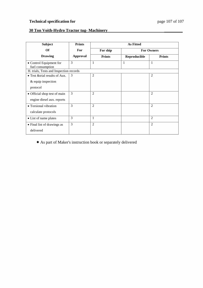
Technical specification for page 107 of 107
30 Ton Voith-Hydro Tractor tug- Machinery _________
As Fitted Prints
For
Approval
Subject
Of
Drawing
For Owners For ship
Prints Reproducible Prints
1 1 1 3 Control Equipment for
fuel consumption
H. trials, Tests and Inspection records
2 2 3 Test &trial results of Aux.
& equip inspection
protocol
2 2 3 Official shop test of main
engine diesel aux. reports
2 2 3 Torsional vibration
calculate protocols
2 1 3 List of name plates
2 2 3 Final list of drawings as
delivered
As part of Maker's instruction book or separately delivered