Hydraulic Dynamometer Type DT Technical Specification
48
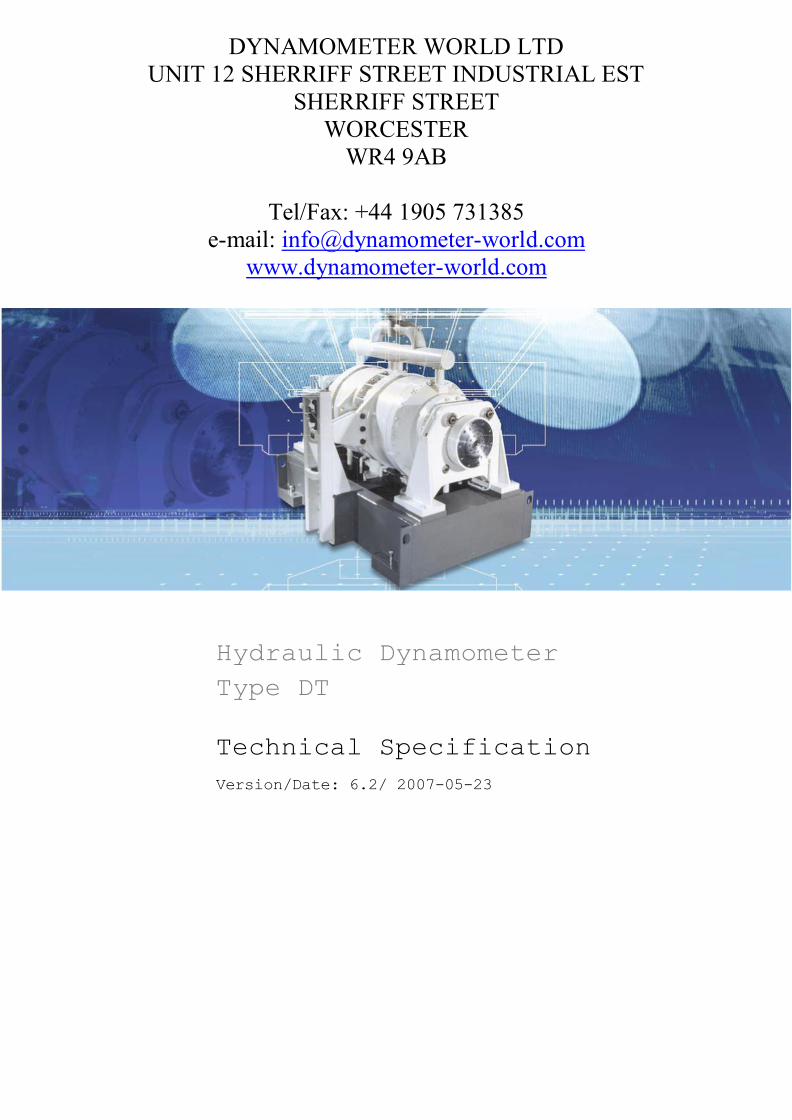
DYNAMOMETER WORLD LTD UNIT 12 SHERRIFF STREET INDUSTRIAL EST SHERRIFF STREET WORCESTER WR4 9AB Tel/Fax: +44 1905 731385 e-mail: [email protected] www.dynamometer-world.com Hydraulic Dynamometer Type DT Technical Specification Version/Date: 6.2/ 2007-05-23
-
Upload
khangminh22 -
Category
Documents
-
view
1 -
download
0
Transcript of Hydraulic Dynamometer Type DT Technical Specification
DYNAMOMETER WORLD LTD UNIT 12 SHERRIFF STREET INDUSTRIAL EST
SHERRIFF STREET WORCESTER
WR4 9AB
Tel/Fax: +44 1905 731385 e-mail: [email protected]
www.dynamometer-world.com
Hydraulic Dynamometer Type DT Technical Specification Version/Date: 6.2/ 2007-05-23
File name: DT-Brake_e_V6.2.doc Date:2007-05-23 Page 2 / 50
Technical Specification Hydraulic Dynamometer Type DT
Table of contents
1 A Horiba ATS Product with Convincing Features ......................... 5
1.1 Fields of Application ................................................................. 6
1.2 Multi-Purpose and Flexible in Design ........................................... 6
1.3 Your Advantages ...................................................................... 7
2 How it Works............................................................................ 8
2.1 Principle of Function ................................................................. 8
2.2 Torque Measurement ................................................................ 9
2.3 Speed Acquisition ..................................................................... 10
2.4 Frame ..................................................................................... 11
2.5 Power Supply ........................................................................... 11
2.6 Brake monitor .......................................................................... 12
2.7 Test Stand Controller SPARC .................................................... 12
2.8 Interfaces ................................................................................ 13
3 What we Deliver ....................................................................... 15
3.1 Scope of Supply ....................................................................... 15
3.2 Order Numbers ........................................................................ 16
3.2.1 Basic scope of supply ........................................................................... 16 3.2.2 Trunnion Bearings............................................................................... 17 3.2.3 Second Coupling Flange ...................................................................... 18 3.2.4 Modification of the control valve drive ...................................................... 19
4 Figures, Data, Facts .................................................................. 20
4.1 Type Key ................................................................................. 20
4.2 Technical Data ......................................................................... 20
4.2.1 Hydraulic Dynamometers with one Rotor and one Direction of Rotation
.. 21 4.2.2 Dynamometers with One Rotor and Two Directions of Rotation ........ 21 4.2.3 Dynamometers with Two Rotors and one Direction of Rotation ......... 22 4.2.4 Dynamometers with two Rotors and two Directions of Rotation ......... 22 4.3 Power Ranges .......................................................................... 23
File name:DT-Brake_e_V6.2.doc Page 3 /50 Date:2007-05-23
Technical Specification Hydraulic Dynamometer Type DT
4.4 Electric Power Components ......................................................... 27
4.5 Dimensions ................................................................................ 28
4.6 Fluctuating Torque ...................................................................... 33
4.7 Connectable mass ....................................................................... 34
5 Things you Should Observe ......................................................... 35
5.1 Planning Assistance.................................................................... 35
5.1.1 Foundation ................................................................................................ 35 5.1.2 Transportation, Unpacking, Storage .......................................................... 37 5.1.3 Cooling Water ........................................................................................... 38 5.1.4 Shaft Connection Parts .............................................................................. 44 5.1.5 Installation Power Electronics .................................................................... 44 5.1.6 Assembly and Commissioning.................................................................. 44
6 Product Options and Accessories ................................................ 45
6.1 Trunnion Bearings ...................................................................... 45
6.2 Second Coupling Shaft ................................................................ 45
6.3 Cooling water monitoring ............................................................ 46
6.4 Shaft Connection ........................................................................ 46
6.5 Starter System .................................................................................. 46
6.6 Calibration System ...................................................................... 46
6.7 Pressure Control System ............................................................. 47
6.8 Inlet Servo Valve ......................................................................... 47
6.9 Special Sizes .............................................................................. 47
6.10 Modification of the control valve drive ........................................... 48
File name:DT-Brake_e_V6.2.doc Page 4 /50 Date:2007-05-23
Technical Specification Hydraulic Dynamometer Type DT
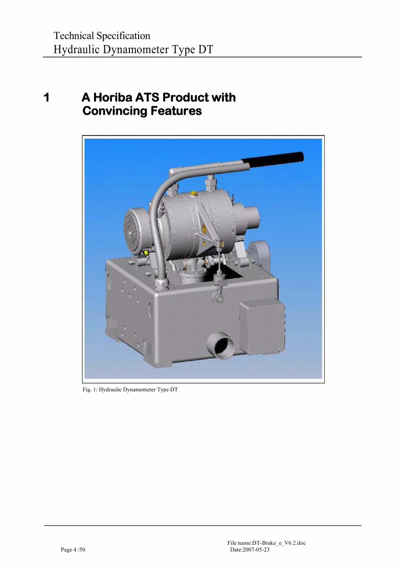
1 A Horiba ATS Product with Convincing Features
Fig. 1: Hydraulic Dynamometer Type DT
File name: DT-Brake_e_V6.2.doc Date:2007-05-23 Page 5 / 50
Technical Specification Hydraulic Dynamometer Type DT
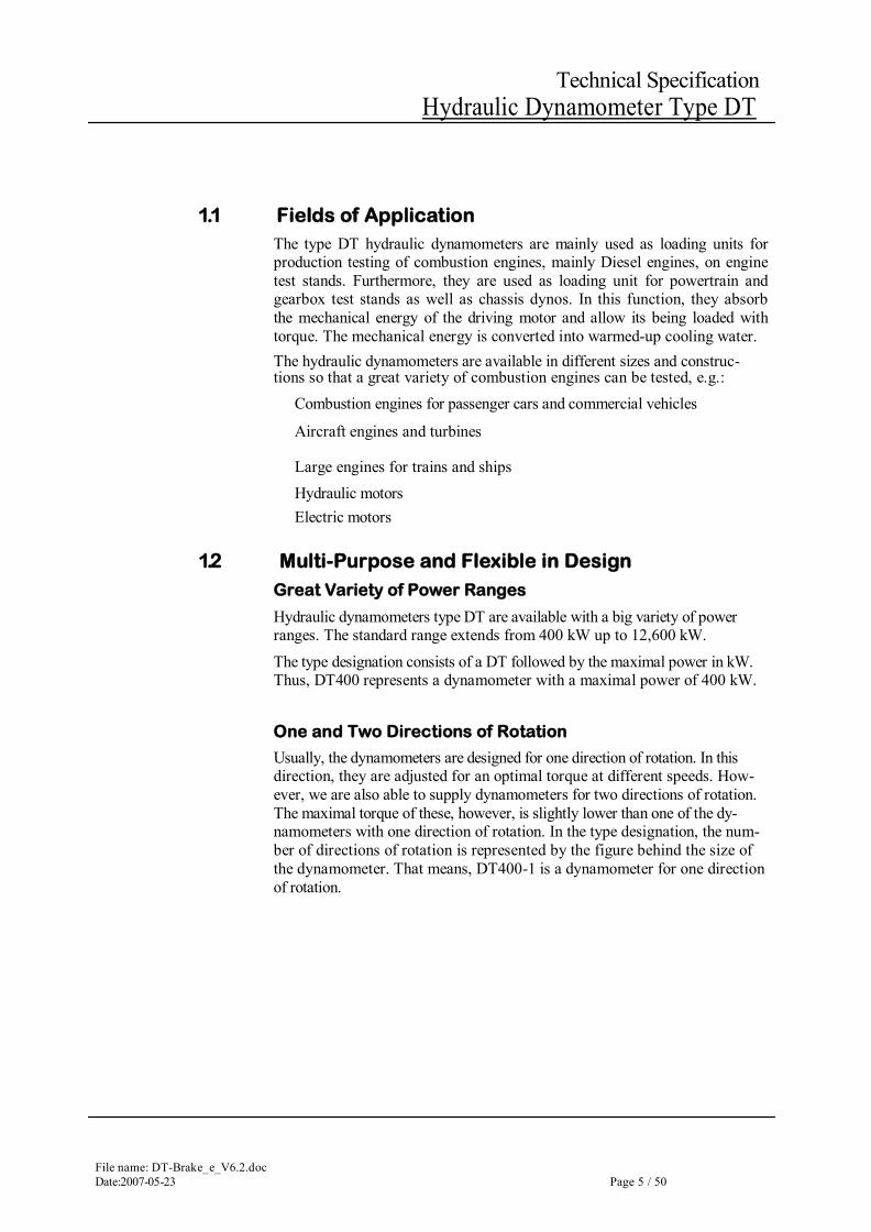
1.1 Fields of Application The type DT hydraulic dynamometers are mainly used as loading units for production testing of combustion engines, mainly Diesel engines, on engine test stands. Furthermore, they are used as loading unit for powertrain and gearbox test stands as well as chassis dynos. In this function, they absorb the mechanical energy of the driving motor and allow its being loaded with torque. The mechanical energy is converted into warmed-up cooling water. The hydraulic dynamometers are available in different sizes and construc-tions so that a great variety of combustion engines can be tested, e.g.:
Combustion engines for passenger cars and commercial vehicles
Aircraft engines and turbines
Large engines for trains and ships Hydraulic motors Electric motors
1.2 Multi-Purpose and Flexible in Design Great Variety of Power Ranges
Hydraulic dynamometers type DT are available with a big variety of power ranges. The standard range extends from 400 kW up to 12,600 kW.
The type designation consists of a DT followed by the maximal power in kW. Thus, DT400 represents a dynamometer with a maximal power of 400 kW.
One and Two Directions of Rotation
Usually, the dynamometers are designed for one direction of rotation. In this direction, they are adjusted for an optimal torque at different speeds. How-ever, we are also able to supply dynamometers for two directions of rotation. The maximal torque of these, however, is slightly lower than one of the dy-namometers with one direction of rotation. In the type designation, the num-ber of directions of rotation is represented by the figure behind the size of the dynamometer. That means, DT400-1 is a dynamometer for one direction of rotation.
File name:DT-Brake_e_V6.2.doc Page 6 /50 Date:2007-05-23
Technical Specification Hydraulic Dynamometer Type DT
One and Two Rotors
If high power at high speed is required from fast-running dynamometers, e.g. for fast-running Diesel engines, DYNABAR dynamometers with two rotors are available. These dynamometers allow the same maximal speed as the ones with one rotor, however, the maximal torque doubles. By that, the double maximal braking force is available as well. In the type designation, dynamometers with two rotors are characterised by a “2” di-rectly behind the DT: DT2-4200-1 is a hydraulic dynamometer with two ro-tors for one direction of rotation and a maximal power of 4200 kW.
1.3 Your Advantages The hydraulic dynamometers type D stand out for essential features: High accuracy of measurement Brushless motor with resolver for the control valve drive (potentiometer has been
dropped) High dynamical characteristics resulting in better controllability
Automatic adjustment of the control valve limit positions Simple design resulting in low effort required for overhaul, dismantling and instal-
lation
High-quality materials (parts in the swirl range of the water are made of bronze and therefore are very resistant to wear and seawater)
high-quality materials. The parts lying in the periptery of the water
are made of bronze. Therefore they are sea water resistant and show particularly low wear.
Reliable operation even in case of not optimal cooling water conditions Wide range of standard sizes for different engine power
Many variants for a great variety of applications Excellent price/performance ratio (Euro/kW) as compared with eddy current dy-
namometers and asynchronous drives High power density Compact construction for low requirement of space Low power requirement
No remarkable reactive current
Extensive accessories, also for the adjustment to different cooling water supplies Definition of the operating time
Self-monitoring (standard bearing temperature and cooling water as an option) and therefore intrinsically safe, low risk with running in (new bearing or relubrica-tion), seldom resp. little damage and repair costs occurring in the case of fault
Prepared for on-site vibration monitoring of the bearings (drilling for vibration sen-sors)
File name: DT-Brake_e_V6.2.doc Date:2007-05-23 Page 7 / 50
Technical Specification Hydraulic Dynamometer Type DT
2 How it Works
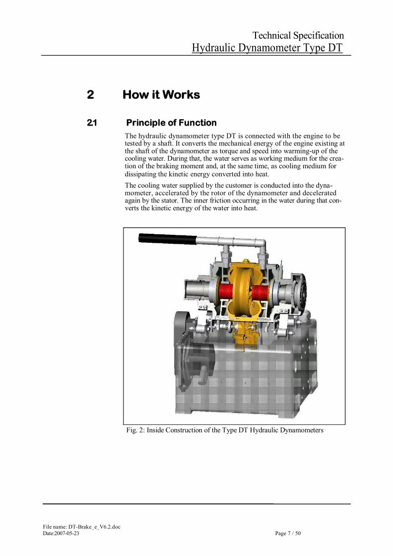
2.1 Principle of Function The hydraulic dynamometer type DT is connected with the engine to be tested by a shaft. It converts the mechanical energy of the engine existing at the shaft of the dynamometer as torque and speed into warming-up of the cooling water. During that, the water serves as working medium for the crea-tion of the braking moment and, at the same time, as cooling medium for dissipating the kinetic energy converted into heat. The cooling water supplied by the customer is conducted into the dyna-mometer, accelerated by the rotor of the dynamometer and decelerated again by the stator. The inner friction occurring in the water during that con-verts the kinetic energy of the water into heat.
Fig. 2: Inside Construction of the Type DT Hydraulic Dynamometers
File name:DT-Brake_e_V6.2.doc Page 8 /50 Date:2007-05-23
Technical Specification Hydraulic Dynamometer Type DT
The braking power of the dynamometer is water-controlled via the fill factor. For that, a control valve driven by a fast controlling motor is installed at the cooling water outlet at the bottom of the dynamometer. Optionally, the water supply can additionally be controlled by inlet servo valve. With that, the torque response times can still be reduced.
The braking power of the dynamometer is controlled through the water filling level by a motor-operated control valve installed in the cooling water outlet at the bottom.
The lowest torque of the dynamometer, the so-called idling characteristics, results from minimal water filling. This characteristics is not zero if there is no water in the dynamometer because in this case air whirls instead of water whirls develop. With minimal water filling neither air nor water whirls can de-velop completely which causes the lowest torque. This so-called “idling power” is highest at maximal speed of the dynamometer and correspond-ingly lower at lower speeds. The idling power, please take from the power ranges in chapter “Technical Data”. These values vary depending on the inlet cooling water quantity.
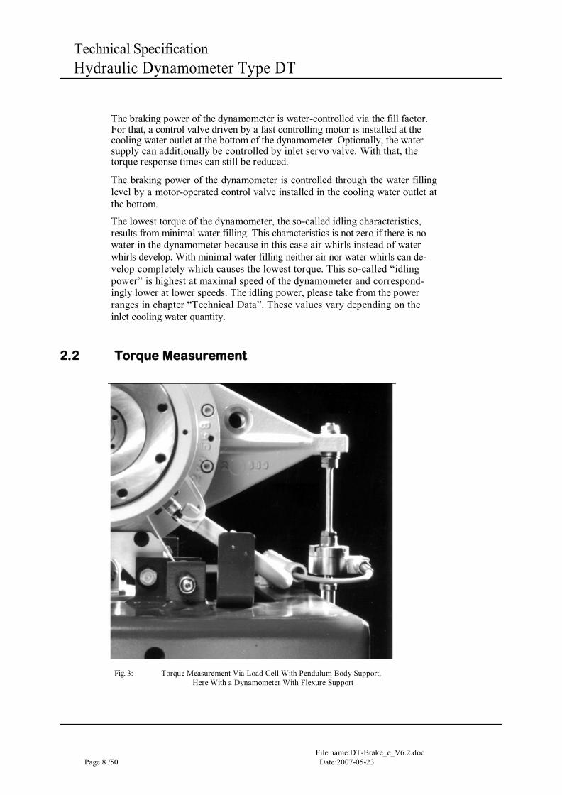
2.2 Torque Measurement
Fig. 3: Torque Measurement Via Load Cell With Pendulum Body Support,
Here With a Dynamometer With Flexure Support

File name: DT-Brake_e_V6.2.doc Date:2007-05-23 Page 9 / 50
Technical Specification Hydraulic Dynamometer Type DT
The test piece is connected with the rotor of the dynamometer via shaft and flange. Due to the rotating movement of the shaft, the body of the dyna-mometer “oscillates” as well. The special flexure support of the dynamome-ter only takes up the weight of the pendulum body and the counterforce to the load cell. Thus, the total torque is effective via a lever arm on the load cell installed by the side of the pendulum body. The measured force is pro-portional with the braking torque. The flexure strips are almost friction- and maintenance-free. They provide a quick response, allow almost hysteresis-free measurement of the torque and keep theses features permanently.
Fig. 4: Principle of Torque Measurement With Pendulum Support
Large dynamometers from D9800 on can exclusively be supplied with roller support. In this case, the pendulum body is supported by eight rollers in-stead of four flexure strips which is usual for large dynamometers. As alternative for flexure/roller support, the hydraulic dynamometers are available with trunnion bearings in which the dynamometer is supported by one rolling bearing each at both ends.
2.3 Speed Acquisition The speed is acquired digitally at the shaft of the dynamometer via a toothed wheel and a pulse generator.
File name:DT-Brake_e_V6.2.doc Page 10 /50 Date:2007-05-23
Technical Specification Hydraulic Dynamometer Type DT
2.4 Frame The dynamometer is installed on a stable welded frame. In this frame, cool-ing water outlet and connection point for the electric lines are integrated as well.
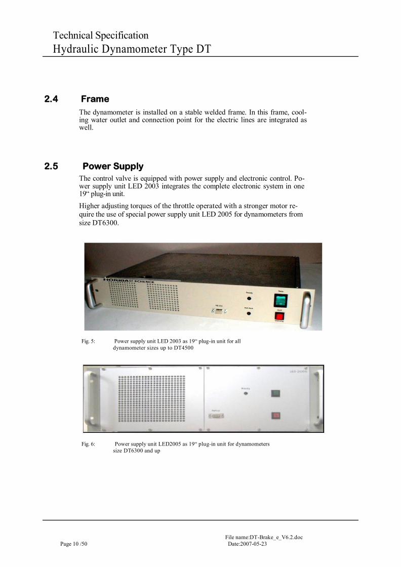
2.5 Power Supply The control valve is equipped with power supply and electronic control. Po-wer supply unit LED 2003 integrates the complete electronic system in one 19“ plug-in unit. Higher adjusting torques of the throttle operated with a stronger motor re-quire the use of special power supply unit LED 2005 for dynamometers from size DT6300.
Fig. 5: Power supply unit LED 2003 as 19“ plug-in unit for all
dynamometer sizes up to DT4500
Fig. 6: Power supply unit LED2005 as 19“ plug-in unit for dynamometers
size DT6300 and up
File name: DT-Brake_e_V6.2.doc Date:2007-05-23 Page 11 / 50
Technical Specification Hydraulic Dynamometer Type DT
2.6 Brake monitor
The dynamometer is equipped with a device to monitor the operation and major functions. The standard version monitors the operating time (dyna-mometer is switched on and running) and the bearing temperature. Exceed-ing the set maximum permissible bearing temperature triggers a fault mes-sage on the monitor and switches off the test stand via the safety circuit. Consequential damage caused by destroyed bearings can be avoided in this way. The bearing temperature is also monitored during running in after relu-brication. Bearing temperatures can be displayed on the SPARC test stand controller. Cooling water monitoring is available as an option and is already prepared in the standard design of the dynamometer. This device monitors the maximum and minimum inlet pressure together with the cooling water outlet temperature. Limit exceeding also initiates a fault message and open-ing of the safety circuit. The brake monitor transmits data to SPARC via CAN-Bus. Fault messages are displayed with clear text. The monitor is equipped with an additional contact to output signals “Dynamometer ready“ and “Fault“.
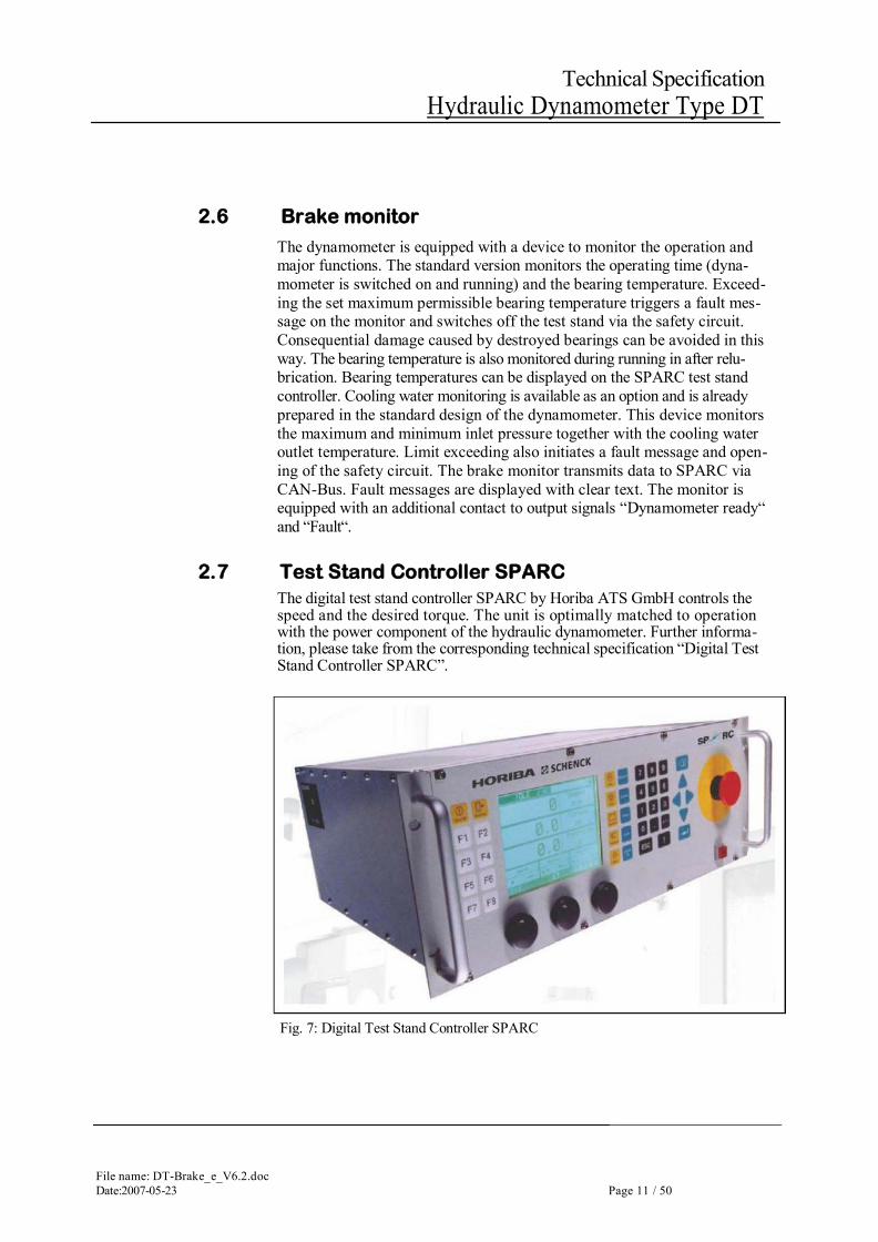
2.7 Test Stand Controller SPARC The digital test stand controller SPARC by Horiba ATS GmbH controls the speed and the desired torque. The unit is optimally matched to operation with the power component of the hydraulic dynamometer. Further informa-tion, please take from the corresponding technical specification “Digital Test Stand Controller SPARC”.
Fig. 7: Digital Test Stand Controller SPARC
File name:DT-Brake_e_V6.2.doc Page 12 /50 Date:2007-05-23
Technical Specification Hydraulic Dynamometer Type DT
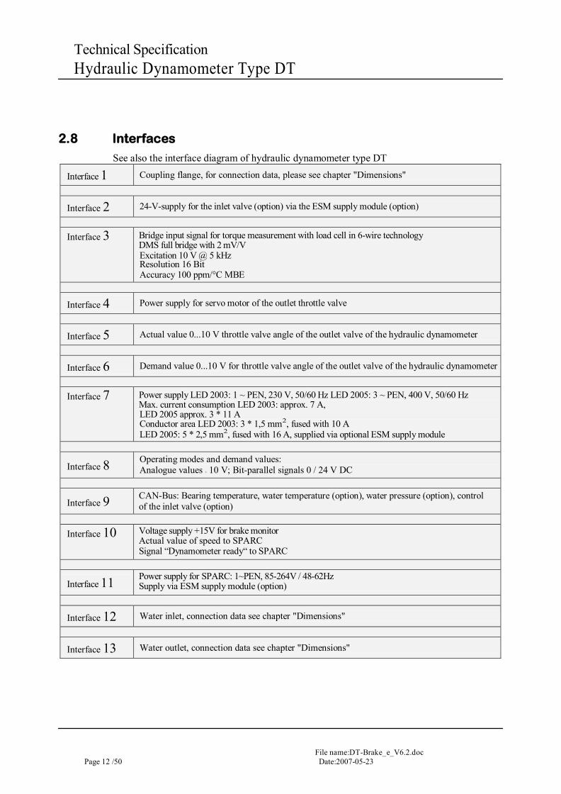
2.8 Interfaces
See also the interface diagram of hydraulic dynamometer type DT
Interface 1 Coupling flange, for connection data, please see chapter "Dimensions"
Interface 2 24-V-supply for the inlet valve (option) via the ESM supply module (option)
Interface 3 Bridge input signal for torque measurement with load cell in 6-wire technology
DMS full bridge with 2 mV/V Excitation 10 V @ 5 kHz Resolution 16 Bit Accuracy 100 ppm/°C MBE
Interface 4 Power supply for servo motor of the outlet throttle valve
Interface 5 Actual value 0...10 V throttle valve angle of the outlet valve of the hydraulic dynamometer
Interface 6 Demand value 0...10 V for throttle valve angle of the outlet valve of the hydraulic dynamometer
Interface 7 Power supply LED 2003: 1 ~ PEN, 230 V, 50/60 Hz LED 2005: 3 ~ PEN, 400 V, 50/60 Hz
Max. current consumption LED 2003: approx. 7 A, LED 2005 approx. 3 * 11 A Conductor area LED 2003: 3 * 1,5 mm2, fused with 10 A LED 2005: 5 * 2,5 mm2, fused with 16 A, supplied via optional ESM supply module
Interface 8 Operating modes and demand values:
Analogue values ± 10 V; Bit-parallel signals 0 / 24 V DC
Interface 9 CAN-Bus: Bearing temperature, water temperature (option), water pressure (option), control of the inlet valve (option)
Interface 10 Voltage supply +15V for brake monitor
Actual value of speed to SPARC Signal “Dynamometer ready“ to SPARC
Interface 11 Power supply for SPARC: 1~PEN, 85-264V / 48-62Hz
Supply via ESM supply module (option)
Interface 12 Water inlet, connection data see chapter "Dimensions"
Interface 13 Water outlet, connection data see chapter "Dimensions"
File name: DT-Brake_e_V6.2.doc Date:2007-05-23 Page 13 / 50
Technical Specification Hydraulic Dynamometer Type DT
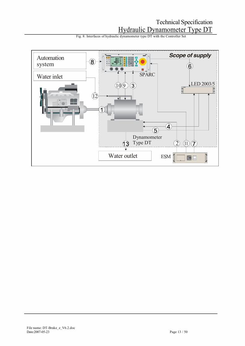
Fig. 8: Interfaces of hydraulic dynamometer type DT with the Controller Set
Automation system
Water inlet
12
Water outlet
10 9
Dynamometer Type DT
SPARC
ESM
Scope of supply
2 11
LED 2003/5
File name:DT-Brake_e_V6.2.doc Page 14 /50 Date:2007-05-23
Technical Specification Hydraulic Dynamometer Type DT
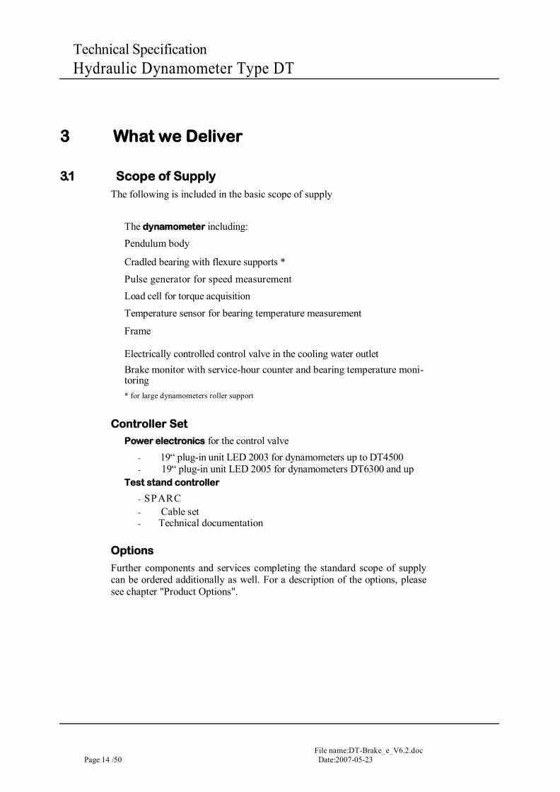
3 What we Deliver
3.1 Scope of Supply The following is included in the basic scope of supply
The dynamometer including: Pendulum body
Cradled bearing with flexure supports *
Pulse generator for speed measurement Load cell for torque acquisition
Temperature sensor for bearing temperature measurement
Frame
Electrically controlled control valve in the cooling water outlet Brake monitor with service-hour counter and bearing temperature moni-toring * for large dynamometers roller support
Controller Set
Power electronics for the control valve - 19“ plug-in unit LED 2003 for dynamometers up to DT4500 - 19“ plug-in unit LED 2005 for dynamometers DT6300 and up
Test stand controller
- SPARC - Cable set - Technical documentation
Options
Further components and services completing the standard scope of supply can be ordered additionally as well. For a description of the options, please see chapter "Product Options".
File name: DT-Brake_e_V6.2.doc Date:2007-05-23 Page 15 / 50
Technical Specification Hydraulic Dynamometer Type DT
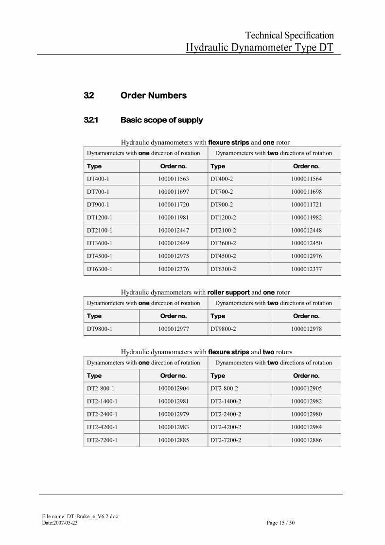
3.2 Order Numbers
3.2.1 Basic scope of supply
Hydraulic dynamometers with flexure strips and one rotor Dynamometers with one direction of rotation Dynamometers with two directions of rotation
Type Order no. Type Order no.
DT400-1 1000011563 DT400-2 1000011564
DT700-1 1000011697 DT700-2 1000011698
DT900-1 1000011720 DT900-2 1000011721
DT1200-1 1000011981 DT1200-2 1000011982
DT2100-1 1000012447 DT2100-2 1000012448
DT3600-1 1000012449 DT3600-2 1000012450
DT4500-1 1000012975 DT4500-2 1000012976
DT6300-1 1000012376 DT6300-2 1000012377
Hydraulic dynamometers with roller support and one rotor Dynamometers with one direction of rotation Dynamometers with two directions of rotation
Type Order no. Type Order no.
DT9800-1 1000012977 DT9800-2 1000012978
Hydraulic dynamometers with flexure strips and two rotors Dynamometers with one direction of rotation Dynamometers with two directions of rotation
Type Order no. Type Order no.
DT2-800-1 1000012904 DT2-800-2 1000012905
DT2-1400-1 1000012981 DT2-1400-2 1000012982
DT2-2400-1 1000012979 DT2-2400-2 1000012980
DT2-4200-1 1000012983 DT2-4200-2 1000012984
DT2-7200-1 1000012885 DT2-7200-2 1000012886
File name:DT-Brake_e_V6.2.doc Page 16 /50 Date:2007-05-23
Technical Specification Hydraulic Dynamometer Type DT
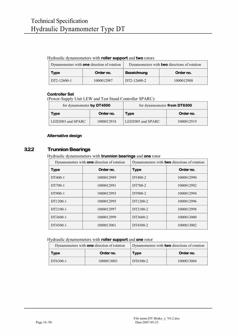
Hydraulic dynamometers with roller support and two rotors Dynamometers with one direction of rotation Dynamometers with two directions of rotation
Type Order no. Bezeichnung Order no.
DT2-12600-1 1000012987 DT2-12600-2 1000012988
Controller Set (Power-Supply Unit LEW and Test Stand Controller SPARC):
for dynamometer by DT4500 for dynamometer from DT6300
Type Order no. Type Order no.
LED2003 and SPARC 1000012918 LED2005 and SPARC 1000012919
Alternative design
3.2.2 Trunnion Bearings Hydraulic dynamometers with trunnion bearings and one rotor
Dynamometers with one direction of rotation Dynamometers with two directions of rotation
Type Order no. Type Order no.
DT400-1 1000012989 DT400-2 1000012990
DT700-1 1000012991 DT700-2 1000012992
DT900-1 1000012993 DT900-2 1000012994
DT1200-1 1000012995 DT1200-2 1000012996
DT2100-1 1000012997 DT2100-2 1000012998
DT3600-1 1000012999 DT3600-2 1000013000
DT4500-1 1000013001 DT4500-2 1000013002
Hydraulic dynamometers with roller support and one rotor Dynamometers with one direction of rotation Dynamometers with two directions of rotation
Type Order no. Type Order no.
DT6300-1 1000013003 DT6300-2 1000013004
File name: DT-Brake_e_V6.2.doc Date:2007-05-23 Page 17 / 50
Technical Specification Hydraulic Dynamometer Type DT
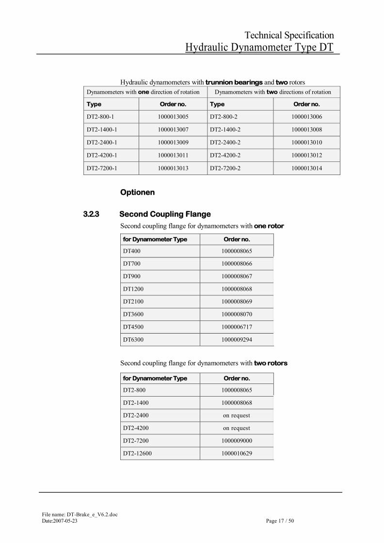
Hydraulic dynamometers with trunnion bearings and two rotors Dynamometers with one direction of rotation Dynamometers with two directions of rotation
Type Order no. Type Order no.
DT2-800-1 1000013005 DT2-800-2 1000013006
DT2-1400-1 1000013007 DT2-1400-2 1000013008
DT2-2400-1 1000013009 DT2-2400-2 1000013010
DT2-4200-1 1000013011 DT2-4200-2 1000013012
DT2-7200-1 1000013013 DT2-7200-2 1000013014
Optionen
3.2.3 Second Coupling Flange
Second coupling flange for dynamometers with one rotor
Second coupling flange for dynamometers with two rotors
for Dynamometer Type Order no.
DT400 1000008065
DT700 1000008066
DT900 1000008067
DT1200 1000008068
DT2100 1000008069
DT3600 1000008070
DT4500 1000006717
DT6300 1000009294
for Dynamometer Type Order no.
DT2-800 1000008065
DT2-1400 1000008068
DT2-2400 on request
DT2-4200 on request
DT2-7200 1000009000
DT2-12600 1000010629
File name:DT-Brake_e_V6.2.doc Page 18 /50 Date:2007-05-23
Technical Specification Hydraulic Dynamometer Type DT
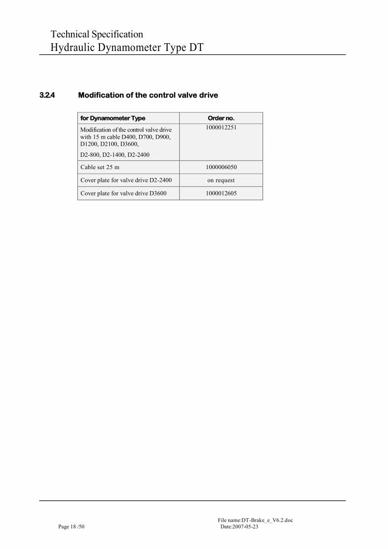
3.2.4 Modification of the control valve drive
for Dynamometer Type Order no.
Modification of the control valve drive with 15 m cable D400, D700, D900, D1200, D2100, D3600,
D2-800, D2-1400, D2-2400
1000012251
Cable set 25 m 1000006050
Cover plate for valve drive D2-2400 on request
Cover plate for valve drive D3600 1000012605
File name: DT-Brake_e_V6.2.doc Date:2007-05-23 Page 19 / 50
Technical Specification Hydraulic Dynamometer Type DT
4 Figures, Data, Facts
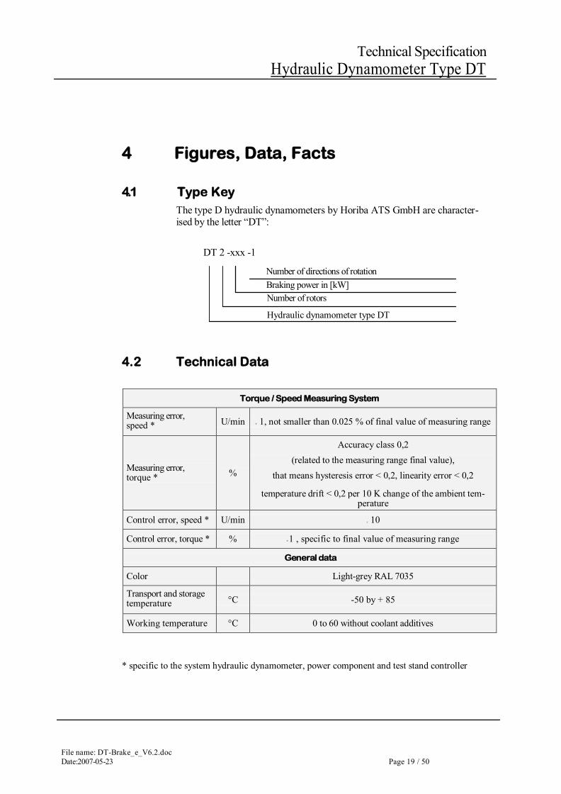
4.1 Type Key The type D hydraulic dynamometers by Horiba ATS GmbH are character-ised by the letter “DT”:
DT 2 -xxx -1
4.2 Technical Data
Torque / Speed Measuring System
Measuring error, speed * U/min ± 1, not smaller than 0.025 % of final value of measuring range
Measuring error, torque * %
Accuracy class 0,2 (related to the measuring range final value),
that means hysteresis error < 0,2, linearity error < 0,2
temperature drift < 0,2 per 10 K change of the ambient tem- perature
Control error, speed * U/min ± 10
Control error, torque * % ± 1 , specific to final value of measuring range
General data
Color Light-grey RAL 7035
Transport and storage temperature °C -50 by + 85
Working temperature °C 0 to 60 without coolant additives
* specific to the system hydraulic dynamometer, power component and test stand controller
Number of directions of rotation Braking power in [kW] Number of rotors
Hydraulic dynamometer type DT
File name:DT-Brake_e_V6.2.doc Page 20 /50 Date:2007-05-23
Technical Specification Hydraulic Dynamometer Type DT
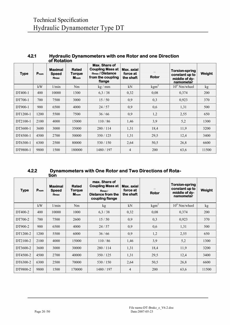
4.2.1 Hydraulic Dynamometers with one Rotor and one Direction of Rotation
Type Pnom
Maximal Speed
nmax
Rated Torque
Mnom
Max. Share of Coupling Mass at
nmax / Distance from the coupling
flange
Max. axial force at the shaft
( )
Rotor
Torsion-spring constant up to middle of dy- namometer
Weight
kW 1/min Nm kg / mm kN kgm2 106 Nm/wheel kg
DT400-1 400 10000 1300 6,3 / 38 0,32 0,08 0,374 200
DT700-1 700 7500 3000 15 / 50 0,9 0,3 0,923 370
DT900-1 900 6500 4000 24 / 57 0,9 0,6 1,31 500
DT1200-1 1200 5500 7500 36 / 66 0,9 1,2 2,55 650
DT2100-1 2100 4000 15000 110 / 86 1,46 3,9 5,2 1300
DT3600-1 3600 3000 35000 280 / 114 1,31 18,4 11,9 3200
DT4500-1 4500 2700 50000 350 / 125 1,31 29,5 12,4 3400
DT6300-1 6300 2500 80000 530 / 150 2,64 50,5 26,8 6600
DT9800-1 9800 1500 180000 1480 / 197 4 200 63,6 11500
4.2.2 Dynamometers with One Rotor and Two Directions of Rota- tion
Type Pnom
Maximal Speed
nmax
Rated Torque
Mnom
max. Share of Coupling Mass at
nmax /
Distance from the coupling flange
Max. axial force at the shaft
( )
Rotor
Torsion-spring constant up to middle of dy- namometer
Weight
kW 1/min Nm kg kN kgm2 106 Nm/wheel kg
DT400-2 400 10000 1000 6,3 / 38 0,32 0,08 0,374 200
DT700-2 700 7500 2600 15 / 50 0,9 0,3 0,923 370
DT900-2 900 6500 4000 24 / 57 0,9 0,6 1,31 500
DT1200-2 1200 5500 6000 36 / 66 0,9 1,2 2,55 650
DT2100-2 2100 4000 15000 110 / 86 1,46 3,9 5,2 1300
DT3600-2 3600 3000 30000 280 / 114 1,31 18,4 11,9 3200
DT4500-2 4500 2700 40000 350 / 125 1,31 29,5 12,4 3400
DT6300-2 6300 2500 70000 530 / 150 2,64 50,5 26,8 6600
DT9800-2 9800 1500 170000 1480 / 197 4 200 63,6 11500
File name: DT-Brake_e_V6.2.doc Date:2007-05-23 Page 21 / 50
Technical Specification Hydraulic Dynamometer Type DT
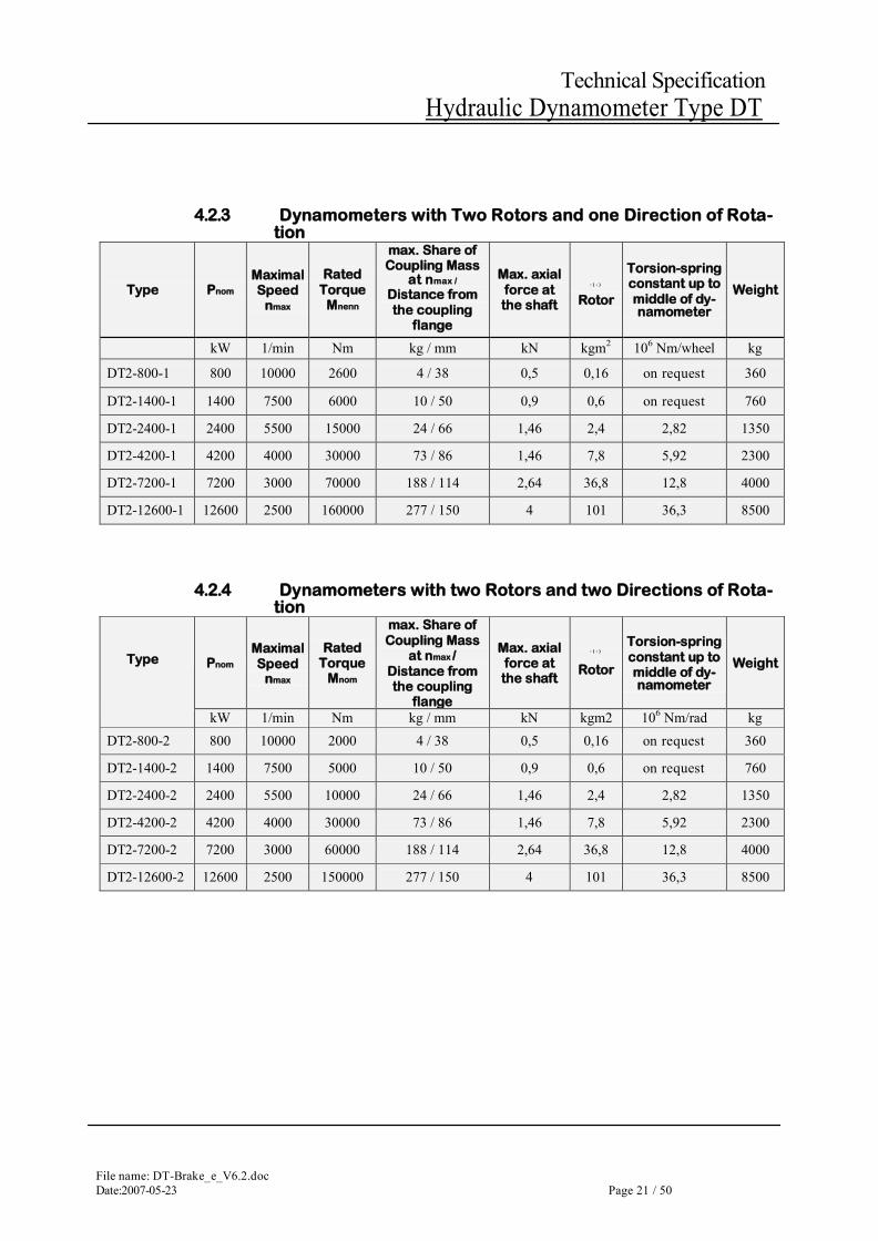
4.2.3 Dynamometers with Two Rotors and one Direction of Rota- tion
Type Pnom
Maximal Speed
nmax
Rated Torque
Mnenn
max. Share of Coupling Mass
at nmax /
Distance from the coupling
flange
Max. axial force at the shaft
: ( - )
Rotor
Torsion-spring constant up to middle of dy- namometer
Weight
kW 1/min Nm kg / mm kN kgm2 106 Nm/wheel kg
DT2-800-1 800 10000 2600 4 / 38 0,5 0,16 on request 360
DT2-1400-1 1400 7500 6000 10 / 50 0,9 0,6 on request 760
DT2-2400-1 2400 5500 15000 24 / 66 1,46 2,4 2,82 1350
DT2-4200-1 4200 4000 30000 73 / 86 1,46 7,8 5,92 2300
DT2-7200-1 7200 3000 70000 188 / 114 2,64 36,8 12,8 4000
DT2-12600-1 12600 2500 160000 277 / 150 4 101 36,3 8500
4.2.4 Dynamometers with two Rotors and two Directions of Rota- tion
Type Pnom
Maximal Speed
nmax
Rated Torque
Mnom
max. Share of Coupling Mass
at nmax / Distance from the coupling
flange
Max. axial force at the shaft
: ( - )
Rotor
Torsion-spring constant up to middle of dy- namometer
Weight
kW 1/min Nm kg / mm kN kgm2 106 Nm/rad kg DT2-800-2 800 10000 2000 4 / 38 0,5 0,16 on request 360
DT2-1400-2 1400 7500 5000 10 / 50 0,9 0,6 on request 760
DT2-2400-2 2400 5500 10000 24 / 66 1,46 2,4 2,82 1350
DT2-4200-2 4200 4000 30000 73 / 86 1,46 7,8 5,92 2300
DT2-7200-2 7200 3000 60000 188 / 114 2,64 36,8 12,8 4000
DT2-12600-2 12600 2500 150000 277 / 150 4 101 36,3 8500
File name:DT-Brake_e_V6.2.doc Page 22 /50 Date:2007-05-23
Technical Specification Hydraulic Dynamometer Type DT
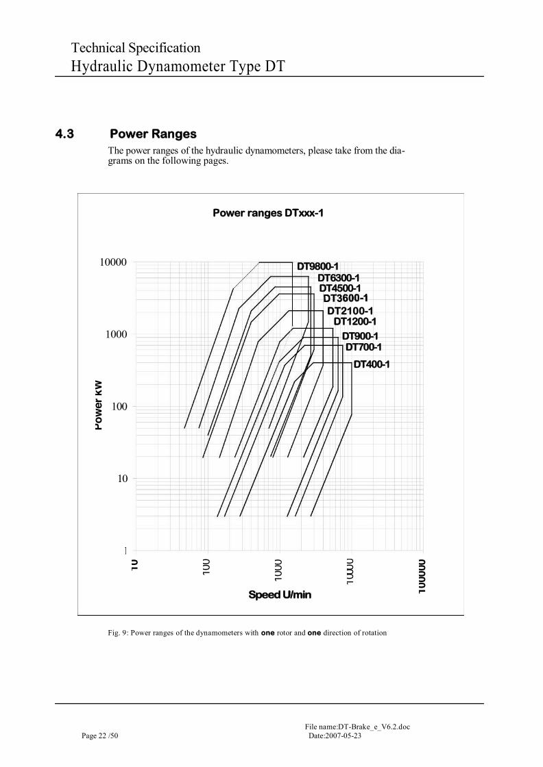
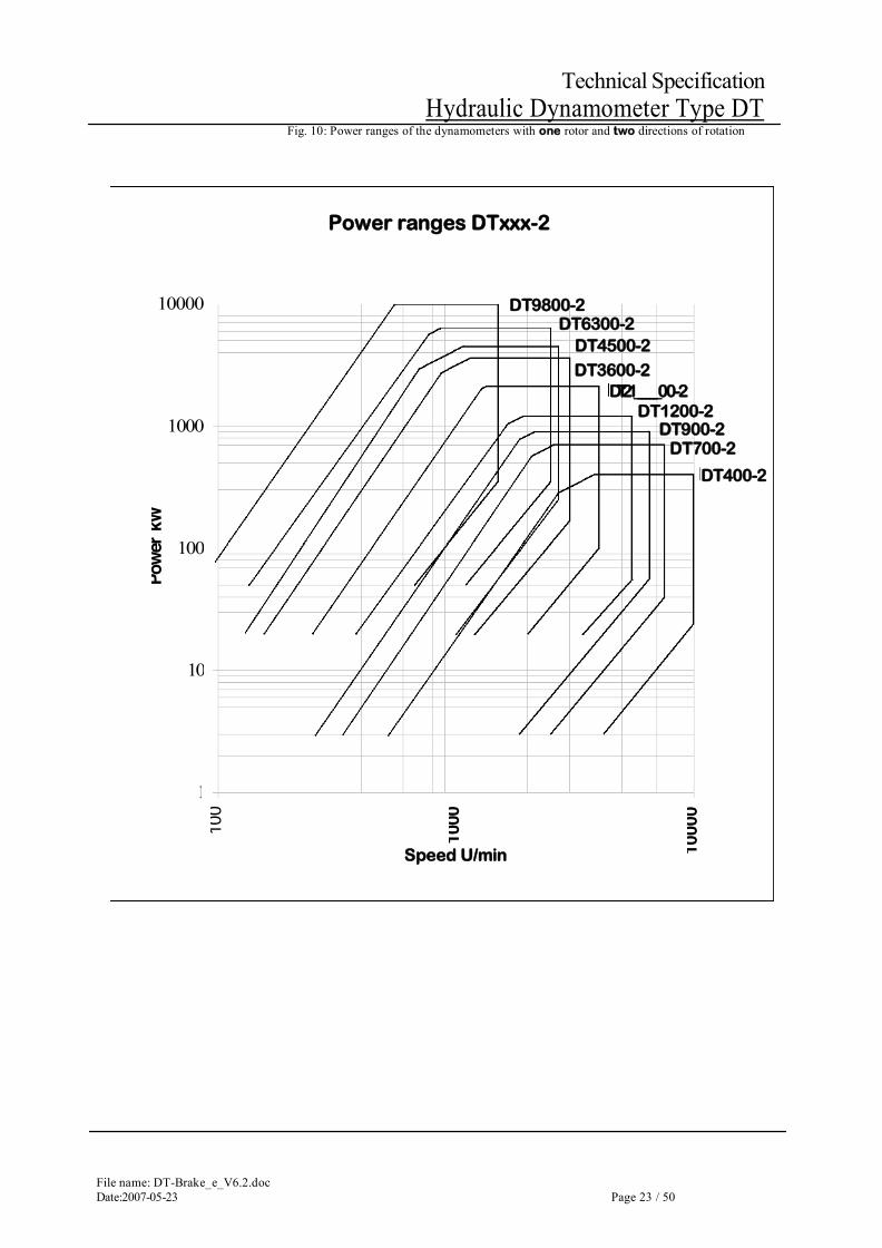
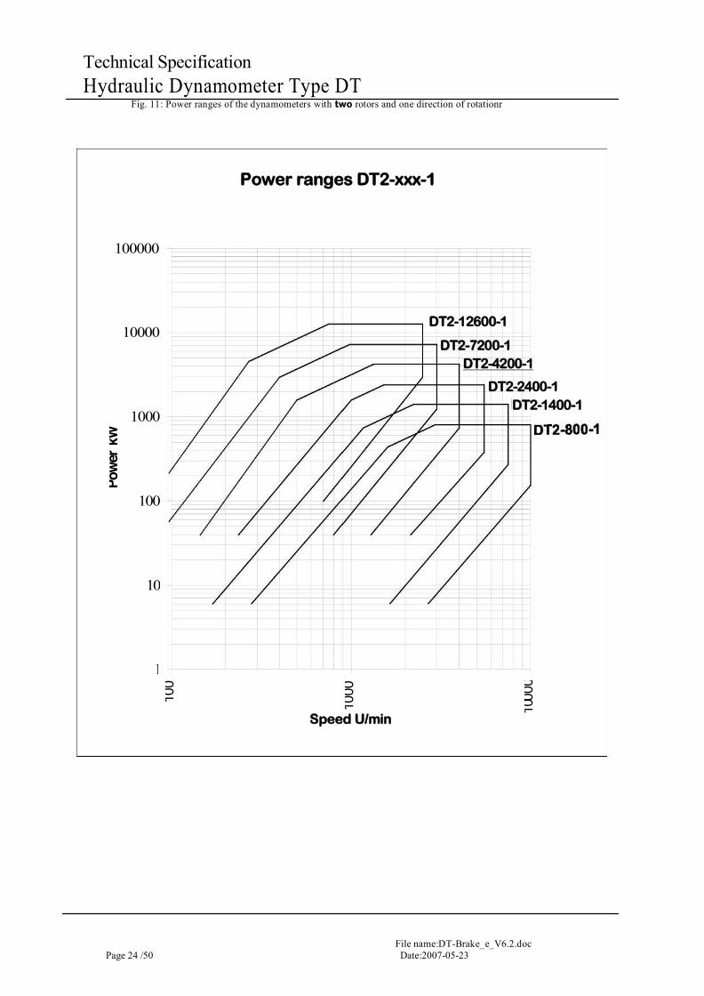
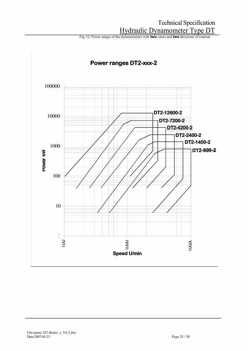
4.3 Power Ranges The power ranges of the hydraulic dynamometers, please take from the dia-grams on the following pages.
Fig. 9: Power ranges of the dynamometers with one rotor and one direction of rotation
Pow
er k
W
10000
1000
100
10
1
10
100
Power ranges DTxxx-1
Speed U/min
1000
DT9800-1
DT6300-1 DT4500-1
DT2100-1 DT1200-1
DT900-1 DT700-1
1 000
0 DT400-1
1000
00
File name: DT-Brake_e_V6.2.doc Date:2007-05-23 Page 23 / 50
Technical Specification Hydraulic Dynamometer Type DT
Fig. 10: Power ranges of the dynamometers with one rotor and two directions of rotation
Powe
r kW
10000
1000
100
10
1
100
Power ranges DTxxx-2
Speed U/min
1000
DT9800-2 DT6300-2
DT3600-2 DT4500-2
DT21 ______ 00-2 DT1200-2
DT900-2 DT700-2
1000
0
DT400-2
File name:DT-Brake_e_V6.2.doc Page 24 /50 Date:2007-05-23
Technical Specification Hydraulic Dynamometer Type DT
Fig. 11: Power ranges of the dynamometers with two rotors and one direction of rotationr
Powe
r kW
100000
10000
1000
100
10
1
100
Power ranges DT2-xxx-1
Speed U/min
1000
DT2-12600-1
DT2-7200-1 DT2-4200-1
DT2-2400-1 DT2-1400-1
1 00 0
0
File name: DT-Brake_e_V6.2.doc Date:2007-05-23 Page 25 / 50
Technical Specification Hydraulic Dynamometer Type DT
Fig. 12: Power ranges of the dynamometers with two rotors and two directions of rotation
Powe
r kW
100000
10000
1000
100
10
1
100
Power ranges DT2-xxx-2
Speed U/min
1000
DT2-12600-2
DT2-7200-2
DT2-4200-2
DT2-2400-2 DT2-1400-2
1 0 00
0
File name:DT-Brake_e_V6.2.doc Page 26 /50 Date:2007-05-23
Technical Specification Hydraulic Dynamometer Type DT
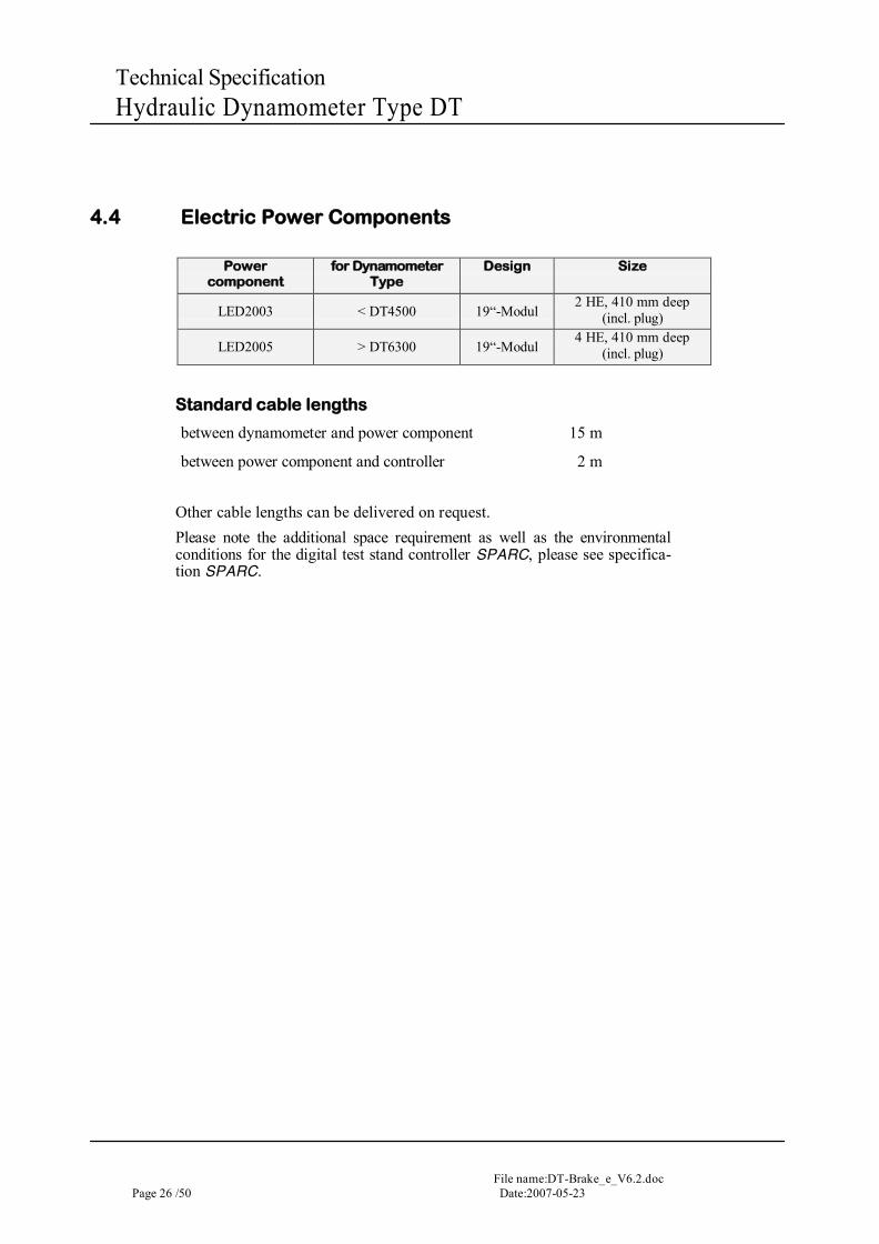
4.4 Electric Power Components
Power component
for Dynamometer Type
Design Size
LED2003 < DT4500 19“-Modul 2 HE, 410 mm deep
(incl. plug)
LED2005 > DT6300 19“-Modul 4 HE, 410 mm deep
(incl. plug)
Standard cable lengths
between dynamometer and power component 15 m
between power component and controller 2 m
Other cable lengths can be delivered on request. Please note the additional space requirement as well as the environmental conditions for the digital test stand controller SPARC, please see specifica-tion SPARC.
File name: DT-Brake_e_V6.2.doc Date:2007-05-23 Page 27 / 50
Technical Specification Hydraulic Dynamometer Type DT
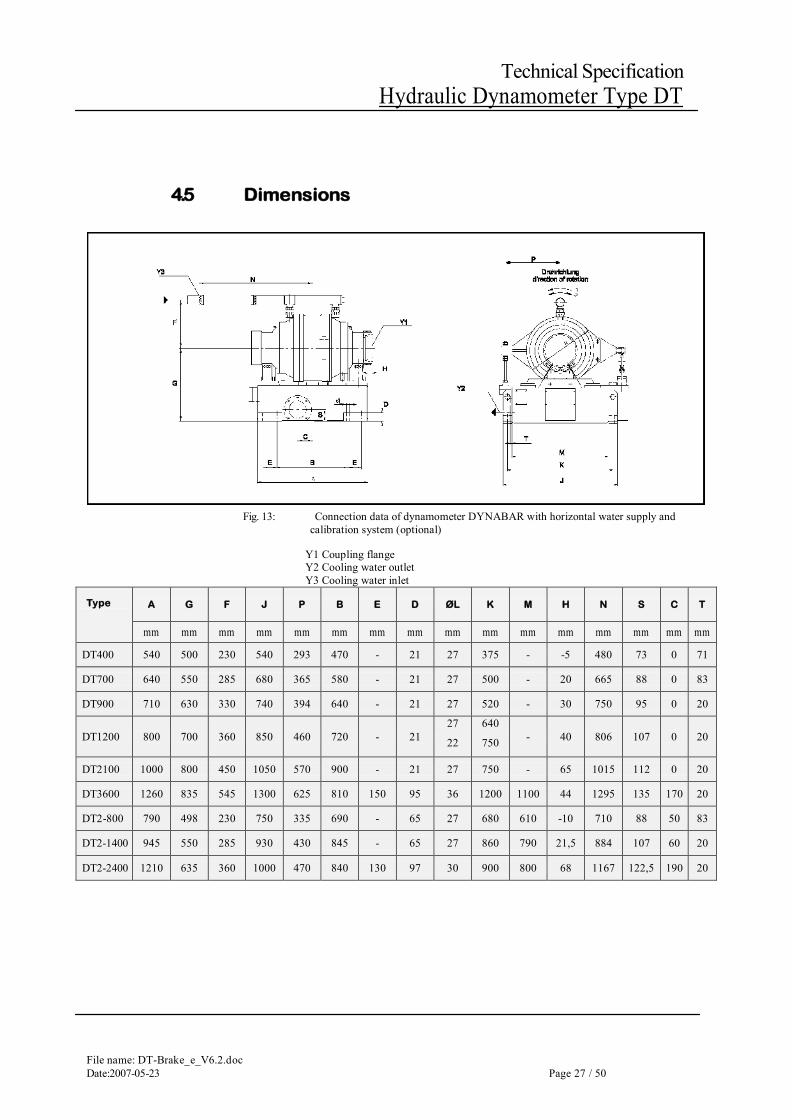
4.5 Dimensions
Fig. 13: Connection data of dynamometer DYNABAR with horizontal water supply and
calibration system (optional)
Y1 Coupling flange Y2 Cooling water outlet Y3 Cooling water inlet
Type A G F J P B E D ØL K M H N S C T
mm mm mm mm mm mm mm mm mm mm mm mm mm mm mm mm
DT400 540 500 230 540 293 470 - 21 27 375 - -5 480 73 0 71
DT700 640 550 285 680 365 580 - 21 27 500 - 20 665 88 0 83
DT900 710 630 330 740 394 640 - 21 27 520 - 30 750 95 0 20
DT1200 800 700 360 850 460 720 - 21 27
22
640
750 - 40 806 107 0 20
DT2100 1000 800 450 1050 570 900 - 21 27 750 - 65 1015 112 0 20
DT3600 1260 835 545 1300 625 810 150 95 36 1200 1100 44 1295 135 170 20
DT2-800 790 498 230 750 335 690 - 65 27 680 610 -10 710 88 50 83
DT2-1400 945 550 285 930 430 845 - 65 27 860 790 21,5 884 107 60 20
DT2-2400 1210 635 360 1000 470 840 130 97 30 900 800 68 1167 122,5 190 20
File name:DT-Brake_e_V6.2.doc Page 28 /50 Date:2007-05-23
Technical Specification Hydraulic Dynamometer Type DT
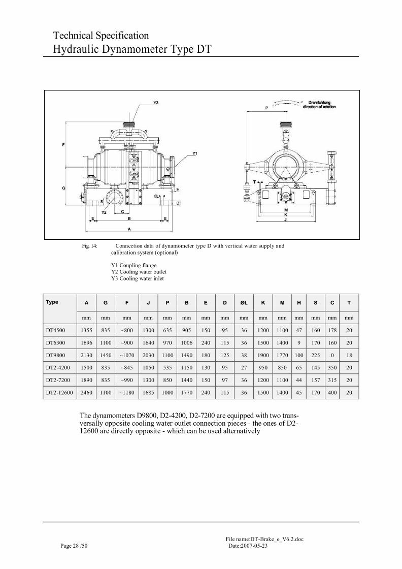
Fig. 14: Connection data of dynamometer type D with vertical water supply and
calibration system (optional)
Y1 Coupling flange Y2 Cooling water outlet Y3 Cooling water inlet
Type A G F J P B E D ØL K M H S C T
mm mm mm mm mm mm mm mm mm mm mm mm mm mm mm
DT4500 1355 835 ~800 1300 635 905 150 95 36 1200 1100 47 160 178 20
DT6300 1696 1100 ~900 1640 970 1006 240 115 36 1500 1400 9 170 160 20
DT9800 2130 1450 ~1070 2030 1100 1490 180 125 38 1900 1770 100 225 0 18
DT2-4200 1500 835 ~845 1050 535 1150 130 95 27 950 850 65 145 350 20
DT2-7200 1890 835 ~990 1300 850 1440 150 97 36 1200 1100 44 157 315 20
DT2-12600 2460 1100 ~1180 1685 1000 1770 240 115 36 1500 1400 45 170 400 20
The dynamometers D9800, D2-4200, D2-7200 are equipped with two trans-versally opposite cooling water outlet connection pieces - the ones of D2- 12600 are directly opposite - which can be used alternatively
File name: DT-Brake_e_V6.2.doc Date:2007-05-23 Page 29 / 50
Technical Specification Hydraulic Dynamometer Type DT
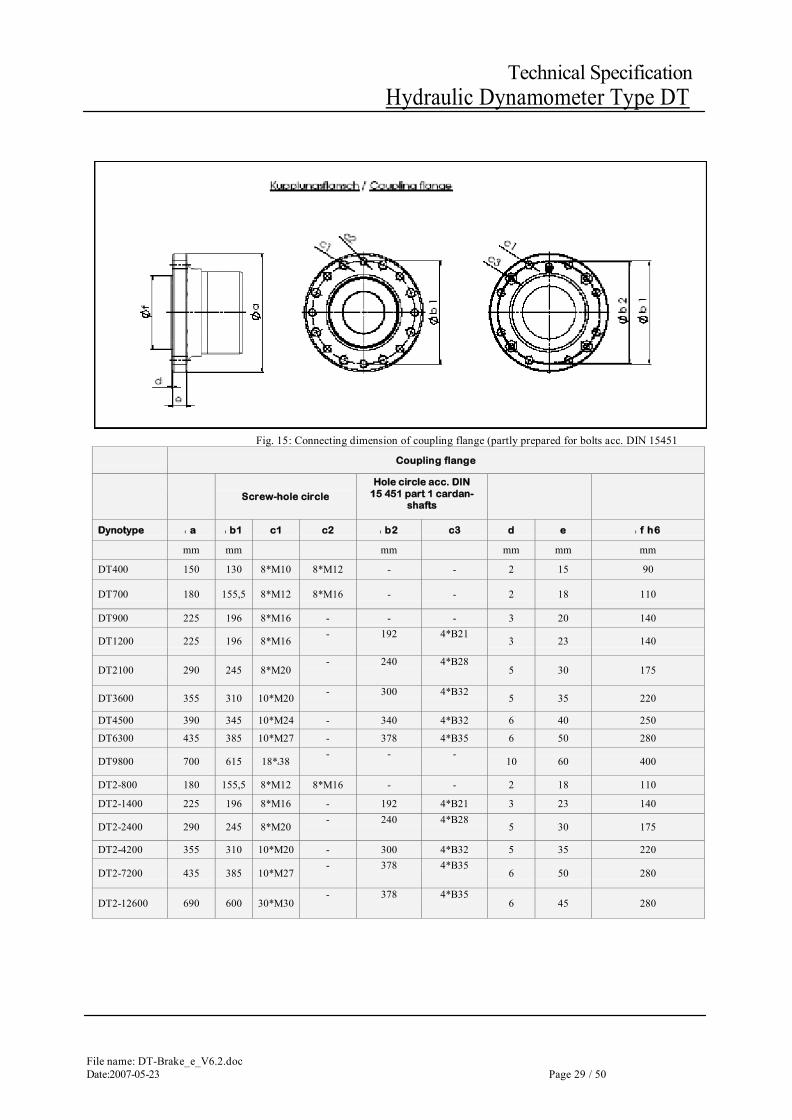
Fig. 15: Connecting dimension of coupling flange (partly prepared for bolts acc. DIN 15451
Coupling flange
Screw-hole circle
Hole circle acc. DIN 15 451 part 1 cardan-
shafts
Dynotype I a I b1 c1 c2 I b2 c3 d e I f h6
mm mm mm mm mm mm
DT400 150 130 8*M10 8*M12 - - 2 15 90
DT700 180 155,5 8*M12 8*M16 - - 2 18 110
DT900 225 196 8*M16 - - - 3 20 140
DT1200 225 196 8*M16 - 192 4*B21
3 23 140
DT2100 290 245 8*M20 - 240 4*B28
5 30 175
DT3600 355 310 10*M20 - 300 4*B32 5 35 220
DT4500 390 345 10*M24 - 340 4*B32 6 40 250
DT6300 435 385 10*M27 - 378 4*B35 6 50 280
DT9800 700 615 18*438 - - -
10 60 400
DT2-800 180 155,5 8*M12 8*M16 - - 2 18 110
DT2-1400 225 196 8*M16 - 192 4*B21 3 23 140
DT2-2400 290 245 8*M20 - 240 4*B28
5 30 175
DT2-4200 355 310 10*M20 - 300 4*B32 5 35 220
DT2-7200 435 385 10*M27 - 378 4*B35
6 50 280
DT2-12600 690 600 30*M30 - 378 4*B35
6 45 280

File name:DT-Brake_e_V6.2.doc Page 30 /50 Date:2007-05-23
Technical Specification Hydraulic Dynamometer Type DT
Fig. 16 Dimensions cooling water inlet Cooling water inlet with tube Cooling water inlet with expansion joint flange
Dyno type : r n o p q
“ mm mm mm mm DT400 1 33,7 DT700 1 % 48,3 DT900 2 60,3 DT1200 2 60,3 DT2100 2 % 76,1 DT3600 3 88,9 DT4500 100 180 220 8*M16 DT6300 125 210 250 8*M16
DT9800 150 240 285 8*M20
DT2-800 1 % 48,3 DT2-1400 2 60,3 DT2-2400 2 % 76,1 DT2-4200 100 180 220 8*M16 DT2-7200 125 210 250 8*M16 DT2-12600 200 295 340 8*M20
File name: DT-Brake_e_V6.2.doc Date:2007-05-23 Page 31 / 50
Technical Specification Hydraulic Dynamometer Type DT
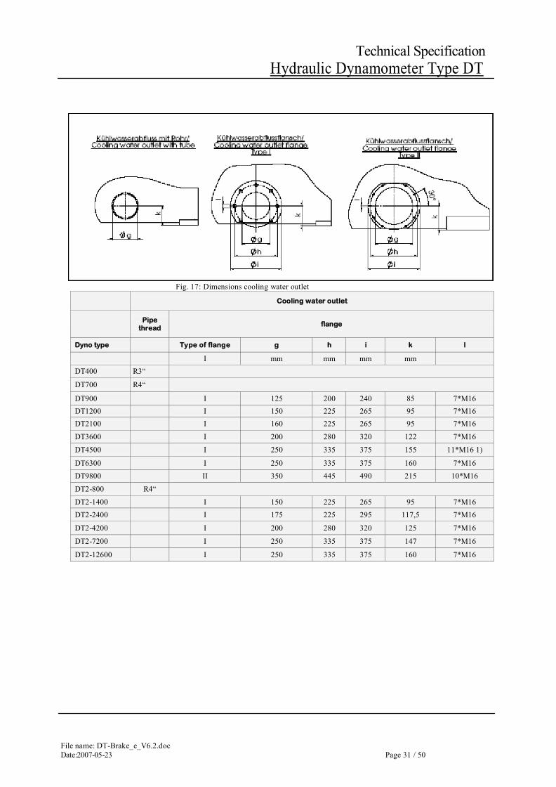
Fig. 17: Dimensions cooling water outlet
Cooling water outlet
Pipe thread
flange
Dyno type Type of flange g h i k l
I mm mm mm mm DT400 R3“ DT700 R4“ DT900 I 125 200 240 85 7*M16 DT1200 I 150 225 265 95 7*M16 DT2100 I 160 225 265 95 7*M16
DT3600 I 200 280 320 122 7*M16
DT4500 I 250 335 375 155 11*M16 1)
DT6300 I 250 335 375 160 7*M16 DT9800 II 350 445 490 215 10*M16
DT2-800 R4“ DT2-1400 I 150 225 265 95 7*M16 DT2-2400 I 175 225 295 117,5 7*M16
DT2-4200 I 200 280 320 125 7*M16
DT2-7200 I 250 335 375 147 7*M16
DT2-12600 I 250 335 375 160 7*M16
File name:DT-Brake_e_V6.2.doc Page 32 /50 Date:2007-05-23
Technical Specification Hydraulic Dynamometer Type DT
4.6 Fluctuating Torque The max. superposed oscillating torque (mechanical vibration) must be lower than 20% of the rated torque The mean value over several seconds shall not exceed 100 % of the rated torque.
File name: DT-Brake_e_V6.2.doc Date:2007-05-23 Page 33 / 50
Technical Specification Hydraulic Dynamometer Type DT
4.7 Connectable mass
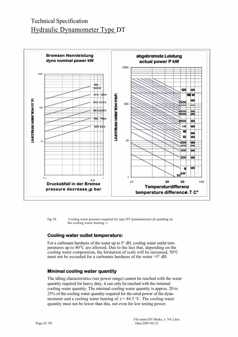
With the help of the water consumption diagram (following pages) you can determine the desired data for the cooling-water supply of the dyno without any calculation.
The diagram can be used for determination of cooling water flow and pres-sure decrease. It applies for different dynamometer sizes. Therefore you need the actual absorbed power and the temperature difference At between cooling water inlet and outlet of your dynamometer.
The determination can be done as follows:
- Enter your temperature difference At in the right diagram and draw in a vertical line upwards
- Find out the intersection point with the curve of your actual absorbed power. From that point draw in a horizontal line to the left and read off the water flow
- Extend the horizontal line to the left diagram and find out the intersection point with the curve of your dynamometer size
Vertically underneath that intersection point you can read the pressure decrease be-tween inlet and outlet of your dynamometer.
File name:DT-Brake_e_V6.2.doc Page 34 /50 Date:2007-05-23
Technical Specification Hydraulic Dynamometer Type DT
5 Things you Should Observe
5.1 Planning Assistance In this chapter, you will find additional information you require for planning the installation of the dynamometers. The mechanical dimensions of the dy-namometers are stated in chapter "Dimensions", the electric interfaces are stated in chapter "Interfaces". Further general information regarding founda-tion, cooling water quality and cooling water consumption, you will find in this chapter.
5.1.1 Foundation
All dynamometers are supplied with processed frame bottom and can be fixed on clamping rails or groove plates as well as on a concrete foundation. Installation position
- Transversal slope max. ± 15° - Longitudinal slope max. ± 15°
For foundation fixing, the dynamometer has to be aligned with water level on the correspondingly prepared concrete foundation, underpoured and an-chored with stone bolts. Dynamometer sizes DT400 to DT1200 with one rotor and dynamometer sizes DT2-800 to DT2-2400 with two rotors are designed for a standard shaft height of 700 mm above normal level, for larger dynamometers, the center-line is higher.
File name: DT-Brake_e_V6.2.doc Date:2007-05-23 Page 35 / 50
Technical Specification Hydraulic Dynamometer Type DT
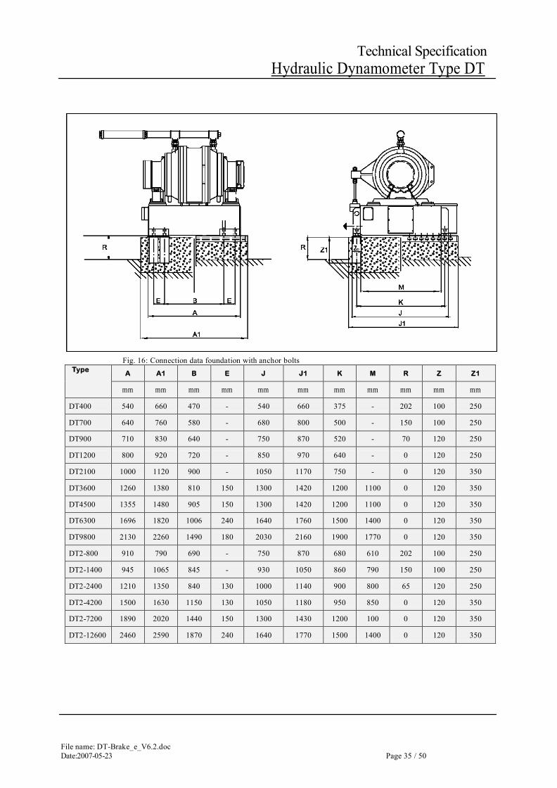
Fig. 16: Connection data foundation with anchor bolts
Type A A1 B E J J1 K M R Z Z1
mm mm mm mm mm mm mm mm mm mm mm
DT400 540 660 470 - 540 660 375 - 202 100 250
DT700 640 760 580 - 680 800 500 - 150 100 250
DT900 710 830 640 - 750 870 520 - 70 120 250
DT1200 800 920 720 - 850 970 640 - 0 120 250
DT2100 1000 1120 900 - 1050 1170 750 - 0 120 350
DT3600 1260 1380 810 150 1300 1420 1200 1100 0 120 350
DT4500 1355 1480 905 150 1300 1420 1200 1100 0 120 350
DT6300 1696 1820 1006 240 1640 1760 1500 1400 0 120 350
DT9800 2130 2260 1490 180 2030 2160 1900 1770 0 120 350
DT2-800 910 790 690 - 750 870 680 610 202 100 250
DT2-1400 945 1065 845 - 930 1050 860 790 150 100 250
DT2-2400 1210 1350 840 130 1000 1140 900 800 65 120 250
DT2-4200 1500 1630 1150 130 1050 1180 950 850 0 120 350
DT2-7200 1890 2020 1440 150 1300 1430 1200 100 0 120 350
DT2-12600 2460 2590 1870 240 1640 1770 1500 1400 0 120 350
File name:DT-Brake_e_V6.2.doc Page 36 /50 Date:2007-05-23
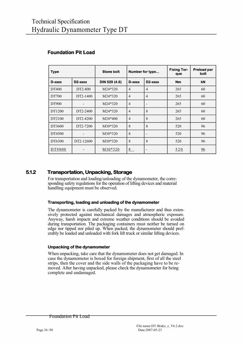
Technical Specification Hydraulic Dynamometer Type DT
Type Stone bolt Number for type... Fixing Tor-
que Preload per
bolt
D-xxxx D2-xxxx DIN 529 (4.6) D-xxxx D2-xxxx Nm kN
DT400 DT2-800 M24*320 4 4 265 60
DT700 DT2-1400 M24*320 4 4 265 60
DT900 - M24*320 4 - 265 60
DT1200 DT2-2400 M24*320 4 8 265 60
DT2100 DT2-4200 M24*400 4 8 265 60
DT3600 DT2-7200 M30*320 8 8 520 96
DT4500 - M30*320 8 - 520 96
DT6300 DT2-12600 M30*320 8 8 520 96
D T9800 - M30*320 8 - 5 2 0 96
5.1.2 Transportation, Unpacking, Storage For transportation and loading/unloading of the dynamometer, the corre-sponding safety regulations for the operation of lifting devices and material handling equipment must be observed.
Transporting, loading and unloading of the dynamometer
The dynamometer is carefully packed by the manufacturer and thus exten-sively protected against mechanical damages and atmospheric exposure. Anyway, harsh impacts and extreme weather conditions should be avoided during transportation. The packaging containers must neither be turned on edge nor tipped nor piled up. When packed, the dynamometer should pref-erably be loaded and unloaded with fork lift truck or similar lifting devices.
Unpacking of the dynamometer
When unpacking, take care that the dynamometer does not get damaged. In case the dynamometer is boxed for foreign shipment, first of all the steel strips, then the cover and the side walls of the packaging have to be re-moved. After having unpacked, please check the dynamometer for being complete and undamaged.
Foundation Pit Load
File name: DT-Brake_e_V6.2.doc Date:2007-05-23 Page 37 / 50
Technical Specification Hydraulic Dynamometer Type DT
Storage of the dynamometer
Perfect storage conditions are provided by an air-conditioned room. Bare metal parts must additionally be coated with an anticorrosive. The dyna-mometer and all parts of the facility must be protected against soiling and dust. For storage outside air-conditioned rooms, the dynamometer has to be heat-sealed into a polyethylene foil of at least 0.2 mm together with a desic-cant (e.g. Silicagel). For that, the air inside the cover has to be sucked off and a humidity indicator has to be installed visibly. Due to the danger of cor-rosion, the desiccant must not get in contact with bare metal parts. The cover has to be protected against mechanical damages. The cover has to be checked regularly approx. every four weeks and, if required, the desiccant or the humidity indicator have to be exchanged. Furthermore, the transportation protection has to be removed and the rotor has to be turned by 15 to 20°.
5.1.3 Cooling Water
The working principle of the hydraulic dynamometer requires flow-off of the cooling water without hindrance and counter-pressure. The cooling water flows through the control valve into the collection tank arranged inside the frame of the dynamometer. From there, it flows through the pressure-free re-turn pipe into the outlet duct in case of once-through flow or into the cooling system in case of re-cooling systems. Thus, cooling water can be supplied alternatively from the normal water system with pressure control valve (once-through flow through the dynamometer, then into the sewage canal) or from an overhead water tank (multiple flow through the dynamometer via re-cooling and pumping back into the overhead water tank). A simple shut-off valve and optional controlled inlet valve for setting the required flow rate must be installed directly in front of the dynamometer.
File name:DT-Brake_e_V6.2.doc Page 38 /50 Date:2007-05-23
Technical Specification Hydraulic Dynamometer Type DT
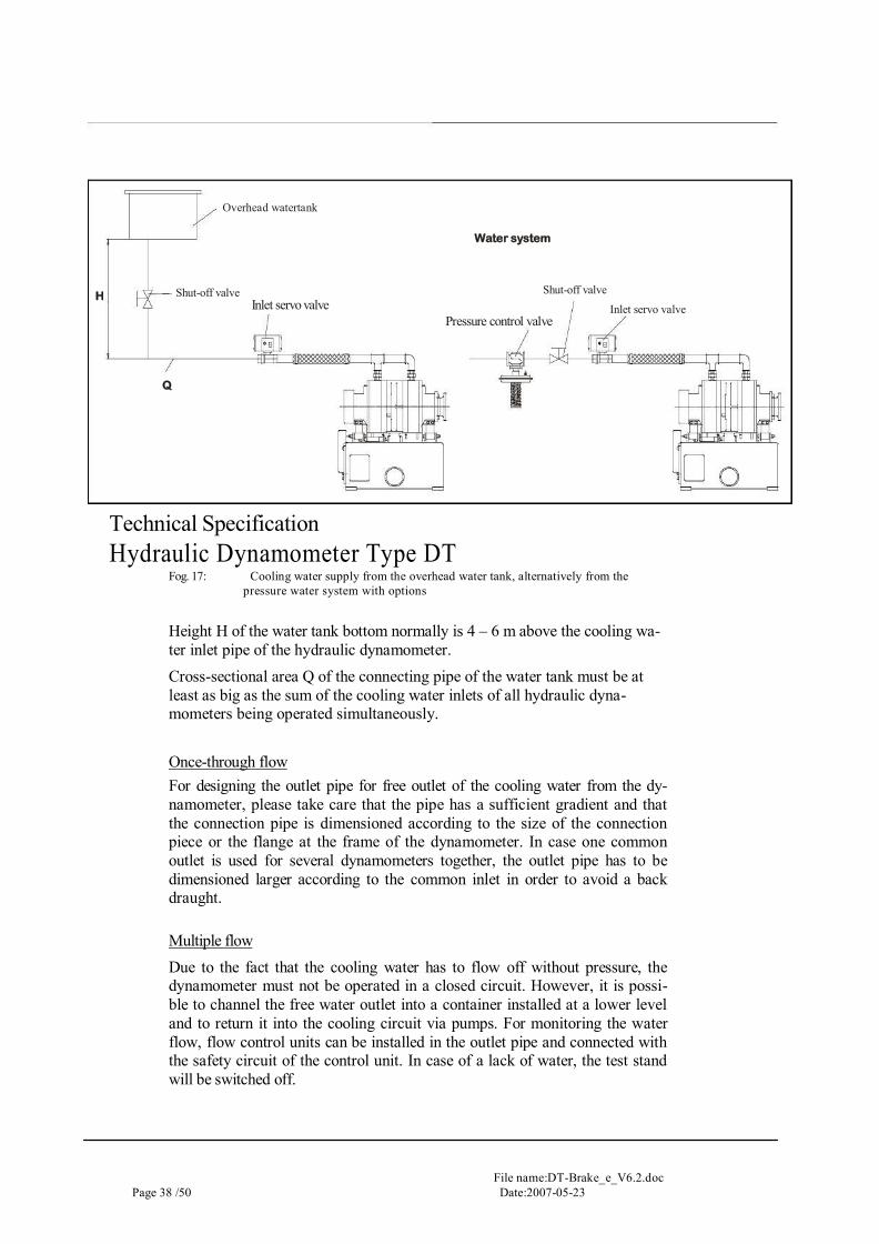
Fog. 17: Cooling water supply from the overhead water tank, alternatively from the pressure water system with options
Height H of the water tank bottom normally is 4 – 6 m above the cooling wa-ter inlet pipe of the hydraulic dynamometer. Cross-sectional area Q of the connecting pipe of the water tank must be at least as big as the sum of the cooling water inlets of all hydraulic dyna-mometers being operated simultaneously.
Once-through flow For designing the outlet pipe for free outlet of the cooling water from the dy-namometer, please take care that the pipe has a sufficient gradient and that the connection pipe is dimensioned according to the size of the connection piece or the flange at the frame of the dynamometer. In case one common outlet is used for several dynamometers together, the outlet pipe has to be dimensioned larger according to the common inlet in order to avoid a back draught.
Multiple flow Due to the fact that the cooling water has to flow off without pressure, the dynamometer must not be operated in a closed circuit. However, it is possi-ble to channel the free water outlet into a container installed at a lower level and to return it into the cooling circuit via pumps. For monitoring the water flow, flow control units can be installed in the outlet pipe and connected with the safety circuit of the control unit. In case of a lack of water, the test stand will be switched off.
Water system
Inlet servo valve Inlet servo valve Pressure control valve
Overhead watertank
Shut-off valve Shut-off valve H
Q
File name: DT-Brake_e_V6.2.doc Date:2007-05-23 Page 39 / 50
Technical Specification Hydraulic Dynamometer Type DT
Laying the pipes
The cooling water inlet pipe must be rigidly mounted by the customer directly in front of the flexible element (hose or rubber bellows). This is to prevent transmission of undesired forces via the water inlet and thus influence on torque measurement or even damage to the water inlet.
With free outlet of the cooling water from the dynamometer, the discharge pipe must be installed with sufficient gradient to prevent backwater in the collector. No counter pressure is allowed in case of water outlet connection to a closed cooling circuit.
Prior to connecting the dynamometer, please flush the pipelines regardless of new or overhauled cooling water pipes.
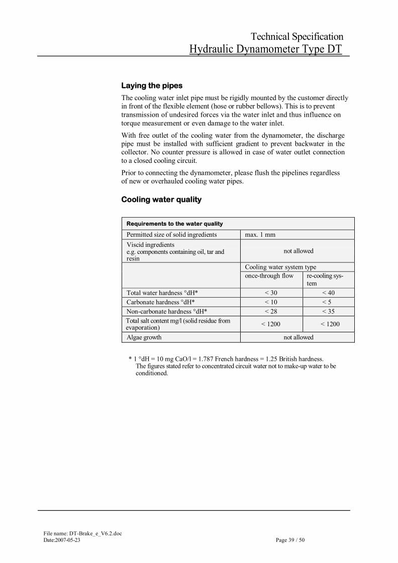
Cooling water quality
Requirements to the water quality
Permitted size of solid ingredients max. 1 mm Viscid ingredients e.g. components containing oil, tar and resin
not allowed
Cooling water system type once-through flow re-cooling sys-
tem Total water hardness °dH* < 30 < 40 Carbonate hardness °dH* < 10 < 5 Non-carbonate hardness °dH* < 28 < 35 Total salt content mg/l (solid residue from evaporation) < 1200 < 1200
Algae growth not allowed
* 1 °dH = 10 mg CaO/l = 1.787 French hardness = 1.25 British hardness. The figures stated refer to concentrated circuit water not to make-up water to be conditioned.
File name:DT-Brake_e_V6.2.doc Page 40 /50 Date:2007-05-23
Technical Specification Hydraulic Dynamometer Type DT
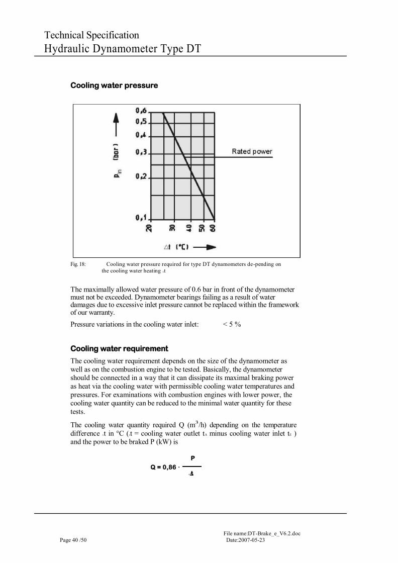
Cooling water pressure
Fig. 18: Cooling water pressure required for type DT dynamometers de-pending on
the cooling water heating At
The maximally allowed water pressure of 0.6 bar in front of the dynamometer must not be exceeded. Dynamometer bearings failing as a result of water damages due to excessive inlet pressure cannot be replaced within the framework of our warranty. Pressure variations in the cooling water inlet: < 5 %
Cooling water requirement
The cooling water requirement depends on the size of the dynamometer as well as on the combustion engine to be tested. Basically, the dynamometer should be connected in a way that it can dissipate its maximal braking power as heat via the cooling water with permissible cooling water temperatures and pressures. For examinations with combustion engines with lower power, the cooling water quantity can be reduced to the minimal water quantity for these tests.
The cooling water quantity required Q (m3/h) depending on the temperature difference At in °C (At = cooling water outlet tA minus cooling water inlet tE ) and the power to be braked P (kW) is
P
Q = 0,86 · A t
File name: DT-Brake_e_V6.2.doc Date:2007-05-23 Page 41 / 50
Technical Specification Hydraulic Dynamometer Type DT
Q [m3/h] = cooling-water quantity
P [kW] = capacity to be braked down
t [°C] = temperature range tA - tE
tA [°C] = cooling-water outlet temperature
tE [°C] = cooling-water inlet temperature
With the help of the water consumption diagram (following pages) you can determine the desired data for the cooling-water supply of the dyno with-out any calculation. On the right side of the diagram the cooling-water flowing-through quantity of the dyno is indicated above the temperature difference dependent on the max. capacity to be braked down (engine capacity). The temperature difference is the difference between the temperature of the cold water flowing within the dyno and the temperature of the warmed-up water leaving the dyno. On the left side of the diagram the cooling-water flowing-through quantity of the dyno is indicated above the (constant-controlled) cooling-water pressure in front of the dyno dependent on the dyno size. The minimum pressure should not be allowed to fall below 0.1 bar. Pressure losses within the pip-ings mounted in front of the dyno are not taken into consideration in the dia-gram.
File name:DT-Brake_e_V6.2.doc Page 42 /50 Date:2007-05-23
Technical Specification Hydraulic Dynamometer Type DT
Fig. 19: Cooling water pressure required for type DT dynamometers de-pending on the cooling water heating At
Cooling water outlet temperature:
For a carbonate hardness of the water up to 5° dH, cooling water outlet tem-peratures up to 80°C are allowed. Due to the fact that, depending on the cooling water composition, the formation of scale will be increased, 50°C must not be exceeded for a carbonate hardness of the water >5° dH.
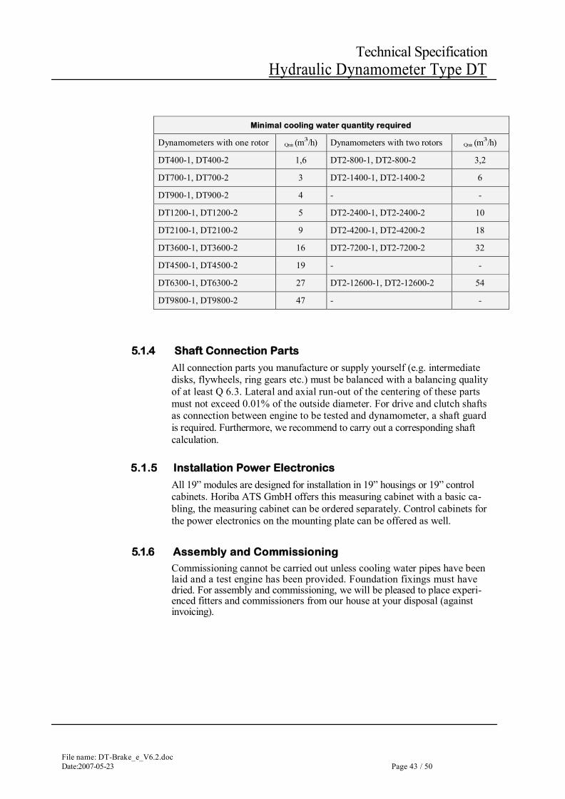
Minimal cooling water quantity
The idling characteristics (see power range) cannot be reached with the water quantity required for heavy duty, it can only be reached with the minimal cooling water quantity. The minimal cooling water quantity is approx. 20 to 25% of the cooling water quantity required for the rated power of the dyna-mometer and a cooling water heating of At = 44.5 °C. The cooling water quantity must not be lower than this, not even for low testing power.
Durc
hflus
s wate
r flow
m3 /h
1000
100
10
1 0,1 1
0 ,6
Druckabfall in der Bremse pressure decrease Ap bar
Bremsen Nennleistung dyno nominal power kW
12 6
DT2 -4 2 0 0
DT 2 -2 4 0 0
DT 2 -
DT2 _ -
DT2 _ -
DT2 -8 0 0
0 0
72 0 0
14 0 0 Du
rchf
luss w
ater fl
ow rn
s/h
1000
100
10
1 10 30 50 100
Temperaturdifferenz temperature difference AT C°
12000 kW
7000
10000 kW
kW
5000 kW 4000 kW 3000 kW 2000 kW
+ 1400 kW 1000
700 kW
kW
500 kW 400 kW 300 kW 200 kW
50
100
kW kW
abgebremste Leistung actual power P kW
File name: DT-Brake_e_V6.2.doc Date:2007-05-23 Page 43 / 50
Technical Specification Hydraulic Dynamometer Type DT
Minimal cooling water quantity required
Dynamometers with one rotor Qmin (m3/h) Dynamometers with two rotors Qmin (m3/h)
DT400-1, DT400-2 1,6 DT2-800-1, DT2-800-2 3,2
DT700-1, DT700-2 3 DT2-1400-1, DT2-1400-2 6
DT900-1, DT900-2 4 - -
DT1200-1, DT1200-2 5 DT2-2400-1, DT2-2400-2 10
DT2100-1, DT2100-2 9 DT2-4200-1, DT2-4200-2 18
DT3600-1, DT3600-2 16 DT2-7200-1, DT2-7200-2 32
DT4500-1, DT4500-2 19 - -
DT6300-1, DT6300-2 27 DT2-12600-1, DT2-12600-2 54
DT9800-1, DT9800-2 47 - -
5.1.4 Shaft Connection Parts
All connection parts you manufacture or supply yourself (e.g. intermediate disks, flywheels, ring gears etc.) must be balanced with a balancing quality of at least Q 6.3. Lateral and axial run-out of the centering of these parts must not exceed 0.01% of the outside diameter. For drive and clutch shafts as connection between engine to be tested and dynamometer, a shaft guard is required. Furthermore, we recommend to carry out a corresponding shaft calculation.
5.1.5 Installation Power Electronics
All 19” modules are designed for installation in 19” housings or 19” control cabinets. Horiba ATS GmbH offers this measuring cabinet with a basic ca-bling, the measuring cabinet can be ordered separately. Control cabinets for the power electronics on the mounting plate can be offered as well.
5.1.6 Assembly and Commissioning
Commissioning cannot be carried out unless cooling water pipes have been laid and a test engine has been provided. Foundation fixings must have dried. For assembly and commissioning, we will be pleased to place experi-enced fitters and commissioners from our house at your disposal (against invoicing).
File name:DT-Brake_e_V6.2.doc Page 44 /50 Date:2007-05-23
Technical Specification Hydraulic Dynamometer Type DT
6 Product Options and Accessories
6.1 Trunnion Bearings As standard, the hydraulic dynamometers type D are equipped with a pen-dulum body supported in flexure strips, alternatively, trunnion bearings can be supplied except for the dynamometers from size D6300 on. D6300 can be supplied with roller support as alternative for the flexure strips. The tech-nical data and dimensions stated in chapter "Figures, Data, Facts" will not change if trunnion bearings are used. The order numbers, please take from chapter "Order Numbers".
6.2 Second Coupling Shaft For some applications such as for engines for starting and tractor operation supplied by the customer, a connection to the rear shaft end of the dyna-mometer is required. For that, the protection cover of the rear end of the shaft will be removed and an additional coupling flange will be installed. The connection drawing (centering diameter, hole circle etc.) as well as the pro-jection of the base frame correspond with the coupling flange of the engine. For operation with two coupling flanges and connection of masses at both sides, the following must be observed:
for maintaining the masses coupled on, the speeds allowed have to be reduced to 90% of the corresponding values and
for maintaining the speeds, the masses allowed on both sides reduce to 81% of the corresponding values.
The order numbers for the coupling flanges of the various dynamometer sizes, please take from chapter "Order Numbers". Scope of supply:
second coupling flange protection cover for coupling flange (The protection cover for the rear end
of the shaft is not required)

File name: DT-Brake_e_V6.2.doc Date:2007-05-23 Page 45 / 50
Technical Specification Hydraulic Dynamometer Type DT
6.3 Cooling water monitoring This device monitors operation of the dynamometer under correct water pressure and availability of the amount of cooling water as required for the set absorbing power. Therefore the minimum and maximum admissible cool-ing water inlet pressures are checked at the dynamometer inlet. A warning message will appear on the test stand controller, the dynamometer be switched off and a contact be output to the test stand, if these values are ex-ceeded. The same occurs in case of exceeding the admissible cooling water outlet temperature of the dynamometer.
The inlet pressure governor must be installed directly at the level of the cool-ing water inlet in front of the dynamometer and the inlet valve (available as an option). Level offset results in wrong values and unreliable monitoring. Please take further information from the relevant technical specification.
6.4 Shaft Connection
For connecting the engine to be tested with the hydraulic dynamometer, a double-cardanic shaft is required. Horiba ATS GmbH offers different shafts for all applications. Further information, please take from the corresponding technical specification.
6.5 Starter System For test stands without starter system of the engine, we offer a starter system with different power ranges installed at the free shaft end of the dynamometer. Further information, please take from the corresponding technical specification.
6.6 Calibration System A calibration of the hydraulic dynamometer is recommended after each op-eration in the area of the load cell or the pendulum body receptacle. For con-trolling the torque measurement system, we recommend the Horiba ATS GmbH calibration system. Further information, please take from the corre-sponding technical specification.
File name:DT-Brake_e_V6.2.doc Page 46 /50 Date:2007-05-23
Technical Specification Hydraulic Dynamometer Type DT
6.7 Pressure Control System
The pressure control system type D is always a space-saving, good-value alternative when an overhead water tank cannot be used for the cooling water. It is used to reduce and to control the pressure of the water supply in Type DT400 to Type DT3600 hydraulic dynamometers. The system is easy to assemble and to connect to the normal water system. Integrated manometers are used to additionally control the inlet and outlet pressure. Easily accessible dirt traps guarantee the trouble-free operation of the system. If maintenance work is required on the dynamometers, the water supply can easily be blocked by ball cocks. Further information, please take from the corresponding technical specification.
6.8 Inlet Servo Valve The inlet valve adjusts the cooling water flow according to performance re-quirements to the dynamometer and enables extremely low torque in idling operation as well as maximum braking power. Further information, please take from the corresponding technical specifica-tion
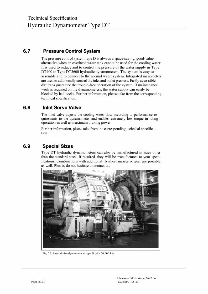
6.9 Special Sizes Type DT hydraulic dynamometers can also be manufactured in sizes other than the standard sizes. If required, they will be manufactured to your speci-fications. Combinations with additional flywheel masses or gear are possible as well. Please, do not hesitate to contact us.
Fig. 20: Special-size dynamometer type D with 50.000 kW
File name: DT-Brake_e_V6.2.doc Date:2007-05-23 Page 47 / 50
Technical Specification Hydraulic Dynamometer Type DT
6.10 Modification of the control valve drive
The control valve drive of standard D-dynamometers with one rotor, D400 – D3600, and two rotors, D2-800 – D2-2400, from year of construction 1990, can be converted to brushless motor design of the DT-dynamometers. In-creased reliability and dynamical characteristics of the control valve drive and better control characteristics of the dynamometer are benefits from this design. Prerequisite: Controller type LSG2000, LSG2010, x-act or or SPARC available on the electrics side.
Scope of supply:
Brushless servomotor mounted on the motor plate
Power supply unit LED 2003
Cable set, control valve drive 15 m
With design sizes D2-2400 and D3600, a new cover plate is required in addi-tion for the valve drive motor in the frame for conversion. With these brakes[1], the screw fitting of the cable routing must be screwed out of the motor plate and into the new cover plate.
File name: DT-Brake_e_V6.2.doc Date:2007-05-23 Page 48 / 50
Technical Specification Hydraulic Dynamometer Type DT
For further info or sales enquiries please contact us:
DYNAMOMETER WORLD LTD UNIT 12 SHERRIFF STREET INDUSTRIAL EST
SHERRIFF STREET WORCESTER
WR4 9AB
Tel/Fax: +44 1905 731385 e-mail: [email protected]
www.dynamometer-world.com