Hydraulic Accessories
156
Hydraulic Accessories Valves, Clamps, & Reservoir Accessories
-
Upload
khangminh22 -
Category
Documents
-
view
0 -
download
0
Transcript of Hydraulic Accessories
Hydraulic AccessoriesValves, Clamps, & Reservoir Accessories

About HYDAC
Mobile Hydraulics• Construction vehicles• Agricultural vehicles• Aerospace• Lift equipment• Shipbuilding
Industrial Hydraulics• Pulp & paper mills• Steel mills.& heavy industry• Plastics• Power generation & wind energy• Offshore oil• Chemical processing• Food processing
ApplicationsHYDAC has over 40 years of global experience in applying hydraulic components in both mobile andindustrial systems. The industries served includes, but is in no way limited to:
HYDAC stands for worldwide presence and accessibility to the customer. HYDAC has over 1000 distributorsworldwide and more than 40 wholly owned branches. The HYCON Division of HYDAC is an industry leader inthe manufacture of hydraulic valves, clamps, reservoir accessories, filters, and elements for both mobile andindustrial applications. The HYCON Division has been providing standard products and custom solutions tothe fluid power industry for more than 30 years.
HYDAC ProductsThe Valves, Clamps, & Accessories group manufactures highlyengineered high pressure ball valves, which guarantee safe andreliable operation. A complete range of DIN 3015 clamps for mountinghoses, tubes, and pipes is complimented by our specialty and com-pletely custom mounting solutions. Reservoir accessories round out ourproduct line, and put the finishing touches on your system.
HYDAC Customer ServiceOur internal staff and worldwide distribution network take care ofthe important matter of customer service. HYDAC values highstandards, professional ethics, and mutual respect in all transactionswith customers, vendors, and employees. We invest in our relationshipsby providing expertise, quality, dependability, and accessibility tofoster growth and a sense of partnership. Our customer servicerepresentatives are committed to serving the customers’ needs.
About this CatalogPlease review the information below to familiarize yourself with the conventions used in this catalog,as well as some general information about ordering the HYDAC products within.
HYDAC QualityHYDAC stands for quality and customer satisfaction. To ensure thatour products are as innovative as possible, they are developed,manufactured, and tested by qualified personnel using state of theart equipment and technology.
Part Numbers and Model CodesEvery HYDAC Product has a Model Code and an eight digit Part Number. A Part Number is simply a unique,computer generated number that identifies a product. A Model Code is a sequence of codes that contains acomplete description of the product, with each portion of the code defining some variable or option. BOTHModel Codes and Part Numbers are listed in this catalog, whenever possible. It is recommended that you useBOTH Model Code and Part Number when communicating with HYDAC.When options are limited, we have created charts that contain ALL possible combinations, or available products.In cases where the options create too many combinations to list, we have provided a Model Code Tree, which isused to create a complete Model Code which specifies the product as well as all options that are desired. PartNumbers are subject to change if HYDAC processes change, or design revisions are implemented by HYDAC. Inthis case, HYDAC Customer Service will refer you to the new part number.
Standard vs. Non-standard ProductsSince HYDAC offers such a vast number of options for many product lines, it becomes necessary to differentiatebetween Standard and Non-standard configurations. Standard products are the most common configurations, whichare continually supported by HYDAC in regular production. Non-standard configurations are less commonly ordered,and may require minimum orders and/or extended delivery times.Throughout this catalog we have distinguished Non-standard products or options from the Standard, by listing thethem in red. In model code trees, any red option selected will cause that configuration to be considered Non-standard.In charts that contain complete model codes, the entire model code will be in red for Non-standard products.

Table Of Contents
Accessories Catalog
High Pressure Ball ValvesOverview ..................................................32-way SAE, NPT Threaded [KHB, KHM] .52-way Split Flange [KHB...F3, KHB...F6]....7Specialty Ball Valves Overview................92-way BSPP Threaded [KHB, KHM]......102-way S.S. Ball Seals [KHB, KHM]........112-way Stainless Steel [KHM] .................123-way Diverter [KHB3K] ..........................132-way Manifold Mount [KHP] ................153 & 4-way Threaded [KH3, KH4].............17Actuators [EDA] ......................................19Locking Devices & Limit Switches..........21Seal Kits.................................................23Handles..................................................24Engineering Data ...................................24SAE Split Flange Direct Mount [KHF3/6]..25Ball Valve with Butt Weld Flange [KHF] .273 Piece Ball Valve [KHM3H]...................29
Flow Control ValvesOverview ...............................................43Needle Valves [DV, DVP, DVE] ...............45Flow Control Valves [DRV, DRVP] ..........49Pressure Compensated Flow Ctrls [SRVR]...53Check Valves [RV, RVP]..........................55Stainless Steel Flow Control Valves[DV, DRV, RV] .........................................57
Cartridge ValvesOverview ................................................58Hose Break Valves [RB, RBE]................59Shuttle Valves [WVE]..............................63Air Vent Valves [AEV]..............................642-way Directional [WSM] .......................653-way Directional [WSE3] ......................69Pressure Relief [DB4] .............................71
Standard SolutionsHOM Series............................................92Cushion Clamps [CUSH] .......................93Beugu Clamps [HRBGS]........................95U-bolt Clamps [HRRBS] ........................97HUB Series ............................................98Oval Clamps [HROS] .............................99HSPN Series .......................................100Accumulator Clamps ...........................101
Custom SolutionsSeries Strips.........................................103Band Straps.........................................104
Other AccessoriesSuction Strainers .................................131Split Flanges ........................................136Fluid Level Indicators...........................137Gauge Isolators....................................143TestPoints ............................................147Gauges.................................................151
Breathers & Filler BreathersOverview ..............................................107Breathers..............................................110Breathers with Optional Dipstick .........115Spin-on Breathers................................117Drymicron.............................................119Filler Breathers.....................................125
DIN 3015 Clamps Clamp Overview.....................................73Technical Specifications [DIN Series] ....75DIN Clamp Overview .............................76Standard Duty [HRL]..............................77Heavy Duty [HRS] ..................................79Twin [HRZ]..............................................81Std. Duty w/ Rubber Inserts [HREL]......83Heavy Duty w/ Rubber Inserts [HRES] ..85Stainless Steel DIN 3015 .......................87Parts for Standard Duty [HRL]...............89Parts for Heavy Duty [HRS] ...................90Parts for Twin [HRZ]...............................91
Process & Automated ValvesOverview ................................................312-way S.S., NPT Threaded [KHNVS]....32Inline Isolation Valve + Actuator [HVA] ..33Angle Seat Valve [ASV] ..........................35Auto 2 Piece S.S. Ball Valve [KHL] ........37Auto 3 Piece S.S. Ball Valve [KHM3L]..39Solenoid Valves......................................41
All information is subject to change without notice.

Valves
Accessories Catalog1
Valve Offering Overview Standard SolutionsHYDAC Manufactures a complete line of valves. Our standard product offering includes:
High Pressure Ball Valves(see pages 3 - 30)Nominal Sizes from 1/4” to 2”
Process / Automated Valves(see page 31 - 42)
Flow Control Valves(see pages 43 - 57)Needle Valves, Flow Control Valves, Check ValvesInline, Manifold mount, Cartridge
Cartridge Valves (see pages 58 - 72)
Hose Break Valves, Shuttle Valves, Automatic Air Vent Valves, 2-waySolenoid Cartridge Valves, 3-way Solenoid Cartridge Valves, PressureRelief Valves

Valves
Accessories Catalog 2
HYDAC Accessories GmbH has done significant work in the Automotive Paint Industry. Many custom and product developments are in the works. Contact HYDAC for additional information.
Custom SolutionsHYDAC is also a market leader in providing custom valve solutions. Our engineers work with yours to developunique solutions that save time and money by simplifying inventory and installation. From simple modifications ofstandard product to complete custom manifolds, we will provide you a successful solution for your application.For more information on custom solutions, please contact product management at 1-877-GO HYDAC.

High Pressure Ball Valves
Accessories Catalog3
High Pressure Ball Valve Overview2-way Ball ValvesKHB Series (see pages 5 - 12)
Block BodiesSizes 1/4” - 2”
2-way Ball Valves KHM Series (see pages 5 -12)
Forged BodiesSizes 1/4” - 2”
2-way Manifold Mounted Ball ValvesKHP Series (see page 15)
Sizes 3/8” - 2”
3-way Diverter Ball Valves KHB3K Series (see page 13)
Sizes 1/4” - 1”
Multiway Ball ValvesKH3 & KH4 Series (see page 17)
Sizes 1/4” - 3/4”
Direct Mount SAE FlangeKHF3/6 Series (see page 25)
Sizes 1/2” - 2”
Direct Mount SAE FlangeKHF3 Series (see page 26)
Sizes 2 1/2” - 4”
Ball Valves with Butt Weld FlangesKHF Series (see page 27)
Sizes 2 1/2” - 5”
3 Piece Ball Valves KHM3H Series (see page 29)
Designed in accordance with ANSI B16.34 and BS5351Sizes 1/2” - 4”
Ball Valve ActuatorsFor KHB & KHM Series (see page 19)
Pneumatic Operation

High Pressure Ball Valves
Accessories Catalog 4
Standard Ball Valve Design Features, & OptionsKHB, KHM, KHP, KHB3K Series
DescriptionThe HYDAC family of dependable high pressure ballvalves provides full, unrestricted flow and positiveshut-off of fluids and gases under extreme serviceconditions. Models are available to accommodatesystem pressures up to 7,250 PSI. Since a variety ofmaterials are available, HYDAC valves can be usedwith various fluids and gases including petroleumbased oils and some water glycols.
Valve DesignThe design of HYDAC ball valves is based on the“floating ball” principle which allows the ball to turnfreely between the ball seals. A positive seal isattained by fluid pressure acting on the upstreamsurface of the ball and producing a constant uniformcontact between the downstream ball seal and theball. The ball is operated by a sealed spindle with aprojecting square end to which the control handle oroptional actuator is attached. Ball valves are intendedto be used as on/off flow control devices and are notto be used to throttle fluid flow. The valves shouldalways be either fully open or closed.
Housing
O-ring (valve sizes 06-25)O-ring & back-up ring (valve sizes 32-50)
Connection Adapter
Chrome Plated Ball
Ball Seal
Spindle
Thrust Washer
O-Ring with Back-up Ring
Stop Pin
Handle
Limit Washer
Product Features• Full passage for unrestricted flow of medium
• Floating ball provides positive seal
• Direction of flow indicated by milled slot in control spindle
• Valve positioning controlled by a stop pin and limit washer
• Fluoroelastomer O-rings (standard)
• Phosphate coated carbon steel valve body (standard)
Available OptionsHYDAC can furnish ball valves with special options including:
• Locking devices
• Stainless steel valve bodies
• Pneumatic or electrical actuators
• Limit switch
• Off-set or straight control handles
• Custom solutions - Contact HYDAC

Specifications• 1/4” - 2” Full Port Design
• NPT or SAE O-Ring connections
• Polyacetal Ball Seals (standard)
• FPM (Fluoroelastomer) O-Rings (standard)
• Carbon Steel Housing
• Block Housing - Sizes 06 - 25
• Forged Housing - Sizes 32 - 50
• Operating Pressure to 7250 psi Depending on Valve Size and Seal Materials Selected
• Temp Range: 14˚F to 176˚F with Standard materials (1114) up to max. pres-sure rating. Extended Temperature range -40˚F to 392˚F on request with spe-cial materials and reduced pressure rating (see page 20).
KHB & KHM Series 2-way Ball Valves with SAE & NPT Connections
KHB - 16 NPT - 1 1 1 4 - 11X - LHousing Type
KHB = Block Housing, Carbon Steel - Sizes 06 - 25KHM = Forged Housing, Carbon Steel - Sizes 32 - 50,
Nominal SizesNom SAE NPTSize Tube Size Thread Size Pipe Size Pipe øD06 -4 7/16-20 UNF 1/4” 0.540”10 -6 9/16-18 UNF 3/8” 0.675”16 -8 3/4-16 UNF 1/2” 0.840”20 -12 1-1/16-12 UN 3/4” 1.050”25 -16 1-5/16-12 UN 1” 1.315”32 -20 1-5/8-12 UN 1-1/4” 1.660”40 -24 1-7/8-12 UN 1-1/2” 1.900”50 -32 2-1/2-12 UN 2” 2.375”
Connection TypeNPT = ANSI/ASME 1.20.1 Taper Pipe ThreadSAE = SAEJ1926 Ports with ISO 725 Threads and O-Ring Sealing
Body Material1 = Carbon Steel (phosphate coated)3 = Stainless Steel (see page 12 for ordering details)
Spindle and Ball Material1 = Carbon Steel (ball is chrome plated, spindle is zinc plated)3 = Stainless Steel
Ball Seal Material1 = Polyacetal (standard)3 = PTFE (1500 psi max)8 = PEEK
O-Ring Material 2 = NBR (Buna)3 = PTFE Spindle Seals and FPM (fluoroelastomer) O-Rings (1500 psi max)4 = FPM (fluoroelastomer) (standard)5 = EPR
Handle Codes09x = Without Handle (see page 24 to order handle separately)11x = Straight Aluminum, Sizes 06-2516x = Offset Steel, Sizes 32-50
Locking Device OptionL = Locking Device (see page 21 to order locking device separately)LS = Locking Device with 5 amp Limit Switch, Available for sizes 20-50 (Not available with PTFE Spindle Seals)Model Codes containing selections listed in red italics are non-standard items – Minimum quantities may apply – Contact HYDAC for information and availability
Not all combinations are available
Model Code
Accessories Catalog5
KHBBlock Housing
KHMForged Housing
High Pressure Ball Valves

Accessories Catalog 6
Dimensions
Dimensions are for general information only, all critical dimensions should be verified by requesting a certified print.Dimensions are in inches/(mm) and lbs./(kg.)*Dependent upon valve and seal materials selected.
NPT PORT SAE PORTInternal Thread Straight Thread
O-Ring Boss
H
H3
SQH2
H1
BøD L
A1
11X, Standard Handlesizes 06 to 25
H4
H4
16X, Standard Handlesizes 32 to 50
Model Thread max. psi* A1 B øD H H1 H2 H3 H4 L SQ Weight
KHB-06SAE 7/16-20UNF (SAE 4)7250
5.91 0.98 0.24 1.89 1.38 0.28 0.51 1.65 2.72 0.35 0.66KHB-06NPT 1/4” NPT (150) (25) (6) (48) (35) (7) (13) (42) (69) (9) (0.3)
KHB-10SAE 9/16-18UNF (SAE 6)7250
5.91 1.26 0.39 2.09 1.57 0.33 0.67 1.69 2.83 0.35 1.10KHB-10NPT 3/8” NPT (150) (32) (10) (53) (40) (8.5) (17) (43) (72) (9) (0.5)
KHB-16SAE 3/4-16UNF (SAE 8)5800
6.88 1.50 0.63 2.48 1.77 0.43 0.75 2.01 3.27 0.47 1.65KHB-16NPT 1/2” NPT (175) (38) (16) (63) (45) (11) (19) (51) (83) (12) (0.75)
KHB-20SAE 1-1/16-12UN (SAE 12)5000
7.88 1.89 0.79 2.95 2.24 0.43 0.96 2.28 3.74 0.55 2.87KHB-20NPT 3/4” NPT (200) (48) (20) (75) (57) (11) (24.5) (58) (95) (14) (1.3)
KHB-25SAE 1-5/16-12UN (SAE 16)5000
7.88 2.24 0.98 3.23 2.52 0.43 1.12 2.40 4.45 0.55 4.41KHB-25NPT 1” NPT (200) (57) (25) (82) (64) (11) (28.5) (61) (113) (14) (2.0)
KHM-32SAE 1-5/8-12UN (SAE 20)5000
12.00 2.95 1.18 4.06 3.35 0.47 1.48 5.94 4.33 0.67 6.84KHM-32NPT 1-1/4” NPT (305) (75) (30) (103) (85) (12) (37.5) (151) (110) (17) (3.1)
KHM-40SAE 1-7/8-12UN (SAE 24)5000
12.00 3.35 1.50 4.49 3.78 0.47 1.67 6.18 5.12 0.67 9.70KHM-40NPT 1-1/2” NPT (305) (85) (38) (114) (96) (12) (42.5) (157) (130) (17) (4.4)
KHM-50SAE 2-1/2-12UN (SAE 32)5000
12.00 4.13 1.89 5.18 4.43 0.47 2.07 6.46 5.51 0.67 14.55KHM-50NPT 2” NPT (305) (105) (48) (131.5) (112.5) (12) (52.5) (164) (140) (17) (6.6)
High Pressure Ball Valves

Accessories Catalog7
Model Code
KHB & KHM Series 2-way Ball Valves with Split Flange ConnectionsSpecifications:• 1/2” - 2” Full Port Design
• SAE Code 61 and 62 Split Flange Connections
• Carbon Steel Housing
• Block Housing - Sizes 16 - 25
• Forged Housing - Sizes 32 - 50
• Polyacetal Ball Seals (standard)
• FPM (Fluoroelastomer) O-Rings (standard)
• Operating Pressure to 5800 psi Depending onValve Size and Seal Materials Selected
• Temp Range: 14˚F to 176˚F with Standard materials (1114) up to max.pressure rating. Extended Temperature range -40˚F to 392˚F on request withspecial materials and reduced pressure rating (see page 20).
KHB - 20 F3 - 1 1 1 4 X - 12X - LHousing Type
KHB = Block Housing, Carbon Steel - Sizes 16-25KHM = Forged Housing, Carbon Steel - Sizes 32-50
Nominal SizesValve Size Nominal Flange Size Flange Dash Size16 1/2” -820 3/4” -1225 1” -1632 1-1/4” -2040 1-1/2” -2450 2” -32
Connection TypeSAE J518 Four bolt split flange type:F3 = Standard Pressure Series, Code 61F6 = High Pressure Series, Code 62
Body Material1 = Carbon Steel (phosphate coated)3 = Stainless Steel (see page 12 for ordering details)
Spindle and Ball Material1 = Carbon Steel (ball is chrome plated, spindle is zinc plated)3 = Stainless Steel
Ball Seal Material1 = Polyacetal (standard)3 = PTFE (1500 psi max)8 = PEEK
O-Ring Material2 = NBR (Buna N)3 = PTFE Spindle Seals and FPM (fluoroelastomer) O-Rings (1500 psi max)4 = FPM (fluoroelastomer) (standard)5 = EPR
Split Flange MaterialX = Without Split Flanges (order split flanges separately see page 136)
Handle Codes09X = Without Handle, Sizes 16-5012X = Offset Aluminum, Sizes 16-2516X = Offset Steel, Sizes 32-50
Locking Device OptionL = Locking Device (see page 21 to order locking device separately)LS = Locking Device with 5 amp Limit Switch, Available for Sizes 20-50 (Not available with PTFE Spindle Seals)
Model Codes containing selections listed in red italics are non-standard items – Minimum quantities may apply – Contact HYDAC for information and availabilityNot all combinations are available
KHBBlock Housing
KHMForged Housing
High Pressure Ball Valves

Accessories Catalog 8
Dimensions
Dimensions are for general information only, all critical dimensions should be verified by requesting a certified print.Dimensions are in inches/(mm) and lbs./(kg.)*Dependent upon valve and seal materials selected.
Model max. psi* Size A1 B C øD øD1 øD2 H H1 H2 H3 H4 L SQ Weight
KHB-16 F3 5000 1/2”6.42 1.50 0.27 0.51 1.19 0.94 2.44 1.77 0.43 0.75 3.27 5.94 0.47 2.4(163) (38) (6.8) (13) (30.2) (24) (62) (45) (11) (19) (83) (151) (12) (1.1)
KHB-20 F3 5000 3/4”7.20 1.89 0.27 0.75 1.50 1.24 2.95 2.24 0.43 0.96 3.62 6.69 0.55 4.0(183) (48) (6.8) (19) (38.1) (31.5) (75) (57) (11) (24.5) (92) (170) (14) (1.8)
KHB-25 F3 5000 1”7.20 2.24 0.31 0.98 1.75 1.50 3.23 2.52 0.43 1.12 3.74 6.95 0.55 5.1(183) (57) (8) (25) (44.45) (38) (82) (64) (11) (28.5) (95) (176.5) (14) (2.3)
KHM-32 F3 4000 1-1/4”12.01 2.95 0.31 1.18 2.00 1.69 4.06 3.35 0.47 1.48 5.94 7.54 0.67 9.0(305) (75) (8) (30) (50.8) (43) (103) (85) (12) (37.5) (151) (191.4) (17) (4.1)
KHM-40 F3 3000 1-1/2”12.01 3.35 0.31 1.50 2.38 1.97 4.49 3.78 0.47 1.67 6.18 9.09 0.67 13.1(305) (85) (8) (38) (60.35) (50) (114) (96) (12) (42.5) (157) (231) (17) (5.9)
KHM-50 F3 3000 2”12.01 4.13 0.38 1.89 2.81 2.44 5.18 4.43 0.47 2.07 6.46 9.21 0.67 19.2(305) (105) (9.6) (48) (71.4) (62) (131.5) (112.5) (12) (52.5) (164) (234) (17) (8.7)
øD1
øD2
C
H
H3
SQH2
H1
BøD
H4
A1
L
12x standard sizes 16-2516x standard sizes 32-50
Model max. psi* Size A1 B C øD øD1 øD2 H H1 H2 H3 H4 L SQ Weight
KHB-16 F6 5800 1/2”6.41 1.50 0.31 0.51 1.25 0.94 2.44 1.77 0.43 0.75 3.27 5.94 0.47 2.4(163) (38) (7.8) (13) (31.8) (24) (62) (45) (11) (19) (83) (151) (12) (1.1)
KHB-20 F6 5000 3/4”7.20 1.89 0.35 0.75 1.63 1.26 2.95 2.24 0.43 0.96 3.62 6.69 0.55 4.0(183) (48) (8.8) (19) (41.3) (32) (75) (57) (11) (24.5) (92) (170) (14) (1.8)
KHB-25 F6 5000 1”7.20 2.24 0.37 0.98 1.87 1.50 3.23 2.52 0.43 1.12 3.72 7.81 0.55 5.4(183) (57) (9.5) (25) (47.6) (38) (82) (64) (11) (28.5) (95) (198.5) (14) (2.4)
KHM-32 F6 5000 1-1/4”12.01 2.95 0.41 1.18 2.13 1.73 4.06 3.35 0.47 1.48 5.94 8.80 0.67 10.6(305) (75) (10.3) (30) (54) (44) (103) (85) (12) (37.5) (151) (223.4) (17) (4.8)
KHM-40 F6 5000 1-1/2”12.01 3.35 0.50 1.50 2.50 2.01 4.49 3.78 0.47 1.67 6.18 11.06 0.67 15.4(305) (85) (12.6) (38) (63.5) (51) (114) (96) (12) (42.5) (157) (281) (17) (7.0)
KHM-50 F6 5000 2”12.01 4.13 0.50 1.89 3.13 2.64 5.18 4.43 0.47 2.07 6.46 12.40 0.67 22.5(305) (105) (12.6) (48) (79.4) (67) (131.5) (112.5) (12) (52.5) (164) (315) (17) (10.2)
SAE Code 61 [...F3]
SAE Code 62 [...F6]
For Dimensional Information on Flanges, see page 136
High Pressure Ball Valves

HYDAC Accessories GmbH is located in Germany and produces Ball Valves for theGlobal Market. Some of the product that they produce is not listed in this catalog.
In some cases you will call HYDAC customer service and the part number will not be in our computer system. In these cases we will provide you a replacement quote in a few days. For additional details visit www.hydac.com and click on support, downloads, brochures, Accessories and check out the literature.
HYDAC has received feedback from customers stating that they prefer charts with model codes and part numbersrather than model code trees. As we release new programs, especially within the KHB and KHM product offering,we will include separate pages with tables including model codes and part numbers provided in tables.
Valves, Clamps, & Accessories Catalog9
New Programs / Specialty Ball Valves
Global Replacement Business
2-way Ball Valveswith BSPP ThreadsKHB & KHM Series (see page 10)
Sizes from G1/4” to G2”
2-way Stainless Steel Ball ValvesKHM Series (see page 12)
Nominal Sizes from 1/4” to 2”
2-way Ball Valves with Steel Ball SealsKHB & KHM Series (see page 11)
Nominal Sizes from 1/4” to 2”
High Pressure Ball Valves

Accessories Catalog 10
KHB & KHM Series 2-way Ball Valves with BSPP Threads
Dimensions
Model Code *MAXPart Number PSI Thread A1 B øD H H1 H2 H3 H4 L SQ Weight
KHB-G1/8-1112-11X-G7250 G1/8”
5.91 0.98 0.24 1.89 1.38 0.28 0.51 1.65 2.72 0.35 0.6602079550 (150) (25) (6) (48) (35) (7) (13) (42) (69) (9) (0.3)KHB-G1/4-1112-11X-G
7250 G1/4” 5.91 0.98 0.24 1.89 1.38 0.28 0.51 1.65 2.72 0.35 0.66
02079551 (150) (25) (6) (48) (35) (7) (13) (42) (69) (9) (0.3)KHB-G3/8-1112-11X-G
7250 G3/8” 5.91 1.26 0.39 2.09 1.57 0.33 0.67 1.69 2.83 0.35 1.10
02079552 (150) (32) (10) (53) (40) (8.5) (17) (43) (72) (9) (0.5)KHB-G1/2-1112-11X-G
5800 G1/2” 6.88 1.50 0.63 2.48 1.77 0.43 0.75 2.01 3.27 47 1.65
02079553 (175) (38) (16) (63) (45) (11) (19) (51) (83) (12) (0.75)KHB-G3/4-1112-11X-G
5000 G3/4” 7.88 1.89 0.79 2.95 2.24 0.43 0.96 2.28 3.74 0.55 2.87
02079554 (200) (48) (20) (75) (57) (11) (24.5) (58) (95) (14) (1.3)KHB-G1-1112-11X-G
5000 G1” 7.88 2.24 0.98 3.23 2.52 0.43 1.12 2.40 4.45 0.55 4.41
02079555 (200) (57) (25) (82) (64) (11) (28.5) (61) (113) (14) (2.0)KHM-G11/4-1112-16X
5000 G1-1/4” 12.00 2.95 1.18 4.06 3.35 0.47 1.48 5.94 4.33 0.67 6.84
02079556 (305) (75) (30) (103) (85) (12) (37.5) (151) (110) (17) (3.1)KHM-G11/2-1112-16X
5000 G1-1/2” 12.00 3.35 1.50 4.49 3.78 0.47 1.67 6.18 5.12 0.67 9.70
02079557 (305) (85) (38) (114) (96) (12) (42.5) (157) (130) (17) (4.4)KHM-G2-1112-16X
5000 G2” 12.00 4.13 1.89 5.18 4.43 0.47 2.07 6.46 5.51 0.67 14.55
02079558 (305) (105) (48) (131.5) (112.5) (12) (52.5) (164) (140) (17) (6.6)
H
H3
SQH2
H1
BøD L
A1
11X, Standard Handlesizes 06 to 25
H4
H4
16X, Standard Handlesizes 32 to 50
Specifications• 1/8” - 2” Full Port Design
• Whitworth Internal Thread to ISO 228
• Carbon Steel Housing
• 1/8” - 1” Zinc Plated (represented by “- G” at end of model code)
• 1 1/4” - 2” Phosphate Coated
• Chrome Plated Steel Ball, Zinc Plated Steel Spindle
• Polyacetal Ball Seals and NBR (Buna-N) O-Rings
• Temperature Range: 14˚F to 176˚F at full pressure
Dimensions are for general information only, all critical dimensions should be verified by requesting a certified print.Dimensions are in inches/(mm) and lbs./(kg.)*Dependent upon valve and seal materials selected.
Model Codes listed in red italics are non-standard items – Minimum quantities may apply – Contact HYDAC for information and availability
KHBBlock Housing
KHMForged Housing
High Pressure Ball Valves

Accessories Catalog11
KHB & KHM Series 2-way Ball Valves with Steel Ball SealsFor Abrasive Media
Dimensions
Model Code *MAX NPTPart Number PSI Thread A1 B øD H H1 H2 H3 H4 L SQ WGTKHB-06NPT-111114-11X-G-SF
7250 1/4” 5.91 0.98 0.24 1.89 1.38 0.28 0.51 1.65 2.72 0.35 0.66
03203692 (150) (25) (6) (48) (35) (7) (13) (42) (69) (9) (0.3)
KHB-10NPT-111114-11X-G-SF7250 3/8”
5.91 1.26 0.39 2.09 1.57 0.33 0.67 1.69 2.83 0.35 1.1003203716 (150) (32) (10) (53) (40) (8.5) (17) (43) (72) (9) (0.5)
KHB-16NPT-111114-11X-G-SF5800 1/2”
6.88 1.50 0.63 2.48 1.77 0.43 0.75 2.01 3.27 47 1.6503203717 (175) (38) (16) (63) (45) (11) (19) (51) (83) (12) (0.75)
KHB-20NPT-111114-11X-G-SF5000 3/4”
7.88 1.89 0.79 2.95 2.24 0.43 0.96 2.28 3.74 0.55 2.8703203718 (200) (48) (20) (75) (57) (11) (24.5) (58) (95) (14) (1.3)
KHB-25NPT-111114-11X-G-SF5000 1”
7.88 2.24 0.98 3.23 2.52 0.43 1.12 2.40 4.45 0.55 4.4103203719 (200) (57) (25) (82) (64) (11) (28.5) (61) (113) (14) (2.0)
KHB-32NPT-111114-16X-G-SF5000 1-1/4”
12.00 2.95 1.18 4.06 3.35 0.47 1.48 5.94 4.33 0.67 6.8403203720 (305) (75) (30) (103) (85) (12) (37.5) (151) (110) (17) (3.1)
KHB-40NPT-111114-16X-G-SF5000 1-1/2”
12.00 3.35 1.50 4.49 3.78 0.47 1.67 6.18 5.12 0.67 9.7003203721 (305) (85) (38) (114) (96) (12) (42.5) (157) (130) (17) (4.4)
KHB-50NPT-111114-16X-G-SF5000 2”
12.00 4.13 1.89 5.18 4.43 0.47 2.07 6.46 5.51 0.67 14.5503203722 (305) (105) (48) (131.5) (112.5) (12) (52.5) (164) (140) (17) (6.6)
H
H3
SQH2
H1
BøD L
A1
11X, Standard Handlesizes 06 to 25
H4
H4
16X, Standard Handlesizes 32 to 50
Specifications• 1/4” - 2” Full Port Design
• NPT Threads
• Carbon Steel Zinc Plated Housing and Spindle
• Chrome Plated Steel Ball
• Steel Ball Seals and Viton O-Rings
• Temperature Range: +14˚F to 176˚F at full pressure
Dimensions are for general information only, all critical dimensions should be verified by requesting a certified print.Dimensions are in inches/(mm) and lbs./(kg.)*Dependent upon valve and seal materials selected.
Model Codes listed in red italics are non-standard items – Minimum quantities may apply – Contact HYDAC for information and availability
KHBBlock Housing
KHMForged Housing
High Pressure Ball Valves

Accessories Catalog 12
KHM Series 2-way Stainless Steel Ball Valves
Dimensions
H
H3
H2
H1
BøDL
A1
H4
16X, Standard Handle 16X, Standard Handle
L
H4
Nom. Connection Part Press Dimensions in millimetersSize Size/Type Hydac Model Code Number Rating A1 B øD H H1 H2 H3 H4 LDN 06 1/4” NPT KHM-06NPT-3314-16X 02078586 7250 101 28 6 49 37 8 14 54 69(1/4”) SAE-4 KHM-06SAE-3314-16X 02078587 7250 101 28 6 49 37 8 14 54 69
DN 10 3/8” NPT KHM-10NPT-3314-16X 02078588 7250 101 36 10 53 41 8 18 54 72(3/8”) SAE-6 KHM-10SAE-3314-16X 02077119 7250 101 36 10 53 41 8 18 54 72DN 16 1/2” NPT KHM-16NPT-3314-16X 02078589 5800 175 46 16 66 49 8 23 91 83(1/2”) SAE-8 KHM-16SAE-3314-16X 02066415 5800 175 46 16 66 49 11 23 91 83
1/2” code 61 KHM-16F3-3314X-16X 02077118 5000 175 46 16 66 49 11 23 91 150.81/2” code 62 KHM-16F6-3314X-16X 02078590 5800 175 46 16 66 49 11 23 91 150.8
DN 20 3/4” NPT KHM-20NPT-3314-16X 02066406 5000 175 56 20 78 60 12 28 98 95(3/4”) SAE-12 KHM-20SAE-3314-16X 02078591 5000 175 56 20 78 60 12 28 98 95
3/4” code 61 KHM-20F3-3314X-16X 02078592 5000 175 56 20 78 60 12 28 98 169.83/4” code 62 KHM-20F6-3314X-16X 02068045 5000 175 56 20 78 60 12 28 98 169.8
DN 25 1” NPT KHM-25NPT-3314-16X 02078593 5000 175 65 25 83 66 12 30 101 113(1”) SAE-16 KHM-25SAE-3314-16X 02078594 5000 175 65 25 83 66 12 30 101 113
1” code 61 KHM-25F3-3314X-16X 02070901 5000 175 65 25 83 66 12 30 101 176.51” code 62 KHM-25F6-3314X-16X 02073032 5000 175 65 25 83 66 12 30 101 198.5
DN 32 1-1/4” NPT KHM-32NPT-3314-16X 02062809 5000 306 78 30 104 86 12 39 151 110(1-1/4”) SAE-20 KHM-32SAE-3314-16X 02078359 5000 306 78 30 104 86 12 39 151 110
1-1/4” code 61 KHM-32F3-3314X-16X 02077117 4000 306 78 30 104 86 12 39 151 191.41-1/4” code 62 KHM-32F6-3314X-16X 02078595 5000 306 78 30 104 86 12 39 151 223.4
DN 40 1-1/2” NPT KHM-40NPT-3314-16X 02062807 5000 306 91 38 117 99 12 46 157 130(1-1/2”) SAE-24 KHM-40SAE-3314-16X 02070209 5000 306 91 38 117 99 12 46 157 130
1-1/2” code 61 KHM-40F3-3314X-16X 02069236 3000 306 91 38 117 99 12 46 157 2311-1/2” code 62 KHM-40F6-3314X-16X 02073038 5000 306 91 38 117 99 12 46 157 281
DN 50 2” NPT KHM-50NPT-3314-16X 02065778 5000 306 109 48 133 115 12 55 164 140(2”) SAE-32 KHM-50SAE-3314-16X 02078596 5000 306 109 48 133 115 12 55 164 140
2” code 61 KHM-50F3-3314X-16X 02078597 3000 306 109 48 133 115 12 55 164 2342” code 62 KHM-50F6-3314X-16X 02072531 5000 306 109 48 133 115 12 55 164 315
Specifications:• 1/4” to 2” Full Port Design
• Connection types available:NPT: Tapered Pipe Threads, ANSI/ASME B.1.20.1SAE: SAE J1926/1 Straight Thread O-ring Boss PortF3: SAE J518 (Code 61), split flange halves not included.F6: SAE J518 (Code 62), split flange halves not included.
• Materials:Housing, Ball and Spindle made of 1.4571 SS (~316 SS)Polyacetal (POM + MoS2) Ball SealsFlurocarbon (FPM) O-rings
• Offset Zinc-plated Steel Handles
• Temperature Range: -4° to 176°F at full pressure
Dimensions are for general information only, all critical dimensions should be verified by requesting a certified print.Dimensions are in millimeters.For information on stainless steel code 61 & 62 flanges, see page 136
Model Codes listed in red italics are non-standard items – Minimum quantities may apply – Contact HYDAC for information and availability
High Pressure Ball Valves

KHB3K - 16 NPT - L - 1 1 1 4 - 11X - L
Housing TypeKHB3K = Three-Way Diverter Ball Valve
Nominal SizesNom SAE NPTSize Tube Thread Pipe Size Pipe OD06 -4 7/16-20 UNF 1/4” 0.540”10 -6 9/16-18 UNF 3/8” 0.675”16 -8 3/4-16 UNF 1/2” 0.840”20 -12 1-1/16-12 UN 3/4” 1.050”25 -16 1-5/16-12 UN 1” 1.315”32 -20 1-5/8-12 UN 1-1/4” 1.660”40 -24 1-7/8-12 UN 1-1/2” 1.900”50 -32 2-1/2-12 UN 2” 2.375”
Connection TypeNPT = ANSI/ASME 1.20.1 Taper Pipe ThreadSAE = SAEJ1926 Ports with ISO 725 Threads and O-Ring Sealing
Ball DrillingL = standard
Body Material1 = Carbon Steel (phosphate coated)
Spindle and Ball Material1 = Carbon Steel (ball is chrome plated, spindle is zinc-plated)3 = Stainless Steel
Ball Seal Material1 = Polyacetal (standard)3 = PTFE (1500 psi max)
O-Ring Material2 = NBR (Buna N)3 = PTFE Spindle Seals and FPM (Fluoroelastomer) O-Rings (1500 psi max)4 = FPM (Fluoroelastomer) (standard)
Handle Codes09x = Without Handle11x = Straight Aluminum, Sizes 06-2516x = Offset Steel Handle, Sizes 32-50
Locking Device OptionL = Locking Device (see page 21 to order locking device separately)LS = Locking Device with 5 amp Limit Switch, Available for Sizes 20-50 (Not available with PTFE Spindle Seals)
Model Codes containing selections listed in red italics are non-standard items – Minimum quantities may apply – Contact HYDAC for information and availabilityNot all combinations are available
Ball Valves
Accessories Catalog13
Specifications• 1/4” - 1” Full Port Design
• 2 Position
• Carbon Steel Housing
• NPT or SAE O-Ring Connections
• Polyacetal Ball Seals (standard)
• FPM (Fluoroelastomer) O-Rings (standard)
• Operating Pressure to 7250 psi Depending onValve Size and Seal Materials Selected
• Temp Range: 14˚F to 176˚F with Standard materials (1114) up to max.pressure rating. Extended Temperature range -40˚F to 392˚F on request withspecial materials and reduced pressure rating (see page 20).
KHB3K Series 3-way Diverter Ball Valves
Model Code
High Pressure Ball Valves

Accessories Catalog 14
Dimensions are for general information only, all critical dimensions should be verified by requesting a certified print.Dimensions are in inches/(mm) and lbs./(kg.)*Dependent upon valve and seal materials selected.
SQS
B
H2
L1L
øD
H1
H3
A
SQ
S
B
H2
L1L
øD
H1
H3
A
Model Port Threads Max. psi* A B øD H1 H2 H3 L L1 SQ S Weight
KHB3K-06SAE... 7/16”-20 UNF7250
5.90 1.02 0.24 0.51 1.26 1.65 2.72 1.46 0.35 1.36 0.88KHB3K-06NPT... 1/4” NPT (150) (26) (6) (13) (32) (42) (69) (37) (9) (34.5) (0.4)
KHB3K-10SAE... 9/16”-18 UNF7250
5.90 1.26 0.39 0.67 1.57 1.69 2.83 1.65 0.35 1.42 1.32KHB3K-10NPT... 3/8” NPT (150) (32) (10) (17) (40) (47) (72) (42) (9) (36) (0.6)
KHB3K-16SAE... 3/4”-16 UNF5800
6.89 1.50 0.63 0.75 1.77 2.01 3.27 1.85 0.47 1.64 1.76KHB3K-16NPT... 1/2” NPT (175) (38) (16) (19) (45) (51) (83) (47) (12) (41.5) (0.8)
KHB3K-20SAE... 1-1/16”-12 UN4500
7.87 1.93 0.79 1.08 2.36 2.28 3.74 2.36 0.55 1.87 3.31KHB3K-20NPT... 3/4” NPT (200) (49) (20) (27.5) (60) (58) (95) (60) (14) (47.5) (1.5)
KHB3K-25SAE... 1-5/16”-12 UN4500
7.87 2.28 0.98 1.16 2.56 2.40 4.45 2.56 0.55 2.22 4.85KHB3K-25NPT... 1” NPT (200) (58) (25) (29.5) (65) (61) (113) (65) (14) (56.5) (2.2)
KHB3K-32SAE... 1-5/8”-12 UNF5000
9.00 4.35 1.18 1.70 3.54 5.47 4.53 2.99 0.67 2.76 7.7KHB3K-32NPT... 1-1/4” NPT (228) (110.5) (30) (43.3) (90.0) (139) (115) (76) (17) (70) (3.5)
KHB3K-40SAE... 1-7/8”-12 UN5000
9.00 4.69 1.38 1.71 3.79 5.71 5.31 3.35 0.67 2.95 11KHB3K-40NPT... 1-1/2” NPT (228) (119) (35) (43.5) (96.2) (145) (135) (85) (17) (75) (5)
KHB3K-50SAE... 2-1/2”-12 UN5000
9.00 5.73 1.73 2.35 4.72 6.02 5.91 4.72 0.67 3.35 16.5KHB3K-50NPT... 2” NPT (228) (145.5) (44) (59.8) (120) (153) (150) (120) (17) (85) (7.5)
DimensionsSizes 06 - 25 Sizes 32 - 50
Ball Drilling Function Diagrams3/2 way ball valve L-bore (90° switch)
L
1
32
1
32
1
32
1
32
*
At intermediate positionflow will not be
completely shut off
Notes:Valve is not designed to be used asa flow control valve. Valve shouldnot be left in the intermediate posi-tion to avoid seal damage.
Notes:Pressure port 1 should always bethe highest pressure port.
High Pressure Ball Valves

Ball Valves
Accessories Catalog15
Specifications• Sizes 3/8” - 2”
• Carbon Steel Housing
• Polyacetal Ball Seals (Standard)
• FPM (Fluoroelastomer) O-Rings (Standard)
• Operating Pressure to 5000 psi Depending onSeal Materials Selected
• Temp Range: 14˚F to 176˚F with Standard materials (1114) up to max. pres-sure rating. Extended Temperature range -40˚F to 392˚F on request with spe-cial materials and reduced pressure rating (see page 24).
KHP Series 2-way Manifold Mounted Ball Valves
KHP - 20 - 1 1 1 4 - 12X - L
Housing TypeKHP = Block Housing for Manifold mounting
Nominal SizesValve NominalSize Size10 3/8”16 1/2”20 3/4”25 1”32 1-1/4”40 1-1/2”50 2”
Body Material1 = Carbon Steel (phosphate coated)
Spindle and Ball Material1 = Carbon Steel (ball is chrome plated, spindle is zinc-plated)3 = Stainless Steel
Ball Seal Material1 = Polyacetal (standard)3 = PTFE (1500 psi max)
O-Ring Material2 = NBR (Buna N)3 = PTFE Spindle Seals and FPM (fluoroelastomer) O-Rings (1500 psi max)4 = FPM (fluoroelastomer) (standard)5 = EPR
Handle Codes09x = Without Handle12x = Offset Aluminum sizes 10 - 2516x = Offset Steel sizes 32 - 50
Locking Device OptionL = Locking Device (see page 21 to order locking device separately)LS = Locking Device with 5 amp Limit Switch, Available for Sizes 20-50 (Not available with PTFE Spindle Seals)
Model Codes containing selections listed in red italics are non-standard items – Minimum quantities may apply – Contact HYDAC for information and availabilityNot all combinations are available
Model Code
High Pressure Ball Valves

Accessories Catalog 16
Dimensions
Model Max. psi* A B B1 ØD ØD1 ØD2 ØD3 HEX H H1 O-ring
KHP-10... 50000.08 2.17 1.575 0.35 0.55 0.374 0.591 1 3/16 1.77 3.58
10x2.6(2) (55) (40) (9) (14) (9.5) (15) (30) (45) (91)
KHP-16... 50000.08 2.36 1.772 0.35 0.55 0.630 0.984 1 7/16 2.17 4.45
20.3x2.6(2) (60) (45) (9) (14) (16) (25) (36) (55) (113)
KHP-20... 50000.12 2.76 2.008 0.41 0.65 0.787 1.181 1 5/8 2.76 5.16
23.4x3.5(3) (70) (51) (10.5) (16.5) (20) (30) (41) (70) (131)
KHP-25... 50000.12 3.15 2.362 0.41 0.65 0.925 1.378 2 3.15 5.55
28.2x3.5(3) (80) (60) (10.5) (17) (23.5) (35) (50) (80) (141)
KHP-32... 50000.12 3.94 3.071 0.51 0.75 1.260 1.551 2 9/16 3.94 8.07
32.9x3.5(3) (100) (78) (13) (19) (32) (39.4) (65) (100) (205)
KHP-40... 50000.12 5.12 3.740 0.69 1.02 1.496 1.906 _ 3.94 8.07
42x3.5(3) (130) (95) (17.5) (26) (38) (48.4) (100) (205)
KHP-50... 50000.12 5.91 4.409 0.87 1.30 1.89 2.181 _ 4.33 8.46
49x3.5(3) (150) (112) (22) (33) (48) (55.4) (110) (215)
Model L L1 L2 L3 L4 L5 L6 L7 L8 S SQ Weight
KHP-10...2.76 0.295 1.083 0.39 1.14 5.51 0.394 1.732 2.165 1.42 0.35 2.6(70) (7.5) (27.5) (10) (29) (140) (10) (44) (55) (36) (9) (1.2)
KHP-16...3.94 0.335 1.634 0.39 1.73 6.42 0.669 2.284 3.268 1.81 0.47 4.6(100) (8.5) (41.5) (10) (44) (163) (17) (58) (83) (46) (12) (2.1)
KHP-20...4.61 0.394 1.909 0.39 2.01 7.20 0.787 2.717 3.819 2.34 0.55 8.2(117) (10) (48.5) (10) (51) (183) (20) (69) (97) (59.5) (14) (3.7)
KHP-25...5.32 0.394 2.264 0.39 2.44 7.20 0.945 3.189 4.528 2.72 0.55 12.3(135) (10) (57.5) (10) (62) (183) (24) (81) (115) (69) (14) (5.6)
KHP-32...6.50 0.512 2.677 0.43 2.95 12.00 1.142 3.780 5.354 3.31 0.67 23.4(165) (13) (68) (11) (75) (305) (29) (96) (136) (84) (17) (10.6)
KHP-40...7.09 1.122 2.205 0.98 3.33 12.00 1.122 4.409 4.409 3.25 0.67 38.6(180) (28.5) (56) (25) (84.6) (305) (28.5) (112) (112) (82.5) (17) (17.5)
KHP-50...8.66 1.496 2.677 0.98 4.17 12.00 1.496 5.354 5.354 3.48 0.67 43.7(220) (38) (68) (25) (106) (305) (38) (136) (136) (88.5) (17) (19.8)
L6 L7
L2
L8L1
B B1
L4 L5
L L3
HA
øD2
øD3
H1
S
øD1
SQ øD
HEX
12x Offset Aluminum Handlefor sizes 10-25
Plug for sizes 10-32
Plate for sizes 40-50
16x Offset Steel Handlefor sizes 32-50
O-ring
Dimensions are for general information only, all critical dimensions should be verified by requesting a certified print.Dimensions are in inches/(mm) and lbs./(kg.)*Dependent upon valve and seal materials selected.
High Pressure Ball Valves
Accessories Catalog
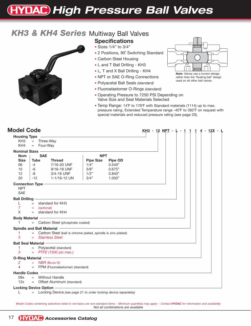
Specifications• Sizes 1/4” to 3/4”
• 2 Positions, 90˚ Switching Standard
• Carbon Steel Housing
• L and T Ball Drilling - KH3
• L, T and X Ball Drilling - KH4
• NPT or SAE O-Ring Connections
• Polyacetal Ball Seals (standard)
• Fluoroelastomer O-Rings (standard)
• Operating Pressure to 7250 PSI Depending onValve Size and Seal Materials Selected
• Temp Range: 14˚F to 176˚F with Standard materials (1114) up to max.pressure rating. Extended Temperature range -40˚F to 392˚F on request withspecial materials and reduced pressure rating (see page 20).
KH3 & KH4 Series Multiway Ball Valves
KH3 - 12 NPT - L - 1 1 1 4 - 12X - L
Housing TypeKH3 = Three-WayKH4 = Four-Way
Nominal SizesNom SAE NPTSize Tube Thread Pipe Size Pipe OD06 -4 7/16-20 UNF 1/4” 0.540”10 -6 9/16-18 UNF 3/8” 0.675”12 -8 3/4-16 UNF 1/2” 0.840”20 -12 1-1/16-12 UN 3/4” 1.050”
Connection TypeNPTSAE
Ball DrillingL = standard for KH3T = (optional)X = standard for KH4
Body Material1 = Carbon Steel (phosphate coated)
Spindle and Ball Material1 = Carbon Steel (ball is chrome plated, spindle is zinc-plated)3 = Stainless Steel
Ball Seal Material1 = Polyacetal (standard)3 = PTFE (1500 psi max.)
O-Ring Material2 = NBR (Buna N)4 = FPM (Fluoroelastomer) (standard)
Handle Codes09x = Without Handle12x = Offset Aluminum (standard)
Locking Device OptionL = Locking Device (see page 21 to order locking device separately)
Model Codes containing selections listed in red italics are non-standard items – Minimum quantities may apply – Contact HYDAC for information and availabilityNot all combinations are available
Model Code
Note: Valves use a trunion design,rather than the “floating ball” designused on all other ball valves.
17
High Pressure Ball Valves
2
13
2
13
1 3
2
1 3
2
2
4
13
2
4
13
1 3
2 4
1 3
2 4
1 3
2 4
Accessories Catalog 18
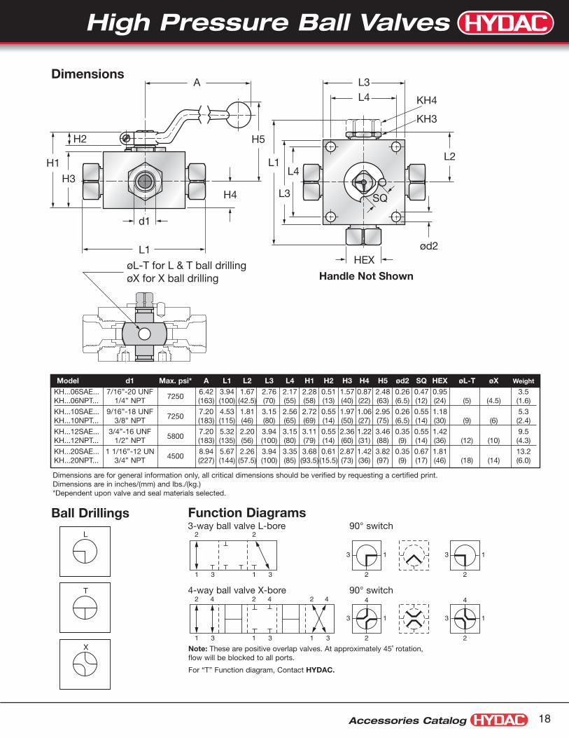
Dimensions
Function Diagrams 3-way ball valve L-bore 90° switch
4-way ball valve X-bore 90° switch
Dimensions are for general information only, all critical dimensions should be verified by requesting a certified print.Dimensions are in inches/(mm) and lbs./(kg.)*Dependent upon valve and seal materials selected.
Model d1 Max. psi* A L1 L2 L3 L4 H1 H2 H3 H4 H5 ød2 SQ HEX øL-T øX Weight
KH...06SAE... 7/16”-20 UNF7250
6.42 3.94 1.67 2.76 2.17 2.28 0.51 1.57 0.87 2.48 0.26 0.47 0.95 3.5KH...06NPT... 1/4” NPT (163) (100) (42.5) (70) (55) (58) (13) (40) (22) (63) (6.5) (12) (24) (5) (4.5) (1.6)
KH...10SAE... 9/16”-18 UNF7250
7.20 4.53 1.81 3.15 2.56 2.72 0.55 1.97 1.06 2.95 0.26 0.55 1.18 5.3KH...10NPT... 3/8” NPT (183) (115) (46) (80) (65) (69) (14) (50) (27) (75) (6.5) (14) (30) (9) (6) (2.4)
KH...12SAE... 3/4”-16 UNF5800
7.20 5.32 2.20 3.94 3.15 3.11 0.55 2.36 1.22 3.46 0.35 0.55 1.42 9.5KH...12NPT... 1/2” NPT (183) (135) (56) (100) (80) (79) (14) (60) (31) (88) (9) (14) (36) (12) (10) (4.3)
KH...20SAE... 1 1/16”-12 UN4500
8.94 5.67 2.26 3.94 3.35 3.68 0.61 2.87 1.42 3.82 0.35 0.67 1.81 13.2KH...20NPT... 3/4” NPT (227) (144) (57.5) (100) (85) (93.5) (15.5) (73) (36) (97) (9) (17) (46) (18) (14) (6.0)
L1
L1
H4
HEXøL-T for L & T ball drillingøX for X ball drilling
H3
H1
H5H2
L3
KH4
KH3
L4A
L4
ød2
SQ
L2
L3
d1
Handle Not Shown
Ball Drillings
L
T
X Note: These are positive overlap valves. At approximately 45˚ rotation,flow will be blocked to all ports.
For “T” Function diagram, Contact HYDAC.
High Pressure Ball Valves

Ball Valves
Accessories Catalog19
Ball Valve Actuators Pneumatic Operation
DescriptionThe HYDAC dependable rack and pinionpneumatic actuators are compact andefficient components with a trouble-free,high-cycle service life.
The double piston design allows significantlyreduced cylinder diameter and overall sizeas compared to single piston design.
Each piston has a gear rack that appliesan equal force at two points directly acrossthe diameter of a common pinion gear.
This feature, combined with the patentedsuspension system, creates a symmetri-cally balanced, center-mount actuatorwith a short, powerful stroke, rapidresponse, and fully concentric operatingloads for optimum life expectancy andperformance in control valve applications.
Product Features • Reliable rack and pinion design.
• High output torque and compactness
• Integrated air manifold and internal port-ing
• A solenoid valve can be mounteddirectly onto actuator body thusexternal piping is simplified
• Double-acting and single-acting (springreturn) models are available
• Self-lubricating bands reduce frictionand smooth piston travel, and increaseefficiency
• Limit switch available
KHB-25SAE-1114 - A 5 1 A A
Ball ValveAvailable for both KHB & KHM SeriesSee pages 5 - 17 for details on ball valve model codesNote: OMIT the Handle code rather than entering the code for no handle.
Actuator TypeA = Pneumatic - single (ESA) OR double acting (EDA)
Size*1 = 12 (recommended for valves KHB-06... & KHB-10)2 = 25 (recommended for valves KHB-16... & KHB-20)3 = 404 = 655 = 100 (recommended for valves KHB-25... & KHM-32)6 = 2007 = 350 (recommended for valves KHM-40... & KHM-50)
Operation1 = All Double acting (air to A to open, air to B to close)
2 = #2 Spring Set (balances with 40 psi)3 = #3 Spring Set (balances with 60 psi)4 = #4 Spring Set (balances with 80 psi) Single acting, spring return 5 = #5 Spring Set (balances with 100 psi) (air to A to open, spring to close)6 = #6 Spring Set (balances with 120 psi)
Limit SwitchesA = noneB = Standard Limit Switch Module (2 SPDT)
Additional OptionsA = noneB = Control Valve: 120V AC, Single Acting, 4-wayC = Control Valve: 24V DC, Single Acting, 4-way
Model Codes containing selections listed in red italics are non-standard items –Minimum quantities may apply - Contact HYDAC for information and availability
Not all combinations are available
Model Code: Ball Valve & Actuator Assemblies
*Recommendations for actuator size are based on a typical application: Double acting actuator, 3000 psi max. pressure, mineral based hydraulic fluid, 80-100 psi shop air, anda moderate duty cycle. Applications with Spring Return actuators, higher system pressures, low lubricity fluids, or infrequent cycling (< once/hr.) may require a larger size actua-tor. Please consult HYDAC Engineering Department for assistance sizing actuators for these applications.1) See pages 41 - 42 for information on solenoid valves.
Ordering: Pneumatic Actuators (double acting) & Mounting Kits
Ordering: Optional Accessories (model code / part number)
Valve Actuator Actuator Mounting Kit Size Model Code Part Number Part NumberKHB-06 (1/4”) EDA-12 02700204 02061508KHB-10 (3/8”) EDA-12 02700204 02061508KHB-16 (1/2”) EDA-25 02700205 02061509KHB-20 (3/4”) EDA-25 02700205 02061510KHB-25 (1”) EDA-100 02700206 02061511KHM-32 (1 1/4”) EDA-100 02700206 02061512KHM-40 (1 1/2”) EDA-350 02700207 02061513KHM-50 (2”) EDA-350 02700207 02061513
Limit Switch Box (2 SPDT switches)ACTUATOR LIMIT SWITCH HDN/2 02700282
Limit Switch Mounting Kit (for EDA-12)ACTUATOR LIMIT SWITCH MTG KIT MKN-12 02700283
Limit Switch Mounting Kit (for EDA-25 thru EDA-350)ACTUATOR LIMIT SWITCH MTG KIT MKN-25/350 02700284
Solenoid Control Valve(1 (120 VAC) 3-Way (for ESA) 020828884-Way (for EDA) 02082890
Solenoid Control Valve(1 (24 VDC) 3-Way (for ESA) 020828874-Way (for EDA) 02082889
Electric Actuators are also availableContact HYDAC for Details
High Pressure Ball Valves
Accessories Catalog 20
AB
Optional Limit Switch2.7"
6.3"
clearance requiredto remove cover
CLOSED
B2
B1B3
A
B
Actuator
Visual Indicator(standard)
H4
Mounting Kit
KHM (forged) type valve shownTie Bar DesignUsed With: KHB & KHB3K sizes -06, -10, -16, -20, -25
H32.00"
Ø 1.8"1.00"
H2
H1
L1
1/4" NPT(2 places)
1.26"
UNC10-24x.31(4 places)
0.95"
L2
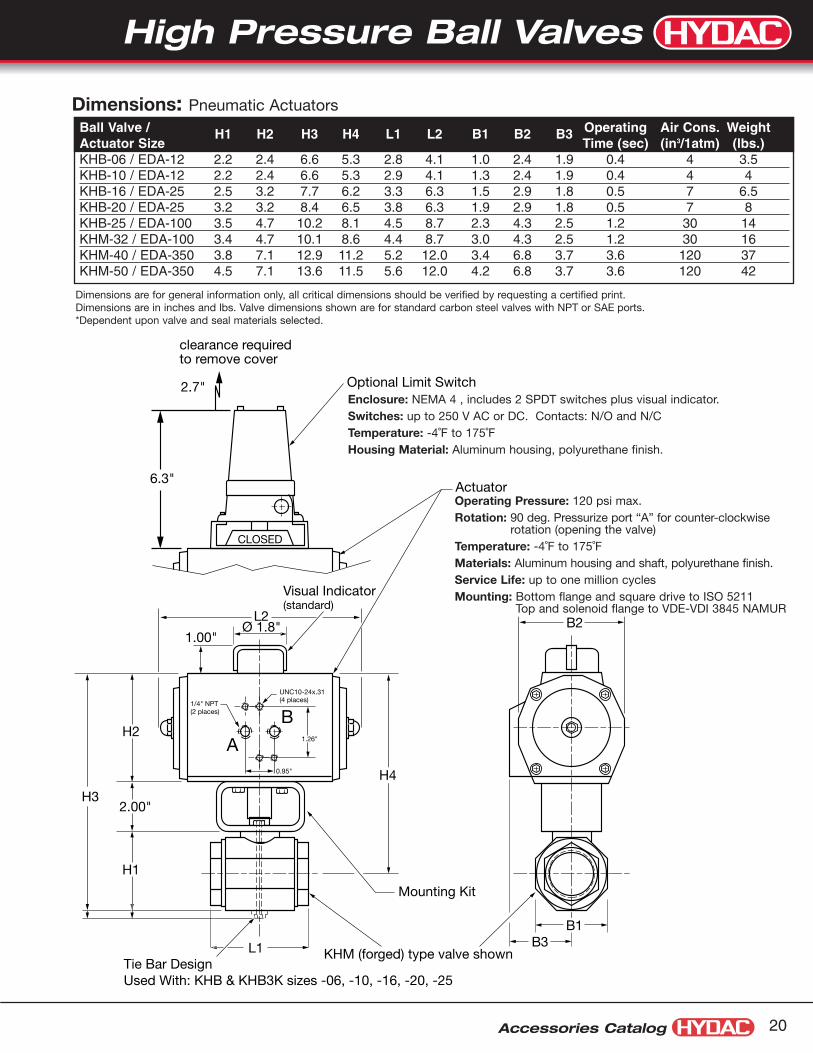
Dimensions: Pneumatic ActuatorsBall Valve / H1 H2 H3 H4 L1 L2 B1 B2 B3 Operating Air Cons. WeightActuator Size Time (sec) (in3/1atm) (lbs.)KHB-06 / EDA-12 2.2 2.4 6.6 5.3 2.8 4.1 1.0 2.4 1.9 0.4 4 3.5KHB-10 / EDA-12 2.2 2.4 6.6 5.3 2.9 4.1 1.3 2.4 1.9 0.4 4 4KHB-16 / EDA-25 2.5 3.2 7.7 6.2 3.3 6.3 1.5 2.9 1.8 0.5 7 6.5KHB-20 / EDA-25 3.2 3.2 8.4 6.5 3.8 6.3 1.9 2.9 1.8 0.5 7 8KHB-25 / EDA-100 3.5 4.7 10.2 8.1 4.5 8.7 2.3 4.3 2.5 1.2 30 14KHM-32 / EDA-100 3.4 4.7 10.1 8.6 4.4 8.7 3.0 4.3 2.5 1.2 30 16KHM-40 / EDA-350 3.8 7.1 12.9 11.2 5.2 12.0 3.4 6.8 3.7 3.6 120 37KHM-50 / EDA-350 4.5 7.1 13.6 11.5 5.6 12.0 4.2 6.8 3.7 3.6 120 42
Dimensions are for general information only, all critical dimensions should be verified by requesting a certified print.Dimensions are in inches and lbs. Valve dimensions shown are for standard carbon steel valves with NPT or SAE ports.*Dependent upon valve and seal materials selected.
Enclosure: NEMA 4 , includes 2 SPDT switches plus visual indicator.Switches: up to 250 V AC or DC. Contacts: N/O and N/CTemperature: -4˚F to 175˚FHousing Material: Aluminum housing, polyurethane finish.
Operating Pressure: 120 psi max.Rotation: 90 deg. Pressurize port “A” for counter-clockwise
rotation (opening the valve)Temperature: -4˚F to 175˚FMaterials: Aluminum housing and shaft, polyurethane finish.Service Life: up to one million cycles Mounting: Bottom flange and square drive to ISO 5211
Top and solenoid flange to VDE-VDI 3845 NAMUR
High Pressure Ball Valves

Ball Valves
Accessories Catalog21
Ball Valve Locking DevicesDescription:In situations where the opening or closing of a ball valve cancause severe damage or personal injury, HYDAC recommendsthe installation of a locking device. Locking devices are availablefor our entire range of high pressure ball valves. Two differentstyles are available to accommodate the different valve bodystyles. All HYDAC high pressure ball valves can be ordered with alocking device. Locking devices can also be ordered separatelyusing the chart below.Material note:All lock plates and lock bars are made of Zinc plated Steel.
OPEN
Apply Pad Lock (not supplied)here to lock in OPEN Postition
CLOSED
Apply Pad Lock (not supplied)here to lock in CLOSED Postition
Apply Pad Lock (not supplied)here to lock in OPEN Postition
Apply Pad Lock (not supplied)here to lock in CLOSED Postition
CLOSED
OPEN
CLOSED
Operation:KHM... KHB..., KHP..., KH3..., KH4..., KHB3K...
(forged valve bodies) (block valve bodies)
Installation:
Ordering:To order a ball valve with a locking device, simply add “-L” to the end of the model code.See the model code page for that particular valve to create a complete code.To order a locking device separately, use the chart below.
Size KHB KHM KHP KH3 & KH4 KHB3K6 02061169 02061169 N/A 02061172 02061175
10 02061169 02061169 02061169 02061173 02061175
12 N/A N/A N/A 02061173 N/A
16 02061170 02061170 02061170 N/A 02061176
20 02061171 02061171 02061171 02061174 02061177
25 02061171 02061171 02061171 N/A 02061177
32 N/A 02055711 02063434 N/A N/A
40 N/A 02055711 02063434 N/A N/A
50 N/A 02055711 02063434 N/A N/A
High Pressure Ball Valves

Accessories Catalog 22
Ball Valve Locking Devices with Limit SwitchesDescription:When remote indication of the valve position is required, a limit switchcan be added to the valve assembly.• A reliable single pole, double throw (SPDT) switch to indicate either
open or closed position of a two-way valve• Hermetically sealed• Can be wired as Normally Open (N/O), or Normally Closed (N/C)• Available for HYDAC valve sizes 20 through 50• Mounting brackets serve as locking devices
Ordering:To Order a valve with Limit Switch, Add “-LS” to end of ValveModel Code, i.e.: KHM-32NPT-1114-16X-LS
Operation:KHB..., KHP..., KH3..., KH4..., KHB3K... (block valve bodies, sizes 20 & 25)
KHM... (forged valve bodies, sizes 32 through 50)
Wiring Details: Electrical Specifications:• NEMA 3, 4, 13 and IEC IP 67• 5A-125, 250 VAC• Temperature range: 14 to 158˚F• UL listed
Valve Retrofit kit:Part #: 02067694
Valve Retrofit kit:Part #: 02063537
Replacement Switch:Part #: 02700009
High Pressure Ball Valves

SEAL KIT KHB - 06 NPT/SAE - XX14
Seal Kit
Valve Body TypeKHB = Block HousingKHM = Forged HousingKH3/4 = 3-Way & 4-Way ValvesKHP = Manifold Mount
Valve Size06, 10, 16, 20, 25, 32, 40,50
Connection Type(omit) = Manifold Mount (KHP)NPT/SAE = NPT or SAEF3/F6 = F3 or F6 Split Flange
Materials
Body MaterialX = Body material does not affect seal kits
Spindle and Ball MaterialX = Spindle and ball material does not affect seal kits
Ball Seal Material1 = Polyacetal (standard)3 = PTFE8 = PEEK
O-Ring Material2 = NBR (Buna N)3 = PTFE Spindle Seals and FPM (Fluoroelastomer) O-Rings4 = FPM (Fluoroelastomer) (standard)5 = EPDM
Model Codes containing selections listed in red italics are non-standard items – Minimum quantities may apply – Contact HYDAC for information and availabilityNot all combinations are available
Model Code
Ball Valves
Accessories Catalog23
Seal Kits High Pressure Ball Valves
O-Ring size 06-25O-Ring with Back-up Ring size 32-50
Ball Seal
Thrust Washer
O-Ring with Back-up Ring
Model Code Part NumberSEAL KIT KHB-06NPT/SAE-XX14 02061479SEAL KIT KHB-10NPT/SAE-XX14 02061467SEAL KIT KHB-16F3/F6-XX14 02061469SEAL KIT KHB-16NPT/SAE-XX14 02061468SEAL KIT KHB-20F3/F6-XX14 02061471SEAL KIT KHB-20NPT/SAE-XX14 02061470SEAL KIT KHB-25F3/F6-XX14 02061473SEAL KIT KHB-25NPT/SAE-XX14 02061472SEAL KIT KHM-32F3/F6-XX14 02061481SEAL KIT KHM-32NPT/SAE-XX14 02061480SEAL KIT KHM-40F3/F6-XX14 02061483SEAL KIT KHM-40NPT/SAE-XX14 02061482SEAL KIT KHM-50F3/F6-XX14 02061485SEAL KIT KHM-50NPT/SAE-XX14 02061484SEAL KIT KHP-06-XX14 00554029SEAL KIT KHP-10-XX14 02061486SEAL KIT KHP-16-XX14 02061487SEAL KIT KHP-20-XX14 02061507SEAL KIT KHP-25-XX14 02061488SEAL KIT KHP-32-XX14 02061489SEAL KIT KHP-40-XX14 02061505SEAL KIT KHP-50-XX14 02061506
Included Seals
Complete maintenance instructions are available on our web site:
Note: Above are the part numbers for standard kits. Other kits may be available, contact HYDAC for details.
High Pressure Ball Valves

Accessories Catalog 24
Handles
Engineering DataHousing
Block Type (KHB) Carbon Steel (standard) 14˚F Min temp
Forged Type (KHM) Forged Steel (standard) 14˚F Min tempStainless Steel (optional) -40˚F Min temp
Coatings Standard Models Phosphate Coated(Others available on Request)
Ball Chrome Plated Steel (standard)Stainless Steel (optional)
Spindle` Zinc Plated Steel (standard)Stainless Steel (optional)
Handles (see above)11X Straight Aluminum, Red
Anodized12X Offset Aluminum, Red Anodized16X Offset Steel, Galvanized
Ball SealPolyacetal (POM) Standard for Hydraulic Oils, Water Glycol
Maximum Pressure: to 7250 psi (500 bar)Temperature Range: -22° to 212°F (-30° to 100°C)
PTFE For Corrosive MediaMaximum Pressure: to 1500 psi (100 bar)Temperature Range: -328° to 212°F (-200° to 100°C)Temperature to 392°F (200°C) at reduced Pressure
(see chart at right for pressure-temperature profile)
NBR For Gaseous MediaMaximum Pressure: to 1500 psi (100 bar)Temperature Range: -13° to 212°F (-25° to 100°C)
(see chart at right for pressure-temperature profile)
PEEK High Temperature SealMaximum Pressure: to 7250 psi (500 bar)Temperature Range: -238° to 212°F (-150° to 100°C)Better high temperature profile than PTFETemperature to 482°F (250°C) at reduced Pressure
(see chart at right for pressure-temperature profile)
Spindle Seal & O-ringsFluorocarbon (FPM) Standard for hydraulic oils and many acids
Maximum Pressure: to 7250 psi (500 bar)Temperature Range: -4° to 392°F (-20° to 200°C)
NBR Seal for hydraulic oils, lubricants, greasesMaximum Pressure: to 7250 psi (500 bar)Temperature Range: -13° to 212°F (-25° to 100°C)
PTFE for corrosive media and basesMaximum Pressure: to 1500 psi (100 bar)Temperature Range: -328° to 212°F (-200° to 100°C)Temperature to 392°F (200°C) at reduced pressure
EPR Ethylene Propylene Rubber for some phosphate estersMaximum Pressure: to 7250 psi (500 bar)Temperature Range: -58° to 300°F (-50° to 150°C)
Special Seals Other materials are available for special applications.
Consult HYDAC for your specific application.
DN Description Model Spindle Model Code Part NumberSizes Designation Code Square Size06,10 Straight Aluminum 11X SW09 HANDLE STR AL SW09 0027009906,10 Offset Aluminum 12X SW09 HANDLE OFS AL SW09 0027142306,10 Offset Steel 16X SW09 HANDLE KIT OFS STL SW09 02064265*16 Straight Aluminum 11X SW12 HANDLE STR AL SW12 0027010016 Offset Aluminum 12X SW12 HANDLE OFS AL SW12 0027038116 Offset Steel 16X SW12 HANDLE KIT OFS STL SW12 02064266*20,25 Straight Aluminum 11X SW14 HANDLE STR AL SW14 0027010120,25 Offset Aluminum 12X SW14 HANDLE OFS AL SW14 0027038220,25 Offset Steel 16X SW14 HANDLE KIT OFS STL SW14 02064267*32,40,50 Offset Steel 16X SW17 HANDLE KIT OFS STL SW17 16X 02064268*32,40,50 Offset Aluminum 12X SW17 HANDLE OFS AL SW17 0027038332,40,50 Straight Aluminum 11X SW17 HANDLE STR AL SW17 00270311
Press-Temp curve for different Ball Seal materials
0
1000
2000
3000
4000
5000
6000
7000
8000
0 100 200 300 400Temp (F)
Pre
ssur
e (p
si)
valve size 6-10
valve size 16
valve size 20-50
POM (standard)
PTFE(all sizes)
Buna (all sizes)
Peek
* These handles require the additional mounting hardware which is included
High Pressure Ball Valves

Ball Valves
Accessories Catalog25
KHF3/6 Series Direct Mount SAE Flange 1/2” to 2”
Features• Compact, space saving design
• Full passage for unrestricted flow of medium
• Floating ball provides positive seal
• Valve positioning controlled by a stop pin and limit washer
• Phosphate coated valve body
Specifications• Connection: Dual bolt pattern fits Code 61 and 62 SAE flanges
• Operating Pressure: to 6000 psi
• Ball Seal Material: Polyacetal
• O-ring Material: Fluoroelastomer (FPM)
• Housing Material: Carbon Steel
• Temperature Range: 14˚ to 176˚F
Dimensions: KHF3/6 (1/2” to 2”)
Code 61 Code 62MAWP MAWP SW Weight
Size Model Code K3 G3 øD3 E3 (psi)* K6 G6 øD6 E6 (psi)* øB H1 H2 øLW L H C (mm) A (lbs)
1/2” KHF3/6-16-1114-16X-UNC 1.50 0.69 5/16”-18UNC 0.63 5000 1.59 0.72 5/16”-18UNC 0.63 6000 3.11 1.34 2.81 0.51 2.95 5.08 1.28 12 7.00 5.5
3/4” KHF3/6-20-1114-16X-UNC 1.87 0.88 3/8”-16UNC 0.71 5000 2.00 0.94 3/8”-16UNC 0.71 6000 3.90 1.73 3.54 0.75 3.15 5.79 1.35 14 7.00 8.6
1” KHF3/6-25-1114-16X-UNC 2.06 1.03 3/8”-16UNC 0.71 5000 2.25 1.09 7/16”-14UNC 0.83 6000 4.69 1.85 4.02 0.98 3.46 6.30 1.50 14 7.00 13.2
1 1/4” KHF3/6-32-1114-36X-UNC 2.31 1.19 7/16”-14UNC 0.71 4000 2.62 1.25 1/2”-13UNC 0.83 6000 5.47 2.32 4.88 1.18 3.94 8.31 1.73 17 12.0 25.6
1 1/2” KHF3/6-40-1114-36X-UNC 2.75 1.41 1/2”-13UNC 1.02 3000 3.12 1.44 5/8”-11UNC 1.02 6000 6.30 2.56 5.51 1.50 4.33 8.94 2.01 17 12.0 36.2
2” KHF3/6-50-1114-36X-UNC 3.06 1.69 1/2”-13UNC 1.02 3000 3.87 1.75 3/4”-10UNC 1.18 6000 7.05 2.86 6.17 1.89 4.57 9.61 2.13 17 12.0 54.9
≈H
E6
øD6
SW
K3
G6Code 62
Code 61
K6 H2G3
øD3
E3
H1
LøB
øLW
≈A C
Dimensions are for general information only, all critical dimensions should be verified by requesting a certified print.Dimensions are in inches and lbs. except where noted.
* Pressure rating listed is valve pressure only. Pressure ratings for available flanges may be less. Consult flange manufacturer and ISO 6162 for flange pressure rating.
Model Codes listed in red italics are non-standard items – Minimum quantities may apply – Contact HYDAC for information and availability
High Pressure Ball Valves

B
H
H1
øD
K
L
J
TøLWA
UNC
Dimensions: KHF3 (2 1/2” to 4”)
Size Model Code øLW L J H1 H øD A B UNC T K MAWP (psi)* Weight (lbs)2 1/2” KHF3-065-1114-05X-UNC 2.48 5.90 2.95 3.70 10.8 7.80 2.00 3.50 1/2”-13UNC 0.75 36 2500 73
3” KHF3-080-1114-05X-UNC 2.99 5.51 2.76 4.09 11.4 8.27 2.44 4.19 5/8”-11UNC 0.95 36 2000 88
4” KHF3-100-1114-05X-UNC 3.94 6.69 3.35 4.80 13.1 10.16 3.06 5.13 5/8”-11UNC 0.95 36 500 132
KHF3 Series Direct Mount SAE Flange 2 1/2” to 4”
Features• Compact, space saving design
• Full passage for unrestricted flow of medium
• Floating ball provides positive seal
• Phosphate coated valve body
• Individually tested for leakage free performance
Specifications• Connection: Bolt pattern fits code 61 SAE flanges
• Operating Pressure: to 2500 psi
• Ball Seal Material: Polyacetal
• O-ring Material: Fluoroelastomer (FPM)
• Housing Material: Carbon Steel
• Temperature Range: 14˚ to 176˚F
Accessories Catalog 26
Dimensions are for general information only, all critical dimensions should be verified by requesting a certified print.Dimensions are in inches and lbs.
Model Codes listed in red italics are non-standard items – Minimum quantities may apply – Contact HYDAC for information and availability
* Pressure rating listed is valve pressure only. Pressure ratings for available flanges may be less. Consult flange manufacturer and ISO 6162 for flange pressure rating.
High Pressure Ball Valves

Accessories Catalog27
KHF Series Ball Valves with Butt Weld Flanges
Features• Full passage for unrestricted flow of medium
• Floating ball design provides positive seal
• Butt Weld flanges allow for higher pressures than SAE code 61 flanges
Specifications• Connections:
Butt Weld adapters per pipe schedule XXS (extra, extra strong) or 160
• Operating pressure: Up to 6900 psi according to pipe schedule
• Housing Material: Carbon Steel
• Ball Seal Material: POM (Polyacetal)
• O-ring Material: FPM (Fluoroelastomer)
• Temperature range: 14F to 176F
KHF - 065 - BW - XXS - 1 1 1 4 - 05X - PN475
SeriesKHF = Ball Valve with Flange Connections
Size065, 080, 100, 125 (nominal size in mm)
Flange TypeBW = Butt Weld
Weld Adapter Pipe ScheduleXXS = Pipe Schedule XXS weld adapter160 = Pipe Schedule 160 weld adapter
Body & Flange Material1 = Carbon Steel
Ball & Spindle Material1 = Carbon Steel
Ball Seal Material1 = POM (Polyacetal)
Body Seal Material4 = FPM (Fluoroelastomer)
Handle Type05X = Straight Steel
Pressure RatingPN... = Pressure rating (in bar)Model Codes containing selections listed in red italics are non-standard items – Minimum quantities may apply – Contact HYDAC for information and availability
Not all combinations are available
Model Code
High Pressure Ball Valves

Accessories Catalog 28
ø D1ø D2ø LW
H1H
øD
9 UNC - screws
K
SW
I
L
Dimensions:
Size Model Code Connection øLW L l øD H H1 K SW ø D1 ø D2Dim. ofscrews
MAWP Weight
2-1/2”KHF-065-BW-XXS-1114-05X-
PN4752-1/2”
BW XXS2.56(65)
9.84(250)
5.91(150)
7.80(198)
10.20(259)
3.70(94)
24(600)
0.63(16)
2.87(73)
1.77(45)
1/2”UNC x1 3/4”
6900(475)
88(40)
3”KHF-080-BW-XXS-1114-05X-
PN4203”
BW XXS2.99(76)
10.24(260)
5.51(140)
8.27(210)
10.91(277)
3.94(100)
24(600)
0.75(19)
3.50(88.9)
2.30(58.4)
5/8”UNC x1 3/4”
6100(420)
95(43)
4”KHF-100-BW-XXS-1114-05X-
PN3654”
BW XXS3.94(100)
12.99(330)
6.69(170)
10.24(260)
12.87(327)
4.80(122)
36(900)
0.94(24)
4.50(114.3)
3.15(80.1)
5/8”UNC x1 3/4”
5300(365)
165(75)
5”KHF-125-BW-XXS-1114-05X-
PN3305”
BW XXS4.65(118)
14.57(370)
8.27(210)
11.81(300)
14.96(380)
5.51(140)
36(900)
1.42(36)
5.56(141.3)
4.06(103.2)
3/4”UNC x2 1/4”
4780(330)
265(120)
Ball Valves with Schedule XXS Butt Weld Flanges
Ball Valves with Schedule 160 Butt Weld Flanges
Dimensions are for general information only, all critical dimensions should be verified by requesting a certified print.Dimensions are in inches (mm), psi (bar) and lbs (kg).
Size Model Code Connection øLW L l øD H H1 K SW ø D1 ø D2Dim. ofscrews
MAWP Weight
2-1/2”KHF-065-BW-160-1114-05X-
PN2902-1/2”
BW 1602.56(65)
9.84(250)
5.91(150)
7.80(198)
10.20(259)
3.70(94)
24(600)
0.63(16)
2.87(73)
2.13(54)
1/2”UNC x1 3/4”
4200(290)
88(40)
3”KHF-080-BW-160-1114-05X-
PN2833”
BW 1602.99(76)
10.24(260)
5.51(140)
8.27(210)
10.91(277)
3.94(100)
24(600)
0.75(19)
3.50(88.9)
2.62(66.6)
5/8”UNC x1 3/4”
4100(283)
95(43)
4”KHF-100-BW-160-1114-05X-
PN2754”
BW 1603.94(100)
12.99(330)
6.69(170)
10.24(260)
12.87(327)
4.80(122)
36(900)
0.94(24)
4.50(114.3)
3.44(87.3)
5/8”UNC x1 3/4”
4000(275)
165(75)
5”KHF-125-BW-160-1114-05X-
PN2655”
BW 1604.65(118)
14.57(370)
8.27(210)
11.81(300)
14.96(380)
5.51(140)
36(900)
1.42(36)
5.56(141.3)
4.31(109.6)
3/4”UNC x2 1/4”
3850(265)
265(120)
High Pressure Ball Valves

Accessories Catalog29
KHM3H Series High Pressure 3 Piece Ball Valve
Specifications• 1/2" - 4" Standard Port• 1/2" - 2" Class 2500 ANSI (up to 6000 psi)
3" - 4" Class 1500 ANSI (up to 3800 psi)• Designed in accordance with ANSI B16.34 and BS5351• Blow-out proof stem• Handle operated or actuated• Available to NACE MR-0175, EN 10204• Available to API 607 4th edition, BS 6755 Pt2, API 6FA• Applications - Offshore, Oil & Gas, Chemical,
Petrochemical, Refining, Energy• Media - Liquid or Gas• Material - Stainless Steel, Carbon Steel• End Connections - Socket weld and threaded.
Other options available
Model CodeKHM3H - SP - 1 SW - 3 3 1 2.
Series TypeKHM3H = High Pressure 3 Piece Ball Valve
PortSP = Standard Port
Connection Size (inches)1/2, 3/4, 1, 1 1/4, 1 1/2, 2, 3, 4
Connection TypeSW = Socket WeldNPT = Tapered Pipe Threads
Body Material1 = Carbon Steel3 = Stainless Steel
Spindle & Ball Material3 = Stainless Steel
Ball Seal Material1 = POM (polyacetal) standard8 = PEEK for higher temperature applications (see chart below)
Body Seal Material2 = NBR (used with POM ball seal) standard8 = Graphite (used with PEEK ball seal) for higher temperature applications
Model Codes containing selections listed in red italics are non-standard items – Minimum quantities may apply – Contact HYDAC for information and availabilityNot all combinations are available
Pressure/Temperature Graph Torque/Pressure Graph
Class 2500
7000
6000
5000
4000
3000
2000
1000
0
400
300
200
100
250200100 1500 50
500400 450300 350200 250100 1500-50 500
Class 1500
bar
°C
°F
psi
PEEK
PEEK
POM
POM
Pre
ssur
e
Temperature
120 1000
900
700
700
600
500
400
300
200
100
0
100
80
60
20
40
5000 4000 3000 2000 1000 6000
1/2”
3/4”
1”
1 1/4”
1 1/2”
2”
0
350 300 250 200 150 100 50 0 400
0
Nm
psi
bar
in. lbs.
Torq
ue
Pressure
High Pressure Ball Valves

Accessories Catalog 30
Item Description Material
1 Body Stainless Steel 316L / Carbon Steel ASTM A105
2 End Connector Stainless Steel 316L / Carbon Steel ASTM A105
3 Ball Stainless Steel 316 (17-4PH 1/2”-3/4”)
4 Stem Stainless Steel 316 / Stainless Steel 17-4PH
5* Ball Seal POM / PEEK
6* Body Seal NBR / Graphite
7* Stem Thrust Seal PA (Nylon) / PEEK
8 Stop Pin Stainless Steel 316
9* Gland Packing PTFE - 25% Carbon Filled
10 Gland Stainless Steel 316
11 Disc Spring Stainless Steel 17-4PH
12 Gland Nut Stainless Steel 316 / Carbon Steel Zinc Plated
13 Tab Washer Stainless Steel
14 Handle Stainless Steel / Carbon Steel Zinc Plated
15 Serrated Washer Stainless Steel
16 Handle Nut Stainless Steel 316 / Carbon Steel Zinc Plated
17 Body Bolts Stainless Steel 316 / Carbon Steel Zinc Plated
18 Body Nuts Stainless Steel 316 / Carbon Steel Zinc Plated
Dimensions are for general information only, all critical dimensions should be verified by requesting a certified print.Dimensions are in inches and lbs.
M AcrossFlat
Dimensions (inches)Valve Size 1/2" - 2"
Valve Size 3" - 4"
Parts & Materials
High Pressure Ball Valves
Size Port A B C G øD H M N S T W LWeight
(Lb)1/2" 0.44 3.07 0.81 1.06 1.50 2.76 1.81 0.22 3/8" UNF 7.05 M5 - 1.34 3.5
3/4" 0.56 3.35 0.97 1.18 1.59 3.15 1.89 0.22 3/8" UNF 7.05 M5 0.59 1.34 5.3
1" 0.81 4.25 1.25 1.50 2.22 3.86 2.40 0.30 7/16" UNF 7.56 M5 0.94 1.65 10
1 1/4" 1.00 4.76 1.63 1.69 2.40 4.13 2.60 0.30 7/16" UNF 7.56 M5 0.94 1.65 12
1 1/2" 1.25 5.16 1.91 1.97 2.91 5.12 3.15 0.34 9/16" UNF 11.30 M6 1.42 1.57 21
2" 1.50 5.59 2.22 2.17 3.06 5.71 3.31 0.34 9/16" UNF 11.30 M6 1.57 2.28 29
3" 2.50 8.82 3.28 2.76 5.71 8.46 7.28 0.74 1" UNS 15.75 M12 2.36 5.51 86
4" 3.25 10.55 4.28 3.54 6.34 9.84 7.91 0.74 1" UNS 24.02 M12 2.76 5.91 141

Process & Automated Valves
Accessories Catalog31
Process & Automated ValvesIntroductionTraditionally the HYDAC product offering existed ofhigh pressure manual valves. As we grow and areexposed to new industries we are adding to ourproduct offering.
DescriptionHYDAC Automated Valves are pneumatically operated.Actuators allow valves to be operated automatically bya control system or manually from a remote location.Valve automation brings significant advantages to aplant in the areas of process quality, efficiency, safety,and productivity. Electric or hydraulically actuatedvalves available on special request.
Low Pressure Ball ValvesKHNVS Series (see page 32)
Nominal Sizes from 1/4” to 2”
Inline Isolation Valve + ActuatorHVA Series (see page 33)
Nominal Sizes from 3/8” to 2”
Angle Seat ValvesASV Series (see page 35)
Nominal Sizes from 3/8” to 2”
Automated 2 Piece Ball ValvesKHL Series (see page 37)
Nominal Sizes from 1/4” to 2”
Automated 3 Piece Ball ValvesKHM3L Series (see page 39)
Nominal Sizes from 1/4” to 2”
Solenoid ValvesNamur 3-way & 4-way (see page 41)
Process & Automated Valves
Accessories Catalog 32
DimensionsModel Code Part No.
Thread Dimensions mm (in.)(NPT) A B øC D
KHNVS-1/4NPT-3333 02074601 1/4” 57 100 13 51(2.24) (3.94) (0.51) (2.01)
KHNVS-3/8NPT-3333 02074602 3/8” 57 100 13 51(2.24) (3.94) (0.51) (2.01)
KHNVS-1/2NPT-3333 02074603 1/2” 60 100 13 51(2.36) (3.94) (0.51) (2.01)
KHNVS-3/4NPT-3333 02074604 3/4” 79 123 17.5 62(3.11) (4.84) (0.69) (2.44)
KHNVS-1NPT-3333 02074605 1” 85 123 22.3 67(3.35) (4.84) (0.88) (2.64)
KHNVS-1 1/4NPT-3333 02074606 1 1/4” 102 144 25.6 84(4.02) (5.67) (1.01) (3.31)
KHNVS-1 1/2NPT-3333 02074607 1 1/2” 111 144 32 89(4.37) (5.67) (1.26) (3.50)
KHNVS-2NPT-3333 02074608 2” 137 180 38.3 94(5.39) (7.09) (1.51) (3.70)
B
D
øCA
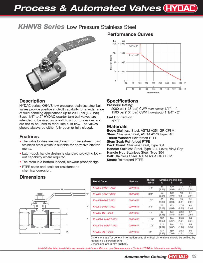
DescriptionHYDAC series KHNVS low pressure, stainless steel ballvalves provide positive shut-off capability for a wide rangeof fluid handling applications up to 2000 psi (138 bar).Sizes 1/4” to 2” HYDAC quarter turn ball valves areintended to be used as on-off flow control devices andare not to be used to modulate fluid flow. The valvesshould always be either fully open or fully closed.
Features• The valve bodies are machined from investment cast
stainless steel which is suitable for corrosive environ-ments.
• Latch-Lock handle design is standard providing lock-out capability where required.
• The stem is a bottom loaded, blowout proof design.
• PTFE seats and seals for resistance to chemical corrosion.
SpecificationsPressure Rating:
2000 psi (138 bar) CWP (non-shock) 1/4” - 1”1500 psi (104 bar) CWP (non-shock) 1 1/4” - 2”
End Connection:NPTF
MaterialsBody: Stainless Steel, ASTM A351 GR CF8MStem: Stainless Steel, ASTM A276 Type 316Thrust Washer: Reinforced PTFEStem Seal: Reinforced PTFEPack Gland: Stainless Steel, Type 304Handle: Stainless Steel, Type 304, Lever, Vinyl GripHandle Nut: Stainless Steel, Type 304Ball: Stainless Steel, ASTM A351 GR CF8MSeats: Reinforced PTFE
Performance Curves
32
1500
1000
500
0
2000
104
69
35
0
138psibar
50 350300250200150100 400
0 10 177149121936638 204
Pre
ssur
e R
atin
g
Temperature
1/4" to 1"
1 1/4" to 2"
KHNVS Series Low Pressure Stainless Steel
Model Codes listed in red italics are non-standard items – Minimum quantities may apply – Contact HYDAC for information and availability
Dimensions are for general information only, all critical dimensions should be verified byrequesting a certified print.Dimensions are in mm (inches).

Accessories Catalog33
Description• The HVA Series combines a pneumatic actuator and isola-
tion valve into one body, which acts as a automated on/offvalve.
Features and Benefits• Compact assembly / Saves space• High CV / Less restriction (low pressure drop)• Integrated actuators / Less parts to order and
no mounting kits• Integral NAMUR solenoid mounting pad
Models Available • NC: spring return, normally closed• NO: spring return, normally open• DA: double acting
Stroke Time (based on 80 psi actuating pressure)
Specifications• Temperature range: -4° to 302°F (-20° to 83°C)• Maximum pressure: 225 psi• Vacuum rating: 740mm Hg (97% vacuum)• Seats & Seals: VITON = High compatibility with majority
of fluids, not advised for steam.• Air pressure required: 40 to 125 psi for double acting,
60 to 125 psi for spring return• Body and Internals: Electroless Nickel Plated Brass
Model CodeHVA - 3/8 NPT- NO - 24VDC.
SeriesHVA = Valve + ActuatorPort Size (NPT)3/8”, 1/2”, 3/4”, 1”, 1 1/4”, 1 1/2”, 2”FunctionNO = Spring return, Normally open, Air to closeNC = Spring return, Normally closed, Air to openDA = Double actingSolenoid Valve Options(omit) = No solenoid valve included24VDC = 24 VDC solenoid valve included120VAC = 120 VAC solenoid valve includedNote: see page 41 - 42 for information on solenoid valves
Spring Return Double Acting
Size Spring Air Opening Air Closing Air
3/8" 20 mS 10 mS 10 mS 10 mS
1/2" 20 mS 10 mS 10 mS 10 mS
3/4" 30 mS 20 mS 20 mS 20 mS
1" 40 mS 20 mS 20 mS 20 mS
1 1/4" 70 mS 40 mS 30 mS 30 mS
1 1/2" 110 mS 60 mS 60 mS 60 mS
2" 130 mS 70 mS 70 mS 70 mS
HVA Series Inline Isolation Valve + Actuator
Process & Automated Valves
Model Codes listed in red italics are non-standard items – Minimum quantities may apply – Contact HYDAC for information and availability

Accessories Catalog 34
Cutaway View
Dimensions
1/8 NPTPorts
(2 places)
#10-24 UNCThreads
(4 places)
Namur Interface
øB
NPT Ports
E
A
C
NPT Port Size Cv A (in.) B (in.) C (in.) E (in.) Wt (lbs.) Air Consumption
3/8" 8 2.11 1.81 3.60 1.21 1.90 0.73 cu. inches
1/2" 10 2.33 2.00 4.21 1.31 2.30 1.05 cu. inches
3/4" 13 2.76 2.10 4.92 1.51 3.70 1.90 cu. inches
1" 17 3.00 2.72 5.31 1.63 4.15 2.45 cu. inches
1 1/4" 28 3.59 3.39 6.02 1.90 7.50 4.58 cu. inches
1 1/2" 57 4.00 3.78 6.73 2.12 8.15 6.70 cu. inches
2" 81 4.50 4.29 7.51 2.35 12.75 9.50 cu. inches
Dimensions are for general information only, all critical dimensions should be verified by requesting a certified print.
Process & Automated Valves

Accessories Catalog35
Model CodeASV - 1 NPT - 3333 - DA - 24DC.
SeriesASV =Angle Seat Valve
Port Size (NPT)3/8”, 1/2”, 3/4”, 1”, 1 1/4”, 1 1/2”, 2”
Materials2333 =Bronze body & SS plug,
PTFE seats & seals3333 =316SS body & plug,
PTFE seats & sealsFunction
NC =Spring return, normally closedDA =Double acting
Solenoid Valve Options(omit) =No solenoid valve included24VDC =24 VDC solenoid valve included120VAC=120 VAC solenoid valve included
Note: see page 41 - 42 for information on solenoid valves
Cutaway
SpecificationsTemperature Range
-14º to 358ºF (-25º to 181ºC)
Pressure/Viscosity Ratings• From 0 to 230 psi• Steam to 150 psi, Max 358°F• Max Viscosity 600CST
ASV...2333• Bronze Body & SS Plug• PTFE seats & seals
ASV...3333• 316 SS Body & Plug• PTFE seats & seals
Leakage rateANSI Class VI Shut off
ASV...2333 ASV...3333Bronze Stainless Steel
Valve SizeActuatorFunction
Closed toOpen (mS)
Open toClosed (mS)
3/8” NC 15 25
3/8” DA 5 5
1/2” NC 15 25
1/2” DA 5 5
3/4” NC 15 25
3/4” DA 5 5
1” NC 60 100
1” DA 10 10
1 1/4” NC 60 100
1 1/4” DA 10 10
1 1/2” NC 150 225
1 1/2” DA 15 15
2” NC 150 225
2” DA 15 15
DescriptionThe Angle Seat Valve is a 2-way pneumatically actuated plugvalve, which provides for automatic isolation of liquids, gases,steam and some aggressive fluids.Available with stainless steel or bronze bodies with plasticactuator housings.
Features and Benefits• Self aligning stem seal reduces potential leak points• High cycle life, provides long service life• Compact assembly / Saves space• Internal flow path designed to minimize pressure drop• NAMUR Solenoid mounting pad
Easy InstallationThe Angle Seat Valve can be mounted in any position.The actuator rotates 360° allowing for the selectivepositioning of the pneumatic inlet port.
Models Available• Spring Return N.C. Bi-directional Flow• Double Acting Bi-directional Flow
Stroke Time
ASV Series Angle Seat Valve
Process & Automated Valves
Model Codes listed in red italics are non-standard items – Minimum quantities may apply – Contact HYDAC for information and availability

Accessories Catalog 36
Dimensions
øE
G
C B
45°
1/8” BSP**NPT adapter is provided -
If you purchase ASVwithout solenoid valve
M5
1212
16A
Actuator can be rotated 360°
D
F
16
TypeNPTPortSize
CVASV...3333 (316 SS) ASV...2333 (Bronze) Wgt
(lbs)A (in) B (in) C (in) D (in) øE (in) F (in) G (in) A (in) B (in) C (in) D (in) øE (in) F (in) G (in)
NC/DA 3/8” 6 7.48 6.14 6.65 1.73 2.76 3.35 0.98 6.42 5.51 6.02 1.73 2.76 2.56 1.06 2.2
NC/DA 1/2" 7 7.48 6.14 6.65 1.73 2.76 3.35 0.98 6.42 5.51 6.02 1.73 2.76 2.56 1.06 2.2
DA 3/4" 12 7.68 6.30 6.93 1.73 2.76 3.74 1.22 6.81 5.79 6.42 1.73 2.76 2.95 1.08 2.6
NC 3/4" 12 8.39 7.00 7.65 1.99 3.32 3.74 1.22 7.52 6.5 7.13 1.99 3.32 2.95 1.08 2.6
DA 1” 23 8.62 7.17 7.95 1.99 3.32 4.13 1.50 8.11 6.93 7.72 1.99 3.32 3.54 1.61 3.5
NC 1” 23 10.20 8.74 9.53 2.61 4.58 4.13 1.50 9.69 8.50 9.29 2.61 4.58 3.54 1.61 3.7
DA 1 1/4” 33 8.90 7.32 8.23 1.99 3.32 4.72 1.85 8.46 7.09 8.07 1.99 3.32 4.33 1.97 4.2
NC 1 1/4” 33 10.47 8.90 9.80 2.61 4.58 4.72 1.85 10.04 8.66 9.65 2.61 4.58 4.33 1.97 6.6
DA 1 1/2” 54 10.67 9.06 10.16 2.61 4.58 5.12 2.13 10.63 9.25 10.39 2.61 4.58 4.72 2.28 7.9
NC 1 1/2” 54 12.09 10.47 11.57 3.05 5.54 5.12 2.13 12.05 10.67 11.81 3.05 5.54 4.72 2.28 8.8
DA 2” 78 11.22 9.45 10.79 2.61 4.58 5.91 2.60 11.02 9.45 10.83 2.61 4.58 5.91 2.76 9.5
NC 2” 78 12.64 10.87 12.20 3.05 5.54 5.91 2.60 12.44 10.87 12.24 3.05 5.54 5.91 2.76 11.7
Dimensions are for general information only, all critical dimensions should be verified by requesting a certified print.
Process & Automated Valves
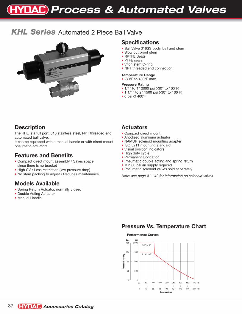
Accessories Catalog37
DescriptionThe KHL is a full port, 316 stainless steel, NPT threaded endautomated ball valve.It can be equipped with a manual handle or with direct mountpneumatic actuators.
Features and Benefits• Compact direct mount assembly / Saves space • since there is no bracket• High CV / Less restriction (low pressure drop)• No stem packing to adjust / Reduces maintenance
Models Available• Spring Return Actuator, normally closed• Double Acting Actuator• Manual Handle
Specifications• Ball Valve 316SS body, ball and stem• Blow out proof stem• RPTFE Seats• PTFE seals• Viton stem O-ring• NPT threaded end connection
Temperature Range• -30°F to 400°F max
Pressure Rating• 1/4” to 1” 2000 psi (-30° to 100°F)• 1 1/4” to 2” 1500 psi (-30° to 100°F)• 0 psi @ 400°F
Actuators• Compact direct mount• Anodized aluminum actuator• NAMUR solenoid mounting adapter• ISO 5211 mounting standard• Visual position indicators• High duty cycle• Permanent lubrication• Pneumatic double acting and spring return• Min 80 psi air supply required• Pneumatic solenoid valves sold separately
Note: see page 41 - 42 for information on solenoid valves
Pressure Vs. Temperature ChartPerformance Curves
32
1500
1000
500
0
2000
104
69
35
0
138psibar
50 350300250200150100 400
0 10 177149121936638 204
Pre
ssur
e R
atin
g
Temperature
1/4" to 1"
1 1/4" to 2"
KHL Series Automated 2 Piece Ball Valve
Process & Automated Valves

Accessories Catalog 38
Dimensions:with normally closed spring return pneumatic actuator(NPT threaded end connection, 2 piece body)
with double acting pneumaticactuator(NPT threaded end connection, 2 piece body)
with manual handle(NPT threaded end connection, 2 piece body)
A
B
C
E F
D
A
B
C
E F
D
A
B
C
E
F
D
CVSizeNPT
A(in)
B(in)
C(in)
D(in)
E(in)
F(in)
Wgt.(lbs)
Model CodePart No.
13 1/4" 2.56 8.62 4.85 2.15 1.65 2.28 3.9KHL-1/4NPT-3333-NC
02083087
13 3/8" 2.56 8.62 4.85 2.15 1.65 2.34 3.9KHL-3/8NPT-3333-NC
02083090
23 1/2" 2.95 8.62 4.85 2.15 1.65 2.35 3.9KHL-1/2NPT-3333-NC
02083093
70 3/4" 3.15 9.36 5.36 2.54 1.77 2.71 5.7KHL-3/4NPT-3333-NC
02083096
116 1" 3.54 11.47 5.99 2.81 2.05 3.05 7.5KHL-1NPT-3333-NC
02083099
151 1 1/4" 4.33 11.47 6.22 2.81 2.28 3.63 8.6KHL-1 1/4NPT-3333-NC
02083102
197 1 1/2" 4.72 12.48 7.32 3.12 2.68 4.33 13.0KHL-1 1/2NPT-3333-NC
02083105
325 2" 5.51 13.92 8.10 3.51 3.07 4.85 18.5KHL-2NPT-3333-NC
02083108
CVSizeNPT
A(in)
B(in)
C(in)
D(in)
E(in)
F(in)
Wgt.(lbs)
Model CodePart No.
13 1/4" 2.56 5.07 4.85 2.15 1.65 2.28 3.2KHL-1/4NPT-3333-DA
02083088
13 3/8" 2.56 5.07 4.85 2.15 1.65 2.34 3.2KHL-3/8NPT-3333-DA
02083091
23 1/2" 2.95 5.07 4.85 2.15 1.65 2.35 3.3KHL-1/2NPT-3333-DA
02083094
70 3/4" 3.15 5.07 4.97 2.15 1.77 2.71 3.5KHL-3/4NPT-3333-DA
02083097
116 1" 3.54 5.62 5.48 2.34 2.05 3.05 5.0KHL-1NPT-3333-DA
02083100
151 1 1/4" 4.33 5.62 5.71 2.34 2.28 3.63 6.1KHL-1 1/4NPT-3333-DA
02083103
197 1 1/2" 4.72 6.59 6.62 2.81 2.68 4.33 9.4KHL-1 1/2NPT-3333-DA
02083106
325 2" 5.51 6.59 7.01 2.81 3.07 4.92 12.4KHL-2NPT-3333-DA
02083109
CVSizeNPT
A(in)
B(in)
C(in)
D(in)
E(in)
F(in)
Wgt.(lbs)
Model CodePart No.
13 1/4" 2.56 4.48 2.80 1.26 1.65 2.28 1.2KHL-1/4NPT-3333
02083086
13 3/8" 2.56 4.48 2.80 1.38 1.65 2.34 1.2KHL-3/8NPT-3333
02083089
23 1/2" 2.95 4.48 2.96 1.40 1.65 2.35 1.2KHL-1/2NPT-3333
02083092
70 3/4" 3.15 5.24 2.96 1.88 1.77 2.71 1.4KHL-3/4NPT-3333
02083095
116 1" 3.54 5.24 3.00 2.00 2.05 3.05 2.6KHL-1NPT-3333
02083098
151 1 1/4" 4.33 7.44 3.80 2.70 2.28 3.63 3.7KHL-1 1/4NPT-3333
02083101
197 1 1/2" 4.72 7.44 4.00 3.30 2.68 4.33 5.7KHL-1 1/2NPT-3333
02083104
325 2" 5.51 7.44 4.40 3.70 3.07 4.92 8.8KHL-2NPT-3333
02083107
Note: Actuators are sized for 300 psi ΔP
Dimensions are for general information only, all critical dimensions should be verified by requesting a certified print.
Process & Automated Valves
Model Codes listed in red italics are non-standard items – Minimum quantities may apply – Contact HYDAC for information and availability

Accessories Catalog39
DescriptionThe KHM3L is a full port, 316 stainless steel, 3 piece ballvalve. It is available with NPT threads or socket weld connec-tors.It can be equipped with a manual handle or with direct mountpneumatic actuators.
Features and Benefits• Compact direct mount assembly / Saves space • since there is no bracket• High CV / Less restriction (low pressure drop)• No stem packing to adjust / Reduces maintenance• 3 piece design allows inline maintenance for
socket weld connections
Models Available• Spring Return Actuator, normally closed• Double Acting Actuator• Manual Handle
Specifications• Ball Valve 316SS body, ball and stem• Blow out proof stem• RPTFE seats• PTFE seals• Viton stem o-ring
Temperature Range• -30°F to 400°F max
Pressure Rating• 1000 psi @ -30° to 100°F• 0 psi @ 400°F
Actuators• Compact direct mount• Anodized aluminum actuator• NAMUR solenoid mounting adapter• ISO 5211 mounting standard• Visual position indicators• High duty cycle• Permanent lubrication• Pneumatic double acting and spring return• Min 80 psi air supply required• Pneumatic solenoid valves sold separately
Note: see page 41 - 42 for information on solenoid valves
Pressure Vs. Temperature Chart
1000
800
600
400
200
04003002001000-30 500
1200
Temperature in °F
Pre
ssur
e in
PS
I
KHM3L Series Automated 3 Piece Ball Valve
Process & Automated Valves

Accessories Catalog 40
Dimensionswith normally closed spring return pneumatic actuator
with double actingpneumatic actuator
with manual handleB
C
E
F
A
D
B
C
E
F
AD
CV SizeA
(in)B
(in)C(in)
D(in)
E(in)
F(in)
Wt(lbs.)
ThreadedModel Code
Part No.
Socket WeldModel Code
Part No.
13 1/4” 2.56 4.80 3.11 1.92 1.65 2.60 1.5KHM3L-1/4NPT-3333
02083038KHM3L-1/4SW-3333
02083041
13 3/8” 2.56 4.80 3.11 1.92 1.65 2.60 1.5KHM3L-3/8NPT-3333
02083044KHM3L-3/8SW-3333
02083047
23 1/2” 2.95 4.80 3.23 1.92 1.65 2.60 1.5KHM3L-1/2NPT-3333
02083050KHM3L-1/2SW-3333
02083053
70 3/4” 3.15 4.80 3.35 1.98 1.77 2.75 1.7KHM3L-3/4NPT-3333
02083056KHM3L-3/4SW-3333
02083059
116 1” 3.54 7.48 3.74 2.52 2.05 3.32 3.1KHM3L-1NPT-3333
02083062KHM3L-1SW-3333
02083065
151 1 1/4” 4.33 7.48 3.94 2.89 2.28 3.68 4.4KHM3L-1 1/4NPT-3333
02083068KHM3L-1 1/4SW-3333
02083071
197 1 1/2” 4.72 8.07 4.41 3.23 2.68 4.30 6.7KHM3L-1 1/2NPT-3333
02083074KHM3L-1 1/2SW-3333
02083077
325 2” 5.51 8.07 4.76 3.71 3.07 4.85 10.0KHM3L-2NPT-3333
02083080KHM3L-2SW-3333
02083083
CV SizeA
(in)B
(in)C(in)
D(in)
E(in)
F(in)
Wt(lbs.)
ThreadedModel Code
Part No.
Socket WeldModel Code
Part No.
13 1/4” 2.56 5.07 4.85 2.15 1.65 2.60 3.5KHM3L-1/4NPT-3333-DA
02083040KHM3L-1/4SW-3333-DA
02083043
13 3/8” 2.56 5.07 4.85 2.15 1.65 2.60 3.5KHM3L-3/8NPT-3333-DA
02083046KHM3L-3/8SW-3333-DA
02083049
23 1/2” 2.95 5.07 4.85 2.15 1.65 2.60 3.6KHM3L-1/2NPT-3333-DA
02083052KHM3L-1/2SW-3333-DA
02083055
70 3/4” 3.15 5.07 4.97 2.15 1.77 2.75 3.9KHM3L-3/4NPT-3333-DA
02083058KHM3L-3/4SW-3333-DA
02083061
116 1” 3.54 5.62 5.48 2.34 2.05 3.32 5.9KHM3L-1NPT-3333-DA
02083064KHM3L-1SW-3333-DA
02083067
151 1 1/4” 4.33 5.62 5.71 2.34 2.28 3.68 7.2KHM3L-1 1/4NPT-3333-DA
02083070KHM3L-1 1/4SW-3333-DA
02083073
197 1 1/2” 4.72 6.59 6.62 2.81 2.68 4.30 10.1KHM3L-1 1/2NPT-3333-DA
02083076KHM3L-1 1/2SW-3333-DA
02083079
325 2” 5.51 6.59 7.01 2.81 3.07 4.85 13.5KHM3L-2NPT-3333-DA
02083082KHM3L-2SW-3333-DA
02083085
CV SizeA
(in)B
(in)C(in)
D(in)
E(in)
F(in)
Wt(lbs.)
ThreadedModel Code
Part No.
Socket WeldModel Code
Part No.
13 1/4” 2.56 8.62 4.85 2.15 1.65 2.60 4.3KHM3L-1/4NPT-3333-NC
02083039KHM3L-1/4SW-3333-NC
02083042
13 3/8” 2.56 8.62 4.85 2.15 1.65 2.60 4.3KHM3L-3/8NPT-3333-NC
02083045KHM3L-3/8SW-3333-NC
02083048
23 1/2” 2.95 8.62 4.85 2.15 1.65 2.60 4.3KHM3L-1/2NPT-3333-NC
02083051KHM3L-1/2SW-3333-NC
02083054
70 3/4” 3.15 9.36 5.36 2.54 1.77 2.75 6.2KHM3L-3/4NPT-3333-NC
02083057KHM3L-3/4SW-3333-NC
02083060
116 1” 3.54 11.47 5.99 2.81 2.05 3.32 8.4KHM3L-1NPT-3333-NC
02083063KHM3L-1SW-3333-NC
02083066
151 1 1/4” 4.33 11.47 6.22 2.81 2.28 3.68 9.4KHM3L-1 1/4NPT-3333-NC
02083069KHM3L-1 1/4SW-3333-NC
02083072
197 1 1/2” 4.72 12.48 7.32 3.12 2.68 4.30 14.3KHM3L-1 1/2NPT-3333-NC
02083075KHM3L-1 1/2SW-3333-NC
02083078
325 2” 5.51 13.92 8.10 3.51 3.07 4.85 20.1KHM3L-2NPT-3333-NC
02083081KHM3L-2SW-3333-NC
02083084
B
C
EF
A
D
Note: Actuators are sized for 300 psi ΔP
Dimensions are for general information only, all critical dimensions should be verified by requesting a certified print.
Process & Automated Valves
Model Codes listed in red italics are non-standard items – Minimum quantities may apply – Contact HYDAC for information and availability
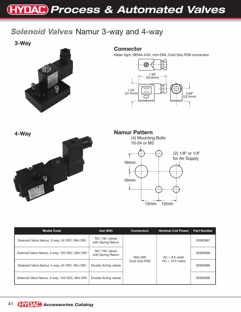
Accessories Catalog41
Solenoid Valves Namur 3-way and 4-way
Model Code Use With Connectors Nominal Coil Power Part Number
Solenoid Valve Namur, 3-way, 24 VDC, Mini DINNO / NC valves
with Spring Return
Mini-DINCord Grip PG9
AC = 8.5 wattsDC = 10.5 watts
02082887
Solenoid Valve Namur, 3-way, 120 VDC, Mini DINNO / NC valves
with Spring Return02082888
Solenoid Valve Namur, 4-way, 24 VDC, Mini DIN Double Acting valves 02082889
Solenoid Valve Namur, 4-way, 120 VDC, Mini DIN Double Acting valves 02082890
1.99”(50.6mm)
1.24”(31.5mm) 0.89”
(22.5mm)
12mm 12mm
16mm
16mm
(4) Mounting Bolts10-24 or M5
(2) 1/8” or 1/4”for Air Supply
4-Way
3-WayConnectorWater tight, NEMA 4/4X, mini-DIN, Cord Grip PG9 connection
Namur Pattern
Process & Automated Valves

Accessories Catalog 42
Dimensions:3-way Solenoid Valve used with N.O. or N.C. Valves2 Sets of bolts provided: #10-24 and M5
4-way Solenoid Valve used with Double Acting Valves2 Sets of bolts provided: #10-24 and M5
0.25
2.04
1.00
0.53
1.51
1.75
1.94
1.19
0.88
1.570.74
0.25
0.05
0.34
IN
AB
0.67 0.56
1/4 NPT (2) Ports
0.88
1.00
1.94
2.50
O-Ring (2) Supplied
VENT
0.94
IN
BA
3 4
0.94
1.56
0.381.87
5.02
0.67
0.58
E A E B
0.58
0.75
1/4” NPT (3 places)
0.47 0.47
1.26
0.15ø 0.228 Locating Hole
0.78
O-Ring (2) Supplied
1.381.59
0.75
Standard Push TypeManual Override
Dimensions are in inches. Dimensions are for general information only, all critical dimensions should be verified by requesting a certified print.
Process & Automated Valves

Ball ValvesFlow Control Valves
Accessories Catalog43
Overview of Flow Control ValvesNeedle Valves DV, DVE & DVP Series (see page 45)
Flow Control Valves DRV & DRVP Series (see page 49)
Pressure Compensated Flow Control Valves SRVR Series (see page 53)
Stainless Steel Flow Control Valves DV, DRV & RV Series (see page 57)
Check Valves RV & RVP Series (see page 55)

Accessories Catalog 44
Flow Control Valves
12345
KnobLockingSet Screw
Color CodedFlowIndicator
SlottedSpindle
B A
NPT, SAE orBSPP Ports
Threaded SpindleHousing for PanelMounting Kit
Safety Screwand Spindle
GuidedPoppet
Flow Control Valve Design Features, & Options
IntroductionOur complete line of flow control valves are designedand manufactured by our ISO 9001 certifiedFLUTEC Division.
Description• The HYDAC family of flow control valves permit
safe, simple and repeatable control of hydraulicfluids at operating pressures to 5000 psi.
• The standard slotted control spindle allows for awide range of infinitely variable flow adjustmentswith excellent flow characteristics.
• Precise adjustment of flow is achieved by amicrometer style adjustment knob featuring a colorcoded flow indicator for accurate, easy-to readvisual flow reference.
• Design modifications and special materials areavailable for corrosive fluids such as phosphateester, acids and caustics.
Valve DesignHYDAC flow control valves can be adjusted easilyand precisely by means of the control knob.Increasing the number of turns from the fully closedposition provides a steady increase of the flow rate.The colored scale permits accurate repetition of set-tings and the colored triangle on the rising spindleprovides a visual indication of the increasing crosssection of the flow area. A set screw on the sidelocks the knob at the desired setting.
HYDAC flow control valves include a unique safetyspindle design feature. As the valve spindle is turnedcounter-clockwise, the spindle shoulder will engage thesafety screw limiting the travel of the spindle. The hard-ened, high-strength steel safety screw is sealed in posi-tion to discourage tampering.
Product Features• Phosphate coated steel valve body
• FPM (Fluoroelastomer) seals
• Slotted control spindle for precise and linear flowadjustments
• Exclusive safety spindle design
• Color coded spindle for accurate flow control
• Guided poppets for smoother, chatter free operation
Available Options• Steel knobs for ambient temperature in excess of
140°F / 60°C
• Panel mounting kit
• 25 and 65 PSI cracking pressure springs(7 psi standard)
• Zinc Plated Body. Consult HYDAC for price and delivery

Accessories Catalog45
Model Code
DV, DVE, & DVP Series Needle Valves
DV - 06 - 01 .X / 5 - S - MNeedle Valve
DV = Inline MountingDVP = Manifold MountingDVE = Cartridge Valve
Nominal SizesDV & DVP SAE (DV only) NPTF (DV Only) BSPP (DV Only)
Nom. Size Tube Size Thread Size Pipe Size Pipe OD Thread Size06 = 1/8” 0.405” G1/808 = -4 7/16-20 UNF 1/4” 0.540” G1/410 = -6 9/16-18 UNF 3/8” 0.675” G3/812 = -8 3/4-16 UNF 1/2” 0.840” G1/216 = -12 1-1/16-12 UN 3/4” 1.050” G3/420 = -16 1-5/16-12 UN 1” 1.315” G125 = -20 1-5/8-12 UN 1-1/4” 1.660” G1 1/430 = -24 1-7/8-12 UN 1-1/2” 1.900 G1 1/2
DVENom Size SAE Cavity BSPP Cavity08 = 3/4-16 UNF G1/2 10 = 7/8-14 UNF G1/2 12 = 1-1/16-12 UN G3/4 16 = 1-5/16-12 UN G1
Housing Material01 = Carbon Steel
Modification NumberPort Configuration
5 = NPTF - ANSI B1.20.312 = SAE - SAEJ1926 Ports with ISO 725 Threads and O-Ring Sealing0 = BSPP to DIN 3852, Part 2-X (special order)(omit) = DVP Only
Supplementary DetailsS = Panel Mounting Kit (for nominal size 20, 25, and 30 panel mount valves are only available with steel knobs)M = Steel Knob (use when ambient temperature exceeds 140ºF)
Model Codes containing selections listed in red italics are non-standard items – Minimum quantities may apply – Contact HYDAC for information and availabilityNot all combinations are available
DVInline Mounting
DVECartridge Valve
DVPManifold Mounting
A B
Hydraulic Symbol
Specifications• 5000 psi operating Pressure
• 8 Sizes, 1/8” - 1-1/2”
• SAE O-Ring, NPT or BSPP Threaded Connections;Manifold Mounting; and Cartridge Type
• Flows to 80 gpm
• Carbon steel housing
• FPM (Fluoroelastomer) O-Rings (standard)
• Color coded spindle for accurate flow control
• Provision for panel mounting
• Unique safety spindle design
• Temperature Range:-4˚F to 212˚F at full pressure
Flow Control Valves

Accessories Catalog 46
40
80
60
40
20
100
0181614 20
5
4
3
Δp
(bar
)
121086420
1 1.5 2 2.5Flow setting in turns
Q (l/min)
Size 06
80
60
40
20
100
075604530150 90
1 2 3 4 5 6 7Flow setting in turns
8
Δp
(bar
)
Q (l/min)
Size 12
80
60
40
20
100
050403020100 60
7
6
1 32 4Flow setting in turns
5
Δp
(bar
)
Q (l/min)
Size 10
80
60
40
20
100
0250200150100500 300
9
8
7
1 4 52 3Flow setting in turns
6
Δp
(bar
)
Q (l/min)
Size 20, 25, 30
80
60
40
20
100
0403020100 50
71 2 3 4
Flow setting in turns5 6
Δp
(bar
)Q (l/min)
Size 08
80
60
40
20
100
01501209060300 180
10
9
81 2 3 4
Flow setting in turns5 6 7
Δp
(bar
)
Q (l/min)
Size 16
50403020100
0.5 1 1.5 2 3
4
567
Flow setting in turns
Q (l/min)
Size 08
40
30
20
10
50
01201401008060200 160
1 2 3 4 5 6Flow setting in turns
8
7
910
Δp
(bar
)
Q (l/min)
Size 12
40
30
20
10
50
0403020100 706050 80
6
789
0.5 1 1.5 2 3 4Flow setting in turns
5
Δp
(bar
)
40
30
20
10
50
0
Δp
(bar
)
Q (l/min)
Size 10
40
30
20
10
50
0140120100806040200 160
109
8
1 2 3 4Flow setting in turns
5 6
7
Δp
(bar
)
Q (l/min)
Size 16
Pressure Drop Curves: DV, DVP, DRV, DRVP Flow Control ValvesFlow Direction: A to B / Throttled Flow
Pressure Drop Curves: DVE Cartridge Flow Control ValvesFlow Direction: A to B / Throttled Flow
Pressure Drop curves were established by using mineral oil with kinematic viscosity 165 SUS at 112°F / 50°C
Flow Control Valves

Accessories Catalog47
F
E
Knob forSizes 20-40
has Hex extensionfor wrench
Hex extension
Knob for sizes 6-16 B
closed
Aopen
D
C
J
12345
Thicknessof panel
1/4" max.
Panel Mount Kit(Nut, Washer, Lock Washer)
12345
øH required hole sizein panel
øG
Model Port Size WeightCode NPTF SAE A B C D E F øG øH J1) Hex [lbs. (kg)]
DV-06 1/8” 5/16-24UNF 2.16 1.97 0.31 0.63 0.75 1.50 0.94 0.51 Pg 7 0.26(55) (50) (8) (16) (19) (38) (24) (13) thread - (0.12)
DV-08 1/4” 7/16-20UNF 2.83 2.56 0.49 0.98 0.94 1.89 1.14 0.75 Pg 11 0.55 (72) (65) (12.5) (25) (24) (48) (29) (19) thread - (0.25)
DV-10 3/8” 9/16-18UNF 2.91 2.64 0.59 1.18 1.14 2.28 1.14 0.75 Pg 11 0.88 (74) (67) (15) (30) (29) (58) (29) (19) thread - (0.40)
DV-12 1/2” 3/4-16UNF 3.62 3.23 0.69 1.38 1.34 2.68 1.50 0.91 Pg 16 1.5 (92) (82) (17.5) (35) (34) (68) (38) (23) thread - (0.70)
DV-16 3/4” 1-1/16-12UN 4.17 3.78 0.89 1.77 1.53 3.07 1.50 0.91 Pg 16 2.6 (105) (96) (22.5) (45) (39) (78) (38) (23) thread - (1.2)
DV-20 1” 1-5/16-12UN 5.71 5.04 0.98 1.97 2.13 4.25 1.93 1.50 Pg 29 3/4 4.6(145) (128) (25) (50) (54) (108) (49) (38) thread (19) (2.1)
DV-25 1-1/4” 1-5/8-12UN 5.91 5.24 1.18 2.36 2.13 4.25 1.93 1.50 Pg 29 3/4 6.2(150) (133) (30) (60) (54) (108) (49) (38) thread (19) (2.8)
DV-30 1-1/2” 1-7/8-12UN 6.10 5.43 1.38 2.76 2.13 4.25 1.93 1.50 Pg 29 3/4 7.7(155) (138) (35) (70) (54) (108) (49) (38) thread (19) (3.5)
Dimensions: DV Inline Needle Valve
1)Note:Pg style thread per DIN 40430Dimensions are for general information only, all critical dimensions should beverified by requesting a certified print.Dimensions are in inches/(mm) and lbs./(kg.) Size Model Code Part Number
6 Kit Panel Mount DV06 00705300
8/10 Kit Panel Mount DV08 00705310
12/16 Kit Panel Mount DV12 00705302
20/25/30 Kit Panel Mount DV20 00705312
Panel Mount Kits
Flow Control Valves

Model Nominal WeightCode Size A B øC øD E øF G(1 H J K L M N øO øP R S T U(2 Hex [lbs. (kg)]
DVP-06 1/8”2.48 2.28 .43 .26 .63 .94 _ .748 1.38 1.112 1.63 0.059 .630 0.197 0.382 0.315 0.35 0.37 Pg 7 _ 0.44(63) (58) (11) (6.6) (16) (24) (19) (35) (28.5) (41.5) (1.5) (16) (5) (9.7) (8) (9) (9.5) thread (0.2)
DVP-08 1/4”3.11 2.83 .43 .26 .79 1.14 _ 1.378 1.87 1.319 1.81 0.177 1.004 0.276 0.500 0.256 0.51 0.47 Pg 11 _ 0.88(79) (72) (11) (6.6) (20) (29) (35) (47.5) (33.5) (46) (4.5) (25.5) (7) (12.7) (6.5) (13) (12) thread (0.4)
DVP-10 3/8”3.31 3.03 .43 .26 .98 1.14 _ 1.319 2.01 1.496 2.01 0.165 1.004 0.394 0.614 0.335 0.71 0.55 Pg 11 _ 1.3(84) (77) (11) (6.6) (25) (29) (33.5) (51) (38) (51) (4.2) (25.5) (10) (15.6) (8.5) (18) (14) thread (0.6)
DVP-12 1/2”3.90 3.50 .43 .26 .98 1.50 _ 1.496 2.95 1.752 2.26 0.157 1.181 0.512 0.732 0.728 0.71 0.89 Pg 16 _ 2.2(99) (89) (11) (6.6) (25) (38) (38) (75) (44.5) (57.5) (4.0) (30) (13) (18.6) (18.5) (18) (22.5) thread (1.0)
DVP-16 3/4”4.45 4.05 .55 .35 1.18 1.50 1.496 2.992 3.68 2.126 2.76 0.433 2.126 0.669 0.965 0.335 0.83 0.77 Pg 16 _ 3.7(113) (103) (14) (9.0) (30) (38) (38) (76) (93.5) (54) (70) (11) (54) (17) (24.5) (8.5) (21) (19.5) thread (1.7)
DVP-20 1”6.5 5.83 .55 .35 1.77 198 1.870 3.740 4.37 2.362 3.01 0.753 2.244 0.866 1.201 0.315 1.42 1.24 Pg 29 3/4 8.0
(165) (148) (14) (9.0) (45) (49) (47.5) (95) (111) (60) (76.5) (19.1) (57) (22) (30.5) (8) (36) (31.5) thread (19) (3.6)
DVP-25 1-1/4”6.5 5.83 .71 .45 1.77 1.93 2.362 4.744 5.63 2.992 3.94 0.819 3.130 1.122 1.472 0.433 1.34 1.81 Pg 29 3/4 12.1
(165) (148) (18) (11.5) (45) (49) (60) (120.5) (143) (76) (100) (20.8) (79.5) (28.5) (37.4) (11) (34) (46) thread (19) (5.5)
DVP-30 1-1/2”6.69 6.02 .79 .55 1.97 193 2.815 5.630 6.73 3.622 4.53 0.937 3.740 1.378 1.709 .591 1.46 1.53 Pg 29 3/4 16.6(170) (153) (20) (14) (50) (49) (71.5) (143) (171) (92) (115) (23.8) (95) (35) (43.4) (15) (37) (39) thread (19) (7.5)
Size A B C D øE øF øG H Hex Weight
DVE-08 1.00 1.85 1.57 0.472 0.177 0.559 1.14 3/4-16UNF 1-1/16 0.33(26) (47) (40) (12) (4.5) (14.2) (29) (27) (0.15)
DVE-10 1.18 2.52 2.13 0.492 0.315 0.622 1.50 7/8-14UNF 1-1/16 0.55(30) (64) (54) (12.5) (8) (15.8) (38) (27) (0.25)
DVE-12 1.57 2.56 2.17 0.531 0.375 0.807 1.50 1-1/16-12UNF 1-5/16 1.10(40) (65) (55) (13.5) (9.5) (20.5) (38) (32) (0.50)
DVE-16 1.71 2.56 2.17 0.689 0.433 1.060 1.50 1-5/16-12UNF 1-5/8 1.54(43.5) (65) (55) (17.5) (11) (26.9) (38) (41) (0.70)
Accessories Catalog 48
Dimensions: DVP Manifold Mount Needle Valve
Dimensions: DVE Cartridge Needle Valve
Knob forSizes 20-40
has Hex extensionfor wrench
Hex 12345
J
RH
G
KL
M N
øF
øD
S
øC
E
Bclosed
Aopen
Knob forsizes 6 - 16
12345
T
U
øOøP
Note: Contact Factory for Certified Drawing of Cartridge Valve Cavity.Dimensions are for general information only, all critical dimensions should be verified by requesting a certified print.Dimensions are in inches/(mm) and lbs./(kg.)
1) Only 4 mounting holes are use on sizes 06, 08, 10, & 122) Pg Style Thread Per DIN 40430
IN
OUT
Hex
D
12345
Cclosed
Bopen
A
øG
øE
H
øF
Flow Control Valves

Model Code
Accessories Catalog49
DRV & DRVP Series
DRV - 06 - 01 . X / 5 - 25 - S-M
Flow Control ValveDRV = Inline MountingDRVP = Manifold Mounting
Nominal SizesNominal Size SAE (DRV only) NPTF (DRV Only) BSPP (DRV Only)(DRV + DRVP) Tube Size Thread Size Pipe Size Pipe OD Thread Size06 = -2 5/16-24 UNF 1/8” 0.405” G1/808 = -4 7/16-20 UNF 1/4” 0.540” G1/410 = -6 9/16-18 UNF 3/8” 0.675” G3/812 = -8 3/4-16 UNF 1/2” 0.840” G1/216 = -12 1-1/16-12 UN 3/4” 1.050” G3/420 = -16 1-5/16-12 UN 1” 1.315” G125 = -20 1-5/8-12 UN 1-1/4” 1.660” G1 1/430 = -24 1-7/8-12 UN 1-1/2” 1.900” G1 1/2
Housing Material01 = Carbon Steel
Modification Number
Port Configuration(omit) = DRVP only 0 = BSPP to DIN 3852, Part 2 -X (Special Order)5 = NPTF - (ANSI B1.20.3)12 = SAE - SAEJ1926 Ports with ISO 725 Threads and O-Ring Sealing
Cracking Pressure(omit) = 7 PSI standard25 = 25 PSI optional65 = 65 PSI optional
Supplementary DetailsS = Panel Mounting Kit (for nominal size 20, 25, and 30 panel mount valves only available with steel knobs)M = Steel Knob (use when ambient temperature exceeds 140˚F)
Model Codes containing selections listed in red italics are non-standard items – Minimum quantities may apply – Contact HYDAC for information and availabilityNot all combinations are available
DRVInline Mounting
DRVPManifold Mounting
A B
Hydraulic Symbol
DRV & DRVP Series Flow Control Valves
Specifications• 5000 psi operating pressure
• 8 sizes, 1/8” - 1-1/2”
• NPTF or SAE O-Ring threaded connections, or manifold mounting
• Flows to 80 GPM
• Carbon steel housing
• FPM (Fluoroelastomer) O-Rings (standard)
• Color coded spindle for accurate flow control
• Provision for panel mounting
• Unique safety spindle design
• Temperature Range: -4˚F to 212˚F at full pressure
Flow Control Valves

Accessories Catalog 50
Pressure Drop CurvesFlow Direction: A to B / Throttled Flow
Flow Direction: B to A / Free Flow Through Check Valve
Pressure Drop curves were established by using mineral oil with kinematic viscosity 335 SUS at 86°F / 30°C
8
6
4
2
10
0180160140120100806040200 200
Q (L/min)
Δp
(bar
)
DRV 06 DRV 08 DRV 10 DRV 12
DRV 16
DRV-06-01.X to DRV-16-01.X
8
6
4
2
10
0550500450400350300250200150100500 600
Q (L/min)
Δp
(bar
)
DRV 20 DRV 25
DRV 30
DRV 40
DRV-20-01.X to DRV-40-01.X
8
6
4
2
10
02752502252001751501251007550250 300
Q (L/min)
Δp
(bar
)
DRVP 06 DRVP 08 DRVP 10 DRVP 12 DRVP 16
DRVP 20
DRVP 25
DRVP 30DRVP 40
DRVP-06-01.X to DRVP-40-01.X
80
60
40
20
100
0181614 20
5
4
3
Δp
(bar
)
121086420
1 1.5 2 2.5Flow setting in turns
Q (l/min)
Size 06
80
60
40
20
100
075604530150 90
1 2 3 4 5 6 7Flow setting in turns
8
Δp
(bar
)
Q (l/min)
Size 12
80
60
40
20
100
050403020100 60
7
6
1 32 4Flow setting in turns
5
Δp
(bar
)
Q (l/min)
Size 10
80
60
40
20
100
0250200150100500 300
9
8
7
1 4 52 3Flow setting in turns
6
Δp
(bar
)
Q (l/min)
Size 20, 25, 30
80
60
40
20
100
0403020100 50
71 2 3 4
Flow setting in turns5 6
Δp
(bar
)
Q (l/min)
Size 08
80
60
40
20
100
01501209060300 180
10
9
81 2 3 4
Flow setting in turns5 6 7
Δp
(bar
)
Q (l/min)
Size 16
Flow Control Valves

E
F
Knob for sizes 20-30(use hexagon for adjustment)
Hex123456
Bclosed
Aopen
Knob for sizes 6-16
øG
D
J
C
12345
Panel Mount Kit(Nut, Washer, Lock Washer)
Thicknessof panel
1/4" max.
B A
øH required hole sizein panel
Accessories Catalog51
Model Port Size WeightCode NPTF SAE A B C D E F øG øH J1) Hex [lbs. (kg)]
DRV-06 1/8” 5/16-24UNF (SAE-2) 2.17 1.97 0.31 0.63 1.02 1.77 0.94 0.51 Pg 7 _ 0.29(55) (50) (8) (16) (26) (45) (24) (13) thread (0.13)
DRV-08 1/4” 7/16-20UNF (SAE-4) 2.84 2.56 0.49 .98 1.32 2.17 1.14 0.75 Pg 11 _ 0.66(72) (65) (12.5) (25) (33.5) (55) (29) (19) thread (0.30)
DRV-10 3/8” 9/16-18UNF (SAE-6) 2.91 2.64 0.59 1.18 1.61 2.56 1.14 0.75 Pg 11 _ 0.99(74) (67) (15) (30) (41) (65) (29) (19) thread (0.45)
DRV-12 1/2” 3/4-16UNF (SAE-8) 3.62 3.23 0.69 1.38 1.73 2.87 1.50 0.91 Pg 16 _ 1.76(92) (82) (17.5) (35) (44) (73) (38) (23) thread (0.80)
DRV-16 3/4” 1-1/16-12UN (SAE-12) 4.17 3.78 0.89 1.77 2.24 3.46 1.50 0.91 Pg 16 _ 2.87 (106) (96) (22.5) (45) (57) (88) (38) (23) thread (1.30)
DRV-20 1” 1-5/16-12UN (SAE-16) 5.71 5.04 0.98 1.97 3.03 5.00 1.93 1.50 Pg 29 3/4 5.29(145) (128) (25) (50) (77) (127) (49) (38) thread (19) (2.40)
DRV-25 1-1/4” 1-5/8-12UN (SAE-20) 5.91 5.24 1.18 2.36 3.66 5.63 1.93 1.50 Pg 29 3/4 7.72(150) (133) (30) (60) (93) (143) (49) (38) thread (19) (3.50)
DRV-30 1-1/2” 1-7/8-12UN (SAE-24) 6.10 5.43 1.38 2.76 4.25 5.63 1.93 1.50 Pg 29 3/4 10.14(155) (138) (35) (70) (108) (143) (49) (38) thread (19) (4.60)
Dimensions: DRV Inline Flow Control Valve
Note: Dimensions shown in inches (millimeters)1) Pg style thread per DIN 40430
Size Model Code Part Number6 Kit Panel Mount DV06 00705300
8/10 Kit Panel Mount DV08 00705310
12/16 Kit Panel Mount DV12 00705302
20/25/30 Kit Panel Mount DV20 00705312
Panel Mount Kits
Flow Control Valves

Accessories Catalog 52
Dimensions: DRVP Manifold Mounted Flow Control Valve
B c
lose
d
A o
pen
Knob for sizes 6-16
øG
øE
øD
F
UC
Dimensions are for general information only, all critical dimensions should be verified by requesting a certified print.Dimensions are in inches/(mm) and lbs./(kg.)1) Only 4 mounting holes are use on sizes 06, 08, 10, & 122) Pg style thread per DIN 40430
T H
O P
JK
L
NM
B A
12345
øRøS
W
X
V
B A
Knob for sizes 20-30(use hexagon for adjustment)
Hex123456
Model NominalCode Size A B C øD øE F øG H(1 J K L
DRVP-06 1/8” 2.48 2.28 0.31 0.43 0.26 0.63 0.94 _ 7.48 1.63 1.81(63) (58) (8) (11) (6.6) (16) (24) (19) (41.5) (46)
DRVP-08 1.4” 3.11 2.83 0.39 0.43 0.26 0.79 1.14 _ 1.378 2.50 2.64(79) (72) (10) (11) (6.6) (20) (29) (35) (63.5) (67)
DRVP-10 3/8” 3.31 3.03 0.49 0.43 0.26 0.98 1.14 _ 1.319 2.76 2.91(84) (77) (12.5) (11) (6.6) (25) (29) (33.5) (70) (74)
DRVP-12 1/2” 4.17 3.78 0.63 0.43 0.26 1.26 1.50 _ 1.496 3.15 3.33(106) (96) (16) (11) (6.6) (32) (38) (38) (80) (84.5)
DRVP-16 3/4” 5.04 4.65 0.89 0.55 0.35 1.77 1.50 1.496 2.992 4.09 4.31(128) (118) (22.5) (14) (9) (45) (38) (38) (76) (104) (109.5)
DRVP-20 1” 6.69 6.02 0.98 0.55 0.35 1.97 1.93 1.870 3.740 5.00 5.24(170) (153) (25) (14) (9) (50) (49) (47.5) (95) (127) (133)
DRVP-25 1-1/4” 6.89 6.22 1.08 0.71 0.45 2.16 1.93 2.362 4.744 6.50 6.77(175) (158) (27.5) (18) (11.5) (55) (49) (60) (120.5) (165) (172)
DRVP-30 1-1/2” 7.68 7.01 1.48 0.79 0.55 2.95 1.93 2.815 5.630 7.32 7.72(195) (178) (37.5) (20) (14) (75) (49) (71.5) (143) (186) (196)
Model Nominal WeightCode Size M N O P øR øS T U V W(2 Hex [lbs. (kg)]
DRVP-06 1/8” 1.122 1.63 0.63 0.630 0.20 0.382 0.252 0.28 0.53 Pg 7 _ 0.57(28.5) (41.5) (1.6) (16) (5) (9.7) (6.4) (7) (13.5) thread (0.26)
DRVP-08 1/4” 1.319 1.81 0.189 1.004 0.28 0.500 0.559 0.28 1.22 Pg 11 _ 1.10(33.5) (46) (4.8) (25.5) (7) (12.7) (14.2) (7) (31) thread (0.50)
DRVP-10 3/8” 1.496 2.01 0.157 1.004 0.39 0.614 0.709 0.28 1.16 Pg 11 _ 1.76(38) (51) (4) (25.5) (10) (15.6) (18) (7) (29.5) thread (0.80)
DRVP-12 1/2” 1.752 2.26 0.157 1.181 0.51 0.732 0.827 0.28 1.44 Pg 16 _ 2.42(44.5) (57.5) (4) (30) (13) (18.6) (21) (7) (36.5) thread (1.10)
DRVP-16 3/4” 2.126 2.76 0.433 2.126 0.67 0.965 0.551 0.35 1.93 Pg 16 _ 5.51(54) (70) (11) (54) (17) (24.5) (14) (9) (49) thread (2.50)
DRVP-20 1” 2.362 3.01 0.748 2.244 0.87 1.201 0.630 0.35 1.93 Pg 29 3/4 8.60(60) (76.5) (19) (57) (22) (30.5) (16) (9) (49) thread (19) (3.90)
DRVP-25 1-1/4” 2.992 3.94 0.811 3.130 1.12 1.472 0.591 0.43 3.03 Pg 29 3/4 14.77(76) (100) (20.6) (79.5) (28.5) (37.4) (15) (11) (77) thread (19) (6.70)
DRVP-30 1-1/2” 3.622 4.53 0.937 3.740 1.38 1.709 0.591 0.51 3.35 Pg 29 3/4 24.25(92) (115) (23.8) (95) (35) (43.4) (15) (13) (85) thread (19) (11.0)
Flow Control Valves
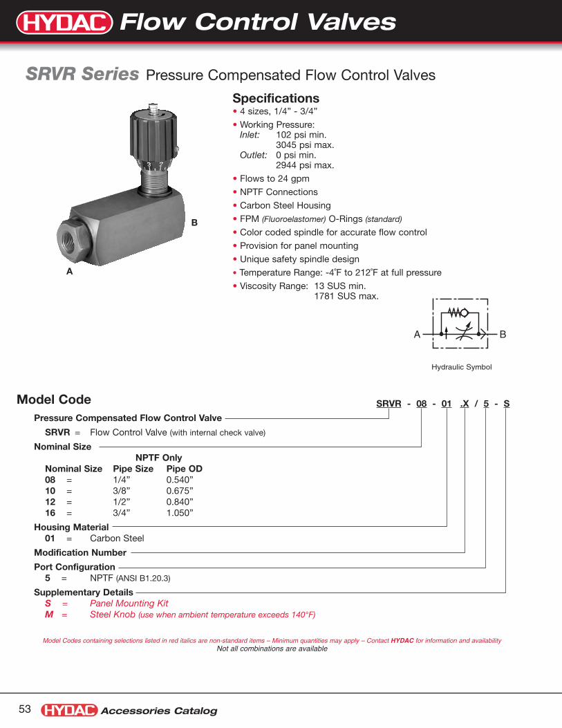
Accessories Catalog53
Model Code
SRVR Series Pressure Compensated Flow Control Valves
Specifications• 4 sizes, 1/4” - 3/4”
• Working Pressure:Inlet: 102 psi min.
3045 psi max.Outlet: 0 psi min.
2944 psi max.
• Flows to 24 gpm
• NPTF Connections
• Carbon Steel Housing
• FPM (Fluoroelastomer) O-Rings (standard)
• Color coded spindle for accurate flow control
• Provision for panel mounting
• Unique safety spindle design
• Temperature Range: -4˚F to 212˚F at full pressure
• Viscosity Range: 13 SUS min.1781 SUS max.
SRVR - 08 - 01 .X / 5 - S
Pressure Compensated Flow Control Valve
SRVR = Flow Control Valve (with internal check valve)
Nominal SizeNPTF Only
Nominal Size Pipe Size Pipe OD08 = 1/4” 0.540”10 = 3/8” 0.675”12 = 1/2” 0.840”16 = 3/4” 1.050”
Housing Material01 = Carbon Steel
Modification Number
Port Configuration5 = NPTF (ANSI B1.20.3)
Supplementary DetailsS = Panel Mounting KitM = Steel Knob (use when ambient temperature exceeds 140°F)
Model Codes containing selections listed in red italics are non-standard items – Minimum quantities may apply – Contact HYDAC for information and availabilityNot all combinations are available
A B
Hydraulic Symbol
Flow Control Valves
A
B

Accessories Catalog 54
Size 10
Q (L
/min
)
Δp (bar)0 15010050 200
20
18
16
14
12
10
8
6
4
2
0
22approx.6.5 turns
approx. 6 turns
approx. 5 turns
approx. 4turns
approx. 3 turns
approx. 2 turns
approx. 1 turns
Size 16
Q (L
/min
)
Δp (bar)0 15010050 200
80
70
60
50
40
30
20
10
0
90 approx.7 turns
approx. 6 turns
approx. 8 turns
approx. 5 turns
approx. 4turns
approx. 3 turns
approx. 2 turns
approx. 1 turns
Size 12
Q (L
/min
)
Δp (bar)0 15010050 200
50
45
40
35
30
25
20
15
10
5
0
55
approx.7 turns
approx. 6 turns
approx. 8 turns
approx. 9 turns
approx. 5 turns
approx. 4turns
approx. 3 turns
approx. 2 turns
approx. 1 turns
Size 08
Q (L
/min
)
Δp (bar)0 15010050 200
10
8
6
4
2
0
12approx. 4.5 turns
approx. 4turns
approx. 3 turns
approx. 2 turns
approx. 1 turns
0 908070605040302010 100
7
5
3
6
4
2
1
0
Q (L/min)
p (b
ar)
SRVR
-12
SR
VR
-10
SR
VR
-08
SRVR-16
Pressure Drop Curves: SRVR Pressure Compensated Flow Control ValveFlow Direction: A to B / Throttled Flow
Flow Direction: B to A / Free Flow Through Check Valve
Dimensions: SRVR Pressure Compensated Flow Control Valve
Model Weight Code Size A B C D E F ØG ØH J1 Hex [lbs. (kg)]
SRVR-08 1/4” NPTF 2.91 2.64 0.59 1.18 0.69 3.62 1.14 0.75 Pg 11 0.94 1.3(74) (67) (15) (30) (17.5) (92) (29) (19) thread (24) (0.6)
SRVR-10 3/8” NPTF 3.62 3.23 0.69 1.38 0.71 4.13 1.50 0.91 Pg 16 1.06 2.0(92) (82) (17.5) (35) (18) (105) (38) (23) thread (27) (0.9)
SRVR-12 1/2” NPTF 4.17 3.78 0.89 1.77 .83 4.92 1.50 0.91 Pg 16 1.26 3.8 (106) (96) (22.5) (45) (21) (125) (38) (23) thread (32) (1.7)
SRVR-16 3/4” NPTF 4.27 3.88 0.98 1.97 1.02 5.51 1.50 0.91 Pg 16 1.61 4.9(108.5) (98.5) (25) (50) (26) (140) (38) (23) thread (41) (2.2)
Dimensions are for general information only, all critical dimensionsshould be verified by requesting a certified print.Dimensions are in inches/(mm) and lbs./(kg.)1) Pg style thread per DIN 40430
EF
Hex
Thicknessof panel
1/4" max.
PanelMountKit
ØHHole requiredin panel
D
øG
Aopen
Bclosed
C
12345
J
A B
Size Model Code Part Number08 Kit Panel Mount DV08 00705310
10/12/16 Kit Panel Mount DV12 00705302
Panel Mount Kits
Flow Control Valves
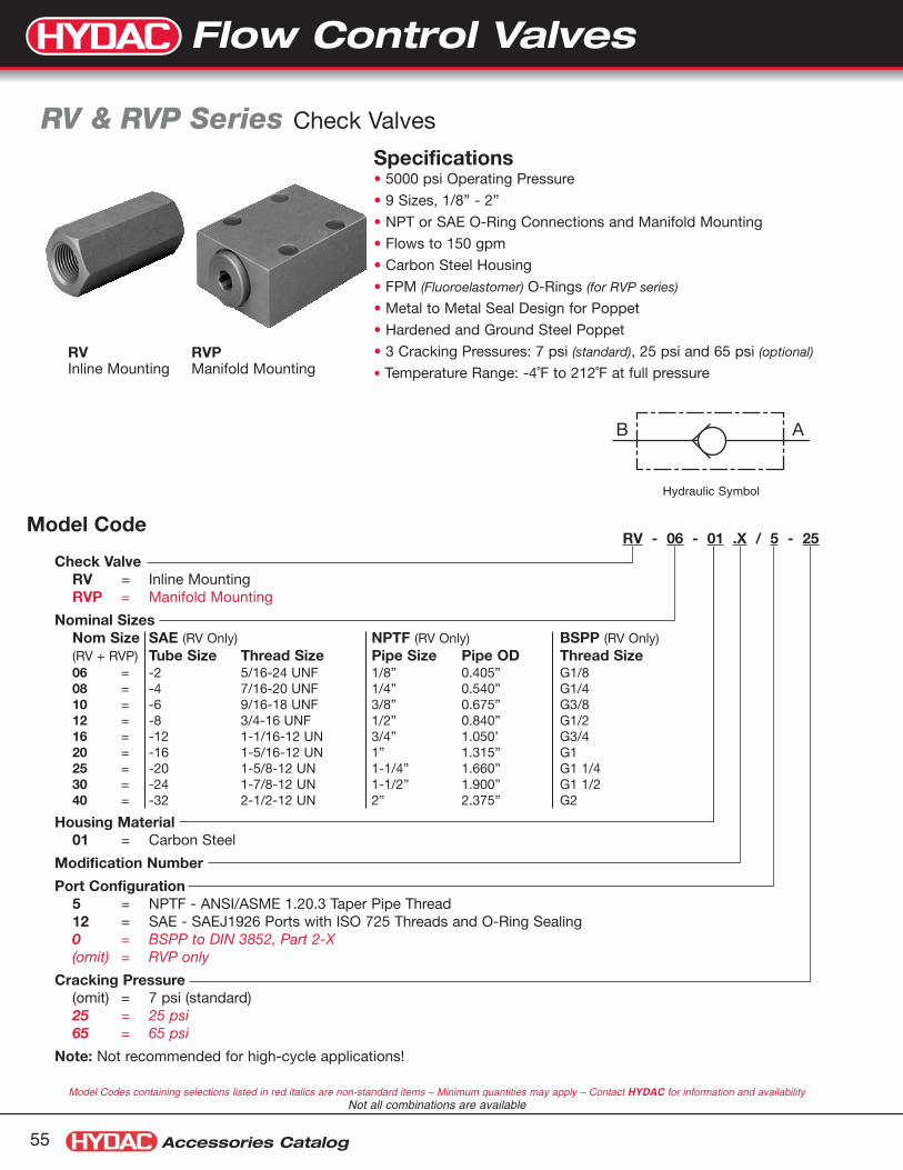
Accessories Catalog55
Model Code
RV & RVP Series Check Valves
Specifications• 5000 psi Operating Pressure
• 9 Sizes, 1/8” - 2”
• NPT or SAE O-Ring Connections and Manifold Mounting
• Flows to 150 gpm
• Carbon Steel Housing
• FPM (Fluoroelastomer) O-Rings (for RVP series)
• Metal to Metal Seal Design for Poppet
• Hardened and Ground Steel Poppet
• 3 Cracking Pressures: 7 psi (standard), 25 psi and 65 psi (optional)
• Temperature Range: -4˚F to 212˚F at full pressure
RV - 06 - 01 .X / 5 - 25
Check ValveRV = Inline MountingRVP = Manifold Mounting
Nominal SizesNom Size SAE (RV Only) NPTF (RV Only) BSPP (RV Only)(RV + RVP) Tube Size Thread Size Pipe Size Pipe OD Thread Size06 = -2 5/16-24 UNF 1/8” 0.405” G1/808 = -4 7/16-20 UNF 1/4” 0.540” G1/410 = -6 9/16-18 UNF 3/8” 0.675” G3/812 = -8 3/4-16 UNF 1/2” 0.840” G1/216 = -12 1-1/16-12 UN 3/4” 1.050’ G3/420 = -16 1-5/16-12 UN 1” 1.315” G125 = -20 1-5/8-12 UN 1-1/4” 1.660” G1 1/430 = -24 1-7/8-12 UN 1-1/2” 1.900” G1 1/240 = -32 2-1/2-12 UN 2” 2.375” G2
Housing Material01 = Carbon Steel
Modification Number
Port Configuration5 = NPTF - ANSI/ASME 1.20.3 Taper Pipe Thread12 = SAE - SAEJ1926 Ports with ISO 725 Threads and O-Ring Sealing0 = BSPP to DIN 3852, Part 2-X(omit) = RVP only
Cracking Pressure(omit) = 7 psi (standard)25 = 25 psi65 = 65 psi
Note: Not recommended for high-cycle applications!
Model Codes containing selections listed in red italics are non-standard items – Minimum quantities may apply – Contact HYDAC for information and availabilityNot all combinations are available
RVInline Mounting
RVPManifold Mounting
B A
Hydraulic Symbol
Flow Control Valves

Accessories Catalog 56
RV-06... to RV-16...
Q (l/min)
Δp
(bar
)
8
6
4
2
08040 1601200 200
10RV-12
RV-16
RV-06 RV-08 RV-10
RV-20... to RV-40...
Q (l/min)
Δp
(bar
)
8
6
4
2
05004003002001000 600
10
RV-25
RV-30
RV-40
RV-20
RVP-06... to RVP-16...
Q (l/min)
Δp
(bar
)
8
6
4
18
16
14
2
0
12
10
16012080400 200
20
RVP-06
RVP-08
RVP-10
RVP-12
RVP-16
RVP-20... to RVP-40...
Q (l/min)
Δp
(bar
)
8
6
4
2
0
10
400200 5003001000 600
RVP-25
RVP-30
RVP-40
RVP-20
Pressure Drop Curves: RV & RVP Check ValvesFlow Direction: B to A / Free Flow Through Check Valve (A to B is Completely Blocked)
Dimensions: RV Inline Check Valves
Dimensions: RVP Manifold Mounted Check Valves
Pressure Drop curves were established by using mineral oil with kinematic viscosity 335 SUS at 86°F / 30°C
Hex L
B A
H
O
Ø M
Ø R
Ø K
Ø L
N
J
A
G FE
DC
BB A
Model Port Size WeightCode NPT SAE Hex L [lbs. (kg)]
RV-06 1/8” 5/16-24 UNF 11/16 1.77 0.22(17) (45) (0.1)
RV-08 1/4” 7/16-20 UNF 3/4 2.17 0.44(19) (55) (0.2)
RV-10 3/8” 9/16-18 UNF 1 2.60 0.44(24) (65) (0.2)
RV-12 1/2” 3/4-16 UNF 1-1/4 2.87 0.66(30) (73) (0.3)
RV-16 3/4” 1-1/16-12 UN 1-7/16 3.46 1.1(36) (88) (0.5)
RV-20 1” 1-5/16-12 UN 1-13/16 5.00 2.4(46) (127) (1.1)
RV-25 1-1/4” 1-5/8-12 UN 2-3/8 5.63 4.0(60) (143) (1.8)
RV-30 1-1/2” 1-7/8-12 UN 2-9/16 5.63 5.7(65) (143) (2.6 )
RV-40 2” 2-1/2-12 UN 3-3/16 6.50 9.7(80) (165) (4.4)
Model Port Size WeightCode A B C D E F(1 G H J K L M N O R [lbs. (kg)]
RVP-06 1.63 1.12 1.31 1.63 0.75 _ 0.25 0.06 0.63 0.38 0.2 0.43 0.35 0.63 0.26 0.4(41.5) (28.5) (46) (41.5) (19) (6.4) (1.6) (16) (9.7) (5) (11) (9) (16) (6.6) (0.2)
RVP-08 1.81 1.32 2.64 2.5 1.38 _ 0.56 0.19 1.00 0.50 0.28 0.43 0.51 0.79 0.26 0.9(46) (33.5) (67) (63.5) (35) (14.2) (4.8) (25.5) (12.7) (7) (11) (13) (20) (6.6) (0.4)
RVP-10 2.01 1.50 2.81 2.76 1.32 _ 0.71 0.16 1.00 0.61 0.39 0.43 0.71 0.98 0.26 1.1(51) (38) (74) (70) (33.5) (18) (4) (25.5) (15.6) (10) (11) (18) (25) (6.6) (0.5)
RVP-12 2.26 1.75 3.33 3.15 1.50 _ 0.83 0.16 1.18 0.73 0.51 0.43 0.98 1.26 0.26 2.2(57.5) (44.5) (84.5) (80) (38) (21) (4) (30) (18.6) (13) (11) (25) (32) (6.6) (1.0)
RVP-16 2.76 2.13 4.31 4.09 2.99 1.50 0.55 0.43 2.13 0.96 0.67 0.55 1.42 1.77 0.35 4.6(70) (54) (109.5) (104) (76) (38) (14) (11) (54) (24.5) (17) (14) (36) (45) (9) (2.1)
RVP-20 3.01 2.36 5.24 5.00 3.74 1.87 0.63 0.75 2.24 1.20 0.87 0.55 1.61 1.97 0.35 7.3(76.5) (60) (133) (127) (95) (47.5) (16) (19) (57) (30.5) (22) (14) (41) (50) (9) (3.3)
RVP-25 3.94 2.99 6.77 6.50 4.74 2.36 0.59 0.81 3.13 1.47 1.12 0.71 1.73 2.17 0.45 12.8(100) (76) (172) (165) (120.5) (60) (15) (20.6) (79.5) (37.4) (28.5) (18) (44) (55) (11.5) (5.8)
RVP-30 4.53 3.62 7.72 7.32 5.63 2.81 0.59 0.94 3.74 1.71 1.38 0.79 2.44 2.95 0.55 22.7(115) (92) (196) (186) (143) (71.5) (15) (23.8) (95) (43.4) (35) (20) (62) (75) (14) (10.3)
RVP-40 5.51 4.37 7.91 7.56 5.26 2.64 0.63 1.00 3.50 2.25 1.85 0.79 3.43 3.94 0.55 39.5(140) (111) (201) (192) (133.5) (67) (16) (25.5) (89) (57.2) (47) (20) (87) (100) (14) (17.9)
Dimensions are for general information only, all critical dimensions should be verified by requesting a certified print.Dimensions are in inches/(mm) and lbs./(kg.)1) Only 4 mounting holes are use on sizes 06, 08, 10, & 12
Flow Control Valves

Accessories Catalog57
DV, DRV, & RV Series Stainless Steel Flow Control ValvesAvailable with BSPP Ports
DVInline MountedNeedle Valves
RVInline MountedCheck Valves
DRVInline MountedFlow Control Valves
Model Code Part Number Dimensions
RV-06-30.X/0 00705859
Same as Standard ProductSee Page 56
RV-08-30.X/0 00705861
RV-10-30.X/0 00705863
RV-12-30.X/0 00705865
RV-16-30.X/0 00705867
RV-20-30.X/0 00705869
RV-25-30.X/0 00705895
RV-30-30.X/0 00707521
DV-06-30.X/0 00705134
Same as Standard ProductSee Page 47
DV-08-30.X/0 00705142
DV-10-30.X/0 00705150
DV-12-30.X/0 00705158
DV-16-30.X/0 00705166
DV-20-30.X/0 00705174
DV-25-30.X/0 00707424
DV-30-30.X/0 00705295
DRV-06-30.X/0 00705634
Same as Standard ProductSee Page 51
DRV-08-30.X/0 00705642
DRV-10-30.X/0 00705650
DRV-12-30.X/0 00705658
DRV-16-30.X/0 00705666
DRV-20-30.X/0 00705674
Flow Control Valves
Model Codes listed in red italics are non-standard items – Minimum quantities may apply – Contact HYDAC for information and availability

Accessories Catalog 58
Cartridge Valve Offering Overview
Global Replacement BusinessHYDAC Fluidtechnik GmbH is located in Germany and produces CartridgeValves for the Global Market. The majority of the product that they produceis in the Metric standard. HYDAC Technology Corporation has a division inChicago, called HHD or the Hydraulic Division, that manufactures Coolers, PowerUnits, and UNF Cartridge Valves. HYDAC Accessories Bethlehem supports the metric cartridge valve sales in the United States.
For additional information on HYDAC’s UNF Cartridge Valve offering please refer to the HYDAC Cartridge Valve Catalog #02080105.
In some cases you will call HYDAC customer service and the part number will not be in our computer system. In these cases we will provide you a replacement quote in a few days. For additional details visit www.hydac.com and click on support, downloads, brochures, Compact Hydraulics and check out the literature.
Hose Break ValvesRB Series & RBE Series (see pages 59 - 62)
Shuttle ValvesWVE Series (see page 63)
Automatic Air Vent ValvesAEV Series (see page 64)
2-Way Solenoid Cartridge ValvesWSM Series (see pages 65 - 68)
3-Way Solenoid Cartridge ValvesWSE Series (see pages 69 - 70)
Pressure Relief ValvesDB4 Series (see pages 71 - 72)
Cartridge Valves
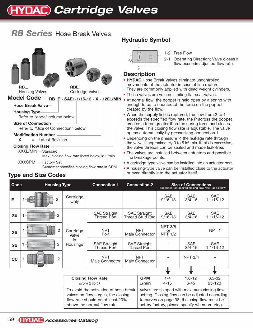
Type and Size Codes
Hose Break Valves
Hydraulic Symbol
1-2 Free Flow
2-1 Operating Direction; Valve closes ifflow exceeds adjusted flow rate.
Accessories Catalog59
Description• HYDAC Hose Break Valves eliminate uncontrolled
movements of the actuator in case of line rupture. They are commonly applied with dead weight cylinders.
• These valves are volume limiting flat seat valves.• At normal flow, the poppet is held open by a spring with
enough force to counteract the force on the poppet created by the flow.
• When the supply line is ruptured, the flow from 2 to 1exceeds the specified flow rate, the P across the poppetcreates a force greater than the spring force and closesthe valve. This closing flow rate is adjustable. The valveopens automatically by pressurizing connection 1.
• Depending on the pressure P, the leakage rate throughthe valve is approximately 0 to 6 in3 min. If this is excessive,the valve threads can be sealed and made leak-free.
• The valves are installed between actuators and possibleline breakage points.
• A cartridge-type valve can be installed into an actuator port.• A housing-type valve can be installed close to the actuator
or even directly into the actuator itself.
RB Series Hose Break Valves
RB...Housing Valves
RBECartridge Valves
1
2
Code Housing Type Connection 1 Connection 2 Size of Connections
SAE SAE SAEE – – – 9/16-18 3/4-16 1 1/16-12
XB SAE Straight SAE Straight SAE SAE SAEThread Port Thread Stud End 9/16-18 3/4-16 1 1/16-12
NPT 3/8XB NPT NPT or NPT 1
Port Male Connector NPT 1/2
XX SAE Straight SAE Straight – SAE SAEThread Port Thread Port 3/4-16 1 1/16-12
CC NPT NPT – NPT 3/4 –Male Connector Male Connector
1 2
1 2
1 2
1 2
1 2
CartridgeValve
inHousings
CartridgeOnly
Closing Flow Rate GPM 1-4 1.6-12 6.5-32(from 2 to 1) L/min 4-15 6-45 25-120
To avoid the activation of hose breakvalves on flow surges, the closingflow rate should be at least 20%above the normal flow rate.
Valves are shipped with maximum closing flowsetting. Closing flow can be adjusted accordingto curves on page 38. If closing flow must beset by factory, please specify when ordering.
RB E - SAE1-1/16-12 - X - 120L/MIN
Hose Break Valve
Housing TypeRefer to “code” column below
Size of ConnectionRefer to “Size of Connection” below
Modification NumberX = Latest Revision
Closing Flow RateXXXL/MIN = Standard
Max. closing flow rate listed below in L/min
XXXGPM = Factory SetCustomer specifies closing flow rate in GPM
Model Code
dependent on desired closing flow rate - see below
Cartridge Valves

Accessories Catalog 60
Adjustment Curves for Closing Flow Rate
Dimensions: Cartridge
Valve Type C D E F øG øH øJ øK øL Hex
RBE-SAE 9/16 inches 0.866 0.453 0.138 0.13 9/16-18UNF-2B 0.374 0.460 0.315 0.098 0.197mm 22 11.5 3.5 3 9.5 11.7 8 2.5 5
RBE-SAE 3/4 inches 1.063 0.531 0.197 0.14 3/4-16UNF-2B 0.472 0.640 0.394 0.138 0.217mm 27 13.5 5 3.5 12 16.3 10 3.5 5.5
RBE-SAE 1 1/16 inches 1.614 0.925 0.256 0.17 1 1/16-12UNF-2B 0.709 0.930 0.630 0.256 0.276mm 41 23.5 6.5 4 18 23.6 16 6.5 7
The closing flow rate is dependent on the dimensions “H”.After loosening the lock nut, set the GAP to dimension “H” with a thickness gauge.The lock nut must be tightened after adjustment.
The adjustment curves are valid for cartridge RBE...and for all housing valves RB... in accordance with “Type andSize Codes” charts on page 37.For model RB... the cartridge must be removed from the housing for adjustment.
See special tool for installation and removal under the dimensional section on page 40.
After Adjustment,Pinch Thread At PointImmediately Behind Lock Nut
Lock Nut
Adjusting Nut
GaugeGauge Thickness "H"
SA
E9/
16-1
8
61-4/3E
AS
SAE1 1/
16-1
2
0 30252015105
0 12080 100604020
0.04
0.08
0.12
1.0
0
2.0
3.0
Gap
in m
m
Gap
in in
ches
Q in gpm
Q in l/min
øKøL
Hex
1 2
CD E
F
øH
øG
øJ
Dimensions: RBXX-SAE 1-1/16-12 Dimensions: RBCC-NPT 3/4 Housing Valve
0.75"19mm
0.75"19mm
3.25"83mm
1 1/16-12UN2B 1 1/16-12UN2B
Hex 1.5" 38mm
1 2
2.44"62mm
1.00"25mm
1.00"25mm
3/4 NPT 3/4 NPT
Hex 1.25" 32mm
1 2
Dimensions are for general information only, all critical dimensions should be verified by requesting a certified print.Dimensions are in inches/(mm) and lbs./(kg.)*Dependent upon valve and seal materials selected.
Cartridge Valves

Accessories Catalog61
Nominal Flow CurvesFlow rate is dependent on operating setting “H”. See “Adjusting Curves for Closing Flow Rates - Settings”. Curves are valid forCartridges RBE and Housing RB... in accordance with charts on page 38. Limit Lines indicate the maximum closing flow rates.These rates cannot be exceeded. Curves were established at 150 SUS.
"950.=
H"530.=
H
"420.=H
"61
0.=
H
"970.=H
"930.=H
"820.=H
"020.=H
"970.=H
"801.=H
"930.=H
"020.=H
"060.=H
10
0 5 10 15 20
0 1 2 3 4 5
30
40
50
20
0
2.0
3.0
4.0
1.0
P in
bar
P in
psi
Q in l/min
Q in gpm
10
0 10 20 30 5040
0 2 4 6 8 1210
30
40
50
20
0
2.0
3.0
4.0
1.0
P in
bar
P in
psi
Q in l/min
Q in gpm
10
0 20 40 60 80 100 120
0 5 10 15 20 25 30
30
40
50
20
0
2.0
3.0
4.0
1.0
P in
bar
P in
psi
Q in l/min
Q in gpm
RBE - SAE 9/16-18 RBE - SAE 3/4-16 RBE - SAE 1 1/16-12
Dimensions: RBXB-... Housing Valves
SAE NPT
Housing Type C D E F Hex
RBXB-SAE 9/16-18 inches 2.13 0.50 0.39 9/16-18UNF-2B 0.75mm 54 13 10 19
RBXB-SAE 3/4-16 inches 2.38 0.56 0.44 3/4-16UNF-2B 1.00mm 60 14 11 25
RBXB-SAE 1 1/16-12 inches 3.25 0.75 0.59 1 1/16-12UNF-2B 1.50mm 83 19 15 38
C
D E
F F1 2
Hex
Housing Type C D E Hex
RBXB-NPT 3/8 inches 2.09 0.59 3/8 NPT 0.88mm 53 15 22
RBXB-NPT 1/2 inches 2.75 0.78 1/2 NPT 1.00mm 70 20 25
RBXB-NPT 1 inches 3.31 0.98 1 NPT 1.75mm 84 25 44
CD
EE1 2
Hex
Dimensions are for general information only, all critical dimensions should be verified by requesting a certified print.Dimensions are in inches/(mm) and lbs./(kg.)*Dependent upon valve and seal materials selected.
Cartridge Valves

Design Flat Seat ValveMounting Method RBE Cartridge
RB.. Housing Valve for In-line InstallationConnection Refer to charts on page 37Mounting Position OptionalDirection of Flow 1 to 2 Free Flow
2 to 1 Free Flow; valve automaticallycloses if flow exceeds preset level
Fluid General purpose hydraulic oil.Consult HYDAC for other media
Operating Pressure Ratings P Max: 5000 psi / 350 barP Min: 145 psi / 10 bar
Fluid Temperature Range -4° to 176°F / -20° to 80°C
Accessories Catalog 62
RecommendationsHose break valves, type RBE must only be used to safeguard users in the event of hose breaks. They must not be used asswitching valves for repeated closing actions.
If closing actions occur during normal operation, the setting of the hose break valve is not suitable for the operating parameters of thesystem. The hose break valve must be replaced by a new one with a modified setting.
In order to prevent hose break valves reacting to flow rate fluctuations inherent in the system, e.g. due to switching of directionalvalves, the actuating flow rate should be at least 20% above the normal maximum system flow rate. If high viscosity fluctuationsoccur, the valves must be set to a higher actuating flow rate to ensure trouble-free operation at high viscosity. However, the valvesmust still react at a low viscosity. Since this range depends largely on the system, whose operational flow rate fluctuations can alsodepend on viscosity, the appropriate setting for the valve is best determined on site.
Sizing Hose Break ValvesIn order for a hose break valve to work properly there must be a difference between the normal operating flow rate (from pump) andthe emergency flow rate created by a hose or line break. The emergency flow rate must be significantly higher than the normal oper-ating flow. Why?
The hose break valve is designed to only be closed in an emergency situation. These valves should not be cycled (opened andclosed) with the system. Cycling the valve and/or excessive vibrations will lead to premature failure of the valve components.
How do you determine the emergency flow rate? You must perform a test with the actual system in a hose break simulation. This testshould be run with the minimum load on the cylinder/lift to determine the minimum emergency flow rate for the system. To test, breakthe line open or open a directional valve and allow gravity to pull down the cylinder/lift. The flow rate measured during this test is theemergency flow rate.
The hose break closing flow rate setting is adjustable and should be set to close at a flow rate between the normal flow rate and theemergency flow rate. The closing flow rate should be set at least 20% higher than the normal flow rate, and should be set at least20% below the emergency flow rate.
How do you set the closing flow rate for the valve? The gap between the poppet and the valve body is adjustable by means of thelock nut and adjustment nut on the end of the poppet. The larger the gap, the higher the closing flow rate for the valve.
Engineering DataRBE lbs.
SAE 9/16-18 0.02SAE 3/4-16 0.04SAE 1 1/16-12 0.13
RBXB lbs.SAE 9/16-18 0.173/8 NPTFSAE 3/4-16 0.241/2 NPTFSAE 1 1/16-12 0.881 NPTF
RBXX lbs.SAE 1 1/16-12 0.92
RBCC lbs.3/4 NPTF 0.37
Weights
Installation Tools:
Cartridge Size Part Number9/16-18 001614213/4-16 001605611-1/16-12 00164180
These are non-standard items –Contact HYDAC for availability
Cartridge Valves

Installation Diagram Dimensions: Cartridge
Shuttle Valves
Hydraulic Symbol
Accessories Catalog63
DescriptionThe HYDAC WVE Valves are shuttle valves with two inletsand one outlet. The inlet with the higher pressure is automaticallyconnected to the outlet. The other inlet is closed. This complieswith DIN-ISO 1219. The shuttle valves are cartridge typevalves for installation into manifolds and control blocks. The shuttle valves are ball-seat type valves without leakage
WVE Series Shuttle Valves
Model Code: WVE-1/2-20UNF-0Part Number: 00710128
2
1 3
17
1/2-20UNF-2A
66Hex Socket
23
O-Ring 6x1 O-Ring 9x1
9.5
Ø 11Ø 10.5
Technical DataDesign• Seat Valve
Mounting Method• Cartridge
Nominal Size• (SAE-5) 1/2”-20 UNFWeight• (SAE-5) 1/2”-20 UNF...12gMounting Position• Optional
Direction of Flow• Optional
Operating Pressure Range• P max. 5000 psi = 350 bar
Temperature Range• -4° to 104°F (-20° to 80°C)
Cross-Over Effect on Shut-off• negligible
Flow Rate• Max flow rate 5 gpm (20 lpm)ΔP approx 175 psi (12 bar)at 5 gpm, 168 SSU, 104°F oil
Standard SAE-5 Plug(Not Included)
Torque Cartridge15 +3 Nm
1.6
1.6
0.1 A
0.1 A
40±0.2
32+1
0
26 0-0.2
Finished Depth
23.5 min.Thread Depth
1/2"-20UNF-2B IN.SAE-5 Port
Ø 5Ø 5
Ø 5
14.5
33+0.5 0
60˚1.6
Ø 11R 0.2 Max.
+0.028 0
Ø 10.8 Min.Predrill
Detail X
X A
Cavity Diagram
Dimensions in millimeters
Cartridge Valves
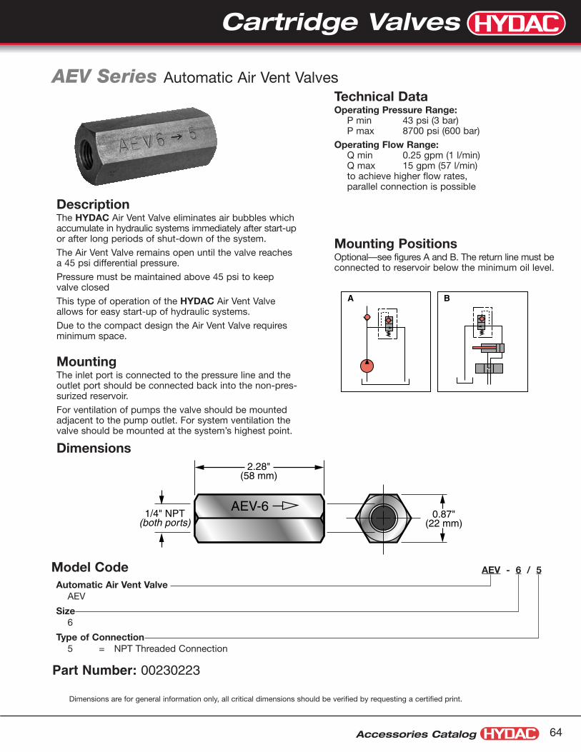
Accessories Catalog 64
Dimensions
Mounting PositionsOptional—see figures A and B. The return line must beconnected to reservoir below the minimum oil level.
Technical DataOperating Pressure Range:
P min 43 psi (3 bar)P max 8700 psi (600 bar)
Operating Flow Range:Q min 0.25 gpm (1 l/min)Q max 15 gpm (57 l/min)to achieve higher flow rates,parallel connection is possible
AEV Series Automatic Air Vent Valves
AEV - 6 / 5
Automatic Air Vent ValveAEV
Size6
Type of Connection5 = NPT Threaded Connection
Model Code
A B
AEV-6
2.28"(58 mm)
1/4" NPT(both ports)
0.87"(22 mm)
Description The HYDAC Air Vent Valve eliminates air bubbles whichaccumulate in hydraulic systems immediately after start-upor after long periods of shut-down of the system.
The Air Vent Valve remains open until the valve reachesa 45 psi differential pressure.
Pressure must be maintained above 45 psi to keepvalve closed
This type of operation of the HYDAC Air Vent Valveallows for easy start-up of hydraulic systems.
Due to the compact design the Air Vent Valve requiresminimum space.
Mounting The inlet port is connected to the pressure line and theoutlet port should be connected back into the non-pres-surized reservoir.
For ventilation of pumps the valve should be mountedadjacent to the pump outlet. For system ventilation thevalve should be mounted at the system’s highest point.
Part Number: 00230223
Dimensions are for general information only, all critical dimensions should be verified by requesting a certified print.
Cartridge Valves

Cartridge Valves
Accessories Catalog65
WSM 2-Way Solenoid Cartridge Valves
Features• Long life and low noise level due to oil-immersed solenoid armature.
• Electro-magnetic actuation in all standard international DC and AC voltagesand many electrical connection types available.
• Minimal wear and long life due to hardened and polished control elements.
• In the closed position the flow paths are shut off by means of a cone seat.
• Solenoid coils can be rotated through 360˚ and replaced without opening thehydraulic system.
• Surfaces are zinc-plated.
• Built-in seals protect solenoid coils from water penetration.
• Compact construction enables space-saving installation in connection hous-ings and control blocks.
SpecificationsOperating Pressure: max. 350 bar (see page 67, 68 for limits)
Flow rate: max. 40 l/min (see page 67, 68 for limits)
Internal leakage: leakfreeFluid Temperature range: -20° to 120°CAmbient temperature range: -20° to 60°CType of voltage: DC solenoid, AC voltage is rectified using a bridge
rectifier built into the coilNominal current draw (at 20˚C): 1.5 A at 12 V DC
0.8 A at 24 V DC0.2 A at 115 V AC
Voltage tolerance: -15% to 15%Switch-on time: 100% (continuous)
Switching time: see pages 45, 46Operating fluid: hydraulic oil to DIN 51524 Part 1 and 2Viscosity range: 10 mm2/s to 420 mm2/s is recommendedFiltration: max. permissible contaminiation level of the operat-
ing fluidto ISO 4406 Class 21/19/16
Mounting position: optionalMaterials: valve body: high tensile steel
closing elements: hardened and polished steel
seals: NBR (standard)FKM (optional)back-up ring in PTFE
Cavity: 06020Weight: Valve complete: 0.37 kg
Coil only: 0.19 kgValve w/out coil 0.18 kg
Seal KitsIncludes: 2 O-rings
1 Back-up RingNBR: Part # 03119017FPM: Part # 02083918
O-Ring
O-RingBack-Up Ring
Cartridge Valves
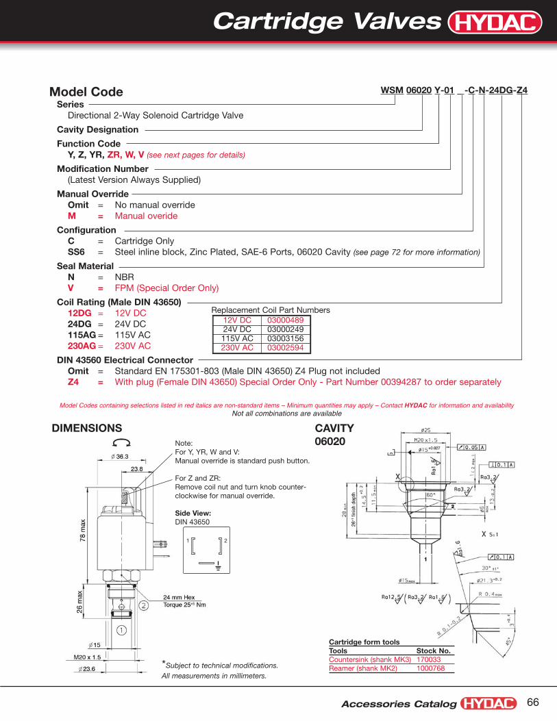
12V DC 0300048924V DC 03000249115V AC 03003156230V AC 03002594
Accessories Catalog 66
Model Code WSM 06020 Y-01 _ -C-N-24DG-Z4.
SeriesDirectional 2-Way Solenoid Cartridge Valve
Cavity Designation
Function CodeY, Z, YR, ZR, W, V (see next pages for details)
Modification Number(Latest Version Always Supplied)
Manual OverrideOmit = No manual overrideM = Manual overide
ConfigurationC = Cartridge OnlySS6 = Steel inline block, Zinc Plated, SAE-6 Ports, 06020 Cavity (see page 72 for more information)
Seal MaterialN = NBRV = FPM (Special Order Only)
Coil Rating (Male DIN 43650)12DG = 12V DC24DG = 24V DC115AG = 115V AC230AG = 230V AC
DIN 43560 Electrical ConnectorOmit = Standard EN 175301-803 (Male DIN 43650) Z4 Plug not includedZ4 = With plug (Female DIN 43650) Special Order Only - Part Number 00394287 to order separately
DIMENSIONS
Model Codes containing selections listed in red italics are non-standard items – Minimum quantities may apply – Contact HYDAC for information and availabilityNot all combinations are available
*Subject to technical modifications.All measurements in millimeters.
Note:For Y, YR, W and V:Manual override is standard push button.
For Z and ZR: Remove coil nut and turn knob counter-clockwise for manual override.
Side View:DIN 43650
CAVITY06020
Cartridge form toolsTools Stock No.Countersink (shank MK3) 170033Reamer (shank MK2) 1000768
Replacement Coil Part Numbers
1 2
Cartridge Valves

Cartridge Valves
Accessories Catalog67
Up to 40 l/minUp to 350 bar
When the solenoid coil is not energized the valve is closed from port 2 to port 1. Inthe reverse direction there is free flow through the valve. The valve spool opens at adifferential pressure of approx. 1.5 bar (check function). When the solenoid coil isenergized, there is free flow through the valve from port 2 to port 1. Flow from port 1to port 2 is severly restricted in this mode.
po rd eru sserP
Flow rate
Measured at 34 cStTOil = 46 °C
2 1 energized
1 2 non-energized
0 5 10 15 20 25 30 35 40 l/min
bar8
6
4
2
0
→
→
WSM06020Z-01
WSM06020Y-01When the solenoid coil is not energized there is free flow through the valve from port2 to port 1. Flow from port 1 to port 2 is severly restricted in this mode. When thesolenoid coil is energized the valve is closed from port 2 to port 1. In the reversedirection there is free flow through the valve when the pressure force on the spoolexceeds the solenoid force (approx. 9 to 20 bar).
Up to 40 l/minUp to 350 bar
po rd erusserP
Flow rate
Measured at 34 cStToil = 46 °C
0 5 10 15 20 25 30 35 40 l/min
bar8
6
4
2
0
2 1 non-energized→
NOTE: The information in this brochure relates to the operating conditions and applications described. For applications or operating conditions notdescribed, please contact the relevant technical department. Subject to technical modifications.
PRESSURE DROP
Normally closedUni-Directional
Switch TimeOn: approx 35msOff: approx 50ms
Switch TimeOn: approx 50msOff: approx 35ms
Normally openUni-Directional
WSM 2-Way Solenoid Cartridge Valves
PRESSURE DROP
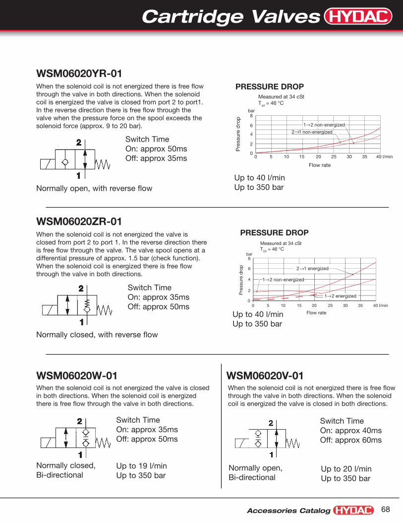
Cartridge Valves
Accessories Catalog 68
WSM06020YR-01
WSM06020ZR-01
WSM06020W-01 WSM06020V-01
po rd erusser
P
Flow rate
Measured at 34 cStToil = 46 °C
2 1 non-energized
0 5 10 15 20 25 30 35 40 l/min
bar8
6
4
2
0
→1 2 non-energized→
po rd eru sserP
Flow rate
Measured at 34 cStTOil = 46 °C
2 1 energized
1 2 non-energized
0 5 10 15 20 25 30 35 40 l/min
bar8
6
4
2
0
→
→
1 2 energized→
When the solenoid coil is not energized there is free flowthrough the valve in both directions. When the solenoidcoil is energized the valve is closed from port 2 to port1.In the reverse direction there is free flow through thevalve when the pressure force on the spool exceeds thesolenoid force (approx. 9 to 20 bar).
When the solenoid coil is not energized the valve isclosed from port 2 to port 1. In the reverse direction thereis free flow through the valve. The valve spool opens at adifferential pressure of approx. 1.5 bar (check function).When the solenoid coil is energized there is free flowthrough the valve in both directions.
Up to 19 l/minUp to 350 bar
When the solenoid coil is not energized the valve is closedin both directions. When the solenoid coil is energizedthere is free flow through the valve in both directions.
PRESSURE DROP
PRESSURE DROP
Up to 20 l/minUp to 350 bar
When the solenoid coil is not energized there is free flowthrough the valve in both directions. When the solenoidcoil is energized the valve is closed in both directions.
Switch TimeOn: approx 50msOff: approx 35ms
Switch TimeOn: approx 35msOff: approx 50ms
Normally open, with reverse flow
Normally closed, with reverse flow
Switch TimeOn: approx 40msOff: approx 60ms
Normally open,Bi-directional
Switch TimeOn: approx 35msOff: approx 50ms
Normally closed,Bi-directional
Up to 40 l/minUp to 350 bar
Up to 40 l/minUp to 350 bar

Cartridge Valves
Accessories Catalog69
SpecificationsMaximum Operating Pressure
7,000 psi (500 bar)P1 ≥ P2 ≥ P3
Nominal Flow3 gpm (12 l/min)(flow only in direction of arrows shown)
Fluid Temperature Range-4°F to 176°F (-20°C to 80°C)
Ambient Temperature Range-4°F to 104°F (-20°C to 40°C)
Recommended MediaGeneral Purpose Hydraulic Fluid
Viscosity Range59 SUS to 1,760 SUS
Filtration Required20 Micron Absolute Rating
Internal LeakageLeakfree
Duty CycleContinuous at 110% Rated Voltage
Solenoid Current (nominal)24 VDC, 1.04 Amps110 VAC, 0.26 Amps
Solenoid Coil Power (nominal)26 Watts
Voltage Tolerance+10%, -5%
MaterialsValve Body:High Strength Carbon Steel
Valve Poppet:Hardened and Polished Alloy Steel
Line Body:Carbon Steel
WSE3 3-Way Solenoid Cartridge Valves
WSE 3 E 0 C . X / G12 - Z4 - 1/4 NPT
Directional Control ValveWSE
Size
Maximum Flow3 = 3 gpm (12 l/min)
Type of ConnectionE = Cartridge Valve OnlyR = Valve with Line Body
Type
ConfigurationC = Normally Closed Port 1-2D = Normally Open Port 1-2
Modification Number (latest version always supplied)
SolenoidG12 = 12 VDCG24 = 24 VDC (standard)W110 = 110 VAC (standard)W230 = 230 VAC
Electrical ConnectionsZ4 = DIN 43650 Connector (standard)
Line Body(omit) = None (if E was chosen in Type of Connection above)
1/4 NPT = 1/4” NPT (if R was chosen in Type of Connection above)SAE-4 = SAE 4Model Codes containing selections listed in red italics are non-standard items – Minimum quantities may apply
Contact HYDAC for information and availabilityNot all combinations are available
Model Code
Hydraulic Symbols
Features • Leakfree poppet design
• No dynamic seals
• Excellent heat dissipation
• Low operating noise level
• Fully encapsulated coil
• DIN 43650 connector standard
• Fluoroelastomer seals standard
Normally Open 1-2(Configuration D)
Normally Closed 1-2(Configuration C)
Connections1 = Pressure Line2 = Actuator3 = Tank Line
1
2
3 1
2
3
Cartridge Valves

Accessories Catalog 70
Dimensions: 3-Way Solenoid Poppet ValveRef: Install in HYDAC Cavity 03230
2.36"(60 mm)
2.36"(60 mm)
1.18"(30 mm)
3
1
2
1.42"(36 mm)
0.47"(12 mm)
0.59"(15 mm)
0.59"(15
1
3
2
mm)
1.24"(31.5 mm)
0.59"(15 mm)
2 Mounting Holesø 0.34"
(8.5 mm)
Port 1/4" NPTor SAE-4(3 places)
1.18"(30 mm)
CavityCenterline 1.18"
(30 mm)
1.00"(25.4 mm)
0.394"(10 mm)
0.354"(9 mm)
0.118"(3 mm)
1.52"(38.5 mm)
3.03"
After loosening nutcoil can be rotatedthrough 360°
(77 mm)4.55"
(115.5 mm)
ø 1.42"(36 mm)
3.15"(80 mm)
PG11connector socket
4 x 90˚ displacable
M20 x 1.5
ø 0.93"(23.5 mm)
Hex 0.94"(24 mm)Torque18-22 ft-lbs25-30 Nm
10
0
20
30
40
1086420 12
a
b
50
Q - Flow (l/min)
Δ P
ress
ure
(bar
)
Δp/Q curvesMeasured at v = 34 mm2/sWSE 3 E
Dimensions: Line Body Pressure Drop vs. Flow
Block with 1/4” NPT Ports: 02056010Block with SAE-4 Ports: 02056012(Blocks are not normally stocked items)
Configuration Flow Direction CurveC energized 1 to 2 a– de-energized 2 to 3 aD de-energized 1 to 2 b– energized 2 to 3 b
Dimensions are for general information only, all critical dimensions should be verified by requesting a certified print.Dimensions are in inches/(mm) and lbs./(kg.)
Cartridge Valves
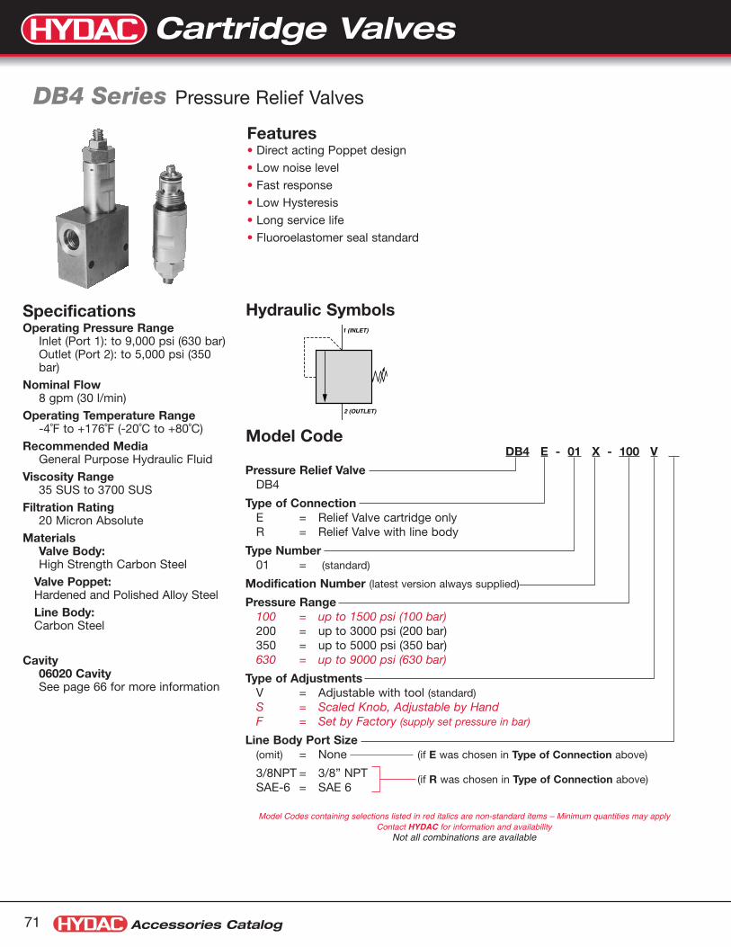
Cartridge Valves
Accessories Catalog71
Specifications Operating Pressure Range
Inlet (Port 1): to 9,000 psi (630 bar)Outlet (Port 2): to 5,000 psi (350bar)
Nominal Flow8 gpm (30 l/min)
Operating Temperature Range-4˚F to +176˚F (-20˚C to +80˚C)
Recommended MediaGeneral Purpose Hydraulic Fluid
Viscosity Range35 SUS to 3700 SUS
Filtration Rating20 Micron Absolute
MaterialsValve Body:High Strength Carbon Steel
Valve Poppet:Hardened and Polished Alloy Steel
Line Body:Carbon Steel
Cavity06020 CavitySee page 66 for more information
DB4 Series Pressure Relief Valves
DB4 E - 01 X - 100 V .
Pressure Relief ValveDB4
Type of ConnectionE = Relief Valve cartridge onlyR = Relief Valve with line body
Type Number01 = (standard)
Modification Number (latest version always supplied)
Pressure Range100 = up to 1500 psi (100 bar)200 = up to 3000 psi (200 bar)350 = up to 5000 psi (350 bar)630 = up to 9000 psi (630 bar)
Type of AdjustmentsV = Adjustable with tool (standard)S = Scaled Knob, Adjustable by HandF = Set by Factory (supply set pressure in bar)
Line Body Port Size(omit) = None (if E was chosen in Type of Connection above)
3/8NPT = 3/8” NPTSAE-6 = SAE 6
(if R was chosen in Type of Connection above)
Model Codes containing selections listed in red italics are non-standard items – Minimum quantities may applyContact HYDAC for information and availability
Not all combinations are available
Model Code
Hydraulic Symbols
Features • Direct acting Poppet design
• Low noise level
• Fast response
• Low Hysteresis
• Long service life
• Fluoroelastomer seal standard
1 (INLET)
2 (OUTLET)
Cartridge Valves

Accessories Catalog 72
Dimensions:Valve Line Body, 06020 Cavity Relief Valve
1.575"(40 mm)
0.197"(5 mm)
1.26"(32 mm)
1.26"(32 mm)
0.594"(15.1 mm)
1.188(30.2 mm)
1.25"(31.8 mm)
2.00(51 mm)
1
1
2
2
0.594"(15.1 mm)
cavitycenterline
Port 3/8" NPTor SAE-6(2 Places)
0.59"(15 mm)
2 Mounting Holesø 0.25"
(6.35 mm)
0.94"(24 mm)
2.36"(60 mm)
0.12"(3 mm)
0.59"(15 mm)
M20 x 1.5
0.93"(23.5 mm)
1.12"(28.5 mm)
ø
0.83"(21 mm)Width
between flats
Torque18-22 ft-lbs25-30 Nm
2 (outlet)
1 (inlet)
ø
ø
0.51"(13 mm)
Hex
0.16"(4 mm)
Hex Socket
appl
icat
ion
limit
00
300
600
900
1200
1500
1800
0
20
40
60
80
100
120
Inle
t Pre
ssur
e (p
si)
Inle
t Pre
ssur
e (b
ar)
Q - Flow (gpm)
Q - Flow (l/min)
1 2 3 4 5 6 7 8
0 5 10 15 20 25 30
00
3500
3000
2500
2000
1500
1000
500
0
40
80
120
160
200
240
Inle
t Pre
ssur
e (p
si)
Inle
t Pre
ssur
e (b
ar)
Q - Flow (gpm)
Q - Flow (l/min)
1 2 3 4 5 6 7 8
0 5 10 15 20 25 30
00
750
22501500
30003750450052506000
0
100
200
300
400
Inle
t Pre
ssur
e (p
si)
Inle
t Pre
ssur
e (b
ar)
Q - Flow (gpm)
Q - Flow (l/min)
1 2 3 4 5 6 7 8
0 5 10 15 20 25 30
00
10500
9000
7500
6000
4500
3000
1500
0
100
200
300
400
500
600
700
Inle
t Pre
ssur
e (p
si)
Inle
t Pre
ssur
e (b
ar)
Q - Flow (gpm)
Q - Flow (l/min)
1 2 3 4 5 6 7 8
0 5 10 15 20 25 30
Size 100Pressure Range: 0-1500 psi (0-100 bar)
Size 200Pressure Range: 0-3000 psi (0-200 bar)
Size 350Pressure Range: 0-5000 psi (0-350 bar)
Size 630Pressure Range: 0-9000 psi (0-630 bar)
Adjustment Curves for Nominal Flow RatesViscosity = 170 SUS @ 120˚F
Dimensions are for general information only, all critical dimensions should be verified by requesting a certified print.Dimensions are in inches/(mm) and lbs./(kg.)
Block with 3/8” NPT Ports: 02056007Block with SAE-6 Ports: 02580404
Cartridge Valves

Accessories Catalog73
Standard SolutionsHYDAC Manufactures a complete line of hose, tube, and pipe mounting components. For many years, these productshave been successfully applied, worldwide. Our standard product offering includes:
DIN 3015 ClampsHRL, HRS, HRZ, HREL, & HRES Series(see pages 75 - 91)Line Sizes from 1/4” to 16” O.D.
Clamp Overview
BueguHRBGS Series (see pages 95 - 96)Line Sizes from 1/4” to 3/4” O.D.
Cushion ClampsCUSH Series (see pages 93 - 94)Line Sizes from 1/4” to 3 1/2” O.D.Mount on standard 1 5/8” x 7/8” unistrut mounting rail
Oval ClampsHROS Series (see page 99)Line Sizes from 1/4” to 1” O.D.
Quick Release Swivel Bolt ClampsHRGKSM Series (see pages 101 - 102)Line Sizes from 1.54” to 17.87” O.D.
U-Bolt ClampsHRRBS Series (see page 97)Line Sizes from 3/4” to 16” O.D.
Flat Cushion ClampsHOM Series (see page 92)Line Sizes from 1/4” to 2” O.D.
U-Bolt with Cushion ClampsHUB Series (see pages 98)Line Sizes from 1/4” to 12” O.D.
“P” Style ClampsHSPN Series (see page 100)Line Sizes from 1/4” to 3” O.D.
Clamps

Accessories Catalog 74
HYDAC is also a market leader in providing custom mounting solutions. Our engineers work with yoursto develop unique solutions that save time and money by simplifying inventory and installation. Fromsimple modifications of standard product to custom bracketry, we will provide you a successful solutionfor your application. For more information on custom solutions, please contact product management at1-877-GO HYDAC.
Custom Solutions
Series Strip ClampsHRRL & HRRLE Series (see page 103)Line Sizes from 6 to 25.4 mm O.D.
Band Straps (see page 104)Length Ranges from 187 to 1511 mm
Series Strip Clamp &Custom Bracketry
Series Strip Clamp &Custom Mounting Plates
Stacking Series Strip Run
Custom Molded Hose Bundle
Cylinder / Tube Clamp
Clamps
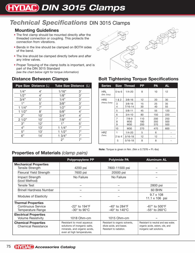
Accessories Catalog75
Polypropylene PP Polyimide PA Aluminum ALMechanical Properties
Tensile Strength 4200 psi 7800-11500 psi –
Flexural Yield Strength 7600 psi 20500 psi –
Impact Strength No Failure No Failure –(Izod Method)
Tensile Test – – 2800 psi
Brinell Hardness Number – – 60 BHN
Modules of Elasticity – – 9.7 x 10811.1 x 106 psi
Thermal PropertiesContinuous Service -22° to 194°F -40° to 284°F -67° to 500°FTemperature Range -30° to 90°C -40° to 140°C -55° to 260°C
Electrical PropertiesVolume Resistivity 1018 Ohm-cm 1015 Ohm-cm –
Chemical PropertiesChemical Resistance
Technical Specifications DIN 3015 Clamps
Properties of Materials (clamp pairs)
Distance Between Clamps Bolt Tightening Torque SpecificationsPipe Size Distance (L) Tube Size Distance (L)
1/4” 4’ 1/16” 3’1/2” 4’ 1/8” 3’3/4” 5’ 1/4” 3’1” 5’ 3/8” 3’
1 1/4” 7’ 1/2” 3’1 1/2” 8’ 5/8” 4’
2” 10’ 3/4” 4’2 1/2” 10’ 7/8” 4’
3” 12’ 1” 5’4” 13’ 1 1/4” 7’5” 13’ 1 1/2” 7’6” 14’ 1 3/4” 7’
2” 7’
Series Size Thread PP PA AL
HRL 0 to 6 1/4-20 8 10 12(Std. Duty)
HRS 1 & 2 3/8-16 12 20 30(Heavy Duty) 3 3/8-16 15 25 35
4 7/16-14 30 40 55
5 5/8-11 45 55 120
6 3/4-10 80 150 220
7 7/8-9 110 200 2508 M30 180 350 500 9 M30 200 370 500
10 M30 270 470 600
HRZ 1 1/4-20 5 6 -(Twin) 2 to 4 5/16-18 12 12 -
5 5/16-18 8 8 -
Resistant to most aqueoussolutions of inorganic salts,minerals, and organic acids,even at high temperatures.
Resistant to organic solvents,dilute acids, and bases.Resistant to radiation.
Resistant to neutral and sea water,organic acids, esters, oils, andinorganic salt solutions.
Mounting Guidelines• The first clamp should be mounted directly after the
threaded connection or coupling. This protects theconnection from vibrations.
• Bends in the line should be clamped on BOTH sidesof the bend.
• The line should be clamped directly before and afterany inline valves.
• Proper Torquing of the clamp bolts is important, and ispart of the DIN 3015 Standard(see the chart below right for torque information)
Note: Torque is given in Nm. (Nm x 0.7376 = Ft.-lbs)
L
DIN 3015 Clamps
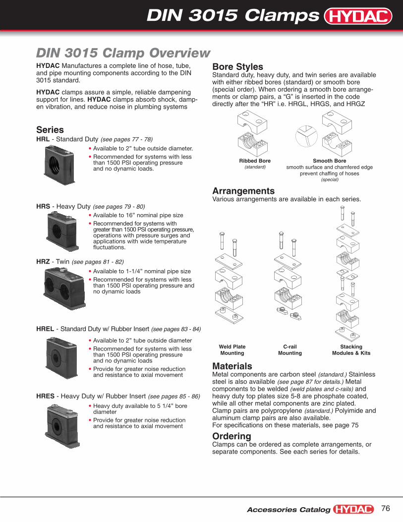
DIN 3015 Clamps
Accessories Catalog 76
DIN 3015 Clamp OverviewHYDAC Manufactures a complete line of hose, tube,and pipe mounting components according to the DIN3015 standard.
HYDAC clamps assure a simple, reliable dampeningsupport for lines. HYDAC clamps absorb shock, damp-en vibration, and reduce noise in plumbing systems
SeriesHRL - Standard Duty (see pages 77 - 78)
HRS - Heavy Duty (see pages 79 - 80)
HRZ - Twin (see pages 81 - 82)
HREL - Standard Duty w/ Rubber Insert (see pages 83 - 84)
HRES - Heavy Duty w/ Rubber Insert (see pages 85 - 86)
Bore StylesStandard duty, heavy duty, and twin series are availablewith either ribbed bores (standard) or smooth bore(special order). When ordering a smooth bore arrange-ments or clamp pairs, a “G” is inserted in the codedirectly after the “HR” i.e. HRGL, HRGS, and HRGZ
ArrangementsVarious arrangements are available in each series.
MaterialsMetal components are carbon steel (standard.) Stainlesssteel is also available (see page 87 for details.) Metalcomponents to be welded (weld plates and c-rails) andheavy duty top plates size 5-8 are phosphate coated,while all other metal components are zinc plated.Clamp pairs are polypropylene (standard.) Polyimide andaluminum clamp pairs are also available. For specifications on these materials, see page 75
OrderingClamps can be ordered as complete arrangements, orseparate components. See each series for details.
• Available to 2” tube outside diameter.• Recommended for systems with less
than 1500 PSI operating pressureand no dynamic loads.
• Available to 16” nominal pipe size• Recommended for systems with
greater than 1500 PSI operating pressure,operations with pressure surges andapplications with wide temperaturefluctuations.
• Available to 1-1/4” nominal pipe size• Recommended for systems with less
than 1500 PSI operating pressure andno dynamic loads
• Available to 2” tube outside diameter• Recommended for systems with less
than 1500 PSI operating pressureand no dynamic loads
• Provide for greater noise reductionand resistance to axial movement
• Heavy duty available to 5 1/4” borediameter
• Provide for greater noise reductionand resistance to axial movement
Weld PlateMounting
Ribbed Bore(standard)
Smooth Boresmooth surface and chamfered edge
prevent chaffing of hoses(special)
C-railMounting
StackingModules & Kits
DIN 3015 Clamps

Accessories Catalog77
Model Code: HRL Series
HRL Series Standard Duty Clamps
HRL 2 A 12.7 PP UNC
SeriesHRL = Standard duty single clamp with ribbed boreHRGL = Standard duty single clamp with smooth bore
Size Family0 to 8 (refer to table A on next page) (size 7 and 8 available in Metric only)
ArrangementA = Single clamp with top plate and weld plateA1 = Single clamp without weld plateA1TM = C-Rail mounted clampD = Single clamp stacking module (not available for size 0)
Bore Size (in mm)(refer to table A on next page)
Clamp MaterialPP = PolypropylenePA = PolyimideAL = Aluminum (not available for size 0)
Metal Component Material(omit) = Carbon SteelA2 = 304 Stainless SteelA4 = 316 Stainless Steel (metric threads only)
Thread TypeUNC = StandardM = Metric
Model Codes containing selections listed in red italics are non-standard items – Minimum quantities may apply – Contact HYDAC for information and availabilityNot all combinations are available
ASingle Clamp withWeld Plate
A1TMSingle Clamp for C-Rail Mounting(order C-Rail separately)
DSingle ClampStacking Module(not available for size 0)
A1Single Clamp withoutWeld Plate
Parts Legend (see page 61 to order parts separately)1 Hex Head Bolt 5 Clamp Pair2 Top Plate 6 Stacking Bolt3 Weld Plate 8 C-Rail Nut4 Safety Plate
1
2
5
4
6
5
3
A + DOrder one A (red) arrange-ment and one D (black)arrangement separately.
A maximum of 3 stacking modules is recommended
DIN 3015 Clamps

DIN 3015 Clamps
Ød Recommended Bolt Size WeightSize Bore Size Nominal Size a1 a2 a3 h1 h2 Arrangement
in mm Tube O. D. Pipe A B0.24 6 - -0.25 6.4 1/4” -0.31 8.0 5/16” - N/A 1.18 1.10 0.63 1.26 1/4-20 x 1-1/4 0.14 0.120 0.37 9.5 3/8” - (30) (28) (16) (32) (M6 x 30) (0.06) (0.05)0.39 10.0 - 1/8”0.47 12.0 - -0.24 6 - -0.25 6.4 1/4” -0.31 8.0 5/16” - 0.79 1.42 1.34 0.63 1.26 1/4-20 x 1-1/4 0.18 0.13
1 0.37 9.5 3/8” - (20) (36) (34) (16) (32) (M6 x 30) (0.08) (0.06)0.39 10.0 - 1/8”0.47 12.0 - -0.50 12.7 1/2” -0.54 13.7 - 1/4”0.50 14.0 - -
2 0.59 15.0 - - 1.02 1.65 1.57 0.77 1.53 1/4-20 x 1-1/2 0.27 0.16
0.63 16.0 5/8” - (26) (42) (40) (19.5) (39) (M6 x 35) (0.12) (0.07)
0.67 17.1 - 3/8”0.71 18.0 - -0.75 19.0 3/4” -0.79 20.0 - -0.84 21.3 - 1/2” 1.30 1.97 1.89 0.85 1.69 1/4-20 x 1-1/2 0.31 0.223 0.87 22.0 - - (33) (50) (48) (21.5) (43) (M6 x 40) (0.14) (0.10)0.91 23.0 - -0.98 25.0 - -1.00 25.4 1” -1.05 26.6 - 3/4”
4 1.10 28.0 - - 1.57 2.32 2.24 0.94 1.89 1/4-20 x 1-3/4 0.33 0.27
1.18 30.0 - - (40) (59) (57) (24) (48) (M6 x 45) (0.15) (0.12)
1.26 32.0 1-1/4” -1.33 33.7 - 1” 2.05 2.83 2.75 1.26 2.52 1/4-20 x 2-1/2 0.42 0.315 1.38 35.01.50 38.0 1-1/2” - (52) (72) (70) (32) (64) (M6 x 60) (0.19) (0.14)1.57 40.0 - -1.65 42.0 - 1-1/4”1.75 44.5 1-3/4” -
6 1.90 48.3 - 1-1/2” 2.60 3.46 3.38 1.42 2.83 1/4-20 x 2-3/4 0.53 0.40
2.00 50.8 2” - (66) (88) (86) (36) (72) (M6 x 70) (0.24) (0.18)
2.37 60.3 - 27 2.5 63.5 2 1/2” - 3.7 4.8 4.64 2.15 4.17 (M6 x 100) - -
2.87 73 - 2 1/2” (94) (122) (118) (54.5) (106) (-) (-)3 76.1 3” -
3.5 88.9 - 3” 4.72 5.8 5.67 2.66 5.16 (M6 x 125) - -8 (120) (148) (143.96) (67.6) (131) (-) (-)
Accessories Catalog 78
Dimensions: HRL SeriesSize 0 Sizes 1-6 C-Rail Nut C-Rail
a3
ø d ø d
a3
h 1
.39(10) .37
(9.5)
a2
.12
(3)
.12
(3)
h 2
1.18(30)
a1
h 1
1.18(30)
a2
.12
(3)
.12
(3)
h 2
ø .39(ø 10)
.20
(5)
.59
(15)
Plastic Cap
.96(24.5)
39 (10)
1/4" -20 UNC
1.10(28)
.43(11)
.43
(11)
.08
(2)
Note: Other bore diameters are available — Consult factory for details.Dimensions are for general information only, all critical dimensions should be verified by requesting a certified print.Dimensions are in inches/(mm) and lbs./(kg.)
Table A
DIN 3015 Clamps

Accessories Catalog79
Model Code: HRS Series
HRS Series Heavy Duty Clamps
HRS 1 S 12.7 PP __ UNC
SeriesHRS = Heavy duty single clamp with ribbed boreHRGS = Heavy duty single clamp with smooth bore
Size Family1 to 10 (refer to table B on next page)
ArrangementS = Single clamp with top plate & weld plateS1 = Single clamp stacking kit (sizes 1-5 only)S1TM = C-Rail mounted clamp (sizes 1-4 only)A = Single clamp stacking module (sizes 1-5 only)
Bore Size (in mm)(refer to table B on next page)
Clamp MaterialPP = PolypropylenePA = PolyimideAL = Aluminum
Metal Component Material(omit) = Carbon SteelA4 = 316 Stainless Steel (metric threads only)
Thread TypeUNC = StandardM = Metric
Model Codes containing selections listed in red italics are non-standard items – Minimum quantities may apply – Contact HYDAC for information and availabilityNot all combinations are available
SSingle Clamp withWeld Plate
S1TMSingle Clamp forC-Rail Mounting(size 1 to 4 only)(order C-Rail separately)
ASingle ClampStacking Module(size 1 to 5 only)
S1Single Clamp withoutWeld Plate
Parts Legend (see page 62 to order parts separately)1 Hex Head Bolt 5 Clamp Pair2 Top Plate 6 Stacking Bolt3 Weld Plate 7 C-Rail Nut4 Safety Plate
1
2
5
4
6
5
3
S + AOrder one S (red) arrange-ment and one A (black)arrangement separately.
A maximum of 3 stacking modules is recommended
DIN 3015 Clamps

DIN 3015 Clamps
Ød RecommendedSize Bore Size Nominal Size a1 a2 a3 b1 h1 h2 s Bolt Size
in mm Tube O.D. Pipe 0.24 6.0 - -0.25 6.4 1/4” -0.32 8.0 5/16” -0.37 9.5 3/8” -0.39 10.0 - -0.41 10.3 - 1/8” 1.30 2.87 2.17 1.18 0.94 1.89 0.31 3/8-16x1-3/41 0.50 12.7 1/2” - (33) (73) (55) (30) (24) (48) (8) (M10 x 45)0.54 13.7 - 1/4”0.55 14.0 - -0.59 15.0 - -0.63 16 5/8” -0.67 17.1 - 3/8”0.71 18.0 - -0.75 19.0 3/4” -0.79 20.0 - -0.84 21.3 - 1/2”
2 0.87 22.0 7/8” -0.98 25.0 - - 1.77 3.35 2.76 1.18 1.26 2.52 0.31 3/8-16x2-1/4
1.00 25.4 1” - (45) (85) (70) (30) (32) (64) (8) (M10 x 60)
1.05 26.7 - 3/4”1.10 28.0 - -1.18 30.0 - -0.98 25.0 - -1.18 30.0 - -1.26 32.0 1-1/4” -
3 1.33 33.7 - 1” 2.36 3.94 3.35 1.18 1.50 2.99 0.31 3/8-16x2-3/41.38 35.0 - - (60) (100) (85) (30) (38) (76) (8) (M10 x 70)1.50 38.0 1-1/2” -1.57 40.0 - -1.65 42.0 - 1-1/4”1.18 30.0 - -1.50 38.0 1-1/2” -1.65 42.0 - -1.75 44.5 1-3/4” -1.90 48.3 - 1-1/2”2.00 50.8 2” - 3.56 5.51 4.52 1.77 2.17 4.33 0.39 7/16-14 x 42.13 54.0 - - (90.5) (140) (115) (45) (55) (110) (10) (M12 x 100)
4 2.24 57.0 2-1/4” -2.37 60.3 - 2”2.50 63.5 2-1/2” -2.56 65.0 - -2.75 70.0 2-3/4” -1.50 38.0 1-1/2” -2.60 66.0 - -2.76 70.0 - - 4.80 7.09 5.98 2.36 2.76 5.51 0.39 5/8-11x5-1/25 2.87 73.0 - 2-1/2” (122) (180) (152) (60) (70) (140) (10) (M16 x 130)3.00 76.1 3” -3.50 88.9 - 3”2.56 65.0 - -3.78 96.0 - - 6.61 8.86 8.07 3.15 3.94 7.87 0.59 3/4-10x7-1/26 4.00 101.6 4” 3-1/2” (168) (225) (205) (80) (100) (200) (15) (M20 x 190)4.25 108.0 4-1/4” -4.50 114.3 4-1/2” 4”3.54 90.0 - -5.35 136.0 - - 8.07 10.63 9.92 3.54 4.53 9.06 0.59 7/8-9x8-1/27 5.50 139.7 - 5” (205) (270) (252) (90) (115) (230) (15) (M20 x 220)6.61 168.0 - 6”
8 7.63 193.7 7-5/8” 7” 10.43 13.39 12.60 4.72 6.30 12.60 0.98 M30 x 3008.62 219.1 - 8” (265) (340) (320) (120) (160) (320) (25)
9 10.75 273.0 - 10” 15.55 20.47 18.35 6.30 9.25 18.50 1.18 M30 x 45012.75 323.9 12” (395) (520) (466) (160) (235) (470) (30)
10 14.00 355.6 - 14” 21.06 26.77 24.80 7.09 11.61 23.23 1.18 M30 x 56016.00 406.4 16” (535) (680) (630) (180) (295) (590) (30)
Accessories Catalog 80
a3
a1a2
ss
h 2
b1
h 1ø d
7/16" -14 UNC
ø .98(ø 25)
ø .79(ø 20)
.24
(6)
.33
(8.5
)
.91
(23)
.45
(11.5)
.50(12.7)
.20
(5)
.87
(22)
1.57(40)
3/8" -16 UNC
ø .98(ø 25)
ø .71(ø 18)
.24
(6)
.28
(7)
.79
(20)
.45(11.5)
Dimensions: HRS SeriesAll Sizes C-Rail Nut (sizes 1-3) C-Rail Nut (size 4) C-Rail (all sizes)
Note: Other bore diameters are available — Consult factory for details.Dimensions are for general information only, all critical dimensions should be verified by requesting a certified print.Dimensions are in inches/(mm) and lbs./(kg.)
Table B
DIN 3015 Clamps
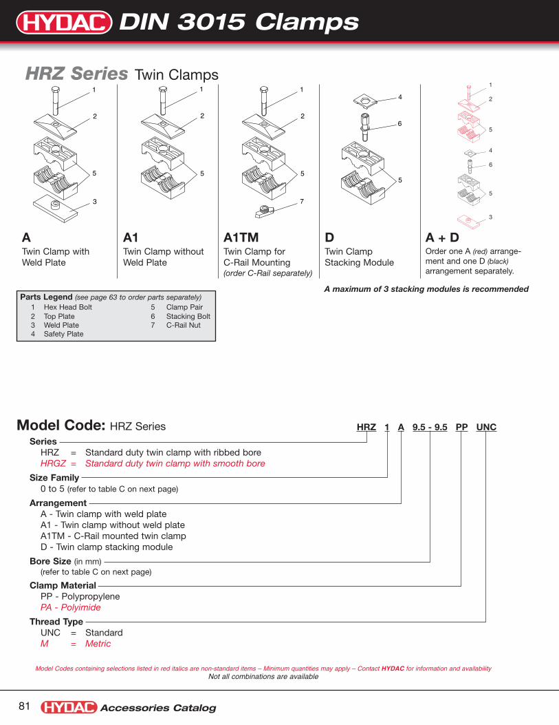
Accessories Catalog81
Model Code: HRZ Series
HRZ Series Twin Clamps
HRZ 1 A 9.5 - 9.5 PP UNC
SeriesHRZ = Standard duty twin clamp with ribbed boreHRGZ = Standard duty twin clamp with smooth bore
Size Family0 to 5 (refer to table C on next page)
ArrangementA - Twin clamp with weld plateA1 - Twin clamp without weld plateA1TM - C-Rail mounted twin clampD - Twin clamp stacking module
Bore Size (in mm)(refer to table C on next page)
Clamp MaterialPP - PolypropylenePA - Polyimide
Thread TypeUNC = StandardM = Metric
Model Codes containing selections listed in red italics are non-standard items – Minimum quantities may apply – Contact HYDAC for information and availabilityNot all combinations are available
ATwin Clamp withWeld Plate
A1TMTwin Clamp forC-Rail Mounting(order C-Rail separately)
DTwin ClampStacking Module
A1Twin Clamp withoutWeld Plate
Parts Legend (see page 63 to order parts separately)1 Hex Head Bolt 5 Clamp Pair2 Top Plate 6 Stacking Bolt3 Weld Plate 7 C-Rail Nut4 Safety Plate
1
2
5
4
6
5
3
A + DOrder one A (red) arrange-ment and one D (black)arrangement separately.
A maximum of 3 stacking modules is recommended
DIN 3015 Clamps

DIN 3015 Clamps
Ød RecommendedSize Bore Size Nominal Size a1 a2 a3 h1 h2 h3 Bolt Size
in mm Tube O.D. Pipe
0.24 6.0 - -0.25 6.4 1/4” -0.32 8.0 5/16” - 0.79 1.46 1.42 0.73 1.06 1.69 1/4-20 x 1-1/2
1 0.37 9.5 3/8” - (20) (37) (36) (18.5) (27) (43) (M6 x 35)0.39 10.0 - 1/8”0.41 10.3 - 1/8”0.47 12.0 - -
0.50 12.7 1/2” -0.54 13.7 - 1/4”0.55 14.0 - - 1.14 2.17 2.09 0.71 1.02 1.71 5/16-18 x 1-1/4
2 0.59 15.0 - - (29) (55) (53) (18) (26) (43.5) (M8 x 35)0.63 16.0 5/8” -0.67 17.1 - 3/8”
0.75 19.0 3/4” -0.79 20.0 - -
3 0.84 21.3 - 1/2” 1.42 2.76 2.64 0.93 1.46 2.15 5/16-18 x 1-3/40.87 22.0 7/8” - (36) (70) (67) (23.5) (37) (54.5) (M8 x 45)0.91 23.0 - -0.98 25.0 - -1.00 25.4 1” -
1.05 26.7 - 3/4” 1.77 3.35 3.23 1.02 1.65 2.34 5/16-18 x 24 1.10 28.0 - - (45) (85) (82) (26) (42) (59.5) (M8 x 50)
1.18 30.0 - -
1.26 32.0 1-1/4” -1.33 33.7 - 1”
5 1.38 35.0 - - 2.20 4.33 4.17 1.26 2.13 2.81 5/16-18 x 2-1/21.50 38.0 1-1/2” - (56) (110) (106) (32) (54) (71.5) (M8 x 60)1.65 40.0 - -1.65 42.0 - 1-1/4”
Accessories Catalog 82
a3
a1
a2
h 2h 3
h 1
.20
(5) 1.18
(30)
ø dø dø dø d
Dimensions: HRZ SeriesAll sizes C-Rail Nut C-Rail
ø .39(ø 10)
.20
(5)
.59
(15)
Plastic Cap
.96(24.5)
39 (10)
1/4" -20 UNC
1.10(28)
.43(11)
.43
(11)
.08
(2)
Note: Other bore diameters are available — Consult factory for details.Dimensions are for general information only, all critical dimensions should be verified by requesting a certified print.Dimensions are in inches/(mm)
Table C
DIN 3015 Clamps

Accessories Catalog83
Model Code: HREL Series
HREL Series Standard Duty Clamps with Rubber Inserts
HREL 4 A 12.7 PP UNC
Series
Size Family4, 6 (refer to table D on next page)
ArrangementA = Single clamp with top plate and weld plateA1 = Single clamp stacking kitA1TM = C-Rail mounted clampD = Single clamp stacking module (not available for size 0)
Bore Size (in mm) (refer to table D on next page)
Clamp MaterialPP = PolypropylenePA = Polyimide
Metal Components Materials(omit) = Carbon SteelA2 = 304 Stainless SteelA4 = 316 Stainless Steel (metric threads only)
Thread TypeUNC = StandardM = Metric
Model Codes containing selections listed in red italics are non-standard items – Minimum quantities may apply – Contact HYDAC for information and availabilityNot all combinations are available
ASingle Clamp withWeld Plate
A1TMSingle Clamp forC-Rail Mounting(order C-Rail separately)
DSingle ClampStacking Module
A1Single Clamp withoutWeld Plate
Parts Legend (see page 61 to order parts separately)1 Hex Head Bolt 5 Clamp Pair2 Top Plate 6 Rubber Insert3 Weld Plate 7 Stacking Bolt4 Safety Plate 8 C-Rail Nut
1
2
5
4
7
6 5
3
6
A + DOrder one A (red) arrange-ment and one D (black)arrangement separately.
A maximum of 3 stacking modules is recommended
DIN 3015 Clamps

Model Codes containing selections listed in red italics are non-standard items – Minimum quantities may apply – Contact HYDAC for information and availability
Note: All other components for these clamps are the same as for HRL series standard duty single clamps.Refer to page 61 for details
* HREL series use the same rubber inserts as the HRES series, therefore the model code for them is HRES.
EE-Rubber Insert RecommendedClamp Bore Size Nominal Size Ø d1 Ø d2 h1 h2 a1 a2 a3 s Bolt SizeSize Size ø D Tube
PipeHose O.D.
in mm O.D. Min (in)Max (in)
0.24 6 - - 0.22 0.240.32 8 5/16” - 0.30 0.320.39 10 - 1/8” 0.37 0.390.47 12 - - 0.45 0.47
4 2/4 L0.50 12.7 1/2” - 0.48 0.50 1.00 1.22 0.925 1.85 1.57 2.32 2.24 0.118 1/4-20x1 3/40.55 14 - - 0.53 0.55 (25.5) (31) (23.5) (47) (40) (59) (57) (3) (M6 x 45)0.59 15 - - 0.57 0.590.63 16 5/8” - 0.61 0.630.68 17.2 - 3/8” 0.66 0.680.75 19 3/4” - 0.73 0.75
0.79 20 - 1/2” 0.77 0.790.87 22 7/8” - 0.85 0.870.98 25 1” - 0.96 0.98
6 3/6 L 1.06 26.9 - 3/4” 1.04 1.06 1.54 1.81 1.40 2.80 2.60 3.46 3.39 0.118 1/4-20x2 3/4
1.10 28 - - 1.08 1.10 (39) (46) (35.5) (71) (66) (88) (86) (3) (M6 x 70)
1.18 30 - - 1.16 1.181.26 32 1 1/4” - 1.24 1.26
Accessories Catalog 84
Parts: HREL Series
a1
ø d1
s
1.18(30)
ø d
a2
h 1
a3
h 2
s
ød 2
KP EE
HREL 4 KP PP
Series
Size4, 6 (refer to table above)
Clamp Pair
Clamp MaterialPP - PolypropylenePA - Polyimide
HRES 2/4 L EE 12
Series*
Size2/4 L, 3/6 L (refer to table above)
Rubber Insert
Bore Size (in mm)(refer to table above)
KP = Clamp Pair EE = Rubber Insert (Santoprene TPE 73)
ø .39(ø 10)
.20
(5)
.59
(15)
Plastic Cap
.96(24.5)
39 (10)
1/4" -20 UNC
1.10(28)
.43(11)
.43
(11)
.08
(2)
Dimensions: HREL SeriesAll sizes C-Rail Nut C-Rail Nut
Table D
Note: Other bore diameters are available — Consult factory for details.Dimensions are for general information only, all critical dimensions should be verified by requesting a certified print.Dimensions are in inches/(mm) and lbs./(kg.)
DIN 3015 Clamps
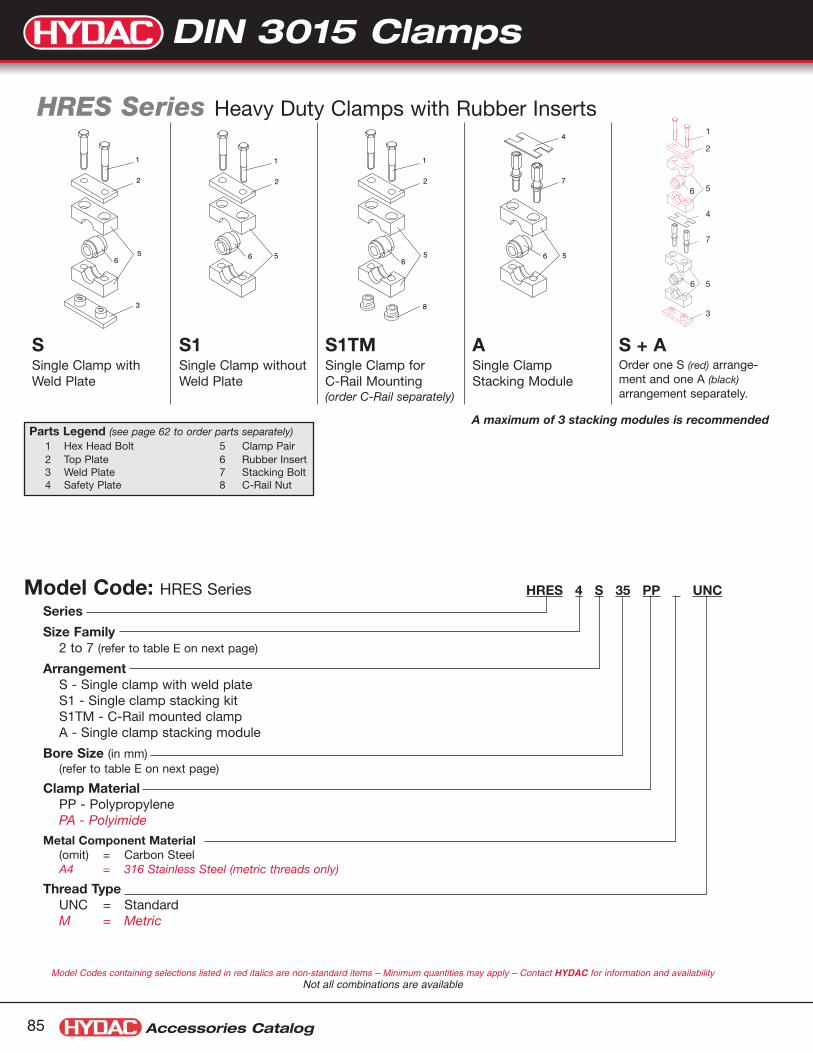
Accessories Catalog85
Model Code: HRES Series
HRES Series Heavy Duty Clamps with Rubber Inserts
HRES 4 S 35 PP UNC
Series
Size Family2 to 7 (refer to table E on next page)
ArrangementS - Single clamp with weld plateS1 - Single clamp stacking kitS1TM - C-Rail mounted clampA - Single clamp stacking module
Bore Size (in mm)(refer to table E on next page)
Clamp MaterialPP - PolypropylenePA - Polyimide
Metal Component Material(omit) = Carbon SteelA4 = 316 Stainless Steel (metric threads only)
Thread TypeUNC = StandardM = Metric
Model Codes containing selections listed in red italics are non-standard items – Minimum quantities may apply – Contact HYDAC for information and availabilityNot all combinations are available
SSingle Clamp withWeld Plate
S1TMSingle Clamp for C-Rail Mounting(order C-Rail separately)
S1Single Clamp withoutWeld Plate
Parts Legend (see page 62 to order parts separately)1 Hex Head Bolt 5 Clamp Pair2 Top Plate 6 Rubber Insert3 Weld Plate 7 Stacking Bolt4 Safety Plate 8 C-Rail Nut
1
2
5
4
7
5
3
6
6
S + AOrder one S (red) arrange-ment and one A (black)arrangement separately.
A maximum of 3 stacking modules is recommended
ASingle ClampStacking Module
DIN 3015 Clamps

DIN 3015 Clamps
Accessories Catalog 86
a1
ø d1
s
b
ø d
a2
h 1
a3
h 2
s
ød 2
3/8" -16 UNC
ø .98(ø 25)
ø .71(ø 18)
.24
(6)
.28
(7)
.79
(20)
.45(11.5)
.50(12.7)
.20
(5)
.87
(22)
1.57(40)
7/16" -14 UNC
ø .98(ø 25)
ø .79(ø 20)
.24
(6)
.33
(8.5
)
.91
(23)
.45
(11.5)
Dimensions: HRES SeriesAll Sizes C-Rail Nut (sizes 1-3) C-Rail Nut (size 4) C-Rail (all sizes)
Parts: HRES Series
HRES 3 KP PPSeriesSize
2 to 7 (refer to table above)Clamp PairClamp Material
PP = PolypropylenePA = Polyimide
HRES 3/6L EE 26.9SeriesSize
2/4 L to 7 (refer to table above)Rubber InsertBore Size (in mm)
(refer to table above)
KP = Clamp Pair EE = Rubber Insert (Santoprene TPE 73)
Table E
KP
Model Codes containing selections listed in red italics are non-standard items – Minimum quantities may apply – Contact HYDAC for information and availabilityNot all combinations are available
Note: All other components for these clamps are the same as for HRS series heavy duty single clamps.Refer to page 62 for details
Note: Other bore diameters are available — Consult factory for details.Dimensions are for general information only, all critical dimensions should be verified by requesting a certified print.Dimensions are in inches/(mm) and lbs./(kg.)
EE-Rubber Insert RecommendedClamp Bore Size Nominal Size Ø d1 Ø d2 b h1 h2 a1 a2 a3 s Bolt SizeSize Size ø D Tube
PipeHose O.D.
in mm O.D. Min (in) Max (in)0.24 6 - - 0.22 0.240.32 8 5/16” - 0.30 0.320.39 10 - 1/8” 0.37 0.390.47 12 - - 0.45 0.47
2 2/4 L0.50 12.7 1/2” - 0.48 0.50 1.00 1.24 1.18 1.22 2.44 1.77 3.35 2.76 0.32 3/8-16x2-1/40.55 14 - - 0.53 0.55 (25.5) (31.5) (30) (31) (62) (45) (85) (70) (8) (M10 x 60)0.59 15 - - 0.57 0.590.63 16 5/8” - 0.61 0.630.68 17.2 - 3/8” 0.66 0.680.75 19 3/4” - 0.73 0.750.79 20 - 1/2” 0.77 0.790.87 22 7/8” - 0.85 0.870.98 25 1” - 0.96 0.98
3 3/6 L 1.06 26.9 - 3/4” 1.04 1.06 1.54 1.83 1.18 1.46 2.91 2.36 3.94 3.35 0.32 3/8-16x2-3/41.10 28 - - 1.08 1.10 (39) (46.5) (30) (37) (74) (60) (100) (85) (8) (M10 x 70)1.18 30 - - 1.16 1.181.26 32 1 1/4” - 1.24 1.261.33 33.7 - 1” 1.31 1.331.38 35 - - 1.36 1.381.50 38 1 1/2” - 1.48 1.501.58 40 - - 1.56 1.58
4 41.65 42 - - 1.63 1.65 2.56 2.91 1.77 2.11 4.21 3.56 5.51 4.53 0.39 7/16-14x41.79 45.5 - - 1.77 1.79 (65) (74) (45) (53.5) (107) (90.5) (140) (115) (10) (M12 x 100)1.89 48 - 1 1/2” 1.87 1.892.01 51 2” - 1.99 2.012.10 53.4 - - 2.08 2.102.22 56.4 - - 2.20 2.222.36 60 - 2” 2.34 2.362.56 65 - - 2.54 2.56
3.50 3.86 2.36 2.70 5.39 4.80 7.09 5.98 0.39 5/8-11x5 1/25 5 2.76 70 - - 2.74 2.76(89) (98) (60) (68.5) (137) (122) (180) (152) (10) (M16 x 130)2.87 73 - 2 1/2” 2.85 2.87
2.99 76 3” - 2.97 2.993.27 83 - - 3.19 3.27
6 63.50 89 3 1/2” 3” 3.43 3.50 4.57 5.20 3.15 3.88 7.76 6.61 8.86 8.07 0.59 3/4-10x7 1/23.70 94 - - 3.62 3.70 (116) (132) (80) (98.5) (197) (168) (225) (205) (15) (M20 x 190)3.98 101 4” 3 1/2” 3.90 3.984.26 108 - - 4.17 4.26
6.06 6.61 3.54 4.47 8.94 8.07 10.63 9.92 0.59 7/8-9x8 1/27 7 4.49 114 - 4” 4.41 4.49(154) (168) (90) (113.5) (227) (205) (270) (252) (15) (M20 x 220)5.24 133 - - 5.16 5.24
EE
DIN 3015 Clamps
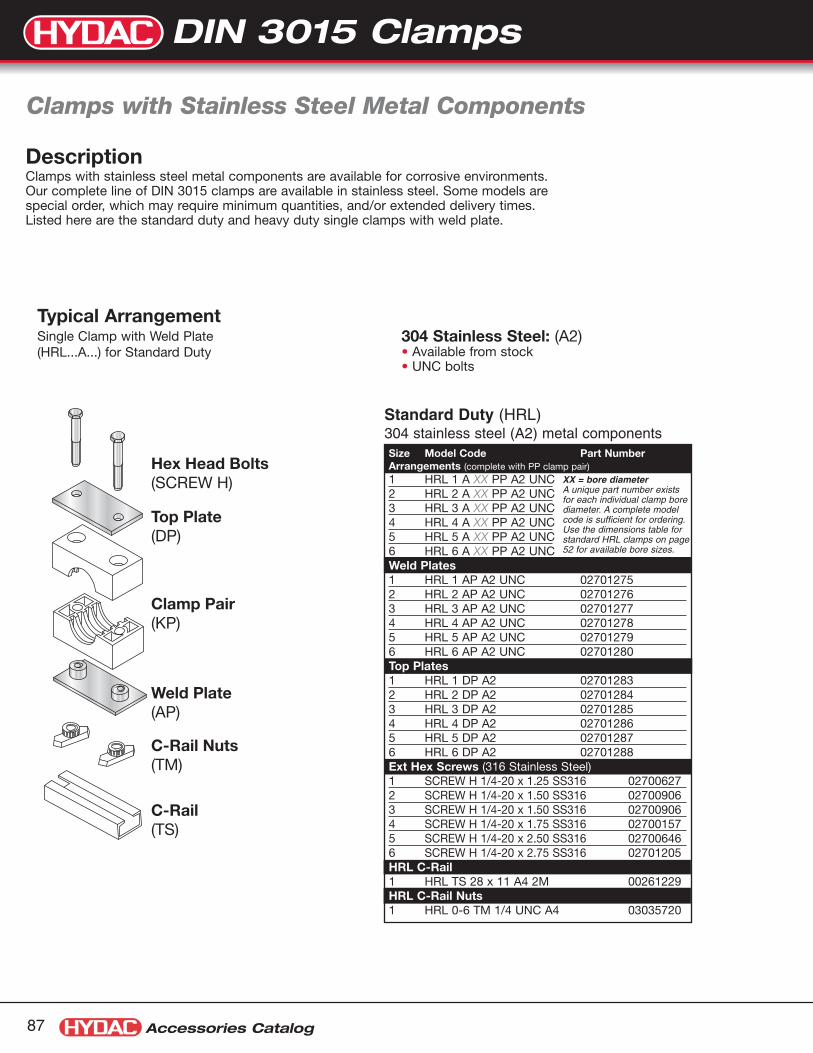
Accessories Catalog87
XX = bore diameterA unique part number existsfor each individual clamp borediameter. A complete modelcode is sufficient for ordering.Use the dimensions table forstandard HRL clamps on page52 for available bore sizes.
Clamps with Stainless Steel Metal Components
Weld Plate(AP)
C-Rail Nuts(TM)
C-Rail(TS)
Clamp Pair(KP)
Top Plate(DP)
Hex Head Bolts(SCREW H)
DescriptionClamps with stainless steel metal components are available for corrosive environments.Our complete line of DIN 3015 clamps are available in stainless steel. Some models arespecial order, which may require minimum quantities, and/or extended delivery times.Listed here are the standard duty and heavy duty single clamps with weld plate.
Standard Duty (HRL)304 stainless steel (A2) metal components
304 Stainless Steel: (A2)• Available from stock • UNC bolts
Typical ArrangementSingle Clamp with Weld Plate(HRL...A...) for Standard Duty
Size Model Code Part NumberArrangements (complete with PP clamp pair)
1 HRL 1 A XX PP A2 UNC2 HRL 2 A XX PP A2 UNC3 HRL 3 A XX PP A2 UNC4 HRL 4 A XX PP A2 UNC5 HRL 5 A XX PP A2 UNC6 HRL 6 A XX PP A2 UNCWeld Plates1 HRL 1 AP A2 UNC 027012752 HRL 2 AP A2 UNC 027012763 HRL 3 AP A2 UNC 027012774 HRL 4 AP A2 UNC 027012785 HRL 5 AP A2 UNC 027012796 HRL 6 AP A2 UNC 02701280Top Plates1 HRL 1 DP A2 027012832 HRL 2 DP A2 027012843 HRL 3 DP A2 027012854 HRL 4 DP A2 027012865 HRL 5 DP A2 027012876 HRL 6 DP A2 02701288Ext Hex Screws (316 Stainless Steel)1 SCREW H 1/4-20 x 1.25 SS316 027006272 SCREW H 1/4-20 x 1.50 SS316 027009063 SCREW H 1/4-20 x 1.50 SS316 027009064 SCREW H 1/4-20 x 1.75 SS316 027001575 SCREW H 1/4-20 x 2.50 SS316 027006466 SCREW H 1/4-20 x 2.75 SS316 02701205HRL C-Rail1 HRL TS 28 x 11 A4 2M 00261229HRL C-Rail Nuts1 HRL 0-6 TM 1/4 UNC A4 03035720
DIN 3015 Clamps
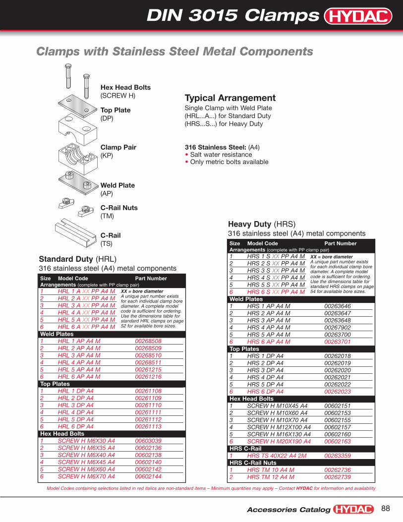
DIN 3015 Clamps
Accessories Catalog 88
XX = bore diameterA unique part number existsfor each individual clamp borediameter. A complete modelcode is sufficient for ordering.Use the dimensions table forstandard HRS clamps on page54 for available bore sizes.XX = bore diameter
A unique part number existsfor each individual clamp borediameter. A complete modelcode is sufficient for ordering.Use the dimensions table forstandard HRL clamps on page52 for available bore sizes.
Standard Duty (HRL)316 stainless steel (A4) metal components
Heavy Duty (HRS)316 stainless steel (A4) metal components
316 Stainless Steel: (A4)• Salt water resistance• Only metric bolts available
Weld Plate(AP)
C-Rail Nuts(TM)
C-Rail(TS)
Clamp Pair(KP)
Top Plate(DP)
Hex Head Bolts(SCREW H)
Clamps with Stainless Steel Metal Components
Typical ArrangementSingle Clamp with Weld Plate(HRL...A...) for Standard Duty(HRS...S...) for Heavy Duty
Size Model Code Part NumberArrangements (complete with PP clamp pair)
1 HRL 1 A XX PP A4 M2 HRL 2 A XX PP A4 M3 HRL 3 A XX PP A4 M4 HRL 4 A XX PP A4 M5 HRL 5 A XX PP A4 M6 HRL 6 A XX PP A4 MWeld Plates1 HRL 1 AP A4 M 002685082 HRL 2 AP A4 M 002685093 HRL 3 AP A4 M 002685104 HRL 4 AP A4 M 002685115 HRL 5 AP A4 M 002612156 HRL 6 AP A4 M 00261216Top Plates1 HRL 1 DP A4 002611082 HRL 2 DP A4 002611093 HRL 3 DP A4 002611104 HRL 4 DP A4 002611115 HRL 5 DP A4 002611126 HRL 6 DP A4 00261113Hex Head Bolts1 SCREW H M6X30 A4 006030392 SCREW H M6X35 A4 006021363 SCREW H M6X40 A4 006021384 SCREW H M6X45 A4 006021405 SCREW H M6X60 A4 006021426 SCREW H M6X70 A4 00602144
Size Model Code Part NumberArrangements (complete with PP clamp pair)
1 HRS 1 S XX PP A4 M2 HRS 2 S XX PP A4 M3 HRS 3 S XX PP A4 M4 HRS 4 S XX PP A4 M5 HRS 5 S XX PP A4 M6 HRS 6 S XX PP A4 MWeld Plates1 HRS 1 AP A4 M 002636462 HRS 2 AP A4 M 002636473 HRS 3 AP A4 M 002636484 HRS 4 AP A4 M 002679025 HRS 5 AP A4 M 002637006 HRS 6 AP A4 M 00263701Top Plates1 HRS 1 DP A4 002620182 HRS 2 DP A4 002620193 HRS 3 DP A4 002620204 HRS 4 DP A4 002620215 HRS 5 DP A4 002620226 HRS 6 DP A4 00262023Hex Head Bolts1 SCREW H M10X45 A4 006021512 SCREW H M10X60 A4 006021533 SCREW H M10X70 A4 006021554 SCREW H M12X100 A4 006021575 SCREW H M16X130 A4 006021606 SCREW H M20X190 A4 00602163HRS C-Rail1 HRS TS 40X22 A4 2M 00263359HRS C-Rail Nuts1 HRS TM 10 A4 M 002627362 HRS TM 12 A4 M 00262739
Model Codes containing selections listed in red italics are non-standard items – Minimum quantities may apply – Contact HYDAC for information and availability
DIN 3015 Clamps
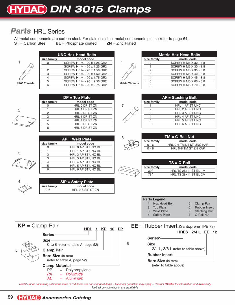
Accessories Catalog89
UNC Hex Head Boltssize family model code
0 SCREW H 1/4 - 20 x 1.25 GR21 SCREW H 1/4 - 20 x 1.25 GR22 SCREW H 1/4 - 20 x 1.50 GR23 SCREW H 1/4 - 20 x 1.50 GR24 SCREW H 1/4 - 20 x 1.75 GR25 SCREW H 1/4 - 20 x 2.50 GR26 SCREW H 1/4 - 20 x 2.75 GR2
DP = Top Platesize family model code
0 HRL 0 DP ST ZN1 HRL 1 DP ST ZN2 HRL 2 DP ST ZN3 HRL 3 DP ST ZN4 HRL 4 DP ST ZN5 HRL 5 DP ST ZN6 HRL 6 DP ST ZN
AP = Weld Platesize family model code
0 HRL 0 AP ST UNC BL1 HRL 1 AP ST UNC BL2 HRL 2 AP ST UNC BL3 HRL 3 AP ST UNC BL4 HRL 4 AP ST UNC BL5 HRL 5 AP ST UNC BL6 HRL 6 AP ST UNC BL
TM = C-Rail Nutsize family model code
0 - 6 HRL 0-6 TM1/4 ST UNC KAP0 - 6 HRL 0-6 TM ST ZN KAP
AF = Stacking Boltsize family model code
1 HRL 1 AF ST UNC2 HRL 2 AF ST UNC3 HRL 3 AF ST UNC4 HRL 4 AF ST UNC5 HRL 5 AF ST UNC6 HRL 6 AF ST UNC
SIP = Safety Platesize family model code
0-6 HRL 0-6 SIP ST ZN
TS = C-Railsize family model code
39” HRL TS 28x11 ST BL 1M78” HRL TS 28x11 ST BL 2M
1 1
Metric Hex Head Boltssize family model code
0 SCREW H M6 X 30 - 8.81 SCREW H M6 X 30 - 8.82 SCREW H M6 X 35 - 8.83 SCREW H M6 X 40 - 8.84 SCREW H M6 X 45 - 8.85 SCREW H M6 X 60 - 8.86 SCREW H M6 X 70 - 8.8
2
3
7
8
4
HRL 1 KP 10 PPSeriesSize
0 to 6 (refer to table A, page 52)
Clamp PairBore Size (in mm)
(refer to table A, page 52)
Clamp MaterialPP = PolypropylenePA = PolyimideAL = Aluminum
KP = Clamp Pair
Parts HRL SeriesAll metal components are carbon steel. For stainless steel metal components please refer to page 64.ST = Carbon Steel BL = Phosphate coated ZN = Zinc Plated
Model Codes containing selections listed in red italics are non-standard items – Minimum quantities may apply – Contact HYDAC for information and availabilityNot all combinations are available
Parts Legend1 Hex Head Bolt 5 Clamp Pair2 Top Plate 6 Rubber Insert3 Weld Plate 7 Stacking Bolt4 Safety Plate 8 C-Rail Nut
UNC Threads Metric Threads
HRES 2/4 L EE 12
Series*
Size2/4 L, 3/6 L (refer to table above)
Rubber Insert
Bore Size (in mm)(refer to table above)
EE = Rubber Insert (Santoprene TPE 73)
6
5
DIN 3015 Clamps

DIN 3015 Clamps
Accessories Catalog 90
Parts HRS Series
UNC Hex Head Boltssize family model code
1 SCREW H 3/8 - 16 x 1.75 GR52 SCREW H 3/8 - 16 x 2.25 GR53 SCREW H 3/8 - 16 x 2.75 GR54 SCREW H 7/16 - 14 x 4.00 GR55 SCREW H 5/8 - 11 x 5.50 GR56 SCREW H 3/4 - 10 x 7.50 GR57 SCREW H 7/8 - 9 x 8.50 GR58 N/A (size 8 metric only)
5
HRS 1 KP 12.7 PPSeriesSize
1 to 8 (refer to table B, page 54)
Clamp PairBore Size (in mm)
(refer to table B, page 54)
Clamp MaterialPP = PolypropylenePA = PolyimideAL = Aluminum
DP = Top Platesize family model code
1 HRS 1 DP ST ZN2 HRS 2 DP ST ZN3 HRS 3 DP ST ZN4 HRS 4 DP ST ZN5 HRS 5 DP ST ZN6 HRS 6 DP ST BL7 HRS 7 DP ST BL8 HRS 8 DP ST BL
AP = Weld Platesize family model code
1 HRS 1 AP ST UNC BL2 HRS 2 AP ST UNC BL3 HRS 3 AP ST UNC BL4 HRS 4 AP ST UNC BL5 HRS 5 AP ST UNC BL6 HRS 6 AP ST UNC BL7 HRS 7 AP ST UNC BL8 HRS 8 AP ST UNC BL
TM = C-Rail Nutsize family model code
1-3 HRS 1-3 TM3/8 ST UNC BL4 HRS 4 TM7/16 ST UNC BL
AF = Stacking Bolt w/ Washersize family model code
1 HRS 1 AF ST UNC2 HRS 2 AF ST UNC3 HRS 3 AF ST UNC4 HRS 4 AF ST UNC5 HRS 5 AF ST UNC
SIP = Safety Platesize family model code
1 HRS 1 SIP ST ZN2 HRS 2 SIP ST ZN3 HRS 3 SIP ST ZN4 HRS 4 SIP ST ZN5 HRS 5 SIP ST ZN
TS = C-Railsize family model code
39” HRS TS 40x22 ST BL 1M78” HRS TS 40x22 ST BL 2M
Metric Hex Head Boltssize family model code
1 SCREW H M10 X 45 - 8.82 SCREW H M10 X 60 - 8.83 SCREW H M10 X 70 - 8.84 SCREW H M12 X 100 - 8.85 SCREW H M16 X 130 - 8.86 SCREW H M20 X 190 - 8.87 SCREW H M20 X 220 - 8.88 SCREW H M30 X 300 - 8.8
2
3
7
8
4
All metal components are carbon steel. For stainless steel metal components please refer to page 53.ST = Carbon Steel BL = Phosphate coated ZN = Zinc Plated
Parts Legend1 Hex Head Bolt 5 Clamp Pair2 Top Plate 6 Rubber Insert3 Weld Plate 7 Stacking Bolt4 Safety Plate 8 C-Rail Nut
1 1
UNC Threads Metric Threads
HRES 3/6L EE 26.9SeriesSize
2/4 L to 7 (refer to table above)Rubber InsertBore Size (in mm)
(refer to table above)
KP = Clamp Pair EE = Rubber Insert (Santoprene TPE 73)
6
Model Codes containing selections listed in red italics are non-standard items – Minimum quantities may apply – Contact HYDAC for information and availabilityNot all combinations are available
DIN 3015 Clamps

Parts HRZ Series
UNC Hex Head Boltssize model code
1 SCREW H 1/4 - 20 x 1.5 GR22 SCREW H 5/16 - 18 x 1.25 GR23 SCREW H 5/16 - 18 x 1.75 GR24 SCREW H 5/16 - 18 x 2.00 GR25 SCREW H 5/16 - 18 x 2.50 GR2
DP = Top Platesize model code
1 HRZ 1 DP ST ZN2 HRZ 2 DP ST ZN3 HRZ 3 DP ST ZN4 HRZ 4 DP ST ZN5 HRZ 5 DP ST ZN
AP = Weld Platesize model code
1 HRZ 1 AP ST UNC BL Anti-Turn2 HRZ 2 AP ST UNC BL Anti-Turn3 HRZ 3 AP ST UNC BL Anti-Turn4 HRZ 4 AP ST UNC BL5 HRZ 5 AP ST UNC BL
TM = C-Rail Nutsize model code
1 HRZ 1 TM1/4 ST UNC KAP2-5 HRZ 2/5 TM5/16 ST UNC O-Ring
AF = Stacking Bolt w/ Washersize model code
1 HRZ 1 AF ST UNC2 HRZ 2 AF ST UNC3 HRZ 3 AF ST UNC4 HRZ 4 AF ST UNC5 HRZ 5 AF ST UNC
SIP = Safety Platesize model code
1 HRZ 1 SIP ST ZN2-5 HRZ 2/5 SIP ST ZN
TS = C-Railsize model code39” HRL TS 28x11 ST BL 1M78” HRL TS 28x11 ST BL 2M
Metric Hex Head Boltssize model code
1 SCREW H M6x35 MM - 8.8 DIN 9332 SCREW H M8x35 MM - 8.8 DIN 9333 SCREW H M8x45 MM - 8.8 DIN 9334 SCREW H M8x50 MM - 8.8 DIN 9335 SCREW H M8x60 MM - 8.8 DIN 933
2
3
7
8
4
5
HRZ 1 KP 9.5-9.5 PPSeriesSize
0 to 5 (refer to table C, page 56)
Clamp PairBore Size (in mm)
(refer to table C, page 56)
Clamp MaterialPP = PolypropylenePA = Polyimide
KP = Clamp Pair
Model Codes containing selections listed in red italics are non-standard items – Minimum quantities may apply – Contact HYDAC for information and availabilityNot all combinations are available
Parts Legend1 Hex Head Bolt 5 Clamp Pair2 Top Plate 6 Rubber Insert3 Weld Plate 7 Stacking Bolt4 Safety Plate 8 C-Rail Nut
1 1
UNC Threads Metric Threads
Accessories Catalog91
DIN 3015 Clamps

Standard Clamps
Accessories Catalog 92
Description: The interlock edge insures thatthe cushion remains in place. TheHOM Series clamp assemblyretains, guides, protects and uniformly spaces line runs. Theygo up fast, lines are rigid, andlook neat.
Features: Attached with two standard* fasteners to any flat surface, theHOM Series clamp eliminates theuse of specials channels, providing a savings in both spaceand cost.• Low profile for limited space
applications.
Materials: The ClampAvailable in steel (with electro-dichromate finish), and 304 stainlesssteel (A2 in the model code denotes304 stainless steel).
The CushionManufactured from a thermoplasticelastomer, it’s built tough to with-stand the effects of most oils,chemical and industrial cleaningcompounds, in temperatures from-50° to 275°F.
*Note: Fasteners not provided.
Model CodePart
Number
Copper &Steel Tubing
O.D.
CopperWaterPipe
PipeSize
A B C D E F
HOM 1/4T 020807471/4” – – 0.25” 0.48” 0.60” 0.22” 0.26” 0.78”
HOM 1/4T A2 02080768
HOM 3/8T 020807483/8” 1/4” – 0.37” 0.62” 0.66” 0.31” 0.26” 0.81”
HOM 3/8T A2 02080769
HOM 1/2T - 1/4P 020807491/2” 3/8” 1/4” 0.50” 0.81” 0.83” 0.40” 0.26” 0.98”
HOM 1/2T - 1/4P A2 02080770
HOM 5/8-3/8P 020807505/8” 1/2” 3/8” 0.62” 0.93” 0.85” 0.46” 0.26” 0.98”
HOM 5/8-3/8P A2 02080771
HOM 3/4T 020807513/4” 5/8” – 0.75” 1.02” 0.90” 0.50” 0.26” 0.98”
HOM 3/4T A2 02080772
HOM 7/8 - 1/2P 020807527/8” 3/4” 1/2” 0.87” 1.12” 1.03” 0.53” 0.26” 0.98”
HOM 7/8 - 1/2P A2 02080773
HOM 1T 020807531” – – 1.00” 1.24” 1.04” 0.59” 0.26” 0.98”
HOM 1T A2 02080774
HOM 3/4P 02080754– – 3/4” 1.05” 1.40” 1.11” 0.70” 0.26” 0.98”
HOM 3/4P A2 02080775
HOM 1 1/8T 020807551 1/8” 1” – 1.12” 1.40” 1.17” 0.70” 0.26” 0.98”
HOM 1 1/8T A2 02080776
HOM 1 1/4T 020807561 1/4” – – 1.25” 1.60” 1.20” 0.77” 0.26” 1.56”
HOM 1 1/4 A2 02080777
HOM 1P 02080757– – 1” 1.31” 1.71” 1.28” 0.81” 0.26” 1.56”
HOM 1P A2 02080778
HOM 1 3/8T 020807581 3/8” 1 1/4” – 1.37” 1.71” 1.28” 0.83” 0.26” 1.56”
HOM 1 3/8T A2 02080779
HOM 1 1/2T 020807591 1/2” – – 1.50” 1.85” 1.36” 0.90” 0.26” 1.56”
HOM 1 1/2T A2 02080780
HOM 1 5/8T 020807601 5/8” 1 1/2” – 1.62” 1.95” 1.43” 0.96” 0.26” 1.56”
HOM 1 5/8T A2 02080781
HOM 1 1/4P 02080761– – 1 1/4” 1.66” 2.12” 1.55” 0.99” 0.34” 1.56”
HOM 1 1/4P A2 02080782
HOM 1 3/4T 020807621 3/4” – – 1.75” 2.12” 1.55” 1.02” 0.34” 1.56”
HOM 1 3/4T A2 02080783
HOM 1 7/8T - 1 1/2P 020807631 7/8” – 1 1/2” 1.87” 2.25” 1.64” 1.09” 0.34” 1.56”
HOM 1 7/8T - 1 1/2P A2 02080784
HOM 2T 020807642” – – 2.00” 2.38” 1.69” 1.15” 0.34” 1.56”
HOM 2T A2 02080785
HOM 2 1/8T 020807652 1/8” – – 2.12” 2.62” 1.86” 1.27” 0.34” 1.56”
HOM 2 1/8T A2 02080786
HOM 2 3/8T - 2P 020807662 3/8” – 2” 2.37” 2.88” 1.94” 1.41” 0.34” 1.56”
HOM 2 3/8T - 2P A2 02080787
HOM 5 1/8T 02080767 5 1/8” 5” – 5.12” 5.82” 3.55” 2.84” 0.43” 1.56”
HOM SeriesDimensions
A
B
J
C
Model Codes containing selections listed in red italics are non-standard items – Minimum quantities may apply – Contact HYDAC for information and availability
Dimensions are for general information only, all critical dimensions should be verified by requesting acertified print. Dimensions are in inches/(mm) and lbs./(kg.)
Standard Clamps

Tube Series: T = with Controlled Squeeze Shoulder Bolt (sizes 1 3/8” and smaller)Pipe Series: P = without Controlled Squeeze Shoulder BoltDimensions are for general information only. Due to constant development and updatingof details, we ask that all critical dimensions be verified by requesting a certified print.
ApplicationModel
Copper Copper Nom.& Steel Water Pipe Pipe Dimensions
Code Tubing in. (nom.) in. Size in. ø A in. B in. C in. Part No.CUSH 1/4T 1/4 0.25 0.62 0.98 02073330CUSH 3/8T 3/8 1/4 0.37 0.82 1.13 02073331CUSH 1/2T 1/2 3/8 0.50 0.94 1.34 02073332CUSH 1/4P 1/4 0.54 0.98 1.34 02073361CUSH 5/8T 5/8 1/2 0.62 1.06 1.54 02073333CUSH 3/8P 3/8 0.67 1.13 1.54 02073362CUSH 3/4T 3/4 5/8 0.75 1.20 1.68 02073334CUSH 1/2P 1/2 0.84 1.29 1.82 02073363CUSH 7/8T 7/8 3/4 0.87 1.31 1.82 02073335CUSH 1T 1 1.00 1.44 1.95 02073336CUSH 3/4P 3/4 1.05 1.50 1.95 02073364CUSH 1-1/8T 1 1/8 1 1.12 1.57 2.08 02073337CUSH 1-1/4T 1 1/4 1.25 1.70 2.21 02073338CUSH 1P 1 1.31 1.76 2.34` 02073365CUSH 1-3/8T 1 3/8 1 1/4 1.37 1.82 2.34 02073339CUSH 1-1/2T 1 1/2 1.50 1.95 2.47 02073340CUSH 1-5/8T 1 5/8 1 1/2 1.62 2.07 2.60 02073341CUSH 1-1/4P 1 1/4 1.66 2.17 2.73 02073366CUSH 1-3/4T 1 3/4 1.75 2.20 2.73 02073342CUSH 1-7/8T 1 7/8 1.87 2.32 2.86 02073343CUSH 1-1/2P 1 1/2 1.90 2.35 2.86 02073367CUSH 2T 2 2.00 2.45 3.04 02073344CUSH 2-1/8T 2 1/8 2.12 2.57 3.23 02073345CUSH 2-3/8T 2 3/8 2.37 2.82 3.67 02073346CUSH 2P 2 2.37 2.82 3.67 02073368CUSH 2-5/8T 2 5/8 2.62 3.07 3.92 02073348CUSH 2-1/2P 2 1/2 2.87 3.32 4.17 02073369CUSH 3-1/8T 3 1/8 3.12 3.57 4.42 02073351CUSH 3P 3 3.50 3.95 4.79 02073370CUSH 4p 4 4.50 4.95 5.95 02073372CUSH 5p 5 5.56 6.01 6.92 02073373CUSH 6P 6 3 6.62 7.07 8.23 02073374
Dimensions
øAC
B
CUSH Series Cushion Clamps
DescriptionCushion clamps are ideal for multiple lineruns, while absorbing shock and vibration,reducing unwanted noise and preventinggalvanic corrosion.
Features• Distortion free clamping
• Shock and vibration reduction
• Elimination of rotation
• Retrofit without disassembly
• Easy installation
• Control squeeze shoulder bolt preventsover tightening of the clamp assembly, preventing the possibility of crushing the tube.
• Fits standard 1-5/8” wide mounting rail
Materials• Clamp - carbon steel
(with electrodichromate finish)
• Cushion - thermoplastic elastomer
• Cushion material withstands the effect ofmost oils, chemicals and industrial cleaningsolvents at temperatures -40° to 275°F.
Mounting Rail• Part Number: 02073325
• Model Code: Cush Rail 1” x 4’ Green
• Material: Low gauge carbon steel
• Finish: Green paint
• Length: 4’
1 5/8"
7/8"
1"
Model Codes containing selections listed in red italics are non-standard items – Minimum quantities may apply – Contact HYDAC for information and availabilityNot all combinations are available
Accessories Catalog93
Standard Clamps

Standard Clamps
1 5/8"
7/8"
13/16"
Accessories Catalog 94
øAC
B
Materials• Clamp - 316 stainless steel
• Cushion - thermoplastic elastomer
Model Code Part Number Size A B C
CUSH 1/4T A2 02080701 1/4” 0.25” 0.62” 0.98”
CUSH 3/8T A2 02080702 3/8” 0.37” 0.82” 1.13”
CUSH 1/2T A2 02080703 1/2” 0.50” 0.94” 1.34”
CUSH 5/8T A2 02080704 5/8” 0.62” 1.06” 1.54”
CUSH 3/4T A2 02080705 3/4” 0.75” 1.20” 1.68”
CUSH 7/8T A2 02080706 7/8” 0.87” 1.31” 1.82”
CUSH 1T A2 02080707 1” 1.00” 1.44” 1.95”
CUSH 1 1/8T A2 02080708 1 1/8” 1.12” 1.57” 2.08”
CUSH 1 1/4T A2 02080709 1 1/4” 1.25” 1.70” 2.21”
CUSH 1 3/8T A2 02080710 1 3/8” 1.37” 1.82” 2.34”
CUSH 1 1/2T A2 02080711 1 1/2” 1.50” 1.95” 2.47”
CUSH 1 5/8T A2 02080712 1 5/8” 1.62” 2.07” 2.60”
CUSH 1 3/4T A2 02080713 1 3/4” 1.75” 2.20” 2.73”
CUSH 1 7/8T A2 02080714 1 7/8” 1.87” 2.32” 2.86”
CUSH 2T A2 02080715 2” 2.00” 2.45” 3.04”
CUSH 2 1/8T A2 02080716 2 1/8” 2.12” 2.57” 3.23”
CUSH 2 1/4T A2 02080717 2 1/4” 2.37” 2.82” 3.67”
CUSH 2 3/8T A2 02080718 2 3/8” 2.37” 2.82” 3.67”
CUSH 2 1/2T A2 02080719 2 1/2” 2.50” 2.94” 3.79”
CUSH 2 5/8T A2 02080720 2 5/8” 2.62” 3.07” 3.92”
CUSH 2 7/8T A2 02080721 2 7/8” 2.87” 3.32” 4.17”
CUSH 3T A2 02080722 3” 3.00” 3.57” 4.42”
CUSH 3 1/8T A2 02080723 3 1/8” 3.12” 3.57” 4.42”
CUSH 3 5/16T A2 02080724 3 5/16” 3.31” 3.96” 4.75”
CUSH 3 1/2T A2 02080725 3 1/2” 3.50” 3.95” 4.79”
CUSH 3 5/8T A2 02080726 3 5/8” 3.62” 4.20” 5.11”
CUSH 4T A2 02080727 4” 4.00” 4.45” 5.11”
CUSH 4 1/8T A2 02080728 4 1/8” 4.12” 4.57” 5.54”
CUSH 4 1/2T A2 02080729 4 1/2” 4.50” 4.95” 5.92”
CUSH 5 1/8T A2 02080730 5 1/8” 5.12” 5.57” 6.54”
CUSH 6T A2 02080731 6” 6.12” 6.57” 7.54”
CUSH 6 1/8T A2 02080732 6 1/8” 6.12” 6.57” 7.54”
CUSH 1/4P A2 02080733 1/4” 0.54” 0.98” 1.34”
CUSH 3/8P A2 02080734 3/8” 0.67” 1.13” 1.54”
CUSH 1/2P A2 02080735 1/2” 0.84” 1.29” 1.82”
CUSH 3/4P A2 02080736 3/4” 1.05” 1.57” 2.08”
CUSH 1P A2 02080737 1” 1.31” 1.76” 2.34”
CUSH 1 1/4P A2 02080738 1 1/4” 1.66” 2.17” 2.73”
CUSH 1 1/2P A2 02080739 1 1/2” 1.90” 2.35” 2.86”
CUSH 2P A2 02080740 2” 2.37” 2.82” 3.67”
CUSH 2 1/2P A2 02080741 2 1/2” 2.87” 3.32” 4.17”
CUSH 3P A2 02080742 3” 3.50” 3.95” 4.79”
CUSH 3 1/2P A2 02080743 3 1/2” 4.00” 4.45” 5.11”
CUSH 4P A2 02080744 4” 4.50” 4.95” 5.92”
CUSH 5P A2 02080745 5” 5.56” 6.01” 6.92”
CUSH 6P A2 02080746 6” 6.62” 7.07” 8.23”
CUSH Series Stainless Steel Cushion Clamps
Dimensions
Mounting RailModel Code: Cush Rail 13/16” x 10’ A2
Part Number: 02701588
Material: Stainless Steel 316
Length: 10’0”
Model Codes containing selections listed in red italics are non-standard items – Minimum quantities may apply – Contact HYDAC for information and availabilityNot all combinations are available
Dimensions are for general information only, all critical dimensions should be verified by requesting a certified print.Dimensions are in inches/(mm) and lbs./(kg.)
Standard Clamps

Dimensions
slotted
a2
a1
d1 h2
h1
0.120"3mm
0.354"9mm 0.120"
3mm
Size: 0a & 0b
slotted
a2
a1
d2d1 h2
h1
0.120"3mm
0.120"3mm 0.780"
20mm
Size: 1 and 2
Ø Ø Ø
1) Consult Factory for sizes 1 and 2 with different bore diameters.Dimensions are for general information only, all critical dimensions should be verified by requesting a certified print.
Accessories Catalog95
HRBGS Series Buegu ClampsDescriptionBuegu clamps are ideal for mobile applica-tions where space is limited. They absorbshock and vibration, and reduce noise.
Features • Low Profile Design
• Shock and vibration reduction
• Easy installation
Materials• Stirrup & Weld Plate - carbon steel
• Clamp Body - thermoplastic elastomer(Santoprene TPE 73)
Temp Specifications• -40° to 257°F (-40° to 125°C)
Model Codes containing selections listed in red italics are non-standard items – Minimum quantities may apply – Contact HYDAC for information and availability
Clamp Tube Pipe Bore Diameter1
Clamp Assembly Part Dimensions Hex
Size Size Size Ød1 Ød2 Model Code Number Headin mm in mm a1 a2 h1 h2 Bolt
1/4” - 0.250 6.4 - - HRBGS 0A A 6.4 STM 02063638 mm 15 34 10 230A 3/8” - 0.375 9.5 - - HRBGS 0A A 9.5 STM 02063639
in 0.59 1.34 0.39 0.91M6x25
- 1/8” 0.394 10.0 - - HRBGS 0A A 10.0 STM 020636401/2” - 0.500 12.7 - - HRBGS 0B A 12.7 STM 02063641
mm 18 39 12 27- 1/4” 0.540 13.7 - - HRBGS 0B A 13.7 STM 02063642
0B 5/8” - 0.625 16.0 - - HRBGS 0B A 16.0 STM 02063643 M6x25- 3/8” 0.675 17.1 - - HRBGS 0B A 17.1 STM 02063644 in 0.71 1.54 0.47 1.06
3/4” - 0.750 19.0 - - HRBGS 0B A 19.0 STM 020636451/4” - 0.250 6.4 0.250 6.4 HRBGS 1 A 6.4-6.4 STM 02063646
mm 30 50 10 231
3/8” - 0.375 9.5 0.375 9.5 HRBGS 1 A 9.5-9.5 STM 02063647-” 1/8” 0.394 10.0 0.394 10.0 HRBGS 1 A 10-10 STM 02063648
in 1.18 1.97 0.39 0.91M6x25
1/2” - 0.500 12.7 0.500 12.7 HRBGS 1 A 12.7-12.7 STM 020636495/8” - 0.625 16.0 0.625 16.0 HRBGS 2 A 16-16 STM 02063650
mm 35 59 12 272 - 3/8” 0.675 17.1 0.675 17.1 HRBGS 2 A 17.1-17.1 STM 02063651 M6x25
3/4” - 0.750 19.0 0.750 19.0 HRBGS 2 A 19-19 STM 02063652 in 1.38 2.32 0.47 1.06
Standard Clamps

Standard Clamps
Accessories Catalog 96
BUE = StirrupSizes Model Code Part Number
0A HRBGS 0A BUE ST ZN 002633060B HRBGS 0B BUE ST ZN 002633071 HRBGS 1 BUE ST ZN 002633162 HRBGS 2 BUE ST ZN 00263309
ASKT = Hex Head Bolt for use with Weld PlateSizes Model Code Part Number
0A, 0B, 1, 2 HRBGS 0A/1 ASKT M6x25 02700852
AP = Weld Plate
HUE= Sleeve
Size 0GT = Rubber Body
Size 1,2
BUE = Stirrup
ASKT = Hex Head Bolt
AP = Weld PlateSizes Model Code Part Number
0A HRBGS 0A AP ST BLM 002635820B HRBGS 0B AP ST BLM 002635831 HRBGS 1 AP ST BLM 002635852 HRBGS 2 AP ST BLM 00263586
1) Consult Factory for sizes 1 and 2 with different bore diameters.
Clamp Bore Diameter1
Model Code PartSize Ød1 Ød2 Numberin mm in mm
0.250 6.4 - - HRBGS 0A GT 6.4 002681690A 0.375 9.5 - - HRBGS 0A GT 9.5 00268170
0.394 10.0 - - HRBGS 0A GT 10.0 002632960.500 12.7 - - HRBGS 0B GT 12.7 002681710.540 13.7 - - HRBGS 0B GT 13.7 00268172
0B 0.625 16.0 - - HRBGS 0B GT 16.0 002632980.675 17.1 - - HRBGS 0B GT 17.1 002681730.750 19.0 - - HRBGS 0B GT 19.0 002647130.250 6.4 0.250 6.4 HRBGS 1 A GT 6.4-6.4 00268174
10.375 9.5 0.375 9.5 HRBGS 1 GT 9.5-9.5 002681750.394 10.0 0.394 10.0 HRBGS 1 GT 10-10 002633130.500 12.7 0.500 12.7 HRBGS 1 GT 12.7-12.7 002640110.630 16.0 0.625 16.0 HRBGS 2 GT 16-16 00263304
2 0.675 17.1 0.675 17.1 HRBGS 2 GT 17.1-17.1 002681760.750 19.0 0.750 19.0 HRBGS 2 GT 19-19 00268177
HUE = Sleeve for use with Weld PlateSizes Model Code Part Number
0A HRBGS 0A/1 HUE 11.5 ZN 002634180B HRBGS 0B/2 HUE 15.5 ZN 002634191 HRBGS 0A/1 HUE 11.5 ZN 002634182 HRBGS 0B/2 HUE 15.5 ZN 00263419
HUE = Sleeve for use without Weld Plate0A HRBGS 0A/1 HUE 18 ZN 002633100B HRBGS 0B/2 HUE 22 ZN 002633111 HRBGS 0A/1 HUE 18 ZN 002633102 HRBGS 0B/2 HUE 22 ZN 00263311
Parts Buegu Clamp Parts
Model Codes containing selections listed in red italics are non-standard items – Minimum quantities may apply – Contact HYDAC for information and availability
Standard Clamps

Accessories Catalog97
U-bolt Clamps
Pipe or U-Bolt Pipe support long versionSize Model Code Part No. Tube A B D1 E1 H1 H2 H3 L2 B1 Pipe Ø1 HRRBS 1 L 21.3 PP ST ZN 02072678 1/2" Pipe 23 40 M10 33 65 5 10 60 25 21.32 HRRBS 2 L 26.9 PP ST ZN 02065150 3/4" Pipe 30 40 M10 40 70 5 12 75 30 26.93 HRRBS 3 L 33.7 PP ST ZN 02065151 1" Pipe 38 40 M10 48 75 5 12 80 30 33.74 HRRBS 4 L 42.4 PP ST ZN 02065152 - 46 50 M10 56 86 5 12 90 30 42.45 HRRBS 5 L 48.3 PP ST ZN 02065153 1 1/2" Pipe 52 50 M10 62 92 5 15 95 35 48.36 HRRBS 6 L 60.3 PP ST ZN 02065154 2" Pipe 64 60 M12 76 109 5 15 110 35 60.37 HRRBS 7 L 76.1 PP ST ZN 02065155 3" Tube 82 60 M12 94 125 5 15 135 35 76.18 HRRBS 8 L 88.9 PP ST ZN 02065156 3" Pipe 94 60 M12 106 138 10 20 145 40 88.99 HRRBS 9 L 108 PP ST ZN 02065157 - 120 80 M16 136 171 10 20 190 40 108
9 HRRBS 9 L 114.3 PP ST ZN 020651584" Pipe /
120 80 M16 136 171 10 20 190 40 114.34 1/2" Tube
10 HRRBS 10 L 139.7 PP ST ZN 02065159 5" Pipe 148 80 M16 164 191 10 20 220 40 139.711 HRRBS 11 L 159 PP ST ZN 02065160 - 176 80 M16 192 217 12 25 250 50 15911 HRRBS 11 L 168.3 PP ST ZN 02065161 6" Pipe 202 80 M16 218 249 12 25 270 50 168.313 HRRBS 13 L 219.1 PP ST ZN 02065162 8" Pipe 228 100 M20 248 283 12 25 315 50 219.114 HRRBS 14 L 273 PP ST ZN 02065163 10" Pipe 282 100 M20 302 334 12 25 370 50 27317 HRRBS 17 L 406.4 PP ST ZN 02068318 16" Pipe 428 100 M24 452 487 15 30 540 60 406.4
Pipe ø
AH1
B
D1E1
B1
L2
H2H3
DescriptionU-bolt clamps are a simple solution for securingpipes and other cylindrical objects. The clampsconsist of a threaded “U” and a contoured saddle.
Features • Metric Threads
• Easy installation
Materials• Threaded “U” - zinc-plated carbon steel
• Saddle - polypropylene
Dimensions are for general information only, all critical dimensions should be verified by requesting a certified print.Dimensions are in inches.
Standard Clamps

Standard Clamps
Description: Designed for the tough jobs, the HUB Series secures piperuns to any flat surface. The U-Bolt traps and secures thecushion in place to prevent lateral movement, while nyloninsert locknuts provide a positive lock.
Features:The cushion design provides total load distribution, allowingthe U-Bolt to become a full contact hanger, eliminatingknife-edge loading. Extremely cost effective, especially inlarger sizes.
Materials:• U-Bolt - Steel with electro-galvanized finish or
316 stainless steel* • Cushion - Thermoplastic elastomer,
rated from -50˚ to 275˚F* the A4 in the model code denotes 316 stainless steel
Model Code Part Number Pipe Size ø A B radius C D E F G H
HUB 1/2P 020807881/2” 0.84” 0.80” 1.60” 1.50” 0.67” 0.68” 1/4 1/4-20 UNC-2B
HUB 1/2P A4 02080803
HUB 3/4P 020807893/4” 1.05” 0.90” 1.80” 1.60” 0.78” 0.68” 1/4 1/4-20 UNC-2B
HUB 3/4P A4 02080804
HUB 1P 020807901” 1.31” 1.02” 2.05” 1.70” 0.91” 0.68” 1/4 1/4-20 UNC-2B
HUB 1P A4 02080805
HUB 1 1/4P 020807911 1/4” 1.66” 1.27” 2.55” 2.10” 1.08” 1.24” 3/8 3/8-16 UNC-2B
HUB 1 1/4P A4 02080806
HUB 1 1/2P 020807921 1/2” 1.90” 1.40” 2.80” 2.20” 1.19” 1.24” 3/8 3/8-16 UNC-2B
HUB 1 1/2P A4 02080807
HUB 2P 020807932” 2.37” 1.67” 3.35” 2.50” 1.45” 1.24” 3/8 3/8-16 UNC-2B
HUB 2P A4 02080808
HUB 2 1/2P 020807942 1/2” 2.87” 1.95” 3.90” 3.00” 1.69” 1.24” 1/2 1/2-13 UNC-2B
HUB 2 1/2P A4 02080809
HUB 3P 020807953” 3.50” 2.27” 4.55” 3.30” 2.00” 1.24” 1/2 1/2-13 UNC-2B
HUB 3P A4 02080810
HUB 3 1/2P 020807963 1/2” 4.00” 2.52” 5.05” 3.70” 2.25” 1.24” 1/2 1/2-13 UNC-2B
HUB 3 1/2P A4 02080811
HUB 4P 020807974” 4.50” 2.75” 5.50” 3.90” 2.50” 1.24” 1/2 1/2-13 UNC-2B
HUB 4P A4 02080812
HUB 5P 020807985” 5.56” 3.25” 6.56” 4.50” 3.03” 1.24” 1/2 1/2-13 UNC-2B
HUB 5P A4 02080813
HUB 6P 020807996” 6.62” 3.87” 7.75” 5.40” 3.56” 1.44” 5/8 5/8-11 UNC-2B
HUB 6P A4 02080814
HUB 8P 020808008” 8.82” 4.85” 9.82” 6.40” 4.56” 1.44” 5/8 5/8-11 UNC-2B
HUB 8P A4 02080815
HUB 10P 0208080110” 10.75” 6.08” 12.16” 7.70” 5.68” 1.65” 3/4 3/4-10 UNC-2B
HUB 10P A4 02080816
HUB 12P 0208080212” 12.75” 7.13” 14.25” 8.70” 6.68” 1.65” 3/4 3/4-10 UNC-2B
HUB 12P A4 02080817
B
C
G
F
E
B
A
HUB Series
Model Codes containing selections listed in red italics are non-standard items – Minimum quantities may apply – Contact HYDAC for information and availability
Dimensions
Accessories Catalog 98
Dimensions are for general information only, all critical dimensions should be verified by requesting a certified print.Dimensions are in inches/(mm) and lbs./(kg.)
Standard Clamps

Accessories Catalog99
Oval Clamps
Size 0 Sizes 1-4Dimensions
Model Code Part Number SizeTube Pipe
a1 a2 b Ød1* & Ød2* Ød1* & Ød2* h1Size Size
HROS 0a KP 6.0 PP 00264377 6.0HROS 0a KP 6.4 PP 00267926 0a 1/4” 9 22.8 7 6.4 6 to 8 13.5
HROS 0a KP 8 PP 00266455 5/16” 8.0
HROS 0b KP 8 PP 00267982 5/16” 8.0HROS 0b KP 9.5 PP 00267981 0b 3/8” 11 27.2 7 9.5 8 to 12.7 18.5HROS 0b KP 12.7 PP 00267931 1/2” 12.7
HROS 0c KP 10 PP 00267993 1/8” 10HROS 0c KP 12.7 PP 00267991 0c 1/2” 15 33.5 6.7 12.7 10 to 16 23.6HROS 0c KP 16 PP 00264380 5/8” 16
HROS 0d KP 14 PP 00268008 14HROS 0d KP 16 PP 00268004 0d 5/8” 3/8” 19 40 5.7 16 14 to 25.4 30.6HROS 0d KP 19 PP 00267999 3/4” 1/2” 19HROS 0d KP 25.4 PP 00268217 1” 25.4
HROS 1 KP 6 - 6 PP 00268231 6-6HROS 1 KP 6.4 - 6.4 PP 00268230 1 1/4” 18 32 N/A 6.4-6.4 6 to 8 13.5
HROS 1 KP 8 - 8 PP 00268229 5/16” 8-8
HROS 2 KP 8 - 8 PP 00268236 5/16” 8-8HROS 2 KP 9.5 - 9.5 PP 00268237 2 3/8” 22 40.5 N/A 9.5-9.5 8 to 12.7 18.5
HROS 2 KP 12.7 - 12.7 PP 00268241 1/2” 12.7-12.7
HROS 3 KP 10 - 10 PP 00268250 1/8” 10-10HROS 3 KP 12.7 - 12.7 PP 00268253 3 1/2” 30 53.6 N/A 12.7-12.7 10 to 16 23.6
HROS 3 KP 16 - 16 PP 00268257 5/8” 16-16
HROS 4 KP 14 - 14 PP 00268270 14-14HROS 4 KP 16 - 16 PP 00268272 4 5/8” 3/8” 38 68.3 N/A 16-16 14 to 25.4 30.6HROS 4 KP 19 - 19 PP 00268275 3/4” 1/2” 19-19HROS 4 KP 25.4 - 25.4 PP 00268280 1” 25.4-25.4
DescriptionOval clamps are ideal for mobile applicationswhere space is limited. One-piece, hingedpolypropylene clamp body.
Features • Low Profile Design
• Easy installation
Materials• PP - Polypropylene (standard)
• PA or others may be available
Temp Specifications• -22° to 194°F (-30° to 90°C)
*d1 and d2 may be different bore sizes. Dimensions listed are standard.Dimensions are for general information only, all critical dimensions should be verified by requesting a certified print.Dimensions are in inches.
Model Codes containing selections listed in red italics are non-standard items – Minimum quantities may apply – Contact HYDAC for information and availability
Standard Clamps

Standard Clamps
Accessories Catalog 100
Description: P style clamp used for mounting a multi-tude of light duty applications includingcables, pnuematic lines, and conduit.
Features: HSPN clamps provide electrical insulationand vibration absorbtion.
Materials: • EPDM cushion• Steel clamps are zinc electroplated for
corrosion resistance• Color- Silver with black EPDM cushion • The A2 in the model code denotes 304
stainless steel
HYDAC Model Code Part Number Holding Dia. D E
HSPN-3 02080818 3/16” (4.8) 3/8” (9.5)
HSPN-4 020808191/4” (6.4) 13/32” (10.3)
HSPN-4 A2 02080844
HSPN-5 020808205/16” (7.9) 7/16” (11.1)
HSPN-5 A2 02080845
HSPN-6 020808213/8” (9.5) 15/32” (11.9)
HSPN-6 A2 02080846
HSPN-7 020808227/16” (11.1) 1/2” (12.7)
HSPN-7 A2 02080847
HSPN-8 020808231/2” (12.7) 17/32” (13.5)
HSPN-8 A2 02080848
HSPN-9 020808249/16” (14.30) 9/16” (14.3)
HSPN-9 A2 02080849
HSPN-10 020808255/8” (15.9) 19/32” (15.1)
HSPN-10 A2 02080850
HSPN-11 02080826 11/16” (17.5) 5/8” (15.9)
HSPN-12 020808273/4” (19.1) 3/4” (19.1)
HSPN-12 A2 02080852
HSPN-14 020808297/8” (22.2) 13/16” (20.6)
HSPN-14 A2 02080854
HSPN-16 020808311” (25.4) 7/8” (22.2)
HSPN-16 A2 02080856
HSPN-18 020808321-1/8” (28.6) 15/16” (23.8)
HSPN-18 A2 02080857
HSPN-20 020808331-1/4” (31.8) 1” (25.4)
HSPN-20 A2 02080858
HSPN-22 02080834 1-3/8” (34.9) 1-5/32” (29.3)
HSPN-24 020808351-1/2” (38.1) 1-7/32” (30.9)
HSPN-24 A2 02080860
HSPN-26 02080836 1-5/8” (41.3) 1-9/32” (32.5)
HSPN-28 020808371-3/4” (44.5) 1-11/32” (34.1)
HSPN-28 A2 02080862
HSPN-30 02080838 1-7/8” (47.6) 1-13/32” (35.7)
HSPN-32 020808392” (50.8) 1-15/32” (37.2)
HSPN-32 A2 02080864
HSPN-34 02080840 2-1/8” (54.0) 1-17/32” (38.8)
HSPN-40 02080841 2-1/2” (63.5) 1-23/32” (43.6)
HSPN-48 02080842 3” (76.2) 1-31/32” (50.1)
0.031”(0.8mm)
0.156”(4.0mm)
0.562”(14.3mm)
0.26”(6.6mm)
0.5”(12.7mm)
Dia.0.26
(6.6mm)
E
D
0.156”(4.0mm)
HSPN Series
Dimensions
Model Codes containing selections listed in red italics are non-standard items – Minimum quantities may apply – Contact HYDAC for information and availability
Dimensions are for general information only, all critical dimensions should be verified by requesting a certified print.Dimensions are in inches/(mm) and lbs./(kg.)
Standard Clamps

Accessories Catalog101
Materials
HRGKSM vs. HYRAC
Dimensions (continued on next page)
DescriptionThe HRGKS is a clamp designed to mount cylindrical com-ponents. It is similar to the HYDAC HYRAC clamp, which isdesigned for accumulators, with some additional benefitsthat make it more practical for non-accumulator applications
Features / Benefits• Swivel Assembly
Provides for simple installation and a tight fit
• Support BaseProvides easy access to bolts / unit easy to install
• The clamp rotates ~270° / Easy access
• Polyethylene profile does not compressClamp stays tight over time
Description Material / Coating Abbreviation
Support Base Zinc Plated Steel ST ZN
Polyethylene Profile Polyethylene PE
Quick Release Swivel Bolt Zinc-Plated Steel F1
Band Strap Stainless Steel ST ZN
Rot
ates
270
°
L B
D
T Clamping widthX-thickness
PolyethyleneProfile
SupportBase
A
C
H
M
SwivelPoint
S
Easy Accessto Bolts
D
E
Difference HRGKSM HYRAC
Profile Material Polyethylene Rubber
Capability to Rotate Can be rotated 270° Fixed at 90 deg
Fit in clamp Component sits flatTwo nubs ensure H dimension is consistent
with other HYDAC Accumulator Clamps
For more detailed information on theHYRAC Clamps please refer to the
HYDAC Accumulator Catalog
HRGKSM Series Quick Release Swivel Bolt Clamps
Standard Clamps

Standard Clamps
Accessories Catalog 102
Details & DimensionsModel Code P/N C Max D* M T A S L B E d WeightHRGKSM 0 R 40-43/44 ST 03018436 66.5 40-43
M 6 X 50 20x0.8 120 3 8 85 40 9
0.15HRGKSM 0 R 44-46/47 ST 03018437 66.5 44-46 0.15HRGKSM 0 R 47-50/50 ST 03018439 70.5 47-50 0.15HRGKSM 0 R 51-54/55 ST 03018440 74.5 51-54 0.15HRGKSM 0 R 55-58/59 ST 03018441 78.5 55-58 0.16HRGKSM 0 R 58-61/62 ST 03018442 85 58-61 0.16HRGKSM 0 R 62-65/65 ST 00444911 85 62-65 0.20HRGKSM 0 R 66-69/69 ST 03018443 89 66-69 0.21HRGKSM 0 R 70-73/73 ST 03018444 93 70-73 0.21HRGKSM 0 R 73-76/76 ST 00444912 96 73-76 0.22HRGKSM 0 R 77-80/80 ST 03018445 100 76-76 0.22HRGKSM 0 R 81-84/85 ST 03018446 104 77-80 0.23HRGKSM 0 R 85-88/89 ST 03018447 108 81-84 0.23HRGKSM 0 R 89-92/93 ST 00444913 112 85-88 0.24HRGKSM 0 R 92-95/96 ST 00444995 115 92-95 0.24HRGKSM 0 R 96-100/100 ST 00444953 120 96-100 0.24HRGKSM 1 R 101-109/106 ST 00444827 137 101-109
M 8 X 80 25x1.0 156 3 18 100 50 9
0.34HRGKSM 1 R 110-118/115 ST 00444584 146 110-118 0.35HRGKSM 1 R 119-127/124 ST 00444505 154 119-127 0.36HRGKSM 1 R 128-136/133 ST 03013551 163 128-136 0.37HRGKSM 1 R 137-145/142 ST 00444653 172 137-145 0.38HRGKSM 1 R 146-154/151 ST 00444321 181 146-154 0.39HRGKSM 1 R 150-158/154 ST 00444399 181 150-158 0.39HRGKSM 1 R 155-163/160 ST 00444940 190 155-163 0.40HRGKSM 1 R 164-172/169 ST 03008433 190 164-172 0.40HRGKSM 2 R 163-171/169 ST 00444400 200 163-175
M 8 X 80 25x1.0 236 3 32 152 60 9
0.57HRGKSM 2 R 167-175/173 ST 00444401 204 167-175 0.58HRGKSM 2 R 172-180/178 ST 00444402 209 172-180 0.58HRGKSM 2 R 181-192/187 ST 00444467 217 181-192 0.59HRGKSM 2 R 186-194/192 ST 00444403 222 186-194 0.60HRGKSM 2 R 199-207/205 ST 00444433 235 199-207 0.61HRGKSM 2 R 208-216/214 ST 03132903 243 208-216 0.62HRGKSM 2 R 217-225/223 ST 03001691 252 217-225 0.63HRGKSM 2 R 226-234/231 ST 03001914 261 226-234 0.64HRGKSM 3 R 235-246/243 ST 00444379 279 235-246
M 10 X 90 30x1.0 300 4 32 214 60 11
0.97HRGKSM 3 R 248-259/256 ST 00444410 292 248-259 0.99HRGKSM 3 R 261-272/269 ST 00444917 304 261-272 1.00HRGKSM 3 R 268-279/276 ST 00444835 309 268-279 1.01HRGKSM 3 R 274-285/282 ST 00444585 317 274-285 1.02HRGKSM 3 R 287-298/295 ST 00444826 295 287-298 1.03HRGKSM 3 R 293-304/301 ST 03083992 330 293-304 1.04HRGKSM 3 R 300-311/308 ST 00444411 342 300-311 1.05HRGKSM 3 R 313-324/321 ST 00444819 355 313-324 1.06HRGKSM 3 R 326-337/334 ST 00444923 368 326-337 1.08HRGKSM 4 R 339-350/347 ST 03025962 385 339-350
M 10 X 90 30x1.5 400 4 32 314 60 11
1.47HRGKSM 4 R 343-354/351 ST 03066064 385 343-354 1.48HRGKSM 4 R 352-363/360ST 00444795 398 352-363 1.49HRGKSM 4 R 378-389/386 ST 00444760 424 378-389 1.52HRGKSM 4 R 391-402/399 ST 00444506 435 391-402 1.54HRGKSM 4 R 404-415-412 ST 00444924 448 404-415 1.56HRGKSM 4 R 417-428/425 ST 00444857 461 417-428 1.58HRGKSM 4 R 430-441/438 ST 03187768 474 430-441 1.60HRGKSM 4 R 443-454-451 ST 03010052 485 443-454 1.62
*Diameter range is noted in the model code. Example: HRGKSM 0 R 40-43/44 STDimensions are in millimeters. Dimensions are for general dimensions only, all critical dimensions should be verified by requesting a certified print.
Standard Clamps

Accessories Catalog103
HRRL & HRRLE Series Series Strip Clamps
Weld Plate Mounting C-Rail Mounting
Stacking
2 Lines / 2 Bolts (HRRL...2 X.../2...)
3 Lines / 2 Bolts (HRRL...3 X.../2...)
4 Lines / 2 Bolts (HRRL...4 X.../2...)
4 Lines / 3 Bolts (HRRL...4 X.../3...)
6 Lines / 3 Bolts (HRRL...6 X.../3...)
10 Lines / 5 Bolts (HRRL...10 X.../5...)
Weld Plate Mounting C-Rail Mounting
Stacking
2 Lines / 1 Bolt (HRRLE...2 X.../1...)
2 Lines / 2 Bolts (HRRLE...2 X.../2...)
3 Lines / 2 Bolts (HRRLE...3 X.../2...)
4 Lines / 2 Bolts (HRRLE...4 X.../2...)
4 Lines / 3 Bolts (HRRLE...4 X.../3...)
6 Lines / 3 Bolts (HRRLE...6 X.../3...)
Description: For OEM’s requiring solutions for multiple line runs HYDAC offers customized series strips. These clamps reduceinventory and installation time, while providing a more compact solution than multiple DIN 3015 clamps. The designand dimensions are based on the DIN 3015 specifications set forth for single and twin clamps. The Series StripProgram, echoes that of the DIN 3015 Clamps in that it offers similar arrangements, sizes, options, and model coding.
HRRL: Standard Duty HRRLE: Heavy Duty w/ Rubber Inserts
HRRL: Standard Duty(diameter range: 6 to 25.4 mm)
HRRLE: Heavy Duty w/ Rubber Inserts(diameter range: 6 to 56.4 mm)
Number of Lines & Bolts:
Arrangements:
Number of Lines & Bolts:
Arrangements:
Series Strip Program: Series Strip Program: Now ordering a Series Strip Clamp has becomeeasier than ever before. Click on www.hydacusa.com and try out our newSeries Strip Sizing Program. When you are finishedyou will have a model code, drawings and everything you need to place your order.
Ordering:Ordering: Series Strip Clamps are a custom product which mustbe quoted on an individual project basis. As with DIN3015 Clamps, the Series Strip Clamps can be orderedas complete arrangements or as individual components.Series Strip Clamps are available with differing boresizes. Contact HYDAC at 1-877-GO HYDAC with yourspecifications to request a quotation.
Check out mySizing Program at
www.hydacusa.com
Custom Clamps

Custom Clamps
H = D/2+h
h = 8 to 105
35
L1
Diameter Range
Accessories Catalog 104
Band Straps
DimensionsWidth x Thickness Length Range (L1)
Light Range 25 x 1 187 - 921 mmHeavy Range 30 X 1 232 - 921 mmHeavy II Range 30 X 1.5 232 - 1511 mm
2 51
Width
Length
Thickness
4 3
Description: For OEM’s requiring mounting solutions to securenon-cylindrical objects such as plastic fuel tanks,HYDAC offers steel band straps.
Ordering: Band Straps are a custom product which must be quoted on an individualproject basis. Band Straps are available with various lengths, widths,connecting hardware, and with or without rubber profiles. Contact HYDACat 1-877-GO HYDAC with your specifications to request a quotation.
Item Description1 Clamping Band2 Metric Zinc-Plated Steel Socket Head Bolts
(Note: other bolt and connection styles are available based on customer’s specifications)
3 Nuts4 Swivel Sleeve5 Rubber Profile
Custom Clamps

Accessories Catalog105
Overview of Reservoir Accessories
Breathers are commonly overlooked, or regarded as a commodity,and selected based solely upon price. This mistake can cause systeminefficiency and component failure, resulting in lost production andcostly repairs, especially when harsh environmental conditions exist.Using high quality HYDAC breathers and filler breathers will effectivelycombat the ingression of airborne contamination and moisture,therefore increasing the efficiency and reliability of the system.
The addition of new oil to a reservoir is yet another opportunity forcontaminant to enter the system. Sometimes large contaminant,which will undoubtabley cause catastrophic damage to the pump.HYDAC filler breathers will ensure that large contaminant do notenter the tank during filling, and suction strainers will keep anylarge contaminant that do exist in the reservoir from entering thesupply line. New oil also contains more fine particle contaminantthan recommended for most systems. That’s right... most new oil is“dirty.” Removal of these fine particles is easily accomplished byusing HYDAC portable filter carts, or hand held filtration units.
Fluid level must also be monitored to avoid starving the pump.HYDAC offers fluid level indicators (sometimes called sight gauges)which allow for the oil level to be viewed outside of the tank. Theseindicators are also available with electric switches which can beused to trigger alarms. Thermometers and thermal probes are addi-tional options in HYDAC’s line of fluid level indicators.
The reservoir provides an excellent opportunity to remove solid con-tamination as well as water through the use of offline filtration loops.HYDAC manufactures offline filtration units for both types of con-tamination. The application of such units will increase system relia-bility, and increase the service life of the system’s other filter ele-ments by capturing a large percentage of total system contamina-tion. These units provide the added benefit of being serviceable dur-ing system operation.
If excessive heat becomes a problem, HYDAC manufactures a widerange of coolers (both air-cooled and water-cooled) to remove this heat.Cooling packages are also available complete with filters, providinga compact solution to remove both heat and contamination.
*Products Not Included in This CatalogFor additional information on these products please refer to:
Offline Filter*
Fluid Level Indicator
Weld Flange
Suction Strainer
Filler Breather
Level & Temperature Sensor*
In-Tank Return Line Filter*
Oil Cooler*
The reservoir of a hydraulic system can be a significant source of contamination. At the same time, the reservoir is anideal location for correcting adverse fluid conditions. The application of proper HYDAC reservoir accessories will allowfor the monitoring and control of oil cleanliness, temperature, and level.
Fluid Service • Portable Filters• Offline Filtration• Contamination
Monitors &Diagnostics
• Water ContentControl
• Fluid Analysis
Coolers • Air Cooled
Oil Coolers• Water Cooled
Oil Coolers• Mobile Coolers• Industrial
Coolers
Hydraulic & Lube Oil Filters• In-Tank • Inside Tank • Inline • Duplex • Return Line
Electronics • Pressure &
TemperatureTransducers &Switches
• Flow Rate Meters• Digital Displays• Portable Data
Recorders
Accessories

Accessories
Accessories Catalog
Fluid Level IndicatorsFSK & FSA Series (see pages 137 - 142)3” to 5” sight tubesElectric level switches availablePressurized or free flowingthermometers and temperature probes available
Suction StrainersSFE, HTMS, MSS Series (see pages 131 - 135)In-tank models (SFE) mount to an internal fitting on reservoirTank Mount models (HTMS) mount through the tank wall and actas the external fitting for connecting supply line hosesFlow rates from 3 to 100 GPMNPT and SAE connectionsmodels available with bypass
TestPoints 1620 & 1215 Series (see pages 147 - 150)
Install these for measuring pressure,or fluid sampling while system is in operation,without fluid loss. Split Flanges
SAE Code 61 & 62 (see page 136)
GaugesHPG Series (see page 151)
Gauge Isolators MA, MSL & MS Series (see pages 144 - 146)
Breathers & Filler BreathersBF, BL & BLT, BD, BDR, BDZ, HBRP, HBRM, & ELF Series(see pages 107 - 130)Air Flow Rates from 80 to 1600 GPMVarious connection typesPressurized or free flowing
106
Accessories

Accessories Catalog107
Breather OverviewBreather Max. Flow Element Connection Notes
Size 3 / Size 435/10 SCFM 250/80 GPM
3 or 10 µm phenolic resin impregnated paper
ThreadedCarbon Steel with External Epoxy Coatingand Zinc Plated Internals Pressurized (optional)
10 SCFM 80 GPM
3 or 10 µmphenolic resin impregnated paper
ThreadedDurable Synthetic Material (PA 6)Pressurized (optional)Anti-Splash (optional)
25 SCFM 200 GPM
3 or 10 µm phenolic resin impregnated paper
ThreadedDurable Synthetic Material (PA 6)Pressurized (optional)Anti-Splash (optional)
65 SCFM 500 GPM
3 or 10 µm phenolic resin impregnated paperReplaceable element
ThreadedDurable Synthetic Material (PA 6) with optional differential gauge
220 SCFM 1600 GPM
3 or 10 µm phenolic resin impregnated paperReplaceable element
Threaded Carbon Steel
Up to:110 SCFM 850 GPMdepending on size
3 or 10 µm phenolic resin impregnated paperBetamicron® orDessicant typeReplacement Can
Threaded, Flanged, or Welded
Spin-on elements (BL...) Dehumidifying element (BLT...)
Up to:250 SCFM 1875 GPMdepending on size,includingBD900
Silica gel dessicantwith 2µm solid particle filter
Threaded, Flanged, or Bayonet
Silica Gel Desiccant adsorbs water then changes color to indicate when breather should be changed
Sizing: Maximum Flow is the greater of the maximum pump flow rate, or the maximum system return rate intothe reservoir. Flow rates given are based on a 0.6 psi initial pressure drop with a clean element in a normaloperating environment. Contact HYDAC for applications in extreme environmental conditions.
BF...3/4 pg 110
BF...10 pg 111
BF...30 pg 112
BF...7 pg 113
BD pg 119
BF...5 pg 114
BL & BLT pg 117
Breathers

Breathers
Accessories Catalog 108
Filler Breather OverviewFiller Breather Max. Flow Element Connection Notes
Size 3 / Size 435/10 SCFM 250/80 GPM
3 or 10 µm phenolic resin impregnated paper
Size 3:6 hole flangeBayonet cap
Size 4:3 hole flangeBayonet cap
Carbon Steel with External Epoxy Coatingand Zinc Plated Internals Lockable models available Pressurized (optional)
10 SCFM 80 GPM
3 µmphenolic resin impregnated paper
3 hole flange / Threaded cap
Durable Synthetic Material (PA 6) Pressurized (optional)
25 SCFM 200 GPM
3 or 10 µm phenolic resin impregnated paper
6 hole flange /Threaded cap
Durable Synthetic Material (PA 6) Pressurized (optional)
65 SCFM 500 GPM
3 or 10 µm phenolic resin impregnated paper Replaceable element
6 hole flange /Threaded cap
Durable Synthetic Material (PA 6) with optional differential gauge
220 SCFM 1600 GPM
3 or 10 µm phenolic resin impregnated paper Replaceable element
Threaded 2 1/2” or 3” BSPP (weld rings avail-able)
Carbon Steel
Sizing: Maximum Flow is the greater of the maximum pump flow rate, or the maximum system return rate intothe reservoir. Flow rates given are based on a 0.6 psi initial pressure drop with a clean element in a normaloperating environment. Contact HYDAC for applications in extreme environmental conditions.
ELF...3/4 pg 125
ELF...10 pg 127
ELF...30 pg 128
ELF...7 pg 129
ELF...5 pg 130
Breathers

Accessories Catalog109
Breathers & Filler Breather Technical OverviewImportance of BreathersBreathers are a integral component in any Hydraulic system. Breathers provide protection from contamination found in harshindustrial environments. It is well advised to address both contaminant exclusion and removal. An old rule of thumb states that itcost 10 times as much to REMOVE a particle from your system as it does to EXCLUDE it. Since this is true, it is easy tosee that the benefits of using a high quality breather greatly out-weigh the costs.
Recommendations1) HYDAC recommends selecting a breather with a filtration rating (micron rating)
that is equivalent to or finer than your finest system filter.
2) Breathers do get clogged over time. HYDAC recommends the following change-out schedules:
For breathers without pressure gauges• Change your breather annually or with every service interval
For breathers with pressure gauges• Change your breathers at a 3 psi pressure drop, at 7 psi pressure drop the pump can cavitate
HYDAC High Quality BreathersHYDAC Breathers use HIGH quality filtration.
• For 3µm breathers: d99.85 = 3 µm
• For 10µm breathers: d100 = 10 µm
Standard elements are made of phenolic resin impregnated paper, which provides resistance to moisture, ensuring proper filtration over the operational service life of your breather.
Pressurized BreathersThe use of pressurized breathers adds certain benefits:
• Provides additional protection from moisture which can condense in your tank, causing oil degradation and tank erosion
• Provides positive pressure to pump suction line
• Increased breather service life due to less breathing
• Performs anti-splash function
Time
Tank PressureUsing a Pressurized Breather
BreatherCracking Pressure
AtmosphericPressure
No Breathing Takes Place
Time
Tank
Pre
ssur
e
AtmosphericPressure
Vacuum(tank breathes in)
Positive Pressure(tank breathes out)
Vacuum(tank breathes in)
Positive Pressure Above Cracking Pressure(tank breathes out)
When fluid level rises, the tank pressure risesand air is immediately expelled through thebreather whenever positive pressure exists.
When fluid level lowers, the tank pressure dropsand air is immediately drawn in through the breatherwhenever a vacuum exists.
Air is constantly moving through the breatherin order to maintain atmospheric pressure.
Tank PressureUsing a Standard Breather
Tank
Pre
ssur
e
When fluid level rises, the existing air volume iscompressed, and no air is expelled until the crackingpressure is surpassed.
When fluid level lowers, the tank pressure dropsuntil a vacuum is created at which point, air will bedrawn in through the breather.
Air is only expelled when the tank pressure is above the cracking pressure, and air is onlydrawn in below atmospheric pressure.The majority of the operational cycle will take placebetween these two conditions.
It cost 10X as much to REMOVE
a particle from your system,
as it does to
EXCLUDEit.
Breathers
The d100 rating means that 100% of 10 µm particles are capturedby the breather during a standard ISO single pass test.

Accessories Catalog 110
BF...3 & BF...4 Series Breathers
BF P 3 G 10 W 1 . 0 / __Filter Type
BF = BreatherFilter Element Material
P = Phenolic Resin Impregnated PaperSize
3 = 35 SCFM (250 GPM) Max.4 = 10 SCFM (80 GPM) Max.
Type of ConnectionG = Threaded
Filtration Rating (micron)3 = 3µm Air Filtration10 = 10µm Air Filtration
Gauge OptionsW = Without Indicator
Tank Thread Connection (ISO 228) 1 = G 3/4 (BF...3 only)1 = G 1/4 (BF...4 only)2 = G 3/8 (BF...3 only)3 = G 1/2 (BF...3 only)4 = G 3/4 with RV Relief Valve (Relief Cracking Pressure 10 psi)5 = G 3/4 with RV Relief Valve (Relief Cracking Pressure 13 psi)6 = G 3/4 with RV Relief Valve (Relief Cracking Pressure 6 psi)
Modification Number.0 = Standard
Supplementary Details(omit) = (standard)RV = Relief Valve (For Use on Pressurized Tanks)(BF3 only)
Model Codes containing selections listed in red italics are non-standard items – Minimum quantities may apply – Contact HYDAC for information and availabilityNot all combinations are available
Model Code: BF...3 & BF...4
ø D1
H1
H3
D2HEX
Size D1 D2 (male) H1 H3 HEX
BF 3...1.0 2.99” G 3/4 3.11” 0.63” 1 7/16”BF 3...RV Ø 76mm (ISO 228) 79mm 16mm 36mm
BF 3...2.0 2.99” G 3/8 2.83” 0.47” 7/8”Ø 76mm (ISO 228) 72mm 12mm 22mm
BF 3...3.0 2.99” G 1/2 2.99” 0.55” 1 1/16”Ø 76mm (ISO 228) 76mm 14mm 27mm
BF 4...1.0 1.73” G 1/4 2.44” 0.53” 11/16”Ø 44mm (ISO 228) 62mm 13.5mm 17mm
Specifications:• Maximum flow rate - 35 SCFM/250 GPM
• Epoxy coated steel cap
• Zinc-plated internals
• 3 or 10 micron
• Threaded connection
• Pressurized breatherwith relief valve (optional - BF3 only)
• Phenolic resin impregnated filter element
Hydraulic Symbols:
with relief valve (BF3 only)
standard
Dimensions:
Breathers

Accessories Catalog111
BF...10 Series Breathers
Model Code: BF...10BF P 10 G 3 W 1.0 / - RV0.4
Filter TypeBF = Breather
Filter Element MaterialP = Phenolic Resin Impregnated Paper
Size10
Type of ConnectionG = BSPPN = NPTU = SAEM = Metric threads
Filtration Rating (microns)3 = 3µm Air Filtration
Gauge OptionW = no indicator
Modification Number
Optionsomit = NoneRV0.2 = Relief Cracking Pressure 3 psiRV0.4 = Relief Cracking Pressure 6 psiRV0.7 = Relief Cracking Pressure 10 psiAS = Anti-splash protection (only for version without RV)
Model Codes containing selections listed in red italics are non-standard items – Minimum quantities may apply – Contact HYDAC for information and availabilityNot all combinations are available
ø 1.93”(49mm)
ø 2.48”(63mm)
ø 0.98”(25mm)
ø 0.53”(13.5mm)
O-Ring
See Type of Connection Below
Specifications• Maximum Flow Rate 10 SCFM / 80 GPM• Durable synthetic material (PA6)• Filtration Rating 3 µm• Buna N O-Ring• Optional dipstick (contact factory)• Optional customer logo (contact factory)• Optional pressurized breather
with relief valve• Optional anti-splash device• -22° to 212°F (-30° to 100°C)• Phenolic resin impregnated filter element
Dimensions:
Hydraulic Symbols:
with relief valve standard
Breathers
Connection TypeG (BSPP) N (NPT) U (SAE) M (Metric)
1.0 G 1/4 – – M22x1.52.0 G 1/2 1/2 NPT SAE-8 M18x1.53.0 – – SAE-12 –

Accessories Catalog 112
BF...30 Series Breathers
ø 83mm
See Optionsin Model Code
14mm SW32
O-Ring16mm
60mm
Model Code: BF...30BF P 30 G 10 W 1.0 / .
Filter TypeBF = Breather
Filter Element MaterialP = Phenolic Resin Impregnated Paper
Size30
Type of ConnectionG = BSPPN = NPTU = SAE
Filtration Rating (micron)3 = 3µm Air Filtration10 = 10µm Air Filtration
Gauge OptionsW = Without Indicator
Modification Number
Options(omit) = noneRV0.4 = Relief Cracking Pressure 6 psiAS = Anti-Splash protection (only for version without RV)
Model Codes containing selections listed in red italics are non-standard items – Minimum quantities may apply – Contact HYDAC for information and availabilityNot all combinations are available
Specifications:• Maximum flow rate - 25 SCFM/200 GPM• Durable synthetic material (PA6)• 3 or 10 micron • Buna N O-Ring• Threaded breather connection• Optional dipstick (contact factory)• Optional customer logo (contact factory)• Optional pressurized breather
with relief valve• Optional anti-splash device• -22° to 212°F (-30° to 100°C)• Phenolic resin impregnated filter element
Dimensions:
Hydraulic Symbol: Anti-Splash:
with relief valve
standardAir OilOil
Breathers
Connection TypeG (BSPP) N (NPT) U (SAE) M (Metric)
1.0 G 3/4 3/4 NPT SAE-12 M42x22.0 – – – M30x1.5

Accessories Catalog113
BF P 7 G 10 K 1 . 0Filter Type
BF = BreatherFilter Element Material
P = Phenolic Resin Impregnated PaperSize
7Type of Connection
G = Threaded BSPPN = Threaded NPT (consult factory)
Filtration Rating (micron)3 = 3µm Air Filtration10 = 10µm Air Filtration
Gauge OptionsW = Without IndicatorK = With Gauge (Range: -14.5 to 9 psi)
Tank Thread Connection (ISO 228)1 = G 1 (1” BSPP)
Modification Number.0 = Standard
Model Codes containing selections listed in red italics are non-standard items – Minimum quantities may apply – Contact HYDAC for information and availabilityNot all combinations are available
Model Code: BF...7
Optional Gauge
4.72"120mm
ø
4.57"116mm
ø
1.73"44mm
4.33"110mm
0.71"18mm
1 5/8"41mm HEX
G 1"ISO 228male
2.36"60mm
Clearance Required forElement Removal
BF...7 Series Breathers
Specifications:• Maximum flow rate - 65 SCFM/500 GPM
• Durable synthetic material (PA6)
• 3 or 10 micron
• Replaceable elementPhenolic resin impregnated paper
• Threaded breather cap connection
• Differential gauge (optional)
Dimensions:
Hydraulic Symbols:
with gauge
without gauge
Replacement ElementsMicron Model Code Part No.
3 0007L003P 00310948
10 0007L010P 00310485
Breathers

Accessories Catalog 114
BF...5 Series Breathers
BF P 5 G 10 W 1 . 0Filter Type
BF = BreatherFilter Element Material
P = Phenolic Resin Impregnated PaperSize
5Type of Connection
G = Threaded Filtration Rating (micron)
3 = 3µm Air Filtration10 = 10µm Air Filtration
Gauge OptionsW = Without Indicator
Tank Thread Connection (ISO 228)1 = G 2 1/2 (standard)
Modification Number.0 = Standard
Model Codes containing selections listed in red italics are non-standard items – Minimum quantities may apply – Contact HYDAC for information and availabilityNot all combinations are available
Model Code
ø 6.97"177mm
3.54"90mmClearanceRequiredForElement Removal
4.21"107mm
G 2 1/2" (ISO 228)
female
Specifications:• Maximum flow rate - 220 SCFM/1600 GPM
• Steel housing
• 3 or 10 micron
• Replaceable element
• G2 1/2 female threaded connection• Phenolic resin impregnated filter element
Dimensions:
Replacement ElementsMicron Model Code Part No.
3 0005L003P 00309450
10 0005L010P 00306097
Hydraulic Symbol:
Breathers

Accessories Catalog115
HBRP Series
ConstructionCap
40 Micron Element
Wire Mesh
Labyrinth Baffle
BodySECTION X-X
Model Code Part No. Displace (GPM) Airflow (SCFM) A (NPT) Ø B C D
HBRP-3/8NPT-40-1-1-A 02076916 55 7 3/8”1.36 1.31” 0.73”
34.54mm 33.27mm 18.54mm
HBRP-1/2NPT-40-1-1-A 02076917 75 10 1/2”1.57” 1.56” 0.76”
39.88mm 39.62mm 19.30mm
HBRP-3/4NPT-40-1-1-A 02076109 115 15 3/4”1.77” 1.60” 0.78”
44.96mm 40.64mm 19.81mm
HBRP-1NPT-40-1-1-A 02076918 150 20 1”1.97” 1.93” 0.95”
50.04mm 49.02mm 24.13mm
Specifications:• Durable synthetic material
• 40 micron foam element
• NPT threaded connection
• Optional dipstick
Dimensions:
Description:This compact plastic design has a foam element and threadedconnection with anti-splash baffle. Dipsticks are available to thecustomer’s requirements - see ordering information below.
Ordering:To order models without dipsticks, simply use the model code from the chart above. If a dipstick is required(dipsticks are special order items and minimum quantities may apply), also include:
• Overall Length
• To Add Mark refer to dimension drawing above
• To Full Mark
40 micron Breathers (Contact HYDAC for 10 micron)
Construction:
Dimensions are for general information only, all critical dimensions should be verified by requesting a certified print.Model Codes and Part numbers listed in red italics are non-standard items – Minimum quantities may apply – Contact HYDAC for information and availability
To Full Mark
Overall Dipstick Length
To Add Mark
ø B
X
X
NPT Male Thread A
D
C
Breathers

Breathers
Accessories Catalog 116
HBRM Series
Ø A
D(NPT Male)
BC
HEXSIZE
To Full Mark
Overall Dipstick Length
To Add Mark
Model Micron Displacement Airflow Hex DimensionsCode Part Number Rating (GPM) (SCFM) Size Ø A B C D (NPT)HBRM-1/4NPT-10-1-2 02080116 10 24 3 0.75” 1.85” 2.00” 0.20” 1/4”
HBRM-1/4NPT-40-1-2 02080117 40 40 5 0.75” 1.85” 2.00” 0.20” 1/4”
HBRM-3/8NPT-10-1-2 02080118 10 24 3 0.75” 1.85” 2.00” 0.20” 3/8”
HBRM-3/8NPT-40-1-2 02080119 40 40 5 0.75” 1.85” 2.00” 0.20” 3/8”
HBRM-1/2NPT-10-1-2 02080120 10 24 3 1.00” 1.75” 2.50” 0.32” 1/2”
HBRM-1/2NPT-40-1-2 02080121 40 40 5 1.00” 1.75” 2.50” 0.32” 1/2”
HBRM-3/4NPT-10-1-2 02077313 10 105 14 1.18” 3.15” 2.80” 0.5” 3/4”
HBRM-3/4NPT-40-1-2 02076096 40 190 25 1.18” 3.15” 2.80” 0.5” 3/4”
HBRM-1NPT-10-1-2 02080122 10 105 14 1.18” 3.15” 2.80” 0.5” 1”
HBRM-1NPT-40-1-2 02080123 40 190 25 1.18” 3.15” 2.80” 0.5” 1”
Specifications:• Chrome-plated carbon steel
• 10 or 40 micron - paper element
• NPT threaded connection
• Optional dipstick
Description:These chrome plated breathers have a paper element and NPTthreads. Dipsticks are available to the customer’s requirement.See ordering information below.
Dimensions:
Ordering:To order models without dipsticks, simply use the model code from the chart above. If a dipstick is required(dipsticks are special order items and minimum quantities may apply), also include:
• Overall Length
• To Add Mark refer to dimension drawing above
• To Full Mark
Dimensions are for general information only, all critical dimensions should be verified by requesting a certified print.Model Codes and Part numbers listed in red italics are non-standard items – Minimum quantities may apply – Contact HYDAC for information and availability
Breathers

Accessories Catalog117
BL P 160 G 10 W 2 . 0Filter Type
BL = Spin-on BreatherBLT = Spin-on Breather with Dehumidifying Element (size 160 only)(in 3 micron only)
Filter Element MaterialP = Impregnated PaperBN = Betamicron®
M = Desiccant (type BLT only)Size
080 = 35 SCFM (250 GPM) Max.160 = 110 SCFM (850 GPM) Max.180 = 110 SCFM (850 GPM) Max.
Type of ConnectionG = Threaded F = Flanged (gasket included, does not include mounting hardware) Available in sizes BL 160 S = Weld Fitting and BL 180 Only
Filtration Rating (micron)3 = 3µm Air Filtration (paper only)10 = 10µm Air Filtration
Gauge OptionsW = Without Indicator
Type NumberSize Tank Connection
1 = BLT 160 1 1/4” NPT Thread, Flange, or Weld Fitting2 = 160/180 1 1/4” NPT Thread, Flange, or Weld Fitting3 = 080 3/4” NPT Thread
Modification Number (standard)Model Codes containing red selections are non-standard items – Minimum quantities may apply – Contact HYDAC for information and availability
Not all combinations are available
Model Code: BL...
ø ø2.87"73mm
H2
H3 Clearance needed
for removal
D3D2
H1
Ø D1
2.36"60mm
(6 places)
Mounting Hole Pattern for Flange Connection (F) (Flange Interface to DIN 24557/T2)
ø 0.18"4.5mm
F Connection G Connection S Connection
Size D1 D2 D3 H1 (F or S) H1 (G) H2 H3
BL...80 3.67” 3/4” NPT 1”-12UNF-2B - 7” 5.4” 0.75”Ø 93mm 178mm 137mm 19mm
BL...160 5.00” 1 1/4” NPT 1 1/2”-16UN-2B 9.25” 8.75” 7” 1.00”Ø 127mm 235mm 222mm 178mm 25.4mm
BL...180 5.00” 1 1/4” NPT 1 1/2”-16UN-2B 13.25” 12.75” 11” 1.00”Ø 127mm 337mm 324mm 279mm 25.4mm
BLT...160 5.33” 1 1/4” NPT 1 1/2”-16UN-2B 9.25” 8.75” 7” 1.00”Ø 136mm 235mm 222mm 178mm 25.4mm
BL Series Spin-on Breathers
Specifications:• Maximum flow rate
110 SCFM/850 GPM
• 3 or 10 micron
• Steel Canister
• 10 micron Betamicron®
• Replaceable element
Hydraulic Symbol:
Dimensions:
Dimensions are for general information only, all critical dimensions should be verified by requesting a certified print.
Breathers

Breathers
Accessories Catalog 118
Replacement Elements
Adapters
BL... Series Breather Components
Size 10 micron 3 micron 10 micron 3 micronPaper Paper Betamicron BLT
80 0080MA010P 0080MA003P 0080MA010BN N/A02058058 02058079 02059424
160 0160MA010P 0160MA003P 0160MA010BN 0160MU003M02058116 02058114 02059436 01265765
180 0180MA010P 0180MA003P 0180MA010BN N/A02058121 02057912 02059440
Size G Threaded Adapter F Flanged Adapter S Welded Adapter
80ADAPTER BL 080G 3/4” NPT NBR
02064393N/A N/A
160180
ADAPTER BL 160/180 G 1 1/4” NPT NBR 02064394
ADAPTER BL 160/180 F (PHOS) 00407646 (w/out Gasket)
02073864 (w/ Gasket)
ADAPTER BL 160/180 S (PHOS) 00416311
Fiber Gasket Sold SeparatelyOrder Part Number 00247102
Spin-on BL80, BL160and BL180
Bayonet Flange shownon page 126.
Adapter Spin-on toBayonet
Part Number 02701342
Mounting Position: ELF & BF Vertical (max. 30° off vertical axis)BL (spin-ons) Vertical or Horizontal
Air Filter Material: Phenolic Resin Impregnated PaperNote: None of the air filter elements can be cleaned.
Temperature Range: -22° to 212°F (-30° to 100°C)Please contact HYDAC for information on extreme low or hightemperature applications
Fluid Compatibility: Compatible with all petroleum oils.(ISO 2943) Contact HYDAC office for information on other fluids.
Engineering Data for Breathers (Models ELF, BF & BL)
WeightsModel lbs. kg.ELF 3 0.55 0.25ELF E RV 0.66 0.30ELF 4 0.44 0.20ELF 5 (TYPE NO. 2) 5.95 2.70ELF 5 (TYPE NO. 3) 6.83 3.10ELF 7 0.84 0.38BF 3 0.62 0.28BF 3 RV 0.73 0.33BF 4 0.18 0.08BF 5 4.41 2.00BF 7 0.88 0.40BL 160 4.63 2.10BL 80G 1.40 0.60BL 160G 2.60 1.20BL 180G 3.48 1.58BL 160S 3.86 1.75BL 180S 4.22 1.91BLT 160 5.31 2.41
Breathers

Accessories Catalog119
BD Series Drymicron
Air Diffuser
Solid ContaminantFilter (2 μm)
Solid ContaminantFilter (2 μm)
CLEAN DRY AIR
360˚ Air Flow
High CapacityWater VaporAdsorbent
DescriptionDRYMICRON breathers use a three-stage filtrationdesign to ensure optimum protection by removingwater vapor and solid contaminant before they enterthe fluid system.
DRYMICRON Breathers replace the standard breathercap or vent tube on a tank or reservoir. They are easyto install using one of several adapters designed fordifferent applications.
When the fluid in the system is lowered, or pressurechanges occur, air is drawn in through openings underthe breather cap. First, air passes through a fine, 2micron solid particle filter. The air then passes througha diffuser to ensure maximum effectiveness within thesilica gel chamber.
Next, water vapor is removed as the air travels througha bed of silica gel — the highest capacity adsorbentavailable. After being dried, the air passes through asecond 2 micron solid particle filter and enters thereservoir clean and dry!
AdvantagesDRYMICRON Breathers protect expensive equipment,increase operation efficiency, and reduce maintenancecosts by:
• eliminating corrosion
• extending life of hydraulic, lubrication, and processfluids
• minimizing component wear, downtime, and repairs
• eliminating oil oxidation,additive depletion, andfreezin
• extending oil filter life
Applications• Hydraulic Reservoirs
• Gear Boxes
• Storage Tanks
A
ø 5"(128 mm)
1.25"(32 mm)
BD 100, 200, 400standard 1" friction fit(see adapter selection guide)BD 8002"NPT only(no adapter needed)
AC
TIV
E GOLD
GREEN
RE
PL
AC
EOperational FeaturesBi-directional Air Flow• Air entering is cleaned and dried. Expelled air partially
regenerates the silica gel and “backflushes” the particulate filter to prolong the life of the breather.
Durable Construction• DRYMICRON is manufactured from rugged ABS
plastic and impact-modified Plexiglas.Water Vapor Adsorbent• Silica gel is chemically inert, non-toxic, and non-
corrosive. The internal structure is composed of interconnected microscopic pores that adsorb up to40% of its weight.
Color Indicator• When maximum adsorption is reached, the silica gel
turns from gold to green to indicate that replacementof the breather is required.
Safety Sealed• Seals keep moisture from entering the units until they
are placed in service. They are easily removed withouttools or sharp instruments.
Unit Selection Guide (adapters sold separately)
Model Code Part No.Height (A)
inches(mm)
Weight lbs (kg)
Max. H2OCapacitylbs (ltr)
BD 100 X 2 W 0.0 02074253 3.5 (90) 1.3 (0.6) 0.2 (0.1)
BD 200 X 2 W 0.0 02074254 5 (128) 1.9 (0.9) 0.4 (0.2)
BD 400 X 2 W 0.0 02074465 8 (205) 3.3 (1.5) 0.9 (0.4)
BD 800 X 2 W 0.0 02075158 10 (254) 4.9 (2.2) 1.3 (0.6)
Dimensions are for general information only, all critical dimensions should be verified by requesting a certified print.Dimensions are in inches/(mm) and lbs./(kg.)
Breathers

Breathers
Plastic Bypass Adapter Part No. 012708016Bayonet Flange Kit with 3.5" Steel Basket Part No. 02079076
Bayonet Adapter Part No. 02074251
2 gaskets
1 Filler Basket
6 Screws for Installation
1 Bayonet Fitting
Vent to atmosphere
1" Friction Fit to Drymicron Breather
1" Friction Fit to any Drymicron Adapter
Plastic Threaded Adapter Part No. 02074248 (3/4" NPT)
Part No. 02074249 (1" NPT)
Plastic Threaded Standpipe AdapterPart No. 02077124
1 1/2-16 UN-2B Existing Standpipe or HYDAC: 00416311 ADAPTER BL 160/180 S (PHOS)
Plastic Flange AdapterPart No. 02074250 (not drilled)Part No. 02075193 (pre-drilled)
gasket not provided
ø 2.36" 60mm
ø 2.874" 73mm
(6 places)
Mounting Hole Pattern for Pre-drilled Adapter
(Flange Interface to DIN 24557/T2)
ø 0.18" 4.5mm
1" Friction fit 1" Friction fit
Accessories Catalog 120
Product SpecificationsPerformance SpecificationNominal Air Flow Rate BD 100-400 35 SCFM (990 l/min)
Equivalent of 260 gpm of fluid volume changeNominal Air Flow Rate BD 800 100 SCFM (2850 l/min)
Equivalent of 750 gpm of fluid volume changeSolid Contamination Filtration Level 2 micron, 100% efficiency @ 35 SCFM air flowSolid Contamination Filtration Surface area 20.6 in2 / 133 cm2
Operating Temperature Range -26˚ to 200˚F / -32˚ to 93˚CSilica Gel: Adsorption Up to 40% of its weight of waterChemical Resistance Resistant to alkalis, hydrocarbons, non-oxidizing acids, salt water, and mineral or synthetic oils
Adapters Selection Guide (adapters sold separately - Note: no adapter needed for BD 800)
Flow Rate vs Pressure Drop
37 75 112 150 187 225 262 3001.0
0.8
0.6
0.4
0.2
00 5 10 15 20 25 30 35 40
GPM
SCFM
ΔP
(PS
I)
1” Friction Fit
1 1/4” NPTFemale
Plastic AdapterPart no. 02081637
Breathers

DRYMICRONS help stop oil contamination and protect your expensive equipment!
DescriptionA disposable desiccant cartridge screws into the top cap assembly for economical replacementwhen the breather has reached the end of its useful life. The BD 900 is designed for applicationswith airflow requirements up to 250 CFM (1875 gpm). Operating at this flow rate produces a pressuredrop of less than 1 psi. Water and abrasive particles are removed before the air enters the system.
ø 6"(152mm)
1.5"(38mm)
3“ MaleNPT
14.25"(362mm)
Model CodePart
NumberRatedAirflow
H2OCapacity
Mounting Weight
BD 900 G 2 W 1.0 02080979250 cfm
1875 gpm1.2 lbs
0.54 liter3” Male NPT
6.5 lbs2.9 kg
Dimensions: Replacement Cartridge(top cap not included):
BD 900 G 2W 1.0 / CartridgePart Number:
02081633
Accessories Catalog121
BD 900 Series - Designed for high airflow requirements
Dimensions are for general information only, all critical dimensions should be verified by requesting a certified print.
Cap (not included) ReplacementCartridge
Breathers

Breathers
Accessories Catalog 122
Dimensions:
DRYMICRONS help stop oil contamination and protect your expensive equipment!
DescriptionHYDAC BDR Series breathers are designed for applications wheregearboxes and reservoirs are subjected to continuous vibration suchas railroad maintenance equipment, off-road vehicles, mining equip-ment, and many more.
The units are easily attached to the equipment by rugged steel pipethreads.
FeaturesThe metal reinforced base of the unit remains on the gearbox or reser-voir, and a replacement cartridge is threaded into the base.
Benefits• Minimize rust & acid corrosion• Reduce component wear• Reduce maintenance cost• Prolong fluid life• Reduce oil oxidation• Enhance lubrication
B
D C
A
ModelPart
NumberA B C D Air Flow
H2Olbs(ltr)
Wgt.(lbs)
BDR 100 G 2 W 1.0 02080971 5.0” 5.2” 4.0” 5.0”260 gpm35 cfm
0.2(0.1)
2.5
BDR 200 G 2 W 1.0 02080972 5.0” 5.2” 5.5” 6.5”260 gpm35 cfm
0.4(0.2)
3.2
BDR 400 G 2 W 1.0 02080973 5.0” 5.2” 8.5” 9.5”260 gpm35 cfm
0.9(0.4)
4.5
BDR 800 G 2 W 1.0 02080974 5.0” 5.2” 10.5 12.0”750 gpm100 cfm
1.3(0.6)
5.5
BDR 100 X 2 W 0.0/Cartridge 02080975 5.0” – 3.75” –260 gpm35 cfm
0.2(0.1)
1.8
BDR 200 X 2 W 0.0/Cartridge 02080976 5.0” – 5.0” –260 gpm35 cfm
0.4(0.2)
2.0
BDR 400 X 2 W 0.0/Cartridge 02080977 5.0” – 8.0” –260 gpm35 cfm
0.9(0.4)
3.3
BDR 800 X 2 W 0.0/Cartridge 02080978 5.0” – 10.0” –750 gpm100 cfm
1.3(0.6)
4.6
BDR Series breathers are attached to the reservoir, gearbox, or tank by 1” male NPT(Models BDR 100, BDR 200, & BDR 400), and by a 2” male NPT (Models BDR 800).
BDR Series - Mobile DRYMICRON
Replaceable cartridge Re-usable bottom cap
Dimensions are for general information only, all critical dimensions should be verified by requesting a certified print.
Breathers

Accessories Catalog123
BDX Series Extreme Operating Environment Drymicron
Dimensions
DRYMICRONS help stop oil contaminationand protect your expensive equipment!
DescriptionThe BDX Series is ideal for certain extreme operating environments such as paper mill, steam cleaning rooms,etc. The humidity level far exceeds that which is experienced in normal industrial applications. In thesesituations, lubricants and other fluids stored in tanksand reservoirs need the protection of a desiccantbreather even more. However, small temperature variations draw in the humid air and unnecessarilyreduce the life of the breather.
Features • Two check valves
One to control airflow into the protected reservoirOne to control airflow outThese valves establish thresholds of vacuum and pressure.
Benefits• Reduced breathing cycles extend product life span,
air to flow through the breather only when needed toprotect the integrity of the tank
• The rugged design includes a reusable top cap whichallows the economic replacement of the desiccantcartridge
Hydraulic SymbolA
CB
ø 5.2"(132mm)
Model Code PartNumber
Connection(C)
Height (A)in / mm
Clearance (B) in / mm Rated Airflow
H20Capacity
(lbs)
In(PSI)
Out(PSI)
BDX 200 X 2 W 0.0/RV 0.3/2.1 02084491 1” press fit 7 / 178 1.25 / 32 35 CFM / (260 gpm) 0.4 0.3 2.1BDX 400 X 2 W 0.0/RV 0.3/2.1 02084492 1” press fit 10 / 254 1.25 / 32 35 CFM / (260 gpm) 0.9 0.3 2.1BDX 200 G 2 W 1.0/RV 0.3/2.1 02084493 2” male NPT 7 / 178 1.5 / 38 35 CFM / (260 gpm) 0.4 0.3 2.1BDX 400 G 2 W 1.0/RV 0.3/2.1 02084494 2” male NPT 10 / 254 1.5 / 38 35 CFM / (260 gpm) 0.9 0.3 2.1BDX 200 X 2 W 0.0/Cartridge 02084495 1” press fit 5 / 127 1.25 / 32 35 CFM / (260 gpm) 0.4 0.3 2.1BDX 400 X 2 W 0.0/Cartridge 02084496 1” press fit 8 / 203 1.25 / 32 35 CFM / (260 gpm) 0.9 0.3 2.1BDX 200 G 2 W 1.0/Cartridge 02084497 2” male NPT 5 / 127 1.5 / 38 35 CFM / (260 gpm) 0.4 0.3 2.1BDX 400 G 2 W 1.0/Cartridge 02084498 2” male NPT 8 / 203 1.5 / 38 35 CFM / (260 gpm) 0.9 0.3 2.1
CompleteAssembly
Cartridge Cap
AirIn
AirOut
0.3 PSI 2.1 PSI
Breathers

Accessories Catalog 124
DescriptionHYDAC BDZ Series breathers are designed for applicationswhen space is limited. They can replace all standardbreather caps.
HYDAC BDZ Series breathers prevent dirt and water vaporfrom entering the gearbox or hydraulic system.
Features• 1/2” NPT female threaded mounting hole (1.0 models only)• 3/4” NPT male fitting (2.0 model only)• All models are rated for 10 cfm airflow.
Benefits• Minimize rust & acid corrosion• Reduce component wear• Reduce maintenance cost• Prolong fluid life• Reduce oil oxidation• Enhance lubrication• Rated Airflow - 75 gpm / 10 cfm
Dimensions:
B
1/2” NPT Female Connection02082356 has 3/4” male connection
A
ModelH2O Capacity
lbs (ltr)Part Number A B
Unit Weight(lbs)
BDZ 015 G 2 W 1.0 0.032 (0.015) 02080980 2.00” 2.25” 0.19
BDZ 025 G 2 W 1.0 0.056 (0.025) 02080981 2.00” 3.50” 0.27
BDZ 045 G 2 W 1.0 0.104 (0.047) 02080982 3.25” 2.25” 0.50
BDZ 085 G 2 W 1.0 0.180 ( 0.082) 02080983 3.25” 3.50” 0.75
BDZ 085 G 2 W 2.0 0.180 (0.082) 02082356 3.25” 3.50” 0.75
BDZ Series - Mini DRYMICRON
Dimensions are for general information only, all critical dimensions should be verified by requesting a certified print.
Breathers

Accessories Catalog125
ELF...3 & ELF...4 Series Filler Breathers
Model Code: ELF...3/4ELF P 3 F 10 W 1 . 0 / .
Filter TypeELF = Filler BreatherELFL = Lockable Filler Breather (not available for size 4)
Filter Element MaterialP = Phenolic Resin Impregnated Paper
Size3 = 35 SCFM (250 GPM) Max.4 = 10 SCFM (80 GPM) Max.
Type of ConnectionF = Flanged
Filtration Rating (micron)3 = 3µm Air Filtration10 = 10µm Air Filtration
Gauge OptionsW = Without Indicator
Type1 = ELF 3 and 44 = ELF 3 RV; Relief Cracking Pressure 10 psi5 = ELF 3 RV; Relief Cracking Pressure 13 psi6 = ELF 3 RV; Relief Cracking Pressure 6 psi
Modification Number.0 = Standard
Supplementary DetailsRV = Relief Valve (for use on Pressurized Tanks; ELFP3 only)SO169H3.5 = 3.5 inch plated steel filler basketSO169H6 = 6 inch plated steel filler basket (ELFP3 only)SO169H8 = 8 inch plated steel filler basket
Model Codes containing selections listed in red italics are non-standard items – Minimum quantities may apply – Contact HYDAC for information and availabilityNot all combinations are available
Tab Thickness0.08"2mm
1.22"31mm
0.83"21mmØ 8mm
2.66"67.5mm
2.26"57.5mm
ø D2ø D1
H1
H2
H3
ø D3
ELF 3(Flange Interface to DIN 24557/T2)
ELF 4Mounting Hole Patterns
Ø 1.18"30mm
Ø 1.63"41.3mm
0.18"4.5mm
(3 places)
ø
Ø 2.87"73mm
Ø 2.36"60mm
0.18"4.5mm
(6 places)
ø
Self-tapping ScrewM5 x 10 (DIN 963)
Size D1 D2 D3 H1 H2 H3
ELF 3 2.99” 3.27” 2.05” 6.26” 3.80” 2.46”Ø 76mm Ø 83mm Ø 52mm 159mm 96.5mm 62.5mm
ELF 4 1.73” 1.97” 1.10” 5.32” 3.21” 2.11”Ø 44mm Ø 50mm Ø 28mm 135mm 81.5mm 53.5mm
Specifications:• Maximum flow rate - 35 SCFM/250 GPM• Epoxy coated steel cap• Zinc-plated internals• 3 or 10 micron• 500 micron plastic filler basket• Bayonet connection to access fill port• Installs via 3 or 6 bolt circle (bolts included)
• Locking tabs (optional - ELF 3 only)
• Pressurized breatherwith relief valve (optional - ELF3 only)
• Phenolic resin impregnated filter element
Dimensions:
Hydraulic Symbols:
with relief valve (ELF3 only) standard
Breathers

Breathers
Accessories Catalog 126
ELF 3 Series Filler Breather Parts
Gaskets1 for under basket1 for on top of basket
6-bolt Filler Basket
Self Tapping ScrewsM5x10 (DIN 963)
Bayonet Flange
Bay
one
t Fl
ang
e K
it
Drop-in Filler Basket
Weld Neck Bayonet Flange
Breather Cap
Part Model Code Part No.Breather Cap ELF P 3 CAP 10 W 1.0 W/CHAIN 02080124Breather Cap ELF P 3 CAP 10 W 6.0/RV W/CHAIN 02080125with 6 psi relief valve
Part Model Code Part No.Bayonet Flange Kit ELF3 BAYONET FLANGE KIT ASSY 00002680
Part Model Code Part No.3.5” Steel Filler Basket ELF3 STRAINER BASKET 3.5” PLATED STEEL 027014746” Steel Filler Basket ELF3 STRAINER BASKET 6” PLATED STEEL 027014758” Steel Filler Basket ELF3 STRAINER BASKET 8” PLATED STEEL 027014414” Plastic Filler Basket ELF3 STRAINER BASKET 4” PLASTIC 01202916
Part Model Code Part No.Weld Neck ELF3 WELD NECK W/CHAIN 02080126
Part Model Code Part No.Drop-in Strainer ELF3 WELD NECK STRAINER 02078939
6 bolt Bayonet Flange
ELF 3 Breather Caps
Weld Neck Bayonet Flange
Note: Parts not sold separately
InstallationCross Section
Reservoir Wall
Breathers

Accessories Catalog127
ELF...10 Series Filler Breathers
Model Code: ELF...10ELF P 10 F 3 W 1.0 / - RV0.4
Filter TypeELF = Filler Breather
Filter Element MaterialP = Phenolic resin impregnated paper
Size10
ConnectionF = Flanged connection
Filtration Rating (microns)3 = 3µm air filtration
Gauge OptionW = without indicator
Type1 = Flanged connection (see dimensions above)
Modification Number.0 = Standard
Optionsomit = StandardRV0.2 = Relief Cracking Pressure, 3 psiRV0.4 = Relief Cracking Pressure, 6 psiRV0.7 = Relief Cracking Pressure, 10 psiAS = Anti-splash protection (only for version without RV)
Model Codes containing selections listed in red italics are non-standard items – Minimum quantities may apply – Contact HYDAC for information and availabilityNot all combinations are available
ø 1.18”(30mm)
ø 1.63”(41.3mm)
ø 0.18”(4.5mm)
ø 1.93”(49mm)
ø 2.17”(55mm)
ø 2.76”(70mm)
ø 6.10”(155mm)
ø 0.63”(16mm)ø 0.79”
(20mm)
ø 0.08”(2mm)
ø 0.03”(1mm)
ø 0.03”(1mm)
ø 0.91”(23mm)ø 1.10”(28mm)
ø 2.01”(51mm)
Dimensions:Specifications• Maximum Flow Rate - 10 SCFM / 80 GPM• Durable synthetic material (PA6)• Filtration rating 3 µm• Buna N O-Ring• Threaded connection to access fill port• Optional dipstick (contact factory)• Optional customer logo (contact factory)• Optional pressurized breather
with relief valve• Optional anti-splash device• -22° to 212°F (-30° to 100°C)• Phenolic resin impregnated filter element
Hydraulic Symbols: Mounting Pattern:
with relief valve
standard
Breathers

Breathers
Accessories Catalog 128
ELF...30 Series Filler Breathers
Model Code: ELF...30ELF P 30 F 10 W 1 . 0 / .
Filter TypeELF = Filler Breather
Filter Element MaterialP = Phenolic Resin Impregnated Paper
Size30
Type of ConnectionF = Flanged Connection
Filtration Rating (micron)3 = 3µm Air Filtration10 = 10µm Air Filtration
Gauge OptionsW = Without Indicator
Type1 = Flanged Connection to DIN 24557/T2
Modification Number.0 = Standard
Supplementary Detailsomit = StandardRV0.2 = Relief Cracking Pressure, 3 psiRV0.4 = Relief Cracking Pressure, 6 psiRV0.7 = Relief Cracking Pressure, 10 psiAS = Anti-splash protection (only for version without RV)
Model Codes containing selections listed in red italics are non-standard items – Minimum quantities may apply – Contact HYDAC for information and availabilityNot all combinations are available
ø 81mm
ø 83mm
62mm
83mm
185mmapprox.
SelfTappingScrewM5 x 10 (DIN 963)
ELF 30(Flange Interface to DIN 24557/T2)
Mounting Hole Pattern
Ø 2.874"73mm
Ø 2.36"60mm
0.18"4.5mm
(6 places)
ø
Specifications:• Maximum flow rate - 25 SCFM/200 GPM• Durable synthetic material (PA6)• 3 or 10 micron• Buna N O-Ring• Threaded connection to access fill port• Installs via 6-bolt circle (bolts included)• Optional dipstick (contact factory)• Optional customer logo (contact factory)• Optional pressurized breather
with relief valve• Optional anti-splash device• -22° to 212°F (-30° to 100°C)• Phenolic resin impregnated filter element
Dimensions:
Hydraulic Symbol:
with relief valve
standard
Breathers

Accessories Catalog129
ELF...7 Series Filler Breathers
Model Code: ELF...7ELF P 7 F 10 K 1 . 0.
Filter TypeELF = Filler Breather
Filter Element MaterialP = Phenolic Resin Impregnated Paper
Size7
Type of ConnectionF = Flanged
Filtration Rating (micron)3 = 3µm Air Filtration10 = 10µm Air Filtration
Gauge OptionsW = Without IndicatorK = With Gauge (Range: -14.5 to 9 psi)
Connection Type1 = Flange interface to DIN 24557/T2
Modification Number.0 = Standard
Model Codes containing selections listed in red italics are non-standard items – Minimum quantities may apply – Contact HYDAC for information and availabilityNot all combinations are available
ø ø2.36"60mm
2.87"73mm
ø 0.18"4.5mm
(6 places)
Mounting Hole Pattern(Flange Interface to DIN 24557/T2)
Optional Gauge
4.72"120mm
ø
4.57"116mm
ø
1.73"44mm
7.13"181mm
3.82"97mm
Counter SunkSlotted ScrewM5 x 10 (DIN 963)
2.36"60mm
3.31"84mm
1.93"49mm
Clearance RequiredFor Element Removal
ø
ELF 7
Dimensions:
Replacement ElementsMicron Model Code Part No.
3 0007L003P 00310948
10 0007L010P 00310485
Specifications:• Maximum flow rate - 65 SCFM/500 GPM
• Durable synthetic material (PA6)
• 3 or 10 micron
• 500 micron plastic filler basket
• Replaceable elementPhenolic resin impregnated paper
• Removable lid to access fill port
• Installs via 6-bolt circle (bolts included)
• Differential gauge (optional)
• -22° to 212°F (-30° to 100°C)
Hydraulic Symbols:
with gauge
without gauge
Breathers

Breathers
Accessories Catalog 130
ELF...5 Series Filler Breathers
Model Code: ELF...5ELF P 5 G 3 W 2 . 0 / .
Filter TypeELF = Filler Breather
Filter Element MaterialP = Phenolic Resin Impregnated Paper
Size5
Type of ConnectionG = Threaded (matching threaded weld ring available see supplementary details below)
Filtration Rating (micron)3 = 3µm Air Filtration10 = 10µm Air Filtration
Gauge OptionsW = Without Indicator
Connection Type2 = G 2 1/2 threaded connection3 = G 3 threaded connection
Modification Number.0 = Standard
Supplementary DetailsNO WELD RING = without weld ringW/ WELD RING = with weld ring
Model Codes containing selections listed in red italics are non-standard items – Minimum quantities may apply – Contact HYDAC for information and availabilityNot all combinations are available
G3(ELF5...3.0)
G2 1/2(ELF5...2.0)
Clearance RequiredFor Element Removal
6.97"177mm
HEX3.54"90mm
13.78"350mm
0.98"25mm
3.54"90mm
9.45"240mm
4.13"105mm
ø
Weld Ring
2.56"65mm(ELF5...2.0)
2.80"71mm
(ELF5...3.0)
2.68"68mm
3.46"88mm(ELF5...2.0)
3.98"101mm
(ELF5...3.0)
Ø
Ø
Reservoir openingfor weld ring
Replacement ElementsMicron Model Code Part No.
3 0005L003P 00309450
10 0005L010P 00306097
Weld RingsSize Model Code Part No.
G 2 1/2 RING WELD ELF 5 G 21/2 02065053
G 3 RING WELD ELF 5 G 3 02065054
Dimensions:Specifications:• Maximum flow rate - 220 SCFM/1600 GPM
• Steel element housing
• 240 mm Zinc-plated metal filler basket
• 3 or 10 micron
• Replaceable element
• Removable Lid to access fill port
• Installs via threaded connection(weld ring optional)
• Phenolic resin impregnated filter element
Breathers

Accessories Catalog131
Model Code
SFE Series In-Tank Suction Strainer ElementDescription HYDAC Suction Strainer Elements are designed for installation intosuction lines of pumps. Extra caution should be taken to ensure thatthe suction elements are always mounted below the minimum oillevel of the reservoir.
The suction strainer elements can be supplied with a bypass valve toreduce high pressure drops caused by contaminated elements or highviscosity fluids during cold starting. The bypass valve opens at 3 psi.for best results, suction strainer elements should be sized for cleanelement pressure drops of no higher than 0.5 to 0.7 psi.
HYDAC suction Strainer Elements are manufactured using stainlesssteel wire screen media, plastic nut cap, and plated steel end capand support tube.
Suction strainer elements are only intended to protect hydraulicpumps against catastrophic failure caused by coarse contaminant.
Suction strainer elements should be inspected and cleaned regularly.
Suction strainer elements should not be used as the only filtrationelements in a hydraulic system. Pressure filters and return line filters,with reasonable dirt holding capacity, must be installed to provideprotection against component damage caused by fine contaminants.
Cleaning Procedure Remove external build-up of contaminant with cleaning fluid inseparate tank.
Flush element with clean solvent and blow through wire screenmedia with air.
SFE 11 G 125 A 1 .0 / .
Type of ElementSFE = In-Tank Suction Strainer Element
Size11 = 3 gpm 100 = 30 gpm15 = 5 gpm 180 = 50 gpm25 = 8 gpm 280 = 75 gpm50 = 10 gpm 380 = 100 gpm80 = 20 gpm
Type of ConnectionG = NPT Threaded Connection
Nominal Filtration Rating (micron)125 = 149 µm 100 Mesh Screen74 = 74 µm 200 Mesh Screen
Clogging Indicator (not applicable)A = No clogging indicator
Type Number1
Modification Number (latest version always supplied).0
Bypass Valve(omit) = Without Bypass-ValveBYP = With Bypass Valve (3 psi) (not available for size 11)
Model Codes containing selections listed in red italics are non-standard items – Minimum quantities may apply – Contact HYDAC for information and availability
Suction Strainers

Suction Strainers
Accessories Catalog 132
Technical DataHydraulic Symbols
Without Bypass-Valve
With Bypass-ValveHydraulic DataPressure Drop vs. Flow:Pressure drop will be < 2 psi when strainers are used withinthe recommended flow range, and with a standard hydraulicfluid with a viscosity of 141 SSU and specific gravity of 0.86.
Temperature:15° to 180°F
����������������������������������������������������������������������������������������������������������������������������������������������������������������������������������������������
����
B D Hex
øA
Optional Bypass-Valve
NPT ThreadedConnection
C
Nominal ØA B C DFlow HEX Media Area
Size (gpm) (Inches) (Inches) (NPT) (Inches) (Sq. Inches)SFE 11 3 1.33 2.62 3/8 1.188 3
SFE 15 5 1.95 4.19 1/2 1.00 16
SFE 25 8 2.67 3.55 3/4 1.31 50
SFE 50 10 2.67 5.25 1 1.62 90
SFE 80 20 3.39 6.62 1 1/4 2.00 135
SFE 100 30 3.39 8.76 1 1/2 2.38 195
SFE 180 50 4.03 9.88 2 2.78 230
SFE 280 75 5.19 10.25 2 1/2 3.38 325
SFE 380 100 5.19 11.53 3 3.81 410
Dimensions
Dimensions are for general information only, all critical dimensions should be verified by requesting a certified print.
Suction Strainers
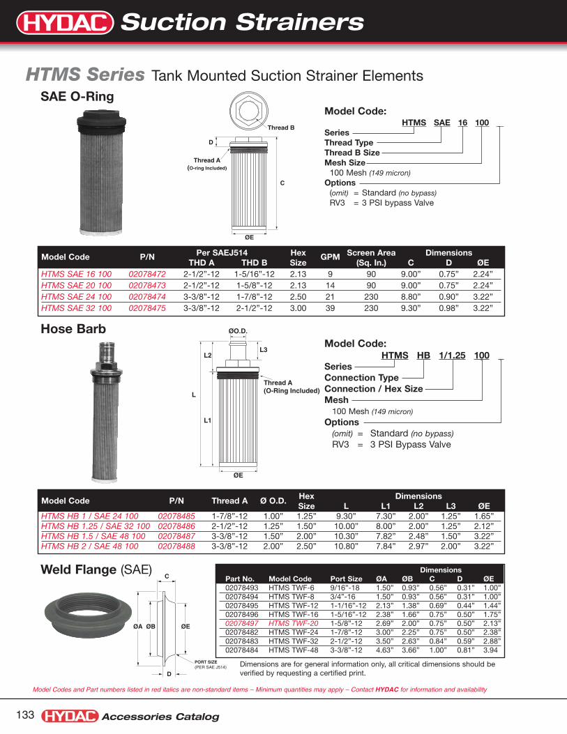
ØO.D.
L3L2
L
L1
ØE
Thread A(O-Ring Included)
Model Code:HTMS HB 1/1.25 100 .
SeriesConnection TypeConnection / Hex SizeMesh
100 Mesh (149 micron)
Options(omit) = Standard (no bypass)RV3 = 3 PSI Bypass Valve
Hose Barb
Model Code P/N Thread A Ø O.D. Hex DimensionsSize L L1 L2 L3 ØE
HTMS HB 1 / SAE 24 100 02078485 1-7/8”-12 1.00” 1.25” 9.30” 7.30” 2.00” 1.25” 1.65”HTMS HB 1.25 / SAE 32 100 02078486 2-1/2”-12 1.25” 1.50” 10.00” 8.00” 2.00” 1.25” 2.12”HTMS HB 1.5 / SAE 48 100 02078487 3-3/8”-12 1.50” 2.00” 10.30” 7.82” 2.48” 1.50” 3.22”HTMS HB 2 / SAE 48 100 02078488 3-3/8”-12 2.00” 2.50” 10.80” 7.84” 2.97” 2.00” 3.22”
Accessories Catalog133
HTMS Series Tank Mounted Suction Strainer Elements
ØE
D
C
Thread B
Thread A (O-ring Included)
Model Code:HTMS SAE 16 100 .
SeriesThread TypeThread B SizeMesh Size
100 Mesh (149 micron)Options
(omit) = Standard (no bypass)RV3 = 3 PSI bypass Valve
SAE O-Ring
Model Code P/N Per SAEJ514 Hex GPM Screen Area DimensionsTHD A THD B Size (Sq. In.) C D ØE
HTMS SAE 16 100 02078472 2-1/2”-12 1-5/16”-12 2.13 9 90 9.00” 0.75” 2.24”HTMS SAE 20 100 02078473 2-1/2”-12 1-5/8”-12 2.13 14 90 9.00” 0.75” 2.24”HTMS SAE 24 100 02078474 3-3/8”-12 1-7/8”-12 2.50 21 230 8.80” 0.90” 3.22”HTMS SAE 32 100 02078475 3-3/8”-12 2-1/2”-12 3.00 39 230 9.30” 0.98” 3.22”
Weld Flange (SAE)
PORT SIZE(PER SAE J514)
C
ØE
D
ØBØA
DimensionsPart No. Model Code Port Size ØA ØB C D ØE02078493 HTMS TWF-6 9/16”-18 1.50” 0.93” 0.56” 0.31” 1.00”02078494 HTMS TWF-8 3/4”-16 1.50” 0.93” 0.56” 0.31” 1.00”02078495 HTMS TWF-12 1-1/16”-12 2.13” 1.38” 0.69” 0.44” 1.44”02078496 HTMS TWF-16 1-5/16”-12 2.38” 1.66” 0.75” 0.50” 1.75”02078497 HTMS TWF-20 1-5/8”-12 2.69” 2.00” 0.75” 0.50” 2.13”02078482 HTMS TWF-24 1-7/8”-12 3.00” 2.25” 0.75” 0.50” 2.38”02078483 HTMS TWF-32 2-1/2”-12 3.50” 2.63” 0.84” 0.59” 2.88”02078484 HTMS TWF-48 3-3/8”-12 4.63” 3.66” 1.00” 0.81” 3.94
Dimensions are for general information only, all critical dimensions should beverified by requesting a certified print.
Model Codes and Part numbers listed in red italics are non-standard items – Minimum quantities may apply – Contact HYDAC for information and availability
Suction Strainers

Suction Strainers
Accessories Catalog 134
ØE
L2
Thread A
Thread B
L
L1
Model Code:HTMS NPTM 2 100 .
SeriesThread TypeThread B SizeMesh Size
100 Mesh (149 micron)Options
(omit) = Standard (no bypass)RV3 = 3 PSI bypass Valve
Male NPT Ports
Model Code P/N THD A THD B Hex Size DimensionsL L1 L2 ØE
HTMS NPTM 2 100 02078480 2” NPT 2” NPT 2.75” 13.50” 10.75” 2.70” 2.12”
ØE
D
Thread B
C
Thread A
Model Code:HTMS NPT 1/2 100 .
SeriesThread TypeThread B SizeMesh
100 Mesh (149 micron)Options
(omit) = Standard (no bypass)RV5 = 5 PSI Bypass Valve
NPT
Model Code P/N GPM Screen Area THD A THD B Hex Dimensions(Sq. In.) Size C D ØE
HTMS NPT 1/2 100 02078460 5 35 1” NPT 1/2” NPT 1.43 5.38” 1.10” 1.18”HTMS NPT 3/4 100 02078461 10 64 1 1/4” NPT 3/4” NPT 1.81 7.50” 1.20” 1.14”HTMS NPT 1 100 02078462 15 86 1 1/2” NPT 1” NPT 2.00 8.25” 1.30” 1.65”HTMS NPT 1 1/4 100 02078463 25 125 2” NPT 1 1/4” NPT 2.55 10.00” 1.30” 2.12”HTMS NPT 2 100 02078464 50 260 3” NPT 2” NPT 3.30 10.25” 1.70” 3.03”HTMS NPT 3 100 02078465 100 315 4” NPT 3” NPT 5.00 11.30” 1.80” 3.78”
Dimensions are for general information only, all critical dimensions should be verified by requesting a certified print.
Suction Strainers

Accessories Catalog135
Magnetic Suction Separators
AC
B Connectionsize
With the use of Hydac’s Magnetic Suction Separators, suction line filtration is providedwithout starving the pump. They offer unique protection for pumps from all sizes offerrous particles, some of which have the potential of destroying a pump in a singlepass. Large ceramic magnets are spaced along the length of the separator. Allhydraulic fluid entering the pump must move at low velocity through a powerful magnetic field. This field traps large quantities of micronic ferrous particles. The viscous properties of the fluid can cause some non-ferrous particles to adhere to themagnetically trapped particles.
Hydac MSS’s are available in sizes ranging from one to three inches. The chartbelow shows the part numbers, specifications, and dimensions of available models.
ModelNumber
Part No.Connection
SizeMax. Flowgpm (lpm)
Δ psi atMax. gpm
Dimensions (mm)A *B C
MSS-1 02082431 1” NPT 15 (55) 0.05 5.25” (133) 3.25” (83) 1.62” (41)
MSS-1 1/4 02082432 1 1/4” NPT 25 (95) 0.05 8.25” (210) 3.50” (89) 3.00” (76)
MSS-1 1/2 02082433 1 1/2” NPT 35 (135) 0.08 8.25” (210) 3.50” (89) 3.00” (76)
MSS-2 02082434 2” NPT 50 (190) 0.10 8.25” (210) 3.50” (89) 3.00” (76)
MSS-3 02082435 3” NPT 100 (380) 0.02 10” (254) 3.50” (89) 4.00” (102)
* ‘B’ Dimension larger for SS20 versions
The standard outer screen has adequate open area (0.079 inch diameter perforations) to eliminate the possibility of pumpstarvation. All models are also availble with a pleated 20 mesh screen (850 micron) by adding SS20 to the model number. (Example MSS-1 SS20).
All units have a removeable outer screen that can be cleaned and re-used to extend service life and minimize pressure drop.
Standardouter screen
SS20Mesh screen
Dimensions are for general information only, all critical dimensions should be verified by requesting a certified print.Dimensions are in inches/(mm) and lbs./(kg.)
Suction Strainers

Suction Strainers
Accessories Catalog 136
Split Flanges SAE Code 61 & 62
ØK
D B
E
FJ
ØHØG
A
Part Number Part NumberSize (Carbon Steel) (Stainless Steel) A B D E F ØG ØH J ØK0.50 02701585 02701539 0.86 2.12 1.50 0.75 0.50 1.22 0.96 0.245 0.344
0.75 02055588 02701540 0.98 2.56 1.88 0.88 0.56 1.53 1.27 0.245 0.406
1.00 02055704 02700970 1.11 2.75 2.06 0.94 0.62 1.78 1.52 0.295 0.406
1.25 02055715 02701541 1.39 3.12 2.31 0.88 0.56 2.03 1.72 0.295 0.469
1.50 02055720 02700919 1.58 3.69 2.75 1.00 0.62 2.41 2.00 0.295 0.531
2.00 02055735 02701542 1.86 4.00 3.06 1.03 0.62 2.84 2.47 0.355 0.531
Code 62 Split Flanges (sold in pairs - each pair makes a single connection)Part Number Part Number
Size (Carbon Steel) (Stainless Steel) A B D E F ØG ØH J ØK0.50 02701585 02701537 0.89 2.22 1.59 0.88 0.62 1.28 0.97 0.285 0.344
0.75 02055882 02700540 1.14 2.81 2.00 1.12 0.75 1.66 1.28 0.325 0.406
1.00 02055883 02700916 1.33 3.19 2.25 1.31 0.94 1.91 1.53 0.355 0.469
1.25 02055889 02701538 1.48 3.75 2.63 1.50 1.06 2.16 1.75 0.385 0.531
1.50 02055890 02700544 1.83 4.44 3.13 1.69 1.19 2.53 2.03 0.475 0.656
2.00 02055891 02700847 2.20 5.25 3.81 2.06 1.44 3.16 2.66 0.475 0.781
Dimensions:
MaterialsPlated Carbon SteelStainless Steel
SpecificationsPressure Rating:Code 61: 3000 psiCode 62: 5000 psi
Code 61 Split Flanges (sold in pairs - each pair makes a single connection)
Dimensions are for general information only, all critical dimensions should be verified by requesting a certified print.Dimensions are in inches.
Part numbers listed in red italics are non-standard items – Minimum quantities may apply – Contact HYDAC for information and availability
front view ofone flange pair
rear view ofone flange pair
Split Flanges

Accessories Catalog137
Model Code
FSK Series Fluid Level Indicators with Electric Level Switch
FSK - 127 - 2 . 4 / 0 / __ / 12 .
Fluid Level IndicatorFSK = Electrical and visual level indicator
Size (Mounting Hole Centers)127 = 5 inches176 = 7 inches254 = 10 inches381 = 15 inches
Seals2 = Fluorocarbon
Modification Number4 = FSK (Determined by Manufacturer)
Electrical SwitchC = Open at Normal LevelO = Closed at Normal Level
Thermometer(omit) = No Thermometer (standard)FT 100 = Probe Thermometer (100mm-3.94”LG)FT 200 = Probe Thermometer (200mm-7.87”LG)FT 300 = Probe Thermometer (300mm-11.87”LG)TS... = Thermo Switch (see chart on page 141)
Hex Head Bolt12 = M12 x 1.75 Bolt
Sight Tube(omit) = Polyimide construction
(not suitable for water glycols or high water based fluids)SO14 = Glass tube construction
Model Codes containing selections listed in red italics are non-standard items – Minimum quantities may apply – Contact HYDAC for information and availability
Fluid Level Indicators

Accessories Catalog 138
Dimensions
1.9750
L
SWITCHLEVEL
2.8572.5
2.8572.5
1.3434.3
0.7920
0.123
M 12(torque to 10 Nm)
max. 0.31max. 8
CLEARANCE HOLEø 0.51 (13mm)
1.7735
1.9349
2.0552
L2
0.205
0.8321
For SwitchRemoval
Size L L2
127 8.46 5.00(215) (127)
176 10.39 6.93(264) (176)
254 13.66 10.00(347) (254)
381 18.66 15.00(474) (381)
Dimensions are in inches/millimeters.
Switch Details: FSK Fluid Level Indicators
ground1
2
FSK...Oground
1
2
FSK...O
ElectricalSpecifications:• Contact Ratings Max. 8W• Maximum Voltage 50V AC or DC• Maximum Current 200 mA• Switch Trips when fluid level drops within
50mm of lower bolt. (see illustration)
Electric Level SwitchFSK...C (Normally Open) FSK...O (Normally Closed)
Contacts CLOSEwhen fluid level dropsBELOW switching level
Contacts OPENwhen fluid level dropsBELOW switching level
Fluid Level Indicators

Accessories Catalog139
FSA Series Fluid Level Indicators
Model CodeFSA 127 - 1 . 1 / T / 12 - .
Fluid Level IndicatorFSA = Visual level indicator
Size (Mounting Hole Centers)76 = 3 inches127 = 5 inches176 = 7 inches254 = 10 inches381 = 15 inches
Seals1 = NBR2 = Fluorocarbon
Housing Material1 = Aluminum2 = ABS Plastic
Thermometer(omit) = No ThermometerT = Built-in TubeFT 100 = Probe Thermometer (100mm-3.94”LG)FT 200 = Probe Thermometer (200mm-7.87”LG)FT 300 = Probe Thermometer (300mm-11.87”LG)TS... = Thermo Switch (see chart on page 141)
Hex Head Bolt12 = M12 x 1.75 Bolt
Sight Tube Material(omit) = Polyimide construction
(not suitable for water glycols or high water based fluids)
SO14 = Glass tube constructionModel Codes containing selections listed in red italics are non-standard items – Minimum quantities may apply – Contact HYDAC for information and availability
Fluid Level Indicators

Fluid Level Indicators
Accessories Catalog 140
Dimensions
0.79200.12
31.7745
205
CLEARANCE HOLEø.51 (13mm)
M 12
max. 0.31max. 8
LL2
1.3434
ºC ºF
HYDAC
80-
70-
60-
50-
40-
30-
20-
10-0-
-10-
-180
-160
-140
-120
-100
-80
-60
-40
-20
L1
Fluid Level Indicators
Size L L1 L2
76 inch 4.25 1.46 2.99mm 108 37 76
127 inch 6.26 2.99 5.00mm 159 76 127
176 inch 8.19 4.92 6.93mm 208 125 176
254 inch 11.26 7.99 10.00mm 286 203 254
381 inch 16.26 12.99 15.00mm 413 330 381

Accessories Catalog141
Options Fluid Level Indicators
~ø 1.51~ø 40
12Special M12 Boltwith 1/16" NPT Portfor Probe Thermometer
11
3.94" or 7.87" or 11.87"100 or 200 or 300
Probe Thermometer / FTFeatures:• Analog dial type thermometer
for visual temperature indication• Temperature Range (Dual Scale)
0 - 212°F0 - 100°C
Probe Thermometers [Temperature Range 32°F(0°C) to 212°F(100°C)]Thermo Switch Model Part Mounting
Code Code Number Thread
FT100 FT-100 TEMP PROBE W/M12 BOLT 02067556 M 12FT200 FT-200 TEMP PROBE W/M12 BOLT 00086740 M 12FT300 FT-300 TEMP PROBE W/M12 BOLT 00086741 M 12
Model Codes and Part numbers listed in red italics are non-standard items – Minimum quantities may apply – Contact HYDAC for information and availability
Thermo Switches (Normally Closed Contact)Thermo Switch Model Part Switch Switch Mounting
Code Code Number Opens @ Closes @ Thread
TS60 TS-L-60/X/12 THERMO-SWITCH 03252752 60°C/140°F 45°C/113°F M 12TS70 TS-L-70/X/12 THERMO-SWITCH 03252766 70°C/158°F 55°C/131°F M 12TS80 TS-L-80/X/12 THERMO-SWITCH 03252767 80°C/176°F 60°C/140°F M 12
Thermo Switch - TS...Detail of Lower Connectionfor Probe Thermometer (FT...) see chart below
ground
1 2 TS...
Electric Thermo Switch / TS Electrical Specifications:• Maximum Voltage 50 VAC or DC• Minimum Current 50 mA• Contact Normally Closed• Switching Tolerance ±10°F • Hysterisis TS 60/70 27°F (15°C)
TS 80 36°F (20°C)
Expected Life Cycle:• at 25 A / 50 V 10,000 cycles• at 0.5 A / 50 V 100,000 cycles
Detail of Lower Connection
Contacts OPENwhen fluid temperature risesABOVE switching temperature
Fluid Level Indicators

Fluid Level Indicators
8
7
1
2
3
4
5
6
10
9
reservoir wall
Accessories Catalog 142
QuantityItem Description Part No. FSA FSK
1 Housing – 1 12 Name Plate – 1 -3 Tube – 1 14* O-Ring 13x2.5 00601916 (Fluorocarbon) 2 200601047 (Buna)
5 Tube Connector – 2 26* O-Ring 12.3x2.4 00601531 (Fluorocarbon) 2 200601045 (Buna)
7* Sealing Washer - 27 x 12 x 3 22183158 (Fluorocarbon) 2 28 Hex Bolt M12 22183153 2 29 Hex Nut M12 22183151 2 210 Thermometer in Indicator Tube 00084108 1 -11 Probe Thermometer (see page 97) – 1 112 Hex Bolt for Probe Thermometer 00278741 1 113 Magnetic Float – - 114 Base Assembly with Type “C” Switch – - 115 Base Assembly with Type “O” Switch – - 116* Washer (optional - see note 2 above) 00001689 1 1
13
14or15
reservoir wall
FSA & FSK FSK Only
Recommended Installation Process1. Drill mounting holes (13 mm) according to dimension L2.
2. Torque the Nut, item 9, to 8+ 1 LB-FT. If it is not possible to torque the nut, the bolt head must be torqued.To avoid damaging the indicator a washer is recommended to be used under the bolt head. This washer is available from HYDAC: Part Number 00001689.Washer Dimensions: øD 18.8 mm, ID 13.10 mm, 0.5 mm thick
Component Parts
Technical DataMaterial
Housing Anodized Aluminum or ABS PlasticSight Tube Polyimide or GlassSeals Fluorocarbon, NBRNuts / Bolts Steel, Zinc plated
Fluid Temperature -4˚F/-20˚C to176˚F/80˚C
Maximum Pressure 14.5 PSI (1 BAR)
Thermometer RangeType T (FSA only) 14°F(-10°C) to 176°F(80°C)Type FT100 32°F(0°C) to 212°F(100°C)Type FT200 32°F(0°C) to 212°F(100°C)Type FT300 32°F(0°C) to 212°F(100°C)
Bolting Torque Max. 8 LB-FT+1 (10 Nm +2) see installation instructions below
* items may be purchased individually.
Fluid Level Indicators

Dimensions
Accessories Catalog143
Model Code
MA Series Single Gauge IsolatorHydraulic DataOperating Pressure• P max. 5075 psi/350 bar (T-Port max. 145 psi/10 bar)
Temperature Range• -4° to 176°F (-20° to 80°C)
Hydraulic Symbol:
Description• Gauge life is extended by using the MA 1 when reading
pressure. When not reading pressure, the gauge isvented to tank to protect the gauge against pressurefrom the system.
• There are two ways to operate the MA 1:Push to read (spring return)Push to rotate clockwise to lock in for continuouspressure reading
SpecificationsMounting• Panel installation maximum 0.39”
Connections• 1/4” NPT, SAE-5, or G1/4 (Ports M, P, T)
Weight• 0.88 lbs./0.4 kg
Mounting Position• Horizontal or Vertical
Operating Fluid• Mineral Oils
MA 1 . A 1 0 / 5 V
Gauge Isolator Single Station
Design1 = Push/Rotating Control Knob
ConnectionA = Threaded
Type Number
Modification Number
Port Configuration0 = BSPP Thread (G1/4) Part No. 020579425 = 1/4” NPT Thread Part No. 0205794012 = SAE-5 (1/2”-20 UNF) Part No. 02057941
SealsV = Fluoroelastomer Seals (standard)
Model Codes containing selections listed in red italics are non-standard items – Minimum quantities may apply – Contact HYDAC for information and availability
M Gauge Port
P T
Pushto read
31mm1.220"
Hole Requiredin Panel
33mm1.299"
27.5mm1.083"
10m
m0.
394"
32.2
mm
1.26
8"
51.7
mm
2.03
5"
88m
m3.
465"
29.7
mm
1.16
9"
PM
T
26mm1.024"
SW 361 7/16"
80mm3.150"
Push to Read
M30x1.5
Push Knob and Turn Clockwise 90°for Continuous Reading
Cover Plate
Max
Pan
elTh
ickn
ess
Ø
ØØ
Gauge Isolators

Gauge Isolators
Accessories Catalog 144
MSL Series Zero Leakage Multi-Station Gauge Isolators with Integral Gauge
1 2 3
T
4 5 6
Hydraulic Symbol:
General• Mounting Method
Flange mounting via four 1/4” bolts. It is recommendedthat the measuring points with pressures of over1450 psi (100 bar) be arranged symmetrically.Ports not in use should be plugged.
• Weight3.8 lbs. / 1.7 kg.
• Mounting PositionOptional
• FluidsGeneral purpose hydraulic oil. For other fluids, contact HYDAC for information.
• Type of Connections6 measuring points1 tank connection
Hydraulic Data• Operating Pressure Range
Max. operating pressure at measuring points 1- 64500 PSI / 315 BAR Max. Tank connection pressure145 PSI / 10 BAR
• Fluid Temperature Range- 5° to 160°F (-20° to 70°C)
• Gauge AccuracyBuilt-in gauge accuracy is ±1.6% of the max. scalevalue at 68°F / 20°C. The error per additional 50°F /10°C temperature increase is +0.3% and 50°F / 10°Ctemperature reduction is -0.3%. Values are based onred scale indication.
Model CodeMSL 2 G 2 . 0 / 315 V
Multi-Station Gauge IsolatorMSL = Zero Leakage Model
Model2 = with Built-in Pressure Gauge
Type and Size of Connection (All Ports)G = 1/4” NPTH = SAE-4 (7/16”-20 UNF)A = BSPP (G1/4)
Type Number
Modification Number
Gauge Indication Range
Supplementary Details(omit) = Buna SealsV = Viton Seals
Dimensions:
04
0200
0
100 300
400
5
0
60
1
0
2
0
3
45°
90°
ø4.01
Use any "0" Position toconnect gauge to tank connections 1-6 for
measuring connections
Adaptor fortank connection
60TYP.
°
1
2
34
5
6
T
Rear View
ø4.7
2
ø2.8
3
5.08
4.29
.55 2.20
X
X
ø2.9
5
ø.26
.28
ø.43
Adaptor fortank connection
DO NOT REMOVE PLUGS!Make all connections in rearfacing ports shown below.
Dimensions are for general information only, all criticaldimensions should be verified by requesting a certified print.
Size Operating Pressure Zone (Black Scale) Over Pressure Zone (Red Scale)40 0 - 570 psi (0 - 40 bar) 570 - 900 psi (40 - 63 bar)63 0 - 900 psi (0 - 63 bar) 900 -1400 psi (63 - 100 bar)100 0 - 1400 psi (0 - 100 bar) 1500 - 2300 psi (100 - 160 bar)180 0 - 2600 psi (0 - 180 bar) 2600 - 3600 psi (180 - 250 bar)315 0 - 4500 psi (0 - 315 bar) 4500 - 5700 psi (315 - 400 bar)
Gauge Isolators

Accessories Catalog145
Model Code
MS Series Multi-Station Gauge Isolators
MS 4 A 2 . 1 / 5 VMulti-Station Gauge IsolatorModel
4 = turn and press to read (6 positions)5 = turn to read (5 positions)6 = turn and press to read (9 positions)7 = turn to read (8 positions)
Type and Size of ConnectionsA = Threaded Connections
Type NumberModification NumberPort Type
5 = NPT Port (1/4” for MS 4 & MS 5 and 1/8” for MS 6 & MS 7)12 = SAE Port (SAE-4 MS4, MS5 only)0 = BSPP (1/4” for MS 4 & MS 5 and 1/8” for MS 6 & MS 7)
Seals(omit) = Buna NV = Fluoroelastomer Seals (standard)
Hydraulic Data• Operating Pressure Range
MS 4 / MS 5 / MS 6 / MS 7Max. operating pressure range at measuring points
4500 PSI / 315 BARMax. tank and leakage connection pressure
145 PSI / 10 BAR
• Fluid Temperature Range- 5° to 160°F (-20° to 70°C)
Hydraulic Symbols:General• Mounting Method
Flange mounting via four 1/4” bolts. It is recommendedthat the measuring points with pressures of over1450 PSI / 100 BAR be arranged symmetrically.Ports not in use should be plugged.
• WeightsMS 4 & MS 5 3.1 lbs. / 1.4 kg.MS 6 & MS 7 4.2 lbs. / 1.9 kg.
• Mounting PositionOptional
• FluidsGeneral purpose hydraulic oil. For other fluids, contact the HYDAC office for information.
• Types of ConnectionsMS 4 / MS 61 gauge connection (M)1 tank connection (T)
1 3 5 7 9
T
M
2 4 6 8
Type MS 6
M = Gauge (measuring) connectionT = Tank connectionL = Leakage connection
1 3 5 7 L
T
M
2 4 6 8
Type MS 7
T
M
1 2 3
4 5 6
Type MS 4
Pushto read
T
M
1 2 3
4 5 L
Type MS 5
Pushto read
MS 5 / MS 71 gauge connection (M)1 tank connection (T)1 leakage connection (L)
Model Codes containing selections listed in red italics are non-standard items – Minimum quantities may apply – Contact HYDAC for information and availability
Gauge Isolators

Gauge Isolators
Accessories Catalog 146
90°
45°
Ø 2.95M T
2
1 5
4
6
3
90°
45°
4
Ø 2.95
M T
3
1 8
6
2 7
5
9
90°
45°
Ø 2.95
M L
2
1 5
4
3
0
T
4.92
3.500.55
All Ports are the same thread type-4 SAE, 1/4"NPTF, or G1/4
(specified by model code)
ø2.3
6
ø0.2
6
ø 0.
43
ø 1.
97
ø 3.
54
0.28
6.02
4.61
1.10 1.02
0.55
ø2.3
6
ø3.5
4
ø1.9
7
90°
45°
Ø 2.95
4
M LT
3
1 8
6
2 7
5
0
2.36
ø 0.
26ø
0.43 0.28
Push to read presure,release to connectgauge back to tank
Turn to "0" positionto connect
gauge back to tank
Push to read presure,release to connectgauge back to tank
Turn to "0" positionto connect
gauge back to tank
ø0.98 typical(spot surface finish)
ø 0.67 typical(spot surface finish
Ports L, M, Tare in this area
Ports 1-6 arein this area
All Ports are the same thread type1/8"NPTF or G1/8
(specified by model code)
Ports L, M, Tare in this area Ports 1-9 are
in these areas
Type MS 4 Type MS 5
Type MS 6 Type MS 7
Dimensions
Dimensions are for general information only, all critical dimensions should be verified by requesting a certified print.
Gauge Isolators

Accessories Catalog147
1620 Series TestPoints & Micro Bore Flex Hoses
DescriptionHYDAC series 1620, guided piston design, TestPoints arecompact, self sealing couplings that provide access tohydraulic and pneumatic systems for pressure measurementto 9000 psi. Mating adapters or hose connections can beconnected without loss of fluid while the system is operating.TestPoints can also be used to take oil samples or to bleedair from hydraulic systems. They are available in 1620(M16x2.0) connection threads with a variety of screw-in portconfigurations.
Features• Can be coupled and uncoupled under pressure
without system shutdown or fluid loss
• Patented guided piston design for leak free performance at operating pressure to 9000 psi
• HYDAC guided piston design provides the followingadvantages over ball seal design:
• Higher working Pressure
• Better sealing characteristics particularly under highvibration
• Less susceptible to fluid contamination
• Can be used for gas as well as fluid
Applications• Pressure measurement with gauges or sensors
• Fluid sampling
• Air bleeding
Technical DataMaximum Working Pressure• 9000 psi (630 bar)
(see pressure utilization factor to adjust for operatingtemperature)
Fluid Compatibility• Suitable for petroleum based fluids and gaseous
media
Materials• Zinc plated steel body (standard)
• Zinc plated metal cap (standard)
Seals• Buna-N (standard)
• Fluorelastomer (optional)
Temperature Range• With metal cap and Buna-N seals:
-22°F to 248°F (-30°C to 120°C)
Options• Anti-vibration seal for metal cap
Series 1620 TestPoint
Guided Piston Design
TestPoints

Part numbers listed in red italics are non-standard items – Minimum quantities may apply – Contact HYDAC for information and availability
TestPoints
1/4 NPTF 5800 psi (400 bar) 33 13 17 027014877/16-20 UNF 5800 psi (400 bar) 33 16.5 17 02701486
1/8 NPTF 5800 psi (400 bar) 33 13 17 060071991/4 NPTF 5800 psi (400 bar) 33 13 17 06007200
7/16-20 UNF 9000 psi (630 bar) 37 9 17 060070299/16-18 UNF 9000 psi (630 bar) 36 10 19 06007030
ISO 228-G 1/4 9000 psi (630 bar) 36 10 19 00606304
Accessories Catalog 148
Thread G Pmax H(mm) T(mm) SW(mm) Part no.
L (inches) L (mm) Part No.8 200 06003723
12 300 0600372416 400 0063263320 500 0600372525 630 0600372631 800 0068285739 1000 0063263449 1250 0600372759 1500 0068285879 2000 0068285998 2500 00682860126 3200 06003728157 4000 06003729197 5000 06003730236 6000 02701721394 10,000 02701722
Specifications:• Maximum working pressure 9000 psi (630 bar) at 122˚F (50°C)
(see pressure utilization factor to adjust for higher temperatures)• Suitable for petroleum based fluids• Temperature range -4°F to 122°F (-20°C to 50°C)• Polyamid core with polyester braid reinforcement and
polyamid jacket• Plastic dust cap• 1620 female connection at both ends• Bending radius: min. 20mm• Hose ID ø 2mm• Custom Hose Assemblies Available:
NPT Male Thread, NPT Female Thread, JIC Male Hose, JICFemale swivel hose ends
Dimensions: TestPoints & Micro Bore Flex Hoses
ø5 mmø2 mm
L
Micro Bore Flexible HosesOperating Temp. Factor Max. Pressure
122°F (50°C) 100% 9000 psi
176°F (80°C) 86% 7740 psi
212°F (100°C) 77% 6930 psi
Pressure Utilization Factor for Hoses:
Carbon Steel TestPoints (Zinc-Plated, Buna N Seals)
Stainless Steel TestPoints (Fluorelastomer Seals)
Dimensions are for general information only, all critical dimensions should be verified by requesting a certified print.* for port configuration drawings contact HYDAC.
Thread G Pmax H(mm) T(mm) SW(mm) Part no.
Carbon Steel TestPoints (Zinc-Plated, Fluorelastomer Seals)
Select desired connectionin chart to the right
Note: All TestPoints have amale connectionthread (G)
Standard 1620 TestPointconnection with cap
1/8 NPTF 5800 psi (400 bar) 33 13 17 060037341/4 NPTF 5800 psi (400 bar) 33 16.5 17 00639645
7/16-20 UNF 9000 psi (630 bar) 37 9 17 060037359/16-18 UNF 9000 psi (630 bar) 36 10 19 06003737
M 8x1 3600 psi (250 bar) 41 8.5 17 06003731M 10x1 3600 psi (250 bar) 37.5 8.5 17 00629237
M 12x1.5 9000 psi (630 bar) 36 10 17 00632615M 14x1.5 9000 psi (630 bar) 36 10 19 00632248M 16x1.5 9000 psi (630 bar) 36 10 22 06003732
ISO 228-G 1/8 5800 psi (400 bar) 38 8 17 00689901ISO 228-G 1/4 9000 psi (630 bar) 36 10 19 00680107ISO 228-G 3/8 9000 psi (630 bar) 36 10 22 06003733ISO 7/I-R 1/8 5800 psi (400 bar) 33 13 17 06003738ISO 7/I-R 1/4 9000 psi (630 bar) 33 13 17 06003739
Thread G Pmax H(mm) T(mm) SW(mm) Part no.
TestPoints
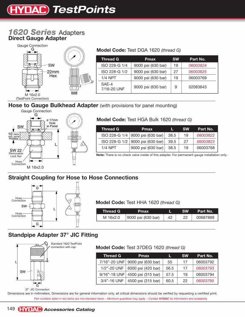
Accessories Catalog149
Thread G Pmax L SW Part No.
7/16”-20 UNF 9000 psi (630 bar) 55 17 06003792
1/2”-20 UNF 6000 psi (420 bar) 56.5 17 06003793
9/16”-18 UNF 4500 psi (315 bar) 57.5 19 06003794
3/4”-16 UNF 4500 psi (315 bar) 60.5 22 06003795
Thread G Pmax L SW Part No.
M 16x2.0 9000 psi (630 bar) 42 22 00687889
Thread G Pmax SW Part No.
ISO 228-G 1/4 9000 psi (630 bar) 19 06003824
ISO 228-G 1/2 9000 psi (630 bar) 27 06003825
1/4 NPT 9000 psi (630 bar) 19 06003769
SAE-4 7/16-20 UNF 9000 psi (630 bar) 9 02083643
Thread G Pmax L SW Part No.
ISO 228-G 1/4 9000 psi (630 bar) 38.5 19 06003822
ISO 228-G 1/2 9000 psi (630 bar) 39.5 27 06003823
1/4 NPT 9000 psi (630 bar) 38.5 19 06003768
Straight Coupling for Hose to Hose Connections
Standpipe Adapter 37° JIC Fitting
M 16x2.0(TestPoint Connection)
M 16x2.0
Hose to Gauge Bulkhead Adapter (with provisions for panel mounting)
Dimensions are in millimeters. Dimensions are for general information only, all critical dimensions should be verified by requesting a certified print.
Note: There is no check valve inside of this adapter. For permanent gauge installation only.
Direct Gauge AdapterGauge Connection
Gauge Connection
Standard 1620 TestPointconnection with cap
37˚ JIC Connection
HoseConnection
HoseConnection
RemovableLock Nut
HoseConnection
Part numbers listed in red italics are non-standard items – Minimum quantities may apply – Contact HYDAC for information and availability
1620 Series Adapters
Model Code: Test DGA 1620 (thread G)
Model Code: Test HGA Bulk 1620 (thread G)
Model Code: Test HHA 1620 (thread G)
Model Code: Test 37DEG 1620 (thread G)
TestPoints

TestPoints
Accessories Catalog 150
Dimensions:
Standard design is zinc plated steel, buna seals, plastic cap and integrated safety device against vibration.
Thread (G) p (max) H I SW Model Code Part Number
ISO 228-G 1/8 400 bar (5800 psi) 33 8 14 TestPoint 1215 (G1/8) PC/NBR –
ISO 228-G 1/4 630 bar (9000 psi) 32 10 19 TestPoint 1215 (G1/4) PC/NBR –
1/8 NPTF 400 bar (5800 psi) 29 12 14 TestPoint 1215 (1/8 NPT) PC/NBR –
1/4 NPTF 630 bar (9000 psi) 29 15 14 TestPoint 1215 (1/4 NPT) PC/NBR 02701305
7/16-20 UNF 630 bar (9000 psi) 32 9 17 TestPoint 1215 (7/16-20 UNF) PC/NBR 02701293
9/16-18 UNF 630 bar (9000 psi) 32 10 19 TestPoint 1215 (9/16-18 UNF) PC/NBR 02701335
L(in) Model Code Part Number
25 Test Hose 1215 25” 02701307
59 Test Hose 1215 59” 02701377
ø5 mmø2 mm
L
Test Hoses
1620 Series Test Point Kits
1215 Series TestPoints
Model CodePart
Number3 GaugeQuantity
5 GaugeQuantity
Testpoint Kit 1620 3 Gauge 02081635 - -
Testpoint Kit 1620 5 Gauge 02081636 - -
HPG-63-1000-LM 02701547 1 1
HPG-63-1500-LM 02701548 0 1
HPG-63-2000-LM 02701549 1 1
HPG-63-3000-LM 02701550 0 1
HPG-63-5000-LM 02701551 1 1
TEST HOSE 1620 12” 06003724 1 2
TEST HOSE 1620 39” 00632634 1 2
TEST HOSE 1620 79” 00682859 1 2
TESTPOINT 1620 (1/4 NPTF) MC/NBR 00639645 2 4
TESTPOINT 1620 (7/16-20 UNF) MC/NBR 06003735 2 4
TESTPOINT 1620 (9/16-18 NPTF) MC/NBR 06003737 2 4
TEST DGA 1620 (1/4 NPT) 06003769 1 3
TEST HGA BULK 1620 (1/4 NPT) 06003768 1 3
TEST HHA 1620 00687889 1 3
5 Gauge Kit
3 Gauge Kit
TestPoints

Accessories Catalog151
Gauges 2 1/2 inch face - 1/4”NPT Connection
MaterialsCase: Stainless SteelRing: Polished SS, crimpedWetted Parts: Copper AlloyWindow: PolycarbonateDial: White ABSPointer: Black AluminumLiquid Filling: Glycerine
SpecificationsAccuracy: ±1.5% of spanScale: PSI outside in black
BAR inside in redConnection: 1/4” NPT male
Model Code Part Number Pressure Range Connection - 1/4” NPTHPG-63-1000-LM 02701547 0 to 1000 psi Lower Mount (LM)HPG-63-1500-LM 02701548 0 to 1500 psi Lower Mount (LM)HPG-63-2000-LM 02701549 0 to 2000 psi Lower Mount (LM)HPG-63-3000-LM 02701550 0 to 3000 psi Lower Mount (LM)HPG-63-5000-LM 02701551 0 to 5000 psi Lower Mount (LM)HPG-63-2000-CBM 02701552 0 to 2000 psi Center Back Mount (CBM)
These are non-standard items – Minimum quantities may apply – Contact HYDAC for information and availability
Gauges

Accessories Catalog
Custom SolutionsWhether OEM’s want to reduce inventory and simplify assembly, orneed help solving unique design challenges, they can rely on HYDAC’sglobal application experience in fluid power. HYDAC’s entire line ofValves, Clamps, and Accessories can all be slightly modified, orcompletely customized for a perfect fit into any application.
Custom Solutions!When a major railroad company was experiencingleakage problems on the hopper gate controls, HYDACdeveloped a ball valve to be retro-fit onto their existing cars.The mounting orientation, direction of porting, and handlelength were all addressed, resulting in a completely customsolution. Design, prototyping, testing, and production wereall performed by the experts at HYDAC.

Accumulators
Filters
Fluid Service Products
Valves
Clamps
Accessories
Electronics
Coolers
Compact Power Units
Cartridge Valves
Mobile Systems
The Single Sourcefor Hydraulic Components
Canada 14 Federal Road WellandOntario, Canada L3B 3P2 905.714.9322www.hydac.ca
Mexico AV. Pirul No. 21254090 los Reyes Iztacala,Tianepantla EDO. DE Mexico01152-5-55565-8511www.hydacusa.com
USA HYDAC CORPORATIONAccumulator Division2280 City Line RoadBethlehem, PA 180171-877 GO HYDACwww.hydacusa.com
HYDAC TECHNOLOGY CORPORATIONHydraulic Division445 Windy Point DriveGlendale Heights, IL 61039(630) 545-0800www.hydacusa.com
HYDAC CORPORATIONHYDAC TECHNOLOGYCORPORATIONHouston Office1718 Fry Road Suite 150Houston, TX 77084(281) 579-8100www.hydacusa.com
HYDAC TECHNOLOGY CORPORATIONHYCON DivisionElectronic Division2260 City Line RoadBethlehem, PA 180171-877 GO HYDACwww.hydacusa.com
HYDAC TECHNOLOGYCORPORATION11650 Mission Park Drive,Suite 108Rancho Cucamonga, CA91730(909) 476-6777www.hydacusa.com
© Copyright 2003, 2006 HYDAC TECHNOLOGY CORPORATION • HYCON Division • Brochure - Hydraulic Accessories Catalog #02080105 / 4.06