HYDRAULIC CLAMPING - Vektek
84
NEW Sequence at the device. Imagine the possibilities! The 1st... Complete 7MPa Decoupling Solution Automatic Shutoff Valve Decouplers for single and double acting systems. NEW Compact Air/Hydraulic Pump LOW PRESSURE 1000 psi // 7MPa // 70 Bar HYDRAULIC CLAMPING 800-992-0236 [email protected] www.vektek.com The latest technology in workholding SWING CLAMPS VEKTEK LLC Low Pressure 1000psi // 7MPa // 70 Bar January 2019
-
Upload
khangminh22 -
Category
Documents
-
view
2 -
download
0
Transcript of HYDRAULIC CLAMPING - Vektek

VEKTEK LLC1334 E 6th AvenueEmporia, KS 66801 U.S.A.
www.vektek.com
Factory Direct:
800-992-0236913-365-1045Fax: [email protected]@vektek.com
Brazil - [email protected]+55-11-4398 7300
Canada - [email protected] China - [email protected]
Shanghai: +86-21-58683679 Dalian: +0411-87566805
Europe - [email protected]
Israel - [email protected] India - [email protected]
+91-40-27844279
Japan - [email protected]
Korea - [email protected]+82-2-26315755
Latin America - [email protected]
Mexico - [email protected]+81-2032-9910
NEWSequence at the device.
Imagine the possibilities!
The 1st...Complete 7MPa
Decoupling SolutionAutomatic Shutoff Valve
Decouplers for single and double acting systems.
NEWCompact
Air/Hydraulic Pump
LOW PRESSURE1000 psi // 7MPa // 70 Bar
HYDRAULICCLAMPING 800-992-0236
The latest technology in workholding
SWING CLAMPS
LOW PRESSURE1000 psi // 7MPa // 70 Bar
HYDRAULICCLAMPING
VEK
TEK LLC
Low
Pre
ssure
1000p
si // 7M
Pa
// 70 B
ar
Jan
ua
ry 2019
© Vektek January 2019 1-800-992-0236 www.vektek.com
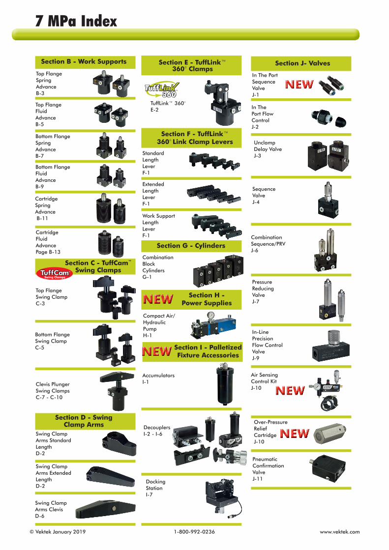
Section B - Work Supports
Section C - TuffCam™ Swing Clamps
Section D - Swing Clamp Arms
Section E - TuffLink™ 360° Clamps
Section F - TuffLink™ 360° Link Clamp Levers
Section G - Cylinders
Section H - Power Supplies
Section I - Palletized Fixture Accessories
Section J- Valves
Top Flange Spring AdvanceB-3
Top Flange Fluid AdvanceB-5
Bottom FlangeSpringAdvanceB-7
Bottom Flange Fluid AdvanceB-9
CartridgeSpring Advance B-11
CartridgeFluid AdvancePage B-13
Top Flange Swing ClampC-3
Bottom Flange Swing ClampC-5
Clevis Plunger Swing ClampsC-7 - C-10
NEW
NEW
Swing Clamp Arms Standard LengthD-2
Swing Clamp Arms Extended LengthD-2
Swing Clamp Arms ClevisD-6
TuffLink™ 360°E-2
Standard Length LeverF-1
Extended LengthLeverF-1
Work Support Length LeverF-1
Combination Block CylindersG-1
Compact Air/ Hydraulic PumpH-1
AccumulatorsI-1
DecouplersI-2 - I-6
Docking StationI-7
In The Port Sequence ValveJ-1
Air Sensing Control KitJ-10
Over-Pressure Relief CartridgeJ-10
NEW
NEW
NEW
CombinationSequence/PRVJ-6
Unclamp Delay ValveJ-3
Sequence ValveJ-4
Pressure Reducing ValveJ-7
In-Line Precision Flow Control ValveJ-9
In The Port Flow ControlJ-2
Pneumatic Confirmation ValveJ-11
7 MPa Index

www.vektek.com 1-800-992-0236 © Vektek January 2019
PLANNING A
WORK SUPPORTS B
SWING CLAMPS C
SWING CLAMP ARMS D
LINK CLAMPS E
LINK CLAMP LEVERS F
CYLINDERS G
POWER SUPPLIES H
PALLET FIXTURE ACCESSORIES I
VALVES J
ACCESSORIES K
FITTINGS
CONVERSION REFERENCE
SAFETY
L In order to support our process of ongoing product improvements, specifications are subject to change without notice. Due to these improvements, products may not be exactly as illustrated. Visit our website PDF catalog for the most current catalog illustrations... www.vektek.com
You will also find a CAD library on the website to assist in designing Vektek product into your machine fixture projects.
Section K- Accessories
Section L- Fittings
FittingsL-1
In-line FilterK-1
SphericalContact PointsK-1
GaugesK-2
Filter PlatesK-2
NEW
7 MPa ContentsQuick Reference

© Vektek January 2019 1-800-992-0236 www.vektek.com
Most expensive CNC met al work ing ma chines are purchased without fixtures to hold the work piece(s). With today’s so phis ti cat ed ma chines making tool changes in frac tions of a second with accuracies we once thought nearly impossible, the quality of part clamping is the next most important opportunity for time savings and pro duc tiv i ty im prove ment. VektorFlo® power clamps provide the “helping hands” to present more parts to the machine spindle with less effort, more con sis ten cy, and greater productivity at a cost only modestly more than manual fixtures. Use VektorFlo® because it can in crease your pro duc tiv i ty.
Many of your machines are purchased without integrated hydraulic power supplies. You have a choice of pressure less than 7 MPa or more than 7 MPa, a choice generally made based on clamping device size. Machines may be purchased with a power supply to deliver either up to 7 MPa or above 7 MPa. This option, if purchased with the machine influences the pressure range of your choice in hydraulic clamping devices. Other influencing factors are the need for “live”, always connected, “disconnected” hydraulics or “palletized” fixtures. Vektek’s 7 MPa products are tested to over 1,000,000 cycles at full operational pressure before they are included in our product line assuring you the long product life you need to keep your production lines operating. The selection of any single brand of hy drau lic clamp, as any other im por tant decision, must be made from an in formed, intelligent point of view. Your choice should be based on many factors in flu enced by your specific ap pli ca tion. Other factors can be used for general com par i son and are strong indicators of the overall quality of the brand selected. Before making any decision, we ask that you take time to ac cu rate ly compare product quality, product and information avail abil i ty, technical support and service both before and after the sale. When you do, you’ll find Vek torFlo® 7 MPa above the rest! This is why Vektek is the world’s leading manufacturer of power workholding products.
Quality ProductAt Vektek, we know that professional users
expect top quality products backed by knowledgeable technical support. They also expect ready availability of parts when needed. Armed with this knowledge our team of en gi neers began an extensive product de vel op ment process. Exhaustive research, design, de vel op ment and testing yielded a unified product line, all of which in cor po rate the following ap pro pri ate features:
n BHC™, a special black hard coating, makes VektorFlo® bodies extra du rable. This high tech surface hard en ing process virtually eliminates the bore scoring and scratch ing that is the most common reason for seal failures and leakage in some brands.
n Hardened and Chromed bearing sur faces are in cor po rated to provide improved load bearing areas where it is critical to device life.
n Every device is ported using standard G 1/4 or G 1/8 L-Series porting. Face seal porting
nor mal ly installs without leaking the first and every time.n Special seals and wipers help keep leaks from
starting by sealing fluid in and con tam i nants out. Load ed lip and crown seals virtually eliminate external (visible) and inter nal (in vis i ble) leaks. Most devices in cor po rate a wiper to keep chips from en ter ing the cylinder and dam ag ing the seal. VektorFlo® seals have been tested in most common cool ants and found to be stable in all those tested.
n Warranty is an indication of a manu fac turer’s con fi dence in the ability of the product to run "trouble free" for a specified time. Our hydraulic prod ucts are war ran ted for one year from date of ship ment. For details see our printed war ran ty statement.
Compare the durability and long life of our devices with that of com pet i tors. Prove it to yourself. We welcome any head-to-head challenge between our product and others in the marketplace.
Availability of Product and Information We customarily maintain inventory of all items in this catalog. This enables us to respond quickly to help you in a difficult situation. Please plan adequate lead times into your production schedule when ordering large quantities. We take pride in the in for ma tion we share with you, our cus tom er. We have at tempt ed to
create a catalog that is easy to read, un der stand and use. You will find the catalog or gan ized so that you can find speci fi ca tions, dimensions and product specific features without a lot of useless rheto ric, but with more in for ma tion than some "parts store" catalogs. Should you need in for ma tion not contained in this catalog, our Application Engineering Staff would be happy to answer your ques tions.
Service Before The Sale Our unique blend of telemarketing, catalog, web, and technical support is there for you when you need us, not when "we’re in the neigh bor hood." Pick up the phone and call us. We’ll do our best to answer your questions, solve your problems or just discuss your application at your convenience. There is no charge for this service.
A typical customer finds that it goes like this:
n After several conversations with a Vektek sales rep re sen ta tive, you may un cover an application where hy drau lic clamping will
pay for itself in a very short time.n Call us at your convenience and
dis cuss the ap pli ca tion with one of our Ap pli ca tion Engineers. They may ask you to send information about your current fixture, part, ma chine and/or processes for them to study and propose a clamping concept.
n To aid in your fixture design, CAD files for each product are available to you online at www.vektek.com or by requesting a CD from your sales representative.
n One more thing to keep in mind . . . You can have all this service at no charge! Call us
and see for yourself.
Service After The SaleUnlike some sales people, we don’t and
won’t disappear after the sale. We want your fixture to work right the first time and keep on working. If it doesn’t work CALL US, you’ll find us ready to help.
Remember when you dial
001-913-365-1045you talk to us, we can’t
and won’t hide!
We want your business today, to mor row and next year. We will continue to do what it takes to earn your busi ness and respect. We want to help make your business more profitable.
Why use VektorFlo® 7 MPa Workholding?

www.vektek.com 1-800-992-0236 © Vektek January 2019
Successful powered workholding does not just happen. Like any other manu fac tur ing process, it must be carefully planned. But that does not mean you need to be a hy drau lics engineer to implement a powered work hold ing system. Designing a system involves nothing more than the common-sense ap pli ca tion of a few basic work hold ing concepts.
Applications for power workholding fall into two categories: retrofits to replace and upgrade clamping on existing fixtures; and new fixtures designed from the outset with power workholding. In both cases it is im pera tive you keep in mind the forces that can be generated by power workholding devices. A single device, small enough to hold in your hand, can gen er ate 26 kN of clamp ing force. If you are replacing existing manual bolt and nut clamping or toggle clamps, make sure the fixture or machine tool base will with stand the forces.
Using power workholding does not in any way invalidate the principles of sound fixture design. The 3-2-1 con cept as it relates to the location of the work piece in three planes is just as applicable when using power workholding devices as when using manual methods. Workholding de vices should be positioned in such a way as to ensure firm contact be tween the work piece and locating buttons, pins or surfaces.
Begin the planning process by asking yourself the following: n What do you want your system to ac com plish? n What sort of operation is going to use this system? n What clamping "speed" is appropriate for the speed at which your production line runs?
You should select "realistic" cycle times . . . the shorter the cycle time, the larger the power source required. For example, a pump with a1/3-hp electric motor may be sat is fac tory to reach clamping pressure on a given system in three seconds. How ever, to accomplish the same task in one second may require a pump with a 1-hp electric motor — at a con sid er able increase in both initial ex pense and operating costs. So before you specify "instantaneous" cycling, be sure the increased clamping speed is really worth the higher costs for your particular installation. Ask your self if you can productively utilize the seconds saved.
With this in mind, let’s proceed step by step through a plan of attack for designing your system.
Planning Your Power Workholding System...A-1
7 MPa PlanningIntroduction
© Vektek January 2019 1-800-992-0236 www.vektek.com
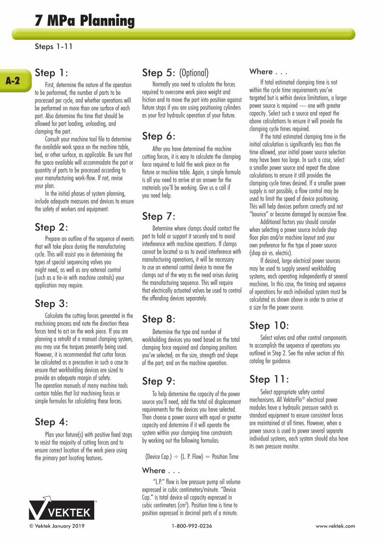
Step 1: First, determine the nature of the op era tion to be performed, the number of parts to be processed per cycle, and whether operations will be performed on more than one surface of each part. Also determine the time that should be allowed for part loading, un load ing, and clamp ing the part. Consult your machine tool file to de ter mine the available work space on the machine table, bed, or other sur face, as applicable. Be sure that the space avail able will accommodate the part or quantity of parts to be proc essed ac cord ing to your man u fac tur ing work-flow. If not, revise your plan. In the initial phases of system planning, include adequate measures and devices to ensure the safety of workers and equip ment.
Step 2: Prepare an outline of the sequence of events that will take place during the manufacturing cycle. This will assist you in determining the types of special se quenc ing valves you might need, as well as any external control (such as a tie-in with machine controls) your application may require.
Step 3: Calculate the cutting forces generated in the ma chin ing process and note the direction these forces tend to act on the work piece. If you are planning a retrofit of a manual clamping system, you may use the torques pres ently being used. However, it is rec om mended that cutter forces be calculated as a pre cau tion in such a case to ensure that work hold ing devices are sized to provide an adequate margin of safety. The operation manuals of many machine tools contain tables that list machining forces or simple formulas for calculating these forces.
Step 4: Plan your fixture(s) with positive fixed stops to resist the majority of cutting forces and to ensure correct location of the work piece using the primary part locating features.
Step 5: (Optional) Normally you need to calculate the forces required to overcome work piece weight and friction and to move the part into position against fixture stops if you are using positioning cylinders as your first hydraulic operation of your fixture.
Step 6: After you have determined the machine cutting forces, it is easy to calculate the clamping force required to hold the work piece on the fixture or machine table. Again, a simple formula is all you need to arrive at an answer for the ma te ri als you’ll be working. Give us a call if you need help.
Step 7: Determine where clamps should con tact the part to hold or support it securely and to avoid interference with machine op er a tions. If clamps cannot be located so as to avoid inter fer ence with manu fac tur ing op era tions, it will be necessary to use an external control device to move the clamps out of the way as the need arises during the manu fac tur ing se quence. This will require that elec tri cally actuated valves be used to control the offending devices sepa rately.
Step 8: Determine the type and number of workholding devices you need based on the total clamping force required and clamping positions you’ve selected; on the size, strength and shape of the part; and on the machine op era tion.
Step 9: To help determine the capacity of the power source you’ll need, add the total oil displacement requirements for the devices you have selected. Then choose a power source with equal or greater capacity and determine if it will operate the system within your clamping time constraints by working out the following formulas:
(Device Cap.) ÷ (L. P. Flow) = Position Time
Where . . . “L.P.” flow is low pressure pump oil volume expressed in cubic centimeters/minute. “Device Cap.” is total device oil capacity expressed in cubic centimeters (cm3). Position time is time to position expressed in decimal parts of a minute.
Where . . . If total estimated clamping time is not within the cycle time requirements you’ve targeted but is within device limitations, a larger power source is required — one with greater capacity. Select such a source and repeat the above cal cu la tions to ensure it will provide the clamping cycle times required. If the total estimated clamping time in the initial calculation is significantly less than the time allowed, your initial power source selection may have been too large. In such a case, select a smaller power source and repeat the above calculations to ensure it still provides the clamping cycle times desired. If a smaller power supply is not possible, a flow control may be used to limit the speed of device positioning. This will help devices perform correctly and not “bounce” or become damaged by excessive flow. Additional factors you should consider when selecting a power source include shop floor plan and/or machine layout and your own preference for the type of power source (shop air vs. electric). If desired, large electrical power sources may be used to supply several workholding systems, each operating in de pen dent ly at several machines. In this case, the timing and sequence of op er a tions for each individual system must be calculated as shown above in order to arrive at a size for the power source.
Step 10: Select valves and other control components to accomplish the sequence of operations you outlined in Step 2. See the valve section of this catalog for guidance.
Step 11: Select appropriate safety control mechanisms. All VektorFlo® electrical power modules have a hydraulic pressure switch as standard equip ment to ensure consistent forces are main tained at all times. However, when a power source is used to power several separate individual systems, each system should also have its own pressure monitor.
7 MPa PlanningSteps 1-11
A-2

www.vektek.com 1-800-992-0236 © Vektek January 2019
Rotary Lug delivers 360O of lever positioning
(Section E) ILML16000 REV D
Clevis Plunger (Section C)
TuffCam™
Swing Clamps(Section C)
Step 12: Finally, select the plumbing com po nents required to connect the power source to the valves and devices. Review your system speci fi ca tions and layout to de ter mine what you need in terms of ratings, sizes, and lengths.
Step 13: Call us for help. Our Application Engineers do not design fixtures. Their job is to help you use hydraulic clamps suc cess ful ly. Whether you are retrofitting existing fixtures, need a concept for clamping a new part or want a quick review of your design, we stand ready to help VektorFlo® customers.
USA, call: 800-992-0236Outside the USA, call:
+001-913-365-1045...for ev ery thing you need in workholding. Discover how easy, eco nomi cal, and efficient power workholding can be — with one call. We’ll be glad to answer your questions, provide concepts or advice, and give you a quote.
Please visit us at: www.vektek.comto download our
most current CAD files.
A-3
7 MPa Planning Steps 12-13

© Vektek January 2019 1-800-992-0236 www.vektek.com
This list of questions was developed by listening to customers just like you when they asked, “Why didn’t I know that?” Before you order devices, build your fixture or even consider your design complete, we suggest you run through this checklist to identify some common problems you might encounter.
What is the advantage of double acting cylinders? Double acting cylinders will assure full cylinder retraction on a timely basis even in systems where restrictions such as small orifices or long tubing runs have been introduced. The use of double acting cylinders is especially important when “return” time is critical (as in some CNC systems).
What should I watch for when selecting fittings, tubing and hoses ? Some fittings and hoses which are locally available (not from Vektek) have extremely small orifices which restrict flow. The use of G 1/8 or similar size fittings can have this effect on a system. This restriction is even more pronounced when introduced at a main feed line. This can happen with some fittings and many hoses. Excessive tubing length can create a column of oil which is very long. Friction created by moving oil through tubing and hose will slow response times because of the inertia of the column of oil and increased back pressure of returning oil. Proper sizing of fittings for main feed lines and device supply lines will normally be accomplished by using an appropriate fluid distribution manifold. Device fittings are G 1/4 or G 1/8. Main feed lines should be at least 8 mm to avoid restrictions.
Is my plumbing free of obstructions and contaminants? Tubing must always be flushed after cutting. Even if not cut in your shop, it was cut before it came to you. Chips, burrs, dirt and other contaminants have collected inside your tubing and drilled passages. These contaminants can cut device seals, damage valve sealing surfaces, cause erratic operation and reduce service life if not cleaned prior to fixture start up. The use of improper fittings can also cause obstructions and restrictions. Be sure you haven’t created obstructions by using non-standard parts.
Is my pump of appropriate size? It is rated for____l/min, or _____cm3 per minute. My devices require a total of _____cc. of oil to actuate. For most normal size fixtures, a pump rated over 8 l/min. (liters per minute) is not recommended. If your pump is rated much more than 4 l/min, call us, we’d rather give you sound advice now than have you damage clamps and have to sell you replacements. Be sure you do not exceed the recommended flow rates for your system. If you aren’t sure, ask us.
My pump runs continuously. Is it the right type of pump? Call us. It can often be made to work. Some modifications will probably be necessary.
I’ve been using a dump pump (builds to pressure, shuts off and releases pressure automatically). Is this pump suitable for workholding? It can be. It will work if the circuitry is properly designed. It may require special circuit modifications to work properly.
I want several sequenced operations to happen on my fixture. Can I put three or four sequence valves in series? We do not recommend it. Our sequence valves operate better if run directly from the main hydraulic supply line and set at different pressures. We recommend at least 1 MPa differential.
When I use a dial indicator on my part, it bends when it is clamped. Why? Clamps should be positioned directly opposite a fixed locator, hydraulic support or other supporting element. This element may be a part of the fixture, a solid portion of a rigid part or a properly sized floating locator, such as a hydraulic work support. If your clamp is putting force into your part which is not transmitted directly into a solid stop, it may distort the part. Clamping on draft angles or “mush room ing” the part with excessive force can also cause part distortion.
I hold all four corners of my part on solid locators. When unclamped, it seems to “spring” back into a different shape. Why? First, holding all four locating points in exactly the same plane on your fixture is virtually impossible. (See your favorite text on fixture design for an explanation of 3-2-1 fixture building principles.) Second, because your part can’t have all four of these points in the same plane, your part is distorting when clamped. Other factors such as stress relief may cause the part to change its “free” shape after machining.
I want to limit the pressure into a sequenced hydraulic circuit. Which valve would I install first? We recommend you avoid putting one special function valve behind another if possible. If you must, put the pressure limiting valve after the sequence valve. This avoids the limiting valve being shut off before the sequenced circuit is fully actuated.
I want to make a cut directly against (into) a clamp. Is this possible? Yes, it is, but it will require special design considerations. We encourage that cutter forces always be directed toward a fixed stop. A fixed stop is designed to prevent part movement. A clamp is designed to position and force a part against a fixed stop. In order to machine “into” a clamp, the clamp must be sufficiently sized to resist all cutter and machine forces or the part will tend to shift.
7 MPa PlanningFrequently Asked Questions
A-4

www.vektek.com 1-800-992-0236 © Vektek January 2019
My company uses a lot of brass on our product. Can I use these to connect my 7 MPa hydraulic clamps? Yes, brass fittings and some aluminum or steel fittings are for lower pressures. Be sure that locally sourced fittings are rated for 7 MPa (70 bar) operation.
We run a fixture for 3 months, store it for 6 months, then bring it back on line. How can we keep everything work ing? Preventive maintenance. Before you store your fixtures, be sure they are free of coolants, coolant buildup, clean and dry. A light coating of corrosion protection may help. Be sure to store in a cool, dry, clean environment.
Our clamps are used for cast iron grinding. Our coolants also seem to be corrosive (our fixture plates rust). Will your clamps stand up to this? Nothing is going to be 100% fool proof. Our extensive use of hard chrome plating, stainless steel and our corrosion resistant BHC™ will give you the best possible resistance to corrosion. Our processes will allow our clamps to run longer with fewer problems, even in this destructive environment. Preventive maintenance is essential to keep hydraulic systems and components running at peak performance through millions of cycles. Be sure to flush your entire system at least once a year and more frequently in high contamination environments.
When I look at my clamps, there are threaded holes in them. What do the labels “P” “ADVANCE” “RETRACT” mean? These threaded holes are called ports. The label “P” or “ADVANCE” ports are normally used to clamp the part, “RETRACT” indicates the port normally used to unclamp or retract the clamp.
I need some type of retractable locator. After my part is loaded, I want it to “disappear”. Do you have anything to do this? Any double acting cylinder may be used in this way. If a highly precise location is required, please be sure to use a guide bushing to provide more pre cise location.
My local chemical representative has rec om mend ed the use of “wa ter-glycol” hydraulic fluid. What are the benefits of this fluid and should I use it? Water-glycol is a non-traditional hydraulic fluid. This fluid was de vel oped for use where pe tro leum based fluids are not allowed. They are commonly used in areas requiring “flameproof” fluid. They often cause problems with device seals, valves and pumps. We do not rec om mend water-glycol fluids. We may in some cases be able to provide devices with seal compounds ac cept able for use in this environment.
How hot is too hot to run hydraulic fluid? Anything above 177°C is con sid ered too hot for most hy drau lic fluids and seals. Our standard seals are rated to operate at temperatures from 4°C to 71°C. Even seals made of fluorocarbon are not recommended above 177°C. For advice on high heat ap pli ca tions, please contact Vektek’s En gi neer ing Department who stand ready to help.
I have my cylinder hooked up to a pump.It extended but won’t retract. What have I done wrong? Is there a directional control valve in the circuit? If not, one is required. Can you provide a photo, schematic or simple hand sketch for us to troubleshoot? We are glad to help.
How do I read my gauge and what does it mean? First, release all pressure on the system. Check the gauge for proper operation. Check to be sure that the gauge is returning to “zero”. Pres sur ize the system and read the gauge. The current reading from the gauge indicates the pressure your clamping system operates at when clamped unless there is a pressure limited circuit branch. (The entire system equalizes at this pressure, ∆ P is negligible when under static clamping conditions.)
I need a clamp just like your L1-4025-00L except it needs a 150 mm long rod. Can you help me? Maybe. We do entertain specials from time to time. Please ask us. We often find that “special” requests coincide with our ongoing new product development. If you have a special need, it is worth asking. We may decide to do your special as a de vel op ment project. We may not be able to produce it (actually you may not want it) because of cost. It may be some thing we have done before and will be relatively easy. The danger involved in using “spe cials” is that we do not stock re place ments on custom parts. When your machine crashes (when, not if) and you need a rush spare, custom parts have to be made from scratch. You will need to order spares at the time of the original order. The cost of a single replacement on a complicated special can often be 5-10 times the cost paid in the beginning. A little foresight will be very beneficial if you must have a special.
If you have questions you’d like answered, call, write, fax or e-mail us. We would
be glad to help you use VektorFlo® products more effectively.
+1-913-365-10451334 East 6th Avenue
Emporia, KS 66801 USAFax: +1-816-364-0471
A-5
7 MPa PlanningFrequently Asked Questions

© Vektek January 2019 1-800-992-0236 www.vektek.com
VektorFlo® Hydraulic Fixture Setup Documentation and Troubleshooting Worksheet Fixture Designed By: ___________________________________
Fixture Built By: _____________________________________
Built For: _________________________________________
Fixture Serial # _____________________________________
1. All pressure gauges reading checked and verified at "0" operating pressure. Yes No
2. Main system operating pressure read from the gauge mounted on the clamping system pump ______ MPa (bar)
or inlet air pressure from air gauge on boosters ______ MPa (bar), booster ratio ______:______.
3. Pump restart pressure checked. Pump restarts at ______ MPa (bar).
4. Fixture operating pressure read at fixture gauge ______ MPa (bar), side A and ______MPa (bar), side B
5. Pressure limit circuits pressure checked:
Side A ______ MPa (bar) Components & location: ______________________________________
Side A ______ MPa (bar) Components & location: ______________________________________
Side A ______ MPa (bar) Components & location: ______________________________________
Side B ______ MPa (bar) Components & location: ______________________________________
Side B ______ MPa (bar) Components & location: ______________________________________
Side B ______ MPa (bar) Components & location: ______________________________________
6. Sequence operations set to:
Side A ______ MPa (bar) Components & location: ______________________________________
Side A ______ MPa (bar) Components & location: ______________________________________
Side A ______ MPa (bar) Components & location: ______________________________________
Side B ______ MPa (bar) Components & location: ______________________________________
Side B ______ MPa (bar) Components & location: ______________________________________
Side B ______ MPa (bar) Components & location: ______________________________________
7. Fittings checked, secure, no leaks, proper type, not restrictive. Yes No
8. Schematic diagram attached. Yes No
9. Bill of materials (hydraulic components) attached. Yes No
For troubleshooting assistance contact your Designer/Builder or, complete steps 1-9 aboveand fax this sheet with all ad di tion al pages to +1-816-364-0471. We are pleased to be of service.
© 1996- 2018 Vektek LLC. This documentation sheet may be used to document fixtures built using VektorFlo® brand hydraulic clamps. This sheet is copyrighted material and remains the sole property of Vektek LLC. The use of this documentation sheet in its original form or altered state to document fixtures with non-Vektek product is a violation of your assigned rights.
7 MPa PlanningFixture Documentation Worksheet
A-6

www.vektek.com 1-800-992-0236 © Vektek January 2019
General Tips ■ When Manifold mounting VektorFlo® components, the mating surface must be flat within 0.08 mm, with a maximum surface roughness of 1.6 µm Ra for proper sealing (unless otherwise noted in the catalog). ■ Unless otherwise noted in our catalog, VektorFlo® 7 MPa devices require a minimum pressure of 1.0 MPa (10 bar) ■ Maximum system flow rate is 5.7 l/m for all VektorFlo® special function valves, unless noted otherwise. Excess flow voids warranty.■ De-burring of pockets or cavities is extremely important to avoid leaks from damaged seals.■ Fluid filtration to catch chips will prevent leaks and extend the life of your components.■ Preventive maintenance is essential to keep hydraulic systems and components running at peak performance through millions of cycles. Be sure to flush your entire system at least once a year and more frequently in high contamination environments.■ To extend the life of your hydraulic components:
* Hydraulic fluid should be changed and the reservoir cleaned out annually * If you operate a full production schedule (one shift daily): change fluid twice annually * Two shifts daily: change fluid three times annually * Three shifts: four times annually * In very dirty conditions (foundries): change hydraulic fluid monthly * Devices and seals are rated to operate from 4 - 71° C.
Work Support Tips■ Install with a six point socket only. Other types of wrenches may damage the work support.
Swing Clamp Tips■ Never allow swing clamp arm to contact the work piece during arm rotation.■ Swing Restrictors are available in 30, 45 and 60 degree angles, Order from your Vektek Sales Representative or Order Entry Specialist. Other swing restricting angles are available upon request as a special.
Arms/Levers■ When installing a swing clamp arm, restrict the arm to prevent rotational torque to the plunger and potential internal cam damage. You may then tighten the locking features to specification without damage to your clamp.
Plumbing Tips■ Use of standard rubber hoses and end
fittings can hamper the action of many devices due to excessive end fitting restrictions. If you choose to purchase hoses locally, choose diameters and end fittings that are not causing excessive restrictions.
Speed Control■Flow controls are often required to make swing clamps and work supports function at appropriate speeds. Swing clamps may be damaged by swinging large mass arms at a greater distance from the clamp centerline than recommended on the catalog pages. Work supports may advance with speed faster than expected, bounce off of the intended part surface and become locked before the spring can mechanically re-extend them. ■In cases where speed control is necessary, all workholding devices should be flow controlled with “meter-in” devices like our in-line or In The Port flow controls with free-flow returns. Needle valves or “meter-out” flow controls as are often used in pneumatics should not be used to prevent a pressure intensification which may occur on “meter-out” hydraulic applications.
Website■ Visit www.vektek.com for extensive fixture building tips.■Check our Tech Tips and Maintenance Videos for convenient on-line help.
7 MPa PlanningFixture Building Tips
A-7

© Vektek January 2019 1-800-992-0236 www.vektek.com
Why do I need to use work supports? The basics of 3-2-1 fixture building require that three points define the plane of part location. When machining, a floating location support (work support) is an easy solution to a part requiring additional support for more than the three basic locators. You can use a work support anywhere a "screw jack" can be used. It adjusts faster, without distortion and without dependence on the operator’s "feel". A work support will provide solid adjustable support for parts ranging from fragile circuit boards to massive airplane spars, without inducing distortion. They provide "automatic" adjustment and lock-up giving repeatable, predictable results without the risk of "forgetting" a clamp or the time of manually adjusted alternatives.
What is required to use work supports? Work supports will work in most applications where part distortion, chatter, ringing or poor surface finish results are present. Work supports can decrease most of the problems caused by part movement during machining. All you need to use them is an application, space to insert the support, power supply and plumb ing. They can work wonders to improve part quality and reduce scrap and rework. Work supports are often used on fixtures where parts are manually clamped but require support. After the plunger is advanced, hydraulic pressure engages a clamping mechanism which locks the plunger and holds it securely against the part. It then becomes a solid support holding the part with the capacity indicated on the appropriate line of the chart (page B-2).
Can I use work supports without other hydraulic clamps? Yes, work supports are often used when manual clamps are used. They reduce the dependence on "operator feel," speed operations by locking multiples with a single adjustment and speed load time dramatically even whenused with manual clamps to secure the part. Infact, one of Vektek’s most effective applications was one where the part was bolted in place over a tower equipped with several work supports. They supported the inside of a case while the outside was being machined. Our work supports reduced the part loading time from over five hours to just under one hour in this application.
Explain the difference in the two advance types and why I might want to use one over the other. Spring advance is typically used when the part is heavy enough to depress the spring loaded plungers. This can be used on most applications. Fluid advance is used to prevent interference during part load and insures part is properly seated before clamping.
What is the "breather port" and can I plug it or use it for my hydraulic connection? All 7 MPa work supports require the exchange of air. They will work consistently when allowed to exchange air to and from the atmosphere.
What type of part will typically need work supports? Are there any I should avoid? Parts with thin webs, unusual shapes or unsupported structures that must be held within a plane are likely candidates for work supports. There are no parts to be avoided. Cast iron and aluminum parts produce large quantities of fines that can infiltrate cavities and reduce work support life.
What about deflection? Deflection is based on Elastic Deformation of materials when loads are applied. All material elastically deforms and it is important to understand that this deflection is not caused by the support slipping or failing. Vektek work supports are designed with selected materials to minimize elastic deformation. Other factors that may affect deflection include: Surface finish, material and contact area of part being supported. In cases were special contact bolts are made, it is important to understand how the shape of the contact surface, along with the material selected, will affect deflection. Deformation values advertised are based on Vektek contact bolts only.
Can I lay my work support on its side?Normally, yes. As long as you are not using
a heavy end effector or unusually side loading your support, the physical orientation should not affect performance. If you have a question about a specific application, please give us a call.
I have an interrupted cut that is going to take place over the top of a work support. The forces involved are transmitted directly down on the support. The cutter is a large straddle milling cutter and the cut is interrupted because I am sawing through webs on a cast part. How do I size the work support for this application? Work Support capacities shown in provided charts and formulas are based on static loading. Because of unknown variables (examples: dull tool factors; mild hydraulic pressure fluctuation; cutter vibrations; etc.) work support selection should be made so that the capacity at specified pressure is a minimum of 1.5 times the sum of applied clamping force and machining force. Interrupted machining cuts and pressure spikes can apply severe dynamic loading to the work supports. In cases where dynamic loading is present you should use a support capacity minimum of 2 times the sum of applied clamping force and machining force.
Do I need to use a torque wrench and socket when installing cartridge work supports? Yes, a torque wrench and a 6 point socket is required. If you use an open end, adjustable or box end wrench you increase the chances of damaging the work support. Please use an appropriate socket, torque wrench and care when installing cartridge work supports.
B-1
7 MPa Work SupportsFrequently Asked Questions

www.vektek.com 1-800-992-0236 © Vektek January 2019
Standard Features n Highly repeatable work supports, repeat position ±0.005 mm.nDesigned for maximum capacity in a minimal envelope.nCollet Locking provides a tremendous mechanical advantage for use in 7 MPa applications.nPiston areas have been optimized for increased holding force and safety.nAvailable with a high or low contact spring force.n Proprietary wiper and seal de signs reduce con tam i na tion and drag for longer lasting, better per form ing work sup ports.n Supports can be manifold mounted or plumbed.nInstall cartridge mount work supports into customer machined cavities.
Easy-access standard G 1/4 and G 1/8 porting to both the clamp and vent ports for remote venting or air purge. (Bronze filter installed before shipping).
Special corrosion resistant high quality bearing grade stainless steel plunger and collet assembly reduces the tendency to stick.
Self-Produced Contact Bolts S/A Work SupportsModel No. L1-0X10-XX-X L1-0X12-XX-X L1-0X15-XX-X L1-0X16-XX-X L1-0X20-XX-X L1-0X22-XX-X
Capacity 3 kN 4 kN 5.5 kN 10 kN 16 kN 26 kN
O-ringPart No. 39-0511-18 39-0511-08 39-0510-91 39-0511-32
A 4.55 5.75 7.80 9.35B 9.0 11.5 12.5 16.5C 3.35 4.35 5.75 6.88D 9.0 9.0 9.0 9.0E 6.25 6.25 6.25 6.0F 1.75 1.75 1.75 2.0G M6 x 1.0 M8 x 1.25 M10 x 1.5 M12 x 1.75
For All 7 MPa Work Supports
Spring Advance
Fluid Advance
0.01.02.03.04.05.06.07.08.09.0
10.011.012.013.014.015.016.017.018.019.020.021.022.023.024.025.026.0
2.5 3.0 3.5 4.0 4.5 5.0 5.5 6.0 6.5 7.0
Supp
ort C
apac
ity (k
N)
Operating Pressure (MPa)
Work Support Capacity Graph
26kN
16kN
10kN
5.5kN
4kN
3kN
ILML10003 REV C
Work Support Capacity OperatingPressure
(MPa)
Support Capacity
(kN)
7.0 3.0 4.0 5.5 10.0 16.0 26.06.5 2.8 3.7 5.0 9.2 14.7 23.86.0 2.5 3.3 4.6 8.3 13.3 21.75.5 2.3 3.0 4.1 7.5 12.0 19.55.0 2.0 2.7 3.7 6.7 10.7 17.34.5 1.8 2.3 3.2 5.8 9.3 15.24.0 1.5 2.0 2.8 5.0 8.0 13.03.5 1.3 1.7 2.3 4.2 6.7 10.83.0 1.0 1.3 1.8 3.3 5.3 8.72.5 0.8 1.0 1.4 2.5 4.0 6.5
NOTE: Work Support maximum operating pressure is 7 MPa. Operating Work Supports above this maximum may damage the devices and will void product warranty.
B-2
7 MPa Work SupportsFeatures, Capacity, Flow Rates

© Vektek January 2019 1-800-992-0236 www.vektek.com
Support Most Parts nAvailable in four capacities: 5.5 kN, 10 kN, 16 kN and 26 kN.nWhen using the 3-2-1 locating principles, you often need additional support for a 4th, 5th or even more areas on your part. A work support gives you “floating” locators that won’t interfere with your 3, 2 or 1 location. Clamp over your locators then lock the supports.nSpring extended plungers maintain contact with the part during loading, exerting only spring force against the part. When hydraulic pressure is applied the plunger “freezes’ without exerting any additional force on the part.nIf spring advance supports are used in flood coolant environments, vent to clean dry air. nTop Flange minimizes the distance from mounting surface to the part for compact and efficient fixture design.nChoose between a High-Tension or Low-Tension spring to fit your application.nPlumb through BSPP ports or manifold mount top flange work supports. Bearing grade stainless steel plunger and collet assembly helps guard against corrosion in most machining en vi ron ments.
Proprietary wiper and seal designs reduce con tam i na tion and drag for longer lasting, better performing work supports.
SpecificationsModel No.
L1-0115-00-L
L1-0115-00-H
L1-0116-00-L
L1-0116-00-H
L1-0120-00-L
L1-0120-00-H
L1-0122-00-L
L1-0122-00-HSupport Capacity*
(kN) 5.5 10 16 26
Support CapacityFormula** (kN) (P-1) x 0.917 (P-1) x 1.667 (P-1) x 2.667 (P-1) x 4.333
Stroke***(mm) 8 10 12 14
Contact Force - L(N) 9.2 -13.7 9.3 -14.4 9.9 - 16.6 9.8 - 17.2
Contact Force - H(N) 12.8 - 20.7 13.1 -22.2 14.5 - 24.2 15.1 - 26.3
Oil Capacity(cm3) 0.39 0.70 1.10 1.80
Spring Advance Work Supports; spring lifts plunger,part weight depresses plunger, hydraulic pressure locks in place.
WARNING: Operating above 7 MPa may damage the work support and will void warranty.* Support capacities are listed at 7 MPa (70 bar) maximum pressure. Support capacities for other pressures are shown on the Capacity Charts at the start of Section B.** "P" in the formula is hydraulic pressure measured in MPa.*** To allow for work piece height variations, it is recommended that the plunger contacts the part at Mid-Stroke.
NOTE: Work Support Capacity to be equal to or greater than 1.5 times clamping force plus machining force.
B-3
7 MPa Work SupportsSpring Advance Top Flange Work Support

www.vektek.com 1-800-992-0236 © Vektek January 2019
For proper sealing, the mating surface must be flat within 0.08 mm with a maximum
surface roughness of 1.6 µm Ra
DimensionsModel No.
L1-0115-00-L
L1-0115-00-H
L1-0116-00-L
L1-0116-00-H
L1-0120-00-L
L1-0120-00-H
L1-0122-00-L
L1-0122-00-H
A 76.5 86.5 98.5 116.5
B 45 51 60 70
C 57.5 63.5 71.5 82.5
D 24.5 25 25 29
E 32.5 40.5 46.5 57.5
F 22.5 25.5 30 35
G 22.5 25.5 30 35
H 17.5 17.5 16 16
J 5.5 5.5 6.8 6.8
K 9.5 9.5 11 11
L 13 13 13 13
M 9.5 12 13 17
N G 1/8 G 1/8 G 1/8 G 1/8
PID 4.0 x CS 3.0
ID 4.0 x CS 3.0
ID 4.0 x CS 3.0
ID 4.0 x CS 3.0
Q 15 16 20 22
R 8 10 12 14
S 12.5 12.5 16.5 16.5
T 4 4 6 6
V 11 11 14 14
W 13 13 17 19
MA 40 48 55 65
MB 17 20 23.5 27.5
MC 17 20 23.5 27.5
MD M5 M5 M6 M6
ME 27 30 33.5 39.5
MF 9.5 12 13 17
MG 3 3 3 3Spring Advance Work Supports; spring lifts plunger,
part weight depresses plunger, hydraulic pressure locks in place.
Refer to contact bolt dimensions at the start of Section B.
B-4
7 MPa Work SupportsSpring Advance Top Flange Work Support

© Vektek January 2019 1-800-992-0236 www.vektek.com
SpecificationsModel No.
L1-0215-00-L
L1-0215-00-H
L1-0216-00-L
L1-0216-00-H
L1-0220-00-L
L1-0220-00-H
L1-0222-00-L
L1-0222-00-HSupport Capacity*
(kN) 5.5 10 16 26
Support Capacity Formula **(kN) (P-1) x 0.917 (P-1) x 1.667 (P-1) x 2.667 (P-1) x 4.333
Stroke***(mm) 8 10 12 14
Contact Force - L(N) 9.2 -13.7 9.2 -14.4 9.9 - 16.6 9.8 - 17.2
Contact Force - H(N) 12.8 - 20.7 13.1 - 22.2 14.5 - 24.2 15.1 - 26.3
Oil Capacity(cm3) 1.02 1.49 2.46 3.39
Port X Depth for Optional In The Port Valves**** G 1/8 X 15.16
Fluid Advance Work Support, hydraulic pressure pushes a spring which lifts plunger; hydraulic pressure locks in place.
Retracted Plunger ApplicationsnAvailable in four capacities: 5.5 kN, 10 kN, 16 kN and 26kN.nNormally retracted plungers do not interfere with part loading. Advance them with hydraulic pressure, exerting only spring force when contacting your part. Hydraulic pressure then automatically sequences, “freezing” the plunger properly against the part. nPlunger contact spring available in both light and heavy forces.nMinimal friction wiper design keeps chips and debris out while providing smooth plunger action.nBearing grade stainless steel clamping mechanism provides long trouble free life and protects against corrosion in most machining environments.n Top flange work supports allow the designer to minimize distance from mounting surface to part providing compact and efficient fixture designs.n In The Port flow control valves can be used to control the plunger advance rate on supports using manifold mount hydraulics.nOptional In The Port flow control is a meter-in device with reverse free flow check valve. nOptional In The Port sequence valve is a sequencing device with reverse free flow check valve.
Bearing grade stainless steel plunger and collet assembly helps guard against corrosion in most machining en vi ron ments.
NOTE: The maximum system back-pressure a fluid advance work support can overcome is 0.07 MPa (0.7 bar). Return back-pressure greater than 0.07 MPa (0.7 bar) may cause slow or failed retraction.
WARNING: Operating above 7 MPa may damage the work support and will void warranty.* Support capacities are listed at 7 MPa (70 bar) maximum pressure. Support capacities for other pressures are shown on the Capacity Charts at the start of Section B. Operating work supports above maximum pressure may damage work support and void warranty.** "P" in the formula is hydraulic pressure measured in MPa.*** To allow for work piece height variations, it is recommended that the plunger contacts the part at Mid-Stroke.**** Set plunger lifting time to 0.5 seconds, or longer, by adjusting the flow control valve. Use a flow control valve with cracking pressure of 0.1 MPa or less. In The Port valves require the use of manifold mount ports.
NOTE: Work Support Capacity to be equal to or greater than 1.5 times clamping force plus machining force.
ILML10200 REV F
B-5
7 MPa Work SupportsFluid Advance Top Flange Work Support

www.vektek.com 1-800-992-0236 © Vektek January 2019
DimensionsModel No.
L1-0215-00-L
L1-0215-00-H
L1-0216-00-L
L1-0216-00-H
L1-0220-00-L
L1-0220-00-H
L1-0222-00-L
L1-0222-00-H
A 68.5 76.5 86.5 102.5
B 45 51 60 70
C 57.5 63.5 71.5 82.5
D 24.5 25 25 29
E 32.5 40.5 46.5 57.5
F 22.5 25.5 30 35
G 22.5 25.5 30 35
H 17.5 17.5 16 16
J 5.5 5.5 6.8 6.8
K 9.5 9.5 11 11
L 13 13 13 13
M 9.5 12 13 17
N G 1/8 G 1/8 G 1/8 G 1/8
PID 4.0 x CS 3.0
ID 4.0 x CS 3.0
ID 4.0 x CS 3.0
ID 4.0 x CS 3.0
Q 15 16 20 22
R 8 10 12 14
S 12.5 12.5 16.5 16.5
T 4 4 6 6
V 11 11 14 17
W 13 13 17 19
MA 40 48 55 65
MB 17 20 23.5 27.5
MC 17 20 23.5 27.5
MD M5 M5 M6 M6
ME 27 30 33.5 39.5
MF 9.5 12 13 17
MG 3 3 3 3
Fluid Advance Work Support, hydraulic pressure pushes a spring which lifts plunger; hydraulic pressure locks in place.
Refer to contact bolt dimensions at the start of Section B.
For proper sealing, the mating surface must be flat within 0.08 mm with a maximum
surface roughness of 1.6 µm Ra
B-6
7 MPa Work SupportsFluid Advance Top Flange Work Support

© Vektek January 2019 1-800-992-0236 www.vektek.com
Support Most Parts nAvailable in four capacities: 3.0 kN , 4.0 kN, 5.5 kN and 10 kN. nWhen using the 3-2-1 locating principles, you often need additional support for a 4th, 5th or even more areas on your part. A work support will give you “floating” locators that won’t interfere with your 3, 2 or 1 location. Clamp over your locators then lock the supports.nSpring extended plungers maintain contact with the part during loading, exerting only spring force against the part. When hydraulic pressure is applied the plunger freezes without exerting any additional force on the part.nIf spring advance supports are used in flood coolant environments, vent to clean dry air. nChoose between a High-Tension or Low-Tension spring to fit your application.nPlumb through BSPP ports or manifold mount top flange work supports.nMore mounting options; either manifold or base mount with additional ports available for venting options. Bearing grade stainless steel plunger and collet assembly helpsguard against corrosion in most machining en vi ron ments.
WARNING: Operating above 7 MPa may damage the work support and will void warranty.* Support capacities are listed at 7 MPa (70 bar) maximum pressure. Support capacities for other pressures are shown on the Capacity Charts at the start of Section B. Operating work supports above maximum pressure may damage work support and void warranty.** "P" in the formula is hydraulic pressure measured in MPa.*** To allow for work piece height variations, it is recommended that the plunger contacts the part at Mid-Stroke.
NOTE: Work Support Capacity to be equal to or greater than 1.5 times clamping force plus machining force.
SpecificationsModel No.
L1-0510-00-L
L1-0510-00-H
L1-0512-00-L
L1-0512-00-H
L1-0515-00-L
L1-0515-00-H
L1-0516-00-L
L1-0516-00-HSupport Capacity*
(kN) 3.0 4.0 5.5 10
Support CapacityFormula** (kN) (P-1) x 0.500 (P-1) x 0.667 (P-1) x 0.917 (P-1) x 1.667
Stroke*** (mm) 6.5 8 8 10
Contact Force - L(N) 3.7 - 6.1 4.3 - 7.4 9.2 - 13.7 9.3 - 14.7
Contact Force - H(N) 6.2 - 9.0 8.8 - 14.9 12.8 - 20.7 12.7 - 22.8
Oil Capacity(cm3) 0.30 0.40 0.39 0.70
Spring Advance Work Supports; spring lifts plunger,part weight depresses plunger, hydraulic pressure locks in place.
B-7
7 MPa Work SupportsSpring Advance Bottom Flange Work Support

www.vektek.com 1-800-992-0236 © Vektek January 2019
DimensionsModel No.
L1-0510-00-L
L1-0510-00-H
L1-0512-00-L
L1-0512-00-H
L1-0515-00-L
L1-0515-00-H
L1-0516-00-L
L1-0516-00-H
A 89.5 98 94 109B 36 38 45 55C 36 38 45 55D 37 37 37 37E 37 42 38 51F 18 19 22.5 27.5G 18 19 22.5 27.5H 28 28 27 27J 4.5 4.5 5.5 5.5K 8 8 9.5 9.5L 10.5 10.5 10.5 10.5N G 1/8 G 1/8 G 1/8 G 1/8P JIS 2401 P7 JIS 2401 P7 ID 4.0 x CS 3.0 ID 4.0 x CS 3.0Q 10 12 15 16R 6.5 8 8 10S 9 11.5 12.5 12.5T 3 4 4 4V 8 10 11 11W 8 10 13 13X 8.75 8.75 8.75 12.25Y M5 x 0.8 M5 x 0.8 M5 x 0.8 M5 x 0.8
MA M26 X 1.5 M30 X 1.5 M36 x 1.5 M45 x 1.5MB 13.5 14.5 17 22MC 13.5 14.5 17 22MD M4 M4 M5 M5ME 7 7 9 10MF 7 7 9 10MG 3 3 3 3MH 9 11 13 16
Spring Advance Work Supports; spring lifts plunger, part weight depresses plunger, hydraulic pressure locks in place.
Refer to contact bolt dimensions at the start of Section B.
For proper sealing, the mating surface must be flat within 0.08 mm with a maximum
surface roughness of 1.6 µm Ra
B-8
7 MPa Work SupportsSpring Advance Bottom Flange Work Support

© Vektek January 2019 1-800-992-0236 www.vektek.com
Retracted Plunger Applications nAvailable in four capacities ranging from 3.0 kN to 10 kN. nNormally retracted plungers do not interfere with part loading. Advance them with hydraulic pressure, exerting only spring force to bring plunger into contact with the part. Hydraulic pressure then automatically sequences, “freezing” the plunger properly against the part. nChoose between a High-Tension or Low-Tension Spring to fit your application nPlumb through BSPP ports or manifold mount. Optional flow control requires the use of manifold mount ports. n“Floating” locator that doesn't interfere with 3-2-1 locating principles. nOnly spring force is applied to the part. Hydraulic actuation freezes the plunger without exerting any additional force on the part. n Minimal friction wiper design keeps chips and debris out while providing smooth plunger action. n In The Port flow control valves can be used to control the plunger advance rate on supports using manifold mount hydraulics. nOptional In The Port flow control is a meter-in device with reverse free flow check valve. nOptional In The Port sequence valve is a pressure sequencing device with reverse free flow check valve. Bearing grade stainless steel plunger and collet assembly helps guard against corrosion in most machining en vi ron ments.
NOTE: The maximum system back-pressure a fluid advance work support can overcome is 0.07 MPa (0.7 bar). Return back-pressure greater than 0.07 MPa (0.7 bar) may cause slow or failed retraction.
Shown with Optional In The Port
Precision Flow Control Valve
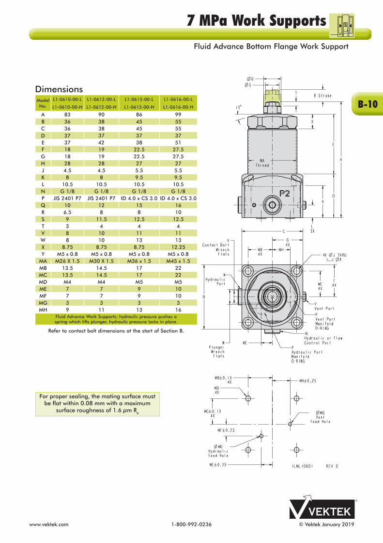
SpecificationsModel No.
L1-0610-00-L
L1-0610-00-H
L1-0612-00-L
L1-0612-00-H
L1-0615-00-L
L1-0615-00-H
L1-0616-00-L
L1-0616-00-HSupport Capacity*
(kN) 3.0 4.0 5.5 10
Support CapacityFormula** (kN) (P-1) x 0.500 (P-1) x 0.667 (P-1) x 0.917 (P-1) x 1.667
Stroke*** (mm) 6.5 8 8 10
Contact Force - L(N) 3.7 - 6.1 4.3 - 7.4 9.2 -13.7 9.3 -14.7
Contact Force - H(N) 6.2 - 9.0 8.8 - 14.9 12.8 - 20.7 12.7 - 22.8
Oil Capacity(cm3) 0.55 0.80 1.02 1.49
Port X Depth for Optional
In The Port Valves****G 1/8 X 15.16
Fluid Advance Work Support, hydraulic pressure pushes a spring which lifts plunger; hydraulic pressure locks in place.
NOTE: Work Support Capacity to be equal to or greater than 1.5 times clamping force plus machining force.
WARNING: Operating above 7 MPa may damage the work support and will void warranty.* Support capacities are listed at 7 MPa (70 bar) maximum pressure. Support capacities for other pressures are shown on the Capacity Charts at the start of Section B. Operating work supports above maximum pressure may damage work support and void warranty.** "P" in the formula is hydraulic pressure measured in MPa.*** To allow for work piece height variations, it is recommended that the plunger contacts the part at Mid-Stroke.**** Set plunger lifting time to 0.5 seconds, or longer, by adjusting the flow control valve. Use a flow control valve with cracking pressure of 0.1 MPa or less. In The Port valves require the use of manifold mount ports.
ILML10600 REV E
B-9
7 MPa Work SupportsFluid Advance Bottom Flange Work Support
www.vektek.com 1-800-992-0236 © Vektek January 2019
For proper sealing, the mating surface must be flat within 0.08 mm with a maximum
surface roughness of 1.6 µm Ra
DimensionsModel No.
L1-0610-00-L
L1-0610-00-H
L1-0612-00-L
L1-0612-00-H
L1-0615-00-L
L1-0615-00-H
L1-0616-00-L
L1-0616-00-H
A 83 90 86 99B 36 38 45 55C 36 38 45 55D 37 37 37 37E 37 42 38 51F 18 19 22.5 27.5G 18 19 22.5 27.5H 28 28 27 27J 4.5 4.5 5.5 5.5K 8 8 9.5 9.5L 10.5 10.5 10.5 10.5N G 1/8 G 1/8 G 1/8 G 1/8P JIS 2401 P7 JIS 2401 P7 ID 4.0 x CS 3.0 ID 4.0 x CS 3.0Q 10 12 15 16R 6.5 8 8 10S 9 11.5 12.5 12.5T 3 4 4 4V 8 10 11 11W 8 10 13 13X 8.75 8.75 8.75 12.25Y M5 x 0.8 M5 x 0.8 M5 x 0.8 M5 x 0.8
MA M26 X 1.5 M30 X 1.5 M36 x 1.5 M45 x 1.5MB 13.5 14.5 17 22MC 13.5 14.5 17 22MD M4 M4 M5 M5ME 7 7 9 10MF 7 7 9 10MG 3 3 3 3MH 9 11 13 16
Fluid Advance Work Supports; hydraulic pressure pushes a spring which lifts plunger, hydraulic pressure locks in place.
Refer to contact bolt dimensions at the start of Section B.
B-10
7 MPa Work SupportsFluid Advance Bottom Flange Work Support
© Vektek January 2019 1-800-992-0236 www.vektek.com
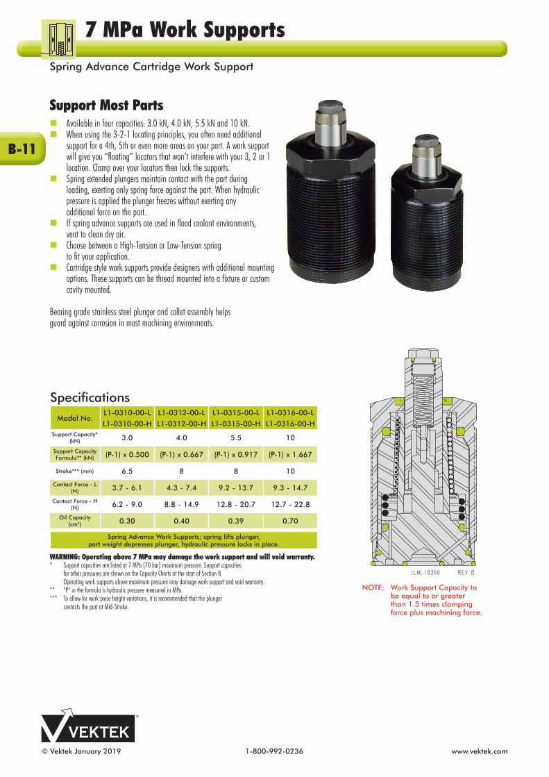
Support Most Parts nAvailable in four capacities: 3.0 kN, 4.0 kN, 5.5 kN and 10 kN. nWhen using the 3-2-1 locating principles, you often need additional support for a 4th, 5th or even more areas on your part. A work support will give you “floating” locators that won’t interfere with your 3, 2 or 1 location. Clamp over your locators then lock the supports.nSpring extended plungers maintain contact with the part during loading, exerting only spring force against the part. When hydraulic pressure is applied the plunger freezes without exerting any additional force on the part.nIf spring advance supports are used in flood coolant environments, vent to clean dry air. nChoose between a High-Tension or Low-Tension spring to fit your application.nCartridge style work supports provide designers with additional mounting options. These supports can be thread mounted into a fixture or custom cavity mounted.
Bearing grade stainless steel plunger and collet assembly helps guard against corrosion in most machining en vi ron ments.
SpecificationsModel No.
L1-0310-00-L
L1-0310-00-H
L1-0312-00-L
L1-0312-00-H
L1-0315-00-L
L1-0315-00-H
L1-0316-00-L
L1-0316-00-HSupport Capacity*
(kN) 3.0 4.0 5.5 10
Support CapacityFormula** (kN) (P-1) x 0.500 (P-1) x 0.667 (P-1) x 0.917 (P-1) x 1.667
Stroke*** (mm) 6.5 8 8 10
Contact Force - L(N) 3.7 - 6.1 4.3 - 7.4 9.2 - 13.7 9.3 - 14.7
Contact Force - H(N) 6.2 - 9.0 8.8 - 14.9 12.8 - 20.7 12.7 - 22.8
Oil Capacity(cm3) 0.30 0.40 0.39 0.70
Spring Advance Work Supports; spring lifts plunger,part weight depresses plunger, hydraulic pressure locks in place.
WARNING: Operating above 7 MPa may damage the work support and will void warranty.* Support capacities are listed at 7 MPa (70 bar) maximum pressure. Support capacities for other pressures are shown on the Capacity Charts at the start of Section B. Operating work supports above maximum pressure may damage work support and void warranty.** "P" in the formula is hydraulic pressure measured in MPa.*** To allow for work piece height variations, it is recommended that the plunger contacts the part at Mid-Stroke.
NOTE: Work Support Capacity to be equal to or greater than 1.5 times clamping force plus machining force.
B-11
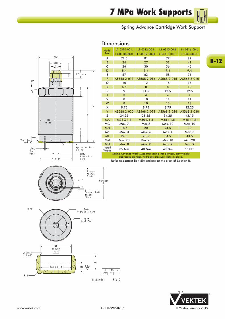
7 MPa Work SupportsSpring Advance Cartridge Work Support
www.vektek.com 1-800-992-0236 © Vektek January 2019
DimensionsModel No.
L1-0310-00-L
L1-0310-00-H
L1-0312-00-L
L1-0312-00-H
L1-0315-00-L
L1-0315-00-H
L1-0316-00-L
L1-0316-00-H
A 72.5 81 77 92B 24 27 32 41C 26 30 36 45D 8.4 9.4 9.4 9.4E 57 62 58 71P AS568 2-013 AS568 2-014 AS568 2-015 AS568 2-015Q 10 12 15 16R 6.5 8 8 10S 9 11.5 12.5 12.5T 3 4 4 4V 8 10 11 11W 8 10 13 13X 8.75 8.75 8.75 12.25Y AS568 2-020 AS568 2-022 AS568 2-026 AS568 2-030Z 24.25 28.25 34.25 43.15
MA M26 X 1.5 M30 X 1.5 M36 x 1.5 M45 x 1.5MG Max. 7 Max.8 Max. 10 Max. 10MH 18.5 20 24.5 30MK Max. 3 Max. 4 Max. 4 Max. 6ML 24.5 28.5 34.5 43.5MM Min. 20 Min. 20 Min. 18 Min. 20MN Max. 8 Max. 9 Max. 9 Max. 9
Install Torque 35 Nm 40 Nm 40 Nm 55 Nm
Spring Advance Work Supports; spring lifts plunger, part weight depresses plunger, hydraulic pressure locks in place.
Refer to contact bolt dimensions at the start of Section B.
B-12
7 MPa Work SupportsSpring Advance Cartridge Work Support

© Vektek January 2019 1-800-992-0236 www.vektek.com
NOTE: The maximum system back-pressure a fluid advance work support can overcome is 0.07 MPa (0.7 bar). Return back-pressure greater than 0.07 MPa (0.7 bar) may cause slow or failed retraction.
Retracted Plunger Applications nAvailable in four capacities ranging from 3.0 kN to 10 kN.nNormally retracted plungers do not interfere with part loading. Advance them with hydraulic pressure, exerting only spring force to bring plunger into contact with the part. Hydraulic pressure then automatically sequences, “freezing” the plunger properly against the part. nChoose between a High-Tension or Low-Tension Spring to fit your application.nFloating locator that doesn't interfere with 3-2-1 locating principles.nOnly spring force is applied to the part. Hydraulic actuation freezes the plunger without exerting any additional force on the part. n Minimal friction wiper design keeps chips and debris out while providing smooth plunger action.nCartridge style work supports provide designers with additional mounting options. These supports can be thread mounted into a fixture or custom cavity mounted.Bearing grade stainless steel plunger and collet assembly helps guard against corrosion in most machining en vi ron ments.
SpecificationsModel No.
L1-0410-00-L
L1-0410-00-H
L1-0412-00-L
L1-0412-00-H
L1-0415-00-L
L1-0415-00-H
L1-0416-00-L
L1-0416-00-HSupport Capacity*
(kN) 3.0 4.0 5.5 10
Support CapacityFormula** (kN) (P -1) x 0.500 (P -1) x 0.667 (P -1) x 0.917 (P -1) x 1.667
Stroke*** (mm) 6.5 8 8 10
Contact Force - L(N) 3.7 - 6.1 4.3 - 7.4 9.2 - 13.7 9.3 - 14.7
Contact Force - H(N) 6.2 - 9.0 8.8 - 14.9 12.8 - 20.7 12.7 - 22.8
Oil Capacity(cm3) 0.55 0.80 1.02 1.49
Fluid Advance Work Support, hydraulic pressure pushes a spring which lifts plunger; hydraulic pressure locks in place.
WARNING: Operating above 7 MPA may damage the work support and will void warranty.* Support capacities are listed at 7 MPa (70 bar) maximum pressure. Support capacities for other pressures are shown on the Capacity Charts at the start of Section B. Operating work supports above maximum pressure may damage work support and void warranty.** "P" in the formula is hydraulic pressure measured in MPa.*** To allow for work piece height variations, it is recommended that the plunger contacts the part at Mid-Stroke.
NOTE: Work Support Capacity to be equal to or greater than 1.5 times clamping force plus machining force.
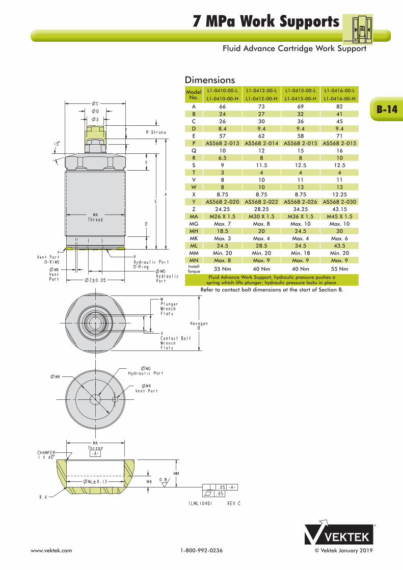
7 MPa Work SupportsFluid Advance Cartridge Work Support
B-13
www.vektek.com 1-800-992-0236 © Vektek January 2019
DimensionsModel No.
L1-0410-00-L
L1-0410-00-H
L1-0412-00-L
L1-0412-00-H
L1-0415-00-L
L1-0415-00-H
L1-0416-00-L
L1-0416-00-H
A 66 73 69 82B 24 27 32 41C 26 30 36 45D 8.4 9.4 9.4 9.4E 57 62 58 71P AS568 2-013 AS568 2-014 AS568 2-015 AS568 2-015Q 10 12 15 16R 6.5 8 8 10S 9 11.5 12.5 12.5T 3 4 4 4V 8 10 11 11W 8 10 13 13X 8.75 8.75 8.75 12.25Y AS568 2-020 AS568 2-022 AS568 2-026 AS568 2-030Z 24.25 28.25 34.25 43.15
MA M26 X 1.5 M30 X 1.5 M36 X 1.5 M45 X 1.5MG Max. 7 Max. 8 Max. 10 Max. 10MH 18.5 20 24.5 30MK Max. 3 Max. 4 Max. 4 Max. 6ML 24.5 28.5 34.5 43.5MM Min. 20 Min. 20 Min. 18 Min. 20MN Max. 8 Max. 9 Max. 9 Max. 9Install Torque 35 Nm 40 Nm 40 Nm 55 Nm
Fluid Advance Work Support, hydraulic pressure pushes a spring which lifts plunger; hydraulic pressure locks in place.
Refer to contact bolt dimensions at the start of Section B.
7 MPa Work SupportsFluid Advance Cartridge Work Support
B-14
© Vektek January 2019 1-800-992-0236 www.vektek.com
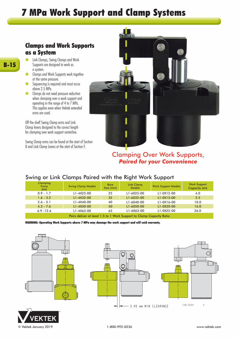
Clamps and Work Supports as a Systemn Link Clamps, Swing Clamps and Work Supports are designed to work as a system.n Clamps and Work Supports work together at the same pressure. n Sequencing is required and must occur above 2.5 MPa.n Clamps do not need pressure reduction when clamping over a work support and operating in the range of 4 to 7 MPa. This applies even when Vektek extended arms are used.
Off the shelf Swing Clamp arms and Link Clamp levers designed to the correct length for clamping over work support centerline.
Swing Clamp arms can be found at the start of Section D and Link Clamp Levers at the start of Section F.
Swing or Link Clamps Paired with the Right Work SupportClamping
Force(kN)
Swing Clamp Models Bore Size (mm)
Link ClampModels Work Support Models
Work Support Capacity (kN)
0.9 - 1.7 L1-4X25-00 25 L1-6025-00 L1-0X12-00 4.01.6 - 3.2 L1-4X32-00 32 L1-6032-00 L1-0X15-00 5.52.6 - 5.1 L1-4X40-00 40 L1-6040-00 L1-0X16-00 10.04.3 - 7.6 L1-4X50-00 50 L1-6050-00 L1-0X20-00 16.06.9 -12.6 L1-4X63-00 63 L1-6063-00 L1-0X22-00 26.0
Pairs deliver at least 1.5 to 1 Work Support to Clamp Capacity Ratio
Clamping Over Work Supports,Paired for your Convenience
WARNING: Operating Work Supports above 7 MPa may damage the work support and will void warranty.
7 MPa Work Support and Clamp Systems
B-15

www.vektek.com 1-800-992-0236 © Vektek January 2019
4.0 kN Work
Support
25 Bore Swing Clamp
Swing Clamp to Work Support
25 BoreLink
Clamp
Link Clamp to Work Support
Operating Pressure
(MPa)
Work Support Capacity
(kN)
Swing Clamp Force(kN)*
Support Capacity
Ratio
Link Clamp Force(kN)**
Support Capacity
Ratio
7.0 4.0 1.7 2.4 1.5 2.7
6.0 3.3 1.4 2.4 1.3 2.6
5.0 2.7 1.2 2.3 1.1 2.5
4.0 2.0 0.9 2.1 0.9 2.2
ILML10005-4.0 REV A *Using L9-1425-01 Arm **Using L9-1625-03 Lever
10 kN Work Support
40 Bore Swing Clamp
Swing Clamp to Work Support
40 BoreLink Clamp
Link Clamp to Work Support
Operating Pressure
(MPa)
Work Support Capacity
(kN)
Swing Clamp Force(kN)*
Support Capacity
Ratio
Link Clamp Force(kN)**
Support Capacity
Ratio
7.0 10.0 5.1 2.0 4.5 2.2
6.0 8.3 4.4 1.9 3.9 2.1
5.0 6.7 3.7 1.8 3.2 2.1
4.0 5.0 2.9 1.7 2.6 1.9
ILML10005-10 REV A *Using L9-1440-01 Arm **Using L9- 1640-03 Lever
16 kN Work Support
50 Bore Swing Clamp
Swing Clamp to Work Support
50 BoreLink Clamp
Link Clamp to Work Support
Operating Pressure
(MPa)
Work Support Capacity
(kN)
Swing Clamp Force(kN)*
Support Capacity
Ratio
Link Clamp Force(kN)**
Support Capacity
Ratio
7.0 16.0 7.6 2.1 7.6 2.1
6.0 13.3 6.5 2.0 6.5 2.0
5.0 10.7 5.4 2.0 5.4 2.0
4.0 8.0 4.3 1.9 4.4 1.8
ILML10005-16 REV A *Using L9-1450-01 Arm **Using L9-1650-03 Lever
26 kN Work Support
63 Bore Swing Clamp
Swing Clamp to Work Support
63 BoreLink Clamp
Link Clamp to Work Support
Operating Pressure
(MPa)
Work Support Capacity
(kN)
Swing Clamp Force(kN)*
Support Capacity
Ratio
Link Clamp Force(kN)*
Support Capacity
Ratio
7.0 26.0 12.0 2.2 12.6 2.1
6.0 21.7 10.3 2.1 10.8 2.0
5.0 17.3 8.6 2.0 9.0 1.9
4.0 13.0 6.9 1.9 7.2 1.8
ILML10005-26 REV A *Using L9-1463-01 Arm **Using L9-1663-03 Lever
5.5 kN Work Support
32 Bore Swing Clamp
Swing Clamp to Work Support
32 BoreLink Clamp
Link Clamp to Work Support
Operating Pressure
(MPa)
Work Support Capacity
(kN)
Swing Clamp Force(kN)*
Support Capacity
Ratio
Link Clamp Force(kN)**
Support Capacity
Ratio
7.0 5.5 3.2 1.7 2.9 1.9
6.0 4.6 2.7 1.7 2.5 1.8
5.0 3.7 2.3 1.6 2.0 1.9
4.0 2.8 1.8 1.6 1.6 1.8
ILML10005-5.5 REV A *Using L9-1432-01 Arm **Using L9-1632-03 Lever
0.0
1.0
2.0
3.0
4.0
4 5 6 7
Forc
e (k
N)
Operating Pressure (MPa)
Clamps and Work Supports
4.0 kN WS 25B SC 25B LC
ILML10005-4.0 REV A
0.0
2.0
4.0
6.0
8.0
10.0
4 5 6 7
Forc
e (k
N)
Operating Pressure (MPa)
Clamps and Work Supports
10 kN WS 40B SC 40B LC
ILML10005-10 REV A
0.0
4.0
8.0
12.0
16.0
4 5 6 7
Forc
e (k
N)
Operating Pressure (MPa)
Clamps and Work Supports
16 kN WS 50B SC 50B LCILML10005-16 REV A
0.04.08.0
12.016.020.024.028.0
4 5 6 7
Forc
e (k
N)
Operating Pressure (MPa)
Clamps and Work Supports
26 kN WS 63B SC 63B LCILML10005 -26 REV A
0.0
1.0
2.0
3.0
4.0
5.0
4 5 6 7
Forc
e (k
N)
Operating Pressure (MPa)
Clamps and Work Supports
5.5 kN WS 32B SC 32B LC
ILML10005-5.5 REV A
Clamp sequencing must always occur above 2.5 MPa
7 MPa Work Support and Clamp Systems
B-16

© Vektek January 2019 1-800-992-0236 www.vektek.com
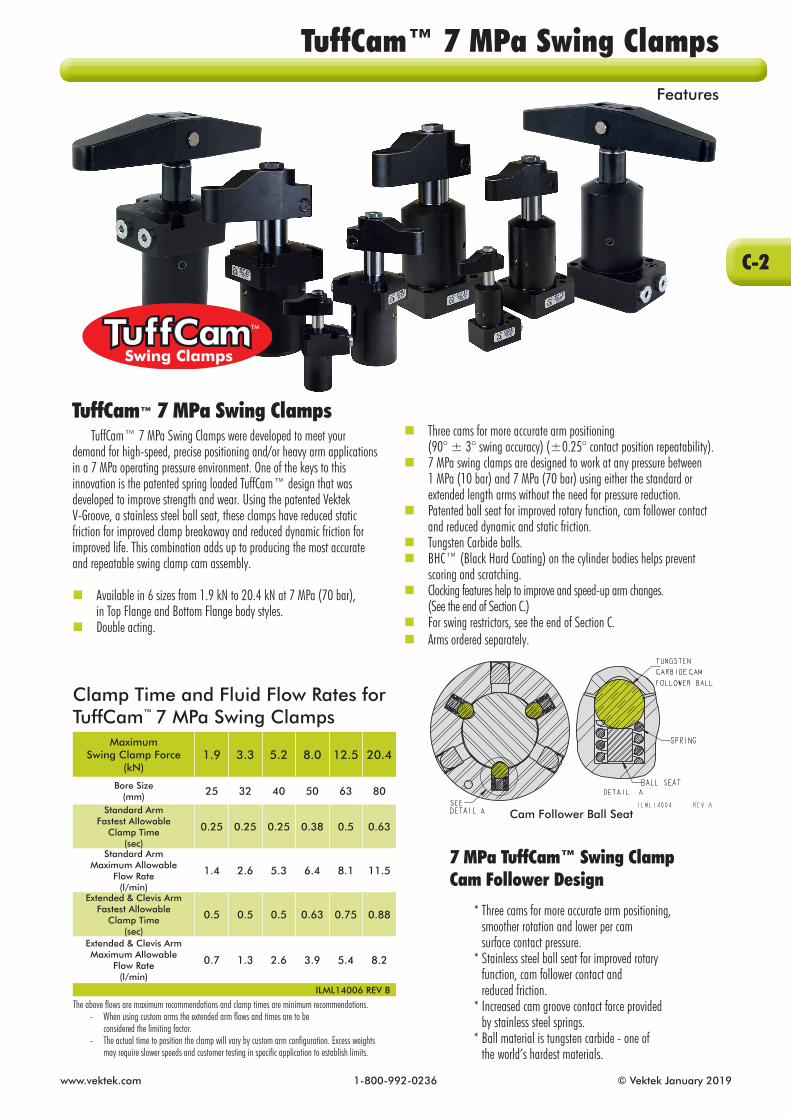
When do you recommend the use of TuffCam™ 7 MPa Swing Clamps over other Vektek product? Sometimes there are applications where speed is essential. Sometimes size and weight are critical. Often an available power supply limits pressure available.
What kind of return on my investment can I reasonably expect by converting my manual clamps to TuffCam™ 7 MPa Swing Clamps? Ask your Vektek sales representative for the Power Workholding Brochure. Time studies and costs are comparable justification. What makes the cam follower ball seat so special in these units? The three cams and three cam balls guide the rotation of the plunger and provide greater guide, support and directional stability. The patented cam follower design is unique in the industry and uses solid tungsten carbide balls and stainless steel ball seats. The ball seat design assures that the ball rolls in the cam rather than jamming and scraping, resulting in wear on both the cam track and ball. This vastly improves swing repeatability, contacting the same point ±0.25 degrees.
I want to use work supports with TuffCam™ 7 MPa Swing Clamps. Can you give me some tips that will help me get the most from my clamping devices? Vektek 7 MPa Work Supports and Swing Clamps are made in capacity sets, as well asarm-to-support centerline measurement.
It is important to hit my part in the exact place every time in my application. Will your TuffCam™ 7 MPa Swing Clamps meet this requirement ? Standardized repeatability of ±0.25 degrees is "Best-In-Class" Worldwide.
What defines a TuffCam™ 7 MPa Swing Clamp? TuffCam™ 7 MPa is a single directiontri-cam design swing clamp. These clamps produce the strength and reliability to support faster speeds and larger arms. TuffCam™ 7 MPa delivers notably better accuracy and repeatability over other brands. The clocking feature, dramatically reduces the time it takes to change arms for maintenance, replacementor design set up.
How can I measure the clamp speed? The maximum speed of a swing clamp is applicable to both clamp and unclamp function, as the momentum on the cam track and cam follower apply to both movements. To approximate the speed of your application:
* Look down the centerline of the swing clamp, perpendicular to the arm. * Actuate your clamping system while watching the arm “swing” into position. * If while looking directly into the end of the swing clamp, you can observe the arm move through its swing, the positioning time should be somewhere around ½ second or longer. See flow rates and clamping time at the start of Section C. * If, while looking directly into the end of the swing clamp, you cannot observe the arm move, or it is unclamped and the next thing you can see is it is in the clamped position, the positioning time is something substantially less than 1/2 second. Your standard model clamp is at risk of premature failure. See flow rates and clamping time at the start of Section C. * It is possible to approximate the clamp time by adding the total active volume of devices in the specific control branch of your system, and dividing that volume (cubic mm) by your pump’s output volume (cubic mm per minute) and then multiplying that number by 60 (60 seconds per minute). This will give you the theoretical calculated time to move a device through its stroke, but does not account for flow loss due to flow restrictions in the system.
I want to use the jam nut only to hold my arm in place. Will this work? It is unlikely that you can use the jam nut to hold arm orientation ad e quate ly. We have had customers modify clamps to include flats, pins, serrations or use set screws to hold orientation. These methods may work in specific instances. We still rec om mend our method of attachment, locknut and cross bolt for a secure, dependable, universal attachment. Other methods may complicate the replacement of clamps when they are damaged by a machine crash or other problems.
Why should I buy your arm rather than have my tool mak er make one? Our arm is designed to hold orientation when properly installed. It has a relief to keep from over-stressing the locknut. It will probably cost you less than the total cost of making your own. You can rest assured that our arm is made to our spec i fi ca tions and will withstand the forces our clamps generate, when used as recommended.
I need an arm slightly different from those you make. Can I make or modify your arms? Our first recommendation is to modifying our existing arms if possible. All VektorFlo® arms are able to be machined or welded. You should be able to easily modify any standard arm you purchase. We recommend this because our original design for the cross bolt orientation mechanism is the most secure, dependable and ver sa tile orientation method available. Many customers and competitors have tried to copy it, some with limited success. If you desire to make your own arm(s), refer to the detailed information at the start of Section D. Please be sure to put in the 0.5 mm step for the locknut and relieve the cut in the arm so that the bolt will squeeze the plunger shaft. If you do not take these two steps, your custom arm may not work satisfactorily.
NOTE: See Arm Length and Pressure Limitation Graphs on Page D-5.
C-1
TuffCam™ 7 MPa Swing ClampsFrequently Asked Questions
www.vektek.com 1-800-992-0236 © Vektek January 2019
TuffCam™ 7 MPa Swing Clamps were developed to meet your demand for high-speed, precise positioning and/or heavy arm applications in a 7 MPa operating pressure environment. One of the keys to this innovation is the patented spring loaded TuffCam™ design that was developed to improve strength and wear. Using the patented Vektek V-Groove, a stainless steel ball seat, these clamps have reduced static friction for improved clamp breakaway and reduced dynamic friction for improved life. This combination adds up to producing the most accurate and repeatable swing clamp cam assembly.
nAvailable in 6 sizes from 1.9 kN to 20.4 kN at 7 MPa (70 bar), in Top Flange and Bottom Flange body styles.nDouble acting.
n Three cams for more accurate arm positioning (90° ± 3° swing accuracy) (±0.25° contact position repeatability).n7 MPa swing clamps are designed to work at any pressure between 1 MPa (10 bar) and 7 MPa (70 bar) using either the standard or extended length arms without the need for pressure reduction.n Patented ball seat for improved rotary function, cam follower contact and reduced dynamic and static friction.nTungsten Carbide balls. nBHC™ (Black Hard Coating) on the cylinder bodies helps prevent scoring and scratching.n Clocking features help to improve and speed-up arm changes. (See the end of Section C.)nFor swing restrictors, see the end of Section C.n Arms ordered separately.
Clamp Time and Fluid Flow Rates forTuffCam™ 7 MPa Swing Clamps
Maximum Swing Clamp Force
(kN)1.9 3.3 5.2 8.0 12.5 20.4
Bore Size(mm) 25 32 40 50 63 80
Standard Arm Fastest Allowable
Clamp Time(sec)
0.25 0.25 0.25 0.38 0.5 0.63
Standard Arm Maximum Allowable
Flow Rate (l/min)
1.4 2.6 5.3 6.4 8.1 11.5
Extended & Clevis Arm Fastest Allowable
Clamp Time(sec)
0.5 0.5 0.5 0.63 0.75 0.88
Extended & Clevis Arm Maximum Allowable
Flow Rate (l/min)
0.7 1.3 2.6 3.9 5.4 8.2
ILML14006 REV B
The above flows are maximum recommendations and clamp times are minimum recommendations. - When using custom arms the extended arm flows and times are to be considered the limiting factor. - The actual time to position the clamp will vary by custom arm configuration. Excess weights may require slower speeds and customer testing in specific application to establish limits.
Cam Follower Ball Seat
7 MPa TuffCam™ Swing Clamp Cam Follower Design
* Three cams for more accurate arm positioning, smoother rotation and lower per cam surface contact pressure. * Stainless steel ball seat for improved rotary function, cam follower contact and reduced friction. * Increased cam groove contact force provided by stainless steel springs. * Ball material is tungsten carbide - one of the world’s hardest materials.
TuffCam™ 7 MPa Swing Clamps
C-2
TuffCam™ 7 MPa Swing ClampsFeatures

© Vektek January 2019 1-800-992-0236 www.vektek.com
Specifications
Model No.L1-4025-00-LL1-4025-00-RL1-4025-00-S
L1-4032-00-LL1-4032-00-RL1-4032-00-S
L1-4040-00-LL1-4040-00-RL1-4040-00-S
L1-4050-00-LL1-4050-00-RL1-4050-00-S
L1-4063-00-LL1-4063-00-RL1-4063-00-S
L1-4080-00-LL1-4080-00-RL1-4080-00-S
Double Acting (D/A) Cylinders, actuated hydraulically both directions.
Swing Direction Left
Right Straight
LeftRight
Straight
LeftRight
Straight
LeftRight
Straight
LeftRight
Straight
LeftRight
StraightCylinder Capacity*
(kN) 1.9 3.3 5.2 8.0 12.5 20.4
Bore Size(mm) 25 32 40 50 63 80
Vertical Clamp Stroke**(mm) 8 8 10 12 14 14
Total Stroke (Swing + Vertical)
(mm)18.5 19.5 25.0 30.0 32.0 35.0
Effective Piston Area(cm2)
Retract3.14 5.50 8.76 13.47 21.00 34.36
Oil Capacity***(cm3)
Extend9.1 15.7 31.4 58.9 99.8 175.9
Oil Capacity***(cm3)
Retract5.8 10.7 21.9 40.4 67.2 120.3
Port X Depth for Optional In The Port Valves**** G 1/8 X 15.16 G 1/8 X 15.16 G 1/8 X 15.16 G 1/4 X 18.72 G 1/4 X 18.72 G 1/4 X 18.72
Double ActingnSix clamp capacities available ranging from 1.9 kN to 20.4 kN.n Clamp can be operated at 7 MPa (70 bar) with long arm; no pressure reduction required.n Patented ball seat delivers improved rotary function and cam follower contact, while reducing dynamic and static friction. n Tungsten-Carbide cam followers for strength and wear.n Clamp repeatability ±0.25° and swing angle repeatability 90° ± 3°.n See the start of Section C regarding flow rate limits and time calculations needed to preserve warranty.n TuffCam™ clocking feature (end of section C) for repeat locating of arm. nFor swing restrictors, see the end of Section C.nArms sold separately in Section D. The standard length 7 MPa arm with the threaded contact bolt hole is designed to clamp over the work support centerline.n Can be either manifold mounted or plumbed.n Optional In The Port flow control is a meter-in device with a reverse free flow check valve. n Optional In The Port sequence valve is a pressure sequencing device with reverse free flow check valve.
ILML14000 REV D
WARNING! Never allow swing arm to contact workpiece or fixture during arm rotation.* Cylinder capacities are listed at 7 MPa (70 bar) operating pressure, with a standard length VektorFlo® 7 MPa arm installed. Maximum operating pressure is 10 MPa (100 bar). The minimum operating pressure is 1 MPa (10 bar). The clamping force is adjustable by varying the hydraulic system pressure. To determine the approximate output force for your application, divide the cylinder capacity shown above by 7 MPa (70 bar), and multiply the resultant number by your system operating pressure MPa (bar) to obtain the approximate clamping force for your application. (Actual force will vary slightly due to internal cantilever loading, and/or friction loss.) ** To allow for piece part height variations, it is recommended that the vertical travel be set to about 50% of the vertical stroke.*** To ensure maximum service life and trouble-free operation, restrict fluid flow according to the start of Section C.**** In The Port valves require the use of manifold mount ports.
C-3
TuffCam™ 7 MPa Swing ClampTop Flange Swing Clamp
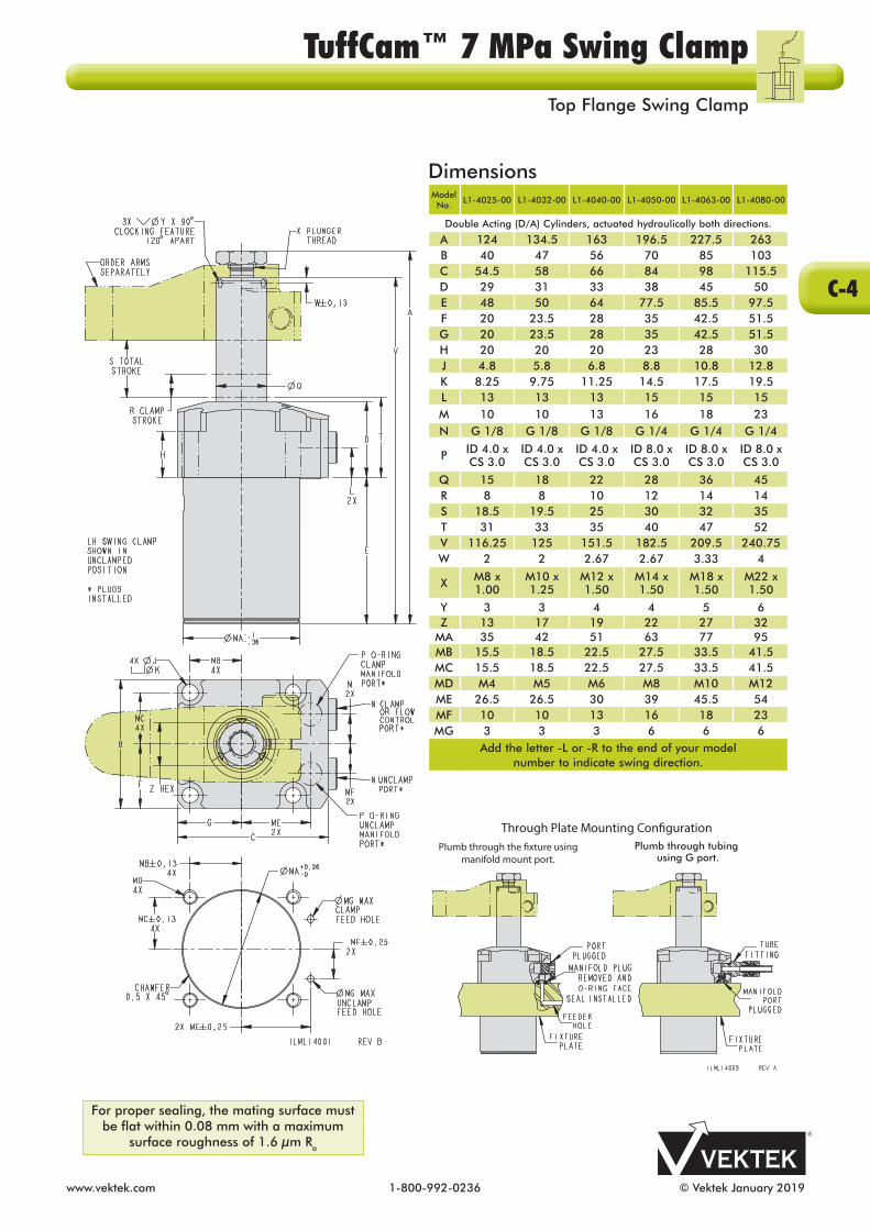
www.vektek.com 1-800-992-0236 © Vektek January 2019
DimensionsModel No.
L1-4025-00 L1-4032-00 L1-4040-00 L1-4050-00 L1-4063-00 L1-4080-00
Double Acting (D/A) Cylinders, actuated hydraulically both directions.
A 124 134.5 163 196.5 227.5 263B 40 47 56 70 85 103C 54.5 58 66 84 98 115.5D 29 31 33 38 45 50E 48 50 64 77.5 85.5 97.5F 20 23.5 28 35 42.5 51.5G 20 23.5 28 35 42.5 51.5H 20 20 20 23 28 30J 4.8 5.8 6.8 8.8 10.8 12.8K 8.25 9.75 11.25 14.5 17.5 19.5L 13 13 13 15 15 15M 10 10 13 16 18 23N G 1/8 G 1/8 G 1/8 G 1/4 G 1/4 G 1/4
P ID 4.0 x CS 3.0
ID 4.0 x CS 3.0
ID 4.0 x CS 3.0
ID 8.0 x CS 3.0
ID 8.0 x CS 3.0
ID 8.0 x CS 3.0
Q 15 18 22 28 36 45R 8 8 10 12 14 14S 18.5 19.5 25 30 32 35T 31 33 35 40 47 52V 116.25 125 151.5 182.5 209.5 240.75W 2 2 2.67 2.67 3.33 4
X M8 x 1.00
M10 x 1.25
M12 x 1.50
M14 x 1.50
M18 x 1.50
M22 x 1.50
Y 3 3 4 4 5 6Z 13 17 19 22 27 32
MA 35 42 51 63 77 95MB 15.5 18.5 22.5 27.5 33.5 41.5MC 15.5 18.5 22.5 27.5 33.5 41.5MD M4 M5 M6 M8 M10 M12ME 26.5 26.5 30 39 45.5 54MF 10 10 13 16 18 23MG 3 3 3 6 6 6
Add the letter -L or -R to the end of your model number to indicate swing direction.
Through Plate Mounting Con�gurationPlumb through the �xture using
manifold mount port.Plumb through tubing
using G port.
For proper sealing, the mating surface must be flat within 0.08 mm with a maximum
surface roughness of 1.6 µm Ra
C-4
TuffCam™ 7 MPa Swing ClampTop Flange Swing Clamp

© Vektek January 2019 1-800-992-0236 www.vektek.com
Double ActingnSix clamp capacities are available ranging from 1.9 kN to 20.4 kN. nTuffCam™ 7 MPa Swing Clamps are designed to operate from 1 MPa (10 bar) to 7 MPa (70 bar) without pressure reducing.n7 MPa Clamps and work supports are paired to work at pressures between 4 MPa (40 bar) and 7 MPa (70 bar) without pressure reducing the clamp.n Clamp repeatability ±0.25° and swing angle repeatability 90° ± 3°.n Consult table at the start of Section C for clamp time and fluid flow rates.n Patented ball seat delivers improved rotary function, cam follower contact, while reducing dynamic and static friction. n Can be either manifold mounted or plumbed. n Tungsten-Carbide ball material; one of the world’s hardest materials.n Clocking feature for the TuffCam™ 7 MPa at the end of Section C for repeat locating of arm. nFor swing restrictors, see the end of Section C.nArms sold separately in Section D. Short arm threaded contact bolt hole is designed to clamp over the work support centerline.n Optional In The Port flow control is a meter-in device with a reverse free flow check valve. n Optional In The Port sequence valve is a pressure sequencing device with reverse free flow check valve.
SpecificationsModel No.
L1-4125-00-LL1-4125-00-RL1-4125-00-S
L1-4132-00-LL1-4132-00-RL1-4132-00-S
L1-4140-00-LL1-4140-00-RL1-4140-00-S
L1-4150-00-LL1-4150-00-RL1-4150-00-S
L1-4163-00-LL1-4163-00-RL1-4163-00-S
L1-4180-00-LL1-4180-00-RL1-4180-00-S
Double Acting (D/A) Cylinders, actuated hydraulically both directions.
Swing Direction Left
Right Straight
LeftRight
Straight
LeftRight
Straight
LeftRight
Straight
LeftRight
Straight
LeftRight
Straight
Cylinder Capacity*(kN) 1.9 3.3 5.2 8.0 12.5 20.4
Bore Size(mm) 25 32 40 50 63 80
Vertical Clamp Stroke** (mm) 8 8 10 12 14 14
Total Stroke (Swing + Vertical)
(mm)18.5 19.5 25.0 30.0 32.0 35.0
Effective Piston Area(cm2)
Retract3.14 5.50 8.76 13.47 21.00 34.36
Oil Capacity***(cm3)
Extend9.1 15.7 31.4 58.9 99.8 175.9
Oil Capacity***(cm3)
Retract5.8 10.7 21.9 40.4 67.2 120.3
Port X Depth for Optional In The Port
Valves****G 1/8 X 15.16 G 1/8 X 15.16 G 1/8 X 15.16 G 1/4 X 18.72 G 1/4 X 18.72 G 1/4 X 18.72
WARNING! Never allow swing arm to contact workpiece or fixture during arm rotation.* Cylinder capacities are listed at 7 MPa (70 bar) operating pressure, with a standard length VektorFlo® 7 MPa arm installed. Maximum operating pressure is 10 MPa (100 bar). The minimum operating pressure is 1 MPa (10 bar). The clamping force is adjustable by varying the hydraulic system pressure. To determine the approximate output force for your application, divide the cylinder capacity shown above by 7 MPa (70 bar), and multiply the resultant number by your system operating pressure MPa (bar) to obtain the approximate clamping force for your application. (Actual force will vary slightly due to internal cantilever loading, and/or friction loss.) ** To allow for piece part height variations, it is recommended that the vertical travel be set to about 50% of the vertical stroke.*** To ensure maximum service life and trouble-free operation, restrict fluid flow at the start of Section C.**** In The Port valves require the use of manifold mount ports.
ILML14100 REV D
C-5
TuffCam™ 7 MPa Swing ClampsBottom Flange Swing Clamp

www.vektek.com 1-800-992-0236 © Vektek January 2019
DimensionsModel No.
L1-4125-00 L1-4132-00 L1-4140-00 L1-4150-00 L1-4163-00 L1-4180-00
Double Acting (D/A) Cylinders, actuated hydraulically both directions.
A 124.5 135 163.5 197 228 263.5B 40 47 56 70 85 103C 54.5 58 66 84 98 115.5D 26 26 26 30 34 35E 51.5 55.5 71.5 86 97 113F 20 23.5 28 35 42.5 51.5G 20 23.5 28 35 42.5 51.5J 4.8 5.8 6.8 8.8 10.8 12.8L 13 13 13 15 17 20M 10 10 13 16 18 23N G 1/8 G 1/8 G 1/8 G 1/4 G 1/4 G 1/4
P ID 4.0 x CS 3.0
ID 4.0 x CS 3.0
ID 4.0 x CS 3.0
ID 8.0 x CS 3.0
ID 8.0 x CS 3.0
ID 8.0 x CS 3.0
Q 15 18 22 28 36 45R 8 8 10 12 14 14S 18.5 19.5 25 30 32 35T 79.5 83.5 99.5 118 133 150V 116.75 125.5 152 183 210 241.25W 2 2 2.67 2.67 3.33 4
X M8 x 1.00
M10 x 1.25
M12 x 1.50
M14 x 1.50
M18 x 1.50
M22 x 1.50
Y 3 3 4 4 5 6Z 13 17 19 22 27 32
MA 35 42 51 63 77 95MB 15.5 18.5 22.5 27.5 33.5 41.5MC 15.5 18.5 22.5 27.5 33.5 41.5MD M4 M5 M6 M8 M10 M12ME 26.5 26.5 30 39 45.5 54MF 10 10 13 16 18 23MG 3 3 3 6 6 6
Add the letter -L or -R to the end of your model number to indicate swing direction.
Above Plate Mounting Con�gurationPlumb through the �xture using
manifold mount port. Under Plate Mounting Con�gurationPlumb through tubing using the G port
For proper sealing, the mating surface must be flat within 0.08 mm with a maximum
surface roughness of 1.6 µm Ra
TuffCam™ 7 MPa Swing ClampsBottom Flange Swing Clamp
C-6

© Vektek January 2019 1-800-992-0236 www.vektek.com
SpecificationsModel No.
L1-4025-10-LL1-4025-10-RL1-4025-10-S
L1-4032-10-LL1-4032-10-RL1-4032-10-S
L1-4040-10-LL1-4040-10-RL1-4040-10-S
L1-4050-10-LL1-4050-10-RL1-4050-10-S
L1-4063-10-LL1-4063-10-RL1-4063-10-S
L1-4080-10-LL1-4080-10-RL1-4080-10-S
Add the Clevis orientation indicator to the end of your item number. The indicators are -0 and -90. Include the dash.
Double Acting (D/A) Cylinders, actuated hydraulically both directions.
Swing Direction Left
RightStraight
LeftRight
Straight
LeftRight
Straight
LeftRight
Straight
LeftRight
Straight
LeftRight
Straight
Cylinder Capacity*(kN) 2.2 3.8 6.1 9.4 14.7 24.1
Bore Size(mm) 25 32 40 50 63 80
Vertical Clamp Stroke** (mm) 8 8 10 12 14 14Total Stroke
(Swing + Vertical)(mm)
18.5 19.5 25.0 30.0 32.0 35.0
Effective Piston Area(cm2)
Retract3.14 5.50 8.76 13.47 21.00 34.36
Oil Capacity***(cm3)
Extend9.1 15.7 31.4 58.9 99.8 175.9
Oil Capacity***(cm3)
Retract5.8 10.7 21.9 40.4 67.2 120.3
Port X Depth for Optional In The Port
Valves****G 1/8 X 15.16 G 1/8 X 15.16 G 1/8 X 15.16 G 1/4 X 18.72 G 1/4 X 18.72 G 1/4 X 18.72
Double ActingnAll left or right swing clamps swing 90°. Clamps available in 6 retract capacities ranging from 2.2 kN to 24.1 kN. Designed to operate at 7 MPa.n Use double ended Rocker Arms to apply equal force on two surfaces of different heights. nMaximum allowable arm travel for work piece height variation is ± 10° nTwo standard arm orientations available (0° and 90°). Request other arm orientations through Vektek.n Clamp repeatability ±0.25° and swing angle repeatability 90° ± 3°.n Consult table at the start of Section C for clamp time and fluid flow rates.nStainless steel pivot pin, carbon steel retaining rings and rubber centralizing springs included.n Patented ball seat delivers improved rotary function and cam follower contact, while reducing dynamic and static friction. n Tungsten-Carbide ball material; one of the world’s hardest materials.nArms sold separately in Section D.n Can be manifold mounted or plumbed.n Optional In The Port flow control is a meter-in device with a reverse free flow check valve. n Optional In The Port sequence valve is a pressure sequencing device with reverse free flow check valve.
WARNING! Never allow swing arm to contact workpiece or fixture during arm rotation.* Cylinder retract capacities are listed at 7 MPa (70 bar) operating pressure. Divide cylinder retract force by 2 for when using symmetrical length arm. Maximum operating pressure is 10 MPa (100 bar). The minimum operating pressure is 1 MPa (10 bar). The clamping force is adjustable by varying the hydraulic system pressure. To determine the approximate output force for your application, divide the cylinder capacity shown above by 7 MPa (70 bar), and multiply the resultant number by your system operating pressure MPa (bar) to obtain the approximate retract force for your application. (Actual force will vary slightly due to internal loading, and/or friction loss.) ** To allow for piece part height variations, it is recommended that the vertical travel be set to about 50% of the vertical stroke.*** To ensure maximum service life and trouble-free operation, restrict fluid flow at the start of Section C.**** In The Port valves require the use of manifold mount ports.
ILML14012 REV C
C-7
TuffCam™ 7 MPa Swing ClampsClevis Plunger Top Flange

www.vektek.com 1-800-992-0236 © Vektek January 2019
90 90
UNCLAMP CLAMP
-0 ORIENTATION -90 ORIENTATION
CLAMPPORT
UNCLAMPPORT
UNCLAMP
SWING SWING
CLAMP
CLAMPPORT
UNCLAMP PORT
DimensionsModel No.
L1-4025-10-L
L1-4025-10-R
L1-4025-10-S
L1-4032-10-L
L1-4032-10-R
L1-4032-10-S
L1-4040-10-L
L1-4040-10-R
L1-4040-10-S
L1-4050-10-L
L1-4050-10-R
L1-4050-10-S
L1-4063-10-L
L1-4063-10-R
L1-4063-10-S
L1-4080-10-L
L1-4080-10-R
L1-4080-10-S
Add the Clevis orientation indicator to the end of your item number. The indicators are -0 or 90. Include the dash.
Double Acting (D/A) Cylinders, actuated hydraulically both directions.
A 119.5 130.75 158.75 188.75 218.75 251.75B 40 47 56 70 85 103C 54.5 58 66 84 98 115.5D 29 31 33 38 45 50E 48 50 64 77.5 85.5 97.5F 20 23.5 28 35 42.5 51.5G 20 23.5 28 35 42.5 51.5H 20 20 20 23 28 30J 4.8 5.8 6.8 8.8 10.8 12.8K 8.25 9.75 11.25 14.5 17.5 19.5L 13 13 13 15 15 15M 10 10 13 16 18 23N G 1/8 G 1/8 G 1/8 G 1/4 G 1/4 G 1/4
PID 4.0 X CS 3.0
ID 4.0 X CS 3.0
ID 4.0 X CS 3.0
ID 8.0 X CS 3.0
ID 8.0 X CS 3.0
ID 8.0 X CS 3.0
Q 15 18 22 28 36 45R 8 8 10 12 14 14S 18.5 19.5 25 30 32 35T 35 37.25 39.75 45.25 53.25 60.25V 110.5 118.75 143.75 170.75 194.75 222.75W 6 8 10 12 16 20X 8 10 12 15 20 24Z 24 30.5 36.5 42.5 55.5 68.5
MA 35 42 51 63 77 95MB 15.5 18.5 22.5 27.5 33.5 41.5MC 15.5 18.5 22.5 27.5 33.5 41.5MD M4 M5 M6 M8 M10 M12ME 26.5 26.5 30 39 45.5 54MF 10 10 13 16 18 23MG 3 3 3 6 6 6
For proper sealing, the mating surface must be flat within 0.08 mm with a maximum
surface roughness of 1.6 µm Ra
C-8
TuffCam™ 7 MPa Swing ClampsClevis Plunger Top Flange

© Vektek January 2019 1-800-992-0236 www.vektek.com
Specifications
Model No.L1-4125-10-LL1-4125-10-RL1-4125-10-S
L1-4132-10-LL1-4132-10-RL1-4132-10-S
L1-4140-10-LL1-4140-10-RL1-4140-10-S
L1-4150-10-LL1-4150-10-RL1-4150-10-S
L1-4163-10-LL1-4163-10-RL1-4163-10-S
L1-4180-10-LL1-4180-10-RL1-4180-10-S
Add the Clevis orientation indicator to the end of your item number. The indicators are -0 and -90. Include the dash.
Double Acting (D/A) Cylinders, actuated hydraulically both directions.
Swing Direction Left
RightStraight
LeftRight
Straight
LeftRight
Straight
LeftRight
Straight
LeftRight
Straight
LeftRight
Straight
Cylinder Capacity*(kN) 2.2 3.8 6.1 9.4 14.7 24.1
Bore Size(mm) 25 32 40 50 63 80
Vertical Clamp Stroke**(mm) 8 8 10 12 14 14
Total Stroke (Swing + Vertical)
(mm)18.5 19.5 25.0 30.0 32.0 35.0
Effective Piston Area(cm2)
Retract3.14 5.50 8.76 13.47 21.00 34.36
Oil Capacity***(cm3)
Extend9.1 15.7 31.4 58.9 99.8 175.9
Oil Capacity***(cm3)
Retract5.8 10.7 21.9 40.4 67.2 120.3
Port X Depth for Optional In The Port Valves**** G 1/8 X 15.16 G 1/8 X 15.16 G 1/8 X 15.16 G 1/4 X 18.72 G 1/4 X 18.72 G 1/4 X 18.72
WARNING! Never allow swing arm to contact workpiece or fixture during arm rotation.* Cylinder retract capacities are listed at 7 MPa (70 bar) operating pressure. Divide cylinder retract force by 2 for when using symmetrical length arm. Maximum operating pressure is 10 MPa (100 bar). The minimum operating pressure is 1 MPa (10 bar). The clamping force is adjustable by varying the hydraulic system pressure. To determine the approximate output force for your application, divide the cylinder capacity shown above by 7 MPa (70 bar), and multiply the resultant number by your system operating pressure MPa (bar) to obtain the approximate retract force for your application. (Actual force will vary slightly due to internal loading, and/or friction loss.) ** To allow for piece part height variations, it is recommended that the vertical travel be set to about 50% of the vertical stroke.*** To ensure maximum service life and trouble-free operation, restrict fluid flow per table at the start of Section C.**** In The Port valves require the use of manifold mount ports.
Double ActingnAll left or right swing clamps swing 90°. Clamps available in 6 retract capacities ranging from 2.2 kN to 24.1 kN. Designed to operate at 7 MPa.n Use double ended Rocker Arms to apply equal force on two surfaces of different heights. nAllowable arm travel for work piece height variation is ± 10° nTwo standard arm orientations available (0° and 90°). Request other arm orientations through Vektek.n Clamp repeatability ±0.25° and swing angle repeatability 90° ± 3°.n Consult table at the start of Section C for clamp time and fluid flow rates.n Patented ball seat delivers improved rotary function, cam follower contact, while reducing dynamic and static friction. n Choose manifold mount above or below the flange or plumb the device. n Tungsten-Carbide cam followers for strength and wear.n Clocking feature for the TuffCam™ 7 MPa at the end of Section C.nArms sold separately in Section D.n Optional In The Port flow control is a meter-in device with a reverse free flow check valve. n Optional In The Port sequence valve is a pressure sequencing device with reverse free flow check valve.
ILML14104 REV C
C-9
TuffCam™ 7 MPa Swing ClampsClevis Plunger Bottom Flange

www.vektek.com 1-800-992-0236 © Vektek February 2021
90 90
UNCLAMP CLAMP
-0 ORIENTATION -90 ORIENTATION
CLAMPPORT
UNCLAMPPORT
UNCLAMP
SWING SWING
CLAMP
CLAMPPORT
UNCLAMP PORT
For proper sealing, the mating surface must be flat within 0.08 mm with a maximum
surface roughness of 1.6 µm Ra
DimensionsModel No.
L1-4125-10-L
L1-4125-10-R
L1-4125-10-S
L1-4132-10-L
L1-4132-10-R
L1-4132-10-S
L1-4140-10-L
L1-4140-10-R
L1-4140-10-S
L1-4150-10-L
L1-4150-10-R
L1-4150-10-S
L1-4163-10-L
L1-4163-10-R
L1-4163-10-S
L1-4180-10-L
L1-4180-10-R
L1-4180-10-S
Add the letter -L or -S to the end of your model number to indicate swing direction. Add -0, -30, -60, -90, -120 or -150 to the end of your
model number to indicate clevis orientation.
Double Acting (D/A) Cylinders, actuated hydraulically both directions.
A 120 131.25 159.25 189.25 219.25 252.25B 40 47 56 70 85 103C 54.5 58 66 84 98 115.5D 26 26 26 30 34 35E 51.5 55.5 71.5 86 97 113F 20 23.5 28 35 42.5 51.5G 20 23.5 28 35 42.5 51.5J 4.8 5.8 6.8 8.8 10.8 12.8L 13 13 13 15 17 20M 10 10 13 16 18 23N G 1/8 G 1/8 G 1/8 G 1/4 G 1/4 G 1/4
PID 4.0 X CS 3.0
ID 4.0 X CS 3.0
ID 4.0 X CS 3.0
ID 8.0 X CS 3.0
ID 8.0 X CS 3.0
ID 8.0 X CS 3.0
Q 15 18 22 28 36 45R 8 8 10 12 14 14S 18.5 19.5 25 30 32 35T 83.5 87.75 104.25 123.25 139.25 158.25V 111 119.25 144.25 171.25 195.25 223.25W 6 8 10 12 16 20X 8 10 12 15 20 24Z 24 30.5 36.5 42.5 55.5 68.5
MA 35 42 51 63 77 95MB 15.5 18.5 22.5 27.5 33.5 41.5MC 15.5 18.5 22.5 27.5 33.5 41.5MD M4 M5 M6 M8 M10 M12ME 26.5 26.5 30 39 45.5 54MF 10 10 13 16 18 23MG 3 3 3 6 6 6
C-10
TuffCam™ 7 MPa Swing ClampsClevis Plunger Bottom Flange

© Vektek January 2019 1-800-992-0236 www.vektek.com
TuffCam™ is a trademark of Vektek LLC
TuffCam™ 7 MPa Arm Clocking Feature The 3 divots or "Clocking Features", located on the plunger, help arm installation in repeat fixture applications and with arm changes when maintaining fixtures. Installing a set screw into the arm properly positions the arm relative to the plunger and swing clamp body. The 3 divots are located at 120° intervals around the plunger to assure access to at least one in any body-arm orientation. Vektek swing clamp arms are made with clearance to allow the drilling and installation of set screws according to this drawing.
Set Screw Size and LocationModel No. L1-4X25-00-X L1-4X32-00-X L1-4X40-00-X L1-4X50-00-X L1-4X63-00-X L1-4X80-00-X
Set Screw M3 M3 M4 M4 M5 M6
A 1.75 1.75 2.42 2.42 3.08 3.75
Shown in Clamp Position
VektekSwing Restrictors
45º
60º
30º
90º
CLAMPPOSITION
TuffCamTM Swing Clamp Swing RestrictorsModel No. L1-4X25-00-X L1-4X32-00-X L1-4X40-00-X L1-4X50-00-X L1-4X63-00-X L1-4X80-00-X
Clamp Capacity
(kN)1.9 3.3 5.2 8.0 12.5 20.4
Bore Size (mm)
25 32 40 50 63 80
Swing Restrictor
30°L1-4925-30 L1-4932-30 L1-4940-30 L1-4950-30 L1-4963-30 L1-4980-30
Swing Restrictor
45°L1-4925-45 L1-4932-45 L1-4940-45 L1-4950-45 L1-4963-45 L1-4980-45
Swing Restrictor
60°L1-4925-60 L1-4932-60 L1-4940-60 L1-4950-60 L1-4963-60 L1-4980-60
Custom angle restrictors available on request. ILML14011 REV A
C-11
TuffCam™ 7 MPa Swing ClampsClocking, Swing Clamp Restrictors

www.vektek.com 1-800-992-0236 © Vektek January 2019
I need to make my own arms, what information do I need? The information that you need is detailed on page D-3. We strongly encourage you to copy our connection to the swing clamp rod. The com bi na tion of the top locknut and side bolt squeezing action is the most secure connection on the market today. You should be sure to put the 0.5 mm step in your custom arms for best results.
Can I modify the arms I buy from you? Yes, you can. Our arms are made of a cast alloy steel that you can easily weld or machine to fit your needs.
Do I really need to put the step in the top of the arm like you do? Yes, you should. The step in top of the arm relieves stress on the locknut and the piston rod. If you make custom arms and leave this off, you will probably experience pre ma ture failures if your clamps are run near maximum capacity.
I want to use the locknut only to hold my arm in place. Will this work? It is unlikely that you can use the locknut to hold arm orientation ad e quate ly. We have had customers modify clamps to include flats, pins, serrations or use set screws to hold orientation. These methods may work in specific instances. We still rec om mend our method of attachment, locknut and cross bolt for a secure, dependable, universal attachment. Other methods may complicate the replacement of clamps when they are damaged by a machine crash or other problems.
I am using a double ended arm. Is the capacity of your 8 kN swing clamp still the same? No. First of all, the 8 kN rating is with a standard arm installed and includes the frictional loss inherent in all can ti le vered designs. The true capacity rating for this clamp is 9.4 kN. If you are pulling in the center of the arm and both points are being contacted at the same time, divide the force by 2 (two).
Why should I buy your arm rather than have my tool mak er make one? Our arm is designed to hold orientation when properly installed. It has a relief to keep from over-stressing the locknut. It will probably cost you less than the total cost of making your own. You can rest assured that our arm is made to our spec i fi ca tions and will withstand the forces our clamps generate, when used as recommended. Vektek arms also include an area to add clocking set screws making arm changes faster and more accurate.
I need an arm slightly different from those you make. How do I make my own? Our first recommendation is to investigate the possibility of modifying our existing arms. All VektorFlo® arms are machinable and weldable. You should be able to easily modify any standard arm you purchase. We recommend this because our original design for the cross bolt orientation mechanism is the most secure, dependable and ver sa tile orientation method available. Many customers and competitors have tried to copy it, some with limited success. We welcome you to use our method. Please be sure to put in the 0.5 mm step for the locknut and use the bolt to squeeze the plunger shaft. If you do not take these two steps, your custom arm may not work satisfactorily.
Can I pin the arm to hold orientation? Yes, it is possible to add a set screw to our standard arms to assure orientation is retained. We do not rec om mend a pin because it limits the future replacement of clamps and arms with standard product when (not if) there is a machine crash. Our arms, when installed properly, will hold orientation in normal use. They will hold even when crashed repeatedly. Customer designed arms sometimes require pins but often are very expensive compared to our "off the shelf" models.
I want to clamp two parts, with each double ended swing clamp arm. Do I need a fixed or pivoting arm? If your parts will not vary in size (clamped height) you can probably get by with a fixed clamp arm. If your parts vary by as little as 0.1 mm you may get sig nif i cant variations in clamp force with a fixed arm (higher force on the taller part, lighter force on the shorter one). If your parts vary or the clamp force is crucial, we recommend a pivoting arm so that the force is equalized on both parts. (Re mem ber, if the length varies, the resulting forces may change. Be sure that both ends are equal length.)
Do you have a way to "quick change" my clamp arms? The Clocking Features, located on the plunger, help arm installation in repeat fixture applications and with arm changes when maintaining fixtures. Installing a set screw into the arm properly positions the arm relative to the plunger and swing clamp body. Vektek swing clamp arms are made with clearance to allow the drilling and installation of set screws. See the end of Section C. I have a number of parts to clamp with my swing clamp fixture. The parts are of different heights. Do you have an easy way to alter the clamp arms to make them work for all heights? You will need to make a custom attachment. Set your swing clamp to be able to clamp the tallest part with the standard arm. The height or width can then be adjusted by attaching a contact device to the arm. You might also want to consider the clevis clamp for minor variations in height
TuffCam™ 7 MPa Swing Clamp Arms Frequently Asked Questions
D-1

© Vektek January 2019 1-800-992-0236 www.vektek.com
Standard 7 MPa Arm DimensionsModel No. L9-1425-01 L9-1432-01 L9-1440-01 L9-1450-01 L9-1463-01 L9-1480-01
Model numbers above have a threaded hole (dimension "F") positioned on work support centerline, the model numbers below do not have a threaded hole.
Model No. L9-1425-00 L9-1432-00 L9-1440-00 L9-1450-00 L9-1463-00 L9-1480-00
Cylinder Capacity
(kN)1.9 3.3 5.2 8.0 12.5 20.4
Bore Size (mm) 25 32 40 50 63 80
A 45.5 49 58.5 68 80.5 89.5B 51.5 57 68.5 80 96.5 109.5C 17.13 21.25 25.75 30.75 39.75 49.25D 22.5 27 33 42 54 67.5E 8.8 11.1 13.5 17.5 23.1 29.9F M6 x 1 M8 x 1.25 M10 x 1.5 M12 x 1.75 M16 x 2 M20 x 2.5
G 4 4 4 4 4 4H 22.5 27 33 42 54 67.5J 15.5 19.5 23.3 30.5 40.2 52.4K 15 18 21 28 35 45L 6 7.75 9.5 10.75 14 17M 11.5 14 17 21 27 33.5N M6 x 1 M8 x 1.25 M10 x 1.5 M12 x 1.75 M16 x 2 M20 x 2.5
P 15 18 22 28 36 45Q 8.5 10.5 12.5 14.5 18.5 22.5R 18.75 22.5 27.5 35 45 56.25S 29 32.25 40 49 56 67.5T 11.25 13.5 16.5 21 27 33.75V 20 20 21 21 25 24
ILML91400 REV A
Extended 7 MPa Arm DimensionsModel No. L9-1425-02 L9-1432-02 L9-1440-02 L9-1450-02 L9-1463-02 L9-1480-02
Extended Arms have no pre-drilled or tapped holes. Swing speed must be reduced.
Cylinder Capacity
(kN)1.9 3.3 5.2 8.0 12.5 20.4
Bore Size (mm)
25 32 40 50 63 80
A 86 98 110 142 176 220B 17.13 21.25 25.75 30.75 39.75 49.25C 22.5 27 33 42 54 67.5D 6 8 10 12 16 20E 4 4 4 4 4 4F 22.5 27 33 42 54 67.5G 10 13 16 19 25 31H 15 18 21 28 35 45J 6 7.75 9.5 10.75 14 17K 11.5 14 17 21 27 33.5L M6 x 1 M8 x 1.25 M10 x 1.5 M12 x 1.75 M16 x 2 M20 x 2.5
M 15 18 22 28 36 45N 8.5 10.5 12.5 14.5 18.5 22.5P 18.75 22.5 27.5 35 45 56.25Q 11.25 13.5 16.5 21 27 33.75R 9 9 10 11 11 11
ILML91401 REV A
- See the end of Section C for suggested hole location for use with the clocking feature.- All dimensions are in mm.
- See the end of Section C for suggested hole location for use with the clocking feature.- All dimensions are in mm.See Section K for
Spherical Contact Points
D-2
TuffCam™ 7 MPa Swing Clamp Arms Arm Dimensions

www.vektek.com 1-800-992-0236 © Vektek January 2019
DimensionsArm Series L9-1425-XX L9-1432-XX L9-1440-XX L9-1450-XX L9-1463-XX L9-1480-XX
Recommended Machining Dimensions for Self-produced Clamp Arms.
Cylinder Capacity
(kN)1.9 3.3 5.2 8.0 12.5 20.4
Bore Size(mm) 25 32 40 50 63 80
A 22.5 27 33 42 54 67.5B 22.5 27 33 42 54 67.5C 17.13 21.25 25.75 30.75 39.75 49.25
ØD 15 18 22 28 36 45ØE 8.5 10.5 12.5 14.5 18.5 22.5F 18.75 22.5 27.5 35 45 56.25G 6 7.75 9.5 10.75 14 17H 11.5 14 17 21 27 33.5ØJ 6.8 8.8 10.8 12.8 16.75 20.75ØK 4.92 - 5.15 6.65 - 6.91 8.38 - 8.68 10.11 - 10.44 13.83 - 14.21 17.29 - 17.74L M6 x 1-6H M8 x 1.25-6H M10 x 1.5-6H M12 x 1.75-6H M16 x 2-6H M20 x 2.5-6HM 3 3 3 4 4 5
- All dimensions in mm- See the end of Section C to prepare arms for use with the clocking features.
SECTION C-C
D-3
TuffCam™ 7 MPa Swing Clamp ArmsSelf-produced Clamp Arm

© Vektek January 2019 1-800-992-0236 www.vektek.com
L1-4X25-00
OperatingPressure
(MPa)
CylinderForce(kN)
Clamping Force (kN) Max Arm
Length“L” (mm)
Arm Length “L” (mm)30 45.5 60 75 86 100 120 150
10.0 3.1 2.7 2.4 2.1 1.9 1.8 1.7 1.5 1439.0 2.8 2.5 2.1 1.9 1.7 1.6 1.5 1.4 1.2 1508.0 2.5 2.2 1.9 1.7 1.6 1.5 1.4 1.2 1.1 1507.0 2.2 1.9 1.7 1.5 1.4 1.3 1.2 1.1 0.9 1506.0 1.9 1.6 1.4 1.3 1.2 1.1 1.0 0.9 0.8 1505.0 1.6 1.4 1.2 1.1 1.0 0.9 0.8 0.8 0.7 1504.0 1.3 1.1 0.9 0.9 0.8 0.7 0.7 0.6 0.5 1503.0 0.9 0.8 0.7 0.6 0.6 0.5 0.5 0.5 0.4 1502.0 0.6 0.5 0.5 0.4 0.4 0.4 0.3 0.3 0.3 1501.0 0.3 0.3 0.2 0.2 0.2 0.2 0.2 0.2 0.1 150
Max Op. Pressure (MPa) 10.0 10.0 10.0 10.0 10.0 10.0 10.0 9.8
ILML.14007-25 REV B
L1-4X32-00
OperatingPressure
(MPa)
CylinderForce(kN)
Clamping Force (kN) Max Arm
Length“L” (mm)
Arm Length “L” (mm)30 40 49 60 80 98 120 150
10.0 5.5 5.1 4.8 4.5 4.2 3.9 929.0 4.9 4.6 4.3 4.1 3.8 3.5 3.3 1098.0 4.4 4.1 3.8 3.6 3.4 3.1 2.9 2.7 1327.0 3.8 3.6 3.3 3.2 3.0 2.7 2.5 2.3 2.1 1506.0 3.3 3.1 2.9 2.7 2.5 2.3 2.2 2.0 1.8 1505.0 2.7 2.6 2.4 2.3 2.1 1.9 1.8 1.7 1.5 1504.0 2.2 2.1 1.9 1.8 1.7 1.6 1.4 1.3 1.2 1503.0 1.6 1.5 1.4 1.4 1.3 1.2 1.1 1.0 0.9 1502.0 1.1 1.0 1.0 0.9 0.8 0.8 0.7 0.7 0.6 1501.0 0.5 0.5 0.5 0.5 0.4 0.4 0.4 0.3 0.3 150
Max Op. Pressure (MPa)
10.0 10.0 10.0 10.0 10.0 9.6 8.4 7.4
ILML14007-32 REV B
L1-4X40-00
OperatingPressure
(MPa)
CylinderForce(kN)
Clamping Force (kN) Max Arm
Length“L” (mm)
Arm Length “L” (mm)35 45 58.5 70 90 110 155 200
10.0 8.8 8.3 7.8 7.3 7.0 6.5 979.0 7.9 7.5 7.1 6.6 6.3 5.8 5.5 1148.0 7.0 6.7 6.3 5.9 5.6 5.2 4.9 1377.0 6.1 5.8 5.5 5.1 4.9 4.5 4.3 3.8 1706.0 5.3 5.0 4.7 4.4 4.2 3.9 3.7 3.3 3.0 2005.0 4.4 4.2 3.9 3.7 3.5 3.2 3.0 2.7 2.5 2004.0 3.5 3.3 3.1 2.9 2.8 2.6 2.4 2.2 2.0 2003.0 2.6 2.5 2.4 2.2 2.1 1.9 1.8 1.6 1.5 2002.0 1.8 1.7 1.6 1.5 1.4 1.3 1.2 1.1 1.0 2001.0 0.9 0.8 0.8 0.7 0.7 0.6 0.6 0.5 0.5 200
Max Op. Pressure (MPa)
10.0 10.0 10.0 10.0 10.0 9.2 7.4 6.3
ILML14007-40 REV B
L1-4X50-00
OperatingPressure
(MPa)
CylinderForce(kN)
Clamping Force (kN) Max Arm
Length“L” (mm)
Arm Length “L” (mm)42 55 68 90 115 142 170 200
10.0 13.5 12.2 11.4 10.8 9.9 9.2 8.6 1569.0 12.1 11.0 10.3 9.7 8.9 8.3 7.7 7.2 1868.0 10.8 9.8 9.1 8.6 8.0 7.4 6.9 6.4 6.0 2007.0 9.4 8.6 8.0 7.6 7.0 6.4 6.0 5.6 5.3 2006.0 8.1 7.3 6.9 6.5 6.0 5.5 5.1 4.8 4.5 2005.0 6.7 6.1 5.7 5.4 5.0 4.6 4.3 4.0 3.8 2004.0 5.4 4.9 4.6 4.3 4.0 3.7 3.4 3.2 3.0 2003.0 4.0 3.7 3.4 3.2 3.0 2.8 2.6 2.4 2.3 2002.0 2.7 2.4 2.3 2.2 2.0 1.8 1.7 1.6 1.5 2001.0 1.3 1.2 1.1 1.1 1.0 0.9 0.9 0.8 0.8
Max Op. Pressure (MPa)
10.0 10.0 10.0 10.0 10.0 10.0 9.5 8.6
ILML14007-50 REV B
L1-4X63-00
OperatingPressure
(MPa)
CylinderForce(kN)
Clamping Force (kN) Max Arm
Length“L” (mm)
Arm Length “L” (mm)
50 65 80.5 110 140 176 210 250
10.0 21.0 19.1 18.0 17.2 15.9 15.0 14.1 2009.0 18.9 17.2 16.2 15.5 14.3 13.5 12.7 12.0 2338.0 16.8 15.2 14.4 13.7 12.7 12.0 11.3 10.7 10.1 2507.0 14.7 13.3 12.6 12.0 11.1 10.5 9.8 9.4 8.9 2506.0 12.6 11.4 10.8 10.3 9.6 9.0 8.4 8.0 7.6 2505.0 10.5 9.5 9.0 8.6 8.0 7.5 7.0 6.7 6.3 2504.0 8.4 7.6 7.2 6.9 6.4 6.0 5.6 5.3 5.1 2503.0 6.3 5.7 5.4 5.2 4.8 4.5 4.2 4.0 3.8 2502.0 4.2 3.8 3.6 3.4 3.2 3.0 2.8 2.7 2.5 2501.0 2.1 1.9 1.8 1.7 1.6 1.5 1.4 1.3 1.3
Max Op. Pressure (MPa)
10.0 10.0 10.0 10.0 10.0 10.0 9.6 8.6
ILML14007-63 REV B
L1-4X80-00
OperatingPressure
(MPa)
CylinderForce(kN)
Clamping Force (kN) Max Arm
Length“L” (mm)
Arm Length “L” (mm)
60 89.5 120 150 180 220 260 30010.0 34.4 31.3 28.7 26.8 25.4 24.2 22.9 2439.0 30.9 28.2 25.9 24.1 22.9 21.8 20.6 19.7 2848.0 27.5 25.0 23.0 21.5 20.3 19.4 18.3 17.5 16.7 3007.0 24.1 21.9 20.1 18.8 17.8 16.9 16.0 15.3 14.6 3006.0 20.6 18.8 17.2 16.1 15.2 14.5 13.7 13.1 12.5 3005.0 17.2 15.7 14.4 13.4 12.7 12.1 11.5 10.9 10.5 3004.0 13.7 12.5 11.5 10.7 10.2 9.7 9.2 8.7 8.4 3003.0 10.3 9.4 8.6 8.0 7.6 7.3 6.9 6.6 6.3 3002.0 6.9 6.3 5.7 5.4 5.1 4.8 4.6 4.4 4.2 3001.0 3.4 3.1 2.9 2.7 2.5 2.4 2.3 2.2 2.1
Max Op. Pressure (MPa)
10.0 10.0 10.0 10.0 10.0 10.0 9.5 8.6
ILML14007-80 REV B
• The tables and graphs show the relationship between arm length, operating pressure and clamping force.
• The arm lengths shown in parentheses (page D-5) are the usable length from the edge of the clamp body to the contact bolt.
• Tables include maximum operating pressure associated with the arm length shown in the header rows of the table.
• The column on the right of the table is the maximum arm length allowed at the associated operating pressure.
• Operating the clamp in the non-usable range will damage the clamp and void product warranty.
= Non-Usable RangeHow to Use the Clamping Force Tables 1) Start by choosing the arm length you need for your application.
2) Then move along the line and select the clamping force and operating pressure or operating pressure and clamping force needed.
Example: Using a L1-4X25-00 with a 30 mm arm; the clamping force would be 1.4 kN at 5.0 MPa
L1-4X25-00
OperatingPressure
(MPa)
CylinderForce(kN)
Clamping Force (kN) Max Arm
Length“L” (mm)
Arm Length “L” (mm)30 45.5 60 75 86 100 120 150
10.0 3.1 2.7 2.4 2.1 1.9 1.8 1.7 1.5 1439.0 2.8 2.5 2.1 1.9 1.7 1.6 1.5 1.4 1.2 1508.0 2.5 2.2 1.9 1.7 1.6 1.5 1.4 1.2 1.1 1507.0 2.2 1.9 1.7 1.5 1.4 1.3 1.2 1.1 0.9 1506.0 1.9 1.6 1.4 1.3 1.2 1.1 1.0 0.9 0.8 1505.0 1.6 1.4 1.2 1.1 1.0 0.9 0.8 0.8 0.7 1504.0 1.3 1.1 0.9 0.9 0.8 0.7 0.7 0.6 0.5 1503.0 0.9 0.8 0.7 0.6 0.6 0.5 0.5 0.5 0.4 1502.0 0.6 0.5 0.5 0.4 0.4 0.4 0.3 0.3 0.3 1501.0 0.3 0.3 0.2 0.2 0.2 0.2 0.2 0.2 0.1 150
Max Op. Pressure (MPa) 10.0 10.0 10.0 10.0 10.0 10.0 10.0 9.8
ILML14008 REV B
D-4
TuffCam™ 7 MPa Swing Clamp Arms Clamping Force Tables

www.vektek.com 1-800-992-0236 © Vektek January 2019
How to Use the Clamping Force Graphs 1) Start by choosing the arm length you need for your application.
2) Then move along the line and select the clamping force and operating pressure or operating pressure and clamping force needed.
Example: Using a L1-4X25-00 with a 30 mm lever (10 mm usable length); the clamping force would be 1.5 kN at 5.5 MPa
0.0
0.5
1.0
2.0
2.5
3.0
0 1 2 3 4 7 8 9 10
Cla
mpi
ng F
orce
(kN
)
Operating Pressure (MPa)
L1-4X25-00 (25mm Bore) Cylinder Force
L = 30 (10) L = 45.5 (25.5) L = 60 (40) L = 75 (55) L = 86 (66) L = 100 (80)
Non- Usable
L = 120 (100) L = 150 (130)
ILML14009 REV B
1.5 kN
5.5 MPa
0.0
0.5
1.0
1.5
2.0
2.5
3.0
0 1 2 3 4 5 6 7 8 9 10
Cla
mpi
ng F
orce
(kN
)
Operating Pressure (MPa)
L1-4X25-00 (25mm Bore) Cylinder Force
L = 30 (10)
L = 45.5 (25.5) L = 60 (40) L = 75 (55) L = 86 (66) L = 100 (80)
Non- Usable Range
L = 120 (100) L = 150 (130)
ILML14007-25 REV B
0.0
1.0
2.0
3.0
4.0
5.0
0 1 2 3 4 5 6 7 8 9 10
Cla
mpi
ng F
orce
(kN
)
Operating Pressure (MPa)
L1-4X32-00 (32mm Bore) Cylinder Force L = 30 (6.5) L = 40 (16.5) L = 49 (25.5) L = 60 (36.5) L = 80 (56.5) L = 98 (74.5)
Non-Usable Range
L = 120 (96.5) L = 150 (126.5)
ILML14007-32 REV B
0.0
1.0
2.0
3.0
4.0
5.0
6.0
7.0
8.0
9.0
0 1 2 3 4 5 6 7 8 9 10
Cla
mpi
ng F
orce
(kN
)
Operating Pressure (MPa)
L1-4X40-00 (40mm Bore) Cylinder Force L = 35 (7) L = 45 (17) L = 58.5 (30.5) L = 70 (42) L = 90 (62) L = 110 (82)
Non-Usable Range
L = 155 (127) L = 200 (172)
ILML14007-40 REV B
0.0
2.0
4.0
6.0
8.0
10.0
12.0
14.0
0 1 2 3 4 5 6 7 8 9 10
Cla
mpi
ng F
orce
(kN
)
Operating Pressure (MPa)
L1-4X50-00 (50mm Bore) Cylinder Force
L = 42 (7) L = 55 (20) L = 68 (33) L = 90 (55) L = 115 (80) L = 142 (107)
Non-Usable Range
L = 170 (135) L = 200 (165)
ILML14007-50 REV B
0.0
5.0
10.0
15.0
20.0
0 1 2 3 4 5 6 7 8 9 10
Cla
mpi
ng F
orce
(kN
)
Operating Pressure (MPa)
L1-4X63-00 (63mm Bore) Cylinder Force
L = 50 (7.5) L = 65 (22.5)
L = 110 (67.5) L = 140 (97.5)
Non-Usable Range
L = 210 (167.5) L = 250 (207.5)
ILML14007-63 REV B
L= 176 (133.5)
L= 80.5 (38)
0.0
5.0
10.0
15.0
20.0
25.0
30.0
35.0
0 1 2 3 4 5 6 7 8 9 10
Cla
mpi
ng F
orce
(kN
)
Operating Pressure (MPa)
L1-4X80-00 (80mm Bore) Cylinder Force L = 60 (8.5) L = 89.5 (38) L = 120 (68.5) L = 150 (98.5) L = 180 (128.5) L = 220 (168.5)
Non-Usable Range
L = 260 (208.5) L = 300 (248.5)
ILML14007-80 REV B
TuffCam™ 7 MPa Swing Clamp ArmsClamping Force Graphs
D-5

© Vektek January 2019 1-800-992-0236 www.vektek.com
7 MPa Double Ended Rocker Arm DimensionsModel No. L9-1425-03 L9-1432-03 L9-1440-03 L9-1450-03 L9-1463-03 L9-1480-03
Cylinder Capacity
(kN)2.2 3.8 6.1 9.4 14.7 24.1
Bore Size (mm) 25 32 40 50 63 80
A 20 26 32 38 50 62B 18 24 30 36 48 58C 120 150 180 210 240 300D 60 75 90 105 120 150E 11.25 13.5 16.5 21 27 33.75F 9 12 15 18 24 29G 6 8 10 12 16 20H 22.5 28.1 34.9 44.5 58.5 73J 8.2 10.2 12.2 15.2 20.2 24.2K 10 13 16 19 25 31L 9 10 11 11 14 13
M 6 8 10 12 16 20ILML91403 REV A
TuffCam™ 7 MPa Double Ended Rocker Armn Purchase arms using Model Numbers in the table.nDimensions to make your own.
D-6
TuffCam™ 7 MPa Swing Clamp Arms Double Ended Rocker Arm for Clevis Models

www.vektek.com 1-800-992-0236 © Vektek January 2019
Swing Clamp
Swing Clamp
Swing Clamp
Clevis Plunger
Versatile Double Acting Clevis Plunger Swing Clampsn TuffCam™ Top Flange Swing Clamps and Clevis Plunger Bottom Flange Swing Clamps working together.nAdjustable clamping force.nUse double ended Rocker Arms to apply equal force on two surfaces of different heights. nAllowable arm travel for work piece deviation is ± 10° nTwo standard arm orientations available (0° and 90°.) Request other arm orientations through Vektek. nClamp position repeatability is ±0.25° and Swing angle at 90° ±3°n Can be manifold mounted or plumbed.
Clevis Plunger
Clevis Plunger
TuffCam™ 7 MPa Swing Clamp Concept
D-7

© Vektek January 2019 1-800-992-0236 www.vektek.com
The link clamp arm pivots up and out of the way to accommodate hard-to-reach or hard-to-hit clamping points. Link clamps contain the beam mechanism often preferred by fixture builders. This self-contained beam eliminates the need to build or design a clamp mechanism as part of the fixture. Vektek‘s unique body and pivot design provides the least side-to-side axial deflection and the most rigid product on the market today. The new TuffLink™ 360° is outfitted with a rotary lug to provide full rotational positioning of the lever. Compare the flexibility of TuffLink™ 360° to others on the market that provide limited positioning.
What benefit does the rotary lug offer? The rotary lug on TuffLink™ 360° allows the clamping lever to be positioned anywhere, 360° around the mounting flange. This feature helps in the design phase of a fixture by simplifying feed hole drilling when manifold mounting. The body can be rotated into optimal alignment with drilled passages. Just rotate the body so the manifold mount ports align with deep drilled feed holes. This feature also saves time and money after the fixture is built by allowing greater flexibility for last minute adjustments in work piece design or casting variations.
How is the rotary lug better than the eccentric levers offered by the competition? Never derate a Link Clamp again due to an offset lever design. The clamp lever can now be rotated to adjust for part changes or last minute variations. Because it maintains symmetric loading on levers, pivots and pins, clamp life is vastly improved and failures eliminated.
How do I adjust the position of the rotary lug? Rotary adjustment is easy- just loosen the two set screws near the pivot on the rotary lug. Use a wrench on the end of the lever to rotate lever to desired orientation and torque set screws. We recommend torquing the set screws while clamping over a work piece at operating pressure.
When should I use a TuffLink™ 360° clamp? A TuffLink™ 360° clamp is often preferred when you must reach over, not swing over or around a height obstacle and need full lever rotation to set points. Reaching down into a die casting, between two mounting lugs, or a direct overhead vertical load are good examples where these devices are required. Keep in mind that the vertical clearance must be greater when you are bringing a part into position, but direct drop-in loading is easily accomplished by an operator or robot.
What is the vertical stroke of a TuffLink™ 360° clamp? The maximum part variation is included in the vertical stroke. When outside the vertical stroke specification, the force generated by the clamp will be reduced and may result in reduced clamp life. You will find vertical stroke specifications on the following page.
When should I avoid using a link clamp? If you are clamping on a draft angle, the angle will exert undue stresses on the linkage mechanism. Make sure the clamp mounting flange and lever are parallel to the clamping surface. This will ensure linkages are not over stressed. Avoid stressing guidance mechanisms of either swing clamps or link clamps as these stresses will cause premature failure not covered by warranty due to misapplication. The drawing below will help you handle clamping on a draft angle.
US Patent No. 8,678,362
TuffLink™ 360°Clamping on a Draft
CORRECT INCORRECT
OthersVektekRotary Lug
No More Eccentric
Levers
7 MPa Link ClampsFrequently Asked Questions
E-1

www.vektek.com 1-800-992-0236 © Vektek January 2019
Double Acting Rotary Lugn Patented rotary lug feature delivers 360° of lever positioning. Simply rotate the lug and lever over the desired clamping location and torque the set screws.nMaximum clamping force - Minimal footprint.n Available in five sizes ranging from 2.4 kN to 16 kN capacities at 7 MPa (70 bar).n Operate at any pressure without pressure reducing the clamp.nExcellent alternative to a swing clamp when swing space or hydraulic pressure is limited.nTop flange manifold mounted or plumbed using G 1/4, G 1/8, S-Series or L-Series fittings (face seal Model No. 39-0510-87 and Model No. 39-0510-88 o-rings included)n Levers sold separately, see the start of Section F. nLink Clamp Levers and Work Supports are paired to clamp over centerline of work support. nOptional In The Port Flow Control is a meter-in device with reverse free flow check valve.nOptional In The Port Sequence Valve is a sequencing device with a reverse free flow check valve.
* Clamp capacities are listed at 7 MPa (70 bar) operating pressure with a standard length 7 MPa link clamp lever installed. Use of an extended length lever will result in a reduction of clamp force. See section "F", for the clamping force of various lever lengths and pressures. The force is adjustable by varying the hydraulic system pressure.** To insure maximum service life and trouble-free operation, restrict fluid flow to the above flow ratings. If you are unable to measure flow rates, these devices should be positioned in no less than 1/2 second. These recommendations apply when using the standard lever. When using the optional extended lever or your custom lever, please restrict the flow rates to position the lever in no less than 1 second.*** Equal to +/- 3˚ with standard lever**** In The Port valves require the use of manifold mount ports.
ILML16000 REV D
SpecificationsModel No. L1-6025-00 L1-6032-00 L1-6040-00 L1-6050-00 L1-6063-00
Double Acting (D/A) Cylinders, actuated hydraulically both directions.
Clamping Capacity*(kN)
2.4 4.0 6.1 10.3 16.0
Bore Size(mm)
25 32 40 50 63
Vertical Clamp Stroke***(mm)
2.0 2.5 3.0 3.5 4.2
Effective Piston Area(cm2)
Extend4.91 8.04 12.57 19.64 31.17
Oil Capacity(cm3)
Extend8.1 15.9 30.7 57.9 109.4
Oil Capacity(cm3)
Retract6.2 12.4 24.5 46.7 90.8
Maximum Flow Rate**(l/min)
0.7 1.5 2.9 5.6 10.9
Port X Depth for Optional In The Port Valves****
G 1/8 X 15.16
G 1/8 X 15.16
G 1/8 X 15.16
G 1/4 X 18.72
G 1/4 X 18.72
NOTE: Maximum operating pressure is 10 MPa (100 bar) Minimum operating pressure is 1 MPa (10 bar)
US Patent No. 8,678,362
7 MPa Link ClampsLink Clamp Specifications
E-2

© Vektek January 2019 1-800-992-0236 www.vektek.com
For proper sealing, the mating surface must be flat within 0.08 mm with a maximum surface
roughness of 1.6 µm Ra
DimensionsModel No. L1-6025-00 L1-6032-00 L1-6040-00 L1-6050-00 L1-6063-00
Double Acting (D/A) Cylinders, actuated hydraulically both directions.A 76.7 86.0 100.2 119.1 138.5B 42 50 62 75 90C 56 61 72 87.5 101D 27 27 29 34 36E 28.23 31.98 37.88 43.73 52.38F 21 25 31 37.5 45G 21 25 31 37.5 45H 20 18 17 20 20J 4.8 5.8 6.8 8.8 10.8K 8.25 9.75 11.25 14.5 17.25L 13 13 13 15 15M 10 11 14 16 18N G 1/8 G 1/8 G 1/8 G 1/4 G 1/4P ID 4.0 x CS 3.0 ID 4.0 x CS 3.0 ID CS 4.0 x 3.0 ID 8.0 x CS 3.0 ID 8.0 x CS 3.0
Q 12 15 18 22 26R 16.5 19.75 24.4 29.5 35.1S 19.5 23.25 28.15 34 40.1T 46.5 50 57 67.5 75.5V 60.5 68 77 92.5 105.5W 80.6 93.2 105.8 127.8 142.1X 19 18 19 19 20Y 50 62 72 88 100Z 35 41.5 51 59 72
AA 51.5 56 65 77.5 87.5AB 33 34 37.5 44.5 48AC 21.5 27 30.5 37 44.5MA 36 43 54 65 78MB 16.5 20 25 30 36.5MC 16.5 20 25 30 36.5MD M4 M5 M6 M8 M10ME 26.5 28 33 40 46MF 10 11 14 16 18MG 3 3 3 6 6
ILML16001 REV B
Plumbed through the fixture using manifold mount port
Plumbed through tubing using
G port
Plumbing Options
E-3
7 MPa Link ClampsLink Clamp Dimensions

www.vektek.com 1-800-992-0236 © Vektek January 2019
DimensionsStandard Length Lever
Model No. L9-1625-01 L9-1632-01 L9-1640-01 L9-1650-01 L9-1663-01
A 35 41.5 51 59 72B 46 54.5 68 80 97C 14 18 20 25 30D 12 14 18 22 26E 5 6 8 10 12F 5 6 8 10 12G 5 6 8 10 12H 5 6 8 10 12J 15 18 22 26.5 32K 3 5 3 4 5L 6 7 9 11 13M 11 13.2 17.6 22 26.4N 5.3 6.3 8.3 10.3 12.3P 13.65 16.35 21.75 27.15 32.55Q 25 35 40 50 60R M6 x 1 M8 x 1.25 M10 x 1.5 M12 x 1.75 M16 x 2.0S 3.2 4 5 6 8T 10 13 16 18 24
Extended Length Lever (without Tapped Hole)
Model No. L9-1625-02 L9-1632-02 L9-1640-02 L9-1650-02 L9-1663-02
A N/A N/A N/A N/A N/AB 66 78 97 112.5 137C 14 18 20 25 30D 12 14 18 22 26E 5 6 8 10 12F 5 6 8 10 12G 5 6 8 10 12H 5 6 8 10 12J 15 18 22 26.5 32K 3 5 3 4 5L 6 7 9 11 13M 11 13.2 17.6 22 26.4N 5.3 6.3 8.3 10.3 12.3P 13.65 16.35 21.75 27.15 32.55Q N/A N/A N/A N/A N/AR N/A N/A N/A N/A N/AS N/A N/A N/A N/A N/AT N/A N/A N/A N/A N/A
Work Support Length Lever(clamps over centerline of a work support)
Model No. L9-1625-03 L9-1632-03 L9-1640-03 L9-1650-03 L9-1663-03
A 46.5 50.5 61.5 70.5 83B 57.5 63.5 78.5 91.5 108C 14 18 20 25 30D 12 14 18 22 26E 5 6 8 10 12F 5 6 8 10 12G 5 6 8 10 12H 5 6 8 10 12J 15 18 22 26.5 32K 3 5 3 4 5L 6 7 9 11 13M 11 13.2 17.6 22 26.4N 5.3 6.3 8.3 10.3 12.3P 13.65 16.35 21.75 27.15 32.55Q 25 35 40 50 60R M6 x 1 M8 x 1.25 M10 x 1.5 M12 x 1.75 M16 x 2.0S 3.2 4 5 6 8T 10 13 16 18 24
Standard Length Levers
Extended Length Levers
Work Support Length Levers
7 MPa Link Clamp Levers
F-1

© Vektek January 2019 1-800-992-0236 www.vektek.com
L1-6050-00
OperatingPressure
(MPa)
CylinderForce(kN)
Clamping Force (kN) Min Lever
Length“L” (mm)Lever Length “L” (mm)
43.5 50 59 70.5 90 102.5 130 15010.0 19.6 4.6 3.9 1169.0 17.7 6.8 5.0 4.2 3.5 868.0 15.7 8.7 6.0 4.4 3.7 3.1 687.0 13.7 10.3 7.6 5.3 3.9 3.2 2.7 576.0 11.8 12.2 8.8 6.5 4.5 3.3 2.8 2.3 495.0 9.8 14.1 10.2 7.4 5.4 3.8 2.8 2.3 1.9 43.54.0 7.9 11.3 8.1 5.9 4.4 3.0 2.2 1.9 1.6 43.53.0 5.9 8.4 6.1 4.4 3.3 2.3 1.7 1.4 1.2 43.52.0 3.9 5.6 4.1 2.9 2.2 1.5 1.1 0.9 0.8 43.51.0 2.0 2.8 2.0 1.5 1.1 0.8 0.6 0.5 0.4 43.5
Max Op. Pressure (MPa) 5.2 6.2 7.2 8.1 9.1 9.6 10.0 10.0
ILML16005-50 REV C
L1-6025-00
OperatingPressure
(MPa)
CylinderForce(kN)
Clamping Force (kN) Min Lever
Length“L” (mm)Lever Length “L” (mm)
24 35 40 46.5 50 61 80 10010.0 4.9 1.0 0.8 749.0 4.4 1.3 0.9 0.7 558.0 3.9 1.7 1.5 1.2 0.8 0.6 427.0 3.4 2.4 1.9 1.5 1.4 1.0 0.7 0.6 346.0 2.9 2.0 1.6 1.3 1.2 0.9 0.6 0.5 295.0 2.5 1.7 1.4 1.1 1.0 0.7 0.5 0.4 254.0 2.0 3.0 1.4 1.1 0.9 0.8 0.6 0.4 0.3 243.0 1.5 2.3 1.0 0.8 0.6 0.6 0.4 0.3 0.2 242.0 1.0 1.5 0.7 0.5 0.4 0.4 0.3 0.2 0.2 241.0 0.5 0.8 0.3 0.3 0.2 0.2 0.1 0.1 0.1 24
Max Op. Pressure (MPa) 4.8 7.2 7.9 8.5 8.7 9.3 10.0 10.0
ILML16005-25 REV B
L1-6040-00
OperatingPressure
(MPa)
CylinderForce(kN)
Clamping Force (kN) Min Lever
Length“L” (mm)Lever Length “L” (mm)
36 42 51 61.5 80 89 120 14010.0 12.6 2.6 2.2 1099.0 11.3 3.9 3.4 2.3 1.9 788.0 10.1 5.2 3.5 3.0 2.1 1.7 607.0 8.8 6.1 4.5 3.1 2.7 1.8 1.5 496.0 7.5 7.6 5.3 3.9 2.6 2.3 1.6 1.3 425.0 6.3 9.1 6.4 4.4 3.2 2.2 1.9 1.3 1.1 364.0 5.0 7.3 5.1 3.5 2.6 1.8 1.5 1.0 0.9 363.0 3.8 5.5 3.8 2.6 1.9 1.3 1.1 0.8 0.6 362.0 2.5 3.6 2.5 1.8 1.3 0.9 0.8 0.5 0.4 361.0 1.3 1.8 1.3 0.9 0.6 0.4 0.4 0.3 0.2 36
Max Op. Pressure (MPa) 5.0 6.1 7.2 8.1 9.1 9.4 10.0 10.0
ILML16005-40 REV C
L1-6063-00
OperatingPressure
(MPa)
CylinderForce(kN)
Clamping Force (kN) Min Lever
Length“L” (mm)Lever Length “L” (mm)
53 60 72 83 100 125 140 16010.0 31.2 7.2 1459.0 28.1 9.4 7.9 6.5 1068.0 24.9 10.8 8.3 7.1 5.7 847.0 21.8 16.1 12.6 9.4 7.3 6.2 5.0 696.0 18.7 19.7 13.8 10.8 8.1 6.3 5.3 4.3 595.0 15.6 21.9 16.4 11.5 9.0 6.7 5.2 4.4 3.6 534.0 12.5 17.5 13.1 9.2 7.2 5.4 4.2 3.5 2.9 533.0 9.4 13.1 9.8 6.9 5.4 4.0 3.1 2.6 2.2 532.0 6.2 8.7 6.6 4.6 3.6 2.7 2.1 1.8 1.4 531.0 3.1 4.4 3.3 2.3 1.8 1.3 1.0 0.9 0.7 53
Max Op. Pressure (MPa) 5.2 6.1 7.2 7.9 8.7 9.5 9.9 10.0
ILML16005-63 REV C
How to Use the Clamping Force Tables 1) Start by choosing the lever length you need for your application.
2) Then move along the line and select the clamping force and operating pressure or operating pressure and clamping force needed.
Example: Using a L1-6025-00 with a 35 mm lever; the clamping force would be 2.0 kN at 6.0 MPa
L1-6025-00
OperatingPressure
(MPa)
CylinderForce(kN)
Clamping Force (kN) Min Lever
Length“L” (mm)Lever Length “L” (mm)
24 35 40 46.5 50 61 80 10010.0 4.9 1.0 0.8 749.0 4.4 1.3 0.9 0.7 558.0 3.9 1.7 1.5 1.2 0.8 0.6 427.0 3.4 2.4 1.9 1.5 1.4 1.0 0.7 0.6 346.0 2.9 2.0 1.6 1.3 1.2 0.9 0.6 0.5 295.0 2.5 1.7 1.4 1.1 1.0 0.7 0.5 0.4 254.0 2.0 3.0 1.4 1.1 0.9 0.8 0.6 0.4 0.3 243.0 1.5 2.3 1.0 0.8 0.6 0.6 0.4 0.3 0.2 242.0 1.0 1.5 0.7 0.5 0.4 0.4 0.3 0.2 0.2 241.0 0.5 0.8 0.3 0.3 0.2 0.2 0.1 0.1 0.1 24
Max Op. Pressure (MPa) 4.8 7.2 7.9 8.5 8.7 9.3 10.0 10.0
ILML16006 REV A
Minimum Lever LengthUsing lever shorter than minimum lever length will produce large clamping forces leading to premature failure of link plates or pins.
L1-6032-00
OperatingPressure
(MPa)
CylinderForce(kN)
Clamping Force (kN) Min Lever
Length“L” (mm)Lever Length “L” (mm)
29 35 41.5 50.5 60 72 100 12010.0 8.0 1.6 1.3 909.0 7.2 2.2 1.5 1.2 628.0 6.4 3.3 2.5 2.0 1.3 1.0 497.0 5.6 4.0 2.9 2.2 1.7 1.1 0.9 406.0 4.8 4.7 3.4 2.5 1.9 1.5 1.0 0.8 345.0 4.0 3.9 2.8 2.0 1.6 1.2 0.8 0.7 304.0 3.2 4.8 3.1 2.3 1.6 1.3 1.0 0.6 0.5 293.0 2.4 3.6 2.4 1.7 1.2 1.0 0.7 0.5 0.4 292.0 1.6 2.4 1.6 1.1 0.8 0.6 0.5 0.3 0.3 291.0 0.8 1.2 0.8 0.6 0.4 0.3 0.2 0.2 0.1 29
Max Op. Pressure (MPa) 4.9 6.2 7.2 8.1 8.8 9.4 10.0 10.0
ILML16005-32 REV C
Indicates Non-Usable Range
F-2
7 MPa Link Clamp LeversClamping Force Tables

www.vektek.com 1-800-992-0236 © Vektek January 2019
How to Use the Clamping Force Graphs 1) Start by choosing the lever length you need for your application.
2) Then move along the line and select the clamping force and operating pressure or operating pressure and clamping force needed.
Example: Using a L1-6025-00 with a 35 mm lever (14 mm usable length); the clamping force would be 2.0 kN at 6.0 MPa
• The tables and graphs show the relationship between lever length, operating pressure and clamping force.
• The lever lengths shown in parenthesis are the usable length from the edge of the clamp body to the contact bolt.
• Tables include maximum operating pressure associated with the arm length shown in the header rows of the table.
• The column on the right of the table is the minimum lever length allowed at the associated operating pressure.
• Operating the clamp in the non-usable range will damage the clamp and void product warranty.
0.0
0.5
1.0
1.5
2.0
2.5
3.0
3.5
0 1 2 3 4 5 6 7 8 10
Cla
mpi
ng F
orce
(kN
)
Operating Pressure (MPa)
L1-6025-00 (25mm Bore)
L = 24 (3)
ILML16005-25 REV B
L = 35 (14)
L = 46.5 (25.5)
L = 61 (40)
L = 40 (19)
L = 50 (29)
L = 80 (59)
L = 100 (79)
Non-Usable Range
0.0
0.5
1.0
1.5
2.0
2.5
3.0
3.5
4.0
4.5
5.0
5.5
0 1 2 3 4 5 6 7 8 9 10
Cla
mpi
ng F
orce
(kN
)
Operating Pressure (MPa)
L1-6032-00 (32mm Bore)
L = 29 (4)
Non-Usable Range
L = 35 (10)
L = 41.5 (16.5)
L= 50.5 (25.5)
L= 72 (47)
L = 60 (35)
L = 100 (75)L = 120 (95)
ILML16005-32 REV C
0.0
1.0
2.0
3.0
4.0
5.0
6.0
7.0
8.0
9.0
0 1 2 3 4 5 6 7 8 9 10
Cla
mpi
ng F
orce
(kN
)
Operating Pressure (MPa)
L1-6040-00 (40mm Bore)
L = 36 (5)
Non-Usable Range
L = 42 (11)
L = 80 (49)
L = 51 (20)
L = 61.5 (30.5)
L = 120 (89)
L = 89 (58)
L = 140 (109)
ILML16005-40 REV C
0.0
2.0
4.0
6.0
8.0
10.0
12.0
14.0
0 1 2 3 4 5 6 7 8 9 10
Cla
mpi
ng F
orce
(kN
)
Operating Pressure (MPa)
L1-6050-00 (50mm Bore)
L = 43.5 (6)
L = 50 (12.5)
L = 59 (21.5)
L = 70.5 (33)
Non-Usable Range
L = 90 (52.5)
L =102.5 (65)L = 130 (92.5)L = 150 (112.5)
ILML16005-50 REV C
0.0
5.0
10.0
15.0
20.0
0 1 2 3 4 5 6 7 8 9 10
Cla
mpi
ng F
orce
(kN
)
Operating Pressure (MPa)
L1-6063-00 (63mm Bore)
L = 53 (8)
L = 60 (15)
-Non-Usable Range
L = 72 (27)
L = 83 (38)
L = 100 (55)
L = 160 (115) L = 140 (95)
ILML16005-63 REV C
L = 125 (80)
0.0
0.5
1.0
1.5
2.5
3.0
3.5
0 1 2 3 4 5 7 8 9 10
Cla
mpin
g F
orc
e (k
N)
Operating Pressure (MPa)
L1-6025-00 (25mm Bore)
L = 24 (3)
Non-Usable Range
ILML16007 REV B
L = 46.5 (25.5)
2.0
6.0
L = 80(59)L = 100(79)
L = 61 (40)
L = 35 (14)
L = 40 (19)
L = 50 (29)
7 MPa Link Clamp LeversClamping Force Graphs
F-3
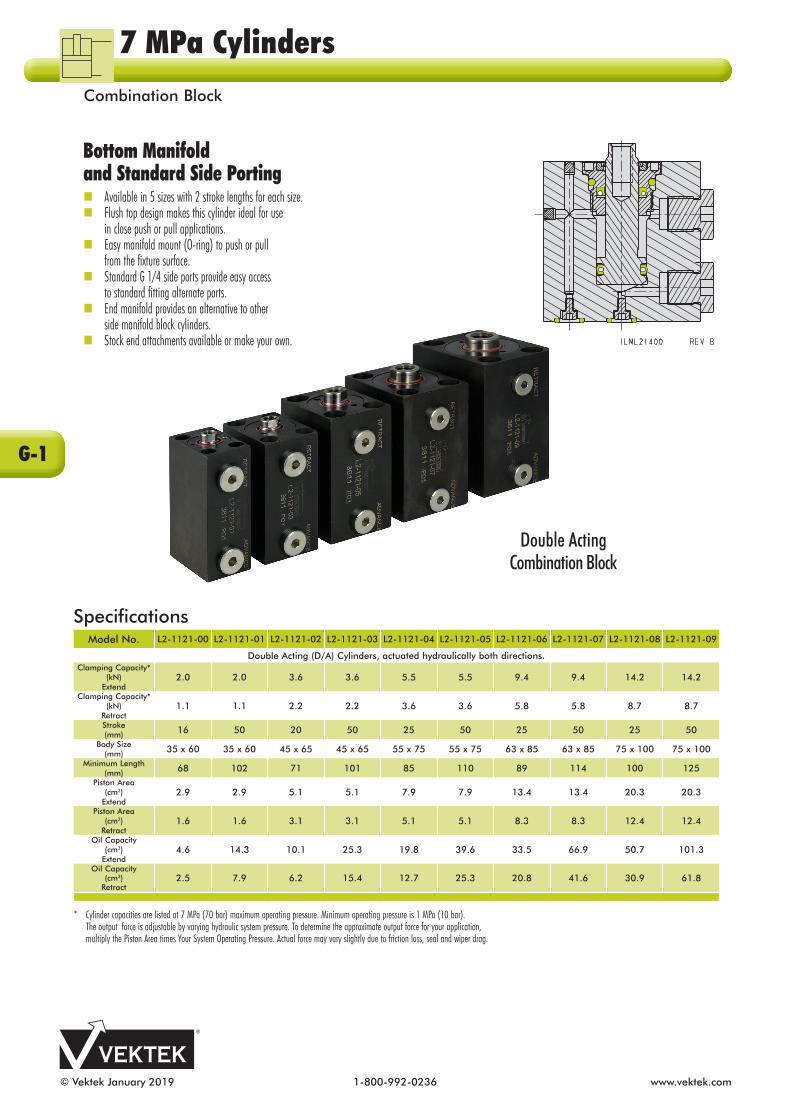
© Vektek January 2019 1-800-992-0236 www.vektek.com
Bottom Manifold and Standard Side PortingnAvailable in 5 sizes with 2 stroke lengths for each size. nFlush top design makes this cylinder ideal for use in close push or pull applications.nEasy manifold mount (O-ring) to push or pull from the fixture surface.nStandard G 1/4 side ports provide easy access to standard fitting alternate ports.nEnd manifold provides an alternative to other side manifold block cylinders. n Stock end attachments available or make your own.
Double ActingCombination Block
SpecificationsModel No. L2-1121-00 L2-1121-01 L2-1121-02 L2-1121-03 L2-1121-04 L2-1121-05 L2-1121-06 L2-1121-07 L2-1121-08 L2-1121-09
Double Acting (D/A) Cylinders, actuated hydraulically both directions.Clamping Capacity*
(kN)Extend
2.0 2.0 3.6 3.6 5.5 5.5 9.4 9.4 14.2 14.2
Clamping Capacity*(kN)
Retract1.1 1.1 2.2 2.2 3.6 3.6 5.8 5.8 8.7 8.7
Stroke (mm) 16 50 20 50 25 50 25 50 25 50
Body Size(mm) 35 x 60 35 x 60 45 x 65 45 x 65 55 x 75 55 x 75 63 x 85 63 x 85 75 x 100 75 x 100
Minimum Length(mm) 68 102 71 101 85 110 89 114 100 125
Piston Area(cm2)
Extend2.9 2.9 5.1 5.1 7.9 7.9 13.4 13.4 20.3 20.3
Piston Area(cm2)
Retract1.6 1.6 3.1 3.1 5.1 5.1 8.3 8.3 12.4 12.4
Oil Capacity(cm3)
Extend4.6 14.3 10.1 25.3 19.8 39.6 33.5 66.9 50.7 101.3
Oil Capacity(cm3)
Retract2.5 7.9 6.2 15.4 12.7 25.3 20.8 41.6 30.9 61.8
* Cylinder capacities are listed at 7 MPa (70 bar) maximum operating pressure. Minimum operating pressure is 1 MPa (10 bar). The output force is adjustable by varying hydraulic system pressure. To determine the approximate output force for your application, multiply the Piston Area times Your System Operating Pressure. Actual force may vary slightly due to friction loss, seal and wiper drag.
G-1
7 MPa CylindersCombination Block
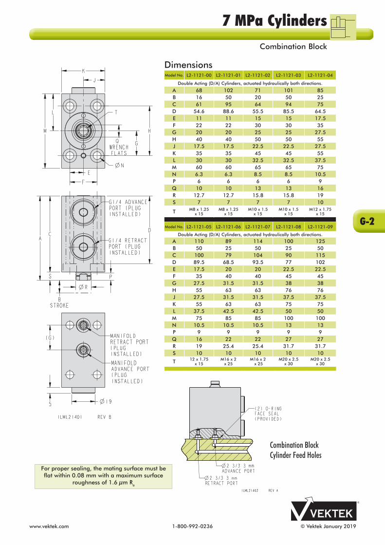
www.vektek.com 1-800-992-0236 © Vektek January 2019
DimensionsModel No. L2-1121-00 L2-1121-01 L2-1121-02 L2-1121-03 L2-1121-04
Double Acting (D/A) Cylinders, actuated hydraulically both directions.
A 68 102 71 101 85B 16 50 20 50 25C 61 95 64 94 75D 54.6 88.6 55.5 85.5 64.5E 11 11 15 15 17.5F 22 22 30 30 35G 20 20 25 25 27.5H 40 40 50 50 55J 17.5 17.5 22.5 22.5 27.5K 35 35 45 45 55L 30 30 32.5 32.5 37.5M 60 60 65 65 75N 6.3 6.3 8.5 8.5 10.5P 6 6 6 6 9Q 10 10 13 13 16R 12.7 12.7 15.8 15.8 19S 7 7 7 7 10
T M8 x 1.25 x 15
M8 x 1.25 x 15
M10 x 1.5 x 15
M10 x 1.5 x 15
M12 x 1.75 x 15
Model No. L2-1121-05 L2-1121-06 L2-1121-07 L2-1121-08 L2-1121-09
Double Acting (D/A) Cylinders, actuated hydraulically both directions.
A 110 89 114 100 125B 50 25 50 25 50C 100 79 104 90 115D 89.5 68.5 93.5 77 102E 17.5 20 20 22.5 22.5F 35 40 40 45 45G 27.5 31.5 31.5 38 38H 55 63 63 76 76J 27.5 31.5 31.5 37.5 37.5K 55 63 63 75 75L 37.5 42.5 42.5 50 50M 75 85 85 100 100N 10.5 10.5 10.5 13 13P 9 9 9 9 9Q 16 22 22 27 27R 19 25.4 25.4 31.7 31.7S 10 10 10 10 10
T 12 x 1.75 x 15
M16 x 2 x 25
M16 x 2 x 25
M20 x 2.5 x 30
M20 x 2.5 x 30
Combination Block Cylinder Feed Holes
For proper sealing, the mating surface must be flat within 0.08 mm with a maximum surface
roughness of 1.6 µm Ra
G-2
7 MPa CylindersCombination Block

© Vektek January 2019 1-800-992-0236 www.vektek.com
2X 114.3
2X 216.6 IF AS SHOWN2X 197.6 IF ONE PLATE IS ROTATED 1802X 178.5 IF BOTH PLATES ARE ROTATED 180
192
194
482102
102
18625
6.4
7.1
2X 7
ILML55220 REV A
PRESSURE GUAGE0-200 BARADJUSTABLE
AIR REGULATOR OIL LEVEL SIGHT GLASSBREATHERFILL PLUG
BREATHER LOCATIONFOR VERTICAL MOUNTINGG1/4 ADAPTER "P" PORT FAR SIDE(AS SHIPPED WITH CROSS-OVER PLATE)"B" PORT WITH PUMP MOUNTED VALVESAE 6 PORT WITHOUT ADAPTER
G1/4 ADAPTER "T" PORT FAR SIDE(AS SHIPPED WITH CROSS-OVER PLATE)"A" PORT WITH PUMP MOUNTED VALVESAE 6 PORT WITHOUT ADAPTER
FILTER FOR SHOP AIR INPUT1/4 BSPT WITH ADAPTER
1/4 NPT WITHOUT ADAPTERROTATE FILTER BOWL DOWN
FOR VERTICAL MOUNTING
CROSS-OVER PLATE FOR REMOTE VALVEREMOVE FOR CETOP 3 VALVE MOUNTINGUSING M5 X 0.8 SOCKET HEAD CAP SCREWS
AIR SAFETY VALVE690 KPa MAX AIR OUTPUT
NEW
Model No. L5-5222-00
DA Pump Ratio Hydraulic:Air 20/20:1
Mounting Options
Horizontal (as shown) Vertical (reservoir up)
Reservoir Capacity (liter)
Horizontal - 1.4 Vertical - 1.9
Air Input Min - Max (kPa) 100 - 550
Hydraulic Operating Pressure
Range (MPa)
2.0 - 10.0
Weight (kg) 10
Compact Air/Hydraulic PumpnSuitable for most single fixtures and small pallet systems operating up to 10 MPa (100 bar). nPowers either single or double acting cylinders. nProvided with cross-over plate for remote valve mounting that can be removed for direct mounting of CETOP 3 or D03 valves. nHydraulic Flow rates up to 4.4 liters per minute at 550 kPa air pressure input.nBuilt in air filter/regulator adjustable to determine hydraulic operating pressure output. nMounting hardware is included. n Noise level, 80 Db at 1 meter.
ILML55221 REV A
Compact Air/Hydraulic PumpFlow vs Pressure Chart
10 8 6 4 2 0
0 1 2 3 4 5
FLOW (LPM)
PRES
SURE
(MPa
)
7 MPa Power SuppliesCompact Air/Hydraulic Pump
H-1

www.vektek.com 1-800-992-0236 © Vektek February 2021
AccumulatorsMaintains circuit pressure while the pallet or tombstone is disconnected from the pump using a decoupler.Piston-type, inert gas precharged accumulators compensate for pallet pressure changes during machining.G 1/4 Threads.
Model No. L9-0116-05
System Operating Pressure
2 - 10 MPa (20 - 100 Bar)
Approximate Useable Volume
At Maximum System Pressure62 cm³
57
51
120
140
14
ILML101000 REV B
L9-0116-05G1/4
Model No. Line StyleL9-0116-05
ILML101102 REV B
70
0 1 2 3 4 5 6 7 8 9 100
10
20
30
40
50
60
HYDRAULIC SYSTEM OPERATING PRESSURE (MPa)ACC
UM
ULA
TOR
USE
ABL
E O
IL V
OLU
ME
(CM
³)
175.6
38.116
90.5
133.4
90.5 104.1
9.7
50.4
9.5
101.6
ILML56010 REV A
B1
SAE 6 PORT (THRU FEED TO OPPOSITE SIDEFOR D/A DEVICES)
SAE 6 PORT(ALTERNATIVEACCUMULATOR PORT)
TWO SAE 6 TO G1/4ADAPTERS (43-0000-24)INCLUDED WITH L5-6001-01
G1/4 OUTLETPRESSURE PORT
VALVE SHOWNIN CLAMPEDPOSITION.ROTATE 90 CWTO UNCLAMP
2X MACHINED FORM6 SHCS
MALE CONNECTOR(30-7727-66) PROVIDED.ORDER FEMALESEPARATELY(30-7827-66).
A1
SpecificationsModel No. Pressure
Range
AccumulatorCapacity
(cm3)L5-6001-01 3-10 MPa 62
7MPa Manual Shutoff Valve Decoupler for Single Acting SystemsThis Decoupler is a convenient, self-contained package that includes a quick connect coupling, manual shutoff valve with handle, accumulator, filter screen, pressure gauge and over-pressure relief valve.Includes auxiliary ports that can be used for double acting pallet circuits or compressed air.
Hydraulic fluid compresses the precharged inert gas across the piston during circuit pressurization. The pressurized gas provides additional fluid to the circuit to reduce pressure changes in the event of small seeps, thermal expansion or contraction while the pallet or tombstone is in the machine. • The 2 MPa (20 Bar) to 10 MPa (100 Bar) operating pressure model has a gas precharge of 1.7 MPa (17 Bar). Perform annual maintenance in accordance with the instructions provided with each accumulator. Contact Vektek for additional copies of the annual maintenance instructions or to arrange for factory performed annual maintenance.
I-1
Palletized Fixture AccessoriesAccumulator

© Vektek January 2019 1-800-992-0236 www.vektek.com
Model No. L5-6005-42
Pressure Range 3 - 10 MPa
Accumulator Capacity 62 cm³
Optional In-Line Filter
CartridgeL7-0048-81
Optional Filter Plate (For Manifold Mount
Filtration)
L7-0842-05 (Bottom A4 & B4) or
L7-0842-06 (Rear A3 & B3)
The First Complete Low Pressure Decoupling SolutionNEW
Automatic Shutoff Valve Decouplers for Single and Double Acting SystemsnDecouplers are a complete, self contained package for disconnecting a fixture from its power supply while machining.nEverything is there for you: Quick connect coupling, filters, accumulators, pilot operated check valve and over-pressure relief valve! nRobust pilot operated check valve with 1 to 5 ratio of pilot to check pressure for proven long term reliability.nInternal 25 micron filters for added protection of pilot operated check valve thru ports A1, A2, A3, A4 & C1. Additional filtration provided at port B1. (Filtration for A3, B3 or A4, B4 available by purchasing Vektek filter block L7-0842-05 or L7-0842-06 depending on mounting orientation.) See Section K.nG1/4 ports and manifold mounting (bottom and rear) connections on all models. n Single acting pallet circuits require 2 hoses to the operating handle for pressure release.
NOTE:These automatic shutoff valve decouplers and operating handle must be used with a suitable pump which includes a 4 port/3 position, P-blocked center (“A” & “B” connected to tank) directional control valve for operation of single or double acting systems. One automatic shutoff valve decoupler can be used to operate only one double acting or one single acting circuit. For operation of a single acting circuit, plug the decoupler outlet port “B” (as shown in the schematic).
For use with Operating Handle Model No. L5-6008-00.
30
77,1
73,3
63,5
88,927
27
41,4 62,3
44,557,9
117,3
5,6
32,9
4,8
31,8
54
31,557,5
4,8108
28,6
64,3
31,5
57,520,221,1
4,8
ILML56001 REV B
A4B4
C1A1B1
B2
B3 A3
DRILLED FOR M6 SHCS (3X)
"A1" QUICK CONNECTOR CLAMP"B1" QUICK CONNECTOR UNCLAMP
G1/4 MANIFOLD MOUNT PORT
DRILLED FOR M6
SHCS (4X)
G1/4 MANIFOLD PORT
SAE 6 PORT PLUG INSTALLED
G1/4 PORT ADAPTER. USE IN END PORT IF REQUIRED (SHIPPED LOOSE)
SPACER - DISCARD IF BOTTOM MANIFOLD MOUNTED. FOR FILTRATION ADD 11,4 THICK FILTER PLATE
G1/4 PORT BOTH ENDS
(WITH ADAPTER)
C1A1B1
A2B2A4B4
A3B3PLUG "B" PORT FOR S/A SYSTEMS
MINIMUM OF 20% CLAMPPRESSURE MUST BEAPPLIED TO UNCLAMP
Palletized Fixture Accessories Decouplers
I-2

www.vektek.com 1-800-992-0236 © Vektek January 2019
177
41.479.2
30.5
89.4
58.5
ILML56000 REV B
PULL BACK TRIGGER TO CONNECT AND DISCONNECT HANDLE. HYDRAULIC PRESSURE MUST BE AT 0 PSI TO CONNECT OR DISCONNECT
"B1" QUICK CONNECTOR
"UNCLAMP"
"A1" QUICK CONNECT
"CLAMP"
G1/4 PORT
One - Handed Operating HandleModel No. L5-6008-00
For use withDecouplerModel No.
L5-6005-42or
L5-6005-43
Model No. L5-6005-43
Pressure Range 3 - 10 MPa
Accumulator Capacity 62 cm³
Optional In-Line Filter
CartridgeL7-0048-81
Optional FilterPlate (For
Manifold Mount Filtration)
L7-0842-05 (Bottom A5 & B5) or
L7-0842-06 (Rear A4 & B4)
119.3
139.5
57.2
50.8
27
27
63.5
30 73.3
77.1
5.6
32.9
44.557.9
4.8
31.8
5431.5
57.5
4.8108
28.6
28.3 57.5117.3
4.8
ILML56002 REV B
C1A1B1
B2
B5 A5
B4 A4
DRILLED FORM6 SHCS (3X)
G1/4MANIFOLD
MOUNTDRILLEDFOR M6SHCS (4X)
G1/4 PORTADAPTER. USE IN END PORT IFREQUIRED.(SHIPPED LOOSE)
SAE 6PORT PLUGINSTALLED.
G1/4MANIFOLDMOUNT
G1/4 PORTBOTH ENDS(WITHADAPTER)
SPACER - DISCARD IFBOTTOM MANIFOLDMOUNTED. FORFILTRATION ADD 11,4THICK FILTER PLATE
C1A1B1
A2B2A5B5
A4B4PLUG "B" PORTFOR S/A SYSTEMS
MINIMUM OF 20%CLAMP PRESSUREMUST BE APPLIEDTO UNCLAMP
A3
B3
NOTE:These automatic shutoff valve decouplers and operating handle must be used with a suitable pump which includes a 4 port/3 position, P-blocked center (“A” & “B” connected to tank) directional control valve for operation of single or double acting systems. One automatic shutoff valve decoupler can be used to operate only one double acting or one single acting circuit. For operation of a single acting circuit, plug the decoupler outlet port “B” (as shown in the schematic).
FeaturesnMaximum working pressure - 10 MPa nProvides a fast, positive connection to the decoupler. nErgonomic design reduces operator fatigue. nThe One - Handed Handle may be used with the optional Handle Docking Module to assure the hoses are disconnected from the pallet before it is shuttled into the machine.
Pallet Decoupler Cover
Model No. A For use with Decoupler
Models
L5-6008-03 8.9 L5-6005-42, L5-6005-43
nCustomers that have previously bought a decoupler can purchase a new cover for their old decoupler. New orders of decouplers will come with cover.
ILML56011 REV A
39.4
40.6
A
ILML56011 REV A
39.4
40.6
A
100 lb. Tensile Strength
Palletized Fixture AccessoriesDecouplers
I-3

© Vektek January 2019 1-800-992-0236 www.vektek.com
Complete 2-Hand Low Pressure Decoupling SolutionNEW
Model No. L5-6005-40
Pressure Range 3 - 10 MPa
Accumulator Capacity 62 cm³
Optional In-Line Filter
CartridgeL7-0048-81
Optional FilterPlate (For
Manifold Mount Filtration)
L7-0842-05 (Bottom A4 & B4) or
L7-0842-06 (Rear A3 & B3)
For use with Operating Handle Model No. L5-6005-04.
Automatic Shutoff Valve Decouplers for Single and Double Acting SystemsnDecouplers are a complete, self contained package for disconnecting a fixture from its power supply while machining.nEverything is there for you: Quick connect coupling, filters, accumulators, pilot operated check valve and over-pressure relief valve! nRobust pilot operated check valve with 1 to 5 ratio of pilot to check pressure for proven long term reliability.nInternal 25 micron filters for added protection of pilot operated check valve thru ports A1, A2, A3, A4 & C1. Additional filtration provided at port B1. (Filtration for A3, B3 or A4, B4 available by purchasing Vektek filter block L7-0842-05 or L7-0842-06 depending on mounting orientation.)nG1/4 ports and manifold mounting (bottom and rear) connections on all models. n Single acting pallet circuits require 2 hoses to the operating handle for pressure release.
Two - Handed Operating HandleModel No. L5-6005-04
For use withDecouplerModel No.
L5-6005-40or
L5-6005-41
76.2
243.8
105.4ILML56003 REV B
"B1" UNCLAMP
QUICK COUPLER
"A1" CLAMP QUICK
COUPLER
G1/4
FeaturesnMaximum working pressure - 10 MPa nProvides a fast, positive connection to the decoupler. nErgonomic design reduces operator fatigue. nThe Two - Handed Handle may be used with the optional Handle Docking Module to assure the hoses are disconnected from the pallet before it is shuttled into the machine.
C1 A1B1
A2B2A4B4
A3B3PLUG "B" PORTFOR S/A SYSTEMS
MINIMUM OF 20%CLAMP PRESSUREMUST BE APPLIEDTO UNCLAMP
4,8
31,8
54
4,8 108
28,3
57,5
67,1
21,1
117,320,2
28,6
31,557,5
15 57,9
5,6
32,9
117,3
27
63,5
119,4
28,688,9
4,8
ILML56004 REV B
A4B4
A1C1B1 B2
B3 A3
"A1" QUICK CONNECTOR CLAMP
"B1" QUICK CONNECTOR
UNCLAMP
G1/4 MANIFOLD MOUNT
DRILLED FOR M6
SHCS (4X)
DRILLED FOR M6
SHCS (3X)
G1/4 PORT BOTH ENDS
(WITH ADAPTER)
SPACER. DISCARD IF BOTTOM MANIFOLD MOUNTED. FOR FILTRATION ADD 11,4 THICK FILTER PLATE.
SAE 6 PORT.PLUGINSTALLED.
G1/4 PORT ADAPTER. USE IN END PORT IF REQUIRED. (SHIPPED LOOSE)
See NOTE about pump requirements on next page.
Palletized Fixture Accessories Decouplers
I-4

www.vektek.com 1-800-992-0236 © Vektek January 2019
Model No. L5-6005-41
Pressure Range 3 - 10 MPa
Accumulator Capacity 62 cm³
Optional In-Line Filter
CartridgeL7-0048-81
Optional FilterPlate (For
Manifold Mount Filtration)
L7-0842-05 (Bottom A5 & B5) or
L7-0842-06 (Rear A4 & B4)
For use with Operating Handle Model No. L5-6005-04.
117.3
63.5
50.8
119.3
139.5
57.2
32.9
5.6
44.557.9
28.6
19 (8X)
4.8
28.6
31.557.5
31.557.5
108 4.8
4.8
54
31.8
2267.1
ILML56005 REV B
C1
A1B1
B5 A5
B4 A4
B2
DRILLED FOR M6 SHCS (3X)
G1/4 MANIFOLD
MOUNT
DRILLED FOR M6 SHCS (4X)
"B1" QUICK CONNECTOR
UNCLAMP
"A1" QUICK CONNECTOR
CLAMP
G1/4 PORT ADAPTER. USE IN
END PORT IF REQUIRED.
(SHIPPED LOOSE)
SAE 6 PORT. PLUG INSTALLED.
G1/4 MANIFOLD
MOUNT
SPACER - DISCARD IF BOTTOM MANIFOLD MOUNTED. FOR FILTRATION ADD 11,4 THICK
FILTER PLATE.
G1/4 PORT BOTH ENDS
(WITH ADAPTER)
C1 A1B1
A2B2A5B5
A4B4
PLUG "B" PORTFOR S/A SYSTEMS
MINIMUM OF 20%CLAMP PRESSUREMUST BE APPLIED
TO UNCLAMP
A3
B3
NOTE:These automatic shutoff valve decouplers and operating handle must be used with a suitable pump which includes a 4 port/3 position, P-blocked center (“A” & “B” connected to tank) directional control valve for operation of single or double acting systems. One automatic shutoff valve decoupler can be used to oper-ate only one double acting or one single acting circuit. For operation of a single acting circuit, plug the decoupler outlet port “B” (as shown in the schematic).
Pallet Decoupler Cover
Model No. A For use with Decoupler
Models
L5-6007-03 12.7 L5-6005-40, L5-6005-41
Also use with Decoupler with Air (next page) L5-6005-44
nCustomers that have previously bought a decoupler can purchase a new cover for their old decoupler. New orders of decouplers will come with cover.
ILML56011 REV A
39.4
40.6
A
ILML56011 REV A
39.4
40.6
A
100 lb. Tensile Strength
Palletized Fixture AccessoriesDecouplers
I-5

© Vektek January 2019 1-800-992-0236 www.vektek.com
NEW
Two-Handed Operating Handle with Air
Model No. L5-6007-01
For use withDecouplerModel No.
L5-6005-44
243.8
76.2105.4
ILML56007 REV A
G1/4
"A1"CLAMPQUICK
COUPLER
"B1"UNCLAMP
QUICKCOUPLER
PNEUMATICQUICK
COUPLER
57.2
119.3139.5
50.8
21
28.6
63.5
2727
28.3
61.6
85.828.617.2
28.3
61.6
85.8
4.8108
117.3
55.9
4.8
54
27
31.8
5.6
38.5
21
28.6
28.3
61.6
95.3
4.8
ILML56006 REV A
A2B4AIR
A4
B5AIRA5
B1
AIR
A1
"B1" QUICK CONNECTOR UNCLAMPAIR QUICK CONNECT
"A1" QUICK CONNECTOR CLAMP
4XDRILLED FORM6 SHCS
G1/4MANIFOLD
MOUNT
AIR 1/8 NPT& MANIFOLD
MOUNT
3XDRILL FORM6 SHCS
G1/4 PORTADAPTER. USEIN END PORTIF REQUIRED
(SHIPPED LOOSE)
G1/4MANIFOLD
MOUNT
AIR 1/8 NPT & MANIFOLD MOUNT
SPACER; DISCARD IF BOTTOM MANIFOLD MOUNTED. FOR FILTRATION ADD 11,4 THICK
FILTER PLATE
G1/4 PORTBOTH ENDS
(WITH ADAPTER)
Model No. L5-6005-44
Pressure Range 3 - 10 MPa
Accumulator Capacity 62 cm³
Optional In-Line Filter
CartridgeL7-0048-81
Optional FilterPlate (For
Manifold Mount Filtration)
L7-0842-05 (Bottom A5 & B4) or
L7-0842-06 (Rear A4 & B4)
For use with Operating Handle Model No. L5-6007-01
C1 A1B1
A2B2A5B5
A4B4PLUG "B" PORTFOR S/A SYSTEMS
MINIMUM OF 20%CLAMP PRESSUREMUST BE APPLIEDTO UNCLAMP
B3
A3AIR
AIR
NOTE:These automatic shutoff valve decouplers and operating handle must be used with a suitable pump which includes a 4 port/3 position, P-blocked center (“A” & “B” connected to tank) directional control valve for operation of single or double acting systems. One automatic shutoff valve decoupler can be used to operate only one double acting or one single acting circuit. For operation of a single acting circuit, plug the decoupler outlet port “B” (as shown in the schematic).
FeaturesnMaximum working pressure - 10 MPa nProvides a fast, positive connection to the decoupler. nErgonomic design reduces operator fatigue. nThe Two - Handed Handle may be used with the optional Handle Docking Module to assure the hoses are disconnected from the pallet before it is shuttled into the machine.
Palletized Fixture Accessories Decoupler with Air
I-6

www.vektek.com 1-800-992-0236 © Vektek January 2019
Approx. 2mCordset
4X 7.14 2X 90.47
2X 38.1
4X 8.7SLOT
HEIGHT
B
104.3
50.5
55.5
111
95.3
47.6
118.3
A14
16.7
ILML56008 REV A
SENSOR FEATURE: NORMALLY OPEN CONTACT LED INDICATOR LIGHT 10 TO 36 VDC OPERATING RANGE 100 mA OPERATING CURRENT
PIN 1: BROWN (+)PIN 2: WHITE (NOT CONNECTED)PIN 4: BLACK (N/O)PIN 3: BLUE (NOT CONNECTED)PIN 5: GREEN/YELLOW (NOT CONNECTED)
PROXIMITY SWITCH WIRE DIAGRAM
4 BLACK
1 BROWN
LOAD
PROXIMITY SWITCH PIN OUT:
M12 MALECONNECTION
PIN 1
PIN 4
PIN 3
PIN 2
EXTENSION CABLE PIN OUT:
M12 FEMALECONNECTION
PIN 1PIN 2
PIN 4
PIN 3
PIN 5
1/4 NPT
FEMALE M12TO PIGTAIL END
EXTENSION CABLE
GUIDE PIN WITHONE-HANDEDMODEL ONLY
MOUNTING HOLES FOR M6
BOLTS
ILML56009 REV A
POLE MOUNTINGVERTICAL MOUNTING
HORIZONTAL MOUNTING
MOUNTING HARDWARE NOT INCLUDED
Handle Docking Stationwith optional feedback sensor Docking Stations for the 1-Handed or 2-Handed Automatic Shutoff Pallet Decoupler Handle. This handy device provides a standard contamination-free location for quick-disconnect handle storage. The Handle Docking Stations have a drain pan to keep your work area free of slip and fall hazards created by dripping disconnects.
nThe optional Proximity Switch confirms the decoupler handle and hoses are connected to the docking station. The pallet can then be safely shuttled into the machine.nAdjustable five positions ensure the Docking Station is ergonomically friendly for operators.n Docking couplers are for handle retention only.nFlexible mounting allows for vertical, horizontal or pole applications. nMounting holes for M6 Diameter bolts.
20.7°
18.4°NEW
Docking StationModel No. L5-6005-28 L5-6005-29 L5-6008-01 L5-6008-02Proximity Switch No Yes No Yes
Handle Size Two - Hand Two - Hand One - Hand One - HandA Proximity
Switch Height N/A 26.3 N/A 17.3
B Dock Width 111 111 75 75
I-7
Palletized Fixture AccessoriesDocking Station

© Vektek February 2021 1-800-992-0236 www.vektek.com
PORTDEPTH
A MAX
FC
G
B
EPORT SIZE
4mm HEX
ILML70203 REV D U.S. Patent No. 11,097,389
DimensionsModel No. L4-7044-30 L4-7044-31 L4-7044-50 L4-7044-51
Factory PresetPressure (MPa)
4 7 4 7
Set PressureRange (MPa)
2 - 6 4 - 10 2 - 5.5 4 - 10
Port Size X Depth
G 1/8 X 15.16 G 1/4 X 18.72
A 28 34.5B 16 19C 20.3 27.4E 17.5 21.0F 5.6 5.0G 14 17
A B
C
ILML70205 REV B
InletPort
OutletPort
Port x Depth
NEWIn The Port Sequence ValvesnInstalls directly into device port, requires oil feed through manifold mount ports. nWorks with Top Flange, Bottom Flange Swing Clamps, Link Clamps and New High Capacity Work Supports. nControls timing of individual devices on your fixture. nEach valve can be individually adjusted from the factory preset.nTrue sequencing design allows full system pressure downstream of valve after opening. nMaintains pressure upstream while device actuates. n Two pressure ranges available with adjustability within each range.* n Can be added after the fixture is built to assure proper sequencing (Requires the use of flange manifold feed ports). nUse with single or double acting clamps; in clamp port, unclamp port, or both. nInternal reverse free flow check valve allows for faster return.nAccessories available; Pressure pre-set block and in-line adapter block.
*Number of sequences within each range depends on number of devices, pump flow & operating pressure.
Model No.
L3-3011-70
Model No.
L3-1941-00 L3-1961-00
Port X DepthG 1/8 X 15.16
G 1/4 X 18.72
Inlet/Outlet G 1/8 G 1/4A 41.3 54.0B 22.2 28.6C 22.2 25.4
Note: Max flow not to exceed the individual device rating or 3.81/min whichever is lower. Maximum inlet pressure for In The Port sequence valve is 35 MPa, excess voids warranty. Consult the double acting work support, the swing clamp, or link clamp specifications page for the valve that is appropriate for your application.
Valve Pressure Pre-Set Block
In the Port Sequence Valve In-Line Adapter Block
nPresets all G 1/4, G 1/8 and SAE 4 sequence and flow control valves.
7 MPa ValvesIn The Port
J-1

www.vektek.com 1-800-992-0236 © Vektek January 2019
7 MPa ValvesIn The Port Flow Control
AMAX
BHEX
PORTDEPTH
13C
14.5
ILML70201 REV E
PORT SIZE
E
SpecificationsModel No. L7-0203-71 L7-0203-74Port Size X Depth
G 1/8 X 15.16
G 1/4 X 18.72
A 20.7 20.9B 14 19C 11.1 11.2E 15.9 21
In The Port Precision Flow Controln Flow control requires the use of manifold mount ports.n Meter-in speed control with reverse free flow check valve.n Smallest flow control valve on the market.n Prevent component cam damage from unexpected or accidental surges in flow rate.n Adjusting screw is positively retained and will not come out under pressure.n Use in the clamps port of single and double acting Swing Clamps or Link Clamps and in double acting Work Supports.
Consult the work support, the swing clamp or link clamp specifications page for the valve that is appropriate for your application.
Flow control requires the use of manifold mounting.
Model No.
L7-0203-71L4-7044-3X
L7-0203-74L4-7044-5X
A 8.84 11.89B 15.16 18.72C 9.9 13.3E 16.5 21.5F 1/8-28 BSPP 1/4-19 BSPP
G 8.5 12.5
H 6 10
J 12.83 16.39K 7 10
In the Port Cavity Dimensions
Note: Max flow rate not to exceed the individual device rating or 3.8 l/min whichever is lower.
G +0.8 / -00THREAD DEPTH
K MAX
C 0.25 X 90
0.25 0.13
J MAX
H MIN
A 0.13THREAD MINOR
B 0.08
SPOT FACE E 0.25
90
ILML70202 REV D
THREAD FOIL INLET( 2.5 MIN)
OIL OUTLET( 2.5 MIN)
1.6
All dimensions are in millimeters. Cavity works for both Sequence Valves and Flow Control Valves.
J-2

© Vektek February 2021 1-800-992-0236 www.vektek.com
For proper sealing, the mating surface must
be flat within 0.08 mm with a maximum surface roughness of 1.6 µm Ra
* Manifold mount o-rings included. Ships with all ports plugged.** Maximum inlet pressure 10 MPa. Excess pressure voids warranty*** Duration of time delay may vary depending on the viscosity of oil in the application. If longer delays are required (up to 20 sec), contact Vektek Customer Support for assistance.
Unclamp Delay ValveModelNo.*
L7-0431-00
Set Pressure Range** 2 to 10 MPa
Time Delay Preset*** (sec)
3 to 7 seconds Using ISO 32 Fluid
Filtration Included
25 micronAll Ports
Max Flow 11.4 l/min
Crossover plate, L9-3197-00, needed whenusing as a standalone manifold mount valve.
Mounting Options
Temporarily Hold Parts During Unclampn Set delay to control unclamp in single acting devices. Use in single or double acting systems. n Eliminate workpiece movement, caused by backpressure, when unclamping over a work support.n Normally open valve allows free fluid flow through the valve during clamping.n Does not require “B” pilot line to open.n Stainless steel internal components for superior corrosion resistance.
Operation: The VektorFlo® Unclamp Delay Valve operates as a normally open element in a hydraulic clamping system. Low pressure fluid flows freely through the valve to downstream devices. As pressure in the system builds, the mechanical pilot piston moves away from the check valve allowing it to close. Full system pressure is reached and flow in the system stops. If pressure leaks off in downstream devices, the check valve will re-open and replenish pressure. During unclamping, inlet pressures falls with main system pressure but downstream pressure is held constant by the check valve. At the low inlet pressure, spring force starts to move the mechanical pilot towards the check valve at a rate set by the flow control and oil viscosity. The mechanical pilot piston moves through its stroke and encounters the check valve. Spring force opens the check to release all downstream pressure to the power unit reservoir.
27.330.6
7.7
45.3
13.947.2
17.9
37.2
62.7
88.1
104
41.3
6.7THRU2X
11.829.6
20.3
34.4
ILML70430 REV C
MANIFOLD MOUNTFEED HOLES
2.3/ 5mm
OUTLETMANIFOLDMOUNTPORT*
SEQUENCEVALVE FEEDMANIFOLDMOUNT PORT*
G1/4INLETPORT*
G1/4OUTLETPORT*
INLETMANIFOLDMOUNT PORT*
SEQUENCEVALVEFEEDMANIFOLDMOUNT PORT
7 MPa ValvesUnclamp Delay Valve
J-3

www.vektek.com 1-800-992-0236 © Vektek February 2021
Sequence Valve DimensionsModel No. L7-0412-00
Description Assembly
Set Pressure Range 2.0 MPa (20 bar) to 6.2 MPa (62 bar)
System Pressure Up to 10 MPa (100 bar)
Sequence Valve for Circuit Timing100% stainless steel valve. Construction resists corrosion which can cause other styles to "misfire".Direct acting poppet style, ad just able, cartridge type con struc tion.Cartridge may be installed directly into your manifold.Set Pressure adjustment range: 2.0 MPa (20 bar) to 6.2 MPa (62 bar).Two-port design eliminates need for third fluid line to drain bypass flow (internal leakage) back to system res er voir.True sequence design allows full system pressure downstream of valve after opening.Up to 10 MPa (100 bar) system pressure.Recommended Filtration: 25 Micron (Nom)/ 40 Micron (ABS) (min). We recommend a 1 - 1.5 MPa (10 -15 bar) spread between pressures when using multiple valves.
Operation: The VektorFlo® sequence valve operates as a pressure sensitive, normally closed element in a clamp ing system. When fluid first enters the sys tem, the valve is closed, blocking the flow of fluid to devices down stream. After devices up stream of the valve have moved into position and pressure begins to increase, the in creas ing pressure overcomes the spring force holding the valve closed, forcing the poppet off its seat, and al low ing fluid flow through the valve. After downstream devices have positioned and clamped, and downstream pressure has increased to equal upstream pressure, entire system pressure increases to the maximum level setting on the hydraulic power supply. When un clamp ing, as pressure falls, force from the adjustment spring pushes the poppet back onto its seat. Fluid trapped in the down stream circuit flows back through the check valve to return to the power unit reservoir.
Gage (Line Press)70 Bar MAX
NOTE: Maximum system flow rate is 11.4 l/m. Excess flow voids warranty.
For proper sealing, the mating surface must
be flat within 0.08 mm with a maximum surface roughness of 1.6 µm Ra
Filter Plate For above Valves
Model No.
L7-0842-03
Order a filter plate to protect valve from debris (more details on page K-2)
7 MPa ValvesSequence Valve
J-4

© Vektek February 2021 1-800-992-0236 www.vektek.com
Sequence CartridgeModel No. L7-0430-00
Description Cartridge Only
Set Pressure Range 2.0 MPa (20 bar)to 6.2 MPa (62 bar)
System Pressure Up to 10 MPa (100 bar)
NOTE: For cavity tooling (multi-step Reamer and M20 x 1.5 Tap), order kit 62-7040-00.
If a sequence valve is no longer needed, use 30-6011-20 plug, to cap cavity for free fluid pass through.
30°±5°
30°±5°
31.75±0.76
30.3 0.25
0.051 A21.39 0.1
0.051 A Minor 18.53 0.15
-A- 15.04 0.02
3±0.13
.101 A0.25 0.13
16.66±0.1345°±5°
PressureInlet
5.2 0.38
SequenceOutlet
5.2 0.38 33.02±0.25
11.88±0.25
34.9±0.25
16.76 0.13
ILML70402 REV C
0.101 A
Thread M20 X 1.5 11.3 Min.0.051 A
12.7 0.25
1.6
1.6
7 MPa ValvesSequence Valve
J-5

www.vektek.com 1-800-992-0236 © Vektek February 2021
* M8 ports are counterbored for o-rings that are used in manifold mounting applications Ø2.29/3.30 feed holes
Efficient Space Saving Combination Sequence/PRV Block Control both timing and pressure with this dual purpose combination block.Common inlet port feeds both sequence and reducing valves.Use with single or double acting devices.Block includes standard Sequence and PRV cartridges.Direct acting poppet style valve construction.Sequence pressure adjustment range: 2.0 to 6.2 MPa (20 to 62 bar), PRV adjustment range: 1.0 - 6.2 MPa (10 to 62 bar).Elements spaced to accommodate Gauge for setup or trouble shooting.Recommended Filtration: 25 Mi cron (NOM) / 40 Micron (ABS) (mini mum).
For proper sealing, the mating surface must be flat within 0.08 mm with a maximum
surface roughness of 1.6 µm Ra
Combination SEQ/PRVAssembly Model L7-0818-01
SEQ Valve L7-0430-00
SEQ Valve Set Pressure Range 2.0 - 6.2 MPa
PRV Model L7-0530-00
PRV Set Pressure Range 1.0 - 6.2 MPaILML709410
NOTE: Maximum system flow rate is 5.7 l/m unless otherwise noted. Excess flow voids warranty.
7 MPa ValvesCombination Sequence/PRV Block
J-6
Filter Plate For above Valves
Model No.
L7-0842-01
Order a filter plate to protect valve from debris (more details on page K-2)

© Vektek February 2021 1-800-992-0236 www.vektek.com
Pressure Reducing Valve for Circuit Pressure ControlFor use in double or single acting systems.Direct acting, poppet style, adjustable, cartridge construction. Cartridge can be installed di rectly into your manifold.Set Range from 1 MPa (10 bar) to 6.2 MPa (62 bar) recommended.Repeatability is +/- 10% of set pressure.Maximum inlet pressure 20 MPa (200 bar). Two-port design eliminates need for third fluid line to drain bypass flow (internal leakage) back to system reservoir. Recommended filtration: 25 Micron (Nom) / 40 Micron (ABS) (min.)
Operation: The Pressure Reducing Valve (PRV) is a Normally Open (N/O) pressure control device. The valve remains open and fluid flows freely to downstream devices (from the valve to devices) until the pressure in the valve reaches the pressure (adjustable) set-point. At the set-point pressure, the valve closes, blocking further flow and pressure rise to the downstream devices. If there is a sufficient down-stream pressure loss (from the valve to devices), the PRV will re-open, allowing flow to pass through the valve until the pressure again reaches the valve set-point. The PRV is designed for use in both single acting and double acting systems.
For proper sealing, the mating surface must be flat within 0.08 mm with a
maximum surface roughness of 1.6 µm Ra
NOTE: Maximum system flow rate is 5.7 l/m, unless otherwise noted. Excess flow voids warranty.
Pressure Reducing Valve (PRV)Model No. L7-0512-00Description Assembly
Set Pressure Range 1.0 MPa (10 bar) to 6.2 MPa (62 bar)
System Pressure 20 MPa (200 bar)ILML70500
The graphs show the repeat range based on set pressure
The graphs show the pressure drop through a PRV and manifold mount block
ILML705405 REV A
0
1
2
3
4
5
6
7
0 2 4 6
Pres
sure
Diff
eren
tial (
MPa
)
Flow (l/m)
Pressure Drop vs Flow
ILML705406 REV A
0
1
2
3
4
5
6
7
0 1 2 3 4 5 6 7Rep
eat P
ress
ure
Ran
ge (
MPa
)
Set Pressure (MPa)
7 MPa ValvesPressure Reducing Valve
J-7
Filter Plate For above Valves
Model No.
L7-0842-02
Order a filter plate to protect valve from debris (more details on page K-2)

www.vektek.com 1-800-992-0236 © Vektek January 2019
PRV CartridgeModel No. L7-0530-00
Description Cartridge
Set Pressure Range 1.0 MPa (10 bar) to 6.2 MPa (62 bar)
System Pressure 20 MPa (200 bar)
NOTE: For cavity tooling (multi-step Reamer), order kit 62-7050-00.
30°±5°
S.F.31 1
0.051 A24 0.1
0.051 A20.55 0.14
14.3
2.54±0.13
DP S.F.0.25 0.13
21.69±0.2537±0.76
0.101 A
30°±5°
45°±5°
Min 5.1PressureReducedOutlet
PresureSupplyInlet
5.1 0.4
38.4±0.76
19.55±0.25
35.5 0.76
45°
-A-15.9 0.025
1.6
R0.76
ILML70502 REV B
M22x1.5-6h TAP 15.75 MIN DP
0.101 A
0.051 A
1.6
7 MPa ValvesPressure Reducing Cartridge Dimensions
J-8

© Vektek January 2019 1-800-992-0236 www.vektek.com
In-Line Flow ControlModel No. L7-0200-14
Port A G 1/4Port B G 1/4
Precision Flow Control Valven Precision flow adjustment with 0.4 mm pitch needle valve.n Protect sensitive components from excessive flow.n For single component or system control.nFlow controls used as meter-in devices in clamping systems to prevent damage.n Flows up to 11.3 l/min at 350 bar (35 MPa) maximum pressure.nCheck valve for reverse free flow.nStainless steel inner valve construction.n Fluorocarbon seals are standard.nLocking adjustment knob preventing change in flow.
7 MPa ValvesIn-Line Flow Control
J-9

www.vektek.com 1-800-992-0236 © Vektek January 2019
1022X 13
2X 7
217.5
82.8184.2
ILML50800 REV A
PRESSURE REGULATORFLOW CONTROL
PRESSURE SWITCH
M12, 5 PIN MALECONNECTION
1/4 BSPT FEMALE INPUT1/4 NPT WITHOUT
ADAPTER
1/4 BSPT OUTPUT1/4 NPT WITHOUTADAPTER
AIR HOSE, 4.6 MPRESSURE GAUGE
0-200 KPa AIR FILTERAUTOMATIC DRAIN
M12 CABLE5 M
Protect Your Low Pressure Devices running within a High Pressure System
n Valve cartridge will open to bleed off excess pressure in the event of over-pressurization.n Screw in valve cartridge adds an extra element of insurance in systems where you must use a pressure sensitive device.n G1/4 male connection. nValve cartridge has a tamper proof plug.n Leak-free operation before and after reseat condition. nThe only valve cartridge designed to bleed off excess pressure and re-seat at approximately 80% of set point.
n Adjustable air pressure and flow gives you the ability to monitor most confirmation valves, part present or clamp position systems.n Easy electronic pressure switch adjustment with 2 PNP* digital set points and 1 analog output to meet your specific needs.n Can be used with Pallet Decouplers, Pneumatic Confirmation Valves, Part Present Sensing Work Supports or self-made part location orifices.n Comes as a ready-to-use kit with everything you need to feed back a confirmation signal of your choice!
NEW
NEW
Air Sensing Control KitModel No. L5-0824-00
Max Air Pressure(kPa) 1379
OperatingPressure Range (kPa) 0-172
Max AirFlow Rate CM/H 20
FiltrationElement (micron) 5
PowerSupply (VDC) 15-32
PowerConsumption (mA) 50
2 DigitalContacts
N/O orN/C
1 AnalogOutput
0-10Vor
4-20 mA
Model No. L7-0638-71-02 L7-0638-71-03 L7-0638-71-04 L7-0638-71-05 L7-0638-71-06
Set Point (MPa) 2 3 4 5 6A (mm) 47 47 47 47 47
Model No. L7-0638-71-07 L7-0638-71-08 L7-0638-71-09 L7-0638-71-10
Set Point (MPa) 7 8 9 10A (mm) 47 47 47 47
A19
ILML70630 REV B
OVER PRESSURE RELIEF HOLE
G 1/4
* For NPN applications order signal converter cable 27-8420-00.
Air Sensing Control Kit for Pneumatic Confirmation Systems
J-10
7 MPa Valves

© Vektek January 2019 1-800-992-0236 www.vektek.com
NOTE: Mounting hardware not included.
Confirm Clamp Stroke Position Pneumatically The pneumatic confirmation valve confirms the stage of loading before or after clamping. It is adaptable to multiple devices including: swing clamps, link clamps, cylinders and supports. Avoid machine crashes by confirming specific actions before you cycle your machine. It is designed to be used in both coolant and dry environments, and is easily mounted either vertically or horizontally. Confirmation at its finest!nEasily fine tune to your fixture giving you a choice of set and differential pressure.nConfirm signal is based on restricting air flow when tested function is present.nOver-travel sensing will reopen if a device depresses plunger too far on over travel models.n Pneumatic Confirmation Valve can be used with almost any clamping device.nCan help you detect missing or misloaded parts.nRemote venting recommended in coolant applications.
For proper sealing, the mating surface must be flat within 0.08 mm with a maximum surface roughness of 1.6 µm Ra
ILML504087 REV B
Max. 8 Valves
Air PressureSensor Switch
Gauge
Air Supply
Air Pressure Regulator Flow Control Valve
Air Sensing Control Kit 50-8240-00
Application Setup:Adjust actuator 0.64± 0.5 abovevalve body with clamp positionedat the bottom of clamping stroke.THIS WILL AVOID VALVE AND ACTUATOR DAMAGE IF CLAMP OVER TRAVELS.
Pneumatic Confirmation Valve Block Style
Model No. L5-0485-00 L5-0485-01
DescriptionOver-Travel
SensingStandard
Max Air Pressure(bar) 10 10
Operating Pressure Range(bar)
0.70 - 4.80 0.70 - 4.80
Air Flow Rate (L/Min) 10 - 20 10 - 20
Differential Pressure*
@1.4 bar Air
PressureMin. 0.8 Min. 0.8
@4.8 bar Air
PressureMin. 3.1 Min. 3.1
Plunger Stroke(mm) 10 Max 10 Max
Spring (N) 6.6 - 13.3 6.6 - 13.3
Feed Port Nominal Diameter
(mm)2 2
Port TypesManifold and M3
Manifold and M3
* Pressure drop when one or more valves open. All valves must be closed for pressure confirmation. Plumb multiple valves in parallel.
29.8
8
6.3
4.5
15.97
31.822
35.8
32.9
22
5.3
2X 9.5
2X 4.7
2X 1.4
50.6
1.7 STROKEAIR FLOWSBOTH MODELS
7.3 STROKENO AIR FLOWSL5-0485-00
8.5 STROKENO AIR FLOWSL5-0485-01
1.2 STROKEAIR FLOWSL5-0485-00
10.2TOTAL
STROKE
ILML504085 REV C
E PortM3 Plug
A PortM3 Plug
M3x.5-6H
M3
NOTE: MOUNTING HARDWARE NOT INCLUDEDE = INPUTA = OUTPUT (VENT TO ATMOSPHERE)A
E
ILML504088 REV B
L5-04X5-01 Standard
L5-04X5-00 Over Travel Sensing
ON
OFF
Swing Stroke Clamping Stroke
Valve Stroke 10.16
2.00 8.25
CLAMPED
Transi�on Range
Swing Clamp Stroke Example
8.90
CLAMPED ON
OFF
Swing Clamp Stroke Example
Swing Stroke Clamping Stroke
Valve Stroke 10.16 2.00
Transi�on Range
nPurchase Vektek Air Sensing Control Kit (Model # 50-8240-00)
7 MPa ValvesPneumatic Confirmation Valve
J-11

www.vektek.com 1-800-992-0236 © Vektek January 2019
Pneumatic Confirmation Valve Cartridge Style
Model No. L5-0495-00 L5-0495-01
DescriptionOver-Travel
SensingStandard
Max Air Pressure(kPa) 1000 1000
Operating Pressure Range(kPa)
70-480 70-480
Air Flow Rate (L/Min) 10 - 20 10 - 20
Differential Pressure*
@140 kPa Air
Pressure80 Min. 80 Min.
@480 kPa Air
Pressure310 Min. 310 Min.
Plunger Stroke(mm) 10 10
Spring (N) 6.6 - 13.3 6.6 - 13.3
Feed Port Nominal Diameter
(mm)2 2
Max Torque(Nm) 25 25
* Pressure drop when one or more valves open. All valves must be closed for pressure confirmation. Plumb multiple valves in parallel.
20.00
.51 .12
4.00
13.00
45
17.50 .12
5.61 .12
23.00 .12
2.80 MAXINLET PORT
13.00
2.70
2.0 MAXOUTLET PORT
50
ILML504097 REV B
M12 X 1.5 6H
Outlet portallowable to connectat any angle tothese surfaces
Inlet portallowable to connectat angle tothese surfaces
32
32
17.3
26.06.3
10.2TOTAL
STROKE
17 HEX
18.9
9.3
1.7
R.5
1.7 STROKEAIR FLOWSBOTH MODELS
7.3 STROKENO AIR FLOWSL5-0495-00
1.2 STROKEAIR FLOWSL5-0495-00
8.5 STROKENO AIR FLOWSL5-0495-01
ILML504096 REV B
RETURN SPRING
O-RING
M3 X 0.5-6H
M12 X 1.5 6H
REV C
7 MPa ValvesPneumatic Confirmation Valve
J-12

© Vektek January 2019 1-800-992-0236 www.vektek.com
In-line Filter nAvailable in 2 filter ratings; 10 and 25 Micron.nFilters up to 35 MPa in either flow direction.nCompact in-line design for maximum flexibility.nProtect sensitive valves and devices.nServiceable for cleaning or filter replacement.nMaximum flow of 11.3 l/m.n Maximum ambient temperature of 93° C.
In-line FiltersModel No. L7-0048-80 L7-0048-81
A G 1/4 G 1/4B G 1/4 G 1/4C 10 Micron 25 MicronD 19 19E 22.2 22.2F 18.8 18.8G 25.4 25.4H 11.9 11.9
Spherical Contact PointsModel No. L4-2106-00 L4-2108-00 L4-2110-00 L4-2112-00 L4-2116-00 L4-2120-00
A M6 X 1.00 M8 X 1.25 M10 X 1.5 M12 X 1.75 M16 X 2 M20 X 2.5B 9 10 12 15 20 25C 8 8 10 10 10 10D 17 18 22 25 30 35E 10 13 17 19 24 30F 12 16 22 25 50 60
Contact points are through hardened to Rc 46-50
Spherical Contact Points
DHEX
9
G3
2H
EF
PORT A
FILTER CNOMINAL
PORT B
20
15
10
5
00 2 4 6 8 10 12
FLOW (LPM)
L7-0048-80
L7-0048-81
PRES
SURE
DRO
P (MP
a)
7 MPa AccessoriesIn-line Filters and Spherical Contact Points
K-1

www.vektek.com 1-800-992-0236 © Vektek January 2019
Standard GaugeModel No. L7-2212-00
Pressure Range0 -10 MPa (100 bar)
Fully Positionable and Re-adjustable G 1/4Ported Gauges360° adjustable mounting for perfect orientation.Install directly into any G 1/4 port, no special port required.No one time use crush rings, no tapered fittings or sealing tape needed.Reusable O-ring seal.Liquid filled analog gauge.ANSI standard B40. 1 Grade B Liquid filled.Safety Glass window.
Back Mount GaugeModel No. L7-2222-00 L7-2122-00
Pressure Range
0 -10 MPa (100 bar)
0 -10 MPa (100 bar)
A 70 42.2B 52 47.2C 33.5 28
First Ever
Model No. L7-0842-01 L7-0842-02 L7-0842-03 L7-0842-05 L7-0842-06
Valve Type
Combination Sequence & Pressure
Reducing Valve
Pressure Reducing
Valve
Sequence Valve
Pallet Decoupler
Bottom Mount
Pallet Decoupler
Rear Mount
Use With Model No. L7-0818-01 L7-0512-00 L7-0412-00
L5-6005-40 L5-6005-41 L5-6005-42 L5-6005-43 L5-6005-44
L5-6005-40 L5-6005-41 L5-6005-42 L5-6005-43 L5-6005-44
A (mm) 12 12 12 18 18
Compact sandwich subplate design adds only 11.4 mm to the device height. Filter Plate dimensions match the mating product footprint. (See mating product catalog specifications)25 micron filters are easily replaceable.Service kits available for easy and simple maintenance.
Subplate isolation filters to protect your valves from debris and contaminationNEW!
11.4
AMANIFOLD MOUNT O-RINGINSIDE DIAMETER
ILML708403 REV A
MANIFOLD MOUNTED FILTER PLATE WITH25 MICRON FILTERS
FIXTURE
SHOWN WITH SEQUENCE VALVEAS AN EXAMPLE
72.4
57.9 B.C.
43.4
ILML720000 REV A
48.32X M6 CapscrewMounting Holes
Coolant DrainBoth Sides
Model No.
L7-2000-00For use with gauge L7-2122-00
* Gauge Protector is available for this gauge ask for details. Model No. 47-2000-00.
7 MPa Accessories
K-2
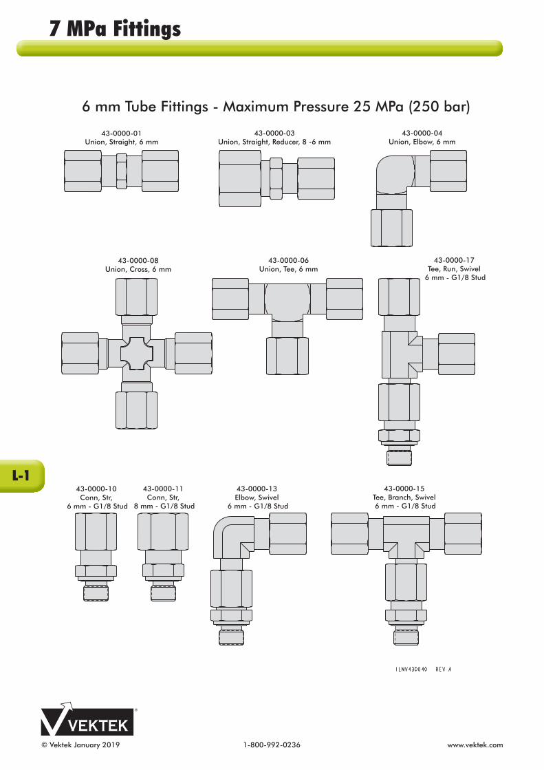
© Vektek January 2019 1-800-992-0236 www.vektek.com
6 mm Tube Fittings - Maximum Pressure 25 MPa (250 bar)
43-0000-03Union, Straight, Reducer, 8 -6 mm
43-0000-04Union, Elbow, 6 mm
43-0000-08Union, Cross, 6 mm
43-0000-06Union, Tee, 6 mm
43-0000-17Tee, Run, Swivel
6 mm - G1/8 Stud
43-0000-10Conn, Str,
6 mm - G1/8 Stud
43-0000-11Conn, Str,
8 mm - G1/8 Stud
43-0000-13Elbow, Swivel
6 mm - G1/8 Stud
43-0000-15Tee, Branch, Swivel 6 mm - G1/8 Stud
43-0000-01Union, Straight, 6 mm
7 MPa Fittings
L-1

www.vektek.com 1-800-992-0236 © Vektek January 2019
8 mm Tube Fittings - Maximum Pressure 35 MPa (350 bar)
43-0000-18Tee, Run, Swivel,
8 mm - G1/4 Stud
43-0000-14Elbow, Swivel,
8 mm - G1/4 Stud
43-0000-12Conn, Str,
8 mm - G1/4 Stud
43-0000-02Union, Straight, 8 mm
43-0000-05Union, Elbow, 8 mm
43-0000-07Union, Tee, 8 mm
43-0000-16Tee, Branch, Swivel,8 mm - G1/4 Stud
43-0000-09Union, Cross, 8 mm
7 MPa Fittings
L-2

© Vektek January 2019 1-800-992-0236 www.vektek.com
30-8782-44Male G1/8 - Female SAE 4
30-8782-64Male G1/4 -Female SAE 4
43-0000-25Nut, Tube, 6mm
43-0000-26Nut, Tube, 8mm
43-0000-27Ring, Cutting
6mm
43-0000-28Ring, Cutting
8mm
43-0680-04Plug, Port
G1/8
43-0680-06Plug, Port
G1/4
43-0000-31Seal, Elastomeric
G1/8
43-0000-32Seal, Elastomeric
G1/4
43-0000-29Plug, BlankingTube, 6 mm
43-0000-30Plug, BlankingTube, 8 mm
39-0550-06Seal, Bonded
G 1/8
39-0500-05Seal, Bonded
G 1/4
43-0000-19Adapter, Reducer
Male G1/8 - Female G1/4
43-0000-20Adapter
Male G1/4 - Female 1/4 NPT
43-0000-21Extender
Male G1/4 - Female G1/4 x 35mm
43-0000-22Extender
Male G1/4 - Female G1/4 x 59mm
43-0000-23Adapter
Male SAE 4 - Female G 1/8
43-0000-24Adapter
Male SAE 6- Female G1/4
ELASTOMERIC SEAL ISDESIGNED TO BE USEDON FITTING WHICHHAS A SEAL GROOVEAS SHOWN
BONDED SEAL ISDESIGNED TO BEUSED ON FITTINGWHICH HAS NOSEAL GROOVEAS SHOWN
ILMV307700 REV A
30-7827-66 Female Quick Connector
30-7727-66 Male Quick Connector
7 MPa Fittings
L-3

www.vektek.com 1-800-992-0236 © Vektek January 2019
SRV SR V R
U
SL
D
First-angleprojection DIN
Symbol
D
SRV SL V SR R
U
Third-angleprojection (ANSI/USA)
Symbol
D
D
First Angle Projection DINLocation of other views in
relation to front elevation VD Plan View Below V
SL Side elevation from left To the right of V
SR Side elevation from right To the left of V
U View from below Above V
R Rear View To the left or right of V
Length Conversion FactorsLength mm inch1 inch 25.4 11 mm 1 0.0393
Force Conversion Factors
Pressure MPa (Megapascal) bar psi
(lbs/sq. in)
1 MPa 1 10 145.041 bar 0.1 1 14.5041 psi 0.00689 0.0689 1
Temperature
Pressure K (Kelvin)
ºC (Celsius)
ºF (Fahrenheit)
K 1 ºC + 273.15 (ºF-459.67) x 5/9ºC K-273.15 1 (ºF-32) x 5/9ºF K x 9/5 +459.67 ºC x 9/5 + 32 1
Third Angle Projection ANSI/USA
Location of other views in relation to front elevation V
D Plan View Above V
SL Side elevation from left To the left of V
SR Side elevation from right
To the right of V
U View from below Below V
R Rear View To the left or right of V
7 MPa Conversion and Drawing Information

© Vektek February 2021 1-800-992-0236 www.vektek.com
30-7727-66 ...................L-330-7827-66 ...................L-330-8782-44 ...................L-330-8782-64 ...................L-339-0500-05 ..................L-339-0510-91 ................. B-239-0511-08 ................. B-239-0511-18 ................. B-239-0550-06 ..................L-343-0000-01 ..................L-143-0000-02 .................. L-243-0000-03 ..................L-143-0000-04 ..................L-143-0000-05 .................. L-243-0000-06 ..................L-143-0000-07 .................. L-243-0000-08 ..................L-143-0000-09 .................. L-243-0000-10 ..................L-143-0000-11 ..................L-143-0000-12 .................. L-243-0000-13 ..................L-143-0000-14 .................. L-243-0000-15 ..................L-143-0000-16 .................. L-243-0000-17 ..................L-143-0000-18 .................. L-243-0000-19 ..................L-343-0000-20 ..................L-343-0000-21 ..................L-343-0000-22 ...................L-343-0000-23 ...................L-343-0000-24 ...................L-343-0000-25 ...................L-343-0000-26 ...................L-343-0000-27 ...................L-343-0000-28 ...................L-343-0000-29 ...................L-343-0000-30 ..................L-343-0000-31 ..................L-343-0000-32 ..................L-343-0680-04 ..................L-343-0680-06 ..................L-3L1-0115-00-H .............. B-3L1-0115-00-L ............... B-3L1-0116-00-H .............. B-3L1-0116-00-L ............... B-3L1-0120-00-H .............. B-3L1-0120-00-L ............... B-3L1-0122-00-H ............... B-3L1-0122-00-L ................ B-3L1-0215-00-H .............. B-5L1-0215-00-L ............... B-5L1-0216-00-H .............. B-5L1-0216-00-L ............... B-5L1-0220-00-H .............. B-5L1-0220-00-L ............... B-5L1-0222-00-H ............... B-5L1-0222-00-L ................ B-5L1-0310-00-H ............ B-11L1-0310-00-L ............. B-11L1-0312-00-H ............. B-11L1-0312-00-L .............. B-11L1-0315-00-H ............ B-11
L1-0315-00-L ............. B-11L1-0316-00-H ............ B-11L1-0316-00-L ............. B-11L1-0410-00-H ............ B-13L1-0410-00-L ............. B-13L1-0412-00-H ............. B-13L1-0412-00-L .............. B-13L1-0415-00-H ............ B-13L1-0415-00-L ............. B-13L1-0416-00-H ............ B-13L1-0416-00-L ............. B-13L1-0510-00-H .............. B-7L1-0510-00-L ............... B-7L1-0512-00-H ............... B-7L1-0512-00-L ................ B-7L1-0515-00-H .............. B-7L1-0515-00-L ............... B-7L1-0516-00-H .............. B-7L1-0516-00-L ............... B-7L1-0610-00-H .............. B-9L1-0610-00-L ............... B-9L1-0612-00-H ............... B-9L1-0612-00-L ................ B-9L1-0615-00-H .............. B-9L1-0615-00-L ............... B-9L1-0616-00-H .............. B-9L1-0616-00-L ............... B-9L1-4025-00-L ...............C-3L1-4025-00-R ...............C-3L1-4025-00-S ...............C-3L1-4025-10-L-0.............C-7L1-4025-10-L-90...........C-7L1-4025-10-R-0 ............C-7L1-4025-10-R-90 ..........C-7L1-4025-10-S-0 ............C-7L1-4025-10-S-90 ..........C-7L1-4032-00-L ................C-3L1-4032-00-R ...............C-3L1-4032-00-S ...............C-3L1-4032-10-L-0 .............C-7L1-4032-10-L-90 ...........C-7L1-4032-10-R-0 ............C-7L1-4032-10-R-90 ..........C-7L1-4032-10-S-0 ............C-7L1-4032-10-S-90 ..........C-7L1-4040-00-L ...............C-3L1-4040-00-R ...............C-3L1-4040-00-S ...............C-3L1-4040-10-L-0 ............C-7L1-4040-10-L-90 ..........C-7L1-4040-10-R-0 ............C-7L1-4040-10-R-90 ..........C-7L1-4040-10-S-0 ............C-7L1-4040-10-S-90 ..........C-7L1-4050-00-L ...............C-3L1-4050-00-R ...............C-3L1-4050-00-S ...............C-3L1-4050-10-L-0 ............C-7L1-4050-10-L-90 ..........C-7L1-4050-10-R-0 ............C-7L1-4050-10-R-90 ..........C-7L1-4050-10-S-0 ............C-7L1-4050-10-S-90 ..........C-7L1-4063-00-L ...............C-3
L1-4063-00-R ...............C-3L1-4063-00-S ...............C-3L1-4063-10-L-0 ............C-7L1-4063-10-L-90 ..........C-7L1-4063-10-R-0 ............C-7L1-4063-10-R-90 ..........C-7L1-4063-10-S-0 ............C-7L1-4063-10-S-90 ..........C-7L1-4080-00-L ...............C-3L1-4080-00-R ...............C-3L1-4080-00-S ...............C-3L1-4080-10-L-0 ............C-7L1-4080-10-L-90 ..........C-7L1-4080-10-R-0 ............C-7L1-4080-10-R-90 ..........C-7L1-4080-10-S-0 ............C-7L1-4080-10-S-90 ..........C-7L1-4125-00-L ...............C-5L1-4125-00-R ...............C-5L1-4125-00-S ...............C-5L1-4125-10-L-0 ............C-9L1-4125-10-L-90 ..........C-9L1-4125-10-R-0 ............C-9L1-4125-10-R-90 ..........C-9L1-4125-10-S-0 ............C-9L1-4125-10-S-90 ..........C-9L1-4132-00-L ................C-5L1-4132-00-R ...............C-5L1-4132-00-S ...............C-5L1-4132-10-L-0 .............C-9L1-4132-10-L-90 ...........C-9L1-4132-10-R-0 ............C-9L1-4132-10-R-90 ..........C-9L1-4132-10-S-0 ............C-9L1-4132-10-S-90 ..........C-9L1-4140-00-L ...............C-5L1-4140-00-R ...............C-5L1-4140-00-S ...............C-5L1-4140-10-L-0 ............C-9L1-4140-10-L-90 ..........C-9L1-4140-10-R-0 ............C-9L1-4140-10-R-90 ..........C-9L1-4140-10-S-0 ............C-9L1-4140-10-S-90 ..........C-9L1-4150-00-L ...............C-5L1-4150-00-R ...............C-5L1-4150-00-S ...............C-5L1-4150-10-L-0 ............C-9L1-4150-10-L-90 ..........C-9L1-4150-10-R-0 ............C-9L1-4150-10-R-90 ..........C-9L1-4150-10-S-0 ............C-9L1-4150-10-S-90 ..........C-9L1-4163-00-L ...............C-5L1-4163-00-R ...............C-5L1-4163-00-S ...............C-5L1-4163-10-L-0 ............C-9L1-4163-10-L-90 ..........C-9L1-4163-10-R-0 ............C-9L1-4163-10-R-90 ..........C-9L1-4163-10-S-0 ............C-9L1-4163-10-S-90 ..........C-9L1-4180-00-L ...............C-5L1-4180-00-R ...............C-5
L1-4180-00-S ...............C-5L1-4180-10-L-0 ............C-9L1-4180-10-L-90 ..........C-9L1-4180-10-R-0 ............C-9L1-4180-10-R-90 ..........C-9L1-4180-10-S-0 ............C-9L1-4180-10-S-90 ..........C-9L1-4925-30 ................C-11L1-4925-45 ................C-11L1-4925-60 ................C-11L1-4932-30 ................C-11L1-4932-45 ................C-11L1-4932-60 ................C-11L1-4940-30 ................C-11L1-4940-45 ................C-11L1-4940-60 ................C-11L1-4950-30 ................C-11L1-4950-45 ................C-11L1-4950-60 ................C-11L1-4963-30 ................C-11L1-4963-45 ................C-11L1-4963-60 ................C-11L1-4980-30 ................C-11L1-4980-45 ................C-11L1-4980-60 ................C-11L1-6025-00 ...................E-2L1-6032-00 ...................E-2L1-6040-00 ...................E-2L1-6050-00 ...................E-2L1-6063-00 ...................E-2L2-1121-00 ................. G-1L2-1121-01 ................. G-1L2-1121-02 ................. G-1L2-1121-03 ................. G-1L2-1121-04 ................. G-1L2-1121-05 ................. G-1L2-1121-06 ................. G-1L2-1121-07 ................. G-1L2-1121-08 ................. G-1L2-1121-09 ................. G-1L3-1941-00 ...................J-1L3-1961-00 ...................J-1L3-3011-70 ...................J-1L4-2106-00 .................. K-1L4-2108-00 .................. K-1L4-2110-00 .................. K-1L4-2112-00 .................. K-1L4-2116-00 .................. K-1L4-2120-00 .................. K-1L4-7044-30 ...................J-1L4-7044-31 ...................J-1L4-7044-50 ...................J-1L4-7044-51 ...................J-1L5-0485-00 .................J-11L5-0485-01 .................J-11L5-0495-00 .................J-12L5-0495-01 .................J-12L5-0824-00 ................... J-2L5-5222-00...................H-1L5-6001-01....................I-1L5-6005-04 ................... I-5L5-6005-28 ................... I-7L5-6005-29 ................... I-7L5-6005-40 ................... I-4
7 MPa Model Number Index
Model No. Page Model No. Page Model No. Page Model No. Page

www.vektek.com 1-800-992-0236 © Vektek February 2021
L5-6005-41 ................... I-5L5-6005-42 ................... I-2L5-6005-43 ................... I-3L5-6005-44 ................... I-6L5-6007-01 ................... I-6L5-6008-00 ................... I-3L5-6008-01 ................... I-7L5-6008-02 ................... I-7L7-0048-80 .................. K-1L7-0048-81 ................... I-2L7-0200-14 ...................J-9L7-0203-71 .................... J-2L7-0203-74 .................... J-2L7-0412-00 ...................J-4L7-0430-00 ...................J-5L7-0431-00 ...................J-3L7-0512-00 ...................J-7L7-0530-00 ...................J-6L7-0638-71-02 .............. J-2L7-0638-71-03 .............. J-2L7-0638-71-04 .............. J-2L7-0638-71-05 .............. J-2L7-0638-71-06 .............. J-2L7-0638-71-07 ............... J-2L7-0638-71-08 .............. J-2L7-0638-71-09 .............. J-2L7-0638-71-10 .............. J-2L7-0818-01 ...................J-6L7-0842-01 ................... K-2L7-0842-02 ................... K-2L7-0842-03 ................... K-2L7-0842-04 ................... K-2L7-0842-05 .................... I-2L7-0842-06 .................... I-2L7-2122-00 ................... K-2L7-2212-00 ................... K-2L7-2222-00 ................... K-2L9-0116-05 ................... I-1L9-1425-00 ..................D-2L9-1425-01 ..................D-2L9-1425-02 ..................D-2L9-1425-03 ..................D-6L9-1432-00 ..................D-2L9-1432-01 ..................D-2L9-1432-02 ..................D-2L9-1432-03 ..................D-6L9-1440-00 ..................D-2L9-1440-01 ..................D-2L9-1440-02 ..................D-2L9-1440-03 ..................D-6L9-1450-00 ..................D-2L9-1450-01 ..................D-2L9-1450-02 ..................D-2L9-1450-03 ..................D-6L9-1463-00 ..................D-2L9-1463-01 ..................D-2L9-1463-02 ..................D-2L9-1463-03 ..................D-6L9-1480-00 ..................D-2L9-1480-01 ..................D-2L9-1480-02 ..................D-2L9-1480-03 ..................D-6L9-1625-01 .................. F-1L9-1625-02 .................. F-1
L9-1625-03 .................. F-1L9-1632-01 .................. F-1L9-1632-02 .................. F-1L9-1632-03 .................. F-1L9-1640-01 .................. F-1L9-1640-02 .................. F-1L9-1640-03 .................. F-1L9-1650-01 .................. F-1L9-1650-02 .................. F-1L9-1650-03 .................. F-1L9-1663-01 .................. F-1L9-1663-02 .................. F-1L9-1663-03 .................. F-1
7 MPa Model Number Index
Model No. Page Model No. Page

© Vektek January 2019 1-800-992-0236 www.vektek.com
7 MPa Notes

www.vektek.com 1-800-992-0236 © Vektek January 2019
No power workholding catalog would be com plete without a few words about safety. Hydraulic clamping can provide significant safety advantages over man ual clamp ing. But carelessness in plan ning or operation can injure workers and damage expensive equipment. So take a positive approach. From the planning stage to the work schedule, think and practice safety.
Like other mechanical devices, the use of hy drau lic workholding devices is subject to certain hazards that cannot be pre cluded by mechanical means, but only by the exercise of intelligence, care and common sense. It is therefore essential to have personnel involved in the use and op era tion of equipment who are careful, competent, trained and qualified in the safe op era tion of the equipment. Some examples of hazards include but are not limited to: inadequate clamping capacity; unprotected pinch points; hoses, tubing and fittings not rated for system working pressures; im proper installation and maintenance; and inadequate system monitoring.
As with all clamping devices, these clamps have pinch points. Secondary pinch points also exist in some devices such as swing clamps, because of their rotation, and other clamps which may be used with extensions. If any of these conditions exist, personal injury may result from crushing action, flying projectiles and burst tubing. These same actions may also result in de struc tion of property.
Plan with safety in mind. Start by pro vid ing good lighting, ample
working space and easy ac ces s for in spec tion and maintenance of your work hold ing equip ment. Position valves, safety guards and controls with the op era tor’s safety in mind. Select hose, tubing and hydraulic com po nents that are rated for the highest working pres suresyour system will encounter. Make sure all com po nents are com pat i ble and ade quate to perform their respective func tions.
Assemble and install equipment with care.
Even minor leaks from high pres sure hydraulics can be dan ger ous. An improperly secured component can be come a projectile. Don’t "build in" hazards by careless in stal la tion of your hydraulic clamping system.
Route tubing and hose where they won’t be exposed to damage. Make sure connections are tight and properly made. Avoid un sup ported straight tubing runs. Use large radius bends to facilitate as sem bly and allow for expansion and contraction. Align fittings carefully so connections do not introduce stress.
See that threads are fully engaged on mountings and brackets. Make sure stops are adequate to withstand the clamping forces that may be developed. Test the system before starting pro duc tion.
Keep your operators thinking. With your system on line and in pro duc tion, set up and enforce work rules that help avoid human injury and damage to equip ment. Be sure every operator knows his equip ment and develops good work habits. An operator should always make sure valves are in the correct position before he starts a hy drau lic pump. Keep hands clear during clamping operations. And use judgment in positioning the work piece. Be sure the work piece is properly positioned before clamping forces are applied. Watch for kinked hoses. Monitor gauges to see that system pressures are within limits. Swing clamps must be able to rotate freely through 90° into clamp ing position before force is applied.
Caution: Be sure to keep clear of swing clamp pinch points. Each "new" setup should be carefully planned and checked.
Follow good maintenance practices. A clean, well-cared-for workplace is a
safer workplace. Make daily inspections for damaged hose, bent tubing and leaks. Repair or replace anything that shows signs of wear or damage before minor problems become big ones.
We design and build your components with durability, per for mance and safety in mind. Properly selected, installed and main tained, they will serve you long and well. The best hydraulic components embodied in properly designed circuitry can be expected to perform properly only if thoroughly cleaned before activated. Dirt is the number one enemy of hydraulics!
As an integral part of system design, care must be taken to select the proper devices and accessories ensuring proper integration with your operations and equipment. Sufficient safety measures must be taken to avoid the risk of per sonal injury and property damage from your ap pli ca tion or system.
Vektek cannot be responsible for injury or damage caused by unsafe use, maintenance or application of its prod ucts.
Please write the Vektek office including specifics for guidance when you are in doubt as to proper safety pre cau tions regarding design, installation or op era tion in your particular ap pli ca tion.
Call +1-913-365-1045for eve ry thing you need in workholding.
We have the equip ment you need and the ex per tise to help you put it to work... fast. So when you want a single-source supplier you can count on, call on us.
Some products can expose you to chemicals including lead and lead compounds which are known to the State of California to cause cancer and birth defects or other reproductive harm. For more information go to www.P65Warnings.ca.gov.
7 MPa Safety
Safety First & Al ways

VEKTEK LLC1334 E 6th AvenueEmporia, KS 66801 U.S.A.
www.vektek.com
Factory Direct:
800-992-0236913-365-1045Fax: [email protected]@vektek.com NEW
Sequence at the device.Imagine the possibilities!
The 1st...Complete 7MPa
Decoupling SolutionAutomatic Shutoff Valve
Decouplers for single and double acting systems.
NEWCompact
Air/Hydraulic Pump
LOW PRESSURE1000 psi // 7MPa // 70 Bar
HYDRAULICCLAMPING 800-992-0236
The latest technology in workholding
SWING CLAMPS
LOW PRESSURE1000 psi // 7MPa // 70 Bar
HYDRAULICCLAMPING
VEK
TEK LLC
Low
Pre
ssure
1000p
si // 7M
Pa
// 70 B
ar Ja
nu
ary 2
019
Brazil - [email protected] +55-11-94012-0760Canada - [email protected] China - [email protected] Dalian: +86-411-83779160 Shanghai: +86-21-58683679
Europe - [email protected]
Israel - [email protected] India - [email protected] +91-40-27844279
Japan - [email protected] +81- 048-987-1371
Korea - [email protected]
Latin America - [email protected]
Mexico - [email protected] +52-722-213-9243