
hydraulic steering & accessories - Navalex
60
HYDRAULIC STEERING & ACCESSORIES ELECTRONIC CONTROLS PNEUMATIC CONTROLS PUSH-PULL CONTROLS DISC BRAKES FOR THE LATEST INFORMATION PLEASE VISIT www.KOBELT.com
-
Upload
khangminh22 -
Category
Documents
-
view
0 -
download
0
Transcript of hydraulic steering & accessories - Navalex

H y d r a u l i c S t e e r i n g & a c c e S S o r i e Se l ect ron ic c on t ro l SP n e u m a t i c c on t ro l SP u S H - P u l l c on t ro l S
d i S c B r a k e S
f o r t H e l a t e S t i n f o r m a t i o nP l e a S e v i S i t w w w . k o B e l t . c o m

3
CoNTRol youR ShIP WITh CoMPlETE SySTEMS AND CoMPoNENTS FRoM KoBElT MANuFACTuRINg
1
2
5
4
6
7
8
9
10
1 Steering components up to 320 tonmeter for hydraulic steering of single and multi-rudder vessels.
2 In the aftdeck control station, complete control over all propulsion and deck machinery.
3 hydraulic cylinders and control devices for lowering and raising masts, davits for lifeboats, loading ramps etc.
4 Weatherproof controls for outside stations to control propulsion and deck machinery.
5 Control components for propulsion and deck machinery, plus electronic alarm systems and electronic telegraphs.
6 Control for all deck machinery such as anchor and towing winches.
7 Controls for bow thrusters.
8 Control components for any propulsion package, fixed pitch CP propellers, load share and load control.
9 Propeller shaft disk brakes, from small engines up to 50,000 hP.
Control components to control stern thrusters.10
INSTAll IT oNCE, uSE IT FoR lIFE... KoBElT MARINE CoMPoNENTS ARE BuIlT To lAST.

h y d r a u l i c s t e e r i n g a n d a c c e s s o r i e s 1
T A B L E O F C O N T E N T S
Description page#
Steering Systems Overview . . . . . . . . . . 2 - 3
Helm Pumps . . . . . . . . . . . . . . . . . . . . . 4 - 5
Cylinders . . . . . . . . . . . . . . . . . . . . . . 6 - 14
Tillers . . . . . . . . . . . . . . . . . . . . . . . . . . . .15
Outboards . . . . . . . . . . . . . . . . . . . . 16 - 17
Header Tank . . . . . . . . . . . . . . . . . . . . . . .18
Sailing Valve . . . . . . . . . . . . . . . . . . . . . .19
Safety Valve . . . . . . . . . . . . . . . . . . . . . . .20
Non - Return Valves . . . . . . . . . . . . . . . . .21
Solenoid Bases . . . . . . . . . . . . . . . . . 22 - 23
Servo Cylinders . . . . . . . . . . . . . . . . . 24 - 26
Power Follow - Up . . . . . . . . . . . . . . . 27 - 28
Joy Sticks . . . . . . . . . . . . . . . . . . . . . 29 - 30
Jog & Follow-Up Levers . . . . . . . . . . . 31 - 33
Wheel Controllers . . . . . . . . . . . . . . . . . . .34
Description page#
Walk-About Controller . . . . . . . . . . . . . . .35
Electric Control Head . . . . . . . . . . . . . . . .36
Rudder Angle Indicators . . . . . . . . . . 37 - 38
Reversing Pumpset . . . . . . . . . . . . . . . . .39
Feedback Units . . . . . . . . . . . . . . . . 40 - 41
Rudder Stock Clamps . . . . . . . . . . . . . . . .42
Amplifier . . . . . . . . . . . . . . . . . . . . . . . . .43
Motor Starters & Alarms . . . . . . . . . . . . . .44
Hydraulic Devices . . . . . . . . . . . . . . . . . . .45
Hydraulic Power Units . . . . . . . . . . . . . . .46
Installation Instructions . . . . . . . . . . 47 - 51
Filling & Bleeding . . . . . . . . . . . . . . 52 - 53
Data Sheet/Selection Guide . . . . . . . 54 - 55
Graphic Symbols . . . . . . . . . . . . . . . . . . .56
Numerical Listing . . . . . . . Inside Back Cover
ISO9001ISO9001 R
EG
IST
RO
I TA L I A NO
NA
VA
LE
1 8 0 1
RINARINA
NOTE: A preliminary Steering Systems Guide “to help you get started” is available on our website at www .Kobelt .com

h y d r a u l i c s t e e r i n g a n d a c c e s s o r i e s2
HELM PUMPrecommended
SAFETY BYPASS VALVE
STEERING CYLINDER
RUDDER
TILLER ARM
RUDDER SHAFT
HEADER TANKrecommended
SoLENoID & BASE PLATE (7144 or 7145)
JoG LEVER
RELAY Box & PUMP SET
1
2
S T E E R I N G S Y S T E M S O V E R V I E W
electricpowersteering dr iven by an electr ic power pack activated by a jog lever which forces the hydraulic oi l to the steering cyl inder
BENEFITS
BENEFITS
u produces a smooth & easy method to steer a boat
u reliable - providing many years of trouble - free steering control
u simple & inexpensive to install
u easily integrated into other steering configurations
u finger-tip control with minimum effort
u can be a back-up system or a main source of steering
HELM PUMPAttached to the back of the steering wheel, forces hydraulic oil down the lines when the wheel is turned.
SAFETY BYPASS VALVEThis valve safeguards against damage to the hydraulic lines or steering gear if the rudder collides with an object.
STEERING CYLINDERThe oil enters the cylinder, causing the piston rod to move.
RUDDERThe rudder steers the boat.
TILLER ARMThe cylinder moves the tiller arm, which then moves the rudder.RUDDER SHAFT
HYDRAULIC LINESManualHydraulicsteering works entirely “by hand” and is dependent solely upon the force/movement of the wheel to push hydraulic oi l to the steering cyl inder which wil l direct the vessel
h y d r a u l i c s t e e r i n g a n d a c c e s s o r i e s 3
HELM PUMPrecommended
SAFETY BYPASS VALVE
STEERING CYLINDER
RUDDER
TILLER ARMRUDDER SHAFT
HEADER TANK recommended
SoLENoID & BASE PLATE
RELAY Box & PUMP SET
AMPLIFIER
TRANSFER Box
STEERING CoNTRoLLERS
FEEDBACK UNIT
RUDDERFEEDBACK INDICAToRS
HELM PUMP
SAFETY BYPASS VALVE
FULL PoWER ASSISTED CYLINDER
RUDDER
TILLER ARM
RUDDER SHAFT
SoLENoID & BASE PLATE (7144 or 7145)optional
JoG LEVERoptional
RELAY Box & PUMP SET
RUDDERFEEDBACK INDICAToR
3
4
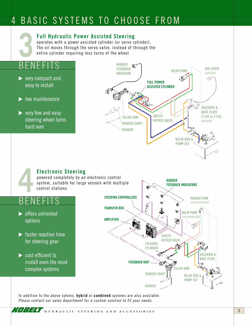
4 B A S I C S Y S T E M S T O C H O O S E F R O MFull Hydraulicpowerassistedsteering operates with a power assisted cyl inder (or servo cyl inder) . The oi l moves through the servo valve, instead of through the entire cyl inder requir ing less turns of the wheel
electronicsteering powered completely by an electronic control system, suitable for large vessels with mult iple control stations
In addit ion to the above sytems, hybrid or combined systems are also available .Please contact our sales department for a custom solution to f i t your needs.
BENEFITS
BENEFITS
u very compact and easy to install
u low maintenance
u very few and easy steering wheel turns hard over
u offers unlimited options
u faster reaction time for steering gear
u cost efficient to install even the most complex systems

h y d r a u l i c s t e e r i n g a n d a c c e s s o r i e s4
Kobelt Manufacturing produces five different Helm Pumps, all of which are made from bronze and stainless steel, with the exception of the thrust and roller bearings and, of course, hardened and ground pistons . These Helm Pumps can be installed in any location on the vessel because of their durable materials and watertight construction .
The Helm Pumps incorporate lock valves, filler plugs and interconnecting plugs for multi-station applications . A front mounting plate is available (optional) for all pumps, where the pump is mounted behind the console face . The following Kobelt Hydraulic Pumps are based on the same design and are of the VARIABLE DELIVERY TYPE . The delivery of these pumps is fully adjustable, with easy-to-alter output flow as simple as turning an external adjusting screw on the pumps’ front face with a standard screwdriver .Model 7003 1 - 3 cu . inches displacement per turn .Model 7005 2 - 6 cu . inches displacement per turn .Model 7012 4 - 12 cu . inches displacement per turn .
HelmpumpvolumesarenominalThese pumps have been extremely well received by the
industry, because of their variable displacement capability, which allows the operator to select the number of turns from hardover to hardover, without installing a different pump .
For manual hydraulic systems, under normal conditions, the load on the steering wheel rim should not exceed 36 ft . lbs . (16 kg), and generally the hydraulic system pressure should not exceed 650 psi (45 bar) for small helm pumps or 400 psi (30 bar) for larger versions .
For electro-hydraulic systems on emergency-driven hydraulic pumps, the steering angle that must be maintained manually, in case the power fails, is only 150 to either side . At 150 the rudder torque is easily controlled with a helm pump and the helmsman will have no problem maintaining the steering .
One must remember that producing 12 cubic inches per turn at 600 to 1000 PSI requires a tremendous amount of human effort, and it is not practical to expect a person to produce this
kind of pressure and volume continuously .
orderingoptionsA Bronze Finish B Black Epoxy FinishL Long Shaft N Short ShaftP Porting Block (no lock valve) T Tapered Shaft
“T” is standard with Model No . 7003, optional with Model No . 7005 .
Mounting plates can be ordered as well . They should be ordered with the
pump number plus -0011 . A letter would then be added for finish, e .g .
7003-0011B = Black mounting plate for 7003 pump .
KobeltModel7035tiltUpsteeringThis patented Kobelt design eliminates the universal joint –
instead the whole helm pump moves with the wheel when rotated up or down so you don’t need to worry about leaks or failures .
The tilting mechanism provides 5 locking positions at 10° increments for a total movement of 50° . This unit is available with helm pumps Model No . 7031 or Model No . 7004 .
The 7031 has 2 cu .in . or (7031-X) 2 .6 cu .in . volume per turn . Model No . 7004 has 3 .4 or (7004-X) 4 .5 cu .in . volume per turn .
The tilt up mechanism and the helm pumps are constructed in bronze with stainless steel hardware .
Due to the simplified construction and selection of superb materials, this pump will outlast any other product on the market .
options7035 2 cu .in .7035-X 2 .6 cu .in .7035-O 3 .4 cu .in .7035-OX 4 .5 cu .in .
H E L M P U M P S
700470317035
7003
7005
7012

h y d r a u l i c s t e e r i n g a n d a c c e s s o r i e s 5
H E L M P U M P S
*
***
*
**
"V"-VIEW
V
A
7003
B C D E F G H I J K L M N O P
7005
7012
7003
7005
7012
TSR
7003
7005
7012
THREAD SIZE in inch
* ** *** ***
FOR SIZE "X"FLAT HEAD SCREW
I
W X Y ZU
GP
U
W
S
Y Z
1/2" DIA (12.7)
FOR SIZE "T" BOLTS
A C E G
H
F
D
B
J
R
R
M
N
L
O
K
NET WEIGHTMODEL
MODEL
MODEL
MODEL
FRONT MOUNTING PLATE(OPTIONAL)

h y d r a u l i c s t e e r i n g a n d a c c e s s o r i e s6
Kobelt Manufacturing makes steering cylinders from 1 .25"
I .D . to 10" I .D . The smaller models, up to 3" I .D ., are made from
bronze and stainless steel .
On the 4" to 10" series, the cylinder tube and spherical
bearings are made from steel . The Piston Rods are made from
stainless steel, and are hard chromed and polished . All castings
are sand cast bronze or steel . On the larger cylinders, adjustable
rudder stops and “V” packings with adjustable packing nuts, are
standard .
Our Models 7040, 7050, 7065, 7080, 7085 and 7093
are available in both balanced and unbalanced versions . The
larger cylinder models 7094, 7096, 7097, 7098 and 7100 are
not available in a balanced version . When using unbalanced
cylinders, two or more must be used in a steering system .
The tables indicate rudder torque for both single and twin
cylinder steering applications .
If a single cylinder is used in a manual hydraulic steering
system, it is of utmost importance that the single cylinder
is of a balanced type . “Balanced” means that the cylinder
piston rod extends out of the cylinder at both ends . This will
give a balanced torque as well as equal volume displacement
7040
7050
7080
7094
in both directions . The manual Helm Pump has a relatively
small reservoir and using an unbalanced cylinder would cause
the reservoir to overflow or the pump to run empty, which is
unacceptable .
“Unbalanced” cylinders have the piston rod extending from
the cylinder only on one side . Since two cylinders are connected
to the same Tiller Arm or steering system, the volumes are
balanced out again . The lines from the source of hydraulic
pressure are crossed at the cylinders, providing equal volume
displacement in both directions . (See installation diagrams on
page 6 .)
orderingoptions
B Balanced – specify stroke in inches
U Unbalanced – specify stroke in inches
K o b e l t S T E E R I N G C Y L I N D E R S

h y d r a u l i c s t e e r i n g a n d a c c e s s o r i e s 7
This sketch shows a typical single rudder twin cylinder steering system . Rudder torques can be obtained up to 160 tonmeter with two cylinders . It is, also possible to install four cylinders on a single rudder stock which would double the rudder torque .
A typical twin rudder steering system with a mechanical tiebar .
Specialized Systems are also available .
K o b e l t S T E E R I N G C Y L I N D E R S F O R O C E A N - G O I N G V E S S E L S
T Y P I C A L S T E E R I N G G E A R I N S T A L L A T I O N S
The mounting foot is of a box-type and allows easy
installation of the cylinder . (Stop blocks should be installed .)
Grease fittings are provided on either end and can be
connected to an automatic lubricating system which is available
from Kobelt . The cylinders are Lloyd’s type approved for 2000 PSI
operating pressure, that is 138 bar .
Our steering cylinders carry a five-year warranty and are
designed for heavy-duty use .
Model 7097, 7098 and 7100 Cylinders are designed for
larger vessels with heavy-duty steering requirements . The non-
welded construction of these cylinders allows for many years of
operation and easy service . The spherical bearings are located
at either end for self-aligning and long life . The steel tube has
an extremely smooth precision finish and provides many years
of trouble-free service . For the 7094 cylinders and larger as
listed on p .9 and p .10, the piston rods are steel, hard-chromed
and polished . The rod seal is a V-packing with adjustable nut .
The piston rod bushing is made from bronze and is replaceable .
With these large steering cylinders, a rudder torque of up to
160 tonmeter per rudder at 2000 PSI (138 bar) is obtainable .
On multi-rudder installations, each rudder can be provided
with up to 160 tonmeter . These rudders can be mechanically
connected with tie bars or electronically connected to move in
synchronization .

h y d r a u l i c s t e e r i n g a n d a c c e s s o r i e s8
For Mounting-foot dimensions for 7040, 7050, 7085 and 7093 cylinders, refer to the chart on the next page for balanced cylinders .
C Y L I N D E R I N F O R M A T I O N

h y d r a u l i c s t e e r i n g a n d a c c e s s o r i e s 9
MoDel
torQUe stroKe DisplaceMent a b c D e lbs . ft . kgm in mm in3 cm3 in mm in mm in mm in mm in mm
428 57 5 .5 139 .7 8 131 2 .75 70 18 .04 458 4 .79 122 4 .31 109 16 .5 419 7040 652 90 7 .5 191 11 180 3 .75 95 22 .04 560 6 .54 166 5 .95 151 19 .50 495 869 120 10 254 14 .6 239 5 127 27 .04 687 8 .72 221 7 .93 201 23 .25 591 1205 167 7 .5 191 20 .3 333 3 .75 95 23 .75 603 6 .54 166 5 .95 151 20 .85 530 7050 1607 223 10 254 27 442 5 127 28 .75 730 8 .72 221 7 .93 201 24 .60 625 1928 267 12 305 32 .4 531 6 152 32 .75 832 10 .46 266 9 .51 242 27 .6 701 2454 340 10 254 41 672 5 127 30 .27 769 8 .72 221 7 .93 201 28 .11 714 7065 2944 407 12 305 49 803 6 152 34 .27 870 10 .46 266 9 .51 242 31 .11 790 3926 543 16 406 66 1082 8 203 42 .27 1074 13 .95 354 12 .69 322 37 .11 943 2603 359 7 .5 191 43 .8 718 3 .75 95 26 .82 681 6 .54 166 5 .95 151 26 .25 667
7080 3493 482 10 254 58 .4 958 5 .00 127 31 .82 808 8 .72 221 7 .93 201 30 .00 762
4170 577 12 305 70 .1 1149 6 152 35 .82 910 10 .46 266 9 .51 242 33 .00 838 5561 770 16 406 93 .4 1531 8 203 43 .82 1113 13 .95 354 12 .69 322 39 .00 991 4580 633 10 254 79 1295 5 127 36 .25 921 8 .72 221 7 .93 201 36 .19 919 7085 5560 769 12 305 94 1540 6 152 40 .25 1022 10 .46 266 9 .51 242 39 .19 995 7400 1023 16 406 126 2065 8 203 48 .25 1226 13 .95 354 12 .69 322 45 .19 1148 7256 1004 12 305 122 1999 6 152 39 .34 999 10 .46 266 9 .51 242 38 .59 980
7093 9674 1339 16 406 163 2671 8 203 47 .34 1202 13 .95 354 12 .69 322 44 .59 1133
12093 1673 20 508 203 3327 10 254 55 .34 1406 17 .43 443 15 .85 403 50 .59 1285 14512 2008 24 610 244 3998 12 305 63 .34 1609 20 .92 531 19 .03 483 56 .59 1437
F G H in mm in mm in mm
2 51 3 .187 81 11/32 8 .7
2 .5 64 3 .625 92 25/64 9 .9
3 76 4 102 1/2 13
4 102 4 .875 124 21/32 16 .7
41/4 108 61/4 159 13/16 21
5 127 6 152 3/4 19
B A L A N C E D C Y L I N D E R S
balanceDcYlinDers–rUDDerangle(ra)35°
MoDel
torQUe stroKe DisplaceMent a b c D e lbs . ft . kgm in mm in3 cm3 in mm in mm in mm in mm in mm
298 41 5 .5 139 .7 8 131 2 .75 70 18 .04 458 3 .89 99 3 .32 84 16 .5 419 7040 456 63 7 .5 191 11 180 3 .75 95 22 .04 560 5 .3 135 4 .52 115 19 .50 495 608 84 10 254 14 .6 239 5 127 27 .04 687 7 .07 180 6 .03 153 23 .25 591 893 116 7 .5 191 20 331 3 .75 95 23 .75 603 5 .3 135 4 .5 115 20 .9 530 7050 1125 156 10 254 27 442 5 127 28 .75 730 7 .07 180 6 .03 153 24 .60 625 1351 187 12 305 32 .4 531 6 152 32 .75 832 8 .49 216 7 .25 184 27 .60 701 1718 238 10 254 41 672 5 127 30 .27 769 7 .07 180 6 .03 153 28 .11 714 7065 2062 285 12 305 49 803 6 152 34 .27 870 8 .49 216 7 .25 184 31 .11 790 2749 380 16 406 66 1082 8 203 42 .27 1074 11 .31 287 9 .65 245 37 .11 943 1825 252 7 .5 191 44 718 3 .75 95 26 .82 681 5 .3 135 4 .5 115 26 .6 676 2432 335 10 254 58 .4 958 5 127 31 .82 808 7 .07 180 6 .04 153 30 .00 762
7080 2922 405 12 305 70 .1 1149 6 152 35 .82 910 8 .49 216 7 .25 184 33 .00 838
3892 539 16 406 93 .4 1531 8 203 43 .82 1113 11 .31 287 9 .65 245 39 .00 991 3270 452 10 254 79 1295 5 127 36 .25 921 7 .07 180 6 .03 153 36 .19 919 7085 3920 542 12 305 94 1540 6 152 40 .25 1022 8 .49 216 7 .25 184 39 .19 995 5230 723 16 406 126 2065 8 203 48 .25 1226 11 .31 287 9 .65 245 45 .19 1148 5081 703 12 305 122 1999 6 152 39 .34 999 8 .49 216 7 .25 184 38 .59 980
7093 6774 937 16 406 163 2671 8 203 47 .34 1202 11 .31 287 9 .65 245 44 .59 1133
8468 1172 20 508 203 3327 10 254 55 .34 1406 14 .14 359 12 .07 307 50 .59 1285 10161 1406 24 610 244 3998 12 305 63 .34 1609 16 .97 431 14 .48 368 56 .59 1437
balanceDcYlinDers–rUDDerangle(ra)45°
torque IS baSed on one cylInder at 1000 PSI (69 bar)
reFer to PaGeS 10 - 13For unbalanced cylInderS
7040-B5.5
CYLINDER
789
1314152829334042444877798491
102113124
LBS Kg.3.23.73.95.96.46.812.813.315.218.219.120.021.835.035.938.241.446.451.456.4
MODEL
7040-B7.57040-B107050-B7.57050-B107050-B127065-B107065-B127065-B16
7080-B107080-B7.5
7080-B127080-B167085-B107085-B127085-B167093-B127093-B167093-B207093-B24
NET WEIGHTS
Performance Data is for reference only.

h y d r a u l i c s t e e r i n g a n d a c c e s s o r i e s10
MoDel torQUe stroKe DisplaceMent a U c D e lbs . ft . kgm in mm in3 cm3 in mm in mm in mm in mm in mm 1056 146 5 .5 140 17 .8 292 2 .75 70 17 .85 453 4 .8 122 4 .36 111 16 .5 419 7040 1441 200 7 .5 191 24 .2 397 3 .75 95 20 .85 530 6 .54 166 5 .95 151 19 .50 495 1921 266 10 254 32 .3 529 5 .00 127 24 .60 625 8 .72 221 7 .93 201 23 .25 591 2608 361 7 .5 191 43 .8 718 3 .75 95 22 .48 571 6 .54 166 5 .95 151 20 .85 530 7050 3477 481 10 254 58 .4 957 5 .00 127 26 .23 666 8 .72 221 7 .93 201 24 .60 625 4171 578 12 305 70 .1 1149 6 .00 152 29 .23 742 10 .46 266 9 .51 242 27 .60 701 5375 744 10 254 90 1475 5 127 30 .17 766 8 .72 221 7 .93 201 28 .11 714 7065 6450 893 12 305 108 1770 6 152 33 .17 843 10 .46 266 9 .51 242 31 .11 790 8599 1190 16 406 144 2360 8 203 39 .17 995 13 .95 354 12 .69 322 37 .11 943 5763 798 7 .5 191 96 .8 1586 3 .75 95 28 .87 733 6 .54 166 5 .95 151 26 .25 667 7676 1061 10 254 129 2114 5 127 32 .62 829 8 .72 221 7 .93 201 30 .00 762
7080 9217 1276 12 305 154 .9 2538 6 .00 152 35 .62 905 10 .46 266 9 .51 242 33 .00 838
12292 1702 16 406 206 .6 3386 8 .00 203 41 .62 1057 13 .95 354 12 .69 322 39 .00 991 10800 1493 10 254 174 2851 5 127 39 .07 992 8 .72 221 7 .93 201 36 .19 919 7085 12360 1709 12 305 209 3425 6 152 42 .07 1069 10 .46 266 9 .51 242 39 .19 995 16430 2272 16 406 279 4572 8 203 48 .07 1221 13 .95 354 12 .69 322 45 .19 1148 16229 2246 12 305 272 4457 6 152 41 .90 1064 10 .46 266 9 .51 242 38 .59 980
7093 21639 2994 16 406 363 5949 8 203 47 .90 1217 13 .95 354 12 .69 322 44 .59 1133
27048 3743 20 508 454 7440 10 254 53 .90 1369 17 .43 443 15 .85 403 50 .59 1285 32458 4492 24 610 546 8947 12 305 59 .90 1521 20 .92 531 19 .03 483 56 .59 1437
UnbalanceDcYlinDers–rUDDerangle(ra)35°
torque IS baSed on two cylInderSat 1000 PSI (69 bar)
MoDel
torQUe stroKe DisplaceMent a U c D e lbs . ft . kgm in mm in3 cm3 in mm in mm in mm in mm in mm 739 102 5 .5 140 17 .8 292 2 .75 70 17 .85 453 3 .9 99 3 .3 84 16 .5 419 7040 1008 140 7 .5 191 24 .2 397 3 .75 95 20 .85 530 5 .3 135 4 .52 115 19 .50 495 1344 186 10 254 32 .3 529 5 .00 127 24 .60 625 7 .07 180 6 .03 153 23 .25 591 1825 252 7 .5 191 43 .8 718 3 .75 95 22 .48 571 5 .3 135 4 .52 115 20 .85 530 7050 2434 337 10 254 58 .4 957 5 .00 127 26 .23 666 7 .07 180 6 .03 153 24 .60 625 2923 405 12 305 70 .1 1149 6 .00 152 29 .23 742 8 .49 216 7 .25 184 27 .60 701 3763 521 10 254 90 1475 5 127 30 .17 766 7 .07 180 6 .03 153 28 .11 714 7065 4516 625 12 305 108 1770 6 152 33 .17 843 8 .49 216 7 .25 184 31 .11 790 6021 833 16 406 144 2360 8 203 39 .17 995 11 .31 287 9 .65 245 37 .11 943 4033 557 7 .5 191 96 .8 1586 3 .75 95 28 .87 733 5 .3 135 4 .52 115 26 .25 667 5375 743 10 254 129 2114 5 127 32 .62 829 7 .07 180 6 .03 153 30 .00 762
7080 6458 894 12 305 154 .9 2538 6 .00 152 35 .62 905 8 .49 216 7 .25 184 33 .00 838
8603 1191 16 406 206 .6 3386 8 .00 203 41 .62 1057 11 .31 287 9 .65 245 39 .00 991 7260 1004 10 254 174 2851 5 127 39 .07 992 7 .07 180 6 .03 153 36 .19 919 7085 8730 1207 12 305 209 3425 6 152 42 .07 1069 8 .49 216 7 .25 184 39 .19 995 11640 1609 16 406 279 4572 8 203 48 .07 1221 11 .31 287 9 .65 245 45 .19 1148 11364 1573 12 305 272 4457 6 152 41 .90 1064 8 .49 216 7 .25 184 38 .59 980
7093 15152 2097 16 406 363 5949 8 203 47 .90 1217 11 .31 287 9 .65 245 44 .59 1133
18940 2621 20 508 454 7440 10 254 53 .90 1369 14 .14 359 12 .07 307 50 .59 1285 22727 3145 24 610 546 8947 12 305 59 .90 1521 16 .97 431 14 .48 368 56 .59 1437
UnbalanceDcYlinDers–rUDDerangle(ra)45°
U N B A L A N C E D C Y L I N D E R S
Performance Data is for reference only.
h y d r a u l i c s t e e r i n g a n d a c c e s s o r i e s 11
MoDel
torQUe stroKe DisplaceMent a b c D e lbs . ft . kgm in mm in3 cm3 in mm in mm in mm in mm in mm
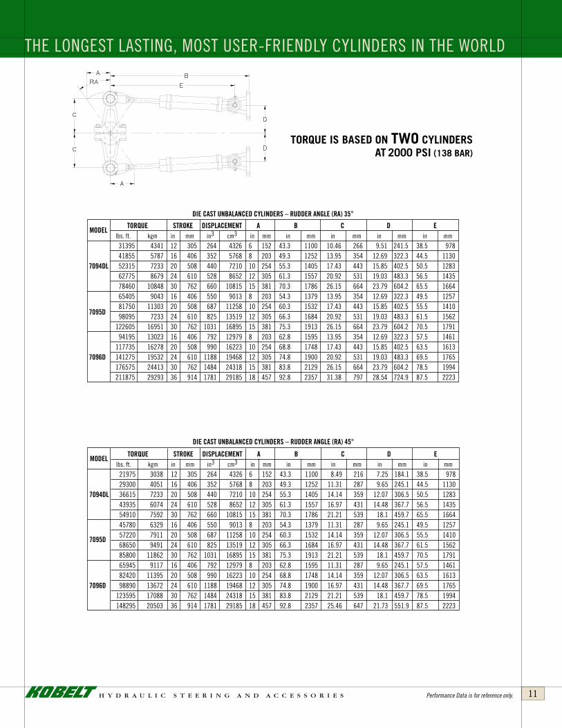
31395 4341 12 305 264 4326 6 152 43 .3 1100 10 .46 266 9 .51 241 .5 38 .5 978 41855 5787 16 406 352 5768 8 203 49 .3 1252 13 .95 354 12 .69 322 .3 44 .5 1130 7094Dl 52315 7233 20 508 440 7210 10 254 55 .3 1405 17 .43 443 15 .85 402 .5 50 .5 1283 62775 8679 24 610 528 8652 12 305 61 .3 1557 20 .92 531 19 .03 483 .3 56 .5 1435 78460 10848 30 762 660 10815 15 381 70 .3 1786 26 .15 664 23 .79 604 .2 65 .5 1664 65405 9043 16 406 550 9013 8 203 54 .3 1379 13 .95 354 12 .69 322 .3 49 .5 1257 7095D
81750 11303 20 508 687 11258 10 254 60 .3 1532 17 .43 443 15 .85 402 .5 55 .5 1410 98095 7233 24 610 825 13519 12 305 66 .3 1684 20 .92 531 19 .03 483 .3 61 .5 1562 122605 16951 30 762 1031 16895 15 381 75 .3 1913 26 .15 664 23 .79 604 .2 70 .5 1791 94195 13023 16 406 792 12979 8 203 62 .8 1595 13 .95 354 12 .69 322 .3 57 .5 1461 117735 16278 20 508 990 16223 10 254 68 .8 1748 17 .43 443 15 .85 402 .5 63 .5 1613 7096D 141275 19532 24 610 1188 19468 12 305 74 .8 1900 20 .92 531 19 .03 483 .3 69 .5 1765 176575 24413 30 762 1484 24318 15 381 83 .8 2129 26 .15 664 23 .79 604 .2 78 .5 1994 211875 29293 36 914 1781 29185 18 457 92 .8 2357 31 .38 797 28 .54 724 .9 87 .5 2223
DiecastUnbalanceDcYlinDers–rUDDerangle(ra)35°
torque IS baSed on two cylInderSat 2000 PSI (138 bar)
THE LONGEST LASTING, MOST USER-FRIENDLY CYLINDERS IN THE WORLD
DiecastUnbalanceDcYlinDers–rUDDerangle(ra)45°
MoDel
torQUe stroKe DisplaceMent a b c D e lbs . ft . kgm in mm in3 cm3 in mm in mm in mm in mm in mm
21975 3038 12 305 264 4326 6 152 43 .3 1100 8 .49 216 7 .25 184 .1 38 .5 978 29300 4051 16 406 352 5768 8 203 49 .3 1252 11 .31 287 9 .65 245 .1 44 .5 1130 7094Dl 36615 7233 20 508 440 7210 10 254 55 .3 1405 14 .14 359 12 .07 306 .5 50 .5 1283 43935 6074 24 610 528 8652 12 305 61 .3 1557 16 .97 431 14 .48 367 .7 56 .5 1435 54910 7592 30 762 660 10815 15 381 70 .3 1786 21 .21 539 18 .1 459 .7 65 .5 1664 45780 6329 16 406 550 9013 8 203 54 .3 1379 11 .31 287 9 .65 245 .1 49 .5 1257
7095D 57220 7911 20 508 687 11258 10 254 60 .3 1532 14 .14 359 12 .07 306 .5 55 .5 1410
68650 9491 24 610 825 13519 12 305 66 .3 1684 16 .97 431 14 .48 367 .7 61 .5 1562 85800 11862 30 762 1031 16895 15 381 75 .3 1913 21 .21 539 18 .1 459 .7 70 .5 1791 65945 9117 16 406 792 12979 8 203 62 .8 1595 11 .31 287 9 .65 245 .1 57 .5 1461 82420 11395 20 508 990 16223 10 254 68 .8 1748 14 .14 359 12 .07 306 .5 63 .5 1613 7096D 98890 13672 24 610 1188 19468 12 305 74 .8 1900 16 .97 431 14 .48 367 .7 69 .5 1765 123595 17088 30 762 1484 24318 15 381 83 .8 2129 21 .21 539 18 .1 459 .7 78 .5 1994 148295 20503 36 914 1781 29185 18 457 92 .8 2357 25 .46 647 21 .73 551 .9 87 .5 2223
Performance Data is for reference only.
h y d r a u l i c s t e e r i n g a n d a c c e s s o r i e s12
C Y L I N D E R I N F O R M A T I O N
UnbalanceDcYlinDers–rUDDerangle(ra)45°
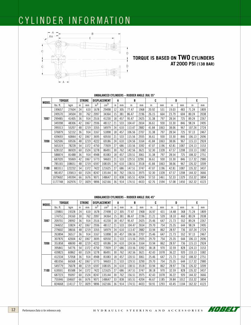
MoDel
torQUe stroKe DisplaceMent a b c D e lbs . ft . kgm in mm in3 cm3 in mm in mm in mm in mm in mm
139801 19328 24 610 1678 27498 12 305 77 .47 1968 16 .97 431 14 .48 368 71 .24 1809 174751 24160 30 762 2097 34364 15 381 86 .47 2196 21 .21 539 18 .10 460 80 .24 2038 7097 209701 28992 36 914 2516 41230 18 457 95 .47 2425 25 .46 647 21 .73 552 89 .24 2267 244652 33824 42 1067 2936 48112 21 533 104 .47 2654 29 .70 754 25 .35 644 98 .24 2495 279602 38656 48 1219 3355 54979 24 610 113 .47 2882 33 .94 862 28 .97 736 107 .24 2724 263894 36517 36 914 3167 51898 18 457 106 .56 2707 25 .46 647 21 .73 552 97 .13 2467 307876 42604 42 1067 3695 60550 21 533 115 .56 2935 29 .70 754 25 .35 644 106 .13 2696 7098 351858 48690 48 1219 4222 69186 24 610 124 .56 3164 33 .94 862 28 .97 736 115 .13 2924 395841 54776 54 1372 4750 77839 27 686 133 .56 3392 38 .18 970 32 .59 828 124 .13 3153 439823 60862 60 1524 5278 86491 30 762 142 .56 3621 42 .43 1078 36 .22 920 133 .13 3382 412334 57058 36 914 4948 81083 18 457 120 .51 3061 25 .46 647 21 .73 552 108 .32 2751 481056 66568 42 1067 5773 94603 21 533 129 .51 3290 29 .70 754 25 .35 644 117 .32 2980 549779 76078 48 1219 6597 108105 24 610 138 .51 3518 33 .94 862 28 .97 736 126 .32 3209 7100 618501 85588 54 1372 7422 121625 27 686 147 .51 3747 38 .18 970 32 .59 828 135 .32 3437 687223 95097 60 1524 8247 135144 30 762 156 .51 3975 42 .43 1078 36 .22 920 144 .32 3666 755946 104607 66 1676 9071 148647 33 838 165 .51 4204 46 .67 1185 39 .84 1012 153 .32 3894 824668 114117 72 1829 9896 162166 36 914 174 .51 4433 50 .91 1293 43 .45 1104 162 .32 4123
torque IS baSed on two cylInderSat 2000 PSI (138 bar)
MoDel
torQUe stroKe DisplaceMent a b c D e lbs . ft . kgm in mm in3 cm3 in mm in mm in mm in mm in mm
199657 27604 24 610 1678 29498 12 305 77 .47 1968 20 .92 531 19 .03 483 71 .24 1809 249570 34504 30 762 2097 34364 15 381 86 .47 2196 26 .15 664 23 .79 604 80 .24 2038 7097 299485 41405 36 914 2516 41230 18 457 95 .47 2425 31 .38 797 28 .54 725 89 .24 2267 349398 48306 42 1067 2936 48112 21 533 104 .47 2654 36 .61 930 33 .30 846 98 .24 2495 399313 55207 48 1219 3355 54979 24 610 113 .47 2882 41 .84 1063 38 .06 967 107 .24 2724 376879 52152 36 914 3167 51898 18 457 106 .56 2707 31 .38 797 28 .54 725 97 .13 2467 439693 60844 42 1067 3695 60550 21 533 115 .56 2935 36 .61 930 33 .30 846 106 .13 2696 7098 502506 69536 48 1219 4222 69186 24 610 124 .56 3164 41 .84 1063 38 .06 967 115 .13 2924 565319 78228 54 1372 4750 77839 27 686 133 .56 3392 47 .07 1196 42 .81 1087 124 .13 3153 628132 86920 60 1524 5278 86491 30 762 142 .56 3621 52 .30 1328 47 .57 1208 133 .13 3382 588874 81488 36 914 4948 81083 18 457 120 .51 3061 31 .38 797 28 .54 725 108 .32 2751 687020 95069 42 1067 5773 94603 21 533 129 .51 3290 . 36 .61 930 33 .30 846 117 .32 2980 785165 108651 48 1219 6597 108105 24 610 138 .51 3518 41 .84 1063 38 .06 967 126 .32 3209 7100 883311 122232 54 1372 7422 121625 27 686 147 .51 3747 47 .07 1196 42 .81 1087 135 .32 3437 981457 135813 60 1524 8247 135144 30 762 156 .51 3975 52 .30 1328 47 .57 1208 144 .32 3666 1079602 149394 66 1676 9071 148647 33 838 165 .51 4204 57 .53 1461 52 .33 1329 153 .32 3894 1177748 162976 72 1829 9896 162166 36 914 174 .51 4433 62 .76 1594 57 .08 1450 162 .32 4123
UnbalanceDcYlinDers–rUDDerangle(ra)35°
Performance Data is for reference only.

h y d r a u l i c s t e e r i n g a n d a c c e s s o r i e s 13
balanceDcYlinDers–rUDDerangle(ra)45°
MoDel
torQUe stroKe DisplaceMent a b c D e F* g* H* lbs . ft . kgm in mm in3 cm3 in mm in mm in mm in mm in mm in mm in mm in mm
7250 1002 12 305 87 1426 6 152 40 .25 1022 8 .5 216 7 .3 184 36 .6 930 5 127 6 152 3/4 19
9583 1325 16 406 115 1885 8 203 46 .25 1175 11 .3 287 9 .7 245 42 .6 1083 5 127 6 152 3/4 19
7087 12000 1659 20 508 144 2360 10 254 52 .25 1327 14 .1 359 12 .1 307 48 .6 1235 5 127 6 152 3/4 19
14417 1993 24 610 173 2835 12 305 58 .25 1480 17 .0 431 14 .5 368 54 .6 1387 5 127 6 152 3/4 19 16833 2327 28 711 202 3310 14 356 64 .25 1632 19 .8 503 16 .9 429 60 .6 1540 5 127 6 152 3/4 19
torque IS baSed on two cylInderS at 2000 PSI (138 bar)
MoDel
torQUe stroKe DisplaceMent a b* c D e lbs . ft . kgm in mm in3 cm3 in mm in mm in mm in mm in mm
10235 1415 10 254 86 1409 5 127 31 .6 803 8 .7 221 7 .9 201 29 .1 740
7067 12255 1695 12 305 103 1688 6 152 34 .6 879 10 .5 266 9 .5 242 32 .1 816
16425 2271 16 406 137 2261 8 203 40 .6 1031 14 .0 354 12 .7 322 38 .1 968 20470 2830 20 508 172 2819 10 254 46 .6 1184 17 .4 443 15 .9 403 44 .1 1121 24040 3324 12 305 202 3310 6 152 38 .2 970 10 .5 266 9 .5 242 35 .1 892
32015 4426 16 406 269 4408 8 203 44 .2 1123 14 .0 354 12 .7 322 41 .1 1045
7087 39985 5529 20 508 327 5506 10 254 50 .2 1275 17 .4 443 15 .9 403 47 .1 1197 48080 6648 24 610 404 6620 12 305 56 .2 1427 20 .9 531 19 .0 483 53 .1 1350 56055 7750 28 711 471 7718 14 356 62 .2 1580 24 .4 620 22 .2 564 59 .1 1502
52960 7322 16 406 445 7297 8 203 47 .4 1204 13 .9 353 12 .7 322 42 .6 1082
66290 9165 20 508 557 9122 10 254 53 .4 1356 17 .4 442 15 .9 403 48 .6 1235
7090 79500 10991 24 610 668 10946 12 305 59 .4 1509 20 .9 531 19 .0 483 54 .6 1387 92745 12882 28 711 779 12765 14 356 65 .4 1661 24 .4 620 22 .2 564 60 .6 1540 105990 14654 32 813 891 14600 16 406 71 .4 1814 27 .9 708 25 .4 644 66 .6 1692
MoDel
torQUe stroKe DisplaceMent a b* c D e lbs . ft . kgm in mm in3 cm3 in mm in mm in mm in mm in mm
7165 991 10 254 86 1408 5 127 31 .6 803 7 .1 180 6 .0 153 29 .1 740
7067 8580 1187 12 305 103 1690 6 152 34 .6 879 8 .5 216 7 .3 184 32 .1 816
11500 1590 16 406 137 2251 8 203 40 .6 1031 11 .3 287 9 .7 245 38 .1 968 14330 1982 20 508 172 2815 10 254 46 .6 1184 14 .1 359 12 .1 307 44 .1 1121 16830 2327 12 305 202 3311 6 152 38 .2 970 8 .5 216 7 .3 184 35 .1 892
22415 3099 16 406 269 4415 8 203 44 .2 1123 11 .3 287 9 .7 245 41 .1 1045
7087 28000 3871 20 508 327 5518 10 254 52 .2 1275 14 .1 359 12 .1 307 47 .1 1197 33665 4655 24 610 404 6622 12 305 56 .2 1427 17 .0 431 14 .5 368 53 .1 1350 39250 5427 28 711 471 7725 14 356 62 .2 1580 19 .8 503 16 .9 429 59 .1 1502
37080 5127 16 406 445 7297 8 203 47 .4 1204 11 .3 287 9 .7 245 42 .6 1082
46415 6417 20 508 557 9122 10 254 53 .4 1356 14 .1 359 12 .1 307 48 .6 1235
7090 55665 7696 24 610 668 10946 12 305 59 .4 1509 17 .0 431 14 .5 368 54 .6 1387 64940 8978 28 711 779 12765 14 356 65 .4 1661 19 .8 503 16 .9 429 60 .6 1540 74220 10261 32 813 891 14600 16 406 71 .4 1814 22 .6 575 19 .3 491 66 .6 1692
UnbalanceDcYlinDers–rUDDerangle(ra)35°
UnbalanceDcYlinDers–rUDDerangle(ra)45°
N E W C Y L I N D E R S – B A L A N C E Dtorque IS baSed on one cylInder at 2000 PSI (138 bar)
MoDel
torQUe stroKe DisplaceMent a b c D e F* g* H* lbs . ft . kgm in mm in3 cm3 in mm in mm in mm in mm in mm in mm in mm in mm
10354 1432 12 305 87 1426 6 152 40 .25 1022 10 .5 266 9 .5 242 36 .6 930 5 127 6 152 3/4 19 13686 1892 16 406 115 1885 8 203 46 .25 1175 14 .0 354 12 .7 322 42 .6 1083 5 127 6 152 3/4 19 7087 17138 2369 20 508 144 2360 10 254 52 .25 1327 17 .4 443 15 .9 403 48 .6 1235 5 127 6 152 3/4 19 20589 2847 24 610 173 2835 12 305 58 .25 1480 20 .9 531 19 .0 483 54 .6 1387 5 127 6 152 3/4 19 24040 3324 28 711 202 3310 14 356 64 .25 1632 24 .4 620 22 .2 564 60 .6 1540 5 127 6 152 3/4 19
balanceDcYlinDers–rUDDerangle(ra)35°
N E W C Y L I N D E R S – U N B A L A N C E D
Note:
Bracket and Pin Kit
available for all cylinders
at an additional cost.
Refer to Page 12 for parameter diagram. * Dimensions for Optional Parts
Refer to Page 9 for parameter diagram. * Dimensions for Optional Parts
Performance Data is for reference only.

h y d r a u l i c s t e e r i n g a n d a c c e s s o r i e s14
C Y L I N D E R S P E C I F I C A T I O N S
boltsiZe-tHreaDpitcH graDe2 graDe5 graDe8 specialalloY 1/4 - 20 6 10 12 14
1/4 - 28 7 12 15 17 5/16 - 18 13 20 24 29 5/16 - 24 14 22 27 35 3/8 - 16 23 36 44 58 3/8 - 24 26 40 48 69 7/16 - 14 37 52 63 98 7/16 - 20 41 57 70 110 1/2 - 13 57 80 98 145 1/2 - 20 64 90 110 160 9/16 - 12 82 120 145 200 9/16 - 18 91 135 165 220 5/8 - 11 111 165 210 280 5/8 - 18 128 200 245 310 3/4 - 10 200 285 335 490 3/4 - 16 223 315 370 530 7/8 - 9 315 430 500 760 7/8 - 14 340 470 550 800 1-8 400 650 760 1130 1 - 14 460 710 835 1210
Max torque (Foot-PoundS)For clean, dry threadS
cYlinDer bore roDDia. roDballtHreaD roDballboltHole portsiZe MaXpressUre 7030 1-1/4” 5/8” — — 1/4” N .P .T . 1000 PSI 7032 1-1/4” 5/8” — — 1/4” N .P .T . 1000 PSI 7033 1-1/2” 3/4” — — 1/4” N .P .T . 1000 PSI 7040 1-1/2” 5/8” 1/2”-20 5/8” 1/4” N .P .T . 1500 PSI 7050 2” 3/4” 5/8”-18 3/4” 3/8” N .P .T . 1500 PSI 7065 2-1/2” 1” 7/8”-14 7/8” 3/8” N .P .T . 1500 PSI 7080 3” 1-1/4” 1”-14 1” 1/2” N .P .T . 1500 PSI 7085 3-1/2” 1-1/2” 1-1/4”-12 1-1/4” 7/8”-14 “O” RING 1000 PSI 7093 4” 1-3/4” 1-1/2”-12 1-3/4” 7/8”-14 “O” RING 1000 PSI 7094 4” 2” 1-3/4”-12 2-1/4” 1-1/16”-12 “O” RING 2000 PSI 7094Dl 4” 2” 1-3/4”-12 2” 3/4”-16 “O” RING 2000 PSI 7095 5” 2” 1-3/4”-12 2-1/4” 1-1/16”-12 “O” RING 1000 PSI 7095D 5” 2-1/2” 2”-12 2-1/4” 7/8”-14 “O” RING 2000 PSI 7096 6” 3” 2-3/4”-12 3-1/4” 1-5/16”-12 “O” RING 2000 PSI 7096D 6” 3” 2-3/4”-12 3-1/4” 1-5/16”-12 “O” RING 2000 PSI 7097 7” 3” 2-3/4”-12 3-1/4” 1-1/16”-12 “O” RING 2000 PSI 7098 8” 4” 3-3/4”-8 4” 1-5/8”-12 “O” RING 2000 PSI 7100 10” 5” 4-3/4”-8 5” 1-7/8”-12 “O” RING 2000 PSI 7147 2” 1” 3/4”-16 3/4” 1/4” N .P .T . 1000 PSI 7067 2-1/2” 1-1/4” 1-1/8”-12 1-1/4” 3/4”-16 “O” RING 2000 PSI 7087 3-1/2” 1-3/4” 1-1/2”-12 1-1/2” 7/8”-14 “O” RING 2000 PSI 7090 4-1/2” 2-1/4” 1-3/4”-12 2” 7/8”-14 “O” RING 2000 PSI
Performance Data is for reference only.

h y d r a u l i c s t e e r i n g a n d a c c e s s o r i e s 15
M
C
F (max)
I
L
K
G
F (min)
SINGLE TWIN
H
T I L L E R A R M SThe Tiller Arm serves a very important function . It
converts the linear motion on a steering cylinder into the
rotary motion of the rudder stock .
It is, therefore, very important that the Tiller Arm
is of sufficient strength to withstand all the pounding,
mechanical and hydraulic force imposed upon it under
severe conditions .
Stock Tiller Arms are available from Kobelt in many
shapes and sizes . We also manufacture custom made
Tiller Arms, especially for bigger applications, where we
are working to specific rudder stock dimensions and larger
cylinders .
When machining a Split Tiller Arm, it is important that
shims are placed between the two halves . This will allow the
clamping pressures to be applied to the rudder stock . The
keyways must also be machined on size and parallel to the
shaft . No lost motion should exist between the Tiller Arm
and the rudder stock .
This is especially important when a Full Power Follow-
Up Hydraulic system is installed such as the Model 7148 .
It is recommended to periodically check all bolts pertaining
to the Tiller Arm and Steering Cylinder to ensure that they
are tight and that all components are in good working order .
MoDel cYlinDer stroKe K l c35° c45° M F(Min) F(MaX) g H I in mm in mm in mm in mm in mm in mm in mm in mm in mm in mm in mm
7041 7040 7 .5 191 4 .5 114 1 .375 35 6 .54 166 0 .625 15 .9 1 .0 25 .4 2 .25 57 .2 1 .60 42 2 .5 64 1/2 12 .7 7042 7040 10 254 4 .5 114 1 .375 35 8 .72 221 0 .625 15 .9 1 .0 25 .4 2 .25 57 .2 1 .60 42 2 .5 64 1/2 12 .7 7051 7050 7 .5 191 5 .125 130 1 .5 38 6 .54 166 5 .3 135 0 .75 19 .1 1 .0 25 .4 2 .875 73 .0 1 .60 42 2 .936 75 5/8 15 .9
7052 7050 10 254
6 .312 160 1 .625 41 8 .72 221
0 .750 19 .1 1 .0 25 .4 3 .50 88 .9 2 .187 56 3 .34 85 3/4 19 .1 12 305 10 .46 266 8 .49 216 7 .5 191 6 .54 166 — — 7054 7050 10 254 6 .312 160 1 .625 41 8 .72 221 7 .07 180 0 .750 19 .1 1 .750 44 .5 3 .750 95 .25 2 .187 56 3 .45 88 3/4 19 .1 12 305 — — 8 .49 216 7065 7065 12 305 10 .46 266 16 406 8 203 2 .125 54 13 .95 354 11 .31 287 0 .875 22 .5 2 .5 63 .5 5 127 2 .375 60 4 .5 114 1 25 .4 7081 7080 7 .5 191 7 .5 191 2 .06 52 6 .54 166 1 .0 25 .4 2 .125 54 .0 4 .250 108 2 .125 54 3 .88 99 1 25 .4 7082 7080 12 305 7 .937 202 2 .125 54 10 .46 266 8 .49 216 1 .0 25 .4 2 .25 57 .2 4 .75 120 .7 2 .56 65 4 .5 114 1 25 .4 7083 7080 16 406 7 .937 202 2 .125 54 11 .31 287 1 .0 25 .4 2 .25 57 .2 4 .75 120 .7 2 .56 65 4 .5 114 1 25 .4 7084 7080 16 406 9 .06 230 2 .375 60 13 .95 354 11 .31 287 1 .0 25 .4 3 .25 82 .6 5 .50 139 .7 2 .65 67 4 .5 114 1 25 .4 7086 7085 16 406 13 .95 354 20 508 12 305 3 .125 79 17 .43 443 14 .14 359 1 .25 31 .8 3 .5 88 .9 7 .25 184 3 .75 95 5 .5 140 1 .25 31 .8 7093-s 7093 12 305 10 .46 266 16 406 11 279 2 51 13 .95 354 11 .31 287 1 .75 44 .5 3 .5 88 .9 7 .5 191 4 102 4 102 1 25 .47093-l 7093 20 508 17 .43 443 24 610 13 330 3 76 20 .92 531 16 .97 431 1 .75 44 .5 4 101 .6 8 203 3 .75 95 5 .5 140 1 .25 31 .8
NOTE: THE DIMENSIONS SHOWN ARE FOR SINGLE TILLER ARMS .FOR TWIN TILLER ARMS THE DIMENSION “C” MUST BE DOUBLED .
Custom hole sizes are available .
Material: Cast Steel

h y d r a u l i c s t e e r i n g a n d a c c e s s o r i e s16
O U T B O A R D M O T O R H Y D R A U L I C S T E E R I N G G E A ROver the years, Kobelt Manufacturing has grown into segments of marine
steering gear and control equipment, and many of our customers have asked us to
provide them with steering gear for outboard motors made with corrosion-resistant
materials . We are, therefore, very pleased to announce our all-bronze and stainless
steel steering gear for outboard motors . This product line is engineered and
manufactured to our high standard of excellence . Because of this we can offer a five-
year warranty . The Model 7031 helm pump has a volume of 2 cu . in . per turn . If larger
volumes are required please refer to helm pump Models 7003, 7005, and 7012 . The
Model 7031 does not have an adjustable displacement and is fixed at 2 cu . in . Our
Models 7032 and 7033 are front -mounted cylinders and our Model 7030 is a side-
mount cylinder . The model 7030 is also available in an unbalanced version . Models
7004 and 7031 can be mounted at an angle .
Patent #5466130
These cylinders are ideally suited for outboard motors up
to 300 HP . The standard stroke is shown in the table below . Any
stroke can be made, but might not be in stock . The cylinders
can also be epoxy-coated .
The 7030 cylinder attaches to the tilt tube . The cylinder
rod passes through the tube and is connected to a link provided
with the motor .
The 7032 cylinder is meant for front mounting to older
model outboards . It can be used for twin outboards .
The 7033 cylinder can be attached directly onto late-
model outboard motor brackets . The provided draglink connects
the cylinder rod onto the motor tiller arm with stainless steel
shoulder bolts . The swiveling arrangement allows the cylinder
to be raised or lowered to suit the height of the tiller arm .
O U T B O A R D M O T O R S T E E R I N G C Y L I N D E R S
70047031
cYlinDer MaXpressUre stanDarDstroKe tUbei.D. pistonroDDia. volUMe pipeport weigHt MoDel psi(bar) in.(MM) in.(MM) in.(MM) in3(cM3) siZe lbs.(Kg) 7030 1000 (68 .7) 8 (203 .2) 1-1/4 (31 .75) 5/8 (15 .9) 7 .37 (121) 1/4” N .P .T . 6 .6 (3 .0) 7032 1000 (68 .7) 7-1/2 (190 .5) 1-1/4 (31 .75) 5/8 (15 .9) 6 .9 (113) 1/4” N .P .T . 11 .0 (5 .0) 7033 1000 (68 .7) 7-1/2 (190 .5) 1-1/2 (38 .10) 3/4 (19 .1) 9 .9 (162) 1/4” N .P .T . 11 .0 (5 .0)
Note: Other strokes are available on request .Products are covered under Patents: 5601463, 5471909
weight
16 lbs . (7 .3 kg)
7032Classic Mounting
7033Bolt-on Mounting

h y d r a u l i c s t e e r i n g a n d a c c e s s o r i e s 17
O U T B O A R D M O T O R T I E B A RKobelt Manufacturing has developed unique tiebars for
multi outboard motor mechanical interconnection . The purpose
is to synchronize the movement of two or more outboard motors
in order to obtain the same steering angle . These tiebars are
available in various lengths and custom made ones are also
readily available . The thread on the ends is 4" long so that it may
be cut by the installer, providing a cleaner fit . The tiebars are
constructed entirely in bronze and stainless steel .
H O S E S A N D F I T T I N G SKobelt Manufacturing can also supply hydraulic hose kits
to go with your outboard system . They are available in standard
lengths or custom lengths as required . They come complete with
brass fittings and protectors on one end . These hoses are non-
expanding and good for 1000 PSI .
Various fittings and other install kits are also available, so
just ask your salesperson when enquiring .
7029
To synchronize the outboard motors .Only to be used in combination with 7030, 7032 or 7033 models .
7038
Hoses
7039
Bleed Fitting
7038
BulkheadFitting

h y d r a u l i c s t e e r i n g a n d a c c e s s o r i e s18
7 0 0 2 H E A D E R T A N KThe purpose of a header tank is to allow for the steering
gear fluid to expand and contract due to temperature variations .
The header tank can be used on a manual-filled system, as
well as on an auto-filled system . The capacity of the tank is one
quart (one liter) . It is available with or without sight glass and
breather .
It is recommended to have this tank installed above the
highest helm pump onboard ship . In addition, a manual-filled
system should be installed with a breather, or an auto-filled
system should be sealed with a vent line going from the header
to the main tank .
The KOBELT expansion tank is die cast from bronze .
weight
6 .6 lbs . (3 .0 kg)
orderinginformation
7002-A = With Sight Glass
7002-B = Without Sight Glass
Letter “C” will add breather
e .g .: 7002-AC Tank Capacity – 1 quart (0 .95 liter)
A,C,D – 1/4 N .P .T .
B – 3/8 N .P .T .
E – M12 x 1 .5

h y d r a u l i c s t e e r i n g a n d a c c e s s o r i e s 19
7 0 1 8 S A I L B O A T E R S L O C K V A LV EThe Kobelt hydraulic steering system was designed with
the avid sailor in mind . The skipper can feel the pressure of the
rudder by turning the lock valve (model 7018), to the “open”
position . If a certain course or rudder position needs to be
maintained, the valve can be closed (engaging the lock valve)
holding the hydraulic oil in position, until the steering wheel
is turned to a new heading . This is handy when leaving the
wheel to set sails or handing over the helm to a less experienced
first mate .
7018 can be ordered in either Black, White, Chrome or
polished Bronze . When ordering a helm pump to go with this
unit, tell your Kobelt dealer that you want a helm pump that
works with a porting block .
weight
4 .4 lbs . (2 .0 kg)
The normal way to operate hydraulic steering is to rotate the helm pump (steering wheel) which pushes oil through the lock valve (check valve) to the cylinder. The 7018 lock valve allows you to open the check valves for
free flow in both directions, enabling you to feel back pressure from the rudder.
7005helm pump
(variable delivery)
7018lock valve
(can be mounted
anywhere that’s convenient, rather than a
pedestal)Patent Pending
7040steering cylinderdirectly/mechanically
connected to the rudder
auTo piloT
The 7018 should be installed below the helm pump for easy bleeding. a porting block must replace the existing lock valve on the back of the helm pump. it can be changed in the field too.
Just tell your Kobelt dealer that you want a helm pump that works with the remote lock valve (model 7018).
at any time, you can add any of these to your system:
n jog lever, or electric helmn auto-pilotn extra helm stations
power
7170jog lever
electronic switch for operating the rudder
optional
7201auto pilot pump
takes signal from jog lever or an autopilot, and moves
the steering cylinder

h y d r a u l i c s t e e r i n g a n d a c c e s s o r i e s20
The purpose of this valve is to safeguard against damage
to the steering gear or rudder from hydraulic shocks and over-
pressure . This valve also incorporates the function of a bypass
valve . This is very useful when bleeding the system or rotating
the rudder by hand . The safety and bypass valve is installed
near the steering cylinder between the port and starboard lines .
The design of the valve allows plumbing directly into lines
without the necessity of pipe tees .
weight
12 lbs . (5 .4 kg)
specifications
Relief pressure: 2000 PSI (138 bar)
Pipe port size: 1 5/16”-12 “O” RING FITTING
Flow capacity: 50 gpm (189 L/min)
7 0 2 0 S A F E T Y A N D B Y P A S S V A LV E
7 1 2 0 S A F E T Y A N D B Y P A S S V A LV E
The purpose of this valve is to safeguard against damage
to the steering gear or rudder, from hydraulic shocks and over
pressure . This valve also incorporates the function of a bypass
valve . This is very useful when bleeding the system, or rotating
the rudder by hand . The safety and bypass valve is installed near
the steering cylinder between the port and starboard lines . The
design of the valve allows plumbing directly into lines without
the necessity of pipe tees .
weight
4 lbs . (1 .7 kg)
specifications
Relief pressure: 1500 PSI (103 bar)
Pipe port size: 7/8”-14 “O” RING FITTING
Flow capacity: 20 gpm (75 L/min)
5 3/4" [146]
5 9/16" [142]
6 3/
16" [
157]
3 1/2" [89]
3 3/4" [95]
3 1/
2" [8
9]

h y d r a u l i c s t e e r i n g a n d a c c e s s o r i e s 21
This valve is intended to be used in power steering systems .
Its purpose is to allow use of the help pump when the power
-driven hydraulic pumps are not operational . Able to retain all
of the hydraulic fluid in the steering system, the 7143/7153
prevents fluid loss, making the helm pump fully functional .
All hydraulic valves, because of their mechanical fit, lose
fluid in various amounts . This would consequently cause the
hydraulic fluid to drain from the highest level to the lowest level .
In most cases, the helm pump is located in the wheelhouse
which is above the main hydraulic tank . The oil will eventually
drain back to the main tank and leave the system dry . The
7143/7153 valve, however, will retain all of the fluid in the
system and, in an emergency condition, will allow the helm pump
to be used almost indefinitely . If this unit is used on a 7147 or
7148 Kobelt Power Assist Unit, it is important to have a buffer
system in order to get these units to shift to manual mode .
The 7143/7153 requires a minimum working pressure of
200 PSI at all times .
7 1 4 3 / 7 1 5 3 N O N - D R A I N B A C K V A LV E
7143 7153
weight 3 .3 lbs . (1 .5 kg) 8 .4 lbs . (3 .8 kg)
capacity 15 GPM 40 GPM
1500 PSI Maximum 2000 PSI

h y d r a u l i c s t e e r i n g a n d a c c e s s o r i e s22
7 1 4 4 S I N G L E S O L E N O I D A D A P T E R B A S EThe 7144 is equipped with a flow control to provide an
adjustable speed for rudder positioning . It also provides a flow
control for an auto-fill system . This small flow control can be
adjusted to provide a very small volume of oil to be delivered
to the header tank . The header tank, in turn, will require an
overflow line to the main tank . The basic purpose for the adapter
base is to provide control over the rudder in either direction . Its
maximum flow capacity is six gallons per minute, and it can be
equipped with either an open or a closed center solenoid valve .
If more than one valve is used with a single system, a closed
center solenoid valve is required on both . It is also recommended
to have volume compensated pumps in the steering gear system
to reduce heat and for better economy .
weight
6 .6 lbs . (3 .0 kg)
orderinginformation:
7144 without Solenoid
7144-DC12 with 12 Volt Solenoid
7144-DC24 with 24 Volt Solenoid
7144-DC32 with 32 Volt Solenoid
7144-AC110 with 110 Volt AC Solenoid
A To Cylinder 9/16"-18 “O” Ring Fitting
B To Cylinder 9/16"-18 “O” Ring Fitting
T Tank 9/16"-18 “O” Ring Fitting
P Pressure 9/16"-18 “O” Ring Fitting
F Auto Fill 1/8" NPT

h y d r a u l i c s t e e r i n g a n d a c c e s s o r i e s 23
The purpose of the 7145 is to provide either two or three
speeds for steering gear . On a steering system having an
autopilot, full power follow-up, both hydraulic and electronic,
it becomes essential to have more than one rudder speed . The
7145 with closed center spools can provide two or three speed
operations and also an auto-fill line in the header tank . By
energizing one solenoid valve and setting the flow control for the
appropriate speed, the rudder can be controlled by full-power
follow up operations and by setting the flow control of the second
solenoid, the rudder can be controlled at a slower speed by an
autopilot . If both valves are open at the same time, a third speed
can be obtained, for jogging the rudder hardover to hardover . The
maximum flow-through capacity will not exceed the needle-valve
setting . The maximum flow capacity with both valves fully open
is twelve gallons per minute . Volume compensated pumps are
recommended .
When more than one spool valve is used in a system, they
should all be closed center . We recommend using soft shift
solenoid valves for a quieter and smoother system .
weight
15 .4 lbs . (7 .0 kg)
orderinginformation:
7145 Without Solenoid
7145-DC12 With 12 Volt Solenoid
7145-DC24 With 24 Volt Solenoid
7145-DC32 With 32 Volt Solenoid
7145-AC110 With 110 Volt AC Solenoid
A To Cylinder 9/16"-18 “O” Ring Fitting
B To Cylinder 9/16"-18 “O” Ring Fitting
T Tank 9/16"-18 “O” Ring Fitting
P Pressure 9/16"-18 “O” Ring Fitting
F Auto Fill 1/8” N .P .T .
7 1 4 5 D U A L S O L E N O I D A D A P T E R B A S E

h y d r a u l i c s t e e r i n g a n d a c c e s s o r i e s24
The 7147 Full Power Follow-Up is the latest development
from Kobelt in the steering gear line . This unit is an extremely
compact device, and provides the ultimate in simplicity as
far as installation and maintenance is concerned .
This unit is primarily designed for boats from 30 ft .
to 80 ft ., depending on power and speed .
Its function is to turn manual steering into power steering,
which will provide the operator with fingertip control over the
rudder . A source of hydraulic pressure is required to make this
unit functional . It is capable of handling up to 8 gallons per
minute at 1000 PSI . Should, however, the hydraulic power fail,
the valving arrangement will switch this unit automatically to
manual steering . Additional turns and effort will be required for
the manual mode . This provides the ultimate safety .
It can be used with a single cylinder or twin cylinder install-
ation . This is achieved by adding one cylinder and two hoses .
Our 7144/45 for Auto Pilot Jog Lever Interface,
can easily be incorporated into the system .
Maximum rudder torque of 5,000 ft .
lbs . or 700 Kilogram Meters . The cylinder is
available in 7-1/2, 10 and 12 inch stroke .
It is constructed entirely in bronze and
stainless steel .
Since a full power follow-up valve and servo cylinder are
incorporated onto the main cylinder, no linkage is required to
make this unit work .
weight
35 .3 lbs . (16 .0 kg)
HP – Helm Pump Line
P – Pressure Line
T – Tank Return Line
7 1 4 7 F U L L P O W E R F O L L O W - U P
MoDel torQUe stroKe DisplaceMent a b c D e lbs . ft . kgm in mm in3 cm3 in mm in mm in mm in mm in mm
1050 145 7 .5 191 17 .67 290 3 .75 95 24 .25 616 6 .54 166 5 .95 151 21 .63 549 7147 1400 193 10 254 23 .56 386 5 127 29 .25 743 8 .72 221 7 .93 201 25 .38 645 1680 232 12 305 28 .27 463 6 152 33 .25 845 10 .46 266 9 .51 242 28 .38 721
F g H K l in mm in mm in mm in mm in mm
3 5/8 92 .1 4 1/8 104 .8 25/64 9 .9 4 55/64 123 .4 4 27/64 112 .3
rUDDerangle(ra)35°
– – 7 .5 191 17 .67 290 3 .75 95 24 .25 616 5 .30 135 4 .52 115 21 .63 549 7147 980 135 10 254 23 .56 386 5 127 29 .25 743 7 .07 180 6 .03 153 25 .38 645 1200 166 12 305 28 .27 463 6 152 33 .25 845 8 .49 216 7 .25 184 28 .38 721
rUDDerangle(ra)45°
U .S . Patent No . 5, 289, 756 Further patents pending .

h y d r a u l i c s t e e r i n g a n d a c c e s s o r i e s 25
7 0 6 5 - s F U L L P O W E R F O L L O W - U P C Y L I N D E RThese cylinders are constructed entirely in bronze and
stainless steel . They are equipped with a servo valve for full
power follow-up (power assisted) steering . The main cylinder
bore is 2 1/2” diameter and the piston rod is made of 1” chromed
stainless steel .
Rated at a maximum operating pressure of 1500 PSI, they
are currently only available in a balanced cylinder configuration .
When a single cylinder is not sufficient to provide the
required rudder torque, they can be installed in a twin cylinder
configuration whereby the 7065-S would serve as a master with
a second cylinder of the same stroke .
These cylinders provide simplicity in installation,
effortless control and years of trouble-free service due
to their design and construction .
Maximum working pressure: 1500 PSI
Refer to Page 7 for other dimensions .
orderinginformation
7065-SB7 .5 for 7 1/2” stroke
7065-SB10 for 10” stroke
7065-SB12 for 12” stroke
7065-SB16 for 16” stroke
MaincYlinDerDisplaceMent Stroke cu . in . cu . cm 7 .5” 30 .9 507 10” 41 .2 672 12” 49 .5 803 16” 66 .0 1082
servocYlinDerDisplaceMent 7 .5” 4 .4 72 10” 5 .9 97 12” 7 .1 116 16” 9 .4 154

h y d r a u l i c s t e e r i n g a n d a c c e s s o r i e s26
7 0 8 5 / 7 0 8 5 - s C Y L I N D E R S E R I E S
7085
7085-S
These cylinders are constructed entirely in bronze and
stainless steel and are available with servo valve (full follow up)
or without . They are also available in a balanced and
unbalanced configuration . If a single cylinder is not
sufficient to provide enough rudder torque, they can be installed
in a twin cylinder configuration whereby one cylinder would serve
as a master (with servo) or 2 plain cylinders can be installed
where other means of control are required . The cylinder is rated
at a maximum operating pressure of 1000 PSI and is available
in many stock lengths; the cylinder bore is 3-1/2" and the piston
rod is 1-1/2" in diameter .
These cylinders are economically priced and will outperform
any other product in the marketplace as far as durability and
savings are concerned .
weight
7085-SB10 99 .0 lbs . (45 .0 kg)
7085-SB20 121 .0 lbs . (55 .0 kg)

h y d r a u l i c s t e e r i n g a n d a c c e s s o r i e s 27
Get power assisted control of such items as water jet
buckets and water jet steering, as well as conventional steering
on smaller crafts . The cylinder is 1-1/2" i .d . with 5/8" stainless
steel hard chrome rod, and is available from 5" to 9" . A source
of hydraulic pressure is required to make this unit operative .
The model shown below is a bulkhead mount, where a sealed
flange fits over the ball and is mounted directly on the transom
of the boat, as per our drawing . The cables that are controlling
7 1 4 2 F U L L P O W E R F O L L O W - U P
Power-assisted steering
W H A T I S F U L L P O W E R F O L L O W - U P ?Hydraulictelemotorpowersteering provides reliable and
trouble-free full follow-up hydraulic power steering control of the
rudder, with automatic changeover to manual hydraulic back-up
and auto-pilot interface .
The movement of the rudder has high position accuracy,
when controlled by a hydraulic follow-up, and follows the
movement of the wheelhouse helm with very few turns and
precise fingertip control .
When a steering control system consists of a hydraulic
telemotor, a second independent system need not be fitted .
For further clarification on full power follow-up systems,
review pages 45 & 46 in this catalogue .
this device are attached to a push-pull control which will
cause proportional motion of the device to be controlled,
maximum pressure 1,000 PSI . Extensions are available to fit
on the cylinder rod to reach buckets, etc . Please specify stroke
and length of cylinder rod extensions to fit your application . The
threads are 1/4" N .P .T . on all connections, 4 on the valve and 2
on the cylinder .

h y d r a u l i c s t e e r i n g a n d a c c e s s o r i e s28
As mentioned earlier, it is difficult to conceive that a person
operating a ship with fairly large engines and big rudders
would be capable of turning the rudders with Manual Hydraulic
Steering . For this reason, Kobelt Manufacturing has developed
a 7148 which is a Full Power Follow-Up Unit . Its prime purpose
is to provide a power steering similar to that used on cars and
highway trucks . This will allow the operator to operate the rudder
with very little effort and provide absolute control . The 7148 is
equipped with all necessary valving for approval by Lloyds,
ABS, U .S . Coast Guard etc .
The four-way closed center solenoid valve will accept
electric signals from either Jog Lever, Electric Full Power Follow-
Up Levers or Auto Pilots . Many of these units have already been
successfully installed on workboats and large pleasure crafts .
The unit is made entirely from bronze and stainless steel and
offers many years of troublefree service . Because of our die-
casting process the performance and accuracy of this product
is unique .
Soleniod valves installed on a steering system must be of
the soft shift type . If multiple solenoids are used, they must be
of a closed center type .
7148 7158
Weight 33 .0 lbs . (15 .0 kg) TBD
Max Supply Pressure 1500 psi (103 bar) 2000 PSI (138 bar)
Max Output Flow 20 gpm (75 L/min) 60 gpm (227 L/min)
Servo Cylinder Displacement 13 .2 cu . in . (216 cu . cm) 30 .2 cu . in . (495 cu . cm)
Dimensions 7148 7158
C 14" (356 mm) 20 5/8" (524 mm)
D 19 9/16" (497 mm) 21 1/16" (535 mm)
E 9 1/2" (241 mm) 9 1/4" (235 mm)
G 4 7/8" (124 mm) 6 3/8" (162 mm)
H 11 1/2" (292 mm) 11 1/2" (292 mm)
P 1/2" NPT 1 5/16" - 12 NF "O"-ring fitting
T 1/2" NPT 1 5/8" - 12 NF "O"-ring fitting
A/B 3/4"-16 "O"-ring fitting 1 5/8" - 12 NF "O"-ring fitting
Note: please specify the type of VDC solenoid you need .
7 1 4 8 / 7 1 5 8 F U L L P O W E R F O L L O W - U P
U .S . Patent No . 4,375,771 Canadian Patent No . 1180958

h y d r a u l i c s t e e r i n g a n d a c c e s s o r i e s 29
This unit is especially designed to control positioning
devices for either on/off or infinite positioning . It can be
equipped with either 2 micro switches or a potentiometer . The
micro switches would give an off/on signal in either direction
and the potentiometer would provide infinite control in both
directions . This unit is available with either spring return or
detent and/or friction . The potentiometer is available in either
1K or 5K and the entire unit is constructed in bronze and
stainless steel . Its compact design allows the unit to be
installed in virtually any small space .
weight
1 .0 lbs . (0 .4 kg)
options
A Detent
B Spring return
D 1K Potentiometer
E Terminal strip
G Jog switches
H 5K Potentiometer
W Friction
7 1 6 5 C O M P A C T S I N G L E A X I S J O Y S T I C K
CUT-OUT DIMENSIONS

h y d r a u l i c s t e e r i n g a n d a c c e s s o r i e s30
This unit is constructed entirely of bronze and stainless
steel and gives control over innumerable industrial and marine
applications .
The flexible rubber boot makes this absolutely watertight
from the topside .
The control handle deflects 38 degrees from the mid-
position in all directions and operates in a square to allow full
stroking for the control devices .
The gear cams can be equipped with either detent or friction .
The unit is available with either two or four potentiometers . It
can also be equipped with additional microswitches, if so desired .
This unit lends itself extremely well to the control of cranes,
winches, propulsion machinery, steering gear, bow thrusters and
manual over-ride for dynamic positioning of drillships and
diving vessels .
weight4 .0 lbs . (1 .8 kg)
7 1 6 7 2 - A X I S E L E C T R O N I C J O Y S T I C K
This unit is ideally suited for many marine and industrial
applications such as bow thruster, steering gear and winch
control, as well as the control of hydraulic servo devices and
even C .P . propulsion and throttle controls .
Operation of the lever moves the potentiometer and also
contacts a make and break microswitch in the mid-position .
The potentiometer can be customer installed or factory
supplied . Various potentiometers and gear ratios are available to
suit customer requirements . The unit is available in either spring
return to mid-position or neutral detent . In neutral detent style
the lever can be left in any position .
The unit is compact and all components are made from
bronze and stainless steel which will give years of trouble-free
service .
orderingoptions
A Detent E Terminal strip
B Spring return F Two switches
C Switch G Jog switches
D 1K Potentiometer H 5K Potentiometer
7 1 6 9 E L E C T R O C O N T R O L L E R ( M U LT I P U R P O S E )
Customers must state resistance in OHMS and rotation of
potentiometer in degrees at time of ordering .
weight2 .2 lbs . (1 .0 kg)
5" [127]
3 13/16" [97]
5 1/
2" [1
40]
4 5/
8" [1
18]
35°
30°
35°
30°
h y d r a u l i c s t e e r i n g a n d a c c e s s o r i e s 31
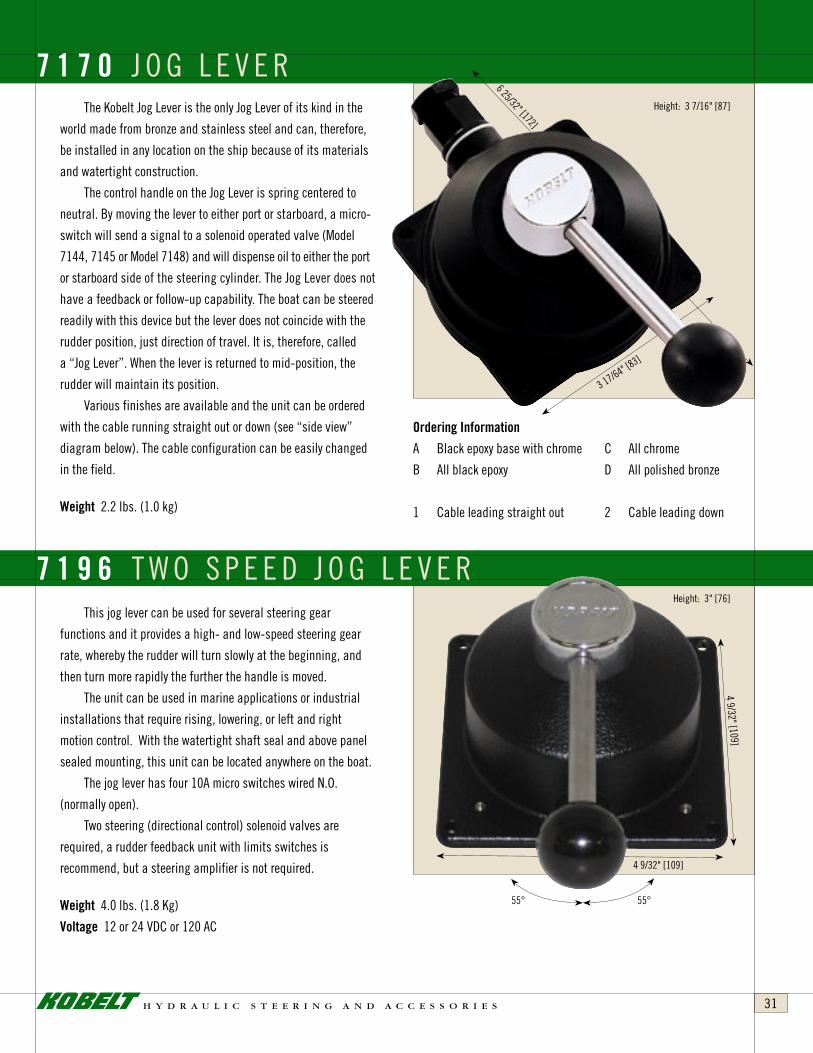
The Kobelt Jog Lever is the only Jog Lever of its kind in the
world made from bronze and stainless steel and can, therefore,
be installed in any location on the ship because of its materials
and watertight construction .
The control handle on the Jog Lever is spring centered to
neutral . By moving the lever to either port or starboard, a micro-
switch will send a signal to a solenoid operated valve (Model
7144, 7145 or Model 7148) and will dispense oil to either the port
or starboard side of the steering cylinder . The Jog Lever does not
have a feedback or follow-up capability . The boat can be steered
readily with this device but the lever does not coincide with the
rudder position, just direction of travel . It is, therefore, called
a “Jog Lever” . When the lever is returned to mid-position, the
rudder will maintain its position .
Various finishes are available and the unit can be ordered
with the cable running straight out or down (see “side view”
diagram below) . The cable configuration can be easily changed
in the field .
weight2 .2 lbs . (1 .0 kg)
orderinginformation
A Black epoxy base with chrome C All chrome
B All black epoxy D All polished bronze
1 Cable leading straight out 2 Cable leading down
7 1 7 0 J O G L E V E R
This jog lever can be used for several steering gear
functions and it provides a high- and low-speed steering gear
rate, whereby the rudder will turn slowly at the beginning, and
then turn more rapidly the further the handle is moved .
The unit can be used in marine applications or industrial
installations that require rising, lowering, or left and right
motion control . With the watertight shaft seal and above panel
sealed mounting, this unit can be located anywhere on the boat .
The jog lever has four 10A micro switches wired N .O .
(normally open) .
Two steering (directional control) solenoid valves are
required, a rudder feedback unit with limits switches is
recommend, but a steering amplifier is not required .
weight4 .0 lbs . (1 .8 Kg)
voltage12 or 24 VDC or 120 AC
7 1 9 6 T W O S P E E D J O G L E V E R
6 25/32" [172]
3 17/64" [83]
4 9/32" [109]
4 9/32" [109]
55° 55°
Height: 3 7/16" [87]
Height: 3" [76]

h y d r a u l i c s t e e r i n g a n d a c c e s s o r i e s32
The Model 7171 is manufactured from bronze and stainless
steel, and is suited for installation anywhere on the ship . Its
watertight construction will not allow seaspray to enter the unit .
This control device is a full follow-up rudder control . It is
equipped with a detent in mid-handle position; the straight-
ahead position . Moving the control lever to either port or
starboard will cause the rudder to follow proportionately .
In order to complete a system of this nature, a feedback device
connected with a link to the rudder stock, such as our Model
7174, and an electronic interface will then give the operator
complete control over the rudder . This is possible at all times
since the control lever and the 7171 correspond with the rudder
position .
The 7171 is available with 2 Microswitches (1 per side),
2 Potentiometers and 2 Trim Pots . The 7171 is also available as
a Jog Lever with 2 Microswitches per side .
weight7 .5 lbs . (3 .4 kg)
orderinginformation
A 2 switches & 1 potentiometer
B 2 switches & 2 potentiometers
G 4 switches
P 1 potentiometer
OHMS rating for potentiometer must be specified when ordering .
A trim pot will be supplied with each potentiometer .
7 1 7 1 F U L L F O L L O W - U P C O N T R O L L E V E R
The basic function of the 7171-SW is the same as the
7171 . This unit, however, can be used as a main electronic
control station and is ideally suited for high-speed craft .
If equipped with two potentiometers, it could be used for
catamaran steering with split electronic rudder demand,
allowing the rudders to move simul taneously and always
remain synchronized . It can also be used for conventional
craft with one potentiometer for rudder positioning . A
second potentiometer could be used to show rudder
demand . The star wheel can be equipped with push buttons
or switches at the end of the grips for special applications .
weight11 .0 lbs . (5 .0 kg)
orderinginformation
A 2 switches & 1 potentiometer
B 2 switches & 2 potentiometers
P 1 potentiometer
Regular potentiometer supplied with this unit is a 1K .
7 1 7 1 - s w F U L L F O L L O W - U P C O N T R O L L E V E R
4 3/4" [121]
10 5/16" [262]
4 3/4" [121]
6 27
/32"
[174
]
45°
45°

h y d r a u l i c s t e e r i n g a n d a c c e s s o r i e s 33
The 7197 is intended for electric over hydraulic steering
systems and provides a control panel with a full follow-up
electronic control lever . At the extreme ends, at either side, jog
lever functions can be used for quick rudder response . With two
functions incorporated into one control lever, this unit is also a
space saving device .
The 7197 is available with up to three potentiometers and
one pair of limit switches .
To complete the systems, a 7173-K steering amplifier,
steering (directional control) solenoid valve and rudder feedback
unit complete with potentiometers and limit switches such
as our 7174-A are required . For systems with more than one
station, a transfer box and station selector switches at each
station are also required .
weight6 .7 lbs . (3 .0 Kg)
7 1 9 7 S I N G L E L E V E R F F U / J O G C O M B I N AT I O N C O N T R O L L E R
The dual mode combination dual lever 7198 is intended
for electric over hydraulic steering systems and is an extension
of our 7197 single lever controller . However, it also provides
independent (or synchronized) control of two rudders . Each
lever is available with up to three potentiometers and one pair of
limit switches, and provides Full Follow-Up rudder control with
a jog steering as the secondary control for each steering gear .
To complete the systems a 7173-K steering amplifier, steering
(directional control) solenoid valve and rudder feedback unit
complete with potentiometers and limit switches, such as our
7174-A, is required for each gear . For systems with more than
one station a transfer box and station selector switches at each
station are also required .
weight12 .7 lbs . (5 .8 Kg)
7 1 9 8 D U A L L E V E R F F U / J O G C O M B I N A T I O N C O N T R O L L E R
4 1/2" [114]
8" [2
03]
6 1/
4" [1
59]
11 3/8" [289]
35°
35°
5°Jog Lever
5°Jog Lever
5°Jog Lever
5°Jog Lever
35°
35°
Height: 5 31/64" [148]

h y d r a u l i c s t e e r i n g a n d a c c e s s o r i e s34
CUT-OUT DIMENSIONS
7 1 6 6 C O M P A C T E L E C T R O N I C H E L MThis electronic helm is specially designed to fit into tight
spaces . The stainless steel shaft has a 3/4 inch taper . The shaft
rotation is 2-2/3 turns from hard-over to hard-over . It’s equipped
with only one potentiometer and is intended for full follow-up
electronic controls . This unit is manufactured from bronze and
stainless steel and will provide years of trouble-free service .
weight5 .5 lbs . (2 .5 kg)
The Model 7172’s basic purpose is to provide an electronic
signal to the hydraulic steering gear for positioning of the rudder .
Normally the 7172 is equipped with two potentiometers .
The first would be used with our 7173 interface to send
the rudder to either port or starboard . This gives precise rudder
positioning, when used in conjunction with our 7168 or 7174
feed-back units .
The second potentiometer can be used to indicate rudder
demand . The actual rudder position is fed back via the 7168 or
7174 to separate the rudder angle indicator 7175 .
The construction of our 7172 is all bronze and stainless
steel, and is designed to give years of trouble-free service .
Straight ahead detent is provided . The wheel has approxi mately
three turns from hardover to hardover .
The heavy duty construction allows the helmsman to hang
onto the wheel in the roughest of weather without causing any
damage to this unit .
weight22 .0 lbs . (10 .0 kg)
7 1 7 2 E L E C T R O N I C H E L M6 1/8" [156]
1" [25]
8 11
/16"
[220
.7]

h y d r a u l i c s t e e r i n g a n d a c c e s s o r i e s 35
This control device is intended to control one or two main
engines . It also provides fingertip control over rudder, and can be
equipped with either two indicator lights or two push buttons or
toggle switches to select various propulsion modes and steering
modes, as well as incorporating a bow thruster .
The 7176 Controller is constructed entirely from bronze
and stainless steel and is very light in weight . Provision for a
shoulder strap has been made so that the unit can be worn
around the neck like a camera . This unit is completely sealed to
prevent moisture from entering the unit .
The 7176 controller can be integrated with the steering gear
via a 7177 circuit board and a 7173-K follow-up amplifier . The
7177 is housed in our 7173 control box and requires a 6511-SP
small control panel to effect station select .
Depending on the propulsion systems, other configurations
using the 6507 or 6505-2000 microprocessor are available .
Please contact your sales rep . for details .
weight4 .4 lbs . (2 .0 kg)
7 1 7 6 W A L K - A B O U T C O N T R O L L E R
Design Patent Pending

h y d r a u l i c s t e e r i n g a n d a c c e s s o r i e s36
The Model 6655 Control Head is an electronic device that
provides control for two main engines and steering gear . The two
control handles can be moved independently 75 degrees in either
direction, and can be used to control fixed pitch gearbox driven
propellors and engine speed . The two control handles can also be
arranged to provide control over waterjets, CP propellors and
any type of propulsion machinery as well as, of course, the
engine speed .
Rotating the control on its horizontal plane will give
precise control over the rudder . In order to make the system
operative, the Kobelt Microprocessor 6535 for a main engine,
and its associated actuators, are required . For the steering gear
portion, the model 7173 and associated hydraulic components are
required .
This control head can be used on virtually any type of vessel
from approximately 60' to ocean-going vessels .
This control head is designed to provide control of two or
four engines, as well as steering gear . The maximum rudder
angle is 90° or 45° on either side . It is a reduced version of
the Kobelt 6655 model because of its compact size . The 6657
is extremely popular where limited space is available, and is
constructed entirely in bronze and stainless steel .
6 6 5 7 E L E C T R O N I C C O N T R O L H E A D
6 6 5 5 E L E C T R O N I C C O N T R O L H E A D
It is constructed in all bronze and stainless steel and is
ideally suited for the marine environment . Our control heads
incorporate the traditional look of sea-going vessels and yet
are modern in appearance, extremely suitable and rugged in
construction .
Note: The 6653 and 6654 control heads are designed for 360° systems

h y d r a u l i c s t e e r i n g a n d a c c e s s o r i e s 37
5 1/
16" [
129]
7 13
/32"
[188
]
5.46" [139] 5.46" [139]
11 13/32" [290]
6.94
" [17
6]
�13/64" [�5]TYP.
55°
5/32
" [4]
CUT-OUT DIMENSIONS
The 7175 rudder indicator system will continuously monitor
and indicate the position of your rudder .
Whether you are manoeuvering, power steering or changing
course, an accurate readout of the rudder position will be shown
on a three inch, three colour display .
The basic system consists of a 7175-M Master Station, and
a Kobelt 7168 Feed Back Unit .
Up to five additional “repeater stations” can be installed by
using the 7175-S repeater .
Both the master and repeater have a backlit translucent
display and are waterproof on the front face .
Up to 5 remote stations may be connected in series .
weight0 .7 lbs . (0 .3 kg)
This multi-purpose device can be used either on
the dashboard of a boat or overhead, and because of the
accommodating angle the control devices are very easy to
view . Alarm systems or control devices with many shipboard
functions can be installed on this unit .
weight6 .8 lb . (3 .1 kg)
7 1 7 5 R U D D E R I N D I C A T O R
7 1 7 5 - 2 0 0 0

h y d r a u l i c s t e e r i n g a n d a c c e s s o r i e s38
MODEL 7180
PORT STBD
Ø2.3 [58]
3.4 [86]
Ø2.
2 [5
5]
Ø2.
1 [5
2]
0.6
[16]
2.2 [56]
1.0 [27]
0.4 [9]
3.0 [77]
1.5 [38]
REMOVE CAPPLUG & INSERT
LIGHT BULB
10-32NF
CUT-OUT DIMENSIONS
This illuminated unit is equipped with a manual dimmer .
A visual alarm is available and a relay signal allows you to
connect to the main alarm system . These are powered from a
secondary source and indicate power or rudder feedback failure .
The bottom inspection door is removable and allows for
easy centering of the pointers . The illuminating lightbulbs have
a 30,000 hour life cycle . The unit is available as 12 and 24 volts
DC . The housing and all hardware are constructed from bronze
and stainless steel . The unit carries our usual warranty .
weight13 .2 lbs . (6 .0 kg)
A smaller version of our popular rudder angle indicator
7175, the 7180 rudder indicating system will provide you with a
realtime visual display of the position of the rudder .
Whether you are manoeuvring, power steering or changing
course, an accurate readout of the rudder position will be
displayed on a tri-coloured two-inch display .
This unit is particularly adapted to the integrated control
head panels for models 7197, 7198 and utility panels such as
model 7175-2000 . Up to five additional “repeater stations” can
be installed using the 7180-S repeater . Both the master and
repeater have an optional backlit translucent display .
weight 0 .55 lb . (0 .25 kg)
7 1 7 8 P A N O R A M I C R U D D E R A N G L E I N D I C A T O R
7 1 8 0 R U D D E R A N G L E I N D I C A T O R

h y d r a u l i c s t e e r i n g a n d a c c e s s o r i e s 39
This unit is designed for many shipboard and industrial
applications where low pressure and a small source of hydraulic
pressure is required .
It is available with either a 12 or 24 volt DC motor and
is intended for intermittent use only . It lends itself extremely
well to manual steering systems where a source of pressure is
required to operate the steering cylinder in conjunction with an
autopilot . It could also be used in raising and lowering hatches,
masts and tables .
The maximum amperage that the motor can handle on an
intermittent basis is approximately 30 amps for a 12 volt motor
and 15 amps for a 24 volt motor . We do, however, recommend
that the motor should not draw any more than 16 amps for the
12 volt motor and 8 amps for the 24 volt motor . The table below
indicates the capabilities of the motor . Adjustable safety valves
for both port and starboard are provided and flow control screws
provide adjustment for the variable delivery from 40 to 250
cubic inches per minute . The lock valve fitted on the pump is to
prevent hydraulic feedback from the steering system . Both pump
and motor are equipped with ball bearings . The pump is made
of silicon bronze, stainless steel hardware with hardened steel
pistons and wear plate .
To order this unit with the reversing relays, the part number is:
7201-PR12 (12 volt) or
7201-PR24 (24 Volt)
Please specify 12 or 24 volt .
pleasenote!
Pump, relay & auto pilot should be the same voltage .
7 2 0 1 - p r A U T O P I L O T P U M P R E L AY S
weight15 .0 lbs . (6 .8 kg)

h y d r a u l i c s t e e r i n g a n d a c c e s s o r i e s40
This small version of a rudder angle feedback unit, with
its all bronze and stainless steel construction, is available with
one or two potentiometers . Its compact design and watertight
construction will allow it to be installed in very tight quarters .
Because of the non-corrosive construction, it is intended for a
saltwater environment . It is used to give a rudder angle position,
feedback signal to either an autopilot, angle indicator
or electronic steering components .
weight2 .2 lbs . (1 .0 kg)
orderinginformation
7168-P 1 potentiometer
7168-PP 2 potentiometers
Standard Potentiometers are 1K .
7 1 6 8 R U D D E R A N G L E F E E D B A C K U N I T
FRONT VIEW BACK VIEW SIDE VIEW

h y d r a u l i c s t e e r i n g a n d a c c e s s o r i e s 41
This unit is designed to be mechanically connected to
the rudder stock . Its purpose is to feed back the rudder angle
position to such items as Auto Pilot, Full Follow Up control
systems and Rudder Angle indicator . The 7174 is available with
up to 3 Potentiometers, 3 Trim Pots and 4 Microswitches . It is
constructed of bronze and stainless steel and will withstand
vibration and corrosion for years . It is available with fittings for
oil-filled applications .
weight6 .6 lbs . (3 .0 kg)
orderinginformation
A 2 switches & 1 potentiometer
B 2 switches & 2 potentiometers
C 2 switches & 3 potentiometers
D 1 trim pot
E 2 trim pots
F 3 trim pots
G 4 switches
e .g . 7174-CE
7 1 7 4 R U D D E R A N G L E F E E D B A C K
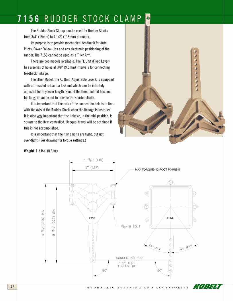
h y d r a u l i c s t e e r i n g a n d a c c e s s o r i e s42
The Rudder Stock Clamp can be used for Rudder Stocks
from 3/4" (19mm) to 4 1/2" (115mm) diameter .
Its purpose is to provide mechanical feedback for Auto
Pilots, Power Follow-Ups and any electronic positioning of the
rudder . The 7156 cannot be used as a Tiller Arm .
There are two models available . The FL Unit (Fixed Lever)
has a series of holes at 3/8" (9 .5mm) intervals for connecting
feedback linkage .
The other Model, the AL Unit (Adjustable Lever), is equipped
with a threaded rod and a lock nut which can be infinitely
adjusted for any lever length . Should the threaded rod become
too long, it can be cut to provide the shorter stroke .
It is important that the axis of the connection hole is in line
with the axis of the Rudder Stock when the linkage is installed .
It is also very important that the linkage, in the mid-position, is
square to the item controlled . Unequal travel will be obtained if
this is not accomplished .
It is important that the fixing bolts are tight, but not
over-tight . (See drawing for torque settings .)
weight 1 .5 lbs . (0 .6 kg)
7 1 5 6 R U D D E R S T O C K C L A M P
MAX TORQUE=12 FOOT POUNDS
7156 7174

h y d r a u l i c s t e e r i n g a n d a c c e s s o r i e s 43
This unit is designed to accept the command signal from
our Models 7167, 7169, 7171, 7172 and 7176 and coordinates
the desired rudder position with our feedback unit Models 7168
or 7174 . Models 7144, 7145 and 7148 are equipped with solenoid
valves, can be activated by the Model 7173-K and will disperse
hydraulic fluid to the hydraulic steering system to maintain the
desired position .
This device can be located anywhere aboard ship, even in
the steering compartment, since its watertight and non-corrosive
materials will not affect the electronics internally .
The Model 7173-K Amplifier is a multi-optional driver board
(12 or 24 VDC POWER) which can be changed in the field (see
manual) and can control:
1 . Single steering system
2 . Dual speed steering system
3 . Two independent steering systems controlled by the same
controller (this is ideal for catamaran steering because of its
electronic tie bar) .
4 . Two independent hydraulic systems; i .e . steering and
bucket control
This unit is the heart of our electronic steering devices .
It has the ability to accomplish many tasks . It can be used for
single or multi rudder full follow-up electronic control in either
single or multi speed . It also has the ability to synchronize multi
rudders without mechanical tie-bars . The unit is extremely
accurate . Our engineering department has made the installation
very simple and inexpensive . The bronze casing protects the
electronics and will provide years of trouble free service .
weight5 .5 lbs . (2 .5 kg)
7 1 7 3 - K E LECTRON IC FULL FOLLOW-UP AMPL I F IER
12 OR 24 VDCPOWER

h y d r a u l i c s t e e r i n g a n d a c c e s s o r i e s44
S T A R T E R P A N E L SKobelt Manufacturing can provide Starter Panels for single
and multi Power Packs as well as remote start and stop and
alarm panels for the wheelhouse or the engine control room .
These units are individually made to customer requirements
and are all made to meet classification standards (i .e . ABS
or Lloyds) .
alarms
Remote start and stop and alarm panels for steering gear
hydraulic power units .
This control panel provides complete control of a single
hydraulic power pack for steering gear purposes . The unit,
constructed entirely in bronze and stainless steel, provides start
and stop functions, as well as indicating for any failure . It also
complies with all regulatory authorities as far as alarm functions
for steering gear are concerned .
This unit is basically the same as the 6511-AP8-S, but is
intended for two separate power packs, whereby the operator
can select either one of the two or both hydraulic power packs for
steering gear purposes .
The Starter Panel (at right) is for a dual pumping system, providing all the necessary breakers and safety devices to comply with the inspection authorities . As well as the transfer of the control from the steering compartment to the engine control room and wheelhouse .
6 5 1 1 - a p 8 - s / 6 5 1 1 - a p 8 - t
6511-AP8-S
6511-AP8-T

h y d r a u l i c s t e e r i n g a n d a c c e s s o r i e s 45
It is mandatory by some of the inspecting authorities to
be able to isolate steering components in case of failure and
maintain the items that are still functional . A series of ball
valves was normally employed to accomplish this task . In
cases of emergency, it was proven that the crew was not always
immediately aware of what to turn, and which way to turn it .
Kobelt Manufacturing, for this reason, provides a Steering
Mode Selector that consists of only two manual levers that are
either in the ON or OFF position . The unit is capable of handling
26 gallons of oil per minute with two small solenoid valves
(13 gallons each) . It is also available, on special request, with
a proportional solenoid valve with a control circuit of 4 to 20
milliamps and a flow capacity of up to 40 gallons per minute .
Two sources of hydraulic pressure can be fed into the 7149 . Both
supply lines are equipped with check valves and flow controls .
The system is designed to control either two or four steering
cylinders . Putting the levers in the ON position will provide
hydraulic pressure to the output port . Cancelling a side (lever in
the OFF position) will stop the flow of oil to that half of the unit
and, consequently, the lines and the cylinders .
Unbalanced cylinders have an unequal volume and,
therefore, the oil needs to be able to circulate and excess oil has
to be returned to the tank .
This unit is pre-assembled by Kobelt . The solenoid valve
provided has a maximum flow of 26 gallons a minute at 2,000
PSI maximum . The solenoid valve is a proportional type and will
deliver very little oil when small corrections are required and
will proportionally increase the flow for larger corrections . In
other words, the solenoid valve will ramp up and down to provide
smooth and accurate control . A 40 gallon valve (Model #7150-
40A) is also available and a 60 gallon valve can be obtained on
request . All of these valves are of a proportional type . In order to
minimize the installation time by the shipyard, the components
as mentioned, are pre-assembled and all the shipyard has to do
is connect 6 hoses, 1 pressure line, 1 return line to the tank, 2
lines to the initiating cylinder, 2 lines to the power cylinder and
a 1/2" roller chain to the rudder stroke . If needed, 2 helm lines
can also be connected for manual back up . Even though Kobelt
Manufacturing uses the best possible seals and connections
available, minute oil leaks are almost inevitable as time goes on .
Therefore, the pan is equipped with 2 drain plugs on either side,
where the oil can be recovered .
7 1 4 9 S T E E R I N G M O D E S E L E C T O R
7 1 5 0 W I D E A N G L E S T E E R I N G G E A R
The 7149 will provide all of these functions . In case of
emergency, a manual hydraulic pump can be connected to
the ports provided on the 7149 that will allow the ship to be
controlled without any electricity of any kind . Of course, the
manual levers turning the unit OFF and ON also require no
electricity . Two safety valves can also be provided to relieve any
excess hydraulic pressure (in case the rudder hits a solid object) .
The unit is constructed entirely from bronze and stainless
steel and carries a five year warranty . Maximum operating
pressure is 2,000 PSI .

h y d r a u l i c s t e e r i n g a n d a c c e s s o r i e s46
H Y D R A U L I C P O W E R P A C K STo complete your steering system, Kobelt Manufacturing can
provide many standard and custom configurations . Motors and pumps are sized for your application . The customer must specify
motor voltages and frequency .
standardequipment
• TEFC (IP44) (IEEE45) electric motors
• Variable volume pressure-compensated piston pumps
• JIC Type “A” reservoirs
• Return line filter (10 Micron) c/w Indicator
• Solenoid operated directional control valves
• SAE O’ring component connections
• Flared steel tubing
• Pressure relief valve – adjustable
• Oil-filled Pressure gauge with isolation valve
• Low Pressure alarm switch
• Flow controls and check valves – as required
• Internal suction strainer
• Sight Level gauge and thermometer
• Low- level sensor alarm switch
• Painted externally with industrial enamel
• Filler / breather
• Tank clean out end – covers
• Lifting eyes and drain plug
• Painted internally with Gylptol
• Tested for specified flow, pressure & function
options
• Low level/High temperature alarms switch
• Filter alarm switch
• “A” and “B” isolation valves
• Dual or split reservoirs
• Dual power units
• Gravity feed filling ports
• Oil coolers
• Two independent hydraulic circuits
• Valving as per customer’s requirements
• Epoxy Paint
• Desiccant filler breather
• Base Mounted Drip Tray c/w Drain
• Custom Aluminum Marine Grade Reservoirs
A typical Kobelt hydraulic unit . Simple to install, reliable and, with motor and pump located on the top, easily accessible for maintenance . Tell us what you need and we will be happy to work out a custom solution for you .
recommendedHydraulicoils
An ISO #32 (Viscosity grade 32) hydraulic oil is
recommended for power operated hydraulic steering systems .
Good quality hydraulic oil with anti-wear properties from
one of the major brands, supplied by a reliable supplier is
recommended . The hydraulic oil should be new and clean of
all contaminants . The principal requirements of a premium
hydraulic fluid are proper viscosity, high viscosity index, anti-
wear protection, adequate pour point, and compatibility with
seal materials .
INSTALLATION TIP: All hydraulic lines in the steering system
must be thoroughly cleaned prior to filling the system . Ensure all
hydraulic lines are secured and fittings are tight .

h y d r a u l i c s t e e r i n g a n d a c c e s s o r i e s 47
OPTIONAL
• It is important to ensure that the steering wheel can be operated without any interference . The Helm Pump must be mounted on a secure structure which will support the helmsman in a rough sea without the pump breaking loose . It is also recommended to have access to the connecting lines on the rear of the pump and the flow adjustment on the face of the pump as well as the filler plug front and back .
• During installation it is of utmost importance to keep dirt and foreign matters out of the system . Cleanliness is extremely important .
• We do not recommend the use of teflon tape for pipe sealing . This often rolls over the edge of the fitting and is cut off on installation; it then floats in the system . It is recommended that liquid teflon sealant or its equivalent is used . It is easier to ensure that none of this type of sealant gets into the system .
• Copper or Stainless Steel tubing is preferred for the piping material . The tubing should be of fairly large inside diameter to avoid excessive friction in the hydraulic system, especially in cold weather environments .
Depending on the number of stations, the length of runs and the size of the Helm Pump, the piping must be chosen accordingly . We recommend the minimum diameter of 1/2" tubing, but on the long runs, and larger pumps, 3/4" tubing is recommended . When installing this tubing, it is very important to have a steady rise in the lines towards the highest point in the steering system . It is very difficult to bleed the tubing system with a rise and fall pattern, because air gets trapped in the elevated pockets .
• It is also recommended that an expansion tank is installed on the uppermost station, to provide an additional reservoir of oil . This expansion tank must have a vented plug . The plug, however, must be arranged in such a fashion that water cannot enter the steering system . All other filler plugs on the steering stations must be of a non-vented type . If an expansion tank is not used, the uppermost steering station must have a vented filler plug on the Helm Pump . This is to allow the oil to expand during a hot day and contract when the temperature declines .
B A S I C I N S T A L L A T I O N I N S T R U C T I O N S F O R H E L M P U M P S

h y d r a u l i c s t e e r i n g a n d a c c e s s o r i e s48
• It is important that the steering cylinders chosen for a specific application are the right diameter and stroke suitable for the installation .
• All of the Kobelt Steering Cylinders are equipped with either ball rod end fittings or spherical bearings . These bearings and rod ends have allowance for a given amount of misalignment and rotation . It is very important that the cylinders are installed without causing any binding in the cylinder mechanism during operation .
• The bolts used for mounting the cylinder must be of Grade 5 or better . The brackets used for fastening the cylinders must be able to withstand the maximum torque of the cylinder and have a solid plain face without any deflection during operation .
• The cylinders must be installed so that in the mid-stroke position the ship’s rudder is in mid-position also . It is important that the tiller arm is installed at right angles to the pivoting point of the cylinder . If this is not followed, unequal rudder travel will result .
• When installing a twin or multi-cylinder steering system, it is of extreme importance that the strokes of all cylinders are matched . If, for example, one cylinder has reached the end of its stroke and the second cylinder has not completed its stroke, it will cause a tremendous amount of unnecessary stress on the rudder stock and the steering system as a whole . It is extremely important that the rod ends at the end of the cylinder and stopnuts are adjusted to balance all cylinder movements .
• Steering cylinders connected to tiller arms move through an arc when in operation . It is necessary to have hoses connected to the steering cylinders for the hydraulic fluid . Solid piping will crack and fail very rapidly because of the movement of the cylinders . When selecting the hose, it is important to have the proper operating range for these hoses to match the hydraulic system pressure .
• On ships where there are two rudders interconnected with a tie bar, the tie bar must also be constructed to take 60% of the total rudder torque . It is highly recommended to leave sufficient room in the steering gear compartment to allow for service . The Kobelt Steering cylinders are also equipped with grease fittings which should be greased at regular intervals (depending on the duty cycle) . Bolts, nuts and cotter keys should be checked regularly .
• Should anyone enter the steering gear compartment when a hydraulic steering system is in operation, it is of extreme importance to stay clear of all moving parts . A human limb could easily be lost if due care and attention is not taken .
I N S T A L L A T I O N I N S T R U C T I O N S F O R K O B E L T S T E E R I N G C Y L I N D E R S

h y d r a u l i c s t e e r i n g a n d a c c e s s o r i e s 49
When installing a manual hydraulic steering system, it is recommended to have a header tank above the highest steering pump . On power hydraulic systems many options are available as far as the location of tanks, filters, valving and, of course, a motor or engine-driven pump . It is known to the trade that there is no valve that is perfectly tight . Any hydraulic valve will lose a very small amount of oil over an extended period of time and if the main tank is at the lowest point, some oil from the highest point will drain to the lowest point . If the steering system consists of manually-operated helm pumps, this may cause the helm pumps to lose oil to the main tanks . If a large enough header tank is installed, the main tank could be vented to the header tank and then the uppermost station will never run out of oil . Another approach would be to put the main tank above the highest manual steering pump and run the suction line from the tank to the pump and return line back to the tank . Another very popular system is the autofill system whereby a continuous trickle of oil from the power system fills the header tank with an overflow line from the header tank back to the main tank . It is important to remember that the main tank should always be above the pump so that there is gravity feed from the tank to the engine or motor-driven pump .
7143 must be installed in all systems with spool valves .
B A S I C H Y D R A U L I C P O W E R S Y S T E M S
B A S I C 7 1 4 4 I N S T A L L A T I O N W I T H 7 1 7 0 J O G L E V E R I N T E R F A C E

h y d r a u l i c s t e e r i n g a n d a c c e s s o r i e s50
RUDDER ANGLE
35°
108
POSITION
DIMENSION K
115
122
129
135
1
2
3
4
5
1426
1497
1568 5.01
4.35
4.57
4.79
3.66
3.90
4.12
45°
3.42
inch mm
RUDDER ANGLE
6.14
5.87
5.33
5.60
5.06
4.52
4.79
4.25
mminch
121
127
105
110
116
87
93
99
LINKAGE
8
4
6
21
7
5
3
PORT T
PRESSURE
PORT B
PORT A
B A
PORT P
K
4
K 8
65
7
A B
PORT A
23
1
RETURN (TO TANK)
SUPPLY (PRESSURE)
PORT P
PORT B
BA
TILLER ARM
STEERING CYLINDER
RUDDERSTOCK
(TO PORT P)
(RETURN TO TANK)
• It is important that the 7148 is installed so that the mechanical feedback linkage between the rudder stock and the Power Follow-Up unit will be square in mid-position, and that the strokes will allow the rudder to go hardover to hardover using all of the available stroke from the 7148 Power Follow-Up .
• The foundation plate for the 7148 must be flat, vibration free and securely attached to the ship’s hull . The oil supply pressure enters port “P” . The fitting provided at port “P” should not be removed or turned . The Helm Pump lines are connected on the underside of the 7148 . The two outgoing lines “A” and “B” to the main steering cylinder must be connected in accordance with the drawings provided . If these lines are incorrectly connected, the Power Follow-Up will shift the rudder hardover to one side and it will remain there . Crossing the lines to the main cylinder will cure this problem .
• For small steering cylinders up to the 7080 series, 1/2" lines are sufficient between the 7148 and the cylinders . For the 7094, steering cylinders 3/4" or larger lines are recommended .
• Any lost motion in either the main steering system (Tiller Arm, Rod Ends, loose Rudder Stock etc .) or in the feedback linkage will cause the steering system to be inaccurate and to “hunt” . It is extremely important that all connection points are tight without lost motion .
• For specifics, please contact Kobelt Manufacturing .
7 1 4 8 B A S I C I N S T A L L A T I O N I N S T R U C T I O N S F U L L P O W E R F O L L O W - U P

h y d r a u l i c s t e e r i n g a n d a c c e s s o r i e s 51
noteAll piping must comply with our specification for a given flow capacity . The
burst pressure must be at least twice as high as the operating pressure . All items that are moving, such as cylinders and tilt helm pumps must be connected with hoses long enough to avoid any fatigue or kink of hose .

h y d r a u l i c s t e e r i n g a n d a c c e s s o r i e s52
For Manual Systems, it is recommended to use i.s.o.#10 Hydraulic Oil . This oil is very light and does not have good basic lubricating qualities, however, it is the most ideal oil since it requires little effort to move through the tubing . We do not recommend using any other type of fluid . The hydraulic oil used should be new and clear of all foreign matters .
Remove the vented filler plug from either the uppermost Helm Pump or Expansion Tank . (Lower Helm Pumps must have a non-vented plug .) Insert funnel of suitable size and fill carefully with the recommended oil . Once the Helm Pump or Expansion Tank has been filled, the Helm Pump steering wheel can be turned . This will then displace the oil into the steering lines . As the oil descends in the Helm Pump, or Expansion Tank, keep adding oil and turning the wheel either to port or starboard until resistance is felt . Continue to turn the wheel hardover to hardover until the air bubbles stop rising and oil level remains constant . There are bleeder fittings supplied on the steering cylinder to vent any air trapped in the cylinder .
expansiontanksExpansion Tanks are normally supplied by the shipyard . They can
also be obtained from Kobelt and, we recommend that approximately 1 Quart (or 1 Litre) minimum volume should be used in this application . The vent line from the Expansion Tank to the Helm Pump should protrude approximately 1" from the bottom of the Expansion Tank into the tank itself . This avoids dirt and condensed water from entering the steering system . The vent plug must be arranged in such a fashion that water spray and rain cannot enter the tank .
F I L L I N G A N D B L E E D I N G A M A N U A L S Y S T E M

h y d r a u l i c s t e e r i n g a n d a c c e s s o r i e s 53
• On a power hydraulic system we recommend using ani.s.o.#32 hydraulic oil . This oil has excellent lubricating qualities for power driven hydraulic pumps . It is important that these are well lubricated . It is recommended to use the electrical solenoid valve via the Jog Lever or Full Power Follow-up Lever, to bleed the main cylinder . The main cylinders can therefore be bled and filled with hydraulic fluid without use of the manual helm pumps . If the main cylinder and the power part of the system is full with oil, the same procedure should then be followed as when filling the manual system .
expansiontankforpowersystem• On a power operated system (engine or motor-driven pump), the
Expansion Tank level can be maintained off the main pressure line, with a small manually operated needle valve . However, only a small volume should be supplied into this tank from the main source of supply . The return line from the header tank to the main oil tank should be no less than 1/2" in diameter and if an auto fill system is used, the header tank should not be vented . The main tank should be vented and the return line from the header tank to the main tank should terminate on the cover plate and not go to the bottom of the main tank .
powerDrivenHydraulicpump,tanksandbasicaccessories• It is highly recommended to have two sources of hydraulic pressure
for a steering system . The hydraulic pumps must also be selected to provide enough hydraulic fluid to turn the rudder from hardover to hardover as requested by the customer . In our cylinder tables, the volume of the cylinders are specified . This is quite readily converted into gallons per minute . Use the following equation; volUMe (cubic inch) times 0.26 divided by seconDs (desired hard-over speed) = Gallons per Minute, e .g . 440 x 0 .26 / 14 = 8 .2 Gpm .
• Kobelt recommends using pressure-compensated pumps for two basic reasons . The pressure-compensated pump only produces volume as required by the hydraulic steering system . If no volume is required, the pump will destroke itself to a minimum volume, requiring very little energy and since very little energy is consumed, very little heat is created in the oil . A hot oil system is not desirable .
• We also recommend that the pumps are gravity fed from the tank . This prevents the pump running dry and causing enormous damage during the start-up period . The oil storage tank should be a minimum of five times the volume of the maximum pump output . It is recommended that the tanks are equipped with a sight glass, vented filler, suction strainer, high pressure and return line filter, low pressure alarm and oil level alarm . If two units are connected, a one-way check valve must also be installed in each pumping output line .
Caution: Oil temperatures must not exceed 120°F (55°C) . Temperatures above this will damage the seals .
F I L L I N G A N D B L E E D I N G A P O W E R H Y D R A U L I C S Y S T E M• When the pump units are shipped, they are usually shipped without
any oil (dry) . Before starting the motor, it is important to fill the tank to near top level with light hydraulic oil (i .e . Shell Tellus 32 or equal) .
• The pump is normally marked with an arrow for direction of rotation . It is very critical that the rotation of the motor is checked to ensure the pump is turning in the right direction . As mentioned earlier, it is of extreme importance that the pipes and fittings are kept immaculately clean on the inside during installation .
• We recommend that the pump system, after start-up, should be run for no more than an hour and all filter elements should then be changed .
• If any impurities are found in the oil, it may also be necessary to change the oil itself . One other important factor is that if there is dirt in the hydraulic system, it will eventually lodge itself between two moving components and score items to the point where they can no longer be successfully used in the system and must be replaced . Dirt can also cause items to physically seize in their respective housings .
• Once the system is up and running, the oil storage tank must be topped and maintained at its appropriate level .
teflontapeshouldnotbeusedonpipefittings.aliquidpipesealantappliedattheendofthefittingispreferable.pipefittingsshouldnotbeover-torquedsincethetaperedthreadcancausesplittingofthecontrolcomponents.thetablebelowindicatestorquerequiredfortaperedpipefittings.
1/8"n.p.t. 10ft.lbs.1/4"n.p.t. 20ft.lbs.3/8"n.p.t. 30ft.lbs.1/2"n.p.t. 40ft.lbs.

h y d r a u l i c s t e e r i n g a n d a c c e s s o r i e s54
Unit of measure ● mm ● inches
H Y D R A U L I C S T E E R I N G T E C H N I C A L D A T A S H E E T
Upon completion, fax to (604) 590-8313 .
toproperlysizethesteeringsystemrequiredforyourvessel,pleasefilloutthefollowingaccurately.
Customer Name ________________________________________________________ Date _______________________
Address ______________________________________________________________ Phone ______________________
________________________________________________________________ Fax _______________________
________________________________________________________________ Email ______________________
Vessel name ___________________________________________________________ Signature ___________________
Hull/Yard number _______________________________________________________
Vessel length __________________________________________________________
Vessel type ____________________________________________________________ (Power, Sail, Workboat, etc .)
Hull type ● Planing ● Displacement ● Sail ● Catamaran ● Other________________________________
Maximum speed _________________ knots
Number of rudders _______________________________________________________
Degree of rudder angle 2 x _________________________________________________
Please specify other details (Nozzle, Tunnel, etc .) __________________________________
Rudder Shaft Diameter at Tiller ______________________________________________
Sketch your rudder with dimensions, as per sample, in the area provided or simply provide dimensions A - E .
saMple

h y d r a u l i c s t e e r i n g a n d a c c e s s o r i e s 55
Hydraulicsteeringsystemsareavailablewiththefollowingoptions:
Please tick box ●A . Manual hydraulic steering or power . . . . . . . . . . . . . . . . . . . . . . . . . . . . . . . . . . . . . . . . . . . . . . M ● P ●B . Manual number of turns required hardover to hardover . . . . . . . . . . . . . . . . . . . . . . . Specify _______________
C . Number of steering stations (hydraulic) . . . . . . . . . . . . . . . . . . . . . . . . . . . . . . . . . . . Specify _______________
D . Header tank (Kobelt #7002) . . . . . . . . . . . . . . . . . . . . . . . . . . . . . . . . . . . . . . . . . . . . . . . . . . . . . . . . . ●E . Rudder angle indicators required (Kobelt #7175) . . . . . . . . . . . . . . . . . . . . . . . . . . . . . . . . . . . . . . . . . ●F . Panoramic Rudder Angle Indicator (Kobelt #7178) . . . . . . . . . . . . . . . . . . . . . . . . . . . . . . . . . . . . . . . . ●G . Auto-pilot hydraulic pump (Kobelt #7201-PR) . . . . . . . . . . . . . . . . . . . . . . . . . . . . . . . . . . . . . . . . . . . ●H . Auto-pilot interface . . . . . . . . . . . . . . . . . . . . . . . . . . . . . . . . . . . . . . . . . . . . . . . . . . . . . . . . . . . . . . . . ● if “yes” indicate speed . . . . . . . . . . . . . . . . . . . . . . . . . . . . . . . . . . . . . . . . . . . . . . . . . . . . . single ● two ●I . Number of jog levers (Kobelt #7170) . . . . . . . . . . . . . . . . . . . . . . . . . . . . . . . . . . . . . . Specify _______________
J . Full power follow up (FFUS) servo hydraulic steering (Kobelt #7147, 7065S, 7085S or #7148) . . . . . . . ●K . Full power follow up (FFU) electronic steering (Kobelt #7173-K) . . . . . . . . . . . . . . . . . . . . . . . . . . . . . . ●L . Electronic tiebar (Kobelt #7173) . . . . . . . . . . . . . . . . . . . . . . . . . . . . . . . . . . . . . . . . . . . . . . . . . . . . . . ●M . Station transfer . . . . . . . . . . . . . . . . . . . . . . . . . . . . . . . . . . . . . . . . . . . . . . . . . . . . . . . . . . . . . . . . . . ●N . Number of stations (electronic) . . . . . . . . . . . . . . . . . . . . . . . . . . . . . . . . . . . . . . . . . Specify _______________
O . Tiller arms . . . . . . . . . . . . . . . . . . . . . . . . . . . . . . . . . . . . . . . . . . . . . . . . . . . . . . . . . . . . . . . single ● twin ●P . Type of control . . . . . . . . . . . . . . . . . . . . . . . . . . . . . . . . . . . . . . . . . . . . . . . . . . . . . . . . . . . . . . . . . . . . 7171 ● 7171-SW ● 7172 ● Specify _______________
rudderinformationrequired
Number of rudders . . . . . . . . . . . . . . . . . . . . . . . . . . . . . . . . . . . . . . . .1 ● 2 ● Specify _______________
Number of cylinders per rudder . . . . . . . . . . . . . . . . . . . . . . . . . . . . . . . . . . . . . . . . . . . . Specify _______________
Tiebar fitting required . . . . . . . . . . . . . . . . . . . . . . . . . . . . . . . . . . . . . . . . . . . . . . . . . . . . . . . . . . . . . . ●Degree of rudder rotation . . . . . . . . . . . . . . . . . . . . . . . . . . . . . . . . . .35 ● 45 ● Specify _______________
Rudder torque (If rudder torque is not available, please complete Hydraulic Steering Technical Data Sheet) ●
powerinformationrequired
Hydraulic Power Source . . . . . . . . . . . . . . . . . . . . . . . . . . . . . . . . . . .Engine Driven ● Electric Motor ●Number of Pumps _______________________________ Hardover Time ________(seconds)
Electric Motor __________ VAC __________ PH __________ HZ Solenoid Voltage 12V ● 24V ●
classification
Specify which classification _____________________________________________________
Name of Shipyard ____________________________________________________________
B A S I C S E L E C T I O N G U I D E F O R K O B E LT H Y D R A U L I C S T E E R I N G
✔
Upon completion, fax to (604) 590-8313 .
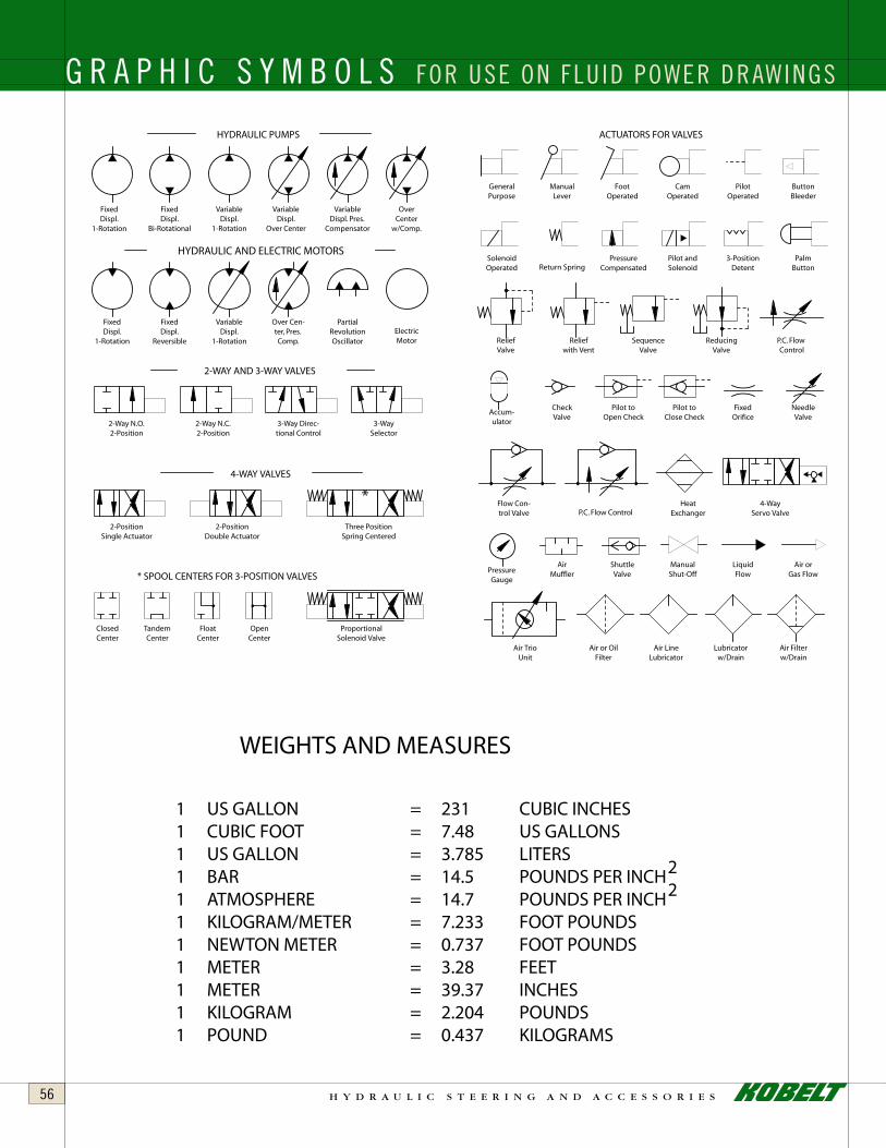
h y d r a u l i c s t e e r i n g a n d a c c e s s o r i e s56
FixedDispl.
1-Rotation
FixedDispl.
Bi-Rotational
*
GeneralPurpose
ManualLever
FootOperated
CamOperated
PilotOperated
ButtonBleeder
PalmButton
3-PositionDetent
Pilot andSolenoid
PressureCompensatedReturn Spring
SolenoidOperated
ReliefValve
Reliefwith Vent
SequenceValve
ReducingValve
P.C. FlowControl
Accum-ulator
CheckValve
Pilot toOpen Check
FixedOrifice
NeedleValve
Pilot toClose Check
Flow Con-trol Valve P.C. Flow Control
HeatExchanger
4-WayServo Valve
PressureGauge
AirMuffler
ShuttleValve
ManualShut-Off
LiquidFlow
Air orGas Flow
Air or OilFilter
Air LineLubricator
Lubricatorw/Drain
Air Filterw/Drain
VariableDispl.
1-Rotation
VariableDispl.
Over Center
VariableDispl. Pres.
Compensator
OverCenter
w/Comp.
ElectricMotor
PartialRevolutionOscillator
VariableDispl.
1-Rotation
FixedDispl.
Reversible
FixedDispl.
1-Rotation
Over Cen-ter, Pres.Comp.
2-Way N.O.2-Position
2-Way N.C.2-Position
3-Way Direc-tional Control
3-Way Selector
2-PositionDouble Actuator
2-PositionSingle Actuator
Three PositionSpring Centered
ClosedCenter
TandemCenter
FloatCenter
OpenCenter
ProportionalSolenoid Valve
4-WAY VALVES
2-WAY AND 3-WAY VALVES
HYDRAULIC AND ELECTRIC MOTORS
* SPOOL CENTERS FOR 3-POSITION VALVES
Air TrioUnit
HYDRAULIC PUMPS ACTUATORS FOR VALVES
WEIGHTS AND MEASURES
1 US GALLON 231= CUBIC INCHESUS GALLONS= 7.48CUBIC FOOT1
1 US GALLON 3.785= LITERS1 BAR 14.5= POUNDS PER INCH1 ATMOSPHERE 14.7=1 KILOGRAM/METER 7.233= FOOT POUNDS1 NEWTON METER 0.737= FOOT POUNDS1 METER 3.28= FEET1 METER 39.37= INCHES1 KILOGRAM 2.204= POUNDS1 POUND 0.437= KILOGRAMS
22POUNDS PER INCH
G R A P H I C S Y M B O L S FOR USE ON FLU ID POWER DRAWINGS

PRODUCT MODEL PAGE
6511-AP8-S 446511-AP8-T 446655 366657 367002 187003 4 - 57004 4 - 57005 4 - 57012 4 - 57018 197020 207029 177030 167031 167032 167033 167035 47038 177040 6 - 147041 157042 157050 6 - 147051 157052 157054 157065 6 - 147065-S 25
PRODUCT MODEL PAGE
7067 13 - 147080 6 - 147081 157082 157083 157085 267085-S 267086 157087 13 - 147090 13 - 14 7093 6 - 147093-S 157093-L 157094 6 - 147094-DL 11 - 147095 147095-D 11 - 147096 147096-D 11 - 14 7097 12 - 147098 12 - 147100 12 - 147120 207142 277143 217144 227145 23
PRODUCT MODEL PAGE
7147 247149 457150 457153 217156 427158 287165 297166 347167 307168 407169 307170 317171 327171-SW 327172 347173 - K 437174 417175 377175-2000 377176 357178 387180 387196 317197 337198 337201 - PR 39
INDEX

8238 129th Street, Surrey
British Columbia, Canada V3W 0A6
Sales: 604.590.7313 Fax: 604.590.8313
[email protected] www.kobelt.com
7.5M 09/08PRINTED IN CANADA
All Kobelt equipment comes with a 2-year limited warranty that is the best in the industry. Strict quality control manufacturing and sturdy corrosion-resistant materials ensure trouble-free service above and beyond this generous warranty period.