Hydraulic Ram Pump - Instructables
24
http://www.instructables.com/id/Hydraulic-Ram-Pump/ Home Sign Up! Browse Community Submit All Art Craft Food Games Green Home Kids Life Music Offbeat Outdoors Pets Photo Ride Science Tech Hydraulic Ram Pump by habolooby on September 28, 2008 Table of Contents Hydraulic Ram Pump . . . . . . . . . . . . . . . . . . . . . . . . . . . . . . . . . . . . . . . . . . . . . . . . . . . . . . . . . . . . . . . . . . . . . . . . . . . . . . . . . . . . . . . . . . . . . . . . . . . . . . . . . . . 1 Intro: Hydraulic Ram Pump . . . . . . . . . . . . . . . . . . . . . . . . . . . . . . . . . . . . . . . . . . . . . . . . . . . . . . . . . . . . . . . . . . . . . . . . . . . . . . . . . . . . . . . . . . . . . . . . . . . 2 Step 1: Bill o' Materials . . . . . . . . . . . . . . . . . . . . . . . . . . . . . . . . . . . . . . . . . . . . . . . . . . . . . . . . . . . . . . . . . . . . . . . . . . . . . . . . . . . . . . . . . . . . . . . . . . . . . . 2 Step 2: Lay out the Loot . . . . . . . . . . . . . . . . . . . . . . . . . . . . . . . . . . . . . . . . . . . . . . . . . . . . . . . . . . . . . . . . . . . . . . . . . . . . . . . . . . . . . . . . . . . . . . . . . . . . . 4 Step 3: Cut your Connecting Pipe Pieces . . . . . . . . . . . . . . . . . . . . . . . . . . . . . . . . . . . . . . . . . . . . . . . . . . . . . . . . . . . . . . . . . . . . . . . . . . . . . . . . . . . . . . . . . 5 Step 4: Fun With Chemicals . . . . . . . . . . . . . . . . . . . . . . . . . . . . . . . . . . . . . . . . . . . . . . . . . . . . . . . . . . . . . . . . . . . . . . . . . . . . . . . . . . . . . . . . . . . . . . . . . . 5 Step 5: Piece by Piece (Main Line) . . . . . . . . . . . . . . . . . . . . . . . . . . . . . . . . . . . . . . . . . . . . . . . . . . . . . . . . . . . . . . . . . . . . . . . . . . . . . . . . . . . . . . . . . . . . . 6 Step 6: Piece by Piece (Pressure Chamber) . . . . . . . . . . . . . . . . . . . . . . . . . . . . . . . . . . . . . . . . . . . . . . . . . . . . . . . . . . . . . . . . . . . . . . . . . . . . . . . . . . . . . . 7 Step 7: Optional Pressure Gauge Assembly . . . . . . . . . . . . . . . . . . . . . . . . . . . . . . . . . . . . . . . . . . . . . . . . . . . . . . . . . . . . . . . . . . . . . . . . . . . . . . . . . . . . . . 8 Step 8: The Last Piece (for the pump anyway...) . . . . . . . . . . . . . . . . . . . . . . . . . . . . . . . . . . . . . . . . . . . . . . . . . . . . . . . . . . . . . . . . . . . . . . . . . . . . . . . . . . . 9 Step 9: Pump Installation . . . . . . . . . . . . . . . . . . . . . . . . . . . . . . . . . . . . . . . . . . . . . . . . . . . . . . . . . . . . . . . . . . . . . . . . . . . . . . . . . . . . . . . . . . . . . . . . . . . . . 11 File Downloads . . . . . . . . . . . . . . . . . . . . . . . . . . . . . . . . . . . . . . . . . . . . . . . . . . . . . . . . . . . . . . . . . . . . . . . . . . . . . . . . . . . . . . . . . . . . . . . . . . . . . . . . . . . 14 Step 10: Howsitdodat? . . . . . . . . . . . . . . . . . . . . . . . . . . . . . . . . . . . . . . . . . . . . . . . . . . . . . . . . . . . . . . . . . . . . . . . . . . . . . . . . . . . . . . . . . . . . . . . . . . . . . . 14 Related Instructables . . . . . . . . . . . . . . . . . . . . . . . . . . . . . . . . . . . . . . . . . . . . . . . . . . . . . . . . . . . . . . . . . . . . . . . . . . . . . . . . . . . . . . . . . . . . . . . . . . . . . . . . 16 Comments . . . . . . . . . . . . . . . . . . . . . . . . . . . . . . . . . . . . . . . . . . . . . . . . . . . . . . . . . . . . . . . . . . . . . . . . . . . . . . . . . . . . . . . . . . . . . . . . . . . . . . . . . . . . . . . . 16
-
Upload
khangminh22 -
Category
Documents
-
view
0 -
download
0
Transcript of Hydraulic Ram Pump - Instructables

http://www.instructables.com/id/Hydraulic-Ram-Pump/
Home Sign Up! Browse Community Submit
All Art Craft Food Games Green Home Kids Life Music Offbeat Outdoors Pets Photo Ride Science Tech
Hydraulic Ram Pumpby habolooby on September 28, 2008
Table of Contents
Hydraulic Ram Pump . . . . . . . . . . . . . . . . . . . . . . . . . . . . . . . . . . . . . . . . . . . . . . . . . . . . . . . . . . . . . . . . . . . . . . . . . . . . . . . . . . . . . . . . . . . . . . . . . . . . . . . . . . . 1
Intro: Hydraulic Ram Pump . . . . . . . . . . . . . . . . . . . . . . . . . . . . . . . . . . . . . . . . . . . . . . . . . . . . . . . . . . . . . . . . . . . . . . . . . . . . . . . . . . . . . . . . . . . . . . . . . . . 2
Step 1: Bill o' Materials . . . . . . . . . . . . . . . . . . . . . . . . . . . . . . . . . . . . . . . . . . . . . . . . . . . . . . . . . . . . . . . . . . . . . . . . . . . . . . . . . . . . . . . . . . . . . . . . . . . . . . 2
Step 2: Lay out the Loot . . . . . . . . . . . . . . . . . . . . . . . . . . . . . . . . . . . . . . . . . . . . . . . . . . . . . . . . . . . . . . . . . . . . . . . . . . . . . . . . . . . . . . . . . . . . . . . . . . . . . 4
Step 3: Cut your Connecting Pipe Pieces . . . . . . . . . . . . . . . . . . . . . . . . . . . . . . . . . . . . . . . . . . . . . . . . . . . . . . . . . . . . . . . . . . . . . . . . . . . . . . . . . . . . . . . . . 5
Step 4: Fun With Chemicals . . . . . . . . . . . . . . . . . . . . . . . . . . . . . . . . . . . . . . . . . . . . . . . . . . . . . . . . . . . . . . . . . . . . . . . . . . . . . . . . . . . . . . . . . . . . . . . . . . 5
Step 5: Piece by Piece (Main Line) . . . . . . . . . . . . . . . . . . . . . . . . . . . . . . . . . . . . . . . . . . . . . . . . . . . . . . . . . . . . . . . . . . . . . . . . . . . . . . . . . . . . . . . . . . . . . 6
Step 6: Piece by Piece (Pressure Chamber) . . . . . . . . . . . . . . . . . . . . . . . . . . . . . . . . . . . . . . . . . . . . . . . . . . . . . . . . . . . . . . . . . . . . . . . . . . . . . . . . . . . . . . 7
Step 7: Optional Pressure Gauge Assembly . . . . . . . . . . . . . . . . . . . . . . . . . . . . . . . . . . . . . . . . . . . . . . . . . . . . . . . . . . . . . . . . . . . . . . . . . . . . . . . . . . . . . . 8
Step 8: The Last Piece (for the pump anyway...) . . . . . . . . . . . . . . . . . . . . . . . . . . . . . . . . . . . . . . . . . . . . . . . . . . . . . . . . . . . . . . . . . . . . . . . . . . . . . . . . . . . 9
Step 9: Pump Installation . . . . . . . . . . . . . . . . . . . . . . . . . . . . . . . . . . . . . . . . . . . . . . . . . . . . . . . . . . . . . . . . . . . . . . . . . . . . . . . . . . . . . . . . . . . . . . . . . . . . . 11
File Downloads . . . . . . . . . . . . . . . . . . . . . . . . . . . . . . . . . . . . . . . . . . . . . . . . . . . . . . . . . . . . . . . . . . . . . . . . . . . . . . . . . . . . . . . . . . . . . . . . . . . . . . . . . . . 14
Step 10: Howsitdodat? . . . . . . . . . . . . . . . . . . . . . . . . . . . . . . . . . . . . . . . . . . . . . . . . . . . . . . . . . . . . . . . . . . . . . . . . . . . . . . . . . . . . . . . . . . . . . . . . . . . . . . 14
Related Instructables . . . . . . . . . . . . . . . . . . . . . . . . . . . . . . . . . . . . . . . . . . . . . . . . . . . . . . . . . . . . . . . . . . . . . . . . . . . . . . . . . . . . . . . . . . . . . . . . . . . . . . . . 16
Comments . . . . . . . . . . . . . . . . . . . . . . . . . . . . . . . . . . . . . . . . . . . . . . . . . . . . . . . . . . . . . . . . . . . . . . . . . . . . . . . . . . . . . . . . . . . . . . . . . . . . . . . . . . . . . . . . 16

http://www.instructables.com/id/Hydraulic-Ram-Pump/
Intro: Hydraulic Ram PumpPump water with no electricity, no gasoline, just gravity!
Sound crazy or impossible? Don't worry, it does obey the laws of physics, but I'll try to explain the operation later. This instructable shows how to build a fairly simplewater pump that needs no energy input other than water flowing from a higher point to a lower point. Most of the pump is constructed from PVC, with a couple of bronzepieces thrown in for flavor. I was able to source all of the parts from a local hardware store (Lowes) for a bit under $100.
To function, the pump does require a reasonable amount of water that will drop at least 3'-5'. The level that the pump can raise water to depends on the water's head(total drop the water will make).
This design was worked out by Clemson University .
If you like what I've done, please take the time to give it a rating, and I'd love to hear your input. Thanks!
Step 1: Bill o' MaterialsBefore you can really do much, you've got to go out and buy some stuff. One of those sad facts of many projects. But if you want to build this (and it's a lot of fun to see itwork), print out this list and head to the plumbing dept of your hardware store.
Materials for the Pump
1-1/4" valve1-1/4" tee (buy two of these)1-1/4" union1-1/4" brass swing check valve1-1/4" spring check valve3/4" tee3/4" valve3/4" union1-1/4" x 3/4" bushing1/4" pipe cock100 psi gauge3/4" x 6" nipple4" x 1-1/4" bushing4" coupling4" x 24" PR160 PVC pipe4" PVC glue cap3/4" x 1/4" bushingShort (4') section of 1-1/4" PVC pipeOld Bicycle Innertube
This parts list comes directly from the Clemson website. I recommend you look there for help in identifying what each of the pieces look like, if you're unsure. I'm also notconvinced that the 100 PSI gauge, or all of the things that make it possible, are necessary. This will probably drop the price a good bit, and I haven't found a need for it onmy pump. The associated pieces are: 100 PSI gauge, 3/4" Tee, 3/4" x 1/4" bushing, the 1/4" pipe cock. Four things not needed. But have them if you like.
Connections Note Read through the instructable and understand all the pipe-fitting connections that will happen before buying materials. The store may not have exactlywhat you're looking for, and you may have to improvise. I wound up getting some different parts because my local store didn't have the exact parts I was looking for. Thisusually appears in the form of not having a threaded fitting, but having a smooth pipe connection, or vice versa. Not a problem, you can figure it out.
Installation Materials
Long section of 1-1/4" PVC ("drive pipe", connects pump to water supply)Garden Hose (male end threads into 3/4" union, supplies pumped water)Bricks, blocks, rocks to prop up and anchor pumpShower Drain assembly (must be able to attach to 1-1/4" pipe, for attaching pipe to water supply)
Build Materials and Tools
PVC Primer (I used Oatey Purple Primer)PVC Cement (Oatey again, just what they had)Teflon Thread TapeHacksaw

http://www.instructables.com/id/Hydraulic-Ram-Pump/
Measuring TapeClampsPocket KnifeLab gloves (keeps the chemicals on the pipe and off your hands)Bike Pump (to inflate the innertube)
Image Notes1. 4" PVC Cap2. 4" x 28" PVC Pipe3. Brass swing check valve. Should have an arrow on it (indicating normaldirection of flow). This arrow should be pointing TOWARD the pipe connected tothe valve.4. 1-1/4" Valve5. 1-1/4" Union6. 1-1/4" x 3/4" Bushing7. 3/4" Union (threads to male garden hose!)8. 3/4" Valve9. 4" x 2" Reducing Fitting10. Cans of Primer and Cement11. Spring Check Valve12. 1-1/4" Tee13. 1-1/4" Tee14. 3/4" pipe, threaded both ends. Make sure that the valve and bushing are alsothreaded. Or just use smooth cemented parts all around.15. 1-1/4" pipe section16. 1-1/4"x2" Bushing: Outside diameter to match the 4" adapter you buy17. 1-1/4" Pipe-to-Thread fitting
Image Notes1. Blue nitrile lab gloves. Handy.2. Front section glued up3. Back section gluing up4. PVC Cement5. Purple Primer
Image Notes1. Swinging flapper (but not like the 1920's)2. SWING check valve3. SPRING check valve. Same original purpose, different application &methodology.
Image Notes1. GUTS! Nah, just bike innertube. Partially inflated, so it's squishy. Pack itdown into the pressure chamber. Prevents waterlogging of the PC.

http://www.instructables.com/id/Hydraulic-Ram-Pump/
Image Notes1. 1/4" Pipe Nipple2. 1/4" Pipe Nipple. But you shouldn't need this one... I don't know why I have itin there.3. 1/4" Pipecock4. 3/4" to 1/4" threaded bushing5. 3/4" threaded tee
Image Notes1. PSI Gauge, metal fittings. Probably unnecessary, which could save you $$.2. Teflon thread tape
Step 2: Lay out the LootNow that you've bought lots of goodies, lay them out on the table (or floor) so that you can start to see how the pump goes together. See the pictures for a visual on this.
You will have to cut the long sections of pipe into shorter sections to go between each of the fittings. This is discussed more in the next step.
Image Notes1. 4" PVC Cap2. 4" x 28" PVC Pipe3. Brass swing check valve. Should have an arrow on it (indicating normaldirection of flow). This arrow should be pointing TOWARD the pipe connected tothe valve.4. 1-1/4" Valve5. 1-1/4" Union6. 1-1/4" x 3/4" Bushing7. 3/4" Union (threads to male garden hose!)8. 3/4" Valve9. 4" x 2" Reducing Fitting10. Cans of Primer and Cement11. Spring Check Valve12. 1-1/4" Tee13. 1-1/4" Tee14. 3/4" pipe, threaded both ends. Make sure that the valve and bushing are alsothreaded. Or just use smooth cemented parts all around.15. 1-1/4" pipe section16. 1-1/4"x2" Bushing: Outside diameter to match the 4" adapter you buy17. 1-1/4" Pipe-to-Thread fitting
Image Notes1. Spring check valve, flow direction is to the left (toward pressure chamber)2. Swing check valve, flow direction (arrow) pointing toward PVC pipes3. First (in terms of water flow) 1-1/4" tee fitting.4. "Main" tee, connected to pressure chamber eventually.

http://www.instructables.com/id/Hydraulic-Ram-Pump/
Image Notes1. Air compression chamber in place
Step 3: Cut your Connecting Pipe PiecesYou need to connect each of these little units with some pipe, so set about cutting segments off of that stock 1-1/4" pipe with the hacksaw. They don't need to be long,just enough to reach all the way into each fitting, maybe with some space between. But not much!
Once these pieces are all cut, take your knife (or some sand paper) and try to smooth the inside edge of the pipe. Get all the burr off, clean it up, give it a nice bevel orrounded edge. The idea here is to make these as smooth as possible, to reduce the likelihood of cracks developing with the repeated pressure waves that occur insidethe pipe. Clean up both ends, and make pieces to join all of the 1-1/4" fittings.
While you're at it, you might as well clean up the edges on the other sections of pipe, though it will be less critical for the other parts. Now that you've got all theconnecting segments, you can actually test fit the first part of the pump together, just for fun.
Don't worry if the pipes seem rather tight when you're test fitting everything. The primer and cement help them go together when you do the real assembly.
Image Notes1. Cut and prepared sections of pipe2. Primer and Cement3. Rough-poured concrete that might become purplish4. The outdoors is very well ventilated
Step 4: Fun With ChemicalsGrab your lab gloves, a clamp, primer, cement, two fittings and their connecting piece of pipe. Then head to a well ventilated space, because the primer and cementaren't precisely aromatherapy. At least not the good kind.
For those of you who haven't built things from PVC in the past, it isn't terribly difficult. The primer serves to clean off the PVC a little bit and gets it ready to really bondwith the cement. The cement keeps everything together.
Most PVC chemical bottles have caps with little brushes attached to them. Take the cap off the primer, and carefully coat the outside face of the pipe, with a band about2" wide beginning at the end. Take care not to drip the primer on anything that you don't want permanently purple. Once the pipe is coated, do the same for the inside ofthe fitting that you're planning on cementing up. Close up the primer bottle.
Open up the cement bottle, which should also have a little brush in it. With this brush, go over the areas that you painted with the primer. Don't rush, but you do want toget the pipes together before the cement dries up. You've got time though, so focus on getting a nice coating of cement on both pieces.
Once you've got cement where you want it (and hopefully only a little where you don't) fit the pipe into the fitting. It should slide in without too much resistance. Whenworking on my pump, I felt that it was best to clamp up each piece after I had assembled it, that way the pipe couldn't slip back at all. It may not be necessary, but I figureit helps.
http://www.instructables.com/id/Hydraulic-Ram-Pump/
Most of the pieces go together in a fairly self-explanatory way, but there are a few things to note: on the spring check valve there is an arrow, and you will want this topoint toward the main tee that will have the 4" pipe (air chamber) on it. This allows water to pass through toward the main tee, which you want. With the brass swingcheck valve , the arrow should point down toward the tee, and the main line of pipe.
On to the next step for order of assembly!
Image Notes1. Primer (not purple one in this picture, this might just be a cleaning solvent)2. Applicator brush for chemical3. No gloves! Bad me!4. Already cleaned / primed end of pipe section
Image Notes1. Blue nitrile lab gloves. Handy.2. Front section glued up3. Back section gluing up4. PVC Cement5. Purple Primer
Image Notes1. Purple primer spots on drop cloth2. Clamp squeezing fittings together3. Clamp keeping force from other clamp in a straight line over section4. Potentially unnecessary pressure valve assembly.5. Connection to pressure tank
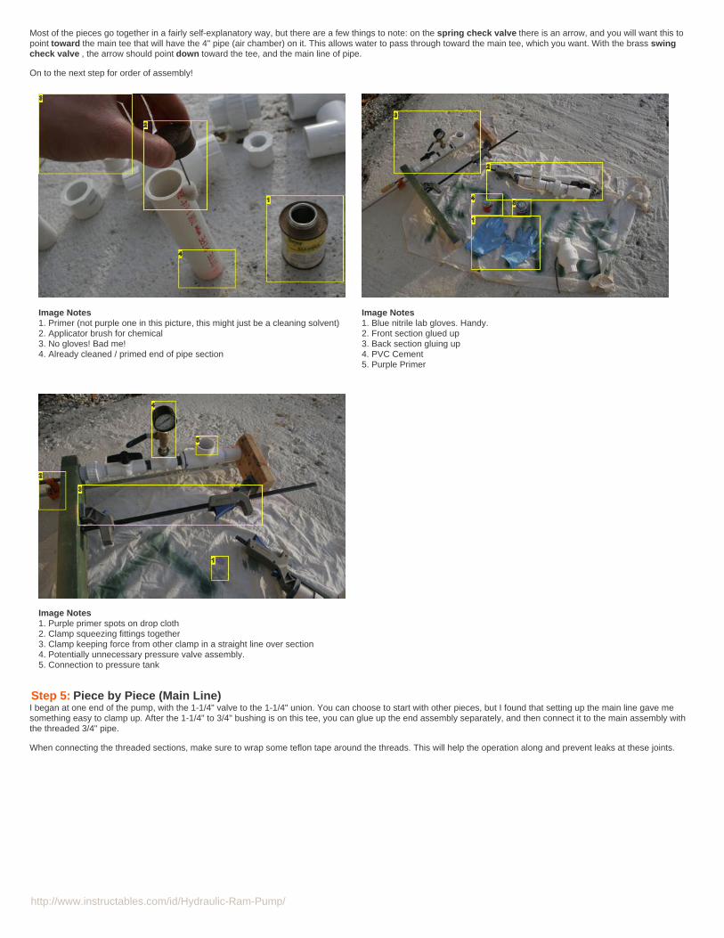
Step 5: Piece by Piece (Main Line)I began at one end of the pump, with the 1-1/4" valve to the 1-1/4" union. You can choose to start with other pieces, but I found that setting up the main line gave mesomething easy to clamp up. After the 1-1/4" to 3/4" bushing is on this tee, you can glue up the end assembly separately, and then connect it to the main assembly withthe threaded 3/4" pipe.
When connecting the threaded sections, make sure to wrap some teflon tape around the threads. This will help the operation along and prevent leaks at these joints.
http://www.instructables.com/id/Hydraulic-Ram-Pump/
Image Notes1. Spring check valve, flow direction is to the left (toward pressure chamber)2. Swing check valve, flow direction (arrow) pointing toward PVC pipes3. First (in terms of water flow) 1-1/4" tee fitting.4. "Main" tee, connected to pressure chamber eventually.
Image Notes1. Blue nitrile lab gloves. Handy.2. Front section glued up3. Back section gluing up4. PVC Cement5. Purple Primer
Image Notes1. 3/4" pipe nipple, threaded both ends. No cement needed, just teflon tape andtorque (via appropriately sized wrench)2. 3/4" Pipe, threaded as needed. I think only one end is here, as I was only ableto find3. Connection to the pressure tank.4. Main tee
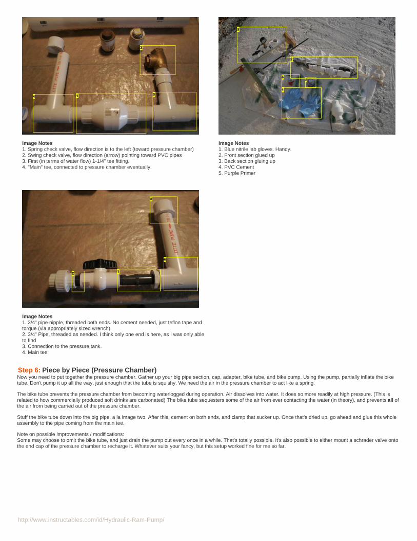
Step 6: Piece by Piece (Pressure Chamber)Now you need to put together the pressure chamber. Gather up your big pipe section, cap, adapter, bike tube, and bike pump. Using the pump, partially inflate the biketube. Don't pump it up all the way, just enough that the tube is squishy. We need the air in the pressure chamber to act like a spring.
The bike tube prevents the pressure chamber from becoming waterlogged during operation. Air dissolves into water. It does so more readily at high pressure. (This isrelated to how commercially produced soft drinks are carbonated) The bike tube sequesters some of the air from ever contacting the water (in theory), and prevents all ofthe air from being carried out of the pressure chamber.
Stuff the bike tube down into the big pipe, a la image two. After this, cement on both ends, and clamp that sucker up. Once that's dried up, go ahead and glue this wholeassembly to the pipe coming from the main tee.
Note on possible improvements / modifications:Some may choose to omit the bike tube, and just drain the pump out every once in a while. That's totally possible. It's also possible to either mount a schrader valve ontothe end cap of the pressure chamber to recharge it. Whatever suits your fancy, but this setup worked fine for me so far.

http://www.instructables.com/id/Hydraulic-Ram-Pump/
Image Notes1. Pressure chamber all together (but not glued yet in this picture)
Image Notes1. GUTS! Nah, just bike innertube. Partially inflated, so it's squishy. Pack it downinto the pressure chamber. Prevents waterlogging of the PC.
Image Notes1. Clamp keeps things together2. The drop cloth is here... and the piece gluing up is not...
Step 7: Optional Pressure Gauge AssemblyIf you want to use the pressure gauge, you will mount that after the main tee. Setup is pretty self explanatory. From top to bottom it goes: Gauge, pipecock, nipple,bushing, tee. Remember to wrap all threaded connections with teflon tape, and make sure you tighten them up well.
Installing this requires cutting the 3/4" x 6" pipe nipple in half, which creates two pieces, threaded on one end and smooth on the other, to go into the bottom arms of thetee. Cement these.
Image Notes1. Teflon tape2. 3/4" to 1/4" threaded bushing
Image Notes1. 1/4" Pipe Nipple2. 1/4" Pipe Nipple. But you shouldn't need this one... I don't know why I have it

http://www.instructables.com/id/Hydraulic-Ram-Pump/
3. Pump outlet end (3/4").4. Teflon tape reel cover.5. Pressure gauge. Numbered face fell off after not much operation. Verydisappointing. At least I wasn't using it for anything.6. 1/4" Brass ball valve. Aka pipecock.
in there.3. 1/4" Pipecock4. 3/4" to 1/4" threaded bushing5. 3/4" threaded tee
Image Notes1. PSI Gauge, metal fittings. Probably unnecessary, which could save you $$.2. Teflon thread tape
Image Notes1. Required cutting 3/4" pipe nipple in half, and inserting tee in the middle. Sothose ends of the tee are smooth.2. Whole assembly, installed.
Image Notes1. 3/4" pipe nipple, threaded both ends. No cement needed, just teflon tape andtorque (via appropriately sized wrench)2. 3/4" Pipe, threaded as needed. I think only one end is here, as I was only ableto find3. Connection to the pressure tank.4. Main tee
Step 8: The Last Piece (for the pump anyway...)If you haven't done it already, install the brass swing check valve. Make sure that the flapper (I just like calling it that) is hanging down, when the pump is held upright(everything pointing upwards). The whole thing should just thread onto the bushing that you've cemented to the end of a 1-1/4" pipe. Simple enough.
After that, you may break out the flapper dress, cut your hair short, and swing dance the night away celebrating the reckless spirit of the Jazz Age (and completion of yourpump). You party animal you.

http://www.instructables.com/id/Hydraulic-Ram-Pump/
Image Notes1. Note the arrow. May I flog this dead horse some more?
Image Notes1. 4" PVC Cap2. 4" x 28" PVC Pipe3. Brass swing check valve. Should have an arrow on it (indicating normaldirection of flow). This arrow should be pointing TOWARD the pipe connected tothe valve.4. 1-1/4" Valve5. 1-1/4" Union6. 1-1/4" x 3/4" Bushing7. 3/4" Union (threads to male garden hose!)8. 3/4" Valve9. 4" x 2" Reducing Fitting10. Cans of Primer and Cement11. Spring Check Valve12. 1-1/4" Tee13. 1-1/4" Tee14. 3/4" pipe, threaded both ends. Make sure that the valve and bushing are alsothreaded. Or just use smooth cemented parts all around.15. 1-1/4" pipe section16. 1-1/4"x2" Bushing: Outside diameter to match the 4" adapter you buy17. 1-1/4" Pipe-to-Thread fitting
Image Notes1. Swinging flapper (but not like the 1920's)2. SWING check valve3. SPRING check valve. Same original purpose, different application &methodology.
Image Notes1. That's right, just like this.
http://www.instructables.com/id/Hydraulic-Ram-Pump/
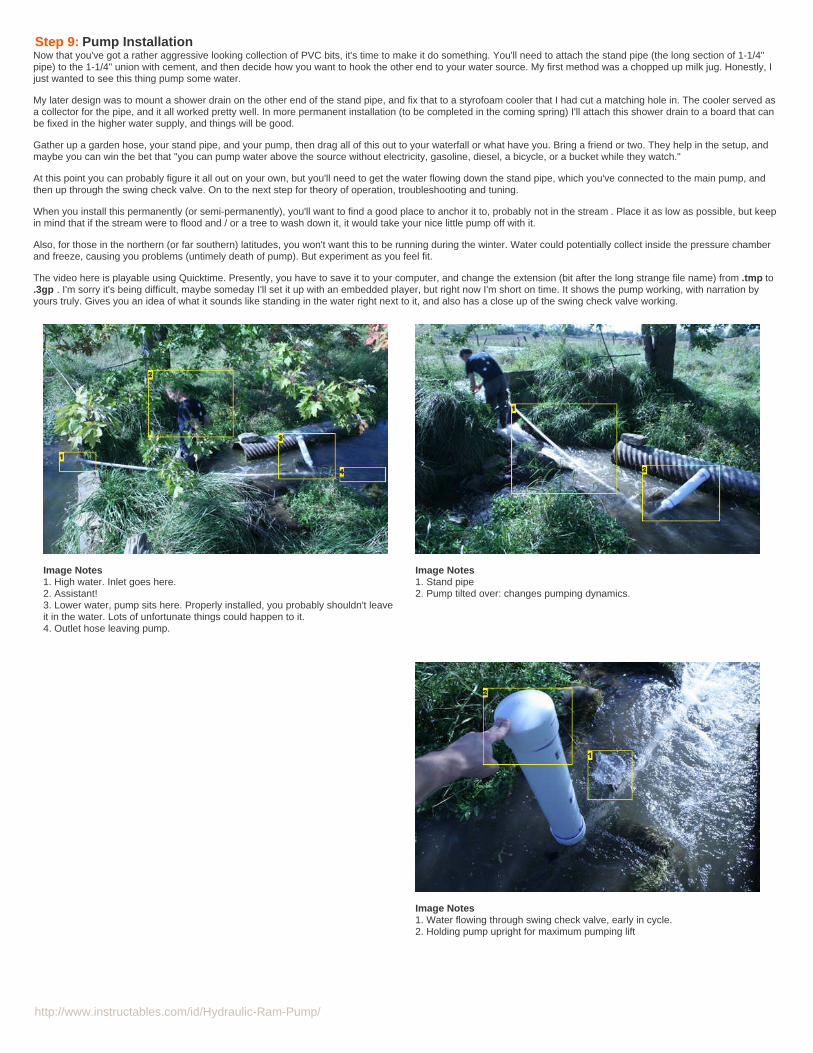
Step 9: Pump InstallationNow that you've got a rather aggressive looking collection of PVC bits, it's time to make it do something. You'll need to attach the stand pipe (the long section of 1-1/4"pipe) to the 1-1/4" union with cement, and then decide how you want to hook the other end to your water source. My first method was a chopped up milk jug. Honestly, Ijust wanted to see this thing pump some water.
My later design was to mount a shower drain on the other end of the stand pipe, and fix that to a styrofoam cooler that I had cut a matching hole in. The cooler served asa collector for the pipe, and it all worked pretty well. In more permanent installation (to be completed in the coming spring) I'll attach this shower drain to a board that canbe fixed in the higher water supply, and things will be good.
Gather up a garden hose, your stand pipe, and your pump, then drag all of this out to your waterfall or what have you. Bring a friend or two. They help in the setup, andmaybe you can win the bet that "you can pump water above the source without electricity, gasoline, diesel, a bicycle, or a bucket while they watch."
At this point you can probably figure it all out on your own, but you'll need to get the water flowing down the stand pipe, which you've connected to the main pump, andthen up through the swing check valve. On to the next step for theory of operation, troubleshooting and tuning.
When you install this permanently (or semi-permanently), you'll want to find a good place to anchor it to, probably not in the stream . Place it as low as possible, but keepin mind that if the stream were to flood and / or a tree to wash down it, it would take your nice little pump off with it.
Also, for those in the northern (or far southern) latitudes, you won't want this to be running during the winter. Water could potentially collect inside the pressure chamberand freeze, causing you problems (untimely death of pump). But experiment as you feel fit.
The video here is playable using Quicktime. Presently, you have to save it to your computer, and change the extension (bit after the long strange file name) from .tmp to.3gp . I'm sorry it's being difficult, maybe someday I'll set it up with an embedded player, but right now I'm short on time. It shows the pump working, with narration byyours truly. Gives you an idea of what it sounds like standing in the water right next to it, and also has a close up of the swing check valve working.
Image Notes1. High water. Inlet goes here.2. Assistant!3. Lower water, pump sits here. Properly installed, you probably shouldn't leaveit in the water. Lots of unfortunate things could happen to it.4. Outlet hose leaving pump.
Image Notes1. Stand pipe2. Pump tilted over: changes pumping dynamics.
Image Notes1. Water flowing through swing check valve, early in cycle.2. Holding pump upright for maximum pumping lift

http://www.instructables.com/id/Hydraulic-Ram-Pump/
Image Notes1. Hard to see, but that's water being pumped out!

http://www.instructables.com/id/Hydraulic-Ram-Pump/
Image Notes1. Another view of water flowing through the swing check valve. Valve may havejust closed in photo.2. Main line underwater here. Still works just fine.
Image Notes1. Valve has closed, water flying into the air. Pressure has just spiked insidepump body, and water is being forced past the spring check valve.2. Outlet hose underwater here
http://www.instructables.com/id/Hydraulic-Ram-Pump/
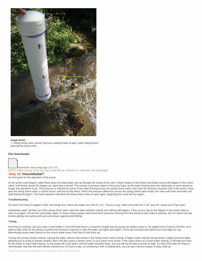
Image Notes1. Swing check valve closed, pressure spiking inside of pipe, water being forcedpast spring check valve.
File Downloads
Hydraulic ram pump.3gp (192 KB)[NOTE: When saving, if you see .tmp as the file ext, rename it to 'Hydraulic ram pump.3gp']
Step 10: Howsitdodat?So here goes for the operation of the pump.
As the pump cycle begins, water flows down the stand pipe, and up through the swing check valve. Water begins to flow faster and faster around the flapper in the checkvalve, until friction draws the flapper up, slamming it closed. This causes a pressure spike in the pump body, as the water flowing down the stand pipe at some speed nolonger has anywhere to go. This pressure is relieved by some of the water flowing across the spring check valve, over onto the pressure chamber side of the pump. Oncepast the swing check valve, it cannot return, and has to stay there. When the pressure difference across the spring check valve drops, the valve will close and water willstop flowing through it. The lower pressure will allow the swing check valve to open again, beginning the cycle all over again.
Troubleshooting
So what if this doesn't happen? Well, first things first, check and make sure that it's "on". That is to say, make sure both the 1-1/4" and 3/4" valves are in fact open.
Sometimes water will flow out of the swing check valve, then the valve will slam closed, but nothing will happen. If this occurs, tap on the flapper in the check valve toopen it up again, and let the cycle begin again. In theory these pumps need some back pressure (coming from the pressure tank side) to operate, but I've never had anytrouble getting mine going with just some basic tapping and fiddling.
Tuning
Now that it's working, can you make it work better? You'll find that there's a maximum height that the pump can deliver water to. Be patient when trying to find this, as ittakes a little while for the pump to achieve the pressure required to raise the water up higher and higher. There are formulas that will tell you how high you cantheoretically pump water based on the source water head. Feel free to look them up.
Tuning ram pumps mostly involves varying the water velocity that results in the swing check valve closing. A higher water velocity will generate a larger pressure spike,allowing you to pump to greater heights. But it will also cause a slower cycle, so you pump more slowly. If the valve closes at a lower water velocity, it will take less timefor the water to reach that velocity, so the pump will cycle faster, and the water pumped faster, but you will not be able to pump as high. So that's the trade off. Keep inmind though, that this will work without interference 24 hours a day, so combining it with a holding tank, you can get a decent supply of water built up.

http://www.instructables.com/id/Hydraulic-Ram-Pump/
To tune this specific design, you take advantage of how gravity acts on the flapper. When the check valve is pointing straight up in the air, the full force of gravity holdsthe flapper down, so the water must flow past the flapper faster to generate enough drag to raise the full weight of the flapper. By rotating the pump about the main line,you put the flapper's degree of freedom at an angle to the force of gravity, so that less drag is required to move the flapper. You could work out all of this fairly easily witha bit of trig, but I feel it would serve you little use out in the field. Just play around with it, you should find a position that works well for your application.
No Power?Well, no. This pump derives its power from the potential energy of the water uphill, and by wasting (not in a bad sense) the majority of the water that flows through thestand pipe. It only pumps a small fraction of the water that actually travels down that pipe. But that's fine if you have a stream already flowing down a hillside. Before, youweren't doing anything with all that potential / kinetic energy. Now you are. Hooray for you!
Image Notes1. Stand pipe2. Pump tilted over: changes pumping dynamics.
Image Notes1. Water flowing through swing check valve, early in cycle.2. Holding pump upright for maximum pumping lift
http://www.instructables.com/id/Hydraulic-Ram-Pump/
Related Instructables
~ World'sGreenestWATER PUMP ~by eltigre
MultipurposeSolarDesalinationPlant by girivs
Top 20 ways tobe green byawsome pie
Installing a newwater pump ona '95 FordTaurus by argon
Recycled Off-Grid Tesla CDTurbine Power-Boost Blenderby mrfixits
Create theArduino drivenLED growbox bycpo
Comments
50 comments Add Comment view all 59 comments
jtejwani says: Mar 15, 2011. 4:37 AM REPLYwell im not too suprise i've my doubts about dem people infact i have doubts on everything that isnt natural including secrets sociaties,religions,peace corpsunited nations and the goverments im getting ahead of myself but good stuff mon really good stuff link me if new vibesThe Great Sphinx Of Giza
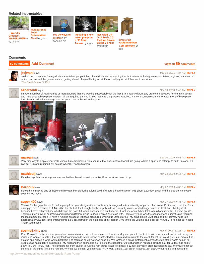
azharzaidi says: Nov 10, 2010. 9:42 AM REPLYI made a number of Ram Pumps or Inertia pumps that are working successfully for the last 3 to 4 years without any problem. I deviated for the main designand have used a base plate to attach all the required parts to it. You may see the pictures attached. It is very convenient and the attachment of base platehas given an added advantage that the pump can be bolted to the ground.
marean says: Sep 30, 2009. 6:53 AM REPLYVery nice way to display your instructions. I already have a Clemson ram that does not work and I am going to take it apart and attempt to build this one. If Ican get it up and running I will do cart wheels. Thanks Marean
mathieulj says: May 28, 2009. 9:16 AM REPLYExcellent application for a phenomenon that has been known for a while. Good work and keep it up.
Bardouv says: May 27, 2009. 4:38 PM REPLYI looked into making one of these to fill my rain barrels during a long spell of drought, but the stream was about 1200 feet away and the change in elevationseemed too much.
super 400 says: May 27, 2009. 6:31 AM REPLYThanks for the great lesson ! I built a pump from your design with a couple small changes due to availability of parts . I had some 2" pipe so I used that for adrive pipe with a reducer to 1 1/4 . Also the shut off tee I bought for the supply side was actually a mis- labeled bigger valve so I left it off . No big dealbecause I have collared hose which keeps the hose full when disconnected on that end . It took me about 5 hrs. total to build and install it . It works great !Took me a few days of searching and studying different plans to decide which one to go with. Ultimately yours was the cheapest and easiest, also requiringthe least amount of tools . I have it running on about 4 ft head pressure pumping up 20 feet or so . My drive pipe is 35 ft. long and my delivery hose is isapproximately 200 feet long emptying into a 55 gal. barrel on the high side of my garden . We timed the volume at .54 gal per minute . Perfect for our needs .Thank you much !
cosmo1kitty says: May 9, 2009. 11:23 AM REPLYPure Genius!!! Unlike some of your other commentators...I actually constructed this yesterday and put it to the test. I have a very small creek that runs yearround and wanted to utilize it for my landscaping needs. My husband constructed the pump and we went to the creek for set up. We dug a small area out asa catch and placed a large waste basket in it to catch as much water as possible. We fastened a small metal mesh across the top of the waste basket tokeep out as much debris as possible. My husband then connected a 3" pipe to the basket for 30 feet and then reduced down to a 2" for 20 feet and finallydown to 1 1/4" for 20 feet. The complete fall from basket to hydrolic ram pump is approximately a 12 foot elevation drop. Needless to say, the water shot outthe end of the pump like a fire hydrant. Why did we do this, you might ask???? Well, simple....our creek is about 150' BELOW our home and needed to

http://www.instructables.com/id/Hydraulic-Ram-Pump/
pump up this elevation in a 3/4" poly pipe for a 500 feet distance. It took a bit to get the pump going. In fact, we thought it wasn't going to work. Nothing washappening. However, I read the very short sentence that stated that you may have to push the check valve flapper down a few times to get the pressure upto par. I pushed it down probably 15 times before the pump started doing on its own. I was amazed!!!! We ran up the hil and within five minutes we hadwater!!! I figured maybe a trickle...being the elevation difference, but we had a nice steady flow. We figure that it will only take about two days to fill up a 1500gallon holding tank. Thanks for the awesome invention!!!!!!!
habolooby says: May 10, 2009. 4:39 AM REPLYHaha, that is excellent! Great to hear of a successful build and implementation, and I'm really glad that it worked out so well. Cheers!
cosmo1kitty says: May 10, 2009. 10:22 PM REPLYIt's awesome!!! We checked it today to see if it was still working....and it was!!! We can't wait to water our garden with FREE, NO ELECTRICITYREQUIRED, water!!! Pure Genius! As Yes....this is ACESSENDING up an elevation rise of approximately 150' !!! It's easy to dig canals and ditchesfor lateral flow....it takes a brain to figure out how to get water to flow AGAINST gravity. Thanks again.
A good name says: Apr 3, 2009. 9:07 PM REPLYI'm getting sick of the "no energy required" crap that I've been reading off of all these hydraulics pumps... Water flows from a higher point to a lower pointalways. Basically you could dig a canal to where you needed the water, and the same purpose is served. Alternatively, get a really really long hose.
Dr_Stupid says: Apr 21, 2009. 9:41 AM REPLYI'm sure by "no energy" means that no additional energy be required to input into the system to make it function, other than the falling water. What is itwith some people and semantics?
drbill says: Apr 14, 2009. 1:23 PM REPLYYeah lets see you dig a canal that lets water flow UP hill.
habolooby says: Apr 4, 2009. 5:45 PM REPLYWell, I'll grant you that "no energy required" is a bit cliched regarding ram pumps at this point, but take time to read the entire instructable. You might seethat the comment was made a bit tongue in cheek. Of course there is energy required. Work is being done, in the physics sense of the word. Thesepumps are capable of lifting water well above the top of the inlet pipe. So a canal or really long hose can't accomplish what these can. The lifting abilitycomes from wasting a huge portion of the water that flows through the system, and using the kinetic energy of that water flow.
drbill says: Apr 14, 2009. 1:25 PM REPLYI think you got the best Ram Pump design on instructables.
A good name says: Apr 4, 2009. 11:25 PM REPLYSo basically you're harvesting the kinetic energy from the water flowing downhill to make it flow... uphill? My knowledge of physics is limited, to besure.
habolooby says: Apr 5, 2009. 6:21 AM REPLYHaha, yeah, that's the basic idea there. And you only get to move a very small bit of water uphill. No worries about physics knowledge, it took mea long while to wrap my mind around exactly how these things worked, and actually seeing one work helped a lot. Rather than boring you with aphysics lesson, let me see if I can come up with a good quick explanation. Though some physics will probably crop up...
Water doesn't like to be compressed. And things in motion like to keep moving, unless something is there to stop them (friction or a wall). So,when you get a column of water moving down the inlet pipe at some speed, it wants to keep moving, but suddenly it's stopped by the brass swingcheck valve. Think multi-car pileup on the highway perhaps. Car 1 stops, car 2 slams into car 1... anyway, when the water is stopped, it causesthe water pressure in that area to spike. Going to take a brief aside here, but just keep in mind that the pressure around both check valves hasgone way up.
In an open column of water, pressure is determined by the height of the water level above the point that you're looking at. The equation isPressure = Density of the Fluid * Acceleration due to Gravity * Depth of water. So if you had two pipes, one twice as tall as the other, both filledup with water, the pressure at the bottom of the taller one would be twice as great as the pressure in the other pipe. The only real important partof all this is that pressure at the bottom of some pipe depends on how high the top of the water is above the bottom.
So if we stick a hose on the outlet of the pump, it acts very much like the pipes that I was just rambling on about. The higher you lift the end of thehose, the higher water has to go to get out of the hose, and the higher the resulting pressure at the pump-end of the hose. Which is importantlyright on the other side of the spring check valve.
OK, back to the fact that when the swing check valve closes, the pressure spikes on the inflow side of both check valves. As long as the pressurerises above the pressure on the other side of the spring check valve, some water will be forced past the valve, until the pressure on both sides ismore or less equal, when the valve will again close. This happens over and over, each time pushing just a little water past the spring check valve,and slowly moves the whole column of water up the hose.
The height that the pump can lift water to is limited by the height that the incoming water drops from, based on the increase in pressure generatedby the water stopping.
Righto, I hope I didn't bore you too much with all of that, and I hope that this all helped explain how these odd little creatures work. There aresome other very odd / cool pumping methods out there that can do strange things just using water dropping some distance. Go and google"pulser pump" if you're interested.

http://www.instructables.com/id/Hydraulic-Ram-Pump/
Shut Up Now says: Mar 14, 2009. 2:51 PM REPLYvery innovative. this could be turned into a nice physics lesson.
zostedguy says: Mar 14, 2009. 4:11 PM REPLYGiza layout is very interesting and very sophisticated. It uses slightly rectangular pipes for reduced friction. (Rectangular pipes have less friction thanround pipes) It has primary drive as 4' x 4' (aprox) and then has a reduction at bottom of drive to a 3' x 3' pipe. It shoots into the vortex chamber with a 2'x 2' output across the room. This is enhanced by the rotation of the fluids in the room. In the middle of the vortex chamber, it has a 4' x 4' drive pipeextension. (Please not diagonal offset - which is directly related to direction of final drive pipe) So there's full flow in the main drive pipes, a restriction/jetat the bottom of main drive pipe and a restriction of out put pipe. This pump hates air, so the air that would be trapped in vortex chamber is pushed tooutlet at rear of room through complex circulation. The vortex room completely modifies the reverse thrust, also. The thrust (compression wave) is bothreflected and utilized. I used a 1 1/4" round drive pipe (both initial and extended drive) This is a bit oversize but I believe that these two pipes aresupposed to have minimum friction loss. I then copied the Giza layout with a 3/4" square jet pipe at bottom of main drive and then used a 1/2" squareoutput pipe which transistions into a 3/4" round (for simplicity). This is a 1/4" to the foot scale (1:48) Good scale for building and translations. Also, vortexin final drive pipe reduces friction. 2000' pipe at Giza, so this may have been significant. Best, John
eltigre says: Mar 22, 2009. 9:14 AM REPLYVery interesting hypothesis about Giza pump configuration. Having built several variations of ram pumps, when I examine the Giza schematicsclosely, I agree it can easily be argued that a ram pump is a real and very logical possibility. Do you think the chamber attached below the king'schamber is a standpipe? have you experimented with a resonator (king's chamber) on top of a standpipe? That would make the vortex room apressure vessel. Perhaps the connected shaft acts as a snifter valve to assist the outflow by providing a measure of compression on each stroke.Just imagine the effect on the locals and sceptical visitors to Giza when they hear the heartbeat of the Nile river god from 20 miles away and see thesun reflecting on the water flowing down the steps of the great pyramid and the green fields of the plateau obtained from magically flowing watersunder the complete control of the Pharoh!!! Talk about political power... the god king Pharoh can start and stop the life giving water and the heartbeatof the Nile god with a wave of his hand. What Pharoh wouldn't pay dearly for that kind of special effect. I could easily design a reliable horizontal gatevalve for you that simulates the Giza gate valve granite block if you want to experiment further with it. just let me know.
zostedguy says: Mar 22, 2009. 5:24 PM REPLYeltigre, Thanks for examining the Giza layout. Only ram pump people understand it. As far as chamber below the King's chamber being a standpipe, are you referring to the grand gallery? The "well shaft" could have been a stand pipe, as it does run with it present. It is anamolous in that itis smaller than the drive pipe, which is not normal for a standpipe. As can bee seen in the vid, the water level in the well shaft is lower than moatlevel. This is not normal for rams. Also, it is not clear if that particular shaft was present upon original construction or not. I added it to the modelto demonstrate that it could have been present and the pump will still run. The well shaft (stand pipe) really reduces efficiency and I much preferto have it turned off. The drive pipe isn't particularly long, anyways. A stand pipe isn't really needed. It's about 370' from top of water tosubterranean chamber, but 2000' to wastegate. The vortex chamber hates air. I had to add an air bleeder valve to remove it. This was actuallyadded after I had built it. No snifter is required because the pulses are stabilized by the sub chamber design. I had a model which had an airchamber on the output line of sub chamber. (see picture) It really didn't make much difference. Removing it made the Giza layout much morerealistically plausible. Dr. Jacke Kolle (Godfather modern Hydraulic pulse generators) talked emphatically about how loud the plateau would havebeen and also how intensely the King's chamber would have resonated. My horizontal wastgate wears relatively quickly. Probably get a year outof it. I ran it for 3 months and there was some wear on valve stem and on the epoxy valve guide (which the valve slides on) I haven't put aresonator on top of the sub chamber yet. Had the pulse frequency analyzed and it is approximately 50Hz. The "King's" chamber is specificallydesigned as a resonating chamber. Several accoustical engineers have done design analysis and agreee on this point. (Even Paul Horn won agrammy for his recordings within the chamber). I am certainly interested in further brainstorming and communication on this subject. Only EdMalkowski understands the vast majority of the research. That's why it is in his next book, "Before the Paraohs, Civilization X" I attached 3pictures of my horizontal waste gate. You can see that I built an epoxy slider for the valve movement. This keeps the valve from dangling andhaving erratic pulsing and severe wear. One picture shows the output side. It's a normal check valve, but the spring is moved from holding thevalve closed to holding the valve open. The spring isn't really needed, but it is so easy just to move it. This modified check valve is a roundinterpretation of what the Giza square waste gate would have been. I did the submerged horizontal wast gate because this is the best design forGiza. It would have been very easy to excavate the valve area and then install granite valve slider guides and granite valve seats. With it beinghorizontal, the intense thrust would have been met with granite (for wear) and 50' of solid limestone for valve seat backing. It would have beensubmerged because of Nile elevation and tunnel location. So, what I built is COMPLETELY ram pump unorthodox. None of it has been donebefore as far as I know. Everything I tried was because that is what the Giza layout demands. Quite honestly, I didn't think the submergedhorizontal wastegate would work. As I've said, it doesn't need the spring. Giza obviously wouldn't have a spring. The valve is sucked open fromthe rarefaction wave. The vortex chamber is also insanely ingenious. Whoever designed this thing is a super genius. (and I'm not talking aboutmyself) Anyways, I'm very interested in talking with anybody with ideas. Best, John
http://www.instructables.com/id/Hydraulic-Ram-Pump/
eltigre says: Mar 23, 2009. 10:32 AM REPLYHey John,
I see why you suffer wear problems with your horizontal valve. Attached is a design that may help you. I don't think we should hijackHabolooby's thread here, so if you have any questions, you can ask me via pm or in my pump thread athttp://www.instructables.com/id/Worlds_greenest_water_pump
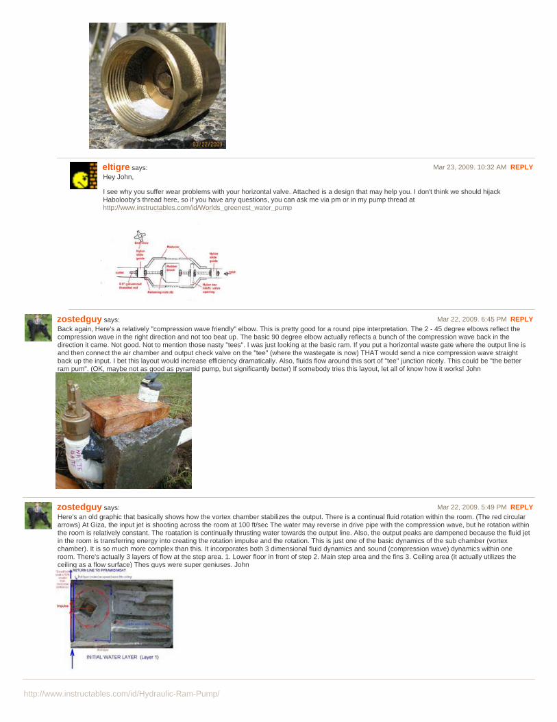
zostedguy says: Mar 22, 2009. 6:45 PM REPLYBack again, Here's a relatively "compression wave friendly" elbow. This is pretty good for a round pipe interpretation. The 2 - 45 degree elbows reflect thecompression wave in the right direction and not too beat up. The basic 90 degree elbow actually reflects a bunch of the compression wave back in thedirection it came. Not good. Not to mention those nasty "tees". I was just looking at the basic ram. If you put a horizontal waste gate where the output line isand then connect the air chamber and output check valve on the "tee" (where the wastegate is now) THAT would send a nice compression wave straightback up the input. I bet this layout would increase efficiency dramatically. Also, fluids flow around this sort of "tee" junction nicely. This could be "the betterram pum". (OK, maybe not as good as pyramid pump, but significantly better) If somebody tries this layout, let all of know how it works! John
zostedguy says: Mar 22, 2009. 5:49 PM REPLYHere's an old graphic that basically shows how the vortex chamber stabilizes the output. There is a continual fluid rotation within the room. (The red circulararrows) At Giza, the input jet is shooting across the room at 100 ft/sec The water may reverse in drive pipe with the compression wave, but he rotation withinthe room is relatively constant. The roatation is continually thrusting water towards the output line. Also, the output peaks are dampened because the fluid jetin the room is transferring energy into creating the rotation impulse and the rotation. This is just one of the basic dynamics of the sub chamber (vortexchamber). It is so much more complex than this. It incorporates both 3 dimensional fluid dynamics and sound (compression wave) dynamics within oneroom. There's actually 3 layers of flow at the step area. 1. Lower floor in front of step 2. Main step area and the fins 3. Ceiling area (it actually utilizes theceiling as a flow surface) Thes guys were super geniuses. John

http://www.instructables.com/id/Hydraulic-Ram-Pump/
mattrobs says: Mar 20, 2009. 2:08 AM REPLYI'd appreciate if you guys can help us.
We're building this as a project for 1st year Engineering. But there's a problem: whenever we attach the air chamber, the swing check valve refuses to drop(or be sucked down). It needs to be triggered manually everytime. Removal of the air chamber results in the pump automating nicely (albeit with reducedefficiency).
We're trying to grasp the physics behind why it won't work, but (unfortunately) have failed. Can you help?
Some specs: The drive tank is elevated 1.3m, connects to a standard hose, which connects to the 3/4-inch pipework. The chamber is two connected tintennis ball containers (= 1m high; 10cm diam.)
Could the chamber be too *big*?
zostedguy says: Mar 20, 2009. 11:45 AM REPLYMattrobs,
For your eventual thesis, maybe you can tackle the following phenomena:
http://www.great-pyramid-giza-pulse-pump.com/Vortex_Anomaly.php
It's not caused by the impuities in the water. I have an idea why it happens, but can't back it. That piece of pipe is still purple today, albeit somewhatfaded.
Also note: In one of the pictures, the waste gate valve is open and no water is coming out. That's the valve sucked open and zero pressure (and zerowater flow) at the wastegate valve because of the compression wave going back up the pipe.
Best,
John
zostedguy says: Mar 20, 2009. 11:30 AM REPLYMatttrobs, Standard rams are quirky as far as starting. They require a certain amount of back pressure from the output line. That's why the output has tobe 5 - 10x the head. I've read where people will put a valve on the output side and choke it down to get the back pressure high enough for the pump tostart cycling. (That's why it cycles with no air) With your pump, maybe put the valve between waste gate valve and the pressure chamber. Choke it downuntil the pressure builds in the air chamber. Maybe even put one on the output side of the air chamber. Generally, the valve on the output side of the airchamber is the one that is choked down. As far as the physics behind the required back pressure, I don't know. Haven't really thought about it, really.That is the beauty of the pyramid pump. This doesn't matter at all. No air chamber, no back pressure needed, starts first try every try, no fiddlingrequired, much higher efficiency . . . it is the much better pump. The pyramid pump is great for lateral tranference which is a phenomenal attribute. (Let'ssay you have a pond and 3' drop on output creek. A garden 500' away, but same height as pond. Normal ram won't work because same elevation)Maybe for 2nd year engineering you can tackle the pyramid pump. It has lots and lots of physics involved. The more you study the pyramid pump, themore you realise the true genius. The fluid dynamics stumped a mechanical engineer from MIT. Best, John
pekar says: Mar 19, 2009. 1:50 PM REPLYNice project, I've been through the same fun process in building and playing with these pumps. What a blast! One correction What you're calling a stand pipeis actually a drive pipe. A stand pipe is an open ended vertical pipe used to improve efficiency when the pipe run from the head to the pump is a very longdistance.
habolooby says: Mar 20, 2009. 5:08 AM REPLYRighto, got that fixed. Thanks for pointing that out. I think it was pretty late when I was putting the finishing touches on this, so thanks for helping me onthat.
zostedguy says: Mar 19, 2009. 2:30 PM REPLYThanks. I'm not sure where I said the drive pipe is a stand pipe. I know the difference, but may have mislabeled something. Maybe the vid. I think Imistated something at the beginning. Best, John
magickaldan says: Mar 12, 2009. 8:51 AM REPLYOr if you want to get fancier I'd use a Hot Water Expansion Tank from the local plumbing store. It has a valve on top for recharging and comes with a goodrubber diaphragm.
kenputer says: Mar 19, 2009. 6:56 PM REPLYJust put a small tire tube with about 15 pounds pressure in the stand pipe for expansion. kenputer
habolooby says: Mar 12, 2009. 8:07 PM REPLYVery good point. That would work great, and it basically comes down to budget considerations.
rimar2000 says: Mar 12, 2009. 5:22 AM REPLYSee this, is some similar: http://www.instructables.com/id/Worlds_greenest_water_pump/

http://www.instructables.com/id/Hydraulic-Ram-Pump/
habolooby says: Mar 12, 2009. 5:35 AM REPLYCertainly. As is mentioned in that instructable, hydraulic ram pumps have been around for a very long time. They used to be commercially produced, andstill are if you look hard enough. The design in that instructable is very cool as well, but I built this last year and just now got around to setting up aninstructable on it. More ways to accomplish the same thing.
rimar2000 says: Mar 12, 2009. 6:38 AM REPLYThose bombs are really amazing, they are very close to perpetual motion. Your instructable is very well done, too.
waterppk says: Mar 12, 2009. 7:37 AM REPLYThese pumps have terrible efficiency , as stated in the referenced source - "The ram is quite inefficient. Usually 8 gallons of water must passthrough the waste valve for each 1 gallon of water pumped by the ram. That is acceptable for a creek or river situation, but may not be a goodoption for a pond that does not have a good spring flow." - http://www.clemson.edu/irrig/equip/ram4.htm
The only utility of these pumps is when you have a dammed river or stream where the water will flow downhill anyways, so you are recoveringwork from an otherwise wasted energy flow, but this doesn't come anywhere near putting a turbine in the stream and generating some power!
Anybody know if these will automatically restart once they've hit the shutoff head? (if I were to plumb the output to a check valve on a water tank,which would shut off when the tank was full, when the valve reopened and allowed flow into the tank again would the pump restart?)
eltigre says: Mar 19, 2009. 5:35 PM REPLYPlease explain your definition of efficiency. Most physics definitions involve lowest cost to move a mass over a specified distance. Cost canbe either currency or energy. Either way, these pumps are wonderfully efficient. They will move a huge mass over a non trivial distance, (mypump lifted more than 145,000 gallons over 100' high and 700' distant last summer) using zero external energy and therefore zero currencyexcluding capital construction costs which are exceptionally low compared to conventional pumps. I hope you would not argue that a waterwheel, or the Hover dam electrical turbines, are inefficient because most of the river that powers them simply flows on downstream? Pleasedon't confuse speed with efficiency, (sign in a Mad Max movie... speed is just a question of cost, how fast do you want to go?)
habolooby says: Mar 12, 2009. 7:41 PM REPLYYup, hugely inefficient. Which is fine, if you have a healthy constant water drop, like you mentioned. I was going to try to run this off of a pondoutflow this spring, and see how it goes. I'm not sure though. I believe, from having fiddled with this a bit, that it would restart. Basically, theshutoff valve would show up as an increased pressure to the pump, much like raising the output hose higher in the air. When you do this, thepump will keep cycling, but won't push water past the spring check valve because the back pressure is so high. When you lower the outlethose, water will start to flow again, as the back pressure is now lower. But that's just what I've seen, with the water source that I have.
rimar2000 says: Mar 12, 2009. 8:33 AM REPLYAnswer to your question: from what I read (or better, so I understood what I read, because I don't speak English) these pumps need to beloaded manually every time you stop them.
frollard says: Mar 13, 2009. 4:13 PM REPLYYou only need to load the pressure on the output end - if you stop the output end, it keeps the pressure, and will stop until the pressuredrops
mdgnys says: Mar 19, 2009. 12:07 PM REPLYIt has 2 nippels!
fwjs28 says: Mar 19, 2009. 12:33 PM REPLYtehehe...but it has no breasts :P
zostedguy says: Mar 18, 2009. 11:57 AM REPLYHi everyone,
****** BIG QUESTION FOR EVERYONE *******
I have no idea about this one:
Is it better to shoot the compression wave (from the wastegate valve) towards the output or input? Maybe shooting towards output would increase efficiency.
I have no idea on this subject with regards to standard hydraulic ram pumps.
Best,
John Cadman
zostedguy says: Mar 16, 2009. 6:32 PM REPLYHi,
I'm back again and still doing my very best at not being the least bit negative but being informative. I also believe in simplicity of design. I've made someultra-simple ram pumps that worked just fine.
When I started in ram pumps, I had all sorts of misconceptions about all the dynamics of the pump. I was a chief engineer on a King crab boat in Alaska so Ialways thought in "fluid dynamics". That's only about 20% correct for hydraulic ram pumps.

http://www.instructables.com/id/Hydraulic-Ram-Pump/
On the page:
http://www.great-pyramid-giza-pulse-pump.com/index.php
Check out the water flow out of top line (5:42 minutes into youtube vid) This is with standpipe off. There's no air anywhere in the whole pump assembly. Ifyou look at the water coming out of the upper pipe, you'll see that it surges a bit, but is CONTINUOUS. Anybody that has run a ram pump with a waterloggedair chamber knows that this is not supposed to be what happens. No-air means intense surge and stop of water flow in normal rams.
How do you explain it? I've run the basic assembly without the complex vortex chamber. It had the typical intense surge and stop action. The vortex not onlystabilizes the flow but also increases efficiency dramatically.
The vortex chamber also dramatically reduces the pulse that goes out the drive pipe entrance. It captures and redirects the pulse.
I attached a picture of the optimum elbow for compression wave redirection.
Looking at the picture, you can see that the pulse is still uniform. It has the shortest wave length possible and the highest amplitude possible.
A compression wave is the same as a sound wave. By doing the optimum redirection, the pulse is kept at the highest amplitude. HIGHEST AMPLITUDE =HIGHEST PRESSURE (That's what we want, right?) It is kept as a single, clean pulse.
Now, visualize what happens when a compression wave shoots towards the bottom of a round "tee". The whole pulse is scattered everywhere. It is bouncingup and down, here and there. The amplitude is significantly reduced. Less amplitude = less pressure
Now couple that random bouncing with the overlapping random bouncing of the rarefaction (negative pressure) wave and there's a giant mess of cancellingwaves. Huge reduction of efficiency.
Looking at the standard fluid elbow, the pulse is now scattered. It's bouncing to-and-fro. It has dissipated immensely.
When you think of compression waves and reflections, think of pool balls on a pool table. It is exactly analagous. The same amount of force that will shoot aball straight down and back on a table will get a ball almost no where when bouncing from side to side. A "tee" is all side-to-side. Each time it bounces off aside, it loses part of it's amplitude. It is being transfered and absorbed by the pipe material.
Ram pumps are all about compression waves and not much about fluid dynamics. These are two completely different dynamics.
If you want to build a better pump then you have to build better plumbing.
I would love to see what people build when they incorporate some of the more "compression wave friendly" plumbing schemes!! I would also love to see thecomparison of the various efficiencies of various simpler pumps.
Best,
John
zostedguy says: Mar 16, 2009. 2:20 AM REPLYOK,
Forgive me if this doesn't attach right. It's my first try with graphics!
There should be 2 graphics: 1. complex ram pump, 2. compression wave/rarefaction wave description.
This is meant in the absolute nicest manner, so PLEASE no one think that I am being negative or criticizing anybodies design. I LOVE the hockey puckwastegate. It's much more durable than any of my valves. Kudos.
This is about having to research exactly why everything does everything . . . trying to figure out the pyramid design. "Why the diagonal pit offset and thesquare pipe???"
#1 thing to understand about ram pumps is compression and rarefaction waves! When the valve slams shut, there is a compression AND rarefaction wavethat travels up the pipe.
The rarefaction is EQUAL and OPPOSITE the compression wave. That means that the pressure is super low when the rarefaction wave leaves the valve.This literally sucks the valve open immediately. (#4 on picture) (#5 picture shows no water leaving waste gate (even though it's open) as thecompression/rarefaction wave travels up the drive pipe.
(This really messes with my mind, but I have watched it over and over)
#2 The pressure at the wastegate and the line away from the compression/rarefaction wave is 0 (ZERO . . . yes, ZERO!!!) as the compression wave travelsup the drive pipe (This is physics)
So, as that compression wave goes up the pipe, no water goes out the the pipe downhill from wastegate valve (because the pressure is zero). The pressuredoesn't come back until the compression wave hits air (or reflecting surface) and comes back down the line.
This is super important and makes one rethink how the compression wave should be directed. Also, you really have to consider how the compression

http://www.instructables.com/id/Hydraulic-Ram-Pump/
wave is redirected . Compression waves bounce like pool balls. THIS IS EXTREMELY IMPORTANT when you look at most ram pumps that have thewastegate at the top of a "tee". What happens to that wave when it strikes the bottom of the "tee"? It is reflected and scattered upline, downline, to thewastegate valve . . . pretty much everywhere!! It's a giant mess of scattered compression waves. Is this efficient? Of course not. (and it's mixed withscattered rarefaction waves . . . which is cancelling)
I attached a photo (hopefully!) of a wild ram pump I built that considers directing of the compression wave. Obviously, you wouldn't use this with a lot ofpressure. The wastegate is on first elbow. Then a standard foot valve (with snifter) and then another swing elbow to shoot the compression wave up to air fordissapation. (That is a mini-air chamber)
The small brass pipe from air compression chamber to the waste gate is just a hinged weight for holding open the wastegate valve .
This is a concept design for efficient redirection of the compression wave. It ran fine, but I don't have any comparisons with other designs. I actually had thisat the end of my pyramid pump!! : ) I eventually went to the super simple wastegate for the pyramid pump. Much more realistic and efficient design!!
When you look at the pyramid pump layout, the compression wave is brilliantly utilized. Beautiful directing, beauifully reflected at the pit-elbow and thenreflected back down from sub chamber ceiling. Pure waves and not all scattered. Smart, smart design. I may have built it, but I just copied what was at Giza.Pure genius.
The rotation in the vortex chamber to assist the output is genius.
So, maybe a waste gate could be put on a "Y" at an angle for better redirection instead of on a "tee". Also, a submeged wastegate is a happy wastegate!
Also, fluid elbows make a total mess of compression waves. Nice for fluid flow, but horrible compression wave redirection. Square pipe with 45 degree flatelbow is best for fluid and compression wave.
This site is about simplicity of dsign and I appreciate that. Just food for thought. Any feedback is certainly welcome.
Best,
John Cadman(Pyramid pump guy)
alexismex says: Mar 12, 2009. 9:11 PM REPLYThank you Habolooby for this good very instructable,Please See this fabulous page where Ram pump is fantastic demonstrate:http://sentinelkennels.com/Research_Article_V41.htmlThis web page is difficult to Find , just casually.... because see the first address is for Kennels dogs??? and no link in the page ???It is a fantastic information and the video too
zostedguy says: Mar 13, 2009. 12:31 AM REPLYLOL! My dog site. The pump was an older project from 2000. It really works great, but I'd use the vertical foot valve submerged in water for easier results.John
zostedguy says: Mar 13, 2009. 4:40 PM REPLYIt is a common ram pump myth that the waste gate valve must exit to air. It works so much better if it is submerged.
The waste gate is not opened by the added springs or weights. It is opened by the rarefaction wave that immediately follows the compression wave.It is literally "sucked open".
By submerging the valve, the opening of the valve is slowed since it has water on the upper side instead of air. It is also slowed to close because thevalve is surrounded by water and the velocity is dampened. I actually use a modified horizontal foot valve with a light spring preload. I did thehorizontal because this mimics what would have been built at Giza in a rock structure.
The vid on this page shows the wast gate in operation:
http://www.great-pyramid-giza-pulse-pump.com/pulsepump6.php
The pyramid pump has another interesting anomaly: it has a heart beat pulse instead of the standard thump . . thump . . thump
(the fellow in the vid is Dr. Jack Kolle - Godfather of the modern hydraulic pulse generator used in offshore drilling and mining)
It has no air compression chamber and doesn't need it. It has continuous flow because of the vortex in the sub chamber assembly. The vortexincreases the efficiency quite dramatically. The builders were utter geniuses and quite advanced.
It's much more work to build (I have built the standard ram pumps) but the results are really impressive. I really like that it starts without tweakingoutput valves, etc. It doesn't matter if ouput is lower and flowing, horizontal and dribbling, elevated and off . . . it always starts first try.

http://www.instructables.com/id/Hydraulic-Ram-Pump/
It all has do do with the dimensions of the pipes and the vortex.
The standpipe was for replication of Giza. I personally wouldn't use it and glad I put a valve on it. Also, in sketch, it shows check valve in drive pipe.It's not needed but was probably at Giza.
This model has about 3 1/2' head and puts out 40 psi.
John
frollard says: Mar 13, 2009. 3:38 PM REPLYEltigre just posted a similar build with all scrap parts - this is a fascinating project. Using the power of a little fall for a lot of lift :D
frollard says: Mar 13, 2009. 3:45 PM REPLYhabolooby; I uploaded your video to youtube for easier viewing, feel free to embed this url to the page (also lightens bandwidth on the instructablesserver)
http://www.youtube.com/watch?v=8dqtPrLtgFQ
view all 59 comments