4x4x4 RGB LED Cube - Instructables
27
Click here to load reader
-
Upload
khangminh22 -
Category
Documents
-
view
0 -
download
0
Transcript of 4x4x4 RGB LED Cube - Instructables

http://www.instructables.com/id/4x4x4-RGB-LED-Cube/
Food Living Outside Play Technology Workshop
4x4x4 RGB LED Cubeby emihackr97 on April 6, 2012
Table of Contents
4x4x4 RGB LED Cube . . . . . . . . . . . . . . . . . . . . . . . . . . . . . . . . . . . . . . . . . . . . . . . . . . . . . . . . . . . . . . . . . . . . . . . . . . . . . . . . . . . . . . . . . . . . . . . . . . . . . . . . . . 1
Intro: 4x4x4 RGB LED Cube . . . . . . . . . . . . . . . . . . . . . . . . . . . . . . . . . . . . . . . . . . . . . . . . . . . . . . . . . . . . . . . . . . . . . . . . . . . . . . . . . . . . . . . . . . . . . . . . . . 3
Step 1: Materials . . . . . . . . . . . . . . . . . . . . . . . . . . . . . . . . . . . . . . . . . . . . . . . . . . . . . . . . . . . . . . . . . . . . . . . . . . . . . . . . . . . . . . . . . . . . . . . . . . . . . . . . . . . 3
Step 2: Planning . . . . . . . . . . . . . . . . . . . . . . . . . . . . . . . . . . . . . . . . . . . . . . . . . . . . . . . . . . . . . . . . . . . . . . . . . . . . . . . . . . . . . . . . . . . . . . . . . . . . . . . . . . . 4
Step 3: Make a grid . . . . . . . . . . . . . . . . . . . . . . . . . . . . . . . . . . . . . . . . . . . . . . . . . . . . . . . . . . . . . . . . . . . . . . . . . . . . . . . . . . . . . . . . . . . . . . . . . . . . . . . . . 5
Step 4: Layer by layer . . . . . . . . . . . . . . . . . . . . . . . . . . . . . . . . . . . . . . . . . . . . . . . . . . . . . . . . . . . . . . . . . . . . . . . . . . . . . . . . . . . . . . . . . . . . . . . . . . . . . . . 6
Step 5: Make a mess . . . . . . . . . . . . . . . . . . . . . . . . . . . . . . . . . . . . . . . . . . . . . . . . . . . . . . . . . . . . . . . . . . . . . . . . . . . . . . . . . . . . . . . . . . . . . . . . . . . . . . . . 9
Step 6: Inserting the rest of the layers . . . . . . . . . . . . . . . . . . . . . . . . . . . . . . . . . . . . . . . . . . . . . . . . . . . . . . . . . . . . . . . . . . . . . . . . . . . . . . . . . . . . . . . . . . . 10
Step 7: Repeat for the rest of the layers . . . . . . . . . . . . . . . . . . . . . . . . . . . . . . . . . . . . . . . . . . . . . . . . . . . . . . . . . . . . . . . . . . . . . . . . . . . . . . . . . . . . . . . . . . 11
Step 8: The control electronics . . . . . . . . . . . . . . . . . . . . . . . . . . . . . . . . . . . . . . . . . . . . . . . . . . . . . . . . . . . . . . . . . . . . . . . . . . . . . . . . . . . . . . . . . . . . . . . . 11
Step 9: Mark and cut the PCBs . . . . . . . . . . . . . . . . . . . . . . . . . . . . . . . . . . . . . . . . . . . . . . . . . . . . . . . . . . . . . . . . . . . . . . . . . . . . . . . . . . . . . . . . . . . . . . . . 12
Step 10: Add the headers to the top PCB. . . . . . . . . . . . . . . . . . . . . . . . . . . . . . . . . . . . . . . . . . . . . . . . . . . . . . . . . . . . . . . . . . . . . . . . . . . . . . . . . . . . . . . . . 14
Step 11: Start mounting the cube. . . . . . . . . . . . . . . . . . . . . . . . . . . . . . . . . . . . . . . . . . . . . . . . . . . . . . . . . . . . . . . . . . . . . . . . . . . . . . . . . . . . . . . . . . . . . . . 14
Step 12: Finish mounting the cube . . . . . . . . . . . . . . . . . . . . . . . . . . . . . . . . . . . . . . . . . . . . . . . . . . . . . . . . . . . . . . . . . . . . . . . . . . . . . . . . . . . . . . . . . . . . . . 15
Step 13: Connecting the columns . . . . . . . . . . . . . . . . . . . . . . . . . . . . . . . . . . . . . . . . . . . . . . . . . . . . . . . . . . . . . . . . . . . . . . . . . . . . . . . . . . . . . . . . . . . . . . 16
Step 14: The second PCB . . . . . . . . . . . . . . . . . . . . . . . . . . . . . . . . . . . . . . . . . . . . . . . . . . . . . . . . . . . . . . . . . . . . . . . . . . . . . . . . . . . . . . . . . . . . . . . . . . . . 16
Step 15: Begin placing components . . . . . . . . . . . . . . . . . . . . . . . . . . . . . . . . . . . . . . . . . . . . . . . . . . . . . . . . . . . . . . . . . . . . . . . . . . . . . . . . . . . . . . . . . . . . . 16
Step 16: Arduinize it. . . . . . . . . . . . . . . . . . . . . . . . . . . . . . . . . . . . . . . . . . . . . . . . . . . . . . . . . . . . . . . . . . . . . . . . . . . . . . . . . . . . . . . . . . . . . . . . . . . . . . . . . 17
Step 17: Adding the oscilator . . . . . . . . . . . . . . . . . . . . . . . . . . . . . . . . . . . . . . . . . . . . . . . . . . . . . . . . . . . . . . . . . . . . . . . . . . . . . . . . . . . . . . . . . . . . . . . . . . 18
Step 18: The MOSFETs . . . . . . . . . . . . . . . . . . . . . . . . . . . . . . . . . . . . . . . . . . . . . . . . . . . . . . . . . . . . . . . . . . . . . . . . . . . . . . . . . . . . . . . . . . . . . . . . . . . . . 18
Step 19: The programming header . . . . . . . . . . . . . . . . . . . . . . . . . . . . . . . . . . . . . . . . . . . . . . . . . . . . . . . . . . . . . . . . . . . . . . . . . . . . . . . . . . . . . . . . . . . . . 19
Step 20: Connecting the ICs . . . . . . . . . . . . . . . . . . . . . . . . . . . . . . . . . . . . . . . . . . . . . . . . . . . . . . . . . . . . . . . . . . . . . . . . . . . . . . . . . . . . . . . . . . . . . . . . . . 19
Step 21: Pull up's . . . . . . . . . . . . . . . . . . . . . . . . . . . . . . . . . . . . . . . . . . . . . . . . . . . . . . . . . . . . . . . . . . . . . . . . . . . . . . . . . . . . . . . . . . . . . . . . . . . . . . . . . . 19
Step 22: Getting the Atmega328 ready . . . . . . . . . . . . . . . . . . . . . . . . . . . . . . . . . . . . . . . . . . . . . . . . . . . . . . . . . . . . . . . . . . . . . . . . . . . . . . . . . . . . . . . . . . 20
Step 23: Connect all the TLCs . . . . . . . . . . . . . . . . . . . . . . . . . . . . . . . . . . . . . . . . . . . . . . . . . . . . . . . . . . . . . . . . . . . . . . . . . . . . . . . . . . . . . . . . . . . . . . . . . 20
Step 24: Do what you can . . . . . . . . . . . . . . . . . . . . . . . . . . . . . . . . . . . . . . . . . . . . . . . . . . . . . . . . . . . . . . . . . . . . . . . . . . . . . . . . . . . . . . . . . . . . . . . . . . . . 21
Step 25: Do what you couldn't . . . . . . . . . . . . . . . . . . . . . . . . . . . . . . . . . . . . . . . . . . . . . . . . . . . . . . . . . . . . . . . . . . . . . . . . . . . . . . . . . . . . . . . . . . . . . . . . . 22
Step 26: Troubleshooting. . . . . . . . . . . . . . . . . . . . . . . . . . . . . . . . . . . . . . . . . . . . . . . . . . . . . . . . . . . . . . . . . . . . . . . . . . . . . . . . . . . . . . . . . . . . . . . . . . . . . 22
Step 27: Connecting the layers. . . . . . . . . . . . . . . . . . . . . . . . . . . . . . . . . . . . . . . . . . . . . . . . . . . . . . . . . . . . . . . . . . . . . . . . . . . . . . . . . . . . . . . . . . . . . . . . . 22
Step 28: The code. . . . . . . . . . . . . . . . . . . . . . . . . . . . . . . . . . . . . . . . . . . . . . . . . . . . . . . . . . . . . . . . . . . . . . . . . . . . . . . . . . . . . . . . . . . . . . . . . . . . . . . . . . 23
File Downloads . . . . . . . . . . . . . . . . . . . . . . . . . . . . . . . . . . . . . . . . . . . . . . . . . . . . . . . . . . . . . . . . . . . . . . . . . . . . . . . . . . . . . . . . . . . . . . . . . . . . . . . . . . . 24
Step 29: Mapping the LEDs . . . . . . . . . . . . . . . . . . . . . . . . . . . . . . . . . . . . . . . . . . . . . . . . . . . . . . . . . . . . . . . . . . . . . . . . . . . . . . . . . . . . . . . . . . . . . . . . . . . 24
Step 30: Enjoy . . . . . . . . . . . . . . . . . . . . . . . . . . . . . . . . . . . . . . . . . . . . . . . . . . . . . . . . . . . . . . . . . . . . . . . . . . . . . . . . . . . . . . . . . . . . . . . . . . . . . . . . . . . . 25

http://www.instructables.com/id/4x4x4-RGB-LED-Cube/
Step 31: (Optional) make a nice base . . . . . . . . . . . . . . . . . . . . . . . . . . . . . . . . . . . . . . . . . . . . . . . . . . . . . . . . . . . . . . . . . . . . . . . . . . . . . . . . . . . . . . . . . . . 25
Step 32: Future updates. . . . . . . . . . . . . . . . . . . . . . . . . . . . . . . . . . . . . . . . . . . . . . . . . . . . . . . . . . . . . . . . . . . . . . . . . . . . . . . . . . . . . . . . . . . . . . . . . . . . . . 25
Step 33: An opportunity for you to win! . . . . . . . . . . . . . . . . . . . . . . . . . . . . . . . . . . . . . . . . . . . . . . . . . . . . . . . . . . . . . . . . . . . . . . . . . . . . . . . . . . . . . . . . . . . 26
Related Instructables . . . . . . . . . . . . . . . . . . . . . . . . . . . . . . . . . . . . . . . . . . . . . . . . . . . . . . . . . . . . . . . . . . . . . . . . . . . . . . . . . . . . . . . . . . . . . . . . . . . . . . . . 26
Comments . . . . . . . . . . . . . . . . . . . . . . . . . . . . . . . . . . . . . . . . . . . . . . . . . . . . . . . . . . . . . . . . . . . . . . . . . . . . . . . . . . . . . . . . . . . . . . . . . . . . . . . . . . . . . . . . 27

http://www.instructables.com/id/4x4x4-RGB-LED-Cube/
Author:emihackr97 emihackr97Interested in all kind of projects, mainly electronics but other stuff too! I try t publish everything I make, eventhough this is not always possible. CONTACT:[email protected] BTW, please like me on facebook. www.facebook.com/emihackr97 Congratulations to Goalie1, who won a 3 month pro membershipsimply for being my subscriber.
Intro: 4x4x4 RGB LED CubeA while ago, when I first started using Arduino, my first project was a 4x4x4 LED cube, I built it from a Guide I found here in Instructables, I didn't know anything aboutprogramming, and little about electronics, yet I was able to build it and make it work, I didn't know how it worked but it did!That success made me like this page a lot and also made me want to make guides like that one, well documented and properly explained, enabling people to make coolthings, at first without them knowing how they work, and from there, from a working piece, start learning and understanding how it works.
note: the last 2 videos are not from my cube, but it works in the same way and gives the same result.
Step 1: MaterialsFor the most basic cue you will need;
1x Atmega328 (With arduino Optiboot bootloader)3x TLC59404x P-Channel MOSFETs3x 4K7 Resistors3x 16 pin Male and Female headers1x 4 pin Male and female header1x 28pin IC socket1x 1000uf 10v capacitor1x 0.1 uf ceramic capacitor2x 22pf capacitors1x 16Mhz crystal oscillator64x RGB common ANODE LEDs (it is very important that you check your LEDs are common ANODE, or else, the cube won't work!!)a LOT of Solder!
for more advanced functions;
3x 8k2 resistors for optional, low power mode.3x 3pin male headers for jumper selection of the power mode3x jumpers for selecting the power usage/brightness setting2+x 64KB EEPROMs for storing custom animations1x DIP switch for selecting different modes (random, serial, music responsive, random2, custom animations, etc.)2x MSGEQ7 chips for audio analyzing and music response.Black paint
Tools;

http://www.instructables.com/id/4x4x4-RGB-LED-Cube/
An Arduino to use as a USB to Serial converter for programmingAn USBTinyISP if your Atmega chip is not pre-BootloadedA Multimeter for troubleshooting and checking connectionsSome way of cutting PCBs, I used a Circular Saw, but you can use whatever you have in hand.Diagonal cuttersA Sharpie or any kind of markerA Drill/DrillpressA Cutter or Xacto knife
Image Notes1. 4x P-Channel MOSFETs2. Atmega3283. 3x TLC5940 PWM IC4. 3x 16x1 Male and female headers.5. 2x 14x1 pin socket and 2 x 4x1 socket
6. 1x 4x1 male and female headers, i'll trim these later
Image Notes1. 64x Common ANODE RGB LEDs
Step 2: PlanningFirst you'll need to decide the size of your cube, it can be any size you want to, but nothing bigger than what the leads on the LEDs allow, my LEDs had 28mm leads, so Idecided my spacing was going to be 25mm between LEDs. THis is usually a good size.

http://www.instructables.com/id/4x4x4-RGB-LED-Cube/
Step 3: Make a gridTo be able to make all the layers with the same spacing and keed all the LEDs "Snapped to Grid" we need to actually make a grid, for this we will need;
a piece of scrap wood bigger than the size of your cubea Bit of the right size for your LEDs, its better to measure it with a caliper, but if you don't have one, just trust your maths and the LED Manufacturer's specifications.
my drill press has a table with 2 axis control, it has handles and moves 1mm per revolution, so I just counted 10 turns between each hole, make sure to make your holesat 0 on both Axis (x and Y). Also make sure to set the stopper for the Z axis or you will drill all the way thru your drill press.
I made my grid bigger, 5x5 in case I, in the future want to build another bigger (or smaller) LED cube.
Image Notes1. The grid, we'll use this as a guide to align and solder the LEDs
Image Notes1. the LED
Image Notes1. Just a little bigger than the LEDs, 0.04 mm.2. just a little bigger then the LEDs3. Drill bit

http://www.instructables.com/id/4x4x4-RGB-LED-Cube/
Step 4: Layer by layerOnce you have your grid ready, you can start making the layer, one by one and testing them as you go, to be able to repair them in case of a faulty LED or solder joint,it's better to take a few extra seconds on each layer than to risk destroying your complete cube trying to replace a faulty LED in the middle.
I figured out an easy process to build the layers quickly and all the same, just follow my steps;
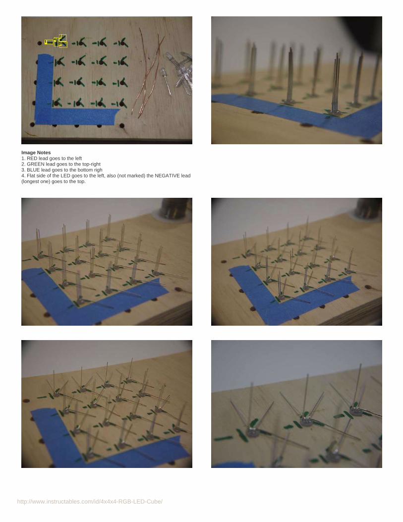
First off, mark your grid as mine (see pic 1) so you don't get confused about the orientation of the LEDs and as to which pin goes where.1.Now place your 16 LEDs (See pic 2), make sure they are in the correct orientation (flat part to the left).2.Start bending the leads (the Rightmost lead goes to the bottom left at about 45 degrees) (pic 3).3.Keep on with the bending, the 2nd lead from right to left goes to the top right corner at about 45 degrees aswell (pic 4).4.Now bend all the longer leads straight to the top, ONLY for the top row (You'll see why) (pic 5).5.Proceed to trimming all the remaining standing leads from the TOP ROW ONLY! (pic 7).6.Now bend them all to the left (pic 8) they should not touch the neighbor LEDs.7.Repeat steps 5 to 7 for the NEXT ROW, soldering each of the leads that reach the top LED's to the leads of those LEDs that go to the top as you go (pics 9 & 10).8.Repeat step 8 for the rest of the rows (pic 11).9.Trim down all the excess leads (pic 12).10.Now proceed to joining the columns, for this, grab a 10 cm long wire and make a small half-loop at the end (pic 13).11.pull it so the lead of the LED from the FIRST column id inside the half-loop and solder it down, use a gentle amount of solder (pic 14).12.solder the remaining columns to the wire and trim the excess off (pic 15).13.add another 3 wires in the same way (pic 16).14.
Now repeat all steps 3 more times to get all the layers, this might seem a bit tedious, but with some good music, it goes real quick!
Make sure to test your layers as you go.
http://www.instructables.com/id/4x4x4-RGB-LED-Cube/
Image Notes1. RED lead goes to the left2. GREEN lead goes to the top-right3. BLUE lead goes to the bottom righ4. Flat side of the LED goes to the left, also (not marked) the NEGATIVE lead(longest one) goes to the top.

http://www.instructables.com/id/4x4x4-RGB-LED-Cube/

http://www.instructables.com/id/4x4x4-RGB-LED-Cube/
Step 5: Make a messNow we need to add the wires for the columns, for this we will need 48 wires (pic 3) that are about 12 cm long, then, with the help of a helping hand to hold them in place(see pic 2), start soldering one wire to each lead from every LED.
Image Notes1. Tadaa!
Image Notes1. barely touching, but enough for a good solder joint
http://www.instructables.com/id/4x4x4-RGB-LED-Cube/
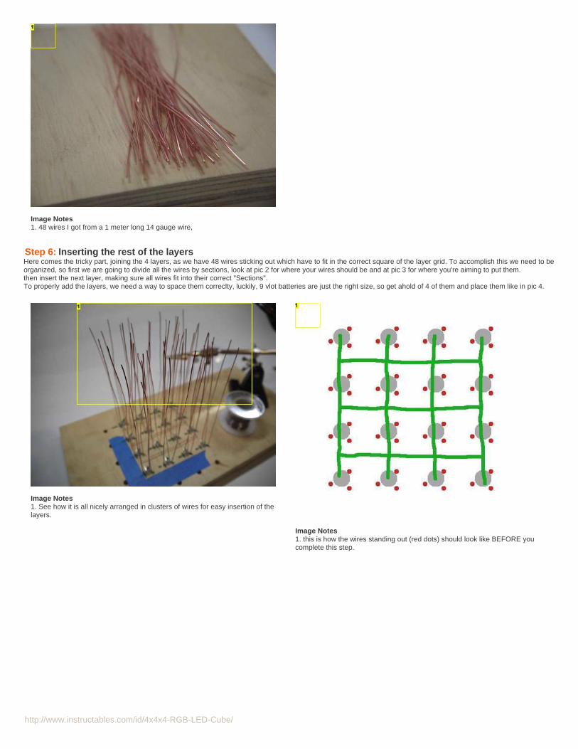
Image Notes1. 48 wires I got from a 1 meter long 14 gauge wire,
Step 6: Inserting the rest of the layersHere comes the tricky part, joining the 4 layers, as we have 48 wires sticking out which have to fit in the correct square of the layer grid. To accomplish this we need to beorganized, so first we are going to divide all the wires by sections, look at pic 2 for where your wires should be and at pic 3 for where you're aiming to put them.then insert the next layer, making sure all wires fit into their correct "Sections".To properly add the layers, we need a way to space them correclty, luckily, 9 vlot batteries are just the right size, so get ahold of 4 of them and place them like in pic 4.
Image Notes1. See how it is all nicely arranged in clusters of wires for easy insertion of thelayers.
Image Notes1. this is how the wires standing out (red dots) should look like BEFORE youcomplete this step.

http://www.instructables.com/id/4x4x4-RGB-LED-Cube/
Image Notes1. this is how the wires standing out (blue dots) should look like AFTER youcomplete this step.
Step 7: Repeat for the rest of the layersjust place the remaining 2 layers as you did for the second one. You should now have a complete LED cube, now we can start with the electronics, but, just to be sure,test all the cube one more time, you know, it's best to find out of a dead LED now and not later.
Step 8: The control electronicsTo begin with the electronic circuitry, we need all the components shown in pic 1 and 2 PCBs the same size or bigger than your cube.

http://www.instructables.com/id/4x4x4-RGB-LED-Cube/
Image Notes1. 4x P-Channel MOSFETs2. Atmega3283. 3x TLC5940 PWM IC4. 3x 16x1 Male and female headers.5. 2x 14x1 pin socket and 2 x 4x1 socket
6. 1x 4x1 male and female headers, i'll trim these later
Step 9: Mark and cut the PCBsMark your PCBs just a little bit bigger than the cube (pics 1 & 2) and cut them, I used a circular saw for this but you can use just about anything, even n X-acto knife (pics3, 4 &5).
Then proceed to sanding all the edges (pic 6).
And finally paint them black with some matte spray paint (pic 7), remember to ONLY paint the top side black, not the copper!

http://www.instructables.com/id/4x4x4-RGB-LED-Cube/

http://www.instructables.com/id/4x4x4-RGB-LED-Cube/
Step 10: Add the headers to the top PCB.get 3 rows of 16 MALE headers and 1 row of 4 MALE headers, we'll be mounting these on one of our PCBs.
First off we need to modify them a bit, pushing the black plastic piece that holds all the pins together right to the very end of the pins, make sure they don't fall off.
Once you've done that, find a proper place to put them in the top board, the exact place is not critical, but try to place them near the edges and make sure they won'tobstruct any hole needed by the cube (see next step for more on this) and then push them all the way in and solder ALL the pins from the other side, the 4 pin header willbe positioned right at the edge of the board, but don't do that just yet, as we are going to place it in any free space we find left (more on this later).
Image Notes1. all 3 of the 16 pin headers ready for mounting on the board.2. this needs to be trimmed down to a 4 pin header.
Image Notes1. All the 16 pin headers in place, I still need to push them in and solder them inplace.2. the 4 pin header will go here
Step 11: Start mounting the cube.We now need to start mounting the LED cube on the top PCB, I'm using 2 PCBs to keep all the electronics hidden while still having access to them, the boards will beplugged together like an Arduino shield.
To mount the cube we need to make 48 wires fit in their proper holes, to make this easier we are going to trim the leads of the cube as in pic 1 (in an angle) I used someheavy duty stainless steel scissors for this but you can use your typical wire snippers if you don't have access to stronger tools.
start inserting the leads of the cube to the top PCB, the longer leads first, once you have all the leads from the first row in, bend them a bit to prevent them from goingback out, then proceed to the next row, I used a pair of modified doctor's thongs (hemostats) (the long, thin ones) to aid me in getting all the leads to the right place, onceyou finish a row, bend the leads a bit and proceed to the next one, DO NOT SOLDER ANYTHING YET!
Image Notes1. All leads in, bent so they don't come out again.

http://www.instructables.com/id/4x4x4-RGB-LED-Cube/
Step 12: Finish mounting the cubeonce you have all your leads in, proceed to soldering the four corner leads to hold the cube in place, BEFORE you do this push the PCB as far in as it will go withoutdamaging anything and make sure all corners are at the same height (pic 1).
Once you have soldered the four corners, check again the height of the corners and, if it's all the same, proceed to soldering all the remaining leads (pic 2).
When you finish soldering all the leads, trim all the excess (pic 3).
Image Notes1. All leads soldered and nicely trimmed.

http://www.instructables.com/id/4x4x4-RGB-LED-Cube/
Step 13: Connecting the columnsNow we need to connect all the columns to the nearest pin in one of the 3 MALE headers, it doesn't matter what do you connect where, you can help yourself by dividingthe PCB in sectors with a marker, leaving 16 leads for each sector and corresponding header. to connect them all together I used a solder tracing technique (pic 1), I loveit as it saves tons of wiring and it is fast, easy and reliable, but it requires a bit of practice, so I would recommend you to do some test traces in one of the pieces of scrapPCB we have left from the cut. also, a PCB with square pads works better with this technique.
Image Notes1. Note how all the traces are made of solder and I need no messy wires on the top side.
Step 14: The second PCBPlace the 3 FEMALE 16 pin headers on the male ones and then place the second PCB on top of that (pic 1), make sure you align them correctly and proceed to solderingall the pins in place (pic 2).
Image Notes1. all pins soldered.
Step 15: Begin placing componentsthe first thing we need to place in are the 3 TLC5940 PWM ICs, we are going to place one aside each header (pic 2), centered and with the outputs facing the header.(see pic 3 for Pinout of the TLC5940).
After you have placed them, flip the board and solder all the outputs to the headers (pic 4).
Don't worry about the connections just now, we will first place everything and then connect what we can via Solder traces and connet what's left via small wires.

http://www.instructables.com/id/4x4x4-RGB-LED-Cube/
Step 16: Arduinize it.Now we are going to add the Atmega328 chip, the brains of our cube.
Place it somewhere near the center of the board, use a socket for this one as it is possible that you may need to replace it.
In this step, we'll also add the 3 3-pin headers and 2 resistors for each, the 4k7 ones and the 8k2 ones, place those near the center of each TLC5940 leaving a 1 pin thickgap between the two (pic 1).

http://www.instructables.com/id/4x4x4-RGB-LED-Cube/
Step 17: Adding the oscilatorAdd the crystal oscillator and caps for the Arduino Chip, see pic 2 for the pinout and where you should connect the crystal (the 2 pins that say crystal), then each pin ofthe crystal goes through a cap to ground.
Step 18: The MOSFETsfind a nice, free space to place your MOSFETs, remember that it needs to be enough to fit them all bent down plus the 4 pin FEMALE header.
If you decided to add some EEPROMs to the cube, now is a good time to add those sockets too, find a small free space and place them there.
Image Notes
http://www.instructables.com/id/4x4x4-RGB-LED-Cube/
1. The sockets for the small, 8-pin EEPROMs2. The 4 MOSFETs nicely resting over the board.
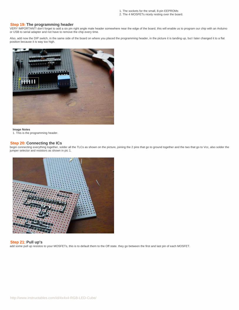
Step 19: The programming headerVERY IMPORTANT! don't forget to add a six pin right angle male header somewhere near the edge of the board, this will enable us to program our chip with an Arduinoor USB to serial adapter and not have to remove the chip every time.
Also, add now the DIP switch, in the same side of the board on where you placed the programming header, in the picture it is tanding up, but I later changed it to a flatposition because it is way too high.
Image Notes1. This is the programming header.
Step 20: Connecting the ICsbegin connecting everything together, solder all the TLCs as shown on the picture, joining the 2 pins that go to ground together and the two that go to Vcc, also solder thejumper selector and resistors as shown in pic 1.
Step 21: Pull up'sadd some pull up resistos to your MOSFETs, this is to default them to the Off state. they go between the first and last pin of each MOSFET.
http://www.instructables.com/id/4x4x4-RGB-LED-Cube/
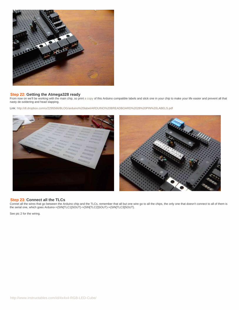
Step 22: Getting the Atmega328 readyFrom now on we'll be working with the main chip, so print a copy of this Arduino compatible labels and stick one in your chip to make your life easier and prevent all thatnasty de-soldering and head slapping.
Link: http://dl.dropbox.com/u/2295566/BLOG/arduino%20label/ARDUINO%20BREADBOARD%2028%20PIN%20LABELS.pdf
Step 23: Connect all the TLCsConnet all the wires that go between the Arduino chip and the TLCs, remember that all but one wire go to all the chips, the only one that doesn't connect to all of them isthe serial one, which goes Arduino->(SIN[TLC1]SOUT)->(SIN[TLC2]SOUT)->(SIN[TLC3]SOUT).
See pic 2 for the wiring.

http://www.instructables.com/id/4x4x4-RGB-LED-Cube/
Image Notes1. this information is available in the sketch you'll download later aswell.
Step 24: Do what you canNow connect what you can directly on the bottom PCB, with solder traces and leave space for adding wires where you couldn't solve a path.
What you need to connect;
your EEPROMs (if you have any).3 of the 4 pins on the dip switch.the 2 1000uF caps from Vcc to Gndthe 2 100nF caps from Vcc to Gndthe 6 pin programing header, the leftmost pin goes to Arduino's Reset, 2nd pin to Arduino's RX, 3rd to Arduino's TX 4th to VCC and 6th to Gnd, the 5th pin is leftunconnected.Your MOSFETs, the Rightmost pin goes to VCC and the center pin goes to a pin on the 4 pin FEMALE header.Gnd and VCC to all ICs, try to get at least Gnd done on the bottom side.

http://www.instructables.com/id/4x4x4-RGB-LED-Cube/
Step 25: Do what you couldn'tFinish up connecting everything on the top side with thin wire wrap, connect each MOSFETs Leftmost pin to a free arduino pin, connect the EEPROMs and connect allthe remaining VCC connections, the PWM ICs and the Arduino chip need little current so you can use thin wire, but the MOSFETs need a lot of current so connect themwith a thick wire.
Image Notes1. Ignore this, it won't be used
Step 26: Troubleshooting.test that all places which should be connected to VCC are indeed connected, do the same for the Gnd pins, and check that Vcc is not shorted with Gnd.
Step 27: Connecting the layers.At this point, you can now add the 4 pin male header to the top PCB and connect, with a wire, each pin to one of the layers, make sure the header aligns with the one onthe bottom.

http://www.instructables.com/id/4x4x4-RGB-LED-Cube/
Image Notes1. This one goes to layer 22. This one goes to layer 4, the other 2 wires are blocked out by the column wires, see if you can find them!
Step 28: The code.
Congratulations! you have successfully built an RGB LED CUBE! all that's left it to configure the code so it works properly with your cube, so start by plugging the bottomPCB and the Cube PCB together.
The first thing you need to do is find out which pins are your layers connected to, once you've done that, you need to tell the code which pin goes to which layer.
Download the zip file below containing the 2 sketches you'll need and open the main sketch.
Go to the functions tab (pic 2) and then scroll down to the function called "Void CubeUpdate(int layerNoVal)", in there, scroll down untill you see something like this (pic3);
PORTC |= _BV(PC1); //layer 4PORTC |= _BV(PC2); //layer 1PORTD |= _BV(PD2); //layer 3PORTD |= _BV(PD4); //layer 2
Tlc.update();
PORTC & ~_BV(PC2); //layer 1
Change the lines to the Proper ports and port numbers for each layer, see pic1 for the corresponding ports and port numbers for each Arduino pin.
Once you change that, scroll down more and you will find it again, make it look exactly the same as the one you edited above, but instead of layer one pin at the bottom,add the layer 2 pin, repeat this 2 more times for layers 3 & 4.
Finally upload the sketch, your cube should look something like the one on the video, don't worry if it looks all random, we are going to solve this problem on the nextstep, as long as all the LEDs light up, you are fine.
<[ VIDEO CONTENT AVAILABLE TOMORROW ]>

http://www.instructables.com/id/4x4x4-RGB-LED-Cube/
Image Notes1. Functions tab2. CubeUpdate Function
Image Notes1. These are what you should edit, change PORTC/POTRD to the correspondingport of each pin's layer and P(PortLetter)(PortNumber) to the corresponding portand number.
File Downloads
RGB LED Cube sketches..zip (11 KB)[NOTE: When saving, if you see .tmp as the file ext, rename it to 'RGB LED Cube sketches..zip']
Step 29: Mapping the LEDsNow we are going to map the columns to the correct LEDs in the software so it looks like the one on the video from last step.
Upload the Mapping sketch and note down the order in which the LEDs turn on, i would recommend you to make a 4 by 4 table to note down the number in the series inwhich each LED is lit up, keep in mind that each LED has 3 colors and that you have to note them down aswel, I used different colored pencils for each color, now labelall the columns from A to D and the rows aswel.
Now go to the main sketch and, in the Declarations tab, change each LEDs column to the prober number (see pic 2).
Image Notes1. Declarations tab2. AAchr 47 where AA stands for column A, row A and chr stands for Red channelof that LEd, the 47 stands for the number of the sequence that this LED is, youneed to change this number to fit your cube, then proceed with the other 48.

http://www.instructables.com/id/4x4x4-RGB-LED-Cube/
Step 30: EnjoyCongratulations! you now have a working RGB LED cube to show up to your friends, so sit down for a while and enjoy the show.
NOTE: this is not how it should look like, I'll upload the correct video as soon as youtube lets me.
Step 31: (Optional) make a nice baseI machined a nice wooden base for my cube on a friend's CNC, it looks great!
Image Notes1. Gluing the 2 parts together
Step 32: Future updates.This project is not complete, I still need to;
Finish an applet to make it easy for you to make your own animations.Make a set of custom animations in case you don't wanna bother on creating your own.add a Serial mode to be able to control it from a custom app on a computerMake it sound responsive with an MSGEQ7 (the chip didn't arrive on time, I will do it as soon as I get it).
This cube is amazing by itself, but, with the proper code, the possibilities are endless so I encourage you to try and Make your own code, to customize it and make it dowhatever you want, this cube makes for a great development platform to learn more advanced coding skills.

http://www.instructables.com/id/4x4x4-RGB-LED-Cube/
Step 33: An opportunity for you to win!I'm running a mini contest to thank my subscribers, if you are one of them, you can win a 3 month pro membership!If you are not yet subscribed, all you need to do to participate in the contest is hit that yellow button that says subscribe.you've got until May the 20th to subscribe, or else, you wont be able to participate. The winner will be chosen randomly.
The winner will be announced here and on my profile on May the 25th.
Remember to rate this 'ible according to what you think it deserves and, if you liked it vote for it, It is currently on the Arduino contest.
Oh, and by the way, please remember to like me on facebook:
Related Instructables
DIY FunkyNightlight: The4x4x4 LED Cubeby Analogue-Chick
Led Cube 4x4x4(video) by bajgik 4x4x4 LED-cube
based Arduinoand Flowerprotoboard byElecFreaks
Arduino 4x4x4LED Cube byPhogie7
The4x4x4 LED cube(Arduino) byforte1994
ACharlieplexedChristmas Treeby lmperkins

http://www.instructables.com/id/4x4x4-RGB-LED-Cube/
Comments
1 comments Add Comment
moshe_S_m says: May 1, 2012. 1:53 AM REPLYA really nice and clean work,Nice to see :)