
G15 Cube Servo User's Manual
56
G15 Cube Servo User’s Manual V1.1 November 2012 Information contained in this publication regarding device applications and the like is intended through suggestion only and may be superseded by updates. It is your responsibility to ensure that your application meets with your specifications. No representation or warranty is given and no liability is assumed by Cytron Technologies Incorporated with respect to the accuracy or use of such information or infringement of patents or other intellectual property rights arising from such use or otherwise. Use of Cytron Technologies’s products as critical components in life support systems is not authorized except with express written approval by Cytron Technologies. No licenses are conveyed, implicitly or otherwise, under any intellectual property rights.
-
Upload
khangminh22 -
Category
Documents
-
view
5 -
download
0
Transcript of G15 Cube Servo User's Manual

G15 Cube Servo
User’s ManualV1.1
November 2012
Information contained in this publication regarding device applications and the like is intended through suggestion only andmay be superseded by updates. It is your responsibility to ensure that your application meets with your specifications. Norepresentation or warranty is given and no liability is assumed by Cytron Technologies Incorporated with respect to theaccuracy or use of such information or infringement of patents or other intellectual property rights arising from such use orotherwise. Use of Cytron Technologies’s products as critical components in life support systems is not authorized exceptwith express written approval by Cytron Technologies. No licenses are conveyed, implicitly or otherwise, under anyintellectual property rights.

ROBOT . HEAD to TOEProduct User’s Manual –G15 Cube Servo
Created by Cytron Technologies Sdn. Bhd. – All Rights Reserved
Index
1. Introduction and Overview 3
2. Packing List 4
3. Product Specification and Limitations
3.1 Electrical Characteristics
3.2 Maximum Ratings
3.3 Specifications
5
5
5
5
4. Product Layout
4.1 Top
4.2 Bottom
6
6
7
5. Installation (hardware) 8
5.1 G15 Cube Servo Slide Fit Latch Mechanism 8
5.2 G15 Cube Servo Daisy Chain Connection 15
5.3 G15 Cube Servo Terminals Polarity 15
6. Getting Started 17
6.1 G15 Cube Servo Half Duplex Serial Implementation 17
6.2 G15 Cube Servo Control Register 18
6.3 G15 Cube Servo Communication Protocol, Instruction Packet & Status
Return Packet
32
7. Sample Instruction Packets 44
8. Dimensions
8.1 G15 Cube Servo Dimensions (mm)
8.2 G15 Inter Connect Dimensions (mm)
8.3 G15 External Joint Dimensions (mm)
8.4 G15 Rotatable Connect Dimensions (mm)
8.5 G15 U-Joint Dimensions (mm)
53
53
54
54
55
55
9 Warranty 56

ROBOT . HEAD to TOEProduct User’s Manual – G15 Cube Servo
Created by Cytron Technologies Sdn. Bhd. – All Rights Reserved 3
1. INTRODUCTION AND OVERVIEW
G15 Cube Servo is a modular smart serial servo which incorporates gear reducer, precision
high torque DC motor and control circuitry with networking functionality. It is made with
high quality engineering plastic to provide high necessary strength and can sustain high
external force. G15 provides 360o endless turn control with resolution up to 0.33 o.
The unique modular design of G15 gives very user friendly setup of desired robotics model.
G15 Cube servo has an output connect (output shaft) on one surface and specially designed
slide-fit latch on 5 other surfaces. With these slide-fit design on the surfaces of G15, user
easily setup robotic models by just sliding the servo and joint parts together without any
single screws. This slide-fit latch design also gives the flexibility for user to dismantle the
parts easily and reconfigure the servo and joints for other designs with minimal effort and
time.
G15 Cube Servo uses serial half duplex communication and allows daisy chain connection to
multiple servos to create a servo network on a single line. G15 Cube servo comes with over
temperature and over torque protection to prevent damage to the servo. It allows the use to set
the servo to shutdown on several alarm factors. Besides, G15 Cube Servo has an internal
LED indicator to show the status of the servo.
ROBOT . HEAD to TOEProduct User’s Manual – G15 Cube Servo
Created by Cytron Technologies Sdn. Bhd. – All Rights Reserved 4
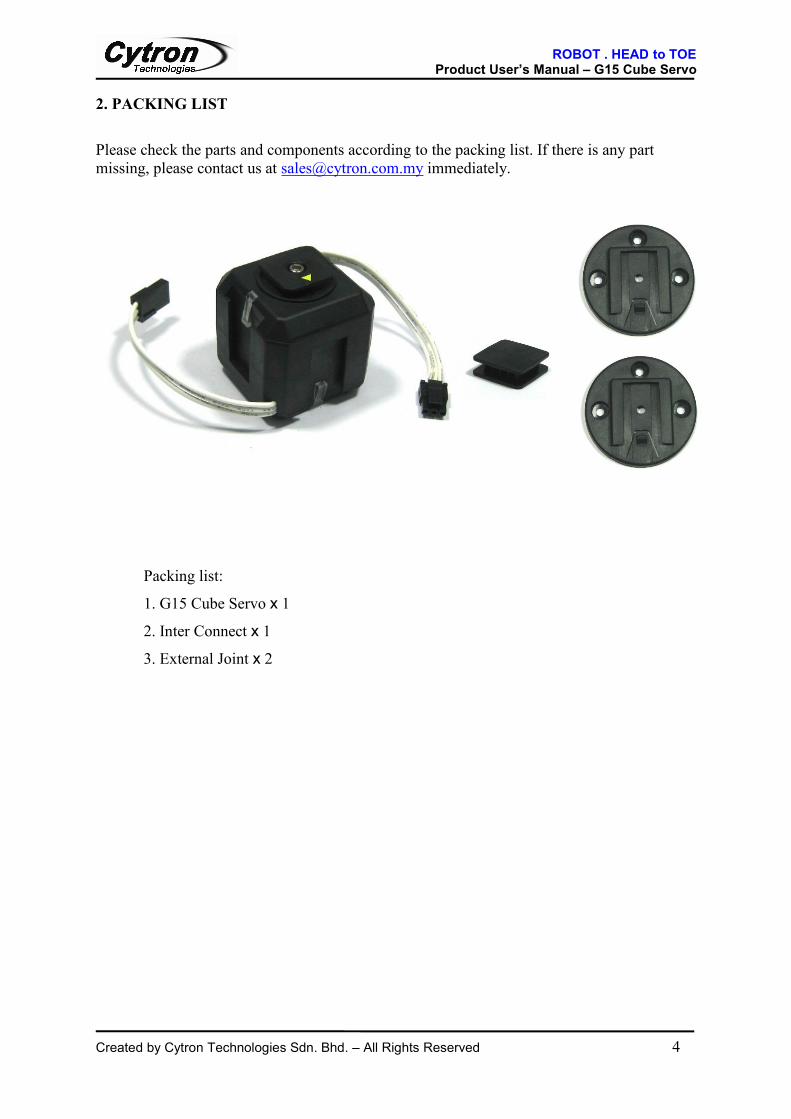
2. PACKING LIST
Please check the parts and components according to the packing list. If there is any partmissing, please contact us at [email protected] immediately.
Packing list:
1. G15 Cube Servo x 1
2. Inter Connect x 1
3. External Joint x 2

ROBOT . HEAD to TOEProduct User’s Manual – G15 Cube Servo
Created by Cytron Technologies Sdn. Bhd. – All Rights Reserved 5
3. PRODUCT SPECIFICATION AND LIMITATIONS
3.1 Electrical Characteristics
3.2 Maximum Ratings
Parameter Minimum Typical Maximum UnitOperating voltage 6.5 12 17.8 VMaximum Current (I/O signal pins) ±35 mATemperature 0 80 oCHolding Torque 15 kg.cm
3.3 Specifications
Weight 63gStall Torque 12kg.cm at 12VPositioning Resolution 0.33 o
Operation Angle 360o endless turn, electrical position controlMax Speed (no load ) 63RPM at 12VGear Ratio 194:1Communication Half duplex asynchronous serial communication
(7812.5bps-500kbps )
Parameter Minimum Typical Maximum Unit
Current Consumption (12V) 1.5 A
Input signal, VIH 2 5.5 V
Input signal, VIL 0 0.8 V
Output Signal, VOH 4.63 5.0 5.3 V
Output Signal, VOL 0 0.33 V

ROBOT . HEAD to TOEProduct User’s Manual – G15 Cube Servo
Created by Cytron Technologies Sdn. Bhd. – All Rights Reserved 6
4. PRODUCT LAYOUT
4.1 Top
A
B
C
D
EF
G
Label Name DescriptionA Output Connect Output shaft of G15 Cube ServoB Orientation Mark The orientation for Output Connect to Slide into the slide fit
latch mechanismC LED Indicator Red LED status indicator behind the semi-transparent latchD Male Connector Power and communication line with male connector.E Female Connector Power and communication line with female connectorF Wire Power and communication line wireG Slide-fit Latch Slide-fit latch mechanism on all 5 surfaces. Each Slide-fit Latch
consists of sliding slot and semitransparent latch.

ROBOT . HEAD to TOEProduct User’s Manual – G15 Cube Servo
Created by Cytron Technologies Sdn. Bhd. – All Rights Reserved 7
4.2 Bottom
A
B
C
Label Name DescriptionA Latch Anti slide latch to hold the G15 Connects.B ID Sticker ID sticker for user to write down the unique ID of servo for
serial communication.C Sliding Slot Sliding Slot of slide-fit mechanism for use to slide in the G15
connects.

ROBOT . HEAD to TOEProduct User’s Manual – G15 Cube Servo
Created by Cytron Technologies Sdn. Bhd. – All Rights Reserved 8
5. INSTALLATION (HARDWARE)5.1 G15 Cube Servo Slide Fit Latch Mechanism
5.1.1 Connectors and Joints
Connects:
Output Connect Inter Connect Rotatable Connect
Joints:
G15 Body (5 Slots) U-Joint (3 Slots) External Joint (1 Slot)

ROBOT . HEAD to TOEProduct User’s Manual – G15 Cube Servo
Created by Cytron Technologies Sdn. Bhd. – All Rights Reserved 9
5.1.2 Slide Fit Jointing Mechanism
G15 Output Connect to Joints:
G15 Output Connect MUSTbe slid into the slot fromthe yellow triangle mark.
G15 OutputConnect
OutputConnect

ROBOT . HEAD to TOEProduct User’s Manual – G15 Cube Servo
Created by Cytron Technologies Sdn. Bhd. – All Rights Reserved 10
Inter Connect to Joints:
Rotatable Connect to Joints:

ROBOT . HEAD to TOEProduct User’s Manual – G15 Cube Servo
Created by Cytron Technologies Sdn. Bhd. – All Rights Reserved 11
Slide Fit Latch:
Make sure all the connects are locked properly to the joint by the latch
External Joint for Customized Usage:
External Joint can be screwed to customized part with M3 screws.
5.1.3 Sample Connections
G15 Cube Servo to G15 Cube Servo:

ROBOT . HEAD to TOEProduct User’s Manual – G15 Cube Servo
Created by Cytron Technologies Sdn. Bhd. – All Rights Reserved 12
G15 Cube Servo to U-Joint
G15 Cube Servo to External Joint
G15 – Inter Connect – G15

ROBOT . HEAD to TOEProduct User’s Manual – G15 Cube Servo
Created by Cytron Technologies Sdn. Bhd. – All Rights Reserved 13
G15 – Inter Connect – U-Joint
G15 – Inter Connect –External Joint
G15 – Rotatable Connect – U-Joint

ROBOT . HEAD to TOEProduct User’s Manual – G15 Cube Servo
Created by Cytron Technologies Sdn. Bhd. – All Rights Reserved 14
U-Joint – Inter Connect – U-Joint
U-Joint – Inter Connect – External Joint
External Connect – Inter Connect – External Connect

ROBOT . HEAD to TOEProduct User’s Manual – G15 Cube Servo
Created by Cytron Technologies Sdn. Bhd. – All Rights Reserved 15
5.2 G15 Cube Servo Daisy Chain Connection
Main Controller 1st CubeServo
2nd CubeServo
3rd CubeServo
To moreCube Servos
Female to maleconnector
Female to maleconnector
MaleConnector
FemaleConnector
Figure above shows the daisy chain connection of G15 Cube Servo to create a servo networkon a single power and communication line.
5.3 G15 Cube Servo Terminals & Polarity
GNDV+DATA
DATAV+GND

ROBOT . HEAD to TOEProduct User’s Manual – G15 Cube Servo
Created by Cytron Technologies Sdn. Bhd. – All Rights Reserved 16
G15 Cube Servo uses high quality silicone rubber wire (22AWG) and Molex Micro-Fitconnector with clip for the power and data line. Types of Connector for G15 Cube Servo arelisted as in table below:
Molex Micro-Fit 3.0 Order No. Description Picture
43645-0300 G15 Cube Servo Maleconnector. (Match to FemalePin Terminal -43030)
43640-0301 G15 Cube Servo Femaleconnector. (Match to MalePin Terminal -43031)
43650-0300 G15 Cube Servo FemaleRight angle connector. Usedas connector on PCB.
43030 Female Pin Terminal
43031 Male Pin Terminal

ROBOT . HEAD to TOEProduct User’s Manual – G15 Cube Servo
Created by Cytron Technologies Sdn. Bhd. – All Rights Reserved 17
6. GETTING STARTED
6.1 G15 Cube Servo Half Duplex Serial ImplementationG15 servo use half-duplex serial communication. A normal UART module with the circuit
shown below can be used to control G15.
Direction Control5V
10K
DATA
TX
RX
Figure below shows Half Duplex implementation with 74HC126 IC. The inverter IC,
74HC04 can be replaced with inversion transistor circuit highlighted with red dotted box as
shown by the figure below. The circuit converts the UART communication lines to G15
DATA line. The UART-TX and UART-RX shown in the circuit need to be connected to
controller’s UART pin of TX and RX respectively. G15-DAT pin shown need to be
connected to G15’s DATA pin. The picture following illustrates the connection of the half-
duplex circuit and power supply to the G15 Cube servo’s terminals.
74HC126/74LVC126A
UART-TX
UART-RX
G15-DAT
10KΩ
5V
47Ω
CTRL74HC04
1OE
1A
1Y
2OE
2A
2Y
VCC
GND
4.7KΩ
4OE
4A
4Y
3OE
3A
3Y5V
NPN2N3904/2N2222

ROBOT . HEAD to TOEProduct User’s Manual – G15 Cube Servo
Created by Cytron Technologies Sdn. Bhd. – All Rights Reserved 18
TX
RX
UART
12V
DATA
Half-Duplexcircuitry
V+ GND
Cube Servo
6.2 G15 Cube Servo Control Register
Control Register contains parameters used to control G15. The Control Register contains
portion of parameters value which are saved to EEPROM and another portion which is not
saved to EEPROM but stored temporary in RAM. For the parameters which are saved to
EEPROM are non-volatile and the values will remain the same after a power off-on reset.
However for those stored in RAM only, all value will be reset to default value after a power
off-on reset.
Most of these parameters in the Control Register values can be modified to change the
characteristic of G15. Table below shows all the Control Register parameters. Parameters
from address of 0 to 23 are stored to EEPROM and parameters from address of 24 to 49 are
stored in RAM only.
Writing to Control Registers in EEPROM area requires extra precautions. First, the power
source has to be stable throughout the process to prevent corrupted data. Secondly user
program has to wait for 25 ms after the EEPROM write command is sent before sending the
next command. Any command sent within this period may not be processed. This is to ensure
no interruption to EEPROM write process.

ROBOT . HEAD to TOEProduct User’s Manual – G15 Cube Servo
Created by Cytron Technologies Sdn. Bhd. – All Rights Reserved 19
Area Address(Hex) Parameter Read only/
Read WriteFactory defaultvalue (Hex)
Minimumvalue (Hex)
Maximumvalue (Hex)
EEPROM
0 (0x00) Model (L) R ‘G’ (0x0F) - -1 (0x01) Model(H) R 15 (0x47) - -2 (0x02) Firmware Revision R - -3 (0x03) ID RW 1 (0x01) 0 (0x00) 253 (0xFD)4 (0x04) Baud Rate RW 103 (0x67) 3 (0x03) 255 (0xFF)5 (0x05) Return Delay RW 250 (0xFA) 1 (0x01) 255 (0xFF)6 (0x06) CW Angle Limit (L) RW 0 (0x0000) 0 (0x0000) 1087 (0x043F)7 (0x07) CW Angle Limit (H) RW8 (0x08) CCW Angle Limit (L) RW 1087 (0x043F) 0 (0x0000) 1087 (0x043F)9 (0x09) CCW Angle Limit (H) RW
10 (0x0A) Reserved - - - -11 (0x0B) Temperature Limit RW 70 (0x46) 0 (0x00) 120 (0x78)12 (0x0C) Lowest Voltage Limit RW 65 (0x41) 65 (0x41) 178 (0xB2)13 (0x0D) Highest Voltage Limit RW 150 (0x96)14 (0x0E) Max Torque (L) RW 1023 (0x03FF) 0 (0x0000) 1023 (0x03FF)15 (0x0F) Max Torque (H) RW16 (0x10) Return Packet Enable RW 2 (0x02) 0 (0x00) 2 (0x02)17 (0x11) Alarm LED RW 36 (0x24) 0 (0x00) 127 (0x7F)18 (0x12) Alarm Shutdown RW 36 (0x24) 0 (0x00) 127 (0x7F)19 (0x13) Reserved - - - -20 (0x14) Down Calibration (L) R21 (0x15) Down Calibration (H) R22 (0x16) Up Calibration (L) R23 (0x17) Up Calibration (H) R
RAM
24 (0x18) Torque Enable RW 0 (0x00) 0 (0x00) 1 (0x01)25 (0x19) LED RW 0 (0x00) 0 (0x00) 1 (0x01)26 (0x1A) CW Compliance Margin RW 1 (0x01) 0 (0x00) 254 (0xFE)
27 (0x1B) CCW ComplianceMargin RW 1 (0x01) 0 (0x00) 254 (0xFE)
28 (0x1C) CW Compliance Slope RW 32 (0x20) 1 (0x01) 254 (0xFE)29 (0x1D) CCW Compliance Slope RW 32 (0x20) 1 (0x01) 254 (0xFE)30 (0x1E) Goal Position (L) RW Address 36
0 (0x0000) 1087 (0x043F)31 (0x1F) Goal Position (H) RW Address 3732 (0x020) Moving Speed (L) RW 0 (0x0000) 0 (0x0000) 1023 (0x03FF)33 (0x21) Moving Speed (H) RW34 (0x22) Torque Limit (L) RW Address 14 0 (0x0000) 1023 (0x03FF)35 (0x23) Torque Limit (H) RW Address 1536 (0x24) Present Position (L) R37 (0x25) Present Position (H) R38 (0x26) Present Speed (L) R39 (0x27) Present Speed (H) R40 (0x28) Present Load (L) R41 (0x29) Present Load (H) R42 (0x2A) Present Voltage R43 (0x2B) Present Temperature R44 (0x2C) Registered R 0 (0x00) 0 (0x00) 1 (0x01)45 (0x2D) Reserved - - - -46 (0x2E) Moving R 0 (0x00) 0 (0x00) 1 (0x01)47 (0x2F) Lock RW 0 (0x00) 1 (0x01) 1 (0x01)48 (0x30) Punch (L) RW 32 (0x0020) 0 (0x0000) 1023 (0x03FF)49 (0x31) Punch (H) RW

ROBOT . HEAD to TOEProduct User’s Manual – G15 Cube Servo
Created by Cytron Technologies Sdn. Bhd. – All Rights Reserved 20
6.2.1 Description of Control Register’s Parameters
Model Number (Address 0x00, 0x01)
Model Number for G15 is 0x47, 0x0F which represents ‘G’ in ASCII and 15 in decimal
respectively.
Firmware revision (Address 0x02)
This value represents firmware revision of G15.
ID (Address 0x03)
ID is unique identification number assigned to each G15 unit. This ID is used for
identification of each G15 unit on the communication network. ID needs to be unique or
different for each of the G15 unit on a same network to prevent communication collisions.
Baud Rate (Address 0x04)
The serial communication speed (bps) of G15 is determined by Baud Rate register value at
address 0x04. The default baudrate of G15 is 19,200bps. The Baud Rate register value
corresponding to a baudrate (bps) is calculated using the equation below.
Baud Rate Register Value =2000000
Baudrate (bps)− 1
User need to set the Baud Rate register value (address 0x04) to the value calculated using the
equation above for a desired communication speed (baudrate). For example if register value
is set to 207 in decimal, then the resulting speed of the serial communication will be 9600bps.

ROBOT . HEAD to TOEProduct User’s Manual – G15 Cube Servo
Created by Cytron Technologies Sdn. Bhd. – All Rights Reserved 21
Table below shows the register value and corresponding baudrate.
Register Value (Hex) Baud Rate (bps) Error (%)
3 (0x03) 500,000 04 (0x04) 400,000 07 (0x07) 250,000 09 (0x09) 200,000 016 (0x10) 115,200 2.1234 (0x22) 57,600 -0.79103 (0x67) 19,200 0.16207 (0xCF) 9600 0.16
Return Delay (Address 0x05)
Return delay is the time taken for the status packet to return from G15 after an instruction
packet is sent by the controller. The return delay time is calculated using the equation below.
Return Delay Time =2µs × Return Delay register value
Operation Angle Limit (Address 0x06, 0x07, 0x08, 0x09)
The operation angle of G15 is limited by the clock wise (CW) and counter clock wise (CCW)
angle limit of the G15. The position value used for representation of angular position in G15
is from 0 to 1087.
359.67o =1087
Resolution=0.33o per position unit
0o /360o =0

ROBOT . HEAD to TOEProduct User’s Manual – G15 Cube Servo
Created by Cytron Technologies Sdn. Bhd. – All Rights Reserved 22
Equation below can be used for conversion between angle in degree unit and register value.
Position = 1088360o × Angle
If the CCW Angle Limit value is more than the CW Angle Limit value, for example CCW
Angle =350o and CW Angle Limit = 10o, G15 servo will operate in shaded sector as shown
in the figure below.
CCWAngleLimit
CWAngleLimit
CWrotation
CCWrotation
0o
If the CW Angle Limit value is more than the CCW Angle Limit value, for example CW
Angle =350o and CCW Angle Limit = 10o, G15 servo will operate in shaded sector as shown
in the figure below.
CWAngleLimit
CCWAngleLimit
CW rotation
CCW rotation
0o

ROBOT . HEAD to TOEProduct User’s Manual – G15 Cube Servo
Created by Cytron Technologies Sdn. Bhd. – All Rights Reserved 23
Temperature Limit (Address 0x0B)
Temperature Limit value limits the operating temperature of G15 to prevent damage due to
overheating of internal motor. If the temperature rises above this Temperature Limit value,
the Over Heat Error bit (bit 2 of ERROR byte in status packet) will be set. The alarm will be
set according to value of Address 17 and 18 of Control Register. Temperature Limit value is
in degree Celsius unit.
Voltage Limit (Address 0x0C, 0x0D)
The Highest Voltage Limit and Lowest Voltage Limit are limiting the operating voltage of
G15 Cube Servo for safety purposes. If the operating voltage is outside of the limits, the
Voltage Range Error bit (bit 0 of ERROR byte in status packet) will be set. This cause G15
will respond all packets with error status. The actual operating voltage can be calculated from
the Voltage Limit value by dividing the value with 10. The default operating limit range is
6.5V to 12V.
Voltage Limit =(Control Register)
Voltage X 10
Maximum Torque & Torque Limit (Address 0x0E, 0x0F, 0x22, 0x23)
These values limit the maximum torque produced by G15. Maximum Torque is stored in
EEPROM area and Torque Limit is stored in RAM area. When G15 is powered on, the
Maximum Torque value at the address of 0x0E to 0x0F is copied to Torque Limit register
located at the address of 0x22 to 0x23. G15 will produce a maximum torque corresponding to
the value in Torque Limit register. The minimum and maximum value for these register are
from 0 to 1023.
Return Packet Enable (Address 0x10)
Return Packet Enable value determines whether return status packet is sent out of G15
responding to the instruction from main controller according to table below.

ROBOT . HEAD to TOEProduct User’s Manual – G15 Cube Servo
Created by Cytron Technologies Sdn. Bhd. – All Rights Reserved 24
Value Return Status packet
0 No return status packet will be sent out
1 Only READ DATA instruction will be responded
2 Respond to all instruction
No return status packet will be sent out of G15 if Broadcast ID (0xFE) is used by the
instruction packet.
ALARM LED (Address 0x11)
The ALARM LED byte set for the LED of G15 to blink on different occurrence of errors.
Table shows function of every bit of the ALARM LED byte. If the corresponding bit is set,
when the error occurs, the LED on G15 will blink. For example, if ALARM LED byte value
is 0x44, the LED on G15 will blink when either Instruction Error or Overheating Error occur.
Bit Error Indication
Bit 7 Reserved
Bit 6 Instruction Error
Bit 5 Overload Error
Bit 4 Checksum Error
Bit 3 Range Error
Bit 2 Overheating Error
Bit 1 Angle Limit Error
Bit 0 Input Voltage Error
ALARM SHUTDOWN (Address 0x12)
The ALARM SHUTDOWN register sets the G15 to shutdown or turn off its torque on
several different errors. Table below shows the bits in ALARM SHUTDOWN byte which
represents the several different errors. User can set these bits to turn off G15 when the
particular error occurs. After an alarm shutdown, G15 will maintain in torque off condition
until user manually reset the TORQUE ENABLE parameter (0x18) in Control Register to
value 1.

ROBOT . HEAD to TOEProduct User’s Manual – G15 Cube Servo
Created by Cytron Technologies Sdn. Bhd. – All Rights Reserved 25
Bit Error
Bit 7 Reserved
Bit 6 G15 shutdown on Instruction Error
Bit 5 G15 shutdown on Overload Error
Bit 4 G15 shutdown on Checksum Error
Bit 3 G15 shutdown on Range Error
Bit 2 G15 shutdown on Overheating Error
Bit 1 G15 shutdown on Angle Limit Error
Bit 0 G15 shutdown on Input Voltage Error
CALIBRATION (Address 0x14-0x17)
These are calibration data used for compensating the position sensor difference used in G15
units. The user cannot change these values.
TORQUE ENABLE (Address 0x18)
TORQUE ENABLE sets the G15 torque to be on or off. When it is on, G15 will hold its shaft
in position and when it is off, G15 shaft is under torque free condition where user can change
the shaft position by turning it.
LED (Address 0x19)
LED on G15 can be turned on by setting this byte to 1 or turned off by setting this byte to 0.
COMPLIANCE MARGIN & SLOPE (Address 0x1A - 0x1D)
The positioning compliance margin and slope of G15 are illustrated as in the figure below.
The values can be utilized for absorbing shocks at the out shaft of G15. The compliance slope
will determine how fast G15 reduces its torque before reaching the goal position. The
compliance margin is the allowable goal position error margin of G15 to prevent G15 shaft

ROBOT . HEAD to TOEProduct User’s Manual – G15 Cube Servo
Created by Cytron Technologies Sdn. Bhd. – All Rights Reserved 26
start oscillating. PUNCH (0x30, 0x31) value determines the minimum torque before G15
release its torque in compliance margin.
E
E
A: CCW Compliance Slope (Address 0x1D)B: CCW Compliance Margin (Address 0x1B)C: CW Compliance Margin (Address 0x1A)D: CW Compliance Slope (Address 0x1C)E: PUNCH(Address 0x30, 0x31)
B C D
Goal Position
CWCCW
CW
CCWA
Y-axis: Output Torque
X-axis: Position
GOAL POSITION (Address 0x1E, 0x1F)
270o 90o
180o
0o
CWCCW
The GOAL POSITION is the destination position that G15 shaft will move to and positioned.
G15 can be electrical positioned to any 360 degrees of position. The resolution of the
positioning is 0.33o. The value of GOAL POSITION can be from 0 to 1087 which represent

ROBOT . HEAD to TOEProduct User’s Manual – G15 Cube Servo
Created by Cytron Technologies Sdn. Bhd. – All Rights Reserved 27
the total 360o angular position. Equation below can be referred for the conversion between
position and angle.
Position = 1088360o × Angle
Normal Positioning Mode:
In Normal Positioning Mode, G15 rotates to the goal position according to the OPERATION
ANGLE LIMIT (0x06, 0x07, 0x08, 0x09) which set the operating sector of G15. The least
significant 11 bits of GOAL position represents the desired position that G15 will move to.
Table below shows the bit definition of GOAL POSITION in normal mode.
Bit 15-11 10-0
Definition Unused Goal position
Direction Positioning Mode:
In Direction Positioning Mode, the rotation of G15 will not be limited by the OPERATION
ANGLE LIMIT value. The direction of rotation will be determined by the user. The least
significant 11 bits of the GOAL POSITION represents the desired angular position. Bit-14 of
GOAL POSITION represents the direction of rotation to the goal position. G15 can rotate
CW or CCW to the goal position depending on the value of bit-14. Bit 15 need to be set to 1to indicate that G15 is in Direction Positioning Mode. Table below shows the bit
representation.
Bit 15 14 13-11 10-0
Definition Direction Positioning Mode = 1 Direction Unused Goal position
Direction=0: CCW rotation
Direction =1: CW rotation

ROBOT . HEAD to TOEProduct User’s Manual – G15 Cube Servo
Created by Cytron Technologies Sdn. Bhd. – All Rights Reserved 28
MOVING SPEED (Address 0x20, 0x21)
MOVING SPEED parameter in Control Register can represent values for 3 different modes
namely, Rotation Speed Mode, Wheel Mode and Time to Goal Position Mode. 3 different
modes operate the Cube Servo differently as described below.
Positioning Mode (Speed Control):
This mode is default mode where 6 most significant bits of the MOVING SPEED are always
‘0’ and CW Angle Limit and CCW Angle Limit are having different value to define the
rotation sector of servo. The MOVING SPEED represents the angular speed of the output
shaft moving to the goal position. The maximum MOVING SPEED value is 1023 (0x3FF)
which is equivalent to 100RPM of the output shaft. The lowest speed is achieved by setting
the MOVING SPEED value to 1. Hence, the speed control resolution is 0.098RPM. If the
MOVING SPEED value is set to 0, G15 will rotate at the maximum rotational speed afforded
by the power supply without speed control. If the value of MOVING SPEED is not in the
range of 0 to 1023 G15 Cube Servo will respond an error.
MOVING SPEED =1023
112.83× Desired RPM
Table below shows the bit definition for Rotation Speed Mode:
Bit 15-10 9-0
Definition 0 Speed
Positioning Mode (Time Control):
Time Control Mode is entered by setting the bit-15 of MOVING SPEED register to ‘1’. The
least significant 12 bits of MOVING SPEED register represents the time will be taken for
G15 Cube Servo to reach the goal position. The maximum value of MOVING SPEED is
4095 which is equivalent to 409.5 seconds. The resolution of the time is 0.1 second. The
minimum value of MOVING SPEED register in this mode is 1, G15 will respond an error if
value ‘0’ is loaded into the least significant 12 bits of register in this mode (bit 15 =1).

ROBOT . HEAD to TOEProduct User’s Manual – G15 Cube Servo
Created by Cytron Technologies Sdn. Bhd. – All Rights Reserved 29
MOVING SPEED Register value =(LSB 12 bits) 0.1 second
Desired Time taken to Goal Position
Table below shows the bit representation of MOVING SPEED register in this mode:
Bit 15 14-13 12-0
Definition 1 unused Time to Goal Position
Wheel Mode (Continuous Rotation):
Wheel Mode is for continuous rotation of G15 output shaft. The wheel mode is entered by
setting both CW Angle Limit and CCW Angle Limit to a same value. In wheel mode, the
MOVING SPEED register’s least significant 10 bits (bit-0 to bit-9) determine the speed of
the rotation. Bit-10 is used to control the rotation direction. The 16 bits value representation
is shown by table below.
Bit 15-11 10 9-0
Definition 0 Direction Speed
In wheel mode, the 10 bits speed value represents the torque applied by the G15’s motor
to the output shaft. There is no actual speed control in this mode.
PRESENT POSITION (Address 0x24, 0x25)
PRESENT POSITION is the current angular position of G15 output shaft.
Direction=0: CCW rotation
Direction =1: CW rotation
ROBOT . HEAD to TOEProduct User’s Manual – G15 Cube Servo
Created by Cytron Technologies Sdn. Bhd. – All Rights Reserved 30
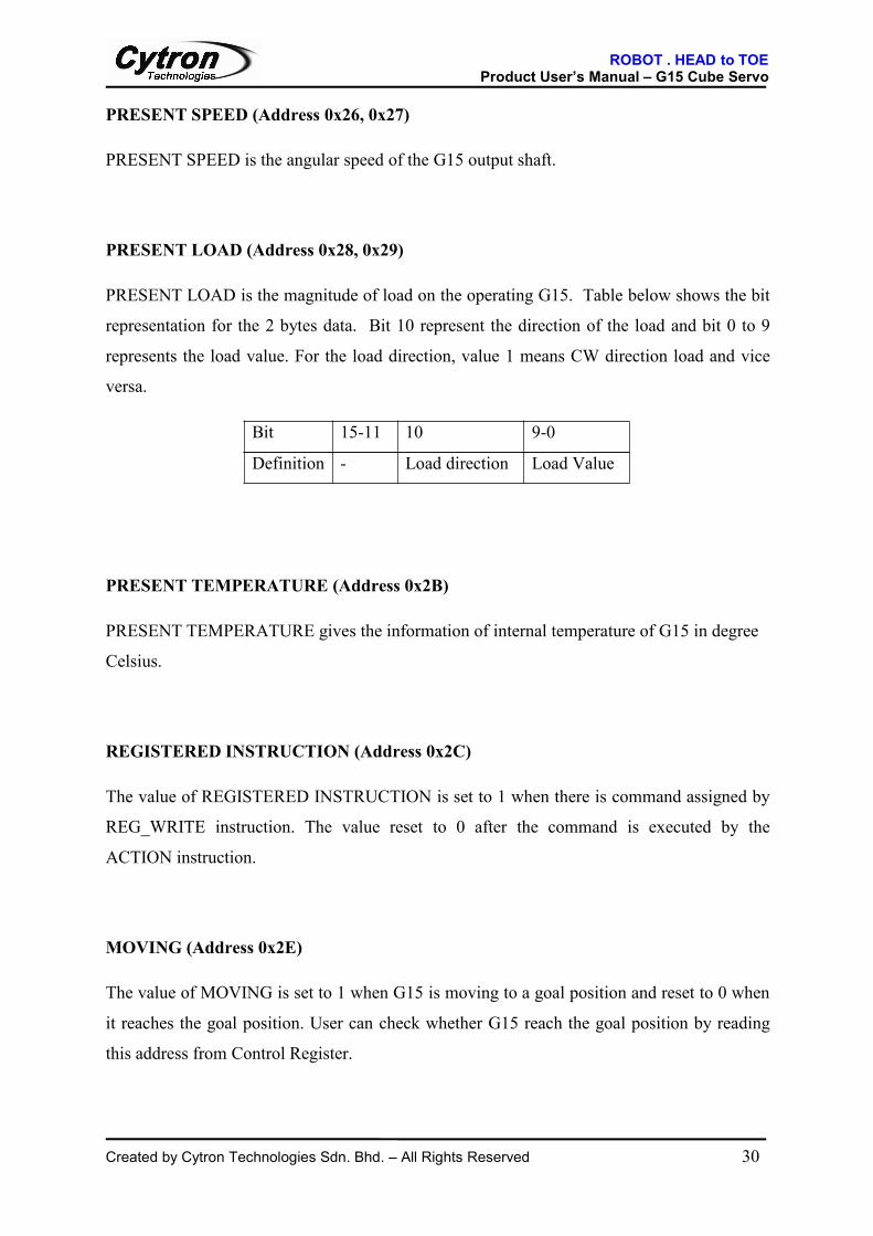
PRESENT SPEED (Address 0x26, 0x27)
PRESENT SPEED is the angular speed of the G15 output shaft.
PRESENT LOAD (Address 0x28, 0x29)
PRESENT LOAD is the magnitude of load on the operating G15. Table below shows the bit
representation for the 2 bytes data. Bit 10 represent the direction of the load and bit 0 to 9
represents the load value. For the load direction, value 1 means CW direction load and vice
versa.
Bit 15-11 10 9-0
Definition - Load direction Load Value
PRESENT TEMPERATURE (Address 0x2B)
PRESENT TEMPERATURE gives the information of internal temperature of G15 in degree
Celsius.
REGISTERED INSTRUCTION (Address 0x2C)
The value of REGISTERED INSTRUCTION is set to 1 when there is command assigned by
REG_WRITE instruction. The value reset to 0 after the command is executed by the
ACTION instruction.
MOVING (Address 0x2E)
The value of MOVING is set to 1 when G15 is moving to a goal position and reset to 0 when
it reaches the goal position. User can check whether G15 reach the goal position by reading
this address from Control Register.

ROBOT . HEAD to TOEProduct User’s Manual – G15 Cube Servo
Created by Cytron Technologies Sdn. Bhd. – All Rights Reserved 31
LOCK (Address 0x2F)
If the LOCK value is set to 1, only register located from address 0x18 to 0x23 can be written
or modified. A power off reset is need to unlock it again.
PUNCH (Address 0x30, 0x31)
PUNCH value determines the minimum current value supplied to G15’s motor during the
operation. This also means the minimum torque of G15 before it releases the torque when
goal position is reach. Refer to previous figure of compliance margin and slope for better
illustration.

ROBOT . HEAD to TOEProduct User’s Manual – G15 Cube Servo
Created by Cytron Technologies Sdn. Bhd. – All Rights Reserved 32
6.3 G15 Cube Servo Communication Protocol, Instruction Packet & Status ReturnPacket
The main controller will communicate with G15 through two way communication by sending
instruction packet and receiving return status packet on the half duplex line (data line). The
communication is using standard UART protocol with 1 start bit, 1 stop bit, 8 data bit and no
parity bit as shown in diagram below.
User can choose the baudrate of the UART communication by setting the value of Baud Rate
parameter of the Control Register.
6.3.1 Instruction Packet
Instruction packet is sent by main controller to G15. Instruction packet contains commands to
the G15 for G15 to response and change states or status accordingly. The instruction packet
format is shown as following.
0xFF 0xFF ID LENGTH INSTRUCTION PARAMETER1…PARAMETER N CHECKSUM
0xFF of the first 2 bytes are packet headers to indicate the starting of communication packet.
Any packet without the header or with wrong checksum will be eliminated by G15.
ID is the unique ID of the G15. Do make sure that there is no 2 units of G15 having same ID.
This will cause the data line collision and communication errors. The value of ID can be from
0 (0x00) to 253 (0xFD). For broadcasting to all connected G15 units, 254 (0xFE) can be used
as the ID in the packet. This will cause all G15 to receive the packet and act correspondingly.
However, G15 unit will not reply any status packet if the broadcast ID is used.
LENGTH is the number of parameter added by 2, N + 2.
INSTRUCTION is the instruction to be performed by G15 (refer to the Instruction set table).
Start bit D0 D1 D2 D3 D4 D5 D6 D7 Stop bit

ROBOT . HEAD to TOEProduct User’s Manual – G15 Cube Servo
Created by Cytron Technologies Sdn. Bhd. – All Rights Reserved 33
PARAMETER 1…PARAMETER N are additional data needed by the instruction (refer to
description of command section).
CHECKSUM is for data sending error checking. This makes sure that there is no corruption
of data during the transmission of packet. Checksum is calculated as bitwise inversion of
summation of all bytes in the packet excluding the header (0xFF, 0xFF). The following
formula shows the calculation of checksum:
Checksum= ~ (ID + Length + Instruction + Parameter1 + Parameter N)
6.3.2 Status Return Packet
Status Return Packet is response packet from G15 Cube Servo after receiving an instruction
packet. The Status Return Packet format is shown as following.
0xFF 0xFF ID LENGTH ERROR PARAMETER1…PARAMETER N CHECKSUM
0xFF of the first 2 bytes are packet headers to indicate the starting of communication packet.
ID is the unique ID of the responding G15 Cube Servo.
LENGTH is the number of parameter added by 2, N + 2.
ERROR is the error status of the G15 Cube Servo. Each bit representing different error
occurred in G15 as shown by the table below.
Bit 7 Bit 6 Bit 5 Bit 4 Bit 3 Bit 2 Bit 1 Bit 0
- InstructionError
OverloadError
ChecksumError
RangeError
OverheatingError
AngleLimit Error
Input VoltageError

ROBOT . HEAD to TOEProduct User’s Manual – G15 Cube Servo
Created by Cytron Technologies Sdn. Bhd. – All Rights Reserved 34
Table below shows the meaning of each bit in the ERROR status byte.
Error Description
Instruction Error Value is set to 1 if unknown instruction is received or Action
Instruction is sent without REG_WRITE instruction being sent
previously
Overload Error Value is set to 1 if the maximum torque set is unable to handle or
control the applied load.
Checksum Error Value is set to 1 if the checksum of received instruction packet is
incorrect
Range Error Value is set to 1 if the Control Register address is incorrect or
parameter is not between the defined min and max values.
Overheating Error Value is set to 1 of the internal temperature rose above the
operating Temperature Limit setting in the Control Register.
Angle Limit Error Value is set to if the Goal Position is outside of the CW and CCW
Angle Limit.
Input Voltage Error Set 1 to if voltage is out of Voltage Limit setting in the Control
Register
PARAMETER1…PARAMETER N are additional information if needed.
CHECKSUM is calculated as bitwise inversion of summation of all bytes in the packet
excluding the header (0xFF, 0xFF).
Checksum= ~ (ID + Length + Instruction + Parameter1 + Parameter N)
6.3.3 Incomplete Packet HandlingG15 Cube Servo is designed to wait for a complete Instruction Packet once it received the
valid header bytes (0xFF, 0xFF). Before G15 Servo Cube obtains a complete packet from
user’s controller, for each byte received, it will wait for another 100ms to receive the next
byte. This will continue until the checksum byte arrives. Therefore if the Instruction packet
received is incomplete due to connection error or any unknown reason, G15 Cube Servo only
will start receiving new Instruction Packet when the 100ms wait period timeouts.

ROBOT . HEAD to TOEProduct User’s Manual – G15 Cube Servo
Created by Cytron Technologies Sdn. Bhd. – All Rights Reserved 35
6.3.3 Instruction Sets
Instruction Name Description Number ofParameter
0x01 PING Used to obtain a status packet 0
0x02 READ DATA Read values from Control Register 2
0x03 WRITE DATA Write values to Control Register 2 or more
0x04 REG WRITE Similar to WRITE_DATA instruction
but pending execution until ACTION
Instruction is called
2 or more
0x05 ACTION Triggers the pending action registered by
REG_WRITE instruction.
0
0x06 FACTORY
RESET
Resetting the Control Register values to
factory defaults.
0
0x83 SYNC WRITE Controlling multiple G15 in one single
instruction packet.
4 or more

ROBOT . HEAD to TOEProduct User’s Manual – G15 Cube Servo
Created by Cytron Technologies Sdn. Bhd. – All Rights Reserved 36
6.3.4 Description of Instructions
1. PING (0x01):
PING instruction is used to check the existence and status of G15 Cube Servo with specific
ID. The instruction does not command any operation but G15 will return a status packet to
the main controller. The PING instruction will always return a status packet even if the
broadcast ID is used and is regardless of Return Enable value in Control Register. Table
below describes the instruction packet:
Function Request a status packet from G15
Length 0x02
Instruction 0x01
Parameter1 None
Example PING instruction packet:
0xFF 0xFF 0x01 0x02 0x01 0xFB
Header ID Length Instruction Checksum
Example PING return status packet:
0xFF 0xFF 0x01 0x02 0x00 0xFC
Header ID Length Error Checksum

ROBOT . HEAD to TOEProduct User’s Manual – G15 Cube Servo
Created by Cytron Technologies Sdn. Bhd. – All Rights Reserved 37
2. READ DATA (0x02):READ DATA instruction is used to retrieve value of desired parameters from the Control
Register of G15. Table below describes the instruction packet:
Function Read Parameters from G15 Control Register
Length 0x04
Instruction 0x02
Parameter1 Starting address data to be read
Parameter2 Length of data in byte to be read
Example READ DATA instruction packet:
Reading internal temperature of G15 with ID 01.
0xFF 0xFF 0x01 0x04 0x02 0xCC
Header ID Length Instruction Checksum
0x2B
0x01
Params1&2
Example return status packet of temperature read:
0xFF 0xFF 0x01 0x03 0x00 0xDB
Header ID Length Error Checksum
0x20
Parameter(Temperature)

ROBOT . HEAD to TOEProduct User’s Manual – G15 Cube Servo
Created by Cytron Technologies Sdn. Bhd. – All Rights Reserved 38
3. WRITE DATA (0x03):WRITE DATA instruction is used to write value of desired parameters to the Control
Register of G15. Writing to Control Register will cause changes of state or characteristic of
G15 Cube Servo. Table below describes the instruction packet:
Function Write to G15 Control Register’s Parameters.
Length N+3 (N is number of data to write)
Instruction 0x03
Parameter1 Starting address data to be written
Parameter2 1st data
Parameter3 2nd data
ParameterN+1 Nth data
Example of WRITE DATA instruction packet:
This example instruction packet set the ID of connected G15 to 1. The ID parameter is
located at address 0x03 of Control Register. The instruction packet is transmitted using
Broadcasting ID (0xFE). The broadcasted instruction will have no return status packet.
0xFF 0xFF 0xFE 0x04 0x03 0xF6
Header ID Length Instruction Checksum
0x03 0x01
Params1&2

ROBOT . HEAD to TOEProduct User’s Manual – G15 Cube Servo
Created by Cytron Technologies Sdn. Bhd. – All Rights Reserved 39
4. REGWRITEThe REG WRITE instruction is similar to WRITE DATA instruction, except that the
instruction is not executed immediately. The instruction will be stored to temporary buffer
and executed only when trigger by ACTION instruction. Table below describes the
instruction packet.
Function Write parameters to buffer and wait ACTION instruction to trigger the
write to the Control Register.
Length N+3 (N is number of data to write)
Instruction 0x04
Parameter1 Starting address data to be written
Parameter2 1st data
Parameter3 2nd data
ParameterN+1 Nth data
Example of REG WRITE instruction packet:
This example instruction packet set the goal position of G15. The goal position is located at
address of 0x1E and is two bytes parameters. The 1st parameter is the starting address of the
goal position (refer to Control Register of G15) and the 2nd and 3rd parameter are the lower
byte and higher byte of the goal position.
0xFF 0xFF 0x01 0x05 0x04 0x2D
Header ID Length Instruction Checksum
0x1E 0xAA
Data 1&2
0x00
Address
Example of return status packet:
0xFF 0xFF 0x01 0x03 0x00 0xFB
Header ID Length Error Checksum

ROBOT . HEAD to TOEProduct User’s Manual – G15 Cube Servo
Created by Cytron Technologies Sdn. Bhd. – All Rights Reserved 40
5. ACTIONThe ACTION instruction triggers the pending instruction by REG WRITE to execute and
change the parameter values in Control Register. This instruction is useful when multiple
G15s need to act simultaneously with minimum delay time between each unit. When multiple
G15s are controlled by the same main controller, there will be slight time delay between the
1st G15 unit which receives the instruction packet and last G15 unit which receive the
instruction packet. Thus, REG WRITE instruction together with ACTION instruction
mitigates this problem. Multiple G15s can be sent REG WRITE instructions and ACTION
instruction with broadcast ID (0xFE) will trigger all the G15 units to execute the instruction
at the same time. Table below describes the instruction packet.
Function Trigger the pending instruction by REG WRITE
ID Broadcast ID (0xFE) can be used for sending more than one G15 units
Length 0x02
Instruction 0x05
Parameter None
Example instruction packet:
0xFF 0xFF 0xFE 0x02 0x05 0xFA
Header ID Length Instruction Checksum
ROBOT . HEAD to TOEProduct User’s Manual – G15 Cube Servo
Created by Cytron Technologies Sdn. Bhd. – All Rights Reserved 41
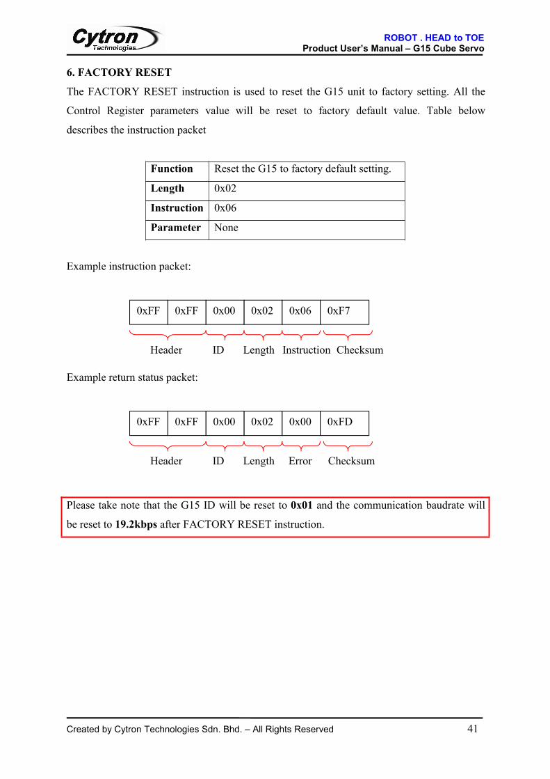
6. FACTORY RESETThe FACTORY RESET instruction is used to reset the G15 unit to factory setting. All the
Control Register parameters value will be reset to factory default value. Table below
describes the instruction packet
Function Reset the G15 to factory default setting.
Length 0x02
Instruction 0x06
Parameter None
Example instruction packet:
0xFF 0xFF 0x00 0x02 0x06 0xF7
Header ID Length Instruction Checksum
Example return status packet:
0xFF 0xFF 0x00 0x02 0x00 0xFD
Header ID Length Error Checksum
Please take note that the G15 ID will be reset to 0x01 and the communication baudrate will
be reset to 19.2kbps after FACTORY RESET instruction.
ROBOT . HEAD to TOEProduct User’s Manual – G15 Cube Servo
Created by Cytron Technologies Sdn. Bhd. – All Rights Reserved 42
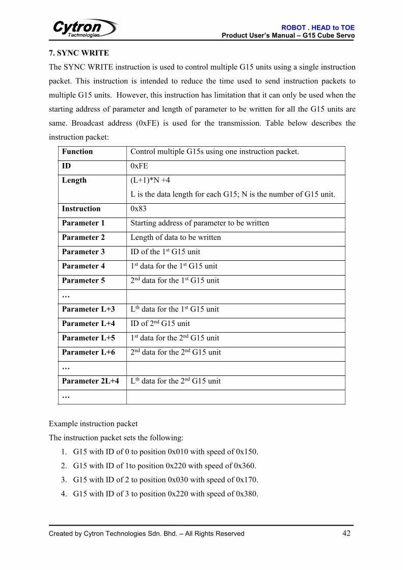
7. SYNCWRITEThe SYNC WRITE instruction is used to control multiple G15 units using a single instruction
packet. This instruction is intended to reduce the time used to send instruction packets to
multiple G15 units. However, this instruction has limitation that it can only be used when the
starting address of parameter and length of parameter to be written for all the G15 units are
same. Broadcast address (0xFE) is used for the transmission. Table below describes the
instruction packet:
Function Control multiple G15s using one instruction packet.
ID 0xFE
Length (L+1)*N +4
L is the data length for each G15; N is the number of G15 unit.
Instruction 0x83
Parameter 1 Starting address of parameter to be written
Parameter 2 Length of data to be written
Parameter 3 ID of the 1st G15 unit
Parameter 4 1st data for the 1st G15 unit
Parameter 5 2nd data for the 1st G15 unit
…
Parameter L+3 Lth data for the 1st G15 unit
Parameter L+4 ID of 2nd G15 unit
Parameter L+5 1st data for the 2nd G15 unit
Parameter L+6 2nd data for the 2nd G15 unit
…
Parameter 2L+4 Lth data for the 2nd G15 unit
…
Example instruction packet
The instruction packet sets the following:
1. G15 with ID of 0 to position 0x010 with speed of 0x150.
2. G15 with ID of 1to position 0x220 with speed of 0x360.
3. G15 with ID of 2 to position 0x030 with speed of 0x170.
4. G15 with ID of 3 to position 0x220 with speed of 0x380.

ROBOT . HEAD to TOEProduct User’s Manual – G15 Cube Servo
Created by Cytron Technologies Sdn. Bhd. – All Rights Reserved 43
The instruction packet will have no return status packet because the broadcast ID is used.
0xFF 0xFF 0xFE 0x18 0x83
Header ID Length Instruction
Checksum
0x1E 0x04 0x00 0x10 0x00
0x50 0x01 0x01 0x20 0x02 0x60 0x03 0x02 0x30 0x00
0x70 0x01 0x03 0x20 0x02 0x80 0x03 0x12
Address DataLength
2nd
ID3rd
ID
4rd
ID
1st
ID

ROBOT . HEAD to TOEProduct User’s Manual – G15 Cube Servo
Created by Cytron Technologies Sdn. Bhd. – All Rights Reserved 44
7. SAMPLE INSTRUCTION PACKET
1. Read Model Number and Firmware Revision of G15 with ID of 1:
Instruction: READ DATA
Address to Read: 0x00
Length: 0x03
Send Packet: 0xFF, 0xFF, 0x01, 0x04, 0x02, 0x00, 0x03, 0xF5
Receive Packet: 0xFF, 0xFF, 0x01, 0x05, 0x00, 0x47, 0x0F, 0x00, 0x7D
Description: Model Number is ‘G’ 15, and Firmware revision is 0.
2. Change the ID of G15 from 1 to 0:Instruction: WRITE DATA
Address to Write: 0x03
Data: 0x00
Send Packet: 0xFF, 0xFF, 0x01, 0x04, 0x03, 0x03, 0x00, 0xF4
Receive Packet: 0xFF, 0xFF, 0x01, 0x02, 0x00, 0xFC
Description: ID change successful if the Error byte in the return status is 0.
3. Changing the Baud Rate of G15 to 9600 bps
Instruction: WRITE DATA
Address to Write: 0x04
Data: 0xCF
Send Packet: 0xFF, 0xFF, 0x04, 0x03, 0x04, 0xCF, 0x25
Receive Packet: 0xFF, 0xFF, 0x00, 0x02, 0x00, 0xFD
Description: Baud Rate change successful if the Error byte in return packet is 0.

ROBOT . HEAD to TOEProduct User’s Manual – G15 Cube Servo
Created by Cytron Technologies Sdn. Bhd. – All Rights Reserved 45
4. Setting the Return Delay Time to 4µs for G15 with ID of 0According to the equation:
Return Delay register value = Return Delay Time2µs
=30 µs2 µs
= 15
Instruction: WRITE DATA
Address to Write: 0x05
Data: 0x02
Send Packet: 0xFF, 0xFF, 0x00, 0x04, 0x03, 0x05, 0x02, 0xF1
Receive Packet: 0xFF, 0xFF, 0x00, 0x02, 0x00, 0xFD
Description: Return Delay change successful if the Error byte in return packet is 0.
5. Change CW Angle Limit to 150o for G15 with ID 0Instruction: WRITE DATA
Address to Write: 0x08
Data: 0xC5, 0x01
Send Packet: 0xFF, 0xFF, 0x00, 0x05, 0x03, 0x08, 0xC5, 0x01, 0x29
Receive Packet: 0xFF, 0xFF, 0x00, 0x02, 0x00, 0xFD
Description: Angle Limit change successful if the Error byte in return packet is 0.
6. Change the Temperature Limit to 80oC for G15 with ID 0
Instruction: WRITE DATA
Address to Write: 0x0B
Data: 0x50
Send Packet: 0xFF, 0xFF, 0x00, 0x04, 0x03, 0x0B, 0x50, 0x9D
Receive Packet: 0xFF, 0xFF, 0x00, 0x02, 0x00, 0xFD
Description: Temperature Limit change successful if the Error byte in return packet
is 0.

ROBOT . HEAD to TOEProduct User’s Manual – G15 Cube Servo
Created by Cytron Technologies Sdn. Bhd. – All Rights Reserved 46
7. Setting the operating voltage to 7V to 12V for G15 with ID of 07 Volt =70 (0x46), 12 Volt= 120 (0x78)
Instruction: WRITE DATA
Address to Write: 0x0C
Data: 0x46, 0x78
Send Packet: 0xFF, 0xFF, 0x00, 0x05, 0x03, 0x0C, 0x46, 0x78, 0x2D
Receive Packet: 0xFF, 0xFF, 0x00, 0x02, 0x00, 0xFD
Description: Operating voltage change successful if the Error byte in return packet
is 0.
8. Setting the Maximum Torque to 50% of maximum value for G15 with ID 050% of maximum torque value is 0x1FF.
Instruction: WRITE DATA
Address to Write: 0x0E
Data: 0xFF, 0x1F
Send Packet: 0xFF, 0xFF, 0x00, 0x05, 0x03, 0x0E, 0xFF, 0x01, 0xE9
Receive Packet: 0xFF, 0xFF, 0x00, 0x02, 0x00, 0xFD
Description: Maximum Torque change successful if the Error byte in return packet
is 0.
9. Set G15 with ID 0 to not returning any status packet
Instruction: WRITE DATA
Address to Write: 0x10
Data: 0x00
Send Packet: 0xFF, 0xFF, 0x00, 0x04, 0x03, 0x10, 0x00, 0xE8
Receive Packet: 0xFF, 0xFF, 0x00, 0x02, 0x00, 0xFD
Description: Maximum Torque change successful if the Error byte in return packet
is 0.

ROBOT . HEAD to TOEProduct User’s Manual – G15 Cube Servo
Created by Cytron Technologies Sdn. Bhd. – All Rights Reserved 47
10. Set G15’s Alarm to blink LED and shutdown for over temperature, G15 ID = 0Alarm LED and Alarm Shutdown are located at address of 0x11 and 0x12 respectively.
Alarm LED and Alarm Shutdown can be written at once with starting address of 0x11.
Instruction: WRITE DATA
Address to Write: 0x11
Data: 0x04, 0x04
Send Packet: 0xFF, 0xFF, 0x00, 0x05, 0x03, 0x11, 0x04, 0x04, 0xDE
Receive Packet: 0xFF, 0xFF, 0x00, 0x02, 0x00, 0xFD
Description: Setting successful if the Error byte in return packet is 0.
11. Turn on Torque and LED, G15 ID = 0Instruction: WRITE DATA
Address to Write: 0x18
Data: 0x01, 0x01
Send Packet: 0xFF, 0xFF, 0x00, 0x05, 0x03, 0x18, 0x01, 0x01, 0xDD
Receive Packet: 0xFF, 0xFF, 0x00, 0x02, 0x00, 0xFD
Description: Setting successful if the Error byte in return packet is 0. If Torque
Enable is on, G15 shaft will hold its shaft in position and is hard to
rotate the shaft with hand.
ROBOT . HEAD to TOEProduct User’s Manual – G15 Cube Servo
Created by Cytron Technologies Sdn. Bhd. – All Rights Reserved 48
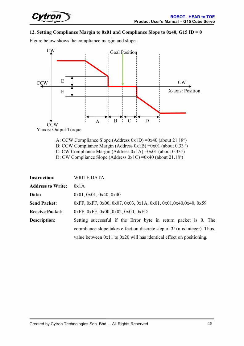
12. Setting Compliance Margin to 0x01 and Compliance Slope to 0x40, G15 ID = 0Figure below shows the compliance margin and slope.
E
E
A: CCW Compliance Slope (Address 0x1D) =0x40 (about 21.18o)B: CCW Compliance Margin (Address 0x1B) =0x01 (about 0.33 o)C: CW Compliance Margin (Address 0x1A) =0x01 (about 0.33 o)D: CW Compliance Slope (Address 0x1C) =0x40 (about 21.18o)
B C D
Goal Position
CWCCW
CW
CCWA
Y-axis: Output Torque
X-axis: Position
Instruction: WRITE DATA
Address to Write: 0x1A
Data: 0x01, 0x01, 0x40, 0x40
Send Packet: 0xFF, 0xFF, 0x00, 0x07, 0x03, 0x1A, 0x01, 0x01,0x40,0x40, 0x59
Receive Packet: 0xFF, 0xFF, 0x00, 0x02, 0x00, 0xFD
Description: Setting successful if the Error byte in return packet is 0. The
compliance slope takes effect on discrete step of 2n (n is integer). Thus,
value between 0x11 to 0x20 will has identical effect on positioning.

ROBOT . HEAD to TOEProduct User’s Manual – G15 Cube Servo
Created by Cytron Technologies Sdn. Bhd. – All Rights Reserved 49
13. Position the output shaft of G15 with ID 0 to 0o and output shaft of G15 with ID 1 to300o and initiate the movement at the same time (Normal Positioning Mode).REG WRITE instruction together with ACTION instruction needs to be used in this case, so
that both G15 units can start to move to goal position at the same time. Broadcast ID is used
to send the ACTION instruction to both G15 units at the same time.
Instruction: REG WRITE, ACTION
Address to Write: 0x1E
Data for ID 0: 0x00, 0x00
Data for ID 1: 0x8B, 0x03
Send Packet ID 0: 0xFF, 0xFF, 0x00, 0x05, 0x04, 0x1E, 0x00, 0x00, 0xD8
Receive Packet ID 0: 0xFF, 0xFF, 0x00, 0x02, 0x00, 0xFD
Send Packet ID 1: 0xFF, 0xFF, 0x01, 0x05, 0x04, 0x1E, 0x8B, 0x03, 0x49
Receive Packet ID 1: 0xFF, 0xFF, 0x01, 0x02, 0x00, 0xFC
Send Packet Broadcast ID: 0xFF, 0xFF, 0xFE, 0x02, 0x05, 0xFA
Description: Setting successful if the Error byte in return packet is 0. The
last broadcast packet will have no return status packet.

ROBOT . HEAD to TOEProduct User’s Manual – G15 Cube Servo
Created by Cytron Technologies Sdn. Bhd. – All Rights Reserved 50
14. Set the goal position to 100o and G15 output shaft rotate CW to goal position withDirection Positioning Mode. G15 has ID 0.
Bit 15 14 13 - 11 10 - 0
Definition Direction Positioning Mode=1 Direction Unused Goal position
Goal Position 100 o=0x12E, Goal Position after add the direction=0xC12E
Instruction: WRITE DATA
Address to Write: 0x1E
Data: 0x2E, 0xC1
Send Packet: 0xFF, 0xFF, 0x00, 0x05, 0x03, 0x1E, 0x2E, 0xC1, 0xEA
Receive Packet: 0xFF, 0xFF, 0x00, 0x02, 0x00, 0xFD
Description: Setting successful if the Error byte in return packet is 0.
15. Position the output shaft of G15 with ID 0 to goal position 180o with angular speed of
57RPM (Normal Positioning Mode with speed control).Position 180o= 0x220, 57 RPM: MOVING SPEED = 0x247
Instruction: WRITE DATA
Address to Write: 0x1E
Data: 0x20, 0x02, 0x47, 0x02
Send Packet: 0xFF, 0xFF, 0x00, 0x07, 0x03, 0x1E, 0x20, 0x02, 0x47, 0x02, 0x6C
Receive Packet: 0xFF, 0xFF, 0x00, 0x02, 0x00, 0xFD
Description: Setting successful if the Error byte in return packet is 0.
Direction=0: CCW rotation
Direction =1: CW rotation

ROBOT . HEAD to TOEProduct User’s Manual – G15 Cube Servo
Created by Cytron Technologies Sdn. Bhd. – All Rights Reserved 51
16. Move the output shaft of G15 with ID 0 to goal position 180o in 20 seconds (NormalPositioning Mode with time control)Position 180o = 0x220, 20 seconds: MOVING SPEED = 0xC8, MOVING SPEED after
setting for time control = 0x80C8
Bit 15 14-12 11-0
Definition 1 unused Time to Goal Position
Instruction: WRITE DATA
Address to Write: 0x1E
Data: 0x20, 0x02, 0xC8, 0x80
Send Packet: 0xFF, 0xFF, 0x00, 0x07, 0x03, 0x1E, 0x20, 0x02, 0xC8, 0x80, 0x6D
Receive Packet: 0xFF, 0xFF, 0x00, 0x02, 0x00, 0xFD
Description: Setting successful if the Error byte in return packet is 0.
17. Lock all Control Register address except address 0x18-0x23 for G15 with ID 0
Instruction: WRITE DATA
Address to Write: 0x2F
Data: 0x01
Send Packet: 0xFF, 0xFF, 0x00, 0x04, 0x03, 0x2F, 0x01, 0xC8
Receive Packet: 0xFF, 0xFF, 0x00, 0x02, 0x00, 0xFD
Description: Locking successful if the Error byte in return packet is 0.
If any attempt to access locked address, status packet with error is returned.
Example:
Send Packet: 0xFF, 0xFF, 0x00, 0x05, 0x03, 0x30, 0x40, 0x00, 0x87
Receive Packet: 0xFF, 0xFF, 0x00, 0x02, 0x08, 0xF5
(Range Error)

ROBOT . HEAD to TOEProduct User’s Manual – G15 Cube Servo
Created by Cytron Technologies Sdn. Bhd. – All Rights Reserved 52
18. Set Minimum torque (PUNCH) to 0x40 for G15 with ID 0Instruction: WRITE DATA
Address to Write: 0x30
Data: 0x40, 0x00
Send Packet: 0xFF, 0xFF, 0x00, 0x05, 0x03, 0x30, 0x40, 0x00, 0x87
Receive Packet: 0xFF, 0xFF, 0x00, 0x02, 0x00, 0xFD
Description: Setting successful if the Error byte in return packet is 0.
ROBOT . HEAD to TOEProduct User’s Manual – G15 Cube Servo
Created by Cytron Technologies Sdn. Bhd. – All Rights Reserved 53
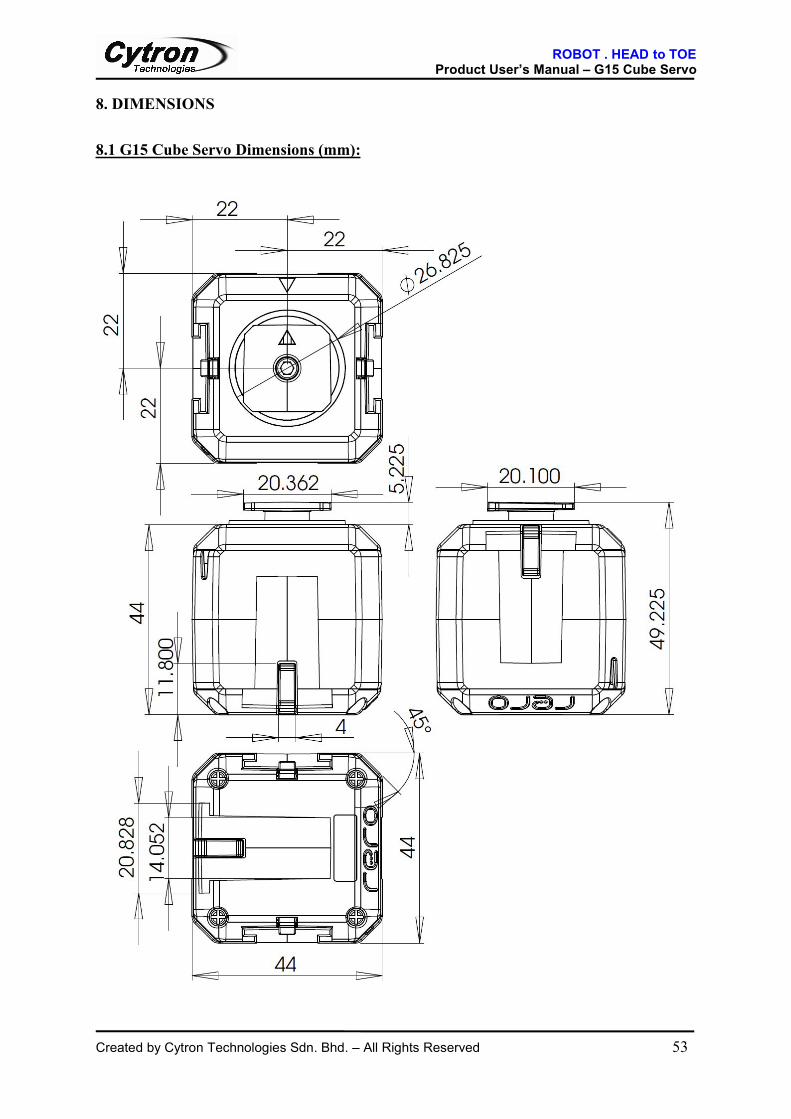
8. DIMENSIONS
8.1 G15 Cube Servo Dimensions (mm):

ROBOT . HEAD to TOEProduct User’s Manual – G15 Cube Servo
Created by Cytron Technologies Sdn. Bhd. – All Rights Reserved 54
8.2 G15 Inter Connect Dimensions (mm):
8.3 G15 External Joint Dimensions (mm):

ROBOT . HEAD to TOEProduct User’s Manual – G15 Cube Servo
Created by Cytron Technologies Sdn. Bhd. – All Rights Reserved 55
8.4 G15 Rotatable Connect Dimensions (mm):
8.5 G15 U-Joint Dimensions (mm):

ROBOT . HEAD to TOEProduct User’s Manual – G15 Cube Servo
Created by Cytron Technologies Sdn. Bhd. – All Rights Reserved 56
9. WARRANTY
Product warranty is valid for 6 months. Warranty only applies to manufacturing defect. Damage caused by misuse is not covered under warranty. Warranty does not cover freight cost for both ways.
Prepared byCytron Technologies Sdn. Bhd.
19, Jalan Kebudayaan 1A,Taman Universiti,
81300 Skudai,Johor, Malaysia.
Tel: +607-521 3178Fax: +607-521 1861
URL: www.cytron.com.myEmail: [email protected]